COM(83)550 final - EUR-Lex
109
ARCHIVES HISTORIQUES DE LA COMMISSION COLLECTION RELIEE DES DOCUMENTS "COM" COM (83) 550 Vol. 1983/0208
-
Upload
khangminh22 -
Category
Documents
-
view
0 -
download
0
Transcript of COM(83)550 final - EUR-Lex

ARCHIVES HISTORIQUES DE LA COMMISSION COLLECTION RELIEE DES DOCUMENTS "COM" COM (83) 550 Vol. 1983/0208

Disclaimer
Conformément au règlement (CEE, Euratom) n° 354/83 du Conseil du 1er février 1983 concernant l'ouverture au public des archives historiques de la Communauté économique européenne et de la Communauté européenne de l'énergie atomique (JO L 43 du 15.2.1983, p. 1), tel que modifié par le règlement (CE, Euratom) n° 1700/2003 du 22 septembre 2003 (JO L 243 du 27.9.2003, p. 1), ce dossier est ouvert au public. Le cas échéant, les documents classifiés présents dans ce dossier ont été déclassifiés conformément à l'article 5 dudit règlement.
In accordance with Council Regulation (EEC, Euratom) No 354/83 of 1 February 1983 concerning the opening to the public of the historical archives of the European Economic Community and the European Atomic Energy Community (OJ L 43, 15.2.1983, p. 1), as amended by Regulation (EC, Euratom) No 1700/2003 of 22 September 2003 (OJ L 243, 27.9.2003, p. 1), this file is open to the public. Where necessary, classified documents in this file have been declassified in conformity with Article 5 of the aforementioned regulation.
In Übereinstimmung mit der Verordnung (EWG, Euratom) Nr. 354/83 des Rates vom 1. Februar 1983 über die Freigabe der historischen Archive der Europäischen Wirtschaftsgemeinschaft und der Europäischen Atomgemeinschaft (ABI. L 43 vom 15.2.1983, S. 1), geändert durch die Verordnung (EG, Euratom) Nr. 1700/2003 vom 22. September 2003 (ABI. L 243 vom 27.9.2003, S. 1), ist diese Datei der Öffentlichkeit zugänglich. Soweit erforderlich, wurden die Verschlusssachen in dieser Datei in Übereinstimmung mit Artikel 5 der genannten Verordnung freigegeben.

C O M M I S S I O N O F T H E E U R O P E A N C O M M U N I T I E S
COM(83) 5 5 0 f i n a l
Brussels, 21 September 1983
PROJECTS OF EUROPEAN SIGNIFICANCE
(Second P r o g r e s s Report from t h e Commission t o the C o u n c i l )
COM(83) 5 5 0 f i n a l

- 1 -
TABLE OF CONTENTS
Page
PROJECTS OF EUROPEAN SIGNIFICANCE 2
I . A TRITIUM HANDLING LABORATORY AT J.R.C.-ISPRA Second p r o g r e s s r e p o r t 1.1
1. I n t r o d u c t i o n 1.4 2. E x e c u t i v e Summary 1.6 3. Main r e p o r t 1.18
I I . A VIBRATING TABLE AT J.R.C.-ISPRA Second p r o g r e s s r e p o r t I I . 1
I I I . PERSPECTIVES OF HOSTING AT THE J.R.C.-ISPRA ESTABLISHMENT A FUSION MACHINE LIKE IGNITOR -Second p r o g r e s s r e p o r t I I I . 1
- 2 -Commission of the European Communities
J o i n t Research Center
PROJECTS OF EUROPEAN SIGNIFICANCE
1. I n t r o d u c t i o n
Three p r e l i m i n a r y s t u d i e s were begun i n March 1983 f o l l o w i n g t h e C o u n c i l meeting o f the 10th of t h a t month i n which the Commission was r e q u e s t e d t o s t u d y p r o j e c t s s u i t a b l e f o r s i t i n g at the JRC I s p r a E s t a b l i s h m e n t .
Terms of r e f e r e n c e i n c l u d e d e x a m i n a t i o n of :
- o p p o r t u n i t y and need a t Community l e v e l ; - f e a s i b i l i t y at I s p r a ; - investment c o s t s .
The s u b j e c t s examined a r e :
~ a T r i t i u m H a n d l i n g L a b o r a t o r y ; - a V i b r a t i n g T a b l e ; - I g n i t o r .
These s u b j e c t s b e i n g of d i f f e r i n g n a t u r e s , d i f f e r e n t elements have had t o be taken i n t o account i n each case and the r a t e of p r o g r e s s has not been u n i f o r m .
2. T r i t i u m H a n d l i n g L a b o r a t o r y .
The second p r o g r e s s r e p o r t on the f e a s i b i l i t y of c o n s t r u c t i n g i n I s p r a a T r i t i u m H a n d l i n g L a b o r a t o r y has reached the n e c e s s a r y completeness as t o c o n s t i t u t e a complete t e c h n i c a l s t u d y . T h i s r e p o r t has been a l r e a d y p r e s e n t e d t o the C o n s u l t a t i v e Committee f o r F u s i o n Programme (CCFP), which has i n t r o d u c e d the t r i t i u m i n i t s a c t i o n of " F i r s t Round P r o j e c t s " i n the frame of the 1982-1986 F u s i o n Technology Programme.

- 3 -
The o p p o r t u n i t y and the need of a European T r i t i u m H a n d l i n g L a b o r a t o r y to s e r v e the f u s i o n r e a c t o r r e s e a r c h programme, a l r e a d y s t r e s s e d by the F u s i o n Review P a n e l h e l d i n 1981, i s w e l l demonstrated. The r e p o r t a n a l y z e s i n d e t a i l the expected problems r e l a t e d t o t r i t i u m i n the d e s i g n - s t u d i e s of the post-JET e x p e r i m e n t a l r e a c t o r INTOR and of NET (Next European T o r u s ) . The t r i t i u m c y c l e i n a f u s i o n r e a c t o r has o p e r a t i o n a l and s a f e t y r e q u i r e m e n t s which a r e d i f f e r e n t from and much more complex than t h o s e found i n m i l i t a r y p l a n t s f o r t r i t i u m p r o d u c t i o n .
JRC-ISPRA can c a n d i d a t e f o r t h e c o n s t r u c t i o n and o p e r a t i o n of such a L a b o r a t o r y on the b a s i s of past and p r e s e n t e x p e r i e n c e i n hydrogen-i s o t o p e s t e c h n o l o g y .
The f a c i l i t y t o be p l a c e d at the d i s p o s a l of a l l the f u s i o n a s s o c i a t i o n s , would be a f l e x i b l e m u l t i p u r p o s e i n s t a l l a t i o n , c a p a b l e of h a n d l i n g up t o 100 grams of T r i t i u m . I t would be m o s t l y d e d i c a t e d to s t u d y t r i t i u m - r e l a t e d s a f e t y p r o b l e m s , t o p r o v i d e c o n d i t i o n s t o handle and t e s t components as w e l l as t r i t i a t e d p a r t s of the f u s i o n r e a c t o r s .
The t o t a l s t a f f i n g o f the l a b o r a t o r y when i n o p e r a t i o n i s e v a l u a t e d i n a maximum of 25 persons (of which 7 p r o f e s s i o n a l s ) . The p r e v i o u s e v a l u a t i o n of the i n s t a l l a t i o n c o s t s of the L a b o r a t o r y , about 10 Mio ECUS (1983 v a l u e ) , i s b e i n g e v a l u a t e d more p r e c i s e l y by an e x t e r n a l e n g i n e e r i n g bureau. The r e s u l t s of t h i s s t u d y w i l l be a v a i l a b l e by September 1 5 t h .
3. V i b r a t i n g T a b l e
The second p r o g r a s s r e p o r t on v i b r a t i n g t a b l e s i s f i r s t of a l l a d e t a i l e d s t u d y on the needs of t h i s k i n d of i n s t a l l a t i o n s as w e l l as of t h e i r p r e s e n t a v a i l a b i l i t y i n t h e Community and i n the w o r l d . A l s o , c u r r e n t r e s e a r c h on s e i s m i c a n a l y s i s i s r e v i e w e d , i n o r d e r t o a s s e s s c u r r e n t t r e n d s i n t h i s f i e l d .

Most Member S t a t e s c o n s i d e r t h a t p r e s e n t norms f o r s e i s m i c d e s i g n may be a d e q u a t e l y f u l f i L l e d u s i n g a l r e a d y a v a i l a b l e e x p e r i m e n t a l and a n a l y t i c a l t o o l s . N e v e r t h e l e s s , t h e r e i s a shared f e e l i n g i n the Community t h a t a s h a k i n g t a b l e of l a r g e r c a p a c i t y than e x i s t i n g ones might be b e n e f i c i a l as a c o o p e r a t i v e European e f f o r t , i n o r d e r t o s t a n d a r d i z e ground motion measurements, thus c r e a t i n g a European dat a base, and d e v e l o p and t e s t r e f i n e d models and computer codes, t o enable a b e t t e r u n d e r s t a n d i n g of t h e phenomena and improve s a f e t y norms.
No major problems seem t o e x i s t f o r the s i t i n g of such a t a b l e i n J R C - I s p r a . However, st u d y c o n t r a c t s have been launched i n o r d e r t o i n v e s t i g a t e by s t a t i c and dynamic g e o t e c h n i c a l t e s t s the adequacy of the p r e s e l e c t e d s i t e i n t h e I s p r a E s t a b l i s h m e n t t o host the i n s t a l l a t i o n .
The JRC w i l l c o n t i n u e i n the next y e a r s the a c c u r a t e t e c h n i c a l and f i n a n c i a l assessment o f t h i s o p e r a t i o n , which p r e s e n t s a s p e c t s of g r e a t i n t e r e s t f o r the Community's needs, and i s w e l l p l a c e d i n the g e n e r a l s a f e t y m o t i v a t i o n of the J o i n t Research C e n t e r .
4. I g n i t o r
In t h i s second p r o g r e s s r e p o r t , t h e t h r e e main items r e l e v a n t f o r the s i t i n g o f IGNITOR i n J R C - I s p r a : e l e c t r i c a l s u p p l y system, main b u i l d i n g and a u x i l i a r y systems and l i c e n s i n g , have been f u r t h e r i n v e s t i g a t e d . In p a r t i c u l a r , i n s t a l l a t i o n c o s t s and t h e annual charge f o r t h e e l e c t r i c a l power s u p p l y have been a s s e s s e d .
The i n s t a l l a t i o n i n the ESSOR containment b u i l d i n g may o f f e r p r a c t i c a l a d vantages, due t o e x i s t i n g f a c i l i t i e s i n t h i s a r e a . The l i c e n s i n g p rocedure does not seem t o p r e s e n t major problems.
The f i n a l e v a l u a t i o n o f a l l the c o s t s i n v o l v e d i n the I g n i t o r i n s t a l l a t i o n , as w e l l as the complete t e c h n i c a l s t u d y w i l l be the o b j e c t of a f i n a l r e p o r t , which w i l l be ready at the end of September 1983. The J o i n t Research Center c o n s i d e r s i n t h i s way t o have f u l f i l l e d i t s o b l i g a t i o n t o p r epare a f e a s i b i l i t y s t u d y f o r the s i t i n g of IGNITOR i n I s p r a . I t w i l l proceed f u r t h e r i n the case a req u e s t i n t h i s sense would be f o r m u l a t e d by at l e a s t one of the F u s i o n A s s o c i a t i o n s .

COMMISSION OF THE EUROPEAN COMMUNITIES JOINT RESEARCH CENTER
I . A TRITIUM HANDLING LABORATORY AT
J.R.C. - ISPRA
Second p r o g r e s s r e p o r t

I . 2
TABLE OF CONTENTS
page
1. INTRODUCTION I . 4
2. EXECUTIVE SUMMARY I . 6
2. 1 G e n e r a l Remarks I . 7 2. 2 The NET req u i r e m e n t s I . 7 2. 3 Review of the e x i s t i n g Know-how and of the a c t i v i t y i n
p r o g r e s s I . 8 2. 4 JRC - e x p e r i e n c e and p r e s e n t a c t i v i t i e s I . 9 2. :5 O b j e c t i v e s of the JRC - T r i t i u m L a b o r a t o r y 1.10 2. 6 D e s c r i p t i o n o f the L a b o r a t o r y 1.11 2. 7 L o c a t i o n 1.12 2. 8 L i c e n s i n g p r o c e d u r e s 1.12 2. 9 P l a n n i n g and r e s o u r c e s 1.13 2.10 C o n c l u s i o n s 1.14
3. MAIN REPORT ! . 1 8
3. 1 Remarks r e l a t e d t o f u s i o n r e a c t o r s as br e e d e r r e a c t o r s 1.19 3. 2 NET and power r e a c t o r r e q u i r e m e n t s r e l a t e d t o t r i t i u m 1.21
3.2.1 I n t r o d u c t i o n 1.21 3.2.2 T r i t i u m p e r m e a t i o n and i n v e n t o r y i n s t r u c t u r a l
m a t e r i a l s 1.21 3.2.3 T r i t i u m p r o c e s s i n g systems 1.23 3.2.4 E f f e c t s of t r i t i u m c o n t a m i n a t i o n d u r i n g s t a n d a r d
o p e r a t i o n , maintenance and a c c i d e n t a l c o n d i t i o n s 1.26
3.2.5 T r i t i u m i n v e n t o r y 1.28 3.2.6 Time s c a l e r e q u i r e m e n t s f o r R&D 1.29
. / .

I . 3
3. 3 Review of the e x i s t i n g know-how and of the a c t i v i t i e s i n p r o g r e s s 1.30
3.3.1 E x p e r i e n c e from f i s s i o n r e a c t o r s 1.30 3.3.2 A c t i v i t i e s i n s u p p o r t t o F u s i o n 1.31
3. 4 Past and p r e s e n t a c t i v i t i e s a t JRC 1.38
3.4.1 O p e r a t i v e e x p e r i e n c e i n t r i t i u m h a n d l i n g and m o n i t o r i n g 1.38
3.4.2 Research a c t i v i t i e s i n f u s i o n t e c h n o l o g y r e l a t e d t o t r i t i u m problems 1.41
3. 5 O b j e c t i v e s o f the JRC T r i t i u m L a b o r a t o r y I.47
3.5.1 M o t i v a t i o n and o r i e n t a t i o n I.47
3.5.2 E x p e r i m e n t a l program p r o p o s e d , r e l a t e d t o the JRC -F u s i o n a c t i v i t y 1.48
3. 6 D e s c r i p t i o n of the l a b o r a t o r y 1.58
3.6.1 B u i l d i n g 1.58 3.6.2 T r i t i u m containment systems 1.58 3.6.3 S i t i n g o f t h e l a b o r a t o r y 1.60 3.6.4 L i c e n s i n g p r o c e d u r e s 1.61 3.6.5 P l a n n i n g and r e s o u r c e s I.70 3.6.6 Cost e v a l u a t i o n 1.71
3. 7 C o n c l u s i o n s 1.72
APPENDIX 1 : F i r s t round p r o j e c t s on t r i t i u m s e t up by the F u s i o n t e c h n o l o g y S t e e r i n g Committee I.73

I . 4
1. Introduction
Tritium has been utilized for many years already in the countries of the European Community in the field of biological, biochemical and chemical research and even for industrial and commercial applications. The confinement and conditioning of tritiated waste waters arising in nuciear fuel reprocessing have also been objectives of research efforts in the Community. Tritium will be used as a fuel in fusion reactors, but its handling in large quantities implies the development of advanced and safe technologies. Anyway, tritium is produced in macroquantities in classified installations of the nuciear weapon states, i.e. France and Great Britain. These two countries have declared, in a statement at the Atomic Questions Group in December 1981 (ref. 1), to be disposed to the release of know-how in tritium technology relevant to fusion. The statement of the UK delegate, which the French delegation declares to support, without reservations, ends as follows: " I am authorized to state that the United Kingdom would be happy to assist the "Commission and the Community oy making available to it information concerning "its axperience with tritium technology relevant to the Community's programme. "I would hope that this would help to define more closely the areas where new "work needs to be undertaken."
The concern, however, expressed by the "European Fusion Review Panel" in its report of December 1981, "that only a pan'of the know-how required in this field (namely the manipulation of tritium for the purpose of fusion technology) exists already in the classified laboratories", is understandable, if one takes into account the quite different goals and requirements such techniques have been developed for. The panel supports its statement by the fact that the United States have built a civil tritium laboratory at Los Alamos, dedicated to fusion. Such a laboratory was felt to be mainly necessary to demonstrate, in relation to regulatory requirements, the safety of the tritium manipulation techniques for the civil application of fusion. This laborator/, however, is not completely open to international collaboration. The panel recommends the construction of a tritium test facility devoted to the development of technologies in the frame of the Community's Fusion Programme, in consideration of the fact that Europe is in an extremely weak position in this field. The panel points cut furthermore the opportunity to deal already now with the aspects of safety and the environmental impact of fusion anticipating the problems of its industrial application (ref. 2). Among the principal items of these safety aspects the handling of tritium is mentioned. Similar concern for tritium related safety aspects was expressed by an IAEA workshop (ref. 3), attributing high priority to research and development on tritium problems.
The Commission of the European Communities, aware of the problem, have introduced the tritium question in its "First Round Projects" aimed at sharing R&D activities in the Community in the frame of the 1982-1986 Fusion Programme (ref. 4).

I . 5
References
1. Statement of the British and French delegations at the Atomic Questions Group offering the release of know-how in tritium technology relevant to fusion. Annex A and Β to document ΑΤΟ 98, 10 December 1981.
2. Rapport du "European Fusion Review Panel", Commission des Communautés Européennes, CRE3T-EN/216b, SEC(81) 1933, Brussels, 3 December 1981.
3. IAEA workshop on Fusion Safety, 23-27 March, 1981. 4. European Fusion Technology Programme 1982-1986, Tasks T l toT6.(see appendix 1).

I . 6
2. EXECUTIVE SUMMARY

I . 7
2.1 General Remarks
The basic factors of the tritium cycle of a post-JET experimental reactor (INTOR) and of a power fusion reactor are summarized in Table 1 and F i g . l . This cycle has a number of requirements which are new as compared to the ones related to those found in military plants for trit ium production. In this last case, in particular, there is no plasma chamber, no exhaust processing nor recovery from coolant. Furthermore there is no requirement for tritium breeding as in the power fusion plant. This indicates that there w i l l be many components and processing units, in the tritium fuel cycle of a fusion reactor, that have no equivalent in the technology developed so far, and that require specific R&D.
Table 1: Tritium Balance in Fusion Reactors
Tritium flow Inventory Tritium burned Tritium breeding rate g/d kg kg/a rate
I N T O R ^ 1600 4-5 12 0.6
POWER , . REACTOR ' 8000 10-20 120 1.05
(1) stage I I I , 50% avai lab i l i ty ; (2) 1600 Mwe, 80% avai labi l i ty
2.2 The NET requirements
In order to identify the specific research and development needs in Europe, a detailed analysis of the expected problems related to tritium in NET (Next European Torus) has been performed. For this analysis reference is made above a l l to the design study of INTOR (phase 1 and phase 2a). The main topics investigated are :
a) trit ium permeation, inventory and outgassing in structural materials ( f i r s t wall and reactor components);
b) systems related to the various aspects of the fuel cycle (tritium recovery from exhaust plasma, coolant and breeder; fuel l ing, waste treatment and disposal) ;
c) reactor contamination during standard operation, maintenance and accidental conditions;
d) processing and disposal of structures and components as waste.
I . 8
Regarding topic a), the problems related to tritium implantation and permeation through the f i r s t wall are complex and the available'data insufficient. An effort is required to extend the existing data on permeation and outgassing · of H/D to tr i t ium, and to study the combined effects of neutron irradiation and tr i t ium. Regarding topic b), different schemes have been proposed for plasma exhaust neutral beam processing, fuel l ing, coolant detr i t iat ion and t r i tium recovery from blanket. The need to develop large tritium-compatible components has been recognized. This applies in particular to pumps (cryogenic-and turbomolecular pumps) as well as to valves and other c i r cuit components. An important problem w i l l be that of reweldability of steel with high tritium content. A number of specific needs related to the single flow-sheets have been identified. The development of apparatus is considered important in order to optimise the various processes. This applies, in particular to systems for gas purification (cold traps, catalytic oxidation) and to isotopic separation units (cryogenic d i s t i l l a t i o n , gas chromatography, electrolysis, etc.) for the plasma exhaast In these fields the experience accumulated in fission reactors and military applications wi l l be of particular help.
2.3 Review of the existing know-how and of the act ivi ty in progress
The available knowledge on tritium problems and in particular on tritium technology is mainly based on the operation experience of fission reactors (in particular heavy water and HTGR reactors) and on the confinement and conditioning of waste water arising in fission fuel reprocessing plants, whereas the information coming from the military applications is for the moment s t i l l l imited. Heavy water reactors give problems related to handling of large volumes of t r i t ia ted water and to i t s processing. Important experience has been gained both in Europe and world-wide (mainly in Canada) on these problems. A detri t iat ion system capable to extract up to 160.000 Ci/a of trit ium from heavy water is in operation at the high flux reactor of Grenoble, based on a process developed by CEA. In HTGRs the problems related to tritium permeation from the primary coolant c i rcu i t have been investigated and solutions to reduce such permeation by coatings have been proposed. Tritium is also a by-product of nuclear (fission) power generation where i t becomes a concern essentially at the spent fuel reprocessing stage. Research act ivi t ies on the treatment, conditioning and disposal of t r i t i a ted waste waters have been shared in the member countries of the EC in the framework of the "Management and Storage of Radioactive Waste" programme (DG XII). In the framework of the "Fusion Programme" some actions have been undertaken in Europe to deal with tritium problems, namely :

I . 9
- conceptual design studies on the fuel cycle of experimental and power reactors;
- design of the tritium plant for the JET-operation with trit ium; - definition of a f i r s t experimental research programme.
The Joint European Torus is scheduled to operate in i ts second phase with tr i t ium. So a trit ium plant w i l l be installed in the JET area to purify the burned gases coming from the plasma chamber and from the neutral injectors. The JET staff is now engaged on detail specification of the Tritium Plant incorporating the essential process elements. A research programme to investigate the tritium problems related to NET and power reactor development has been launched recently by the Commission in the framework of the Fusion Technology actions decided by the Fusion Technology Steering Committe. Study contracts have been proposed by the European Fusion Associations. The areas considered are :
- fuel clean-up system; - tritium recovery from waste streams; - tritium detector; - e lectrolyt ic eel 1; - decontamination system; - industrial development of large components; - tritium recovery from blanket ( l iquid and solid breeder).
The total amount of money already allocated is about 11 MECU. The experimental work w i l l cover the period 1984-1986. In USA the construction of the Tritium System Test Assemvly (TSTA) at Los Alamos is now complete and the commissioning tests with tritium are expected to start in autumn this year. Other laboratories such as Mound Laboratory and Lawrence Livermore Laboratory are engaged in experimental research. Design and specifications of components for the tritium test plant of the Princeton Large Tokamak TFTR have been also performed. In Japan a Tritium Process Laboratory of multipurpose type is in construction. The operation is planned for 1985.
2.4 JRC-experience and present act ivi t ies
At JRC-Ispra two heavy water test reactors have been operated for many years, the Ispra-1 reactor and the ESSOR reactor. Therefore the Centre is well equipped for trit ium monitoring, health physics and in- f ie ld control analysis. It has experience on maintenance and component replacement for tritium-contaminated water loops and hardware. In the framework of the JRC Hydrogen Programme, now approaching i ts conclusions, a well acknowledged experience on problems related to hydrogen production, handling, corrosion etc. , has been acquired. In the framework of the JRC-Fusion Technology Programme a number of ac t i v i ties related to trit ium are on-going at Ispra; these ac t iv i t ies , started in 1978, are of three types: - conceptual design and flow-sheet assessments related to the fuel cycle
of experimental and power reactors;

I . 10
- measurement.of basic data on H/D Interaction with metals and breeding materials;
- experiments with H/D to investigate the feas ib i l i ty of some aspects of the processes of the fuel cycle (electrolytic cel l development, tritium recovery from l iquid breeders).
2.5 Objectives of the JRC-Tritium Laboratory
The analysis of the expected problems in NET and power reactors and of the existing know-how calls for a strong effort in the coming years. On the basis of the multi-facet situation previously decribed i t is believed that a Tritium Laboratory at the JRC-Ispra, dedicated primarily to the safety problems of tritium technology in fusion f i t s well to the planned act ivi t ies within the Member Countries of the Community. There are common objectives to be achieved in this f i e l d , to which the laboratory w i l l be devoted, such as :
. acquire experience on handling tritium in complex systems in connection with the safety of operators during routine operation (general and in dividual protective means as well as with the protection of the environment (waste treatment, emergency clean-up, monitoring);
. provide the conditions to experience procedures for handling t r i t ia ted parts of the reactor and to optimize process components in relation to their operational safety and tritium inventory. In particular :
a) execute experiments based on tritium loaded mock-ups reproducing renewable parts of the NET reactor and aimed at decontamination and/or further treatment and conditioning (boots, seals, weldings) in adverse operating conditions and by remote handling;
b) test new concepts and components developed in the European laboratories, such as gas chromatography, electrolyzers and catalyzers, t r i tium recovery systems from blanket;
c) check the val idi ty of physico-chemical data extrapolated to the t r i tium case from H/D behaviour. The r e l i a b i l i t y of such data is of p r i mary importance for the proper design of containment and clean-up systems.
To cope with these requirements, a flexible multipurpose instal lat ion rather than a f ac i l i t y devoted to a specific problem or system seems to be the most suited. Given the objectives of the laboratory, a total trit ium inventory not exceeding 100 g can be taken as reference value for the design. The laboratory u t i l i sa t ion w i l l be oriented towards two goals: - to host research groups from the European Associations not disposing of
f ac i l i t i e s for tritium handling, - to perform tritium related experiments in the frame of the JRC-Fusion
Technology programme. They are :
I . 11
. an investigation of the outgasing of D/T in f i r s t wall structures;
. a simulation by mock-ups of the handling and treatment of typical reactor components (as for instance the blanket and divertor/1imiter segments ) ;
. the optimisation of some process systems such as the electrolytic cells and the gas chromatography technique for isotope separation;
. the tritium recovery from liquid breeders.
These items correspond to the work already in progress at Ispra in "cold" conditions ( i . e . with hydrogen and deuterium) and/or to the design ac t iv i ty being pursued in the INTOR/NET frame work.
These experimental act ivi t ies imply the avai labi l i ty of adequate and reliable systems and procedures, for health protection and safety, which can not therefore represent a research item "a p r io r i " . It is intended, however, to evaluate and to qualify by their day-to-day performance in practical conditions, systems and procedures such as :
. monitoring systems for area and surface contamination,
. protective clothing and equipment,
. dosimetry and operator surveillance,
. environmental dispersion and control,
. secondary containment clean-up and gaseous waste treatment systems,
. procedures for intervention and maintenance,
. glove-box techniques,
. tritium-compatible materials and equipment.
The results w i l l help to formulate recommendations for future f ac i l i t i e s and in particular for the appropriate design of fusion reactor systems.
2.6 Description of the Laboratory
A layout of the laboratory is shown in Fig.2. It includes:
- a Hall for Process Development (HPD.) of about 3000 m volume, equipped for housing glove boxes with inert atmosphere to allow the installation and handling of equipment containing large amounts of tr i t ium. The H.P.D. will be air-tight.with.interlocked doors and be kept s l ightly below at-
. mospherlc pressure by an appropriate "hot ventilation" systems. In case 9 f abnormal tritium release from the secondary containment to the atmosphere of the H.P.D., an Emergency Clean-up (E.C.U.) system, automatically actuated, w i l l be able to reduce the tritium concentration in the operational area and the tritium release to the environment to permissible levels. The H.P.D. wi^l include an additional f a c i l i t y (expanded area) consisting of a 500 m steel box ful ly tight and separately ventilated. This w i l l provide a containment for large components and wi l l allow experimental tests on their detri t iat ion and handling.
3 - A set of laboratories (about 450 m ) for experiments with low-tritium
inventory. - A laboratory for t r i t ia ted l iquid waste conditioning and containing the
gaseous waste treatment (G.W.T.) systems.

I. 12
In order to comply w i th the e x i s t i n g r e g u l a t i o n s fo r nuc lea r f a c i l i t i e s the l abo ra to ry w i l l a l so inc lude hea l th phys ics room, hea l th physics s tore and moni to r ing s t a t i o n .
2.7 L o c a t i o n
The u t i l i s a t i o n of the ESSOR dome as t e r t i a r y containment i m p l i e s some draw-backs tha t might e a s i l y o f f - s e t the advantages o f having the b u i l d i n g a v a i l a b l e w i th a i r c o n d i t i o n i n g v e n t i l a t i o n and s t ack . The huge volume o f the dome (2 38.000 m ) and the nature of c o n s t r u c t i o n m a t e r i a l s would r e qu i re the r e a l i s a t i o n of another containment s h e l l i n s i d e the dome i n order to keep the emergency c lean-up w i t h i n a reasonable s i z e both fo r investment costs and opera t iona l e f f i c i e n c y . The u t i l i s a t i o n o f the ESSOR bunkers would appear p r a c t i c a l on ly f o r the i n s t a l l a t i o n o f an a l ready f u l l developed and we l l def ined p i l o t i n s t a l l a t i o n to be operated remotely (such as c ryogen ic or water d i s t i l l a t i o n ) due to the d i f f i c u l t i e s f o r access to the bunkers and t h e i r p a r t i c u l a r shape ( u n p r o p o r t i o n a l l y high w i th respec t to t h e i r surface a rea ) . A t h i r d p o t e n t i a l area w i t h i n the ESSOR complex i s s i t u a t e d near the s tack and the r eac to r dome. Two p o s s i b i l i t i e s e x i s t . One o f these would a l l o w the i n c o r pora t ion o f the a l ready e x i s t i n g b u i l d i n g f o r the Super-Sara power supply system. The second p o s s i b i l i t y i s to r a t i o n a l i z e the l a y - o u t by c o n s t r u c t i n g a new b u i l d i n g near the s tack ( F i g . 3 ) .
2.8 L i c e n s i n g Procedures
According to the I t a l i a n r e g u l a t i o n s f o r nuc lea r i n s t a l l a t i o n s , the l i c e n s i n g procedure fo r a l a b o r a t o r y handl ing bulk t r i t i u m amounts beyond 100 Ci i s normal ly e s t a b l i s h e d by A r t i c l e 55 o f the LAW D . P . R . 13 .2 .1964 , n.185 which normally i m p l i e s a s t r i c t and l e n g t h l y procedure . A favourab le s i t u a t i o n e-merges i f such a l a b o r a t o r y i s b u i l t a t the J R C - I s p r a , i n the area covered by the e x i s t i n g opera t ion l i c e n s e o f the ESSOR r e a c t o r , u t i l i s i n g f a c i l i t i e s o f the l a t t e r such as s t a c k , gaseous e f f l u e n t s moni to r ing system, power supp ly ( i n c l u d i n g emergency s u p p l y ) , and o t h e r s . In a meeting w i t h r ep re sen ta t ives from the l e g a l and t e c h n i c a l a u t h o r i t i e s fo r nuc lear l i c e n s e s i n I t a l y , the former cons idered tha t a t r i t i u m l a b o r a t o r y should therefore be cons idered as a pa r t o f the ESSOR complex and as such be / , approved by the procedure foreseen f o r " M o d i f i c a t i o n o f e x i s t i n g nuc lea r i n s t a l l a t i o n s " ( s t a r t i n g from a r t . 42 o f D . P . R . 185) . In t h i s case the a u t h o r i z a t i o n f o r the c o n s t r u c t i o n could p o s s i b l y be obta ined w i t h i n l e s s than one y e a r . Another advantage i s tha t the r a d i o a c t i v e r e l ease l i m i t s f o r ESSOR remain v a l i d a l so f o r the t r i t i u m l a b o r a t o r y . Indeed the hazard p o t e n t i a l r ep re sented by the t o t a l inven tory o f t r i t i u m i n the l a b o r a t o r y (100 g) w i l l be lower than the e x i s t i n g reference value f o r the Ex te rna l Emergency Plan o f the Cent re : This p lan r e f e r s to a maximum c r e d i b l e acc iden t of the ESSOR wi th an expected dose of 4 rem to adu l t s l i v i n g i n the nearest v i l l a ge, whereas the maximum re lease o f t r i t i u m (even i n ox ide form) from the 80 m high s tack of ESSOR would g ive a dose o f l e s s than 1 rem.

I. 13
2.9 P lanning and resources
S t a r t i n g from a p o s i t i v e Counci l d e c i s i o n , the f o l l o w i n g steps can be e n v i s a ged f o r the r e a l i s a t i o n of the t r i t i u m l a b o r a t o r y :
A) P repa ra t ion o f the p r e l i m i n a r y safe ty r epor t to be t r ansmi t t ed w i th the request f o r " M o d i f i c a t i o n o f the ESSOR l i c e n s e " to the M i n i s t r y fo r In dus t ry and Trade;
B) Approval o f the request by the safe ty a u t h o r i t i e s together wi th i d e n t i f i c a t i o n of sa fe ty r e l evan t items ( " p r o g e t t i p a r t i c o l a r e g g i a t i " ) ;
C) Execut ive design o f the l abo ra to ry ( exc lud ing experimental equipment);
D) Cons t ruc t ion and mounting o f s t r uc tu r e s and components;
E) Func t iona l t e s t i n g and commiss ioning;
F) Experimental equipment p r e p a r a t i o n .
I t i s intended to perform the phases C to E by an A r c h i t e c t - E n g i n e e r f i r m from o u t s i d e , the task o f which w i l l be to prepare the l a b o r a t o r y , excluded the s c i e n t i f i c equipment. The JRC s t a f f i n g r e q u i r e d f o r the s u p e r v i s i o n of such a con t r ac t and f o r the Implementation o f phase A and B w i l l be l i m i t e d i n the i n i t i a l pe r iod to two p r o f e s s i o n a l s and an adequate number of t e c h n i c i a n s . With the complet ion o f the c o n s t r u c t i o n o f the f a c i l i t y and i t s c o l d commissioning, o ther t e c h n i c ians and opera tors w i l l be added, up to a maximum of about 14 persons, i n c l u ding mechanics, e l e c t r o n i c s and v e n t i l a t i o n s p e c i a l i s t s . In p a r a l l e l the d e s i g n , p repa ra t ion and t e s t i n g of research s p e c i f i c equ ipment w i l l be performed ( p o i n t F ) . This task w i l l be ass igned to the groups a l ready i n v o l v e d a t JRC i n the measurements wi th H/D to eva lua te processes for T r i t i u m Handl ing (Fus ion Safe ty Programme). On t h i s bas i s the t o t a l s t a f f i n g when the l a b o r a t o r y i s i n opera t ion i s evalua ted i n a maximum of 25 persons , 7 o f which w i l l be p r o f e s s i o n a l s . These f i g u r e s do not take i n t o account , of course , s c i e n t i f i c and t e c h n i c a l groups from ou t s ide tha t might be i n t e r e s t e d i n performing s p e c i f i c experiments i n the Ispra l a b o r a t o r y . In Table 2 a break-down of the schedule r e l a t e d to the phases A to F i s g iven
' together wi th tha t o f the o v e r a l l manpower accounted f o r the l a b o r a t o r y ( t a k ing i n t o account the JRC ' s supports and overhead, a f a c t o r o f 2.2 has been a p p l i e d to the above i n d i c a t e d pure ly l a b o r a t o r y s t a f f ) .

I. H
TABLE 2
TIME AND MEN POWER RESOURCES FOR TRITIUM LABORATORY
1 2 Years
3 4 5
A B C
1
D
E
F
Prelim. Safety report A P.S.R. approval Executive design - contractor select.
- project elab. Construct + Mount - construct, selectis.
- construct + mount Funct. testing
Experim. equip. - projects - preparation - cold, tests - install., hot tests
B « 1
F*
C-» ' D —
D «
— — ·
E< • ·
Men power - A to E - F
8 6
20 6
20 10
22 17
30 25
Total 14 26 30 39 55
A p re l imina ry cost e v a l u a t i o n i s being made by an ex te rna l engineer ing bureau. The r e s u l t s w i l l be a v a i l a b l e by September 15th.
2.10 Conclusions
The ana lys i s . performed shows that the problems ra i sed by the presence of t r i t i u m i n the fuel c y c l e of fus ion reac tors are complex. The data and informat ion a l ready a v a i l a b l e or expected from c l a s s i f i e d work do not seem s u f f i c i e n t to solve these problems. A vigorous experimental programme i s needed to meet the requirements o f NET and those of large scale power r eac to r s . On t h i s basis i t has been shown that a l abora to ry for t r i t i u m handling at 0RC could give a s i g n i f i c a n t c o n t r i b u t i o n to the European e f f o r t i n t h i s area. The main ob jec t ive of such a l abora to ry would be that of p rov id ing a basis to t e s t components and opera t ion procedures i n support of the NET design and cons t r u c t i o n . The ob j ec t i ve could be achieved i n the f o l l o w i n g way :
- by making experimental v e r i f i c a t i o n s of concepts r e l a t e d to fuel cyc l e and reac tor opera t ions , accord ing to proposals which w i l l be made by the European Assoc i a t i ons and by the NET team;

I . 15
- by pursuing the t r i t i u m - o r i e n t e d a c t i v i t y s t a r t e d a t JRC i n the framework o f i t s fu s ion technology programme.
This w i l l imply a c l o s e c o l l a b o r a t i o n w i th the European fus ion research cent res and the NET team s t a r t i n g w i th the des ign p h a s e , s i m i l a r to tha t being done i n the other areas o f the Fus ion Technology a c t i v i t y where JRC i s i n v o l v e d . In doing t h i s , p a r t i c u l a r a t t e n t i o n w i l l be payed to a c q u i r i n g exper ience i n the operational s a fe ty aspects r e l a t e d to t r i t i u m , a task which i s i n harmony wi th the general voca t i on o f the JRC, as i t has been r e c e n t l y approved by the Counc i l o f M i n i s t e r s .

The small arrows indicate losses due to leakage / and decay V
In a seiJ'-iUstaming re; Di · Pi - pi > q
F i g . l : Scheme o f the t r i t i u m c y c l e i n a f u s i o n reac to r
F i g . 2 : T r i t i u m l abora to ry l a y - o u t

F i g . 3 : General l a y - o u t of the ESSOR complex

I. 18
3. MAIN REPORT

I. 19
3.1 Remarks related to fusion reactors as breeder reactors
A 1 GWe fusion power plant will bum 120 kg of tritium per year. The total production of tritium from C A N D U reactors in 1980 was (~ 6 GWe installed) 1.4 kg. It is clear that, if fusion power will have to play a significant role in the energy economy, it must be self-sustaining. Each reactor must produce more tritium than the amount needed to fuel the plasma in order to be self-sufficient. The excess tritium will be required . to return the initial supply after some years of operation; . to compensate for losses due to leakage and radioactive decay; . to supply tritium for new power plants.
The tritium breeding ratio (TBR) required to achieve these goals is ideally 1.05. There are reasons to believe that this value is not easy to obtain, and will heavily affect the overall design of the reactor. The basic parameters of the tritium cycle of INTOR and. of a power fusion reactor are summarized in Table 1.
T A B L E 1 - Tritium balance in fusion reactors
Tritium flow Inventory Tritium burned Tritium breeding rate (g/d) (kg) (kg/a) ratio
INTOR 1 1600 5-6 12 0.6-0.7 Power reactor2 8000 10-20 120 1.05
1 stage III, 50% availability. 2 1000 MWe, 80% availability.
The main units and processing steps of the fuel cycle of a fusion reactor are shown in Fig. 1. The rectangles indicate the processing steps, and the circles the units of the reactor where tritium will flow. The arrows from each part of the system indicate leakages and radioactive decay. The requirement of a T B R greater than unity means that the flow rate into the storage exceeds the flow rate from the storage into the plasma, allowing for leakage and decay. In a military plant for tritium production there is no plasma chamber, no exhaust processing, nor recovery from coolant. Furthermore, there is no constraint similar to that on the T B R . In both cases the optimisation of the tritium cycle requires minimizing the radioactive hazard and the leakages, but in the case of a fusion reactor, the constraint of T B R > 1 may be achieved only with a careful reduction of the radioactive decay, which means minimizing inventories and reprocessing times.
This rough picture shows that there are many physical phenomena, components, processing units, in the tritium fuel cycle of a fusion reactor, that have no equivalent in the technology developed so far, and that require specific R & D .

The small arrows indicate losses due to leakage j/ and decay y
In a self-sustaining reactor pi + p2 + p3 > q
- Scheme of die tritium cycle til a fusion reactor.

I . 21
3.2 NET and power reactor requirements related to tritium
3.2.1 Introduction
In the Next European Torus the presence of tritium will play in important role. Therefore it is important to identify the most relevant problems related to tritium "n such a type of machine and evaluate the research and development needed during the various phases of design, construction and operation. The solution of the problems related to tritium for NET will apply to a large extent also to the fusion power reactors. Indeed, all the main tritium systems of these power stations will already be present in the NET-machine. For some problems, e.g. the permeation through the first wall and blanket structures, differences will arise from the operating temperature (higher in case of a-power reactor) or from the irradiation time. A scale-up of the basic components, such as pumps, valves, etc., is also to be expected. However, the research related to N E T should, enable to extrapolate the results to the conditions of a power reactor. A comprehensive assessment,of..these problems has been performed during the INTOR (refs.l:2"> design study. Therefore, we will largely refer to this work to identity the critical issues and the required research and development. The main topics to be investigated can be subdivided as follows: . tritium permeation, inventory and outgassing in structural materials (first wail
and reactor components); . systems related to the various aspects of the fuel cycle (tritium recover/ from
exhaust plasma, coolant and. breeder; fuelling, waste purification and disposal); . reactor contamination during standard operation, maintenance and accidental con
ditions; . waste processing and disposal.
In the following an outline will be given of the state-of-the-art in these areas; then the experimental effort and the related time scale needed to meet the target requirements for the engineering design and construction of NET will be evaluated.
3.2.1 Tritium permeation and inventory in structural materials
Tritium permeation through first wall, limiter or divertor collectors is governed by the implantation of the charge exchange neutral flux in the near surface zone, by the recombination of these atoms into molecules at the plasma/first wall and coolant/first wail interfaces and by diffusion in the bulk of the wall. Where no tritium implantation is present (e.g. in the breeding blanket cooling ducts), the modellisation of the phenomenon is somewhat simpler, since the permeation is . -.. ..— governed by better known physico-chemical phenomena. In the models adopted for calculation of the implantation of charge exchange neutral flux, the surface boundary condition is characterized by a recombination constant which depends on the activation energy for migration, the heat of solution and the

I. 22
Slevert's constant The surface cleanliness is taken into account by a molecular sticking coefficient. On the wail-coolant side, the presence of oxide layers and hydrogen produced by radiolytic decomposition of water originates complex surface conditions which are approximated by recombination limited kinetics or diffusion limited conditions. The diffusion inside, the layer is described by a temperature-dependent diffusion coefficient and also considering a thermal gradient (Soret effect). Neutron damage of the wall is taken into account with a trap concentration and. a detrapping energy. In INTOR, the calculated permeation rates for the first wall (SS-wall surface: 400 m J , Tinner 200 - 300°C, T j U t e r : 100°C, t = 0.5 - 1.3 cm) cover a broad range of values, from 10"- to 0.2 g/a. The highest permeation rates are obtained for dirty inner surface and clean outer surface (Le. low recombination rate on plasma side and high recombination rate on coolant side). In the same way, the. tritium, inventory in the- first wail depends on the recombina-tive and trapping effects- In the INTOR case, values from 0.7 to 7 kg have been evaluated. Both tritium permeation and Inventory decrease with the wail thickness. Variations in duty cycle have small influence. As far as the divertor/limiter collec-. tors are concerned, tritium permeation and inventory vaiues have been found of the same order of magnitude as in the previous case. The relative importance of the tritium permeation and tritium trapping in the wall is strongly related to the temperature of the outer (coolant side) surface.- In the INTOR case, this temperature is low (100°C) whereas for a power reactor it will be much higher (~ 300°C) so increasing strongly the tritium permeation into the coolant and reducing possibly the inventory. In the case of N E T the problem of first wall coolant temperature is still open, a value between 100°C and 300°C could be the selected one. This calls for experimental research over a large range of temperatures both on the inner and outer wall side. The question of tritium outgassing during the dwell time of the pulsed operation ?.nd after the reactor shut-down has been recognized as being one of the most critical. The release of D and T during the dwell time will influence the vacuum conditions and then the pumping requirements. The vacuum chamber has to be pumped down to the pre-shot pressure (~ 10"5 torr); at the same time the gas release from the walls has to be reduced to a level low enough that it does not appreciably influence the D-T species mixture during current initiation and ohmic heating. Tae calculations performed during the INTOR study have shown that, depending on. the hypotheses of the mechanisms for gas desorption and surface conditions, these requirements can or cannot be satisfied. The same uncertainties apply to the case of reactor shutdown. The outgassing rate knowledge is fundamental to establish the operations (waiting time, baking, pumping) before removing the reactor components inside the vacuum vessel. A preliminary calculation has shown that the quantity of tritium retained in the first wall could be significantly reduced by outgassing. A 350°C baking for 100 hours should release about 90% of the tritium trapped in a 13 mm SS first wall. However, neither recombinative, nor trapping effects were taken into account and these results must be reviewed.

I . 23
3 .2 .3 Tritium processing systems
Vacuum requirements and pumping
A number of vacuum systems will be needed in NET and power reactors: many of them will be placed in a tritium environment. This will apply in particular to the plasma exhaust, plasma heating (neutral injection) and tritium recovery from blanket. In INTOR Phase-1 an evaluation of the pumping requirements for the torus vacuum system was performed (ref. 3). This system must perform the following operations: . to pump down the torus chamber to an initial base pressure of Torr before
the first start-up and to a base pressure of about 3-10"5 Torr during dwell time; . to exhaust a gas quantity equal to that for refuelling during the burn time.
A nominal pumping speed of 10 4' Is"1 was calculated as needed for cleaning before start-up whereas during dwell and burn time the required pumping value was =s 4· 10s Is"1. Assuming 12 pumping units, each of them should have a speed of = 3-104" Is"1. Concerning the pump selection, the suggestion was made to use compound cryopumps equipped with microporus sorbents on the cryosorption panels for the plasma exhaust during the burn-time, whereas pumping before start-up and during the cleaning process could be provided by turbomolecuiar or mechanical pumps. For the cryopumps the most important problems to be solved are: . the He-pumping rate (compared to that for D and T); . the heat load and radiation effects; . the tritium storage in the cryopanels.
For turbomolecuiar pumps, the problems will regard the industrial scale-up (the maximum speed is now 3.5· 103 Is' 1), the effects of the electromagnetic field and the tritium compatibility (no oils and greases). The same applies to the mechanical pumps. The other vacuum systems will call for similar requirements on the pumping side.
Plasma exhaust and neutral beam processing
Various schemes have been proposed to process the plasma exhaust pumped-out through the divertor/limiter ducts from the vacuum torus chamber. Three are the main steps in this process: . gas purification; . He-separation;
. . hydrogen-isotopes separation. A flow-sheet for plasma exhaust and neutral beam processing systems has been proposed during the INTOR-Phase HA study (ref.4). In this scheme the two streams coming out from the torus and the neutral beam injectors are purified on cold traps (palladium-silver membranes or getters may also be used). H , D, T are liquefied in a condensor, whereas gaseous He is separated and sent to other processing lines (e.g. the blanket recovery system). The hydrogen isotopes are separated in cryodis-tillation columns which can be connected to other process systems, such as the blanket recovery and the coolant reprocessing.

I . 24
.Alternative modes for plasma exhaust reprocessing have been proposed (see chapter where alter the separation of the impurities, the exhaust plasma is oxidized to (H .D,T) ? 0 in a catalytic recombiner and fed to the hydrogen isotopes separation system. Here, the liquid stream is fed discontinuousiy to a separative electrolytic cell, where a protium-enriched fraction of the isotopes is electrolysed. The gaseous isotopes are separated by gas-chromatography. The non-eiectrolysed residue constituted mainly by DTO is sent to a second electrolytic cell, operating at low liquid inventory for its transformation to D,T.
Fuelling
In INTOR fuelling into the plasma chamber can be provided by gas puffing and/or a pellet injection system. Twelve ports are available for the gas injection. Both continuous and pulsed flow control of the selected gas are provided. Two pellet fuel injectors are located on opposite sides of the torus. Remotely controlled selector valves determine the fuel gas admitted to the liquefiers, which are located inside the insulated fuel injector. The design pellet injection velocity is 2-10 3 ms"1 (.pneumatic or centrifugal injectors can be used, depending on their development).
Tritium recovery from blanket
Solid Breeders
For the INTOR reference design ( L i 2 C as a breeder at 400 - 600°C, water as a coolant), tritium may be extracted using helium as a sweeping gas (ref. 4). The process envisages a countercurrent cooling of the helium which emerges from the' blanket at = 600°C, containing tritium at = 0.1 Pa of partial pressure. In the analysis the hypothesis was made to recover daily all the tritium bred (50 g/d); the corresponding helium flow rate was calculated to be 7800 m 3 / h , subdivided among the twelve blanket segments considered in the design. Tritium is first completely oxidized on a catalytic bed (= 200°C). In a subsequent step it is cooled to liquid nitrogen temperature to trap tritiated water as frost. Helium is heated to s 400°C before re-entering into the blanket. The trapped tritiated water is then recovered in liquid form and decomposed in an electrolytic cell. Tritium is sent for purification to the plasma exhaust processing line and oxygen is sent back to the catalytic bed. This scheme has been developed for the case where helium is used only for tritium recovery, whereas the cooling is afforded by water. Proposals to use helium both for cooling and tritium recovery have been also worked out, in particular for application to power reactor systems (ref. 5). In this case a similar approach for detri-tiation of the gas can be devised, even if the difficulties are expected to be larger as a consequence of the higher pressure and mass flow of the helium coolant, the lower concentration of tritium and T 2 O in the coolant and the advisability of avoiding cooling the helium to very low temperatures in the extraction system in order to maintain a reasonable thermohydraulic efficiency for electricity generation.

I. 25
Liquid Breeders
Various schemes for tritium recovery from liquid breeders have been proposed, in particular from L i l 7 P b 8 3 which looks attractive for NET-applications. These include either a direct pumping in vacuum from the breeder or the use of a purge gas in contact with the liquid. A more detailed description of the advantages and disadvantages of these methods and of the research needed to demonstrate them is given in chapter 5.
• Coolant detritiation
During the INTOR assessment several processes for water detritiation have been investigated. The most appropriate are described hereunder: a) Vapour Phase Catalytic Exchange/Cryogenic Distillation (VPCE/CD) . Tritium is
transferred from light or heavy water to elemental form in a catalytic exchange reactor. Cryogenic distillation is used for the isotopic separation of the elemental forms.
b) Direct Electroiysis/Cryogenic Distillation (DEL/CD) . Water is electrolysed, to
hydrogen and oxygen. Hydrogen is distilled in a cryogenic column for isotopic separation. Detritiated hydrogen is recombined with oxygen from the electrolytic cell and recycled to the coolant loop.
c) Combined Electrolysis Catalytic Exchange/Cryogenic Distillation (CECE/CD). Here electrolysis and catalysis perform a preliminary isotopic separation and produce elemental hydrogen, then the process is completed by cryogenic distillation.
d) Water Distillation/Electrolysis/Cryogenic Distillation (WD/EL/CD). Water distilla- • • tion produces slightly enriched water to an electroiyser. H ie elemental hydrogen is fed to a cryogenic distillation system for the final isotopic separation.
A comparative analysis of these processes has been performed, assuming a tritium permeation of 10 3 Ci /d (0.1 g/d) through the first wall and a tritium concentration in the coolant of 1 CI/1. Correspondingly, the volume processed was 1000 1/d.
The results of the comparison are as follows: . the C E C E / C D and the W D / E L / C D seem the most promising processes from an
economical point of view; . C E C / C D can detritiate water to low levels which could be unrestrictedly released
to the environment, and accepts feeds with different tritium concentrations which should permit to process together several tritium systems. The disadvantages are a limited operating experience and the necessity to operate in the front end tritiated water at higher concentrations than the other processes;
. W D / E L / C D has many years of commercial experience in heavy water production. This process can accept feeds at different tritium concentrations. In the design option used for the economic analysis, water would not be detritiated to levels allowing unrestricted release to environment. In this case multiple processing would be required;

I. 26
. D E L / C D seems feasible since there is practical experience in low level tritiated water electrolyses and hydrogen isotopes cryogenic distillation, also if they were not used together on a large scale;
. V P C E / C D does not appear suitable for low level light water purification. It could be of interest in case heavy water were the coolant in the firs: wall system.
2.4 Effects of tritium contamination during standard operation, maintenance and accidental conditions
J ^ a c ^ c r J ^ U j i ^^ua t^n_^s t e jm
The determination of the tritium concentration in the main reactor volumes (vacuum chamber, reactor hall, etc.) will be an important item of the NET design and it will represent the basis to optimize the various components and reactor operations during normal and abnormal conditions. In INTOR a rough evaluation of all the sources of tritium in the reactor room has been made which has led to the following global values for the tritium release:
. standard operation 10 - 30 Ci/day
. maintenance up to 103 Ci/day
. accident (single release) up to 105 C i
The safety criteria taken during the INTOR design study for the tritium contamination are: . 10.000 Ci/a released to the environment during standard operation; . 5-10"6 C i / m 3 maximum allowable concentration for unprotected workers. This
limit could be raised to up to 5-10"* C i / m 3 in case workers are equipped with protective suits.
Various strategies can be devised in order to meet these targets. They will depend also on other hypotheses, in particular on the minimum time required for human intervention after the reactor shut-down. In setting-up these targets, one has also to take into account the other sources of radioactivity, mainly those related to neutron activation.
The first evaluations made during the INTOR study (reactor hull volume s 1.5-103 m 3
have shown that: i
. during standard operation, if the release will be a 10 Ci /d , the reactor room air could be ventilated directly to the stack;
. for higher tritium standard leakages, an air detritiation system is needed. Such a system will consist of blowers, pre-heaters, catalytic reactors, after-cooler and water removal systems. The required flow rate and cost was evaluated as a function of the tritium concentration level. Typically, for a release of 30 Ci/d, a cost of 75 MS has to be expected for the air detritiation system to meet the conditions for worker in the reactor hall (5 juG/m 3 ) . A reduction of a factor of 10 in cost was found if the concentration level could be increased to up to 500 ,^Ci /m 3 . The corresponding total costs for a ten-year operation would be = 200 and 16 MS, respectively. This is an incentive to reduce as much as possible the air detritiation volumes, for example by subdividing the reactor hall in various rooms.

I. 27
. In case of maintenance or accidental conditions, the air detriation system required for enabling the worker's access within 24 hours after the reactor shut-down results too expensive and impractical. Such a short time delay would also require a torus extra-shield of 1.5 m thickness, as compared to that strictly needed for superconducting coil protection from neutron and gamma irradiation. Alternatively, one will have to rely on protective suits for the workers (which, however, will imply more limited efficiency) or on remote handling operation.
Plasjjia J/£cuu m^£sjjej_ j;o_nt arnjrurrion ^ t ^ma jn t^n^jicej^^nj e_rn als_
As mentioned before, the plasma vacuum chamber will be contaminated after the reactor shut-down as a consequence of the tritium desorbed from its surfaces and of the neutron activation of its structures. In INTOR, 40 - 100 Ci /cm 3 (10 7 rem/h of contact dose) are expected in the first wall, an average value of 10 Ci /cm 3 in the blanket structures, with a total shut-down activity of 109 Ci. Possibly a part of this activity will be associated to dusty material (1 mm erosion of INTOR first wall implies about 3 tons). The extreme working conditions of the plasma vacuum chamber will require automated and remote inspection and maintenance systems. They must be capable to reach the whole inner surface of the plasma chamber to carry out " i n situ" repair and to substitute small pieces. More important repairs or the complete substitution of reactor components will require the disconnection of large and heavy (up to 150 tons) structures and their transport to hot cells. It can be shown that the most difficult items are: . control and repair systems for the reactor inner components with visualisation
capabilities and/or with fully automated operation; . disconnection/connection of welded and bolted flanges; . transport and precise positioning of large and heavy pieces.
Al l the previous interventions cause a loss of containment and the design philosophy for maintenance must reduce to the minimum possible the spreading of contamination due to tritium and erosion products. Possible solutions are to employ provisional tunnels or transfer flasks between the containment enclosures (e.g. torus, hot cells).
Waste processing and disposal
Gaseous wastes
Gaseous tritiated wastes coming out from the reactor system (plasma chamber, neutral beam lines, blanket, tritium storage) must be detritiated before their release to the environment. The processing system must be apt to treat organic compounds. The process proposed for INTOR foresees an uranium bed (s 600°C) where water and organic compounds are decomposed in uranium compounds and hydrogen. Hydrogen diffuses through a palladium silver membrane and it is sent to the plasma exhaust reprocessing system. The detritiated gases are released via the stack.
I . 28
Reactor components conditioning
Maintenance of reactor components in the hot cells will include decontamination procedures and methods to extract soaked tritium. In particular, thermal processing under vacuum can be carried out at higher temperatures than those allowed in the torus. Final disposal of solid waste can require volume reduction by compactation or melting.
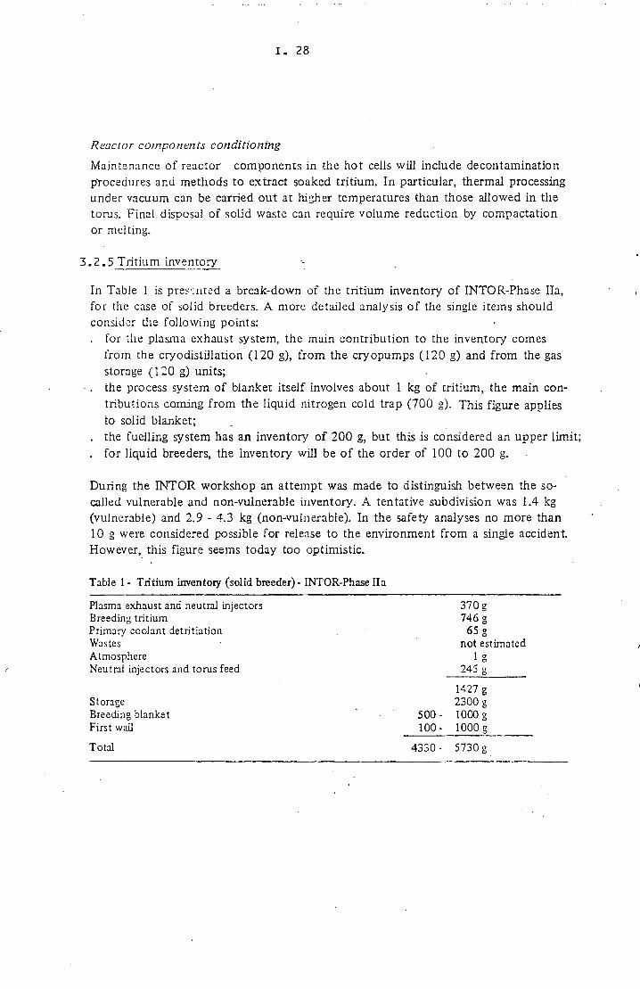
3 .2.5 Tritium inventory
In Table 1 is predated a break-down of the tritium inventory of INTOR-Phase Ha, for the case of solid breeders. A more detailed analysis of the single items should consider the following points: . for the plasma exhaust system, the main contribution to the inventory comes
from the cryodistillation (120 g), from the cryopumps (120 g) and from the gas storage (120 g) units;
- . the process system of blanket itself involves about 1 kg of tritium, the main contributions coming from the liquid nitrogen cold trap (700 g). This figure applies to solid blanket;
. the fuelling system has an inventory of 200 g, but this is considered an upper limit;
. for liquid breeders, the inventory will be of the order of 100 to 200 g.
During the INTOR workshop an attempt was made to distinguish between the so-called vulnerable and non-vulnerable inventory. A tentative subdivision was 1.4 kg (vulnerable) and 2.9 - 4.3 kg (non-vulnerable). In the safety analyses no more than 10 g were considered possible for release to the environment from a single accident. However, this figure seems today too optimistic.
Table 1 - Tritium inventory (solid breeder) - INTOR-Phase lia
Plasma exhaust and neutral injectors Breeding tritium Primary coolant detritiation Wastes Atmosphere Neutral injectors and torus feed
370 g 746 g
65 g not estimated
1 o 245 s
Storage Breeding blanket First wail
1427 g 2300 g
500- 1000 g 100- 1000 g
Total 4330- 5730 g
I. 29
3.2 .6 Time scale requirements for R&D
Assuming for NET:
. beginning of engineering design 1987 - 1988
. beginning construction 1992 - 1993
. start operation 1998 - 1999
the following time scale for R&D related to tritium problems can be evaluated:
. basic information on H/D simulation data for permeation, fuel cycle processes,
etc.: 1984 - 1986; . check of these data with tritium: 1986 - 1989;
. large components development: 1985 - 1993;
. tests o f NET sub-system with tritium: 1988 - 1993;
. development of waste disposal systems: 1989 - 1995.
References .
1. G. Casirü (EC), D. Leaer_(EC), Rogers (USA), G. Shatalcv (USSR), T. Suzuki { apan), INTOR, Phase Il-a, Final Report, Ch.8: Tritium and Blanket, under publication.
2. European Contribution to LNTOR, Phase Il-a, Ch.8, Tritium, Blanket and Safety, edited by G. Casini,P. Rocco, EUR FU BRU/XII-132/82/EDV 30 (December 1982).
3. European Contribution to LNTOR, Phase I, Ch. XI, Vacuum and Tritium Systems, edited by D.: Leger and F. Reiter,. FUR FU BRU/XII-132/82/EDV 2 (April 1982).
4. D. Leger, M.H. Plouzeniicc, INTOR Tritium Systems CEA report DCAEA/SECF/82-103/DL/AM, June 1982 (also reported in ref. 2).
5. Conceptual Design of an Electricity Generating Tritium Breeding Blanket Sector for 1NTOR/NE1, edited by Bond and P. Reynolds, NET-contract 085/81-12/FU (UK), final report (May 1983).

I . 30
3.3 Review of the existing know-how and of the activities in progress
The available knowledge on tritium problems and in particular on tritium technology is mainly based on the operation experience of fission reactors (in particular heavy water and HTGR reactors) and on the confinement and conditioning of waste water arising in fission fuel reprocessing plants, whereas the information coming from the military applications is for the moment still limited. In the following the existing knowledge on tritium is briefly revised and the main research activities related to fusion in progress or scheduled in Europe and throughout the world are outlined.
3.3.1 Experience from fission reactors
In heavy water plants, tritium is produced in the moderator by neutron absorption. This implies the solution of a number of problems related to the handling of large volumes of tritiated water and to its processing. Important experience has been gained both in Europe and outside in the world (mainly in Canada) on these problems. A detritiation system from heavy water capable to extract up to 160,000 Ci/a of tritium is in operation at the high flux reactor of Grenoble, based on a process developed by C E A . It applies cryodistillation of elemental hydrogen isotopes for their separation. Due to the know-how acquired by the operation of this facility, this technique represents todav the first choice for tritium separation and recovery in fusion reactors.(ref. 1).
In HTGRs tritium is formed in the He primary coolant from which it permeates partially through the heat exchanger walls into the water of the steam generator at levels which can be kept within acceptable limits without particular purification procedures. In the H T G R concept as heat source for energy carriers (hydrogen, hydrocarbons), the tritium permeation rate was required to be reduced for safety reasons. Tests performed at K F A Jülich have shown that by coating ferritic steel with an oxide layer, a reduction factor of about 100 was obtainable. These oxide films showed, however, a low stability with temperature changes. Better behaviour was found with oxide layers on Incoloy.
Tritium is also a by-product of nuclear (fission) power generation, where it becomes a concern for LWRs at the spent fuel reprocessing stage. Table 1 gives an overview of T inventories and waste volumes arisings in a reprocessing facility. Research activities on the treatment, conditioning and disposal of tritiated waste waters have been shared in the member countries of the EC by the "Indirect Actions Program" of the CEC in the frame of the "Management and Storage of Radioactive Waste" program (DG XII), as summarized in Table 2.
Reference
1. J . Chatoux, W. Eisermann, Atomwirtschaft, Vol. 14 (1969), 25-31.
I. 31
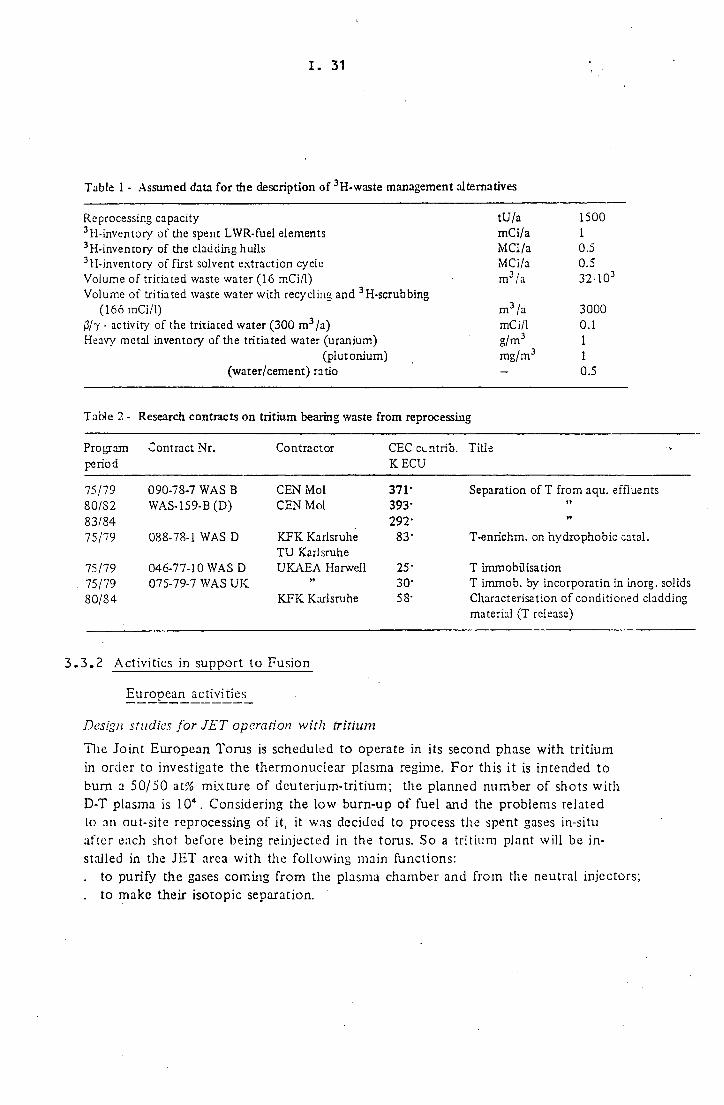
Table 1 - Assumed data for the description of 3H-waste management alternatives
Reprocessing capacity tU/a 1500 3H-inventory of the spent LWR-fuel elements mCi/a 1 3H-inventory of the cladding hulls MCi/a 0.5 3H-inventory of first solvent extraction cycle MCi/a 0.5 Volume of tritiated waste water (16 mCi/1) m 3 /a 32-103
Volume of tritiated waste water with recycling and 3H-scrubbing (166 mCi/1) m 3 /a 3000
0/7 - activity of the tritiated water (300 m 3/a) mCi/1 0.1 Heavy metal inventory of the tritiated water (uranium) g/m 3 1
(plutonium) mg/m 3 1 (water/cement) ratio — 0.5
Table 2 - Research contracts on tritium bearing waste from reprocessing
Program Contract Nr. Contractor CEC cuntrib. Title period K E C U
75/79 090-78-7 WAS B CEN Mol 371· Separation of T from aqu. effluents 80/S2 WAS-159-B(D) CEN Mol 393· 83/84 292· »
75/79 088-78-1 WAS D K F K Karlsruhe T U Karlsruhe
83' T-enrichm. on hydrophobic catal.
75/79 046-77-10 WAS D U K A E A Harwell 25· T Immobilisation 75/79 075-79-7 WAS U K 30· T immob. by incorporatin in inorg. solids 80/84 K F K Karlsruhe 58· Characterisation of conditioned cladding
material (T release)
3.3 .2 Activities in support to Fusion
Eujop_ e a n_ activi ties
Design studies for JET operation with tritium
The Joint European Torus is scheduled to operate in its second phase with tritium in order to investigate the thermonuclear plasma regime. For this it is intended to bum a 50/50 at% mixture of deuterium-tritium; the planned number of shots with D-T plasma is 10". Considering the low burn-up of fuel and the problems related lo an out-site reprocessing of it, it was decided to process the spent gases in-situ after each shot before being reinjected in the torus. So a tritium plant will be installed in the JET area with the following main functions: . to purify the gases coming from the plasma chamber and from the neutral injectors; . to make their isotopic separation.
I . 32
The plant is characterised by the following operational requirements which strongly influence design: . low throughput of about 2 kg during life . short life of about 2 years . unchanging dr.ty . parallel circuits permit replacement without interrupting operation . active handling of components and waste disposal are available off-site . small size . cryogenics, ultra-high vacuum and remote handling facilities are all available within
JET. Cryogenic dumping will be used extensively.
The gas purification will be performed by means of cold traps which will allow to eliminate gaseous impurities without making solid wastes. The isotopic separation by gas chromatography has been chosen in order to obtain the best process efficiency and the lowest tritium inventory. The whole processing unit, including the gas analysis apparatus, will be placed in glove-boxes. The glove-box atmosphere will permanently be processed by two cleanup systems. The first one is intended for glove-boxes with high contamination such as that for repairing and maintenance, whereas the second one will be related to glove-boxes with low contamination such as those for the process. The tritium room will be normally ventilated by a routine ventilation and air conditioning system whereas in case of contamination, an Emergency Clean-up System will be needed. A i l the atmosphere processing systems will be positioned in "caissons". A l l these systems will be located at different floors of a building which will be forbidden to workers during the pulse operation of the machine. An annex building is planned for services, laboratories, process control and safety.
The JET staff is now engaged in detailed specification for the tritium plant incorporating the following essential process elements: . removal of chemically active impurities from torus and neutral injector exhaust ga: . removal of helium . removal of protium . isotope separation of T and D . storage of separated hydrogen isotopes . storage of waste . pumps . valves . instruments for process control and inventory monitoring . input/output interfaces
EUR-association research activity
A research programme to investigate the tritium problems related to fusion power reactor development has been launched recently by the Commission in the frame of the Fusion Technology Programme 1982 - 1986 set up by the Fusion Technology Steering Committee. In Appendix I are indicated the areas related to tritium

I . 33
for which study contracts have been proposed by the European Fusion Associations together witli the state of the art of the décisions about the acceptance of thèse proposais. The areas considered are: •
. fuel clean-up system;
tntmm recovery trom waste streams;
. tritium detector;
. electrolytic cell;
. decontamination system;
. industrial development of large components;
. tritium recovery from blanket (liquid and solid breeders).
The proposais are based in gênerai on previous expérience in fission reactors; in some cases, référence is made to spécifie experiments carried out in the frame of the fusion activity prior to 1983, and to the conceptual design work carried out in Europe on fusion reactor Systems.
Activiries outside Europe
Los Alamos labomtory
The TSTA facility has been completed and tested with hydrogen. Opération with
tritium is scheduled by the end of 1983. The principal objectives of this facility are: . to demonstrate the fuel cycle for DT fusion power Systems; . to develop and evaluate personnel and environmental protection Systems; . to provide a facility that will yield a reliable data base for tritium handling Systems; . to develop tritium compatible components with long-term reliability.
A schematic block diagram of the fuel supply and exhausted plasma recovery Systems is represented in Fig. 2, indicating that the followina main sub-svstems are reauired:
. plasma chamber évacuation system by cryogénie pump;
. transfer pumping;
. fuel clean-up removing ail the impurities (He included); . séparation of hydrogen isotopes by cryogénie distillation; . waste treatment and disposai; . fuel injection; . safety control and monitoring; . emergency clean-up.
Other Systems or sub-systems connected with the plant are: . the impurity simulation; . the neutral beam injection; . the gas analysis; . the gênerai data acquisition and control.

I . 34
In this plant, in which 500 moles of DT are treated per day, three levels of tritium containment are considered: . the primary level constituted by the material of construction of the apparatus con;
taining tritium; . the secondary level constituted by glove-boxes for major tritium handling hardware
and components; . the tertiary level constituted by the large volume room maintained at tritium
concentration below 1-10"5 Ci/m" 3 by a normal and an emergency (operating in case of accident) d pan-up system.
This plant, locate^ in an old buil'ding of 3000 m 3 room volume, should maintain a tritium inventory below 200 g.
Other US laboratories
Recently, Mound Laboratory has focused most of its tritium technology development on tritium containment and environmental control..The principal goals are: . to prevent any tritium release to the environment and recover for re-use all
tritium released within the laboratory; . to demonstrate the CECE/CD water detritiation system. An electrolytic cell is
fabricated by G.E. and has been working for a long time with tritium concentration of 10 Ci /cm 3 .
. to develop a system for injecting into the torus of T F T R ;
. to design containers for tritiated liquid waste.
The principal activities pursued at Lawrence L.L. are: . the tritium recovery from atmospheric release, by using catalytic oxidation units; . the development of organic getters which, in the presence of air, minimize the
formation of more hazardous tritiated water; . the measurement and correlation of the physical and chemical properties of the
hydrogen isotopes below 30 K.
At the Princeton Plasma Physics Laboratory, in view of the T F T R operation with tritium, a tritium systems area (Fig. 3) has been constructed in accordance with the requirements of storage of tritium on-site and with no attempt to recover, purify and re-use tritium. The supply of tritium, according to the Mound Laboratory tests, will be made automatically and rapidly for a maximum of 400 Curies or 0.4 g.s"1 in 15 ms. Many precautions are taken in order to provide barriers to prevent passage of particulate matter into the torus and means for removal of He 3 and impurities. Major components will be fabricated from 316 stainless steel using all welded constructions except for the connections required for the maintenance of components and for replacement of removable items. The whole area is supplied with a clean-up system which, in the main line, is similar to the TSTA, but in smaller dimensions as the room atmosphere and the tritium inventory are strongly limited.

I . 35
Fig. 2 - Flow schematic of TSTA process system
Japanese activities
A Tritium Process Laboratory (TPL) is now under construction and will be in operation in 1985. It is conceived as a multipurpose facility, with the following main design characteristics: . to apply multiple barrier containment and tritium removal systems; . to make zoning division clear and to install proper ventilation systems; ' . to select materials and components suitable for tritium handling. The dimensions of the building are about 48 x 26 m of which the controlled area is 1080 m 2 . In the experimental room, which is 15 m high, the glove-boxes are arranged. The rest of the building is composed of an equipment room where various types of tritium removal systems are furnished (Fig. 4). Each block of glove-boxes has a function of individual ventilation and pressure control and is provided by airtight boxes with accommodated vacuum pumps. There are three containment systems: The first one is composed of the material of the apparatus; the second one is the tritium removal system which is formed by:

I . 36
Fig. 3- Tritium systems-general arrangement at TFTR.
F i " 4 layout of TPL (Japan).
1 f d o w h o i for i r u l v t u 2 0 nvr ho » for n o r i p
3 gjnvcbo* for c r v o y r n c uj iul lauon
4 gioveoo» for p n a « 1 equilibrium m u t u r c m e n i 5 g) nvx bo » for recover* 6 ^ o *c bo « for thermal d i i T u i o n
7 J J O V T D O I for componeni trjt Ä pctvKt»n lor purification
9 p o v r b ö 1 for lol idif icanon 10 ( loveoo» for i n i i u m "rno^aJ teil
11 evacuatile »lo^t-bo* for transfer
12 e va cu i b i c pJovrhot for transfer
13 pai·.hot fur loJûina jnd uni^adm? |4 pii fot tel l ine upcr>(>):cntc cniumn 15 pat for drajrijpr
16 hehum reì 'nuerator
17 c o n i m i panel 18 power tuppK
19 c o m m i pj ne l i

I . 37
. a glove-box purification system for removing tritium and oxygen;
. a pressure control of each block in order to prevent tritium leak from the glove-boxes and to avoid the radiation exposure of operators during normal and off-normal operation.
Tae third containment system is formed of a clean-up system for the room atmosphere during the normal operation. In case of accident an emergency ciean-up is automatically put into operation.
As far as the planned program is concerned, to date the glove-boxes in the airtight glove-box room will contain units for tritium measurement and analysis systems, tritium storage systems, cryogenic distillation systems, liquid-vapour equilibrium measurement and thermal diffusion systems, tritium purification and trapping systems, liquid waste solidification systems and. tritium containment and removal testing systems.
Canadian activities
In Canada a fusion fuels technology project has been set up, focused on supply of tritium and tritium technology, with the mandate to extend and adapt existing ' C A N D U tritium technology for use in international fusion programs. The production rate of tritium in this country was about 1.4 kg/a already in 1980 and it will produce still much more consistent stock piles of .tritium in function of its nuclear power programme. It has acquired an outstanding operational experience and know-how in handling of tritium oxide bearing fluids and components, in dynamic and static (leak:-tight) containment design, in occupational exposure and environmental dispersion models. It has developed to commercial maturity highly efficient monitoring systems, protective clothing and remote handling techniques and devices. Two facilities will become operational in the near future for T separation from heavy water, the first one for commercial use based on the C E A process by isotopic exchange in the vapour phase, the second one as a pilot plant based on isotopic exchange in the liquid phase (Canadian development). Both apply cryogenic distillation for final T purification and getters for long-term T storage.

I . 38
3.4 Past and present activities at JRC
3.4.1 Operative experience in tritium handling and monitoring
Introduction
The first nuclear installation generating tritium oxide bearing effluents has been commissioned at the JRC in 1959. Since then the monitoring of tritium has been carried out systematically on samples of air and water (environment), on biological materials and on plant effluents. During this time period, the procedures for sampling and measurement have bee.i continuously revised and adapted according to the technical evolution in order to improve their sensitivity.
. Tritium generating installations ·
ISJPR.4.-1, D 2 0 cooled and moderated research reactor of 5 MWth nominal power, in operation from 1959 to 1973. The IX O inventory was ss 7' m2 with a final T-activity of 2. l , C i / l . T' ^monitoring in the reactorand ..its effluents was pursued until 1977. ESSOR research reactor (critical in 1967) moderated and cooled by D 2 0 . in two distinct loops. Nominal power 25 and 17 MWth in the feeding and experimental zones,, respectively, of the core. The D 7 0 inventories in these two zones are 8 and 12 nv3, respectively. In the latter tritium has reached an activity level of 3.2 Ci/1. The total tritium content in the heavy water at Ispra is about 7 grams.
Tritium monitoring
Types of samples
Air from operation areas, from gaseous effluents of experimental loops, from off-gas systems, from outside area of the installations. Water from liquid effluents and. from cooling water of experimental loops, from waste streams, from irradiated fuel elements storage pools, from rain and surface water, from the water table and water supply system. Process fluids, like D20, He, No. Food chain and environment, like vegetables, fruit, milk, soil, etc. Biological samples, especially urine for radiological surveillance of operators. Surface contamination control in operation areas.
Applied techniques and procedures
Detailed information on this item is given in a series of reports (refs.1-6). Presently the preferential measuring technique applied is that by liquid scintillators adapted to the type of sample preparation (distillation, lyophilisation, centrifugation, electrolytic isotope enrichment). The on-line control of operation areas and gaseous effluents contamination levels are

I. 39
performed by ionisation chambers with or without compensation of external radiation fields, depending on the specific requirements. The "in-situ" surface contamination control is performed by window-less gas flow proportional counters. Sampling for environmental air- contamination control is performed by bubbling the air through distilled water or passing it over H2 O selective molecular sieves columns. Chemical or cryogenic techniques have been abandoned.
Sensitivir? of the measurements
Ionisation flow chambers, direct measurement: 5-10"6 + 5-10"5 C i / m 3 air. Liquid scintillators:
air sampling: 10"â - 1CT12 C i / m 3 ; by applying electrolytic enrichment a limit of 5-10"14 C i / m 3 is attained, which allows to evaluate the natural atmospheric tritium background.
. environmental water and materials samples: ÎCT^-IO" 7 C i / m 3 ; with electrolytic. enrichment the limit is brought to about 5-1CT9' C i / m 3 , which again is sufficient for the evaluation of the natural background levels.
. biological samples (urine): 1CP /xCi/ml; this value represents less than 0.1% of the "maximum body burden", ie . the level leading to the maximum annual dose limit for occupationally exposed workers.
Laboratories and equipment at the JRC-Ispra.
Process analyses laboratory
This radiochemical laboratory in the ESSOR complex is equipped for treatment and measurement by liquid scintillation of samples with a relatively high T content and has acquired a considerable practical experience in this field.
Health physics laboratory
Measurements at low T levels are performed in this laboratory which disposes in particular of a pre-treatment section by lyophilisation, electrolytic enrichment (in-house project and construction), etc., and various liquid scintillators. The staff of this laboratory has a large experience in handling samples of various nature, in performing the measurements and in evaluating the results (see annual reports, ref. 7).
In-field control
Portable instrumentation is currently applied by the Health Physics Division for infield control of tritium in air and surface contamination. This Division has under its control also the local monitoring instrumentation in the installations.

I. 40
Radio tossicological laboratory
This laboratory, divided, into a radiochemical section for samples preparation and
an analytical section with liquid scintillation counting equipment, has performed
more than 9000 control measurements on internai tritium contamination of workers.
Biological laboratory
Research activities are going on in this laboratory on the micro-distribution of T in
living organisms and plants and on its biological effects (rets. 8 - 12).
Experience in operation and, maintenance with tritium at the JRC
The operation of the ISPRA-1 and. the ESSOR reactor systems has required conti
nuously interventions for maintenance and replacement, on a routine basis, as well
as exceptionally on T contaminated heavy water loops and components, in an
atmosphere with tritium oxide contamination. The protective means for the opera
tors have been carefully selected. JRC technicians, in collaboration with, supply,
industry- for suits,, masks and other protective clothing, have developed or modified,
such items in order to improve their performance and adapt them to the special
requirements of operation on tritium contaminated heavy water loops. A close
exchange of information exists on these items with other nuclear centres with simi
lar problems.
References
1. V . Camera, G. Dominici, Determinazione di tritio (DTO) nell'aria, con scintillalori liquidi, EUR-Ispra-514 (10.1463).
2. D. D'Adamo, M . De Borfoci, G. Dominici, Prelievo di vapore d'acqua tritiaia mediante selacci molecolari e misure in scintillatore liquido con coincidenza multiple, Giornale di Fisica Fumitaria, Vol . 14.N.1, pp.31-37, 1/3, 1970.
3. G. Donunici, A . Fenzi, E. Momiroci, Concentrazione di tritio in alcune acque naturali dell'Italia Settentrionale, Energia Nucleare, Voi. 26, N . l l , 11 - 1979.
4. R. Cazzaniga, G. Dominici, Tritio in acque naturali della zona di Ispra, EUR-7349it, 198 1. 5. G. Dominici, Misure di tritio in campioni acquosi ambientali, Bollettino delTAIPF, N.50/51,
Anno IX, Nov.-Dec, 1982. 6. G. Dominici, La misura dell tritio in aria al CCR-Ispra (in corso di pubblicazione). 7. Series of annual reports on "Misure di radioattività ambientale", 1978 - 1982 (EUR-6632Ì,
72S0Ì, 7958L 3572Ì). 8. Margaret Meriini and R Van Steenwinkel, The evolution of biological studies on tritium toxicity,
1979, Eur-6369EN, JRC-Ispra, preprint. 9. Libero Cerici, Margaret Meriini and M.J. Carroll, The effects of tritiated compounds on the eariy
mouse embryo in culture. Campagnari, F., Van Steenwinkel R. and Meriini Margaret, Molecular aspects of tritium contamination of DNA. Tritium-hydrogen exchanges at the C-8 position of purines. Both talks were presented at the Meeting of the Committee for Internal Emitters of the European Late Effects Project, St. Bartholomew's Hospital, London, September 1980.
10. L . Clerici, M J . Carroll, Margaret Meriini, Luisa Vercellini and F. Campagnari, The toxicity of tritium: the effects of tritiated amino acids on preimplanted mouse embryos. Int J.Rad.Biol. (in press).
11. Margaret Meriini and Libero Clerici, Toxicologicai aspects of tritium. Talk to be presented at the 2nd Int.Symp.on Environ-Pollution and its Impact on Life in the Mediterranean Region. Iraklion, Crete, Greece, September 6-9, 1983.
12. Paper in preparation: The uptake and incorporation of tritiated precursor macromolecuies in the ceils of the mouse embryos. L . Cerici and Margaret Meriini.

I. 41
3 . 4 . 2 Research activities in fusion technology related to tritium problems
For the past several years a series of activities is going on in several research groups and laboratories of the JRC-Ispra on tritium problems related to fusion technology. These activities concern basic parameter studies such as hydrogen-metal interaction, as well as technological aspects, and impiy paper as.well as experimental work. The latter is obviously performed up to now with the lighter isotopes H and D for simulation of and extrapolation to tritium behaviour pending verification with the radioactive isotope.
^_tuxiie£_on_ hydrogeii Jsotapes-metal interaction
Since about ten years, the surface thermodynamics laboratory is active in fusion technology studying problems of plasma-surface interactions and physico-chemical properties of fusion reactor materials (e.g. first wall). Measurements have been performed on: . desorption spectra, adsorption states, surface coverages and sticking probabilities
of the systems M o — N r and Mo-EU (refs. 1-3); . initial thermal outgassing after different methods of surface preparation, thermal
desorption spectra, equilibrium desorption rates, equilibrium surface coverages of different materials: Inconels, stainless steels, aluminium (refs. 4-10);·
. diffusivity of H and D in Inconel type-alloys (refs. 11,12).
On-going and planned activities are: . solubiity and diffusivity measurements of hydrogen (H,D), in the first wall and
structural candidate materials; . determination of outgassing rates of implanted H,D as a function of time; . thermodynamical properties and vapour pressure measurements of L i l 7 P b 8 3 (ref. 13); . solubility and diffusivity of H,D in L i 1 7 P b S 3 .
In order to obtain diffusion data for the evaluation of the tritium losses through the piping of the cooling systems in a liquid blanket composed of L i i 7 P b s 3 , an experimental apparatus has been set up. Several deuterium permeation flux measurements through stainless steel membranes have been performed at different temperatures using an ultra high vacuum installation. Some measurements have been performed on oxidized membranes.
References
1. F. Reiter, J. Camposüvan, Desorption spectra and adsorption states of the system M o - N 2 , EUR-5404 (1975).
2. F. Reiter, J. Camposüvan, Surface coverages and sticking probabilities of the system M o - N 2 , EUR-5762 (1977).
3. F. Reiter, Desorption studies from Mo-surfaces, 9th SOFT, Garrnish-Partenkirchen (FRG), 14 -18 June 1976.
4. F. Reiter, J. Camposüvan, Thermal desorption of Inconel, EUR-5792 (1977). 5. F. Reiter, Thermal outgassing behaviour of Inconel after different methods of surface preparation
Vacuum, 23 (1978), 559.

I. 42
6. F. Reiter, J. Camposilvan, Thermal outgassing properties of stainless steel 316 L after different methods of surface preparation, 10th SOFT, Padova (Italy), 4-8 September 1978.
7. F. Reiter, J. Camposilvan, Thermal outgassing properties of smooth and rough Inconel 600 surfaces, 8th Int. Vacuum Congress, Cannes (France), 22-29 September 1980.
8. J. Camposilvan, F. Reiter, Thermal desorption spectra, equilibrium desorption rates and equilibrium surface coverages of mechanically polished and of sand-and bead-blasted Inconel 600 surfaces, EUR-7114 (1980).
9. F. Reiter, J. Camposilvan, Initial thermal outgassing properties of aluminium from 20°C up to 320° C, 9th Symp. on Engineering Problems of Fusion Research, Chicago (USA), 26-29 October 1981.
10. F. Reiter, J. Camposilvan, Thermal outgassing properties of mechanically polished and of sand- and bead-blasted Inconel 600 surfaces up to 500°C, Vacuum, 32, (1982), 227.
11. M . Caodin, J. Camposilvan, F . Reiter, Solubility and diffusivity measurements of hydrogen in fusion reactor candidate materials, VUI Congresso Italiano sulla Scienza e Tecnologia dei Vuoto, L'Aquila (Italy), 11-15 Aprii 1983.
12. G. Gervasmi, J. Camposilvan, F . Reiter, Solubility and diffusivity measurements of protium and deutenum in Inconel 625, to be presented at the 9th int. Vacuum Congress, Madrid (Spain), 16-30 September 1983.
13. F. Reiter, R. Rota, J. Camposilvan, Thermodynamic properties of Li^Pb^-, 12th SOFT, Julich (FRO), 13-17 September 1982.
14. O. Gautscir., G . Hodapp, E U R report in press. The permeation of deuterium through austenitic stainless steel.
Tritium processing
• Conceptual design studies
Feasibility studies have been carried, out starting in 1978 on a series of conceptual process schemes for the exhaust plasma processing, taking the Los Alamos T S T A process as a reference. The aim of these studies was to identify simpler and more compact processes which possibly might allow to increase the overall safety standard of such a plant concept, besides savings in investment and operation costs. Two scheme have been retained (refs.2,3), as indicated in Figs. 5 and 6.. The second scheme offers a decisive advantage with respect to the first one for its lower T inventory by periorming the final separation of H from D and T by gas chromatography rather than by water distillation. Both schemes rely on electrolysis as key process steps. In the first stage this procedure is used for isotopic pre-enrichment (of H), in the second one for reconversion of the oxides to elementary DT. The success of these key steps depends on three factors: . achieve a separation factor of at least 10 (in the cell 1); . develop an electrolyzer with an as low as possible liquid inventor/ maintaining
nevertheless a (relatively) high throughput; . render the design and material of these cells compatible with high T-oxide con
centrations. Answers to these questions are required for a definitive safety assessment of these schemes.

I. 43
STREAJ4 in «nutUd
<S>w,wt < ^ dintiUt» <S> oui put
H .O < 2." H, 15
0 ,0 120 t.4-10- 0 , 120
T , 0 120 <10-' T , 120 Fig. 5
STHEAU «n moiud
m o û t Ç> o u i OUI
M . 1 M , 15 o j o 120 0 , 1?0 T , 0 120 T, 120
Fig. 6

I. 44
Coolant detntiarion
Tritium losses from the blanket to the He-primary cooling loop has been analysed (ref. 4) for a FINTOR-D type fusion reactor. Under the realistic assumtion that in such a loop also some water would be present due to in-leakage from the (secondary) steam generation loop HTO (tritiated water) would build up with time to non acceptable levels by isotonic exchange of T with H . This exchange offers on the other hand the opportunity for using an oxide-hydroxide equilibrium reaction for dehydration and hence detritiation of the He-stream. Studies of the- kinetics of the water absorption reaction: Si O + H , O ^ Sr. (OH) 2 performed at the temperature of the cold side of the He-ioop-, have shr'vn (ref. 5) that the tritiated water content in the loop could be kept at acceptable levels by this reaction without any losses in thermodynamic efficiency.
Electrolytic cells development
Experimental work, was started for the verification of cathode potentials in relation to H-D isotopic separation factors of various cathode materials (refs.6,7). N i or Fe electrodes finally coated, by NiS resulted, the. most promising, materials.. In parallel for the reconversion step of DTO to D-T, a new cell concept was designed, constructed and successfully tested. In order to eliminate the liquid content in the ceil compartments (= high T inventory), only the separator is soaked by the electrolyte, sprayed into, the anode compartment in the form of an aerosol. The separator-material utilised in these experiments was built from asbestos fibres, the electrodes from Ni . High current densities have been achieved, so that a relatively small unit could already satisfy the daily throughput requirements of an INTOR-type fusion device. Expending the isotope enrichment tests to this new cell type, a substantial improvement of the separation factors (above 10 for H/D) has been obtained, encouraging further research on still more efficient materials for suitable cathode and separator materials (wettability, radiation resistance besides enrichment) and on optimisation of operative conditions.
References
1. G. Pierini, H. Dworschak, B. Spelta, C. Rizzeilo, S. Sansolini, A . Tata, Feasibility on exhaust plasma processes, Proc. Tritium Technology in Fission, Fusion and Isotopic Applications, Dayton, Ohio, April 29 - May 1, 1980, ANS (1980) 119-124.
2. G. Pierini, Reprocessing of spent plasma, UK Patent 2.040.399B, 1982 published, 1981 application. 3. Process for removing helium and other impurities from a mixture containing deuterium and
tritium especially from a fusion reactor, European Patent 0032327, 1983 published, 1982 appl ication.
4. F. Lanza, P. Rocco, F. Van Rutten, A system for die control of tritium losses in primary and steam circuit of a fusion power plant, Proc. of the Fusion Technology 1978, Padova, 1978.
5. F. Van Rutten, Helium purification by a tritiated water absorption system, Proc. of Fusion Technology 1980, Culham, 1980.
6. G. Pierini et al.. Experimental investigation on key equipments related to an alternative exhaust plasma process, 9th Symp. on Engineering Problems of Fusion Research, Chicago, HI., October 26-29, 1981, Vol . H, pp.2080-33.
7. G. Pierini, B. Spelta, .Alternative processing modes to cryogenic hydrogen isoiopes separation in exhaust fuel treatment, Contribution to a special issue of Nuclear Engineering and Design, 1983.

I. 45
Tritium recovery from bjanket
Theoretical and experimental studies to investigate the best method for tritium recovery from the liquid breeder material L i 1 7 P b 8 3 are in progress at JRC-Ispra since some years. Measurements of hydrogen isotopes solubility and absorption kinetics on L i 1 7 P b 8 3 at various temperatures (refs. 1,2,3) have been carried out. Based on these data different models for tritium extraction from the blanket material have been considered. In the first two models, direct pumping was assumed on either a stagnant melt or an ideally agitated one. For an LNTOR type blanket, in the first case a steady state Τ inventory of about 19 kg was calculated, whereas for the second case, less than 160 g were obtained. Taking into account the impossibility of agitating the melt "in-situ", direct pumping could be applied practically only on a side stream of the alloy outside the blanket area, as indicated schematically in Fig.. 7 , scheme A , the final Τ inventory depending in this case essentially on the flow rate of the melt in the side stream. A third model is based, on countercurrent inert gas purging through the melt in a parked or a bubble column. In Fig. 7", scheme B, a schematic representation is .. shown. Provided that the Τ inventory shall be kept as low as. 200 g in a total blanket volume of 76 m 3 , about 50 m 3 must be treated daily. To achieve this, a 1.7 m high column of 0.15 m diameter and. ~ 520 m 3 He is required (ret. 4). For an engineering layout of such a facility it is however necessary to dispose of reliable data on hydrodynamic characteristics of the alloy such as viscosity and surface tension and on the hydrogen desorption rate. For- the latter determination an experimental assembly has been- designed and is to be realized at JRC, in which either direct pumping or countercurrent gas stripping operation conditions can be applied (see chapter 6).
References
1. G. Pierini, A . M . Polcaro, P.F. Ricci, A . Viola, Tritium recovery from liquid L i 1 7 P b 8 3 alloy, blanket material. Nuclear Engineering and Der.gn, in press, 1983.
2. G. Pierini, A . M . Polcaro, P.F. Ricci, A. Viola, Tritium recovery from liquid Li 1 7 Pba3, paper presented at the 12th SOFTJulleh, September 13-17, 1982 (in press).
3. A_M. Polcaro, P.F. Ricci, A . Viola, Kinetics of hydrogen absorption on liquid P b 8 3 L i 1 7 alloy, to be published.
4. G. Pierini, A .M. Polcaro, P.F. Ricci, A. Viola, Perspectives for tritium recovery from liquid P b 8 3 L i 1 7 alloy, EUR report, in press, 1983.

I. 46
S C H E M E A
C o m p . A B C.
T 2 5G g / d 50 g / d ' T R A C E S
H e 66.67 g /d 66 .67 g / d
S C H E M E B
C o m p . A Β C D E
τ 2 136 g 86 g 50 g /d / 50 g / d
H e / / 518 m V d 518 m V d / 5.10 5Kg/d 5.10 s Kg/d / / /
Fig. 7 - Tritium recovery schemes from blanket (L inPr j B 3 as a breeding material).

I. 47
3.5 ' Objectives of the JRC Tritium Laboratory
3.5.1 Motivation and orientation
The problems posed by the utilisation and by the presence of tritium .in fusion devices came to the forefront only when the design of large T-burning devices was started. It is not so much a question of demonstrating their technical feasibility like for the plasma ignition and control, but rather of verifying urgently their practical applicability, in particular for the specific requirements of the operational and envi-' ronmental safety aspects. As seen in the case of a fusion power station, the tritium produced inside the reactor must be continuously recovered in situ; furthermore, the tritium content in the breeder has to be very low in order to ensure a low tritium inventory for safety and economical reasons. These facts will possibly ask for tritium recovery methods not so far considered.
Another example is represented by the permeation and trapping of tritium in the first wail structures. As shown in chapter 3, the fact that tritium will be in. the. form of high energy particles (100 - 1000 eV) and in the presence of simultaneous neutron irradiation, will possibly strongly modify the implantation, diffusion and trapping mechanisms across the metallic structures. A third point is related to the: type of operations foreseen in the fusion reactor. As mentioned, one has to expect to handle large pieces of tritiated materials, in a very difficult environment and with stringent safety requirements, in particular concerning the maximum allowable concentration of tritium. A final aspect is that related to the conditioning of the used reactor parts (to be recycled or disposed of as waste) which wil l be at the same time tritiated and activated and which will be heavy and complex in shape. Again the new problems to be solved will be numerous.
In front of such a multi-facet situation, it is thought that a tritium laboratory at the JRC-Ispra, committed primarily to the safety problems of tritium technology in fusion, fits very well in the framework of the on-going and planned activities within the member countries of the Community. There are common objectives to be achieved in this field, to which the laboratory will be devoted, such as: . . acquire experience on handling tritium in complex systems in connection with
the safety of operators during routine operation (general and individual protective means) as well as with the protection of the environment (waste treatment, emergency clean-up, monitoring);
. provide the conditions to experience procedures for handling tritiated parts of the reactor and to optimize process components in relation to their operational safety and tritium inventory. In particular: a) execute experiments on tritium loaded mock-ups reproducing renewable parts
the NET reactor in adverse operating conditions and by remote handling, aiming to assess decontamination, conditioning (boots, seals, weldings), assembling, and quality control procedures.

I . 48
b) test new concepts and components developed in the European laboratories, such as gas chromatography, electrolyzers and. catalyzers, tritium recovery systems from blanket.
c) check the validity of physico-chemical data extrapolated to the tritium case from H/D behaviour. The reliability of such data is of primary importance for the proper design of containment and ciean-up systems.
To copewith these requirements, a flexible multipurpose installation is required rather than a facility devoted to a specific problem or system such as for example TSTA (Los Alamos) 'the time factor plays,, of course, an important role in such a decision too. When TSTA was decided in the second half of the seventies, TNS (the next step) and EPR (experimental power reactor) were scheduled, respectively, for 1984 and 1990 with 0.25 and 4.6 kg tritium inventories, respectively. The time- span apparently available before a. reliable tritium handling, system was needed for effectively operational purposes, was very short. The only possibility therefore was to rely on sufficiently weil known techniques, such as water or cryogenic hydrogen distillation, and to experience on a representative pilot plant scale one selected streamlined process scheme.
In an experimental reactor such as NET/ INTOR, the expected tritium inventory will be of the order of several kilograms. However, it appears that the major part of this inventory will be present as hold-up in intermediate storage or at a stationary state in the blanket. In TSTA the expected tritium inventory is 150 g, a significant part of which is taken by the cryodistillation column. Given the objectives of the JRC-tritium laboratory, tritium inventories even lower, of the order of 50 - 100 g, would be sufficient for a significant operation.
As far as the utilisation of the laboratory is concerned, it has a twofold goal: . to host research groups from laboratories in the European Community not dispo
sing of facilities for tritium handling for hot experimental verifications; . to perform tritium related experiments in the frame of the JRC Fusion Techno
logy Programme. In the following an outline is given of these activities proposed by the JRC.
3 .5.2Experimental program proposed related to the JRC-fusion activity
Tritium permeation, inventory and outgassing in metallic structures
A n experimental investigation will be carried out on the outgassing of deuterium and tritium into the plasma chamber during dwell-time, on the permeation and trapping of tritium through the first wall structures. The measurement program will deal with:

I . 49
deterrniiiation of outgassing rates of implanted hydrogen isotopes from a target of stainless steel, Inconel or another first wall or divertor candidate material as a function of time - at different target temperatures (200 - 600°C), - at different particle energies (0.1 - 5 keV), - at different panicle beam densities (up to 10 1 5 cm^.s" 1 );
. determination of the recombination constant at the inner surface of the target; determination of diffusivities and permeabilities of the target material;
'. investigations Ion the mfluencs oflh-situ formed diffusion barriers on the permeability of the target;
. determination of the hydrogen inventory as a function of the number of reaction cycles;
. comparison of the experimental results on the behaviour of implanted hydrogen during dwell-time with the results of existing, models (TRIT, PERI , DIFFUSE) , and possible new theoretical developments.
As said, the activity will begin with measurements-using protium and deuterium in-a cold laboratory from 1984 - 1986 and will continue with tritium. The experimental installation is schematically represented in Fig. 8. The experimental conditions will simulate the INTOR burn and dwell-time cycles (100, 200 and 20 s, respectively).
Fig. 8 - Schematic view of an installation for investigation of the behaviour of implanted hydrogen (H,D,T) in the first wall of a thermonuclear fusion reactor.

I. 50
Tritiated components treatment
In any situation where the structurai materials (metals) are in contact with tritium, this is adsorbed and - especially at higher temperatures - dissolved in the metal, proportionally to the square root of its partial pressure. Decontamination can be achieved by outgassing at a pressure and temperature dependent tune rate. Appropriate heating and tritium trapping systems must be developed suitable aiso for remote operation with complex and bulky structures and components arising from maintenance and repair of torus subassemblies. Experimentation of such techniques on tritium loaded mock-vps prepared in close collaboration with the NET design team at JRC, are another item of research at the JRC. The mock-ups can be built in a reduced scale, but the dimensions must be such as to allow the integration of critical items in them (e.g. pipe connections, welding joints) in true dimensions. The mock-ups should be built in the materials foreseen for the reactor with a possible reduction in thickness and weight of the shielding layers. A l l the remote maintenance operations should be simulated, taking into account:
. the radiation levels due to neutron-induced activation,
. the contamination' due to tritium and erosion products,
. the possible pyroforic effects of erosion dusts, (fire hazard). In particular the following topics must be tested: . the outgassing properties of neutron-damaged materials, . the tritium recovery methods. Particular attention will be paid here also to the further treatment and conditioning of these tritiaied waste arisings and their characterisation. This problem, although dealt with already in the fission reactor scenario, requires reconsideration because of the anticipated drastic increase in quantity of such- waste streams. One example of structures to be reproduced for maintenance simulation is shown in Figs. 9 - n .
Testing on processes
Electrolysis
In the alternative schemes for tritium recovery and recycling, assessed by the JRC (see chapter 5.2.2), electrolysis of tritium oxide represented a key process step. The recovery of tritium from highly tritiated waste waters, however, must be considered anyway an indispensable necessity in a fusion reactor system, whatever might be the process concept applied for the main stream and blanket treatment. The activities proposed are the testing of: . suitable separators withstanding the adverse operating conditions due to the very
high beta-radiation levels. A series of small cells (separator dimension of about 40 x 40 mm) is planned, equipped with a catalytic recombiner from which the oxide is refluxed into the cells (Fig. 12).
. leak-tight cell to be assembled by remote handling techniques. No hands-on operations should be applied for maintenance of such a unit considering the high toxicity level of the tritium oxide.
. procedures for detritiation of separator and recombiner materials before removal.

I . 51
Column chromatography
This technique offers a very high degree of intrinsic safety as compared to the other isotope separation processes. Contrarily to cryogenic or water distillation, it works with "zero" steady state hold up of tritium, and has therefore no stationary inventory providing a "clean" facility in shut-down conditions. Two concepts are applicable. The first one relying on the classical adsorption gas chromatographic technique, has been tested at the EPF Garching (ref. I) up to batches of 2 litres per cycle with alumina (plus 1% SiO^) filing. The isotopic mixture is separated into 6 streams, Le. FL>, HD, D-,, HT, DT, T2 in about 2 hours at liquid nitrogen temperature. To be applicable its throughput must be increased by either shorter cycle periods or higher batch volumes, or parallel units, or fr/entuaily a combination of these possibilities. The parameters to be studied in this respect are column diameter, working temperature, gas flow rate, and finally other support materials having a shorter retention time. Such materials are described in the literature (ref. 2), but their compatibility with tritium has to be experimentally proven. A schematic, representation of a test loop is shown in Fig. 13.
The second system uses chemisorption on palladium supported on alumina grains. The three isotope species are extracted in their pure form in the sequence T2, Di, R2- This technique has been proposed by C E A for the-JET Tritium Cleanup System. The procedure is described in ref. 3. The volumes treated per cycle are larger than for the first system, but the time period required is much longer, so that also here the daily throughput rates must still be considerably increased for full industrial scale application. Such scale-up appears feasible theoretically but has to be demonstrated experimentally. A simplified test loop is represented in Fig. 1.4.
Tritium recovery from blanket
On the basis of the results from the on-going cold tests, tritium extraction from liquid metal blanket material will be performed on the most appropriate model. A similar test loop to the one applied for the cold experiments will be used (Fig. 15). It is composed of:
a gas feeding and cleaning system; . a "saturator" in which the desired concentrations of tritium (or other hydrogen
isotopes) in the alloy are prepared by bubbling a He stream containing tritium through the alloy;
. a "reactor", to which the pre-loaded alloy is fed as a uniform and continuous thread. The desorption kinetics of tritium can be measured with He flowing in countercurrent through the reactor or keeping it stagnant. The decision between the dynamic or the static operation mode is primarily related to the most convenient analytical technique available. In the case of testing with tritium, the static technique appears most suitable. In this way the He recycling system to the reactor (part within dashed line of Fig. 15) can be eliminated, allowing a considerable simplification of the test loop as well as a reduction of its overall tritium inventory.

I . 52
Operational safety
Experimental activities such as those described in the foregoing sections, imply the availability of adequate and reliable systems and procedures, for health protection and safety, which cannot therefore represent a research item ”a priori” . It is intended, however, to evaluate and to qualify by their day-by-day performance in practical conditions, systems and procedures such as:. monitoring systems for area and surface contamination,. protective clothing and equipment,. dosimetry and operators surveillance,. environmental dispersion and control,. secondary containment ciean-up and gaseous waste treatment systems,. procedures for intervention and maintenance, ·. gove-box techniques,. tritium compatible materials and equipment.Tne results shall help to formulate recommendations for future facilities and in particular for the appropriate design of fusion reactor -systems.
References
1. H. Weichselgartner, H. Frischmuth, J. Perchermeier, A. Stimmelmayr, Garching EURATOM Association, Ootimisation of a large scale gas chromatograph for separating tritium andDT from other H isotopes, presented at Knoxville Conf., 1983.
2. M. Bonivento, U. Croatto, R. Ganzeriaand G. Micheion, Isotopic separation of mixtures by gas-chromatography, Annuali di Chimica, 68, 1978, p.63-70.
3. Le Tritium, BIST No. 178, Février 1973, Pag.13-14.

Fig. 9 - Semi-permanent parts of the toms and internal renewable segments constituting one of the 12 sectors.
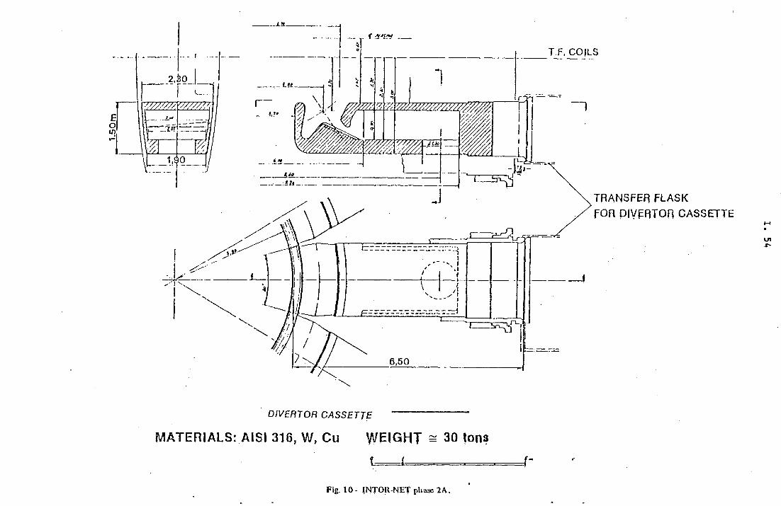
DIVERTOR CASSETTE
M A T E R IA L S : A1SI 316. W , C u W E IG H T = 30 Ions
Fig. 10- INTOR-hjET plvase 2A.

Fig. 11 - INTOR-NET pfiase 2AKenuivubic blanke! scgmenls (lief. siJuliou willi poIoiJal di verlor).
MATERIALS: AISI 316, BREEDER, SHIELD (Fe)
WEIGHTS:SEGMENT A s 150 tona SEGMENT B £ 100 Ions
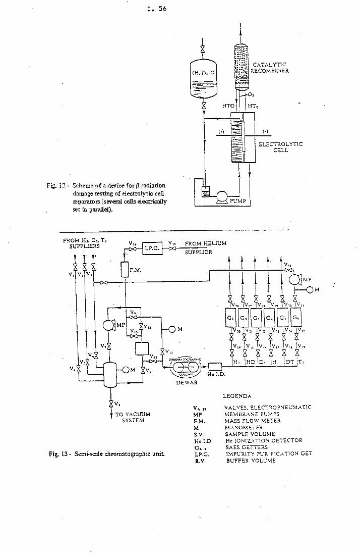
I . 56
Fig. 12- Scheme o f a device for (3 radiation damage testing of electrolytic ceil separators (several cells electrically set in parallel).
Fig. 13 - Semi-scale chromatographic unit
LEGENDA
V,. u VALVES, ELECTRO PNEUMATIC MP MEMBRANE PUMPSF. M. MASS FLOW METERM MANOMETERS.V. SAMPLE VOLUMEHe I.D. He IONIZATION DETECTORG, . . SAES GETTERSI.P.G. IMPURITY PURIFICATION GET B.V. BUFFER VOLUME

X. 57
Fig. 14- Palladium coated alumina chromatographic unit
Fig. 15 - Schematic design of the tritium recovery apparatus from liquid PbS3Li

I . 58
3.6 Description of the laboratory
3 . 6 . 1 Building
The building will be a reinforced, concrete structure, partially divided into two floors.A layout of the laboratory is shown in Fig. 16. It includes:
A 'nail for process development (HPD), which occupies approximately 3000 m3. It is equipped for housing glove-boxes with inert atmosphere to allow the installation and handling of equipment containing large amounts of tritium. The HPD will be air-tight, by means cn interlocked doors and be kept slightly below atmospheric pressure by an appropriate ’’hot ventilation” system. In case of abnormal tritium release from the secondary containment to the atmosphere of the HPD, an Emergency Gean-up (ECU) system, automatically actuated, will be able to reduce the tritium concentration in the operational area and the tritium release to the environment to permissible levels..The HPD will include an expanded area, consisting of a 500 mJ steel box fully tight and separately ventilated. This will provide a containment for large components and will allow experimental tests on their detritiation and handling.A set oî four laboratories (about 450 m3 ) for experimental research on items requiring sophisticated apparatus»:, but limited tritium inventories. These labs are therefore not connected to the ECU.A separate laboratory will be equipped for tritiated wastes treatment and conditioning. It is positioned under the area containing the different gaseous waste treatment systems and is connected to the ECU.The hot ventilation and tritium removal apparatus from gaseous effluents will cover a volume of about 1400 m3 on the upper floor.
In order to comply with the existing regulations for nuclear facilities, the following systems will also be provided:. dressing room, health physics room, health physics store and monitoring station,
which cover about 250 m3 of the hot area;. tritium storage and a counting area; this will cover about 250 m3 ;. waste storage area; this will cover about 150 m3 .
3 .6 .2 Tritium containment systems
The concept of ’’multiple barrier containment system” will be adopted in the planning of the facility. The purpose of this concept is to limit the dispersion of tritium within each barrier system so that it can be recovered before it penetrates into the next containment area. This concept starts from a high-integrity primary containment system that is normally the processing equipment, connecting pipes, storage containers, etc.
I . 59
Large pieces of this equipment are enclosed in glove-boxes which form a secondary containment system and contain an inert gas atmosphere that is monitored for tritium.The entire laboratory is enclosed within a hermetically sealed building that forms the tertiary containment, which can be hermetically sealed in case of accident.Tritium monitoring and removal from each enclosure is assured by the following gas processing systems:. gaseous waste treatment (GWT) for the effluents from the primary containment;. inert atmosphere purification system (IAP) for the glove-boxes atmosphere and
other secondary containment apparatus·;.. emergency clean-up (ECU) for the HPD, the expanded area and the tritiated waste
treatment laboratory.
Gaseous wastes treatment (GWT)
The reference flow sheet of this system is shown in Fig. 17. All gaseous effluents generated in the Tritium Laboratory are processed through the GWT system before being discharged into the atmosphere. The gaseous effluents will enter the GWT system through baffled traps and charcoal filters to collect organic vapours primarily due to vacuum pump oil. These steps are necessary to prevent possible poisoning of the catalyst bed. At the exit of the charcoal trap the gas is dumped into a large ballast tank kept at low pressure. This receiver tank is equipped with pressure sensing switches When the pressure in the tank reaches the high, sex value, a compressor is activated and transfers the gas from the tank to the treatment system. When the pressure in the tank is reduced to the low set value, the compressor stops and the gas flow ceases. The gas stream enters an electrical preheater and a catalytic reactor where the hydrogen isotopes and hydrocarbons are catalytically converted into water vapour and carbon dioxide by reacting with the oxygen in the gas stream at a temperature of about 500° C. The catalyst consists of a fraction percentage by weight of precious metal dispersed on a high surface-area of alumina carrier. On leaving the catalytic reactor, the gas stream enters a gas cooler where, by means of refrigerated water, its temperature is lowered to 25°C. The tritiated vapours are removed from the gaseous stream by a set of three fixed-bed driers one being in operation, another in regeneration and the third one in stand-by. The fixed-bed driers are filled with molecular sieves These driers operate in two steps with an intermediate moisture addition in order to obtain a further reduction of the amount of the tritium oxide by isotopic dilution. The purified effluents either go to the exhaust stack or, if the tritium content is still excessively high, are recycled into the low-pressure receiver tank.The driers are regenerated by heating and purging with a reverse flow gas stream. The purge gas is then cooled, separated from the condensate moisture and then recycled to the low pressure receiver tank.
inert atmosphere purification (IAP)
The reference flow sheet of this system is shown in Fig. 18. This system is aimed at keeping the inert gas atmosphere in the glove-boxes free from impurities. The inert

I . 60
atmosphere purification consists of a set of molecular sieve driers for water removal followed by copper oxide beds for oxygen removal. The gas is moved through the IAP by two blowers operating in parallel. These blowers are not hermetically sealed but are mounted in a sealed box provided with water cooling to prevent excessive temperature rises of the blowers.. A heated getter bed is included as part of the LAP system. This bed can getter tritium and nitrogen. Once the bed is saturated by nitrogen, it must be replaced. Nitrogen can be reduced to low ppm levels when necessary in this way; because of the limited capacity of the getter bed, however, this unit is not left on line continuously and is placed on stream only when it is necessary to reduce mtrogen or tritium levels in the glove-boxes. The drying towers are regenerated wnen either oxygen or water levels begin to increase. The regeneration is achieved by heating the towers and then flowing in countercurrent hydrogen, to regenerate the bed for oxygen removal and inert gas to regenerate the molecular sieve driers. On the exit of the towers the regeneration gas stream is cooled and then sent to the· GWT system to recover all. the tritiated water thus formed.
Emergency clean-up system i ECU)
The reference flow sheet of this system is shown in'Fig. 19. The ECU is a large capacity air detritiation system able to lower to permissible levels the tritium concentration in the operational area and the tritium release to the environment. The ECU is automatically actuated in case the room monitoring system detects an abnormal tritium concentration in the controlled area. At the same time the hot ventilation has to be stopped, thus isolating the atmosphere of the controlled area. A schematic representation of the gas processing systems both in normal and abnormal situations, . is shown in Figs. 20,21. Tritium is removed from the gaseous stream by a combined effect of catalytic oxidation and adsorption on molecular sieve beds. The room is kept at a lower pressure than the other rooms, thus limiting the back-streaming of contamination to the latter. The effluents from the ECU are recycled to the controlled area, thus improving the air detritiation efficiency. The ECU is pan of the tertiary containment and has to be designed in function of the other characteristics of the tertiary containment system. These are mainly:. the size and the tightness of the tertiary containment enclosure;. the sensitivity and the response time of the tritium room monitor'' in the controlled
area. The second parameter is strongly depending on their location;. the time required to stop the hot ventilation and to run in steady state with the ECU . the possible adsorption of tritium on the different surfaces in the laboratory. This
may cause delay effects increasing the operation time required for the ECU.
3 .6 .3 Siting of the laboratory
In the preliminary design study of the laboratory as described in the foregoing points, the possible utilisation of already existing buildings or structures (except the stack) has not been considered in order to allow an objective identification of all requirements free from constraints deriving from such structures. However, it is known that, with the shut-down of the ESSOR-reactor, a number of facilities will become available which could, in principle, be exploited to host the tritium laboratory.

I . 61
In the following we will evaluate, in the light of the design requirements, which are the capabilities inside the ESSOR complex for doing this.The utilisation of the ESSOR dome as tertiary containment implies some draw-backs that might easily off-set the advantage of having the building available with air- conditioning, ventilation and stack. The huge volume of the dome (~ 38,000 nr5) and the nature of construction materials would require the realisation of another containment shell inside the dome in order to keep the emergency clean-up within a reasonable size both for investment costs and operational efficiency.The utilisation of the ESSOR bunkers on the contrary would appear practical only for the installation of an already fully developed and well defined pilot installation to be operated remotely (such as e.g. cryogenic or water distillation), due to the difficulties of access to the bunkers and their particular shape (unproportionally high with respect to their surface area).A third potential area within the ESSOR complex is situated near the stack and the reactor dome. Two possibilities exist, one of which would allow the incorporation of the already existing building for the Super-Sara power supply system.The second possibility is to-rationalize the layout by constructing a new building near the stack, as shown in Fig. 22.
3 .6 .4 Licensing procedures
According to. the Italian regulations for nuclear installations, the licensing procedure for a laboratory handling bulk tritium amounts beyond 100 Ci is normally established by Article 55' of the LAW D.P.R. 13.2.1964, n. 185. A particular situation emerges for such a laboratory if built at the JRC-Ispra, in the area covered by the operation license of the ESSOR reactor, utilising facilities of the latter such as stack, gaseous effluents monitoring system, power supply (including emergency supply), and others.In a meeting with representatives from the Direction ’’Energy Resources and Basic Industry” of the Ministry for Industry and Trade and from ENEA-DISP, respectively , the legal and technical authorities for nuclear licences in Italy, the former considered a licensing procedure by Art. 55 for a T laboratory practially not compatible with the above mentioned particular situation, due to foreseeable interferences with the ESSOR license in effluents surveillance and safety control procedures both for normal operation and accidental situations.A tritium laboratory should therefore be considered as a part of the ESSOR complex and as such be approved by the procedure foreseen for ’’Modifications of existing nuclear installations” (starting from art. 42 of D.P.R. 185). In this case the authorisation for the construction could possibly be obtained within less than one year.Another advantage would be that the release limits for ESSOR remain valid also for the T laboratory. For routine operation the amount of tritium oxide that can be released through the 80 m high stack is 2000 Ci/a.

I . 62
The dose commitment in case of the release of 10a Ci* of gaseous tritium from a 100 m high, stack would be only 10 /a rem. For che very hypothetical release of the same amount in the form of initiated water, a factor of 10s must be applied, leading to 1 rem of committed dose. The hazard potential represented by this inventory of tritium even in its oxide form remains within the existing reference vaiue for the External Emergency Plan of the Centre, avoiding so any necessity for modification. This plan refers to a maximum credible accident of the ESSOR reactor resulting in an expected dose of 4 rem to adults living in the nearest village.
*■ approximately 100 g of tritium.

PLAN AT 0.00 LEVEL (SCALE 1:200}
| ) P H A S I N G
2) LAVAlOniES
3) HOT AREA
4| All) EOCK
PLAN AT + 4.00 LEVEL (SCALP 1:200)
Pig- !<»

pig. J7 - Gaseoiis γ/aste treatment.

Fig. 18 - fner( gfmosplien: puri fica (ion.

Fig 19- Emergency clean-up system.

FLOW DIAGRAM IN NORMAL OPERATION MODE (TRITIUM RELEASE TO H.P.D.)
STACK
Fig. 20

FLOW DIAGRAM IN ABNORMAL OPERATION MODE (TRITIUM RELEASE TO H.P.D.)
STACK
Fig. 21

Fig. 22- Celierai lavo»! '>f (lie liSSOU conijiîex.

I . 70
3 .6 .5 Planning and resources
Starting from a positive Council decision the following steps can be envisaged for the realisation of the tritium laborator)':A) preparation of the preliminary safety report to be transmitted with the request
for ’’Modification of the ESSOR license” to the Ministry for Industry and Trade;B) approval of the request by the safety authorities together with identification of
safety relevant items (’’progetti particolareggiati”);C) executive design of the laboratory (excluding experimental equipment);D) construction and mounting of structures and components;E) functional testing and commissioning.
It is intended to subcontract phases C) to E) to an external Architect-Engineer firm which will be responsible for the complete laboratory, excluded the scientific equipment. The JRC staffing required for the supervision of such a contract and for the implementation of phases A) and B) will be limited in the initial period to two prefessionals and an adequate number of technicians. With the completion of the construction of the facility and its cold commissioning, other technicians and operators will be added, up to a maximum of about 14 persons, including mechanics, electronics and ventilation specialists.In parallel the design, preparation and testing of research specific equipment will be performed (point F) of Fig. 23). This task will be assigned to the groups already involved at JRC in the measurements with H/D to evaluate processes for Tritium Handling (fusion Safety Programme).On this basis the total operational and scientific staffing of the JRC related research activities (excluded the technical and administrative support) is evaluated to a maximum of 25 persons, 7 of whom will be professionals. This staff will be needed at the moment of the beginning of full operation. In the first 4 years, 10 persons will have to be allocated to this activity.These figures do not take account, of course, of the scientific and technical groups from outside that might be interested to perform specific experiments in this laboratory. In Fig. 23 a break-down of the time schedule related to the various phases of preparation and commissioning is given together with that of the overall manpower accounted for the laboratory (in order to take account of the JRC’s technical and administrative overheads a factor of 2.2 has been applied).

I . 71
3 .6 .6 Cost evaluation
A preliminary design and cost evaluation are underway. The results of these studies will be supplied at the FTSC meeting of 16 September 1983.
Fig. 23 - T IM E A N D M E N P O W E R R E S O U R C E S F O R T R IT IU M L A B O R A T O R Y
1 2Years
3 4 5
ABC
D
E
F
Prelim. Safety report A< P.S.R. approvalExecutive design - contractor select.
- project elab.Construct + Mount - construct, selectis.
- construct + mountFunct. testing
Experim. equip. - projects- preparation- cold, tests- install., hot tests
B --------------C —
F«-----------
C «------------D —
D «-------------E<
Men power ■ - A to E - F
8
620
620
1022
1730
25
Total 14 26 30 39 53

I . 72
3.7 Conclusions
The analysis performed shows that the problems raised by the presence of tritium in the fuei cycle of fusion reactors are complex. The data and information already available or expected from classified work do not seem sufficient to solve these problems. A vigorous experimental programme is needed to meet the requirements of NET and those of large scale power reactors.
On this basis it has been shown that a laboratory for tritium handling at JRC could give a significant contribution to the European effort in this area. The main objective of such a laboratory would be that of providing a basis to test components and operation procedures in support of the NET design and construction. This objective could be achieved in the following way: . by making experimental verifications of concepts related to fuel cycle and reactor
operations, according to proposals which will be made by the European Association and by the NET team;
. by pursuing the tritium-oriented activity started at JRC in the framework of its fusion technology programme.
This will imply a close collaboration with the European fusion research centres and the NET team starting with the design phase, similar to fhat being done in the other areas of the Fusion Technology activity, where JRC is involved. In doing this, particular attention will be paid to acquiring experience in the operational safety aspects related to tritium, a task which is in harmony with the general vocation of the JRC, as it has been recently approved by the Council of Ministers.

I . 73
APPENDIX 1 - First round projects on tritium set up by the Fusion Technology Steering Committee
The projects are presented in the form of sheets following the "call for proposals" launched by the Commission in December 1982, namely: . fuel clean-up system, . tritium recovery from waste streams, . tritium detector, . electrolytic cell, . decontamination system, . industrial development of large components, . tritium recovery from blanket (liquid and solid breeder).
Each sheet contains: . the description of the requested activity (doc FTSC 418) . a summary of the actions proposed by the Associations (doc. FTSC 5/3.3) . the state of the art of the related contracts with the Association (doc. FTSC 5/6 and 6/9·)·
Tritium 1
FueJ_ clean-up system_
Paper study of alternative solutions for the fuel clean-up system. The input specification is a gas flow rate of 1.5 kg per day of a fifty-fifty mixture of deuterium-tritium with an impurity content of less than \% except helium, corresponding to the INTOR requirements. The main impurities are 0 2 , N2, H 7 0 C H 4 , but the expected level of these impurities is not known. An effort should be made to determine these levels, and while precise data is lacking, model cases with high fractions of each of the species should be separately studied. The total impurities content in the output gas from the fuel clean-up system must be less than 1 ppm.
Proposal s_ from Dj__F_
D : The proposal contains: a) experimental work in course, using metal getters for impurity removal; b) a paper study, followed by design and construction of a cryogenic dis
tillation test unit (1982 - 1986).
F : Proposed study (corresponding exactly to the call for proposals) (1983 - 1984);
. accepted contracts/ceilings/time schedule: F - 0.4 M E C U - 1983/84 D - 1.1 M E C U - 1982/84
. German technical description has to be modified according to the reduced ceiling, avoiding duplication with French contract.
I. 74
Tritium 2
Tritium recover/ from waste streams
Study of the recovery of tritium from impurities collected in the fuel clean-up system. This will involve tritium both in the gaseous and chemically bound condition. This tritium must be recovered in order to limit the amount of effluents. The following different processes may be considered: . decomposition of water and hydrocarbons on metallic beds, followed by the
permeation of hydrogen isotopes through a palladium alloy membrane; . oxidation of all impurities on a catalytic bed followed by the trapping and de
composition of the tritiated water; . separation of the impurities by means of a chromatographic column. These im
purities may be either burnt and collected as water, or decomposed and separated on a second chromatographic column.
Al l these methods should be studied firstly on paper. However, problems such a; those arising from the poisoning of the palladium membrane by water or hydrocarbons should be indicated to enable the first step of experimentation to start as soon as possible. The study of these processes should include an evaluation of the amount of tritiated waste produced.
Proposals from B, D, F
B proposes: a) exp. R&D of laser separation of T from water (1983 - 1985) b) a study followed by construction of a loop for T-recovery from the fuel
. clean-up waste (1983 - 1986).
D proposes: a) exp. R&D of the recovery of T from tritiated water and methane
(1984 - 1986) b) exp. study of the poisoning of Pd-Ag membranes (to start in 1985).
F. proposes: a) a paper study examining the cases for
i) metal beds ii) oxidation iii) chromatography (1983 - 1984)
b) exp. study of the poisoning of Pd-Ag membranes, using existing loop (1983 - 1986)
c) i) exp. study of some components critically determining the T-content in the waste streams (electrolytic cell, package in cryodistillation columns)
h) an evaluation of the influence of the T-level on the extraction process.

I . 75
. accepted contracts/ceilings/time schedule: F - 1.2 M E C U - 1983 - 1986
. technical description should be modified such as to exclude experimental studies other than poisoning palladium-silver membranes
. the Belgian-laser proposal was referred to a later stage.
Tritium 3
T ri tjum_ dj^ejrtor
Development of a tritium detector capable of detecting low levels of tritium against a radiation background. The tritium detection system should be able to measure under these conditions a level of tritium around 1 MPC with a response time less than a few minutes.
Proposal s_ from JJ^ U K _
B : would develop prop, counter for air or id. (or GM) with individual gas flow; prototype by 1986. • •·•- -
D : would develop the sensor according to required T-level and environment for the monitor. Start 1984, prototype 1986.
U K : would develop method to distinguish between T-gas and water; and sensor to operate continuously in a nuclear facility (1983 - 1984).
. accepted contracts/ceilings/time schedule.
It appeared that a monitor close to that specified in this task has been developed in Canada. Where B and D still maintain their proposals, the Commission will analyse the situation and report to the FTSC.
Tritium 4
Ekcjrojiy_tic_cell_
Study of an electrolytic cell processing up to 100 ml per day with special consideration of maintenance and waste, for the reduction of small quantities of tritiated water.
Proposal^ from f J^K,_JJRC_
B : proposes to scale up ongoing e-ccll development for 100 - 1000 Ci , to the levels required in task T-4, including building of a prototype by 19S6.
F : proposes to investigate critical problems such as the diaphragm material and remote maintenance; and to build (1985) and test an active prototype at levels 106 Ci/1 (1986 or later).

I . 76
U K : proposes stepwise development: i) 10 - 100 Ci ii) 100 - 1000 Ci iii) ending up in recommendations for the design of an e-cell system for
1 MCi/day (1986).
JRC : is studying low-liquid inventory e-cells since 1981, aiming at hydrogen isotopic separation. Only inactive expts. Project ends 1984.
. accepted contracts,fceilings/time schedule
. no conclusions have been reached yet between B and F, but discussions continue and die project will be settled in the next future.
Tritium 5
Decontamination system
Paper study of the economic feasibility of processing.large volumes of air contaminated with tritium, including estimations of cost, release to the environment and maintenance problems. The decontamination unit should enable personnel to enter the reactor hall without special protection 24 hours after shut-down. Normal or accidental leaks to the hall atmosphere may be in the range 1 to 1000 parts per million of the inventory per day.
rhe atmosphere of glove-boxes and of secondary containments will need to be routinely processed. The normal process consists of oxidising tritium and trapping :he water. Catalytic beds operating at very low tritium concentrations should be evaluated and, if necessary, research directed towards increasing the efficiency of :he best catalysts.
Proposals by B, D, F
B : offers a) studying the economic feasibility of processing large volumes of air; b) exp. R & D to decontaminate and possibly recover T from inert gas
flush systems in glove-boxes (1983 - 1986).
D : proposes to develop organometallic getters in which T is irreversibly fixed so that final disposal is easy (1983 - 1986).
F : proposes a) a paper study including identification of T-source terms, concentration
levels, layout and economic optimisation of clean-up system (1983 -1984);
b) testing of commercial catalysts in a wide range of parameters and developing the most promising ones towards an optimal solution (1983 - 1986).

I . 77
. accepted contracts/ceilings/time schedule: D - 1.7 M E C U - 1983/86 F - 1.6 M E C U - 1983/86
. further discussions on the experimental part of the proposals were necessary
. technical description of German proposal should be more detailed.
Tritium 6
Industrial development of large components
Industrial development of specific large components, fully compatible for use with tritium, including turbomolecular pumps with pumping speed between 500 and 10,000 litres per second and valves of large dimensions with a diameter between 1.5 and 2 metres. The different steps should'be as follows: . Ask from laboratories with expertise in tritium handling proposals to make
available a unit in which such components could undergo final testing with tritium. This facility should be available at the time required by the development of the programme.
. Make enquiries in industry with the aim of assessing the present level of development of specific tritium-compatible components.
. Start a study with industry of tritium compatible components not available to the specifications required for fusion needs.
Propc^als_frojm
D : proposes a) industrial survey b) feasibility study of components (pumps and valves) c) planning of a test facility (1985) (this could be followed by fabrication
of components and construction of test facility by 1986/S7, as a possible second step).
F : proposes a) industrial survey b) study and development of components c) adaptation and equipment of existing test facility (which should be
rented by the fusion programme) (1983 - 1986).
. accepted contracts/ceilings/time schedule: D and F Q'ointly) - 2.85 M E C U - 1983/86
. the industrial survey and feasibility study will be carried out jointly between D and F
. the existing French test-facility will be accessible to all the Associations and the question of rental is subject to further discussions.

I . 78
Pro posal s_ by_ D^F,_JRC
D : a) H solubility measurements and other physico-chemical studies (1982/86) b) lab-scale testing of the gas bubbling method (unspecified).
F : a) feasibility test of the method (1983 - 1986) b) H solubility and diffusion coefficient measurements (1982 - 1985) c) demonstration unit (1986).
JRC : a) solubility and diffusion measurements (1983 - 1984, University of Cagliari)
b) experimental verification of the method (1983 - 1985).
. accepted contracts/ceilings/time schedule: D - 0.4 M E C U - 1983/84 F - 0.3 M E C U - 1983/84
Blanket 9
Proposals^ by_ B,_D,_F, _I
B : a) evaluate reaction kinetics with L i and Li-Pb; regeneration of solid getters (Y, ...) (1983 - 1984)
b) demonstration of method in experimental loop (1984 - 1986).
Blanket 8
Tritium extraction from LinVbco: inert "as bubbling
Demonstration type laboratory tests should be performed to determine the potential of the method. First experiments should be carried out in static L i 1 7 P b 8 3 with hydrogen. The eutectic used should be well defined and the impurity uptake during the tests must be measured. In a second stage the validity of the method should be confirmed in experiments based on tritium. Additional experiments will be required to determine the dependence of solubilities of hydrogen and its isotopes in L i 1 7 P b 8 3 , on temperature and partial pressure (Sievert's law).
Tritium extraction based on the use of solid getters
Thermodynamically it is possible to extract tritium from lithium or L i 1 7 P b 8 3 with the use of solid getter materials such as yttrium. However, the reaction kinetics, the getter regeneration and the poisoning rate by impurities are aspects which will determine the potential of this method. Also the possible reaction of the getter material with the liquid breeder or a component of it such as Pb should be considered. In a first stage, experiments should be performed in static devices based on hydrogen. In a second stage, confirmation experiments based on tritium should be included.

I . 79
D : a) batch experiments on solubility and reactions with Li-Pb; poisoning of getters (Y, ...) (1983 - 1984)
b) loop experiments up to 10 mg tritium (1985 - 1986) c) idem up to 1 g tritium (1986 -
F : experimental study of reaction kinetics and extraction from various getters (1984 - 1985).
I : a) capsule (batch) e:.perimeiits on reactions with L i and relevant parameters; poisonin : of getier (Y, Y-based alloys) (1983 - 1984)
b) loop extraction (! 985).
. accepted contracts/ceilin's/timi schedule
. following discussions bet veen B and D, the repartition of founds will now be: B : 0.26 M E C U D : 1.44 M E C U
Blanket 16
Tritium recover/
A n experiment will be designed or proposed for an existing irradiation facility in which the recovery of tritium from the solid breeders will be directly demonstrated as a function of irradiation temperature and burn-up (or dose), using in appropriate method of T recovery: the samples will also be used to determine property changes for comparison wi 'h Task B-15 within the limitations posed by the study of T extraction.
Pro£Osals by B . J D . J ^ J _
B : proposes on-line montoring and trapping of T released from vented capsules (see B-15).
D : proposes a loop expe iment in DIDO, monitoring of T by an ionisation chamber in the carrie gas, after reduction of T 2 0 in a hot metal bed.
F : proposes irradiation i i SILOE and systematic study of extraction methods covering T 2 and tritu: ted species.
I : proposes to irradiate L i A 1 0 2 in a He-gas loop in T R I G A RC-1 and trap the tritium in the gas by cryogenic and getter systems.
. budget allocation not y r decided.

COMMISSION OF THE EUROPEAN COMMUNITIES Jo i n t Research Center
I I . A VIBRATING TABLE
at
JRC - ISPRA
Second progress report

I I . 2
TABLE OF CONTENTS
page
1. INTRODUCTION I I . 3
2. REVIEW OF RESEARCH UNDERWAY ON SEISMIC ANALYSIS AND IDENTIFICATION OF USE AND INTEREST FOR VIBRATING TABLES I I . 3
3. REVIEW OF EXISTING VIBRATING TABLES I I . 4
4. IDENTIFICATION OF POSSIBLE COMMUNITY NEEDS FOR A LARGE TABLE I I . 4
4.1 Conclusions of the I t a l i a n ad hoc Working Group I I . 4 4.2 The s i t u a t i o n i n France I I . 5 4.3 The s i t u a t i o n i n the U.K. I I . 6 4.4 The s i t u a t i o n i n Greece I I . 6 4.5 The s i t u a t i o n i n the FRG I I . 7
5. EVALUATION OF THE ADEQUACY OF THE ISPRA SITE I I . 8
6. CONCLUDING REMARKS I I . 9
7. FUTURE DEVELOPMENTS I I . 9

1. INTRODUCTION
This report is the second progress report on vibrating tables prepared by the JRC ad hoc Working Group, whose mandate is to evaluate the interest for the Community to insta l l at JRC-Ispra a vibrating table of intermediate size (100-300 t ) .
The report includes:
1. A review of research underway on seismic analysis and identif ication of use and interest for vibrating tables.
2. A review of existing vibrating tables.
3. Possible Community needs for a large vibrating table.
4. Evaluation of the adequacy of the Ispra s i te .
5. Concluding remarks.
6. Future developments.
2i Review of research underway on seismic analysis and identif ication of use and interest for vibrating tables.
Community
- Qualification and model validation tests are performed using medium-size tables.
- No large-scale tests are performed at present, but some interest has been expressed (see section 3).
- Efforts are underway for model and computer code development for seismic analysis. Amongst others, progress is hampered by a lack of representative data on the reference ground motion to be considered.

I I . 4
Japan
- Extremely vast research act iv i t ies covering a l l aspects of seismic analysis.
- Series of large-scale demonstration tests (nuclear and petrochemical structures) planned on Tadotsu 15 m x 15 m, 1.000 t, shaking table.
- Pseudo-static (reaction wall) tests on apartment buildings up to five stories high: repeated reversed lateral forces increased in steps (Tsukuba).
U.S.A.
- Wide spectrum of research act iv i t ies sponsored mainly by National Science Foundation and National Regulatory Commission.
- Active research on aseismic design and construction of buildings using both pseudo-static tests and a 45 t shaking table at University of C a l i fornia, Berkeley.
- Collaboration with Japan for testing of very large models.
3. Review of existing vibrating tables.
Four tables have been prepared,l isting the major vibrating tables in the world and their main characterist ics . They are reproduced in annex of the present note. The biggest tables are in Japan with six tables in the range 100-1.000 t. The largest table in the U.S.A. is the 45 t table at Berkeley (Ca.) . The largest table in the Community appears to be the 14 ft x 14 ft biaxial table with 100 t capacity installed at 6EC Power Engineering, Stafford Mech. Lab. , U.K.
4. Identification of possible Community needs for a large table.
4.1 Conclusions of the Ital ian ad hoc Working Group
An ad hoc Working Group was set up by ENEA in March 1983 with the objective of
a) col lecting up-to-date information on dynamic testing of structures throughout the world-,
b) analysing the needs in Italy for a vibrating table of large capacity;
c) indicating the optimal characteristics of such a table.

I I . 5
The W.G. report was received in July and its main conclusions can be summarised as follows:
- there i s , in principle , an interest for the poss ibi l i t ies that could be offered by a large vibrating table with a capacity in the range 100-300 t:
• Poss ibi l i ty to test complex components in the non-linear range.
• Poss ibi l i ty to refine present state of knowledge on dynamic structural behaviour and thereby reduce safety margins, both in nuclear and non-nuclear f ie lds .
- Perplexity is expressed as far as cost is concerned, both for the operation of the table and for the construction of large-scale complex models.
- Access by road to inland sites imposes restrictions to the size and weight of the equipment that could be tested. The use of the 1.000 t Japanese table could be the ideal solution for very large models.
- At present, the potential "market" in Italy is not judged sufficient to just i fy an adequate use of a large table. However, the situation could change in case of a substantial modification of the present norms.
- Final advice can be given only when the needs from the other Community countries have been fu l ly appraised.
- The large table should not be seen as an isolated tool , but rather as part of an adequate experimental context of seismic engineering which clearly involves other experimental equipment than shaking tables. Attention should also be given to the problem of ensuring the ava i lab i l i ty of the necessary competences.
4.2 The situation in France
Two potentially interested organisations have been identified in France:
a) according to FRAMATOME there is a lack of adequate experimental means in the Community for the seismic qualif ication of large equipment. The problem arises in particular for sites with a high seismic risk in the sense that non-linear phenomena have to be taken into account and, therefore, large-scale models should be bui l t and tested. Among the problems to be considered, mention was made of:
- the primary coolant loop of a PWR and its support;
- steam generators (behaviour of tube bundles);
- devices for storage in water pools of spent fuel elements;
- behaviour of cranes.

I I . 6
b) The "Centre Scientifique et Technique du Bâtiment" (CSTB) in association with "Laboratoire Central des Ponts et Chaussées" has in project the construction of a tr iax ia l 6 m x 8 m vibrating table with 100 t maximum equipment weight. The construction of this table has not yet been decided by the French authorities, but CSTB is fu l ly convinced that a large vibrating table is a unique tool for:
- the research on building structures constructed by assembly of prefabricated components. Singularities are present at the junctions between assemblies which are impossible to model analyt i cal ly and experimentation with a large table is the only way to i n vestigate the fai lure modes provoked by seismic loading;
- the improvement of aseismic design concepts and construction techniques;
- the development of techniques to increase the seismic resistance of existing buildings;
- the development of models to represent actual structural behaviour and the validation of calculation methods;
- the qual i f i cat ion , against a specified seismic excitation, of f u l l -scale equipment and housing structures.
4.3 The situation in the U.K.
From contacts with UKAEA, CEGB and Nuclear Installations Inspectorate, i t appears that the seismic qual i f icat ion requirements as specified by the U.K. code are well met by the existing vibrating tables. The problem of qual i f icat ion against earthquakes is not considered very relevant in the U.K.
The National Engineering Laboratory at Glasgow which operates three tables is open to collaborations.
Contact has also been taken by letter with the Building Research Establishment, but no reply has been received yet.
4.4 The situation in Greece
Prof. P.G. CARYDIS, chair for Earthquake Engineering, National Technical University, Athens, v is i ted JRC-Ispra in July and i l lustrated the Earthquake Simulation F a c i l i t y presently under construction in his department.
According to Prof. Carydis, an effort should be made at the Community level to

I I . 7
- col lect and disseminate information on earthquakes
- instal l standardised seismographs to record strong ground motions and create a corresponding data bank
- create a European network of shaking tables with a centralised information service on the particular characteristics
- complement the above network with a table of large capacity
- develop models describing dynamic structural behaviour under rea l i s t i c ground motion, and disseminate the resulting computer programmes.
4.5 The situation in the FRG
In the FRG research act iv i t ies in the f i e ld of anti-earthquake design have been intensified in the last decade, in particular in view of b u i l ding nuclear reactors. At present a spin-off is observed in the f i e ld of c i v i l engineering. Dynamic testing of models and/or components is limited to the use of smaller shaking tables and to the use of shakers on existing structures. Since six months, a 25 t shaking table is in operation at HRB J ü l i c h (see table 1).
The contacts which have been taken in FRG concern:
(i) reactor vendors (KWU, HRB) ( i i ) l icensing authorities (IRS, Köln) ( i i i ) research institutes (TH Darmstadt, HDR project of KfK).
The vendors of reactor systems have a tendency to be in favor of tests of prototypes scale up 1:1, in particular in the f i e ld of f lu id structure interaction (fuel elements, steam generators, e tc . ) . The research institutes prefer the smaller shaking tables in order to make detailed experimental verif ications of the fundamental bricks of computer programmes. The licensing authorities are inclined to follow the research institutes i . e . to rely on the computer programmes to simulate huge structures provided the constitutive laws in the non-linear regime are validated by means of clean experiments. In general, in FRG like in Japan and U . S . A . , the interest in huge shaking tables is decreasing and preference is given to the pseudo-dynamic method to verify experimentally huge buildings. The main reasons are cost/benefit considerations: a shaking table costs around 100 2 / kg of model.
The various organisations in FRG which have been contacted appreciate the in i t ia t ive of the Commission. They wi l l formulate in the near future a more detailed advice on the need to coordinate in Europe the research in the f i e ld of anti-earthquake design and the need on thereby huge experimental test f a c i l i t i e s .

I I . 8
5. Evaluation of the adequacy of the Ispra s i te .
Study contracts have been launched in order to investigate by static and dynamic geotechnical tests the adequacy of the preselected site within the JRC-Ispra to host a large vibrating table.
The tests to be performed include:
- the construction of a vertical s trat i graphic map of the s i te ;
- the geomechanical characterisation of the soil (standard penetration tests, laboratory tests on soil specimens, control of underground water);
- dynamic consolidation tests;
- use of special dynamic exciters to measure the attenuation of seismic waves as a function of their frequency, and thereby to evaluate possibl effects of the operation of the table on neighbouring installations and buildings..
Contacts with the local e l ec tr i c i ty company (ENEL) have ascertained that the necessary power supply can be ensured-without any d i f f i c u l t y .
Concerning access to JRC-Ispra, the present road connections have permitted the transportation of components for three research reactors (Ispra-I, ECO, ESSOR). The construction of a new road, connecting the JRC to the nearby highway, could also be envisaged. Transportation of cumbersome and heavy equipment was also a concern for the USA (space and nuclear programmes): a solution has been envisaged based on d i r i gibles. Similar studies have been performed in Europe. Nevertheless, transportation of complete models could be avoided in many cases. On-site assembly is possible at JRC-Ispra, using existing f a c i l i t i e s .
As far as the ava i lab i l i ty of the necessary competences is concerned, although the JRC is not involved at present in seismic analysis, expertise exists in the f ields of
- dynamic testing
- instrumentation, data acquisition
- numerical analysis of structures
which could be used for the present project. Obviously the recruitment of a few specialists would be necessary to build up a competent team.

I I . 9
6. Concluding remarks.
The analysis presented above, while s t i l l incomplete, allows to draw some f i r s t indications:
- Except for Greece, a l l other Member States consider that the present norms for seismic design may be adequately f u l f i l l e d using avaiblable experimental and analytical tools.
- A large number of small and even medium size shaking tables exists , some of them having six controlled degrees of freedom which allow a more rea l i s t i c simulation of expected ground motion.
- A number of organisations in the Community have expressed a real interest for a shaking table of larger capacity. This indicates that not a l l phenomena until now can be modeled either by small-scale tests, or analyt ical ly .
- A co-operative European effort would be beneficial in the following areas
• Standardisation of ground motion measurements and creation of a European data base.
• Development of refined models and computer codes verif ied by experimental equipment either available or to be bui l t to enable a better understanding of phenomena and possibly reduce safety margins.
7 · Future developments.
The following studies wi l l be executed and included in a report to be issued by mid 1985:
- evaluation of the study contracts to assess by static and dynamic geotechnical tests the adequacy of the Ispra site to host a large vibrating table;
- further evaluation of the Community interest;
- description of a possible research ac t iv i ty ;
- preliminary estimate of staff requirements and costs.
The results of these studies should allow to decide whether or not to build a vibrating table at Ispra and to launch a detailed design study to be ready by the end of 1986.

I I . 10
Comments to Tables 1 to 4:
1. Istituto SperimentalcModelli e Strutture S.p.a. 2. National Engineering Laboratory 3. 4. Commissariat à l'Energie Atomique 5. Société pour le Perfectionnement des Matériels et Equipements Aérospatiaux 6. Hochtemperatur Reaktorbau GmbH 7. Construction Engineering Res. Lab. (US Army) 8. National Research Centre for Disaster Prevention, Science and Technology Agency 9. The Nuclear Power Engineering Test Centre 10. Institute of Industrial Science, University of Tokyo 11. Railway Technical Research Institute, Japan National Railway 12. Public Works Research Institute, Ministry of Construction 13. Central Research Institute of Electric Power Industry 14. Takasago Research Institute, Mitsubishi Heavy Industries 15. National Research Institute of Agricultural Engineering, Ministry of Agriculture 16. Port and Harbour Research Institute, Ministry of Transport 17. Shimizu Construction Co. Ltd. 18. Kajima Construction Co. L td . 19. Building Research Institute, Ministry of Construction 20. Ohbayashhgumi Construction Co. Ltd. 21. Disaster Prevention Research Institute, Kyoto University
Keywords:
DOF Degrees Of Freedom EHSS Electro-Hydraulic Servo System E V S Electrodynamic Vibration System H Horizontal V Vertical

TA J 31 j 1 - M a j o r v i b r a t i n g t a b l e s i n E u r o p e
T a b l e c n a r a c t o r i s t i e s ] - e r f o r i a u c e
F a c i l i t y T a b l e s i z e (m)
Free r . P a n n e J fax r o d e l w e i g ! i t ( t )
C o n t r o l l e d D . O . P .
i ' ax d i s p . (nun)
! ; a x v e l . " a : iv.y.'/soc ( g
: a c c e l . T O
1.1 A a r a l s o I r , m i a n t i
G e n o v a - T t a l y 3 · 5 x 3 · 5 0 - 6 0 2 H + 70
V ± 70
CGO
550 2 . 4
1.2 ic:'.::r. 1
B c r g a . n o - I t a l y 2 . 5 x 4 0 . 1 - 5 0 2 ± 35 400
1 .3 il!-2L2
G l a s g o w - U K 3 x 3 0-33 20 3 ?I± 125 V ± 125
1 , / | G I X 3
• J h e t s t o n d - U K S t a P f o r d - U K
3 .85 x 3 .2 1 4 f t x 1 4 f t
1-33 3-1000
25 100
2 o
1.5 C . ' i A 4 " V E S U V S " S a c l a y - F r a n . e e 3.1 x 3 .1 1st
r e s o n a n c e f r e q . 2 0 0 H z
20 1 i 100 1000 1.8
1 .6 CiJA "TOlJliTIAGOL" Sa c 1 a y - F r anc e
2 x 2 1 s t r e s o n a n c e f r e o . 2 0 0 M z .
10 2 H ± 125 V ± 100
2200 1200
1.7 so i 'ünc/w V <: 1 i : ' V - V i 11 ac on b 1 a y F r a n c e
3 x 3 0 - 5 0 10 2 ff I 110
V ± 110
6 0 0
6 0 0 3
LH i l k U 6 CfcibH "SAMSOM" . J u l n c - i - F i ' J G
5 x 5 0 . 5 - 1 0 0 25 3 1" 200 1000 1.5
1 .S' n a t i o n a l T e c h . U n i v e r s i t y A t h e n s - G r e e c e
4 x 4 0 - 6 0 10 6 ;i ± loo V ± 100
cso 625
1.5 ·."> n
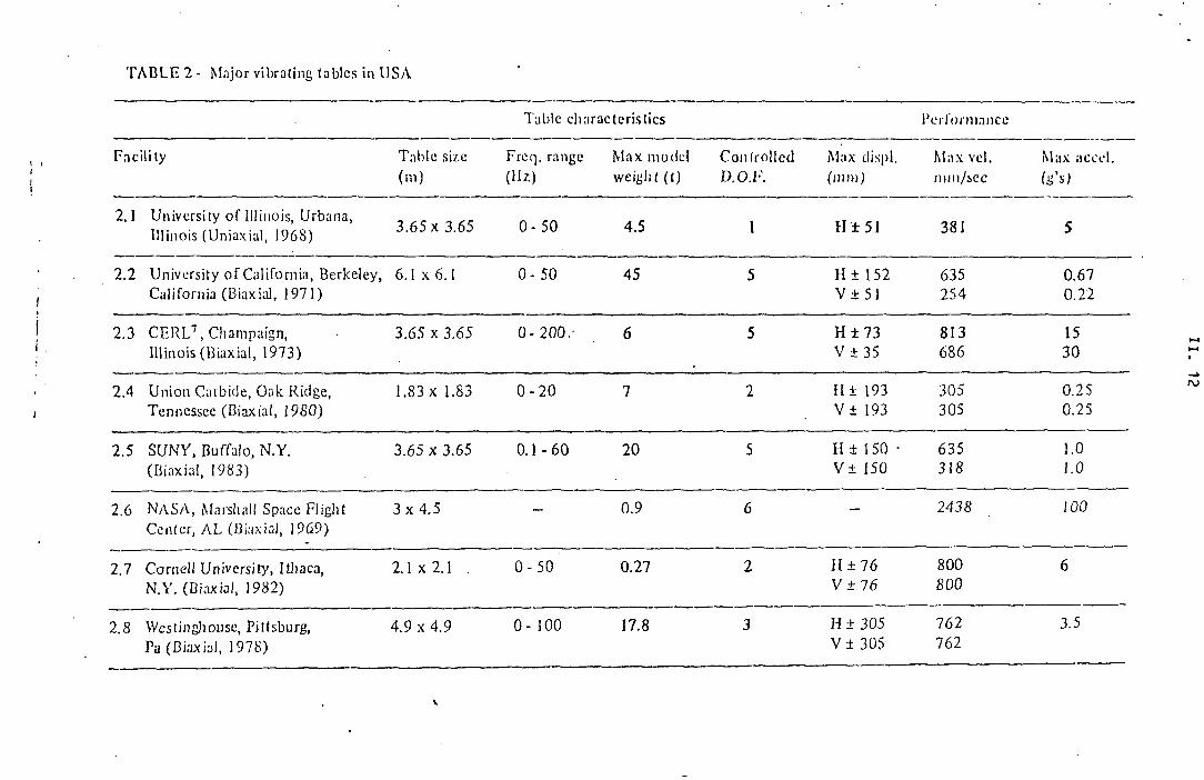
T A B L E 2 - Major vibrating tables in USA
Facility Table size (m)
Freq. range (Hz)
Max model weight (t)
Controlled D.O.I7.
Max displ. (mm)
Max vel. nun/sec
Max aceel. Is'*)
2.1 University of Illinois, Urbana, Illinois (Uniaxial, 1968) 3.65 x 3.65 0- 50 4.5 1 H ± 5 1 381 5
2.2 University of California, Berkeley, California (Biaxial, 1971)
6.1 x 6.1 0- 50 45 5 II ± 1 52 V ± 51
635 254
0.67 0.22
2.3 C E R L 7 , Champaign, Illinois (Biaxial, 1973)
3.65 x 3.65 0- 200.· 6 5 H ± 7 3 V ± 35
813 686
15 30
2.4 Union Carbide, Oak Ridge, Tennessee (Biaxial, 1980)
1.83 x 1.83 0 - 2 0 7 2 H ± 193 V ± 193
305 305
0.25 0.25
2.5 SUNY, Buffalo, N .Y. (Biaxial, 1983)
3.65 x 3.65 0 .1-60 20 5 II ± 150 · V ± 150
635 318
1.0 1.0
2.6 N A S A , Marshall Space Flight Center, A L (Biaxial, 1969)
3 x 4.5 — 0.9 6 — 2438 100
2.7 Cornell University, Ithaca, N . Y . (Biaxial, 1982)
2 .1x2.1 . 0 -50 0.27 2 H ± 7 6 V + 76
800 800
6
2.8 Westinghouse, Pittsburg, Pa (Biaxial, 1978)
4.9 x 4.9 0- 100 17.8 3 H ± 305 V ± 305
762 762
3.5
Table characteristics l'ci Tonmnce

T A B L E 3 - Major vibrating tables in Japan
Table characteristics Performance
Facility Table size (m).
Freq. range (Uz)
Max mode! weight (t)
Con [rolled D.O.F.
Max displ. (mm)
Max vel. mm/sec
Max accel. (S's)
3.1 NRCDP STA B
Tsukubo-Ibanigi 1 5 x 1 5 EHSS 0-50 500 2 H ± 30
V ± 30 370 370
0.55 1
3.2 NUPEC 9
Tadotsu-Takamatsu 15 x 15 EHSS · 1000 2 II ± 200
V ± 100 750 375
1.8 0.9
3.3 IIS, U T 1 0 .Chibeu- 10 x 2 EHSS 170 1 ± 100 0.4
3.4 RTRI, J N R 1 1
Kusutsdii, Tokyo 10x 2 100 1 ± 30 0.4
3.5 PWRI, M C 1 2 , Tsusubct/ 6 x 8 EHSS 0 - 3 0 100 1 ± 75 600 0.8
3.6 C R I E P I 1 3 , Abiko, Chiba, 6.5 x 6 EHSS 125 I ± 50 600 1.2
3.7 NRCDP STA 8
Tsuku beu-6 x 6 EHSS 0 - 5 0 75 3 H ± 100
V ± 5 0 SOO 600
1.2 1
3.8 TRI MM14
Wmcji, Hyogo 6 x 6 EHSS 50 2 II ± 50
V ± 50 420 420
1.2 1.2
3.9 N R I A E M A 1 5 , Tsukuba 6 x 3 . 2 EVS . 0- 50 30 1 ± 50 320 0.4

Table 3 - cont.
Table characferislics Performance
Facility Table size (m)
Frcq. raiige Max model weight (t)
Controlled D.O.F.
Max dLspl. (mm)
Max vol. mm/see
Max accol. (H's)
3.10IM-IRI, M T 1 6
Yokosuka, Fanaga me 5 . 5 x 2 E V S 17 1 ± 50 150 0.5
3.11 S H I M I Z U ' 7 , Tokyo 5 x 4 EHSS 12 1 ± 100 720 1
3.12 K A J I M A " Tokyo
4 x 4 EHSS 20 2 II ± 150 V ± 7 5
1140 455
1.2 2
3 . I 3 P H R I , M T , Ä , Yokosiika 4 x 3.5 EVS 30 1 ± 50 250 0.45
3.14 B R I M C " , Tsukube 4 x 3 EHSS 0 - 5 0 20 1 ± 7 5 600 1
3.15 0 I IBAYASHI , T o k y o 2 0 4 x 3 EHSS 10 1 ± 100 · 1
3.16 DPR2 1 1 , Kyoto 3 x 3 EHSS 12 1 ± 100 0.5
3.17 D P R I 1 1
Kyoto 2.5 x 2.5 E V S 8 2 H ± 50
V ± 5 0 500 500
0.5 0.5

T A B L E 4 - Major vibrating tables around (lie world (besides EEC, USA and Japan)
Table characteristics Performance
Facility Tabic size (m)
Freq. range (Hz)
Max model weight (t)
Controlled D.O.F.
Max displ. (mm)
Max vcl. mm/sec
Max accel. la'*i
4.1 University of Kiril and Mctocljj, Scopie, Yugoslavia (Kiaxial, 1980)
5 x 5 0 - 3 0 40 5 II ± 125 V ± 50
635 380
0.67 0.4
4.2 Arya Mchz University, Teheran, Iran (Uniaxial)
5 x 5 0 - 5 0 50 1 II ± 50 — 0.6
4.3 University of Palliavi, Siraz, Iran (Uniaxial)
4 x 4 0 - 5 0 20 1 H ± 50 — 1.1
4.4 University of Mexico, Mexico City, Mexico (Uniaxial, 1975)
4 .5x2 .5 0 - 5 0 20 1 H ± 5 1 381 1-2
4.5 Toni'. Ji University, Shanghai, PRC
• (Biaxial, 1982) 4 x 4 0 - 6 0 10 6 II ± 100
V ± 100 890 625
1.5 2.7

COMMISSION OF THE EUROPEAN COMMUNITIES J o i n t Research Center
I I I . PERSPECTIVES OF HOSTING AT THE JRC-ISPRA ESTABLISHMENT
A FUSION MACHINE LIKE IGNITOR
Second p r o g r e s s r e p o r t

III. 2
TABLE OF CONTENTS
page
1. INTRODUCTION
2 . POWER SUPPLY
3. MAIN BUILDING AND AUXILIARY SYSTEMS
4. LICENSING
5. COSTS EVALUATION
I I I . 3
I I I . 3
I I I . 4
I I I . 4
I I I . 5

I I I . 3
1. I n t r o d u c t i o n
In the p r e c e d i n g p r o g r e s s r e p o r t d a t e d May 1383 (COM (83)393 f i n a l ) the r e s u l t s o f a p r e l i m i n a r y assessment o f t h r e e main it e m s r e l a t e d t o the s i t i n g o f IGNITOR a t I s p r a were g i v e n : e l e c t r i c a l s u p p l y system, main b u i l d i n g and a u x i l i a r y s ystems, l i c e n s i n g .
D u r i n g t h i s p e r i o d t h e s e i t e m s have been f u r t h e r i n v e s t i g a t e d , c o n s i d e r i n g e s p e c i a l l y t h e u t i l i s a t i o n o f t h e f a c i l i t i e s o f f e r e d by the ESSCR i n s t a l l a t i o n s . The c o n s i d e r a t i o n o f many d e t a i l e d and p r a c t i c a l a s p e c t s has been made p o s s i b l e on one s i d e by a b e t t e r d e f i n i t i o n o f t h e v a r i o u s n u c l e a r a c t i v i t i e s p l a n n e d i n the ES30R a r e a , i n t h e frame o f t h e p r o p o s e d p l u r i a n n u a l programme o f the JRC (CO." (83)327 f i n a l ) , and on the o t h e r s i d e by the a v a i l a b i l i t y o f updated d e t a i l e d i n f o r m a t i o n on t h e f e a t u r e s and' r e q u i r e m e n t s o f the IGNITOR e x p e r i m e n t .
2. .Power s u p p l y
We have r e c e i v e d the d e t a i l e d answer o f ENZL t o the q u e s t i o n n a i r e s p e c i f y i n g t h e s u p p l y r e q u i r e m e n t s . The f e a s i b i l i t y o f the s u p p l y d i r e c t l y from t h e 380 kV l i n e a t t h e b o r d e r o f the I s p r a C e n tre has been o f f i c i a l l y c o n f i r m e d . The c o s t f o r the c o n n e c t i o n t o the l i n e has been g i v e n t o g e t h e r w i t h t h e c o n t r a c t u a l c o n d i t i o n s f o r t h e s u p p l y i n the p e r i o d 1907-1991.
In the r e f e r e n c e : cose o f 3 p u l s o n / d a y , the o f f e r am be quoted as f o l l o w s :
. I n s t a l l a t i o n c o s t s : 820.000.000 L i t
. C o n s t r u c t i o n t i m e : 24 months
..Annual c h a r g e f o r e l e c t r i c a l power : 565.000.000 L i t ( s u p p o s i n g a consumption o f 120.000 kv/h/y
, F o r energy d i s s i p a t e d i n the t r a n s f o r m e r a s u p p l e m e n t a r y charge o f 75 L i t / k w h i s r e q u e s t e d .

III. 4
The or. l y c o n d i t i o n put on the power d e l i v e r y i s t h a t the s h o t s be pre-.i;xou. n.C8d. I t i s f u r t h e r s u g g e s t e d t o o p e r a t e d u r i n g the w o r k i n g time o f w o r k i n g days when the c h o r t c i r c u i t power i s a t maximum l e v e l and the p u l s e s provoke l e s s d i s t u r b a n c e t o the power g r i d .
The s i t e o f the t r a n s f o r m e r s t a t i o n w i t h i n t h e I s p r a C e n t r e has been i d e n t i f i e d , and the l a y o u t o f t h e e l e c t r i c a l l i n e up t o t h e medium v o l t a g e s u b s t a t i o n n e a r t h e IGNITOR main b u i l d i n g has been d e f i n e d .
3. Main b u i l d i n g and a u x i l i t i r y nyntcms
C o n s i d e r i n g t h a t no o t h e r use i s p r o p o s e d f o r t h e ESSCR c o n t a i n m e n t b u i l d i n g and on t h e b a s i s o f t h e updated i n f o r m a t i o n on the d e s i g n o f IGDITOR and o p e r a t i o n and l i c e n s i n g r e q u i r e m e n t s , t h e i n s t a l l a t i o n o f IGN'ITOR i n t h i s b u i l d i n g has been r e c o n s i d e r e d . I n f a c t i n v i e w o f the new i n f o r m a t i o n o b t a i n e d , the p r e v i o u s judgement about d i f f i c u l t i e s i n l o c a t i n g the machine i n s i d e the c o n t a i n m e n t was p remature.
The s o l u t i o n e n v i s a g e d now i s i t s i n s t a l l a t i o n a t w o r k i n g f l o o r l e v e l ( T i g . 1) which seems t o o f f e r many p r a c t i c a l a d v a n t a g e s . The s h i e l d i n g can be p r o v i d e d by removable b l o c k s h a n d l e d by t h e e x i s t i n g 50 T c r a n e . Many a u x i l i a r i e s , l i k e l i q u i d n i t r o g e n d i s t r i b u t i o n s t a t i o n , e x i s t a l r e a d y i n t h e b u i l d i n g . Other a u x i l i a r y s e r v i c e s , i n c l u d i n g a c t i v a t e d m a t e r i a l s i n t e r i m s t o r a g e , can be e a s i l y l o c a t e d i n v a r i o u s e x i s t i n g rooms, w i t h d i r e c t a c c e s s t o h o t c e l l s ( F i g , 2 ) . The l a r g e c ontainment b u i l d i n g c o n n e c t e d w i t h an 80 m. h i g h v e n t i l a t i o n s t a c k ensure ample p r o t e c t i o n a g a i n s t any maximum h y p o t h e t i c a l r e l e a s e o f t r i t i u m o r a c t i v a t e d d u s t .
The r e l a t i v e d i s p o s i t i o n o f IGHITOR and t h e o t h e r l a b o r a t o r i e s and programmes w i t h i n t h e ESSOR i n s t a l l a t i o n i s shown on F i g . 3.
Δ , L i c e n s i n g
An e x p l o r a t i v e c o n t a c t har. been made w i t h the I t a l i a n l i c e n s i n g a u t h o r i t i e s i n o r d e r t o a s s e s s t h e p o s s i b l e approach t o t h e l i c e n s i n g o f v a r i o u s p o s s i b l e new n u c l e a r a c t i v i t i e s i n the ESSOR complex i n c l u d i n g IGMITOR.
The suj'j-ested a p p r o a c h i s t o p u t a l l t h e s e a c t i v i t i e s under t h e e x i s t i n g l i c e n c e and t o d e a l w i t h tho.-.i an " m o d i f i c a t i o n o f the i n s t a l l a t i o n " . I n t h i s h y p o t h e s i s , t h a t most p r o b a b l y w i l l be f o l l o w e d os a c e n t r a l g u i d e l i n e i n the l i c e n s i n g p r o c e s s , i t w i l l n o t even be n e c e s s a r y f o r IGTJITOP. t o f o l l o w the p r o c e d u r e r e q u i r e d by the a r t . DP?. 12.2, 196£ n. 1S5, mentioned i n the p r e v i o u s p r o g r e s s r e p o r t . I n t h i s case t h e s i m p l e r p r o c e d u r e o f the a r t . 12 DPR 155 would be f o l l o w e d .

III. 5
5. Cor.t3 e v a l u a t i o n
The e v a l u a t i o n o f the c o s t . j f o r the s i t e p r e p a r a t i o n ( i n c l u d i n g the p c ver s u p p l y system and b u i l d i n g s ) , t h e a d a p t a t i o n o f v a r i o u s a u x i l i a r i e s , the s u p p l y o f power and t e c h n i c a l s e r v i c e s , c o n s i d e r i n g a c o n s t r u c t i o n p e r i o d o f a b o u t t h r e e y e a r s (1SS4-87) and an o p e r a t i o n p e r i o d o f f o u r y e a r s (19BB-1991) i s i n p r o g r e s s . T h i s e v a l u a t i o n w i l l be a v a i l a b l e t o g e t h e r w i t h t h e t e c h n i c a l report a t the end o f September.
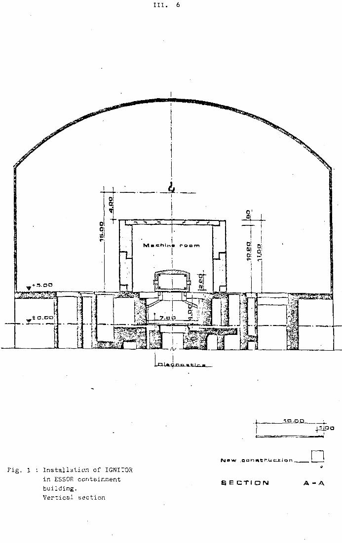
I I I . 6
F i g . 1 : I n s t a l l a t i o n o f IGNITQR i n ESSOR c o n t a i n m e n t b u i l d i n g . V e r t i c a l s e c t i o n

I I I . 7
F i g . 2 : I n s t a l l a t i o n o f IGNITOR i n ESSOR c o n t a i n m e n t b u i l d i n g L ayout o f a u x i l i a r i e s
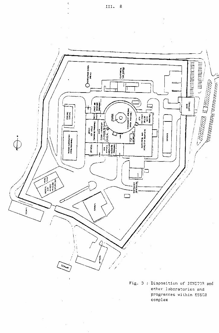
I I I . 8
Fig. 3 : Disposition of IGNJTQR and other laboratories and programmes within E5SCR complex