Collaborative distributed network system: a lightweight middleware supporting collaborative DEVS...
17
Future Generation Computer Systems 17 (2000) 89–105 Collaborative distributed network system: a lightweight middleware supporting collaborative DEVS modeling Hessam S. Sarjoughian *,1 , Bernard P. Zeigler, Sunwoo Park AI & Simulation Research Group, Department of Electrical and Computer Engineering, University of Arizona, Tucson, AZ 85721-0104, USA Abstract The present and future of our world, in part, depends on the effective application of problem solving techniques and tools that are able to bring together expertise from many disciplines, e.g. problems such as how world wide distribution of commodities are inherently multidisciplinary in nature. As such they demand collaborative computer-based tools that enable subject matter experts to work cooperatively while overcoming the constraints of space and time. The realization of collaborative tools can benefit greatly by relying on “out-of-the-box” higher level network interconnectivity software. In this paper, we discuss the collaborative distributed network model (CDNM). Based on this model, a lightweight middleware called collaborative distributed network system (CDNS) is implemented using Java technologies. We discuss CDNM’s architecture and the services it can provide to modeling and simulation applications built on its foundation. Furthermore, we discuss Collaborative DEVS Modeler, a collaborative modeling environment, where dispersed clients interact with one another using the services offered by the CDNS. The explicit architectural design of CDNM will facilitate its future migration into emerging middleware standards such as High Level Architecture (HLA) and CORBA. © 2000 Elsevier Science B.V. All rights reserved. Keywords: Architecture; Collaboration; CSCW; Design; Distributed computing; Java; Middleware; Modeling; Network; Simulation 1. Introduction Use of modeling and simulation is increasing since it provides insight into how complex systems work. Indeed, many contemporary systems can only be understood and manipulated using modeling and sim- ulation techniques. Collaboration provides a powerful approach for creating simulation models [1]. For ex- ample, problems such as shipment of commodities can no longer be modeled and understood by under- * Corresponding author. E-mail addresses: [email protected] (H.S. Sarjoughian), [email protected] (B.P. Zeigler), [email protected] (S. Park). 1 http://www.acims.arizona.edu standing the inner working of the shipping company alone. Instead, subject matter experts from the ship- ping company as well as others from the Airline Company, Telephone Company, etc. must join forces to understand the complexity and intricacies of an entire shipping process. The objective in designing a collaborative modeling environment is to enable mul- tiple modelers to share each other’s knowledge and build well-structured models of multifaceted systems better and cheaper [2]. The development of collaborative modeling tools requires wide-area networking capabilities. Many al- ternative middleware (networking) environments with varying degrees of expressive power, cost and ease of use exist. Such environments can be highly generic or conversely, very specific. Consequently, a desir- 0167-739X/00/$ – see front matter © 2000 Elsevier Science B.V. All rights reserved. PII:S0167-739X(99)00106-5
-
Upload
independent -
Category
Documents
-
view
0 -
download
0
Transcript of Collaborative distributed network system: a lightweight middleware supporting collaborative DEVS...

Future Generation Computer Systems 17 (2000) 89–105
Collaborative distributed network system: a lightweightmiddleware supporting collaborative DEVS modeling
Hessam S. Sarjoughian∗,1, Bernard P. Zeigler, Sunwoo ParkAI & Simulation Research Group, Department of Electrical and Computer Engineering,
University of Arizona, Tucson, AZ 85721-0104, USA
Abstract
The present and future of our world, in part, depends on the effective application of problem solving techniques andtools that are able to bring together expertise from many disciplines, e.g. problems such as how world wide distributionof commodities are inherently multidisciplinary in nature. As such they demand collaborative computer-based tools thatenable subject matter experts to work cooperatively while overcoming the constraints of space and time. The realization ofcollaborative tools can benefit greatly by relying on “out-of-the-box” higher level network interconnectivity software. In thispaper, we discuss the collaborative distributed network model (CDNM). Based on this model, a lightweight middleware calledcollaborative distributed network system (CDNS) is implemented using Java technologies. We discuss CDNM’s architectureand the services it can provide to modeling and simulation applications built on its foundation. Furthermore, we discussCollaborative DEVS Modeler, a collaborative modeling environment, where dispersed clients interact with one another usingthe services offered by the CDNS. The explicit architectural design of CDNM will facilitate its future migration into emergingmiddleware standards such as High Level Architecture (HLA) and CORBA. © 2000 Elsevier Science B.V. All rights reserved.
Keywords:Architecture; Collaboration; CSCW; Design; Distributed computing; Java; Middleware; Modeling; Network; Simulation
1. Introduction
Use of modeling and simulation is increasing sinceit provides insight into how complex systems work.Indeed, many contemporary systems can only beunderstood and manipulated using modeling and sim-ulation techniques. Collaboration provides a powerfulapproach for creating simulation models [1]. For ex-ample, problems such as shipment of commoditiescan no longer be modeled and understood by under-
∗ Corresponding author.E-mail addresses:[email protected] (H.S. Sarjoughian),[email protected] (B.P. Zeigler), [email protected](S. Park).
1 http://www.acims.arizona.edu
standing the inner working of the shipping companyalone. Instead, subject matter experts from the ship-ping company as well as others from the AirlineCompany, Telephone Company, etc. must join forcesto understand the complexity and intricacies of anentire shipping process. The objective in designing acollaborative modeling environment is to enable mul-tiple modelers to share each other’s knowledge andbuild well-structured models of multifaceted systemsbetter and cheaper [2].
The development of collaborative modeling toolsrequires wide-area networking capabilities. Many al-ternative middleware (networking) environments withvarying degrees of expressive power, cost and ease ofuse exist. Such environments can be highly genericor conversely, very specific. Consequently, a desir-
0167-739X/00/$ – see front matter © 2000 Elsevier Science B.V. All rights reserved.PII: S0167-739X(99)00106-5

90 H.S. Sarjoughian et al. / Future Generation Computer Systems 17 (2000) 89–105
able middleware can be customized from a general,all-purpose middleware such as CORBA [3], or in-stead be conceived, designed and developed based onits intended use. With this point of view in mind, ourobjective has been to develop acollaborative networkarchitecture that can interconnect a relatively smallgroup of modelers (e.g., 5–30) independent of theirwhereabouts.2 Indeed, it is desirable to develop a col-laborative network architecture that can support notonly collaborative modeling, but also other activitiesof the modeling and simulation enterprise such assimulation set-up and execution.
A detailed taxonomy of collaboration has been es-tablished based ontime andplaceconstraints [4]. Inthis taxonomy, collaboration is defined to take placein three modes: conventional, synchronous and asyn-chronous. Conventional collaboration entails immedi-ate, face-to-face communication. This form of collab-oration requires all participants to be in the same placeat the same time. Synchronous collaboration can oc-cur when the participants have agreed on a time tomeet, but not necessarily in the same physical location.Video-teleconferencing is an example of synchronouscollaboration. Asynchronous collaboration does notrequire any agreements on time or place. In this mode,neither time nor place is considered to be essentialfor collaboration. Electronic mail and a computer bul-letin board are examples of asynchronous collabora-tion. Based on the general taxonomy of collaborationmodes, two modes of model development have beenproposed: model discovery/invention and model syn-thesis [1]. The former emphasizes creation of primitivemodels while the latter focuses on building compositemodels from existing primitive, smaller models.
This paper addresses architectural design issues thatfacilitate the development of collaborative modelingsystems. The main focus is on the use of a middle-ware (CDNS) to support the design of an extensiblecollaborative DEVS modeling environment (CDM).Section 2 provides a brief account of relevant archi-tectural approaches for multiuser systems. Section 3gives a precise definition for the concept of sessionsince it provides the basis for much of what is con-
2 The suggested number of modelers participating in model build-ing is not based on any scientific studies. Group size and otherrelated issues that can support effective collaborative modelingrequires research on its own right.
tained in Section 4, where the collaborative distributednetwork model (CDNM) is discussed in detail. Theobjective of this detailed discussion is to provide an“insider view” of network related issues such as ob-jects moving around in a wide-area network, CDNSarchitectural integrity (e.g., extensibility) and the im-plications of such a middleware for building specificapplications (e.g., CDM) based on its services. Specif-ically, the layered architecture of the CDNM exposesinnocent looking, yet critical, issues that should beconsidered. For example, much detail is presented onthe types of objects and their roles so that the CDNSservices can be interpreted and utilized in a systematicfashion by an application built on top of it. In Section5, a brief view of the CDNM realization (i.e., CDNS)is presented. Collaborative DEVS Modeler applica-tion is described in terms of its high-level architecture.The remaining two sections consider related/futureresearch and conclusions.
2. Client/server system architectures
During the last several decades, three distinctmodels of the distributed software/system architec-tures have emerged. These are client/server network,peer-to-peer network and server-network. Each en-ables dispersed users to join forces to tackle problemsthat cannot be effectively solved by a single machineor user. Theclient/servermodel consists of clients anda server where the server provides services that arerequested by its clients [5]. In a client/server network,a client sends a request to the server which in turnsends a reply back to the client. The interactions aremany-to-one from clients to server and one-to-manyfrom server to clients. In this model, clients do notcommunicate directly, but use the server as an inter-mediary.
Several styles of client/server architectures are usedin network-enabled applications. With the emergenceof the World Wide Web, thethin-client style hasgained much popularity for ease of deployment andversion control. Thin-clients are typically very small,indicating that they can be downloaded quickly froma network server and used in a “one shot” fashion.Versioning of the thin-client is almost trivial. Whenthe software is recompiled, a user has automatic ac-cess to the new version when she/he connects to the

H.S. Sarjoughian et al. / Future Generation Computer Systems 17 (2000) 89–105 91
server. The thin-client, however, has several disad-vantages such as demand for significant bandwidthfor all, but small applications. Thin-clients rely on theserver to do most, if not all, of application’s requests.
Thick-clients, unlike thin-clients, tend to be morerobust, scalable and capable of handling even the worstnetwork conditions/constraints. The thick-client appli-cation requires that the client process maintain a localcopy of the relevant data and program. This allowseach client to act independently to the extent that ithas been empowered to. A server provides servicesthat the client cannot provide by itself. A thick-clientcan make the network invisible to the user while thesoftware is being used.
The peer-to-peer(serverless) network allows allclients (or subsets thereof) to be directly intercon-nected to one another. In such an arrangement, thereis no intermediary and the client broadcasts (or mul-ticasts) its messages directly to every client in thenetwork. This removes the single point of failure andeliminates the server bottleneck. However, it intro-duces ambiguities when any dispute arises.
The remaining client/server architecture style,server-network model, provides hybrid architecturebased on both the client/server and the peer-to-peermodel [6]. Groups of clients are connected to a server.Several servers are interconnected. The nodes of theserver network (i.e., servers) can be configured aseither permanent or dynamic where they can be pe-riodical or otherwise according to the type of dataexchange requirements. For example, each servermay send a message to a specific server or all servers(commonly referred to as flooding). A client inserver-network environment may access a local serveras well as remote servers. It also provides improvedscalability over the client/server model and bettercontrol management than the peer-to-peer model.Once again, the enhanced features of server-networkmust be traded-off against added complexity.
3. Anyplace/anytime session
Before we proceed, we describe what is aCollab-orative Session[7]. It is a workspace dedicated to agroup of clients who are working together via a net-work. It provides a set of services to its users duringa period having astart-time and anend-time. The
Fig. 1. Example of collaborative sessions in multiclient and multi-server system.
services are well-defined both in terms of the func-tionalities they provide and how they arerequestedand deliveredvia specific communication protocols(e.g., Java RMI). A session is the combination ofa session-clientand asession-serveras depicted inFig. 1. A session-client provides a client with services,some of which are performed at the client side andothers at the server side. A session-server providesservices directly to itself and indirectly to its clients.A user can have multiple session-clients when she/heis involved in multipledistinct sessions at that time.Furthermore, these sessions are independent of oneanother with the implication that communicationamong session-servers are not supported.
4. Collaborative distributed network model
The CDNM is a model for collaborative distributednetwork system (CDNS) [8]. It provides genericnet-work managementservices to both clients and servers.It employs event multicasting, system managementand monitoring facilities. This section discusses themain software components of the CDNM from aSys-tem Architectureperspective. The functional require-ments for CDNM are the following:• Extensible/flexible software development/evolution.
CDNM architecture should be extensible to sup-port future capabilities such as (synchronized) pub-lish/subscribe to an application component.

92 H.S. Sarjoughian et al. / Future Generation Computer Systems 17 (2000) 89–105
Fig. 2. Layered architectural view of collaborative client/server model.
• Simple design and implementation. Design, andconsequently, implementation should be devoidof complexity (e.g., introducing fictitious classesthat have little or no impact in achieving a robustsoftware design).
• Be an adaptable middleware given lower level net-work layers. Network level should readily be re-placeable with an alternative one (e.g., choosingRMI instead of Socket).
• Support building non-monolithic applications. Thedesign should support a multitude of applicationssuch as modeling, simulation, animation, businessprocesses, etc. The CNDM should support addingnew applications without requiring modifications tothe ones already supported.
• Have well-defined interfaces to application layerand network layer. Interface designs (GUI andotherwise) should be well-defined to fit both upperand lower layers. For example, the applicationinterface provided for the DEVS Modeling applica-tion should remain intact despite adding animationcapabilities.
• Conceptual and structural modularity. Design musthave integrity by coalescing a set of related conceptsand structures (e.g., various GUI components) intoa super-component. For example, Graphical UserInterface, Client Services and Server Services mustbe independent super-components.
4.1. Collaborative network system model abstractarchitecture
CDNM is comprised of two main layers: System-Layer and Application-Layer (Fig. 2). The system-layerprovides collaborative networking (network layer),event multicasting (event multicast layer) and manage-ment (management layer). The application-layer pro-vides a number of session-clients and session-serverimplementations (session-implementation layer). Inthe following sections, each layer and its componentsare discussed in detail.
Before we continue with the remainder of thissection, we define the types of objects that will behandled by various components of the collabora-tive client/server system model. We have four typesof objects: Communication Object, Request Object,Indication Object and Event Object.
Communication object is an object (e.g.,Objectfrom the Javalang library) with object name (ObjectID), a source (Source ID) destination (Destination ID)and message (Data object) as depicted in Tables 1and 2. The source and destination IDs are the com-ponent IDs (e.g., connection-client, connection-server,or session-server IDs). It also contains an object (i.e.,Data object). The data object contains “data” that istransmitted among components residing in a singlemachine or between multiple machines (e.g., client
H.S. Sarjoughian et al. / Future Generation Computer Systems 17 (2000) 89–105 93
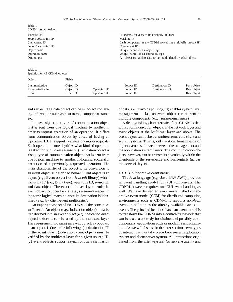
Table 1CDNM limited lexicon
Machine IP IP address for a machine (globally unique)Source/destination IP Machine IPComponent ID Each component in the CDNM model has a globally unique IDSource/destination ID Component IDObject name Unique name for an object typeOperation name Unique name for an operation typeData object An object containing data to be manipulated by other objects
Table 2Specification of CDNM objects
Object Fields
Communication Object ID Source ID Destination ID Data objectRequest/indication Object ID Operation ID Source ID Destination ID Data objectEvent Event ID Operation ID Source ID Data object
and server). The data object can be an object contain-ing information such as host name, component name,etc.
Request object is a type of communication objectthat is sent from one logical machine to another inorder to request execution of an operation. It differsfrom communication object by virtue of having anOperation ID. It supports various operation requests.Each operation name signifies what kind of operationis asked for (e.g., create a session). Indication object isalso a type of communication object that is sent fromone logical machine to another indicating successfulexecution of a previously requested operation. Themain characteristic of the object is its conversion toan event object as described below. Event object is anobject (e.g., Event object from Javautil library) whichhas event ID (i.e., Event type), operation ID, source IDand data object. The event-multicast layer sends theevent object to upper layers (e.g., session-manager) inthe same logical machine once its destination is iden-tified (e.g., by client-event multicaster).
An important aspect of the CDNM is the concept ofan “event”. An object (e.g., indication object) must betransformed into anevent object(e.g., indication eventobject) before it can be used by the multicast layer.The requirement for using an event object, as opposedto an object, is due to the following: (1) destination IDof the event object (indication event object) must beverified by the multicast layer for a given source ID,(2) event objects support asynchronous transmission
of data (i.e., it avoids polling), (3) enables system levelmanagement — i.e., an event object can be sent tomultiple components (e.g., session-managers).
A distinguishing characteristic of the CDNM is thatit uses communication objects at the network layer andevent objects at the Multicast layer and above. Theevent object cannot be transmitted across the client andserver systems. That is, only vertical transmission ofobject events is allowed between the management andthe application system layers. The communication ob-jects, however, can be transmitted vertically within theclient-side or the server-side and horizontally (acrossthe network layer).
4.1.1. Collaborative event modelThe Java language (e.g., Java 1.1.* AWT) provides
an event handling model for GUI components. TheCDNM, however, requires non-GUI-event handling aswell. We have devised an event model called collab-orative event model (CEM) for distributed computingenvironments such as CDNM. It supports non-GUIevents in addition to the already available Java GUIevents. The principal benefit of such an event model isto transform the CDNM into a control-framework thatcan be used seamlessly for distinct and possibly com-plementary, applications such as modeling and simula-tion. As we will discuss in the later sections, two typesof interactions can take place between an applicationsystem and client/server system. All interactions orig-inated from the client-system (or server-system) and

94 H.S. Sarjoughian et al. / Future Generation Computer Systems 17 (2000) 89–105
Fig. 3. Event/object passing between application-system andclient/server-systems.
sent to client (or server) application-system will bein the form of events (see Fig. 3). The interactionsoriginated from the application-system and sent to theclient-system (server-system) will be in the form ofobjects.
The CEM model consists of event objects, event lis-tener interfaces and event multicasters. An event ob-ject (e.g., indication event object) is a typical (possi-bly non-serializable) object which has source ID anddata object. Here the data object can be any objectincluding event object. An event listener interface isan interface containing a set of methods without theirimplementations. The objects responsible for handlingthe events will implement the specifics of operations(methods) that are declared in the interfaces’ meth-ods (see Section 4.1.3 for a particular realization ofCEM). In terms of the CDNM, the event multicasterlayer and session implementation layer have differentreasons to implement the event listeners. Componentsof event multicaster layer (i.e., client event multicastand server event multicaster) implement those listen-ers toproduceevents. But, components of applicationlayer (i.e., session-client and session-server implemen-tation) implement those listeners toconsumeevents.
4.1.2. Network layerThe network layer consists of three components:
Connection-Client, Connection-Server and Session-Server. A connection-client and connection-server pairprovides the primitive (lowest level)3 communication
3 These communication primitives sit on top of the transport layer.
link between a client-system and a server-system. Aclient-system refers to a number ofsession clientsand its client-system network— session-managers,client-event multicaster and connection-client (seeFig. 2). Similarly, a server system refers to a num-ber ofsession-server implementationsand theserver-system network— server-manager, session-monitor,server-event multicaster, session-servers and con-nection-server. Obviously, a client-system and aserver-system can be executing on a single machine oron two distinct machines (having their own machineIP addresses).
A client-system and a server-system have oneconnection-client and one connection-server, respec-tively. A server-system, however, can have a numberof session-servers where each session-server has adistinct component ID. The session-server representsa session by furnishing session-related services andcommon data access/storage. These services are real-ized at the application layer.
Connection-client and connection-server. Theconnection-client and connection-server have recip-rocal communications with each other. A connection-client communicates by sendingrequest objectstothe connection-server. The possible requests are:(1) connect to a session, (2) disconnect from a ses-sion, (3) create a new session, (4) remove an ex-isting session, or (5) query a session. Similarly, aconnection-server performs network communicationby sendingindication objectsto the connection-client.The connection-client is informed of successful com-pletion of its request by the connection-server. Theconnection-client or connection-server acts as gate-way to send objects to their respective upper layers.Table 3 below shows the list of operations recognizedby the connection-client and the connection-server.
All defined object IDs (i.e., Request object and In-dication object) and their corresponding operation IDs(e.g., DISCONNECT) for the given request and indi-cation operation parameters are shown in Table 4. Theobjects operated upon by the network layer are sentto the Event Multicaster Layer which is discussed inSection 4.1.3.
Session-server. A session-server supports: (1)session-connectivity, (2) object manipulation, (3)object multicast operations (see Tables 5–7). Whilethe operations below enable system-level activi-ties (e.g., joining a session), they do not support

H.S. Sarjoughian et al. / Future Generation Computer Systems 17 (2000) 89–105 95
Table 3Connection-client and connection-server operations
Communication mode Operation Source ID Destination ID Operation parameter
Forwarda Send Connection-client Connection-server Request objectReceive Connection-server Connection-client Indication object
Callback Send Connection-server Connection-client Request objectReceive Connection-client Connection-server Indication object
aForward mode is initiated by the client and callback mode is initiated by the server.
Table 4Connection request and indication object operation IDs
Functionality Object Object ID Operation ID Description
Establishing a connection Request object REQUESTOBJ CONNECT Establish connection to a logical machineDISCONNECT Terminate connection to a logical machine
Indication object INDICATEOBJ CONNECT Confirm connection establishmentDISCONNECT Confirm connection termination
Manipulating a session Request object REQUESTOBJ CREATE Create a new sessionREMOVE Remove an existing session
Indication object INDICATEOBJ CREATE Confirm creation of a new session
Table 5Session request and indication object operation IDs
Communication mode Operation Source ID Destination ID Operation parameter
Forward Send Connection-client Session-server Request object or Communication objectReceive Session-server Connection-client Indication object
Callback Unicast Session-server Connection-client Communication object
Multicast Session-server Connection-client Communication object
Table 6Connection-client and session-server operations
Object (operation parameter) Object ID Operation ID Description
Request object REQUESTOBJ QUERY Query a sessionJOIN Join a sessionDROP Drop from a session
Indication object INDICATEOBJ QUERY Confirm a queryJOIN Confirm joining a sessionDROP Confirm dropping from a session
Table 7Data manipulation IDs of session request and indication object
Object (operation parameter) Object ID Operation ID Description
Request object REQUESTOBJ ADD Add an object to a sessionDELETE Delete an object from a sessionUPDATE Update an object of a session
Indication object INDICATEOBJ ADD Confirm adding an objectDELETE Confirm deleting an objectUPDATE Confirm updating an object

96 H.S. Sarjoughian et al. / Future Generation Computer Systems 17 (2000) 89–105
application-oriented activities. For example, in anonline class registration system, students may wantto “add” or “drop” a class from their class listings.Such operations are application-dependent. Theseapplication-layer operations are similar to the systemlevel operations (e.g., JOIN) in that they are handledthe same way in terms of their transmissions betweenthe client-system and the server-system.
The session connectivity operations are Join andDrop. The Join operation enables a client tosubscribe(log on) to an existing session. Likewise, a client mayrequest tounsubscribe(log off) from a previously“joined” session using the Drop operation. The objectmanipulation operations are Add, Remove and Up-date. They provide services for adding, removing, orupdating (replacing) an object of a session when thesession-client sends an add request, a remove request,or an update request to the session-server, respectively.The server-event multicast layer supports “indicationobject” unicast and multicast operations. These oper-ations can send an object to a session-client (unicast)or a set of session-clients (multicast).
Multicast control provides two supplementaryservices: selecting a multicastmodeand setting aninterval for it. A session-server can multicast anobject to all registered session clients. Three trans-mission modes are supported: periodic, non-periodicand intelligent. The session-server sends an objectto session-clients every fixed interval in periodicmode. In the non-periodic mode, the session-serversends an object to session-clients immediately af-ter serving a client request. In the intelligent mode,the session-server dynamically switches transmissionmode (periodic versus non-periodic) based on ananalysis of network traffic or system performance.
Registration and deregistration service are per-formed when a server-manager creates or removesone or more sessions. The session-server providesonly “signatures” of the above services. The specifics(implementations) of the definitions are provided atapplication layer (i.e., Session-Server Implementa-tion). A critical feature of the CDNM model is theseparation between the signatures and their implemen-tations. This facilitates devising application-specificneeds independent of the system layer, thus support-ing customized application services without any mod-ifications to the underlying system layer architecture(see Figs. 4 and 5).
Fig. 4. Objects passing between components of network layer.
4.1.3. Event multicast layerAs shown in Fig. 2, the Event Multicast Layer
consists of the Client-Event Multicaster and theServer-Event Multicaster. These support object dis-semination (transport) and control between the net-work and management layers as well as betweenthe network and session implementation layers. Theclient-event (or server-event) multicaster receives anobject (either communication object or indication ob-ject) from the network layer, converts it to an event ob-ject which is then sent (multicast) to the management
Fig. 5. Object passing between network layer and other layers.

H.S. Sarjoughian et al. / Future Generation Computer Systems 17 (2000) 89–105 97
Table 8Multicast Table specification of event multicasters
Multicaster Fields
Client-event multicaster Server reference ID List of component IDsServer-event multicaster Server ID List of component IDs
layer or session implementation layer.4 The con-version is performed by (1) validating source and/ordestination IDs of the given object (e.g., indicationobject) and (2) if necessary retrieving its data object(refer to Table 2) to compose the event object. Theclient/server-event multicasters rely on a set of Tablesto route event objects to their destinations (Table 8).
Component IDs maintained in the client-eventmulticaster table can be of two types (i.e., session-manager’s ID or session-client’s ID (see Fig. 7)), whilethe component IDs maintained by the server-eventmulticaster can be either session-monitor ID,server-manager ID, or session-server implementationID (see Fig. 9). We are using the termreferencetoindicate that it holds a “reference” to the component’sID as opposed to holding the ID itself.
Client-event multicaster. A client-event multi-caster sends an event to a session-manager and/orsession-client(s) based on the type of the object (seeSection 4.1.2) it receives from the network layer(Fig. 6). We begin by describing the event objectdissemination from the client-event multicaster tosession-clients (see Fig. 7). When a connection-clientprovides acommunication objectto the client-eventmulticaster, it is converted to acommunication eventobject which is then sent to components (i.e., listof component IDs of the client-event multicaster inTable 8). This goes to the components that havealready been registered to receive it. In general, theremay exist multiple session-servers where each mustserve its own (possibly unique) clients. Therefore,it is necessary for the client-event multicaster toknow which session-server (i.e., server reference ofthe client-event multicaster ID in Table 8) has beenthe originator of an event object to be sent to itssession-clients.
4 The event multicast layer is based on the Java’s listeners AWTmulticast model where an event is sent to multiple listener objects.The client–event multicaster, for example, multicasts event objectsto a set of registered recipients — e.g., session clients.
Fig. 6. Client-event multicaster.
Fig. 7 shows an example of event multicastingfor the client-system. It assumes client 1 and client2 are already registered (i.e., listed in the MulticastTable) with the session-server 1, i.e., both clientshave a “session-client 1”. Assuming the client-eventmulticaster receives a communication object from thesession-server 1, the client-event multicaster convertsthe communication object into a communication eventobject and multicasts it to session-client 1 for eachclient 1 and client 2.
The client-event multicaster also receives indica-tion objects. These objects are converted to indicationevent objects which are then sent to each client’ssession-manager where each client may have mul-tiple session-clients. Every client must, of course,be registered with the event multicaster through asession-manager. In terms of Table 8, therefore, theServer reference ID is the connection-server.
Server-event multicaster. A server-event multicastersends an event to server-side management componentsand/or session implementation components when thenetwork layer provides a request object or a commu-
98 H.S. Sarjoughian et al. / Future Generation Computer Systems 17 (2000) 89–105
Fig. 7. Example of communication and indication event object multicast.
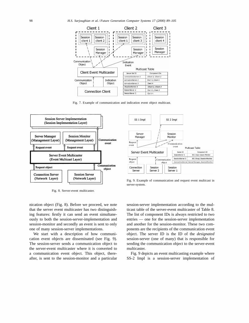
Fig. 8. Server-event multicaster.
nication object (Fig. 8). Before we proceed, we notethat the server event multicaster has two distinguish-ing features: firstly it can send an event simultane-ously to both the session-server-implementation andsession-monitor and secondly an event is sent to onlyone of many session-server implementations.
We start with a description of how communi-cation event objects are disseminated (see Fig. 9).The session-server sends a communication object tothe server-event multicaster where it is converted toa communication event object. This object, there-after, is sent to the session-monitor and a particular
Fig. 9. Example of communication and request event multicast inserver-system.
session-server implementation according to the mul-ticast table of the server-event multicaster of Table 8.The list of component IDs is always restricted to twoentries — one for the session-server implementationand another for the session-monitor. These two com-ponents are the recipients of the communication eventobject. The server ID is the ID of thedesignatedsession-server (one of many) that is responsible forsending the communication object to the server-eventmulticaster.
Fig. 9 depicts an event multicasting example whereSS-2 Impl is a session-server implementation of

H.S. Sarjoughian et al. / Future Generation Computer Systems 17 (2000) 89–105 99
session-server 2. In this scenario, when session-server2 (server ID in Fig. 9) sends a communication objectto the server-event multicaster, the multicaster con-verts the object to its corresponding communicationevent object before sending it to the session-server 2implementation and the session-monitor according tothe multicast table of the session-server.
In the case of a request object, it is initially sentby the connection-server to the server-event multi-caster. The server-event multicaster, in turn, convertsit to a request event objectand then sent to theserver-manager. (Note that only one session-managerand one session-monitor exists for the server-system.)In the next section, we describe the role of theserver-manager in dealing with the communicationevent object.
4.1.4. Management layerThis layer consists of three components: a
client session-manager, a server-manager and asession-monitor (see Fig. 10). The session-managerand server-manager components provide mecha-nisms for creating and removing session-clients andsession-servers. Within the server-system manage-ment layer, the session-monitor is responsible formonitoring the activities that take place between theserver-event multicaster and session-server imple-mentation.
A client-system provides distributed session man-agement facilities by furnishing a session-manager toeach client. The session-manager maintains a record
Fig. 10. Management layer interacting with other layers.
of all session-clients that a client is interacting with.A server-system, unlike a client-system, providescentralized session management mechanism usingits server-manager. The server-manager controls andcoordinates all system components that are related tosession activities.
Session-manager. Each session-client is associatedwith a session-manager. The session-manager keepstrack of all session-clients that a client owns. Its re-sponsibilities are to supportjoining anddroppingfroman existing session-server as well ascreatingand re-moving session-clients in cooperation with compo-nents from the event-multicaster and network layers.
By providing session management facilities toeach client, client-system provides robust andclient-customizable session management system.Since each client has a separate session-manager,anomalies associated with one session-manager do notaffect other session-managers. Furthermore, with adedicated session-manager, each client can efficientlymaintain a large number of session-clients.
For a client tojoin a session-server, it is the re-sponsibility of the session-manager to provide a listof available (existing) session-servers for a givenserver-system. The client, therefore, will be ableto join one or more session-servers simultaneously,thus creating one or more session-clients. Of course,since multiple server-systems can be available, thesession-manager can provide a list of session-serversfor each server-system. Similarly, a client candropfrom any number of existing session-servers simulta-neously.
For the joint operation, the session-manager re-ceives an indication event object from the client-eventmulticaster as a response to an inquiry (requestobject) sent to the server-manager. The responsefrom the server-manager contains a list of existingsession-servers. Thereafter, a session-client is createdfor the client by the session-manager which is distinctfrom the one that is created on the server-system.The indication event object entails knowledge aboutthe session-server such as server reference ID. Like-wise, session-manager handles a client’s request tobe dropped from the list of session-clients that areassociated with the session-server.
The session-manager is responsible forcreatingor removingsession-clients. A specific session-clientis created for each session-server belonging to a

100 H.S. Sarjoughian et al. / Future Generation Computer Systems 17 (2000) 89–105
given server-system. Hence, if there exist threesession-servers, a client can create three session-clients.A client can request for creation of a session-client onthe client-system. However, such a request can onlybe granted after its corresponding session-server hasbeen created on the server-system. The creation of asession-client is initiated by a communication objectsent by a client (i.e., application component) to thesession-manager. Once the session-manager receivesa communication event object from the client-eventmulticaster, it creates the session-client where theaforementioned communication event object is sentby the session-server.
The removal of a session-client is similar to thesession-client creation with the exception that thesession-server is removed and consequently anysession-client is connected to it.
Server-manager/session-monitor. A server-manageris a server-side session management system based ona centralized strategy. It manages a connection-serverand multiple session-servers in the network layer. Itis responsible for registering, deregistering, creatingand removing session-server implementations usingthe event multicaster layer and the network layer ofthe server-system.
The creation or removal of session-servers andtheir corresponding session-server implementationsis the responsibility of the server-manager. Theserver-manager determines, for example, whether asession-server already exists or not before creatinga new session-server. Likewise, it is responsible forappropriate registering and deregistering of a givensession-server. The server-manager’s responsibilityincludes sending event objects to the session-serverimplementations as well as receiving objects from thesession-server implementation. The server-managerdoes not have any interactions with the client’s ap-plication system directly. All such interactions takeplace via the network layer.
A session-monitor’s role is tomonitor variouscommunications that take place in the server-system.It receives a copy of every message that is sent tothe session-server implementations. The messagesreceived by the session-monitor, however, are not re-stricted to those that are sent to the server-manager.While the server-manager receives only communica-tion event objects, the session-monitor also receivesrequest event objects.
Generally, the session-monitor relies on more infor-mation (inputs), as compared to the server-manager, tocarry out its operations (e.g., keeping track of the num-ber of messages originated by each client). It shouldbe noted that the session-monitor must not alter thedynamics of the systems that it “observes”. However,the system’s operations may be affected adversely (forexample, reduced performance) if the session-monitorrequires substantial processing cycles. Another con-sideration in this model is that the session-monitoris not responsible for monitoring session-clients. Theproposed model, however, does not preclude the ex-tension of the monitor concept to the client-system.
4.1.5. Session implementation layerSimilar to the other layers in the CDNM, this
layer is comprised of components on the client andserver sides. The components of this layer providethe gateway to specific application components.The chief role of these components is to provideapplication independentplug-ins for CDNM. Thesession-implementation layer provides session-clientsfor the client-systems and session-server implementa-tions for the server-systems. Each session-client andsession-server implementation are deployed in thecollaborative environment by registering them withthe underlying CDNM.
Given the basic types of objects discussed in Sec-tion 4.1.2, the session-server implementation com-ponent sends communication objects to and receivescommunication-event objects from the server-system.The session-server implementation interacts withthe server-management layer, server-event multicas-ter and session-servers. The same principle holdsfor the session-client. Specifically, the session-clientreceives communication-event objects from thesession-manager and the client-event multicaster. Thesession-client sends communication objects to theconnection-client and session-manager.
The obvious distinguishing feature between thesession-client and session-server implementationis that the former is based on a one-to-one re-lationship and the latter on a many-to-one rela-tionship. The one-to-one relationship involves asession-client implementation (application) interac-tion with a session-manager. Themany-to-onerela-tionship involves many session-server implementa-tions interacting with a single server-manager. That

H.S. Sarjoughian et al. / Future Generation Computer Systems 17 (2000) 89–105 101
is, while a client may have many session-clients,each can only interact with a unique session-serverimplementation, thus conforming to a one-to-onerelationship even though the “client” per se can beinteracting with several session-server implementa-tions. Furthermore, on the server-side, the relation-ship between the session-server implementation andthe session-monitor is the same as the just definedmany-to-one relationship. Given the above interac-tions (relationships), the session-server implemen-tation may interact with both server-manager andsession-monitor while adhering to the above relation-ship types.
5. Collaborative distributed network system
CDNS is an implementation of the CDNM inJava [8]. The realization of CDNS makes use ofObject Serialization, Remote Method Invocation andthe SWING Java APIs. Object Serialization is themechanism of converting an object to byte stream(marshaling) and byte stream to an object (unmar-shaling) for network access or transmission [9]. Anyobject can be defined simply as a serializable object.
Fig. 11. Session-manager window.
All objects of CDNS requiring transmission betweenclient-system and server-system (i.e., communicationobject, request object and indication object) are seri-alizable. The only objects that are not serializable arethe “event objects”. This is due to the fact that thereis no need for transmitting event objects from onemachine to another across a network or even betweenany two JVMs running on the same physical machine.
Upon launching a client application, a session-manager window (see Fig. 11) consisting of twopanels (Session-Manager and System Information)is displayed to the user. Using theEnter button, thesession-manager can connect its client to one or moreserver application sessions on one or more hosts (e.g.,ais1 andais4). At this point, for example, client cancreatea new session or alternativelyjoin an existingsession. Similarly, client maydeleteor leavea sessionas appropriate. Each client’s selected server appli-cation session has its own associated panel throughwhich client commands are sent to the server appli-cation for processing. The server may in turn informother participants (clients) of the client’s activities.The System Information displays system-relatedinformation such as Host Name.

102 H.S. Sarjoughian et al. / Future Generation Computer Systems 17 (2000) 89–105
6. Collaborative DEVS modeling
Collaborative DEVS modeler (CDM) [10] is an en-vironment enabling geographically dispersed model-ers to develop hierarchical models within the DEVSframework [11]. The basic architecture of CDM isdepicted in Fig. 12. The DEVS Modeler and CDNScomponents collectively contain either a KnowledgeWorker or a Knowledge Manager. The KnowledgeWorker represents the client and Knowledge Managerthe server.
In DEVS, models have input/output ports throughwhich they can send messages to one another. CDM’smodeling syntax is based on Dispersed Clients that cancollaborate with each other to develop a model whereeach client performs modeling tasks locally while acentral server maintains the overall model. Clients can
Fig. 12. CDM system architecture.
create, delete, join, or leave a modeling session (seeFig. 11). Each modeling session has associated with ita model with a unique name assigned to a given server.
While the CDNS design involves many kinds ofcommunications (i.e., client-side, server-side and be-tween client and server sides) taking place among itslayers, it offers simple “plug-ins” for an applicationto use its services. In the case of the CDM appli-cation, its server and client pieces “Session-Client”and “Session-Server Implementation” components(see Fig. 2) are simply extended to support DEVSmodeling constructs. For the client application,only methodssend(Request req), get(), userProto-colIndicated(commEvent ev)and updateIndicated-(commEvent ev)are needed. These methods han-dle communication and event objects as well asrequest/indication objects. Similarly, the server appli-

H.S. Sarjoughian et al. / Future Generation Computer Systems 17 (2000) 89–105 103
cation methods that are counterparts to those of theclient application areupdateRequested(commEventev), userProtocolRequested(commEvent ev), send-(Request res)anduserProtocolBroadcast(Object, ob).For example, the method updateRequested respondsto an “update request” sent by a client. Session-relatedmethods such as a client’s request to resign an ap-plication session (using the Delete button in Fig. 11)can be simply incorporated in the server application.
7. Related research
There exist varieties of middleware that can provideclient/server applications. These can vary extensivelydepending on the range of capabilities they support.For example, powerful middleware environments suchas common object broker architecture (CORBA) anddistributed COM (DCOM) have emerged during thisdecade [12,13]. One of the principal objectives of theseenvironments is to support integration of legacy sys-tems with their contemporary counterparts as opposedto being used for modern systems. CORBA compliantmiddleware such as VisiBroker [3] enable a varietyof computer languages (C, C++, Fortran, ADA, etc.)and computing platforms to be integrated togetherto form an “enterprise system”. These middleware,however, provide a plethora of capabilities and ser-vices whereby requiring greater operational resourcescompared with the CDNS. The exact interpretation ofcomputational demands, of course, depends on manyelements such as the languages (C++ versus Java)and protocol communications (e.g., sockets) beingused.
Aside from these general middleware environments,there also exist computer supported cooperative work(CSCW) frameworks implemented in Java and Tcl/Tk[14]. These environments have their basis in group-ware where the emphasis has been generally on appli-cations such as Voting Tool, Audio Chat, GIS Viewer,etc. An example of such collaborative environmentsis Habanero [15], which supports creation of virtualcommunities where sessions can be recorded, persis-tent, or access controlled. From an operational pointof view, Habanero and CDNS have many essentialfunctions in common. However, at the time of writ-ing this paper, we have not been able to obtain thearchitectural design of the Habanero to compare it to
that of the CDNM (Fig. 2). In the next paragraph, wecompare CDNS with two other environments that areclosely related to it.
The Java collaborative environment (JCE) architec-ture consists of a session-server and a pair of eventcontroller and session control manager for each client[16]. The collaboration is based on producer/consumermodel where the session-server acts as intermediaryto transmit an event to one or more event consumers.Session server is also responsible for facilitating join-ing or leaving a session as well as control. The clientproduces customized AWT events that are consumedby other clients via session server.
The TANGO’s architecture is more complex[17,18]. It is similar to JCE and CDNS in that ituses a central server. Its other components are localdaemons, client applications, Java applets and controlmechanism. The local daemons provide low level col-laborative functionality such as launching client appli-cations, message passing among applications runningon a client machine and communication among userapplication, Java applets and central server. Table 9illustrates pros and cons of JCE, TANGO and CDNS.Of particular importance is that CDNS supports dis-tinct types of communications, layering of activities(e.g., Management Layer) and an abstract layer uponwhich applications can be developed with minimal in-trusion into lower layers (e.g., Network Layer). Thatis, CDNS provides generic and well-defined layeredarchitecture which can be extended in a straightfor-ward manner to support newer services. These char-acteristics of the CDNM/CDNS support the Applica-tion Layer Support and Extensibility ratings listed inTable 9.
Table 9Comparison of CDNM with TANGO and JCE
CDNM/CDNS TANGO JCE
Generic model√ √
Layered design√
Web-support√ √
Multimedia support√ √
Database support√
Network protocol RMI Socket, HTTP RMI, SocketApplication layersupport
Best Very good Good
Extensibility Best Very good Good

104 H.S. Sarjoughian et al. / Future Generation Computer Systems 17 (2000) 89–105
8. Conclusions and future research
The central goal of this research was to devise aNetworking Environmentthat could support collabo-rative modeling. From the software engineering view,we believe the CDNM benefits its own developers aswell as domain-specific application developers. We in-formally discussed the CDNM and its primitive andhigher-level services in order to shed light on issuesthat need to be taken into account in devising col-laborative modeling environments such as CDM. TheCDNM model provided insight into services that en-abled architecting the Collaborative DEVS Modeler.In particular, we discussed three separate layers (Net-work, Event-Multicaster and Management layers (seeFig. 2)). The separation of services into these layersaids the developers of collaborative modeling tool tobe aware of issues in a systematic fashion. The archi-tects, designers and developers would have a model toput to use, compare with their own, or perhaps use asa basis to devise their own. While the CDNM archi-tecture is a step toward, it also illustrates the need forfeatures that may prove to be essential in giving mod-elers greater support. For example, CDNM does notallow multiple distinct modeling sessions to collabo-rate with one another at a higher level. Imagine twoteams work independently for some time to developtwo models. At some later time, these models need tobe combined. Neither CDNM nor CDM is able to sup-port this higher level model construction/synthesis.
Obviously, tools such as Collaborative DEVS Mod-eler not only are expected to support basic modelingcapabilities, they are increasingly expected to supportbasic simulation needs as well as a variety of multi-media needs that can greatly enrich the simulationist’spower. Given the basic underlying framework adoptedby CDNM/CDNS, network capabilities (e.g., modelrepository and intelligent synthesis of models) as wellas loosely dependent network features (e.g., graphicsand animation) can be supported. The proposed net-work environment, however, needs to be extended toprovide guidelines as to how domain-specific capabil-ities may be incorporated into it without being forcedto follow the CDNS mold. That is, other applicationsmay need to characterize their own model of a session.In such a situation, CDNS needs to provide lower-levelplug-ins instead of providing the Session-Client andSession-Server Implementation models. Furthermore,
the proposed architecture put forth an explicit sepa-ration between the application and the network lay-ers (two-tier architecture). For applications where useof database is paramount to the application, three-tierarchitecture is most desirable.
Aside from the above unrealized feature, the pro-posed network environment does not provide timemanagement services, nor can it effectively supportlarge-scale knowledge repository. In applications suchas E-Commerce, the networking capabilities mustsupport directly time-critical demands at higher vol-umes. At the present time, collaborative modeling(i.e., CDM) does not require real-time handling ofmodeler’s commands in milliseconds or finer timescale. In the current CDNS implementation, data andtime (in a very limited fashion) are manipulated at theapplication layer. Therefore, it might be desirable (andeven necessary) for the CDNS to also manage timeamong dispersed users where potential “users” can be“simulation models”. Given such users, a time-basedCDNS would need to be devised to support dis-tributed simulation. As of this writing, however, therealready exists middleware (e.g., High-Level Archi-tecture [19]) that can support distributed simulation(e.g., DEVS/HLA [20]). Another avenue for futureresearch inquiry is with respect to comprehensivecomparison of CDNS with other existing middlewareenvironments, especially HLA and CORBA, whichwould entail performance measurements and securityassessment.
References
[1] B.P. Zeigler, H.S. Sarjoughian, S. Vahie, An architecturefor collaborative modeling and simulation, 11th EuropeanSimulation Multiconference, Istanbul, Turkey, 1997.
[2] J.F. Nunamaker, Electronic meetings to support group work.communications of the ACM 34 (7) (1991) 40–61.
[3] VisiBroker, VisiBroker Homepage, 1999, www.inprise.com/visibroker.
[4] J. Grudin, Computer-supported cooperative work: history andfocus, . IEEE Comput. 27 (5) (1994) 19–26.
[5] R. Orfali, D. Harkey, J. Edwards, The Essential Client/ServerSurvival Guide, Wiley, New York, 1997.
[6] R. Orfali et al., The Essential Distributed Objects SurvivalGuide, Wiley, New York, 1995.
[7] H.S. Sarjoughian, J. Nutaro, B.P. Zeigler, CollaborativeDEVS Modeler, in: International Conference on Web-BasedModeling and Simulation, San Francisco, SCS, 1999.

H.S. Sarjoughian et al. / Future Generation Computer Systems 17 (2000) 89–105 105
[8] S. Park, Collaborative Distributed Network SystemArchitecture: Design and Implementation, Electrical andComputer Engineering Department, University of Arizona,Tucson, AZ, USA, 1998.
[9] B. Eckel, Thinking in Java, Prentice-Hall, Englewood Cliffs,NJ, 1998.
[10] AIS-CDM, Collaborative DEVS Modeler, AI & SimulationResearch Group, Tuscon, AZ, USA, 1999.
[11] B.P. Zeigler, T.G. Kim, H. Praehofer, Theory of Modelingand Simulation, 2nd ed., Academic Press, New York, 1999.
[12] OMG, CORBA/IIOP 2.2 Specification, 1998, http://www.omg.org/corba/corbaiiop.html.
[13] Microsoft, DCOM, 1998, http://www.microsoft.com/com/dcom.asp#Technical.
[14] S. Usability, Groupware, 1999, http://www.UsabilityFirst.com/groupware/index.html.
[15] NCSA, Habanero, 1999, http://havefun.ncsa.uiuc.edu/habanero/.
[16] H. Abdel-Wahab et al., Using Java for multimediacollaborative applications in PROMS, Third InternationalWorkshop on Protocols for Multimedia Systems, 1996.
[17] L. Beca et al., TANGO — A Collaborative Environ-ment for the World Wide Web, 1998, http://trurl.npac.syr.edu/tango/Documentation/Papers/TANGOInteractiveWhitePaper/tangointeractivewhite paper.html.
[18] NPAC, TANGOsim: A Java Based Collaborative System witha Built-in Event Simulator, Syracuse University, 1998, http://www.npac.syr.edu/users/gcf/PPTTango2096/index.html.
[19] DMSO, Runtime Infrastructure, 1997, http://hla.dmso.mil/hla/rti.
[20] B.P. Zeigler et al., The DEVS/HLA Distributed SimulationEnvironment and Its Support for Predictive Filtering, ECE,The University of Arizona, 1998.
Hessam S. Sarjoughianis an AssistantResearch Professor of Electrical and Com-puter Engineering at the University of Ari-zona. His current research interests arein the theory, methodology and practiceof Distributed/Collaborative Modeling andSimulation.
Bernard P. Zeigler is a Professor ofElectrical and Computer Engineering atthe University of Arizona, Tucson. Hehas written several foundational bookson modeling and simulation theory andmethodology. He is currently leadinga DARPA sponsored project on DEVSframework for HLA and predictive con-tracts. He is a Fellow of the IEEE.
Sunwoo Park received his BS degree ininformation and telecommunication engi-neering from the Chonbuk National Uni-versity, Korea, in 1994 and MS in com-puter engineering from the University ofArizona in 1988. He is currently a Ph.D.student in the Department of Electrical andComputer Engineering at the Universityof Arizona. His primary research interestsare high performance discrete event driven
simulation and collaborative/agent-based/mobile computing.