COHERENT BACK-SCATTERING AND WEAK LOCALIZATION OF SEISMIC WAVES
19
ADVANCES IN GEOPHYSICS, VOL. 50, CHAPTER 1 COHERENT BACK-SCATTERING AND WEAK LOCALIZATION OF SEISMIC WAVES Ludovic Margerin Abstract I present a review of the weak localization effect in seismology. To understand this multiple scattering phenomenon, I begin with an intuitive approach illustrated by experiments performed in the laboratory. The importance of reciprocity and interference in scattering media is emphasized. I then consider the role of source mechanism, again starting with experimental evidence. Important theoretical results for elastic waves are summarized, that take into account the full vectorial character of elastic waves. Applications to the characterization of heterogeneous elastic media are discussed. Key Words: Multiple scattering, interference, reciprocity, elastic waves. ß 2008 Elsevier Inc. 1. Introduction In strongly scattering media, the propagation of multiply-scattered waves is best described by considering the transport of the energy. An elastic scattering medium is an inhomogeneous medium where the wavespeed and the density vary laterally. It can also contain embedded obstacles such as cracks or cavities. Upon propagation, an incoming plane wave with well-defined wavevector k will transfer energy to all possible space directions, a phenomenon known as scattering. The energy transport approach has been developed by astrophysicists at the beginning of the twentieth century and has given birth to the theory of radiative transfer (Chandrasekhar, 1960; Apresyan and Kravtov, 1996). Phenomenologically, the transfer equation for acoustic, electromagnetic, and elastic waves can be derived from a detailed local balance of energy that neglects the possible interference between wave packets (see, e.g., Sato, 1994; Sato and Fehler, 1998; and Margerin, 2005, for seismic applications). This important assumption is justified by the fact that the phase of the wave is randomized by the scattering events. Thus at a given point, the field can be written as a sum of random phasors and on average, intensities can be added, rather than amplitudes. This seemingly convincing argument can actually be shown to be wrong and one of the goals of this paper will be to put forward the role of interferences in scattering media in specific cases. To begin with, we present the results of an experiment of ultrasound propagation in a granular material, which can be defined as a material containing many individual solid particles with arbitrary sizes. An array of 128 acoustic transducers has been placed at the surface of a box with lateral dimensions 0.15 m 0.15 m 0.15 m containing commercial sand for aquariums. The sand does not have a well-defined granulometry but the typical size of a grain is 2 mm. The central transducer emits a short pulse in the 11.5 MHz frequency range and the waves are recorded 1 # 2008 Elsevier Inc. All rights reserved. ISSN: 0065-2687 DOI: 10.1016/S0065-2687(08)00001-0
Transcript of COHERENT BACK-SCATTERING AND WEAK LOCALIZATION OF SEISMIC WAVES
ADVANCES IN GEOPHYSICS, VOL. 50, CHAPTER 1
COHERENT BACK-SCATTERING AND WEAKLOCALIZATION OF SEISMIC WAVES
Ludovic Margerin
Abstract
I present a review of the weak localization effect in seismology. To understand this multiplescattering phenomenon, I begin with an intuitive approach illustrated by experiments performedin the laboratory. The importance of reciprocity and interference in scattering media is emphasized.I then consider the role of source mechanism, again starting with experimental evidence. Importanttheoretical results for elastic waves are summarized, that take into account the full vectorialcharacter of elastic waves. Applications to the characterization of heterogeneous elastic mediaare discussed.
Key Words: Multiple scattering, interference, reciprocity, elastic waves. ! 2008 Elsevier Inc.
1. Introduction
In strongly scattering media, the propagation of multiply-scattered waves is bestdescribed by considering the transport of the energy. An elastic scattering medium isan inhomogeneous medium where the wavespeed and the density vary laterally. It canalso contain embedded obstacles such as cracks or cavities. Upon propagation, anincoming plane wave with well-defined wavevector k will transfer energy to all possiblespace directions, a phenomenon known as scattering. The energy transport approach hasbeen developed by astrophysicists at the beginning of the twentieth century and has givenbirth to the theory of radiative transfer (Chandrasekhar, 1960; Apresyan and Kravtov,1996). Phenomenologically, the transfer equation for acoustic, electromagnetic, andelastic waves can be derived from a detailed local balance of energy that neglects thepossible interference between wave packets (see, e.g., Sato, 1994; Sato and Fehler, 1998;and Margerin, 2005, for seismic applications). This important assumption is justified bythe fact that the phase of the wave is randomized by the scattering events. Thus at a givenpoint, the field can be written as a sum of random phasors and on average, intensities canbe added, rather than amplitudes. This seemingly convincing argument can actually beshown to be wrong and one of the goals of this paper will be to put forward the role ofinterferences in scattering media in specific cases. To begin with, we present the resultsof an experiment of ultrasound propagation in a granular material, which can be definedas a material containing many individual solid particles with arbitrary sizes. An array of128 acoustic transducers has been placed at the surface of a box with lateral dimensions0.15 m! 0.15 m! 0.15 m containing commercial sand for aquariums. The sand does nothave a well-defined granulometry but the typical size of a grain is "2 mm. The centraltransducer emits a short pulse in the 1#1.5MHz frequency range and thewaves are recorded
1 # 2008 Elsevier Inc. All rights reserved.ISSN: 0065-2687
DOI: 10.1016/S0065-2687(08)00001-0
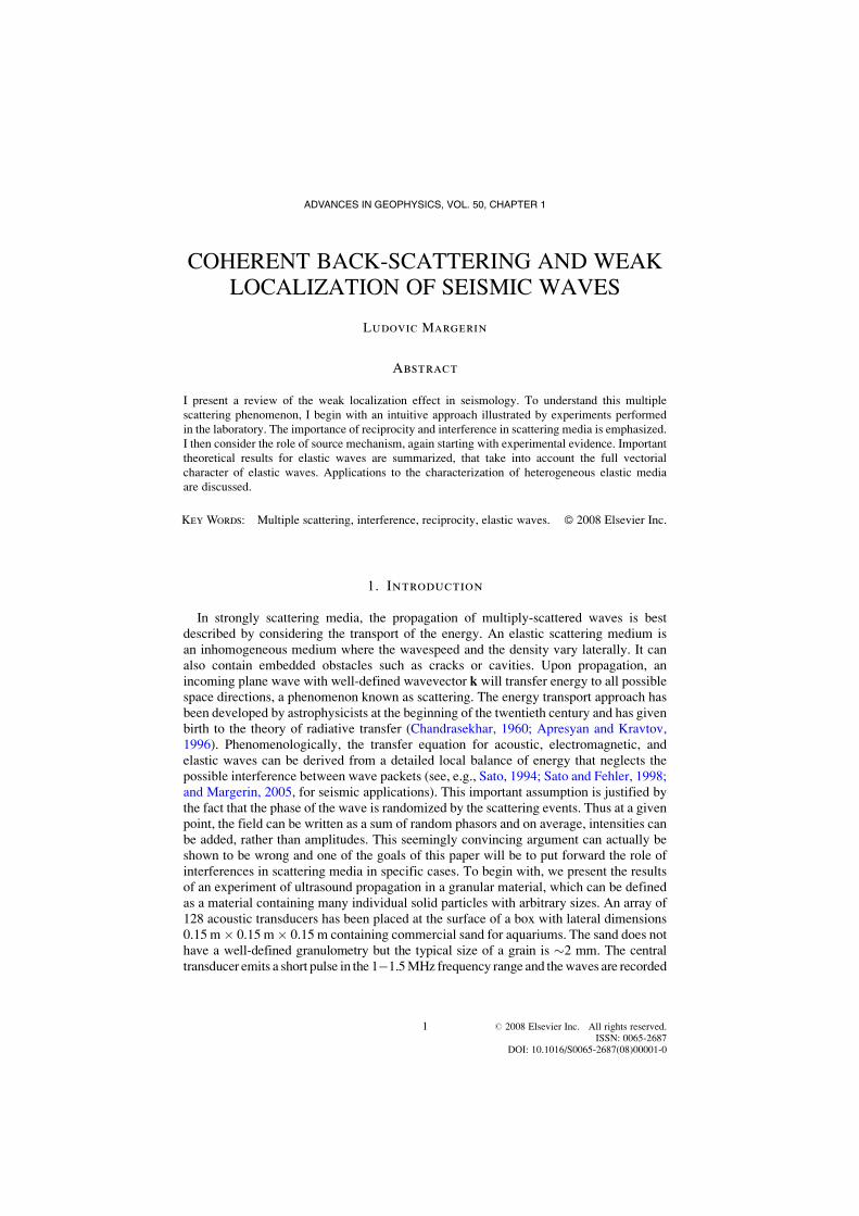
by the whole array. The wavespeed of the dominant ballistic pulse is about 1000 m/s,which gives a dominant wavelength of "0.8 mm, which is of the same order asthe size of one transducer of the array ("0.55 mm). The logarithm of the energy ofthe wavefield along the array after time averaging over four cycles is shown inFig. 1, as a function of distance from the center of the array in millimeters(horizontal axis) and time in microseconds (vertical axis).In this figure, one can identify direct waves that propagate along the array and decay
exponentially with distance because of the energy losses due to scattering. They arefollowed by a diffuse coda, which can be thought of as the result of the random walk ofthe energy in the scattering medium. As a rule of thumb, the multiple scattering halogrows like
!!!!!Dt
p, whereD = ul*/3 is the diffusion constant of the waves in the medium and
u is the wave velocity. The transport mean free path l* (see, e.g., Sheng, 1995, for arigorous definition) represents the typical step length of the random walk of the energy inthe scattering medium and is much larger than the wavelength. In the case of sandsamples, the transport mean free path is roughly 10 times larger than the wavelength.According to diffusion theory (Akkermans and Montambaux, 2005), at fixed time t = t0,the energy distribution in the scattering medium is approximately proportional toe#3r2=$4ut0l%&, where r is the distance from the source. Therefore, at fixed time, the energyin the diffuse halo is expected to vary significantly on the scale of l*. Yet, at the center ofFig. 1, the reader will notice a clear, but highly localized increase of intensity. This is not
Weaklocalization
Ballisticwaves
Diffusehalo
10
20
30
40
50
60
70
80
90
100
110
Tim
e (m
icro
sec)
!40 !20 0Distance (mm)
20 40!60 60
Log
(ene
rgy)
!11
!10
!9
!8
!7
!6
!5
!4
!12
!3
FIG. 1. Energy of the wavefield recorded at the surface of a granular material as a function oftime. A short pulse with a central frequency of 1.2 MHz is shot at the central transducer. Directwaves propagating along the array rapidly attenuate. They are followed by coda waves that form adiffuse halo in the medium. Note the sharp increase of intensity at the center of the array, whereenergy was initially released. Experiment performed at the Laboratoire Ondes et Acoustique, Paris,by R. Hennino and A. Derode.
2 MARGERIN
an artifact. In this particular experiment, the typical width of the zone of enhancedintensity is roughly equal to the size of one transducer. Other experiments, to be describedlater, have demonstrated that the zone of enhancement actually coincides with the centralwavelength of the waves, which is the clear signature of an interference effect that takesplace around the source in the multiple scattering medium: this is known as weaklocalization. In the next section, I provide a simple explanation for this observation.
2. Weak Localization Effect: A Heuristic View
In what follows, I represent a scalar partial wave as a complex number c = Aeif, whereA and f are real numbers denoting the amplitude and phase, respectively. Each partialwave follows an arbitrarily complicated scattering path from source to receiver in themedium. At a given point, the measured field u is a superposition of a large number ofpartial waves that have propagated along different scattering paths
u 'X
j
Ajeifj ; $1&
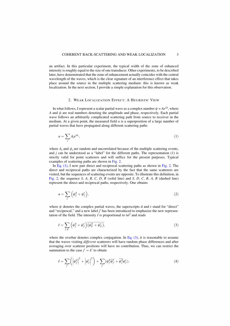
where Aj and fj are random and uncorrelated because of the multiple scattering events,and j can be understood as a “label” for the different paths. The representation (1) isstrictly valid for point scatterers and will suffice for the present purposes. Typicalexamples of scattering paths are shown in Fig. 2.In Eq. (1), I now pair direct and reciprocal scattering paths as shown in Fig. 2. The
direct and reciprocal paths are characterized by the fact that the same scatterers arevisited, but the sequences of scattering events are opposite. To illustrate this definition, inFig. 2, the sequence S, A, B, C, D, R (solid line) and S, D, C, B, A, R (dashed line)represent the direct and reciprocal paths, respectively. One obtains
u 'X
j0cdj0 ( cr
j0
" #; $2&
where c denotes the complex partial waves, the superscripts d and r stand for “direct”and “reciprocal,” and a new label j0 has been introduced to emphasize the new represen-tation of the field. The intensity I is proportional to |u|2 and reads
I 'X
j0;k0cdj0 ( cr
j0
" #cdk0 ( cr
k0$ %
; $3&
where the overbar denotes complex conjugation. In Eq. (3), it is reasonable to assumethat the waves visiting different scatterers will have random phase differences and afteraveraging over scatterer positions will have no contribution. Thus, we can restrict thesummation to the case j0 ' k0 to obtain
I 'X
j0cdj0
&&&&&&2
( crj0
&&&&&&2
' ((X
j0$cd
j0crj0 ( cd
j0crj0&: $4&
3COHERENT BACK-SCATTERING AND WEAK LOCALIZATION
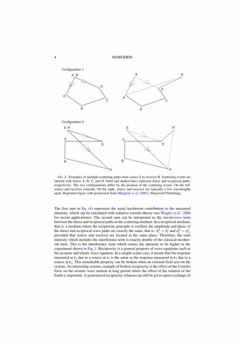
The first sum in Eq. (4) represents the usual incoherent contribution to the measuredintensity, which can be calculated with radiative transfer theory (see Wegler et al., 2006for recent applications). The second sum can be interpreted as the interference termbetween the direct and reciprocal paths in the scattering medium. In a reciprocal medium,that is, a medium where the reciprocity principle is verified, the amplitude and phase ofthe direct and reciprocal wave paths are exactly the same, that is, Ad
j ' Arj and fd
j ' frj ,
provided that source and receiver are located at the same place. Therefore, the totalintensity which includes the interference term is exactly double of the classical incoher-ent term. This is the interference term which causes the intensity to be higher in theexperiment shown in Fig. 1. Reciprocity is a general property of wave equations such asthe acoustic and elastic wave equation. In a simple scalar case, it means that the responsemeasured at r2 due to a source at r1 is the same as the response measured at r1 due to asource at r2. This remarkable property can be broken when an external field acts on thesystem. An interesting seismic example of broken reciprocity is the effect of the Coriolisforce on the seismic wave motion at long period where the effect of the rotation of theEarth is important. A generalized reciprocity relation can still be given upon exchange of
A
B
C
D
RS
RS
A
D
B
C
RS
A
D
B
C
RS
A
B
C
D
Configuration 1
Configuration 2
FIG. 2. Examples of multiple scattering paths from source S to receiver R. Scattering events arelabeled with letters A, B, C, and D. Solid and dashed lines represent direct and reciprocal paths,respectively. The two configurations differ by the position of the scattering events. On the left:source and receiver coincide. On the right, source and receiver are typically a few wavelengthsapart. Reprinted figure with permission from Margerin et al. (2001). Blackwell Publishing.
4 MARGERIN

source and receiver, which involves the inversion of the instantaneous rotation vector ofthe Earth (see Dahlen and Tromp, 1998, for a thorough discussion).Although it had been theoretically predicted in several pioneering papers published
around 1970 (Watson, 1969; de Wolf, 1971; Barabanenkov, 1973), it is only in the mid-eighties that the role of interference in multiple scattering has been appreciated with thediscovery of the coherent backscattering of light (Kuga and Ishimaru, 1984; van Albadaand Lagendijk, 1985; Wolf and Maret, 1985; Kaveh et al., 1986). Later the coherentbackscattering effect has been predicted and observed for acoustic and elastic waves inboth stationary and dynamic experiments (Bayer and Niederdrank, 1993; Sakai et al.,1997; Tourin et al., 1997; de Rosny et al., 2000). Today, coherent backscattering or weaklocalization is still a very active topic of research. The coherent backscattering formoving scatterers has been studied by Snieder (2006) and Lesaffre et al. (2006).Derode et al. (2005) have used the coherent backscattering effect to measure theheterogeneity of human bones. Aubry and Derode (2007) have devised an ingenioustechnique to measure lateral variations of the diffusion constant of strongly scatteringmedia based upon the separation of the incoherent and coherent intensities.Note that the term “coherent backscattering” refers to the intensity enhancement
observed in a small cone of direction in the far-field of a disordered sample for planewave sources with fixed incident direction k. Although the basic physics of coherentbackscattering and weak localization are identical, the latter term indicates that the loopsof interference occur inside the disordered sample, and should therefore be preferred todescribe the seismic experiments. These interference loops result in a deviation from thediffusive behavior (Haney and Snieder, 2003). When the wavelength is of the same orderas the mean free path, the interference effects can completely block the transport ofenergy away from the source, a phenomenon known as strong localization (see, e.g.,Sheng, 1995; Akkermans and Montambaux, 2005). Weak localization is therefore a basicphenomenon to explain the transition from the diffuse to the localized propagationregime. Note that there exists a number of other mechanisms of intensity enhancement.One of the most famous is the “opposition effect” in astrophysics, which manifests itselfas an increase of the reflectance of celestial bodies such as the Moon when the light of theSun reflected from the regolith is observed close to the backscattering direction. Hapkeet al. (1993) have shown that the opposition effect is partly explained by the coherentbackscattering of light. I refer the interested reader to the paper by Barabanenkov et al.(1991) for an extensive review of backscattering enhancement phenomena in optics. Inparticular, these authors discuss the case of backscattering enhancement by severaldeterministic scatterers which can also be of interest in seismology. Let me finallypoint out that weak localization is only one manifestation of the role of the phase inthe seismic coda (see Campillo, 2006, for a review).I have shown with a very simple argument that interference effects have to be
incorporated in the usual transport theory, but for the moment, it has not been explainedwhy the enhancement due to interference is so highly localized. In Fig. 2, I schematicallyrepresent the more usual case where source and detection are not collocated. In that casethere is a phase shift between the two wavepaths which is acquired during the propaga-tion from the source to the first scattering event and from the last scattering event to thereceiver. Clearly, if the distance between source and detection is “large enough,” thephase shift will fluctuate randomly from one configuration of the scatterers to the other.Therefore, the interference term is expected to vanish upon averaging when source andreceiver are sufficiently far apart. One of the goals of the paper is to demonstrate and
5COHERENT BACK-SCATTERING AND WEAK LOCALIZATION

illustrate the fact that the enhancement zone is actually narrow and about the size of thewavelength. A final comment on the role of multiple scattering is in order. It is clear thatthe representation of the wavefield [Eq. (3)] makes sense only if one can pair the directand reciprocal propagation paths. If there is a single scattering event, there is only onepossible path from source to receiver and therefore no interference is possible. This basicobservation proves that weak localization is indeed a genuine multiple scattering effect.In what follows, I pursue the experimental approach of weak localization by consideringthe role of the source mechanism.
3. The Role of Source Mechanism and Wavefield Polarization
Because of their vectorial nature, the weak localization of elastic waves cannot be fullyexplained by the simple intuitive approach presented above. As will be shown shortly,the reciprocity principle of elastic waves in its full extent has to be obeyed in order topreserve the factor of 2 enhancement at the source position. This subtle effect is firstexamined through a laboratory experiment with ultrasound.
3.1. Effect of Source Mechanism
The most common seismic sources, that is, explosions and earthquakes are combina-tions of dipoles and/or couples of forces. We must therefore consider more complexsources than simple isotropic point sources. In the case of earthquakes, the radiation isstrongly anisotropic and the radiation pattern displays nodal planes with reversal of thepolarity of first motions. de Rosny et al. (2001) have studied the weak localization ofelastic waves propagating in a chaotic reverberant cavity. The nature of the disorder isdifferent from the scattering medium, but until a time known as the Heisenberg time, themechanisms of enhancement are similar and can be based on an intuitive ray description.Beyond theHeisenberg time, the eigenmodes of the systemcanbe resolved and the statisticalproperties of the eigenfunctions lead to an enhancement of intensity by a factor 3around the source, as demonstrated experimentally and theoretically by Weaverand Burkhardt (1994) and Weaver and Lobkis (2000). This result is valid in chaoticcavities only. Using an interferometer, de Rosny et al. (2001) have recorded thevertical motions of Lamb waves generated by vertical monopole and dipole sourcesin a thin (0.5 mm thickness) chaotic plate of total area 2335 mm2, with the shape ofa quarter stadium. The dominant frequency of the signal is 1.0 MHz and the typicalwavelength is "2.5 mm. After time averaging between lapse time t = 200 ms andt = 500 ms, they have measured the intensity patterns shown in Fig. 3. Thebeginning of the signal is excluded in order to avoid the first reflection on theboundary of the plate and the choice of the end of the time window is dictated bythe signal to noise ratio. The distribution of energy is perfectly homogeneous in theplate, except in a small area centered around the source where, in the case of amonopole, it is the double of the background intensity. An important result of thisstudy is the confirmation of the typical wavelength size of the zone of intensityenhancement, which shows that weak localization is a near-field effect. In the 3-Dcase, the increase of intensity would occur inside a sphere centered at the source.
6 MARGERIN
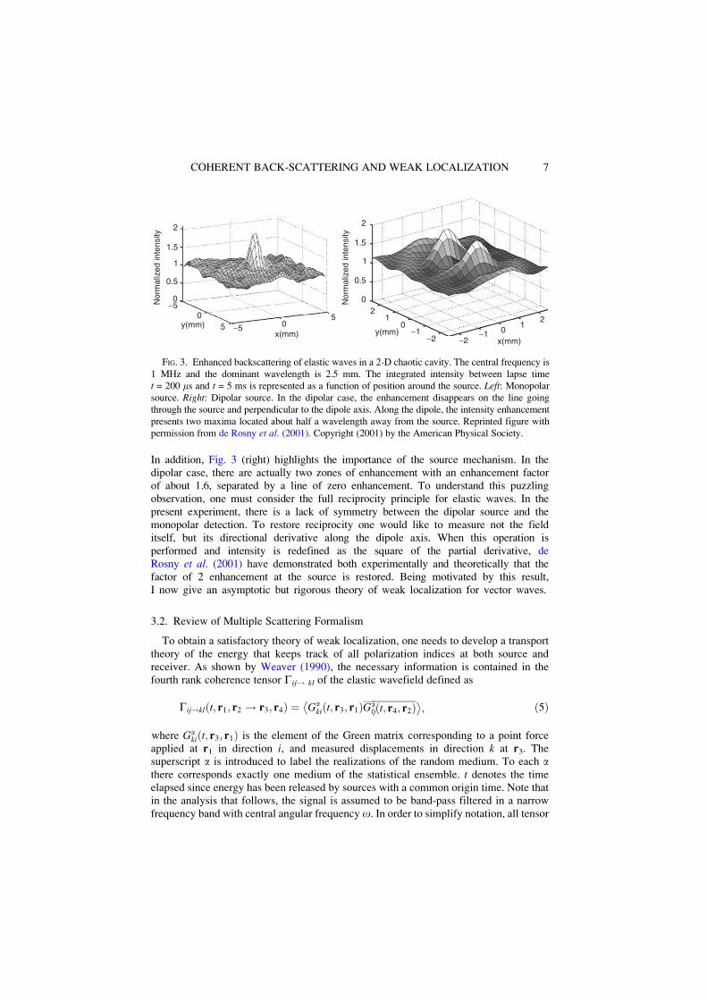
In addition, Fig. 3 (right) highlights the importance of the source mechanism. In thedipolar case, there are actually two zones of enhancement with an enhancement factorof about 1.6, separated by a line of zero enhancement. To understand this puzzlingobservation, one must consider the full reciprocity principle for elastic waves. In thepresent experiment, there is a lack of symmetry between the dipolar source and themonopolar detection. To restore reciprocity one would like to measure not the fielditself, but its directional derivative along the dipole axis. When this operation isperformed and intensity is redefined as the square of the partial derivative, deRosny et al. (2001) have demonstrated both experimentally and theoretically that thefactor of 2 enhancement at the source is restored. Being motivated by this result,I now give an asymptotic but rigorous theory of weak localization for vector waves.
3.2. Review of Multiple Scattering Formalism
To obtain a satisfactory theory of weak localization, one needs to develop a transporttheory of the energy that keeps track of all polarization indices at both source andreceiver. As shown by Weaver (1990), the necessary information is contained in thefourth rank coherence tensor Gij! kl of the elastic wavefield defined as
Gij!kl t; r1; r2 ! r3; r4$ & ')Ga
ki t; r3; r1$ &Galj t; r4; r2$ &
*; $5&
where Gaki$t; r3; r1& is the element of the Green matrix corresponding to a point force
applied at r1 in direction i, and measured displacements in direction k at r3. Thesuperscript a is introduced to label the realizations of the random medium. To each athere corresponds exactly one medium of the statistical ensemble. t denotes the timeelapsed since energy has been released by sources with a common origin time. Note thatin the analysis that follows, the signal is assumed to be band-pass filtered in a narrowfrequency band with central angular frequency o. In order to simplify notation, all tensor
x(mm)
Nor
mal
ized
inte
nsity
y(mm)
2
1.5
1
0.5
0
2
1.5
1
0.5
02
10
-1-2 -2
-1 01
205
-5
-5 05
y(mm)x(mm)
Nor
mal
ized
inte
nsity
1
FIG. 3. Enhanced backscattering of elastic waves in a 2-D chaotic cavity. The central frequency is1 MHz and the dominant wavelength is 2.5 mm. The integrated intensity between lapse timet = 200 ms and t = 5 ms is represented as a function of position around the source. Left: Monopolarsource. Right: Dipolar source. In the dipolar case, the enhancement disappears on the line goingthrough the source and perpendicular to the dipole axis. Along the dipole, the intensity enhancementpresents two maxima located about half a wavelength away from the source. Reprinted figure withpermission from de Rosny et al. (2001). Copyright (2001) by the American Physical Society.
7COHERENT BACK-SCATTERING AND WEAK LOCALIZATION
quantities are assumed to depend implicitly on o. The tensor Gij!kl (t, r1, r2!r3, r4)describes the transfer of the displacement correlation function from source (displacementindices i, j and positions r1, r2) to receiver (displacement indices k, l and positions r3, r4).The brackets denote an average over a, that is, over an ensemble of random media withprescribed statistics. In what follows we assume that the property of statistical homoge-neity holds, in which case the ensemble-averaged Green tensor depends on the differenceof the position vectors of the source and detector only
hGaki t; r3; r1$ &i ' Gki t; r3 # r1$ &; $6&
where for notational simplicity Gki (without superscript) denotes the ensemble averagedGreen tensor.The complete evolution of the tensor Gij!kl is described by the Bethe-Salpeter
equation which contains all correlations among all possible scattering paths in themedium (Sheng, 1995). This is far too detailed for the present purposes, and one usuallycontents oneself with the approximate calculation of two terms: the classical contribu-tion—also termed “diffuson”—and the interference term between reciprocal paths—alsotermed “cooperon”—(see Akkermans and Montambaux, 2005, for the origin of thisterminology). In the radiative transfer equation, information on source is usuallyintegrated out and the cooperon term is neglected (see Margerin, 2005, for details).Apresyan and Kravtov (1996) have suggested a modification of the radiative transferequation, which includes contribution of the cooperon and thereby is able to describecoherent phenomena such as weak localization. The cooperon and diffuson contributionsare conveniently represented by Feynman diagrams which are both computationallyefficient and physically meaningful. Typical diagrams are shown in Fig. 4. In the ladderdiagrams, the Green function (upper line) and its complex conjugate (lower line) visit thesame scatterers in the same order. In the crossed diagrams, first introduced for multiplescattering of classical waves in the pioneering papers of Barabanenkov (1973, 1975), theupper line is unchanged but in the lower line the sequence of scattering is reversed. Theladder and crossed diagrams correspond to the classical (incoherent) and interference(coherent) contributions, respectively. To make the link with the elementary treatmentgiven in Section I, the reader can think of the ladder diagrams alone, as the result ofsumming the intensities of the direct path (solid line in Fig. 2) and reciprocal path(dashed line in Fig. 2). The ladder and crossed diagrams altogether are the result offirst summing and then squaring the fields of the direct and reciprocal paths.Below, I give a long-time asymptotic formula for the ladder term. To calculate the
crossed term, one can make use of the following reciprocity argument: the field producedby a force in direction k at r2 and recorded in direction l at r4 after scattering at A, B,C, D, . . . is equal to the field produced by a force in direction l at r4 and recorded indirection k at r2 after scattering at . . ., D, C, B, A. This is equivalent to saying that everycrossed diagram can be turned into a ladder diagram after suitable exchange of thepolarization indices, and positions on the lower line. We now decompose the tensorGij!kl into the fundamental diffuson and cooperon contributions and write
Gij!kl t; r1; r2 ! r3; r4$ & ' Lij!kl t; r1; r2 ! r3; r4$ & ( Cij!kl t; r1; r2 ! r3; r4$ &: $7&
The previous discussion implies the following fundamental reciprocity relation betweenCij!kl and Lij!kl
8 MARGERIN
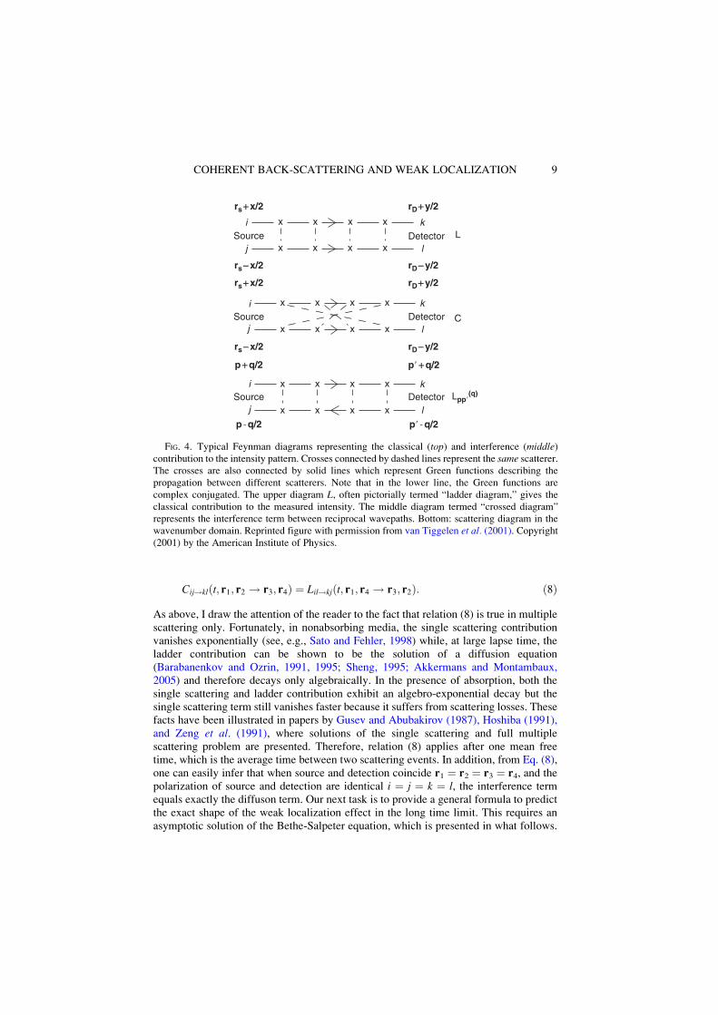
Cij!kl t; r1; r2 ! r3; r4$ & ' Lil!kj t; r1; r4 ! r3; r2$ &: $8&
As above, I draw the attention of the reader to the fact that relation (8) is true in multiplescattering only. Fortunately, in nonabsorbing media, the single scattering contributionvanishes exponentially (see, e.g., Sato and Fehler, 1998) while, at large lapse time, theladder contribution can be shown to be the solution of a diffusion equation(Barabanenkov and Ozrin, 1991, 1995; Sheng, 1995; Akkermans and Montambaux,2005) and therefore decays only algebraically. In the presence of absorption, both thesingle scattering and ladder contribution exhibit an algebro-exponential decay but thesingle scattering term still vanishes faster because it suffers from scattering losses. Thesefacts have been illustrated in papers by Gusev and Abubakirov (1987), Hoshiba (1991),and Zeng et al. (1991), where solutions of the single scattering and full multiplescattering problem are presented. Therefore, relation (8) applies after one mean freetime, which is the average time between two scattering events. In addition, from Eq. (8),one can easily infer that when source and detection coincide r1 ' r2 ' r3 ' r4, and thepolarization of source and detection are identical i ' j ' k ' l, the interference termequals exactly the diffuson term. Our next task is to provide a general formula to predictthe exact shape of the weak localization effect in the long time limit. This requires anasymptotic solution of the Bethe-Salpeter equation, which is presented in what follows.
j lC
Lx
x x
x
x
x
x
x x x x
x x x x
x x x x
x x x x
x
i k
k
k
lj
rD+y/2rs+x/2
rs-x/2
rs+x/2
rD-y/2
rD-y/2rs-x/2
rD+y/2
Lpp!(q)
i
i
j l
p+q/2 p! +q/2
Detector
Detector
Detector
Source
Source
Source
p -q/2 p! -q/2
FIG. 4. Typical Feynman diagrams representing the classical (top) and interference (middle)contribution to the intensity pattern. Crosses connected by dashed lines represent the same scatterer.The crosses are also connected by solid lines which represent Green functions describing thepropagation between different scatterers. Note that in the lower line, the Green functions arecomplex conjugated. The upper diagram L, often pictorially termed “ladder diagram,” gives theclassical contribution to the measured intensity. The middle diagram termed “crossed diagram”represents the interference term between reciprocal wavepaths. Bottom: scattering diagram in thewavenumber domain. Reprinted figure with permission from van Tiggelen et al. (2001). Copyright(2001) by the American Institute of Physics.
9COHERENT BACK-SCATTERING AND WEAK LOCALIZATION
3.3. Theoretical Results for Acoustic and Elastic Waves
The Bethe-Salpeter equation is an exact equation for the full coherence tensor of thewavefield. The complete solution of this equation seems out of reach in general, butasymptotic solutions for the diffuson contribution in the long time limit have beenpresented by Barabanenkov and Ozrin (1991, 1995), which can be applied to classicalscalar and vectorial linear waves, independent of the underlying equation of motion. Inthe theoretical approach, one considers a narrowly band-passed signal with central periodT which is much smaller than the typical duration of the coda. This is known in theliterature as the slowly varying envelope approximation (Sheng, 1995). The results ofBarabanenkov and Ozrin are valid in this limit and I refer the interested reader to theoriginal publications for further technical details. Asymptotically t ! 1, the ladder ordiffuson or classical contribution takes the form
Lij!kl t; r1; r2 ! r3; r4$ & ' e#t=ta
Dt$ &3=2ImGij r1 # r2$ &ImGlk r4 # r3$ &; $9&
where Im denotes the imaginary part of a complex number, D is the diffusion constant ofthe waves in the random medium, and ta denotes a phenomenological absorption term.Note that in the last equation, the tensor Gij stands for the spatial part of the ensemble-averaged elastic Green tensor at angular frequency o ' 2p/T.Because of the underlying assumption of statistical homogeneity, the tensor Gij
depends on the separation vector between source and station only and is an implicitfunction of o. The tensor Gij!kl depends on both central frequency of the waves, andlapse time in the coda. Equation (9) is valid in the slowly varying envelope approxima-tion. The reader is referred to Sheng (1995) and Apresyan and Kravtov (1996) for moremathematical details. According to Eq. (8), the cooperon term reads
Cij!kl t; r1; r2 ! r3; r4$ & ' e#t=ta
Dt$ &3=2ImGil r1 # r4$ &ImGjk r2 # r3$ &: $10&
Let us investigate some consequences of Eq. (10) for a given source station configura-tion: r1' r2, r3' r4. To illustrate the fact that interference effects are important only in aregion of the size of one wavelength around the source, we consider the scalar case andintroduce the enhancement factor defined as the total intensity normalized by thediffuson contribution: E ' 1 ( C/L. For scalar waves in 3-D, the enhancement profileE is given by
E ' 1( sin kr$ &kr
' (2
; $11&
where k ' o/c is the central wavenumber of the scalar waves with velocity c and r is thesource receiver distance. For scalar waves in 2-D, the corresponding formula is
E ' 1( J0 kr$ &2 $12&
10 MARGERIN
where J0 denotes the Bessel function of the first kind of order 0. These results are valid inthe long lapse time limit and when the mean free path is much larger than the wavelength,which is the most common situation in practice. When scattering is extremely strong, thewavelength can be of the order of the mean free path, and strong localization can set in, aregime which is very difficult to reach (Akkermans and Montambaux, 2005). Thecardinal sine and Bessel function in Eqs. (11) and (12) are proportional to the imaginarypart of the Green function of the Helmoltz equation in 2-D and 3-D, respectively.Equation (11) has been verified by numerical simulations (Margerin et al., 2001),while Eq. (12) has been checked experimentally by de Rosny et al. (2000) (see alsothe left part of Fig. 3). It is important to note that the enhancement profile is independentfrom absorption. This is not surprising since absorption does not affect the reciprocityprinciple. This is often illustrated by the following sentence (van Tiggelen and Maynard,1997): “If you can see me, I can see you!” that applies even in the fog. This independenceof the weak localization effect on absorption is used later in the paper to give estimates ofthe scattering properties of heterogeneous media.I now explore theoretically the role of the source mechanism. As an example, I will
give a simple formula that explains all the features of the experiments described in Fig. 3with a dipole source. The radiation of the dipole is obtained by taking the directionalpartial derivative of the Green function with respect to source coordinates. For a dipolesource along the x axis of the coordinate system, the coherence function G of the scalarfield is given by
G t; r1; r2 ! r3; r4$ & ' h@x1Ga t; r3; r1$ &@x2Ga t; r4; r2$ &i: $13&
Because the operation of taking derivatives is linear, the @x1 and @x2 symbols can be takenoutside of the ensemble average brackets. For the diffuson and cooperon contributions,one obtains respectively
L ' e#t=ta
$Dt&3=2ImG$0&@x1@x2 ImG$r2 # r1&jr2'r1
$14&
C ' e#t=ta
$Dt&3=2@x1 ImG$r1 # r4&jr4'r3
@x2 ImG$r3 # r2&jr2'r1: $15&
In the 2-D case, after some algebra, one obtains the following enhancement pattern forthe dipole source
E ' 1( $J1 kr$ &cos y&$ &2; $16&
where J1 denotes the Bessel function of the first kind of order 1. This theoreticalprediction matches the observations of Fig. 3 (left) very closely.
The calculation of the weak localization effect has thus been illustrated in simplecases. The calculations in the full elastic case with arbitrary moment tensor sources havebeen performed by van Tiggelen et al. (2001). The principle is the same as above but thecalculations are much more tedious. To illustrate the effect of broken symmetry betweensource and receiver, I show in Fig. 5 the calculation of the weak localization profile forexplosion and dislocation sources in an infinite elastic medium. As usual, an explosion
11COHERENT BACK-SCATTERING AND WEAK LOCALIZATION
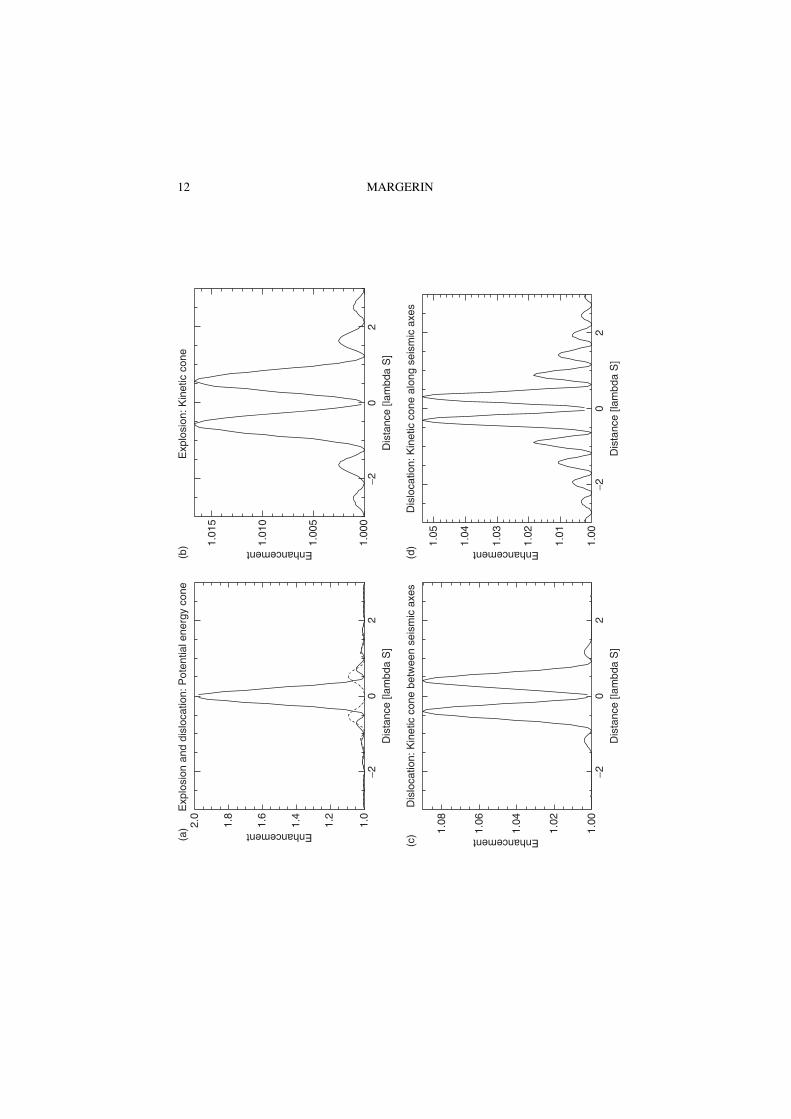
1.4
2.0
1.8
1.6
1.2
1.0
!20
Dis
tanc
e [la
mbd
a S
]
Enhancement
Exp
losi
on a
nd d
islo
catio
n: P
oten
tial e
nerg
y co
ne
2
1.08
1.06
1.04
1.02
1.00
!20
Dis
tanc
e [la
mbd
a S
]
Dis
loca
tion:
Kin
etic
con
e be
twee
n se
ism
ic a
xes
Enhancement
2
(a)
1.04
1.05
1.03
1.02
1.01
1.00
!20
Dis
tanc
e [la
mbd
a S
]
Dis
loca
tion:
Kin
etic
con
e al
ong
seis
mic
axe
s
Enhancement
2
(d)
(c)
1.01
5
1.01
0
1.00
5
1.00
0
Enhancement
!20
Dis
tanc
e [la
mbd
a S
]
Exp
losi
on: K
inet
ic c
one
(b)
2
12 MARGERIN
and a seismic dislocation will be represented by three mutually orthogonal dipole offorces, and by a double couple of forces, both with zero net applied linear and angularmomentum, respectively. The enhancement profiles in Fig. 5 are calculated in the planeperpendicular to the axis of the double couple. In this plane, there exist two perpendiculardirections, termed seismic axes, with respect to which the moment tensor is diagonal. Forthe simple dislocation source, the seismic axes define the direction of maximum radia-tion of P waves and make an angle 45) with the applied forces. Note that the direction ofapplication of the forces also coincide with the maximum radiation of S waves. Figure 5demonstrates that the backscattering enhancement can be totally destroyed if the opera-tions carried out at the source and at the detection are different. For instance, theenhancement of kinetic energy due to a dislocation is typically less than 10% andvanishes exactly at the source position. The angular dependence of the enhancementprofile in the plane containing the double couple is illustrated in Fig. 5c and d. It isseen that the enhancement is slightly higher along the direction of maximum radiation ofS waves. Although I shall not prove it, it is always possible to recover the factor 2enhancement by measuring the appropriate quantity. For the case of a dipole source, oneneeds to measure the derivative of the field along the dipole axis. This of coursecomplicates the experimental setup but it can be done in practice (see, e.g., Henninoet al., 2001). For an explosion, one needs to evaluate the divergence of the wavefield(i.e., the compressional energy of the waves), which is even more demanding. Althoughthis seems discouraging, I present below some experiments with seismic waves thatdemonstrate the potential usefulness of weak localization.
4. Geophysical Applications
At this point, I would like to convince the reader that the weak localization effect is notonly a theoretical or mathematical curiosity but a useful interference effect which can beused to probe the medium properties when multiple scattering hampers the detection ofballistic waves. I give two examples of applications of weak localization: the first oneillustrates the measurement of elastic properties of a concrete slab (Larose et al., 2006); thesecond one reports themeasurement of themean free path in a volcano (Larose et al., 2004).
4.1. Measurement of the Dispersion Relation of Surface Waves
Let me first consider an application at a scale which is intermediate between thelaboratory and the field. An array of vertical accelerometers with typical bandwidth 0.1–5 kHz has been set up on a steel reinforced concrete slab. Upon propagation, wavesundergo strong multiple scattering and reflections. In the time domain, the ballisticsignals are difficult to separate from the multiple reflections on the sides of the slab and
FIG. 5 Enhancement profiles as a function of the distance from the source, in units of the shearwavelength, for an infinite Poissonian medium. (a) The enhancement of the potential energy for anexplosion (solid) and a dislocation (dashed). (b) Enhancement profile for the kinetic energy near anexplosion. (c) and (d) Enhancement profiles for the kinetic energy between (at an angle 45) to) andalong the seismic axes of a dislocation source. The term “cone” shown on top of each plot refers tothe zone of intensity enhancement around the source. Reprinted figure with permission from vanTiggelen et al. (2001). Copyright (2001) by the American Institute of Physics.
13COHERENT BACK-SCATTERING AND WEAK LOCALIZATION
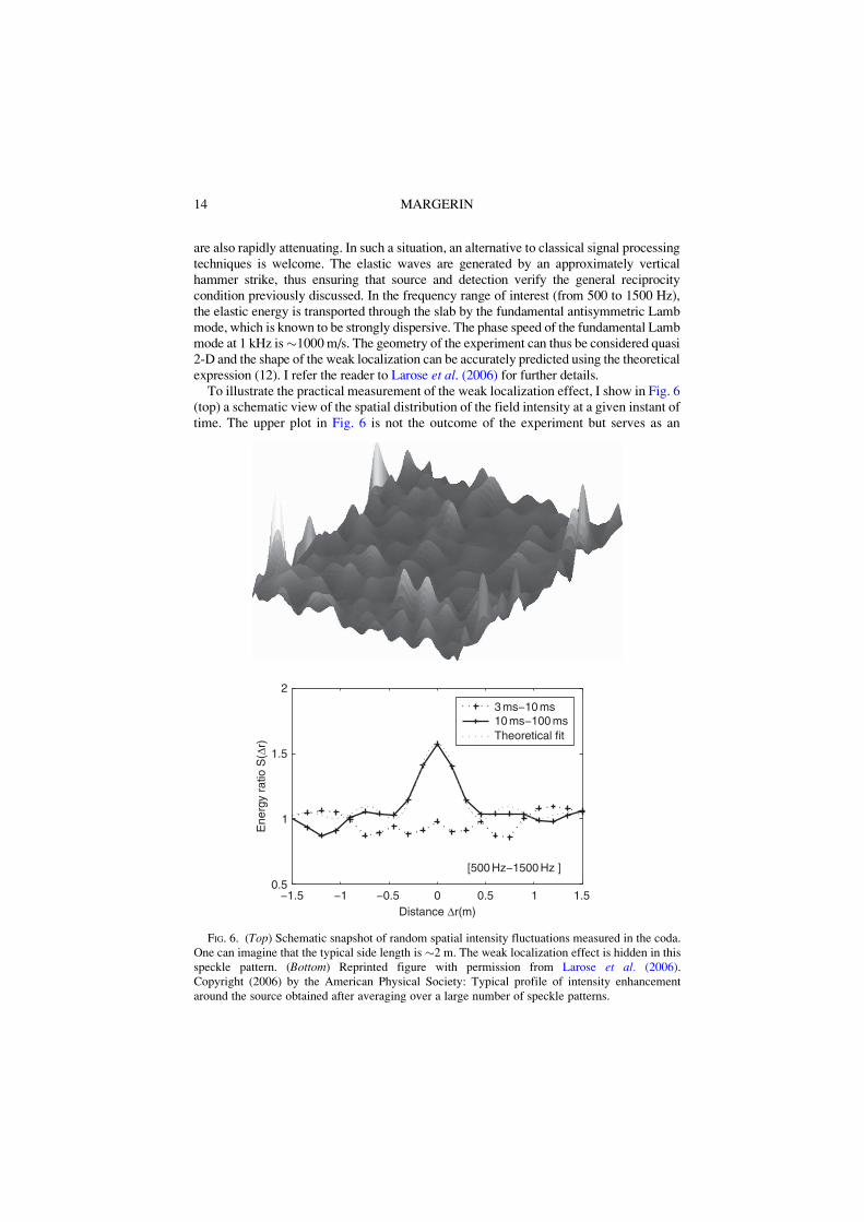
are also rapidly attenuating. In such a situation, an alternative to classical signal processingtechniques is welcome. The elastic waves are generated by an approximately verticalhammer strike, thus ensuring that source and detection verify the general reciprocitycondition previously discussed. In the frequency range of interest (from 500 to 1500 Hz),the elastic energy is transported through the slab by the fundamental antisymmetric Lambmode, which is known to be strongly dispersive. The phase speed of the fundamental Lambmode at 1 kHz is"1000m/s. The geometry of the experiment can thus be considered quasi2-D and the shape of the weak localization can be accurately predicted using the theoreticalexpression (12). I refer the reader to Larose et al. (2006) for further details.To illustrate the practical measurement of the weak localization effect, I show in Fig. 6
(top) a schematic view of the spatial distribution of the field intensity at a given instant oftime. The upper plot in Fig. 6 is not the outcome of the experiment but serves as an
!1.5 !1 !0.5 0 0.5 1 1.50.5
1
1.5
2
[500 Hz!1500 Hz ]
Distance Dr(m)
Ene
rgy
ratio
S(D
r)
3 ms!10 ms10 ms!100 msTheoretical fit
FIG. 6. (Top) Schematic snapshot of random spatial intensity fluctuations measured in the coda.One can imagine that the typical side length is "2 m. The weak localization effect is hidden in thisspeckle pattern. (Bottom) Reprinted figure with permission from Larose et al. (2006).Copyright (2006) by the American Physical Society: Typical profile of intensity enhancementaround the source obtained after averaging over a large number of speckle patterns.
14 MARGERIN
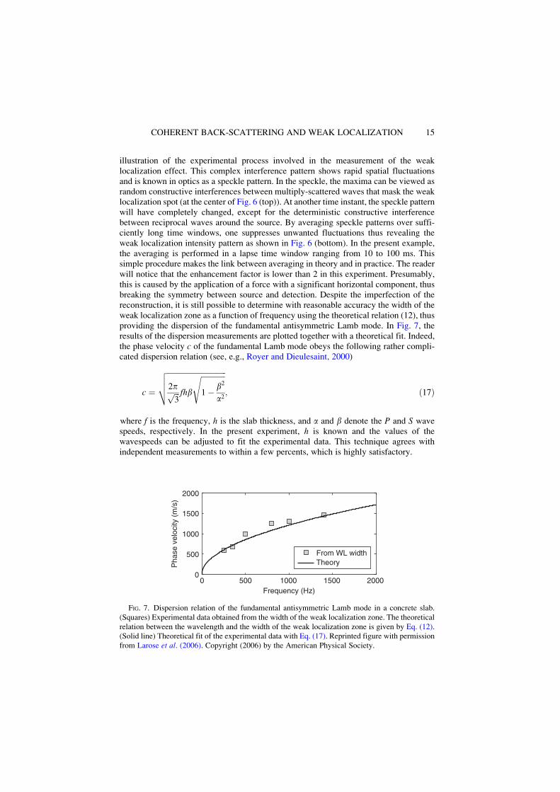
illustration of the experimental process involved in the measurement of the weaklocalization effect. This complex interference pattern shows rapid spatial fluctuationsand is known in optics as a speckle pattern. In the speckle, the maxima can be viewed asrandom constructive interferences between multiply-scattered waves that mask the weaklocalization spot (at the center of Fig. 6 (top)). At another time instant, the speckle patternwill have completely changed, except for the deterministic constructive interferencebetween reciprocal waves around the source. By averaging speckle patterns over suffi-ciently long time windows, one suppresses unwanted fluctuations thus revealing theweak localization intensity pattern as shown in Fig. 6 (bottom). In the present example,the averaging is performed in a lapse time window ranging from 10 to 100 ms. Thissimple procedure makes the link between averaging in theory and in practice. The readerwill notice that the enhancement factor is lower than 2 in this experiment. Presumably,this is caused by the application of a force with a significant horizontal component, thusbreaking the symmetry between source and detection. Despite the imperfection of thereconstruction, it is still possible to determine with reasonable accuracy the width of theweak localization zone as a function of frequency using the theoretical relation (12), thusproviding the dispersion of the fundamental antisymmetric Lamb mode. In Fig. 7, theresults of the dispersion measurements are plotted together with a theoretical fit. Indeed,the phase velocity c of the fundamental Lamb mode obeys the following rather compli-cated dispersion relation (see, e.g., Royer and Dieulesaint, 2000)
c '
!!!!!!!!!!!!!!!!!!!!!!!!!!!!!!!!
2p!!!3
p fhb
!!!!!!!!!!!!!
1# b2
a2
svuut; $17&
where f is the frequency, h is the slab thickness, and a and b denote the P and S wavespeeds, respectively. In the present experiment, h is known and the values of thewavespeeds can be adjusted to fit the experimental data. This technique agrees withindependent measurements to within a few percents, which is highly satisfactory.
0 500 1000 1500 20000
500
1000
1500
2000
Frequency (Hz)
Pha
se v
eloc
ity (
m/s
)
From WL widthTheory
FIG. 7. Dispersion relation of the fundamental antisymmetric Lamb mode in a concrete slab.(Squares) Experimental data obtained from the width of the weak localization zone. The theoreticalrelation between the wavelength and the width of the weak localization zone is given by Eq. (12).(Solid line) Theoretical fit of the experimental data with Eq. (17). Reprinted figure with permissionfrom Larose et al. (2006). Copyright (2006) by the American Physical Society.
15COHERENT BACK-SCATTERING AND WEAK LOCALIZATION
4.2. Measurement of the Diffusion Constant in Strongly Scattering Media
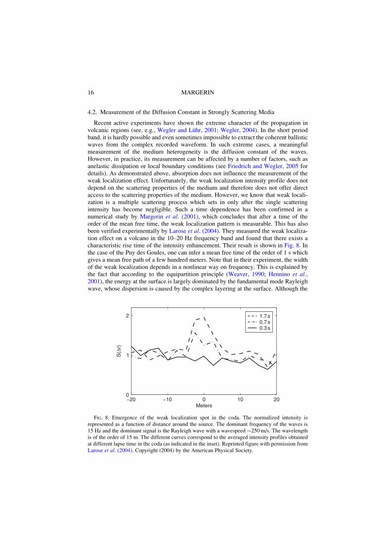
Recent active experiments have shown the extreme character of the propagation involcanic regions (see, e.g., Wegler and Luhr, 2001; Wegler, 2004). In the short periodband, it is hardly possible and even sometimes impossible to extract the coherent ballisticwaves from the complex recorded waveform. In such extreme cases, a meaningfulmeasurement of the medium heterogeneity is the diffusion constant of the waves.However, in practice, its measurement can be affected by a number of factors, such asanelastic dissipation or local boundary conditions (see Friedrich and Wegler, 2005 fordetails). As demonstrated above, absorption does not influence the measurement of theweak localization effect. Unfortunately, the weak localization intensity profile does notdepend on the scattering properties of the medium and therefore does not offer directaccess to the scattering properties of the medium. However, we know that weak locali-zation is a multiple scattering process which sets in only after the single scatteringintensity has become negligible. Such a time dependence has been confirmed in anumerical study by Margerin et al. (2001), which concludes that after a time of theorder of the mean free time, the weak localization pattern is measurable. This has alsobeen verified experimentally by Larose et al. (2004). They measured the weak localiza-tion effect on a volcano in the 10–20 Hz frequency band and found that there exists acharacteristic rise time of the intensity enhancement. Their result is shown in Fig. 8. Inthe case of the Puy des Goules, one can infer a mean free time of the order of 1 s whichgives a mean free path of a few hundred meters. Note that in their experiment, the widthof the weak localization depends in a nonlinear way on frequency. This is explained bythe fact that according to the equipartition principle (Weaver, 1990; Hennino et al.,2001), the energy at the surface is largely dominated by the fundamental mode Rayleighwave, whose dispersion is caused by the complex layering at the surface. Although the
!20 !10 0 10 200
1
2
Meters
S(D
r)
1.7 s0.7 s0.3 s
FIG. 8. Emergence of the weak localization spot in the coda. The normalized intensity isrepresented as a function of distance around the source. The dominant frequency of the waves is15 Hz and the dominant signal is the Rayleigh wave with a wavespeed "250 m/s. The wavelengthis of the order of 15 m. The different curves correspond to the averaged intensity profiles obtainedat different lapse time in the coda (as indicated in the inset). Reprinted figure with permission fromLarose et al. (2004). Copyright (2004) by the American Physical Society.
16 MARGERIN
observation of weak localization on a volcano requires active sources, it is free of theeffect of absorption and therefore offers direct access to the scattering properties of themedium.
5. Conclusion
In this paper, I have given a brief introduction to the weak localization effect inseismology. I have summarized general formulas that enable the calculation of the weaklocalization effect for a wide range of practical cases. The fundamental role of reciprocitybetween source and detection has been emphasized and illustrated with experimentalresults. In practice, the control of the source mechanism is crucial. The simplest solutionis to measure the vertical displacements generated by vertical forces. Applications to thecharacterization of scattering or bulk elastic properties have been presented. In particu-lar, I have shown that the emergence time of weak localization yields an estimate of thescattering mean free path, independent of absorption effects. Thus, weak localizationcombined with other measurements such as time and space dependence of the coda couldbe used to discriminate anelastic and scattering attenuation.
Acknowledgments
I would like to thank E. Larose, A Derode, J. de Rosny, and R. Hennino for their invaluable helpwith the figures and for many discussions on the weak localization effect. I would like to thank M.Campillo and B. van Tiggelen for their constant input. Comments by H. Sato, Yu. Kravtsov, and ananonymous reviewer greatly helped to improve the presentation and the readability of this chapter.
References
Akkermans, E., Montambaux, G. (2005). Physique mesoscopique des electrons et des photonsCNRS Editions, Paris: EDP Sciences, Paris.
Apresyan, L.A., Kravstov, Yu. A. (1996). Radiation Transfer: Statistical and Wave Aspects.Amsterdam: Gordon and Breach, Amsterdam.
Aubry, A., Derode, A. (2007). Ultrasonic imaging of highly scattering media from local measure-ments of the diffusion constant: Separation of coherent and incoherent intensities. Phys. Rev. E75, 026602.
Barabanenkov, Yu.N. (1973). Wave corrections to the transfer equation for “back” scattering.Radiophysics and Quantum Electronics 16, 65–71.
Barabanenkov, Yu.N. (1975). Multiple scattering of waves by ensembles of particles and the theoryof radiation transport. Sov. Phys. Usp 18, 673–689.
Barabanenkov, Yu.N., Ozrin, V.D. (1991). Asymptotic solution of the Bethe-Salpeter equation andthe Green-Kubo formula for the diffusion constant for wave propagation in random media.Phys. Lett. A 154, 38–42.
Barabanenkov, Yu.N., Ozrin, V.D. (1995). Diffusion asymptotics of the Bethe-Salpeter equationfor electromagnetic waves in discrete random media. Phys. Lett. A 206, 116–122.
Barabanenkov, Yu.N., Kravtsov, Yu.A., Ozrin, V.D., Saichev, A.I. (1991). Enhanced backscatter-ing in optics. Prog. Opt. 29, 65–197.
Bayer, G., Niederdrank, T. (1993). Weak localization of acoustic waves in strongly scatteringmedia. Phys. Rev. Lett. 70, 3884–3887.
17COHERENT BACK-SCATTERING AND WEAK LOCALIZATION
Campillo, M. (2006). Phase and correlation in ‘random’ seismic fields and the reconstruction of theGreen function. Pure Appl. Geophys. 163, 475–502.
Chandrasekhar, S. (1960). Radiative Transfer. New York: Dover, New York.Dahlen, F.A., Tromp, J. (1998). Theoretical Global Seismology. Princeton, New Jersey: Princeton
University Press, Princeton, New Jersey.Derode, A., Mamou, V., Padilla, F., Jenson, F., Laugier, P. (2005). Dynamic coherent backscatter-
ing in an absorbing heterogeneous medium: Application to human trabecular bone characteri-zation. Appl. Phys. Lett. 87, 114101.
de Rosny, J., Tourin, A., Fink, M. (2000). Coherent backscattering of elastic wave in a chaoticcavity. Phys. Rev. Lett. 84, 1693–1695.
de Rosny, J., Tourin, A., Fink, M. (2001). Observation of a coherent backscattering effect with adipolar source for elastic waves: Highlight of the role played by the source. Phys. Rev. E 64,066604, doi:10.1103/PhysRevE.64.066604.
de Wolf, D.A. (1971). Electromagnetic reflection from an extended turbulent medium: Cumulativeforward-scatter single-backscatter approximation. IEEE Trans Antennas Propagation 19,254–262.
Friedrich, C., Wegler, U. (2005). Localization of seismic coda at Merapi volcano (Indonesia).Geophys. Res. Lett. 32, L14312, doi: 10.1029/2005GL023111.
Gusev, A., Abubakirov, I.R. (1987). Monte-Carlo simulation of record envelope of a near earth-quake. Phys. Earth Planet. Inter. 49, 30–36.
Haney, M., Snieder, R. (2003). Breakdown of wave diffusion in 2D due to loops. Phys. Rev. Lett.91, 093902.
Hapke, B.W., Nelson, R.M., Smythe, W.D. (1993). The opposition effect of the moon—The contribution of coherent backscatter. Science 260, 509–511.
Hennino, R., Tregoures, N., Shapiro, N.M., Margerin, L., Campillo, M., van Tiggelen, B.A.,Weaver, R.L. (2001). Observation of equipartition of seismic waves. Phys. Rev. Lett. 86,3447–3450.
Hoshiba, M. (1991). Simulation of multiple-scattered coda wave excitation based on the energyconservation law. Phys. Earth Planet. Inter. 67, 123–136.
Kaveh, M., Rosenbluh, M., Edrei, I., Freund, I. (1986). Weak localization and light scattering fromdisordered solids. Phys. Rev. Lett. 57, 2049–2052.
Kuga, Y., Ishimaru, A. (1984). Retroreflection from a dense distribution of spherical particles.J. Opt. Soc. Am. A 8, 831–835.
Larose, E., Margerin, L., Campillo, M., van Tiggelen, B.A. (2004). Weak localization of seismicwaves. Phys. Rev. Lett. 93, 048501.
Larose, E., de Rosny, J., Margerin, L., Anache, D., Gouedard, P., Campillo, M., van Tiggelen, B.(2006). Observation of multiple scattering of kHz vibrations in a concrete structure andapplication to monitoring weak changes. Phys. Rev. E 73, 016609.
Lesaffre, M., Atlan, M., Gross, M. (2006). Effect of the photon’s Brownian Doppler shift on theweak-localization coherent-backscattering cone. Phys. Rev. Lett. 97, 033901.
Margerin, L. (2005). Introduction to radiative transfer of seismic waves. In: Levander, A.,Nolet, G., (Eds.), Seismic Earth: Array Analysis of Broadband Seismograms: GeophysicalMonograph Series, Vol. 157, Chapter 14. AGU, Washington, pp. 229–252.
Margerin, L., Campillo, M., van Tiggelen, B.A. (2001). Coherent backscattering of acoustic wavesin the near field. Geophys. J. Int. 145, 593–603.
Royer, D., Dieulesaint, E. (2000). Elastic Waves in Solids, Part I. Free and Guided Propagation.Berlin Heidleberg: Springer-Verlag, Berlin Heidleberg.
Sakai, K., Yamamoto, K., Takagi, K. (1997). Observation of acoustic coherent backscattering.Phys. Rev. B 56, 10930–10933.
Sato, H. (1994). Multiple isotropic scattering model including P-S conversions for the seismogramenvelope formation. Geophys. J. Int. 117, 487–494.
18 MARGERIN
Sato, H., Fehler, M. (1998). Seismic Wave Propagation in the Heterogeneous Earth. Heidelberg:Springer, Heidelberg.
Sheng, P. (1995). Introduction to Wave Scattering, Localization and Mesoscopic Phenomena SanDiego: Academic Press, San Diego.
Snieder, R. (2006). The coherent backscattering effect for moving scatterers. Europhys. Lett. 74,630–636.
Tourin, A., Roux, P., Derode, A., van Tiggelen, B.A., Fink, M. (1997). Time dependent coherentbackscattering of acoustic waves. Phys. Rev. Lett. 79, 3637–3639.
van Albada, M.P., Lagendijk, A. (1985). Observation of weak localization of light in a randommedium. Phys. Rev. Lett. 55, 2692–2695.
van Tiggelen, B.A., Maynard, R. (1997). Reciprocity and coherent backscattering of light.In: Papanicolaou, G.R., (Ed.), Wave Propagation in Complex Media (IMA Volumes in Mathe-matics and Its Applications, Vol. 96). Springer, New York, pp. 247–271.
van Tiggelen, B.A., Margerin, L., Campillo, M. (2001). Coherent backscattering of elastic waves:Specific role of source, polarization, and near field. J. Acoust. Soc. Am. 110, 1291–1298.
Watson, K. (1969). Multiple scattering of electromagnetic waves in an underdense plasma. J. Math.Phys. 10, 688–702.
Weaver, R.L. (1990). Diffusivity of ultrasound in polycrystals. J. Mech. Phys. Solids 38, 55–86.Weaver, R., Burkhardt, J. (1994). Weak Anderson Localization and enhanced backscatter in
reverberation rooms and quantum dots. J. Acoust. Soc. Am. 96, 3186–3190.Weaver, R.L., Lobkis, O.I. (2000). Enhanced backscattering and modal echo of reverberant elastic
waves. Phys. Rev. Lett. 84, 4942–4945.Wegler, U. (2004). Diffusion of seismic waves in a thick layer: Theory and application to Vesuvius
volcano. J. Geophys. Res. 109, doi: 10.1029/2004JB003048.Wegler, U., Luhr, B.G. (2001). Scattering behavior at Merapi volcano (Java) revealed from an
active seismic experiment. Geophys. J. Int. 145, 579–592.Wegler, U., Korn, M., Przybilla, J. (2006). Modelling full seismogram envelopes using radiative
transfer theory with Born scattering coefficients. Pure Appl. Geophys. 163, 503–531.Wolf, P.E., Maret, G. (1985). Weak localization and coherent backscattering of photon. Phys. Rev.
Lett. 55, 2696–2699.Zeng, Y., Su, F., Aki, K. (1991). Scattering wave energy propagation in a random isotropic
scattering medium. 1. Theory. J. Geophys. Res. 96, 607–619.
19COHERENT BACK-SCATTERING AND WEAK LOCALIZATION