C:\My Documents\WP Docs\MANUALS\APLEX\3100E.WPD
74
INTRAMERICA SECURITY TECHNOLOGIES SCARBOROUGH, ONTARIO, CANADA M1B 3L6 TEL (416) 754-4313 FAX (416) 754-8992 E-MAIL [email protected] INSTALLATION AND OPERATION MANUAL FOR APLEX MODEL 3100E 100-ZONE, SINGLE-AREA SUBSCRIBER'S CONTROL PANEL (C) COPYRIGHT EUROPLEX LIMITED 1986 REVISED: MARCH 1999 SOFTWARE: A1E250/L1100E66
-
Upload
khangminh22 -
Category
Documents
-
view
0 -
download
0
Transcript of C:\My Documents\WP Docs\MANUALS\APLEX\3100E.WPD

INTRAMERICA SECURITY TECHNOLOGIES SCARBOROUGH, ONTARIO, CANADAM1B 3L6
TEL (416) 754-4313FAX (416) 754-8992E-MAIL [email protected]
INSTALLATION AND OPERATION MANUAL FOR
APLEX MODEL 3100E100-ZONE, SINGLE-AREA
SUBSCRIBER'S CONTROL PANEL
(C) COPYRIGHT EUROPLEX LIMITED 1986
REVISED: MARCH 1999SOFTWARE: A1E250/L1100E66

CONTENTS
GENERAL INFORMATION . . . . . . . . . . . . . . . . . . . . . . . . . . . . . . . . . . . . . . . . . . . . . . . . . . . . 1
KEYBOARD . . . . . . . . . . . . . . . . . . . . . . . . . . . . . . . . . . . . . . . . . . . . . . . . . . . . . . . . . . . . . . . . . 3
OPERATING CONVENTIONS . . . . . . . . . . . . . . . . . . . . . . . . . . . . . . . . . . . . . . . . . . . . . . . . . . 5
INSTALLATION PLANNING GUIDE AND CHECKLIST . . . . . . . . . . . . . . . . . . . . . . . . . . . . 6
MOUNTING THE PANEL AND WIRING THE SYSTEM . . . . . . . . . . . . . . . . . . . . . . . . . . . . 8
TERMINAL CONNECTIONS . . . . . . . . . . . . . . . . . . . . . . . . . . . . . . . . . . . . . . . . . . . . . . . . . . 10
NOTES CONCERNING THE TERMINAL CONNECTIONS . . . . . . . . . . . . . . . . . . . . . . . . . 11
MODEL 1020 DUAL LEM (D-LEM) . . . . . . . . . . . . . . . . . . . . . . . . . . . . . . . . . . . . . . . . . . . . 13
LOOP-WIRING CONFIGURATIONS . . . . . . . . . . . . . . . . . . . . . . . . . . . . . . . . . . . . . . . . . . . . 16
MODEL 1024 QUAD LEM (Q-LEM) . . . . . . . . . . . . . . . . . . . . . . . . . . . . . . . . . . . . . . . . . . . . 20
MODEL 1024 REV. 2.1 QUAD LEM (Q-LEM) . . . . . . . . . . . . . . . . . . . . . . . . . . . . . . . . . . . . 21
MODEL 1101 COMMAND LEM (C-LEM) . . . . . . . . . . . . . . . . . . . . . . . . . . . . . . . . . . . . . . . 22
MODEL 1121 COMBINATION LEM (COMBO LEM) . . . . . . . . . . . . . . . . . . . . . . . . . . . . . . 24
MODEL 1020 D-LEM, 1101 C-LEM, AND 1121 COMBO LEM CODING TABLE . . . . . . . 25
MODEL 1024 Q-LEM CODING TABLE . . . . . . . . . . . . . . . . . . . . . . . . . . . . . . . . . . . . . . . . . 26
PANEL OUTPUTS . . . . . . . . . . . . . . . . . . . . . . . . . . . . . . . . . . . . . . . . . . . . . . . . . . . . . . . . . . . 27
ZONE TYPES . . . . . . . . . . . . . . . . . . . . . . . . . . . . . . . . . . . . . . . . . . . . . . . . . . . . . . . . . . . . . . . 28
POWERING UP THE PANEL . . . . . . . . . . . . . . . . . . . . . . . . . . . . . . . . . . . . . . . . . . . . . . . . . . 34
PROGRAMMING THE PANEL . . . . . . . . . . . . . . . . . . . . . . . . . . . . . . . . . . . . . . . . . . . . . . . . 39
NOTES CONCERNING PANEL OPERATION . . . . . . . . . . . . . . . . . . . . . . . . . . . . . . . . . . . . 61
NOTES CONCERNING AUTODIAL MODEMS . . . . . . . . . . . . . . . . . . . . . . . . . . . . . . . . . . . 64
NOTES CONCERNING DVACS(tm) TECHNOLOGY . . . . . . . . . . . . . . . . . . . . . . . . . . . . . . . . 66
INDEX . . . . . . . . . . . . . . . . . . . . . . . . . . . . . . . . . . . . . . . . . . . . . . . . . . . . . . . . . . . . . . . . . . . . . 69

1
GENERAL INFORMATION
The APLEX Model 3100E is a microprocessor-based, subscriber's control panel that can monitora maximum of 100 zones. These are connected to the panel via line encoder modules (LEMs)using a 3-conductor, multiplex cable that should not exceed 2 km in length. Time-divisionmultiplexing is used to sequentially interrogate each protection point. The panel has beendesigned to display extensive information in a way that can be quickly interpreted by the user.
The APLEX Model 3100E control panel accommodates one Master user code, one Service usercode, and up to 248 general user codes. The user's name can be entered and will be printed onthe log output. The extent of access to the system for each general user is determined by theMaster user who selects, from a list, the options allowed the general user. In addition, an alarmlog is maintained showing date, time, and event descriptions of the last 600 events.
The system has 19 pre-assigned outputs, the first 7 of which are available directly from the paneland the remaining 12 from C-LEMs or COMBO LEMs.
This manual describes the installation and operation of the APLEX Model 3100E with softwareversion A1E259/L1100E66. If you are presently using an earlier version of software, you mayobtain an update. Contact the factory for further assistance. Software version numbers aredisplayed in two parts. The first part identifies the main operating software version (e.g.,A1E250) and the second part identifies the literal file (e.g., L1100E66).
L Note: The L icon in the margin signifies a new function or option or one that has changed fromthe previous manual.
KEYBOARD AND KEYBOARD SECURITY
An important feature of the APLEX control panel is the membrane keyboard on the cabinetexterior. The user can enter a letter, character, number, or one of many important functions ormodes directly into the system. There are 20 keys on the keyboard, 19 of which have 3 letters,characters, or numbers. This allows for 57 different selections on the keyboard, plus 5 predefinedoperating modes (e.g., fully armed, part armed, etc.).
Special attention has been given to prevent unauthorized access to the panel via the keyboard. Ifone or two incorrect codes or function or mode selections are entered, the message ** INVALIDENTRY ** will be displayed each time and no action will be taken. As well, if 90 secondselapse after the start of the first or second incorrect attempt, the display will show CODEENTRY TIME-OUT. If an entry is not completed within that 90-second period, it will also becounted as an incorrect entry and the display will show CODE ENTRY TIME-OUT. On thethird incorrect attempt, the alert message *ID SECURITY ALERT* will be displayed and a fullalarm will occur if the system is in the fully armed mode. The incorrect-entry counter is resetafter a valid code, function, or mode is entered.

2
GENERAL INFORMATION cont.
CABINET
The metal cabinet is made from 18-gauge sheet steel. The door is hinged on the left and securedat the right with two fixing screws. A terminal-strip identification label on the inside of the doorprovides a quick reference for the installer or serviceperson.
MODULES
Model 1020 Dual Line Encoder Modules (D-LEMs), Model 1024 Quad Line Encoder Modules(Q-LEMs), Model 1101Command Line Encoder Modules (C-LEMs), and Model 1121 and 1166Combination Line Encoder Modules (COMBO LEMs) may be placed in any order at anyposition on the network. No remote power is required by the D-LEMs or Q-LEMs; however, theAPLEX 12-volt DC auxilliary power must be used to power the C-LEMs and COMBOLEMs, and may also be used to power other devices such as PIRs. If you are using D-LEMsand/or Q-LEMs mixed with COMBO LEMs and/or C-LEMs, we recommend two runs of22-gauge, "telephone-style" quad wire (one quad supplying LEM data and the other quadparallelled to supply 12-volt DC power). The network of D-LEMs, Q-LEMs, and COMBOLEMs is scanned twice in one second to determine if any changes have occurred. This doublepass minimizes the effect of external interference from lightning, static electricity, and inductiveload switching (e.g., motors, fluorescent lamps, etc.).
When choosing a location for the LEMs, avoid any areas exposed to condensation (e.g., wheresnow or rain could enter around doors, windows, eaves, or attics; steam tables in restaurants;etc.). Condensing moisture of any amount will cause tamper or disconnect alarms to be created.If a LEM has to be in such an environment, then it must be installed in a weatherproofhousing.

3
A ! YES !
B : NO X
C . DISARM +
D ,PART ARM1
E ‘ PART ARM2
F G FULL ARM /
H ? HELP =
SHIFT/ DELETE
U V ²
8(SPACE) %
RETURN
KEYBOARD
An important feature of the APLEX control panel is the 20-key alphanumeric keyboard. Inaddition to the numbers 0 to 9, special keys allow access to certain functions and modes, as wellas accessing letters and characters of the alphabet. These special keys are described below in thenormal non-shifted mode:
Used to acknowledge YES to an alarm condition or to confirm an option as displayed. Also causes the cursor to FORWARDSPACE.
Used to acknowledge NO to an alarm condition, to reject an option as displayed, or to eXit the current function. Also the letter "X".
Selects DISARM mode or increments a value. Also the character "+".
Selects PART ARM 1 mode or decrements a value.Also the character "-".
Selects PART ARM 2 mode. Also the character "*".
Selects FULL ARM mode. Also the character "/".
Provides HELP by listing the available options.Also the character "=".
SHIFTS all keys to the letter or character at the upper left or upper right, orthe character or number below as indicated by the position of the cursor (v). When pressed continuously, it will DELETE characters.
Causes the cursor to BACKSPACE.
Completes an entry; ends a description; etc. Same as carriage RETURN on atypewriter. (The upper left character is a space bar.)

4
KEYBOARD cont.
The keys described above will be referred to in this manual by the names shown in the left-handcolumn on the previous page. The cursor is normally a flashing /\ symbol. In normal operation,when the cursor is pointing up, the number or phrase in the centre of a key is chosen when thatkey is pressed. If the SHIFT/DELETE key (generally referred to as the SHIFT key) is pressedonce, the cursor changes to a < symbol and the upper, left-hand letter or character of each key isavailable. For example, in the case of the NO key, this is a "B" and, in the case of the RETURNkey, it is a space, designated by the space bar symbol. This cursor mode is called LEFT SHIFT.Pressing the SHIFT key a second time will change the cursor to a > symbol and the upper,right-hand letter or character is then available. This is a ":" in the case of the NO key and "%" inthe case of the RETURN key. This cursor mode is called RIGHT SHIFT. Pressing the SHIFTkey again will return the cursor to a /\ symbol and each key will have its original meaning. Intext- entry mode, when the cursor is pointing up, the bottom character on non-numeric keys (e.g.,+) becomes available instead of the operating phrase (e.g., DISARM). If you examine the layoutof the keys, you will see that the letters used most often are available in left shift. This isconvenient for zone-description entry as most descriptions can be completed without having toshift between characters. Because the keyboard has non-tactile keys, an audible feedback (a shortbeep from the piezo-sounder) confirms each operation of a key.
All keys have an autorepeat capability. If a key is pressed for longer than one second, the panelwill generate about four duplicate characters a second until the key is released. The SHIFT keyoperates differently. If pressed for longer than one second, it will delete characters at about halfthe normal repeat rate. This is used when editing to delete errors made during zone-descriptionentries, name entries, etc. To correct an error, ensure that the flashing cursor is pointing up.Press the BACKSPACE (²) key to position the cursor over the error. Press and hold the SHIFTkey to delete the incorrect character or characters, reposition the cursor and enter the correctcharacter or characters (these will appear on the display, automatically moving the rest of theentry to the right), and use the YES key (in normal shift) to move the cursor right (forwardspace)to continue.
To summarize the editing functions:
- BACKSPACE: Cursor in normal shift; press BACK SPace key.- DELETE: Press and hold SHIFT/DELETE key.- FORWARDSPACE: Cursor in normal shift; press YES key.- SPACEBAR: Cursor in left shift; press RETURN key.
The keyboard, made from high-grade polycarbonate, is very durable and can easily be cleanedwith a damp cloth. Although firmly attached with contact adhesive, the keyboard can be peeledoff if it is damaged without having to replace the cabinet.

5
OPERATING CONVENTIONS
The following is a brief summary of how to select a function or mode, how to perform variousfunctions, and how to exit from a selected function or mode.
FUNCTION OR MODE SELECTION
To execute any function or to select any mode on the panel, you need to do two things: first,identify yourself and, second, tell the panel what you want to do. To identify yourself, enter your
L four- or five-digit user code on the keypad. If you are using a four-digit code even though thefive-digit option has been chosen (see SET IDS/OPTIONS, page 47), you must remember topress the RETURN key to complete the entry. For security reasons, the display will not show thenumbers entered but instead will display a * for every digit. To tell the panel what you want todo, enter a single character or number corresponding to the function or mode required. If youare allowed access to this option, the entry will be accepted. If you do not know the commandcharacter for the function or mode you want, enter your user code and press the HELP key. Thepanel will list the options available to you.
ANSWERING A QUESTION
When the panel requires a yes or no reply to a question, it displays a flashing ?. For example:QUIT ? - The panel is asking if you want to quit (exit) the present operating function or mode.To answer yes, press the YES key. To answer no, press the NO key.
ENTERING A NUMBER
When the panel requires a numeric entry, the display will usually indicate what is required. Forexample: SHUNT ZONE 0 - A flashing cursor symbol indicates where the digits are to beplaced. Type in the required number. If a number has been entered in error, press theBACKSPACE key to return the cursor to the incorrect number and then enter the correct numberin its place. Press the RETURN key to complete the entry. To exit a numeric-entry routinewithout entering a number, simply press the NO key.
SUB-MENUS
Certain functions and modes display a flashing message showing three choices, each separatedby dashes. In such cases, the required choice is selected by pressing the key directly under theword in the display. For example: IDS--OPTIONS--NAMES - Press the DISARM key to selectIDS, the PART ARM 2 key to select OPTIONS, and the HELP key to select NAMES.
MESSAGES
Flashing alert messages (e.g., *** FIRE ALARM ***) can only be removed by using theACKNOWLEDGE ALARMS function (see page 40). WARNING messages (e.g., AC POWERFAIL) will disappear when the cause is removed.

6
INSTALLATION PLANNING GUIDE AND CHECKLIST
Installation of the system involves mounting and wiring the control panel, configuring thesystem, and finally performing a thorough system test. The various steps involved are outlinedbelow.
First-time users are well advised to configure a simple system on the bench using one or twoLEMs to become fully familiar with the operation of the APLEX control panel's features beforeattempting to install a system at a site.
1. MOUNT THE PANEL AND WIRE THE SYSTEM
Read the section on pages 8 and 9 describing the mounting of the panel and wiring of the system.This section contains important information concerning cable type and length, LEM location,and various other installation rules and restrictions.
2. CLEAR THE PANEL MEMORY
The panel's memory should be cleared (COLD START/ZAP) if it is being powered up for thefirst time. Clearing the memory will set all values to their default factory settings. Somecompanies prefer to program the panel before taking it to the installation site. In this case, thememory should not be cleared at the site.
3. INITIALIZE THE LEMS
When all the LEMs are connected and the wiring has been checked, you may now have the panelperform a check of the LEM line and a count of the number of zones (two per D-LEM orCOMBO LEM or four per Q-LEM) that it sees responding. This process is referred to asLEM-LINE INITIALIZATION and is described on page 35. If the system shows ILLEGALLEM NUMBER, or ON-LINE 0 --> 0, or something similar to NIGHT 3 = 22, then refer topage 36.
4. CHECK LEM ANALOGUE VALUES
Select the SERVICE MODE mode (see page 43) and then the SINGLE-ZONE MONITOR option.Check the analogue values for all inputs on the system. Refer to page 46 for details on the analoguevalues. If the analogue values are incorrect, refer to page 45 for help with trouble-shooting.
5. SET ZONE DESCRIPTIONS, ZONE TYPES, VARIABLES
Refer to page 49 and select the ASSIGN ZONES/VARIABLES function. This function allows atext description of each zone to be entered, allows each zone number to be assigned a zone type(e.g., EXIT, NIGHT, PANIC, etc.), and allows all the system variables to be set (e.g., Exit Time,Bell Run Time, etc.).

7
INSTALLATION PLANNING GUIDE AND CHECKLIST cont.
6. SET USER IDENTIFICATION CODES, OPTIONS, NAMES
L The system can have up to 248 general users. Each user can be assigned an identification (ID)code and his or her name can be stored in the panel. In addition, every user can be assigned anynumber of system options, including arming, disarming, shunting, setting the time, etc. Refer topage 47 for details on this function.
7. SET DATE AND TIME
Refer to page 60 for instructions on setting the date and time.
8. PRINT REPORTS
When the system is fully configured, a complete system report should be printed. This gives afull record of the installation and prints all variables, user options and names, a list of anyprogram changes (literals), an on-line zone report (zone descriptions and types), and then thesystem log. It is important to produce two copies of this report, one for your own records and onefor the customer. Refer to page 54 for further details.
9. WALKTEST THE ENTIRE SYSTEM
This test should be done with a printer connected to the panel. A printed record of the test willthen be obtained and a copy may be given to the customer. The object of the walktest is to tripevery zone on the system and to confirm that the panel receives the activation. Refer to theWALKTEST option in the SERVICE MODE mode on page 44 for further details.
10. CHECK SYSTEM OPERATION
The system may be connected to a central/monitoring station. In this case, the system should bearmed, a zone tripped, and then the system disarmed. The central/monitoring station should becontacted to ensure that the relevant signals were received. If a dialler is used, all conditionsbeing monitored should be activated (e.g., fire, holdup, etc.) to verify correct operation.
All system outputs being used, including C-LEMs and COMBO LEMs, should be tripped andreset to verify correct operation. Refer to the RELAY/C-LEM TEST function on page 54 forfurther details.

8
MOUNTING THE PANEL AND WIRING THE SYSTEM
Locate the panel in an area that has convenient access and then fasten the panel securely to awall at about chest height. Six mounting holes are provided. The keyholes at the top allow initialpositioning and levelling. The panel can then be secured at the remaining holes using suitablescrews and anchors.
If a communicator module is required, it may be installed to the right of the printed circuit boardor underneath it by using double-sided foam tape. If it is to be located underneath the mainboard, prewire the terminal screws of this module with 6- to 10-inch wires and preset anyswitches or install any EPROMs because the module will be hidden beneath the APLEX printedcircuit board. To remove the APLEX printed circuit board from the panel, proceed as follows:First, unplug the keyboard connector. Avoid pulling it by the ribbon cable; to loosen it correct-ly, lever the blue connector plug to the left with a small, flat-blade screwdriver and then pull itfree from the header pins. The printed circuit board is secured by six nylon mounts. Squeeze theout-flanged arm of each nylon mount with a pair of needle-nose pliers and gently pull up on theboard. To remount the printed circuit board, gently press each clearance hole onto its nylonmount. To determine which outputs could be connected to the module, refer to the terminal-stripdesignation chart on page 10 and the relevant operational characteristics on pages 11 and 12.
LOCAL MULTIPLEX TELEMETRY CABLE (LMTC) - LEM LINE
The APLEX Model 3100E subscriber's control panel allows for the direct connection of zones 1through 4. To add zones 5 through 100 requires the addition of a Local Multiplex TelemetryCable (LMTC), more commonly known as a LEM line, and the installation of either up to sixD-LEMs or COMBO LEMs or alternatively, two D-LEMs or COMBO LEMs and two Q-LEMs.The LMTC requires only three conductors for proper operation. C-LEMs, COMBO LEMs, andModel 3220/3230 remote keypads require an extra source of DC power in addition to theLEM-line connection. Normally, two "telephone-style" quad wires or a 6-conductor,mixed-gauge cable should be used. One quad wire is used for LEM signals, while the secondquad wire or the extra conductors in the multi-cable can be used to supply auxilliary DC powerfrom the panel. This auxilliary power source must be used to operate the C-LEMs and/orCOMBO LEMs, and may be used to supply DC power to operate PIRs, etc. The extra conductorsin the multi-cable must not be used for AC power or for DC power to disruptive loads likemechanical bells or strobelights. A network of up to 2 km of unshielded cable, consisting of thetrunk cable connecting the panel to the furthest LEM and including the length of the singlelongest zone loop, can be supported. It is good practice to double up the LEM negative (-ve)wire. Connect the spare fourth wire in parallel with the wire selected as LEM negative to reducethe resistance
L value. THIS PRACTICE IS MANDATORY IN LARGE SYSTEMS TO ALLOW PROPERINITIALIZATION OF THE ZONES!! If shielded cable is used, only about half the length ofLEM-line cable can be installed because of excess cable capacitance.

9
MOUNTING THE PANEL AND WIRING THE SYSTEM cont.
WIRING
Zones 1 through 4 are "home-run" wired to the panel. Zones 5 through 100 are connected usingD-LEMs, Q-LEMs, or COMBO LEMs. Refer to page 13 for a drawing of how a door contact,PIR, etc., is wired to a zone input. Connect zone 1 to terminals 19 (input) and 20 (commonnegative), zone 2 to terminals 21 (input) and 20 (common negative), zone 3 to terminals 22(input) and 23 (common negative), and zone 4 to terminals 24 (input) and 23 (commonnegative). If you require more than four zones, you will need to install a LEM line. Since zones 1through 4 are directly connected, you may use a D-LEM for zones 5 and 6, and D-LEMs,Q-LEMs, or COMBO LEMs for zones 7 through 100. Based on this allocation, determinewhether it is more economical to install D-LEMs or Q-LEMs given the number of zones requiredversus the cost of either LEM unit. The D-LEM is recommended for zones 5 and 6 because thelowest address Q-LEM services zones 3, 4, 5, and 6. Since zones 3 and 4 are already directlyconnected, the use of a Q-LEM in this situation would waste two zones as you cannot have zones1 through 4 connected on a LEM line. (See the Q-LEM Coding Table on page 26.)
For additional wiring information, refer to page 13 for the D-LEM, page 22 for the C-LEM,pages 20 and 21 for the Q-LEMs, and page 24 for the COMBO LEM. Ensure that all covers areinstalled on the LEMs. Connect a 16- to 18-volt, 30-va transformer to terminals 34 and 35.Connect a 12-volt, 6-AHr minimum, standby battery to the flexible leads provided. WATCHPOLARITY!! Connect the red lead to the standby battery positive (+ve) post and the black lead tothe battery negative (-ve) post. At this time, the panel will automatically start up and willprobably stop when the display shows ENTER NAME/ADDRESS ?. You may now proceedwith the powering up of the panel. Refer to page 34.
SERVICING THE PRINTED CIRCUIT BOARD
To remove the printed circuit board for service, disconnect the red positive (+ve) battery leadfrom the standby battery, disconnect the AC source from terminals 34 and 35, and then carefullylever up each terminal strip with a thin, flat-blade screwdriver. Remember always to remove thepositive (+ve) battery lead and power from terminals 34 and 35 before attempting to lever offterminal strip 3. Do not unplug the keyboard connector by pulling it by the ribbon cable. Toloosen it correctly, lever the blue connector plug to the left with a small, flat-blade screwdriverand then pull it free from the header pins. The printed circuit board is secured by six nylonmounts. Squeeze the out-flanged arm of each nylon mount with a pair of needle-nose pliers andgently pull up on the board. To remount the printed circuit board, gently press each clearancehole on its nylon mount, push the blue connector plug onto the 9-pin header, and then squeezethe 12-pin terminal strips back onto the header pins.

10
TERMINAL CONNECTIONS
TERMINAL OPERATION/FUNCTION
1 Remote Buzzer -ve Switch 2 +12 VDC (Fused at 1.25 amp, Fuse F2) 3 Output 3 +ve Switch (Clear To Arm) 4 Output 4 +ve Switch (System Armed) 5 Output 5 +ve Switch (Fire Trouble) 6 Output 6 +ve Switch (System Fault) 7 Relay 7 N/O 8 Relay 7 Common (Timed Bell Cut-off) 9 Relay 7 N/C 10 Relay 2 N/O 11 Relay 2 Common (Fire Alarm)12 Relay 2 N/C
13 Relay 1 N/C 14 Relay 1 Common (Intrusion Output) 15 Relay 1 N/O 16 Aux. 4 Input (Cabinet Back Tamper N/O) Affects keyboard!17 Aux. 4 Common 18 DO NOT USE. 19 Zone 1 Input 20 Common (-ve)21 Zone 2 Input 22 Zone 3 Input 23 Common (-ve)24 Zone 4 Input
25 LEM-Line -ve Do not use as -ve for anything else!26 LEM-Line Clock27 LEM-Line Data28 0 VDC (Power -ve) 29 0 VDC (Power -ve) 30 Standby Battery -ve (Black wire)31 Standby Battery +ve (Red wire, Fuse F1, 13.5-13.8 VDC)32 12 VDC Aux. Power +ve (Fuse F2)33 12 VDC Aux. Power +ve (Fuse F2)34 AC Input (16 VAC, 30 VA)35 AC Input (16 VAC, 30 VA)36 Earth/Water-Pipe Ground
Comms Terminal Strip Reads bottom up. (J Strip designations reference older PCBs.) 40/J24 RX Data or Printer-ready handshake
39/J23 TX Data (Prntr. = 1200 Baud, 7 Data bits, Even parity)38/J22 +12 VDC (Not fused, Direct connect to bat. +ve!!)37/J21 -ve (Signal ground)

11
NOTES CONCERNING THE TERMINAL CONNECTIONS
Terminal 1 is a switched-negative output. Whenever the panel piezo-sounder is beeping, a quadDarlington-transistor integrated circuit (ULN 2004) switches to negative any load (remotebuzzer, lamp, relay, etc.) connected to these terminals. To prevent the failure of this transistorswitch, a 27-ohm, 2-watt current-limiting resistor is connected in series with this terminal.Should a short circuit occur in the load conected to terminal 1, all of the supply voltage isdeveloped across this resistor, protecting the transistor switch. As a result, the useful amount ofcurrent available to operate the buzzer, lamp, relay, etc., is limited to approximately 100 ma.Terminal 2 is a convenient, fused, 12-volt DC source that can be used to provide positive powerfor the buzzer, lamp, relay, etc.
Terminals 3, 4, 5, and 6 are switched-positive outputs. Similar to the integrated circuit of terminal1above, a quad Darlington-transistor integrated circuit (54563) will switch 12 volts DC, thereforesourcing power to a load. As above, in series with each of these terminal screws, there are27-ohm, 2-watt resistors to limit the current to approximately 100 ma. Should the load requiremore current, the output terminal voltage will drop below 10 volts. Terminals 7 through 15 are standard Form C contact relays with a 2-amp, 24-volt DC resistiveload rating. Terminals 16 and 17 can be used, only if necessary, to connect a normally open back tamperswitch to detect removal of the panel from the wall. This input, when operated, affects thekeyboard! Do not extend wiring leads from the panel!
Terminal 18 is not used.
Terminals 19, 21, 22, and 24 are the inputs for zones 1 through 4 respectively. These are 2-wire,twin-resistor, EOL circuits connected to common terminals 20 and 23.
Terminal 25 is the LMTC (LEM-line) negative and must not be used as a negative return forany other applications. An excessive voltage drop (millivolts) could result, thereby causing theLEM data to be incorrectly decoded.
Terminal 26 is the LMTC (LEM-line) clock line providing a continuous train of nominally 9-voltpulses for use by the LEMs.
Terminal 27 is the LMTC (LEM-line) data line returning a series of nominally 6-volt pulsesfrom the LEMs to be decoded by the panel.
Terminals 30 and 31 are used to connect the standby battery negative and positive respectively.Flexible wires terminated with Faston lugs have been provided. Connect the red lead to thepositive (+ve) post and the black lead to the negative (-ve) post. Watch the polarity. A zenerdiode on the panel will fail short circuit if the polarity is reversed! No extra chances!!

12
NOTES CONCERNING THE TERMINAL CONNECTIONS cont.
Terminals 2, 32, and 33 provide an auxilliary 12 volts (actually 13.6 volts) DC, fused at 1.25amp, used for powering C-LEMs, COMBO LEMs, remote keypads, PIRs, ultrasonics, etc.Should this fuse fail in service, we recommend replacing it with a 2.0-amp fuse. Replacementfuses can be obtained from electronic wholesalers or retailers carrying the BUSSMAN orLITTLEFUSE line (BUSS product code GMA 2, or LITTLEFUSE 211.2).
Terminals 34 and 35 are used to connect a 16- to 18-volt AC, 30-va minimum transformer.
L Terminal 36 must be connected to a cold-water pipe or Hydro ground using a heavy-gauge wire(18 ga. or 16 ga.) routed over the shortest possible distance. A solid, direct connection isessential for effective operation of the lightning-protection devices on the printed circuitboard.
COMMS TERMINAL STRIP/J TERMINAL STRIP
The Comms terminal strip, or J terminal strip as it was designated on earlier revisions, is used fortelecommunications. Please notice that it reads from the bottom up.
Terminal 37/J21 is a signal ground (-ve). Connect this terminal to pin 7 (signal -ve) on aserial-input printer.
Terminal 38/J22 supplies +12 volts DC to power other serial devices, autodial modems, etc.This terminal is connected directly to the positive battery and is not fused. Short circuitson this terminal will blow up tracks on the printed circuit board. If extending the wiringbeyond the panel, you must install some type of fuseable link.
Terminal 39/J23 is the transmit line for serial ASCII data. Terminal 39/J23 connects to pin 3 (Rxdata) of a serial-input printer. It is not true RS-232C, as this line is not held to a negative level inthe absence of data. If true RS-232C is required, then a EUROPLEX Model 1405 RS-232Cadapter must be connected to this output.
Terminal 40/J24 is the receive line for incoming data [e.g., DVACS(tm) technology for polling theAPLEX panel, autodial modem, etc.]. In non-polling applications (e.g., logging printer), thisterminal is alternatively used as a handshake line. Connect this terminal to a pin that will supplypositive voltage when your printer is on line (e.g., pin 4, 11, or 20 of the connector). Consultyour printer manual. If the handshake line from the printer is not used, connect a 2,200-ohmresistor between terminals 38/J22 and 40/J24; otherwise, real-time data such as arming anddisarming will not be printed. The presence of this handshake is not required for system log orreport printing.

13
1020 DUAL LEM
MODEL 1020 DUAL LEM (D-LEM)
The Model 1020 Dual Line Encoder Module (D-LEM) is used to multiplex two devices (e.g., adoor contact, a PIR, etc.) onto the LEM line. The LEM operates in an analogue mode allowingthe APLEX control panel to measure the signal amplitude from a zone, compare it with a presetvalue, and therefore determine whether the particular zone is open (Alarm), closed (Restored),disconnected (LEM-cover tamper switch open or Break in loop wiring) or shorted (Cross in loopwiring). Transorbs and "spark-gap" staggered traces on each LEM printed circuit board protectagainst lightning and induced voltage transients on the LEM line.
The three LEM-line conductors used by the D-LEM are designated LEM GROUND (use black,if available), LEM CLOCK (use yellow), and LEM DATA (use green). It is good practice to
L parallel the black wire with the red wire to provide a heavier ground return. ON VERYLARGE SYSTEMS WITH LONG WIRE RUNS, THIS DOUBLING OF THE GROUND RETURN ISABSOLUTELY NECESSARY!! By convention only, these colours are connected in to terminals 1,3, and 4 respectively on the left side of the D-LEM and out to terminals 9, 11, and 12 on theright side of the D-LEM. The D-LEM tracking provides continuity through the printed circuitboard. This cable may be branched at any point by connecting it in parallel with the main cable.

14
MODEL 1020 DUAL LEM (D-LEM) cont.
The D-LEMs may be placed in any order and in any position on the cable. There is norestriction on the distance between D-LEMs. The end of the cable does not need to be loopedback to the control unit; however, if convenient, you may install a "round-robin" LEM lineterminated back again in the APLEX control panel. This will allow continuous operation of thesystem with a single break in the LEM line and easier trouble-shooting for service personnel.
MODEL 1020 D-LEM CODING
The Model 1020 D-LEM is addressed by coding the Dual-in-Line (DIL) switch on the printedcircuit board. There are eight individual numbered switches. In the up or ON position (towardsthe centre of the PCB), each switch number has a value zero (0); in the down or OFF position(towards the edge of the PCB), each switch number has a different decimal value. The decimalvalue is displayed in the chart below:
Switch No.: 1 2 3 4 5 6 7 8 ON = 0, OFF = Dec. ValueDecimal Value: 128 64 32 16 8 4 2 1
The sum of the decimal value for all switches in the down (OFF) position is the address for thatD-LEM unit (e.g., Switch numbers 6 and 8 down would be address 5; i.e., 4 + 1).
There are two zone inputs per D-LEM unit; therefore, the zone number is calculated as follows:
ODD NO. Zone (input terminals 7 - 6) = (LEM address value x 2)-1EVEN NO. Zone (input terminals 5 - 6) = LEM address value x 2
For example: The D-LEM unit above, coded to address 5, monitors zone inputs 9 and 10. Thetamper microswitch on the D-LEM printed circuit board is in series with the even-numberedzone input, in this case, zone 10. If the zone is on line and the tamper is opened, a disconnectsignal will be received by the panel. The APLEX panel will display NIGHT 10 DISCON. Oninitialization, the system will only recognize inputs that are not in the disconnect state (i.e., inputloops with continuity); therefore, be sure that the covers are on the D-LEM units if theeven-numbered zones are expected to function.
IMPORTANT NOTES:
1. The first four zones on the APLEX control panel are directly connected. Even if these inputsare not used, the LEM line cannot have a D-LEM address of 1 (zones 1 and 2) or of 2 (zones 3and 4) as these zones are not monitored on the LEM-line input.
2. No two D-LEM units may have the same address on the system. There is just one exception tothis rule. If only one zone input is used on one D-LEM unit (say, zone 12 using terminals 5 to 6),

15
MODEL 1020 DUAL LEM (D-LEM) cont.
leaving the second zone input open circuited, then the second zone input (say, zone 11 usingterminals 6 to 7) may be used on the other identically addressed D-LEM unit, leaving its firstinput open circuited.
3. The coding table on page 25 shows the DIL switch settings for D-LEMs, C-LEMs, andCOMBO LEMs. (Refer to page 22 for information on C-LEMs.) The maximum useable zonenumber, 100, comes from D-LEM address 50. The chart reflects this with the notation LIMIT of3100. The table also shows C-LEM address 50 as this is the highest useable C-LEM/COMBOLEM address.
4. The coding table on page 26 shows the DIL switch settings for Q-LEMs. (Refer to pages 20and 21 for information on Q-LEMs.) The maximum useable quad zone number, 98, comes froma Q-LEM address of 48. The chart reflects this with the notation LIMIT of 3100.

16
LOOP-WIRING CONFIGURATIONS
Each Model 1020 D-LEM provides for two separate zone input loops to be connected. EffectiveL mid-1995, for ULC-listed installations using 2 EOL resistor loops, you may use a Form B
(SPST-NC) contact, connected in parallel with one of the two resistors. A short across the loopwill result in a tamper alarm, a break in the loop in a disconnect alarm, and operation of theForm B contact (open across one resistor) in a general alarm. Each 2 EOL loop must have two2,200-ohm (red-red-red) resistors in series with the loop and the normally closed alarm contactsare connected across one of the resistors. In the case of motion sensors, etc., the tamper contactsare connected in series with the loop.
Circuit Wiring for ULC/Non-ULC Listed Installations
The above circuit wiring is easily implemented in a standard QBB block that may be installedclose to the detector.
Connection inside an intrusion detector is even simpler:
17
LOOP-WIRING CONFIGURATIONS cont.
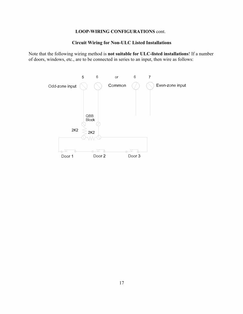
Circuit Wiring for Non-ULC Listed Installations
Note that the following wiring method is not suitable for ULC-listed installations! If a numberof doors, windows, etc., are to be connected in series to an input, then wire as follows:

18
LOOP-WIRING CONFIGURATIONS cont.
Circuit Wiring for ULC-Listed Installations
Use Form C contacts and 4,300-ohm (yellow-orange-red) resistors to provide an alternatesupervised connection for ULC-listed central/monitoring station installations.
To series-connect two Form C devices, one with a detector cover tamper and one without, installthe 4K3-ohm resistors in the first and second devices as follows:

19
LOOP-WIRING CONFIGURATIONS cont.
Circuit Wiring for ULC-Listed Installations cont.
To series-connect three or more Form C devices, install the 4K3-ohm resistors in the first andlast contacts as shown below. Pay close attention to the wiring as an interchange will cause azone tamper alarm (a short on the loop).
To connect a normally open, fire-detector circuit, install one 2K2-ohm resistor in the lastdetector or after the last detector using an EOL plate:

20
1024 QUAD LEM
MODEL 1024 QUAD LEM (Q-LEM)
The Model 1024 Quad Line Encoder Module (Q-LEM) features four input-loop connections anda tamper switch that can either be active or be shunted by switch number 8 on the DIL switch.The Q-LEM can be connected anywhere along the LEM line and the terminal connections aresimilar to those of the D-LEM except that the "in" and "out" connections are both made on theleft-hand terminal strip only.
The DIL switch settings establish the address of the Q-LEM. Only switches 1 through 7 areused. Switch number 8 controls the tamper switch. When switch number 8 is OFF, the tamperswitch is in series with zone input A (terminal 5); therefore, on a Q-LEM cover tamper alarm,the panel will display a DISCON for zone A. The general formula for determining the zonenumbers from the address (decimal) value is the following:
Zone A Terminal 5 = (Address Value x 2)Zone B Terminal 7 = (Address Value x 2)-1Zone C Terminal 8 = (Address Value x 2)+2Zone D Terminal 10 = (Address Value x 2)+1
The coding table on page 26 may be used to determine the switch settings.

21
1024 REV 2.1 QUAD LEM
MODEL 1024 REV 2.1 QUAD LEM (Q-LEM)
The Model 1024 Rev 2.1 Quad Line Encoder Module (Q-LEM) features four input-loopconnections and a tamper switch that can either be active or be shunted by switch number 8 onthe DIL switch. The Q-LEM can be connected anywhere along the LEM line, and the terminalconnections are similar to those of the D-LEM. The Rev 2.1 printed circuit board features anLMTC (LEM-line) terminal strip on the right-hand side and a more secure tamper switch. Noticethat the terminals on the right-hand strip are designated 7 through D. Do not confuse them withthe terminals designated 5 through 10 on the earlier ISS. 1 printed circuit board.
The DIL switch settings establish the address of the Q-LEM. Only switches 1 through 7 areused. Switch number 8 controls the tamper switch. When switch number 8 is OFF, the tamperswitch is in series with zone input A (terminal 5); therefore, on a Q-LEM cover tamper alarm,the panel will display a DISCON for zone A. The general formula for determining the zonenumbers from the address (decimal) value is the following:
Zone A = (Address Value x 2)-1Zone B = Address Value x 2Zone C = (Address Value x 2)+1Zone D = (Address Value x 2)+2
The coding table on page 26 may be used to determine the switch settings.

22
1101 C-LEM
MODEL 1101 COMMAND LEM (C-LEM)
L The Model 1101 Command Line Encoder Module (C-LEM) is a remote switching module thatmay be installed anywhere along the LEM line. The revised C-LEM MK II is fitted with anSPDT relay which is capable of switching a 2-amp, resistive load at 24 volts DC. The originalC-LEM MK I (now discontinued) is described later on page 23. Similar to D-LEMs, C-LEMshave to be programmed to certain address values that determine their function and how they willoperate. (See the OUTPUT ASSIGNMENT table for details, page 27). Unlike D-LEMs, severalC-LEMs may be programmed to the same address, in which case they will all respondidentically. C-LEM addresses are not monitored by the panel and therefore the panel does notknow if any C-LEMs are connected. C-LEMs are coded similarly to D-LEMs, with addressvalues 1 to 54 being valid.
The decoding electronics on the C-LEM printed circuit board are powered from the LEM line;however, the on-card relay coil requires an external source of power. It is imperative that thispower be supplied from the APLEX control panel's auxilliary power terminals 28 (-ve) and 32 or33 (+ve). Connection can be made by using a second quad for power or the extra conductors ofthe multi-cable as described on page 2. The use of an extra field-installed power supply,powered from a different phase or branch circuit than the main panel, has created severeproblems in the main panel.

23
MODEL 1101 COMMAND LEM (C-LEM) cont.
Terminals 1, 3, 4, 9, 11, and 12 are connected exactly as for D-LEMs. Terminals B or F require+12 volts DC, while terminals A or E are negative. Note that the 12 volts DC must have acommon negative with the panel. If you are using the APLEX panel's terminal 28 or 29 as anegative, then this requirement is met. If you use an auxilliary 12-volt DC power supply, try topower it from the same branch circuit as the panel. Connect a 2200-ohm (2K2) resistor link fromthe auxilliary supply negative to panel terminal 28 or use a 2200-ohm resistor to link terminal Ato terminal 1 on a C-LEM. If more than one C-LEM is powered from the same auxilliary supply,then only one C-LEM should have the link between A and 1 to avoid ground loops. Terminals 5and 6 are the dry contacts from the tamper microswitch on the C-LEM printed circuit board.You may wish to link this microswitch in series with the tamper circuit of a nearby LEM tosupervise the C-LEM cover.
C-LEM MK I (discontinued)
Information on the C-LEM MK I is presented here for reference purposes only. The C-LEMMK I differs from the MK II version in that the MK I used a 0.5-amp DIL SPST relay connectedto terminals 7 and 8. The MK I C-LEM is distinguished by the rainbow-coloured BCD switchused to set the address. Normally open (i.e., close on alarm) or normally closed (i.e., open onalarm) operation is controlled by the brown DIL switch 1. As the MK I was originally designedto operate from 7 volts DC, terminal 3 should be linked to terminal 2 with a 1N4001 general-purpose diode or an equivalent. Connect the anode to terminal 3 and the cathode (banded end) toterminal 2.

24
1121 COMBO LEM
MODEL 1121 COMBINATION LEM (COMBO LEM)
The Model 1121 Combination Line Encoder Module (COMBO LEM) features one D-LEM andone C-LEM combined together on a standard LEM-size printed circuit board. The D-LEM isseparately addressable from the C-LEM. This device is intended for use in installations thatrequire local contact closure upon detection of an alarm condition (e.g., fire doors with a localsiren).
The DIL switches are used to address the D-LEM and C-LEM sections of the COMBO LEM inexactly the same way as an individual unit. See the coding table on page 25. The alarm inputloops are wired like a standard D-LEM. See page 13.

25
MODEL 1020 D-LEM, 1101 C-LEM, AND 1121 COMBO LEM CODING TABLE
ZONE NUMBER VS. D-LEM/C-LEM/ TERM. STRIP SCREWS COMBO LEM DIL SW. NO.TERM. NO. 5 (Even) 7 (Odd) ADDRESS (Set to OFF)ZONE NO. 2 1 1 8
4 3 2 7 6 5 3 7,8 8 7 4 6 10 9 5 6,8 12 11 6 6,714 13 7 6,7,816 15 8 5 LIMIT of 3016 LEM LINE18 17 9 5,820 19 10 5,722 21 11 5,7,8 24 23 12 5,626 25 13 5,6,8 28 27 14 5,6,730 29 15 5,6,7,8 LIMIT of 3030 LEM LINE32 31 16 434 33 17 4,8 36 35 18 4,738 37 19 4,7,840 39 20 4,6 42 41 21 4,6,844 43 22 4,6,746 45 23 4,6,7,848 47 24 4,5 50 49 25 4,5,852 51 26 4,5,754 53 27 4,5,7,856 55 28 4,5,658 57 29 4,5,6,8 60 59 30 4,5,6,762 61 31 4,5,6,7,864 63 32 366 65 33 3,868 67 34 3,770 69 35 3,7,872 71 36 3,674 73 37 3,6,8 76 75 38 3,6,778 77 39 3,6,7,880 79 40 3,582 81 41 3,5,884 83 42 3,5,7 86 85 43 3,5,7,888 87 44 3,5,690 89 45 3,5,6,892 91 46 3,5,6,794 93 47 3,5,6,7,896 95 48 3,498 97 49 3,4,8
100 99 50 3,4,7 LIMIT of 3100

26
MODEL 1024 Q-LEM CODING TABLE
ZONE NUMBER VS. TERM. STRIP SCREWS
QUAD LEM REV 1.0 QUAD LEM REV 2.1 Q-LEMADDRESS DIL SW. NO.
TERM. NO. 5 7 8 10 TERM NO. ZA ZB ZC ZD VALUE (Set to OFF) Designation A B C DZONE NO. 4 3 6 5 ZONE NO. 3 4 5 6 2 7
8 7 10 9 7 8 9 10 4 612 11 14 13 11 12 13 14 6 6,716 15 18 17 15 16 17 18 8 5 LIMIT of 301620 19 22 21 19 20 21 22 10 5,7 24 23 26 25 23 24 25 26 12 5,628 27 30 29 27 28 29 30 14 5,6,7 LIMIT of 303032 31 34 33 31 32 33 34 16 436 35 38 37 35 36 37 38 18 4,740 39 42 41 39 40 41 42 20 4,644 43 46 45 43 44 45 46 22 4,6,748 47 50 49 47 48 49 50 24 4,552 51 54 53 51 52 53 54 26 4,5,756 55 58 57 55 56 57 58 28 4,5,660 59 62 61 59 60 61 62 30 4,5,6,764 63 66 65 63 64 65 66 32 368 67 70 69 67 68 69 70 34 3,772 71 74 73 71 72 73 74 36 3,676 75 78 77 74 76 77 78 38 3,6,780 79 82 81 79 80 81 82 40 3,584 83 86 85 83 84 85 86 42 3,5,788 87 90 89 87 88 89 90 44 3,5,6 92 91 94 93 91 92 93 94 46 3,5,6,796 95 98 97 95 96 97 98 48 3,4 LIMIT of 3100
100 99 n/a n/a 99 100 n/a n/a 50 3,4,8
Note: This chart has been extended to show all possible address settings and reference is made tothe 16-zone (3016) and 30-zone (3030) control panels.

27
PANEL OUTPUTS
Included in the basic panel are seven outputs: three SPDT relays and four switched-positive,current-limited voltage outputs. The relay outputs have been arbitrarily designated as outputs 1,2, and 7 and the voltage switches have been designated as outputs 3 through 6. If dry contacts arerequired from the voltage outputs, a EUROPLEX Model 1104 Quad Relay Module (QRM) maybe installed either outside of the panel or within the panel. Operating in tandem with these paneloutputs are C-LEMs 1 through 7 which can be used to provide remote-location duplicates of theoutputs on the main control panel. Additionally, C-LEM outputs 8 through 19 have been factoryassigned to provide dry-contact output for certain functions (refer to ZONE TYPES, page 28).Note that all output C-LEMs and INTRUSION panel output RELAY 1 (central/monitoringstation alarm relay) are normally energized. These relays will fail in alarm in the event all powerto the panel is removed. The other panel relays are normally de-energized. All panel outputs andC-LEMs except FIRE TROUBLE panel voltage OUTPUT 5 and TECH output C-LEMs 12 and13 are reset upon entry or re-entry to the DISARM mode
OUTPUT ASSIGNMENT
PANEL/C-LEM PANEL TERMINAL FUNCTIONOUTPUT NO. SCREW
1 13-15 Cen./Mon. Station Output, SPDT relay 2 10-12 Fire Alarm, SPDT relay 3 3 Clear To Arm, +ve voltage 4 4 System Armed, +ve voltage 5 5 Fire Trouble, +ve voltage 6 6 System Fault, +ve voltage 7 7-9 Timed Bell Cut-off, SPDT relay
8 - Remote Buzzer, C-LEM 8L 9 - Panic, C-LEM 9
10 - Internal Bell, C-LEM 1011 - Monitor Zone, C-LEM 1112 - Group-follow Tech, C-LEM 12
L 13 - Holdup/Duress, C-LEM 1314 - Fire Door, C-LEM 1415 - Line-cut Monitor, C-LEM 1516 - Gate Valve, C-LEM 1617 - Pressure Drop, C-LEM 1718 - 24Hour, C-LEM 18
L 19 - Smoke Detector Reset, C-LEM 19
28
ZONE TYPES
As received from the factory, all 30 zones in the panel are programmed as instant-acting, NIGHTintrusion zones. Unless indicated, the zone loops are wired normally closed, opening on alarm.Each of the 30 zones in the panel may be programmed with a new zone type. These have beengiven descriptive names and their characteristics are described in the following section:
FOLLWR: This zone type is used to provide protection along the exit and entry path(s) betweenthe control panel or the remote keypad and the exit and entry door(s). When the panel is armed,this type of zone is instant acting except for the following two cases. During exit, no alarm willoccur on any follower zone within the exit time allowed (see Exit Time delay variable, page 50) and, similarly, during entry, no alarm will occur within the entry time allowed (see Entry Timedelay variable, page 50). After the delay time expires, the FOLLWR zone responds as aninstant-acting NIGHT zone. Straying from the follower path into other protected zones duringthe exit/entry time will also cause instant-acting alarms.
L REMARM: This zone type is used to allow remote arming and disarming of the control panelfrom keyswitch plates, digital keypads, access control systems, etc. It provides for two methodsof operation as chosen from the Remarm Toggle variable (see page 52). If the variable is set to aone (1), each momentary closure of the dry contact (switch or relay) connected to a single end-of-line resistor input will change the armed/ disarmed status of the panel. If the momentaryclosure operation is chosen, multiple arming stations wired in parallel may be used. The end-of-line resistor should be installed in the last arming station. To wire a Form A (SPST-NO) contactas a momentary switch, see the drawing for contacts configured for a single end-of-line resistorfire detector service on page 19. If the variable is set to zero (0), a two-position dry contact(switch or relay) is used to provide a continuously closed contact, thus arming the panel, or acontinuously open contact, thus disarming the panel. To wire a Form B (SPST-NO) contact as atwo-position switch, see the Model 1020 Dual LEM drawing on page 13. Note: A Clear-to-Armstatus is available from the CLEAR TO ARM panel voltage output 3 and output C-LEM 3. ASystem Armed status is available from the SYSTEM ARMED panel voltage output 4 and outputC-LEM 4.
NOTPT2: This zone type is not active when the panel is in PART ARM 2 mode but is activewhen the panel is in PART ARM 1 or FULL ARM mode at which time the zone responds as aninstant-acting NIGHT zone. This zone type is used with space or interior protection that must beinoperative when the panel is turned on and the customer is remaining within the protected area(the "home/away" philosophy of a residential panel).
DOUBLE: This DOUBLE-knock zone type is a special type of NIGHT intrusion zone. Twoactivations must occur within a specified time period in order to cause an alarm. This period isthe value of the Double/Twin Time variable (see page 50) as entered in the panel by the installerduring set-up. The same zone or another DOUBLE-knock zone may provide the second acti-vation. This zone type is only active when the panel is in the FULL ARM mode. When the

29
ZONE TYPES cont.
double-knock timer is started, the second activation must occur within the specified timeperiod or the timer will reset. Use this option for motion detectors or inertia detectors thatcould create false alarms by being tripped once but that will be tripped more than once duringthe course of a genuine intrusion. (See also TWIN zone type, below.)
EXIT: This zone type is used to monitor the final exit and entry points, usually the mainentrance door, employee entrance, etc. When the panel is placed in PART ARM 1 mode, thiszone is inoperative and unrestricted exit or entry is possible. When the panel is placed in PARTARM 2 or FULL ARM mode, the exit door must be closed by the time the exit timer (see ExitTime delay variable, page 50) expires to avoid an IMPROPER CLOSING alarm. When youenter the premises through an exit door, the piezo-sounder will beep and the panel must bedisarmed or placed in PART ARM 2 mode before the entry timer (see Entry Time delay variable,page 50) expires to avoid a full alarm condition. Note: A door chime feature is available duringDISARM and PART ARM 1 modes (see page 61). FIRENO: This zone type is used with smoke detectors, manual-pull stations, fire alarmthermostats, fire hall relay contacts of evacuation alarm panels, etc. A normally open contact iswired as a two-wire, single end-of-line resistor loop. Contact closure will operate FIREALARM panel relay output 2 and output C-LEM 2 and cause the event to be logged. If the Alert& Display variable (see page 50) is set to one (1) for an attended site (default value), then thepiezo-sounder will beep and the display will show the flashing alert message ** FIRE ALARM** , alternating with a flashing zone description. The loop wiring of a FIRENO zone is alsosupervised for trouble conditions. A break in the loop wiring (disconnect) will operate FIRETROUBLE panel voltage output 5 and output C-LEM 5 and cause the event to be logged. Asbefore, if the Alert & Display variable is set to one (1), then the piezo-sounder will beep and thedisplay will show the flashing alert message ** FIRE TROUBLE **. When all FIRENO loopsare normal (not disonnected or shorted), FIRE TROUBLE panel voltage output 5 and outputC-LEM 5 will restore. If the Alert & Display variable is set to zero (0) for an unattended site,FIRE ALARM panel relay output 2 and output C-LEM2 will also reset. Note: For monitoringthe trouble relay on a fire alarm panel, see the zone type FIRTBL below.
NOTPT1: This zone type is not active when the panel is in PART ARM 1 mode but is activewhen the panel is in PART ARM 2 or FULL ARM mode at which time the zone responds as aninstant-acting NIGHT zone. This zone type is used with space or interior protection that must beinoperative when the panel is turned on and the customer is remaining within the protected area(the "home/away" philosophy of a residential panel).
24HOUR: This zone type is used with foil, fine wire, emergency doors, etc. When the panel is inDISARM mode, an alarm on this zone will operate INTRUSION ALARM panel output relay 1and output C-LEM 1 and 24HOUR output C-LEM 18, which may be used for local annunciation(buzzer, lamp, etc.), and cause the event to be logged. If the Alert & Display variable (see page

30
ZONE TYPES cont.
50) has been set to one (1) for an attended site, then the piezo-sounder will beep and the displaywill show the flashing alert message ** INTRUDER ALARM **, alternating with a flashingzone description. When the panel is in PART ARM 1, PART ARM 2, or FULL ARM mode, thiszone responds as an instant-acting NIGHT zone.
INTRNL: This zone type is similar to the NOTPT1 and NOTPT2 zones; however, it is notactive when the panel is in either PART ARM 1 or PART ARM 2 mode but is active when thepanel is in FULL ARM mode at which time this zone responds as an instant-acting NIGHT zone.Use these three zone types (NOTPT1, NOTPT2, INTRNL) to configure a system for "home","sleep", and "away" operation.
FIRENC: This zone type is identical in operation to the FIRENO zone type except that the inputloop is wired normally closed and opens on alarm. A break in the loop wiring (disconnect) or ashort in the loop wiring will result in a trouble condition.
KEY: This zone type is used when manual control of exit and entry timers is desired (e.g.,high-risk customers such as jewellery stores). A two-position keyswitch or similar secure devicemust be installed outside the protected area. Then, when the panel is armed and the customer hasexited from the premises, he or she must operate this switch in order to zero the remaining exittime and to fully arm the system. In a similar manner, the switch must be re-operated in order tostart the entry timer before the customer re-enters the premises. Note: The main exit/entry door should be assigned as a FOLLWR zone type (not EXIT zone type) to create an instant-acting alarm if an intrusion occurs. As well, the Entry Time (see page 50) and Exit Time (see page 50)delay variables should be set to a longer time than for normal entry or exit, say five minutes (300seconds). This is important in a KEY zone because the keyswitch is outside the protected area;hence, when the exit door is closed, the piezo-sounder beeping inside cannot always be heard bythe customer outside and there is nothing to prompt a speedy arming on exit or disarming whenentering.
TELFLT: This zone type is used to monitor the relay output of a dialler telephone line-cutmodule. An open on this zone will operate TELFLT output C-LEM 15 and cause the event to belogged. If the panel is in the FULL ARM mode, the Bell Delay value (see page 51) will bereduced to two seconds. If the Alert & Display variable (see page 50) is set to one (1) for anattended site, the piezo-sounder will beep and the display will show the flashing alert message*TELCO FAULT*, alternating with a flashing zone description. When the TELFLT zone isrestored, output C-LEM 15 will be reset and the event will be logged.
MONITR: This zone type is used to monitor cold storage room doors, internal doors, fire/smokedoors, etc., that should not be open for longer than a preset period of time. You may assignmultiple zones as a MONITR zone; however, there is only one monitor timer. If the timer isstarted by one MONITR zone and another MONITR zone is opened soon thereafter, the timerwill not be restarted by the second zone, thereby giving an erroneous open time for that zone.

31
ZONE TYPES cont.
When the panel is in DISARM mode, an open on the MONITR zone that exceeds the timeallowed in the Mon/Firtbl Delay variable (see page 51) will operate MONITOR output C-LEM11 and cause the event to be logged, the piezo-sounder to beep, and the display to show theflashing alert message **MONITOR ALARM**, alternating with a flashing zone description.When the panel is in FULL ARM mode, this zone responds as an instant-acting NIGHT zone.
NIGHT: This zone type is an an absolutely instant-acting, intrusion zone. When the panel is inFULL ARM, PART ARM 1, or PART ARM 2 mode, a violation of this zone will cause animmediate full alarm. TIMED BELL panel relay output 7 and output C-LEM 7, INTERNALBELL output C-LEM 10, and central/monitoring station INTRUSION panel output relay 1 andoutput C-LEM 1 will operate and the event will be logged. When the panel is in DISARM mode,a TAMPER alarm (short on loop wiring) or DISCONNECT alarm (open on loop wiring orremoval of D-LEM/ Q-LEM/COMBO LEM cover) will operate TECHNICAL FAULT panelvoltage output 6 and output C-LEM 6 and cause the piezo-sounder to beep, the event to belogged, and the display to show the flashing alert message *ZONE TAMPER ALARM*,alternating with a flashing zone description. Note that some other zone types described in thissection respond as instant-acting NIGHT zones when the panel is fully armed.
FIRDR1: This zone type is used with fire exit doors that should never be opened when thepremises is occupied. Violation of this zone is displayed locally and transmitted to the central/monitoring station. There is also available a companion zone type, FIRDR2, which only displayslocally during the disarmed period (see below). When the panel is in DISARM, PART ARM 1,or PART ARM 2 mode, an open on this zone will operate FIREDR group output C-LEM 14 andFIREDR individual-zone output C-LEM (20 + the zone number: e.g., 20+1, 20+2, 20+3, etc., toavoid conflict with the preprogrammed outputs 1 through 19, see page 27) and cause thepiezo-sounder to beep, the event to be logged, and the display to show the flashing alert message*FIRE DOOR OPENED*, alternating with a flashing zone description. When the panel is inFULL ARM mode, this zone responds as an instant-acting NIGHT zone.
PANIC: This zone type should be used with latching panic buttons to ensure that activation willbe detected. Activation at any time will operate CONTINUOUS BELL panel relay output 7 andoutput C-LEM 7 and PANIC output C-LEM 9 and cause the piezo-sounder to beep, the event tobe logged, and the display to show the flashing alert message **PANIC ALARM**, alternatingwith a flashing zone description. PANIC is an audible HOLDUP zone!
HOLDUP: This zone type should be used with latching holdup buttons to ensure that activationL will be detected. An open at any time will operate HOLDUP output C-LEM 13 and cause the
event to be logged but piezo-sounder will not beep. Note: Since the panel will display a zonedescription any time a zone is violated, you should program a zone description that avoids theuse of the word HOLDUP; choose some innocuous phrase such as TEST ZONE X. HOLDUP isa silent PANIC zone!

32
ZONE TYPES cont.
TECH: This zone type is used to provide supervisory monitoring of non-burglary conditions(e.g., freezer monitor, boiler flame-out, building temperature, etc.). You may use normallyclosed switches (2 EOL) or normally open switches (1 EOL) or a mixture of both. If the AudibleTech variable (page 50) is set to one (1) and the Alert & Display variable (see page 50) is set toone (1) for an attended site, then the piezo-sounder will beep and the display will show a flashingzone description. A TECH zone alarm can have two distinct outputs: you may use an individualoutput C- LEM to give a one-for-one dry contact that follows the state of the zone input (e.g.,alarm equals contact closure, restore equals contact open) or you may choose to have agroup-following
L output C-LEM 12 that will respond to any zone labelled TECH. The group-following outputC-LEM will reset only when all TECH zones are normal. To avoid conflict with the pre-programmed outputs 1 through 19 (see page 27), TECH zone individual output C-LEMshave been offset by 20 plus the zone number. For example, TECH zone 4 will operateindividual output C-LEM 24; TECH zone 8 will operate individual output C-LEM 28; etc. WhenTECH zone 4 restores, output C-LEM 24 will also reset. The group-following output C-LEM isrigidly assigned. For example, if TECH zone 6 alarms, the group-following TECH outputC-LEM 12 will operate; however, if TECH zone 4 alarms at a later time, there will be no furtheraction from output C-LEM 12 since it is already operated. When all TECH zones restore, outputC-LEM 12 will reset.
FIRDR2: This zone type is used with fire exit doors that should never be opened when thepremises is occupied. Violation of this zone is only displayed locally. A companion zone type,FIRDR1 (see above), is also available. When the panel is in DISARM or PART ARM 1 mode,an open on this zone will operate FIREDR group output C-LEM 14 and cause the piezo-sounderto beep and the display to show a flashing zone description; however, the event will not belogged nor transmitted to the central/monitoring station. In DISARM or PART ARM 1 mode,then, response is solely the responsibility of the customer. When the panel is in PART ARM 2mode, an alarm will be logged and the central/monitoring station will be alerted as well. Whenthe panel is in FULL ARM mode, this zone responds as an instant-acting NIGHT zone.
FIRTBL: This zone type is used to monitor the trouble-relay contacts of a local fire alarmcontrol panel. IT IS NOT A FIRE ALARM ZONE INPUT AS DESCRIBED IN THE FIRENO/NC ZONETYPE ABOVE! Because many fire alarm control panels respond immediately to local AC powerfailures, a delay timer has been incorporated into the zone. The time value is selected in theMon/Firtbl Delay variable (see page 51). The default value is 30 seconds but it may be reducedto 0. Note that this one timer is used for both MONITR zones and FIRTBL zones. If both zonetypes are to be used, then determine a common time value suitable for both applications. Anopen on this zone will start the timer. If the zone restores before the time expires, the timer isreset and no further action occurs. If the zone remains open at the expiry of the time, FIRETROUBLE panel voltage output 5 and output C-LEM 5 will operate and the event will belogged. If the Alert & Display variable (see page 50) is set to one (1) for an attended site, thepiezo-sounder will beep and the display will show the flashing alert message **FIRE

33
ZONE TYPES cont.
TROUBLE**, alternating with a flashing zone description and the warning message ++CALLSERVICE++. When all FIRTBL zones are normal, FIRE TROUBLE panel voltage output 5 andoutput C-LEM 5 will reset. A tamper or a disconnect on this zone will operate TECHNICALFAULT panel voltage output 6 and output C-LEM 6 and cause the piezo-sounder to beep, theevent to be logged, and the display to show the flashing alert message *ZONE TAMPERALARM*, alternating with a flashing zone description.
TWIN: This zone type is a special type of NIGHT zone and is similar to the DOUBLE-knockzone type (see page 28); however, two TWIN zones must open within the time allowed by theDouble/ Twin Time variable (see page 50) to cause an alarm. This zone type is only active whenthe panel is in PART ARM 2 or FULL ARM mode. You may therefore twin (pair) zones withdetectors of different types (e.g., a PIR and an ultrasonic covering the same area). As with aDOUBLE-knock zone, when one TWIN zone operates, the double-knock timer is started and asecond TWIN zone must operate within the specified time period or the timer is reset. Note: Ifonly one zone is assigned as a TWIN type, it will never create an alarm! Also, you may havemore than two TWIN zones but, if one starts the timer, an open on any other TWIN zone willcomplete the event and result in a full alarm.
GATE: This zone type is used to monitor the gate valve or the post indicator valve (PIV) in asprinkler system. When a gate valve closes (i.e., the switch contacts open), GATE VALVE outputC-LEM 16 will operate and the event will be logged. If the Alert & Display variable (see page 50)is set to one (1) for an attended site, then the piezo-sounder will beep and the display will showthe flashing alert message *SPRINKLER SUPERVY* , alternating with the warning message++CALL SERVICE++ and a flashing zone description. During service to the sprinkler riser, the
L gate valve switch may have to be operated a number of times in succession. To avoid unnecessarytraffic to the central/monitoring station, a Supvry Shutdown variable (see page 52) may beprogrammed to limit the number of signals.
PRESR: This zone type is used to monitor the pressure switch on a sprinkler riser. When apressure drop occurs, PRESSURE output C-LEM 17 will operate and the event will be logged. IftheAlert & Display variable (see page 50) is set to one (1) for an attended site, then the piezo-sounderwill beep and the display will show the flashing alert message *SPRINKLER SUPERVY* ,alternating with the non-flashing warning message ++CALL SERVICE++ and a flashing zonedescription. In the course of servicing the sprinkler riser, the pressure switch may have to be
L operated a number of times in succession. To avoid unnecessary traffic to the monitoring station aSupvry Shutdown variable (see page 52) may be programmed to limit the number of signals.
FLOW: This zone type is used to monitor the normally open flow switch on a sprinkler riser.Contact closure causes the retard timer (see Retard Time variable, page 51) to count down. If theswitch contact is still closed at the expiry of the retard time, the panel will execute the FIRENOroutine (see page 29). If the switch opens before the timer finishes counting down, the retard timerwill reset and no further action will occur.

34
POWERING UP THE PANEL
INITIAL ACTIVATION OF THE PANEL
The control panel as received from the factory has been given a COLD START and all settingswill be at their default value. The next time that power is applied to the panel, it will execute aWARM START (see page 35). On powering up, you will be concerned with entering thecustomer's name and address and initializing the LEM LINE. Once powering up is finished, youwill be ready to program the panel.
When power is first applied to the control panel, the display will show the following: RAMPROTECTED!. Next, the display will show the operating system version number and date:MXOS2M44 27AUG97; followed by the copyright message: (C) EUROPLEX 1989 andfinally the application program version and date: M100 1A 250U 8SEP97. This last messagewill be displayed for about three seconds during which time an option to COLD START thepanel will be available. COLD START WITH ZAP
It may sometimes be necessary to clear the panel's RAM memory in the field. For example, if thepanel has been removed from a previous location and is to be installed in a new location or ifsevere transients (lightning, etc.) have caused corruption of the memory, it will be necessary tostart anew. A COLD START will clear the whole of the memory, destroying all existing log,zone, and user files.
To select a COLD START, press the FULL ARM key within the three seconds allowed above.(If the FULL ARM key is not pressed within these three seconds, the panel will execute aWARM START, see page 35. To return to a COLD START option, press the CPU reset button.)If a COLD START is chosen, then the piezo-sounder will beep and the display will show ZAP?.
Press the YES key to accept the selection. (If you decide to leave the RAM memory unchangedat this stage, press any other key than the YES key. You will then abort the COLD START andinstead execute an AUTO START, see page 37). If the YES key is pressed, the display will show RAM=0000 for about five seconds, indicating that all RAM memory is being zeroed, followedby ENTER NAME/ADDRESS ?. Press the YES key and the display will show a flashingcursor, /\, in the farthest-left position.
It is important that you enter the name and address of the site as this will be printed in theheading of the system log, literal print-out, and on-line report and will provide a useful record forall print-outs. Refer to page 4 for information on how to enter the necessary characters. Once thename and address information is entered, position the cursor up and press the RETURN key.

35
POWERING UP THE PANEL cont.
The display will now show COLD START and, in another two seconds, PROM CHKSUM=nnnnH. The piezo-sounder will beep. Press the RETURN key to continue and the display willshow ON-LINE O-->N. Proceed to LEM-LINE INITIALIZATION (see below).
Note: If you do not select yes to the ZAP? function during a COLD START, you will not begiven the chance to enter a name and address. If you wish to return to a name and address query,you must select a SOFT START (see page 36) to restart the panel. See SYSTEM RESETSTART below for the procedure to follow.
SYSTEM RESET START
When power is applied to the control panel, the display will show the usual start-up messages fora moment. If a COLD START is not initiated, then a SYSTEM RESET START will be effected.On a SYSTEM RESET START, if no name and address entry has previously been made, thedisplay will stop at ENTER NAME/ADDRESS ?. Press the YES key and a flashing cursor, /\,will appear in the farthest-left position.
If a name and address has previously been entered, the panel will by-pass this query. To changean entry or correct it in this case, you must select the SET DATA FORMAT function (see pages55 and 56). If you fail to enter a name and address when requested, you must use a SOFTSTART (see page 36) to restart the panel to return to this query.
It is important that you enter the name and address of the site as this will be printed in theheading of the system log, literal print-out, and on-line report and will provide a useful record forall print-outs. Refer to page 4 for information on how to enter the necessary characters. Once thename and address information is entered, position the cursor up and press the RETURN key.
Enter the name and address information and press the RETURN key. The panel will showWARM START and then ON-LINE O-->N. Proceed to LEM-line initialization below.
LEM-LINE INITIALIZATION
An initialization of the LEM line brings any newly connected zones on line; otherwise, they willbe ignored by the panel. When the display shows ON-LINE O-->N, O represents the original(old) number of zones on line prior to powering up and N represents the current (new) number ofzones on line. The piezo-sounder will sound a single beep if there is no change in the totalnumber of inputs (i.e., Old = New) or a multibeep if there has been a change. In either case,press the YES key to accept the initialization or the NO key to repeat the initialization check. Ifthe NO key is pressed, account for the missing inputs and then press the YES key.

36
POWERING UP THE PANEL cont.
Note: Any LEM input loops in the disconnect state or short circuited will not be included in thecount or be recognized by the panel when the program continues.
Remember that the LEM cover tamper switch is in series with terminal 5 (the even-numberedinput) of any LEM.
Loop states are categorized as:
DISCON - Loop open circuited. Loop resistance = infinityOPEN - Alarm contact open. Loop resistance = 4K4 ohmsCLOSED - Alarm contact closed. Loop resistance = 2K2 ohmsSHORT - Loop short circuited. Loop resistance = 0 ohms
The initialization routine checks the resistance of the loops. If the values returned are outside theallowed ranges, the zone number of the offending input will be displayed. For example: NIGHT3 = 22 indicates the analogue value of 22 from zone 3 is out of range. This is a problem thatmust be corrected. Usually a wiring fault or the wrong value of end-of-line resistor isresponsible. If the panel sees a response from zone numbers 101 to 108, ILLEGAL LEMNUMBER is displayed as these zone addresses are used by Model 3210, 3220, and 3230 remotekeypads. All zones that have allowable values at or near the threshold of acceptability will becounted and the total will be displayed at the end of this routine. Excessive capacitance and/orresistance of the cable can also be a problem if more than 2 km of cable are connected or cablewith high capa-citance (i.e., shielded cable) is used. Individual responses from the LEM inputs can be checkedin the SINGLE-ZONE MONITOR option of the SERVICE MODE mode (see page 44). Whenthe correct number of zones is displayed, press the YES key to proceed to the main program..
L At this time, the display will show 5 DIGIT CODES ?. Press the YES key to accept thefive-digit code option or press the NO key to choose the four-digit code option. See the SETIDS/OPTIONS function on page 47 for further information. If neither key is pressed within threeseconds, the panel will default to the four-digit code option.
The panel will now show BUSY...RE-SCHEDULING for a few seconds. Next, DATE andTIME will appear, alternating with some flashing alert messages. If any of the zones are open(in alarm), then ZONE TYPE ZONE NUMBER OPEN will also be displayed. For infor-mation on how to acknowledge the alert messages, refer to page 61. This confirms the operationof the hardware and you may now proceed with programming the control (see page 39).
SOFT START - LEM-LINE RE-INITIALIZATION
If a re-initialization of the LEM line is required, select the RESTART SYSTEM function (seepage 54). To select this function, enter the Service user code and then press the R key (shift 7). A

37
POWERING UP THE PANEL cont.
reboot, or SOFT START, of the panel will be effected. The display will show the usual start-upmessages for a few seconds. From this moment on, the procedure is the same as for a SYSTEMRESET START (see page 35).
AUTO START
The panel contains a "watch-dog" timer. Should there be a major disturbance to the hardware(e.g., electrical storm, static, etc.), this timer will reset and force the panel to effect an AUTOSTART. A flashing alert message will appear that must be acknowledged (see page 40).
P.CODE START
As the panel is executing its instructions from the main program EPROM, it will check theEPROM checksum against a stored value. If it detects a difference, it will restart the programand indicate this by displaying P. CODE START. An alert message will appear that must beacknowledged (see page 40). This situation is very rare.
PROGRAM SELF-TESTS
During the start-up routine, the panel will perform several comprehensive self-tests and display afault warning message if any test fails. The display will show RAM FILE ERROR and thepiezo-sounder will beep. Press the RETURN key to acknowledge the condition and thencontinue on. For the sake of clarity and because such failures are rare, these tests have not beenincluded in the previous discussion.
The self-checks performed are for RAM function and a RAM data checksum. The flashingwarnings displayed are:
RAM FAIL AT nnnn - indicates a memory-component fault. The printed circuit board has to bereplaced.
LOG DATA LOSS! - indicates that the log data is corrupted. If the log is printed or displayed,then certain entries may yield garbage displays. The dates and/or times of logged events mayalso be corrupted. The log error message is cleared when acknowledged and no further action isrequired.
LIT DATA LOSS! - indicates corruption of the system literals. The corruption may be total oronly partial. The panel will check all 750 literals in the program and any that are corrupted willbe defaulted back to their factory settings. The defaulted literals are displayed and printed. If thepanel can complete this routine, print a copy of the system literals (see page 53) and compare it

38
POWERING UP THE PANEL cont
with an old record. Depending on the severity of the corruption, a recovery may not be possibleand a COLD START with ZAP will have to be performed (see page 34).
IDS/OPTIONS ERROR - indicates corruption of the user identification codes or options. Thepanel may default all identification codes and options to their factory settings. All useridentification codes and options may need to be reprogrammed.

39
PROGRAMMING THE PANEL
FUNCTIONS AND MODES
There are 26 functions or modes available in the control panel. Access to these by each of the248 general users is assigned by the Master user (see page 47). Activities pertaining to theService
L user have to do with installation and service and are only accessed by him or her. Note that theService user code can now be entered when the control is in FULL ARM mode. When the control panel is initially powered up, the Service user will automatically be assignedcode 1010 and the Master user will be assigned code 1020. These are the default codes to allowaccess into the panel. Both codes can be changed later. The following table shows the selectionof program functions and modes. To gain access, enter the appropriate user code, followed bythe required function, number, or letter key.
FUNCTION OR MODE USER NUMBER KEYBOARD PAGE NO. DESIGNATION
OPTIONS AVAILABLE/HELP 1 2 HELP 40ACKNOWLEDGE ALARMS 1 2 0 40DISARM 1 2 DISARM 40PART ARM 1 2 PART ARM 1 41PART ARM 2 2 PART ARM 2 41FULL ARM 1 2 FULL ARM 41DOOR ACCESS 1 2 5 41NEW CLOSING TIME 2 6 429 KEY (used for custom applications) 1 2 9 42SYSTEM LOG 1 2 YES 42SINGLE-ZONE SHUNT 1 2 NO 43SERVICE MODE 1 A (Shift YES) 43BLOCK SHUNT/CLEAR 2 B (Shift NO) 46SET IDS/OPTIONS 1 2 C (Shift DISARM) 47ASSIGN ZONES/VARIABLES 1 D (Shift PART ARM 1) 49LITERAL EDIT 1 E (Shift PART ARM 2) 53DISABLE MODE 1 F (Shift FULL ARM) 53DAYLIGHT SAVING TIME CHNGE 1 2 H (Shift HELP) 53(IMMEDIATE) COMMAND MODE 1 I ( Shift 1) 54RELAY/C-LEM TEST 1 O (Shift 5) 54PRINT REPORTS 1 P (Shift 6) 54RESTART SYSTEM/SOFT START 1 R (Shift 7) 54SET DATA FORMAT 1 S (Shift 8) 55SET DATE/TIME 1 2 T (Shift 9) 60SET TIME COMMANDS 1 2 U (Shift BACKSPACE) 60TIME ADVANCE 1 2 ! (Shift Shift YES) 60
Some functions or modes are self-completing (i.e., they exit automatically). Others will requirefurther action. For the NEW CLOSING TIME, SET DATE/TIME, and SET TIME

40
PROGRAMMING THE PANEL cont.
COMMANDS functions, enter a military (24-hour) time and press the RETURN key to exit.Other functions will display a flashing sub-menu. To select from these sub-menus, follow theguidelines on the keyboard leading to the DISARM, PART ARM 2, or HELP keys and press the one that is appropriate. For example, in SERVICE MODE mode, a sub-menu of threechoices will appear. These will be REPORT--TEST-MONITOR. If you wish to chooseREPORT, then press the DISARM key; if TEST, then press the PART ARM 2 key; and ifMONITOR, then press the HELP key. Having made your choice, follow the instructions thatappear on the next display. To exit, press the NO key when there are no further entries to bemade. Then, when the display shows QUIT ?, press the YES key to exit, or any other key toforce a redisplay of the sub-menu.
IMPORTANT!! Do not leave the panel with a sub-menu showing. Anyone could make aselection and gain access to the premises later. Always complete your selection and exit to dateand time. EXPLANATION OF FUNCTIONS AND MODES
L Note that a four-digit code entry in the four-digit code option or a five-digit code entry in afive-digit option will be presumed in the following explanation of functions and modes. Should afour-digit code be entered when the five-digit code option has been chosen, then you must pressthe RETURN key to complete the entry.
OPTIONS AVAILABLE (HELP KEY): This function is included to help the user who is notsure of the system options available. Enter your user code and then press the HELP key. Thepanel will display SELECT AN OPTION..., followed by the first option available. The optionwill have a ? beside it. If you wish to select this option, then press the YES key. If you do notwish to select this option, then press the NO key to continue on to the next available option. Thisprocedure must be repeated until an option is chosen. To exit from this function withoutchoosing an option, repeatedly press the HELP key until you see CLEAR DISPLAY. Press theYES key.
ACKNOWLEDGE ALARMS (0 key): This function is used to acknowledge receipt of analarm condition (e.g., **FIRE ALARM**). Enter your user code and then press the 0 (zero)key. This action will stop the flashing display, silence the piezo-sounder, and turn off the bells. Atamper or disconnect condition on any zone will also create an alarm that is logged in the systemlog. When this happens, both the zone description and zone state are displayed. This may beacknowledged to stop the piezo-sounder.
DISARM (DISARM key): This is the normal daytime or open-period operating mode. Todisarm the panel, enter your user code and then press the DISARM key. When the panel is inDISARM mode, the date and time will alternate with a display of any zones that are open (inalarm). If a zone description has been programmed, then the panel will display the actual zone

41
PROGRAMMING THE PANEL cont.
description (e.g., 1. SIDE DOOR) instead of the zone type, number, and state (e.g., NIGHT 1 OPEN). All shunted zones are cleared and all panel relays, most C-LEMs, and panel voltageswitches are reset when this mode is selected or reselected. (The exceptions are FIRE TROUBLEpanel voltage output 5 and output C-LEM 5, TECH output C-LEM 12, HOLDUP and DURESSoutput C-LEM 13, GATE VALVE output C-LEM 16, PRESSURE DROP output C-LEM 17, andSMOKE DETECTOR reset C-LEM 19, all of which reset when the appropriate zone resets.)
PART ARM 1 (PART ARM 1 key): When the panel is in PART ARM 1 mode, FOLLWR, EXIT,NOTPT1, and INTRNL zones will not cause an alarm if they open, but will cause a full alarm iftampered with or disconnected. All other burglary zone types respond as they would in the FULLARM mode. This mode allows unrestricted access through the exit/entry door and is the equivalent to the "home" mode of operation of a residential panel. Enter your user code andthen press the PART ARM 1 key.
PART ARM 2 (PART ARM 2 key): When the panel is in PART ARM 2 mode, FOLLWR,NOTPT2, and INTRNL zones will not cause an alarm if they open; however, if an exit/entry door isopened, the entry timer (see Entry Time delay variable, page 50) will start and the DISARM orPART ARM 2 key must be pressed before the entry timer expires to avoid a full alarm. This isequivalent to the "sleep" mode of operation of a residential panel. All other burglary zone typesrespond as they would in the FULL ARM mode. If the panel is in the PART ARM 2 mode and youwish to leave the premises, enter your user code, press the PART ARM 2 key if someone isremaining in the premises, or press the FULL ARM key if the premises will now become vacant.Both actions will start the exit timer (see Exit Time delay variable, 50). The timer will start beepingimmediately if FULL ARM mode is chosen. If PART ARM 2 mode is chosen, there will be nobeeping immediately but the exit timer will be counting down silently; as soon as the exit door isopened, the beeping will start, indicating that the timer is operating! Do not delay unnecessarilywhen leaving!!
FULL ARM (FULL ARM key): This is the nighttime or closed-period operating mode. In thismode, the display may be blank depending on the setting of the Full Arm Display variable (see page51). Enter your user code and then press the FULL ARM key. If any zones are open, the displaywill show CANNOT ARM. If all zones are closed, the piezo-sounder will beep to indicate thatexit time is in progress; when an EXIT zone or a FOLLWR zone is opened, the beeping rate willchange until that zone is closed. During this exit and the subsequent entry time, an open (alarm) onany other zone will cause an instant, full alarm and the open zone will be logged in the system log.
DOOR ACCESS (5 key): This function is used to provide simple door access. The field of 250users has been split up into five blocks of 50 users each (i.e., 1-50, 51-100, 101-150, 151-200, and201-250). A C-LEM address of 41, 42, 43, 44, or 45 has been assigned to each block. If you are auser in block 1 to 50, enter your user code and then press the 5 key. This action will be logged andC-LEM 41 will operate for five seconds and then release. An electric door strike or magnetic doorlock can be connected to the C-LEM relay output. Similarily, a user in block 51 to 100 will operateC-LEM 42; etc. The block sizes can be changed to suit the need. Consult the factory for assistance.
42
PROGRAMMING THE PANEL cont
NEW CLOSING TIME (6 key): This function is only used if the panel has been programmedfor the Late-to-Close Warning feature in the Closing Warning variable (see page 50). The Masteruser and selected general users may program a new closing time if they intend to stay later thanthe regularly scheduled closing time for that day. New closing times can be entered at any timeof the day before a *PAST CLOSING TIME* alarm is to occur. Note that the alarm will occurat the expiry of the time programmed in the Closing Delay variable (see page 50); the warningitself will be given at the regularly scheduled or newly chosen closing time. The new timeentered is only valid for the day in question and does not alter the regular, daily scheduledclosing time. Enter your user code and then press the 6 key. The panel will display NEWCLOSING TIME for a moment and then will display the previous closing time in a messagesimilar to 19:55/[1 NEW CLOSNG]. The cursor will be flashing on the first digit. Enter a new closingtime using military (24-hour) time. Press the RETURN key to complete the entry. Thepiezo-sounder will beep if an illegal numeric entry has been made and the display will show **INVALID ENTRY **, followed by the original entry. Enter the correct time and press theRETURN key. The panel will display BUSY .. RE-SCHEDULING and in a moment willreturn to date and time. If the panel is not armed by the newly programmed closing time, thepiezo-sounder will beep and the panel will display CLOSING TIME SOON !. At this time,either arm the panel or repeat the above procedure.
9 KEY (9 key) : This is a spare key that can be programmed for custom functions (e.g., shunt aspecial block of zones, turn on a C-LEM, etc.). Contact the factory for a programming form andcost estimate for code development.
SYSTEM LOG (YES key): This function is used to print or display the historical log. Enteryour user code and then press the YES key. In a polled [DVACS(tm)] installation without aModel 3302R3 port splitter, the display will briefly show SYSTEM LOG and then the log willbe scrolled on the 20-character display. In a non-polled installation (local printer) or a polledinstallation with a Model 3302R3 port splitter, the display will show PRINT LOG ?. Press theYES key to make a hard-copy record of the system log. While the printing is in progress, thedisplay will show PRINTING SYSTEM LOG. If a printed copy is not required, press anyother key. The display will briefly show SYSTEM LOG and the log will then be scrolled on thedisplay. To abort the system log at any time, press the NO key. The format of the displayedoutput is as follows: Starting with the last event and working back in time, the panel will showthree messages for each alarm entry:
Message 1 is DATE**TIMEMessage 2 is ZONE NUMBER or USER NUMBERMessage 3 is ZONE DESCRIPTION or ACTION TAKEN BY USER
The date and time are separated by ** to distinguish an historical log display from the normalDISARM mode display. The content of the second and third messages will depend on whether it
43
PROGRAMMING THE PANEL cont.
was a user action (e.g., SET DATE/TIME), in which case the user number will be the secondmessage and action taken will be the third message, or a zone changing state, in which case thezone number will be the second message and the zone description will be the third message. Thealarm log is capable of storing 300 of these three-part entries. While the log is being displayed,you may press the RETURN key to advance each line entry on the display. You may also pressthe DISARM (+) key to move just the time entry back in time more quickly (i.e., to the older logentries) and then you may press the PART ARM 1 (-) key to advance just the time entry forwardin time more quickly (i.e., to rewind the log to the most recent entry). When you stop pressingthese keys, the log will again continue its slow scroll back in time. This will allow you to easilyreview any display. When all entries have been displayed, the word FINISHED will appear andthe panel will return to date and time. Press the NO key at any time to abort the system log.
SINGLE-ZONE SHUNT (NO key): This function provides a simple method of shunting whenonly a single zone is to be shunted or the total number of zones to be shunted is quite small. Enter your user code and then press the NO key. The display will show SHUNT ZONE 0. Enterthe number of the zone that is to be shunted and press the RETURN key. The display will thenshow the description of the zone (e.g., t3. MANAGER'S OFFICE), if one exists, or, if nodescription exists, the display will show the zone type and zone number (e.g., tNIGHT 3).Having a zone description allows the user to see exactly which zone has been shunted. Theflashing t to the left of the description indicates that the zone is currently shunted. If anincorrect zone number has been entered, that zone can be unshunted by pressing the YES key.(Pressing the YES key, in fact, toggles the shunt on and off. As the YES key is pressed, theflashing t will come and go indicating whether a zone is shunted or not.) The DISARM (+) keycan be used to select higher zone numbers and the PART ARM 1 (-) key can be used to selectlower zone numbers. By using the DISARM (+), PART ARM 1 (-), and YES keys, you canquickly step through a range of zones and examine or change their status. If the zone displayed isthe one to be shunted, then press the RETURN key and the panel will exit from this mode. Asthe exit occurs, the panel beeps and then briefly displays the number of shunts in place. To exitat any time, press the RETURN key or the NO key.
SERVICE MODE (A key): To select this mode, enter the Service user code and then press theA key (shift YES). The display will show a flashing sub-menu: REPORT--TEST-MONITOR.
ON-LINE REPORT - The on-line report displays all zones that are connected to the panel andwhose state was not disconnected or shorted at the last LEM-line initialization. The report startswith the lowest-numbered zone and increases numerically until all the on-line zones have beenreported. To select the on-line report, press the DISARM key. In a polled [DVACS(tm)]installation without a Model 3302R3 port splitter, the panel cannot print a report and willimmediately start displaying the report. In a non-polled installation (local printer) or a polledinstallation with a Model 3302R3 port splitter, the display will show PRINT ON-L REPORT ?.
Press the YES key to make a hard-copy record of the on-line report. While the printing is in

44
PROGRAMMING THE PANEL cont.
progress, the display will show PRINTING ON-L REPORT. If a printed copy is not required,press any other key. The on-line report will now be scrolled on the display. As in the SYSTEMLOG function above, you may use the RETURN key and the PART ARM 1 key to advance orrewind the display. The NO key will abort the report. When the display shows QUIT ?, youmay chose to return to the sub-menu by pressing the NO key or exit this function by pressing theYES key.
WALKTEST - This option, selected by pressing the PART ARM 2 key, is designed to ensurethat all zones and their associated detectors are working correctly [i.e., reporting open (alarm)and closed (restored) conditions]. If possible, connect a printer to the panel when performing awalktest for a concise, date-stamped report showing the name and address of the installation, thenumber of zones tested, and a list of any untested zones.
In this option, the panel will display WALKTEST for a moment, followed by TEST 1 (if zone 1is on line!). To identify zone 1, press the HELP key and the display will briefly show the zonedescription. When zone 1 is activated, the panel will report this by displaying TEST 2 : 1CLOSED. It has now set up for zone 2 and is waiting until that zone is activated beforeproceeding. (In the phrase TEST 2 : 1 CLOSED, 2 represents the zone on the system that is tobe tested and 1 represents the last zone operated.) If zones other than the one requested by the display are activated, their number and state (open orclosed) will be shown; however, the panel will not ask for them when their position in thesequence occurs. If a zone cannot be tested, it may be disregarded by pressing any key. The NOkey is used to exit.
TIMED BELL panel relay output 7 can be turned on very briefly (less than one second) on everyzone change by pressing the FULL ARM key. Pressing the FULL ARM key again will cancelthis function. This is useful to the serviceperson when working alone.
SINGLE-ZONE MONITOR - This option allows the user to examine any zone and display itsstate and analogue value. Once the zone number is entered, say 14, and the RETURN keypressed, it is possible to increment [press the DISARM (+) key] or decrement [press the PARTARM 1 (-) key] the zone number without having to exit and re-enter this option. The display isshown as follows:
NIGHT 14 CLOSED [28], if the input is On Line NIGHT 14 CLOSED *28*, if the input is Not On Line NIGHT 14 CLOSED /28/, if the input is Disabled
*NIGHT 14 CLOSED [28], if the input is Manually Shunted /NIGHT 14 CLOSED [28], if the input is Program Shunted +NIGHT 14 CLOSED [28], if the input is both Manually & Program Shunted

45
PROGRAMMING THE PANEL cont.
L The analogue value displayed will increase on systems with long cable runs due to wireresistance and increased cable capacitance.
The piezo-sounder is used in this option to indicate the state of the LEM input under test. Therelationship between the beeping sound and the state of the input is as follows:
STATE OF INPUT PIEZO-SOUNDERCLOSED OffOPEN Long beepSHORT Short beepDISCON Continuous
NOTES:
1. The piezo-sounder may be turned off by pressing the PART ARM 2 key. Press this key again to re-enable the piezo-sounder.
2. The zone description for any zone may be displayed by pressing the HELP key.
3. As in the WALKTEST option above, you may press the FULL ARM key and TIMED BELL panel relay output 7 will trip briefly every time the displayed zone changes state.
TROUBLE-SHOOTING INPUT LOOPS:
The following section is included to give the installer guidance in trouble-shooting zone inputs.Zone 5 (an odd numbered zone, therefore connected to terminals 6 and 7 of a LEM addressedto 3) has been chosen.
1. In the SINGLE-ZONE MONITOR option, if a 2K2-ohm resistor is connected between terminals 6 and 7, the display will show NIGHT 5 CLOSED [28].
2. If the circuit is opened between terminals 6 and 7, the panel will show NIGHT 5 DISCON [89].
3. If a short circuit is placed across terminals 6 and 7, the panel will show NIGHT 5 SHORT [3].
4. If two resistors in series are connected to terminals 6 and 7, the panel will show NIGHT 5 OPEN [42].
The number in square brackets represents the analogue value of the signal coming from the LEM

46
PROGRAMMING THE PANEL cont.
zone input and should be within +2 of this value. By examining different inputs, you will be able to determine the analogue values for all zones and these can be printed or recorded for futurereference when trouble-shooting faulty zones. A table of acceptable analogue values follows:
INPUT COND. MIN. MAX. TYP.SHORT 0 21 3 CLOSED 22 36 28 OPEN 37 55 42 DISCON 56 90 85
These readings will remain near the typical values unless the resistance of the LEM trunkincreases due to excessive length (around 1500 meters) or until the limit of cable capacitance isreached, at which point they will increase as extra cable is added. The system assumes a nominalcable capacity of 50 pf/m to allow 2-km maximum length.
During initialization, zones with marginal responses will also be displayed. Zones with valuesthat are outside of the min./max. range will be individually displayed. (See LEM-LINEINITIALIZATION on page 35 for further information.)
BLOCK SHUNT/CLEAR (B key): This function allows the user to shunt a single zone orblocks of zones, clear existing shunts, or re-apply a previously determined pattern of shuntedzones with one key. Zones that are shunted will still report a tamper or disconnect state. Enter your user code and then press the B key (shift NO). The display will show a flashingsub-menu: MEMORY--SHUNT--CLEAR.
SHUNT - To shunt a zone or block of zones, press the PART ARM 2 key. The display will showSHUNT FROM 1. Enter the number of the first zone to be shunted and press the RETURN key. The next message displayed will be SHUNT TO #. If only one zone is to be shunted, then pressthe RETURN key; otherwise, enter the number of the last zone in the block of zones to beshunted and press the RETURN key. If you have shunted a single on-line zone or block of zones,the piezo-sounder will beep and the display will show # SHUNTS, followed by QUIT ?. If youhave shunted a non-existent zone, QUIT ? will be displayed. Press the YES key to exit or anyother key to return to the sub-menu. The display will now continuously show the total number ofzones shunted.
CLEAR - To clear the shunts, press the HELP key when MEMORY-- SHUNT--CLEAR isdisplayed. The message CLEAR FROM 1 will then appear. The procedure for clearing is thesame as for shunting. Follow the steps described above. Shunted zones are automatically clearedon entry to DISARM mode following a previous arming.
MEMORY - Shunted zones are cleared automatically after one use: that is, when the panel isdisarmed, all shunts are removed. However, the system remembers which zones were shuntedand the MEMORY feature allows these shunts to be re-activated with the press of a single key.
47
PROGRAMMING THE PANEL cont.
This feature is very useful when the same group of zones are regularly being shunted. Zones canonly be cleared from the shunt memory by using the CLEAR option described above. Press theDISARM key to select the MEMORY option. The display will show PRE-PROGRAMMDSHUNT and then the number of shunts, if any. The piezo-sounder will beep and then the displaywill show QUIT ?. If there are no shunts programmed, the display will immediately show QUIT ?. The total number of shunted zones is continuously displayed.
SET IDS/OPTIONS (C key): Both the Service user, user number 1, and the Master user, usernumber 2, can select this function to set identification codes for the 248 general users. These twousers can also assign functions and modes to other users but each will be presented with adifferent list of functions and modes to choose from. General users, if authorized, can then re-assign their functions and modes to others. At any point, should a general user attempt to enter afunction or mode other than that permitted in his or her list, the display will show ** INVALIDENTRY **. Enter your user code and then press the C key (shift DISARM). The panel willdisplay a flashing sub-menu: IDS--OPTIONS-NAMES.
IDS (IDENTIFICATION CODES) - To select or change identification codes (IDS), press theDISARM key. The panel will display ENTER USER NO. 1. If user number 1 is to be chosen,press the RETURN key. If a user other than number 1 is to be chosen, enter his or her numberand then press the RETURN key. The next message displayed will be ENTER CODE _ _ _ _ _.User codes can have four or five digits. The five-digit code capability must be enabled by theinstaller during the powering-up sequence (see page 36). Otherwise, the control panel willdefault to the four-digit capacity. Four-digit codes are acceptable if the five-digit option has beenchosen but, in this case only, the RETURN key must be pressed to complete the entry. If youhave elected to use four-digit codes, enter any numeric code from 1000 up to 9999. (Note that,unlike
L in the previous software, numeric codes 1 to 0999 are not allowed. This is because the newDuress alarm feature described on page 61 uses a lead 0 numbering scheme.) If you have electedto use five-digit codes, enter any numeric code from 1000 to 32767 but remember that four-digitcodes with a five-digit option will require the use of the RETURN key. As a security feature,user codes are never displayed as they are entered because they may be seen by others near thepanel or at a remote keypad. Instead, a * will be displayed for every digit entered. After a code isassigned, you must press the RETURN key to advance to the next user number. If this userrequires a code, then press the RETURN key and follow the procedure described above. Note:No two user codes can be the same!! The panel will test for duplicate codes. If one is entered,the piezo-sounder will beep and the display will show USER # DUPLICATE. To exit, press theNO key when the display shows ENTER USER NO. #. The QUIT ? message will appear andyou may press the YES key to exit or any other key to return to the sub-menu.
L REMOVING A USER CODE: Select IDs as above, enter the user number in question, pressthe RETURN key, enter single * (PART ARM 2) for the code, and then press the RETURN keyagain. This will delete the old code. Press the NO key to quit and the YES key to exit.

48
PROGRAMMING THE PANEL cont.
RESETTING USER 1 AND 2 IDS: If through the course of staff changes, etc., the Serviceuser’s code or the Master user’s code has been lost, then these two user codes only may be resetto the factory default value (i.e., Service user 1 will again have code 1010 and Master user 2 willagain have code 1020). New codes may then be assigned. All other user codes will remainunchanged!
To perform this reset procedure, open the panel door and press the CPU reset button to the left ofthe display. Quickly close the door and press the PART ARM 2 key when the display showsM100 1A 250U 8SEP97. The piezo-sounder will beep and the display will show RESET USER1&2 IDS ?. Press the YES key to reset the Service user's code to 1010 and the Master user's odeto 1020 or the NO key to leave them unchanged.
OPTIONS - To select OPTIONS, press the PART ARM 2 key. The panel will display ENTERUSER NO. 1. Enter the number of the user to whom you wish to assign the options and pressthe RETURN key. The panel will now display DISARM NO. If you do not wish to allow thisgeneral user to disarm the panel, press the RETURN key. The flashing NO will remain and thenext option will follow. If this option is to be allowed, then press the YES key. This changes the NO to a YES on the panel to confirm your choice. The next option will then appear, along withNO. This procedure must be repeated for this user for all 11 options listed below. The PARTARM 1 (-) key may be used to return to a previous option. Hint: If you are only changing a fewoptions, you may wish to exit before all 11 options have been displayed. Press the HELP key andthe next user will appear. To exit from this option, press the NO key whenever the display shows ENTER USER NO. #. The display will now show QUIT ? and you may press the YES key toexit or any other key to return to the sub-menu.
The following is a list of all possible options presented to the Master user, user number 2:
DISARM BELL TEST SINGLE-ZONE SHUNT PART ARM 1 NEW CLOSING TIME SET DATE/TIME PART ARM 2 CLEAR DISPLAY SET IDS/OPTIONSFULL ARM SYSTEM LOG
If the Service user, user number 1 is at the keyboard and has entered his or her user code andselected SET IDS/OPTIONS, the procedure for assigning identification codes is the same asabove; however, in the OPTIONS option, a different list is presented.
DISARM SINGLE-ZONE SHUNT SERVICE MODEFULL ARM SET DATE/TIME DISABLE MODECLEAR DISPLAY ASSIGN ZONES/VARS LITERAL EDITSYSTEM LOG SET IDS/OPTIONS

49
PROGRAMMING THE PANEL cont.
NAMES - To select NAMES, press the HELP key. The display will show ENTER USERNO. 1. If user number 1 is to be chosen, press the RETURN key. If a user other thannumber 1 is to be chosen, enter his or her number and then press the RETURN key. The displaywill show a flashing cursor, /\, in the farthest-left position. Enter a user’s name up to a maximumof 20 characters. (See page 4 for information on how to select the letters of the alphabet.) Whenthe entry is complete, make sure that the cursor is at normal shift (up) and then press theRETURN key. The display will now show the next user number. If this user’s name is to beentered, press the RETURN key and follow the procedure described above. To exit, press theNO key when the display shows ENTER USER NO. #. The QUIT ? message will then appearand you may press the YES key to exit or any other key to return to the flashing sub-menu.
ASSIGN ZONES/VARIABLES (D key): This function is used to enter the actual location ofeach zone or a description associated with it (e.g., 1. FRONT DOOR, 6. FACTORY PASSIVE,etc.). To select this function, enter the Service user code and then press the D key (shift PARTARM 1).The panel will display a flashing sub-menu: DESCS---TYPES--VARS. ZONE DESCRIPTIONS - To select ZONE DESCRIPTIONS, press the DISARM key. Thepanel will display ENTER ZONE NO. 1. If this is the desired zone, then press the RETURNkey; otherwise, enter the number of the required zone and then press the RETURN key. The display will then show a flashing cursor, /\, in the farthest-left position. Enter the zone number,followed by a zone description up to 18 characters long. (See page 4 for instructions on the useof the keyboard.) When the entry is complete, make sure that the cursor is at normal shift (up)and then press the RETURN key. The panel will display ENTER ZONE NO. # for the nextzone in the sequence. Proceed as described above. To exit, press the NO key whenever thedisplay shows ENTER ZONE NO. #. The QUIT ? message will appear and you may press theYES key to exit or any other key to return to the sub-menu.
ZONE TYPES - To select ZONE TYPES, press the PART ARM 2 key when the flashingsub-menu is displayed. The panel will then display SET FROM 1. If the required zone isnumber 1, then press the RETURN key; otherwise, enter the number of the required zone andpress the RETURN key. The panel will display SET TO #. If a range of zones is required, enterthe upper limit and press the RETURN key; otherwise, just press the RETURN key. The panelwill respond with NIGHT ?. In the same manner as with the OPTIONS option (see page 48),select the appropriate zone type to be allocated to this zone or group of zones. To exit, press theNO key whenever the display shows SET FROM 1. The QUIT ? message will appear and youmay press the YES key to exit or any other key to return to the sub-menu.
SYSTEM VARIABLES - To amend system variables, press the HELP key when the flashingsub-menu is displayed. The system variables will now be presented. In response, enter time

50
PROGRAMMING THE PANEL cont.
values in seconds (e.g., 10 minutes = 600 seconds) or select a condition specified by a numericentry. Note: The time entries can range from 1 to 9999 seconds and 0 seconds means infinitetime (forever). If no entry is required, press the RETURN key to advance to the next item. Usethe PART ARM 1 (-) key to return to the previous entry.
ENTRY TIME 30: This is the delay time in seconds that a user is allowed to disarm the panelafter an exit/entry door is opened. (Do not enter 0.)
EXIT TIME 30: This is the delay time in seconds that a user is allowed to exit the premises viathe FOLLWR and EXIT zones from the moment the system is placed in FULL ARM or PARTARM 2 mode. (Do not enter 0.)
AUDIBLE TECH ? 0: This variable allows for an audible alert from a TECH zone. Change thisvalue to a 1 to cause the piezo-sounder to beep when an alarm ocurs on a TECH zone.
CLOSING WRNING ? 0: This variable allows a Late-to-Close Warning to be given. Enter 1 ifyou wish to turn on the Late-to-Close Warning feature. Having done this, you may change theClosing Delay variable from its default value (see below). An alert message CLOSING TIME SOON ! will then be displayed if the premises has not been armed by the closing time scheduledfor that day. The piezo- sounder will also start beeping. At any time within the closing delayperiod, you may arm the panel or give yourself additional time by selecting the NEW CLOSINGTIME function (see page 42). The closing times for each day of the week are programmed byusing the SET TIME COMMANDS function (see page 60).
CLOSING DELAY 900: This variable sets in seconds the delay time allowed after the regularlyscheduled or newly chosen closing time for that day. It is used in conjunction with theLate-to-Close Warning feature (see page 61).
SHUNT LIMIT 99: This is the highest zone number that can be shunted. Important zones likeFIRENO, PANIC, or HOLDUP should be assigned high zone numbers and this limit lowered toprevent the accidental shunting (bypassing) of those zones.
ALERT & DISPLY? 1: This variable is used to enable the control panel and the remote keypaddisplays to show warning and alert messages. If the panel is installed in an unattended location(e.g., a sprinkler room), then warning and alert messages will be unnecessary. Enter a 0 to turnoff the alert procedure.
DOUBLE/TWIN TIME 900: This is the time in seconds within which the two activations of aDouble-knock or the alarming of two TWIN zone types must occur in order to cause a full alarm.

51
PROGRAMMING THE PANEL cont.
FULL ARM DISP 0: This variable controls the action of the display in the FULL ARM mode. It can be set to one of the following values:
0 - The display remains blank.1 - ALERT messages only are displayed. 2 - ALERT and WARNING messages are displayed.3 - ALERT messages, WARNING messages, OPEN zones, and DATE/TIME are displayed.4 - All of the above plus OPEN zones display zone state and zone description.
For example: If, while the panel is armed, an immediate display of an alarm is required, then setthe variable to 1.
MON/FIRTBL DELAY 10: This is the delay time in seconds that a MONITOR or FIRTBL zonetype can remain open (in alarm) before the panel responds.
BELL DELAY 1: When an alarm occurs, this is the time delay in seconds between theimmediate operation of INTRUSION panel relay output 1 and output C-LEM 1 and theactivation of TIMED BELL panel relay output 7 and output C-LEM 7. (Do not enter 0.)
LOG OUTPUTS? 0: When a panel relay output or an output C-LEM is operated or reset, thisaction can be stored in the system log and simultaneously be printed on the system printer. Asthis action creates unnecessary, wasteful log data, it should only be used in certain instances. Ifneeded, set this variable to 1.
PART 1/2 DISPLY 0: If the panel is to be used in the PART ARM 1 or PART ARM 2 mode, itis advisable to indicate this fact on the panel for the benefit of people remaining in the protectedarea. Set this variable to 2 to allow this to happen. The chart for the Full Arm Display variableabove also applies.
RETARD TIME 3: This variable is used to set the amount of retard time that must expire beforea FLOW zone type will create an alarm. The allowable values are 1 second to 60 seconds.Values entered outside this range will default to the minimum (3) or maximum (60) values.
RETRIGGER 1: This variable controls the retriggering of the external bell relay during analarm. It can be set to one of the following values:
0 - The bell relay will reset after the bell time expires and will not retrigger on any further zone violations.1 - The bell relay will reset after the bell time expires and will retrigger when a zone is violated.2 - The bell relay will reset after the bell time expires only if all zones on the system have closed (restored). If any of the zones are open (in alarm), then the bell relay will remain operated.

52
PROGRAMMING THE PANEL cont.
BELL RUN TIME 900: This is the time in seconds that TIMED BELL panel relay output 7 andoutput C-LEM 7 will operate before an automatic shutdown.
L REMARM TOGGLE? 1: This variable is used in conjunction with the REMARM zone type(see page 28). If it is left as 1, then momentary short circuits to the end-of-line resistor from drycontacts toggle the armed/disarmed mode of the panel. If it is changed to 0, a two-position drycontact can provide both a continuous closed contact to arm the panel and a continuous opencontact to disarm the panel.
L FORCED REMARM? 0: This variable is used in conjunction with the REMARM zone type(see page 28). If it is left as 0 and the panel is armed using a REMARM zone and one or morezones are in alarm, then the panel will not arm. If it is changed to 1 and the panel is armed asbefore and one or more zones are in alarm, the panel will arm and the message *IMPROPERCLOSING* will be logged and sent to the central/monitoring station.
L ENABLE DURESS? 0: The old DURESS function has been changed. This variable is used toactivate the Duress alarm feature. Leave the variable at 0 to deny the Duress alarm feature orchange it to 1 to enable the Duress alarm feature. To create a duress alarm, the user must enter azero (0) and then their code and then press a valid function key (e.g., DISARM). It does notmatter what the function is because that funtion will be executed and a duress alarm sent as well.
ARM/DISRM ALRT? 0: This variable is only to be used with a central/monitoring station thatis not equipped with an automation computer. If the station operator is to be alerted when thecustomer has armed or disarmed his or her system (e.g., for purposes of manually preparing anopening/closing summary), then set this variable to 1. (Do not set this variable to 1 when usingan automation computer.)
L COMMS TEST 0: This variable is used to cause a periodic communications test to be sent tothe central/monitoring station. Such a test can be used to prove the integrity of the system in lowtraffic applications such as fire alarm panel monitoring, sprinkler riser monitoring, buildingtemperature monitoring, etc.. To select the frequency of the testing, you must enter a numericvalue (e.g., 0= No test, 1= Every day, 2= Every second day, 3= Every third day, etc.). The testwill occur at 03:00 hours and this time can be changed by using the SET TIME COMMANDSfunction (see page 60).
L SUPVRY SHUTDOWN 0: This variable is used to allow a fixed number of alarm and restoresignals from a sprinkler riser (gate valve, post indicator valve, or pressure drop switches) to besent to the central/monitoring station, after which no more signals are sent for a period of 90minutes (5400 seconds) or unless the service technician manually resets the timer either bysimply pressing the DISARM key once or by entering his or her code and then pressing theDISARM key. This shutdown does not apply to the FIRENO, FIRENC, or FLOW zones!

53
PROGRAMMING THE PANEL cont.
L AC FAIL DLY TIME 1: This variable is used to allow an extra amount of time to occurbefore the control panel reports an AC power failure. The normal delay period is six seconds.This consists of five seconds built in to the panel’s operating system plus the one second defaultvalue of this variable. You may select any value from 1 to 9999 seconds, which, added to theinternal five seconds, will form the new delay time. A value of zero (0) will default back to a one(1).
SYSTEM VARIABLES RECHECK:
When the AC FAIL DLY TIME 1 variable is displayed, press the PART ARM 1 (-) key tocheck the variables. This will start a reverse scroll through the list. When the entire list has beenchecked, press the NO button and the display will show QUIT ?. Press the YES button to exit orthe NO button to return to the flashing sub-menu.
LITERAL EDIT (E key): This mode is used by the serviceperson to modify text phrases,command strings, zone responses, etc. Programming instructions are explained in theENHANCED PROGRAMMING MANUAL. To select this mode, enter the Service user codeand then press the E key (shift PART ARM 2). Sub-menu selections are summarized in theINSTALLER SET-UP BOOKLET.
DISABLE MODE (F key): This mode is used by the serviceperson to disable zones. The stepsare similar to those followed in the BLOCK SHUNT/CLEAR function (see page 46); however,the main difference is that disabled inputs are treated as if they were no longer on line (i.e., nochange of any state is reported). To select the DISABLE mode, enter the Service user code andthen press the F key (shift FULL ARM). If some zones are already disabled, the messageCLEAR ALL DISABLES ? will appear. Respond by pressing either the YES or NO key.Pressing the YES key will remove all disables, while pressing the NO key will leave the disablesin place. Both selections will cause the display to show DISABLE FROM 1. Press the NO keyto exit or proceed with the rest of this section to disable more zones. Enter the first zone numberto be disabled and then press the RETURN key. The display now will show DISABLE TO #. Enter the last zone number to be disabled, which may be the same as the first, and then press theRETURN key. The panel display will show N DISABLES, where N is the number of zonesdisabled. Exit is automatic.
Disabled zones are not cleared on entry to the DISARM mode but the number of disables, if any,is displayed each time any arming or disarming mode is entered.
DAYLIGHT SAVING TIME CHANGE (H key): Any time during the week that the DaylightSaving Time change occurs, enter your user code and then press the H key (shift HELP). Whenthis mode is selected, the display will continuously show HOUR CHNGE ON SUNDAY andthe time will advance or retard by one hour at 2 a.m. on the following Sunday morning. Thepanel will figure out whether to advance or retard the hour by looking at the current month. Thehour change may be cancelled by reselecting this mode. Once selected, the message HOUR

54
PROGRAMMING THE PANEL cont.
CHANGE ON SUNDAY will be automatically cleared when the hour change takes place. If thismode is entered in error, re-enter your user code and press the H key. The display will showCANCEL HOUR CHANGE for a moment and the message will be removed.
(IMMEDIATE) COMMAND MODE ( I key): This mode is used by the serviceperson toprogram a command that will be executed by the control panel when the RETURN key ispressed. Command strings should only be entered by experienced personnel as improperlyentered data can cause havoc with the panel. To select this mode, enter the Service user code andthen press theI key (shift 1).
RELAY/C-LEM TEST (O key): This function allows all outputs on the panel to be examinedand tested. Enter the Service user code and then press the O key (shift 5). The display will showOUTPUT 1 ON. The current state of the output, on or off, is indicated and the state may bechanged by pressing the YES key. Use the DISARM (+) key to advance to the next output andthe PART ARM 1 (-) key to back up to the previous output. Press the NO key to quit. Theoutputs will remain as set. To reset any changed outputs to their normal state, you must disarmthe panel.
PRINT REPORTS (P key): This function allows all system reports to be printed. The followingreports are available:
1. SYSTEM VARIABLES 4. ON-LINE REPORT2. USER NAMES AND OPTIONS 5. SYSTEM LOG 3. CHANGED LITERALS
Enter the Service user code and then press the P key (shift 6). The display will show PRINT ALLREPORTS ?. Press the YES key to print all the reports or press the NO key to exit. If the YES keyis pressed, reports 1, 2, and 3 will be printed. The display will show PRINTING VARIABLES.After the variables have been printed, the display will show PRINT USER IDS ?. If the YES keyis pressed, the display will show ENTER CODE _ _ _ _ _. If you wish the user list to include alluser codes, then enter the Master user's code and press the RETURN key. If no code or the thewrong Master user’s code is entered, then the list will not contain the user codes. The panel willthen prompt the user with PRINT ON-L REPORT ?. Press any key to proceed. The panel willprint the on-line report and then the system log. Press the NO key to abort these at any time. Note:this option is not available with DVACS(tm) unless the Model 3302R3 port splitter is installed.
RESTART SYSTEM/SOFT START (R key): This function is used to restart the panel withouthaving to open the cabinet door and press the CPU reset button. This capability is essential if theserviceperson is changing the LEM count and requires a re-initialization of the LEM line. Enterthe Service user code and then press the R key (shift 7). All outputs will immediately be resetand the usual start-up messages will be displayed. When the display shows INITIALIZE LEM

55
PROGRAMMING THE PANEL cont.
LINE?, press the YES key. The display will show ON-LINE O-->N, where O is the old zonecount and N is the new zone count. From this moment on, the procedure is the same as forLEM-LINE INITIALIZATION (see page 35).
SET DATA FORMAT (S key): This function allows the panel communications to beconfigured for connection to a number of devices including a printer, an autodial modem, acomputer, and the DVACS(tm) network. Enter the Service user code and then press the S key(shift 8). There are many options to be chosen; the actual options presented will depend on thedevice being configured. Some options require a yes or no selection (e.g., TRANSMIT NAME YES, where the flashing YES indicates the current setting). Others will require a numeric entry.
L The display will show COMMS MODE 0. The following chart summarizes the choices:
0 - Used in a polled environment (e.g., DVACS(tm) , PANELMAN, autodial modem,etc.).
1 - Used when a serial-input logging printer is directly connected to the panel.2 - Used when the panel is both polled and a Model 3302R3 port splitter is connected to the panel to permit simultaneous use of a logging printer.
If 0 is the desired selection, press the RETURN key. The display will show SYSTEM ID 0.Proceed to where SYSTEM ID is shown below in bold type. If a logging printer only is desired,enter a 1 and then press the RETURN key. The word length (data bits), parity, and baud rate willbe chosen later. When configured for a printer only, the RX panel input is used as a "busy input"from the printer and should normally be held high (+ve) to allow real time events (e.g., arming,disarming, zone shunting, etc.) to be printed. If the printer does not provide a busy output, RXshould be linked to +12 volts DC via a 2K2-ohm resistor (see chart below). If a logging printerand polling is desired, enter a 2 and then press the RETURN key. The logging printer wordlength (data bits) and baud rate are fixed at eight data bits and 2400 baud respectively. Theprinter parity must match the polling application (i.e., even parity for DVACS(tm), no parity forautodial modem). At this time, RX becomes the receive data line. See complete instructionsaccompanying the EUROPLEX Model 3302R3 port splitter.
COMMS MODE 1: LOCAL PRINTER CONNECTION
APLEX PRINTER 37/J21 -ve (Gnd) ......... 7 (Gnd) 39/J23 Tx .................... 3 (Rx) 40/J24 Rx .................... 4 (RTS) On/Off line **
** The On-/Off-line output may vary between printers. The above is valid for the Citizen ModelGSX 190 dot-matrix printer (EUROPLEX product code 1510). Consult your serial-interfacemanual for other printers.
56
PROGRAMMING THE PANEL cont.
If the Comms Mode was changed to a 1 or 2 and the RETURN key was pressed, the display willshow TRANSMIT NAME NO. If the name and address of the installation are not to be printedat the start of any data sent to the printer, press the RETURN key to proceed. However, if youwish this information to be printed, press the YES key. The display will show ENTERNAME/ADDRESS for a moment and then the current name and address, if any. This can beedited or entered as required. This feature is intended for installations where a number ofAPLEX control panels share a common printer and printing the name allows identification of thedata from each control panel. Press the RETURN key to proceed.
The display now shows SYSTEM ID 0. This is the APLEX polling address and is used whencommunicating with the EUROPLEX Model 1431/1432 autodial modem, PANELMAN software(product code 3305AP3), or when connected to the DVACS(tm) network. Any commands sent to aAPLEX control panel contain the system ID and the panel will only respond if the ID in thecommand matches its own system ID. All panels on a common network [as in the case of theDVACS(tm) network] must have a unique system ID. Allowable addresses are 1 to 255. If you areusing the Model 1431/1432 autodial modem or the PANELMAN program, set this address to 1. Ifyou are using a logging printer only, then leave this value at 0. Press the RETURN key to proceed.
L The display will now show ACCESS CONTROL 543. This value, from 0 to 543, controls the types of remote commands that can be sent to a APLEX control panel in a polledenvironment (e.g., when used with a DVACS(tm) network or PANELMAN program) and can beused to restrict remote-control capability on high-security installations. A value of 543 allows allcommands to be sent and a value of 0 allows only polling. To select a value for access control,consult the table below. If a logging printer only is to be used, this value may be left at 543.Otherwise, decide which commands are to be allowed and add the numbers in the right-handcolumn of the table for those commands. This number is the access control value. Enter thisnumber into the control panel and press the RETURN key to proceed.
CONTROL FUNCTION SELECT
Output Control - turn on/off outputs 1Input Control - shunt/unshunt zones 2Write Commands - IDs/options, time, etc 4Read Commands - zone state, output state, literal 8Write DISARMed - write commands allowed in DISARM mode 16Read Commands - Ids/options 512
543
For example: Suppose that only read commands (read zone states, read output states) and writecommands (set IDs, options, time, etc.) are allowed when the APLEX control panel is inDISARM mode. Then set the access control to 24 (8 + 16). Press the RETURN key to proceed.

57
PROGRAMMING THE PANEL cont.
The display will now show LOG FILTER. All data reported to a central/monitoring station,either on the DVACS(tm) network or through an autodial modem, is obtained from the log thatcontains a record of all activity. The log filter provides a means of filtering this data such thatonly the required data is reported. The panel defaults to reporting all logged data. The log filtercan be set to meet the installation requirements by adding up the values, shown in the right-handcolumn in the table below, of the various data types that are to be reported.
LOG DATA TYPE SELECT
1 - Zone activations 1 2 - Status changes 2 3 - User actions 4 4 - Output switching 8 5 - Variable values 16 6 - Single-byte variable 32 7 - User-defined message format 64 8 - Date change (never reported) N/A 9 - Not used 25610 - Zone shunting 51211 - Zone unshunting 102412 - Zone disabling 2048 13-15 - Not used 4096
8191
For example: If only zone activations are to be reported, set the log filter to 1. If zone activationsand user actions are required, set the log filter to 5 (1 + 4). The default value is all choices(8191). Enter the new value or press the RETURN key to proceed.
The display will now show DIAL MODE 0. Press the RETURN key to leave the value at 0 forlogging printer only and DVACS(tm) operation and the display will show DATA BITS =8 ?; inthis case, proceed to page 59 where this display is shown in bold type; otherwise, an autodialmodem may be connected to the APLEX control panel to allow remote communications over theswitched telephone network. A number of choices allow data to be sent to a remote printer orcomputer. If an autodial modem is connected, set DIAL MODE 0 to 1 or 3. Enter the appropriatevalue as determined from the following chart and press the RETURN key to proceed.
0 - No autodial modem connected.1 - A logging printer is connected to an autodial modem at the remote location. When any
event is logged by the panel, but not filtered by the log filter, the remote location will be dialledimmediately and any logged data will be sent to the remote printer. When all the data is sent, thepanel will instruct the autodial modem to hang up.

58
PROGRAMMING THE PANEL cont.
2 - Allows incoming calls, e.g. PANELMAN.3 - Allows incoming and outgoing calls. A personal computer with the PANELMAN
program or a EUROPLEX Model 1430 autoanswer modem/polling multiplexer interface. Thefollowing options appear for dial modes 1, 2, and 3 but they are relevant for dial mode 3 only.The display will show ACCESS MODE 0. Leave this value unchanged if unrestricted accessis to be allowed when dialling remotely into the panel using the PANELMAN program. If youwish to restrict access by means of a password, enter a 1. If you wish to have the panel dial backto you after you have previously established contact with the panel, enter a 2. Press the RETURNkey and the display will show ACCOUNT #A 0. The numbering scheme for a controlpanel when used with the autodial modem is from 000-000 to 099-254. This six-digit value hasbeen broken down into two three-digit values, account #a and account #b. Enter a three-digitvalue ranging from 000 to 099 in the account #a window. Note that a value up to 127 can beentered in account #a; however, this will create a six-digit account number and most central/monitoring station automation computers cannot handle account numbers greater than five digits.Press the RETURN key and the display will show ACCOUNT #B 0. Enter a three-digitvalue ranging from 000 to 254 and then press the RETURN key.
The display will momentarily show ACCESS CODE followed by a blank screen with the cursorflashing at the left. If you have chosen password protection (access mode 1) when dialling into acontrol panel, enter your password here; otherwise, press the RETURN key. The password maybe an alphanumeric string up to 127 characters long. You may have a unique password for everypanel because the PANELMAN program will store the password on a per customer basis. Pressthe RETURN key to proceed.
The display will show DIAL LIMIT 5. This value may be changed to reflect the number oftimes that an attempt is made to call out to the central/monitoring station. The maximum allowedvalue is 15. The panel will check both stored telephone numbers in attempting to dial out and, ifthe dial limit is reached, the flashing alert message CALL NOT ANSWERED will bedisplayed. Enter a new value or press the RETURN key to proceed.
The display will show ENTER DIAL COMMAND for a moment, followed by the dialcommand AT E0 X2 S0=8 DP. This command is sent to the autodial modem ahead of thetelephone number and tells the autodial modem to listen (AT), turn the echo off (E0), wait fordial tone (X2), set the autoanswer to eight rings (S0=8), and choose the dialling method to use(default command is DP for pulse dialling). You may edit this command as necessary; however,you should check with the factory to ensure that you are using the correct command structure.The most common change will be to edit DP to DT for tone dialling. For more details on dialcommands, consult any commercial autodial modem manual. Press the RETURN key toproceed.
The display will now show ENTER TEL. NO. 1, followed in a moment by a blank screen.Enter the telephone number of the autodial modem at the remote location. A two-second pause

59
PROGRAMMING THE PANEL cont.
between numbers can be included by entering a comma (shift shift PART ARM 1) (e.g., 9,4167548992). Press the RETURN key to proceed.
The display will now show ENTER TEL. NO. 2. If an alternative location is available for usewhen no connection can be made with the first number, then enter that telephone number;otherwise, either leave this entry blank or re-enter the first number. Press the RETURN key toproceed.
If access mode 2 (the dial-back option) was chosen above, the display will now show ENTERDIAL-BACK NUM, followed in a moment by a blank screen. Enter a telephone number that thepanel can call to allow linking to the PANELMAN program. Press the RETURN key to proceed.The display will now show TRANSMIT NAME YES or TRANSMIT NAME NO. Press the YES key to select yes, the NO key to select no, or the RETURN key to maintain the currentsetting. If no is selected, the display may show DATA BITS =7 ? or DATA BITS =8 ?(proceed to the next paragraph). If the panel is in dial mode 1 and yes is selected, the name andaddress of the installation will be transmitted to a remote printer every time that data is sent. Thisallows any EUROPLEX 3000 series control panel to access a common remote printer byensuring that the data from each panel can be uniquely identified on the printout. When yes isselected, the display will show ENTER NAME/ADDRESS for a moment and then the currentname and address, if any. This can be entered or edited as required. Press the RETURN key toproceed.
The display may now show DATA BITS =7 ? or DATA BITS =8 ?. When the panel is sendingor receiving data, it will transmit or listen for a seven-bit or eight-bit data word. In someapplications, the word length must be changed. If the panel is in dial mode 1, the word length ofthe remote printer may be already set as seven bits long. When the panel is in dial mode 3, theword length must be eight bits long for either remote or local use with PANELMAN programand for remote communication with the EUROPLEX Model 1430 autoanswer modem/pollingmultiplexer interface. Press the RETURN key to accept the value shown or press the NO key tochange to the other value. If the NO key is pressed to select an eight-bit word, the display willshow PARITY =EVEN. As above, if the dial mode is 3, no parity is required for remote usewith PANELMAN program or with the the Model 1430 autoanswer modem/polling multiplexerinterface. Press the YES key to accept even parity or press the NO key to select no parity. If theNO key is pressed, the display will show PARITY =NONE for a moment (if the NO key waspressed previously to change an eight-bit word to a seven-bit word, the parity is automaticallyset to even).
The display may now show BAUD RATE =150 ?. This is the default communicationspeed. Depending on the application, this may be changed to other speeds by pressing the NO key andthen pressing the RETURN key when the desired value appears. To leave this value unchanged,press the RETURN key. The panel now returns to date and time.

60
PROGRAMMING THE PANEL cont.
SET DATE/TIME (T key): In this function, the existing date and time will be displayed using anumeric format. A flashing cursor will indicate the first of the characters that are to be updatedand the BACKSPACE and YES (forwardspace) keys may be used to position the cursor. Toselect this function, enter your user code and then press the T key (shift 9). The display is in theformat MM/DD/YY HH:MM:SS and the date and time must be entered in this way. Therefore,to enter Feb. 14, 1987, 2:46 p.m., enter 02/14/87 14:46:00. Use either the YES key toforwardspace to the next number location or the FULL ARM key to enter a forwardslash ( /) andthe HELP key to enter a colon (:). Then press the RETURN key. Note that 24-hour military timeis used and ** INVALID ENTRY ** will be displayed if the correct format is not used. Thedisplay will show ENTER DAY NO. 1. Since the panel can perform time tasks, it must be toldwhat day of the week it is. Enter 1 = Sunday, 2 = Monday, 3 = Tuesday, 4 = Wednesday, etc.Press the RETURN key and the panel will exit to the date and time.
SET TIME COMMANDS (U key): This function provides a convenient method for setting alltime commands on the panel. Enter your user code and then press the U key (shiftBACKSPACE). The display will momentarily show SET TIME COMMANDS. A timecommand is a literal that contains a time (hour:min.) and an action that is executed at thatspecified time. The panel contains a number of default time commands (daylight saving timechange, closing times, comms test time, etc.). This function will search through all systemliterals and display any time commands it finds. When a time command is displayed, only anumeric entry
L is allowed and only the time part of the literal can be modified. Enter 24 00 as a time value ifyou do not want a particular time task to execute. Once the time is correct, press theRETURN key to proceed to the next time command. Repeat this process until all times havebeen reviewed. Press the NO key at any time to exit from this function.
TIME ADVANCE (! key): This function is used to test time tasks in the panel without waitingfor the real time to occur. Enter the Service user code and then press the ! key (shift shift YES).The time clock in the panel will now be reset to five seconds before the first chronological timetask. The panel will display TIME ADVANCE and the task will execute. This procedure mustbe repeated for each time task. When all tests are finished, the original date and time and day ofthe week must be re-entered (see SET DATE/TIME above).
61
NOTES CONCERNING PANEL OPERATION
ACKNOWLEDGING AND RESETTING OUTPUTS
ACKNOWLEDGING ALARMS - Whenever the piezo-sounder is beeping or audible bells aresounding (e.g., fire alarm or intrusion alarm), they can be silenced by acknowledging the alarm.To do this, enter your user code and then press the 0 (zero) key. The panel will momentarilyshow CLEAR DISPLAY and then return to date and time.
RESETTING OUTPUTS - Whenever an alarm condition results in a panel relay or C-LEMbeing operated, selected outputs can be turned off by acknowledging alarms (see above) or byfully disarming the panel. To fully disarm the panel, enter your user code and then press theDISARM key.
DOOR CHIME FEATURE
L A door chime feature is available that will annunciate the opening of any exit/entry door bycausing the piezo-sounder to beep for three seconds. The beeping will only occur when the dooris opened and not if the door is left open or subsequently closed.
Press the PART ARM 2 key twice in three seconds and the display will show DOOR CHIMEON. If you do not wish the piezo-sounder to beep, press the PART ARM 2 key twice again andthe message will disappear indicating that the door chime is turned off.
DURESS ALARM FEATURE
L A Duress alarm feature is available that will allow the user to transmit a duress alarm to thecentral/monitoring station while simultaneously executing a valid function or mode change. Theduress feature must be activated by the serviceperson (see Enable Duress variable, page 52).
To create a duress alarm, enter a zero (0) before your code and then press a valid function ormode key (e.g., 0 + 1234 + DISARM). The function will be executed and a silent duress alarmsent to the central/monitoring station.
LATE-TO-CLOSE WARNING FEATURE
The APLEX Model 3100E control panel allows for a Late-to-Close Warning feature that, inconjunction with a programmed Closing Delay variable, gives the customer extra time to exitafter a regularly scheduled or newly chosen closing time; no alarm will be created until theexpiry of the delay time. An audible and a visual display warning is given to alert the customerat the beginning of the delay time. The following is a description of the steps that a servicepersonmust take to activate this feature and the steps the user must take when presented with thewarning.

62
NOTES CONCERNING PANEL OPERATION cont.
SET-UP BY THE SERVICEPERSON - To select the Late-to-Close Warning feature, enter theService user code and then press the D key (shift PART ARM 1). Select VARS from theflashing sub-menu. Press the RETURN key until the display shows CLOSING WRNING 0.Enter 1 for the Late-to-Close Warning feature. Press the RETURN key and then, if desired, entera new value in the next variable, CLOSING DELAY 900. The default value is 900 seconds or15 minutes. Press the NO key to exit. The serviceperson must next set or confirm the closingtimes for each day of the week. Enter the Service or Master user code and then press the U key(shift BACKSPACE). This will access the SET TIME COMMANDS option. Press the RETURNkey until 17:55/[SUNDAY CLOSE] appears on the display. Using the number keys only, enterthe required closing time for SUNDAY. If you are not open on a Sunday, enter 24 00 to disablethe time task or leave the default value unchanged since the panel will not create a closingalarm if you are already closed. Press the DISARM (+) key to select the next entry, which isMonday, and enter the closing time as necessary. Similarily, enter the relevant times for theremainder of the week. The PART ARM 1 (-) key may be used to reverse scroll through theselections.
The panel can now alert the customer to the fact that closing time has arrived; however, theClosing Delay will allow the amount of time assigned to that variable to elapse before an actual*PAST CLOSING TIME* alarm is sent. Within that time, the following actions must be taken.
OPERATION BY THE USER - If the premises is not armed before the regularly scheduledclosing time for that day, the piezo-sounder will beep and the panel will display the flashing alertmessage CLOSING TIME SOON !. The user now has the fixed amount of time of the ClosingDelay to arm that area or to choose a new closing time by entering the NEW CLOSING TIMEfunction. To enter a new closing time, enter your user code and then press the 6 key. The panelwill display NEW CLOSING TIME for a moment and then 19:55/[1 NEW CLOSING. Enterthe revised closing time (military format) and press the RETURN key. If an illegal numeric entryhas been made, the piezo-sounder will beep and the display will show ** INVALID ENTRY**, followed by the original entry. Enter the correct time and press the RETURN key. The panelwill display BUSY .. RE-SCHEDULING and in a moment will return to date and time. Thepanel is now reprogrammed with a new closing time. The new time entered is only valid for theday in question and does not alter the regular, daily scheduled closing time. If the premises is notarmed by the new closing time, then the same procedure as above will apply. If a closingwarning is not acknowledged by the end of the closing delay time, then the *PAST CLOSINGTIME* alarm will be sent.
SLOW ENTRY ALARM FEATURE
When the panel is in FULL ARM or PART ARM 2 mode, an entry through an EXIT zone willcause the piezo-sounder to start beeping. This is to remind the user to disarm the panel. If theuser waits too long, the entry time will expire and a full alarm will occur. When the panel isfinally

63
NOTES CONCERNING PANEL OPERATION cont.
disarmed, the display will show the flashing alert message *SLOW ENTRY ALARM*,alternating with a flashing zone description.
SMOKE DETECTOR RESET FEATURE
If you are using smoke detectors that latch up in alarm and require temporary removal of DCpower to allow them to reset, then you may use C-LEM 19 to provide this power interruption.Connect the power feed to the smoke detectors through the normally closed contacts of theC-LEM (see page 22).
When a fire alarm occurs and the panel is disarmed or the alarm conditon is acknowledged, FIREALARM panel relay output 2 is turned off and output C-LEM 19 will operate for approximatelyfive seconds and then reset. This will interrupt the power to the smoke detectors allowing themto reset.
SPRINKLER TRANSFORMER
If the APLEX control panel is used to monitor a sprinkler riser or a fire alarm panel, then theEUROPLEX Model 1055 sprinkler transformer must be used to provide AC power to the panel.

64
NOTES CONCERNING AUTODIAL MODEMS
AUTODIAL MODEMS
This section describes the connection and operation of a typical Hayes(tm)-compatible autodialmodem to the APLEX control panel and the connection of a second modem to a serial-inputprinter to allow off-site monitoring of the panel's operation.
SMART MODEM SET-UP
The following information pertains to the SMARTEAM(tm) MicroModem 1200,Hayes(tm)-compatible, self-powered autodial modem. Remove the front cover of each of themodems to allow access to the DIP switch. Set the DIP switches for the panel modem and theprinter modem as follows:
DIP SW. FUNCTION APLEX END PRINTER END
1 Word Resp.(Verbose) OFF OFF 2 No Echo ON ON 3 Autoanswer ON OFF 4 Carrier Detect ON ON 5 Bell 103/212 OFF OFF 6 OFF OFF 7 OFF OFF 8 OFF OFF
Other autodial (smart) modems may be used provided that the functions can be set up asdescribed above.
REMOTE PRINTER SET-UP WITH SMART MODEM
Configure the printer for a data format of seven data bits, even parity, one stop bit, and a baudrate of 1200. Set the printer to add a line-feed character when it receives a carriage-return char-acter. Do not select eight data bits and even parity as most modems will not support this setting.
CONNECTION OF MODEMS TO THE PANEL AND THE PRINTER
1. Connecting the APLEX control panel to the autodial modem.
A DB-25F (female) plug must be prepared to allow the autodial modem to be plugged in. Amodular, "telephone-style" plug is used to connect the autodial modem to the switched telephonenetwork and the "house" phone is plugged into the autodial modem using another modular-stylecord.

65
NOTES CONCERNING AUTODIAL MODEMS cont.
APLEX MODEM
-ve(Gnd) ................................ 7 (Gnd) +12 VDC ................................ 4 (RTS) Tx ......................................... 2 (Rx) Rx ......................................... 3 (Tx)
2. Connecting the remote printer to the autodial modem.
The MicroModem 1200 is equipped with a DB-25 male plug and simply plugs into the printersocket from which it derives its power. It is recommended that the printer be powered from anuninterruptable power supply (UPS). The telephone line plugs into the autodial modem using amodular-style cord.
AUTODIAL OPERATION
When the APLEX control panel wants to send data to a printer, it dials the programmed numberand then waits until the autodial modem at the printer end signals that a connection has beenmade. At this time, data is sent to the printer and the autodial modem at the panel end hangs up.If no reply is received from the first number, the APLEX panel will then dial the second number.If no number is programmed, it will then redial the first number. The panel will make fiveattempts to make a connection. If these attempts are unsuccessful, then the message CALL NOTANSWERED appears as an alert message that must be acknowledged by the customer and theevent is logged. Similarily, each time a new log entry (alarm, etc.) occurs, the autodial procedureis repeated.
In the event of a communications failure caused by autodial modem power failure, loss ofcarrier, etc., during transmission of data between the APLEX control panel and the printer, thepanel will stop sending data and will backtrack by two entries to ensure that no data has beenlost. It will then wait a number of seconds, redial the number, and if a connection is made,recommence transmission of the data.
66
NOTES CONCERNING DVACS(tm) TECHNOLOGY
DVACS(tm) - DIGITAL/VOICE ACCESS and CONTROL SYSTEM
Where the service is provided, the APLEX control panel may be connected to a Schedule 3AData Channel equipped with the DVACS(tm) option for on-line central/monitoring station servicewith companies using the EUROPLEX Model 4100/4300 polling multiplexer. The followingconnections must be established between the panel and the F1F2 subset:
APLEX F1F2 SUBSET
-ve(Gnd) <--------------------> Gnd (Yellow of six cond.) Tx -----------------------------> Rx (White of six cond.) Rx <---------------------------- Tx (Orange/Blue of six cond.)
Select the serial-data set-up using the procedure on page 55. The following data configuration is required for DVACS(tm):
COMMS MODE 0SYSTEM ID # where # is the polling address, 1 to 127.ACCESS CONTROL # where # can have values 0 to 543.LOG FILTER # where # can have values 0 to 8191.DIAL MODE 0DATA BITS = 8BAUD RATE = 150
You must obtain the polling address from your alarm company and only they can set yourcustomer on line. Note: When the alarm company gives you an address, it must be a three-digitnumber (e.g., C4046 only uses the last three digits, 046, as the SYSTEM ID; 875022 only usesthe last three digits, 022, as the SYSTEM ID). After you have completed the data configuration,call up the central/monitoring station personnel and ask them to set your customer on line.
A service diagnostic is available for use with the DVACS(tm) installation. Press the HELP keytwice within three seconds. Do not enter your user code! The display will show POLL TIME =#. The # value indicates the time between polls. If this value is 0, then no polling is occurring.Either the customer address is not on line, the wiring connection from the F1F2 subset to yourpanel is incorrect, or the link between the customer's F1F2 subset and the central/ monitoringstation is out of service. Typical times will be 150 minus the time between polls (i.e., on aten-customer circuit, the poll time would show 140). This represents the difference in timebetween 150 seconds and the time a poll command was received (i.e., 10 seconds). To turn thisdiagnostic off, press the HELP key twice again or the poll time message will automaticallydisappear after a period of time equal to the bell cut-off time [i.e., if the bell cut-off time is 15
67
NOTES CONCERNING DVACS(tm) TECHNOLOGY cont.
minutes (900 seconds), then the message will disappear 15 minutes after it is first turned on].Press the HELP key twice again and the process will repeat itself. Note: This diagnostic onlyindicates receipt of the correct polling address from the station. If there is a wiring problem fromthe transmit line of the panel TX to the F1F2 subset, or a defective EIA (RS-232) portion of theF1F2 subset, then the panel will still indicate an off-line condition in the central/monitoringstation.
If the APLEX control panel will not go on line, perform the following extremely effective test: Atthe subset, unplug the cord labelled F1F2. The loop and carrier leds should extinguish. Check forthe following voltages as measured on the APLEX panel's Comms/J terminal strip:
F1F2 List 1 Subset F1F2 List 3 Subset
37 (-ve) to 39 (Tx) -0.5 VDC 37 (-ve) to 39 (Tx) 0 VDC 37 (-ve) to 40 (Rx) +10 VDC 37 (-ve) to 40 (Rx) -9 VDC(steady)
Plug the cord back into the subset jack labelled F1F2. Remeasure the APLEX control panel'sComms/ J terminal strip:
F1F2 List 1 Subset F1F2 List 3 Subset
37 (-ve) to 39 (Tx) -0.5 VDC 37 (-ve) to 39 (Tx) 0 VDC 37 (-ve) to 40 (Rx) -5 VDC (pulsing +ve) 37 (-ve) to 40 (Rx) -9 VDC (pulsing +ve) These measurements indicate that the F1F2 subset is functioning properly. Reconfirm with thetelephone company that the hub card leg is turned up (in service) and then request the alarmcompany to set your control panel on line again.
PRINTING AND DVACS(tm)
In this manual, reference has been made to the printing of the system log, on-line reports, etc.Printing these items is not possible when the panel is set up for DVACS(tm) because the serialport has been used with the DVACS(tm) data channel. To print a log, report, etc., lever up theComms/J terminal strip from the panel and remove it from the header pins. Prepare a printercable, complete with its own terminal strip, and press this terminal strip onto the panel headerpins (see page 55). This procedure will avoid the problem of incorrect re-installation of theDVACS(tm) F1F2 subset. If you choose not to use a printer cable equipped with its own terminalstrip, then remove the signal ground negative (-ve) and TX and make the connections to theprinter. Do not leave the DVACS(tm) signal ground parallelled with the printer signal ground asthis will damage the F1F2 List 1 subset. This is not a problem with the F1F2 List 3 subset.

68
NOTES CONCERNING DVACS(tm) TECHNOLOGY cont.
If your customer has been using a local printer and has lost the use of it because of DVACS(tm) operation, then you may install a Model 3302R3 port splitter. This device splits the panelserial-communications port into two separate ports. One port on the Model 3302R3 is thenreconnected to the F1F2 subset and the other port would be connected to the local serial-inputprinter. Real-time events from the panel and the printing of reports will now be logged on theprinter.
DVACS is a registered trademark of Electro-Arts Ltd., Scarborough, Ontario.

69
INDEX
A
AC FAIL DELAY TIME VAR. 53AC POWER 8, 53ACCESS CONTROL VALUE 56, 66ACKNOWLEDGE ALARMS FN. 40ACKNOWLEDGING 40, 61ADDRESS 9, 34, 35, 56, 59ADDRESS VALUE 14, 20, 21, 25, 26ALERT & DISPLAY VAR. 50ALERT MESSAGE 1, 5, 29, 30, 31, 32, 33, 50, 51, 58, 62, 63, 65ANALOGUE VALUE 6, 36, 44, 45, 46 ARM/DISARM ALERT VAR. 52ARMING 28, 40 , 41, 42, 50, 61ASSIGN ZONES/VARS FN. 49AUDIBLE TECH VAR. 50AUTO START 37AUTODIAL MODEM 56, 57, 58, 64-65
B
BATTERY 9, 10, 12BAUD RATE VALUE 55, 59, 64, 66 BELL DELAY VAR. 51BELL RUN TIME VAR. 52BLOCK SHUNT/CLEAR FN. 46
C
CABINET 2CABLE CAPACITANCE 8, 36, 45, 46CABLE RESISTANCE 8, 36, 45, 46CIRCUIT WIRING 13, 16-19, 20, 21, 22, 24CLEARING (DISABLES) 53CLEARING (DISPLAY) 40, 61CLEARING (MEMORY) 6, 34, 38, 45CLEARING (SHUNTS) 41, 43, 46C-LEM 2, 22-23, 25, 27CLOSING DELAY VAR. 50, 61, 62CLOSING WARNING 42, 50, 61, 62CLOSING WARNING VAR. 50, 61, 62
C
CODE ENTRY 1, 36, 40, 47CODE ENTRY TIME-OUT 1CODES 7, 36, 38, 40, 47CODING 14, 25, 26COLD START 6, 34-35COMBINATION LEM 2, 24, 25COMBO LEM 2, 24, 25COMMAND LEM 2, 22-23, 25, 27COMMAND MODE MODE 54COMMS MODE 55, 66COMMS TERMINAL STRIP 10, 12, 67COMMS TEST VAR. 52CONDENSING MOISTURE 2CPU BUTTON 34, 48, 54
D
DATA BITS VALUE 55, 57, 59, 66DATE 7, 60DAYLIGHT SAV. TIME CHG. MODE 53 DEFAULT USER CODES 39, 48DESCS---TYPES--VARS 49DESCRIPTIONS 6, 49DIAL COMMAND 58DIAL MODE VALUE 57DISABLE MODE 53DISARM MODE 40DISARMING 28, 40, 50DISCONNECT ALARM 2, 14, 20, 21, 29, 30, 31, 36D-LEM 2, 13-15, 25DOOR ACCESS 41DOOR CHIME FEATURE 61DOUBLE-KNOCK VAR. 50DOUBLE-KNOCK ZONE 28DOUBLE/TWIN TIME VAR. 50DOUBLE ZONE 28DUAL LEM 2, 13-15, 25DURESS ALARM FEATURE 61DVACS(tm) 66-68

70
INDEX cont.
E
EDITING 4, 53ENABLE DURESS VAR. 52END-OF-LINE RESISTOR 11, 16, 19, 32ENTER NAME/ADDRESS 34, 35, 56, 59ENTRY TIME VAR. 50EOL RESISTOR 11, 16, 19, 32EXIT TIME VAR. 50EXIT ZONE 29
F
FIRDR1 ZONE 31FIRDR2 ZONE 32FIRE DETECTOR 19 FIRE TROUBLE 10, 27, 29, 32, 33, 41FIRENC ZONE 30FIRENO ZONE 29FIRTBL ZONE 32FLOW ZONE 33FOLLWR ZONE 28FORCED REMARM VAR. 52FULL ARM DISPLAY VAR. 51FULL ARM MODE 41FUNCTIONS 5, 39-60FUSE 11, 12
G
GATE ZONE 33GROUNDING 10, 11
H
HELP (OPTIONS AVAILABLE) 40 HOLDUP ZONE 31HOUR CHANGE ON SUNDAY 5324HOUR ZONE 29
I
ID SECURITY ALERT 1IDENTIFICATION CODES 7, 36, 38, 40, 47IDS 7, 36, 38, 40, 47IDS/OPTIONS ERROR 38IDS--OPTIONS-NAMES 47ILLEGAL LEM NUMBER 6(IMMEDIATE) COMMAND MODE MODE 54INITIALIZATION 6, 35-37, 54INPUT LOOPS 45, 46INSTALLATION GUIDE 6-7INTRNL ZONE 30INVALID ENTRY 42, 47, 60, 62
J J TERMINAL STRIP 10, 12, 67
K
9 KEY 42KEY SELECTION 39KEY ZONE 30KEYBOARD 1, 3-4KEYBOARD SECURITY 1, 5, 40, 47
L
LATE-TO-CLOSE WRNG FEATURE 61 LEM LINE 6, 8, 35-37, 54LEM-LINE INITIALIZATION 6, 35-37, 54LIGHTNING 12LIT DATA LOSS 37LITERAL EDIT MODE 53LMTC 8, 35-37, 54LOG DATA LOSS 37LOG DATA TYPE 57LOG FILTER VALUE 57,66LOG OUTPUTS VAR. 51
71
INDEX cont.L
LOG, PRINT 42,67LOOP STATES 36LOOP WIRING13, 16-19, 20, 21, 22, 24, 45
M
MASTER USER 1, 39, 48 MEMORY (SHUNTS) 46 MEMORY--SHUNT--CLEAR 46MODEM 56, 57, 58, 64-65MODES 5, 39-60MODULES 2MON/FIRTBL DELAY VALUE 51MONITOR 44MONITOR DELAY VALUE 51MONITOR ZONE 30
N
NAME/ADDRESS 9, 34, 35, 56, 59NAMES 7, 9, 34, 35, 49, 56, 59NEW CLOSING TIME FN. 42NIGHT ZONE 319 KEY 42NOTPT1 ZONE 29NOTPT2 ZONE 28
O
ON-LINE REPORT 43OPTIONS 7, 48OPTIONS AVAILABLE FN. 40OUTPUTS 7,10, 11-12, 27OUTPUTS, RESETTING 61
P
P. CODE START 37PANIC ZONE 31
P
PART ARM 1 MODE 41PART ARM 2 MODE 41PART 1/2 DISPLAY VAR. 51 POLL TIME VALUE 66POWER SUPPLY 12, 22, 23POWERING UP 34-38PRESR ZONE 33PRINT LOG 42, 67PRINT REPORTS 7, 54, 67PRINT REPORTS FN. 54 PRINTER 12, 42, 43, 44, 55, 56, 57, 59, 64, 67PRINTER CONNECTION 55PROGRAMMING 39-60
Q
Q-LEM 20, 21, 26QRM 27QUAD LEM 20, 21, 26QUAD RELAY MODULE 27QUIT 5
R
RAM DATA 6, 34, 37, 38REBOOT PANEL 36, 54RELAY/C-LEM TEST FN. 54REMARM TOGGLE VAR. 52REMARM ZONE 28REPORT--TEST--MONITOR 43REPORTS, PRINT 7, 54, 67RESET PANEL 36, 54RESETTING IDS 47, 48RESETTING OUTPUTS 61RESTART SYSTEM/SOFT START FN. 54 RETARD TIME VALUE 51RETRIGGER VAR. 51ROUND-ROBIN LEM LINE 14

72
INDEX cont.
S
SECURITY 1, 5, 40, 47SERIAL-INPUT PRINTER 12, 42, 43, 44, 55, 56, 57, 59SERVICE MODE 43SERVICE USER 1, 39, 48, 62SET DATA FORMAT FN. 55SET DATE/TIME FN. 60SET IDS/OPTIONS FN. 47SET TIME COMMANDS FN. 60SHUNT LIMIT VAR. 50SHUNTING 41, 43, 46SINGLE-ZONE MONITOR 44SINGLE-ZONE SHUNT FN. 42SLOW ENTRY ALARM FEATURE 62SMART MODEM 64SMOKE DETECTOR RESET 19, 63SMOKE DETECTOR RESET FEATURE 63SOFT START 36, 54 SOFTWARE VERSION 1SPRINKLER TRANSFORMER 63STANDBY BATTERY 9, 11START-UP 34-38SUB-MENU 5, 40, 43, 46, 47, 49SUPVERY SHUTDOWN VAR. 52SYSTEM ID VALUE 55, 56, 66 SYSTEM LOG FN. 42SYSTEM RESET START 35SYSTEM VARIABLES 49-53
T
TAMPER ALARM 16, 19, 20, 21, 33TAMPER MICROSWITCH 14, 23TECH ZONE 32TELFLT ZONE 30TERMINAL CONNECTIONS 10, 11-12TIME 7, 60TIME COMMANDS 60TIME ADVANCE FN. 60
T
TROUBLE-SHOOTING LOOPS 4524HOUR ZONE 29TWIN ZONE 31TYPES (ZONE) 6, 49
U
USER CODES 7, 36, 38, 40, 47
V
VARIABLES 6, 49-53VOLTAGE 11, 12, 27, 67
W
WALKTEST 9, 42WARM START 35WARNING MESSAGES 5, 33, 37, 51WIRING 6, 8, 9, 13, 16-19, 20, 21
Z
ZAP 6, 34, 38ZONE DESCRIPTIONS 6, 49ZONE STATES 36ZONE TYPES 6, 49