
CLM 1.4 / CLM 1.3 2 (4) Axis Positioning Control LA1-01VRS
386
Functional Description DOK-CONTRL-CLM1.4LA1*1-FK01-AE-P CLM 1.4 / CLM 1.3 2 (4) Axis Positioning Control LA1-01VRS
-
Upload
khangminh22 -
Category
Documents
-
view
3 -
download
0
Transcript of CLM 1.4 / CLM 1.3 2 (4) Axis Positioning Control LA1-01VRS

Functional Description
DOK-CONTRL-CLM1.4LA1*1-FK01-AE-P
CLM 1.4 / CLM 1.32 (4) Axis Positioning Control
LA1-01VRS

About this Documentation
CLM 1.4 / CLM 1.3
2 (4) Axis Positioning Control
LA1-01VRS
Functional Description
DOK-CONTRL-CLM1.4LA1*1-FK01-AE-P
•
• Based on DOK-CONTRL-CLM01.3*A**-ANW1-AE-P
• Document Number 120-0400-B330-01/EN
This following documentation describes the function of the firmwareFWA-CLM1.4-LA1-01VRS-MS
• for description of all functional features
Description ReleaseDate
Notes
DOK-CONTRL-CLM1.4LA1*1-FK01-AE-P 06.01 First release
2001 Rexroth Indramat GmbH
Copying this document, giving it to others and the use or communicationof the contents thereof without express authority, are forbidden. Offendersare liable for the payment of damages. All rights are reserved in the eventof the grant of a patent or the registration of a utility model or design (DIN34-1).
The specified data is for product description purposes only and may notbe deemed to be guaranteed unless expressly confirmed in the contract.All rights are reserved with respect to the content of this documentationand the availability of the product.
Rexroth Indramat GmbH
INDRAMAT Hoffman Estates • 5150 Prairie Stone Parkway • HoffmanEstates, IL 60192 • USA
Phone: 847-645-3600 • Fax: 847-645-6201
http://www.rexroth.com/indramat
Dept ESV1(VH).
Title
Type of Documentation
Document Typecode
Internal File Reference
Purpose of Documentation
Record of Revisions
Copyright
Validity
Published by

CLM01.4-LA1-01VRS i
DOK-CONTRL-CLM1.4LA1*1-FK01-AE-P
TABLE OF CONTENTS
TABLE OF CONTENTS.......................................................................................... i
1. GENERAL DESCRIPTION ................................................................................ 1-1
1.1 About this Manual....................................................................................................................... 1-31.1.1 Hardware and Software Support ........................................................................................ 1-31.1.2 How To Use This Manual .................................................................................................. 1-3
1.2 System Features........................................................................................................................... 1-51.3 Physical Description of the CLM Control................................................................................... 1-91.4 Brief Operational Description ..................................................................................................... 1-111.5 Specifications .............................................................................................................................. 1-12
1.5.1 Physical .............................................................................................................................. 1-121.5.2 Control Specifications ........................................................................................................ 1-121.5.3 Options ............................................................................................................................... 1-13
2. CONTROLS AND INDICATORS ...................................................................... 2-1
2.1 Keypad and Display .................................................................................................................... 2-12.2 Data Entry Keys .......................................................................................................................... 2-32.3 Display Screens ........................................................................................................................... 2-4
2.3.1 Scrolling Through Display Screens.................................................................................... 2-42.3.2 Parameter Mode Display Screens....................................................................................... 2-112.3.3 Software Version / Control Status / Fault Display Screens................................................ 2-112.3.4 System I/O Display Screens ............................................................................................... 2-132.3.5 Counter Display Screen...................................................................................................... 2-192.3.6 Axis Position Display Screen............................................................................................. 2-192.3.7 Mode/Tasks Display Screens ............................................................................................. 2-222.3.8 Edit Mode Display Screen.................................................................................................. 2-23
2.4 Lower Front Panel ....................................................................................................................... 2-25

ii CLM01.4-LA1-01VRS
DOK-CONTRL-CLM1.4LA1*1-FK01-AE-P
3. FUNCTIONAL DESCRIPTION OF I/O CONNECTIONS............................. 3-1
3.1 Signal Definitions........................................................................................................................ 3-13.2 Interface Descriptions.................................................................................................................. 3-2
3.2.1 Operating Mode Selection.................................................................................................. 3-53.2.2 Servo System Operation Enables ....................................................................................... 3-63.2.3 Safety Interlocks................................................................................................................. 3-73.2.4 Normal Operation Signals .................................................................................................. 3-83.2.5 Axis Homing ...................................................................................................................... 3-93.2.6 Manual Operations ............................................................................................................. 3-123.2.7 Fault/Diagnostic Monitoring .............................................................................................. 3-133.2.8 Feed Monitoring / Program Interruption ............................................................................ 3-133.2.9 Special Functions ............................................................................................................... 3-15
3.3 Input Signal Descriptions ............................................................................................................ 3-173.3.1 Parameter Mode Select....................................................................................................... 3-173.3.2 Automatic Mode Select ...................................................................................................... 3-173.3.3 Emergency Stop ................................................................................................................. 3-183.3.4 Cycle Start .......................................................................................................................... 3-183.3.5 Cycle Stop .......................................................................................................................... 3-193.3.6 Amplifier Ready (Axis #1 through #4) .............................................................................. 3-193.3.7 Clear (External) .................................................................................................................. 3-193.3.8 Jog Forward (Axis 1 through 4) ......................................................................................... 3-203.3.9 Jog Reverse (Axis 1 through 4).......................................................................................... 3-203.3.10 Restart Select.................................................................................................................... 3-203.3.11 High Speed Registration Mark Detect.............................................................................. 3-21
3.4 Output Signal Descriptions ......................................................................................................... 3-223.4.1 Manual Mode Indicator ...................................................................................................... 3-223.4.2 Automatic Mode Indicator ................................................................................................. 3-223.4.3 Parameter Mode Indicator .................................................................................................. 3-223.4.4 Amplifier Enable, RF (Axis #1 through #4) ...................................................................... 3-233.4.5 Brake Release (Axis #1 through #4) .................................................................................. 3-233.4.6 System Fault Indicator........................................................................................................ 3-243.4.7 Restart Possible Indicator................................................................................................... 3-24
4. PARAMETERS ..................................................................................................... 4-1
4.1 Description of Parameter Sets ..................................................................................................... 4-14.2 Parameter List.............................................................................................................................. 4-24.3 Entering the Parameters............................................................................................................... 4-3
4.3.1 Displaying of Decimals ...................................................................................................... 4-54.3.2 Auxiliary Inputs/Outputs.................................................................................................... 4-54.3.3 Unit of Measurement.......................................................................................................... 4-5
4.4 Linear or Rotary Operation ......................................................................................................... 4-7

CLM01.4-LA1-01VRS iii
DOK-CONTRL-CLM1.4LA1*1-FK01-AE-P
4.5 Parameter Descriptions ............................................................................................................... 4-84.5.1 Parameter Ax00 - Maximum Velocity, Axis 1 - 4 ............................................................. 4-94.5.2 Parameter Ax01 - Jog Velocity, Axis 1 - 4 ....................................................................... 4-104.5.3 Parameter Ax02 - Acceleration, Axis 1 - 4 ........................................................................ 4-114.5.4 Parameter Ax03 - Position Gain (KV Factor) Axis 1 - 4 ................................................... 4-124.5.5 Parameter Ax04 - Incremental Encoder Data, Axis 1 - 4................................................... 4-134.5.6 Parameter Ax05 - Absolute Encoder Data, Axis 1 - 4 ....................................................... 4-144.5.7 Parameter Ax06 - Position Tolerance, Axis 1 - 4 .............................................................. 4-154.5.8 Parameter Ax07 - Position Pre-Signal, Axis 1 - 4.............................................................. 4-164.5.9 Parameter Ax08 - Feed Constant, Axis 1 - 4...................................................................... 4-174.5.10 Parameter Ax09 - Direction of Operation, Axis 1 - 4 ...................................................... 4-184.5.11 Parameter Ax10 - Homing, Incremental Encoder, Axis 1 - 4 .......................................... 4-194.5.12 Parameter Ax10 - Homing, Absolute Encoder, Axis 1 - 4............................................... 4-204.5.13 Parameter Ax11 - Homing Offset, Axis 1 - 4 .................................................................. 4-214.5.14 Parameter Ax12 - Homing Acknowledgement, Axis 1 - 4 .............................................. 4-224.5.15 Parameter Ax13 - Travel Limit, Minimum Value, Axis 1 - 4.......................................... 4-234.5.16 Parameter Ax14 - Travel Limit, Maximum Value, Axis 1 - 4 ......................................... 4-244.5.17 Parameter Ax15 - Special Functions, Axis 1 - 4 (Position Loop Reset/VelocityAchieved/Master Encoder Averaging) ........................................................................................ 4-254.5.18 Parameter Ax16 - Rotary Axis Gear Ratio, Axis 1 - 4..................................................... 4-274.5.19 Parameter Ax17 - Second Acceleration Rate, Axis 1 - 4 ................................................. 4-284.5.20 Parameter Ax18 - Single/Dual Speed Motor Positioning (Max), Axis 1 - 4 ................... 4-294.5.21 Parameter Ax19 - Single/Dual Speed Motor Positioning (Min), Axis 1 - 4 .................... 4-304.5.22 Parameter Ax20 - Feed Angle Monitoring, Feed Interrupt, Axis 1 - 4 ............................ 4-314.5.23 Parameter Ax21 - Drive Input Sensitivity, Axis 1 - 4 ...................................................... 4-324.5.24 Parameter Ax22 - Monitor Window, Axis 1 - 4............................................................... 4-334.5.25 Parameter Ax23 - Follow / Synchronous / Measuring Wheel.......................................... 4-364.5.26 Parameter Ax24 - Delay Axis x ....................................................................................... 4-384.5.27 Parameter Ax25 - Jerk constant ....................................................................................... 4-394.5.28 Parameter B000 - Enable Axis 2 ...................................................................................... 4-404.5.29 Parameter B001 - Enable Axis 3 ...................................................................................... 4-414.5.30 Parameter B002 - Enable Axis 4 ...................................................................................... 4-424.5.31 Parameter B003 - Serial Interface Information ................................................................ 4-434.5.32 Parameter B004 - Serial Interface Information ................................................................ 4-444.5.33 Parameter B005 - Memory Display.................................................................................. 4-454.5.34 Parameter B006 - Start Task 2 & 3 .................................................................................. 4-464.5.35 Parameter B007 - Display Language / Decimal Place / Keypad Lockout ........................ 4-474.5.36 Parameter B008 - Variations ............................................................................................ 4-494.5.37 Parameter B009 - Start Program Block - Task 4, Task 5 ................................................. 4-504.5.38 Parameter B010 - Clear Outputs ...................................................................................... 4-504.5.39 Parameter B011 - Manual Vector..................................................................................... 4-514.5.40 Parameter B012 - Program Interrupt Vector .................................................................... 4-534.5.41 Parameter B013 - Analog Input........................................................................................ 4-54

iv CLM01.4-LA1-01VRS
DOK-CONTRL-CLM1.4LA1*1-FK01-AE-P
4.5.42 Parameter B014 - Restart Vector...................................................................................... 4-564.5.43 Parameter B015 - Cycle Time .......................................................................................... 4-574.5.44 Parameter B016 - Measuring Wheel Encoder ................................................................. 4-574.5.45 Parameter B017 - Measuring Wheel Encoder, Lines/Revolution .................................... 4-584.5.46 Parameter B018 - Measuring Wheel Feed Constant ....................................................... 4-584.5.47 Parameter B019 - Measuring Wheel Offset .................................................................... 4-58
5. PROGRAMMING................................................................................................. 5-1
5.1 Positioning................................................................................................................................... 5-15.2 Auxiliary Inputs/Outputs............................................................................................................. 5-2
5.2.1 Programming Inputs/Outputs ............................................................................................. 5-25.2.2 Inputs/Outputs Signal Definition ....................................................................................... 5-2
5.3 Multi-tasking ............................................................................................................................... 5-45.4 Start of the Program .................................................................................................................... 5-45.5 End of the Program ..................................................................................................................... 5-45.6 Programming Mode..................................................................................................................... 5-45.7 General Format............................................................................................................................ 5-55.8 Command Summary.................................................................................................................... 5-6
5.8.1 Positioning Commands ...................................................................................................... 5-65.8.2 Position Support Commands.............................................................................................. 5-75.8.3 Branch Commands ............................................................................................................. 5-85.8.4 Jump Commands................................................................................................................ 5-85.8.5 Auxiliary Functions............................................................................................................ 5-95.8.6 Counter Commands............................................................................................................ 5-95.8.7 Timer Commands............................................................................................................... 5-95.8.8 Other Commands................................................................................................................ 5-10
5.9 Command Descriptions ............................................................................................................... 5-115.10 ACC Acceleration Change ....................................................................................................... 5-125.11 AEA Auxiliary Output ON/OFF .............................................................................................. 5-13
5.11.1 AEO Acceleration Override ............................................................................................ 5-145.12 AKN Acknowledge Single Input.............................................................................................. 5-165.13 AKP Parallel Acknowledgment Input ...................................................................................... 5-17
5.13.1 ANC Analog Input Compare........................................................................................... 5-195.14 APE Activate Parallel Outputs................................................................................................. 5-205.15 APJ Activate Parallel Output, then Jump................................................................................. 5-225.16 ATS Acknowledge Output Status ............................................................................................ 5-245.17 BAC Branch And Count .......................................................................................................... 5-255.18 BCA Branch Conditional on Acknowledgment (Output-Dependent)...................................... 5-275.19 BCB Binary Conditional Branch (Inputs) ................................................................................ 5-285.20 BCD BCD Conditional Branch ................................................................................................ 5-305.21 BCE Branch Conditional on Input ........................................................................................... 5-32 5.21.1 BIC Branch Conditional On Binary Inputs...................................................................... 5-33

CLM01.4-LA1-01VRS v
DOK-CONTRL-CLM1.4LA1*1-FK01-AE-P
5.22 BIO Branch Input/Output Compare ......................................................................................... 5-345.23 BMB Branch on Multiple Binary Outputs ............................................................................... 5-355.24 BPA Branch on Parallel Acknowledgments (Outputs) ............................................................ 5-365.25 BPE Branch on Parallel Inputs ................................................................................................. 5-375.26 BPT Branch on Position Test ................................................................................................... 5-385.27 BZP Branch If the Target Position Exceeds the Position Limit ............................................... 5-395.28 CID Change Instruction Data ................................................................................................... 5-405.29 CIO Copy Input/Output to Output............................................................................................ 5-425.30 CLA Clear Axis (Absolute Encoder Value)............................................................................. 5-435.31 CLC Clear Counter................................................................................................................... 5-435.32 COC Cam Output Control........................................................................................................ 5-445.33 CON Continuous Operation ..................................................................................................... 5-465.34 COU Count............................................................................................................................... 5-47 5.24.1 CPL Clear Position Lag................................................................................................... 5-485.35 CST Change Subroutine Stack................................................................................................. 5-49
5.35.1 DEC Deceleration Change .............................................................................................. 5-515.36 FAK Factor All Motions .......................................................................................................... 5-525.37 FMS Follow Master ................................................................................................................. 5-535.38 FOL Follow (Axis Synchronization)........................................................................................ 5-545.39 FUN Functions ......................................................................................................................... 5-555.40 HOM Home Axis ..................................................................................................................... 5-565.41 JMP Jump Unconditional......................................................................................................... 5-575.42 JSR Jump to Subroutine............................................................................................................ 5-585.43 JST Jump and Stop................................................................................................................... 5-595.44 JTK Jump in Task .................................................................................................................... 5-605.45 KDI Copy Position Difference ................................................................................................. 5-61
5.45.1 MLO Material Length Output ......................................................................................... 5-625.46 NOP No Operation (Blank Block) ........................................................................................... 5-635.47 PBK Position Break ................................................................................................................. 5-645.48 POA Position Absolute ............................................................................................................ 5-655.49 POI Position Incremental ......................................................................................................... 5-665.50 POM Position On Memory ...................................................................................................... 5-675.51 PSA Position Absolute (With In-Position Signal) ................................................................... 5-685.52 PSI Position Incremental (With In-Position Signal) ................................................................ 5-695.53 PSM Position On Memory (with In-Position Signal) .............................................................. 5-705.54 PST Position Test ..................................................................................................................... 5-715.55 REF Referencing (Detect Registration Mark Input)................................................................. 5-725.56 REP Registration Position Limit (Search Limit Branch) ......................................................... 5-735.57 RMI Registration Mark Interrupt ............................................................................................. 5-745.58 RSV Restart Vector.................................................................................................................. 5-775.59 RTM Rotary Table Mode .......................................................................................................... 5-785.60 RTS Return from Subroutine .................................................................................................... 5-795.61 SAC Set Absolute Counter....................................................................................................... 5-80

vi CLM01.4-LA1-01VRS
DOK-CONTRL-CLM1.4LA1*1-FK01-AE-P
5.62 SIN Sine Oscillation................................................................................................................. 5-815.63 SO1 Scanning of Inputs and Modifying a Length (Special Option #1) .................................. 5-825.64 SO2 Position Correction Via Analog Input.............................................................................. 5-85 5.64.1 SRM Drive To Registration Mark................................................................................... 5-875.65 STH Send To Host.................................................................................................................... 5-88
5.65.1 STO Send Information To Outputs .................................................................................. 5-905.66 VCA Velocity Change Absolute .............................................................................................. 5-925.67 VCC Velocity Change Command ............................................................................................ 5-935.68 VEO Velocity Override Command .......................................................................................... 5-945.69 WAI Wait (Time Delay)........................................................................................................... 5-965.70 WRI Write in Absolute Position (Teach Command) ............................................................... 5-97
6. INSTALLATION/START-UP ............................................................................. 6-1
6.1 Unpacking / Parts Inventory........................................................................................................ 6-16.2 Mounting Cabinet........................................................................................................................ 6-36.3 Power........................................................................................................................................... 6-46.4 Cable Routing.............................................................................................................................. 6-46.5 Transformer - Heat Dissipation................................................................................................... 6-46.6 Hardware Installation .................................................................................................................. 6-56.7 Electrical Installation................................................................................................................... 6-56.8 CLM Connectors ......................................................................................................................... 6-66.9 Pre-Operation Start Up Tests ...................................................................................................... 6-96.10 Connections............................................................................................................................... 6-96.11 Inputs ......................................................................................................................................... 6-106.12 Outputs ...................................................................................................................................... 6-116.13 Power-up ................................................................................................................................... 6-116.14 Parameter Entry......................................................................................................................... 6-126.15 Program Entry ........................................................................................................................... 6-136.16 Axis Jogging In Manual Mode.................................................................................................. 6-146.17 Automatic Mode Operation....................................................................................................... 6-14
7. SERIAL INTERFACE.......................................................................................... 7-1
7.1 Connector Wiring (DB-25) ......................................................................................................... 7-27.1.1 Signal Level Requirements ................................................................................................ 7-37.1.2 Serial Cable Configurations ............................................................................................... 7-4
7.2 Data Format................................................................................................................................. 7-57.2.1 Word Length....................................................................................................................... 7-57.2.2 Parity Check ....................................................................................................................... 7-57.2.3 Baud Rate ........................................................................................................................... 7-67.2.4 Interface Mode ................................................................................................................... 7-6

CLM01.4-LA1-01VRS vii
DOK-CONTRL-CLM1.4LA1*1-FK01-AE-P
7.3 CLM Control String Protocol...................................................................................................... 7-77.3.1 First (1) Control String Character (Transmission Type) .................................................... 7-77.3.2 Second (2) Control String Character (CLM Unit # Identifier)........................................... 7-87.3.3 Third (3) Control String Character (Information Type) ..................................................... 7-87.3.4 Other Important Control Characters................................................................................... 7-9
7.4 Information Characters................................................................................................................ 7-107.5 CHECKSUM Calculations.......................................................................................................... 7-117.6 Sending Information to the CLM ................................................................................................ 7-12
7.6.1 Sending Program Blocks to the CLM ................................................................................ 7-127.6.2 Sending Parameters to the CLM ........................................................................................ 7-13
7.7 Information Request .................................................................................................................... 7-167.7.1 Requesting a Program Block from the CLM...................................................................... 7-167.7.2 Requesting a System Parameter from the CLM ................................................................. 7-177.7.3 Requesting System Status from the CLM .......................................................................... 7-18
7.8 Control Commands...................................................................................................................... 7-35 7.8.1 Program Start...................................................................................................................... 7-35 7.8.2 Program Stop...................................................................................................................... 7-35 7.8.3 Clear Fault.......................................................................................................................... 7-35 7.8.4 Activate Axis x................................................................................................................... 7-35 7.8.5 Deactivate Axis x............................................................................................................... 7-367.9 Polling Query.............................................................................................................................. 7-37
8. DIAGNOSTICS AND TROUBLESHOOTING................................................. 8-1
8.1 SYSTEM RELATED ERROR CODES ..................................................................................... 8-18.2 AXIS RELATED ERROR CODES............................................................................................ 8-6
A. APPENDIX A: LA PROGRAMMING NOTES ............................................ A-1
A.1 LA PROGRAMMING NOTES ................................................................................................. A-1A.2 Axis Homing for the CLM ......................................................................................................... A-1
A.2.1 General .............................................................................................................................. A-1A.2.2 Normal Homing................................................................................................................. A-1A.2.3 Homing Without Using the Homing Routine.................................................................... A-3A.2.4 Homing to a Switch........................................................................................................... A-3A.2.5 Homing to the Marker Pulse ............................................................................................. A-6
A.3 Aligning a Stegmann Absolute Encoder to a CLM.................................................................... A-7
B. DOCUMENTATION, EKITS AND CABLES .................................................. B-1
B.1 Manuals and Drawings ............................................................................................................... B-1B.2 CLM E-Kits ............................................................................................................................... B-2

viii CLM01.4-LA1-01VRS
DOK-CONTRL-CLM1.4LA1*1-FK01-AE-P
B.3 CLM Cable Sets......................................................................................................................... B-3
C. CLM DISPLAY SCREEN MAP......................................................................... C-1
D. CLM PROGRAM COMMANDS/FORMAT .................................................... D-1
D.1 CLM Alphabetical Listing of Program Command Formats ..................................................... D-1
E. PARAMETER INPUT SHEETS ........................................................................ E-1
E.1 Axis 1 Parameter Input Sheet ..................................................................................................... E-1E.2 Axis 2 Parameter Input Sheet ..................................................................................................... E-2E.3 Axis 3 Parameter Input Sheet ..................................................................................................... E-3E.4 Axis 4 Parameter Input Sheet ..................................................................................................... E-4E.5 "B" System Parameters Input Sheet ........................................................................................... E-5
F. DRAWINGS AND SCHEMATICS .................................................................... F-1
F.1 Encoder Input Connections, Axis 1 ............................................................................................ F-2F.2 Encoder Input Connections, Axis 2 ............................................................................................ F-3F.3 Input Connections ....................................................................................................................... F-4F.4 Output Connections..................................................................................................................... F-5F.5 Power Supply Connections ......................................................................................................... F-6F.6 Interface Connections.................................................................................................................. F-7F.7 RS 232 / RS 485 Interface Connections...................................................................................... F-8F.8 RS 485 Interface Connections..................................................................................................... F-9F.9 Input Connections ....................................................................................................................... F-10F.10 Input Connections ..................................................................................................................... F-11F.11 Output Connections................................................................................................................... F-12F.12 Command Value / Drive Enable and I/O Connections ............................................................. F-13F.13 Encoder Inputs, Axis 3.............................................................................................................. F-14F.14 Encoder Inputs, Axis 4.............................................................................................................. F-15F.15 CLM-TVM / TDM 1.2 & 2.1.................................................................................................... F-16F.16 CLM-TVM / TDM 1.2 & 2.1.................................................................................................... F-17F.17 CLM-TVM / TDM 1.2 & 2.1.................................................................................................... F-18F.18 CLM-TVM / TDM 3.2.............................................................................................................. F-19F.19 CLM-TVM / TDM 3.2.............................................................................................................. F-20F.20 CLM-KDV / KDS..................................................................................................................... F-21F.21 CLM-KDV / KDS..................................................................................................................... F-22F.22 CLM-RAC 3.1 .......................................................................................................................... F-23F.23 CLM-RAC 2.2 .......................................................................................................................... F-24

CLM01.4-LA1-01VRS ix
DOK-CONTRL-CLM1.4LA1*1-FK01-AE-P
F.24 CLM-NAM / TVD / DDS......................................................................................................... F-25F.25 CLM-NAM / TVD / DDS (Incremental) .................................................................................. F-26F.26 CLM-NAM / TVD / DDS (Absolute)....................................................................................... F-27F.27 CLM-DKS / DAE (Incremental)............................................................................................... F-28F.28 CLM-DKA / DAA (Absolute) .................................................................................................. F-29F.29 CLM-DKC (Incremental).......................................................................................................... F-30F.30 CLM-DKC (Absolute) .............................................................................................................. F-31
G. INSTALLATION DRAWINGS ......................................................................... G-1
G.1 Keypad Replacement Face Plate Panel Dimensions (AM 1037) ............................................... G-2
H. CLM TYPE CODE DESCRIPTIONS ............................................................... H-1
H.1 CLM Hardware Type Code Description..................................................................................... H-1H.2 Software Type Code Description ............................................................................................... H-2H.3 IDS Hardware Type Code Description....................................................................................... H-3H.4 IDS Software Type Code Description ........................................................................................ H-3
K CLM 1.4................................................................................................................ K-1
K.1 Differences between CLM 1.4 and CLM 1.3 ........................................................................ K-1K.2 Display/Keypad module ........................................................................................................ K-1K.3 Parameters ............................................................................................................................. K-2K.4 Programming......................................................................................................................... K-6K.5 Saving Data ........................................................................................................................... K-6K.6 CLM 1.4 Type Code.............................................................................................................. K-7
L Important directions for use .............................................................................. L-1
L.1 Appropriate use ..................................................................................................................... L-1Introduction ................................................................................................................................. L-1Areas of use and application ....................................................................................................... L-2
L.2 Inappropriate use ................................................................................................................... L-2
M Safety Instructions for Electric Servo Drives and Controls........................... M-1
M.1 Introduction ........................................................................................................................... M-1M.2 Explanations .......................................................................................................................... M-1M.3 Hazards by inappropriate use ................................................................................................ M-2M.4 General Information .............................................................................................................. M-3

x CLM01.4-LA1-01VRS
DOK-CONTRL-CLM1.4LA1*1-FK01-AE-P
M.5 Protection against contact with electrical parts ..................................................................... M-4M.6 Protection by protective low voltage (PELV) against electrical shock ................................. M-6M.7 Protection against dangerous movements ............................................................................. M-6M.8 Protection against magnetic and electromagnetic fields during operations andmounting ........................................................................................................................................... M-8M.9 Protection against contact with hot parts............................................................................... M-9M.10 Protection during handling and installation .......................................................................... M-9M.11 Battery safety......................................................................................................................... M-10M.12 Protection against pressurized Systems................................................................................. M-10
N Service & Support ............................................................................................... N-1
N.1 Helpdesk................................................................................................................................ N-1N.2 Service-Hotline...................................................................................................................... N-1N.3 Internet................................................................................................................................... N-1N.4 Vor der Kontaktaufnahme... - Before contacting us.............................................................. N-1N.5 Kundenbetreuungsstellen - Sales & Service Facilities.......................................................... N-2

CLM01.4-LA1-01VRS 1-1
DOK-CNTRL-CLM1.4LA1*1-FK01-AE-P
1. GENERAL DESCRIPTION
The CLM is a modular, microprocessor-based positioning control. This multi-tasking, userprogrammable unit is designed for precision motion control of to four axes. The CLM module isillustrated in Figure 1.1. The CLM controls an Indramat maintenance-free AC servo system to drivea ballscrew or some other positioning device. This is a closed-loop feedback system which providesprecise control of speed and position at all times. The CLM/servo system is used for a variety ofpositioning applications.
Typical applications include:Roll feeds Packaging machines
Thermoforming machines Linear gantry robots
Handling equipment Woodworking machines
Automatic bending machines.
Figure 1-1 CLM Positioning Control Module
The extensive program command set permits the CLM to perform even complex processing tasks. Itcan do multi-tasking, operating two motion programs and a background PLC programsimultaneously. The CLM can be programmed both on-line, and off-line.

1-2 CLM01.4-LA1-01VRS
DOK-CNTRL-CLM1.4LA1*1-FK01-AE-P
The CLM can be used in remote operation, where it is controlled by the customer’s line control,usually a computer or a programmable controller, which controls operation of the whole machine.The function of the line control is to convey commands and to receive information from the CLM.This can be accomplished using discrete I/O connections to the CLM.
The standard CLM has 16 inputs and 16 outputs, which are available for assignment by the user.Options allow increasing the inputs to 88 and the outputs to 51. In many applications, the CLMprovides sufficient machine control without the use of an external line control. Other information,such as programs, parameters, and system status can be communicated (two way) between the CLMand a host device, such as a computer, programmable controller, via a multi-format serialcommunications port.
A typical system consists of an Indramat CLM control, a MAC AC Servo motor (with integralencoder for position feedback), and a Servo controller (amplifier). Complete interconnect cable setsare also available from Indramat. The components are chosen to best fit the required application.Figure 1.2 is a block diagram of a typical system configuration.
Figure 1-2 Block Diagram

CLM01.4-LA1-01VRS 1-3
DOK-CNTRL-CLM1.4LA1*1-FK01-AE-P
1.1 About this Manual
This document is written for machine builder and end user operating personnel. It explains how tointerface, install, setup and operate the Indramat CLM Positioning Control with LA software.
1.1.1 Hardware and Software Support
This manual describes the CLM-01.3-A hardware, used with LA01.3-02.x software (x=minorrevision number).
Indramat provides assistance for any problems you may encounter with this system. Yourfirst source of information should be this manual. To report a problem or request assistance,look at Sales & Service Facilities. Ask for Technical Service.
1.1.2 How To Use This Manual
The manual is organized such that Chapters 1 and 2 describe the control and its operation.These chapters, plus Chapter 8 on diagnostics, will be sufficient for most operatingpersonnel. Chapters 3-8 provide functional description, installation, setup, parameter entry,programming, and diagnostic and troubleshooting information required by the machinebuilder and setup personnel.
Chapter 1. General Description Describes the CLM control and the features which make itwell suited for motion control. Describes and illustratesvarious options. Lists specifications.
Chapter 2. Controls &Indicators
Describes the controls and indicators of the CLM and itsoptions.
Chapter 3. FunctionalDescription
Describes all pre-defined, plus several user definable, inputand output signals and the various interfacing and operatingmodes of the CLM. This information is necessary forinterfacing the CLM to the machine builder’s equipment,control panel design and troubleshooting.
Chapter 4. Parameters Describes all user-entered parameters required to adapt theCLM to the mechanical and electrical characteristics of eachapplication.
Chapter 5. Programming Describes all program commands provided in the CLM forthe user to create the executable program, as desired for theapplication.
Chapter 6. Installation/Start-up Describes procedures for installing a CLM control system.Provides an example of a CLM start-up and testingprocedure.

1-4 CLM01.4-LA1-01VRS
DOK-CNTRL-CLM1.4LA1*1-FK01-AE-P
Chapter 7. Serial Interface Describes the multi-format RS-232/422/485 port and theprotocol for two way communication between the CLM anda host device.
Chapter 8. Diagnostics &Troubleshooting
Describes the CLM’s self-diagnostic system, lists andexplains all diagnostic messages and describestroubleshooting procedures.
Appendix A LA Programming Notes, this section is periodically updatedwith hints and examples of use for programming commands.
Appendix B References to other Indramat documentation.
Appendix C Display Map (CLM control panel display screens)
Appendix D Listing of each LA command and its format.
Appendix E Blank parameter record forms (in proper format) for use indocumenting your system parameters.
Appendix F Drawings & schematics of the CLM and its connections.
Appendix G Installation drawings & details for the CLM and options:CLM keypad (remote mounting), CLM outline/mountingdimensions.
Appendix H A CLM type code description shows how to interpret thedata plate for hardware/software options included.
Registration Form Complete and return to Indramat to receive revisions to thismanual.

CLM01.4-LA1-01VRS 1-5
DOK-CNTRL-CLM1.4LA1*1-FK01-AE-P
1.2 System Features
Superior Performance
The system offers high precision motion control with feed resolution of 0.001 inch. Note thatmaximum system performance depends on the mechanical characteristics of the user’s system.
Easy to Operate
The user simply and easily operates the control system by entering a simple user program using frontpanel controls or optional interfaces. Operating status messages appear on the display in the userselected language - English, French, German, Spanish or Italian. Other input and display options aredescribed later in this section. The CLM system includes features to make setup quick and easy,eliminating time consuming mechanical setup or complex programming when changing parts.
Parameter-adaptable to Multiple Machines
The machine manufacturer or the user easily adapts the CLM to the mechanical and electricalcharacteristics of an application by entering data into a set of parameters, using the CLM’s 20 digitkeypad and liquid crystal display. These parameters define the characteristics of the machine, suchas: maximum and minimum feed lengths, jog, acceleration and deceleration rates, units of feedmeasurement, RS-232/422/485 serial communication characteristics, etc. This allows one singletype of CLM control to handle the mechanics of various types of different machines. Thus, plantpersonnel need be familiar with only one control system.
Generally, parameters are entered once when setting up the system, then changed only if theconfiguration changes or if different types of operations are required. The factory installed CLMexecutive program interprets the parameters to match the CLM to the machine, and translatesoperator-entered commands into motion control signals, coordinating the feed motion with the partsof the other machinery. Complicated system programming is not required.
Fully Self-Diagnostic
System protection is paramount. The CLM detects normal operating status, operator errors, errors inthe control itself and machine faults.
Fault and normal status messages are displayed on the CLM control panel in the user selectedlanguage. Thus, the operator is informed of the current operating status of the system and alerted toany condition that causes a fault. These messages help the operator quickly locate and correctproblems.
The CLM processor models and predicts the motion profile, and continuously compares it with theactual response of the servo drive, thereby detecting irregularities in drive conditions, such as driverunaway or excess position lag conditions. Parameters allow the user to set the magnitude of certainvariations, as required for the application, before an error is considered a fault condition.

1-6 CLM01.4-LA1-01VRS
DOK-CNTRL-CLM1.4LA1*1-FK01-AE-P
Programming Structure
The basic program for standard motions is user programmed. The user prepares a program of up to3000 lines/blocks, utilizing pre-defined commands. These commands, represented by three lettermnemonic codes on the CLM display, specify the function. The CLM display guides the user forproper entry of the necessary data for each command/function utilized, such as axis number, desiredposition, desired velocity, etc. The CLM can be programmed to run up to five separate tasksimultaneously (multi-tasking). The CLM can be programmed with several sub-routines. The usercan select a different sub-routine from the main program to run different applications. The user cancustomize the operation of the CLM control for any number of particular applications. The user candownload program blocks to the CLM from a host device (computer, PLC, etc.), while the control isin operation.
Programmable Acceleration Rate
The acceleration rate, set by parameter, can be changed (reduced) by programming command. Therate can be changed to different levels for subsequent moves "on the fly" in automatic mode. This isuseful for establishing proper rates for new materials or setting required rates for different materialswithout changing parameter settings.
Programmable I/O
The Standard CLM includes a set of 16 auxiliary inputs and 16 auxiliary outputs which can bedefined by the user for electrically controlling and acknowledging machine functions. The ExpandedCLM option increases the auxiliary I/O to 88 inputs and 51 outputs. Additional outputs can beprogrammed as flags.
The CLM I/O connections are illustrated in Figure 1.5. The additional I/O connections are illustratedas optional, available only with the Extended version CLM.

CLM01.4-LA1-01VRS 1-7
DOK-CNTRL-CLM1.4LA1*1-FK01-AE-P
Control/Machine Synchronization
The CLM has 16 input and 16 output connections which are pre-defined. They include connectionsto the machine and its control panel for mode selection, cycle start and stop, emergency stop, modeselection acknowledgment, etc. These connections are typically made to keep synchronizationbetween the control and machine. For example, on a slide, the control will not feed if the ram is tooclose to the material, and/or the external operation will not start until the controlled feed is complete.The axis will not feed if an external operation is pending.
Homing
Homing allows absolute referencing of one or both axes when using an incremental encoder. Theuser can initiate homing in the manual mode or automatic mode of operation. The CLM offers agreat deal of flexibility in customizing the homing routine to compensate for backlash, forward-moving-only applications, homing to a switch, or a variety of other needs.
Registration Control
Registration control maintains each feed as close as possible to a registration mark printed on thematerial. This ensures that printed patterns are kept in alignment with the finished product.
RS-232/422/485 Serial Interface
A multi-format serial interface allows communication with a programmable logic controller, aIndramat IDS, a personal computer or other host device. All information normally entered with thekeypad and displayed on the LCD (except for registration display) can be communicated at rates ofup to 19200 Baud.
Remote Keypad/Display Mounting
The CLM front panel with keypad/display can be mounted separately from the CLM, up to 5 metersaway. Thus the CLM can be panel-mounted inside a cabinet, with the CLM’s front panel separatelymounted on the cabinet surface.

1-8 CLM01.4-LA1-01VRS
DOK-CNTRL-CLM1.4LA1*1-FK01-AE-P
Optional IDS (Thumbwheel Switch Panel with Alphanumeric Display)
An optional thumbwheel switch module (IDS) with alphanumeric display, illustrated in Figure 1.3 isavailable for the CLM. The IDS connects to the RS-232 connector of the CLM. This unit isremotely mounted, up to twenty (20) meters from the CLM. The operator selects the required feedlength and a feed rate on different sets of thumb-wheel switches. The decimal place (resolution) forthe feed length is set by parameter. The feed rate is selected as a percentage of the maximum feedrate set by parameter. All status and diagnostic message codes appear on the two digit LEDalphanumeric display.
Figure 1-3 Optional IDS
MotionManagerTM (Option)
The MotionManager program assembler is an efficient method of creating and editing executableuser programs for the CLM control. This user friendly software package runs on a PC computer. Itprovides several benefits over programming the CLM from its control panel. It also includesenhanced features for creating and editing programs that are not possible from the CLM controlpanel.

CLM01.4-LA1-01VRS 1-9
DOK-CNTRL-CLM1.4LA1*1-FK01-AE-P
1.3 Physical Description of the CLM Control
The modular CLM Control mounts to the panel of a control cabinet (electrical enclosure) using twoscrews. It is designed for mounting side-by-side with the servo amplifiers (one for each axis) and theservo power supply. Installation procedures are described in Chapter 6.
The CLM control panel includes a keypad for entering operating data and a liquid crystal displaywhich shows operating status and diagnostic fault conditions. This keypad / display module can beremotely mounted -- up to 5 meters from the CLM module (i.e. on the user’s control panel). Thefunctions and use of the keypad and display are described in detail in Chapter 2.
The CLM includes a set of auxiliary inputs and outputs (I/O) which can be defined by the user forcontrolling and acknowledging machine functions. The CLM I/O connectors are illustrated in Figure1.5. The Standard CLM includes 16 auxiliary inputs and 16 auxiliary outputs. The expandedversion CLM includes additional connections to expand the I/O to 88 auxiliary inputs and 51auxiliary outputs. Chapter 3 provides a functional description of each I/O signal connection.

1-10 CLM01.4-LA1-01VRS
DOK-CNTRL-CLM1.4LA1*1-FK01-AE-P
Figure 1-4 CLM Connection Layout

CLM01.4-LA1-01VRS 1-11
DOK-CNTRL-CLM1.4LA1*1-FK01-AE-P
1.4 Brief Operational Description
The CLM, servo amplifier, servo power supply and servomotor are designed into a mechanicalsystem. It, for example, could feed some type of material into another processing station, such as apunch press, thermoforming station, packaging machine, etc.
The machine builder or user enters data into the CLM parameters to specify the mechanical andoperating characteristics of the system. Based on this data, plus the feed length and feed rate enteredby the operator, the CLM issues positioning commands to the servo amplifier, which controls thecurrent driving the servomotor, which drives the mechanical feed mechanism.
The servomotor includes a tachometer and encoder which provide velocity and position feedback tothe control, ensuring precise, repeatable positioning of the material being fed. The final accuracy ofthe feed system depends on various factors, such as type of material, gearbox backlash and othermachine mechanics.
System components are modular, thus installation and replacement of any component of the controlsystem is fast and easy. The CLM module, servo amplifier and servomotor have quick-connectcabling. The servo amplifier and motor are matched for optimum operation using a plug-in"personality" module. Thus, should a failure occur, amplifier replacement is accomplished quicklywithout the need for electronic fine tuning. This results in a minimum of lost production.
The system is designed to ensure operating integrity and safety, using various inputs and outputs forhandshaking to assure that the feeder and subsequent processing station or device operate inharmony. A complete diagnostic system monitors all inputs / outputs and operating conditions andstops the system if a fault is detected. Diagnostic messages are displayed to aid the operator introubleshooting problems and quickly getting the system back into production.

1-12 CLM01.4-LA1-01VRS
DOK-CNTRL-CLM1.4LA1*1-FK01-AE-P
1.5 Specifications
The following sections provide full specifications for the CLM Control and options.
NOTE: Performance specifications can vary, depending on the mechanical limitations of theequipment.
1.5.1 Physical
Dimensions
Height 15.35 in. (390 mm)
Width 4.13 in. (105 mm)
Depth 12.80 in. (325 mm)
Weight 14 lbs. (6 kg)
Operating Environment
CoolingConvection
Allowable Ambient 41 to 113 deg. F
Temperature Range (5 to 45 deg. C)
Storage and Transport -22 to 185 deg. F
Temperature Range (-30 to 85 deg. C)
Maximum Operating 3,280 ft. (1000 meters)
Altitude at Rated (higher altitudes permitted
Values with proper cooling)
Protection System IP 10 - Open Frame Module suitable for mounting in a control cabinet (e.g., NEMA 12)
1.5.2 Control Specifications
Number of Axes Four (use one, two, three or four)
Position Feedback One Incremental or Absolute Encoder per Axis
Measuring Wheel Feedback Incremental Encoder only
Feed Length Resolution 0.001 inches (0.01 mm)
Feed Rate
Normal -(Operator Selectable) 0.1 - 99.9% of Maximum
Jog - (Parameter Selectable) 0.1 - 99.9% of Maximum
NOTE: Maximum Feed Rate will vary, depending on the mechanical design of the equipment.
Programmable Dwell Time 0.01 - 99.99 seconds in 0.01 steps
Programmable Counters - Limited only by number of program lines
Status/Fault Display LCD, Four (4) line, Alphanumeric, 16 Characters/Line
Entry Keypad 20 membrane switch keys

CLM01.4-LA1-01VRS 1-13
DOK-CNTRL-CLM1.4LA1*1-FK01-AE-P
Power RequirementsControl Voltage, and amperage needed
CLM Control 24 Vdc, 450 mA
Incremental Encoder 24 Vdc, 50 mA (per encoder)
Absolute Encoder 24 Vdc, 125 mA Each
Optional IDS Module - 24 Vdc, 50 mA
Optional Expanded I/O 24 Vdc, 100 mA
NOTE: Add current listed for each item for total system requirements (also see I/O’s).
I/O InterfaceInputs max. 24 (+24 Vdc @ 10 mA)
(pre-defined function)
Auxiliary Inputs max. 88 (+24 Vdc @ 10 mA)
(user defined and programmable)
Outputs max. 18 (+24 Vdc @ up to 50 mA)
(pre-defined function)
Auxiliary Outputs max. 51 (+24 Vdc @ up to 50 mA)
(user defined and programmable)
CAUTION: Inputs will have a 10 mA current draw at 24 Vdc. Outputs are thermally protected by acurrent limiter circuit which eliminates requirement for added fuses. If the load on the output causesa current draw in excess of 50 mA, the output comes on, but then fades. The higher the overload, thefaster the fade occurs (within seconds).
Other Interfaces
Parallel cycle interface Used to exchange control, interlock, and status information with a machinecontrol.
Parallel operation interface Used for control signals to / from a local operator station.
Servo interface Provides control of a servo drive with position feedback and for home and over-travel limit switches.
1.5.3 Options
Remote Keypad/Display A cable allows remote mounting of the keypad / display, up to 5 meters fromthe CLM.
RS-232/422/485 Interface Options This standard interface allows remote operation and other datatransfer between the CLM and a optional host device, such as the IDS, computer or programmable controller
IDS Assembly A remote thumbwheel switch assembly used for entering feed length and feed rate foroperation; displays status and fault codes.

1-14 CLM01.4-LA1-01VRS
DOK-CNTRL-CLM1.4LA1*1-FK01-AE-P
Notes

CLM01.4-LA1-01VRS 2-1
DOK-CONTRL-CLM1.4LA1*1-FK01-AE-P
2. CONTROLS AND INDICATORS
This chapter contains a general description of the CLM control layout, plus the followinginformation:
• Description of CLM keypad and display.
• Description of the functions of the keys on the keypad.
• Description of display screens; how to scroll through different screens and how to interpret andchange data on the screens.
• Description of the lower front panel.
Figure 1.5 illustrates the CLM front panel, plus top and bottom views of the CLM connectors for thestandard and expanded versions. The CLM front panel consists of two sections. The keypad anddisplay module (Figure 2.1) normally attaches to the front of the CLM. The bottom of the frontpanel includes connectors and other components (Figure 2.3). They are each described in thefollowing sections. The system input/output connections (top and bottom of CLM) are described inChapter 3. The connections are further described in Chapter 6 for installation.
2.1 Keypad and Display
The CLM keypad / display panel consist of a keypad with 20 pressure-sensitive membrane type keysand a liquid crystal display (LCD) which shows up to four lines of up to 16 alphanumeric characterseach. The number of lines and characters showing depends on the selected display mode and thecurrent operating status of the control.
The display informs the operator of the operating status of the CLM system and displays alldiagnostic messages. It is also used when entering or editing program or parameters.
The keypad contains all the keys required for data entry, cursor movement, clearing fault/errormessages, entering program and parameter data, etc.
The following sections describe the key and display functions.
The keypad and display module are usually attached to the front of the CLM. However, the modulecan be removed and remotely mounted up to two meters away (with required cable).

2-2 CLM01.4-LA1-01VRS
DOK-CONTRL-CLM1.4LA1*1-FK01-AE-P
Figure 2-1 Display/Keypad Module

CLM01.4-LA1-01VRS 2-3
DOK-CONTRL-CLM1.4LA1*1-FK01-AE-P
2.2 Data Entry Keys
This section describes the general function of each key on the CLM keypad. Their use is furtherdescribed throughout the manual for specific functions.
CL Clear -- Use to clear a displayed hard or soft fault message, if the fault can be cleared (causeof fault has been corrected). It also clears parameter entry errors. (See Store key foradditional uses.)
CR Carriage Return -- When changing data values, press this key before pressing the Store key tocancel the change and leave the data as previously stored (clear entry).
In all display screens which show a flashing cursor (allow editing data fields), use this key tomove the cursor to the first position of the data field; press again to move to a previous datafield on the display. Continue pressing to move the cursor to home position of the displayand allow scrolling to different display screens with the arrow keys.
Store -- Press to store (save) entered data to the CLM user memory when programming orediting programs or parameters. Pressing the CR key, changing to another block number orother display screen, without first pressing the Store key, cancels data changes and datareturns to that previously stored.
+ & - Plus and Minus -- Use in programming (from Edit screen) to specify the feed direction.When on the Edit screen or Counter Display screen, use these keys to page through the blocknumbers (the cursor must be on the first line). In parameter mode, use these keys to scrollthrough the parameter displays.
0 - 9 Numerical Keys -- Use for entering data values.
Ä Å Left and Right Arrow -- Use to move the cursor to the left or right one position at a time.From certain display screens (ones without a cursor), the right and left arrow keys selectadditional display screens (see next section).
Ç Æ Up and Down Arrows -- Use to scroll through display screens (see next section), orparameters (see Chapter 5). Use to scroll through program commands when on the Editscreen. With the cursor positioned next to the command mnemonic (i.e. NOP_), press thesekeys to step through the program commands in alphabetical order.
NOTE: All displays illustrated in this manual use an underline character (_ ) to represent thecursor.

2-4 CLM01.4-LA1-01VRS
DOK-CONTRL-CLM1.4LA1*1-FK01-AE-P
2.3 Display Screens
The CLM uses its liquid crystal display for several screens. The operating mode and keyboardselections determine the resulting display.
When the CLM is in Parameter Mode, data for each parameter can be viewed, entered or edited.While in Automatic or Manual Mode, other display screens show the control software version,operation status messages, faults, status of each input and output, counters, etc. The Edit screenallows programming or editing the program data.
The following section describes procedures for scrolling through each of these display screens. Eachfollowing section describes the function of each screen, procedures to edit the screens data, etc.
2.3.1 Scrolling Through Display Screens
Refer to the "Display Map" in Figure 2.2 for a full illustration of the display accessprocedure. For convience, the same illustration is included in Appendix C. This sectiondescribes the basic procedures for reading this "map" and scrolling through the differentdisplays. Each display screen is fully described in the following sections.
To allow easier description, each row of the map is labeled A, B, C, etc. In general, use theup or down arrow keys to change to the "home" display screen of the proceeding or followingrow. Use the left or right arrow keys to scroll through the displays on each row. All rowsallow wrapping from the last screen on the row back to the first screen, and vice versa, bycontinuing to press the right (or left) arrow key.
NOTE: The CLM display provides four lines with 16 character spaces on each line. However, alldisplay screens do not require all the lines or character spaces. For simplicity, this manual typicallyillustrates the example displays at the size required for the screen’s data.

CLM01.4-LA1-01VRS 2-5
DOK-CONTRL-CLM1.4LA1*1-FK01-AE-P
Figure 2-2 Map of CLM Control Panel Display Screens

2-6 CLM01.4-LA1-01VRS
DOK-CONTRL-CLM1.4LA1*1-FK01-AE-P
Row A (Refer to the "Display Map" in Figure 2.2)
With power ON to the CLM and in Automatic or Manual Mode, the display shows the LA softwareversion in the control. Use the right / left arrow keys to toggle between the Software Version screenand the Control Status screen.
CLM-01.3-A-E-4
CLM1.3-LA1-04VRS
Figure 2-3 Software Display
⇔
System Is Ready
Figure 2-4 Example Status Display
If a fault is present at power ON, a diagnostic status message appears first.
EMERGENCY STOP EMERGENCY STOP
Figure 2-5 Example Fault Display
⇔
CLM-01.3-A-E-4
CLM1.3-LA1-04VRS
Figure 2-6 Software Display

CLM01.4-LA1-01VRS 2-7
DOK-CONTRL-CLM1.4LA1*1-FK01-AE-P
Row B (Refer to the "Display Map" in Figure 2.2)
Pressing the down arrow key from either display on the top row, changes to the System I/O Displayson Row B. They show the status of each system and auxiliary input and output.
Pressing the right arrow key from the first System Inputs screen causes the display of specific SystemInputs for axes 3 and 4. Pressing the right arrow key from this screen causes the display of theAuxiliary Inputs, 16 at a time (i.e. 1-16, 17-32, etc., up to input 99). Continue pressing the rightarrow key to see System Outputs, then the axes 3 and 4 specific System Outputs, then the AuxiliaryOutputs, 16 at a time (i.e. 1-16, 17-32, etc., up to output 99). Continue pressing the right arrow keyto scroll past the end of the line back to System Inputs. Use the left and right arrow keys to scrollthrough screens on the same line.
System Inputs.11.111.........
⇔
System Inp. A3/41..1..
⇔
CLM Inputs 01-16.....1.......11.
⇔
Inputs 97-99.1.
Figure 2-7 System I/O Display Screens

2-8 CLM01.4-LA1-01VRS
DOK-CONTRL-CLM1.4LA1*1-FK01-AE-P
System Outputs.1.111111.......
⇔
System Outp.A3/41.1.
⇔
CLM Output 01-16..1.1......1....
⇔
CLM Output 97-99.1.
Figure 2-8 System I/O Display Screens (cont’d)
Row C (Refer to the "Display Map" in Figure 2.2)
Pressing the down arrow key from any display in the B row, changes to the Counter Display on RowC. It show the status of the counter now executing or in the selected block number.
C _0104 Counter 000003 000005
Figure 2-9 Counter Display

CLM01.4-LA1-01VRS 2-9
DOK-CONTRL-CLM1.4LA1*1-FK01-AE-P
Row D (Refer to the "Display Map" in Figure 2.2)
Pressing the down arrow key from the display in Row C, changes to the Current Position Display inRow D.
Pressing the right arrow key causes display of the Position Lag screen. Continue pressing the rightarrow key to display the Remaining Feed and Actual Speed RPM display screens. The "L" in the toprow of the display indicates Axes Position Display mode. The "S" , "P" , or "R" after the "L"indicates the Lag (S), the Current Position (P) or Remaining Feed (R) display screen respectively.
L P 1 +00000.000 2 +00000.000 3 +00000.000 4 +00000.000
Figure 2-10 Current Position Display
⇔
L S 1 +00000.000 2 +00000.000 3 +00000.000 4 +00000.000
Figure 2-11 Position Lag Display
⇔
L R 1 +00000.000 2 +00000.000 3 +00000.000 4 +00000.000
Figure 2-12 Remaining Feed Display
⇔
Act. Speed RPM1: 0000 2: 00003: 0000 4: 0000
Figure 2-13 Actual Speed Display

2-10 CLM01.4-LA1-01VRS
DOK-CONTRL-CLM1.4LA1*1-FK01-AE-P
Row E (Refer to the "Display Map" in Figure 2.2)Press the down arrow key from any display in Row D to see the CLM Mode/Tasks Displays. If theCLM is in Manual Mode, a "M" appears on the screen, along with the status of Task 1, 2 and 3. Usethe left / right arrow keys to toggle between this screen and the Axis Enabled screen.
M:Program Status Task 1:0091 BCE Task 2:0366 VCC Task 3:0901 BCE
Figure 2-14 Manual Mode Task Display
⇔
Manual A1 Init. A2 Init. A3 Init. A4 Init.
Figure 2-15 Axis Enabled Display
When the CLM is in Automatic Mode, only the task display is available on this row. An "A" appearson the screen (Automatic Mode), along with the status of Task 1, 2 and 3.
A:Program Status Task 1:0091 BCE Task 2:0366 VCC Task 3:0901 BCE
Figure 2-16 Automatic Mode Task Display
Row F (Refer to the "Display Map" in Figure 2.2)From any screen in Row E, press the down arrow key to display the Program Edit screen in Row F.Notice the "E" in the upper left corner of the screen easily identifies it as the Edit display screen.
E _0096 BCE0200 02 1
Figure 2-17 Edit Display
NOTE: From Row F, press the down arrow key to wrap to a display screen in Row A. From RowA, press the up arrow key to display the Edit screen in Row F.
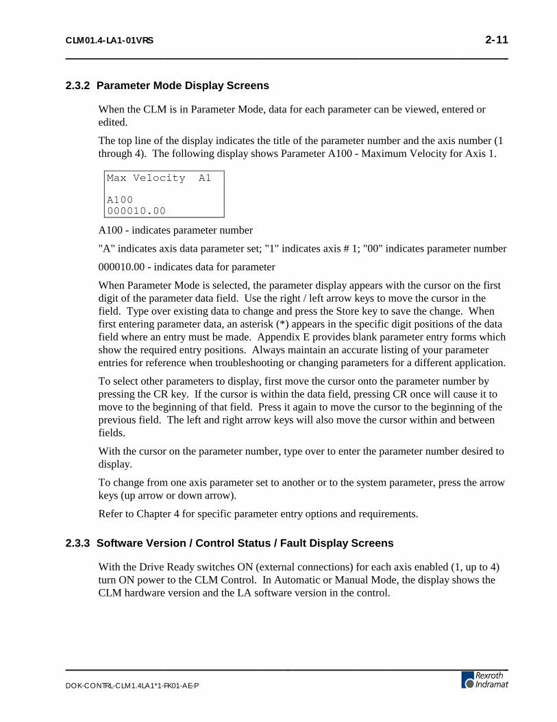
CLM01.4-LA1-01VRS 2-11
DOK-CONTRL-CLM1.4LA1*1-FK01-AE-P
2.3.2 Parameter Mode Display Screens
When the CLM is in Parameter Mode, data for each parameter can be viewed, entered oredited.
The top line of the display indicates the title of the parameter number and the axis number (1through 4). The following display shows Parameter A100 - Maximum Velocity for Axis 1.
Max Velocity A1
A100000010.00
A100 - indicates parameter number
"A" indicates axis data parameter set; "1" indicates axis # 1; "00" indicates parameter number
000010.00 - indicates data for parameter
When Parameter Mode is selected, the parameter display appears with the cursor on the firstdigit of the parameter data field. Use the right / left arrow keys to move the cursor in thefield. Type over existing data to change and press the Store key to save the change. Whenfirst entering parameter data, an asterisk (*) appears in the specific digit positions of the datafield where an entry must be made. Appendix E provides blank parameter entry forms whichshow the required entry positions. Always maintain an accurate listing of your parameterentries for reference when troubleshooting or changing parameters for a different application.
To select other parameters to display, first move the cursor onto the parameter number bypressing the CR key. If the cursor is within the data field, pressing CR once will cause it tomove to the beginning of that field. Press it again to move the cursor to the beginning of theprevious field. The left and right arrow keys will also move the cursor within and betweenfields.
With the cursor on the parameter number, type over to enter the parameter number desired todisplay.
To change from one axis parameter set to another or to the system parameter, press the arrowkeys (up arrow or down arrow).
Refer to Chapter 4 for specific parameter entry options and requirements.
2.3.3 Software Version / Control Status / Fault Display Screens
With the Drive Ready switches ON (external connections) for each axis enabled (1, up to 4)turn ON power to the CLM Control. In Automatic or Manual Mode, the display shows theCLM hardware version and the LA software version in the control.

2-12 CLM01.4-LA1-01VRS
DOK-CONTRL-CLM1.4LA1*1-FK01-AE-P
CLM-01.3-A-0-4
CLM1.3-LA1-04VRS
Figure 2-18 Software Display
CLM-01.3-A-0-4 - indicates hardware type
CLM1.3-LA1-04VRS - indicates software version
Use the right / left arrow keys to toggle between the Software Version screen and the ControlStatus screen. This screen shows the status of the control. In the example below, AutomaticMode is selected (A:), but Cycle Start has not been pressed to start automatic operation.
A: No Cycl Start
If a hard or soft fault occurs, control function stops and a diagnostic message appears on thedisplay. If a fault is present at power ON, a diagnostic status message appears first (insteadof the software version). It is in the status display screen. Pressing the right arrow key willcause the software version to display. See Chapter 8 for diagnostic messages andtroubleshooting procedures.
EMERGENCY STOP EMERGENCY STOP
Figure 2-19 Example Fault Status Display

CLM01.4-LA1-01VRS 2-13
DOK-CONTRL-CLM1.4LA1*1-FK01-AE-P
2.3.4 System I/O Display Screens
System I/O Display screens show the status of each system and auxiliary input and output.The status of a block of 16 inputs or outputs display on a screen at a time. These displays arehelpful to verify wiring during start-up or troubleshooting. They also provide a quicksummary of system status during normal operation.
System Inputs.11.111.........
⇔
System Inp. A3/41..1..
⇔
CLM Inputs 01-16.....1.......11.
etc.
etc.
CLM Inputs 97-9911.
Figure 2-20 System I/O Display Screens

2-14 CLM01.4-LA1-01VRS
DOK-CONTRL-CLM1.4LA1*1-FK01-AE-P
System Outputs.1.111111.......
⇔
System Outp.A3/41.1.
⇔
CLM Output 01-16..1.1......1....
etc.
etc.
CLM Output 97-99..1
Figure 2-21 System I/O Display Screens (cont’d.)
The status of each of the 16 input or output signal lines on a screen are represented by acharacter in the bottom row of the display. A Low signal (0 volts) is represented by adecimal (.). A High signal (+24 volts) is indicated by a one (1). The signal lines count fromleft to right on the display (1-16, 17-32, etc.).
24 System Inputs and 18 System Outputs have a fixed or pre-defined function for the CLM.The first 16 lines of connector X3 (input) and X4 (output) are dedicated for functions likemode selection and acknowledgment, cycle start, jog forward/reverse for axis 1 and 2, etc.The first 8 lines of connector X22 are dedicated for functions like jog forward/reverse, driveready, etc. for axis 3 and 4. Chapter 3 provides a functional description for each of these I/Oconnections. Table 2.1 (following this section) provides a legend of the I/O signal functionfor each I/O display screen, and the corresponding connector for hardware I/O connections.

CLM01.4-LA1-01VRS 2-15
DOK-CONTRL-CLM1.4LA1*1-FK01-AE-P
Auxiliary I/O connections are user definable and programmable. The numbers "1-16" in thetop row of the display indicates the 16 lines designated auxiliary of connector X3 (input) orX4 (output), that are being monitored on the Standard CLM. The Expanded CLM providesadditional I/O hardware connections. With either the Standard or Expanded CLM, theseoutput points above the auxiliary connections (hardware), can be programmed as softwareflags. Certain output flags are set in firmware and can be queried by the user program.Chapter 5 defines the restrictions and use of these auxiliary outputs as software flags.
Table 2-1 I/O Signal Display Legend
Display/Position Signal Description Connector pin #
System Inputs
1 Parameter Mode Select X3- 1
2 Automatic Mode Select 2
3 Emergency Stop 3
4 Cycle Start 4
5 Cycle Stop 5
6 Axis #1 Drive (Amp) Ready 6
7 Axis #2 Drive (Amp) Ready 7
8 Clear 8
9 Axis #1 Jog Forward 9
10 Axis #1 Jog Reverse 10
11 Axis #2 Jog Forward 11
12 Axis #2 Jog Reverse 12
13 not currently defined 13
14 not currently defined 14
15 Execute Restart Vector 15
16 High Speed Interrupt 16
System Inputs, A3/A4
1 Axis #3 Drive (Amp) Ready X22-1
2 Axis #3 Jog Forward 2
3 Axis #3 Jog Reverse 3
4 Axis #4 Drive (Amp) Ready 4
5 Axis #4 Jog Forward 5
6 Axis #4 Jog Reverse 6
Auxiliary Inputs 01-16
01 user defined X3-17
through through
16 user defined 32
Auxiliary Inputs 17-32 (Use requires Expanded I/O option)

2-16 CLM01.4-LA1-01VRS
DOK-CONTRL-CLM1.4LA1*1-FK01-AE-P
Display/Position Signal Description Connector pin #
17 user defined X11-1
through through
32 user defined 16
Auxiliary Inputs 33-48 (Use requires Expanded I/O option)
33 user defined X11-17
through through
48 user defined 32
Auxiliary Inputs 49-64 (Use requires Expanded I/O option)
49 user defined X12-1
through through
64 user defined 16
Auxiliary Inputs 65-80 (Use requires Expanded I/O option)
65 user defined X12-17
through through
80 user defined 32
Auxiliary Inputs 81-88
81 user defined X22-9
through through
88 user defined 16
Auxiliary Inputs 98 & 99 (System Defined Use)
98 High Speed Input (future use) X22-7
99 High Speed Input (future use) 8
System Outputs
1 Manual Mode Indicator X4-1
2 Automatic Mode Indicator 2
3 Parameter Mode Indicator 3
4 Axis #1 Drive (RF) Enable 4
5 Axis #1 Brake Release 5
6 System Fault Indicator 6
7 Axis #2 Drive (RF) Enable 7
8 Axis #2 Brake Release 8
9 Restart Possible 9
10 Auto Cycle Running 10
11 - 14 not currently defined 11-14
15 Axis #3 Drive (RF) Enable 15
16 Axis #4 Drive (RF) Enable 16

CLM01.4-LA1-01VRS 2-17
DOK-CONTRL-CLM1.4LA1*1-FK01-AE-P
Display/Position Signal Description Connector pin #
System Outputs, A3/A4
1 Axis #3 Drive (RF) Ready X19-6
2 Axis #3 Brake Release X22-17
3 Axis #4 Drive (RF) Ready X19-7
4 Axis #4 Brake Release X22-18
Auxiliary Output 01-16
01 user defined X4-17
through through
16 user defined 32
Auxiliary Output 17-32 (Requires Expanded I/O option, see Table 5.1 inChapter 5 for restrictions and use as software flags)
17 user defined X13-1
through through
32 user defined 16
Auxiliary Output 33-48 (Requires Expanded I/O option, see Table 5.1 inChapter 5)
33 user defined X13-17
through through
48 user defined 32
Auxiliary Output 49-64 (See Table 5.1 in Chapter 5 for use as software flag)
49, 50, 51 user defined X22-19 through21
52 - 64 user defined as software flag
Auxiliary Output 65-80 (See Table 5.1 in Chapter 5 for use as software flags)
65 user defined as software flag
through
80 user defined as software flag
Auxiliary Output 81-88 (See Table 5.1 for use as software flags)
81 user defined as software flag
through
88 user defined as software flag
Auxiliary Output 89-99 (See Table 5.1 for specific use and warnings)
89 - 94 function set in firmware as follows:
89 1 indicates Manual Mode
90 1 indicates Automatic Mode
91 not currently defined/used
92 not currently defined/used

2-18 CLM01.4-LA1-01VRS
DOK-CONTRL-CLM1.4LA1*1-FK01-AE-P
Display/Position Signal Description Connector pin #
93 not currently defined/used
94 0 indicates a system Fault
95-99 function set in user program toprovide specific function, as follows:
95 Monitoring Window, Axis 1 turned:OFF=1, ON=0
96 Monitoring Window, Axis 2 turned:OFF=1, ON=0
97 not currently defined/used
98 1=Axis 1 motion is interrupted
99 1=Axis 2 motion is interrupted

CLM01.4-LA1-01VRS 2-19
DOK-CONTRL-CLM1.4LA1*1-FK01-AE-P
2.3.5 Counter Display Screen
The Counter display screen shows the status of the counter now executing in the selectedblock number. Any counter programmed in blocks 0000-2999 can be monitored using thisdisplay mode.
C _0123 Counter 123456 456789
Table 2-2 Counter Display:
C indicates counter display
0123 indicates block number of counter
123456 actual number of counts
456789 preset number of counts
Use the right arrow to move the cursor on the first digit of the block number. Enter a numberfor another block to select that block number counter information to display. The second linedisplays the current values of the counter. To scroll to the next or previous block with acounter, use the + , - keys. To leave the counter display mode, use the up or down arrowkeys.
A counter can be programmed (see Chapter 5, BAC or COU command) to execute “X”number of parts then stop, and turn ON a light, etc. Count is maintained during shut-down,so the actual manufacturing process can be over several days. Counters can also be used tokeep track of production.
NOTE: The actual count will be maintained by battery backup, even when power is turned OFF.
2.3.6 Axis Position Display Screen
Pressing the right arrow key from the Current Position screen causes display of the PositionLag screen. Continue pressing the right arrow key to display the Remaining Feed and ActualSpeed RPM display screens. The "L" in the top row of the display indicates Axes PositionDisplay mode. The "S" , "P" , or "R" after the "L" indicates the Lag (S), the Current Position(P) or Remaining Feed (R) display screen respectively.
The values on these screens keep changing as they display the actual current information foreach axis. Each display screen is further described below. See following section 2.3.6.5 forchanges in displays when the Measuring Wheel option is enabled.

2-20 CLM01.4-LA1-01VRS
DOK-CONTRL-CLM1.4LA1*1-FK01-AE-P
2.3.6.1 Current Axis Position Display Screen
L P 1A+00000.000 2A+00000.000 3A+00000.000 4A+00000.000
Table 2-3 Current Position Display
L indicates axis position display mode
P indicates axis current position screen
1A, 2A, 3A, 4A designation of axis (the ’A’ will only appear after the axis has been homed)
+00100.000 indicates direction of travel (+/-) and actual position of indicated axis (1, 2, 3 or 4) inInput Units
The position values displayed can be cleared by pressing the CR key (if the axis has not beenhomed).
2.3.6.2 Axis Position Lag Display Screen
L S 1A+00000.000 2A+00000.000 3A+00000.000 4A+00000.000
Table 2-4 Position Lag Display
L indicates axis position display mode
S indicates axis position deviation screen
1A, 2A, 3A, 4A designation of axis (the ’A’ will only appear after the axis has been homed)
+00000.000 deviation between commanded position and actual axis position in Input Units.
When an axis is in motion, the value displayed here is also known as "following error". Thisvalue is directly proportional to the velocity command output to the amplifier. The higher thespeed, the higher the following error. This value is zero only when the drive is in position.An excess following error (limits set by parameter) due to binds in the system, etc. will causea fault condition.

CLM01.4-LA1-01VRS 2-21
DOK-CONTRL-CLM1.4LA1*1-FK01-AE-P
2.3.6.3 Axis Remaining Feed Display Screen
L R 1A+00000.000 2A+00000.000 3A+00000.000 4A+00000.000
Table 2-5 Remaining Feed Display
L indicates axis position display mode
R indicates axis remaining feed screen
1A, 2A, 3A, 4A designation of axis (the ’A’ will only appear after the axis has been homed)
+00000.000 difference between the commanded feed length and current actual axis position inInput Units.
The value displayed here is the feed length remaining before the axis reaches the commandedfeed length target position (including any programmed alteration [+/-] to the normal feeddistance).
2.3.6.4 Actual Speed/RPM Display Screen
Act. Speed RPM1: 0000 2: 00003: 0000 4: 0000
Table 2-6 Actual Speed Display
+0000.00 - Direction (+/-) and actual speed (RPM) of the axis.
The actual speed displays for each axis. The second line of the display shows information foraxis 1, then axis 2. The third line shows information for axis 3, then axis 4.
2.3.6.5 LP/LS Display Screens with Measuring Wheel
When the Measuring Wheel option is selected, only axis 1 and 2 may be enabled. The ActualPosition and Position Lag screen are expanded beyond the normal 2-axis display, asillustrated below.
L P 1A+00059.990 2 +00012.690---------------- P 1 +00059.870
Table 2-7 Current Position Display
line 1 position axis 1 (all MW movements are used)
line 4 position motor encoder 1
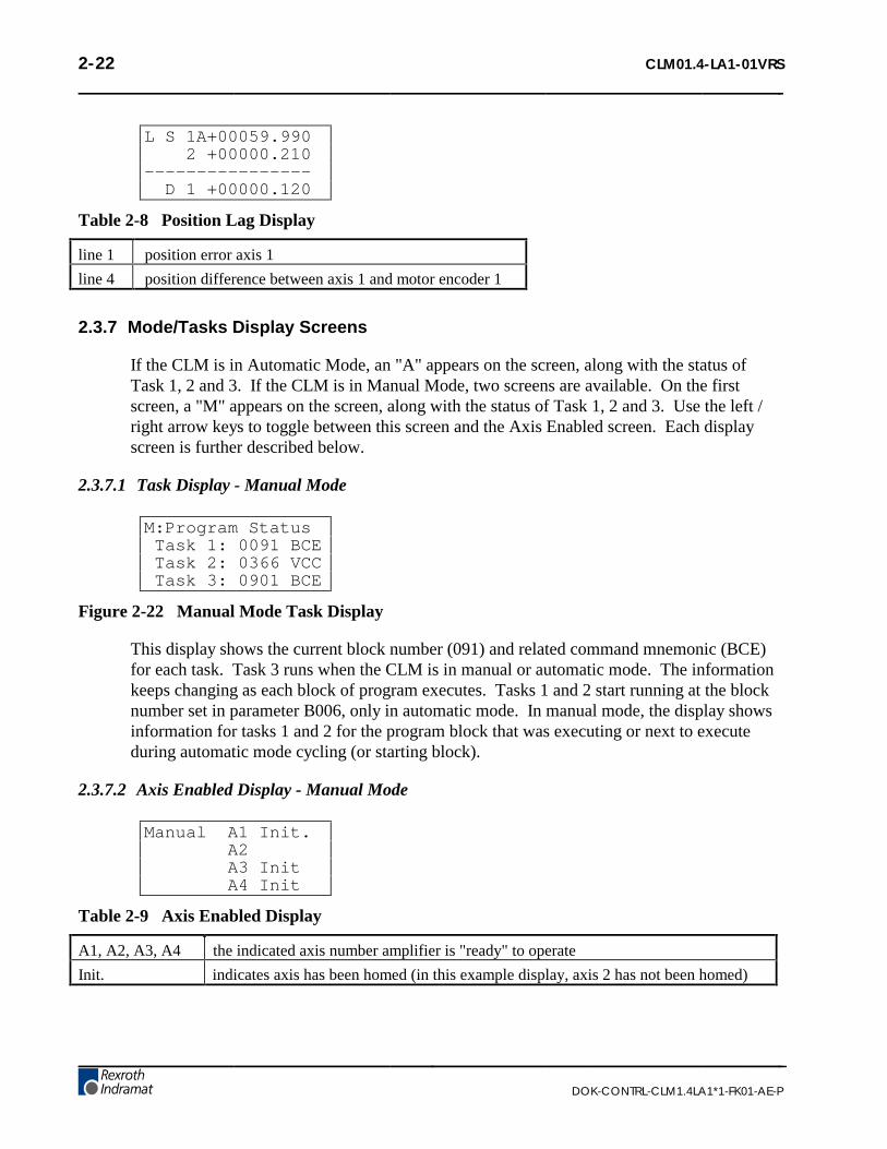
2-22 CLM01.4-LA1-01VRS
DOK-CONTRL-CLM1.4LA1*1-FK01-AE-P
L S 1A+00059.990 2 +00000.210---------------- D 1 +00000.120
Table 2-8 Position Lag Display
line 1 position error axis 1
line 4 position difference between axis 1 and motor encoder 1
2.3.7 Mode/Tasks Display Screens
If the CLM is in Automatic Mode, an "A" appears on the screen, along with the status ofTask 1, 2 and 3. If the CLM is in Manual Mode, two screens are available. On the firstscreen, a "M" appears on the screen, along with the status of Task 1, 2 and 3. Use the left /right arrow keys to toggle between this screen and the Axis Enabled screen. Each displayscreen is further described below.
2.3.7.1 Task Display - Manual Mode
M:Program Status Task 1: 0091 BCE Task 2: 0366 VCC Task 3: 0901 BCE
Figure 2-22 Manual Mode Task Display
This display shows the current block number (091) and related command mnemonic (BCE)for each task. Task 3 runs when the CLM is in manual or automatic mode. The informationkeeps changing as each block of program executes. Tasks 1 and 2 start running at the blocknumber set in parameter B006, only in automatic mode. In manual mode, the display showsinformation for tasks 1 and 2 for the program block that was executing or next to executeduring automatic mode cycling (or starting block).
2.3.7.2 Axis Enabled Display - Manual Mode
Manual A1 Init. A2 A3 Init A4 Init
Table 2-9 Axis Enabled Display
A1, A2, A3, A4 the indicated axis number amplifier is "ready" to operate
Init. indicates axis has been homed (in this example display, axis 2 has not been homed)

CLM01.4-LA1-01VRS 2-23
DOK-CONTRL-CLM1.4LA1*1-FK01-AE-P
2.3.7.3 Task Display - Automatic
A:Program Status Task 1: 0091 BCE Task 2: 0366 VCC Task 3: 0901 BCE
Figure 2-23 Automatic Mode Task Display
This display shows the current block number, 0091 for Task 1, and related commandmnemonic (BCE) for each task. Task 3 runs when the CLM is in manual or automatic mode.Tasks 1 and 2 start running at the block number set in parameter B006, only in automaticmode.
During automatic operation (after Cycle Start), the information keeps changing as each blockof program executes. If Cycle Stop signal goes low (switch is pressed), the driveimmediately stops and the display shows information for the program block that wasexecuting or just about to execute.
2.3.8 Edit Mode Display Screen
Use the Program Edit screen to enter the complete executable program. Also use this screento edit or review an existing program.
E _0096 BCE0200 02 1
Table 2-10 Edit Display
E indicates edit display mode
0096 block number, 0000-2999 is user selectable for edit and review; automatically increments tonext higher number during programming
BCE command mnemonic
0200 02 1 data for the block command
When first scrolling to this screen, a flashing cursor appears in the home position (thirdposition from left in the first line). As with other display screens which include a cursor,press the left or right arrow keys to move the cursor within the screen. Also, press the CRkey to move the cursor to the first digit position of a data field. Press CR again to move thecursor to the first position of the previous field. Continue pressing the CR key until thecursor is in home position or over the left digit of the block number, before using theup/down arrow keys to scroll to different display screens.

2-24 CLM01.4-LA1-01VRS
DOK-CONTRL-CLM1.4LA1*1-FK01-AE-P
To select different program blocks of information to display (for review or edit), press theright/left arrow keys to position the cursor over the first digit of the block number and typeover the existing block number. Command and data for this selected block will then appear.To scroll through the block numbers, press the CR key to locate the cursor in the top line,then use the + or - key to scroll through the blocks (with previous version software, thecursor must be to the left of the block number - home position). The block number willincrease or decrease accordingly and display the respective data for each block.
To enter program, start at block "0000" for task 1. Note that task 2 and task 3 program startsat the block number assigned by the user in parameter B006. If block "0000" is notdisplayed, press the right arrow key one time from home position to move the cursor on thefirst digit of the block number. Type the number "0000" to display that block number.
To enter or change a program command for each block, first press the right arrow key untilthe cursor moves to the right of the three digit program command mnemonic (i.e. NOP_).Press the up or down arrow keys to increment or decrement through the commandsalphabetically. When the desired command appears on the screen, press the right arrow key.The cursor moves to the beginning of the second line where the data fields appear specificallyfor the selected command. If this block was not previously programmed with this samecommand, asterisks (*) appear in the digit positions where data must be entered. Afterentering and verifying the program, press the Store key to save the programmed block tomemory. The next program block number automatically appears, waiting to be programmed.Continue this process until all lines of user program are done. Note that the program can beedited or added to at a later time.
When changing data from the Edit display screen, pressing the CR key before pressing theStore key, will cancel the change and leave the data as previously stored (saved). The displayremains at the same block number and the cursor moves to the first position of the previousfield. Changing to another block number, display screen, etc. without first pressing the Storekey also causes loss of a change to a block’s data.
Chapter 5 provides the information on commands required for creating the user executableprogram.
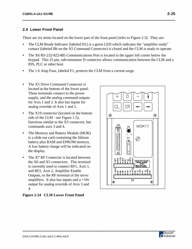
CLM01.4-LA1-01VRS 2-25
DOK-CONTRL-CLM1.4LA1*1-FK01-AE-P
2.4 Lower Front Panel
There are six items located on the lower part of the front panel (refer to Figure 2.3). They are:
• The CLM Ready Indicator (labeled H1) is a green LED which indicates the "amplifier ready"contact (labeled Bb on the X5 Command Connector) is closed and the CLM is ready to operate.
• The X6 RS-232/422/485 Communications Port is located in the upper left corner below thekeypad. This 25 pin, sub-miniature D connector allows communication between the CLM and aIDS, PLC or other host.
• The 1.6 Amp Fuse, labeled F1, protects the CLM from a current surge.
• The X5 Drive Command Connector islocated at the bottom of the lower panel.These terminals connect to the powersupply, and the analog command outputsfor Axis 1 and 2. It also has inputs foranalog override of Axis 1 and 2.
• The X19 connector (located on the bottomside of the CLM - see Figure 1.5),functions similar to the X5 connector, butcommands axes 3 and 4.
• The Memory and Battery Module (MOK)is a slide out card containing the lithiumbattery plus RAM and EPROM memory.A low battery charge will be indicated onthe display.
• The X7 RF Connector is located betweenthe X6 and X5 connectors. This terminalis currently used to connect RF1, Axis 1,and RF2, Axis 2, Amplifier EnableOutputs, to the RF terminal of the servoamplifiers. It also has inputs and a +10voutput for analog override of Axis 3 and4.
Figure 2-24 CLM Lower Front Panel

2-26 CLM01.4-LA1-01VRS
DOK-CONTRL-CLM1.4LA1*1-FK01-AE-P

CLM01.4-LA1-01VRS 3-1
DOK-CONTRL-CLM1.4LA1*1-FK01-AE-P
3. FUNCTIONAL DESCRIPTION OF I/O CONNECTIONS
The CLM motion control system is designed to function harmoniously within the machine builder’sequipment design. Several input / output signals of the CLM control provide communication to /from the other components of the machine builder’s equipment. This chapter describes thefunctional operation of the interfacing inputs and outputs of the CLM.
The first sections of this chapter describe the various interface functions in terms of the inputs /outputs involved with each. This includes the pre-defined I/O connections of the CLM, as well ascertain functions which the user can select through parameter or programming, using auxiliary I/Oconnections. Certain auxiliary output functions are set in firmware, as described in Chapter 5 foruser programming.
This first section is followed by an individual description of each pre-defined I/O signal, includingname, pin assignments, and functional description. The designer utilizes these signals as necessaryto implement the CLM for his application, including the design of his system control panel.
3.1 Signal Definitions
The states of the input and output signals described in this manual are:
• High = +24 Vdc
• Low = 0 Vdc
A signal line is described as "active high" when its associated action is initiated by a high (+24 Vdc)signal level. It is described as "active low" when its function is initiated by a low signal (0 volts).Active low signals are shown in this manual (when specifically referred to as a signal) with a bar
(line) over the signal name, as an example, Emergency Stop . This signal must be high duringnormal operation. If it goes low, the CLM initiates the actions required for an emergency stopfunction.

3-2 CLM01.4-LA1-01VRS
DOK-CONTRL-CLM1.4LA1*1-FK01-AE-P
3.2 Interface Descriptions
The CLM input and output signals provide communication to/from the machine builder’s equipment.Certain I/O signals should be considered as functional groups of signals, working in concert.
These functions include:
• Operating Mode Selection
• Servo System Operation Enables
• Safety Interlocks
• Normal Operation Signals
• Axis Homing
• Manual Operations
• Fault/Diagnostic Circuitry
• Feed Monitoring / Program Interruption
• Special Functions
Figures 3.1, 3.2 and 3.3 illustrate the X3 Input, X4 Output and X22 Input/Output connectors andeach pin designation.
The following sections describe each group of interface functions, first listing the I/O signalsinvolved (and section where each signal is individually described), then describing the generalfunction of the signals.

CLM01.4-LA1-01VRS 3-3
DOK-CONTRL-CLM1.4LA1*1-FK01-AE-P
Figure 3-1 X3 Input Connector and Pin Designations

3-4 CLM01.4-LA1-01VRS
DOK-CONTRL-CLM1.4LA1*1-FK01-AE-P
Figure 3-2 X4 Output Connector and Pin Designations
Figure 3-3 X22 Input/Output Connector and Pin Designations

CLM01.4-LA1-01VRS 3-5
DOK-CONTRL-CLM1.4LA1*1-FK01-AE-P
3.2.1 Operating Mode Selection
InputsParameter Mode Select (3.3.1)
Automatic Mode Select (3.3.2)
OutputsManual Mode Indicator (3.4.1)
Auto Mode Indicator (3.4.2)
Parameter Mode Indicator (3.4.3)
The CLM will always be in one of three operating modes:
Parameter Mode Allows entry/verification of the parameters required to adapt the control for the specificrequirements of the application.
Automatic Mode Runs the user written executable program for automatic cycle operation (process 1 and 2run after a Cycle Start input).
Manual Mode Default mode when neither of the above are selected. In this mode, use the jog inputs tomove the material forward or reverse through the system.
Parameter and Automatic Modes are selected by bringing the appropriate signal line high(+24 Vdc). A fault is diagnosed and an "Invalid Mode Selection" error message is issued ifboth Automatic and Parameter Mode signal lines are high simultaneously.
The suggested interface design is to wire the Parameter Mode signal to a key-switch, where akey is required to enter Parameter Mode and/or mount the switch inside the cabinet. Thishelps to prevent unauthorized parameter changes. Wire the Automatic Mode input signal to atwo-position selector switch, where Manual Mode is selected when the switch is set to anopen contact position.
The CLM has outputs to verify or acknowledge the currently selected mode. These aretypically wired to indicator lights on the user’s control panel or to a PLC.

3-6 CLM01.4-LA1-01VRS
DOK-CONTRL-CLM1.4LA1*1-FK01-AE-P
3.2.2 Servo System Operation Enables
InputsAxis 1 Amplifier Ready (3.3.6)
Axis 2 Amplifier Ready (3.3.6)
Axis 3 Amplifier Ready (3.3.6)
Axis 4 Amplifier Ready (3.3.6)
OutputsAxis 1 Amplifier Enable (3.4.4)
Axis 1 Brake Release (3.4.5)
Axis 2 Amplifier Enable (3.4.4)
Axis 2 Brake Release (3.4.5)
Axis 3 Amplifier Enable (3.4.4)
Axis 3 Brake Release (3.4.5)
Axis 4 Amplifier Enable (3.4.4)
Axis 4 Brake Release (3.4.5)
The CLM is designed so that various conditions must be satisfied to allow the servos tooperate. If these conditions are not satisfied, the appropriate diagnostic message is displayed.
When the system is powered up, the CLM expects to receive Amplifier Ready inputs for eachaxis (#1 through #4) that has been enabled in parameters B000-B003, indicating the servoamplifiers and power supply have properly powered up and the amplifiers are ready for anEnable signal.
Assuming conditions are appropriate for operation, the CLM issues axis #1 through #4Amplifier Enable outputs to allow the amplifier to operate and axis #1 through #4 BrakeRelease outputs to lift the spring-loaded servomotor brake (if using motor versions wherebrake is present).

CLM01.4-LA1-01VRS 3-7
DOK-CONTRL-CLM1.4LA1*1-FK01-AE-P
3.2.3 Safety Interlocks
InputsEmergency Stop (3.3.3)
Motor Overtemp
Outputs
System Fault Indicator (3.4.6)
As described in the previous section, the CLM and its servos must perform operationalchecks and provide the proper signals to enable operation. There are other signals whichserve as interlocks.
Emergency Stop -- The Emergency Stop input must remain high for the CLM to operate.The system incorporates an Emergency Stop (E-Stop) chain. This is a circuit connected inseries to both the CLM and the user’s machine. Should any sensor in the E-stop chain open,all operations immediately stop. Note that the time taken to stop depends on the wiringmethod used, and inertia of the load connected to the servo motor on the machine.
Elements connected in the E-stop chain commonly include the Emergency Stop switch onthe user’s control panel; E-stop switch(es) on the machine; switches on lubrication or coolantpumps; and various safety interlock switches on guards and doors.
Motor Overtemp -- The thermally activated switch (TAS) of an Indramat MAC servomotoris typically connected to the respective Drive Ready input through a relay (to provideisolation for the motor power cable). If a motor overheats, the TAS opens and drops the +24Vdc signal (de-energizing the relay, opening the Drive Ready input line). The "Drive NotReady" diagnostic message is displayed and the system is halted. Although not a direct inputto the CLM, this TAS circuit is important for servo motor protection.
There are several categories of faults, as described in Chapter 8. In general, once a fault is
detected, an error message is displayed on the CLM display, the System Fault Indicatoroutput turns OFF and all axes are decelerated to a stop.
The fault recovery procedure is to first troubleshoot and remedy the problem. Then, press theClear key on the CLM control panel (or external Clear input on user control panel, seesection 3.2.7) to clear the CLM fault status and diagnostic message on the display.

3-8 CLM01.4-LA1-01VRS
DOK-CONTRL-CLM1.4LA1*1-FK01-AE-P
3.2.4 Normal Operation Signals
InputsCycle Start (3.3.4)
Cycle Stop (3.3.5)
OutputsAxis Nearing Position (Pre Signal) (Ax07)
Axis In-Position (Ax06)
The automatic execution of the user program begins when the Cycle Start line goes high(momentary) with the CLM in Automatic Mode. Once the automatic cycle begins, it isnormally stopped by actuating the Cycle Stop input (signal goes low). The system will alsostop if an error is detected or if the CLM is switched to Manual Mode.
An auxiliary output can be assigned for each axis in parameters Ax07 (Position Pre-signal) toturn ON when the feed axis position is at a specified distance (in input units) from the targetposition of the commanded feed. Use this pre-signal when there is a need to anticipate theend of a feed, so another process can be initiated ahead of time. An example use would be toturn on a heater for bag sealing or plastic thermal forming operations. See Chapter 4 forfurther information on this parameter function.
NOTE: As described in Chapter 4, an "A" parameter set is provided for each axis (1 through 4).The first number after the "A" determines the axis number. Throughout this manual, when referringto an "A" parameter that effects all axes, an "x" is used in the second position to indicate 1, 2, 3,and/or 4.
An auxiliary output (Axis In-Position) can be assigned for each axis in parameters Ax06 toturn ON when the feed axis position is within the position threshold specified in theparameter. This position threshold does not affect the accuracy of the feed. It tells theprogram when to read the next program block (see PSI, PSA in Chapter 5). This output canbe used to turn ON a light or buzzer on the user’s control panel, or as a flag in the program tostart a sub-routine program operation, etc. See Chapter 4 for further information on thisparameter function.

CLM01.4-LA1-01VRS 3-9
DOK-CONTRL-CLM1.4LA1*1-FK01-AE-P
3.2.5 Axis Homing
InputsInitiate Homing in Manual Mode
Home Switch
OutputsHome Established Indicator
For absolute referencing of the axis with an incremental encoder, it is necessary to establish acorrect measurement reference with the help of a homing routine. To initiate homing duringmanual operation, use auxiliary input signals (as defined in parameter Ax12); duringautomatic operation, by use of the "HOM" command.
Auxiliary inputs (Initiate Homing) can be assigned for each axis in parameters Ax12 toinitiate the homing process in Manual Mode by a push-button switch or from a PLC output.Home position can be set to an Incremental Encoder marker pulse, or to a Home Switch(assign an auxiliary input for the home switch in parameter).
Homing each axis in Automatic Mode is accomplished through use of the HOM command(when using an incremental encoder). After reading in this command for one axis, the nextblock is read in with the same command for the second axis, allowing the homing procedureto occur simultaneously for both axes. Use an ATS command to monitor the HomeEstablished auxiliary output (as set in parameter Ax12) to prevent reading any AbsolutePosition commands (POA, PSA) until the home procedure is finished.
3.2.5.1 Homing Procedure--Refer to Figure 3.4
1. Homing command is issued.
2. If the slide is not on the Home Limit switch, it moves in "reverse" at the Velocity 1 (V1)speed (set in Ax10) toward home until the switch closes. It will then decelerate, reversedirection and move "forward" at V2 speed (25% of V1) until the switch opens. If theslide is already on the switch when the command is issued, it moves forward off theswitch at V2 speed.
NOTE: For any amount of travel that exists in the minus direction of the home switch point, thehome switch must remain closed. The home switch dog must be at least as long as the reverse traveldistance from the home switch.
3. The axis decelerates, reverses direction and creeps in the "reverse" direction at V3 speed(5000 pulses/second) passing and closing the Home Limit switch, and continues in the"reverse" direction at a super creep rate until the zero (or marker) pulse of the encoderoccurs.
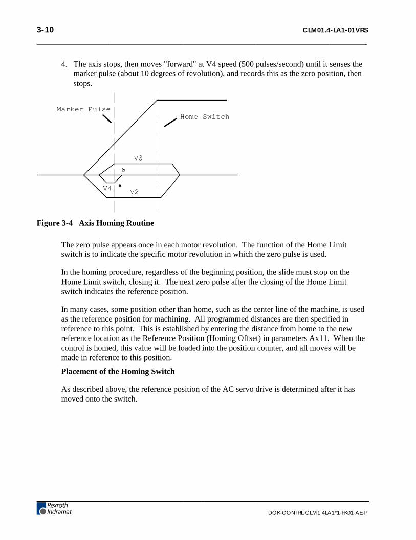
3-10 CLM01.4-LA1-01VRS
DOK-CONTRL-CLM1.4LA1*1-FK01-AE-P
4. The axis stops, then moves "forward" at V4 speed (500 pulses/second) until it senses themarker pulse (about 10 degrees of revolution), and records this as the zero position, thenstops.
Marker PulseHome Switch
V3
V4 V2
b
a
Figure 3-4 Axis Homing Routine
The zero pulse appears once in each motor revolution. The function of the Home Limitswitch is to indicate the specific motor revolution in which the zero pulse is used.
In the homing procedure, regardless of the beginning position, the slide must stop on theHome Limit switch, closing it. The next zero pulse after the closing of the Home Limitswitch indicates the reference position.
In many cases, some position other than home, such as the center line of the machine, is usedas the reference position for machining. All programmed distances are then specified inreference to this point. This is established by entering the distance from home to the newreference location as the Reference Position (Homing Offset) in parameters Ax11. When thecontrol is homed, this value will be loaded into the position counter, and all moves will bemade in reference to this position.
Placement of the Homing Switch
As described above, the reference position of the AC servo drive is determined after it hasmoved onto the switch.

CLM01.4-LA1-01VRS 3-11
DOK-CONTRL-CLM1.4LA1*1-FK01-AE-P
The reference position can be set in steps of one motor revolution each, by using the positionthe switch is in when it is activated. By monitoring the switching point of the homing switchand the marker pulse, a CLM diagnostic check eliminates the danger that these two are soclose to each other that the switching tolerance limits will result in uncertainty about themotor revolution to be evaluated. If the switching point of the homing switch is closer than1/16 of a motor revolution, with respect to the marker pulse, the control unit will notcomplete the homing process, and will change over to fault indication. The display willshow: Marker Pulse 1? (or 2, 3, or 4, depending on the axis affected). The homing switchshould be relocated by 1/3 of the feed constant.
Activating the Homing Switch
Activating the homing switch must be done in such a way that the switch closes uponbacking up, i.e. upon the movement away from the work piece. The dog cam for activatingthe homing switch must be long enough so that the activation is not canceled by a continuingreverse movement up to the minus travel limit of the axis. This is required to indicate to thecontrol unit in which direction the slide must be moved in order to approach the referenceposition.
Since the interrelationship between the direction of rotation of a servo motor and themovement away from, and toward, the work piece depends on the particular design of themachine, the homing direction must be also set correctly in the parameters.
If there is no marker pulse from the encoder within one revolution of the encoder, homingsequence is halted, and a fault is displayed. The display will show: "No Marker Pulse 1" (or2, 3, 4 - affected axis).
Interruption of the Homing Routine
If, while in manual operation, there is a stop, an interruption, feed angle monitoring, or aswitch of operating modes, the homing cycle is interrupted and must be restarted. After aninterruption or stop occurs while in automatic operation, the homing cycle is restartedimmediately by activating the Cycle Start input. After a fault or a change of operating modesduring the homing cycle, the CLM must be re-initiated (switch to Auto Mode, press CycleStart).
Over-travel Switches
It is recommended that you install forward and reverse over-travel switches on applicationsthat have limited axis travel, such as a slide or a ballscrew driven axis. The switches can bewired either to the "drives ON" circuit or to the Cycle Stop input of the CLM. See appendixF for recommended interconnection. You must reserve distance beyond the limit switches toallow for deceleration of the axis to a stop.

3-12 CLM01.4-LA1-01VRS
DOK-CONTRL-CLM1.4LA1*1-FK01-AE-P
3.2.6 Manual Operations
InputsJog Forward (Axis 1) (3.3.8)
Jog Reverse (Axis 1) (3.3.9)
Jog Forward (Axis 2) (3.3.8)
Jog Reverse (Axis 2) (3.3.9)
Jog Forward (Axis 3) (3.3.8)
Jog Reverse (Axis 3) (3.3.9)
Jog Forward (Axis 4) (3.3.8)
Jog Reverse (Axis 4) (3.3.9)
Initiate Manual Vector Program
OutputsNone
The CLM’s Jog inputs allow jogging of each axis forward and reverse. Parameter Ax01specifies the jog feed rate for each axis. It usually is set to approximately 10% of themaximum feed rate. It can never be more than the maximum feed rate.
In Manual Mode, either axis can be jogged forward or reverse. The Jog inputs are notfunctional in Parameter or Automatic Modes. A high on the Jog Forward input causes theaxis to feed forward at the velocity set in parameter. The feed continues as long as the JogForward remains high. The Jog Reverse operates similarly, jogging the axis in the reversedirection.
In order to make use of the software travel limits when in Manual Mode, the axis must behomed first. It is recommended to prevent jogging by interlock until home is established forthe axis. The Home Established output (Ax12) can be used for this purpose.
An auxiliary input, Initiate Manual Vector Program, can be assigned in parameter B011and used to initiate a user program to run in Manual Mode. This program may not containany feed instructions and should not be located in the main program. Select by parameter tostart this program by an external input (push-button switch) or automatically when mode ischanged from Automatic to Manual. The program is aborted if switched out of ManualMode. The manual vector is not accepted while jogging or homing in Manual Mode (see lastsection). Jogging or homing is not possible while the manual vector program is running.
An example use of the Manual Vector program is to use the APE command to set the statesof auxiliary outputs. This command is programmed to set a bank/group of ten outputsindividually to ON, OFF or Don’t Care states. This allows setting outputs for a "shut-down"mode, or as default before starting automatic operation. See Chapter 4 for additionalinformation on parameters and Chapter 5 for programming commands.

CLM01.4-LA1-01VRS 3-13
DOK-CONTRL-CLM1.4LA1*1-FK01-AE-P
3.2.7 Fault/Diagnostic Monitoring
InputsClear (External) (3.3.7)
Restart Select (3.3.10)
Outputs
System Fault Indicator (3.4.6)
Restart Possible Indicator (3.4.7)
The CLM includes extensive diagnostic monitoring circuitry, detecting normal operatingstatus, operator errors, errors in the control itself and machine faults.
There are several categories of faults, as described in Chapter 8. In general, once a fault is
detected, an error message is displayed on the CLM display, the System Fault Indicatoroutput turns OFF (turns OFF “System OK” or turns ON “Fault” light, driven by relay, on usercontrol panel) and both axes are decelerated to a stop.
The fault recovery procedure is to first troubleshoot and remedy the problem. Then, press theClear key on the CLM control panel (or external Clear input on user control panel) to clearthe CLM fault status and diagnostic message on the display.
If the user program is interrupted by a power loss, system error or mode change, the status ofoutputs, absolute target position and velocity are temporarily stored in memory. ParameterB014 can be used to define the starting program block for a Restart Vector routine. Based onthe type of error and system configuration, it may be possible to restore the status of the CLMas before the interrupt. This is indicated by the Restart Possible output (ON = restartpossible, OFF = restart not possible). The Restart Vector routine is initiated by a momentaryinput pulse, OFF to ON, from the Restart Select input. The Restart Vector program shouldstart with the RSV command. See Chapter 5 for information on programming commands.See Chapter 4 for further information on this parameter function. Diagnostics and faulttroubleshooting procedures are described in Chapter 8.
3.2.8 Feed Monitoring / Program Interruption
InputsInterrupt Vector Program
Feed Angle, Axis 1
Feed Angle, Axis 2
Feed Interrupt , Axis 1
Feed Interrupt , Axis 2
OutputsNone

3-14 CLM01.4-LA1-01VRS
DOK-CONTRL-CLM1.4LA1*1-FK01-AE-P
An auxiliary input, Interrupt Vector/Program, can be assigned in parameter B012 tointerrupt the user program at any time and start an Interrupt Vector sub-routine program(Automatic Mode only). When this input goes high, the current program sequence will beinterrupted immediately or after the current sub-routine program is finished (option set inparameter). The program sequence will then continue at the start program block numberassigned in the parameter for the Interrupt Vector program. See Chapter 4 for furtherinformation on this parameter function.
An auxiliary input, Feed Angle Monitoring, can be assigned for each axis in parameterAx20 to prevent the program from executing any feed length commands. The CLM willprocess all program blocks not containing any feed lengths. If there is no signal at theassigned input, the program continues to execute until it processes to a block containing afeed length. The CLM will stop in this block until there is a signal at the input. If the inputsignal turns OFF during a feed, the feed will be stopped and an error message will bedisplayed.
An auxiliary input, Feed Interrupt ( Feed Hold ), can be assigned for each axis in parameterAx20 to prevent the program from executing any feed length commands. The CLM willprocess all program blocks not containing any feed lengths. If the input is low, the programcontinues to execute until it processes to a block containing a feed length. The CLM willstop in this block until the assigned input goes high. If the input goes low during a feed, thefeed will be stopped. Feed will automatically resume as soon as the signal goes high.
An example of use for this signal is in conjunction with a material loop. Material is fed from
an uncoiler into a looping pit, with an optical sensor in the pit tied to the Feed Interrupt line.If the material pulls too tight, the signal goes low and the feed cycle is interrupted. As soonas an adequate amount of material is fed into the looping pit, the signal returns high and thefeed cycle immediately resumes. Another example of use for this signal is in conjunctionwith a press type system. For a punch press, this signal would come up shortly after the ramclears the material on its upstroke. The signal would drop (go low) on the ram downstroke,allowing some safety margin before the ram reaches the material. The material feed musthave stopped before this signal drops. See Chapter 4 for further information on thisparameter function.
WARNING: If the automatic cycle is interrupted by a low on the Feed Interrupt line, all feedmotion is suspended. Once this signal is restored high, the feed cycle will immediately resume.The work area should not be entered if the feed has stopped as a result of this signal.

CLM01.4-LA1-01VRS 3-15
DOK-CONTRL-CLM1.4LA1*1-FK01-AE-P
3.2.9 Special Functions
InputsDetect Registration Mark (High Speed) (3.3.11)
Position Loop Reset
Interrupt Vector/Program
Enable Measuring Wheel Operation and Dual Encoder Option
OutputsAcknowledge Roll Lifting Active
Achieved Programmed Velocity
An auxiliary input, Detect Registration Mark, can be assigned in the REF programcommand to cause the CLM to search for a registration or reference mark on the material. Toprovide this input signal, use a sensor which detects a printed mark or stamp on each piece ofmaterial. A high signal must be present on this input when a reference mark is present underthe sensor.
The accuracy and duration of this signal is essential to the proper operation of positioncorrection, especially if the mark needs to be detected at high speeds. Three high speedinputs are provided for this specific purpose. They can detect an input signal of 150microseconds duration, compared to the 2 to 4 milliseconds duration required for otherinputs. Refer to the REF program command in Chapter 5 for additional information on usingthis feature.
For Measuring Wheel operation, set options in parameters Ax23, B016, B017 and B018.These parameters establish the feed rate constant and the number impulses of the measuringwheel encoder. They also allow assigning an auxiliary input for selecting measuring wheel ormotor encoder feedback. During measuring wheel operation, the measurement of lengths isfrom the measuring wheel encoder, rather than the integral motor encoder.
The Dual Encoder Option in parameter Ax23 allows quicker response with measuring wheeloperation. When selected, the position loop is closed using motor encoder feedback and themeasuring wheel encoder provides adjustments to the length during feeding. When thisoption is not selected, the Position Loop is closed using the measuring wheel encoder. Lackof stiffness in the mechanical components between the motor and the wheel can require usinga lower gain, which increases the response time.
During manual operation, the position feedback always comes from the motor encoder.During automatic operation, there is a choice between continuous measuring wheel operationand using an auxiliary input signal to select measuring wheel operation.

3-16 CLM01.4-LA1-01VRS
DOK-CONTRL-CLM1.4LA1*1-FK01-AE-P
The following conditions must be met:
• The material is in the feed rolls and under the measuring wheel
• The feed rolls are closed
• The measuring wheel is pressing against the material
If one of the above conditions is not met, the drive can run temporarily out of control until itis stopped through an internal error detection procedure of the control unit.
Error messages are:
• Encoder Error
• Drive Runaway
If the feed roll has to be lifted in conjunction with the measuring wheel operation, theauxiliary input signal must be used to discontinue the "measuring wheel operation" while theroll is lifted. Care must be taken that the timing is correct during the cycling of the feed rollscontacting and releasing from the material. Refer to Chapter 4 for additional information onthis parameter function.
Auxiliary inputs, Position Loop Reset inputs, can be assigned in parameters Ax15 for eachaxis. This function allows shifting of the incremental position without causing a positionfault. This parameter also allows user assigned auxiliary outputs to indicate when PositionLoop is reset and separately, when the programmed velocity has been achieved. Their aremechanical limitations that must be considered when using this function. Consult a IndramatCLM Application Engineer for additional requirements. Refer to Chapter 4 for additionalinformation on this parameter function.

CLM01.4-LA1-01VRS 3-17
DOK-CONTRL-CLM1.4LA1*1-FK01-AE-P
3.3 Input Signal Descriptions
This section describes the Inputs to the CLM control from external sources. The Input and Outputsignal lines of the CLM are optically isolated from the CLM’s internal bus structure to minimizeelectrical noise interference.
The connectors and pin numbers of these signals are described in the following sections and shownin Figures 3.1 (X3) and 3.3 (X22).
3.3.1 Parameter Mode Select
Connector X3, pin 1
Function (Input) Selects Parameter Mode
+24 Vdc Parameter Mode selected.
0 Vdc Parameter Mode is not selected; another mode is selected or the system has defaulted to theManual Mode.
The Parameter Mode Select will override any other mode selection input. If properly wired,selecting Parameter Mode while Automatic Mode is already selected, does not cause an error.When Parameter Mode is deselected, the CLM returns to the previously selected mode -Automatic or Manual (default when no other modes are selected).
NOTE: Task 3 stops in Parameter Mode.
3.3.2 Automatic Mode Select
Connector X3, pin 2
Function (Input) Selects Automatic Mode
+24 Vdc Automatic Mode selected.
0 Vdc Automatic Mode is not selected; another mode is selected or the system has defaulted to theManual Mode.
If this signal line is high at the same time the Parameter Mode is selected (input high), theCLM issues the "Invalid Mode Selection" diagnostic error message.
NOTE: Task 3 will be running in either Manual or Automatic Mode.

3-18 CLM01.4-LA1-01VRS
DOK-CONTRL-CLM1.4LA1*1-FK01-AE-P
3.3.3 Emergency Stop
Connector X3, pin 3
Function (Input) Commands Motor Drive to immediate stop
+24 Vdc Allows the CLM to operate
0 Vdc The motor drive is commanded immediately to zero velocity. Drive reaches zero speed in theminimum time possible; given the inertia and maximum torque available. The CLM issues an"Emergency Stop" diagnostic message
WARNING: This signal must be used to ensure safety.
Conditions which warrant pressing the E-Stop include:
• Any condition posing an immediate danger to personnel.
• A jam in the machinery or any other condition that poses an immediate harm to thesystem equipment.
3.3.4 Cycle Start
Connector X3, pin 4
Function (Input) Starts automatic feed cycle
+24 Vdc (momentary) Starts the execution of Task 1 and 2 when the CLM is in the Automatic Mode.
0 Vdc Has no effect on the system operation. Once initiated, only a system failure (fault or error), the
presence of the Emergency Stop or Feed Interrupt (or user defined Feed Interrupt ) willhalt the automatic cycle.
This input is typically wired to a normally open push-button switch on the user control panel.
NOTE: Task 3 will be running in either Manual or Automatic Mode.

CLM01.4-LA1-01VRS 3-19
DOK-CONTRL-CLM1.4LA1*1-FK01-AE-P
3.3.5 Cycle Stop
Connector X3, pin 5
Function (Input) Used to stop the automatic cycle
+24 Vdc (Continuous) Allows Automatic Mode operation.
0 Vdc (Momentary) Stops Automatic Mode cycling.
This input is typically wired to a normally closed push-button switch on the user controlpanel.
NOTE: None of the axes can be jogged when this input is low.
3.3.6 Amplifier Ready (Axis #1 through #4)
Connector X3, pin 6 (axis 1)
Connector X3, pin 7 (axis 2)
Connector X22, pin 1 (axis 3)
Connector X22, pin 4 (axis 4)
Function (Input) Informs the CLM that the relevant Axis Amplifier is ready for operation
+24 Vdc relevant Axis Amplifier has power applied and is ready to be enabled.
0 Vdc After power-up, typically indicates either a power loss at the servo power supply or relevantamplifier, or an internal fault in the amplifier.
This input originates at the ready (Bb) contact of the relevant servo amplifier. Chapter 6describes these connections, as required for installation.
3.3.7 Clear (External)
Connector X3, pin 8
Function (Input) Clears the Hard or Soft Fault status of the CLM
+24 Vdc (momentary)- Clears the Soft Fault status of the CLM, or Clears the Hard Fault status and re-initializes the CLM.
0 Vdc Has no effect.
Once a fault occurs, the CLM displays a diagnostic message (refer to Chapter 8). Theoperator must then physically correct the problem. Next, the operator must press the Clearkey on the CLM control panel or the Clear button on the user’s control panel, to clear thediagnostic message.
This signal is typically wired to a normally open push-button switch on the user controlpanel.

3-20 CLM01.4-LA1-01VRS
DOK-CONTRL-CLM1.4LA1*1-FK01-AE-P
3.3.8 Jog Forward (Axis 1 through 4)
Connector X3, pin 9 (axis 1)
Connector X3, pin 11 (axis 2)
Connector X22, pin 2 (axis 3)
Connector X22, pin 5 (axis 4)
Function (Input) Jogs the axis forward
+24 Vdc In Manual Mode, the axis feeds forward at the velocity set in Parameters Ax01. The axis willfeed forward as long as the high signal is present (switch held closed).
0 Vdc In Manual Mode, stops forward feed (switch released) after started with a high signal (switchwas closed).
This input is typically wired to a normally open push-button switch on the user control panel.
Jog Forward is not functional when the CLM is in the Parameter or Automatic Mode.
3.3.9 Jog Reverse (Axis 1 through 4)
Connector X3, pin 10 (axis 1)
Connector X3, pin 12 (axis 2)
Connector X22, pin 3 (axis 3)
Connector X22, pin 6 (axis 4)
Function (Input) Jogs the axis in the reverse direction
+24 Vdc In Manual Mode, the axis feeds in the reverse direction at the velocity set in Parameters Ax01.The axis will feed in reverse as long as the high signal is present (switch held closed).
0 Vdc In Manual Mode, stops reverse feed after started with a high signal.
This input is typically wired to a normally open push-button switch on the user control panel.Jog Reverse is not functional when the CLM is in the Parameter or Automatic Mode.
3.3.10 Restart Select
Connector X3, pin 15
Function (Input) Initiates a Restart Vector program
+24 Vdc (momentary)- Initiates a Restart Vector program after a power loss, system error, or changefrom Automatic to Manual Mode while cycling, if a restart is possible.
0 Vdc Has no effect.
Parameter B014 can be used to enable this function and define the starting program block fora Restart Vector routine. The Restart Possible output will indicate if restart is possible. Thisinput is typically wired to a normally open push-button switch on the user control panel.

CLM01.4-LA1-01VRS 3-21
DOK-CONTRL-CLM1.4LA1*1-FK01-AE-P
3.3.11 High Speed Registration Mark Detect
Connector X3, pin 16
Function (Input) Informs the CLM when a registration mark is present on the material
+24 Vdc (momentary)- A registration mark is detected (sensor is over a mark on the material).
0 Vdc A registration mark is not currently being detected.
These input can be assigned in the REF program command to cause the CLM to search for aregistration or reference mark on the material. This input must be wired to a high speedsensor which will detect a printed mark or stamp on each section or piece of material beingfed (signal duration of at least 150 microseconds). Refer to REF command in Chapter 5 foradditional information on use of this input.

3-22 CLM01.4-LA1-01VRS
DOK-CONTRL-CLM1.4LA1*1-FK01-AE-P
3.4 Output Signal Descriptions
This section describes the outputs from the CLM control system to external devices. CLM input andoutput lines are optically isolated from the CLM’s internal bus structure to minimize electricalinterference. The connectors and pin designation of these signals are described in the followingsections and shown in Figures 3.2 (X4) and 3.3 (X22).
3.4.1 Manual Mode Indicator
Connector X4, pin 1
Function (Output) Indicates that Manual Mode is active
+24 Vdc No other modes are selected. The CLM defaults to Manual Mode.
0 Vdc Another mode is selected or an error has occurred.
This output signal is typically wired to an indicator light on the user control panel or to aPLC.
3.4.2 Automatic Mode Indicator
Connector X4, pin 2
Function (Output) Indicates that Automatic Mode is active
+24 Vdc Automatic Mode is selected.
0 Vdc Another mode is currently selected, or normal conditions that allow Automatic Mode operationare not satisfactory, or a fault is preventing entry into Automatic Mode.
This output signal is typically wired to an indicator light on the user control panel or to aPLC.
3.4.3 Parameter Mode Indicator
Connector X4, pin 3
Function (Output) Indicates that Parameter Mode is active
+24 Vdc Parameter Mode is selected. This overrides any other mode selection.
0 Vdc Parameter Mode is not selected.
This output signal is typically wired to an indicator light on the user control panel or to aPLC.

CLM01.4-LA1-01VRS 3-23
DOK-CONTRL-CLM1.4LA1*1-FK01-AE-P
3.4.4 Amplifier Enable, RF (Axis #1 through #4)
Connector X7, pin 1 (Axis #1, RF1)
Connector X7, pin 2 (Axis #2, RF2)
Connector X19, pin 6 (Axis #3, RF3)
Connector X19, pin 7 (Axis #4, RF4)
Function (Output) Enables respective Axis Amplifier
+15 Vdc Enables the respective Axis Amplifier for operation.
0 Vdc respective Axis Amplifier is faulty (respective Axis Amplifier Ready input is missing), theCLM is in the Parameter Mode, or a Hard Fault condition exists.
Connector X4, pin 4 (Axis #1, RF1)
Connector X4, pin 7 (Axis #2, RF2)
Connector X4, pin 15 (Axis #3, RF3)
Connector X4, pin 16 (Axis #4, RF4)
+24 Vdc Amplifier Enable signal. A 50-mA output, sufficient for sending to a PLC to confirm AxisEnabled.
0 Vdc respective Axis Amplifier is faulty (respective Axis Amplifier Ready input is missing), theCLM is in the Parameter Mode, or a Hard Fault condition exists.
3.4.5 Brake Release (Axis #1 through #4)
Connector X4, pin 5 (Axis #1)
Connector X4, pin 8 (Axis #2)
Connector X22, pin 17 (Axis #3)
Connector X22, pin 18 (Axis #4)
Function (Output) Controls respective servomotor brake (when so equipped)
+24 Vdc All power-up initialization and verifications are correct and the respective Axis motor brake iselectrically lifted - disengaged (unless motor brake circuit faulty).
0 Vdc The respective motor brake is engaged (mechanically).
The motor brake is spring loaded. When +24 Vdc is applied, the brake is electrically liftedfrom the motor. When the voltage is removed, the spring action of the brake engages it to themotor shaft.

3-24 CLM01.4-LA1-01VRS
DOK-CONTRL-CLM1.4LA1*1-FK01-AE-P
3.4.6 System Fault Indicator
Connector X4, pin 6
Function (Output) Indicates a fault has occurred
+24 Vdc The system is functioning properly
0 Vdc The CLM has detected a fault
This output is typically wired to an indicator light (ON when no fault is present) on the usercontrol panel, or the signal is relayed to a buzzer when 0 Vdc occurs.
NOTE: Any Hard Fault will turn OFF this output. See Chapter 8 for a description of faults.
WARNING: This output is a semiconductor that should not be relied upon in the event of anemergency condition. If this signal is used, it should be in conjunction with the Bb contacts ofterminal X5.
3.4.7 Restart Possible Indicator
Connector X4, pin 9
Function (Output) - Indicates if it is possible to restore the status of the CLM as before the program wasinterrupted by a power loss, system error or mode change by executing a Restart Vectorprogram.
+24 Vdc Restart is possible.
0 Vdc Restart is NOT possible.
Parameter B014 can be used to enable this function and define the starting program block fora Restart Vector routine. The Restart Possible output will indicate if restart is possible.
This output is typically wired to an indicator light on the user control panel or to a PLC.

CLM01.4-LA1-01VRS 4-1
DOK-CONTRL-CLM1.4LA1*1-FK01-AE-P
4. PARAMETERS
This chapter describes the user entered parameters required for the CLM to perform the motioncontrol operation. The user adapts the CLM to his machine and the mechanical characteristics of theapplication by entering values for various parameters. These parameters permit a standard controlsystem to conform to different but similar applications. It also assures that all application programsare written with a uniform data format. The user must enter parameter values into the CLM memoryprior to the operation and programming of the CLM control.
NOTE: All values for parameters must be known before an application program can be written. If afunction is programmed or attempted which would exceed the bounds established by the parameters,the control will halt and a diagnostic error will be displayed.
4.1 Description of Parameter Sets
The CLM includes the following sets of parameters:
Parameter Set A:
This axis oriented parameter set includes the axis operating values for Automatic and Manual Modeoperation. These parameters allow the user to configure the CLM for the motor and drive packagethat the CLM is controlling. They also allow the user to set the various factors of the motion profile,as required for the material and application. These include the resolution of the feed, accelerationand deceleration rates, feed rates in different modes, etc.
Each of the up to four axes have separate but identical parameter sets (A1xx-A4xx), as described inthe next section.
Parameter Set B:
This system oriented parameter set establishes the operating arrangement of the CLM. It allows theuser to configure the CLM for various options such as the language that shows on the display(English, German, Spanish or French); selecting control interface options, such as the IDS; selectingand configuring other optional features like synchronization, multi-tasking, axis enable, etc.

4-2 CLM01.4-LA1-01VRS
DOK-CONTRL-CLM1.4LA1*1-FK01-AE-P
4.2 Parameter List
Table 4-1 lists all of the parameters for the CLM-01.3-A with software version LA01.3-01.x.
NOTE: A separate but identical "A" parameter set is provided for each axis (1 through 4). The firstnumber after the "A" determines the axis number. In the following table, substitute the axis number(1, 2, 3, or 4) for the "x" following the A. Throughout this manual, when referring to an "A"parameter that effects all enabled axes, an "x" is used to indicate axis 1, 2, 3, and/or 4.
Table 4-1 Parameter List
Axis Parameters System Parameters
Ax00 Max Velocity B000 Enable axis 2
Ax01 Jog Velocity B001 Enable axis 3
Ax02 Acceleration Rate B002 Enable axis 4
Ax03 Position Gain B003 Serial Interface
Ax04 Enc Lines/Revolution B004 Serial Interface
Ax05 Absolute Data B005 Memory Display
Ax06 Position Tolerance B006 Start Task 2 & 3
Ax07 Position Pre-signal B007 Language
Ax08 Feed Constant B008 Variations
Ax09 Direction B009 Start Task 4 & 5
Ax10 Homing Setup B010 Clear Outputs
Ax11 Homing Offset B011 Manual Vector
Ax12 Homing Acknowledge B012 Interrupt Vector
Ax13 Min Travel B013 Analog Input
Ax14 Max Travel B014 Restart Vector
Ax15 Special Functions B015 Cycle Time
Ax16 Rotary Table B016 Measuring Wheel Encoder 1
Ax17 Knee Point B017 Measuring Wheel Encoder Lines/Rev
Ax18 Polum. Max. (Position Max.) B018 Measuring Wheel Feed Constant
Ax19 Polum. Min. (Position Min.) B019 Measuring Wheel Offset
Ax20 Feed Angle Monitor B020 Free
Ax21 Drive Input Sensitivity B021 Free
Ax22 Monitor Window B022 Free
Ax23 Follow/Sync. Measuring Wheel B023 Free
Ax24 Delay
Ax25 Jerk constant

CLM01.4-LA1-01VRS 4-3
DOK-CONTRL-CLM1.4LA1*1-FK01-AE-P
4.3 Entering the Parameters
The CLM must be in Parameter Mode to enter or edit parameters, and the E-Stop signal must bepresent (+24 Vdc at connector X3, pin 3). The Parameter Mode is normally selected via a switch onthe user control panel. This selector switch will typically require a key to enter this mode to preventunauthorized changes to the parameter values.
Parameters are entered or changed by writing over any previous data stored. These changes are madethrough the CLM keypad (or via a serial interfaced host). A Lithium backup battery assures thismemory is retained when the CLM is powered down or if the system experiences a power loss.
In Parameter Mode, the CLM display shows the parameter name, number and data value of theparameter selected, as illustrated below.
Max Velocity
A10000200.000
When selecting Parameter Mode, the display shows the first parameter of the A set of parameters(A100), unless a fault exists, as described later in this section. The parameter display appears withthe cursor on the second digit of the parameter number. Use the right / left arrow keys to move thecursor in the data field. Enter or change a Parameter’s data by writing over any previous data stored.Press the Store key to save the data change. The display automatically changes to the next parameternumber in the parameter set.
The following conditions will cause a parameter data change to revert back to the values last saved,if performed BEFORE pressing the Store key:
• Pressing the CR key (clear entry),
• Scrolling to another parameter,
• Exiting Parameter Mode.
The parameter displays are visible in the CLM’s control panel display, and on an optional host, viathe RS-232/422/485 serial interface, when used.
NOTE: The optional remote florescent tube display, available with the IDS option, will only displaythe message Parameter Mode while the CLM is in this mode. The two digit display on the IDSshows code number 17 when this mode is selected.
When first entering parameter data, an asterisk (*) appears in the specific digit positions of the datafield where an entry must be made. Appendix E provides blank parameter entry forms which showthe required entry positions. Always maintain an accurate listing of your parameter entries forreference when troubleshooting or changing parameters for a different application.

4-4 CLM01.4-LA1-01VRS
DOK-CONTRL-CLM1.4LA1*1-FK01-AE-P
To select other parameters to display, first move the cursor onto the parameter number by pressingthe CR key. If the cursor is within the data field, pressing CR once will cause it to move to thebeginning of that field. Press it again to move the cursor to the beginning of the previous field. Theleft and right arrow keys will also move the cursor within and between fields.
With the cursor on the parameter number, type over to enter the parameter number desired to display.The display changes as the new parameter number is entered.
To change from one axis parameter set to another or to the system parameter, press the arrow keys(up arrow or down arrow).
Pressing the plus or minus keys will also cause the parameter display to change to the next higher orlower parameter number within the axis parameter set.
Perform the following steps to change or edit the value of a parameter (from the CLM control panel;see Chapter 7 for procedures to download from a PC via the serial interface):
1. Move the cursor (arrow keys) over the digit you want to change.
2. Enter the desired number from the CLM keypad (type over existing entry).
3. Verify data changes are correct in the display.
4. Press the Store key to save the new parameter values (displayed data) into memory. Thedisplay automatically changes to the next parameter.
5. Repeat this procedure to change each parameter required by your application. Maintain acurrent list of parameter entries. Appendix E provides work sheets which show theorganization of each parameter and provide spaces to list each entry.
NOTE: Should the displayed message appear in a language other than the language desired by theuser, enter the B Parameter Set and scroll to B007. Change the display to the desired language, asexplained for parameter B007 in this chapter (field entry of 01xxxxxx will cause a display inEnglish).
The CLM checks the parameter values each time it is powered ON, as well as each time parametersare read in. If there are parameters that are incorrect or missing, an appropriate error message will bedisplayed.
Upon exit from the Parameter Mode, if any parameters have been changed, internal buffers that aredependent on parameter values will be re-calculated. During that time the display will show themessage "Please Wait!" If you have entered a value higher or lower than the limits of the parameter,the display will show the error message "Is Invalid". Switch back to Parameter Mode. The firstinvalid parameter description and number will display. In place of the data, the message "Is Invalid"appears.

CLM01.4-LA1-01VRS 4-5
DOK-CONTRL-CLM1.4LA1*1-FK01-AE-P
Is INVALID Parameter A100
Max Velocity A1
Press the CL key to clear the fault status message. The display returns to the normal parameter entrydisplay. Enter correct values for the parameter (within limits).
4.3.1 Displaying of Decimals
It is important to note that decimal points are not shown on the CLM display when enteringparameters till software version LA01.3-04.0. They are implied in the parameter definitions.
At newer software versions decimal points are shown on the CLM display when enteringparameters.
This manual describes a CLM software version that has programmable decimal positions.This version has two or three decimal places in the commands that involve positioning.Specific decimal places allowed for parameters and commands are listed in their specificdescription in Chapters 4 and 5. The number of decimal digits (can be up to 5) depends onthe selection you set in Parameter B007. You must set this parameter before the other onescan be derived.
NOTE: If the decimal precision is not programmed in B007, "Is Invalid Language"diagnostic will appear when switched out of Parameter Mode. When switched back to P-Mode, the parameter with incorrect entry is displayed.
4.3.2 Auxiliary Inputs/Outputs
Certain parameters require the selection of auxiliary outputs or auxiliary inputs(Acknowledgments) to be used. The auxiliary numbers to use must be selected by themachine builder and shown on their interconnect drawings, where applicable. Each auxiliaryoutput selected should be unique; i.e. A106 and A206 should not use the same auxiliaryoutput number.
WARNING: Auxiliary input and output numbers that have been dedicated by the machine builderfor a specific purpose must not be changed. Personal injury or damage to the machine/drive traincould result from such changes.
4.3.3 Unit of Measurement
The user specifies most parameter data in terms of input units (IU). A unit is defined by theuser, and can be feet, inches, millimeters, degrees, radians, etc. Once the user has chosen theunit of measurement, then all position and feed rate data must be in accordance to that unit,where it is logically required.

4-6 CLM01.4-LA1-01VRS
DOK-CONTRL-CLM1.4LA1*1-FK01-AE-P
For example, the input unit could be specified as inches. The maximum feed rate inparameter A100 might be programmed as 12 inches/second. The acceleration parameterwould then be in units of inches per second squared. Note that positioning commands for theapplication program are to two or three decimal places. If you require positioning to 0.001",set the decimal selection in parameter B007 to three places. In general, when using USSystem (inches) measurements, set B007 for three decimal places. When using Metric(millimeters), set B007 for two decimal places.

CLM01.4-LA1-01VRS 4-7
DOK-CONTRL-CLM1.4LA1*1-FK01-AE-P
4.4 Linear or Rotary Operation
The CLM is capable of Linear or Rotary operation for each axis. Most applications will utilize thelinear method of programming (i.e. Ball Screw, Belt, Slide). Some applications require the specialfeatures allowed with rotary programming (Ax16 - Rotary Axis Gear Ratio).
Linear operation (programming) allows each axis minimum and maximum software over-travellimits (effective after the axis has been Homed). Motions can be programmed in any type of InputUnits (i.e. inches, mm, degrees, etc.).
Rotary operation (programming) allows each axis the capability of 360 degrees of motion. Theactual position screen (L P Screen), counts from 0 degrees to the value set in Ax08, resetting back tozero after each complete revolution (360 degrees). Each axis can be programmed to make multiplerevolutions in either direction (direction is relative to the programming of Ax09 - Direction ofOperation). The software over-travel limits are disabled when implementing rotary programming.

4-8 CLM01.4-LA1-01VRS
DOK-CONTRL-CLM1.4LA1*1-FK01-AE-P
4.5 Parameter Descriptions
The following sections describe each parameter, as required for the CLM to command motion. Eachparameter description includes an illustration of the CLM display and the formula required to obtainthe parameter value, where applicable.
For easy reference, this section describes each parameter in numerical order, (Ax00 through Ax25,then B000 through B023), as shown in Table 4.1, and each new parameter begins on a new page.The parameter description for A100 is the same for A200, A300 and A400, only the axis number isdifferent. Therefore, this section combines the common descriptions for the A parameter set, using"x" to indicate any axis 1 through 4.
NOTE: Enter parameter data for axis 1 in parameters A100-A125, for axis 2 in parameters A200-A225, etc. Also enter system parameter data in parameters B000-B023. Parameters Ax08 (FeedConstant) for each axis must be determined before the velocity parameters can be entered correctly.These parameters set the Input Units for each axis movement.

CLM01.4-LA1-01VRS 4-9
DOK-CONTRL-CLM1.4LA1*1-FK01-AE-P
4.5.1 Parameter Ax00 - Maximum Velocity, Axis 1 - 4
Max Velocity Ax
Ax0000123.456
• Min.: 00000.100 IU
• Max.: 50000.000 IU
This parameter defines the maximum velocity for the axis (1-4), entered in Input Units(defined in Ax08). All motion commands are a percentage of this maximum velocity.Velocity is specified in Input Units/second to two or three decimal places. Set the decimalresolution in B007 before entering this parameter.
A motion command programmed for 99.9% velocity results in a travel velocity equal to themaximum velocity (100.0%). All lesser numbers programmed, results in a travel velocityequal to the actual percent of maximum velocity entered.
The formula for calculating the max. velocity is :
Max Velocity = Max RPM (Ax21) x Feed Constant (Ax08) (input units/sec)60
NOTE: Any gear ratio between the motor shaft (input shaft) and the output shaft is taken intoconsideration in the calculation of the Feed Constant (Ax08).
Example: Linear Maximum Velocity Calculation
Input sensitivity of the amplifier = 1500 RPM @ +10V
Feed Constant = 2.441 IU’s per rev.
Max Velocity = 1500 rev/min x 1 min/60 sec x 2.441 IU/rev x 1500 RPM/60 sec x 2.441 IU= 61.025 IU/sec
The entry in Ax00 would be <00061.025> for the system maximum, or a percentage of thisnumber for your preferred maximum velocity.
NOTE: Always round the result down; i.e. if the result was 66.6667, the entry would be 66.666.
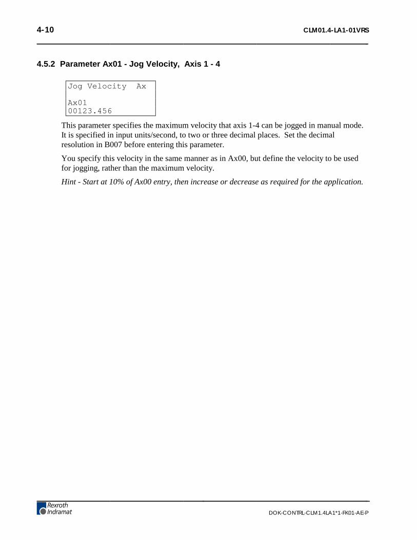
4-10 CLM01.4-LA1-01VRS
DOK-CONTRL-CLM1.4LA1*1-FK01-AE-P
4.5.2 Parameter Ax01 - Jog Velocity, Axis 1 - 4
Jog Velocity Ax
Ax0100123.456
This parameter specifies the maximum velocity that axis 1-4 can be jogged in manual mode.It is specified in input units/second, to two or three decimal places. Set the decimalresolution in B007 before entering this parameter.
You specify this velocity in the same manner as in Ax00, but define the velocity to be usedfor jogging, rather than the maximum velocity.
Hint - Start at 10% of Ax00 entry, then increase or decrease as required for the application.

CLM01.4-LA1-01VRS 4-11
DOK-CONTRL-CLM1.4LA1*1-FK01-AE-P
4.5.3 Parameter Ax02 - Acceleration, Axis 1 - 4
Accel Rate Ax
Ax021234567.8
The axis accelerates at the rate specified by this parameter.
This parameter provides a protection for the machinery as it can limit the amount of torqueproduced during speed changes. The amplifier drive system must be capable of accelerationat the rate specified here. If not, an overshoot or an error message may occur during a speedchange.
The parameter value is specified in input units /second² (units/second/second), in whole units(0 decimal places) or to one decimal place. Set the decimal resolution in B007 beforeentering this parameter.
For example:
To program the machine in the force of 1G, assuming your Input Units are programmed ininches,
1G = 32.16 feet/second²
Convert to inches, (input units, inches used in this example)
32.16 x 12 = 386.0 inches/second²
For an Accel/Decel rate of 1G,
Enter parameter data <0000386.0>
Multiply or divide this number for a rate of 2G, 1/2 G, etc.
Use similar procedures to program in factors other than G force.
NOTE: Parameter Ax24, Delay, can be programmed to select a different acceleration / decelerationrate based on velocity.

4-12 CLM01.4-LA1-01VRS
DOK-CONTRL-CLM1.4LA1*1-FK01-AE-P
4.5.4 Parameter Ax03 - Position Gain (KV Factor) Axis 1 - 4
Position Gain Ax
Ax030000 12.34
• Minimum: 0.01
• Maximum:20.00
This is the position gain of the system for the axis (1-4).
The standard machining Kv Factor = 1. Entering a larger number (higher gain) will yield atighter system (less following error). Entering too large a number can result in overshoot,oscillation, sporadic faults, and/or high wear on the system parts (bearings, chains, gears,etc.). Set this parameter for optimum high performance (not necessarily maximum) for yoursystem.
Input is specified to two decimal places.
Hint: A gain of 3 to 5 is typical when the motor is matched to the load inertia.
This entry sets the amount of velocity command given to the amplifier per a given positionerror (deviation). The following error (deviation) while feeding is inversely proportional tothe KV selected.
KV = Vel or FE = Vel 1000 x FE 1000 x KV
Where:
• Vel (velocity) is in IU/minute
• FE (following error) is in IU’s (input units)
• KV=Velocity (in IU/minute) per thousand IU of Following Error

CLM01.4-LA1-01VRS 4-13
DOK-CONTRL-CLM1.4LA1*1-FK01-AE-P
4.5.5 Parameter Ax04 - Incremental Encoder Data, Axis 1 - 4
Enc Lines/Rev Ax
Ax040000 1250
• 0000 - Not used
• 1250 - Incremental encoder lines /revolution
• Minimum: 0100
• Maximum: 5000
This parameter specifies the number of line counts from the incremental encoder, per encoderrevolution. The CLM determines the encoder/ motor revolutions, based on this entry. Thisdata is used in several different computations which affect positioning.
The information for this entry is provided on the data plate of the incremental encodermounted on the rear of the servo motor.
If using an Absolute encoder, enter <0000 0000> for this parameter and see Ax05.

4-14 CLM01.4-LA1-01VRS
DOK-CONTRL-CLM1.4LA1*1-FK01-AE-P
4.5.6 Parameter Ax05 - Absolute Encoder Data, Axis 1 - 4
Absolute Data Ax
Ax051234 5678
• 1234 - number of revolutions (including ratio of encoder to motor, if applicable);maximum number of turns of the absolute encoder before it either physically stops or thepoint it rolls over back to 0.
• 5678 - resolution of encoder in steps per 360 degrees revolution of encoder; number ofpulses (bit count) per revolution of the encoder.
This parameter is required when an absolute encoder is used.
The first set of digits specifies the number of revolutions of the encoder for the entire set ofdata. The second set of digits specifies the number of increments per encoder revolution.The absolute encoder is activated in parameter Ax10.
The information for this entry is provided on the data plate of the absolute encoder.
If using an incremental encoder, enter <0000 0000> for this parameter and see Ax04.
The number of revolutions of the encoder must be precisely an even power of 2. One ofthese numbers must be selected for each set of digits: 1, 2, 4, 8, 16, 32, 64, 128, 256, 512,1024, 2048, or 4096. The resolution of the encoder can be one of the preceding numbers,with the exception of 1, 2, 4 or 8.
Example:
• Number of encoder revolutions = 256
• Resolution of encoder = 1024
• Ax05 entry: <0256 1024>

CLM01.4-LA1-01VRS 4-15
DOK-CONTRL-CLM1.4LA1*1-FK01-AE-P
4.5.7 Parameter Ax06 - Position Tolerance, Axis 1 - 4
Position Tol Ax
Ax0615 000.010
• 15 - auxiliary output number to be turned on when position reached.
• 000.010 - Position tolerance to two or three decimal places. Set the decimal resolution inB007 before entering this parameter. i.e.. <XX 000.010 = 0.010 IU>
This parameter sets the positional band tolerance for the axis (1-4). It is defining a windowin which the CLM will consider the axis in position. Adjusting this tolerance does not affectthe accuracy of the move. It tells the control when to read the next command line (see PSI,PSM in chapter 5) and to turn ON the auxiliary output. The first two digits specify the outputnumber that will turn ON when the axis is in position. You can use this output to turn on alight, buzzer or as an internal flag. If no output is needed, a "00" can be programmed or anoutput that is not physically accessible can be programmed.
NOTE: The auxiliary output number must be unique to all other parameter selected auxiliaryoutputs; i.e. A106 is output #15, A206 cannot be output #15 (even if axis 2 is not used).
The remaining digits are the switching threshold (position tolerance), entered in input units.A typical setting is 5 thousandths of an inch. The second half of the entry would be<000.005>.
The following sketch shows an example of switching threshold:
Position Tolerance | |(in input units) | |at this point, program ⇒| | ⇐reads in next block | | |
| ⇒ | |⇐ Position Tolerance - The Aux. Output| | | will turn back OFF momentarily if an| | | overshoot exceeds this amount
Axis Direction ⇒ | | | ---------------------------------------------------------- 0---------------------------------------------------------------- >
| overshoot (if any) ⇒V
Commanded Position
NOTE: A properly tuned system does not overshoot. See Ax02 and Ax03. If overshoot occurs, theacceleration rate and/or gain may be set too high.

4-16 CLM01.4-LA1-01VRS
DOK-CONTRL-CLM1.4LA1*1-FK01-AE-P
4.5.8 Parameter Ax07 - Position Pre-Signal, Axis 1 - 4
Pos Presignal Ax
Ax0714 0.2 123.4
• 14 - auxiliary output number to be turned on (00=not activated)
• 0.2 - time in 0.1 seconds (0.1 - 9.9 in 0.1 increments)− 0.0 = output as a constant signal which stays on until next feed or a command AEA
(output ON/OFF).
• 123.4 - Pre-signal distance in Input Units (zero or one decimal place) to the targetposition. Set the decimal resolution in B007 before entering this parameter.
The Pre-Signal feature is used to turn ON an aux. output at a specified distance prior to thecompletion of a feed command. Typically, the Pre-Signal is used when anticipation of theend of a feed is needed, so other processes can be initiated ahead of time.
A pre-signal can be programmed for each axis. The Pre-signal applies to each feedcommand: POI, PSI, POA, POM, PSA, PSM.
After the initiation of the motion, if the Current Distance to travel is less than the Pre-signalDistance programmed in this parameter, the Pre-Signal output is switched ON. The Pre-Signal output will be ON for either the programmed period of time or until the next move(dependent on the parameter settings).
Pre-Signal Distance< -----------------------------> |
Pre-Signal Off¦ -------------------------------------------------------------------¦ ----------------------------------¦ Begin Motion Pre-Signal ON Target Position
(For Programmed Time)
If the "Target Position" is equal to or less than the "Pre-Signal" distance, the Pre-Signaloutput is switched ON at the start of the feed motion for the specified amount of time.
¦ -------------------------------------------------------------------------------------------------------- ¦Begin Motion Target PositionPre-Signal ON -(For Programmed Time)

CLM01.4-LA1-01VRS 4-17
DOK-CONTRL-CLM1.4LA1*1-FK01-AE-P
4.5.9 Parameter Ax08 - Feed Constant, Axis 1 - 4
Feed Constant Ax
Ax08001.00000
• Minimum: 000.01000
• Maximum: 500.00000
This parameter sets the feed constant, which is the ratio of slide movement per encoderrevolution.
The number entered equals the distance the axis will travel per one revolution of the encoder,to four or five decimal places. Set the decimal resolution in B007 before entering thisparameter.
This parameter defines the input units used in other parameters.
ROTARY NOTE: Enter the amount of travel for one revolution of the table/device (one revolutionof the gearbox output). The CLM will internally calculate the motor feed constant.

4-18 CLM01.4-LA1-01VRS
DOK-CONTRL-CLM1.4LA1*1-FK01-AE-P
4.5.10 Parameter Ax09 - Direction of Operation, Axis 1 - 4
Direction Ax
Ax0901 01 00 00
This parameter allows changing the axis direction ( +/- ) by software in the CLM-A. Iteliminates the need for wiring changes on direction and polarity.
• 00 00 00 00 = Direction of operation remains unchanged
• 01 00 00 00 = Reverse (switch) drive encoder
• 00 01 00 00 = Reverse (switch) analog polarity output
• 00 00 00 01 = Reverse (switch) absolute value encoder
Example:
• 01 01 00 00 = Reverse (switch) drive encoder and analog polarity output.
NOTE: If the command and the encoder are wired according to the interconnect diagram inAppendix F, the first four digits should be either 00 00 or 01 01.
WARNING: Runaway conditions can occur if changes to these parameters result in incorrectlydefined encoder/analog polarity in relation to the hardware. When these parameters are changed, it isrecommended that the motor not be connected to the load until results are verified.

CLM01.4-LA1-01VRS 4-19
DOK-CONTRL-CLM1.4LA1*1-FK01-AE-P
4.5.11 Parameter Ax10 - Homing, Incremental Encoder, Axis 1 - 4
(For homing with Absolute Encoder, see next page)
Homing Setup Ax
Ax1000 0 1 05 00
This parameter specifies the search direction and speed for the zero reference point. Seesection 3.2.5 for homing function description and Appendix A for additional applicationinformation.
• 00 - Search direction for home switch− 00 = Search Forward− 01 = Search Reverse
• 0 1 - Encoder type− 0 0 = No homing (disable homing function)− 0 1 = Homing using an incremental encoder
• 05 - Search velocity in % of max velocity− 01-99 = % of Ax00 in 1% increments (25% to 50% is normal for power up homing)
• 00 - Linear/rotary operation select− 00 = Standard operation− 01 = Rotary operation, with shortest path− 02 = Rotary operation, follows programmed direction, forward/reverse
The last digit of this parameter allows using the CLM for rotary table applications. If anincremental encoder is used with this function, homing is required because of the absolutemeasuring system. The rotary table option also must be activated by parameter (Ax16).

4-20 CLM01.4-LA1-01VRS
DOK-CONTRL-CLM1.4LA1*1-FK01-AE-P
4.5.12 Parameter Ax10 - Homing, Absolute Encoder, Axis 1 - 4
(For Homing with Incremental Encoder, see previous page)
Homing Setup Ax
Ax1000 0 2 00 00
When an absolute feedback device is used, this parameter specifies the search direction andspeed for the zero reference point. See section 3.2.5 for homing application information.
• 00 - Absolute Encoder Type− 00 = Standard 24 bit absolute encoder - Type AG 101− 12 = Single turn Absolute encoder, 12 bit, - Type AG 110− 21 = Special, 21 Bit Absolute encoder - Type AG100 512/4096
• 0 2 - Encoder type− 0 2 = Multi turn Absolute encoder− 1 2 = Single turn Absolute encoder
• 00 - Unassigned
• 00 - Linear/Rotary Operation Select− 00 = Standard operation− 01 = Rotary operation, with shortest path− 02 = Rotary operation, follows programmed direction, forward/reverse
The last digit of this parameter allows using the CLM for rotary table applications. Anabsolute value encoder can be used with this function, however, the gear ratio must be aneven power of 2.

CLM01.4-LA1-01VRS 4-21
DOK-CONTRL-CLM1.4LA1*1-FK01-AE-P
4.5.13 Parameter Ax11 - Homing Offset, Axis 1 - 4
Homing Offset Ax
Ax110 1234.567
In many cases, some position other than the home position, such as the center-line of theslide, is used as the reference position. This parameter defines the distance (in input units),and the direction from the home switch that you want to use as the reference position.
This parameter is specified to two or three decimal places. Set the decimal resolution inB007 before entering this parameter.
For incremental encoder operation:
• 0 - Offset direction− 0 = Forward (+)− 1 = Reverse (-)
• 1234.567 - Offset distance in input units, to 2 or 3 decimal places
For absolute value encoder operation:
• 0 - No significance
• 1234.567 - Offset calculated from encoder reference point in input units, to 2 or 3decimal places
For rotary applications, the zero offset may not exceed the value of input units / revolution oftable. Otherwise, the error message "input error" will appear. For instance, if degrees havebeen selected as input units (360° / table revolution) and 10 has been programmed as the zerooffset, the zero point is set at 10.
Refer to section 3.2.5 for additional information on the Homing function.

4-22 CLM01.4-LA1-01VRS
DOK-CONTRL-CLM1.4LA1*1-FK01-AE-P
4.5.14 Parameter Ax12 - Homing Acknowledgement, Axis 1 - 4
Homing ACK Ax
Ax1209 12 00 13
This parameter is used to identify the various I/O assigned to the Homing Process. In Manual Mode,homing can take place by means of the assigned auxiliary input number, or in Automatic Mode byuse of the command "HOM".
• 09 - Auxiliary input number used to initiate Homing in Manual Mode (push-button orPLC output)− 00 = Manual Mode homing not used− 01-80 = Selected input number to be used to initiate Homing
• 12 - Home Zero Reference Select (Marker Pulse or Home Switch)− 00 = Homing to Incremental Encoder Marker Pulse (Homing Speed for Homing to
Marker Pulse is 3% of Max. Velocity)− 01-80 = Selected input number to be used for home switch input
NOTE: The standard CLM-01.3-A has a maximum of 16 auxiliary inputs that are physicallyaccessible to the user. The CLM-01.3-A-E has expanded auxiliary input capability of 80 inputs.
• 00 - Unassigned
• 13 - Auxiliary output number to be used for "Home Established" signal
NOTE: The standard CLM-01.3-A has a maximum of 16 auxiliary outputs that are physicallyaccessible to the user. The CLM-01-A-E has expanded auxiliary output capability of 48 outputs.
For absolute value encoder operation, Ax12 should be set to 00 00 00 00.
NOTE: The auxiliary output for Homing complete/established can be turned OFF with an AEAcommand (output ON/OFF). The travel limits will remain in effect (still referenced to home).

CLM01.4-LA1-01VRS 4-23
DOK-CONTRL-CLM1.4LA1*1-FK01-AE-P
4.5.15 Parameter Ax13 - Travel Limit, Minimum Value, Axis 1 - 4
Min Travel Ax
Ax13–01234.567
This parameter specifies the travel limit value in the negative direction, in reference to theHome Position. The limit is effective only after the axis has been Homed.
In the Manual Mode, the corresponding Jog key is disabled when this position has beenreached. If, in the Automatic Mode, the commanded position is smaller (more negative) thanthis limit value, an error message will be displayed.
The travel limit value is measured from the reference point, Home Position, and is not addedto, or subtracted from, the offset distance.
This parameter is specified in input units to two or three decimal places. Set the decimalresolution in B007 before entering this parameter.
For absolute value encoder operation:
A plus sign will appear for this parameter (instead of a minus sign) and the value here will bethe minimum travel allowed. The travel limit value is measured from the zero point of theencoder and is not added to, or subtracted from, the offset distance.

4-24 CLM01.4-LA1-01VRS
DOK-CONTRL-CLM1.4LA1*1-FK01-AE-P
4.5.16 Parameter Ax14 - Travel Limit, Maximum Value, Axis 1 - 4
Max Travel Ax
Ax14+01234.567
This parameter specifies the travel limit value in the positive direction, in reference to theHome Position. The limit is effective only after the axis has been Homed.
In the Manual Mode, the corresponding Jog key is disabled when this position has beenreached. If, in the automatic mode, the commanded position is greater than this limit value,an error message will be displayed.
The travel limit value is measured from the reference point, Home Position, and is not addedto, or subtracted from, the offset distance.
This parameter is specified in input units to two or three decimal places. Set the decimalresolution in B007 before entering this parameter.
For absolute value encoder operation:
The travel limit value is measured from the zero point of the encoder and is not added to, orsubtracted from, the offset distance.

CLM01.4-LA1-01VRS 4-25
DOK-CONTRL-CLM1.4LA1*1-FK01-AE-P
4.5.17 Parameter Ax15 - Special Functions, Axis 1 - 4(Position Loop Reset/Velocity Achieved/Master Encoder Averaging)
Special Funct Ax
Ax1512 34 56 7 8
• 12 - Acknowledgment input to reset the position loop (with 24v potential). The functionwill remain in effect until the input goes low again. Enter any number in the range of 01-80. Entering 00 here disables the function.
• 34 - Auxiliary output number (01-19) to indicate that the position loop is in a reset state.
• 56 - Aux. Output to indicate when the programmed velocity has been achieved.
• 7 - Not used - Enter 0
• 8 - Averaging of Master Encoder input pulse train for Master/Slave Mode (See FOLcommand).− 0 = No Averaging, No Feed Forward (1-9=Feed Forward Mode)− 1 = Average over 1 read− 2 = Average over 2 reads− 3 = Average over 4 reads− 4 = Average over 8 reads− 5 = Average over 16 reads− 6 = Average over 32 reads− 7 = Average over 64 reads− 8 = Average over 128 reads− 9 = Average over 256 reads
NOTE: 1 Read = 2 milliseconds (when using 1 or 2 axis, 3 ms for 3 axes, 4 ms for 4 axes). Feedforward automatically adjusts for following error between the axes, when averaging is selected. Anyremaining following error can usually be minimized by slightly changing Ax21 RPM/10V (typicaladjustment is less than 2%).
If no Special Functions are used, enter <00 00 00 0 0>.
This special function parameter is to reset position feedback and velocity command. Itallows shifting of incremental position without causing an error (position fault). During thisfunction, changes in the position feedback are ignored. Along with activating the resetfunction in the parameter, an auxiliary output number (not equal to 00) must be programmedto indicate the position loop reset state.

4-26 CLM01.4-LA1-01VRS
DOK-CONTRL-CLM1.4LA1*1-FK01-AE-P
Notes about the Special Function - "Position Loop Reset"
With a potential of 24 volts at the acknowledgment input, Position Loop Reset takes placeonly if the axis is stopped; i.e., the motor is in position according to the position toleranceparameter set in Ax06.
CAUTION: While Position Loop Reset takes place, zero volts is output as the velocity commandvalue. This may cause the drive to drift.
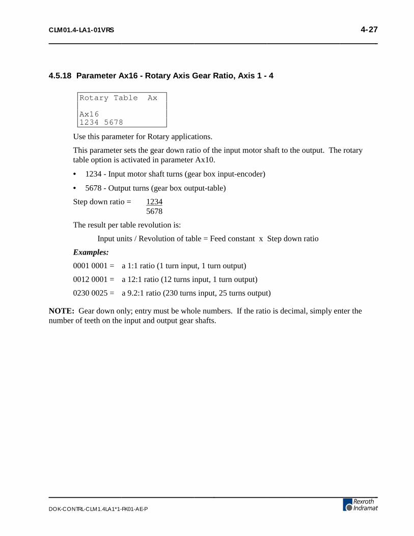
CLM01.4-LA1-01VRS 4-27
DOK-CONTRL-CLM1.4LA1*1-FK01-AE-P
4.5.18 Parameter Ax16 - Rotary Axis Gear Ratio, Axis 1 - 4
Rotary Table Ax
Ax161234 5678
Use this parameter for Rotary applications.
This parameter sets the gear down ratio of the input motor shaft to the output. The rotarytable option is activated in parameter Ax10.
• 1234 - Input motor shaft turns (gear box input-encoder)
• 5678 - Output turns (gear box output-table)
Step down ratio = 12345678
The result per table revolution is:
Input units / Revolution of table = Feed constant x Step down ratio
Examples:
0001 0001 = a 1:1 ratio (1 turn input, 1 turn output)
0012 0001 = a 12:1 ratio (12 turns input, 1 turn output)
0230 0025 = a 9.2:1 ratio (230 turns input, 25 turns output)
NOTE: Gear down only; entry must be whole numbers. If the ratio is decimal, simply enter thenumber of teeth on the input and output gear shafts.

4-28 CLM01.4-LA1-01VRS
DOK-CONTRL-CLM1.4LA1*1-FK01-AE-P
4.5.19 Parameter Ax17 - Second Acceleration Rate, Axis 1 - 4
Knee Point Ax
Ax1712003860
• 12 - Velocity change point (in % of Velocity Max - Ax00) - Above this %, the secondacceleration turns on - Knee point of acceleration change.− 00 = Disables this parameter− 01-99 = % in increments of 1%
• 003860 - Second acceleration - Input Units /second² (units/second/second) to zero or onedecimal place, above the knee point velocity. Set the decimal resolution in B007 beforeentering this parameter.
The first acceleration below the knee point velocity is programmed in parameter Ax02.
This function is effective in Automatic operation as well as in Manual operation (forinstance, jogging). The only limitation for the user programming is that the command ACC(change of acceleration) is not effective as long as this parameter is switched ON (can useone or other).
NOTE: Since the second acceleration may be greater than the first acceleration, the greater of thetwo values is to be considered the maximum acceleration.
Figure 4-1 Examples of Attainable Velocity Profiles
NOTE: Since the introduction of parameter Ax24 delay (as of software version LA01.3-03.0) thefunction Knee Point is disabled.

CLM01.4-LA1-01VRS 4-29
DOK-CONTRL-CLM1.4LA1*1-FK01-AE-P
4.5.20 Parameter Ax18 - Single/Dual Speed Motor Positioning (Max), Axis 1 - 4
Polum Max Ax
Ax180 1234.567
• 0 - Enable/Disable Option− 3 = function switched ON− 0 = function disabled
• 1234.567 - Braking distance from Vmax to Vmin (fast to slow), in input units to 2 or 3places. Set the decimal resolution in B007 before entering this parameter.
You can use this function to control motors with speed and reversing contactors with absolutevalue encoders.
NOTE: This function is currently not supported. Consult an Indramat Application Engineer foradditional information.
NOTE: See Parameter Ax19 for further description of function.
• Ax18 is Decel mode, Vmax to Vmin,
• Ax19 is Decel mode, Vmin to Stop.
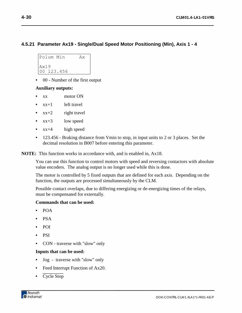
4-30 CLM01.4-LA1-01VRS
DOK-CONTRL-CLM1.4LA1*1-FK01-AE-P
4.5.21 Parameter Ax19 - Single/Dual Speed Motor Positioning (Min), Axis 1 - 4
Polum Min Ax
Ax1900 123.456
• 00 - Number of the first output
Auxiliary outputs:
• xx motor ON
• xx+1 left travel
• xx+2 right travel
• xx+3 low speed
• xx+4 high speed
• 123.456 - Braking distance from Vmin to stop, in input units to 2 or 3 places. Set thedecimal resolution in B007 before entering this parameter.
NOTE: This function works in accordance with, and is enabled in, Ax18.
You can use this function to control motors with speed and reversing contactors with absolutevalue encoders. The analog output is no longer used while this is done.
The motor is controlled by 5 fixed outputs that are defined for each axis. Depending on thefunction, the outputs are processed simultaneously by the CLM.
Possible contact overlaps, due to differing energizing or de-energizing times of the relays,must be compensated for externally.
Commands that can be used:
• POA
• PSA
• POI
• PSI
• CON - traverse with "slow" only
Inputs that can be used:
• Jog - traverse with "slow" only
• Feed Interrupt Function of Ax20.
• Cycle Stop

CLM01.4-LA1-01VRS 4-31
DOK-CONTRL-CLM1.4LA1*1-FK01-AE-P
4.5.22 Parameter Ax20 - Feed Angle Monitoring, Feed Interrupt, Axis 1 - 4
Feed Angle MonAx
Ax2001 02 00 00
• 01 - Aux. input number for Feed Angle Monitoring with error display, Axis X− 00 = Feed Angle Monitoring Axis X not used
• 02 - Aux. input number for Feed Interrupt, Axis X (Feed Hold)− 00 = Feed Interrupt Axis X not used
• 00 - Not Used
• 00 - Output: "Deceleration of the commanded position active"− 00 = Function disabled
NOTE: There are no diagnostics for Feed Angle input missing before a feed or when a FeedInterrupt is executed.
01 - Feed Angle Monitoring (Active High)
This parameter specifies if the feed is to be monitored or not. If "00" is input here, the corre-sponding axis is not monitored. If an auxiliary input number has been specified and if thereis no signal at the specified input, no feed will take place. The CLM processes all blocks notcontaining any feed lengths. As soon as the program processing comes to a block containinga feed length, the CLM will stop in this block until there is a signal at the input. If thespecified auxiliary input signal shuts off during a feed, the feed will be stopped and an errormessage will be displayed.
02 - Feed Interrupt or Feed Hold (Active Low)
This parameter specifies whether an interruption of the programmed feed in process ispossible or not. If "00" is input here, there will be no monitoring for interruption. If an inputnumber is assigned, and an interrupt is present, those feed movements that have not beeninitiated will not be executed. The CLM will continue to process all blocks not containingany feed lengths, regardless of how Ax20 is set. As soon as the program processing comes toa block containing a feed length, the CLM will stop in this block until there is a signal at theinput. If the specified auxiliary input shuts off during a feed, the feed will be stopped.
WARNING: The continuation of the feed will occur immediately as the auxiliary input, FeedInterrupt returns high.
NOTE: If feed angle monitoring has been specified for an axis, the Feed Interrupt input numbermust be different for that axis (the two functions cannot be used together for the same axis with thesame input number).

4-32 CLM01.4-LA1-01VRS
DOK-CONTRL-CLM1.4LA1*1-FK01-AE-P
4.5.23 Parameter Ax21 - Drive Input Sensitivity, Axis 1 - 4
Drv Input Sen Ax
Ax212000 0 10.0
• 2000 - Maximum motor RPM (0001 to 9999) at specified input voltage
• 0 – Not Used
• 10.0 - Input voltage at maximum motor RPM− One decimal place precision
This parameter defines the sensitivity of the motor (RPM) to the drive input voltage. Thevoltage range input can vary from 0.5 volts to 10.0 volts. Typically, the user enters themaximum RPM at 10 volts.
Enter the input sensitivity rating shown on the amplifier personality module for E1/E2.
Example: A121 entry for 1500 RPM/10 V is:
Drv Input Sen A1
A1211500 0 10.0

CLM01.4-LA1-01VRS 4-33
DOK-CONTRL-CLM1.4LA1*1-FK01-AE-P
4.5.24 Parameter Ax22 - Monitor Window, Axis 1 - 4
Monitor Wind. Ax
Ax220 0 00 0 010
• 0 - Error Messages− 0= Error Messages active− 8= Error Messages deactivated
• 0 - Unassigned
• 00 - Output for Positioning Error greater than maximum permissible deviation.
NOTE: The output programmed here is only set if the error messages have been deactivated, byentering "8" in the first screen position of this parameter.
• 0 - Unassigned
• 010 - Maximum position deviation error, in percent of the maximum position deviation.Entry limits: 001-100. A typical entry here is 010-020, for 10-20%.
The CLM continuously monitors all enabled axes for "Drive Runaway" and blockage of theaxis(es), "Excessive Pos Lag". The CLM uses a mathematical model of the system tocalculate the "normal" following error expected. "Drive Runaway" and "Excessive Pos Lag"cause the corresponding error message to appear. Drive runaway occurs if the actual positionof the encoder exceeds the expected position calculated with the model. The axis isconsidered blocked if the actual position of the encoder is less than the position expected bythe model.
Program the maximum permissible deviation (in percentage) between the actual position andthe position calculated by the model, in this parameter. For the monitoring to functionproperly, program a value in this parameter greater than the percentage of deviation thatresults under normal operation. Otherwise, nuisance faults will occur.
Calculate the maximum Following Error:
Max. Following Error = Max. Velocity (IU/sec) x 60
Position Gain (KV) 1000
Example:
If Max. Velocity = 00050.000 (50 inches/second) and Position Gain = 000004.00 (4 inches/minute/mil), the calculated following error at maximum speed would be:
FE = 50 in x 60 sec x 1 = 0.75 in1 sec 1 min KV x 1000

4-34 CLM01.4-LA1-01VRS
DOK-CONTRL-CLM1.4LA1*1-FK01-AE-P
If Ax22 = 0 0 00 0 005, the CLM will issue an error if the actual following error differs fromthe expected following error by more than 5%. Take 5% of 0.750 inches: 0.05 x 0.750 =0.0375. When feeding at maximum velocity, the LS display screen (following error) wouldread about 0.750 inches.
An "E.P.L." error would occur if the following error exceeded 0.750 + 0.0375 = 0.788 inches.A "D.R." error would occur if the following error went below 0.750 - 0.0375 = 0.712 inches.When feeding at a lower velocity, the following error will be lower, but the maximumdeviation from the expected following error will still be ± 0.0375 inches.
Note the following:
If you change the parameters Position Gain or Maximum Velocity, you do not need to repro-gram the Monitor Window, because it is entered in percentage of maximum positiondeviation.
If the Monitor Window entry, as converted, is smaller than the Position Tolerance, the CLMis unable to correctly distinguish between "Drive Runaway" and "Excessive Position Lag."Therefore, the converted Monitor Window parameter should be greater than the PositionTolerance.
If the programmed entry for Monitor Window is too small, even a normal feed will generate a"Drive Runaway" or "Excessive Position Lag" error.
The Monitor Window value depends on your application. You should enter the lowestpercentage possible that will not cause nuisance faults.
Possible causes for "Drive Runaway"
• The parameter "Direction of Operation" is incompatible with the wiring of the encoder orwith the command inputs E1/E2/E3/E4.
• The axis moved when no command value has been output.
• Ax04 does not correspond to the actual encoder data (too small).
• The maximum RPM in Ax21 is smaller than specified on the amplifier personalitymodule.
• Ax22 entry is too small (typical setting is 10%).
Possible causes for "Excess Position Lag"
• Feed command issued, but no movement detected:− the encoder cable is not connected,− the encoder cable or encoder is defective,− the motor cannot turn because of a mechanical bind.
• Ax04 does not correspond to the actual encoder data (too large).
• The maximum RPM in Ax21 is greater than specified on the amplifier personalitymodule.

CLM01.4-LA1-01VRS 4-35
DOK-CONTRL-CLM1.4LA1*1-FK01-AE-P
• The acceleration is too great (Ax02, also Ax17 second acceleration).
• The CLM signal controller enable is not reaching the drive.
• The CLM velocity command is not reaching the drive.
• Ax22 entry is too small (typical setting is 10%).

4-36 CLM01.4-LA1-01VRS
DOK-CONTRL-CLM1.4LA1*1-FK01-AE-P
4.5.25 Parameter Ax23 - Follow / Synchronous / Measuring Wheel
Follow-/Sync.-Ax
Ax231 3 00 12 34
• 1 = Mode− 0 = Normal Feed Axis− 1 = Synchronous Axis− 2 = Following Axis− 3 = Meas. Wheel Version 1 (Regular Measuring Wheel)− 4 = Meas. Wheel Version 2 ( Meas. Wheel with Feed Correction)
• 3 = If Synchronous Mode selected− 1 = Axis X synchronized with Axis 1− 2 = Axis X synchronized with Axis 2− 3 = Axis X synchronized with Axis 3
If Following Mode selected− 1 = Axis X follows Axis 1− 2 = Axis X follows Axis 2− 3 = Axis X follows Axis 3− 5 = Axis X follows Measuring Wheel
• 00 = Not Used
• 12 = Percent deviation allowed (00-99) between Measuring Wheel encoder and axisencoder
• 34 = Measuring Wheel Mode− 00 = Measuring Wheel Not Active− 01-99 = Input used to activate the Measuring Wheel
The Following Modes available are:
(A123)Axis 1: Normal Feed Axis 0 0 00 00 00
Following Mode, Axis 1 follows Meas. Wheel 2 5 00 00 00Measuring Wheel, Version 1 3 5 00 00 00Measuring Wheel, Version 2 4 5 00 00 00

CLM01.4-LA1-01VRS 4-37
DOK-CONTRL-CLM1.4LA1*1-FK01-AE-P
(A223)Axis 2: Normal Feed Axis 0 0 00 00 00
Synch. Mode, Axis 2 synchronized with Axis 1 1 1 00 00 00Following Mode, Axis 2 follows Axis 1 2 1 00 00 00Following Mode, Axis 2 follows Meas. Wheel 2 5 00 00 00
(A323)Axis 3: Normal Feed Axis 0 0 00 00 00
Synch Mode, Axis 3 synchronized with Axis 1 1 1 00 00 00Synch Mode, Axis 3 synchronized with Axis 2 1 2 00 00 00Following Mode, Axis 3 follows Axis 1 2 1 00 00 00Following Mode, Axis 3 follows Axis 2 2 2 00 00 00Following Mode, Axis 3 follows Meas. Wheel 2 5 00 00 00
(A423)Axis 4: Normal Feed Axis 0 0 00 00 00
Synch. Mode, Axis 4 synchronized with Axis 1 1 1 00 00 00Synch. Mode, Axis 4 synchronized with Axis 2 1 2 00 00 00Synch. Mode, Axis 4 synchronized with Axis 3 1 3 00 00 00Following Mode, Axis 4 follows Axis 1 2 1 00 00 00Following Mode, Axis 4 follows Axis 2 2 2 00 00 00Following Mode, Axis 4 follows Axis 3 2 3 00 00 00Following Mode, Axis4 follows Meas. Wheel 2 5 00 00 00

4-38 CLM01.4-LA1-01VRS
DOK-CONTRL-CLM1.4LA1*1-FK01-AE-P
4.5.26 Parameter Ax24 - Delay Axis x
(as of software version LA01.3-3.0)
Delay Ax
Ax240000000.0
Delay Ax
Ax2400000000
• 00000000 - Maximum delay in Input Units /second²
or
• 0000000.0 - Additional programming for the delay can be done using the DEC command(in ‰ of maximum amount in Ax24)
• Range: As in Parameter Ax02

CLM01.4-LA1-01VRS 4-39
DOK-CONTRL-CLM1.4LA1*1-FK01-AE-P
4.5.27 Parameter Ax25 - Jerk constant
(as of software version CLM1.3-LA1-04V07)
Jerk constant Ax
Ax250000 0.000
• 0000 - Not used, set to 0000
• 0.000 - Time constant for acceleration change (in s)− Range: 0.000 to 1.024− 0 = Constant acceleration
The “acceleration time constant” indicates the time during which the CLM accelerates.
Internally, the CLM rounds up the time constant according to the following equation:
Jerk constant (s) 1000
Position control cycle time (ms) = 2
n×
tB
Time
Time
Acceleration
Velocity
tB = Acceleration time constant
tB
tB tB
Figure 4-2 Jerk limit

4-40 CLM01.4-LA1-01VRS
DOK-CONTRL-CLM1.4LA1*1-FK01-AE-P
4.5.28 Parameter B000 - Enable Axis 2
Enable Axis 2
B0001 0000000
• 1 - Axis Enable/Disable− 0 = Axis 2 is disabled− 1 = Axis 2 is enabled
• 0000000 - Not used, must be set to 0000000
This parameter allows enabling axis 2. Note that axis 1 is always enabled. The CLM willcontrol axis 1, 2, 3 and/or 4 , as enabled in these "B" parameters.
With axis 2 enabled, values must be entered into parameters A200-A225. If the axis isenabled without entering the necessary values for parameters A200-A225, an error conditionoccurs and the message "Is Invalid" appears.

CLM01.4-LA1-01VRS 4-41
DOK-CONTRL-CLM1.4LA1*1-FK01-AE-P
4.5.29 Parameter B001 - Enable Axis 3
Enable Axis 3
B0011 0000000
• 1 - Axis Enable/Disable− 0 = Axis 3 is disabled− 1 = Axis 3 is enabled
• 0000000 - Not used, must be set to 0000000
This parameter allows enabling axis 3. Note that axis 1 is always enabled. The CLM willcontrol axis 1, 2, 3 and/or 4 , as enabled in these "B" parameters.
With axis 3 enabled, values must be entered into parameters A300-A325. If the axis isenabled without entering the necessary values for parameters A300-A325, an error conditionoccurs and the message "Is Invalid" appears.

4-42 CLM01.4-LA1-01VRS
DOK-CONTRL-CLM1.4LA1*1-FK01-AE-P
4.5.30 Parameter B002 - Enable Axis 4
Enable Axis 4
B0021 0000000
• 1 - Axis Enable/Disable− 0 = Axis 4 is disabled− 1 = Axis 4 is enabled
• 0000000 - Not used, must be set to 0000000
This parameter allows enabling axis 4. Note that axis 1 is always enabled. The CLM willcontrol axis 1, 2, 3 and/or 4 , as enabled in these "B" parameters.
With axis 4 enabled, values must be entered into parameters A400-A425. With axis 4enabled, values must be entered into parameters A400-A425. If the axis is enabled withoutentering the necessary values, an error condition occurs and the message "Is Invalid" appears.

CLM01.4-LA1-01VRS 4-43
DOK-CONTRL-CLM1.4LA1*1-FK01-AE-P
4.5.31 Parameter B003 - Serial Interface Information
Serial Interface
B0030960 0 1 8 1
The serial interface of the CLM can exchange data with peripherals in various ways. Definethe transmission method in this parameter. Chapter 7 describes the interface in more detail.
• 0960 - Baud Rate− Min.= 110 Baud− Max.=19200 Baud
• 0000 = Interface not operating (to host computer)
Baud Rate input examples using common rates:
1920 - 19200 Baud, 0960 - 9600 Baud, 0480 - 4800 Baud, 0240 - 2400 Baud
• 0 - Interface Mode− 0 = Standard RS232/RS422 (full duplex)− 1 = IDS, decade switch, option− 2 = Same as Mode 0− 3 = Serial port RS485, half duplex, one station only (station 1)− 4 = Serial bus link RS485, half duplex, station 1 through 32
NOTE: If you select the IDS option, do not enter the other values for this parameter. The CLM willconfigure the interface automatically.
• 1 - Parity− 1 = No parity− 2 = Even parity− 3 = Odd parity
• 8 - Word Length− 7 = 7 Bits− 8 = 8 Bits
• 1 - Number of Stop Bits− 1 = 1 Bit− 2 = 2 Bits

4-44 CLM01.4-LA1-01VRS
DOK-CONTRL-CLM1.4LA1*1-FK01-AE-P
4.5.32 Parameter B004 - Serial Interface Information
Serial Interface
B0041 1 08 9 0 00
• 1 - Checksum/Hardware Handshake (RTS/CTS)− 0 = Checksum ON, RTS/CTS OFF− 1 = Checksum OFF, RTS/CTS OFF− 2 = Checksum ON, RTS/CTS ON− 3 = Checksum OFF, RTS/CTS ON
• 1 - Transmission Acknowledgment - " Y CR/LF "− 0 = Acknowledgment OFF− 1 = Acknowledgment ON
• 08 - Station Number, 01-32Used with serial bus link for RS485 communication (See Parameter B003: SerialInterface - Interface Mode description)
• 9 - Error Code Over Serial Interface− 0 = Function Disabled− 1 = In case of CLM fault, automatically send an error message via the serial interface.
See Status 53 in chapter 7 for details.
• 0 = Not used
• 00 - Send Delay Time During RS-485 Operation− 00 = no delay
This parameter allows the integration of the calculation of the check sum into the interface.The CLM will perform a bit count comparison from one operation (processing).
If a "0" is not programmed in the first bit, a check sum is not required for communication, i.e.instead of "Checksum CR/LF", a "_CR/LF" is sufficient.
If it is important that the data sent to the CLM is received correctly, it is recommended thatthe checksum be turned ON. The host device must be programmed to calculate and send thechecksum with each transmission to use this option.
Transmission Acknowledgment, when active, returns a "Y" "CR/LF" from the CLM to theHost Device. This occurs after any command transmitted to the CLM that does not requireany other response from the CLM.
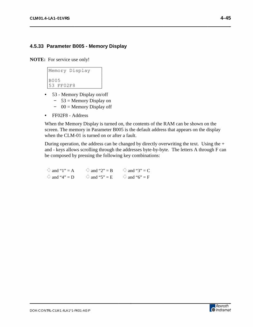
CLM01.4-LA1-01VRS 4-45
DOK-CONTRL-CLM1.4LA1*1-FK01-AE-P
4.5.33 Parameter B005 - Memory Display
NOTE: For service use only!
Memory Display
B00553 FF02F8
• 53 - Memory Display on/off− 53 = Memory Display on− 00 = Memory Display off
• FF02F8 - Address
When the Memory Display is turned on, the contents of the RAM can be shown on thescreen. The memory in Parameter B005 is the default address that appears on the displaywhen the CLM-01 is turned on or after a fault.
During operation, the address can be changed by directly overwriting the text. Using the +and - keys allows scrolling through the addresses byte-by-byte. The letters A through F canbe composed by pressing the following key combinations:
and “1” = A and “2” = B and “3” = C
and “4” = D and “5” = E and “6” = F

4-46 CLM01.4-LA1-01VRS
DOK-CONTRL-CLM1.4LA1*1-FK01-AE-P
4.5.34 Parameter B006 - Start Task 2 & 3
Start Task 2 & 3
B0060201 0301
• 0201 - Starting block number for second task− 0001-2999 = Any Block number except 0000 or a block number of another task− 0000 = Task 2 program disabled
• 0301 - Starting block number for third task− 0001-2999 = Any block number except 0000 or a block number of another task− 0000 = Task 3 program disabled
Task 1 always starts at block number 0000.
This parameter allows running separate sub-routines of the program at the same time.
As soon as the CLM is switched to Manual or Automatic mode, Task 3 begins running.
As soon as Cycle Start actuated, in Auto Mode, Task 1 and 2 start running.
NOTE: Do not access the same routine by two tasks at the same time (within 2 milliseconds) or asystem fault will occur. The user program must be in place for task 3 before leaving the parametermode because task 3 will start running immediately.
WARNING: Do not use task 3 for servo commands. Task 3 continues running in Manual Modeand during an E-Stop.

CLM01.4-LA1-01VRS 4-47
DOK-CONTRL-CLM1.4LA1*1-FK01-AE-P
4.5.35 Parameter B007 - Display Language / Decimal Place / Keypad Lockout
Language
B00701 03 0 0 45
Use this parameter to specify in which language text will display on the CLM control paneland to set the number of decimal places used in positioning commands and certainparameters. It also allows disabling any program entry/changes from the CLM keypad.
• 01 - Language− 00 = German− 01 = English− 02 = French− 03 = Spanish− 04 = Italian− 05 = Portuguese
• 03 - Number of decimal places used in positioning commands and certain parameters− 02 = Metric (e. g., millimeters, XXX.YY)− 03 = US System (e. g., inches, XX.YYY)
The number entered for decimal places specifies how many digits are to the right of thedecimal point for positioning commands and many parameters. Make your selectiondepending on the resolution required. See Appendix E, parameter input sheets, showing thedecimal location for each parameter, with resolution set at 2 or 3 in B007.
Parameter # affected: 4th digit of B007 = 2 = 3
Ax02, Ax07, Ax17,Ax24 0 1
Ax00, Ax01, Ax06, Ax11, Ax13, Ax14, Ax18, Ax19 2 3
Ax08, B018 4 5
Command affected: 4th digit of B007 = 2 = 3
POI, PSI, POA, PSA, PSM, PST, VCA, VCC, BPT, BZP 2 3
REP 0 1

4-48 CLM01.4-LA1-01VRS
DOK-CONTRL-CLM1.4LA1*1-FK01-AE-P
• 0 - Unassigned, set to zero
• 0 - Enable "fault code via outputs"− 0 = No fault code via outputs− 1 = Fault code via outputs, 01 to 08− 2 = Fault code via outputs, 09 to 16− 3 = Fault code via outputs, 17 to 24− 4 = Fault code via outputs, 25 to 32− 5 = Fault code via outputs, 33 to 40− 6 = Fault code via outputs, 41 to 48
If the function is enabled, an appropriate fault code is outputted via the programmed outputwhen there is a fault. The fault code consists of 2 hex digits.
Fault code assignment: 00 to 3F - General disturbance
40 to 6F - Disturbance axis 1
70 to 9F - Disturbance axis 2
A0 to CF - Disturbance axis 3
D0 to FF - Disturbance Axis 4
Example: Parameter B007 = xx xx x 3 xx
Error = Excessive Position Lag Axis 2
Output # 24 23 22 21 20 19 18 17
Weight 23 22 21 20 23 22 21 20
__________ __________
0 1 1 1 0 0 1 1
__________ __________
7 3 Hex Code is 73
For a complete list of fault codes and explanations, see chapter 8, Diagnostics andTroubleshooting.
• 45 - Lock out feature− 45 = Inhibits storage in memory of program blocks which are entered via the CLM
keypad.− 55 = Allows changes in data, but not in data structure (as of software version
04V07).
NOTE: Programming can still be accomplished via the RS232 interface, such as by downloadingfrom MotionManager program assembler. The lock out feature prevents accidental or unauthorizedchanges.

CLM01.4-LA1-01VRS 4-49
DOK-CONTRL-CLM1.4LA1*1-FK01-AE-P
4.5.36 Parameter B008 - Variations
Variations
B0080000 1 0 00
• 0000 - Not Used
• 1 -Position of Axis 1 that is used to turn on expansion outputs− 0 = Disabled− 1 = Enabled
• 0 - Position of Axis 2 that is used to turn on expansion outputs− 0 = Disabled− 1 = Enabled
• 00 - Number of scanned blocks per block cycle in Task 3.

4-50 CLM01.4-LA1-01VRS
DOK-CONTRL-CLM1.4LA1*1-FK01-AE-P
4.5.37 Parameter B009 - Start Program Block - Task 4, Task 5
Start Task 4 & 5
B0090000 0000
• 0000 - Starting block number for task 4− 0001-2999 = Any Block number except 0000 or a block number of another task− 0000 = Task 4 program disabled
• 0000 - Starting block number for task 5− 0001-2999 = Any Block number except 0000 or a block number of another task− 0000 = Task 5 program disabled
Task 4 and 5 behave like Task 2. For further information, see Section 5.3 Multi-tasking.
4.5.38 Parameter B010 - Clear Outputs(as of software version LA01.3-3.0)
Clear outputs
B01000000000
0 - Outputs 01 to 080 - Outputs 09 to 160 - Outputs 17 to 240 - Outputs 25 to 320 - Outputs 33 to 400 - Outputs 41 to 480 - Outputs 49 to 560 - Outputs 57 to 64
This function enables clearing of outputs when faults occur. For each group of 8 outputs, thefollowing inputs are possible:
• 0 = Clear outputs when a fault or E-STOP occurs.
• 1 = Do not clear outputs when a fault or E-STOP occurs. Outputs are cleared when thefault is cleared.
• 2 = Do not clear outputs when a fault or E-STOP occurs or is cleared (clear key orexternal clear).
If “00000000” is entered for Parameter B010, the outputs have the same characteristics as inprevious revisions of the software (e.g. software version LA 01.3-02.9 or previous).

CLM01.4-LA1-01VRS 4-51
DOK-CONTRL-CLM1.4LA1*1-FK01-AE-P
4.5.39 Parameter B011 - Manual Vector
Manual - Vector
B01107 1 0 1678
• 07 - Aux. input number to initiate Manual Vector program start with rising signal edge− 00 = No Aux. input− 01-80 = Aux. Input Number
• 1 - 0 = Start Manual Vector program only when in Manual Mode and manual vector inputgoes high− 1 = Jump to the Manual Vector program when switching from Automatic to Manual
Mode (Automatic input goes Off), or when in Manual Mode and Manual Vectorinput goes High
• 0 - Not used, set to 0
• 1678 - Start block of Manual Vector program, Block 0000-2999.
NOTE: You must use Command RTS, Return from Sub-routine, to terminate the Manual Vectorprogram.
This function allows you to run a user program in Manual Mode. This program mustconclude with an "RTS" (the sub-routine stack will not be changed). This program may notcontain any feed instructions. The program is aborted if there is a switch over from "Manual"to "Parameter Mode". While the Manual Vector program is running, a switch over from"Manual" to "Automatic Mode" is prevented. The program is started externally by means of arising signal edge at one of the aux. inputs. If "00" is input for the aux. input, the ManualVector program is started when switching from "Automatic" to "Manual Mode". Whenprogramming Parameter B011, make sure that the start block of the Manual Vector programis not located in the main program.
NOTES:
• The manual vector input is not accepted during jogging or homing (in the manual mode).Homing is possible in the manual program by using the HOM command, but this shouldbe avoided.
• While the manual vector program is running, jogging or homing is not possible.
• It is not possible to start the program unless all enabled axes drive ready inputs have 24volt potential.

4-52 CLM01.4-LA1-01VRS
DOK-CONTRL-CLM1.4LA1*1-FK01-AE-P
Example:
Manual - Vector
B01113 1 0 0400
0400 APE 0 0200000000
0401 APE 1 1000222222
0402 RTS

CLM01.4-LA1-01VRS 4-53
DOK-CONTRL-CLM1.4LA1*1-FK01-AE-P
4.5.40 Parameter B012 - Program Interrupt Vector
(for Task 1 only)
Interrupt Vector
B01208 1 2 2678
Immediate interruption of main program, start Interrupt Vector program. Can be used as an"Emergency Return" procedure.
• 08− 00 = Disables Interrupt Vector− 01-80 = Aux. input number used to initiate Interrupt Vector program on rising edge
of signal
• 1− 0 = The vector is disabled while a subroutine (JSR) is running (rising edge)− 1 = The vector is always active (rising edge)− 2 = The vector is disabled while a subroutine (JSR) is running (falling edge)− 3 = The vector is always active (falling edge)
• 2− 0 = A started feed will finish before executing the Interrupt Vector program− 1 = Feed is interrupted (drive(s) braked until stopped) and execute the Interrupt
Vector program
• 2678 - Start block of Interrupt Vector program, Block 0000-2999
The Interrupt Vector permits you to interrupt a user program externally at any time. The pro-gram sequence will then continue at the start block number specified for the Interrupt Vectorprogram. No RTS command is required at the end of the Interrupt Vector Program. There isno return jump to the interrupted main program.
NOTE: When a main program is interrupted, it cannot be resumed. It must be started over.
The Interrupt Vector can be called up only in Automatic operation. The "Cycle Start" and"Cycle Stop" remain effective.
The sub-program stack (JSR, RTS) is always cleared any time the Interrupt Vector program iscalled up.
While a sub-program is running, a call to the Interrupt Vector program can be prevented("xx0xxxxx" is stored in B012), until all sub-programs have been processed. Only then willthe program continue with the "Interrupt Vector" program address.

4-54 CLM01.4-LA1-01VRS
DOK-CONTRL-CLM1.4LA1*1-FK01-AE-P
4.5.41 Parameter B013 - Analog Input
Analog Input
B0130 0 0 0 0 3 08
0 - Override axis 10 - Override axis 20 - Override axis 30 - Override axis 4
For each of the four axes listed above:
• 0 = override off
• 1 = override through analog input 1
• 2 = override through analog input 2
• 3 = override through analog input 3
• 4 = override through analog input 4
• 5 = override binary-encoded through inputs 09-16
• 6 = override gray-encoded through inputs 13-16
NOTE: If Gray Code Override is selected for axis 1-4, the auxiliary inputs 13-16 are used for allaxes. Each axis is overridden by the same amount. See the table on the following page.
• 0 -− <>9 = minimum velocity limited to 5%− 9 = minimum velocity is 0 when 0V present at the analog input (as of software
version 03V07)
• 3 - Digit value corresponding to an update time, in milliseconds, for analog averaging.
Digit Value Update at cycle time 2ms Update at cycle time 4ms Analog Value
0 2 ms 4 ms 1
1 16 ms 32 ms 8
2 32 ms 64 ms 16
3 64 ms 128 ms 32
4 128 ms 256 ms 64
5 256 ms 512 ms 128
6 512 ms 1024 ms 256
7 1024 ms 2048 ms 512
8 2048 ms 4096 ms 1024
9 4096 ms 8192 ms 2048

CLM01.4-LA1-01VRS 4-55
DOK-CONTRL-CLM1.4LA1*1-FK01-AE-P
• 08 - Analog Averaging Enable− 00 = Analog Averaging is always enabled− 01-80 = Aux. input for enabling Analog Averaging.
This parameter is used to select the averaging of the analog input values for the AnalogInputs: AE1, AE2, AE3 and AE4. These inputs are received via the CLM’s connections X5and X7. By selecting a value from 0 to 9, one can average the analog value that will be usedby the CLM over the course of 1 to 2048 reads of the analog input. When selecting a highervalue, the filtering and damping effect will be increased.
NOTE: 1 read = 2 milliseconds with 1 or 2 axes enabled, 3 ms with 3 axes, 4 ms with 4 axes. Readtimes can also be set (increased) in parameter B015.
If the aux. input number is set to 00, Analog Averaging is always enabled. If an aux. input isused, Analog Averaging is enabled when the input is ON (+24 Vdc).
Gray Code Override - The following input assignments result in the noted speed. Note thevelocity in the right column, enter the respective number on that line for the input number(top line).
Input Number 13 14 15 16
Significance ofAcknowledgment
2º 2¹ 2² 2³ Velocityin %
0 0 0 0 0
1 0 0 0 1
1 1 0 0 2
0 1 0 0 4
0 1 1 0 6
1 1 1 0 8
1 0 1 0 10
0 0 1 0 20
0 0 1 1 30
1 0 1 1 40
1 1 1 1 50
0 1 1 1 60
0 1 0 1 70
1 1 0 1 80
1 0 0 1 90
0 0 0 1 100

4-56 CLM01.4-LA1-01VRS
DOK-CONTRL-CLM1.4LA1*1-FK01-AE-P
4.5.42 Parameter B014 - Restart Vector
Re-Start Vector
B0140000 1234
• 0000 - Unused, set to 0000
• 1234 - Starting block for the Restart Vector program.
NOTES:
• If B014 is programmed with all zeros, Restart Vector is not active.
• Use this parameter only if the system is equipped with an absolute encoder.
This parameter is used to define the starting block for the Restart Vector routine. If aprogram is interrupted by a power loss, system error or mode change, the status of outputs,absolute target position and velocity are temporarily stored in memory.
Based on the type of error and system configuration, it may be possible to restore the status ofthe CLM as before the interrupt. This is indicated by System Output 09: ON - Restartpossible; OFF - Restart Not possible.
The Restart Vector routine is initiated by a momentary pulse, OFF to ON (0V to +24V), atSystem Input 15.
NOTE: The temporarily stored absolute target position will only be resume if the correspondingaxis is equipped with an absolute encoder.

CLM01.4-LA1-01VRS 4-57
DOK-CONTRL-CLM1.4LA1*1-FK01-AE-P
4.5.43 Parameter B015 - Cycle Time
Cycle Time
B01512 000000
This parameter allows changing the default cycle time to match a PLC or other externalmachine device. The default cycle time depends on the number of axes enabled (B000,B001, B002).
• 12 - Program block cycle time− 00 = Default cycle time (depends on the number of axes enabled, as listed below):
2.0 milliseconds for 1 or 2 axes enabled3.0 milliseconds for 3 axes enabled4.0 milliseconds for 4 axes enabled
− 20 = 2.0 milliseconds per interrupt cycle− 25 = 2.5 milliseconds per interrupt cycle− 30 = 3.0 milliseconds per interrupt cycle− 35 = 3.5 milliseconds per interrupt cycle− 40 = 4.0 milliseconds per interrupt cycle
• 000000 - Not used, must be set to 000000
4.5.44 Parameter B016 - Measuring Wheel Encoder
Measure Encoder1
B0165 0 1 00000
• 5 - Encoder type, for Measuring Wheel− 5 = Incremental
• 0 - Not Used
• 1 - Direction of Operation− 0 = No change− 1 = Change direction
• 00000 - Not Used

4-58 CLM01.4-LA1-01VRS
DOK-CONTRL-CLM1.4LA1*1-FK01-AE-P
4.5.45 Parameter B017 - Measuring Wheel Encoder, Lines/Revolution
ME1 Lines/Rev
B0170000 5000
• 0000 - Not Used
• 5000 - Encoder lines per revolution− Min. = 100− Max. = 5000
4.5.46 Parameter B018 - Measuring Wheel Feed Constant
ME1 Feed Const
B018050.00000
• 050.00000 - Feed Constant
To 4 or 5 decimal places, depending on value entered in Parameter B007.− Minimum value = 0.01000− Maximum value = 500.00000
4.5.47 Parameter B019 - Measuring Wheel Offset
ME1 Offset
B01900000000
This parameter is currently under development. Contact Indramat Engineering for furtherinformation.

CLM01.4-LA1-01VRS 5-1
DOK-CONTRL-CLM1.4LA1*1-FK01-AE-P
5. PROGRAMMING
The application program of the system is defined and entered by the user. It can be entered directlyvia the CLM keyboard, or from a remote terminal device interfaced through the RS-232, RS-422, orRS-485 port. The application program flow is similar to a Basic program. Three letter mnemoniccommands are used. There are 3000 programming lines/blocks available for user programming,numbered 0000 through 2999.
The Indramat MotionManagerTM Program Assembler provides an efficient method of creating and
editing the user program for the CLM control. It is a software package that runs on any DOS-basedcomputer. It provides several benefits over programming the CLM from its control panel. It alsoincludes enhanced features for creating and editing program that are not possible from the CLMcontrol panel. Refer to Publication IA 74733 for specific information on using this softwareprogram.
This chapter begins by describing some basic information that should be considered before creating aprogram for the CLM. It then describes the methods to enter the user program directly into the CLMcontrol panel. It further describes the programming commands and their function in a user program.
5.1 Positioning
Two types of positioning can be selected in the system, absolute and incremental. All positioning isdone in the units of your choice and are referred to as Input Units (IU). Input Units are the user’sdesired units of measure (i.e. inches, mm, radians, degrees, etc.).
In absolute positioning, all movements of the slide are made some absolute distance from themachine reference point. Thus, if the slide is at +2 inches from home, and an absolute positioncommand to move +3 inches is executed, a one inch feed in the positive direction will result.
In incremental positioning, all movements of the slide are made in the commanded direction to thedistance specified, starting from the current position. Thus, if a slide is at +2 inches from home, anincremental command to move +3 inches will result in the slide being positioned +5 inches fromhome.

5-2 CLM01.4-LA1-01VRS
DOK-CONTRL-CLM1.4LA1*1-FK01-AE-P
5.2 Auxiliary Inputs/Outputs
The CLM has a set of I/O points with a predefined use. It also includes a set of I/O points which canbe defined by the user for controlling machine functions. They will be referred to as auxiliary inputsand auxiliary outputs (or aux. inputs and aux. outputs). Auxiliary inputs are also known asacknowledgments. Certain commands are provided for use to address these inputs and outputs. TheI/O Commands are described in section 5.8.5.
WARNING: Auxiliary input and output numbers that have been dedicated by the machine builderfor a specific purpose must not be changed. Personal injury or damage to the machine/drive traincould result from such changes.
5.2.1 Programming Inputs/Outputs
Certain outputs are predefined in the CLM internal program and cannot be changed by theuser program. When the CLM is powered ON, it sets certain outputs, per the internalprogram, to default position. Likewise, when a fault occurs, it sets many outputs OFF.Outputs are re-established, either through hardware or software, i.e. the Automatic ModeIndicator turns ON after that mode is selected by input (assuming all other conditions aremet), a software flag is turned ON or OFF as the user program executes the block containingthe command.
Chapter 2 describes the functional use of each system input/output, as well as manyprogramming and parameter entries specifying input or output connections. Several I/O areavailable for use as flags in the user program. Certain output flags are set in firmware andcan be queried by the user program. Table 5.1 list the hardware outputs that can be used inprogram to electrically control an external component. It also lists the output software flagsthat can be used internally in the program. It defines the output flags which are set infirmware. Refer to this table when programming an output. Also refer to Table 2.1 inChapter 2 which lists all inputs and outputs, along with hardware connections.
5.2.2 Inputs/Outputs Signal Definition
There are two states that system inputs/outputs and auxiliary inputs/outputs could hold. The"ON" or High state, means that there is a +24 Vdc signal present at the input/output. The"OFF" or Low state, means that there is a O Vdc signal at the input/output. A signal line isdescribed as “Active High” when its associated action is initiated by a High (+24 volts) signallevel. It is described as “Active Low” when its function is initiated by a Low signal (0 volts).An active low signal must remain in the high state to allow normal operation. If it goes low,the CLM initiates the actions required for an Emergency Stop condition. Refer to Chapter 3for further description of I/O signals.

CLM01.4-LA1-01VRS 5-3
DOK-CONTRL-CLM1.4LA1*1-FK01-AE-P
Table 5-1 Output Definitions
Standard CLM 16 Hardware Outputs 1-16
83 Software Flags 17-99
Expanded CLM 48 Hardware Outputs 1-48
51 Software Flags 49-99
Outputs and Flags 1 to 72 will be cleared (set to 0 volts) when:
1) the CLM is first powered-up or if there is a loss of power
2) there is a system fault (hardware or program)
3) the CLM is switched to Parameter Mode
Output Flags 73 to 80 are cleared when:
1) the CLM is first powered-up or there is a loss of power
2) the CLM is switched to Parameter Mode
Output Flags 81 to 88 are retained in RAM (battery backed), they can only be cleared:
1) if they are turned ON/OFF in the user program
2) if the battery is disconnected or fails
Output Flags 89 to 94 are set in firmware and can be queried by the user program
89 “1” indicates Manual Mode
90 “1” indicates Automatic Mode
91 currently not used
92 currently not used
93 currently not used
94 “0” indicates a system fault
Output Flags 95 to 99 are set within the user program to provide specific actions; they arecleared when the CLM is first powered up or loses power
95 “x” Monitoring Window, Axis 1 is turned:
OFF =1 or ON =0 (see Warning below)
96 “x” Monitoring Window, Axis 2, is turned:
OFF =1 or ON =0 (see Warning below)
97 currently not used
98 “1” Axis 1 motion is interrupted (see Warning below)
99 “1” Axis 2 motion is interrupted (see Warning below)
WARNING: If the Monitoring Window is turned OFF, the CLM will have no way of detecting if amotor has Drive Runaway or Drive Stalled.
WARNING: If motion is interrupted by setting flags 98 or 99 ON, it will resume automaticallywhen the output is turned OFF.

5-4 CLM01.4-LA1-01VRS
DOK-CONTRL-CLM1.4LA1*1-FK01-AE-P
5.3 Multi-tasking
The CLM is capable of operating four motion programs and a background PLC program simulta-neously when multiple tasks are programmed (see next section). This allows a single CLM tooperate four independent processes at the same time or utilize multi-tasking in a single process.
5.4 Start of the Program
When the CLM is first powered up or an error is cleared, the program block pointer is set to block0000 for Task 1. If Tasks 2, 3, 4 and 5 are used, they will start at their assigned starting point as userdefined in parameter B006 and B009. All programs must start at their assigned starting points; Task1 must start at block 0000. Blocks of numbers of programming will be followed sequentially unlessa jump or branch instruction is encountered.
If block 2999 is executed and it is not a jump command, all motions are stopped, and an error code isdisplayed. Typically, the last command block you enter will be a jump command to return to thestart of the next cycle or to return from a sub-program routine.
5.5 End of the Program
Take extreme care to control the flow of the program. This is especially important when usingmulti-tasking. Most programs are designed so they will loop back to the start of each task and waitfor the proper sequence of events before starting again. Make sure that each task will not interferewith another task.
5.6 Programming Mode
The CLM must be in either Automatic or Manual mode to accept program entry/edit from the frontpanel. It is recommended that the CLM be placed in manual mode when editing the program,especially when this involves changing a command, or several blocks.
WARNING: Program entry in Automatic Mode, while the unit is in operation, will be accepted assoon as the Store key is pressed. The next time the block is scanned in the program, the updated datawill be executed. It is recommended that the CLM be placed in Manual Mode when editing theprogram. Complete and verify the program changes before returning to Automatic Mode. Haveaccurate listings of the program and parameters when editing, to reduce the possibility of errors.

CLM01.4-LA1-01VRS 5-5
DOK-CONTRL-CLM1.4LA1*1-FK01-AE-P
5.7 General Format
The general format, shown on the CLM control panel display during program entry / edit, is asfollows:
E _0000 ABC (DATA)
• E = shows the display is in the program edit mode
• 0000 = block number displayed; command or data can be viewed or edited.
You can select any block number 0000-2999 to display. To scroll through the block numbers, firstpress the CR key to locate the cursor in the top line (or use the left/right arrow keys). Then use the+ and - keys to scroll up or down through the block numbers. You can also type the block numberdesired directly over the existing number.
• ABC = 3-letter mnemonic of command programmed in displayed block
To scroll through the commands, position the cursor to the right of the displayed command threeletter mnemonic. Use the up or down arrow keys to scroll alphabetically through commands. Whenthe desired command is on the display, press the right arrow key to select the command and movethe cursor into the data field that appears for the specific command on the second line.
• (Data) = Each command requires entry of data specific for the commend, as described inthe following sections.
NOTE: The CLM display provides up to four lines of 16 character positions each. All displayscreens do not require all lines. This manual illustrates the displays at the size required for the data.

5-6 CLM01.4-LA1-01VRS
DOK-CONTRL-CLM1.4LA1*1-FK01-AE-P
5.8 Command Summary
The various commands can be classified into categories by their function, as described in thefollowing sections. These sections describe the general use and differences between all theprogramming commands. For future reference, you can use these sections to select the specificcommand desired for the general function. Then refer to that command description in section 5.9 forfurther details on how it works and requirements for its entry.
5.8.1 Positioning Commands
There are two major types of positioning commands: Incremental - movement from one pointto the next point, or Absolute - movement in relationship to a known home point. These canbe further broken into two different functional types of positional commands.
1. Commands that require the axis to be at the final programmed position, as determined bythe In Position Signal, before stepping to the next block. These are identified by the letter"S" in the mnemonic (Stop).
2. Commands that, after being read into the position buffer, immediately go to the nextblock for further program execution. These are identified by the letter "O" in themnemonic (Onward).
The following is a list of the position commands:
• POI Incremental position command
• PSI Incremental position command with In Position Acknowledged
• POA Absolute position command
• PSA Absolute position command with In Position Acknowledged
• POM Incremental or Absolute positioning to IDS thumbwheel switch setting
• PSM Incremental or Absolute positioning to IDS with In Position Acknowledged
Position commands have the following characteristics:
• Position commands must include Axis, Position or Distance, and Velocity.
• Positions are programmed directly in units of your choice: inches, metric, degrees, etc.
• You can select either two or three decimal points of accuracy (in parameter B007).
• The acceleration rates specified in parameter Ax02 will be used as defaults, unless theyare changed with the ACC command prior to the motion.
• Select either Constant acceleration or Knee Point acceleration profile.
• Motion can be independent or simultaneous.
• Axis can be programmed for Rotary motion (rotation resetting to zero after one rev).

CLM01.4-LA1-01VRS 5-7
DOK-CONTRL-CLM1.4LA1*1-FK01-AE-P
5.8.2 Position Support Commands
The following commands are used either in conjunction with a positioning command or bythemselves to achieve the specific result.
• ACC Change acceleration/deceleration rate (0.1 to 99.9% of Ax02)
• AEO Acceleration Override
• ANC Analog Input Compare
• CLA Clear absolute position buffer (set to zero)
• COC Cam Output Control - turn 6 outputs ON or OFF at axis position
• CON Constant velocity command (sets axis to a continuous speed)
• DEC Deceleration Change
• FAK Factor all feed distances by a set ratio
• FOL Axis synchronization factor (master/slave mode)
• FUN Functions
• HOM Execute a homing routine
• KDI Copy a position difference to a target block
• MLO Material Length Output
• PBK Position break (immediate stop of selected axis)
• PST Position test (turn output ON/OFF based on position)
• REF Move at a set velocity until a registration mark is detected
• REP Maximum search distance for REF command (branch if exceeded)
• RMI Registration mark interrupt (high speed)
• SAC Set Absolute position reference
• SIN Sinusoidal oscillation
• SO1 Read inputs to program a distance into memory
• SO2 Alter next feed distance based on an analog input level (0 to 10 Vdc)
• VCA Velocity change absolute
• VCC Velocity change during a profile
• VEO Velocity override (analog/binary/factor override)
• WRI Write current position to a target block (Teach)

5-8 CLM01.4-LA1-01VRS
DOK-CONTRL-CLM1.4LA1*1-FK01-AE-P
5.8.3 Branch Commands
These are commands for conditional program flow control, used to direct the actions of thecontrol based on events that can be monitored by the CLM.
• BAC Branch when the item count is met (up to 99,999 counts)
• BCA Output-dependent conditional branch (1 to 99)
• BCB Binary inputs conditional branch (16 or 256 possible targets)
• BCD BCD input conditional branch (100 possible targets)
• BCE Single input-dependent conditional branch (1 to 88)
• BIO Branch if Input/Output mask matches (compares 10 bits)
• BIC Multiple input-dependent conditional branch
• BMB Binary output conditional branch (compares any # of outputs)
• BPA Parallel output conditional branch (compares 10 outputs)
• BPE Parallel input conditional branch (compares 10 inputs)
• BPT Branch on position reached (must be at position)
• BZP Branch if at or past a position
5.8.4 Jump Commands
Very similar to branch commands except they are not conditional; i.e., jumping takes placeimmediately when the command is read. Subroutines are also part of this category. They arecommon program sequences that are used repeatedly throughout a program, returning to thecalling point when completed.
• APJ Turn parallel outputs ON or OFF, then jump
• CST Change subroutine stack level
• JMP Unconditional jump to a block
• JSR Jump to a subroutine
• JST Unconditional jump to a block, then stop the program
• JTK Immediately cause a jump to a block in a selected task (task interrupt)
• RTS Return from subroutine

CLM01.4-LA1-01VRS 5-9
DOK-CONTRL-CLM1.4LA1*1-FK01-AE-P
5.8.5 Auxiliary Functions
Refers to the monitoring of Inputs and controlling the states of Outputs. This ability is vitalfor a control to be capable of acknowledging and responding to the external environment andto control functions other than motion. Note that branch commands and certain positionsupport and jump commands (COC, PST, APJ) are also used for I/O interfacing.
Output control commands:
• AEA Turn a single output ON or OFF (1 to 89)
• APE Turn a parallel group of outputs ON or OFF (10 outputs, group 0-9)
• APJ Turn a parallel group of outputs ON or OFF, then jump (10 outputs)
• CIO Copy a group of inputs or outputs to a set of outputs (10 outputs)
• COC Turn 6 outputs ON or OFF based on Cam position
• PST Position test (turn output ON/OFF based on position)
• STO Send information to outputs
Input/Output monitoring commands:
• AKN Check a single input state, continue if state matches (1 to 88)
• AKP Check a parallel group of inputs, continue if all match (10 inputs, group 0-9)
• ATS Check a single output state, continue if state matches (1 to 99)
5.8.6 Counter Commands
Useful for tracking progress of a process. You can use any number of cycle/parts/batchcounters within a program.
• BAC Branch until the item count is met (up to 99,999 counts)
• CLC Clears the counter at a block with a counter command in it (set to zero)
• COU Turn output ON at end of count (up to 999,999 counts)
5.8.7 Timer Commands
The LA firmware supports the delay of the program in a wait block for a preset time. Itcurrently has no free standing times for asynchronous delays; counters or a separate programtask must be used.
• WAI Wait for a set time delay, then move to next block (10 ms to 99.99 sec)

5-10 CLM01.4-LA1-01VRS
DOK-CONTRL-CLM1.4LA1*1-FK01-AE-P
5.8.8 Other Commands
The following commands have the indicated function. Refer to the next section for a detaileddescription of every programming command.
• CID Change instruction data
• NOP No Operation
• RSV Restart vector
• STH Send to host (Communications)

CLM01.4-LA1-01VRS 5-11
DOK-CONTRL-CLM1.4LA1*1-FK01-AE-P
5.9 Command Descriptions
This section describes each programming command. The first line of the illustrated displays are aspreviously described, with E indicating Edit Mode, a random block line number, the three lettermnemonic for the command and relative data fields.
This manual principally describes hardware version CLM 01.3-A with software versionLA01.3-01.x. The software has parameter selected two or three decimal place precision in thecommands that involve positioning and position related parameters (See Parameter B007).
Each command requires specific data. All places for required data in a user program block whichcontains illegal characters (a space or an undefined character - not a number or the +/- sign) arereplaced by the asterisk character (*) in the display. This enables the user to easily recognize whichpoints in a command data need to be programmed. A block of program has the correct syntax whenit contains no asterisk (*) characters in the display.
NOTE: The following sections fully describe the use and data field entry requirements of eachcommand. For easier reference, the commands are listed in alphabetical order and each command’sdescription begins on a new page.

5-12 CLM01.4-LA1-01VRS
DOK-CONTRL-CLM1.4LA1*1-FK01-AE-P
5.10 ACC Acceleration Change
E 0001 ACC1 750
• 1 - Axis (1, 2, 3 or 4)
• 750 - Acceleration in percentage of the acceleration rate set in parameter Ax02− Min.= 00.1%− Max.= 99.9%− One decimal place precision (i.e. 750 = 75.0%).
The ACC command allows the acceleration rate to be changed in the user program. The desired rateis programmed as a percentage of the acceleration entered in parameters Ax02.
Stepping to the next block takes place immediately after the block is read in. If you change this rate"on the fly" it will take effect starting with the next positioning command. A change in accelerationcan only take affect if the feed comes to a complete stop. The change will not take affect if a feed iscurrently in progress.
The acceleration rate remains in effect for every positioning command until it is changed via anotherACC command. If the CLM is taken out of Automatic Mode, after a system fault or after power-up,the acceleration rate resets to the value programmed in the acceleration parameters Ax02.
NOTE: You can use the ACC command or Parameters Ax17 (Knee Point/Second Acceleration),but not both. When using one, the other does not function.
This command has no function if the jerk constant is activated (Parameter Ax25).
Acceleration change is regulated by the DEC command (as of software LA01.3-03.0)
Example:
0000 NOP ; No operation0001 ACC 1 750 ; Change the acceleration rate to 75.0% of A102 (Axis 1)0002 PSI 1 +00100.000 999 ; Axis 1, incremental feed, with acknowledgment, of
+100.000 IU* at max speed0003 WAI 005 ; Wait, allows for axis motion to completely stop0004 ACC 1 999 ; Change the acceleration back to max. (the value set in
A102)0005 JST 0001 ; Jump and stop to block 0001
* IU= Input Units- desired unit of measure for positioning

CLM01.4-LA1-01VRS 5-13
DOK-CONTRL-CLM1.4LA1*1-FK01-AE-P
5.11 AEA Auxiliary Output ON/OFF
E 0020 AEA07 0
• 07 - Auxiliary output number
• 0 - Output state− 0 = turn output Off− 1 = turn output On
The AEA command is used to set the state of any single auxiliary output. Stepping to the next blockoccurs immediately after this program block is read.
The auxiliary outputs retain their status when the CLM exits Automatic Mode into Manual Mode.
In a fault condition or the entry to Parameter Mode, the auxiliary outputs will automatically be set tothe Off (0) state. Upon the clearing of the fault or exiting of Parameter Mode, the auxiliary outputsremain in the Off state until their status is changed in the user program in Automatic Mode.
WARNING: The manipulation of aux. outputs 89 through 99 can have unexpected results. SeeTable 5.1 for more information on auxiliary outputs that serve as status markers.
Example:
0000 JMP 0020 ; Jump to block 00200020 AEA 07 0 ; Turn auxiliary output 07 Off0021 POI 1 00000.550 865 ; Axis 1, incremental feed of +0.550 IU at 86.5% of max
velocity (A101)0022 ATS 15 1 ; Check auxiliary output 15 until On status (axis in position
per tolerance set in A106)0023 AEA 07 1 ; Turn auxiliary output 07 On0024 WAI 1.00 ; Wait 1 second0025 JMP 0020 ; Jump to 0020 (repeat cycle)

5-14 CLM01.4-LA1-01VRS
DOK-CONTRL-CLM1.4LA1*1-FK01-AE-P
5.11.1 AEO Acceleration Override
E 0043 AEO1 2 0 400 500
• 1 - Axis (1, 2, 3 or 4)
• 2 - Override input selection− 0 = Override OFF or in accordance with Parameter B013− 1 = Analog value 0 to +10 Volts at the corresponding analog input (Axis 1: AE1 …
Axis 4: AE4)− 2 = Binary value at inputs 09-16 (Input 09=20 … 16=27)− 3 = Gray code at inputs 13-16 (for significance of acknowledgement, see Parameter
B013)− 4 = Override value from AEO command− 5 = Pulse frequency of measuring wheel encoder 1
• 0 - Override update− 1 = Read override input value only once (each time the command is executed)− 0 = Read override input value every program cycle
• 400 - Scaling factor (000-999) for input selection 5 only
• 500 - Acceleration limit (000-999) in per mil (‰) of parameter Ax02
Override velocity factor using encoder 1
The Override via measuring wheel encoder 1 pulse frequency can be activated only if the axisin parameter A123 is configured as a “Normal Feed Axis” (setting: 0). The measuringencoder 1 must be configured correctly in parameters B016 through B019. Otherwise,indexing to the next statement is executed. The acceleration is changed according to theencoder frequency, so that the acceleration path remains constant from 0 to V-Drive=encodervelocity.
The AEO command is processed the same way as the ACC command, as soon as anypositioning command in process is completed.
The new acceleration value is calculated as follows:
2
2
2 Ax00) (Parameter
]s
IU[ SpeedEncoder
Ax02Parameter ]s
IU[on Accelerati ×=
This relationship is only valid for commanded velocity 999.

CLM01.4-LA1-01VRS 5-15
DOK-CONTRL-CLM1.4LA1*1-FK01-AE-P
When the scaling factor is selected, the new acceleration value is calculated as follows:
1000
Factor Scaling
Ax00) (Parameter
]s
IU[ SpeedEncoder
Ax02Parameter ]s
IU[on Accelerati
2
2
2××=
The acceleration cannot be below the minimum acceleration set in the AEO command.

5-16 CLM01.4-LA1-01VRS
DOK-CONTRL-CLM1.4LA1*1-FK01-AE-P
5.12 AKN Acknowledge Single Input
E 0860 AKN12 1
• 12 - Auxiliary input number
NOTE: Input 00 does not exist. AKN commands containing Input 00 result in an “Invalid ProgramCommand” diagnostic.
• 1 - Input status− 0 = input status Off− 1 = input status On
With the AKN command, the CLM scans the status of the programmed auxiliary input for thespecified state. Stepping to the next block will not take place until the desired status is present at thespecified auxiliary input.
Example:
0000 JMP 0860 ; Jump to block 08600860 AKN 02 1 ; Scan aux. input 02 until status is ON0861 PSI 1 +00010.56 500 ; Axis 1 incremental feed, with acknowledgment, of +10.56
IU at 50% of maximum velocity (A101)0862 AEA 11 1 ; Turn On auxiliary output 110863 JMP 0900 ; Unconditional Jump to block 09000900 AKN 02 0 ; Scan aux. input 02 until status is OFF0901 AEA 11 0 ; Turn OFF output 110902 PSI 1 -00010.56 999 ; Axis 1 incremental feed reverse, with acknowledgment, of
10.56 IU at 100% of maximum velocity (A101)0903 JMP 0860 ; Jump to block 0860 (repeat cycle)

CLM01.4-LA1-01VRS 5-17
DOK-CONTRL-CLM1.4LA1*1-FK01-AE-P
5.13 AKP Parallel Acknowledgment Input
E 0044 AKP3 2100122011
• 3 - Bank number 0-9 (group of 10 inputs)− Bank X = Inputs X0-X9, i.e. Bank 2= Inputs 20-29, Bank 3= Inputs 30-39, etc.
• 2100122011 input status (each of 10) as listed below:− 0 = the input will be checked for condition Off− 1 = the input will be checked for condition On− 2 = the input will not be checked - "Don’t Care"
The AKP command is used to verify the status of a specific bank, or group, of ten auxiliary inputs.Stepping to the next program block takes place after all inputs have met their programmed statussimultaneously.
NOTE: Input 00, of Bank 0, does not exist. Program this input with a “Don’t Care” (2) status. Noerror diagnostic is issued if this input is programmed with anything besides a Don't Care condition.
NOTE: The standard CLM-01.3-A has a maximum of 16 auxiliary inputs that are physicallyaccessible to the user. The CLM-01.3-A-E has expanded auxiliary input capability of 80 inputs.
The following page shows an example use of the AKP command.

5-18 CLM01.4-LA1-01VRS
DOK-CONTRL-CLM1.4LA1*1-FK01-AE-P
The AKP command waits until all the specified aux. inputs, 10-19, have achieved the indicatedstatus shown by the data field "0110201222".
E 0044 AKP1 0110201222
Bank 1 (tens) = 1 1 1 1 1 1 1 1 1 1| | | | | | | | | |
Individual # (ones) = 0 1 2 3 4 5 6 7 8 9| | | | | | | | | |
Input Number = 10 11 12 13 14 15 16 17 18 19Programmed state 0 1 1 0 2 0 1 2 2 2
Inputs 10, 13 and 15 are checked for condition "OFF"Inputs 11, 12, and 16 are checked for condition "ON"Inputs 14, 17, 18 and 19 are not checked for a condition (Don’t Care)
Example:
0000 NOP0001 AEA 01 1 ; Turn ON output number 10002 AKP 1 0110201222 ; Scan inputs 10-19 until programmed state is matched0003 AEA 01 0 ; Turn OFF output number 10004 JST 0001 ; Jump to block 0001 and stop
Programming inputs 17-19 with other than Don’t Care (2) or using bank numbers 2-7 is onlyphysically feasible with a CLM-01.3-A-E. The expanded aux. input capability allows the inputs 17-80 to be accessed. If inputs 17-19 were programmed with anything besides a Don’t Care (2)condition in this example, the Standard CLM-01.3-A would hang-up in this block because the inputswill not be satisfied.

CLM01.4-LA1-01VRS 5-19
DOK-CONTRL-CLM1.4LA1*1-FK01-AE-P
5.13.1 ANC Analog Input Compare
(as of software version LA04V07)
E 0010 ANC1 ±1.52 ±9.99 01
• 1 - Analog input (1, 2, 3 or 4)
• ±1.52 - Minimum value (range: -9.99 to +9.99)
• ±9.99 - Maximum value (range: -9.99 to +9.99)
• 01 - Auxiliary output number
The input voltage is compared to a range of values, determined by the minimum andmaximum values set in this command. If the voltage at the selected analog input is within theset limits, the output is set to “1” (on). If the voltage is outside the limits, the output is set to“0” (off). The output is set once each time the command is executed. The next programblock is executed.
Parameter B013 can be programmed to compare the input voltage to an averaged value.

5-20 CLM01.4-LA1-01VRS
DOK-CONTRL-CLM1.4LA1*1-FK01-AE-P
5.14 APE Activate Parallel Outputs
E 0044 APE1 2100122011
• 1 - Bank number 0-9 (group of 10 aux. outputs)− Bank X => aux. outputs X0-X9, i.e. Bank 2= aux. outputs 20-29,
Bank 3= aux. outputs 30-39, etc.
• 2100122011 aux. output status (each of 10) as defined below:− 0 = the aux. output will be reset to an OFF condition− 1 = the aux. output will be set to an ON condition− 2 = the aux. output will not be changed
The APE command sets the state of any programmed bank, or group, of ten aux. outputs. Thedesired bank of aux. outputs to be manipulated is first selected. The next ten digits set the status ofeach individual aux. output in the bank. Stepping to the next block takes place immediately after theAPE command is read. The standard CLM has aux. output numbers 1-16. You can use aux. outputsnumber 17 through 88 as flags (bit memory).
WARNING: The manipulation of aux. outputs 89 through 99 can have unexpected results. Refer toTable 5.1 for more information.
NOTE: Auxiliary Output 00, of Bank 0, does not exist. Program this aux. output with a “Don’tChange" (2) status. No error diagnostic occurs if this output is programmed with anything besides aDon't Change condition.
NOTE: The standard CLM-01.3-A has a maximum of 16 auxiliary outputs that are physicallyaccessible to the user. The CLM-01.3-A-E has expanded auxiliary output capability of 48 outputs.

CLM01.4-LA1-01VRS 5-21
DOK-CONTRL-CLM1.4LA1*1-FK01-AE-P
Example of the APE command:
The aux. outputs in Bank 1, aux. outputs 10-19, will be programmed to the states designated in thedata field "2100122011" respectively.
E 0044 APE1 2100122011
Bank 1 = 1 1 1 1 1 1 1 1 1 1| | | | | | | | | |
Individual # = 0 1 2 3 4 5 6 7 8 9| | | | | | | | | |
Aux. Output Number = 10 11 12 13 14 15 16 17 18 19Programmed state 2 1 0 0 1 2 2 0 1 1
Aux. Outputs 12, 13 and 17 are programmed for an "OFF" state.
Aux. Outputs 11, 14, 18, and 19 are programmed for an "ON" state.
Aux. Outputs 10, 15 and 16 are programmed with a Don’t Change condition. This causes the outputto remain in its previous state.

5-22 CLM01.4-LA1-01VRS
DOK-CONTRL-CLM1.4LA1*1-FK01-AE-P
5.15 APJ Activate Parallel Output, then Jump
E 0304 APJ12341 2100122011
• 1234 - Target block (0000-2999)
• 4 - Bank number 0-9 (group of 10 aux. outputs)− Bank X => aux. outputs X0-X9, i.e. Bank 2= aux. outputs 20-29,
Bank 3= aux. outputs 30-39, etc.
• 2100122011 aux. output status (each of 10) as listed below:− 0 = the output will be reset to an Off condition− 1 = the output will be set to an On condition− 2 = the output will not be changed
This command is a combination of the APE and JMP command. The APJ command sets the state ofany programmed bank, or group, of ten aux. outputs. The desired bank of aux. outputs to bemanipulated is first selected. The next ten digits set the status of each individual aux. output in thebank. After the designated bank of aux. outputs have been programmed, the program jumps to thedesired block.
NOTE 1: Output 00, of Bank 0, does not exist. Program this aux. output with a “Don’t Change" (2)status. No error diagnostic occurs if this output is programmed with anything besides a Don'tChange condition.
NOTE 2: The standard CLM-01.3-A has a maximum of 16 auxiliary outputs that are physicallyaccessible to the user. The CLM-01.3-A-E has expanded auxiliary output capability of 48 outputs.
WARNING 1: If the Monitoring Window is turned OFF by setting flag 95 or 96 to ON, the CLMwill have no way of detecting if a motor has Drive Runaway or Drive Stalled.
WARNING 2: If motion is interrupted by setting flag 98 or 99 ON, it will resume automaticallywhen the output is turned OFF.

CLM01.4-LA1-01VRS 5-23
DOK-CONTRL-CLM1.4LA1*1-FK01-AE-P
The following is an example of the APJ command.
The aux. outputs in Bank 4, outputs 40-49, will be programmed to the states designated in the datafield "2100122011" respectively. The program then jumps to the desired block designated by thedata "0100" in the example.
E 0044 APJ01004 2100122011
• 0100 - After the designated bank of aux. outputs have been programmed, the programjumps to this block.
Bank 4 = 4 4 4 4 4 4 4 4 4 4| | | | | | | | | |
Individual # = 0 1 2 3 4 5 6 7 8 9| | | | | | | | | |
Aux. Output Number = 40 41 42 43 44 45 46 47 48 49Programmed state 2 1 0 0 1 2 2 0 1 1
Outputs 42, 43 and 47 are programmed for an "OFF" state.
Outputs 41, 44, 48, and 49 are programmed for an "ON" state.
Outputs 40, 45 and 46 are programmed with a Don’t Change condition. This causes the output not tochange state.
The aux. outputs shown, 40-49, only serve as flags if a CLM-01.3-A is being programmed. If theCLM-01.3-A-E is being programmed, the aux. outputs up to 48 are accessible. Auxiliary output 49serves as a flag because it is not physically accessible.

5-24 CLM01.4-LA1-01VRS
DOK-CONTRL-CLM1.4LA1*1-FK01-AE-P
5.16 ATS Acknowledge Output Status
E 0050 ATS05 1
• 05 - Auxiliary output number scanned
• 1 - Auxiliary output status− 0 = output status Off− 1 = output status On
The ATS command scans the status of the programmed aux. output. Stepping to the next block doesnot take place until the desired status is present at the specified aux. output. This command is usedto perform handshaking with a parameter specified output or with an output whose state is changedby another task number.
All aux. outputs can be monitored and used in the execution of an ATS command. Auxiliary outputs73 through 99 function differently than other aux. outputs. See Table 5.1 for more information.
The following example shows how the ATS command is used to test axis position. The program canbe held up until the moving axis is in position by monitoring the "In Position" output programmed inParameters Ax06 for each axis.
Example:
The "In Position" output programmed for Axis 1 is number 15 (Aux. output 15 is Off while Axis 1 isin motion until it is "In Position" at which time it will come On).
0500 POI 1 +00100.15 39.5 ; Incremental position command, Axis 1, +100.15 IU at 39.5% of max. feed rate.
0501 ATS 15 1 ; Poll status of aux. 15 for an On status (Axis 1 has reached position).
0502 AEA 02 1 ; Turn On aux. output 02.0503 JST 0000 ; Jump and Stop at Block 0000.

CLM01.4-LA1-01VRS 5-25
DOK-CONTRL-CLM1.4LA1*1-FK01-AE-P
5.17 BAC Branch And Count
E 0060 BAC1234 +0000 00500
• 1234 - Target Block (0000-2999)− +0000 - Offset Value− 00500 - Preset Count
Each time this block is executed, the Actual Count increments by one. Program branching to theTarget Block occurs until the Actual Count equals the Preset Count. Then, the Actual Count is setto zero and stepping to the next program block number takes place. See Counter Display screenexample below.
Information about the Offset Value:
• +1234 - add Offset Number of items to Actual Number of items
• -1234 - subtract Offset Number of items from Actual Number of items
• 00000 - delete Actual Number of items
• +0000 - Actual Number of items unchanged
• -0000 - Actual Number of items unchanged
This is an example of the Counter Display screen (See Chapter 2 for procedures to scroll throughdisplays and view the Counter Display screen).
_____________ Program block number of BAC command ___|
C 0150 Counter 000056 000500
______ ______ | | | |_ Preset Counter Value | |_ Actual Count
Immediately after this block is stored in memory, the Offset Value entered is summed with theActual Count and becomes the New Actual Count. Then, the Offset Value in the BAC programblock display is set to "+0000." This ensures that the Actual Number of items is only affected once(for instance, if Store is pressed again, the actual count will not be changed).

5-26 CLM01.4-LA1-01VRS
DOK-CONTRL-CLM1.4LA1*1-FK01-AE-P
The jump to the Target Block continues to be executed until the programmed Preset Count has beenreached. After that, the CLM steps to the next block and the Actual Counter is set to zero. TheActual Count can also be set to zero by using the program command "CLC".
Example:
Assume the Preset Count desired is normally 100. At this time, the Actual Count is 50. However,you desire only 20 more pieces, 70 total. Program the BAC block as follows:
The Offset Number data field should be programmed with a "+0030".
E 0060 BAC1234 +0030 00100
When you press the Store key, the Actual Count is set to 80 (when viewing the Counter Displayscreen). Therefore, the Preset Count is reached after 20 counts, resulting in 70 total parts. All timesafter that, the counter starts at 000000, resulting in 100 increments.
The same holds true if a negative number is entered in the Offset Number data field of the BACprogram block. Using the same example as above, if an Offset Number of <-0030> was entered, theActual Count starts at 20. Therefore, 80 increments are encountered before the 100 Preset Count isachieved. Thereafter, the Actual Count begins at 000000.
If a negative Offset Number entered is greater than the Actual Count, the Actual Count will be set tozero. The Actual Count cannot be set to a negative value (set to do less than zero increments).
An example use for this command would be when you need to make up for bad parts. Let’s say youhad a jam, reached the end of the roll of material, or for some other reason you have five defectiveparts. Now instead of 100 parts, you need 105 parts to make your production quota. There are twothings that can be done to the program block containing the BAC command. The Preset Count can bechanged from 100 to 105 parts or <-0005> can be entered as an Offset Value to yield five extra parts(by decrementing the Actual Count by five parts). If the Preset Count is modified, a new PresetCount may need to be entered for proper quantity of parts per quota.

CLM01.4-LA1-01VRS 5-27
DOK-CONTRL-CLM1.4LA1*1-FK01-AE-P
5.18 BCA Branch Conditional on Acknowledgment (Output-Dependent)
E 0070 BCA1234 22 0
• 1234 - Target block (0000-2999)
• 22 - Auxiliary output number (01-99)
• 0 - Jump condition− 0 = jump if aux. output is Off− 1 = jump if aux. output is On
A jump is executed if the programmed output meets the preselected condition (0/Off or 1/On). If thecondition is not met at the programmed output, the program steps to the next block, instead ofbranching to the target block.
Example:
Assume that the following conditions exist: a part requires a constant absolute positioning by Axis 1to +8.125 inches. Then, the program needs to jump to one of two places, dependent on the status ofoutput 20, for an absolute positioning by Axis 2. In this example, output 20 is turned ON in anotherpart of the program. To run this program, both axes must first be homed.
0000 JMP 0053 ; Jumps to block 00530053 PSA 1 +8.125 999 ; Axis 1, absolute positioning to +8.125 in. at max. feed
rate.0054 BCA 0100 20 1 ; Jump to block 0100, if output 20 is ON (ON in this
example)0055 BCA 0200 20 0 ; Jump to block 0200 if aux. output 20 is OFF0056 JMP 0054 ; Program execution could progress to here, if output 20
turns ON after block 0054 executes, scan output 20 again0100 PSA 2 +5.25 75.5 ; Axis 2 absolute position to +5.25 in. at 75.5% max. feed
rate0101 JST 053 ; Jump to beginning of cycle at block 0053 and stop0200 PSA 1 +0.000 500 ; Axis 1 absolute position to 0.0 IU at 50% velocity0201 PSA 2 +0.000 200 ; Axis 2 absolute position to 0.0 IU at 20% velocity0202 JST 0000 ; Jump to beginning of cycle and stop

5-28 CLM01.4-LA1-01VRS
DOK-CONTRL-CLM1.4LA1*1-FK01-AE-P
5.19 BCB Binary Conditional Branch (Inputs)
E 0080 BCB1234 12 1
• 1234 - Block Offset− 12 - Length of jump− 1 - Auxiliary input bank selection (can be 1, 2, or 3) (This determines the location of
the Binary inputs)
The BCB command executes a jump which has been defined by means of the Binary Inputs at theaux. inputs 1 to 8, relative to input bank selection.
The target block is calculated as follows:
Target Block = Block Offset + (Binary Input Value x Length of Jump)
The Binary Input Value should be converted to a decimal value to calculate the target block.
The Binary input location can be selected from the following:
Input Bank Selection 1 - use auxiliary inputs 1-4
Aux. Input: 4 3 2 1
Binary: 23 22 21 20
SignificanceDecimal: 8 4 2 1Significance
Input Bank Selection 2 - use auxiliary inputs 5-8
Aux. Input: 8 7 6 5
Binary: 23 22 21 20
SignificanceDecimal: 8 4 2 1Significance
With input bank selection 1 or 2, a total of 15 targets is possible.

CLM01.4-LA1-01VRS 5-29
DOK-CONTRL-CLM1.4LA1*1-FK01-AE-P
Input Bank Selection 3 - use auxiliary inputs 1-8
Aux. Input: 8 7 6 5 4 3 2 1
Binary: 27 26 25 24 23 22 21 20
SignificanceDecimal: 128 64 32 16 8 4 2 1Significance
With input bank selection 3, a total of 256 targets is possible.
NOTE: There is no "Invalid Program Command" diagnostic if this command is programmed toexceed block 2999. That is because the destination block is dependent on the value determined fromaux. inputs (relative to the Binary Input Value selected). However, an "Invalid Block #" diagnosticis issued when the BCB command is executed and the destination block exceeds program block2999.

5-30 CLM01.4-LA1-01VRS
DOK-CONTRL-CLM1.4LA1*1-FK01-AE-P
5.20 BCD BCD Conditional Branch
E 0090 BCD0100 12
• 0100 - Block Offset
• 12 - Length of jump
The BCD command executes a jump which has been defined by means of BCD (Binary CodedDecimal) inputs at the auxiliary inputs 1 to 8.
The target block is calculated as follows:
Target Block = Block Offset + (BCD Input Value x Length of Jump)
The BCD Input Value should be converted to a decimal value to calculate the target block.
If a parallel input is not sensed in the BCD format, this will result in "BCD Input Error" diagnostic.
Aux.: 8 7 6 5 4 3 2 1InputsBCD: 80 40 20 10 8 4 2 1Significance
Example:
Aux.: 8 7 6 5 4 3 2 1InputsBCD Input = 0 1 0 1 0 0 1 1DecimalEquivalent = 50 + 3Target Block = 0100 + (53 x 12) = 0736
In the example above, a jump to block 0736 takes place.

CLM01.4-LA1-01VRS 5-31
DOK-CONTRL-CLM1.4LA1*1-FK01-AE-P
Aux.: 8 7 6 5 4 3 2 1InputsBCD Input = 0 0 0 1 0 0 0 1DecimalEquivalent = 10 + 1Target Block = 0100 + (11 x 12) = 0232
In the example above, a jump to block 0232 takes place.
Example:
If BCD input(decimal equivalent) = 00 - jump to block 0100
• 01 - jump to block 0112; offset of 0100 + (1 x 12)
• 66 - jump to block 0892; offset of 0100 + (66 x 12)
NOTE: There is no "Invalid Program Command" diagnostic if this command is programmed toexceed block 2999. That is because the destination block is dependent on the value determined fromaux. inputs (relative to the BCD value selected). However, an "Invalid Block #" diagnostic is issuedwhen the BCD command is executed and the destination block exceeds program block 2999.

5-32 CLM01.4-LA1-01VRS
DOK-CONTRL-CLM1.4LA1*1-FK01-AE-P
5.21 BCE Branch Conditional on Input
E 0100 BCE1234 01 0
• 1234 - Target block
• 01 - Auxiliary input number
• 0 - Condition:− 0 = jump if input is OFF/low− 1 = jump if input is ON/high
A conditional jump to the target block will be executed if the auxiliary input meets the preselectedcondition (0 or 1). If the condition is not met at the programmed input, stepping to the next blocktakes place.
One use of this command is to allow selecting different routine programs to run for making differentparts, by turning ON a different switch on the control panel. In the following example, the mainprogram runs, then branches and executes the routine program indicated by the first input that is high(ON). The last block of the routine can jump back to the first block of the main program forcontinuous operation. It can jump back to the beginning of the main program (block 0000), andbranch to the respective block for the input that is high.
Example:
0000 NOP0001 BCE 0600 01 1 ; Branch to block 0600 if input 01 is high0002 BCE 0700 02 1 ; Branch to block 0700 if input 02 is high0003 BCE 0800 03 1 ; Branch to block 0800 if input 03 is high0004 BCE 0900 04 1 ; Branch to block 0900 if input 04 is high0005 JMP 0000 ; Jump to beginning of cycle at block 0000 (scan inputs 1-4 again)

CLM01.4-LA1-01VRS 5-33
DOK-CONTRL-CLM1.4LA1*1-FK01-AE-P
5.21.1 BIC Branch Conditional On Binary Inputs
E 0801 BIC1321 10 15 7 0
• 1321 - Block Offset
• 10 - Length of jump
• 15 – Starting Auxiliary Input Number
• 7 – Number of Auxiliary Inputs
• 0 – Mode: 0 = Binary Mode
The BIC command executes a jump which has been defined by the binary state of the selectednumber of inputs required multiplied by the length of jump, added to the target block. The userselects the starting auxiliary input number and the number of consecutive binary inputs required.
The target block is calculated as follows:
Target Block = Block Offset + (Binary Input Value x Length Of Jump)

5-34 CLM01.4-LA1-01VRS
DOK-CONTRL-CLM1.4LA1*1-FK01-AE-P
5.22 BIO Branch Input/Output Compare
E 0801 BIO13214 1111222222
• 1321 - Target Block Number
• 4 - Bank number 0-9 (group of 10 aux. inputs/outputs)Bank X => aux. I/O X0-X9, i.e. Bank 2= aux. I/O 20-29,Bank 3= aux. I/O 30-39, etc.
• 1111222222 aux. inputs/outputs states for comparison. States are defined below:− 0 = I/O compared for OFF condition− 1 = I/O compared for ON condition− 2 = I/O not compared - Don’t Care
This command is used to check the aux. inputs and aux. outputs marked with "1" for the level "1"and to check the aux. inputs and aux. outputs marked with "0" for the level "0". The inputs / outputsmarked with "2" will not be checked. The jump to the target block will be executed when allconditions are met. Otherwise stepping to the next program block takes place.
Example:
E 0801 BIO00401 1111000022
Inputs and outputs from 10 to 19 will be compared
BIO Data 10="1" 11="1" 12="1" 13="1" 14="0" 15="0" 16="0" 17="0"18="2" 19="2"Outputs 10="1" 11="0" 12="1" 13="0" 14="0" 15="0" 16="1" 17="1"18="0" 19="0"Inputs 10="1" 11="0" 12="0" 13="1" 14="0" 15="1" 16="0" 17="1"18="1" 19="0"Condition Y N N N Y N N N X X
Y = condition metN = condition not metX = condition not checked
Since the condition is not being met at six points, the jump will not be executed. Stepping to thenext program block takes place instead.

CLM01.4-LA1-01VRS 5-35
DOK-CONTRL-CLM1.4LA1*1-FK01-AE-P
5.23 BMB Branch on Multiple Binary Outputs
E 0120 BMB0123 45 67 8
• 0123 - Block Offset
• 45 - Length of Jump
• 67 - Starting Output Number (01-99)
• 8 - Number of Outputs (consecutive) Being Used
This command will cause a jump to be executed which is determined by means of the outputassignment as defined in the command.
Example:
E 0120 BMB0100 02 05 8
Outputs 12 11 10 09 08 07 06 05Significance 128 64 32 16 08 04 02 01Output value 0 0 1 1 0 0 1 1Output value = 51
The target block is calculated as follows:
• Block offset + ( output value x length of jump )
• 0100 + ( 51 x 02 )
• Target block = 0202

5-36 CLM01.4-LA1-01VRS
DOK-CONTRL-CLM1.4LA1*1-FK01-AE-P
5.24 BPA Branch on Parallel Acknowledgments (Outputs)
E 0130 BPA12345 1111000022
• 1234 - Target Block
• 5 - Bank number 0-9 (group of 10 aux. outputs)
• 1111000022 Output State (each of 10) as listed below:− 0= the output will be checked for condition Off− 1= the output will be checked for condition On− 2= the output will not be checked - Don’t Care
This command represents an expansion of the command BCA. It can be used to check if a conditionis being met at 10 aux. outputs of the CLM. The condition can be specified separately for eachoutput.
The jump to the target block takes place only if all 10 aux. outputs meet their programmed condition.If not, stepping to the next block takes place.

CLM01.4-LA1-01VRS 5-37
DOK-CONTRL-CLM1.4LA1*1-FK01-AE-P
5.25 BPE Branch on Parallel Inputs
E 0150 BPE13456 1111000022
• 1345 - Target Block
• 6 - Bank number 0-9 (group of 10 aux. inputs)
• 1111000022 Input State (each of 10) as listed below:− 0 = the input will be checked for condition OFF− 1 = the input will be checked for condition ON− 2 = the input will not be checked - Don’t Care
This command represents an expansion of the command "BCE". It can be used to checksimultaneously if a condition is being met at 10 inputs of the CLM. The condition can be specifiedseparately for each input.
The jump to the target block takes place only if all 10 inputs meet the programmed condition. If not,stepping to the next block takes place.

5-38 CLM01.4-LA1-01VRS
DOK-CONTRL-CLM1.4LA1*1-FK01-AE-P
5.26 BPT Branch on Position Test
E 0006 BPT14562 +12345.678
• 1456 - Target Block
• 2 - Axis Number (1, 2, 3 or 4)
• +12345.678 Absolute Position (2 or 3 decimal places, as set in B007)
This command can be used to check absolute positions. If the axis is in this position (+/- switchingtolerance set in Ax06), the jump to the target block will take place. If not, stepping to the next blocktakes place.
NOTE: BPT only functions after the axis has been homed. Prior to this, the block is scanned onlyand no execution takes place.

CLM01.4-LA1-01VRS 5-39
DOK-CONTRL-CLM1.4LA1*1-FK01-AE-P
5.27 BZP Branch If the Target Position Exceeds the Position Limit
E 0155 BZP16782 +12345.678
• 1678 - Target Block
• 2 - Axis Number (1, 2, 3 or 4)
• +12345.678 Position Limit Value (to 2 or 3 decimal places, as set in B007)
You can use this command to check that a commanded position does not exceed the position limitvalue set by this command.
At the execution of this block, the jump to the target block takes place if the actual position or thetarget position of the axis is equal to or greater than the programmed position limit value.
If the actual position is less than the programmed position limit value, the program steps to the nextblock, instead of jumping to the branch block number.
NOTE: The BZP command only functions after the axis has been homed. Otherwise, the block isscanned only. It is not executed.

5-40 CLM01.4-LA1-01VRS
DOK-CONTRL-CLM1.4LA1*1-FK01-AE-P
5.28 CID Change Instruction Data
E 0240 CID12341 0 +0000001
• 1234 - Target block in which the information is to be changed
• 1 - Type of information:− 1 = The first variable in the target block is processed (e.g., the length in POI
command)− 2 = The second variable in the target block is processed (e.g., the velocity in POI
command)
• 0 - Operation value added or subtracted− 0 = Add or subtract operation value (depending on sign of change value)− 1 = Same as 0, but the result of the operation must be positive, otherwise the
operation will not be carried out− 2 = Same as 0, but the result of the operation must be negative, otherwise the
operation will not be carried out.− 3 = Overwrite information with the prefix in the target block
• +/-− ’+’ = the change value is added to target value− ’-’ = the change value is subtracted from the target value
• 0000001 - The information in the target block (specified by the entry for ’type ofinformation’) is changed by this amount.
This command changes the data in another block. Stepping to the next block takes place when thedata changes in the target block have been completed or when, due to restrictions, no change can becarried out. If the target block includes no valid command, stepping to the next block will take placewithout any changes in the target block.

CLM01.4-LA1-01VRS 5-41
DOK-CONTRL-CLM1.4LA1*1-FK01-AE-P
Type of Information
Command 1 2
CON Velocity in % Velocity in %
FOL Axis synchronizationfactor
Axis synchronizationfactor
POI, PSI, POA, PSA Length Velocity in %
PST, BPT Test position Test position
JMP Target block Target block
VCA Position Velocity in %
WAI Wait time Wait time
VEO Override value Override value as of Software version04VRS
FAK Multiplication factor Multiplication factor as of Software version04VRS
VCC Path Velocity in % as of Software version04VRS
NOTE: It is only possible to process one CID, KDI or WRI command at a given time. Thecommands waiting in other tasks will be delayed until completion of the first instruction.

5-42 CLM01.4-LA1-01VRS
DOK-CONTRL-CLM1.4LA1*1-FK01-AE-P
5.29 CIO Copy Input/Output to Output
E 0160 CIO1 03 75 9
• 1 - Copy source− 0 = Copy source auxiliary inputs− 1 = Copy source auxiliary outputs− 2 = Copy source system inputs− 3 = Copy source system outputs− 4 = Copy source system inputs (Connector X22)− 5 = Copy source system outputs (Connector X22)
• 03 - First Input/Output Number looked at (Copy Source)
• 75 - First Output Number to Copy to (Copy Target / Destination)
• 9 - Quantity of I/O to be Copied (1-9), 0 means quantity = 10
This command can be used to copy the status of several inputs or outputs to other outputs.
NOTE: You can use number 1 through 16 as the first Input/Output Number of the Copy Source.
Example: Five inputs are copied to five outputs;
E 0160 CIO0 01 23 5
Results of this command can be monitored using the input/output status display. Status of the inputsare displayed as:
CLM Inputs 1-161.1.111..1.1..1.
Status of inputs 1-5 = 10101
Status of the outputs before the command is executed:
CLM Outputs17-321..11..111.11.1.
Status of outputs 23-27 = 01110
Status of the outputs after the command is executed:
CLM Outputs17-321..11.1.1.111.1.
Status of outputs 23-27 is now 10101

CLM01.4-LA1-01VRS 5-43
DOK-CONTRL-CLM1.4LA1*1-FK01-AE-P
5.30 CLA Clear Axis (Absolute Encoder Value)
E 0170 CLA2
• 2 - Axis Number (1, 2, 3 or 4)
This command is used to set the absolute value position register to zero.
Parameter Ax10 = xxx2xxxxThe present position is set to zero. An offset measure from parameter Ax11 is not taken intoconsideration. Therefore the actual position is zero.
Parameter Ax10 = xxx1xxxxThe present position is set to zero. An offset measure from parameter Ax11 is taken intoconsideration. Therefore the actual position is the offset measure from parameter Ax11.
Parameter Ax10 = xxx0xxxxThe message "illegal command" will appear when the command CLA is called up.
If there is an incremental encoder:
• The output "home established" is set to 24-volt potential (see parameter Ax12).
• Absolute positioning is enabled.
Application: Enable of the absolute positioning with incremental encoder even without homing (forinstance; reference positioning but always feeding in the same direction).
5.31 CLC Clear Counter
E 0080 CLC1234
• 1234 - Counter block number (0000-2999)
Use this command to clear (set to zero) the actual value of the counter at the indicated block number.If the indicated block does not contain the count command "COU" or "BAC", this block is onlyscanned.

5-44 CLM01.4-LA1-01VRS
DOK-CONTRL-CLM1.4LA1*1-FK01-AE-P
5.32 COC Cam Output Control
E 0020 COC1 05 110022 +090
• 1 - Axis Number (1 or 2)
• 05 - Number of the first of six aux. outputs to be set
• 110022 - Status of the 6 aux. outputs starting with the first:− 0 = resets output to Off− 1 = sets output to On− 2 = output remains unchanged
• +090 - Test position of axis in Input Units to zero or one decimal place (can be + or)− If B007 is set for 2 decimal places (B007= xx02xxxx), the test position has no
decimals (i.e. 360= 360).− If B007 is set for 3 decimal places (B007= xx03xxxx), the test position has one
decimal (i.e. 360= 36.0).
The COC command sets a bank of six aux. outputs relative to the axis position in degrees. The CLMwaits for the programmed axis to reach the test position before setting the six aux. outputs to thedesired states. The first of six consecutive aux. outputs to be changed is entered in the programblock. The CLM then advances to the next program block.
Due to the scan time, the delay of setting the output states compared to the axis position can take upto 0.002 seconds (or more, see parameter B015). Therefore, the actual position of the axis when theoutputs are set can vary with the present velocity of the axis. The formula used to calculate theaccuracy of the outputs is:
Minimum actual position the outputs will turn ON = Test position + (velocity x 0.002 sec)
Velocity = Present velocity in IU/sec that the axis is traveling when COC command is pending.
If the axis has been homed, all test positions are taken in reference to the current absolute position.If the axis has not been homed, the test position is taken in reference to the last incremental feed.
Example: If the axis is traveling at 50"/sec and a COC test position of 12" is programmed, theoutputs will be set at a position of between 12.000" and 12.024" (12 + [50 x 0.002] = 12.024")
Set up Ax16 for Rotary Table, Ax08 for 360 degree feed constant and the system implements anincremental encoder for position feedback.

CLM01.4-LA1-01VRS 5-45
DOK-CONTRL-CLM1.4LA1*1-FK01-AE-P
0000 CLA 2 ; Sets actual position counter for axis 2 to zero (initializes axis).
0001 APE 0 2000000222 ; Sets all cam outputs (aux. outputs) 1 through 6 to the Off state.
0002 CON 2 1 +001 00 ; Sets Axis 2 into continuous motion at 0.1% of max. velocity.
0003 COC 2 01 001100 +005 ; Waits for the 5-degree mark, then turns On cam outputs (aux. outputs) 3 and 4.
0004 COC 2 01 001101 +090 ; Waits for the 90-degree mark, then turns output 1 Off and 6 On.
0005 COC 2 01 000001 +180 ; Waits for the 180-degree mark, then turns output 3 and 4 Off
0006 COC 2 01 000000 +360 ; Waits for the 360-degree mark, then turns all outputs Off.
0007 JMP 0003 ;Jump to block 0003.

5-46 CLM01.4-LA1-01VRS
DOK-CONTRL-CLM1.4LA1*1-FK01-AE-P
5.33 CON Continuous Operation
E 0190 CON2 1 +345 01
• 2 - Axis number (1, 2, 3 or 4)
• 1 - Start/stop continuous operation (0=stop, 1=start)
• +345 - Speed in % to 1 decimal place− +/- direction (relative to Direction of Operation Parameter Ax09)
• 01 - Output (auxiliary function) to turn ON when CON velocity is achieved− 00 = no output
WARNING: Subsequent commands relating to the axis programmed here may be affected by thecontinuous operation. If the axis has limited travel (i.e. ballscrew), safeguards should be taken toassure the axis will be stopped before travel limit is exceeded.
An output can be programmed which is set to "1" once the continuous operating velocity has beenreached. Axis position commands should not be used while continuous operation is on. Thiscommand will not be executed for an axis with an absolute value encoder.
The following example could be used on a web application to run speeds to keep a loop storageaccumulator filled:
0000 JMP 0100 ; Jumps to block 0100init 0100 CON 1 1 +750 00 ; Feed at initial Fill Speed (75%)
0101 BCE 0110 02 1 ; Branch to 0110 if first loop light (input 02) is covered/input high (normal running),
0102 BCE 0120 03 1 ; Branch to 0120 if second loop light (input 03) is covered/input high (loop full)
0103 JMP 0101 ; Scan inputs 02 and 03 again (continue fill speed)norm 0110 CON 1 1 +500 02 ; Change speed to 50%, turn ON "loop normal"
output0111 BCE 0100 02 0 ; Branch if accumulator storage is low0112 BCE 0120 03 1 ; Branch if accumulator is full0113 JMP 0111 ; Scan again for low/full conditions (inputs 02 and 03)
full 0120 CON 1 0 +000 00 ; Stop feeding, accumulator is full0121 AEA 03 1 ; Turn ON "storage full" output0122 AKN 03 0 ; Wait for additional material to be removed to
uncover loop full sensor0123 AEA 03 0 ; Turn OFF "storage full" output0124 JMP 0110 ; Resume at normal running speed (block 0110)

CLM01.4-LA1-01VRS 5-47
DOK-CONTRL-CLM1.4LA1*1-FK01-AE-P
5.34 COU Count
E 0200 COU+12345 12 123456
• +12345 - Offset number of items
• 12 - Signal (aux.) output number
• 123456 - Preset number of counts
Once this block has been read, the actual item number is increased by 1. Once the preselected itemcount has been reached, the programmed output is switched on. The actual value is subsequentlycleared. The item counter can be also set to zero by using the command ’CLC.’ Any number of itemcounters can be programmed.
For an example of how to offset the actual count, refer to the example for the BAC command.
This is an example of the Counter Display screen (See section 2.3.4 for information how to view theCounter Display screen).
____________ Program Block Number of COU command ___|
C 0200 Counter 000056 000500
______ ______ | | | |____ Preset Counter Value | |_______ Actual Count

5-48 CLM01.4-LA1-01VRS
DOK-CONTRL-CLM1.4LA1*1-FK01-AE-P
5.34.1 CPL Clear Position Lag
E 0170 CPL2
• 2 - Axis Number (1, 2, 3 or 4)
The position lag of the axis is set to zero on a one-time basis. Normally, this action is useful only forspecial tasks such as moving to a positive stop. When this task is performed, buildup of a substantialposition lag is possible because the monitoring systems are deactivated and the performance of thedrive has been affected.
NOTE: This command directly accesses the position control circuit. It is therefore possible forunauthorized changes to be made in the values for length, position and acceleration.

CLM01.4-LA1-01VRS 5-49
DOK-CONTRL-CLM1.4LA1*1-FK01-AE-P
5.35 CST Change Subroutine Stack
E 0201 CST1 4
• 1 - Changes subroutine level (0-2, 4-5)− 0 = changes subroutine level in Task 1 and Task 2.− 1 = changes subroutine level in Task 1 only.− 2 = changes subroutine level in Task 2 only.− 4 = changes subroutine level in Task 4 only.− 5 = changes subroutine level in Task 5 only.
• 4 - Set subroutine stack to this level− 0 = sets stack to zero (See Note below.)− 1-9 = change subroutine stack level from one to nine levels
The starting block for Task 2 is set up in "Parameter B006 – Start Task 2 & 3". Task 1 programmingdoes not need to be set up in parameters.
The CST command is used to change to different subroutine stack levels. It is used in conjunctionwith JSR and RTS. Task 1 and Task 2 have a maximum number of nine stack levels that can bechanged in a single CST command. The CST command can be used in subroutines to allow formore functions when program space is limited.
After using a CST command to correct a stack, the next RTS command will jump the programbeyond undesirable subroutines to a selected level.
NOTE: If the stack is set to zero, an RTS command cannot be used as this becomes the programsmain level. If an RTS command is used after setting the stack to zero, the error "RTS Nesting" willoccur.

5-50 CLM01.4-LA1-01VRS
DOK-CONTRL-CLM1.4LA1*1-FK01-AE-P
Example:
The following example shows the program flow and the CST command (Subroutine level 3, block,"E309 CST 1 1", is used to change the subroutine stack level to level 1, in Task 1).

CLM01.4-LA1-01VRS 5-51
DOK-CONTRL-CLM1.4LA1*1-FK01-AE-P
5.35.1 DEC Deceleration Change
E 0002 DEC1 100
• 1 - Axis (1, 2, 3 or 4)
• 100 - Deceleration in percentage of the deceleration rate set in parameter Ax24− Min.= 00.1%− Max.= 99.9%
NOTE: One decimal place precision (i.e. 750 = 75.0%).
The DEC command allows the deceleration rate to be changed in the user program. Thedesired rate is programmed as a percentage of the deceleration entered in parameter Ax24.
Stepping to the next block takes place immediately after the block is read in. If you changethis rate "on the fly" it will take effect starting with the next positioning command. Then, achange in deceleration can only take effect if the feed comes to a complete stop. The changewill not take effect if a feed is currently in progress. This command has no function if the jerkconstant is activated (Parameter Ax25).
The deceleration rate remains in effect for every positioning command until it is changed viaanother DEC command. If the CLM is taken out of Automatic Mode, after a system fault orafter power-up, the deceleration rate resets to the value programmed in the decelerationparameter Ax24.
NOTE: Acceleration change is regulated by the ACC command.

5-52 CLM01.4-LA1-01VRS
DOK-CONTRL-CLM1.4LA1*1-FK01-AE-P
5.36 FAK Factor All Motions
E 0210 FAK2 1.999999
Global position correction (factor all feeds)
• 2 - Axis 1, 2, 3 or 4
• 1.999999 - Multiplication Factor - 0.000000 to 1.999999
This programmable factor is used to multiply the feed length or position in feed commands. Thefeed rate is not changed. At the start of operating mode Automatic, the factor is 1.0000 until it ischanged by the command FAK. The factor remains in effect until a new value is read with thecommand FAK during program execution or by changing the operating mode to Manual.
Example:E 0000 PSI1 +00010.000 200
= 10.0 inches feed at 20% feedrateE 0001 WAI01.00E 0002 FAK1 0.500000
= multiply feed by 0.5E 0003 PSI1 +00010.000 200
= 5.0 inches feed (0.5 x 10.0) at 20% feedrateE 0004 JST000
A new value for the factor has no effect on the length of a feed currently still in progress. The FAKfactor takes affect on the next feed command.

CLM01.4-LA1-01VRS 5-53
DOK-CONTRL-CLM1.4LA1*1-FK01-AE-P
5.37 FMS Follow Master
E 0000 FMS1 170.0 01 01 00
• 1 - Axis (axis #1 only)
• 170.0 - Feed end point, in degrees
• 01 - Input− 01 = Input for start of feed− 01+1 = Input feed correction ’plus’− 01+2 = Input feed correction ’minus’
• 01 - Output for end of feed
• 00 - Not used, set to 00
Output for end of feed is off at the beginning of the condition. At the end of the feed (feed end pointreached) this output is turned on.
Input for start of feed; feed begins at the leading edge of this input. With the start, feed length andcorrection from the IDS-01 is accepted. The start point corresponds to an angle of 0 degrees.

5-54 CLM01.4-LA1-01VRS
DOK-CONTRL-CLM1.4LA1*1-FK01-AE-P
5.38 FOL Follow (Axis Synchronization)
E 0220 FOL2 1 +1.234567
• 2 - Axis number to be the slave (1, 2, 3 or 4)
• 1 - Synchronizing axis mode− 0 = Off− 1 = On
• + - Following direction− + (plus sign) = same direction− − (minus sign) = opposite direction
• 1.234567 - Synchronizing factor− Min.= 0.000000− Max.= 9.999999
NOTE: If all zeros are entered, the following axis no longer follows the master axis.
If the function Following Axis (parameter Ax23) is selected, the slave axis executes all movementsin synchronism with the master axis. The follow-on movement can take place in any ratio (1 = 1:1, 2= 1:2, etc.). This ratio is initially set by comparing the axis parameters Ax04 and Ax08. The ratiocan then be modified by the FOL command factor in the program.
If axis 1 is the master, only move commands for axis 1 need be programmed in subsequent blocks.The slave axis will still respond to move commands (i.e. POI) in subsequent blocks. The resultantspeed will be the sum of the synchronous speed and the POI speed.
NOTE: Filtering (averaging) might be required to prevent motor noise (see parameter Ax15).
CAUTION: The command to the slave amplifier is not limited by the acceleration parameter Ax02.The acceleration rate commanded will be the acceleration rate of the master encoder times the ratioof master:slave times the FOL synchronizing factor.
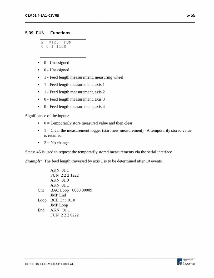
CLM01.4-LA1-01VRS 5-55
DOK-CONTRL-CLM1.4LA1*1-FK01-AE-P
5.39 FUN Functions
E 0123 FUN0 0 1 1100
• 0 - Unassigned
• 0 - Unassigned
• 1 - Feed length measurement, measuring wheel
• 1 - Feed length measurement, axis 1
• 1 - Feed length measurement, axis 2
• 0 - Feed length measurement, axis 3
• 0 - Feed length measurement, axis 4
Significance of the inputs:
• 0 = Temporarily store measured value and then clear
• 1 = Clear the measurement logger (start new measurement). A temporarily stored valueis retained.
• 2 = No change
Status 46 is used to request the temporarily stored measurements via the serial interface.
Example: The feed length traversed by axis 1 is to be determined after 10 events.
AKN 01 1FUN 2 2 2 1222AKN 01 0AKN 01 1
Cnt BAC Loop +0000 00009JMP End
Loop BCE Cnt 01 0JMP Loop
End AKN 01 1FUN 2 2 2 0222

5-56 CLM01.4-LA1-01VRS
DOK-CONTRL-CLM1.4LA1*1-FK01-AE-P
5.40 HOM Home Axis
E 0230 HOM1
• 1 - Axis number (1, 2, 3 or 4)
Homing proceeds according to how parameters Ax10 - Ax14 have been programmed. Stepping tothe next block takes place immediately after the block has been read in. This allows homing of allenabled axes simultaneously (with one task). Programming measures must be taken (ATS, AKN) toprevent absolute positioning commands (POA, PSA, etc.) from being encountered, before thehoming sequence is completed, or an error message will be issued. An ATS command programmedto monitor the "Home Established" output (Parameter Ax12) will prevent stepping to the next blockuntil the homing sequence is finished.
If the HOM command is used for an axis with an absolute value encoder, it will result in an errormessage.
NOTE: There are alternatives to Homing an axis, other than using this predefined routine. They aredescribed in Appendix A, as LA Programming Notes, number .001 and in section 3.2.5.

CLM01.4-LA1-01VRS 5-57
DOK-CONTRL-CLM1.4LA1*1-FK01-AE-P
5.41 JMP Jump Unconditional
E 0250 JMP1234
• 1234 - Target block
When this command is encountered in a given task, the program immediately jumps to the specifiedtarget block.
There are several other commands that also provide an unconditional jump, and provide addedfeatures in the same block. They can be useful when program space is limited. Refer to section 5.8,Command Summary, for alternatives.

5-58 CLM01.4-LA1-01VRS
DOK-CONTRL-CLM1.4LA1*1-FK01-AE-P
5.42 JSR Jump to Subroutine
E 0250 JSR1567
• 1567 - Start block of the subroutine
Subroutines can be called up at any time. The maximum permissible number of nested subroutinesis 127.
A subroutine must end with the command "RTS" (program jumps back to the block following theJSR command). If an RTS command is not programmed at the end of a subroutine, the programmedlines following the end of the subroutine will be executed. This can result in unexpected axismovement, "Invalid Program Command" diagnostic, etc.
NOTE: Additional program flow control is possible by using the Change Subroutine Stackcommand (CST) with the JSR/RTS commands for advanced programming.

CLM01.4-LA1-01VRS 5-59
DOK-CONTRL-CLM1.4LA1*1-FK01-AE-P
5.43 JST Jump and Stop
E 0260 JST1678
• 1678 - Target Block Number
This command causes the program to jump directly to the target block. The CLM will issue asoftware command and stop the program, waiting in the target block for a new start impulse atsystem input "Cycle Start". The start impulse will cause the CLM to continue processing theprogram beginning with the target block.
A JST command executed in Task 1 will cause the program running in Task 2, 4 or 5 to halt in itscurrent block until a "Cycle Start" command is issued to restart the program.

5-60 CLM01.4-LA1-01VRS
DOK-CONTRL-CLM1.4LA1*1-FK01-AE-P
5.44 JTK Jump in Task
E 0134 JTK0100 1
• 0100 - Target block
• 1− 1 = Task 1− 2 = Task 2− 4 = Task 4− 5 = Task 5
The JTK command is used for initiating an Unconditional Jump within a selected task. Thiscommand terminates the current program sequence for the selected task and then causes it to jump tothe target block. If the task is currently executing a move profile, the motion is completed before thetask can be interrupted. If necessary, a PBK command can be used before the JTK to terminate themotion thereby providing an immediate interrupt. The JTK command permits the use of manyspecific interrupt routines trapped by numerous events.
NOTE: If only one (input dependent) interrupt routine is needed, it is recommended to use theinterrupt parameter B012.
In most applications, the JTK command will be issued from one of the other tasks - typically oneassigned a supervisory status. If used correctly, the JTK command can provide many of the functionsavailable in B012 (Interrupt Vector) with the additional flexibility to use any event or series of events:position, count, one or more inputs or outputs to cause an interrupt to Task 1, 2 or 3.
• The command JTK_0100_2 in Task 1 causes the program to continue executing at Block100 of Task 2.
• JTK can also be programmed in Task 3.
• JTK_0100_1 in Task 1 has the same meaning as JMP_0100!
• When this command is executed, Task 3 does not branch to any other target block.

CLM01.4-LA1-01VRS 5-61
DOK-CONTRL-CLM1.4LA1*1-FK01-AE-P
5.45 KDI Copy Position Difference
E 0050 KDI0200 0100 1
• 0200 - Target block for the stored position difference
• 0100 - Compare position block number
• 1 - (as of software version LA04V09)− 0 = Commanded position minus the compared position− 1 = Compared position minus the commanded position− 2 = Actual position minus the compared position− 3 = Compared position minus the actual position
The Compared Position is the difference between the Actual Absolute Position (LP Screen) and anAbsolute Position at a specific program block (for example, block 0100 as shown above).
The KDI command will copy the position difference between the actual absolute position and theabsolute position at a specific block number (Compare position block number). The compareposition axis number and the position difference is then stored in the target block. The amount oftime to process the KDI command can be up to 100 ms. The program will advance to the next blockafter the position difference is stored in the target block. The actual position is either subtractedfrom the compared position or the compared position is subtracted from the actual position.
In order for the KDI command to function properly, the following conditions must be met:
1. The appropriate Axis (1, 2, 3 or 4) must be homed. If the Axis is not homed when theKDI command is encountered in the program, then the error message "Axis (#1, 2, 3 or4) Not Homed" is displayed.
2. The compare position block number must contain an absolute feed command (POA;PSA). If the program block is not an absolute feed, then the error message "Invalid ProgCmd" will occur.
3. The target block must contain an incremental feed command (POI; PSI).
4. The WRI command cannot be processed while using the KDI command.
5. The KDI command can only be used in one task at a time.

5-62 CLM01.4-LA1-01VRS
DOK-CONTRL-CLM1.4LA1*1-FK01-AE-P
5.45.1 MLO Material Length Output
(as of software version LA04V07)
E 0025 MLO01000.00 10 1
• 01000.00 - Material length in IU
• 10 - Output
• 1 - Output ON/OFF− 0 = OFF− 1 = ON
During automatic operation, the MLO command allows an output to be turned ON/OFFbased on the material length measured by the measuring wheel.
The first time the command is read in, the measurement feature is turned on. If themeasurement is larger than the programmed value, the output is turned ON/OFF, dependingupon the setting. The measurement starts over, and if the next measurement is larger than theprogrammed value, the output is turned ON or OFF again. Immediately after the command isread, the next program block is executed.
If the material length is programmed to 0, or if automatic operation is turned off, themeasurement feature is turned off.
NOTE: If the material has already been measured when the MLO command is read, and themeasurement is larger than the programmed value, the output is turned ON or OFF and measurementstarts over.

CLM01.4-LA1-01VRS 5-63
DOK-CONTRL-CLM1.4LA1*1-FK01-AE-P
5.46 NOP No Operation (Blank Block)
E 0270 NOP
This is the command to describe a blank block. During processing in the automatic mode, this blankblock is scanned only: processing continues with the next block.
NOP’s can be used to reserve program block space for future program change and expansion. Alsouse NOP’s in the program where you may want to add commands "on the fly" to modify production.
NOP’s may also be used as a program delay for each block. Note that the smallest delay pro-grammable in the WAI command is 10 milliseconds. The NOP command allows for smallerincrements of delay.
• If one or two axes are enabled, the default delay time for each NOP block is 2milliseconds.
• If three axes are enabled, the default delay time is 3.0 milliseconds for each NOP block.
• If all four axes are enabled, the default delay time is 4.0 milliseconds for each NOP block.
• Note that these default delay times can be changed in parameter B015.

5-64 CLM01.4-LA1-01VRS
DOK-CONTRL-CLM1.4LA1*1-FK01-AE-P
5.47 PBK Position Break
E 0055 PBK1
• 1 - Axis number (1, 2, 3 or 4)
The PBK command stops the execution of the current motion profile by decelerating the selectedaxis to a controlled stop. The selected axis will decelerate using the current programmedacceleration rate. The remaining distance to be traveled is ignored and the program jumps to thenext block.
This command could be used in another task to control the actions of the selected axis.
NOTE: The KDI command could be used for storing the approximate remaining distance, otherwisethe information is permanently lost.

CLM01.4-LA1-01VRS 5-65
DOK-CONTRL-CLM1.4LA1*1-FK01-AE-P
5.48 POA Position Absolute
E 0280 POA1 +12345.678 999
• 1 - Axis (1, 2, 3 or 4)
• +12345.678 - Plus or minus absolute target position in input units (to 2 or 3 decimalplaces, depending on the setting in B007)
• 999 - Feed rate in % (00.1-99.9) of the maximum velocity set in the parameters.
The specified axis must be homed (HOM or CLA) prior to execution of this command. Otherwise,an error message will be issued. Stepping to the next block takes place immediately after theabsolute position has been read into the position buffer. Since this command does not wait for theaxis to be in position before jumping to the next block, the program command following thiscommand will be executed. This allows other functions and status to be executed while the axis ismoving toward the end position.
If multiple POA commands are in sequence, the resulting move will, in most cases, continue andstop at the last POA Target Position issued.
An ATS command programmed in a subsequent block to monitor the Position Tolerance Output(Parameter Ax06) or the Position pre-signal (Parameter Ax07) is useful in controlling when to stepto the next block.

5-66 CLM01.4-LA1-01VRS
DOK-CONTRL-CLM1.4LA1*1-FK01-AE-P
5.49 POI Position Incremental
E 0290 POI2 +12345.678 999
• 2 - Axis number (1, 2, 3 or 4)
• + - Incremental feed direction (+ or -)
• 12345.678 - Incremental feed length in input units (to 2 or 3 decimal places, dependingon setting in B007)
• 999 - Feed rate in % (00.1 - 99.9) of the maximum velocity set in the parameters
Example: 500 would be 50.0% of the maximum velocity.
Stepping to the next block takes place immediately after the feed block has been read in.
Since this command does not wait for the axis to be in position before jumping to the next block, theprogram command following this command will be executed. This allows other functions and statusto be executed while the axis is moving toward the end position.
If multiple POI commands are in sequence, the resulting move will be the sum of all incrementalfeeds.
The ATS command programmed to monitor the Position Tolerance Output (Parameter Ax06) or thePosition pre-signal (Parameter Ax07) is useful in controlling when to step to the next block.

CLM01.4-LA1-01VRS 5-67
DOK-CONTRL-CLM1.4LA1*1-FK01-AE-P
5.50 POM Position On Memory
E 0300 POM3 0 0
• 3 - Axis Number (1, 2, 3 or 4)
• 0 - Mode− 0 = Feed incremental− 1 = Feed in absolute dimensions
• 1 - Feed direction− 0 = Positive− 1 = Negative
The POM command is an incremental or absolute positioning command. The programmed feedlength and velocity are stored in a single memory location by either Indramat IDS decade switchoption. Note that any axis can be controlled by the POM command, but given a single memorylocation, only one value can be stored at one time.
Stepping to the next block takes place immediately after the POM command is read into theprogram.
When using the IDS decade switch, enable this option in Parameter B003. If the decade switchoption is not enabled, this block is scanned and no positioning takes place.

5-68 CLM01.4-LA1-01VRS
DOK-CONTRL-CLM1.4LA1*1-FK01-AE-P
5.51 PSA Position Absolute (With In-Position Signal)
E 0310 PSA1 +12345.678 999
• 1 - Axis number (1, 2, 3 or 4)
• +12345.678 - Plus (+) or minus (-) absolute target position in input units (to 2 or 3decimal places, depending on the setting in B007)
• 999 - Feed rate as % (00.1 - 99.9) of the maximum velocity set in parameters
NOTE: The axis must be homed prior to execution of this command. Otherwise, an error messagewill be issued.
Stepping to the next block takes place only after the positioning has been completed. ParameterAx06 (Position Tolerance) is used to set the release point for stepping to the next block.

CLM01.4-LA1-01VRS 5-69
DOK-CONTRL-CLM1.4LA1*1-FK01-AE-P
5.52 PSI Position Incremental (With In-Position Signal)
E 0142 PSI2 +12345.678 999
• 2 - Axis number (1, 2, 3 or 4)
• + - Incremental feed direction, plus (+) or minus (-)
• 12345.678 - Feed length in input units (to 2 or 3 decimal places, depending on setting inB007)
• 999 - Feed rate as % (00.1 - 99.9) of the maximum velocity set in parameters
Stepping to the next block takes place only after the positioning has been completed. ParameterAx06 (Position Tolerance) is used to set the release point for stepping to the next block.

5-70 CLM01.4-LA1-01VRS
DOK-CONTRL-CLM1.4LA1*1-FK01-AE-P
5.53 PSM Position On Memory (with In-Position Signal)
E 0330 PSM3 0 1
• 3 - Axis Number (1, 2, 3 or 4)
• 0 - Mode− 0= Feed incremental− 1= Feed in absolute dimensions
• 1 - Feed direction− 0 = Positive− 1 = Negative
The PSM command is an incremental or absolute positioning command with positionacknowledgment. The programmed feed length and velocity are stored in a single memory locationby either Indramat IDS decade switch option. Note that any axis can be controlled by the PSMcommand, but given a single memory location, only one value can be stored at one time.
Stepping to the next block takes place after positioning is complete. The "In Position" aux. output isprogrammed in Parameter Ax06 - Position Tolerance.
When using the IDS decade switch option, enable this option in Parameter B003. If the decadeswitch option is not enabled, this block is scanned and no positioning takes place.

CLM01.4-LA1-01VRS 5-71
DOK-CONTRL-CLM1.4LA1*1-FK01-AE-P
5.54 PST Position Test
E 0340 PST1 05 +12345.678
• 1 - Axis number (1, 2, 3 or 4)
• 05 - Auxiliary output number
• +12345.678 - Test position value (to 2 or 3 decimal places, depending on setting in B007)
This command is used to check for a position and control an output based on current position status.At the execution of this block, the designated auxiliary output is turned ON if the actual position ofthe axis is less than the test position value.
If the actual position is equal to or greater than the test position value, the auxiliary output is turnedOFF. Stepping to the next block takes place immediately after the block has been read in. Pleasenote that the position is only tested once during the execution of the PST block. A program loopmust be created to test for a position repeatedly.
The Test position is related to the proceeded path of the last positioning if the axis has not beenhomed. If the axis has been homed, the Test position is related to the absolute position of the axis.

5-72 CLM01.4-LA1-01VRS
DOK-CONTRL-CLM1.4LA1*1-FK01-AE-P
5.55 REF Referencing (Detect Registration Mark Input)
E 0350 REF2 0 123 01
• 2 - Axis number (1, 2, 3 or 4)
• 0 - Direction− 0= forward− 1= reverse
• 123 - Search speed in % (00.1 - 99.9) of the maximum velocity set in parameters
• 01 - Registration auxiliary input number
NOTE: If the value 00 is entered here, possible only for axis 1, then system input 16, connector X3,pin 16, must be used. This is a high speed input, which makes possible a much more precisedetection of the reference mark.
It is possible at any time to search for a registration (reference) mark. The axis, direction, searchspeed (velocity) and registration input number can be freely selected. After the start of the block, theaxis moves at the specified search speed until a positive edge occurs at the specified aux. input.Stepping to the next block takes place only after the reference marker has been found (unless thenext block is a REP command, see page on REP command).
When the registration mark is found, the axis is decelerated and travels in reverse to the position theregistration mark was detected at. If it is desired that the axis does not back up in this manner, theREF (or REF/REP) can be followed by a PSI command. The PSI feed length would be set to thedistance it takes to decelerate the axis from the search speed.
The CLM includes a high speed input for this function. This input must be wired to a high speedsensor which will detect a printed mark or stamp on each section or piece of material being fed(signal duration of at least 150 microseconds). Signal duration for other auxiliary inputs must be atleast 2-4 milliseconds.

CLM01.4-LA1-01VRS 5-73
DOK-CONTRL-CLM1.4LA1*1-FK01-AE-P
5.56 REP Registration Position Limit (Search Limit Branch)
E 0351 REP0100 4 12345.678
• 0100 - Target block number (0000-2999), if search path exceeded
• 4 - Axis number (1, 2, 3 or 4)
• 12345.678 - Maximum search path for REF command (to 2 or 3 decimal places,depending on setting in B007)
The REP command is used to limit the maximum search distance while looking for the registrationinput. It will cancel a registration search command REF, and jump to the target block. REF andREP are run simultaneously. The REP command has to follow the REF command directly. The REPcommand cannot be run by itself.
At the start of the REF/REP commands, the axis moves at the search speed until either theregistration mark is detected, or the search length has passed.
If the registration mark is not detected, the axis will be decelerated to a stop after the search lengthoccurs. The actual length traveled will be the search length plus the distance it takes to deceleratethe axis to a stop. A jump is executed to the target block at the end of the search length, as the axisstarts decelerating.
If the registration mark is detected, the axis is decelerated (as described for the REF command) andstepping to the next block takes place.
The target block should be the start of a recovery routine written to restore operation from a missedmark. It will need to be customized for each application.

5-74 CLM01.4-LA1-01VRS
DOK-CONTRL-CLM1.4LA1*1-FK01-AE-P
5.57 RMI Registration Mark Interrupt
E 0300 RMI0 01
This command can be used to initiate additional processing, independently of the feed program. Theadditional registration mark processing is initiated after the recognition of an input pulse, and afteran offset has been traversed. The startup signal edge of the pulse is evaluated. The feed program isinterrupted for this registration mark processing and subsequently continued.
• 0 - Mode− 0 = Wait for pulse at the registration mark input (stepping to the next block takes
place after recognition of the pulse and traversing the offset.)− 1 = Terminate registration mark processing continue feed program. (stepping to the
next block takes place immediately)− 2 = Start the function unconditionally
• 01 - Registration mark input− 0 = quick input (system input 16, connector X3, pin 16), recognition in approx. 100
microseconds− 01-88 = standard input (recognition in approx. 2 - 4 milliseconds)
The registration mark program has to be programmed in Task 2. An offset can be programmed inthe form of an incremental feed (POI, PSI, POM or PSM). The incremental feed command has tofollow the RMI command directly.
Example of application:
Press Registration Sensor
Forming Rolls
Cutter
Perforated sheet metal should be cut according to the location of the perforations, which are stampedinto the flat sheet metal on the press. The material is then fed through the forming rolls. A holeserves as a reference signal for recognition of the registration sensor. Since an unknown change oflength occurs during profiling, the same feed program cannot be used for the cutting process becausethe possibility that the perforation will drift to the edge cannot be excluded. Because of this reason,cutting is done depending on the reference hole.
The reference hole can be detected by means of a light barrier, initiator, or similar device.

CLM01.4-LA1-01VRS 5-75
DOK-CONTRL-CLM1.4LA1*1-FK01-AE-P
NOTES:
• Possible only with Axis 1; not usable with an adjusting axis or a motor with reversiblepoles.
• Not usable with synchronous axis, in accordance with parameter A123 = 1XXXXXXX
• Cannot be used simultaneously with a REF command for Axis 1
• Will be ignored in the case of re-start
• The RMI works correctly only with feeds and offset feeds in positive direction (e.g., PSI 1+....)
• In Task 2, (RMI program) there should be not other feed except for the offset
• After the RMI command (RMI 0 XX) has been called up, masking a hole is no longerpossible
• Recognition of an additional registration mark prior to the command ’RMI 1 XX’ is notpossible
The velocity that can be changed by means of the offset feed is returned to its old value when thefeed program resumes. The interruption, feed monitoring and override functions may be used.

5-76 CLM01.4-LA1-01VRS
DOK-CONTRL-CLM1.4LA1*1-FK01-AE-P
Sample program:
Task1: PSI 1 +000050.00 999JSR Stamp1PSI 1 +000025.00 999JSR Stamp2JMP Task1
Stamp1: AEA 01 1 stamping with stamp 1WAI 00.20AEA 01.00RTS
Stamp2: AEA 02 1 stamping with stamp 2WAI 00.20AEA 02 0RTS
Task2: RMI 0 00 wait for registration markpulse and traversing of offset distance
PSI 1 +000015.50 500 offset distance from position of registration markJSR ToolRMI 1 00JMP Task2
Tool: AEA 03 1 cutter onWAI 00.25 waiting timeAEA 03 0 cutter offWAI 00.20 waiting timeRTS

CLM01.4-LA1-01VRS 5-77
DOK-CONTRL-CLM1.4LA1*1-FK01-AE-P
5.58 RSV Restart Vector
E 0700 RSV1 000 10000
• 1 -− 0 = Restore status as before interrupt (except outputs) and finish Restart program− 1 = Do not finish the Restart program
• 000 - Not used, set to 000
• 1 - Outputs status− 0 = Restore status of outputs as before interrupt− 1 = Do not restore outputs
• 0000 - Not used, set to 0000
The Restart Vector is used to recover for a power loss, System Error or change in mode from Auto toManual. When any of these events occur, the status at the time (velocity, absolute target position,outputs, etc.) are temporarily stored and can be recovered with this command.

5-78 CLM01.4-LA1-01VRS
DOK-CONTRL-CLM1.4LA1*1-FK01-AE-P
5.59 RTM Rotary Table Mode
E 0000 RTM1 1
• 1- Axis number (1, 2, 3 or 4)
• 1- Rotary Table Mode:− 0 = set to mode designated in Parameter Ax10− 1 = shortest path− 2 = programmed direction− >2 = no mode change
The specified axis must be homed (HOM or CLA) prior to execution of this command. Otherwise,an error message will be issued
After restarting, clearing a fault, or exiting Parameter Mode, the settings from Parameter Ax10 arevalid. Toggling between Manual and Automatic modes does not affect the current Rotary TableMode.

CLM01.4-LA1-01VRS 5-79
DOK-CONTRL-CLM1.4LA1*1-FK01-AE-P
5.60 RTS Return from Subroutine
E 0370 RTS
The RTS command is used to return from a subroutine which has been called by using the JSRcommand. The program is continued at the point where the subroutine had been called which is thenext block after the JSR command.
If in multiple subroutines, the RTS command will take the program back only to level of the currentsubroutine stack.
NOTE: Additional program flow control is possible by using the Change Subroutine Stackcommand (CST) with the JSR/RTS commands for advanced programming.

5-80 CLM01.4-LA1-01VRS
DOK-CONTRL-CLM1.4LA1*1-FK01-AE-P
5.61 SAC Set Absolute Counter
E 0300 SAC1 0 +12345.678
• 1 - Axis number (1, 2, 3 or 4)
• 0 -− 0 = Absolute zero offset relative to the zero position after homing− 1 = Set absolute position, with respect to the command position.− 2 = Set absolute position, with respect to the actual position.− 9 = Clear ‘Homed’ (only with incremental encoder)
• +12345.678 - Absolute position or offset, plus (+) or minus (-)
This command is used to set or change the value of the absolute position counter. The axis must behomed before this command can be used.
NOTE: For absolute encoder operation the offset distance is calculated only in forward direction.

CLM01.4-LA1-01VRS 5-81
DOK-CONTRL-CLM1.4LA1*1-FK01-AE-P
5.62 SIN Sine Oscillation
E 0380 SIN1 10 12.345 999
• 1 - Axis number (1, 2, 3 or 4)
• 10 - Auxiliary input which enables SIN function
• 12.345 Amplitude in Input Units (to 2 or 3 decimal places, depending on setting in B007)
• 999 - Frequency of oscillation in Hertz (0.01 to 9.99)
This function will start up with 0 degrees when the enable input is switched On. When the enableinput is switched Off, the function ends at 360 degrees. After this, stepping to the next block willtake place. The axis must be homed, or an error will occur when this command is read.

5-82 CLM01.4-LA1-01VRS
DOK-CONTRL-CLM1.4LA1*1-FK01-AE-P
5.63 SO1 Scanning of Inputs and Modifying a Length (Special Option #1)
E 0320 S011 1 10 1000
• 1 -− 0 = Read decade switch values.− 1 = Convert decade switch values and store this in the first variable of the target
block.− 2 = Convert decade switch values and store this in the second variable of the target
block
• 1 - Decimal Position (Y value): (to 2 or 3 decimal places, depending on setting in B007)
For 3 decimal places For 2 decimal places
1= 10-3 1= 10-2
2= 10-2 2= 10-1
3= 10-1 3= 100
4= 100 4= 101
5= 101 5= 102
6= 102 6= 103
7= 103 7= 104
8= 104 8= 105 9= + or - 9= + or -
• 10 - Starting Input Number XX, with the BCD value (see illustration):
XX = 10XX+1 = 11XX+2 = 12XX+3 = 13
• 0000 - Target Block

CLM01.4-LA1-01VRS 5-83
DOK-CONTRL-CLM1.4LA1*1-FK01-AE-P
Command Type Mode 1 Mode 2
POA, POI, PSA, PSI Position Velocity
VCA, VCC Position Velocity
ACC Acceleration ----------
BAC, COU ---------- Command Quantity
BPT, BZP Position ----------
CON as of sw LA01.3-3.3 ---------- Velocity
CID as of sw LA01.3-3.3 ---------- Information
PST ---------- Position
SAC as of sw LA01.3-3.0 Position ----------
SIN as of sw LA01.3-04V07 Amplitude Frequency
WAI as of sw LA01.3-3.3 Time ----------
The target block must contain one of the commands listed in the table above. Decade switch IDS-01can be used simultaneously.
The SO1 command is used to read length information, via decade switches or from a programmablelogic controller.
In the following example, aux. input 10 is the least significant digit. Enter 10 for the XX entry.Input 11 is 10+1 (XX+1). Input 13 is the most significant digit (XX+3). The CLM must read in alldecimal places, one after the other. An SO1 command is required for each decimal place. Theresulting information is converted and stored in the first or second variable of the target block.
The information is zeroed after a fault, Emergency Stop, enabling of Parameter Mode, or poweringup the CLM system.
The illustration is an example of an external decade switch group connection (4 decade).

5-84 CLM01.4-LA1-01VRS
DOK-CONTRL-CLM1.4LA1*1-FK01-AE-P
The following example program, using the SO1 command, uses APE command to switch outputs.
BLOCK#/COMMAND/COMMAND DATA
0900 APE 1 1000222222 = Fourth Decade (10-1)0901 WAI 00.020902 SO1 0 2 10 01000903 WAI 00.02
0904 APE 1 0100222222 = Third Decade (10-0)0905 WAI 00.020906 SO1 0 3 10 0000907 WAI 00.02
0908 APE 1 0010222222 = Second Decade (101)0909 WAI 00.020910 SO1 0 4 10 01000911 WAI 00.02
0912 APE 1 0001222222 = First Decade (102)0913 WAI 00.020914 SO1 0 5 10 01000915 WAI 00.020916 SO1 1 5 10 0100 = Read in as Length
The fourth decade is read in via output 10, the third via output 11, the second via output 12, and thefirst via output 13. In the example, inputs 10 to 13 are programmed as an input. The length is thenread in.
NOTES:
• It is useful to program this type of decade switch query in Task 3.
• All numbers which are not read in (pseudo-nibbles) are assumed to be 0.
• The sign is established at the starting input. +24 Vdc signal means "+" and O Vdc signalmeans "-" .

CLM01.4-LA1-01VRS 5-85
DOK-CONTRL-CLM1.4LA1*1-FK01-AE-P
5.64 SO2 Position Correction Via Analog Input
E 0045 SO21 +123.456 2
• 1 - axis selection− 1 = axis 1 and analog input AE1− 2 = axis 2 and analog input AE2− 3 = axis 3 and analog input AE3− 4 = axis 4 and analog input AE4
• + - prefix of the stroke− (+) = positive stroke with positive voltage and negative stroke with negative voltage− (-) = negative stroke with positive voltage and positive stroke with negative voltage
• 123.456 - stroke between 0 volts and 10 volts, in input units (the voltage range of -10 Vto +10V corresponds to 2 * stroke)
• 2 = command mode: 0 to 4
Description of command mode options:
• 0 = a) preparation for mode 2. The current absolute position becomes zero position for mode 2b) End of mode 4
• 1 = One time feed (with POI) = stroke * voltage / 10 (feed length increased/decreased)
• 2 = Absolute feed with respect to the zero position (set in mode 0). Zero volts at theanalog input positions the axis onto zero.One time feed (with POA) = (stroke- zero position) * voltage / 10
• 3 = One-time feed = stroke * voltage / 10 (feed is set)
This command must be called up again and again in a loop for purposes of control. Anexternal measuring device provides a voltage of +/- 10 V, proportional to the path traversed.Positioning on the zero position of the measuring device then takes place, i.e., to 0 volt =>corresponding to the command value control.
• 4 = Startup of the position detection via the analog input. This function is always activeuntil it is shut down by mode 0. Traversing within the range "-stroke" to "+stroke" can bedone now with an absolute travel command.

5-86 CLM01.4-LA1-01VRS
DOK-CONTRL-CLM1.4LA1*1-FK01-AE-P
NOTES:
• In modes 2 and 4, the axis must have been set up, otherwise, there will be acorresponding error message ’Axis Not Homed’.
• Mode 4 is not cleared when the operating mode changes from automatic to manual orfrom manual to automatic; however, it is cleared in case of fault, emergency shutdown,and startup.
Example entries/results:
Entry:
E 0045 SO21 +002.000 1
Result:
Voltage at AE 1 Position Correction Value
+ 10 V + 2.000+ 5 V + 1.000 0 V 0.000- 3 V - 0.600- 10 V - 2.000

CLM01.4-LA1-01VRS 5-87
DOK-CONTRL-CLM1.4LA1*1-FK01-AE-P
5.64.1 SRM Drive To Registration Mark
E 0350 SRM2 0 123 01
• 2 - Axis number (1, 2, 3 or 4)
• 0 - Direction− 0= forward− 1= reverse
• 123 - Search speed in % (00.1 - 99.9) of the maximum velocity set in parameters
• 01 - Registration auxiliary input number
NOTE: If the value 00 is entered here, possible only for axis 1, then system input 16, connector X3,pin 16, must be used. This is a high speed input, which makes possible a much more precisedetection of the reference mark.
It is possible at any time to search for a registration (reference) mark. The axis, direction, searchspeed (velocity) and registration input number can be freely selected. After the start of the block, theaxis moves at the specified search speed until a positive edge occurs at the specified aux. input.Stepping to the next block takes place only after the reference marker has been found (unless thenext block is a REP command, see page on REP command).
When the registration mark is found, the axis is decelerated and travels in reverse to the position theregistration mark was detected at. If it is desired that the axis does not back up in this manner, theSRM (or SRM/REP) can be followed by a PSI command. The PSI feed length would be set to thedistance it takes to decelerate the axis from the search speed.
The CLM includes a high speed input for this function. This input must be wired to a high speedsensor which will detect a printed mark or stamp on each section or piece of material being fed(signal duration of at least 150 microseconds). Signal duration for other auxiliary inputs must be atleast 2-4 milliseconds.

5-88 CLM01.4-LA1-01VRS
DOK-CONTRL-CLM1.4LA1*1-FK01-AE-P
5.65 STH Send to Host
E 0390 STH0 0002
• 0 - Type of information− 0 = Status 00, 02, 03, 04, 05, 06, 07, 08, 09, 10, 19, 39, 40, 41, 42, 43, 44, 45, 46, 47,
48, 49, 50, 51, 52, 53 (See Chapter 7)− 1 = Counter status of preset and actual number of pieces. The block number of the
counter must be entered in the status code field.
• 0002 - Code for Status, options as below:− 0000 = Current position, axis 1 & 2− 0002 = Current program block (task 1 only)− 0003 = Current position, axis 1 & 2 (as a hexadecimal value)− 0004 = Counter status− 0005 = Software version− x006 = Current input status− x007 = Current output status− 0008 = Current Block and RTS return block (Task 1, 2 & 3)− 0009 = Measuring wheel: Current position, axis 1 and measuring wheel− 0010 = Position Lag, axis 1 & 2− 0019 = Hardware and Software version− 0039 = Current Block and RTS return block (Task 4 & 5)− 0040 = Current position, axis 3 & 4 (as a hexadecimal value)− 0041 = Current position of axis 1 at reference mark− 0042 = Current Motor RPM, axis 3 & 4− 0043 = Position Lag, axis 3 & 4− 0044 = Current Position, axis 3 & 4− 0045 = Analog inputs 3 & 4− 0046 = Feed length measurement− 0047 = Current RPM, measuring wheel− 0048 = Current Motor RPM, axis 1 & 2− 0049 = Analog inputs 1 & 2− 0050 = System inputs and system outputs as a hexadecimal value− 0051 = Auxiliary inputs as a hexadecimal value− 0052 = Auxiliary outputs as a hexadecimal value− 0053 = Fault Indication
NOTE: In x006 and x007, x = Input/output bank number, 0-9

CLM01.4-LA1-01VRS 5-89
DOK-CONTRL-CLM1.4LA1*1-FK01-AE-P
Program-controlled data output via the serial interface (see Chapter 7). Stepping to the next blocktakes place immediately after the block has been read in. Serial interface must have been activatedthrough parameters B003 and B004. Otherwise, stepping to the next block takes place withouthaving an output transmitted.
Examples of STH entry:
0__0003______
Status ‘03’ current position of axis 1 and 2 in Hexadecimal, is transmitted to Host device via theserial interface.
1__0100______
Status of counter located in block 0100. The desired and actual number of pieces, is transmitted toHost device via the serial interface.
NOTE: Status Messages are processed in the background of the program. Since this has a lowerpriority, the exact time of execution (and transmission) are not easily calculated.

5-90 CLM01.4-LA1-01VRS
DOK-CONTRL-CLM1.4LA1*1-FK01-AE-P
5.65.1 STO Send Information To Outputs
E 0002 STO101 1 3 0000 05
• 1 - Axis number or general data− 0 = Counter status− 1-4 = Axis 1-4
• 0 - Not used, set to 0
• 1 - Information type− 1 = Absolute position− 2 = Counter status
• 1 - Mode− 0 = Store current information (position or counter)− 1 = Output stored information via outputs in BCD format
• 3 - Decimal positionDecimal Significance
1 1st digit starting from the right
2 2nd digit starting from the right
3 3rd digit starting from the right
4 4th digit starting from the right
5 5th digit starting from the right
6 6th digit starting from the right
7 7th digit starting from the right
8 8th digit starting from the right
9 9th digit is prefix; + = 0 - = 1
For the prefix, 24V is output for minus, and 0V is output for plus.
• 0000 - Block number (save if in counter)
• 05 - Starting output number XX (otherwise 00):
− XX = 10 corresponding value 1 = 20
− XX+1 = 11 corresponding value 2 = 21
− XX+2 = 12 corresponding value 4 = 22
− XX+3 = 13 corresponding value 8 = 23

CLM01.4-LA1-01VRS 5-91
DOK-CONTRL-CLM1.4LA1*1-FK01-AE-P
The STO command is used to output either axis position or counter status information viafour auxiliary outputs in BCD format. The user specifies the type of information, number ofdecimal places, counter block (if counter status is selected), and the starting output number.The three outputs after the starting output number will be used to output the information.
The commands are processed as follows:
• Mode 0 Store information in internal buffer, then
• Mode 1 Output information
Only one type of information can be stored internally at one time, either absolute position orcounter status. The buffer is never zeroed by the CLM.
STO Command Example:
For this example, the absolute position for the axis is equal to +598.00 inches. The auxiliaryoutputs 04 through 07 are used for the BCD value.
0900 AKN 02 0 ; Toggle input #2 to begin the program0901 AKN 02 1
0902 STO 101 0 0 0000 00 ; Store actual position0903 JSR 0925 ; Jump to subroutine at program block 09250904 STO 101 1 9 0000 04 ; Output the direction of the sign0903 JSR 0925 ; Jump to subroutine at program block 09250906 STO 101 1 3 0000 04 ; Output third digit
; ( XX+3=1, XX+2=0, XX+1=0, XX=0) = 8
0907 JSR 0925 ; Jump to subroutine at program block 09250908 STO 101 1 4 0000 04 ; Output fourth digit
; ( XX+3=1, XX+2=0, XX+1=0, XX=1) = 9
0909 JSR 0925 ; Jump to subroutine at program block 09250910 STO 101 1 5 0000 04 ;Output fifth digit
; ( XX+3=0, XX+2=1, XX+0 =0, XX=1) = 5
0911 JSR 0925 ; Jump to subroutine at program block 09250912 STO 101 1 6 0000 04 ; Output sixth digit
; ( XX+3=0, XX+2=0, XX+0 =0, XX=0) = 0
0913 JMP 0900 ; Jump to program block 0900 and start a new read in; the cycle
0925 AKN 01 0 ; Toggle input #1 to output the next digit0926 AKN 01 10927 RTS ; Return from subroutine

5-92 CLM01.4-LA1-01VRS
DOK-CONTRL-CLM1.4LA1*1-FK01-AE-P
5.66 VCA Velocity Change Absolute
E 0410 VCA2 +12345.678 100
• 2 - Axis number (1, 2, 3 or 4)
• +12345.678 Absolute position at which the new velocity is achieved (to 2 or 3decimal places, depending on the setting in B007)
• 100 - Speed in % (00.1 - 99.9) of the maximum velocity set in the parameters
The VCA command changes the velocity of a positioning move in progress such that the desiredvelocity is reached at the specified absolute position.
The program proceeds to the next instruction immediately after the drive unit begins changing itsvelocity. This point depends on the acceleration, the difference in velocity and the position lag.
If this point has already been reached or exceeded when the VCA command arrives, the programproceeds immediately to the next instruction, accepting the new velocity.
This command may be used only if an absolute measurement reference is present. Otherwise theerror message "Not homed" is generated.
A change in velocity can take place only when the positioning functions do not include positionacknowledgement (POA, POI and POM).
Example:
0000 POA 1 +00100.000 9990001 VCA 1 +00050.000 2500002 VCA 1 +00075.000 5000003 VCA 1 +00090.000 1000004 ATS 15 10005 JST 0000

CLM01.4-LA1-01VRS 5-93
DOK-CONTRL-CLM1.4LA1*1-FK01-AE-P
5.67 VCC Velocity Change Command
E 0410 VCC2 12345.678 100
• 1 - Axis number (1, 2, 3 or 4)
• 12345.678 Path to be traversed before the velocity change (to 2 or 3 decimal places,depending on the setting in B007)
• 100 - Speed in % (00.1 - 99.9) of the maximum velocity set in the parameters
The VCC command is used to alter the current rate of velocity at some point along a path. MultipleVCC commands can be used to create a "step" effect in the velocity profile. Velocity changes arealways referenced to the most recently initiated positioning function.
The program proceeds to the next instruction immediately after the distance programmed in the VCCcommand, referenced to the start position of the most recent positioning function, has been traversed.
A change in velocity can take place only when the positioning functions do not include positionacknowledgement (POA, POI and POM).
NOTE: The position portion in the last VCC value must be smaller than the previously startedpositioning function, otherwise that VCC command is not executed and the program proceeds to thenext instruction.
Example:
0000 POI 1 +00010.000 9990001 VCC 1 +00050.000 2500002 VCC 1 +00075.000 5000003 VCC 1 +00090.000 1000004 ATS 15 10005 WAI 01 . 000006 JST 0000

5-94 CLM01.4-LA1-01VRS
DOK-CONTRL-CLM1.4LA1*1-FK01-AE-P
5.68 VEO Velocity Override Command
E 0400 VEO1 2 3 456 7
• 1 - Axis number (1, 2, 3 or 4)
• 2 - Override input selection− 0= switched OFF or override in accordance with Parameter B013− 1= Analog value of 0...+10 volts at the corresponding analog input
− 2 = Binary value at Inputs #9-16, Significance: input 9= 20... input 16= 27
− 3 = Value in Gray Code at inputs #13-16 (as in B013)− 4 = Override value from VEO command (see above)− 5 = Default value via measuring wheel encoder− 6 = Analog input 1 × Override Value (as of software version LA03V07)
• 3 - Override update− 0 = Read the Override input value every program cycle (time depends on the number
of axes enabled and user settings, see parameter B015)− 1 = Reads Override value only once (each time the command is executed)
• 456 - Velocity factor to 3 decimal places (001-999). This factor is significant only inmodes 4 and 6. Subsequent feeds are reduced by this factor.
• 7 - Function− 0 = Override as factor− 1 = Override as limit
This command produces a reduction in the velocity of all the programmed traversing commands.With the "Override as factor" function, the override value is multiplied by the programmed velocityfrom the commands.
With the "Override as limit" function, the override value is multiplied by the programmed velocityfrom the parameter Ax00 and therefore limits the velocity. Activation of an override function usingthe VEO command has priority over activation of any function within parameter B013.
Once a VEO command has been invoked, it applies to all subsequent motions until it is canceled.
Any change in operation mode between "Automatic" and "Manual" cancels the override functioninvoked by the VEO command. The values can be changed again in Task 3.
Override selection ’5’ can be activated with the VEO command only if ’0xxxxx’ is programmed inParameter Ax23. Parameters B016, B017 and B018 must also be programmed.

CLM01.4-LA1-01VRS 5-95
DOK-CONTRL-CLM1.4LA1*1-FK01-AE-P
The feed constants and the number of lines of the motor encoder and of the measuring wheel encoderare taken into account in such a way that, at a feed rate of 100 % velocity, both mechanisms (axisand measuring wheel) are running at the same velocity. This velocity can be determined by means ofthe synchronizing factor with the command FOL.
If the axis should achieve a velocity of more than 1.25 times Vmax due to incorrect programmingor because of excessive velocity of the measuring wheel, the following error message will bedisplayed: "Error maximum override Ax".
The velocity of the axis is limited in all instances to Vmax in case measuring wheel velocities exceedVmax.

5-96 CLM01.4-LA1-01VRS
DOK-CONTRL-CLM1.4LA1*1-FK01-AE-P
5.69 WAI Wait (Time Delay)
E 0420 WAI00.50
• 00.50 - Dwell time (00.01-99.99 seconds)
Examples of how a time delay is programmed:− 00.01 = 10 milliseconds (the minimum dwell time programmable),− 00.50 = 0.5 seconds.
The CLM waits in the program block until the specified time has elapsed. After the time delay, theprogram steps to the next block. See the NOP command for related function (when require less than10 milliseconds dwell time).

CLM01.4-LA1-01VRS 5-97
DOK-CONTRL-CLM1.4LA1*1-FK01-AE-P
5.70 WRI Write in Absolute Position (Teach Command)
E 0042 WRI0357 002
• 0357 - Target block number
• 00 - Command type− 00 = save command position− 01 = save actual position
• 2 - Axis number (1, 2, 3 or 4)
Use this command to "write in" (teach) an absolute positioning command in the user program. Notethat an absolute positioning command requires that the selected axis MUST BE HOMED.Otherwise, an "Axis Not Homed" error occurs.
When the WRI command is read, the current absolute position or the command position is saved inthe target block as the positional indication. One of the following commands must already beprogrammed in the target block: POA, PSA, VCA, BPT, BZP, PST or SAC. The previous positionindication in the target block is overwritten by the WRI command.
The next block is executed when the position is saved in the target block.
The last digit specifies which axis (1, 2, 3 or 4) the absolute feed command controls.
This command is used to teach or update a position into a functional program. The axis is typicallyjogged into a desired position, then a predefined teach routine is run that will teach this position intoall the appropriate blocks. The teach routine can be written as a manual vector or as program forTask 1, 2 or 3.
The absolute feed command selected by the WRI command must have a distance to feed. Thisdistance is taken from the Actual Position Display. The speed automatically inserted for doing thefeed is always the maximum (99.9%). A preceding VEO (selection 4) or subsequent POI (zero feedlength) can be used to reduce the written velocity to a lower percentage.
Using the WRI command in Manual Mode
This is an example of how to "write in" absolute positions in the main program.
Task 3 is selected as the location for the WRI command. The Task 3 program must be loaded intothe CLM before enabling parameter B006. Task 3 is always running, even before Cycle Start ispressed.

5-98 CLM01.4-LA1-01VRS
DOK-CONTRL-CLM1.4LA1*1-FK01-AE-P
Start Task 2&3Parameter B006 00000150
NOTE: Axis must be homed.
Example: Program for the WRI command.
0150 AKN 02 1 Aux. input #2 "writes in" 1st position0151 BCA 0150 15 0 Check axis 1 is homed0152 BCA 0150 16 0 Check axis 2 is homed0153 WRI 0015 001 Writes in Abs. Position at Block 00150154 WRI 0016 012 Writes in Abs. Position at Block 00160155 AKN 02 0 Write-in complete0156 AKN 02 1 Aux. Input #2 "writes in" 2nd position0157 WRI 0020 001 Writes in Abs. Position at Block 00200158 WRI 0021 012 Writes in Abs. Position at Block 00210159 AKN 02 0 Write-in complete0160 JMP 0150 Jump to Block 0150
Example: Main Program Before It "Writes In" the New Position
0000 JMP 00150015 PSA 1 +00000.000 5000016 PSA 2 +00000.000 5000017 AEA 01 10018 WAI 00.500019 AEA 01 00020 PSA 1 +00000.000 5000021 PSA 2 +00000.000 5000022 AEA 02 10023 WAI 00.500024 AEA 02 00025 JMP 0015

CLM01.4-LA1-01VRS 5-99
DOK-CONTRL-CLM1.4LA1*1-FK01-AE-P
Procedure for Using the WRI Command in Manual Mode
1. In Manual mode, home Axis 1 and 2.
2. Jog Axis 1 and 2 to the first position desired.
Example:
First position desired: L P 1A +00010.000 2A -00020.000
3. Turn Auxiliary Input #2 on and off.
4. Jog Axis 1 and 2 to the second position desired.
Example:
Second position desired: L P 1A -00005.000 2A +00012.000
5. Turn Auxiliary Input #2 on and off.
6. Now blocks 0015 and 0016 should change to the first position desired. Blocks 0020 and0021 should change to the second position desired.
Example: Main Program After It "Writes In" the New Position Block Number
0015 PSA 1 + 00010.000 9990016 PSA 2 - 00020.000 9990017 AEA 01 10018 WAI 00.500019 AEA 01 00020 PSA 1 - 00005.000 9990021 PSA 2 +00012.000 9990022 AEA 02 10023 WAI 00.500024 AEA 02 00025 JMP 0015

5-100 CLM01.4-LA1-01VRS
DOK-CONTRL-CLM1.4LA1*1-FK01-AE-P
Notes

CLM01.4-LA1-01VRS 6-1
DOK-CONTRL-CLM1.4LA1*1-FK01-AE-P
6. INSTALLATION/START-UP
This Chapter covers the installation and initial start up testing procedures for the CLM controlsystem. The system consists of the following components:
• The CLM Control Module
• The Servo Amplifier(s)
• The Power Supply
• The Servomotor(s)
The instructions in this chapter primarily describe the installation of the CLM Control Module. Theinstallation particulars of the other components (such as a TVM or KDV power supply, and TDM orKDS servo amplifiers) are explained in detail in their respective manuals. Appendix B list relevantpublications which you may require.
Tools required:
• A small 1/8" blade, standard screwdriver
• A multi-meter (VOM)
• An appropriate wrench for 1/4" machine type bolts (use for mounting module[s] tocabinet).
6.1 Unpacking / Parts Inventory
The CLM system is shipped in reinforced cardboard cartons and is sufficiently packed to withstandnormal shipping activity. Upon receiving equipment, inspect shipping carton for any evidence ofexternal damage (i.e., ripped or punctured carton, water marks, etc.). Should carton show any signsof damage, immediately inspect contents and contact carrier for damage claim if necessary.
Open cartons and remove the Styrofoam and bubble packing material from around the equipment.Remove the equipment and place on a firm level surface.

6-2 CLM01.4-LA1-01VRS
DOK-CONTRL-CLM1.4LA1*1-FK01-AE-P
The CLM carton contains the following items:
• The CLM module
• CLM cable set (SK5001) contains:− 1 Input cable− 1 Output cable− 1 Encoder cable
• CLM Electrical Accessory Kit (E15-CLM) which contains:− 15 pin Phoenix connector (X5)− Wire tie wraps− 7 pin Phoenix connector (X7)
CLM optional equipment includes:
• Remote Keypad - accessories include:− Remote keypad extension cable (typically 2 meters)− 2 dual side adhesive foam gaskets for keypad− A dummy CLM face plate
• IDS Assembly - with Electrical accessory kit that contains:− A 5 pin Phoenix connector− A serial interface cable with a RS-232 connector at one end and Ferrule connectors
on the other.

CLM01.4-LA1-01VRS 6-3
DOK-CONTRL-CLM1.4LA1*1-FK01-AE-P
6.2 Mounting Cabinet
The CLM and its associated modules are designed for cabinet mounting. It is recommended theCLM be mounted in a cabinet, side by side with the Amplifier and Power Supply modules (seeFigure 6.1). The enclosure should be sufficient to protect the equipment from contaminants, such aswater, oil, etc. Indramat recommends a NEMA 4 or 12 enclosure or equivalent.
Figure 6-1 CLM System Modules

6-4 CLM01.4-LA1-01VRS
DOK-CONTRL-CLM1.4LA1*1-FK01-AE-P
6.3 Power
The CLM requires 24 Vdc to operate. This voltage is supplied from the TVM (KDV) or from anexternal 24 Vdc supply. Refer to section 1.6.2 for power specifications for the CLM and its options.Refer to separate manuals (listed in Appendix B) for power requirements of the other modules(power supply, servo amplifier, etc.).
6.4 Cable Routing
For higher reliability, the feedback cables must be shielded and routed away from high voltage powersources to reduce electrical noise.
Do not route the CLM cables near high amperage type machines, like welding equipment, whichproduce strong magnetic field interference.
Suppress inductive loads (such as solenoids and motors) that are switched ON and OFF during CLMoperation, with R-C networks (AC) or diodes (DC).
Correct grounding is essential for trouble free operation. The ground connection must be made byobserving strictly the branching conditions shown in the wiring diagram.
6.5 Transformer - Heat Dissipation
The incoming 3-Phase power must be ground referenced. Use an isolation transformer with a "Y"secondary if this cannot be confirmed. Refer to TVM/KDV (or appropriate) manual for additionalinformation.
If a transformer is needed for operation, exercise caution on its location. Do not install thetransformer in the same cabinet as the CLM modules unless a sufficient method of cooling isapplied.

CLM01.4-LA1-01VRS 6-5
DOK-CONTRL-CLM1.4LA1*1-FK01-AE-P
6.6 Hardware Installation
The CLM and its supporting modules mount to the back wall of the equipment enclosure (cabinet).The mounting brackets of the modules are pre-drilled to accept a 1/4" machine bolt.
See Appendix G for mounting hole dimensions and location of the CLM module, the cut-outdimensions for the remote keypad, keypad gasket, and keypad replacement panel (dummy faceplate), and mounting holes and cut-out dimensions for the optional IDS.
The mounting dimensions and cabinet cut-out data for the TVM (KDV) and the TDM (KDS) arelocated in the units respective support manuals.
The method of mounting the MAC servomotor is dependent upon the application. Additionalinformation and a drawing package for the MAC servomotor is available on request from Indramat.
6.7 Electrical Installation
There are many variations of wiring techniques used to connect the CLM to the machine builder’sequipment. The Interconnect Drawings supplied with this manual (see Appendix F) show anexample of the CLM connections to a typical metalforming machine.

6-6 CLM01.4-LA1-01VRS
DOK-CONTRL-CLM1.4LA1*1-FK01-AE-P
6.8 CLM Connectors
This section describes all the connectors on the CLM module. Refer to Figure 1.5 in Chapter 1 foran illustration of the CLM module and its connector locations.
X - 1: Encoder Input Axis 1
Female, DB 25 connector is located on the top of the CLM and used for inputs from the respectiveencoder assembly for axis 1 and measuring encoder.
X - 2: Encoder Input Axis 2
Female, DB 25 connector is located on the top of the CLM and used for inputs from the respectiveencoder assembly for axis 2.
X - 3: System Input
Male, DB 37 connector is located on the top of the CLM and used for inputs from various locationsof the system (see Chapter 3 for I/O descriptions; see Table 2.1 for quick reference to I/Oconnections).
X - 4: System Output
Female, DB 37 connector is located on the top of the CLM and used for various outputs (see Chapter3 for I/O descriptions; see Table 2.1 for quick reference to I/O connections).

CLM01.4-LA1-01VRS 6-7
DOK-CONTRL-CLM1.4LA1*1-FK01-AE-P
X - 5: Command Connector
A 15 pin Phoenix connector is located on the lower front panel of the CLM. This is a multi-functional connector.
The various contacts of X - 5 are:
• 24 Vdc Power Supply - ins 1 & 2
• Bb motor Contacts - pins 3 & 4
• Analog Command Axis 1 (A1) - pins 5 & 6
• Analog Command Axis 2 (A2) - pins 8 & 9
• Ground (not used) - pins 7 & 10
• Analog Input, Axis 1 (AE1) - pins 11 & 12
• Analog Input, Axis 2 (AE2) - pins 14 & 15
NOTE: To prevent a ground loop condition, connect the shields for the command cables to theservo amplifier only. Refer to Appendix F, drawing BE 1117, sheet 3, coordinates B1.
X - 6: RS-232/422/485 Communications Port (Interface)
Female, DB 25 connector is located on the lower front panel of the CLM. It is used for serialcommunication between the CLM and a host terminal or the IDS option. Refer to Chapter 7 fordescription of this multi-functional, two-way communications port.
X - 7: Auxiliary Drive Connector
An 8 pin Phoenix connector is located above the X - 5 connector on the lower front panel of theCLM. See Figure 2.3 for an illustration and description of the lower front connector panel.
The various contacts of X - 7 are:
• Enables Axis 1 Amplifier for operation (RF1) - pin 1
• Enables Axis 2 Amplifier for operation (RF2) - pin 2
• Potentiometer supply for analog override (+10 Vdc) - pin 3
• Analog Input, Axis 3 (AE3/0 Vdc) - pins 4 & 5
• Ground (not used) - pin 6
• Analog Input, Axis 4 (AE4 +/-) - pins 7 & 8

6-8 CLM01.4-LA1-01VRS
DOK-CONTRL-CLM1.4LA1*1-FK01-AE-P
X - 11 & 12: Optional System Input
These connectors are included with the optional Expanded version CLM only. These Male, DB 37connectors are located on the top of the CLM and used for inputs from various locations of thesystem (see Chapter 3 for I/O descriptions; see Table 2.1 for quick reference to I/O connections).
X - 13: Optional System Output
This connector is included with the optional Expanded version CLM only. This Female, DB 37connector is located on the top of the CLM and used for various outputs (see Chapter 3 for I/Odescriptions; see Table 2.1 for quick reference to I/O connections).
X - 19: Command and Drive Enable Connector
A 7 pin Phoenix connector is located on the bottom of the CLM. This is a multi-functionalconnector.
The various contacts of X - 19 are:
• Analog Command Axis 3 (A3) - pins 1 & 2
• Ground/shield (not used) - pin 3
• Analog Command Axis 4 (A4) - pins 4 & 5
• Enable Axis 3 Amplifier for operation (RF3) - pin 6
• Enable Axis 4 Amplifier for operation (RF4) - pin 7
NOTE: To prevent a ground loop condition, connect the shields for the command cables to theservo amplifier only. Refer to Appendix F, drawing BE 1117, sheet 3, coordinates B1.
X - 20: Encoder Input Axis 3
Female, DB 25 connector is located on the bottom of the CLM and used for inputs from therespective encoder assembly for axis 3.
X - 21: Encoder Input Axis 4
Female, DB 25 connector is located on the bottom of the CLM and used for inputs from therespective encoder assembly for axis 4.
X - 22: System Input/Output
Male, DB 25 connector is located on the bottom of the CLM and used for various system (axis 3 and4) and auxiliary inputs and outputs (see Chapter 3 for I/O descriptions; see Table 2.1 for quickreference to I/O connections).

CLM01.4-LA1-01VRS 6-9
DOK-CONTRL-CLM1.4LA1*1-FK01-AE-P
6.9 Pre-Operation Start Up Tests
The following sections are intended to provide the user with an example of a CLM start-up. Theyprovide an example of a single axis application that will verify proper function of the system.
WARNING: The information given in the following sections may not be suitable for a specificapplication. If you use this example for testing, do not mechanically connect the servomotor to theactual load.
Refer to the drawings in the Appendixes F and G for additional mounting and connectioninformation.
6.10 Connections
NOTE: Do NOT apply power until all connections have been made. Refer to section 6.8 forconnector descriptions.
1. Install the TVM (or KDV) power supply and the TDM (or KDS) amplifier per theirrespective support manuals.
2. Make connections to the CLM Command Connector X5 (24 Vdc supply, Bb motorcontacts, analog command for each servo amplifier).
3. Make the motor connections per drawings in Appendix F, and the TDM and motorsupport manuals.
4. Connect the encoder(s) to X1 connector for axis 1; X2 connector for axis 2; X20connector for axis 3; X21 connector for axis 4.

6-10 CLM01.4-LA1-01VRS
DOK-CONTRL-CLM1.4LA1*1-FK01-AE-P
6.11 Inputs
The connections in this example for a single axis application are minimized for the sake ofsimplicity. If desired, add connections for axis 2, as illustrated in Figure 6.2. Refer to theinterconnect drawings in Appendix F for any additional details. Connect the incoming side of eachswitch to a +24 Vdc source.
1. Connect a 2-position selector switch to provide a +24 Vdc signal to Pin 2 (AutomaticMode input). The second position is not wired (0 Vdc), and is used for Manual Mode(default mode). Connect a key switch to provide +24 Vdc to Pin 1 (Parameter Modeinput).
2. Connect a Normally Closed pushbutton switch to Pin 3 (Emergency Stop) of the SystemInput Connector X3.
3. Connect a Normally Open momentary switch to Pin 4 (Cycle Start) of connector X3.
4. Connect a Normally Closed momentary switch to Pin 5 (Cycle Stop) of connector X3.
5. Connect the Bb Contact of the drive amplifier to Pin 6 (Axis #1 Amplifier Ready) ofconnector X3.
6. Connect a Normally Open momentary switch to Pin 9 (Jog Forward) of connector X3..
7. Connect a Normally Open momentary switch to Pin 10 (Jog Reverse) of connector X3.
8. Connect an external power supply to pins 34 and 35 (0 Vdc) and pins 36 and 37 (+24Vdc) of connector X3.

CLM01.4-LA1-01VRS 6-11
DOK-CONTRL-CLM1.4LA1*1-FK01-AE-P
6.12 Outputs
The output for Amplifier Enable (Systems Output Connector X4 - Pin 4, or RF Connector X7 - Pin1) must be connected to the Drive. Connector X4, pins 34 and 35 must be connected to 0 Vdc ofthe external supply. Connector X4, pins 36 and 37 must be connected to +24 Vdc of the externalsupply. See the interconnect drawings in Appendix F.
6.13 Power-up
The system can now be powered up. All voltages should be checked by a qualified electrician toensure proper signals and connections.
Figure 6-2 Example Input Diagram

6-12 CLM01.4-LA1-01VRS
DOK-CONTRL-CLM1.4LA1*1-FK01-AE-P
6.14 Parameter Entry
The parameters given here are the minimum required to operate the CLM for this example. Thefollowing descriptions assume an IU = 1 inch. Turn the key switch to the Parameter Mode to enableparameter entry. Enter the following parameters (refer to Chapter 4 for parameter entry proceduresor for further description of each parameter, if necessary); also enter A2xx parameters when testing a2-axes system.
• B007 Language 01030000 (English display, resolution to 3 places)
• A100 Max Velocity Refer to Amplifier personality module nameplate for E1/E2rating. See example entries at bottom of page.
• A101 Jog Velocity 00005000 (5.0 in/sec)
• A102 Acceleration 00000250 (25.0 in/sec²)
• A103 Position Gain 00000100 (1.0 in/min/mil of Following Error)
• A104 Encoder Lines/Rev. Refer to motor encoder nameplate.
The two most common encoders are:− 625 Enter 00000625 (625 lines/encoder rev)− 1250 Enter 00001250 (1250 lines/encoder rev)
• A106 Position Tolerance 15000050 (output 15, Axis 1 pos. tol.= 0.050 in)
• A108 Feed Constant 01000000 (10.0 in/motor rev)
• A109 Direction 00000000 (direction of operation is unchanged)
• A121 Drive Input Sensitivity Refer to Amplifier personality module nameplate forE1/E2 rating. See example entries below.
• A122 Monitor Window 00000010 (10% window)
Following are three examples for A100 and A121 input. Refer to Parameter Ax00description to calculate the Max Velocity.
• E1/E2 Sensitivity A121 Entry A100 Entry
• 1500 / 10 V 15000100 00025000 (25 in/sec)
• 2000 / 10 V 20000100 00033333 (33.333 in/sec)
• 3000 / 10 V 30000100 00050000 (50 in/sec)

CLM01.4-LA1-01VRS 6-13
DOK-CONTRL-CLM1.4LA1*1-FK01-AE-P
6.15 Program Entry
This is a sample program for operating the CLM in an automatic mode. Enter the program as shown.The WAI command should be stored into block 0001 for the example program shown.
Block 0000
E 0000 PSI1 +00100.000 200
Block 0001
E 0001 WAI01.00
Block 0002
E 0002 PSI1 -00100.000 200
Block 0003
E 0003 WAI01.00
Block 0004
E 0004 JST0000
• Block 0000 - commands the axis to rotate in the plus direction 100 input units, at 20% ofthe maximum velocity. Since the feed constant equals 10, the motor should turn 10revolutions.
• Block 0001 - causes a 1 second delay once the axis has reached position.
• Block 0002 - causes the axis to rotate in the minus direction 100 input units, at 20% ofthe maximum velocity.
• Block 0003 - causes a 1 second delay once the axis has reached position.
• Block 0004 - jump back to block 0000 and stop. See following sections for testingprocedures.

6-14 CLM01.4-LA1-01VRS
DOK-CONTRL-CLM1.4LA1*1-FK01-AE-P
6.16 Axis Jogging In Manual Mode
To verify proper motor hook-up, and control of the motor, jog the axis in Manual Mode. Turn theselector switches to the OFF position so that Automatic nor Parameter Mode inputs are high(defaults to Manual Mode).
NOTE: Verify Drive is ON and H-1 LED on lower front of CLM is ON.
1. Press the Forward Jog pushbutton (connected to X3, Pin 9). The axis should jog in theforward direction, until the button is released.
2. Press the Reverse Jog pushbutton (connected to X3, Pin 10). The axis should jog in thereverse direction, until the button is released.
3. Should either the forward or reverse motor movement fail to react, check all cableconnections and verify the CLM is in Manual Mode.
NOTE: If the CLM displays any errors, refer to Chapter 8, Diagnostics.
6.17 Automatic Mode Operation
To run the sample program and check Automatic Mode operation:
1. Turn the selector switch to Automatic Mode (wired to connector X3, Pin 2).
2. Press the Cycle Start pushbutton (connected to X3, Pin 4)
NOTE: The CLM will execute the sample program and stop after one cycle. Change block 0004 toJMP 0000 to run the cycle continuously.
3. Press the Cycle Stop pushbutton to stop operation. Press Cycle Start to restart theprogram.
NOTE: Cycle Stop will cause an immediate stop without error. Emergency Stop will cause animmediate stop also, but will cause a fault to be displayed. De-actuate the E-stop switch and pressthe CL (clear) key on the CLM keypad to clear the fault, to allow restarting the operation.

CLM01.4-LA1-01VRS 7-1
DOK-CONTRL-CLM1.4LA1*1-FK01-AE-P
7. SERIAL INTERFACE
The CLM Control includes a multi-format RS-232/422/485 port for two-way communication ofprograms, parameters and system status between the CLM and a host device. The interface protocolis designed to easily transmit and receive data to and from the CLM. This chapter describes theprotocol and other communication requirements.
The host device must strictly adhere to the communications format as described in this chapter toachieve proper communication, or one of several "RS Format Errors" will be returned through theport (or indicated on the control status display, see Figure 2.2 for a map of displays) indicating thatthe information was not properly formatted or understood.
User programs (Block information) can be downloaded to the CLM when it is in any mode ofoperation (Auto, Manual, or Parameter). The same is true for system status. System parameters canbe downloaded to the CLM, only when it is in Parameter Mode. If attempted in any other mode, thehost receives a "Invalid Mode" error message through the port. Parameters can be read from theCLM in any mode.
The optional Indramat program assembler software (MotionManager) allows you to write and edituser programs and parameter list on any DOS based computer. You can download these into theCLM control through the serial interface. You can also upload the information from the CLM andmake a print out of your program and parameter files.

7-2 CLM01.4-LA1-01VRS
DOK-CONTRL-CLM1.4LA1*1-FK01-AE-P
7.1 Connector Wiring (DB-25)
The serial interface connector (standard DB 25), is located on the lower front of the CLM ControlModule (see Figure 2.3 in Chapter 2 for an illustration of the lower front connector area of theCLM).
Refer to Figure 7.1 for a pin-out diagram of the multi-function port (X6 connector). It shows the pinnumbers and definitions of signal connections for each type of communication.
CAUTION: Do not connect to any pin numbers, other than those shown in Figure 7.1. Some pinsare used for Indramat options and factory diagnostics.
Figure 7-1 CLM X6 Connector

CLM01.4-LA1-01VRS 7-3
DOK-CONTRL-CLM1.4LA1*1-FK01-AE-P
7.1.1 Signal Level Requirements
Figure 7.2 illustrates the signal level requirements for the different communications(RS232/422/485) for the CLM. To minimize signal degradation over long cable runs, theserial device driver should provide the following levels:
• RS-232 ± 15 Vdc (50 ft maximum run)
• RS-422 ± 5 Vdc (1000 ft maximum run)
• RS-485 ± 5 Vdc (3000 ft maximum run)
The length of the transition for each word "T" is set in the serial interface parameter B003.The current hardware version is capable of 110 to 19200 baud.
Figure 7-2 Signal Level Requirements

7-4 CLM01.4-LA1-01VRS
DOK-CONTRL-CLM1.4LA1*1-FK01-AE-P
7.1.2 Serial Cable Configurations
For RS-232 serial communications, you should note that the connector on the serial card inyour computer can vary in configuration. Figure 7.3 illustrates two common serialconnections for interfacing from the RS-232 port of a computer to the CLM.
CLM COMPUTER CLM COMPUTER25 pin D 25 pin D 25 pin D 9 pin D
2 > --------------------------> 3 2 >-----------------------------> 23 < --------------------------< 2 3 <-----------------------------< 37 < --------------------------> 7 7 <-----------------------------> 5
25 pin to 25 pin 25 pin to 9 pinD connector D connector
Figure 7-3 RS-232 Serial Cable Configurations
The CLM requires only three lines of the standard 25-pin connector for RS-232 communication. Pin2 is for Transmitted Data, pin 3 for Received Data, and pin 7 is the Data Signal Ground. Typically,pin 1 connects the cable shield to ground on one end only. The transmit data connection from onedevice connects to the receive data of the other device, and vice versa. Signal ground connectionmust be common on both devices. This often requires a Nul Modem cable. It connects pin 3 of oneend to pin 2 on the other end. Consult the manufacturers information for the serial card in yourcomputer for its specific pin configuration. You can locally purchase many common cableconfigurations. You may prefer to buy the required connectors and wire the cable in-house. Notethat most serial cards do not provide a signal strong enough to go through a cable longer than about50 feet. When possible, use a shielded cable no more than 25-50 feet long.

CLM01.4-LA1-01VRS 7-5
DOK-CONTRL-CLM1.4LA1*1-FK01-AE-P
7.2 Data Format
To achieve proper communications, configure the communication parameters (B003 and B004) tomatch between your computer and the CLM. Figure 7.4 illustrates the data format. Followingsections describe each parameter for data communication. Section 7.5 further describes theChecksum options of parameter B004.
Figure 7-4 Data Format
7.2.1 Word Length
The word length is set in parameter B003 (see Chapter 4 for entry procedures).
• 7 = 7 bit word length
• 8 = 8 bit word length
7.2.2 Parity Check
The parity type is set in parameter B003 (see Chapter 4 for entry procedures).
• 1 = no parity
• 2 = even parity
• 3 = odd parity

7-6 CLM01.4-LA1-01VRS
DOK-CONTRL-CLM1.4LA1*1-FK01-AE-P
7.2.3 Baud Rate
The baud rate is set in parameter B003 (see Chapter 4 for entry procedures). You may choose anybaud rate from among the following values:
Parameter BaudEntry Rate
0011 =01100015 =01500020 =02000030 =03000040 =04000060 =06000080 =08000120 =12000240 =24000320 =32000480 =48000640 =64000960 =96001920 =19200
7.2.4 Interface Mode
The interface mode is set in parameter B003 (see Chapter 4 for entry procedures). You may choosefrom among the following:
• 0 = Standard RS232/RS422 (Full Duplex)
• 1 = IDS, decade switch option
• 2 = Same as Mode 0
• 3 = Serial port RS485, half duplex, one station only (station 1)
• 4 = Serial bus link RS485, half duplex, station 1 through 32

CLM01.4-LA1-01VRS 7-7
DOK-CONTRL-CLM1.4LA1*1-FK01-AE-P
7.3 CLM Control String Protocol
The following sections describe each control character requirements for proper protocol.
7.3.1 First (1) Control String Character (Transmission Type)
All data transmissions to the CLM must start with one of the following control characters to identifywhat type of transmission is to follow:
• ? Hexadecimal 3F
The CLM interprets this character (received via the RxD channel) as a "Request for Information" -when followed by the proper requesting codes, the CLM will transmit the desired data via the TxDchannel.
• # Hexadecimal 23
This character signifies a block of "Information to be Stored" into memory. The data that followswill be read into the proper memory location.
• ! Hexadecimal 21
This character signifies a "System Parameter" or "Control Command" is to follow.

7-8 CLM01.4-LA1-01VRS
DOK-CONTRL-CLM1.4LA1*1-FK01-AE-P
7.3.2 Second (2) Control String Character (CLM Unit # Identifier)
This character is used to identify the CLM unit # to receive the current message. If communicating inRS-232/422 mode, this character will be a space (Hex 20).
• s
Space = RS-232/422 Mode1 = CLM#1 RS-485 Mode2 = CLM#2 RS-485 Mode3 = CLM#3 RS-485 Mode... ... ... ...... ... ... ...... ... ... ...7 = CLM#7 RS-485 Mode8 = CLM#8 RS-485 Mode9 = CLM#9 RS-485 ModeA = CLM#10 RS-485 ModeB = CLM#11 RS-485 ModeC = CLM#12 RS-485 Mode... ... ... ...... ... ... ...... ... ... ...U = CLM#30 RS-485 ModeV = CLM#31 RS-485 ModeW = CLM#32 RS-485 Mode
7.3.3 Third (3) Control String Character (Information Type)
This character is used to identify the type of information to be sent.
• N Hexadecimal 4E
Identifier for a program block. The information which follows this character will be stored as aprogram block (0000-2999).
• K Hexadecimal 4B
Identifier for a system parameter. The information which follows this character will be stored as aparameter.
• X Hexadecimal 58
Identifier for CLM status. The status type requested will be sent back to the host device.

CLM01.4-LA1-01VRS 7-9
DOK-CONTRL-CLM1.4LA1*1-FK01-AE-P
7.3.4 Other Important Control Characters
The following are additional control characters required for proper protocol.
• $ Hexadecimal 24
Identifier for check sum. The two characters following this character represent the check sum of theinformation transmitted. This check sum must be transmitted along with every transmission.
• CR Hexadecimal OD
• LF Hexadecimal OA
These two characters, CR (Carriage Return) and LF (Line Feed) form the end of every transmission.
• X-ON Hexadecimal 11
• X-OFF Hexadecimal 13
Serial transmission can be controlled using handshaking.
• If the CLM is sending data via the TxD channel and receives the "X-OFF" signal(Hexadecimal 13/ASCII DC3) via the RxD channel, the CLM will interrupt thetransmission until the "X-ON" signal (Hexadecimal 11/ASCII DC1) is received again viathe RxD channel.
• If the CLM is receiving data via the RxD channel, and an interruption of the datatransmission becomes necessary, the CLM will send the "X-OFF" signal (Hexadecimal13/ASCII DC3) via the TxD channel. When the transmission can be resumed, the CLMwill send the "X-ON" signal (Hexadecimal 11/ASCII DC1) via the TxD channel.

7-10 CLM01.4-LA1-01VRS
DOK-CONTRL-CLM1.4LA1*1-FK01-AE-P
7.4 Information Characters
All information characters are coded in hexadecimal. The following characters are used forexchange of information:
0 Hexadecimal 30
through through
9 Hexadecimal 39
A Hexadecimal 41
through through
Z Hexadecimal 5A
Used as command codes for the CLM, depending on programming,
A - Z must be uppercase.
_ (space) Hexadecimal 20
For creating the desired format, the space-character is used.
NOTE: This chapter indicates a space with the underline character.+ Hexadecimal 2B
- Hexadecimal 2D
The operational sign must be transmitted for feed blocks. Hexadecimal 2E
, Hexadecimal 2C
Used in data fields, depends on Language selected if responds with period (.) or comma (,). TheCLM treats both the same.

CLM01.4-LA1-01VRS 7-11
DOK-CONTRL-CLM1.4LA1*1-FK01-AE-P
7.5 CHECKSUM Calculations
If checksum is enabled in parameter B004, the following example shows how it would be calculated.After all characters are added together, the High-byte is added to the Low-byte, then the complimentof the two is taken. This number should immediately follow the "$" character.
Figure 7-5 CHECKSUM Example Calculation
The complement of the two from "B8" is "48".

7-12 CLM01.4-LA1-01VRS
DOK-CONTRL-CLM1.4LA1*1-FK01-AE-P
7.6 Sending Information to the CLM
The CLM is capable of receiving new program block and parameter data from a host device, usingthe set of protocols described in the following sections. They use the key characters defined insections 7.3 to 7.5, and a set data field to transfer the required information.
To get a acceptable transmission, it is very important that all characters, including all spaces, areused in the exact described format when sending to the CLM. If there is any type of discrepancy, theCLM will respond with an error message describing the type of format error that was found, and thecurrent data will not be changed.
7.6.1 Sending Program Blocks to the CLM
A program block sent to the CLM must follow this format:
#sNbbbb_ccc_dddddddddddddddd_$hhCRLF
The following describes each part of the command string:
#sN Send program block to CLM
bbbb Block Number
ccc Command Mnemonic
dd-->dd Data, 16 characters in the proper format for a given command
$ End of block (check sum may follow)
hh Check sum (if enabled in parameter B004)
CrLf Carriage Return, Line Feed
NOTE: All transmitted data fields must be comprised of 16 characters. Send trailing spaces to fillthe data block.
The following provides example of command strings for program blocks with different sizedata fields. Note the information as it appears on the CLM display, then the format requiredto send the information, filling all 16 characters positions of the data field.
Display Screens
E 0100 AEA07 0
E 0101 PSI1 +12345.678 999

CLM01.4-LA1-01VRS 7-13
DOK-CONTRL-CLM1.4LA1*1-FK01-AE-P
Serial Data To Transmit
(same information that can be entered from the CLM keypad on the Edit display screensabove)
| |#sN0100_AEA_|07__0___________|_$5BCRLF | | | Data Field | |****************| | | #sN0101_PSI_|1_+12345.678_999|_$53CRLF | |
Refer to Chapter 5 for description of each command and its data field requirements. Table7.1 illustrates the serial data string arrangement for each command and its data field.
7.6.2 Sending Parameters to the CLM
Parameters sent to the CLM must follow this format:
! s K _ y y x x _ d d d d d d d d _ $ h h CR LF
The following describes each part of the command string:
!sK Send parameter to CLM
yy Parameter Set (see table below for entry)
xx Parameter Number (see table below for entry)
dd-->dd Data, 8 characters in the proper format for a given parameter
$ End of block (check sum may follow)
hh Check sum (if enabled in parameter B004)
CrLf Carriage Return, Line Feed
Parameter set Code (yy=) Parameter number (xx=)
General parameter B0 00 to 23
Axis 1 parameter A1 00 to 25
Axis 2 parameter A2 00 to 25
Axis 3 parameter A3 00 to 25
Axis 4 parameter A4 00 to 25
NOTE: The CLM must be in Parameter Mode before sending parameter information, or an errorwill be issued.

7-14 CLM01.4-LA1-01VRS
DOK-CONTRL-CLM1.4LA1*1-FK01-AE-P
Table 7-1 CLM-01.3-A / LA01.3-01.x Program Command Format
ACC _ 1 _ _ 9 9 9 _ _ _ _ _ _ _ _ _ _ Acceleration Change
AEA _ 0 7 _ _ 1 _ _ _ _ _ _ _ _ _ _ _ Auxiliary Output ON/OFF
AKN _ 0 7 _ _ 1 _ _ _ _ _ _ _ _ _ _ _ Acknowledge Single Input
AKP _ 0 _ _ _ _ _ 0 0 0 1 1 1 2 2 2 0 Parallel Acknowledgment Input
APE _ 0 _ _ _ _ _ 0 0 0 1 1 1 2 2 2 0 Parallel Outputs ON/OFF
APJ _ 1 2 3 4 4 _ 0 0 0 1 1 1 2 2 2 0 Set Parallel Outputs, then Jump
ATS _ 0 7 _ _ 1 _ _ _ _ _ _ _ _ _ _ _ Output State Monitor
BAC _ 1 2 3 4 _ + 1 2 3 4 _ 1 2 3 4 5 Branch And Count
BCA _ 1 2 3 4 _ _ 0 7 _ _ 1 _ _ _ _ _ Output-Dependent Conditional Branch
BCB _ 1 2 3 4 _ _ 2 0 _ _ 1 _ _ _ _ _ Binary Input Conditional Branch
BCD _ 1 2 3 4 _ _ 2 0 _ _ _ _ _ _ _ _ BCD-Dependent Conditional Branch
BCE _ 1 2 3 4 _ _ 0 7 _ _ 1 _ _ _ _ _ Input-Dependent Conditional Branch
BIO _ 1 2 3 4 1 _ 0 0 0 1 1 1 2 2 2 0 Branch Input/Output Compare
BMB _ 1 2 3 4 _ 1 0 _ 0 4 _ 8 _ _ _ _ Binary Output-Dependent Conditional Branch
BPA _ 1 2 3 4 1 _ 0 0 0 1 1 1 2 2 2 0 Branch on Parallel Outputs
BPE _ 1 2 3 4 1 _ 0 0 0 1 1 1 2 2 2 0 Branch on Parallel Inputs
BPT _ 1 2 3 4 2 _ + 1 2 3 4 5 . 6 7 8 Branch If Position Has Been Reached
BZP _ 1 2 3 4 2 _ + 1 2 3 4 5 . 6 7 8 Branch if Target Position Exceeds Position Limit
CID _ 1 2 3 4 1 _ 0 _ + 1 2 3 4 5 6 7 Change Instruction Data
CIO _ 0 _ 0 1 _ 2 3 _ 4 _ _ _ _ _ _ _ Copy Input/Output to Output
CLA _ 1 _ _ _ _ _ _ _ _ _ _ _ _ _ _ _ Clear Axis (Absolute Encoder Value)
CLC _ 1 4 5 6 _ _ _ _ _ _ _ _ _ _ _ _ Clear Counter
COC _ 1 _ 0 7 _ 0 0 1 1 2 2 _ + 3 6 0 Cam Output Control
CON _ 1 _ _ 0 _ + 9 9 9 _ 0 7 _ _ _ _ Continuous Operation (ON/OFF)
COU _ + 1 2 3 4 5 _ 1 2 _ 1 2 3 4 5 6 Count
CST _ 1 _ 1 _ _ _ _ _ _ _ _ _ _ _ _ _ Change Subroutine Stack - Pointer
FAK _ 1 _ _ 1 . 2 3 4 5 6 7 _ _ _ _ _ Factor All Motions (All Positions by X)
FMS _ 1 _ 1 2 3 . 4 _ 0 1 _ 0 1 _ 0 1 Follow Master
FOL _ 1 _ _ 2 _ _ 1 . 2 3 4 5 6 7 _ _ Axis Synchronization (on/off)
FUN _ 2 _ 2 _ 1 _ 2 2 2 2 _ _ _ _ _ _ Functions
HOM _ 1 _ _ _ _ _ _ _ _ _ _ _ _ _ _ _ Home Axis
JMP _ 1 2 3 4 _ _ _ _ _ _ _ _ _ _ _ _ Unconditional Jump (to block)
JSR _ 1 2 3 4 _ _ _ _ _ _ _ _ _ _ _ _ Jump to Subroutine
JST _ 1 2 3 4 _ _ _ _ _ _ _ _ _ _ _ _ Jump and Stop
JTK _ 1 2 3 4 _ 1 _ _ _ _ _ _ _ _ _ _ Jump in Task (task interrupt)
KDI _ 2 0 0 0 _ _ 1 0 0 0 _ _ 1 _ _ _ Copy Position Difference

CLM01.4-LA1-01VRS 7-15
DOK-CONTRL-CLM1.4LA1*1-FK01-AE-P
NOP _ _ _ _ _ _ _ _ _ _ _ _ _ _ _ _ _ Blank Block (no operation)
PBK _ 1 _ _ _ _ _ _ _ _ _ _ _ _ _ _ _ Position Break
POA _ 1 _ + 1 2 3 4 5 . 6 7 8 _ 9 9 9 Position Absolute Feed
POI _ 1 _ + 1 2 3 4 5 . 6 7 8 _ 9 9 9 Position Incremental Feed
POM _ 1 _ 0 _ 1 _ _ _ _ _ _ _ _ _ _ _ Incremental Feed to Decade Switch Position
PSA _ 1 _ + 1 2 3 4 5 . 6 7 8 _ 9 9 9 Absolute Feed with Position Acknowledgment
PSI _ 1 _ + 1 2 3 4 5 . 6 7 8 _ 9 9 9 Incremental Feed with Position Acknowledge
PSM _ 1 _ 0 _ 1 _ _ _ _ _ _ _ _ _ _ _ Feed to Decade Switch Pos. w/ Acknowledge
PST _ 1 _ _ 0 1 _ + 1 2 3 4 5 . 6 7 8 Position Test
REF _ 1 _ 0 _ 9 9 9 _ 1 2 _ _ _ _ _ _ Detect Registration Mark Input
REP _ 1 2 3 4 _ 1 _ 1 2 3 4 5 . 6 7 8 Registration Search Limit Branch
RMI _ 0 _ 0 1 _ _ _ _ _ _ _ _ _ _ _ _ Registration Mark Interrupt
RSV _ 1 _ 0 0 0 _ 1 0 0 0 0 _ _ _ _ _ Restart Vector
RTS _ _ _ _ _ _ _ _ _ _ _ _ _ _ _ _ _ Return from Subroutine
SAC _ 1 _ 0 _ _ _ + 1 2 3 4 5 . 6 7 8 Set Absolute Counter
SIN _ 1 _ _ 0 7 _ 1 2 . 3 4 5 _ 1 2 3 Sine Oscillation
SO1 _ 1 _ 1 _ 0 7 _ 1 2 3 4 _ _ _ _ _ Scanning of Inputs and Modifying a Length
SO2 _ 1 _ + 1 2 3 . 4 5 6 _ 2 _ _ _ _ Position Correction via the Analog Input
STH _ 0 _ _ 0 0 0 0 _ _ _ _ _ _ _ _ _ Send to Host
VCA _ 1 _ + 1 2 3 4 5 . 6 7 8 _ 9 9 9 Velocity Change Absolute
VCC _ 1 _ _ 1 2 3 4 5 . 6 7 8 _ 9 9 9 Velocity Change
VEO _ 1 _ 1 _ 1 _ 9 9 9 _ 0 _ _ _ _ _ Velocity Override Command
WAI _ 0 1 . 0 0 _ _ _ _ _ _ _ _ _ _ _ Time Delay (Wait)
WRI _ 1 2 3 4 _ _ 0 1 1 _ _ _ _ _ _ _ Write in Absolute Position (teach command)

7-16 CLM01.4-LA1-01VRS
DOK-CONTRL-CLM1.4LA1*1-FK01-AE-P
7.7 Information Request
Program, Parameter and System Status can be requested from the CLM. This allows a host device todiscern the status of the CLM and access the following information:
• Request Program Block
• Request Parameter
• Request Status Information
Each is fully described in the following sections.
7.7.1 Requesting a Program Block from the CLM
A request for a program block begins with "?sN" and ends with "CrLf" - a checksum is notrequired. Request format is as follows:
? s N b b b b _ CR LF
The following describes each part of the command string:
?sN - Send program block to host
bbbb - Block Number
CrLf - Carriage Return, Line Feed
The CLM will send the requested program block in the following format (refer to Table 7.1for illustration of the data format for each command ):
# s N b b b b _ c c c _ d d d d d d d d d d d d d d d d _ $ h h CR LF
The following describes each part of the command string:
#sN Sending program block to host
bbbb Block Number
ccc Command Mnemonic
dd-->dd Program block Data
$ End of block (check sum may follow)
hh Check sum (if enabled in parameter 42)
CrLf Carriage Return, Line Feed

CLM01.4-LA1-01VRS 7-17
DOK-CONTRL-CLM1.4LA1*1-FK01-AE-P
7.7.2 Requesting a System Parameter from the CLM
It is not necessary to be in Parameter Mode to request parameter data.
The computer Sends a Request in the format as follows:
? s K _ y y x x _ CR LF
The following describes each part of the command string:
?sK - Send parameter to host
yy - Parameter Set
xx - Parameter Number
CrLf - Carriage Return, Line Feed
The CLM responds to the requested parameter in the following format:
! s K y y x x _ d d d d d d d d _ $ h h CR LF
The following describes each part of the command string:
!sK Sending parameter to host
yy Parameter Set
xx Parameter Number
dd-->dd Parameter Data
$ End of block (check sum may follow)
hh Check sum (if enabled in parameter B004)
CrLf Carriage Return, Line Feed
Parameter set Code (yy=) Parameter number (xx=)General parameter B0 00 to 23
Axis 1 parameter A1 00 to 25
Axis 2 parameter A2 00 to 25
Axis 3 parameter A3 00 to 25
Axis 4 parameter A4 00 to 25
Examples:
Query: ?_K_B003 (Serial interface)
Reply: !_K_B003_19200181
Query: ?_K_A308 (feed constant axis 3)
Reply: !_K_A308_01000000

7-18 CLM01.4-LA1-01VRS
DOK-CONTRL-CLM1.4LA1*1-FK01-AE-P
7.7.3 Requesting System Status from the CLM
The following System Status Information can be requested from the CLM.
00 Current Position. Axis 1 & 2
01 Transmission Error # and text
02 Current program block (task 1 only)
03 Current Position, Axis 1 & 2 (as a Hex value)
04 Counter status
05 Software version
06 Current input status
07 Current output status
08 Current block and RTS return block (task 1, 2 & 3)
09 Measuring wheel encoder
10 Position Lag, Axis 1 & 2
19 Hardware and Software Version
39 Current block and RTS return block (task 4 & 5)
40 Current Position, Axis 3 & 4 (as a Hex value)
41 Current Position of Axis 1 at Reference Mark
42 Current Motor RPM, Axis 3 & 4
43 Position Lag, Axis 3 & 4
44 Current Position, Axis 3 & 4
45 Analog inputs 3 & 4
46 Feed length measurement
47 Current RPM, Measuring Wheel
48 Current Motor RPM, Axis 1 & 2
49 Analog Inputs 1 & 2
50 System inputs and outputs (as Hex value)
51 Auxiliary inputs (as Hex value)
52 Auxiliary outputs (as Hex value)
53 Fault Indication
Each Status Request and CLM Response is described on the following pages.

CLM01.4-LA1-01VRS 7-19
DOK-CONTRL-CLM1.4LA1*1-FK01-AE-P
7.7.3.1 Status 00 Current Position of Axis 1 & 2 (in decimal)
Request format:
? s X _ _ 0 0 _ Cr Lf
Response format:
X s 0 0 _ e d 1 1 1 1 1 . 1 1 1 _ e d 2 2 2 2 2 . 2 2 2 _ $ h h Cr Lf
e "_" if axis has not been Homed, "A" if axis has been Homed
d Direction (+/-)
11111.111 Current position of Axis 1 (in decimal format, in input units)
22222.222 Current position of Axis 2 (in decimal format, in input units)
7.7.3.2 Status 01 RS Transmission Error # and text
This information is sent automatically by the CLM when there is a RS communication formaterror received via the port. This information cannot be requested.
Transmission format:
X s 0 1 _ e e _ t t t t t t t t t t t t t t t t t t t t _ $ h h Cr Lf
e Error Number
t Error Text

7-20 CLM01.4-LA1-01VRS
DOK-CONTRL-CLM1.4LA1*1-FK01-AE-P
Bellow is a list of error numbers and their meanings:
ERROR # ERROR MESSAGE DESCRIPTION
01 RS Block # Wrong Incorrect character in the instruction number. The transmittedinstruction number is not a decimal number.
02 RS Format Error The format of the transmitted data is incorrect
03 RS Blk Data Err The transmitted instruction data are incorrect
04 RS Cksum Error The transmitted checksum is incorrect
05 Invalid Mode Attempt was made to transmit parameter data. The CLM wasnot in "Parameter" operating mode at the time.
06 RS-Par.No. false The transmitted parameter number is not a decimal number
07 Param. # illegal The transmitted parameter number is too large
08 RS-Status# false The number given in a status request is not a decimal number
09 Status # illegal An attempt was made to query status information that was notpresent
10 M-Wheel P. false An attempt was made to query status information 46 or 47,but the measuring parameters B017, B018 and B019 are notprogrammed
11 Invalid P.-Block Incorrect parameter instruction identifier
12 Block# too large The transmitted instruction number is greater than 2999
13 Invalid Prg Command An illegal command was transmitted to the CLM
7.7.3.3 Status 02 Current program block (for task 1 only)
Request format:
? s X _ _ 0 2 _ Cr Lf
Response format:
X s 0 2 _ N N N N _ n n n n _ $ h h Cr Lf
N Current Block Number
n Return to Main program Block number, if in a sub-routine (JSR Stack pointer)

CLM01.4-LA1-01VRS 7-21
DOK-CONTRL-CLM1.4LA1*1-FK01-AE-P
7.7.3.4 Status 03 Current Position of Axis 1 & 2 (Hexadecimal format)
Request format:
? s X _ _ 0 3 _ Cr Lf
Response format:
X s 0 3 _ z z z z z z z z _ y y y y y y y y _ _ _ _ _ _ _ $ h h Cr Lf
zzzzzzzz Current position of Axis 1 (in Hexadecimal format)
yyyyyyyy Current position of Axis 2 (in Hexadecimal format)
Response is in Hexadecimal. Use the following formulas to convert to Input Units, or usestatus requests 00 for current axis position of axes 1 and 2 in decimal format.
For Linear: IU’s = zzzzzzzz * Ax08 Ax04 x 4
For Rotary: IU’s = zzzzzzzz * Ax08 360° (Ax05)
7.7.3.5 Status 04 Counter status
Request format:
? s X _ _ 0 4 _ N N N N _ Cr Lf
Response format:
X s 0 4 _ N N N N _ a a a a a a _ t t t t t t _ _ _ _ _ _ $ h h Cr Lf
N Counter block number
aaaaaa Actual count
tttttt Target count
If the requested instruction contains no counter, blank spaces "_" are output for "a" and "t".

7-22 CLM01.4-LA1-01VRS
DOK-CONTRL-CLM1.4LA1*1-FK01-AE-P
7.7.3.6 Status 05 Software version
Request format:
? s X _ _ 0 5 _ Cr Lf
Response format:
X s 0 5 _ _ v v v v v v v v v v v v v v v v _ $ h h Cr Lf
v = Software version (as displayed on the CLM Front panel)
7.7.3.7 Status 06 Current Input Status
Request format:
? s X _ _ 0 6 _ b _ Cr Lf
Response format:
X s 0 6 _ b _ e e e e e e e e e e e e e e e e _ $ h h Cr Lf
b Bank number (Input range)
0 System Inputs 1-16
1 Aux. Inputs 1-16
2 Aux. Inputs 17-32
3 Aux. Inputs 33-48
4 Aux. Inputs 49-64
5 Aux. Inputs 65-80
6 Aux. Inputs 81-97 (only at 4 axis)
7 Highspeed Inputs 98-99 (only at 4 axis)
8 System Inputs Axis 3 & 4 (only at 4 axis)
e State of each of 16 inputs in sequence, as follows:
0 OFF (0 Vdc)
1 ON (24 Vdc)

CLM01.4-LA1-01VRS 7-23
DOK-CONTRL-CLM1.4LA1*1-FK01-AE-P
7.7.3.8 Status 07 Current Output Status
Request format:
? s X _ _ 0 7 _ b _ Cr Lf
Response format:
X s 0 7 _ b _ a a a a a a a a a a a a a a a a _ $ h h Cr Lf
b Bank number (Output range)
0 System Outputs 1-16
1 Aux. Outputs 1-16
2 Aux. Outputs 17-32
3 Aux. Outputs 33-48
4 Aux. Outputs 49-64
5 Aux. Outputs 65-80
6 Aux. Outputs 81-96
7 Aux. Outputs 97-99
8 System Outputs Axis 3 & 4 (only at 4 axis)
a State of each of 16 outputs in sequence, as follows:
0 OFF (0 Vdc)
1 ON (24 Vdc)
7.7.3.9 Status 08 Current block and RTS return block (for task 1, 2, 3)
Request format:
? s X _ _ 0 8 _ Cr Lf
Response format:
X s 0 8 _ 0 1 0 0 _ 0 2 0 0 _ 0 3 0 0 _ 0 4 0 0 _ 0 5 0 0 _ 0 6 0 0 _ $ h h Cr Lf
0100 Task 1 - Current block number
0200 Task 1 - Main program block number
0300 Task 2 - Current block number
0400 Task 2 - Main program block number
0500 Task 3 - Current block number
0600 Task 3 - Main program block number

7-24 CLM01.4-LA1-01VRS
DOK-CONTRL-CLM1.4LA1*1-FK01-AE-P
In the case of tasks that have not been activated, an appropriate number of blank spaces isoutput.
If a task is not located in a subroutine, only the current instruction number is output.
7.7.3.10 Status 09 Measuring Wheel / Motor Encoder (Position Readings)
Request format:
? s X _ _ 0 9 _ Cr Lf
Response format:
X s 0 9 _ _ x ± 1 2 3 4 5 . 6 7 8 _ ± 1 2 3 4 5 . 6 7 8 _ $ h h Cr Lf
Xs09 Status 09
_ Reserved - not used at present
x "A" - Axis 1 has been Homed
"_" - Axis 1 has not been Homed
±12345.678 Current Position Axis 1 (in input units)
if Measuring Wheel activated, all MW movements are usedif MW deactivated, all motor transmitter movements are used
±12345.678 Current Position Axis 1 (in input units)
7.7.3.11 Status 10 Position Lag, Axis 1 & 2
Request format:
? s X _ _ 1 0 _ Cr Lf
Response format:
X s 1 0 _ d 1 1 1 1 1 . 1 1 1 _ d 2 2 2 2 2 . 2 2 2 _ $ h h Cr Lf
Xs10 Status 10
d Direction (+/-)
11111.111 Position Lag of Axis 1 (in input units)
22222.222 Position Lag of Axis 2 (in input units)

CLM01.4-LA1-01VRS 7-25
DOK-CONTRL-CLM1.4LA1*1-FK01-AE-P
7.7.3.12 Status 19 Hardware and Software Version
Request format:
? _ X _ _ 1 9 _ Cr Lf
Response format:
X s 1 9 _ h h h h h h h h h h h h h h h h s s s s s s s s s s s s s s s s $ h h Cr Lf
Xs19 Status 19
h Hardware Version (example: __CLM-01.3-A__)
s Software Verson (example: __LA01.3-01.0__)
7.7.3.13 Status 39 Current block and RTS return block (for task 4 & 5)
Request format:
? s X _ _ 3 9 _ Cr Lf
Response format:
X s 3 9 _ 0 1 0 0 _ 0 2 0 0 _ 0 3 0 0 _ 0 4 0 0 _ $ h h Cr Lf
0100 Task 4 - Current block number
0200 Task 4 - Main program block number
0300 Task 5 - Current block number
0400 Task 5 - Main program block number
In the case of tasks that have not been activated, an appropriate number of blank spaces isoutput.
If a task is not located in a subroutine, only the current instruction number is output.

7-26 CLM01.4-LA1-01VRS
DOK-CONTRL-CLM1.4LA1*1-FK01-AE-P
7.7.3.14 Status 40 Current Position of Axis 3 & 4 (Hexadecimal format)
Request format:
? s X _ _ 4 0 _ Cr Lf
Response format:
X s 4 0 _ z z z z z z z z _ y y y y y y y y _ _ _ _ _ _ _ $ h h Cr Lf
zzzzzzzz Current position of Axis 3 (in Hexadecimal format)
yyyyyyyy Current position of Axis 4 (in Hexadecimal format)
Response is in Hexadecimal. Use the following formulas to convert to Input Units, or usestatus requests 44 for current axis position of axes 3 and 4 in decimal format.
For Linear: IU’s = zzzzzzzz * Ax08 Ax04 x 4
For Rotary: IU’s = zzzzzzzz * Ax08 360° (Ax05)
7.7.3.15 Status 41 Current Position of Axis 1 at Reference Mark
Request format:
? s X _ _ 4 1 _ Cr Lf
Response format:
X s 4 1 _ x ± 1 2 3 4 5 . 6 7 8 _ $ h h Cr Lf
Xs41 Status 41
x "A" - Axis 1 has been Homed
"_" - Axis 1 has not been Homed
±12345.678 Current Position Axis 1 at last reference point (in input units)
As soon as the reference marker is detected by means of the rising edge of a pulse at theRaster input (Connector X3, Pin 16), the absolute position is stored.
The achievable accuracy is determined through the delay between the signal and the detectionof the signal at the input of the CLM (within a time frame of approximately 150microseconds).

CLM01.4-LA1-01VRS 7-27
DOK-CONTRL-CLM1.4LA1*1-FK01-AE-P
7.7.3.16 Status 42 Current Motor RPM, Axis 3 & 4
Request format:
? s X _ _ 4 2 _ Cr Lf
Response format:
X s 4 2 _ 3 _ d 1 2 3 4 . 5 6 _ 4 _ d 1 2 3 4 . 5 6 _ $ h h Cr Lf
Xs42 Status 42
3 0 = axis 3 is turned off, 1 = axis 3 is turned on
d Direction (+/-)
1234.56 Current Motor RPM for Axis 3
4 0 = axis 4 is turned off, 1 = axis 4 is turned on
d Direction (+/-)
1234.56 Current Motor RPM for Axis 4
7.7.3.17 Status 43 Position Lag, Axis 3 & 4
Request format:
? s X _ _ 4 3 _ Cr Lf
Response format:
X s 4 3 _ d 3 3 3 3 3 . 3 3 3 _ d 4 4 4 4 4 . 4 4 4 _ $ h h Cr Lf
Xs43 Status 43
d Direction (+/-)
33333.333 Position Lag for Axis 3
44444.444 Position Lag for Axis 4

7-28 CLM01.4-LA1-01VRS
DOK-CONTRL-CLM1.4LA1*1-FK01-AE-P
7.7.3.18 Status 44 Current Position, Axis 3 & 4
Request format:
? s X _ _ 4 4 _ Cr Lf
Response format:
X s 4 4 _ e d 3 3 3 3 3 . 3 3 3 _ e d 4 4 4 4 4 . 4 4 4 _ $ h h Cr Lf
Xs44 Status 44
e "_" if axis has not been Homed
"A" - if axis has been Homed
d Direction (+/-)
33333.333 Current Position of Axis 3
44444.444 Current Position of Axis 4
7.7.3.19 Status 45 Analog Inputs 3 & 4
Request format:
? s X _ _ 4 5 _ Cr Lf
Response format:
X s 4 5 _ P V V V V V V _ P K K K K K K _ $ h h Cr Lf
Xs45 Status 45
P Polarity (+/-) of voltage at analog input
V Voltage at analog input 3 (mV)
K Voltage at analog input 4 (mV)

CLM01.4-LA1-01VRS 7-29
DOK-CONTRL-CLM1.4LA1*1-FK01-AE-P
7.7.3.20 Status 46 Feed Length Measurement
Request format:
? s X _ _ 4 6 _ A Cr Lf
A = Axis number (1, 2, 3 or 4), 0 = Measuring wheel
NOTE: When A = 0: If the measuring wheel option has not been set in parameters B017, B018 andB019, the error message ’M-Wheel P. false’ will be sent instead of Status 46.
Response format:
X s 4 6 _ A _ d 1 2 3 4 5 . 6 7 8 _ $ h h Cr Lf
Xs46 Status 46
A Axis number (1-4, 0=measuring wheel)
d Direction (+/-)
12345.678 Length selected axis has fed between the programmed ON and OFF of the commandFUN (in input units)
7.7.3.21 Status 47 Current RPM, Measuring Wheel
Request format:
? s X _ _ 4 7 _ Cr Lf
Response format:
X s 4 7 _ O _ d 1 2 3 4 . 5 6 _ $ h h Cr Lf
Xs47 Status 47
d Direction (+/-)
O reserved
1234.56 Current RPM of the Measuring Wheel
NOTE: If the measuring wheel option has not been set in parameters B017, B018 and B019, theerror message ’M-Wheel P. false’ will be sent instead of Status 47.

7-30 CLM01.4-LA1-01VRS
DOK-CONTRL-CLM1.4LA1*1-FK01-AE-P
7.7.3.22 Status 48 Current Motor RPM, Axis 1 & 2
Request format:
? s X _ _ 4 8 _ Cr Lf
Response format:
X s 4 8 _ 1 _ d 1 2 3 4 . 5 6 _ 2 _ d 1 2 3 4 . 5 6 _ $ h h Cr Lf
Xs48 Status 48
1 0 = axis 1 is turned off, 1 = axis 1 is turned on
d Direction (+/-)
1234.56 Current RPM of axis 1
2 0 = axis 2 is turned off, 1 = axis 2 is turned on
d Direction (+/-)
1234.56 Current RPM of axis 2
7.7.3.23 Status 49 Analog Inputs 1 & 2
Request format:
? s X _ _ 4 9 _ Cr Lf
Response format:
X s 4 9 _ P V V V V V V _ P K K K K K K _ $ h h Cr Lf
Xs49 Status 49
P Polarity (+/-) of voltage at analog input
V Voltage at analog input 1 (mV)
K Voltage at analog input 2 (mV)

CLM01.4-LA1-01VRS 7-31
DOK-CONTRL-CLM1.4LA1*1-FK01-AE-P
7.7.3.24 Status 50 System Inputs and Outputs Hexadecimal
Request format:
? s X _ _ 5 0 _ Cr Lf
Response format:
X s 5 0 _ e e e e a a a a $ h h Cr Lf
e Four system inputs (hexadecimal)
a Four system outputs (hexadecimal)
Table 7-2 Hexadecimal Conversion Table
Weight = 23 22 21 20 e/a
0 0 0 0 0
0 0 0 1 1
0 0 1 0 2
0 0 1 1 3
0 1 0 0 4
0 1 0 1 5
0 1 1 0 6
0 1 1 1 7
1 0 0 0 8
1 0 0 1 9
1 0 1 0 A
1 0 1 1 B
1 1 0 0 C
1 1 0 1 D
1 1 1 0 E
1 1 1 1 F

7-32 CLM01.4-LA1-01VRS
DOK-CONTRL-CLM1.4LA1*1-FK01-AE-P
Status example:
X _ 5 0 _ 0 0 7 4 0 0 F 9 & h h CR LF
0000 0000 0111 0100 0000 0000 1111 1001
16...... System Inputs .... ........ 1 16..... System Outputs .... ......... 1
In this example:
System inputs 3, 5, 6, and 7 are at +24 volts.System outputs 1, 4, 5, 6, 7, and 8 are at +24 volts.

CLM01.4-LA1-01VRS 7-33
DOK-CONTRL-CLM1.4LA1*1-FK01-AE-P
7.7.3.25 Status 51 Auxiliary Inputs (Hexadecimal)
Request format:
? s X _ _ 5 1 _ CR LF
Response format:
X s 5 1 _ e e e e e e e e e e e e e e e e e e e e $ H h CR LF
Input numbers (e = 4 auxiliary inputs, hexadecimal code) e e e e e e e e e e e e e e e e e e e e | | | | | | | | | | | | | | | | | | | |
80 76 72 68 64 60 56 52 48 44 40 36 32 28 24 20 16 12 8 4 =23
79 75 71 67 63 59 55 51 47 43 39 35 31 27 23 19 15 11 7 3 =22
78 74 70 66 62 58 54 50 46 42 38 34 30 26 22 18 14 10 6 2 =21
77 73 69 65 61 57 53 49 45 41 37 33 29 25 21 17 13 9 5 1 =20
7.7.3.26 Status 52 Auxiliary Outputs (Hexadecimal)
Request format:
? s X _ _ 5 2 _ CR LF
Response format:
X s 5 2 _ a a a a a a a a a a a a a a a a a a a a a a a a $ H h CR LF
Output numbers (a = 4 auxiliary outputs, hexadecimal code) a a a a a a a a a a a a a a a a a a a a a a a a | | | | | | | | | | | | | | | | | | | | | | | |
96 92 88 84 80 76 72 68 64 60 56 52 48 44 40 36 32 28 24 20 16 12 8 4 =23
95 91 87 83 79 75 71 67 63 59 55 51 47 43 39 35 31 27 23 19 15 11 7 3 =22
94 90 86 82 78 74 70 66 62 58 54 50 46 42 38 34 30 26 22 18 14 10 6 2 =21
93 89 85 81 77 73 69 65 61 57 53 49 45 41 37 33 29 25 21 17 13 9 5 1 =20

7-34 CLM01.4-LA1-01VRS
DOK-CONTRL-CLM1.4LA1*1-FK01-AE-P
7.7.3.27 Status 53 Fault Indication
Request format:
? s X _ _ 5 3 _ Cr Lf
Response format:
X s 5 3_ n n _ t t t t t t t t t t t t t t t t _ $ h h Cr Lf
n n error code (hexadecimal)
t Fault description in plain text
For error codes and text see chapter 8.

CLM01.4-LA1-01VRS 7-35
DOK-CONTRL-CLM1.4LA1*1-FK01-AE-P
7.8 Control Commands
For all commands it is necessary for the checksum to be transmitted independently of parameterB004.
7.8.1 Program Start
! s S T A R T _ $ h h Cr Lf
This command will start the program in Automatic mode.
7.8.2 Program Stop
! s S T O P _ $ h h Cr Lf
This command stops the execution of the program in Automatic mode. If the execution isstopped with the "program stop" command, it cannot be started via the system input "cyclestart".
7.8.3 Clear Fault
! s C L E A R _ $ h h Cr Lf
This command clears an error message.
7.8.4 Activate Axis x
! s M x O N _ $ h h Cr Lf
x Axis number (1, 2, 3 or 4)
The system outputs "Axis x amplifier enable" and "Axis x brake release" are switched to 24Vdc if the system inputs "Emergency Stop" and "Axis x amplifier ready" are connected to 24Vdc
NOTE: Axis x will be activated when the CLM is first powered-up or if there was a loss of power.The momentary status (activated / deactivated) will stay even when changing the operating mode orwhen a fault occurs.

7-36 CLM01.4-LA1-01VRS
DOK-CONTRL-CLM1.4LA1*1-FK01-AE-P
7.8.5 Deactivate Axis x
! s M x O F F _ $ h h Cr Lf
x Axis number (1, 2, 3 or 4)
The system outputs "Axis x amplifier enable" and "Axis x brake release" are switched to0 Vdc.
NOTE: Axis x will be activated when the CLM is first powered-up or if there was a loss of power.The momentary status (activated / deactivated) will stay even when changing the operating mode orwhen a fault occurs.

CLM01.4-LA1-01VRS 7-37
DOK-CONTRL-CLM1.4LA1*1-FK01-AE-P
7.9 Polling Query
A query, in the shortest possible format, which cyclically polls all of the controls connected to theRS485 bus.
The query:
: s Cr Lf
produces the CLM message:
: s n n Cr Lf
s Station number
n n Error code (hexadecimal)
For error codes and text see chapter 8.

7-38 CLM01.4-LA1-01VRS
DOK-CONTRL-CLM1.4LA1*1-FK01-AE-P
Notes

CLM01.4-LA1-01VRS 8-1
DOK-CONTRL-CLM1.4LA1*1-FK01-AE-P
8. DIAGNOSTICS AND TROUBLESHOOTING
When the CLM detects an error, all outputs are turned off and the error message appears on the CLMdisplay module. Typically, the word "ERROR" appears on the top line of the display. The secondline displays an error message. After the error condition has been corrected, the message must becleared by pressing the CL key on the CLM keypad, or by providing a +24-volt input to the externalClear input (connector X3, pin 8).
8.1 SYSTEM RELATED ERROR CODES
HEX CODE # ERROR MESSAGE DESCRIPTION
00 (No Error Message isDisplayed)
When the CLM is operating properly, with no system errorspresent, requesting the Status Code 53 from a host devicecauses the CLM to transmit the error code "00." No errormessage will be displayed.
01 Parameter Mode The CLM is operating in Parameter mode.
02 IS INVALID This message appears when the value stored in a CLMparameter exceeds the minimum or maximum limits. Themessage appears on the first line of the display; the secondline displays the number of the affected parameter.
1.The parameter containing the invalid input can be displayedby switching into Parameter mode and pressing the CL key onthe CLM keypad, or by providing +24 Vdc to the externalClear input (connector X3, pin 8).
2.Consult chapter 4 for the minimum and maximum limits ofthe parameter in which the error occurred.
03 EMERGENCY STOP The "EMERGENCY STOP" error occurs when +24 Vdcsignal to the CLM Emergency Stop input is interrupted(connector X3, pin 3).
1.The Emergency Stop pushbutton has been pressed.
2.The Emergency Stop circuit has been broken. Consult themachine builder’s wiring diagrams to determine what couldhave caused the break in the E-Stop circuit.
3.+24 Vdc has been applied to CLM connector X5, pins 1 and2, but CLM connector X3 is not installed.
4.+24 Vdc must be applied to CLM connector X3, pins 36 and37. Also, the reference (0 Vdc) must be applied to the CLMconnector X3, pins 34 and 35.

8-2 CLM01.4-LA1-01VRS
DOK-CONTRL-CLM1.4LA1*1-FK01-AE-P
HEX CODE # ERROR MESSAGE DESCRIPTION
04 Battery Is Low This condition occurs when the lithium battery which retainsCLM memory (programs, parameters, counter status, etc.)during power OFF, is below minimum voltage level. A batterytest is made at CLM power-up. If the battery is low, the errormessage is displayed; press Clear to continue. The diagnosticmessage reappears every ten minutes as a reminder. Duringnormal operation, in any of the three CLM operating modes, abattery test is made every four hours. If the battery is stilllow, the diagnostic message appears but a fault is not issued.Replace the battery within two weeks of the first appearanceof the diagnostic message. Turn power OFF to the CLM,remove the Memory and Battery Module (refer to Figure 2.3),and replace the 3.5-volt lithium battery. Call the IndramatService Department if you have any questions concerningbattery replacement.
05 Parameters Lost This error will occur when the back-up battery, which storesthe CLM parameters when power to the CLM is turned off, isdisconnected or the battery voltage is low.
1.If this error occurs every time the CLM is turned off and on,replace the back-up battery. This error might also occur if thefirmware is removed or a different CLM firmware is installed.2.Verify that every CLM parameter has valid numbers storedin each parameter. The CLM parameters might containasterisks (*), indicating invalid data has been entered. Referto chapter 4 for information on how to enter the CLMparameters.
06 Program Lost The error will occur when the back-up battery, which storesthe CLM program when power to the CLM is turned off, isdisconnected or the battery voltage is low.
1.If this error occurs every time the CLM is turned off and on,replace the back-up battery. This error might also occur if thefirmware is removed or a different CLM firmware is installed.2.Verify that every CLM program has valid numbers stored ineach program block. The CLM program commands mightcontain asterisks (*). Refer to chapter 5 for information onhow to enter the CLM program commands.
3.This error will also occur if the number of decimal places inparameter B007 has been changed, but the program blockswere not re-stored correctly. Re-store the program blocks bydownloading a program from Motion Manager or by scrollingto the edit screen and pressing the Block Store key.
07 Division By Zero The error is an internal software fault in the CLM. If thiserror occurs, contact the Indramat Service Department.

CLM01.4-LA1-01VRS 8-3
DOK-CONTRL-CLM1.4LA1*1-FK01-AE-P
HEX CODE # ERROR MESSAGE DESCRIPTION
08 Invalid Mode System inputs #1 and #2, parameter and automatic mode, areon simultaneously. Check CLM display screen for status ofsystem inputs.
09 Store Block # The program contains a jump or branch command that causesthe CLM user program to jump to a block number greater than2999. NOTE: If Task 3 is being used, enter the Task 3program in the appropriate program block location, beforeenabling the Task 3 program in parameter B006.
OA Invalid ProgramCommand
The error occurred because the CLM program encountered aninvalid program command or the program command containsasterisks (*) NOTE: If Task 3 is being used, enter the Task 3program in the appropriate program block location, beforeenabling the Task 3 program in parameter B006. Refer tochapter 5 to determine if the program command is usedproperly.
OB JSR Nesting This nesting error occurs if the nesting depth of theprogrammed subroutines is greater than 127. Change the userprogram so that the number of nested subroutines does notexceed 127.
OC RTS Nesting This nesting error occurs when an RTS command isencountered in the CLM program without a matching JSRcommand. Refer to chapter 5 for information on the JSR andRTS commands. Verify in the CLM user program that a JSRcommand appears before the RTS command is encountered.
OD BCD Input Error This error will occur if a BCD command is encountered in theuser program and the auxiliary inputs are not in a BCDformat. Refer to chapter 5 for information on the BCDcommand.
1.The BCD program commands is programmed incorrectly.
2.Verify auxiliary inputs 1 through 8 are in a BCD format.
OE Invalid Block # The program contains a jump or branch command that causesthe CLM user program to jump to a program block greaterthan 2999. NOTE: If Task 3 is being used, enter the Task 3program in the appropriate program block location beforeenabling the Task 3 program in parameter B 006.
1.The BCB, BCD, and BMB program commands can result ina jump or branch to a target block greater than 2999. Thisjump is caused by a combination of an offset, jump distance,or binary input. If either of these commands are used, refer tochapter 5 to determine if the program command is usedproperly.
2. The branch or jump command contains an asterisk (*) inthe target block. Refer to chapter 5 to determine if theprogram command is used properly.

8-4 CLM01.4-LA1-01VRS
DOK-CONTRL-CLM1.4LA1*1-FK01-AE-P
HEX CODE # ERROR MESSAGE DESCRIPTION
OF WRITE Command WRI command tried to write in a target block which did notcontain a POA or PSA command.
1. Check the CLM program blocks.
10 System Failure Check the wiring in the CLM cabinet. Wiring should be asshown in the installation instructions. This error can alsooccur during startup or battery replacement, if the parametershave not yet been entered.
11 System Failure The error is an internal software fault in the CLM. If thiserror occurs, contact Indramat Service Department.
12 IDS Break Error This error will occur if the optional IDS board is enabled, butthe CLM does not detect the connection of the IDS board.
The IDS board is enabled in parameter B003.
1. The cable between the IDS board and the CLM connectorX6 is not installed properly.
2. The CLM serial communication port is defective.
3. The IDS board is defective.
13 IDS Checksum Error This error will occur if the optional IDS board is enabled, butthe CLM does not detect the connection of the IDS board.
The IDS board is enabled in parameter B003.
1. The cable between the IDS board and the CLM connectorX6 is not installed properly.
2. If the IDS board is connected, then the wiring and its layoutto the decade switch should be checked. Maximum cablelength is 15m.
14 IDS Char Format This error will occur if the optional IDS board is enabled, butthe CLM does not detect the connection of the IDS board.
The IDS board is enabled in parameter B003.
1. The cable between the IDS board and the CLM connectorX6 is not installed properly.
2. If the IDS board is connected, then the wiring and its layoutto the decade switch should be checked. Maximum cablelength is 15m.
15 IDS Length Format This error will occur if the optional IDS board is enabled, butthe CLM does not detect the connection of the IDS board.
The IDS board is enabled in parameter B003.
1. The cable between the IDS board and the CLM connectorX6 is not installed properly.
2. The CLM serial communication port is defective.
3. The IDS board is defective.
16 Axis # False This error occurs because the CLM program encountered aprogram command with an illegal axis number.

CLM01.4-LA1-01VRS 8-5
DOK-CONTRL-CLM1.4LA1*1-FK01-AE-P
HEX CODE # ERROR MESSAGE DESCRIPTION
17 Hardware Axis 3 & 4 The parameters for axis 3 or 4 are set but there is no 4 axisoption CLV2 available
18 CLK Revision False The CLM hardware revision number is smaller than 07.Operating with this hardware is not possible.
19 CLM +/- 15 Volt This error is an internal hardware fault in the CLM. Theinternal 15 Volt power supply is broken.
1A REP Without REF The REP command is only in combination with the REFcommand allowed.
1B SAC Command The homing function is disabled in parameter Ax10.
1C CLA Command The homing function is disabled in parameter Ax10.
1D Command Input/Output This error occurs if the CLM program encounters a programcommand with an illegal input or output number.
2B FMS Command This error occurs if the CLM program encounters an FMScommand and the measuring wheel has made more than half arevolution backward from the starting point.

8-6 CLM01.4-LA1-01VRS
DOK-CONTRL-CLM1.4LA1*1-FK01-AE-P
8.2 AXIS RELATED ERROR CODES
HEX CODE # ERROR MESSAGE DESCRIPTION
40/70/A0/D0 Drive 1-4 Not Ready CLM is in Automatic mode, but no signals are present at CLMamplifier inputs. The recommended interconnect for the 4-axisCLM-LA (BE 1158), shows that the axis Drive Ready input issupplied with a +24 Vdc through the servo amplifier’s Bbcontacts. These contacts close when the servo amplifier has theproper condition and 3-phase power is applied. For moreinformation about the Bb contacts, consult the manual for theservo amplifier being used.
41/71/A1/D1 Feed Angle Loss 1-4 This error occurs if the Feed Angle auxiliary input designated inparameter Ax20 goes low while the axis is moving.
42/72/A2/D2 Drive Runaway 1-4 The "Drive Runaway Axis" error will occur if the direction ofthe axis encoder and direction of the axis command polarity arenot the same.
1. The Direction Axis parameter must be compatible with thewiring of the encoder or with the command inputs E1/E2.
2. The data entered in the Encoder Data parameter does notcorrespond to the encoder used on the back of the axis motor.Check that the lines per revolution entered in the parametermatches the data on the encoder.
3. The RPM/Volts in the Drive Sensitivity parameter does notcorrespond to the RPM/Volts on the axis amplifier’s commandinput (E1/E2).
4. The axis moved without a command voltage being applied tothe amplifiers command input (E1/E2), i.e., the axis wasphysically moved by means other than the motor.

CLM01.4-LA1-01VRS 8-7
DOK-CONTRL-CLM1.4LA1*1-FK01-AE-P
HEX CODE # ERROR MESSAGE DESCRIPTION
43/73/A3/D3 Excess Pos Lag 1-4 This error occurs when axis is commanded to a position but theaxis servo system has excessive position lag.
1. The axis servo amplifier does not have power applied. Verifythat the Bb contacts on the axis servo amplifier are closed. Formore information on conditions that are needed to apply power,consult the manual for the servo amplifier being used.
2. The Encoder Data parameter does not correspond to theencoder used on the back of the axis motor. Verify that theencoder value stored in parameter corresponds to the encodermounted on the motor.
3. The RPM/Volt in the Drive Sensitivity Axis parameter doesnot correspond to the RPM/Volts on the axis servo amplifiercommand input (E1/E2).
4. The Acceleration Rate parameter value is too large. Themotor is unable to accelerate at this rate.
5. The axis Amplifier Enable output is not connected to theAmplifier Enable (RF) input on the amplifier.
6. The axis encoder cable is not connected to the CLM encoderconnector, or the axis motor encoder cable is not connected.
7. The axis encoder cable is wired incorrectly or is defective.
8. The axis encoder is defective.
9.The motor cannot turn because of a mechanical bind.
44/74/A4/D4 Abs. Encoder Error1-4 The condition occurs if the axis absolute encoder is notconnected, or the data transmission to the CLM is interrupted orincorrect.
1. The absolute encoder value stored in the Encoder Dataparameter does not correspond to the encoder used on the backof the axis motor. Verify that the absolute encoder value storedin parameter corresponds to the absolute encoder value.
2. The axis absolute encoder cable is not connected to the CLMencoder connector or the axis absolute encoder cable is notconnected to the axis motor.
3. The axis absolute encoder cable is defective or wiredincorrectly.
4. The axis absolute encoder is defective.

8-8 CLM01.4-LA1-01VRS
DOK-CONTRL-CLM1.4LA1*1-FK01-AE-P
HEX CODE # ERROR MESSAGE DESCRIPTION
45/75/A5/D5 Abs. Range Error 1-4 This error occurs if the maximum number of turns of theabsolute encoder is exceeded.
1. The absolute encoder value stored in the Encoder Dataparameter does not correspond to the encoder used on the backof the axis motor. Verify that the absolute encoder value storedin parameter corresponds to the value shown on the absoluteencoder.
2. The axis absolute encoder cable is defective or is wiredincorrectly.
3. The axis absolute encoder is defective.
46/76/A6/D6 Min Travel Lmt 1-4 This minimum travel error occurs in Automatic mode, if thevalue stored in the Minimum Travel Limit parameter isexceeded.
1. The commanded position has exceeded the axis minimumtravel limit.
2. Verify that the axis minimum travel limit parameter is correct.
47/77/A7/D7 Max Travel Lmt 1-4 This maximum travel error occurs in Automatic mode, if thevalue stored in the Maximum Travel Limit parameter isexceeded.
1. The commanded position has exceeded the axis maximumtravel limit.
2. Verify that the axis maximum travel limit parameter is correct.
48/78/A8/D8 Axis 1-4 Not Homed This error occurs if the user program encounters an absoluteposition command for an axis, but that axis has not yet beenhomed. Refer to chapter 3, section 3.2.5 for details.
1. Verify that the axis parameters are correct. Axis can behomed in Manual or Automatic mode. Refer to chapter 4,Parameters for more information on axis homing.
2. Verify that the axis position command in the CLM userprogram is correct. Refer to chapter 5 for more information onthe axis position commands.
49/79/A9/D9 Cam Too Short 1-4 The error occurs if the marker pulse of the axis encoder isdetected and the homing switch cam is open when the axismoves back at 5000 pulses/sec (V3). Refer to Appendix Asection A2.2 for details.
4A/7A/AA/DA No Marker Pulse 1-4 The error occurs if the axis marker pulse was not detected withinone rotation of the encoder during the axis homing cycle, or ifthere is a continuous marker pulse, most likely as the result of adefective encoder. Refer to chapter 3, section 3.2.5 for details.Switch the marker wires at the encoder connector.

CLM01.4-LA1-01VRS 8-9
DOK-CONTRL-CLM1.4LA1*1-FK01-AE-P
HEX CODE # ERROR MESSAGE DESCRIPTION
4B/7B/AB/DB Marker Pulse 1?-4? The error occurs if the marker pulse of the axis encoder is closerthan 1/16 revolution to the homing switch cam. Refer to chapter3, section 3.2.5 for details. Move the axis home limit switch adistance equal to or greater than 1/3 of the axis Feed Constant.
4C Encoder Fault A1 This error occurs when the percentage of deviation between themeasuring wheel encoder position and the axis position isexceeded. The percentage of deviation is defined in parameterA123.
1. The measuring wheel encoder lines/revolution and feedconstant parameters B017 & B018 are incorrect. Verify that theparameters are correct.
2. Verify that the parameter axis feed constant A108 is correct.
3. The percentage defined in the follow axis parameter A123 istoo small.
4. Verify that the measuring wheel encoder direction parameterB016 is correct.
5. Slippage between the measuring wheel encoder and thematerial or coupling. Try a lower acceleration to reduce theslippage.
6. The measuring wheel encoder is wired incorrectly.
4D/7D/AD/DD Max. Override 1-4 This error occurs if the axis has achieved a velocity of more than1.25 times Vmax due to incorrect programming or because ofexcessive velocity of the measuring wheel.
1. The measuring wheel encoder lines/revolution and feedconstant parameters B017 & B018 are incorrect. Verify that theparameters are correct.
4E/7E/AE/DE Axis 1-4 not enabled This error occurs if the user program encounters a command foran axis, but the axis has not been enabled in parameter B000,B001, B002 or the axis has been deactivated by the controlcommand "! s M x O F F _ $ h h Cr Lf" via the serial port.
4F/7F/AF/DF Marker High Axis 1-4 This error occurs if there is a continuous marker pulse withinone rotation of the encoder during the homing to the markerpulse.
1. The axis encoder is wired incorrectly.
2. The axis encoder is defective.
50/80/B0/E0 Target Pos < Lim This error occurs if the user program encounters an absoluteposition command for an axis, but the target position is out ofthe negative position limit.
51/81/B1/E1 Target Pos > Lim This error occurs if the user program encounters an absoluteposition command for an axis, but the target position is out ofthe positive position limit.

8-10 CLM01.4-LA1-01VRS
DOK-CONTRL-CLM1.4LA1*1-FK01-AE-P
HEX CODE # ERROR MESSAGE DESCRIPTION
52/82/B2/E2 HOM Command This error will occur if a HOM command is encountered in theuser program and the homing function with incremental encoderis disabled or an absolute encoder is enabled in parameter Ax10.

CLM01.4-LA1-01VRS A-1
DOK-CONTRL-CLM1.4LA1*1-FK01-AE-P
A. APPENDIX A: LA PROGRAMMING NOTES
A.1 LA PROGRAMMING NOTES
This section is periodically updated with hints and examples of use and application of differentprogramming commands.
Notes included in this section:
Page DescriptionA-1 Axis Homing for the CLMA-7 Aligning a Stegmann Absolute Encoder to a CLM
A.2 Axis Homing for the CLM
A.2.1 General
Homing of a linear or rotary axis is required if you need to do absolute positioning and areusing an incremental position feedback device mounted on the motor or machine. Thehoming process, usually a series of back and forth moves to locate a reference point inrelation to a mechanical setup, can be accomplished through a variety of methods when usingthe CLM control. This Programming Note describes several different homing methods indetail.
NOTE: In some applications, for mechanical or safety reasons, the axis cannot be homed after theprocess has started. For these applications, a Synchronous Serial Data (SSD) absolute encoder isrequired. Because an absolute device is capable of providing a known position relative to themachine’s mechanical limits at all times, homing is not required.
A.2.2 Normal Homing
The CLM includes a homing routine suitable for most applications. This is described indetail in section 3.2.5 of the CLM manual. This routine, in conjunction with parameters anda home switch, provides a fast and easy way for the user to implement a homing sequence.This routine is activated by an input in manual mode or through a short seies of commands inautomatic mode. This home sequence in either mode starts with the selected axis performingthe following steps.

A-2 CLM01.4-LA1-01VRS
DOK-CONTRL-CLM1.4LA1*1-FK01-AE-P
1. The axis moves towards the home switch, at the velocity set in parameter Ax10 (V1),unless the axis is already on the switch.
2. After the home switch closes, the axis decelerates to a stop then reverses, moving off theswitch at 25% of home velocity (V2) until the switch opens.
3. The axis then moves back toward the switch at 5000 pulses/sec (V3) until it senses boththe home switch closure and the next occurrence of the marker pulse.
4. After the marker pulse is sensed, the axis decels to a stop, then returns toward the markerat 500 pulses/sec (V4). At the next occurence of the marker pulse, the CLM records thisas the zero position (a) and ramps to a stop (b).
0000 BCE 0005 21 1 Branch if Axis 1 Homed0001 HOM 1 Home Axis 1 (fig. 1)0002 ATS 21 1 Axis Homed output0003 JMP 00050004 NOP0005 BCE 0010 22 1 Branch if Axis 2 is Homed0006 HOM 2 Home Axis 2 (fig.1)0007 ATS 22 1 Axis 2 Homed output0008 JMP 00100010 NOP -- Start of Program --0011 .0012 .
Marker PulseHome Switch
V3
V4 V2
b
a
Figure A-1 Normal Homing Example

CLM01.4-LA1-01VRS A-3
DOK-CONTRL-CLM1.4LA1*1-FK01-AE-P
A.2.3 Homing Without Using the Homing Routine
In certain applications, it is not possible or desirable to use the standard homing sequence.For those instances, the user must define a homing sequence that satisfies the application,then write a short program routine to home the axes. With this method, the user cancustomize the homing routine to compensate for backlash, forward-moving-only applications,homing to a switch, or a variety of other needs.
A.2.4 Homing to a Switch
The following program sequences demonstrate several methods of homing to a switch. Thefirst example is used to home an axis that cannot backup. The second example will provide amore accurate homing relative to the home switch, because the axis backs up to the switch.The third example is used if you must detect whether the axis is already on the home switchand must back off the switch before homing. Note that when customized homing routines areused, they are only executed in automatic mode, and the ability to home in manual mode islost.
NOTE: The following examples assume the parameters and I/O are set as shown below. This canbe freely modified to fit the particular application.
Inputs Outputs
1 Home switch, axis 1 (A112) 21 Axis 1 Homed (A112)2 Home switch, axis 2 (A212) 22 Axis 2 Homed (A212)
23 Axis 1 In Position (A106)24 Axis 2 In Position (A206)
Example 1: Illustrates the simplicity of creating a routine to home both axes in sequence(axis 1 first, then axis 2)). This routine is very useful for an application in which the axisshould not back up while homing, such as a rotary table, conveyor or continuous web.
The program starts with blocks 0000 & 0001, used to detect if either axis has been previouslyhomed. If not, the homing routines at blocks 0800 and 0806 will be executed as required.The homing program starts by branching to the CON command, which causes the program towait until the home switch input is activated. The PBK command causes the axis to ramp toa stop at the current acceleration rate. The distance traveled past the switch is a function ofboth the selected velocity and the acceleration rate. The ATS command waits for the axis tobe fully stopped (in position) before the CLA command is executed. The CLA command setsthe axis position buffer to zero and sets the Homed flag high. This completes the homingprocess for either axis.

A-4 CLM01.4-LA1-01VRS
DOK-CONTRL-CLM1.4LA1*1-FK01-AE-P
0000 BCA 0800 21 0 Branch if axis 1 has not been homed0001 BCA 0806 22 0 Branch if axis 2 has not been homed0002 NOP -- Start of Program --0800 CON 1 1 -050 00 Sets axis 1 in (-) direction at 5% max. velocity0801 AKN 1 1 Waits for axis 1 home switch to close0802 PBK 1 Stops axis 1 motion (CON off could also be used)0803 ATS 23 1 Waits for axis 1 to be in position0804 CLA 1 Initializes axis 1 position buffer to zero0805 JMP 00000806 CON 2 1 -050 00 Sets axis 2 in (-) direction at 5% max. velocity0807 AKN 2 1 Waits for axis 2 home switch to close0808 PBK 2 Stops axis 2 motion0809 ATS 24 1 Waits for axis 2 to be in position0810 CLA 2 Initializes axis 2 position buffer to zero0811 JMP 0000
Example 2: Illustrates the use of the REF command, which causes the axis to back up to thepoint where the home switch was first closed before setting the position buffer to zero.Otherwise, it will function similar to example 1.
0800 REF 1 1 050 01 Sets axis 1 in REV direction, at 5% max. velocity waits for home switch to close, then ramps to stop and reverses to the point the switch first closed.
0801 ATS 23 1 Waits for axis 1 to be in position0802 CLA 1 Initializes axis 1 position buffer to zero0803 NOP0804 JMP 00000805 NOP0806 REF 2 1 050 02 Sets axis 2 in REV direction, at 5% max. velocity, waits for
home switch to close, then ramps to stop and reverses to the point the switch first closed.
0807 ATS 24 1 Waits for axis 2 to be in position0808 CLA 2 Initializes axis 2 position buffer to zero0809 NOP0810 JMP 0000
Example 3: Illustrates a routine that is very useful for applications in which the axis shouldnot back up past the home switch. The program starts with blocks 0000 and 0001, used todetect if either axis has been previously homed. If not, the homing routines at blocks 0800and 0810 will be executed as required. The homing program starts by branching to a BCEcommand that will branch to block 0805/0815 (core homing program) if the switch is notclosed. If the home switch was closed, the program will drop down to the next three steps,comprised of a CON command which will cause the axis to move off the switch at a setvelocity, an AKN command which causes the program to wait until the home switch input isopened, and the PBK which causes the axis to ramp to a stop.

CLM01.4-LA1-01VRS A-5
DOK-CONTRL-CLM1.4LA1*1-FK01-AE-P
The REF command starts the core homing program, used to locate the home switch. The axismoves toward the home switch at a set velocity until the switch is closed. After this, the axisramps to a stop and then moves in the reverse direction, stopping at the point where theswitch was first closed. The ATS command waits for the axis to be fully stopped (inposition) before the CLA command is executed. The CLA command set the axis positionbuffer to zero and sets the Homed Flag high. This completes the homing process for a givenaxis.
0000 BCA 0800 21 0 Branch if axis 1 has not been homed0001 BCA 0810 22 0 Branch if axis 2 has not been homed0800 BCE 0805 1 0 Branch if axis 1 is not on the home switch0801 CON 1 1 +050 00 Sets axis 1 in (+) direction at 5% max. velocity0802 AKN 1 0 Waits for axis 1 home switch to open0803 PBK 1 Stops axis 1 motion0804 NOP0805 REF 1 1 050 01 Sets axis 1 in REV direction at 5% max. velocity,
waits for home switch to close, then ramps to a stop and reverses to the point the switch first closed.
0806 ATS 23 1 Waits for axis 1 to be in position0807 CLA 1 Initializes axis 1 position buffer to zero0808 JMP 00000809 NOP0810 BCE 0815 2 0 Branch if axis 2 is not on the home switch0811 CON 1 1 +050 00 Sets axis 2 in the (+) direction at 5% max. velocity0812 AKN 1 0 Waits for axis 2 home switch to open0813 PBK 1 Stops axis 2 motion0814 NOP0815 REF 2 1 050 02 Sets axis 2 in the (+) direction at 5% max. velocity,
waits for home switch to close, then ramps to a stop and reverses to the point the switch first closed.
0816 ATS 24 1 Waits for axis 2 to be in position0817 CLA 2 Initializes axis 2 position buffer to zero0818 JMP 000

A-6 CLM01.4-LA1-01VRS
DOK-CONTRL-CLM1.4LA1*1-FK01-AE-P
A.2.5 Homing to the Marker Pulse
The CLM can be set to home directly to the next occurrence of the encoder marker pulse. This isvery useful for single revolution applications where the rotating mechanisms are directly attached tothe motor shaft (rotary knife, print drum). This type of operation is enabled when the home switchinput is set to 00 in parameter Ax12. The homing routine can be activated by an input in manualmode, or through a short series of commands in automatic mode. This home sequence, in eithermode, starts with the selected axis performing the following steps:
1. The axis moves in the desired direction (CW, CCW) at the velocity set in parameterAx10, until the marker pulse is detected (V1).
2. The CLM notes where the marker pulse was sensed and continues to move in the samedirection for approximately one revolution. The axis starts to decelerate prior to the nextoccurrence of the marker pulse, and stops at a position at or just past the marker pulse.
First occurenceof marker pulse
Second occurenceof marker pulse
V1
Figure A-2 Homing to the Marker Pulse Example
Homing routine at start of user program
0000 BCE 0005 21 1 Branch if Axis 1 is already homed0001 HOM 1 Home Axis 1 (figure 2)0002 ATS 21 1 Wait for Axis 1 Homed output0003 JMP 00050004 NOP0005 BCE 0010 22 1 Branch if Axis 2 is already Homed0006 HOM 2 Home Axis 2 (figure 2)0007 ATS 22 1 Wait for Axis 2 Homed output0008 JMP 00100010 NOP -- Start of Program --0011 .0012 .

CLM01.4-LA1-01VRS A-7
DOK-CONTRL-CLM1.4LA1*1-FK01-AE-P
A.3 Aligning a Stegmann Absolute Encoder to a CLM
Tools required:
1. Standard Flathead Screwdriver
2. Stegmann Alignment Tool for Absolute Encoders (PN 243044)
Procedure:
1. Select Manual mode and apply 3-phase power to the servo system.
2. Press the Jog Forward or Reverse button until the axis reaches the desired home position.
3. Turn off three-phase power, but allow single-phase to be applied to the power supply.The +24V from the power supply is used to power the CLM and the absolute encoder.
4. Use a screw driver to remove the screw cap on the back of the encoder.
5. Look inside the absolute encoder and you should notice a cylinder with a 4-mm Allen-type screwhead.
6. Stegmann absolute encoders require the use of an alignment tool. See Figure 1 on thefollowing page. The alignment tool has two handles and fits over the cylinder. Theinside handle fits over the outside of the cylinder. The outside handle consists of a 4-mmAllen wrench which fits into the top of the cylinder.
7. Loosen the allen screw inside the absolute encoder by turning the outside handle counter-clockwise. A half-turn should be sufficient. By loosening the allen screw, the lockingpin inside of the encoder is released. The locking pin is used to connect the absoluteencoder to the coupling of the motor.
8. Observe the LP screen on the CLM. By turning the inside handle in the clockwise orcounter-clockwise direction, the LP screen position should count up or down. Turn theinside handle of the alignment tool until the LP screen displays the desired home position.Typically, the desired position is +0.000.
9. When the desired home position has been reached, turn the outside handle in theclockwise direction until the locking pin is securely tightened into the coupling.
CAUTION: Do not overtighten the locking pin. This could result in breaking the encodercoupling.
10. Remove the alignment tool and reapply the screw cap, using the screwdriver.

A-8 CLM01.4-LA1-01VRS
DOK-CONTRL-CLM1.4LA1*1-FK01-AE-P
Inside Handle Outside Handle
Figure A-3 Stegmann Tool
1. The outside handle is used to loosen the connection between the motor and the absoluteencoder.
2. The inside handle is used to set the position of the absolute encoder.

CLM01.4-LA1-01VRS B-1
DOK-CONTRL-CLM1.4LA1*1-FK01-AE-P
B. DOCUMENTATION, EKITS AND CABLES
B.1 Manuals and Drawings
The CLM-01.3-A is used as part of a system, operating with servo amplifiers (one for each axisenabled, 1-4), power supply, and servo motors.
For detailed information and specifications on these devices, refer to the Indramat technicalpublications listed below. Contact Indramat if you require additional information.
Manual Title Publication Number
TVM/KDV AC Power Supplies IA 74156
TDM/KDS AC Servo Amplifiers IA 74145
TDM Amplifier Drive Selection List IA 74122
KDS Amplifier Drive Selection List IA 74142
TDM/KDS User Manual IA 74725
TVM/KDV User Manual IA 74727
TVD 1.2 User Manual IA 74791
MotionManagerTM Application Software IA 74733
Screen Manager Software IA 74784
Drawings Publication Number
4-axis CLM-01.3-A/SOT/TVD/TDM/MAC BE 1158
Overtravel Hardware Limit Sw. Interconnect BE 1127
CLM Outline/Mounting Dimensions 109-0736-3001-01A

B-2 CLM01.4-LA1-01VRS
DOK-CONTRL-CLM1.4LA1*1-FK01-AE-P
B.2 CLM-01.3 E-Kits
E-Kit Type "X" Connectors Supplied
E1-CLM 1 3 4 5 6 7
E2-CLM 1* 3 4 5 6 7
E3-CLM 2 5 6 7
E4-CLM 5 6 7 Exp. I/O Exp. Axis 3/4
E5-CLM 5 7
E6-CLM 1 2 3 4 5 6 7
E7-CLM 1* 2 3 4 5 6 7
E8-CLM 1 3 4 5 6 7 11 12 13
E9-CLM 1 2 3 4 5 6 7 11 12 13
E10-CLM 1* 3 4 5 6 7 11 12 13
E11-CLM 1* 2 3 4 5 6 7 11 12 13
E12-CLM 1 2 3 4 5 6 7 19 20 21 22
E13-CLM 1 2 3 4 5 6 7 11 12 13 19 20 21 22
E14-CLM 5 6 7 19
E15-CLM 5 7 19
E16-CLM 1* 2 3 4 5 6 7 19 20 21 22
E17-CLM 1* 2 3 4 5 6 7 11 12 13 19 20 21 22
NOTE: These E-kits supply connector shells only. If you need connector shells with cables, refer tothe SKS numbers for cable sets. (See next page)
* Denotes two cable outputs from one connector shell, for measuring wheel.

CLM01.4-LA1-01VRS B-3
DOK-CONTRL-CLM1.4LA1*1-FK01-AE-P
B.3 CLM 01.3A Cable Sets
Set Type CLM "X" Connectors
TotalAxes
IncrAxes
Incr.withM.W.
Abs.Axes
Abs.withM.W.
Exp.I/O
SKS 001 1 3 4 1 1
SKS002 1* 3 4 1 1 1
SKS003 1 3 4 1 1
SKS004 1 2 3 4 2 2
SKS005 1* 2 3 4 2 2 1
SKS006 1 2 3 4 2 2
SKS007 1 2 3 4 2 1 1
SKS008 1* 2 3 4 2 1 1 1
SKS011 1 3 4 11 12 13 1 1 1
SKS012 1* 3 4 11 12 13 1 1 1 1
SKS013 1 3 4 11 12 13 1 1 1
SKS014 1 2 3 4 11 12 13 2 2 1
SKS015 1* 2 3 4 11 12 13 2 2 1 1
SKS016 1 2 3 4 11 12 13 2 2 1
SKS017 1 2 3 4 11 12 13 2 1 1 1
SKS018 1* 2 3 4 11 12 13 2 1 1 1 1
SKS019 1* 2 3 4 11 12 13 2 2 1 1
SKS020
SKS021 1* 3 4 1 1 1
SKS022 1* 2 3 4 11 12 13 1 1 1 1
SKS023 1 2 3 4 11 12 13 2 1 1 1 1
SKS035 1 2 3 4 20 21 22 4 2 2
SKS036 1 2 3 4 20 21 22 4 4
SKS037 1 2 3 4 11 12 13 20 22 3 3 1
SKS038 1 2 3 4 20 21 22 4 4
SKS039 1 2 3 4 11 12 13 20 21 22 4 4 1
SKS040 1 2 3 4 20 22 3 3
SKS041 1* 2 3 4 20 22 3 1 1 2
SKS042 1* 2 3 4 20 22 3 3 1
SKS043 1 2 3 4 20 22 3 3

B-4 CLM01.4-LA1-01VRS
DOK-CONTRL-CLM1.4LA1*1-FK01-AE-P
Cable sets "SKS 001 - 008" are for a CLM 01.3 with 2 axes.
Cable sets "SKS 011 - 023" are for a CLM 01.3 with expansion I/O.
Cable sets "SKS 035 - 043" are for a CLM with 4 axes.
* Denotes two cables from one connector shell.

CLM01.4-LA1-01VRS C-1
DOK-CONTRL-CLM1.4LA1*1-FK01-AE-P
C. CLM DISPLAY SCREEN MAP
This page is included for illustrative purposes only. Refer to chapter 2, section 2.3, for description ofusing this map, and how to interpret the information on the screens of the CLM control paneldisplay.

C-2 CLM01.4-LA1-01VRS
DOK-CONTRL-CLM1.4LA1*1-FK01-AE-P

CLM01.4-LA1-01VRS D-1
DOK-CONTRL-CLM1.4LA1*1-FK01-AE-P
D. CLM PROGRAM COMMANDS/FORMAT
The pages in this appendix provide a quick reference to the program commands and their format.
D.1 CLM-01.3-A / LA01.3-01.x Alphabetical Listing of Program Command Formats
ACC _ 1 _ _ 9 9 9 _ _ _ _ _ _ _ _ _ _ Acceleration ChangeAEA _ 0 7 _ _ 1 _ _ _ _ _ _ _ _ _ _ _ Auxiliary Output ON/OFFAEO _ 1 _ 1 _ 1 _ 9 9 9 _ 5 0 0 _ _ _ Acceleration OverrideAKN _ 0 7 _ _ 1 _ _ _ _ _ _ _ _ _ _ _Acknowledge Single InputAKP _ 0 _ _ _ _ _ 0 0 0 1 1 1 2 2 2 0 Parallel Acknowledgment InputANC _ 1 _ + 1 . 5 2 _ + 9 . 9 9 _ 0 1 Analog Input CompareAPE _ 0 _ _ _ _ _ 0 0 0 1 1 1 2 2 2 0 Parallel Outputs ON/OFFAPJ _ 1 2 3 4 4 _ 0 0 0 1 1 1 2 2 2 0 Set Parallel Outputs, then JumpATS _ 0 7 _ _ 1 _ _ _ _ _ _ _ _ _ _ _ Output State MonitorBAC _ 1 2 3 4 _ + 1 2 3 4 _ 1 2 3 4 5 Branch And CountBCA _ 1 2 3 4 _ 0 7 _ _ 1 _ _ _ _ _ _ Output-Dependent Conditional BranchBCB _ 1 2 3 4 2 0 _ _ 1 _ _ _ _ _ _ _ Binary Input Conditional BranchBCD _ 1 2 3 4 2 0 _ _ _ _ _ _ _ _ _ _ BCD-Dependent Conditional BranchBCE _ 1 2 3 4 _ 0 7 _ _ 1 _ _ _ _ _ _ Input-Dependent Conditional BranchBIC _ 1 2 3 4 _ 1 0 _ 0 4 _ 7 _ 0 _ _ Branch Conditional On Binary InputsBIO _ 1 2 3 4 1 _ 0 0 0 1 1 1 2 2 2 0 Branch Input/Output CompareBMB _ 1 2 3 4 _ 1 0 _ 0 4 _ 8 _ _ _ _Binary Output-Dependent Conditional BranchBPA _ 1 2 3 4 1 _ 0 0 0 1 1 1 2 2 2 0 Branch on Parallel OutputsBPE _ 1 2 3 4 1 _ 0 0 0 1 1 1 2 2 2 0 Branch on Parallel InputsBPT _ 1 2 3 4 2 _ + 1 2 3 4 5 . 6 7 8 Branch If Position Has Been ReachedBZP _ 1 2 3 4 2 _ + 1 2 3 4 5 . 6 7 8 Branch if Target Position Exceeds Position LimitCID _ 1 2 3 4 1 _ 0 _ + 1 2 3 4 5 6 7 Change Instruction DataCIO _ 0 _ 0 1 _ 2 3 _ 4 _ _ _ _ _ _ _ Copy Input/Output to OutputCLA _ 1 _ _ _ _ _ _ _ _ _ _ _ _ _ _ _ Clear Axis (Absolute Encoder Value)CLC _ 1 4 5 6 _ _ _ _ _ _ _ _ _ _ _ _ Clear CounterCOC _ 1 _ 0 7 _ 0 0 1 1 2 2 _ + 3 6 0 Cam Output ControlCON _ 1 _ _ 0 _ + 9 9 9 _ 0 7 _ _ _ _Continuous Operation (ON/OFF)COU _ + 1 2 3 4 5 _ 1 2 _ 1 2 3 4 5 6CountCPL _ 1 _ _ _ _ _ _ _ _ _ _ _ _ _ _ _ Clear Position LagCST _ 1 _ 1 _ _ _ _ _ _ _ _ _ _ _ _ _ Change Subroutine Stack - PointerDEC _ 1 _ _ 9 9 9 _ _ _ _ _ _ _ _ _ _ Deceleration ChangeFAK _ 1 _ _ 1 . 2 3 4 5 6 7 _ _ _ _ _ Factor All Motions (All Positions by X)FMS _ 1 _ 1 2 3 . 4 _ 0 1 _ 0 1 _ 0 1 Follow MasterFOL _ 1 _ _ 2 _ _ 1 . 2 3 4 5 6 7 _ _ Axis Synchronization (on/off)FUN _ 2 _ 2 _ 1 _ 2 2 2 2 _ _ _ _ _ _FunctionsHOM _ 1 _ _ _ _ _ _ _ _ _ _ _ _ _ _ _Home Axis

D-2 CLM01.4-LA1-01VRS
DOK-CONTRL-CLM1.4LA1*1-FK01-AE-P
JMP _ 1 2 3 4 _ _ _ _ _ _ _ _ _ _ _ _ Unconditional Jump (to block)JSR _ 1 2 3 4 _ _ _ _ _ _ _ _ _ _ _ _ Jump to SubroutineJST _ 1 2 3 4 _ _ _ _ _ _ _ _ _ _ _ _ Jump and StopJTK _ 1 2 3 4 _ 1 _ _ _ _ _ _ _ _ _ _ Jump in Task (task interrupt)KDI _ 2 0 0 0 _ _ 1 0 0 0 _ _ 1 _ _ _ Copy Position DifferenceMLO _ 0 1 0 0 0 . 0 0 _ 1 0 _ 1 _ _ _ Material Length OutputNOP _ _ _ _ _ _ _ _ _ _ _ _ _ _ _ _ _ Blank Block (no operation)PBK _ 1 _ _ _ _ _ _ _ _ _ _ _ _ _ _ _ Position BreakPOA _ 1 _ + 1 2 3 4 5 . 6 7 8 _ 9 9 9 Position Absolute FeedPOI _ 1 _ + 1 2 3 4 5 . 6 7 8 _ 9 9 9 Position Incremental FeedPOM _ 1 _ 0 _ 1 _ _ _ _ _ _ _ _ _ _ _Incremental Feed to Decade Switch PositionPSA _ 1 _ + 1 2 3 4 5 . 6 7 8 _ 9 9 9 Absolute Feed with Position AcknowledgmentPSI _ 1 _ + 1 2 3 4 5 . 6 7 8 _ 9 9 9 Incremental Feed with Position AcknowledgePSM _ 1 _ 0 _ 1 _ _ _ _ _ _ _ _ _ _ _ Feed to Decade Switch Pos. w/ AcknowledgePST _ 1 _ _ 0 1 _ + 1 2 3 4 5 . 6 7 8 Position TestREF _ 1 _ 0 _ 9 9 9 _ 1 2 _ _ _ _ _ _ Detect Registration Mark InputREP _ 1 2 3 4 _ 1 _ 1 2 3 4 5 . 6 7 8 Registration Search Limit BranchRMI _ 0 _ 0 1 _ _ _ _ _ _ _ _ _ _ _ _ Registration Mark InterruptRSV _ 1 _ 0 0 0 _ 1 0 0 0 0 0 _ _ _ _ Restart VectorRTM _ 1 1 _ _ _ _ _ _ _ _ _ _ _ _ _ _Rotary Table ModeRTS _ _ _ _ _ _ _ _ _ _ _ _ _ _ _ _ _ Return from SubroutineSAC _ 1 _ 0 _ _ _ + 1 2 3 4 5 . 6 7 8 Set Absolute CounterSIN _ 1 _ _ 0 7 _ 1 2 . 3 4 5 _ 1 2 3 Sine OscillationSO1 _ 1 _ 1 _ 0 7 _ 1 2 3 4 _ _ _ _ _ Scanning of Inputs and Modifying a LengthSO2 _ 1 _ + 1 2 3 . 4 5 6 _ 2 _ _ _ _ Position Correction via the Analog InputSRM _ 1 _ 0 _ 9 9 9 _ 1 2 _ _ _ _ _ _ Detect Registration Mark InputSTH _ 0 _ _ 0 0 0 0 _ _ _ _ _ _ _ _ _ Send to HostVCA _ 1 _ + 1 2 3 4 5 . 6 7 8 _ 9 9 9 Velocity Change AbsoluteVCC _ 1 _ _ 1 2 3 4 5 . 6 7 8 _ 9 9 9 Velocity ChangeVEO _ 1 _ 1 _ 1 _ 9 9 9 _ 0 _ _ _ _ _ Velocity Override CommandWAI _ 0 1 . 0 0 _ _ _ _ _ _ _ _ _ _ _ Time Delay (Wait)WRI _ 1 2 3 4 _ 0 1 1 _ _ _ _ _ _ _ _ Write in Absolute Position (teach command)

CLM01.4-LA1-01VRS E-1
DOK-CONTRL-CLM1.4LA1*1-FK01-AE-P
E. PARAMETER INPUT SHEETS
E.1 Axis 1 Parameter Input Sheet
Description Parameter # Parameter DataMAX VELOCITY A100 _ _ _ _ _ _ _ _
JOG VELOCITY A101 _ _ _ _ _ _ _ _
ACCEL RATE A102 _ _ _ _ _ _ _ _
POSITION GAIN A103 _ _ _ _ _ _ _ _
ENC LINES/REV A104 _ _ _ _ _ _ _ _
ABSOLUTE DATA A105 _ _ _ _ _ _ _ _
POSITION TOL A106 _ _ _ _ _ _ _ _
POS PRE-SIGNAL A107 _ _ _ _ _ _ _ _
FEED CONSTANT A108 _ _ _ _ _ _ _ _
DIRECTION A109 _ _ _ _ _ _ _ _
HOMING SETUP A110 _ _ _ _ _ _ _ _
HOMING OFFSET A111 _ _ _ _ _ _ _ _
HOMING ACK A112 _ _ _ _ _ _ _ _
MIN TRAVEL A113 _ _ _ _ _ _ _ _
MAX TRAVEL A114 _ _ _ _ _ _ _ _
SPECIAL FUNCT A115 _ _ _ _ _ _ _ _
ROTARY TABLE A116 _ _ _ _ _ _ _ _
KNEE POINT A117 _ _ _ _ _ _ _ _
POLUM. MAX A118 _ _ _ _ _ _ _ _
POLUM. MIN A119 _ _ _ _ _ _ _ _
FEED ANGLE MON A120 _ _ _ _ _ _ _ _
DRV INPUT SEN A121 _ _ _ _ _ _ _ _
MONITOR WINDOW A122 _ _ _ _ _ _ _ _
FOLLOW/SYNC MW A123 _ _ _ _ _ _ _ _
DELAY A124 _ _ _ _ _ _ _ _
JERK CONSTANT A125 _ _ _ _ _ _ _ _
NOTE: The placement of the decimal (2 or 3 decimal places) is determined by the setting ofParameter B007.

E-2 CLM01.4-LA1-01VRS
DOK-CONTRL-CLM1.4LA1*1-FK01-AE-P
E.2 Axis 2 Parameter Input Sheet
Description Parameter # Parameter Data
MAX VELOCITY A200 _ _ _ _ _ _ _ _
JOG VELOCITY A201 _ _ _ _ _ _ _ _
ACCEL RATE A202 _ _ _ _ _ _ _ _
POSITION GAIN A203 _ _ _ _ _ _ _ _
ENC LINES/REV A204 _ _ _ _ _ _ _ _
ABSOLUTE DATA A205 _ _ _ _ _ _ _ _
POSITION TOL A206 _ _ _ _ _ _ _ _
POS PRE-SIGNAL A207 _ _ _ _ _ _ _ _
FEED CONSTANT A208 _ _ _ _ _ _ _ _
DIRECTION A209 _ _ _ _ _ _ _ _
HOMING SETUP A210 _ _ _ _ _ _ _ _
HOMING OFFSET A211 _ _ _ _ _ _ _ _
HOMING ACK A212 _ _ _ _ _ _ _ _
MIN TRAVEL A213 _ _ _ _ _ _ _ _
MAX TRAVEL A214 _ _ _ _ _ _ _ _
SPECIAL FUNCT A215 _ _ _ _ _ _ _ _
ROTARY TABLE A216 _ _ _ _ _ _ _ _
KNEE POINT A217 _ _ _ _ _ _ _ _
POLUM. MAX A218 _ _ _ _ _ _ _ _
POLUM. MIN A219 _ _ _ _ _ _ _ _
FEED ANGLE MON A220 _ _ _ _ _ _ _ _
DRV INPUT SEN A221 _ _ _ _ _ _ _ _
MONITOR WINDOW A222 _ _ _ _ _ _ _ _
FOLLOW/SYNC MW A223 _ _ _ _ _ _ _ _
DELAY A224 _ _ _ _ _ _ _ _
JERK CONSTANT A225 _ _ _ _ _ _ _ _
NOTE: The placement of the decimal point (2 or 3 decimal places) is determined by the setting ofParameter B007.

CLM01.4-LA1-01VRS E-3
DOK-CONTRL-CLM1.4LA1*1-FK01-AE-P
E.3 Axis 3 Parameter Input Sheet
Description Parameter # Parameter Data
MAX VELOCITY A300 _ _ _ _ _ _ _ _
JOG VELOCITY A301 _ _ _ _ _ _ _ _
ACCEL RATE A302 _ _ _ _ _ _ _ _
P0SITION GAIN A303 _ _ _ _ _ _ _ _
ENC LINES/REV A304 _ _ _ _ _ _ _ _
ABSOLUTE DATA A305 _ _ _ _ _ _ _ _
POSITION TOL A306 _ _ _ _ _ _ _ _
POS PRE-SIGNAL A307 _ _ _ _ _ _ _ _
FEED CONSTANT A308 _ _ _ _ _ _ _ _
DIRECTION A309 _ _ _ _ _ _ _ _
HOMING SETUP A310 _ _ _ _ _ _ _ _
HOMING OFFSET A311 _ _ _ _ _ _ _ _
HOMING ACK A312 _ _ _ _ _ _ _ _
MIN TRAVEL A313 _ _ _ _ _ _ _ _
MAX TRAVEL A314 _ _ _ _ _ _ _ _
SPECIAL FUNCT A315 _ _ _ _ _ _ _ _
ROTARY TABLE A316 _ _ _ _ _ _ _ _
KNEE POINT A317 _ _ _ _ _ _ _ _
POLUM. MAX A318 _ _ _ _ _ _ _ _
POLUM. MIN A319 _ _ _ _ _ _ _ _
FEED ANGLE MON A320 _ _ _ _ _ _ _ _
DRV INPUT SEN A321 _ _ _ _ _ _ _ _
MONITOR WIND A322 _ _ _ _ _ _ _ _
FOLLOW/SYNC MW A323 _ _ _ _ _ _ _ _
DELAY A324 _ _ _ _ _ _ _ _
JERK CONSTANT A325 _ _ _ _ _ _ _ _
NOTE: The placement of the decimal point (2 or 3 decimal places) is determined by the setting ofParameter B007.

E-4 CLM01.4-LA1-01VRS
DOK-CONTRL-CLM1.4LA1*1-FK01-AE-P
E.4 Axis 4 Parameter Input Sheet
Description Parameter # Parameter Data
MAX VELOCITY A400 _ _ _ _ _ _ _ _
JOG VELOCITY A401 _ _ _ _ _ _ _ _
ACCEL RATE A402 _ _ _ _ _ _ _ _
POSITION GAIN A403 _ _ _ _ _ _ _ _
ENC LINES/REV A404 _ _ _ _ _ _ _ _
ABSOLUTE DATA A405 _ _ _ _ _ _ _ _
POSITION TOL A406 _ _ _ _ _ _ _ _
POS PRE-SIGNAL A407 _ _ _ _ _ _ _ _
FEED CONSTANT A408 _ _ _ _ _ _ _ _
DIRECTION A409 _ _ _ _ _ _ _ _
HOMING SETUP A410 _ _ _ _ _ _ _ _
HOMING OFFSET A411 _ _ _ _ _ _ _ _
HOMING ACK A412 _ _ _ _ _ _ _ _
MIN TRAVEL A413 _ _ _ _ _ _ _ _
MAX TRAVEL A414 _ _ _ _ _ _ _ _
SPECIAL FUNCT A415 _ _ _ _ _ _ _ _
ROTARY TABLE A416 _ _ _ _ _ _ _ _
KNEE POINT A417 _ _ _ _ _ _ _ _
POLUM. MAX A418 _ _ _ _ _ _ _ _
POLUM. MIN A419 _ _ _ _ _ _ _ _
FEED ANGLE MON A420 _ _ _ _ _ _ _ _
DRV INPUT SEN A421 _ _ _ _ _ _ _ _
MONITOR WIND A422 _ _ _ _ _ _ _ _
FOLLOW/SYNC MW A423 _ _ _ _ _ _ _ _
DELAY A424 _ _ _ _ _ _ _ _
JERK CONSTANT A425 _ _ _ _ _ _ _ _
NOTE: The placement of the decimal point (2 or 3 decimal places) is determined by the setting ofParameter B007.

CLM01.4-LA1-01VRS E-5
DOK-CONTRL-CLM1.4LA1*1-FK01-AE-P
E.5 "B" System Parameters Input Sheet
Description Parameter # Parameter Data
ENABLE AXIS 2 B000 _ _ _ _ _ _ _ _
ENABLE AXIS 3 B001 _ _ _ _ _ _ _ _
ENABLE AXIS 4 B002 _ _ _ _ _ _ _ _
SERIAL INTERFACE B003 _ _ _ _ _ _ _ _
SERIAL INTERFACE B004 _ _ _ _ _ _ _ _
MEMORY DISPLAY B005 _ _ _ _ _ _ _ _
START TASK 2 & 3 B006 _ _ _ _ _ _ _ _
LANGUAGE B007 _ _ _ _ _ _ _ _
VARIATIONS B008 _ _ _ _ _ _ _ _
START TASK 4 & 5 B009 _ _ _ _ _ _ _ _
CLEAR OUTPUTS B010 _ _ _ _ _ _ _ _
MANUAL VECTOR B011 _ _ _ _ _ _ _ _
INTERRUPT VECTOR B012 _ _ _ _ _ _ _ _
ANALOG INPUT B013 _ _ _ _ _ _ _ _
RESTART VECTOR B014 _ _ _ _ _ _ _ _
CYCLE TIME B015 _ _ _ _ _ _ _ _
MW ENCODER 1 B016 _ _ _ _ _ _ _ _
MW ENC’R LINES/REV B017 _ _ _ _ _ _ _ _
MW FEED CONSTANT B018 _ _ _ _ _ _ _ _
MEAS WHEEL OFFSET B019 _ _ _ _ _ _ _ _
FREE B020 _ _ _ _ _ _ _ _
FREE B021 _ _ _ _ _ _ _ _
FREE B022 _ _ _ _ _ _ _ _
FREE B023 _ _ _ _ _ _ _ _

E-6 CLM01.4-LA1-01VRS
DOK-CONTRL-CLM1.4LA1*1-FK01-AE-P

CLM01.4-LA1-01VRS F-1
DOK-CONTRL-CLM1.4LA1*1-FK01-AE-P
F. DRAWINGS AND SCHEMATICS
CAUTION: The drawings in this Appendix are included for illustrative purposes only and aresubject to change without notice. Check with Indramat to be sure you are working with the latestdrawings prior to installing, wiring and powering equipment.

F-2 CLM01.4-LA1-01VRS
DOK-CONTRL-CLM1.4LA1*1-FK01-AE-P
F.1 Encoder Input Connections, Axis 1
Figure F-1 Encoder, Axis 1 (Incremental Encoder, Absolute Encoder, Measuring Wheel)

CLM01.4-LA1-01VRS F-3
DOK-CONTRL-CLM1.4LA1*1-FK01-AE-P
F.2 Encoder Input Connections, Axis 2
Figure F-2 Encoder, Axis 2 (Incremental Encoder, Absolute Encoder)
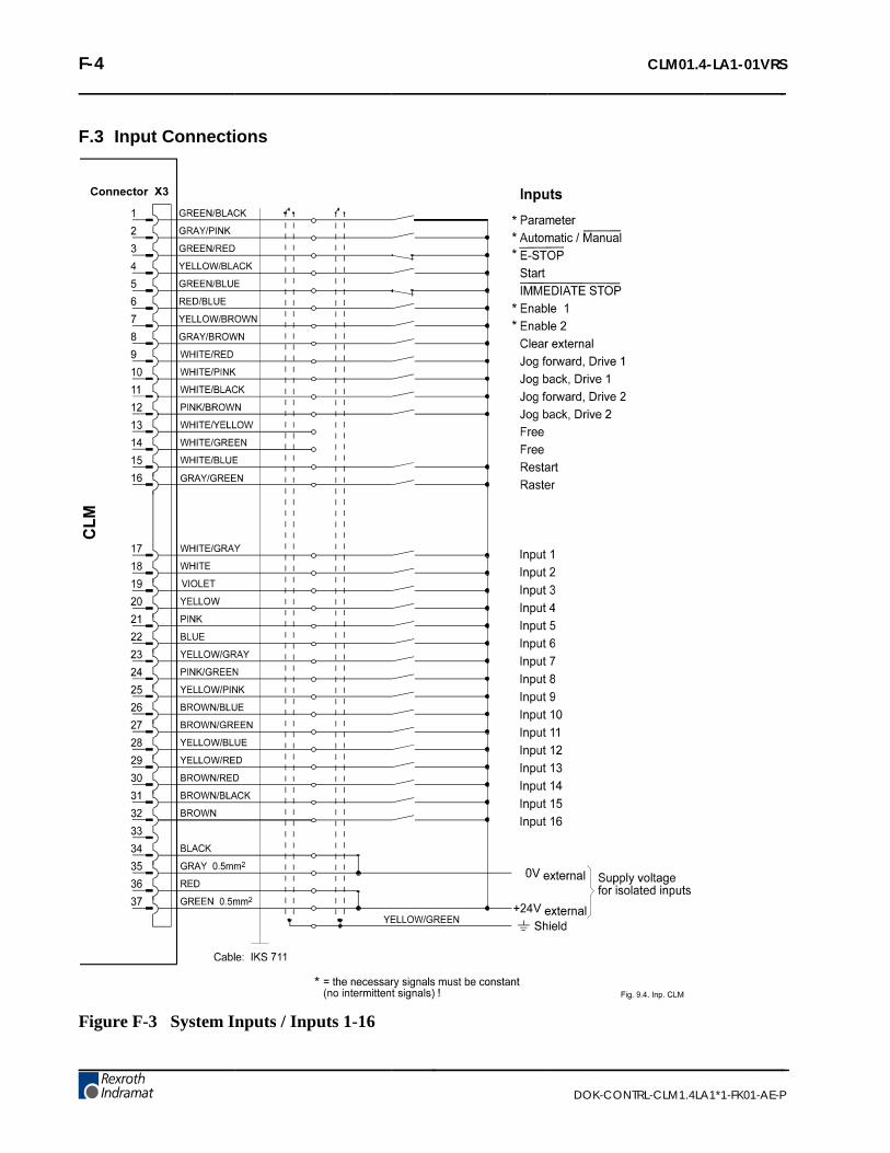
F-4 CLM01.4-LA1-01VRS
DOK-CONTRL-CLM1.4LA1*1-FK01-AE-P
F.3 Input Connections
Figure F-3 System Inputs / Inputs 1-16

CLM01.4-LA1-01VRS F-5
DOK-CONTRL-CLM1.4LA1*1-FK01-AE-P
F.4 Output Connections
Figure F-4 System Outputs / Outputs 1-16

F-6 CLM01.4-LA1-01VRS
DOK-CONTRL-CLM1.4LA1*1-FK01-AE-P
F.5 Power Supply Connections
Figure F-5 Command Value for Axes 1 and 2, Drive Enable, Analog Inputs

CLM01.4-LA1-01VRS F-7
DOK-CONTRL-CLM1.4LA1*1-FK01-AE-P
F.6 Interface Connections
Figure F-6 Data Interfaces

F-8 CLM01.4-LA1-01VRS
DOK-CONTRL-CLM1.4LA1*1-FK01-AE-P
F.7 RS 232 Interface Connections
Figure F-7 RS 232 Data Interfaces

CLM01.4-LA1-01VRS F-9
DOK-CONTRL-CLM1.4LA1*1-FK01-AE-P
F.8 RS 485 Interface Connections
Master
Figure F-8 Master with up to 32 CLM Stations

F-10 CLM01.4-LA1-01VRS
DOK-CONTRL-CLM1.4LA1*1-FK01-AE-P
F.9 Input Connections
Figure F-9 Inputs 17-48 (expanded)

CLM01.4-LA1-01VRS F-11
DOK-CONTRL-CLM1.4LA1*1-FK01-AE-P
F.10 Input Connections
Figure F-10 Inputs 49-80 (expanded)

F-12 CLM01.4-LA1-01VRS
DOK-CONTRL-CLM1.4LA1*1-FK01-AE-P
F.11 Output Connections
Figure F-11 Ouputs 17-48 (expanded)

CLM01.4-LA1-01VRS F-13
DOK-CONTRL-CLM1.4LA1*1-FK01-AE-P
F.12 Command Value / Drive Enable and I/O Connections
Figure F-12 Command Value for Axes 3 and 4, Inputs/Outputs for Axes 3 and 4

F-14 CLM01.4-LA1-01VRS
DOK-CONTRL-CLM1.4LA1*1-FK01-AE-P
F.13 Encoder Inputs, Axis 3
Figure F-13 Encoder, Axis 3 (Incremental Encoder, Absolute Encoder)

CLM01.4-LA1-01VRS F-15
DOK-CONTRL-CLM1.4LA1*1-FK01-AE-P
F.14 Encoder Inputs, Axis 4
Figure F-14 Encoder, Axis 4 (Incremental Encoder, Absolute Encoder)

F-16 CLM01.4-LA1-01VRS
DOK-CONTRL-CLM1.4LA1*1-FK01-AE-P
F.15 CLM-TVM / TDM 1.2 & 2.1
Figure F-15 CLM-TDM

CLM01.4-LA1-01VRS F-17
DOK-CONTRL-CLM1.4LA1*1-FK01-AE-P
F.16 CLM-TVM / TDM 1.2 & 2.1
Figure F-16 CLM-TDM

F-18 CLM01.4-LA1-01VRS
DOK-CONTRL-CLM1.4LA1*1-FK01-AE-P
F.17 CLM-TVM / TDM 1.2 & 2.1
Figure F-17 CLM-TDM

CLM01.4-LA1-01VRS F-19
DOK-CONTRL-CLM1.4LA1*1-FK01-AE-P
F.18 CLM-TVM / TDM 3.2
Figure F-18 CLM-TDM3

F-20 CLM01.4-LA1-01VRS
DOK-CONTRL-CLM1.4LA1*1-FK01-AE-P
F.19 CLM-TVM / TDM 3.2
Figure F-19 CLM-TDM3

CLM01.4-LA1-01VRS F-21
DOK-CONTRL-CLM1.4LA1*1-FK01-AE-P
F.20 CLM-KDV / KDS
Figure F-20 CLM-KDS

F-22 CLM01.4-LA1-01VRS
DOK-CONTRL-CLM1.4LA1*1-FK01-AE-P
F.21 CLM-KDV / KDS
Figure F-21 CLM-KDS

CLM01.4-LA1-01VRS F-23
DOK-CONTRL-CLM1.4LA1*1-FK01-AE-P
F.22 CLM-RAC 3.1
Figure F-22 CLM-RAC3

F-24 CLM01.4-LA1-01VRS
DOK-CONTRL-CLM1.4LA1*1-FK01-AE-P
F.23 CLM-RAC 2.2
Figure F-23 CLM-RAC2

CLM01.4-LA1-01VRS F-25
DOK-CONTRL-CLM1.4LA1*1-FK01-AE-P
F.24 CLM-NAM / TVD / DDS
Figure F-24 CLM-DDS

F-26 CLM01.4-LA1-01VRS
DOK-CONTRL-CLM1.4LA1*1-FK01-AE-P
F.25 CLM-NAM / TVD / DDS (Incremental)
Figure F-25 CLM-DDS

CLM01.4-LA1-01VRS F-27
DOK-CONTRL-CLM1.4LA1*1-FK01-AE-P
F.26 CLM-NAM / TVD / DDS (Absolute)
Figure F-26 CLM-DDS

F-28 CLM01.4-LA1-01VRS
DOK-CONTRL-CLM1.4LA1*1-FK01-AE-P
F.27 CLM-DKS / DAE (Incremental)
Figure F-27 CLM-DKS / DAE

CLM01.4-LA1-01VRS F-29
DOK-CONTRL-CLM1.4LA1*1-FK01-AE-P
F.28 CLM-DKA / DAA (Absolute)
Figure F-28 CLM-DKS / DAA

F-30 CLM01.4-LA1-01VRS
DOK-CONTRL-CLM1.4LA1*1-FK01-AE-P
F.29 CLM-DKC (Incremental)
Figure F-29 CLM-DKC (Incremental)

CLM01.4-LA1-01VRS F-31
DOK-CONTRL-CLM1.4LA1*1-FK01-AE-P
F.30 CLM-DKC (Absolute)
Figure F-30 CLM-DKC (Absolute)

F-32 CLM01.4-LA1-01VRS
DOK-CONTRL-CLM1.4LA1*1-FK01-AE-P

CLM01.4-LA1-01VRS G-1
DOK-CONTRL-CLM1.4LA1*1-FK01-AE-P
G. INSTALLATION DRAWINGS
CAUTION: The drawings in this Appendix are included for illustrative purposes only and aresubject to change without notice. Check with Indramat to be sure you are working with the latestdrawings prior to installing, wiring and powering equipment.

G-2 CLM01.4-LA1-01VRS
DOK-CONTRL-CLM1.4LA1*1-FK01-AE-P
G.1 Keypad Replacement Face Plate Panel Dimensions (AM 1037)
(Refer to this drawing when keypad is to be remote-mounted.)

CLM01.4-LA1-01VRS G-3
DOK-CONTRL-CLM1.4LA1*1-FK01-AE-P
Figure G-1 CLM Outline/Mounting Dimensions (109-0736-3001-01A)

G-4 CLM01.4-LA1-01VRS
DOK-CONTRL-CLM1.4LA1*1-FK01-AE-P
Figure G-2 CLM Keypad Remote Installation Gasket (AM 1035)

CLM01.4-LA1-01VRS H-1
DOK-CONTRL-CLM1.4LA1*1-FK01-AE-P
H. CLM TYPE CODE DESCRIPTIONS
H.1 CLM Hardware Type Code Description
Hardware Type Code Designation: CLM - XX.X - X - X - X - X | | | | | |Indramat Position Control Designation ___| | | | | | | | | | |CLM Hardware Version Number __________________| | | | | 1.0 (and 1.1) Original Version | | | | 1.2 Two Line Display | | | | *01.2 AK11 Memory Module, | | | | additional drive connectors | | | | 01.3 Four Line Display | | | | | | | |Corresponding Software Type _________________________| | | | A = Standard | | | M = Flying Cutoff | | | R = Feed to Length (Single Axis CFS emulation) | | | Z = Rollfeed Dual Axis Feed to Length | | | | | |Hardware Options ________________________________________| | | 0 = No Option | | E = Expansion I/O Board | | | |Number of Axes ______________________________________________| | 1 = 1 Axis Flying Shear and Standard I/O | 2 = 2 Axis | 4 = 4 Axis | |Display _________________________________________________________| 0 = Standard LCD Display 1 = Backlit LCD Display
* Many 01.2 units were shipped with 4-line display. (The lower two lines were not used.)

H-2 CLM01.4-LA1-01VRS
DOK-CONTRL-CLM1.4LA1*1-FK01-AE-P
H.2 Software Type Code Description
Software Type Code Designation: L X - XX.X - 00X.XX | | | | ||Indramat Position Control Designation ______| | | | || | | ||Software Type _____________________________________| | || A = Standard | || M = Flying Cutoff | || R = Feed to Length (Single Axis CFS emulation) | || Z = Rollfeed Dual Axis Feed to Length | || | ||Corresponding CLM Hardware Version Number _________________| || 01.2 Two Line Display || 01.3 Four Line Display || ||Software Revision Number ____________________________________|| (Supported with Documentation) | |Software Minor Revision Number _______________________________| (Not Supported with Documentation)

CLM01.4-LA1-01VRS H-3
DOK-CONTRL-CLM1.4LA1*1-FK01-AE-P
H.3 IDS Hardware Type Code Description
Hardware Type Code Designation: IDS - X . X - X | | | |Product Type _________________________________| | | | | | |Ids Hardware Version Number _______________________| | | | |IDS Hardware Revision Number __________________________| | |Number of Digits to the Right of _________________________| the Decimal Point (0 to 3) (These decade switches will be in Red as opposed to Black.)
H.4 IDS Software Type Code Description
Software Type Code Designation: IDS - X . X - X | | | |Product Type _________________________________| | | | | | |IDS Software Version Number _______________________| | | | |IDS Software Revision Number __________________________| | |Corresponding CLM Software Version (Letter) _______________| Required For The IDS Software To Work

H-4 CLM01.4-LA1-01VRS
DOK-CONTRL-CLM1.4LA1*1-FK01-AE-P

CLM01.4-LA1-01VRS K-1
DOK-CONTRL-CLM1.4LA1*1-FK01-AE-P
K CLM 1.4
K.1 Differences between CLM 1.4 and CLM 1.3
Display/Keypad module
Parameters
Programming
Saving Data
CLM 1.4 Type Code
K.2 Display/Keypad module
42_front_AE.WMF
Fig. K-1: Display/Keypad module
Instead of the blank key the CLM 1.4 has a F1 key.

K-2 CLM01.4-LA1-01VRS
DOK-CONTRL-CLM1.4LA1*1-FK01-AE-P
K.3 Parameters
Parameter Ax04 Incremental Encoder Data, Axis 1 - 4
• 000 - Not used
• 01500 - Incremental encoder lines /revolution
• Minimum: 100
• Maximum: 10000
This parameter specifies the number of line counts from theincremental encoder, per encoder revolution. The CLMdetermines the encoder/ motor revolutions, based on this entry.This data is used in several different computations which affectpositioning.
The information for this entry is provided on the data plate of theincremental encoder mounted on the rear of the servo motor.
Enc. Lines/Rev Ax
Ax04000 01500

CLM01.4-LA1-01VRS K-3
DOK-CONTRL-CLM1.4LA1*1-FK01-AE-P
Parameter B017 Measuring Wheel Encoder Lines/Revolution
• 000 - Not Used
• 01500 - Encoder lines per revolution− Min. = 100− Max. = 10000
Parameter Ax22 Monitor Window, Axis 1 - 4
• 0 - Error Messages− 0= Error Messages active− 8= Error Messages deactivated
• 8 – Encoder signal monitoring- 0 = Monitoring active- 8 = Monitoring deactivated
• 22 - Output for Positioning Error greater than maximumpermissible deviation.
• 0 – Not Used
• 010 - Maximum position deviation error, in percent of themaximum position deviation. Entry limits: 001-100. A typicalentry here is 010-020, for 10-20%.
ME1 Lines/Rev
B017000 01500
Monitor Wind. Ax
Ax220 8 22 0 010

K-4 CLM01.4-LA1-01VRS
DOK-CONTRL-CLM1.4LA1*1-FK01-AE-P
Parameter B016 Measuring Wheel Encoder
• 5 - Encoder type, for Measuring Wheel− 5 = Incremental
• 8 – Encoder signal monitoring- 0 = Monitoring active- 8 = Monitoring deactivated
• 1 - Direction of Operation− 0 = No change− 1 = Change direction
• 00000 - Not Used
Parameter B020 Measuring Wheel Encoder 2 Lines/Revolution
• 0 – Not Used
• 2 – Type of measuring wheel encoder 2- 1 = Incremental encoder 1 (Connector X1)- 2 = Incremental encoder 2 (Connector X2)- 3 = Incremental encoder 3 (Connector X20)- 4 = Incremental encoder 4 (Connector X21)
• 1 - Direction of Operation− 0 = No change− 1 = Change direction
• 01500 – Encoder lines per revolution- Min. = 100- Max. = 10000
Parameter B021 Measuring Wheel 2 Feed Constant
• 0100.0000 - Feed Constant
Measure Encoder1
B0165 8 1 00000
ME2 Lines/Rev
B0200 2 1 01500
ME2 Feed Const.
B0210100.0000

CLM01.4-LA1-01VRS K-5
DOK-CONTRL-CLM1.4LA1*1-FK01-AE-P
Parameter B022 Measuring Wheel Monitoring
• 00 – Not Used
• 04 – Output "Tolerance Exceeded" for tolerance greater thanmaximum permissible deviation- 00 = deactivated
• 01.00 – Monitoring window in IU
For Measuring Wheel Encoder Monitoring, the values from two measuringwheel encoders over one measuring distance are continuously shown andcompared to a tolerance field. If the difference between the readings onthe two measuring wheel encoders becomes larger than the programmedmonitoring window, the output "Tolerance Exceeded" is turned on.
Using the FUN command, the measuring counter can be reset for a newmeasurement.
Notes: The Measuring Wheel Encoder Monitoring functionality is availableonly in Automatic Mode.
When switching from Automatic to Manual, the measuring counter iscleared and the output "Tolerance Exceeded" is turned off.
Measure Monitor
B02200 04 01.00

K-6 CLM01.4-LA1-01VRS
DOK-CONTRL-CLM1.4LA1*1-FK01-AE-P
K.4 Programming
FUN - Functions
• 0 – Not Used
• 1 – Deviation measurement between measuring wheelencoder 1 and measuring wheel encoder 2
• 2 - Feed length measurement, measuring wheel encoder 1
• 1 - Feed length measurement, axis 1
• 1 - Feed length measurement, axis 2
• 0 - Feed length measurement, axis 3
• 0 - Feed length measurement, axis 4
Significance of the inputs:
• 0 = Temporarily store measured value and then clear
• 1 = Clear the measurement logger (start new measurement).A temporarily stored value is retained.
• 2 = No change
K.5 Saving Data
The user program is saved in buffered RAM memory on a module card(MOK19) inside the CLM.
Note: This data can be lost in the event of an error. Therefore, it iscritically important to back up this data in another place outside the control(e.g.: external computer that contains the MotionManager PC program, oras a hard copy).
Buffering occurs with the help of a battery back-up, which is continuouslycharged during operation and which provides power to the RAM memorywhen the power supply is turned off. At the factory, the battery is notcharged to 100% capacity. Total charging time is approx. 40 hours anddata security using a fully charged battery is 0.5 years.
During each new start-up of the control and every four hours duringoperation, a battery test is performed. If the battery charge is notsufficient, the error "Battery is low" is displayed after turning on the powersupply, and the "Error" output is not set. This error can be cleared usingthe Clear key. Every 10 minutes, the message "Battery is low" isdisplayed.
E 0123 FUN0 1 2 1100

CLM01.4-LA1-01VRS K-7
DOK-CONTRL-CLM1.4LA1*1-FK01-AE-P
K.6 CLM 1.4 Type Code
CLM01.4 - N - N - 2 - B - FW
ProduktgruppeCLM = CLM
Baureihe1 = 01
Ausführung4 = 4
Zusätzliche Schnittstelleohne zusätzliche Schnittstelle = N
Ein-/ Ausgangserweiterungohne Erweiterung, Standard = Nmit Erweiterung, 64 Ein- u. 32 Ausgänge = E
Anzahl der Achsen2-achsige, Standard = 24-achsige = 4
Ausführung der LCD-Anzeigemit Hintergrundsbeleuchtung = B
FirmwareKennzeichnung für Firmware. Diese muss
als separate Unterposition bestellt werden = FW
CLM14_Hard_LA1.WMF
Abb. K-1: Hardware – Type Code CLM 01.4
FWA - CLM1.4 - Lxx - 01 V RS -MS
FirmwareSteuerungstype = CLM1.4
Firmware-TypLA1 = Kompatibel zu CLM1.3-LA1LM1 = Kompatibel zu CLM1.3-LM1LAP = Standard , Profibus möglichLAD = Standard , Device Net
Firmware-Versionz.B. 1 = 1
Charakter der FirmwareTestversion = TStandard (Vollversion) = V
Firmware-Release-Standautomatisch gültiger Stand = RSspezifischer Release-Stand,z.B. 03 = 03
SpracheMehrsprachig = MS
CLM14_Firm.WMF
Abb. K-2: Firmware – Type Code CLM 01.4

K-8 CLM01.4-LA1-01VRS
DOK-CONTRL-CLM1.4LA1*1-FK01-AE-P
Notes

CLM01.4-LA1-01VRS Important directions for use L-1
DOK-CONTRL-CLM1.4LA1*1-FK01-AE-P
L Important directions for use
L.1 Appropriate use
IntroductionRexroth Indramat products represent state-of-the-art developments andmanufacturing. They are tested prior to delivery to ensure operating safetyand reliability.
The products may only be used in the manner that is defined asappropriate. If they are used in an inappropriate manner, then situationscan develop that may lead to property damage or injury to personnel.
Note: Rexroth Indramat, as manufacturer, is not liable for anydamages resulting from inappropriate use. In such cases, theguarantee and the right to payment of damages resulting frominappropriate use are forfeited. The user alone carries allresponsibility of the risks.
Before using Rexroth Indramat products, make sure that all the pre-requisites for appropriate use of the products are satisfied:
• Personnel that in any way, shape or form uses our products must firstread and understand the relevant safety instructions and be familiarwith appropriate use.
• If the product takes the form of hardware, then they must remain intheir original state, in other words, no structural changes arepermitted. It is not permitted to decompile software products or altersource codes.
• Do not mount damaged or faulty products or use them in operation.
• Make sure that the products have been installed in the mannerdescribed in the relevant documentation.

L-2 Important directions for use CLM01.4-LA1-01VRS
DOK-CONTRL-CLM1.4LA1*1-FK01-AE-P
Areas of use and applicationFor CLM1.4-LA1 Rexroth Indramat defines appropriate use as forprecision motion control of to four axes.
Control and monitoring of (the) CLM1.4-LA1 may require additionalsensors and actors.
Note: CLM1.4-LA1 may only be used with the accessories and partsspecified in this document. If a component has not beenspecifically named, then it may not be either mounted orconnected. The same applies to cables and lines.
Operation is only permitted in the specified configurations andcombinations of components using the software and firmwareas specified in the relevant function descriptions.
The CLM1.4-LA1 and every drive controller has to be programmed beforestarting it up, making it possible for the motor to execute the specificfunctions of an application.
The CLM1.4-LA1 has been developed for use in single or multiple-axisdrives and control tasks.
Typical applications of CLM1.4-LA1 are:
• Handling and assembly systems,
• Roll feeds
• Automatic bending machines and
• Woodworking machines
The CLM1.4-LA1 may only be operated under the assembly, installationand ambient conditions as described here (temperature, system ofprotection, humidity, EMC requirements, etc.) and in the positionspecified.
L.2 Inappropriate use
Using the CLM1.4-LA1 outside of the above-referenced areas ofapplication or under operating conditions other than described in thedocument and the technical data specified is defined as “inappropriateuse".
CLM1.4-LA1 may not be used if
• they are subject to operating conditions that do not meet the abovespecified ambient conditions. This includes, for example, operationunder water, in the case of extreme temperature fluctuations orextremely high maximum temperatures or if
• Rexroth Indramat has not specifically released them for that intendedpurpose. Please note the specifications outlined in the general SafetyGuidelines!

CLM01.4-LA1-01VRS Safety Instructions for Electric Servo Drives and Controls M-1
DOK-CONTRL-CLM1.4LA1*1-FK01-AE-P
M Safety Instructions for Electric Servo Drives andControls
M.1 Introduction
Read these instructions before the equipment is used and eliminate therisk of personal injury or property damage. Follow these safetyinstructions at all times.
Do not attempt to install, use or service this equipment without firstreading all documentation provided with the product. Read andunderstand these safety instructions and all user documentation of theequipment prior to working with the equipment at any time. If you do nothave the user documentation for your equipment contact your localRexroth Indramat representative to send this documentation immediatelyto the person or persons responsible for the safe operation of thisequipment.
If the product is resold, rented or transferred or passed on to others, thenthese safety instructions must be delivered with the product.
WARNING
Inappropriate use of this equipment, failure tofollow the safety instructions in this documentor tampering with the product, includingdisabling of safety devices, may result inproduct damage, personal injury, severeelectrical shock or death!
M.2 Explanations
The safety warnings in this documentation describe individual degrees ofhazard seriousness in compliance with ANSI:
Warning symbol with signalword
Degree of hazard seriousness
The degree of hazard seriousnessdescribes the consequences resulting fromnon-compliance with the safety guidelines.
DANGER
Bodily harm or product damage will occur.
WARNING
Death or severe bodily harm may occur.
CAUTION
Death or severe bodily harm may occur.
Fig. M-1: Classes of danger with ANSI

M-2 Safety Instructions for Electric Servo Drives and Controls CLM01.4-LA1-01VRS
DOK-CONTRL-CLM1.4LA1*1-FK01-AE-P
M.3 Hazards by inappropriate use
DANGER
High voltage and high discharge current!Danger to life, risk of severe electrical shockand risk of injury!
DANGER
Dangerous movements! Danger to life and riskof injury or equipment damage by unintentionalmotor movements!
WARNING
High electrical voltage due to wrongconnections! Danger to life, severe electricalshock and severe bodily injury!
WARNING
Health hazard for persons with heartpacemakers, metal implants and hearing aids inproximity to electrical equipment!
CAUTION
Surface of machine housing could be extremelyhot! Danger of injury! Danger of burns!
CAUTION
Risk of injury due to inappropriate handling!Bodily injury caused by crushing, shearing,cutting and mechanical shock or improperhandling of pressurized systems!
CAUTION
Risk of injury due to inappropriate handling ofbatteries!

CLM01.4-LA1-01VRS Safety Instructions for Electric Servo Drives and Controls M-3
DOK-CONTRL-CLM1.4LA1*1-FK01-AE-P
M.4 General Information
• Rexroth Indramat GmbH is not liable for damages resulting fromfailure to observe the warnings given in these documentation.
• Order operating, maintenance and safety instructions in your languagebefore starting up the machine. If you find that due to a translationerror you can not completely understand the documentation for yourproduct, please ask your supplier to clarify.
• Proper and correct transport, storage, assembly and installation aswell as care in operation and maintenance are prerequisites foroptimal and safe operation of this equipment.
• Trained and qualified personnel in electrical equipment:Only trained and qualified personnel may work on this equipment orwithin its proximity. Personnel are qualified if they have sufficientknowledge of the assembly, installation and operation of the productas well as an understanding of all warnings and precautionarymeasures noted in these instructions.Furthermore, they should be trained, instructed and qualified to switchelectrical circuits and equipment on and off, to ground them and tomark them according to the requirements of safe work practices andcommon sense. They must have adequate safety equipment and betrained in first aid.
• Only use spare parts and accessories approved by the manufacturer.
• Follow all safety regulations and requirements for the specificapplication as practiced in the country of use.
• The equipment is designed for installation on commercial machinery.
European countries: see directive 89/392/EEC (machine guideline).
• The ambient conditions given in the product documentation must beobserved.
• Use only safety features that are clearly and explicitly approved in theProject Planning manual.For example, the following areas of use are not allowed: Constructioncranes, Elevators used for people or freight, Devices and vehicles totransport people, Medical applications, Refinery plants, the transportof hazardous goods, Radioactive or nuclear applications, Applicationssensitive to high frequency, mining, food processing, Control ofprotection equipment (also in a machine).
• Start-up is only permitted once it is sure that the machine, in which theproduct is installed, complies with the requirements of national safetyregulations and safety specifications of the application.
• Operation is only permitted if the national EMC regulations for theapplication are met.The instructions for installation in accordance with EMC requirementscan be found in the INDRAMAT document "EMC in Drive and ControlSystems”.The machine builder is responsible for compliance with the limitingvalues as prescribed in the national regulations and specific EMCregulations for the application.
European countries: see Directive 89/336/EEC (EMC Guideline).
U.S.A.: See National Electrical Codes (NEC), National ElectricalManufacturers Association (NEMA), and local building codes. The user ofthis equipment must consult the above noted items at all times.
• Technical data, connections and operational conditions are specified inthe product documentation and must be followed at all times.

M-4 Safety Instructions for Electric Servo Drives and Controls CLM01.4-LA1-01VRS
DOK-CONTRL-CLM1.4LA1*1-FK01-AE-P
M.5 Protection against contact with electrical parts
Note: This section refers to equipment with voltages above 50 Volts.
Making contact with parts conducting voltages above 50 Volts could bedangerous to personnel and cause an electrical shock. When operatingelectrical equipment, it is unavoidable that some parts of the unit conductdangerous voltages.
DANGER
High electrical voltage! Danger to life, severeelectrical shock and severe bodily injury!⇒ Only those trained and qualified to work with or on
electrical equipment are permitted to operate,maintain or repair this equipment.
⇒ Follow general construction and safety regulationswhen working on electrical installations.
⇒ Before switching on power the ground wire must bepermanently connected to all electrical units accor-ding to the connection diagram.
⇒ Do not operate electrical equipment at any time if theground wire is not permanently connected, even forbrief measurements or tests.
⇒ Before working with electrical parts with voltagepotentials higher than 50 V, the equipment must bedisconnected from the mains voltage or powersupply.
⇒ The following should be observed with electricaldrives, power supplies, and filter components:Wait five (5) minutes after switching off power toallow capacitors to discharge before beginning work.Measure the voltage on the capacitors beforebeginning work to make sure that the equipment issafe to touch.
⇒ Never touch the electrical connection points of acomponent while power is turned on.
⇒ Install the covers and guards provided with theequipment properly before switching the equipmenton. Prevent contact with live parts at any time.
⇒ A residual-current-operated protective device (r.c.d.)must not be used on an electric drive! Indirectcontact must be prevented by other means, forexample, by an overcurrent protective device.
⇒ Equipment that is built into machines must besecured against direct contact. Use appropriatehousings, for example a control cabinet.
European countries: according to EN 50178/1998,section 5.3.2.3.
U.S.A: See National Electrical Codes (NEC), NationalElectrical Manufacturers Association (NEMA) and localbuilding codes. The user of this equipment must observethe above noted instructions at all times.

CLM01.4-LA1-01VRS Safety Instructions for Electric Servo Drives and Controls M-5
DOK-CONTRL-CLM1.4LA1*1-FK01-AE-P
To be observed with electrical drives, power supplies, and filtercomponents:
DANGER
High electrical voltage! High leakage current!Danger to life, danger of injury and bodily harmfrom electrical shock!⇒ Before switching on power for electrical units, all
housings and motors must be permanently groundedaccording to the connection diagram. This applieseven for brief tests.
⇒ Leakage current exceeds 3.5 mA. Therefore theelectrical equipment and units must always be firmlyconnected to the supply network.
⇒ Use a copper conductor with at least 10 mm² crosssection over its entire course for this protectiveconnection!
⇒ Prior to startups, even for brief tests, always connectthe protective conductor or connect with ground wire.High voltage levels can occur on the housing thatcould lead to severe electrical shock and personalinjury.
European countries: EN 50178/1998, section 5.3.2.1.
USA: See National Electrical Codes (NEC), NationalElectrical Manufacturers Association (NEMA), and localbuilding codes. The user of this equipment must maintainthe above noted instructions at all times.

M-6 Safety Instructions for Electric Servo Drives and Controls CLM01.4-LA1-01VRS
DOK-CONTRL-CLM1.4LA1*1-FK01-AE-P
M.6 Protection by protective low voltage (PELV) againstelectrical shock
All connections and terminals with voltages between 5 and 50 Volts onINDRAMAT products are protective low voltages designed in accordancewith the following standards on contact safety:
• International: IEC 364-4-411.1.5
• EU countries: see EN 50178/1998, section 5.2.8.1.
WARNING
High electrical voltage due to wrongconnections! Danger to life, severe electricalshock and severe bodily injury!⇒ Only equipment, electrical components and cables of
the protective low voltage type (PELV = ProtectiveExtra Low Voltage) may be connected to allterminals and clamps with 0 to 50 Volts.
⇒ Only safely isolated voltages and electrical circuitsmay be connected. Safe isolation is achieved, forexample, with an isolating transformer, an opto-electronic coupler or when battery-operated.
M.7 Protection against dangerous movements
Dangerous movements can be caused by faulty control or the connectedmotors. These causes are be various such as:
• unclean or wrong wiring of cable connections
• inappropriate or wrong operation of equipment
• malfunction of sensors, encoders and monitoring circuits
• defective components
• software errors
Dangerous movements can occur immediately after equipment isswitched on or even after an unspecified time of trouble-free operation.
The monitors in the drive components make faulty operation almostimpossible. Regarding personnel safety, especially the danger of bodilyharm and property damage, this alone should not be relied upon toensure complete safety. Until the built-in monitors become active andeffective, it must be assumed in any case that some faulty drivemovements will occur. The extent of these faulty drive movementsdepends upon the type of control and the state of operation.

CLM01.4-LA1-01VRS Safety Instructions for Electric Servo Drives and Controls M-7
DOK-CONTRL-CLM1.4LA1*1-FK01-AE-P
DANGER
Dangerous movements! Danger to life and riskof injury or equipment damage!⇒ Personnel protection must be secured for the above
listed reason by means of superordinate monitors ormeasures.These are instituted in accordance with the specificsituation of the facility and a danger and faultanalysis conducted by the manufacturer of thefacility. All the safety regulations that apply to thisfacility are included therein. By switching off,circumventing or if safety devices have simply notbeen activated, then random machine movements orother types of faults can occur.
Avoiding accidents, injury or property damage:⇒ Keep free and clear of the machine’s range of
motion and moving parts. Prevent people fromaccidentally entering the machine’s range ofmovement:- use protective fences
- use protective railings
- install protective coverings
- install light curtains or light barriers
⇒ Fences must be strong enough to withstandmaximum possible momentum.
⇒ Mount the emergency stop switch (E-stop) in theimmediate reach of the operator. Verify that theemergency stop works before startup. Don’t operatethe machine if the emergency stop is not working.
⇒ Isolate the drive power connection by means of anemergency stop circuit or use a start-inhibit systemto prevent unintentional start-up.
⇒ Make sure that the drives are brought to standstillbefore accessing or entering the danger zone.
⇒ Secure vertical axes against falling or slipping afterswitching off the motor power by, for example:- Mechanically securing the vertical axes
- Adding an external brake / clamping mechanism
- Balancing and thus compensating for the verticalaxes mass and the gravitational force
The standard equipment motor brake or an externalbrake controlled directly by the servo drive are notsufficient to guarantee the safety of personnel!

M-8 Safety Instructions for Electric Servo Drives and Controls CLM01.4-LA1-01VRS
DOK-CONTRL-CLM1.4LA1*1-FK01-AE-P
⇒ Disconnect electrical power to the equipment using amaster switch and secure the switch againstreconnection for:- maintenance and repair work
- cleaning of equipment
- long periods of discontinued equipment use
⇒ Avoid operating high-frequency, remote control andradio equipment near electronics circuits and supplyleads. If use of such equipment cannot be avoided,verify the system and the plant for possiblemalfunctions at all possible positions of normal usebefore the first start-up. If necessary, perform aspecial electromagnetic compatibility (EMC) test onthe plant.
M.8 Protection against magnetic and electromagnetic fieldsduring operations and mounting
Magnetic and electromagnetic fields generated by current-carryingconductors and permanent magnets in motors represent a serious healthhazard to persons with heart pacemakers, metal implants and hearingaids.
WARNING
Health hazard for persons with heartpacemakers, metal implants and hearing aids inproximity to electrical equipment!⇒ Persons with pacemakers, metal implants and
hearing aids are not permitted to enter followingareas:- Areas in which electrical equipment and parts are
mounted, being operated or started up.
- Areas in which parts of motors with permanentmagnets are being stored, operated, repaired ormounted.
⇒ If it is necessary for a person with a pacemaker toenter such an area, then a physician must be con-sulted prior to doing so. Pacemaker, that are alreadyimplanted or will be implanted in the future, have aconsiderable deviation in their resistance tointerference. Due to the unpredictable behavior thereare no rules with general validity.
⇒ Persons with hearing aids, metal implants or metalpieces must consult a doctor before they enter theareas described above. Otherwise health hazardswill occur.

CLM01.4-LA1-01VRS Safety Instructions for Electric Servo Drives and Controls M-9
DOK-CONTRL-CLM1.4LA1*1-FK01-AE-P
M.9 Protection against contact with hot parts
CAUTION
Housing surfaces could be extremely hot!Danger of injury! Danger of burns!⇒ Do not touch surfaces near the source of heat!
Danger of burns!⇒ Wait ten (10) minutes before you access any hot
unit. Allow the unit to cool down.⇒ Do not touch hot parts of the equipment, such as
housings, heatsinks or resistors. Danger of burns!
M.10 Protection during handling and installation
Under certain conditions unappropriate handling and installation of partsand components may cause injuries.
CAUTION
Risk of injury through incorrect handling!Bodily harm caused by crushing, shearing,cutting and mechanical shock!⇒ Observe general instructions and safety regulations
during handling installation.⇒ Use only appropriate lifting or moving equipment.⇒ Take precautions to avoid pinching and crushing.⇒ Use only appropriate tools. If specified by the product
documentation, special tools must be used.⇒ Use lifting devices and tools correctly and safely.⇒ Wear appropriate protective clothing, e.g. safety
glasses, safety shoes and safety gloves.⇒ Never stay under suspended loads.⇒ Clean up liquids from the floor immediately to
prevent personnel from slipping.

M-10 Safety Instructions for Electric Servo Drives and Controls CLM01.4-LA1-01VRS
DOK-CONTRL-CLM1.4LA1*1-FK01-AE-P
M.11 Battery safety
Batteries contain reactive chemicals in a solid housing. Inappropriatehandling may result in injuries or equipment damage.
CAUTION
Risk of injury through incorrect handling!⇒ Do not attempt to reactivate discharged batteries by
heating or other methods (danger of explosion andcorrosion).
⇒ Never charge batteries (danger from leakage andexplosion).
⇒ Never throw batteries into a fire.⇒ Do not dismantle batteries.⇒ Handle with care. Incorrect extraction or installation
of a battery can damage equipment.
Note: Environmental protection and disposal! The batteriescontained in the product should be considered as hazardousmaterial for land, air and sea transport in the sense of the legalrequirements (danger of explosion). Dispose batteriesseparately from other refuse. Observe the legal requirementsgiven in the country of installation.
M.12 Protection against pressurized Systems
Certain Motors (ADS, ADM, 1MB etc.) and drives, corresponding to theinformation in the Project Planning manual, must be provided with andremain under a forced load such as compressed air, hydraulic oil, coolingfluid or coolant. In these cases, improper handling of the supply of thepressurized systems or connections of the fluid or air under pressure canlead to injuries or accidents.
CAUTION
Danger of injury when pressurized systems arehandled by untrained personnel!⇒ Do not attempt to disassemble, to open or to cut a
pressurized system.⇒ Observe the operation restrictions of the respective
manufacturer.⇒ Before the disassembly of pressurized systems,
lower pressure and drain off the fluid or gas.⇒ Use suitable protective clothing (for example
protective eyewear, safety shoes and gloves)⇒ Remove any fluid that has leaked out onto the floor
immediately.
Note: Environmental protection and disposal! The fluids used in theoperation of the pressurized system equipment is notenvironmentally compatible. Fluid that is damaging to theenvironment must be disposed of separate from normal waste.Observe the national specifications of the country ofinstallation.

CLM01.4-LA1-01VRS Service & Support N-1
DOK-CONTRL-CLM1.4LA1*1-FK01-AE-P
N Service & Support
N.1 Helpdesk
Unser Kundendienst-Helpdesk im Hauptwerk Lohram Main steht Ihnen mit Rat und Tat zur Seite.Sie erreichen uns
- telefonisch: +49 (0) 9352 40 50 60über Service Call Entry Center Mo-Fr 07:00-18:00
- per Fax: +49 (0) 9352 40 49 41
- per e-Mail: [email protected]
Our service helpdesk at our headquarters in Lohr amMain, Germany can assist you in all kinds of inquiries.Contact us
- by phone: +49 (0) 9352 40 50 60via Service Call Entry Center Mo-Fr 7:00 am - 6:00 pm
- by fax: +49 (0) 9352 40 49 41
- by e-mail: [email protected]
N.2 Service-Hotline
Außerhalb der Helpdesk-Zeiten ist der Servicedirekt ansprechbar unter
+49 (0) 171 333 88 26oder +49 (0) 172 660 04 06
After helpdesk hours, contact our servicedepartment directly at
+49 (0) 171 333 88 26or +49 (0) 172 660 04 06
N.3 Internet
Weitere Hinweise zu Service, Reparatur undTraining finden Sie im Internet unter
www.indramat.de
Außerhalb Deutschlands nehmen Sie bitte zuerstKontakt mit Ihrem lokalen Ansprechpartner auf. DieAdressen sind im Anhang aufgeführt.
Verkaufsniederlassungen
Niederlassungen mit Kundendienst
Additional notes about service, repairs and trainingare available on the Internet at
www.indramat.de
Please contact the sales & service offices in yourarea first. Refer to the addresses on the followingpages.
sales agencies
offices providing service
N.4 Vor der Kontaktaufnahme... - Before contacting us...
Wir können Ihnen schnell und effizient helfen wennSie folgende Informationen bereithalten:
1. detaillierte Beschreibung der Störung und derUmstände.
2. Angaben auf dem Typenschild derbetreffenden Produkte, insbesondereTypenschlüssel und Seriennummern.
3. Tel.-/Faxnummern und e-Mail-Adresse, unterdenen Sie für Rückfragen zu erreichen sind.
For quick and efficient help, please have thefollowing information ready:
1. Detailed description of the failure andcircumstances.
2. Information on the type plate of the affectedproducts, especially type codes and serialnumbers.
3. Your phone/fax numbers and e-mail address,so we can contact you in case of questions.

N-2 Service & Support CLM01.4-LA1-01VRS
DOK-CONTRL-CLM1.4LA1*1-FK01-AE-P
N.5 Kundenbetreuungsstellen - Sales & Service Facilities
Deutschland – Germany vom Ausland: (0) nach Landeskennziffer weglassen!from abroad: don’t dial (0) after country code!
Vertriebsgebiet Mitte Germany Centre
Rexroth Indramat GmbHBgm.-Dr.-Nebel-Str. 297816 Lohr am Main
Kompetenz-Zentrum Europa
Tel.: +49 (0)9352 40-0Fax: +49 (0)9352 40-4885
S E R V I C E
C A L L E N T R Y C E N T E RMO – FR
von 07:00 - 18:00 Uhr
from 7 am – 6 pm
Tel. +49 (0) 9352 40 50 [email protected]
S E R V I C E
H O T L IN EMO – FR
von 17:00 - 07:00 Uhrfrom 5 pm - 7 am
+ SA / SO
Tel.: +49 (0)172 660 04 06o d e r / o r
Tel.: +49 (0)171 333 88 26
S E R V I C E
ERSATZTEILE / SPARESverlängerte Ansprechzeit- extended office time -
♦ nur an Werktagen- only on working days -
♦ von 07:00 - 18:00 Uhr- from 7 am - 6 pm -
Tel. +49 (0) 9352 40 42 22
Vertriebsgebiet Süd Germany South
Rexroth Indramat GmbHLandshuter Allee 8-1080637 MünchenTel.: +49 (0)89 127 14-0Fax: +49 (0)89 127 14-490 [email protected]
Gebiet Südwest Germany South-West
Mannesmann Rexroth AGVertrieb Deutschland – VD-BIGeschäftsbereich Rexroth IndramatRegionalzentrum SüdwestRingstrasse 70 / Postfach 114470736 Fellbach / 70701 Fellbach
Tel.: +49 (0)711 57 61–100Fax: +49 (0)711 57 61–125
Vertriebsgebiet Ost Germany East
Rexroth Indramat GmbHBeckerstraße 3109120 Chemnitz
Tel.: +49 (0)371 35 55-0Fax: +49 (0)371 35 55-333
Vertriebsgebiet Nord Germany North
Mannesmann Rexroth AGRegionalzentrum HannoverGesch.ber. Rexroth IndramatWalsroder Str. 9330853 Langenhagen
Tel.: +49 (0) 511 72 66 57-0Fax: +49 (0) 511 72 66 57-95
Vertriebsgebiet West Germany West
Mannesmann Rexroth AGVertrieb DeutschlandRegionalzentrum WestBorsigstrasse 1540880 Ratingen
Tel.: +49 (0)2102 409-0Fax: +49 (0)2102 409-406
Vertriebsgebiet Mitte Germany Centre
Mannesmann Rexroth AGGesch.ber. Rexroth IndramatLilistraße 14-1863067 Offenbach
Tel.: +49 (0) 69 82 00 90-0Fax: +49 (0) 69 82 00 90-80
Vertriebsgebiet Ost Germany East
Mannesmann Rexroth AGGB Rexroth Indramat GmbHHolzhäuser Str. 12204299 Leipzig
Tel.: +49 (0)341 86 77-0Fax: +49 (0)341 86 77-219
Vertriebsgebiet Nord Germany North
Rexroth Indramat GmbHKieler Straße 21222525 Hamburg
Tel.: +49 (0) 40 81 955 966Fax: +49 (0) 40 85 418 978

CLM01.4-LA1-01VRS Service & Support N-3
DOK-CONTRL-CLM1.4LA1*1-FK01-AE-P
Europa (West) - Europe (West)
vom Ausland: (0) nach Landeskennziffer weglassen, Italien: 0 nach Landeskennziffer mitwählenfrom abroad: don’t dial (0) after country code, Italy: dial 0 after country code
Austria - Österreich
Mannesmann Rexroth GmbHBereich IndramatStachegasse 131120 Wien
Tel.: +43 (0)1 801 87-0Fax: +43 (0)1 801 87 93
Austria – Österreich
Mannesmann Rexroth G.m.b.H.Gesch.ber. Rexroth IndramatIndustriepark 184061 Pasching
Tel.: +43 (0)7221 605-0Fax: +43 (0)7221 605-21
Belgium - Belgien
Mannesmann Rexroth N.V.-S.A.Gesch.ber. Rexroth IndramatIndustrielaan 81740 TernatTel.: +32 (0)2 5830719Fax: +32 (0)2 5830731 [email protected]
Denmark - Dänemark
BEC ASZinkvej 68900 Randers
Tel.: +45 (0)87 11 90 60Fax: +45 (0)87 11 90 61
England
Mannesmann Rexroth Ltd.Rexroth Indramat DivisionBroadway Lane, South CerneyCirencester, Glos GL7 5UHTel.: +44 (0)1285 863000Fax: +44 (0)1285 863030 [email protected] [email protected]
Finland - Finnland
Rexroth Mecman OyRexroth Indramat divisionAnsatie 6017 40 VantaaTel.: +358 (0)9 84 91-11Fax: +358 (0)9 84 91-13 60
France - Frankreich
Mannesmann Rexroth S.A.Division Rexroth IndramatAvenue de la TrentaineBP. 7477503 CHELLES CEDEXTel.: +33 (0)164 72-70 00Fax: +33 (0)164 72-63 00Hotline: +33 (0)608 33 43 28
France - Frankreich
Mannesmann Rexroth S.A.Division Rexroth Indramat1270, Avenue de Lardenne31100 ToulouseTel.: +33 (0)5 61 49 95 19Fax: +33 (0)5 61 31 00 41
France - Frankreich
Mannesmann Rexroth S.A.Division Rexroth Indramat91, Bd. Irène Joliot-Curie69634 Vénissieux – CedexTel.: +33 (0)4 78 78 53 65Fax: +33 (0)4 78 78 53 62
Italy - Italien
Mannesmann Rexroth S.p.A.Divisione Rexroth IndramatVia G. Di Vittoria, 120063 Cernusco S/N.MITel.: +39 02 2 365 270Fax: +39 02 700 408 252378
Italy - Italien
Mannesmann Rexroth S.p.A.Divisione Rexroth IndramatVia Borgomanero, 1110145 TorinoTel.: +39 011 7 50 38 11Fax: +39 011 7 71 01 90
Italy - Italien
Mannesmann Rexroth S.p.A.Divisione Rexroth IndramatVia del Progresso, 16 (Zona Ind.)35020 PadovaTel.: +39 049 8 70 13 70Fax: +39 049 8 70 13 77
Italy - Italien
Mannesmann Rexroth S.p.A.Divisione Rexroth IndramatVia Mascia, 180053 Castellamare di Stabia NATel.: +39 081 8 71 57 00Fax: +39 081 8 71 68 85
Italy - Italien
Mannesmann Rexroth S.p.A.Divisione Rexroth IndramatViale Oriani, 38/A40137 BolognaTel.: +39 051 34 14 14Fax: +39 051 34 14 22
Netherlands - Niederlande/Holland
Rexroth B.V.Kruisbroeksestraat 1(P.O. Box 32)5281 RV BoxtelTel.: +31 (0)411 65 19 51Fax: +31 (0)411 65 14 83 [email protected]
Netherlands - Niederlande/Holland
Rexroth Hydrocare B.V.Kruisbroeksestraat 1(P.O. Box 32)5281 RV BoxtelTel.: +31 (0)411 65 19 51Fax: +31 (0)411 67 78 14
Norway - Norwegen
Rexroth Mecman ASRexroth Indramat DivisionBerghagan 1 or: Box 30071405 Ski-Langhus 1402 SkiTel.: +47 (0)64 86 41 00Fax: +47 (0)64 86 90 62 [email protected]
Spain - Spanien
Mannesmann Rexroth S.A.Divisiòn Rexroth IndramatCentro Industrial SantigaObradors s/n08130 Santa Perpetua de MogodaBarcelonaTel.: +34 9 37 47 94 00Fax: +34 9 37 47 94 01
Spain - Spanien
Goimendi S.A.División Rexroth IndramatParque Empresarial ZuatzuC/ Francisco Grandmontagne no.220018 San SebastianTel.: +34 9 43 31 84 21- service: +34 9 43 31 84 56Fax: +34 9 43 31 84 27- service: +34 9 43 31 84 60 [email protected]
Sweden - Schweden
Rexroth Mecman Svenska ABRexroth Indramat DivisionVaruvägen 7125 81 Stockholm
Tel.: +46 (0)8 727 92 00Fax: +46 (0)8 647 32 77
Sweden - Schweden
Rexroth Mecman Svenska ABIndramat SupportEkvändan 7254 67 Helsingborg
Tel.: +46 (0) 42 38 88 -50Fax: +46 (0) 42 38 88 -74
Switzerland West - Schweiz West
Mannesmann Rexroth Suisse SADépartement Rexroth IndramatRue du village 11020 Renens
Tel.: +41 (0)21 632 84 20Fax: +41 (0)21 632 84 21
Switzerland East - Schweiz Ost
Mannesmann Rexroth Schweiz AGGeschäftsbereich IndramatHemrietstrasse 28863 ButtikonTel. +41 (0) 55 46 46 205Fax +41 (0) 55 46 46 222

N-4 Service & Support CLM01.4-LA1-01VRS
DOK-CONTRL-CLM1.4LA1*1-FK01-AE-P
Europa (Ost) - Europe (East)
vom Ausland: (0) nach Landeskennziffer weglassen from abroad: don’t dial (0) after country code
Czech Republic - Tschechien
Mannesmann-Rexroth, spol.s.r.o.Hviezdoslavova 5627 00 Brno
Tel.: +420 (0)5 48 126 358Fax: +420 (0)5 48 126 112
Czech Republic - Tschechien
DEL a.s.Strojírenská 38Zdar nad Sázavou591 01 Czech republicTel.: +420 616 64 3144Fax: +420 616 216 57
Hungary - Ungarn
Mannesmann Rexroth Kft.Angol utca 341149 Budapest
Tel.: +36 (1) 364 00 02Fax: +36 (1) 383 19 80
Poland – Polen
Mannesmann Rexroth Sp.zo.o.Biuro Poznanul. Dabrowskiego 81/8560-529 PoznanTel.: +48 061 847 67 99Fax: +48 061 847 64 02
Rumania - Rumänien
Mannesmann Rexroth Sp.zo.o.Str. Drobety nr. 4-10, app. 1470258 Bucuresti, Sector 2
Tel.: +40 (0)1 210 48 25+40 (0)1 210 29 50
Fax: +40 (0)1 210 29 52
Russia - Russland
Mannesmann Rexroth INDRAMATWolokolamskoje Chaussee 73Zimmer 406, 408RUS – 123424 Moskau
Tel.: +7 095/ 232 08 34+7 095/ 232 08 35
Fax: +7 095/ 232 08 36 [email protected]
Russia - Russland
ELMIS10, Internationalnaya Str.246640 Gomel, Belarus
Tel.: +375/ 232 53 42 70Fax: +375/ 232 53 37 69 [email protected]
Turkey - Türkei
Mannesmann Rexroth Hidropar A..S.Fevzi Cakmak Cad No. 334630 Sefaköy Istanbul
Tel.: +90 212 541 60 70Fax: +90 212 599 34 07
Slowenia - Slowenien
DOMELOtoki 2164 228 ZeleznikiTel.: +386 5 5117 152Fax: +386 5 5117 225 [email protected]

CLM01.4-LA1-01VRS Service & Support N-5
DOK-CONTRL-CLM1.4LA1*1-FK01-AE-P
Africa, Asia, Australia – incl. Pacific Rim
vom Ausland: (0) nach Landeskennziffer weglassen!from abroad: don’t dial (0) after country code!
Australia - Australien
AIMS - Australian IndustrialMachinery Services Pty. Ltd.Unit 3/45 Horne STCampbellfield , VIC 3061MelbourneTel.: +61 (0) 393 590 228Fax: +61 (0) 393 590 286Hotline: +61 (0) 419 369 195 [email protected]
Australia - Australien
Mannesmann Rexroth Pty. Ltd.No. 7, Endeavour WayBraeside Victoria, 31 95Melbourne
Tel.: +61 (0)3 95 80 39 33Fax: +61 (0)3 95 80 17 33 [email protected]
China
Shanghai Mannesmann RexrothHydraulics & Automation Ltd.Wai Gaoqiao Free Trade ZoneNo.122, Fu Te Dong Yi RoadShanghai 200131 - P.R.China
Tel.: +86 21 58 66 30 30Fax: +86 21 58 66 55 23 [email protected]
China
Mannesmann Rexroth (China) Ldt.15/F China World Trade Center1, Jianguomenwai AvenueBeijing 100004, P.R.China
Tel.: +86 10 65 05 03 80Fax: +86 10 65 05 03 79
China
Mannesmann Rexroth (China) Ldt.A-5F., 123 Lian Shan StreetSha He Kou DistrictDalian 116 023, P.R.China
Tel.: +86 411 46 78 930Fax: +86 411 46 78 932
China
Mannesmann Rexroth (China) Ldt.Guangzhou Repres. OfficeRoom 1014-1016, Metro Plaza,Tian He District, 183 Tian He Bei RdGuangzhou 510075, P.R.China
Tel.: +86 20 8755-0030+86 20 8755-0011
Fax: +86 20 8755-2387
Hongkong
Rexroth (China) Ldt.1/F., 19 Cheung Shun StreetCheung Sha Wan,Kowloon, Hongkong
Tel.: +852 22 62 51 00Fax: +852 27 41 33 44
India - Indien
Mannesmann Rexroth (India) Ltd.Rexroth Indramat DivisionPlot. A-58, TTC Industrial AreaThane Turbhe Midc RoadMahape VillageNavi Mumbai - 400 701
Tel.: +91 (0)22 7 61 46 22Fax: +91 (0)22 7 68 15 31
India - Indien
Mannesmann Rexroth (India) Ltd.Rexroth Indramat DivisionPlot. 96, Phase IIIPeenya Industrial AreaBangalore - 560058
Tel.: +91 (0)80 8 39 73 74Fax: +91 (0)80 8 39 43 45
Indonesia - Indonesien
PT. Rexroth WijayakusumaBuilding # 202, CilandakCommercial EstateJl. Cilandak KKO, Jakarta 12560
Tel.: +62 21 7891169 (5 lines)Fax: +62 21 7891170 - 71
Japan
Rexroth Automation Co., Ltd.Service Center JapanYutakagaoka 1810, Meito-ku,NAGOYA 465-0035, Japan
Tel.: +81 (0)52 777 88 41+81 (0)52 777 88 53+81 (0)52 777 88 79
Fax: +81 (0)52 777 89 01
Japan
Rexroth Automation Co., Ltd.Rexroth Indramat Division1F, I.R. BuildingNakamachidai 4-26-44, Tsuzuki-kuYOKOHAMA 224-0041, Japan
Tel.: +81 (0)45 942 72 10Fax: +81 (0)45 942 03 41
Korea
Mannesmann Rexroth-Korea Ltd.1515-14 Dadae-Dong, Saha-KuRexroth Indramat DivisionPusan Metropolitan City, 604-050Republic of South Korea
Tel.: +82 (0)51 26 00 741Fax: +82 (0)51 26 00 747 [email protected]
Malaysia
Mannesmann Rexroth SDN.BHD.Head OfficeNo. 3, Block B, Jalan SS 13/5Subang Jaya Industrial Estate47500 Petaling Jaya - Selangor
Tel.: +60 (0) 3 73 44 870Fax: +60 (0) 3 73 44 864 [email protected]
South Africa - Südafrika
TECTRA Automation (Pty) Ltd.28 Banfield Road,Industria NorthRSA - Maraisburg 1700
Tel.: +27 (0)11 673 20 80Fax: +27 (0)11 673 72 69Hotline: +27 (0)82 903 29 23 [email protected]
Taiwan
Rexroth Uchida Co., Ltd.No.17, Lane 136, Cheng Bei 1 Rd.,Yungkang, Tainan HsienTaiwan, R.O.C.
Tel.: +886 (0)6 25 36 565Fax: +886 (0)6 25 34 754 [email protected]
Thailand
NC Advance Technologies Co. Ltd.59/76 Moo 9Soi Ramintra 34Ramintra Road, Tharang, BangkhenBangkok 10220
Tel.: +66 2 943 70 62 +66 2 943 71 21Fax: +66 2 509 23 62 [email protected]

N-6 Service & Support CLM01.4-LA1-01VRS
DOK-CONTRL-CLM1.4LA1*1-FK01-AE-P
Nordamerika – North AmericaUSAHauptniederlassung - Headquarters
Mannesmann Rexroth CorporationRexroth Indramat Division5150 Prairie Stone ParkwayHoffman Estates, IL 60192-3707
Tel.: +1 847 6 45 36 00Fax: +1 847 6 45 62 01 [email protected]
USA Central Region - Mitte
Mannesmann Rexroth CorporationRexroth Indramat DivisionCentral Region Technical CenterAuburn Hills, MI 48326
Tel.: +1 248 3 93 33 30Fax: +1 248 3 93 29 06
USA Southeast Region - Südwest
Mannesmann Rexroth CorporationRexroth Indramat DivisionSoutheastern Technical Center3625 Swiftwater Park DriveSuwanee, Georgia 30174
Tel.: +1 770 9 32 32 00Fax: +1 770 9 32 19 03
USA SERVICE-HOTLINE
- 7 days x 24hrs -
+1-800-860-1055
USA East Region –Ost
Mannesmann Rexroth CorporationRexroth Indramat DivisionCharlotte Regional Sales Office14001 South Lakes DriveCharlotte, North Carolina 28273
Tel.: +1 704 5 83 97 62+1 704 5 83 14 86
USA Northeast Region – Nordost
Mannesmann Rexroth CorporationRexroth Indramat DivisionNortheastern Technical Center99 Rainbow RoadEast Granby, Connecticut 06026
Tel.: +1 860 8 44 83 77Fax: +1 860 8 44 85 95
USA West Region – West
Rexroth Indramat – Western Office7901 Stoneridge Drive, Suite 220Pleasant Hill, California 94588
Tel.: +1 925 227 10 84Fax: +1 925 227 10 81
Canada East - Kanada Ost
Basic Technologies CorporationBurlington Division3426 Mainway DriveBurlington, OntarioCanada L7M 1A8
Tel.: +1 905 335 55 11Fax: +1 905 335-41 84 [email protected]
Canada West - Kanada West
Basic Automation Burnaby5345 Goring St.Burnaby, British ColumbiaCanada V7J 1R1
Tel. +1 604 205-5777Fax +1 604 205-6944 [email protected]
Südamerika – South AmericaArgentina - Argentinien
Mannesmann Rexroth S.A.I.C.Division Rexroth IndramatAcassusso 48 41/7RA - 1605 Munro (Buenos Aires)
Tel.: +54 (0)11 4756 01 40Fax: +54 (0)11 4762 6862
Argentina - Argentinien
NAKASEServicio Tecnico CNCCalle 49, No. 5764/66RA - 1653 Villa BalesterProv. - Buenos Aires
Tel.: +54 (0) 11 4768 36 43Fax: +54 (0) 11 4768 24 13 [email protected] [email protected]
Brazil - Brasilien
Mannesmann RexrothAutomação Ltda.Divisão Rexroth IndramatAv. Tégula, 888Ponte Alta, Atibaia SPCEP 12940-000
Tel.: +55 (0)11 4414 56 92 +55 (0)11 4414 56 84
Fax sales: +55 (0)11 4414 57 07Fax serv.: +55 (0)11 4414 56 86 [email protected]
Brazil - Brasilien
Mannesmann RexrothAutomação Ltda.Divisão Rexroth IndramatR. Dr.Humberto Pinheiro Vieira, 100Distrito Industrial [Caixa Postal 1273]BR - 89220-390 Joinville - SC
Tel./Fax: +55 (0)47 473 58 33Mobil: +55 (0)47 974 66 45 [email protected]
Mexico
Mannesmann Rexroth Mexico S.A.de C.V.Calle Neptuno 72Unidad Ind. VallejoMEX - 07700 Mexico, D.F.
Tel.: +52 5 754 17 11+52 5 754 36 84+52 5 754 12 60
Fax: +52 5 754 50 73+52 5 752 59 43
Columbia - Kolumbien
Reflutec de Colombia Ltda.Calle 37 No. 22-31Santafé de Bogotá, D.C.Colombia
Tel.: +57 1 368 82 67+57 1 368 02 59
Fax: +57 1 268 97 [email protected]. co


Prin
ted
in th
e U
.S.A
.
287646