
Classic Console St rip Pro - URS Plugins
33
Classic Console St rip Pro Compressor, EQ, Filters and Side chain TDM and Native Plug-in Version 1.1 User’s Guide www.ursplugins.com
-
Upload
khangminh22 -
Category
Documents
-
view
0 -
download
0
Transcript of Classic Console St rip Pro - URS Plugins

Classic Console St rip Pro Compressor, EQ, Filters and Side chain
TDM and Native Plug-in Version 1.1
User’s Guide
www.ursplugins.com

Copyright Copyright 2006 Unique Recording Software, Inc. All trademarks are property of their respective owners.
URS is a trademark of Unique Recording Software, Inc. URS Classic Console Strip & URS Classic Console Strip Pro are copyrighted 2006 by Unique Recording Software, Inc.
Unique Recording Software 21218 St . Andrews Blvd Boca Raton, FL 33433 United States Web site: www.ursplugins.com
Credits
Product Development Team: Bobby Nathan GUI and Programming: Cool Stuff Labs, Inc. Graphics: Manny Ojeda Documentation: Bobby Nathan
Catalog Number URSSTRIPPROTDM URSSTRIPPRONAT

URS Classic Console Strip Pro 3
Table of Contents
Chapter 1: Introduction 4 Chapter 2: Installation, Registration, and Authorization 5
Installing 5 Registering 5 Authorizing 6
Chapter 3: URS Classic Console Strip Pro Overview 7 About the URS Strip Pro 8 URS Strip Pro Specifications 8 URS Strip Specifications 9
Chapter 4: URS Strip Pro Input Stage – Signal Flow – Input Output Section 10 Adjusting Input Level Gain 10 Adjusting Output Level Gain 10 Input Stage Models 11 Selecting the Input Stage Modeling 11 Adjusting the Input Stage Model Intensity 12 The Input Stage Unlock Function 12 Interactive Signal Flow Section 12 Mouse Control 12 Phase Reverse Button 13
Chapter 5: URS Strip Pro Compressor Section 14 Compressor Starting Points 14 Selecting the Compressor Starting Points 14 Compressor Starting Points Explained 15 Adjusting the Compressor's Threshold 18 Adjusting the Compressor's Ratio 18 Adjusting the Compressor's Attack Time 18 Adjusting the Compressor's Release Time 19 Selectng the Compressor's Auto Release Modes 19 Adjusting the Compressor's Gain Makeup 19 Selecting the Compressor's Knee 20 Bypassing the Compressor 20 Using the Gain Reduction Meter 21 Selecting the Compressor's function and position in the signal path 21
Chapter 6: URS Strip Pro Filters Section 22 Setting the High and Low Pass Filters 22 Bypassing the High and Low Pass Filters 22 Selecting the function of the Filters Section 22 Using the Listen Feature 22 Selecting Internal or External Side Chain 23
Chapter 7: URS Strip Pro EQ Section 24 Adjusting the EQ Modeling of each Band 24 Adjusting Frequency of each Band 24 Adjusting Gain of each Band 25 Adjusting the Q of each Band 25 Selecting Peak or Shelving on the Low and High Bands 25 The In/Out button on each EQ band 25 Bypassing the EQ Section 25 Guide to the Strip Pro's Vinatge Console EQ frequencies 26
Chapter 8: Global Functions 27 Adjusting Input Gain 27 Adjusting Output Gain 27 Phase Reverse Button 27 Bypassing 26 Using the Input and Output Plasma VU Meters 28 Clearing the Gain Clip Indicators 28
Chapter 9: Operational Tips 29 ICON, ProControl, Control|24, Command 8 and Other Control Surfaces 29 Operational Tips 30 Version Number 30 Mouse Scroll Wheel Support 30
Chapter10: URS Quick Start Guide 31

4 URS Classic Console Strip Pro
Chapter 1: Introduction
Welcome to the URS Classic Console Strip Pro from Unique Recording Software, Inc. or URS for short. The URS Classic Console Strip Pro digitally recreates the characteristics of selected Input Stages, Compressor and EQ sections of the most popular British and American consoles individually characterized by their different sound.
The URS Classic Console Strip Pro includes the URS Strip Pro version and the URS Strip version.
URS Strip Pro URS Strip
The URS Strip Pro and the URS Strip plug-ins are easy to use thanks to the engineers at Unique Recording Software who developed a unique (!) software interface making each plug-in simple to learn and operate.
Most importantly the URS Strip Pro plug-in sounds great thus providing faithful analog emulations.
The URS Classic Console Strip Pro is available in packages for Pro Tools TDM or LE.
The TDM version includes TDM, RTAS and AudioSuite with support up to 192 kHz sample rates.
The Native version includes RTAS and AudioSuite with support up to 192 kHz sample rates.
The URS Classic Console Strip Pro supports Mono, Stereo and Multi-Mono formats.
System Requirements
Version 1.0 of the URS Strip plug-in supports PPC and Intel Macintosh (Mac OSX 10.3.9 minimum) and WinXP. TDM, RTAS, Audio Units and VST supported.
The URS Strip Pro TDM plug-in supports any Pro Tools TDM or LE system capable of running Pro Tools software version 6.x or higher including support for Pro Tools 7.x.
URS Strip Pro plug-in requires an iLok Smart key for authorization. If you do not have an iLok, consult the Digidesign web site for information to acquire one for your Pro Tools software.
DSP and TDM Systems
This table provides the theoretical maximum number of mono instances of each plug-in supported
on TDM systems.
Pro Tools TDM System: HD Accel HD MIX
sample rates (kHz): 44.1 / 48
88.2/ 96
186.4/
192
44.1 / 48
88.2 / 96
186.4/
192
44.1 /48
Plug-In URS Strip Pro 5 3 1 2 1 1 1
URS Strip 26 12 6 12 6 3 6

URS Classic Console Strip Pro 5
Chapter 2: Installation, Registration and Authorization
Installing the Strip Pro plug-in involves the following three steps:
1. Installing the plug-in.
2. Registering with Unique Recording Software.
3. Authorizing your plug-in using the authorization code generated by your registration with URS.
Follow the instructions below to complete the installation, registration and authorization process.
Installing
To install the Strip Pro plug-in: 1. Download the installer for your Pro Tools system, computer platform and operating system from the
Unique Recording Software web site (www.ursplugins.com) or insert the Strip Pro Installer disc into your CD-ROM drive.
2. Double-click the installer for the URS plug-in bundle you have purchased. TDM users should install the TDM bundle. LE users should install the Native bundle.
3. Follow the instructions onscreen to install the plug-in. When you are finished, remove the URS disc from your CD-ROM drive.
Registering is required in order to initiate the plug-in authorization process. Registering your plug-in also entitles you to free periodic updates as they become available.
Registering
Register your purchase online at the URS web site. Registering is the best way to protect your investment and to get the most out of your URS software purchase.
To register: 1. Browse to the URS web site at www.ursplugins.com
and follow links to register.
2. Complete the registration form supplying all required information including your email address. The invoice or dealer license number is required depending whether you purchased online or through a dealer.
If you purchased your URS software from the URS Online Store, provide your invoice number and date of purchase.
If you purchased URS software from a dealer, provide the dealer’s name, their license number and date of purchase (See the URS Registration Card included with your package). Upon registration, URS will send you an email to the address you provided. This email includes your URS User ID and a temporary password.
3. Upon receipt of the notification email, return to www.ursplugins.com
and log in using the provided User ID and temporary password.
4. Follow the instructions onscreen to create a permanent password for yourself. Upon completion, you will be taken to the URS Welcome page.
5. From the URS Welcome page, follow the Download links to get to the download page. On the downloads page you will find all currently available versions of URS plug-ins, Pace Interlok software extensions (with an installer), user manual (and demos when available).
If necessary, download the software appropriate for your computer platform, operating system and Pro Tools hardware as well as any Pace extensions required.

6 URS Classic Console Strip Pro
Authorizing
After completing the registration process, use iLok.com to update your iLok Smart Key with URS assets (URS transfers assets or authorizations to the iLok.com web site when you register your purchase with URS).
Authorizing your software involves the following three steps:
Registering as a URS customer to generate your iLok assets.
Transferring your iLok assets to update your iLok Smart Key from the iLok.com web site.
Authorizing the installed URS plug-in with your updated Smart Key.
The following section explains each of these steps in detail.
Before you begin: 6. If you have not already done so browse to www.ursplugins.com
and follow the links and instructions onscreen to register as a Unique Recording Software customer (see Registering on page 5). URS generates authorization iLok assets for your purchased software upon completion of the registration process.
7. Make sure your iLok Smart key is inserted into an active USB port on your computer.
To transfer your assets to your own iLok: 1. Browse to www.iLok.com.
2. Log in or sign up and create an account. If you are new to iLok copy protection see your Pro Tools plug-in guides for more information about iLok or go to www.iLok.com
3. Follow the onscreen instructions to transfer your Strip Pro assets to your iLok Smart Key.
To authorize your plug-in: 1. Make sure you have installed the plug-in and registered with URS and that you have transferred your
iLok assets as described in the previous steps.
2. Launch Pro Tools.
3. If prompted, insert your iLok Smart Key into an available USB port. Follow any onscreen instructions to complete the authorization.
Customer Support
Technical support is available online. Please email URS at:
Please include your Online Store Invoice number or your URS License number and your telephone number.
Downloads of the latest versions of URS software as well as manuals and other resources are also available at the URS web site (www.ursplugins.com).

URS Classic Console Strip Pro 7
Chapter 3: URS Classic Console Strip Pro over view
The URS Classic Console Strip Pro is a multi function plug-in that digitally recreates professional recording console’s channel strips. The URS Classic Console Strip Pro plug-in includes separate Input Stage, Compressor, Equalizer and Filters sections that handle the majority of the engineer’s work in a convenient manner all within a unified plug-in window.
The URS Classic Console Strip Pro features advanced routing capabilities making it easy to route the Compressor pre or post the EQ section.
The URS Classic Console Strip Pro Filters section can be routed before the Compressor or the EQ.
The Filters section can also be used to control the internal side chain feature of the compressor.
Our EQ section digitally recreates the characteristics of the EQ sections of the most popular British and American consoles individually characterized by their different sound.
The URS Strip Pro plug-in supports all TDM sample rates up to 192 kHz and can be used on mono and stereo audio tracks, aux inputs and master faders.
The URS Strip Pro v1.1
8 URS Classic Console Strip Pro
To Insert a URS Strip Pro plug-in on a track: 1. Create an audio track, aux input or master fader.
2. Choose URS Strip Pro version from the track Insert selector (see your Pro Tools guides for more information if you are unfamiliar with inserting plug-ins).
3. To adjust the plug-in see the next sections.
Using the AudioSuite version involves selecting the material to process, adjusting the AudioSuite URS Strip Pro only version then processing. See your Pro Tools documentation for AudioSuite instructions.
About the URS Classic Console Strip Pro version
The URS Classic Console Strip Pro is easy to operate. It combines vintage sound with modern features. There are two versions:
URS Strip Pro
URS Strip - DSP efficient version
The URS Strip Pro digitally recreates the characteristics of selected Input Stages, Compressor and EQ sections of the most popular British and American consoles individually characterized by their different sound.
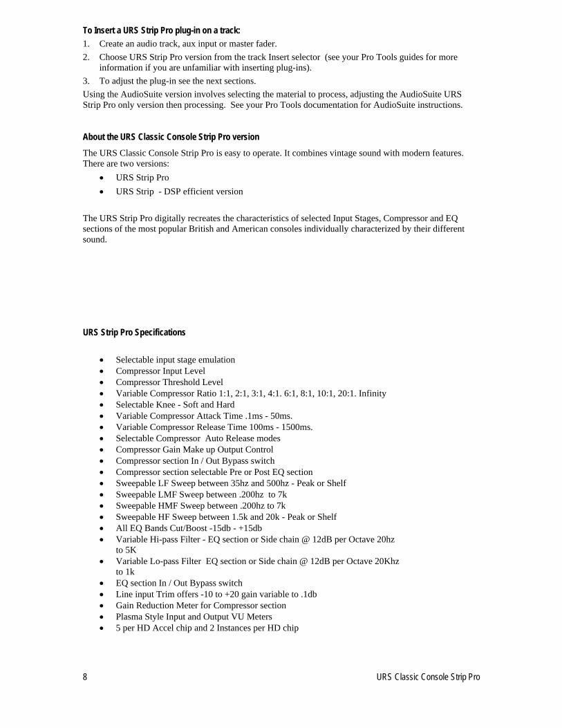
URS Strip Pro Specifications
Selectable input stage emulation
Compressor Input Level
Compressor Threshold Level
Variable Compressor Ratio 1:1, 2:1, 3:1, 4:1. 6:1, 8:1, 10:1, 20:1. Infinity
Selectable Knee - Soft and Hard
Variable Compressor Attack Time .1ms - 50ms.
Variable Compressor Release Time 100ms - 1500ms.
Selectable Compressor Auto Release modes
Compressor Gain Make up Output Control
Compressor section In / Out Bypass switch
Compressor section selectable Pre or Post EQ section
Sweepable LF Sweep between 35hz and 500hz - Peak or Shelf
Sweepable LMF Sweep between .200hz to 7k
Sweepable HMF Sweep between .200hz to 7k
Sweepable HF Sweep between 1.5k and 20k - Peak or Shelf
All EQ Bands Cut/Boost -15db - +15db
Variable Hi-pass Filter - EQ section or Side chain @ 12dB per Octave 20hz to 5K
Variable Lo-pass Filter EQ section or Side chain @ 12dB per Octave 20Khz to 1k
EQ section In / Out Bypass switch
Line input Trim offers -10 to +20 gain variable to .1db
Gain Reduction Meter for Compressor section
Plasma Style Input and Output VU Meters
5 per HD Accel chip and 2 Instances per HD chip
URS Classic Console Strip Pro 9
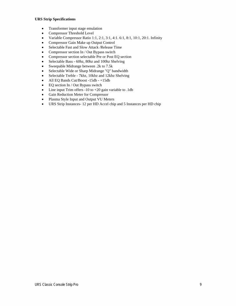
URS Strip Specifications
Transformer input stage emulation
Compressor Threshold Level
Variable Compressor Ratio 1:1, 2:1, 3:1, 4:1. 6:1, 8:1, 10:1, 20:1. Infinity
Compressor Gain Make up Output Control
Selectable Fast and Slow Attack /Release Time
Compressor section In / Out Bypass switch
Compressor section selectable Pre or Post EQ section
Selectable Bass - 60hz, 80hz and 100hz Shelving
Sweepable Midrange between .2k to 7.5k
Selectable Wide or Sharp Midrange "Q" bandwidth
Selectable Treble - 7khz, 10khz and 12khz Shelving
All EQ Bands Cut/Boost -15db - +15db
EQ section In / Out Bypass switch
Line input Trim offers -10 to +20 gain variable to .1db
Gain Reduction Meter for Compressor
Plasma Style Input and Output VU Meters
URS Strip Instances- 12 per HD Accel chip and 5 Instances per HD chip
10 URS Classic Console Strip Pro
Chapter 4: URS Strip Pro Input Stage – Signal Flow – Input Output Section
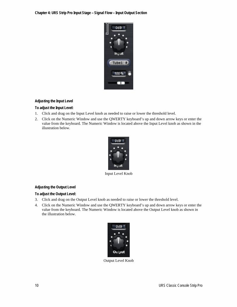
Adjusting the Input Level
To adjust the Input Level: 1. Click and drag on the Input Level knob as needed to raise or lower the threshold level.
2. Click on the Numeric Window and use the QWERTY keyboard’s up and down arrow keys or enter the value from the keyboard. The Numeric Window is located above the Input Level knob as shown in the illustration below.
Input Level Knob
Adjusting the Output Level
To adjust the Output Level: 3. Click and drag on the Output Level knob as needed to raise or lower the threshold level.
4. Click on the Numeric Window and use the QWERTY keyboard’s up and down arrow keys or enter the value from the keyboard. The Numeric Window is located above the Output Level knob as shown in the illustration below.
Output Level Knob

URS Classic Console Strip Pro 11
Input Stage Modeling
The URS Strip Pro currently includes a selection of Tube, Tape and Console Input Stage colorizations.
Combinations of transformer (Iron) and Tape simulate console and tape machine signal path color.
Input Stage Models Explained
Current included Input Stage Models:
Digital Transparent Input Stage (No colorization) (Bypass)
1951 1951 Input Stage
1967 1967 Input Stage and Summing Buss
1970 1970 Input Stage and Summing Buss
1972 1972 Input Stage and Summing Buss
1980 1980 Input Stage and Summing Buss
15ips 15ips 2” Tape Head Bump and Electronics curve
30ips 30ips 2” Tape Head Bump and Electronics curve
30ipsH 30ips 1/2” Tape Head Bump and Electronics curve
IronA American Class A Transformer Input Stage – Warm Bottom
IronA 15 American Class A Transformer + 15ips 2” Tape Head Bump and Electronics curve
IronA 30 American Class A Transformer + 30ips 2” Tape Head Bump and Electronics curve
IronA 30H American Class A Transformer + 30ips 1/2” Tape Head Bump and Elect. curve
IronB British Class A Transformer Input Stage – Warm Bottom
IronB15 British Class A Transformer + 15ips 2” Tape Head Bump and Electronics curve
IronB30 British Class A Transformer + 30ips 2” Tape Head Bump and Electronics curve
IronB30H British Class A Transformer + 30ips1/2” Tape Head Bump and Electronics curve
IronC American Class A Transformer Input Stage – Warm Top End
IronC15 American Class A Transformer + 15ips 2” Tape Head Bump and Electronics curve
IronC30 American Class A Transformer + 30ips 2” Tape Head Bump and Electronics curve
IronC30H American Class A Transformer + 30ips 1/2” Tape Head Bump and Elect. curve
IronD American Class A Transformer Input Stage – Warm Bottom & Top
IronD15 American Class A Transformer + 15ips 2” Tape Head Bump and Electronics curve
IronD30 American Class A Transformer + 30ips 2” Tape Head Bump and Electronics curve
IronD30H American Class A Transformer + 30ips 1/2” Tape Head Bump and Elect. curve
IronG German Class A Transformer Input Stage – Warm Bottom - Top End Boost
IronG15 German Class A Transformer + 15ips 2” Tape Head Bump and Electronics curve
IronG30 German Class A Transformer + 30ips 2” Tape Head Bump and Electronics curve
IronG30H German Class A Transformer + 30ips 1/2” Tape Head Bump and Elect. curve
Tube1 Tube Electronics Input Stage – Warm Midrange Boost
Tube2 Tube Electronics Input Stage – Warm Low Freq Boost
To select the Input Stage Modeling Click on “Input Stage Modeling Drop down Select” button located below the “Input Level” control. You can select from the different input stage digital recreations above. Currently there are 30 with room to add more as they are developed. The Inputs stages provide a range of subtle to pronounced colorizations. The Input Stage Drop Down Select will display and indicate the Input Stage model selected.
Input Stage Modeling drop down
The Input Stage Modeling Intensity The Input Stage Modeling Intensity slider is located below the “Input Stage Modeling Drop down Select” control. The default setting for the digitally recreated Input stages is 100%. Click on and move the slider left to lessen the effect (percentage) or right to increase the effect. At 200% the Input Stage Model is amplified for a more pronounced effect.
To A/B or Bypass the effect select “Digital” from the “Input Stage Modeling Drop down Select” control.

12 URS Classic Console Strip Pro
To Adjust the Input Stage Modeling Intensity
1 Click on and move the slider left or right to adjust the desired Intensity of the Input Stage Model.
2 Click on the Numeric Window and use the QWERTY keyboard’s up and down arrow keys or enter the value from the keyboard. The Numeric Window is located above the Input Stage Modeling Intensity Slider as shown in the illustration below.
Input Stage Modeling Intensity Slider and Numeric Display
The Input Stage Unlock Function The Input Stage Unlock function allows the Input Stage settings to be unlocked from the Compressor Starting points!
Input Stage Locked and Unlocked
Interactive Signal Flow Section
The Interactive Signal Flow Section controls the bypass state of the entire plug-in and each individual section. The three buttons located under the Bypass button will change labeling dependant on the status of the Pre/Post switches on the Compressor and Filters section.
The Compressor’s Pre/Post switch will place the Compressor Section Pre or Post the EQ section.
The Filter’s Pre/Post switch will place the Filter Section Pre or Post the Compressor section or utilize the Filters Section as the Compressor Section’s Side Chain.
The Interactive Signal Flow Section always displays the current status of the URS Strip Pro’s signal flow.
The position and labeling of the Buttons will change to correspond with the current signal flow.
Bypass – Master Bypass for the entire Plug-in – LED is lit when the plug-in is bypassed.
Comp – Compressor Section bypass – LED is lit when the Compressor Section is in circuit.
Filters – Filter Section bypass – LED is lit when the Filters Section is in circuit.
SChain – Filter Section SideChain bypass – LED is lit when the Filters Section SideChain is in circuit.
EQ – EQ Section bypass – LED is lit when the EQ Section in is in circuit.
Mouse Control: When the Mouse Icon is diagonal - mouse control is X / Y.
When the Mouse Icon is circular - mouse control is circular.
Mouse Control – X/Y

URS Classic Console Strip Pro 13
Phase Reverse Button: Click on the Phase Reverse button below the Output Level knob to reverse the Phase of the signal.
When the Phase Reverse Button is activated the LED will be lit.
Phase Reverse Button

14 URS Classic Console Strip Pro
Chapter 5: URS Strip Pro Compressor Section
Compressor Starting Points Explained
The URS Strip Pro includes powerful Compressor Starting Points that Digitally Recreate the compression curves of many popular console and outboard compressors. In addition, 15ips and 30 ips Tape compression curves are included. The Tape compression starting points are most useful when used in combination with the 15ips and 30 ips Tape Input Stage models.
The Compressor Starting Points can be changed without loosing your Input/Output Levels, Input Stage Modeling, Filters, EQ and Phase settings. This allows you to audition the most suitable compression for the track you are working with. Adjust the Compressor’s Threshold control to quickly add the amount of compression desired from the Compressor Starting points without changing the original compression curves. Then adjust the Gain Make Up control to balance any loss/gain of level. Keep in mind that changes to the Ratio, Attack/Release and Knee will alter the starting point compression curves.
Selecting the Compressor Section Starting Points Click on the “Compressor Drop down Select” button located to the right of the Threshold Control’s Numeric Window. You can select from the different Compressor digital recreations. Currently there are 35 Compressor Starting Points with room to add more as they are developed. The Compressor Starting Points provide a selection of FET, OPTO, VCA and Tube compression curves. The Compressor Drop Down Select will display and indicate the Compressor starting point selected.
Compressor Starting Point drop down

URS Classic Console Strip Pro 15
Compressor Starting Points Explained
1967 1967 American Feed Forward Compressor 2:1 ratio 1967L 1967 American Feed Forward Limiter 20:1 ratio 1970C1 1970 British Channel Compressor Ratio 1.5:1 100ms Release 1970C2 1970 British Channel Compressor Ratio 2:1 100ms Release 1970C3 1970 British Channel Compressor Ratio 3:1 400ms Release 1970C4 1970 British Channel Compressor Ratio 4:1 400ms Release 1970C5 1970 British Channel Compressor Ratio 6:1 400ms Release 1970L1 1970 British Channel Limiter Ratio 100:1 50ms Release 1970L2 1970 British Channel Limiter Ratio 100:1 100ms Release 1980C1 1980 British VCA Channel Compressor Ratio 2:1 Fast Attack 1980C2 1980 British VCA Channel Compressor Ratio 3:1 Slow Attack 1980C3 1980 British VCA Channel Compressor Ratio 4:1 Fast Attack 1980C4 1980 British VCA Channel Compressor Ratio 5:1 Fast Attack 1980C5 1980 British VCA Channel Compressor Ratio 8:1 Fast Attack Fet 4 1967 Fet Limiter 4:1 ratio Fet 8 1967 Fet Limiter 8:1 ratio Slowest Attack Fastest Release Fet 12 1967 Fet Limiter 12:1 ratio Fet 20 1967 Fet Limiter 20:1 ratio Fet All 1967 Fet Limiter All Buttons Opto2a 1965 Opto Compress setting Opto2aL 1965 Opto Limit setting Opto3a 1969 Opto Compress setting Opto3aL 1969 Opto Limit setting Rm Mic TalkBack Compressor Full bandwidth 25:1 ratio Stress 3 1995 Stress Compressor 3:1 ratio Stress 6 1995 Stress Fet Compressor 6:1 ratio Stress10 1995 Stress Opto Limiter 10:1 ratio Stress20 1995 Stress Fet Limiter 20:1 ratio Strip A Preset A from URS Classic Console Strip Strip B Preset B from URS Classic Console Strip Strip C Preset C from URS Classic Console Strip Tape15 Tape 15ips 2" Normal Compression Tape15L Tape 15ips 2" Light Compression Tape30 Tape 30ips 2" Normal Compression Tape30L Tape 30ips 2" Light Compression Tape30H Tape 30ips Half inch Normal Compression Tube 1 Tube Child setting 6:1 ratio – fast release Tube 2 Tube Child setting 6:1 ratio – normal release Tube 3 Tube Child setting 6:1 ratio – slow release Tube 4 Tube Child setting 6:1 ratio – slowest release TubeA 1950's American Tube Compressor 2:1 ratio – 300ms release TubeB 1950's American Tube Limiter 5:1 ratio – 333ms release TubeE 1960's British Tube Compressor 2:1 ratio – 500ms release TubeEL 1960's British Tube Limiter 6.5:1 ratio – 100ms release TubeF 1954 American Tube Limiter 4:1 ratio TubeSL 1950's American Tube Leveler 8:1 ratio TubeT02 Tube compressor 2:1 Ratio Mid Point Release TubeT04 Tube compressor 4:1 Ratio Mid Point Release TubeT10 Tube compressor 10:1 Ratio Mid Point Release VCA60 American VCA setting 2:1 ratio VCAX American VCA X 4:1 ratio hard knee VCAXS American VCA X 4:1 ratio soft knee

16 URS Classic Console Strip Pro
VCA65a American VCA 2:1 ratio soft knee VCA65b American VCA 4:1 ratio soft knee VCA 3 Rouge VCA 3 setting 3.5:1 ratio VNewC Very New Compress 1.5:1 ratio VNewL Very New Limit 4:1 ratio XTC-A American Class A Buss Compressor Preset A XTC-B American Class A Buss Compressor Preset B XTC-C American Class A Buss Compressor Preset C
Guide To Compressor Presets -The Compressor Presets above are both starting points and actual great sounding presets. Below are tips to adjusting the Ratio amount and Attack and Release times.
Please note that after adjusting the Ratio and Attack and Release times, Threshold and Gain Make up will need re-adjustment. As you get to know the Strip Pro this will become easier. Below are alternate Ratio, Attack and Release settings that keep the Vintage sound of the starting points. Print this as a reference.
1967 Console Compressor – Vintage Attack .1us fixed, Vintage Ratio 2:1 fixed Vintage release times were 100ms, 500ms, 2 seconds, 2.5 seconds and 3 seconds. Modern Ratio’s – 1.5:1, 2:1, 3:1, 4:1, 6:1, 10:1 and 100:1
1967 Console Limiter – Vintage Attack .1us fixed, Vintage Ratio 20:1 fixed Vintage release times were 100ms, 500ms, 2 seconds, 2.5 seconds and 3 seconds. Modern Ratio’s – 1.5:1, 2:1, 3:1, 4:1, 6:1, 10:1 and 100:1
1970 Console Compressor presets – Set up to show the available Ratio’s – 1.5:1, 2:1, 3:1, 4:1 and 6:1. Vintage Attack 3ms fixed, Vintage release times were 100ms, 400ms, 800ms and 1.5 seconds
1970 Console Limiter presets – Vintage Ratio 100:1 Vintage Attack 2ms Fast and 4ms Slow. Vintage release times were 50ms, 100ms, 200ms, 800ms and 1.5 seconds
1980 Console Compressor presets Set up to show the popular Ratios 2:1, 3:1, 4:1. 5:1 and 8:1. Vintage ratio’s are sweep able from 2:1 to 100:1. Vintage attack times were fixed at 1ms Fast and Auto 10ms. Vintage Release was sweep able from 100-4000ms - The soft Knee gets harder as the Ratio increases
FET Compressor/Limiter presets – Vintage Ratios 4:1, 8:1, 12:1 and 20:1 plus a special ALL mode that measures out to 16:1, Vintage Attack sweep able from .2ms Fast to .8ms Slow. Vintage Release 50ms Fast to 1100ms Slow. Slight soft Knee gets harder as the Ratio increases.
OPTO Compressor/Limiter – Vintage Compressor Ratio 6:1 and Limiter ratio 10:1, Attack fixed at .1 Release sweet spot at 727ms,. Slight Soft Knee. Vintage unit had only Threshold and Gain Make Up
Stress Compressor/Limiter – Vintage Ratio 3:1, 6:1, 10:1(Opto) and 20:1 – Note Ratios 6:1, 10:1(Opto) and 20:1 actually are all 20:1 with different Attack and release times
Strip Presets from the URS Strip
Tape Compression Presets – Ratio 1.8:1 Light Compression (Higher Output Tape) and 2:1 for normal
Tube Child settings 1-4 – Vintage Tube Unit Ratio fixed at 6:1, Preset Settings 1 and 2 = Attack .2ms, Settings 3 and 4 = Attack .4ms. Vintage Release times represented . Soft Knee
Tube A – Vintage 436 Tube Compressor had only Threshold and Gain Make up. Attack 50ms and Release fixed at 300ms

URS Classic Console Strip Pro 17
Tube B – Vintage Ba6a Tube Compressor had only Threshold and Gain Make up. Attack fixed .6ms and Release fixed at 333ms. Hard Knee
Tube E – Vintage American Tube Compressor with British Mods Ratio fixed at 2.1 - Attack fixed at 47ms. Release times 250ms, 500ms, 1200ms, 2500ms and 4000ms, Slight Soft Knee
Tube E Limiter – Vintage American Tube Compressor with British Mods Ratio fixed to 6.5:1 and Attack fixed at 8ms. Release times 50ms, 100ms, 250ms, 500ms, 1000ms and 2000ms. Slight Soft Knee
Tube F – 1954 Vintage AM864 Tube Limiter. It’s Ratio fixed at 4.1 - Attack fixed at 1.2ms. Release times 508ms Slight Soft Knee. Great Drum and Acoustic Guitar Limiter
Tube SL Leveler - Vintage Tube American Leveler helped the signal to Stay Level. Unit had only adjustable Threshold and Gain Make up and Release switch that switched between the 2500ms and 4000ms. Also try 500ms. Slight soft Knee, Great on Bass Guitar – Check out the Bass Leveler preset!
Tube T Compressor – Vintage Danish Tube Compressor with sweep able Ratio 2:1 to 10:1 and Attack at midpoint 44ms. Release times at sweet spot 727ms, Very Soft Knee. Actual ratio much less than faceplate indicated.
Presets for 2:1. 4:1 and 10:1 ratios.. Vintage unit also had an Attack/release preset of 1ms Attack and 50ms Release- Dial in those settings on the 4:1 preset for a Great Drum Compressor.
VCA60 – Vintage Ratios – 2:1, 4:1, 6:1, 10: Attack fixed at 15ms and Release at 80ms.
Hard Knee
VCAX, VCAXS – Vintage Ratios – 2:1, 4:1, 6:1 Attack fixed at 15ms and Release at 80ms.
Hard Knee at 0 and Soft Knee at 5. VCA60X soft Knee mode reduces ratio by more than half.
VCA65 – Vintage Ratios – 2:1, 4:1, 6:1 as presets a, b and c. Preset Attack fixed at 15ms and Release at 80ms. Extremely soft knee
VCA 3 Compressor - Vintage Ratio 1.5:1 – 10:1, Attack Fast / Slow and Release 100- 4000ms
VNew – Compressor 1.5:1 and Limiter at 4:1, Vintage Attack Time 25ms -70ms, Vintage Release adjustable 200ms, 400ms, 600ms and 4000ms. For Limiting above 12db gain reduction use 20:1 ratio
XTC – Vintage Class A Buss Compressor features gentle Ratios 1.7:1 to 1.8:1 and Soft Knee.

18 URS Classic Console Strip Pro
Adjusting the Compressor’s Threshold
To adjust the Compressor’s Gain Reduction Threshold 1. Click and drag on the Compressor’s Threshold knob as needed to raise or lower the threshold
level.
2. Click on the Numeric Window and use the QWERTY keyboard’s up and down arrow keys or enter the value from the keyboard. The Numeric Window is located above the Compressor’s Threshold knob as shown in the illustration below.
Compression Threshold Knob
Setting the Compression Ratio
Adjusting the Compressor’s Gain Reduction Ratio 1. Click and drag on the Compressor’s Ratio knob as needed to raise or lower the ratio amount.
2. Click on the Numeric Window and use the QWERTY keyboard’s up and down arrow keys or enter the value from the keyboard. The Numeric Window is located above the Compressor’s Ratio knob as shown in the illustration below.
Compression Ratio Knob
Adjusting the Compression Attack Time
To adjust the Compressor’s Gain Reduction Attack Time: 1. Click and drag on the Compressor’s Attack Time knob as needed to raise or lower the attack time.
2. Click on the Numeric Window and use the QWERTY keyboard’s up and down arrow keys or enter the value from the keyboard. The Numeric Window is located above the Compressor’s Attack Time knob as shown in the illustration below.
Compressor Attack Time Knob

URS Classic Console Strip Pro 19
Adjusting the Compression Release Time
To adjust the Compressor’s Gain Reduction Release Time: 1. Click and drag on the Compressor’s Release Time knob as needed to raise or lower the release time.
2. Click on the Numeric Window and use the QWERTY keyboard’s up and down arrow keys or enter the value from the keyboard. The Numeric Window is located above the Compressor’s Release Time knob as shown in the illustration below.
Compressor Release Time Knob
Compressor Auto Release Function The Compressor Auto Release drop down is located below the Compressor’s release knob. When “M” is selected (Manual) the compressor’s release time can be manually adjusted When Auto Release is engaged the numeric window above the Release knob displays “Auto”.
Compressor with Auto Release mode A1 engaged
There are seven program dependent Auto Release selections available The Auto Release presets are organized from Fast to Slow:
A1 1970 Fast
A2 Opto3a A3 1970 Slow A4 Opto2a A5 1980 A6 Fet A7 Tube Child
Adjusting the Compressor’s Gain Make Up
The Compressor’s Gain Make Up knob amplifies the output level after the Compressor’s Gain Reduction circuit.
Compressor Gain Make Up Knob

20 URS Classic Console Strip Pro
To adjust the Compressor’s Gain Makeup: 1. Click and drag on the Compressor’s Gain Make Up knob as needed to raise or lower the make up gain.
2. Click on the Numeric Window and use the QWERTY keyboard’s up and down arrow keys or enter the value from the keyboard. The Numeric Window is located above the Compressor’s Gain Make Up knob as shown in the illustration below.
Adjusting the Compressor’s Knee
The Compressor’s Knee button selects between Hard and Soft Knee.
Hard Knee is a normal compressor curve to gain reduction. Hard knee is well suited on Drums and percussive instruments.
Soft Knee is softer as the name implies and smoother. Soft knee is better suited on Vocals. It can also be used on instruments with non-percussive attacks.
Compressor Knee knob
Bypassing the Compressor section
To bypass the Compressor section: Click on the button label “Comp” in the Signal Flow section. The position of the “Comp” button will change depending on how you have the Compressor section or Filter section Pre/Post switch set. Clicking the “Comp” button will toggle bypass state. When button is in (processing), the IN button LED is lit. When bypassed (out), the IN LED is dark and the plug-in Bypass switch is lit.
Signal Flow section “Comp” IN / OUT button
When the Compressor section is OUT the Gain Make Up control is also out of circuit. Be careful when in and out of circuit and loud listening levels.

URS Classic Console Strip Pro 21
Using the Gain Reduction Meter
The Gain Reduction Meter monitors gain reduction of the Compressor section.
The scale goes from 0db to 20db of gain reduction.
URS Strip Gain Reduction Meter
Selecting the Compressor’s function and position in the signal path The Compressor can be used two different ways.
Pre the Equalizer Section
Post the Equalizer section
.
To select the Compressor’s position in the signal path:
Click the toggle switch to the left for pre (Pre Equalizer)and to the right for post (Post Equalizer).

22 URS Classic Console Strip Pro
Chapter 6: URS Strip Pro Filters Section
Adjusting the Low Pass and High Pass Filters
The URS Strip Pro provides both a Low Pass Filter and a High Pass Filter.
The Low Pass Filter The Low Pass Filter allows only Low frequencies to pass through. As you increase the knob clockwise you start rolling off the higher frequencies, letting only the Low frequencies pass through.
The High Pass Filter The High Pass Filter allows High frequencies to pass through. As you increase the knob clockwise you start rolling off the lower frequencies, letting only the High frequencies pass through.
Adjusting the Low and High Pass Filters
To Adjust the Low and High Pass Filters:
Click and drag on either the Low Pass or High Pass filter knob
Click on the Numeric Window and use the QWERTY keyboards up and down arrow keys
Click on the Numeric Window and enter the value from the keyboard
To Bypass each filter, click on the In /Out button below the High and Low Pass or High Filter knob.
Selecting the Filters function and position in the signal path The Filters can be used three different ways
Pre the Compressor Section
Post the Compressor section as part of the EQ Section
As part of the Internal Side Chain
.
To select the Filters position in the signal path:
Click the toggle switch to left for pre (Pre Compressor), right for post (Post Compressor) or center for Side Chain

URS Classic Console Strip Pro 23
Using the Listen Feature
The Listen Button allows you to Listen to how you are equalizing the signal being sent to the sidechain gain reduction sensing circuit. To enable the Listen feature Click the Listen feature IN button to toggle bypass state. When in (processing), the IN button is in and the IN LED is lit. When bypassed (out), the IN LED is dark.
.
Selecting Internal or External Side Chain (TDM Version only)
To select Internal or External Key input Click on the Key located on the gray Pro Tools header of the URS Strip Pro version plug-in to toggle the Key Input source.
You can also click on the Key Internal – Key External toggle switch in the Filters section.
To bypass the Filters section: Click on the button label “Filters” in the Signal Flow section. The position of the “Filters” button will change depending on how you have the Filters section or Filter section Pre/Post switches set. Clicking the “Filters” button will toggle bypass state. When button is in (processing), the IN button LED is lit. When bypassed (out), the IN LED is dark and the plug-in Bypass switch is lit.
Signal Flow section “Filters” IN / OUT button
To bypass the Filters section when used as the Internal Side Chain When the Pre/Post/Side chain toggle is set to Side chain the Filters button will display “SChain” in the Signal Flow Display Section.
Clicking the “SChain” button will toggle bypass state. When button is in (processing), the IN button LED is lit. When bypassed (out), the IN LED is dark and the plug-in Bypass switch is lit.
Signal Flow section “SChain” IN / OUT button

24 URS Classic Console Strip Pro
Chapter 7: URS Strip Pro EQ Section
The EQ section digitally recreates the sound of four different analog consoles plus a program EQ. All bands features fully sweep able frequency and "Q" bandwidth selection. The Mid range bands overlap over four octaves of frequency selection. The LF and HF EQ Bands are selectable Peak or Shelving. Each EQ band presently selects from either:
1951 Program EQ - Tube
1967 Console EQ – American
1970 Console EQ - British Class A Three Band
1972 Console EQ - British Class AB Four Band
1980 Console EQ - British
Adjusting the EQ Modeling of each band
To adjust EQ Modeling for each band:
Click on the desired band’s “EQ Modeling Drop down Select” located below the “Q” control. You can select from the different digital recreations included. Currently there are five with room to add more as they are developed. The Drop Down Select will display and indicate the EQ model selected
Click on the down arrow to the right of the drop down window to advance down to the next model
Shift + Click to advance up to the previous model
Clicking the EQ Modeling Drop down Select button to EQ Models per band
Linking the EQ Modeling of each band
The “EQ Model Link” enables all four bands to change simultaneously to the same EQ Model year
When enabled, you can change the model year on any one band all four bands will change to the same year.
The EQ Model Link is located to the right of the HF Gain control.
Click on the EQ Modeling Led. When it is illuminated it is enabled:
The EQ Model Link in the off position
Adjusting Frequency of each band
To adjust frequency for any band:
Click and drag on the desired band’s knob as needed to raise or lower frequency gain. Click on the Numeric Window and use the QWERTY keyboards up and down arrow keys or enter the value from the keyboard. Frequency is entered 750 and Return for 750Hz or 7500 or 7.5k and Return for 7.5k
Clicking the numeric window to adjust a Frequency setting

URS Classic Console Strip Pro 25
Adjusting Gain of each band
To adjust filter Gain: 1. Click and drag on the desired band’s knob as needed to raise or lower frequency gain. Click on the Numeric
Window and use the QWERTY keyboards up and down arrow keys or enter the value from the keyboard.
Adjusting Gain
Adjusting the Q of each band
To adjust filter Q:
Click and drag on the desired band’s knob as needed to select narrow or wider frequency Q. Click on the Numeric Window and use the QWERTY keyboards up and down arrow keys or enter the value from the keyboard.
Adjusting Q
Selecting Peak or Shelving on the Low or High Bands
The Low and High bands are set to Shelving as default. Click the toggle switch selects Peak or Shelving. Please make note of the Shelving Icon on the left in the diagram below and the Peak icon in the diagram below on the right.
Selecting Peak or Shelving using the BEL switch
The IN button on each Band
The IN button (shown below) puts each band In or Out of circuit. When in, the Led to the right of the IN button is illuminated.
To bypass the EQ section: Click on the button label “EQ” in the Signal Flow section. When button is in (processing), the IN button LED is lit. When bypassed (out), the IN LED is dark.
Signal Flow section “EQ” IN/OUT button

26 URS Classic Console Strip Pro
Guide to the URS Classic Console Strip Pro’s Vintage Console EQ Frequencies Below are the PRIME frequencies that were featured on the vintage units. Print this as reference.
1951 HF- 5k, 8k, 10k, 12k, 15k, 20k HMF– 200hz, 300hz, 500hz, 700hz, 1.5k, 2k, 3k, 4k, 5k LMF – 200hz, 300hz, 500hz, 700hz, 1.5k, 2k, 3k, 4k, 5k LF - 30hz, 60hz, 80hz, 100hz Note * Original 1951 EQ had only three bands The Strip Pro duplicates the Mid range band for LMF and HMF
1967 HF – 2.5k, 5k, 7k, 10k, 12.5k, 15k, 20k HMF – 200hz,, 240hz, 500hz, 700hz, 800hz, 1k, 1.5k, 3k, 5k LMF – 240hz, 500hz, 700hz, 800hz, 1k, 1.5k, 3k, 5k LF – 30hz, 40hz, 50hz, 100hz, 200hz, 300hz, 400hz,
1970 HF – 12k HMF – 350hz, 700hz, 1.6k, 3.2k, 4.8k, 7k LMF – 350hz, 700hz, 1.6k, 3.2k, 4.8k, 7k LF - 5hz, 60hz, 110hz, 220hz Note * Original 1970 EQ had only three bands The Strip Pro duplicates the Mid range band for LMF and HMF
1972 HF – 3.3k.4.7k, 6.9k, 10k, 15k HMF – 1.5k, 1.9k, 2.2k, 2.7k, 3.3k,3.9k, 4.7k, 5.8k, 6.9k LMF – 220hz, 270hz, 330hz, 390hz, 470hz, 560hz, 690hz, 820hz, 1k, 1.2k LF – 33hz, 56hz, 100hz, 180hz, 330hz
1980 HF – Sweep 1.5k to 18k HMF– Sweep 500hz to 7.5k LMF– Sweep 200hz to 7.5k HF– Sweep 30hz to 450hz

URS Classic Console Strip Pro 27
hapter 8: Global Functions
Adjusting the Input Gain
To adjust the Input Gain: 1 Click and drag on Input knob as needed to raise or lower the input level.
2 Click on the Numeric Window and use the QWERTY keyboard’s up and down arrow keys or enter the value from the keyboard. The Numeric Window is located above the Input level knob as shown in the illustration below.
Input level Knob
Adjusting the Output Gain
To adjust the Output Gain: 1 Click and drag on Input knob as needed to raise or lower the input level.
2 Click on the Numeric Window and use the QWERTY keyboard’s up and down arrow keys or enter the value from the keyboard. The Numeric Window is located above the Input level knob as shown in the illustration below.
Phase reverse switch
To flip phase:
Click on the Phase (ø) switch – LED will light to indicate Phase reversal.

28 URS Classic Console Strip Pro
Using the Input and Output Plasma VU Meters
The Input and Output meters are placed on top of each other to quickly compare input to output levels with out having to leave the plug-in window. Gain staging in the Digital Domain is critical and not overloading the track(s) is essential. The Meters include a Red Clipping indicator.
Stereo and Mono Metering
When using the URS Strip Pro on a Stereo source Stereo Meters will be displayed (as shown below).
The top meter of the Input pair is the Left channel and the bottom meter of the Output pair is the Right channel.
When using the URS Strip Pro on a Mono source Mono Meters will be displayed
The URS Strip Pro’s Input and Output Meters
To clear the Gain Clip Indictors
Click once on the Red gain clip indicator to clear its status.
Operation Tip! - Hold the Option key and click on either Gain Clip Indicator to clear both.
URS Classic Console Strip Pro 29
Chapter 9: Operational Tips
This chapter provides additional information for the URS Classic Console Strip Pro and the
URS Classic Console Strip versions including control surface support and operational tips to
help you get the most out of the Classic Console Strip Pro and Strip.
ICON, ProControl, Control|24and Other Control Surfaces
The Strip Pro fully supports Digidesign ICON, ProControl, Control|24, Command 8 and other supported control surfaces. For example, on ProControl the URS plug-in supports the EQ and DYN functions for selecting Strip’s equalizer or compressor as inserts on tracks.
In addition, ProControl maps each plug-in toggle switch to the BYPASS/IN/ø switch (in the DSP Edit/Assign area).
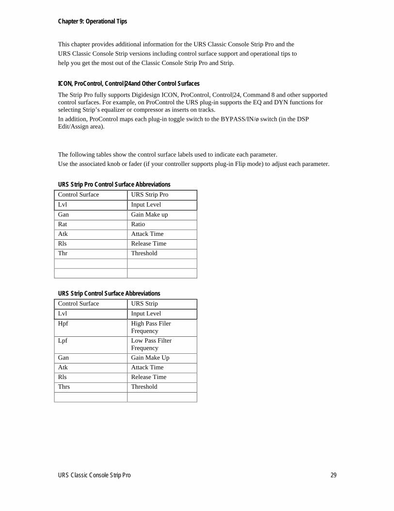
The following tables show the control surface labels used to indicate each parameter.
Use the associated knob or fader (if your controller supports plug-in Flip mode) to adjust each parameter.
URS Strip Pro Control Surface Abbreviations
Control Surface URS Strip Pro
Lvl Input Level
Gan Gain Make up
Rat Ratio
Atk Attack Time
Rls Release Time
Thr Threshold
URS Strip Control Surface Abbreviations
Control Surface URS Strip
Lvl Input Level
Hpf High Pass Filer Frequency
Lpf Low Pass Filter Frequency
Gan Gain Make Up
Atk Attack Time
Rls Release Time
Thrs Threshold

30 URS Classic Console Strip Pro
Operational Tips
TDM or RTAS If you purchased the TDM (full version) you can use TDM and/or RTAS.
If you have the native version, you can use RTAS version only.
When mixing, if you need more TDM memory for reverbs and other TDM only plug-ins,
we recommend using our plug-in as RTAS.
We Do Not recommend using our plug-in as RTAS for live tracking due to the nature of RTAS latency.
Using Multi-Mono Mode for TDM or RTAS If you want to adjust a stereo track, master fader or 5.1 Master fader with one set of controls left and right or more:
1. Select the insert point on your Stereo fader, Master fader or 5.1 Master fader.
2. From the plug-in window open the Multi-Mono Mode plug-in list.
3. Select either the URS Strip Pro or the URS Strip version.
(Multi-channel tracks greater than stereo (LCR to 7.1) Pro Tools HD or MIX.)
Use the Link controls for ganged control of all channels (see your Pro Tools manuals for plug-in linking).
Version Number
URS Classic Console Strip Pro and the URS Classic Console Strip version number To find out what version number you have installed, click on the URS logo in the upper right hand corner of the plug-in. The Version number will then be displayed. Click again to hide the version number.
URS Logo
Mouse Scroll Wheel Support
The URS Classic Console Strip Pro & the URS Classic Console Strip include Mouse Scroll Wheel Support for Mac OSX Panther and Tiger
Our new Wheel Mouse Scroll Wheel Support for Mac OSX requires no clicking. Simply place the mouse cursor over the knob and without clicking just move the mouse scroll wheel to adjust the knob.
You can use your Mouse Scroll Wheel to control the Compressors knobs, buttons and/or numeric windows. Each click of the wheel mouse scroll wheel moves the knob or slider .1db. Holding the option key will enable a 10x multiplier.
Unique Recording Software
www.ursplugins.com
URS Classic Console Strip Pro 31
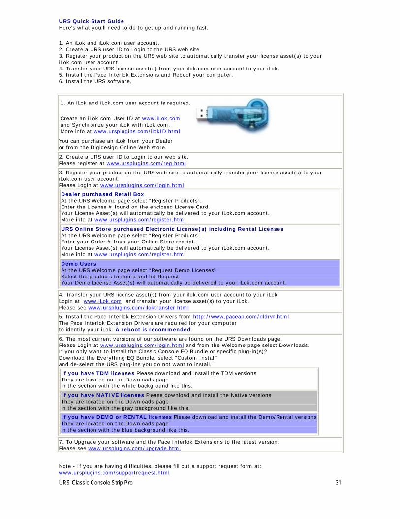
URS Quick Start Guide Here's what you'll need to do to get up and running fast.
1. An iLok and iLok.com user account. 2. Create a URS user ID to Login to the URS web site. 3. Register your product on the URS web site to automatically transfer your license asset(s) to your iLok.com user account. 4. Transfer your URS license asset(s) from your ilok.com user account to your iLok. 5. Install the Pace Interlok Extensions and Reboot your computer. 6. Install the URS software.
1. An iLok and iLok.com user account is required.
Create an iLok.com User ID at www.iLok.com
and Synchronize your iLok with iLok.com. More info at www.ursplugins.com/ilokID.html
You can purchase an iLok from your Dealer or from the Digidesign Online Web store.
2. Create a URS user ID to Login to our web site. Please register at www.ursplugins.com/reg.html
3. Register your product on the URS web site to automatically transfer your license asset(s) to your iLok.com user account. Please Login at www.ursplugins.com/login.html
Dealer purchased Retail Box At the URS Welcome page select “Register Products”. Enter the License # found on the enclosed License Card. Your License Asset(s) will automatically be delivered to your iLok.com account. More info at www.ursplugins.com/register.html
URS Online Store purchased Electronic License(s) including Rental Licenses At the URS Welcome page select “Register Products”. Enter your Order # from your Online Store receipt. Your License Asset(s) will automatically be delivered to your iLok.com account. More info at www.ursplugins.com/register.html
Demo Users At the URS Welcome page select “Request Demo Licenses”. Select the products to demo and hit Request. Your Demo License Asset(s) will automatically be delivered to your iLok.com account.
4. Transfer your URS license asset(s) from your ilok.com user account to your iLok Login at www.iLok.com
and transfer your license asset(s) to your iLok. Please see www.ursplugins.com/iloktransfer.html
5. Install the Pace Interlok Extension Drivers from http://www.paceap.com/dldrvr.html
The Pace Interlok Extension Drivers are required for your computer to identify your iLok. A reboot is recommended.
6. The most current versions of our software are found on the URS Downloads page. Please Login at www.ursplugins.com/login.html
and from the Welcome page select Downloads. If you only want to install the Classic Console EQ Bundle or specific plug-in(s)? Download the Everything EQ Bundle, select "Custom Install" and de-select the URS plug-ins you do not want to install.
If you have TDM licenses Please download and install the TDM versions They are located on the Downloads page in the section with the white background like this.
If you have NATIVE licenses Please download and install the Native versions They are located on the Downloads page in the section with the gray background like this.
If you have DEMO or RENTAL licenses Please download and install the Demo/Rental versions
They are located on the Downloads page in the section with the blue background like this.
7. To Upgrade your software and the Pace Interlok Extensions to the latest version. Please see www.ursplugins.com/upgrade.html
Note - If you are having difficulties, please fill out a support request form at: www.ursplugins.com/supportrequest.html

32 URS Classic Console Strip Pro
Addendum to the URS Strip Pro Manual
Using an External Sidechain with Apple Logic and Abelton Live Note: There is no external sidechain capabilities in Digital Performer currently.
Apple Logic:
In Apple Logic - if you load an instance of an effect plug-in that has a sidechain input, then a "sidechain" menu will appear in the plug-in window's toolbar:
If you click on this pop-up menu button, you will get a menu that includes every available audio track that you can route into the plug-ins sidechain input:
Note: When you route another track in, that track will still play on its own. You may want to enable mute on that sidechain track's channel strip if you want it to be played into the effect only.
Abelton Live:
In Abelton Live - if you load an instance of an effect plug-in that has more than one input bus source, then each additional input bus will show up as an audio output destination on other audio tracks (e.g. the audio tracks other than the one which has the effect plug-in instantiated on it). To enable sending audio from another audio track to an extra input bus of a plug-in you need to first make sure that you are in "Session View" mode (button circled in orange) with "Show In/Out Section" enabled (button circled in red):
Then, on the channel strip for the other audio track that you want to route into the plug-in, choose the track that has the plug-in on it from the "Audio To" menu:
After you do this, the menu below the "Audio To" menu will fill up with options for the selected "Audio To" destination track:

URS Classic Console Strip Pro 33
Choose the input destination for the effect on the track that you want to send this track’s audio output to.


![Hank Howie Biz & Mktg From Console to[2].ppt (Read-Only)](https://static.fdokumen.com/doc/165x107/63191b740255356abc081fd8/hank-howie-biz-mktg-from-console-to2ppt-read-only.jpg)


