clarks Creek 200-07 - US Environmental Protection Agency
80
United States Environmental Protection Agency I. EPA ID Num .. oEPA Underground Injection Control ' I D:� �6 - 1/ ·� T/A Permit Application (Collected under the authority of the Safe Drinking u Cr1.L, { 1 bO i 7 Water Act. Sections 1421, 1422, 40 CFR 144) rvp Read Attached Instructions Bere Staing For Official Use Only Application approved Date received Permit Number Well ID FINDS Number mo day year mo day year -·· - II. Owmn Name ,nd Addres,, . ·1 Operator Name 'nd .ddress Owner Name Clarks Creek 200-07SWD Street Address ··--· - -· Owner Name EOG Resources, Inc. Phone Number Street Address Phone Number C 600 17th Street, Suite I 000N (303) 262-9973 600 17th Street, Suite IO00N (303) 262-9973 City State Denver co IV. Commercial FaG'Qt� V ' Own_ersb:IP � Yes § """ No Federal Other DA Date Started mo day year Operating ZIP CODE 80202 City Denver . egal Contt � Owner Operator . . -· --,- VIII. W+ Stat+11 (Mk �x D B. Modification/Conversion l State ZIP CODE Co 80202 VII•, SIC C'odes 2133 I 2/1389 .. 0 C. Proposed IX-. T פof Perm.It Re.quest a *x" ad 8 If r,al) A. Individual B. Area Number of Existing Wells Number of Proposed Wells Name(s) of fleld(s) or project(s) I ··- , Class a'd pe of Well v ven" A. Class(es) B. Type(s) C. If class Is "other" or type Is code 'x,' explain D. Number of wells per type (If area permit) (enter code(s)) (enter code(s)) I D Class II Xt L.alioa o.f Wllll•) r Ap; pflmate Center,,, �•Id r PtoJect XII. ·dl+ Lands (Mark 'x') Latitude Longitude Township and Range Deg I Min I Sec Deg I Min I Sec Sec I T w p I Range 1 1/4 Sec Feet From Line Feet From Line a Yes No 47 54 24.1 102 45 13.7 7 151 94 SE 463 X. A,hments s (Complete the following questions on a separate sheet(s) and number accordingly; see Instructions) 854 E For Classes I, II, Ill, (and other classes) complete and submit on a separate sheet(s) Attachments A--U (pp 2-6) as appropriate. Attach maps where required. List attachments by letter which are applicable and are Included with your application. XI. O:tcatlo: I certify under the penalty of law that I have personally examined and am familiar with the Information submitted In this document and all attachments and that, based on my Inquiry of those Individuals immediately responsible for obtaining the information, I believe that the Information Is true, accurate, and complete. I am a w are that there are significant penalties for submitting false Information, Including the possibility of fine and Imprisonment. (Ref. 40 CFR 144.32) A. Name and Title (Type or Print) B. Phone No. rea Code and No.) Cal � Wescoat - (303) 262-9973 IC . D.e t /� n /201 � EPA '°� mo� 3 "·"I � I
-
Upload
khangminh22 -
Category
Documents
-
view
0 -
download
0
Transcript of clarks Creek 200-07 - US Environmental Protection Agency
United States Environmental Protection Agency I. EPA ID NumJ)e,r ..
oEPA Underground Injection Control
' I D;1.:�?:, �6 - 1/ '-:2 tA·�T/A
Permit Application (Collected under the authority of the Safe Drinking u
Clc..r1.L, { '({' 1 bO --li 7 Water Act. Sections 1421, 1422, 40 CFR 144) t-< r:xvp
Read Attached Instructions Before Starting For Official Use Only
Application approved Date received Permit Number Well ID FINDS Number
mo day year mo day year
-··
-
II. Owmn Name ,nd Addres,, . ·ll11 Operator Name '!!nd .A:ddress Owner Name
Clarks Creek 200-07SWD
Street Address
··--· - -·
Owner Name EOG Resources, Inc.
Phone Number Street Address Phone Number
C
600 17th Street, Suite I 000N (303) 262-9973 600 17th Street, Suite IO00N (303) 262-9973
City State Denver co
IV. Commercial FaG'Qt� V '. Own_ersb:IP
�Yes
§ """No Federal Other
DA. Date Started
mo day year
Operating
ZIP CODE 80202
City Denver
Vl. l,egal Cont}o;t
� Owner Operator
. . -· --,-
VIII. W11ll Stat1111 (M,tk �xii
D B. Modification/Conversion
l State ZIP CODE Co 80202
VII•, SIC C'odes
2133 I 2/1389
..
0 C. Proposed
IX-. TY!pe of Perm.It Re.quest..rl (Mark *x" atrd PP8t;/fy If r,q,alrec/J)
L:J A. Individual [j B. Area Number of Existing Wells Number of Proposed Wells Name(s) of fleld(s) or project(s)
I
··-
){, Cllass a'lild 'ty,pe of Well ($118 reven"
A. Class(es) B. Type(s) C. If class Is "other" or type Is code 'x,' explain D. Number of wells per type (If area permit)
(enter code(s)) (enter code(s)) I
D Class II
Xt Llm.alioa o.f Wllll•) o:r Ap;pfcqlmate Center,,., �•Id o:r PtoJect XII. lll·dl11r:1 Lands (Mark 'x')
Latitude Longitude Township and Range
Deg I Min I Sec Deg I Min I Sec Sec I Tw
p I Range 1
1/4 Sec Feet From Line Feet From Line a Yes
No 47 54 24.1 102 45 13.7 7 151 94 SE 463
XIII. A,ttai::hments
s
(Complete the following questions on a separate sheet(s) and number accordingly; see Instructions)
854 E
For Classes I, II, Ill, (and other classes) complete and submit on a separate sheet(s) Attachments A--U (pp 2-6) as appropriate. Attach maps where required. List attachments by letter which are applicable and are Included with your application.
XIII. O:trttflcatlo:lil
I certify under the penalty of law that I have personally examined and am familiar with the Information submitted In this document and all attachments and that, based on my Inquiry of those Individuals immediately responsible for obtaining the information, I believe that the Information Is true, accurate, and complete. I am a
ware that there are significant penalties for submitting false Information, Including the possibility of fine and
Imprisonment. (Ref. 40 CFR 144.32)
A. Name and Title (Type or Print) B. Phone No. (Area Code and No.)
Cal� Wescoat f'- (303) 262-9973 IC --- .
D.et
/�n
/201 � EPA '°� mo� 3"·"I �
I
Clarks Creek 200-07SWD
EPA: Appendix
EPA Underground Injection Control (UIC) Permit Application
• (UIC) Permit Form 7520-6
o Class II, Type "D"
• A: Area of Review Method
• B: Maps of Well/Area and Area of Review
• C: Corrective Action Plan and Well Data
• E: Names and Depth of USDW's (Class II)
' eog resources
• G: Geological Data on Injection and Confining Zones (Class II)
• H: Operating Data
• M: Construction Details
• Q: Plugging and Abandonment Plan
• R: Necessary Resources
• I: Formation Testing Program
• K: Injection Procedure
• 0: Plans for Well Failure
• U: Description of Business
• Area of Potential Impact
• Plats
Clarks Creek 200-07SWD
Area of Review Method
eog resources
The Area of Review was determined, based on a fixed radius of ¼-mile around
the wellbore.
See attached map.
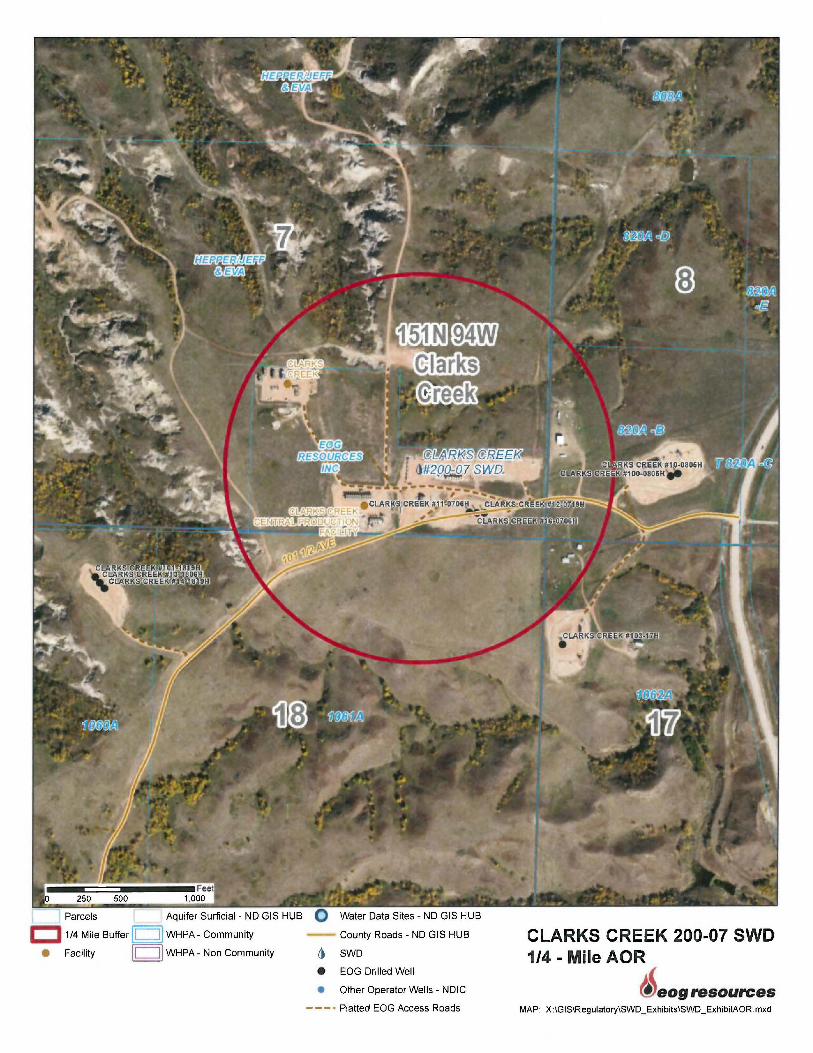
L Parcels Aquifer Surficial - ND GIS HUB Q Water Data Sites - ND GIS HUB
c::::J 1/4 Mile Buffer Ii i] WHPA- Community County Roads - ND GIS HUB
• Facility Ii II WHPA- Non Community () SWD
e EOG Drilled Well
• Other Operator Wells - NDIC
- - - • Platted EOG Access Roads
CLARKS CREEK 200-07 SWD 1/4 - Mile AOR
eog resources MAP: X:IGIS\Regulatory\SWD_Exhibits\SWD_ExhibitAOR.mxd

Clarks Creek 200-07SWD eog resources
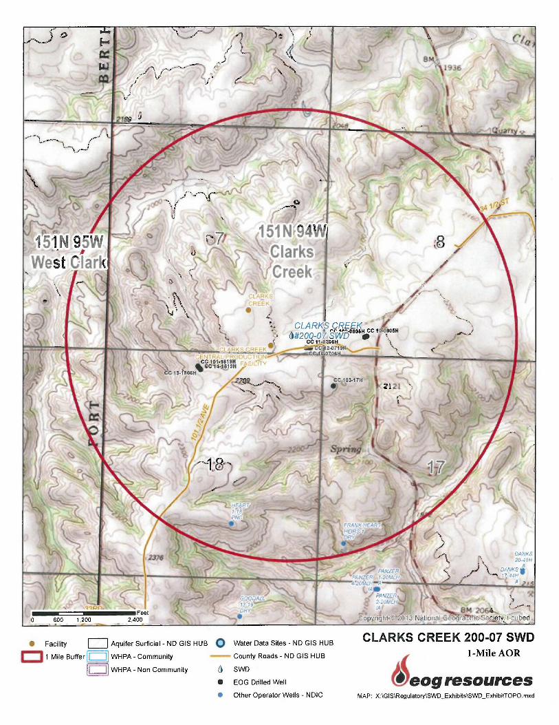
Area of Review Method
The Area of Review was determined, based on a fixed radius of 1-mile around
the wellbore.
See attached map.
0
\ \ l.)
l
J\
• Facility CJ Aquifer Surficial - ND GIS HUB O Water Data Sites - ND GIS HUB
c::::J 1 Mile Buffer II II WHPA - Community County Roads - ND GIS HUB
II ii WHPA - Non Community () SWD
e EOG Drilled Well
• Other Operator Wells - NDIC
lq
CLARKS CREEK 200-07 SWD I-Mile AOR
eog resources MAP: X \GIS\Regulatory\SWD_Exhibits\SWD_Exhibi!TOPO.mxd

Clarks Creek 200-07SWD eog resources
Corrective Action Plan and Well Data

Clarks Creek 200-07SWD eog resources
Corrective Action Plan and Well Data
The Clarks Creek 11-0706H lateral penetrates the ¼ mile AOR, but is completed in the Bakken/Three Forks which is over 5300 feet deeper than the proposed injection zone of the Clarks Creek 200-0?SWD. The vertical section of the Clarks Creek 11-0706H wellbore is cemented from the intermediate casing point to 3,708 feet with 825 sacks of cement. The well encounters the Mowry confining zone from 4560'- 4935' MD and the Swift from 5339'- 5816' MD. The calculated top of cement is at 3,708' feet which is above the top of the Dakota. As the Bakken/Three Forks and Dakota formations are separated by 5,300 feet, no corrective action is needed.
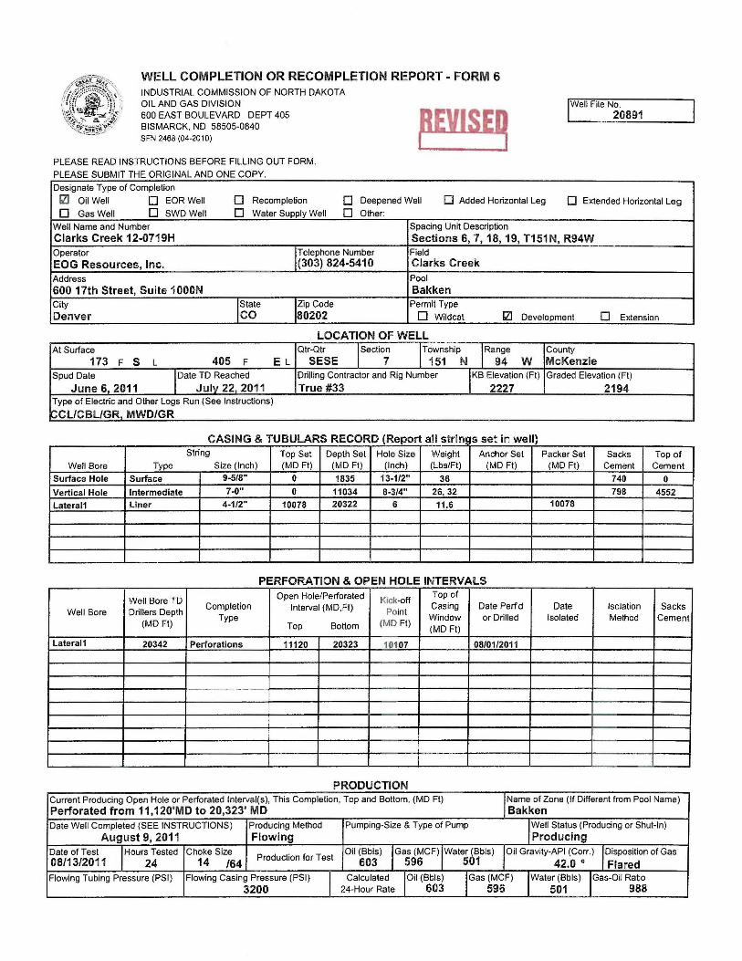
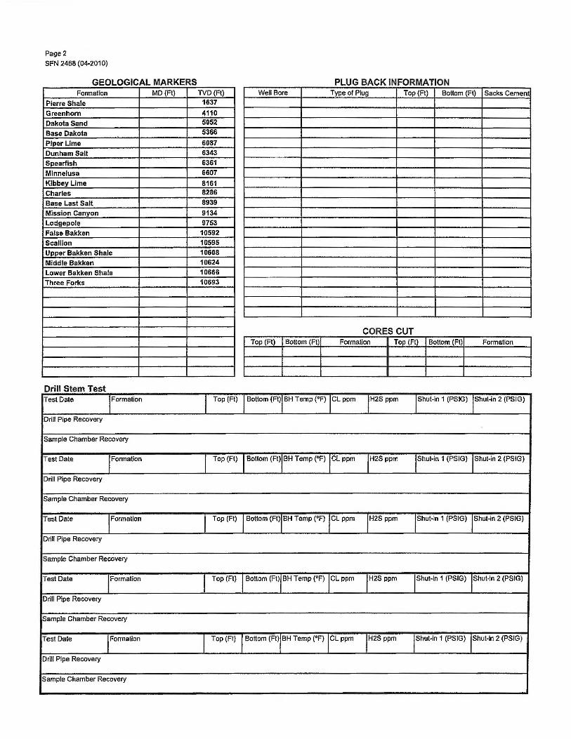
The Clarks Creek 12-0719H lateral penetrates the ¼ mile AOR, but is completed in the Bakken/Three Forks which is over 5,400 feet deeper than the proposed injection zone of the Clarks Creek 200-0?SWD. The vertical section of the Clarks Creek 12-0719H wellbore is cemented from the intermediate casing point to 3,800 feet with 798 sacks of cement. The well encounters the Mowry confining zone from 4567'- 4951'MD and the Swift from 5377'- 5821' MD. The calculated top of cement is at 3,800 feet which is above the top of the Dakota. As the Bakken/Three Forks and Dakota formations are separated by 5,400 feet, no corrective action is needed.
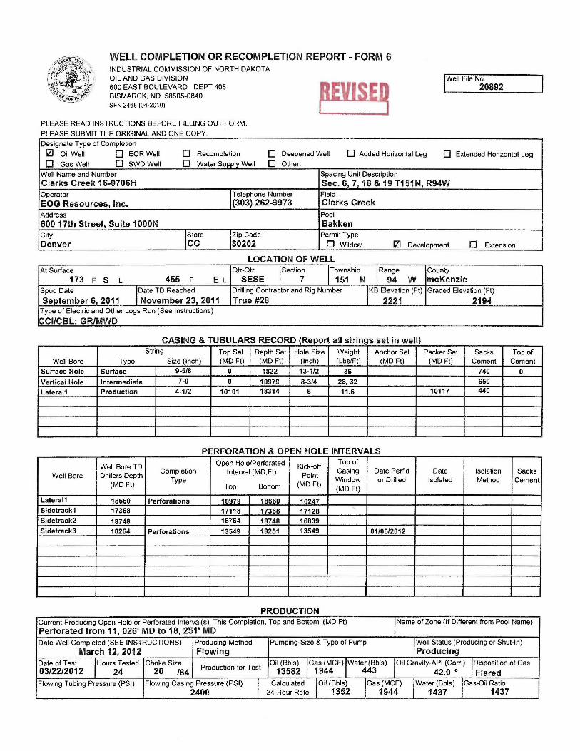
The Clarks Creek 16-0706H lateral penetrates the ¼ mile AOR, but is completed in the Bakken/Three Forks which is over 5,250 feet deeper than the proposed injection zone of the Clarks Creek 200-0?SWD. The vertical section of the Clarks Creek 16-0706H wellbore is cemented from the intermediate casing point to 3,950 feet with 650 sacks of cement. The well encounters the Mowry confining zone from 4567'- 4938' and the Swift from 5352'- 5822' MD. The calculated top of cement is at 3,950 feet which is above the top of the Dakota.

Clarks Creek 200-07SWD eog resources
As the Bakken/Three Forks and Dakota formations are separated by 5,250 feet, no corrective action is needed.
After review, there are no wells within the ¼-mile AOR that needed corrective action
Corrective Action Plan and Well Data
See additional details:
• We do not expect the wells within the AOR to be influenced by pressure from the injection well.
• See attached: Completion reports for each well within ¼-mile AOR • Cement Bond Logs emailed to Jason Deardorff at
Clarks Creek 200-07SWD eog resources
Completion Reports for Wells within AOR
• Clarks Creek 11-0706H • Clarks Creek 12-0719H • Clarks Creek 16-0706H
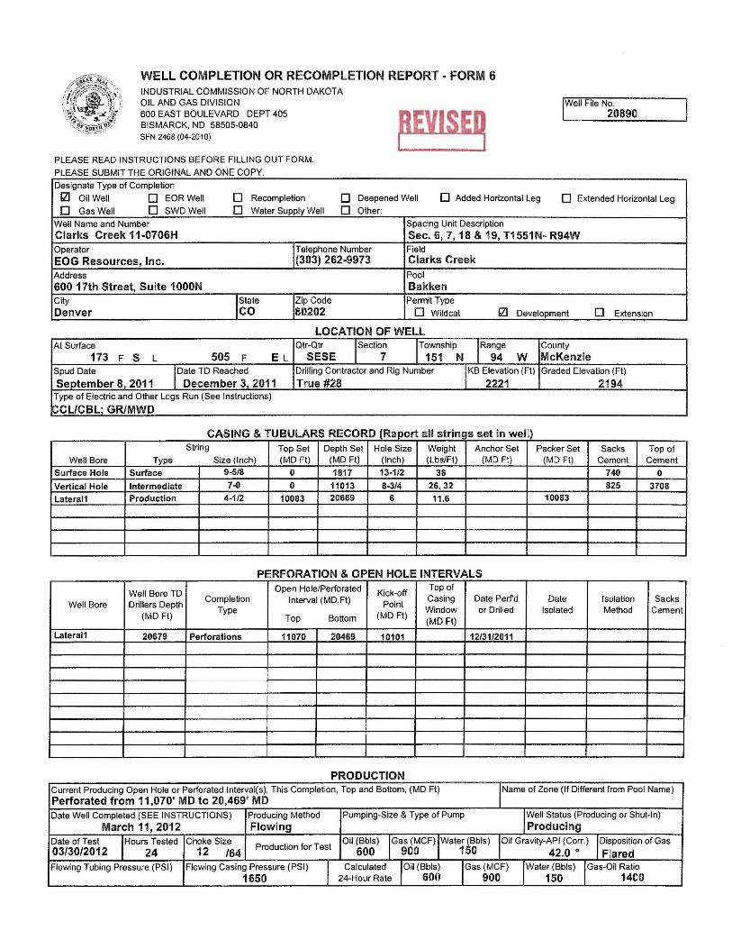
WELL COMPLETION OR RECOMPLETION REPORT - FORM 6 INDUSTRIAL COMMISSION OF NORTH DAKOTA OIL AND GAS DIVISION 600 EAST BOULEVARD DEPT 405 BISMARCK, ND 58505-0840 SFN 2468 (04-2010)
PLEASE READ INSTRUCTIONS BEFORE FILLING OUT FORM.
PLEASE SUBMIT THE ORIGINAL AND ONE COPY
Designate Type of Completion
~EVISE~ 'Well File No.
20890
121 Oil Well D EORWell D Recompletion D Deepened Well D Added Horizontal Leg 0 Extended Horizontal Leg
D Gas Well D SWDWell D Water Supply Well D Other:
Well Name and Number Spacing Unit Description
Clarks Creek 11-0706H Sec. 6, 7, 18 & 19, T1551N- R94W Operator 'Telephone Number Field
EOG Resources, Inc. (303) 262-9973 Clarks Creek Address Pool
600 17th Street, Suite 1000N Bakken City 'State IZip Code Permit Type
Denver co 80202 D Wildcat 121 Development D Extension
LOCATION OF WELL At Surface Qtr-Qtr ISectio; I Township 'Range County
173 F s L 505 F EL SESE 151 N 94 w McKenzie Spud Date 'Date TD Reached Drilling Contractor and Rig Number IKB Elevation (Fl) Graded Elevation (Ft)
Seotember 8. 2011 December 3. 2011 True #28 2221 2194 Type of Electric and Other Logs Run (See Instructions)
CCL/CBL · GR/MWD
CASING & TUBULAR$ RECORD (R eport a s rings se m we II t . t. I!) String Top Set Depth Set Hole Size Weight Anchor Set Packer Set Sacks Top of
Well Bore Type Size (Inch) (MD Ft) (MD Ft) (Inch) (Lbs/Ft) (MD Ft) (MD Ft) Cement Cement
Surface Hole Surface 9-5/8 0 1817 13-1/2 36 740 0
Vertical Hole Intermediate 7-0 0 11013 8-3/4 26,32 825 3708
Lateral1 Production 4-1/2 10083 20669 6 11.6 10083
PERFORATION & OPEN HOLE INTERVALS
Well Bore TD Open Hole/Perforated Kick-off
Top of
Well Bore Drillers Depth Completion Interval (MD,Ft) Point
Casing Date Perfd Date Isolation Sacks Type Window or Drilled Isolated Method Cement
(MD Ft) Top Bottom (MDFI) (MDFI)
Lateral1 20679 Perforations 11070 20469 10101 12/31/2011
PRODUCTION Current Producing Open Hole or Perforated lnterval(s), This Completion, Top and Bottom, (MD Ft) I Name of Zone (If Different from Pool Name) Perforated from 11,070' MD to 20,469' MD Date Well Completed (SEE INSTRUCTIONS) Producing Method Pumping-Size & Type of Pump I Well Status (Producing or Shut-In)
March 11, 2012 Flowing Producing Date of Test 'Hours Tested Choke Size
Production for Test Oil (Bbls) 'Gas (MCF) 'Water (Bbls) 'Oil Gravity-AP! (Corr.) I Disposition of Gas 03/30/2012 24 12 /64 600 900 150 42.0 ° Flared Flowing Tubing Pressure (PSI) Flowing Casing Pressure (PSI) I Calculated 'Oil (Bbls) 'Gas (MCF) 'Water (Bbls) 'Gas-Oil Ratio
1650 24-Hour Rate 600 900 150 1400

Page 2 SFN 2468 (04-2010)
GEOLOGICAL MARKERS PLUG BACK INFORMATION Formation MD (Ft) TVD (Ft) Well Bore Type of Plug Top (Ft) Bottom (Ft) Sacks Cement
Pierre Shale 1656
Greenhorn 4177
Dakota Sandstone 4993
Base Dakota 5332
Piper lime 6155
Dunham Salt 6329
Spearfish 6378
Minnelusa 7568
Kibbey Lime 8D37 Charles 8368
Base Last Salt 8998
Mission Canyon 9160
Lodgepole 9802
3rd Shale Marker 10613
False Bakken 1D633
Scallion 10637
Upper Bakken 1D652
Middle Bakken Shale 10668
Lower Bakken 10713 Three Forks 10745
CORES CUT Top(Ft) Bottom (Ft) Formation Top(Ft) Bottom (Ft) Formation
Drill Stem Test Test Date ·,Formation I Top (Ft) I Bottom (Ft)IBH Temp (°F) ICL ppm IH2S ppm IShut-in 1 (PSIG) !Shut-In 2 (PSIG)
Drill Pipe Recovery
Sample Chamber Recovery
Test Date I Formation I Top (Ft) I Bottom (Ft),BH Temp (°F) (L ppm t2S ppm IShut-in 1 (PSIG) IShut-in 2 (PSIG)
Drill Pipe Recovery
Sample Chamber Recovery
Test Date rormalion I Top {Ft) I Bottom (Ft), BH Temp (°F) ICL ppm IH2Spprn lShut-in 1 (PSIG) IShut-in 2 (PSIG)
Drill Pipe Recovery
Sample Chamber Recovery
Test Date I Formation I Top (Ft) l Bottom (Ft),BH Temp (°F) icl ppm IH2S ppm 'Shut-in 1 (PSIG) 'Shut-in 2 (PSIG)
Drill Pipe Recovery
Sample Chamber Recovery
Test Date I Formation l Top (Ft) l Bottom (Ft)IBH Temp ("F) ICL ppm t2S ppm 'Shut-in 1 (PSIG) IShut-in 2 (PSIG)
Drill Pipe Recovery
Sample Chamber Recovery

Page3 SFN 2468 (04-2010)
W 115 e iP8CI IC 1mu a ions ·r. Sf I f Date Stimulated I Stimulated Formation I Top (Ft) I Bottom (Ft) I Stimulation Stages !Volume !Volume Units 01/06/2012 Bakken 11070 20469 22 2704086 Gallons
Type Treatment 1Acid% 'Lbs Proppant !Maximum Treatment Pressure (PSI) I Maximum Treatment Rate (BBLS/Min) Sand Frac 4052313 8540 38.3
Details Treated fracture with 2,704,086 gallons of water, cross link and linear gel; 333,281 lbs of 100 mesh and 3,719,032 lbs of 20/40 sand.
Date Stimulated !Stimulated Formation I Top (Ft} I Bottom (Ft},Stimulation Stages 'Volume !Volume Units
Type Treatment 1Acid% !Lbs Proppant I Maximum Treatment Pressure (PSI) I Maximum Treatment Rate (BBLS/Min)
Details
Date Stimulated 'Stimulated Formation I Top (Ft) I Bottom (Ft)IStimulation Stages 'Volume 'Volume Units
Type Treatment IAcid % 'Lbs Proppant 'Maximum Treatment Pressure (PSI) !Maximum Treatment Rate (BBLS/Min)
Details
Date Stimulated !Stimulated Formation I Top (Ft) I Bottom (Ft)IStimulation Stages !Volume 'Volume Units
Type Treatment rcid % 'Lbs Proppant 'Maximum Treatment Pressure (PSI) 'Maximum Treatment Rate (BBLS/Min)
Details
Date Stimulated !Stimulated Formation I Top (Ft) I Bottom (Ft}IStimulation Stages !Volume !Volume Units
Type Treatment 1Acid% I Lbs Proppant I Maximum Treatment Pressure (PSI) I Maximum Treatment Rate (BBLS/Min)
Details
ADDITIONAL INFORMATION AND/OR LIST OF ATTACHMENTS
Revised: Perforation interval, casing depth and total fluid.
I hereby swear or affirm that the information Email Address Date provided Is true, complete and correct as
Cally_ [email protected] 8/~lznua determined from all available records.
Signature Printed Name lntle
. Cally Wescoat Sr. Regulatory Assistant
WELL COMPLETION OR RECOMPLETION REPORT - FORM 6 INDUSTRIAL COMMISSION OF NORTH DAKOTA OIL AND GAS DIVISION 600 EAST BOULEVARD DEPT 405 BISMARCK, ND 58505-0840 SFN 2468 (04-2010)
PLEASE READ INSTRUCTIONS BEFORE FILLING OUT FORM.
PLEASE SUBMIT THE ORIGINAL AND ONE COPY.
Designate Type of Completion
IWell File No. 20891
Ill Oil Well D EORWell D Recompletion D Deepened Well 0 Added Horizontal Leg 0 Extended Horizontal Leg
D Gas Well D SWDWell D Water Supply Well D Other:
Well Name and Number Spacing Unit Description
Clarks Creek 12-0719H Sections 6, 7, 18, 19, T151N, R94W Operator !Telephone Number Field
EOG Resources, Inc. (303) 824-5410 Clarks Creek Address Pool
600 17th Street, Suite 1000N Bakken City IState 1
1
Zip Code Permit Type
Denver co 80202 D Wildcat Ill Development D Extension
LOCATION OF WELL At Surface Qtr-Qtr ISectio; I Township I Range County
173 F s L 405 F EL SESE 151 N 94 w McKenzie Spud Date IDate TD Reached Drilling Contractor and Rig Number IKB Elevation (Ft) Graded Elevation (Ft)
June 6 2011 July 22, 2011 True #33 2227 2194 Type of Electric and Other Logs Run (See Instructions)
CCL/CBL/GR MWD/GR
CASING & TUBULARS RECORD (R epo a s nn! rt II t· s se m we II) String Top Set Depth Set Hole Size Weight Anchor Set Packer Set Sacks Top of
Well Bore Type Size (Inch) (MD Ft) (MD Ft) (Inch) (Lbs/Ft) (MD Ft) (MD Ft) Cement Cement
Surface Hole Surface 9-518" 0 1835 13-112" 36 740 0
Vertical Hole Intermediate 7-0" 0 11034 8-314" 26,32 798 4552
Lateral1 Liner 4-112" 10078 20322 6 11.6 10078
PERFORATION & OPEN HOLE INTERVALS
Well Bore TD Open Hole/Perforated Kick-off
Top of
Well Bore Drillers Depth Completion Interval (MD.Ft) Point
Casing Date Perfd Date Isolation Sacks Type Window or Drilled Isolated Method Cement
(MD Ft) Top Bottom (MD Ft) (MD Ft)
Lateral1 20342 Perforations 11120 20323 101 07 08/01/2011
- - -· - --
PRODUCTION Current Producing Open Hole or Perforated lnterval(s), This Completion, Top and Bottom, (MD Ft) IName of Zone (If Different from Pool Name) Perforated from 11,120'MD to 20,323' MD Bakken Date Well Completed (SEE INSTRUCTIONS) Producing Method Pumping-Size & Type of Pump IWell Status (Producing or Shut-In)
August 9, 2011 Flowing Producing Date of Test I Hours Tested Choke Size
Production for Test Oil (Bbls) I Gas (MCF) I Water (Bbls) IOil Gravity-AP! (Corr.) I Disposition of Gas
08/13/2011 24 14 /64 603 596 501 42.0 ° Flared Flowing Tubing Pressure (PSI) Flowing Casing Pressure (PSI)
I
Calculated IOil (Bbls) I Gas (MCF) IWater (Bbls) IGas-Oil Ratio 3200 24-Hour Rate 603 596 501 988
Page2
SFN 2468 (04-2010)
GEOLOGICAL MARKERS PLUG BACK INFORMATION Formation MD {Ft) TVD (Ft) Well Bore Type of Plug Top (Ft) Bottom (Ft) Sacks Cement
Pierre Shale 1637 Greenhorn 4110 Dakota Sand 5052 Base Dakota 5366
Piper Lime 6087 Dunham Salt 6343 Spearfish 6361 Minnelusa 6607 Kibbey Lime 8161 Charles 8286 Base Last Salt 8939 Mission Canyon 9134 Lodgepole 9753 False Bakken 10592 Scallion 10595 Upper Bakken Shale 10608 Middle Bakken 10624 Lower Bakken Shale 10666 Three Forks 10693
CORES CUT Top (Ft) Bottom (Ft) Formation Top (Ft) Bottom (Ft) Formation
Drill Stem Test Test Date I Formation I Top (Ft) I Bottom (Ft)IBH Temp (°F) ICL ppm IH2S ppm IShut-in 1 (PSIG) 'Shut-in 2 (PSIG)
Drill Pipe Recovery
Sample Chamber Recovery
Test Date I Formation I Top (Ft) I Bottom (Ft),BH Temp (°F) 'CL ppm IH2S ppm 'Shut-in 1 (PSIG) 'Shut-in 2 (PSIG)
Drill Pipe Recovery
Sample Chamber Recovery
Test Date rormation I Top (Ft) I Bottom (Ft),BH Temp (°F) ICL ppm IH2S ppm 'Shut-in 1 (PSIG) IShut-in 2 (PSIG)
Drill Pipe Recovery
Sample Chamber Recovery
Test Date 'Formation I Top (Ft) I Bottom (Ft)IBH Temp (°F) ICL ppm IH2S ppm I Shut-In 1 {PSIG) I Shut-in 2 (PSIG)
Drill Pipe Recovery
Sample Chamber Recovery
Test Date 'Formation I Top (Ft} I Bottom (Ft)IBH Temp (°F) ICL ppm r2s ppm I Shut-in 1 (PSIG) IShut-in 2 (PSIG)
Drill Pipe Recovery
Sample Chamber Recovery
Page3 SFN 2468 (04-2010)
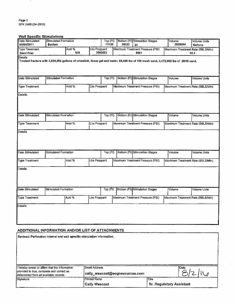
W II S e ,pec1 ,c tImu atIons ·r, S . I • Date Stimulated !Stimulated Formation I Top (Ft) I Bottom (Ft),Stimulation Stages 'Volume ivolume Units 08/09/2011 Bakken 11120 20323 24 2829204 Gallons
Type Treatment rcid % ILbs Proppant I Maximum Treatment Pressure (PSI) I Maximum Treatment Rate (BBLS/Min) Sand Frac N/A 3560553 8801 35.3
Details Treated fracture with 2,829,204 gallons of crossllnk, linear gel and water; 88,488 lbs of 100 mesh sand, 3,472,065 lbs of 20/40 sand.
Date Stimulated !Stimulated Formation I Top (Ft) I Bottom (Ft)IStimulalion Stages ivolume !Volume Units
Type Treatment 1Acid% llbs Proppant I Maximum Treatment Pressure (PSI) !Maximum Treatment Rate (BBLS/Min)
Details
Date Stimulated 'Stimulated Formation I Top (Ft) I Bottom (Ft),Stimulalion Stages 'Volume 'Volume Units
Type Treatment 'Acid% llbs Proppant I Maximum Treatment Pressure (PSI) 'Maximum Treatment Rate (BBLS/Min)
Details
Date Stimulated !Stimulated Formation I Top (Ft) I Bottom (Ft),Stimulation Stages !Volume rolume Units
Type Treatment 'Acid% I Lbs Proppant I Maximum Treatment Pressure (PSI) I Maximum Treatment Rate (BBLS/Min)
Details
Date Stimulated 1sumulated Formation I Top (Fl) I Bottom (Ft),Stimulation Stages ivolume rolume Units
Type Treatment tcid % I Lbs Proppant I Maximum Treatment Pressure (PSI) !Maximum Treatment Rate (BBLS/Min)
Details
ADDITIONAL INFORMATION AND/OR LIST OF ATTACHMENTS
Revised: Perforation interval and well specific stimulation information.
I hereby swear or affirm that the lnformatlon Email Address
DS/-z-/tv provided is true, complete and correct as
cally _ [email protected] determined from all available records.
Signature Printed Name 'Title
Cally Wescoat Sr. Regulatory Assistant
WELL COMPLETION OR RECOMPLETION REPORT - FORM 6 INDUSTRIAL COMMISSION OF NORTH DAKOTA OIL AND GAS DIVISION 600 EAST BOULEVARD DEPT 405 BISMARCK, ND 58505-0840 SFN 2468 (04-2010)
PLEASE READ INSTRUCTIONS BEFORE FILLING OUT FORM.
PLEASE SUBMIT THE ORIGINAL AND ONE COPY.
Designate Type of Completion
REVISE~ I
!Well File No. 20892
121 Oil Well D EORWell D Recompletion D Deepened Well D Added Horizontal Leg D Extended Horizontal Leg
D Gas Well 0 SWDWell D Water Supply Well D Other:
Well Name and Number Spacing Unit Description Clarks Creek 16-0706H Sec. 6, 7, 18 & 19 T151N, R94W Operator 'Telephone Number Field
EOG Resources, Inc. (303) 262-9973 Clarks Creek Address Pool
600 17th Street, Suite 1 OOON Bakken City !State IZip Code PermitType
Denver co 80202 D Wildcat 121 Development D Extension
LOCATION OF WELL At Surface Qtr-Qtr ISectio; I Township IRange County
173 F s L 455 F E L SESE 151 N 94 w mcKenzie Spud Date IDate TD Reached Drilling Contractor and Rig Number IKB Elevation (Ft) Graded Elevation (Ft)
September 6 2011 November 23 2011 True #28 2221 2194 Type of Electric and Other Logs Run (See Instructions)
CCI/CBL· GR/MWD
CASING & TUBULARS RECORD (Report all strin~ s set in well) String Top Set Depth Set Hole Size Weight Anchor Set Packer Set Sacks Top of
Well Bore Type Size (Inch) (MD Ft) (MD Ft) (Inch) (Lbs/Ft) (MD Ft) (MD Ft) Cement Cement
Surface Hole Surface 9-5/8 0 1822 13-1/2 36 740 0
Vertical Hole Intermediate 7-0 0 10979 8-3/4 26,32 650
Lateral1 Production 4-1/2 10101 18314 6 11.6 10117 440
PERFORATION & OPEN HOLE INTERVALS
Well Bore TD Open Hole/Perforated Kick-off Top of
Well Bore Drillers Depth Completion Interval (MD.Ft) Point
Casing Date Perfd Date Isolation Sacks Type Window or Drilled Isolated Method Cement
(MD Ft) Top Bottom (MD Ft) (MD Ft)
Lateral1 18660 Perforations 10979 18660 10247 Sidetrack1 17368 17118 17368 17128 Sidetrack2 18748 16764 18748 16839 Sidetrack3 18264 Perforations 13549 18251 13549 01/06/2012 - ·- ·---- -
PRODUCTION Current Producing Open Hole or Perforated lnterval(s), This Completion, Top and Bottom, (MD Ft) I Name of Zone (If Different from Pool Name) Perforated from 11,026' MD to 18,251' MD Date Well Completed (SEE INSTRUCTIONS) Producing Method Pumping-Size & Type of Pump 'Well Status (Producing or Shut-In)
March 12, 2012 Flowing Producing Date of Test 'Hours Tested Choke Size
Production for Test Oil (Bbls) 'Gas (MCF) IWater i9bls) IOil Gravity-AP! (Corr.) I Disposition of Gas 03/22/2012 24 20 /64 13582 1944 4 3 42.0 ° Flared Flowing Tubing Pressure (PSI) Flowing Casing Pressure (PSI) I Calculated 'Oil (Bbls) 'Gas (MCF) 'Water (Bbls) 'Gas-Oil Ratio
2400 24-Hour Rate 1352 1944 1437 1437

Page2
SFN 2468 (04-2010)
GEOLOGICAL MARKERS PLUG BACK INFORMATION Formation MD(Ft) TVD (Ft) Well Bore Type of Plug Top (Ft) Bottom (Ft) Sacks Cement
Pierre Shale 1624
Greenhorn 4150
Dakota Sandstone 4959
Base Dakota 5295
Piper Lime 6107
Dunham Salt 6334
Spearfish 6390
Minnelusa 7268
Kibbey Lime 8201
Charles 8346
Base Last Salt 8944
Mission Canyon 9156 Lodgepole 9782
3rd Shale Marker 10573
False Bakken 70592
Scallion 10600
Upper Bakken 10611
Middle Bakken Shale 10629
CORES CUT Top (Ft) Bottom (Ft) Formation Top (Ft) Bottom (Ft) Formation
Drill Stem Test Test Date I Formation I Top (Ft) I Bottom (Fl)IBH Temp (°F) 'CL ppm t2Sppm f Shut-in 1 (PSIG) 'Shut-in 2 (PSIG)
Drill Pipe Recovery
Sample Chamber Recovery
Test Date I Formation I Top (Ft) I Bottom (Ft)I BH Temp (°F) ICL ppm IH2S ppm 'Shut-in 1 (PSIG) 'Shut-in 2 (PSIG)
Drill Pipe Recovery
Sample Chamber Recovery
Test Date rormalion I Top (Ft) I Bottom (Ft),BH Temp (°F) ICL ppm lH2S ppm lShul-in 1 (PSIG) 'Shut-in 2 (PSIG)
Drlll Pipe Recovery
Sample Chamber Recovery
Test Date rormation I Top (Ft) I Bottom (Ft),BH Temp (°F) ICL ppm IH2S ppm !Shut-in 1 (PSIG) 'Shut-in 2 (PSIG)
Drill Pipe Recovery
Sample Chamber Recovery
Test Dale I Formation I Top (Ft) I Bottom (Ft),BH Temp (°F) ICL ppm -1H2S ppm lShut-in 1 (PSIG) IShut-in 2 (PSIG)
Drill Pipe Recovery
Sample Chamber Recovery
Page3
SFN 2468 (04-2010}
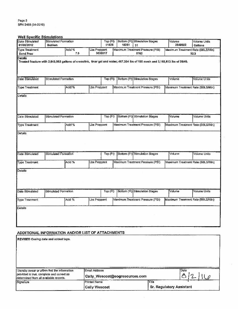
W II S e ;pec1 ,c 1mu a ions T Sf If Date Stimulated !Stimulated Formation I Top (Ft) I Bottom (Ft) !Stimulation Stages !Volume ivolume Units 01/06/2012 Bakken 11026 18251 31 2648982 Gallons
Type Treatment IAcid % !Lbs Proppant I Maximum Treatment Pressure (PSI) !Maximum Treatment Rate (BBLS/Min) Sand Frac 7.5 3636917 8762 32.3
Details Treated fracture with 2,648,982 gallons of crossllnk, liner gel and water; 467,304 lbs of 100 mesh and 3,169,613 lbs of 20/40.
Date Stimulated !Stimulated Formation I Top (Ft) !Bottom (Ft)IStimulation Stages !Volume !Volume Units
Type Treatment rcid % I Lbs Proppant I Maximum Treatment Pressure (PSI) !Maximum Treatment Rate (BBLS/Min)
Details
Date Stimulated !Stimulated Formation I Top (Ft) I Bottom (Ft)IStimulation Stages ivolume ivolume Units
Type Treatment 1Acid% I Lbs Proppant I Maximum Treatment Pressure (PSI) !Maximum Treatment Rate (BBLS/Min}
Details
Date Stimulated !Stimulated Formation I Top (Ft) I Bottom {Ft)IStimulation Stages !Volume !Volume Units
Type Treatment IAcido/o I Lbs Proppant I Maximum Treatment Pressure (PSI) I Maximum Treatment Rate (BBLS/Min)
Details
Date Stimulated !Stimulated Formation I Top (Ft) I Bottom (Ft),Stimulation Stages 'Volume 'Volume Units
Type Treatment IAcid % ILbs Proppant I Maximum Treatment Pressure (PSI) I Maximum Treatment Rate (BBLS/Min)
Details
ADDITIONAL INFORMATION AND/OR LIST OF ATTACHMENTS
REVISED Casing data and added tops.
I hereby swear or affirm that the information Email Address Date provided is true, complete and correct as
Cally_ [email protected] 6/2-llv determined from all available records.
Signature Printed Name ri{le I
.
Cally Wescoat Sr. Regulatory Assistant
Clarks Creek 200-07SWO eog resources
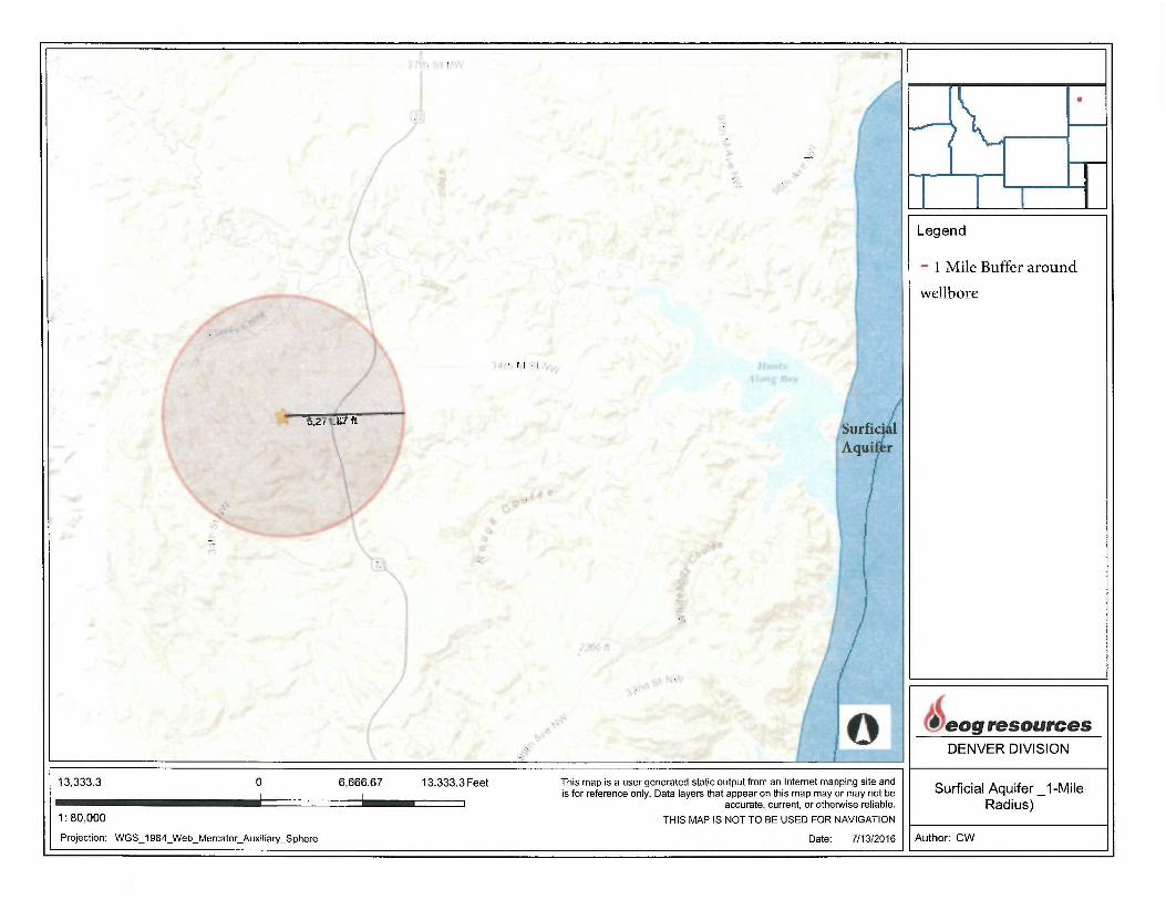
Names and Depth of USDW's (Class II)
No surficial water sources were found within a one mile radius. See attached map.
I , L
' I 11 · I
a.21•:a11t
13,333.3 0 6,666.67 13,333.3 Feet
1: 80,000
Projection: WGS_ 1984_Web_Mercator_Auxiliary_Sphere
Surfi¥ Aquir r
I j
) I
! This map is a user generated static output from an Internet mapping site and is for reference only. Data layers that appear on this map may or may not be
accurate, current, or otherwise reliable.
THIS MAP IS NOT TO BE USED FOR NAVIGATION
Legend
- 1 Mile Buffer around
wellbore
•
i1eog resources DENVER DIVISION
Surficial Aquifer_ 1-Mile Radius)
Date: 7/13/2016 11 Author: CW
Clarks Creek 200-07SWO ' eog resources
Geological Data on Injection and Confining Zones (Class II)
Clarks Creek 200-07SWD eog resources
Geological Data on Injection and Confining Zones (Class II)
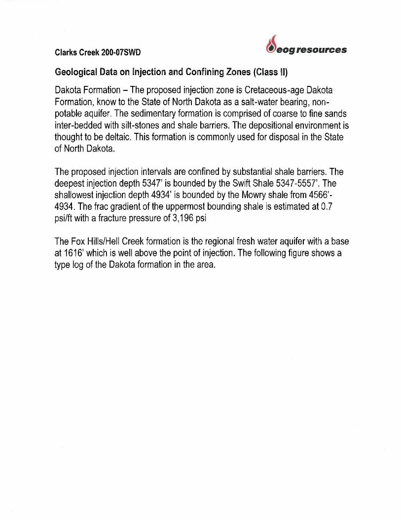
Dakota Formation - The proposed injection zone is Cretaceous-age Dakota Formation, know to the State of North Dakota as a salt-water bearing, nonpotable aquifer. The sedimentary formation is comprised of coarse to fine sands inter-bedded with silt-stones and shale barriers. The depositional environment is thought to be deltaic. This formation is commonly used for disposal in the State of North Dakota.
The proposed injection intervals are confined by substantial shale barriers. The deepest injection depth 5347' is bounded by the Swift Shale 5347-5557'. The shallowest injection depth 4934' is bounded by the Mowry shale from 4566' -4934. The frac gradient of the uppermost bounding shale is estimated at 0.7 psi/ft with a fracture pressure of 3,196 psi
The Fox Hills/Hell Creek formation is the regional fresh water aquifer with a base at 1616' which is well above the point of injection. The following figure shows a type log of the Dakota formation in the area.

Clarks Creek 200-07SWD
Lithological Log
eog resources

GOODAL 13.•9 )3053015, lj()COD
TQ::9SSOOC TWP 151,-,i . J::;,";}1! 9-lW 1:c: 19
rF .~~
c-:~- ., >-
/~z r-f·-- -
_;_,_
Mowry Upper Flow Barrier
Zone
Dakota Injection Zone
Swift Lower Flow Barrier Zone

Clarks Creek 200-07SWD
Operating Data
eog resources

Clarks Creek 200-075WD eog resources
Operating Data
This facility and well will handle and dispose into the Dakota Formation. Produced water and drilling fluid used in the development of EOG Resources, lnc.'s North Dakota oil and gas operations.
While it's anticipated the facility may dispose on average of 12,000 barrels of water daily at a pressure of 800 psi, the facility may handle up to 20,000 barrels daily at 1,487 psi at the peak of the field production. Pump type is to be determined.
Water will be transported to a tank battery approximately 100 ft. from the well. Skim oil will be transferred to the skim oil tank and the oil bound with water will be moved to the bad oil tank. Water will then settle in three tanks before entering the suction tank. From the suction tank, water will be filtered to 200 microns before injection into the disposal well. A site schematic is provided in the "Plans for Well Failure" section of the permit.
Clarks Creek 200-07SWD
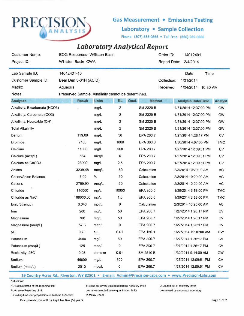
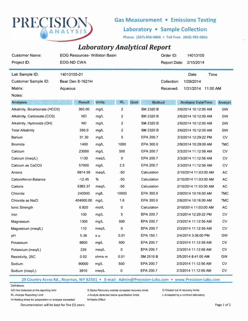
Analysis of Injection Water
Bear Den 5-31 H Bear Den 8-1621 H Clarks Creek 13-1806H Clarks Creek 100-0805H Horse Camp 102-16H Mandaree 1-1 OH Riverview 1-32H Riverview 100-3031 H
eog resources
P ~l_JCISION Gas M easurement • Emissions Testing
Laboratory • Sample Collection Phone: {307)-856-0866 • Toll Free: {866)-985-0866
Customer Name:
Project ID:
Lab Sample ID:
Customer Sample ID:
Laboratory Analytical Report EOG Resources- Williston Basin
Williston Basin CWA
14012401-10
Bear Den 5-31H (ACID)
Order ID: 14012401
Report Date: 2/4/2014
Date
Collection: 1 /21/2014
Time
Matrix: Aqueous Received: 1/24/2014 10:30 AM
Notes:
Analyses
Alkalinity, Bicarbonate (HC03)
Alkalinity, Carbonate (C03)
Alkalinity, Hydroxide (OH)
Total Alkalinity
Barium
Bromide
Calcium
Calcium (meq/L)
Calcium as CaC03
Anions
Cation/Anion Balance
Cations
Chloride
Chloride as NaCl
Ionic Strength
Iron
Magnesium
Magnesium (meq/L)
pH
Potassium
Potassium (meq/L)
Resistivity, 25C
Sodium
Sodium (meq/L)
Preserved Sample. Alkalinity cannot be determined.
Result Units RL Qual.
mg/L 2
mg/L 2
mg/L
mg/L
119.00 mg/L
7100 mg/L
11000 mg/L
564 meq/L
28000 mg/L
3239.48 meq/L
-7.99 %
2759.90 meq/L
110000 mg/L
189000.00 mg/L
3.340
200
700
57.3
0.70
4900
125
0.03
46000
2010
mol/L
mg/L
mg/L
meq/L
s.u.
mg/L
meq/L
ohms m
mg/L
meq/L
2
2
50
1000
500
0
2.5
-50
-50
-50
10000
1.6
0
50
50
0
0.01
50
0
0.01
500
0
Method
SM 2320 B
SM 2320 B
SM 2320 B
SM 2320 B
EPA 200.7
EPA 300 .0
EPA 200.7
EPA 200.7
EPA 200.7
Calculation
Calculation
Calculation
EPA 300.0
EPA 300.0
Calculation
EPA 200 .7
EPA 200 .7
EPA 200 .7
EPA 150.1
EPA 200.7
EPA 200.7
SM 2510 B
EPA 200.7
EPA 200.7
Analysis Date/Time
1/31/201412:37:00 PM
1/31/201412:37:00 PM
1/31/201412:37:00 PM
1/31/2014 12:37:00 PM
1/27/20141:26:17 PM
1/30/2014 4:07:00 PM
1/27/201412:09:51 PM
1/27/2014 12:09:51 PM
1/27/201412:09:51 PM
2/3/2014 10:20:00 AM
2/3/2014 10:20:00 AM
2/3/2014 10:20:00 AM
1/30/2014 3:56:00 PM
1/30/2014 3:56:00 PM
2/3/2014 10:20:00 AM
1/27/20141:26:17 PM
1/27/20141:26:17 PM
1/27/20141:26:17 PM
1/27/2014 10:16:00 AM
1/27/20141 :26:17 PM
1/27/20141:26:17 PM
1/30/2014 9:14:00 AM
1/27/2014 12:09:51 PM
1/27/2014 12:09:51 PM
Analyst
GW
GW
GW
GW
CV
TMC
CV
CV
CV
AC
AC
AC
TMC
TMC
AC
CV
CV
CV
GW
CV
CV
GW
CV
CV
29 Country Acres Rd., Riverton, WY 82501 • E-mail: [email protected] • www.Precision-Labs.com
Definitions:
ND-Not Detected at the reporting limit $-Spike Recovery outside accepted recovery limits
RL-Analyte Reporting Limit J-Analyte detected below quantitation limits
H-Holding times for preparation or analysis exceeded M-Matrix Effect
Documentation will be kept for five (S) years.
D-Diluted out of recovery limits
L-Analyzed by a contract laboratory
Page 1 of 2

Customer Name:
Project ID:
Specific Gravity
Strontium
Sulfate
Temperature (Thermometric)
Total Dissolved Solids (TDS)
Total Solids (TS)
Gas Measurement • Emissions Testing
Laboratory • Sample Collection Phone: (307)-856-0866 • Toll Free: (866)-985-0866
Laboratory Analytical Report EOG Resources- Williston Basin Order ID: 14012401
Williston Basin CWA Report Date: 2/4/2014
1.125 glee 0.001 ASTM D 1429-03 1/27/2014 5:05:00 PM
906.00 mg/L 50 EPA 200.7 1/27/20141:26:17 PM
190 mg/L 10 Hach 8051 1/29/2014 9:45:00 AM
4.8 oc 0.1 N/A 2/3/2014 10:20:00 AM
180000 mg/L 5 Calculation 2/3/2014 10:20:00 AM
250000 mg/L 1 SM 2540 B 1/30/2014 8:24:00 AM
29 Country Acres Rd., Riverton, WY 82501 • E-mail: [email protected] • www.Precision-Labs.com
Definitions:
ND-Not Detected at the reporting limit
RL-Analyte Reporting Limit
S-Spike Recovery outside accepted recovery limits
J-Analyte detected below quantitation limits
H-Holding times for preparation or analysis exceeded M-Matrix Effect
D-Diluted out of recovery limits
L-Analyzed by a contract laboratory
GW
CV
TMC
AC
AC
KF
Documentation will be kept for five (S) years. Page 2 of 2
Customer Name:
Project ID:
Lab Sample ID:
Customer Sample ID:
Gas Measurement • Emissions Testing
Laboratory • Sample Collection
Phone: (307)-856-0866 • Toll Free: (866)-985-0866
Laboratory Analytical Report EOG Resources- Williston Basin
EOG-ND CWA
14013105-01
Bear Den 8-1621H
Order ID: 14013105
Report Date: 2/10/2014
Date
Collection: 1/28/2014
Time
Matrix: Aqueous Received: 1/31/2014 11:00AM
Notes:
Analyses
Alkalinity, Bicarbonate (HCO3)
Alkalinity, Carbonate (CO3)
A lkalinity, Hydroxide (OH)
Total Alkalinity
Barium
Bromide
Calcium
Calcium (meq/L)
Calcium as CaCO3
A nions
Cation/Anion Balance
Cations
Chloride
Chloride as NaCl
Ionic Strength
Iron
Magnesium
Magnesium (meq/L)
pH
Potassium
Potassium (meq/L)
Resistivity, 25C
Sodium
Sodium (meq/L)
Result
350.00
ND
ND
350.0
31.30
1400
23000
1130
57000
Units
mg/L
mg/L
mg/L
mg/L
mg/L
mg/L
mg/L
meq/L
mg/L
6914.59 meq/L
-12.45 %
5383.37 meq/L
240000 mg/L
404000.00 mg/L
6.820
100
1300
110
5.36
8800
226
0.02
90000
3910
mol/L
mg/L
mg/L
meq/L
s.u.
mg/L
meq/L
ohms m
mg/L
meq/L
RL Qual. Method
2 SM 2320 B
2 SM 2320 B
2
2
5
1000
500
0
2.5
-50
-50
-50
10000
1.6
0
5
500
0
0.01
500
0
0.01
500
0
SM 2320 B
SM 2320 B
EPA 200.7
EPA 300.0
EPA 200.7
EPA 200.7
EPA 200.7
Calculation
Calculation
Calculation
EPA 300.0
EPA 300.0
Calculation
EPA 200.7
EPA 200.7
EPA 200.7
EPA 150.1
EPA 200.7
EPA 200.7
SM 2510 B
EPA 200.7
EPA 200.7
Analysis Date/Time
2/6/2014 10:12:00 AM
2/6/2014 10:12:00 AM
2/6/2014 10:12:00 AM
2/6/2014 10:12:00 AM
2/3/2014 12:29:22 PM
2/9/2014 10:29:00 AM
2/3/201411:12:56AM
2/3/2014 11 :12:56 AM
2/3/2014 11 :12:56 AM
2/10/2014 11 :03:00 AM
2/10/2014 11 :03:00 AM
2/10/2014 11 :03:00 AM
2/9/2014 10:16:00 AM
2/9/2014 10:16:00 AM
2/10/2014 11 :03:00 AM
2/3/2014 12:29:22 PM
2/3/201411:12:56AM
2/3/2014 11 :12:56 AM
2/4/2014 3:36:00 PM
2/3/2014 11: 12:56 AM
2/3/2014 11 :12:56 AM
2/5/2014 8:41:00 AM
2/3/2014 11 :12:56 AM
2/3/2014 11 :12:56 AM
Analyst
GW
GW
GW
GW
CV
TMC
CV
CV
CV
AC
A C
AC
TMC
TMC
A C
CV
CV
CV
GW
CV
CV
GW
CV
CV
29 Country Acres Rd., Riverton, WY 82501 • E-mail: [email protected] • www.Precision-Labs.com
Definitions:
ND-Not Detected at the reporting limit S-Spike Recovery outside accepted recovery limits
RL-Analyte Reporting Limit J-Analyte detected below quantitation limits
H-Holding times for preparation or analysis exceeded M-Matrix Effect
Documentation will be kept for five (5) years.
D-Diluted out of recovery limits
L-Analyzed by a contract laboratory
Page 1 of 2

Customer Name:
Project ID:
Specific Gravity
Strontium
Sulfate
Temperature {Thermometric)
Total Dissolved Solids (TDS)
Total Solids (TS)
Gas Measurement • Emissions Testing
Laboratory • Sample Collection Phone: (307)-856-0866 • Toll Free: (866)-985-0866
Laboratory Analytical Report EOG Resources- Williston Basin Order ID: 14013105
EOG-ND CWA Report Date: 2/10/2014
1.203 glee 0.001 ASTM D 1429-03 2/4/2014 5:13:00 PM
1810.00 mg/L 500 EPA 200.7 2/3/201411 :12:56 AM
63 mg/L Hach 8051 2/6/2014 3:01 :00 PM
5.4 oc 0.1 N/A 2/10/2014 11 :03:00 AM
370000 mg/L 5 Calculation 2/10/2014 11 :03:00 AM
370000 mg/L SM 2540 B 2/7/2014 4:00:00 PM
29 Country Acres Rd., Riverton, WY 82501 • E-mail: [email protected] • www.Precision-Labs.com
Definitions:
ND-Not Detected at the reporting limit
RL-Analyte Reporting Limit
S-Spike Recovery outside accepted recovery limits
J-Analyte detected below quantitation limits
H-Holding times for preparation or analysis exceeded M-Matrix Effect
D-Diluted out of recovery limits
L-Analyzed by a contract laboratory
GW
CV
TMC
AC
AC
KF
Documentation will be kept for five (5) years. Page 2 of 2

Customer Name:
Project ID:
Lab Sample ID:
Customer Sample ID:
Matrix:
Notes:
Gas Measurement • Emissions Testing
Laboratory • Sample Collect ion Phone: (307)-856-0866 • Toll Free: (866)-985-0866
Laboratory Analytical Report EOG Resources- Williston Basin Order ID: 14020406
EOG-ND CWA Report Date: 2/13/2014
14020406-03 Date Time
Clarks Creek 13-1806H Collection: 1/29/2014
Aqueous Received: 2/4/2014 9:10 AM
Analyses Result Units RL Qual. Method Analysis Date/Time Analyst
Alkalinity, Bicarbonate (HCO3) 210.00 mg/L 2 SM 2320 B 2/13/2014 2:09:00 PM
Alkalin ity, Carbonate (CO3) ND mg/L 2 SM 2320 B 2/13/2014 2:09:00 PM
Alkalinity, Hydroxide (OH) ND mg/L 2 SM 2320 B 2/13/2014 2:09:00 PM
Total Alkalinity 210.0 mg/L 2 SM 2320 B 2/13/2014 2:09:00 PM
Barium 32.90 mg/L 5 EPA 200 .7 2/5/2014 1 :16:22 PM
Bromide 1500 mg/L 1000 EPA 300.0 2/11/2014 4:27:00 PM
Calcium 22000 mg/L 500 EPA 200.7 2/5/2014 11 :43:49 AM
Calcium (meq/L) 1080 meq/L 0 EPA 200.7 2/5/2014 11 : 43 :49 AM
Calcium as CaCO3 54000 mg/L 2.5 EPA 200.7 2/5/2014 11 :43:49 AM
Anions 8645 .91 meq/L -50 Calculation 2/13/2014 4:23:00 PM
Cation/Anion Balance -26.12 % -50 Calculation 2/13/2014 4:23:00 PM
Cations 5064.36 meq/L -50 Calculation 2/13/2014 4:23:00 PM
Chloride 310000 mg/L 10000 EPA 300.0 2/11/2014 4:14:00 PM
Chloride as NaCl 505000.00 mg/L 1.6 EPA 300.0 2/11/20144:14:00 PM
Ionic Strength 7.480 mol/L 0 Calculation 2/13/2014 4:23:00 PM
Iron 300 mg/L 5 EPA 200.7 2/5/2014 1 :16:22 PM
Magnesium 820 mg/L 500 EPA 200.7 2/5/2014 11 :43:49 AM
Magnesium (meq/L) 67.7 meq/L 0 EPA 200.7 2/5/2014 11 :43:49 AM
pH 5.27 s.u. 0.01 EPA 150.1 2/10/2014 2:16:00 PM
Potassium 8300 mg/L 500 EPA 200.7 2/5/2014 11 :43:49 AM
Potassium (meq/L) 213 meq/L 0 EPA 200.7 2/5/2014 11 :43:49 AM
Resistivity, 25C 0.02 ohmsm 0.01 SM 2510 B 2/11/2014 8:33:00 AM
Sodium 85000 mg/L 500 EPA 200 .7 2/5/2014 11 :43:49 AM
Sodium (meq/L) 3710 meq/L 0 EPA 200.7 2/5/2014 11 :43:49 AM
29 Country Acres Rd., Riverton, WY 82501 • E-mail: [email protected] • www.Precision-Labs.com
Definitions:
ND-Not Detected at the reporting limit
RL-Analyte Reporting Limit
S-Spike Recovery outside accepted recovery limits
J-Analyte detected below quantitation limits
H-Holding times for preparation or analysis exceeded M-Matrix Effect
D-Diluted out of recovery limits
L-Analyzed by a contract laboratory
GW
GW
GW
GW
CV
TMC
CV
CV
CV
AC
AC
AC
TMC
TMC
AC
CV
CV
CV
GW
CV
CV
GW
CV
CV
Documentation will be kept for five (S) years. Page 1 of 2
PRE~C Sl()N Gas Measurement • Emissions Testing
Laboratory • Sample Collection Phone: {307)-856-0866 • Toll Free: {866)-985-0866
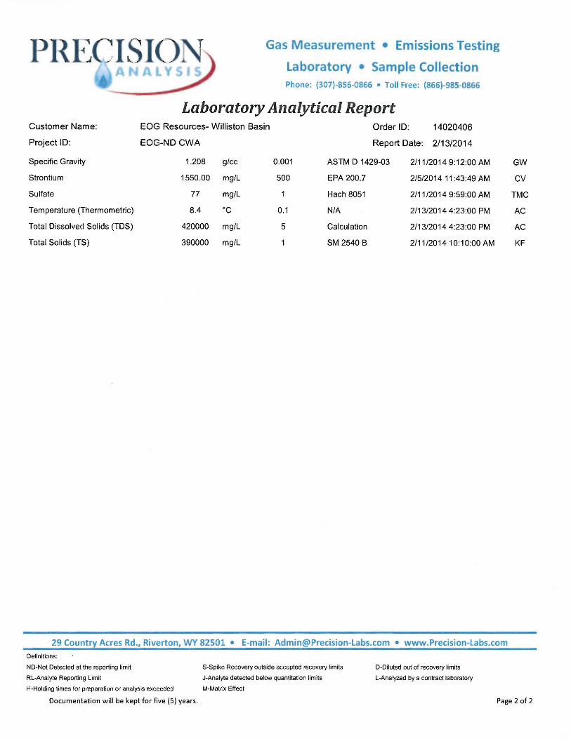
Laboratory Analytical Report Customer Name: EOG Resources- Williston Basin Order ID: 14020406
Project ID: EOG-ND CWA Report Date: 2/13/2014
Specific Gravity 1.208 glee 0.001 ASTM D 1429-03 2/11/2014 9:12:00 AM
Strontium 1550.00 mg/L 500 EPA 200.7 2/5/2014 11 :43:49 AM
Sulfate 77 mg/L Hach 8051 2/11/2014 9:59:00 AM
Temperature (Thermometric) 8.4 oc 0.1 N/A 2/13/2014 4:23:00 PM
Total Dissolved Solids (TDS) 420000 mg/L 5 Calculation 2/13/2014 4:23:00 PM
Total Solids (TS) 390000 mg/L 1 SM 2540 B 2/11/2014 10: 10:00 AM
29 Country Acres Rd., Riverton, WY 82501 • E-mail: [email protected] • www.Precision-Labs.com
Definitions:
ND-Not Detected at the reporting limit
RL-Analyte Reporting Limit
S-Spike Recovery outside accepted recovery limits
J-Analyte detected below quantitation limits
M-Matrix Effect
D-Diluted out of recovery limits
L-Analyzed by a contract laboratory
GW
CV
TMC
AC
AC
KF
H-Holding times for preparation or analysis exceeded
Documentation will be kept for five (S) years. Page 2 of 2

Customer Name:
Project ID:
Lab Sample ID:
Customer Sample ID:
Matrix:
Notes:
Gas Measurement • Emissions Testing
Laboratory • Sample Collection Phone: (307)-856-0866 • Toll Free: (866)-985-0866
Laboratory Analytical Report EOG Resources- Williston Basin Order ID: 14013111
EOG-Williston Basin CWA Report Date: 2/10/2014
14013111-07 Date Time
Clarks Creek 100-0805H Collection : 1/27/2014
Aqueous Received: 1/31/2014 3:36 PM
Analyses Result Units RL Qual. Method Analysis DatelTime Analyst
Alkalinity, Bicarbonate (HCO3) 300.00 mg/L 2 SM 2320 B 2/7/2014 12:08:00 PM GW
Alkalinity, Carbonate (CO3) ND mg/L 2 SM 2320 B 2/7/2014 12:08:00 PM GW
Alkalinity, Hydroxide (OH) ND mg/L 2 SM 2320 B 2/7/2014 12:08:00 PM GW
Total Alkalinity 300.0 mg/L 2 SM 2320 B 2/7/201412 :08:00 PM GW
Barium 41.60 mg/L 5 EPA 200 .7 2/3/2014 8:09:25 PM CV
Bromide 1200 mg/L 1000 EPA 300.0 2/9/2014 10:48:00 PM TMC
Calcium 26000 mg/L 500 EPA 200 .7 2/3/2014 5:19:52 PM CV
Calcium (meq/L) 1280 meq/L 0 EPA 200.7 2/3/2014 5:19:52 PM CV
Calcium as CaCO3 64000 mg/L 2.5 EPA 200.7 2/3/2014 5: 19:52 PM CV
Anions 6446.38 meq/L -50 Calculation 2/10/2014 11 :20:00 AM AC
Cation/Anion Balance -11 .24 % -50 Calculation 2/10/2014 11 :20:00 AM AC
Cations 5144.04 meq/L -50 Calculation 2/10/2014 11 :20:00 AM AC
Chloride 230000 mg/L 10000 EPA 300.0 2/9/2014 10:35:00 PM TMC
Chloride as NaCl 376000.00 mg/L 1.6 EPA 300 .0 2/9/2014 10:35:00 PM TMC
Ionic Strength 6.520 mol/L 0 Calculation 2/10/2014 11 :20:00 AM AC
Iron 300 mg/L 5 EPA 200.7 2/3/2014 8:09:25 PM CV
Magnesium 880 mg/L 500 EPA 200.7 2/3/2014 5:19:52 PM CV
Magnesium (meq/L) 72.2 meq/L 0 EPA 200.7 2/3/2014 5:19:52 PM CV
pH 5.43 s.u . 0.01 EPA 150.1 2/6/2014 2:36:00 PM GW
Potassium 9400 mg/L 500 EPA 200.7 2/3/2014 5:19:52 PM CV
Potassium (meq/L) 241 meq/L 0 EPA 200 .7 2/3/2014 5:19:52 PM CV
Resistivity, 25C 0.02 ohms m 0.01 SM 2510 B 2/5/2014 1:51 :00 PM GW
Sodium 82000 mg/L 500 EPA 200.7 2/3/2014 5:19:52 PM CV
Sodium (meq/L) 3550 meq/L 0 EPA 200.7 2/3/2014 5:19:52 PM CV
29 Country Acres Rd., Riverton, WY 82501 • E-mail: [email protected] • www.Precision-labs.com
Definitions:
ND-Not Detected at the reporting limit
RL-Analyte Reporting Limit
H-Holding times for preparation or analysis exceeded
Documentation will be kept for five (5) years.
S-Spike Recovery outside accepted recovery limits
J-Analyte detected below quantitation limits
M-Matrix Effect
D-Diluted out of recovery limits
L-Analyzed by a contract laboratory
Page 1 of 2
Customer Name:
Project ID:
Specific Gravity
Strontium
Sulfate
Temperature (Thermometric)
Total Dissolved Solids (TDS)
Total Solids (TS)
Gas Measurement • Emissions Testing
Laboratory • Sample Collection Phone: (307)-856-0866 • Toll Free: {866)-985-0866
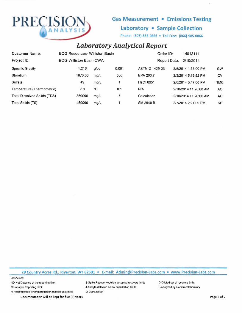
Laboratory Analytical Report EOG Resources- Williston Basin Order ID: 14013111
EOG-Williston Basin CWA Report Date: 2/10/2014
1.216 glee 0.001 ASTM D 1429-03 2/5/2014 1 :53:00 PM
1670.00 mg/L 500 EPA 200.7 2/3/2014 5:19:52 PM
49 mg/L Hach 8051 2/6/2014 3:47:00 PM
7.8 oc 0.1 N/A 2/10/2014 11 :20:00 AM
350000 mg/L 5 Calculation 2/10/2014 11 :20:00 AM
450000 mg/L SM 2540 B 2/7/20142:21:00 PM
29 Country Acres Rd., Riverton, WY 82501 • E-mail: [email protected] • www.Precision-Labs.com
Definitions:
ND-Not Detected at the reporting limit
RL-Analyte Reporting Limit
S-Spike Recovery outside accepted recovery limits
J-Analyte detected below quanti tation limits
M-Matrix Effect
D-Diluted out of recovery limits
L-Analyzed by a contract laboratory
GW
CV
TMC
AC
AC
KF
H-Holding times for preparation or analysis exceeded
Documentation will be kept for five (5) years. Page 2 of 2

PR ~~CISl()N Gas Measurement • Emissions Testing
Laboratory • Sample Collection Phone: (307)-856-0866 • Toll Free: (866)-985-0866
Laboratory Analy tical Report Customer Name: EOG Resources- Williston Basin Order ID: 14012403
Project ID: Williston Basin CWA Report Date: 2/4/2014
Lab Sample ID: 14012403-02 Date Time
Customer Sample ID: Horse Camp 102-16H Collection: 1/21/2014
Matrix: Aqueous Received: 1/24/2014 1:00 PM
Notes:
Analyses Result Units RL Qual. Method Analysis Date/Time Analyst
Alkalinity, Bicarbonate (HCO3) 310.00 mg/L 2 SM 2320 B 1/31/2014 4:39:00 PM GW
Alkalinity, Carbonate (CO3) ND mg/L 2 SM 2320 B 1/31/2014 4:39:00 PM GW
Alkalinity, Hydroxide (OH) ND mg/L 2 SM 2320 B 1/31/2014 4:39:00 PM GW
Total Alkalinity 310.0 mg/L 2 SM 2320 B 1/31/2014 4:39:00 PM GW
Barium 50.40 mg/L 50 EPA200.7 1/27/201410:16:00 PM CV
Bromide ND mg/L 10000 EPA 300.0 1/31/2014 4:36:00 PM TMC
Calcium 33000 mg/L 500 EPA 200.7 1/27/2014 6:42:38 PM CV
Calcium (meq/L) 1660 meq/L 0 EPA 200 .7 1/27/2014 6:42:38 PM CV
Calcium as CaCO3 83000 mg/L 2.5 EPA 200 .7 1/27/2014 6:42:38 PM CV
Anions 9065.26 meq/L -50 Calculation 2/3/2014 1 :39:00 PM AC
Cation/Anion Balance -24.36 % -50 Calculation 2/3/2014 1 :39:00 PM AC
Cations 5514.26 meq/L -50 Calculation 2/3/2014 1 :39:00 PM AC
Chloride 320000 mg/L 10000 EPA 300.0 1/31/2014 4:36:00 PM TMC
Chloride as NaCl 530000.00 mg/L 1.6 EPA 300 .0 1/31/2014 4:36:00 PM TMC
Ionic Strength 8.260 mol/L 0 Calculation 2/3/2014 1 :39:00 PM AC
Iron 200 mg/L 50 EPA 200.7 1/27/2014 10:16:00 PM CV
Magnesium 2000 mg/L 50 EPA 200.7 1/27/201410:16:00 PM CV
Magnesium (meq/L) 163 meq/L 0 EPA 200.7 1/27/201410:16:00 PM CV
pH 5.54 s.u. 0.01 EPA 150.1 1/27/201411:58:00AM GW
Potassium 8900 mg/L 500 EPA 200.7 1/27/2014 6:42:38 PM CV
Potassium (meq/L) 228 meq/L 0 EPA 200.7 1/27/2014 6:42:38 PM CV
Resistivity, 25C 0.02 ohms m 0.01 SM 2510 B 1/30/2014 3:03:00 PM GW
Sodium 80000 mg/L 500 EPA 200.7 1/27/2014 6:42:38 PM CV
Sodium (meq/L) 3470 meq/L 0 EPA 200 .7 1/27/2014 6:42:38 PM CV
29 Country Acres Rd., Riverton, WY 82501 • E-mail: [email protected] • www.Precision-Labs.com
Definitions:
ND-Not Detected at the reporting limit
RL-Analyte Reporting Limit
H-Holding times for preparation or analysis exceeded
Documentation will be kept for five (5) years.
S-Spike Recovery outside accepted recovery limits
J-Analyte detected below quantitation limits
M-Matrix Effect
D-Diluted out of recovery limits
L-Analyzed by a contract laboratory
Page 1 of 2
Customer Name:
Project ID:
Specific Gravity
Strontium
Sulfate
Temperature (Thermometric)
Total Dissolved Solids (TDS)
Total Solids (TS)
Gas Measurement • Emissions Testing
Laboratory • Sample Collection Phone: (307)-856-0866 • Toll Free: (866)-985-0866
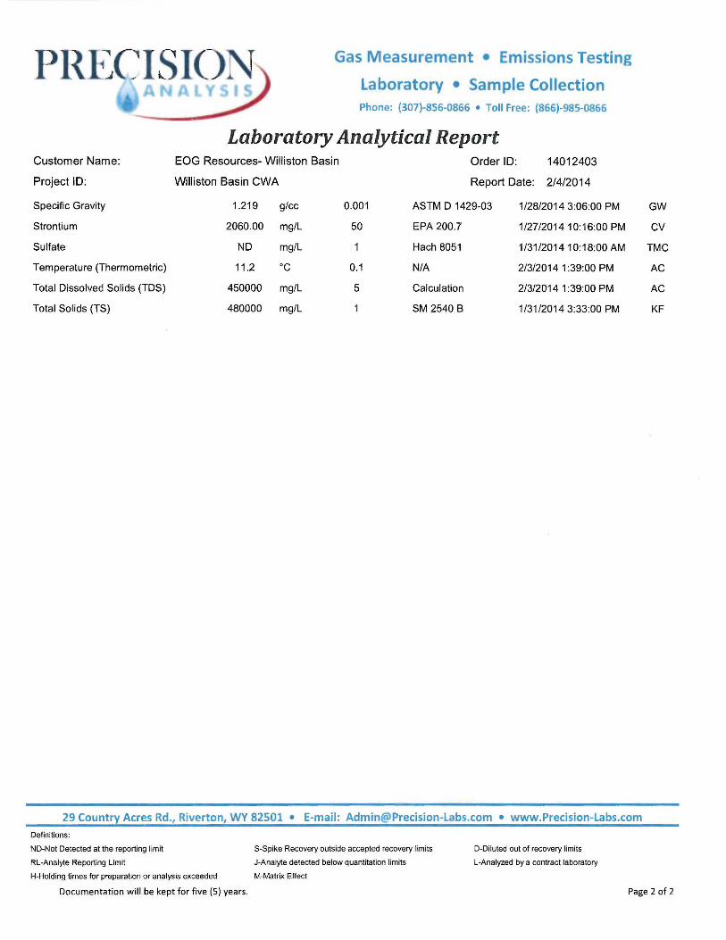
Laboratory Analytical Report EOG Resources- Williston Basin Order ID: 14012403
Williston Basin CWA Report Date: 2/4/2014
1.219 glee 0.001 ASTM D 1429-03 1/28/2014 3:06:00 PM
2060.00 mg/L 50 EPA 200.7 1/27/2014 10:16:00 PM
ND mg/L Hach 8051 1/31/201410:18:00 AM
11 .2 oc 0.1 N/A 2/3/2014 1 :39:00 PM
450000 mg/L 5 Calculation 2/3/2014 1 :39:00 PM
480000 mg/L SM 2540 B 1/31/2014 3:33:00 PM
29 Country Acres Rd., Riverton, WY 82501 • E-mail: [email protected] • www.Precision-Labs.com
Definitions:
ND-Not Detected at the reporting limit
RL-Analyte Reporting Limit
S-Spike Recovery outside accepted recovery limits
J-Analyte detected below quantitation limits
H-Holding times for preparation or analysis exceeded M-Matrix Effect
D-Diluted out of recovery limits
L-Analyzed by a contract laboratory
GW
CV
TMC
AC
AC
KF
Documentation will be kept for five (5) years. Page 2 of 2

Customer Name:
Project ID:
Lab Sample ID:
Customer Sample ID:
Gas Measurement • Emissions Testing
Laboratory • Sample Collection Phone: (307)-856-0866 • Toll Free: (866)-985-0866
Laboratory Analytical Report EOG Resources- Williston Basin
Williston Basin CWA
Order ID: 14012402
Report Date: 2/4/2014
Date
Collection: 1 /21/2014
Time
Matrix:
14012402-01
Mandaree 1-1 OH
Aqueous Received: 1/24/2014 12:03 PM
Notes:
Analyses
Alkalinity, Bicarbonate (HCO3)
Alkalinity, Carbonate (CO3)
Alkalinity, Hydroxide (OH)
Total Alkalinity
Barium
Bromide
Calcium
Calcium (meq/L}
Calcium as CaCO3
Anions
Cation/Anion Balance
Cations
Chloride
Chloride as NaCl
Ionic Strength
Iron
Magnesium
Magnesium (meq/L)
pH
Potassium
Potassium (meq/L)
Resistivity, 25C
Sodium
Sodium (meq/L)
Result
300.00
ND
ND
300.0
50.00
1700
32000
1580
79000
9611.95
-19.51
Units
mg/L
mg/L
mg/L
mg/L
mg/L
mg/L
mg/L
meq/L
mg/L
meq/L
%
6473.27 meq/L
340000 mg/L
562000.00 mg/L
8.960
200
1600
135
5.76
11000
276
mol/L
mg/L
mg/L
meq/L
s.u.
mg/L
meq/L
0.02 ohms m
100000 mg/L
4480 meq/L
RL Qual. Method
2 SM 2320 B
2 SM 2320 B
2
2
50
1000
500
0
2.5
-50
-50
-50
10000
1.6
0
50
50
0
0.01
500
0
0.01
500
0
SM 2320 B
SM 2320 B
EPA 200.7
EPA 300 .0
EPA 200.7
EPA 200.7
EPA 200.7
Calculation
Calculation
Calculation
EPA 300.0
EPA 300.0
Calculation
EPA 200.7
EPA 200.7
EPA 200.7
EPA 150.1
EPA 200.7
EPA 200 .7
SM 2510 B
EPA 200.7
EPA 200.7
Analysis Datefflme
1/31/2014 2:29:00 PM
1/31/2014 2:29:00 PM
1/31/2014 2:29:00 PM
1/31/2014 2:29:00 PM
1/27/2014 8:21:10 PM
1/31/2014 9:53:00 AM
1/27/2014 4:40:58 PM
1/27/2014 4:40:58 PM
1/27/2014 4:40:58 PM
2/3/2014 12:15:00 PM
2/3/2014 12:15:00 PM
2/3/201412:15:00 PM
1/31/2014 9:42:00 AM
1/31/2014 9:42:00 AM
2/3/2014 12:15:00 PM
1/27/2014 8:21 :10 PM
1/27/2014 8:21 :10 PM
1/27/2014 8:21:10 PM
1/27/201410:42:00 AM
1/27/2014 4:40:58 PM
1/27/2014 4:40:58 PM
1/30/201411:34:00AM
1/27/2014 4:40:58 PM
1/27/2014 4:40:58 PM
Analyst
GW
GW
GW
GW
CV
TMC
CV
CV
CV
AC
AC
AC
TMC
TMC
AC
CV
CV
CV
GW
CV
CV
GW
CV
CV
29 Country Acres Rd., Riverton, WY 82501 • E-mail: [email protected] • www.Precision-Labs.com
Definitions:
ND-Not Detected at the reporting limit S-Spike Recovery outside accepted recovery limits
RL-Analyte Reporting Limit J-Analyte detected below quantitation limits
H-Holding limes for preparation or analysis exceeded M-Matrix Effect
Documentation will be kept for five (5) years.
D-Diluted out of recovery limits
L-Analyzed by a contract laboratory
Page 1 of 2
PR 1~C~ISIC)N Gas Measurement • Emissions Testing
Laboratory • Sample Collection Phone: (307)-856-0866 • Toll Free: (866)-985-0866
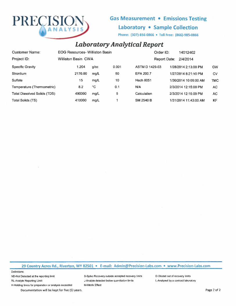
Laboratory Analytical Report Customer Name: EOG Resources- Williston Basin Order ID: 14012402
Project ID: Williston Basin CWA Report Date: 2/4/2014
Specific Gravity 1.204 glee 0.001 ASTM D 1429-03 1/28/20142:13:00 PM
Strontium 2170.00 mg/L 50 EPA 200.7 1/27/2014 8:21 :10 PM
Sulfate 15 mg/L 10 Hach 8051 1/30/201410:09:00 AM
Temperature (Thermometric) 8.2 "C 0.1 N/A 2/3/201412:15:00 PM
Total Dissolved Solids (TDS) 490000 mg/L 5 Calculation 2/3/2014 12:15:00 PM
Total Solids (TS) 410000 mg/L SM 2540 B 1/31/2014 11 :43:00 AM
29 Country Acres Rd., Riverton, WY 82501 • E-mail: [email protected] • www.Precision-Labs.com
Definitions:
ND-Not Detected at the reporting limit
RL-Analyte Reporting Limit
S-Spike Recovery outside accepted recovery limits
J-Analyte detected below quantitation limits
H-Holding times for preparation or analysis exceeded M-Matrix Effect
O-Diluted out of recovery limits
L-Analyzed by a contract laboratory
GW
CV
TMC
AC
AC
KF
Documentation will be kept for five (5) years. Page 2 of 2

PR
Customer Name:
Project ID:
Lab Sample ID:
Customer Sample ID:
Matrix:
Notes:
Gas Measurement • Emissions Testing
Laboratory • Sample Collection Phone: (307)-856-0866 • Toll Free: (866)-985-0866
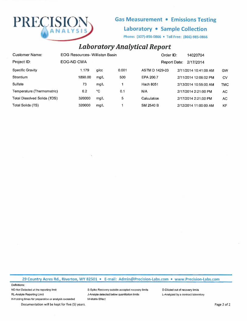
Laboratory Analytical Report EOG Resources- Williston Basin Order ID: 14020704
EOG-ND CWA Report Date: 2/17/2014
14020704-04 Date Time
Riverview 1-32H Collection: 1/31/2014
Aqueous Received: 2/7/2014 9:10 AM
Analyses Result Units RL Qual. Method Analysis Date/Time Analyst
Alkalinity, Bicarbonate (HCO3) 420.00 mg/L 2 SM 2320 B 2/12/2014 3:27:00 PM
Alkalinity, Carbonate (CO3) ND mg/L 2 SM 2320 B 2/12/2014 3:27:00 PM
Alkalinity, Hydroxide (OH) ND mg/L 2 SM 2320 B 2/12/2014 3:27:00 PM
Total Alkalinity 420.0 mg/L 2 SM 2320 B 2/12/2014 3:27:00 PM
Barium 29.80 mg/L 5 EPA 200 .7 2/11/2014 2:17:06 PM
Bromide 1200 mg/L 1000 EPA 300.0 2/13/2014 4:24:00 PM
Calcium 21000 mg/L 500 EPA 200.7 2/11/201412:06:02 PM
Calcium (meq/L) 1060 meq/L 0 EPA 200.7 2/11/2014 12:06:02 PM
Calcium as CaCO3 53000 mg/L 2.5 EPA 200.7 2/11/201412:06:02 PM
Anions 5934.05 meq/L -50 Calculation 2/17/20142:21:00 PM
Cation/Anion Balance -10.13 % -50 Calculation 2/17/20142:21:00 PM
Cations 4842.39 meq/L -50 Calculation 2/17/20142:21:00 PM
Chloride 210000 mg/L 10000 EPA 300.0 2/13/2014 4:12:00 PM
Chloride as NaCl 346000.00 mg/L 1.6 EPA 300.0 2/13/2014 4:12:00 PM
Ionic Strength 6.030 mol/L 0 Calculation 2/17/20142:21 :00 PM
Iron 90 mg/L 5 EPA 200.7 2/11/2014 2:17:06 PM
Magnesium 1400 mg/L 500 EPA 200.7 2/11/201412:06:02 PM
Magnesium (meq/L) 117 meq/L 0 EPA 200.7 2/11/201412:06:02 PM
pH 5.89 s.u . 0.01 EPA 150.1 2/11/2014 9:51 :00 AM
Potassium 8200 mg/L 500 EPA 200 .7 2/11/2014 12:06:02 PM
Potassium (meq/L) 209 meq/L 0 EPA 200 .7 2/11/201412:06:02 PM
Resistivity, 25C 0.02 ohms m 0.01 SM 2510 B 2/11/2014 10:12:00 AM
Sodium 79000 mg/L 500 EPA 200 .7 2/11/201412:06:02 PM
Sodium (meq/L) 3450 meq/L 0 EPA 200.7 2/11/201412:06:02 PM
29 Country Acres Rd., Riverton, WV 82501 • E-mail: Admin @Precision-Labs.com • www.Precision-Labs.com
Definitions:
ND-Not Detected at the reporting limit
RL-Analyte Reporting Limit
S-Spike Recovery outside accepted recovery limits
J-Analyte detected below quantitation limits
H-Holding times for preparation or analysis exceeded M-Matrix Effect
D-Diluted out of recovery limits
L-Analyzed by a contract laboratory
GW
GW
GW
GW
CV
TMC
CV
CV
CV
AC
AC
AC
TMC
TMC
AC
CV
CV
CV
GW
CV
CV
GW
CV
CV
Documentation will be kept for five (5) years. Page 1 of 2
PllI~~CISl()N Gas Measurement • Emissions Testing
Laboratory • Sample Collection Phone: (307)-856-0866 • Toll Free: (866)-985-0866
Laboratory Analytical Report Customer Name: EOG Resources- Williston Basin Order ID: 14020704
Project ID: EOG-ND CWA Report Date: 2/17/2014
Specific Gravity 1.179 glee 0.001 ASTM D 1429-03 2/11/2014 10:41 :00 AM
Strontium 1890.00 mg/L 500 EPA 200.7 2/11/2014 12:06:02 PM
Sulfate 73 mg/L Hach 8051 2/13/2014 10:55:00 AM
Temperature (Thermometric) 6.2 oc 0.1 N/A 2/17/2014 2:21 :00 PM
Total Dissolved Solids (TDS) 320000 mg/L 5 Calculation 2/17/2014 2:21 :00 PM
Total Solids (TS) 320000 mg/L SM 2540 B 2/12/2014 11 :00:00 AM
29 Country Acres Rd., Riverton, WY 82501 • E-mail: [email protected] • www.Precision-Labs.com
Definitions:
ND-Not Detected at the reporting limit
RL-Analyte Reporting Limit
S-Spike Recovery outside accepted recovery limits
J-Analyte detected below quantitation limits
M-Matrix Effect
D-Diluted out of recovery limits
L-Analyzed by a contract laboratory
GW
CV
TMC
AC
AC
KF
H-Holding times for preparation or analysis exceeded
Documentation will be kept for five (5) years. Page 2 of 2
Customer Name:
Project ID:
Lab Sample ID:
Customer Sample ID:
Matrix:
Notes:
Analyses
Alkalinity, Bicarbonate (HCO3)
Alkalinity, Carbonate (CO3)
Alkalinity, Hydroxide (OH)
Total Alkalinity
Barium
Bromide
Calcium
Calcium (meq/L)
Calcium as CaCO3
Anions
Cation/Anion Balance
Cations
Chloride
Chloride as NaCl
Field Dissolved CO2
Field pH - Strip
Ionic Strength
Iron
Magnesium
Magnesium (meq/L)
Manganese
pH
Phosphorus
Potassium
Gas Measurement • Emissions Testing
Laboratory • Sample Collection Phone: (307)-856-0866 • Toll Free: (866)-985-0866
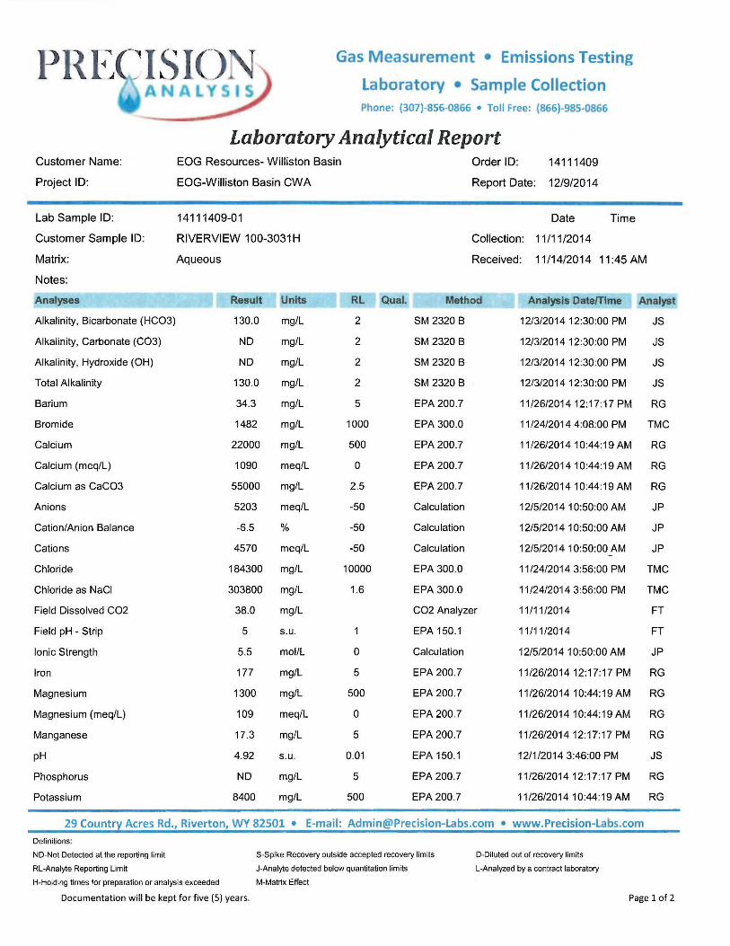
Laboratory Analytical Report EOG Resources- Williston Basin
EOG-Williston Basin CWA
14111409-01
RIVERVIEW 100-3031H
Aqueous
Result Units
130.0 mg/L
ND mg/L
ND mg/L
130.0 mg/L
34.3 mg/L
1482 mg/L
22000 mg/L
1090 meq/L
55000 mg/L
5203 meq/L
-6.5 %
4570 meq/L
184300 mg/L
303800 mg/L
38.0 mg/L
5 s.u.
5.5 mol/L
177 mg/L
1300 mg/L
109 meq/L
17.3 mg/L
4.92 s.u.
ND mg/L
8400 mg/L
Order ID: 14111409
Report Date: 12/9/2014
Date Time
Collection: 11/11/2014
Received: 11/14/2014 11 :45 AM
RL Qual. Method
2 SM 2320 8
2 SM 2320 8
2 SM 2320 8
2 SM 2320 8
5 EPA 200 .7
1000
500
0
2.5
-50
-50
-50
10000
1.6
0
5
500
0
5
0.01
5
500
EPA 300.0
EPA 200.7
EPA 200.7
EPA 200.7
Calculation
Calculation
Calculation
EPA 300.0
EPA 300.0
CO2 Analyzer
EPA 150.1
Calculation
EPA 200 .7
EPA 200 .7
EPA 200 .7
EPA 200.7
EPA 150.1
EPA 200.7
EPA 200.7
Analysis Date/Time Analyst
12/3/2014 12:30:00 PM JS
12/3/2014 12:30:00 PM JS
12/3/2014 12:30:00 PM JS
12/3/2014 12:30:00 PM JS
11/26/201412:17:17 PM RG
11/24/2014 4:08:00 PM TMC
11/26/201410:44:19AM RG
11/26/201410:44:19 AM RG
11/26/201410:44:19AM RG
12/5/2014 10:50:00 AM JP
12/5/2014 10:50:00 AM JP
12/5/2014 10:50:00 AM JP
11/24/2014 3:56:00 PM TMC
11/24/2014 3:56:00 PM TMC
11/11/2014 FT
11/11/2014 FT
12/5/2014 10:50:00 AM JP
11/26/201412:17:17 PM RG
11/26/2014 10:44: 19 AM RG
11/26/201410:44:19AM RG
11/26/201412:17:17 PM RG
12/1/2014 3:46:00 PM JS
11/26/201412:17:17 PM RG
11/26/201410:44:19AM RG
29 Country Acres Rd., Riverton, WY 82501 • E-mail: [email protected] • www.Precision-Labs.com
Definitions:
ND-Not Detected at the reporting limit $ -Spike Recovery outside accepted recovery limits
RL-Analyte Reporting Limit J-Analyte detected below quantitation limits
H-Holding times for preparation or analysis exceeded M-Matrix Effect
Documentation will be kept for five (5) years.
D-Diluted out of recovery limits
L-Analyzed by a contract laboratory
Page 1 of 2
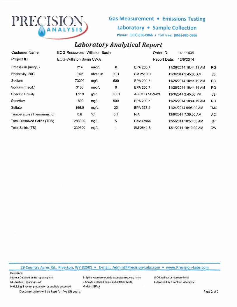
Customer Name:
Project ID:
Potassium (meq/L)
Resistivity, 25C
Sodium
Sodium (meq/L)
Specific Gravity
Strontium
Sulfate
Temperature (Thermometric)
Total Dissolved Solids (TDS)
Total Solids (TS)
Gas Measurement • Emissions Testing
Laboratory • Sample Collection Phone: {307)-856-0866 • Toll Free: {866)-985-0866
Laboratory Analytical Report EOG Resources- Williston Basin Order ID: 14111409
EOG-Williston Basin CWA Report Date: 12/9/2014
214 meq/L 0 EPA 200.7 11/26/201410:44:19AM
0.02 ohms m 0.01 SM 2510 B 12/3/2014 9:45:00 AM
73000 mg/L 500 EPA 200.7 11/26/2014 10:44: 19 AM
3160 meq/L 0 EPA 200.7 11/26/2014 10:44:19 AM
1.219 glee 0.001 ASTM D 1429-03 12/3/2014 2:45:00 PM
1890 mg/L 500 EPA 200.7 11/26/2014 10:44:19 AM
165.0 mg/L 20 EPA 375.4 11/24/2014 9:05:00 AM
0.6 oc 0.1 N/A 12/9/2014 7:39:00 AM
288900 mg/L 5 Calculation 12/5/2014 10:50:00 AM
339300 mg/L SM 2540 8 12/1/201410:10:00 AM
29 Country Acres Rd., Riverton, WY 82501 • E-mail: [email protected] • www.Precision-Labs.com
Definitions:
ND-Not Detected at the reporting limit
RL-Analyte Reporting Limit
S-Spike Recovery outside accepted recovery limits
J-Analyte detected below quantitalion limits
M-Matrix Effect
D-Diluted out of recovery limits
L-Analyzed by a contract laboratory
RG
JS
RG
RG
JS
RG
TMC
AC
JP
GW
H-Holding times for preparation or analysis exceeded
Documentation will be kept for five (5) years . Page 2 of 2
Clarks Creek 200-07SWD
Construction Details:
eog resources

16" Conductor set 80' @ surface
13 1/2" Hole
9-5/8" 36ppf J-55 STC set - =1 766'
' w/ 349+ 270 sx cmt@ surf
8 ¾" Hole
v .
~,, I
"w !)
1' (
6/29/16 Proposed Well Bore Dakota SWD
Clarks Creek 200-07 SWD 463' FSL & 854' FEL (SESE) Sec. 7, T151N, R94W McKenzie County, ND
Weatherford Arrow 1 X Injection Packer set at - 4,884' (-50 feet from uppermost perforation) on 4.5-inch 11 .6 ppf J-55 LT&C internally coated tubing
7" 26 ppf HCP-110 LTC casing set - 5,647' MD w/ 51 + 99 sx. Cement top estimated 500' above Dakota
Estimated Dakota SWD I Perforations: 4,934' to 5,346' Actual perforations will be determined by open hole logs when drilled I
Name Pierre Shale
Greenhorn
Dakota SS
Base Dakota TD
ETD - 5,647'
Vertical Subsea TVD-RKB
601 1616'
-1920 4137'
-2717 4934'
-3130 5347'
-3380 5597'
Clarks Creek 200-07SWD eog resources
Plugging and Abandonment Plan

0MB No. 2040-0042 Approval Expires 12/31/2018
United States Environmental Protection Agency
SEPA Washington, DC 20460
PLUGGING AND ABANDONMENT PLAN
Name andAdc:lms .c>f Fi!t;!IIW Name and Address of Owner/Operator Clarks Creek 200-07SWD EOG Resources, Inc. 600 17th Street, Suite lO00N, Denver. CO
80202 -
Locate Well and Outline Unit on Stat_, North Dakota Section Plat - 640 Acres I ��k:nzie - - - I
Permit Number
.. , .. ....... .. ,
N I I I I I I
._..J._LJ. _ _ J._LJ._ I I I I I
>-- -j- - t- -t - --t-t--t-._..J._LJ._ ..,_J._LJ._
I I I I I I w ' ' ' I I '
_J._LJ. _ _ J._LJ._ I I I I I I
--j--j--j-- --j--j--j--._..J._LJ. _ _ J._LJ._
I I I I I I
s
E
Surface Location Description
SE 1/4 of,.§£.. 1/4 of --Y4 of. J/4 of Section,7 Township 151. Range '. 94
Locate well In two directions rrom nearest lines or quarter section and drllllng unit
Surface Location __ ft. rrm (NIS) ,L-Llne of quarter section and ..,...._, ft. from (EIW) .]._ Line of quarter section.
TYPE OF AUTHORIZATION IZ] Individual Permit 7 Area Permit [J Rule
Number of Wells ..L:....
Lease Name -·
n CLASS I P'I CLASS II
WELL ACTIVITY
[{.] Brine Disposal n Enhanced Recovery 1-·1 Hydrocarbon Storage
I 7 CLASS 111
Well Number I ,.,.,...,. ..... , ..... . ·�""" �---- ·�--�� .. . .
CASING AND TUBING RECORD AFTER PLUGGING METHOD OF EMPLACEMENT OF CEMENT PLUGS
SIZE
9,5!8
7
WT (LB/FT)
36 .J.L
. . ...
TO BE PUT IN WELL (FT)
...... ..... - .
"'"
TO BE LEFT IN WELL (FT)
)766.'. . .. � . • "
J l '564'1' , ....
-- .,,., .,_,,.=� .,., . ... ,. .... -...
HOLE SIZE 'i)�i_/2 '&-3i4
,.,,. ..... . ...
········· �- ..
n The Balance Method D The Dump Baller Method
The Two-Plug Method L?J Other
CEMENTING TO PLUG AND ABANDON DATA: PLUG #1 PLUG #2 PLUG #3 PLUG #4 PLUG #5 PLUG #6 PLUG #7 Size of Hole or Pipe In which Plug Will Be Placed (lnche,
" " ,, ,,, Depth to Bottom of Tubing or Drill Pipe (ft 5647 ·-, Sacks of Cement To Be Used (each plug) 4�S Slurry Volume To Be Pumped (cu, ft.) 6i I . ,, , .. .. , .. ,,_. Calculated Top of Plug (ft.) ,2630 Measured Top of Plug (if tagged ft.) it',3(C
....
Slurry Wt. (Lb./Gal.) ,1 .. ff . ..... Type Cement or Other Material (Class Ill) Ciass d
,,,
-
. . � "' •
,,
---
...
.... ....•
. "
.. ..... ...
' ..... ............ . ,.,;'
,,WM . .. ........ , .. .
" _ , _
.. , .. .
,,.,.., ...
,, .... ...
LIST ALL OPEN HOLE AND/OR PERFORATED INTERVALS ANO INTERVALS WHERE CASING WILL BE VARIED (If any) From
,. .. ,.,, .,,,.,_.,,. ·" «N•,M#'<', ,O, ·"·-········· ''' •••,rn••·
... . ,. -
To
. . ....... ,
•.•. . .. , .... .. . . , . ., , .,. "
From .. ..
... . ···""·=-�- ... .. .. ......
To
·-
" '''' '" •••-••••• .. •mmm ... ............ . . ... . .. .. .... ........ _,. -- ..... , --
-�-,,.. . ,., .. ...... ··-�· .. Estimated Cos,\ t9 Fl�g- Wells
$72,127.00 (highest bid)
- . j
Certification
I certify under tho penalty of law that I have personally examined and am familiar with the Information submitted In this document and all attachment� and that, based on my Inquiry of those Individuals Immediately responsible for obtaining the Information, I believe that the Information Is true, accurate, and complete .. I am aware that there are significant penalties for submitting ratse Information, Including the possibility of fine and Imprisonment. (Ref. 40 CFR 144.32)
/
l Oate Signed
8/t(f.j/�
0
,

6eog resources P&A PROCEDURE
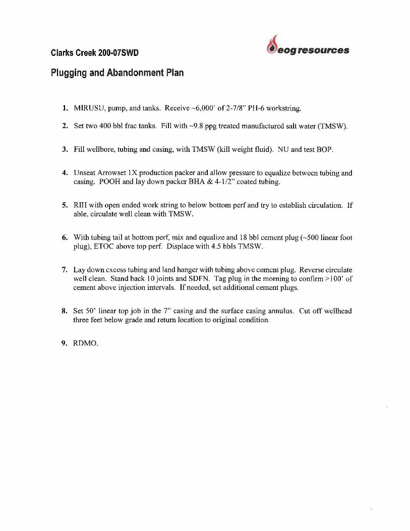
1. MIRUSU, pump, and tanks. Receive -6,000' of2-7/8" PH-6 workstring.
2. Set two 400 bbl frac tanks. Fill with - 9.8 ppg treated manufactured salt water (TMSW).
3. Fill wellbore, tubing and casing, with TMSW (kill weight fluid). NU and test BOP.
4. Unseat Arrowset IX production packer and allow pressure to equalize between tubing and casing. POOH and lay down packer BHA & 4-1 /2" coated tubing.
5. RIH with open ended work string to below bottom perf and try to establish circulation. If able, circulate well clean with TMSW.
6. With tubing tail at bottom perf, mix and equalize 61 l cubic ft (485 sxs) class G cement plug (- 3,017' linear foot plug), ETOC at 2,630'. Displace with 4.5 bbls TMSW.
7. Lay down excess tubing and land hanger with tubing above cement plug. Reverse circulate well clean. Stand back 10 joints and SDFN. Tag plug in the morning to confirm >100' of cement above injection intervals. If needed, set additional cement plugs.
8. Set 50 ' linear top job in the 7" casing and the surface casing annulus. Cut off wellhead three feet below grade and return location to original condition.
9. ROMO.
Clarks Creek 200-07SWD eog resources
Plugging and Abandonment Plan
1. MIRUSU, pump, and tanks . Receive -6,000 ' of 2-7/8" PH-6 workstring.
2. Set two 400 bbl frac tanks. Fill with -9.8 ppg treated manufactured salt water (TMSW).
3. Fill wellbore, tubing and casing, with TMSW (kill weight fluid). NU and test BOP.
4. Unseat Anowset IX production packer and allow pressure to equalize between tubing and casing. POOH and lay down packer BHA & 4-1 /2" coated tubing.
5. RIH with open ended work string to below bottom perf and try to establish circulation. If able, circulate well clean with TMSW.
6. With tubing tail at bottom perf, mix and equalize and 18 bbl cement plug (-500 linear foot plug), ETOC above top perf. Displace with 4.5 bbls TMSW.
7. Lay down excess tubing and land hanger with tubing above cement plug. Reverse circulate well clean. Stand back IO joints and SDFN. Tag plug in the morning to confirm> I 00 ' of cement above injection intervals. If needed, set additional cement plugs.
8. Set 50 ' linear top job in the 7" casing and the surface casing annulus. Cut off wellhead three feet below grade and return location to original condition.
9. RDMO.

Clarks Creek 200-07SWD eog resources
Plugging and Abandonment Proposals
• Gibson Production Services • Fortis Energy Services • MBI Energy Services

SLICKLINE SER VICE AJAX SALES & SERVICE
PUMPING UNIT SPECIALISTS BOP & EQUIPMENT RENTALS
TRUCKING & CRANE SERVICE
SKID HOUSE & TANK RENTALS NEW & USED OIL FIELD EQUIPMENT
WELL SERVICING RIGS- PLUG & ABANDONMENTS MANUFACTURERS REPRESENTATIVES
July 15th, 2016
EOG Resources Inc.
Clarks Creek 200-7 SWD, McKenzie County ND
Liberty 200-14 SWD, Mountrail County ND
In regards to your request for pricing to perform plug and abandon service on the above mentioned wells, WISCO Inc. can
provide the necessary service rig and crews, cementing equipment & materials to perform the P&A services in accordance with a North Dakota State approved plug & abandonment procedure.
It is the understanding of WISCO Inc. that tubing presently in the well is to be used for plugging & abandonment purposes.
In addition to the proposed P&A pricing, EOG Resources Inc. will then be required to provide all additional tubing, all Vac
Truck or Hot Oil Services if necessary, all the required fresh and salt water, cleaning of the utilized 400 barrel upright tanks
along with the proper disposal of all excess liquids. In the event we encounter and maintain a measurable amount of
Hydrogen Sulfide Gas, all necessary H2S safety equipment, safety personnel and additional H2S Wireline charges will be
the responsibility of EOG Resources Inc.
In the event of unforeseen problems or difficulties such as stuck rods or tubing, collapsed or parted casing, water flows,
blow outs, etc., or any procedural changes requested by EOG Resources Inc. or the State of North Dakota Oil and Gas
Division will result in additional charges being billed to EOG Resources Inc. in accordance with our most current pricing &
rate schedule.
The P&A pricing shall remain effective for a period of no less than ninety days from the date of this proposal and the
estimated amount below is to be remitted in full to WISCO Inc., in US Funds, upon successful completion of P&A operations.
---------------- $46,870.00 USO Clarks Creek 200-7 SWD
Liberty 200-14 SWD ------------------ $48,710.00 USO (400 bbl Tank Cleaning, Liquids and Liquid Waste Disposal ore NOT included in WISCO pricing)
This estimated pricing DOES NOT include any clean up or restoration of the location. In addition, WISCO Inc. no longer manages used surface equipment or used tubular goods, therefore all of the surface equipment and tubing that is
recovered from the wellbore will be left on location and in the control of EOG Resources Inc. WISCO Inc. can provide
contact information for interested parties of used equipment if desired.
Upon formal request, WISCO may provide pricing & service for trucking and transportation of tubulars, pumping units &
equipment, pumping unit teardown specialists along with crane & trucking transportation service.
Respectfully,
.
Scott Clark Well Servicing Supervisor
WISCO Inc. - GIBSON PRODUCTION SERVICES
WISCO Inc. 4903 2nd Avenue West PO Box 2477 Williston, ND, 58801
Tel: (701) 572-2135 Fax: (701) 572-0664 Fed ID# 27-5490511 Web: www.gibsons.com
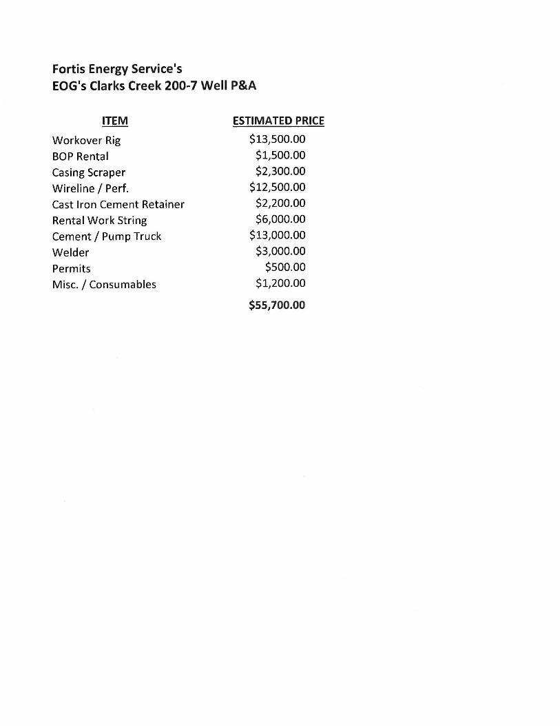
Fortis Energy Service's
EOG's Clarks Creek 200-7 Well P&A
ITEM
Workover Rig
BOP Rental
Casing Scraper
Wireline / Perf.
Cast Iron Cement Retainer
Rental Work String
Cement/ Pump Truck
Welder
Permits
Misc./ Consumables
ESTIMATED PRICE
$13,500.00
$1,500.00
$2,300.00
$12,500.00 $2,200.00
$6,000.00
$13,000.00 $3,000.00
$500.00
$1,200.00
$55,700.00
Submitted By:
Aubrey Van Dyke
MBI Energy Services
(701) 842-7783
MBI Energy Services Inc.
Plug & Abandonment Proposal
EOG Resources, Inc.
Liberty 200-14 SWD
Clarks Creek 200-07 SWD
McKenzie County, ND
Prepared for:
Dan Johnson
July 19, 2016

Plug and Abandonment Proposal
Mr. Johnson,
MBI Energy Services is submitting our estimated plug and abandonment proposal for the Liberty 200-14 SWD and
the Clarks Creek 200-07 SWD to EOG Resources, as summarized below and detailed in the attached pricing and
documentation for the well servicing operations. Because there were no procedures provided, assumptions were
made to estimate the scope of work, including tools, quantities, depths, etc. Should the NDIC approve any P&A work
to these wells, this proposal will need to be modified to reflect.
Scope of Work:
Plug and abandon the Liberty 200-14 SWD and Clarks Creek 200-07 SWD well bores.
Bid Inclusions for each well:
• 485 sxs 15.8 ppg Class G cement - 35% silica as required
• 3 - 7" CICR for each well
• 280 BBls Freshwater
• 3 - Surface Wireline Perfs
• Wellhead removal with excavation/ backfill
• Cut & Cap Wellhead with marker
Standard Equipment:
• 500 Series Service Rig w/4 man crew & supervisor
• Rod & Tubing handling equipment including power tongs (casing excluded)
• Sk Double BOP w/ accumulator trailer (TIW valve included)
• Cementing Equipment/ Services
• 3 - 400 BBL upright tank
• Associated lines, connections, and hoses to hook up equipment
• Mobilization/demobilization of equipment - with standard rig move permits (frost law permits excluded)
• Backhoe and welder
Exclusions:
• Production water and production water transportation
• Disposal transportation and disposal fees
• Reclamation to location or lease roads
• Excavation beyond digging out/backfilling the well head
• Pumping unit or tank battery removal or relocation
• Salvage credits for tubing, rods, location equipment, etc.
• Hot oiling/ heating freshwater
• Hydro-testing
• Work string
• Bit & Scraper run
• H2S Safety Equipment
• 40' Engineered base beam
2
Plug and Abandonment Proposal
Conditions:
Well complications, including but not limited to, water flow, stuck tubing or rods, fishing, casing leaks, extra
squeezes, paraffin, stuck anchor/packers, blow outs, etc., or any procedure changes incurred by the customer, State,
and/or BLM that require additional time and services from MBI Energy Services, beyond the provided scope of work,
will be billed additionally in accordance with the attached pricing and/or current MBI service rates.
Hydro-Testing any tubing will be billed directly to the customer. Any time associated with Hydro-testing will be billed
additionally at the hourly rig rate specified in the attached Plug and Abandonment Schedule. EOG will be responsible
for the condition, including the installation and testing, of each anchor on location prior to commencing operations.
EOG Resources will be responsible for providing all production water required as well as disposal fees and
transportation for any associated fluids. Additional tankage needed, beyond our standard tankage listed above, can
be provided by MBI Energy Services at an additional cost. EOG Resources will be responsible for cleaning all tankage
utilized in the proposed operations.
This bid includes up to three (3) days of cementing/pumping services. Any additional days of cementing required
beyond the number included will be billed back to the customer at cost. Any cement pumped beyond the amount
listed in the customer provided procedures will be charged at $40/sack. Requests for additional services, provided
by a 3rd party, will be billed back at cost plus 10%. Additionally, all tubing required (including a suitable work string)
will be supplied by the customer.
Extreme weather conditions (cold, wind, snow, etc.) that limit the timeliness and/or progress of our operations will
be billed in addition to the proposed prices. Additionally, in severely cold temperatures, MBI may add a rig heater,
which will be billed back to the customer.
Proposal:
MBI Energy Services proposes the above scope of work, to be completed on the Liberty 200-14 SWD & Clarks Creek
200-07 SWD:
Well County State Price
Liberty 200-14SWD McKenzie ND $ 74,663
Clarks Creek 200-07 SWD McKenzie ND $ 72,127
Total $ 146,790
Thank you for allowing MBI Energy Services the opportunity to bid plugging operations for EOG Resources, and
please let me know if there are any questions.
Sincerely,
Aubrey M. Van Dyke
Operations Engineer
MBI Energy Services
(701) 842-7783
3

Clarks Creek 200-07SWD
Necessary Resources
eog resources

Clarks Creek 200-07SWD
Formation Testing Program
eog resources
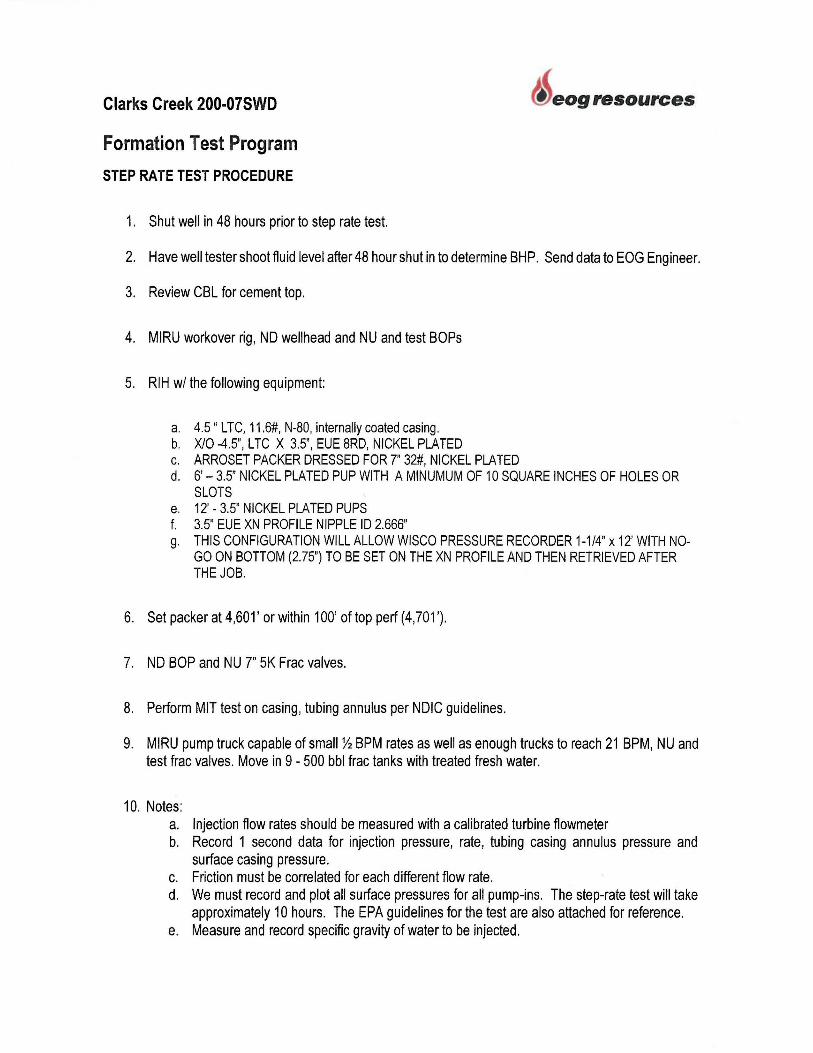
Clarks Creek 200-07SWD
Formation Test Program
STEP RA TE TEST PROCEDURE
1. Shut well in 48 hours prior to step rate test.
eog resources
2. Have well tester shoot fluid level after 48 hour shut in to determine BHP. Send data to EOG Engineer.
3. Review CSL for cement top.
4. MIRU workover rig, ND wellhead and NU and test BOPs
5. RIH w/ the following equipment:
a. 4.5 " LTC, 11 .6#, N-80, internally coated casing. b. X/0 -4.5", LTC X 3.5", EUE BRO, NICKEL PLATED c. ARROSET PACKER DRESSED FOR 7" 32#, NICKEL PLATED d. 6' -3.5" NICKEL PLATED PUP WITH A MINUMUM OF 10 SQUARE INCHES OF HOLES OR
SLOTS e. 12' - 3.5" NICKEL PLATED PUPS f. 3.5" EUE XN PROFILE NIPPLE ID 2.666" g. THIS CONFIGURATION WILL ALLOW WISCO PRESSURE RECORDER 1-1/4" x 12' WITH NO
GO ON BOTTOM (2.75") TO BE SET ON THE XN PROFILE AND THEN RETRIEVED AFTER THE JOB.
6. Set packer at 4,601' or within 100' of top perf (4,701 ').
7. ND BOP and NU 7" SK Frac valves.
8. Perform MIT test on casing, tubing annulus per NDIC guidelines.
9. MIRU pump truck capable of small ½ BPM rates as well as enough trucks to reach 21 BPM, NU and test frac valves. Move in 9 - 500 bbl frac tanks with treated fresh water.
10. Notes: a. Injection flow rates should be measured with a calibrated turbine flowmeter b. Record 1 second data for injection pressure, rate, tubing casing annulus pressure and
surface casing pressure. c. Friction must be correlated for each different flow rate. d. We must record and plot all surface pressures for all pump-ins. The step-rate test will take
approximately 10 hours. The EPA guidelines for the test are also attached for reference. e. Measure and record specific gravity of water to be injected.
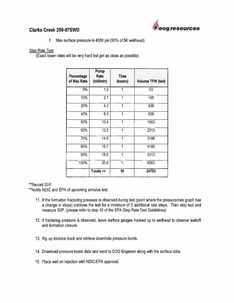
Clarks Creek 200-07SWD
f. Max surface pressure is 4500 psi (90% of 5K wellhead)
Step Rate Test (Exact lower rates will be very hard but get as close as possible)
Pump Percentage Rate Time
eog resources
of Max Rate (bbl/min) (hours) Volume TFW (bbl)
5% 1.0 1 63
10% 2.1 1 188
20% 4.2 1 438
40% 8.3 1 938
50% 10.4 1 1563
60% 12.5 1 2313
70% 14.6 1 3188
80% 16.7 1 4188
90% 18.8 1 5313
100% 20.8 1 6563
Totals=> 10 24750
**Record !SIP **Notify NDIC and EPA of upcoming annulus test.
11 . If the formation fracturing pressure is observed during test (point where the pressure/rate graph has a change in slope) continue the test for a minimum of 2 additional rate steps. Then stop test and measure !SIP. (please refer to step 10 of the EPA Step Rate Test Guidelines)
12. If fracturing pressure is observed, leave surface gauges hooked up to wellhead to observe leakoff and formation closure.
13. Rig up slickline truck and retrieve downhole pressure bomb.
14. Download pressure bomb data and send to EOG Engineer along with the surface data.
15. Place well on injection with NDIC/EPA approval.
Clarks Creek 200-07SWD
Additional Logging:
Cased Hole Log: 7" Casing: CBL/GR (TD to Surface)
• Log will be submitted after the well has been drilled.
eog resources
A total dissolved solids (TDS) sample will be conducted after the well is drilled, but before injection is authorized. If the TDS content of injection zone fluid is found to be less than 10,000 mg/L, this meets the definition of an Underground Source of Drinking Water then EOG would need to request an Aquifer Exemption before injection could occur.

Clarks Creek 200-07SWD
Plan for Well Failures
eog resources
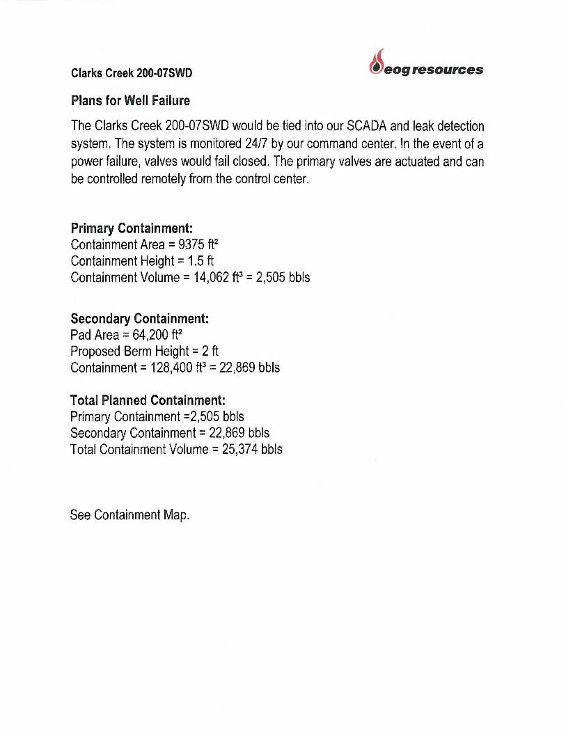
Clarks Creek 200-07SWD eog resources
Plans for Well Failure
The Clarks Creek 200-07SWD would be tied into our SCADA and leak detection system. The system is monitored 24/7 by our command center. In the event of a power failure, valves would fail closed. The primary valves are actuated and can be controlled remotely from the control center.
Primary Containment: Containment Area = 9375 ft2 Containment Height = 1.5 ft Containment Volume = 14,062 ft3 = 2,505 bbls
Secondary Containment: Pad Area = 64,200 f t2 Proposed Berm Height = 2 ft Containment= 128,400 ft3 = 22,869 bbls
Total Planned Containment: Primary Containment =2,505 bbls Secondary Containment= 22,869 bbls Total Containment Volume= 25,374 bbls
See Containment Map.
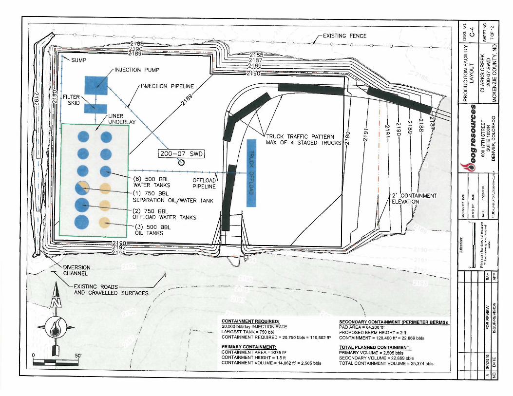
N; ,~.
l',JI
SUMP
:~j t FILTER lttd SKID
/ /
-
• DIVERSION
- -- --0 - ---- · c)- - - - 1"} - .'·-· - .•
a - ,,.::___ , ,-2J9Cl.= ,._ , 2·189-
~
-
INJECTION PUMP
INJECTION PIPELINE
r;,/ <o n;"
(6) 500 BBL WATER TANKS
(1) 750 BBL SEPARATION OIL/WATER TANK
(2) 750 BBL OFFLOAD WATER TANKS
(3) 500 BBL OIL TANKS
EXISTING FENCE
' . '--- - -O··- -- -~-- -1 ----c, ----0----0---o-- -~~~-
Ol TRUCK TRAFFIC PATTERN MAX OF 4 STAGED TRUCKS!& "'
'"-- ... --... - --- ·--~-----
N ~
lO
~
lO 0
Ol lO
2' :coNTAINMENT ELEVATION
-·- ---- - ---- ·-__ ... / """\_ CHANNEL J A ""-EXISTING ROADS---~ - - - ·~ - -- . -- __,,.____,, - - ---Ll AND GRAVELLED SURFACES / _.,.
·------ ~ "• . I
I , --0 50'
I
CONTAINMENT REQUIRED: 20,000 bbl/day INJECTION RATE LARGEST TANK= 750 bbl CONTAINMENT REQUIRED= 20,750 bbls = 116,502 ft'
PRIMARY CONTAINMENT: CONTAINMENT AREA= 9375 ft' CONTAINMENT HEIGHT= 1.5 ft CONTAINMENT VOLUME= 14,062 ft' = 2,505 bbls
.... ~·--- ·-, \
SECONDARY CONTAINMENT (PERIMETER BERMS): PAD AREA= 64,200 ft' PROPOSED BERM HEIGHT = 2 ft CONTAINMENT= 128.400 ft'= 22,869 bbls
TOTAL PLANNED CONTAINMENT: PRIMARY VOLUME = 2,505 bbls SECONDARY VOLUME = 22,869 bbls TOTAL CONTAINMENT VOLUME= 25,374 bbls
ci z "'t' ~ (.) 0
~ ::::;
~ LL f-z :::> 00 - >-0 ::i :::, 0 0 Cl'.'. a.
u, Q) ; 0 u, e a, 0
~
I
~
in
I O'. 0
~ a,
~ LL 0 ,-..
0 z
~G~ Ws;Z
5 C/)5 C/) ti (.) :.:::ow a: o N <{ N Z ...J w (.) :.:::
(.) ::::;
0 1-- 0
lliz~ Q:'.OQ 1-- 0 ..J (/) ~ 0 :i:w o 1--t-- " ,-... - Q:'. ~::iw 0 (/) > 0 Z <D UJ
0
i' <O
I I. ~
~ !· u:
~ §, 0 g !!! Q)
g>~ '! U)
-1; C . £
Iln. <( n. ID <(
z ~ Q w "' 5 5 w w D:'. D:'. D:'. w 0::, LL if)
~
0 1-~lw £:! <( t:: 0 <O
<Clg

Clarks Creek 200-07SWD
Description of Business
eog resources
Clarks Creek 200-07SWD eog resources
Description of Business
Our future drilling and completing plans will be in the Antelope Extension - Fort Berthold Reservation. Having a disposal will help eliminate truck traffic and road maintenance. The well will be located in a central location that will allow EOG to utilize existing infrastructure.
Clarks Creek 200-07SWD eog resources
Area of Potential Effects (APE)
Clarks Creek 200-0?SWD well site - shape file submitted through email.
SWCA Report:
Contact: TBD
Clarks Creek 200-07SWD
Plats:
eog resources
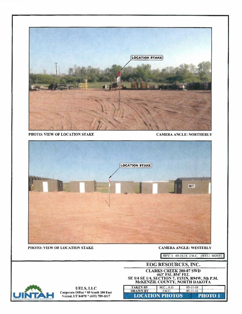
PHOTO: VIEW OF LOCATION ST AKE
PHOTO: VIEW OF LOCATION ST AKE
---,;; UINT.AH l'.:.NCilNE:CRING & LAND SUfi:Vf:: VI b
UELS, LLC Corporate Office * 85 South 200 East
Vernal, UT 84078 * (435) 789-1017
CAMERA ANGLE: NORTHERLY
LOCATION STAKE
CAMERA ANGLE: WESTERLY
I REV: I 05-18-16 J.M.C. (WELL MOVE) I EOG RESOURCES, INC. CLARKS CREEK 200-07 SWD
463' 'FSL 854' FEL SE 1/4 SE 1/4, SECTION 7, T151N, R94W, 5th P.M.
McKENZIE COUNTY, NORTH DAKOTA
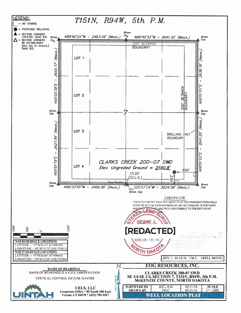
LEGEND: L = so· SYMBOL T151N, R94W, 5th P.M. • = PROPOSED WELLHEAD.
Brass .A= SECTION CORNERS LOCATED. (NAO 63) Bras s
f1 = SECTION CORNERS Cap N89.42'25"W 2463. 08' (M, ) Cap N89.49'33"W 264 - eas. - 1.30 Meas. , (, ) Brass
Cap
0 0 0
RE-ESTABLISHED. (Not Set on Ground.) (NAO 63) ,
� � '--
k :g � I
.L..J
� c:::i �
�
Brass Cap
--
I -
-
-200 SI- (HLl.l�K -
BOUNDARY
LOT 1
LOT 2
7
LOT 3
:,:::
<( >-�Cl:'. W<C (/JC)
o=> 00 lD CD
DRILLING UNIT BOUNDARY
I
--
'
•
'
.
Brass Cap
� '
I
•
CLARKS CREEK 200-07 SWD '
LOT 4 Elev. Ungraded Ground = 2190.8'854'
13.20'
�
l_ /(G.L.O.)
,._ .. I """ ··- ... Brass Cap N89".33'45"W - 2466.96' Meas. } -\ , "
-'
w.c_S89'57'24 W 2624.08 {Meas.}
-- Brass Cap
0 0 V") 0
LATITUDE - 47'54'24.12" (47.906700) LONGJTUDE- 102'45'13.72" (102.753811) NAD 27 (SURFACE LOCATION) LATITUDE � 47'54'24.06" (47.906683) LONGITUDE - 102'45'12.04" (102.753344)
0 0 0
BASIS OF BEARINGS
BASIS OF BEARINGS IS A G.P.S. OBSERVATION
VERTICAL CONTROL DA TUM: NA VD88
---AU\ UELS, LLC
Brass Cap
I REV: l 05-18-16 J.M.C. (WELL MOVE) I
N EO RESOURCES, INC. ------------'------CLARKS CREEK 200-07 SWD
SE 1/4 SE 1/4, SECTION 7, T151N, R94W, 5th P.M. McKENZIE COUNTY, NORTH DAKOTA
UINTAH Corporate Office * 85 South 200 East
Vernal, UT 84078 * (435) 789-1017 l::i:N(�INE-b.RINC' S LANO StJHVtYIN{�
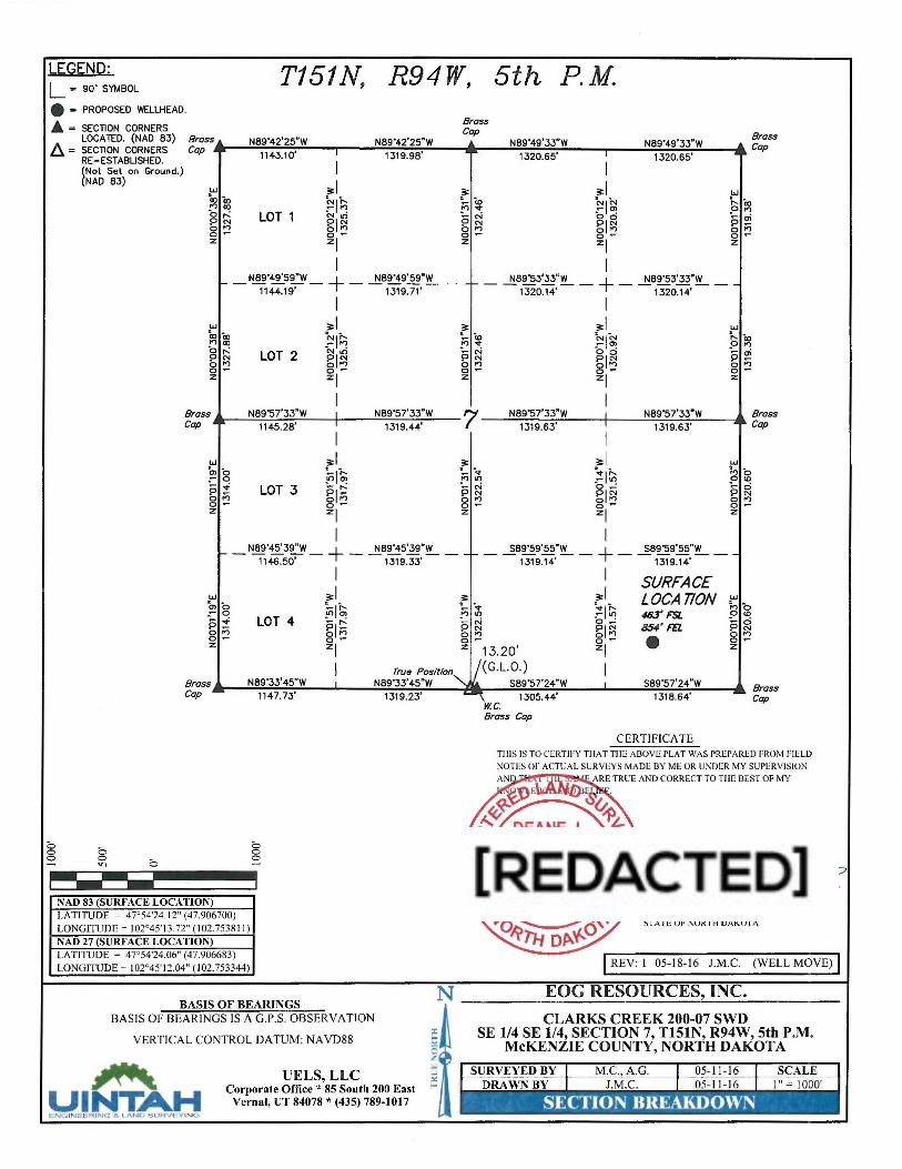
LEGEND: L ~ so· SYMBOL
T151N, R94W, 5th P. M. • ~ PROPOSED WELLHEAD.
• = SECTION CORNERS LOCATED. (NAO 83) Bros
6_ = SECTION CORNERS Cop s
RE-ESTABLISHED. (Not Set on Ground.) (NAO 83)
w U) to ..., Q)
b,...: PN 8 :2 z
N89"42'25"W N89"42'25"W 1143.10' I 1319.98'
I ;r:I ~11:,
LOT 1 s,~ 0..., o-zl I
Bross Cop
;r: ~~ ';....c,,,j
PN 0..., o-z
N8s·49'33•w
1320.65' I
I ;r:I ~I~ bci gp::i o-zl I
N89"49'33"W 1320.65' --
w ,.._ . .0 p 0 0 z
Bross Cop
._ _ N89"49'59"W _ + _ N89"49'59"'.!'!'_ __ N89"53'33"W N89"53'33"W 1144.19' 1319.71' '- 1320.14' + 1320.14' -
w . . Q) CX) ..., CX)
s~ 0..., o-z
Bross Cop .
w b, b "o -. P-0..., o-z
LOT 2
N89"57'33"W 1145.28'
LOT 3
I ;r:I ~11:, ~I~ 0..., o-zl I I N89"57'33"W I 1319.44'
I ;r:I ~1;.... !fl O? pl~ on 0 -zl I
I ;r: ;r:I ~~ ""I"' b d ;.... N PN g1;;:i 0..., o- o-z zl
I 7 N89"57'33"W I
1319.63' I
I ,. ;r:I -<t ~It; ..., Ii)
;.... N b...: PN g1;;:i on o- o-z zl
I
N89"57'33"W 1319.6.3'
w ,.._. CX) n ai ;;;
.0 p 0 0 z
~ ..., .0 p 0
0 (0
0 N t')
o-z
Bross Cop
N89'45'39"W N89"45'39"W ~ 1146.50' + 1319.33' -
S89"59'55"W S89"59'55"W 1- 1319.14' + 1319.14' - -
I I SURFACE w ;r:I !. ;r:I LOCATION w "' b ~1;.... - <t :!11n ~b -o ~ O? ..., Ii) 46.J' F'SL 0 (0 -. LOT 4 ;....N P- pl~ ·a...:
85,t.' Fn ';.... ci
0..., PN g1;;:i PN o- on on 0...,
z o- o- o- • o-zl z 13.20' zl z
Bross Cop
N89"33'45"W I I
Trut1 Position'-... N8s·33•45•w
j(G.L.O.) I S89"57'24"W I S8s·57'24•w Bross
Cop
8 0
0 0 V) 0
NAD 83 (SURFACE LOCATION)
-
Lt\TITUDF - 47' 54'24. 12" (47.906700) LONGITlffiE - 102°45' 13.72" (102.7538 1 I) NAD 27 (SURFACE LOCATION) LATITUDE = 47'54'24.06" (47.906683) LONGITlffiE- 102c45•12.04" (102.753344)
1147.73'
0 0 0
BASIS OF BEARINGS BA SIS OF BEARIN GS IS A G.P.S. OBSERVATION
VERTICAL CONTROL DATUM: NAVD88
---.ANt UELS, LLC
1319.23'
UINT>.H Corporate Office * 85 South 200 East
Vernal, UT 84078 * (435) 789-1017 E:N G INE E R I N G & l I\Nr.~ SURVE Y ING
\ 1305.44' 1318.64' --w.c. Bross Cop
CERTIFICATE TII IS IS TO CERTIFY TIIAT TIIEAl3OVE PLAT WAS PREPARED FROM FIELD
VBa-n&<;:t, «d~ E REGISTERED LAND SURVEYOR
REGISTRATION :SO. LS-6609
STA TE OF ~ORTH DAKOTA
I REV: I 05-18-16 J.M.C. (WELL MOVE) l N ____ E_O_G_R_E_SO_U_R_E_S..:...., I_N_C_. ___ _
CLARKS CREEK 200-07 SWD SE 1/4 SE 1/4, SECTION 7, T151N, R94W, 5th P.M.
McKENZIE COUNTY, NORTH DAKOTA

£)
C 3.1
C 3.4
C 6.0
/
_ ......... /
A .. ----- ~ ~-- .. U';.J
0 111.J
/
/ I
I 140'
(
___;'" '\.._
F 0.6 -.
/ --
200-07 SWD ELEV. 2189.2
EXISTING FENCE
_-- --(L--(,. - -- -0---()-- --0----o----{)--
~..... . -- :..:· --~· ·: ~~ su,., _-,:,, ' r· I. ~ .. PS~- -·•w
C 1.6
\ \
-',;:------+------go· I r·.· --- s;: I
140'
~EXISTING ~~ SURf"1:ES-AND GRAV 1
;
l !
50'
I
..!! C-2
C4.2
L----
r I
\, 180'
. ---~
- ~-=-- - __, ___ _
SURFACE DISTURBANCE
PAD AREA 2.11 AC
DIVERSION DITCH 0.06 AC I TOTAL DISTURBANCE 2.17 AC
-- - -- - - ---EARTHWORK QUANTITIES
TOPSOIL 1704 CY
UNCLASSIFIED CUT 2013 CY
TOTAL CUT 3717 CY
UNCLASSIFIED FILL 1857 CY
TOPSOIL REPLACEMENT 1704 CY
TOTAL FILL 3561 CY
SPOIL (EXCESS CUT) 156 CY
..... .....___
ci z ......
. I
~u 0
1-::l :,::'. OUJo
~~s ...luC/l 0 C/) r--<( :>::'. 9 o..o::g .J <( N .J .J
~u
= e = 0 fll e r
'4 I
;f;
ci Z N f- ~ W LL w 0 I " en
0 s z_ 'St >"'1-0:: z ·::i
~o LO U ~ UJ I- -·N r---z u UJ UJ :>::'. C/) u ~
0 f- 0
l±Jz ~ Cl'. 0 0 f- 0 ....I
en~ o IwU f- f- -r----Cl'. ~:::i UJ o rn > 0 Z <D UJ
<O
0
§
w ~ 0
0
~'
i 8 ,, ~
]' u:
1! t g ;"* ~ ~ ls .1:
I 10.. <( 0.. OJ <(
z S'. Q w (/) 5 5 w w Cl'. Q, Cl'. w 0 :::, LL Cf)
~
a >-~lw ~ <( t:: 0 <D
<(lg

2195-.--------------------------------r-2195
2190 _J_ r EXISTING GROUND
----1 % SLOPE 2190
2' (MIN). PROPOSED WELL PAD
2185 2185
2180-+--~-~--~---~-~--.---~---~-~--~----+-2180 -0+60 -0+40 -0+20 ~ 0+20 0+40 0+60
CROSS SECTION Scale H: 1"=50' V: 1"= 10'
2195~-------------------------------~2195 EXISTING GROUND~
_J_ STAKED LOCATION
2190 -1% SLOPE 2190
2' (MIN) . PROPOSED WELL PAD
2185 2185
21 80 -i-----.---.--...---------.------,---,,---.-----.------.----,--,---.----;- 2180 -0+60 -0+40 -0+20 ~ 0+20 0+40 0+60
CROSS SECTION Scale H: 1"=50' V: 1"= 10'
2195-.-------------------------------~2195
2190 I /\~ -1% SLOPE \_PROPOSED WELL PAD
2' (MIN) . j 2190
2185 I ~ EXISTING GROUND 2185
10' 2180-+--~-~--~---~-~--.---~---~----~------+-2180
-0+60 -0+40 -0+20 ~ 0+20 0+40 0+60
CROSS SECTION 0 50'
Scale H: 1"=50' V: 1"= 10'
0
. I 0 ~ N ~ ~ C) I W ~ S: U w 0 0 I '° VJ
0 u sz W:,,:: 'I'~ CJ',lwo ~t-><W> "'"Z :.:: c:: 115 z:::i c::U .-0 owr-- LOU
s~~ i'.=~ ~<{~ r-:~ c::...J uw <{ u w:.:: W WU
:::E Cl) Cl) e ... g ~ ttl z ~ 0 o::oo •• I- g _J .. , en~ o ... :c UJ u :.-, I- I- -- r---0:: - ~::, UJ ..,, o en> 0 0 Z
ID UJ Cl) 0
!) ~'
~ ! ~ ~ ~ ~· CD CD .- >-
~ >- i ~ ~ UJ ~· <( ~ I- ~
~ 5 <3 u::
;.. Tl ~ ]! :: g .!!! <Ii
"'" ·§ ~ ~ 0
,.s ~
fi1i
z ~ Q w VJ 5 5 w w ct: ct: ct: w 0 :::, LL VJ
~
~lw 0 I-N <,: t: 0
"' .,: ,g
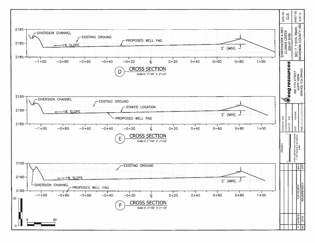
. I 0 ~ M ~ ~ C) I W lL ~ (.) wO o r "' (/)
0
2195 I [rl :.:'. s z_ ~ >-
I~~~ O'l t-
rEXISTING GROUND
I O::z
- ::i
PROPOSED WELL PAD ~ u (/) ~o 2190--j \ Q(l)I'- LO U
-1% SLOPE 5:.:'.o j'.: ~ IQ'.O " N t- 5 ~ r--z ~u uw
W:.:'.
2185 w CllU :a:
-1+00 -0+80 -0+60 -0+40 -0+20 ~ 0+20 0+40 0+60 0+80 1+00 fl)
CROSS SECTION G» ~ 0
I- 0 Scale H: 1"=50' V: 1"=10' = tl:lz~
0 o::oo I- 0 ..J
fl) cn~o Q) J: w u ... t:::!::o:: en ~ ::i w o en> 0 0 z
<D w
2195 I. _Q» 0
~ n1\1i:-i:;,c::11"'111.1 r1-1ti.11.11\1i:-1 r EXISTING GROUND
~ ;,
2190--l \ -1% SLOPE r STAKED LOCATION
"' I ' ~ :1i I a' PROPOSED WELL PAD <( S! (D CD
~ ;.. ;.. 2185 (D
~ I I ID 0 uJ ~ -1+00 -0+80 -0+60 -0+40 -0+20 ~ 0+20 0+40 0+60 0+80 1+00 "' !;; a: ::c
0 <.) 0 a:
CROSS SECTION ~TI ~-(II .!:
Scale H: 1"=50' V: 1"=10' ~ -~ ~ i
.le gj ~--~ ~ ~ C
,!! .. I
o .i.l i:
2195 I / EXISTING GROUND I I I I ,~,~ 2190--I b -1% SLOPE ~ I DIVERSION CHANNEL
I z
;;; Q w (/) r PROPOSED WELL PAD 5 5 2185 , I I ~ , I I I I I I I I I w w 11'. ~
-1+00 -0+80 -0+60 -0+40 -0+20 ~ 0+20 0+40 0+60 0+80 1+00 11'. w 0 =,
10' .- u. (fJ (fJ
CROSS SECTION -Scale H: 1"=50' V: 1"=10'
I I I I I "' ~ w
0 0 ....
50' ~ c!i "' o .i.. <( 0 z
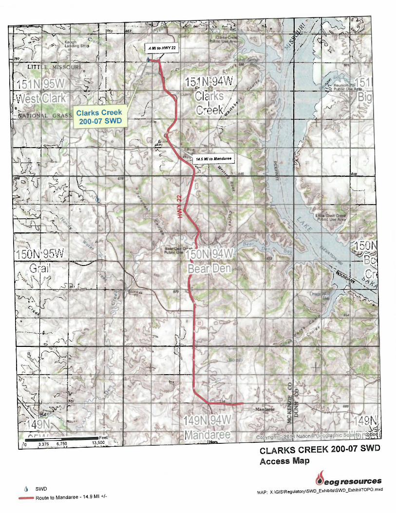
i\ 150N··95W
'.o
() SWD
- Route to Mandaree -14.9 Ml+/-
CLARKS CREEK 200-07 SWD Access Map
eog resources MAP: X :IGIS\Regulatory\SWD _Exhibits\SWD _ExhibitTOPO. mxd
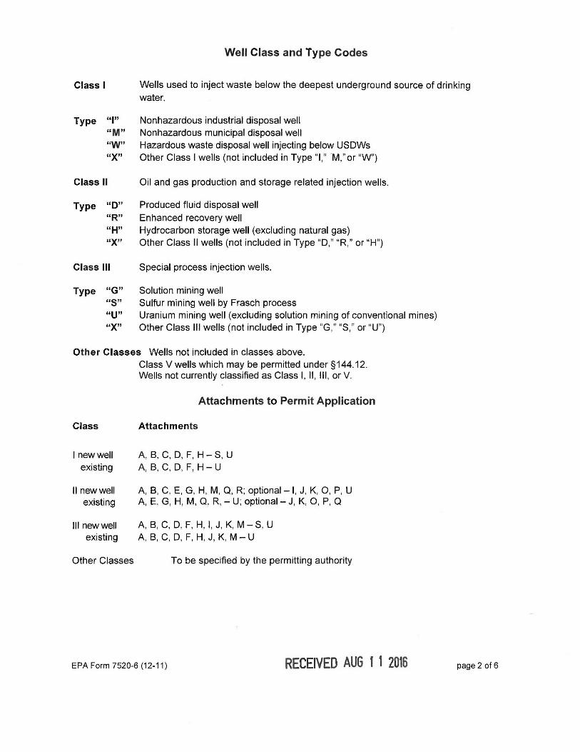
Well Class and Type Codes
Class I Wells used to inject waste below the deepest underground source of drinking water.
Type "I" Nonhazardous industrial disposal well "M" Nonhazardous municipal disposal well "W" Hazardous waste disposal well injecting below USDWs "X" Other Class I wells (not included in Type "I, " ''M," or "W")
Class II Oil and gas production and storage related injection wells.
Type "D" Produced fluid disposal well "R" Enhanced recovery well "H" Hydrocarbon storage well (excluding natural gas) "X" Other Class II wells (not included in Type "D," "R," or "H")
Class Ill Special process injection wells.
Type "G" Solution mining well "S" Sulfur mining well by Frasch process "U" Uranium mining well (excluding solution mining of conventional mines) "X" Other Class Ill wells (not included in Type "G," "S," or "U")
Other Classes Wells not included in classes above. Class V wells which may be permitted under §144.12. Wells not currently classified as Class I, II , Ill , or V.
Attachments to Permit Application
Class Attachments
I newwell A, B, C, D, F, H-S, U existing A, B, C, D, F, H - U
II new well A, B, C, E, G, H, M, Q, R; optional -1 , J, K, 0 , P, U existing A, E, G, H, M, Q , R, - U; optional - J, K, 0, P, Q
111 new well A, B, C, D, F, H, I, J, K, M -S, U existing A, B, C, D, F, H, J, K, M - U
Other Classes To be specified by the permitting authority
EPA Form 7520-6 (12-11) RECEIVED AUG 1 1 2016 page 2 of 6
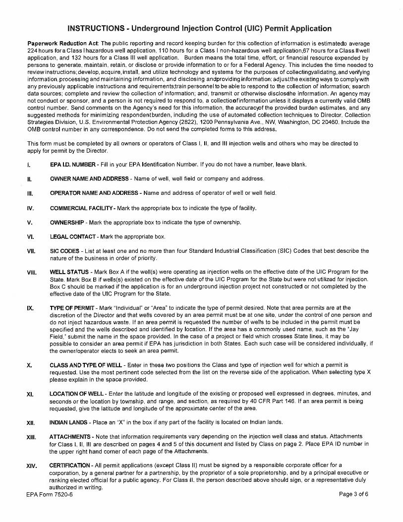
INSTRUCTIONS - Underground Injection Control (UIC) Permit Application
Paperwork Reduction Act: The public reporting and record keeping burden for this collection of information is estimatedo average 224 hours for a Class I hazardous well application , 110 hours for a Class I non-hazardous well application,67 hours fora Class II well application, and 132 hours for a Class Ill well application. Burden means the total time, effort, or financial resource expended by persons to generate, maintain , retain, or disclose or provide information to or for a Federal Agency. This includes the time needed to review instructions; develop, acquire, install , and utilize technology and systems for the purposes of collectingyalidating , and verifying information , processing and maintaining information, and disclosing andproviding information ; adjustthe existing ways to comply with any previously applicable instructions and requirements~rain personnel to be able to respond to the collection of information; search data sources; complete and review the collection of information ; and , transmit or otherwise disclosehe information . An agency may not conduct or sponsor, and a person is not required to respond to, a collectioofinformation unless it displays a currently valid 0MB control number. Send comments on the Agency's need for this information , the accuraqof the provided burden estimates, and any suggested methods for minimizing respondent burden , including the use of automated collection techniques to Director, Collection Strategies Division, U.S. Environmental Protection Agency (2822), 1200 Pennsylvania Ave ., NW, Washington, DC 20460. Include the 0MB control number in any correspondence. Do not send the completed forms to this address.
This form must be completed by all owners or operators of Class I, II , and Ill injection wells and others who may be directed to apply for permit by the Director.
I. EPA I.D. NUMBER - Fill in your EPA Identification Number. If you do not have a number, leave blank.
II. OWNER NAME AND ADDRESS - Name of well , well field or company and address.
111. OPERATOR NAME AND ADDRESS - Name and address of operator of well or well field.
IV. COMMERCIAL FACILITY - Mark the appropriate box to indicate the type of facility.
V. OWNERSHIP - Mark the appropriate box to indicate the type of ownership.
VI. LEGAL CONTACT - Mark the appropriate box.
VII. SIC CODES - List at least one and no more than four Standard Industrial Classification (SIC) Codes that best describe the nature of the business in order of priority.
VIII. WELL STATUS - Mark Box A if the well(s) were operating as injection wells on the effective date of the UIC Program for the State. Mark Box B if wells(s) existed on the effective date of the UIC Program for the State but were not utilized for injection. Box C should be marked if the application is for an underground injection project not constructed or not completed by the effective date of the UIC Program for the State.
IX. TYPE OF PERMIT - Mark "Individual" or "Area" to indicate the type of permit desired . Note that area permits are at the discretion of the Director and that wells covered by an area permit must be at one site, under the control of one person and do not inject hazardous waste. If an area permit is requested the number of wells to be included in the permit must be specified and the wells described and identified by location. If the area has a commonly used name, such as the "Jay Field ," submit the name in the space provided. In the case of a project or field which crosses State lines, it may be possible to consider an area permit if EPA has jurisdiction in both States . Each such case will be considered individually, if the owner/operator elects to seek an area permit.
X. CLASS AND TYPE OF WELL - Enter in these two positions the Class and type of injection well for which a permit is requested. Use the most pertinent code selected from the list on the reverse side of the application. When selecting type X please explain in the space provided.
XI. LOCATION OF WELL- Enter the latitude and longitude of the existing or proposed well expressed in degrees, minutes, and seconds or the location by township , and range, and section , as required by 40 CFR Part 146. If an area permit is being requested , give the latitude and longitude of the approximate center of the area.
XII. INDIAN LANDS - Place an "X" in the box if any part of the facility is located on Indian lands.
XIII. ATTACHMENTS - Note that information requirements vary depending on the injection well class and status. Attachments for Class I, II , Ill are described on pages 4 and 5 of this document and listed by Class on page 2. Place EPA ID number in the upper right hand corner of each page of the Attachments.
XIV. CERTIFICATION- All permit applications (except Class II) must be signed by a responsible corporate officer for a corporation, by a general partner for a partnership, by the proprietor of a sole proprietorship, and by a principal executive or ranking elected official for a public agency. For Class II , the person described above should sign, or a representative duly authorized in writing .
EPA Form 7520-6 Page 3 of 6

INSTRUCTIONS - Attachments
Attachments to be submitted with permit application for Class I, II , Ill and other wells.
A. AREA OF REVIEW METHODS - Give the methods and, if appropriate, the calculations used to determine the size of the area of review (fixed radius or equation).The area of review shall be a fixed radius of 1/4 mile from the well bore unless the use of an equation is approved in advance by the Director.
B. MAPS OF WELUAREA AND AREA OF REVIEW - Submit a topographic map, extending one mile beyond the property boundaries, showing the injection well(s) or project area for which a permit is sought and the applicable area of review. The map must show all intake and discharge structures and all hazardous waste treatment, storage , or disposal facilities. If the application is for an area permit, the map should show the distribution manifold (if applicable) applying injection fluid to all wells in the area, including all system monitoring points. Within the area of review, the map must show the following :
Class I
The number, or name, and location of all producing wells , injection wells , abandoned wells , dry holes , surface bodies of water, springs, mines (surface and subsurface) , quarries, and other pertinent surface features , including residences and roads , and faults , if known or suspected . In addition , the map must identify thosewells , springs, other surface water bodies , and drinking water wells located within one quarter mile of the facility property boundary. Only information of public record is required to be included in this map;
Class II
In addition to requirements for Class I, include pertinent information known to the applicant. This requirement does not apply to existing Class II wells ;
Class Ill
In addition to requirements for Class I, include public water systems and pertinent information known to the applicant.
C. CORRECTIVE ACTION PLAN AND WELL DATA-Submit a tabulation of data reasonably available from public records or otherwise known to the applicant on all wells within the area of review, including those on the map required in B, which penetrate the proposed injection zone. Such data shall include the following :
Class I
A description of each well's types, construction, date drilled , location, depth , record of plugging and/or completion , and any additional information the Director may require. In the case of new injection wells , include thecorrective action proposed to be taken by the applicant under 40 CFR 144.55.
Class II
In addition to requirement for Class I, in the case of Class II wells:iperating overthe fracture pressure ofthe injection formation , all known wells within the area of review which penetrate formations affected by the increase in pressure. This requirement does not apply to existing Class II wells.
Class Ill
In addition to requirements for Class I, the corrective action proposed under 40 CFR 144.55 for all Class Ill wells .
D. MAPS AND CROSS SECTION OF USDWs - Submit maps and cross sections indicating the vertical limits of all underground sources of drinking water within the area of review (both vertical and lateral limits for Class I), their position relative to the injection formation and the direction of water movement, where known, in every underground source of drinking water which may be affected by the proposed injection. (Does not apply to Class II wells .)
EPA Form 7520-6 Page 4 of 6
E. NAME AND DEPTH OF USDWs (CLASS II) - For Class II wells , submit geologic name, and depth to bottom of all underground sources of drinking water which may be affected by the injection .
F. MAPS AND CROSS SECTIONS OFGEOLOGICSTRUCTUREOFAREA- Submit maps and cross sections detailing:he geologic structure ofthe local area (including the lithology of injection and confining intervals) ancyeneralized maps and cross sections illustrating the regional geologic setting . (Does not apply to Class II wells.)
G. GEOLOGICAL DATA ON INJECTION AND CONFINING ZONES (Class II) - For Class II wells , submit appropriate geological data on the injection zone and confining zones including lithologic description , geological name, thickness, depth and fracture pressure.
H. OPERATING DATA - Submit the following proposed operating data foreach well (including all those to be covered by area permits) : (1) average and maximum daily rate and volumeofthe fluids to be injected ; (2) average and maximum injection pressure ; (3) nature of annulus fluid ; (4) for Class I wells , source and analysis ofthe chemical, physical, radiological and biological characteristics , including density and corrosiveness, of injection fluids ; (5) for Class II wells , source and analysis of the physical andchemical characteristics of the injection fluid ; (6) for Class Ill wells, a qualitative analysis and ranges in concentrations of all constituents efinjected fluids. If the information is proprietary, maximum concentrations only may be submitted , but all records must be retained .
I. FORMATION TESTING PROGRAM - Describe the proposed formation testing programForClass I wells the program must be designed to obtain data on fluid pressure , temperature, fracture pressure, other physical , chemical , and radiological characteristics of the injection matrix and physical and chemical characteristics of the formation fluids.
For Class II wells the testing program must be designed to obta in data on flu id pressure , estimated fracture pressure, physical and chemical characteristics of the injection zone. (Does not apply to existing Class II wells or projects.)
For Class Ill wells the testing must bedesigned to obtain data on fluid pressure, fracture pressure , and physical and chemical characteristics of the formation flu ids if theformation is naturally water bearing . Only fracture pressure is required if the program formation is not water bearing. (Does not apply to existing Class Ill wells or projects.)
J. STIMULATION PROGRAM - Outl ine any proposed stimulation program.
K. INJECTION PROCEDURES - Describe the proposed injection procedures including pump, surge, tank, etc.
L. CONSTRUCTION PROCEDURES - Discuss the construction procedures (accord ing to §146.12 forClass I, §146.22 for Class II , and §146.32 for Class Ill) to be utilized. This should include details of the casing and cementing program, logging procedures, deviation checks, and the drilling , testing and coring program , and proposed annulus flu id. (Request and submission of justifying data must be made to use an alternative to packer for Class I.)
M. CONSTRUCTION DETAILS - Submit schematic or other appropri ate drawings of the surface and subsurface construction details of the well.
N. CHANGES IN INJECTED FLUID - Discuss expected changes in pressure, native flu id displacement, and direction of movement of injection fluid . (Class Ill wells only.)
o. PLANS FOR WELL FAILURES - Outline contingency plans (proposed plans, if any, for Class II ) to cope with all shut-ins or wells failures , so as to prevent migration of fluids into any USDW.
P. MONITORING PROGRAM - Discuss the planned monitoring program . This should be thorough , including maps showing the number and location of monitoring wells as appropriate and discussion of monitoring devices , sampling frequency, and parameters measured . If a manifold monitoring program is utilized , pursuant to §146.23(b)(5) , describe the program and compare it to individual well monitoring.
Q. PLUGGING AND ABANDON MENT PLAN - Submit a plan for plugging and abandonment of the well including : (1) describe the type, number, and placement (including the elevation of the top and bottom) of plugs to be used; (2) describe the type, grade, and quantity of cement to be used; and (3) describe the method to based to place plugs, including the method used to place the weli n a state of static equilibrium prior to placement of the plugs. Also for a Class Ill well that underlies or is in an exempted aquifer, demonstrate adequate protection oUSDWs. Submit this information on EPA Form 7520-14, Plugging and Abandonment Plan.
EPA Form 7520-6 Page 5 of 6

R NECESSARY RESOURCES - Submit evidence such as a surety bond or financial statement to verify that the resources necessary to close, plug or abandon the well are available.
S. AQUIFER EXEMPTIONS-lfan aquifer exemption is requested , submit data necessary to demonstrate that theaquifer meets the following criteria : (1) does not serve as a source of drinking water; (2) cannot now and will not in the future serve as a source of drinking water; and (3) the TDS content of the ground water is monihan 3,000 and less than 10,000 mg/I and is not reasonablyexpected to supply a public water system. Data to demonstrate that the aquifer is expected to be mineral or hydrocarbon production , such as general description of themining zone, analysis of the amenability of the mining zone to the proposed method , and time table for proposed development must also be included. For additional information on aquifer exemptions, see 40 CFR Sections 144.7 and 146.04.
T. EXISTING EPA PERMITS - List program and permit number of any existing EPA permits, for example, NPDES, PSD, RCRA, etc.
U. DESCRIPTION OF BUSINESS - Give a brief description of the nature of the business.
EPA Form 7520-6 Page 6 of 6