Clamping Module - Single - Wixroyd
46
Clamping Module - Single flanged 12043 wixroyd.com Created 2022-01-06 Material Steel (AISI 4140), induction hardened, black oxide finish. Technical Notes For suitable clamping screws see part no.s 12046 through 12050. For permissible cutting forces and corresponding workpiece weights when using the clamping module system, see technical pages. Order No. Type Size l 1 d 1 d 2 d 3 d 4 h 1 ±0,0 1 h 2 h 3 h 4 w 1 A/F Max. clam ping Forc e kN. Max. scre w torq ue Nm. X g 12043.W0008 One 8 42 30 34,5 15 6,6 25 12,5 12,5 7 54 3 5 4 100 12043.W0011 Two 11 50 40 46,0 22 9,0 40 20,0 20,0 10 65 4 8 8 300 12043.W0016 Two 16 75 60 69,0 32 13,0 63 33,0 30,0 15 95 6 15 50 1400 12043.W0021 Two 21 100 80 91,0 44 17,0 80 40,0 40,0 20 130 8 25 50 3300
-
Upload
khangminh22 -
Category
Documents
-
view
0 -
download
0
Transcript of Clamping Module - Single - Wixroyd
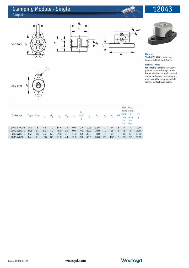
Clamping Module - Singleflanged
12043
wixroyd.comCreated 2022-01-06
Material
Steel (AISI 4140), induction
hardened, black oxide finish.
Technical Notes
For suitable clamping screws see
part no.s 12046 through 12050.
For permissible cutting forces and
corresponding workpiece weights
when using the clamping module
system, see technical pages.
Order No. Type Size l1
d1
d2
d3
d4
h1
±0,0
1
h2
h3
h4
w1
A/F
Max.
clam
ping
Forc
e
kN.
Max.
scre
w
torq
ue
Nm.
X
g
12043.W0008 One 8 42 30 34,5 15 6,6 25 12,5 12,5 7 54 3 5 4 100
12043.W0011 Two 11 50 40 46,0 22 9,0 40 20,0 20,0 10 65 4 8 8 300
12043.W0016 Two 16 75 60 69,0 32 13,0 63 33,0 30,0 15 95 6 15 50 1400
12043.W0021 Two 21 100 80 91,0 44 17,0 80 40,0 40,0 20 130 8 25 50 3300
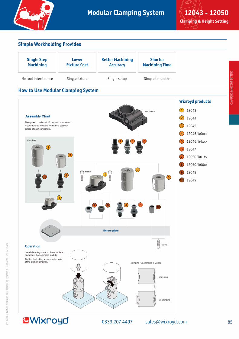
Simple Workholding Provides
Single Step Machining
Lower Fixture Cost
Better Machining Accuracy
Shorter Machining Time
No tool interference Single fixture Single setup Simple toolpaths
fixture plate
workpiece
The system consists of 10 kinds of components.
Please refer to the table on the next page for
details of each component.
clamping / unclamping is visible
Assembly Chart
clamping
unclamping
coupling
screw
screw
1
2
3
4 5 6
7 8
9
j10
1
2
3
4
4
6
Install clamping screw on the workpiece
and mount it on clamping module.
Tighten the locking screws on the side
of the clamping module.
Operation
1
2
3
4
5
6
7
8
9
j10
How to Use Modular Clamping System
12043
12044
12045
12046.W0xxx
12046.W4xxx
12047
12050.W01xx
12050.W00xx
12048
12049
Wixroyd products
CLA
MP
ING
& H
EIG
HT
SET
TIN
GCL
AM
PIN
G &
HEI
GH
T S
ETTI
NG
850333 207 4497 [email protected]
12043 - 12050 Clamping & Height Setting
Modular Clamping Systemo
v-1
20
43
-12
05
0-m
od
ula
r-p
ull
-cla
mp
ing
-sys
tem
-a-
Up
dat
ed -
19
-07
-20
21

perfect for machining
from 5 sides
no tool interference!
Title Here
Locating Mechanism
workpiece
tapered
clamping screw
tapered surface of
clamping module
gap
tapered surface
contact surfacedual contact
clampedcontactunclamped
Dual surface contact at the tapered surfaces and contact surfaces provides 5 µ m locating repeatability.
CLA
MP
ING
& H
EIGH
T SETTIN
G
86 wixroyd.com [email protected]
Modular Clamping System12043 - 12050 Clamping & Height Setting
ov-1
20
43
-12
05
0-m
od
ular-p
ull-clam
pin
g-system
-b- U
pd
ated -3
1-0
3-2
02
1

Permissible Cutting Force & Workpiece Weight for Clamping Module System 12043 to 12050
F2 (kN)F1 (kN)
(machin
ing a
rea/ cente
r)
H
p1
horizontal vertical
p1
(machining area/ center)
H
F1 (kN)
w1 (kg)
F2 (kN)
w2 (kg)
(machining area/ center)
H
p2
1 Module Ensure the cutting force and the workpiece weight are within the allowable level.
Note: Prepare a locator
when the workpiece gets
big rotating force.
(machining area/ center)
H
FZ (kN)
F (kN)
Part Number Allowable Cutting Force Allowable Workpiece
Weight w(kg)F(kN) Fz(kN)
12043.W0008 50/H
1.5
50 x 100/H
12044.W0008 25/H 25 x 100/H
12045.W0008 25/H 25 x 100/H
12043.W0011 120/H
2.5
120 x 100/H
12044.W0011 70/H 70 x 100/H
12045.W0011 70/H 70 x 100/H
12043.W0016 250/H
7.5
250 x 100/H
12044.W0016 150/H 150 x 100/H
12045.W0016 150/H 150 x 100/H
12043. W0021 500/H
15
500 x 100/H
12044. W0021 300/H 300 x 100/H
12045. W0021 300/H 300 x 100/H
2 Modules
F (kN)
W (kg)VerticalHorizontal
Part Number Allowable Cutting Force Allowable Workpiece Weight
F1(kN) F2(kN) Max(kN) w1(kg) w2(kg) Max (kg)
12043.W0008 (0.10p1 + 180)H 100/H
1.8
100x100/H (0.10p2 + 180) x 100/H
18012044.W0008 (0.05p1 + 90)H 50/H 50x100/H (0.05p2 + 90) x 100/H
12045.W0008 (0.05p1 + 90)H 50/H 50x100/H (0.05p2 + 90) x 100/H
12043.W0011 (0.24p1 + 432)H 240/H
3.2
240x100/H (0.24p2 + 432) x 100/H
32012044.W0011 (0.14p1 + 252)H 140/H 140x100/H (0.14p2 + 252) x 100/H
12045.W0011 (0.14p1 + 252)H 140/H 140x100/H (0.14p2 + 252) x 100/H
12043.W0016 (0.50p1 + 900)H 500/H
6
500x100/H (0.50p2 + 900) x 100/H
60012044.W0016 (0.30p1 + 540)H 300/H 300x100/H (0.30p2 + 540) x 100/H
12045.W0016 (0.30p1 + 540)H 300/H 300x100/H (0.30p2 + 540) x 100/H
12043. W0021 (1.00p1 + 1800)H 1000/H
10
1000x100/H (1.00p2 + 1800) x 100/H
100012044. W0021 (0.60p1 + 1080)H 600/H 600x100/H (0.60p2 + 1080) x 100/H
12045. W0021 (0.60p1 + 1080)H 600/H 600x100/H (0.60p2 + 1080) x 100/H
CLA
MP
ING
& H
EIGH
T SETTIN
G
87 wixroyd.com [email protected]
12043 - 12050 Clamping & Height Setting Permissable Cutting Force & Workpiece Weight
Modular Clamping Systemo
v-cuttin
g-fo
rce-wo
rkpiece-w
eigh
t-12
04
3-1
20
50
-a-Up
dated
-01
-04
-20
21
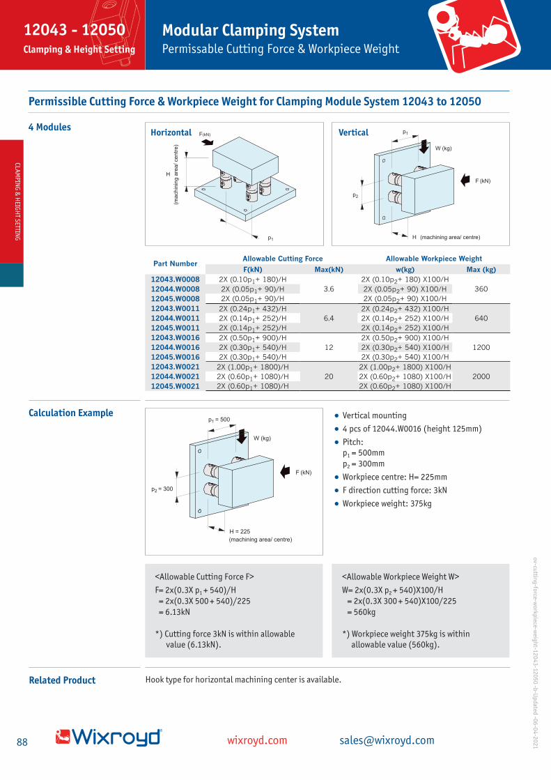
Permissible Cutting Force & Workpiece Weight for Clamping Module System 12043 to 12050
4 Modules
Part Number Allowable Cutting Force Allowable Workpiece Weight
F(kN) Max(kN) w(kg) Max (kg)
12043.W0008 2X (0.10p1+ 180)/H
3.6
2X (0.10p2+ 180) X100/H
36012044.W0008 2X (0.05p1+ 90)/H 2X (0.05p2+ 90) X100/H
12045.W0008 2X (0.05p1+ 90)/H 2X (0.05p2+ 90) X100/H
12043.W0011 2X (0.24p1+ 432)/H
6.4
2X (0.24p2+ 432) X100/H
64012044.W0011 2X (0.14p1+ 252)/H 2X (0.14p2+ 252) X100/H
12045.W0011 2X (0.14p1+ 252)/H 2X (0.14p2+ 252) X100/H
12043.W0016 2X (0.50p1+ 900)/H
12
2X (0.50p2+ 900) X100/H
120012044.W0016 2X (0.30p1+ 540)/H 2X (0.30p2+ 540) X100/H
12045.W0016 2X (0.30p1+ 540)/H 2X (0.30p2+ 540) X100/H
12043.W0021 2X (1.00p1+ 1800)/H
20
2X (1.00p2+ 1800) X100/H
200012044.W0021 2X (0.60p1+ 1080)/H 2X (0.60p2+ 1080) X100/H
12045.W0021 2X (0.60p1+ 1080)/H 2X (0.60p2+ 1080) X100/H
p1
F(kN)
(ma
ch
inin
g a
rea
/ ce
ntr
e)
H
p1
W (kg)
F (kN)
(machining area/ centre)H
p2
VerticalHorizontal
Calculation Example
Related Product Hook type for horizontal machining center is available.
• Vertical mounting
• 4 pcs of 12044.W0016 (height 125mm)
• Pitch: p1 = 500mm
p2 = 300mm
• Workpiece centre: H= 225mm
• F direction cutting force: 3kN
• Workpiece weight: 375kg
p1 = 500
W (kg)
F (kN)
(machining area/ centre)
H = 225
p2 = 300
<Allowable Cutting Force F>
F= 2x(0.3X p1 + 540)/H
= 2x(0.3X 500 + 540)/225
= 6.13kN
*) Cutting force 3kN is within allowable value (6.13kN).
<Allowable Workpiece Weight W>
W= 2x(0.3X p2 + 540)X100/H
= 2x(0.3X 300 + 540)X100/225
= 560kg
*) Workpiece weight 375kg is within allowable value (560kg).
CLAM
PING
& H
EIGH
T SETTING
88 wixroyd.com [email protected]
12043 - 12050 Clamping & Height Setting Permissable Cutting Force & Workpiece Weight
Modular Clamping Systemo
v-cuttin
g-fo
rce-wo
rkpiece-w
eigh
t-12
04
3-1
20
50
-b-U
pd
ated -0
6-0
4-2
02
1

Installation Instructions Modular Clamping System
Part Numberd1
(H7)Lf M p1
12043.W0008 8 5.5 M 6X1 42
12043.W0011 12 5.5 M 8X1.25 50
12043.W0016 18 6.5 M 12X1.75 75
12043.W0021 22 8 M 16X2 100
2-m
Lf
d1
hex. socket-head
cap screws
fixture platetapered bushing
(accurate/standard)
12050.W01xx -
12050.W00xx
p1
Use 12050.W01xx tapered bushing (accurate) for precise locating.
Use 12050.W00xx tapered busing (standard) for rough locating.
Spacing Tolerance
spacing tolerance ±0.02 *
tapered clamping
screws (diamond)
12046.W4xxx
tapered bushing
(accurate)
12050.W01xx
tapered clamping
screws (round)
12046.W0xxx
tapered bushing
(accurate)
12050.W01xx
fixture plate
Spacing tolerance for 12050.W01xx tapered bushings (accurate) should be ±0.02.
Spacing tolerance for 12050.W01xx tapered bushings (standard) should be ±0.01.
Mounting-Hole Dimension
Tightening Order
tapered clamping screw
(diamond) 12046.W4xxx
tapered clamping screw
(round) 12046.W0xxx
clamping screws 12047
2-clamping
screws 12047
tapered bushing
(accurate)
12050.W01xx
tapered clampingscrew (diamond)
12046.W4xxx
tapered bushing
(accurate)
12050.W01xx
tapered clamping screw
(round) 12045.W0xxx
tapered bushing
(standard)
12050.W00xx
1
2
3
4
Tighten the locking screws in order of
Round tapered clamping screw
Diamond tapered clamping screw
Clamping screw
Clamping screw
Note: For 12043.W0008, use 2
pieces of round tapered clamping
screw. Tighten these 2 screws in
the same order to maintain the
locating repeatability.
1
2
3
4
CLAM
PING
& H
EIGH
T SETTING
89 wixroyd.com [email protected]
12043 - 12050 Clamping & Height Setting Installation Instructions
Modular Clamping Systemo
v-12
04
3-1
20
50
-mo
du
lar-pu
ll-clamp
ing
-installatio
n-U
pd
ated -11
-05
-20
21

Clamping Module - Doubleunflanged
12044
wixroyd.comCreated 2022-01-06
Material
Steel (AISI 4140), induction
hardened, black oxide finish.
Technical Notes
For suitable clamping screws see
part no.s 12046 through 12050.
For permissible cutting forces and
corresponding workpiece weights
when using the clamping module
system, see technical pages.
Order No. Sizeh
1±0,01
h2
d1
d2
d3
A/F
Max.
clamping
force
kN.
Max.
screw
torque
Nm.
X
g
12044.W0008 8 50 12,5 30 34,5 15 3 5 4 200
12044.W0011 11 80 20,0 40 46,0 22 4 8 8 700
12044.W0016 16 125 30,0 60 69,0 32 6 15 22 2600
12044.W0021 21 160 40,0 80 91,0 44 8 25 50 5800

Installation Instructions Modular Clamping System
Part Numberd1
(H7)Lf Lf1 M
12044.W0008 8 9 5.5 M 6X1
12044.W0011 12 13 5.5 M 8X1.25
12044.W0016 18 19 6.5 M 12X1.75
12044.W0021 22 23 8 M 16X2
fixture plate
tapered clamping
screw (round)
12046.W0xxx
d1
M
fixing
clamping screw
12047
M
locating
and fixing
Lf1
Lf Lf
Use 12046.W0xxx tapered clamping screw (round) for precise locating.
Use 12047 clamping screw just for fixing.
Mounting-Hole Dimension
Note: Only tapped hole
is required for 12047
clamping screw.
Spacing Tolerance
tapered clamping screws
(diamond) 12046.W4xxx
tapered clamping screws
(round) 12046.W0xxx
tapered clamping screws
(round) 12046.W0xxx
spacing tolerance ±0.02*fixture plate
Spacing tolerance for 12046.W0xxx tapered clamping screws (accurate) should be ±0.02.
*Spacing tolerance for 12047 clamping screws should be ±0.2.
Note: For 12046.W0xxx, use 2
pieces of round tapered clamping
screw. Tighten these 2 screws in
the same order to maintain the
locating repeatability.
Coupling with Other Clamping Modules
Can be coupled with each clamping module. (Locating repeatability is 0.2)
Tightening Order
2-clamping screws
12047
tapered clamping screw
(round) 12046.W0xxx
tapered clamping
screws (diamond)
12046.W4xxxtapered clamping
screw (round)
12046.W0xxx
2-clamping screws
12047
the direction of clamping module
can be changed for easy operation
clamping screws
12047
tapered clamping
screw (diamond)
12046.W4xxx
tapered clamping
screw (round)
12046.W0xxx
2
3
4
1
Note: For 12044.W0008, use 2
pieces of round tapered clamping
screw. Tighten these 2 screws in
the same order to maintain the
locating repeatability.
clamping module
(flanged)
12043
clamping module
(double)
12044
clamping module
(single)
12045
double tapered
clamping pin
12048
Tighten the locking screws in order of
Round tapered clamping screw
Diamond tapered clamping screw
Clamping screw
Clamping screw
1
2
3
4
CLAM
PING
& H
EIGH
T SETTING
90 wixroyd.com [email protected]
Modular Clamping SystemInstallation Instructions
12044Clamping & Height Setting
ov-1
20
44
-clamp
ing
-mo
du
le-do
ub
le-installatio
n-U
pd
ated -1
2-0
5-2
02
1

Clamping Module - Singleunflanged
12045
wixroyd.comCreated 2022-01-06
Material
Steel (AISI 4140), induction
hardened, black oxide finish.
Technical Notes
For suitable clamping screws see
part no.s 12046 through 12050.
For permissible cutting forces and
corresponding workpiece weights
when using the clamping module
system, see technical pages.
Order No. Size d1
d2
d3
d4
d5
h1
±0,01h
2h
3h
4h
5A/F
Max.
clam
ping
force
kN.
Max.
scre
w
torq
ue
Nm.
X
g
12045.W0008 8 30 34.5 15 8 M 6x1,00 32 19,5 12,5 11,5 5,0 3 5 4 200
12045.W0011 11 40 46,0 22 12 M 8x1,25 50 30,0 20,0 18,0 7,5 4 8 8 500
12045.W0016 16 60 69,0 32 18 M12x1,75 80 50,0 30,0 25,0 10,5 6 15 22 1600
12045.W0021 21 80 91,0 44 22 M16x2,00 100 60,0 40,0 31,0 12,5 8 25 50 3800

Installation Instructions Modular Clamping System
Part Numberd1
(H7)Lf
d1
12045.W0008 8 6.5 6
12045.W0011 12 8.5 8
12045.W0016 18 12.5 12
12045.W0021 22 16.5 16
hex. socket-head
cap screw
locating bushing
12049
locating and
fixing
fixture plate
d
Lf
hex. socket-head
cap screw
fixing
Use 12049 locating bushing for precise locating.
Use only hex. socket-head cap screw just for fixing.
Mounting-Hole Dimension
Note: Only c’bored hole is
required just for fixing.
Spacing Tolerance
tapered clamping screws
(diamond) 12046.W4xxxlocating bushings
12049
tapered clamping screws
(round) 12046.W0xxx
spacing tolerance ±0.02*
hex. socket-head cap screws
fixture plate
Spacing tolerance for 12049 locating bushing should be ±0.02.
*Spacing tolerance for hex. socket-head cap screw should be ±0.01.
Coupling with Other Clamping Modules
Can be coupled with each clamping module. (Locating repeatability is 5 µ m).
Tightening Order
12047
tapered clamping
screw (diamond)
12046.W4xxx
clamping screws
2-clamping
screws 12047
locating bushing
12049
tapered clamping
screws (diamond)
12046.W4xxxlocating
bushing
12049
4-hex. socket-head
cap screws
tapered clamping
screw (round)
12046.W0xxx
tapered clamping
screw (round)
12046.W0xxx
2
3
4
1
Note: For 12045.W0008, use 2
pieces of round tapered clamping
screw. Tighten these 2 screws in
the same order to maintain the
locating repeatability.
clamping module
(single) 12045
tapered clamping screw
(round) 12046.W0xxx
clamping module
(double) 12044
clamping module
(flanged) 12043
Tighten the locking screws in order of
Round tapered clamping screw
Diamond tapered clamping screw
Clamping screw
Clamping screw
1
2
3
4
ov-1
20
45
-clamp
ing
-mo
du
le-sing
le-installatio
n-U
pd
ated -2
5-0
5-2
02
1
+0.2
0( )
CLAM
PING
& H
EIGH
T SETTING
91 wixroyd.com [email protected]
Installation Instructions
Modular Clamping System12045Clamping & Height Setting

Tapered Clamping Screwsround and diamond
12046
wixroyd.comCreated 2022-01-06
Material
Bushing: steel (C45E), black oxide
finish, precision ground.
Screw: steel (SCM435), tempered,
black oxide finish.
Technical Notes
For suitable clamping modules, see
parts 12043, 12044 and 12045.
Round type can be used for
mounting 12044 double clamping
module to fixture plate.
Used together, round and diamond
type tapered clamping screws can
provide x and y location of
workpiece with up to 5 mircon
repeatability.
Order No. Size Type
Suita
ble
clamp
ing
modu
le
size
d1
tol.
G6
d2
d3
d4
d5
l1
l2
l3
A/F Xg
12046.W0061 8 Round 8 8 11,5 8 4,8 M 6x1,00 13 10,0 5,0 3 6
12046.W0062 11 Round 11 10 15,5 11 6,5 M 6x1,00 17 16,5 5,0 3 17
12046.W0081 11 Round 11 12 15,5 11 6,5 M 8x1,25 17 16,5 5,0 3 20
12046.W0082 16 Round 16 12 24,5 16 9,5 M 8x1,25 17 25,0 5,0 5 52
12046.W0121 16 Round 16 18 24,5 16 9,5 M12x1,75 24 25,0 6,0 5 70
12046.W0122 21 Round 21 18 31,5 21 13,0 M12x1,75 24 33,0 6,0 6 125
12046.W0161 21 Round 21 22 31,5 21 13,0 M16x2,01 30 33,0 7,5 6 150
12046.W4062 11 Diamond 11 10 15,5 11 6,5 M 6x1,01 17 16,5 5,0 3 17
12046.W4081 11 Diamond 11 12 15,5 11 6,5 M 8x1,26 17 16,5 5,0 3 20
12046.W4082 16 Diamond 16 12 24,5 16 9,5 M 8x1,26 17 25,0 5,0 5 52
12046.W4121 16 Diamond 16 18 24,5 16 9,5 M12x1,75 24 25,0 6,0 5 70
12046.W4122 21 Diamond 21 18 31,5 21 13,0 M12x1,75 24 33,0 6,0 6 125
12046.W4161 21 Diamond 21 22 31,5 21 13,0 M16x2,01 30 33,0 7,5 6 150
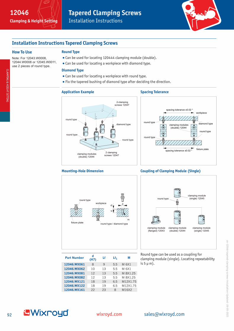
Installation Instructions Tapered Clamping Screws
Round Type
•Can be used for locating 120444 clamping module (double).
•Can be used for locating a workpiece with diamond type.
Diamond Type
•Can be used for locating a workpiece with round type.
•Fix the tapered bushing of diamond type after deciding the direction.
How To Use
Note: For 12043.W0008,
12044.W0008 or 12045.W0011,
use 2 pieces of round type.
Application Example
ov-1
20
46
-tapered
-clamp
ing
-screws-in
stallation
-Up
dated
-26
-05
-20
21
2-clamping
screws 12047
2 clamping
screws 12047
diamond type
round type
clamping modules
(double) 12044
round type
round type
diamond typeround type
spacing tolerance ±0.02 *fixture plate
round type
round type
clamping modules
(double) 12044
workpiece
spacing tolerance ±0.02 *
Mounting-Hole Dimension
fixture plate
round type
lf�
lf
d
m
workpiece
round type / diamond type
clamping module
(flanged) 12043
clamping module
(double) 12044
clamping module
(single) 12045
clamping module
(single) 12045round type
Spacing Tolerance
Coupling of Clamping Module (Single)
Part Numberd
(H7)Lf Lf1 M
12046.WX061 8 9 5.5 M 6X1
12046.WX062 10 13 5.5 M 6X1
12046.WX081 12 13 5.5 M 8X1.25
12046.WX082 12 13 5.5 M 8X1.25
12046.WX121 18 19 6.5 M12X1.75
12046.WX122 18 19 6.5 M12X1.75
12046.WX161 22 23 8 M16X2
Round type can be used as a coupling for clamping module (single). Locating repeatability is 5 µ m).
CLAM
PING
& H
EIGH
T SETTING
92 wixroyd.com [email protected]
Installation Instructions
Tapered Clamping Screws12046Clamping & Height Setting

Tapered Clamping Screwsfloating
12047
wixroyd.comCreated 2022-01-06
Material
Bushing: steel (C45E), black oxide
finish, precision ground.
Technical Notes
Can be used to couple double
clamping modules (see part
no.12044) together for greater
height.
Locating repeatability ± 0,2mm.
Order No. Size Type
Suitabl
e clam
ping
module
size
d1
d2
d3
d4
l1
l2
A/F Xg
12047.W0061 8 Floating 8 11 8 4,8 M 6x1,00 8 10,0 3 5
12047.W0062 11 Floating 11 15 11 6,5 M 6x1,00 9 16,5 3 13
12047.W0081 11 Floating 11 15 11 6,5 M 8x1,25 12 16,5 3 16
12047.W0082 16 Floating 16 24 16 9,5 M 8x1,25 12 25,0 5 46
12047.W0121 16 Floating 16 24 16 9,5 M12x1,75 18 25,0 5 57
12047.W0122 21 Floating 21 31 21 13,0 M12x1,75 18 33,0 6 108
12047.W0161 21 Floating 21 31 21 13,0 M16x2,01 22 33,0 6 125

Tapered Clamping Screws - Doublefloating
12047
wixroyd.comCreated 2022-01-06
Material
Bushing: steel (C45E), black oxide
finish, precision ground.
Technical Notes
Can be used to couple double
clamping modules (see part
no.12044) together for greater
height.
Locating repeatability ± 0,2mm.
Order No. Size Type
Suitable
clamping
module
12044
d1
d2
d3
l1
l2
Xg
12047.W0011 11 Floating 11 15,5 11 6,5 33 16,5 24
12047.W0016 16 Floating 16 24,5 16 9,5 50 25,0 85
12047.W0021 21 Floating 21 31,5 21 13,0 66 33,0 190

Locating Bushfor single clamping module 12045
12048
wixroyd.comCreated 2022-01-06
Material
Steel (SK95), tempered, black oxide
finish, precision ground.
Technical Notes
Can be used to increase the accuracy
of single clamping module (see part
no. 12045) location on the fixture
plate.
Can achieve clamping module
locating repeatability of up to
0,04mm.
Order No. Size
Suitable
clamping
module 12045
d1
d2
tol. h6h
1X
g
12048.W0008 8 8 6,0 8 11 2
12048.W0011 11 11 8,5 12 15 7
12048.W0016 16 16 12,5 18 22 22
12048.W0021 21 21 16,5 22 28 35

Tapered Locating Bushesfor single clamping module - flanged 12043
12048
wixroyd.comCreated 2022-01-06
Material
Steel (C45E), tempered, black oxide
finish, precision ground (precision
type only)
Technical Notes
Can be used to increase the accuracy
of flanged single clamping module
(see part no. 12043) location on the
fixture plate.
Can achieve clamping module
locating repeatability of up to 5
microns (precision type), or 0,1mm
(standard type).
Only the precision type is precision
ground for increased locating
accuracy.
Order No. Size Type
Suitable
clampin
g
module
12043
Standar
d
d1
-0,02
-0,05
Precisio
n
d1
tol. g6
d2
d3
h1
h2
Xg
12048.W0108 8 Standard 8 8 - 11,5 M 6x1,00 4 5,0 4
12048.W0111 11 Standard 11 12 - 15.5 M 8x1,25 5 5,0 8
12048.W0116 16 Standard 16 18 - 24,5 M12x1,75 8 6,0 27
12048.W0121 21 Standard 21 22 - 31,5 M16x2,00 10 7,5 51
12048.W0208 8 Precision 8 - 8 11,5 M 6x1,00 4 5,0 4
12048.W0211 11 Precision 11 - 12 15.5 M 8x1,25 5 5,0 8
12048.W0216 16 Precision 16 - 18 24,5 M12x1,75 8 6,0 27
12048.W0221 21 Precision 21 - 22 31,5 M16x2,00 10 7,5 51

Hook Moduleflanged
12049
wixroyd.comCreated 2022-01-06
Material
Steel (AISI 4140), induction
hardened, black oxide finish,
precision ground.
Technical Notes
For suitable clamping screws see
part no.s 12049.W0212 - .W0224.
For permissible cutting forces and
corresponding workpiece weights
when using the clamping module
system, see technical pages.
Diagram shown is for right hand
version, left hand version only
varies by location of locking screw
A/F which is on the left hand side of
module rather than right.
Order No. Type Size l1
h1
±0,0
1
h2
h3
h4
h5
d1
d2
d3
d4
w1
w2
A/F
Max.
clam
ping
forc
e
kN.
Max.
scre
w to
rque
Nm.
Xg
12049.W0012 Right 12 50 40 22 18 5 13 34 46 20 M 8 70 40 4 8 8 400
12049.W0019 Right 19 75 63 35 28 8 20 52 69 30 M12 100 60 6 15 22 1400
12049.W0024 Right 24 100 80 44 36 10 26 70 93 40 M16 140 80 8 25 50 3200
12049.W0112 Left 12 50 40 22 18 5 13 34 46 20 M 8 70 40 4 8 8 400
12049.W0119 Left 16 75 63 35 28 8 20 52 69 30 M12 100 60 6 15 22 1400
12049.W0124 Left 24 100 80 44 36 10 26 70 93 40 M16 140 80 8 25 50 3200

Tapered Clamping Screws - Plainprecision
12049
wixroyd.comCreated 2022-01-06
Material
Bushing: steel (C45E), black oxide
finish, precision ground.
Screw: steel (SCM 435), tempered,
black oxide finish.
O-ring: nitrile rubber.
Technical Notes
For suitable clamping modules see
part no.12049.W0012 - .W0124.
Order No. Size TypeO-ring
size
Suit
able
cla
mpi
ng
mod
ule
size
d1
tol.
g6
d2
d3
l1
l2
l3
w1
w2
Xg
12049.W0212 12 Precision SS050 (CS1 I/D 5,0) 12 12 15,5 M 8x1,25 17 13,0 5,0 12 15,0 22
12049.W0219 19 Precision S8 (CS1,5 I/D 7,5) 19 18 24,5 M12x1,75 24 21,5 6,0 19 23,5 81
12049.W0224 24 Precision S12 (CS 1,5 I/D 11,5) 24 22 31,5 M16x2,00 30 27,0 7,5 24 30,0 170

Tapered Clamping Screws - Hookprecision
12049
wixroyd.comCreated 2022-01-06
Material
Bushing: steel (C45E), black oxide
finish, precision ground.
Screw: steel (SCM 435), tempered,
black oxide finish.
O-ring: nitrile rubber.
Technical Notes
For suitable clamping modules see
part no. 12049.1.
Order No. Size TypeO-ring
size
Suit
able
cla
mpi
ng
mod
ule
size
d1
tol.
g6
d2
d3
l1
l2
l3
w1
w2
Xg
12049.W0312 12 Precision SS050 (CS1 I/D 5,0) 12 12 15,5 M 8x1,25 17 25 5,0 12 15,0 30
12049.W0319 19 Precision S8 (CS1,5 I/D 7,5) 19 18 24,5 M12x1,75 24 40 6,0 19 23,5 115
12049.W0324 24 Precision S12 (CS 1,5 I/D 11,5) 24 22 31,5 M16x2,00 30 51 7,5 24 30,0 235
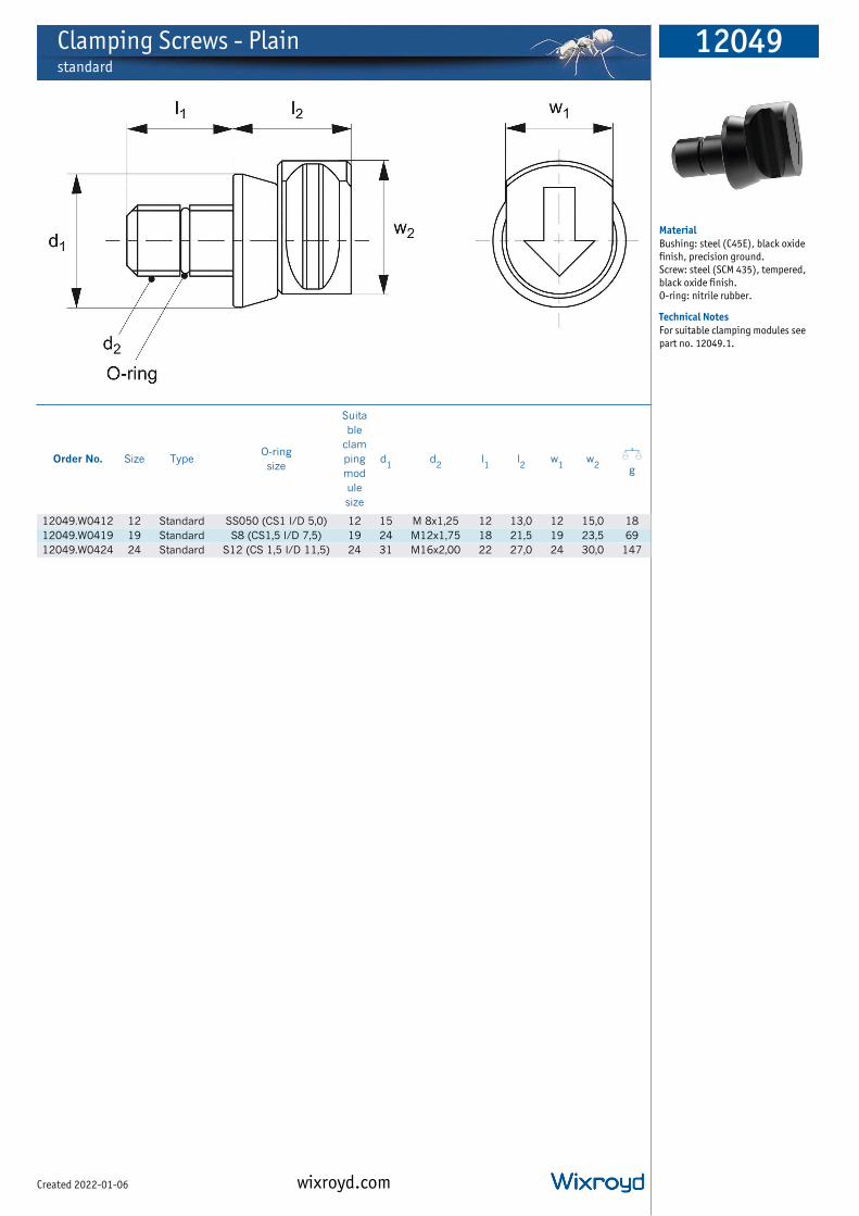
Clamping Screws - Plainstandard
12049
wixroyd.comCreated 2022-01-06
Material
Bushing: steel (C45E), black oxide
finish, precision ground.
Screw: steel (SCM 435), tempered,
black oxide finish.
O-ring: nitrile rubber.
Technical Notes
For suitable clamping modules see
part no. 12049.1.
Order No. Size TypeO-ring
size
Suita
ble
clam
ping
mod
ule
size
d1
d2
l1
l2
w1
w2
Xg
12049.W0412 12 Standard SS050 (CS1 I/D 5,0) 12 15 M 8x1,25 12 13,0 12 15,0 18
12049.W0419 19 Standard S8 (CS1,5 I/D 7,5) 19 24 M12x1,75 18 21,5 19 23,5 69
12049.W0424 24 Standard S12 (CS 1,5 I/D 11,5) 24 31 M16x2,00 22 27,0 24 30,0 147

Clamping Screws - Hookstandard
12049
wixroyd.comCreated 2022-01-06
Material
Bushing: C45E. Black oxide finish,
precision ground.
Screw: steel (SCM 435), tempered,
black oxide finish.
O-ring: nitrile rubber.
Technical Notes
For suitable clamping modules see
part no. 12049.1.
Order No. Size TypeO-ring
size
Suita
ble
clam
ping
mod
ule
size
d1
d2
l1
l2
l3
w1
w2
Xg
12049.W0512 12 Standard SS050 (CS1 I/D 5,0) 12 15 M 8x1,25 12 25 5,0 12 15,0 26
12049.W0519 19 Standard S8 (CS1,5 I/D 7,5) 19 24 M12x1,75 18 40 6,0 19 23,5 103
12049.W0524 24 Standard S12 (CS 1,5 I/D 11,5) 24 31 M16x2,00 22 51 7,5 24 30,0 213

How to Use
•Use 12048.W02XX tapered bushing (accurate) for precice locating.
•Use 12048.W01XX tapered bushing (standard) for rough locating.
Mounting Hole Dimensiontapered bushing (accurate / standard)
12048.W02xx / 12048.W01XX
hex. socket-head cap screws
fixture plate
h1
d2 (x2)l1
d1
Part Numberd1
(H7)l1 d2 h1
12049.W0012 12 5.5 M 8X1,25 50
12049.W0112 12 5.5 M 8X1,25 50
12049.W0019 18 6.5 M12X1,75 75
12049.W0119 18 6.5 M12X1,75 75
12049.W0024 22 8 M16X2 100
12049.W0124 22 8 M16X2 100
* The tolerance of dimension ‘d1 ‘ for tapered bushings (standard) should be
Spacing Tolerancetapered clamping screw
(hook) 12049.W03xxtapered bushing
(accurate) 12048.W02xx
tapered bushing
(accurate) 12048.W02xx
tapered clamping
screw 12049.W02xxfixture
plate
spacing tolerance
±0.02*
Spacing tolerance should be ±0,02 for tapered bushings (accurate).
*Spacing tolerance should be ± 0,1 for tapered bushings (standard).
Layout
workpiece
12049.W01XX
12049.W00XX
right
left
Use 12049.W00XX for tightening from right side, 12049.W01XX for left side.
ov-1
20
49
-clamp
ing
-mo
du
les-installatio
n-U
pd
ated -1
3-07
-20
21
CLAM
PING
& H
EIGH
T SETTING
96 wixroyd.com [email protected]
12048 -12049Clamping & Height Setting
Clamping Modules & Tapered BushingsInstallation Instructions

ov-1
20
49
-clamp
ing
-mo
du
les-vertically-mo
un
ted-fi
xtures-U
pd
ated -2
6-0
5-2
02
1
Clamping Modules for Vertically Mounted Fixtures
Application Example
Note: Do not remove the hoists
until the unit fully clamped.
Firstly tighten the hook type clamping screw.
The first one becomes reference.
The products should be positioned as shown below.
12049.W03xx, 12049.W01xx and 12049.W02xx tapered clamping screws and 12048.W02xx tapered bushings (accurate) should be used together, and 12049.W04xx and 12049.W05xx clamping screws and 12049.W01xx tapered bushings (standard) should also be used together.
Example 1
clamping screws
12049.W04xx
clamping screws
12049.W04xx, 12049.W05xx
tapered bushings
(accurate) 12048.W02xx
tapered clamping screws
(hook) 12049.W03xxtapered clamping screws
(hook) 12049.W03xx
tapered bushings
(standard) 12048.W01xx
Example 2
tapered bushings
(accurate)
12048.W02xx
tapered clamping
screws (hook) 12049.W03xx
tapered clamping screws
(hook) 12049.W03xx
tapered clamping screws
12049.W01xx, 12049.W02xx, 12049.W03xx
Example 3
tapered bushings
(accurate) 12048.W02xx
tapered clamping
screws (hook) 12049.W03xx
tapered clamping
screws (hook) 12049.W03xx
CLAM
PING
& H
EIGH
T SETTING
93 wixroyd.com [email protected]
Clamping Modules for Vertically Mounted Fixtures
12049Clamping & Height Setting

ov-1
20
49
-clamp
ing
-mo
du
les-ang
le-mo
un
ted-fi
xtures-U
pd
ated -1
2-07
-20
21
•Each clamping screw has commercially available O-ring to prevent rotation and keep the direction of arrow marking.
•O-ring should be replaced by the customer when it is worn.
•Tapered clamping screws can be used for locating fixture plate or workpiece.
•Clamping screws can be used for just clamping.
Mounting Hole Dimension
12049.W03xx
fixture plate / workpiece
12049.W02xx
l1l2
d1
d2
Clamping Modules for Angle Mounted Fixtures
Part Number d1* l1 l2 d2
12049.W0212 12 13 5.5 M 8X1,25
12049.W0312 12 13 5.5 M 8X1,25
12049.W0219 18 19 6.5 M12X1,75
12049.W0319 18 19 6.5 M12X1,75
12049.W0224 22 23 8 M16X2,00
12049.W0324 22 23 8 M16X2,00
* The hole tolerance should always be when tapered clamping screws are always mounted on the fixture plate. Ficture plate and tapered bushing fit tightly and keep repeatability without chip incursion.
The hole tolerance should be H7 when mounting on workpiece. Tapered bushing can be easily mounted/ removed.
Spacing Tolerancetapered clamping screw
(hook) 12049.W03xxtapered bushing
(accurate) 12048.W02xx
tapered bushing
(accurate) 12048.W02xx
tapered clamping
screw 12049.W02xxfixture
plate
spacing tolerance
±0.02**
Installation
clamping screw
fixture plate / workpiece
gapclamping screw
1. Fully tighten the clamping screw
on fixture plate or workpiece.
2. Turn the screw counter
clockwise within one turn until the
arrow marking points downward.
(There is a gap between clamping
screw and tapered bushing)
3. Install the clamping screws
into the clamping modules.
Spacing tolerance should be ±0,02 for tapered clamping screws.
**Spacing tolerance should be ± 0,2 for clamping screws.
CLAM
PING
& H
EIGH
T SETTING
94 wixroyd.com [email protected]
Clamping & Height Setting
Clamping Modules forAngle Mounting Fixtures

Ensure the cutting force and workpiece weight are within the allowable level.
Permissible Cutting Force & Workpiece Weight of Clamping Modules (Hook)
2 Modules p1
w1 (kg)
F1 (kN)
hmachining area / center
p2
w2 (kg)
F2 (kN)
machining area / centerh
Part Number
Permissible Cutting Force Permissible Workpiece Weight
F1
(kN)
F2
(kN)
Max
(kN)
w1
(kN)
w2
(kN)
Max
(kg)
12049.W0012 / W0112 (0,24p1 + 432)/h 240/h 3,2 240 x100/h (0,24p2 + 432) x100/h 320
12049.W0019 / W0119 (0,50p1 + 900)/h 500/h 6 500 x100/h (0,50p2 + 900) x100/h 600
12049.W0024 / W0124 (1,00p1 +1800)/h 1000/h 10 1000x100/h 1,00p2 + 1880) x100/h 1000
4 Modulesw1 (kg)
F1 (kN)
p1
p2
hmachining area / center
ov-1
20
49
-clamp
ing
-mo
du
les-cuttin
g fo
rce-wo
rkpiece-w
eigh
t-Up
dated
-13
-07-2
02
1
Part Number
Permissible Cutting Force Permissible Workpiece Weight
F1
(kN)
Max
(kN)
w1
(kN)
Max
(kg)
12049.W0012 / W0112 2x(0,24p1 + 432)/h 6.4 2x(0,24p2 + 432) x100/h 640
12049.W0019 / W0119 2x(0,50p1 + 900)/h 12 2x(0,50p2 + 900) x100/h 1200
12049.W0024 / W0124 2x(1,00p1 +1800)/h 20 2x(1,00p2 + 1880) x100/h 2000
Calculation Example
Note: Heavy cutting force in
the open direction may cause
workpiece move.
Note: Heavy cutting force in
the open direction may cause
workpiece move.
w1 (kg)
F1 (kN)
p1 = 500
p2 = 300
h = 200machining area / center
• 4 pieces of 12049.W0019 (height 63mm)
• Pitch: p1 = 500mm p2 = 300mm
• Workpiece center: h = 200mm
• F1 direction cutting force: 5kN
• Workpiece weight: 600kg
<Allowable Workpiece Weight W1>W1 = 2x(0.5X p2 + 900)X100/H
= 2x(0.5X 300 + 900)X100/200
= 1050kg
*) Workpiece weight 600kg is within allowable value (1050kg).
<Allowable Cutting Force F1>
F1 = 2x(0.5X p1 + 900)/H
= 2x(0.5X 500 + 900)/200 = 11.5kN
*) Cutting force 5kN is within allowable value (11.5kN).
CLAM
PING
& H
EIGH
T SETTING
95 wixroyd.com [email protected]
Permissible Cutting Force & Workpiece Weights
Clamping Modules12049Clamping & Height Setting

ID Xpansion Clamps - Machinablefor clamping internal bores
12051
wixroyd.comCreated 2022-01-06
Material
Body: mild steel.
Tapered screw: steel, heat-treated
(coated to prevent seizing).
12051.W0250: aluminium
(7075-T6) .
Technical Notes
For holding parts on an inside
diameter, for high density
machining on vertical or horizontal
mills.
Diameter can range from 4,1mm to
a maximum of 250mm!
This product can also be used as an
expanding mandrel on a lathe.
Tighten with hex key or hydraulic
pull cylinders.
The flange diameter of the base is
held to a close tolerance for
precision location in a machined
pocket.
Tips
"d3" is the minimum diameter the
"d2" dimension can be machined or
turned down to.
Mounting screws included.
Important Notes
Installation for clamps
12051.W0010 to .W0051.
1. Expand clamp 0,1mm over the
relaxed diameter and machine to fit
workpiece bore (on lathe or mill).
If using the clamp on a lathe then
use the nut provided to tighten the
taper screw. This nut is only used to
machine the clamp.
2. Machine a pocket in the fixture
for the close tolerance "d1"
dimension, and drill and tap
mounting holes "d4".
3. Drill and tap a hole "d5" in the
centre of the pocket for the tapered
screw.
4. A recessed dowel pin can be
installed into the flange for extra
rigidity if required.
5. Range of expansion 0,13 -
0,64mm depending on clamp size.
Installation for clamps
12051.W0077 to .W0250.
1. Insert machining locking ring
(provided), tighten taper screw and
machine clamp to required bore
size.
2. Release taper screw and remove
locking ring prior to any machining
of workpieces.
Note: 12051.W0175 and W0250
have four mounting holes on PCD as
dimension "d4".
Order No. h1
h2
h3
h4
d1
+,000
-,050
Stock
d2
Xg
12051.W0010 10,7 7,6 6,1 3,0 20,0 7,4 23
12051.W0012 21,8 16,0 15,0 5,9 29,7 12,4 59
12051.W0014 24,9 19,0 15,0 5,9 31,5 14,2 109
12051.W0020 24,9 19,0 15,0 5,9 37,5 20,0 204
12051.W0027 28,6 22,2 17,5 6,4 50,0 27,0 213
12051.W0035 31,8 25,4 20,6 6,4 56,0 35,3 317
12051.W0042 39,6 31,8 27,0 7,9 69,5 42,0 593
12051.W0051 39,6 31,8 27,0 7,9 75,5 51,5 775
12051.W0077 45,5 37,6 32,3 7,9 107,5 77,7 1826
12051.W0103 45,5 37,6 32,3 7,9 132,9 103,0 2954
12051.W0175 45,5 37,6 32,3 7,9 132,9 175,0 6795
12051.W0250 45,5 37,6 32,3 7,9 152,4 250,2 5436
Order No.d
3min.
d4
d5
r1
on PCD
Torque
to max.
Nm.
Holding
force kN.
Max.
expansion
from
relaxed dia.
12051.W0010 4,1 M 2 4,1 M 2 at 13,7 0,7 1,1 0,1
12051.W0012 7,1 M 4 7,2 M 3 at 21,0 5,0 4,2 0,3
12051.W0014 12,2 M 6 11,2 M 3 at 23,1 17,0 8,4 0,3
12051.W0020 13,5 M 8 13,2 M 3 at 29,0 34,0 11,1 0,4
12051.W0027 18,0 M10 16,3 M 4 at 39,4 60,0 20,0 0,4
12051.W0035 23,0 M12 20,3 M 4 at 45,5 150,0 26,2 0,4
12051.W0042 29,3 M16 21,4 M 5 at 55,9 280,0 44,5 0,4
12051.W0051 29,3 M16 21,4 M 5 at 63,9 280,0 44,5 0,4
12051.W0077 29,3 M16 19,3 M 6 at 92,6 280,0 44,5 0,4
12051.W0103 29,3 M16 19,3 M 6 at 118,1 280,0 44,5 0,4
12051.W0175 29,3 M16 19,3 M 6 at 118,1 280,0 44,5 0,5
12051.W0250 29,3 M16 19,3 M 6 at 133,4 170,0 26,0 1,0

ID Xpansion Clamps - Machinablefor clamping internal bores
12051
wixroyd.comCreated 2022-01-06
Material
Body: mild steel.
Tapered screw: steel, heat-treated
(coated to prevent seizing).
12051.W0250: aluminium
(7075-T6) .
Technical Notes
For holding parts on an inside
diameter, for high density
machining on vertical or horizontal
mills.
Diameter can range from 4,1mm to
a maximum of 250mm!
This product can also be used as an
expanding mandrel on a lathe.
Tighten with hex key or hydraulic
pull cylinders.
The flange diameter of the base is
held to a close tolerance for
precision location in a machined
pocket.
Tips
"d3" is the minimum diameter the
"d2" dimension can be machined or
turned down to.
Mounting screws included.
Important Notes
Installation for clamps
12051.W0010 to .W0051.
1. Expand clamp 0,1mm over the
relaxed diameter and machine to fit
workpiece bore (on lathe or mill).
If using the clamp on a lathe then
use the nut provided to tighten the
taper screw. This nut is only used to
machine the clamp.
2. Machine a pocket in the fixture
for the close tolerance "d1"
dimension, and drill and tap
mounting holes "d4".
3. Drill and tap a hole "d5" in the
centre of the pocket for the tapered
screw.
4. A recessed dowel pin can be
installed into the flange for extra
rigidity if required.
5. Range of expansion 0,13 -
0,64mm depending on clamp size.
Installation for clamps
12051.W0077 to .W0250.
1. Insert machining locking ring
(provided), tighten taper screw and
machine clamp to required bore
size.
2. Release taper screw and remove
locking ring prior to any machining
of workpieces.
Note: 12051.W0175 and W0250
have four mounting holes on PCD as
dimension "d4".

Xpansion Clamps - Side-Loc 12052
wixroyd.comCreated 2022-01-06
Material
Mild steel body, with heat-treated
tapered screw (coated to prevent
seizing).
Technical Notes
For clamping blind holes from
17,8mm to 53mm.
Actuated from the side. The cam
shaft and the plunger expand the
clamp.
Tips
Actuated by turning a socket head
cam shaft on the side which moves a
tapered plunger to expand the
clamp.
Two versions: one for milling (type:
mill) and one for turning (type:
lathe).
"d2" is the minimum diameter the
"d1" dimension can be machined or
turned down to.
Mounting screws included.
Important Notes
Installation Instructions:
ID Xpansion Clamps are designed for
clamping on the inside diameter of
a component. To install correctly,
please follow the following
guidelines:
1. Expand the clamp approximately
0,1mm over its relaxed diameter
and machine diameter d1
to suit
bore of the workpiece, either on
lathe or mill.
2. If machining the clamp on a lathe
use the nut provided, on the back of
the clamp, to tighten the tapered
screw. This nut is used only to
machine the clamp.
3. Machine a pocket in the fixture to
the close tolerance of dimension w1,
and depth h4.
4. Drill and tap mounting holes as
per dimension r1.
5. In the centre of the pocket, drill
and tap a hole to dimension d3
for
the tapered screw.
6. For additional rigidity, a recessed
dowel pin may be installed into the
flange, if required.
Order No. Type
w1
+,000
-,05
h1
h2
h3
h4
h5
d1
d2
min.d
3
r1
on PCDA/F
Tor
que
to
max
.
Nm.
Hol
ding
forc
e
kN.
Xg
12052.W0828 Mill 50,0 41,3 22,2 17,5 19,0 - 28,7 17,8 - Ø39,4 (M 4) M 6 66 20 340,2
12052.W0853 Lathe - 44,4 25,4 21,3 19,0 44,4 53,3 17,8 25 - M 6 66 20 -

ID Xpansion Clamp,
machinableThe ID Xpansion Clamp is
the ideal way to hold multiple
parts on an inside diameter
for machining on your VMC
or HMC.
ID Xpansion Clamps can be used to hold components
with complex internal shapes, not just plain bores.
These machinable clamps are produced in 10 sizes and
can hold internal diameters from 21,8 to 45,5mm.
• Low profile and ideal for secondary operations on
lathe parts.
• Easily machined to size on lathe or mill.
• Excellent for palletised setups.
• Allow more parts per workcube or fixture plates.
• Body made of mild steel for machinability.
• Tighten with hex key, hydraulic pull cylinders
or speed block.
Wixroyd introduces a new style clamp to its range of
ID-Xpansion clamps, the Side-Loc Xpansion Clamp.
Actuated by turning a socket head cam shaft on the
side, it is ideal for clamping on blind internal diameters.
The locking ring provides an accurate preset diameter
and rigidity for machining. Like our original ID Xpansion
clamps, the Side-Loc Xpansion Clamp has the dead
length feature which is critical for close tolerance
dimensions.
Designed in two styles, one for milling operations and
one for lathe applications; the mill Side-Loc Xpansion
Clamp can be machined from 28.4 to 18mm and the
lathe version from 53 to 18mm.
Clamp activated from the side with a standard hex key.
Side-Loc Xpansion Clamp, when the component
obstructs the clamps tapered screw.
wixroyd.com
12051ID Expansion Clampand side-loc xpansion clamp
Side-Loc Xpansion Clamp machinable
12052

Manual Actuatorsfor ID Xpansion clamps
12054
wixroyd.comCreated 2022-01-06
Material
Steel.
Technical Notes
Versatile manual actuators when
combined with our ID Xpansion
clamps 12051. Enables clamping of
smaller internal diameters and blind
holes. Mount corresponding ID
Xpansion clamp.
Mill type actuator is adaptable and
can be used on both vertical and
horizontal planes. Once installed
the clamp can be actuated with use
of an actuator screw (6mm A/F).
Tips
Order ID Xpansion clamp 12051
separately.
Important Notes
Manual actuators for mills and
lathes.
Introducing another new and
innovative workholding system.
Specifically designed to clamp on
blind internal diameters smaller
than our Side-Loc clamps would
allow.
We took the design a step further,
by increasing the functionality to
clamp smaller inside diameters. For
the mill version the option of
holding the workpiece in a vertical
or horizontal plane. By simply
mounting our standard ID Xpansion
clamps on these manual actuators,
or using another style clamp that
has a "straight draw", you can now
perform operations that previously
required extensive
hydraulic/pneumatic cylinders.
Mill mounted manual actuators for
ID Xpansion clamps are suitable for
holding workpieces of very small
blind internal diameters.
Order No. Type
Suitable
for ID
Xpansion
clamp
l1
w1
d1
d2
ford
3d
4h
1h
2A/F
12054.W0002 Mill .W0010 57,2 57,2 M 2 M 6 - - 57,2 - 6
12054.W0004 Mill .W0012 57,2 57,2 M 4 M 6 - - 57,2 - 6
12054.W0006 Mill .W0014 57,2 57,2 M 6 M 6 - - 57,2 - 6
12054.W0008 Mill .W0020 57,2 57,2 M 8 M 6 - - 57,2 - 6
12054.W0010 Mill .W0027 57,2 57,2 M10 M 6 - - 57,2 - 6
12054.W0012 Mill .W0035 57,2 57,2 M12 M 6 - - 57,2 - 6
12054.W0102 Lathe .W0010 - - M 2 - 25,0 56,9 38 25,4 6
12054.W0104 Lathe .W0012 - - M 4 - 25,0 56,9 38 25,4 6
12054.W0106 Lathe .W0014 - - M 6 - 25,0 56,9 38 25,4 6
12054.W0108 Lathe .W0020 - - M 8 - 25,0 56,9 38 25,4 6
12054.W0110 Lathe .W0027 - - M10 - 25,0 56,9 38 25,4 6
12054.W0112 Lathe .W0035 - - M12 - 25,0 56,9 38 25,4 6
12054.W0550 Spare - Actuator Screw

Manual Actuatorsfor ID Xpansion clamps
12054
wixroyd.comCreated 2022-01-06
Material
Steel.
Technical Notes
Versatile manual actuators when
combined with our ID Xpansion
clamps 12051. Enables clamping of
smaller internal diameters and blind
holes. Mount corresponding ID
Xpansion clamp.
Mill type actuator is adaptable and
can be used on both vertical and
horizontal planes. Once installed
the clamp can be actuated with use
of an actuator screw (6mm A/F).
Tips
Order ID Xpansion clamp 12051
separately.
Important Notes
Manual actuators for mills and
lathes.
Introducing another new and
innovative workholding system.
Specifically designed to clamp on
blind internal diameters smaller
than our Side-Loc clamps would
allow.
We took the design a step further,
by increasing the functionality to
clamp smaller inside diameters. For
the mill version the option of
holding the workpiece in a vertical
or horizontal plane. By simply
mounting our standard ID Xpansion
clamps on these manual actuators,
or using another style clamp that
has a "straight draw", you can now
perform operations that previously
required extensive
hydraulic/pneumatic cylinders.
Mill mounted manual actuators for
ID Xpansion clamps are suitable for
holding workpieces of very small
blind internal diameters.

Flexible Form Clamping Baseuse with flexible form holding jaws 12056 or 12057
12055
wixroyd.comCreated 2022-01-06
Material
Body: steel.
Technical Notes
For use with jaws part no.s 12056
and 12057 for clamping on the
external of a component (jaw no.
12056) or for clamping on internal
bore of a component (jaw no.
12057). Order jaws separately.
Supplied with one diamond locating
pin to suit.
Can achieve part location
repeatability of ± 0,03 and jaw
repeatability of ± 0,02. Max.
clamping stroke of 0,3mm diameter.
To prevent damage or deformation,
do not tighten the cam cylinder
without a holding jaw installed.
Order No. Type Size d1
d2
tol.
G6
d3
d4
d5
h1
±0,
01
h2
h3
h4
Stro
ke
s1
±0,
02
A/F
Tor
que
to
max
.
Nm.
Exter
nal
form
no.
1205
6 cla
mpin
g
force
kN.
Intern
al
form
no.
1205
7 cla
mpin
g
force
kN.
Xg
12055.W0065 Base 65 65 28 42 M 8x1,25 M 6 35 27 12 12 22 8 15 4,5 4,5 800
12055.W0090 Base 90 90 42 60 M10x1,5 M 8 40 30 14 14 30 8 25 7,0 7,0 1700
12055.W0120 Base 120 120 55 80 M10x1,5 M10 45 33 16 18 43 10 40 10,0 10,0 3500
12055.W0160 Base 160 160 63 110 M12x1,75 M12 50 36 18 24 60 10 40 12,0 10,0 7100

Lathe Mounting Adaptorfor flexible form holding clamp 12055
12055
wixroyd.comCreated 2022-01-06
Material
Steel, hardened and blackened.
Technical Notes
Adaptor to enable mounting of
flexible form holding clamp (part
no. 12055) to a lathe.
Order No. Size
Suitable
for
clampin
g base
12055
d1
d2
d3
d4
d5
h1
h2
h3
Xg
12055.W1065 65 4,5 80 28 63 42 M 6x1,00 38 8 13 910
12055.W1090 90 7,0 100 42 80 60 M 8x1,25 43 8 15 1600
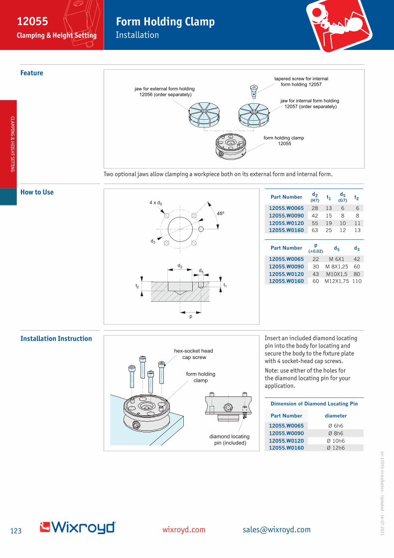
Featuretapered screw for internal
form holding 12057
jaw for internal form holding
12057 (order separately)
form holding clamp
12055
jaw for external form holding
12056 (order separately)
How to Use
45º
d3
4 x d5
d2d5
t1t2
p
Part Numberd2
(H7)t1
d5 (G7)
t2
12055.W0065 28 13 6 6
12055.W0090 42 15 8 8
12055.W0120 55 19 10 11
12055.W0160 63 25 12 13
Part Numberp
(±0,02)d5 d3
12055.W0065 22 M 6X1 42
12055.W0090 30 M 8X1,25 60
12055.W0120 43 M10X1,5 80
12055.W0160 60 M12X1,75 110
Installation Instruction
diamond locating
pin (included)
form holding
clamp
hex-socket head
cap screw
Dimension of Diamond Locating Pin
Part Number diameter
12055.W0065 Ø 6h6
12055.W0090 Ø 8h6
12055.W0120 Ø 10h6
12055.W0160 Ø 12h6
Insert an included diamond locating
pin into the body for locating and
secure the body to the fixture plate
with 4 socket-head cap screws.
Note: use either of the holes for
the diamond locating pin for your
application.
Two optional jaws allow clamping a workpiece both on its external form and internal form.
CLA
MP
ING
& H
EIGH
T SETTIN
G
123 wixroyd.com [email protected]
12055Clamping & Height Setting Installation
Form Holding Clampo
v-12
05
5-in
stallation
- Up
dated
- 16-0
7-2
02
1

Versatile holding of complexed shaped workpieces on either the external or internal form - quick,
secure, versatile.
Single clamping base designed to accept either external form or neutral form clamping jaws, fully
flexible holding of custom forces.
1 2
3
1 Prepare Jaw 2 Machine Jaw 3 Mount Workpiece 4 Tighten Cam Cylinder
ExternalParts 12055, 12056
Internal Parts 12055, 12057
Clamping Low Profile Workpiece
Parts 12055 and 10257. 8 jaw
clamping sections distribute
clamping force to workpiece
for deformation prevention.
Note to control the tightening
torque using adequate tools in
reference to the data provided
by the performance curve.
Fixture for Temporal Job
Parts 12055 and 10256. Can be
mounted on the existing vise by
attaching the clamp on plate.Internal
Form
External
Form
External Form Jaw - 12056
Internal Form Jaw - 12057
Flexible Form Clamping Base - 12055
1
2
3
CLA
MP
ING
& H
EIG
HT
SET
TIN
GCL
AM
PIN
G &
HEI
GH
T S
ETTI
NG
1250333 207 4497 [email protected]
12055- 12057Clamping & Height Setting
Flexible Form Holding Clampo
v-1
20
55
-12
057
-fle
xib
le-f
orm
-mo
uld
ing
-cla
mp
- U
pd
ated
-20
-07
-20
21

Internal Form Holding Jawsfor flexible form holding clamp no. 12055
12057
wixroyd.comCreated 2022-01-06
Material
Jaws: aluminium (A7075), silver
anodised.
Tapered screw: steel (C45E),
tempered, nickel plated.
Technical Notes
Order jaw and tapered screw
separately.
Tapered screw expands jaw
outwards to hold irregular shaped
workpieces securely.
Offers 0,15mm clamping stroke on
jaw. Ideal for die-cast and extruded
parts.
Used with flexible form clamping
base no. 12055.
Order No. Type Size d1
d2
d3
d4
h1
h2
h3
l1
l2
A/F
Suitable
for
clamping
base
12055
Suitable
for
internal
jaw
12057
Xg
12057.W0065 Jaw 65 65 - - - 28,5 25 10 - - - .W0065 - 200
12057.W0090 Jaw 90 90 - - - 34,5 30 15 - - - .W0095 - 400
12057.W0120 Jaw 120 120 - - - 40,5 35 20 - - - .W0120 - 900
12057.W0160 Jaw 160 160 - - - 46,5 40 25 - - - .W0160 - 1900
12057.W2065 Screw 65 - 22,5 13,2 M 8x1,25 - - - 29 10 6 - .W1065 50
12057.W2090 Screw 90 - 27,0 16,0 M10x1,5 - - - 35 11 8 - W.1090 80
12057.W2120 Screw 120 - 29,0 13,0 M10x1,5 - - - 41 16 8 - W.1120 100
12057.W2160 Screw 160 - 33,0 18,0 M12x1,75 - - - 47 14 10 - W.1160 150

Internal Form Holding Jawsfor flexible form holding clamp no. 12055
12057
wixroyd.comCreated 2022-01-06
Material
Jaws: aluminium (A7075), silver
anodised.
Tapered screw: steel (C45E),
tempered, nickel plated.
Technical Notes
Order jaw and tapered screw
separately.
Tapered screw expands jaw
outwards to hold irregular shaped
workpieces securely.
Offers 0,15mm clamping stroke on
jaw. Ideal for die-cast and extruded
parts.
Used with flexible form clamping
base no. 12055.

cam
cylinder
workpiece
Prepare Jaw for
Mounting
a. Insert O-ring to the groove on top surface of the Flexible Form Holding Clamp 12055.
b. Mount jaw 12057 to clamping base, align with locating pins and fix with tapered screw.
Machine Jaw
2.1 Loosen the clamping bases cam cylinder fully. Measure dimension of the jaw for machining. Tighten the cam cylinder until each jaw section expands a further 0.15mm beyond desired clamping dimensions.
2.2 Machine the jaw to the contours of workpiece. (Do not machine the jaws beyond the machinable depth – see data tables of jaws 12056 and 12057 for dimension.
depth
machin
eable
Load Workpiece After machining of jaw, loosen cam cylinder of clamp base and load workpiece. Tighten the cam cylinder again to clamp.
12057.W0120
12057.W016012057.W0090
12057.W0065
0 5 10 15 20 25 30 35 40
tightening force (N•m)
cla
mpin
g forc
e (
kN
)
10
8
6
4
2
Take note of recommended tightening forces.
Function
1
clamped
unclamped
22
a. Tapered screw fixes jaw to clamping base and expands the jaws in eight directions for ‘pre-holding’ of irregularly-shaped workpieces.
b. Final 0.15mm clamping stroke of the jaw is activated via the cam cylinder to provide final clamping of workpiece on its internal contours.
1 When the cam cylinder is tightened, the tapered screw is pulled down.
2 At the same time the 8 jaw sections expand to clamp the internal form of workpiece.
cam cylinder
round locating pins
o-ring
(furnished with jaw)
12057 jaw
12057-B screw
Note: Do not tighten the cam cylinder without the workpiece set to prevent damage and deformation. Tightening with the torque beyond allowable screw torque will lower the durability of the jaw.
12057-B screw
12057 jaw
O-ring
(furnished with jaw)
round locating pins
cam cylinder
cam
cylinder
workpiece
clamped
unclamped
depth
machin
eable
CLAM
PING
& H
EIGH
T SETTING
126 wixroyd.com [email protected]
12057Clamping & Height Setting
Installation and Machining of Jaw Profile
ov-1
20
57-in
stallation
-and
-mach
inin
g-o
f-jaw-p
rofi
le - Up
dated
- 20
-07-2
02
1
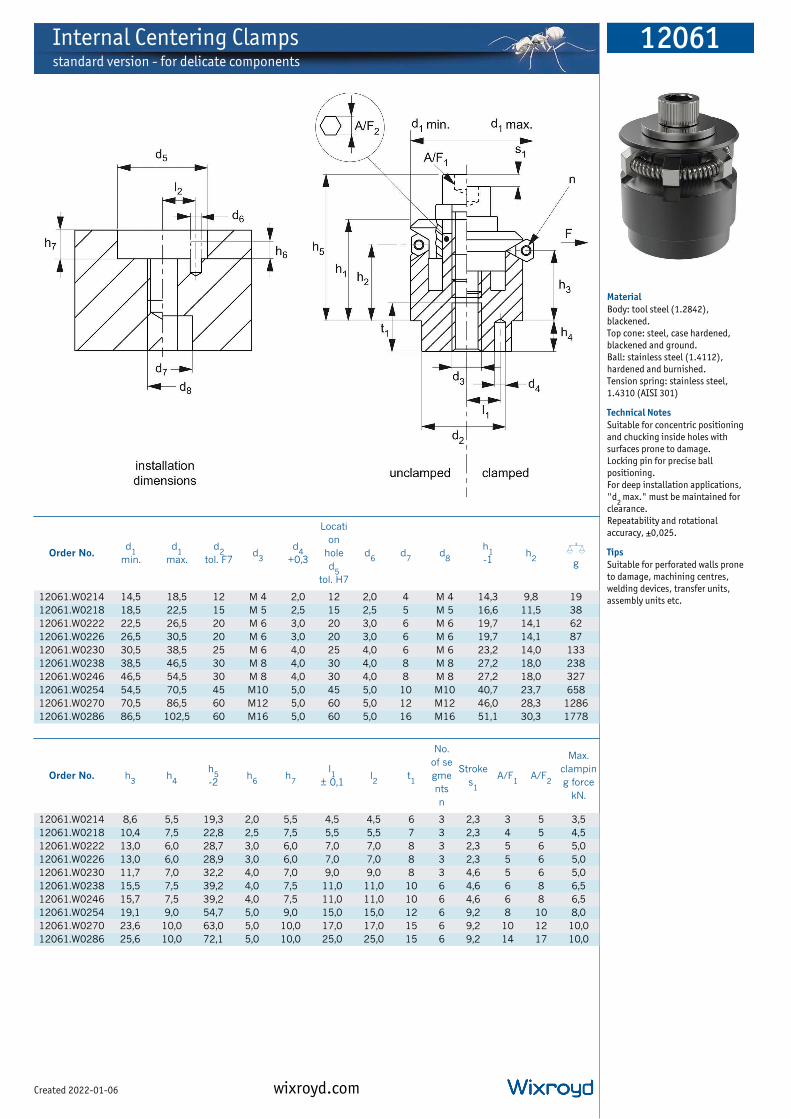
Internal Centering Clampsstandard version - for delicate components
12061
wixroyd.comCreated 2022-01-06
Material
Body: tool steel (1.2842),
blackened.
Top cone: steel, case hardened,
blackened and ground.
Ball: stainless steel (1.4112),
hardened and burnished.
Tension spring: stainless steel,
1.4310 (AISI 301)
Technical Notes
Suitable for concentric positioning
and chucking inside holes with
surfaces prone to damage.
Locking pin for precise ball
positioning.
For deep installation applications,
"d2
max." must be maintained for
clearance.
Repeatability and rotational
accuracy, ±0,025.
Tips
Suitable for perforated walls prone
to damage, machining centres,
welding devices, transfer units,
assembly units etc.
Order No.d
1min.
d1
max.
d2
tol. F7d
3
d4
+0,3
Locati
on
hole
d5
tol. H7
d6
d7
d8
h1
-1h
2X
g
12061.W0214 14,5 18,5 12 M 4 2,0 12 2,0 4 M 4 14,3 9,8 19
12061.W0218 18,5 22,5 15 M 5 2,5 15 2,5 5 M 5 16,6 11,5 38
12061.W0222 22,5 26,5 20 M 6 3,0 20 3,0 6 M 6 19,7 14,1 62
12061.W0226 26,5 30,5 20 M 6 3,0 20 3,0 6 M 6 19,7 14,1 87
12061.W0230 30,5 38,5 25 M 6 4,0 25 4,0 6 M 6 23,2 14,0 133
12061.W0238 38,5 46,5 30 M 8 4,0 30 4,0 8 M 8 27,2 18,0 238
12061.W0246 46,5 54,5 30 M 8 4,0 30 4,0 8 M 8 27,2 18,0 327
12061.W0254 54,5 70,5 45 M10 5,0 45 5,0 10 M10 40,7 23,7 658
12061.W0270 70,5 86,5 60 M12 5,0 60 5,0 12 M12 46,0 28,3 1286
12061.W0286 86,5 102,5 60 M16 5,0 60 5,0 16 M16 51,1 30,3 1778
Order No. h3
h4
h5
-2h
6h
7
l1
± 0,1l2
t1
No.
of se
gme
nts
n
Stroke
s1
A/F1
A/F2
Max.
clampin
g force
kN.
12061.W0214 8,6 5,5 19,3 2,0 5,5 4,5 4,5 6 3 2,3 3 5 3,5
12061.W0218 10,4 7,5 22,8 2,5 7,5 5,5 5,5 7 3 2,3 4 5 4,5
12061.W0222 13,0 6,0 28,7 3,0 6,0 7,0 7,0 8 3 2,3 5 6 5,0
12061.W0226 13,0 6,0 28,9 3,0 6,0 7,0 7,0 8 3 2,3 5 6 5,0
12061.W0230 11,7 7,0 32,2 4,0 7,0 9,0 9,0 8 3 4,6 5 6 5,0
12061.W0238 15,5 7,5 39,2 4,0 7,5 11,0 11,0 10 6 4,6 6 8 6,5
12061.W0246 15,7 7,5 39,2 4,0 7,5 11,0 11,0 10 6 4,6 6 8 6,5
12061.W0254 19,1 9,0 54,7 5,0 9,0 15,0 15,0 12 6 9,2 8 10 8,0
12061.W0270 23,6 10,0 63,0 5,0 10,0 17,0 17,0 15 6 9,2 10 12 10,0
12061.W0286 25,6 10,0 72,1 5,0 10,0 25,0 25,0 15 6 9,2 14 17 10,0
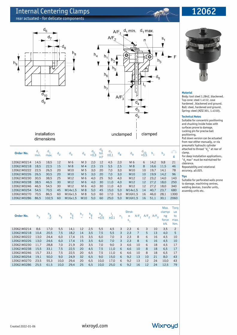
Internal Centering Clampsrear actuated - for delicate components
12062
wixroyd.comCreated 2022-01-06
Material
Body: tool steel 1.2842, blackened.
Top cone: steel 1.4112, case
hardened , blackened and ground.
Ball: steel, hardened and ground.
Spring: steel (AISI 301, 1.4310).
Technical Notes
Suitable for concentric positioning
and chucking inside holes with
surfaces prone to damage.
Locking pin for precise ball
positioning.
Pull down version can be actuated
from rear either manually, or via
pneumatic hydraulic cylinder
attached to thread "d5" at rear of
clamp.
For deep installation applications,
"d2
max" must be maintained for
clearance.
Repeatability and rotational
accuracy, ±0,025.
Tips
Suitable for perforated walls prone
to damage, machining centres,
welding devices, transfer units,
assembly units etc.
Order No.d
1min.
d1
max.d
2d
3d
4
d5
+0,3
d6
tol.
H7
d7
±0,1d
8d
9
d10
+0,5h
1h
2X
g
12062.W0214 14,5 18,5 12 M 6 M 3 2,0 12 4,5 2,0 M 6 6 14,2 9,8 21
12062.W0218 18,5 22,5 15 M 8 M 4 2,5 15 5,5 2,5 M 8 8 16,6 11,5 46
12062.W0222 22,5 26,5 20 M10 M 5 3,0 20 7,0 3,0 M10 10 19,7 14,1 78
12062.W0226 26,5 30,5 20 M10 M 5 3,0 20 7,0 3,0 M10 10 19,9 14,2 96
12062.W0230 30,5 38,5 25 M12 M 6 4,0 25 9,0 4,0 M12 12 23,2 14,0 143
12062.W0238 38,5 46,5 30 M12 M 6 4,0 30 11,0 4,0 M12 12 27,2 18,0 250
12062.W0246 46,5 54,5 30 M12 M 6 4,0 30 11,0 4,0 M12 12 27,2 18,0 340
12062.W0254 54,5 70,5 45 M14x1,5 M 8 5,0 45 15,0 5,0 M14x1,5 14 40,7 23,7 680
12062.W0270 70,5 86,5 60 M16x1,5 M 8 5,0 60 17,0 5,0 M16X1,5 16 46,0 28,1 1300
12062.W0286 86,5 102,5 60 M16x1,5 M10 5,0 60 25,0 5,0 M16X1,5 16 51,1 30,1 2060
Order No. h3
h4
- 2h
5
h6
+1
h7
~
h8
+1
h9
+0,5
l1
±0,1n
1
Strok
e
s1
A/F1
A/F2
A/F3
Max.
clampi
ng
force
kN.
Torq
ue
to
max.
Nm.
12062.W0214 8,6 17,0 5,5 14,1 12 2,5 5,5 4,5 3 2,3 6 3 10 3,5 2
12062.W0218 10,4 20,5 7,5 18,2 14 3,5 7,5 5,5 3 2,3 7 5 13 4,0 5
12062.W0222 13,0 24,4 6,0 17,4 15 3,5 6,0 7,0 3 2,3 8 6 16 4,5 10
12062.W0226 13,0 24,6 6,0 17,4 15 3,5 6,0 7,0 3 2,3 8 6 16 4,5 10
12062.W0230 11,7 28,8 7,0 21,9 20 3,5 7,0 9,0 3 4,6 10 6 18 4,5 17
12062.W0238 15,5 33,1 7,5 22,5 20 4,5 7,5 11,0 6 4,6 10 8 18 6,5 17
12062.W0246 15,7 33,1 7,5 22,5 20 6,5 7,5 11,0 6 4,6 10 8 18 6,5 17
12062.W0254 19,1 50,0 9,0 24,9 32 6,5 9,0 15,0 6 9,2 13 10 21 8,0 43
12062.W0270 23,5 55,3 10,0 29,4 20 6,5 10,0 17,0 6 9,2 13 12 24 10,0 43
12062.W0286 25,5 61,5 10,0 29,4 25 6,5 10,0 25,0 6 9,2 16 12 24 12,5 79

Internal Centering Clampsstandard version - for casts and forgings
12071
wixroyd.comCreated 2022-01-06
Material
Body: tool steel, blackened.
Top cone: case hardened stainless
steel 1.4112, blackened and
ground.
Ball: stainless steel, 1.4034.
hardened and ground.
Spring: stainless steel, 1.4310 (AISI
301).
Technical Notes
For deep installation applications,
"d2
max." must be maintained for
clearance. A locking pin can be used
for precise ball positioning.
Suitable for concentric positioning
and chucking inside holes,
repeatability and rotary accuracy
±0,025.
Tips
Precise self-centering, providing
clamping and positioning of
components.
Important Notes
If machining delicate components,
see parts 12061.
Order No.d
1min.
d1
max.
d2
tol. f7d
3
d4
+0,3
d5
tol. H7d
6>d
7d
8
h1
-1h
2X
g
12071.W0211 11,7 14,2 10 M 4 1,5 10 1,5 4 M 4 8,6 3,9 9,0
12071.W0214 14,5 18,5 12 M 4 2,0 12 2,0 4 M 4 14,2 9,8 20,0
12071.W0218 18,5 22,5 15 M 5 2,5 15 2,5 5 M 5 16,5 11,6 39,0
12071.W0222 22,5 26,5 20 M 6 3,0 20 3,0 6 M 6 19,6 14,1 60,0
12071.W0226 26,5 30,5 20 M 6 3,0 20 3,0 6 M 6 19,8 14,1 86,0
12071.W0230 30,5 38,5 25 M 6 4,0 25 4,0 6 M 6 23,2 14,1 125,0
12071.W0238 38,5 46,5 30 M 8 4,0 30 4,0 8 M 8 27,2 18,0 233,0
12071.W0246 46,5 54,5 30 M 8 4,0 30 4,0 8 M 8 27,1 18,0 323,0
12071.W0254 54,5 70,5 45 M10 5,0 45 5,0 10 M10 40,6 23,7 653,0
12071.W0270 70,5 86,5 60 M12 5,0 60 5,0 12 M12 46,1 28,3 1271,0
12071.W0286 86,5 102,5 60 M16 5,0 60 5,0 16 M16 51,2 30,3 1783,0
Order No. h3
h4
h5
-2h
6
h7
+0,5
l1
±0,1
l2
±0,1t1
Stroke
s1
A/F1
A/F2
Max.
clampin
g force
kN.
Torque
to max.
Nm.
12071.W0211 3,2 3,5 14,7 2,0 3,5 3,5 3,5 4 1,3 3 - 0,5 5
12071.W0214 8,6 5,5 19,2 2,5 5,5 4,5 4,5 6 2,3 3 5 3,5 5
12071.W0218 10,4 7,5 22,7 3,5 7,5 5,5 5,5 7 2,3 4 5 4,5 10
12071.W0222 12,9 6,0 28,6 3,5 6,0 7,0 7,0 8 2,3 5 6 5,0 17
12071.W0226 13,0 6,0 28,8 3,5 6,0 7,0 7,0 8 2,3 5 6 5,0 17
12071.W0230 11,8 7,0 32,2 3,5 7,0 9,0 9,0 8 4,6 5 6 5,0 17
12071.W0238 15,7 7,5 39,2 4,5 7,5 11,0 11,0 10 4,6 6 8 6,5 43
12071.W0246 15,7 7,5 39,2 6,5 7,5 11,0 11,0 10 4,6 6 8 6,5 43
12071.W0254 19,1 9,0 54,6 6,5 9,0 15,0 15,0 12 9,2 8 10 8,0 79
12071.W0270 23,7 10,0 63,1 6,5 10,0 17,0 17,0 15 9,2 10 12 10,0 141
12071.W0286 25,6 10,0 72,2 6,5 10,0 25,0 25,0 15 9,2 14 17 10,0 354

Internal Centering Clampsrear actuated, for casts and forgings
12072
wixroyd.comCreated 2022-01-06
Material
Body: tool steel, blackened.
Top cone: case hardened stainless
steel 1.4112, blackened and
ground.
Ball: stainless steel, 1.4034.
hardened and ground.
Spring: stainless steel, 1.4310 (AISI
301).
Technical Notes
Suitable for concentric positioning
and chucking inside holes, provided
that small ball impressions can be
accepted.
Pull down version can be actuated
from rear either manually, or via
pneumatic of hydraulic cylinder
attached to thread "d4" at rear of
clamp.
For deep installation applications,
"d2
max." must be maintained for
clearance.
A locking pin can be used for precise
ball positioning.
Repeatability and rotational
accuracy, ±0,025.
Tips
Suitable for; machining centres,
welding devices, transfer units,
assembly units etc.
Important Notes
If machining delicate components,
see parts 12062.
Order No.l1
±0,1h
1
d1
min.
d1
max.h
2
d2
tol.
f7
h3
d3
h4
-2d
4h
5
d5
+0,3
h6
+1
d6
tol.
H7
Xg
12072.W0211 3,5 9,9 11,7 14,2 3,9 10 3,2 M 5 12,7 M 3 3,5 1,5 11,0 10 12
12072.W0214 4,5 14,2 14,5 18,5 9,8 12 8,6 M 6 17,0 M 3 5,5 2,0 14,1 12 21
12072.W0218 5,5 16,5 18,5 22,5 11,6 15 10,4 M 8 20,4 M 4 7,5 2,5 18,2 15 45
12072.W0222 7,0 19,6 22,5 26,5 14,1 20 12,9 M10 24,3 M 5 6,0 3,0 17,4 20 77
12072.W0226 7,0 19,8 26,5 30,5 14,1 20 13,0 M10 24,5 M 5 6,0 3,0 17,4 20 96
12072.W0230 9,0 23,2 30,5 38,5 14,1 25 11,8 M12 28,8 M 6 7,0 4,0 21,9 25 140
12072.W0238 11,0 27,1 38,5 46,5 18,0 30 15,5 M12 33,0 M 6 7,5 4,0 22,5 30 246
12072.W0246 11,0 27,2 46,5 54,5 18,0 30 15,7 M12 33,1 M 6 7,5 4,0 22,5 30 327
12072.W0254 15,0 40,6 54,5 70,5 23,7 45 19,1 M14x1,5 49,9 M 8 9,0 5,0 24,5 45 650
12072.W0270 17,0 46,1 70,5 86,5 28,3 60 23,7 M16x1,5 55,4 M 8 10,0 5,0 29,4 60 1272
12072.W0286 25,0 51,2 86,5 102,5 30,3 60 25,7 M16x1,5 61,6 M10 10,0 5,0 29,4 60 2042
Order No.
d6
tol.
H7
h7
~d
7
h8
+0,5d
8h
9d
9
w1
±0,1A/F
1A/F
2A/F
3
Clamp
ing
force
F1
kN.
Ball Ø
Nu
mb
er
of
ball
s
n
Strok
e
s1
Torq
ue
to
max.
Nm.
12072.W0211 10 10 1,5 3,5 5 2,0 M 5 3,5 5,5 4 8 0,5 2,5 3 1,3 2
12072.W0214 12 12 2,0 5,5 6 2,5 M 6 4,5 5,5 3 10 3,5 4,0 3 2,3 2
12072.W0218 15 14 2,5 7,5 8 3,5 M 8 5,5 7,0 5 13 4,0 4,0 3 2,3 5
12072.W0222 20 15 3,0 6,0 10 3,5 M10 7,0 8,0 6 16 4,5 4,0 3 2,3 10
12072.W0226 20 15 3,0 6,0 10 3,5 M10 7,0 8,0 6 16 4,5 4,0 3 2,3 10
12072.W0230 25 20 4,0 7,0 12 3,5 M12 9,0 10,0 6 18 4,5 8,0 3 4,6 17
12072.W0238 30 20 4,0 7,5 12 4,5 M12 11,0 10,0 8 18 6,5 8,0 6 4,6 17
12072.W0246 30 20 4,0 7,5 12 6,5 M12 11,0 10,0 8 18 6,5 8,0 6 4,6 17
12072.W0254 45 32 5,0 9,0 14 6,5 M14x1,4 15,0 13,0 10 21 8,0 16,0 6 9,2 43
12072.W0270 60 20 5,0 10,0 16 6,5 M16x1,5 17,0 13,0 12 24 10,0 16,0 6 9,2 43
12072.W0286 60 25 5,0 10,0 16 6,5 M16x1,5 25,0 16,0 12 24 15,5 16,0 6 9,2 79

Internal Centering Clampsrear actuated, for casts and forgings
12072
wixroyd.comCreated 2022-01-06
Material
Body: tool steel, blackened.
Top cone: case hardened stainless
steel 1.4112, blackened and
ground.
Ball: stainless steel, 1.4034.
hardened and ground.
Spring: stainless steel, 1.4310 (AISI
301).
Technical Notes
Suitable for concentric positioning
and chucking inside holes, provided
that small ball impressions can be
accepted.
Pull down version can be actuated
from rear either manually, or via
pneumatic of hydraulic cylinder
attached to thread "d4" at rear of
clamp.
For deep installation applications,
"d2
max." must be maintained for
clearance.
A locking pin can be used for precise
ball positioning.
Repeatability and rotational
accuracy, ±0,025.
Tips
Suitable for; machining centres,
welding devices, transfer units,
assembly units etc.
Important Notes
If machining delicate components,
see parts 12062.
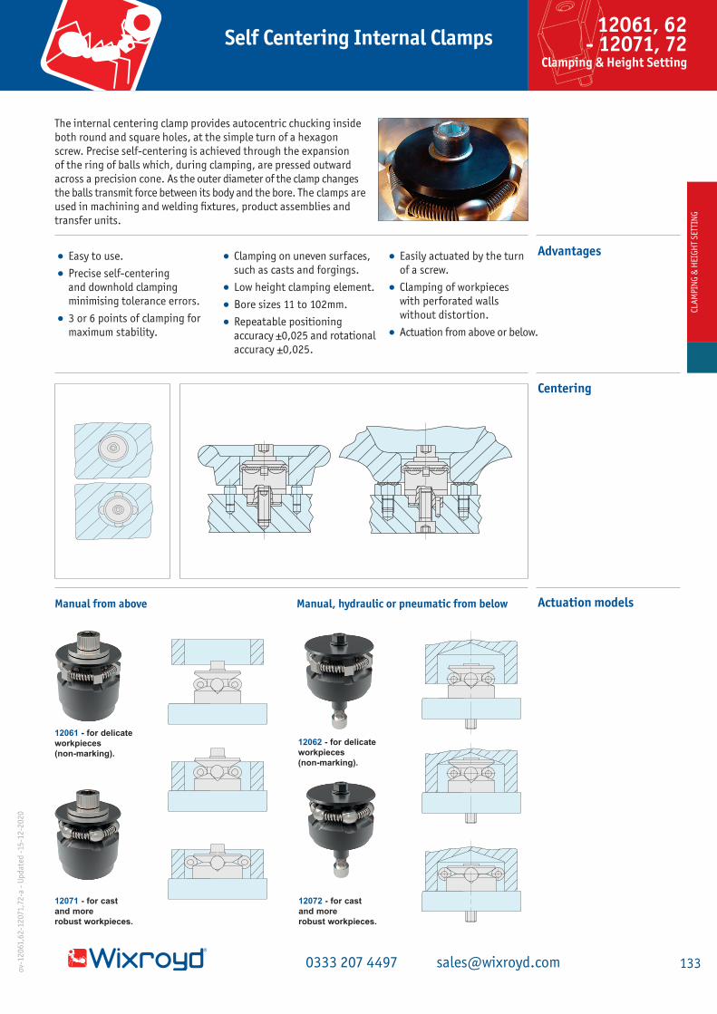
• Easy to use.
• Precise self-centering
and downhold clamping
minimising tolerance errors.
• 3 or 6 points of clamping for
maximum stability.
• Clamping on uneven surfaces,
such as casts and forgings.
• Low height clamping element.
• Bore sizes 11 to 102mm.
• Repeatable positioning
accuracy ±0,025 and rotational
accuracy ±0,025.
• Easily actuated by the turn
of a screw.
• Clamping of workpieces
with perforated walls
without distortion.
• Actuation from above or below.
The internal centering clamp provides autocentric chucking inside
both round and square holes, at the simple turn of a hexagon
screw. Precise self-centering is achieved through the expansion
of the ring of balls which, during clamping, are pressed outward
across a precision cone. As the outer diameter of the clamp changes
the balls transmit force between its body and the bore. The clamps are
used in machining and welding ixtures, product assemblies and
transfer units.
Manual from above Manual, hydraulic or pneumatic from below
12062 - for delicate
workpieces
(non-marking).
Advantages
Centering
Actuation models
12061 - for delicate
workpieces
(non-marking).
12071 - for cast
and more
robust workpieces.
12072 - for cast
and more
robust workpieces.
CLA
MP
ING
& H
EIG
HT
SET
TIN
GCL
AM
PIN
G &
HEI
GH
T S
ETTI
NG
1330333 207 4497 [email protected]
12061, 62 - 12071, 72
Clamping & Height Setting
Self Centering Internal Clampso
v-1
20
61,6
2-1
20
71,7
2-a
- U
pd
ated
-1
5-1
2-2
02
0

Compact ID Holding Clamps 12074
wixroyd.comCreated 2022-01-06
Material
Steel (AISI 4140), 33-39 HRc,
blackened.
Technical Notes
Compact clamps to hold workpiece
on an inside diameter. Wedge
construction provides powerful
clamping force. Generates both
horizontal and vertical clamping
force.
Tips
Clamps are suited to holding on cast
or roughed holes. Contact point
nature of clamp may result in
marking of workpiece. Not
recommended for use in accurately
finished holes.
Order No. Typel1
at d1
max.
d1
min.
d1
max.
h1
at d1
min.
h1
at
d1
max.
h2
d2
A/F
Torqu
e
to
max.
Nm.
Max.
clampin
g force
kN.
Xg
12074.W0008 Countersunk 7,3 8 10,3 5,5 4,6 0,9 M 4x0,70 3 0,9 2,1 3
12074.W0010 Countersunk 9,1 10 12,3 6,4 5,6 1,1 M 5x0,80 3 1,5 4,3 5
12074.W0012 Countersunk 11,2 12 16,3 8,6 7,0 1,3 M 6x1,00 4 2,1 7,3 9
12074.W0016 Countersunk 16,2 16 22,0 11,5 9,4 1,6 M 8x1,25 5 4,0 18,0 22
12074.W0108 Socket Head 7,1 8 10,3 5,5 4,6 5,1 M 4x0,70 3 1,5 2,7 4
12074.W0110 Socket Head 9,0 10 12,3 6,4 5,6 6,2 M 5x0,80 4 2,5 5,4 7
12074.W0112 Socket Head 10,6 12 16,3 8,6 7,0 7,9 M 6x1,00 5 5,0 9,1 11
12074.W0116 Socket Head 15,4 16 22,0 11,5 9,4 10,4 M 8x1,25 6 9,0 25,0 28
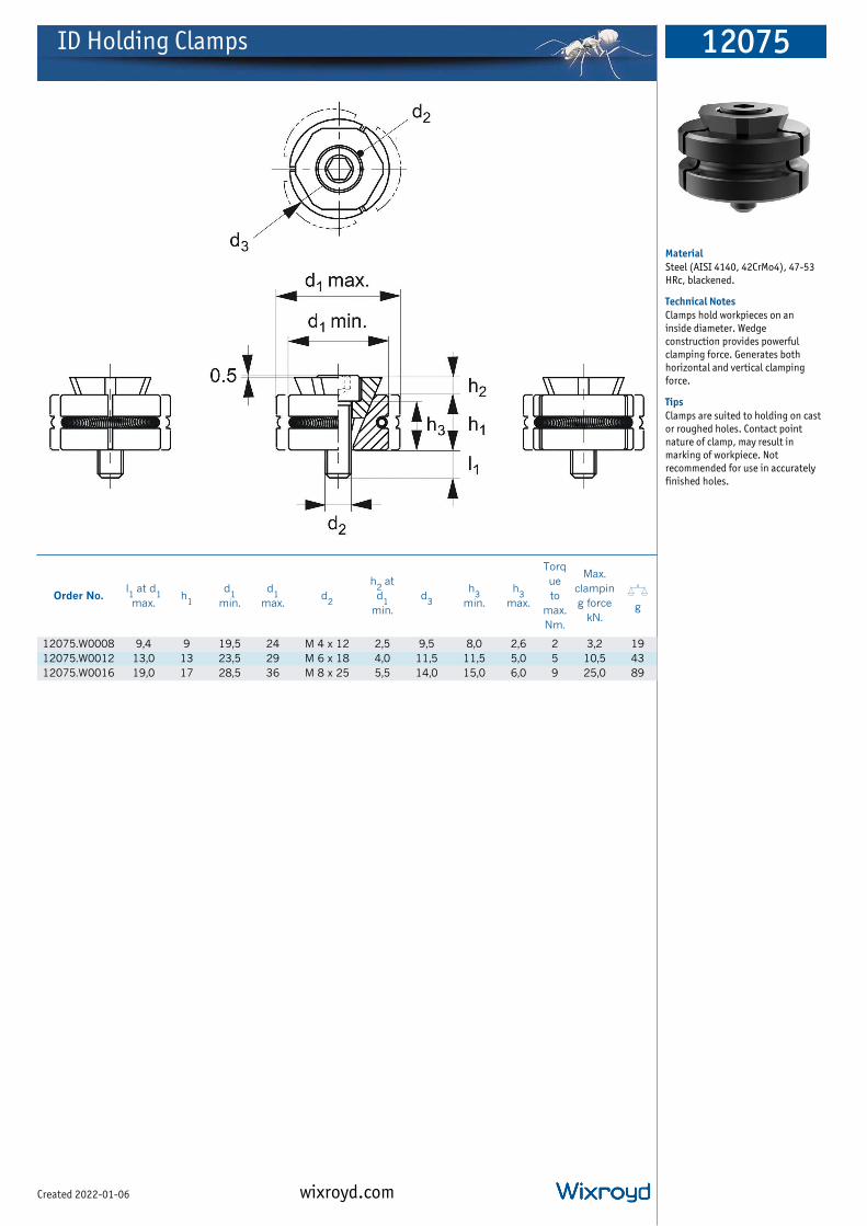
ID Holding Clamps 12075
wixroyd.comCreated 2022-01-06
Material
Steel (AISI 4140, 42CrMo4), 47-53
HRc, blackened.
Technical Notes
Clamps hold workpieces on an
inside diameter. Wedge
construction provides powerful
clamping force. Generates both
horizontal and vertical clamping
force.
Tips
Clamps are suited to holding on cast
or roughed holes. Contact point
nature of clamp, may result in
marking of workpiece. Not
recommended for use in accurately
finished holes.
Order No.l1
at d1
max.h
1
d1
min.
d1
max.d
2
h2
at
d1
min.
d3
h3
min.
h3
max.
Torq
ue
to
max.
Nm.
Max.
clampin
g force
kN.
Xg
12075.W0008 9,4 9 19,5 24 M 4 x 12 2,5 9,5 8,0 2,6 2 3,2 19
12075.W0012 13,0 13 23,5 29 M 6 x 18 4,0 11,5 11,5 5,0 5 10,5 43
12075.W0016 19,0 17 28,5 36 M 8 x 25 5,5 14,0 15,0 6,0 9 25,0 89