
Civil Works & Structures - UK HPR1000
71
-
Upload
khangminh22 -
Category
Documents
-
view
2 -
download
0
Transcript of Civil Works & Structures - UK HPR1000
UK HPR1000 GDA
Pre-Construction Safety Report Chapter 16 Civil Works & Structures
UK Protective Marking: Not Protectively Marked
Rev: 001 Page: II
UK Protective Marking: Not Protectively Marked
DISTRIBUTION LIST
Recipients Cross Box
General Nuclear System Executive ☐
General Nuclear System all staff ☐
General Nuclear System and BRB all staff ☒
CGN ☒
EDF ☒
Regulators ☒
Public ☒
UK HPR1000 GDA
Pre-Construction Safety Report Chapter 16 Civil Works & Structures
UK Protective Marking: Not Protectively Marked
Rev: 001 Page: 1 / 69
UK Protective Marking: Not Protectively Marked
TABLE OF CONTENTS
16.1 List of Abbreviations and Acronyms .................................................................. 3
16.2 Introduction .......................................................................................................... 5
16.2.1 Scope ....................................................................................................................... 5
16.2.2 Chapter Route Map ................................................................................................. 8
16.2.3 Chapter Structure .................................................................................................. 12
16.2.4 Interfaces with Other Chapters ............................................................................. 16
16.3 Safety Functional Requirements and Design Requirements .......................... 19
16.3.1 Safety Functional Requirements ........................................................................... 19
16.3.2 Classification and Categorisation ......................................................................... 20
16.3.3 Design Requirements ............................................................................................ 21
16.4 Applicable Codes and Standards ...................................................................... 24
16.4.1 Seismic Analysis ................................................................................................... 24
16.4.2 Structural Analysis and Design ............................................................................. 24
16.4.3 Materials ............................................................................................................... 25
16.4.4 Metrication ............................................................................................................ 25
16.5 Seismic Analysis ................................................................................................. 26
16.5.1 Seismic Input for SSE1 and SSE2 Structures ....................................................... 26
16.5.2 Modelling of Structures ........................................................................................ 26
16.5.3 Seismic Analysis of SSE1 Structures .................................................................... 26
16.5.4 Seismic Analysis of SSE2 Structures .................................................................... 27
16.5.5 Analysis of Non-nuclear Seismic Structures ......................................................... 28
16.6 Design of Nuclear Safety-Related Structures .................................................. 28
16.6.1 Design Principles .................................................................................................. 28
16.6.2 Loads and Load Combinations ............................................................................. 30
16.6.3 Nuclear Safety-Related Structures Layout ............................................................ 37
UK HPR1000 GDA
Pre-Construction Safety Report Chapter 16 Civil Works & Structures
UK Protective Marking: Not Protectively Marked
Rev: 001 Page: 2 / 69
UK Protective Marking: Not Protectively Marked
16.6.4 Reactor Building ................................................................................................... 37
16.6.5 Other Structures .................................................................................................... 44
16.6.6 Foundation ............................................................................................................ 55
16.7 Beyond Design Basis Conditions ....................................................................... 58
16.7.1 Ultimate Capacity Evaluation for Internal Containment ...................................... 58
16.7.2 Aircraft Impact Evaluation .................................................................................... 59
16.7.3 Cliff-edge effects of extreme environmental hazards ........................................... 60
16.8 Construction and Testing .................................................................................. 61
16.9 In-Service Inspection and Testing ..................................................................... 62
16.10 ALARP .............................................................................................................. 63
16.10.1 Holistic ALARP Assessment .............................................................................. 63
16.10.2 Specific ALARP Assessment .............................................................................. 64
16.11 Concluding Remarks ....................................................................................... 67
16.12 References ......................................................................................................... 67
UK HPR1000 GDA
Pre-Construction Safety Report Chapter 16 Civil Works & Structures
UK Protective Marking: Not Protectively Marked
Rev: 001 Page: 3 / 69
UK Protective Marking: Not Protectively Marked
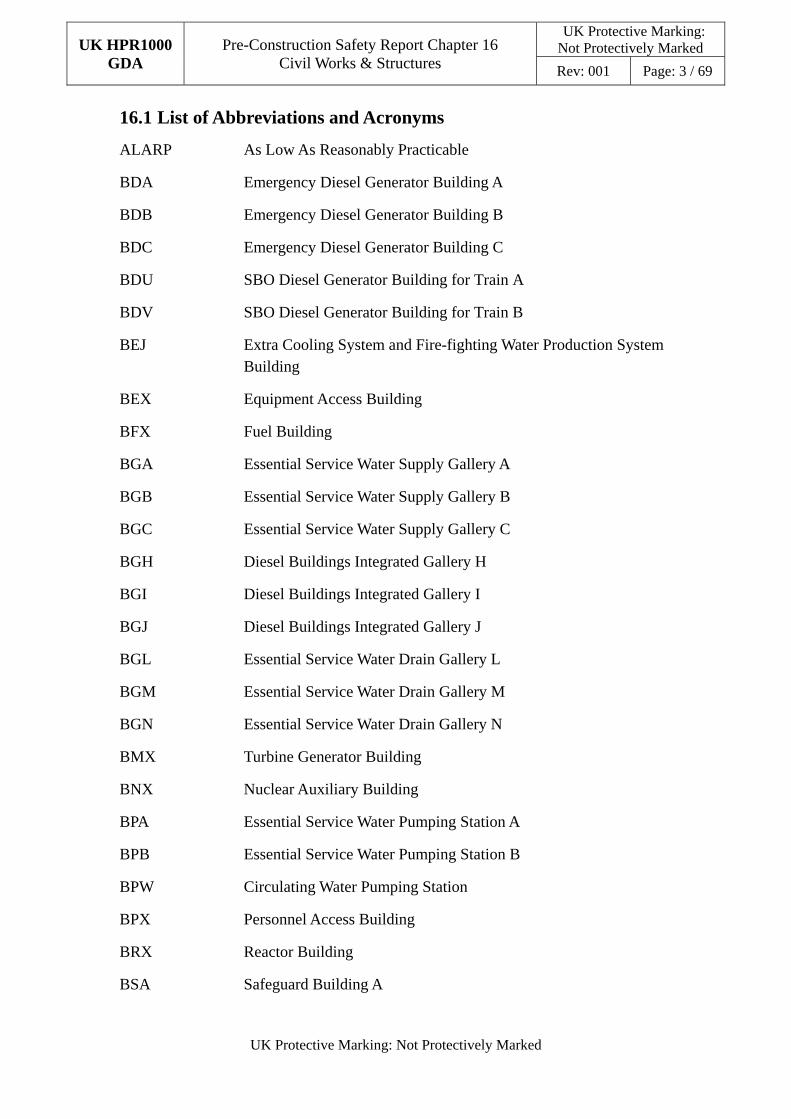
16.1 List of Abbreviations and Acronyms
ALARP As Low As Reasonably Practicable
BDA Emergency Diesel Generator Building A
BDB Emergency Diesel Generator Building B
BDC Emergency Diesel Generator Building C
BDU SBO Diesel Generator Building for Train A
BDV SBO Diesel Generator Building for Train B
BEJ Extra Cooling System and Fire-fighting Water Production System Building
BEX Equipment Access Building
BFX Fuel Building
BGA Essential Service Water Supply Gallery A
BGB Essential Service Water Supply Gallery B
BGC Essential Service Water Supply Gallery C
BGH Diesel Buildings Integrated Gallery H
BGI Diesel Buildings Integrated Gallery I
BGJ Diesel Buildings Integrated Gallery J
BGL Essential Service Water Drain Gallery L
BGM Essential Service Water Drain Gallery M
BGN Essential Service Water Drain Gallery N
BMX Turbine Generator Building
BNX Nuclear Auxiliary Building
BPA Essential Service Water Pumping Station A
BPB Essential Service Water Pumping Station B
BPW Circulating Water Pumping Station
BPX Personnel Access Building
BRX Reactor Building
BSA Safeguard Building A
UK HPR1000 GDA
Pre-Construction Safety Report Chapter 16 Civil Works & Structures
UK Protective Marking: Not Protectively Marked
Rev: 001 Page: 4 / 69
UK Protective Marking: Not Protectively Marked
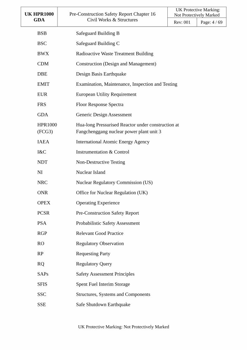
BSB Safeguard Building B
BSC Safeguard Building C
BWX Radioactive Waste Treatment Building
CDM Construction (Design and Management)
DBE Design Basis Earthquake
EMIT Examination, Maintenance, Inspection and Testing
EUR European Utility Requirement
FRS Floor Response Spectra
GDA Generic Design Assessment
HPR1000 (FCG3)
Hua-long Pressurised Reactor under construction at Fangchenggang nuclear power plant unit 3
IAEA International Atomic Energy Agency
I&C Instrumentation & Control
NDT Non-Destructive Testing
NI Nuclear Island
NRC Nuclear Regulatory Commission (US)
ONR Office for Nuclear Regulation (UK)
OPEX Operating Experience
PCSR Pre-Construction Safety Report
PSA Probabilistic Safety Assessment
RGP Relevant Good Practice
RO Regulatory Observation
RP Requesting Party
RQ Regulatory Query
SAPs Safety Assessment Principles
SFIS Spent Fuel Interim Storage
SSC Structures, Systems and Components
SSE Safe Shutdown Earthquake
UK HPR1000 GDA
Pre-Construction Safety Report Chapter 16 Civil Works & Structures
UK Protective Marking: Not Protectively Marked
Rev: 001 Page: 5 / 69
UK Protective Marking: Not Protectively Marked
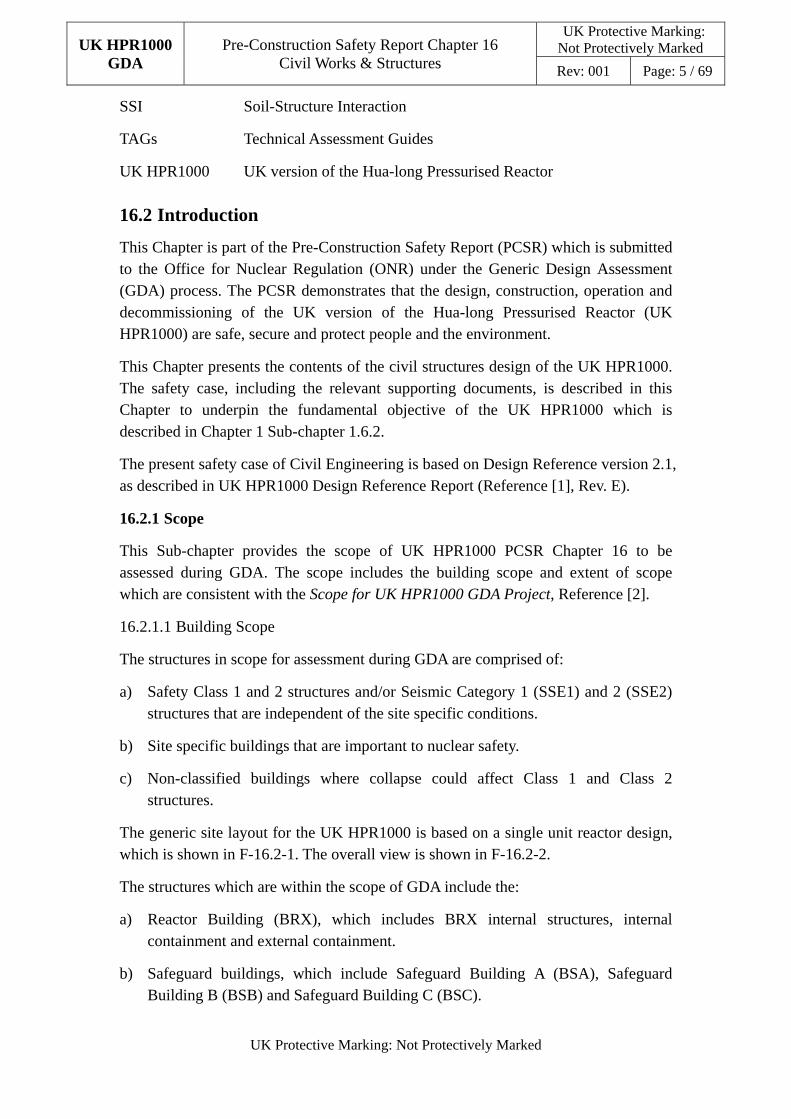
SSI Soil-Structure Interaction
TAGs Technical Assessment Guides
UK HPR1000 UK version of the Hua-long Pressurised Reactor
16.2 Introduction
This Chapter is part of the Pre-Construction Safety Report (PCSR) which is submitted to the Office for Nuclear Regulation (ONR) under the Generic Design Assessment (GDA) process. The PCSR demonstrates that the design, construction, operation and decommissioning of the UK version of the Hua-long Pressurised Reactor (UK HPR1000) are safe, secure and protect people and the environment.
This Chapter presents the contents of the civil structures design of the UK HPR1000. The safety case, including the relevant supporting documents, is described in this Chapter to underpin the fundamental objective of the UK HPR1000 which is described in Chapter 1 Sub-chapter 1.6.2.
The present safety case of Civil Engineering is based on Design Reference version 2.1, as described in UK HPR1000 Design Reference Report (Reference [1], Rev. E).
16.2.1 Scope
This Sub-chapter provides the scope of UK HPR1000 PCSR Chapter 16 to be assessed during GDA. The scope includes the building scope and extent of scope which are consistent with the Scope for UK HPR1000 GDA Project, Reference [2].
16.2.1.1 Building Scope
The structures in scope for assessment during GDA are comprised of:
a) Safety Class 1 and 2 structures and/or Seismic Category 1 (SSE1) and 2 (SSE2) structures that are independent of the site specific conditions.
b) Site specific buildings that are important to nuclear safety.
c) Non-classified buildings where collapse could affect Class 1 and Class 2 structures.
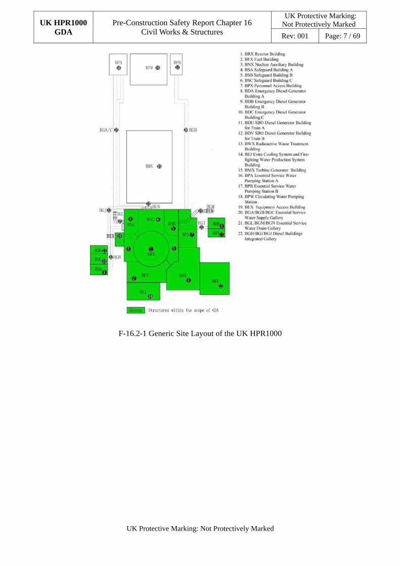
The generic site layout for the UK HPR1000 is based on a single unit reactor design, which is shown in F-16.2-1. The overall view is shown in F-16.2-2.
The structures which are within the scope of GDA include the:
a) Reactor Building (BRX), which includes BRX internal structures, internal containment and external containment.
b) Safeguard buildings, which include Safeguard Building A (BSA), Safeguard Building B (BSB) and Safeguard Building C (BSC).
UK HPR1000 GDA
Pre-Construction Safety Report Chapter 16 Civil Works & Structures
UK Protective Marking: Not Protectively Marked
Rev: 001 Page: 6 / 69
UK Protective Marking: Not Protectively Marked
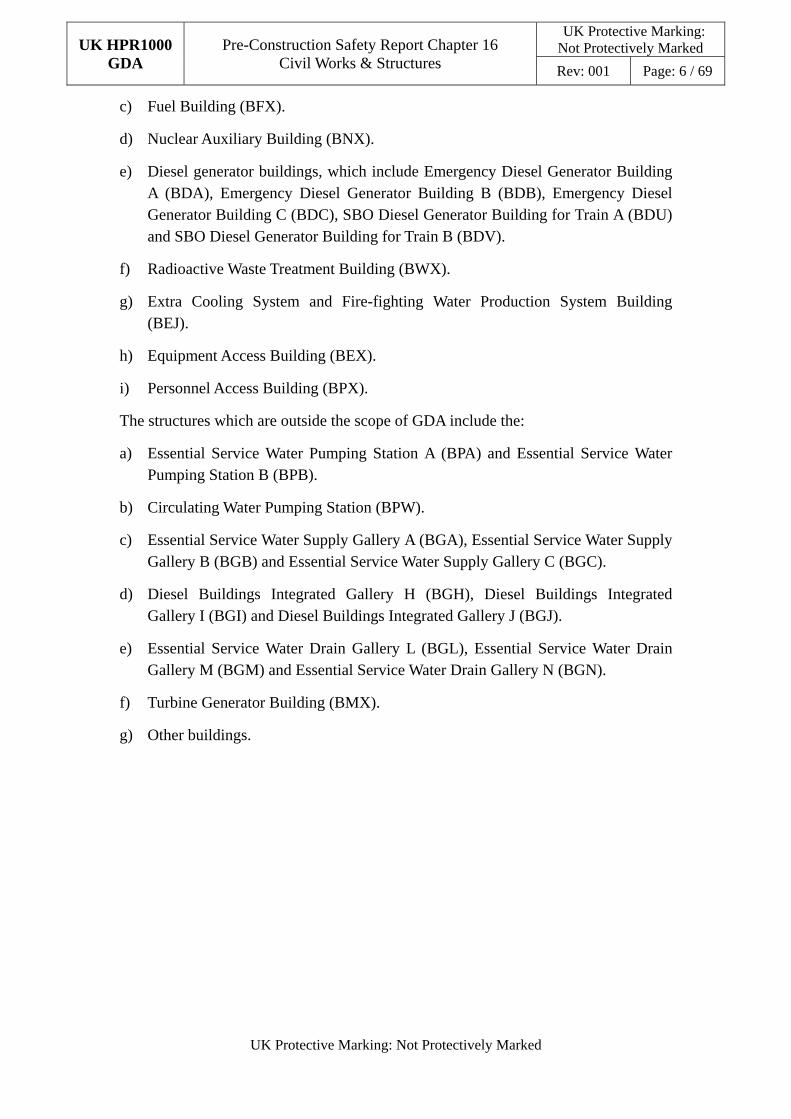
c) Fuel Building (BFX).
d) Nuclear Auxiliary Building (BNX).
e) Diesel generator buildings, which include Emergency Diesel Generator Building A (BDA), Emergency Diesel Generator Building B (BDB), Emergency Diesel Generator Building C (BDC), SBO Diesel Generator Building for Train A (BDU) and SBO Diesel Generator Building for Train B (BDV).
f) Radioactive Waste Treatment Building (BWX).
g) Extra Cooling System and Fire-fighting Water Production System Building (BEJ).
h) Equipment Access Building (BEX).
i) Personnel Access Building (BPX).
The structures which are outside the scope of GDA include the:
a) Essential Service Water Pumping Station A (BPA) and Essential Service Water Pumping Station B (BPB).
b) Circulating Water Pumping Station (BPW).
c) Essential Service Water Supply Gallery A (BGA), Essential Service Water Supply Gallery B (BGB) and Essential Service Water Supply Gallery C (BGC).
d) Diesel Buildings Integrated Gallery H (BGH), Diesel Buildings Integrated Gallery I (BGI) and Diesel Buildings Integrated Gallery J (BGJ).
e) Essential Service Water Drain Gallery L (BGL), Essential Service Water Drain Gallery M (BGM) and Essential Service Water Drain Gallery N (BGN).
f) Turbine Generator Building (BMX).
g) Other buildings.
UK HPR1000 GDA
Pre-Construction Safety Report Chapter 16 Civil Works & Structures
UK Protective Marking: Not Protectively Marked
Rev: 001 Page: 7 / 69
UK Protective Marking: Not Protectively Marked
F-16.2-1 Generic Site Layout of the UK HPR1000
UK HPR1000 GDA
Pre-Construction Safety Report Chapter 16 Civil Works & Structures
UK Protective Marking: Not Protectively Marked
Rev: 001 Page: 8 / 69
UK Protective Marking: Not Protectively Marked
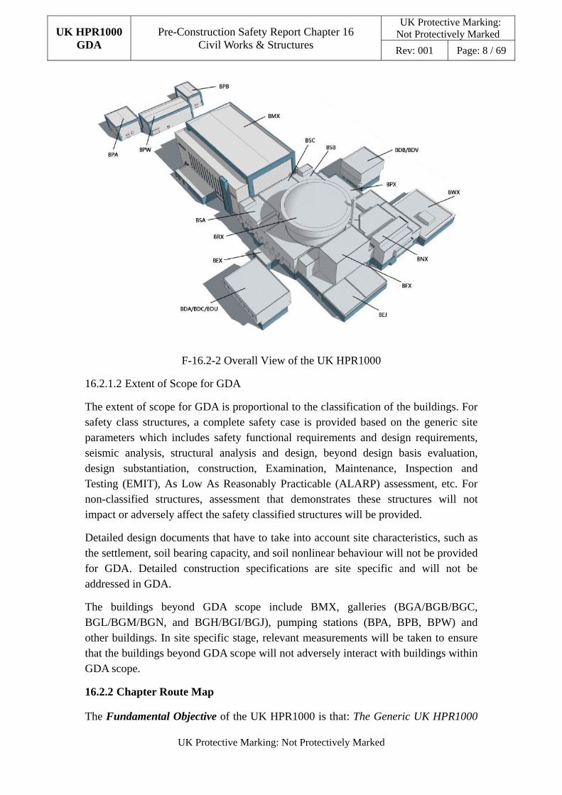
F-16.2-2 Overall View of the UK HPR1000
16.2.1.2 Extent of Scope for GDA
The extent of scope for GDA is proportional to the classification of the buildings. For safety class structures, a complete safety case is provided based on the generic site parameters which includes safety functional requirements and design requirements, seismic analysis, structural analysis and design, beyond design basis evaluation, design substantiation, construction, Examination, Maintenance, Inspection and Testing (EMIT), As Low As Reasonably Practicable (ALARP) assessment, etc. For non-classified structures, assessment that demonstrates these structures will not impact or adversely affect the safety classified structures will be provided.
Detailed design documents that have to take into account site characteristics, such as the settlement, soil bearing capacity, and soil nonlinear behaviour will not be provided for GDA. Detailed construction specifications are site specific and will not be addressed in GDA.
The buildings beyond GDA scope include BMX, galleries (BGA/BGB/BGC, BGL/BGM/BGN, and BGH/BGI/BGJ), pumping stations (BPA, BPB, BPW) and other buildings. In site specific stage, relevant measurements will be taken to ensure that the buildings beyond GDA scope will not adversely interact with buildings within GDA scope.
16.2.2 Chapter Route Map
The Fundamental Objective of the UK HPR1000 is that: The Generic UK HPR1000
UK HPR1000 GDA
Pre-Construction Safety Report Chapter 16 Civil Works & Structures
UK Protective Marking: Not Protectively Marked
Rev: 001 Page: 9 / 69
UK Protective Marking: Not Protectively Marked
could be constructed, operated, and decommissioned in the UK on a site bounded by
the generic site envelope in a way that is safe, secure and that protects people and the
environment.
To underpin this objective, five high level claims and a number of level 2 claims are developed and presented in Chapter 1 Sub-chapter 1.6. This chapter supports the Claim 3.3 derived from the high level Claim 3.
Claim 3: The design and intended construction and operation of the UK HPR1000 will protect the workers and the public by providing multiple levels of defence to fulfil the fundamental safety functions, reducing the nuclear safety risks to a level that is as low as reasonably practicable.
Claim 3.3: The design of the processes and systems has been substantiated and the safety aspects of operation and management have been substantiated.
In terms of civil structures, Claim 3.3.9 is developed according to the Claim 3.3.
Claim 3.3.9: The design of the civil works and structures has been substantiated.
To support Claim 3.3.9, this Chapter develops five Sub-claims and a number of relevant arguments and evidence:
a) Sub-claim 3.3.9.SC16.1: The safety functional requirements have been derived for the civil works and structures:
1) Argument 3.3.9.SC16.1-A1: The safety functional requirements have been identified based on fundamental safety functions, described in Sub-chapter 16.3.1.
- Evidence 3.3.9.SC16.1-A1-E1: The safety functional requirements of internal and external containment have been identified, Reference [3].
- Evidence 3.3.9.SC16.1-A1-E2: The safety functional requirements of the BRX internal structures have been identified, Reference [4].
- Evidence 3.3.9.SC16.1-A1-E3: The safety functional requirements of the safeguard buildings have been identified, Reference [5].
- Evidence 3.3.9.SC16.1-A1-E4: The safety functional requirements of the BFX have been identified, Reference [6].
- Evidence 3.3.9.SC16.1-A1-E5: The safety functional requirements of the BNX, BWX, BDA/BDB/BDC/BDU/BDV, BEJ, BPX, and BEX have been identified, Reference [7], [8], [9], [10], [11], and [12].
2) Argument 3.3.9.SC16.1-A2: The classification & categorisation of the structures have been identified, described in Sub-chapter 16.3.2.
UK HPR1000 GDA
Pre-Construction Safety Report Chapter 16 Civil Works & Structures
UK Protective Marking: Not Protectively Marked
Rev: 001 Page: 10 / 69
UK Protective Marking: Not Protectively Marked
- Evidence 3.3.9.SC16.1-A2-E1: The methodology of classification & categorisation has been developed, Reference [13];
- Evidence 3.3.9.SC16.1-A2-E2: The classification & categorisation of civil structures have been identified based on the methodology, described in Sub-chapter 16.3.2.
3) Argument 3.3.9.SC16.1-A3: The structure design requirements have been derived, described in Sub-chapter 16.3.3.
- Evidence 3.3.9.SC16.1-A3-E1: The design requirements of internal and external containment have been identified, Reference [3].
- Evidence 3.3.9.SC16.1-A3-E2: The design requirements of the BRX internal structures have been identified, Reference [4].
- Evidence 3.3.9.SC16.1-A3-E3: The design requirements of the safeguard buildings have been identified, Reference [5].
- Evidence 3.3.9.SC16.1-A3-E4: The design requirements of the BFX have been identified, Reference [6].
- Evidence 3.3.9.SC16.1-A3-E5: The design requirements of the BNX, BWX, BDA/BDB/BDC/BDU/BDV, BEJ, BPX, and BEX have been identified, Reference [7], [8], [9], [10], [11] and [12].
b) Sub-claim 3.3.9.SC16.2: The design of civil structures satisfies the safety functional requirements:
1) Argument 3.3.9.SC16.2-A1: Appropriate design codes and standards have been identified, described in Sub-chapter 16.4.
- Evidence 3.3.9.SC16.2-A1-E1: The approach to codes and standards on civil structures has been developed, Reference [14].
- Evidence 3.3.9.SC16.2-A1-E2: Applicability of codes and standards on civil structures design has been developed, Reference [15].
2) Argument 3.3.9.SC16.2-A2: The methodology for civil structures analysis and design has been developed according to the codes and standards, described in Sub-chapter 16.5-16.7.
- Evidence 3.3.9.SC16.2-A2-E1: The structural analysis and design method statement has been developed, Reference [16].
- Evidence 3.3.9.SC16.2-A2-E2: Raft foundation analysis and design method statement has been developed, Reference [17].
- Evidence 3.3.9.SC16.2-A2-E3: The internal containment analysis and design method statement has been developed, Reference [18].
UK HPR1000 GDA
Pre-Construction Safety Report Chapter 16 Civil Works & Structures
UK Protective Marking: Not Protectively Marked
Rev: 001 Page: 11 / 69
UK Protective Marking: Not Protectively Marked
- Evidence 3.3.9.SC16.2-A2-E4: The overall seismic analysis method statement has been developed, Reference [19].
- Evidence 3.3.9.SC16.2-A2-E5: The aircraft impact evaluation method statement has been developed, Reference [20].
3) Argument 3.3.9.SC16.2-A3: Analysis and design of the structures will be conducted according to the methodology to ensure the safety functional requirements will be achieved, described in Sub-chapter 16.5-16.7.
- Evidence 3.3.9.SC16.2-A3-E1: Structural analysis and design, which include analysis and design of raft foundation and superstructure and reinforced concrete barrier substantiation, will be conducted.
- Evidence 3.3.9.SC16.2-A3-E2: Seismic analysis for structures will be conducted.
- Evidence 3.3.9.SC16.2-A3-E3: Aircraft impact evaluation for structures will be conducted.
- Evidence 3.3.9.SC16.2-A3-E4: Ultimate capacity evaluation for internal containment will be conducted.
- Evidence 3.3.9.SC16.2-A3-E5: Cliff-edge effect of extreme environmental hazard for civil engineering structure will be conducted.
c) Sub-claim 3.3.9.SC16.3: All reasonably practicable measures have been adopted to improve the design of the civil structures:
1) Argument 3.3.9.SC16.3-A1: The civil structures meet the requirements of the relevant design principles and therefore of Relevant Good Practice (RGP), described in Sub-chapter 16.10.
- Evidence 3.3.9.SC16.3-A1-E1: The consistency review against the RGP has been conducted, described in Sub-chapter 16.10.
2) Argument 3.3.9.SC16.3-A2: Design improvements will be considered and any reasonably practicable changes are implemented, described in Sub-chapter 16.10.
- Evidence 3.3.9.SC16.3-A2-E1: The potential improvements against the RGP have been identified, described in Sub-chapter 16.10.
- Evidence 3.3.9.SC16.3-A2-E2: The potential improvements will be considered in the design of civil structures.
d) Sub-claim 3.3.9.SC16.4: The civil structures performance will be validated by commissioning and testing:
1) Argument 3.3.9.SC16.4-A1: The civil structures have been designed to take
UK HPR1000 GDA
Pre-Construction Safety Report Chapter 16 Civil Works & Structures
UK Protective Marking: Not Protectively Marked
Rev: 001 Page: 12 / 69
UK Protective Marking: Not Protectively Marked
benefit from a suite of pre-construction tests, to provide assurance of the initial quality of the manufacture, described in Sub-chapter 16.8.
- Evidence 3.3.9.SC16.4-A1-E1: The pre-construction tests for the civil structure components and materials will be conducted.
2) Argument 3.3.9.SC16.4-A2: The civil structures have been designed to take benefit from a suite of commissioning tests, to provide assurance of the initial quality of the build, described in Sub-chapter 16.8.
- Evidence 3.3.9.SC16.4-A2-E1: The tests on civil structures before commissioning will be conducted.
e) Sub-claim 3.3.9.SC16.5: The ageing effects of civil structures have been addressed in the design and suitable EMIT specified:
1) Argument 3.3.9.SC16.5-A1: The ageing effects have been considered in the design of the civil structures, described in Sub-chapter 16.9.
- Evidence 3.3.9.SC16.5-A1-E1: The detailed ageing effects consideration will be provided.
2) Argument 3.3.9.SC16.5-A2: An initial EMIT strategy has been developed, described in Sub-chapter 16.9.
- Evidence 3.3.9.SC16.5-A2-E1: The detailed EMIT approach will be developed.
The Sub-claim/Argument/Evidence code has been modified to present the link with the Overall Route Map. The current Claims, Arguments, Evidence (CAE) code “…x-Ay-Ez” stands for “Evidence x.y.z” in the previous CAE code. For example, Sub-claim 3.3.9.SC16.1 stands for Sub-claim 3.3.9.1 in the previous version, and Evidence 3.3.9.SC16.1-A1-E1 stands for Evidence 1.1.1.
16.2.3 Chapter Structure
The general structure of this Chapter is presented as the following:
a) Sub-chapter 16.1 lists the abbreviations and acronyms that are mentioned in this Chapter.
b) Sub-chapter 16.2 presents the Sub-claims, arguments and evidence of the civil structures design, and describes the scope of the PCSR and interfaces with other Chapters.
c) Sub-chapter 16.3 describes the safety functional requirements, classification and categorisation and design requirements of the civil structures.
d) Sub-chapter 16.4 presents the selection approach and list of the applicable codes and standards.
UK HPR1000 GDA
Pre-Construction Safety Report Chapter 16 Civil Works & Structures
UK Protective Marking: Not Protectively Marked
Rev: 001 Page: 13 / 69
UK Protective Marking: Not Protectively Marked
e) Sub-chapter 16.5 presents the seismic analysis.
f) Sub-chapter 16.6 describes design of nuclear safety-related structures which include loads and load combinations, structure description, structural analysis and design method.
g) Sub-chapter 16.7 presents beyond design basis conditions, which include ultimate capacity evaluation for internal containment, aircraft impact evaluation and cliff-edge effects of extreme environmental hazards for civil engineering structure.
h) Sub-chapter 16.8 summarises the consideration of construction and testing.
i) Sub-chapter 16.9 describes the initial strategy and forward plan of EMIT.
j) Sub-chapter 16.10 presents the approach of ALARP.
k) Sub-chapter 16.11 presents concluding remarks for this chapter.
l) Sub-chapter 16.12 lists the supporting references of this chapter.
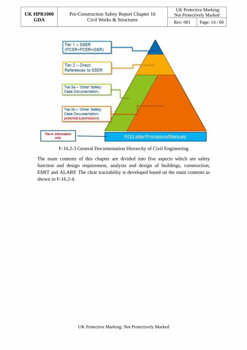
This chapter and relevant reference documents form the complete safety case for civil structures. The PCSR presents the Claims and Sub-claims of civil structures (Tier 1 document). The basis of safety case reports, methodology reports, the generic design parameters report and other reports which are direct references to the PCSR present the arguments (Tier 2 documents); “Other” safety case documents (Tier 3a will be submitted to ONR, and the Tier 3b documents act as the potential submissions) provide the evidence; and the responses to the Regulatory Query (RQ) / Regulatory Observation (RO), mails, presentation, meeting minutes, etc., are for information only (Tier 4 documents). The general documentation hierarchy of civil engineering is shown in Figure F-16.2-3.
UK HPR1000 GDA
Pre-Construction Safety Report Chapter 16 Civil Works & Structures
UK Protective Marking: Not Protectively Marked
Rev: 001 Page: 14 / 69
UK Protective Marking: Not Protectively Marked
F-16.2-3 General Documentation Hierarchy of Civil Engineering
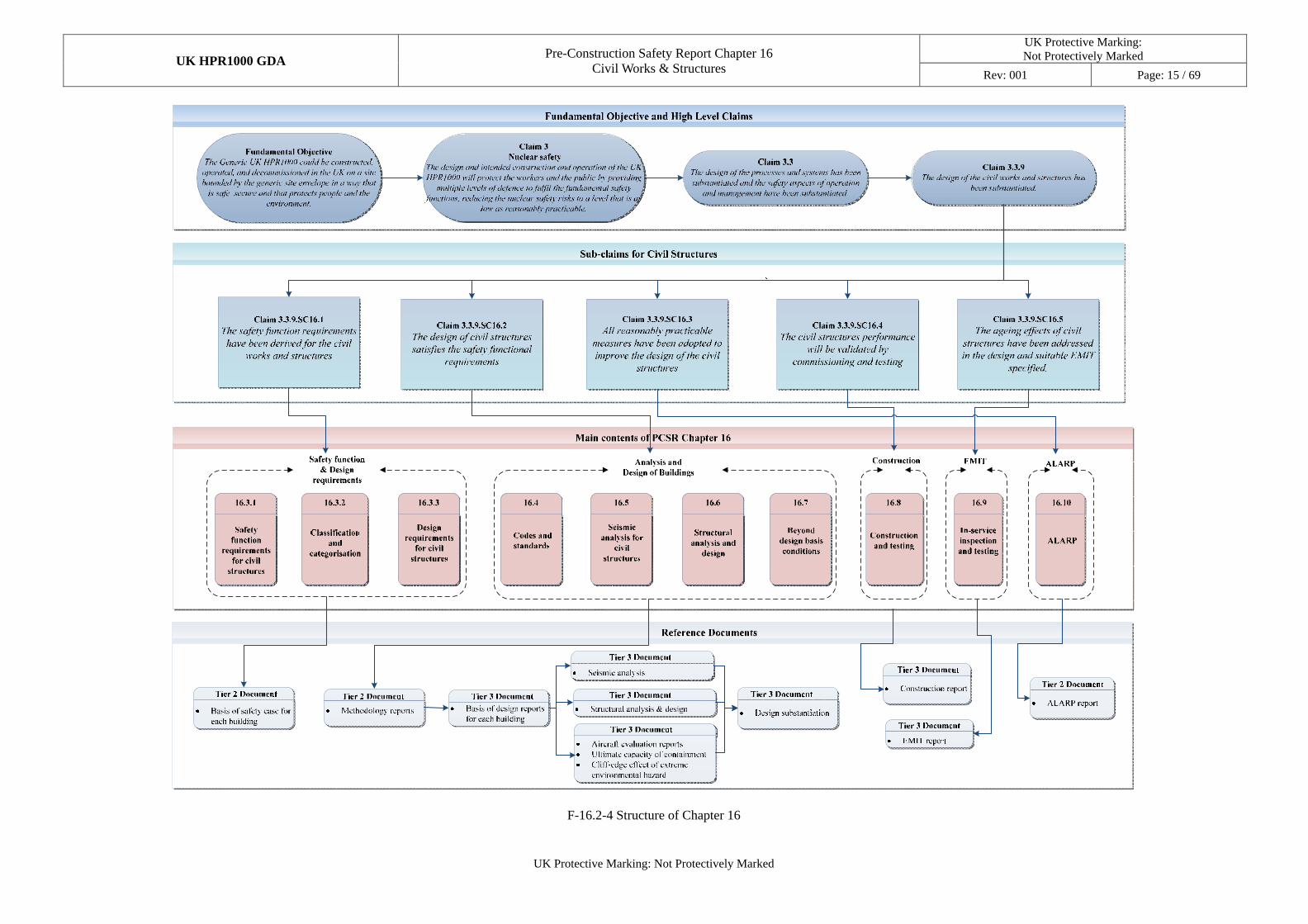
The main contents of this chapter are divided into five aspects which are safety function and design requirement, analysis and design of buildings, construction, EMIT and ALARP. The clear traceability is developed based on the main contents as shown in F-16.2-4.
UK HPR1000 GDA Pre-Construction Safety Report Chapter 16
Civil Works & Structures
UK Protective Marking: Not Protectively Marked
Rev: 001 Page: 15 / 69
UK Protective Marking: Not Protectively Marked
F-16.2-4 Structure of Chapter 16
UK HPR1000 GDA
Pre-Construction Safety Report Chapter 16 Civil Works & Structures
UK Protective Marking: Not Protectively Marked
Rev: 001 Page: 16 / 69
UK Protective Marking: Not Protectively Marked
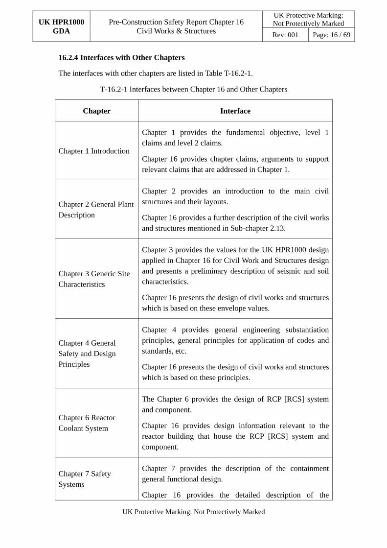
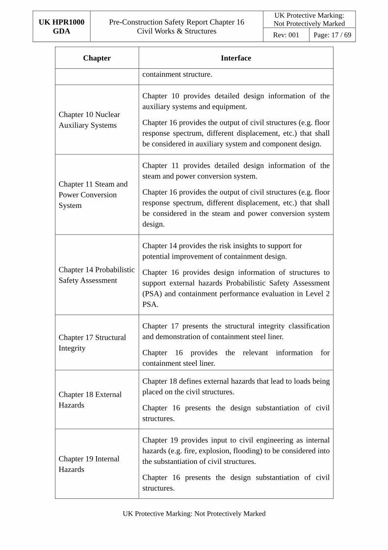
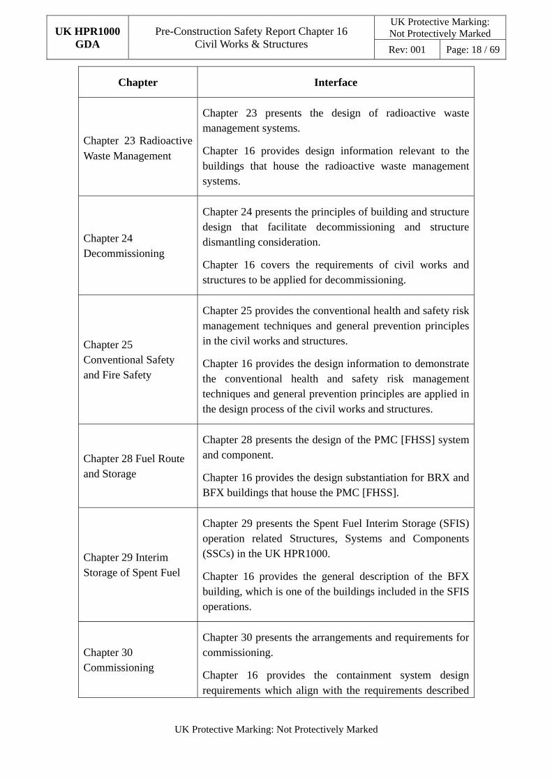
16.2.4 Interfaces with Other Chapters
The interfaces with other chapters are listed in Table T-16.2-1.
T-16.2-1 Interfaces between Chapter 16 and Other Chapters
Chapter Interface
Chapter 1 Introduction
Chapter 1 provides the fundamental objective, level 1 claims and level 2 claims.
Chapter 16 provides chapter claims, arguments to support relevant claims that are addressed in Chapter 1.
Chapter 2 General Plant Description
Chapter 2 provides an introduction to the main civil structures and their layouts.
Chapter 16 provides a further description of the civil works and structures mentioned in Sub-chapter 2.13.
Chapter 3 Generic Site Characteristics
Chapter 3 provides the values for the UK HPR1000 design applied in Chapter 16 for Civil Work and Structures design and presents a preliminary description of seismic and soil characteristics.
Chapter 16 presents the design of civil works and structures which is based on these envelope values.
Chapter 4 General Safety and Design Principles
Chapter 4 provides general engineering substantiation principles, general principles for application of codes and standards, etc.
Chapter 16 presents the design of civil works and structures which is based on these principles.
Chapter 6 Reactor Coolant System
The Chapter 6 provides the design of RCP [RCS] system and component.
Chapter 16 provides design information relevant to the reactor building that house the RCP [RCS] system and component.
Chapter 7 Safety Systems
Chapter 7 provides the description of the containment general functional design.
Chapter 16 provides the detailed description of the
UK HPR1000 GDA
Pre-Construction Safety Report Chapter 16 Civil Works & Structures
UK Protective Marking: Not Protectively Marked
Rev: 001 Page: 17 / 69
UK Protective Marking: Not Protectively Marked
Chapter Interface
containment structure.
Chapter 10 Nuclear Auxiliary Systems
Chapter 10 provides detailed design information of the auxiliary systems and equipment.
Chapter 16 provides the output of civil structures (e.g. floor response spectrum, different displacement, etc.) that shall be considered in auxiliary system and component design.
Chapter 11 Steam and Power Conversion System
Chapter 11 provides detailed design information of the steam and power conversion system.
Chapter 16 provides the output of civil structures (e.g. floor response spectrum, different displacement, etc.) that shall be considered in the steam and power conversion system design.
Chapter 14 Probabilistic Safety Assessment
Chapter 14 provides the risk insights to support for potential improvement of containment design.
Chapter 16 provides design information of structures to support external hazards Probabilistic Safety Assessment (PSA) and containment performance evaluation in Level 2 PSA.
Chapter 17 Structural Integrity
Chapter 17 presents the structural integrity classification and demonstration of containment steel liner.
Chapter 16 provides the relevant information for containment steel liner.
Chapter 18 External Hazards
Chapter 18 defines external hazards that lead to loads being placed on the civil structures.
Chapter 16 presents the design substantiation of civil structures.
Chapter 19 Internal Hazards
Chapter 19 provides input to civil engineering as internal hazards (e.g. fire, explosion, flooding) to be considered into the substantiation of civil structures.
Chapter 16 presents the design substantiation of civil structures.
UK HPR1000 GDA
Pre-Construction Safety Report Chapter 16 Civil Works & Structures
UK Protective Marking: Not Protectively Marked
Rev: 001 Page: 18 / 69
UK Protective Marking: Not Protectively Marked
Chapter Interface
Chapter 23�Radioactive Waste Management
Chapter 23 presents the design of radioactive waste management systems.
Chapter 16 provides design information relevant to the buildings that house the radioactive waste management systems.
Chapter 24 Decommissioning
Chapter 24 presents the principles of building and structure design that facilitate decommissioning and structure dismantling consideration.
Chapter 16 covers the requirements of civil works and structures to be applied for decommissioning.
Chapter 25 Conventional Safety and Fire Safety
Chapter 25 provides the conventional health and safety risk management techniques and general prevention principles in the civil works and structures.
Chapter 16 provides the design information to demonstrate the conventional health and safety risk management techniques and general prevention principles are applied in the design process of the civil works and structures.
Chapter 28 Fuel Route and Storage
Chapter 28 presents the design of the PMC [FHSS] system and component.
Chapter 16 provides the design substantiation for BRX and BFX buildings that house the PMC [FHSS].
Chapter 29 Interim Storage of Spent Fuel
Chapter 29 presents the Spent Fuel Interim Storage (SFIS) operation related Structures, Systems and Components (SSCs) in the UK HPR1000.
Chapter 16 provides the general description of the BFX building, which is one of the buildings included in the SFIS operations.
Chapter 30 Commissioning
Chapter 30 presents the arrangements and requirements for commissioning.
Chapter 16 provides the containment system design requirements which align with the requirements described
UK HPR1000 GDA
Pre-Construction Safety Report Chapter 16 Civil Works & Structures
UK Protective Marking: Not Protectively Marked
Rev: 001 Page: 19 / 69
UK Protective Marking: Not Protectively Marked
Chapter Interface
in Chapter 30.
Chapter 33 ALARP Evaluation
Chapter 33 presents the overall ALARP evaluation.
Chapter 16 provides the ALARP demonstration for the civil structures according to the principles described in Chapter 33.
16.3 Safety Functional Requirements and Design Requirements
16.3.1 Safety Functional Requirements
According to the fundamental safety functional requirements and high level safety functions described in Chapter 4 Sub-chapter 4.4 and decomposition of safety functions, Reference [21], low level safety functions related to civil structures are identified. Then, safety functional requirements of civil structures are derived: housing, support and protection for SSCs, and confinement of radioactive materials as well as limitation of accidental radioactive releases.
These safety functional requirements have been further decomposed into the following detailed requirements.
a) F1: Function to provide structural support to SSCs;
b) F2: Function to provide protection to SSCs against external hazards;
c) F3: Function to provide protection to SSCs against internal hazards;
d) F4: Function to confine the radioactive materials, shield radiation, and reduce radioactive release;
e) F5: Function to maintain specific internal building environments appropriate for SSCs during normal operating and accident situations;
f) F6: Function to satisfy the requirements of decommissioning which include supporting SSCs, providing a barrier and confining the radioactive materials.
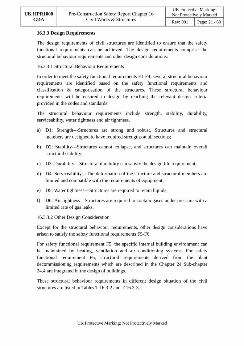
These safety functional requirements in different design situations of the civil structures which correspond to the UK HPR1000 design conditions described in Chapter 4 Sub-chapter 4.4.3 are listed in Tables T-16.3-2 and T-16.3-3.
BEX and BPX are Non-classified structures. During GDA stage, the BEX and BPX are designed to ensure that they do not affect the adjacent safeguard buildings. Then the safety functional requirements of these two buildings will not be presented in the tables.
Detailed information about safety functional requirements for internal and external
UK HPR1000 GDA
Pre-Construction Safety Report Chapter 16 Civil Works & Structures
UK Protective Marking: Not Protectively Marked
Rev: 001 Page: 20 / 69
UK Protective Marking: Not Protectively Marked
containment, BRX internal structures, BSA/BSB/BSC, BFX, BNX, BWX, BDA/BDB/BDC/BDU/BUV and BEJ are respectively shown in the section 4 of reports basis of safety case for corresponding buildings, Reference [3], [4], [5], [6], [7], [8], [9], and [10].
16.3.2 Classification and Categorisation
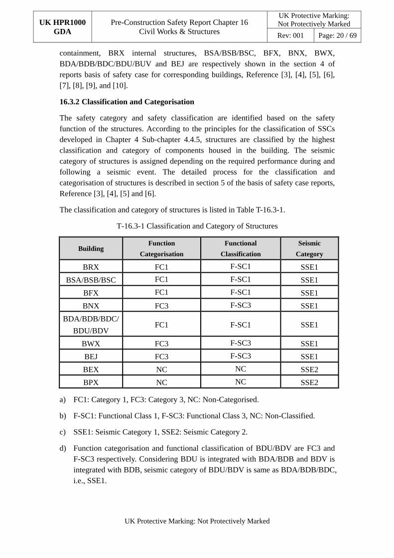
The safety category and safety classification are identified based on the safety function of the structures. According to the principles for the classification of SSCs developed in Chapter 4 Sub-chapter 4.4.5, structures are classified by the highest classification and category of components housed in the building. The seismic category of structures is assigned depending on the required performance during and following a seismic event. The detailed process for the classification and categorisation of structures is described in section 5 of the basis of safety case reports, Reference [3], [4], [5] and [6].
The classification and category of structures is listed in Table T-16.3-1.
T-16.3-1 Classification and Category of Structures
Building Function
Categorisation
Functional
Classification
Seismic
Category
BRX FC1 F-SC1 SSE1
BSA/BSB/BSC FC1 F-SC1 SSE1
BFX FC1 F-SC1 SSE1
BNX FC3 F-SC3 SSE1
BDA/BDB/BDC/
BDU/BDV FC1 F-SC1 SSE1
BWX FC3 F-SC3 SSE1
BEJ FC3 F-SC3 SSE1
BEX NC NC SSE2
BPX NC NC SSE2
a) FC1: Category 1, FC3: Category 3, NC: Non-Categorised.
b) F-SC1: Functional Class 1, F-SC3: Functional Class 3, NC: Non-Classified.
c) SSE1: Seismic Category 1, SSE2: Seismic Category 2.
d) Function categorisation and functional classification of BDU/BDV are FC3 and F-SC3 respectively. Considering BDU is integrated with BDA/BDB and BDV is integrated with BDB, seismic category of BDU/BDV is same as BDA/BDB/BDC, i.e., SSE1.
UK HPR1000 GDA
Pre-Construction Safety Report Chapter 16 Civil Works & Structures
UK Protective Marking: Not Protectively Marked
Rev: 001 Page: 21 / 69
UK Protective Marking: Not Protectively Marked
16.3.3 Design Requirements
The design requirements of civil structures are identified to ensure that the safety functional requirements can be achieved. The design requirements comprise the structural behaviour requirements and other design considerations.
16.3.3.1 Structural Behaviour Requirements
In order to meet the safety functional requirements F1-F4, several structural behaviour requirements are identified based on the safety functional requirements and classification & categorisation of the structures. These structural behaviour requirements will be ensured in design by reaching the relevant design criteria provided in the codes and standards.
The structural behaviour requirements include strength, stability, durability, serviceability, water tightness and air tightness.
a) D1: Strength---Structures are strong and robust. Structures and structural members are designed to have required strengths at all sections;
b) D2: Stability---Structures cannot collapse, and structures can maintain overall structural stability;
c) D3: Durability---Structural durability can satisfy the design life requirement;
d) D4: Serviceability---The deformation of the structure and structural members are limited and compatible with the requirements of equipment;
e) D5: Water tightness---Structures are required to retain liquids;
f) D6: Air tightness---Structures are required to contain gases under pressure with a limited rate of gas leaks.
16.3.3.2 Other Design Consideration
Except for the structural behaviour requirements, other design considerations have arisen to satisfy the safety functional requirements F5-F6.
For safety functional requirement F5, the specific internal building environment can be maintained by heating, ventilation and air conditioning systems. For safety functional requirement F6, structural requirements derived from the plant decommissioning requirements which are described in the Chapter 24 Sub-chapter 24.4 are integrated in the design of buildings.
These structural behaviour requirements in different design situation of the civil structures are listed in Tables T-16.3-2 and T-16.3-3.
UK HPR1000 GDA Pre-Construction Safety Report Chapter 16
Civil Works & Structures
UK Protective Marking: Not Protectively Marked
Rev: 001 Page: 22 / 69
UK Protective Marking: Not Protectively Marked
T-16.3-2 Safety Functional Requirements and Design Requirements for the Reactor Building
UK HPR1000
Design Condition
UK Context TerminologyStructural
Design Situation
Safety Functional
Requirements and Design
Requirements
Buildings
Plant State BRX Internal
Containment
BRX External
Containment
BRX Internal
Structures
DBC-1
Normal operation
Design basis
Safety functional requirements F1,F2,F3,F4 F1,F2,F3,F4 F1,F2,F3,F4 DBC-2
Frequent faults
DBC-3
Civil design requirements D1,D2,D3,
D4, D5,D6
D1,D2,D3,
D4,D5,D6
D1,D2,D3,
D4,D5
Infrequent faults DBC-4
DEC-A
Frequent fault + failure of
1st line of protection
Beyond design basis
(including severe accident)
Beyond design
basis
Safety functional requirements F1, F4 F1,F2 F1,F3
DEC-B Civil design requirements D1,D2,D6 D1,D2 D1,D2,D5
UK HPR1000 GDA Pre-Construction Safety Report Chapter 16
Civil Works & Structures
UK Protective Marking: Not Protectively Marked
Rev: 001 Page: 23 / 69
UK Protective Marking: Not Protectively Marked
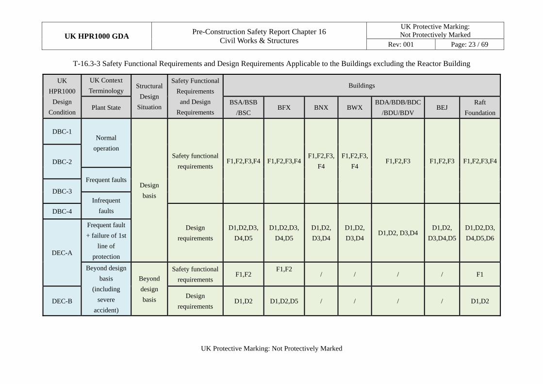
T-16.3-3 Safety Functional Requirements and Design Requirements Applicable to the Buildings excluding the Reactor Building
UK
HPR1000
Design
Condition
UK Context
Terminology Structural
Design
Situation
Safety Functional
Requirements
and Design
Requirements
Buildings
Plant State BSA/BSB
/BSC BFX BNX BWX
BDA/BDB/BDC
/BDU/BDV BEJ
Raft
Foundation
DBC-1 Normal
operation
Design
basis
Safety functional
requirements F1,F2,F3,F4 F1,F2,F3,F4
F1,F2,F3,
F4
F1,F2,F3,
F4 F1,F2,F3 F1,F2,F3 F1,F2,F3,F4 DBC-2
Frequent faults
DBC-3 Infrequent
faults DBC-4
Design
requirements
D1,D2,D3,
D4,D5
D1,D2,D3,
D4,D5
D1,D2,
D3,D4
D1,D2,
D3,D4 D1,D2, D3,D4
D1,D2,
D3,D4,D5
D1,D2,D3,
D4,D5,D6
DEC-A
Frequent fault
+ failure of 1st
line of
protection
Beyond design
basis
(including
severe
accident)
Beyond
design
basis
Safety functional
requirements F1,F2
F1,F2
/ / / / F1
DEC-B Design
requirements D1,D2 D1,D2,D5 / / / / D1,D2
UK HPR1000 GDA
Pre-Construction Safety Report Chapter 16 Civil Works & Structures
UK Protective Marking: Not Protectively Marked
Rev: 001 Page: 24 / 69
UK Protective Marking: Not Protectively Marked
16.4 Applicable Codes and Standards
The applicable codes and standards are selected based on the General Principles for Application of Laws, Regulations, Codes and Standards, Reference [22]. During the UK HPR1000 design, UK regulations need to be followed, which include Construction (Design and Management) (CDM) Regulations, Reference [23], and Building Regulations, Reference [24]. The codes and standards which are recognised as RGP are considered.
In order to select applicable codes and standards, an approach to codes and standards for civil structures which reflects the ALARP principle is carried out. More details about the approach to codes and standards are specified in Reference [14].
Strategy on application of codes and standards for the UK HPR1000 considers the following:
a) Adoption of American codes and standards for strength design.
b) Adoption of a combination of American and European codes for serviceability design.
c) Material specification is in accordance with European and British codes.
The application of US nuclear design codes and standards in the UK has been developed to identify the gaps between US codes and UK context and to provide an approach/methodology to eliminate these gaps. More details about the application of codes and standards are specified in Reference [15].
The codes and standards listed below are either the latest version at the time of production of this report or the most compatible to the primary code. The primary codes and standards are supported by a series of supplementary documents and will be listed in its relevant sections or reports.
16.4.1 Seismic Analysis
a) ASCE/SEI 4-16, Seismic Analysis of Safety-Related Nuclear Structures, American Society of Civil Engineers, 2017, Reference [25];
b) ASCE/SEI 43-05, Seismic Design Criteria for Structures, Systems, and Components in Nuclear Facilities, American Society of Civil Engineers, 2005, Reference [26].
16.4.2 Structural Analysis and Design
a) Internal Containment Structure Design
ASME Boiler & Pressure Vessel Code, Section III, Division 2, Subsection CC: Code for Concrete Containments, American Society of Mechanical Engineers, July 2017, Reference [27].
UK HPR1000 GDA
Pre-Construction Safety Report Chapter 16 Civil Works & Structures
UK Protective Marking: Not Protectively Marked
Rev: 001 Page: 25 / 69
UK Protective Marking: Not Protectively Marked
b) Other Nuclear Safety-related Structure Design
1) ACI 349M-13, Code Requirements for Nuclear Safety-Related Concrete Structures and Commentary, American Concrete Institute, August 2013, Reference [28];
2) BS EN 1992, Eurocode 2, Design of Concrete Structures and its UK National Annex, December 2004, Reference [29].
c) Foundation Design
1) BS EN, Eurocode 7, Geotechnical design and its UK National Annex, BS EN 1997, February 2009, Reference [30];
2) ACI 349M-13, Code Requirements for Nuclear Safety-Related Concrete Structures and Commentary, American Concrete Institute, August 2013, Reference [28];
3) NUREG-0800, US NRC Standard Review Plan for Review of Safety Analysis Reports for Nuclear Power Plants-LWR Edition. Section 3.8.5: Foundations, Revision4, September 2013, Reference [31].
16.4.3 Materials
a) BS EN 206: 2013, Concrete - Specification, Performance, Production and Conformity, Reference [32];
b) BS EN 10080:2005, Steel for the Reinforcement of Concrete - Weldable Reinforcing Steel –General, December 2005, Reference [33];
c) BS 4449:2005, Specification for Carbon Steel Bars for the Reinforcement of Concrete, November 2005, Reference [34];
d) Pr EN10138:2009, Prestressing Steels, August 2009, Reference [35].
16.4.4 Metrication
The design and construction of the UK HPR1000 is carried out based on the international metric system. However, if the reference code or standard is only in the form of imperial system, there are two available options for applying the UK HPR1000 design according to the specific conditions:
a) Conversion of the code or standard to international metric system for carrying out the UK HPR1000 design;
b) Conversion of the design input from metric to imperial units, and then carries out the design according to the imperial code, finally conversion of the design output from imperial to metric system.
UK HPR1000 GDA
Pre-Construction Safety Report Chapter 16 Civil Works & Structures
UK Protective Marking: Not Protectively Marked
Rev: 001 Page: 26 / 69
UK Protective Marking: Not Protectively Marked
16.5 Seismic Analysis
16.5.1 Seismic Input for SSE1 and SSE2 Structures
16.5.1.1 Design Response Spectra
For the GDA phase, the European Utility Requirement (EUR) spectra, Reference [36], are adopted as the Design Basis Earthquake (DBE) input motion for the seismic analysis of SSE1 and SSE2 structures. The peak horizontal and vertical ground accelerations are 0.30 g and 0.20 g respectively. The design response spectra are applied at the bottom of the foundation.
In the site specific design phase, site specific design response spectra will be developed and used for the seismic analysis.
16.5.1.2 Design Time Histories
For each subgrade condition, a single set of time histories consisting of two horizontal components and one vertical component are generated to perform time history analysis of civil structures.
The set of time histories is compatible with the design response spectra and satisfies the requirements defined in Reference [26], such as requirements about time increment and duration, amplitude, directional correlation, power spectral densities, etc. The development method of time histories refers to Appendix A in the report Generic Design Parameters for Civil Engineering, Reference [37].
16.5.1.3 Subgrade Properties
The generic subgrade properties are defined in the section 3.4 of the report Generic Design Parameters for Civil Engineering, Reference [37].
16.5.2 Modelling of Structures
The structures are simulated using three-dimensional finite element models that can represent the properties of mass and stiffness appropriately. The mass of the structure includes self-weight, equipment, distribution systems, effective live load, etc. The stiffness of the structural component is represented based on the material properties and the geometric features.
The structural components are modelled as appropriate element types such as beam elements, shell elements, etc. A reasonable element mesh size of elements is adopted to achieve results of an acceptable accuracy, taking into account the different analysis purposes of finite element models.
The detailed modelling method of structures is described in Reference [19].
16.5.3 Seismic Analysis of SSE1 Structures
The quasi one-step method is adopted to carry out seismic analysis of SSE1 structures
UK HPR1000 GDA
Pre-Construction Safety Report Chapter 16 Civil Works & Structures
UK Protective Marking: Not Protectively Marked
Rev: 001 Page: 27 / 69
UK Protective Marking: Not Protectively Marked
to ensure that the structures can fulfil their safety functional requirements during and after the DBE. In this method, the Soil-Structure Interaction (SSI) analysis is performed as a first step to establish dynamic responses and calculations of demands on components are performed in the subsequent step.
The SSI analysis is performed by the substructuring method with computer program ACS SASSI and the calculations of demands are recovered through the ANSYS program. The analytical seismic models for the first and subsequent steps are identical and the analytical results can be transferred directly using an automatic routine, on a node by node basis. The quasi one-step method is described in detail in Reference [19].
The Floor Response Spectra (FRS) and seismic member demands are developed to design the subsystems and structures.
16.5.3.1 Development of FRS
The FRS are developed by using the acceleration time series which are determined by the SSI analysis.
The FRS are enveloped over the generic subgrade site conditions. To account for the uncertainties in the dynamic behaviour of the soil and structures, the approach of peak broadening is adopted and the broadening used is ±15% at each peak frequency in the amplified region.
The procedure of developing the FRS is described in Reference [19].
16.5.3.2 Development of Seismic Member Demands
Seismic member demands are calculated using a quasi one-step analysis method and will be combined with other loads as shown in Sub-chapter 16.6.1.
In the quasi one-step analysis, dynamic response analysis is performed as the first step to establish overall responses, including acceleration time series and displacement histories. Calculations of member demands are performed in the subsequent step with boundary conditions consistent with the model used for the first step. The dynamic responses obtained from the first step are used as the analysis input for the second step.
The detailed information about calculations of seismic member demands is described in Reference [19].
16.5.4 Seismic Analysis of SSE2 Structures
SSE2 structures are designed to ensure that the DBE action could not cause unacceptable impact on adjacent SSCs of SSE1 structures. The seismic gaps between the SSE2 structures and adjacent SSE1 structures will be checked to ensure that there is no interaction between these structures. The detailed seismic analysis method of
UK HPR1000 GDA
Pre-Construction Safety Report Chapter 16 Civil Works & Structures
UK Protective Marking: Not Protectively Marked
Rev: 001 Page: 28 / 69
UK Protective Marking: Not Protectively Marked
SSE2 structures is described in Reference [19].
16.5.5 Analysis of Non-nuclear Seismic Structures
Non-nuclear seismic structures are outside the scope of GDA. The design of these structures adopts the normal industrial codes and standards and will be developed in the site specific stage.
16.6 Design of Nuclear Safety-Related Structures
This Sub-chapter introduces the design of nuclear safety-related structures, which includes loads and load combinations, structure descriptions, analysis and design methods.
This Sub-chapter provides the description of the Safety classified structures which include BRX, BSA/BAB/BSC, BFX, BNX, BDA/BDB/BDC/BDU/BDV, BWX and BEJ. The BEX and BPX are Non-classified structures and the descriptions are provided in the basis of safety case reports, Reference [12] and [11].
16.6.1 Design Principles
Sub-chapter 16.3.3 presents the design requirements of the civil structures under different operating conditions. In order to achieve these design requirements, the following design principles are followed in the design process.
The plant design life is 60 years which is determined in Chapter 2 Sub-chapter 2.4. The aging mechanism of the structures is considered in the design to ensure the safety functional requirements can be achieved throughout the design life.
The principal construction materials for civil structures are concrete, reinforcing steel, prestressing tendons and structural steelwork. The materials selected will be widely available in the UK and will conform to the applicable design requirements and associated specifications.
Based on the design codes and standards listed in Sub-chapter 16.4, a conservative method and complete load list are adopted to analyse and design in order to ensure that a reliable result is achieved that can satisfy the design requirements. The durability design is also taken into consideration in the normal operation.
a) BRX internal containment
For normal and fault conditions, the structures are designed to ensure that the Strength (D1) and Stability (D2) requirements can be achieved according to Reference [27]. For D1 requirements, the stresses of structures and structural members are designed to be under the allowable stresses. For D2 requirements, the global structure cannot collapse. Structures can maintain overall structural stability to prevent the overturning, sliding and flotation.
Complying with the provisions specified in Reference [27] and [29] about
UK HPR1000 GDA
Pre-Construction Safety Report Chapter 16 Civil Works & Structures
UK Protective Marking: Not Protectively Marked
Rev: 001 Page: 29 / 69
UK Protective Marking: Not Protectively Marked
durability and serviceability, the structures can satisfy Durability (D3) and Serviceability (D4) behaviour requirements. For D3, the structures are designed to achieve an adequately durable structure to ensure that the deterioration over its design working life shall not impair the performance of the structure. For D4, the deformation of the structure and structural members are limited and compatible with the requirements of equipment according to the design codes.
Air tightness (D6) for the internal containment is achieved by two barriers. The first barrier is steel liner and the second barrier is prestressing concrete structure by controlling the concrete stress to limit the development of cracks and adding structural inspection measures.
Air tightness (D6) for the external containment is achieved by the thickness of wall and the air tightness of penetrations. The crack width limitation of external containment is not required specifically for the air tightness requirement. The ventilation system placed in the annulus between the external containment and internal containment also ensures the air tightness of external containment.
For beyond design basis conditions, the detailed structure analysis will be developed in Ultimate Capacity Evaluation for Internal Containment and Cliff-edge Effect of Extreme Environmental Hazard for Civil Engineering Structure.
b) Other nuclear structures
For normal and fault conditions, the structures are designed to ensure that the Strength (D1) and Stability (D2) requirements can be achieved according to Reference [28]. For D1 requirements, the design strength of the structures and structural members are designed to be at least equal to the required strengths at all sections. For D2 requirements, the global structure cannot collapse. Structures can maintain overall structural stability to prevent the overturning, sliding and flotation.
Complying with the provisions specified in Reference [28] and [29] about durability and serviceability, the structures can satisfy Durability (D3) and Serviceability (D4) behaviour requirements. For D3, the structures are designed to achieve an adequately durable structure to ensure that the deterioration over its design working life shall not impair the performance of the structure. For D4, the deformation of the structure and structural members are limited and compatible with the displacement requirements according to the design codes.
The first barrier for Water Tightness (D5) is achieved by an internal stainless steel liner. The most important pools with steel liners are equipped with a leakage detection system. The concrete structural members are used as the second barrier by controlling concrete cracks.
UK HPR1000 GDA
Pre-Construction Safety Report Chapter 16 Civil Works & Structures
UK Protective Marking: Not Protectively Marked
Rev: 001 Page: 30 / 69
UK Protective Marking: Not Protectively Marked
For beyond design basis conditions, the detailed structure analysis will be developed in Structural Evaluation for Aircraft Impact and Cliff-edge Effect of Extreme Environmental Hazard for Civil Engineering Structure.
Detailed information about design requirements for internal and external containment, BRX internal structures, BSA/BSB/BSC, BFX, BNX, BWX, BDA/BDB/BDC/BDU/BUV and BEJ are respectively shown in the section 6 of reports basis of safety case for corresponding buildings, Reference [3], [4], [5], [6], [7], [8], [9], and [10]. Those of BEX and BPX are respectively shown in the section 5 of reports basis of safety case for corresponding buildings, Reference [11] and [12].
The design methodology is provided in Reference [16], [17], [18] and [19].
The software used in the analysis and design for the civil structures in the UK HPR1000 are listed below:
a) ACS SASSI: A commercial Windows software for linear and non-linear three-dimensional seismic SSI analysis.
b) ANSYS: A commercial finite element software which is used to undertake modelling and analysis of the civil structures.
c) ABAQUS: A commercial finite element software which is used to undertake the analysis of beyond design basis of the containment.
d) LS-DYNA: A commercial software which is used to undertake non-linear analysis against malicious aircraft impact, dropped loads analysis, etc.
e) REINCAL: A custom software, internally-developed by the RP, which determines the section and reinforcement of structural members.
The verification of the commercial software refers to the section 8.1 of report Structural Analysis and Design Method Statement, Reference [16]. The verification and validation of the custom software REINCAL is conducted. The detail information refers to the report Verification and Validation for Software used in Civil Engineering.
16.6.2 Loads and Load Combinations
The loads used in the design of the civil structures are derived from normal operation, internal hazards and external hazards. Normal loads conservatively reflect the maximum loads encountered during normal plant operation and shutdown. The external hazards are presented in Chapter 18 Sub-chapter 18.6 and the internal hazards are presented in Chapter 19 Sub-chapter 19.6.
16.6.2.1 Normal Loads
Normal loads include dead loads (D), live loads (L), liquid loads (F), earth pressures (H), prestressing loads (Fp), crane loads (Ccr), normal operating temperature loads (To) and normal operating equipment reactions (Ro).
UK HPR1000 GDA
Pre-Construction Safety Report Chapter 16 Civil Works & Structures
UK Protective Marking: Not Protectively Marked
Rev: 001 Page: 31 / 69
UK Protective Marking: Not Protectively Marked
a) Dead Loads (D)
Dead loads include the weight of the structure and the weight of the fixed piping and equipment during the normal operation of the plant.
b) Live Loads (L)
Live loads are divided into live loads during construction and during normal operation. Live loads during construction (carried loads, support imposed loads, etc.) are specified according to the construction conditions. Live loads during normal operation are produced by the use and occupancy of the buildings.
c) Liquid Loads (F)
For the water pools within the Nuclear Island (NI), hydrostatic loads caused by a depth of water in the pools are treated as liquid loads (F).
d) Earth Pressures (H)
Earth pressures are derived from the effect of backfilled soil and have impact on side walls which are not protected by another building.
e) Prestressing Loads (Fp)
Prestressing loads are the loads resulting from the application of prestressing which is used in the design of the prestressed concrete containment.
f) Crane Loads (Ccr)
The dead load components of the crane loads are incorporated within the dead load (D) estimation. The crane load-rated capacity, Ccr, is applied as a separate load case in detailed local models in accordance with the variability and probability of occurrence.
g) Normal Operating Temperature Loads (To)
Normal operating thermal loads are thermal effects and loads during normal operating or shutdown conditions, based on the most critical transient or steady-state condition.
h) Normal Operating Equipment Reactions (Ro)
Normal operating equipment reactions are piping and equipment reactions, or related internal moments and forces that occur under normal operating and shutdown conditions, excluding dead loads and earthquake reactions.
i) Ground Water Level
There are two assumptions for ground water level. One is at ground level and another is at bottom level of the common raft foundation.
UK HPR1000 GDA
Pre-Construction Safety Report Chapter 16 Civil Works & Structures
UK Protective Marking: Not Protectively Marked
Rev: 001 Page: 32 / 69
UK Protective Marking: Not Protectively Marked
16.6.2.2 Loads from Internal Hazards
Loads arising from internal hazards include internal flooding, postulated high energy pipe failures, dropped loads, internal missiles, internal explosion and vehicular impact.
a) Internal Flooding (Fa)
Internal flooding can occur due to failure of pipework or tanks containing liquid.
For compartments within the NI, the potential internal flooding is treated as a static load.
b) Postulated High Energy Pipe Failures
The effects caused by the failures of high energy pipes include overpressure, high temperature, pipe whip, jet impingement, flooding and blast.
1) Accident Pressure Load (Pa)
The design of the civil structures considers a differential pressure across the compartment or building components (such as walls or slabs).
2) Accident Temperature Load (Ta)
The accident temperature load is caused by temperature distributions within the concrete structure occurring as a result of accident conditions generated by a postulated pipe break and includes To.
3) Accident Pipe Reactions (Ra)
The accident pipe reactions are considered under thermal conditions generated by a postulated pipe break and includes Ro.
4) Jet Impingement (Yj)
The accident jet impingement load is generated by the postulated pipe breaks, and has an effect that is limited to a small area.
5) Missile Impact (Ym)
The accident missile impact load is generated by the postulated pipe breaks such as pipe whip which effect is limited to a small area.
6) Reaction of the Broken Pipe (Yr)
The accident reaction force is generated by the postulated pipe breaks.
7) Blast (Yr)
The accident blast wave is generated by the postulated pipe breaks and has an effect that is limited to a small area.
UK HPR1000 GDA
Pre-Construction Safety Report Chapter 16 Civil Works & Structures
UK Protective Marking: Not Protectively Marked
Rev: 001 Page: 33 / 69
UK Protective Marking: Not Protectively Marked
c) Dropped Loads (Am)
A dropped load occurs if the lifting device can no longer control the load on the hook. Moreover, the lifting devices have the potential to fall or collapse according to the standards applicable to the lifting devices.
d) Internal Missiles (Am)
Internal missiles may be generated by high energy component failures and rotating equipment.
e) Internal Explosion (Aexp)
The main potential sources of internal explosion include explosive gases released from a regular operational process, explosive gases released as a result of a pipe failure and high energy arcing faults.
f) Vehicular Impact (Am)
Vehicular impact may be considered as a type of missile impact.
16.6.2.3 Loads from External Hazards
Loads from external hazards include earthquake, aircraft impact, wind and tornado, temperature, snow and icing, and external explosion.
a) Earthquake (Ess)
Ess is defined as a Safe Shutdown Earthquake (SSE) which certain SSCs in the plant are designed against to ensure that they remain functional.
b) Aircraft Impact
Aircraft impact considered in GDA is divided into two types, accidental aircraft impact and malicious aircraft impact. Accidental aircraft impact is considered as a design basis event. Malicious aircraft impact is considered as beyond design basis condition.
c) Wind (W)
Wind loading is determined using the wind speed value (3-second gust).
d) Tornado Load (Wt)
Tornado loads, including the effects of missile impact, are determined in the following ways:
1) The tornado generated missile impact effects (Wtm).
2) The differential pressure loads due to rapid atmospheric pressure change (Wtp).
UK HPR1000 GDA
Pre-Construction Safety Report Chapter 16 Civil Works & Structures
UK Protective Marking: Not Protectively Marked
Rev: 001 Page: 34 / 69
UK Protective Marking: Not Protectively Marked
3) The loads due to tornado wind pressure (Wtq).
e) Temperature
Extreme ambient temperatures include extreme high or low temperatures. These temperature values are used to calculate the thermal effect on the civil structures based on the temperature gradient.
f) Snow (S) and Icing (Di)
Snow and icing loads are considered to be live loads. The design basis for snow and icing is determined in the UK HPR1000 generic site report.
g) External Explosion
An external explosion may take the form of a deflagration, which generates moderate pressures, heat or fire, or a detonation which generates high pressures and thermal effects.
h) External Flooding
According to Reference [38], flooding is highly site specific. The probable influence of flooding for civil structures will be considered in the site specific stage.
16.6.2.4 Test Loads
Test loads are loads which are applied during structural integrity or leak rate tests of prestressed concrete containment, which include:
a) Pressure during the structural integrity and leak rate tests (Pt);
b) Thermal effects and loads during the test (Tt).
16.6.2.5 Load Combinations
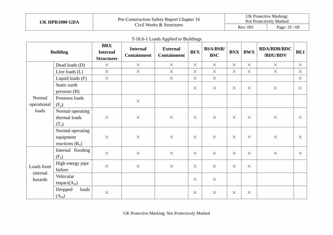
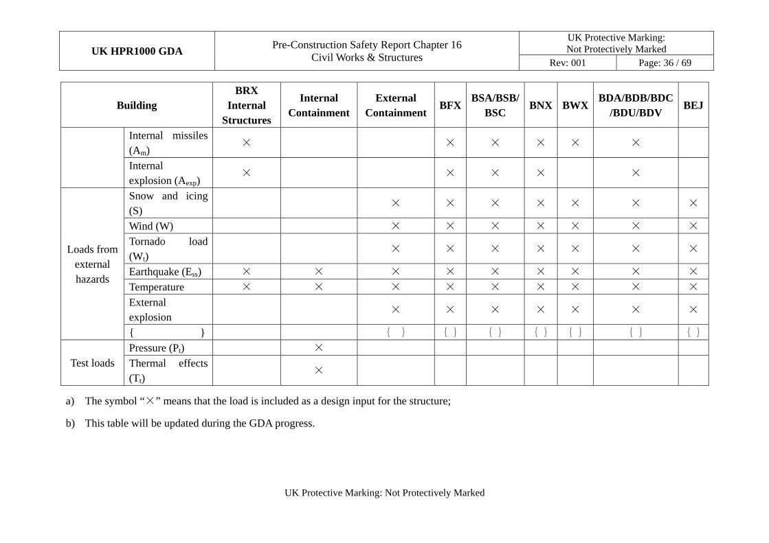
To achieve the design requirements introduced in Sub-chapter 16.3, the civil structures are analysed and designed under the loads arising from normal operations, internal hazards and external hazards. The individual loads applied to the buildings are listed in Table T-16.6-1.
The individual load is multiplied by corresponding load factor. These factored loads are combined to make different load combinations. The load combinations considered in the design of concrete structures comply with Reference [28]. The load combinations considered in the design of prestressed concrete containment comply with Reference [27]. The detailed load combinations for the civil structures are specified in method statement reports, Reference [16], [17], and [18].
UK HPR1000 GDA Pre-Construction Safety Report Chapter 16
Civil Works & Structures
UK Protective Marking: Not Protectively Marked
Rev: 001 Page: 35 / 69
UK Protective Marking: Not Protectively Marked
T-16.6-1 Loads Applied to Buildings
Building BRX
Internal Structures
Internal Containment
External Containment
BFXBSA/BSB/
BSC BNX BWX
BDA/BDB/BDC/BDU/BDV
BEJ
Normal operational
loads
Dead loads (D) × × × × × × × × ×
Live loads (L) × × × × × × × × ×
Liquid loads (F) × × × × ×
Static earth pressure (H)
× × × × × ×
Prestress loads (Fp)
×
Normal operating thermal loads (To)
× × × × × × × × ×
Normal operating equipment reactions (Ro)
× × × × × × × × ×
Loads from internal hazards
Internal flooding (Fa)
× × × × × × × × ×
High energy pipe failure
× × × × × × ×
Vehicular impact(Am)
× ×
Dropped loads (Am)
× × × × ×
UK HPR1000 GDA Pre-Construction Safety Report Chapter 16
Civil Works & Structures
UK Protective Marking: Not Protectively Marked
Rev: 001 Page: 36 / 69
UK Protective Marking: Not Protectively Marked
Building BRX
Internal Structures
Internal Containment
External Containment
BFXBSA/BSB/
BSC BNX BWX
BDA/BDB/BDC/BDU/BDV
BEJ
Internal missiles (Am)
× × × × × ×
Internal explosion (Aexp)
× × × × ×
Loads from external hazards
Snow and icing (S)
× × × × × × ×
Wind (W) × × × × × × ×
Tornado load (Wt)
× × × × × × ×
Earthquake (Ess) × × × × × × × × ×
Temperature × × × × × × × × ×
External explosion
× × × × × × ×
{ } { } { } { } { } { } { } { }
Test loads Pressure (Pt) ×
Thermal effects (Tt)
×
a) The symbol “×” means that the load is included as a design input for the structure;
b) This table will be updated during the GDA progress.
UK HPR1000 GDA
Pre-Construction Safety Report Chapter 16 Civil Works & Structures
UK Protective Marking: Not Protectively Marked
Rev: 001 Page: 37 / 69
UK Protective Marking: Not Protectively Marked
16.6.3 Nuclear Safety-Related Structures Layout
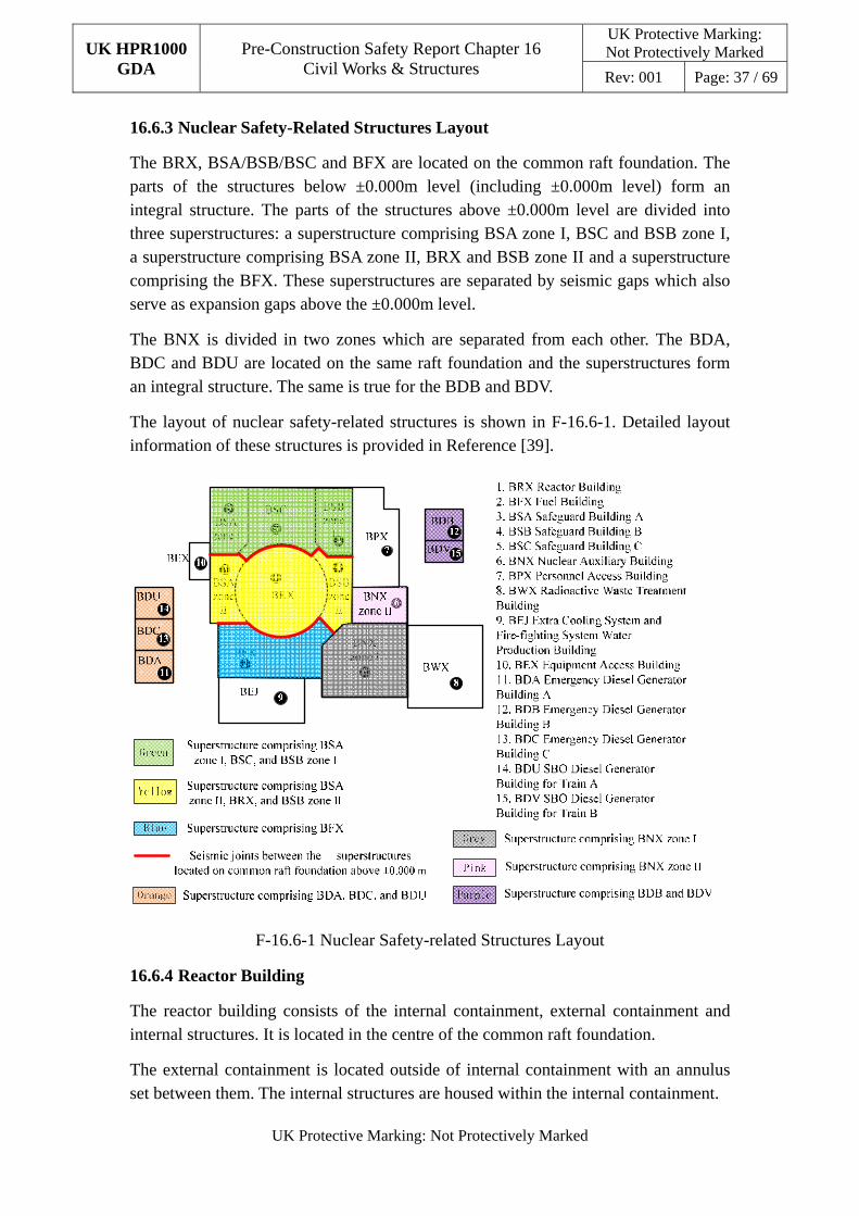
The BRX, BSA/BSB/BSC and BFX are located on the common raft foundation. The parts of the structures below ±0.000m level (including ±0.000m level) form an integral structure. The parts of the structures above ±0.000m level are divided into three superstructures: a superstructure comprising BSA zone I, BSC and BSB zone I, a superstructure comprising BSA zone II, BRX and BSB zone II and a superstructure comprising the BFX. These superstructures are separated by seismic gaps which also serve as expansion gaps above the ±0.000m level.
The BNX is divided in two zones which are separated from each other. The BDA, BDC and BDU are located on the same raft foundation and the superstructures form an integral structure. The same is true for the BDB and BDV.
The layout of nuclear safety-related structures is shown in F-16.6-1. Detailed layout information of these structures is provided in Reference [39].
F-16.6-1 Nuclear Safety-related Structures Layout
16.6.4 Reactor Building
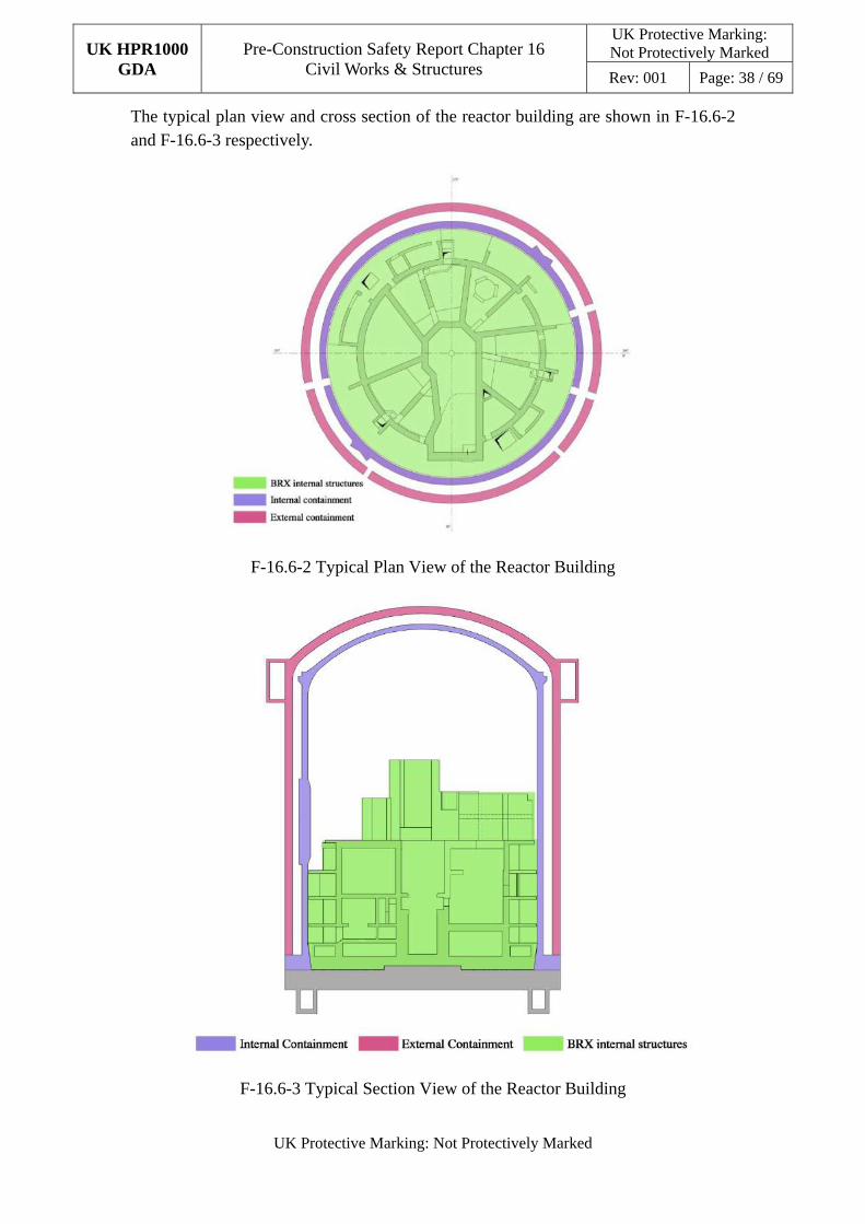
The reactor building consists of the internal containment, external containment and internal structures. It is located in the centre of the common raft foundation.
The external containment is located outside of internal containment with an annulus set between them. The internal structures are housed within the internal containment.
UK HPR1000 GDA
Pre-Construction Safety Report Chapter 16 Civil Works & Structures
UK Protective Marking: Not Protectively Marked
Rev: 001 Page: 38 / 69
UK Protective Marking: Not Protectively Marked
The typical plan view and cross section of the reactor building are shown in F-16.6-2 and F-16.6-3 respectively.
F-16.6-2 Typical Plan View of the Reactor Building
F-16.6-3 Typical Section View of the Reactor Building
UK HPR1000 GDA
Pre-Construction Safety Report Chapter 16 Civil Works & Structures
UK Protective Marking: Not Protectively Marked
Rev: 001 Page: 39 / 69
UK Protective Marking: Not Protectively Marked
16.6.4.1 Internal Containment
a) Structural Form
The internal containment is a prestressed concrete structure, the inner surface of which is covered with a steel liner. It is comprised of a cylindrical wall, dome, ribs and ring belt. Two vertical ribs are located on the cylindrical wall symmetrically. A prestressing gallery is set below the common raft foundation for the tensioning of prestressed tendons.
The main geometry of the internal containment is as follows:
1) The internal diameter is ~45m.
2) The height is ~68m.
3) The thicknesses of the cylindrical wall and dome are 1.2m and 1.0m respectively.
4) The elevation of the equipment hatch centre is +20.800m.
5) The elevation of ring belt is between +45.000m and +51.000m.
The typical plan view of components in the reactor building is shown in F-16.6-4 and the typical cross section of components in the reactor building is shown in F-16.6-5.
The internal containment prestressing systems adopt bonded tendons, which include horizontal tendons and vertical tendons. The horizontal tendons surround the cylinder wall and are anchored to the ribs. The vertical tendons are anchored to the bottom of the raft foundation at one end and anchored to the ring belt at the other end.
The steel liner is composed of anchoring system and liner plate. The anchoring system is anchored to the inner concrete surface of the internal containment and at the top of the reactor building foundation. The anchoring system of the steel liner is buried within the concrete structure and the steel liner plate is welded to the anchoring system. The anchoring system is composed of grids at right angles. The anchoring system is used to reinforce the steel liner and ensure its stability during construction and operation periods. It can also serve as the construction formwork of the internal containment wall.
The monitoring system is embedded in the internal containment, which will monitor the structural behaviour of the internal containment throughout the service lifetime. More detailed information is described in Sub-chapter 16.9.
In order to allow for the passage of equipment, personnel and pipes, the internal containment and external containment are equipped with an equipment hatch, two personnel access airlocks and other small penetrations. There are also some
UK HPR1000 GDA
Pre-Construction Safety Report Chapter 16 Civil Works & Structures
UK Protective Marking: Not Protectively Marked
Rev: 001 Page: 40 / 69
UK Protective Marking: Not Protectively Marked
typical secondary structural members arranged in the internal containment, for example, the fuel transfer tube and the polar crane bracket.
b) Analysis and Design Method
The analysis and design of the internal containment are divided into two parts: prestressed containment global structural analysis and design and local detailed analysis and design.
The aim of the analysis and design is to satisfy that the structural behaviour requirements as described in Sub-chapter 16.3.3.1 can be achieved.
1) Prestressed Containment Global Structural Analysis and Design
The prestressed containment global structural analysis and design includes modelling of the structural system, load application to the model, load combinations, allowable stress design for service loads, and allowable stress design for factored loads.
This analysis and design process is based on Reference [27]. The structure is modelled and analysed using ANSYS.
The requirements identification for design of the internal containment liner, and analysis and design of the liner will be conducted.
2) Local Detailed Analysis and Design
For the global model of containment, some small penetrations in the current zones which would require an increase in discretisation for accurate representation need to be neglected. Hence, the local models need to provide a more accurate representation of the penetrations layouts to provide better resolution of the local stresses. Detailed design of these zones therefore needs be conducted by combining the results from both the local and global model analyses.
The detailed design methodology is provided in Reference [18].
16.6.4.2 External Containment
a) Structural Form
The external containment is located outside of the internal containment. It is a reinforced concrete structure composed of a cylindrical wall and dome. A passive water tank is located on the top of the cylindrical wall.
The main geometrical parameters of the external containment are the following:
1) The internal diameter is ~51m;
2) The height is ~70m;
UK HPR1000 GDA
Pre-Construction Safety Report Chapter 16 Civil Works & Structures
UK Protective Marking: Not Protectively Marked
Rev: 001 Page: 41 / 69
UK Protective Marking: Not Protectively Marked
3) The thickness of the cylindrical wall and dome is 1.5m.
The typical plan view of components in the reactor building is shown in F-16.6-4 and the typical cross section of components in the reactor building is shown in F-16.6-5.
b) Analysis and Design Method
A conservative methodology is adopted, largely based on the American nuclear-specific codes and standards (which are internationally recognised design codes and standards for nuclear facilities). This ensures reliable results which satisfy the requirements of all safety-related design conditions. The structural design also considers durability and the potential aging mechanisms during normal operation. Where required, beyond design basis assessments will be performed with processes and arguments developed to demonstrate lack of cliff-edge in the response.
Civil structural analysis and design includes global and local structural analysis, serviceability design checks and durability design.
The global structural analysis generates the overall response of the structure and provides the distribution of the internal forces, moment and deflections of structural members. As part of global analysis, the overturning and sliding stability of each structure will be evaluated. The results of the global structural analysis will be evaluated to confirm member section sizes and quantities of reinforcement based upon the specified codes and standards.
For local areas of concrete walls and slabs with discontinuities or large penetrations, refined results are obtained from detailed analysis. The detailed design of local areas or components is carried out and compared against the results of the analysis.
During the analysis and design, the serviceability and durability design requirements (given in terms of exposure categories and classes) are evaluated.
More detailed information about analysis and design method can be found in the report Structural Analysis and Design Method Statement and Raft Foundation Analysis and Design Method Statement, Reference [16] and [17].
16.6.4.3 BRX Internal Structures
a) Structural Form
The BRX internal structures are located in the centre of the BRX. The plan view of the internal structure is a circle with a radius of 22.5m. The total height is ~41m and the height above the ground is 33.2m.
The BRX internal structures comprise three main functional levels below:
UK HPR1000 GDA
Pre-Construction Safety Report Chapter 16 Civil Works & Structures
UK Protective Marking: Not Protectively Marked
Rev: 001 Page: 42 / 69
UK Protective Marking: Not Protectively Marked
1) +1.200m (main equipment floor).
2) +5.660/+7.160m (reactor pool).
3) +17.500m (service floor).
4) Other auxiliary levels (served by stairs and a lift).
The typical plan view of components in the reactor building is shown in F-16.6-4 and the typical cross section of components in the reactor building is shown in F-16.6-5.
The BRX internal structures include the reactor cavity, secondary shield wall and reactor pools.
The reactor cavity is composed of a cylinder which is coaxial with the reactor building. The cavity supports the reactor pressure vessel and acts as radiation shielding to protect personnel and equipment. The secondary shield walls consist of walls, support slabs and floors. The walls and the reactor cavity form the compartments that enclose all the main reactor cooling systems and equipment.
The reactor pool is composed of two parts, the cavity pool and the reactor internal component pool. The pool is lined internally with a stainless steel liner. The liner forms the primary barrier to potential leakage and the concrete walls and slabs form the secondary barrier.
The BRX internal structures are reinforced concrete walls and slab structures. The horizontal loading is transferred by the slabs to the walls. The vertical loading is supported by the slabs and is transferred by walls of the secondary shield wall, reactor cavity and reactor pools to the common raft foundation.
Detailed design requirements and the layout of the BRX internal structures are provided in Reference [4].
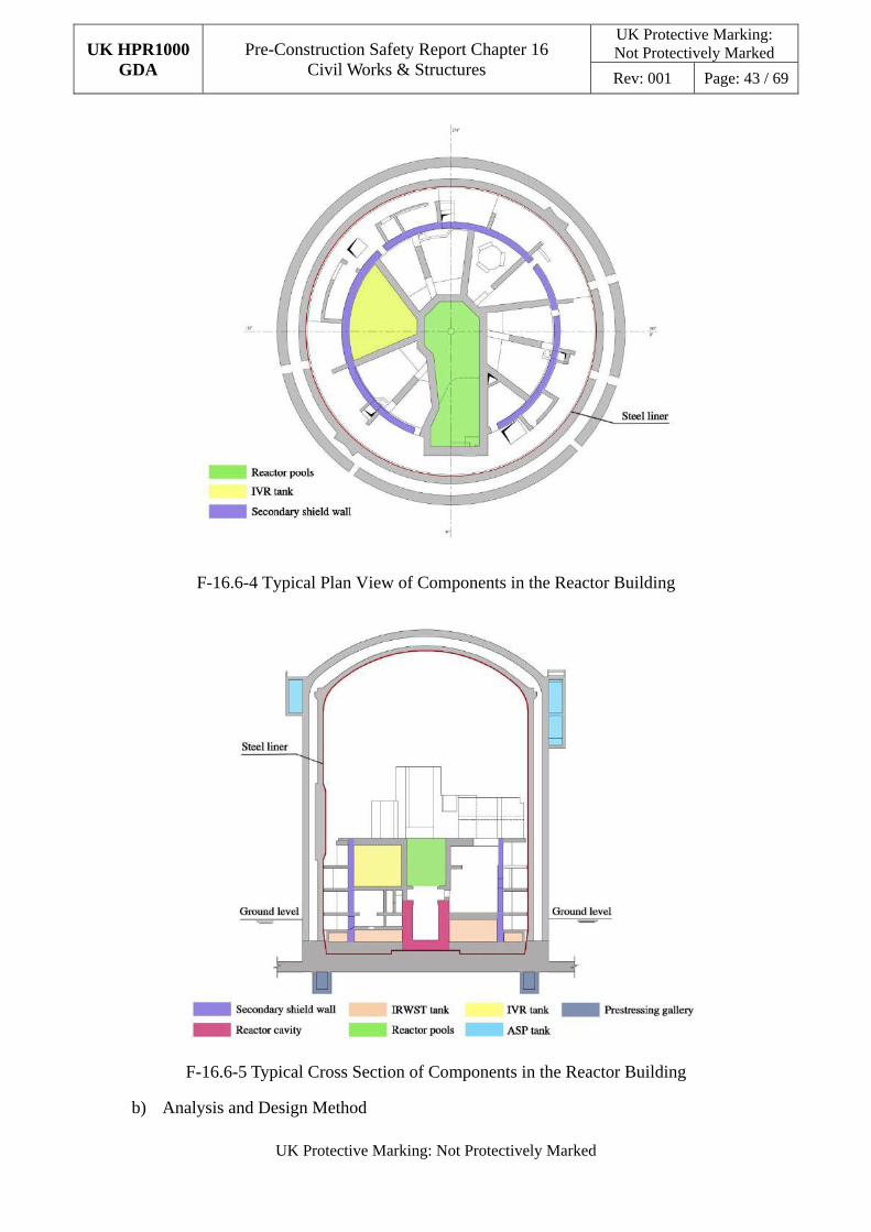
UK HPR1000 GDA
Pre-Construction Safety Report Chapter 16 Civil Works & Structures
UK Protective Marking: Not Protectively Marked
Rev: 001 Page: 43 / 69
UK Protective Marking: Not Protectively Marked
F-16.6-4 Typical Plan View of Components in the Reactor Building
F-16.6-5 Typical Cross Section of Components in the Reactor Building
b) Analysis and Design Method
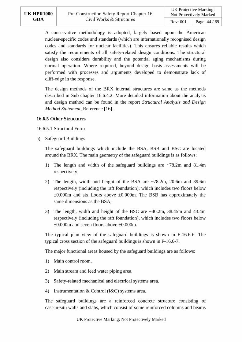
UK HPR1000 GDA
Pre-Construction Safety Report Chapter 16 Civil Works & Structures
UK Protective Marking: Not Protectively Marked
Rev: 001 Page: 44 / 69
UK Protective Marking: Not Protectively Marked
A conservative methodology is adopted, largely based upon the American nuclear-specific codes and standards (which are internationally recognised design codes and standards for nuclear facilities). This ensures reliable results which satisfy the requirements of all safety-related design conditions. The structural design also considers durability and the potential aging mechanisms during normal operation. Where required, beyond design basis assessments will be performed with processes and arguments developed to demonstrate lack of cliff-edge in the response.
The design methods of the BRX internal structures are same as the methods described in Sub-chapter 16.6.4.2. More detailed information about the analysis and design method can be found in the report Structural Analysis and Design Method Statement, Reference [16].
16.6.5 Other Structures
16.6.5.1 Structural Form
a) Safeguard Buildings
The safeguard buildings which include the BSA, BSB and BSC are located around the BRX. The main geometry of the safeguard buildings is as follows:
1) The length and width of the safeguard buildings are ~78.2m and 81.4m respectively;
2) The length, width and height of the BSA are ~78.2m, 20.6m and 39.6m respectively (including the raft foundation), which includes two floors below ±0.000m and six floors above ±0.000m. The BSB has approximately the same dimensions as the BSA;
3) The length, width and height of the BSC are ~40.2m, 38.45m and 43.4m respectively (including the raft foundation), which includes two floors below ±0.000m and seven floors above ±0.000m.
The typical plan view of the safeguard buildings is shown in F-16.6-6. The typical cross section of the safeguard buildings is shown in F-16.6-7.
The major functional areas housed by the safeguard buildings are as follows:
1) Main control room.
2) Main stream and feed water piping area.
3) Safety-related mechanical and electrical systems area.
4) Instrumentation & Control (I&C) systems area.
The safeguard buildings are a reinforced concrete structure consisting of cast-in-situ walls and slabs, which consist of some reinforced columns and beams
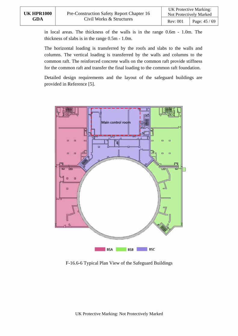
UK HPR1000 GDA
Pre-Construction Safety Report Chapter 16 Civil Works & Structures
UK Protective Marking: Not Protectively Marked
Rev: 001 Page: 45 / 69
UK Protective Marking: Not Protectively Marked
in local areas. The thickness of the walls is in the range 0.6m - 1.0m. The thickness of slabs is in the range 0.5m - 1.0m.
The horizontal loading is transferred by the roofs and slabs to the walls and columns. The vertical loading is transferred by the walls and columns to the common raft. The reinforced concrete walls on the common raft provide stiffness for the common raft and transfer the final loading to the common raft foundation.
Detailed design requirements and the layout of the safeguard buildings are provided in Reference [5].
F-16.6-6 Typical Plan View of the Safeguard Buildings
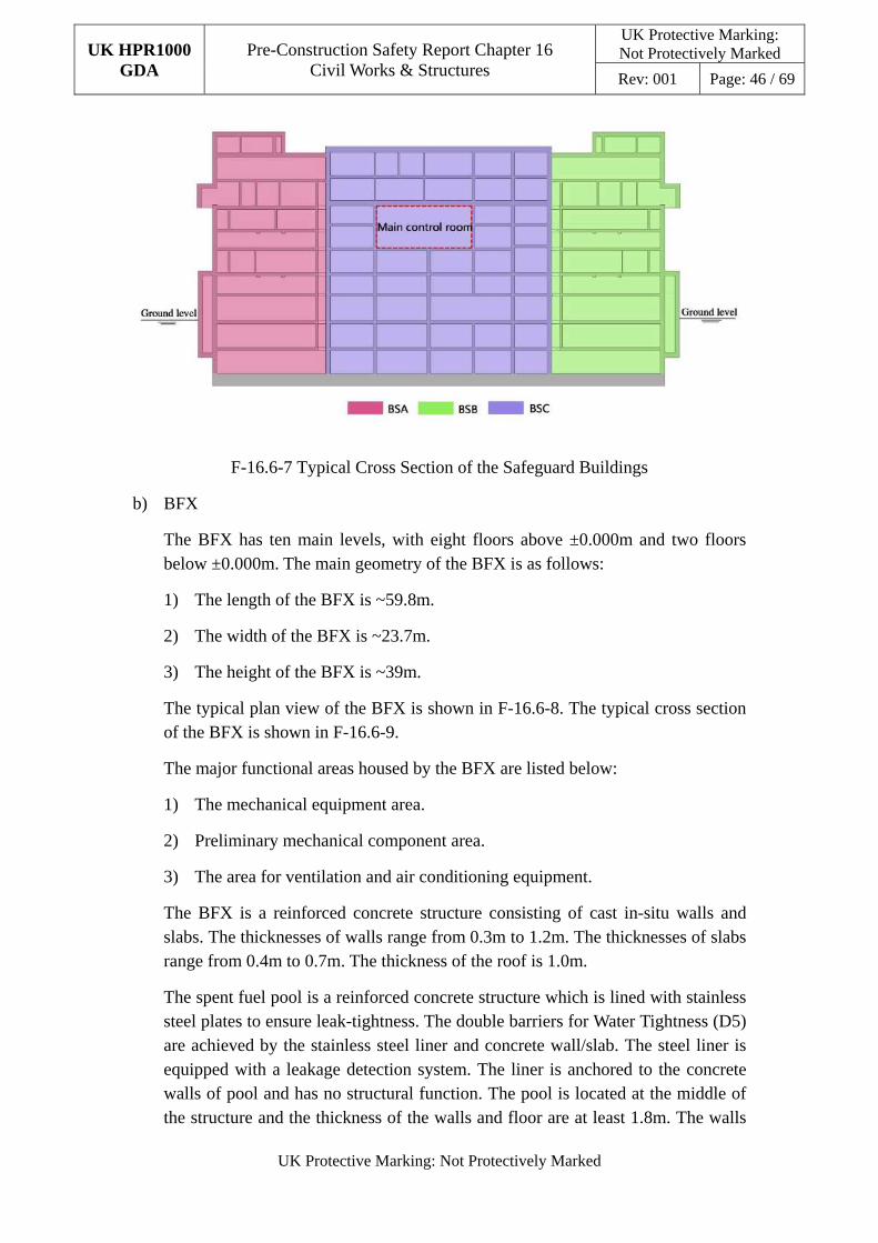
UK HPR1000 GDA
Pre-Construction Safety Report Chapter 16 Civil Works & Structures
UK Protective Marking: Not Protectively Marked
Rev: 001 Page: 46 / 69
UK Protective Marking: Not Protectively Marked
F-16.6-7 Typical Cross Section of the Safeguard Buildings
b) BFX
The BFX has ten main levels, with eight floors above ±0.000m and two floors below ±0.000m. The main geometry of the BFX is as follows:
1) The length of the BFX is ~59.8m.
2) The width of the BFX is ~23.7m.
3) The height of the BFX is ~39m.
The typical plan view of the BFX is shown in F-16.6-8. The typical cross section of the BFX is shown in F-16.6-9.
The major functional areas housed by the BFX are listed below:
1) The mechanical equipment area.
2) Preliminary mechanical component area.
3) The area for ventilation and air conditioning equipment.
The BFX is a reinforced concrete structure consisting of cast in-situ walls and slabs. The thicknesses of walls range from 0.3m to 1.2m. The thicknesses of slabs range from 0.4m to 0.7m. The thickness of the roof is 1.0m.
The spent fuel pool is a reinforced concrete structure which is lined with stainless steel plates to ensure leak-tightness. The double barriers for Water Tightness (D5) are achieved by the stainless steel liner and concrete wall/slab. The steel liner is equipped with a leakage detection system. The liner is anchored to the concrete walls of pool and has no structural function. The pool is located at the middle of the structure and the thickness of the walls and floor are at least 1.8m. The walls
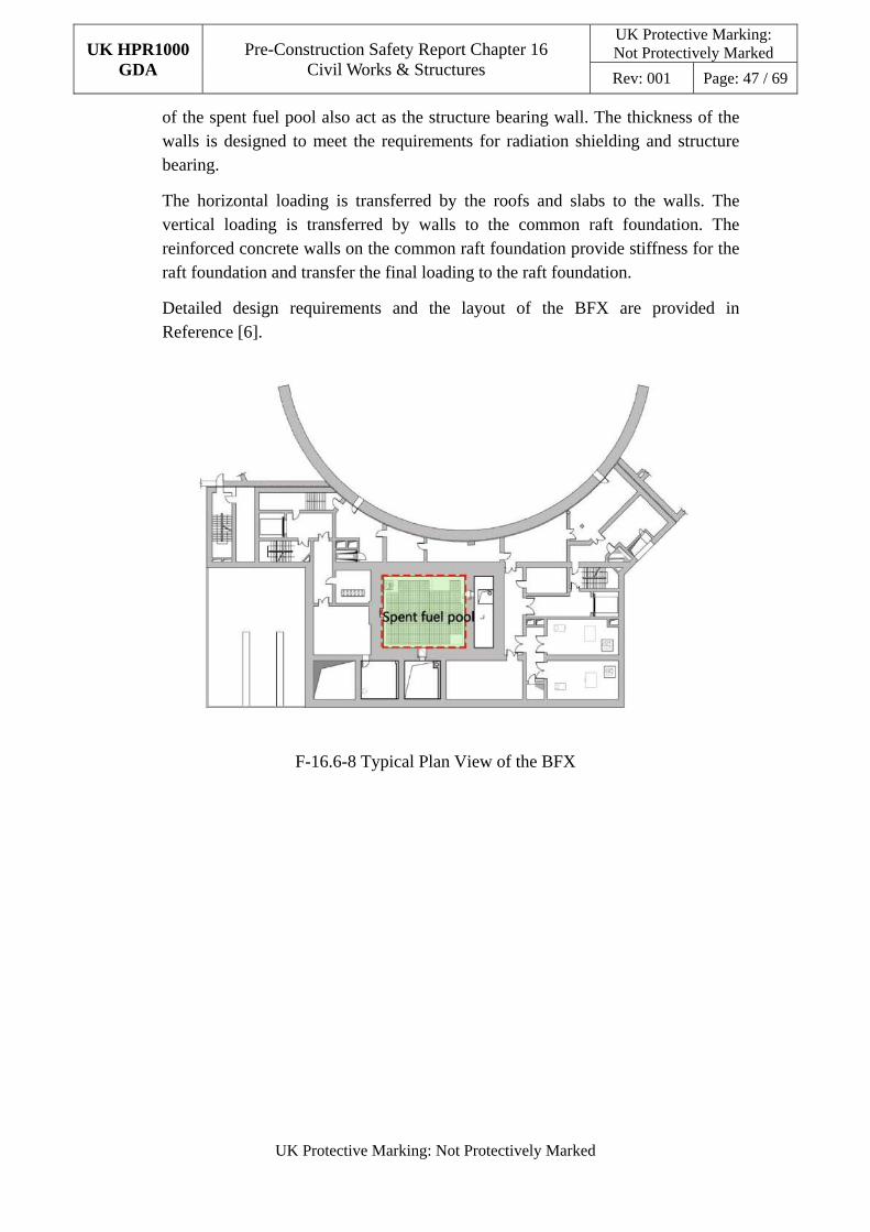
UK HPR1000 GDA
Pre-Construction Safety Report Chapter 16 Civil Works & Structures
UK Protective Marking: Not Protectively Marked
Rev: 001 Page: 47 / 69
UK Protective Marking: Not Protectively Marked
of the spent fuel pool also act as the structure bearing wall. The thickness of the walls is designed to meet the requirements for radiation shielding and structure bearing.
The horizontal loading is transferred by the roofs and slabs to the walls. The vertical loading is transferred by walls to the common raft foundation. The reinforced concrete walls on the common raft foundation provide stiffness for the raft foundation and transfer the final loading to the raft foundation.
Detailed design requirements and the layout of the BFX are provided in Reference [6].
F-16.6-8 Typical Plan View of the BFX
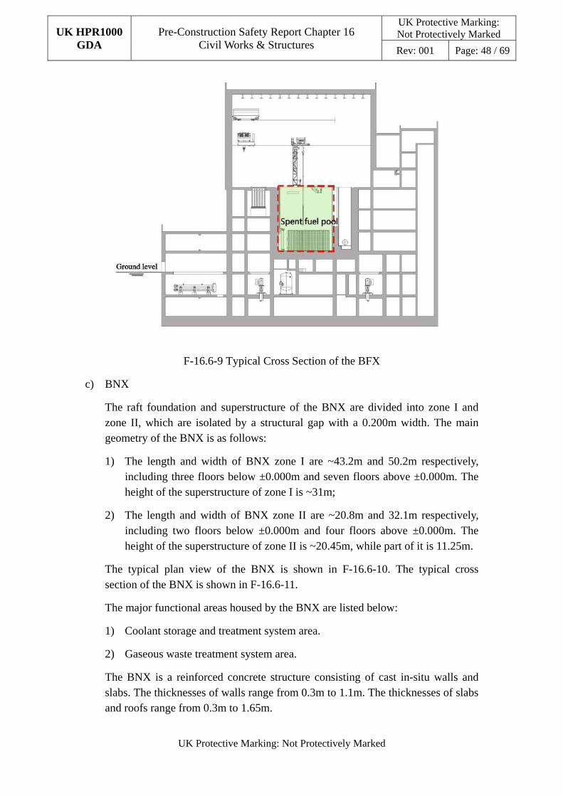
UK HPR1000 GDA
Pre-Construction Safety Report Chapter 16 Civil Works & Structures
UK Protective Marking: Not Protectively Marked
Rev: 001 Page: 48 / 69
UK Protective Marking: Not Protectively Marked
F-16.6-9 Typical Cross Section of the BFX
c) BNX
The raft foundation and superstructure of the BNX are divided into zone I and zone II, which are isolated by a structural gap with a 0.200m width. The main geometry of the BNX is as follows:
1) The length and width of BNX zone I are ~43.2m and 50.2m respectively, including three floors below ±0.000m and seven floors above ±0.000m. The height of the superstructure of zone I is ~31m;
2) The length and width of BNX zone II are ~20.8m and 32.1m respectively, including two floors below ±0.000m and four floors above ±0.000m. The height of the superstructure of zone II is ~20.45m, while part of it is 11.25m.
The typical plan view of the BNX is shown in F-16.6-10. The typical cross section of the BNX is shown in F-16.6-11.
The major functional areas housed by the BNX are listed below:
1) Coolant storage and treatment system area.
2) Gaseous waste treatment system area.
The BNX is a reinforced concrete structure consisting of cast in-situ walls and slabs. The thicknesses of walls range from 0.3m to 1.1m. The thicknesses of slabs and roofs range from 0.3m to 1.65m.
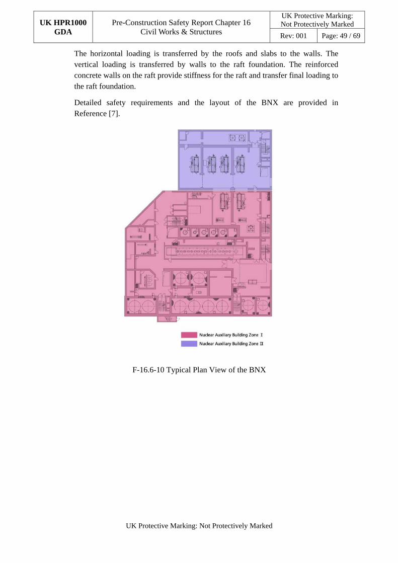
UK HPR1000 GDA
Pre-Construction Safety Report Chapter 16 Civil Works & Structures
UK Protective Marking: Not Protectively Marked
Rev: 001 Page: 49 / 69
UK Protective Marking: Not Protectively Marked
The horizontal loading is transferred by the roofs and slabs to the walls. The vertical loading is transferred by walls to the raft foundation. The reinforced concrete walls on the raft provide stiffness for the raft and transfer final loading to the raft foundation.
Detailed safety requirements and the layout of the BNX are provided in Reference [7].
F-16.6-10 Typical Plan View of the BNX
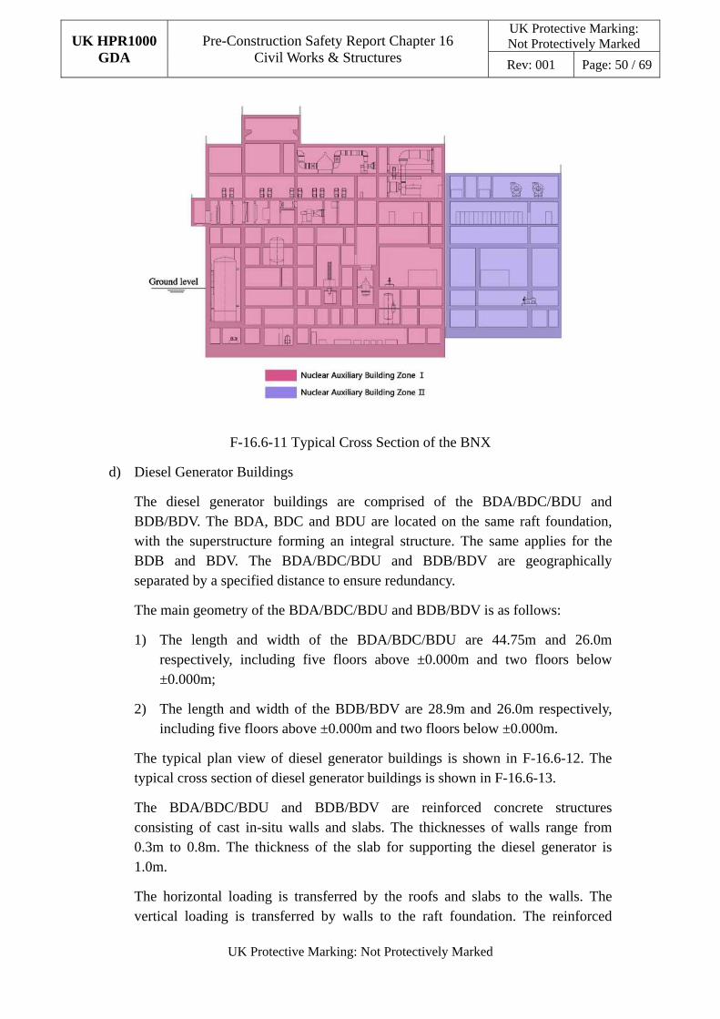
UK HPR1000 GDA
Pre-Construction Safety Report Chapter 16 Civil Works & Structures
UK Protective Marking: Not Protectively Marked
Rev: 001 Page: 50 / 69
UK Protective Marking: Not Protectively Marked
F-16.6-11 Typical Cross Section of the BNX
d) Diesel Generator Buildings
The diesel generator buildings are comprised of the BDA/BDC/BDU and BDB/BDV. The BDA, BDC and BDU are located on the same raft foundation, with the superstructure forming an integral structure. The same applies for the BDB and BDV. The BDA/BDC/BDU and BDB/BDV are geographically separated by a specified distance to ensure redundancy.
The main geometry of the BDA/BDC/BDU and BDB/BDV is as follows:
1) The length and width of the BDA/BDC/BDU are 44.75m and 26.0m respectively, including five floors above ±0.000m and two floors below ±0.000m;
2) The length and width of the BDB/BDV are 28.9m and 26.0m respectively, including five floors above ±0.000m and two floors below ±0.000m.
The typical plan view of diesel generator buildings is shown in F-16.6-12. The typical cross section of diesel generator buildings is shown in F-16.6-13.
The BDA/BDC/BDU and BDB/BDV are reinforced concrete structures consisting of cast in-situ walls and slabs. The thicknesses of walls range from 0.3m to 0.8m. The thickness of the slab for supporting the diesel generator is 1.0m.
The horizontal loading is transferred by the roofs and slabs to the walls. The vertical loading is transferred by walls to the raft foundation. The reinforced
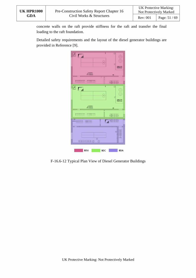
UK HPR1000 GDA
Pre-Construction Safety Report Chapter 16 Civil Works & Structures
UK Protective Marking: Not Protectively Marked
Rev: 001 Page: 51 / 69
UK Protective Marking: Not Protectively Marked
concrete walls on the raft provide stiffness for the raft and transfer the final loading to the raft foundation.
Detailed safety requirements and the layout of the diesel generator buildings are provided in Reference [9].
F-16.6-12 Typical Plan View of Diesel Generator Buildings
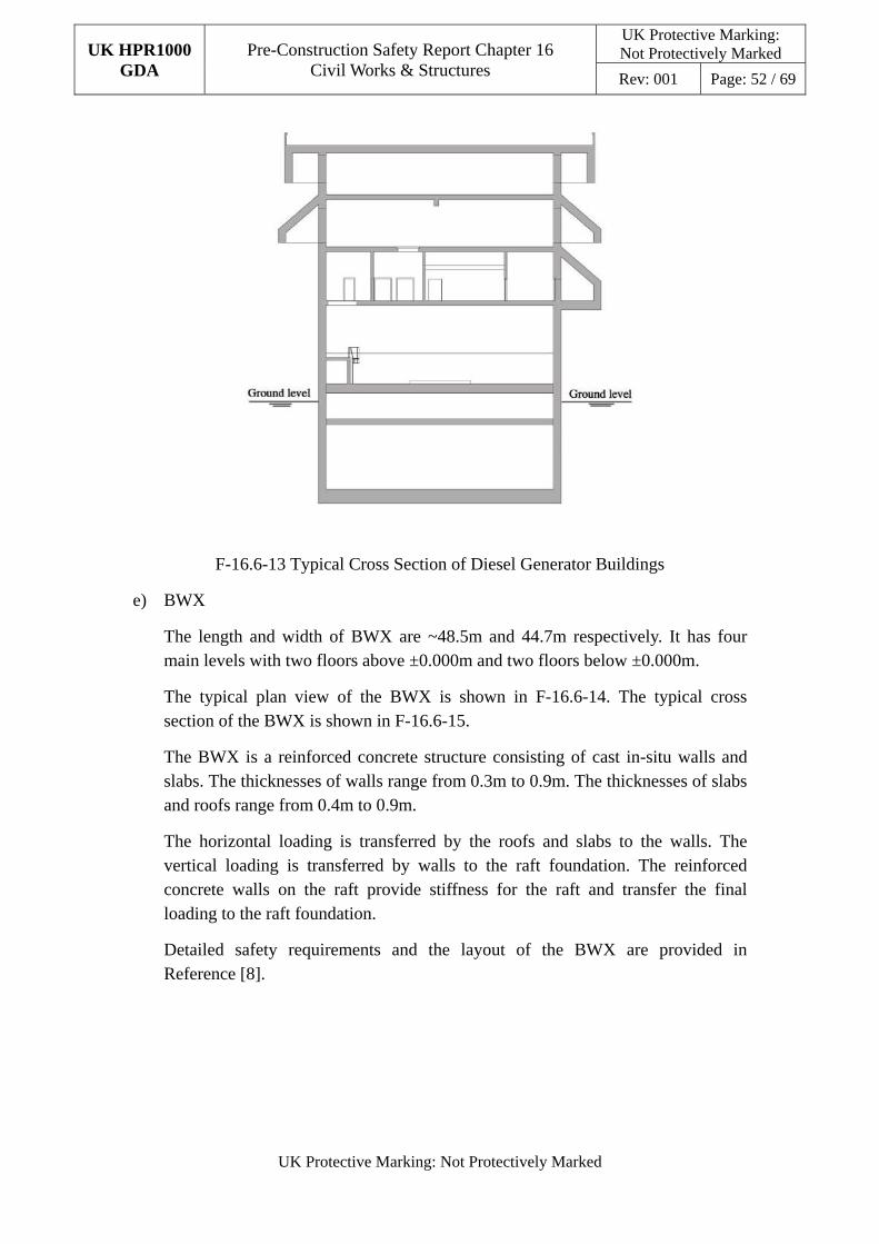
UK HPR1000 GDA
Pre-Construction Safety Report Chapter 16 Civil Works & Structures
UK Protective Marking: Not Protectively Marked
Rev: 001 Page: 52 / 69
UK Protective Marking: Not Protectively Marked
F-16.6-13 Typical Cross Section of Diesel Generator Buildings
e) BWX
The length and width of BWX are ~48.5m and 44.7m respectively. It has four main levels with two floors above ±0.000m and two floors below ±0.000m.
The typical plan view of the BWX is shown in F-16.6-14. The typical cross section of the BWX is shown in F-16.6-15.
The BWX is a reinforced concrete structure consisting of cast in-situ walls and slabs. The thicknesses of walls range from 0.3m to 0.9m. The thicknesses of slabs and roofs range from 0.4m to 0.9m.
The horizontal loading is transferred by the roofs and slabs to the walls. The vertical loading is transferred by walls to the raft foundation. The reinforced concrete walls on the raft provide stiffness for the raft and transfer the final loading to the raft foundation.
Detailed safety requirements and the layout of the BWX are provided in Reference [8].
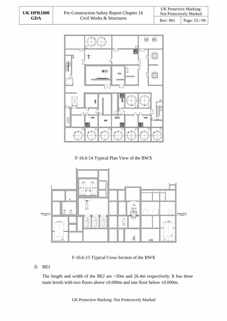
UK HPR1000 GDA
Pre-Construction Safety Report Chapter 16 Civil Works & Structures
UK Protective Marking: Not Protectively Marked
Rev: 001 Page: 53 / 69
UK Protective Marking: Not Protectively Marked
F-16.6-14 Typical Plan View of the BWX
F-16.6-15 Typical Cross Section of the BWX
f) BEJ
The length and width of the BEJ are ~50m and 26.4m respectively. It has three main levels with two floors above ±0.000m and one floor below ±0.000m.
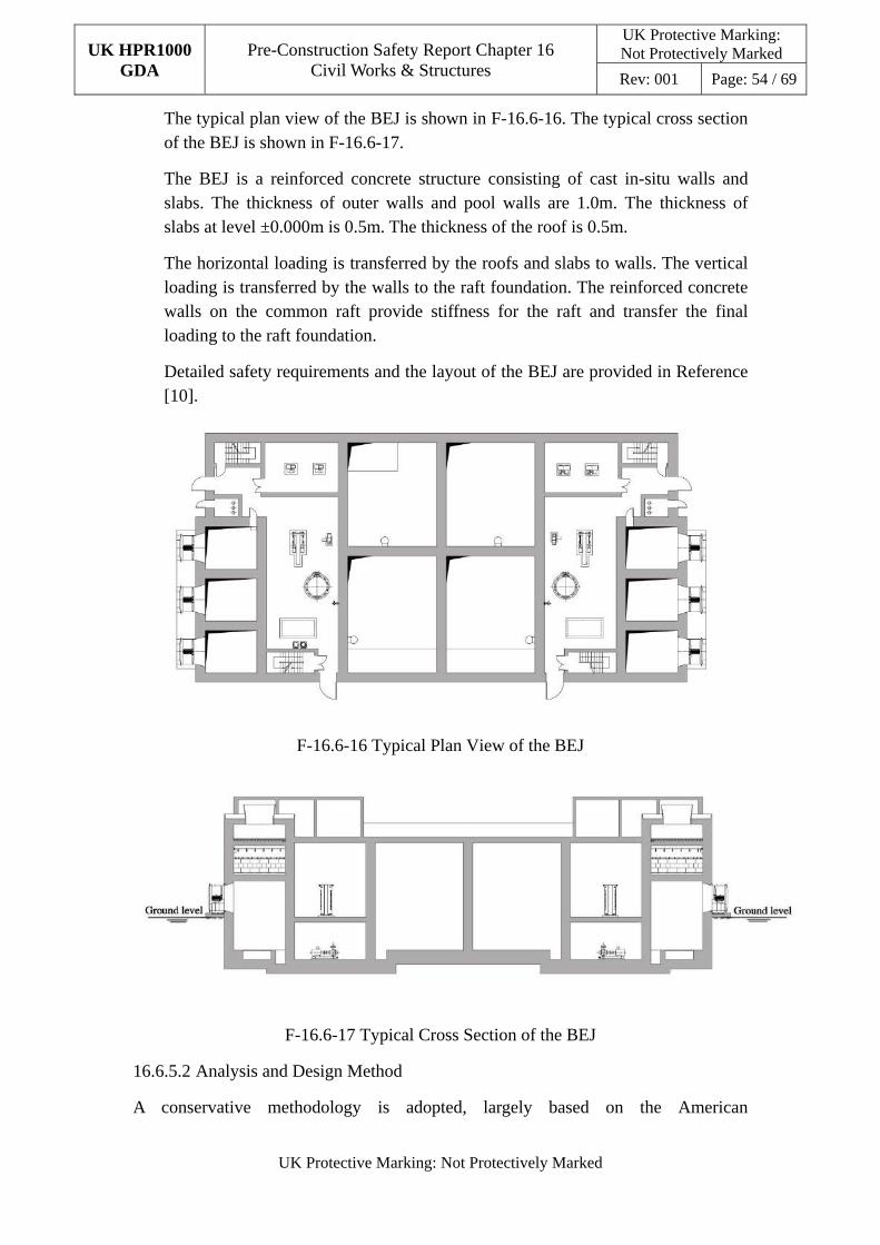
UK HPR1000 GDA
Pre-Construction Safety Report Chapter 16 Civil Works & Structures
UK Protective Marking: Not Protectively Marked
Rev: 001 Page: 54 / 69
UK Protective Marking: Not Protectively Marked
The typical plan view of the BEJ is shown in F-16.6-16. The typical cross section of the BEJ is shown in F-16.6-17.
The BEJ is a reinforced concrete structure consisting of cast in-situ walls and slabs. The thickness of outer walls and pool walls are 1.0m. The thickness of slabs at level ±0.000m is 0.5m. The thickness of the roof is 0.5m.
The horizontal loading is transferred by the roofs and slabs to walls. The vertical loading is transferred by the walls to the raft foundation. The reinforced concrete walls on the common raft provide stiffness for the raft and transfer the final loading to the raft foundation.
Detailed safety requirements and the layout of the BEJ are provided in Reference [10].
F-16.6-16 Typical Plan View of the BEJ
F-16.6-17 Typical Cross Section of the BEJ
16.6.5.2 Analysis and Design Method
A conservative methodology is adopted, largely based on the American
UK HPR1000 GDA
Pre-Construction Safety Report Chapter 16 Civil Works & Structures
UK Protective Marking: Not Protectively Marked
Rev: 001 Page: 55 / 69
UK Protective Marking: Not Protectively Marked
nuclear-specific codes and standards (which are internationally recognized design codes and standards for nuclear facilities). This ensures reliable results which satisfy the requirements of all safety-related design conditions. The structural design also considers durability and the potential aging mechanisms during normal operations. Where required, beyond design basis assessments will be performed with processes and arguments developed to demonstrate lack of cliff-edge in the response.
The design methods of the buildings described in this section are the same as the methods described in Sub-chapter 16.6.4.3.
More detail information about analysis and design method is given in the report Structural Analysis and Design Method Statement and Raft Foundation Analysis and Design Method Statement, Reference [16] and [17].
16.6.6 Foundation
16.6.6.1 Description
The BRX, BFX and BSA/BSB/BSC are located on a common raft foundation. The BNX, BWX, BEJ, BPX, BEX, BDA/BDC/BDU and BDB/BDV are separately located on independent raft foundations.
Considering that the foundations contact the soil or rocks directly, a waterproof layer is provided surrounding the external surface of the outer walls and the bottom of the foundations. The raft foundations of the buildings are shown in F-16.6-18.
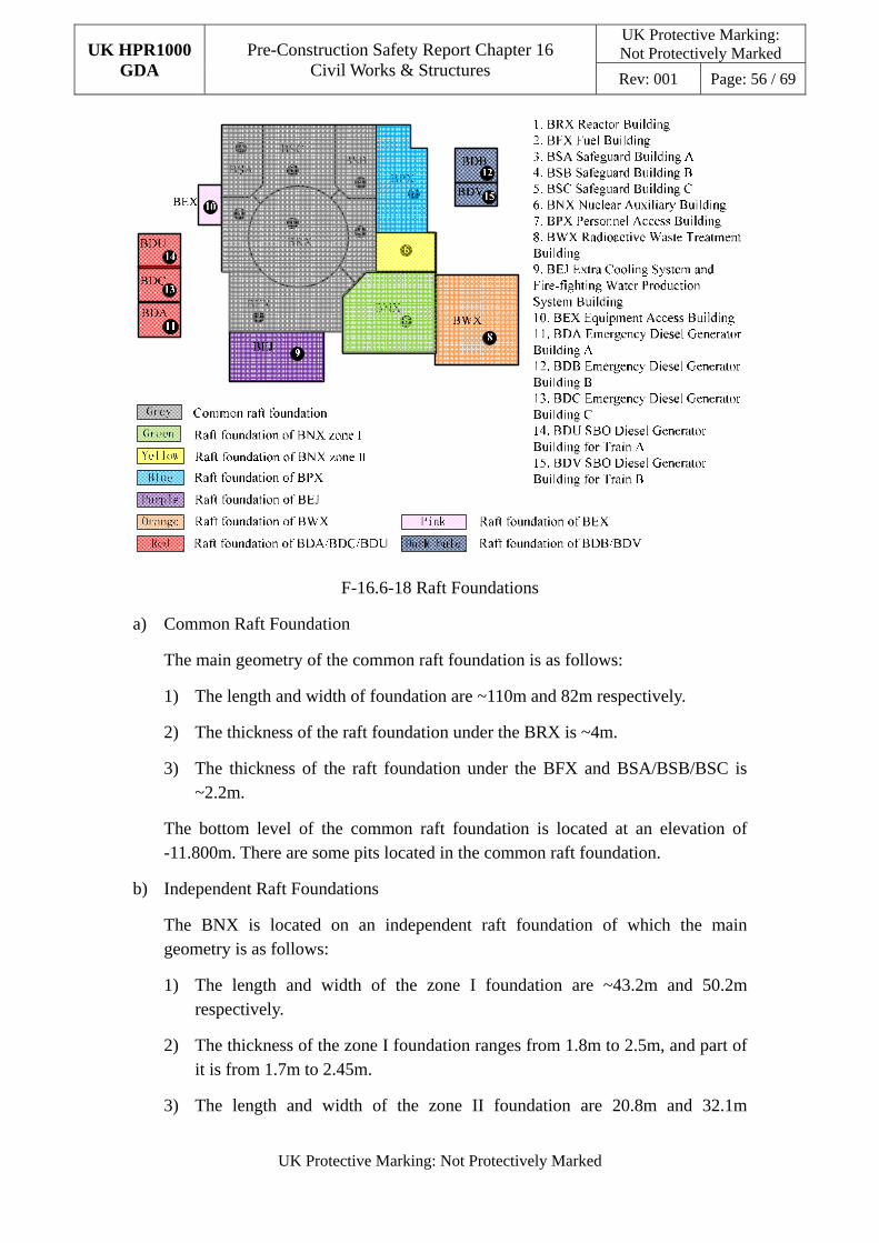
UK HPR1000 GDA
Pre-Construction Safety Report Chapter 16 Civil Works & Structures
UK Protective Marking: Not Protectively Marked
Rev: 001 Page: 56 / 69
UK Protective Marking: Not Protectively Marked
F-16.6-18 Raft Foundations
a) Common Raft Foundation
The main geometry of the common raft foundation is as follows:
1) The length and width of foundation are ~110m and 82m respectively.
2) The thickness of the raft foundation under the BRX is ~4m.
3) The thickness of the raft foundation under the BFX and BSA/BSB/BSC is ~2.2m.
The bottom level of the common raft foundation is located at an elevation of -11.800m. There are some pits located in the common raft foundation.
b) Independent Raft Foundations
The BNX is located on an independent raft foundation of which the main geometry is as follows:
1) The length and width of the zone I foundation are ~43.2m and 50.2m respectively.
2) The thickness of the zone I foundation ranges from 1.8m to 2.5m, and part of it is from 1.7m to 2.45m.
3) The length and width of the zone II foundation are 20.8m and 32.1m
UK HPR1000 GDA
Pre-Construction Safety Report Chapter 16 Civil Works & Structures
UK Protective Marking: Not Protectively Marked
Rev: 001 Page: 57 / 69
UK Protective Marking: Not Protectively Marked
respectively.
4) The thickness of the zone II foundation is 2.0m.
For the BNX, the bottom level of the zone I foundation is located at an elevation of -12.750m. The bottom level of the foundation of zone II is located at an elevation of -9.250m.
The diesel generator buildings are separately located on two independent raft foundations. The length and width of the BDA/BDC/BDU foundation are ~44.75m and 31.0m respectively. The length and width of the BDB/BDV foundation are ~31.9m and 33m respectively. The thickness of the foundation is ~1.5m and the bottom level of the foundation is located at an elevation of -12.800m.
The BWX is located on an independent raft foundation. The length and width of the BWX foundation are ~48.5m and 44.7m respectively. The thickness of the foundation is ~1.8m. The bottom level of the foundation is located at an elevation of -12.050m.
The BEJ is located on an independent raft foundation. The length and width of the BEJ foundation are ~26m and 52m respectively. The thickness of the foundation is ~1.5m. The bottom level of the foundation is located at an elevation of -4.000m.
16.6.6.2 Analysis and Design Method
The design of the raft foundations is based on the American codes and standards, relevant Euro codes and BS codes as listed in Sub-chapter 16.4.
The raft foundation is the structural element that serves as the interface between the building structures and the soil. The raft foundation needs to support the structure and ensure the stability of the buildings.
A global finite element model with the raft and superstructures is used to design the raft foundation. The raft foundation analysis and design adopt the results of the global structural analysis and seismic analysis.
The generic subgrade conditions in GDA are Soft and Medium ground conditions. Static ground springs have been derived for the main safety related buildings based on a range of shear wave velocity values for considered soil conditions.
Although generally considered to be a site specific issue and not part of the GDA, it is recognised that settlement, specifically differential settlement could introduce considerable demand to the raft design.
The overall stability analysis includes sliding, overturning stability and flotation stability.
UK HPR1000 GDA
Pre-Construction Safety Report Chapter 16 Civil Works & Structures
UK Protective Marking: Not Protectively Marked
Rev: 001 Page: 58 / 69
UK Protective Marking: Not Protectively Marked
The detailed design principles, design process, applicable codes and standards, overall stability analysis, static performance requirement and raft design as a structural element is provided in the raft foundation design methodology document, Reference [17].
16.7 Beyond Design Basis Conditions
Beyond design basis conditions are identified according to the fault sequences that have lower frequencies than that of the design basis. The beyond design basis evaluation includes the ultimate capacity evaluation for internal containment, malicious aircraft impact evaluation and cliff-edge effect evaluation of extreme environmental hazards.
16.7.1 Ultimate Capacity Evaluation for Internal Containment
16.7.1.1 Purpose
The purpose of ultimate capacity evaluation for internal containment is to evaluate the limit of containment structure capacity under the beyond design basis pressure.
16.7.1.2 Evaluation Method
This evaluation is carried out through a non-linear analysis methodology by using three-dimensional finite element simulation, which includes modelling, establishing the constitutive relations of materials, loading, global analysis of structural reactions, analysis of typical locations of containment, determination of failure modes and criteria, and evaluation of the ultimate capacity of containment according to the failure criteria.
a) Modelling
Finite element analysis software is used to establish an overall model of the containment. The model includes prestressing, steel liner, rebar, concrete, typical members and discontinuity parts (such as the equipment hatch and personnel hatches, ribs, etc.). Appropriate elements are used to simulate different materials. Concrete is simulated by solid elements, steel liner is simulated as a skin covering the surface of a concrete solid element, reinforcement is simulated as surface elements, and prestressing is simulated as beam elements.
b) Establishing the Materials Constitutive Relations
Establishing the constitutive relations of materials by considering their non-linear characteristics is carried out according to UK materials, which is then used as the input data in the model.
c) Loadings
When the model is established, a series of loadings are applied. The permanent loading and prestressing loading are set in the first analysis step, and then a
UK HPR1000 GDA
Pre-Construction Safety Report Chapter 16 Civil Works & Structures
UK Protective Marking: Not Protectively Marked
Rev: 001 Page: 59 / 69
UK Protective Marking: Not Protectively Marked
step-by-step analysis applying pressure loading is carried out in the second analysis step. In the last step, the thermal effect is taken into consideration.
d) Analysis
In accordance with the calculation results, a global analysis of structural reactions and an analysis of typical locations of containment are carried out to evaluate the structural behaviour and performance.
e) Criteria and Evaluation
Based on Reference [40], failure modes and criteria are determined. The ultimate capacity of the containment can be evaluated according to the calculation results and failure criteria.
16.7.2 Aircraft Impact Evaluation
The civil structures are designed to meet the requirements of protection against malicious aircraft impact. The detailed protection principles are described in reference [41].
16.7.2.1 Safety function
The following functional requirements are incorporated in the plant design:
a) The reactor core remains cooled, or the containment remains intact.
b) Spent fuel cooling or spent fuel pool integrity is maintained.
16.7.2.2 Scope of Protection
The civil structures which are physically protected against aircraft impact are shown in the report Basis of Safety Case for Aircraft Impact, Reference [42].
16.7.2.3 Evaluation Method
For malicious aircraft impact, the global effects, local effects, vibration effects and fire effects of the aircraft impact are considered.
{
UK HPR1000 GDA
Pre-Construction Safety Report Chapter 16 Civil Works & Structures
UK Protective Marking: Not Protectively Marked
Rev: 001 Page: 60 / 69
UK Protective Marking: Not Protectively Marked
}
16.7.3 Cliff-edge effects of extreme environmental hazards
The civil structures are designed to maintain an elastic stage in design basis conditions. For beyond design basis extreme environmental hazards, including seismic hazards, structural evaluation is needed to ensure that no sudden failure occurs. Structure evaluation will be conducted to ensure there is reasonable margin to avoid the cliff-edge effect.
The cliff-edge effects of extreme environmental hazard will be considered in the GDA process.
UK HPR1000 GDA
Pre-Construction Safety Report Chapter 16 Civil Works & Structures
UK Protective Marking: Not Protectively Marked
Rev: 001 Page: 61 / 69
UK Protective Marking: Not Protectively Marked
16.8 Construction and Testing
The design of the civil structures must be transferrable into real structures through construction. The final structural performance will be validated and shall comply with the design intent.
Detailed consideration of the construction phase of the UK HPR1000 design is not considered within the scope of the GDA. Aspects that are fundamental to underpin the safety case for construction and testing of the civil structures are taken into consideration, including requirements for materials, testing and/or inspections. CDM regulations are also considered appropriately in the design and construction.
The construction materials that are selected comply with the applicable codes and standards. They are suitable for withstanding construction, operation and accidental conditions throughout the life of plant, including decommissioning phases. The design and selection of materials shall enable inspection, maintenance and repair during this period. Provision for inspection and testing during construction will be made to demonstrate that appropriate standards of workmanship are achieved.
In terms of approach to construction, the steel liner of the internal containment cylinder and dome are used as the internal formwork for the concrete. The steel liner welds will be fully inspected before concreting. The inspection measures include visual inspection and suitable Non-Destructive Testing (NDT). The internal containment structure will be instrumented to allow the monitoring of its structural behaviour and the monitoring system will be developed during the design.
All structures will be inspected and tested during construction to confirm their compliance with the design intent and construction specifications. The inspection and test methodologies are proportionate to the safety categorisation of each structure. For any significant structural defects that are identified, their effects on the safety functional requirements are assessed and remedial measures are applied where necessary.
The containment system test will be completed before commissioning. The objective of the test is to verify that the containment system can withstand the applied pressure in an essentially elastic manner with acceptable leakage.
The tensioning installation of the internal containment bonded tendon is monitored to ensure that the required tendon preload is achieved. The grouting operation is qualified to ensure that the ducts are filled in accordance with acceptable criteria.
The stainless steel liner of the important pools (include spent fuel pool, reactor pool, etc.) will be subject to leakage tests before commissioning.
Conventional health and safety design of the buildings is considered in the GDA phase. The risks about health and safety in buildings are identified based on statistics from UK regulation and Operational Experience (OPEX) relevant to the construction,
UK HPR1000 GDA
Pre-Construction Safety Report Chapter 16 Civil Works & Structures
UK Protective Marking: Not Protectively Marked
Rev: 001 Page: 62 / 69
UK Protective Marking: Not Protectively Marked
operation, maintenance of the power plant. Typical health and safety risks include fire, explosion, noise, vibration, lifting operations, mechanical hazards, working at height, working in confined spaces, vehicle movement, and hazardous substances. Once the risks have been identified, the approach to prevention needs to be established and managed to eliminate, reduce or control the risks.
The detailed consideration of construction and testing will be developed in Construction and Testing report.
16.9 In-Service Inspection and Testing
In-service examination, maintenance, inspection and testing procedures of the civil structures will be undertaken to:
a) Demonstrate that the structures continue to meet their safety functional requirements.
b) Confirm that the structures retain or prevent leakage and are leak tight.
c) Identify any significant defects, including aging and degradation that could compromise the safety functional requirements of structures.
d) Check the validity of predictions of performance made during the design, e.g. the settlement of structures.
All nuclear safety-related structures will be visually inspected at regular intervals as required, appropriate to their operating conditions and demands. The inspection interval will be selected according to the anticipated aging and degradation mechanisms and the safety categorisation of each structure, appropriate to their operating conditions and demands.
The in-service inspection for structures consists of two types of inspection. One type is the containment inspection with embedded sensors and various devices installed for a long time and the other type is for other structures which mainly include visual inspection and topographical survey.
The sealing performance monitoring program for containment is based on the following basic principles:
a) Periodic tests including comprehensive and local tests will be conducted.
b) The bonded tendons will be directly or indirectly monitored throughout the service life to demonstrate that their integrity and behaviour are acceptable. A number of unbound tendons will be provided in the internal containment structure to allow more detailed testing and visual inspection throughout the service life. The effectiveness of the tendon monitoring program will be demonstrated and validated prior to operation.
In-service inspection and monitoring of the foundations will be undertaken. The
UK HPR1000 GDA
Pre-Construction Safety Report Chapter 16 Civil Works & Structures
UK Protective Marking: Not Protectively Marked
Rev: 001 Page: 63 / 69
UK Protective Marking: Not Protectively Marked
settlement of the foundations will be measured at regular intervals and will be compared to design predictions and acceptance limits.
The detailed consideration of in-service inspection and testing will be developed in In-service Inspection and Testing for Civil Engineering report.
16.10 ALARP
The design of civil structures of the UK HPR1000 takes the Hua-long Pressurised Reactor under construction at Fangchenggang nuclear power plant unit 3 (HPR1000 (FCG3)) as a reference, and will be developed based on UK context - moving forward in the form of ALARP.
This sub-chapter summarises the systematic review carried out against UK RGP, OPEX and takes cognisance of PSA input (and other safety assessment findings) where relevant. Based on the review results, this sub-chapter lists the gaps or high risks, and provides links to the lower tier supporting documents that address them.
The general ALARP methodology for the UK HPR1000 is described in the report ALARP Methodology, Reference [43], and the detailed ALARP demonstration for civil engineering refers to Reference [44].
16.10.1 Holistic ALARP Assessment
The holistic ALARP assessment aims at identifying potential gaps and improvements against RGP and OPEX. Where available, insights from PSA will provide additional information on potential improvements.
The following are sources of RGP for civil structures:
a) International Atomic Energy Agency (IAEA) safety standards:
1) IAEA, Safety Requirements: Safety of Nuclear Power Plant: Design, No.SSR-2/1, Revision 01, 2016.
b) Safety Assessment Principles (SAPs) and Technical Assessment Guides (TAGs):
2) ONR, Safety Assessment Principles for Nuclear Facilities, Revision 0, 2014.
3) ONR, Civil Engineering, NS-TAST-GD-017, Revision 3, 2013.
4) ONR, Civil Engineering Containments for Reactor Plants, NS-TAST-GD-020, Revision 3, 20134.
c) Codes and Standards:
The RGP codes and standards are recognised and listed in Sub-chapter 16.4.
The consistency review work has been carried out based on the requirements from RGP for the overall design of civil works and structures, including the consistency review against the SAPs & TAGs and the comparison between Chinese codes and
UK HPR1000 GDA
Pre-Construction Safety Report Chapter 16 Civil Works & Structures
UK Protective Marking: Not Protectively Marked
Rev: 001 Page: 64 / 69
UK Protective Marking: Not Protectively Marked
American codes.
The outcome of the consistency review work includes the document named consistency review against SAPs and TAGs, and the report named Safety Comparison of Chinese and American Design Codes for Nuclear Safety-related Concrete Structures.�These document and report belong to the tier 4 level within the document
hierarchy.
The risks identification work from evaluation types of PCSR Chapters in GDA has been undertaken. The risks related to civil structures are identified and the potential improvements are ongoing, for example, the potential improvement of civil structures during the assessment of equipment classification in the structure integrity area. The detailed assessment process and results refer to the related reports of different areas. The improvements of civil structures which are confirmed will be collected in the report ALARP Demonstration Report of PCSR Chapter 16.
The result shows that the safety functional requirements and the design requirements of civil works comply with RGP. Meanwhile, some potential improvements have been identified in Table T-16.10-1. Except the GAP-1 and GAP-2, other gaps have been identified and related work is in progress.
T-16.10-1 Identification of Gaps and Risks
No. Identification of Gaps and Risks
GAP-1 The design codes and standards adopted in reference design are not compliant with RGP.
GAP-2 The application of the design codes and standards selected in the UK, particularly in relation to the use of UK material grades, requires additional consideration.
16.10.2 Specific ALARP Assessment
Following the identification of gaps and risks, specific ALARP assessment is carried out. This section gives the improvement to determine whether the gaps and risks identified are reasonably practicable to implement in the design.
Improvement is undertaken according to the GDA process described in Requirements on Optioneering & Decision-Making. The improvement process and future work are described in Table T-16.10-2. Given that the optioneering reports are separate and large documents, the optioneering reports are referenced and only briefly summarised in this section.
ALARP is a continuous process. New potential improvements will be identified and analysed in the GDA process. The ALARP analysis for the new potential improvements will be conducted according to the approach of ALARP, and the document will be updated.
UK HPR1000 GDA
Pre-Construction Safety Report Chapter 16 Civil Works & Structures
UK Protective Marking: Not Protectively Marked
Rev: 001 Page: 65 / 69
UK Protective Marking: Not Protectively Marked
The ALARP assessment will be described in ALARP Demonstration Report of PCSR Chapter 16. For each gap and potential risk, further analysis and the justifications or modifications will be given. These gaps and potential risks will be traced systematically until closed.
Once the reviews discussed above have been completed, all of the identified areas for potential enhancement have been subject to optioneering and all of the reasonably practicable improvements have been incorporated, it will be possible to demonstrate that the nuclear safety risks associated with civil works and structures are ALARP.
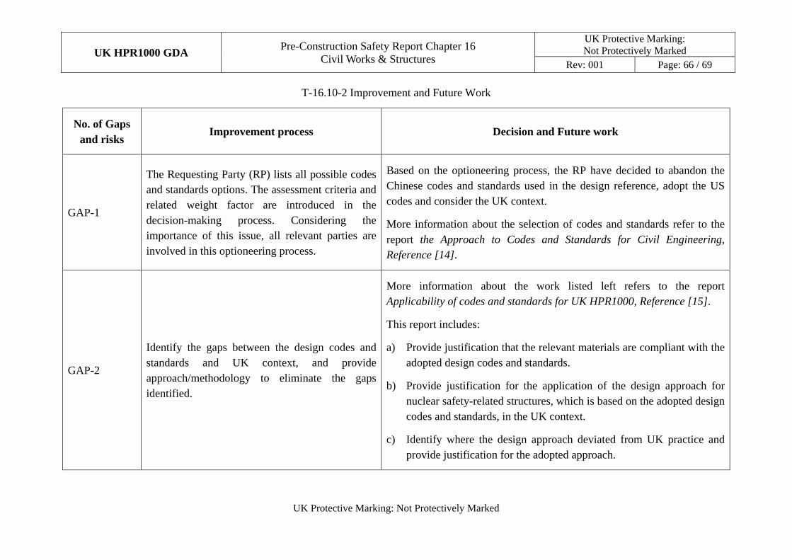
UK HPR1000 GDA Pre-Construction Safety Report Chapter 16
Civil Works & Structures
UK Protective Marking: Not Protectively Marked
Rev: 001 Page: 66 / 69
UK Protective Marking: Not Protectively Marked
T-16.10-2 Improvement and Future Work
No. of Gaps and risks
Improvement process Decision and Future work
GAP-1
The Requesting Party (RP) lists all possible codes and standards options. The assessment criteria and related weight factor are introduced in the decision-making process. Considering the importance of this issue, all relevant parties are involved in this optioneering process.
Based on the optioneering process, the RP have decided to abandon the Chinese codes and standards used in the design reference, adopt the US codes and consider the UK context.
More information about the selection of codes and standards refer to the report the Approach to Codes and Standards for Civil Engineering, Reference [14].
GAP-2
Identify the gaps between the design codes and standards and UK context, and provide approach/methodology to eliminate the gaps identified.
More information about the work listed left refers to the report Applicability of codes and standards for UK HPR1000, Reference [15].
This report includes:
a) Provide justification that the relevant materials are compliant with the adopted design codes and standards.
b) Provide justification for the application of the design approach for nuclear safety-related structures, which is based on the adopted design codes and standards, in the UK context.
c) Identify where the design approach deviated from UK practice and provide justification for the adopted approach.
UK HPR1000 GDA
Pre-Construction Safety Report Chapter 16 Civil Works & Structures
UK Protective Marking: Not Protectively Marked
Rev: 001 Page: 67 / 69
UK Protective Marking: Not Protectively Marked
16.11 Concluding Remarks
This Chapter presents the contents of the civil structures design to underpin the fundamental objective of the UK HPR1000 plant. The chapter is one of the overall PCSR documents and will be updated during the GDA progress.
The complete civil works and structures safety case is established in this chapter and relevant reference documents. The detailed arguments and evidence are provided for the sub-claims to ensure the safety case is valid, complete and evidential.
16.12 References
[1] CGN, UK HPR1000 Design Reference Report, NE15BW-X-GL-0000-000047, Rev E, 2019.
[2] General Nuclear System Limited, Scope for UK HPR1000 GDA Project, HPR/GDA/REPO/0007, Rev 001, 2019.
[3] CGN, Basis of Safety Case for Internal and External Containment, GHXRXX10001DWJG42GN, Rev D, 2019.
[4] CGN, Basis of Safety Case for BRX Internal Structures, GHXREX10001DWJG42GN, Rev B, 2018.
[5] CGN, Basis of Safety Case for Safeguard Buildings, GHXSXX10001DWJG42GN, Rev B, 2018.
[6] CGN, Basis of Safety Case for BFX, GHXFXX10001DWJG42GN, Rev C, 2019.
[7] CGN, Basis of Safety Case for BNX, GHXNXX10001DWJG42GN, Rev A, 2019.
[8] CGN, Basis of Safety Case for BWX, GHXWXX10001DWJG42GN, Rev A, 2019.
[9] CGN, Basis of Safety Case for Diesel Generator Buildings, GHXDXX10001DWJG42GN, Rev A, 2019.
[10] CGN, Basis of Safety Case for BEJ, GHXEJX10001DWSJ42GN, Rev A, 2019.
[11] CGN, Basis of Safety Case for BPX, GHXPXX10001DWJG42GN, Rev A, 2019.
[12] CGN, Basis of Safety Case for BEX, GHXEXX10001DWJG42GN, Rev A, 2019.
[13] CGN, Methodology of Safety Categorisation and Classification, GHX00100062DOZJ03GN, Rev B, 2018.
UK HPR1000 GDA
Pre-Construction Safety Report Chapter 16 Civil Works & Structures
UK Protective Marking: Not Protectively Marked
Rev: 001 Page: 68 / 69
UK Protective Marking: Not Protectively Marked
[14] CGN, The Approach to Codes and Standards for Civil Engineering, GHXNIX10010DWJG42GN, Rev C, 2018.
[15] CGN, Applicability of Codes and Standards for UK HPR1000, GHXNIX10011DWJG42GN, Rev B, 2019.
[16] CGN, Structural Analysis and Design Method Statement, GHXNIX10001DWJG42GN, Rev C, 2019.
[17] CGN, Raft Foundation Analysis and Design Method Statement, GHXNIX10002DWJG42GN, Rev C, 2019.
[18] CGN, Internal Containment Analysis and Design Method Statement, GHXRXX10010DWJG42GN, Rev C, 2019.
[19] CGN, Overall Seismic Analysis Method Statement, GHXNIX10003DWJG42GN, Rev C, 2019.
[20] CGN, Aircraft Impact Evaluation Method Statement, GHXNIX10020DWJG42GN, Rev C, 2019.
[21] CGN, Decomposition of Safety Functions, GHX80001001DOZJ03GN, Rev D, 2019.
[22] CGN, General Principles for Application of Laws, Regulations, Codes and Standards, GHX00100018DOZJ03GN, Rev F, 2018.
[23] Construction (Design and Management) Regulations (CDM), 2015.
[24] UK, Building Regulations, S.I. 2010/2214, 2010.
[25] ASCE/SEI, Seismic Analysis of Safety-Related Nuclear Structures, ASCE/SEI 4-16, 2017.
[26] ASCE/SEI, Seismic Design Criteria for Structures, Systems, and Components in Nuclear Facilities, ASCE/SEI 43-05, 2005.
[27] ASME, ASME Boiler & Pressure Vessel Code, Section III, Division 2, Subsection CC: Code for Concrete Containments, July 2017.
[28] ACI, Code Requirements for Nuclear Safety-Related Concrete Structures and Commentary, ACI 349M-13, August 2013.
[29] BS EN, Eurocode 2, Design of Concrete Structures and its UK National Annex, BS EN 1992, December 2004.
[30] BS EN, Eurocode 7, Geotechnical design and its UK National Annex, BS EN 1997, February 2009.
[31] USNRC, Standard Review Plan for Review of Safety Analysis Reports for Nuclear Power Plants-LWR Edition, NUREG-0800.
UK HPR1000 GDA
Pre-Construction Safety Report Chapter 16 Civil Works & Structures
UK Protective Marking: Not Protectively Marked
Rev: 001 Page: 69 / 69
UK Protective Marking: Not Protectively Marked
Section 3.8.5: Foundations, Revision4, September 2013.
[32] BS EN, Concrete - : Specification, performance, production and conformity BS EN 206: 2013.
[33] BS EN, Steel for the Reinforcement of Concrete - Weldable Reinforcing Steel –General, BS EN 10080:2005, December 2005.
[34] BS, Specification for Carbon Steel Bars for the Reinforcement of Concrete, BS 4449:2005, November 2005.
[35] EN, Prestressing Steels, Pr EN10138:2009, August 2009.
[36] EUR, European Utility Requirements for LWR Nuclear Power Plants, Volume 2, Chapter 4, Rev D, 2012.
[37] CGN, General Design Parameters for Civil Engineering, GHXNIX10016DWJG42GN, Rev C, 2019.
[38] General Nuclear System Limited, UK HPR1000 Generic Site Report, HPR-GDA-REPO-0015, Rev 002, 2019.
[39] CGN, Overview of the UK HPR1000 Civil Structures, GHXNIX10004DWJG42GN, Rev B, 2018.
[40] USNRC, Containment Structural Integrity Evaluation for Internal Pressure Loadings above Design Basis Pressure, RG 1.216, Reversion 0, August 2010.
[41] CGN, Aircraft Impact Safety Evaluation Methodology Report, GHX00100036DOZJ03GN, Rev D, 2019.
[42] CGN, Basis of Safety Case for Aircraft Impact, GHXNIX10021DWJG42GN, Rev C, 2019.
[43] CGN, ALARP Methodology, GHX00100051DOZJ03GN, Rev B, 2018.
[44] CGN, ALARP Demonstration Report of PCSR Chapter 16, GHX00100059KPGB03GN, Rev B, 2019.