City of Pigeon Forge, Tennessee Guidance Manual Water and ...
212
City of Pigeon Forge, Tennessee Guidance Manual Water and Sewer System Design and Construction June 2020 6/19/2020 APPROVED FOR CONSTRUCTION THE DOCUMENT BEARING THIS STAMP HAS BEEN RECEIVED AND REVIEWED BY THE TENNESSEE DEPT. OF ENVIRONMENT & CONSERVATION THIS APPROVAL SHALL NOT BE CONSTRUED AS CREATING A PRESUMPTION OF CORRECT OPERATION OR AS WARRANTING BY THE COMMISSIONER THAT THE APPROVED FACILITIES WILL REACH THE DESIGNED GOALS. DIVISION OF WATER RESOURCES APPROVAL EXPIRES 5 YEARS FROM ABOVE DATE AND IS HEREBY APPROVED FOR CONSTRUCTION BY THE COMMISSIONER June 25, 2020 DW 2020-0676
-
Upload
khangminh22 -
Category
Documents
-
view
0 -
download
0
Transcript of City of Pigeon Forge, Tennessee Guidance Manual Water and ...

City of Pigeon Forge, Tennessee
Guidance Manual
Water and Sewer System
Design and Construction
June 2020
6/19/2020
APPROVED FOR CONSTRUCTION
THE DOCUMENT BEARING THIS STAMP HAS BEEN RECEIVED AND REVIEWED BY THE
TENNESSEE DEPT. OF ENVIRONMENT & CONSERVATION
THIS APPROVAL SHALL NOT BE CONSTRUED AS CREATING A
PRESUMPTION OF CORRECT OPERATION OR AS WARRANTING BY THE
COMMISSIONER THAT THE APPROVED FACILITIES WILL REACH THE
DESIGNED GOALS.
DIVISION OF WATER RESOURCES
APPROVAL EXPIRES 5 YEARS FROM ABOVE DATE
AND IS HEREBY APPROVED FOR CONSTRUCTION BY THE COMMISSIONER
June 25, 2020
DW 2020-0676 � � � � � � � � � � � � � � � � � � � � � � � � � � � � � � � � � � � � � � � � � � � � � � � � � � � � � � � � � � � � � � � � � � � � � � � � � � � �! " # # " $ $ " " % " & ! ' ( ) " # * + , ( # - " # ! . / ( # $ " , * 0 ! + ( #1 2 3 4 5 6 6 7 8 9 5 : 4 2 5 : : ; 8 1 < = > 8 ; 4 1 7 ? = @ 5 4 > 7 = 5 1 3 ; A 56 7 = 4 ? B 6 1 3 8 ; 8 C > 8 7 7 = > 1 8 6 = 7 5 1 3 8 ; 8 7 5 4 D 5 7 7 5 ; 1 3 ; A < E 1 2 => 8 B B 3 4 4 3 8 ; = 7 1 2 5 1 1 2 = 5 6 6 7 8 9 = @ C 5 > 3 : 3 1 3 = 4 D 3 : : 7 = 5 > 2 1 2 =@ = 4 3 A ; = @ A 8 5 : 4 FG H I H J H K L K M N O P Q R R Q J K S R T Q JU V V W X Y U Z [ \ V ] W [ ^ X _ [ ` [ U W a W X b U c X Y [ d U e [0 ; @ 3 4 2 = 7 = < E 5 6 6 7 8 9 = @ C 8 7 > 8 ; 4 1 7 ? > 1 3 8 ; < E 1 2 = > 8 B B 3 4 4 3 8 ; = 7f g h i j h i f i fk l m n o p o q o nl r s t u v w u x s t y z { v | { x | y } t ~ r � r ~ { z r u v �


STATE OF TENNESSEE
DEPARTMENT OF ENVIRONMENT AND CONSERVATION DIVISION OF WATER RESOURCES
William R. Snodgrass Tennessee Tower 312 Rosa L. Parks Avenue, 11th Floor
Nashville, Tennessee 37243 PHONE: 615-532-0191 FAX: 615-532-0686
June 25, 2020
Mr. Paolo Fonda, PE Smith Seckman Reid, Inc. 2995 Sidco Drive Nashville TN 37204 RE: Pigeon Forge Water Department (PWSID# 0000548)
Sevier County
Project Number DW 2020-0676
Standard Specifications for Water Line Construction
Dear Mr. Fonda:
This letter acknowledges receipt of standard construction specifications for the City of
Pigeon Forge Water Department. We have reviewed the specifications and found them
satisfactory. The specifications have been stamped to indicate our approval. This
approval is valid for five years and will expire on June 25, 2025. You must then either
resubmit the standard specifications or request in writing for extension of approval.
The approved standard specifications may be referenced on any plans submitted for
approval before the expiration date. We are retaining one copy of the specifications for
our records. Any addenda, revisions, or correspondence concerning these specifications
should contain the DW Project Number as referenced. If you have any questions contact
us at (615) 532-0191.
Very truly yours,
R. William Hench, P.E. Drinking Water Engineering Division of Water Resources RWH/ DWS-35 cc: Knoxville Field Office – Water Resources Pigeon Forge Water Department


STATE OF TENNESSEE
DEPARTMENT OF ENVIRONMENT AND CONSERVATION DIVISION OF WATER RESOURCES William R. Snodgrass - Tennessee Tower
312 Rosa L. Parks Avenue, 11th Floor Nashville, Tennessee 37243-1102
July 23, 2020
Mr. Paolo Fonda, P.E.
Smith Seckman, Reid, Inc.
e-copy: [email protected]
2995 Sidco Drive
Nashville, TN 37204
Subject: Pigeon Forge Public Works
County: Sevier
Wastewater Project Number: 20.0402
Job Number: 1741012.0 / 0241002.0
Project: Pigeon Forge Standard Specifications
Dear Mr. Fonda:
The Tennessee Department of Environment and Conservation, Division of Water Resources, acknowledges
the receipt of your engineering documents on June 24, 2020. On July 23, 2020, we received the additional
information we previously requested.
Review of these standard sanitary sewer specifications shows that they are in conformance with our
guidelines. Therefore, they have been stamped "APPROVED". This approval will remain in effect until
July 23, 2025.
To expedite matters, please reference the assigned wastewater project number 20.0402 on any future
correspondence. If we may be of any assistance, please feel free to contact Mr. Adnan Bahour, Ph.D. at
(615) 532-0638 or by E-mail at [email protected].
Sincerely,
Vojin Janjić Manager, Water-Based Systems
cc: Water-Based Systems File
Mr. Mark Miller, Public Works Director, City of Pigeon Forge, [email protected]
Mr. Michael J. Atchley, Unit Manager, TDEC Division of Water Resources,


City of Pigeon Forge, TN 00 01 10-1 Version: 2020
SECTION 00 01 10
TABLE OF CONTENTS
Section Number
Section Title
(VOLUME 1 OF 1)
Introductory Information
00 01 01 Cover and Title Page00 01 10 Table of Contents00 01 15 List of Contacts00 01 20 General Requirements
DIVISION 01 – GENERAL REQUIREMENTS
01 57 13 Erosion and Sediment Control
DIVISION 03 – CONCRETE
03 00 05 Concrete, Mortar, and Grout Material03 31 00 Concrete and Reinforcing Steel
DIVISION 09 – FINISHES
09 97 13 Welded Steel Tank Painting
DIVISION 31 – EARTHWORK
31 11 00 Site Preparation31 11 10 Site Clearing31 23 16 Earth Excavation31 23 17 Rock Excavation31 23 19 Removal of Water31 23 23 Backfill31 70 00 Rip-Rap
DIVISION 32 – EXTERIOR IMPROVEMENTS
32 01 29 Restoration of Street Surfaces32 31 00 Vinyl Coated Chain Link Fencing32 90 00 Site Rehabilitation
DIVISION 33 – UTILITIES
33 05 23 Boring and Casing for Utility Lines33 11 00 Water Distribution System33 16 00 Potable Water Storage Tanks33 31 00 Sewers and Force Mains33 31 22 Sanitary Sewer Cleaning and Inspection

Section Number
Section Title
City of Pigeon Forge, TN 00 01 10-2 Version: 2020
33 31 30 Leakage Tests – Sewer Pipe and Force Main33 32 13 Submersible Sewer Lift Stations33 39 00 Manholes and Catch Basins
DIVISION 40 – PROCESS INTEGRATION
40 75 21 Chlorine Analyzer40 90 00 Water Instrumentation/Telemetry Monitoring
DIVISION 43 – PROCESS GAS AND LIQUID HANDLING, PURIFICATION, AND STORAGE EQUIPMENT
43 21 13 Factory-Built Water Booster Pump Stations
DIVISION 46 – WATER AND WASTEWATER EQUIPMENT
46 33 44 Peristaltic Metering Pumps
APPENDICES
Appendix A – Standard Details
1. Table of Dimensions for Concrete Thrust Blocks
2. Typical Concrete Thrust Blocking
3. Concrete Anchor
4. Casing Pipe Detail
5. Valve Box Setting
6. Fire Hydrant Installation Detail
7. Water Service Line Connection Detail
8. 1” Air Relief Valve
9. 2” Self-Flushing Hydrant
10. Precast Concrete Manhole
11. Gasket for Precast Manhole Sections
12. Resilient Connection to Manhole
13. Manhole Casting Installation

Section Number
Section Title
City of Pigeon Forge, TN 00 01 10-3 Version: 2020
14. Manhole Frame and Cover
15. Watertight Manhole Frame and Cover
16. Force Main Connection
17. Typical Trench Section
18. Utility Marker Detail
19. Drop Pipe Assembly for Standard Manholes
20. 6” PVC House Sewer Service
21. Sewer Service Line Inspection Assembly
22. Concrete Encasement
23. Pavement Replacement
24. Temporary Silt Fence

City of Pigeon Forge, TN 00 01 10-4 Version: 2020
THIS PAGE INTENTIONALLY LEFT BLANK

City of Pigeon Forge, TN 00 01 15-1 Version: 2020
CITY OF PIGEON FORGE
WATER AND SEWER SYSTEM
CONTACT LIST FOR ACCEPTANCE
PUBLIC WORKS DEPARTMENT
MARK MILLER (865) 429-7312
STORMWATER MANAGER
BRANDON WILLIAMS (865) 429-7312
UTILITIES SUPERINTENDENT
JERRY SUTTON (865) 453-3043
CHIEF BUILDING INSPECTOR
JOE DUNN (865) 429-7312
WATER TREATMENT PLANT
LYNN LIGHT (865) 453-1275
WASTEWATER TREATMENT PLANT
MARTIN CROSS (865) 428-3558
FIRE DEPARTMENT
ROGER PRICE (865) 429-7312

City of Pigeon Forge, TN 00 01 15-2 Version: 2020
THIS PAGE INTENTIONALLY LEFT BLANK

City of Pigeon Forge, TN 00 01 20-1 Version: 2020
PIGEON FORGE DEPARTMENT OF PUBLIC WORKS
WATER AND SEWER IMPROVEMENT GUIDANCE MANUAL
1. PURPOSE
The City of Pigeon Forge Department of Public Works endeavors to partner with Developers, Engineers, and Contractors to promote growth within the City Limits of Pigeon Forge and within Sevier County. The Department is committed to doing this while maintaining stringent standards on the distribution and storage of potable water and the collection of wastewater from its Service Area. The Mission of the Department is to provide sanitary services which protect both the customers within the Service Area and the waters of the State of Tennessee.
2. USE OF MANUAL
This Guidance Manual has been prepared to assist Developers, Engineers, and Contractors with the requirements of constructing infrastructure improvements within the jurisdiction of the Pigeon Forge Department of Public Works. The Guidance Manual outlines application and approval procedures that must be adhered to prior to extension of water or sewer service to any development. The Guidance Manual also summarizes basic design and construction requirements for infrastructure improvements which connect to the City of Pigeon Forge water and sewer systems.
This Guidance Manual should not be utilized as a comprehensive design and construction guide. The Manual does not include provisions for every situation that may arise. The use of sound engineering principals combined with adherence to the design criteria mandated by the State of Tennessee is necessary for the successful completion of water and sewage construction projects.
The City of Pigeon Forge reserves the right to deny any request for water or sewer service inside or outside the City Limits. The Department also reserves the right to review the design of any extension of service and determine the most advantageous sizing of that extension to meet the needs of the entire system.

City of Pigeon Forge, TN 00 01 20-2 Version: 2020
PIGEON FORGE APPROVAL PROCESS FOR WATER
AND WASTEWATER PROJECTS
06/2020
1. DRINKING WATER PROJECT WITHIN CITY LIMITS
A. Submit request for waterline extension to Director of Public Works. Information Shall include:
i. Name of Developer with address and telephone number
ii. Name of Engineer with address and telephone number
iii. Name and location of proposed development (include sketch or map with Tax Map Number and Parcel Number)
iv. Available platting and/or water service plans, including any proposed booster station(s) and water storage tank(s)
v. Topographic and boundary surveys
vi. Use of development (i.e. Commercial, Overnight Rental, Single Family Residential, etc.)
vii. Approximate number of water system customers (or Single-Family Equivalents) to be added to system
viii. Minimum and Maximum elevations on property
ix. Maximum finished floor elevation within development
x. Estimate of daily and peak hourly water consumption
xi. Approximate start and completion dates for construction.
B. Requests for water inside the City Limits will typically be analyzed by the City’s Engineer within its hydraulic model. A fee payable to the City of Pigeon Forge must be submitted with each request to cover this analysis. The fee will largely range between a minimum of $750 and a maximum of $2500 for the hydraulic review.
C. Inclusion of any water booster station or water storage tank shall require additional review by the City of Pigeon Forge and/or the City’s Engineer. Such items shall be identified and submitted to the Department of Public Works at time of water extension request, at which time a review fee will be determined in addition to the standard identified above.
D. Director of Public Works will notify Developer in a timely manner of the availability of water service.

City of Pigeon Forge, TN 00 01 20-3 Version: 2020
2. DRINKING WATER PROJECT OUTSIDE CITY LIMITS
A. Request permission of the Sevier County Water Board to connect to the county owned waterline if applicable.
B. Submit request for waterline extension to Director of Public Works. Information shall include:
i. Written permission to connect to a county owned line from the Sevier County Water Board where applicable
ii. Name of Developer with address and telephone number
iii. Name of Engineer with address and telephone number
iv. Name and location of proposed development (include sketch or map with Tax Map Number and Parcel Number)
v. Available platting and/or water service plans, including any proposed booster station(s) and water storage tank(s)
vi. Topographic and boundary surveys
vii. Use of development (i.e. Commercial, Overnight Rental, Single Family Residential, etc.)
viii. Approximate number of water system customers (or Single-Family Equivalents) to be added to system
ix. Minimum and Maximum elevations on property
x. Maximum finished floor elevation within development
xi. Estimate of daily and peak hourly water consumption
xii. Approximate start and completion dates for construction.
B. Requests for water outside the City Limits must be analyzed by the City’s Engineer within its hydraulic model and reviewed against the City’s Master Plan for Water Services. A fee payable to the City of Pigeon Forge must be submitted with each request to cover this analysis. The fee will largely range between a minimum of $1000 and a maximum of $3500 for the hydraulic review, although unusual development conditions, pumps, and storage tanks could result in a higher review cost.
C. Inclusion of any water booster station or water storage tank shall require additional review by the City of Pigeon Forge and/or the City’s Engineer. Such items shall be identified and submitted to the Department of Public Works at time of water extension request, at which time a review fee will be determined in addition to the standard identified above.

City of Pigeon Forge, TN 00 01 20-4 Version: 2020
D. Upon approval of the plans by the City's Engineer, requests for water outside the City Limits will then be submitted to the City Commission for approval. Developers shall:
i. Submit a letter addressed to the City Manager requesting to be placed on the agenda for the next available City Commission meeting. This letter shall include the developer's name, address, contact person's phone number, general information on the development (number of units to be served, general location, etc.) and the request to connect to the City's water service.
ii. The developer or his representative must be present at the City Commission meeting to represent the request and answer any questions the Commissioners may have.
E. Upon City Commission's approval, the Director of Public Works will notify Developer in a timely manner of the availability of water service.
F. A fee of one thousand dollars ($1,000 USD) per lot in the development is to be paid to the City of Pigeon Forge.
G. Maintenance easement documents suitable for recording shall be provided to the City prior to commencing construction.
3. SEWER PROJECT WITHIN CITY LIMITS
A. Submit request for sewer extension to Director of Public Works. Information Shall include:
i. Name of Developer with address and telephone number
ii. Name of Engineer with address and telephone number
iii. Name and location of proposed development (include sketch or map with Tax Map Number and Parcel Number)
iv. Available platting and/or sewer service plans, including any proposed sewer pump stations
v. Topographic and boundary surveys
vi. Use of development (i.e. Commercial, Overnight Rental, Single Family Residential, etc.)
vii. Approximate number of sewer system customers (or Single-Family Equivalents) to be added to system
viii. Minimum and Maximum elevations on property
ix. Estimate of daily and peak hourly sewer flows

City of Pigeon Forge, TN 00 01 20-5 Version: 2020
x. Approximate start and completion dates for construction.
B. Request for sewer inside the City Limits will typically be analyzed by the City’s Engineer. A fee payable to the City of Pigeon Forge must be submitted with each request to cover this analysis. The fee will range between a minimum of $500 and a maximum of $2000 depending on the sewer flow and distance from the treatment plant.
C. Inclusion of any sewer pump station shall require additional review by the City of Pigeon Forge and/or the City’s Engineer. Such items shall be identified and submitted to the Department of Public Works at time of sewer extension request, at which time a review fee will be determined in addition to the standard fee identified above.
D. Director of Public Works will notify Developer in a timely manner of the availability of sewer service.
4. SEWER PROJECT OUTSIDE CITY LIMITS
A. The City of Pigeon Forge does not offer sewer service to entities outside the City Limits. Developers must contact the Sevier County authorities for approval of alternative systems.
5. ALL WATER AND SEWER PROJECTS
A. Before construction begins on any water and sewer project:
i. All water booster stations, water storage tanks, and sewer pump stations shall require additional review by the City of Pigeon Forge. Such items shall be identified and submitted for approval to the Department of Public Works prior to bidding or procuring said equipment.
ii. Any equipment or installation specification which differs from the City of Pigeon Forge Standard Waterline or Sewer line Specifications must be submitted for approval to the Department of Public Works prior to beginning any construction.
B. Before system is placed into service:
i. All work must have been approved by the City Construction Inspector
ii. All waterlines must be pressure tested, disinfected, and receive an approved bacteriological test from the City Water Plant Operator
iii. All sewer lines must pass mandrel, air and pressure tests
iv. All pump stations must pass an operational test at their design flows

City of Pigeon Forge, TN 00 01 20-6 Version: 2020
v. All water storage tanks must be properly disinfected, pass a leakage test and receive an approved bacteriological test from the City Water Plant Operator
vi. One hardcopy and one electronic copy (in AutoCad or Microstation) of record drawings must be provided for the Public Works Department’s files
vii. The attached System Acceptance Checklists must be completed and signed by all listed parties

City of Pigeon Forge, TN 00 01 20-7 Version: 2020
PIGEON FORGE DESIGN APPROVAL PROCESS FOR WATER
AND WASTEWATER PROJECTS
06/2020
1. GENERAL
A. All extensions of water and sewer service from infrastructure owned and/or operated by the City of Pigeon Forge must be approved by the Pigeon Forge Department of Public Works and then by the City Council. Seven (7) sets of Engineering Calculations, Plans and Specifications must be submitted Public Works Director prior to submission to the Tennessee Department of Environment and Conservation (TDEC). The City of Pigeon Forge reserves the right to establish more stringent requirements on drinking water or sanitary sewer systems other than those required by TDEC.
2. FORMAT
A. In general, all submissions shall conform to the requirements of TDEC’s Community Public Water Systems Design Criteria- Part 1, Submission of Engineering Documents. The following additional requirements shall be met:
B. Engineering Report
i. At minimum, the Engineering report shall include:
a) General description of the proposed water and sewer infrastructure.
b) Average daily and peak hourly water demand calculations.
c) Fire Flow required by City Fire Department.
d) Pump and storage tank sizing calculations, if applicable.
e) Minimum and maximum pressures within force main or water system during peak demand periods.
1) For water systems, peak demand shall be the sum of the peak hourly flow and the required fire flow for the development.
ii. Report shall be stamped and signed by a Licensed Professional Engineer in the State of Tennessee.
C. Plans
i. At minimum, the Plans shall meet the following standards:

City of Pigeon Forge, TN 00 01 20-8 Version: 2020
a) All plans shall be stamped and signed by a Licensed Professional Engineer in the State of Tennessee
b) Sheet size shall be 24” x 36” minimum
c) A cover sheet shall be included. Cover shall include the name of the project, a 1”=1000 ft or greater scale map of the vicinity of the project, and contact information for the Developer and Engineer of the project.
d) Plans shall detail all connections to existing infrastructure, as well as the location of any buried or above ground utilities in the vicinity of the project.
e) Easements which will be deeded to the City of Pigeon Forge or County Water Authority shall be indicated on the drawings
f) Plans shall indicate existing and proposed grading in the vicinity of water or sewer infrastructure. Topographic information shall be provided and shall be tied to State Plane Coordinates. Assumed starting elevations should be tied to Means Sea Level (MSL). Control points shall be clearly identified.
g) Highest and lowest finished floor elevations for all existing and proposed structures shall be indicated.
h) Inclusion of any water or sewer pump station or water storage tank shall require additional review by the City of Pigeon Forge. Such items shall be identified and submitted to the Department of Public Works prior to bidding or procurement of said equipment.
D. Specifications
i. All specifications shall be stamped and signed by a Licensed Professional Engineer in the State of Tennessee
ii. A cover sheet shall be included. Cover shall include the name of the project and contact information for the Developer and Engineer of the project.
iii. Any equipment or installation specification which differs from the City of Pigeon Forge Standard Waterline or Sewerline Specifications must be submitted for approval to the Department of Public Works prior to beginning any construction.

City of Pigeon Forge, TN 00 01 20-9 Version: 2020
PIGEON FORGE GENERAL DESIGN AND CONSTRUCTION GUIDELINES FOR
WATER AND WASTEWATER PROJECTS
06/2020
1. GENERAL
A. The Design and Construction of all water and sewer improvements shall comply with the latest revisions of mandates from the following agencies and documents
i. TDEC Public Water Systems Design Criteria
ii. TDEC Design Criteria for Sewage Works
iii. Standard Building Code
iv. National Electric Code
v. OSHA
vi. City of Pigeon Forge Standard Specifications for Waterline and Sewerline Construction
vii. City of Pigeon Forge Water and Sewer System Extension Guidance Manual
B. The City of Pigeon Forge will periodically observe the progress and quality of work on water and sewer projects. Twenty-four hours prior to starting construction or concealing/covering any portion of the project the City Construction Inspector shall be notified by calling 865-429-7312 to schedule inspection of the work. The presence or absence of the City Construction Inspector does not relieve the Developer or Contractor from any provision of the plans or specifications. The City Construction Inspector shall not bear any responsibility for the safety of construction work crews. However, if unsafe work practices are observed, the representative will notify the Department of Public Works. Work may then be stopped by the Department. The City Construction Inspector shall be present and witness all pressure, leakage, and bacteriological testing. Systems shall not be connected to the City’s distribution or collection systems until such testing is completed satisfactorily.
C. All Plans and Specifications shall be approved by the State of Tennessee prior to commencement of construction. Contractors shall maintain a copy of the plans with the State Approval certification on the jobsite at all times.
D. Developers and their contractors are responsible for obtaining all construction permits, stormwater permits, discharge permits and utility crossing permits prior to commencement of construction.

City of Pigeon Forge, TN 00 01 20-10 Version: 2020
E. All work performed on the water or sewer systems shall be subject to a one-year warranty covering all material and labor. This one-year period will commence on the date of acceptance by the Department of Public Works. An annual inspection may be scheduled at the end of this period to identify deficiencies for the Developer/Contractor to remedy.
F. Record drawings indicating changes to the approved plans shall be submitted to the Department of Public Works following acceptance by the Department of Public Works.
G. Permanent easements shall be deeded to the City of Pigeon Forge upon acceptance of infrastructure line improvements. Pump station and tank sites shall be deeded fee simple to the City of Pigeon Forge.
H. Developers shall return all copies of Plans and Specifications to the Department of Public Works prior to close out of the project.
2. PRELIMINARY MATTERS
A. Developers shall obtain permanent easements across adjacent landowners where necessary at their own expense for water and sewer projects. In addition, easements shall be included for all infrastructure within the development. Minimum permanent easement width for new pipelines shall be 15 ft. Easements shall be deeded to the City of Pigeon Forge after completion of construction.
B. Pre-construction videos in DVD format shall be provided to the City of Pigeon Forge for any work within any public right-of-way or easement obtained for construction. Videos shall be utilized to evaluate restoration after construction completion.
C. Developers are required to acquire all permits required for construction, grading, utility crossings, stormwater discharge, etc. Copies of these permits may be required by the City of Pigeon Forge.
3. WATER DISTRIBUTION SYSTEM DESIGN
A. The system shall be designed to provide normal working pressures at ground level at all points in the distribution system not less than 35 psi.
B. The system shall be designed to maintain a minimum pressure of 20 psi at ground level at all points in the distribution system under a combined peak hour and fire flow condition.
i. If fire flow is provided by a gravity storage tank, this minimum pressure shall be maintained with the tank at one-half (1/2) its maximum water level. Additional fire flow capacity may be required depending upon the type and density of structures within a proposed development. The Department of Public Works should be contacted for specific requirements.

City of Pigeon Forge, TN 00 01 20-11 Version: 2020
C. Distribution systems shall be designed to limit maximum pressures to less than 100 psi at all points within the system. Where static pressures exceed 80 psi, pressure reducing devices shall be provided on mains or as part of the meter setting on individual service lines in the distribution system.
D. Fire hydrants are required along distribution lines at intervals not to exceed 500 feet. A minimum clear distance of 3 feet shall be maintained around all fire hydrants.
E. Isolation valves are required at intersections of distribution lines and along mains at intervals not to exceed 1000 feet. Placement of isolation valves shall be at fire hydrants to facilitate easy location.
4. WATERLINE CONSTRUCTION
A. The minimum size of water main which provides for fire protection and serving fire hydrants shall be 6-inch diameter. Larger size mains will be required where necessary to allow the withdrawal of the required flow while maintaining the minimum residual pressure specified above.
B. All waterlines shall have a minimum cover of 36”.
C. Sufficiently sized air release valves shall be located at all high significant high points along the length of the waterline.
D. Automatic flushing valves may be required on rural unlooped waterlines.
E. Reduced pressure backflow prevention devices may be required for commercial developments. All domestic and irrigation backflow devices shall be located at the meter with insulated hot box. The Department of Public Works shall make the determination which developments are subject to this provision.
F. Pipelines which cross public roadways owned and/or maintained by the State of Tennessee or Sevier County must be located within casing pipes.
G. All waterlines shall have a minimum of 36” separation from gas, electrical, and telecommunications lines.
H. All water lines regardless of pipe material shall have 6” of crushed stone bedding and 12” of crushed stone cover.
5. WATER BOOSTER STATIONS
A. Pump on demand type booster stations are not permissible within the Pigeon Forge Water System. Ground storage tanks or elevated water storage tanks are required on the discharge side of all booster stations to provide for fire protection and to allow storage capacity in the event of pump station failure. Hydro-pneumatic storage tanks in lieu of gravity

City of Pigeon Forge, TN 00 01 20-12 Version: 2020
storage tanks will only be approved for small developments serving fewer than 50 single-family equivalent units.
B. In general, water booster stations shall be located with all operable equipment above grade, within a structure fabricated by the pump station manufacturer. Enclosures shall be UL Listed and shall conform to the Standard Building Code. Hypochlorite dosing may be required at the station site. If required, a separate chemical dosing room will be provided as an integral part of the pump station enclosure.
C. Pumps shall be end-suction centrifugal pumps where possible. Turbine pumps will only be approved under extenuating circumstances (i.e. extremely low flow/ high pressure applications).
D. All booster stations shall be designed to maintain discharge pressures below 100 psi.
E. Any piping under flooring shall be ductile iron.
F. Surge release valves shall be included within the station and shall discharge to atmospheric pressure outside the station.
G. Provide means for bypass around booster station.
H. A low-pressure suction shutoff mechanism shall be included with the pump station. The mechanism shall not permit pressures in the suction line to drop below 20 psi.
I. Stations serving more than 10 residences must include provisions to interface with the City’s SCADA system located at the Water Treatment Plant.
J. Station sites shall provide a minimum 20 feet of clear, level area on all sides of the station within the fenced limits of the property. Paved access to the site shall meet City of Pigeon Forge standards for road construction. A gravel driveway around the station shall be provided to allow service trucks access to all four sides of the structure. Permanent restoration of the site after construction shall minimize erosion of the site.
K. Other provisions of the TDEC Public Drinking Water Design Criteria shall be adhered to.
6. WATER STORAGE TANKS
A. Storage tanks shall be sized to provide required residential, commercial and fire flows. Tanks shall be designed so that 35 psi minimum system pressure is sustained with the water level at its lowest operating level.
B. To prevent stagnant water, inlet pipes shall terminate within 3 feet of the overflow elevation within the tank.

City of Pigeon Forge, TN 00 01 20-13 Version: 2020
C. Only cylindrical welded steel, glass fused bolted steel, or prestressed concrete tanks will be allowed. Rectangular tanks will not be permitted.
D. All storage tanks shall have a level sensor and a chlorine analyzer interfaced to the Water Treatment Plant SCADA system.
E. A chlorine analyzer and hypochlorite dosing system may be required in instances where reasonable turnover of storage tanks cannot be assured. If so, the equipment shall be housed within an approved weatherproof enclosure.
F. Tank sites shall provide a minimum 20 feet of clear, level area on all sides of the tank within the fenced limits of the property. Access to the site shall meet City of Pigeon Forge standards for road construction. A gravel driveway around the site shall be provided to allow service trucks access to all four sides of the structure. Permanent restoration of the site after construction shall minimize erosion of the site.
G. Tanks serving more than 10 residences must include provisions to interface with the City’s SCADA system located at the Water Treatment Plant. If, at anytime, the station servers more than 10 residences through additional connections or any other means, it shall be upgraded to interface with the City’s SCADA system located at the Water Treatment Plant.
H. Other provisions of the TDEC Public Drinking Water Design Criteria shall be adhered to.
7. PROCEDURE FOR WATER TESTING
A. The Public Works Construction Inspector determines that the water is to be tested and sends customer to City Hall Utility Department Clerks.
B. Contractor is responsible for flushing line prior to bacteriological testing.
C. Contractor is charged a $100.00 fee for water test per each 2500 liner feet of line to be tested and a work order is generated.
D. Line will be retested at time of meter connection.
E. Work order is sent to Public Works Construction Inspector and stamped “APPROVED” for test.
F. Work order is then sent to Utility Department Superintendent to take the water sample.
G. The Utility Department takes water sample and the “BACTERIOLOGICAL EXAMINATION OF NEW LINES” report to the Water Treatment Plant Supervisor, who then tests the water sample.

City of Pigeon Forge, TN 00 01 20-14 Version: 2020
H. If the Water Treatment Plant approves sample, the work order is stamped “APPROVED” and returned to City Hall Utility Department Clerks along with a copy of the “BACTERIOLOGICAL EXAMINATION OF NEW LINES” report. Copies of both are also sent to Public Works Administration, the Construction Inspector, and the Utility Department Superintendent.
I. Upon approval, the Utility Department Superintendent informs the customer, who then must pay meter deposit and tap fee to begin water service.
8. SEWERLINE AND FORCE MAIN CONSTRUCTION
A. All gravity sewer lines conveying raw sewage shall be at least 8-inches in diameter.
B. All lines shall have a minimum cover of 36”.
C. Sufficiently sized air release or combination air release valves shall be located at all significant high points along the length of force main pipelines.
D. Pipelines which cross public roadways owned and/or maintained by the State of Tennessee or Sevier County must be located within casing pipes.
9. SEWAGE LIFT STATIONS
A. The City of Pigeon Forge endeavors to limit the number of sewage lift stations within the collection system. If gravity sewer service can be provided with reasonable depths of cut, the City reserves the right to modify sewer service plans to require such gravity service.
B. Sewage lift stations shall utilize submersible pumps, where possible. Pumps shall be able to pass a 3” diameter sphere. Grinder pumps will only be considered on a case-by-case basis, and only in developments containing less than 10 residences.
C. All stations shall have an emergency bypass connection located on the pump station parcel.
D. Station sites shall provide a minimum 20 feet of clear, level area on all sides of the station within the fenced limits of the property. Access to the site shall meet City of Pigeon Forge standards for road construction. A gravel driveway around the station shall be provided to allow service trucks access to all four sides of the structure. Permanent restoration of the site after construction shall minimize erosion of the site.
E. Stations serving more than 10 residences must include provisions to interface with the City’s SCADA system located at the Sewage Treatment Plant. If, at anytime, the station servers more than 10 residences through additional connections or any other means, it shall be upgraded to

City of Pigeon Forge, TN 00 01 20-15 Version: 2020
interface with the City’s SCADA system located at the Sewage Treatment Plant.
F. Other provisions of the TDEC Design Criteria for Sewage Works shall be adhered to.
END OF SECTION

City of Pigeon Forge, TN 00 01 20-16 Version: 2020
THIS PAGE INTENTIONALLY LEFT BLANK

City of Pigeon Forge, TN 00 01 20-17 Version: 2020
CITY OF PIGEON FORGE
WATER SYSTEM ACCEPTANCE CHECKLIST
1 System Pressure Tested
2 System Disinfected
3 Bacteria Testing Satisfactory
4 Successful Fire Flow Testing of System
5 Booster Station/Tanks Inspected and Approved
6 Telemetry Installed and Tested
7 Erosion Control Approved
8 Property Restoration Complete
9 Record Drawings Submitted
10 Service Contracts Submitted
11 All Easements Acquired and Transferred to City
12 All Warranty Deeds Transferred to City
13 All Documentation Submitted on One-Year Warranty
14 All Testing and Development Fees Paid
15 Punch List Items and Deficiencies Corrected
16 Construction is in Accordance with Guidance Manual
Contractor Developer
Emergency Phone # Emergency Phone #
Fire Department Water Treatment Plant
Chief Building Inspector Utilities Superintendent
Construction Inspector Public Works Department

City of Pigeon Forge, TN 00 01 20-18 Version: 2020
THIS PAGE INTENTIONALLY LEFT BLANK

City of Pigeon Forge, TN 00 01 20-19 Version: 2020
CITY OF PIGEON FORGE
SEWER SYSTEM ACCEPTANCE CHECKLIST
1 Sewer Lines Air and Mandrel Tested
2 Force Mains Pressure Tested
3 Lift Stations Inspected and Approved
4 Telemetry Installed and Tested
5 Erosion Control Approved
6 Property Restoration Complete
7 Record Drawings Submitted
8 Service Contracts Submitted
9 All Easements Acquired and Transferred to City
10 All Warranty Deeds Transferred to City
11 All Documentation Submitted on One-Year Warranty
12 All Testing and Development Fees Paid
13 Punch List Items and Deficiencies Corrected
14 Construction is in Accordance with Guidance Manual
Contractor DeveloperEmergency Phone # Emergency Phone #
Fire Department Water Treatment Plant
Chief Building Inspector Utilities Superintendent
Construction Inspector Public Works Department

City of Pigeon Forge, TN 00 01 20-20 Version: 2020
THIS PAGE INTENTIONALLY LEFT BLANK

City of Pigeon Forge, TN 01 57 13-1 Version: 2020
SECTION 01 57 13
EROSION AND SEDIMENT CONTROL
PART 1 GENERAL
1.01 SUMMARY
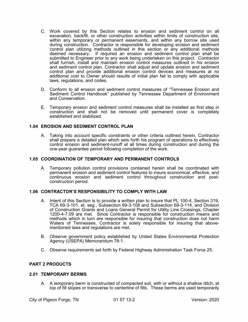
A. The work covered by this Section relates to erosion and sediment control on all cut and fill operations, excavation, backfill, or other construction activities within the limits of the construction site, within any temporary or permanent easements, and within any borrow site used during the period of construction. It is the Contractor’s responsibility to develop an erosion control plan utilizing the methods outlined in this section or any additional methods deemed necessary. This plan shall be submitted prior to any work being undertaken on this project. The Contractor shall furnish, install and maintain the erosion control measures outlined in this erosion control plan. The Contractor shall adjust and update the plan and provide additional erosion control devices at no additional cost to Owner should the results of the initial plan fail to comply with applicable codes and laws. Contractors shall be responsible for obtaining and adhering to all construction, erosion control, and stormwater permits required in conjunction with this construction.
1.02 REFERENCES
A. Tennessee Water Quality Control Act of 1977 (T.C.A. 69-3-101).
B. Tennessee Erosion and Sediment Control Handbook.
C. Pigeon Forge Stormwater Management Documents
1.03 PERFORMANCE REQUIREMENTS
A. Erosion Control:
1. Erosion control procedures, including, but not limited to mulching, shall be utilized on site as required. Erosion control shall occur as required and immediately following completion of site clearing.
B. Sediment Control:
1. Care should be taken not to damage or kill vegetation by excessive watering or by damaging silt accumulation in discharge area. Settling basins, plastic filter fabrics or other control measures should be used where necessary to protect vegetation and to achieve environmental objectives to allow sediment to settle out of runoff waters that come in contact with construction, before such water enters any surface waters.
2. Proper treatment and disposal of water from dewatering operations shall, at a minimum, require use of a sedimentation/filtration system as necessary to remove suspended matter and other possible contaminants such as spilled fuel, lubricants, etc. Design and operation of settling basin(s) and/or filter(s) shall be sufficient to protect environment in accordance with all pertinent TDEC regulations, including Tennessee Erosion and Sediment Control Handbook. Contractor shall be responsible for maintaining such compliance at all times during dewatering operations.
City of Pigeon Forge, TN 01 57 13-2 Version: 2020
C. Work covered by this Section relates to erosion and sediment control on all excavation, backfill, or other construction activities within limits of construction site, within any temporary or permanent easements, and within any borrow site used during construction. Contractor is responsible for developing erosion and sediment control plan utilizing methods outlined in this section or any additional methods deemed necessary. If required an erosion and sediment control plan shall be submitted to Engineer prior to any work being undertaken on this project. Contractor shall furnish, install and maintain erosion control measures outlined in his erosion and sediment control plan. Contractor shall adjust and update erosion and sediment control plan and provide additional erosion control devices and measures at no additional cost to Owner should results of initial plan fail to comply with applicable laws, regulations, and codes.
D. Conform to all erosion and sediment control measures of “Tennessee Erosion and Sediment Control Handbook” published by Tennessee Department of Environment and Conservation.
E. Temporary erosion and sediment control measures shall be installed as first step in construction and shall not be removed until permanent cover is completely established and stabilized.
1.04 EROSION AND SEDIMENT CONTROL PLAN
A. Taking into account specific constraints or other criteria outlined herein, Contractor shall prepare a detailed plan which sets forth his program of operations to effectively control erosion and sediment-runoff at all times during construction and during the one-year guarantee period following completion of the work.
1.05 COORDINATION OF TEMPORARY AND PERMANENT CONTROLS
A. Temporary pollution control provisions contained herein shall be coordinated with permanent erosion and sediment control features to insure economical, effective, and continuous erosion and sediment control throughout construction and post-construction period.
1.06 CONTRACTOR’S RESPONSIBILITY TO COMPLY WITH LAW
A. Intent of this Section is to provide a written plan to insure that PL 100-4, Section 319, TCA 69-3-101, et. seg., Subsection 69-3-108 and Subsection 69-3-114, and Division of Construction Grants and Loans General Permit for Utility Line Crossings, Chapter 1200-4-7.09 are met. Since Contractor is responsible for construction means and methods which in turn are responsible for insuring that construction does not harm Waters of Tennessee, Contractor is solely responsible for insuring that above-mentioned laws and regulations are met.
B. Observe government policy established by United States Environmental Protection Agency (USEPA) Memorandum 78-1.
C. Observe requirements set forth by Federal Highway Administration Task Force 25.
PART 2 PRODUCTS
2.01 TEMPORARY BERMS
A. A temporary berm is constructed of compacted soil, with or without a shallow ditch, at top of fill slopes or transverse to centerline of fills. These berms are used temporarily

City of Pigeon Forge, TN 01 57 13-3 Version: 2020
at top of newly constructed slopes to prevent excessive erosion until permanent controls are installed or slopes stabilized.
2.02 TEMPORARY SLOPE DRAINS
A. A temporary slope drain is a facility consisting of stone gutters, fiber mats, plastic sheets, concrete or asphalt gutters, half round pipe, metal pipe, plastic pipe, sod, or other material that may be used to carry water down slopes to reduce erosion.
2.03 SEDIMENT STRUCTURES
A. Sediment basins, ponds, and traps are prepared storage areas constructed to trap and store sediment from erodible areas in order to protect properties and stream channels below construction areas from excessive siltation.
2.04 CHECK DAMS
A. Check dams are barriers composed of large stones, sandbags, or other non-erodible materials placed across or partially crossing a natural or constructed drainage way.
2.05 TEMPORARY SEEDING AND MULCHING
A. Temporary seeding and mulching are measures consisting of seeding, mulching, fertilizing, and matting utilized to reduce erosion. All cut and fill slopes, including waste sites and borrow pits, shall be seeded when and where necessary to eliminate erosion.
2.06 BRUSH BARRIERS
A. Brush barriers shall consist of brush, tree trimmings, shrubs, plants, and other approved refuse from clearing and grubbing operations.
B. Brush barriers are placed on natural ground at bottom of fill slopes, where most likely erodible areas are located to restrain sedimentation particles.
2.07 BALED HAY OR STRAW CHECKS
A. Baled hay and straw checks are no longer approved for use as an erosion and sediment control measure in State of Tennessee and therefore are not permitted for use on this project.
2.08 TEMPORARY SILT FENCES
A. Silt fences are temporary measures utilizing woven wire or other approved material attached to posts with filter cloth composed of burlap, plastic filter fabric, etc., attached to upstream side of fence to retain suspended silt particles in runoff water.
B. Silt fence shall be constructed using material, fence posts and wire fence or prefabricated units in accordance with Tennessee guidelines for urban erosion and sediment control.
2.09 DIVERSION TERRACES
A. Diversion terraces shall be installed on uphill side of disturbed areas to divert surface runoff away from unstabilized slopes.

City of Pigeon Forge, TN 01 57 13-4 Version: 2020
2.10 INTERCEPTOR CHANNELS
A. Interceptor channels shall be installed across disturbed areas where slope is running parallel to direction of trenches.
2.11 TRENCH BARRIERS
A. Trench barriers shall be used where disturbed area is sloped in direction of pipeline, when slope exceeds 15 percent.
2.12 RUBBLE STONE RIP-RAP
A. Where rip-rap backfill is called for on drawings, coarse stone from excavation may be conserved and used. Rip-rap for bank stabilization shall be sound, dense, durable, and free from excessive cracks, pyrite intrusions, and other structural defects. At least ninety (90%) percent of stone shall be not less than eight (8") inches wide by twelve (12") inches long by twelve (12") inches deep and shall be approximately rectangular in shape.
2.13 SHORT-TERM EROSION CONTROL BLANKETS
A. Erosion control blanket is a measure utilizing a geotextile fabric laid onto slopes to reduce their potential to erode. Erosion control blanket for this project shall be - Manufacture and Catalog Number: North American Green of Evansville, Indiana number S150 (or product numbers noted on Drawings) or Propex, Inc. (formerly SI Geosolutions), Chattanooga, Tennessee 37416 USA, Phone (423) 899-0444, LandLOK S2 Erosion Control Blanket or equal.
2.14 EXTENDED-TERM EROSION CONTROL BLANKETS
A. Erosion control blanket is a measure utilizing a geotextile fabric laid onto slopes to reduce their potential to erode. Erosion control blanket for this project shall be - Manufacture and Catalog Number: North American Green of Evansville, Indiana number SC150 (or product numbers noted on Drawings) or Propex, Inc. (formerly SI Geosolutions), Chattanooga, Tennessee 37416 USA, Phone (423) 899-0444, LandLOK CS2 Erosion Control Blanket or equal.
2.15 TURF REINFORCEMENT MATS
A. Turn reinforcement mat is a measure utilizing a geotextile fabric laid onto slopes to reduce their potential to erode. Turf mats for this project shall be - Manufacture and Catalog Number: North American Green of Evansville, Indiana number P300 (or product numbers noted on Drawings) or Propex, Inc. (formerly SI Geosolutions), Chattanooga, Tennessee 37416 USA, Phone (423) 899-0444, LandLOK 300 or equal.
2.16 GEOTEXTILE EROSION CONTROL FABRIC FOR RIP-RAP
A. Geotextile fabric used underneath rip-rap to aid in holding rip-rap in place for erosion control shall meet Corps of Engineers specifications for erosion control fabric and shall be equivalent to Mirafi 600X fabrics.
2.17 STAKES AND FASTENERS
A. Shall be a 2-inch by 2-inch by 48-inch hardwood post for silt fences.

City of Pigeon Forge, TN 01 57 13-5 Version: 2020
PART 3 EXECUTION
3.01 GENERAL
A. Conduct construction so as to provide site with maximum protection from erosion and sedimentation at all times.
B. General guidelines to be followed by Contractor include, but are not limited to, following:
1. Grading and construction operations should be timed to minimize soil exposure.
2. Remove only existing vegetation that is absolutely necessary.
3. Reseed and mulch areas where vegetation is removed.
4. Divert runoff water around areas where vegetation has been removed.
5. Utilize measures to keep runoff velocities as low as possible.
6. Trap sediment on-site.
7. Construction debris must not be allowed to enter stream channels.
8. Inspect and maintain control measures as necessary.
9. Under no circumstances shall spent oil wastes be discharged anywhere on site without expressed written consent of Tennessee Office of Water Management.
3.02 CONSTRUCTION REQUIREMENTS
A. Engineer has authority to limit surface area of erodible earth material exposed by clearing and grubbing, surface area of erodible earth material exposed by excavation, and to direct Contractor to provide immediate permanent or temporary pollution control measures to prevent contamination of adjacent streams or other watercourses, lakes, ponds, or other water impoundments. Such work may involve construction of temporary berms, dikes, dams, sediment basins, slope drains, and use of temporary mulches, mats, seeding, or other control devices or methods as necessary to control erosion.
B. Contractor shall be required to incorporate all permanent erosion control features into project at earliest practicable time. Temporary pollution control measures shall be used to correct conditions that develop during construction; that are needed prior to installation of permanent pollution control features; or that are needed temporarily to control erosion that develops during normal construction practices, but are not associated with permanent control features on project.
C. Where erosion is likely to be a problem, clearing and grubbing operations should be so scheduled and performed that grading operations and permanent erosion control features can follow immediately thereafter if project conditions permit; otherwise erosion control measures may be required between successive construction stages. Under no conditions shall surface area of erodible earth material exposed at one time by clearing and grubbing exceed 40,000 square feet without approval of Engineer.
D. Engineer shall limit area of excavation, borrow, and embankment operations in progress commensurate with Contractor's capability and progress in keeping finish grading, mulching, seeding, and other such permanent pollution control measures.

City of Pigeon Forge, TN 01 57 13-6 Version: 2020
Should seasonal limitations make such coordination unrealistic, temporary erosion control measures shall be taken immediately to extent feasible and justified.
E. Engineer may increase or decrease amount of surface area of erodible earth material to be exposed at one time by clearing and grubbing, excavation, and borrow and fill operations as determined by his analysis of project conditions.
F. In event of conflict between these requirements and pollution control laws, rules, or regulations, or other Federal, State, or Local agencies, more restrictive laws, rules, or regulations shall apply.
G. Contract Documents may not describe all of necessary control measures to prevent erosion and sedimentation for Work. There are a number of control techniques discussed in this section as well as in State and Federal regulations and handbooks. Contractor is fully responsible for design, implementation, and maintenance of all erosion and sediment control measures and to ensure that those measures are effective in preventing erosion and sedimentation in and around construction site and for full compliance with local, state, and federal regulations.
H. Earthmoving activities shall be conducted in such a manner as to prevent accelerated erosion and sedimentation.
I. All erosion and sedimentation control measures shall be inspected by Contractor daily and immediately after periods of rainfall.
1. Repair and/or maintenance of sedimentation and erosion control measures shall be made as soon as needed.
2. Contractor shall be held responsible for implementation and maintenance of all control measures on this site.
J. Land disturbance shall be kept to a minimum.
1. Re-stabilization shall be scheduled immediately after any disturbance.
K. Silt fences shall be installed along toe of all critical cut and fill slopes.
L. Catch basins shall be protected with silt fences or other approved methods throughout construction sequence and until all disturbed areas is stabilized.
M. Erosion and sedimentation control measures shall be installed prior to all construction activities.
N. Sediment removal from control structures shall be responsibility of Contractor.
1. Sediment shall be disposed of in a manner which is consistent with overall intent of plan and which does not result in additional erosion.
O. Erosion and sedimentation control measures described herein are intended as a general guide for Contractor.
1. It is Contractor’s responsibility to provide any and all work necessary to prevent erosion of soil from construction site and to provide silt fences or other control measures as need arises during construction at no additional cost to Owner.
P. Remove all sedimentation and erosion control barriers after completion of construction and permanent stabilization of erosion.

City of Pigeon Forge, TN 01 57 13-7 Version: 2020
3.03 PIPELINE CONSTRUCTION NEAR STREAMS AND ACROSS STREAMS
A. In areas where pipeline is parallel to a stream bank, excavated material shall be stored on upslope side of trench rather than between trench and stream. Staked and entrenched silt fences shall be placed where necessary to prevent runoff from construction site from entering stream channel.
B. At stream crossings, Contractor shall utilize construction methods and erosion control methods which shall minimize entrance of sediment into stream channel. Silt fences shall be placed where required.
C. Water pumped from cofferdams or excavations must be held in settling or dewatering basins until it is at least as clean as stream water on upstream side of crossing. Once stream crossing has been completed, Contractor shall place rubble stone rip-rap to protect bank areas disturbed by construction.
D. Prior to placement of rip-rap material, sloping ground surface shall be thoroughly compacted by use of hand or mechanical tamps. Geotextile erosion control fabric shall then be placed in strict accordance with manufacturer's recommendations. At bottom of slope, rip-rap shall be placed at least two (2') feet below natural ground surface. Across face of slope, rip-rap shall be placed a minimum of five (5') feet beyond firm ditch line. See section 31 37 00.
3.04 MAINTENANCE
A. Temporary erosion and sediment control features installed by Contractor shall be acceptably maintained by Contractor until no longer needed or until permanent erosion control methods are installed. Any materials removed shall become property of Contractor.
B. In event that temporary erosion and pollution control measures are required due to Contractor's negligence, carelessness, or failure to install permanent controls as a part of work as scheduled, and are ordered by Engineer, such work shall be performed by Contractor at his own expense.
3.05 EROSION AND SEDIMENT CONTROL OUTSIDE PROJECT AREA
A. Temporary erosion and sediment control shall include construction work outside project area where such work is necessary as a result of construction such as borrow pit operations, haul roads, and equipment storage sites.
3.06 SPECIAL CONDITIONS
A. Prohibited Construction Practices - Prohibited construction practices include but shall not be limited to following:
1. Dumping of spoil material into any stream corridor, any wetlands, and any surface waters or at unspecified locations, even with permission of property owner.
2. Indiscriminate, arbitrary or capricious operation of equipment in any stream corridors, any wetlands or any surface waters.
3. Pumping of silt-laden water from trenches or other excavations into any surface waters, any stream corridors or any wetlands.
4. Damaging vegetation adjacent to or outside of access road or right-of-way.
City of Pigeon Forge, TN 01 57 13-8 Version: 2020
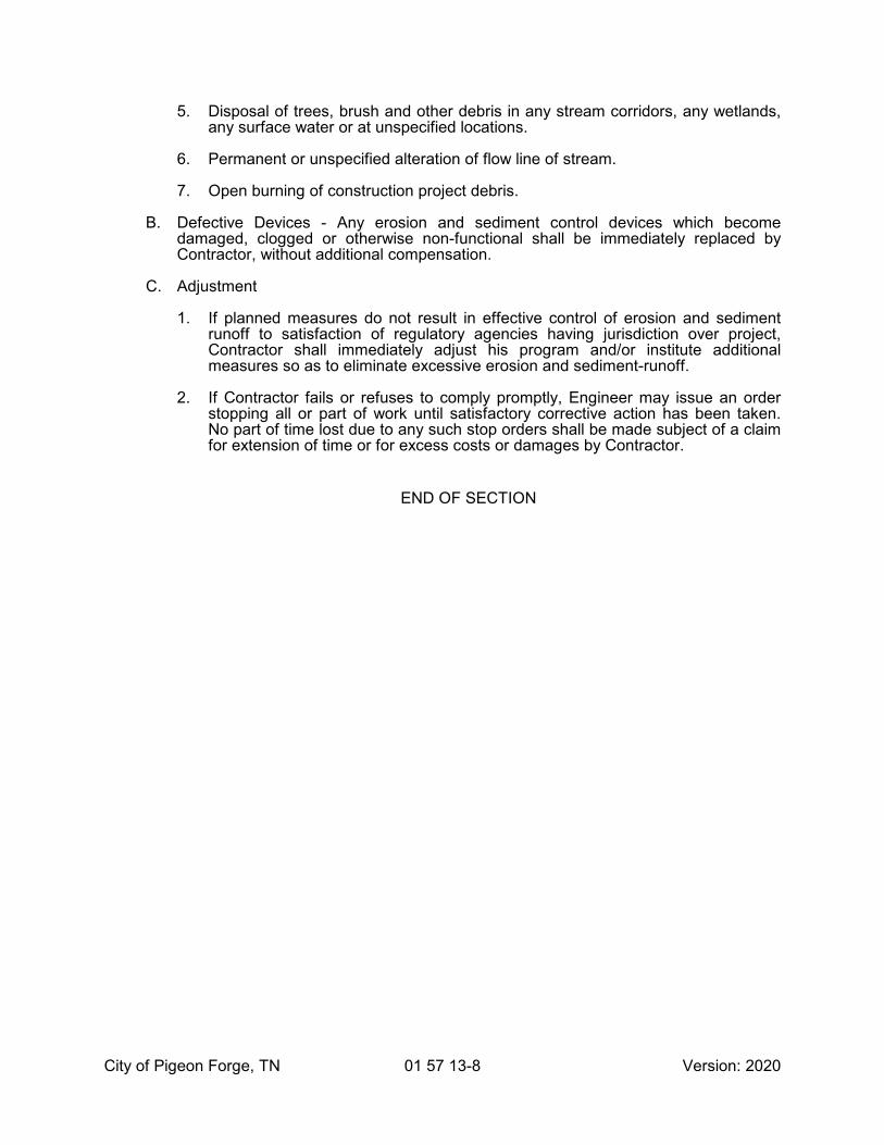
5. Disposal of trees, brush and other debris in any stream corridors, any wetlands, any surface water or at unspecified locations.
6. Permanent or unspecified alteration of flow line of stream.
7. Open burning of construction project debris.
B. Defective Devices - Any erosion and sediment control devices which become damaged, clogged or otherwise non-functional shall be immediately replaced by Contractor, without additional compensation.
C. Adjustment
1. If planned measures do not result in effective control of erosion and sediment runoff to satisfaction of regulatory agencies having jurisdiction over project, Contractor shall immediately adjust his program and/or institute additional measures so as to eliminate excessive erosion and sediment-runoff.
2. If Contractor fails or refuses to comply promptly, Engineer may issue an order stopping all or part of work until satisfactory corrective action has been taken. No part of time lost due to any such stop orders shall be made subject of a claim for extension of time or for excess costs or damages by Contractor.
END OF SECTION

City of Pigeon Forge, TN 03 00 05-1 Version: 2020
SECTION 03 00 05
CONCRETE, MORTAR AND GROUT MATERIALS
PART 1 GENERAL
1.01 RELATED DOCUMENTS
A. Drawings and general provision of the Contract, including General and Supplementary Conditions and Division 01 Specification Sections, apply to this Section.
B. Section 03 31 00 – Concrete and Reinforcing Steel
1.02 GENERAL
A. The materials covered under this section are cement, sand, crushed stone, gravel and water for use in concrete mortar and grout.
1.03 CEMENT
A. Except as otherwise specified, all cement used on the work shall be either air-entraining Portland cement or standard Portland cement. Cement shall be a domestic product from a source approved by the Engineer before the cement is ordered. If standard Portland cement is used, an air-entraining agent meeting the requirements of ASTM Des. C260 shall be added to the concrete at the time of mixing in an amount sufficient to produce from four to six percent entrained air in the concrete.
B. Air-entraining cement shall meet the requirements of ASTM Des. C175, Type 1A or Type 11A, and standard Portland cement shall meet the requirements of ASTM Des. C150, Type 1 or Type 11.
C. Standard Portland cement without an air-entraining agent shall be used in the manufacture of concrete pressure pipe.
D. The Engineer shall have the right at all times to inspect the materials, the processes of manufacture, the laboratory records of the analyses and tests made at the cement works, and to supervise the packing.
1.04 HIGH-EARLY STRENGTH CEMENT
A. In case high-early strength cement is required for special parts of the work, it shall be a true Portland cement with no chemicals or other substances added to expedite hardening, and of a brand approved by the Engineer. The cement shall meet the requirements of ASTM Des. C150, Type III or C175, Type IIIA. High-early strength cement shall be used only with the approval of the Engineer.
1.05 DELIVERY AND STORAGE OF CEMENT
A. Cement delivered to the jobsite shall be in strong, well-made bags plainly marked with the brand name of manufacturer, and net weight. Packages received in damaged condition will be rejected or they may be accepted as fractional packages when permitted by the Engineer.

City of Pigeon Forge, TN 03 00 05-2 Version: 2020
B. For ready-mixed concrete, cement may be delivered in bulk provided that the batching plant meets the requirements of ASTM Des. C94.
C. Cement shall be stored in a weather tight building having a wooden floor raised above ground and shall be protected from dampness. Cement that has deteriorated from storage shall not be used. Cement remaining in storage, prior to use, for a period greater than six months after test, shall be retested and shall be rejected if it fails to meet any of the requirements of these Specifications. Accepted cement which has been in storage for more than one year from the time of original acceptance shall not be used.
1.06 SAMPLES OF AGGREGATES
A. At least 15 days before the first concrete is to be used, a 50-pound representative sample of each aggregate shall be submitted to the Engineer for approval. As the work proceeds, additional samples shall be submitted if, and when required, by the Engineer.
1.07 FINE AGGREGATE
A. Fine aggregate shall be natural sharp sand meeting the requirements of ASTM Des. C33, except as modified herein.
B. Fine aggregate for concrete shall meet the requirements for grading in ASTM Des. C33.
C. Fine aggregate for mortar and grout shall be well graded within the following limits by weight when tested in accordance with ASTM Des. C136.
Sieve Percentage Passing Mortar Grout
3/8 inch 100 100No. 4 100 100No. 8 96 to 100No. 16 70 to 90No. 30 40 to 70 50No. 50 15 to 35No. 100 5 to 15
1.08 COARSE AGGREGATE
A. Coarse aggregate shall consist of gravel or crushed stone and shall meet the requirements of ASTM Des. C33, except that no exceptions shall be made in the requirements for passing the soundness test as set forth in Paragraph 10A of those Specifications. Coarse aggregate shall be graded according to Sizes 467 and 57 in Table II.
B. Size No. 57 shall be used for all thin or closely reinforced concrete work, such as floors and roofs less than 7 inches thick, walls less than 9 inches thick, all beams, girders, struts, columns and all fireproofing. For all other concrete work, Size No. 467 shall be used.

City of Pigeon Forge, TN 03 00 05-3 Version: 2020
1.09 STORAGE AND HANDLING OF AGGREGATES
A. Aggregates shall be kept clean and free from all other materials during transportation and handling. They shall be kept separated from each other at the site until measured in batches and placed in the mixer.
B. Unless finish screening is provided at the batch plant, aggregates shall be stockpiled in a manner to prevent segregation in accordance with ACI Standard 614.
1.10 ADMIXTURES
A. The use of admixtures in concrete, other than air-entraining agents as hereinbefore specified, will not be permitted.
1.11 WATER
A. Water used in mixing concrete shall be clean and shall not contain deleterious amounts of acids, alkalis or organic materials. All water shall be furnished from sources approved by the Engineer.
END OF SECTION

City of Pigeon Forge, TN 03 00 05-4 Version: 2020
THIS PAGE INTENTIONALLY LEFT BLANK

City of Pigeon Forge, TN 03 31 00-1 Version: 2020
SECTION 03 31 00
CONCRETE AND REINFORCING STEEL
PART 1 GENERAL
1.01 GENERAL
A. Concrete shall be of two classes as follows:
1. Class C shall be used for manhole bases and tops, sidewalks, curbs, pavements, pipe cradle, anchor and encasement.
2. Class D concrete shall be used for filling soil stabilization and similar purposes.
3. Flowable fill shall be used for street backfill, filling of abandoned pipe and encasements at creek crossings or other similar purposes.
PART 2 PRODUCTS
2.01 MATERIALS
A. Cement shall meet the requirements of ASTM Des. C150, Type I or Type II.
B. Coarse aggregate shall meet the requirements of ASTM Des. C33.
C. Fine aggregate shall meet the requirements of ASTM Des. C33.
2.02 CONCRETE
A. All concrete shall be ready mixed and shall meet the requirements of ASTM Des. C94.
B. The compressive strength of concrete at 28 days shall be not less than the following:
1. Class C = 3000 psi
2. Class D = 2000 psi
C. The concrete shall have a slump of not less than 2 inches nor more than 4 inches when tested in accordance with ASTM Des. C143.
D. The amount of water per sack of cement shall not exceed 6 gallons for Class C concrete nor 8 gallons for Class D concrete.
2.03 FORMS
A. Forms shall conform to the shape, lines, and dimensions of the member as shown on the Plans. They shall be substantial, properly braced, and tied together so as to maintain position and shape and to resist all pressures to which they may be subjected. They shall be sufficiently tight to prevent leakage of mortar.

City of Pigeon Forge, TN 03 31 00-2 Version: 2020
2.04 FLOWABLE FILL
A. Flowable fill shall be of such consistency and strength as to not settle and of such consistency and strength that it can be removed without the use of heavy equipment after final set. Materials used in the placement of flowable fill shall meet the following requirements:
TDOT Material Subsection
portland cement, type I 901.01fine aggregate* 903.01fly ash (Class C or Class F) 921.15water 921.01air entraining admixtures** 921.06
*Any clean fine aggregate with one hundred (100) percent passing a three-eighths (3/8) inch mesh sieve and not more than fifteen (15) percent passing a no. 200 sieve may be used.
**High air generators or forming agents may be used in lieu of conventional air entraining admixtures and may be added at jobsite and mixed in accordance with manufacturer’s recommendation.
B. Flowable fill is a mixture of portland cement, fly ash, fine aggregate, air entraining admixture, and water and contains a low cementitious content for reduced strength development. Submit mix designs to the Engineer for approval. The following are suggested mix guides for excavatable and non-excavatable flowable fill:
Excavatable Non-ExcavatableMaterial Per Cubic Yard Per Cubic Yard
portland cement, type I 75 lbs. - 100 lbs. 75 lbs. - 150 lbs.fly ash (Class C or Class F) none 150 lbs. - 600 lbs.water * *air** 5% - 35% 5% - 15%28 day compressive strength** 100 psi max. 125 psi min.unit weight (wet)** 90 lbs - 110 lbs. 100 lbs. - 125 lbs.
*Mix designs shall produce a consistency that will result in a flowable self leveling product at time of placement.
**The requirements for percent air, compressive strength, and unit weight are for laboratory designs only and are not intended for jobsite acceptance requirements.
Fine aggregate shall be proportioned to yield one cubic yard (1 yd3).
C. Use flowable fill manufactured at plants that qualify as approved sources in accordance with the “Standard Operating Procedure for Ready-Mix Concrete”.
D. The Contractor shall furnish certification that all flowable fill delivered to the project contains the relative proportions of solid materials specified above.

City of Pigeon Forge, TN 03 31 00-3 Version: 2020
2.05 REINFORCING STEEL
A. Reinforcing bars shall meet the requirements of ASTM Des. A305 and shall be of steel meeting the requirements of ASTM Des. A15, Intermediate Grade.
B. Reinforcing mesh shall meet the requirements of ASTM Des. A185.
PART 3 EXECUTION
3.01 PLACING CONCRETE
A. Concrete shall be deposited as closely as possible to its final resting place and in no case more than eight feet distant in a horizontal direction. It shall be handled and placed so as to prevent any segregation of the material. In other respects, the handling and placing of concrete shall conform to the recommendation of the ACI.
B. Deliver flowable fill using concrete construction equipment. Place flowable fill by chute, pumping, or other methods approved by the Engineer.
C. Use straps, soil anchors, or other approved means of restraint to ensure correct alignment when flowable fill is used as backfill for pipe or where floatation or misalignment may occur.
1. Protect flowable fill from freezing for a period of thirty-six (36) hours after placement.
2. Place flowable fill to the designated fill line without vibration or other means of compaction. Do no place flowable fill during inclement weather, e.g. rain or ambient temperature below forty (40) degrees Fahrenheit.
3. Take all necessary precautions to prevent any damages caused by the hydraulic pressure of the fill during placement prior to hardening. Provide the means to confine the material within the designated space.
3.02 CURING
A. Concrete exposed to the atmosphere shall be protected against too rapid drying for a period of at least seven days. It shall be kept moist by sprinkling, covering with soaked quilted covers or impermeable paper, coating with sprayed-on during membrane, or other means acceptable to the Engineer.
3.03 REINFORCING STEEL
A. Reinforcing steel shall be fully protected from moisture, grease, dirt, mortar or concrete and shall be cleaned of all rust, mill scale, and dirt before being finally incorporated in the work.
B. Reinforcing steel shall be placed and held in position so that the concrete cover as measured from the surface of the bar shall be not less than 2 inches.
END OF SECTION

City of Pigeon Forge, TN 03 31 00-4 Version: 2020
THIS PAGE INTENTIONALLY LEFT BLANK

City of Pigeon Forge 09 97 13-1 Version: 2020
SECTION 09 97 13
WELDED STEEL TANK PAINTING
PART 1 GENERAL
1.01 WORK INCLUDED
A. The work covered by this Section includes cleaning, abrasive blast cleaning, and painting of all interior and exterior steel surfaces. Other items include cleaning and disinfection of the tank after coating, sampling and testing (by OWNER), final acceptance of the project, and the tank and paint system warranties.
1.02 REFERENCE STANDARDS
A. Work performed and materials used must comply with the latest revisions of the following standards:
1. AWWA (American Water Works Association) D100 Standard for Welded Steel Tanks for Water Storage.
2. AWWA D102 Standard for Painting Steel Water Storage Tanks.
3. AWWA C652 Standard for Disinfection of Water Storage Facilities.
4. NSF (National Sanitation Foundation) 61 - Materials in contact with Potable Water.
5. Steel Structures Painting Council Manual - Volume 1 - Good Painting Practices.
6. Steel Structures Painting Council Manual - Volume 2 - Systems and Specifications.
1.03 SUBMITTALS
A. Before beginning the work, the Contractor shall provide the Engineer with the following information:
1. Name of the protective coating supplier and manufacturers data for the paint systems being used, including MSDS sheets.
2. A listing of the specific products proposed for use including but not limited to: abrasive materials, paint, solvents, and thinners.
3. Product data sheets for each of the proposed materials.
4. Samples of the color specified for Owner approval.
1.04 QUALITY CONTROL
A. Only paint and painting materials as specified shall be used.
B. Paint shall be delivered in unbroken containers bearing the designated name, specification number, color, directions for use, manufacturer, and date of manufacture.
C. All manufacturers’ instructions shall be carefully followed in the preparation, application, curing or drying and handling of the paint.

City of Pigeon Forge 09 97 13-2 Version: 2020
D. All prime, intermediate and finish coating materials shall be applied in different color shades.
E. Paint shall be stored in a location that is protected from the elements, well-ventilated and free from excessive heat or open flame sources.
F. The Contractor shall obtain the Inspector’s written approval of the steel surface preparation and of each coat of paint, before applying succeeding coats. Such approval will not relieve the Contractor of his obligations under the Contract.
G. The Contractor shall record environmental conditions, at the beginning of each daily operation, thirty minutes before painting begins, and every hour during painting operations, on the Environmental Conditions Report (see Appendix).
H. Painting shall be performed by skilled painters using the materials and methods specified.
1.05 HEALTH AND SAFETY
A. The Contractor shall comply with all regulations as established by the Occupational Safety and Health Act and other government authorities. Up-to-date Material Safety Data Sheets shall be available on-site for all products used. Workers shall wear proper protection devices. Where ventilation is used, all equipment shall be explosion proof. Temporary ladders and scaffolding systems shall conform to applicable safety requirements. It shall be the responsibility of the Contractor to adequately protect, shield, or cover all structure, machinery, equipment, and openings as required to prevent damage or contamination from the work procedures. The work area shall be kept clean at all times, consistent with the type of work being performed.
1.06 TESTING
A. Dry coating thickness measurements shall be made using a Magnetic Gauge. Tolerances to be in accordance with SSPC-PA 2 Measurement of Dry Coating Thickness with Magnetic Gauges. Additional costs shall be applied as required to obtain the specific thickness. The Inspector will perform Holiday Testing as soon as the work is sufficiently cured according to the manufacturer’s recommendations. All pinholes and deficiencies will be repaired.
1.07 SITE CONDITIONS
A. The Contractor shall ensure that surface and ambient conditions are in accordance with the manufacturer’s instructions immediately prior to and during application and for the period of curing. No paint shall be applied when the surrounding air temperature as measured in the shade is above or below the manufacturer’s specifications. No paint shall be applied when the temperature of the surface to be painted is below manufacturer’s recommended application temperature. Painting shall not be applied to wet or damp surfaces or when the ambient temperature is less than 5 degrees above the dew point.
PART 2 PRODUCTS
2.01 ACCEPTABLE MANUFACTURERS
A. Specified paint products are those manufactured by TNEMEC Co., Inc., Kansas City, MO, and are specified as the standard of quality required for use on this project.
B. Products for each specified function and system shall be of a single manufacturer.

City of Pigeon Forge 09 97 13-3 Version: 2020
2.02 INTERIOR COATING SYSTEM
A. Surface Preparation
1. Shop Surface Preparation: Remove all visible oil, grease, soil, dirt, and other soluble contaminants in accordance with SSPC-SP1. The surface shall be abrasive blast cleaned to a Near White Finish in accordance with the recommended methods outlined in The Society for Protective Coatings Specification SSPC-SP10 (NACE No. 2). A surface profile of 1.5 to 2.5 mils is required.
2. Field Surface Preparation: After erection and prior to field touch-up, remove all visible oil, grease, soil, dirt and other soluble contaminants in accordance with SSPC-SP1. Weld slag, weld spatter, rough edges and sharp edges of weld seams shall be ground smooth. All rusted, abraded, and unpainted areas shall be abrasive blast cleaned to a Near White Finish in accordance with the recommended methods outlined in The Society for Protective Coatings Specification SSPC-SP10 (NACE No. 2). A surface profile of 1.5 to 2.5 mils is required.
B. Interior Coating System
1. Type: Zinc/Epoxy Coating System
2. Shop Prime Coat: Immediately after abrasive blasting and before any rusting occurs, apply one coat of Tnemec Series 91-H2O Hydro-Zinc 2000 primer at a dry film thickness of 2.5 to 3.5 mils.
3. Field Spot Prime Coat: Immediately after abrasive blasting and before any rusting occurs, apply one coat of Tnemec Series 91-H2O Hydro-Zinc 2000 zinc primer to all bare steel surfaces. The coating shall be applied at a dry film thickness of 2.5 to 3.5 mils.
4. Field Stripe Coat: Apply one complete coat of Tnemec 20-1255 Pota-Pox Beige to all weld seams by brush or roller.
5. Field Intermediate Coat: Apply one complete coat of Tnemec Series 20-1255 Beige Pota-Pox applied at a dry film thickness of 4.0 to 6.0 mils.
6. Field Finish Coat: Apply one complete coat of Tnemec Series 20-15BL Tank White Pota-Pox applied at a dry film thickness of 4.0 to 6.0 mils.
*Tnemec Series FC20 Pota-Pox (Fast Cure) may be substituted for Series 20 Pota-Pox when surface temperatures are below 50 degrees F. Series FC20 shall not be applied at surface temperatures below 35 degrees F.
2.03 EXTERIOR COATING SYSTEM
A. SURFACE PREPARATION
1. Shop Surface Preparation: Remove all visible oil, grease, soil, dirt, and other soluble contaminants in accordance with SSPC-SP1. The surface shall be abrasive blast cleaned to a Commercial Finish in accordance with the recommended methods outlined in The Society for Protective Coatings Specification SSPC-SP6 (NACE No. 3). A surface profile of 1.5 to 2.5 mils is required.
2. Field Surface Preparation: Remove all oil, grease, soil, dirt, and other soluble contaminants in accordance with SSPC-SP1. Weld slag, weld spatter, rough edges and sharp edges of weld seams shall be ground smooth. All rusted, abraded, and unpainted areas shall be abrasive blast cleaned to a Commercial Finish in

City of Pigeon Forge 09 97 13-4 Version: 2020
accordance with the recommended methods outlined in The Society for Protective Coatings Specification SSPC-SP6 (NACE No. 3). A surface profile of 1.5 to 2.5 mils.
B. EXTERIOR COATING SYSTEM
1. Type: Zinc/Epoxy/Polyurethane
2. Shop Prime Coat: Immediately after abrasive blasting and before any rusting occurs, apply one coat of Tnemec Series 91-H2O Hydro-Zinc 2000 zinc primer to all bare steel surfaces. The coating shall be applied at a dry film thickness of 2.5 to 3.5 mils.
3. Field Spot Prime Coat: Immediately after blasting and before any rusting occurs, apply one coat of Tnemec Series 91-H2O Hydro-Zinc 2000 zinc primer to all bare steel surfaces. The coating shall be applied at a dry film thickness of 2.5 to 3.5 mils.
4. Field Intermediate Coat: Apply one complete coat of Tnemec Series 66-Color Build Epoxiline at a dry film thickness of 3.0 to 4.0 mils. To achieve complete finish coat coverage, the intermediate coat color should be noticeably different than the specified finish coat color. When feasible, the field intermediate coat should be in the same finish coat color family (blue, beige, gray, etc.) with a difference in light reflectance value of about 10%.
5. Field Finish Coat: Apply one complete coat of Tnemec Series 1074/1075-Color Endura-Shield at a dry film thickness of 2.0 to 3.0 mils. Certain colors may require two coats depending upon the method of application and color of the intermediate coat. Color shall be selected by the Owner.
2.04 FILLER AND SURFACER FOR SEAM CAULKING
A. Elastomeric sealant, Sikaflex-1a as manufactured by the Sika Corporation, or approved equal.
PART 3 EXECUTION
3.01 PRE-WORK INSPECTION
A. Examine surfaces to be coated and report conditions that would adversely affect appearance or performance of coating systems and which cannot be put into an acceptable condition by surface preparation methods specified in PART 2.
B. Do not proceed with surface preparation and application until surface is acceptable and authorization to proceed is given by the Engineer/Owner or his designated representative.
C. Contractor shall remove any water which remains in the bottom of the tank or bottom of the riser.
3.02 APPLICATION
A. Materials shall be mixed, thinned, and applied according to the manufacturer’s printed instructions.
B. Prepare surfaces in accordance with coating manufacturer’s recommendations and PART 2 of this specification.
C. Allow each coat to dry thoroughly before applying next coat. Provide adequate ventilation for tank interior to carry off solvents during drying phase.

City of Pigeon Forge 09 97 13-5 Version: 2020
3.03 INSPECTION
A. Degree of surface cleanliness and blast profile of steel surfaces shall conform to the specifications detailed in PART 2 - Surface Preparation. Reference SSPC or NACE visual standards and consult Testex tape to verify anchor pattern.
B. Wet film thickness readings for successive coats shall be taken as soon as possible at a frequency of at least one per 100 square feet.
C. Dry film thickness readings of steel surfaces shall be taken prior to the application of successive coats with a non-destructive magnetic type gauge in accordance with SSPC-PA-2.
D. All interior coated steel surfaces shall receive holiday testing with a Tinker and Rasor Model M-1, or equivalent, low voltage holiday detector. Any areas failing this test shall be marked and receive an additional repair coat in accordance with Section 2.02 - Interior Wet Coating System until satisfactory test results are achieved.
E. The final film is to be visually inspected and should be free of sags, runs, wrinkles and other excessive film-build characteristics and surface defects.
3.04 ACCEPTANCE OF WORK
A. All surface preparation shall be approved by the Engineer/Owner before primer is applied. The Contractor shall request acceptance of each coat before applying next coat and shall correct work that is not acceptable and request re-inspection. All rigging to remain in place, and Contractor shall aid in use of rigging for all inspections by Owner’s Representative.
3.05 CLEANING AND DISINFECTION
A. GENERAL
1. The Contractor shall be responsible for removing from the tank all containers, debris, and foreign material of every description and for leaving the interior of the tank in a clean and sanitary condition. After the recommended paint curing time has elapsed and the tank is ready to be filled, the Contractor shall disinfect the tank using the procedure as outlined hereinafter. Contractor shall provide all necessary chlorine bearing compounds and equipment required for cleaning, disinfecting, and flushing operations.
B. CLEANING
1. Allow a minimum of 7 days curing after application of final coat to tank interior before cleaning, flushing, sterilizing, or filling with water.
2. After painting, remove all scaffolding, planks, tools, rags, blast media, and all other materials not part of the structural or operating facilities of the tank. Thoroughly clean and wash the walls, floor, roof, and operating facilities of the tank by use of a high pressure (100 psi minimum) water jet, sweeping, scrubbing, and other effective means. Flush out and otherwise remove from the tank all water, debris, and foreign materials accumulated during this cleaning operation. Thoroughly clean and flush out the bottom of the tank and the inlet/outlet pipe.
C. DISINFECTION
1. When the tank is ready to be filled, the Contractor shall disinfect the tank with a chlorine solution. The interior surfaces of the tank shall be thoroughly washed and

City of Pigeon Forge 09 97 13-6 Version: 2020
disinfected in accordance with the requirements of AWWA C652-92, Section 4.3, Chlorination Method 3 (See Appendix).
D. SAMPLING AND TESTING
1. After the chlorination procedure is completed, and before the storage tank is placed in service, Owner will collect water samples from the full tank for bacteriological analysis. If the results are favorable, the tank may be placed in service. In the event the bacteriological tests are unsatisfactory, the Owner will undertake to determine and correct the cause. In the event the cause is found to result from improper cleaning and/or disinfection, the Contractor will be billed for the additional expense to the Owner for correcting the problem.
3.06 ACCEPTANCE OF COMPLETED WORK
A. Upon completion of work, including disinfection, The Contractor shall remove all debris and shall restore the area surrounding the tank to at least as good condition as before he moved in. When the Contractor requests a final inspection, Engineer will inspect the work for completeness in accordance with the Contract Documents. Any deficiencies shall be promptly corrected by the Contractor.
B. Final acceptance cannot be made until the Contractor furnishes to the Owner a notarized Waiver and Release of Lien from each supplier of goods and services. A copy of the required form is included in the Appendix.
C. Payment in full of the Final Application for Payment shall constitute acceptance of the Work by the Owner subject to conditions of the Contract Documents.
3.07 WARRANTY
A. The Contractor shall guarantee the work which he performs to be free from defects in material and workmanship for a period of two years from date of acceptance. The Contractor shall guarantee the water tank to be free from leakage upon completion of the project.
B. This warranty shall cover all work performed by the Contractor under the terms of the contract or as extra work authorized in writing by the Owner. The Contractor shall not be relieved from the terms of the warranty because of any additional work which may be recommended, but which was not performed because it was not authorized by the Owner.
C. A first anniversary inspection will be conducted by Pigeon Forge staff or authorized agent in accordance with Section 9 of AWWA D102, latest revision. Following that inspection, Contractor must return within a reasonable period of time to correct observed defects.
END OF SECTION

City of Pigeon Forge, TN 31 11 00-1 Version: 2020
SECTION 31 11 00
SITE PREPARATION
PART 1 GENERAL
1.01 GENERAL
A. The work covered by this section consists of furnishing all materials and equipment and performing all labor necessary for Site Preparation and Development which includes, but is not limited to clearing, excavating, backfilling, grading and grassing, and all incidentals as shown on the Plans.
B. The work specified under this Section which constitutes Site Preparation shall be performed in such a chronological order as to leave the site in the best possible finished condition. The order of this work is subject to the Engineer’s approval but such approval shall in no way relieve the Contractor of any responsibilities for repair of work damaged by his acts or acts of God.
1.02 SUBSURFACE CONDITIONS
A. The Contractor affirms by the submission of his bid that he has examined the location of the work and has informed himself fully as to the site conditions, the configuration of the ground, the character, quality and quantity of the materials to be encountered, the equipment and facilities needed preliminary to and during the prosecution of the work, the general and local conditions, and all other matters which can in any way affect the work to be done.
1.03 LAYOUT WORK
A. Engineer to provide reference points on Base Line and Bench Mark on Contract Drawings.
B. Contractor to perform required field work and establish building lines, hubs, grade stakes, etc.
1.04 LOCATION OF UNDERGROUND OBSTRUCTIONS
A. Contract Drawings show approximate location of known obstructions.
B. Contractor shall locate, identify, ascertain size, and protect all underground pipelines, utilities, and other obstructions within construction area, including those that are to remain as well as those to be demolished.
C. Contractor shall provide proper notification prior to commencing any construction activities to Tennessee One-Call and local utilities and follow all guidelines of Tennessee One-Call throughout construction in accordance with Section 01 76 00.
1.05 REGULATORY AND DISPOSAL REQUIREMENTS
A. Coordinate clearing Work with utility companies.
B. Conform to applicable local, state and federal codes for environmental requirements, disposal of debris, stockpiling, and use of herbicides.

City of Pigeon Forge, TN 31 11 00-2 Version: 2020
C. On-site disposal of surplus materials, if permitted by Owner, shall be as approved by Engineer.
D. Contractor shall make all arrangements for disposal sites. All expenses for disposal shall be borne by Contractor. Bidders shall carefully investigate all aspects of surplus material disposing operations.
E. Prior to depositing surplus material at any off-site location, obtain a written agreement between Contractor and owner of property on which disposal of material is proposed. Agreement shall state that owner of property gives permission for Contractor to enter and deposit material of a particular classification on owner’s property at no expense to project Owner, and shall include any other conditions pertinent to situation as agreed upon by each party. A copy of said agreement shall be furnished to Owner.
PART 2 MATERIALS (NOT USED)
PART 3 EXECUTION
3.01 CLEARING AND STRIPPING OF TOPSOIL
A. The site shall be cleared of all obstructions interfering with the construction of new work.
B. The Contractor shall strip the entire area within cut, fill, and graded areas to remove all topsoil, vegetable matter, stumps, roots, and other objectionable materials. Topsoil and vegetable matter shall be carefully stockpiled and preserved for reuse. Roots and stumps shall be grubbed out and removed from the property entirely. The base of all embankments and fills shall be scarified and rolled so that the base will be well bonded with the first layers of fill. The disposal of refuse will be the responsibility of the Contractor.
3.02 STRUCTURES ON EARTH
A. When structures rest on earth, all loam, organic, or other undesirable material shall be removed as required by the Engineer. When filling is required to bring such excavated area to the levels required to receive structures, the fill shall be compacted by tamping and rolling to obtain 98% of maximum density as per ASTM D-698-66T Method A. Layers shall be not more than six (6”) inches thick.
B. Where shown on the Plans or otherwise required under structures, the Contractor shall place and compact crushed stone in twelve (12”) inches or thinner layers. Materials shall meet the same requirements as those given for concrete except gradation.
3.03 CATCH BASINS AND STORM DRAINS
A. Catch basins, drop inlets, and other special drainage structures shall be constructed in accordance with the Details shown on the Plans.
B. Storm sewers and appurtenances shall be constructed as shown on the Plans and specified herein.

City of Pigeon Forge, TN 31 11 00-3 Version: 2020
C. Generally, all storm drainage pipes crossing under roadways shall be corrugated metal culvert pipe or reinforced concrete pipe with end walls at both ends and all other storm sewers are shown as reinforced or non-reinforced concrete pipe. Corrugated metal pipe and/or concrete pipe may be used interchangeably PROVIDED the proposed substitution is approved in advance by the Engineer and the substitute material provides equal or greater strength.
3.04 FINISH GRADING AND TOPSOILING
A. Finish grading shall be performed in accordance with the finished elevations and grades shown on the Plans and shall be made to blend into conformation with remaining natural ground surfaces. All finished grading surfaces shall be left smooth and free to drain. The tops of all cuts shall have berm ditches. Selected materials, which have been obtained from stripping the site, shall be spread upon the slopes of fills and all other areas at the site to a uniform depth and compacted suitable for planting. Excess four (4) to six (6) inches of material in areas to be grassed shall be topsoil. All stone chips, gravel, etc. shall be removed by raking or by hand so that lawn mowing will be safe and practical.
3.05 SEEDING, SODDING, AND LANDSCAPING
A. All graded areas, which shall include all areas at the site shall be left smooth and thickly sown with a mixture of Blue Grass, Italian Rye Grass, Kentucky Fescue #31 and/or such other grasses as are specified by the Engineer. When the final grading has been completed, the entire area to be seeded shall be lined with raw agricultural lime at the rate of 3 tons per acre and fertilized with ammonium nitrate at the rate of 5 lbs. per 1000 square feet and an approved commercial fertilizer at the rate of 10 lbs. per 1000 square feet. The analysis of the commercial fertilizer shall be determined by soil tests. After the fertilizer has been distributed, the Contractor shall disc or harrow the ground to thoroughly work the fertilizer into the soil. The seed shall then be sowed in two operations broadcast either by hand or by approved sowing equipment. The application shall be 30 pounds per acre for each operation. If the Engineer determines to use “hulled” or “unhulled” Bermuda, the application rate shall be seven pounds per acre. After the seed has been distributed, the Contractor shall then lightly cover the seed by use of a drag or other approved device. All seed shall be certified not more than three percent weed. The seeded area shall then be covered with straw at the rate of 1-1/2 tons per acre.
B. Any necessary reseeding or repairing shall be accomplished by the Contractor prior to final acceptance. Unless otherwise approved in writing by the Engineer, seeding shall be limited to the following planting periods: Spring - March 1 through May 10 or Fall - August 15 through October 31. If the construction work is brought to completion when, in the opinion of the Engineer, the season is not favorable for the seeding of the grounds, the Contractor shall delay this item of the work until the proper season for such seeding as directed by the Engineer.
C. Sodding is required on all slopes 3 horizontal to 1 vertical or steeper unless the said slope to receive rip-rap. Sod shall be Bermuda or other approved type reasonably free of weeds and carefully cut, transported, and laid. Sod shall be so laid that no voids occur between strips. Weed roots shall be removed as the sod is laid, and the finished surface shall be true to grade, even and equally firm at all points. Well screened topsoil shall be lightly sprinkled over the sodded areas, and shall be raked to insure sealing the sod joints.
D. The Contractor shall be responsible for all seeding and/or sodding necessary to restore the construction area to its original condition.

City of Pigeon Forge, TN 31 11 00-4 Version: 2020
1.08 FINAL CLEAN-UP
A. Before the work is considered as complete, all rubbish and unused material due to or connected with the construction shall be removed and the premises left in a condition satisfactory to the Engineer. Streets, curbs, crosswalks, pavements, sidewalks, fences, and other public and private property disturbed or damaged shall be restored to their former condition at the Contractor’s expense. Final acceptance will be withheld until such work is completed.
END OF SECTION

City of Pigeon Forge, TN 31 11 10-1 Version: 2020
SECTION 31 11 10
SITE CLEARING
PART 1 GENERAL
1.01 GENERAL
A. The work required under this section consists of all clearing, grubbing, shrub removal and related items necessary to complete the work.
B. The Contractor shall protect shrubs, pavement and other items adjacent to his work.
C. Where adjacent surface areas within the project site, but outside the contract limits, are disturbed as a result of work under this contract, they shall be cleaned of all debris and restored to original condition.
1.02 BENCH MARKS AND MONUMENTS
A. The Contractor shall protect all bench marks, monuments, and other reference points; if disturbed or destroyed, the Contractor shall replace at his own expense as directed by the Engineer.
PART 2 MATERIALS (NOT USED)
PART 3 EXECUTION
3.01 CLEARING
A. Clearing shall be removal of all shrubs, trees, sod, and other landscape items as directed by Engineer.
B. Site around tanks shall be cleared for a 30 foot radius.
3.02 GRUBBING
A. Grubbing shall be removal of all stumps, roots, trash, rubbish, vegetable matter to a depth of not less than 18” within limits directed by the Engineer.
3.03 REMOVAL OF SHRUBS AND SOD
A. Remove all shrubs and sod from area to be occupied by Construction.
B. All shrubs and sod shall be replanted at locations determined by Engineer.
3.04 LIMITS OF WORK
A. The contract limits are shown on the drawings. All areas within the contract limits shall be cleared as specified.
END OF SECTION

City of Pigeon Forge, TN 31 11 10-2 Version: 2020
THIS PAGE INTENTIONALLY LEFT BLANK

City of Pigeon Forge, TN 31 23 16-1 Version: 2020
SECTION 31 23 16
EARTH EXCAVATION
PART 1 GENERAL
1.01 GENERAL
A. Earth excavation shall be made to the widths and depths necessary for constructing all structures and pipe lines included in this Contract, and includes the excavation of any material defined as earth which is desirable to be excavated for any purpose pertinent to the construction of the work.
B. The term “earth” as used herein shall include all materials which, in the opinion of the Engineer, do not require blasting, barring, or wedging for their removal from their original beds. Specifically excluded are all ledge and bed rock and boulders or pieces of masonry larger than one cubic yard in volume.
C. The method of making excavation below ground water shall be submitted in detail to the Engineer and his approval obtained before such work is started.
PART 2 PRODUCTS (NOT USED)
PART 3 EXECUTION
3.01 AUTHORIZED ADDITIONAL EXCAVATION
A. In case the materials encountered at the elevations shown are not suitable, or in case it is found desirable or necessary to remove to an additional depth as the Engineer may direct, in writing, the Contractor shall refill such excavated space with either Class D concrete or selected fill materials as ordered. Additional earth excavation so ordered and concrete or selected fill materials ordered for filling such additional excavation will be paid for under the appropriate unit price Contract Items, or at a price negotiated by the Owner and the Contractor.
3.02 UNAUTHORIZED EXCAVATION
A. Wherever the excavation is carried beyond or below the lines and grades shown or given by the Engineer, except as specified in Section 31 23 16-3.01, all such excavated space shall be refilled with such material and in such manner as may be directed in order to insure the stability of the various structures. Beneath all structures or pipe lines, space excavated without authority shall be refilled by the Contractor at his own expense with Class D concrete or selected fill materials, as ordered by the Engineer.
3.03 SEGREGATION AND DISPOSAL OF MATERIAL
A. Topsoil suitable for final grading and landscaping and excavating material suitable for backfilling or embankments, shall be stockpiled separately on the site in locations approved by the Engineer. Surplus excavated material shall be disposed of in locations on the site as indicated or approved by the Engineer or disposal areas obtained by the Contractor.

City of Pigeon Forge, TN 31 23 16-2 Version: 2020
3.04 SHORING AND SHEETING
A. All excavations shall be properly shored, sheeted and braced to furnish working conditions acceptable to OSHA standards to prevent shifting of material, to prevent damage to the structures or other work, and to avoid delay to the work. Bracing shall be so arranged as not to place any strain on portions of completed work until the general construction has proceeded far enough to provide ample strength and to meet the standards set by OSHA. If, at any point, the sheeting or supports furnished are inadequate or unsuited for the purpose, the Contractor shall provide the additional sheeting and supports necessary to bring the sheeting and shoring supports into compliance with the standards of OSHA. The sole responsibility for the design, methods of installation, and adequacy of the sheeting and supports shall be and shall remain that of the Contractor.
B. In general, sheeting for pipe lines shall not be driven below the elevation of the top of the pipe. If, in order to obtain a dry trench or satisfactory working conditions, it is necessary to drive the sheeting below that elevation, the sheeting shall be cut off and let in place below the top of the pipe at no additional cost.
C. The sheeting and bracing shall be removed as the excavation is refilled in such a manner as to avoid the caving in of the bank or disturbance to adjacent areas or structures. The voids left by the withdrawal of the sheeting shall be carefully filled by ramming or other methods.
D. The safety of all employees, the effectiveness of the system, and any damages or injuries resulting from the lack of inadequacy of the sheeting, shoring and bracing shall be the sole responsibility of the Contractor.
3.05 SHEETING LEFT IN PLACE
A. Any or all sheeting or bracing to be left in place necessary for the purpose of preventing injury to the structures or to other property or to persons shall be the sole responsibility of the Contractor and shall be done in accordance with OSHA standards. If left in place, such sheeting shall be prepared and carried out in accordance with standards set by OSHA.
3.06 REMOVAL OF WATER
A. At all times during the excavation period and until completion and acceptance of the work at final inspection, ample means and equipment shall be provided with which to remove promptly and dispose of properly all water entering any excavation or other parts of the work. The excavation shall be kept dry. No water shall be allowed to rise over or come in contact with masonry and concrete until the concrete and mortar have attained a set satisfactory to the Engineer, and in any event, not sooner than 12 hours after placing the masonry. Water pumped or drained from the work hereunder shall be disposed of in a suitable manner without damage to adjacent property or to other work under construction. Water shall be discharged into sanitary sewers. No water containing settleable solids shall be discharged into storm sewers. Any and all damage caused by dewatering the work shall be promptly repaired by the Contractor at his expense. Refer to Section 31 23 19.
3.07 STRUCTURE EXCAVATION
A. The site of all excavations for structures shall first be cleared of all trees and obstructions unless otherwise directed preparatory to excavation.

City of Pigeon Forge, TN 31 23 16-3 Version: 2020
B. The excavations shall be of sufficient size and only of sufficient size to permit the work to be economically and properly constructed in the manner and of the size specified. Wherever the nature of the ground will permit, the bottom of the excavation shall have the shape and dimensions of the underside of the structure.
END OF SECTION

City of Pigeon Forge, TN 31 23 16-4 Version: 2020
THIS PAGE INTENTIONALLY LEFT BLANK

City of Pigeon Forge, TN 31 23 17-1 Version: 2020
SECTION 31 23 17
ROCK EXCAVATION
PART 1 GENERAL
1.01 SUMMARY
A. Section Includes:
1. Removal of subsurface rock encountered during excavation, utilizing mechanical or blasting methods.
1.02 GENERAL
A. Rock excavation shall include the excavation and disposal of all rock within the boundary lines and grades shown on the Plans and given by the Engineer.
B. The term “rock” as used herein shall include all materials which, in the opinion of the Engineer, require blasting, barring, or wedging for their removal from their original beds and which have compressive strengths in their natural undisturbed state in excess of 300 psi, and specifically includes all ledge or bed rock and boulders or pieces of masonry larger than one cubic yard in volume.
C. For excavation in which pipe will be laid, the rock shall be excavated to a depth of at least six inches below the bottom of the barrel and bell of the pipe and filled in to the proper grade with selected fill material properly shaped and compacted placing. Compacting and shaping of the selected fill material shall be included as part of the rock excavation and no extra payment will be made therefore.
PART 2 PRODUCTS (NOT USED)
PART 3 EXECUTION
3.01 ROCK REMOVAL – GENERAL
A. Remove shaled layers to provide sound and unshattered base for footings, foundations, and pipe bedding as work requires.
B. In utility trenches, trim rock to depth of width around pipe as shown on Drawings and specified in Section 31 23 23.
C. Remove excavated materials from site in accordance with Sections 31 11 00 and 31 11 10.
3.02 ROCK REMOVAL – MECHANICAL METHOD
A. Excavate and remove rock by mechanical methods at locations required by Contract Documents and when trimming bottom or sides of excavation is necessary to meet project requirements.

City of Pigeon Forge, TN 31 23 17-2 Version: 2020
3.03 DISPOSAL
A. Where excavated rock can be mixed with earth so that each piece is completely surrounded by fine material, it may be used for backfill or embankment as specified in Section 31 23 23. All excess excavated rock shall be disposed of in disposal areas obtained by the Contractor.
3.04 BLASTING
A. Blasting shall be performed by workmen experienced in the handling of explosives and as approved by the Engineer as to number, length, placing, direction, and loading of holes. The charges used shall not make the excavation unduly large or irregular nor shatter the rock upon or against which masonry or concrete will be built nor injure existing structures at the site or in the vicinity thereof. Each blast shall be covered with heavy timber or steel mats. Blasting will not be permitted within 25 feet of completed pipes or structures. Blasts in tunnels shall be such that the material surrounding the tunnel base proper shall not be loosened or displaced. Whenever the Engineer determines that further blasting may injure or damage adjacent rock, masonry, utility lines, or other structures, blasting shall be discontinued. In such case, the remaining rock shall be excavated by barring, wedging, or other approved method.
B. Where sewers, gas, water, steam, or other utility ducts for lines, basin connections or other structures have been exposed during excavation, such structures shall be adequately protected from damage before proceeding with the blasting. Any structure damage by blasting shall be promptly repaired by the Contractor at his own expense.
C. Blasting shall not be carried on within 300 feet of any radio transmitter or radio-frequency emission equipment such as high-frequency welders. The blasting caps shall be kept in tightly closed all-metal cans when in the vicinity of such equipment.
3.05 EXPLOSIVES
A. A sufficient quantity of explosives to avoid delay to the work shall be kept on the site, but at no time will there be a quantity in excess of that which will be required for use within the following twelve hours. Such explosives shall be stored, handled, and used in conformance with all State and local laws, ordinances and regulations governing the storage and use of explosives. The Contractor shall take out permits and execute a bond for blasting.
B. The magazine keeper shall keep accurate daily records and shall account for each piece of explosive, detonator and equipment from the time of delivery at the magazine until used or removed from the site.
3.06 RESPONSIBILITY
A. The methods of handling, use, and storage of explosives and any damage to persons or property resulting there from shall be the sole responsibility of the Contractor. Approval by the Engineer of these methods or his failure to order that blasting be discontinued shall not relieve the Contractor of any of this responsibility.
END OF SECTION
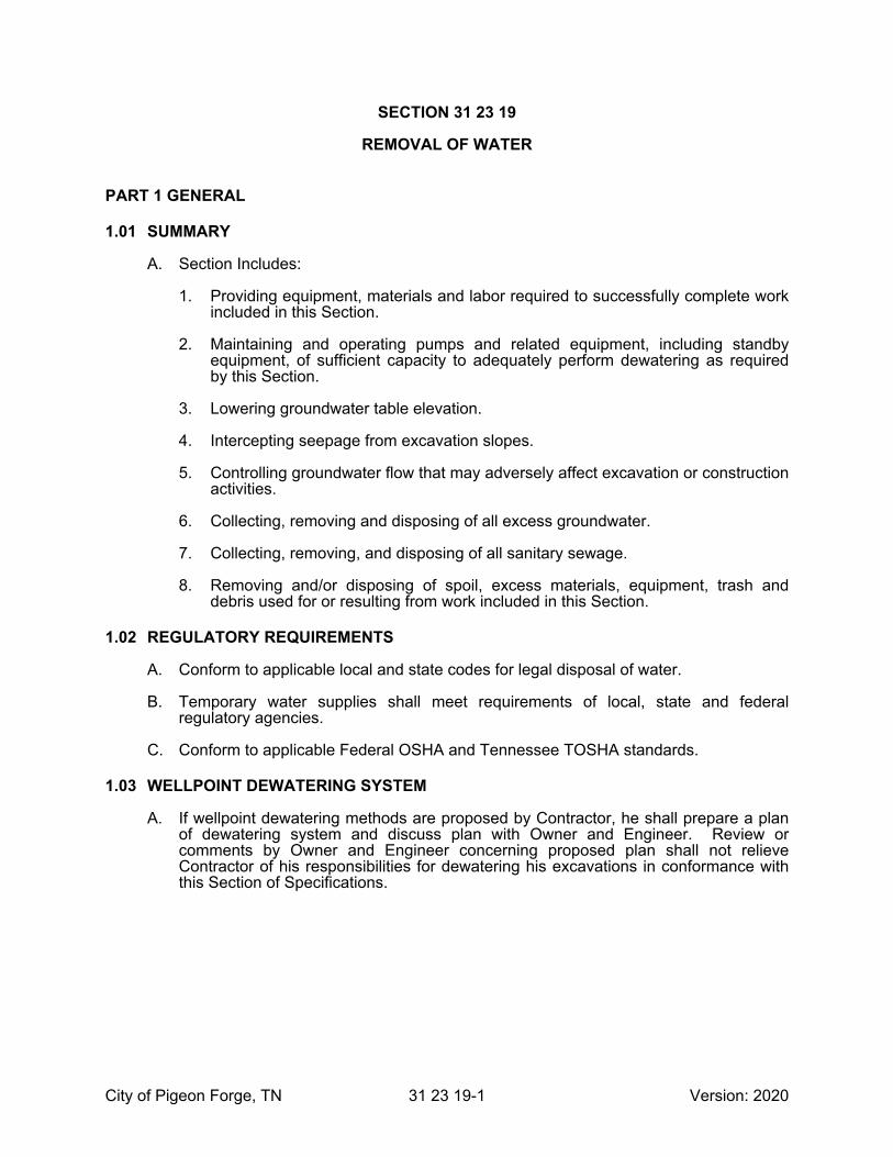
City of Pigeon Forge, TN 31 23 19-1 Version: 2020
SECTION 31 23 19
REMOVAL OF WATER
PART 1 GENERAL
1.01 SUMMARY
A. Section Includes:
1. Providing equipment, materials and labor required to successfully complete work included in this Section.
2. Maintaining and operating pumps and related equipment, including standby equipment, of sufficient capacity to adequately perform dewatering as required by this Section.
3. Lowering groundwater table elevation.
4. Intercepting seepage from excavation slopes.
5. Controlling groundwater flow that may adversely affect excavation or construction activities.
6. Collecting, removing and disposing of all excess groundwater.
7. Collecting, removing, and disposing of all sanitary sewage.
8. Removing and/or disposing of spoil, excess materials, equipment, trash and debris used for or resulting from work included in this Section.
1.02 REGULATORY REQUIREMENTS
A. Conform to applicable local and state codes for legal disposal of water.
B. Temporary water supplies shall meet requirements of local, state and federal regulatory agencies.
C. Conform to applicable Federal OSHA and Tennessee TOSHA standards.
1.03 WELLPOINT DEWATERING SYSTEM
A. If wellpoint dewatering methods are proposed by Contractor, he shall prepare a plan of dewatering system and discuss plan with Owner and Engineer. Review or comments by Owner and Engineer concerning proposed plan shall not relieve Contractor of his responsibilities for dewatering his excavations in conformance with this Section of Specifications.
City of Pigeon Forge, TN 31 23 19-2 Version: 2020
PART 2 PRODUCTS (NOT USED)
PART 3 EXECUTION
3.01 PREPARATION
A. Conduct appropriate investigations and become familiar with groundwater conditions at site. Allocate sufficient time and use appropriate procedures based on these conditions for dewatering excavations.
B. Examine adjacent structures and utilities, both existing and under construction, for possible settlement, movement or other adverse effects resulting from dewatering methods or water removal. Take necessary precautionary steps to protect such structures and utilities both from water accumulation and water removal.
C. Should drawdown of groundwater levels by removal or dewatering systems critically reduce or disrupt public or private water supplies, Contractor shall be prepared to:
1. Provide adequate potable water to Owners or users of affected water supplies until groundwater levels have recovered, so as to sufficiently restore those deficient water supplies.
2. Provide to Engineer documentation to confirm that temporary water supplies meet requirements of Local, State and Federal Regulatory Agencies.
3.02 REMOVAL OF WATER
A. Contractor shall take all necessary measures to keep excavations clear of ground water, sewage or storm water during process of work and until finished work is safe from injury.
B. Contractor shall be responsible for site, surface and subsurface drainage. Maintain such drainage as specified herein during life of contract.
C. Supply all supervision, labor, material, equipment, including standby equipment, necessary to maintain a dry excavation as may be necessary to construct project.
D. Maintain groundwater in or below bearing strata at a safe level at all times by methods which prevent loss of fines, which preserves undisturbed state of subgrade soils and which sufficiently lowers groundwater level in permeable strata at or below excavation and fill levels such that blowing or unstable conditions do not develop in bottom or sides of excavation or fill areas.
E. Water shall be kept out of exaction areas as necessary to protect supporting strength of foundation material, to permit efficient and satisfactory assembly or replacement of facilities, to prevent floatation of equipment or structures, to prevent misalignment of facilities, and to prevent unstable conditions developing in bottom or sides of excavation areas.
F. Protect all adjacent structures, existing and under construction, from settlement, flotation, damage or other adverse effects resulting from accumulation of water, water removal or dewatering methods.
G. Install all drains, ditching, sluiceways, pumping and bailing equipment, wicking, sumps, wells, well points, cutoff trenches, curtains, sheeting, drains, and all other equipment and structures necessary to create and maintain a dry excavation and a groundwater level at a minimum of 2 feet below excavation subgrades.

City of Pigeon Forge, TN 31 23 19-3 Version: 2020
1. As part of any dewatering system, observation wells or piezometers shall be provided and installed, as required, to effectively and efficiently monitor drawdown to required levels.
H. Discharge water removed from site to natural watercourses, storm drains or channels.
1. Disposal of water shall be in a manner satisfactory to Engineer and Owner and in conformance with all Federal, State, and local rules, regulations, codes, and permits.
2. Disposal of water shall cause no damage to property or any work under construction or constructed.
3. Large quantities of water shall not be discharged as overland flow. Overland flow is not permitted onto private property.
4. No water shall be discharged to sanitary sewers.
5. Sanitary sewage shall be disposed of in a manner satisfactory to local, state, and federal officials.
I. Dewatering operations shall cease when all foundations, structures, pipe installations and other excavated areas have been properly backfilled and compacted, and are safe from damage, flotation, settlement, displacement, or other injury.
J. No pipe shall be laid in water, and water shall not be allowed to run over masonry until concrete or mortar has set at least forty-eight (48) hours.
K. Necessary precautions shall be taken to protect all new and existing structures against flooding and/or floatation from hydrostatic uplift.
L. Dewatering of excavation shall be considered an integral part of excavation work, and therefore shall be provided at no additional cost to Owner.
3.03 MAINTENANCE
A. Operate and maintain dewatering and removal operations on a 24-hour basis for time required to complete that portion of Work which requires dewatering prior to its construction and which requires protection from flotation or displacement of such Work until proper backfilling and compaction is completed.
B. Corrective work required as a result of Contractor failing, refusing, or neglecting to maintain a dry excavation or otherwise dewater a work area shall be performed at no additional cost to owner.
3.04 REMOVAL
A. After groundwater levels have returned to elevations appropriate for conditions and time of year, without causing damage to work, remove all dewatering equipment and related equipment from site and restore site to original conditions or rehabilitate site to meet requirements of Contract Documents.
END OF SECTION

City of Pigeon Forge, TN 31 23 19-4 Version: 2020
THIS PAGE INTENTIONALLY LEFT BLANK

City of Pigeon Forge, TN 31 23 23-1 Version: 2020
SECTION 31 23 23
BACKFILL
PART 1 GENERAL
1.01 GENERAL
A. All excavation shall be backfilled to the original surface of the ground or to such other grades as may be shown or directed. For areas to be covered by topsoil, backfill shall be left 6 inches below the finished grades shown on the Plans. In all backfilling, all compressible and destructible rubbish and refuse which might cause later settlement and all lumber and braces shall be removed from the excavated space before backfilling is started, except that sheeting and bracing to be left in place or removed as the work progresses as specified in Section 31 23 16, Articles 1.05 and 1.06.
B. Backfilling, unless otherwise specified, shall be done with sound materials, free from waste, objectionable organic matter, rubbish, boggy or other unsuitable materials. No frozen material shall be used for backfilling.
C. Unless otherwise specified all piping shall have a minimum of 6” bedding with crushed stone and shall have a minimum 12” of crushed stone backfill over the top of the pipe. Backfill in roadways shall be crushed stone up to base of pavement.
1.02 BACKFILL AND TAMPING
A. Initial backfill surrounding the pipe and to a one-foot minimum depth of cover shall be crushed stone, free from rocks greater than ½” diameter, dirt clods, or frozen material. If automatic tampers are used, care should be exercised to avoid damaging the pipe.
B. In water pipe installations, the top of the bells can be left exposed for visual inspection during the test, if required.
C. Complete backfill with a uniformly dense backfill load using machines, if desired. This backfill should be free of frozen lumps and rocks over 6” in diameter and free of stumps, etc. The backfill should be placed and spread in approximately uniform layers in such a manner as to completely fill the trench with a uniformly dense backfill load on the pipe and avoid unfilled spaces in the backfill. Rolling equipment should not be used until a minimum of 18 inches of backfill material has been placed over the top of the pipe. Hydrohammer compaction will not be allowed except with 48” of cover.
1.03 BACKFILL CONSOLIDATION
A. In paved, sodded or seeded areas, each layer of backfill shall be consolidated at optimum moisture content by pneumatic or machine tampers to such density that paving, sodding or seeding can proceed immediately after the backfilling is completed without danger of settlement (8+/- inches layers). It is estimated that a density of approximately 95 percent of maximum after compaction, determined as specified in Subsection 31 23 23-1.04, will be required. In the event that settlement does occur, the Contractor shall immediately, at his own expense, resurface or retop affected areas to bring them up to proper grade.

City of Pigeon Forge, TN 31 23 23-2 Version: 2020
1.04 SPECIAL CONSOLIDATION
A. Where structures, pipe lines, walks, roadways, or railroad tracks are to be supported on backfilled excavations or embankments without sufficient available time for normal settlement and where selected fill is not specified or ordered, special provisions shall be made for consolidation of the fill. The entire backfill or embankment shall be made with material meeting the requirements set forth below. If such material is not available from the excavation, suitable material shall be obtained from borrow. No material shall be used which has not been approved in advance as to quality and source by the Engineer. Samples shall be submitted at least one week in advance of the desired date of approval. Approval of the samples will not constitute approval of the entire source, but only in so far as the material continues to meet the requirements. If visual inspection indicated that the material varies from the approved sample, the work shall be stopped until additional representative samples can be obtained and analyzed. Not less than one sample shall be submitted for every 100 cubic yards or fraction thereof of the material to be used.
B. The material shall be a combination of sand, silt and clay well graded, of which not more than 30 percent shall be retained on a No. 4 sieve and not less than 55 percent nor more than 85 percent shall be sand passing a No. 4 sieve and retained on a No. 200 sieve. The material shall have a liquid level not greater than 35 as determined by AASHO Des. T89. Gravel or stones shall not be larger than one-third the depth of the layer to be compacted. The material shall contain no trash, brick, broken concrete or cinders.
C. The fill material shall be placed in uniform horizontal layers 6 inches in thickness. Stones, if present, shall be disturbed throughout the mass so that all interstices are solidly filled with fine material.
D. The material in each layer of fill at the time of compaction shall have a moisture content within 2 percent of the optimum value for compaction as determined by the AASHO Standard Method of Test for the Compaction and Density of Soils, Des. T99, except that the soil shall be compacted in the specified mold in 5 equal lifts by a 10-pound hammer falling freely at a distance of 18 inches with 25 blows per layer.
E. When the fill materials are too dry, the Contractor shall wet the surface of the preceding layer to an amount directed by the Engineer, and shall then add water to the new layer by sprinkling and mixing as required to bring the material to the optimum moisture content specified.
F. When the material is too wet, it shall be allowed to dry until the optimum moisture content is reached.
G. Each layer of fill shall be compacted by means of a mechanical tamper or other approved method which will give the desired results until the density of compaction is at least equal to 9 percent of the optimum density of the material as determined by the test specified above. Determination of the density of the material in place shall be in accordance with AASHO Des. T99.
1.05 SELECTED FILL MATERIAL
A. Selected fill material shall consist of any pea gravel, gravel, crushed stone, or other granular or similar material approved by the Engineer that can be readily and thoroughly compacted. Sand or other fine materials that have a tendency to flow under pressure when wet will not be acceptable. Selected fill material for small spaces shall be placed as specified in Subsection 31 23 23-1.02.

City of Pigeon Forge, TN 31 23 23-3 Version: 2020
1.06 PIPE COVER
A. Minimum cover over the top of pipe shall not be less than 3.0 feet where pipe is not subjected to traffic or where ductile iron pipe is used. The minimum cover where the pipe is subjected to traffic shall not be less than 4.0 feet.
B. Where the cover is insufficient, an earth fill shall be constructed, ductile iron pipe shall be used, or the pipe shall be encased in concrete as shown on the Plans or directed by the Engineer in the field.
1.07 BACKFILL AROUND BELOW GRADE STRUCTURES
A. Excavated areas around below grade structures shall be backfilled and consolidated with selected fill material. Consolidation shall be as hereinbefore specified.
1.08 BACKFILL IN ROADWAYS
A. Excavated areas in roadways shall be backfilled to their full depth with selected fill material as specified in Subsection 31 23 23-1.05.
END OF SECTION

City of Pigeon Forge, TN 31 23 23-4 Version: 2020
THIS PAGE INTENTIONALLY LEFT BLANK

City of Pigeon Forge, TN 31 37 00-1 Version: 2020
SECTION 31 37 00
RIP-RAP
PART 1 GENERAL
1.01 SUMMARY
A. This section shall include furnishing and placement of rubble stone rip-rap for permanent stabilization of banks that were disturbed by construction.
PART 2 PRODUCTS
2.01 RIP-RAP
A. Machined Rip-Rap: Machined rip-rap is clean, hard, durable, very angular shot rock containing no sand, dust, organic material, trash, debris, shale, snow, ice, or other frozen or mechanically deleterious materials and is size designated for class specified below. Thickness of stone layer shall be that designated for specified area below unless otherwise noted on drawings. Material shall be free from cracks, seams, or other defects that would tend to cause increased deterioration because of freezing and thawing or other natural causes.
B. Machined Rip-Rap: Rip-rap material shall be reasonably well graded from minimum size stone. Rip-Rap shall vary in size from 2 in. to 1.25 ft. with no more than 20 percent by weight being less than 4 in. Thickness of stone layer shall be 1.5 ft. with a tolerance of 3 in. Material shall meet or exceed TDOT requirements for Class A-1 machined rip-rap. At least 90 percent of rip-rap shall not be not less than 8 inches wide by 12 inches long by 12 inches deep and shall be approximately rectangular in shape.
1. Fragments or spalls shall be used to fill voids between larger rocks. Inclusion of appreciable quantities of dirt, sand, clay, or rock fines will not be accepted. All materials considered for use as rip-rap shall be approved by Engineer.
C. Rip-rap shall be from an off-site source. Use of onsite materials is not permitted.
D. Rip-rap shall be hard enough to withstand exposure to air, water, freezing, and thawing.
E. Unless otherwise specified, rip-rap shall consist of fieldstone or rough unhewn quarry stone and shall have a minimum specific gravity of 2.5 for individual stones.
F. Filter Blanket
1. A filter blanket is a layer of material placed between rip-rap and underlying soil to prevent soil movement into or through riprap. A suitable filter may consist of a well-graded gravel, sand-gravel layer or a synthetic filter fabric manufactured for this purpose. Design of a gravel filter blanket is based on ratio of particle size in overlying filter material to that of base material. Multiple layers may be designed to affect a proper filter if necessary.
2. Filter refers to overlying material while base refers to underlying material. These relationships must hold between base and filter and filter and riprap to prevent migration of material. In some cases, more than one filter may be needed. Each filter layer should be a minimum of 6 inches thick, unless an acceptable filter

City of Pigeon Forge, TN 31 37 00-2 Version: 2020
fabric is used. A synthetic filter fabric may be used with or in place of gravel filters.
PART 3 EXECUTION
3.01 EXAMINATION
A. Do not place riprap over frozen or spongy subgrade surfaces.
3.02 INSTALLATION
A. Place machined rip-rap by use of appropriate power equipment in a manner that will produce a surface that is uniform in appearance. Hand work may be required to correct irregularities. Place rip-rap to final grade lines shown on drawings. Place rip-rap so that top surface matches required invert of ditches and culverts. Minimize drop height when placing rip-rap. Place rip-rap carefully to avoid puncturing or displacing engineering filter fabric.
B. Upon completion, visual inspection shall reveal that approximately 50 percent of surface area consists of stones no smaller than one-half of maximum size specified.
C. Any previously seeded or grassed area which has been disturbed during placement of rip-rap shall be reseeded in accordance with Section 32 90 00.
D. Place riprap material to lines and thicknesses shown on Contract Drawings and described in this Section such that most cost-effective erosion control measure is achieved with consideration of following guidelines:
1. Ground surface on which rip-rap is to be placed shall be free of brush, trees, stumps, and other objectionable material and shall be dressed to a smooth surface.
2. Rip-rap shall be placed to allow weight of stone to be carried by underlying material and not by adjacent stones.
3. On slopes, largest stones shall be placed at bottom of slope.
4. Rip-rap shall be properly aligned and placed so as to minimize void spaces between adjacent stones.
5. Spaces between stones shall be filled with spalls of suitable size.
6. Riprap shall be placed in a manner to prevent damage to underlying separation geotextile.
E. Earth surface on which rip-rap is to be placed shall be trimmed and graded so as to provide for thickness of rip-rap shown on Drawings. Surfaces that are below grade shall be brought to grade by filling with well compacted materials similar to adjacent materials. Prior to placement of rip-rap, prepared earth foundation will be inspected and no materials shall be placed thereon until approved by Owner/Engineer.
F. Sand and gravel filter blanket – Place filter blanket immediately after ground foundation is prepared. For gravel, spread filter stone in a uniform layer to specified depth. Where more than one layer of filter material is used, spread layers with minimal mixing.

City of Pigeon Forge, TN 31 37 00-3 Version: 2020
G. Synthetic filter fabric – Place cloth directly on prepared foundation. Overlap edges by at least 2 feet, and space anchor pins every 3 feet along overlap. Bury upper and lower ends of cloth a minimum of 12 inches below ground. Take precautions not to damage cloth by dropping riprap. If damage occurs, remove riprap and repair sheet by adding another layer of filter fabric with a minimum overlap of 12 inches around damaged area. Where large stones are to be placed, a 4 inch layer of fine sand or gravel is recommended to protect filter cloth. Filter fabric is not recommended as a filter on slopes steeper than 2 horizontal to 1 vertical.
H. Place rip-rap to full course thickness at one operation and in such a manner as to avoid serious displacement of underlying materials. Deliver and spread material so that mass of pieces in place shall be reasonably well graded, with larger pieces uniformly distributed and smaller pieces and spalls filling voids between larger pieces. Finished rip-rap shall be free from objectionable concentration of large or small pieces.
I. A tolerance of +12 inches or -6 inches from slope lines and grades shown on Drawings will be permitted in finished surface of rip-rap, except that extreme minus tolerance shall not be continuous over an area exceeding 200 square feet.
END OF SECTION

City of Pigeon Forge, TN 31 37 00-4 Version: 2020
THIS PAGE INTENTIONALLY LEFT BLANK

City of Pigeon Forge, TN 32 01 29-1 Version: 2020
SECTION 32 01 29
RESTORATION OF STREET SURFACES
PART 1 GENERAL
1.01 SUMMARY
A. The various street surfaces disturbed, damaged, or destroyed during the performance of the work shall be restored and maintained as specified herein and as shown and directed. Included in this classification are pavements and surfaces of all types, pavement bases, curbs, and sidewalks.
B. The quality of workmanship and materials used in the restoration shall produce a street surface equal to or better than that which existed before the work began.
1.02 STANDARDS
A. The materials used in restoring any permanent base or surface shall be of the type and kind in the base and surface existing prior to its removal.
B. The work of restoration shall be conducted in accordance with the requirements of the Owner’s specifications for such work in force at the date of the “Notice to Bidders” and the latest edition of Standard Specifications for Road and Bridge Construction, Tennessee Department of Transportation, whichever is applicable.
PART 2 PRODUCTS (NOT USED)
PART 3 EXECUTION
3.01 TIME
A. Permanent restoration of all street surfaces shall be completed immediately after trenches have been completely and satisfactorily backfilled. However, if, in the opinion of the Engineer, field conditions are such that permanent restoration is not possible, the Contractor shall immediately proceed with temporary restoration.
3.02 TEMPORARY RESTORATION
A. Upon completion of satisfactorily backfilling, the street or sidewalk damaged or destroyed shall be promptly placed in condition for temporary use until such time as the permanent restoration can be made.
B. Curbs, where possible, shall be temporarily reset in their place as part of the work of temporary restoration of pavement.
C. Damaged or destroyed sidewalks shall be temporarily restored immediately upon the placing of the backfilling either by relaying the old sidewalk pavement or by laying a pavement of wooden planks of sufficient strength to carry such traffic suitably fastened and flush with the adjacent sidewalk or otherwise as directed.
D. Pavements and other road surfaces shall be temporarily restored by placing thereon to proper line and grade a layer of crushed stone or other approved material. Where

City of Pigeon Forge, TN 32 01 29-2 Version: 2020
the existing pavement is laid on other than a cement concrete base, this layer shall have a thickness equal to or greater than the thickness of the existing wearing binder surface plus six (6) inches. Where the existing pavement is laid on a cement concrete base, the temporary surface shall be of any thickness satisfactory to withstand the traffic loads as directed by the Engineer. The material shall be compacted by rolling or tamping until thoroughly keyed. This temporary base or surface shall be treated with an application of suitable bitumen material to consolidate further the surfacing and to eliminate dust nuisance, or the Contractor may use satisfactory cold patch material.
E. Temporary work shall be maintained in a suitable and safe condition for traffic until the permanent pavement is to be installed.
F. Until permanent restoration, all temporary work and adjacent street surfaces shall be maintained in a condition similar to that existing before construction with regard to dust, mud, and other foreign matter.
3.03 PERMANENT RESTORATION
A. Where temporary restoration of streets has been made, permanent restoration shall be as follows:
1. After due notice, the temporary resurfacing materials shall be removed as directed by the Engineer. Where the existing pavement is laid without a base or on a base other than cement concrete, only enough of the temporary materials shall be removed to provide space for the wearing and binder surface. The remaining materials shall be shaped and compacted as hereinafter specified in Subsection 31 23 23-1.05 to act as the permanent base. Where the existing pavement is laid on a cement concrete base, sufficient amount of the temporary materials shall be removed to provide space for the concrete base and the wearing surface. The concrete base shall be constructed of Class D Concrete, and will be measured and paid for as such. The subgrade shall be thoroughly compacted and brought to the required grade and cross section to receive the permanent pavement. Service boxes, manhole tops, and step stones within the street surface cut for the sewer and not conforming to the new work shall be set to established grade.
2. The top surface shall conform with the grade of the existing adjacent pavement and the entire replacement shall match the existing pavement.
B. Where temporary restoration of streets is not necessary, permanent restoration shall be as follows:
1. After backfill and consolidation as specified in Section 31 23 23, crushed stone shall be placed thereon to form a base of not less than 8 inches in depth after compaction to receive the wearing and binder surface. The wearing and binder surface shall be replaced to correspond in kind to the existing pavement. Compaction of the base, wearing, and binder surface shall be accomplished separately by using not less than an 8-ton roller.
2. The pavement, in all instances, shall be cut back the minimum distance on each side of 6 inches, however where the pavement has been broken or cracked due to pipe laying beyond the limits specified, the pavement shall be removed and cut back 6 inches beyond the cracked or broken pavement. The cut shall be sharp and clean and a suitable tack coat shall be applied to all surfaces prior to paving.

City of Pigeon Forge, TN 32 01 29-3 Version: 2020
END OF SECTION

City of Pigeon Forge, TN 32 01 29-4 Version: 2020
THIS PAGE INTENTIONALLY LEFT BLANK

City of Pigeon Forge, TN 32 31 00-1 Version: 2020
SECTION 32 31 00
VINYL COATED CHAIN LINK FENCING
PART 1 GENERAL
1.01 DESCRIPTION OF WORK
A. Contractor shall furnish and install PVC or polyolefin elastomer-coated chain link fencing and accessories for commercial use.
B. Fences shall be located around all tanks, pump stations, and other above ground structures.
1.02 SUBMITTALS
A. Shop drawings: Layout of fences and gates with dimensions, details, and finishes of components, accessories and post foundations.
B. Product data: Manufacturer’s catalog cuts indicating material compliance and specified options.
C. Color selection for PVC finishes. Color shall be green.
PART 2 PRODUCTS
2.01 MANUFACTURER
A. Fence shall be installed by experienced personnel of a company regularly engaged in this type of work. Work shall conform to recommendations of the Chain Link Fence Manufacturers Institute.
B. Obtain chain link fences and gates, including accessories, fittings, and fastenings, from a single source.
C. Approved Manufacturers: Cyclone Fence Division of USX Corporation, Master-Halco, Jamieson, Ameristar Fence or approved equal.
2.02 CHAIN LINK FENCE FABRIC
A. PVC or polyolefin elastomer coating, 7 mil (0.18mm) to 15 mil (0.38mm) thickness, thermally fused to zinc-coated steel core wire: Per ASTM F668 Class 2b. Core wire tensile strength 75,000 psi (517 MPa).
B. Size: Helically wound and woven to height of 6 feet with 2-inch diamond mesh, 9 gauge, with a core wire diameter of 0.148 inch and a breakload of 1290 lbf. Color: Black or Green. Submit color chart for final selection.
C. Selvage of fabric twisted at top and at bottom.
D. Fence shall have three (3) strands of barbed wire around the top of the fence.
E. Fence shall have a minimum height of six (6) feet.

City of Pigeon Forge, TN 32 31 00-2 Version: 2020
2.03 STEEL FENCE FRAMING
A. Steel pipe - Type I: ASTM F 1083, standard weight schedule 40; minimum yield strength of 25,000 psi (170 MPa); sizes as indicated. Hot-dipped galvanized with minimum average 1.8 oz/ft² (550 g/m²) of coated surface area.
B. Steel pipe - Type II: Cold formed and welded steel pipe complying with ASTM F 1043, Group IC, with minimum yield strength of 50,000 psi (344 MPa), sizes as indicated. Protective coating per ASTM F 1043, external coating Type B, zinc with organic overcoat, 0.9 oz/ft² (275 g/m²) minimum zinc coating with chromate conversion coating and verifiable polymer film. Internal coating Type B, minimum 0.9 oz/ft² (275 g/m²) zinc or Type D, zinc pigmented, 81% nominal coating, minimum 3 mils (0.08 mm) thick.
C. Formed steel (“C”) sections: Roll formed steel shapes complying with ASTM F 1043, Group II, produced from 45,000 psi (310 MPa) yield strength steel; sizes as indicated. External coating per ASTM F 1043, Type A, minimum average 2.0 oz/ft² (610 g/m²) of zinc per ASTM A 123, or 4.0 oz/ft² (1220 g/m²) per ASTM A 525.
D. Steel square sections: [ASTM A 500, Grade B] Steel having minimum yield strength of 40,000 psi (275 MPa); sizes as indicated. Hot-dipped galvanized with minimum 1.8 oz/ft² (550 g/m²) of coated surface area.
E. PVC or polyolefin elastomer coated finish: In accordance with ASTM F1043, apply supplemental color coating of 10 to 15 mils (0.254 - 0.38 mm) thermally fused in color to match fabric.
F. End and Corner Post 2.875” od 5.79 lbs/ft
G. Line Post 2.375” od 3.65 lbs/ft
H. Top Rail and Braces 1.660” od 2.27 lbs/ft
2.04 GATES
A. Gate frames: Fabricate chain link swing gates in accordance with ASTM F 900 using aluminum tubular members, 2” (50 mm) square, weighing 0.94 lb/ft (1.39 kg/m). Fusion or stainless steel welded connections forming rigid one-piece unit. Polyolefin coated frames thermally fused with minimum 10 mils (0.254 mm) per ASTM 1043 after fabrication. Coating before fabrication will not be allowed.
B. At a minimum, gate shall have two 6’ leafs that have latch that is capable of being secured with a padlock.
2.05 ACCESSORIES
A. Chain link fence accessories: [ASTM F 626] Provide items required to complete fence system. Galvanize each ferrous metal item and finish to match framing.
B. Post caps: Formed steel, cast malleable iron, or aluminum alloy weathertight closure cap for tubular posts. Provide one cap for each post. Cap to have provision for barbed wire when necessary. “C” shaped line post without top rail or barbed wire supporting arms do not require post caps. (Where top rail is used, provide tops to permit passage of top rail.)
C. Top rail and brace rail ends: Pressed steel per ASTM F626, for connection of rail and brace to terminal posts.

City of Pigeon Forge, TN 32 31 00-3 Version: 2020
D. Top rail sleeves: 7” expansion sleeve with spring, allowing for expansion and contraction of top rail.
E. Wire ties: 9 gauge [0.148”] galvanized steel wire for attachment of fabric to line posts. Double wrap 13 gauge [0.092”] for rails and braces. Hog ring ties of 12-1/2 gauge [0.0985”] for attachment of fabric to tension wire.
F. Brace and tension (stretcher bar) bands: Pressed steel. At square post provide tension bar clips.
G. Tension (stretcher) bars: One piece lengths equal to 2 inches less than full height of fabric with a minimum cross-section of 3/16” x 3/4” or equivalent fiber glass rod. Provide tension (stretcher) bars where chain link fabric meets terminal posts.
H. Tension wire: Thermally fused PVC or polyolefin elastomer applied to metallic coated steel wire: Per ASTM F 1664 Class 2 b, 7 gauge, [0.177”] diameter core wire with tensile strength of 75,000 psi (517 MPa).
I. Truss rods & tightener: Steel rods with minimum diameter of 5/16”. Capable of withstanding a tension of minimum 2,000 lbs.
J. Nuts and bolts are galvanized but not vinyl coated. Cans of PVC touch up paint shall be provided to color coat nuts and bolts.
K. Barbed wire: Thermally fused PVC-coated steel wire double-strand, 13-3/4 gauge, [0.083”] twisted line wire with galvanized steel, 4 point barbs (without PVC finish) spaced approximately 3” on center. Fence shall have 3 stran evenly spaced ontop of fence as seen in detail.
L. Barbed wire supporting arms: Pressed steel arms with provisions for attaching 3 rows of barbed wire. Arms shall withstand 250 lb. Downward pull at outermost end of arm without failure.
1. Provide 90º 3 strands, single arm.
2. Provide intermediate arms with hole for passage of top rail.
2.06 SETTING MATERIALS
A. Concrete: Minimum 28 day compressive strength of 3,000 psi (20 MPa).
PART 3 EXECUTION
3.01 EXAMINATION
A. Verify areas to receive fencing are completed to final grades and elevations.
B. Ensure property lines and legal boundaries of work are clearly established.
3.02 CHAIN LINK FENCE FRAMING INSTALLATION
A. Install chain link fence in accordance with ASTM F 567 and manufacturer’s instructions.

City of Pigeon Forge, TN 32 31 00-4 Version: 2020
B. Locate terminal post at each fence termination and change in horizontal or vertical direction of 30° or more.
C. Space line posts uniformly at 10’ (3048 mm) on center.
D. Concrete set terminal and gate posts: Drill holes in firm, undisturbed or compacted soil. Holes shall have diameter 4 times greater than outside dimension of post, and depths approximately 6”deeper than post bottom. Excavate deeper as required for adequate support in soft and loose soils, and for posts with heavy lateral loads. Set post bottom 36” below surface when in firm, undisturbed soil. Place concrete around posts in a continuous pour. Trowel finish around post. Slope to direct water away from posts.
E. Anchor line posts: With protective cap, drive post 36” into ground. Slightly below ground level install drive anchor shoe fitting. Install 2 diagonal drive anchors and tighten in the shoe.
F. Check each post for vertical and top alignment, and maintain in position during placement and finishing operations.
G. Bracing: Install horizontal pipe brace at mid-height for fences 6’ and over, on each side of terminal posts. Firmly attach with fittings. Install diagonal truss rods at these points. Adjust truss rod, ensuring posts remain plumb.
H. Tension wire: Provide tension wires at top and at bottom of fabric. Install tension wire before stretching fabric and attach to each post with ties. Secure tension wire to fabric with 12-1/2 gauge [0.0985”] hog rings 24” oc.
I. Center Rails (for fabric height 12’ and over). Install mid rails between posts with fittings and accessories.
J. Bottom Rails: Install bottom rails between posts with fittings and accessories where the fence crosses a ditch or as required at the gate for support.
3.03 CHAIN LINK FABRIC INSTALLATION
A. Fabric: Install fabric on security side and attach so that fabric remains in tension after pulling force is released. Leave approximately 2” between finish grade and bottom selvage. Attach fabric with wire ties to line posts at 15” on center and to rails, braces, and tension wire at 24” on center.
B. Tension (stretcher) bars: Pull fabric taut; thread tension bar through fabric and attach to terminal posts with bands or clips spaced maximum of 15” on center.
3.04 ACCESSORIES
A. Tie wires: Bend ends of wire to minimize hazard to persons and clothing.
B. Fasteners: Install nuts on side of fence opposite fabric side for added security.
3.05 CLEANING
A. Clean up debris and unused material, and remove from the site.
END OF SECTION

City of Pigeon Forge, TN 32 90 00-1 Version: 2020
SECTION 32 90 00
SITE REHABILITATION
PART 1 GENERAL
1.01 SUMMARY
A. Section Includes:
1. Placement of seed, sod, and topsoil including mulch, where required.
2. Site rehabilitation of disturbed areas.
3. Restoration of uncultivated lands.
4. Site modifications and development to meet new conditions.
5. Removal and disposal of all excess materials, equipment, trash and debris used for, or resulting from, work included in this Section.
1.02 REFERENCES
A. American Association of Nurserymen Standards - ANSI Standard 2-60.1, “Nursery Stock.”
B. Soil Conservation District of Department of Agriculture.
1.03 QUALITY ASSURANCE
A. Areas and Features to be Restored
1. All areas, including natural features occurring thereon, which are damaged or disturbed by Contractor’s operations, shall be restored, repaired or replaced to same or superior condition which existed prior to construction or as modified herein or as shown on Drawings.
1.04 SUBMITTALS
A. Topsoil - Submit sieve analysis and characteristics of topsoil as listed in PART 2 - MATERIALS.
B. Seed mixture data.
1.05 QUALIFICATIONS
A. All planting material to be furnished from a nursery which meets requirements of American Association of Nurserymen.
1.06 PACKING AND SHIPPING
A. All seed furnished for this project shall be delivered in standard size unopened bags of vendor, showing weight, mixture, vendor’s name and guaranteed analysis.

City of Pigeon Forge, TN 32 90 00-2 Version: 2020
1.07 STORAGE
A. Seed shall be properly stored in dry conditions at site of work.
1. Any seed damaged or spoiled during storage shall be replaced by Contractor.
1.08 ENVIRONMENTAL CONDITIONS
A. Topsoil shall not be delivered or placed in a frozen or muddy condition.
B. Seeding is to be done on dry or moderately dry soil.
1. Seeding is to be done when wind velocity does not exceed 5 miles per hour.
1.09 GUARANTEE
A. Any new, reestablished, replaced or disturbed plant material that fails to respond properly within one-year guarantee period shall be replaced as specified above at Contractor’s expense.
B. Provide a uniform stand of grass by watering, moving, and maintaining seed and sod areas until Substantial completion and subsequently, until end of Contractor’s required maintenance period. Re-sod and re-seed areas, with specified materials, which fail to provide a uniform stand of grass until all affected areas are accepted by Owner.
C. Acceptance of all site rehabilitation work shall be at sole discretion of Owner who shall make final determination regarding whether work provided is acceptable. Any additional work required to meet Owner’s requirements shall be at sole cost of Contractor.
PART 2 PRODUCTS
2.01 SEED MATERIALS
A. Inspect and test seed for germination and purity prior to mixing. All seed shall be fresh and of latest crop year.
B. Uniformly mix by Group.
C. Seed Group and Use Schedule:
Seed Group Seed NameQuantity
(% By Weight)
Allowable Periods Of Use
Common Bermuda (hulled seed)
40%
Common Bermuda (un-hulled seed)
40%
A
(permanent; slopes 3:1 or less)
White Dutch Clover 20%
February 15 to August 15
B
(permanent; slopes 3:1 or
Common Bermuda (un-hulled seed)
40%August 16 to February 14

City of Pigeon Forge, TN 32 90 00-3 Version: 2020
Seed Group Seed NameQuantity
(% By Weight)
Allowable Periods Of Use
less) Ryegrass 60%
Weeping Lovegrass 10%C
(permanent; slopes greater than 3:1)
Lespedeza Sericea (scarified)
90%March 1 to July 31
Lespedeza Sericea (un-scarified)
70%D
(permanent; slopes greater than 3:1) Tall Fescue 30%
August 1 to February 29
Ryegrass 95%E (temporary; slopes 3:1 or
less) Common Bermuda (un-hulled)
5%Anytime
Weeping Lovegrass 10%F (temporary; slopes greater than 3:1) Tall Fescue 80%
Anytime
1. For residential areas using Seed Group A, omit white Dutch clover and increase both types of Bermuda to 50 percent each unless directed otherwise by Designer.
2. For any Seed Group B applied between August 16 and February 14, in following March or April when weather is suitable, provide Seed Group A to all areas without permanent ground cover.
3. Regardless of when used by Contractor, use of temporary Seed Group E and F shall not preclude Contractor from providing permanent Seed Groups A, B, C, and/or D at end of project.
D. All seed shall meet requirements of Tennessee Department of Agriculture and any more stringent Federal requirements, including those for purity and germination. Weed content of each component shall not exceed 0.1 percent.
E. Furnish Designer a certified laboratory report showing analysis of seed to be furnished. Report shall bear signature of a senior seed technologist.
F. Inoculate for legumes for Seed Group C and D:
1. Nitrogen fixing bacteria cultures adapted to particular seed to be treated.
2. Furnish in containers of a size sufficient to treat specified quantity of seed to be planted.
2.02 MULCH MATERIAL
A. Hay composed of approved stalks from grasses, sedges, or legumes; or straw composed of stalks from rye, oats, wheat, or other approved grains.
B. Air dried and reasonably free from noxious weeds, weed seeds, and other detrimental plant growth.

City of Pigeon Forge, TN 32 90 00-4 Version: 2020
C. Suitable for spreading with mulch blower machinery.
D. Hardwood fiber mulch, when used, shall meet following specifications.
1. Moisture Content – 10.0 percent plus or minus 2.0 percent
2. Organic Matter – 99.4 percent plus or minus 0.2 percent
3. Ash Content – 0.6 percent plus or minus 0.2
4. Water Hold Capacity – 1,050 grams minimum (per 150 grams of oven dry fiber)
E. Mulch binders.
1. Cut back asphalt, Grade RC-70 or RC-250 conforming to AASHTO M-81, M-82, or M-141, for type and grade specified.
2. Emulsified asphalt, Type SS-1 conforming to AASHTO M-140. In addition to Type SS-1, a special mixing material AE-3 or special priming material AE-P may be specified.
2.03 EROSION MATTING
A. Excelsior Matting:
1. Machine-produced mat of curled wood excelsior fibers, 80 percent of which are 6 inches or longer in length, evenly distributed over entire area of mat, with one side of mat covered with a maximum 1 inch by 1 inch photodegradable extruded plastic mesh; mats minimum 47-inch width and weigh 0.975 pounds per square yard plus or minus 10 percent.
2. Wire staples machine made of No. 11 gauge new steel wire “U” shaped, not less than 6 inches in length with not less than a 1-inch wide throat.
B. Straw Matting:
1. Manufacturers: Propex, Inc. (formerly SI Geosolutions), Chattanooga, Tennessee 37416 USA, Phone (423) 899-0444, LandLOK S2 Erosion Control Blanket, North American Green, S150 Blanket or approved equal.
2. Description: Machine-produced mat of straw fibers, evenly distributed throughout blanket, with photodegradable, extruded plastic netting covering top and bottom of each blanket.
3. Netting shall be photodegradable polypropylene with mesh openings of approximately 0.4 in by 0.4 in.
4. Ground Anchoring Devices:
a. Length: 8 to 18 inches; sufficient ground penetration to resist pullout. Use longer anchors for loose soils.
b. U-shaped wire staples, or metal pins.
c. Metal pins: Steel, minimum 0.20 inches in diameter with 1.5-inch steel washer.

City of Pigeon Forge, TN 32 90 00-5 Version: 2020
2.04 STAPLES
A. New and unused, machine made of No. 11 gauge steel wire formed into a "U" shape, not less than 6 inches in length with not less than a 1-inch wide throat.
2.05 SOD MATERIAL
A. Live dense, well-rooted growth of permanent grasses, free from Johnson grass, nutgrass, and other undesirable grasses or weeds and well-suited for proposed application to particular soils.
B. Cleanly cut in strips having a reasonably uniform thickness of not less than 2 1/2 inches, a uniform width of approximately 8 inches, and a minimum length of 12 inches.
2.06 COMMERCIAL FERTILIZERS
A. Unless otherwise specified, inorganic 10-20-10 nitrogen, phosphoric acid, and potash for seeding and 10-10-10 or 1-1-1 for sodding.
B. Furnish in standard containers with brand name, weight and guaranteed analysis of contents clearly marked.
C. Comply with Federal, State, and local laws.
D. Ammonium nitrate shall be a standard commercial product, having a minimum of 33.5 percent nitrogen.
E. Agricultural limestone shall contain a minimum of 85% of calcium carbonate and magnesium carbonate combined, and is of particular size that 85% shall pass a No. 10 mess sieve.
F. Notwithstanding above, fertilizer shall be as recommended by local Soil Conservation District of Department of Agriculture for type(s) of soil(s) and plant(s).
2.07 WATER
A. Free from harmful organisms or other objectionable materials.
2.08 TOPSOIL
A. Natural, friable, fertile, fine, sandy loam possessing characteristics of representative topsoil in vicinity which produces heavy growths of vegetation.
B. Free from subsoil, noxious weeds, stones larger that one inch in diameter, lime, cement, ashes, slag, or other deleterious matter.
C. Well-drained in its original position and free from toxic quantities of acid or alkaline elements. pH of topsoil shall be between 5.0 and 7.0.
D. Topsoil shall contain no less than 6.0 percent organic matter.
E. Topsoil shall contain less than 52 percent sand.
F. Topsoil may be from previously excavated, stockpiled and protected materials, provided materials meet requirements for topsoil.

City of Pigeon Forge, TN 32 90 00-6 Version: 2020
G. Topsoil shall meet following gradation requirements free of stones, roots, sticks and other foreign substances:
Grain Diameter
Sieve SizePercent Passing
By Weight
6.3 mm 6.3 mm 100
4.75 mm No. 4 60-85
0.075 mm No. 200 20-45
0.002 mm -- 7-27
PART 3 EXECUTION
3.01 EXAMINATION
A. Determine that surface area is ready for fine grading and/or to receive topsoil and seeding.
1. Remove trash, debris, large stones and other foreign materials from surface areas to be restored or rehabilitated.
2. Topsoil shall be free of frozen fragments, debris, large stones, and other foreign materials.
3.02 PREPARATION
A. Fine Grading - Areas requiring topsoil shall be fine graded to within 4 inches of finished grade to provide a minimum compacted thickness of 4 inches of topsoil at all locations.
1. All such areas, whether in cut or fill, shall be raked to a depth of 1 inch, be parallel to finished grade as shown on Drawings or required and shall be free of all stones, larger than 1 inch, roots, rubbish and other deleterious material.
3.03 INSTALLATION
A. Contractor shall reestablish all existing cultivated or landscape items, trees, shrubs, vines and ground covers as practicable.
1. Contractor shall provide additional or modify existing vegetation, as shown on Drawings.
2. Existing trees, plants, shrubs, saplings, ground cover, vines, etc., which are disturbed or damaged by Contractor’s operations shall be replaced with new plant materials.
3.04 TOPSOIL
A. Furnish and spread topsoil at depths and locations shown on drawings, but no less than 4 inches in depth and in all areas requiring rehabilitation unless otherwise shown on Drawings.
1. Stockpiled topsoil may be used if it is acceptable to Engineer.

City of Pigeon Forge, TN 32 90 00-7 Version: 2020
2. In event this topsoil is not satisfactory, or is inadequate to cover required areas, Contractor shall furnish required amount of satisfactory topsoil from approved sources off site.
B. Soil shall be uniformly compacted with a light hand roller to a final depth of not less than 4 inches.
1. When finished, surface shall conform to finished lines and grades shown on Drawings or required and shall have a smooth pulverized surface at time of seeding.
2. Any irregularities shall be corrected before fertilizer and seed are placed.
3. Any subsequent settlement or displacement of topsoil shall be restored to an acceptable condition at Contractor’s expense.
3.05 FERTILIZER
A. Fertilizer shall be uniformly spread by a mechanical spreader at rate of 25 pounds per 1000 square feet for grade 10-20-10 or equivalent when seeding or 12 pounds per 1000 square feet for grade 10-10-10 or equivalent when sodding.
B. If sprigging, fertilizer shall be uniformly spread by a mechanical spreader at rate of 12 pounds per 1000 square feet for grade 0-20-20 or equivalent.
C. Not less than 100 pounds per 1000 square feet for agricultural limestone.
D. Fertilizer shall be incorporated into upper 2 inches of topsoil immediately after spreading for seeding or upper 1/2-inch when sprigging.
E. Fertilizer need not be incorporated in soil as specified above when mixed with seed in water and applied with power sprayer equipment, also known as hydroseeding.
3.06 SEEDING
A. Scarify, disc, harrow, rake, or otherwise work each area to be seeded until it has been loosened and pulverized to a depth as directed by Engineer.
B. Sow seed of specified group as soon seedbed has been prepared.
C. Sow uniformly by means of a rotary seeder, hydraulic equipment, or other satisfactory means at rate of 1-1/2 pounds per 1,000 square feet, unless otherwise specified.
D. Inoculate Group "C" seed and seeds of legumes, when sown alone, before sowing in accordance with recommendations of manufacturer of inoculant.
E. Upon completion of seeding, area shall be raked lightly and rolled with a light hand roller.
F. Do not perform seeding during windy weather, or when ground surface is frozen, wet, or otherwise non-tillable. No seeding shall be performed during December through February unless otherwise permitted.
G. Provide seeding with mulch unless otherwise specified:
1. Spread hay or straw mulch evenly over seeded area at an approximate rate of 75 pounds per 1,000 square feet immediately following seeding operations. This
City of Pigeon Forge, TN 32 90 00-8 Version: 2020
rate may be varied by Engineer, depending on texture and condition of mulch material and characteristics of area seeded.
2. Hold hay or straw mulch in place by use of a mulch binder applied at approximate rate of 4 gallons per 1,000 square feet as required.
3. Cover bridges, guardrails, signs, and appurtenances, if mulch binder is applied in such a way that it would come in contact with or discolor structures.
4. When wood fiber mulch is used, uniformly apply at rate of 28 to 35 pounds per 1,000 square feet with hydraulic mulching equipment.
H. Process of spraying grass seeds, water, fertilizer and mulch known as hydroseeding or hydro-mulching may be utilized provided that water hazards are minimized.
1. Presoaking, spraying of materials and watering after spraying shall be in strict accordance with manufacturer’s instructions.
2. All materials, protection, maintenance, etc., shall be in conformance with this specification.
3. Mulch may be a wood fiber material compatible with spray equipment.
3.07 MULCHING AND PROTECTION
A. Contractor shall protect and maintain seeded areas to assure a full even stand of grass.
B. Immediately after seeding and rolling, Contractor shall apply oat, wheat or rye straw, free from noxious weeds, as a mulch, to a loose depth of about 1 inch.
C. Contractor shall perform all watering and reseeding as necessary for a minimum of 30 days and until final acceptance of Contract, to ensure establishment of a uniform stand of specified grasses.
D. For slopes 3:1 or greater or where shown on Drawings, provide erosion matting. Comply with manufacturer’s instructions for soil type, slope and, where applicable, channel flow; secure with staples.
3.08 SODDING
A. Place sod at all locations shown on Drawings or where directed.
B. Loosen surface of ground to be sodded to a depth of not less than one inch with a rake or other device.
C. If necessary, sprinkle with water until saturated for a minimum depth of one inch and keep moist until sod is placed.
D. Place sod as soon as practical after removal from point of origin, and keep in a moist condition during interim.
E. Carefully place, by hand, on prepared ground surface with edges in close contact and, as far as possible, in a position to break joints.
F. Each strip of sod laid shall be fitted and pounded into place using 10 inch by 10 inch wood tramps, or other satisfactory implements.

City of Pigeon Forge, TN 32 90 00-9 Version: 2020
G. Immediately after placing, thoroughly wet and roll with an approved roller or hand-tamp as approved by Engineer.
H. On slopes of 2:1 or steeper, pinning or pegging may be required to hold sod in place.
3.09 MAINTENANCE
A. Seeded Areas: Any portion of seeded areas failing to produce a full uniform stand of grass from any cause shall be re-seeded at full rate and re-fertilized at one-half rate and protected and maintained until such a full stand has been obtained.
B. Sodded Areas:
1. Maintain sodded areas until Substantial Completion and for a period of at least 60 days after Substantial Completion and acceptance of sodding operations.
2. Maintain sodded areas, including watering, spot weeding, mowing, applications of herbicides, fungicides, insecticides, and reseeding until a full, uniform stand of grass free of weeds, undesirable grass species, disease, and insects is achieved and accepted by Owner.
a. Water sodded areas thoroughly every 2 to 3 days to establish proper rooting.
b. Repair, re-work, and re-sod all areas that have washed out or are eroded. Replace unacceptable or dead areas with new sod.
c. Mow sodded areas as soon as top growth reaches a 3-inch height. Cut back to 2 inches in height. Repeat mowing as required to maintain specified height. Do not remove more than 40 percent of grass leaf at any single mowing.
d. Apply fertilizer to lawns approximately 30 days after sodding at recommended rate in soil test report. Apply with mechanical rotary or drop distribution. Thoroughly water into soil.
e. Apply herbicides as required to control weed growth or undesirable grass species.
f. Apply fungicides and insecticides as required to control diseases and insects.
g. Remove sod pegs.
C. Plantings: Plantings to be maintained for 1 year.
3.10 RESTORATION OF UNCULTIVATED LANDS
A. Areas of uncultivated land shall be restored as follows:
1. Disturbed surfaces shall be rough-graded to original elevations (+1 inch) and general appearance which existed prior to construction (or to new elevations and grades which are required), all debris, loose stones over 1 inch, boulders, etc., being removed in process.
2. Surface shall then be seeded with perennial rye grass, being spread at rate of 1 lb. per 800 square feet.
3. Area need not be raked or rolled after completion of seeding.

City of Pigeon Forge, TN 32 90 00-10 Version: 2020
3.11 SPECIAL CONDITIONS
A. Damaged Trees - Vegetation which has been damaged by site preparation activities and deemed non-functional by Owner or Engineer shall be replaced by Contractor with vegetation of same caliper, genus and species at no additional compensation to Contractor.
END OF SECTION

City of Pigeon Forge, TN 33 05 23-1 Version: 2020
SECTION 33 05 23
BORING AND CASING FOR UTILITY LINES
PART 1 GENERAL
1.01 GENERAL
A. The work to be performed hereunder shall consist of the installation of a casing pipe for the purpose of installing a water line as shown on the Drawings or as called for in these specifications. It shall include the excavation of a boring pit, auger boring between the points specified on the Drawings, furnishing and installing of the carrier pipe, and disposing of the excavated materials in the manner herein provided.
B. The Owner will provide the necessary control points required by the Contractor for this construction. The Contractor will provide the detailed layout required to keep the tunnel or bore on grade.
PART 2 PRODUCTS
2.01 CARRIER PIPE FOR CASING PIPE APPLICATIONS
A. The carrier pipe within the casing pipe shall be restrained joint and used to convey water, sewage, or other medium.
2.02 CASING PIPE FOR UTILITY PIPELINES
A. The casing pipe or encasement shall be used for structural integrity of the installation and protection of the carrier pipe. In all instances the casing pipe shall have a minimum nominal diameter 4 inches larger than the greatest outside diameter of the carrier pipe, including the pipe bells. Casing pipe is required under local roadways, state roadways, and railways and meet the requirements of TDOT’s Design Guidance and the American Railway Engineering and Maintenance of Way Association’s Specifications for Pipelines Conveying Flammable and Non-Flammable Substances, current edition.
B. The casing pipe material shall be as noted on the Drawings and as approved by the Agency having jurisdiction over the area being crossed.
C. The casing pipe shall be new, welded or seamless steel pipe per ASTM A139, Grade B; ASTM A252, Grade 2; or ASTM A53, Grade B. The steel casing pipe shall have a minimum yield strength of 35,000 psi and shall have a minimum wall thickness as shown in the following table:
TABLE OF MINIMUM WALL THICKNESS FOR STEEL CASING PIPE
(For Highway H20 Loading) (For Railroad E72 Loading)
Carrier Pipe
(Inches)
Casing Pipe (Inches)
Nominal Thickness (Inches)
Casing Pipe
(Inches)
Nominal Thickness (Inches)
2 6 0.250 8 0.250

City of Pigeon Forge, TN 33 05 23-2 Version: 2020
4 8 0.250 10 0.250
6 12 0.250 14 0.250
8 16 0.250 18 0.281
12 20 0.281 24 0.375
16 24 0.375 30 0.500
20 30 0.500 30 0.500
24 36 0.500 36 0.625
30 42 0.500 42 0.625
36 48 0.625 48 0.750
42 54 0.625 54 0.875
48 60 0.750 60 0.875
D. When the steel casing pipe is installed without the benefit of a protective coating, the wall thickness should be increased to the nearest standard size, which is a minimum of 0.063 inches greater than the thickness indicated in the Table.
2.03 CASING SPACERS
A. Casing spacers/isolators shall be installed on any carrier pipe passing through a casing pipe or tunnel. They are designed to support and protect the carrier pipe, and electrically isolate the carrier pipe from the casing pipe. Casing spacers are not required when HDPE carrier pipe is used in directional drilling applications that utilize HDPE casing pipe. Casing spacers are not required for service pipe installations.
B. Spacing: Number of spacers and distance between spacers are determined by type of pipe used. Recommended spacing for steel carrier pipe is 6ft to 8 ft. Recommended spacing for PVC pipe is 3 spacers per joint.
C. Band: shall be constructed of minimum 14 gauge 304 stainless, two segment. For carrier pipes 42 inch diameter and larger, bands shall be three or more segments and 12 gauge carbon steel.
D. Risers: shall be constructed of minimum 10 gauge high grade 304 stainless steel. Risers shall be sized to position the carrier pipe in the casing, support all loads and provide proper contact for the isolation function.
E. Liner: the casing spacers/isolators shall have a flexible PVC liner of 0.09 inch thickness with a Durometer "A" 85-90 hardness and a minimum 58,000 volt dielectric strength.
F. Runners: the runners shall be of high pressure molded Glass Reinforced Polymer with a minimum compressive strength of 18,000 psi, 2 inch in width and a minimum of 8 inches long. Polyethylene runners are not acceptable. The runners shall be attached to the band or riser by welded stainless steel studs and lock

City of Pigeon Forge, TN 33 05 23-3 Version: 2020
nuts which shall be recessed far below the wearing surface on the runner. The recess shall be filled with a corrosion inhibiting filler.
G. Hardware: the band sections shall be bolted together with 304 stainless steel studs, nuts and washers. Hardware shall be 5/16-inch for pipes up to 42-inch diameter and 3/8-inch for carrier pipes 42-inch and larger.
H. Casing spacers shall be made by Cascade Waterworks Mgf. Co. or Pipeline Seal and Insulator, Inc., Model S 12G-2.
2.04 END SEALS
A. End seals shall be used to effectively seal the casing pipe to the carrier pipe at each end of the casing pipe prior to backfilling. End seals are not required for service pipe installations.
B. Material: shall be made of 1/8 inch thick synthetic rubber and use stainless steel bands and clamps to secure each end to the casing and carrier pipes.
PART 3 EXECUTION
3.01 BORING
A. The boring shall be accomplished by means of auguring to the size, line, and grade shown on the Drawings.
3.02 INSTALLATION OF CASING PIPE
A. Jack the steel casing pipe into place as the boring proceeds. Weld sections of casing pipe together to provide watertight joints.
B. Do not remove unacceptable casing without prior approval from the A/E. If the removal of casing pipe is permitted, make proper provisions to prevent caving in of the earth surrounding the casing.
3.03 INSTALLATION OF CARRIER PIPE
A. The carrier pipe(s) shall be furnished by the Contractor. Upon acceptance of the casing, install the carrier pipe in the casing by jacking it through the casing.
Spacers shall be used within the casing pipe. Casing Spacers shall be bolt on style with a shell made in two sections of heavy T-304 Stainless Steel. Connecting flanges shall be ribbed for extra strength. The shell shall be lined with a PVC liner 0.090 inch minimum thickness with 85-90 durometer. All nuts and bolts are to be 18-8 stainless steel. Runners shall be made of ultra high molecular weight polymer with inherent high abrasion resistance and a low coefficient of friction. Runners shall be supported by risers made of heavy 304 Stainless Steel. The supports shall be mig welded to the shell and all welds shall be passivated. The height of the supports and runners combined shall be sufficient to keep the carrier pipe at least 0.75 inch from the casing pipe wall at all times. A minimum of three spacers shall be placed on each joint of pipe. Each end of the casing pipe shall be sealed with a wrap-around end seal.

City of Pigeon Forge, TN 33 05 23-4 Version: 2020
PART 4 GUARANTEE OF WORK
4.01 GUARANTEE
A. Guarantee a usable completed casing or tunnel between the points specified and to the line and grade specified. The allowable tolerance at the downstream end point of the bore shall be such that the invert of the carrier pipe may be positioned within a vertical area limited on the top by an elevation no higher than the elevation shown on the Drawings and on the bottom by and elevation no lower than the existing inlet pipe invert.
B. The allowable tolerance at the upstream end point of the bore shall be such that the invert of the carrier pipe may be positioned at the elevation shown on the Drawings.
END OF SECTION

City of Pigeon Forge, TN 33 11 00-1 Version: 2020
SECTION 33 11 00
WATER DISTRIBUTION SYSTEM
PART 1 GENERAL
1.01 GENERAL
A. The work covered by this Section of the specifications consists of materials necessary for the satisfactory completion of the water distribution system. All materials used on the job shall be new and conform to the standards and descriptions listed herein.
1.02 INSPECTION
A. All pipe and accessories shall be laid, jointed and tested under pressure for defects and leakage in the manner specified. All material found during the progress of the work to have cracks, flaws or other defects will be rejected. All defective material furnished by the Contractor shall be promptly removed by him from the jobsite. Any material furnished by the Owner and found defective shall promptly be removed from the jobsite by the Owner. The City of Pigeon Forge or their designated representative will provide periodic observation of construction activities. The City reserves the right to request that underground utility installations not be covered until their inspector has an opportunity to observe the quality of the installation and materials.
1.03 RESPONSIBILITY FOR MATERIAL
A. Material furnished by the Contractor shall be his responsibility and he shall replace at his own expense all such material found defective or damaged in handling. This shall include the furnishing of all material and labor required for the replacement of installed material discovered defective prior to the final acceptance of the work.
B. The Contractor’s responsibility for material furnished by the Owner shall begin at the point of delivery thereof to said Contractor. The Contractor shall examine all materials furnished by the Owner at the time and place of delivery to him and shall reject all defective materials. After acceptance, the Contractor is responsible as specified in paragraph above.
C. The Contractor shall be responsible for the safe storage of material intended for the work that is furnished by or to him and accepted by him until it has been incorporated in the complete project.
D. All materials furnished by the Contractor shall be delivered and distributed at the jobsite by the Contractor. All materials furnished by the Owner shall be delivered and distributed at the jobsite by the Owner as directed by the Contractor.
PART 2 PRODUCTS
2.01 DUCTILE CAST IRON
A. All pipe used for potable water mains larger than 2” in diameter shall be ductile cast iron pipe. Ductile cast iron pipe shall conform to the latest revision of ANSI/AWWA C151/A21.51 and be furnished with joints and fittings conforming to the latest revisions of ANSI/AWWA C110/A21.10 and C111/A21.00 ductile cast iron pipe and fittings shall be

City of Pigeon Forge, TN 33 11 00-2 Version: 2020
provided as shown in the plans in accordance with these specifications. All ductile iron pipe and fittings must be American made.
B. Mechanical joints shall have the same pressure rating as the pipe or fittings of which they are a part. Joints shall be provided with either ductile iron or gray iron glands with an asphaltic coating unless otherwise specified. Mechanical joints shall be manufactured by American Cast Iron Pipe Company or Romac and be provided with a gland, rubber gasket, and tee head allow steel bolts with hex nuts for each socket. The City of Pigeon Forge reserves the right to reject any mechanical joint system.
C. If push-on joints are to be used with the ductile cast iron pipe, the joints shall be (1) “Tyton” joints as manufactured by the U.S. Pipe and Foundry Company, or (2) “Fastite” joints as manufactured by the American Cast Iron Pipe Company, or (3) “Tyton” joints as manufactured by McWane Ductile, or (4) an approved equal. The push-on joints shall have the same pressure rating as the pipe fittings of which they are a part. Fittings shall have an asphaltic coating and be cement lined and seal coated with an asphaltic material.
D. Flanged joints, restrained joints, and ball and socket joints shall be in accordance with the latest revisions of ANSI/AWWA C110/A21.10 and C111/A21.11 and manufactured by U.S. Pipe and Foundry Company, American Cast Iron Pipe Company, McWane Ductile, or by an approved equivalent.
E. Unless otherwise specified on the Plans, the pipe shall have a minimum wall thickness in accordance with the following table:
SIZES PRESSURE CLASS 4 inch through 12 inch 350 14 inch through 21 inch 350
F. The wall thickness shall be designed in strict accordance with ANSI/AWWA C150/A21.50 or the latest revision thereof.
G. Ductile cast iron pipe shall be cement lined, and seal coated conforming to ANSI/AWWA C104/A21.4 Specifications, the latest revision thereof. The thickness of the coating shall be not less than 1/16 inch for 4-12 inch pipe, 3/32 inch for 14-24 inch pipe and 1/8 inch for 30-48 inch pipe.
2.02 POLYVINYL CHLORIDE (PVC)
A. 2” dia. And less pipe shall conform to the latest revision of AWWA C900/905 and be furnished with joints and fittings conforming to the latest revisions of AWWA C907/909. PVC pipe and fittings shall be provided as shown in the plans in accordance with these specifications and meet NSF 61 certification requirements.
B. Mechanical joints shall have the same pressure rating as the pipe or fittings of which they are a part. Mechanical joints shall be manufactured by (Romac) or (EBAA). Romac style restraints shall be “grip ring” and EBAA shall be “Mega Lug”. Other systems will not be allowed.
C. Push on pipe joints shall incorporate a rubber gasket that is integral to the pipe as supplied from the manufacturer. Lubricant shall be used as recommended and shall not adversely affect the potable water quality. The gasketed joint shall meet the laboratory performance requirements specified in ASTM D3139.

City of Pigeon Forge, TN 33 11 00-3 Version: 2020
D. The pressure class of the pipe must exceed the maximum working pressure of the system. For pipe (4”) inches through (12”) inches in diameter, pipe shall be minimum pressure class 305 psi (DR14) with integral wall thickness bell. For pipe (14”) and larger, minimum pressure class shall be DIP 350 with integral wall thickness bell ends and furnished in cast iron pipe equivalent outside diameters.
2.03 SERVICE LINES
A. Service lines shall be ¾” Type K copper. Tubing shall be connected to fittings, meters, corporation stops, etc., using Mueller water service stops and fittings or approved equal. Service lines shall be continuous.
B. Meter box will be Rhino brand model MB-4, 18”x18” with model FB-18 Lid.
C. Meters are not to be located in an area subject to vehicular loads such as driveways or entrance roads. If site restrictions are such that meter must be located in roadway, driveway, or other area intended for use by vehicles, meter box and lid must be of cast iron or concrete construction and load rated for vehicular loads. Lid must be cast with lettering indicating purpose of the box.
D. Meter yoke shall be AY McDonald brand model 12-70-2-QFQP33996 with ¾” brass gate valve on the customer side and ¾” female adapter (compression) on the inlet side.
E. Tapping saddle for PVC pipe ¾” service tap shall be brass hinge type.
F. At a minimum, one meter shall be provided per structure. Master meters will not be permitted except for condos, hotels, multi-family housing structures, PUD’s or multi-family housing. City of Pigeon Forge reserves the right to dictate meter quantity and location at its sole discretion.
G. A curb stop shall be installed at the property line for all services.
H. The City of Pigeon Forge shall provide the water meter.
2.04 FITTINGS
A. Fittings shall be ductile iron with push-on or mechanical joints conforming to ANSI/AWWA C110/A21.10 and ANSI/AWWA C111/A21.11 Specifications.
B. For joining existing pipe or proposed ductile iron pipe with polyvinyl chloride pipe on the branch, tapped tees and adapters shall be used as recommended by the manufacturer.
2.05 GATE VALVES
A. Gate valves shall be Mueller or M&H resilient seated wedge type, epoxy coated to AWWA C550, cast iron body design. They shall comply with the AWWA gate valve standard C-509 as latest revised.
B. Valves shall be rated for zero leakage at 200 psi water working pressure and have a 400 psi hydrostatic test for structural soundness for 4” thru 12”. All testing shall be conducted in accordance with AWWA C-509.
C. All gate valves shall be furnished with mechanical joint end connections unless flanged connections are requested by the Contractor. The end-connections furnished shall be suitable for connection to ductile iron pipe. Slip-on joints will not be allowed.

City of Pigeon Forge, TN 33 11 00-4 Version: 2020
D. The gate valves shall be of the non-rising stem type with the stem being a high strength bronze material. The valves shall be furnished with O-ring seals protected by a weather seal.
E. The inside and outside of all valves shall be coated with epoxy meeting AWWA C550 latest revision. The gate shall be totally encapsulated in rubber.
F. All gate valves shall have the name of monogram of the manufacturer, the year the valve casting was made, the size of the valve, and the working water pressure cast on the body of the valve.
G. All gate valves shall be provided with a 2-inch square operating nut on which the word “OPEN” and an arrow are cast to denote the proper direction the valves turn to open and shall open by turning to the left (counter clockwise). Valves shall be installed with a three-piece, screw type adjustable roadway type cast iron valve box. The top of the box shall be coated in the field with black asphaltum varnish. They shall be set vertically and properly adjusted so that the cover will be in the same plane as the finished surface of the ground or street.
H. Gate valves shall be installed in a vertical position.
2.06 FLUSHING HYDRANTS
A. Flushing hydrants will be required at the end of water service lines at the discretion of the City.
B. City reserves the right to dictate which lines will or will not require flushing hydrants or automatic flushing hydrants with de-chlorination.
C. Automatic flushing hydrants shall be installed at the end of unlooped rural waterlines. Units shall be fully programmable, battery powered, standard discharge units, with automatic de-chlorination, Hydro-Guard HG-4 or Eclipse 9800.
D. Flushing hydrants shall include a pressure reducing valve and 2” meter.
E. Blow-offs consisting of a 2-inch pipe turned up will not be permitted.
2.07 CHECK VALVES
A. Check valves shall be Horizontal Swing Check Valve unless otherwise specified as manufactured by the Clow Corporation or an approved equal. Check valves shall conform to the latest revision of ANSI/AWWA C-508.
B. Check valves shall be of the iron body, bronze mounted, non-assisted, swing-check type with mechanical-joint or flanged ends that are installed horizontally in water systems. The end type is as shown on the Plans. Seating shall be the resilient material to metal seat construction. The swing check valve, when fully open, shall have a net flow area not less than the area of the circle with a diameter equal to the nominal pipe size.
2.08 AIR RELEASE VALVES
A. Air release valves are to be located at high points on the waterline as shown on the Plans or as directed by the Engineer.
B. Valves shall be APCO Model 200A, or approved equal.
C. Materials of Construction shall be as follows:

City of Pigeon Forge, TN 33 11 00-5 Version: 2020
1. Body and Cover- Cast Iron
2. Float- Stainless Steel
3. Seat- Buna-N
4. All Internal Parts- Stainless Steel
2.09 BUTTERFLY VALVES
A. Butterfly valves shall be utilized if the line size exceeds 12”.
B. All butterfly valves shall be as manufactured by Henry Pratt Company or an approved equal.
C. Butterfly valves shall be mechanical joint and shall be rated for 250 psi working pressure. Shafts shall be constructed of Type 304, 18-8 Stainless Steel. Packing shall be of Chevron V. The valve body shall be extra heavy cast iron, with mechanical joint end connections. Bearings shall be chemically inert nylon and shall be liberally sized and self-lubricating. The disc shall be lens shaped and designed to minimize pressure drip and turbulence. Material shall be gray ductile iron with Ni-Chrome seating surface. The seat shall be bonded to the valve body and shall be Buna-N. All valves shall be furnished with fully greased packed actuators with 2” operating nuts. Extension stems shall be provided as necessary. Actuators will open when operated counterclockwise.
2.10 ALTITUDE VALVES
A. Altitude control valves shall be the solenoid operated, single acting type functioning to close off at maximum water level in the tank or reservoir. The valve shall open to replenish the tank supply when the water level drops below a pre-determined level. All altitude control valves shall be as manufactured by Cla-Val, Ross or an approved equal.
B. The valve shall be of semi-steel body and cover, with non-corrosive trim construction throughout. The valve body shall be provided with one flanged cover opening at the top from which all inside parts are accessible. No guides, rods, springs, or cushion cylinders shall be within the confines of the water passageway which would cause turbulence or increase pressure drop. The valve shall be completely lined with bronze down to and forming the seat. The piston shall be all bronze construction with the piston cups, liner cups, and seat washer constructed of renewable leather and rubber material. The valve shall be flanged, faced, and drilled in accordance with the most recently published ANSI B16.1 Standards.
C. This valve shall be designed such that no metal-to-metal contacts occur within the main valve; all wear will be absorbed by the renewable leather or rubber cups and seat ring. The piston shall be of the differential design providing for approximately twice the area above the piston as below it. Piston movement shall be regulated by the action of a 3-way type pilot valve. The pilot valve shall be provided with a strainer thus preventing the passage of foreign particles. The valve must be cushioned to prevent hammer and shock when closing. A regulating device shall be provided to adjust the speed of the valve closing. An indicator rod directly attached to the piston shall show the position of the piston at all times.
2.11 VALVES
A. Valves 1-1/2” and smaller shall be all bronze, solid wedge disc, O-ring packing, threaded ends, and non-rising stem. Valves shall be rated for 200 psi.
City of Pigeon Forge, TN 33 11 00-6 Version: 2020
2.12 FIRE HYDRANTS
A. Fire hydrants shall be of the compression type, opening against and closing with the water pressure. They shall conform to the specification of the American Water Works Association, C-502 as extended and/or modified herein. Hydrants shall be Super Centurion 250 as manufactured by Mueller or Model 129 as manufactured by M&H.
B. All hydrants shall be 4-1/2 inch valve opening size.
C. The inlet connection shall be 6-inch mechanical joint including glands, gaskets, bolts and nuts.
D. Hydrants shall have one pumper and two 2-1/2” hose connections threaded to conform to the standards now in use in the system. The hydrants shall open by turning to the left (counter-clockwise). Size and shape of operating nut shall be Pent. 1-1/2” P. to F. The operating nut shall be made of bronze.
E. Hydrants shall be of a suitable length of a trench three feet and nine inches deep, measured from the surface of the ground to the bottom of the connecting pipe, unless otherwise shown on the Plans.
F. All hydrants shall be equipped with an operating lock nut/weather shield which shall function as thrust bearing to retain the bronze operating nut. An O-ring seal shall be provided to prevent entry of weather elements. The O-ring seal plate shall prevent water from entering bonnet during operation. The bonnet shall be sealed from moisture. The drain valve shall be bronze, shall be an integral part of the main valve top plate and shall operate within the bronze cylinder seat of the hydrant.
G. Hydrants shall be equipped with the “traffic” or “breakable” features to allow for breakage without damage to main valve or lower rod.
H. Hydrant shall be painted from the factory with Sherman Williams KEM 400 4084 Safety Yellow enamel paint.
I. Fire hydrants shall have 36” clearance around the hydrant and shall have a minimum of 18” from the ground to the bottom of the nozzle cap.
PART 3 EXECUTION
3.01 PIPE LAYING - DUCTILE IRON
A. Handling of Pipe: Satisfactory and proper implements, tools and facilities shall be provided and used by the Contractor for the safe and convenient prosecution of the work. All material shall be carefully lowered into the trench. Under no conditions shall materials be dropped or dumped into the ditch.
B. Cleaning Pipe and Fittings: All lumps, blisters, and excess coatings shall be removed from the ends of each section of pipe and fittings and the spigot and bell shall be wire brushed, wiped clean and dry and be free from oil and grease prior to laying. Every precaution shall be taken to prevent the entrance of foreign material into the pipe.
C. Laying Pipe: After placing a length of pipe in the trench, the spigot end shall be centered in the bell and the pipe forced into the bell to correct line and grade. The pipe shall be secured in place with approved backfill material tamped under it except at the joints.
D. Mechanical Jointing of Pipe and Fittings: After placing the pipe in the trench, wash socket and plain end with soapy water, then slip gland followed by gasket over spigot end

City of Pigeon Forge, TN 33 11 00-7 Version: 2020
of pipe. The gasket is now washed with soapy water after which the pipe is inserted into the socket. The gasket is then pushed into position so that it is evenly seated in the socket. The gland is then moved into position against the face of the gasket and bolts are inserted and made finger tight. When tightening bolts, it is essential that the gland be brought up toward the pipe flange evenly, maintaining the same distance between the gland and the face of the flange at all points around the socket. This is accomplished by partially tightening the bottom bolt first, then the top bolt, next the bolts at either side, and last, the remaining bolts. This procedure or cycle should be repeated until all bolts are within 60 to 90 foot pounds torque. If the joint is not effectively sealed at the upper torque limit, the joint should be disassembled and reassembled after thorough cleaning. Over stressing of bolts shall not be permitted.
E. Slip Type Gasket Joints for Pipe: After placing the pipe in the trench and before assembly, the inside of the bell and the outside of the plain or spigot end of the pipe shall be thoroughly cleaned from the end of the pipe to the painted stripe. The groove retaining the gasket in the bell must be also thoroughly cleaned. After taking the above precautions, the gasket is carefully inserted into the groove provided for same in bell of pipe. At this point, check to assure that the gasket is properly installed. Apply a coating of the lubricant to the outside of the pipe from the plain end to the strip. Also apply a coating of the lubricant to the outside surface of the gasket. Center the plain end of the pipe in the bell and push “home” the spigot. The spigot shall be pressed into the socket to the full depth of the strip. The spigot under no circumstances shall be seated against the bell such as to prevent deflection of the pipe. When using plain end of field cut pipe, the end shall be beveled to insure proper installation.
F. Setting Valves and Fittings: Valves, fittings, plugs and caps shall be set and jointed to the pipe as herein before specified for pipe cleaning, laying and jointing. Locations shall be as shown on the Plans or as directed in the field. A valve box or pit shall be provided for every valve as shown on the Plans or specified herein. Drainage of mains shall be accomplished by means of blow-offs as shown on the Plans or specified herein. Anchorage for valve fittings, caps, plugs, or bends shall be provided with reaction backing or metal harness.
G. Testing: Hydrostatic Test: Each section of new piping shall be given a hydrostatic test at a pressure of not less than 150 pounds per square inch and measurements taken for leakage in the section. Leakage is defined as the quantity of water to be supplied into the section pipe under test, necessary to maintain the specified test pressure after the pipe has been filled with water and the air expelled. The allowable leakage shall be based upon the following formula:
L = SD P1/2
133,200 where L = Allowable leakage in gallon per hour S = Length of pipe tested in feet D = Pipe diameter in inches P = Average test pressure during leakage test in pounds per square inch
3.02 PIPE LAYING – PVC
A. Handling of Pipe: Satisfactory and proper implements, tools and facilities shall be provided and used by the Contractor for the safe and convenient prosecution of the work. All material shall be carefully lowered into the trench. Under no conditions shall materials be dropped or dumped into the ditch. Installation procedures shall be in accordance with AWWA C600/605.

City of Pigeon Forge, TN 33 11 00-8 Version: 2020
B. Cleaning Pipe and Fittings: All lumps, blisters, and excess coatings shall be removed from the ends of each section of pipe and fittings and the spigot and bell shall be wire brushed, wiped clean and dry and be free from oil and grease prior to laying. Every precaution shall be taken to prevent the entrance of foreign material into the pipe.
C. Laying Pipe: After placing a length of pipe in the trench, the spigot end shall be centered in the bell and the pipe forced into the bell to correct line and grade. The pipe shall be secured in place with approved backfill material tamped under it except at the joints.
D. Mechanical Jointing of Pipe and Fittings: After placing the pipe in the trench, wash socket and plain end with soapy water, then slip gland followed by gasket over spigot end of pipe. The gasket is now washed with soapy water after which the pipe is inserted into the socket. The gasket is then pushed into position so that it is evenly seated in the socket. The gland is then moved into position against the face of the gasket and bolts are inserted and made finger tight. When tightening bolts, it is essential that the gland be brought up toward the pipe flange evenly, maintaining the same distance between the gland and the face of the flange at all points around the socket. This is accomplished by partially tightening the bottom bolt first, then the top bolt, next the bolts at either side, and last, the remaining bolts. This procedure or cycle should be repeated until all bolts are within 60 to 90 foot pounds torque. If the joint is not effectively sealed at the upper torque limit, the joint should be disassembled and reassembled after thorough cleaning. Over stressing of bolts shall not be permitted.
E. Slip Type Gasket Joints for Pipe: After placing the pipe in the trench and before assembly, the inside of the bell and the outside of the plain or spigot end of the pipe shall be thoroughly cleaned from the end of the pipe to the painted stripe. The groove retaining the gasket in the bell must be also thoroughly cleaned. After taking the above precautions, the gasket is carefully inserted into the groove provided for same in bell of pipe. At this point, check to assure that the gasket is properly installed. Apply a coating of the lubricant to the outside of the pipe from the plain end to the strip. Also apply a coating of the lubricant to the outside surface of the gasket. Center the plain end of the pipe in the bell and push “home” the spigot. The spigot shall be pressed into the socket to the full depth of the strip. The spigot under no circumstances shall be seated against the bell such as to prevent deflection of the pipe. When using plain end of field cut pipe, the end shall be beveled to insure proper installation.
F. Setting Valves and Fittings: Valves, fittings, plugs and caps shall be set and jointed to the pipe as herein before specified for pipe cleaning, laying and jointing. Locations shall be as shown on the Plans or as directed in the field. A valve box or pit shall be provided for every valve as shown on the Plans or specified herein. Drainage of mains shall be accomplished by means of blow-offs as shown on the Plans or specified herein. Anchorage for valve fittings, caps, plugs, or bends shall be provided with reaction backing or metal harness.
G. Testing: Hydrostatic Test: Each section of new piping shall be given a hydrostatic test at a pressure of not less than 150 pounds per square inch and measurements taken for leakage in the section. Leakage is defined as the quantity of water to be supplied into the section pipe under test, necessary to maintain the specified test pressure after the pipe has been filled with water and the air expelled. The allowable leakage shall be based upon the following formula:
Q = LD P1/2
148,000 where Q = Allowable make-up water in gallons per hour L = Length of pipe section being tested in feet D = Pipe diameter in inches

City of Pigeon Forge, TN 33 11 00-9 Version: 2020
P = Average test pressure during leakage test in pounds per square inch
3.03 DISINFECTION OF LINES
A. The new finished water lines shall not be placed in service, either temporarily or permanently, until they have been thoroughly disinfected in accordance with the following requirements and to the satisfaction of the Engineer.
B. After all hydrostatic testing as described herein has been successfully completed, a solution of hypochlorite using HTH or equal shall be introduced into the section of the lines being disinfected at an amount sufficient to insure a chlorine dosage of at least 50 ppm in the lines. While the solution is being applied, the water shall be allowed to escape at the ends of the lines until tests indicate that a dosage of at least 50 ppm has been obtained throughout the pipe. The chlorinated water shall be allowed to remain in the pipe for 24 hours. A residual of at least 10 ppm should be present in the pipe at the end of the 24-hour period. After the chlorinated water has remained in the line for 24 hours, the line shall be thoroughly flushed and filled with water from the system. A bacteriological sample will then be taken by the City Personnel. A set (minimum of two) samples are to be collected on new lines (“N”) no sooner than 48 hours after the highly chlorinated water has been flushed from the new line. Developers shall contact the City of Pigeon Forge Water Treatment Plant at (865) 453-1275 to schedule the test. If a negative sample is obtained, the line shall be thoroughly flushed and then may be connected to the system. If a positive sample is obtained, the disinfection procedure must be repeated until a negative sample is obtained. The cost of the bacteriological test will be borne by the Contractor. The cost of the test shall be $100 per sample. This fee shall be paid to the City Hall Utility Clerk along with applicable tap fees prior to connection to the City system. The required water will be supplied by the Owner. Disinfection is to be included in the cost of the pipe.
3.04 CONNECTIONS TO EXISTING LINES
A. Connection of the new water line to existing water lines shall be accomplished, including all valves, fittings, and pipe, in accordance with the details shown on the drawings. The Contractor shall verify in the field the type and size of existing pipe prior to undertaking to make the connections.
B. Water service will not be supplied until all testing requirements have been fulfilled, all fees have been paid, all easements have been recorded, and record drawings have been submitted.
3.05 SETTING FIRE HYDRANTS
A. Hydrants shall be located as shown on the drawings or as directed in the field. Hydrants shall be set on a concrete base as indicated on the drawings which shall have set sufficiently to support the hydrant. After the joints have been made, a concrete thrust block shall be poured between the back of the hydrant and the undisturbed earth behind it. Concrete shall be kept clear of the weep hole at the base of the hydrant. The bridle rods and collars shall not be less than ¾ inch stock and shall be protected by a coat of acid resistant paint. Not less than seven cubic feet of stone as shown on the drawings shall be placed around the base of each hydrant to insure drainage from the weep holes before placement of backfill. All hydrants shall be set with the steamer or pumper connection facing the road unless otherwise directed.
B. After setting, the paint shall be touched up or the hydrant repainted as directed. All hydrants shall be connected to the main via a 6-inch valve as shown on the drawings.

City of Pigeon Forge, TN 33 11 00-10 Version: 2020
3.06 TAPPING
A. Tapping shall be with a machine approved by the Inspector.
B. Tapping may be dry or under pressure, as required.
C. Tapping shall be by competent personnel.
D. Tapping valves shall be Mueller Company Model H-667, M&H or approved equal.
E. Tapping saddles shall be Romac Style 202NS for water mains.
3.07 BEDDING AND COVER
A. All water mains shall be laid with a minimum 6” of crushed stone bedding and 12” of crushed stone backfill.
3.08 RELATION TO SEWER MAINS
A. All water mains shall be laid with a minimum ten foot (10’) horizontal separation, measured edge to edge, from any sewer main.
B. If conditions physically prohibit a ten-foot separation, the water main may, upon the approval of the Engineer, be laid in a separate trench with the elevation of 18” above the top of the sewer main.
C. Where sewer and water mains cross, the invert of the water main shall be separated from the crown of the sewer main by 18”. The water main shall be installed above the sewer main.
D. If conditions physically prohibit an 18” separation, the sewer main shall be constructed of ductile iron pipe with mechanical joints for a distance of ten feet (10’) either side of the crossing.
3.09 RELATION TO GAS, TELECOMMUNICATIONS, ELECTRICAL, AND CABLE LINES
A. All water mains shall be laid with a minimum three foot (3’) horizontal separation, measured edge to edge, from any other utility including gas and electrical lines.
3.10 CONFLICT WITH EXISTING UTILITIES
A. Horizontal Conflict: Horizontal distance shall be defined as the actual horizontal separation between the edge of a utility, main, or service and the closest edge of the proposed water main. The horizontal distance shall be at least 3 feet between the water main and other utilities (except sewer, which is 10 feet). The Contractor must change the proposed alignment of the water main to avoid horizontal conflicts.
B. Vertical Conflict: Vertical distance shall be defined as the actual vertical separation between the edge of a utility, main, or service and the closest edge of the proposed water main. The vertical distance shall be at least 18” between the water main and other utilities. The Contractor must change the proposed alignment of the water main to avoid horizontal conflicts.
END OF SECTION

City of Pigeon Forge 33 16 00-1 Version: 2020
SECTION 33 16 00
POTABLE WATER STORAGE TANKS
PART 1 GENERAL
1.01 WORK INCLUDED
A. The intent of this specification is to provide general minimum guidelines for the design and construction of potable water storage tanks for the City of Pigeon Forge Water Distribution System. Due to the varying nature of site-specific conditions, the specifications are not intended to be specific. Developers/Contractors intending to include storage tanks within their projects shall notify the Department of Public Works to discuss details regarding the detailed design of the tank.
B. These specifications cover the design, furnishing, fabrication, erection, and painting (welded steel tank) of potable water storage tanks, complete with foundation, excavation, forms, piping and all specified accessories.
C. A soil investigation by a reputable Geotechnical Consultant must be performed and submitted to the Department of Public Works prior to tank design. Foundation shall be designed by Developer’s Engineer, based on recommendations of the Geotechnical Consultant.
1.02 ACCEPTABLE STORAGE TANKS
A. Only welded steel/epoxy coated, bolted steel/glass lined, or pre-stressed cylindrical concrete water storage tanks will be permitted. The Department of Public Works reserves the right to dictate which tank system is utilized based upon site-specific information. In general, the following guidelines apply:
1. Capacity less than 500,000 gallons - Bolted Steel/Glass Lined or Welded Steel/Epoxy coated tanks may be utilized.
2. Capacity greater than 500,000 gallons - Welded Steel/Epoxy Coated or Pre-stressed Cylindrical Concrete tanks may be utilized.
3. Maximum tank height is fifty (50) feet.
B. Storage tanks will, at a minimum, meet all requirements of the Tennessee Department of Environment and Conservation Community Public Water Systems Design Criteria.
1.03 QUALIFICATION OF MANUFACTURERS
A. Tank manufacturers/contractors must have at least ten (10) years of professional experience producing/building storage tanks for municipal potable water use which meet all applicable AWWA Standards. Tank manufacturers/contractors must submit a list of at least ten (10) similar installations for consideration. Manufacturers/ Contractors shall have on staff a full-time professional engineer, registered in Tennessee, who shall have no less than five years experience in the design and field construction of drinking water storage tanks, and who shall be in responsible engineering charge of the work to be done. All working drawings and design calculations shall carry the seal of such registered professional engineer.

City of Pigeon Forge 33 16 00-2 Version: 2020
1.04 MINIMUM DESIGN/CONSTRUCTION STANDARDS
A. Design, fabrication and construction of bolted steel tanks shall meet all requirements of AWWA D103 of latest revision. All components must additionally meet the requirements of NSF 61 for potable water use. Tanks shall be as manufactured by Aquastore Engineered Storage Products, Dekalb, Illinois or approved equal.
B. Design, fabrication and construction of welded steel tanks shall meet all requirements of AWWA D100. The interior and exterior coatings shall additionally meet the requirements of specification Section 09 97 13 and AWWA D102. Tanks shall be as manufactured by Caldwell Tanks, Louisville, Kentucky, or approved equal.
C. Design and construction of pre-stressed cylindrical concrete tanks shall be in accordance with ANSI/AWWA D110 of latest revision. Tanks shall be as constructed by Crom Corporation, Gainesville, Florida or approved equal.
D. Design and construction of all potable water storage tanks shall include applicable provisions for seismic, wind and snow loadings. Confirmation of tank design shall be submitted to the Department of Public Works prior to procurement.
E. The foundation design shall be based upon data from the Geotechnical Report, and shall be in strict accordance with ACI 318-Building Code Requirements for Reinforced Concrete.
F. Upon approval of the tank, developer shall grant City of Pigeon Forge fee simple deed to property. Deed shall include proper access to tank location.
G. Site around tank shall be cleared of trees for a radius of thirty (30) feet from the edge of the tank.
H. Temporary power intended to serve permanent installations will be allowed for no more than forty-five (45) days. After that time has elapsed, City will disconnect temporary power supply until permanent electrical connection is complete. Under no circumstances will a system be allowed to operate on temporary power.
PART 2 PRODUCTS
2.01 GENERAL
A. Tank Materials
1. Tank construction and materials shall be in accordance with the applicable AWWA Standards.
2. For steel tanks, the outside painting color shall be Forest Green unless otherwise agreed to by the City of Pigeon Forge.
B. Level Indication
1. A manual level indicator shall be mounted to the outside of the storage tank.
2. Either an ultrasonic level sensor/transmitter or a submerged pressure transducer/transmitter shall be utilized to determine the water depth inside the tank. The level transmitter shall relay a 4-20 mA signal to a radio telemetry unit (RTU) for transmittance to the Water Treatment Plant SCADA system.
3. Pressure Transducer

City of Pigeon Forge 33 16 00-3 Version: 2020
a. The transducer shall continuously monitor hydrostatic pressure in the storage tank and convert this measurement to water depth. All pressure measurement sensors, transmitters and related appurtenances shall be installed in strict accordance with manufacturer’s shop drawings and installation instructions. Pressure transmitters shall be Siemens or equal, and be provided with the following:
1) 4-20 mA analog output with HART protocol; loop powered
2) +/- 0.2% accuracy
3) 100:1 turndown
4) NEMA 4X enclosure
5) 316L stainless steel wetted parts
b. All outdoor installations shall be installed with a sunshield.
4. Ultrasonic Level Sensor
a. Non-contact ultrasonic level sensor shall be designed for flanged mounting at the top of the storage tank. The sensor shall have a 12° conical beam angle, and a measuring range sufficient for monitoring the entire depth of the storage tank. Level transmitter shall be Siemens or equal, and be provided with the following:
1) 4-20 mA analog output with HART protocol
2) NEMA 4X enclosure
3) 120V AC supply voltage
4) Six (6) relay outputs.
5) All outdoor installations shall be installed with a sunshield.
5. Requirements for the RTU panel are included in Section 40 90 00.
C. Roof Vent
1. All tanks shall have a properly sized vent assembly in accordance with the applicable AWWA Standard (D-100, D-103, D-110). The vent assembly shall be furnished and installed above the maximum water level and be of sufficient capacity so that at the maximum design rate of water fill or withdrawal, the resulting interior pressure or vacuum shall not exceed 0.5” water column.
2. The vent shall be constructed of aluminum such that the hood can be unbolted and used as a secondary roof access.
3. The vent shall be so designed and constructed as to prevent the entrance of birds and/or animals by including an expanded aluminum screen (1/2 inch) opening. An insect screen of 23 to 25 mesh polyester monofilament shall be provided and designed to open should the screen become plugged by ice formation.
D. Overflow Pipe

City of Pigeon Forge 33 16 00-4 Version: 2020
1. All tanks will have a properly sized overflow assembly in accordance with the applicable AWWA standard. Overflow pipes shall be sized sufficiently to expel water at the maximum water fill rate without allowing pressurization of the tank.
2. The terminus of the overflow must be protected from erosion and from insect/pest intrusion. The terminus must also be located such that submersion of the outlet is not allowed. An iron body, fully bronze-mounted with flanged end flap valve, Clow, M & H or equal shall be mounted at the terminus of the overflow pipe. A stainless steel, 24 mesh screen shall be inserted within the valve to prevent insect intrusion.
3. A suitable weir shall be provided inside the tank with the crest located at High Water Level.
E. Outside Tank Ladder
1. An outside tank ladder shall be furnished and installed.
2. Ladders shall be fabricated of aluminum and utilize grooved, skid-resistant rungs.
3. Safety cage and step-off platforms shall be fabricated of galvanized steel. Offset ladders shall be utilized on all climbs exceeding 25 feet. Ladders shall be equipped with a hinged lockable entry device.
4. Ladders shall be equipped with a fall arrest system meeting OSHA regulations. The system shall be supplied complete with safety harnesses, locking mechanisms, lanyards and accessories for two persons.
F. Inside Tank Ladder
1. Inside ladder shall be all fiberglass with Type 316 stainless steel fasteners. Provide safe climbing device for interior ladder.
2. Ladders shall be equipped with a fall arrest system meeting OSHA regulations. The system shall be supplied complete with safety harnesses, locking mechanisms, lanyards and accessories for two persons.
G. Shell Access Manhole
1. One 24-inch diameter shell manhole shall be provided near grade level to allow access to the tank interior. The manhole lid shall be hinged or otherwise self-supported and open outward.
H. Roof Hatches
1. Storage tanks shall be constructed with a roof access hatch. Hatch shall be a minimum 24” diameter and allow access from the roof to the interior of the tank. The hatch will be constructed of corrosion resistant materials, and will be hinged and equipped with a locking mechanism.
2. Welded steel tanks shall additionally be constructed with a second roof access hatch. The hatch will be 24-inch diameter and flanged with a removable cover. This hatch shall be constructed so that an exhaust fan may be connected for ventilation during painting operations.
3. All access openings shall have a minimum 4-inch curb.

City of Pigeon Forge 33 16 00-5 Version: 2020
4. Entry alarm sensors shall be installed on roof hatches and interlocked into the tank telemetry system to alarm of the Water Treatment Plant.
I. Identification Plate
1. A tank identification plate shall be mounted above a shell manhole. The identification plate shall be corrosion resistant and contain the following information:
a. Tank Contractor
b. Contractor’s project or file number
c. Tank capacity
d. Tank diameter and height to High Water Level
e. Date erected
J. Cathodic Protection
1. Steel tanks shall incorporate a passive Cathodic protection anode system for the tank based upon data provided by the City.
2. Attachment of rectifier boxes, anodes, or wiring to the tank structure shall be approved by the tank manufacturer.
3. Electrical Continuity between the entire tank structure and the protection system shall be the responsibility of the tank manufacturer.
K. Inlet Pipe
1. To prevent water stagnation within the tank, the inlet pipe shall terminate within 3 feet of the overflow elevation of the tank.
L. Handrail system on the roof of a potable water storage tank, traveling from the opening of the shell ladder to the roof vent.
1. Refer to OSHA Standard 1910.23 (e)(1) latest revision
a. A standard railing shall consist of top rail, and posts, and shall have a vertical height of 42 inches nominal from upper surface of top rail to floor, platform, runway, or ramp level. The top rail shall be smooth-surfaced throughout the length of the railing. The intermediate rail shall be approximately halfway between the top rail and the floor, platform, runway, or ramp. The ends of the rails shall not overhang the terminal posts except where such overhang does not constitute a projection hazard.
2. OSHA Standard 1910.23 (e)(3)(iv)
a. The anchoring of posts and framing of members for railings of all types shall be of such construction that the completed structure shall be capable of withstanding a load of at least 200 pounds applied in any direction at any point on the top rail.
M. Confined Space Entry
City of Pigeon Forge 33 16 00-6 Version: 2020
1. “Confined Space” entry signs are to be placed on all openings to the interior of the storage tank, i.e. man way openings and hatch openings.
N. Frost Proof Yard Hydrant
1. All tanks shall require a frost proof yard hydrant on the discharge line of the tank.
O. Site
1. Site inside fence must be paved or graveled at the discretion of the City.
2. Site around tanks shall be cleared for a 30 foot radius.
P. Baffles
1. Depending on tank geometry, baffles maybe required.
2. Baffles shall be constructed of material typically used in water tank baffling applications.
PART 3 EXECUTION
3.01 TANK CONSTRUCTION
A. All construction methods shall be in accordance with the provisions of the applicable AWWA Standard.
3.02 DISINFECTION
A. When the tank is ready to be filled, the Contractor shall disinfect the tank with a chlorine solution. The interior surfaces of the tank shall be thoroughly washed and disinfected in accordance with the requirements of AWWA C652, Section 4.2, Chlorination Method 2.
3.03 SAMPLING AND TESTING
A. After the chlorination procedure is completed, and before the storage tank is placed in service, Owner will collect water samples from the full tank for bacteriological analysis. If the results are favorable, the tank may be placed in service. In the event the bacteriological tests are unsatisfactory, the Owner will undertake to determine and correct the cause. In the event the cause is found to result from improper cleaning and/or disinfection, the Contractor will be billed for the additional expense to the Owner for correcting the problem.
3.04 WARRANTY
A. Water Storage Tank Installers/Contractors shall guarantee workmanship and materials on the complete structural portion of the tank for five years from the date that the City of Pigeon Forge Department of Public Works accepts the tank. In case of leakage or structural defects are noted within this period, the Tank Installer/Contractor shall promptly repair the tank at its own expense.
B. Interior and exterior coatings shall additionally be guaranteed for five years from the date of acceptance.
City of Pigeon Forge 33 16 00-7 Version: 2020
C. Tank appurtenances and accessories shall be guaranteed against defects in materials or workmanship for a period of five years from the date of acceptance.
D. Warranty inspections will be scheduled prior to the termination of the warranty periods. Defects identified in these inspections will be corrected by the Tank Installer/Contractor with two weeks of receiving notice of the defects.
E. Should defects be noted which compromise the structural integrity of the tank or finished water quality within the system, the Tank Installer/Contractor will be required to correct the deficiency immediately.
END OF SECTION

City of Pigeon Forge 33 16 00-8 Version: 2020
THIS PAGE INTENTIONALLY LEFT BLANK

City of Pigeon Forge, TN 33 31 00-1 Version: 2020
SECTION 33 31 00
SEWERS AND FORCE MAINS
PART 1 GENERAL
1.01 GENERAL
A. The laying and jointing of sewer pipes shall be done in accordance with ASTM Recommended Practice D-2321-Underground Installation of Flexible Thermoplastic Sewer Pipe - as modified or supplemented by the specifications of this section. The laying and jointing of force mains shall be done in accordance with ASTM Recommended Practice D-2774-Underground Installation of Thermoplastic Pressure Piping - as modified or supplemented by the specifications of this section.
B. During loading, transportation, and unloading, care shall be taken to prevent injury to the pipe.
C. Pieces shall be examined for defects and no pipe shall be installed which is known to be defective. If any defective piece should be discovered after having been installed, it shall be removed and replaced with a sound one in a satisfactory manner by the Contractor at his own expense.
D. Shop drawings and manufacturer certification are required for all products specified in this section.
E. Each type of sewer pipe and fittings (PVC, DIP, etc.) supplied under this section shall be provided by the same manufacturer.
F. Sewers shall be laid with uniform slope between manholes.
G. All changes in pipe diameters shall be at manholes.
PART 2 PRODUCTS
2.01 PLASTIC PIPE AND FITTINGS - GRAVITY SEWERS
A. General - All plastic pipe shall be solid wall polyvinyl chloride (PVC) sewer pipe and fitting shall meet the minimum requirements of SDR 26 in ASTM D3034 or PS 115 in ASTM F679. Ductile iron pipe will be required when depths of cover exceed 20 feet. Nominal laying lengths shall not exceed 20’-0”. Flexibility with one 20-foot pipe length fixed in adjacent pipe length may be deflected in any direction .93 feet.
B. Joints - Components for joining shall consist of a gasket, spigot and bell. Solvent cemented fittings shall be unacceptable. The bell shall be formed integrally with the pipe or fitting and shall have a raceway or groove which is specially formed to accept and retain the gasket. The pipe spigot shall have a bevel and an insertion stop mark. The bevel shall be at 10º angle with the pipe axis and to a depth of ½ to 2/3 the wall thickness. The distance from the spigot end to the insertion stop mark shall provide adequate allowance for both expansion and contraction over a range of 100º F (38º C) at each joint. The assembled joint shall be designed so the gasket shall be radically compressed to assure a positive water-tight seal for all installation conditions recommended by the manufacturer and under all combinations of production tolerances for the joint components. Each size joint shall be qualified to have no
City of Pigeon Forge, TN 33 31 00-2 Version: 2020
leakage under various test conditions in conformance with ASTM Specification D3212, Joints for Drain and Sewer Plastic Pipes Using Flexible Elastomeric Seals.
C. Manufacturer:
1. Hawk Plastics Corporation,
2. Vulcan Plastic Corporation,
3. North American Pipe Corporation, or
4. Approved equal
D. Fittings - Fittings shall be made from white PVC compound having physical properties and chemical resistance of cell classifications 12454-B, 12454-C, or 13343-C, as defined in ASTM Specification D1784, Rigid Polyvinyl Chloride Compounds. All fittings shall be SDR 26. Dimensions shall be per manufacturer’s standards.
E. Detection tape and tracer wire must be installed with gravity sewer. The tape shall have a minimum overall thickness of 5.0 mils and a minimum width of 3 inch (non-metallic piping) with a minimum unit weight of 2-1/2 pounds/ 1 inch x 1,000 foot. The tape shall be color coded green in accordance with APWA National Color Code and permanently imprinted “Caution Buried Sewer Line Below”. Wire must be 12 gauge solid with PVC coating.
2.02 PLASTIC PIPE AND FITTINGS - FORCE MAIN (PRESSURE PIPE)
A. General - All plastic pipe shall be solid wall polyvinyl chloride (PVC) pressure pipe meeting the requirements of ASTM Specifications D1784 and D2241 and Commercial Standard PS22-70. The dimension ration shall be Standard Dimension Ratio SDR 14 with a pressure rating of 200 psi at 73.4 degrees Fahrenheit. Normal laying length shall not exceed 20 feet.
B. Joints - All joints of both pipe and fittings shall comply with ASTM Specification D3139, Joints for Plastic Pressure Pipes Using Flexible Elastomeric Seals. Joint bells shall be formed integrally with the pipe or fitting and shall have a raceway or groove which is specially formed to accept and retain the gasket. Pipe spigots shall be beveled and shall have insertion stop marks. Qualification tests of the joint design shall result in no leakage under various laboratory test conditions of joint alignment and pressure at 2-1/2 times rated pressure and at 22” (56º Hg vacuum).
C. Manufacturer:
1. Hawk Plastics Corporation,
2. Vulcan Plastic Corporation,
3. North American Pipe Corporation, or
4. Approved equal
D. Fittings - Fittings for PVC pressure pipe shall be cast iron or ductile iron and cost of fittings shall be included in unit price per foot of pipe.
E. Detection tape and tracer wire must be installed with gravity sewer. The tape shall have a minimum overall thickness of 5.0 mils and a minimum width of 3 inch (non-metallic piping) with a minimum unit weight of 2-1/2 pounds/ 1 inch x 1,000 foot.

City of Pigeon Forge, TN 33 31 00-3 Version: 2020
The tape shall be color coded green in accordance with APWA National Color Code and permanently imprinted “Caution Buried Sewer Line Below”. Wire must be 12 gauge solid with PVC coating.
2.03 DUCTILE IRON PIPE AND FITTINGS – GRAVITY SEWERS
A. Ductile iron pipe shall conform to the requirements of ANSI 21.151/AWWA C151 latest revision for ductile iron pipe centrifugally cast in metal or sand-lined molds. It shall be made and tested in accordance with ASTM A536, latest revision. The pipe shall be able to withstand a hydrostatic pressure of 500 psi.
B. The design thickness shall be that specified by ANSI A21.50/AWWA C150 latest revision except that all pipe with a diameter of 12 inches or less shall be Pressure Class 350 and all pipe with a diameter 14 inches or greater shall be Pressure Class 250 unless determined otherwise by the Owner or Engineer.
C. Coatings and Lining: Pipe shall be lined with Protecto 401ceramic epoxy lining, an amine cured novolac epoxy containing at least 20% by volume of ceramic quartz pigment. The outside coating shall be an asphaltic coating approximately 1 mil thick in accordance with ANSI A21.51/AWWA C151.
D. The bell of each pipe shall have a tapered annular opening and a cast or machined retaining groove for the gasket. The gasket shall have a flared design so that maximum deflection will be provided. The plain spigot end of the pipe shall be beveled in order to simplify its entry into and centering within the bell and compression of the gasket.
E. Gaskets:
1. Gaskets shall be Styrene Butadiene Copolymer (SBR) or Ethylene Propylene Diene Monomer (EPDM) in accordance with ANSI A21.11/AWWA C111, latest revision made in the form of a solid ring to exact dimensions.
2. Push-on Joint Gaskets: The design of the gasket groove in the bell of the pipeand the design, hardness, and other properties of the gasket itself shall be such that the joint is liquid tight for all pressures from a vacuum to a maximum rating of 350 psi of internal liquid pressures.
3. Lubricant: Lubricant shall be furnished with each order to provide for the proper installation of the pipe supplied with said order. This lubricant shall be nontoxic, impart no taste or smell to the water, and have no harmful effect on the rubber gasket. It shall have a consistency that will allow it to be easily applied to the pipe in either hot or cold weather and that will enable it to adhere to either wet or dry pipe.
F. Manufacturer:
1. American Cast Iron Pipe Company,
2. McWane,
3. U.S. Pipe, or
4. Approved equal.

City of Pigeon Forge, TN 33 31 00-4 Version: 2020
2.04 LINE MARKERS
A. Markers shall be single piece design, constructed of durable, UV resistant, composite material, and have a pointed end for ease of installation. The marker shall have a constant flat “T” cross-sectional design and be 3.75 inch in width and of such length to provide a minimum height above the ground surface of 44 inches and a minimum embedment depth of 18 inches. The marker shall resist displacement from wind and vehicle impact forces. The marker shall be free of burns, discoloration, cracks, bulges, or other objectionable marks. A line shall be stamped horizontally across the front of the marker to indicate proper burial depth.
B. The marker shall be pigmented throughout the entire cross-section so as to produce a uniform color which is an integral part of the material. The marker shall be colored green.
C. Line markers shall be labeled with the lettering “CAUTION SEWER LINE” with the Owner’s name and telephone number written below the lettering.
2.05 TEMPORARY BULKHEADS
A. At the ends of contract sections where adjoining sewer sections have not been completed and in connections built into sewers where adjoining sewers or structures have not been completed and are not ready to be connected, temporary bulkheads approved by the Engineer shall be built. Such bulkheads encountered in connecting sewers or structures embraced in this Contract, or sewers or structures previously built, shall be moved by the Contractor when the need for them has passed or when ordered by the Engineer.
2.06 CONCRETE WATER STOPS
A. Concrete water stops shall be constructed five (5) feet to ten (10) feet upstream of all manholes, on each side of all creek crossings, and at other locations as shown in the Plans.
B. Water stops shall be constructed from Class “D” concrete (2000 psi) and shall be keyed into undisturbed soil a minimum of 12 inches into the side of the trench and 12 inches below the bottom of the trench. The top of the water stop shall extend a minimum of 12” above the top of the pipe. The use of bagged, pre-mixed concrete (Sack-crete) shall not be permitted.
C. The Contractor may substitute clay material for concrete with the permission of the Owner and Engineer.
2.07 GREASE TRAPS
A. A grease trap shall intercept the entire kitchen waste stream, including floor drains/ floor sinks, all prep and wash sinks, dishwashers, food grinders, disposals, etc. Bathroom waste shall not be introduced into a grease trap.
B. Grease traps are to be NCPA certified.
C. Grease traps must have metal ring and covers, 26” dia. and 1.5” thick with cover stating “grease trap” covers. Size of grease trap is determined by seating, starting with a minimum size of 1,500 gallons.

City of Pigeon Forge, TN 33 31 00-5 Version: 2020
PART 3 EXECUTION
3.01 TRENCH PREPARATION
A. The clear width of the trench, measured at the pipe, shall be held to the minimum practical to permit proper laying and jointing of the pipes. This width should only be enough to provide adequate space for jointing the pipe properly or approximately the outside diameter of the pipe plus 16 inches.
B. Trenches shall be opened up far enough ahead of pipe laying to reveal obstructions, but in general shall not include more than 400 feet of continuous open trench at any time. The Contractor will be required to follow up trenching operations promptly with pipe laying, backfill and clean-up, and in event of failure to do so, may be prohibited from opening additional trench until such work is completed.
C. The bottom of the trench shall be carefully graded, compassed, and formed to fit the bottom of the barrel of the pipe as shown on the Plans. Where the trench bottom is in rock, it shall be excavated to a sufficient depth below grade to insure that no part of the pipe or fittings shall be in contact with solid rock, and brought back to grade with a bed of thoroughly compacted granular material having a minimum thickness of 6 inches below the bell and barrel of the pipe. All PVC pipe shall be installed on a minimum bedding of 6” crushed stone with ¼” as largest.
D. Crushed stone shall be placed in the trench to a sufficient height so that upon completion of compaction, the entire upper surface of the crushed stone shall be no lower than the bottom of the barrel of the pipe. The upper surface of the crushed stone shall be shaped as necessary to provide grade for the pipe. Bell holes shall be made in the crushed stone so that the pipe shall be supported on its barrel portion only and the pipe laid to line and grade in the manner described in the drawings.
E. When the pipe is properly positioned, crushed stone shall be pulled or scraped up against the pipe and suitably rammed into place along the barrel of the pipe only, to firmly hold the pipe in position. Care shall be taken during the operations to insure that the pipe shall not be disturbed. The pipe shall then be backfilled with crushed stone from the crushed stone bedding to a point at least 12” above the top of the pipe and to the same elevation out to the trench wall. Backfill in roadways shall be crushed stone up to base of pavement. Care shall be taken when placing this crushed stone backfill to assure that the pipe shall not be disturbed.
F. All cost of furnishing and placing the crushed stone as described shall be included in the price bid per foot of pipe.
G. Compaction from top of pipe to natural ground or sub-base shall be compacted in layers not to exceed 6” in uncompacted thickness and shall be compacted to 95% maximum laboratory density obtained in accordance with ASTM Specifications D1557, Method D (Modified Proctor).
H. Where ground water is to be encountered, the Contractor shall make every effort to secure an absolutely dry trench bottom. If all efforts fail to obtain this condition and the Engineer determines that the trench bottom is unsuitable for pipe foundation, he will order, in writing, the kind of stabilization to be constructed, as provided for under the appropriate Contract Item.
I. If, in the opinion of the Engineer, the Contractor has failed to obtain an absolutely dry trench bottom by insufficient use of all known methods of trench dewatering, the Engineer may then order the Contractor to excavate below grade and place sufficient selected fill material over the trench bottom at the Contractor’s own expense.

City of Pigeon Forge, TN 33 31 00-6 Version: 2020
J. Pipe laying will be permitted only in dry trenches having a stable bottom.
K. In general, sheeting shall not be driven below the elevation of the top of the pipe. If, in order to obtain a dry trench or satisfactory working conditions, it is necessary to drive the sheeting below the elevation, it shall be cut off and left in place below the top of the pipe at no additional cost.
3.02 JOINING THE PIPE
A. The following steps shall be taken to insure proper joining of the pipe:
1. Wipe the inside of the bell of the pipe with a clean dry rag to remove grease, sand or mud which may have accumulated in the gasket “groove”.
2. Insert the gasket into the groove, seating it evenly in the groove with the groove with the flat side of the gasket at the base of the groove and the gasket slot facing the spigot end of the pipe.
3. Lubricate the beveled end of the spigot only.
4. Align spigot and bell.
5. Push spigot into the bell up to within ½” of the stop mark. (If the spigot is not pushed in up to the stop mark, the joint has not been correctly made.)
NOTE: WHEN MAKING A FIELD CUT, ALWAYS BEVEL THE CUT END OF THE PIPE BEFORE MAKING A CONNECTION.
3.03 FITTINGS
A. If it is desired to place a fitting at a location other than at the end of a pipe section, the pipe may be sawed making a square cut with a fine toothed saw. Clean burrs from inside of the pipe wall and bevel the end similar to factory-finished pipe end using a curved tooth file. Assembly pipe fitting in similar manner as coupling pipe. Fittings can be furnished with double bell to allow for use of the remaining portion of the pipe. This remaining piece should also be beveled for easy assembly by inserting in bell to the same depth as marked pipe.
3.04 FLOTATION
A. The actual flotation or buoyancy per lineal foot of I.P.P.C. - P.V.C. plastic sewer pipe is 6” at 11.08 lbs., 8” at 19.64 lbs., 10” at 30.67 lbs., and 12” at 44.17 lbs. Therefore, installed pipe should never be left for any length of time without at least one foot of backfill above the top of the pipe.
B. Wastewater lines located near bodies of water shall not “float”. Calculations shall be submitted verifying if the wastewater line floats. If the wastewater line may float, it shall be anchored.
3.05 DEFLECTION
A. After completion and in addition to other tests required herein, the pipe shall pass a go mandrel (or effective equivalent), the size to be determined in the field as described below.

City of Pigeon Forge, TN 33 31 00-7 Version: 2020
B. Flexible pipe deflection under earth loading may be calculated using the formula presented in the ASCE/WPCF publication Design and Construction of Sanitary and Storm Sewers.
C. Deflection Testing
1. Deflection testing of all flexible pipe is required. The test shall be conducted after the backfill has been in place at least 2 weeks.
2. No pipe shall exceed a deflection of 5%.
3. The test should be run with a rigid ball or an Engineer-approved 9-arm mandrel having a diameter equal to 95% of the inside diameter of the pipe. The test must be performed by manually pulling the test device through the line.
3.06 PRELIMINARY TESTING OF SEWERS
A. After the pipe joints have been approved and the trench has been backfilled and tamped as specified for hand tamping in Section 32 90 00-2, the completed line between manholes shall be inspected by the Engineers. Any section of pipe when inspected from either end must show a full circle of light at the far end. Pipes must be free of stoppage, and no gasket material or joint compound may protrude into the pipe. The line of pipe must be on a uniform grade, free from humps or depressions. Such defects, if encountered, shall be remedied by and at the expense of the Contractor to the satisfaction of the Engineer.
B. The leakage outward or inward (exfiltration or infiltration) shall not exceed the following limits, 25 gallons per inch of pipe diameter per mile per day.
C. Low pressure air-testing shall be performed as per ASTM C-828 on all gravity pipe. The time required for the pressure to drop from the stabilized 3.5 psig to 2.5 psig should be greater than or equal to the minimum calculated test time (the test criteria should be based on the air loss rate. The testing method should take into consideration the range in groundwater elevations projected and the situation during the test. The height of the groundwater should be measured from the top of the invert (one foot of H2O = 0.433 psi).
D. The following table gives the minimum test times and allowable air loss values for various pipe size per 100 ft.
PIPE SIZE TIME ALLOWABLE AIR LOSS Q (Inches) (Sec/100 ft) (Ft3/Min) 6 42 2.0 8 72 2.0 10 90 2.5 12 108 3.0
15 126 4.018 144 5.021 180 5.524 216 6.027 252 6.530 288 7.0

City of Pigeon Forge, TN 33 31 00-8 Version: 2020
3.07 CONNECTIONS TO EXISTING SEWERS
A. Where it is necessary to connect to existing sewers or manholes, and where the existing stub-outs or fittings are not compatible to the pipe being used, the existing stub-outs or fittings shall be removed and a stub-out or fitting installed that is compatible with the pipe being used. A rigid stainless steel repair coupling shall be used for the connection. Fern-co flexible couplings will not be allowed.
3.08 SERVICE LATERALS
A. 6” PVC service laterals shall be ran to property line and shall be equipped with 12 ga. green tracer wire. The end of service shall be marked with wooden plank and a cleanout as directed by the Owner or Engineer.
B. Sewer cleanouts for paved or concreted areas shall be Geneco Model “C040P” Solvent Hub-Sch 40 DWV and Geneco Model “C026” Gasketed Bell – SDR-26 PVC.
3.09 SEPARATION FROM WATER MAINS
A. Where sewer and water mains cross, the invert of the water main shall be separated from the crown of the sewer main by 18”. The water main shall be installed above the sewer main.
B. If conditions physically prohibit an 18” separation, the sewer main shall be constructed of ductile iron pipe with mechanical joints for a distance of ten feet (10’) either side of the crossing.
3.10 CLEANUP
A. After completing each section of the sewer line, remove all debris, construction materials, and equipment from the site of the work, grade and smooth over the surface on both sides of the line, and leave the entire right-of-way in a clean, neat, and serviceable condition. Refer to Sections 01 74 13 and 32 90 00 for more information.
END OF SECTION

City of Pigeon Forge, TN 33 31 22-1 Version: 2020
SECTION 33 31 22
SANITARY SEWER CLEANING AND INSPECTION
PART 1 GENERAL
1.01 SECTION INCLUDES
A. Sewer line cleaning to remove foreign materials from lines and restore sewer to a minimum of 95% of original carrying capacity, for proper seating of pipe lining, or as required for other specified rehabilitation.
B. Closed-circuit television inspection of lines cleaned.
PART 2 PRODUCTS
2.01 CLEANING EQUIPMENT
A. Hydraulically Propelled Equipment: Equipment used shall be of a movable dam type and be constructed in such a way that a portion of dam may be collapsed at any time during cleaning operation to protect against flooding of sewer. Movable dam shall be equal in diameter to pipe being cleaned and shall provide a flexible scraper around outer periphery to insure removal of grease. If sewer cleaning balls or other equipment which cannot be collapsed is used, special precautions to prevent flooding of sewers and public or private property shall be taken.
B. High-Velocity Jet (Hydrocleaning) Equipment: All high-velocity sewer cleaning equipment shall be constructed for ease and safety of operation. Equipment shall have a selection of two or more high-velocity nozzles. Nozzles shall be capable of producing a scouring action from 15 to 45 degrees in all size lines designated to be cleaned. Equipment shall also include a high-velocity gun for washing and scouring manhole walls and floor and produce at least 2000 psi pressure. Gun shall be capable of producing flows from a fine spray to a solid stream. Equipment shall carry its own water tank, auxiliary engines, pumps, and hydraulically driven hose reel.
C. Mechanically Powered Equipment: Bucket machines shall be in pairs with sufficient power to perform work in an efficient manner. Machines shall be belt operated or have an overload device. Machines with direct drive that could cause damage to pipe will not be allowed. A power rodding machine shall be either a sectional or continuous rod type capable of holding a minimum of 750 feet of rod. Rod shall be specifically heat-treated steel. To insure safe operation, machine shall be fully enclosed and have an automatic safety clutch or relief valve.
2.02 TELEVISION INSPECTION EQUIPMENT
A. Television camera used for inspection shall be one specifically designed and constructed for such inspection. Lighting for camera shall be suitable to allow a clear color picture of entire periphery of pipe. Camera shall be capable of a “360º” viewing area. Television system shall be equipped with a device that indicates camera travel distance in feet by display on video viewing screen. Backup camera shall be available on project site. Camera shall be operative in 100% humidity conditions. Camera, television monitor, and other components of video system shall be capable of producing picture quality to satisfaction of Owner’s Representative; and if unsatisfactory, equipment shall be removed and no payment will be made for an unsatisfactory inspection.
City of Pigeon Forge, TN 33 31 22-2 Version: 2020
PART 3 EXECUTION
3.01 CLEANING
A. Cleaning Precautions: During sewer cleaning operations, satisfactory precautions shall be taken in use of cleaning equipment. When hydraulically propelled cleaning tools (which depend upon water pressure to provide their cleaning force) or tools which retard flow in sewer line are used, precautions shall be taken to insure that water pressure created does not damage or cause flooding of public or private property being served by sewer. When possible, flow of sewage in sewer shall be utilized to provide necessary pressure for hydraulic cleaning devices. When additional water from fire hydrants is necessary to avoid delay in normal work procedures, water shall be conserved and not used unnecessarily. No fire hydrant shall be obstructed in case of a fire in area served by hydrant.
B. Sewer Cleaning: Designated sewer manhole sections shall be cleaned using hydraulically propelled, high-velocity jet, or mechanically powered equipment. Selection of equipment used shall be based on conditions of lines at time work commences. Equipment and methods selected shall be satisfactory to Owner’s Representative. “Light cleaning” equipment shall be capable of removing dirt, grease, rocks, sand, and other materials and obstructions from sewer lines and manholes. If cleaning of an entire section cannot be successfully performed from one manhole, equipment shall be set up at other manhole and cleaning shall be attempted again. If again successful cleaning cannot be performed or equipment fails to traverse entire manhole section, it will be assumed that a major blockage exists and cleaning effort shall be repeated with alternate methods or equipment and deemed to be “heavy cleaning.”
C. Material Removal: All sludge, dirt, sand, rocks, grease, and other solid or semi-solid material resulting from cleaning operation shall be removed at downstream manhole of section being cleaned. Passing material from manhole section to manhole section, which could cause line stoppage, accumulations of sand in wet wells, or damage pumping equipment, shall not be permitted.
D. Disposal of Materials: All solids or semi-solids resulting from cleaning operations shall be removed from site and disposed of at a site designated by Owner. All materials shall be removed from site no less often than at end of each workday. Under no circumstances will Contractor be allowed to accumulate debris, etc., on site of work beyond stated time, except in totally enclosed containers and as approved by Owner.
E. Internal Service Reinstatements/Renewals: All sewer service reinstatements and/or renewals by internal means shall be inspected with 360º camera equipment.
F. Final Acceptance: Acceptance of sewer line cleaning shall be made upon successful completion of television inspection and shall be to satisfaction of Owner’s Representative. If TV inspection shows cleaning to be unsatisfactory, Contractor shall be required to reclean and reinspect sewer line until cleaning is shown to be satisfactory. In areas where television inspection is not performed, Owner’s Representative may require Contractor to pull a double squeegee (with each squeegee same diameter as sewer) through each manhole section as evidence of adequate cleaning. If lining is to follow television inspection, particular attention should be given to adequacy of cleaning to insure that proper seating of lining can be achieved.

City of Pigeon Forge, TN 33 31 22-3 Version: 2020
3.02 SEWER FLOW CONTROL FOR CLEANING AND INSPECTION
A. When sewer line depth of flow at upstream manhole of manhole section being worked is above maximum allowable for testing, television inspection, or pipe lining; flow shall be reduced to level shown below by operation of pump stations, plugging or blocking of flow, or by pumping and bypassing of flow as specified.
B. Contractor shall not be allowed to float the camera unless permitted by Owner.
C. Plugging or Blocking: A sewer line plug shall be inserted into line upstream of section being worked. Plug shall be so designed that all or any portion of sewage can be released. During TV inspection, testing and sealing operations, flow shall be reduced to within limits specified above. After work has been completed, flow shall be restored to normal.
D. Pumping and Bypassing: When pumping and bypassing is required, Contractor shall supply pumps, conduits, and other equipment to divert flow of sewage around manhole section in which work is to be performed. Bypass system shall be of sufficient capacity to handle existing flow plus additional flow that may occur during a rainstorm. Contractor will be responsible for furnishing necessary labor and supervision to set up and operate pumping and bypassing system. If pumping is required on a 24-hour basis, engines shall be equipped in a manner to keep noise to a minimum.
E. Flow Control Precautions: When flow in a sewer line is plugged, blocked, or bypassed; sufficient precautions must be taken to protect sewer lines from damage that might result from sewer surcharging. Further, precautions must be taken to insure that sewer flow control operations do not cause flooding or damage to public or private property being served by sewers involved.
3.03 TELEVISION INSPECTION
A. After cleaning, manhole sections shall be visually inspected by means of closed-circuit television. Inspection will be done one manhole section at a time and flow in section being inspected will be suitable controlled as specified (see Article Sewer Flow Control).
B. Camera shall be moved through line in either direction at a moderate rate, stopping when necessary to permit proper documentation of sewer’s condition. In no case will television camera be pulled at a speed greater than 30 feet per minute. Manual winches, power winches, TV cable, and powered rewinds or other devices that do not obstruct camera view or interfere with proper documentation of sewer conditions shall be used to move camera through sewer line. If, during inspection operation, television camera will not pass through entire manhole section, Contractor shall set up his equipment so that inspection can be performed from opposite manhole. If, again, camera fails to pass through entire manhole section, inspection shall be considered complete and no additional inspection work will be required.
C. Importance of accurate distance measurements is emphasized. Measurement for location of defects shall be above ground by means of a meter device. Marking on cable, or like, which would require interpolation for depth of manhole, will not be allowed. Accuracy of distance meter shall be checked by use of a walking meter, roll-a-tape, or other suitable device, and accuracy shall be satisfactory to Owner’s Representative.
D. Documentation of television results shall be as follows:

City of Pigeon Forge, TN 33 31 22-4 Version: 2020
1. Television Inspection Logs: Printed location records shall be kept by Contractor and will clearly show location in relation to an adjacent manhole of each infiltration point observed during inspection. In addition, other points of significance such as locations of building sewers, unusual conditions, roots, storm sewer connections, broken pipe, presence of scale and corrosion, and other discernible features will be recorded and a copy of such records will be supplied to Owner.
2. Videotape Recordings: Purpose of tape recording shall be to supply a visual and audio record of problem areas of lines before rehabilitation and after rehabilitation that may be replayed. Videotape recording shall include, at a minimum, a display of footage meter and a display of manhole segment number being televised. Where appropriate, comments should be included by concurrent audio recording on tape or electronic display. Videotape recording playback shall be at same speed that it was recorded. Slow motion or stop-motion playback features may be supplied at option of Contractor. Tape shall remain with Contractor; however, Owner will be supplied with all of tapes at completion of project. Contractor shall have all videotapes and necessary playback equipment readily accessible for review by Owner during project. Tapes will be provided by Contractor to Owner prior to final acceptance of Work.
3. Contractor shall submit in electronic format digital videos, photos, and evaluation reports to Owner and Engineer in DVD format. All digital videos will become the property of Owner.
4. If digital videos are of such poor quality that Owner is unable to evaluate the condition of the sanitary sewer main, locate the sewer service connections, or verify the cleaning Contractor shall be required to re-televise the sanitary sewer and provide new digital videos of good quality, at no additional cost to Owner
3.04 EVALUATION REPORTS
A. Each video shall be accompanied by a TV inspection report, which shall be a written/narrated log of all pipe defects, sags, service connection locations and conditions, etc., recorded on a footage basis. Report shall be provided in an electronic (computer usable) format that is transferable to a Microsoft Access database.
B. The pipe defects shall include separate codes for the following: Radial Cracks, Longitudinal Cracks, Misaligned Joints, Broken Joints, Root Intrusion, Laterals, and Infiltration. The size/length of the defect shall be reported. The beginning of all sags of the pipe, the length that is underwater as well as where the camera pulls out of the sag shall be reported. The clock position of each service connection and the condition shall be reported. The condition of each service connection will include the distance protruding when appropriate and the type. All other information required for analysis such as degrees of deterioration, deformation or collapsed pipe shall be reported. All reports and/or submittals shall adhere to Pipeline Assessment Certification Program (PACP) Standards.
C. This log shall also identify the section being televised, flow and camera direction, type of pipe, pipe condition, weather conditions, type of surface cover, or any other information required by Owner.
D. At the end of the project, Contractor shall provide a summary listing of all videos provided under this project.
END OF SECTION

City of Pigeon Forge, TN 33 31 30-1 Version: 2020
SECTION 33 31 30
LEAKAGE TESTS-SEWER PIPE AND FORCE MAIN
PART 1 GENERAL
1.01 GENERAL
A. All sewer lines, force mains, and appurtenances shall be tested for leakage by the Contractor under the direction of the Engineer. All sewer lines shall be tested by means of the air test specified herein. Also, all sewers, including manholes and other appurtenances, shall be given a final infiltration test after completion. Infiltration tests may be made either on entire completed trunk systems or on sections of the systems at the Contractor’s option. All force mains shall be tested by means of a hydrostatic pressure test as specified herein.
B. All tests shall be conducted in a manner to minimize as much as possible any interference with the Contractor’s work or progress.
C. The Contractor shall notify the Inspector when the work is ready for testing, and tests shall be made as soon thereafter as possible. Personnel for witnessing tests and reading meters, gauges or other measuring devices will be furnished by the Engineer, but all other labor, equipment, and materials, including meters, gauges, air compressors, blower, fuel, bulkheads, and accessory equipment shall be furnished by the Contractor. The Contractor shall obtain written approval of testing equipment from the Inspector prior to making the tests.
D. A vacuum test is acceptable in lieu of or in conjunction with an air pressure test at the discretion of the City Inspector.
PART 2 PRODUCTS (NOT USED)
PART 3 EXECUTION
3.01 AIR TEST
A. Length of line tested at one time shall be limited to the length between adjacent manholes.
B. Air test procedures shall be as follows:
1. Low pressure air testing for all pipes should be performed as per ASTM C-828. The time required for the pressure to drop from the stabilized 3.5 psig to 2.5 psig should be greater than or equal to the minimum calculated test time (the test criteria should be based on the air loss rate. The testing method should take into consideration the range in groundwater elevations projected and the situation during the test. The height of the groundwater should be measured from the top of the invert [one foot of H2O = 0.433 psi]).
C. The following table gives the minimum test times and allowable air loss values for various pipe size per 100 ft.

City of Pigeon Forge, TN 33 31 30-2 Version: 2020
TEST TABLE
Pipe Size Time, T Allowable Air Loss, O(inches) (sec/100 ft) ft. 3/min
6 42 2.08 72 2.010 90 2.512 108 3.015 126 4.018 144 5.021 180 5.524 216 6.027 252 6.530 288 7.0
D. If the test is not passed, the leak shall be found and repaired to the satisfaction of the Engineer.
E. House sewers shall be considered part of the lateral to which they are connected and no adjustment of time shall be allowed to compensate for the smaller diameter of the house sewers.
F. The pressure gauge used shall be supplied by the Contractor, shall have minimum divisions of 0.10 psi, and shall have an accuracy of 0.04 psi. Accuracy and calibration of the gauge shall be certified by a reliable testing firm at six month intervals or when requested by the Engineer. In addition, the Engineer may compare the Contractor’s gauge with a properly calibrated gauge at any time.
3.02 FORCE MAIN PRESSURE TESTS
A. Force mains shall be tested as a whole or in sections, valved or bulkheaded at the ends. All force mains shall be tested at a minimum pressure of at least 50 percent above the design operating pressure for at least 30 minutes. The pressure shall be applied to the piping, after it has been purged of air, through a tap in the pipe by means of a hand pump or other approved method.
B. The leakage shall not exceed the amount given by the following formula:
L = ND P1/2
7400in which
L = allowable leakage in gallon per hourN = number of joints in the length of pipe line testedD = nominal diameter of pipe in inchesT = average test pressure in psig
Any leaks shall be located and made tight until the pipeline meets the above tests.
3.03 FINAL INSPECTION
A. Upon completion of the work herein contracted for, the Engineer and the Contractor will carefully inspect all sewers, appurtenances and all other work done by the

City of Pigeon Forge, TN 33 31 30-3 Version: 2020
Contractor. In each stretch of sewer intended to be straight, light shall be visible from one end to the other. Any broken or cracked pipe shall be replaced with sound ones. Any deposits found in the sewers, protruding cement or packing, shall be removed and the sewer left clean and free through its entire length. All manholes and all other appurtenances shall be of specified size and form, of neat appearance, and shall be set to proper grade. In general, the work shall conform to these specifications, and if found not to do so in any respect, it shall be brought to the proper condition by cleaning, pointing, or if necessary, by excavating and rebuilding, all at the expense of the Contractor.
END OF SECTION

City of Pigeon Forge, TN 33 31 30-4 Version: 2020
THIS PAGE INTENTIONALLY LEFT BLANK

City of Pigeon Forge, TN 33 32 13-1 Version: 2020
SECTION 33 32 13
SUBMERSIBLE SEWER LIFT STATIONS
PART 1 GENERAL
1.01 WORK INCLUDED
A. This specification includes the general requirements for design and construction of submersible sewer lift stations. Because of varying site conditions and operational considerations, these specifications should only be used as a guideline in the design and construction of sewer lift stations. Developers and their engineers shall schedule a meeting with the Department of Public Works early in the design process to determine if additional requirements will be necessary. Pump station configurations other than those specified (including grinder pumps) will only be considered on a case-by-case basis. The City of Pigeon Forge shall be contacted for requirements in these situations.
B. Pumping systems shall incorporate fully automatic equipment, capable of handling raw, unscreened sewage. All equipment components shall be furnished and assembled by a single supplier.
1.02 PUMPING SYSTEMS
A. Contractor shall furnish and install one factory built duplex, automatically controlled, submersible pump station. The station shall be complete with all equipment specified herein. Pumps shall be installed in a pre-cast concrete wet well. Check valves and isolation valves shall be installed in a watertight below grade valve vault.
B. Principle items of equipment shall include a minimum of two sewage pumps, motors, internal piping, valves, motor control panel, automatic liquid level control system, and internal wiring.
C. Pumps must be designed to handle raw, unscreened, domestic sanitary sewage. All internal passages, impeller vanes, and recirculation ports shall pass a 3” spherical solid. Smaller internal passages that create a maintenance nuisance or interfere with priming and pump performance shall not be permitted.
1.03 CODES AND STANDARDS
A. Reference Standards
1. Hydraulic Institute Standards
2. ANSI - American National Standards Institute
3. NEMA - National Electrical Manufacturers Association
4. UL - Underwriters Laboratory
5. ETL - Electrical Testing Laboratories
6. NEC - National Electric Code
7. ASTM - American Society for the Testing of Materials
8. NSF - National Sanitation Foundation

City of Pigeon Forge, TN 33 32 13-2 Version: 2020
B. Fabrication and manufacture shall be in compliance with all local, state, and federal codes having jurisdiction in the project area.
C. Upon approval of the lift station, developer shall grant City of Pigeon Forge fee simple deed to property. Deed shall include proper access to pump station location.
D. Temporary power intended to serve permanent installations will be allowed for no more than forty-five (45) days. After that time has elapsed, City will disconnect temporary power supply until permanent electrical connection is complete. Under no circumstances will a system be allowed to operate on temporary power.
1.04 QUALITY ASSURANCE
A. In order to maintain a standard of compatibility, all equipment and accessories specified in this Section shall be provided by same manufacturer who has been regularly engaged in design and manufacture of submersible pumps for at least ten (10) years and with no less than ten (10) similar units installed in United States in similar applications.
B. Equipment shall be factory operated and inspected prior to shipment to ensure proper operation of equipment.
C. Submersible pump manufacturers (representatives) shall be:
1. Sulzer/ABS, Meriden, CT; (Southern Sales Company, 615-254-0066)
2. KSB Inc., Richmond, VA; (Water and Waste Equipment, 423-280-7743)
3. Flygt-USA, Charlotte, NC; (Nedrow and Associates, 615-867-7576)
4. Wilo-USA, Thomasville, GA; (BAR Environmental, 615-373-0788)
1.05 SPECIAL WARRANTY
A. A warranty by the pump station manufacturer shall be provided.
1. The warranty shall provide for the replacement and/or repair of all equipment and materials provided with the station due to defect or workmanship for a period of one year from the date of acceptance by the Owner.
2. The pump station manufacturer shall be the one-point contact for all equipment provided.
3. All labor and parts including removal, modifications, and replacement shall be included in the warranty.
4. The one-year warranty period will apply regardless of individual component, standard manufacturer warranties.
1.06 SERVICE CONTRACT
A. In addition to the Special Warranty, a five-year service contract shall be supplied to the City of Pigeon Forge prior to acceptance of the pump station. This service contract period will begin on the day the station is accepted by the City. The service provider under this contract shall be the licensed service representative in the area. The contract shall include:

City of Pigeon Forge, TN 33 32 13-3 Version: 2020
1. 24-hour per day/365 day per year telephone support. At a minimum, the service provider shall maintain a call center where emergency assistance may be obtained.
2. 6-hour response time - If unable to resolve issues over the telephone, service technicians certified by the equipment manufacturer shall be dispatched to the pump station site. Technicians shall be on-site within six hours of the time of the call by the City of Pigeon Forge.
PART 2 PRODUCTS
2.01 WETWELL
A. Pump stations shall include either pre-cast or cast-in-place wetwells of sufficient size to limit pump start times to a minimum of 10 minutes or as specified by the pump manufacturer.
B. Wetwell design shall include grout fillets to prevent solids deposition.
C. Wetwell and influent line design shall minimize turbulence around the pumps.
D. Wetwells shall have an aluminum access hatch directly above each pump.
2.02 PUMP DESIGN
A. The pump(s) must be submersible slide rail type and be properly selected with the necessary characteristics to deliver the required flow and total dynamic head.
B. Hydraulic Components and Solids Handling:
1. The pump casing shall be of gray iron with a gray iron or ductile iron slide rail guide shoe attached to the discharge flange as an integral assembly. Casing shall be easily removable from the motor for full inspection of impeller.
2. All pump openings and passages shall be of adequate size to pass 3” diameter spheres (minimum) and any trash or stringy material which may pass through a sewage collection system.
3. The impeller shall have a tapered locking fit onto the shaft and further be secured by a key and locking bolt. Impeller fasteners shall be non-corroding.
4. A hoisting bail shall provide for proper balance of pump and détente from the discharge connection while using a single lift cable.
5. All other major pump components such as stator housing, seal housing, and bearing brackets must be of structural grade steel or gray iron - Class 30. All external surfaces coming into contact with sewage shall be protected by an epoxy coating of 8 mils minimum thickness. All exposed fasteners and lock washers shall be of 304 stainless steel.
C. Pump Motor:
1. Motor Description:
a. The submersible pump motor shall operate in accordance with the electrical power required and available. The motor and pump must be connected to form an integral unit. Motor shall be a squirrel-cage, induction type in an air-filled watertight enclosure. The motor shall conform to NEMA design Class

City of Pigeon Forge, TN 33 32 13-4 Version: 2020
B, and incorporate Class F insulation materials to withstand a continuous operating temperature of 1550 C (3110 F). The pump and motor shall be capable of handling liquids with a maximum temperature of 400 C (1040 F).
b. Motor shall be capable of sustaining a minimum of 10 starts per hour. The motor shall operate while only partially submerged and not require a cooling jacket or any other means of auxiliary cooling during normal continuous operation.
c. Motor housing shall be of cast iron. The stator shall consist of copper windings with copper connectors applied to high-grade electrical steel laminations. The stator shall be held securely in place by a heat-shrink fit into the motor housing. Any other means of securing the stator which would require penetration of the motor housing shall not be considered acceptable.
2. Watertight Integrity:
a. All static seals at water tight mating surfaces shall be of nitrile “O” ring type. Use of auxiliary sealing compounds shall not be required. The power and control cables shall enter the motor through a terminal housing. The entrance shall be sealed with a rubber grommet and clamp set which when compressed longitudinally causes a radial watertight seal. The clamp set shall prevent all slippage and rotation of cable while engaged, yet may be easily removed and reused during routine maintenance. Any other cable entrance design requiring use of epoxies, silicones, or similar caulking materials shall be considered unacceptable.
b. The pump and electrical cables shall be capable of continuous submergence without loss of waterproof integrity to a depth of 65 feet.
c. The water tight integrity of the motor housing and shaft seal shall be tested during manufacture by pressurizing the motor cavity and submerging in water with motor operating.
3. Motor Protection:
a. The motor shall be protected from thermal and moisture damage. Thermal protection shall consist of three separate thermostatic switches embedded into the stator windings. Each switch shall open independently and terminate motor operation if temperature of the protected winding reaches the high temperature set point. Any moisture in the motor housing shall be detected by a mechanically activated moisture sensing micro-switch. The switch shall be sensitive enough to detect airborne moisture and terminate operation of motor before liquid enters the cavity. Use of probes or floats that rely on the presence of liquid to initiate signal shall not be considered acceptable. The thermal and moisture sensing devices shall be connected to the pump control panel by the Contractor.
2.03 AUTOMATIC DISCHARGE CONNECTION
A. Each pump shall be furnished with a submersible discharge connection system to permit removal and installation of the pump without the necessity of an operator entering the wet well. The design must insure an automatic and firm connection of the pump to the discharge piping when lowered into place.
B. A stainless steel base plate with integral guide rail pilots shall be provided along with all hardware and anchor bolts required for permanent installation to the wet well floor. The base plate shall be designed with an integral 900 elbow, or adapt to a commercially available elbow for connection to the vertical discharge piping utilizing

City of Pigeon Forge, TN 33 32 13-5 Version: 2020
standard ANSI 125 lbs. flanges. The manufacturer shall provide all necessary drawings to insure proper installation and alignment of base plate within the sump.
C. Each pump shall be provided with a replaceable stainless steel slide rail guide shoe attached to pump discharge flange. A replaceable neoprene seal shall be provided as an integral part of the guide shoe to form a seal with the base plate connection and eliminate the possibility of leakage and erosive wear during operation. The seal shall contact mating faces in a static position and shall have adequate flexibility to flex under pumping pressure to increase seal efficiency. Metal-to-metal contact at the discharge connection shall not be acceptable.
D. Upper guide rail pilots, and a lifting cable shall be furnished for each pump. Bottom pilots shall be an integral part of the base plate for ease of installation and proper alignment.
E. The guide shoe shall direct the pump down two vertical guide rails and onto the discharge connection in a simple lineal movement. The build-up of sludge and grease on guide rails shall not present problems during the lifting operation. The guide shoe shall be designed with integral hooks at the top to transmit full weight of the pump to the base plate flange. No portion of the pump shall be supported directly on the bottom of the wet well, guide rails, or lifting cable.
F. Lifting cable shall consist of a stainless steel braided wire cable attached to the pump lifting bail. An eyelet shall be provided at the upper end of this cable for attaching to the wet well access frame.
G. All bolts, machine screws, nuts, washers, and lock washers for complete assembly of access cover, guide rails, and discharge elbow shall be stainless steel.
2.04 WET WELL ACCESS
A. The wet well access shall be fabricated from welded aluminum sections. A hinged aluminum door shall be provided for each pump. The hinged door shall be fabricated from ¼” thick aluminum with non-skid diamond tread on upper surface. All hardware on access assembly shall be stainless steel with a flush upper surface without protrusions. For safety, the door shall have a 300-lbs/sq. ft. rating and be fitted with a recessed staple for padlock. Door shall be furnished with a flush aluminum drop handle and automatic hold open arm. Access door shall be Bilco or approved equal.
2.05 VALVES AND PIPING
A. Each pump shall be equipped with a full flow type check valve, capable of passing a 3” spherical solid, with flanged ends and be fitted with an external lever and spring. The valve seat shall be constructed of stainless steel and shall be replaceable. The valve body shall be cast iron and incorporate a 3” cleanout port. Valve clapper shall have a molded neoprene seating surface incorporating low pressure sealing rings. Valve hinge pin and internal hinge arm shall be stainless steel supported on each end in brass bushings, replaceable without requiring access to interior of valve body. Valve shall be rated at 175 psi water working pressure, 350 psi hydrostatic test pressure. Valves other than full flow type or valves mounted in such a manner that prevents the passage of a 3” spherical solid shall not be acceptable.
B. Each discharge line shall be equipped with a 2-way plug valve to permit isolation of the pumps from the common discharge header. The plug valve shall be non-lubricated type. Valve body shall be semi-steel with flanged end connections drilled to 125 pound standard. Valve shall be furnished with a drip-tight shut-off plug mounted in stainless steel or Teflon over phenolic bearings, and shall have a resilient facing bonded to the sealing surface. Valves shall have ports designed to pass 3” spherical solids.

City of Pigeon Forge, TN 33 32 13-6 Version: 2020
C. Piping:
1. Flanged header pipe shall be centrifugally cast, ductile iron, complying with ANSI/AWWA A21.51/C115 and Class 53 thickness.
2. Flanges shall be cast iron Class 125 and comply with ANSI B16.1.
3. Pipe and flanges shall be threaded and suitable thread sealant applied before assembling flange to pipe.
4. Bolt holes shall be in angular alignment within ½0 between flanges. Flanges shall be faced and a gasket finish applied.
D. Discharge Bypass Piping:
1. The station header pipe shall incorporate a 2-way plug valve to permit emergency access to the pump station force main after isolation of the pumps. The plug valve shall be non-lubricated, tapered type. Valve body shall be semi-steel with flanged end connections drilled to 125 pound standard. Valve shall be furnished with a drip-tight shut-off plug mounted in stainless steel or Teflon over phenolic bearings, and shall have a resilient facing bonded to the sealing surface. The bypass piping shall terminate with a male quick-connect fitting.
E. Discharge Gauge Kit:
1. The pump station shall be equipped with a glycerin-filled pressure gauge to monitor discharge pressures. Gauge shall be a minimum of 4 inches in diameter, and shall be graduated in feet water column. Rated accuracy shall be 1 percent of full scale reading. Pressure gauge shall be graduated 0 to 140 feet water column minimum. Gauge kit shall be mounted within the valve vault and shall be complete with all hoses, fittings and a shut-off valve installed in the connection to the discharge piping.
2.06 ELECTRICAL CONTROL COMPONENTS
A. Panel Enclosure:
1. The electrical control equipment shall be mounted within a 36" x 30" x 14" NEMA 3R stainless steel, dead front type control enclosure. The enclosure door shall be hinged and sealed with a neoprene gasket. It shall include a removable plated steel back panel on which control components shall be mounted. Back panel shall be secured to enclosure with collar studs. Operator controls shall be mounted on the enclosure door. The control panel shall be equipped with vapor emission type corrosion inhibitors.
2. Pump station controls shall conform to third party safety certification. The panel shall bear a serialized UL label listed for "Enclosed Industrial Control Panels". The enclosure, and all components mounted on the sub-panel or control cover shall conform to UL descriptions and procedures.
3. The lift station shall be equipped with a 500VA step-down transformer to supply 115 volt, AC, single-phase for the control and auxiliary equipment. The primary and secondary side of the transformer to be protected by a thermal magnetic circuit breaker, sized to meet the power requirements of the transformer. An operating mechanism shall penetrate the control panel door, and a pad lockable operator handle shall be secured on the exterior surface. Interlocks must prevent opening the door until circuit breakers are in "OFF" position.

City of Pigeon Forge, TN 33 32 13-7 Version: 2020
4. The control panel shall be equipped with a transient voltage surge suppressor to minimize damage to the pump motors and control from transient voltage surges. The suppressor shall utilize silicon-oxide varistors encapsulated in a non-conductive housing. The arrestor shall have a current rating of 60,000 amps, and a Joule rating of 1,500.
B. Motor Branch Components:
1. A properly sized heavy duty air circuit breaker shall be furnished for each pump motor.
2. An open frame, across-the-line, NEMA rated magnetic motor starter shall be furnished for each pump motor under 40 HP. RVSS starters may be required for larger motors.
3. Overload relays shall be solid state block type, having visual trip indication with trip-free operation.
C. Other Control Components:
1. The control circuit shall be protected by a normal duly thermal-magnetic air circuit breaker which shall be connected in such a manner as to allow control power to be disconnected from all control circuits.
2. Pump mode selector switches shall be connected to permit manual start and manual stop for each pump individually, and to select automatic operation of each pump under control of the liquid level control system. Manual operation shall override the liquid level control system. Selector switches shall be heavy duty, oil-tight design, with contacts rated NEMA A300 minimum.
3. Pump alternator relay contacts shall operate after pump shutdown. Relay contacts shall be rated 10 amperes minimum at 120 volts non-inductive.
4. Control panels shall be equipped with one oil-tight pilot light for each pump motor. Light shall be wired in parallel with the related pump motor starter to indicate that the motor is on or should be running.
5. Six digit elapsed time indicators (non-reset type) shall be connected to each motor starter to indicate the total running time of each pump in "hours" and "tenth of hours".
6. A switch shall be provided to permit the station operator to select automatic alternation of the pumps, to select pump number one to be the lead pump for each pumping cycle or to select pump number two to be the lead pump for each pumping cycle. Selector switch shall be oil-tight design, with contacts rated NEMA A300 minimum.
7. The control circuit for pump #2 shall be equipped with a time delay to prevent simultaneous motor starts.
8. The control panel shall be equipped with a panel heater to minimize the effects of humidity and condensation. The heater shall include a thermostat.
9. The pump control panel shall be equipped to terminate pump operation due to high motor winding temperature or moisture in the motor housing and shall utilize the contacts in the pump motor.

City of Pigeon Forge, TN 33 32 13-8 Version: 2020
10. A duplex GFCI utility receptacle providing 115VAC, 60 Hz single phase current shall be mounted on the door panel of the control enclosure. Receptacle circuit shall be protected by a 20 Amp thermal-magnetic circuit breaker.
11. The control panel shall include provisions for power by a portable generator. A double throw switch shall be included. The generator receptacle shall be an Appleton Powertite AP4004ERS.
D. Wiring:
1. The control panel, as furnished by the manufacturer, shall be completely wired. The Contractor shall field connect the power feeder lines to the main terminal block, final connections to the remote alarm devices, and the connections between the pump and the pump motor control. All wiring, workmanship, and schematic wiring diagrams shall be in compliance with applicable standards and specifications set forth by the National Electric Code {NEC).
2. All user serviceable wiring shall be Type MTW or THW, 600 volts, and shall be color coded as follows:
a. Line and load circuits, AC or DC power Black
b. AC control circuit less than line voltage Red
c. DC control circuit Blue
d. Interlock control circuit, from external source Yellow
e. Equipment grounding conductor Green
f. Current carrying ground White
g. Hot with circuit breaker open Orange
3. Control circuit wiring inside the panel, with the exception of internal wiring of individual components, shall be of 16 gauge minimum, Type MTW or THW, 600 volts. Power wiring shall be 14 gauge minimum.
4. The ampacity of motor branch conductors and other power conductors shall not exceed the temperature rating of the connecting terminals. Wires shall be clearly numbered at each end in accordance with the electrical diagrams. All wires on the sub-plate shall be bundled and tied.
5. Wires connected to components mounted on the enclosure door shall be bundled and tied in accordance with good commercial practice. Bundles shall be made flexible at the hinged side of the enclosure. Adequate length and flex shall be provided to allow the door to swing to its full open position without undue stress or abrasion on the wire or insulation. Bundles shall be held in place on each side of the hinge by mechanical fastening devices.
E. Conduit requirements are as follows:
1. All conduit and fittings shall be UL listed.
2. Liquid tight flexible metal conduit shall be constructed of smooth, flexible galvanized steel core with smooth abrasion resistant, liquid tight, polyvinyl chloride cover.

City of Pigeon Forge, TN 33 32 13-9 Version: 2020
3. Conduit shall be supported in accordance with Articles 346, 347 and 350 of the National Electric Code.
4. Conduit shall be sized according to the National Electric Code.
F. Grounding:
1. The pump control manufacturer shall provide a common ground bar mounted on the enclosure back plate. The mounting surface of the ground bar shall have any paint removed before making final connections.
2. The Contractor shall make the field connections to the main ground lug and. each pump motor in accordance with the National Electric Code.
G. Identification:
1. A permanent corrosion resistant name plate{s) shall be attached to the control and include the following information:
a. Equipment serial number
b. Supply voltage, phase and frequency
c. Current rating of the minimum main conductor
d. Electrical wiring diagram number
e. Motor horsepower and full load current
f. Motor overload heater element
g. Motor circuit breaker trip current rating
h. Name and location of equipment manufacturer
2. Control components shall be permanently marked using the same identification shown on the electrical diagram. Identification label shall be mounted adjacent to the device.
3. Switches, indicators, and instruments shall be plainly marked to indicate function, position, etc. Marking shall be mounted adjacent to and above the device.
H. Telemetry
1. Telemetry shall be provided in accordance with Pigeon Forge Wastewater Treatment Plant requirements. Wastewater Treatment Plant personnel shall be contacted at (865) 428-3558 for exact requirements.
2.07 LIQUID LEVEL CONTROL (ULTRASONIC TRANSMITTER TYPE)
A. The level control system shall start and stop the pump motors in response to changes in wet well level, as set forth herein.
B. The level control system shall be capable of operating as either an air bubbler type level control system, submersible transducer type system, or ultrasonic transmitter type system.

City of Pigeon Forge, TN 33 32 13-10 Version: 2020
C. The level control system shall utilize the alternator relay to select first one pump, then the second pump, to run as lead pump for a pumping cycle. Alternation shall occur at the end of a pumping cycle.
D. The level control system shall utilize an electronic pressure switch which shall continuously monitor the wet well level, permitting the operator to read wet well level at any time. Upon operator selection of automatic operation, the electronic pressure switch shall start the motor for one pump when the liquid level in the wet well rises to the "lead pump start level". When the liquid is lowered to the "lead pump stop level", the electronic pressure switch shall stop this pump. These actions shall constitute one pumping cycle. Should the wet well level continue to rise, the electronic pressure switch shall start the second pump when the liquid re ches the "lag pump start level" so that both pumps are operating. These levels shall be adjustable as described below.
1. The electronic pressure switch shall include integral components to perform all pressure sensing, signal conditioning, EMI and RFI suppression, DC power supply and 120 volt outputs. Comparators shall be solid state, and shall be integrated with other components to perform as described below.
2. The electronic pressure switch shall be capable of operating on a supply voltage of 12VDC in an ambient temperature range of -10°C (14°F) through 55°C (131°F). Control range shall be to 12.0 feet of water with an overall repeat accuracy of (plus/minus) 0.1 feet of water. Memory shall be retained using a non-volatile lithium battery back-up.
3. The electronic pressure switch shall consist of the following integral components: pressure sensor, display, electronic comparators and output relays.
a. The internal pressure sensor shall be a strain gauge transducer and shall receive an input pressure from the ultrasonic transducer system. The transducer shall convert the input to a proportional electrical signal for distribution to the display and electronic comparators. The transducer output shall be filtered to prevent control response to level pulsations or surges. The transducer range shall be 0-15 psi, temperature compensated from -40°C (-40°F) through 85°C (185°F), with a repeat accuracy of (plus/minus) 0.25% full scale about a fixed temperature. Transducer overpressure rating shall be 3 times full scale.
b. The electronic pressure switch shall incorporate a digital back lighted LCD panel display which, upon operator selection, shall indicate liquid level in the wet well, and the pre-set start and stop level for both lead and lag pump. The display shall include twenty (20), 0.19" high alpha-numeric characters calibrated to read out directly in feet of water, accurate to within one-tenth foot (0.1 foot), with a full scale indication of not less than 12 feel. The display shall be easily convertible to indicate English or metric units.
c. Level adjustments shall be electronic comparator set-points to control the levels at which the lead and lag pumps start and stop. Each of the level settings shall be easily adjustable with the use of membrane type switches, and accessible to the pressure switch. Controls shall be provided to permit the operator to read the selected levels on the display. Such adjustments shall not require hard wiring, the use of electronic test equipment, artificial level simulation or introduction of pressure to the electronic pressure switch.
d. Each output relay in the electronic pressure switch shall be solid state. Each relay input shall be optically isolated from its output and shall incorporate zero crossover switching to provide high immunity to electrical noise. The "ON" state of each relay shall be indicated by illumination of a light emitting

City of Pigeon Forge, TN 33 32 13-11 Version: 2020
diode. The output of each relay shall be individually fused providing overload and short circuit protection. Each output relay shall have an inductive load rating equivalent to one NEMA Size 4 contactor. A pilot relay shall be incorporated for loads greater than a Size 4 contactor.
4. The electronic pressure switch shall be equipped with an output board which shall include LED status indicators and a connector with cable for connection to the main unit.
5. The electronic pressure switch shall be equipped with pump start delay(s) preset at a fixed delay time of five (5) seconds.
6. Circuit design in which application of power to the lag pump motor starter is contingent upon completion of the lead pump circuit shall not be acceptable.
7. The electronic pressure switch shall be equipped with a simulator system capable of performing system cycle testing functions.
8. The electronic pressure switch shall be capable of controlling liquid levels in either a pump up or pump down application.
9. The electronic pressure switch shall be equipped with a security access code to prevent accidental set-up changes and provide liquid level set-point lock-out.
10. The electronic pressure switch shall be equipped with one (1) 0-33 ft. W.C. input, one (1) scalable analog input of either 0-5VDC, 0-10VDC, or 4-20mA, and one (1) 4-20mA scalable output. Output is powered by 10VDC supply. Load resistance for 4-20mA output shall be 100-400 ohms.
11. The electronic pressure switch shall include a DC power supply to convert 120VAC control power to 12VDC EPS power. The power supply shall be 500 mA (6W) minimum and be UL listed Class II power limited power supply.
12. The electronic pressure switch shall be contained within a NEMA 4X enclosure including a polycarbonate face and stainless steel case.
13. The electronic pressure switch shall be equipped with an electronic comparator and solid state output relay to alert maintenance personnel to a high liquid level in the wet well. An indicator, visible on the front of the control panel, shall indicate that a high wet well level exists. The alarm signal shall be maintained until the wet well level has been lowered and the circuit has been manually reset. High water alarm shall be furnished with a dry contact wired to terminal blocks.
14. The electronic pressure switch shall be equipped with an electronic comparator and solid state output relay to alert maintenance personnel to a low liquid level in the wet well. An indicator, visible on the front of the control panel, shall indicate that a low wet well level exists. The alarm signal shall be maintained until the cause for the low wet well level has been corrected and the circuit has been manually reset. A low liquid level condition shall disable both pump motors. When the wet well rises above the low level point, both pump motors shall be automatically enabled. Low water alarm shall be furnished with a dry contact wired to terminal blocks.
E. An alarm silence pushbutton and relay shall be provided to permit maintenance personnel to de-energize the audible alarm device while corrective actions are underway. After silencing the alarm device, manual reset of the alarm condition shall clear the alarm silence relay automatically. The pushbutton shall be oil tight design with contacts rated NEMA A300 minimum.

City of Pigeon Forge, TN 33 32 13-12 Version: 2020
F. Ultrasonic Transmitter System:
1. The level control system shall utilize an ultrasonic level transmitter housed in a NEMA 4X electrical enclosure with a sensor designed to mount at the top of the wet well. The transmitter shall provide a proportional level signal for distribution to the display and electronic comparators of the electronic pressure switch, and remainder of the level control system. Transmitter full scale operating range shall be 1-31 ft., and shall provide a 4-20mA output signal. The sensor shall have a 12° conical beam angle, and a pressure range of -10 - +50 psig minimum. The transmitter shall be a microprocessor- based unit capable of easy calibration. The ultrasonic transmitter shall be Milltronics Multi-Ranger.
G. Alarm Light:
1. Station manufacturer will supply one 115 volt AC alarm light fixture with vapor-tight red globe, guard, conduit box, and mounting base. The design must prevent rain water from collecting in the gasketed area of the fixture, between the base and globe. The alarm light shall be mounted on the control panel.
H. Alarm Horn:
1. Station manufacturer will supply one 115 volt AC weatherproof alarm horn with projector, conduit box, and mounting base. The design must prevent rain water from collecting in any part of the horn. The alarm horn shall be mounted on the control panel.
I. Redundant High Water Alarm:
1. A redundant high water alarm float and sensor shall be supplied. When activated, the sensor will output a signal to the alarm light, alarm horn and the remote monitoring system to indicate that a high water condition exists.
PART 3 EXECUTION
3.01 EXAMINATION
A. Contractor shall off-load equipment at installation site using equipment of sufficient size and design to prevent injury or damage. Station manufacturer shall provide written instruction for proper handling. Immediately after off-loading, Contractor shall inspect complete pump station and appurtenances for shipping damage or missing parts. Any damage or discrepancy shall be noted in written claim with shipper prior to accepting delivery. Validate all station serial numbers and parts lists with shipping documentation. Notify the manufacturer’s representative of any unacceptable conditions noted with shipper.
3.02 INSTALLATION
A. Install, level, align, and lubricate pump station as indicated on project drawings. Installation must be in accordance with written instructions supplied by the manufacturer at time of delivery.
B. Check motor and control data plates for compatibility to site voltage. Install and test the station ground prior to connecting line voltage to station control panel.
C. Prior to applying electrical power to any motors or control equipment, check all wiring for tight connection. Verify that protective devices (fuses and circuit breakers) conform to project design documents. Manually operate circuit breakers and switches to ensure operation without binding. Open all circuit breakers and

City of Pigeon Forge, TN 33 32 13-13 Version: 2020
disconnects before connecting utility power. Verify line voltage, phase sequence and ground before actual start-up.
3.03 FIELD QUALITY CONTROL
A. Operational Test:
1. Prior to acceptance by Owner, an operational test of all pumps, and control systems shall be conducted to determine if the installed equipment meets the purpose and intent of the specifications. Tests shall demonstrate that all equipment is electrically, mechanically, structurally and otherwise acceptable; it is safe and in optimum working condition; and conforms to the specified operating characteristics.
2. After construction debris and foreign material has been removed from the wet well, Contractor shall supply clear water volume adequate to operate station through several pumping cycles. Observe and record operation of pumps, suction and discharge gage readings, ampere draw, pump controls, and liquid level controls. Check calibration of all instrumentation equipment, test manual control devices, and automatic control systems. Be alert to any undue noise, vibration or other operational problems.
B. Manufacturers Start-up Services:
1. Coordinate station start-up with manufacturer’s technical representative. The representative or factory service technician will inspect the completed installation. Calibrate and adjust instrumentation, correct or supervise correction of defects or malfunctions, and instruct operating personnel in proper operation and maintenance procedures.
3.04 CLEANING
A. Prior to acceptance, inspect interior and exterior of pump station for dirt, splashed material or damaged paint. Clean or repair accordingly. Remove from the job site all tools, surplus materials, scrap and debris.
3.05 PROTECTION
A. The pump station should be placed into service immediately. If operation is delayed, station is to be stored and maintained per manufacturer’s written instructions.
END OF SECTION

City of Pigeon Forge, TN 33 32 13-14 Version: 2020
THIS PAGE INTENTIONALLY LEFT BLANK

City of Pigeon Forge, TN 33 39 00-1 Version: 2020
SECTION 33 39 00
MANHOLES AND CATCH BASINS
PART 1 GENERAL
1.01 GENERAL
A. Manholes shall be constructed of pre-cast concrete manhole sections with eccentric cones unless directed otherwise by the Engineer. Cast-in-place concrete or brick manholes will not be allowed.
1.02 QUALITY ASSURANCE
A. Material Testing: All precast reinforced concrete manhole risers and tops specified herein shall be tested and inspected by a commercial testing laboratory approved by the Owner prior to delivery to the site, and all materials that fail to conform to these specifications shall be rejected. After delivery to the site, any materials that have been damaged in transit or are otherwise unsuitable for use in the work shall be rejected and removed from the site.
B. The commercial testing laboratory shall be engaged and paid for by the Contractor.
C. Manholes shall be watertight and of high quality.
1.03 SUBMITTALS
A. Shop drawings are required for castings, plastic gaskets, manhole steps, resilient pipe connection, and precast manholes specified in this section.
B. Supply certified copies in duplicate for the inspection and acceptance reports of the testing laboratory to the Owner before using the materials.
C. Submit a certificate from the manufacturer of the castings indicating that they meet all applicable requirements of these specifications.
PART 2 PRODUCTS
2.01 MATERIALS AND WORKMANSHIP
A. Pre-cast concrete manhole sections shall meet the requirements of ASTM-C478.
B. Each pre-cast concrete riser section shall be constructed with a tongue and groove joint and sealed using two (2) pieces of butyl rubber sealant. Sealant shall also be utilized at connection points for grade rings and castings.
C. The outside of the manhole shall have a 4-inch wide non curing butyl tape on all joints.
D. The inside of all manhole structures shall be cleaned and grouted at the joints.
E. The butyl rubber sealant shall meet or exceed the requirements of Federal Specification (GSA-FSS) SS-S-00210.
City of Pigeon Forge, TN 33 39 00-2 Version: 2020
F. The concrete manhole base shall be constructed to have a smooth invert channel with circular shaped bottom with a radius equal to the inside radius of the sewer section.
G. Care must be taken to cut subgrade for manhole base as level as possible. A 6” layer of crushed stone shall be used as a bedding course.
H. The top rim of manhole frames and covers shall be set to conform with finished grade and anchor bolted to the manhole.
I. Manhole steps are to be copolymer polypropylene plastic reinforced with ½” grade 60 reinforcement. The steps shall have a serrated thread and tall end lugs to prevent the feet from slipping forward, backward, or sidewards off of the step.
J. Xypex Admin C-1000 (Dye) shall be added to the concrete mix at the time of batching. Dosage rate and sequence of procedures shall be determined by manufacturer and manhole supplier. Manhole supplier shall submit this information to the City as part of review. Finished manhole must be able to resist pH of 3-11 constant and spikes of 2-12 pH. Color shall be incorporated into the admixture which shall be visible in the finished manhole as verification of the presence of Xypex. Manhole supplier shall also provide certification that Xypex was added at the proper dosage.
K. Connections to manholes shall include resilient pipe connectors manufactured in accordance with ASTM C-923. The connection shall consist of a durable rubber boot which shall be clamped securely to the cutout I the manhole wall and to the pipe by means of stainless steel clamps or bands. The void area between the pipe and connector shall be sealed with an approved flexible gasket material. Resilient connectors shall be Kor-n-Seal, Press-Boot, or approved equal.
L. Manhole castings shall conform to ASTM A48 of latest revision, Class 30B. Covers shall be of solid type. Bearing surfaces of frames and covers shall be machined to provide a solid bearing to prevent rocking. Pattern drawings and weights shall be submitted to the Department of Public Works for approval.
M. Castings shall be bolted to the manhole with a minimum of four (4) stainless steel bolts tightened such that the butyl sealant provides a water tight barrier between the concrete surface and the casting.
N. Watertight covers shall incorporate gaskets and stainless steel bolts in lieu of locking-bar type systems.
O. All lift holes shall be filled with grout prior to backfilling of the manhole structure.
P. Services within the manhole, higher than 2 foot above the manhole invert, shall be constructed of an outside drop structure.
Q. Ventilation of gravity wastewater mains should be considered where continuous watertight sections greater than 1,000 feet are incurred. The height of the vent pipe opening shall be a minimum of 1 foot above the 100 year flood plain elevation.
2.02 MANHOLE DIAMETERS
A. The minimum diameter of manholes should be 48 inches; larger diameters are preferable. The minimum clear opening in the manhole frame shall be 24 inches to provide safe access for emergencies.

City of Pigeon Forge, TN 33 39 00-3 Version: 2020
B. Manholes connecting significant industries to the system should be larger, to provide space for monitoring and sampling equipment.
PART 3 EXECUTION
3.01 PREPARATION
A. Dewater sufficiently to maintain the ground water level at or below the bottom of the manhole foundation prior to and during placement of the foundation.
B. Obtain an adequate foundation for all manhole structures by removing and replacing unsuitable material with well graded granular material, by tightening with coarse rock, or by such other means as provided for foundation preparation of the connected sewers or as directed by the Owner. Wherever water is encountered at the site, place all cast in place bases or monolithic structures on a one-piece waterproof membrane to prevent any movement of water into the fresh concrete.
3.02 INSTALLATION
A. For precast manholes, carefully block the base section above the prepared surface so that it is fully and uniformly supported in true alignment; make sure that all entering pipe can be inserted at proper grade. Then place the concrete foundation and invert under and upon this base section as shown in the standard drawings. A base section with monolithic foundation (bottom) may be used when approved by the Owner.
B. Thoroughly wet and then completely fill all lift holes and all interior joints between precast elements with non-shrink grout. Smooth them inside to ensure water tightness.
C. Construct monolithic concrete manholes and bases of 4,000 psi concrete in accordance with the provisions of this section. The manhole steps shall be cast in place.
D. Carefully set the cast iron frame for the cover at the required elevation, and properly bond it to the masonry with cement grout. Wherever manholes are constructed in paved areas, tilt the top surface of the frame and cover so as to conform to the exact slope, crown, and grade of the existing adjacent pavement. Existing frames and covers reused for elevation adjustment shall be thoroughly cleaned before reinstallation.
E. Manhole inverts shall be constructed of concrete or mortared masonry fill and may, at the Contractor's option, be covered with cement mortar to the approximate cross section of the sewers connected to them. Make any necessary changes in cross sections gradually from side to side of the manhole; make changes in direction of flow of the sewers to a true curve of as large a radius as is permitted by the size of the manhole.
F. Where the difference in the invert elevation of two or more sewers intersecting in one manhole is 24 inch or more, construct a drop manhole. Drop manholes shall be similar in construction to standard manholes except that a drop connection of pipe and fittings of the proper sizes and materials shall be constructed outside the manhole and supported by 3,000 psi concrete as indicated by the standard drawings. Pipe material used in the drop is the same as the service.

City of Pigeon Forge, TN 33 39 00-4 Version: 2020
G. Place backfill by hand around the manhole and to a distance of at least one pipe length into each trench, and tamp with selected material up to an elevation of 12 inch above the crown of all entering pipes. Continue backfilling in accordance with the requirements for trenching backfilling.
3.03 TESTING
A. All lifting holes shall be filled and pointed with an approved non-shrinking mortar.
B. Manholes are to be tested immediately after assembly and before backfilling. No standing water shall be allowed in the manhole excavation which may affect the accuracy of the test. Adjustments in the manhole will require additional testing.
C. All pipes and other openings into the manhole shall be suitably plugged in such a manner as to prevent displacement of the plugs while the vacuum is drawn.
D. Installation and operation of vacuum equipment and indicating devices shall be in accordance with equipment specifications and instructions provided by the manufacturer.
E. The test head shall be placed to include the manhole casting (frame).
F. A vacuum of 10 inches of mercury shall be drawn. The time for the vacuum to drop to 9 inches of mercury shall be recorded.
G. Acceptance for 4 foot diameter manholes shall be defined as when the time to drop to 9 inches of mercury conforms to the table below. Contractor shall keep a log of all tests which shall be submitted to the Owner for approval.
Manholes Depth Diameter Time to Drop 1 Inch Hg
10 feet or less
10.1 feet to 15 feet
15.1 feet to 25 feet
4 feet
4 feet
4 feet
60 seconds
75 seconds
90 seconds
H. For manholes 5 feet in diameter, add an additional 15 seconds and for manholes 6 feet in diameter, add an additional 30 seconds to the time requirements for four foot diameter manholes.
I. If the manhole fails to test, necessary repairs shall be made and vacuum test repeated until the manhole passes the test.
J. If the manhole joint mastic or gasket is displaced during the vacuum test, the manhole shall be disassembled and the seal replaced.
K. No additional payment will be made for testing and cost shall be merged into cost of manholes.
END OF SECTION

City of Pigeon Forge 40 75 21-1 Version: 2020
SECTION 40 75 21
CHLORINE ANALYZER
PART 1 GENERAL
1.01 DESCRIPTION OF WORK
A. Contractor shall furnish, install, and place into operation one (1) wall-mounted chlorine analyzer. The analyzer shall be used to measure the chlorine residual in potable water at either water booster stations or water storage tanks.
B. The chlorine analyzer shall be installed in accordance with manufacturer’s recommendations.
C. This system shall be supplied as a complete system, including chemicals, power cords, pumps, etc. and shall be suitable for wall mounting.
D. The analyzer shall be supplied with spare parts for the particular pump and chemicals for a year of operation.
E. The analyzer shall be capable of sending a 4-20 ma signal through the Pigeon Forge’s SCADA system for indication of system operation, chlorine level and water distribution alarms.
F. If located at a water storage tank, the analyzer shall be installed within an approved weatherproof enclosure.
1.02 ACCEPTABLE MANUFACTURER
A. Hach Model CL17
1.03 RELATED WORK SPECIFIED ELSEWHERE
A. Potable Water Storage Tanks - Section 33 16 00
B. Factory-Built Water Booster Pump Stations - Section 43 21 13
C. Peristaltic Metering Pump - Section 33 16 00
PART 2 PRODUCTS
2.01 ANALYZER
A. The chlorine analyzer shall employ a DPD colorimetric method of measurement using DPD indicator and buffer solution. The analyzer shall be capable of measuring free or total residual chlorine by changing the indicator and buffering solution. A measurement shall be taken every 2.5 minutes and the results displayed by a three-digit LCD read-out in the range of 0 to 5 mg/L. The read-out shall be an integral part of the analyzer housing. The analyzer shall be designed for 30 days unattended operation and use only 473 mL of each reagent per month.
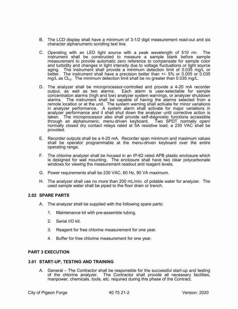
City of Pigeon Forge 40 75 21-2 Version: 2020
B. The LCD display shall have a minimum of 3-1/2 digit measurement read-out and six character alphanumeric scrolling text line.
C. Operating with an LED light source with a peak wavelength of 510 rm. The instrument shall be constructed to measure a sample blank before sample measurement to provide automatic zero reference to compensate for sample color and turbidity and changes in light intensity due to voltage fluctuations or light source aging. The instrument shall provide a minimum detection limit of 0.035 mg/L or better. The instrument shall have a precision better than +/- 5% or 0.005 or 0.035 mg/L as CL2. The minimum detection limit shall be no greater than 0.035 mg/L.
D. The analyzer shall be microprocessor-controlled and provide a 4-20 mA recorder output, as well as two alarms. Each alarm is user-selectable for sample concentration alarms (high and low) analyzer system warnings, or analyzer shutdown alarms. The instrument shall be capable of having the alarms selected from a remote location or at the unit. The system warning shall activate for minor variations in analyzer performance. A system alarm shall activate for major variations in analyzer performance and it shall shut down the analyzer until corrective action is taken. The microprocessor also shall provide self-diagnostic functions accessible through an alphanumeric, menu-driven keyboard. Two SPDT normally open/ normally closed dry contact relays rated at 5A resistive load, a 230 VAC shall be provided.
E. Recorder outputs shall be a 4-20 mA. Recorder span minimum and maximum values shall be operator programmable at the menu-driven keyboard over the entire operating range.
F. The chlorine analyzer shall be housed in an IP-62 rated APB plastic enclosure which is designed for wall mounting. The enclosure shall have two clear polycarbonate windows for viewing the measurement readout and reagent levels.
G. Power requirements shall be 230 VAC, 60 Hz, 90 VA maximum.
H. The analyzer shall use no more than 200 mL/min. of potable water for analyzer. The used sample water shall be piped to the floor drain or trench.
2.02 SPARE PARTS
A. The analyzer shall be supplied with the following spare parts:
1. Maintenance kit with pre-assemble tubing.
2. Serial I/O kit.
3. Reagent for free chlorine measurement for one year.
4. Buffer for free chlorine measurement for one year.
PART 3 EXECUTION
3.01 START-UP, TESTING AND TRAINING
A. General – The Contractor shall be responsible for the successful start-up and testing of the chlorine analyzer. The Contractor shall provide all necessary facilities, manpower, chemicals, tools, etc. required during this phase of the Contract.

City of Pigeon Forge 40 75 21-3 Version: 2020
B. Start-Up – The start-up of the chlorine analyzer shall be accomplished under the supervision of a certified representative of the manufacturer.
C. Certification – The Contractor shall submit a written certification signed by a representative of the analyzer manufacturer that the system is installed correctly and is in proper operational condition prior to start-up.
D. Training – The Contractor shall supply a minimum of one (1) day (4 hours) of training for the plant personnel in the operation and maintenance of the chlorine analyzer.
END OF SECTION

City of Pigeon Forge 40 75 21-4 Version: 2020
THIS PAGE INTENTIONALLY LEFT BLANK

City of Pigeon Forge, TN 40 90 00-1 Version: 2020
SECTION 40 90 00
WATER INSTRUMENTATION/TELEMETRY MONITORING
PART 1 GENERAL
1.01 WORK INCLUDED
A. The project’s general contractor (CONTRACTOR) shall provide all services and equipment defined in this section and as specifically noted on contract drawings and other specification sections.
B. All RTU configuration and programming will be provided by the City of Pigeon Forge’s telemetry supplier (TELE-SUPPLIER). This TELE-SUPPLIER will be responsible for providing System Integration services at remote sites and at the central Pigeon Forge Water Treatment Plant. The TELE-SUPPLIER shall program and configure the remote telemetry RTU. The contractor will provide an allowance of $10,000.00 in his bid/estimate for system integration services by the TELE-SUPPLIER. On projects funded by the city, this allowance will be deducted from the CONTRACTOR’S final contract amount. On all other projects the OWNER/ DEVELOPER will pay the allowance directly to the city to cover the cost of integration services.
C. The TELE-SUPPLIER is not involved in the actual pump station control. The control system shall be provided by the pump supplier.
D. The CONTRACTOR shall provide the RTU panel, antenna tower, and antenna. The ELECTRICAL CONTRACTOR shall furnish field instruments below that do not come as part of the pump station control package. The ELECTRICAL CONTRACTOR shall provide the associated wiring/cabling between the RTU panel, the field instruments and antenna.
1.02 SUBMITTALS
A. General
1. Shop drawings shall provide a true and complete record of equipment as manufactured, delivered and installed. Shop drawings shall demonstrate that the equipment furnished complies with provisions required by this contract. Submittals shall be transmitted in electronic form.
B. Provide drawings of RTU panel and enclosure. These drawings shall include:
1. Wiring diagrams showing all power connections to equipment within and on panels.
2. Fuse and breaker sizes.
3. Grounding scheme.
4. Wiring of relays, analog line surge protectors, etc.
5. Show all wiring numbers and terminal block designations.
6. Cabinets shall be drawn to scale.

City of Pigeon Forge, TN 40 90 00-2 Version: 2020
7. List material, fabrication and painting specifications.
8. Show elevation of panel front cover, including, location of door handles, windows, lifting lugs, and enclosure mounted items.
1.03 CODES AND STANDARDS
A. All equipment shall be installed in compliance with Federal, State and Local codes.
1.04 RTU/SCADA CONTROL SYSTEM OVERVIEW
A. The RTU system will consist of one RTU panel at the remote pump station. This RTU will communicate with the Pigeon Forge central SCADA computer system. All RTUs shall be provided, and associated antennas and tower. The Polling Master RTU will poll the remote RTU and transfer the information from it and all other remote RTUs to the Water Treatment Plant RTU. Because of the mountainous terrain in the Pigeon Forge area, some RTUs may need to be used as repeater stations for some other RTUs. This information, from the remote RTUs, will be displayed via the Water Treatment Plant’s SCADA system. The TELE-SUPPLIER is responsible for the design of the central SCADA HMI required at the Water Treatment Plant to monitor all of the I/O at all of the remote RTU locations.
B. The CONTRACTOR shall provide the RTU control panel, antenna tower, and antenna. All associated wiring/cabling between the RTU control panel and the field instruments and antenna shall also be provided by the CONTRACTOR.
C. All downtime of pump stations, raw water intake, and tanks shall be coordinated with the OWNER. All downtime must be pre-approved by the OWNER five (5) days prior to downtime.
D. The TELE-SUPPLIER shall provide all programming at the remote RTU PLC associated with local monitoring. There shall be no loss of local control functionality at any of the remote locations as a result of this project. The TELE-SUPPLIER will provide the OWNER with a detailed description of the exact operation of the new RTU system.
E. All HMI screen design shall be coordinated with the OWNER by the TELE-SUPPLIER. Screen design shall follow all Water Treatment Plant standards including color scheme, navigation buttons, trending, historical logging, report generation, symbology, etc. The TELE-SUPPLIER is responsible for generating (daily, monthly, yearly) reports and miscellaneous reports required by the owner in Excel VBA.
F. The CONTRACTOR shall furnish all antennae towers, antennas, and miscellaneous equipment required for an operational system. The TELE-SUPPLIER shall coordinate antennae tower heights with topographical information as to insure that all remote sites are able to communicate with the main polling site. The TELE-SUPPLIER shall provide the results of this study and provide the CONTRACTOR with the exact height of the antennae tower. The TELE-SUPPLIER shall account for the height of trees and other obstacles that may interfere with communication. All control panels shall be NEMA 3R with heaters and other equipment necessary to operate in the weather conditions to which they will be installed. All control panels shall also have a battery backup, sized to provide a minimum of 1 hour of back-up power under normal operating conditions. All PLCs shall be powered by the 24VDC battery/battery charger.
G. The Factory Witness Test shall take place at Pigeon Forge Water Treatment Plant. All testing shall be done in conjunction with the Water Treatment Plant’s PLC testing
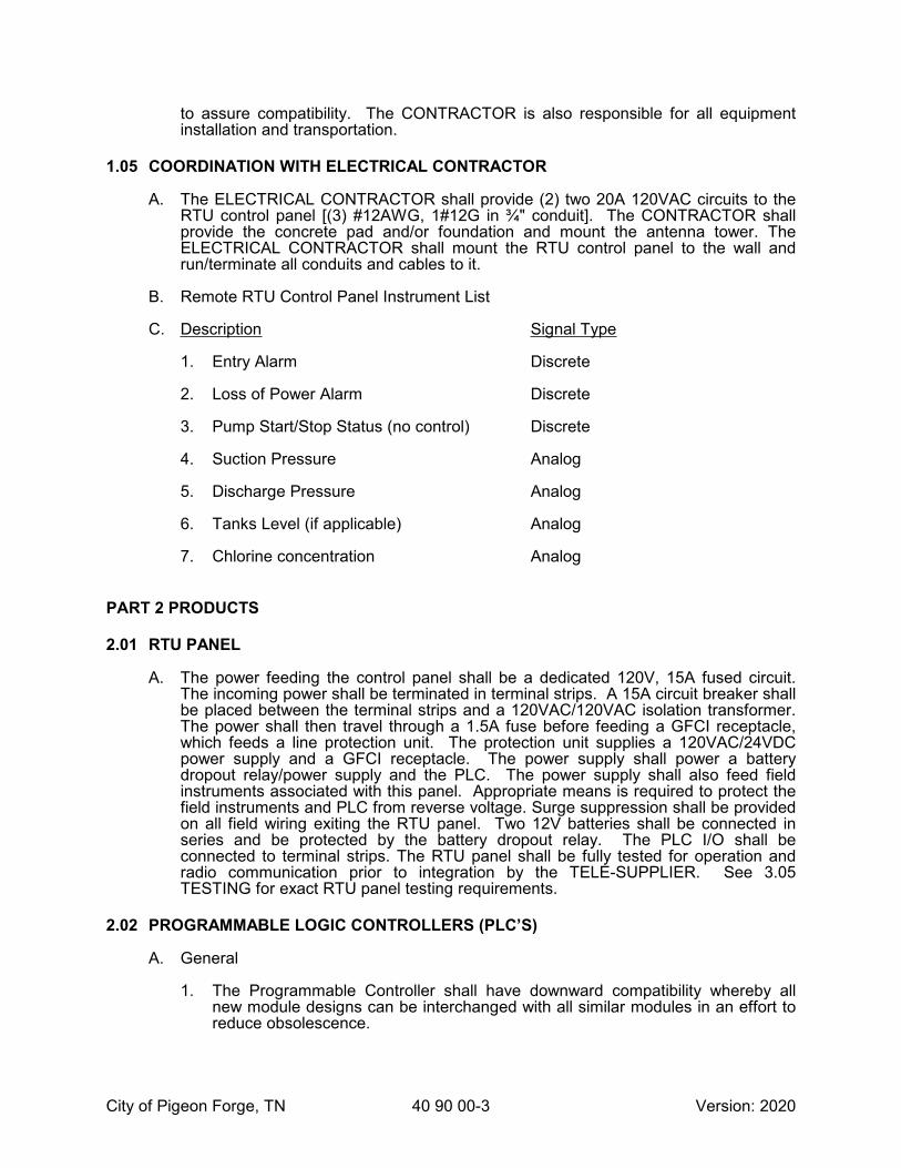
City of Pigeon Forge, TN 40 90 00-3 Version: 2020
to assure compatibility. The CONTRACTOR is also responsible for all equipment installation and transportation.
1.05 COORDINATION WITH ELECTRICAL CONTRACTOR
A. The ELECTRICAL CONTRACTOR shall provide (2) two 20A 120VAC circuits to the RTU control panel [(3) #12AWG, 1#12G in ¾" conduit]. The CONTRACTOR shall provide the concrete pad and/or foundation and mount the antenna tower. The ELECTRICAL CONTRACTOR shall mount the RTU control panel to the wall and run/terminate all conduits and cables to it.
B. Remote RTU Control Panel Instrument List
C. Description Signal Type
1. Entry Alarm Discrete
2. Loss of Power Alarm Discrete
3. Pump Start/Stop Status (no control) Discrete
4. Suction Pressure Analog
5. Discharge Pressure Analog
6. Tanks Level (if applicable) Analog
7. Chlorine concentration Analog
PART 2 PRODUCTS
2.01 RTU PANEL
A. The power feeding the control panel shall be a dedicated 120V, 15A fused circuit. The incoming power shall be terminated in terminal strips. A 15A circuit breaker shall be placed between the terminal strips and a 120VAC/120VAC isolation transformer. The power shall then travel through a 1.5A fuse before feeding a GFCI receptacle, which feeds a line protection unit. The protection unit supplies a 120VAC/24VDC power supply and a GFCI receptacle. The power supply shall power a battery dropout relay/power supply and the PLC. The power supply shall also feed field instruments associated with this panel. Appropriate means is required to protect the field instruments and PLC from reverse voltage. Surge suppression shall be provided on all field wiring exiting the RTU panel. Two 12V batteries shall be connected in series and be protected by the battery dropout relay. The PLC I/O shall be connected to terminal strips. The RTU panel shall be fully tested for operation and radio communication prior to integration by the TELE-SUPPLIER. See 3.05 TESTING for exact RTU panel testing requirements.
2.02 PROGRAMMABLE LOGIC CONTROLLERS (PLC’S)
A. General
1. The Programmable Controller shall have downward compatibility whereby all new module designs can be interchanged with all similar modules in an effort to reduce obsolescence.

City of Pigeon Forge, TN 40 90 00-4 Version: 2020
2. The PLC in the RTU panel shall be a MicroLogix 1400 manufactured by Allen Bradley. All 120V units shall be model #1764-24BWA, and all 24VDC units shall be model #1764-28BXB. Each PLC shall be equipped with a memory module and real time clock. Each PLC shall also include appropriate input and output cards to transmit and receive the required analog and discrete signals described above.
2.03 SPARE HARDWARE
A. Each PLC rack shall have 20% spare physical slots for future I/O cards to be added. Provide 1 spare for each of the following:
1. One (1) spare piece of hardware for all panel equipment in critical system pump stations. For example: processors, power supplies, surge suppressors, and I/O modules. The spare processor shall be preloaded by the TELE-SUPPLIER with the same configuration as the online processor to enable quick swap maintenance.
2.04 RADIO TRANSCEIVERS AND ACCESSORIES
A. Antenna and Coaxial Cable shall be type and size specified by City of Pigeon Forge’s IT Dept. The antenna shall be cabled to the transmitter enclosure connection by 7/8 inch Andrew Heliax coaxial cable by Andrew, Inc.
B. Antenna Lightning Protection
1. Coaxial connection to enclosures shall be by means of a coaxial type bulk-head lightning arrester. The units shall be rated at 1 kilowatt with a minimum 500V and maximum 2000V breakdown voltage. Coaxial lightning arresters shall be a PD-593 or PolyPhaser IS-B50LU-CO.
C. Antenna Mounting Systems
1. The antennas shall be mounted at a height and location specified by City’s IT Dept. The CONTRACTOR shall verify exact antenna tower height with the TELE-SUPPLIER prior to bid. The antenna shall be mounted as follows:
2. A bracketed antenna tower shall be supplied at all remote RTU locations. The tower shall be assembled from 10ft sections built on an 18” equilateral triangle design. Tower sections shall be constructed of 1-1/4” steel tubing with continuous solid steel rod “zig-zag” cross-bracing electrically welded to the tubing. The entire 10’ sections shall be Hot-Dip Galvanized after fabrication for long life. The antenna towers shall be Rohn Model 45G. CONTRACTOR to submit guy and anchor details for engineer’s approval.
2.05 INSTRUMENTATION AND ACCESSORIES
A. General
1. All items in the RTU system (electronic cards, power supplies, time delays, relays, etc.) shall be of plug-in construction or make use of a plug-in wiring harness and be interchangeable without recalibration. To insure field reparability by non-technical personnel, equipment that must be unwired for replacement will not be accepted.
2. The following instrumentation devices and techniques shall be used as specifically called for in the PLC and Telemetry input/output sections of this specification.

City of Pigeon Forge, TN 40 90 00-5 Version: 2020
B. Power Supplies
1. The common 24 VDC power supplies shall provide +0.1% line and load regulation with +10% input variations. The input/output isolation shall be 100 Mohms DC (900Volts AC) with output transient response of 50 microseconds maximum. The power supply shall be sized to operate the remote unit equipment with or without the back-up battery in place. Power Supplies shall be an ELPAC Series OLV, Sola SLS, or approved equal.
C. Battery Back-up Operation
1. Provide battery back-up operation for PLC and Telemetry System. Two 12 VDC rechargeable batteries shall be connected in a series configuration to provide the 24 VDC necessary for the RTU PLC. The rechargeable batteries shall be the sealed solid gelled electrolyte type, designed for float or stand-by service. Batteries shall be sized to maintain 1-hour service at zero degrees Celsius. The remote shall include a plug-in charging module to recharge the battery when power is resumed, maintain the charge between outages, and provide a low voltage cut-off to protect the battery from excessive discharge during prolonged outages. All discrete and analog inputs (i.e. switch closures, pressure, level, flows, etc.) shall continue to function on battery back-up. Batteries shall be Globe Gel/Cell, Power Sonic, or an approved equal.
D. Single Phase 120VAC Power Line Lightning Protection
1. Each new site in the system shall be equipped with a combination AC line filter and lightning arrester. The unit shall provide 3-stage lighting/transient protection including inductive and capacitive filtering, MOV overvoltage protection, and three terminal gas discharge tube lightning protection. The unit shall be a TT-LPU, TrippLite ISOBAR IB-2-0, or StediWatt Model 1120-3.
2.06 ACCEPTABLE MANUFACTURERS
A. Relays shall be Potter & Brumfield, or equal.
B. Enclosures shall be Hoffman, or equal.
C. Surge Suppressors shall be Edco, or equal.
D. GFCI Receptacles shall be Hubbell, or equal.
E. Circuit Breakers shall be Square D, or equal.
F. Fuses and Fuseblocks shall be Littlefuse, or equal.
PART 3 EXECUTION
3.01 GENERAL
A. Panel and field raceway systems shall separate discrete, analog and power wiring. An exception shall be made for motor starter control wiring associated with motors, which shall be run in conduit with power conductors. In no case shall wire bundles contain mixed signal types.
B. CONTRACTOR shall verify location of all hazardous classified areas as defined by the National Electric Code. Proper wiring methods and equipment as detailed in the National Electric Code shall be provided in these hazardous classified areas.

City of Pigeon Forge, TN 40 90 00-6 Version: 2020
C. All process variable signal displays shall read out in linear process units, unless otherwise noted.
D. All instrumentation and control equipment shall be suitable for the environment in which it is installed. CONTRACTOR shall take into consideration relative humidity, corrosive vapors, ambient temperatures, dust, splashing water, etc. All equipment cabinets and devices provided by the CONTRACTOR shall be heavy-duty type designed for continuous industrial service.
E. All equipment shall be of modular construction and shall be capable of future field expansion. Equipment shall be located to easily facilitate future expansion. Provide space next to control panels to facilitate the installation of a future control panel of the same size as the one installed to handle future expansion.
F. All electrical equipment supplied shall be designed for 117V nominal, 60Hz alternating current. Equipment shall be designed to withstand +10% voltage sags and/or distortion.
G. Instrumentation and control equipment shall be UL listed. Control panels shall be built by a certified UL panel building shop capable of UL labeling the custom panel they build as a complete assembly with a unique UL ID serial number.
H. The control system shall be configured in such a way as to provide orderly shutdown and automatic restart when power outages occur.
I. Operation of the control system shall not require any knowledge of software programming.
J. All instrumentation signal cable shall bear an outer shield that is to be continuous from source to destination and grounded per manufacturers’ recommendations. However, in no case shall the shield be grounded at more than one place.
K. The CONTRACTOR shall insure that all field wiring for power and signal circuits are installed in accordance with best standard industrial practice and provide all necessary system grounding to insure a satisfactory functioning installation.
3.02 CONTROL PANELS AND FIELD WIRING
A. The RTU panel is to be designed and fabricated by a U.L. Certified Panel Builder.
B. All major pieces of equipment in panels shall be identified by permanent engraved labels. Attach labels to panels with stainless steel self-tapping screws. Identify the following electrical equipment as a minimum:
1. Motor control centers, and individual devices installed therein.
2. Panelboards.
3. Safety switches and disconnects.
4. Contactors and motor starters.
5. Telephone cabinets.
6. Individually mounted circuit breakers.
7. Relays.

City of Pigeon Forge, TN 40 90 00-7 Version: 2020
8. Transformers.
9. PLC’s
10. UPS’s
11. VFD’s
12. Control pushbuttons
13. Solenoid valves
C. Identify electrical equipment with permanently attached black phenolic plates with ¼” white engraved lettering on the face of each, attached with two sheet metal screws. Colors shall match existing scheme presently used throughout the facility.
D. All control and instrumentation wiring shall be named and labeled at both ends. Labels at both ends of the same wire shall be identical. Label names shall be selected to indicate where the wire runs to and from. For example, a wire running from Panel CP2080 to Level Transmitter LT1000 shall be labeled “CP2080-LT1000" at both ends of the wire.
E. Panel mounted equipment shall be arranged in a manner that allows servicing, adjustment, testing, removal without disconnecting, or removal of other components. All components shall be mounted on removable plates, not directly attached to cabinet enclosure.
F. Panels located outdoors shall have radiant shields or a small awning to shield them from direct sunlight.
G. All exterior panel mounted equipment shall be installed with suitable gaskets, faceplates, or other accessories as required to maintain the NEMA rating of the panel.
H. All conduit and cable penetrations shall be provided with ground bushings, hubs, gasketed locknuts or other accessories as required to maintain the NEMA rating of the panel.
I. Provide print storage pockets on the inside of each panel. These pockets should be of sufficient size to hold all prints and operations manuals associated with panel. Place a reduced set of all drawings associated with panel in its pockets. All panels shall be suitable for top and/or bottom conduit entry.
J. Wiring.
1. All wiring entering or exiting control panels shall terminate on the Master Terminal Board. The Master Terminal Board is a plate mounted in the panel for termination of external wiring. All external wiring shall enter panel and terminate on one side of terminal blocks mounted on the Master Terminal Board. Wiring from components within the panel shall terminate on the other side of the terminal blocks.
2. Wiring between the Master Terminal Board and components within the panel shall be factory installed.
3. All terminal blocks and wires shall be uniquely named and labeled. This means that even small jumper wires shall have unique names and be labeled. (i.e. J21,

City of Pigeon Forge, TN 40 90 00-8 Version: 2020
J22, J32, etc.) All wire label identifications shall be identified on loop and panel wiring diagrams. Labels at both ends of the same wire shall be identical.
4. The Master Terminal Board shall have a minimum of 20% spares.
5. Terminal blocks shall be arranged in vertical rows and separated into groups (Incoming 120VAC power, 120VAC Discrete Inputs, 120VAC Discrete Outputs, 24VDC Discrete Inputs, 24VDC Discrete Outputs, 4-20mA Analog Inputs, 4-20mA Analog Outputs, etc.). The line AC control terminal block shall be used to terminate 120v power conductors fed from 208\120, three-phase panelboards. Provide circuit breakers on circuits 120VAC (and higher) for overcurrent protection and convenient disconnection means.
6. Terminal blocks shall be barrier type (equivalent to Buchanan Cat# 0625) with the appropriate voltage rating. They shall be raised channel mounted type.
7. Wire connectors shall be the snap-on fork type (equivalent to Thomas and Betts) with insulated barrel for crimp type compression connection to the wire.
8. Group all wiring in rigid gray vinyl wire duct. (Equivalent to PANDUIT Style G)
9. Only one side of a terminal block row shall be used for internal wiring. The field wiring side of the terminal shall not be within 6" of the side panel, an adjacent terminal, or a piece of equipment.
10. All 120V and above power wiring shall be identified as such.
11. Signal wiring of different types shall be color-coded to easily identify the signal types. (i.e. 120VAC=red, 24VDC=blue, etc.)
K. Each control loop or system shall be individually protected by fuses or breakers. All overcurrent protection devices shall be clearly labeled and located for ease of maintenance.
L. Provide isolation relays (equivalent to Potter & Brumfield KUP, 10Amp, 3PDT contacts, plug-in type, w/ associated relay socket rail mount) on all discrete outputs.
M. Provide surge suppressor (equivalent to EDCO PC642C, plug-in type) for all input and output low voltage signals.
N. All panels shall be fabricated of not less than USS 14-gauge steel. All wall-mounted panels shall be manufactured by Hoffman, Stahlin, Robroy Industries or approved equivalent.
O. Provide UL approved GFCI 20 amp Duplex receptacle in surface mounted two gang box with stainless steel cover plate in panel or plug in of portable equipment.
P. Provide Thermo-statically controlled space heater (equivalent to Hoffman D-AH1001A) in all outdoor panels.
3.03 PLC INSTALLATION
A. Within the enclosure all I/O racks, processor racks, and power supplies shall be grounded to meet the manufacturer’s specifications.
B. All cables (with associated plugs, connectors and receptacles) shall be designed for commercial use to withstand an industrial environment.

City of Pigeon Forge, TN 40 90 00-9 Version: 2020
C. Each limit switch, push-button, or other input device shall be connected to only one individual input point.
D. Each output device shall be connected to only one individual output point.
E. PLC input and output cards shall be configured to fail in a safe manner. Determination of fail safe position (ie. 2mA, 20mA, last-value, open, closed, etc.) shall be determined by the OWNER.
3.04 DOCUMENTATION
A. As-built documentation shall include all previous submittals as described in this specification updated to reflect the as-built system. Any errors in or modifications to the system resulting from the factory and/or field acceptance tests shall be incorporated in this documentation.
B. Maintenance Manuals shall describe preventive and corrective procedures required to keep the system in good operating condition. Hardware maintenance manuals shall include:
1. Diagnostic procedures for troubleshooting system.
2. Preventative maintenance instructions.
3. Corrective maintenance instructions.
4. Operation information.
5. Spare parts information including identification of all equipment. Identification shall include all information necessary to order new equipment. Name and address of local distributor carrying this equipment shall also be supplied. All spare parts equipment lists shall be cross-referenced to equipment name on drawings and designation on loop drawings.
C. The TELE-SUPPLIER provide operating instruction manuals with adequate information pertaining to the following outline:
1. System specifications
2. Electrical power requirements
3. Application considerations
4. Assembly and installation procedures
5. Power up procedures
6. Troubleshooting procedures
7. Programming procedures
8. Explanation of internal fault diagnostics
9. Shut down procedures
10. Recommended spare parts list
11. Labeled tabs shall separate these 10 manual sections.
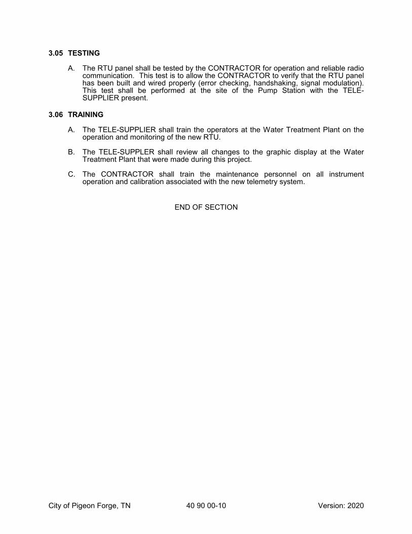
City of Pigeon Forge, TN 40 90 00-10 Version: 2020
3.05 TESTING
A. The RTU panel shall be tested by the CONTRACTOR for operation and reliable radio communication. This test is to allow the CONTRACTOR to verify that the RTU panel has been built and wired properly (error checking, handshaking, signal modulation). This test shall be performed at the site of the Pump Station with the TELE-SUPPLIER present.
3.06 TRAINING
A. The TELE-SUPPLIER shall train the operators at the Water Treatment Plant on the operation and monitoring of the new RTU.
B. The TELE-SUPPLER shall review all changes to the graphic display at the Water Treatment Plant that were made during this project.
C. The CONTRACTOR shall train the maintenance personnel on all instrument operation and calibration associated with the new telemetry system.
END OF SECTION

City of Pigeon Forge, TN 43 21 13-1 Version: 2020
SECTION 43 21 13
FACTORY-BUILT WATER BOOSTER PUMP STATIONS
PART 1 GENERAL
1.01 WORK INCLUDED
A. This specification includes the general requirements for design and construction of pre-engineered water booster stations. Because of varying site conditions and operational considerations, these specifications should only be used as a guideline in the design and construction of water booster stations. Developers and their engineers shall schedule a meeting with the Department of Public Works early in the design process to determine if additional requirements will be necessary.
B. Pumping systems shall include the enclosure, frame, pumps, meters, valves, fittings, piping electrical equipment, HVAC, controls and other ancillary equipment as specified herein or as necessary for a fully operational automatic booster station. All equipment shall be assembled by a single supplier who shall bear unitary responsibility for the station’s quality.
1.02 CODES AND STANDARDS
A. Reference Standards
1. Hydraulic Institute Standards
2. ANSI - American National Standards Institute
3. NEMA - National Electrical Manufacturers Association
4. UL - Underwriters Laboratory
5. ETL - Electrical Testing Laboratories
6. NEC - National Electric Code
7. AWWA - American Water Works Association
8. ASTM - American Society for the Testing of Materials
9. NSF - National Sanitation Foundation
B. Fabrication and manufacture shall be in compliance with all local, state, and federal codes having jurisdiction in the project area.
C. The booster station manufacturer will be responsible for providing all plans, documents, and calculations as required for building approval.
D. Station shall be located and constructed to minimize erosion of site. Engineer shall perform analysis to determine impact of pump station on existing storm water flow through the site and certify the station will not experience or cause any erosion.
E. Upon approval of the pump station, developer shall grant City of Pigeon Forge fee simple deed to property. Deed shall include proper access to pump station location.

City of Pigeon Forge, TN 43 21 13-2 Version: 2020
F. Temporary power intended to serve permanent installations will be allowed for no more than forty-five (45) days. After that time has elapsed, City will disconnect temporary power supply until permanent electrical connection is complete. Under no circumstances will a system be allowed to operate on temporary power.
G. Pumps stations are to have paved dedicated access from roadway.
H. Site inside fence must be paved or graveled at the discretion of the City.
1.03 QUALITY CONTROL
A. Manufacturer must have been engaged regularly in the manufacture of booster stations for a minimum of ten years.
B. The booster station shall be in compliance with the Underwriter Laboratory standard for assembled equipment under the Packaged Pumping Systems (QCZJ) UL listing category. The station shall bear the UL label indicating compliance with this standard.
C. All welders shall be certified in welding and be employees of the booster station manufacturer.
D. Booster station manufacturer shall assemble, install, mount, and integrate all electrical apparatus.
E. Booster station shall be:
1. Engineered Fluid, Inc.
2. Or approved equal.
1.04 SPECIAL WARRANTY
A. A warranty by the pump station manufacturer shall be provided:
1. The warranty shall provide for the replacement and/or repair of all equipment and materials provided with the station due to defect or workmanship for a period of one year from the date of acceptance by the Owner.
2. The booster station manufacturer shall be the one-point contact for all equipment provided.
3. All labor and parts including removal, modifications, and replacement shall be included in the warranty.
4. The one-year warranty period will apply regardless of individual component, standard manufacturer warranties.
1.05 SERVICE CONTRACT
A. In addition to the Special Warranty, a 5-year service contract shall be supplied to the City of Pigeon Forge prior to acceptance of the booster station. This service contract period will begin on the day the station is accepted by the City. The service provider under this contract shall be the licensed service representative in the area. The contract shall include:

City of Pigeon Forge, TN 43 21 13-3 Version: 2020
1. 24-hour per day/365 day per year telephone support. At a minimum, the service provider shall maintain a call center where emergency assistance may be obtained.
2. 6-Hour Response Time - If unable to resolve issues over the telephone, service technicians certified by the equipment manufacturer shall be dispatched to the pump station site. Technicians shall be on-site within six hours of the time of the call by the City of Pigeon Forge.
PART 2 PRODUCTS
2.01 BOOSTER STATION
A. General
1. Provide clearances above, below and around equipment to provide for safe servicing, removal and reinstallation of that equipment.
2. Doors shall be located and sized to facilitate removal and replacement of equipment without requiring the enclosure to be altered or removed.
3. Structure shall include beam with a chain and hoist for removal of the pumps and motors.
B. Modular Structure
1. Modular enclosure shall be affixed to a steel deck structure. The completed booster station shall be one piece when delivered to the Site and not require disassembling to off-load. The Enclosure shall incorporate, at minimum, two rooms, one shall be for the pumps, controls and electrical equipment, and the other shall be for chemical feed.
2. Side and Ceiling Panels:
a. Interior and Exterior Skin: 26-gauge galvanized steel with sprayed and baked polyester coating in the pump room. In the chemical room, interior panels shall be Marlite FRP or equal.
b. Poured-in-place polyurethane foam core bonded to metal skins.
c. Fire Rating: UL rated flame spread of 25 or lower and smoke generation of 450 or lower when tested in accordance with ASTM E-84-76.
d. Thickness: Minimum four inches.
e. Heat transfer value: Minimum R-30.
3. Panels shall be tongue-and-groove and fasten together using a cam-action locking arm system that draws panels tight together. Provide cam lock wrench with building.
4. Doors:
a. Size: Double door 72” x 78” clear opening.

City of Pigeon Forge, TN 43 21 13-4 Version: 2020
b. Interior and exterior skins identical to wall panels for the pump room. Doors and hardware for the chemical room shall be corrosion resistant RFP and aluminum.
c. 2-inch foam polyurethane insulation core.
d. Hinges: Three on each door with tamper-proof pinned butt hinges.
e. Locks: Deadbolt type locking assembly. Schlage lock, keyed to City of Pigeon Forge master key. Provide two keys.
f. Sill plate: Extruded aluminum.
g. Provide metal shield above door to divert rain and snow away from door opening.
h. Provide weather stripping and wiper gasket.
i. The chemical feed room door shall be fitted and wired to an interlock microswitch to provide activation of an exhaust fan whenever the door is open.
5. Roof:
a. Single piece EPDM membrane system covering ceiling panels.
b. Thickness: Minimum 45 mil.
c. Color: White
d. Design Wind Load: Minimum 80 MPH or as required by codes.
e. Roof hatches equal to Bilco ME-50 shall be located over pumps and motors for equipment removal.
6. Safety Floor Matting:
a. Nyacord, industrial, safety matting. Not fastened to floor. Allow free drainage.
b. Thickness: ½ inch.
c. Coverage: From entrance to the control panels and entire NEC clearance area.
7. Chemical Room Exposed Metal:
a. All exposed ferrous metal within the Chemical Room shall receive a 12-16 mil DFT coating with TNEMEC Series 120 “Vinester” in accordance with the manufacturer’s instructions for surface preparation, prime coating, and finish coating.
C. Base Frame
1. Constructed of standard structural steel members or tubing.
2. Floor: ¼-inch steel across top of frame.

City of Pigeon Forge, TN 43 21 13-5 Version: 2020
3. Provide floor drains.
4. Provide eyelet devices welded to the frame at the pipe inlet and outlet points designed to withstand movement between the buried pipe and the booster station.
D. Pumping Equipment
1. Number of pumps: Minimum of two. One duty pump capable of delivering the rated capacity and one full capacity redundant on-line spare.
2. Type: Horizontal, end suction close-coupled centrifugal, where possible. Turbine pumps may be utilized in special situations. The City of Pigeon Forge shall be consulted should turbine pumps be required.
3. Casing: Cast iron; provide taps for suction and discharge gages. Class 125 suction and discharge flanges shall be utilized unless pressures necessitate Class 300.
4. Impeller: Bronze; enclosed, multi-vane, statically and hydraulically balanced.
5. Wear Rings: Bronze; replaceable.
6. Shaft Sleeves: Bronze; shall cover full length of shaft and protect shaft from liquid, bronze.
7. Seal: Mechanical with carbon rotating face and Ni-Resist stationary face and all stainless steel metal parts.
8. Motor:
a. Open drip proof, designed to carry all radial thrust loads.
b. Premium efficiency.
c. Inverter duty rated motors shall be utilized if greater than 40 HP.
d. Rotational speed shall be less than 1800 rpm.
9. Supports: Fabricated steel frame shall support pump and motor. Provide vibration isolation pad.
E. Piping
1. All piping and fittings shall be steel.
2. Steel Pipe and Fittings
a. Material:
1) 4-inch and smaller: ASTM A53 (CW).
2) Above 4-inch: ASTM A53 (ERW) Grade B.
b. Class:
1) 10-inch and below: Schedule 40.

City of Pigeon Forge, TN 43 21 13-6 Version: 2020
2) Above 10-inch: Standard weight (0.375-inch wall).
c. Flanges: Conform to ASTM A105/A181 and ANSI B16.5
d. Supports: Use steel sections or tubing. Cut to match pipe and fully weld to floor or pipe at each end. Design to resist transverse and lateral forces.
e. Interior Coating:
1) Fusion bonded epoxy.
2) Conformance: ASTM C213-91.
3) Total dry mil thickness of 12.0 to 14.0 mils.
4) Quality Standards: ASTM B117 1,000-hour Salt Spray Resistance; ASTM D2247 1,000-hour Humidity Resistance; ASTM G14-72 Impact Resistance (160 inch-pounds).
3. Valves, Meters and Accessories
a. Pump Control Valves:
1) Pilot-controlled, hydraulically operated diaphragm-type automatic control valve.
2) Cast iron body with flanged connections.
3) Pilot shall be a four-way solenoid-control electrically interlocked with the booster pump controls and operate on a 115-volt, 60-cycle AC power source. Energize to open main valve.
4) Provide two variable-position limit switches activated by stem when valve is in the full open or full closed position.
5) Provide field-adjustable slow opening and closing control.
6) Provide strainer for water entering pilot assembly.
7) Provide shut-off cocks to isolate pilot assembly.
8) Provide built-in check valve to close main valve in the event of power loss.
9) Manufacturer: Cla-Val, Ross or approved equal.
b. Isolation Valves:
1) 3-inch and below: Bronze body ball or gate valves.
2) Above 3-inch: Resilient wedge gate valve per AWWA C509.
c. Flow Meter:
1) Type¨ Electromagnetic. Microprocessor-based displaying totalized and instantaneous flow in full pipe.
2) Suitable for installation through a 2” corporation stop.

City of Pigeon Forge, TN 43 21 13-7 Version: 2020
3) Power: 120-volt AC.
4) Accuracy: 0.5% of flow rate over a 33:1 turndown.
5) Transmitter shall be within a NEMA 4X enclosure relayed to the station SCADA system.
6) Provide 4-20 ma analog flow signal.
7) Manufacturer: Marsh McBarrey Model 284 or equal.
d. Pressure Gages:
1) Glycerin filled with built-in snubber.
2) 4 ½-inch dial.
3) Provide isolation stopcock.
4) Suction pressure: 0 to 100 psi to 10-psi intervals with graduation marks every one-psi.
5) Discharge pressure: 0 to 200 psi in 20-psi intervals with graduation marks every two-psi.
6) Mount gages off the pipe, clear of vibration, and provide a flexible connection line to the pipe.
e. Pressure Control:
1) Power: 120 VAC, 60 Hz.
2) Low pressure cut-off, field-adjustable up to 150 psi.
f. Provide flanged restrained elastomer connector on pump inlet for vibration control.
g. Surge Relief Valve:
1) Pilot-controlled, hydraulically operated diaphragm-type automatic control valve.
2) Cast iron body with flanged connections.
3) Pilot shall be a direct-acting, adjustable, spring loaded, normally closed unit designed to close the main valve whenever the sensed pressure is below the pilot spring setting
4) The relief valve shall function to limit the discharge header pressure to the value set in the control pilot.
5) Provide field-adjustable slow opening and closing control.
6) Provide strainer for water entering pilot assembly.
7) Provide shut-off cocks to isolate pilot assembly.

City of Pigeon Forge, TN 43 21 13-8 Version: 2020
8) Provide built-in check valve to close main valve in the event of power loss.
9) Manufacturer: Cla-Val, Ross or approved equal.
h. Miscellaneous: Provide restrained adapters, couplings, and unions to permit the easy removal of pumps, valves, meter and strainer.
4. Hydro-Pneumatic Tanks
a. Hydro-pneumatic tanks will only be allowed under extenuating circumstances and only when less than 50 single family equivalents will be tied to the water system.
b. Pumping systems utilizing hydro-pneumatic tanks must be equipped with a high flow pump capable of meeting the required fire flows within the system.
c. The equipment capsule shall be complete with two (2) diaphragm type hydro pneumatic ASME coded storage tanks. Storage tanks and bladders shall be rated at 50% over the design pressure of the water system.
d. The hydro pneumatic storage tanks shall feature deep drawn steel upper and lower domes with side shell construction specifically designed for diaphragm type storage tanks. Storage tank welding shall be carefully done to eliminate rough spots and sharp edges. The storage tank base shall be designed so as to permit free airflow to prevent moisture from accumulating beneath the storage tank.
e. The hydro pneumatic storage tank internals shall include two (2) separate pieces. The first piece shall be a heavy duty butyl diaphragm that effectively separates the air chamber from the water chamber. The shape of the diaphragm shall conform exactly to the shell configuration and shall be of seamless construction meeting FDA requirements for potable water.
f. The second piece shall be a polypropylene liner that conforms exactly to the lower dome and acts as the water receptacle. Water shall never touch steel.
g. The polypropylene liner shall be 100% non corrosive and will not be bonded to the steel shell wall or lower dome. A mechanical clamping ring shall permanently affix the diaphragm and the liner to the shell groove. The polypropylene liner shall be tested and accepted by the National Sanitation Foundation.
1) Hydro-pneumatic storage tanks shall be Wessels Company or approved equal.
5. Bypass Hydrants
a. Every pump station shall have a standard fire hydrant on the suction and discharge side of the pump station to allow a temporary pumping arrangement incase of a fire or emergency.
F. Painting and Exterior Surfaces
1. Exterior surfaces shall be metal, concrete, or other approved durable surface. Wood finishes are not allowed without prior written approval.

City of Pigeon Forge, TN 43 21 13-9 Version: 2020
2. Paint all exposed interior and exterior metal surfaces including base frame, floor, piping, pumps, fittings, valves, etc.
3. Do not paint surfaces already containing finished coatings from the manufacturer such as side panels, control panels and other metals not requiring painting for corrosion protection such as stainless steel and aluminum. Do not paint plastic or rubber surfaces or other flexible conduits.
4. Surface Preparation: Abrasive blast all exposed surfaces to SSPC-SP6.
5. Apply two coats of Tnemec Series 66 Hi-Build Epoxoline at 2.0-4.0 mils DFT each. Finished dry thickness 4.0-8.0 mils DFT.
G. HVAC Equipment
1. Heater
a. Provide one wall or roof-mounted electric unit in each room.
b. Capable of maintaining temperature at 500 F in station.
c. UL listed.
d. Adjustable thermostat with OFF-AUTO-CONSTANT switch.
2. Air Conditioner
a. Provide one wall or roof-mounted unit in each room.
b. UV resistant shroud.
c. Permanent washable polyurethane filter.
d. Three-speed fan with adjustable airflow direction.
e. Capable of maintaining temperature at 800 F in station.
f. Adjustable thermostat with OFF-AUTO-CONSTANT switch.
g. Heater and air conditioner units may share compound thermostat.
3. Exhaust Fan
a. Provide one wall mount unit in each room.
b. Size per local code for required air exchange flow rate.
c. 120 volt, 60 Hz, 1725 RPM totally enclosed motor, Class F insulation.
d. Solid cast aluminum frame, non-corrosive fasteners, anti-vibration supports.
e. UL listed and CSA certified.
f. Aluminum fixed louver with insect screen mounted exterior opposite of fan.
g. Wall-mount thermostat and HAND-AUTO switch.

City of Pigeon Forge, TN 43 21 13-10 Version: 2020
h. Exhaust fan for the chemical room shall be interlocked to a door switch so that the fan activates when the door opens. Fan shall either de-energize via timer or via a switch.
4. Motorized Air Return Shutter
a. Provide one wall-mounted unit in each room.
b. 16-gauge extruded aluminum frame.
c. 120 volt, 60 Hz single phase electric motor.
d. Aluminum fixed louver with insect screen mounted exterior opposite of shutter.
e. Operation of shutter from start/stop operation.
5. Dehumidifier
a. Provide one portable unit.
b. Capacity: 25 pints per 24 hours (AHAM Standard DH-1)
c. 120 volt
d. UL listed
e. Condensate piped to sump or outside building.
f. Dial-controlled adjustable humidistat.
6. Openings
a. All openings that allow for air passage into or out of the station shall be equipped with an insect screen.
H. Electrical Equipment
1. Control Panel
a. NEMA 4X Enclosure
b. Shall incorporate circuit breakers, motor starters, time delay relays and control relays.
c. One (1) main breaker.
d. Branch breakers, one for each pump.
e. One (1) transformer breaker, primary side.
f. One (1) transformer breaker, secondary side.
g. One (1) phase monitor breaker.
h. Nine (9) auxiliary circuit breakers for: controls, lights, heater, air conditioner, dehumidifier, exhaust fan, convenience outlets, telemetry, spare.

City of Pigeon Forge, TN 43 21 13-11 Version: 2020
i. Provide place to keep record documents of electrical control schematic and wiring diagram inside door.
2. Pump Starters
a. Starter design shall be based on site specific date. In general, motors 40 HP or larger shall require RVSS starters.
b. Control shall be provided as described below.
3. Running Time Meter
a. Provide for each pump.
b. Dust and moisture proof molded plastic case.
c. Register in tenths of hours up to 99999.9 hours before repeating.
d. Power supply: 115 volt, 60 Hz.
4. Phase Monitor
a. Provide to protect three-phase equipment against phase loss, under voltage and phase reversal conditions.
b. Shut down equipment through relay upon fault condition.
c. Monitor both delta and wye systems.
d. Automatic reset with adjustable voltage delay.
e. LED indicators to show normal and alarm conditions and to show phase sequence.
f. Audible alarm.
g. UL approved and CSA certified.
5. Surge Arrester
a. Provide secondary surge arrester for lightning protection.
b. Housing: Noryl and ultrasonically sealed.
c. Valve Blocks: Metal oxide with insulating ceramic collar.
d. Annular gap design.
e. Permanently crimped lead wire to upper electrode forming part of gap structure.
f. UL listed and CSA certified.
6. Power Transformer
a. Dry step down transformer sized for station loads.
b. Balanced 115/230 single-phase power for auxiliary circuits.
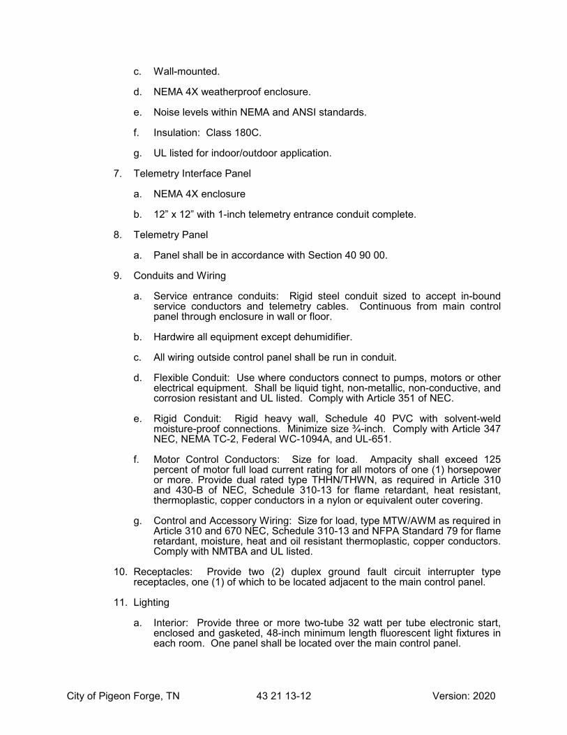
City of Pigeon Forge, TN 43 21 13-12 Version: 2020
c. Wall-mounted.
d. NEMA 4X weatherproof enclosure.
e. Noise levels within NEMA and ANSI standards.
f. Insulation: Class 180C.
g. UL listed for indoor/outdoor application.
7. Telemetry Interface Panel
a. NEMA 4X enclosure
b. 12” x 12” with 1-inch telemetry entrance conduit complete.
8. Telemetry Panel
a. Panel shall be in accordance with Section 40 90 00.
9. Conduits and Wiring
a. Service entrance conduits: Rigid steel conduit sized to accept in-bound service conductors and telemetry cables. Continuous from main control panel through enclosure in wall or floor.
b. Hardwire all equipment except dehumidifier.
c. All wiring outside control panel shall be run in conduit.
d. Flexible Conduit: Use where conductors connect to pumps, motors or other electrical equipment. Shall be liquid tight, non-metallic, non-conductive, and corrosion resistant and UL listed. Comply with Article 351 of NEC.
e. Rigid Conduit: Rigid heavy wall, Schedule 40 PVC with solvent-weld moisture-proof connections. Minimize size ¾-inch. Comply with Article 347 NEC, NEMA TC-2, Federal WC-1094A, and UL-651.
f. Motor Control Conductors: Size for load. Ampacity shall exceed 125 percent of motor full load current rating for all motors of one (1) horsepower or more. Provide dual rated type THHN/THWN, as required in Article 310 and 430-B of NEC, Schedule 310-13 for flame retardant, heat resistant, thermoplastic, copper conductors in a nylon or equivalent outer covering.
g. Control and Accessory Wiring: Size for load, type MTW/AWM as required in Article 310 and 670 NEC, Schedule 310-13 and NFPA Standard 79 for flame retardant, moisture, heat and oil resistant thermoplastic, copper conductors. Comply with NMTBA and UL listed.
10. Receptacles: Provide two (2) duplex ground fault circuit interrupter type receptacles, one (1) of which to be located adjacent to the main control panel.
11. Lighting
a. Interior: Provide three or more two-tube 32 watt per tube electronic start, enclosed and gasketed, 48-inch minimum length fluorescent light fixtures in each room. One panel shall be located over the main control panel.

City of Pigeon Forge, TN 43 21 13-13 Version: 2020
b. Exterior: Provide one (1) 50 watt, high-pressure sodium light fixture with Class H normal power factor reactor type ballast and photocell near the entry door. Lamp shall operate automatically dusk to dawn.
c. Light switches shall have night glow and be located adjacent to entry door.
12. Auxiliary Power Connection
a. Double throw switch shall be furnished on the building exterior to transfer the electrical load from one supply to another. The transfer switch shall be non-fusible, 3-pole, 460 VAC, 600 amp.
b. The manual transfer switch shall be a Model DT366Urk as manufactured by Cutler Hammer.
c. The manual transfer switch shall include a receptacle assembly, Model AP4004ERS as manufactured by Appleton.
I. CONTROLS
1. Control Panel Face - Provide the following on the panel face:
a. Selector switches:
1) LOCAL-REMOTE (L-R)
2) HAND-OFF-AUTO (H-O-A) (one for each pump)
3) HAND-OFF-AUTO (H-O-A) (for bypass control valve)
4) PUMP MODE BYPASS VALVE MODEL (PM-BVM)
5) HAND-OFF-AUTO (H-O-A) (exhaust fan)
6) LOW PRESSURE CUT-OFF RESET (for suction and discharge cut-off switches)
b. Indicator lights: Oil tight, full voltage
1) Pump in operation - Green (one for each pump)
2) Low pressure suction-side alarm - Red
3) Low pressure discharge-side alarm - Red
c. Lockable intrusion alarm switch.
d. Run time meters for each pump.
e. Flow meter LED displaying gallons per minute. (may be omitted if LED display is integral part of flow meter)
f. Provide nameplates for all switches and indicators.
2. Intrusion Alarm
a. Alarm condition when main entrance door is opened. System shall send digital signal to telemetry.

City of Pigeon Forge, TN 43 21 13-14 Version: 2020
b. Provide time delay reset adjustable from 10 seconds to 10 minutes with LED power indicator. Time delay relay shall be DIN rail socket type, removable without disturbing wiring.
3. Description of Operation
a. Lead Pump Call: The site operation shall have logic that shall call for a lead pump based on the level of water in the remote water storage tank. The lead pump call shall energize when the level of the remote tank site falls to a point equal to or less than the lead pump call set point. The lead pump call shall be turned off when the level of the remote storage tank rises to a point equal to or greater than the lead pump call off set point. In the event of a low suction alarm condition or a high discharge alarm condition, the call for lead pump shall be suspended until the condition clears.
b. Lag Pump Call: The site operation shall have logic that shall call for a lag pump based upon the level of water in the remote water storage tank. The lag pump call shall energize when the level of the remote tank site falls to a point equal to or less than the lag pump call set point. The lag pump call shall be turned off when the level of the remote storage tank rises to a point equal to or greater than the lag pump call off set point. In the event of a low suction alarm condition or a high discharge alarm condition, the call for lag pump shall be suspended until the condition clears.
c. Pump Failure: The site operation shall have logic that shall activate alarm indicators and outputs when a pump is called to operate, is in the automatic mode of operation, and fails to provide a positive motor engaged indication or if an input from the called pump’s motor starter overload indicates a thermal overload trip.
d. Automatic Transfer of Pump Call upon Failure: The site operation shall have logic that shall transfer the pump call of a failed pump to the next available pump. This shall override the alternation logic.
e. Alternation of Pumps: The site operation shall have logic that shall alternate the lead pump duty after the completion of a pumping cycle. This mode shall have two selectable modes, automatic and manual. In the automatic mode, the logic shall automatically alternate the lead duty through all the pumps. In the manual mode, the operator must select which pump is desired to be the lead pump at all times.
4. Telemetry Input/Output Contacts:
a. Provide telemetry input and output contacts in accordance with Section 40 90 00.
PART 3 EXECUTION
3.01 INSTALLATION
A. Enclosure and Pumping Equipment
1. Install, level, align, and lubricate pump station as indicated on project drawings.
2. Installation must be in accordance with written instructions supplied by the manufacture at time of delivery.

City of Pigeon Forge, TN 43 21 13-15 Version: 2020
3. Fasteners at all pipe connections must be tight. Install pipe with supports and thrust blocks to prevent strain and vibration on pump station piping.
B. Electrical Equipment
1. All mounting and installation shall be performed in accordance with UL Standards 508 and the NEC.
2. Service entrance, power distribution, control, and starting equipment panels shall be constructed in accordance with UL Standard 508.
3. Main distribution panel shall contain a UL label indicating a Service Entrance SE rating and is suitable for service entrance equipment.
4. Panels shall be shop inspected by UL or constructed in a UL recognized facility.
5. Properly ground all electrical equipment including pump motor frames, control panel, transformer, convenience receptacles, dedicated receptacles, air conditioner, dehumidifier, lights, switches, exhaust fans and pressure switch per Section 250 of NEC.
6. Install ground wires in conduit and terminate at the control panel to an aluminum bus dedicated and labeled for grounding. Bus shall be provided space for copper ground wire to earth at time of installation.
7. Metal framing members shall be used solely to support electrical components.
C. Testing
1. Perform hydrostatic test of station after fully assembled including pipe, pumps, valves, fittings and taps.
a. Test pressure shall be the greater of 150 psi or the shut-off head of the pumps.
b. Maintain test pressure for 20 minutes.
c. No leakage shall be evident during test procedure.
2. Conduct electrical test to ensure all equipment and controls are operating properly.
3. Perform certified performance test on each pump.
4. Submit certified test results to the Owner.
3.02 COMMISSIONING SERVICES
A. Start-Up
1. Provide a start-up service technician certified by the pump station manufacturer to provide overall start-up services for the booster station including all electrical equipment.
2. Provide a start-up service technician certified by the manufacturer for the pumps and pump control valves. The overall start-up technician may be the same technician for the pump and/or pump control valve provided the respective manufacturers approve them.

City of Pigeon Forge, TN 43 21 13-16 Version: 2020
3. Provide one full day at the jobsite for start-up and training of the Owner’s personnel.
4. Provide a Start-Up Service Report indicating the station is working properly and identifying any changes made during start-up.
5. Make return trips as required to correct deficient items at no additional cost to the Owner.
6. Provide three (3) copies of bound O&M manuals, including Start-Up Report.
END OF SECTION

City of Pigeon Forge, TN 46 33 44-1 Version: 2020
SECTION 46 33 44
PERISTALTIC METERING PUMP
PART 1 GENERAL
1.01 DESCRIPTION OF WORK
A. Contractor shall furnish, install, and place into operation one complete metering pump system. The system shall include one peristaltic pump, controller, power supply, mounting assembly, piping, valves, injection nozzle and any appurtenances necessary for a complete operational system.
B. If located at the booster pump station, the metering system shall be installed in a separate room in the modular structure.
C. If located at a water storage tank site, the metering system shall be located within an approved weatherproof shelter.
D. The metering system shall be controlled to maintain a minimum chlorine level within the waterline or tank.
1.02 ACCEPTABLE EQUIPMENT
A. Stenner Model SVP4
1.03 RELATED WORK SPECIFIED ELSEWHERE
A. Factory-Built Water Booster Pump Stations - Section 46 33 44
B. Potable Water Storage Tanks - Section 33 16 00
C. Chlorine Analyzer - Section 40 75 21
PART 2 PRODUCTS
2.01 PERISTALTIC PUMP
A. The metering pump shall be capable of supplying 40 gallons per day of 12% sodium hypochlorite solution at 100 psi discharge pressure.
B. The peristaltic tube shall be sufficient for continuous contact with 12% sodium hypochlorite.
C. The pump shall be self-priming up to a static lift of 25 feet.
D. The pump shall be supplied with a controller capable of adjusting flow over a 20:1 turndown range based upon an analog 4-20 mA input.
E. The pump controller shall include a 4-character LED display and a 4-button keypad (up, down, on/off, prime).

City of Pigeon Forge, TN 46 33 44-2 Version: 2020
PART 3 EXECUTION
3.01 START-UP, TESTING AND TRAINING
A. General – The Contractor shall be responsible for the successful start-up and testing of the peristaltic metering pump system. The Contractor shall provide all necessary facilities, manpower, chemicals, tools, etc. required during this phase of the Contract.
B. Start-Up – The start-up of the peristaltic metering pump system shall be accomplished under the supervision of a certified representative of the manufacturer.
C. Certification – The Contractor shall submit a written certification signed by a representative of the peristaltic metering pump system manufacturer that the system is installed correctly and is in proper operational condition prior to start-up.
END OF SECTION

APPENDICES


APPENDIX A
Standard Details


SIZEOF
PIPE
TEES & PLUG
H1 H2 V D DVH2H1 H1 H2 V D H1 H2 V D H1 H2 V D
90 BEND 45 BEND 22 1/2 BEND 11 1/4 BEND
18"18" 12"8"12"8"18" 18"18"12"8"18"18"12"12"24"24" 12" 12" 18"3"&4"
24" 50"48"24"85" 106" 48" 53" 23" 68" 25" 45" 22" 28"44" 21" 36" 18" 28"14" 14"
20"
18"
16"
12"
10"
8"
6"
30"
36"
18"18"16"24" 30" 16" 18" 18" 24" 10" 16" 18" 24"24" 10" 16" 10" 16"18" 18"
18"18" 16"11"18"11"24" 24"18"18"11"30"18"24"18"39"36" 18" 18" 18"
24"18"24"48" 54" 32" 24" 18" 24" 18" 21" 18" 24"24" 18" 21" 18" 21"18" 18"
24"24" 21"18"24"18"24" 24"24"24"18"42"24"36"32"54"54" 30" 24" 24"
24"36"34"66" 69" 48" 48" 24" 48" 30" 36" 24" 27"36" 30" 27" 24" 27"24" 24"
24" 30"30"24"30"24"48"36" 24"
24"38" 48" 24" 40" 24" 36" 40"24"
24"52" 72" 24" 48" 24" 48" 48"24"
24"58" 96" 24" 72" 24" 72" 48"24"
Reid, Inc.SeckmanSmith
www.ssr-inc.com
fax 615.386.8469
615.383.1113
Nashville, TN 37204
2995 Sidco DriveSTANDARD DETAILS
PIGEON FORGE, TENNESSEE
CITY OF
1DET. NO.
NOT TO SCALE
TABLE OF DIMENSIONS FOR CONCRETE THRUST BLOCKS
EARTH, CINDRES, ETC.
POURED AGAINST SAND, LOOSE FILL, WET
FT. BEARING AREA SHALL BE INCREASED WHEN
PRESSURES ARE FIGURED AT 4000# PER SQ.
BE 3000 P.S.I.- 3500# SQ. IN. EARTH
NOTE: CONCRETE USED FOR BLOCKING SHALL
PRESSURE EXCEEDS 150 P.S.I.
SHALL BE INCREASED AS NEEDED IF WORKING
ALLOWANCE. THRUST BLOCK DIMENSIONS
WORKING PRESSURE PLUS 50% SURGE
TABLE BASED ON 225 P.S.I. OR 150 P.S.I.
T:\Team 41\Client Details\Pigeon-Forge\Master.dgn Revised: 2017

Reid, Inc.SeckmanSmith
www.ssr-inc.com
fax 615.386.8469
615.383.1113
Nashville, TN 37204
2995 Sidco DriveSTANDARD DETAILS
PIGEON FORGE, TENNESSEE
CITY OF
2DET. NO.
NOT TO SCALE
SECTIONAL VIEW
TEES, CROSSINGS, & BENDS
6" MIN.
TEE
CROSS
6"
PLUG PIECE OF 6" PIPE TO BEUSED ONLY WHEN SPECIFIED ON LAYOUT SHEET
12"
D
H1
H1
H1
VH1
V
H2D
H1
H1
D
H1
D
H1
D
D
H1
12"
D
D
D
90? BEND 22-1/2? BEND
KICKER
CONCRETE
45? BEND & 11-1/4? BEND
TYPICAL CONCRETE THRUST BLOCKING
B & S FITTINGS ARE USED
FROM KICKER TO BELL JOINT WHERE
NOTE: LEAVE APPROX. 12" CLEARANCE
T:\Team 41\Client Details\Pigeon-Forge\Master.dgn Revised: 2017

Reid, Inc.SeckmanSmith
www.ssr-inc.com
fax 615.386.8469
615.383.1113
Nashville, TN 37204
2995 Sidco DriveSTANDARD DETAILS
PIGEON FORGE, TENNESSEE
CITY OF
3DET. NO.
NOT TO SCALE
24" MIN.
18"
PROVIDE NO ANCHOR ON GRADES LESS THAN 20% UNLESS NOTED.
FOR CONDITIONS OTHER THAN SHOWN HEREON PROVIDE ANCHORS
IN THE FIELD.
NOTE:
BELOW GROUND WHEN
NECESSARY TO PREVENT
WASHING OUT OF BACKFILL
BY SURFACE WATER
9"
TRENCH
6"
12"
12"
CONCRETE ANCHOR
FOR PIPELINES 12" DIA. OR LESS
FOR PIPELINES 14"-24" DIA.
JOINT
ENCASE EACH
COMPLETELY
ANCHOR SHALL
EXTEND ANCHOR TO 6"
4’-6"
MIN.
PROVIDE ANCHOR AT EACH JOINT ON GRADES BETWEEN 20% AND 34%.
AS REQUIRED BY THE CONTRACT OR AS REQUIRED BY THE ENGINEER
3000 P.S.I. CONCRETE
}
T:\Team 41\Client Details\Pigeon-Forge\Master.dgn Revised: 2017

OR STRAPS
STAINLESS STEEL BANDS
JOINTS
CASINGS SHALL BE RESTRAINED
ALL JOINTS LOCATED WITHIN
NOTE:
(2 PER JOINT MIN.)
SUPPORT DIP PIPE
AS REQUIRED TO
EACH END
BULKHEAD AT
CONC. OR BRICK
Reid, Inc.SeckmanSmith
www.ssr-inc.com
fax 615.386.8469
615.383.1113
Nashville, TN 37204
2995 Sidco DriveSTANDARD DETAILS
PIGEON FORGE, TENNESSEE
CITY OF
4DET. NO.
NOT TO SCALE
CARRIER PIPE
CASING PIPE
CARRIER PIPE
CASING PIPE
STAINLESS STEEL BANDS
12" 12" A
A
PLAN VIEW
SECTION A-A
CASING PIPE DETAIL
SKIDS
PER SPECS
SKID MATERIAL
T:\Team 41\Client Details\Pigeon-Forge\Master.dgn Revised: 2017

Reid, Inc.SeckmanSmith
www.ssr-inc.com
fax 615.386.8469
615.383.1113
Nashville, TN 37204
2995 Sidco DriveSTANDARD DETAILS
PIGEON FORGE, TENNESSEE
CITY OF
5DET. NO.
NAME OF SERVICE
CAST IN TOP
WATER MAIN-SEE
PLAN FOR SIZE
AND LOCATION.
SEE PLANS AND
SPECIFICATIONS FOR
SIZE AND TYPE OF
VALVE.
BOX SLEEVE WITH
COVER FOR ROADWAY
AS REQUIRED.
FINISHED GRADE
SUPPORT VALVEWITH BLOCK
CAST IRON VALVE
2 PIECE SREW TYPE
ON VALVE
BASE - RESTING
VALVE BOX
CAST IRON
VALVE BOX SETTING
NOT TO SCALE
AREA
PAD IF VALVE IS IN UNPAVED
24"X24" PRECAST CONCRETE
SHALL BE MIN. 36"
DEPTH OF BURIAL
INSTALLATION
OR UNDERGROUND
T:\Team 41\Client Details\Pigeon-Forge\Master.dgn Revised: 2017

Reid, Inc.SeckmanSmith
www.ssr-inc.com
fax 615.386.8469
615.383.1113
Nashville, TN 37204
2995 Sidco DriveSTANDARD DETAILS
PIGEON FORGE, TENNESSEE
CITY OF
6DET. NO.
6" ANCHOR COUPLING
CONC. THRUST BLOCK
BLOCK. DO NOT BLOCK HYDRANT
WEEP HOLES WITH CONCRETE7 CU. FT. MIN. CLEAN
CRUSHED STONE AROUND
WEEP HOLES
FIRE HYDRANT INSTALLATION DETAIL
CONNECTION
2 1/2" HOSE
NOT TO SCALE
3000 P.S.I. CONC. THRUST
TO GRADE
REQUIRED TO BRING HYDRANT
BARREL EXTENSION WHERE
STREET. PROVIDE HYDRANT
STEAMER OUTLET FACING THE
HYDRANT TO BE PLUMB WITH
AREA
PAD IF VALVE IS IN UNPAVED
24"X24" PRECAST CONCRETE
BOX SLEEVE WITH
COVER FOR ROADWAY
AS REQUIRED.
CAST IRON VALVE
2 PIECE SREW TYPE
INSTALLATION
OR UNDERGROUND
OBSTRUCTION
CLOSER THAN 3’ FROM THE NEAREST
NOTE: FIRE HYDRANT SHALL NOT BE SET
T:\Team 41\Client Details\Pigeon-Forge\Master.dgn Revised: 2017

Reid, Inc.SeckmanSmith
www.ssr-inc.com
fax 615.386.8469
615.383.1113
Nashville, TN 37204
2995 Sidco DriveSTANDARD DETAILS
PIGEON FORGE, TENNESSEE
CITY OF
7DET. NO.
MAIN
WATER
NECK
GOOSE
SERVICE LINE
�" TYPE "K"
STOP
CORP.
STOP
CURB
FIN. GRADE
TO HOUSE
MATERIAL & LOCATION)
HOUSE (VERIFY SIZE,
EXIST. SERVICE TO
OR ADAPTORS AS REQUIRED.
TO EXIST. SERVICE LINE USING FITTINGS
CONTRACTOR TO MAKE CONNECTION
NOTE:
METER
WATER
WATER SERVICE LINE CONNECTION DETAIL
OR DIRECT TAP (DIP)
W/ S.S. BANDS
SERVICE CLAMP (PVC)
TOUCH READ METER
1 7/8" HOLE IN LID FOR
METAL TOP FB-18 W/
BOX 18"X18"
MB4 PLASTIC
RHINO BRAND
METER BOX
MUELLER H-14180
METER SETTER
ADAPTER
3/4" FEMALE
NOT TO SCALE
GATE VALVE
3/4" BRASS
TYPE "K"
3/4 " PVC SERVICE LINE
T:\Team 41\Client Details\Pigeon-Forge\Master.dgn Revised: 2017
AY MCDONALD

Reid, Inc.SeckmanSmith
www.ssr-inc.com
fax 615.386.8469
615.383.1113
Nashville, TN 37204
2995 Sidco DriveSTANDARD DETAILS
PIGEON FORGE, TENNESSEE
CITY OF
8DET. NO.
WATER MAIN
GRADE
REST MANHOLE ONPOURED CONCRETE
PRECAST BLOCKS.STONE#67 CRUSHED
1’- 4"8"
1’- 0"
FILL WITHNON-SHRINKGROUT.
1" THREADEDGATE VALVE
24"
OR
MANHOLE FRAME
PRECAST CONCRETEMANHOLE
1" BRASSCOUPLING
1" AIR RELEASE VALVE BYAPCO, MODEL 200 w/ 1�"ORIFICE, OR EQUAL.
SADDLE
TAPPING
1" AIR RELIEF VALVE
NOT TO SCALE
DEP
TH A
S N
EE
DE
D F
OR M
H
& COVER VULCANNO. V-1380 OR EQUAL
T:\Team 41\Client Details\Pigeon-Forge\Master.dgn Revised: 2017

Reid, Inc.SeckmanSmith
www.ssr-inc.com
fax 615.386.8469
615.383.1113
Nashville, TN 37204
2995 Sidco DriveSTANDARD DETAILS
PIGEON FORGE, TENNESSEE
CITY OF
9DET. NO.
NOT TO SCALE
SECTION A-A
SIDE VIEW
AA
SLIP JOINT TYPEPLUG TAPPED 2"
SURFACE GRADE
C.I. VALVE BOXFRAME & COVER
STANDARD PRE-CASTCONCRETE VALVE BOX
2" GALV. CAP
2"x4" GALV. NIPPLE
HAND TIGHT FOREASY REMOVAL
2" GALV. NIPPLE
2"x1’-0" GALV. NIPPLE
2" BLOWOFF DETAIL
1’-6"?
2" GALV. 90 ? ELL
DETAIL
THRUST BLOCK
SEE CONCRETE
2" BRONZE GATE VALVE
T:\Team 41\Client Details\Pigeon-Forge\Master.dgn Revised: 2017

Reid, Inc.SeckmanSmith
www.ssr-inc.com
fax 615.386.8469
615.383.1113
Nashville, TN 37204
2995 Sidco DriveSTANDARD DETAILS
PIGEON FORGE, TENNESSEE
CITY OF
10DET. NO.
& BASE AS PER ASTM
C-478.4’-0"
6" CRUSHED STONE BASE
KOR-N-SEAL OR EQUAL
AS MANUFACTURED BY
TO BE A RESILIENT CONNECTOR
WATER STOP AROUND PIPE
ALL MANHOLE SECTIONS
FINAL FINISHED GRADE
OR PAVING.
BACKFILL AS
SPECIFIED.
FLEXIBLE BUTYL RESIN
WATER TIGHT WITH
JOINTS ARE TO BE MADE
BASE
PRECAST CONCRETE
BENCH HEIGHT =� X PIPE DIA.
PRECAST CONCRETE MANHOLE
NOT TO SCALE
MIN.
OTHER STANDARD DETAILS
AS SHOWN ON DRAWINGS &
MANHOLE FRAME AND COVER
3000 P.S.I. CONCRETE
FINAL FINISHED GRADE.
FOR ADJUSTMENT TO
CONCRETE GRADE RINGS
T:\Team 41\Client Details\Pigeon-Forge\Master.dgn Revised: 2017

Reid, Inc.SeckmanSmith
www.ssr-inc.com
fax 615.386.8469
615.383.1113
Nashville, TN 37204
2995 Sidco DriveSTANDARD DETAILS
PIGEON FORGE, TENNESSEE
CITY OF
11DET. NO.
NOT TO SCALE
TONGUE
GROOVE
TONGUE
GASKET
INSPECTION OF
PERMITTING VISUAL
"SQUEEZE-OUT"
SECTIONS
PRECAST MANHOLE
INSTALLATION
PLACED BEFORE
RUBBER GASKET
PREFORMED
PRIMER
(REMOVE)
PAPER WRAPPER
PROTECTIVE
OPEN JOINT CLOSED JOINT
AND OUTSIDE OF EACH JOINT.
MASTIC SHALL PROTRUDE FROM BOTH INSIDE
NOTE:
GASKET FOR PRECAST MANHOLE SECTIONS
GROOVE
T:\Team 41\Client Details\Pigeon-Forge\Master.dgn Revised: 2017

Reid, Inc.SeckmanSmith
www.ssr-inc.com
fax 615.386.8469
615.383.1113
Nashville, TN 37204
2995 Sidco DriveSTANDARD DETAILS
PIGEON FORGE, TENNESSEE
CITY OF
12DET. NO.
STRUCTURE
MANHOLE
FLOW
BEDDING
CRUSHED STONE
4" MIN.
& CEMENT MORTAR.
1:2 GROUT OR BRICK
RESILIENT CONNECTION TO MANHOLE
NOT TO SCALE
EXTERNAL BAND (S.S.)
RESILIENT CONNECTOR
EXTERNAL BAND (S.S.)
RESILIENT CONNECTOR
T:\Team 41\Client Details\Pigeon-Forge\Master.dgn Revised: 2017

Reid, Inc.SeckmanSmith
www.ssr-inc.com
fax 615.386.8469
615.383.1113
Nashville, TN 37204
2995 Sidco DriveSTANDARD DETAILS
PIGEON FORGE, TENNESSEE
CITY OF
13DET. NO.
SLAB OR TOP
OF M.H. RISER
M.H. FRAME
1:2 GROUT
PRECAST ADJUSTING RING.
EXPOSED EDGE OF
1" MIN. THICKNESS
NOT TO SCALE
MANHOLE CASTING INSTALLATION
T:\Team 41\Client Details\Pigeon-Forge\Master.dgn Revised: 2017

Reid, Inc.SeckmanSmith
www.ssr-inc.com
fax 615.386.8469
615.383.1113
Nashville, TN 37204
2995 Sidco DriveSTANDARD DETAILS
PIGEON FORGE, TENNESSEE
CITY OF
14DET. NO.
NOT TO SCALE
SECTION VIEW
PLAN VIEW
LUGS
1/4" X 1-1/4"
1-1/4" LETTERS
SEWER
SANITARY
1-1/2"
8"
27-1/2"
26-3/4"
24-1/4"
26-3/4"
36"
MANHOLE FRAME AND COVER
BEARING SURFACES MACHINED
TOTAL 360 LBS.
COVER 195 LBS.
FRAME 165 LBS.
VULCAN V-1380 FRAME AND COVER
ASTM-A48 CLASS 30
1" DIA. HOLE
T:\Team 41\Client Details\Pigeon-Forge\Master.dgn Revised: 2017

Reid, Inc.SeckmanSmith
www.ssr-inc.com
fax 615.386.8469
615.383.1113
Nashville, TN 37204
2995 Sidco DriveSTANDARD DETAILS
PIGEON FORGE, TENNESSEE
CITY OF
15DET. NO.
NOT TO SCALE
SECTION VIEW
PLAN VIEW
LUGS
1/4" X 1-1/4"
1-1/4" LETTERS
1-1/2"
8"
27-1/2"
26-3/4"
24-1/4"
26-3/4"
36"
BEARING SURFACES MACHINED
TOTAL 360 LBS.
COVER 195 LBS.
FRAME 165 LBS.
VULCAN V-2380 FRAME AND COVER
ASTM-A48 CLASS 30
SEWER
S
ANITARY
1" DIA. BOLT HOLE
& TAPPED IN LUGS
HOLES DRILLED
(4) 5/8" DIA. BOLT
WATERTIGHT DETAIL
HEX HD. BOLTS
(4) 5/8" X 2" S.S.
GASKET
1/8" FLAT
WATERTIGHT MANHOLE FRAME AND COVER
T:\Team 41\Client Details\Pigeon-Forge\Master.dgn Revised: 2017

8"
6"
2�"
2�"
OVERFLOW LEVEL
MANHOLE BASE
GRAVITY SEWER
4"
MIN.
CONCRETE FILL
Reid, Inc.SeckmanSmith
www.ssr-inc.com
fax 615.386.8469
615.383.1113
Nashville, TN 37204
2995 Sidco DriveSTANDARD DETAILS
PIGEON FORGE, TENNESSEE
CITY OF
16DET. NO.
NOT TO SCALE
FORCE MAIN CONNECTION
MJ & PE 90 D.I. BEND
90 FORCE MAIN ENTRANCE
FORCE MAIN
TYP.
CONNECTOR
RESILIENT
T:\Team 41\Client Details\Pigeon-Forge\Master.dgn Revised: 2017

Reid, Inc.SeckmanSmith
www.ssr-inc.com
fax 615.386.8469
615.383.1113
Nashville, TN 37204
2995 Sidco DriveSTANDARD DETAILS
PIGEON FORGE, TENNESSEE
CITY OF
17DET. NO.
6"
6"6"
MIN. MIN.
MIN.
6"
6"6"
MIN. MIN.
SELECT BACKFILL
NO ROCKS OVER
6" ALLOWED. FILL
TO TOP OF TRENCH
WITH CRUSHED
STONE UNDER ALL
PAVED AREAS
MIN.
MIN.
#57 CRUSHED STONE
ALLOW FOR SETTLEMENT
MOUND OVER TRENCH TO
4/3 PIPE DIA. + 15"
"TENNESSEE STATE STANDARDS"
MUST COMPLY WITH
RELATION TO WATER LINES,
SEWER LINES, WHEN IN
4/3 PIPE DIA. + 15"
TO BASE OF PAVMENT
#57 CRUSHED STONE
(SEE PAVEMENT REPLACEMENT DETAIL)
SECTION IN PAVED AREAS
(IN GRASS AREAS)
SECTION
TYPICAL TRENCH SECTION
BITUMINOUS SURFACE
NOT TO SCALE
BOXES.
INTO ADJOINING VALVE
TRACER SHALL BE STUBBED
REQUIRED FOR PVC PIPE.
COATED 12 GAUGE TRACER
DETECTION TAPE & PVC
BOXES.
INTO ADJOINING VALVE
TRACER SHALL BE STUBBED
REQUIRED FOR PVC PIPE.
COATED 12 GAUGE TRACER
DETECTION TAPE & PVC
T:\Team 41\Client Details\Pigeon-Forge\Master.dgn Revised: 2017
12"

Reid, Inc.SeckmanSmith
www.ssr-inc.com
fax 615.386.8469
615.383.1113
Nashville, TN 37204
2995 Sidco DriveSTANDARD DETAILS
PIGEON FORGE, TENNESSEE
CITY OF
18DET. NO.
NOT TO SCALE
BLACK LETTERING.
DECAL COLOR BLUE WITH
EQUAL, POST COLOR WHITE,
UTILITY MARKER OR APPROVED
MARKER TO BE CARSONITE
NOTE :
CAUTI
ON
WATER
PIPELINE
18"
MIN.
6"
62"
UTILITY MARKER DETAIL
PIGEON FORGE
CITY OF
865-453-3043
CALL
DIGGING
BEFORE
3000 P.S.I. CONCRETE
T:\Team 41\Client Details\Pigeon-Forge\Master.dgn Revised: 2017

Reid, Inc.SeckmanSmith
www.ssr-inc.com
fax 615.386.8469
615.383.1113
Nashville, TN 37204
2995 Sidco DriveSTANDARD DETAILS
PIGEON FORGE, TENNESSEE
CITY OF
19DET. NO.
NOT TO SCALE
"M" = 12" WHERE "N" = 21" TO 30"
"M" = 8" WHERE "N" = 8" TO 18"
AS REQUIRED
6" MIN. BEDDING
EARTH
UNDISTURBED
DROP ACROSS MANHOLE.
PROVIDE A MINIMUM OF 0.2 FT. INVERT
AS SPRING LINE OF MAIN LINE SEWER OR
C OF SEWER TO BE AT SAME ELEVATIONL
8" MIN.
8" MIN.
M
N
DROP PIPE ASSEMBLY FOR STANDARD MANHOLES
3000 P.S.I. CONCRETE
24"
MINIM
UM
BACKFILL
#57 CRUSHED STONE
TEE
AT BOTH MANHOLE PENETRATIONS
NOTE: RESILIENT CONNECTOR REQUIRED
T:\Team 41\Client Details\Pigeon-Forge\Master.dgn Revised: 2017

Reid, Inc.SeckmanSmith
www.ssr-inc.com
fax 615.386.8469
615.383.1113
Nashville, TN 37204
2995 Sidco DriveSTANDARD DETAILS
PIGEON FORGE, TENNESSEE
CITY OF
20DET. NO.
NOT TO SCALE
PROPERTY LINE
2 POINTS
REFERENCE FROM
FLUSH W/ GROUND.
SURVEYORS HUB
COMPACTED STONE
SERVICE LINE
NATURAL GROUND
MIN. GR. �"/FT.
PAVEMENT
SEWER MAIN
SECTION
PLAN
6" PVC HOUSE SEWER SERVICE
APPROVED SERVICE SADDLE
BE THROUGH SERVICE TEE OR
CONNECTION TO SEWER SHALL
TO HOUSE SEWER
OR EQUAL REQUIRED AT CONNECTION
MUELLER "MAX-FIT" TYPE CONNECTOR
T:\Team 41\Client Details\Pigeon-Forge\Master.dgn Revised: 2017

Reid, Inc.SeckmanSmith
www.ssr-inc.com
fax 615.386.8469
615.383.1113
Nashville, TN 37204
2995 Sidco DriveSTANDARD DETAILS
PIGEON FORGE, TENNESSEE
CITY OF
21DET. NO.
NOT TO SCALE
1’-6"OR EASEMENT LINEAPPROXIMATE PROPEPTY
OR EASEMENT
RIGHT-OF-WAY
APPROPRIATE PIPE BEDDING MATERIAL
UNDISTURBED EARTH
6" DOUBLE TEE WYE
SUITABLE BACK-FILL MATERIAL
WITH THREADED CAP6" P.V.C. CLEANOUT FITTING
GRADING HAS BEEN PERFORMED.
DEVICE SHOULD BE INSTALLED AFTER FINAL
WELD (SDR-35).
ALL FITTINGS AND LINES TO BE PVC, SOLVENT
NOTE:
SEWER SERVICE LINE INSPECTION ASSEMBLY
SEWER
LINE TO PUBLIC
6" P.V.C. SERVICE4" HOUSE SERVICE LINE
(AS NEEDED)
OR EQUAL,
COUPLING W/ S.S. CLAMPS
MULLER "MAX-FIT"
TRANSITION SHALL BE
T:\Team 41\Client Details\Pigeon-Forge\Master.dgn Revised: 2017
(SDR-26).

Reid, Inc.SeckmanSmith
www.ssr-inc.com
fax 615.386.8469
615.383.1113
Nashville, TN 37204
2995 Sidco DriveSTANDARD DETAILS
PIGEON FORGE, TENNESSEE
CITY OF
22DET. NO.
NOT TO SCALE
6"
6"
9"9"
MIN. MIN.
MIN.
MIN.
PAVED AREAS
STONE UNDER ALL
WITH CRUSHED
TO TOP OF TRENCH
6" ALLOWED. FILL
NO ROCKS OVER
SELECT BACKFILL
CONCRETE ENCASEMENT
3000 P.S.I. CONCRETE
T:\Team 41\Client Details\Pigeon-Forge\Master.dgn Revised: 2017

Reid, Inc.SeckmanSmith
www.ssr-inc.com
fax 615.386.8469
615.383.1113
Nashville, TN 37204
2995 Sidco DriveSTANDARD DETAILS
PIGEON FORGE, TENNESSEE
CITY OF
23DET. NO.
NOT TO SCALE
PAVEMENT REPLACEMENT
IN 6" LAYERS
BACKFILL COMPACTED
#57 CRUSHED STONE EXISTING GROUND
1’-0" 1’-0"
TYPE "B", MODIFIED
3" COMPACTED BINDER,
UTILITY LINE
T:\Team 41\Client Details\Pigeon-Forge\Master.dgn Revised: 2017

Reid, Inc.SeckmanSmith
www.ssr-inc.com
fax 615.386.8469
615.383.1113
Nashville, TN 37204
2995 Sidco DriveSTANDARD DETAILS
PIGEON FORGE, TENNESSEE
CITY OF
24DET. NO.
NOT TO SCALE
TRENCH
BOTTOM OF
STEEL POST
WOOD OR
FABRIC
FILTER CLOTH
SPACING
POST
6’ TO 10’
2’
+ -
BACKING
APPROVED GROUND
EXIST.
2’ T
O 3’
2’
MIN.6" MIN.
FABRIC
FILTER CLOTH
GROUND
EXIST.
FILTER CLOTH
OF TRENCH AND
DESIRABLE DETAIL
TRENCH
BACKFILL
AND FABRIC
BETWEEN POST
APPROVED BACKING
2" T
O 3’
6"
MIN.
ELEVATION
SECTION
TEMPORARY SILT FENCE
T:\Team 41\Client Details\Pigeon-Forge\Master.dgn Revised: 2017