
Circuit ideas: - World Radio History
88
-
Upload
khangminh22 -
Category
Documents
-
view
2 -
download
0
Transcript of Circuit ideas: - World Radio History

NBEATABLE OFFER — SmartCard reader/writer half rice!
ELECTRON CS JUNE 2001 £2.80
Audio-visual router
Impedance meter
Understanding transformers LC resonant tanks
Hands-on DSP design Ethernet i/o interface
Circuit ideas: Low-power Class A
Colour bar generator
High-speed PC i/o
Stepper controller
3-phase indicator
Shunt regulator
Ripple reducer Frequency doubler

Te net Tel: 02476 650702
Hewlett Packard
8642A — high performance R/F synthesiser (01-1050N1Hz)
333M — synthesiser (200Hz-8IMHz) Hewlett Packard
436A potter meter and sensor (various) 4378 power meter and sensor (various)
Hewlett Packard
Marconi 6310 — programmable sweep generator (2 to 20GHz) — new £2750
Marconi 6311 Prog'ble sig. gen. (I0MHz to 20GHz) £3500
Marconi 6313 Prog'ble sig. gen. (10MHz to 26.5GHz) £5750 Hewlett Packard
5370B — universal time interval counter £1500
Hewlett Packard 8662A synth. sig. gen. (10kHz to 1280MHz)
£8250 Hewlett Packard 3324A synth. function/sweep gen. (2IMHz)
£2500 Hewlett Packard 33I4A Function Generator 20MHz £1250 Hewlett Packard
8904A Multifunction Synthesiser (opt 2+4)
R&S SMG (0.1-1GHz) Sig. Generator (opts
OSCILLOSCOPES
£4750 £2200
from £750
fmni £1100
£1950 111+2) £2950
Gould 400 20MHz - DSO - 2 channel Gould 1421 20MHz - DSO - 2 channel Gould 4068 150MHz 4 channel DSO Gould 4074 100MHZ - 400 Mss 4 channel Hewlett Packard 54201A - 300MHz Digitizing Hewlett Packard 54600A - 100fv1Hz - 2 channel Hewlett Packard 54502A - 400MHz-400 MS/s 2 channel Hewlett Packard 54810A Infinrum. 500MHi2ch Hewlett Packard 54520A 500MHz 2ch Hameg 205-2 20MHz DSO Hitachi V152N2 12N222N302BN302FN353FN550BN650F Hitachi VI 100A -100MHZ - 4 channel Intron 2020 - 20MHz. Dual channel D.S.0 (new) lwatstu SS 5710/SS 5702 - Kikusui COS 5100 - 100MHZ - Dual channel Lecroy 9314L 300MHz - 4 channels Meguro MSO 1270A 20MHz - D S.O. (new) Philips PM3094 - 200MHz - 4 channel %bps 3295A - 400MHz - Dual channel Philips PM3392 • 200MHz - 200Ms/s - 4 channel Ptxhps PM3070 - 100MHz - 2 channel - cursor readout Tektronix 465 -100MHZ - Dual channel Tektronix 464/466 • 100MHZ - (with AN. storage) Tektronix 475/475A • 200MHz/250MHz - Tektronix 468 -100MHZ - D.S.O. Tektronix 2213/2215 - 60MHz - Dual channel Tektronix 2220 - 60MHZ - Dual channel D S 0 Tektronix 2235 -100MHZ - Dual channel Tektronix 2221 - 60MHz - Dual channel D S 0 Tektronix 2245A - 100MHZ - 4 channel Tektronix 2440 - 300MHz/500 MS/s D.S.0 Tektronix 2445A/2445B - 150MHz - 4 channel Tektronix 2445 - 150MHZ - 4 channel r DMM Tektronix TAS 475 - 100MHZ - 4 channel Tektronix 7003 Series (100MHZ to 500MHZ) Tektronix 7104 - 1GHz Real Time - with 7A29 x2. 7810 and 7B15 Tektronix 2465/2465A/2465B - 300MHz/350MHz 4 channel Tektronix 2430/2430A - Digital storage - 150MHz Tektronix TOS 310 50MHz DSO - 2 channel Tektronix TDS 320 100MHz 2 channel Tektronix TOS 340A 100MHz DSO - 2 channel
SPECTRUM ANALYSERS Ando AC 8211 - 1.7GHz Avcom PSA-65A - 2 to 1000MHz Anntsu MS 610B 10KHz - 2GHz - as new Anntsu MS3606B (10KHz-1 GHz) network Analyser AdvantestTAKEDA RIKEN - 4132 - 100KHz -1000MHz Hewlett Packard 8756A/8757A Scaler Network Analyser Hewlett Packard 853A Mainframe 8559A Spec An. (0.01 to 21GHz) Hewlett Packard 182T Mainframe 8559A Spec An (0 01 to 21GHz) Hewlett Packard 8568A (100Hz - 1500MHz) Spectrum Analyser Hewlett Packard 8567A - 100Hz - 1500MHz Hewlett Packard 8752A • Network Analyser (1 3GHz) Hewlett Packard 8754A - Network Analyser 4MHz-1300MHz Hewlett Packard 3561A Dynamic signal analyser Hewlett Packard 35660A Dynamic signal analyser Hewlett Packard 8753A (3000KHz-3GHz) Network An IFR A7550 - 10KHz-1GHz - Portable Meguro - MSA 4901 - 30MHz - Spec Analyser Meguro - MSA 4912 -1MHz - IGHZ Spec Analyser Tektronix 2712 Spec Analyser (9kHz - 1 8GHz) Wendel g Gottennann TSA-1 system analyser (100Hz•180MHz) Wiltron 6409 - 10-2000MHz R/F Analyser
£800 £600 f 1500 £1350 £995 £750
£1800 £4000 £3000 £550
from £125 £900 £450
from £125 £350
f3000 f450
£1750 £1600 £1995 £750 £350 £350
from £450 £650 £350 £995 £600 f995 £900
£2450 £1000 £1200 £995
from £200 from £2500 from £1250 from £1250
£750 £850
£1250
£1500 £850
£3500 £3500 £1500
from £1000 £2750 £2250 £3500 £3995 £5995 £1500 £3995 £3250 £3500 £1950 £700 £995
£3750 £2750 £1750
Quality second-user test 8t measurement equipment NEW PHONE CODE FOR COVENTRY 02476
Radio Communications Test Sets Marconi 2955
Marconi 29558/608 Marconi 2955A Marconi 2955R Marconi 2945 Comms service monitor Antntsu MS555A2
Hewlett Packard 8922B (GSM) Hewlett Packard 8920A (opts 1,2,3.4,5.11)
Hewlett Packard 8920B (opts 1.4,7,11.12) Hewlett Packard 8922M
Schlumberger Stabilock 4031
Schlumberger Stabilock 4040 Racal 6111 (GSM) Racal 6115 (GSM)
Rhode 8 Schwarz CMTA 94 (GSM) Rhode 8 Schwarz CMT 55 (2GHz)
Rhode 8 Schwarz CMT 90 (2GHz) DECT Wavetek 4103 (GSM 900) Mobile phone tester Wavetek 4106 (GSM 900. 1800. 1900) Mob. Phone tester
lei NI
0111 •
0 El • itt eel
in • :
m en. 111.1101111111. •111•1111.•1• INI•110.
• "
fitalCIR21 '21=11::•
rgr
£1500
£3995
£2000 £2200 £4500 £1200
£4000
£5250 £7250
£6000 £3500 £1500 £1750
£3995
£4995 £8000 £4995 £1500
£2200
Fax 02476 650 773 MISCELLANEOUS Eaton 2075-2A - Nase Gain Analyser al £2750 EIP 548A 26.5GHz Frequency Counter £1995 ENI 440LA (150KHz-300MHz) 35 Watt Power Amp £2500 ENI 1040 (10KHz-500KHz) 400 Watt Power Amp £2750 Fluke 5100A/5100B/5200A - Calibration Units (various available) front £1000 Fluke 2620 Data Buckets £500 Fluke 45 Dual Display M/meter (IEEE) £550 Hewlett Packard 339A Distortion measunng set £1200 Hewlett Packard 7780 Dual-Directional Couplers £650 Hewlett Packard 3488A - Switch/Control unit £250 Hewlett Packard 3457A multi meter 6 1/2 digit £950 Hewlett Packard 3784A - Cheat Transmission Analyser £4500 Hewlett Packard 3785A - Jitter Generator 8 Receiver £1250 Hewlett Packard 5385A • 1 GHZ Frequency counter £650 Hewlett Packard 6033A - Autoranging System PSU (205-30a( £750 Hewlett Packard 6622A - Dual 0/P system p s u £1250 Hewlett Packard 6624A - Clued Output Power Supply £2000 Hewlett Packard 6612A - System Power Supply (20v-5A) £800 Hewlett Packard 83506 - Sweep Generator Mainframe £1500 Hewlett Packard 8656A Synthesised signal generator £850 Hewlett Packard 8656B Synthesised signal generator £1250 Hewlett Packard 8657A Synth sig gen (0.1-1040MHz) £1750 Hewlett Packard 890113 - Modulation Analyser £2750 Hewlett Packard 8903A, B and E - Distortion Analyser from £1250 Hewlett Packard 16500A r B - Loge Analyser Mainframes from £1000
Hewlett Packard 165011/B 8 C - Logic Analyser System Expander Frame from £2000 Hewlett Packard 37900E) - Signalling test set £3750 Hewlett Packard 83220A DCS/PCS test sets £3000 Hewlett Packard 865713 - 100KHz-2060 MHz Sig Gen £3995 Hewlett Packard 8657D - XX DOPSK Sig Gen £4500 Hewlett Packard 8130A - 300 MHz High speed pulse generator £5250 Hewlett Packard 4275A LCR Meter (10KHz-10MHz) £3250 Hewlett Packard 4276A LCZ Meter (100Hz-20KHz)-Marconi 106613 - Demulhplexer 8 Frame Alignment Monitor (140MBIT to 64KBIT) NEW
£1750 Marconi 2305 - modulation meter £999 Marconi 2610 True RMS Voltmeter £550 Marconi 6950/6960/69608 Power Meters 8 Sensors from £400 Marconi 2840A 2Mbrt/s Transmission Analyser P 0.A Philips 5515 - TN - Colour TV pattern generator £1400 Philips PM 5193 - 50MHz Function generator £1500 Leader 3216 Signal generator 100KHz - 140MHz - AM/FM/CW with built in FM stereo modulator (as new) a snip at £795 Racal 1992 - 1.3GHz Frequency Counter £500 Rohde 8 Schwarz NRV dual channel power meter 8 NAV 22 Sensor £1250 Systron Donner 6030 - 26.5GHz Microwave Freq Counter £1995 Tektronix ASG100 - Audio Signal Generator £750 Wavetek 178 Function generator (50 MHz) £950 Wayne Kerr 3245 - Precision Inductance Analyser £1995 Wayne Kerr 6245 - Precision Component Analyser £2500
All equipment is used - with 30 days guarantee and 90 days in some cases
Add carriage and VAT to all goods.
Telnet, 8 Cavans Way, Binley Industrial Estate, Coventry CV3 2SF. CIRCLE NO. 101 ON REPLY CARD
Tel: 02476 650 70, Fax: 02476 650 77

•
411 COMMENT Taxing times for the contractor
412 NEWS • Photon-level secure conuns • New optical-fibre technology • 1.5Mbit/s mains network • New phone health worry • UK electronics growth • Commercial 3D displays
418 E-FRAUD EXPOSED Andrew Emmerson reports on the growing problem of Internet and on-line fraud.
423 PRO AV ROUTER Available commercially as the VRS 8x4, Emil N'Iadkov's, audio and video muter system allows you to select one of the eight video inputs and one of eight stereo audio channels using either a keypad or a PC.
432 TECHNOLOGY THAT'S ALL TALK After decades of research into speech
recognition, the technology still seems to have very few serious applications. David Manners reports.
434 PC INTERFACING VIA ETHERNET II In this second article on connecting external devices to your PC via a cheap Ethernet card, Eddy Imam describes a development device that can get you going in no time at all.
442 DESIGNING WITH DSP Using a design example incorporating audio data converters, Patrick Gaydecki reveals that the DSP hardware needed for communicating with a PC, memory addressing and codec interfacing is not too difficult to implement.
447 NEW PRODUCTS New product outlines, selected and edited by Electronics Weekly.
458 UNDERSTANDING TRANSFORMERS Ian Hickman provides a backgrounder on electricity and magnetism, arguing that unless you understand them, you cannot fully appreciate how a transformer works.
463 CIRCUIT IDEAS • Colour-bar generator • Efficient Class-A power • Ripple reducing filter • Measure revs-a-second via a PC • Negative high-voltage regulator • High-gain amp. uses power PET • Radio receiver works off 12µA • Detect 3-phase faults • PC-based step motor driver • Single IC oscillator/doubler • Load-sensing and switching
EXCLUSIVE OFFER - PAGE 472 This is believed to be the lowest cost smart-card reader/writer and SIM adaptor kit available - at just over £20 inclusive to EW readers.
473 100KHZ IMPEDANCE METER Designed for checking electrolytic capacitor health, Cyril Bateman's impedance meter has a variety of other uses.
480 WEB DIRECTIONS Useful web addresses for the electronics designer.
483 LC RESONANT TANKS Joe Carr takes a look at how LC tank circuits work and describes how to get the best from them in radio designs.
Illustration: Hashim Akib
Capacitor guru Cyril Bateman has designed this 100kHz impedance meter with two ranges - 0-212 and 0-2012. Read about it on page 473.
..••••••••• ••••• ••••••••• •••••• •-•••••
fr-Mt •• •04
Ve ••••• 01.• 144.
MUM,.
lwe
A 10Mbit/s Ethernet card is a sophisticated interface, yet you can buy one for under a tenner thanks to mass production. On page 434, Eddy lnsam describes how you can use them for real-world interfacing.
July issue on sole 1 June
June 2001 ELECTRONICS WORLD 409

bz Spice 2000 Analogue and digital circuit design for the PC
r P. 1-
D•sign and test circuits quickly and easily
VISA
Yam. um bum« •••
••••
du.»
••••• Om. Mom 1•••••••
•••••1 11e
en.
Packed with new features:
• Uses the latest xspice engine for
guasonteed accurate mixed mode simulation
• Parameterised oc sweep • Monte carlo
analyses • Parameterised transient sweep
• New xspice simulations • New noise
and distortion analyses • Improved features
for processing plot families as units • New
menu items to show local maxima, minima, and
zero crossings and much morel
Accurate results that can be relie
RD Research, Research House, Norwich Rood, Easiest, Norwich NR1J4HA Tel: 01603 872331 Email: rd.researchOpaston.co.uk www.looking.co uk/spice
•Please odd £5 00 postage and pock,ng (30 p1,es to users of B Spice & B. Logic All trademarks acknowledged
on
Research
CIRCLE NO.105 ON REPLY CARD
Next Generation Electronics CAD
electronic design STUDIO
Qulckroute Systems Ltd Regent House, Heaton Lane. Stockport SK4 1 BS UK
Tel/Fax 0161 476 0202/0505 Email sa(esOdotqr.com 'Price excludes P&P and We (c) 2001 QuIckroute Systems. E & O. E.
Introducing Electronic Design Studio 2, the new modular electronics design system that includes simulation, schematic, PCB, autorouting and CADCAM modules as standard.
Our state of the art integrated design environment brings powerful management to your projects and now features expanded libraries with 3D style PCB footprints, and the new Viper autorouter. EDS 2 Advance also includes rip up and retry routing, net styles, shape based realtime design rule checking (DRC), full copper pour support with unlimited automatic zones, split power planes with router support, cross probing, netlist navigation, DTP quality feature rich schematics and a wide range of import/export options.
EDS 2 is fully compatible with the latest TINA Pro 5.5 with support for FAST TINA net import using the Project Wizard.
Standard Advance
Schematic, Simulation, PCB & CADCAM Modules
Viper Autorouter
Yet Yes
Single Pass Resue/Peey
Multiple copper pour, thermal relief, power Planes Yes
Cross probing & Net Styles
Shape based Design Rule Check
Yes
Yes
Pite' £199 £349
www.dotqr.com CIRCLE NO.106 ON REPLY CARD
410 ELECTRONICS WORLD June2001

EDITOR
Martin Eccles
020 8652 3614
CONSULTANTS
Ian Hickman
Philip Darrington
Frank Ogden
EDITORIAL ADMINISTRATION
Jackie Lowe
020 8652 3614
EDITORIAL E-MAILS
ADVERTISEMENT
SALES MANAGER
David Wilson
0208 652 3033
GROUP SALES EXECUTIVE
Pat Bunce
020 8652 8339
ADVERTISEMENT E-MAILS
ADVERTISING PRODUCTION
020 8652 8339
PUBUSHER
Mick Elliott
EDITORIAL FAX
020 8652 8111
CLASSIFIED FAX
020 8652 8938
NEWSTRADE ENQUIRIES
020 7907 7777
ISSN 0939-8332
For a full listing of RBI magazines: http/htntrw.reedbusiness.com
SUBSCRIPTION HOTUNE
Tel (0) 1444 475662 Fax (0) 1444 445447
SUBSCRIPTION QUERIES
[email protected] Tel (0) 1444 445566 Fax (0) 1444 445447
Taxing times for the contractor
Very few tears are shed when IT contractors hit hard times. They are always the butt of jokes at work. There is often a simmering
resentment between full-time employees and contractors who are paid twice as much and who have worked at the company for as many years. Their quality of work is generally low because of a lack of commitment — they are a pretty useless bunch really! Managers take a different view though.
Contractors can offer specialist services not immediately available within the company. They possess a flexibility not possible with full time employees. They require only minimal supervision and often produce more than regular employees. They can also be hired for other purposes — use
of contractors in Government Departments is a convenient way to keep the number of civil servants down while getting more work done. The down side is that a contractor can become very valuable and will try to hold the company to ransom.
If you are technically minded, contracting can be an attractive career because of the high wages, the freedom, the variety of work and the absence of politics in getting the job done. When companies employ contractors, the work is often better defined and more focused on results. The down side is the need to keep one's skills up
to date, ensuring that you have a good agent who pays you when he should, providing for sickness and pension and too much travelling. And there's the uncertainty, particularly in times of economic slowdown. Unfortunately, the tax man has now added to
that uncertainty. Rules were announced, in the 1999 Budget press release number IR35, to close a loophole in the national insurance rules for contractors. The previous scenario ran like this: a contractor
sets up a limited company of which he or she would become an employee. That company would then offer its services to another company and be paid a handsome daily rate to work at that company's premises. The contractor and fellow directors — husband,
wife, partner and the like — would draw a minimum salary on which national insurance was payable, but then take a big dividend every quarter, which was not subject to national insurance. Expenses could also be offset against company profits thus reducing the tax bill. Quite neat really.
IR35 identified these contractors as "disguised employees" and said that they would in future have to be taxed at source and expenses would be limited to 5% (www.inlandrevenue.goc.uk/ir35/). In the present climate, where it is politically
incorrect to increase direct taxation, the Inland Revenue has been told to squeeze everyone as tightly as possible and to apply the rules rigidly. These new rules have created considerable uncertainty for both contractors and companies. The interpretation and advice from the Inland
Revenue is so woolly that companies are afraid that they will face heavy fines. It has also created genuine hardship by the sudden imposition of IR35. For example, some contractors travel great distances to work or have to stop over locally — which is frighteningly expensive in London. These genuine expenses will no longer be offset against tax. The Professional Contractors Association
(www.pcgroup.org.uk) was formed in May 1999 to fight IR35. They recently took the Inland Revenue to the High Court in an attempt to prove that IR35 contravenes EC and human rights laws. More down to earth, it was said to restrict free
movement and unfairly help large companies that do contract work but employ people directly. The judge ruled that IR35 was "unfair and unworkable" but not illegal. The Inland Revenue has been told to redraft the
guidance manual used by officials to assess who falls under IR35. This is a small victory that will ease the pain but not end the "suffering". So what of the future for contracting? There
have been the dire warnings that the UK will cease to be competitive in e-business, that contractors will move overseas etc, etc. In fact the impact of IR35 will probably be minimal. Rates will increase — not immediately because of
the economic slowdown — and some contractors will throw in the towel. If you are being taxed at source you may as well become an employee to enjoy the protection which that gives, and the lack of hassle from the tax man (and why is the tax system so complex?). The drop in salary could be compensated for by good company benefits such as a bonus scheme or share options. There will continue to be a need for highly-
skilled specialist contractors in the fast moving and risky high-tech world. Maybe the industry needed a shake out before Asian software competition really starts to bite.
Peter Marlow
Electronics World is published monthly. By post, current issue £2.80, bock issues if available). Orders, payments and general correspondence to 1.314, Electronics World, Quadrant House, The Quadrant, Sutton, Surrey 3M2 3A3. Tlx:892984 REED BP G. Cheques should be made payable to Reed Business Information Ltd Nevestrade: Distributed by Morketforce (UK) Ltd, 247 Tonenham Court Road London W I P OAU, tel. 020 7907 7777. Subscriptions: Quadrant Subscription Services, Ookfield House Perrymount Road, Hoywords Heath, Sussex RH16 3DH. Telephone 01444 445566. Please notify change of address. Subscription rates 1 year UK £36.00 2 years £58.00 3 years £72.00. Europe/Eu 1 year £36.00 2 years £82.00 3 years £103.00 ROW 1 year £61.00 2 years £98.00 3 years £123
Overseas advertising agents: France and Belgium: Pierre Mussord, 18-20 Place de la Madeleine, Paris 75008. United States of America: Ray Barnes, Reed Business Publishing Ltd, 475 Park Avenue South, 2nd Fl New York, NY 10016 Tel; (212) 679 8888 Fax; (212) 679 9455 USA mailing agents: Mercury Airfreight International Ltd Inc, 10(6) Englehard Ave, Avenel NI 07001. Periodicals Postage Paid at Rahway NJ Postmaster. Send address changes to above. Printed by Polestar (Colchester) Ltd, Filmsetting by IlTypographics Ltd, Unit 4 Baron Court, Chandlers Way, Southend-on-Sea, Essex SS2 5SE.
CD Reed Business Information Ltd 1997 ISSN 0959 8332
June 2001 ELECTRONICS WORLD 411

UP
Update is produced by Electronics Weekly
DATE DERA breaks photon-level secure communications record A team of UK scientists from the Defence Evaluation and Research Agency (DERA) is claiming a world record for transmitting quantum cryptography keys using a laser link. The keys are sent via free-space
quantum transmission. "We transmitted successfully over
1.91cm. That is 0.3Icm further than the previous best published result," said Professor John Rarity. The team working on the project are based at DERA's research site in Malvern. Under 2Icm may not sound very
far, but when you realise that "the demonstration experiment went down to 0.1photon/pulse," according to Rarity, you get some idea of the achievement. Only one in ten pulses leaving the transmitter contains a photon. Quantum cryptograph key
transmission relies on sending individual photons across a link with information encoded on their polarisation states.
Undetected eavesdropping is almost impossible because the photon disappears in the detection process.
Feedback by conventional means
DERA scientists in the lab. Pictured are (I to 1): Phil Gorman, Professor John Rarity and Dr Paul Tapster. At the end of the telescope is the Wyche Inn — the pub that holds the transmission end of the new communication link.
tells the sender at what time a successfully detected photon arrived, then both sender and receiver can add this to a list of key bits that have completed the crossing. The next step is, under the auspices
of the European Quantum Cryptography Collaboration, to transmit over 201un between two mountains in the Alps. The move to the Alps is to remove
optical alignment problems in the experiment caused by turbulence in the air. "Turbulence wobbles the beam," said Rarity. "Britain is particularly bad, the Alps are better." Los Alamos, where the previous record was set, is in the desert and has one tenth of the turbulence typically found around Malvern, he said. "The final aim, over the next four
or five years, is to develop a key exchange between here and Los Alamos in the USA," said Rarity.
This future link will involve free-space transmission between Earth and satellites, and between satellites. It will be used for secure Government communication between the two countries.
Building to building communication links could be another development.
Steve Bush Electronics Weekly
UK company wins $9m to develop a new generation of optical fibre BlazePhotonics, a spin-off of the University of Bath, has won $9m in first-round funding to develop photonic crystal fibre — also known as 'holey' fibre. "Our fibres are going places," said
Professor Philip Russell, who leads Bath's optoelectronics group. "Their properties give them the potential to out-perform and replace conventional fibres in a variety of applications. I am delighted that we now have the backing to build
BlazePhotonics." The company will use the funding
to establish a custom built facility and increase its R&D and operational teams. The operations will remain close to Bath and will maintain links with the University. As part of the deal, the University
will be a significant shareholder and will vest all of its existing and future intellectual property arising from research in photonic crystal fibres in BlazePhotonics.
Funding was led by Celtic House Investment Partners and included Quester Capital Management.
Pre-incorporation seed cash came from Sulis Seedcorn Fund.
Photonic Crystal Fibres are single-material all-silica optical fibres. Instead of the conventional core-cladding structure, light is trapped in the core by an array of tiny air holes running along the whole length of the fibre.
Steve Bush Electronics Weekly
412 June 2001 ELECTRONICS WORLD

SMALL SELECTION ONLY LISTED - EXPORT TRADE AND QUANTITY DISCOUNTS - RING US FOR YOUR REQUIREMENTS WHICH MAY BE IN STOCK
Ring for Latest Reduced Prices on this advert HP8444A Tracking Generator • 5-1300Mc/s - £450. HP8444A OPT 059 Tracking Gen • 5-1500Mcs £650. HP35601A Spectrum Anz Interface - £300. HP4953A Protocol Anz - 3400. HP8970A Noise Figure Meter 3468 Noise Head £3k. HP8755A.B.0 Scalar Network Anz PI - £250 . MF 180C - Heads 11664 Extra £150 each. HP370913 Constellation ANZ £1,000. FARNELL TVS70MKII PU 0-70V 10 amps - £150. MARCONI 6500 Network Scaler Anz - £500. Heads available to 40GHz many types in stock. Mixers are available forANZs to 60GHz. Marconi TF2374 Zero Loss Probe - £200. Racal/Dana 1250-1261 Universal Switch Controller . 200Mc s PI Cards and other types. Racal/Dana 9303 True RMS Levelmeter • Head - £450. TEKA5902A also A6902B Isolator - £300-£400. TEK CT-5 High Current Transformer Probe - £250. HP Frequency comb generator type 8406 - £400. HP Sweep Oscillators type 8690 A.B • plug-ins from 20Mc's to 18GHz also 18-40GHz. HP Network Analyser type 8407A . 8412A . 8601A - 100Kc s - 110Mc .s - £500 £1000. HP 8410-A-B-C Network Analyser 110Mcis to 12 GHz or 18 GHz - plus most other units and displays used in thi - 8411a-8412-8413-8414-8418-8740-8741-8742-8650. From f1k. Racal/Dana 9301A-9302 RF millivolt stock £250-£400. Racal/Dana Modulation Me T 1.5GHz £150/£250 - 90 Marconi Microwa 6650PI - 18-26 £600 MF on Gould JIS
& St
ainfram GHz-t750 d
nual £150. er EF3 0.1Hz-100Kc/s
ther makes in stock. 9 RMS voltmeter - £250.
HP storage normalizer - £400 with lead . S.A Ma i mod meters type TF2304 £250 - TF230 Racal/Dana counters-99904-9905-9906-991 9921-50Mcis-3GHz - £100 - £400 - all f standards. HP180TR. HP181T, HP182T .nfra HP432A-435A or B-436 60GHz - £150 - £175 HP3586A or C select' Hp86,22A+B Sweep P ATT £1000-£1250. HP86290A•B Sweep Pl- Hz - £1000 - £1250. HP8620C Mainframe - £2 IEEE £350. HP8I65A Programmable signal source - 1MHz - 50Mc/s - Elk HP3455/3456A Digital voltmeter £400. HP5370A Universal time interval counter - £1k. HP5335A Universal counter 200Mcds-£1000. TEKTRONIX 577 Curve tracer . adaptors -TEKTRONIX 1502/1503 IDA cable tes HP8699B Sweep PI YIG oscillator .0 MF -£250. Both £500. Dummy Loads & Power att up to 2.5 X up to 18GHz microwave parts new and ex - relays - attenuators - switches waveguides - Yigs - SMA • APC7 plugs-adaptors etc. qty in stock. 1381K Items in stock-ask for list. Power Supplies Heavy duty • bench in stock - Farnell - HP - Weir - Thurlby • Racal etc. Ask for list. Large quantity in stock, all types to 400 amp - 100Kv. HP8405A Vector voltmeter - late colour - £400. HP8508A Vector voltmeter - £2500.
LIGHT AND OPTICAL EQUIPMENT Anritsu ML93A & Optical Lead Power %later Anritsu ML936 & Optical Lead Po rMeter 3 Power Sensors for above M A98A1i1A Battery Pack M295A. Anritsu MW97A Pulse E PI available - MH914C 1. MH925A 1.3 - MH929A 1.55 • MH925A 1 3GI MH914C 1.3SM - £500 • one P.I. Anritsu MW98A Time Domain Reflector PI available - MH914C 1.3 - MH915B 1.3 - MH913B 0.85 - MH925A 1.3 - MH929A 1 55 - MH925A 1 3GI - MH914C 1.3SM - £500 • one Pl. Anritsu MZ100A E 0 Converter • MG912B ILD 1.351 Light Source • MG92B ILO 0.85) Light Source £350. Anritsu M2118A 0 E Converter. •MH922A 08 OrE unit MH923 A1.3 0/E unit £350. Anritsu ML9613 Power Meter & Charger £450.
r eads to
.3 • MH913B 0.85 -
Anritsu MN95B Variable An. 1300 £100. Photo Dyne 1950 XR Continuous Att. 1300 - 1500 £100. Photo Dyne 1800 FA. An £100. Cossor-Raytheon 1081 Optical Cable Fault Locator 0-1000M 0-10kM £200. TEK P6701 Optical Converter 700 MC, S-850 £250. TEK 0E150 Fibre Optic IDA - £750. HP81512A Head 150MC.S 950-1700 £250. HP84801A Fibre Power Sensor 600-1200 £250. HP8158B ATT OPT 002.011 1300-1550 £300 HP81519A AX DC-400MC/S 550-950 £250. STC OFR10 Reflectometer - £250 STC OFSK15 Machine jointing • eye ma
MISCELLANEOUS ITEMS HP 4261 LCR meter - £650. HP 4274 FX LCR meter HP 3488 Switch C HP 75000 VXI HP 8322 use wit HP 163 P 8754A
Networ
DVM ntity 990MCIS or fo
c ANZ's in s
8350Uweep -8 4GHz 5 9-12 4)1»kll 3 - £ HP MICROWAVE TWT-AMPLIFIE £.404
PREAMPUF1E R 8447A 0 1-4 I - £300. eFtEAMPLIFIER 84470,9.01-1. 4.1 POWER A 8547 0.0 z - £400. PRE . P 8447F 0.01-1.3
HP 35 z•13MC/S OP - £4 anon Meter- Hz 'GHz- f1,000. RMS Met
B AF Power nad Mraie£250-
NI 6950-69608 ad ARCONI SIGNAL SOU 7s £4
FX Ra 4 1PG131- £250-COMMUNICA s RX -
I , he lighting and byt • Nykr • MMUNICATION&X 00-
MAlNFRAJM5002-
501 og 20MC/S F DM P
S rog Scann
MAIN A-7104 -
I A11-7Al2- 1 A42-7B1 1
7-19- '2-7A24-68 1392A-
5- 520. K 7000 - -51-52-S3A-
S51-55 21A-6623A-types [PO
K HP a ot d hich when S/G erator dou to 50-2600
SPE UM Hz-50k 50 al 0.2Hz-25.5kHz - 1 z-40MC/S -
Hz-150 100Hz- 5
HP 85688 100 HP 85 C HP
uency s cket of a
EG.50-1 450 each.
Hz) - £3 lyzer 15Hz-50
Hz OPT 2 - £2,50 Hz-21GHz OPT 1-2-3 -
TE 50kHz-21GHz OPT 1.2.3,e0. TEK492EIP 50kHz-21GHz - £3,000-£4, TEK495 100kHz-1.8GHz - £2,000. HP 8557A 0.01MCS-350MCS - £500 • MF180T or 180C - £150 - 182T - £500. HP 855813 0.01-1500MC/S - £750 - MF180T or 180C - £150 - 182T -- £500. HP 8559A 0.01-21GElz - £1,000 - MF180T or 1800 - £150 - 1827 - £500. HP 8901A AM FM Modulation ANZ Meter - £800. HP 8901E1 AM FM Modulation ANZ Meter - £1,750. HP 8903A Audio Analyzer - E, 007 HP 89038 Audio Analyzer ) '
MARCONI 2370 SPECTRUM ANALYZERS - HIGH QUALITY - DIGITAL STORAGE - 30 received from Gov - II s C100 for basic testi pick your o rive A EARLY
-110MCee qty to clear as s complete or add
allers preferred - discount on qtys o'
horizontal alloy cooling fins -
E TE; EY - vertical alloy cooling fins - £300 T DEL BROWN - as above (few only , - £500
LLOSCOPES K 465-4658 100MC/S • 2 probes - £250•£300
TEK 466 100MC S storage 2 probes - £200 K 475-475A 200MCS-250MC'S • 2 probes - £300-£350
4-2225-2235-2236-2245-60 K 2213-2213A-2215-221 C S - £250-£400
K 2445 4ch 1 14 2445A 4ei
TEK 24458 4ff 1 TEK 466
142
s - £450 es - £600
pr es - £750 probes - £500
robes - £550 C/S - £1,150
TEX 24lb c 350MC S - £1,550. TEK D S.O. 2430A -150MCS . 2 probes - £1,750. TEK D 5.0. 2440 -300MC S • 2 probes - £2,000 TEK TAS 475-485 -100MC S•20MC.S-4 ch . 2 probes - £90C C1.1K.
40A - 100MC/S • 2 probes - £250 A - 100MC/S storage 2 probes - £200. - 1722A - 1725A • C/S . 2 probes - £300-
- 100M 1745A - 1..j&61
HP54100A=M•>. I HP54100A - g - £500.
511bla - igitizing - £500. 1000 igitizing - £1,000.
ge screen - £250. e screen - £350.
AVE COUNTERS - ALL LED READOUT ID Autohet 20Hz-18GHz - £750.
IP 371 Micro Source Locking - 20Hz-18GHz - EIP 451 Micro Pulse Counter - 300MC/S-1 E Microwave Frequency Counte
Microwave Frequency
rowave Sou z - £1.2K T51*trowave_P,it5
SD 60546 Milir SD 60548 Micro
6054D o 6246A 6244A Mi
-26.5GHz -
Hz - SMA Socket - £800. z-18GHz - N Socket - C700.
er 800MC/S-18GHz - £600. Counter 20Hz-26GHz - £1.2K. o Counter 20Hz-4.5GHz - £400.
3526 Micro Counter OPT 010-005-46GHz - new in box -
HP5340A o Co HP5342A 00' 1015803-HP5342A .1.63 HP5345A 11 Digit LED Readout - £400. P534540- 5354A Plugin - 4GHz - £700.
455 • 5355A Plugin with 5356A 18GHz Head - £1K 385A 1GHz 5386A-5386A 3GHz Counter - £1K-£2K.
Racal/Dana Counter 1991-160MC/S - £200. Racal/Dana Counter 1992-1 3GHz - £600. Racal/Dana Counter 9921-3GHz - £350.
r 10Hz-18GHz - Nixey - £500. 18-24GHz - £800-£1K - OPTS
le. rce Synchronizer - £1.5K.
SIGNAL GENERATORS HP8640A - AM-FM 0.5-512-1024W/5 - C200-£400 P86406 - Phase locked - AM-FM-0.5-512-1024MC S -
0-fl 2K. Opts 1-2-3 available. HP8654A - B AM-FM 10MC S-520MC S - £300. HP13656A SYN AM-FM 0 1-990MC S - £900. HP86566 SYN AM-FM 0 1-990MC S - C1.5K. HP8657A SYN AM-FM 0.1-1040MC S - £2K. HP8660C SYN AM-FM-PM-0.01-1300MC/S-2600MC/S - £2K. HP86600 SYN AM-FM-PM-0.01-1300MC/S•2600MC/S - £3K. HP86730 SYN AM-FM-PM-0.01-26.5 GHz - £12K. HP3312A Function Generator AM-FM 13MC/S-Dual - £300. HP3314A Function Generator AM-FM-VC0-20MCiS - £600. HP3325A SYN Function Generator 21MC/S - £800. HP3326A SYN 2CH Function Generator 13MC/S-IEEE - L1 4K HP3336A-B-C SYN Func/Level Gen 21MC/S - £400-E300-L500 Racal/Dana 9081 SYN S/G AM-FM-PH-5-520MC/S - £300. Racal/Dana 9082 SYN SG AM-FM-PH-t,5-520MCS - E400 Racal/Dana 9084 SYN S,G AM-FM-PH-.001.104MC.S -
SPECIAL OFFERS MARCONI 2019A SYNTHESIZED SIGNAL GENERATORS 80KC S-1040MC,'S - AM-FM - £400 inc instruction book - tested MARCONI 2022E SYNTHESIZED SIGNAL GENERATOR - 10KC S-1 01GH1 AM-FM - f500 inc. instruction book - tested R&S APN 62 LF Sig Gen 0.1Hz - 260 kHz c/w book - £250.
ITEMS BOUGHT FROM HM GOVERNMENT BEING SURPLUS. PRICE IS EX WORKS SAE FOR ENQUIRIES. PHONE FOR APPOINTMENT OR FOR DEMONSTRATION OF ANY ITEMS. AVAILABILITY OR PRICE CHANGE VAT AND CARRIAGE EXTRA. ITEMS MARKED TESTED HAVE 30 DAY WARRANTY. WANTED, TEST EQUIPMENT-VALVES-PLUGS AND SOCKETS-SYNCROS-TRANSMITTING AND RECEIVING EQUIPMENT ETC
MARCONI 2383 S ANZ 100Hz - 4.2 GHz. £2K H P RF AMP 8349A 2-20 GHz microwave. C2K. H P RF AMP 83478, 100 kHz - 3GHz £1,500. H.P. 8922 radio communication test sets. G - H - M. options various. £2,000 £3,000 each. H.P. 4193A VECTOR IMPEDANCE METER . probe kit. 400 kHz. To 110 MUS. £3,500.
H.P 83220A - E GMS UNITS for above. £1.000 - £1.500. WAVETECK SCLUMBERGER 4031 RADIO COMMUNICATION TEST SET. Internal Spectrum ANZ. £1,800 £2,000. ANRITSU MS555A2 RADIO COMM ANZ. To 1000MC/S. No C.R. tube in this model. £450. TEK 2445A - 4CH - 150MLS SCOPE • New X1 • X10-probe. Instruction book. £500 each.
Johns Radio, Whitehall Works, 84 Whitehall Road East, Birkenshaw, Bradford BD11 2ER. Tel: (01274) 684007. Fax: 651160
CIRCLE NO. 107 ON REPLY CARO

UPDATE
controller, an analogue interface chip, and an AC coupler for connecting to the mains. The digital controller will be sold as a standalone chip or licensed as a core. The system modulates data on to a
carrier of between 10 and 30MHz. "A low injected signal strength
reduces the chances of that signal affecting other systems," said Gilhooly.
In order to ensure a robust system,
New technology for home networking at 1.5Mbit/s over existing mains wiring UK firm nSine has unveiled its powerline technology, providing 1.5Mbit/s network links through existing mains cables. The company is aiming its nPlug
technology at home and small office networking. "The technology's been under
development for three years now," says John Gilhooly, business development manager at nSine.
nPlug includes a digital baseband
M`40C
Px (›-E 2 :NT-1 (")- - I NT -2 ()-
VA C. GNDA
NSINE LTD 2001
data is sent over multiple channels. "You have various methods of
ensuring robustness. We use multi-tone," said Gilhooly. "The early versions will send the sanie data down all four channels."
This is done because impulse noise on the mains can easily destroy the data on a channel. Methods of avoiding this, such as
forward error correction, are not used because of the cost implications. "The focus here is low cost," said
Gilhooly. nSine estimates that a complete
network node — including digital baseband controller, analogue interface and main coupler — will cost $5.
Devices that could attach to the network include PCs, printers, audio and video systems, white goods and Internet gateways. Four reference designs are
available. Two link PCs and peripherals to the network via either a USB or PCI-bus. Third is an ADSL gateway, while the last is a standard telephone connection.
Future versions of nPlug will offer increased performance of up to 40Mbit/s, the firm said.
Report highlights health concerns over letra mobile comms Worries over the health effects of GSM mobile phones could be eclipsed by new concerns about the digital packet mobile communications system known as Tetra.
These new mobile phone health concerns have been highlighted in a report on the siting of mobile phone masts by the House of Commons Trade and Industry Committee.
While welcoming the review, the cross-party Committee said: "We are very disturbed that there seems to have been no examination of the evidence on potentially adverse health effects before bringing it (Tetra) into service."
Concern about the technology has led to a review currently being undertaken by DERA and the National Radiological Protection Board (NRPB). The problem is Tetra terminals use
TDMA which produces a burst of energy at a rate of 17.6 times per second. The Stewart Report, commissioned
last year to look at mobile phones and health, recorded studies that showed the calcium loss from brain tissue was greatest at 16Hz, close to the 17.6Hz present in Tetra transmissions. It suggested amplitude modulation around 16Hz should be avoided.
Website for R&D launched by DTI The Department of Trade and Industry has set up a new web site, www.ukresearchanddevelopment.com. It styles itself as 'a one-stop-shop for information on science parks, universities, research and development organisations and national laboratories involving all aspects of R & D in the UK'. Patricia Hewitt, e-commerce minister, said: "Visitors to the new Web site will be able to immediately identify which UK centres have the technical expertise to help them develop their products."
We thought that that was an area that should be avoided if at all possible. Clearly it has not been avoided," said Sir William Stewart, chairman of the Independent Expert Group on Mobile Phones which wrote the report.
Stewart told the Committee he was sure this area would "become a major facet of any future investigation". BT, whose Tetra 'Airwave' service
is being rolled out for UK police forces, said it fully complies with guidelines on exposure to electromagnetic fields. And despite the references in the Stewart Report "no health risks were suggested in the report and none have been identified". Dolphin Telecom, which launched
a commercial Tetra network in August 1999, told EW that it supported additional research into wireless technologies and possible health issues. But said its handsets and masts were "well below the recommended exposure guidelines." Melanie Reynolds, Electronics Weekly
414 June 2001 ELECTRONICS WORLD

UPDATE
UK electronics growth despite US slowdown The electronics sector in the UK is still predicted to grow this year, according to a recent report, despite growing fears that a US slowdown could hit the industry hard. The latest set of figures from the
Engineering Employers' Federation (EEF) forecasts that the economic slowdown in the US, combined with the cooling of the global boom in IT and telecoms, will halve growth in the UK electronics industry from 17 to 9 per cent for 2001.
Electronics business is leading growth in the engineering sector as a whole in the UK, which continues to grow but is already showing early signs of impact from the US slowdown, according to the EEF report. Growth in the UK engineering
industry will outstrip the rest of the economy this year but growth in orders and output is down on the last quarter of 2000, said the latest RSM Robson Rhodes-sponsored quarterly survey of the sector. The EEF's chief economist
Stephen Radley said that, despite signs of slower world growth, output and orders had generally held up well and companies were reasonably optimistic about the future. "The overall picture for the sector
remains optimistic," agreed John Nutton, head of RSM Robson Rhodes Engineering Group. However, Nutton added one
caveat: "The pressure on margins
persists as UK-based companies continue to struggle against unfavourable European exchange rates and lower cost economies." The report surveyed 1,396
companies in the UK during the period from February 12 to March 5, 2001.
It found that growth had slowed in the south east, south west and Scotland but identified growth in the north west and north east.
Helps fight cancer using your PC's idle time Spare personal computer time is to be harnessed to help cure cancer in an international project backed by the University of Oxford and Intel among others. Anyone can join in and their computer will run mathematical models to assess the fit of molecules to each other. Intel
estimates 50Tflop/s of spare capacity will be made available. Check out
www.intel.com/cure if you are interested.
HUNK computational chernistn 0.1eCt4211
N
11,19,114
70 el
Commercial 3D displays on the horizon Three dimensional displays have taken a step closer to commercial reality with US firm Actuality Systems producing a 90 million voxel unit. The display is a volumetric type
system, with a flat, vertical screen rotating at 600rev/inin. A series of images, between 4000 and 10 000 per second are flashed onto the translucent screen so the eyes and brain perceive a 3D image. The downside of volumetric
displays — compared to other types of 3D display— is the sheer amount of data that has to be stored and projected. With an refresh rate of 20Hz, the
10 000frames/s results in 500 unique frames per revolution, each being a 768 by 768 pixel image, pixels
having eight colours. Thus feeding the display requires a memory buffer containing up to 6Gbit of data.
Actuality has worked with Avnet and Xilinx on the design. Xilinx's Spartan II FPGAs are used in the raster engine. This converts 3D data from a PC via an ultra-SCSI link into the individual image slices. Image data is fed to the 6Gbit of
buffer memory, organised as 1Gbitx3x2 (three colours, double buffered). The images are projected using a Texas Instruments micromirror projector and some rather clever optics.
Three mirrors reflect the image onto the screen ensuring accurate focus and that there is no parallax errors.
Avnet's contribution to the system
Three types of display have shown themselves suitable for 3D viewing; stereoscopic goggles, parallax viewers and volumetric displays. Actuality is an example of the volumetric. A series of image slices is
projected onto a spinning screen. The more slices that are projected as the screen rotates through 360°, the more lifelike the 3D image. Parallax viewers are being looked at by firms such as Philips. A
lenticular sheet, or other optics, in front of a display steers different images to each eye, causing a 3D effect. Stereoscopic goggles are a simpler, but cumbersome, way of placing a different image at each eye.
is its team dedicated to start-ups, helping Actuality source hard to find components.
Richard Ball Electronics Weekly
LIFE SCIENCE
ta,. OLII/OLC S Wile
la • Mare AC.Ul
WImpere
Wig
ELECTRONICS WORLD June 2001 415

UPDATE
New standard capacitor technique involves counting single electrons In the Kingston-upon-Thames museum are standard yards from the past. Made of iron, they were the fundamental unit of length in their day. The trouble is they differ in length,
some by hundreds of millimetres, as they were based on the length of the Kings arm at the time.
If you had a short monarch, you got less cloth for your groat. Times have changed and in an
attempt to remove variability from
Scanning force microscope ola set en-junction
electron pump. Its chain of tunnelling
junctions move electrons with a certainty of 1 in 100 million. See
text for more.
standards, they are being related to the invariant — as far as anyone knows — quantities discovered by quantum physicists.
First to fall was time with the invention of the atomic clock. Then in 1990 two more went to a Josephson junction-based voltage reference and the Hall-effect quantum resistance standard.
If work at the US National Institute of Standards and Technology (NIST) proves to be right, capacitance will be
next. So far, results compare favourably with an existing state-of-the-art standard capacitor — based on an accurately made physical arrangement of metal plates in a vacuum. The Institute has tackled the
capacitance problem from the formula C=Q/DV using multiples of e, the invariant charge on an electron, as Q. The proposed new standard is a
cryogenic vacuum-gap capacitor of around 2pF. The researchers measured it by
counting 100 million individual electrons on to one plate then measuring the voltage change across the capacitor. The count takes around 40s and the voltage measurement takes 20s. Key to the project is the electron
pump. This took two years to develop and is a seven-stage single-electron transistor, or SET, pump — see photo. The pump is constructed from two
layers of aluminium separated by aluminium oxide and shifted by 200nm. This forms 40 by 40nm tunnel junctions where the tip of an island overlaps its neighbour.
Sequential signals through gate capacitors — left and right — lower tunnel barriers and pump electrons between the metal islands. The islands are small enough to
hold only one electron when cooled to near absolute zero.
Steve Bush, Electronics Weekly
Quantum devices are the key The upper circuit is the standard capacitor, Cstd, and its measurement circuit. The lower circuit is the standard capacitor in action,
calibrating a room-temperature secondary standard Cref. Switches Si and S2 switch between modes and the
dotted line is the limit of cryogenic isolation. E and the lfF capacitor form a two-SET electrometer
that can measure charge down to e-/100. These control the voltage source V to maintain the island as a virtual earth through Cstd as N electrons are counted on to it. The value of the standard capacitance is then Cstd=Ne—/DV. Maintaining the virtual earth removes the effect of the 10pF stray capacitance and is necessary for the pump as it only works correctly with OV across it. To transfer the cryogenic standard value to a room
temperature secondary standard, the two switches are toggled and a conventional AC bridge technique (V, and the null indicator) is used to measure the ratio of Cd to Creí. Cref=CstdV1N2
416 June 2001 ELECTRONICS WORLD

• I .
•
•
•
Build It In C b
vfflw.labcenter.co.uk CIRCLE NO. 108 ON REPLY CARD
Develop and test complete micro-controller designs without building a physical prototype. PROTEUS VSM simulates the CPU and any additional electronics used in your designs. And it does so in real time. *
111, *N. le re. Deep .10. blue I». en 11.11. *I
• CPU models for PIC and 8051 and series micro-controllers available now. 68HC11 comming soon. More CPU models under development. See website for latest info.
• Interactive device models include LCD displays, RS232 terminal, universal keypad plus a range of switches, buttons, pots, LEDs, 7 segment displays and much more.
• Extensive debugging facilities including register and memory contents, breakpoints and single step modes.
• Source level debugging supported for selected development tools.
• Integrated 'make' utility - compile and simulate with one keystroke.
• Over 4000 standard SPICE models included. Fully compatible with manufacturers' SPICE models.
• DLL interfaces provided for application specific models. • Based on SPICE3F5 mixed mode circuit simulator. • CPU and interactive device models are sold separately -
build up your VSM system in affordable stages. • ARES Lite PCB Layout also available.
CDC n- en .E.g. PROTEUS VSM can simulate an 8051 clocked at 12MHz on a 300MHz Pentium II.
8051 CALCULATOR •
nr-ir Ifei
II 11111 ii
Electronics Write, phone or fax for your free demo CD - or email [email protected]. Tel: 01756 753440. Fax: 01756 752857. 53-55 Main St, Grassington. BD23 5AA.

Not all attainments are creditable and the recent revelation that the United Kingdom is the 'epicentre of illegal credit card dealings in
Europe is a decidedly dubious honour. There's little consolation for neighbouring countries,
however, since across the European Union card fraud rose by a staggering 50 per cent in the year 2000.
Facilitating this spate of swindling is the wired society: a large proportion of this massive increase in deception involves payments made by telephone or over the Internet, the so-called 'cardholder-not-present' fraud. Overall, illegal transactions amounted to an estimated 600 million euros ($553 million) across the European Union. The penalty — quite apart from the obvious cost to those
defrauded — is a reduced potential for expansion of electronic commerce. While on-line trading has exceeded the most favourable estimates, it remains inhibited by lack of confidence in the privacy and security of payment transactions performed over the Internet.
Doing the sums
• Between 20 and 40 per cent of on-line purchases are fraud attempts, according to US on-line fulfilment house Digital River.
• Cardholder not present' fraud in Britain alone cost an estimat-ed f184 million last year.
• The cost of credit and debit card fraud in the USA this year is predicted to reach $1221.87 billion.
• In the USA, Forrester Research estimates that e-commerce companies lost some $2.8 billion last year on account of consumers' privacy concerns.
• While on-line credit card use accounts for only about 2% of Visa International's total credit card transactions, more than 50% of its discovered frauds and disputes relate to on-line use.
E fraud If problems are opportunities in disguise, then mounting on-line credit card fraud should present fabulous opportunities - and not just for criminals. Making technology solutions work is harder than it seems though, as Andrew Emmerson reports.
The Grand Plan An ambitious three-year plan aimed at tackling frauds across Europe is the European Commission's response to this rise in illegal transactions. The aim is to increase co-ordination with the industry, so as to introduce, "the highest economically viable level of security" for remote transactions by mid-2002, majoring in five main areas:
• Technological improvements • Improved information exchange • Better educational material and co-operation, new
Fears allayed?
Two thirds of private customers with access to the Internet lack the confidence to buy goods and services on-line. It was this research, carried out last year for Barclaycard, that led the company to launch a multi-million pound advertising campaign on television aimed at laying to rest shoppers' fears about credit card fraud on the Internet. James Davison, managing director of e-commerce
at Barclaycard, hoped the promotion would persuade consumers that they could shop as safely on the net as they can on the high street. He expected a huge surge in the number of on-line purchases to follow. Private individuals concerned about items falsely
debited to their credit cards on the Net can take comfort in the fact that under the Consumer Credit Act of 1974, the card issuer (and vendor) are liable for disputed personal purchases worth more than £100 — with some exceptions. This applies to cardholders in Britain
Legislation is different in other countries. In the USA for instance card users can recover losses over $50.
418 ELECTRONICS WORLD June 2001

exposed training programmes
• Specific fraud prevention measures • Improved co-operation with non-EU countries.
In specific terms, proposals include:
• The introduction of a single phone number, operational in all EU member states — or at least a single phone number for all issuers based in each country — so as to make it easier for consumers to notify the loss or theft of their cards;
• The setting-up of an EU-wide fraud prevention web site with information on initiatives and links to all relevant organisations;
• Agreement on which key items of evidence are needed to investigate and prosecute fraud cases and on a common format for the exchange of relevant information.
While European in origin, these initiatives must be applied globally, the EC concludes. Action must be taken to prevent criminals from affecting the interests of the European Union by relocating their activities in third countries and only global co-operation will succeed in preventing fraud that's essentially international in scope.
Types of fraud Most of the mechanisms built into credit card handling to prevent fraud fail when cardholders purchase using the Internet or telephone. So convenient and lucrative are these 'cardholder-not present transactions', however, that nobody would contemplate removing the facility, meaning that fraud proliferates seemingly unimpeded. The types of frauds perpetrated on merchants revolve
mainly around repudiation — when a customer refuses to pay for transactions already made — and impersonation — 'phantom' purchases made with stolen credit cards. Users become the victim when they find their card
statement indicates charges higher than agreed or repeat transactions that they never authorised. Both parties are the losers when thieves steal cardholder information from poorly protected web sites.
A victim-less crime? Contrary to common belief, everyone pays for credit card fraud. Losses that card issuers cannot recover are simply spread over all users in the form of higher charges, but in general the banks aim not to be caught. The burden is thus transferred to the traders or merchants, also their customers, who may or may not be protected against losses at the hands of credit card thieves. Whereas consumers' liabilities are generally restricted
(see the panel entitled 'Fears allayed?'), the bulk of the burden of on-line fraud is borne by the traders themselves when credit card companies refuse to honour transactions. A 'charge-back' is created when a cardholder refuses to
accept a purchase on a monthly statement, a fertile source
being disputed visits to porno websites accessed using stolen credit cards. For traders ('merchants' in card industry jargon) these
chargebacks are very bad news , since not only do they receive no payment for the disputed transaction, they are also charged a penalty fee of around £10. Even worse, traders are under pressure from the card issuers to keep their charge-back rates to a minimum or face escalating 'review fee' penalties. Smaller companies argue this policy could force them
off the Web altogether, although it is felt that the real target of this policy is to 'punish' large merchants considered to have lax credit card authorisation policies. A further charge on the profits of web site traders is a
straightforward scam that exploits the all-too-simple way they handle purchases. Although their on-line shopping software correctly collects customers' orders, personal details and credit card data, the opportunity remains for buyers to alter the HTML code generated before clicking to confirm the purchase. Traders failing to examine that the sum paid matches the catalogue price of the good ordered on each transaction stand to lose large sums in aggregate.
Remedial measures Techniques for counteracting these frauds rely on both technical and legal means. Credit cards were never designed to function on the Internet and the remedies to provide safer payment systems inevitably involve some redesign of methods in use. Since April 2000, British card users have had to provide
the three-digit identifier number printed on the signature
False security
Last year was a poor one for customer confidence in on-line trading. A man logging on to Powergen's
web site to pay his bill came across unencrypted credit card details, home address and payment records for himself and 7000 other customers. Woolworths had to shut down its on-line store after customers' details and credit card numbers were spotted by another user.
In the USA, travellers with Northwest Airlines discovered a security breach in the company's web site that potentially exposed customers' credit card numbers and other personal information. Over there, American Express and Discover Financial Services had to replace the credit cards of all their
customers who shopped at CD Universe. This followed a security breach at the on-line music store that exposed some 350 000 customer credit card numbers.
In Wales, police arrested two teenagers on charges of hacking into Web sites and stealing more than 26 000 consumers' credit card numbers from web sites based in the United States, Canada, Thailand, Japan and Britain. Back in the USA a federal judge
ordered three Californians to pay $37.5 million for billing 700 000 credit card holders for visits they never made to X-rated web sites. Some of the cardholders wrongfully charged did not even possess computers, according to the Federal Trade Commission.
June 2001 ELECTRONICS WORLD 419

Quotes of the year
"I would like to thank the nice people at all the sites I cracked for having left their entire sales database, readable & writable for any one who bothered to check their site out. Maybe one day people will set up their sites properly before they start trading because otherwise this won't be the last page I post to the NET. Also greetz to my friend Bill Gates. I think that any guy who sells Products Like SQL Server, with default world readable permissions can't be all BAD." Credit card snaffler Curador.
"We're not blaming Microsoft, but that was the point of entry." Chris Keller, founder of SalesGate, one of the sites that Curador cracked.
"We're still trying to make customers aware that there is a patch." Microsoft spokesperson.
"Payment card fraud is the fastest-growing crime, bar none". Independent fraud prevention specialist, John McVitie,
"Nine out of ten Internet frauds in the UK go unreported." Richard Fiddis, Chief Operating Officer, Experian.
"Merchants who cannot control the flood of fraudulent purchase attempts will soon be out of business." Alvin Cameron, Credit/Loss Prevention Manager, Digital River.
strip on the back of the card for cardholder-not-present transactions and also give their address. The companies have not introduced personal identification numbers (PINs), however, which many experts claim would be a highly effective means of preventing fraud. The card companies are also working on the introduction
of new chip technology, which they claim will put a stop to the counterfeiting of cards. Unfortunately, while a chip can guarantee that a card is genuine, it does not show that the person presenting the card is entitled to use it. Nor can it prevent 'phantom' purchases by telephone or Internet.
In the USA, American Express has announced a plan to give its US cardholders 'disposable', unique numbers for
Grand larceny - a practical example
The most sophisticated credit card fraud case ever seen in Britain came to light in February of this year when two Russian criminals were jailed for four years and served a deportation order for their part in a massive credit card fraud and pirate CD ring. The Russian criminals had
produced thousands of perfect-quality fake credit cards by 'stealing' and then copying the magnetic details from customers' cards in restaurants and hotels. Equipment seized by police included special duplicating plates to forge the hologram security marks of Visa and MasterCard. The pirate music CDs were part
of the same massive Russian organised crime operation, with couriers on false passports
smuggling supplies from St Petersburg to a secret counterfeiting factory in North London. According to trade association
IFPI, the case shows an increasingly prevalent form of credit card fraud. A network of accomplices working as waiters or shop assistants would secretly clone the credit details with special swipe machines. The information was then handed to the Russian syndicate and fed into a lap-top computer to create an exact copy of the card. As well as selling on thousands
of fake cards and defrauding Britain's banks of millions of pounds, the gang distributed their top-hit CDs to retail outlets across London and South-East England.
each on-line purchase to avoid giving out their account number on the Web. By using the 'Private Payments' feature, the random number will expire even if a thief steals it from a merchant site or elsewhere. MasterCard announced a similar plan replacing account
data with customer numbers resembling PIN codes for use when shopping on-line or over cell phones. Recourse to the law may provide a remedy, but it does
not provide protection. It is debatable whether any sum recovered can compensate for the loss of status, reputation or competitive advantage following a security breach. Assuming that the police — or private investigators — will catch fraudsters is also unwise. Arrests under Britain's Computer Misuse Act of 1990 are by no means common and in most cases the culprits remain at liberty. When the credit and business information company
Experian UK questioned 800 firms about their attitudes to on-line fraud it transpired that just 57 per cent of them felt it worth reporting fraud cases to the police: of these a mere 9 per cent led to prosecution. Furthermore, legal remedies lose effectiveness when
incidents cross international borders. Even if culprits are caught, they are seldom in a position to compensate an organisation for extensive economic or other loss.
The cost of apathy A recent survey of British companies involved in on-line trading indicated that most either did no checking or relied almost totally on manual fraud prevention measures. It's understandable, but equally unfortunate, that many companies implement effective information security technology only after a security breach has occurred, according to a report published by IDC Research. Total suppression of fraud is impossible but Meridien
Research calculates that investment in anti-fraud software would deduct $2 billion from the cost of card fraud worldwide this year. Virtually all damage is self-inflicted, either through
inadequate discipline or by technical incompetence. When
420 ELECTRONICS WORLD June 2001

Northwest Airlines confirmed that a programming error had revealed customers' credit card details to third parties, the company blamed the problem on a programmer who forgot to turn the encryption software back on after doing maintenance on the page that yielded the stolen data. Bug-ridden software is another means of gaining
sensitive information; last year, American on-line brokerage company E*Trade acknowledged that its web site had allowed unauthorised access to customers' log-in cookies. Because these were encoded, not encrypted, a cracker could easily unscramble the cookie, yielding customers' user names and passwords. The task is simplified when miscreants use automated software tools to scan the Web for commerce sites with security holes open.
In a high-profile case last year, a cracker using the screen-name Curador claimed responsibility for at least eight Web site break-ins in four countries. He, or she, claimed to have taken advantage of a known bug in Microsoft software to read sites' commerce databases for downloading more than 23 000 credit card numbers. Although Microsoft released a patch for the security hole in mid-1998 and alerted software users, the task of downloading and installing it was clearly too much trouble for the companies whose web sites were breached.
Never-ending battle If on-line traders are to outsmart their adversaries, it's clear they must get their act together. Implementing SET — secure electronic transaction — standards universally is an ideal but one that's considered unworkable and unaffordable by many observers.
Instead, merchants must put their own houses in order, closing the loopholes currently exploited by crackers. And the card issuers must apply the same kind of neural software used for detecting fraud patterns that mobile phone companies are now using so successfully to combat swindlers. Allowing the status quo to continue is unthinkable.
One rule for all
Firms handling credit cards on line are expected to exercise due diligence to protect their customers and themselves against fraud. A further incentive to act responsibly is a new reg-
ulation that the EC intends to impose. It forces com-panies to comply with national law in every one of the 15 member states and exposes them to legal redress wherever they trade. Compliance with national legislation in the trader's
home country will no longer suffice; businesses will be liable in any EU territory where they do business. The proposal, known as Rome II, would supersede
the current principle that e-commerce should abide by the rules of its country of origin. Although this accords perfectly with natural justice, in that com-panies trading abroad must abide by the laws of that country, certain interests in the British e-commerce community allege that forcing companies to comply with national law in every one of the 15 member states would stifle e-commerce.
Make sure of your copy of Electronics World It can be difficult finding a copy of Electronics World at your local newsagents. The number of magazines being published keeps increasing, which means that newsagents have less shelf space for the display of particular titles. Specialist magazines in particular get crowded out.
There's a solution to the problem. Most newsagents provide "shop-save" and/or home-delivery services. There is no charge for a shop save. You simply ask your newsagent to order a copy for you: it will be kept on one side each month ready for you to collect. Home-delivered copies are ordered in the same way, but generally incur a delivery charge.
A newsagent can order any magazine for you, whether or not the shop normally stocks it.
If you buy your copies of Electronics World from a newsagent and want to make sure you get every issue, just ask at the counter.
ELECTRONICS WORLD June 2001 42 1

TiePieScope HS801 PORTABLE MOST
ABRITARY WAVEFORM GENERATOR-
STORAGE OSCILLOSCOPE-
SPECTRUM ANALYZER
MULTIMETER-
TRANSIENT RECORDER
• The HS801 the first 100 Mega samples per second measuring instrument that consists of a MOST (Multimeter. Oscilloscope, Spectrum analyzer and Transient recorder) and an AVVG (abritary waveform generator). This new MOST portable and compact measuring instrument can solve almost every measurement problem. With the integrated AVVG you can generate every signal you want.
The versatile software has a user-defined toolbar with which over 50 instrument settings quick and easy can be accessed. An intelligent auto setup allows the inexperienced user to perform measurements immediately. Through the use of a setting file, the user has the possibility to save an instrument setup and recall it at a later moment. The setup time of the instrument is hereby reduced to a minimum.
When a quick indication of the input signal is required, a simple click on the auto setup button will immediately give a good overview of the signal. The auto setup function ensures a proper setup of the time base, the trigger levels and the input sensitivities.
• The sophisticated cursor read outs have 21 possible read outs. Besides the usual read outs, like voltage and time, also quantities like rise time and frequency are displayed.
• Measured signals and instrument settings can be saved on disk.This enables the creation of a library of measured signals. Text balloons can be added to a signal, for special comments. The (colour) print outs can be supplied with three common text lines (e.g. company info) en three lines with measurement specific information.
• The HS801 has an 8 bit resolution and a maximum sampling speed of 100 MHz. The input range is 0.1 volt full scale to 80 volt full scale. The record length is 32K/64K samples. The AVVG has a 10 bit resolution and a sample speed of 25 MHz.The HS801 is connected to the parallel printer port of a computer.
• The minimum system requirement is a PC with a 486 processor and 8 Mbyte RAM available. The software runs in Windows 3.xx/ 95 / 98 or Windows NT and DOS 3.3 or higher.
• TiePie engineering (UK), 28 Stephenson Road, Industrial Estate, St. Ives. Cambridgeshire, PE17 4VVJ, UK Tel 01480-460028: Fax: 01480-460340
TiePie engineering (NL). Koperslagersstraat 37. 8601 VVL SNEEK The Netherlands Tel: +31 515 415 416: Fax+31 515 418 819
Web: http://www.tiepie.n1
CIRCLE NO. 109 ON REPLY CARD

Available commercially AVRS8x4,
audio and video router system allows you to select one of eight video inputs and one o eight stereo audio channels using either a keypad or a PC. This first article looks at the multiplexer's hardware.
Audio specifications
Input Impedance Level Number of inputs Common mode rejection
Output Impedance Level Number of outputs Gain Frequency response Total harmonic distortion Intermodulation distortion Crosstalk Noise Floor Coupling DC on output
>201d1 balanced (600Q option) +27dBp maximum 8 balanced stereo >40dB, 20Hz to 20kHz
600Q balanced +27dBp maximum 2 balanced stereo
<±0.25dB, 20Hz-20kHz 0.03%, 20Hz to 20kHz <0.05 % (SMPTE) > 60dB to 20kHz -75dBp, 30kHz BW DC ±50mV maximum
CONTROL & INSTRUMENTATION
'visual router
.r his audio and video switching system is professional quality and suit-able for studio use. It consists of two sections, one handling the audio, the other the video. Each section can be used independently, or con-
nected in a stack to perform simultaneous switching of the video sources with their accompanying sound sources. Called the AVRS-8x4 commercially, this audio-visual router has eight
inputs and four outputs on the video module and eight stereo inputs and two stereo outputs on the audio module. Every output of the devices can be connected to every input, or be disabled. This equipment is very useful for TV studio production.
Circuit details — video section The schematic diagram for the VRS-8x4 video switcher is given on Fig. 1. The heart of the circuit is /CI, a Maxim MAX459 cross-point switch with integrated buffers. The eight inputs are supplied through eight BNC connectors J1 to Jg. Each
input presents a standard 75i1 load via terminating resistors R1 to Rg. The signals can be AC or DC coupled to the switching matrix /CI. Capacitors C1 to Cg provide the AC coupling. Correct biasing of the inputs of /CI is per-formed with resistors R9 to R16. An industry standard 80051 microcontroller, /C2, is used. Code for the
controller is stored in EPROM /C4 and /C3 serves the necessary address latching in a typical 8051 system. A quartz oscillator is used, and the frequency of 11.0592MHz proved to
be more than suitable for the switching purposes of the equipment. Configuration data is loaded into the switch matrix /CI by connecting the
signals of Port 1 of the microcontroller to the appropriate digital controls of the matrix. The transfer is performed in two passes because of the internal double latched architecture of the Maxim IC.
In the first pass, the input-select data, presented on lines DO-D3 (P1.0-P1.3), is latched in the input registers of /CI. The writing operation is per-formed by asserting the CEN(P1.6) line low and applying a low-going write pulse WR\. This signal is generated automatically by the microcontroller when accessing external data memory.
In the second pass, data from the input registers is transferred to the switch registers of the outputs. At this point, the actual change in the switch con-figuration affecting the outputs takes place. This is done by asserting the UPDATE\ line (P1.7) low. In the first pass, the output is selected by the address lines AO-Al
June 2001 ELECTRONICS WORLD 423

1 19'
>1 ).).
85883888
ramsarsti 8
e
8588588B
assrava
'ç7
çè'
U U
82 =
h I MaiY2grh§ 88
a
EEEZ le \\.\
at
o
ke
o
o
î
o
o
25
• p fdo • D
o;
L[LL LILL il
î Y(3-1 }—•
Pi
2\
î
o Co
it
kr.
o
Co
F-1>
n-e qr® -D k,c)
re
e
Am> F. 4
9
5
: H>
41> e
ee5 HE-D
8
8 a
1
ELECTRONICS WORLD Jun
e 20
01

VCC o
024 1,1403 029 In803
D23 In303 028 In703
022 In203 027 11,603
025 17103 026 0503
845 666 847 842
841 Rarl 843 848
560
ADO 3
AD1 4
602 7
AD3 8
AD4 13
405 14
AD6 17
607 18
IC12
02
DO 00
DI Ot
02 02
03 03
04 04
05 05
06 06
07 07
C\>°C CLK
2
5
6
12
15
16
19
741101374
033 IMO., 037 In804
032 In304 030 In704
030 11,204 035 In604
031 In104 D34 In504
053 854 855 050
049 852 851 856
560
IC13
602
003
606
ADS
606
AD
DO
01 02
03
04
05
06
07
'C„OC
CLK
740C1374
oo a, 02
03
04
05
oe
07
12
9
Y 880
51,1
VCC
Tr I
80238 059
75
061
510
P9 0 0
C11
1( 25V
J15
St/net:TA
J9
OUT,
75 818
70
25V
o 10
OUT2
C15
00n
75 R19
75 820
7
75
C3 C4
ADO
/601 4
/AD2
/AD3
/ 6°4 /AD5
/AD6
/607
13
ALE
DO
DI
D2
03
04
06
G
7592
102
2 AO AO 10
00 AI \ A°
01 '—'747 — \/..6▪ = --2 8 Ai
02 963 03
04
05
06
07
2 A4
6 9 AS \/A5
96
A7 \/▪ A7
\./A8 /69 2
/A10 2
/All 23
748C373 /Al2
/613 26
/614 2
A15 20
*VP
2
ET
INTO
,NTI
TO
Pt 0
Pt I
PI 2
PI 3
PI 4
PI 5
PI 6
Pt 7
PO
PO
PO
PO
PO
PO
PO
PO 7
P20
P21
P22
P23
P24
P2
P26
P27
RD
We
PSEN
ALEP
TXD
AXE/
80051
63
A5
INTO /PS 22
VCC o
A8
0
2
4
CE
oe
VPP
01
02
03
04
05
06
ADO 27C256
AD1
AD
AD3
AD4
ADS
606
607
38
37
21 68
22
23
24
25
26
27
A9
610
All
612
613
Ala
A 5
16
29
30
RD
WR \
PS \
ALE \ RXD
Nat/
II ADO
2 AD ,
13 602 \
lO 603 N,
6 AD4 \
605 N,
18 ADO N,
19 607 \ N,
VCC
CI)
N A° \ADI
\AD3
\ ADS
\AD7
\Ye
\Ya
10 16V
'CS
1 c.20 10/16
TOO
ROD
\All
\612 2
\613
\A14
\wri, 45
'Cg
Dl
G2A
028
YO
Y1
Y2
Y3
YA
Vs
Ye
77
748C138
W IT, lo Swse a0Oress buttons to snot» specarc LEDs
D YO
Y1
02
Y3
Y4
Y5
76
Y7 D
C2
Address Dawes
8000,6 LED1
eeoo,, LED2
9000, 6 LED3
9600,6 LED4
A0001. Not us.t1
A800 Not used
61030, 6 Nol use
8800 06 Not ussal
12C
o VCC
o 013 470
II 25V
J11
011T3
016
C14 470 al ( 25V
O VEO
JP12
JI2
OUT'
P3
C 2D
C 3 D
Cs 6D
C 7 BD
C 9 10 D
Co,12 D
C 13 I4 D
C 15 16 D
VCC
021
10
16V
C22
N T1OU
N 7201.IT D
R1OUT OlIN
R2OUT 82104
MAX232
RD
ADO
602
AD4
606
v7
Y5 P2
5
9 °
N/ ° —0
7 ° o
PI
0
o
o _43 0
3
F1
DC supoty
2516116
o
J13
O B9-F
POWERJACK
\/
Fig. 1. Video switching section, with genlock. There's two RS232 ports; one of them is for controlling the switch, the other to allow switches to be stacked.
June 2001 ELECTRONICS WORLD 425

VEE
JP5
2 D D
JP6
2
—ETA—
JP7
JP8
JP9
Cu In0
1165 I k0 —F R57 ISkI
R66 I k0 RS8 15k1 3
ip0 R59 ee
VCC C48 R64 en 1n0
R67 I k0 —F rimai IC198
R68 L_IIC= t:IL 7
2
¿7T02 R63 (11,2
2 D---=1
R77 IW
D 3
2
2
2
JP11
2
1
JPI2
2
/\
IC190.
NE5532
NE5532
. Ill. /
.11R /
R72 ,1:413 812
VEE
2
C50 'MO
R79 117
RE10 lkO 5
C51 Intl W I_
14E5532
VCC
R76 ee
C52 1 nO
14E5032
Re° 11 ru-121 T R90 lkO 1 3
2
VEE
IC21A
605532
. ino reel_
C54 R8I3 802 1170
IR91 lk ,T I _rbul e IC218
L H=H_x___R92 EIk0
•
Mere In
C58 In0
665532
f101 —/— ppL1151
R102 lkO R941 1 3
C58 1110
R103 I k0
Ii R104 1 k0 P.56 1501
ruai
T1
C59
02
DI 4 1144001
VEE
VCC
6E5532
P11000k2
r998k2
R4 DC Supply
lot
1144001
7
NE5532
04
2412Vf330mA I 03 1144001
1144001
13R /
L
. I4R
LA471X/5
VI
JPI3
1 2 D R113 IkO 1 R105 I5k1
1 14 1 1 3
J914 R115 Ill _F
2 D
RII8 1kC I 14110 1511
InSR
VEE
C61 ,—, < 'no R107 (11‘21_
C82 In0
JPIS
ML
JP18
2
JPI7
2
If 7I
pie
In7R
JPI9
2
MOL
/\
1n0
1 RI17 15k1
R121 15k1 1:=
RI 1 R122 15k1 5
C67
< Tn°
R123 602
/\ 1 IC,88
n0
VCC
IC23A
6E5532
R112 61,2
NE5532
Npule
R132 VEE
RI 1 1
In° R131 662
C70 R136 602 In0
15R
rI39 11 ruasi
RI 1 RI 15k1 s
Cil
< Tn° r135 8k2
C72 In0
r14.11 RI 1 1 3
C73 <_..4104 1143 91
470p 16V
1405532
VCC
R144 802
C74 In°
VEE
VCC
P.1451501
RI 1 R146 15k1 s
C75 < IR147 0142
330n
IC7
L9479135
5632
48 eta
605532
VI
1.0
R
VCC VCC
o VEE
C13
470p 16V
C12
426 ELECTRONICS WORLD June 2001

vCC 0
09 1,9101 013 0801
08 1n301 012.701
D7 1n201 D11 .601
DO InI01 D10 .501
R9 RIO All Re
R5 R8 R7 RI2
IC9
ACO 3
AD1 4
AD2 7
AD3 e ADO 13
ADO 14
AD6 17
AD7 113
YO
VCC VCC
R2 R3
5111 5111
CO 00
Dl cn 00 02
03 03
1:14 04
D5 05
06 06
07 07
QOC
12
15
16
19
7414C1174
560
017 0402 021 In802
D16 19302 D20 .702
015 1n202 D19 .602
(314 1n102 DIS 19502
ADO 3
A01
802
803 e AD4 13
ADS 14
A06 17
AD7 le
R17 R18 RI9 F114
R13 RIO RI5 R20
4
7
YI
DO 00
Dl Cd
02 02
03 03
04 04
05 05
oe 06
D7 07
OC > Cu
2
12
15
16
19
74NCT374
Poil 1 velue 0,41 conneclko Pod I Velue 0162 connsebon
001, Uni C616 Inl 01 912 101, I.
201, 60
3°16 One
4°16 W6
"16 W4 601e In7
"16 Ine. "16 Olecorskected
02,, 1113
"18 In4 ofie 11,6
C6 I6 643
0°16 ln7 07,, le oe,, Deconnected
ADO
/801
/AD2
/AD3
/804
/805
/AD6
ALE 'c
VCC
100
\ All
\Al2
\813
PI W U.. met De °Red
IC2
DO CO
01
02 02
CO
04
06
7 07
05
o
74kIC373
r.7°
\AI5 6
\ A14
\wF6
IC3
o Pé2A, Al
9 A3 \ /A3 7 A2 12 A4 \—/A4 o A4
IS A5
M
Al
/ 1" 4 A8 A9
INTO
Pl .0
/Pl 1
/P1 2
/P1 3
/Pt 5
0213
vo D' vi
Y2 D,,12 73
94 D 75 D
vo D7 p
74FIC138
Wnte to des «el« locetice lo amble sped110 LEDs
/A10
/All
/812
/A13
/A14
A15
./Ps
23
21
20
vcc 0
3
ifiGve
SET
Tt
P1.0
1 1
1.2
PI.3
1.4
1.5
Pl 6
7
10
2
A13
CE
00
01
02
03
04
05
06
IC8
P0 .I
P02
PO
PO
PO
PO
PO.
P2.
P2.1
P2.2
P2.3
P2A
P2.5
P21
P2.7
Address Devee YO 71 8000,, LED1
Y2 8803,6 LED2 73 9131:0,8 Not used
94 9030,, Nol used 95 A0001, Nol und
Ye 89001e Nol use!
Y7 60001, Not tom! 6800,, Nol used
A01
AD2
AD3
N. N. N.
N.
N.
N.
N.
N.
N.
N.
N.
N.
N.
N.
N.
N.
560
TOO
B R01
Ven \
29 PS \
30 ALE \ ROD
11 \ —/--ROD C
Table 1. Address lines AO and Al on the MAX459 determine which output is active.
Al AO 0/p amp selected
H 1 H L 2 H H 3
Table 2. Three data inputs on the MAX456 video switch IC are used to select one of the eight input channels. A fourth line, 03, provides an active-high disable input.
D3 D2 Dl DO I/p channel selected LL L L 0 LL L H 1 LL HL 2 LL H H 3 LHL L 4 LHL H 5 LHHL 6 L H H H 7 Hx x x Disable output amplifier
(P .4-P l .5). The amplifier selection and the Input selection data is presented in Tables 1 and 2. The input configuration data, Table 2,
is written to each of the four output reg-isters by asserting the corresponding address, Table I. So the first pass con-sists of four write cycles. In the second pass, the update is performed only once. The video switcher is programmed to
load the new configuration at the vertical sync. pulse, so a genlock-feature is pro-vided. The source of the sync. signal can be selected through jumpers JP 13 and JP14. It can be either input 1 or the exter-nal sync. input, J14. Vertical sync. pulses are separated by
/C 14, a National Semiconductor LM1881 sync. separator. The VSYNC-output of this IC is. applied as interrupt-source 0 (INTO) to the microcontroller, so that the firmware can decide when to switch the matrix. Actually the switching is performed in
interrupt driven mode. If the sync. signal fails, because there is no source at input 1 or external sync input, the microcon-troller waits for about two frame intervals and performs a timeout switching event. So locking of the video router is avoided, which can be disastrous in critical live studio applications.
Fig. 2. Audio switch section. As this router was designed for studio use, its audio inputs and outputs are balanced, but the audio is converted to unbalanced form to make it compatible with the 4051 switch IC, then back to balanced form before output. This should make it very easy to adapt the unit for unbalanced use.
June 2001 ELECTRONICS WORLD 427

CONTROL & INSTRUMENTATION
The outputs of the video matrix are standard 750, which is assured by resistors R12_20. Again the outputs can be AC-coupled, through C11 to C14, or DC-coupled through the jumpers JP9_12. Output connectors i9-J12 are BNC types on the commercial design.
13
\ nit
N151.
\
\
12
5
Pt 3
Pt
Pt
P
o
\1111
\12R
\13R
\14R
\uso
\Ion
\17R
\en
P 1 3
15
12
ICI I
00
62
02
03
04
05
4031
1C12
xc
02
03
04
05
P 1 1
P 1 2
13
622 VCC
bol
IC13
\la
\km.
\ usu.
\ e-\71
\um.
PI 7
Pl 4
P 1 5
Pt 6
12 :2 3
04
05
o.
\Ina
\12R
\136
\Ma
\no
\1613
\17R
\ ea
626 100k
4051
IC14
PI 7
PI 4
PIS
PI 6
Is 1.
4
00
02
03
04
05
06
07
661
C26 264
627 1001,
4051
C27
264 656 100k
JI
DC &WY \
250rM
lo.
640 654
10k
I. I T lowItIV
IC4
_L 5
12
CI
C2-
71161
12*4
RIOL17
1101.17
720U7 D7
R2C4J7 RON
POWERJACX
A composite sync. output from the /C 14 sync. separator is provided at J15 (SyncOut). The signal is buffered by Tri. This composite sync. signal can be used for supplying addi-tional equipment with a clock signal. Visual indication of the active configuration
VEO
SEE
IC17.4
is provided by four rows of eight red LEDs, D6.32, with their current limiting resistors R25.56. The LEDs are driven by /C 10_13 74HC374 latches. These are loaded with data by the firmware of the microcontroller. Each of the four latches is visible as a loca-
629
10k
S1,1
ICIS8
IC 1 13A
665622
o s 7 o o
PI
o
o
o
MAX232
o o o
o
636
10k
10k
Sk 1
830
10k
lo.
ICI48
.I.SV
IC14-19. 20.23, 78-88 VDD
R41 C26 47,, • 2SV
C29 gt
C30 471, • 2SV
25V
640 100k
R50 Ica
R51 1031,
642 100k
160
01.1111
cao 01016
VCC VEE o
C89-104
Decoupling for the audio-switch section. This decoupling is placed near the interface circuit and amplifier supply pins.
428 ELECTRONICS WORLD June 2001

CONTROL & INSTRUMENTATION
tion in the external memory address space of the microcontroller. The decoding of the address, applied in a standard write MOVX operation of the micro, is performed by /C9. To light the corresponding LED, the micro has to write to the corresponding latch a word with logical 0 at the LED's location. The microcontroller subsystem includes a
non-volatile EEPROM memory /C6, which is a 24CO2 or similar. This memory stores the data for the start-up configuration to be load-ed into the matrix immediately after power is applied. Control signals for the serial EEP-ROM are emulated by the lines P3.4 (serial clock) and P3.5 (serial data). The video router uses a linear power supply.
It comprises 7'1, which is 2x9V, 330mA trans-former, rectifying diodes D1_4 and voltage regulators /C7 and /C8 for the +5V and —5V rails respectively. In my design, the trans-former is mounted on the PCB. Supply volt-ages of +5V and —5V are needed for the Maxim crosspoint switch. Capacitors C30_39 are power supply bypass-
ing capacitors. The raw power supply after the rectifier can be used to supply an external key-board, which can be used to control the switcher with a simple button interface. Such a keyboard would connect to the video switch-er through the P1 serial RS-232 port and the J13 power jack.
In the actual implemented configuration, I use only a small banana plug to apply the DC voltage supply to the keyboard. Ground is pro-vided via the 'D' connector. Fuse F1, rated at 250mA, protects the power supply in the case the keyboard cable is damaged, resulting in possible short circuit. A serial communication channel is used to
control the switcher and to enhance its func-tions. This channel is incorporated in the 80051 microcontroller. Voltage-level con-verter /C5 is necessary to supply the RS-232 standard voltage levels. There are two serial 9-pin D-type connectors
at the back of each switcher module — one male and one female. The female connector P1 is the master control input, where the exter-nal keyboard or the host controlling computer is connected. This port provides full duplex communication, which means that the switch-er can not only receive configuration data through it but also return configuration status data. Male port P2 is the slave port, where the
next device in the stack (discussed later) can be connected. This port provides no return receive channel. Only configuration data to the next stacked video router — or audio switcher — can be transmitted through it. Status infor-mation can not be received. Power-on LED D5 provides the user with a
visual indication that there is no power supply failure and the system is on.
Circuit of the audio router The schematic diagram of the stereo audio switcher is presented on Fig. 2. The routeing
Video specifications of the 8x4 audio-visual multiplexer
Input Video type Impedance Number of inputs Return loss Level Sync input Synchronisation
Output Number of outputs Impedance Return loss Frequency response Gain Differential phase Differential gain Tilt Sync output
Crosstalk
Composite DC or AC coupled, backporch at ground 75a, internally terminated 8 >40dB to 10MHz 1V p-p nominal +1.5V to 0.5V 1V p-p composite video or 0.4V p-p composite sync From input 1 or sync input jumper selectable
4 75i2DC (or AC) coupled >40dB to 10MHz <±0.5dB to 5MHz 3dB bandwidth 90MHz 1 ±0.05dB <0.140
<0.1% (DC coupled mode) 2.5Vp-p (loaded 752) from sync Input or input 1 depending on jumper position >55dB worst case @ 4.43MHz >65dB typ. 11) 4.43MHz
S-to-n, inc. hum >70dB unweightecl wideband >76dB unweighted to 10MHz
Switch Vertical interval (external sync or from master input signal)
Electrical Power consumption Approximately 8W
Note: some specifications will depend on PCB layout. Figures given are for author's design.
matrix has eight balanced stereo inputs and two balanced stereo outputs. The balanced input/output feature makes the
device suitable for work in noisy environment. Connections JP' and JP2 are for the left and right channels of output 1 and JP3 and JP4 are for output 2. The differential inputs are provided by
NE5532 operational amplifiers /C19.26, wired as differential amplifiers. The differential nature of the processing involved means that resistors with tolerance <1% have to be used for R57_152 to achieve a good CMRR value. An alternative method is to select matched resistor pairs.
The internal processing of the signals is unipolar, minimising the number of channels for the audio multiplexers needed. The unipo-lar output signals of the multiplexers have to be converted back to differential signals. This is done by op-amps /C15.18, which are wired as followers and inverting amplifiers. The out-put is a standard 600Q type, which is assured by resistors R41_48. The signal is AC-coupled through capacitors C28_35. My PCB is designed so that additional 60()Q
resistors can be placed at the inputs to termi-nate properly the audio path if necessary. This is recommended only if you are sure that the source audio equipment can drive the loads. If
Router control system
Local control Display: Configuration: Keyboard control:
PC control Type: Configuration: Interface:
4 (2) rows of 8LEDs Indication only PVRS-1 device, connected to the serial port of the first device in the stack with the power plug inserted
GUI-application, running under Windows95 Full control, stackable Serial RS-232, 9600bith
June 2001 ELECTRONICS WORLD 42')

CONTROL & INSTRUMENTATION
it cannot, as in the case of my prototypes, these resistors should be omitted. Four 4051 8-to-1 multiplexers, /C 11.14,
switch the audio signals. Multiplexer /CI 1,13 switch the left channel while /C12,14 handle the right-channel signals. The multiplexers are controlled through the PI port of the 80051 microcontroller /CI, clocked at 11.0592MHz (x1). When writing the appropriate values to the
port pins P1.0, P1.1 and P1 .2, the micro selects the source for the left output channel. Using line PI.3, the microcontroller can inhibit the work of the multiplexer, so that no input is connected to the corresponding output. This is the so called 'disabled' state of the output. Selection of the right-hand channel is con-
trolled through lines PIA, P1 .5 and P 6, while the right-hand 'disable' function is controlled by P1 .7. The values, which should be written (after the OR-operation) to the Pi port, are given in Fig. 2. Code for the micro is stored in the EPROM
/C3. The start-up configuration for the switch-er is stored in EEPROM /C5. Address decod-ing is performed by /C2. This is necessary for the microcontroller subsystem. A serial RS-232 transceiver is incorporated
in the microcontroller and is supported by interface circuit /C4. Serial port connections Pi and P2 are built in a similar manner to those of the video switcher section, assuring the possibility of stacking mode of operation. Visual indication of the actual connections is
given via LEDs D2i, driven by latches /C9.10. Resistors R5_20 are current limiting resistors for the LEDs. To select the appropriate LED latch, decoder
/C8 is necessary. The two latches are at their corresponding locations in the address space of the microcontroller. Linear power supply for the audio switcher
consists of Ti transformer, rectifiers DI.., volt-age regulators /C6,7 and the accompanying capacitors. Because of the great number of interface circuits and amplifiers, special atten-tion has to be paid to power supply filtering. A great number of bypass capacitors are needed - C14_23 and C76404. Because the audio switcher can be used
without the video switcher, the power supply option for an external keyboard is provided by J1 power jack and the F I fuse.
The keyboard The audio-visual routeing system can be con-trolled in two ways — through a computer, or via an external keyboard. Despite having a powerful and versatile
PC-based GUI interface, I found that some studio staff would prefer to work with simple buttons. So I developed this 8x2 keyboard. This keyboard was published as a circuit
idea in the March 2000 issue of Electronics World, pp. 259-260. I will not discuss it in detail here, but for the case of completeness the circuit diagram is given in Fig. 3. The keyboard is build around the 89C2051
microcontroller. It has simple push buttons with LED user feedback. When pressed once, the corresponding connection is established. Pressing the button a second time releases the connection. Communication with the rest of the system
is performed through RS-232 (P1) and the power is supplied to the power jack J1 from the host system. Alternatively, you could use one of the unused D-connector pins to supply power, so that the keyboard is connected to the router with only one cable. I have hard-wired the serial cable to the key-
VCC Tr2
2N3906
P3.7
P3.4
board, and at other end (the AVRS-side) I have branched the cable into two connectors — one a standard male D-type connector and one a power-supply jack. So the serial port of the switcher remains standard (it does not carry power) and at the same time the power is transmitted through the dedicated single cable to the keyboard. The keyboard has a very useful feature,
namely a lock switch. When activated, it pre-vents its operator from disturbing the whole production in the studio by accidentally sitting on the keyboard.
VCC • Tr I
2N3906
R22 8k2
P1.0
R19 5k1
D9 LED2-I
R3 560
SW9
0
SW2-I
D10 LED2-2
R4 560
SW2-2
DI1 LED2-3
RS 560
SW11 --o- 0 0-
SW2-3
R20 Ski
R21 8k2
D1 LEDI-1
R11 560
-^
>9.2
SW 1
0 0
D2 LEDI -2
R12 560
SW2 --o- 0 0
SW1-2
D3 LED1 -3
R13 560
SW3
0 0-
SW1-3
P1.4 1.5
P1.11 1.1
Fig. 3. If you don't need the versatility of a PC-controlled AV router, you can add this keypad to the audio and video switches and control them manually.
430 ELECTRONICS WORLD June 2001

CONTROL & INSTRUMENTATION
Putting it together I strongly advise that you use sockets for expensive components like the MAX459 crosspoint switch and the microcontrollers. The same is valid for the serial EEPROMS and the firmware EPROM. For the transformers I, used ANG parts.
These are readily available here in Bulgaria — they are manufactured here. They are sealed and have excellent reliability. If you can not find the same components, use substitutes with comparable reliability.
In my system, the video and audio switchers are in separate single RU 19in metal cases. In
the commercial system, only the active con-nection LEDs and the power supply green LED are mounted on the front panel of the video router. The front panel of the audio switcher differs from the video panel only in the number of LEDs and their colour, because of the fewer output channels available. The rear panels of the systems carry all the
connectors. A mains switch, the AC-power connector and the fuse socket are also on the rear panel. Master and slave connectors for the RS232
interface are standard 9-pin female and male D-type connectors. The inputs and outputs of
the video switcher use standard BNC-type connectors. The balanced inputs and outputs of the audio switcher are wired to two rows of screw type connectors that allow audio con-necting cords to be connected directly. •
Next month, Emil discusses the software need-ed for the audio and video section microcon-
trollers, and for the PC GUI. Details on how to
obtain the software will also be revealed.
1312 LE 02-4
R6 560
SW12
0 0
SW2-4
D13 LED2-5
R7 560
SW13
0 0
SW2-5
014 LED2-6
R8 560
SW14
0 0
SW2-6
D15 LED2-7
R9 560
SW15
0 0-
SW2-7
016 LED2-8
R10 560
SW16
0 0
SW2-8 P3.5
D4 LED1-4
R14 560
SW4
0 0
SW1-4
05 LED1-5
R15 560
SW5
0 0-
SWI-5
06 LED1-6
R16 560
SW6
0 0-
SW1-6
07 LEDI-7
R17 560
SW7
0 0
SW1-7
D8 LED 1-8
R18 560
SW8
0 0
SW1-8 P3.3
Cl
13 C2
)13
VCCo_H." ( 1
P XI
V
8k2 IC1
VCCo_H
11 0592
R23
8k2
P3.7 11
P3.5 9 P3.4 P3.3 7 P3.2 6
8
3 2
RSTNPP
XTAL2 XTAL1
P3.7
P3.5(T1 P3.4() P3.30Arri ) P3.2(fArl) P3.1(TXD) P3.0(RXD)
P1.7 P1.6 P1.5 P1.4 P1.3 P1.2
P1.1(AIN1) P1.0(AINO)
AT89C2051
19 P1.7 18 P1.6 17 16 15 14
P1.5 P1.4 P1.3 PI.2
C4I, lop
T. 16V 13 P1.1 P1.0
11
10
12
SW17
LOCK
9
IC2
CI +
C 1 C2+
C2
Tl IN
T2IN
R1OUT
R2OUT
T1OUT
T2OUT
R1IN
R2IN
10p + I ply_o vcc
C6 I
10p
) ., 1.1. /
c7H>
1
7 D-
13
P1
5 9 0
8 o 3 7 2 6
O o o
steM
June 2001 ELECTRONICS WORLD 431

'David is Components
Editor with Electronics
Weekly.
NEC has developed a personal robot called PaPeRo (partner-type personal robot) that can recognise 650 spoken phrases and speak more than 3000.
Techno I ogy After decades of developing speech recognition technology there are a few commercial applications emerging like turning on the car radio but nothing dynamic that will fulfil its promise. David Manners* talks technology
The question is always asked: 'When will speech recognition technology fulfil its promise?' The answer from the experts these past twenty years has always been: 'In the next three to five years'.
The difficulties have always been under-estimated. Back in the 1980s, the UK government's 'Alvey Programme' tried to crack speech recognition and concluded that the necessary hardware processing power didn't exist. It still doesn't.
Nonetheless, Alvey produced some valuable software that was widely licensed to, among others, Microsoft, AT&T, MIT, HP, Sharp and Logics. Today, in Sweden, if you
phone the directory enquiry service of network operator Telia, you will be asked to speak a postcode and street name and the phone number is automatically spoken back. That system was supplied to Telia by the UK company Vocalis which was spun out of Logica in 1993. The technology being used by Telia derives from the Alvey technology.
There are other examples of practical voice recognition technology. If you're in Los Angeles and dial 411 on a telephone, you'll get an automated voice asking for the name of the party you wish to call. You speak the name into the handset. The automated voice replies with the telephone number. Pop into an up-market car
salesroom and you'll find
that the top-of-the-range Jaguars, BMWs and Mercedes will be featuring speech recognition capabilities for the settings on their radios and for telephone dialling.
Last October, NIT Data Corporation of Japan started selling a speech recognition telephone system to network operators and corporations which costs around $20000 for four lines aimed at providing information services for tourism, medical help, educational assistance and corporate guides. At the end of last year, AOL announced a service
called AOLbyPhone by which users could telephone voice commands and receive information in return — including having their e-mails read to them. It attracted 200000 subscribers in its first three months of service.
So, after decades of development, we are seeing a few commercial applications emerging. But they are only a few, and they're not making anyone rich.
After all, Lernout & Hauspie (L&H), one of the world's great practitioners of speech recognition technology, is bankrupt. It went into Chapter 11 in the US last year and, in January, went into bankruptcy in Belgium. This is despite big investments. Intel invested $30m in the company; Microsoft invested $45m. With L&H looking as though it can no longer
remain independent, the main speech recognition developers are IBM, Philips and Microsoft. All three are said to be considering buying L&H, because everyone regards the technology as potentially valuable. That's because it has always been thought that good speech recognition technology would be the key to a new electronics boom. For instance take China where the language has over
eight thousand characters making keyboards a problem. Or take the 50 per cent of the Western world who don't own a PC because it takes effort and training to use them and requires you to use your eyes, brain and fingers. A voice-controlled PC would not need such effort. It
would be more of an electronic personal servant rather than a quirky, complicated machine seemingly intent on baffling its owner.
432 ELECTRONICS WORLD June 2001

that's a
For 3G mobile phones, speech recognition is thought to be valuable if their full potential is to be realised, and many companies are working on it. One is the Israeli company Advanced Recognition Technologies (ART). "From the time we set up the company we designed our algorithms to fit into a limited space", says ART's v-p Yakov Schulman. Accordingly ART's basic speech recognition programme fits into 60kbyte.
Thereafter, the storage requirement depends on the number of commands the user wants recognised. For 20 commands, the storage required is 50kbytes. For recognising 50 names, each taking one second to say, needs 30Kbytes.
Philips has developed special chips for adding speech commands to any product. Called SPHERIC, the speech recogniser chips require half a megabyte to store up to 120 words. In a one-user, one-language telephone application requiring 20 words of user-dependent vocabulary, the SPHERIC chip would need 47kbyte of storage of which 27kbyte would be user-dependent vocabulary. Other applications for SPHERIC are remote controls, telephones, answering machines, personal digital assistants, car navigation and audio systems and toys. IBM produced the technology for adding speech
talk
recognition to the PalmPilot. According to Tom Houy, of IBM's embedded speech operation, the add-on hardware device which is attached to the PalmPilot contains 400kbyte of memory and is capable of storing 500 words. 3G phones are one thing, but there's a better thing —
a Holy Grail of a product which successful development of speech recognition will make possible — the portable, real-time translation machine. Companies estimate, that this application will require
3Gips microprocessors, which are expected in 2003. Two years after that should come versions cool enough, and low power enough, to fit into portable products.
If the cost of processing power in terms of Mips/$ continues to decline at the current rate — i.e. by two orders of magnitude per decade, from $100 to $1 in the '90s — then, in 2004/5, a microprocessor Mips should cost ten cents. This would price a 3Gips microprocessor at $300, and a portable translator at an affordable $1000. The software people think they can do it. "In three to
four years you will be able to say something in one language and the computer will say it in, for example, Japanese," said Jo Lernout at an L&H demo last year.
So it's three to four years away — so what's new? •
Some Jaguars, BMWs and Mercedes feature speech recognition capabilities for the settings on their radios and for telephone dialling.
June 2001 ELECTRONICS WORLD 433

Connecting external devices to your PC via a local-area network card is not as difficult as it may seem. In this second article on the topic, Eddy lnsam describes a development device that can get you going in no time at all.
interfacing
Ethernet II In last month's article, I covered some of the theory behind
designing embedded microprocessors and local networks. In this second part, I describe a practical implementation using a preprogrammed PIC 16F877 controller. Together with a cheap, standard Ethernet PC card, this PIC can be used for demonstrations or as the basis for a prototype interface project.
The circuit Figure 1 shows the main interface circuit diagram. To avoid using difficult-to-obtain parts such as Ethernet line transformers, I opted for a ready made cheap ISA PC LAN
A cheap PC network card plus micro controller forms the basis for a simple unit that allows a PC access to external I/O devices via a local area network.
card; these are readily available for less than £10. The 16F877 uses quite a few of its
available 110 ports to drive the PC card: port D is used for hi-directional 8 bit data transfers, five bits of port B are used to address the sixteen I/O mapped registers, and the three available bits of port E are used to drive the read/write strobes. Remaining ports are available for user interfacing, including serial communications, reading the DIL switch, and for general purpose digital and analogue I/0. As mentioned, only five address
lines are used with the PC card. The Ethernet chip communicates via 32 I/O-mapped registers, so five bits are all that is needed. The other address lines are just hard wired to map to the nominal address range Ox300 to Ox30F, the usual default for this type of card. You will notice that ISA PC cards
have two edge connectors, and that I am using only one here. This is because these cards were designed as plug-compatible 16-bit enhancements of the original PC XT bus, which only work in 8-bit mode. The second edge connector carries the remaining 8 data bits plus a few more control lines. The electrical design of the card works in such a way that leaving the second connector floating or unconnected will automatically configure the card for XT compatible 8-bit transfers. The only other IC device in the
diagram is an RS232 converter. This is only needed if the PIC is to communicate with another controller, PC or microprocessor via its serial
434 ELECTRONICS WORLD June 2001

PC INTERFACING
interface. Of course, this is only relevant if you want to develop your own application and drive the PIC via the serial port. You may decide to dispense with
the converter chip and provide the output at TTL levels. After all, there is not much point in converting your data to RS232 levels only to be converted back to TTL levels at the other end. The serial interface operates at either 57600bit/s or 2400bit/s, depending on DIL settings. I added a DIL switch to read start-
up conditions during reset, such as port serial speed. The PIC also operates a 'clean-up' reset to force
MCLP
2C6
7A1
487
2B6
S1-2 p3 785
DI S1-3 p4 02 I 1% km, e4
S-4 P5
D3 SI -512 C3
SI -6-11.-41p7 04 C2
% pr 05 SI -7 1 7C1
06 -1.-4/01-1C0 S1-8 10k
ONO.
J3 user I/O
31 9
27 25 23 21 9 7 5 3
11
7
3
12 PIC programming
X1-9 )-X1-8 )-X1-7 )-X1-6)-X1-5) X1-4 )-X1 3) X1 2)
P9 50k
ONO.
PIO 10k
kem
the contents of the internal EEPROM to absolute default conditions. This is done by forcing port C6 down while resetting the chip, hence the two DIL positions connected to these pins. Other DIL positions are connected
in series with the LEDs to allow the same ports to be used as inputs and avoid being loaded by the resistance of the lights. The demonstration software
mentioned later uses these ports to flash the LEDs. No project is worth anything unless it can flash some lights, so this is a good reason for including them here. Of course, you can use these ports for anything you like, input or output.
NIO
PC? PC6 PC5 PC4 PC3 PC? PC' PCO PA5 P84 PA3 PA2 RAI PAO UCC•
P83 PB6 PB7
MCLP
C2 01 30p4
121411i-lz
-III-
The various spare I/0 port data lines are brought out to connector J3. The assumption here is that there would be another PC board containing the 'user' section and other custom interfaces. The 16F877 has a built-in 10-bit a-
to-d converter, and can read analogue data from any of the 5 lines in port A. This can be quite useful for reading sensors and other devices. The analogue outputs must be conditioned to supply an output voltage range between 0 and 5 volts, as this is the range of the a-to-d inputs. Figure 2 shows some simple
examples of sensors that may be used
Pl
Mr P
PAP 1:281 082 RA1
/44)CC•
UL1 UM
30p4 Cl
ONO.
I. WLI WL Z WLj
Uk1 Ul
U00 NCLRe/TNU
580/880 RAI/881 882/882 883/883 RA4/TOCKI RA5/AN4 RE0/1100/AN5 REI/WRII/AN6 P£2/CS/N47
OSCl/CLKIN OSC2/CLKOUT RCO/TIOSO RCl/TIOSI TiC2/CCP1 RC3/SCK ROO/PSPO ROI/PSIN
USS
PGD/P87 1760/P136
1185 884
PGM/P83 P82 881
INT/P80
OSP7/Q07 PSP6/P06 PSPS/P05 OSP4/PO4
PP/PC? 111/1106 SOURGS SOI /804
P03/PSP3 P02/PSP2
P S
WWI 1.783 Rtll 1.71:11 Plik1
U/ U6 US Ui
ONO.
U
C10 .1uF
—2 4
4
)1
I 2 C9
.1uF
.1- C11 ,2 ••"""•• 1-- .luF J-----.—. L
max232
ONO.
xi-1 )-Ji RS232 corms UCCue
ell y J 3J4 _J.C.j.ljD LID 4 C 111C' 6 7 '1 "El ur urp u T 1 0 0 u F
ONO.
ONO.
ONO.
IOW
I OP
UCC•1
GM!.
PS150
Psuo
Ptak
Psuo
Psik)
Ps220
Ptak)
osuo
P12,10
Pslio 1 PO4
P9290 1 P03
°Iwo .0ACK2
PIZZO TC
PS220 ALE
PUS 45U2
P4220 OSC
P1310 GNO3
.10CMK Cgle2
07 Cree
06 CfS6e
05 CfS59
04 Cf$5e
03 CfS57
02 Cf$56
01 CfS55
d i" oe
ON0210CMPDY
WIENW
uNEPIR
.10W
.1011
•CMCK3
0893
0001
.REFSM
CLK
IRO]
IRO6
1P05
AEN
MIS
818
AI?
AI5
AI4
A13
Al2
AII
A10
89
(18
Al
A6
A5
A4 CfS36
07
06
05
04
03
02
01
00
• • J4 - ISA PC card connector
Fig. I. Circuit diagram for the microcontroller. The ISA socket is a standard 62-pin, O. lin pitch double-sided edge connector as used in most ISA PC motherboards. The trimmer potentiometer and LEDs are used mainly with the demonstration software. The circuit may draw up to 100mA from the 5V supply, depending on which ISA card you use.
June 2001 ELECTRONICS WORLD 435

PC INTERFACING
Fig. 2. Ethernet capuccino maker
for the person who has everything.
Various sensors for temperature,
sound and light intensity can be
used to feed back data to the PC on
request. Data from the PC can be used
to drive digital outputs such as
the mains switch and timers.
Fig. 3. One PC can be used to test and also to
drive the controller. The PC uses two
Windows programs open at the same time,
one driving the controller via the
RS232 port, the other via the Ethernet
network.
opto dot
light
sound
Mains
Terminal emulator program communicating via RS232
(0-5V)
1M 1M
100n
.01•11,
Remote PC Enabled for TCP/IP communications via the LAN
PIC Ethernet microcontroller
LAN
100 3k3
:
(d)
in a hypothetical Ethernet controlled coffee maker. In Fig. 2a). a standard opto detector diode is connected in voltage mode, making it respond to the logarithm of light intensity. The two resistors provide a gain of 6-8 to bring the output to within the 0-5 volt range. Similarly, in Fig. 2b), a
temperature sensor, namely a LM35CZ device with a sensitivity of 10mVI° output, is used with an op-amp with a gain of 5 to bring up the voltage output to cover a 0-100°C span within the required 0-5v range. The LM35 is a pretty accurate device, so 1% resistors should be used if you want to read temperatures to the nearest tenth of a degree or so. In Fig. 2c), the ambient noise level
sensor uses a basic electret microphone with a simple peak level detector to give an output roughly proportional to overall ambient noise levels. Gain and time constants can be adjusted to suit your requirements. Figure 2d) shows how one of the
436 ELECTRONICS WORLD June 2001

PC INTERFACING
outputs can be used to switch the kettle on and off via an opto isolated triac circuit. Those of you who are digitally
inclined could use devices such as the Dallas one-wire bus temperature probes. These sensors do not rely on external analogue components for accuracy, and deliver their outputs as serial bit encoded data. Outputs from these can be fed to a
separate small PIC, a 16F84 for example, suitably programmed to generate a serial stream at either 57600 or 2400bitis, which is then feed to the 16F877 via its serial port.
Putting it all together You now need a network card. Ensure the card is an ISA card, not PCI, and uses the Realtek 8019AS chip-set. The 'AS' version of the 8019 chip includes an internal 16Kb buffer — the non-AS version does not. Many NE2000 generic cards are compatible with the 8019AS, but not all. There may be a problem if you
want to use an existing or obsolete card from your old computer. The 'Plug-and-Play' system in your PC may have initialised it to a different base address value from the default of Ox0300. If this is the case, the micro controller may not be able to access the registers. Try reconfiguring the card by
formatted serial input
ext data port I/O
TCP processor
formatted serial out
UDP processor
b2
<
Useful references:
It is impossible to give a thorough list of the products available, as they are appear — and disappear — faster than you can write them down on paper. This is just a very short selection. You may also like to try searching on the web under the keywords "embedded and TCP". www.Siteplayer.com www.rabbitsemiconductor.com www.beck-ipc.com/products/catalog/a/chip.asp?status=0_EN_products_a www.j-works.com www. I a ntron i x.com/prod ucts/embedded/coboxm i cro/ www.compulab.co. i I www.ibutton.com
placing it back in your PC. Using the Control Panel in Windows 95 or 98, reconfigure the base address to Ox300. There is no need to change the interrupt settings as they are not used. It may be also possible to disable plug-and-play on the chip by hard wiring one of the pins on the 8019AS chip to V. Refer to the chip's data sheet to find out the exact pin number, which will depend on the device package used. You will need a very small soldering iron. After the PCB has been wired up
and connected together, it is time for some tests. Plug the PC Ethernet card into the socket and power the board with 5V. The LED should start flashing at about once a second, indicating the PIC is working and addressing the Ethernet card.
arp req
ping req
TCP UDP IP ICMP RAW
serial out
checksum processor
b6
IP adcr match
dump
Connect the unit to your PC LAN via the BNC or twisted cable*. Ensure DIL switches B5-B7 are in
the 'off' position. This will default the chip to 57600bit/s, and also enable demonstration mode. It is not essential to use the serial port at this
Fig. 4. Internal signal flow path for the controller. The switches correspond to bit flags in an internal register byte, and can be programmed to modify the path of the incoming signal. This seemingly unconventional architecture allows for various pre-processing levels for the incoming and outgoing data blocks. An external processor handling serial character streams is then presented with 'pre-cooked' data blocks, ranging from Ethernet raw packets to processed TCP segments. The controller also adds check sum and size entries to outgoing packets to simplify the user software. Using simple external processing power, the device can form the basis for a network analyser, embedded mail system or simple web server.
4 senal out
arp
1,5
IP header
b4 (64 byte limit) "..5 0
but switches gstatus b(x)
*I think you'll need a chanegover cable for this as the normal twisted pair is intended for connection to a hub. If in doubt, use coaxial cable. You'll also need two BNC tee pieces and two son terminators for this option.
o
hw add match',
bl
hethernet i/f
ethernet i f
dump
LAN
June 2001 ELECTRONICS WORLD 437

PC INTERFACING
house mains wiring
X-10 Home Control interface
PIC 16F84
Serial data to controller 2400 bps
877 controller ethernet interface
Fig. 5. An X-10 home control interface. A separate PIC forms the basis of a simple interface between X-10 home automation and the local area network. No interface standards exist at present for this kind of interactivity.
stage, but it could be very useful for performing initial tests and for generally seeing what's going on. Connect the PIC serial port interface to a spare COM port in your computer. You can use any terminal emulator
software if you have one in your PC. Alternatively, use the supplied program "877driver.exe". This program has facilities for transmitting pre-programmed ASCII sequences making any setting up easier. The program communicates at 57600bitis, so make sure that bit 5 of the DIL b5 is 'off, i.e. PORTB-5 or pin 38 of the PIC is not connected to ground, Fig. 3. With '877driver.exe' running,
resetting the controller will cause the string <Pp> to be sent to the PC, and be shown on the screen. This is an indication that the card is working. The character pair "Pp" is specific to Realtek 8019 chips. You may get a different character pair if your card uses other chip sets.
If the string is not displayed at all, the Ethernet card is not being
Technical support A set of parts is available for this project for f35 including VAT and p&p in mainland UK. The kit consists of a preprogrammed PIC, PC demonstration software, application notes and an instruction manual. More information on devices for the other appli-
cations mentioned is also available. Please contact Eddy for more details: e-mail edinsamOeix.co.uk or write to Eddy lnsam, BelleVue, London Road, Harrow on the Hill, Middlesex HAI 3NH with an SAE. You can obtain the hex code for the controller from
Eddy's web site at: http://www.eix.co.uk/Ethernet
addressed by the PIC properly. In this case, refer to the previous note on plug-and-play addressing. Once you get a response, try
querying the controller for its IP address. You do this by entering the single letter Q in the transmit Edit control, or alternatively by clicking the 'Query variables' tick box, followed by a click on the 'xinie button to send the command to the PIC. The PIC will return a string of
bytes corresponding to the current MAC and IP allocations for the card. To display these properly, you must ensure the screen display is set to receive in hexadecimal notation. Just click on the appropriate 'hex display' box.
If this is the first time that you are using the device, you may get the 'factory default' values. You can change these if you like, using the various options provided in the Windows software. The default IP address is
'192.68.0.15'. Some people prefer to use numbers ranging from '10.0.0.1'. The exact numbers used will not matter as long as each workstation in your domain has a different address.
If your PC is part of a larger system, contact your network manager, who will suggest a non conflicting address that you can use. You will also need to know the IP
address of your PC workstation. This can be found in Windows' Control Panel under the Network applet. If your PC is part of a larger network, your IP address may be dynamically allocated, so it may change from session to session. Consult your network manager, who will be able to allocate your workstation with a fixed IP address. The address values are retained in
the PLC's EEPROM for future reference, so you will only need to enter them once. If you know your PC's allocated IP address, enter it under 'remote IP'. Open an MS DOS console on your
PC and use the ping and arp commands to check that the PC is talking to the controller and that all is working properly. If there is no response, ensure the controller address matches the requested ping address. Also make sure that the network
card green LED is flashing. This shows that packets are being fired across. Disk files supplied with the chip cover the above instructions in more detail, including examples and lists of commands available.
And now for some excitement... With '877driver.exe' running, enter the two digits '03' in the 'set status flag' box. Then set the tick next to it, and click on 5unit' to send this command to the PIC. Now watch the PC screen. Maybe
nothing will happen. If this is so, get your PC to access other workstations on the network, e.g. via Network Neighbourhood in Explorer, or start a network printer. The screen display will suddenly start filling with packet information. You are now watching your
network connection and all packets that float past it. The command you have just entered has set the PIC to act in a 'receive all packets' mode. Figure 4 shows how the internal
flow in the PIC depends on this internal global flag. The data will quickly fill your screen, so press the 'clear screen' button every so often. You may notice that even when all the workstations are idle, there will be the odd packet being displayed. Soon you will easily differentiate between ARP, ICMP, DHCP and TCP messages, and with a bit of practice — and help from the literature — deduce where they come from and their purpose.
Can it flash lights? On the 'set status flag' box, enter the two digits '08', set the tick next to it, and click on 'xinie. This sets the PIC to demonstration mode. At this point, you don't need '877driver.exe' any more. Now run the program
'877demo.exe'. This program is a Windows version of the listing shown last month. It sends a UDP packet to the PIC via the network, retrieves a response, and then displays the results. The GUI front end lets you tick
438 ELECTRONICS WORLD June 2001

PC INTERFACING
boxes to set any LEDs you want to turn on, and will also display the returning data as digital or analogue values. The program is very simple. It operates on the five least-significant bits of port C (digital output), and on return, reads port A bit 0 as an analogue voltage, which is displayed as a voltage between 0 and 5 volts. With '877demo.exe' running,
ensure the IP addresses shown in the top two windows correspond to that of your PC, and that of the PIC controller. Click 'send request', and wait for a response. If nothing happens, check again that all the IP addresses are correct. Do not forget to ensure the PIC board is set to demo mode as described. Reset the PIC with all the DLL switches in the off position to guarantee this. Once you start getting a response,
tick some of the LED selector boxes and click on 'send request' again. The LEDs on the PIC board should start turning on or off according to your settings. Try adjusting the trimmer on the PIC board, and watch how the progress bar follows it on the PC screen every time you transmit a request. Full C++ source code is provided
so that you can customise this program to your needs. The software was developed in Microsoft Visual C version 6. It should not be too difficult to port this to other environments such as Borland or Basic. In practice you will only need to
deal with one function or subroutine, which is fully documented to make it as easy to understand as possible. The rest of the program is just the standard template functions used by the Visual C environments to provide visual support for dialogue boxes, user buttons and others.
How fast can it work? You should be asking this question, but a more relevant one is, "how fast can data be moved across the network?" I have used the controller to deliver a stream of 8-bit speech from a microphone at 8kbit/s, and I am sure it could easily run faster than that. The controller itself is purely limited by its ability to read or write the 8019 buffers via its I/O ports. However, there are many other
factors to consider as well. In practice, the main limit is the network itself, i.e. how busy it is. There is a major difference in performance whether you want to transmit short bursts of high speed data, or a continuous stream of bytes at a guaranteed rate. Starting a network printer or running a file transfer
MSF time radio
receiver
Fig. 6. Practical application. A slave PIC 16F84 receives time signals from the MSF radio receiver, which are re-encoded as UDP datagrams and submitted to the controller for sending on to the local area network. The payload conforms to the SNTP protocol on UDP port 123. SNTP or 'simple network time protocol' is used in Windows 2000 networks as its main time synchronisation service. It can be used to time lock PC workstations to an external clock reference. More information on SNTP can be found in RFCs 1769 and RFC 2030.
_i_ stable
32.768kHz —7 xtal
between two PCs causes a noticeable flow disruption. This makes it impossible to guarantee a particular data transfer rate.
What else can it do? The controller provides various levels of functionality. At the lowest level it can deliver raw formatted Ethernet IP or TCP packets via its serial port. The packets are enclosed in a simple header trailer arrangement, and simple software can be written to decode them. This is useful if you want to build a simple network 'sniffer', want to develop your own protocols, or just want to see what's going on in your network. At the highest level, it can provide a
point-to-point data stream with all necessary ARP and ICMP support handled internally and transparently. A single flag variable controls the overall data flow, Fig. 4. On transmission you just supply the
data component of the packet, the PIC will add all check sum and size fields, thus simplifying their generation. A powerful combination is
obtained when using the controller with another device, e.g. another PIC. The serial port is an effective method of communicating between the two and for passing both commands and data. In a typical context, a separate PIC
is used to accept data signals from the environment, perform the simple conversions, and to control the 16F877 PIC controller using plain byte and text commands. This is a very powerful option as you can develop your own software using your own device, avoiding the complexities of network protocols. The example in Fig. 5, duplicated
PIC 16F84 -4
serial link to '877
>
here from last month's article, shows how an interface to a home X10 network could be wired up. The 16F84 shown has a simple job; it only needs to convert serial data sent from the PIC controller — at 2400bit/s in this case — to X-10 type commands. Another example of a two-chip
application is shown in Fig. 6. This forms the basis of a simple PC network-wide atomic clock reference. The circuit shows a 16F84 used to decode bit data stream signals from a standard Rugby MSF receiver. The '84 performs some simple conversion on the time received, and generates a simple pre-formatted UDP data packet containing the clock information which is reformatted as a 32-bit binary word. The exact protocol and format is
known as SNTP and is fully described in RFC 1769 and 2030. SNTP is the main method used in Windows 2000 and other networks to align all workstations to an external precision clock. SNTP is enabled in Windows by using the NET TIME command. More information can be found in the hapihnsdn.microsoft com technical information web site by searching under SNTP', ̀ Q216734' or *Q224799'.
What you can't do This Ethernet interface system's main limitation is the very small amount of RAM space available within the PIC chip. Input data is streamed, i.e. not stored, so incoming packets can be of any size. However output datagrams are buffered within the chip. The buffer is dynamically allocated
June 2001 ELECTRONICS WORLD 439

PC INTERFACING
to whatever remaining RAM is available at the time, usually between 80 and 200 bytes. This is enough for quite a few applications, but not enough for everything. I tried using the internal RAM buffer of the 8019AS for this purpose, but it appears it cannot be used in full duplex mode, i.e. for doing DMA read and write transfers at the same time. This buffer ceiling places a
limitation on any applications that needs to deal with large amounts of data. This means you won't be able to build sophisticated applications such as a web server that require large amounts of data. For this, you'd be better off buying ready-made cards and devices with sufficient spare RAM or ROM.
Network security The controller was originally developed as a custom tool for validating security and throughput aspects of routers and fire walls in both IPv4 and IPv6. Recent concerns about overloading systems using low level SYN attacks, incomplete IP fragments and other difficult to trace methods have made this a very relevant issue. Note that using the controller in a
shared network can cause real havoc if used irresponsibly. It can be distressing to think that such a small device can be used to bring an apparently secure network to a grinding halt, and without leaving any traces. So if you want to use the controller
in a shared office, lab or a college, make sure that you know what you are doing. Otherwise disconnect the cable to the rest of the network.
New Standards. Do we need them? Nowadays, print servers are using TCP and SNMP for their configuration screens. The user just clicks open a standard internet browser to communicate with the print driver, or with the printer itself by means of a standard web page. This has great advantages for the
The author Dr Eddy Insam is a consultant in innovative appli-cations of telecommunications and specialises in graphics and signal processing. He can be reached on [email protected]. If you are considering a serous application for this device, Eddy will endeavour to answer your queries via e-mail.
printer manufacturer. It means that special configuration software programs for the PC are unnecessary. Everything is done via web page commands and using a normal web browser. Of course, the Ethernet connected
printer or appliance has to act like a fully-fledged web server. But as shown in this article, this is not a difficult task, if you know how and have enough computer power. For point-to-point and time-critical
applications, some of these protocols are not efficient ways of providing communications. Some concepts such as safety, feedback paths and constant throughput have barely been considered in the present standards, which are mainly aimed at user oriented systems. So there is a possibility that new, or variations on existing standards may be developed specifically for certain areas of appliance and embedded device control and communications. Pointers? In a nutshell, IP provides
for basic routeing facilities, so any new standard will reap their benefits if developed on top of this. Protocols based on UDP are fast and easy to implement, but as UDP contains no in-built error management, facilities would have to be provided by the higher layers. This could result in performance degradation if not done properly. TCP on the other hand, provides a
reliable flow, but it requires disproportionate overheads both in terms of extra data and time delays. Many embedded devices may require a reliable connection with quick response, but not necessarily a time consistent circuit, so TCP could easily degrade efficiency. There is plenty of scope for experimentation and new ideas. Of course, this may not happen at
all. The Hayes AT modem command set is still in common use for computer driven applications, complete with its idiosyncrasies and computer unfriendly command set.
What next? I hope that these two articles will have made you a bit more knowledgeable about using the Ethernet in your applications. My main purpose was to bring the concept of network aware devices from a 'bottom up' point of view, and help to dispel some of the black magic associated with ready-made boxed solutions.
If there is enough interest, I will produce more articles, perhaps on more specific projects, and using some of the latest devices available.•
Make sure
of your
copy of
Electronics World It can be difficult finding a copy of Electronics World at local newsagents. The number of magazines being published keeps increasing, which means that newsagents have less shelf space for the display of particular titles. Specialist magazines in particular get crowded out.
There's a solution to the problem. Most newsagents provide "shop-save" and/or home-delivery services. There is no charge for a shop save. You simply ask your newsagent to order a copy for you: it will be kept on one side each month ready for you to collect. Home-delivered copies are ordered in the same way, but generally incur a delivery charge.
A newsagent can order any magazine for you, whether or not the shop normally stocks it.
If you buy your copies of Electronics World from a newsagent and want to make sure you get every issue, just ask at the counter.
440 ELECTRONICS WORLD June 2001

THE OSCILLOSCOPE IS MOVING ON...
Features: AA fraction of the cost of benchtop scopes A Save multiple setups, for ease of use A Save, print and e-mail your traces A FREE software and upgrades A Automated measurements A Large colour displays A Scope, spectrum
analyser & meter functions
" See-
e
Ask for a FREE catalogue and Cf. demo software, or visit:
www,picotech.ce)m
W ke-
toe. kee 19\ Ye_ Iraq ta,, slfv. 090 1.0
...DON't GET LEFT BEHIND
.. , i c) Ychpiologt, Limited
Tel:+44 (0) 1480 396395, Fax:+44 (0) 1480 396296, E-mail: [email protected]
CIRCLE NO.110 ON REPLY CARD
MARCONI 2019A
11111111111111
.4- MIR . • • II . . a
AM/FM synthesised synthesised signal
generator BOKHz-1040KHz
NOW ONLY £400 H.P 3312A Fun Gen 0 Hz-13MHZ £300 AM/FM Sweep/Tri/Gate/Burst etc. M.P. 3310A Fun Gen 0.005Hz-5MHz £125 Sine/Seri/Ramp/Pulse FARRELL LFM4 Sine/Sq Oscillator 10Hz-1MHz £125 Low distortion TTLOutput. Amplitude Meter M.P. 545A Logic Probe with 546A Logic Pulser £90 and 547A Current Tracer FLUKE 77 Multimeter IA digit Handheld ..... £60 FLUKE 77 Series 11.. . £70 HEME 1000 LCD Clamp Meter 0-1000A, In Carri,ng Case £60
RACAL 9008
AUTOMATIC
MODULATION
METER AM/FM
1.5MHz-2GHz ONLY tin
HP 8494A Attenuator DC-4GHz 0-1 1dB
N SMA £250 H P 8492A Attenuator DC-1 8GHz 0-6dB APC7 £95 MANY OTHER ATTENUATORS, LOADS.
COUPLERS etc AVAILABLE
DATRON 1061 HIGH QUALITY 5' .
DIGIT BENCH MULTIMETER
True RMS/4 wire Res/Curren ze
Convertor/IEEE
MARCONI TF2015 AM/FM se de, . '. '-RACAL 9008 Auto Mod Meter 1 5MHz-23H: 223: LEVELL TG200DMP RC OscIllator IHz-IMHz . . £50 See,Sq. Meter battery operated (bans not suppled) FARRELL 1Fr See Sq OscIllator 10Hz-I MHz £75 RACALIIIM 9343M LCR Databndge. Deal Auto £200
Ask_
STILL AVAILABLE • PREVIOUSLY
ADVERTISED WITH PHOTOS MARCONI 8930 55-Unused Used MARCONI 8938 - No Salad 5: 5 MARCONI 2610 True HMS Voltmeter AutorarJ 25M Hz GOULD 236 SeeSq Osc 10Hz-100KHz Low
f75.0125 AVO 8R6I6 n Ever Ready Case wah leads etc 080 Others »as from f50 GOODWILL GFC8010G Fred Counter Hz-120MHz Unused £75 GOODWILL Gt:7427 Dual Ch AC klenroftmeter 0100-0125 10mV-300V e 12 Ranges Fred 104-1z-IMHz SOLARTRON 7150 DUN 6 . de True RMS - IEEE
095-C150 SOLARTRON 7150 Plus £200 RACAL TIME EMS VOLTMETERS 9300 5Hz-20MHz usable to 60MHz. 10V-3161/. £95 93008 Versen £150 9301.9302 RF Versen to 1 56Hz from £200-0300 HIGH QUALM RACAL COURIERS 9904 Universal Timer Counter 50MHz .£50 9916 Counter. 10Hz-520MHz ..E75 9918 Counter. 10Hz-560MHz, 9-de FARRELL AMM255 Automate Mod Meter 1 5MHz-2GHz. Unused £400
•
CLASSIC AVOMETER DA 116 DIGITAL 3.5 DIGIT COMPLETE WITH BATTERIES
AND LEADS
ONLY ED
SOLARTRON 7045 BENCH MULTIMETER
4' , digit BRIGHT
LED WITH LEADS
ONLY 4:D CT'S SO CHEAP YOU SHOULD HAVE IT AS A SPARE
HUNTRON TRACKER Model 1000 H P 5315A Un versal Counter 1GHz 2-cl FLUKE 8050A DMM 4, de 2A True HMS 5. '.55 ^MI.. , 1; • • ̂A
£12 f 8 f7 5.5
TIME 1 051 Low Ohm Res Box 0.01 ohm to 1M Ohm in ECD 0.01 ohm steps. Unused
STEWART of READING 110 WYKEHAM ROAD. READING, BERKS RG6 1PL Telephone. (01 181 9268041 Fax. (01 1ffi 9351696
Callers welcome 9am-5 30pm Monday to Friday (other times by arrangerne^t
VISA
SCOPE FOR IMPROVEMENT
GOULD OS 300 OSCILLOSCOPE 111 • DUAL TRACE 20MHz
!. I TESTED WITH MANUAL
FOR THE FIRST TIME EVER ONLY
ITS SO CHEAP YOU SHOULD CC)
REPLACE THAT OLD SCOPE
MAA034 2C22E Stresseo 0H FIA Sç 32' 101Clizl LCD ChSSILly HP 8657A S)resaw( 2-18Getz Sp Gen HP 86579 SeeeSISINI 1001d4.1(1401ft Sp Gen HP 66546 Syneereee 10C04-990MHz Sp Gen HP 66564 Syringed 100diz-99014Hz Sp Gee HP 8640.1 MOM 503ide-1024Alliz Sp Gen HP 9940.9 WM 5031dtz-512Ve Sp Gen PHILIPS P145328 100kHz.18011Ftz rot 200MHz Sp Gen FroCasier IEEE £550
RACAL 9081 WY mom 4 Gen 5-520MHz £250 HP 33254 Sy, %eon Gen 2161Hz £600 MARCCell 6595 Meth Allüfff £1500 HP 42754 LCR Mow 1C4kolaktz £2750 HP 8803.1Detetat Mebear f 1000 WAYNE KERR 3245 Year. Meese £2003 HP 8112A Pule Demote 50141lz £1250 ogle« AuloCe Ikaenner 5 -7 drr 10651061A 1071
bork f300-f600 MAXON 2400 Fleecy Career 21:IGHz £1000 HP 53608 Frequerry Career 20Gliz £2000 HP 5342A 10Hz-18GHz Froouncy Cower £800 664 Acceeromt* tee 4366 £300 HP 11892D Duei Marini Cage 2Vetz.18GH2 £1600 HP 11691D Due Cerectenel Cower Melee 11250 TEKTRCNIX P61COB Probe 1001414z Rabat Ureesd £60 TEXTFOIX P61084 Probe 25018t Reelout Unwed £65 FAINELL memo he Mod Lbw 10Hz.7 4GHz Urseed £950 'AMMO 2305 Mod male 500letz-2Grez hem £750
5525 275.:
£4000 £2000 f 1 350 f9b5 £400 £250
ROHDE I SCHWAR2 APE 62 SYNTHESISED 1Hz-260kHz SIGNAL GENERATOR BALANCED op UN-BALANCED OUTPUT LCD DISPLAY
FARRELL AP60 50 1kW Autorangeg FARRELL H60,50 0-60V. 0-50A FARRELL H6C1,25 0-60V: 0-250 Power Supply HPS3010 0-30V 0-10A FARRELL L30-2 0-30V, 0-20 FARRELL L30-1 0-30V. 0-1A Many other Power Supplies uva/upe Isolating Transformer 240V In Out 500 VA
£1000 £1000 £750 £400 £140 000 £60
£40
PORTABLE APPLIANCE TE MEGGER PAT2 Only £180
SPECTRUM ANALYSERS ADVANTEST R3261A 9kHz,2 6GHz Synth £1000 EATOKAILTECH 757 0.001-22GHz £2500 TEKTRONIX 492 50KHz-18GHz £3500 H.P 65588 with Main frame 1001diz-15001.461z £1250 H.P. 853A (Dg Frame) with 8559A 1001cHp2IGHz £2750 HP 35800 Audio Analyser 5Hz•501tHz. As new £1000 MARCONI 2382 100Hz-1001.1Hz Hgh Resolution. £2030 13 & K 2033R Signal Analyser £1500 H.P 182 with 8557 10kHz-350MHz £500 MARCONI 2370 30Hz-1101.4Hz from £500 HP111 Systems 8553 lkHz.110MHz from £503 8554 50Hz-1250MHz trono £750; 8555 10MHz-113GHz from £1000
UNUSED OSCILLOSCOPES TEKTRONIX TAWS 4 Ch 200M-2 e; H.P. 546008 Dual Trace 1001.1Hz 20M S £900 TEKTRONIX TH57204 Dual Trace LCD 100MHz 50011 5
£900 TEKTRONIX THS 720P as THS 7200, power measurement £1300 TEKTRONIX TFIS 710 Dual Trace. 601.4Hz 250IASS... £750 HITACHI VC6523 Dual Trace, 20MHz 20MS'S Delay C
OSCILLOSCOPES PHILIPS PM3C92 2+2 Ch 200MHz.. Delay etc £800. As new . £950 PHILIPS PM3082 2+2 Ch 100MHz. Delay etc £700. As new £800 TEK TAS465 Dual Trace 100MHz. Delay £800 TEK 2465B 4 Ch 400MHz. Delay Curs £1250 TEK 2465 4 Ch 300MHz Delay Curs £900 TEK 2145/A/B 4Ch 150MHz. Delay etc £500-£900 TEK 468 Dig Storage Dual 100MHz Delay £450 TEK 466 Analogue Storage. Dual 100MHz £250 TEK 485 Dual Trace 350MHz. Delay £600 TEK 475 Dual Trace 200 MHz. Delay £400 TEK 4658 Dual Trace 100MHz. Delay £325 PHILIPS PM321 7 Dual Trace 50MHz.Delay £250-£300 GOULD 0S1100 Dual Trace 30MHz. Delay.. £200
HAMEG HM303.4 Dual Trace 30MHz ...... £325 HAMEG HM303 Dual Trace 30MHz £300 HAMEG HM203.7 Dual Trace 20MHz £250 FARNELL DTV20 Dual Trace 20MHz £180 MANY OTHER OSCILLOSCOPES AVAILABLE
RACAL RECEIVER RA1772 5001/ 30MH/
LEO chs.la Basicall wuilun £250 USED EQUIPMENT -GUARANTEED. Manuals supplied
This is VERY SMALL SAMPLE OF STOCK. SAE or telephone for lists Please check availability before order ,g CARRIAGE all units £16 VAT to be added to total of goods and carriage
ELECTRONICS WORLD June 2001 CIRCLE NO.111 ON REPLY CARI)
441

Designing with
Using a design example incorporating audio data converters,
Patrick Gaydecici reveals that the DSP hardware needed for
communicating with a PC, memory addressing and codec interfacing
is not too difficult to implement.
In the first article in this set, I introduced the general concept of real-time DSP. I also looked at some of the internal design features that allow DSP chips, such as
the DSP56002, to perform arithmetic operations so quickly and efficiently. Typical hardware requirements are covered in this
second article, together with a simple design example incorporating the DSP56002 as the core processor.
Implementing DSP hardware Figure 1 shows the pin assignments of the DSP56002; pins are grouped according to function. These are described in detail in the DSP56002 technical data document supplied by Motorola.' Although quite straightforward in concept, the design is
suitable for advanced stereophonic signal processing of audio bandwidth signals, as is shown in Fig. 2. This design involves a dual-channel audio codec and 32K-words of external memory for holding both code and data. It also has facilities for communicating directly with the serial interface of a PC. Because the design has been kept simple, it does not
service interrupts generated by external hardware. However, this is not an issue here since the system is intended as a stand-alone processing environment.
It can of course respond to interrupts generated both by software and internal hardware systems: there's more on this later. As Fig. 2 also indicates, a number of the control signals
Dr Patrick Gaydecki is a Senior Lecturer with the Department of Instrumentation and Analytical Science at UMIST in Manchester.
are tied to the power rail or ground by 15k resistors. This is because of the operating modes that have been selected for this system. For more detailed information, you should investigate the relevant Motorola literature.23
Resetting and clocking The DSP56002 is reset by a low-going pulse on its input. A suitable reset circuit is easy to construct, involving a capacitor, resistor and a Schmitt trigger such as a 74HC14. As Fig. 1 shows, the DSP56002 may be clocked by
connecting a crystal, a resistor and two capacitors to the pins labelled XTAL and EXTAL. It can also be clocked more simply by connecting a clock oscillator module to EXTAL. If you are using an oscillator module, XTAL should be left unconnected. In common with many modern microprocessors, the
DSP56002 incorporates a phase-locked loop (PLL) that can be programmed to multiply the externally applied clock frequency, generating a higher internal clock frequency. This enables a relatively low-frequency clock oscillator to be included in the design, minimising interference and EM radiation. The PLL can be programmed not only with a
multiplication factor, but also simultaneously with a division factor, thus generating non-integer multiples of the externally applied clock frequency.
If the PLL is used, a capacitor must be connected between the PCAP input and V. Its value is given by 540pFxMF, where MF is the multiplication factor chosen. Hence if the external clock is 10MHz, and an internal clock of 60MHz is required, the capacitor must be 3.24nF; 3.3nF is suitable.
Initially, the PLL should be disabled by taking the PINIT
442 ELECTRONICS WORLD June 2001

Innovative ideas New product news Updates on research Circuit diagrams
For your eyes only Subscribe NOW and get your own copy of Electronics World
See rUNIN4

Yes I'd like to subscribe to Electronics World Today! Please enter my subscription for one of the following terms. When I subscribe for three years, I pay the price for just two years.
3 years (36 issues)
1 year (12 issues)
UK Europe Rest of World
£72 £103 £123
£36 £51 £61
• Detailed circuit diagrams
• New product news
• Informative design-orientated explanations
• CAE software
If you're not completely satisfied with Electronics World
within the first 60 days we'll refund your money in full
- no questions asked.
Please allow 28 days for delivery of your first issue.
Reed Business Information Limited may use this information for direct marketing purposes, from ourselves or other companies. If you do not wish to receive direct marketing visit our data protection web page at www.reedbusiness.com/dataprotection or write to us at RBI, Freepost
RCC2619, Haywards Heath RH16 3BR, UK
élk REED BUSINESS Reed Business Information Limited, Quadrant House, re- INFORMATION The Quadrant, Sutton,
Surrey, SM2 SAS, UK. (Registered number 151537)
I enclose a cheque for made payable to Electronics World.
Please charge my Visa/Mastercard/American Express/Diners
Club/Switch/Delta (Please delete as appropriate)
Card number
Li I
Expiry date 7 1, Il Valid from (Switch/Delta only)
Issue no. I
Signed Date
Please invoice me/my company. Purchase Order No.
Name
Job title
Company
Address
Tel No. Fax No.
E-mail address
Company VAT registration number
Return your completed form to: Electronics World Subscriptions, FREEPOST RCC 2619, PO BOX 302, HAYWARDS HEATH, UK, RH16 3BR
Fax: +44 (0)1444 445447 E-mail: [email protected]
Credit Card Orders - (quoting code '158) Tel: +44(0)1444 475662
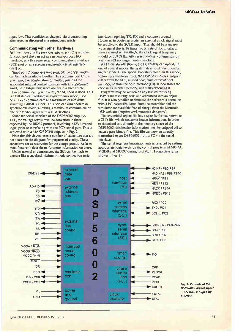
DIGITAL DESIGN
input low. This condition is changed via programming after reset, as discussed in a subsequent article.
Communicating with other hardware As I mentioned in the previous article, port C is a triple-function port that can act as a general-purpose I/O interface, as a three-pin serial communications interface (SCI) port or as a six-pin synchronous serial interface (SSI) port. Since port C comprises nine pins, SCI and SSI modes
can be made available together. To configure port C in a given mode or combination of modes, you load the associated internal control registers with an appropriate word, i.e. a bit-pattern; more on this in a later article. For communicating with a PC, the SCI port is used. This
is a full duplex interface; in asynchronous mode, used here, it can communicate at a maximum of 625kbit/s assuming a 40MHz clock. This port can also operate in synchronous mode, allowing a maximum communication rate of 5Mbit/s, again with a 40MHz clock. Since the serial interface of the DSP56002 employs
TTL, the voltage levels must be converted to those expected by the RS232 protocol, involving ±12V inverted logic, prior to interfacing with the PC's serial port. This is achieved with a MAX232CPE chip, as in Fig. 2. Note that this device uses a number of capacitors that are
not shown in the diagram for purposes of clarity. These capacitors act as reservoirs for the charge pumps. Refer to manufacturer's data sheets for more information on these. Under normal circumstances, the SCI can be made to
operate like a standard minimum-mode connection serial
DO-D23
AO-A15
PS
DS 1111
X/7"118
RD 4
BR
W7
MODA / IRQA
MODB / IROB
MODO / NMI
RESET
DR
DSO e DSI / OSO 4111
DSCK / 0S1 ."4- 1111"
V„
GND
interface, requiring TX, RX and a common ground. However, in bootstrap mode, an external clock signal must be supplied to the SCLK input. This should be a square-wave signal that is 16 times the bit rate of the interface. Hence if used at 19200bit/s, the clock signal frequency should be 307.2kHz. After reset booting, communication with the SCI no longer needs this clock. As I have already shown, the DSP56002 can operate in
one of several modes; the system described here operates under 'Mode I', the special bootstrap mode. In this mode, following a hardware reset, the DSP downloads a program either from the SCI, as used here, from external boot memory, or from the host interface (HI). It then stores the code in its internal memory, and starts executing it. Programs may be written on any text editor using
DSP56000 assembly code and assembled into an object file. It is also possible to simulate the software's operation with a PC-based simulator. Both the assembler and the simulator are available free of charge from the Motorola DSP web site (http://www Lmotorola-dsp.com/). The assembled object file has a specific format known as a CLD file, which has some header information. In order to download this directly to the memory space of the DSP56002, this header information must be stripped off to leave a pure binary file. This file can now be directly transmitted to the DSP56002 from a PC via the serial interface. The serial interface bootstrap mode is selected by setting
appropriate logic levels on the control pins termed MODA, MODB and MODC during reset (0, 1, 1 respectively, as shown in Fig. 2).
lil0 d1a1ta11,111111111111117.77777.1
bus host interface
(HI) external address bus
external bus control
interrupt/ mode control
emulator port
power and ground
D S
5 6
o o
serial comms
interface (SCI)
sync. serial
interface (SSI)
timer/ counter
phase locked
loop (PLL)
clock/ oscillator
Ole HO-H7 / PBO-PB7
HAO-HA2 / PB8-PB10
HR/VV /PB11
HEN / PB12
4 HACK / PB14
▪ HREQ / PB13
RXD / PCO
▪ TXD / PC1
• MP> SCLK / PC2
• pr. SCO-SC2 / PC3-PC5
SCK / PC6
4 SRD/PC7
▪ STD/PCB
.411-
TIO
CKP
111 PLOCK
PCAP
PINIT
▪ CKOUT
EXTAL
XTAL
Fig. 1. Pin-outs of the DSP56002 digital signal
processor, grouped by
function.
June 2001 ELECTRONICS WORLD 443

DIGITAL DESIGN
FROM PC
TO PC
vin vin
vaut vaut
13 12
4
AUDIO CODEC
CLOCK AND RESET
11111111 vcc
v.
. . . . GND
11.11
Fig. 2. Principal components of a real-time D.SP system using the DSP.56002, incorporating a serial PC interface, 32K x 24-bit external memory and a stereo audio codec. For reasons of clarity, only key input/output signals are included. All resistors are 15k12.
STATIC RAM CS' RD v".R
Bootstrap code must be preceded by three bytes that specify the number of program words and three bytes that specify the program start address. Following this, the code proper is downloaded, comprising three bytes for each program word loaded.
It is essential that the least significant byte is received first and the most significant last. After the final byte has been loaded, the code immediately commences execution at the start address specified.
It goes without saying that this facility is enormously useful. Effectively, it means that a simple emulator or evaluation module can be constructed for less than £50, and the results of any program changes can be seen within seconds.
External memory system If program and data requirements are small, the DSP56002 can operate using just its internal memory. For more adventurous designs, external memory can be added. The DSP56002 has 16 address lines and can therefore
address 64K words of a particular memory type, each word being 24 bits in width. This requires a little explanation. As mentioned in the first article, the DSP56002 exploits
super Harvard architecture. Code and data memory space is segregated, and the data memory space is further subdivided between X data and Y data memory. Internally, all three memory spaces have their own address and data buses. The three address and data buses are multiplexed into
single bus structures externally. Harvard design is maintained by using control signals that determine the type of the external memory being accessed. Thus in total, the DSP56002 can address up to 64K words of code, 64K words of X data and 64K words of Y data memory. This design incorporates 32K words of mixed-mode
external memory; in other words, the design makes no distinction between the different memory types and the external memory can be used to hold code, data or both, in any combination. Although this does not compromise the speed of the system — since the external buses are multiplexed — it does mean the programmer must be aware of where code and data reside. Figure 2 shows that three 32K by 8-bit static RAM chips
are combined to hold the 24-bit words. The first chip holds the low order byte and is connected to data lines DDO-DD7; the second holds the mid-order byte, and is
connected to data lines DD8-DD15; the final chip holds the high-order byte, and is connected to data lines DD16-DD23. All address lines are connected to AO-A14. The chips are
enabled, i.e. selected, by connecting the Al5 line to the inputs of each memory device. Only if this line is low during a memory cycle, i.e. an address is generated equal to or below 32K, will the external memory be activated. At this point it is worth mentioning that the internal
program memory resides at addresses between 0 - 511 (0-1FF 16), and the X data and Y data memory reside at addresses between 0 - 255 (0-FF16).
If code or data are read from or written to any of these locations, the DSP56002 will not activate the external memory, i.e. it will keep line Al5 high. This ensures that internal memory is used, which has a clear advantage in terms of access time.
Timing requirements In order to select the appropriate external memory devices for the system, it is essential to consider the speed of the various bus signals and the timing relationships that exist between them. A handful of simple equations is all that is required for this procedure. It is important though to navigate the method with due diligence, since a mistake will lead to a faulty design which will simply not work. Standard static RAM suitable for general-purpose
microprocessors and microcontrollers is no use here; fast static RAM must be employed, with access times of less than 3Ons. Specifications necessary to determine the access time of
the memory to be used are the external clock period, 4. the internal clock period, ri., the internal clock low period,
the PLL division factor fd and the PLL multiplication factor f,„. These are discussed in detail in various Motorola technical documents.4 For a read cycle, these specifications allow you to
calculate the time between the address becoming valid and the data appearing on the data bus. This is termed taa. For a write cycle, they allow you to calculate the time between the data becoming valid on the data bus and the de-assertion of the signal. This is termed tsd. The relationships are shown in Fig. 3. The two parameters to„ and ts, are obtained using the following expressions,
=tr + t, — 7ns (1)
444 ELECTRONICS WORLD June 2001

DIGITAL DESIGN
and, t, = t, — 0.4ns
(2)
(3)
and,
t, = 0.4671, La (4)
Any memory used in the system should have values for taw, and tad less than or equal to those calculated for the DSP56002, for given external and internal clock rates. For example, if the DSP56002 is clocked externally by a 10MHz oscillator with a PLL multiplication factor of 6, this yields a value for tu, of 17.5ns and a value for tsd of 7.4ns. Motorola and other semiconductor manufacturers supply
fast static RAM suitable for real-time DSP systems. In this case, a Cypress CY7CI99-10 (32K x 8-bit fast static RAM) would be ideal. Figure 3 shows the timing involved in memory accessing.
The audio coder/decoder Most DSP chips are designed to work with a wide range of different a-to-d and d-to-a converters, produced by different manufacturers, all of which have slightly different data formats. Furthermore, in order to minimise the physical number
of pins of VLSI devices, many a-to-d and d-to-a converters and DSP chips make use of serial communication for digitised data streams. Digital processors, and the DSP56002 is no exception,
can be configured for these different formats by loading appropriate bit patterns in the relevant control registers. If a-to-d and d-to-a converters are combined into a single package, it is generally referred to as a codec. Figure 2 shows a simple interconnection strategy for
interfacing a codec — or separate a-to-d and d-to-a converters — to the SSI of the DSP56002. Because the device is synchronous, for any one device it requires a minimum of three signal lines. Considering the a-to-d converter requirement first, it
requires a framing signal that delimits the start and end points of a datum word sent by the a-to-d converter. This connects to pin SC2 of the SS! — also known as pin PC5, since it can be configured as a general purpose I/O pin of port C. Next, it requires a serial bit clock whose negative
transitions indicate to the DSP56002 when to sample the individual data bits. This connects to pin SCK/PC6. Finally, it requires a signal line carrying the data in serial form, connected to pin SRD/PC7. For a d-to-a converter, an identical arrangement is used
except that the serial data are transmitted by the DSP56002. Thus instead of SRD/PC7, the pin labelled STD/PC8 is connected to the data input of the converter.
If the a-to-d and d-to-a converters are combined as a codec, then the framing signal and serial bit clock are common to the input and output sections of the device; thus a codec will require a minimum of four signal lines. The SSI can be configured to operate in slave or master
mode; if in slave mode, the framing signal and serial bit clock are provided by the codec; if in master mode, they are generated by the SSI. Figure 4 illustrates the various timing waveforms
associated with the analogue voltage input/output process operating in normal mode. More complex arrangements
Read Cycle
Address Valid
ta.
Previous Data Valid
Write Cycle
WR
Data Valid
Data Valid
Fig. 3. Critical timing parameters for calculating access times of static RAM used with the DSP56002.
Framing Signal
Bit Clock
Data in normal Mode
Data in Network Mode
Data
IS 1 TS 2 TS 3 TS 4
are also possible, and further information is provided in an article that has appeared previously in this magazine.5 An important property of the SSI interface is that the
number of signal lines required does not increase if a multi-channel codec is used — for example a stereo or quadraphonic device. With a multi-channel system, the SSI is set up to operate
in what is termed network mode, also shown in Fig. 4 and is used in this design. In this protocol, the framing signal delimits the start and end points of all the datum words within one sample period. The bit clock remains the same, and the serial data are
multiplexed on the lines connected to SRD/PC7 and STD/PC8 in packets called time slots. Clearly, when the SSI is configured, information must be supplied that details the resolution of the a-to-did-to-a converter or codec system. Information is also needed as to whether the device must operate in normal or network mode, and the length of the time slots if the latter mode is used. How the SSI registers are configured for codec operation is discussed in a fourth article.
In the third and next article, I will introduce the DSP56K assembly language set, and explain why it facilitates powerful, efficient and high-speed real-time digital signal processing. •
References 1. DSP56002/DSPL56002 24-bit Digital Signal Processor,
Motorola Inc. Technical Data, document DSP56002/D, 1995.
2. DSP56000 Digital Signal Processor Family Manual, Motorola Inc. document DSP56KFAMUM/AD, 1995.
3. DSP56002 Digital Signal Processor User's Manual, Motorola Inc. document DSP56002UM/AD, 1993.
4. Calculating Timing Requirements of External SRAM for the 24-bit DSP56000 Family, Motorola Inc., document APR I6/D, 1994.
5. Gaydecki P, 'Interfacing Digital Audio', Electronics World, December 1999, pp. 1026-1030.
Fig. 4. Synchronisation and data signals for transfer of information between a codec and the SS!.
June 2001 ELECTRONICS WORLD 445

New Version. 2001 out now! lb» pi,11.111.111111111111111MIM;daboal tab mors.„Jaje
0 • e
u
••••
Call 01462 480055 today for your FREE product guide or visit www.adeptscience.co.uk
multiSIM Lould very well herald the next step forward in Paillesign methodology, because it can co-simulate both MDL and SPICE components... 3„
Vein at lever), afforil a léricd: Nu, Gh". I 11 \Ibt„ I d:
•
S Schematic Capture, Simulation & Programmable Logic multISIM - the professional design solution from Electronics Workbench.
Schematic capture, SPICENHDUVerilog co-simulation of analogue and digital parts,
built-in analyses and virtual instruments, and a huge library of parts in a single,
affordable package.
ADEPT'
)
Adept Scientific pk, Amor Way, Letchworth, Hens SG6 I ZA
4 Tel: 0 1462 480055 • Fax: 01462 4802 13
. Email: [email protected] gem WebStore: www.adeptstore.co.uk
• Electrollq
multisim
CIRCLE NO.112 ON REPLY CARD
WATCH SLIDES ON TV MAKE VIDEOS OF YOUR SLIDES DIGITISE YOUR SLIDES (using a video capture card)
Liesgang diatv" automatic slide viewer with built in high quality colour TV camera. It has a composite video output to a phono plug (SCART & BNC adaptors are available). They are in very good condition with few signs of use. For further details see www diatv.co.uk
£91 91+ vat = £108 00 Board cameras all with 512x582 pixels 8.5mm 1.3 inch sensor and composite video out
All need to be housed in your own enclosure and have fragile exposed surface mount parts. They all require a power supply of between 10 and 12v DC 150mA
47MIR size 60x36x27mm with 6 infra red LEDs (gives the same illumination as a small torch but is not visible to the human eye) £37.00 + vat = £43 48
30MP size 32x32x14mm spy camera with a fixed focus pin hole lens for hiding behind a very small hole £35.00 + vat= £41.13
40MC size 39x38x27mm camera for 'C' mount lens these give a much sharper image than with the smaller lenses £32.00 + vat = £37.60
Economy C mount lenses all fixed focus & fixed iris
VSL1220F 12mm F1.6 12x15 degrees viewing angle £15.97 vat = £18.76
VSL4022F 4mm F1.22 63x47 degrees viewing angle £17.65 « vat = £20 74
VSL6022F 6mm F1 22 42x32 degrees viewing angle £19.05 • vat = £22.38
VSL8020F 8mm F1.22 32x24 degrees viewing angle £19.90 « vat = £23.38
Better quality C Mount lenses
VSL1614F 16mm F1.6 30x24 degrees viewing angle £26.43 vat = £31.06
VWL813M 8mm F1.3 with iris 56x42 degrees viewing angle £77.45 + vat = £91.00
1206 surface mount resistors E12 values 10 ohm to 1M ohm 100 of 1 value £1.00 + vat 1000 of 1 value £5.00 + vat
866 battery pack originally intended to be used with an orbitel mobile telephone it contains 10 1 6Ah sub C batteries f42x22dia the size usually used in cordless screwdrivers etc.) the pack is new and unused and can be broken open quite
easily £7.46+vat = £8.77
Ream adcl 1.66 + vat =£'1.95 postage & packing per order
JPG ELECTRONICS 276-278 Chatsworth Road, Chesterfield, S40 2BH.
Tel 01246 211202 Fax 01246 550959 MastercardNisa/Switch Callers welcome 9:30 a.m .to 5:30 p m. Monday to Saturday
FREQUENCY SHIFTER FOR HOWL REDUCTION
• For public address and sound reinforcement.
• Provides more gain and greater stability.
• 5Hz Fixed Shift Board with mains supply.
• Broadcast Monitor Receiver 150kHz-30MHz.
• Advanced Active Aerial 4kHz-30MHz.
• Stereo Variable Emphasis Limiter 3.
• PPM10 In-vision PPM and chart recorder.
• Twin PPM rack and Box Units.
• PPM5 hybrid, PPM9 microprocessor and PPM8 IEC/DIN -50/+6dB drives and movements.
SURREY ELECTRONICS LTD The Forge, Lucks Green, Cranleigh GU6 7BG Telephone: 01483 275997 Fax: 01483 276477 _
CIRCLE NO.113 ON REPLY CARD
446 ELECTRONICS WORLD June 2001

New Products are edited by
Electronics Weekly
Power supplies suit network 1U uses
Lite-On Power supplies are for networks and communications in 1U applications. They deliver 12, 24 and 48V DC with combinations available. Active PFC complies with LEC1000-3-2, having a typical power factor of 0.99. Size is 17.8 by 12.7cm by 1U for 350W units and 19 by 10.2cm by 1U for 200W models. Efficiency is 85 per cent at full
PRODUCTS load. With an input of 85 to 264V AC, they are also available with active current share and hot plug ability, while airflow requirements are 11.9m3/hr. Lite-On Power Tel: 0191 427 0255 www.liteon-power.com
Electronic loads rate at lkA to test cells The Dynaload RBL single-channel electronic loads have ratings of lkA and are for testing batteries, power supplies, fuel cells and related DC power equipment. From Thurlby Thandar, the loads have a constant power feature to aid battery testing and analysis. The internal pulse generator provides variable slew rate up to zero to full scale in lOpts. They can perform below 0.5V at up to lkA making them suitable for fuel-cell testing. They operate in five modes — constant-current, constant-resistance, constant-power, constant-voltage and
pulse. Multiple units can be synchronised as master and slave units that are controlled simultaneously using analogue control or the GPIB interface on the RBL488 model. Voltage is from 0 to lkV and there are three power ranges: 0.8, 2 and 4kW. Thur/by Thandar Instruments Tel: 01480 412451 www.tlinst.co.uk
Electrolytic capacitor can handle heated situations BC Components has announced an SMD electrolytic capacitor, the 140 CLH. Applications include mobile telephone network infrastructure, engine management, ABS systems and ovens. It can be used in environments at temperatures up to 150°C for short periods; useful life is up to 1500 hours at 125°C. It can also be used for filtering, buffering or smoothing voltages in applications where life times over ten years at 60°C are required. BC Components Tel: 00 31 40 259 0724 www.bccomponents.com
Flexible encapsulant in transparent layer Dymax 9-20558 thick film coating from Intertronics provides a transparent layer to protect circuits and components from moisture, dust and contaminants. It cures in
seconds on exposure to uy and visible light. The flexible encapsulant adheres to and forms a coating over glass-filled epoxy, metal, ceramic and Kapton. It has a secondary heat-curing capability and flow characteristics for quick coverage without running. Cure time is 20 to 30s, even under 200mW/cm2 longwave light. Cure depths of 0.635cm are possible. Intertronics Tel: 01865 842842 www.intertronics.co.uk
June 2001 ELECTRONICS WORLD 447

NEW PRODUCT
Please quote Electronics World when seeking further information
Power supervisor monitors supplies An adjustable supervisor IC for monitoring power supplies down to 300mV has been developed by Micrel. Available in the firm's Ittybitty SOT23-5 packaging; the MIC2776 has a choice of output options. A manual reset input is provided for a reset switch or for daisy-chaining it onto existing power supervision circuitry. It is made using a BiCMOS process. The three versions are the MIC2776H-BM5 with an active-high output, the MIC2776L-BM5 with an active-low output and the MIC2776N-BM5 with an open-drain, active-low output. Micrel Semiconductor Tel: 01635 524455 www.micreLcom
Line interface uses ADSL card.chip set Advanced Power Components has launched the APCC78120 line interface hybrid component for ADSL line cards. It uses Centillium's multimode ADSL chip set. The hybrid contains the necessary transmit and receive filtering components, line drivers and matching components between the chip
set and the line interface transformers, occupying less than 3.9cm2 per channel. It replaces discrete components with one module. APC Tel: 01634 290588
Embedded workbench includes promo The latest release of IAR Systems' embedded workbench for Mitsubishi M16C microcontrollers includes a promotional version of the Segger Embos real-time operating system. IAR Systems Tel: 00 465 18 167800 www.iar.com
Quad amplifier aids signal processing Zetex has launched an amplifier for video and high-speed signal processing applications. The ZXFV201 has a bandwidth of 300MHz, slew rate of 400V/gs and output drive of 40mA. The device is stable with up to 400pF capacitance load. Differential gain is 0.01 per cent and differential phase 0.01°. Power supply requirements are ±5V at a current of 7mA per amplifier. The device is for —40 to +85°C operation. Applications are in video amplification and buffering, RGB driving, video distribution, high frequency instrumentation and medical imaging. Zetex Tel: 0161 622 4422 www.zetex.com
Bluetooth tester checks true RF Anritsu has introduced the MT8850A Bluetooth test set for
design proving and production test. The instrument can test Bluetooth modules or any product with a Bluetooth wireless interface, such as mobile phones, PDAs, PCs and other office or consumer devices. It lets developers conduct true RF measurements rather than simple functional testing. Test time is lOs for typical production requirements, including measurements of power, frequency, modulation and receiver bit error rate. Preprogrammed or user-defined test scripts are initiated by one press of the run key. The reference Bluetooth transceiver incorporated has a better than 11cHz frequency accuracy at the start of any packet and complies with dirty transmitter requirements. Anritsu Tel: 01582 433200 www.anritsu.co.uk
Dual output buffer adds to DIMM support Fairchild has introduced a dual output registered buffer to add to its DDR Dimm support for 184-pin, 2.5V PC200 and PC266, 72-bit wide registered SDRAM modules. They comply with the Jedec DDR SDRAM Dimm design. The SSTV 16859 buffer is a 13-bit register for address and control buffering with 184-pin and 232 DDR-1
Tester handles GSM Rohde & Schwarz has introduced the CMU300 mobile base-station tester for all GSM bands and 8PSK Edge modulation. It can be upgraded for 3G mobile radio. It is available for GSM 400, 850, 900, 1800 and 1900 and provides various RF layer-one measurements on the transmitter and various receiver bit-error-rate measure.ments. Measurements are based on real-time coding and decoding of channels for GMSK and 8PSK modulation and circuit and packet switched modes. Rohde & Schwartz Tel: 01252 811377 www.rohde-schwarz.com
stacked memory modules. The device has a differential input clock, SSTL-2 compatible data inputs and an LVCMOS compatible reset input. It has been fabricated on a sub-micrometre CMOS process. Fairchild Semiconductor Tel: 001 888 522 5372 www.fairchildsemi.com
Space mapping of Trillium Lynxos Trillium Digital Systems and Lynuxworks have announced a certified application-space mapping of the Trillium SSI system services interface to Lynxos. Trillium compliant certification of Lynxos for the Trillium Tapa advanced portability architecture means developers can choose Lynxos for the Trillium SSI that can run Trillium protocol stacks in the application space. Tapa is a set of architectural and coding standards that is independent from the target system's compiler, processor, operating system and architecture. Telecoms equipment makers can use the Trillium software for developing IP telephony, session initiation protocol and next-generation converged network infrastructure. With Trillium's SS! layer, Lynxos will let companies migrate tens or hundreds of thousands of lines of protocol stack code out of the kernel into the application space. This reduces kernel software maintenance and improves system reliability because any protocol code failure that may occur is less catastrophic in application space than in the kernel. Lynuxworks Tel: 00 33 1 30 850600 www.lynuxworks.com
Power switch for chargers Fairchild's latest power switch is a voltage mode PWM controller and SenseFET
448 ELECTRONICS WORLD June 2001

Please quote Electronics World when seeking further information
(LDMOS) power switching element integrated into a single chip in an 8-lead DIPH. The FSDH0165 consumes 0.3W, it is a self-biased and protected linear control current-to-duty cycle converter with an open drain output. Fairchild Semiconductor Tel: 001 888 522 5372 www.fairchildsemi.com
SM-compatible connectors suit PIHIR Surface-mount compatible connectors for use with high-temperature production
processes, such as pin-in-hole intrusive reflow (PIHIR) soldering, are available from Townsend Coates. Made by Harting, they can withstand the temperatures associated with reflow soldering —210 to 225°C. They have controlled lead lengths for compatibility with the PIHIR process. The range includes straight and angled DIN41612 male and females, headers to DIN41651, D-subs and 1.27mm pitch SCSI connectors. Among the products in SM format is the recently introduced Har-Bus 64 with 160 contacts for VME 64 extensions bus applications. Townsend Coates Tel: 0116 276 9191 www.townsendcoates.co.uk
Models added to signal generators LFR has announced two frequency models for its 2026 multi-source generator. The 2026B 2.51GHz model is for the 2.4GHz ISM frequency band, used for wireless LAN applications, including Bluetooth. The 2026A is a 2.05GHz model with two or
Transceiver to hit satellites Later this year, Pascall plans to start shipping commercially the STR-1812 solid-state 18GHz transceiver for use in private satellite networks. It transmits at 17.3 to 18.4GHz and receives at 10.7 to 12.75GHz. Data rates of up to 2Mbit/s from a 1.2m antenna and up to 4Mbit/s from a 1.8m antenna are supported, making it suitable for V-Sat type networks
where data such as intranet information needs to be transmitted almost instantaneously around the globe. The L-band interface eliminates the up-conversion stage between interface and transceiver. Pascall Microwaves Tel: 01621 816655 www.paradise.co.uk
three sources. For research, development and manufacturing where there is a need for two or three combined sources for conducting tests such as intermodulation and selectivity performance of components and receiver assemblies, the signal generators use a built-in combiner, switches and cables to reduce measurement uncertainties introduced by connecting separate signal generators. Adding Option 116 to either extends the functionality to test amplifiers in GSM base stations and, when used with a radio test set, for providing the interference signals for GSM receivers and intermodulation tests. IFR Systems Tel: 01438 772087 www.ifrsys.com
SM crystals follow dual stocking deal Flint has expanded its range of leaded and surface mount crystals following a dual stocking agreement with Acal to distribute standard and custom quartz devices from Advanced Crystal Technology. The agreement covers SMD metal can quartz crystals, surface mount oscillators, watch
crystals, through-hole microprocessor crystals, through hole oscillators, ceramic resonators and crystal oscillators. HC49 can microprocessor crystals also form part of the range with frequencies from 1.8432 to 160MHz. The HC49 metal can SMX-4 and SMX-6 SMD quartz crystals have frequencies from 3.2 to 75MHz, with frequency tolerance options between 10 and 5Oppm. They have four and six pads respectively. A 2.5mm high version is also available. The ZTA, ZTB and ZTT through hole ceramic resonators are stable from —20 to +80°C. The ZTA and Zr!' are available over a 1.8 to 50MHz frequency range, with the ZTB covering 190 to 1250kHz. Flint Tel: 01530 510333 www.flint.co.uk
Development kits based on SBC Arcom has announced development kits for Microsoft Windows NT Embedded 4.0 and Windows CE 3.0 for embedded systems designers. Both kits are based on the firm's SBC-Geode-GXm single board computer providing EBX compatibility with multimedia functions. The embedded NT kit contains a set of components and comes in several preconfigured builds. The options support workstation products or server systems. They are licensed and ready to run out of the box. A CD includes pre-built implementations of the operating system. The component definitions for the SBC let developers use Microsoft Target Designer and Component Builder to generate customised implementations of the operating system. The Windows kit contains the Windows CE 3.0 kernel preloaded into an onboard flash drive on the SBC. It ships with a copy of Microsoft's Embedded Visual Tools. Both kits provide software drivers, cables and documentation. Also included are a PS/2 mouse, power supply
June 2001 ELECTRONICS WORLD 449

NEW PRODUCT
Please quote Electronics World when seeking further information
and cables for interfacing the SBC to a VGA-CRT display. An optional NEC 16.5cm TFT colour LCD module is available. Arcom Control Systems Tel: 0800 411300 www.paradise.co.uk
SD connectors keep memory cards secure Molex has introduced connectors for use with secure digital (SD) memory cards for products such as PDAs, portable audio players, digital cameras and cellular phones. The connectors can handle SD cards with a capacity of up to 64Mbyte and incorporate card detect and write protect switch functions for secure downloading of digital data such as audio or image files. Connectors come in top and bottom mount styles and are 3.1rnm high. Metal grounding covers that provide EMI and RFI protection are incorporated. A push-push eject system is used for card insertion and extraction and secure card retention. The 2.5mm pitch connectors are rated at 0.5A and supplied on embossed tape for automatic board mounting. Molex Tel: 01252 720720 www.molex.co.uk
Low-noise stereo volume controller Profusion has introduced the WM8816 low-distortion low-noise stereo volume controller for audio applications. Total harmonic distortion plus noise is 0.001 per cent at 100dB. It combines digitally controlled volume adjustment and peak level detection on one chip. This makes it suitable for audio
amplifiers and preamplifiers, home entertainment systems, mixing desks and audio recording equipment. Maximum input signal level is ±18V and positive gain up to 15.5dB. The device is based on a resistor chain design with external op-amps, so users can tailor the system. It is controlled via a three-wire digital interface with daisy-chain capability for multi-channel systems. The gain of each channel can be individually adjusted from —111.5 to +15.5dB in 0.5dB steps. On-chip peak detection circuitry can be used to implement volume monitoring and automatic gain control systems without the need to digitise the audio signal. It can be configured in double differential mode to reduce hum and other audible noise. Profusion Tel: 01702 543500 www.profusionplc.com
Eight-channel d-to-a 14-bit converter Hunt Engineering has announced that the HEGD14 14-bit DAC is shipping. Part of the Heron range, the digital-to-analogue converter is for high output rate applications, such as wireless, especially digital radio
oti "leillialalliall :,,,-;;Ç.,'n•s•
AL
transmission. It can also be used in test, high-speed control and instrumentation. The device provides eight channels of 14-bit d-to-a converter at up to 33MS/s. This is a mirror of the HEGD9 12-bit a-to-d converter. Hunt Engineering Tel: 01278 760188
Multiband transceiver for unlicensed use The nRF903 is a single chip multichannel UHF transceiver for the unlicensed 433, 868 and 915MHz low power radio device frequency bands. Available from Clerc, the
Nordic VLSI product has GMSK and GFSK modulation and demodulation capability at an effective bit rate of 76.8kbit/s for I53.6kHz bandwidths. With transmission power adjustable to a maximum of +10dBm and a differential antenna interface, it is suitable for PCB antenna applications. Configuration data is programmed by a 14-bit word architecture via a serial peripheral interface. Operating from a +3V DC supply, it has power down and standby modes, and complies with EN300 220-1 and CFR47. Clere Tel: 01635 298574 www.clere.corn
Single board supports Celeron and Pentium From Advanced Modular Computers is the AMC-3782EVS Socket 370 architecture board. The CPU card supports both Celeron and Pentium III processors, up to 133MHz front side bus, up to 512Mbyte SDRAM and dual Ultra DMA66 IDE interface. The Intel i810E chip set uses a shared system architecture
allowing the on-chip VGA and audio to access system memory. Onboard utilities include dual Intel 82559 10 or 100Mbit/s Ethernet controllers, Ultra 160 SCSI chip and one Compacttlash socket. Because the VGA and audio is onboard, slot space is freed up. AMC Tel: 01753 580660 www.amcuk.corn
Solid-state relays in 6 and 8-pin models Crydom has introduced six and eight-pin DIP solid-state relays. The G2 devices are available in contact configurations, including form A, dual form A, form B, dual form B and one form A one form B. All can be wired for AC operation or one of three DC configurations. They can switch AC or DC voltages from the microvolt and nanoamp range up to 400V and 400mA, and can be wired in series to achieve switching in the kilovolt range. Typical input voltage and current are 1.25V DC at 5mA. Dielectric strength input to output is 3750V and capacitance is 0.8pF for single-relay and 1.2pF for dual-relay devices. Power dissipation is
Button has split screen Omron has launched a rectangular lighted pushbutton switch with split screen options for process and motor control. The A3PJ measures 18.9 by 26.1mm and comprises a switch unit and indicator and pushbutton unit, which are joined with a snap action. The indicator unit is available in solid colour as well as two, three and four split screen options in horizontal and vertical orientations. Colours include white, red, green and orange and can be specified to 5, 12 or 24V DC. There are three types of indicator unit LED-lit with built-in LED chip, LED ball-lit with removable LED and incandescent lamp-lit. Omron Tel: 0208 450 4646 www.omron.co.uk
ELECTRONICS WORLD June 2001

I Visit our website www.distel.co.uk
THE ORIGINAL SURPLUS WONDERLAND! THIS MONTH'S SELECTION FROM OUR VAST EVER CHANGING STOCKS
I Surplus always wanted for cash!
THE AMAZING TELEBOX Converts your colour monitor into a QUALITY COLOUR TV!'
TV SOUND & VIDEO TUNER CABLE COMPATIBLE •
The TELEBOX is an attractive fuly cased mans powered un& centering al electronics ready to plug into a host of video monitors Cr AV equement Mich are Wed with a oornposte video or SCART hput The cemposite video output ail aSo plug directly (Ito most video recorders, allowing recepticn of TV chan-nels not normally receivable on most television receivers' (TELEBOX MB). Push button centrols on the tent panel allow reception of 8 fuly tuneable 'off air UHF codur television channels. TELEBOX MB mews %/dually al teen-sic() frequencies VHF and UHF including the HYPERBAND as used by morn cable TV operators. Ideal for desktop computer video systems & PIP (picture in pCure) setups. For complete cempetalty - even for mentors without sound - an htegral 4 watt audio amplifier and how level Hi Fi audio output are provded as standard Brand new - fully guaranteed. TELEBOX ST for composite video input type monitors £36.95 TELEBOX STL as ST but fitted with integral speaker £39.50 TELEBOX MB Multiband VHF/UHF/Cable/Hyperband tuner £69.95 For overseas PAL versions state 5.5 or 6 mHz sound specification. 'For cable / hyperband signal reception Telebox MB should be con-nected tg a cable type service. Shipping on all Telebox's, code (B)
State of the art PAL (UK spec) UHF TV tuner module . with composite 1V pp video & NICAM hi fi stereo sound
• "outputs. Micro electronics all on one small PCB only 73 x 160 • x 52 mm enable full tuning control via a simple 3 wire link to an IBM pc type computer. Supplied complete with simple working pro-gram and documentation. Requires +12V & + 5V DC to operate.
BRAND NEW - Order as MY00. Only £49.95 code (B) See hww.disteLco.uk/data_my00.htm for picture r full details
FLOPPY DISK DRIVES 21/2 " - 8" All units (unless stated) are BRAND NEW or removed from often brand new equipment and are fully tested, aligned and shipped to you with a full 90 day guarantee. Call or see our web site www.distel.co.uk for over 2000 unlisted drives for spares or repair.
315* Mitsubishi MF355C-L. 1.4 Meg. Laptops only £25.95(B) 31/2 " Mitsubishi MF355C-D, 1.4 Meg. Non laptop £18.95(B) 51." Teac FD-55GFR 1.2 Meg (for IBM pc's) RFE £18.95(B) 51/4 " Tesc FD-55F-03-U 720K 40/80 (for BBC's etc) RFE £29.95(B) VA" BRAND NEW Mitsubishi MF501B 360K £22.95(B) Table top case with integral PSU for filH 5Yi" Floppy / HD £29.95(B) 8" Shugart 80W801 8' SS refurbished & tested £210.00(E)
£195.00(E) £260.00(E) £295.00(E) £295.00(E) £499.00(E)
8" Shugart 810 8' SS HH Brand New 8" Shugart 651 8' double sided refurbished & tested 8" Mitsubishi M2894-63 double sided NEW 8" Mitsubishi M2896-63-02U DS slim line NEW Dual 8" cased drives with integral power supply 2 Mb
HARD DISK DRIVES 21/2" - 14" 2W TOSHIBA MK10C4MAV 1.1Gb laptop(12.5 mm H) New £79.95 2Y2' TOSHIBA MK2101MAN 2.16 Gb laptop (19 rrim H) New £89.50 21/2 " TOSHIBA MK4309MAT 4.3Gb laptop (8.2 mm H) New C105.00 2Y2"TOSHIBAMK6409MAV 3.1Gb laptop (12.7 mm H) New£190.00 21/2 " to 31/2 ' conversion kit fcr Pc's, complete with connectors £14.95 31/2 FUJI FK-309-26 20mb MFM I/F RFE £59.95 31/2 " CONNER CP3024 20 mb IDE t/F (or equiv.) RFE £59.95 3Y2* CONNER CP3044 40 mb IDE VF (or equiv.) RFE £69.00 31/2 " QUANTUM 405 Prodri ve 42mb SCSI I/F, New RFE £49.00 5U• MINISCRIBE 3425 20mb MFM I/F (or equiv.) RFE £49.95 5'4" SEAGATE ST-238R 30 mb RLL I/F Refurb £69.95 5',4" CDC 94205-51 40mb HH MFM I/F RFE tested £69.95 5l4" HP 97548 850 Mb SCSI RFE tested £99.00 51/4" HP C3010 2 Gbyte SCSI differential RFE tested £195.00 8' NEC D2246 85 Mb SMD interface. New £199.00 8' FUJITSU M2322K 160Mb SMD I/F RFE tested £195.00 8' FUJITSU M2392K 2 Gb SMD I/F RFE tested £345.00 Many other drives in stock - Shipping on all drives is code (Cl)
IC's -TRANSISTORS - DIODES OBSOLETE - SHORT SUPPLY - BULK
10,000,000 items EX STOCK For MAJOR SAVINGS
CALL OR SEE OUR WEB SITE mvw.distel.co.uk
VIDEO MONITOR SPECIALS One of the highest specification monitors you will ever see - Art At this price - Don't miss it!!
Mitsubishi FA3415ET(L 14" SVGA Muttisync colour monitor with fine 028 dot pitch tube and resolution of 1024 x 768. A variety of inputs slows annection to a host of ers nducing BM PCs n CGA. EGA VGA &ce 1- 2A1. modes, BBC, COMMODORE (inducing Amiga 1203), ARCtilMEDES and APPLE Many features: Etched faceplate, tee swelling and LOW RADI, AllON MPR specification. Fully guaranteed, n EXCELLENT little
used canc. on Order as Tilt & Smvel Base £4.75 Only £119 (n MRS-SVGA VGA cable fa IBM PC Included. External cabes for other types of computers available - CALL
Ex demo 17"0.28 SVGA Mitsubishi Diamond Pro
monitors, Full multisync etc.
Full 90 day guarantee. Only £199.00 (E)
Just in - Microvitec 20" VGA (800 x 600 res.) colour monitors. Good SH condition - from £299 - CALL for Info
PHILIPS HCS35 (same style as CM8833) attractively styled 14" colour monitor with 112112 RGB and standard composite 15.625 Khz video Inputs via SCART socket and separate phono jacks. Integral audio power amp and speaker for all audio visual uses. Will connect direct to Amiga and Atari BBC computers. Ideal for all video monitoring / security applications with direct connection to most colour cameras. High quality with many features such as front concealed flap controls, VCR correction button etc. Good used condition - fully tested - guaranteed O n ly palm nn Dimensions W14' x H1234* 15Y2' D. •••••••••••••••• (E)
PHILIPS HCS31 Ultra compact 9" colour video monitor with stan-dard composite 15.625 Khz video input via SCART socket. Ideal for all monitoring / security applications. High quality, ex-equipment fully tested & guaranteed (possible minor screen bums). In attrac-tive square black plastic case measuring W10" x H10' x 131/2" D. 240 V AC mains powered. Only £79.00 (D) KME 10" 15M10009 high definition colour monitors with 0.28' dot pitch. Superb clarity and modern styling.. Operates from any 15.625 khz sync RGB video source, with RGB analog and composite sync such as Atari, Commodore Amiga, Acorn Archimedes & BBC. Measures only 13Y2" x 12' x 11". Good used condition. Only £125 (E)
20" 22" and 26" AV SPECIALS Superbly made UK manufacture. PIL all solid state colour monitors, complete with composite video & optional sound input. Attractive teak style case. Perfect for Schools, Shops, Disco, Clubs, etc In EXCELLENT little used condition with full 90 day guarantee.
20"....£135 22"....£155 26"....£185(F) We probably have the largest range of video monitors in Europe, All sizes and types from 4" to 42" call for Info.
DC POWER SUPPLIES Virtually every type of power supply you can imagine.Over
10,000 Power Supplies Ex Stock Call or see our web site.
TEST EQUIPMENT & SPECIAL INTEREST ITEMS MITS. A FA3445ETKL 14" Industrial spec SVGA monitors £245 FARNELL 0-60V DC 0 50 Amps, bench Power Supplies FARNELL AP3080 0-30V DC 0 80 Amps, bench Suppy £1850 IkW to 400 kW - 400 Kt 3 phase power sources - ex stock £P0A IBM 8230 Type 1, Token ring base unit driver £760 Wayne Kerr RA200 Audio frequency response analyser £2500 IBM 53F5501 Token Ring ICS 20 port lobe modules £750 IBM MAU Token ring distribution panel 8228-23-5050N £95 AIM 501 Low distortion Oscillator 9Hz to 330Khz, IEEE £550 ALLGON 8360.11805-1880 MHz hybrid power combiners £250 Trend OSA 274 Data Analyser with G703(2M) 64 Vo £P0A Marconi 6310 Programmable 2 to 22 GHz sweep generator £6500 Marconi 2022C 10KHz-IGHz RF signal generator £1550 Marconi 2030 opt 03 10KHz-1.3 GHz signal generator,New £4995 HP1650B Logic Analyser £3750 HP3781A Pattern generator & HP3782A Error Detector EPOA HP6621A Dual Programmable GPIB PSU 0-7 V 160 watts £1800 HP6264 Rack mount variable 0-20V 0 20A metered PSU £675 HP54121A DC to 22 GHz four channel test set £P0A HP8130A opt 020 300 MHz pulse generator. GPIB etc £7900 HP At, AO 8 pen HPGL high speed drum plotters - from £550 HP DRAFTMASTER 1 8 pen high speed plotter £750 EG+G Brooktleal 95035C Precision lock in amp £1800 View Eng. Mod 1200 computerised inspection system £P0A Sony DXC-3000A High quality CCD colour TV camera £995 Keithiey 590 CV capacitor / voltage analyser £P0A Racal ICR40 dual 40 channel voice recorder system £3750 Fiskers 45KVA 3 ph On Line UPS - New batteries £9500 Emerson AP130 2.5KVA industrial spec UPS £2100 Mann Tally MT645 High speed line printer £2200 Intel SBC 486/1335E Multibus 486 system. 8Mb Ram £945 Siemens K4400 64Kb to 140Mb demux analyser £2950
HP6030A 0-200V DC 0 17 Amps bench power supply £1950 Intel SBC 486/125C08 Enhanced Multibus (MSA) New £1150 Nikon HFX-11 (Ephiphot) exposure control unit £1450 PHIUPS PM5518 pro. TV signal generator £1250 Motorola VME Bus Boards & Components List. SAE / CALL £P0A Trio 0-18 vdc linear, metered 30 amp bench PSU. New £550 Fujitsu M3041R 600 LPM high speed band printer £1950 Fujitsu M3041D 600 LPM printer with network interface £1250 Perkin Elmer 299B Infrared spectrophotometer £500 Perkin Elmer 597 infrared spectrophotometer £3500 VG Electronics 1035 TELETEXT Decoding Margin Meter £3250 LIghtBand 60 output high spec 2u rack mount Video VDA's £495 Sekone SD 150H 18 channel digital Hybrid chart recorder £1995 B&K 2633 Microphone pre amp £300 Taylor Hobson Tallysurf amplifier / recorder £750 ADC SS200 Carbon dioxide gas detector / monitor £1450 BBC AM20/3 PPM Meter (Ernest Turner) + drive electronics £75 ANRITSU 9654A Optical DC-2.5G/b waveform monitor £5650 ANRITSU MS9001B1 0.6-1.7 uM optical spectrum analyser £P0A ANRITSU ML93A optical power meter £990 ANRITSU Fibre optic characteristic test set EPOA R&S FTDZ Dual sound unit £650 R&S SBUF-El Vision modulator £775 WILTRON 6630B 12.4 / 20GHz RF sweep generator £5750 TEK 2445 150 MHz 4 trace oscilloscope £1250 TEK 2465 300 Mhz 300 MHz oscilloscope rack mount £1955 TEK TDS380 400Mhz digital realtime + disk drive. FFT etc £2900 TEK TDS524A 500Mhz digital realtime + colour display etc £5100 HP3585A Opt 907 20Hz to 40 Mhz spectrum analyser £3950 PHIUPS PW1730/10 60KV XRAY generator & accessories £P0A CLAUDE LYONS 12A 240V single phase auto, volt. regs £325 CLAUDE LYONS 100A 240/415V 3 phase auto, volt. regs £2900
19" RACK CABINETS Superb quality 6 foot 40U
Virtually New, Ultra Smart Less than Half Price!
Top quality 19' rack cabinets made in UK by Optima Enclosures Ltd. Units feature designer, smoked acrylic lockable front door, full height lockable half louvered back door and louvered removable side panels. Fully adjustable internal fixing struts, ready punched for any configuration of equipment mounting ,plus ready mounted integral 12 way 13 amp socket switched mains distribution strip make these racks some of the most versatile we
have ever sold. Racks may be stacked side by side and therefore require only two side panels to stand singly or in multiple bays. Overall dimensions are: 771/2 " H x 32H" D o 22' W. Order as: OPT Rack 1 Complete with removable side panels. £345.00 (G) OPT Rack 2 Rack Less side .ane s £245.00 G
Over 1000 racks, shelves, accessories 19" 22" & 24" wide 3 to 46 U high.
Available from stock!!
32U - High Quality - All steel RakCab Made by Eurocrafl Enclosures Ltd to the highest possible spec, rack features all steel construction with removable side, front and back doors. Front and back doors are hinged for easy access and all are lockable with live secure 5 lever barrel locks. The front door is constructed of double walled steel with a 'designer style' smoked acrylic front panel to enable status indicators to be seen through the panel, yet remain unobtrusive. Internally the rack features fully slotted reinforced vertical fixing members to take the heaviest of 19" rack equipment. The two movable vertical fixing struts (extras available) are pre punched for standard 'cage nuts'. A mains distribution panel internal-ly mounted to the bottom rear, provides 8 x IEC 3 pin Euro sockets and 1 x 13 amp 3 pin switched utility socket. Overall ventilation is provided by fully louvered back door and double skinned top section with top and side louvres. The top panel may be removed for fitting of integral fans to the sub plate etc. Other features include: fitted castors and floor levelers, prepunched utility panel at lower rear for cable / connector access etc. Supplied in excellent, slightly used condition with keys. Colour Royal blue. External dimensions mm.1625H x 835D x 603 W. ( 64" H x 25" D x 233/4 " W )
Sold at LESS than a third of makers price !!
A superb buy at only £245.00 (G)
42U version of the above only £345 - CALL
12V BATTERY SCOOP - 60% off!! A special bulk purchase from a cancelled export order brings you the most amazing savings on these ultra high spec 12v DC 14 Ah rechargeable batteries. Made by Hawker Energy Ltd, type SBS15 featuring pure lead plates which offer a far superior shelf & guaran-teed 15 year service life. Fully BT & BS6290 approved. Supplied BRAND NEW and boxed. Dimensions 200 wide, 137 high, 77 deep. M6 bolt terminals. Fully guaranteed. Current makers price over £70
each Our Price £35 each ICI or 4 for £'99 (E)
RELAYS - 200,000 FROM STOCK Save Mrs by choosing your next relay from our Massive Stocks covering types such as Military, Octal, Cradle. Hermetically Sealed, Continental, Contactors, Time Delay, Reed, Mercury Wetted, Solid State, Printed Circuit Mounting etc. , CALL or see our web site www.distel.co.uk for more Information. Many obsolete types from stock. Save Mrs
Undoubtedly a miracle of modern technology & our special buying power ! A quality product fea-turing a fully cased COLOUR CCD camera at a give away price ! Unit features full autolight sensing for
use in low light & high light applications. A 10 mm fixed focus wide angle lens gives excellent focus and resolution from close up to long '=inge. The composite video output will
nnect to any composite monitor or TV SCART socket) and most video
•icorders. Unit runs from 12V DC so .teal for security & portable applica-tions where mains power not available.
Overall dimensions 66 mm wide x 117 deep x 43 high. Supplied BRAND NEW & fully guaranteed with user data, 100's of applica-tions including Security, Home Video, Web TV, Web Cams etc, etc.
Web ref = LK33 ONLY £99.00 or 2 for £180.00 (e)
SOFTWARE SPECIALS NT4 WorkStation, complete with service pack 3 and licence - OEM packaged. ONLY £89.00 (e) ENCARTA 95 - CDROM, Not the latest - but st this price I £7.95 DOS 5.0 on 31/2 " disks with concise books chw ()Basic. £14.95 VVIndows for Workgroups 3.11+ Dos 6.22 on 3.r disks £55.00 Wordperfect 6 for DOS supplied on 312" disks with manual £24.95
shipping charges for software is code B
DISTEL on the web II - Over 16,000 000 Items from stock - www.clistelco.uk • • •
• • •
• • • • •
• • •
• • • •
• • •
• • • •
• • • • • • • • • • • • •
• • •
• :
- EL EC TeCNICf -
ALL MAIL TO Dept ww, 29/35 Osborne Rd
Thornton Heath Surrey CR7 BPD
Open Mon - Fri 9.00 - 5:30
LONDON SHOP Open Mon - Sat 9:00 - 5:30
215 Whitehorse Lane South Norwood On 88A Bus Route
IS. Thornton Heath & Selhurst Perk SR Rail Stations
‘0" DISTEL© Visit our web site www.distel.co.uk email = adminddistel.co.uk
ALL 13' ENQUIRIES
0208 653 3333 FAX 0208 653 8888
= EST
eueRS
All prices for UK Manland. UK custaners add 17.5% VAT to TOTAL order errata. Ahrimum order £10. Bona Fide account orders acaapted from Government Schoce, Unrversites and Local Authontres - mnimum account order £50. Cheques over £100 are subject to 10 working days clearance. Carriage charges (A)=£3.00, (Al )£4.00, (B).£5.50, (C(=03 50, (Cl) £12.50, (D)=£15.00. (E»£18 .CO, (F>£20.03, (G»CALL Mow approx 6 days for shelf:fig - taster CALL Al goods supplied to our Standard Conditions of Sale arid unless stated guaranteed tr 93 deys. All guarantees on a return to base basis. Al nets reserved to change pnces / specifications without prior notice. Orders suttel to seck. Ckscounts for iotturne. Ted CASH cones pad for surplus goods. Al trademarks. traderames sic admoa. Display Electronics 1999. E & 0 E. 0799.
CIRCLE NO. 114 ON REPLY CARO

NEW PRODUCT
Please quote Electronics World when seeking further information
500 or 600mW respectively. Relays are available in through-hole and surface-mount variants, including a package 2.2mm high, making it suitable for PCMCIA applications. Crydom Tel: 01444 473555 www.crydom.com
1.2kW supplies will support hot swapping Artesyn has launched two 1.2kW front-end AC/DC power supplies with configuration and control facilities for system integration and power management. For data processing, datacoms and telecoms applications that use distributed power architectures, the AFE1200 supplies have current sharing capabilities and support hot-swapping. Rack-mountable power shelves are available for users wishing to configure multiple power
sources. There is a choice of 48 or 24V DC outputs. The 48V model can deliver up to 25A and the 24V model up to 50A. Both provide an auxiliary 12V, IA DC output for powering items such as external housekeeping circuitry. The auxiliary output is isolated from the main output, and both outputs are floating, letting users adopt whatever rail reference configuration they require. They have an 85 to 264V AC universal input range and accommodate mains frequencies from 47 to 63Hz. The supplies incorporate power factor correction, providing a minimum power factor of 0.99. Artesyn Tel: 00 353 24 25572 www.crydom.corn
Single board supports Celeron and Pentium
Azzurri is shipping the ZX4500 Openarchitect from Znyx Networks. The open-source Linux Ethernet switch provides a line-rate hardware switching environment that lets OEMs deploy standard and customised IP switching applications within a 6U CompactPCI blade. It handles packet manipulation within the switch silicon to achieve line-rate speeds of 6.6 million packet/s. Layers two to seven filtering is accomplished by downloading and running existing Linux networking applications. Media conversions are possible because it allows direct access to its switching fabric from its open PPMC slot. It has 12 or 24 10 or 100Mbit/s Ethernet ports, two Gigabit Ethernet ports, embedded Motorola 8240 PowerPC processor and a PMC or PPMC slot for an expansion processor or additional I/0. The design is hot swap compliant, with all Ethernet ports implemented as rear-panel I/O. There are 64Mbyte of buffer RAM and a non-blocking switch fabric. Up to 30 switches may be stacked via one or both Gigabit ports, putting up to 720 10 and 100Mbit/s ports under the same management as the rest of the equipment in the chassis. It can be combined with Znyx's Rainlink technology to provide switch-to-switch or port-to-port failover and link aggregation and load-balancing services. Applications include VolP gateway, network load balancing, web load balancing, Firewall IVPN, multimedia multicasting and SS7 signalling. Azzurri Technology Tel: 0118 944 5900 www.azzurrLcom
Ergonomic tuning knobs in six sizes OKW has introduced the Corn-Knobs series of ergonomic tuning knobs. They come in six sizes from 16 to 50mm in diameter. The three-part construction comprises cover, knob and marking element. Individual marking elements, which slide into the side of the
knob moulding, are available in five standard colours — coral, beach, lagoon, sky and mineral. They can be attached to control spindles of 4, 6 or 6.35mm diameter using a collet system in the top of the knob moulding. The knobs are suitable for the fine control and adjustment of machines and devices and for electronic measurement applications. OKW Tel: 01489 583858 www.okw.co.uk
Open-frame switcher has output choices From Ultimate Renaissance is a 60W AC/DC power supply that provides power densities above 0.43W/cm3 in a 50.8 by 101.6 by 20.3nun package. The VLT60 open-frame switcher comes with single or multiple outputs, at various voltages, and has efficiencies above 85 per cent. It has universal inputs
from 90 to 264V AC. Operating between 0 and 50°C, the supply has overcurrent protection and convection cooling. Weighing 0.17kg, it can be used by OEMs in POS, data networking, computer peripherals, touch-screen displays, telecoms, medical equipment and industrial products. Maximum leakage current is 50011A and it qualifies as a class B FCC and CISPR EMI filter. Ultimate Renaissance Tel: 01793 439310 www.ur-home.com
452 ELECTRONICS WORLD June 2001

The Headphone Amplifier Box Balanced or unbalanced microphone or line input
to headphone output
Professional portable units operating from an internal PP3
battery or external mains adaptor
* Precision transformerless balanced input * Bridged headphones output drive * Sensitivity selectable_over a wide
range of input levels * Low noise and distortion * High common mode rejection * Loop through facility
* Extensive RFI protection
The Balance Box (precision mic/line amplifier ) - The Phantom Power Box - The OneStop DIN rail mounting
radio frequency interference filter and voltage transient protector for voltage and current loop process signal lines
Conford Electronics Conford Liphook Hants GU30 7QV1 Information line 01428 751469 Fax 751223
E-mail [email protected] Web http://www.confordelec.co.uk/
CIRCLE NO.115 ON REPLY CARD
ERVICING YOUR COMPLETE PROTOTYPE N EE
Prototypes at a fraction of the cost Industry standard quality
Tooling and setup included Follow up series runs
Any contour CAM ' CAD consulting
Fr4 1.6mm, 35pm Cu
1+ Tooling EUROCARD OS Pie
Simply send your files and order ONIINE.
£49 ates may Price = =9 diieer
Mir M U le. »On
I
II .353(0)6170117D Sc. -353(016181164 (4,16.1 soirl ,tson-loroo iori
fee"'
000-3"
WWW.PCP-POOL.COM ea• 4. LI gca, Eim;\ GraphiCode
CIRCLE NO.116 ON REPLY CARD
PHONE 020 8684 1166
LANGREX SUPPLIES LTD DISTRIBUTORS OF ELECTRONIC VALVES FAX TUBES AND SEMICONDUCTORS AND I.C.S. 020 8684
1 MAYO ROAD • CROYDON • SURREY CRO 20P 3056 24 HOUR EXPRESS MAIL ORDER SERVICE ON STOCK ITEMS
email: [email protected]
E p KT66 Special 20.00 5Z4GT 3.00 6U8A 1.50 0231 8.00 KT88 Special 20.00 6A05 2.00 6V6G 10.00 C L33 15.00 NTh 8006AR5 6.00 6V6GT 6.00
E88CC 8.50 0A2 3.00 6AS7G 7.50 6X4 3.00
E180F 3.50 0132 3.00 6AU5GT 4.00 6X5GT 300 E810F 20.00 0C3 3.00 6AU6 2.00 12AT7 3.00
EABC80 4.00 003 3.00 6AW8A 4.00 12AU7 3.50
EB91 1.50 PCF80 2.00 6134G 22.00 I2AX7 5.00 EBF80 1.50 PCL82 2.00 6BA6 150 12AX7A 7.50
EBF89 1.50 PCU35/805 2.50 68E6 1 so 12AX7WA 6.00
EBL31 2500 PCL86 2.50 68646 2.00 12BA8 2.00
ECC33 1200 PD500 8.00 61307A 2.00 12BE6 2.00
ECC35 12.00 PL36 3.00 6BR7 4.00 12BH7 1000
ECC81 300 PL81 2.00 6BR8 4.00 12BY7A 7.00
ECC82 5.00 PL504 3.00 6BW6 4.00 12DW7 15.00
ECC83 300 PL508 3.00 6BW7 3.00 12E1 10.00 ECC85 5.00 PL509/519 10.00 6BX7GT 7.50 13E1 85.000 ECC88 &CO PL802 4.00 6BZ6 3.00 572B 27.50
ECC808 15.00 PY500A 3.00 6C4 2.00 805 4500 ECF80 1.50 PY800/801 1.50 6CB8A 3.00 807 7.50 ECH35 3.50 00V02-6 12.00 6DC6G 5.00 811A 10.00
ECH42 3.50 00V03-10 5.00 6CL6 3.00 812A 55.00 ECH81 3.00 00V03-20A 1000 6CG7 7.50 813 27.50
ECL82 5.00 00V06-40A 12.00 6CH6 3.00 833A 85.00
ECL136 500 U19 8.00 6CW4 6.00 865A 20.00 ECLL800 25.00 UABC80 1.60 61305 17.50 872A 3000 EF37A 3.50 UCH42 5.50 60068 10.00 931A 25.00
EF39 2.75 UCL82 2.00 6F6G 8.00 20504 12.50
EF40 4.00 UCL83 2.00 6F07 7.50 5687WB 6.00
EF86 5.00 UF89 4.00 6GK6 4.00 5751 6.00 EF91 2.00 UL41 12.00 6J5G 6.00 5763 8.00
EF183/4 2.00 UU34 3.00 6J5M 4.03 5814A 5.00
EL33 15.00 UY41 4.00 6.17 up 5842 12.00
EL34 &00 UY85 2.00 6J96A 27.5o 6072A 600
EL340 5.00 VR105/30 3.00 6JE6C 27.50 6080 600 EL38 5.00 VR150/30 3.00 6JS8C 27.30 61468 15.00 EL41 3.50 2759 10.00 6K6GT goo 6201 8.50
EL84 3.03 790111 15.00 6L63 15.00 6336A 35.00 EL95 2.00 2021 3.50 6L6GC 17.50 6550A 25.00
EL360 15.00 3828 12.00 6L6WGB 10.00 68838 15.00
EL509/519 7.50 4CX25013 45.00 607 3.00 7025 7.50
EM34 25.00 5R413Y 7.50 6SA7 3.03 7027A 26.00
EM81/4r7 5.00 5U4G 10.00 6SC7 3.00 7360 26.00
EN91 7.50 5U4GB 10.00 6SG7 3.03 7581A 15.00
EZ80/EZ81 5.00 5V4G 5.00 65.17 3.00 7586 1500
GZ32 8.50 5Y3GT 2.50 6SK7 3.00 7587 2000
0233/37 15.00 5Z3 500 6SL7GT 5,00 PreCeS correct when KT61 15.00 5Z4G 6.00 6SN7GT 7.50 going to press
OPEN TO CALLERS MON-FRI 9AM-4PM. CLOSED SATURDAY This is a selection from our stock of over 6.000 types. Please enquire for types not listed.
Obsolete items are our speciality. Valves are new mainly original British or American brands. Terms CWO/min order £10 for credit cards. P&P 1-3 valves £2.00. 4-5 valves £3.00
/a Add 17.5% VAT to total including P&P
Customised design services from Intec Associates Limited
I NTEC look for interdisciplinary collaborations with experts who work in other fields. We supply creative
and cost-effective solutions.
Key expertise • PC interfacing applications • Implementation of PIC micro-controllers and PC-104 • Implementation of radio linkers • Implementation of sensors • Analogue and digital circuit design • PC software development using VB. VC, Java, Turbo
Pascal and Delphi
Applied areas • Standalone data logger using PIC micro-controller • Standalone devices using PIC micro-controller • Data logging/control system using PCs or PC-104 • Remote data logging/control via radio link • Remote data logging/control via telephone line
Intec instant solutions • PC-based data loggers controllers • Standalone data loggers • Sound loggers • Remote control and telemetry applications
www.intec-group.co.uk
11 Sandpiper Drive, Stockport, Cheshire, SK3 8UL, UK Tel: +44 (0)161 477 5855 Fax: +44 (0)161 477 5755
E-mail: [email protected]
CIRCLE NO. 117 ON REPLY CARD
June 2001 ELECTRONICS WORLD
CIRCLE NO.118 ON REPLY CARD
433

NEW PRODUCT
Please quote Electronics World when seeking further information
Raid controllers support seven levels Crellon Microsystems has introduced two controllers to support Raid levels zero, one, three, five, ten, 30 and 50. The Cyclone Microsystems PMC57 is a 64-bit Raid PMC module that can be used with single board computer hosts. The CPCI-975, also from Cyclone, is a 3U CompactPCI Raid controller with two channels of 80Mbyte/s Ultra2 LVD Scsi. Each controller has a 64-bit host PCI interface and is built round the Intel i960 I/O processor, which offloads the host processor by driving disk array controller functions including parity generation, Raid algorithms, striping algorithms and cache management. The controller firmware is in 2Mbyte onboard flash ROM. Integrated Raid management
software performs remote configuration and array management via Megaraid Webbios, clustering support, scatter and gather, tagged command queuing, synchronous operation and automatic, transparent rebuild of hot spare drives. The management software also supports error statistics, logging and on-line maintenance. Self monitoring and recovery technology is
BOOK TO BUY
common to both models, capable of detecting up to 70 per cent of detectable drive failures and recovering through drive remapping and on-line physical drive migration. Each controller supports the shared disk model of Microsoft Cluster Server for Windows NT clustering. Crellon Microsystems Tel: 0118 977 6161 www.crelion.corn
Pie eitez
1'6
ebb* ,id F..zt. . •. csbec,
Dual regulators have
built-in protection
Two voltage regulators from Rohm Electronics combine dual outputs of either 3.3 and 2.5V or 3.3 and 1.8V with built-in protection. The BA33C25FP and 18FP two-channel, low-dropout regulators are for inputs between 3 and 16V and maximum currents of 1A. Output voltages are controlled
Servicing Audio and Hi-Fi Equipment Return to Jackie Lowe, Room 1514, Quadrant House,
The Quadrant, Sutton, Surrey, SM2 SAS
Please supply the following title:
Servicing Audio and Hi-fi Equipment
Total
Name
Address
Postcode
Telephone
Method of payment (please circle)
Mastercard/Visa/Cheque/PO
Cheques should be made payable to Reed Business Information
Credit card no
Card expiry date
Signed
'Its readers will benefit from its wealth of easily assimilated information, and repairs hitherto thought impossible will speedily become routine. And the first may well cover its purchase price. Congratulations on a comprehensive, well-written and lucid work' Electronics Informer.
'Interesting, entertaining and useful for both practitioners and teachers. All round a satisfying book which deserves to be considered as a tool rather than an ornament collecting dust on the shelf.' Skillset Newsletter Service engineers and technicians
have come to regard this book as essential to their work. As a bench-side companion and guide it has no equal. Its purpose is to ease and speed up the processes of fault diagnosis, repair and testing of all classes of home audio equipment: receivers, amplifiers, recorders and playback machines. The mechanics and electronics of domestic audio are examined by Nick Beer in a down-to-earth and practical way, concentrating on what goes wrong, how to track down problems, and how to solve them. A symptom index and comprehensive manufacturer and supplier
guide allow quick access to specific advice and suggestions. The third edition is bang up to date with the latest technology -
DVD, CD Recordable, PC audio systems. There is also new material on PA equipment.
UK Price: £32.00 Europe £34.00 ROW £64.50
**Price includes delivery and packing**
— SERVICING
AUDIO
• Essential bench companion for all service engineers.
AND
HI-FI EQUIPMENT THIRD EDITION
• New technology such as DVD and expanded material on MiniDisk will ensure another successful launch to this new edition
454 ELECTRONICS WORLD June 2001

Professional PCB Layout for Windows at Computer Store Prices!
Easy-PC For Windows 4.0 4t Easy-PC - Number One Systems - [PCB Design Design 566 pctej
Number One Systems Call +44 1684 773662 or Fax +44 1684 773664
E-mail info@_riumberone.com
call us for a demonstration copy or download from wvvw.nuIllberone.corn Number One Systems. Oak Lane,Bredon, Tewkesbury, Glos, GL20 7LR. UK
now reads Ultiboard designs/libraries* Suddenly, a professional level PCB layout product is available at a realistic price. Just check the specification and see what excellent value you get with Easy-PC For Windows. Then test before you buy with a demo version - you will be simply amazed with Easy-PC For Windows. True Windows 32 bit product Over 7,000 users must be right! Integrated Schematics and Layout as standard Windows drag & drop throughout Multiple documents open within display Technology files for fast start-up Tiled display - Cascade, Vertical, Horizontal Multi-level Undo/Redo Integrated standard Autoplace Optional shape based AutoRouter Full Copper Pour Split powerplanes Unlimited signal/powerplane layers Unlimited non-electrical/doc layers Keep out/keep in areas for routing R/H mouse menu support Pan across design to cursor position cross probing between Schematics and PCB Full forward & backward annotation Schematics /PCB Modeless driven operation, no menu selection required
consistently, one of Europe's most popular PCB Layout products for Windows 95/98/NT/2000, Easy-PC has won praise from users for the wealth of features within each new release. Many of these new features are normally only found in the world's most expensive PCB Layout software packages.
Now try Easy-PC For Windows for yourself !
•Ultiboard is a trademark of Ultimate Technology
CIRCLE NO.119 ON REPLY CARD
The Complete Integrated Schematic PCB Layout
Package
Too good for words
The New Ranger
XL Series Ranger 2 tor Windows £170
NEW Ranger 2XL £500
NEW Ranger XL from £950
FREE Website Download Demo
, - Advanced Systems & Technology for PCB Manufacturers
Oki Buriton Lime Works, Buriton. Petersfield, Hams. UK GU3I 5SJ Tee (44) 01730 300002 Fax: (44) 01730 27273
CIRCLE NO.120 ON REPLY CARD
June 2001 ELECTRONICS WORLD 455

Valve Radio and Audio Repair Handbook • A practical manual for collectors, owners, dealers and
service engineers * Essential information for all radio and
audio enthusiasts Valve technology is a hot topic
This book is not only an essential read for every professional working with
antique radio and gramophone equipment, but also dealers, collectors and valve technology enthusiasts the world over. The emphasis is firmly on the practicalities of repairing and restoring, so technical content is kept to a
minimum, and always explained in a way that can be followed by readers
with no background in electronics. Those who have a good grounding in
electronics, but wish to learn more about the practical aspects, will benefit
from the emphasis given to hands-on repair work, covering mechanical as
well as electrical aspects of servicing. Repair techniques are also illustrated throughout.
This book is an expanded and updated version of Chas Miller's classic Practical Handbook of Valve Radio Repair. Full coverage of valve amplifiers will add to its appeal to all audio enthusiasts who appreciate the
sound quality of valve equipment.
Contents: INCLUDES: Electricity and magnetism;
Voltage, current, resistance and Ohm's Law; Real life
resistors; Condensers; Tuning; Valves; Principles of transmission and reception; Practical receiver design; Mains valves and power supplies; Special features of
superhets; Battery and mains battery portable
receivers; Automobile receivers; Frequency modulation; Tools for servicing radio receivers; Safety
precautions; Fault finding; Repairing power supply
stages; Finding faults on output stages; Faults on detector/AVC/AF amplifier stages; Finding faults on IF
amplifiers; Faults on frequency-changer circuits; Repairing American midget' receivers; Repairing faults
on automobile radios; Repairing battery operated receivers; Repairing FM and AM/FM receivers; Public
address and high fidelity amplifiers.
UK Price: £22.50 Europe £25.00 ROW £21.00
' Price includes delivery and packing **
Return to Jackie Lowe, Room 1333, Quadrant House,
The Quadrant, Sutton, Surrey, SM2 SAS
Please supply the following title:
Valve Radio and Audio Repair Handbook
Tota I
Name
Address
Postcode
Telephone
Method of payment (please circle)
Mastercard/Visa/Cheque/PO
Cheques should be mode payable to Reed Business Information
Credit card no
Card expiry date
Signed
NEW PRODUCTS Please quote Electronics World when seeking further information
to within ±2 per cent. They integrate a pnp transistor with over current output protection circuitry that prevents the IC being damaged if there is a short circuit. Onboard thermal shutdown circuit protects against thermal breakdown. They come in TO252-5 packaging. Rohm Electronics Tel: 01908 282666 www.rohm.co.uk
Configuration device
has 16Mbit flash
Altera has available the EPC16 configuration device with 16Mbit flash memory. The chip is for system-on-a-programmable-chip designs and those requiring multiple PLDs. Data compression lets the device provide up to 30Mbit configuration data. It has in-system programmability and reprogramming, and can configure two Apex EP20K1500Es and one EP20K600E, or any other combination of devices up to six million system gates of programmable logic. Altera Tel: 01494 602000 www.altera.com
125W multi-output
power supply taken to
hospital Condor has announced a 125W multi-output switching power supply in an 89 by 152 by 38mm package. Called the GPFM125, it is approved to UL260I, CSA 22.2N0.601.1 and EN60601-1 for medical systems applications. Power density is 0.24W/cm3 and
power factor correction is integral to meet IEC10000-3-2. Rated at 125W continuous power with forced air, the supply can also be operated with only convection cooling with up to 80W of continuous power available. Eight models are available with four fully regulated outputs each. Outputs include a combination of 3.3, 5, 12, 15 and 24V. Features include power fail signal, remote sense and overvoltage protection. Condor Tel: 01769 540744 www.condorpower. corn
Contacts for supplies
ODU has designed single contacts for power supplies, testing and monitoring equipment, docking systems, lighting and aeronautics. Three
systems are available — slotted. lamella and Springtac — with contact diameters from 0.6 to 50mm. Solid pins are common to all three. In a typical 4mm contact, the slotted contact will provide two or four pin-to-socket contact points, the lamella will provide 18 and the Springtac 38. The Springtac has spring wires inside the socket each contacting the pin surface independently. ODU Tel: 0116 230 1457 www.odu.de
436 ELECTRONICS WORLD June 2001

Quality Alphanumeric backlit LCDs in 4x40, 2x40, 4x20, 2x20 and 2x16 formats
Supplied either bare or pre-fitted with one of our Eze-Use, Serial interface boards with options such as software buzzer control, backlight control, operator interface, start-up message,
big character generation, and PC-AT Keypad /mouse interface - all at very competitive pricing. We also stock Serial Interface Graphic modules and front panel bezels for all our LCDs.
Please call (01977 683665) or check our web site (www.milinst.com) for full details and pricing.
Milford Instruments - your total LCD solution
Low power, easy serial interface
Milford Instruments Milford House, 120 High St
South Milford LEEDS LS25 5AQ
Tel 01977 683665 Fax 01977 681465
www.milinst.com
Multi Ple
+Grophicl.
CIRCLE NO.121 ON REPLY CARD
Need directing to fitters...
cables, connectors or sockets? Whatever your business needs find it on kompass.com.
WWW.1413 I IIPASAS _1= 0 IN 1.5 million companies worldwide at your fingertips.
Telephone: +44(0)1342 335876.
( II \O IL! ()1 PI I (
June 2001 ELECTRONICS WORLD

Beginners' corner
Understanding transformers As Ian Hickman explains, electricity and magnetism have many
similarities - but they also have many differences. It is important
to understand them before you can fully appreciate the main
topic of this set of two articles - transformers.
Ipromised in the January issue to write about transformer equivalent circuits and believe me, I will. But in considering how to start, where to start seemed
the more important question. So in time honoured fashion, I'll begin at the beginning, in this case with basic electromagnetism. This is a topic most of you will have studied at some
stage in the past. But you will probably find that you are not as comfortable with it now as you are with Ohm's Law and the like. I will develop the topic of electromagnetism by analogy
with electric circuits.
Rivers and ring roads Some phenomena are circular, like London's M25 ring road; the traffic goes round and round. Other phenomena are open ended, such as a river. But most phenomena are ultimately circular; everything thing forms part of a circuit. Water that a river empties into the ocean evaporates,
falls as rain on the land and finds its way back into the river. Similarly, electric currents can only flow in a circuit — even if intermittently like lightning — and the same applies to magnetic flux. Whether this also applies to electric flux is a point I hope to be able to expand on in a future article.
The electric circuit Figure 1 shows a source of EMF (electromotive force), a battery of voltage E volts say, capable of supplying current to a load consisting of a resistor of value R ohms. A potential difference of E volts exists between points A and B, due to the EMF of the battery.
If the switch is closed, the same potential difference exists between points A' and B', and a current of / amps flows through the resistor, where I=E÷R. This is Ohm's Law; most of you will have been familiar with it for
longer than you care to remember. Forgive me for stating the obvious, but if the switch is
open, then no current flows out of the battery. This an important difference between the electric circuit and a magnetic circuit.
It is generally assumed that the resistance of the connecting wires is zero, or at least negligible compared with R. It is also assumed that the resistance of any insulators — in the switch and elsewhere — is infinite. If this were not the case, if air had a resistance which, although high, were finite, then some small current would flow even if the circuit via R was broken. This would be analogous to the magnetic circuit. Considering resistor R in more detail, assume that it's a
wire-wound type, the length of whose resistance wire is / metres. Now the current equals E—R, where R=p1+A, A being the cross-sectional area of the wire in square metres. So,
, E EA = R pf
where p — the Greek lower-case letter 'rho' — is called the resistivity, in ohm.metres, of the material that the resistance wire is made from.
In the case of a high-wattage resistor, this would typically be Nichrome, a nickel-chromium alloy with a reasonably low temperature coefficient of resistance, and good resistance to oxidation. Rearranging,
EA I = —
P/
a little gives,
/ E e — = — + p, or J = — A P
where J is the current density in amps per square metre of cross-section in the wire, and e is the electric field strength gradient along the wire, in volts per metre. These terms will all prove to have analogous equivalents in a magnetic circuit.
The magnetic circuit Figure 2 shows a source of magnetomotive force, or MMF for short, consisting of a single turn of current-carrying wire. In this instance, it is wound on a core of ferromagnetic material. Imagine that this core is toroidal with a mean path
length or effective circumference of / metres, and cross-sectional area Am2. If the current in the wire is 1 amps, the MMF is I amp.tunis. The fashion nowadays is to
458 ELECTRONICS WORLD June 2001

COMPONENTS
drop the 'turns', and say simply that the MMF is I amps, or NI amps if there are N turns. My venerable textbook' defines the unit of MMF as the
"ampere turn". But certainly in the example quoted, the MMF would still be I amps (or amp turns), if the current were one amp flowing in N turns, instead of / amps in 1 turn, if You may find it easier, like me, to think in terms of
amp turns, but as the number of turns N is a pure dimensionless number, it comes to the same thing. The symbol for the units of MMF is 'A' (for amps). It
is convenient though to also have a symbol to use in equations, to denote an MMF as a variable. I use 'F'. Thus in general, F=NIA; the MMF equals the number of amperes times the number of turns. Note the convention that symbols denoting variable
quantities in equations - such as N turns, I amps - are in italics, while constants and symbols denoting units, such as A for amps, V for volts, etc., are not. Just as the EMF E volts in Fig. 1 establishes a voilage
gradient on the wire of the resistor, forcing a current of I amps to flow through it, the MMF in Fig. 2 does something very similar. Where the voltage gradient
volts/metre, the MMF gradient is denoted by H, where H=F÷/amps/metre, (ampere turns per metre). Note the difference between the variable H with units
A.m-I, and the H that denotes the unit of inductance, the henry. Unfortunately, there are only 26 letters in the Roman alphabet, so inevitably some get used to denote both a variable and a unit. The value of H is called the magnetic field strength. In
Fig. 2, it is virtually constant at all points around the magnetic circuit of the toroidal core. Likewise, e would be constant around the circuit in Fig. 1, if the resistor, switch and copper wires were all replaced by a single length of resistance wire of constant cross section. In Fig. 1, e causes a current to flow, of value related to
the length, cross-section and resistivity of the wire. Something similar happens in Fig. 2. The magnetic field strength H=F+l causes a flux offtiWb, where Wb denotes webers, to flow in the core, where,
(1) F x P.P,
The flux density 4)-!-A=BT, where T denotes teslas, is analogous to I+A=J in an electric circuit. So B=Hxpop„ just like J=e+ pxA. A run-down of the equivalent terms is given in the Table. Rearranging one of the earlier equations gives,
/ = E x —A x —1 1 p
where 1/p - the reciprocal of resistivity - is the
conductivity, a, of the conductor. Conductivity is a measure of how easy it is to make current flow. The unit of conductivity is the siemen, and its abbreviation is S. Formerly, an inverted (1 sign was used, and the units were called 'mhos'. A similar rearrangement gives,
( = F x —A I) x pop,
where pop„ is a measure of how easy it is to make flux flow, and is called the permeability of the material. Parameter go is the permeability of free space, while pr is the permeability of the core material relative to po. Permeability po has a value 4/tie, specified in teslas per amp per metre, or T.m/A. On the other hand, p, may be anything from two or three for the highest frequency grades of ferrite, to 300000 or more for certain types of transformer laminations in mu-metal. By contrast, the conductivity of free space is zero, and virtually the same for air and all common insulators. Thus in Fig. 2, if the core were removed, there would still be some magnetic flux produced by the magnetic field. In Fig. 1 though, if the wire of the resistor were replaced by air, no current would flow. Rearranging the last equation yet again, gives,
cl) A x µop,
The term,
A x µop,
is called the reluctance, S, of the magnetic path, and is specified in amperes per weber. Comparing with,
E _ fp
I A
reluctance is to a magnetic circuit what resistance is to an electric circuit. And by analogy with resistivity,
1
pop,
might be called 'reluctivity' - though I have never heard of the term - while permeability pop, is analogous to 1÷p or conductivity a. So just like,
E F I = cb = — R S
The crucial difference Despite the similarities in the formulae involving EMF and MMF, the crucial difference concerns energy. In Fig. 1,
Table. Run-down of commonly used electrical quantities and their magnetic counterparts.
Name Electromotive force (EMF) Magnetomotive force (MMF) Electric current Magnetic flux Potential gradient Magnetic field Current density Flux density Conductivity (1/resistivity) Permeability
Symbol in equations E
H
a(l/p)
Polir
Unit name volt amp amp weber volts per metre amps per metre amps per square metre tesla (webers per square metre) 1/(ohm.metre) webers per amp.metre
Abbreviation V A A Wb V/m A/m A/m2 T (Wb/m2) (amyl
Wb/Am
June 2001 ELECTRONICS WORLD 459

COMPONENTS
Fig. 3. Diagram a) shows changing current in single-turn coil, while b) and c) show EMF and PD sources combining and opposing respectively. Diagram b) also illustrates energy storage. Energy storage in inductor field is illustrated in d). Assuming the resistance of the winding — shown as R — is negligible, the back EMF will equal the applied EMF.
the current through the resistance is responsible for the dissipation of electrical energy, measured in joules, abbreviated to J, into heat. The rate of dissipation is measured in joules per second, where J/s=W, where W is the abbreviation for watts. Dissipation W is /2R. By contrast, no energy is dissipated in Fig. 2, assuming
that the turn of wire producing the MMF has zero resistance. But in the very act of the current starting to flow and creating a magnetic field, energy was stored in the resultant magnetic flux. In the steady state shown in Fig. 2, that energy just sits there, waiting for something to happen. The flux is conventionally indicated by lines of flux, forming closed loops; in Fig. 2 there will be some in the air and many more in the core. Just as the individual resistances around an electric
circuit can be added up when working out the total EMF E needed to cause a current I to flow, so in a non-homogeneous magnetic circuit — for example a core of magnetic material with a permeability p, having an air gap — the reluctances of the core and gap can be added up to find the total MMF needed to cause a given total flux. So far, I have looked at the field produced by a constant
current of I amperes, but what happens when the current changes? Indeed, how can the current get to flow in the first place? Figure 2 rather begs the question by assuming that the current is already flowing. Consider what happens when you connect an EMF of
one volt to a very large single-turn coil, as in Fig. 3a). Assume that the coil has negligible resistance. Nothing can change instantaneously, so the moment after connecting the supply the current must be the same as the moment before, i.e. zero. Clearly, you can expect the current to increase thereafter, but how fast? Assume that the current increases at one ampere per
second, so that after one second the MMF F is just one ampere turn, and assume that the reluctance S is 1A/Wb (or, one amp per weber), so that the resulting flux (Pis one weber. In fact, for this to be so, the coil would have to be very
large indeed, or immersed in a magnetic medium with a huge relative permeability. But that is a minor practical
point that does not affect the principle of the thing. Having assumed the coil to have negligible resistance,
the current will ultimately become very large; so why isn't it already huge after just one second? The reason is that the steadily increasing flux linking the coil induces an EMF in it, in opposition to the applied EMF: this is known as Lenz's Law.
If the flux c increases by a small amount di:I) in a fraction of a second di, so that the rate of increase is dadt, then the back EMF Eg induced in the single-turn coil is EB=—dedt. But 0=MMF+reluctance = F—S, i.e. (1)=N/+S. As the current and flux are both increasing, for this to remain true their rates of change must also be equal, i.e.,
do:1) N d/ — = — x — dt S di
This rate of flux increase will induce a voltage —EB=deeldt in series with each and every one of the N turns of the coil, so in all,
N a N2_ x E8 ¡ = S cit
The term N2+S, which determines the induced voltage resulting from a unit rate of change of current, is called the inductance L. It is measured in henries: that is, L=/V2+S henries. You must keep the difference between an electromotive
force (EMF) and a potential drop or difference (PD) very clearly in mind, to understand the minus sign in EB=—d/dt. To illustrate this, consider two secondary — i.e. rechargeable — batteries and a resistor as in Fig. 3b). The total EMF round the circuit, counting clockwise, is
3+1 volts. This is balanced by the PD of IR volts across the resistor. The batteries supply a total of 4W of power, all of which is dissipated in the resistor.
If now you reverse the polarity of the 1V battery, as in Fig. 3c), the total EMF acting is 3-1V, so the current is 0.5A. The 3V battery is now supplying 3x0.5=1.5W, but the dissipation in the resistor I2R is only 1W. The other 0.5W is disappearing into the IV battery; but it is not being dissipated, it is being stored as chemical energy. In Fig. 3d), the situation is just the same; the applied
EMF of the battery is opposed by the back EMF of the inductor — which in turn is determined by the inductance and the rate of increase of the current — while energy from the battery is being stored in the steadily increasing magnetic flux. If the internal resistance of the battery and the resistance R of the inductor are vanishingly small, the current will continue to increase indefinitely; if not the current will reach a limit set by the applied EMF and the total resistance in the circuit.
Returning now to Fig. 3a), if the switch is closed one second after connecting the battery, at which time the current has risen to 1A, then there is no voltage across the ends of the coil. No back EMF means that dVdt must be zero, so dl/di is also zero. Hence the current now circulates indefinitely its value frozen at lA — provided that the coil really has zero resistance. In the meantime, imagine the battery disconnected and
replaced with a lfl resistor; you will see why in a moment. Thus energy stored in a magnetic field is preserved by a short-circuit, just as the energy stored in a capacitor is preserved by an open-circuit. Now open the switch in Fig. 3a), thus substituting the
1f1 resistor in place of the short-circuit. At the moment the switch opens the current of lA continues to flow in the resistor; it cannot change its value instantaneously. So the energy stored in the magnetic flux is being dissipated and
460 ELECTRONICS WORLD June 2001

COMPONENTS
Fig. 4a) Vector diagram
showing current lagging voltage
by 90° in a perfect
inductor. In 4b), you can see the
associated voltage and
current waveforms.
a)
co radians per second <
E
OV
b) Frequency fi-lz. w = 2/cf
1If seconds
/
Time
therefore the current must fall. This will establish a IV potential difference across the resistor, of opposite polarity to the now disconnected battery. In other words, the top end of the resistor will be negative with respect to the lower end, because d/÷dt is now negative. The coil is now acting as a generator feeding its stored
energy into the resistor, initially at a rate of 1 joule per second, i.e. 1W. How much energy is there stored in the field, and how long before it is all dissipated as heat in the resistor?
Initially the current must be falling at 1 A per second, since we have IV across the resistor, and E=—Ldildt, where the inductance is unity in this case. Of course dl/di is itself now negative, i.e. current is decreasing, as the polarity reversal witnesses. After a fraction of a second, the current being now less
than one ampere, the voltage across the resistor will have fallen likewise; so the rate of decrease of current will also be lower.
How much energy? To find the energy stored in the field, you could integrate the product E8x/ from t=0 — i.e. the point at which the switch was opened — to infinity. But there is an easier way. Suppose you use a variable resistor and increase its
resistance, keeping the value inversely proportional to the current. Now IR will be constant at 1V and the current will fall linearly to zero in 1 second. Since the induced voltage across the resistor has, by this
dodge, been maintained constant at IV, the energy dissipated in it is easily calculated. On opening the switch, the dissipation is 1Vx1A, and
this falls linearly to zero over one second. So the average power is 0.5W maintained for one second giving a stored energy of 0.5J.
If the inductance had been 2H and the current 1 A when the switch was opened, the initial rate of fall would have been 0.5A per second and the discharge would have lasted 2s, dissipating 1J in the resistor. This assumes that its value was adjusted to maintain 1V across it as before. Thus the stored energy is proportional to the inductance L. On the other hand, if the current was 2A when the switch
was opened, the voltage across the 10 resistor would have been 2V, so the rate of fall would need to be 2A/s, assuming 1H inductance. Thus the initial dissipation would have been 4W, falling to zero over is, giving a stored energy of 2J, or four times as much as with 1A. So the stored energy is proportional to the square of the
current. In fact, the stored energy is given by,
J = —1 Lx 12 2
Uses of inductors An inductor can be, and often is, used as an energy store in
power supplies, but there are certain limitations to the inductor's energy storing ability. In particular, the energy stored in the magnetic field of a short-circuited inductor is rapidly lost due to dissipation in the resistance of its windings. For a high-quality capacitor, the shunt loss resistance R
is almost infinite, whereas it is not possible to make the series loss r of an inductor negligible. At very low temperatures though, the electrical resistivity of certain alloys and compounds vanishes entirely — a phenomenon known as superconductivity. Under these conditions an inductor can store energy indefinitely in its magnetic field, as none is dissipated in the conductor. In addition to use as energy storage devices, inductors
have several other applications. For example, inductors with cores of magnetic material are used to pass the direct current output of a rectifier to later circuitry while attenuating the alternating hum components. Air or ferrite-cored inductors — RF chokes — are used to
supply power to radio-frequency amplifier stages while preventing RF power leaking from one stage to another via the power supply leads. This application, and others, makes use of the AC behaviour of an inductor. Since the back EMF, EB, is given by,
—NdcD L, ell EB = —
di di
it follows that the higher the frequency, the smaller the alternating current required to give a back EMF balancing the applied alternating EMF. In fact, the reactance XL, of an inductor is given by XL=2nfL=o)L, where f is the frequency in hertz, co is the angular velocity in radians per second, and L is the inductance in henrys. This may be represented vectorially as in Fig. 4a), where
the projection of the voltage E and current / vectors on the horizontal gives the instantaneous value of those variables. Thus the position of the vectors in Fig. 4a) corresponds to the start of the waveforms shown in b). You can see that when the voltage is at its positive peak,
the current is zero but increasing. In fact, the current is increasing — or becoming less negative — all the time that the applied voltage is positive and vice versa. The net energy flow is zero.
In calculations, the 90* phase shift between the voltage and lagging current can be accommodated by using the j operator and writing XL=j0.)L. The foregoing provides all the background necessary to
start unravelling the intricacies of transformers. I plan to cover those in another article. •
Reference 1. Fundamentals of Electrical Engineering in MKS Units,
E. Hughes, Longmans, Green and Company, 1954.
June 2001 ELECTRONICS WORLD 461

CIRCUIT Fact: most circuit ideas sent to Electronics World get published The best circuit ideas are ones that save time or
money, or stimulate the thought process. This includes
the odd solution looking for a problem — provided it
has a degree of ingenuity.
Your submissions are ¡udged mainly on their
originality and usefulness. Interesting modifications to
existing circuits are strong contenders too — provided
that you clearly acknowledge the circuit you have
modified. Never send us anything that you believe has
been published before though.
Don't forget to say why you think your idea is
worthy.
Clear hand-written notes on paper are a minimum
requirement: disks with separate drawing and text files
in a popular form are best — but please label the disk
clearly.
Send your ideas to: Jackie Lowe, Room L514,
Quadrant House, The Quadrant, Sutton, Surrey, SM2
5AS
0.12u
IC4 LM78LOS
C4 Ee 10pF
GNO OUT
IDEAS Colour-bar generator TI his is a colour bar generator intended to soak test colour video monitors. It had to be low cost and small, therefore it had to have a low parts count. Some cunning tricks where employed to achieve this. The heart of the colour bar generator
is a 74LS90 decade counter. Its outputs are used as in the table.
If /C1 is used as a straightforward
divide-by- 10, an error occurs in some monitors. Technically correct monitors use black level clamping on the back porch. The back porch is defined as the
period after the sync pulse but before the active video starts. If the counter were allowed to count to 10 there would be a blue bar in this time period. This would be clamped by the
Count A B 0 0 0 0 0 1 1 0 0 0 2 0 1 0 0 3 1 1 0 0 4 0 0 1 0 5 1 0 1 0 6 0 1 1 0 7 1 1 1 0 8 0 0 0 1 9 1 0 0 1 To eliminate blue bar, reset to count 0.
Table. Outputs of the 7490 counter have the following functions. Blue Red Green Sync
D Colour displayed Black Blue Red Magenta Green Cyan Yellow White Sync. ( Black )
VERTICAL OSC
30HZ to 60Hz
ou •
3 I C3 — 1pF
OPTIONAL POWER
SUPPLY REGULATOR FOR 7.5U TO 1SV INPUT
TOP VIEW LM78LOS
£50 winner IC? 4 LMSSS
DIS--THR
OUT CU
C2 = 560eF
ICI 4 LMSSS
• IR DIS
THR 5
--3 -OUT CV---
c EplpF
_t
R2 2k2
RI 100k
RV1 220k
R3
PINS . +SU PINIO ONO
IC3 74LS90
2k2 7
R4 3k3
R92 R91
R02 ROI
A
81
- RS _, 10K
11 OD
8 OC
OB 1 OA
RE 270R
R7 27OR f I R8 27OR
1K
VERTICAL SYNC
COMPOSITE SYNC
0
®EiC547 TRI
SYNC COMBINER
GREEN 0
HORIZ OSC * 9 DIVIDE BY 9 OD is 14.7kHz to 21.7kHz
RED o BLUE 0
ONO 8UT
HORIZONTAL SYNC
R6.R7.R8 Nominal for I volt Into 7Sr termination
+SU
OU
462 ELECTRONICS WORLD June 2001

CIRCUIT IDEAS
COLOUR BAR GENERATOR WAVEFORMS
monitor and so it would display no blue; to avoid this the counter is reset to zero at the ninth count, see above. Timer /C2 is the horizontal oscillator,
running at 9 times the line frequency. It is used in the schmitt trigger mode to reduce component count — it saves a resistor. Output QD is inverted horizontal sync, settable in the range 14.71cHz to 21.71cHz. The QD output of /C3 is inverted by
Tri to give correct polarity horizontal sync. Timer /CI is the free running vertical oscillator, settable in the range 30Hz to 60Hz. Resistor R2 sets the vertical sync time, while RV' & R2 set the vertical frequency. Vertical sync output is normally high
and goes low at sync time. This is used as collector supply to Tri and so mixes horizontal and vertical syncs together. Outputs are at TTL levels but can be
attenuated to 1V by inserting 270e series resistors and feeding into nominal 75f1 terminations. Colin Pye Coventry
HORIZONTAL WAVEFORMS
CLOCK
HR9
OA BLUE
08
RED
—1 7 7
DIU NORM, COUNT
9 DIU 10
F OA MISSING
•
•
OC OMEN
OD 14 SYNC OD
RESET TO ZERO WHEN OA t 00 ARE HIGH
MISSING
COMPOSITE SYNC WAVEFORM MAGNIFIDED TIME SCALE AROUND VERTICAL SYNC INTERVAL
00
U SYNC
COMPOSITE 7------1_ SYNC
r ii NOT LOCKED TOGETHER
r ri
Ten year index: new update TABLE OF CONTENTS
Broadc ast Communications Components Computing Consumer Electronics Control Electronics Deal & DSP Design Ffistory
The Electronics World Softlndea runs from January 19E6 to May 1996 and contains references to 1300 articles and 930 circurt ideas There is a separate author index mth full cross references Repnnts can be obtained for all the articles in this nd,, - see the Information section for more details For up to date information about Electronics World see our websrte at http /Mee« soacopy co uk ,;reeerairsh,
"
ww.softcopy.co.uk
Photo copies of Electronics World articles from back issues are available at a flat rate of £3.50 per article, £1 per circuit idea, excluding postage. mud
Hard copy Electronics World index Indexes on paper for volumes 100,101, and 102 are available at £2 each, excluding postage.
Hard copies and floppy-disk databases both available
Whether as a PC data base or as hard copy, SoftCopy can supply a complete index of Electronics World articles going back over the past nine years.
The computerised index of Electronics World magazine covers the nine years from 1988 to 1996, volumes 94 to
102 inclusive and is available now. It contains almost 2000 references to articles, circuit ideas and applications - including a synopsis for each.
The EW index data base is easy to use and very fast. It runs on any IBM or compatible PC with 512K ram and a hard disk.
The disk-based index price is still only £20 inclusive. Please specify whether you need 525m, 3.5in DD or 3.5in HD format. Existing users can obtain an upgrade for £15 by quoting their serial number with their order.
Ordering details
The EW index data base price of £20 includes UK postage and VAT. Add an extra £1 for overseas EC orders or £5 for non-EC overseas orders Postal charges on hard copy indexes and on photocopies ore 50p UK, £1 for the rest of the EC or £2 worldwide. For enquires about photocopies etc please send an sae to SoftCopy Ltd. Send your orders to SoftCopy Ltd, 1 Vineries Close, Cheltenham GL53 ONU. Cheques payable to SoftCopy Ltd, please allow 28 days for delivery.
June 2001 ELECTRONICS WORLD 463

CIRCUIT IDEAS £100 winner
Measure revs-per-second on a PC T his design uses the BIOS INT1Ch of a I PC, together with a few inexpensive components, as a high-speed rev/min meter. The meter can measure speed in the range of 1 to 65 500rev/s, which equates to around 1 to 3 932 160rev/min. A dozen ICs are used, in conjunction
with the computer's BIOS INT1Ch, without affecting its normal ISR. Printer port LPT1's data and and status ports are also used. Figure 1 shows the circuit diagram,
which interfaces with LPTI.The design was originally developed for remotely measuring the speed of turbo molecular vacuum pumps, but it can be used for any application where the speed range is up to 65 500rev/s. Input pulses are generated by a Hall
element or slotted disk with infra-red photo diode, at a calibrated rate of 1 pulse per revolution. These pulses are fed via a 74LSO8 AND gate to a 16 bit up/down counter. Output from the counters and the flip-
flops' Q outputs are routed to the status port (at Ox379h) of LPT1 through
74LS244 buffers. A 74LS138 3-to-8 line decoder, controlled from data port at Ox378 16, provides various control signals as dictated by the software. A simple Turbo C program controls the
speed measurement. The BIOS INTICh occurs 18.2 times a second. It is used only for keeping time of day. In this design, it is exploited for generating a timing window of 1 second by incrementing the TIMERINTR variable, which is set to zero initially. At the start, input pulses are inhibited by
disabling the AND gate. All the counters are loaded with Ox0016 and the flip flops are cleared. When the INT1Ch interrupt occurs, it immediately enables the AND gate and the counters count up. When each counter's output crosses
from Ox0F 16 to Ox00 16, its carry output sets the 74LS74 D-type flip-flop connected to it to logic 1. When the TIMERINTR reaches 18, the pulses are again inhibited by disabling the AND gate and flip-flop outputs Qo, Q1, Q2 — initially set to 000 — are read through the status port. The timing window is actually 0.989
seconds, but the measurement is subsequently corrected to a one second measurement by multiplying by 18.2/18. The binary word Q0,(21,Q2 indicates
progress in counting, the counters involved and the maximum speed expected as given in the Table. This relieves the PC from reading all the counters. Instead it reads only the counters that actually counted, thereby reducing the number of read operations and subsequent manipulations. The SPEEDREAD routine reads the
counter output, a nibble at a time, starting from counter 1 (nib0), depending on the binary word, up to counter 4 (nib3). Nibbles are manipulated and the speed
in revolutions per second and revolutions per minutes are displayed. At the end of one measurement cycle,
the TIMERINTR is reset to zero and the counters and the flip flops are cleared, leading to another speed measurement cycle. K Suresh Kalpakkam India
Software for the PC-based high-speed rev counter. Turbo C code for 'BIOS INT1Ch turns PC into high speed measuring device'
#include<stdio.h> #include<dos.h>
#include<conio.h>
#include<process.h>
#include<math.h,
#define INT1C Ox1C /*INT 1Ch*/
int TIMERINTR=0; /* Time Base Variable>!
float SPEED=0.0; I* Measured SPEED*!
int CUWORD=0,MCR,DP,SP;
float yl 0.0,y2=0.0;
void interrupt (*oldvect)(); void interrupt TIMEBASE(); window of 1 sec*/
unsigned int SPEEDREAD(); for reading the*/ /* counter output*/
void interrupt TIMEBASE() /*Our
disable(); outp(DP, Ox08);
input pulses>!
TIMERINTR..; TIMERINTR becomes 18*/
oldvect();
enable();
LPT of a a
/* INT1Ch pointer*!
/*Routine for Time
/*Routine declaration
ISR for INT1Ch*/
!Enable AND gate and feed
/*Increment continues till
unsigned int SPEEDREAD()
unsigned char nib0,nibl,nib2,nib3,bytel,byte2; int temp,i,a;
y1=0.0;
y2.0.0;
byte1.0; byte2.0;
outp(DP,Ox03);
a.((inp(SP)>>4) & Ox07); !*Read the Flipflop output Q0Q1Q2*/
switch(a)
case 0: !*Counter 1 alone counted, read nibble 0*/
outp(DP,Ox04);
nib0=inp(SP); /*Read nibble 0*/
nib0.nib0»4;
bytel=nib010x00; byte2=0;
break;
case 1: !*Counter 1 & 2 involved in counting*/ outp(DP,Ox04);
nib0=inp(SP)>>4; /*Read nibble 0*/ outp(DP,Ox05);
nibl.inp(SP)&0xFO: !*Read nibble 1*/ bytel=niblInib0; byte2=0;
break;
case 3: /*counters1,2 & 3 involved in counting*
outp(DP,Ox04); nib0=inp(SP)»4;
outp(DP,Ox05);
nibl.inp(SP)&0xFO; outp(DP,Ox06);
nib2=inp(SP)»4; bytel=niblinib0;
byte2=nib2&0x0F;
break;
case 7:
counting* /
outp(DP,Ox04);
nib0=inp(SP)>>4;
outp(DP,Ox05);
nibl=inp(SP)&0xFO;
outp(DP,Ox06); nib2=inp(SP)»4;
outp(DP,Ox07);
nib3.inp(SP)&0xFO;
bytel niblinib0; byte2 nib3Inib2; break;
default:
printf('\n Error
exit(l)
!*Read nibble 0*/
!*Read nibble 1*/
!*Read nibble 2*/
!*all counters involved in
!Read nibble 0*/
!*Read nibble 1*/
!*Read nibble 2*/
!*Read nibble 3*/
...Check the flip flops');
/* Convert binary words
for(i.8;
bytel,byte2 to dec1:.
464 ELECTRONICS WORLD June 2001

CIRCUIT IDEAS
Table. ICs involved for the four speed ranges of the PC-based rev counter.
Flip-flop output word
02 01 Q0
o 0 1
o 1 1 1 1 1
Count advanced to Counters to be read Maximum expected speed (rev/min)
Ici ICI
IC2 lc,, IC2 IC3 IC1, IC2, IC3
Ic4 IC1, IC2, IC3, IC4
16'et0
25660
4096'60
65536'60
2 3 4
13 12 10 11 --chl
4 3
1 14 2 f9 13
9 7
1 0-
- 2 el 18 4 J
6 14 12
02
6 3
9 11G-
12 13 0_ 0
8 g 2
3 5 1 O
741.674 8 --cKj 74LS14 9
18 2 18 4 14 6 12 6
▪ 1 0 190
9 r- 11 7 13 6 16 3 17
18 2 18 4 14 8 2 8
• 1
• 190 9 ;1'. 11 7 13 5 16 3 17
+6v
5
*-0
6-0
9 5p 415-2 - 1 tc,
e -
1112 1
2
+ 5V
D1
o-1 K
D2
Hall Sensor
Slotted disc
with IR L ED-
Photo
diode
for(i.0;
temp.byte2;
byte2=byte2 E.(0x01);
yl=y1.byte2*pow(2,i);
byte2=temp; byte2=byte2»1;
i<8;i..)
temp=bytel;
bytel=bytel &(0x01); y2=y2.bytel*pow(2,i);
bytel.temp;
bytel.bytel»1;
printf('\n\n\n LPT1 address .0x8X',DP);/* Address of
DATAPORT*/
SP = DP,1; while(!kbhit())
/Address of STATUS PORT/
oldvect.getvect(0x1C); /store vector address
of INT1Ch*/
outp(DP,Ox00); /Disable AND and inhibit
pulses to counter/ outp(DP,Ox02); /* Load the counters
with Ox00h*/ outp(DP,Ox01); /*Clear all Flip
CUWORD.(yl.y2); Flops*/ return(CUWORD); /*Return decimal equivalent/ while(TIMERINTR<=18)/*Wait for time base
generation of 1 sec/
int main() /*Main Program starts here*/ {
( float CF.18.2/18; clrscr(); outp(DP,Ox00); /Disable AND/
printf('BIOS INT1Ch turns LPT into a high speed setvect(0x1C,oldvect); measuring); SPEEDREAD(); /Read speed routine */
printf('\n\t\t\t device by'); SPEED. CUWORD*CF;
printf('\n\tK.Suresh,MSD,IGCAR,Kalpakkam,Tamil gotoxy(10,10); Nadu,India'); printf('\nSPEED in RPS.A.lf', SPEED);/*Display speed in
DP = peek(0x40,8); /check up for availability of RPS*/ printer port */ printf('\nSPEED in RPM.8.1f',SPEED*60); /Display
if (DP..0) speed in RPM/ ( TIMERINTR.0;
printf('\n\n\n LPT NOT AVAILABLE! }/*Speed measurement continues till a key is
EXITING'); pressed/ exit(1); setvect(0x1C,oldvect);
setvect(0x1C,TIMEBASE);
}
June 2001 ELECTRONICS WORLD 465

CIRCUITS IDEAS
£50 winner
Fig. 1. High. voltage, low-noise negative regulator.
Negative high-voltage regulator W hen a regulated negative
supply is required, the LM337T may be used, provided the input never exceeds —40V. For higher voltages, the circuit shown in Fig. 1 is simple but effective. The p-channel MOSFET Tr' acts as
the pass element, and can withstand up to 100V. It is regulated by means of the op-amp Ni and voltage-
reference Z2, with feedback from the output provided by the potential divider consisting of R5 and R6. Output from N1 is coupled to the
gate of Tri by the common-base transistor Tr2. If the voltage at the output terminals tries to exceed 24V, resistor R4 moves upwards and current is drawn through Tr2 and hence RI, tending to turn Tri off by
( • not fitted )
Fuse 1A
Heatsink 2°C/W
OV
(E77b)
Z1 BZX79c12
Z2 BZX79c5V1
Tr' IRF9530
Tr2 BC327 Tr3 BC327
OV
02
1N4002
Vout —24V
(E77a)
Fig. 2. Rearranging the circuit around the op-amp in this way allows the circuit to give outputs greater than 36V.
reducing its gate voltage. Z,ener diode Z1 protects the gate
against excessive voltage — which might occur when V,„ is first applied. With the components shown, the circuit is stable with C3 omitted. The current that may safely be
drawn depends primarily on the heat sinking of Tr'. Sense-resistor R2 begins to turn the clamp Tr3 on at approximately 250mA, thus robbing Tri of more gate drive and limiting any further increase in output current. Tests with the input varying from
—65V down to —30V yielded less than lmV shift in the —24V output; in fact the only observable change was from the warm-up of Z2, roughly 200ppmPC. This could be improved by using a better device, such as 1N821 (100ppinfC). With the load current varied from
zero to 200mA, output voltage fell by only 0.25mV, which implies an output resistance of less than 1.5m.Q. Using a raw supply that gave ripple of 4V pk-pk at 100Hz, the measured output ripple and noise was 0.2mV pk-pk, which is a stabilisation ratio of 20000:1. The minimum input/output
difference for regulation is less than 6V at 250mA loading. For inputs higher than —85V, the value of R1 should to be increased to reduce its dissipation.
If V,„ is likely to exceed 100V, Tri should be uprated, for example to an IRF9630 for 200V, or an MTP2PSOE for 500V. Output voltages other than the —24V shown in Fig. 1 can readily be obtained by scaling R6 accordingly, but for more than —36V it is advisable to restrict the voltage supplied to A/1; this is easily done by adding R8 and Z3, and re-arranging the feedback as illustrated in Fig. 2. CID Catto Cambridge
High-gain amplifier uses medium-power MOSFET This is a very good little general-purpose I pre-amplifier, which was designed as part of a bigger project. It is rather unorthodox in that it uses a medium power MOSFET as the input device, but this is what gives it the edge over other designs.
It has a medium to high gain, (300 to 4000 adjustable or —50 to 72dB), a high input impedance of 10Mf2 and a bandwidth of 10Hz to 100kHz making it suitable for many audio applications. It is self-biasing, which takes care of the wide spread of threshold voltages for the FET, and it is stable with a
wide variety of input and output devices. Output voltage can be as high as 8V pk-pk
and so it can drive into most high power amplifiers directly. The VN1OKM may be replaced with a 2N7000, which is probably more readily available. lack Paterson Livingston Scotland E82
466 ELECTRONICS WORLD June 2001

CIRCUIT IDEAS
.3V
Radio works off 2V Originally, the low-power radio circuit
in Fig. 1 a) appeared in circuit ideas in the April 2000 issue. The circuit was so puzzling that I just had to see if it worked. The circuit reappeared as the winning entry in the June 2000 edition. What is even more intriguing is that with a few changes, the sensitivity of the radio can be drastically increased, and at the same time made to consume even less power. The original circuit is a negative
resistance oscillator. Bases of the transistors are tied to each other collectors, making the oscillation swing very low in amplitude, and resulting in very low power consumption. The low slope of negative
resistance means that the oscillator can be very responsive and lock easily to external disturbances such as a radio signal. By rearranging the circuit slightly, and by
adding an extra 10uH coil, the circuit can be turned into a super-regenerative receiver Fig. 1 b). RF oscillations are blocked by the
quenching action of the RC network in the emitter circuit. The radio only consumes power during oscillations, and sensitivity is sharply increased due to the regenerative action. Consumption is less than 12mA with a 2V supply. Eddy Imam Via e-mail F71
Constant-current ripple reducer
Often, it is necessary to reduce the ripple on a power supply line.
Usually, the solution is just to increase the filtering capacitance. There is however an alternative
possibility, using a capacitance multiplier circuit. The circuit shown was specifically designed as part of a Class-A amplifier power supply. It reduced 2V pk-pk ripple to less than 100pV while delivering 2A into the load. The only disadvantage is the 2.5V headroom required by the circuit. Transistors Tri and Tr2, together
with R1 and R2, form a constant current source providing 1mA into
PRI. Transistors Tr3 and Tr4 form an output Darlington to provide current to the load. The high level of ripple reduction is due to the high impedance at Tr2's collector, which forms an AC voltage divider with the low impedance of C1. Potentiometer PR' allows the output voltage to be adjusted from zero to about 45V given a suitable power supply.
If the load current is less than an amp, Tr3 and Tr4 can be replaced with a TIP120 device. Jeff Macaulay Chichester West Sussex E81
+Vc,
Tri
BC557AP
OV
100n
Aucho out
1000o
Au0.0 (a)
Fig. 1. In a) is the low-power radio receiver, as published in the April 2000 issue.
(b) Fig. lb) shows how the original circuit can be modified slightly to produce a super-regenerative receiver.
Low-dissipation Class A amplifier T his amplifier keeps the output transistor Tri operating in Class A I regardless of signal potential but without the large standing current
that would normally be required. The circuit is initially set up with the preset R9 so that 50mA flows in the output stage.
(E80)
C2 In mu 10
R12 39k
OP2134
$ R > 2 OP2134 >2k7
CI
100
Op-amp A2 continuously monitors the current flow through Tri via the voltage drop across R5. When Tri's base is driven positive it turns on in the normal manner delivering power to the load. As it does so the non inverting input of A2 goes positive and it's output
goes negative cutting off Tr2. On negative going signal excursions A2
1R
Tr,
TIP142
RLOAD
VV
Tri
TIP142
R6
1R
biases Tr2 in such a way as to maintain the 50mA flow through R5. Transistor Tr2 thus supplies the load current, plus 50mA.
V1 Hence Tri is always conducting and 15V operating as a single-ended class-A stage.
Signal voltage supplied to the load is determined by Ai and the associated negative feedback loop RI, R2 and C1. By using the low noise, low distortion 2134 IC, distortion levels are below 0.01% and the bandwidth extends from 2Hz to around 100kHz.
15V Jeff Macaulay Chichester West Sussex E80
V2
June 2001 ELECTRONICS WORLD 467
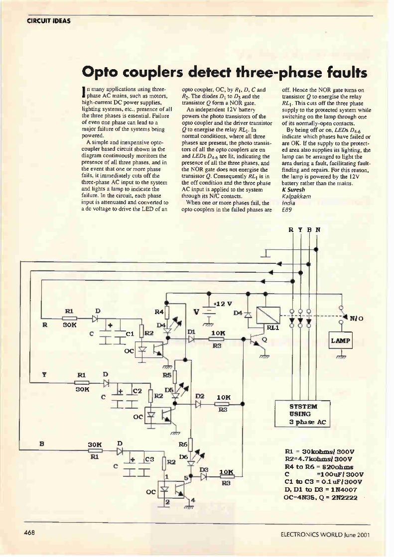
CIRCUIT IDEAS
Opto couplers detect three-phase faults I n many applications using three-phase AC mains, such as motors,
high-current DC power supplies, lighting systems, etc., presence of all the three phases is essential. Failure of even one phase can lead to a major failure of the systems being powered. A simple and inexpensive opto-
coupler based circuit shown in the diagram continuously monitors the presence of all three phases, and in the event that one or more phase fails, it immediately cuts off the three-phase AC input to the system and lights a lamp to indicate the failure. In the circuit, each phase input is attenuated and converted to a dc voltage to drive the LED of an
opto coupler, OC, by RI, D, C and R2. The diodes DI to D3 and the transistor Q form a NOR gate. An independent 12V battery
powers the photo transistors of the opto coupler and the driver transistor Q to energise the relay RL1. In normal conditions, where all three phases are present, the photo transis-tors of all the opto couplers are on and LEDs D4.6 are lit, indicating the presence of all the three phases, and the NOR gate does not energise the transistor Q. Consequently RL1 is in the off condition and the three phase AC input is applied to the system through its N/C contacts. When one or more phases fail, the
opto couplers in the failed phases are
off. Hence the NOR gate turns on transistor Q to energise the relay RLI. This cuts off the three phase supply to the protected system while switching on the lamp through one of its normally-open contacts. By being off or on, LEDs D4.6
indicate which phases have failed or are OK. If the supply to the protect-ed area also supplies its lighting, the lamp can be arranged to light the area during a fault, facilitating fault-finding and repairs. For this reason, the lamp is powered by the 12V battery rather than the mains. K Suresh Kalpakkam India E89
RYB If
R1 D
R
OC
R4
D4
Y RI D
30K I+ IC2
IE
30H
R_1
OC
D
D5
C3
OC
7 +12 V V = D4
.-177
R6
D6
D3
5
2
10H
R8
10H
R3
10H
7 RL1
SYSTEM
USING
3 phase AC
_41 N1 0 ( 1
1 LAMP
RI = 30kohms/ 300V
R2= 4.7kohins/ 300V
R4 to R6 = 820ohms
=100uF/ 300V
R3 Cl to C3 = 0.1uFi 300V
D, D1 to [XI = 1N4007
OC=4N35, Q = 2N2222
468 ELECTRONICS WORLD June 2001

£50 winner CIRCUIT IDEAS
Stepper motor driver using PC printer port LPTI
Small stepper motors are often used for motion control. This simple and inexpensive stepper motor driver is for
small stepper motors taking up to 500mA. It uses only one external component, a ULN2003, and the printer port LPT1 of a PC. The stepping sequence is generated with PC parallel port and the phase current is amplified with ULN2003. This IC has internal diodes to suppress the inductive transients of the motor coils, and can sink up to 500mA per phase. This is a resistive-inductive unipolar type of drive. The value of the series resistance is calculated as follows,
R seriese(Vsupplv- I motorXRcoil)+ 'motor
The program generates the sequence and outputs it through LPT1. The program given in the listing implements only a few basic features like half step, full step, number of steps and direction control. The software can be readily modified to include more features, such as acceleration, deceleration and variable speed. Vikas W Meshram Indore
25
14
•' 3 • •
• •
• •
• •
• •
• •
• •
e
e e e
Do
D6 —
6
8 9
Vmotor
senes
ULN2003 Supr.
Stepper motor
500mA max/phase
(E90)
Listing for the LPT controlled stepper motor driver. This software only BufStart.0;
implements a few basic features like half step, full step, number of for (i.0; i<=steps;i.+) (
steps and direction control but it can be modified to include features outport (LPT1, DmraFs[Bufstart).data); such as acceleration, deceleration and variable speed. delay (30);
*include estdio.h› BufStart...;
*include ‹dos.h> if (BufStart...Full)BufStart = 0;
*include <ctype.h, *include <conio.h>
*define LPT1 Ox378 else( *define R 1 BufStart-4; *define F 0 for (1..o; i.c.steps;i++){
void FullStep(intsteps); outport (LPT1,
void HalfStep(intsteps); DataFS[BufStart].data) ; void park(void); delay (30);
struct FSData ( unsigned char data; BufStart-; )DataFS[ ] = (10,9,5,6); if )BufStart--0)
struct HSData ( unsigned char data; BufStart . 4 ; }DataHS[ I= (10,8,9,1,5,4,6,2);
int i; char StepHode,dir; 1 void main (void) void HalfStep (int steps)
int NoOfSteps; char BufStart;
park ( ); char Full-8;
printf ('\nFull/Half Step(H/F):'); if (dir){ StepMode = getche ( ) ; BufStart.0;
printf( \nNo of Steps:'); for (i.0; i<=steps; (
scanf ('%d',&NoOfSteps); outport
printf ('\ndir:(F.1,12.0)'); (LPT1,DataHS[BufStart].data); scanf ('%d', &dir) ; delay (30);
switch (toupper (Steeode) ) ( BufStart*.; case 'F' : if (BufStart.-Full)
FullStep (NoOfSteps) ; BufStart = 0;
park ( ) ;
break ; case 'H' : else(
HalfStep(NoOfSteps); BufStart-8; park ( ) ; for (i.0; i< -steps; ( break; outport (LPT1,DataHS[BufStart].data);
default: delay (30); FullStep(NoOfSteps); BufStart -;
park ( ) ; if )BufStart--0)
break; BufStart . 8;
}
void FullStep (int steps) void park (void)
char BufStart ;
char Full-4; outport (LPT1,0); if (dir) (
June 2001 ELECTRONICS WORLD 469

CIRCUIT IDEAS
Single IC oscillator/doubler A nalog Devices' AD725 ROB-to-r\ PAUNTSC encoder integrated circuit needs a 4Fsc clock signal of 17.734475MHz (4xFsc PAL frequency). This is usually not widely available as a crystal frequency. The chip's application note
suggests a design for a low-cost crystal oscillator with a 17.734475MHz crystal' and I have used the idea to build a clock with a
commonly available 8.867238MHz crystal. The generated frequency thus needs to be doubled. The crystal oscillator uses one
inverter in a 74HCO4 IC, and a second as a buffer. The frequency doubler has been designed using the other four inverters in the same IC. The result is a frequency doubler using six inverters, two diodes and a few passive components. Crystal oscillator Uip and
+5V
associated components is the design suggested in the application note, but operating at half the required frequency. Inverter (JIB buffers the signal, to avoid loading the oscillator. The two edge-detector circuits, C3-R3 and C4-R4, differentiate complementary squarewaves. Positive spikes are amplified and buffered by UID, U1E, and combined by the diode negative OR gate DI, D2. Gate output is buffered and negated by the inverter UIF. The circuit works well and can be
used with various crystal frequencies if the appropriate modifications in the crystal oscillator component values are made. Emil Vladkov Sofia Bulgaria
Reference 1. Low Cost ROB to NTSC/PAL
encoder with Luma Trap Port., AD725 Data Sheet, Rev, 0, Analog Devices Inc.. 1997, pp. 12-13.
Low-cost load-sensing and switching circuit T his arrangement allows the 1 operation of an ac mains electrical load of 250W or less to be sensed, and for power to be switched to a slave circuit. This is particularly useful where the load is remote and the wiring difficult of access. Where the load also has a local
switch, such as a time-switch, thermostat or PIR, additional wiring to carry a control signal is eliminated.
Live •
47R
Shunt
47R
•
Applications could include: • Synchronisation of a ventilation
fan with other equipment • Basic remote monitoring of a load,
e.g., positive indication of load status in a home automation circuit, or security system
• Slave indicator of PIR operation, or synchronisation of several floodlights with one PIR detector
• Slave operation of several domes-
Neutral •
Triac TIC226M Optional relay/ contactor
0 11 11 Slave load
(E99)
Master load
• •
tic lamps through switching on one lamp.
When the master load is switched into the circuit, alternating current flowing through the diodes develops a positive and negative voltage, equivalent to double the diode forward voltage drop. This triggers the triac via the 470 resistor within a few degrees of zero crossover. Although RF levels in the power
circuit caused by the triac switching are relatively low, there may be some configurations where additional filtration may be required.
If the load being sensed includes a residual current drain, such as a time-switch or sensor circuit, discrimina-tion against a load of up to 5W can be achieved by including a 0.25W 472 shunt resistor in the position shown. Thermal considerations caused by
current flow in the diodes and triac affect the master and slave circuit ratings, and heat sinking or relays should be deployed if necessary. The circuit as illustrated is adequate for 250W master and slave loads without additional heat sinking. R I Phipps Bedford E99
470 ELECTRONICS WORLD June 2001

now to gv
our comprehens' vast archive o' gularly, the -
1 Upch
r.'
Accurate recruitment information when you need it.
Simple Really.
...askemer &donne% . Free Career H Electronics Wet HyperActire ha with the (Arm service t-daliç? its users a F'
Our appointments senrice is online electronics enginee. marker++
MEW czu
....w•www our. ...um
iniaiewm• Flea
ree e.„
1. tp://yeseew.
=E1 AIM ,WEDIYonline,
Every week HyperActive ha contract vacancies that are anywhere else' Click the lo search screen and choos "Job Type." field
www.electronicsweeklg.co.uk

Smart card reader/writer kit Exclusive reader offer
Gee ess
croege
System features • Archive administration - copy, save and restore complete card data sets - display amount of available used memory on
card
- options for each directory on how to add data: - do not modify directory - append entries to existing data
- overwrite existing directory - quick links to the various data editing dialogs
• Short message functions - select net broadcast message topics of interest (weather, traffic) - read and send short messages
- set up address templates for frequent message recipients
• Preferred service providers - selection of foreign GSM service providers - setup of prioity ranking - database which can be updated with new providers
• The card profile — Detailed display of all card
features: network operator (c ard issuer), card ID number, card phase, PIN status, size of data
fields, avaible and enabled/disabled services. • PIN administration
- change, enable and disable PIN/PIN2 - unlock the card PIN(s)
- display the error countervalue for eachPIN • Charge control
- display the current value of the charge counter - set up a charge counter limit - interesting feature for rental services:
set up the displayed price per unit (including currency)
• The GSM editor
- immediate access to the file on a GSM card - display of data content, status and access rights
lose-
Crownhill Associates is offering Electronics World readers what is believed to be the lowest cost smart-card reader/writer and SIM adaptor system available in the UK — at just over £20 fully inclusive. Full details in the panel below. Available at this special price for a limited period
only, the product is shipped with the ChipDrive Micro smart card reader/writer, a Mini SIM adapter and software — all in retail packing. The product is CE certified. Instructions are via a Windows help file. Help on installation is provided by printed documentation shipped with the product.
-11111111.--- With the software included in the package, you can configure, modify, copy and print the data on any GSM card with the help of your PC. This easy-to-use software gives you access to all data on your card and you won't need to punch in complicated sequences on the numeric keypad of your mobile phone again.
• detailed card profile display • prints report sheets on various data
directories • easy phonebook administration • short messages, address templates, net
broadcast messages. • administration of PINs and much
more...
VICL.
Wflee 114tx.t1 Gloyeuml Br, 1.1.11»
C,05M, 14
.41117 ,4114 Emma
Edo
_1;••• j› ..j _11>j, .±j -
I
a pp«
7
...atammemea..91..Omm 1.71.1
Price and ordering details The total UK inclusive price* £20.57 (*Carriage £2.50, VAT £.071 The total EC price £24.08* EC postage and packing £5.50 inclusive of insurance. EC customers pay VAT @ 17.5% unless they are VAT registered.
Overseas customers outside Europe will be charged according to the method of shipment, which will vary from country to country. Crownhill has distributors in TRNC, Cyprus, Algeria, Nigeria, Kenya, Tanzania, Australia, USA and Rep Ireland. Purchase may be made by Credit card, cheque or postal order. This offer is for mail-
order sales only and is limited to one purchase only per company or household. Quote "Electronics World offer" when ordering. Post your order to: Crownhill Associates Limited, 32, Broad Street, Ely, Cambridge CB7 4AH, UK. Tel: +44 (011353 66 67 09, fax +44 (01 1353 66 67 10.
**Offer ends 30 June 2001
To the best of our knowledge this product cannot be used for illegal or nefarious purposes, such as, but not limited to, adding credit to a prepaid SIM card. Crownhill reserves the right to refuse sale to any person that we suspect may abuse the product or bring the product or our company's reputation into disrepute.
472 June 2001 ELECTRONICS WORLD

Peda eter
Although designed for checking electrolytic capacitor health, Cyril Bateman's impedance meter has a variety of uses. Operating at a test frequency of 100kHz, the meter has two ranges, 0-2S2 and 0-20£2.
Combining the charged capacitor protection circuits and four terminal input stage
designs from my tant5 meterl with the impedance measuring stages from my high-frequency impedance meter2, 1 have designed a self contained, hand held, battery powered 100kHz impedance meter. Using a 150mV maximum test voltage, it provides two measurement ranges — 0-2f1 and 0-20f2. The result is displayed on a low-cost 3.5-digit PM128 liquid-crystal panel meter. While designed for measuring the
impedance of capacitors, this meter can be used to measure any impedance within its ranges, whether inductive, capacitive or resistive. Indeed I% metal film resistors were used to confirm measurement accuracy. This 100kHz meter is intended to
aid circuit design by accurately measuring the impedance of stock capacitors inserted into a four terminal test jig. Suitable jigs can be assembled using commercial Kelvin contact four-terminal test sockets, to accept axial or radial leaded devices. Attached to 'panel mount plugs',
Fig. 1. Measuring a 220pF OSCON capacitor that has been inserted into the radial-lead jig. This Textool test socket is available from RS Components.
these four-terminal jigs plug into the 100kHz impedance meter front panel. This facilitates the measurement of axial or radial lead components. My prototype used four-terminal test sockets3 manufactured by Textool, Fig. 1. At higher frequencies the 'soldered
into stripline' test jig approach of my high frequency IZI meter2 becomes mandatory, but at 100kHz, using plug-in Kelvin contact test jigs is feasible.
ce
•••••\ lOOkHo Mel MOO MOW MOW
10,6 OA / le. I. 0 12 • AY •:3 ••• e.
10 • 5.5 •Ik oh§ We• duonp1. Itad
June 2001 ELECTRONICS WORLD 473

TEST & MEASUREMENT
Table 1. Wayne Kerr 6425/HP16047A measurements of a Philips 1000pF 25V type 135 capacitor.
Frequency 100Hz 300Hz lkHz 3kHz 10kHz 30kHz 100kHz 300kHz
Capacitance 980.2pF 964.7pF 940.4pF 898.9pF 836.2pF 820pF 0.7nH 5.4nH
Tan6 0.06405 0.1457 0.4175 1.1228 3.3024 9.496 115 5.37
ESA (mi)) 103.95 80.15 70.595 66.335 62.83 61.5 59.4 57.6
IZI (m0) 1627 555.6 183.4 88.64 65.78 61.6 59.5 69.6
Phase angle (5) -86.34 -81.72 -67.3 -41.7 -16.82 -6.0 +0.4 +28.0
apreette 100k Ile I. %kw.
loremeeletée «
%I...m..1.m pnoeted einaele leuent,
i7; :t. . Nun, nip& »bag e bed
• lime, p.e. dIef.e.ied eltk•
Hid 11.4 I &rem
It Fig. 2. Prototype meter performing an in-circuit measurement using my 'best' four-wire test-lead set.
Fig. 3. Two versions of my 'Method 3' impedance measurement. Using the stripline test jig and co-located sense resistor my High Frequency Z1 meter needed two voltages only. With the sense resistors mounted in the meter body, the voltage drop along the current return wire necessitates an extra measurement V3, the voltage at the sense resistor.
vi D
Signal Generator
u
VI -V2
D. U. T
Signal Generator
Sense ft. on Jig
Pu
PLI
Sense'Fr in Meter
PI.5
Despite using Kelvin contacts, mutual coupling between their voltage and current contacts introduces minor measurement errors. This can be corrected by offsetting a voltage measurement. Alternatively, these plug-in jigs can
be replaced by four-wire test leads fitted with test probes. The meter's 150mV maximum test signal then allows it to be used for accurate in-circuit capacitor measurements, Fig. 2. While the general circuit
arrangement looks quite different, this meter uses exactly the same 'method 3' used in my high frequency IZI meter2 but with one essential difference. The current-sense resistor for that design was co-located with the device under test. The current sense resistors for this 100kHz portable meter are located within the test meter's body. To ignore the voltage drop along
the return current lead of the device being tested now requires the measurement of three voltages. When
using a co-located sense resistor. two voltage measurements suffice. Fig. 3.
Four-wire test leads and jigs At DC and low frequencies, designing four wire test leads/jigs is straightforward, provided the current leads used have low resistance compared to the generator's output impedance. As test frequency increases - and especially when measuring impedances4 less than IS2 - a large test signal current flows through the current leads. This current couples an error voltage into the voltage sensing leads, resulting in incorrect readings. At 100kHz and above, test lead
inductance cómbined with mutual inductive coupling provides the main source of measurement errors. These can only be minimised by using the 'four-terminal pair' configuration.4 There's more on this in the panel entitled, 'Four terminal pairs'. The classic four-terminal pair
configuration uses four coaxial test cables. All four cable outer screens are bonded together only at the end of the cables where the device is being tested. This provides four fully shielded paths from the test meter to the four-terminal test jig. Two coaxial cables supply the test current and two monitor the voltage drop across the device being tested. When measuring capacitors
mounted on a PCB, a four terminal test jig with these essential earth paths is not practicable. Two test prods must be used. Routeing a four-terminal pair system into two test
Fig. 4. Prototype meter opened to show the general arrangement. The PM128 display and the 'top' board can be seen on the left. The +5V power supply and auto-off boards are located either side of the battery box top right. The top and
474 ELECTRONICS WORLD June 2001

TEST & MEASUREMENT
prods while maintaining adequate earth paths and minimising mutual coupling, proved extremely difficult. More on this later.
Why not simply use two test leads? A conventional test-lead pair exhibits some 100m of DC resistance and around 2pH of self inductance. Even worse, this inductance is not a finite value; it increases significantly with separation of the leads and test prods. Every capacitor also exhibits some
self inductance. This is why most aluminium electrolytics become series self resonant between 10kHz and 1MHz, depending on capacitance value5. See the panel entitled 'Capacitor impedance versus ESR' for details. For example, with just 5nH self
inductance, a typical 1000pF radial-lead capacitor resonates close to 100kHz. Above resonance, the capacitor exhibits an inductive reactance. its measured impedance increases rapidly with frequency. For accuracy it is essential that any test leads used do not influence the capacitor's series self resonant frequency. Table 1. To illustrate this test lead effect. I
measured a 47pF 50V Panasonic radial-lead electrolytic capacitor using a Wayne Kerr 6425 precision component analyser, equipped with the Hewlett Packard 16047A four terminal test fixture. This expensive test fixture is usable up to 13MHz. At 300kHz, which is the analyser's highest test frequency, this 47pF, 50V capacitor measured as —I° phase and 171.6m impedance. This confirms that the capacitor's self resonance frequency was above 300kHz.
Inserting a pair of test leads caused this 47µF electrolytic capacitor to resonate between 15 and 20kHz. This is substantially less than the desired 100kHz measuring frequency, resulting in gross impedance measurement errors when the device is re-measured at 100kHz. Using a Wayne Kerr analyser at
100kHz with the capacitor mounted directly in the Hewlett Packard test fixture, the impedance of this capacitor measured 171.6mf2. Replacing the test fixture with a pair of standard two wire test leads, the capacitor/test lead combination measured 1.26e. As capacitance value increases, a
two-wire test leads/capacitor combination will resonate at ever lower frequency, further increasing measured impedance errors. These errors can only be eliminated by
using the 'four-wire pair' test lead configuration. There's more on this in the panel entitled, 'Four-terminal pairs'. To ensure a professional finished
appearance, I used the same OKW case as used for my tans meter design'. The PCB is again split into two halves, one mounted in the
•
A•SV
100nF
6-41
go—
AS VDCPSC
NAS
IR- NO
IR.
RIS
RST
RT
R C
7
13
I.
R15 5666
2
3 VRI 56
U3 4047 C3
10111oF IS PS
bottom of the case adjacent to the batteries, the other in the top half adjacent to the display module, Fig. 4.
Bottom board This board houses the test signal generator, the range switching relay and both the voltage and current
2
3
7
V IN- CM
IN•ej
-5V
4
C36 111111r.F
5
OUT 4
NE5534
CI 1.F
vW RI8 7668
CO
PS
C7 InFIX
PS
•5V
1. C38
V. 1111111nF ---- IN -
IN
V-
OUT
U50
7
4 NESS 32
R21A2113 1360
2
LVVV\-•
Nég5e32
R2 3143
PLI
PL2 R3 108FR
PL4
R27 RI I'S
Through C
525 I8R
R26 I OR
I 01114HC 0 tor
ZDIS ZDIO
All 3.3V
ZDI6 ZDI7
Output Dr.vor
Ul 5 INAI28
C32 C3I 1110nF
V -5V
Vol tage Drop Measurement
-5V t Pleetur•P•nt
Bottom Board
A11 ,614002
To u7 .nout
R13 Il
Vc eeeee I
C45 I C46 I C47
All 22111uF111V
To US Input
C33 11111nF
Fig. 5. Full schematic for the 'Bottom' or right hand board of Fig. 4, including all decoupling used. The 100kHz signal source is provided by the upper circuits, the voltage and current channel front ends comprise the lower half.
June 2001 ELECTRONICS WORLD 475

TEST & MEASUREMENT
A.sv
2
From ul 3 2 •
measuring differential input amplifiers together with their charged capacitor protection circuits, Fig. 5.
Isolating the four-terminal current and voltage sensing paths within the test meter PCB proved relatively easy. Adequate separation of components together with Faraday
.5V
2
f8L771T8i,,F
MÉS534
vAst I006
Voltage Oro., eeeeeeeeee t
•SV
V channel
r V. Lst r—Gc•o. Out s
— E rt cvo- ve I Icbas
I.'.-
5V
C70
Sne "d LV
• U6e
AX457 4
051
R 4 47OR
en.
shielding earth tracks was found to suffice for the original prototype single range design.
Current-sensing resistors. The relay switching needed to provide two measurement ranges complicates the design because of the inductance
Matched oo.r 5192-2435 / N\F$S2 or MMS2022
The.. 470R 041tChed
Two 22OR notched
22OuF 22OuF I OlInF
COO
4
RS,
•55
NC e
RO Out
CtS Ref 5
-Out
— F Crrr
3lf' II 220uF ieenF 221uF
IOC
A.sv
V 5 22oF
—194-"MOUT s. IN.B
V U0
NESS]
VR52 I004
Through Curren t
1U182L
I channel
M244.
it!F
•1V
fit” "v
f:8.=
22OuF 22OuF SmF
6
S
eeeee 47OR notched
Two 225R notched
Offeell Voltige
M 4m
yr54
-5V
C69
CLL__
• es4 V-5V
.1 IV tor Outset voltige eeeeee tor
/7111 Top Board
TIOnF
To PMI20
In H.
CS4
Feos Offeett Voltige
Matched per 5002-2635 or MMS2O22
-SV
• Ou t
To PM1211
Reg m,
rse
Fig. 6. The full schematic for the Top' or left hand board of Fig. 4. This board houses both Voltage and Current channel precision rectifiers, together with the INA126 output amplifiers. The 9V supply for the PM128 and the offset generator can be seen bottom left, the —5V generator is shown centre left of the circuits.
introduced by the relay contacts. The physical size of a relay also increases the PCB path lengths. At 100kHz these added inductances become important, so they must be compensated for by reducing the actual sense resistor value used for the 2i1 range. While it preferable to use non-
inductive current-sense resistors, at 100kHz normal metal-film resistor inductance is small compared to the relay and PCB inductances. However,
Setting up
With a frequency meter connected between PLi and ground, adjust VR1 to read 100kHz. Alternatively, connect a DVM between the V.„, test-pin, adjacent to Um and ground. Adjust VR1 to maximise this voltage. With nothing connected
between pins PLI through PL4, connect a DVM between R23 and earth at the end nearest to U8. Adjust VR52 to read zero volts. Solder a good short circuit
directly to pins PL2 and PL3, taking care to make contact only to these pins. Connect a DVM between R53 and earth at the end nearest to U2. Adjust VR51 to read zero volts. Replace the short circuit with a
known 100 resistor connected to PL2 and PL3, link PLI to PL2 also PL3 to PL4 and set the 100kHz IZI meter to its 10i1 range. Connect a temporary short
circuit across R84. Adjust VR53 to read ICA-Ion the PM128 display meter. Replace the 10f1 resistor with a
known 1 LI resistor. Set the 100kHz meter to its ln range. If necessary, adjust the value of R27 until the display reads lfl. On the prototype meter a 6.8i2
resistor in parallel with R27 was needed to compensate for the relay contact resistance. Remove the resistor and links
from the four test pins. With the axial-lead four-
terminal test jig fitted to the meter, insert a good short circuit into this test jig. My usual short circuit is a 7mm wide 25mm long piece of 1 mm thick, polished copper sheet. Remove the short from R84 and
adjust VR54 until the PM128 display reads zero. Removing the short circuit from
the test jig completes the setting up.
476 ELECTRONICS WORLD June 2001

TEST & MEASUREMENT
I designed my PCB to accommodate either low-inductance surface-mount current-sense resistors or conventional metal film types.
Signal generator. The test signal generator for my tanS meter used a low cost LT700 audio transformer to ensure a low source impedance. I could not find a suitable high-frequency transformer for this new meter. Eventually I decided to see if the LT700 could be used at 100kHz. I was pleased to find that its reduced output could be accommodated simply by increasing drive levels. I evaluated a number of ICs for the
Fig. 7. This photo shows the test probe ends of the three test lead sets I assembled. The 'best' set, with its external braid link, can be seen at the top of the picture. The easiest to assemble lead was made using the black four-way screened flat strip cable at the bottom.
Test-lead assembly My easy test-lead set ‘‘as assembled using a low-cost four-way screened audio cable, available in cut lengths from Maplin as part number XS95D. Comprising four individually lap screened 10/0.12mm wire cores, co-joined into a flexible flat strip cable, Fig. 8d). All four wire screens were connected
together inside the meter plug and isolated inside the test probes to produce effectively a five-terminal test arrangement. Using this test lead, resistance values of 0.47f1 and above could be measured. I decided I needed to use much lower
resistance current leads, but four screened or coaxial cables with thicker inner conductors were much too large to fit into most four-pin plugs. I decided to tightly pre-twist and double
screen the voltage wire pair for as far as possible, and use heavier non-screened current wires to ensure an acceptable cable diameter. My remaining two lead sets used
identical voltage lead pairs but with different current leads and test prods. The voltage pair leads were twisted and
double screened to minimise mutual coupling from the current leads. I used PTFE insulated 7/0.2mm wire with some screening braid removed from RG174 coax. At 20cm from one end of two 1 metre
lengths, I carefully opened the braid wires to form exit holes. Both braids were then expanded, sliding one onto 5mm the other onto 3.5mm knitting needles.
Fig. 8. Schematic drawing of the three possible four-wire test lead configurations. The traditional four-terminal arrangement
(a) is restricted to low frequencies. The five-terminal lead set (b) offers improved performance. The shielded four-terminal
(c) extends both usable frequency and impedance measurement range. Bottom
line, the three leads I assembled. The 'easy' lead is shown in (d), the 'intermediate'
lead in (c) and the 'best' lead is (0.
The smaller diameter was drawn inside the larger, to emerge via that exit hole. A double braid, emerging as two short,
separate, single braids, produced a 'Y' jointed cable. Using the knitting needles I carefully aligned both exit holes, ensuring an easy wire path from each single braid into and through the double braid section. Two 1 metre lengths of the PTFE coated
wires were twisted together for a distance of 70cm, leaving the remainder separate. Two pull wires were inserted, one into each single braid to pass into and through the doubled braid section, and used to draw the PTFE wires into position. This 'Y' jointed assembly was covered
in yellow heat-shrink sleeving. It is clearly visible in the photograph. Both braid screens were connected to
ground in the connecting plug. For the intermediate test leads, two
lengths of 0.5mm2 extra flex and the double screened length were drawn into clear heat-shrink sleeving using a slow twist to aid flexibility of the completed test lead. Emerging from the 'Y' joint, one current wire and one screened wire were passed through each FH32K probe body, then soldered together into the
brass probe tip, Fig. 8e). Using this intermediate test lead
resistance values of 0.22f1 and above could be measured. For the best accuracy test lead, a pair
of Maplin HF33L pre-assembled test leads replaced the 0.5mm2 wire and FK32K test prods. Otherwise, assembly generally followed that described for the intermediate lead set except for the screen braid ends at the test prods. For this lead set the PTFE voltage wires
were soldered to the test probes lcm from the pointed ends. Both screening braids were then interconnected using another 10cm length of braid as in the photograph, Fig. 8f). Using these best practical test leads,
board mounted resistance values of 0.1n and above can be measured in-circuit. Using each of the above test leads to
measure a good 1001.IF electrolytic I found much smaller differences, ranging from a measured impedance of 0.142n using the best leads to 0.280 for the worst. For in-circuit diagnosis, all three test
leads were able to identify a failed capacitor.
(a) (b) (c)
(d) (e) (f)
une 2001 ELECTRONICS WORLD ;--

TEST & MEASUREMENT
filter and output stages. Using NE5534 and NE5532 ICs with 1% polystyrene capacitors, the resistor values used in the filter stages were adjusted to provide a bandpass response. The resulting strange resistor values were obtained by parallel combinations of 1% metal films, mounted on Vero pins. At 100kHz, variations in internal
resistance in the HEF4047BP oscillator IC could result in a 7% frequency variation between ICs. This is compensated by the un pre-set resistor VR1. While it is preferable to adjust this
oscillator frequency to exactly 100kHz, if a frequency meter is not available, the oscillator can be adjusted to maximise the output signal. Using 1% components, the filter centre frequency for maximum output will usually be between 99 and 101kHz. This frequency accuracy should suffice.
Four-terminal Inputs. The diac, fusible resistor and diode protection methods used in my tan8 meter design' have been closely followed except for two resistor values R2 and R5 which are much increased. These resistors are only needed to maintain earth continuity should the test jigs/test leads be removed. So as not to affect the voltage measurement, their value must be much larger than the impedance of any test leads used at 100kHz. To monitor the voltage drop at the
test capacitor and across the current sense resistor, two instrumentation op-amps are used. For accurate measurements, better than 40dB of common-mode rejection at 100kHz is needed. The INA118 in-amps used in tan&
meter have been replaced by INA128 instrumentation amps. These offer the same degree of input self protection and improved high frequency performance. To optimise the input levels to the
rectifier stages, the voltage channel INA128 IC has been set to a gain of 12.9 while the current channel INA128 IC gain is set to 9.1 times. These gain differences are compensated after rectification.
Top board This board contains the rectifier stages needed for the V and I measurement channels, together with a floating 9V supply for the PM128 meter and the —5V converter needed to power the op-amps, Fig. 6.
Rectifier stages. I originally hoped to be able to drive the rectifier stages direct from the INA128 instrumentation amps, but these could not supply sufficient drive to the 47012 input resistors. So a buffer stage was needed. This could be provided using a dual amplifier, but for accuracy I also needed to minimise input offset voltages. Two single channel NE5534 ICs with offset nulling were used. Both rectifier stages are evolved
from those proven in my RF millivoltmeter and the high-frequency IZI meter. Designed to work with a 1 V nominal maximum input signal, their output attenuators have been modified. This allows two INA126 instrumentation amps to be used to convert the floating outputs to single ended for the PM128 display. These have a minimum gain of five. My earlier designs used two AD712
ICs to perform this task in a circuit with a minimum gain of two. While I was building the prototypes though, AD712s were in short supply. With U6 mounted in a turned-pin
socket, various ICs, including the NE5532, TL2062, and TLE2072, were evaluated for use in these rectifiers. I had hoped that at 100kHz, lower cost devices would prove suitable. However as with my other designs, the Maxim MAX457 provides by far the best dynamic range and measurement accuracy.
Unfortunately it also consumes significant power — some 30mA at 5V. Used only for in-circuit
measurement, these other ICs could be used, almost doubling battery life but with the penalty of some reduction in low impedance measurement accuracy. For in-circuit diagnosis, this level of accuracy should suffice.
Measurement accuracy After calibration, this measurement method ensures that a short circuit connected directly across the PCB terminals PL., through PL4 reads as zero ohms. However with the mutual inductive coupling along the length of the four terminal contacts in the Textool jigs, the same short circuit mounted in these test jigs measures as a small resistance. The mutual inductance produces a
small, near-constant error voltage. This voltage can be overcome by introducing a similar error offset voltage into the Reference' input of U10, pin 5. Usually, this pin connects directly to earth but I found that by connecting a 10Q resistor to earth, the resulting few millivolts provided the necessary error correction. This correction voltage is arranged
using an LM334 IC to generate a constant current into R62. This current can be varied from near zero to several milliamps by adjusting VR54, to ensure accurate measurement.
If the meter is used only with test leads for in-circuit diagnosis using the 20Q range, Re can be shorted and the LM334 circuitry omitted.
Power supplies The floating 9V supply is based on Siemens' low-cost B62152A4X30 two-hole ferrite 'balun' beads. This design has proved repeatable and reliable, consuming less than 2mA at 5V to power the PM128 meter. The ferrite is conductive, so to
avoid accidental stripping of the
Four-terminal pairs
At DC and very low frequencies, the conventional four-wire test cable with Kelvin contacts can provide accurate measurements, but mutual inductance generated errors increase with frequency, Fig. 8a). The most accurate four-wire measure-
ment — especially for high frequency or low impedance — uses the 'four-terminal pair' method.4 The five-terminal and shielded four-
terminal cable arrangements provide a capability between these two extremes,
Figs. 8b) & 8c) The four-terminal pairs or '4TP' with
Kelvin contacts are the best solution for any wide-range impedance measure-ments. From my own tests, they can be used at 100kHz with 1 metre leads without needing error correction. This 4TP method relies on using four
coaxial test cables with all four cable screening braids connected together by a low impedance path, immediately adjacent to the device under test. Two coaxial cables supply the mea-
surement current to and return from the
device under test. The remaining pair monitor the voltage drop across the device being tested. The inner cores of each cable should be connected sepa-rately to the component being tested to form Kelvin contacts. The four earth braids must be directly
interconnected, using typically a 1.6mm thick, 30mm by 50mm aluminium plate, or equivalent low-impedance connec-tion, immediately adjacent to the device under test. Unfortunately this 4TP method is not
practical for in-circuit measurements.
478 ELECTRONICS WORLD June 2001

TEST 8. MEASUREMENT
winding wire enamel, any sharp edges around the holes should first be deburred then the cores varnished before winding. Negative 5V supply is derived
using MAX665 or TC660CPA switching inverters with low ESR electrolytics. This design provides a low noise, reliable, near —5V supply when supplied from +5V.
Display meter Measured impedance is output as two voltages, one representing the voltage drop across the device under test, the second representing the DUT through current. From Ohms law, these two voltages
divided produce the unknown impedance. As with my tads meter design, this division is most easily arranged using the PM128 digital panel meter, modified to ratio mode This modification is easily made by
removing two resistors, R2 and R3, from the PM128 module. The 100kHz IZI meter 'Ref-Hi' output from Ug connects to the 'Ref-Hi' pad which originally linked both resistors. The 'In-Hi' output from U10 connects to the PM128 normal 'In-Hi' terminals ad the 100kHz IZI meter ground to the PM 128 input ground.
Four-wire test leads Considerable time and experimentation was needed to devise usable test leads that could measure in-circuit impedances with acceptable accuracy. I evaluated nine different possible configurations using three differing wire types. In each case my 100kHz impedance meter was calibrated to read øû when measuring a short circuit mounted in the axial four wire test jig. Carrying 100mA DC, the
unscreened four-wire test leads from my tan& meter measure 35mû per lead. At 100kHz using these leads, a good short circuit measured 0.19Q to 0.4Q depending on lead orientation. While excellent working at 100Hz, this lead was found to be suitable only when measuring impedances greater than lû at 100kHz.
Similarly, a two-wire standard test lead that measured 62mQ at DC per lead, at 100kHz the same lead measured this short circuit as varying between 0.74Q and 1.04Q, depending on lead orientation. This two-wire test lead was not usable at 100kHz either. By measuring the same test
capacitors and resistors inserted directly into my four-terminal test jigs and then using test leads, I was able to ascertain the measurement errors caused by my differing test
Capacitor impedance versus ESR
When an alternating current is passed through an ideal, or perfect, capacitor, having neither inductance nor resistance, the voltage waveform lags that of the current by 90°. The capacitor produces an impedance with a phase angle of —90°. At any one frequency, a practical
capacitor can be represented by a series combination of inductance, capacitance and resistance. In a practical capacitor the inductive component may be relatively constant, but not so the resistive and capacitive components. Both are strongly frequency dependent. These combine to produce an impedance 1ZI with a much reduced phase angle. Depending on frequency, the measured phase angle can he either positive or negative. Fig. 9. Using the standard mathematical
conversion from polar to rectangular notation, we find,
IZIZO = R jX
where R is the capacitor equivalent series resistance at the measured frequency and X
Fig. 9. Impedance and Phase Angle curves of another low ESR 1000pF
25V Philips type 135 capacitor, measured using my High-
frequency impedance meter2.
Impedance
2.0
04
is the capacitor's net reactance at that frequency. But as you probably know, this X
comprises two elements's — one a capacitive reactance X0 the other an inductive reactance XL.
IZI= NIESR2 +(x — X2L)2
From the above, you can see that ESR is not a finite value. It varies widely with frequency. Furthermore, with aluminium electrolytic capacitors it is also extremely temperature sensitive. At one frequency only the capacitive
reactance Xcand inductive reactance X/ being equal and opposite, cancel. At all other frequencies IZI is greater than ESR, but at this one frequency only, then VI is exactly equal to ESR.
0 01 1
Phase y Impedance
. r
Phase degrees
100
o
..- - - .i.q¡j- - - 4- ¡-¡¡¡1.--- -%- • ................................. 4. ..... :* ...... %10,...:::0000
10 100 1 000
I owitionry kHz
l000 pf 25V Phibps 135 Capecttor
-SO
lead designs exactly. Ultimately, three test lead sets were
assembled for final testing. One offered ease of assembly and use, one gave best accuracy for low impedance measurements but less ease of assembly or use, and the third represents an intermediate or compromise set, Fig. 7. Using the 'easy-build' test leads,
my short circuit measured 0.23Q, but resistance values of 0.47Q and above could be measured in-circuit, Fig. 8d). With the 'intermediate' test leads, my short circuit measured 0.075Q, so resistance values of 0.22Q and above could be measured, Fig. 8e). My best test-lead set measured this short circuit as 0.015Q. Board-mounted resistance values of 0.10 and above, could then be measured in-circuit, Fig. 8f).
Performance Using each of the above test leads to measure a good 100g electrolytic in-circuit, I found much smaller differences. They ranged from a measured impedance of 0.142Q with the 'best' leads to 0.28Q for the 'easy build' or worst. In practice, for in-circuit diagnosis measurements, all
three assembled test leads were able to identify a failed capacitor. Using either the axial or radial four
terminal test jigs, with the meter set to its 2..Q range, impedances of a few milliohms to 1.999Q were accurately measured, extending to 19.99Q using the meter high range. I plan to offer professionally made
PCBs for this meter together with a self adhesive front panel label, and a set of drawings and assembly notes. •
References I. Bateman C., 'Tan8 capacitor
tester', Electronics World, Jan 2000.
2. Bateman C., 'High-frequency impedance meter', Electronics World, Jan 2001.
3. Axial or Radial Lead Sockets. (Textool) 3M Electronic Products Division, In-line socket (radial lead) RS Components part No 160-7090.
4. The Impedance Measurement Handbook, Agilent Technologies.(HP) USA.
5. Bateman C., 'Understanding Capacitors', Electronics World. June 1998.
Technical support For PCB details please send a stamped, self addressed, A4 sized envelope to Cyril at the address below. Overseas readers should send an International Reply Coupon and self-addressed envelope. Cyril Bateman, Nimrod, New Road, Acle, Norfolk NR13 3BD, UK
June 2001 ELECTRONICS WORLD 479

WEB ECTIO ACQUIVISION http://www.acquivision.com
AcquiVision solutions, including XV-Plotting, Oscilloscopes (with FFT). Data Logging and Custom Software, have been getting the most from computers since 1994. Download software. Telephone (01903)830502.
AQUILA VISION http://www.aquila-vision.co.uk
Aquila Vision specialises in supplying and supporting Embedded Microprocessor Development products from PICs to DSPs. We also stock robotics boards. Linux and general interest CD-ROM's.
ALCATEL COMPONENTS http://www.components ©alcatel.de
ASH WELL ELECTRONICS http://www.ashwell-hq.com
Ashwell provide technical support for Apex Microtechnology op-amps and DC/DC'S, Aeroflex, EMP filtered connectors; M S Kennedy; Mintech obsolescence; NSC Mil/Aero; Teledyne Relays and isocom mil/optocouplers.
ARCOM httewww.arcomcontrols.com/eW
EW
•--
BIII
A leading international supplier of communication and control technology to industry. Arcom provides leading edge solutions through a comprehensive range of market leading products.
BROADERCASTING COMMUNICATIONS SYSTEMS www.broadercasting.co.uk
WINRADIO now brings you a complete choice in personnel computer controlled
radio scanning and reception solutions • Broadcast • Media • Monitoring • Professional Amateur Radio communications
BEDFORD OPTO TECHNOLOGY LTD http://www.bot.co.uk Optoelectronic products UK design development manufacture standard and custom. LED bargraphs, circuit board indicators, stand offs. transmissive/reflective switches. baseefa optocouplers tubular and surlacemount. pannel mount LED assemblies.
CONCEPT ELECTRONICS
http://www.conceptkey.co.uk
Concept Keyboards are specialists in the design and manufacture of customer specified membrane panels and keyboards, and electronic design. Concept's membrane manufacture is supported by a full electronic production facility to provide a complete turnkey keyboard and electronics service, fully accredited to IS09001.
CONTROL SOLUTIONS www.controlsolutions.co.uk Data acquisition and control for beginners, hobbyists, and professionals. Perform mathematical and logical operations on data in real time. Email: [email protected].
COOKE INTERNATIONAL http://www.cooke-int.com
e-mail: [email protected]
Stockists of Quality Used Electronic Test Instruments and Operating 8 Service Manuals.
CROWNHILL ASSOCIATES LTD http://www.crownhill.co.uk
Crownhill supply low cost development tools for use with Micro-Controllers and Smart Cards. Products include Smart Card development tools. Smart cards. Micro Development tools and Bespoke Design Services.
DANIEL MCBREARTY
http://www.danmcb.demon.co.0 k/eng.html
Experienced engineer based in London, specialist in audio and control systems. Available for design, project engineering or general consultancy. Background of high-quality work.
DESIGNER SYSTEMS CO.
http://www.designersystems.co. uk
›.
= = =
• tà«,acea_ NOMMOMIlle
lie‘
1111>
Electronic product design company with over a decade of experience promoting it's own product range and designing and manufacturing innovative products for client companies/individuals.
ECM SELECTION http:// www.ecmsel.co.uk
ECM SELECTION
For the pick of the UK's Top High-Tech Software and Hardware career opportunities - from fresh Grad/PhD to Senior Engineer/Manager -- £22.000 - £70.000
EDWIN PCB DESIGN SOFTWARE http://www.swifteurotech.co.uk
Swift Eurotech supply the best-selling EDWin CAD/CAE system for PCB design. including schematics, simulation and PCB design. Discounts up to 613°,. for non-commercial users.
ELECTRONICS AND COMPUTING PRINCIPLES http://www.eptsoft.com
Studying electronics or computing or just want to keep up-to-date in an easy and enjoyable way, then this fully interactive software is for you.
EQUINOX TECHNOLOGIES UK LTD
http://www.equinox-tech.com
»pawed s- la .10.
III•kon. to the Nedra per, of
41Mir
«ID i0MOX
«Mr
«CD
«M.
III ...........7 .......
Oleateelieeledul
...«••••
Wire reerad
te smog
See Mee
Equinox Technologies UK Ltd.. specialise in development tools for the embedded microcontroller market.
FARADAY TECHNOLOGY LTD
http://www.faradaylech.co.uk
FT1
raciat_i
Over 17 years experience in the design and manufacture of high quality passive filters and delay lines. Used in Broadcast. Telecommunications, Medical. Multimedia, and computer industries. Currently exporting worldwide
FELLER UK http://www.feller-at.com
Feller (UK) Ltd. manufacture Fully approved cordsets (Moulded mains plugs and connectors) and Power Supply Cables for all industrial Countries to National and International Standards
FLASH DESIGNS LTD http://www.flash.co.uk
Flash supply low cost AVR ISP programmers (£39). MINI-ICE starter kits (from £69), Portable Easy-ICE emulators (from £199), ICE Adapters
'C compilers for any ATMEL AVR. MCS51, Dallas, Hitachi 1-(8 microcontroller. Download FLASH NEWS now, Watch out for Special Offers'. ARE YOU developing code in a Flash?
GOOT PRODUCTS http://www.kieagoot.co.uk
Kiea Trading Company is the sole agent of
480 ELECTRONICS WORLD June 2001

To reserve your web site space contact Pat Bunce
Tel: 020 8652 8339 Fax: 020 8652 3981
Goat products. We specialise in supplying the soldering and desoldering product range manfactured by Goat Japan for the UK market. Goof uses advanced production technology to manufacture high quality soldering iron products for industrial, professional and general purpose use.
HSPS LTD
http://dspace.dial.pipex.com/hsps/ FILTER DESIGNER - Advanced analog and digital filter design software for the PC. - Standard and Professional versions.- Free download of Evaluation version.
HTB ELEKTRONIK http://www.htb-elektronik.com
We are selling second-hand test 8. measurement equipment and accessories for over 10 years.from all leading manufactures.
LEVY/LATHAM GLOBAL http://www.levylatham.com
U.S. Military Surplus meters. plug-ins. test sets, oscilloscopes, power supplies. signal generators, spectrum analyzers and radio components from Tektronix, Hewlett Packard. Sony, Phillips and more!
LOW POWER RADIO SOLUTIONS
http://www.lprs.co.uk
LPRS markets low power radio transmitters, receivers and transceiver modules manufactured by ourselves. Radiometrix, Circuit Designs. ROT and Micrel. Applications for telemetry, video and remote control.
MATRIX MULTIMEDIA LTD www.matrixmultimedia.co.uk Matrix Multimedia publishes a number of highly interactive CD ROMs for learning
electronics including: Complete electronics course, Analogue filter design. and PlCmicro(R) microcontroller programming (C and assembly).
NEWNES - BOOKS FOR THE ELECTRONICS WORLD http://www.newnespress.com Over 300 books and information packages
*Newnes
for those working with electronics and engineering technology. Visit our site for a free catalogue and downloads.
NOR CALL
http://www.norcall.co.uk Suppliers and repairers of MOBILE RADIO equipment SALES HIRE REPAIR Huge stocks of used radios and spares Pye Philips Simoco lcom Kenwood Standard Cleartone Maxon Yaesu Key Midland, WE CAN PROGRAM ANYTHING 24hr Service
OMEGA RESEARCH LTD
http://www.omega-research .co.uk 'SMD prototyping adapters Unique, flexible, low cost adapters to allow bench working with SM devices. Range suits most devices down to 0.5mm pitch.'
PCA:PHILIP COLLINS & ASSOCIATES PTY. LTD
http://www.pca.cc
PCA manufactures Radphone 2000DX remote control systems for shortwave broadcasters and government agencies wanting worldwide control of communications receivers and transceivers from any tone phone.
POLY-FLEX CIRCUITS LTD http://www.polyflex.corn
Design, manufacture and population of printed polyester flexible circuits, including Flip Chip on Flex providing practical. low cost, reliable solutions for today's small lightweight products.
QUASAR ELECTRONICS www.guasarelectronics.com
The eon. N. 1 111••••••le
Over 250 electronic kits, projects and ready built units for hobby, educational 8. industrial applications. TEL: 01279 306504, FAX: 07092 203496 or EMAIL: ewsaleseequasarelectronics.com
OUILLER ELECTRONICS
http://www.guiller.com 100+ pages of detailed technical information on Schrack Relays, MEC Switches, Hirose Connections.
RADIOMETRIX
http://www.radiometrix.co.uk
Radiometrix specialises in the design and manufacture of VHF 8. UHF. RF data modules. We offer a broad range of PCB mounted miniature transmit, receive and transceiver modules for OEM use.
RADIO-TECH LIMITED http://www.radio-tech.co.uk Radio modules, modems. telemetry, audio transmitters, pagers. antenna, remote controls and much more. All UK designed and manufactured.
RALFE ELECTRONICS
Me.e
_
professional test & measurement www.ralfe-electronics.co.uk
RD RESEARCH
http://www.looking.co.uk/spice
Analogue and digital SPICE modelling software. Full details available on this site. Available on a 30 day evaluation basis.
RS COMPONENTS LTD
http://rswww.com
"r: rsvvwvv. cOm
The award winning on-line service from RS
- 110.000+ products available - Technical data library - Stock availability check - Integrated on-line purchasing - Order by 8pm - with you tomorrow.
SOFTCOPY http://www.softcopy.co.uk As a PC data base or hard copy. SoftCopy can supply a complete index of Electronics World articles over the past ten years. Photo copies of articles from back issues are also available.
SESCOM, INC. http://www.sescom.com
SESCOM. INC. is a 30-year manufacturer of audio problem solvers and transformers. We also offer easily-fabricated aluminum enclosures for small production runs and prototypes.
STAFFORDSHIRE WIRELESS COMPANY http://www.staffs-wireless.corn Wireless, communication, test equipment, bought and sold for very competitive prices visit our web site or telephone John on 01889 569928 or 0973 296461.
SUPRA AUDIO CABLES
http://www.jenving.se Jenving Technology AB is the manufacturer of Supra Audio Cables. OEM productions are also accepted.
e±d
.4,•••••• e fern '
‘31,4
-tee»
TEMWELL CORPORATION http://www.temwell.com.tw
Manufacturer 8 Exporter of Heelical BPF Filter. 30 Watts BPF Power Filter and Handset/Base Station Duplexers
TEST EQUIPMENT SOLUTIONS
http://www.TestEguipmentHQ.com Quality second user test equipment with full warranty and support. All types of equipment from all leading manufacturers including general purpose, communications and industrial test.
I-- SOLUTIONS TuT Efillettierr
Les_
Lee— Specialists in the supply
of quality refurbished
Test Equipment
Phone: +44 (0)1753 596000 Email: InfoaTestEqutprnentMO corn
June 2001 ELECTRONICS WORLD 481

WEB LOTIONS TELNET http://www.telnet.uk.com
Top quality second-user Test and Measurement Equipment eMail telnetkm©msn corn
THOSE ENGINEERS LTD http://www.spiceage.com
log e ̀
ri- ,
11
Working evaluations of SpiceAge mixed-mode simulator. Spicycle PCB design tools and Superfilter demo (synthesises passive, active, digital filters). Tech support, sales links and price list.
THERMOSPEED
http://www.thermospeed.co.uk
11110=1;
THERMO
NOV en-lin
T her moS peed Ova réa•Io,er sees cor•••, •r cn• ..•••CS
•• • .1‘. ,I••••••,••••••• •••••• ••••••• .1.••••.. •••••••tIdenta
Temperature and pressure, control and instrumentation. Full on-line purchasing. • Overnight ex-stock delivery ' Create your own hotlist ' Download datasheets • Full technical support
TOTAL ROBOTS http://www.totalrobots.co.uk
Robot Kits and Control Technology products, including 00Pic the first Object-Oriented Programmable Integrated Circuit. Secure on-line ordering and fast delivery.
TRIDENT MICROSYSTEMS LTD
http://www.trident-uk.co.uk Visit the Trident website for details and datasheets on their entire LCD and printer product range. Download data and subscribe for our regularly updated newsleter.
TOWER HILL TECHNICAL SERVICES
http://www.towerhillaerials.com
Everything you need for DIY Satellite 8 TV aerial installation. The one stop shop for TV, FM, Satellite, Amateur Radio PMR Aerials. Distribution Equipment, Cable 8 Accessories.
TECHNICAL AND SCIENTIFIC SUPPLIES
http://www.technicalscientific.com
Suppliers of pre-1985 equipment and components. - Test/Measurement equipment - Valves and semiconductors - Transducers and pressure gauges - Scientific books and catalogues - Manuals and data sheets
VANN DRAPER ELECTRONICS LTD
http://www.vanndraper.co.uk
Test equipment from Grundig. Kenwood, Hitachi. Fluke, Avo, Glassman. Advance in a comprehensive site including oscilloscopes, multimeters, power supplies, generators, counters, soldering, digital tv etc.
VUTRAX PCB DESIGN SOFTWARE http://www.vutrax.co.uk
AX
3
"eeve-Tr.-- 1..1...F -7+ •'-:" • ' ee.
VUTRAX electronic schematic and pcb design system for Windows 95. 98 and NT. Limited Capacity FREE version downloads available, all upgradeable to various customised levels.
WOOD & DOUGLAS http://www.woodanddouglas.co.uk
Wood 8 Douglas Ltd is the leading independent British designer and manufacturer of quality radio products for International telemetry, data,voice video wireless communications.
UK ELECTRICAL DIRECT
http://www.uked.com For a comprehensive on-line directory. buyers guide and resource locator for the UK Electrical Industry look at this site. Many of the companies listed have links to their own web sites, making
this a one-stop shop for a huge amount of information
UK MAILING LIST GROUP
http://www.egroups.com/list/uk tvrepair
Following on from the newsgroup discussion last month there is a UK Email group for TV technicians where you can send an Email to everyone in the group. There s just over 30 people in the group at present. For more details and how to register look at the egroup home page. Just a general comment though - you do have to be careful who you give your Email address to so that you can avoid spamming - that is getting lots of unwanted Email about dubious Russian site (amongst others).
REED CONNECT
http://www.reedconnect.net/
Another free internet access site, this time from Reed Business Information. However the site possesses a useful UK People and Business Finder, with an e-mail search. There's also business news and local information, and some good links to directory sites
REPAIRWORLD
http://www.repairworld.com Repairworld is a sophisticated US based fault report database which is updated bi-weekly. It operates on a subscription basis and describes itself as an 'affordable solution for all technicians'. You can see some samples of the material for free, monitors, VCR. DVD and Camcorders being of particular relevance to UK users. The site also provides a chat room'.
Pat Bunce on 020 8652 8339 or fax on 020 8652 3981. or e-mail: [email protected]
Put your web address in front of 21 000
electronics enthusiasts and experts.
Electronics World acknowledges your
company's need to promote its web site, which
is why we are now dedicating pages in every
issue to announce your
WEB ADDRESS.
This gives other readers the opportunity to
look up your company's name, to find your
web address and to brovise the magazine page
to find new sites.
We understand that cost is an important
factor, as web sites are an added drain on
budgets. But we are sure you %%ill agree that
the following rates make all the difference:
FOR 12 ISSUES:
Lineage only will cost £150 for a full year just
£12.50 per month.
This includes your company's naine, web
address and a 25-word description.
lineage with colour screen shot costs £350 for
a full sear, which equates to just £29.17 per
month.
This price includes the above mentioned information, plus a 3cm screen shot of your
site, w hich %se can produce if required.
To take up this offer or for more
information ring:
Pat Bunce on 020 8652 8339 or fax on 020 8652 3981. or e-mail: [email protected]
company name Web address
482 ELECTRONICS WORLD June 2001

LC resonant tanks Joe Carr takes a look at how LC tank circuits work and describes how to get the best from them.
Sadly, Joe passed away late last year. I don't know enough about Joe's background to produce a proper tribute, but I do know that he was extremely popular and an unbelievably prolific writer. I met Joe twice, but only briefly. He was a warm and friendly man and a great conversationalist. His passing is a great loss.
When you use an inductor, L, and a capacitor, C, together in the same circuit, the combination forms an
LC resonant circuit. This is also sometimes called a tank circuit or resonant tank circuit. These circuits are used to select one fre-quency, while rejecting all others - as in to tune a radio receiver. There are two basic forms of LC resonant
tank circuit: series, Fig. la) and parallel Fig. 1 b). These circuits have much in common, and much that makes them fundamentally different from each other. The condition of resonance occurs when
the capacitive reactance Xc and inductive reactance XL, are equal in magnitude (1+XLI=1-X). As a result, the resonant tank circuit shows up as purely resistive at the resonant frequency, Fig. 1c), and as a com-plex impedance at other frequencies. LC resonant tank circuits operate by an
oscillatory exchange of energy between the magnetic field of the inductor, and the elec-trostatic field of the capacitor. A current between them carries the charge. Because the two reactances are both fre-
quency dependent, and because they are inverse to each other, the resonance occurs at only one frequency f. You can calculate the standard resonance frequency by setting the two reactances equal to each other and solving for f. The result is:
1
f = 27r,riC (1)
Series-resonant circuits Like other series circuits, the series-resonant circuit of Fig. la) is arranged so that the ter-minal current I from the source V flows in both components equally. The vector dia-grams of Fig. 2a) and Fig. 2b) show the sit-uation under three different conditions. In Fig. 2a), the inductive reactance is larg-
er than the capacitive reactance, so the exci-tation frequency is greater than f,. Note that the voltage drop across the inductor is greater than that across the capacitor, so the total circuit looks like it contains a small inductive reactance.
In Fig. 2b), the situation is reversed: the excitation frequency is less than the resonant frequency, so the circuit looks slightly capacitive to the outside world. Finally, in Fig. lc) the excitation frequency is at the resonant frequency, so Xc=XL and the volt-age drops across the two components are equal but of opposite phase.
In a circuit that contains a resistance, inductive reactance and a capacitive reac-tance, there are three vectors to consider Fig. 3, plus a resultant vector. As in the other cir-
o
—11
XL
(a) lb
(c)
-x
I•x.1 - l.•xi
Z . .ble • (XL • X(
. "ffir .-TOT
Z s R' R
Fig. 1. There are two forms of LC tank - series, a), and parallel, b). At the resonant frequency, the tank is purely resistive, c).
+X .
+XL •
-xc •
-x -
(a)
R +R
+X
+XL
-xc
-x
(b)
R +R
IZI
Fig. 2. In a), the inductive reactance is larger than the capacitive reactance while in b), the situation is reversed.
•X
•XLÀ I
Fig. 3. In a circuit that contains a resistance and inductive and capacitive reactances, there are three vectors to consider.
June 2001 ELECTRONICS WORLD 483

RF DESIGN
cuit, the 'north' direction represents XL, the 'south' direction represents Xe., and the 'east' direction represents R. Using the parallelogram method, first con-
struct a resultant for the R and Xc, which is shown as vector 'A'. Next, construct the same kind of vector 'B' for R and X. The resultant, 'C' is made using the parallelo-gram method on 'A' and 'B'. Vector 'C' represents the impedance of the circuit: the magnitude is represented by the length, and the phase angle by the angle between 'C' and R. Figure 4a) shows a series-resonant LC
tank circuit, and Fig 4b) the current and impedance as a function of frequency. The series-resonant circuit has a low impedance at its resonant frequency, and a high
Fc
Fig. 4. In a) is a series- resonant-tank circuit and in b), its current and impedance plotted as a function of frequency.
Fig. 5. Parallel-resonant tank circuit, a), and its current and frequency characteristics, b).
impedance at all other frequencies. As a result, the line current / from the source is maximum at the resonant frequency and the voltage across the source is minimum.
Parallel-resonant circuits The parallel-resonant tank circuit Fig. 5a) is the inverse of the series resonant circuit. Line current (/) from the source splits and flows in inductor and capacitor separately. The parallel-resonant circuit has its highest
impedance at the resonant frequency, and a low impedance at all other frequencies Fig. 5b). Thus, the line current from the source is minimum at the resonant frequency, Fig. 5c), and the voltage across the Lc tank cir-cuit is maximum. This fact is important in radio tuning circuits, as you will see in due course.
Tuned RF/IF transformers Many of the resonant circuits used in RF cir-cuits — and especially radio receivers — are actually transformers that couple signal from one stage to another. Figure 6 shows several popular forms of tuned, or coupled, RF/IF tank circuits. In Fig. 6a), one winding is tuned while the other is untuned.
In the configurations shown, the untuned winding is the secondary of the transformer. This type of circuit is often used in transistor and other solid-state circuits, or when the transformer has to drive either a crystal or mechanical bandpass filter circuit. In the reverse configuration, where L1 is the output and L2 the input, the same circuit is used for the antenna coupling network, or as the inter-stage transformer between RF ampli-fiers in TRF radios. The circuit in Fig. 6b) is a parallel-reso-
nant LC tank circuit that is equipped with a low impedance tap on the inductor. This type of circuit is often used to drive a crystal detector or other low impedance load. Another circuit for driving a low
impedance load is shown in Fig. 6c). This circuit splits the capacitance that resonates the coil into two series capacitors. As a result, we have a capacitive voltage divider. The circuit in Fig. 6d) uses a tapped induc-tor for matching low impedance sources — antenna circuits for example — and a tapped capacitive voltage divider for low impedance loads. Finally, the circuit in Fig. 6e) uses a
tapped primary and tapped secondary wind-ing in order to match two low impedance loads while retaining the sharp bandpass characteristics of the tank circuit.
Construction of RF/IF transformers The tuned RF/IF transformers built for radio receivers are typically wound on a common cylindrical form. They are surrounded by a metal shield can that prevents interaction of the fields of coils that are in close proximity to each other. Figure 7a) shows the schematic for a typi-
cal RF/IF transformer, while the sectioned view Fig. 7b) shows one form of construe-
Fig. 7. Typical RF/IF transformer, a), and a cut-away view of a practical implementation of it, b).
484 ELECTRONICS WORLD June 2001

RF DESIGN
L1
d
I Cl
6dB
V
BW
L2
FR
Fig. 8. Parallel-resonant RF/IF transformer, a), the two coils of which are normally wound as in b). Bandwidth of such a transformer is the range of frequency between the -6dB points on the bandpass curve, c). The shape of this response curve represents critical coupling.
(b)
d larger
L1
FR
Fig. 9. In the undercoupled RF/IF transformer, a), the gap between the windings is greater than it is with critical coupling, b). This makes the bandwidth narrower, c).
Lion. This method of building the transform-ers was common at the beginning of World War II, and continued into the early transis-tor era. The methods of construction shown in
Figs. 7c) and 7d) were popular prior to World War II. The capacitors in Fig. 7b) were built into the base of the transformer. while the tuning slugs were accessed from holes in the top and bottom of the assembly. In general, expect to find the secondary at the bottom hole, and the primary at the top hole. The term 'universal wound' refers to a
cross-winding system that minimises the interwinding capacitance of the inductor, and therefore raises the self-resonant fre-quency of the inductor - a good thing.
Bandwidth of RF/IF transformers Figure 8a) shows a parallel resonant RF/IF transformer, while Fig. 8b) shows the usual construction in which the two coils L1 and L2 are wound at distance d apart on a com-mon cylindrical form. Bandwidth of the RF/IF transformer is the
frequency difference between the frequen-cies where the signal voltage across the out-put winding falls off -6dB from the value at the resonant frequency fr, as shown in Fig. 8c).
If Fland F2 are -6dB - also called the -3dB point when signal power is measured instead of voltage - frequencies, then the bandwidth BW is F2-F1. The shape of the frequency response curve in Fig. 8c) is said to represent critical coupling. An example of a subcritical or undercou-
pled RF/IF transformer is shown in Fig. 9. As shown in Figs. 9a) and 9b), the windings are farther apart than in the critically cou-pled case, so the bandwidth, Fig. 9c) is much narrower than in the critically coupled case. The subcritically coupled RF/IF trans-former is often used in shortwave or com-munications receivers in order to allow the narrower bandwidth to discriminate against adjacent channel stations. The overcritically-coupled RF/IF trans-
former is shown in Fig. 10. Note that in Figs 10a) and 10b) that the windings are closer together, so the bandwidth, Fig. 10c), is much broader. In some radio schematics and service man-
uals - not to mention early textbooks - this form of coupling was sometimes called 'high fidelity' coupling because it allowed more of the sidebands of the signal - which carry the audio modulation - to pass with less distortion of frequency response. The bandwidth of the resonant-tank cir-
cuit, or the RF/IF transformer, can be sum-marised in a figure of merit called Q. The Q of the circuit is the ratio of the bandwidth to the resonant frequency
BW Q = (2)
An overcritically-coupled circuit has a low Q, while a narrow bandwidth subcritically
Fig. 10. In the overcritical coupled RF/IF transformer, a), the gap between the windings is relatively small, b), and the bandwidth much broader, c).
Fig. 11. Introducing resistance into the tank circuit causes its Q to go down, a). A switched resistor is sometimes used in radios to allow the bandwidth to be tweaked. Such a switch might be labelled 'fidelity' or 'tone'.
coupled circuit has a high Q. A resistance in the LC tank circuit will
cause it to broaden, that is to lower its Q. The resistor is sometimes called a ̀de-Qing resistor'. The 'loaded Q' - that is, Q when a resistance is present - as in Fig. 11a) is always less than the unloaded Q. In some radios, a switched resistor, Fig. 11 b) is used to allow the user to broaden or narrow the bandwidth. This switch might be labelled 'fidelity' or 'tone' or something similar. In a second article on this topic, I will be
looking at how LC tank circuits are imple-mented and the practical problems associat-ed with them in radio designs. •
June 2001 ELECTRONICS WORLD 485

APPOINTMENTS R&D ELECTRONIC ENGINEERING POSITIONS The company CEL is a dynamic Irish company with expert knowledge in the total development process for automotive electronics. We focus on providing global automotive customers with innovative solutions in access and security technologies. We offer the opportunity to be part of a dynamic, vibrant company on a steep growth curve.There's a lot of excitement in CEL. Come and join our team?
The positions
SENIOR MICROWAVE DESIGN ENGINEER The appointee must be qualified to degree level in Electronic Engineering or equivalent with a minimum of eight years' relevant experience. Primary responsibilities include RF design (DC-26GHz), RF filter design, antenna design. LNA design, signal processing and analog electronics. Experience of RF/Microwave simulation tools and signal processing is also required.Additionally, candidates should have project management skills and good communication skills. Salary £40k+.
MICROWAVE DESIGN ENGINEER The appointee must be qualified to degree level in Electronic Engineering or equivalent with a minimum of four years' relevant experience. Primary responsibilities include RF design (DC-26GHz). RF filter design, antenna design. LNA design, signal processing and analog electronics. Experience of RF/Microwave simulation tools and signal processing is also required. Salary BOk+.
RF DESIGN ENGINEER The appointee must be qualified to degree level in Electronic Engineering or equivalent with a minimum of four years' relevant experience. Primary responsibilities include development of low power UHF transmitters and receivers (200MHz-20GHz), design of: RF filter, antenna, and LNA. Also knowledge of signal processing, RF simulation tools, Analog Electronics, circuit design PCB layout, Design Failure Mode Ef-fectAnalysis (DFMEA), Design for Manufacture and test (DFM&T), Design for Assembly (DFA). design and product validation testing as well as RF type approvals is also required Salary E30k+.
The person We employ skilled professionals, supported by state-of-the-art technology to provide our customers with the next generation of superior automotive products. These positions require a high level of innovation and creativity. The candidates must be self-starters who, take ownership of a product development from initial specification through to the start of production.
Applications to: Human Resources Department, Connaught Electronics Ltd, Dunmore Road,Tuam, Co Galway Email: [email protected] www.celeurope.com
Cheltenham Induction Heating Limited
We requ!re a
POWER ELECTRONICS
DEVELOPMENT ENGINEER who has experience of medium to high power switching applications (like SMPS, motor drives and induction heating).
Duties will include:-• New product conception • Turn the concept into reality • Design and test of prototype circuits • Evaluate and debug pre-production design • Development of existing technology
Reporting:- As a key member of the Development Team, the Development Engineer will be directly responsible to the Group Technical Director.
Salary:- >£25k depending on experience and ability.
Location:- Cheltenham (relocation assistance if appropriate).
C.I.H. Ltd manufacture high power, load resonant inverters (induction heaters). We have a worldwide reputation for supplying quality products for use in industrial, scientific and medical applications.
We have licensing agreements in several countries, including the USA, whereby products of our design are manufactured under our license.
We use FET and IGBT power technology typically working in the 3kHz to 1MHz range and we produce equipments with continuous output powers of one kW to hundreds of kWs.
In the first instance, please send a current CV and covering letter to Andy Davies, Managing Director of:
Cheltenham Induction Heating Ltd Saxon Way, Battledown Industrial Estate, Cheltenham,
Gloucestershire GL52 6RU www.cih-group.co.uk
Product Support Manager
Growing Midlands-based company in HEVAC industry is looking for a qualified and experienced Product Support Manager to take
prototypes and develop them into live products.
Position will include considerable self-management, working to
deadline and budget. This will involve visiting live site situations, as
well as team working at head office. Experience in Building Control
Network systems advantageous, computer literacy essential.
All replies to:
PO BOX NO. 23
c/o Electronics World, Quadrant House, The Quadrant, Sutton, Surrey SM2 5AS
As an advertiser you can be certain that your advertisement is going to be read by
DECISION-MAKING ELECTRONIC PROFESSIONALS
with the POWER TO PURCHASE your products.
Why not let Electronics World help you? Call Pat Bunce
Tel: 020 8652 8339 Fax: 020 8652 3981 E-mail: [email protected]
486 ELECTRONICS WORLD June 2001

As an advertiser you can be certain that your sales message is going to be read by decision-making electronics professionals with the power to purchase your products.
The pre-paid rate for semi-display setting is £17 per single column centimetre (maximum 4cm). Box number £22 extra. All prices plus 171/2% VAT. All cheques, postal orders etc to be made payable to Reed Business Information. Advertisements together with remittance should be sent to Electronics World Classified, 12th Floor, Quadrant House, The Quadrant, Sutton, Surrey SM2 5AS. Fax: 0208 652 3981. Tel: 0208 652 8339
Service
Link
ARTICLES WANTED
TOP PRICES PAID For all your valves,
tubes, semi conductors and ICs.
Langrex Supplies Limited 1 Mayo Road. Croydon. Surrey CRO 2QP
TEL: 020 8684 1166 FAX: 020 8684 3056
Rack Enclosures New and Used most sizes
16U to 50U side and rear panels mains distribution 19- Panel mounts optima eurocraft. Prices from £45
M&B Radio 86 Bishopsgate Street Leeds 1.51 4BB Tel. 0113 2702114 Fax. 0113 2426881
BEST CASH PRICES PAID
For all valves KT88 PX4 and other audio types
Wide range of valves and CRT stocked
Tel: 01403 784961
Minimum Order UK - £50+VAT+Freight
Buffington Export I' Email
ussex RHl il talent
SERVICES RF DESIGN SERVICES All aspects of RF
hardware development considered from
concept to production.
WATERBEACH ELECTRONICS
wwm.rlaver.dial.pipex.com
TEL: 01223 862550 FAX: 01223 440853
Please Mention
Electronics World When Replying
to advertisements
SERVICES °ailment 11-NR
Prodiktion Electronic design and engineering services for the new millennium:
Embedded control Telecommunication products Datacommunucatuon products SM PSU and battery management Wireless transmission systems Audio and Video processrng DM control systems Internet site and graphics authonng PCB design Schematic layout and re-drawing Technical documentation 8. translation
Tel/Fax: +44 (0) 1872 223306 Email salesedeffignersystems co uk
Designer Systems 4à r=.7
POWER SUPPLY DESIGN
Switched Mode PSU
Power Factor Correction
designed to your specification
Tel/Fax: 01243 842520 e-mail: eugen_kusecix.co.uk
Lomond Electronic Services
PRINTED CIRCUIT BOARDS DESIGNED & MANUFACTURED
• Prototype or production quantities • Fast turnround available • PCBs designed from circuit diagrams • Almost all computer files accepted • PCB assembly - mechanical assembly • Full product design-manufacture-test-repair
TEL 028 9073 8897 • agar FAX 028 9073 1802 •••• t!!!! Circuits agareargonet.co.uk Unit 5, East Belfast Enterprise Park
308 Albertbndge Rd Belfast BT5 4GX
ANALOGUE DESIGN
Designed to your specification
CONTACT BOX. D318
ELECTRONIC UPDATE DAQ DesignerTM 2001 National Instruments new DAD Designer" 2001 is a FREE CD that helps engineers and scientists interactively configure custom measurement systems. DA() Designer" 2001 includes the capability to recommend real-time data acquisition and motion control hardware and software. Phone: 01635 523545 Fax: 01635 524395 E-mail: [email protected] Web: www.ni.com/uk
CIRCLE NO.123 ON REPLY CARD
, Lem Vf Scheele, Recteers
ClOSHI »M. ro Po, bone,
cus.uzoi. 0 /e,p serge
CIIISX3-201. 10 Ino «no
CSiCS.2 50 Poo owes C514010454. .0 Ano loon
DPOe
1111111 Mob Delltile, I ne mocoom
c.tuoni. a.. Cceoner eocco S.'01003C Ct.• Co-nee Caro. Vol:03003S Cea. SOT.Z3
LUIlmi telia• Dirges S, 1,600•
".1.1600 Du. Cortex, e-coe ClOP0600` C Cluo Connor teca. CUP01001S Otew le Senn
SOT-23
CliC0100 Soo.. SOD-3:11
C3à0Dece• 500.123
j)Ve—e—elp RIM WWI 11111E*
Energy Efficient Devices (EEDS): Central Semiconductes new family of Energy Efficient Devices fEEDsi are designec to reduce the power requirements necessary for today's portable electronic products
With VF as low as 0.35V. Central's Schottky Rectifiers are the perfect solution for battery powered hand-held applications such as PDAs, pagers. laptops and cell phones in addition. the Low Leakage 200 Volt diodes and Ultra Low Leakage diodes provide design engineers with yet another tool for controlling size power management and battery conservation
Central Semiconductor is dedicated to complete customer satisfaction, perfect quality. on-time delivery. and reasonable prices Visit our website at www centralsemi corn for current information on all devices manufactured by Central
MN COMPONENTS Tel: 01420 542500 Email: [email protected]
Central' 111 RITURI Of SAI
CIRCLE NO.124 ON REPLY CARD
CIRCLE NO.125 ON REPLY CARD
Comp ham
85 Sued liandy Reefed« cite Color DISSII)
These compact, light recorders have 2 or 4 analogue channels with isolated inputs, PC card slot, fax/modem communication function, versatile trigger functions and 3-way power. They are ideal for a variety of applications requiring long memory lengths and high transient speed capability.
Telonic Instruments Ltd J Tel: 0118 978 6911 Fax: 0118 979 2388
ELECTRONICS WORLD June 2001 487

CIRCLE NO.126 ON REPLY CARD
ADVERTISERS' INDEX
ADEPT SCIENTIFIC
BETA
CONFORD ELEC
COOKE INTERNATIONAL
CROWNHILL
DISPLAY ELECTRONICS
EPTSOFT
INTEC ASSOCIATES
JOHNS RADIO
JPG ELECTRONICS
KOMPASS
LABCENTER ELECTRONICS
446
453
453
488
IBC
451
OBC
453
413
446
457
417
LANGREX 453
MILFORD INST 457
PICO 441
QUICKROUTE 410
RD RESEARCH 410
SEETRAX 455
SIGHTMAGIC 455
STEWART OF READING 441
SURREY ELECTRONICS 446
TELNET IFC
TIE PIE 422
WEB PAGES 480, 481, 482
444 ELECTRONICS WORLD June 2001

ELECTRONICS WORLD
READER INFORMATION SERVICE
Newsagent order form For more information about any of the products or services in this issue of ELECTRONICS WORLD
simply ring the relevant enquiry number
Enquiry numbers may be bond at the bottom of each individual advertisement
101 112 123 134 145
505 516 527 538 549 560 571 582 593
102 113 124 135 146
506 517 528 539 550 561 572 583 594
103 114 125 136 147
507 518 529 540 551 562 573 584 595
104 115 126 137 148
508 519 530 541 552 563 574 585 596
105 116 127 138 149
509 520 531 542 553 564 575 586 597
106 117 128 139 150
510 521 532 543 554 565 576 587 598
107 118 129 140
500 511 522 533 544 555 566 577 588 599
108 119 130 141
501 512 523 534 545 556 567 578 589 600
109 120 131 142
502 513 524 535 546 557 568 579 590
110 121 132 143
503 514 525 536 547 558 569 580 591
111 122 133 144
504 515 526 537 548 559 570 581 592
Name
Job title
Company Address
Telephone JUNE 2001
Only tick here if you do not wish to receive direct marketing promotions from other companies
Subscribe today! Guarantee your own
personal copy each month
Pass this order form to your newsagent to ensure you don't miss the next issue of EVV.
To (name of Newsagent)
Please reserve me the July issue of Electronics World and continue to order
every month's issue until further notice
Name
Address
Thank you
Subscribe today! Guarantee your own
personal copy each month
Save on a 2 year Save on a 2 year subscription subscription
ELECTRONICS ELECTRONICS WORLD WORLD
INCOIPOtATING

ibl3
A0 33S
ELECTRONICS WQ!UP SUBSCRIPTION CARD
Please enter my subscription to ELECTRONICS WORLD I enclose Cnequelutocheque to the value of made payable to Reed Business Information Please courge my
MastercardNisai Amex account
With £
Signature
Name
Job Title
Address
Expiry Date
Tel:
Postcode
Country
SUBSCRIPTION RATES UK 1 year
UK 2 years UK 3 years Student rate (proof required)
Airmail Europe 1 year Europe 2 years Europe 3 years Rest of the world 1 year
Rest of the world 2 years Rest of the world 3 years Surface mail 1 year
£36 £58 £72 £21.30
£51 £82 £103 £61 £98 £123 £41
Post to
ELECTRONICS WORLD
PO Box 302
Haywards Heath
West Sussex RH16 3DH UK
CREDIT CARD HOTLINE
Tel: +44 01444 445566
Fax: +44 01414 445447
Please tick here if you do not wish to receive direct marketing-promotion from
other companies D
ELECTRONICS WORLD
N•
SUBSCRIPTION CARD Please enter my subscription to ELECTRONICS WORLD I enclose ChequetEurocheque to the value of L made payable to Reed Business Information Please charge my
MastercardNiSai Amex account
With £
Signature
Name
Job Title
Address
Expiry Date
Postcode
Tel Country
SUBSCRIPTION RATES UK 1 year UK 2 years UK 3 years
Student rate (proof required)
Airmail Europe 1 year Europe 2 years
Europe 3 years Rest of the world 1 year
Rest of the world 2 years Rest of the world 3 years Surface mail 1 year
£36 £58 £72 £21.30
£51 £82 £103 £61 £98
£123 £41
Post to
ELECTRONICS WORLD
PO Box 302
Haywards Heath
West Sussex RH16 3DH UK
CREDIT CARD HOTLINE
Tel: +44 01444 445566
Fax: +44 01444 445447
Please tick here it you do not wish to receive direct marketing-promotion from other companies::
049 049

PIC Basic Pro TA Plet,t444,414 eeele,£
Write your PIC programs in BASIC! - No STAMP REQUIRED!
emit Obi% Quicker and easier than 'C' or assembler PIC BASIC is a true compiler providing faster execution and shorter programs than BASIC stamp interpreters, built in I2C routines and serial comma upto 115K Baud and full BASIC STAMP compatibility make writing for the Microchip PlCmicro's easy! PIC BASIC compiles your basic language programs to Microchip Hex format for use with In-circuit emualtors or for programming directly into the PIC CHIP. Supports PIC12C67x, PIC14Cxxx, PIC16C55x, 6xx, Sxx,84. 92xand 16F87x Full documentation with syntax examples are provided in the 168 page user manual. A .ochnical support mailing list Is provided for life time support
• Pe bah 114% esUllAVA•MAINIP• (dIPJfab The PIC BASIC Pro compiler instruction set is compatible with the Basic Stamp I providing additional functionality over PIC BASIC. feature like LCD. ADCin.12CRead. I2CVVnte customisable Serial in / out. (Create a serial LCD display driver in miniutes) Full de-bug facilities, compile with debug to produce assembly commented with your Basic commands PIC BASIC and PIC BASIC PRO compile tight efficient code without the use of a basic interpreter Supplied with a 188Page manual, explaining each command and worked examples FREE PIC Macro compiler. FREE Programmers File Editor. FREE Windows Front End PIC BASIC PRO Includes samples programs and code to support Smart card read8whte
Download the full 168 page PIC BASIC MANUAL and more
httri://www.picbasic.co.uk Order Online via our secure server
http://www.crownhill.co.uk It Low cost programmer for PIC12Cxxx. PIC12CExxx. PIC14Cxxx. PIC18C505 55x, 6ux
7xx.84, 9xxPIC 18CE82> and PIC18F87x • ZIF adaptors are available for 8/18 in 40/28Pin DIL. 8.18 and 28 SOIC. 44 Pin MOFP.
44 and 88 Pin PLCC • Powered by 2x 9V batteries or AC adapter • Connects to PC parallel port • Upgradable software is supplied for future PIC Micro's • FREE 8051 style PIC Macro compiler
£35 When purchased -fth 15IC BA C
Parallel port extension cable - £5.911 40Pin ZIF socket -£22.50 8/18Pin ZIF Socket - £22.50
PIC8 Prototype board - £4.50 PIC18 Prototype board -£5.50 PIC64 Prototype board - £8.50 , ebtect VAI0175%
PIC Real-time Imitator' grammer Pei>
‘7.9e PIC 16F817 In WWI
v 0.4 PRnelliiii Primate«
11"
PIC16F87X (emulates most PIC16C6X/7M devices) Eli-Circuit run Um debugging Edileal Time code meanie 3211hz to 20Mhz real time operation 10 High Speed Parallel pert Interlace E2.511 to 6.1leperallug rouge [aunt In device eregrammer Elgua,Step.giute Cursor etc EICengltlenal anlmetlen Snob ESoftware animation trace captures 3 user defined variables
in addition to opcode.W.Status,FSR
registers and corresponding instructions ESource level and symbolic debugging
ERuns under PICINI IDE I win95/ 98 or NT) or ?ARAB ESupplied with ICD debug module.Proto board.
401In and 28Pin emulator headers. Cables IDE software and user guide
PIC 16184/040 - E1.90 PIC 16184 / 04so - £2.00 PIC 16184 /100 - £3.95 PIC 16C622 / 040 - £2.50 PIC 161877/040 - £5.50 PIC 161877/200 - £6.00 PIC 161876 /040 - £4.50 PIC 161874/040 - £4.50 PIC 161873/W .50
PIC 12C508A - £0.63 PIC 12C50911- £0.63 241C16 - £0.95 24LC16 so - £0.95 24LC32 - £1.50
24LC64 - £1.50 2 4LC 6 5 - £1.50
Includes: Connection cable Diagnostic POD User Manual PC Sotware Driver 240VAC/12V adapter
A comprehensive guide to using PIC BASIC Section 1
Displays
SectIon2 Interlacing eta
Section3
EXPERIMENTING
with the
PICBASIC PRO
A COLLECTION OF BUILDING BLOCKS
AND WORKING APPLICATIONS
USING MELABS
SIMPLE TO USE
YET POWERFUL COMPILER
O Programming Tocnolosos
Section 11
Serial bursas
Section 4 Analogue lo 0101101C eeeee tors
Section 5 0111111 to nuoloono C..vsrtira
Section 6 nontolo Control
Section 7 Temperature Misuru.eul
Section 8
A CleffllilLPIJIILICAtirer.
nonot1cs
Section 9 noel Control
Section 10
Permute Up tn. PIC
rtt Downloail SectIon3 from www.pichasic.co.uk Available NOW! £24.95 -i-P&P
DEVELOPMENT SYSTEM ::',E 'COWS Software
Read am Write data cri &kit Cets aid Memory cards Microsak PCSC compatible Package Indies Professicnal card Reader Writes (Chet Io), Amsted Smart Cads (3 pie, Samples of source code C and Delpli. Examples A,cns to Read and Wrie bp Smart Cads and GSM cards Documentabonaid detaied Nindas D1Ldssae,
Visit our web site tor Smart Cards, Preprawftwere add Smart Card applications. 9111e largest stockist of Smart Card audImett Card Tedlielepp
Www.crownhill.co.ukiltm00041.htm
eeetpl!.abProg 48LV - Low Cost -High Performance
4 iite*L Intelligent Universal Device Programmer
e Cialrtified
Universal Serial EEpre
..••"‘".
preerimmer
SS/00
Plugs luto parallel port of your PC
Adaptors for TSOP.PSOP.QFP.SOIC.PICC
True No Adapter Programming unto 48 Pins
Programs and Verifies 22.1.3.32 a SV devices
FREE software updates 3 Year Warranty
PreProm UNIVERSAL Eprom Programmer Adapters for TSORPSOP.OFP.SOIC,PlCC Adapters for Microurocesors Adaptors for Eeprom
Emulator adator 414 111111.•
g1401* CAA a$ ix VA/0175%
Crownhill Associates Limited
VISA 32 Broad Street Ely Cambridge Cb7 4PW
Tel: 01353 666709 Fax: 01353 666710
ORDER ON-LINE www.crownhill.co.uk all prices are Wilco to a delivery charge +111174817.5%
CIRCLE NO. 102 ON REPLY CARI)

Tel: +44 (0)1376
'Computer Science & Mathematics Principles V7'
• ad Frumplre • /
I 2111 ...me nu..
nit
'Electronics and Computing Princi es V7' •
Computer Science:-I 1.0 ,1../.0. StiuLtures, I I ;H I Ir HIP, I .-10.11119nt, Cowl i'; I H • metic. Digital Techniques:-I —binational Logic, Counters, Counting, Shift I•'. 'rrgan's Theorems.
Microcomputers:-Micro Computer, Busses, Memory Addressing,
/. Reset, Instnetions and Control, Memory RNV, 1- Inst ctions #1, Inst .o #2, Instructions 3 Mathematics:
Il' III \!, ,rhr'r Cony Than( I • ea,
Prrrcerilree,. i iIon Ruler», ; Translation, C,ilf\ru'.
I t. ria
brli:1 Al I, , •
•r•
n, Neber Types, Fioots, Triangle ce Area & Symmetry, Volume, tors, (.ircles Angles, Laws, Algebra,
ors, mplifying, Equations, Graphing, Slope 8. ( , ;version, Physicleience.
Persondl user £' Education* £29
('Includes un'
El ics
ige,
Digital Techniques:-I keyiers, L. Therisr-Microprocessors and PIC Microcontrollers:-F ar,u
,. ROM and RAM. Memory Addressing, riwction. PIC16F84 Architecture. PIC160,71 A/D... . :_;oritrrit • •
Measurement and Component Testing:-•- • •nalit Measurement, Component
Mathematics:-simp - Number Types. Roots, Triangle R
gles, Area, Surface Area and Symmetry, Volume, 's, Fractions, Vectors, Circle Angles, La
ers, Si-rplifying, Equations, Graphir ri gles, Comnlex Numbers sts •
'cal Sc,r •
's. Triangle ercentages, bra Rules, Algebra. Translation, Phase
er Prerl
Personal user £99.95 +VAT
nett, am • el
Computing:-Hard \vare Devices, Data Structures, Data Files, Arithmetic.
Toolbox:-DC C-,' .-ç AC (7F1',-.'ct!.n•-•:. f\ii.mbers, Applicati
Self-Assessment Questions:-tip-Amps. Digital. Ma
Components and Equipment Picture Diction High quality digital came', .les and explanatory text.
ucation* £299.95 +VAT (*Includes unlimited multi-user site licence.) Wye PC based courses on CD-ROM for Windows 95, .98, NT and 2000
Visit www.eptsoft.com or telephone for full details. limited. Pump House, Lockram Lane, Witham, Essex. UK. CM8 2BJ. : +44 (0)870 0509660. Email: [email protected]. Switch, Delta, Visa and MasterCard accepted. No additional postage or airmail charges.
•
CIRCLE NO. 704 O\ REPLY CARD