Chicken Operation Manual - Jamesway Incubators
122
Jamesway Incubation Systems Chicken Operation Manual for ACI Single Stage MANOPSCACI Revision B
-
Upload
khangminh22 -
Category
Documents
-
view
1 -
download
0
Transcript of Chicken Operation Manual - Jamesway Incubators

Jamesway Incubation Systems
Chicken Operation Manualfor ACI Single Stage
MANOPSCACIRevision B

Jamesway Incubator Company Inc.30 High Ridge Court
Cambridge, Ont., CanadaN1R 7L3
tel: (519) 624-4646fax: (519) 624-5803
email for customer service:[email protected]
This book and its contents are the property of the Jamesway Incubator Company Inc.Reproduction in whole or in part, by any means, without permission of Jamesway Incubator Company Inc. is prohibited.
© 2002 Jamesway Incubator Company Inc.

Table of Contents
1. Introduction to the ACI
Introduction ..................................................................................................................................................... 11The Single Stage Concept ......................................................................................................................... 11Advantages of the Jamesway ACI Single Stage Incubation System .......................................................... 12
Bio-Security ........................................................................................................................................... 12Flexibility ............................................................................................................................................... 12Optimized Hatchability and Chick Quality ............................................................................................. 12
An Overview of the Single Stage Incubation System ................................................................................. 13Size and Capacity Options of ACI Single Stage Incubators ....................................................................... 14Size and Capacity Options of ACI Single Stage Hatchers ......................................................................... 15
ACI Single Stage Component Identification .................................................................................................... 17Sentry Control System ............................................................................................................................... 17
Display Panel ........................................................................................................................................ 18Fibre Optic Hub ..................................................................................................................................... 18Machine Controller ................................................................................................................................ 19Operator’s Interface Panel and Status Lights ........................................................................................ 19Temperature and Humidity Probe ......................................................................................................... 20Room Sentry - Optional ........................................................................................................................ 20
Ventilation, Heat and Cooling System ........................................................................................................ 21ECU - Environmental Control Unit ........................................................................................................ 21Environmental Control Unit ................................................................................................................... 22Water Supply ........................................................................................................................................ 23Damper ................................................................................................................................................. 24Hatcher Exhaust Plenum ...................................................................................................................... 24Egg Rotation System ............................................................................................................................ 25
Compressed Air Supply ................................................................................................................... 25Farm, Incubator and Hatcher Racks .......................................................................................................... 26
Farm Racks ........................................................................................................................................... 26SST Egg Transport System ................................................................................................................... 26
The Automatic Incubator Rack Loader ............................................................................................ 26Incubator Racks .................................................................................................................................... 27Hatcher Racks ...................................................................................................................................... 27Egg Flats ............................................................................................................................................... 28Hatcher Dollies and Hatcher Baskets ................................................................................................... 29
Accessories ................................................................................................................................................ 30Back Up Alarm ...................................................................................................................................... 30Velometer Air Flow Meter ...................................................................................................................... 31Egg Flat Cabinet ................................................................................................................................... 31Egg Flat Storage ................................................................................................................................... 31Battery Operated Circuit Tester ............................................................................................................. 31Digital Thermometer .............................................................................................................................. 31Incubator Rack Tester ........................................................................................................................... 31Water Tester .......................................................................................................................................... 31

2. ACI Single Stage Requirements
Ventilation Requirements ................................................................................................................................ 35Egg Room .................................................................................................................................................. 35Optimum Settings ACI Single Stage Incubator Rooms .............................................................................. 35Optimum Settings ACI Single Stage Hatcher Rooms................................................................................. 36Pull/Wash Room......................................................................................................................................... 36Chick Room ................................................................................................................................................ 36Clean Room ............................................................................................................................................... 37Water Requirements .................................................................................................................................. 37
1. Cooling Water System ....................................................................................................................... 372. Heating Water Recommendations ..................................................................................................... 373. Humidity Water Supply ...................................................................................................................... 38
Recommendations for Humidity Water Supply ................................................................................. 38
Electrical Requirements .................................................................................................................................. 38Standard .................................................................................................................................................... 38
Air Requirements ............................................................................................................................................ 39Compressed Air ......................................................................................................................................... 39
3. ACI Single Stage Profiles
ACI Single Stage Profiles ................................................................................................................................ 43Broiler Breeders and Broilers ..................................................................................................................... 43Layers ........................................................................................................................................................ 46
4. Operational Procedures
Procedures ...................................................................................................................................................... 51Egg Handling Basics .................................................................................................................................. 51Obtaining and Storing the Eggs ................................................................................................................. 51Transferring the Eggs to the Incubator Racks ............................................................................................ 52Methods for Loading Eggs into the Incubator Rack ................................................................................... 52
Preparation ........................................................................................................................................... 52Method 1: from Farm Rack to Incubator Rack ....................................................................................... 53Method 2: Traying Up by Hand .............................................................................................................. 53Method 3: Automated ............................................................................................................................ 54Loading a Full Set ................................................................................................................................. 54Loading a Partial Set ............................................................................................................................. 54Final Inspection of Loaded Racks ......................................................................................................... 55
Start Up ...................................................................................................................................................... 56Left or Right Hand? ............................................................................................................................... 56Pre-Start Check .................................................................................................................................... 56Initial Start Up ....................................................................................................................................... 57
Setting Procedures ..................................................................................................................................... 58Loading Racks into the Incubator ......................................................................................................... 58Switching on the Incubator .................................................................................................................... 59
Guidelines for Egg Setting and Transfer Procedures .................................................................................. 60Transferring Eggs from Incubator Racks to Hatcher Baskets .................................................................... 62
Method 1: Manual ................................................................................................................................. 62To Finish the Transfer ............................................................................................................................ 64
Wash and Sanitize Incubators .................................................................................................................... 65Hatching the Eggs ...................................................................................................................................... 66
Taking Off the Hatch ............................................................................................................................. 66Method 1: Manual ............................................................................................................................ 66Method 2: Semi Automated and Fully Automated ............................................................................ 67
Wash and Sanitize Hatchers ...................................................................................................................... 67

5. Routine Maintenance
Maintenance .................................................................................................................................................... 71Time Schedules ......................................................................................................................................... 71
Daily ...................................................................................................................................................... 71Weekly .................................................................................................................................................. 71After Every Transfer/Wash..................................................................................................................... 71Three Month Maintenance Schedule .................................................................................................... 72
Maintenance Schedule for ACI Incubators and Hatchers .......................................................................... 73
6. Chick Development and Troubleshooting Hatchability
Chick Development and Troubleshooting Hatchability ..................................................................................... 79Chicken Embryology, The Timing of Major Embryonic Developments ........................................................ 79
Before Egg Laying................................................................................................................................. 79Between Laying and Incubation ............................................................................................................ 79During Incubation .................................................................................................................................. 79
Analysing Hatch Residue ........................................................................................................................... 811. Chicks Hatch Late ............................................................................................................................. 812. Fully Developed Embryo with Beak not in Air Cell ............................................................................ 813. Fully Developed Embryo with Beak in Air Cell .................................................................................. 814. Chicks Pipping Early ......................................................................................................................... 815. Chick Dead After Pipping Shell ......................................................................................................... 816. Malpositions ...................................................................................................................................... 817. Sticky Chicks (albumen sticking to chicks) ........................................................................................ 818. Sticky Chicks (albumen sticking to down).......................................................................................... 829. Chicks Covered with Egg Remnants ................................................................................................. 8210. Eggs Exploding ............................................................................................................................... 8211. Clear Eggs ...................................................................................................................................... 8212. Blood Ring (embryonic death 2-4 days) .......................................................................................... 8213. Dead Embryos, 2nd Week of Incubation ......................................................................................... 8214. Air Cell Too Small ............................................................................................................................ 8315. Air Cell Too Large ............................................................................................................................ 8316. Chicks Hatch Early .......................................................................................................................... 8317. Chicks Too Small ............................................................................................................................. 8318. Chicks Too Large ............................................................................................................................. 8319. Trays Not Uniform in Hatch or Chick Quality.................................................................................... 8320. Soft Chicks ...................................................................................................................................... 8321. Chicks Dehydrated .......................................................................................................................... 8322. Mushy Chicks .................................................................................................................................. 8323. Unhealed Navel, Dry ....................................................................................................................... 8324. Unhealed Navel, Wet and with Odour ............................................................................................. 8425. Chicks Cannot Stand ...................................................................................................................... 8426. Crippled Chicks ............................................................................................................................... 8427. Crooked Toes .................................................................................................................................. 8428. Spraddle Legs ................................................................................................................................. 8429. Short Down ..................................................................................................................................... 8430. Closed Eyes .................................................................................................................................... 84

7. AppendicesAppendix I: Operator’s Interface Panel Configuration Menu ....................................................................... 87
To Access These Features .................................................................................................................... 87To Select the Available Menu Options ................................................................................................... 87To Start the Calibration Function ........................................................................................................... 87
To Start the Calibration Function ..................................................................................................... 87Calibration ............................................................................................................................................. 87
To Keep the New Settings ................................................................................................................ 87Alarms ................................................................................................................................................... 88Setpoints ............................................................................................................................................... 88
To Use Setpoints .............................................................................................................................. 88
Appendix II: Carbon Dioxide Sensor Operating Instructions ...................................................................... 89Installation ............................................................................................................................................. 89
To Replace the Eprom ..................................................................................................................... 89Using the Carbon Dioxide Sensor ......................................................................................................... 89Machine State ....................................................................................................................................... 89
To Change Setpoints ....................................................................................................................... 89Edit Profile ............................................................................................................................................. 89Carbon Dioxide Setup ........................................................................................................................... 90
Concentration of Span Gas ............................................................................................................. 90High Carbon Dioxide Alarm ............................................................................................................. 90Minimum Safety Damper Opening ................................................................................................... 90Safety Damper Starts At Day ........................................................................................................... 90Setpoint Control Hysteresis ............................................................................................................. 90Damper Duty Cycle .......................................................................................................................... 90
Change Calibration ............................................................................................................................... 90To Calibrate the Zero Point .............................................................................................................. 91To Calibrate the Sensor Span .......................................................................................................... 91
Carbon Dioxide Units ............................................................................................................................ 91Alarms ................................................................................................................................................... 91Operator Interface Panel Display .......................................................................................................... 91
To Access this Screen ..................................................................................................................... 91To Calibrate the Carbon Dioxide Sensor .......................................................................................... 91
Appendix III: The Importance of Egg and Chick Transportation ................................................................. 93Bacterial Contamination ........................................................................................................................ 93Temperature Control ............................................................................................................................. 93Avoid Temperature Shocks .................................................................................................................... 93Relative Humidity .................................................................................................................................. 93Motion ................................................................................................................................................... 94Transportation of Day-Old Chicks ......................................................................................................... 94Control Temperature and Humidity ........................................................................................................ 94Giving Enough Ventilation ..................................................................................................................... 94Preparing for the Flight ......................................................................................................................... 95
Appendix IV: Give Day-Old Chicks the Best Start ...................................................................................... 97Arrival of the Chicks .............................................................................................................................. 97Mortality during Brooding ...................................................................................................................... 98Hygiene and Health .............................................................................................................................. 98Control of Wet Droppings ...................................................................................................................... 98Water before Feed ................................................................................................................................ 99

Appendix V: Hatchery Sanitation: Concepts, Logistics and Assessment ................................................. 101Quality Control Programmes ............................................................................................................... 101Minimise Contamination ...................................................................................................................... 102Prevention through Design .................................................................................................................. 102Chemical Control ................................................................................................................................ 103
Appendix VI: Practical Hatchery Sanitation Guidelines to Assure Quality ................................................ 105Prevent Problems from Entering or Multiplying ................................................................................... 105Define an Effective Program for Each Facility ..................................................................................... 105The Effectiveness of a Sanitiser and Disinfectant ............................................................................... 106Routinely Monitor the Process ............................................................................................................ 106Hatchery Monitoring Program ............................................................................................................. 107The 50 Critical Sampling Points .......................................................................................................... 107Problem Solving if There Is One ......................................................................................................... 108Determine the True Results ................................................................................................................. 108
Appendix VII: What to Do with Hatchery Waste ........................................................................................ 111Systems to Remove Waste ................................................................................................................. 111Vacuum Disposal ................................................................................................................................ 111What to Do with Waste ........................................................................................................................ 112Premium Pet Food .............................................................................................................................. 112
Appendix VIII: Breakout Analysis Guide for Hatcheries ............................................................................ 113Fresh Egg Breakout ............................................................................................................................ 113Candling Breakout Analysis ................................................................................................................ 114Hatch Day Breakout ............................................................................................................................ 114Breakout Procedure: ........................................................................................................................... 115Embryo Mortality Determination ......................................................................................................... 115Identifying Fertility ............................................................................................................................... 116Keep Accurate Records ...................................................................................................................... 117
Glossary ....................................................................................................................................................... 119

8 Operation Manual for ACI Single Stage - Chickens

Operation Manual for ACI Single Stage - Chickens 9
1. Introduction to the ACI
• single stage concept
• advantages
• overview
• sizes & capacities
• component identification

10 Operation Manual for ACI Single Stage - Chickens

Operation Manual for ACI Single Stage - Chickens 11
INTRODUCTION TO THE ACI
THE SINGLE STAGE CONCEPT
The Jamesway ACI (Advanced Concepts in Incuba-tion) Single Stage Incubation System provides the in-dustry with a very efficient means of hatching highquality chicks.
By definition, Single Stage Incubation is a system inwhich all eggs are loaded into the incubator at the sametime and all eggs are removed at the same time, with adistinct interruption of operation between each set ofeggs inside the unit, i.e., All-in, All-out.
Jamesway developed the ACI Single Stage IncubationSystem to complement the existing Jamesway MultiStage Incubation System in order to meet the indus-try’s technological and genetic demands. This sophis-ticated system combines state of the art componentsand controls with ease of operation and low mainte-nance.

12 Operation Manual for ACI Single Stage - Chickens
ADVANTAGES OF THE JAMESWAY ACISINGLE STAGE INCUBATION SYSTEM
BIO-SECURITY
Warm temperatures and high humidity levels requiredfor incubation also provide an ideal climate for bacte-rial growth. The ACI Single Stage machines can bethoroughly cleaned and sanitized after each cycle ofeggs without any disruption to the incubation process.This high level of cleanliness not only improves chickquality but also reduces early field mortality. As well,any contamination that does occur is contained withinthe batch of eggs inside the machine and can be ad-dressed during or after the incubator is emptied.
FLEXIBILITY
Variable settings and set time, as well as partial sets,can be handled with ease. In times of reduced demand,the machine can be switched off. The ACI Single StageIncubation System’s all-in, all-out feature along withfully programmable controls allows for transfer timevariation.
OPTIMIZED HATCHABILITY AND CHICK QUALITY
The ACI Single Stage Incubation System was devel-oped to incubate a large number of eggs under condi-tions that closely match those provided by the hen,e.g., increased CO
2 levels. In nature, the brooding hen
provides the eggs with a progressively changing envi-ronment. Using the Jamesway ACI Single Stage Sys-tem, this natural environment can easily be maintainedand monitored.

Operation Manual for ACI Single Stage - Chickens 13
Conditioned Air
Air returning fromeggs
ECUprovides
air quality exchange
EggMass
ExhaustAir
FreshAir
AN OVERVIEW OF THE SINGLE STAGEINCUBATION SYSTEM
SentryMachine
Controller
Machineenvironment
adjusted as required
EnvironmentControl
Unit
Temperature & Humidity Sensors(CO Sensor optional)
"read" the machine environment
Profiles
2
Machine temperature, fresh airvolume and humidity are adjustedand programmed to best suit eachbatch of eggs (see ACI SingleStage Profiles).
Roll-in racks are positioned on ei-ther side of the EnvironmentalControl Unit.
The Environmental Control Unit(ECU) governs the system’s ven-tilation, heating, cooling and hu-midity functions. Fresh air entersthrough the front of the machineand exhausts through the back ofthe machine. Circulation fans,along with automatically control-led fresh air and exhaust dampers,operate to maintain optimal envi-ronmental conditions for each eggbatch. Due to the specific airflowpattern of the ACI Single Stagemachine, only one sensing pointis required to maintain optimaltemperature and humidity.
Machine conditions are recog-nized by temperature and humid-ity sensor probes, centrally locatedover the egg mass, and informa-tion is sent to the Sentry Control-ler, which adjusts the machine forproper function.
Incubator racks are rolled into themachine through doors on eitherside of the ECU.
After incubation, the eggs aretransferred to the hatcher wherethey remain until hatched.
After the hatch is complete, thechicks are removed from thehatcher, processed and delivered tothe prospective grow out opera-tion.
What are profiles?Profiles are user defined machine environment parameters (primarily temperature, humidity and damper, optionally CO ,etc.) versus time in cycle. These parameters are:• Specific to the type of egg being incubated. • Change (sometimes several times per day) depending on stage of embryonic development in order to optimize hatchability and hatchling quality.
In general fewer changes are made during the first half of incubation than in the second half.
2
14 Operation Manual for ACI Single Stage - Chickens
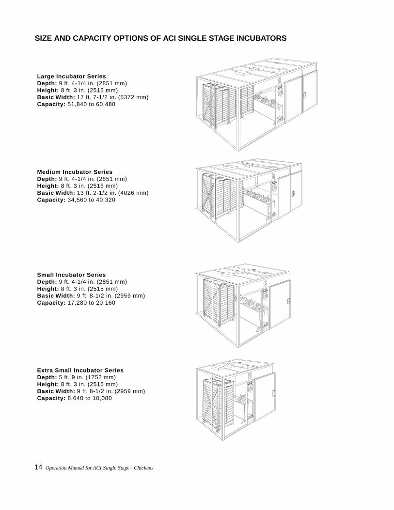
Large Incubator SeriesDepth: 9 ft. 4-1/4 in. (2851 mm)Height: 8 ft. 3 in. (2515 mm)Basic Width: 17 ft. 7-1/2 in. (5372 mm)Capacity: 51,840 to 60,480
Medium Incubator SeriesDepth: 9 ft. 4-1/4 in. (2851 mm)Height: 8 ft. 3 in. (2515 mm)Basic Width: 13 ft. 2-1/2 in. (4026 mm)Capacity: 34,560 to 40,320
Small Incubator SeriesDepth: 9 ft. 4-1/4 in. (2851 mm)Height: 8 ft. 3 in. (2515 mm)Basic Width: 9 ft. 8-1/2 in. (2959 mm)Capacity: 17,280 to 20,160
Extra Small Incubator SeriesDepth: 5 ft. 9 in. (1752 mm)Height: 8 ft. 3 in. (2515 mm)Basic Width: 9 ft. 8-1/2 in. (2959 mm)Capacity: 8,640 to 10,080
JAMESWAY
JAMESWAY
JAMESWAY
SIZE AND CAPACITY OPTIONS OF ACI SINGLE STAGE INCUBATORS
JAMESWAY

Operation Manual for ACI Single Stage - Chickens 15
Medium Hatcher SeriesDepth: 9 ft. 4-1/4 in. (2851 mm)Height: 8 ft. 3 in. (2515 mm)Basic Width: 13 ft. 2-1/2 in. (4026 mm)Capacity: 25,920 to 30,240
Small Hatcher SeriesDepth: 9 ft. 4-1/4 in. (2851 mm)Height: 8 ft. 3 in. (2515 mm)Basic Width: 9 ft. 8-1/2 in. (2959 mm)Capacity: 17,280 to 20,160
Extra Small Hatcher SeriesDepth: 5 ft. 9 in. (1752 mm)Height: 8 ft. 3 in, (2515 mm)Basic Width: 9 ft. 8-1/2 in. (2959 mm)Capacity: 8,640 to 10,080
JAMESWAY
JAMESWAY
JAMESWAY
SIZE AND CAPACITY OPTIONS OF ACI SINGLE STAGE HATCHERS

16 Operation Manual for ACI Single Stage - Chickens
Operation Manual for ACI Single Stage - Chickens 17
Electrical Men
Mechanical
Incu
bato
r R
oom
Hat
cher
Roo
m
Egg Room Clean RoomWash/PullRoom Chick Room
Storage
Sto
rage Office
BreakRoom
Shop
Water
Women
Ple
num
Master Sentry Display
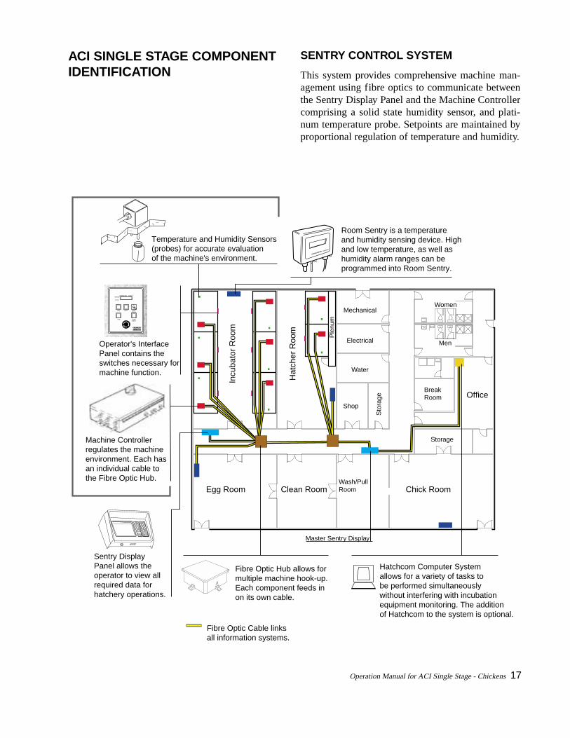
Sentry DisplayPanel allows theoperator to view allrequired data for hatchery operations.
Operator's Interface Panel contains the switches necessary for machine function.
Machine Controllerregulates the machineenvironment. Each has an individual cable to the Fibre Optic Hub.
Temperature and Humidity Sensors(probes) for accurate evaluation of the machine's environment.
Room Sentry is a temperature and humidity sensing device. Highand low temperature, as well as humidity alarm ranges can be programmed into Room Sentry.
Fibre Optic Cable links all information systems.
Fibre Optic Hub allows formultiple machine hook-up.Each component feeds inon its own cable.
Hatchcom Computer Systemallows for a variety of tasks to be performed simultaneouslywithout interfering with incubationequipment monitoring. The additionof Hatchcom to the system is optional.
ALARMCANCEL
TURN
FANS LIGHTS ALARMBYPASS
TEMPERATURE HUMIDITYSETPOINT
ACTUAL
ROOM SENTRY JAMESWAY
ACI SINGLE STAGE COMPONENTIDENTIFICATION
SENTRY CONTROL SYSTEM
This system provides comprehensive machine man-agement using fibre optics to communicate betweenthe Sentry Display Panel and the Machine Controllercomprising a solid state humidity sensor, and plati-num temperature probe. Setpoints are maintained byproportional regulation of temperature and humidity.

18 Operation Manual for ACI Single Stage - Chickens
DISPLAY PANEL
Sentry System display panels should be strategicallylocated throughout the hatchery. Any number of dis-plays can be connected to the network; however, aminimum of one is required for the system to func-tion. Each machine can be accessed from each andevery display. This allows full hatchery monitoring andcontrol from any display connected to the network.
All machine control and performance features areaccessed from the display. This display is menu-drivenallowing the operator to change setpoints, cancel analarm, enter graph data, change alarm parameters, entera profile, etc.
Only one display may be setup as a Master Display.The Master Display is the unit that drives the network.It can be identified by noting the word “Master” in thetop left of its screen. There are several special featuresthat this unit can perform that are not available at otherdisplay panels, such as password enabling/disabling.
FIBRE OPTIC HUB
The fibre optic hub is a data distribution point on thenetwork. Each hub has ten ports. Typically two are re-served for hub to hub communication. The remainingeight are used to connect to machine controllers, dis-play panels, etc. The fibre optic cable is the pathwayfor data on the network and connects hubs to hubs,machines, displays and other optional accessories.
Screen
Alarm Light
Printer Port
Keypad
FIBRE OPTIC HUB POWER SUPPLY WIRING(ACDC or Condor POWER SUPPLY)
LINE VOLTAGE 120 220 230/240 CONNECT 1+2 2+3 2+3 TOGETHER 3+4 LINE
1+4 1+5 1+4CONNECTION TERM . COLOUR 1 RED 2 YELLOW 3 BLUE 4 BLACK 5 ORANGE
PB 4839
Fibre Optic Wiring label located on the inside of the box top.
Power Supply
Fibre OpticBox - closed
Fibre Optic Hub
Circuit Breaker

Operation Manual for ACI Single Stage - Chickens 19
Power Interface Module
Transformer
Power Supply
Sensor Module
MachineController Module
POWER
ALARM
ALARM BY-PASS
This GREEN light indicatesthe power is on. The light flashes when machine is offline.
This RED light signals an alarm state.
This AMBER light indicates that the alarms have been placed in by-pass mode.
ALARMCANCEL
TURN
FANS LIGHTS ALARMBYPASS
TEMPERATURE HUMIDITYSET POINT
ACTUAL
Displays temperatureand humidity, both,set point and actual.
Switching off enables theaudible alarm. This switch hasa key. Once the key is removed the alarm cannot be permanentlydisabled unless the key is used.
Allows an audible alarm to be cancelled for a short period of time. If the alarm is not corrected, the alarm will sound again.
Emergency Stop (Push) Buttonis safety feature of the machine.It allows the machine to be quickly shut down.
Interior light switch
Fan switch (GREEN) turns on the fans, and places the machine in operational mode.
Turn switch allows the eggsto be turned manually, (incubators only).
OPERATOR’S INTERFACE PANEL AND
STATUS LIGHTS
Please refer to Page 87 in the Appendices forconfiguring the Operator’s Interface Panel.
MACHINE CONTROLLER
A Machine Controller is located at each machine.This unit performs both the environment control andmonitoring of the incubator or hatcher. All instru-mentation and control devices are connected to themachine controller.

20 Operation Manual for ACI Single Stage - Chickens
TEMPERATURE AND HUMIDITY PROBE
Platinum Temperature probe - for measuring the am-bient temperature inside the ACI Single Stage machine.
Solid State Humidity Sensor - for measuring the per-centage relative humidity.
ROOM SENTRY - OPTIONAL
Room Sentry can operate as a stand alone unit or beconnected to the Sentry Network by the fibre opticcable. Using a platinum resistance temperature probeand a electronic humidity sensor, Room Sentry givesan immediate response alarm should temperature and/or humidity problems arise. Alarm ranges can bechanged or calibrated remotely if the unit is connectedto a Sentry Display Panel. If the unit is stand alone,the changes and calibration can be done at the unit.
ROOM SENTRY JAMESWAY
TEMPERATURE HUMIDITY
Temperature probemeasures the ambient temperature inside the machine.
Humidity probe measuresthe percentage relativehumidity.
Attach protective cover over humidity probe when washing the machine. Remove afterwards.
Control Cable links the machine controllerand the Temperatureand Humidity Sensors.
Roof

Operation Manual for ACI Single Stage - Chickens 21
Environmental Control UnitFour fans circulate the air.
Damper Drive Box controlsboth air intake and exhaust according to the profiles.
Air in.
Air in.
Air out.
Air out.
VENTILATION, HEAT AND COOLINGSYSTEM
ECU - ENVIRONMENTAL CONTROL UNIT
The Environmental Control Unit provides an optimalconditioned air pattern. Circulation fans mounted inthe ECU force air upward, over the top of the racks,back through the egg mass, and re-enter the modulebelow the heat exchanger (coils) and fans, ensuringthat the air is conditioned before it passes over the eggmass.

22 Operation Manual for ACI Single Stage - Chickens
Frame Assembly with castors mobility allows for ease of cleaning.
Fans and AssemblyFans may be four or five blade,1625 – 60 cycle or 1350 – 50 cycle rpm,1/3 HP, 230 V, 1.9 A.These energy efficient fans provide the airflow in the ACI machines.Fans 1 and 4 rotate clockwise, while fans2 and 3 rotate counter-clockwise pushing airupward.
Side Panel provides the enclosure of the ECU unit.
Humidity Pan Assembly provides water for humidity. Humidity Drum Assembly turnsand picks up water out of humidity pan assembly for dispersion.
Humidity Drum Motor Assembly operates the turning of the humiditydrum for the dispersion of the water for humidity.
Junction Box Assembly
Duct Assembly connects ECU to intake damper opening.
Float Assembly controls the level of water in the humidity pan assembly for proper humidity.
Male & Female Valve Coupler for connection of hot and cold water supply to ECU.
Right and Left Hand Coil Assembly provides circulation of hot and cold water for the heating and cooling functions of the ACI machine. The number of coils per foot varies with the size of the ACI machine.
Fan Assemblies are hinged for ease of cleaning.
ENVIRONMENTAL CONTROL UNIT

Operation Manual for ACI Single Stage - Chickens 23
Solenoid Valve
Cold Water Supply
Hot Water Supply inout
inout
Water Manifold
Check Valves
Front of machine
WATER SUPPLY
For each unit, cold water temperature should be 65°F(18°C) and hot water temperature should be 140°F(60°C). Maximum flow per machine for each is 3 USgal./min. (11.4 L/min). Pressure drop through the unitis 10-12 psig at 3.0 US gal./min. (68.9-82.7 kPa at11.4 L/min). For cooling, Jamesway recommends a re-circulatory system using a water chiller and pump, withfull back up capability. For the boiler and pump, James-way recommends a full re-circulatory system with fullback up capability. Humidity water supply is less than65 psig (448 kPa).
Refer to Water Requirements on page 37.

24 Operation Manual for ACI Single Stage - Chickens
The damper drive box adjusts the air intake and exhaust openings according to the information received from the machine controller.
DAMPER
Air intake is controlled by the damper system to en-sure that the best levels of O
2 and CO
2 are maintained
at all times during the incubation cycle.
• Intake Damper - for fresh air. Located in the lowerfront centre panel.
• Exhaust Damper - Incubator: located on the cen-tre roof panel at the back. Hatcher: located on thecentre back wall panel near the top.
The Damper Control regulates the opening and clos-ing of both the intake and exhaust dampers, main-taining the pre-programmed damper position foreach egg batch. It includes the damper motor as-sembly, plastic drive block and magnet assembly,and printed circuit board (damper position sensors).
HATCHER EXHAUST PLENUM
PlenumOptions
2. TowerPlenum
1. Tower Plenumto ceiling
3. FlushPlenum
EntranceDoor
The hatcher plenum floor should slope towards a com-mon trough that runs along the length of the far wall.The trough should slope 1/2 in. per 10 ft. (4mm/m)towards a common drain located at the end oppositethe entrance door. This floor design will aid ease ofclean out.
Note: This illustration is for reference purposes only.If further details are required, please refer to TheHatchery Design Manual for Single Stage or con-tact a Jamesway representative.

Operation Manual for ACI Single Stage - Chickens 25
EGG ROTATION SYSTEM
COMPRESSED AIR SUPPLY
Compressed air is required for turning the turningactuators of the incubator racks. Requirements are0.05 SCFM (0.085 m3/hr) at 65 psig (448 kPa) per rackper hour.
Optional valve forextension, capped
Valve to each machine formaintenance
Regulator andFilter Assembly
Drain plug
26 Operation Manual for ACI Single Stage - Chickens
FARM, INCUBATOR AND HATCHERRACKS
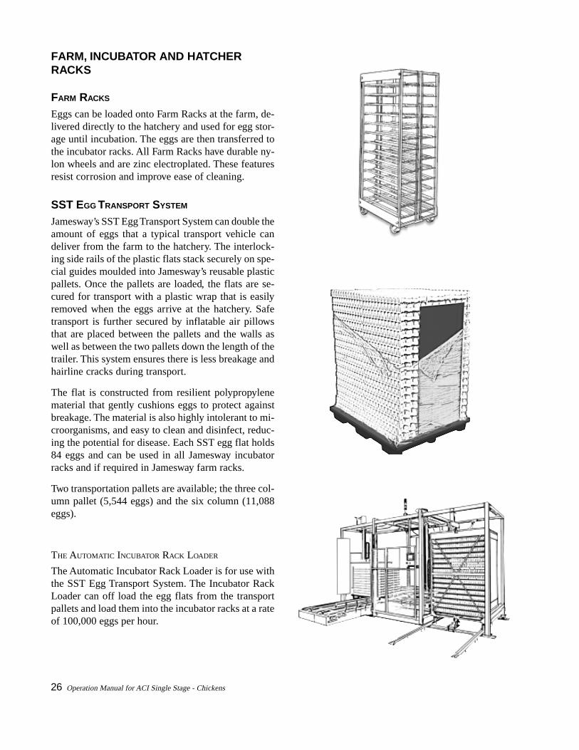
FARM RACKS
Eggs can be loaded onto Farm Racks at the farm, de-livered directly to the hatchery and used for egg stor-age until incubation. The eggs are then transferred tothe incubator racks. All Farm Racks have durable ny-lon wheels and are zinc electroplated. These featuresresist corrosion and improve ease of cleaning.
SST EGG TRANSPORT SYSTEM
Jamesway’s SST Egg Transport System can double theamount of eggs that a typical transport vehicle candeliver from the farm to the hatchery. The interlock-ing side rails of the plastic flats stack securely on spe-cial guides moulded into Jamesway’s reusable plasticpallets. Once the pallets are loaded, the flats are se-cured for transport with a plastic wrap that is easilyremoved when the eggs arrive at the hatchery. Safetransport is further secured by inflatable air pillowsthat are placed between the pallets and the walls aswell as between the two pallets down the length of thetrailer. This system ensures there is less breakage andhairline cracks during transport.
The flat is constructed from resilient polypropylenematerial that gently cushions eggs to protect againstbreakage. The material is also highly intolerant to mi-croorganisms, and easy to clean and disinfect, reduc-ing the potential for disease. Each SST egg flat holds84 eggs and can be used in all Jamesway incubatorracks and if required in Jamesway farm racks.
Two transportation pallets are available; the three col-umn pallet (5,544 eggs) and the six column (11,088eggs).
THE AUTOMATIC INCUBATOR RACK LOADER
The Automatic Incubator Rack Loader is for use withthe SST Egg Transport System. The Incubator RackLoader can off load the egg flats from the transportpallets and load them into the incubator racks at a rateof 100,000 eggs per hour.

Operation Manual for ACI Single Stage - Chickens 27
INCUBATOR RACKS
Each rack is constructed of 30 percent zinc electro-plated and 70 percent hot-dipped galvanized steel, andis equipped with pneumatic cylinders for egg turning,polyurethane (non-kink) air-lines, mercury switch ac-tivated turning indicators, and four injection mouldedplastic wheels.
Each rack holds a variable number of eggs dependingupon egg type and the size of the egg flat.
Incubator Racks can be used as Farm Racks. Eggs canbe loaded onto the Incubator Racks at the farm andremain on the rack until the end of the incubation cy-cle.
HATCHER RACKS
Dollies with plastic baskets are standard equipmentwith ACI Single Stage hatchers. See page 29. Galva-nized steel hatcher racks along with galvanized steelhatcher baskets (shown here) are optional for use inhatchers.
talFggErebmuNtraP
forebmuNtalF/sggE
forebmuNkcaR/stalF
ggElatoTkcaR/yticapaC
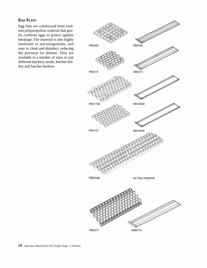
9054BP 63 021 023,4
5124BP 24 021 040,5
B9713BP 48 06 040,5
8744BP 77 06 026,4
6405BP 861 03 040,5
7705BP 48 06 040,5
Type of Rack Maximum Outer Dimensions TraysDepth Width Height
Farm Rack 46.125 in. 26.875 in. 75.5 in. 30
1172 mm 683 mm 1917 mm
Hatcher 49.563 in. 29.5 in. 71.875 in. 30
1259 mm 749 mm 1825 mm
Incubator 49.375 in. 26.5 in. 80.875 in. 30
1254 mm 673 mm 2054 mm
28 Operation Manual for ACI Single Stage - Chickens
EGG FLATS
Egg flats are constructed from resil-ient polypropylene material that gen-tly cushions eggs to protect againstbreakage. The material is also highlyintolerant to microorganisms, andeasy to clean and disinfect, reducingthe potential for disease. They areavailable in a number of sizes to suitdifferent hatchery needs, hatcher dol-lies and hatcher baskets.

Operation Manual for ACI Single Stage - Chickens 29
HATCHER DOLLIES AND HATCHER BASKETS
Hatcher Dollies have double columns for baskets. Theyare zinc electroplated and have durable nylon wheels.These two features resist corrosion and improve easeof cleaning.
Hatcher Baskets are constructed of polyethylene forrigidity, lightweight and stability. The light colour al-lows for quick visual inspection for cleanliness.
Baskets may be stacked 15-high. This allows 30 baskets in total.
Type of Dolly Maximum Outer Dimensions BasketsDepth Width Height
Double Column 50 in. 32 in. 71 in. 30
(Chicken) 1270 mm 813 mm 1803 mm
30 Operation Manual for ACI Single Stage - Chickens
ACCESSORIES
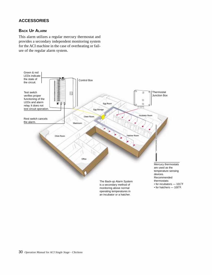
BACK UP ALARM
This alarm utilizes a regular mercury thermostat andprovides a secondary independent monitoring systemfor the ACI machine in the case of overheating or fail-ure of the regular alarm system.
The Back-up Alarm Systemis a secondary method of monitoring above normal operating temperatures in an incubator or a hatcher.
Control Box
Green & red LEDs indicate the state ofthe circuit.
Rest switch cancels the alarm.
Test switchverifies properfunctioning of the LEDs and alarmrelay. It does not test circuit operation.
Mercury thermostatsare used as the temperature sensingdevices. Recommended thermostats:• for incubators — 101˚F• for hatchers — 100˚F.
ThermostatJunction Box
Operation Manual for ACI Single Stage - Chickens 31
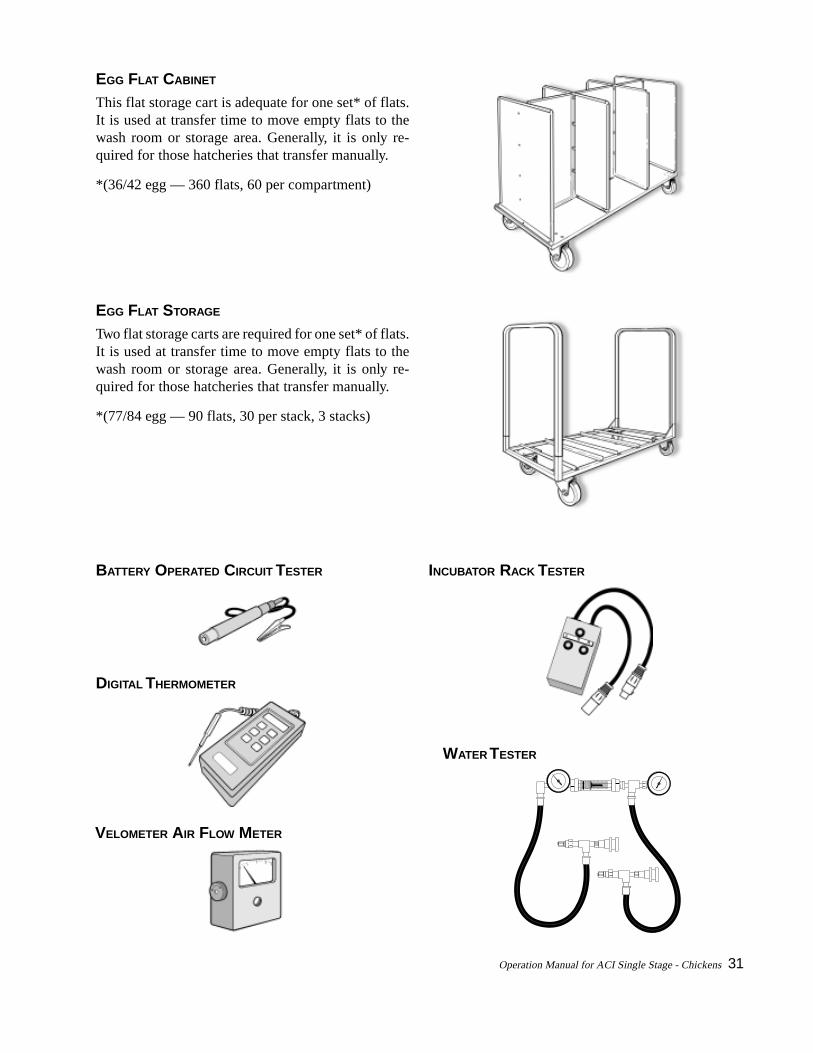
EGG FLAT CABINET
This flat storage cart is adequate for one set* of flats.It is used at transfer time to move empty flats to thewash room or storage area. Generally, it is only re-quired for those hatcheries that transfer manually.
*(36/42 egg — 360 flats, 60 per compartment)
EGG FLAT STORAGE
Two flat storage carts are required for one set* of flats.It is used at transfer time to move empty flats to thewash room or storage area. Generally, it is only re-quired for those hatcheries that transfer manually.
*(77/84 egg — 90 flats, 30 per stack, 3 stacks)
BATTERY OPERATED CIRCUIT TESTER
DIGITAL THERMOMETER
INCUBATOR RACK TESTER
VELOMETER AIR FLOW METER
WATER TESTER

32 Operation Manual for ACI Single Stage - Chickens
Operation Manual for ACI Single Stage - Chickens 33
2. ACI Single Stage Requirements
• ventilation requirements
• water requirements
• electrical requirements
• air requirements

34 Operation Manual for ACI Single Stage - Chickens

Operation Manual for ACI Single Stage - Chickens 35
Egg Room General ConditionsOptimum Temperature, dry bulb 65-68°F 18-20°C
Relative Humidity 75-80% 75-80%
Incubator Room General ConditionsMinimum Temperature, dry bulb 70°F 21°C
Maximum Temperature, dry bulb 85°F 29°C
Optimum Temperature, dry bulb 73°F 23°C
Relative Humidity 50% 50%
VENTILATION REQUIREMENTS
Most modern hatchery operations in use today willimplement a Heating, Ventilation and Air Condition-ing (HVAC) system. The sophistication and type ofsystem will depend largely on climactic as well as eco-nomic conditions. It is recommended that fresh air ofthe correct temperature, humidity and pressurizationbe provided to the area in front of the incubators andhatchers. This conditioned air enters the machinethrough a dampered air intake located on the lowerhalf of the centre post between the doors of the ma-chine.
Normally, the stale air from incubators exhausts di-rectly to the outside atmosphere through an exhaust in
Incubator Room Fresh Air Supply per IncubatorLarge Cabinets 0-175 cfm* 0-300 m3/h
Medium Cabinets 0-125 cfm 0-215 m3/h
Small Cabinets 0-75 cfm 0-130 m3/h
Extra Small Cabinets 0-60 cfm 0-105 m3/h
Room Pressure Differential to outside 0.005-0.015 in. w.g. 1.2-3.7 Pa
* cfm (cubic feet per minute), in.w. g. (inches water gauge), Pa (Pascals)
the rear on the roof, but it is equally feasible to con-nect the machines to a common duct powered exhaust,or to provide individual non-powered machine exhauststhrough the roof of the building. Incubator plenumsare becoming more popular and usually work best witha pressure controlled exhaust fan.
Hatchers should be allowed to vent into a plenum be-hind the machines. This plenum or dust corridor canthen be exhausted naturally or power assisted. An opendrain should be installed in this room to facilitate clean-ing. If this system cannot be used, each hatcher can beindividually exhausted to the outside of the building.Exhaust ducts must be provided with clean-outs atconvenient locations.
EGG ROOM
Avoid direct blasts of cool air onto exposed eggs. Keepthe velocity of the re-circulating air to a minimum.This is necessary to prevent dehydration of the eggs.If eggs are held longer than 7 days, a lower tempera-ture is recommended.
OPTIMUM SETTINGSACI SINGLE STAGE INCUBATOR ROOMS

36 Operation Manual for ACI Single Stage - Chickens
OPTIMUM SETTINGSACI SINGLE STAGE HATCHER ROOMS
* cfm (cubic feet per minute), in.w. g. (inches water gauge), Pa (Pascals)
PULL/WASH ROOM
This room should have a controlled environment forworker and chick comfort. Since this is one of the dirti-est rooms in the hatchery, it is common to have a nega-tive pressure relative to the rest of the hatchery. Thisis achieved by using an exhaust fan with proper pro-portions of make up air.
Pull/Wash Room General ConditionsOptimum Temperature, dry bulb 70-80°F 21-27°C
Chick Room General ConditionsOptimum Temperature, dry bulb 70-80°F 21-27°C
Relative Humidity, %RH 40-50% 40-50%
Fresh Air Supply per 10,000 chicks 300 cfm 510 m3/h
CHICK ROOM
It is very important to provide proper ventilation fornewly hatched chicks. This includes the appropriateamount of outside air as well as proper heating and/orcooling. Although the velocity of the re-circulating airshould be kept to a minimum, it is crucial that all chickshave access to sufficient circulating air. This is neces-sary to provide oxygen to the newly hatched birds.
Hatcher Room General ConditionsMinimum Temperature, dry bulb 70°F 21°C
Maximum Temperature, dry bulb 85°F 29°C
Optimum Temperature, dry bulb 73°F 23°C
Relative Humidity, %RH 50% 50%
Hatcher Room Fresh Air Supply per HatcherMedium Cabinets 50-250 cfm 85-425 m3/h
Small Cabinets 25-100 cfm 40-170 m3/h
Extra Small Cabinets 15-60 cfm 25-105 m3/h
Room Pressure Differential to outside 0.005-0.015 in.w.g. 1.2-3.7 Pa

Operation Manual for ACI Single Stage - Chickens 37
Clean Room General ConditionsOptimum Temperature, dry bulb 70-80°F 21-27°C
CLEAN ROOM
This is the cleanest room in the hatchery and is usedto temporarily store recently cleaned equipment. Itshould have a positive pressure relative to the rest ofthe hatchery and an adequate fresh air supply. It is im-portant to provide an air exchange with outside air toallow drying of the equipment.
WATER REQUIREMENTS
Water supply for ACI machines consists of three sepa-rate systems: Cooling Water, Heating Water and Hu-midity Water.
Cooling Water System General ConditionsOptimum Temperature at unit 65°F 18°C
Optimum Flow per Machine 3 US gal./min. 11.4 L/min
Pressure Drop through Machine 10-12 psig @ 3 US gal./min. 69-82.7 kPa @11.4 L/min
2. HEATING WATER RECOMMENDATIONS
(for coiled heat exchangers, ECU)
Jamesway recommends a re-circulatory system withfull backup capacity (boiler and pumps).
Heating Water General ConditionsOptimum Temperature at ECU 140°F 60°C
Optimum Flow per Machine 3 US gal./min. 11.4 L/min
Pressure Drop through Machine 10-12 psig @ 3 US gal./min. 69-82.7 kPa @11.4 L/min
Note: If holding eggs use 55°F (13°C) for optimum temperature at unit.
1. COOLING WATER SYSTEM
(for incubators and hatchers)
Jamesway recommends a re-circulatory system with afull backup capability (water chiller and pumps).
Note: To properly size your cooling and or heat-ing system for ACI incubators and hatcher pleasecontact your Jamesway representative.

38 Operation Manual for ACI Single Stage - Chickens
RECOMMENDATIONS FOR HUMIDITY WATER SUPPLY
To avoid excessive scale build up, Jamesway recom-mends that the water for humidity meets the follow-ing parameters.
1. Since most hatchery water supplies do not meetthe criteria listed below, treat the water for thehumidity water supply, using a reverse osmosis(RO) or other suitable water treatment system.
2. Separate the humidity water supply from the wa-ter supply to the rest of the hatchery.
3. The pressure must be a minimum of 65 psig (5 bars)at all times. A booster pump may be necessary onthe water line to ensure the minimum pressure ismaintained. The system must be capable of pro-viding each incubator or hatcher with 1.25 US gal.(4.73 L) of water per hour.
4. Water supplied to the incubator and hatcher spraynozzles should meet the following characteristics:
No sediment (a 10 micron filter is suggested).
TDS (Total Dissolved Solids) less than 10.0 ppm(parts per million).
pH range of 6-8.
Hardness less than 2.0 ppm.
No iron, manganese and hydrogen sulfide, oras close to 0.0 ppm as possible.
Bacteria, zero (0) bacteria count (no detectableamount).
Dissolved organic compounds less than 2.0 ppm.
Humidity Water Supply RequirementsUsage per Cabinet 1.25 US gal./h 4.73 L/h
Pressure 65 psig 448 kPa
Room Temperature 70°F 21°C
Room RH 40% 40%
Machine Temperature 100°F 38°C
Machine RH 55% 55%
Average Outside Air Flow 175 cfm 297 m3/h
Humidity water requirements of a typical humidity water supply given theabove conditions.
3. HUMIDITY WATER SUPPLY
(evaporation pan with circulating mesh drum)
Reduced maintenance, cleaner machine interior, mini-mal scale buildup, improved sanitation, longer equip-ment life and optimum machine performance are someof the benefits gained by investing in water quality.
ELECTRICAL REQUIREMENTS
STANDARD
One single pole 20 A circuit breaker protecting eachload carrying conductor. Where two breakers are used,they must be mechanically connected. Total connectedload at 230 V is 7.6 A with a starting load of 9 A. Thisincludes four (4) 230 A, 0.44 kW single phase motors.

Operation Manual for ACI Single Stage - Chickens 39
AIR REQUIREMENTS
COMPRESSED AIR
Compressed air is required for the turning actuatorsof the incubator racks. Requirements are 0.05 cfm(0.0014 m3) at 65 psig (448.175 kPa) per rack onceper hour.
Calculate the total requirement by multiplying theabove base requirement by the total number of racksin the incubator.
Note: When sizing the compressor, the numberof incubators turning simultaneously should betaken into consideration.
Compressed Air Requirements for Turning ActuatorsIncubator Rack CFM/Cabinet M3/Cabinet
Large Cabinet 12 0.6000 0.0168
Medium Cabinet 8 0.4000 0.0112
Small Cabinet 4 0.2000 0.0056
Extra Small Cabinet 2 0.1000 0.0028

40 Operation Manual for ACI Single Stage - Chickens

Operation Manual for ACI Single Stage - Chickens 41
3. ACI Single Stage Profiles
• breeder, broiler guidelines
• layer guidelines

42 Operation Manual for ACI Single Stage - Chickens

Operation Manual for ACI Single Stage - Chickens 43
ACI SINGLE STAGE PROFILES
Variable environments allow for improved perform-ance in different flocks. ACI Single Stage machinescan be programmed to specific settings, which in turnallows flexibility in the environment. The profileslisted here are specifications for an average flock andshould be used as a guideline. Implement profiles foreach particular situation (breed, age of flock, age ofeggs, etc.) that occurs.
BROILER BREEDERS AND BROILERS
Note: Manually disable thehigh humidity alarm for thefirst 10 days of incubation.
Moisture loss plays an im-portant part in the incuba-tion process.
In the example above thedamper is closed until day9. As a consequence highincubator humidity results inreduced moisture loss dur-ing the first 9 days.
To achieve the desiredweight loss the balance ofthe moisture must be lost inthe time remaining.
Warning: The valuesshown in the exampleabove are to be used as aguideline only. The profileis not specific to any lo-cation, and does not takeinto account breed, age offlock or age of egg.
ACI Chicken Incubator 1 - Example Profile 1Days Temperature Humidity Damper
in Cycle °F °C %RH %
0.00 100.2 37.9 70.0 0
0.50 100.2 37.9 70.0 0
3.00 100.2 37.9 70.0 0
4.00 99.8 37.7 70.0 0
6.00 99.8 37.7 70.0 0
9.00 99.7 37.6 65.0 5
10.00 99.6 37.6 65.0 5
11.00 99.5 37.5 61.0 8
12.00 99.4 37.4 58.0 10
13.00 99.3 37.4 58.0 10
13.50 99.2 37.3 54.0 14
14.00 99.1 37.3 52.0 19
14.50 99.0 37.2 50.0 24
15.00 98.9 37.2 49.0 28
15.50 98.8 37.1 48.0 31
16.00 98.7 37.1 47.0 34
17.00 98.6 37.0 46.0 38
18.00 98.6 37.0 46.0 40
18.50 98.6 37.0 46.0 40
44 Operation Manual for ACI Single Stage - Chickens
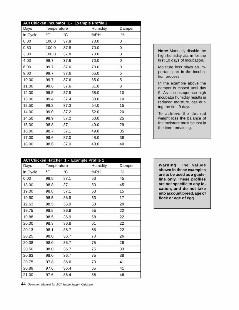
Note: Manually disable thehigh humidity alarm for thefirst 10 days of incubation.
Moisture loss plays an im-portant part in the incuba-tion process.
In the example above thedamper is closed until day9. As a consequence highincubator humidity results inreduced moisture loss dur-ing the first 9 days.
To achieve the desiredweight loss the balance ofthe moisture must be lost inthe time remaining.
Warning: The valuesshown in these examplesare to be used as a guide-line only. These profilesare not specific to any lo-cation, and do not takeinto account breed, age offlock or age of egg.
ACI Chicken Incubator 1 - Example Profile 2Days Temperature Humidity Damper
in Cycle °F °C %RH %
0.00 100.0 37.8 70.0 0
0.50 100.0 37.8 70.0 0
3.00 100.0 37.8 70.0 0
4.00 99.7 37.6 70.0 0
6.00 99.7 37.6 70.0 0
9.00 99.7 37.6 65.0 5
10.00 99.7 37.6 65.0 5
11.00 99.6 37.6 61.0 8
12.00 99.5 37.5 58.0 10
13.00 99.4 37.4 58.0 10
13.50 99.2 37.3 54.0 15
14.00 99.0 37.2 52.0 20
14.50 98.9 37.2 50.0 25
15.00 98.8 37.1 49.0 29
16.00 98.7 37.1 49.0 35
17.00 98.6 37.0 48.0 38
18.00 98.6 37.0 48.0 40
ACI Chicken Hatcher 1 - Example Profile 1Days Temperature Humidity Damper
in Cycle °F °C %RH %
0.00 98.8 37.1 53 45
18.00 98.8 37.1 53 45
19.00 98.8 37.1 53 15
19.50 98.5 36.9 53 17
19.63 98.5 36.9 53 20
19.75 98.5 36.9 55 22
19.88 98.5 36.9 58 22
20.00 98.3 36.8 61 22
20.13 98.1 36.7 65 22
20.25 98.0 36.7 70 26
20.38 98.0 36.7 75 26
20.50 98.0 36.7 75 33
20.63 98.0 36.7 75 38
20.75 97.8 36.6 70 41
20.88 97.6 36.4 65 41
21.00 97.6 36.4 65 46

Operation Manual for ACI Single Stage - Chickens 45
Warning: The valuesshown in these examplesare to be used as a guide-line only. These profilesare not specific to any lo-cation, and do not takeinto account breed, age offlock or age of egg.
ACI Chicken Hatcher 1 - Example Profile 2Days Temperature Humidity Damper
in Cycle °F °C %RH %
0.00 98.5 36.9 55 10
18.00 98.5 36.9 55 10
19.00 98.5 36.9 55 10
19.63 98.5 36.9 55 10
19.75 98.5 36.9 58 15
19.88 98.5 36.9 60 18
20.00 98.5 36.9 63 20
20.13 98.4 36.9 66 25
20.25 98.3 36.8 70 30
20.63 98.3 36.8 70 40
20.75 98.2 36.8 64 48
20.88 98.1 36.7 59 55
21.00 98.0 36.7 56 60
21.13 98.0 36.7 56 60
ACI Chicken Hatcher 1 - Example Profile 3Days Temperature Humidity Damper
in Cycle °F °C %RH %
0.00 98.8 37.1 48.0 15
18.00 98.8 37.1 48.0 15
18.50 98.8 37.1 50.0 15
19.00 98.5 36.9 52.0 15
19.50 98.4 36.9 56.0 25
20.00 98.3 36.8 62.0 35
20.10 98.2 36.8 67.0 40
20.20 98.1 36.7 67.0 40
20.30 98.0 36.7 68.0 50
20.40 97.8 36.6 68.0 50
20.50 97.4 36.3 67.0 60
20.60 97.3 36.3 62.0 60
20.70 97.2 36.2 60.0 60
20.80 97.2 36.2 58.0 80
20.90 97.2 36.2 56.0 80
21.00 97.2 36.2 56.0 80

46 Operation Manual for ACI Single Stage - Chickens
LAYERS
Note: Manually disable thehigh humidity alarm for thefirst 10 days of incubation.
Moisture loss plays an im-portant part in the incuba-tion process.
In the example above thedamper is closed until day5. As a consequence highincubator humidity results inreduced moisture loss dur-ing the first 5 days.
To achieve the desiredweight loss the balance ofthe moisture must be lost inthe time remaining.
Warning: The valuesshown in these examplesare to be used as a guide-line only. These profilesare not specific to any lo-cation, and do not takeinto account breed, age offlock or age of egg.
ACI Chicken Incubator 1 - Example Profile 1Days Temperature Humidity Damper
in Cycle °F °C %RH %
0.00 100.4 38.0 70.0 0
0.50 100.4 38.0 70.0 0
2.00 100.4 38.0 70.0 0
3.00 100.2 37.9 70.0 0
3.50 100.1 37.8 70.0 0
5.00 100.0 37.8 65.0 5
8.50 99.9 37.7 65.0 5
10.00 99.8 37.7 61.0 8
11.00 99.7 37.6 58.0 10
12.00 99.6 37.6 58.0 10
13.00 99.5 37.5 54.0 14
13.50 99.4 37.4 52.0 19
14.00 99.3 37.4 50.0 24
14.50 99.2 37.3 49.0 28
15.00 99.1 37.3 48.0 31
16.00 99.0 37.2 47.0 34
17.00 99.0 37.2 46.0 38
18.00 99.0 37.2 46.0 40
19.00 99.0 37.2 46.0 40

Operation Manual for ACI Single Stage - Chickens 47
Warning: The valuesshown in these examplesare to be used as a guide-line only. These profilesare not specific to any lo-cation, and do not takeinto account breed, age offlock or age of egg.
Note: Manually disable thehigh humidity alarm for thefirst 10 days of incubation.
Moisture loss plays an im-portant part in the incuba-tion process.
In the example above thedamper is closed until day3. As a consequence highincubator humidity results inreduced moisture loss dur-ing the first 3 days.
To achieve the desiredweight loss the balance ofthe moisture must be lost inthe time remaining.
ACI Chicken Incubator 1 - Example Profile 2Days Temperature Humidity Damper
in Cycle °F °C %RH %
0.00 100.4 38.0 70.0 0
1.00 100.4 38.0 70.0 0
2.00 100.2 37.9 70.0 0
3.00 100.0 37.8 70.0 5
4.00 100.0 37.8 70.0 5
5.00 100.0 37.8 65.0 5
6.00 99.8 37.7 65.0 10
8.00 99.8 37.7 61.0 10
9.00 99.6 37.6 58.0 15
11.00 99.6 37.6 58.0 15
13.00 99.4 37.4 54.0 20
14.00 99.2 37.3 52.0 25
15.00 99.0 37.2 50.0 30
15.50 98.8 37.1 49.0 35
16.00 98.6 37.0 49.0 40
17.00 98.6 37.0 48.0 45
18.00 98.6 37.0 48.0 45

48 Operation Manual for ACI Single Stage - Chickens
Warning: The valuesshown in these examplesare to be used as a guide-line only. These profilesare not specific to any lo-cation, and do not takeinto account breed, age offlock or age of egg.
ACI Chicken Hatcher 1 - Example Profile 1Days Temperature Humidity Damper
in Cycle °F °C %RH %
0.00 99.2 37.3 55 15
18.00 99.2 37.3 55 15
19.00 99.0 37.2 55 15
19.50 98.9 37.2 55 15
19.88 98.9 37.2 58 20
20.00 98.9 37.2 61 20
20.13 98.7 37.1 64 20
20.25 98.6 37.0 67 25
20.38 98.6 37.0 70 25
20.50 98.5 36.9 72 30
20.63 98.5 36.9 72 35
20.75 98.5 36.9 71 40
20.88 98.2 36.8 68 40
21.00 98.0 36.7 65 45
21.13 97.9 36.6 65 45
21.25 97.8 36.6 65 50
ACI Chicken Hatcher 1 - Example Profile 2Days Temperature Humidity Damper
in Cycle °F °C %RH %
0.00 99.0 37.2 60 15
18.00 99.0 37.2 60 15
19.00 98.8 37.1 60 20
19.75 98.6 37.0 62 20
19.88 98.6 37.0 64 20
20.00 98.6 37.0 66 25
20.13 98.5 36.9 68 30
20.25 98.5 36.9 70 30
20.38 98.5 36.9 70 30
20.50 98.4 36.9 70 35
20.63 98.3 36.8 70 40
20.75 98.3 36.8 70 45
20.88 98.3 36.8 66 50
21.00 98.2 36.8 62 55
21.13 98.1 36.7 60 55
21.25 98.0 36.7 60 60
21.38 98.0 36.7 60 65
21.50 98.0 36.7 60 65

Operation Manual for ACI Single Stage - Chickens 49
4. OperationalProcedures• egg handling basics
• obtaining & storing eggs
• transferring eggs from farmracks to incubator racks
• start-up
• setting procedures
• guidelines for egg setting &transfer procedures
• transferring eggs from incuba-tor racks to hatcher baskets
• wash & sanitize incubators
• hatching eggs
• wash & sanitize hatchers

50 Operation Manual for ACI Single Stage - Chickens
Operation Manual for ACI Single Stage - Chickens 51
PROCEDURES
EGG HANDLING BASICS
Store eggs small end down from the time of collec-tion.
During transportation, keep the temperature as uniformas possible to prevent condensation, and avoid tem-perature shocks, especially during loading and unload-ing.
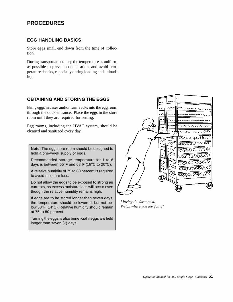
OBTAINING AND STORING THE EGGS
Bring eggs in cases and/or farm racks into the egg roomthrough the dock entrance. Place the eggs in the storeroom until they are required for setting.
Egg rooms, including the HVAC system, should becleaned and sanitized every day.
Note: The egg store room should be designed tohold a one-week supply of eggs.
Recommended storage temperature for 1 to 6days is between 65°F and 68°F (18°C to 20°C).
A relative humidity of 75 to 80 percent is requiredto avoid moisture loss.
Do not allow the eggs to be exposed to strong aircurrents, as excess moisture loss will occur eventhough the relative humidity remains high.
If eggs are to be stored longer than seven days,the temperature should be lowered, but not be-low 58°F (14°C). Relative humidity should remainat 75 to 80 percent.
Turning the eggs is also beneficial if eggs are heldlonger than seven (7) days.
Moving the farm rack.Watch where you are going!
52 Operation Manual for ACI Single Stage - Chickens
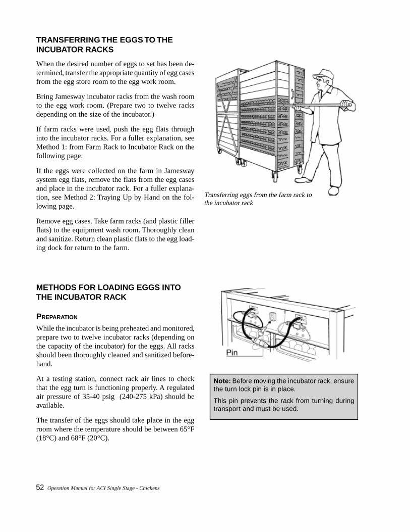
TRANSFERRING THE EGGS TO THEINCUBATOR RACKS
When the desired number of eggs to set has been de-termined, transfer the appropriate quantity of egg casesfrom the egg store room to the egg work room.
Bring Jamesway incubator racks from the wash roomto the egg work room. (Prepare two to twelve racksdepending on the size of the incubator.)
If farm racks were used, push the egg flats throughinto the incubator racks. For a fuller explanation, seeMethod 1: from Farm Rack to Incubator Rack on thefollowing page.
If the eggs were collected on the farm in Jameswaysystem egg flats, remove the flats from the egg casesand place in the incubator rack. For a fuller explana-tion, see Method 2: Traying Up by Hand on the fol-lowing page.
Remove egg cases. Take farm racks (and plastic fillerflats) to the equipment wash room. Thoroughly cleanand sanitize. Return clean plastic flats to the egg load-ing dock for return to the farm.
METHODS FOR LOADING EGGS INTOTHE INCUBATOR RACK
PREPARATION
While the incubator is being preheated and monitored,prepare two to twelve incubator racks (depending onthe capacity of the incubator) for the eggs. All racksshould been thoroughly cleaned and sanitized before-hand.
At a testing station, connect rack air lines to checkthat the egg turn is functioning properly. A regulatedair pressure of 35-40 psig (240-275 kPa) should beavailable.
The transfer of the eggs should take place in the eggroom where the temperature should be between 65°F(18°C) and 68°F (20°C).
Note: Before moving the incubator rack, ensurethe turn lock pin is in place.
This pin prevents the rack from turning duringtransport and must be used.
Transferring eggs from the farm rack tothe incubator rack
Operation Manual for ACI Single Stage - Chickens 53
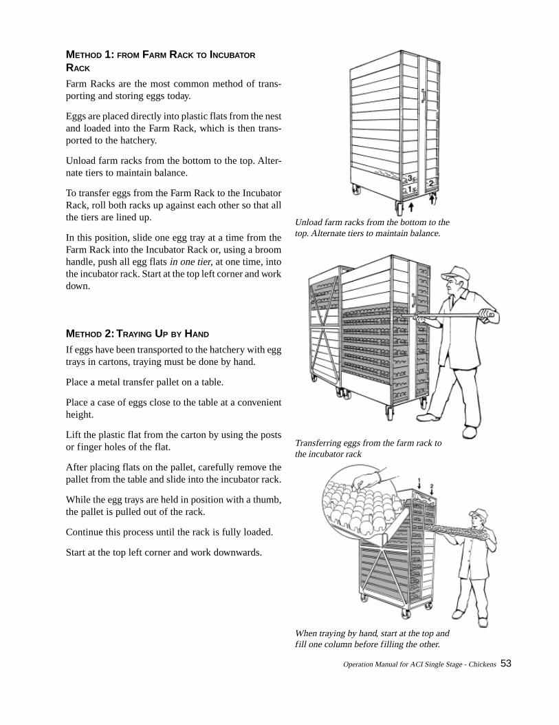
METHOD 1: FROM FARM RACK TO INCUBATOR
RACK
Farm Racks are the most common method of trans-porting and storing eggs today.
Eggs are placed directly into plastic flats from the nestand loaded into the Farm Rack, which is then trans-ported to the hatchery.
Unload farm racks from the bottom to the top. Alter-nate tiers to maintain balance.
To transfer eggs from the Farm Rack to the IncubatorRack, roll both racks up against each other so that allthe tiers are lined up.
In this position, slide one egg tray at a time from theFarm Rack into the Incubator Rack or, using a broomhandle, push all egg flats in one tier, at one time, intothe incubator rack. Start at the top left corner and workdown.
METHOD 2: TRAYING UP BY HAND
If eggs have been transported to the hatchery with eggtrays in cartons, traying must be done by hand.
Place a metal transfer pallet on a table.
Place a case of eggs close to the table at a convenientheight.
Lift the plastic flat from the carton by using the postsor finger holes of the flat.
After placing flats on the pallet, carefully remove thepallet from the table and slide into the incubator rack.
While the egg trays are held in position with a thumb,the pallet is pulled out of the rack.
Continue this process until the rack is fully loaded.
Start at the top left corner and work downwards.
Transferring eggs from the farm rack tothe incubator rack
Unload farm racks from the bottom to thetop. Alternate tiers to maintain balance.
When traying by hand, start at the top andfill one column before filling the other.
54 Operation Manual for ACI Single Stage - Chickens
METHOD 3: AUTOMATED
A vacuum lift may be used to load eggs into the eggflats. Refer to equipment manufacturer’s instructionsfor proper operation.
LOADING A FULL SET
Place two to twelve racks side by side, depending onsize of incubator.
Start with the first tray at the top left tier of the incu-bator rack.
Load eggs working downward until the first tier is full.
Continue loading eggs, starting with the top of the righttier. Work top to bottom.
After completing the second or right tier of the firstrack, repeat the process to fill all racks required.
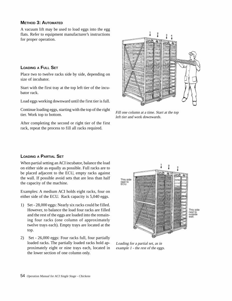
LOADING A PARTIAL SET
When partial setting an ACI incubator, balance the loadon either side as equally as possible. Full racks are tobe placed adjacent to the ECU, empty racks againstthe wall. If possible avoid sets that are less than halfthe capacity of the machine.
Examples: A medium ACI holds eight racks, four oneither side of the ECU. Rack capacity is 5,040 eggs.
1) Set - 28,000 eggs: Nearly six racks could be filled.However, to balance the load four racks are filledand the rest of the eggs are loaded into the remain-ing four racks (one column of approximatelytwelve trays each). Empty trays are located at thetop.
2) Set - 26,000 eggs: Four racks full, four partiallyloaded racks. The partially loaded racks hold ap-proximately eight or nine trays each, located inthe lower section of one column only.
Fill one column at a time. Start at the topleft tier and work downwards.
Loading for a partial set, as inexample 1 - the rest of the eggs.
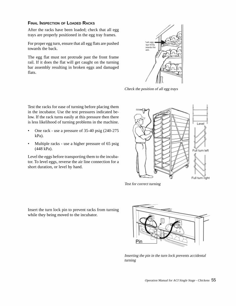
Operation Manual for ACI Single Stage - Chickens 55
FINAL INSPECTION OF LOADED RACKS
After the racks have been loaded; check that all eggtrays are properly positioned in the egg tray frames.
For proper egg turn, ensure that all egg flats are pushedtowards the back.
The egg flat must not protrude past the front framerail. If it does the flat will get caught on the turningbar assembly resulting in broken eggs and damagedflats.
Test the racks for ease of turning before placing themin the incubator. Use the test pressures indicated be-low. If the rack turns easily at this pressure then thereis less likelihood of turning problems in the machine.
• One rack - use a pressure of 35-40 psig (240-275kPa).
• Multiple racks - use a higher pressure of 65 psig(448 kPa).
Level the eggs before transporting them to the incuba-tor. To level eggs, reverse the air line connection for ashort duration, or level by hand.
Insert the turn lock pin to prevent racks from turningwhile they being moved to the incubator.
Check the position of all egg trays
Test for correct turning
Inserting the pin in the turn lock prevents accidentalturning
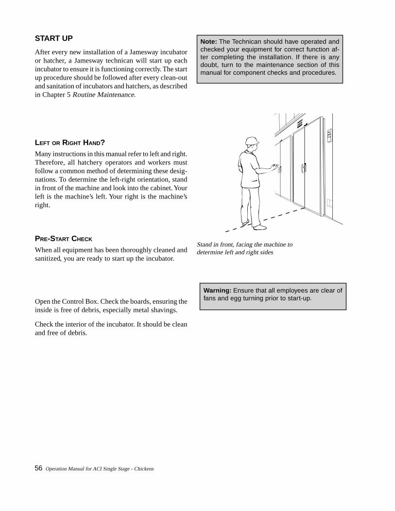
56 Operation Manual for ACI Single Stage - Chickens
START UP
After every new installation of a Jamesway incubatoror hatcher, a Jamesway technican will start up eachincubator to ensure it is functioning correctly. The startup procedure should be followed after every clean-outand sanitation of incubators and hatchers, as describedin Chapter 5 Routine Maintenance.
LEFT OR RIGHT HAND?Many instructions in this manual refer to left and right.Therefore, all hatchery operators and workers mustfollow a common method of determining these desig-nations. To determine the left-right orientation, standin front of the machine and look into the cabinet. Yourleft is the machine’s left. Your right is the machine’sright.
PRE-START CHECK
When all equipment has been thoroughly cleaned andsanitized, you are ready to start up the incubator.
Open the Control Box. Check the boards, ensuring theinside is free of debris, especially metal shavings.
Check the interior of the incubator. It should be cleanand free of debris.
Stand in front, facing the machine todetermine left and right sides
Note: The Technican should have operated andchecked your equipment for correct function af-ter completing the installation. If there is anydoubt, turn to the maintenance section of thismanual for component checks and procedures.
Warning: Ensure that all employees are clear offans and egg turning prior to start-up.

Operation Manual for ACI Single Stage - Chickens 57
INITIAL START UP
Before using the machine for the first time, orafter a period of prolonged inactivity, it is recom-mended to test the machine by carrying out thefollowing checks.
1. Turn on the power to the machine.
2. Access the “Machine State” screen from thedisplay unit of the Sentry Network and check toensure the machine is functioning normally:
• Environment: Check temperature and humid-ity against a recommended device.
• Status: check all operating functions.
• Damper position: check operation.
• Alarms: check correct operation.
3. Make any changes to the setpoints by access-ing the “Change Setpoint” screen.
This screen shows the humidity on when temperature hasreached setpoint. The damper is closing.
The screen shows cooling on when temperature is abovesetpoint. The damper is opening.
This screen shows communication alarm, etc. You cannotproceed and check if machine is functioning normallywhen a communication alarm is active. Temperature andhumidity readings will not update on display.
Note: Check and operate all functions for atleast 24 hours before attempting to set eggsin a new machine.
Note: Following the check, the machine shouldbe left to operate at incubation temperaturefor a minimum of 24 hours.

58 Operation Manual for ACI Single Stage - Chickens
SETTING PROCEDURES
Generally speaking, if eggs are set at a specific time,the pull time should be 21 days later, plus or minus 4 to6 hours, depending on breed and age of flock.
Before loading the incubator check the profile. Is itcorrect for the type of eggs to be incubated?
LOADING RACKS INTO THE INCUBATOR
Open door.
Switch off fans (if on).
Remove threshold.
Ensure the ECU (Environmental Control Unit) is cor-rectly positioned.
Push in racks, one by one, filling all positions on ei-ther side. Load the racks against the wall first.
Connect air lines. Ensure all lines are fastened securely.Connect air lines of racks nearest the wall to air lineshanging from the ceiling; match colours. Connect rackair lines of similar colour to those of adjoining racks.Air lines of racks adjacent to the ECU are connectedto the air lines hanging from the ceiling above the ECU.
Connect turn indicator cables. Connect the cables ofthe racks nearest the side wall to the cord hanging fromthe ceiling. Connect the male plug to the female socketof adjoining racks. The cable of the rack adjacent tothe ECU is connected to the drop cord hanging fromthe ceiling above.
Press the Manual Turn Button on the Display Panel toactivate the air valve. The incubator racks will turnthrough 90°. This is an additional check to see if all airlines have been correctly connected. (Alarm willsound.)
Pull racks from either the front orthe back. Watch where you aregoing!
Connecting air lines
Connecting air turn cables
Warning: During air line hook up no alarm willsound. Ensure employees do not have fingers inthe racks as the racks will turn, possibly causinginjury.

Operation Manual for ACI Single Stage - Chickens 59
SWITCHING ON THE INCUBATOR
Check that the start-up temperature and humid-ity are correctly set on the Display Unit.
Turn on the fans by depressing the fan switch onthe front of the machine once. Wait a few sec-onds for the fans to start up. Check turning. Pressthe "Turn" switch on the Operator Interface Panel.The warning buzzer sounds for several secondsprior to the turn. Once turning is complete, checkthe Display screen. The TURN VALVE: shouldindicate "ON" when the RACK LOCATION:shows "LEFT". TURN VALVE: and RACK LO-CATION: should be "OFF" and "RIGHT" respec-tively (see "Typical start-up screen"), when theracks are turned in the opposite direction. Pressthe turn button again to return racks to the origi-nal position.
Check the following on the display unit of theSentry Network to ensure that the machine isfunctioning normally:
• System Alarms; Low Temp. & Low Humid-ity - flashing.
• System status; Damper position, heating,fans.
• Temperature and Humidity readouts.
• Alarm lamp on front of machine - flashing.
• Temperature Setpoint.
• Humidity Setpoint.
This is a typical screen after a machine has been loadedand incubation initiated. Alarm override is active,profile #1 is active, and both machine low temperatureand low humidity alarms have not been cancelled.
Typical start-up screen
Setup alarm override for desired period – e.g., if ma-chine takes 6 hours to achieve setpoint override lowtemperature, low humidity, and high humidity for 6.0hours.
Enable alarm by turning key. Alarm light goes out (Re-fer to Sentry Display Manual for further details).
Note: The left half of the incubator should beused as an indicator of whether or not turningis correct.
Warning: During air line hook up no alarm willsound. Ensure employees do not have fingersin the racks as the racks will turn, possibly caus-ing injury.
Note: If the profiles in this manual are used,the High Humidity alarms should be disabledduring the first 10 days.
Note: Check calibration once the machine hascome up to temperature and settled down. It isrecommended that incubator calibration shouldbe checked after every set with a thermometerverified for accuracy.
Note: In the event of a power outage incubatordoors must be opened to prevent overheating ofeggs. If eggs in the incubator are at 14 days ofincubation or older remove racks from cabinet.

60 Operation Manual for ACI Single Stage - Chickens
GUIDELINES FOR EGG SETTING ANDTRANSFER PROCEDURES
A variety of methods can be used with success in theACI Single Stage machine, as long as some guide-lines are followed.
It is important that eggs be grouped and identified fromfarm all the way through to the hatch process. Oncethe eggs are in the egg room, determine when theywill be set into the incubator. Group the total set to-gether, with each rack identified. Number each rackof eggs according to its location in the incubator.Record the location of each rack on a set sheet.
At transfer time, the location and identity of the eggsmust be maintained. Once transfer from the incubatorhas begun, complete the process into the hatcher with-out delay. Take care not to damage the eggs.
Remove one incubator rack at a time from the incuba-tor. Locate the new position of the eggs in the hatcher.Transfer. When eggs are transferred into the hatcherracks their location and identity must be recorded forthe chick processing.
Remember:
• During transfer, handle eggs with care.
• Do not transfer eggs into wet hatcher baskets.
• Do not bang the basket down on the table duringtransfer.
• Do not slam or tilt baskets in the racks or dollies.
• Once transfer has started, it must be completedfor all of the racks.
• Do not allow eggs to cool excessively during trans-fer.
• Do not remove all incubator racks from one sideand then the other side.
• Do not remove racks without levelling eggs first.
• Do not flip eggs too quickly during transfer. Turnin a smooth gently rotating motion.
• Ensure all racks or dollies are positioned properlyin the hatchers.
It is extremely important that a balanced air flowin the incubator and hatchers be maintained whilethe transfer is in progress. Do not remove all theeggs first on one side of the incubator and thenon the other side as this may cause air flow dis-ruption and overheating.
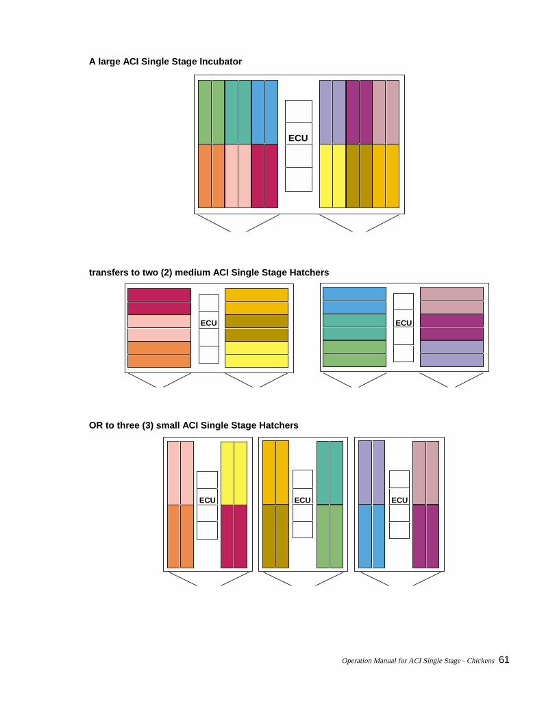
Operation Manual for ACI Single Stage - Chickens 61
A large ACI Single Stage Incubator
transfers to two (2) medium ACI Single Stage Hatchers
OR to three (3) small ACI Single Stage Hatchers
ECU
ECU ECU
ECU ECU ECU
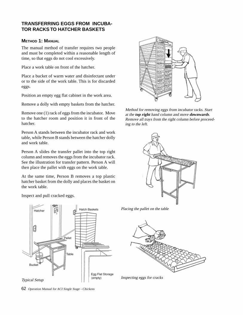
62 Operation Manual for ACI Single Stage - Chickens
TRANSFERRING EGGS FROM INCUBA-TOR RACKS TO HATCHER BASKETS
METHOD 1: MANUAL
The manual method of transfer requires two peopleand must be completed within a reasonable length oftime, so that eggs do not cool excessively.
Place a work table on front of the hatcher.
Place a bucket of warm water and disinfectant underor to the side of the work table. This is for discardedeggs.
Position an empty egg flat cabinet in the work area.
Remove a dolly with empty baskets from the hatcher.
Remove one (1) rack of eggs from the incubator. Moveto the hatcher room and position it in front of thehatcher.
Person A stands between the incubator rack and worktable, while Person B stands between the hatcher dollyand work table.
Person A slides the transfer pallet into the top rightcolumn and removes the eggs from the incubator rack.See the illustration for transfer pattern. Person A willthen place the pallet with eggs on the work table.
At the same time, Person B removes a top plastichatcher basket from the dolly and places the basket onthe work table.
Inspect and pull cracked eggs.
Inspecting eggs for cracks
Placing the pallet on the table
Method for removing eggs from incubator racks. Startat the top right hand column and move downwards.Remove all trays from the right column before proceed-ing to the left.
Typical Setup
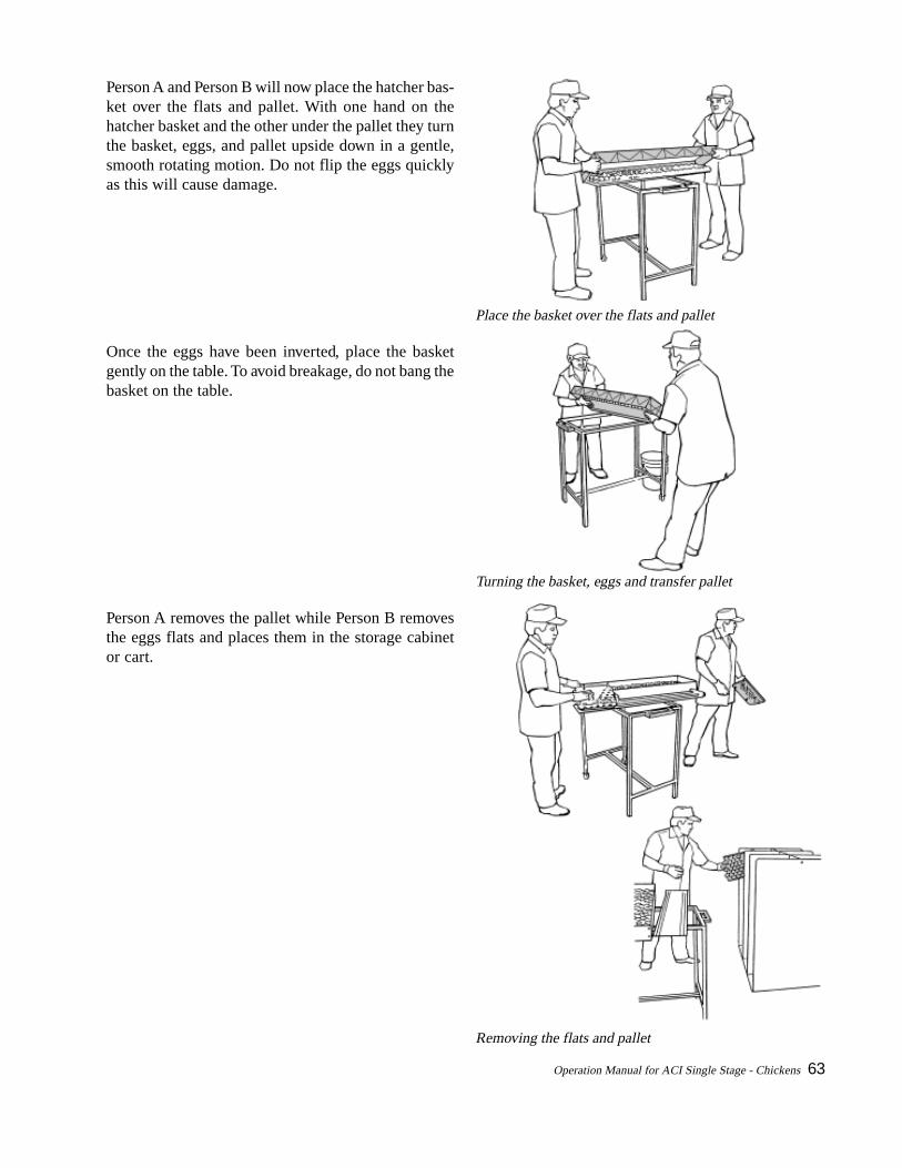
Operation Manual for ACI Single Stage - Chickens 63
Person A and Person B will now place the hatcher bas-ket over the flats and pallet. With one hand on thehatcher basket and the other under the pallet they turnthe basket, eggs, and pallet upside down in a gentle,smooth rotating motion. Do not flip the eggs quicklyas this will cause damage.
Once the eggs have been inverted, place the basketgently on the table. To avoid breakage, do not bang thebasket on the table.
Person A removes the pallet while Person B removesthe eggs flats and places them in the storage cabinetor cart.
Turning the basket, eggs and transfer pallet
Place the basket over the flats and pallet
Removing the flats and pallet

64 Operation Manual for ACI Single Stage - Chickens
Person A picks up the hatcher basket filled with eggsand places it on the right hand side of an emptyhatcher dolly. Do not slam the basket into the dollyas eggs will be damaged. Person A now takes an-other empty basket and places it on the table.
Continue removing the trays of eggs from the rightcolumn in an downward direction. (See illustrationon page 60.) Continue placing hatcher baskets witheggs on right side of dolly. Stack one column at atime.
When all the eggs have been transferred, place thehatcher dolly into the hatcher and close the hatcherdoor.
Remove the empty incubator racks from the workarea and return to the incubator for the next rack.
Place them in front of the hatcher, leaving as muchwork space as possible, allowing easy access to thehatcher door.
Repeat the process as described above until all eggshave been transferred.
TO FINISH THE TRANSFER
Switch on the fans.
Install thresholds.
Close the hatcher door.
When machine has reached temperature and humid-ity setpoint, enable alarm. To test machine alarmswitch the fans off momentarily. The alarm shouldsound. Alternatively, depress and hold ALARM CAN-CEL button until alarm sounds.
When all hatchers have been transferred go to Dis-play and check that profiles are active and machinesare functioning correctly. (See Sentry Control Sys-tem Display Panel Guide for further details)
When the transfer is complete, the empty incubatorracks must be cleaned and sanitized before reload-ing.
Hatcher baskets are first stacked on the right hand side.The right stack will contain all the eggs from the rightcolumn of the incubator rack. The left stack will containall the eggs from the left column of the incubator rack.
Has the machine reached both temperature andhumidity setpoints? If so, enable the alarm.
ALARMCANCEL
TURN
FANS LIGHTS ALARMBYPASS
TEMPERATURE HUMIDITYSET POINT
ACTUAL
98.5 F98.4 F
58 % RH58 % RH
Note: Check hatcher calibration bi-weekly (everyfourth hatch). Use thermometer which has beenverified for accuracy.
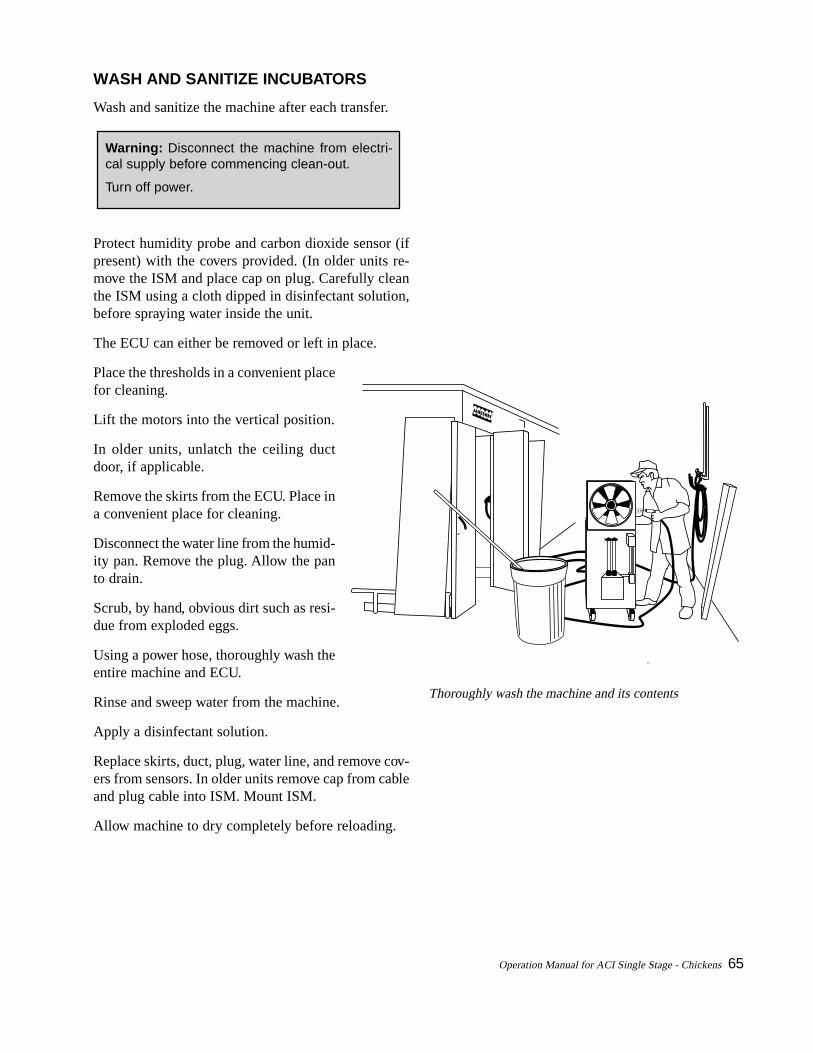
Operation Manual for ACI Single Stage - Chickens 65
WASH AND SANITIZE INCUBATORS
Wash and sanitize the machine after each transfer.
Warning: Disconnect the machine from electri-cal supply before commencing clean-out.
Turn off power.
Protect humidity probe and carbon dioxide sensor (ifpresent) with the covers provided. (In older units re-move the ISM and place cap on plug. Carefully cleanthe ISM using a cloth dipped in disinfectant solution,before spraying water inside the unit.
The ECU can either be removed or left in place.
Place the thresholds in a convenient placefor cleaning.
Lift the motors into the vertical position.
In older units, unlatch the ceiling ductdoor, if applicable.
Remove the skirts from the ECU. Place ina convenient place for cleaning.
Disconnect the water line from the humid-ity pan. Remove the plug. Allow the panto drain.
Scrub, by hand, obvious dirt such as resi-due from exploded eggs.
Using a power hose, thoroughly wash theentire machine and ECU.
Rinse and sweep water from the machine.
Apply a disinfectant solution.
Replace skirts, duct, plug, water line, and remove cov-ers from sensors. In older units remove cap from cableand plug cable into ISM. Mount ISM.
Allow machine to dry completely before reloading.
Thoroughly wash the machine and its contents
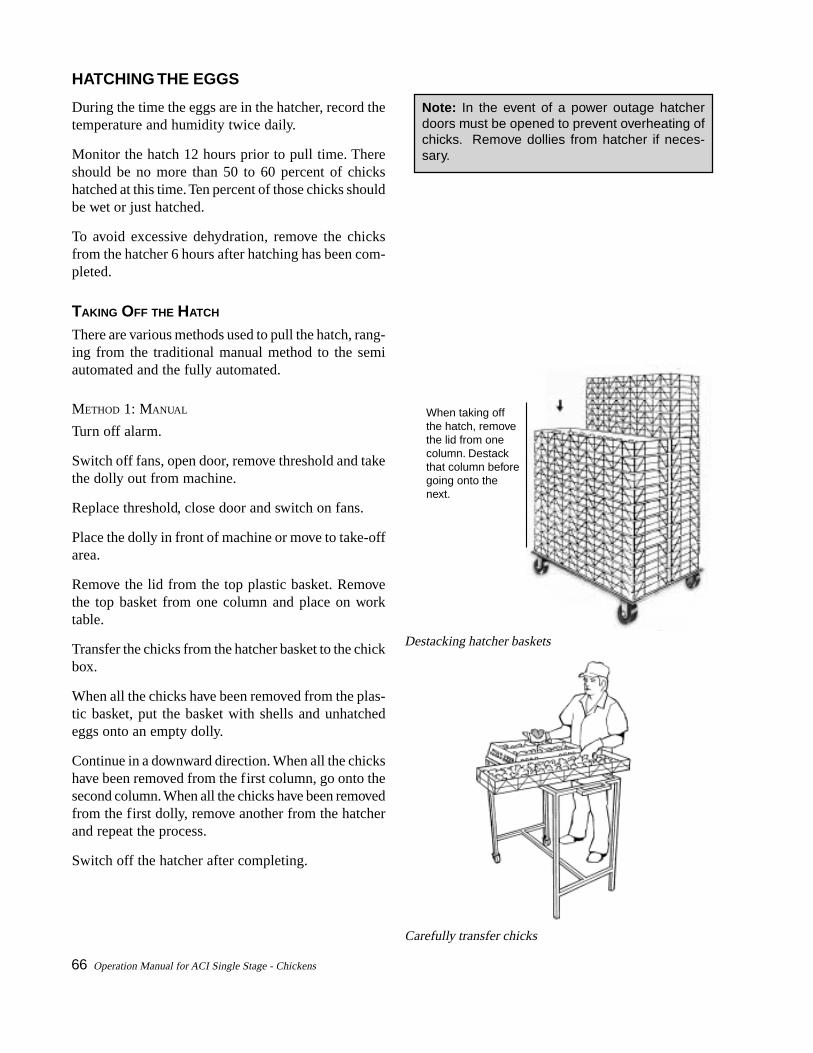
66 Operation Manual for ACI Single Stage - Chickens
HATCHING THE EGGS
During the time the eggs are in the hatcher, record thetemperature and humidity twice daily.
Monitor the hatch 12 hours prior to pull time. Thereshould be no more than 50 to 60 percent of chickshatched at this time. Ten percent of those chicks shouldbe wet or just hatched.
To avoid excessive dehydration, remove the chicksfrom the hatcher 6 hours after hatching has been com-pleted.
TAKING OFF THE HATCH
There are various methods used to pull the hatch, rang-ing from the traditional manual method to the semiautomated and the fully automated.
METHOD 1: MANUAL
Turn off alarm.
Switch off fans, open door, remove threshold and takethe dolly out from machine.
Replace threshold, close door and switch on fans.
Place the dolly in front of machine or move to take-offarea.
Remove the lid from the top plastic basket. Removethe top basket from one column and place on worktable.
Transfer the chicks from the hatcher basket to the chickbox.
When all the chicks have been removed from the plas-tic basket, put the basket with shells and unhatchedeggs onto an empty dolly.
Continue in a downward direction. When all the chickshave been removed from the first column, go onto thesecond column. When all the chicks have been removedfrom the first dolly, remove another from the hatcherand repeat the process.
Switch off the hatcher after completing.
When taking offthe hatch, removethe lid from onecolumn. Destackthat column beforegoing onto the next.
Destacking hatcher baskets
Carefully transfer chicks
Note: In the event of a power outage hatcherdoors must be opened to prevent overheating ofchicks. Remove dollies from hatcher if neces-sary.
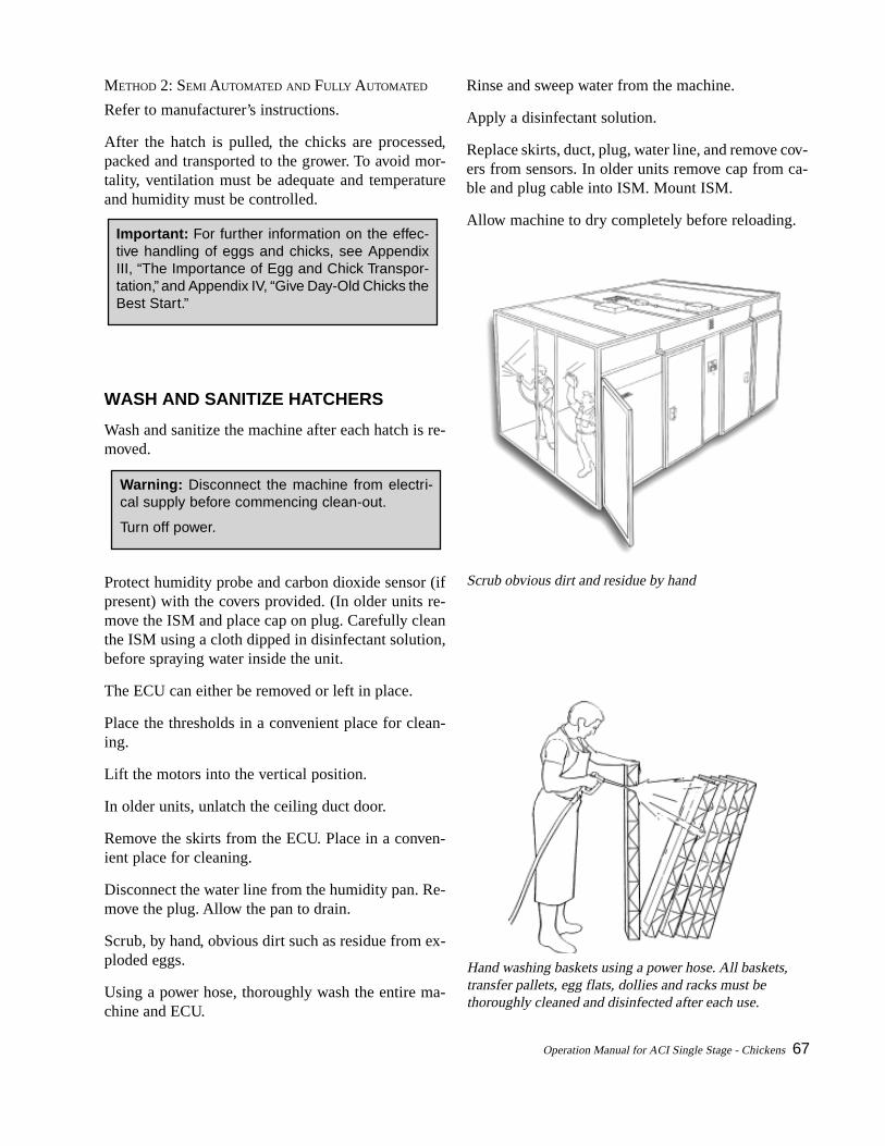
Operation Manual for ACI Single Stage - Chickens 67
METHOD 2: SEMI AUTOMATED AND FULLY AUTOMATED
Refer to manufacturer’s instructions.
After the hatch is pulled, the chicks are processed,packed and transported to the grower. To avoid mor-tality, ventilation must be adequate and temperatureand humidity must be controlled.
Warning: Disconnect the machine from electri-cal supply before commencing clean-out.
Turn off power.
Important: For further information on the effec-tive handling of eggs and chicks, see AppendixIII, “The Importance of Egg and Chick Transpor-tation,” and Appendix IV, “Give Day-Old Chicks theBest Start.”
WASH AND SANITIZE HATCHERS
Wash and sanitize the machine after each hatch is re-moved.
Protect humidity probe and carbon dioxide sensor (ifpresent) with the covers provided. (In older units re-move the ISM and place cap on plug. Carefully cleanthe ISM using a cloth dipped in disinfectant solution,before spraying water inside the unit.
The ECU can either be removed or left in place.
Place the thresholds in a convenient place for clean-ing.
Lift the motors into the vertical position.
In older units, unlatch the ceiling duct door.
Remove the skirts from the ECU. Place in a conven-ient place for cleaning.
Disconnect the water line from the humidity pan. Re-move the plug. Allow the pan to drain.
Scrub, by hand, obvious dirt such as residue from ex-ploded eggs.
Using a power hose, thoroughly wash the entire ma-chine and ECU.
Rinse and sweep water from the machine.
Apply a disinfectant solution.
Replace skirts, duct, plug, water line, and remove cov-ers from sensors. In older units remove cap from ca-ble and plug cable into ISM. Mount ISM.
Allow machine to dry completely before reloading.
Hand washing baskets using a power hose. All baskets,transfer pallets, egg flats, dollies and racks must bethoroughly cleaned and disinfected after each use.
Scrub obvious dirt and residue by hand

68 Operation Manual for ACI Single Stage - Chickens

Operation Manual for ACI Single Stage - Chickens 69
5. Routine Maintenance
• daily
• weekly
• after every transfer/wash
• 3 month
• 6 month

70 Operation Manual for ACI Single Stage - Chickens

Operation Manual for ACI Single Stage - Chickens 71
MAINTENANCE
TIME SCHEDULES
DAILY
Access the “Machine State” screen on the display unitof the Sentry Network and check the temperature,humidity and damper positions against the setpoints.
Check the machine functions.
Check the profile number and day in cycle.
Visually check the automatic drain attached to the fil-ter on the incubator compressed air regulator. This canbe done when the compressed air pressure reading istaken. If water has built up inside the unit, the auto-matic drain components may have failed and will needreplacing.
WEEKLY
Drain Compressor Tank. All compressors come witha drain petcock located underneath the pressure ves-sel. Open the petcock and drain until the air escapingis clear of water or vapour.
AFTER EVERY TRANSFER/WASH
Door and Threshold Seals. Check for torn or miss-ing door seals. Replace if worn or damaged. Good doorseals are required for proper air flow.
Racks. After washing the incubator racks, greasewheels and castor plate bearings. One or two pumpson the grease gun are adequate. More than this causesthe grease to be forced out through the rubber seals.
Check the turning operation. Use an air line connectedto a 35-40 psig (240-275 kPa) supply. If there is anyrubbing or binding locate the problem area and rec-tify.
Check the turn sensors and cables by using a batteryoperated turn tester.
Drain plug
Air Regulator

72 Operation Manual for ACI Single Stage - Chickens
Fan Vibration. Either remove the ECU (Environmen-tal Control Unit) and connect to 220 V supply, or enterthe machine with the fans running and check the fansfor excessive vibration.
If you are unable to read the nameplate clearly the fanis vibrating too much. Switch off the fans. Disconnectthe defective motor. Switch the fans back on. If allvibration ceases, replace the motor or the fan blade.
THREE MONTH MAINTENANCE SCHEDULE
Perform these checks only when the machine is empty.
Check the Control Box. Open the Control Box andexamine the Sentry boards, wiring connections andrelay contacts for obvious faults such as discolouredwiring and burnt or blackened areas. Pay special at-tention to the terminals or connections and relay points.Disconnect the Control Box from electrical supply, andvacuum interior if dust or down has accumulated. Makesure that the boards and plug connections are firmlyseated after vacuuming. Warning: If the power has notbe turned off, use extra caution during examination.
Check the Damper System. The knob on the damperdrive box will indicate that the damper is closing oropening. From the Sentry Display Unit access the“Change Setpoint” screen and alter the damper posi-tion. Then climb to the roof of the machine and ensurethat the damper acts accordingly.
If the damper is not moving, the motor may need to bereplaced.
If the knob on the drive box is turning but the damperis not moving, replace the plastic drive block on thethreaded rod in the damper drive.
Check the RPM of the drive motor. It should be turn-ing at 6 RPM.
Check that both the intake and exhaust damper slidesare free and not binding anywhere. At the same timeensure that both openings are equal.
See also:
Appendix V, Hatchery Sanitation: Concepts, Logis-tics and Assessment,
Appendix VI, Practical Hatchery Sanitation Guide-lines, and
Appendix VII, What to Do with Hatchery Waste.
Note: Allow the fans to stop completely beforeswitching them back on. If you do not, some ofthe fans may run backwards. All fans should beblowing the air upwards. If a fan is running back-ward switch off, remove and repair (capacitormay be defective).
Warning: Turn off the power before discon-necting or changing a motor.
ECU and Water Hoses. Check for leaks.
Humidity Drum. Check that the humidity drum isrotating by depressing and holding the "Turn" switchon the Operator Interface Panel. The drum should ro-tate freely.

Operation Manual for ACI Single Stage - Chickens 73
MAINTENANCE SCHEDULE FOR ACI INCUBATORS AND HATCHERS
All of the items mentioned below should be checked, as scheduled.Actual readings should be recorded and compared with the optimum.All other items should be assessed as to their operating condition – either satisfactory orunsatisfactory.Unsatisfactory would include not operating properly, excessive wear, dirt or any potentialproblem. Items, not in satisfactory condition, should be repaired or replaced, and/or cleanedprior to further use.
ITEMS TO BE CHECKED TIME SCHEDULE
Incubators Hatchers Both Both
After Every Monthly Every Every
Transfer/Wash 3 Months 6 Months
A) Temperature Calibration
1. Display reading °F or °C
2. Check reading °F or °C
3. Set point °F or °C
B) Humidity Calibration
1. Set point RH °FWB or °CWB
2. Display reading RH °FWB or °CWB
3. Check reading RH °FWB or °CWB
C) Compressed Air
1. Reading
2. Water build up?
3. Tank - drain
D) General Machine
1. Doors seal properly
2. Doors latch properly
3. Door Gasket condition
4. Threshold gasket condition
5. Caulking - all joints
6. Damper zero position
7. Damper operating properly. See page 69.
8. Damper motor, 6 rpm
9. Damper slides not binding
10. Damper openings equal
11. Water hose connections
12. Water hose couplings
13. Air lines
14. Air connections
15. Turning drop cords
*denotes weekly

74 Operation Manual for ACI Single Stage - Chickens
ITEMS TO BE CHECKED TIME SCHEDULE
Incubators Hatchers Both Both
After Every Monthly Every Every
Transfer/Wash 3 Months 6 Months
16. Temperature sensor condition
17. RH Sensor
18. RH Cover
19. CO2
sensor (optional)
20. CO2
cover
21. ECU track & guides
22. ECU umbilical cable
E) Environmental Control Unit (ECU)
1. Fan condition (vibration?)
2. Fan rotation
3. Junction box
4. Junction receptacle
5. Heating & cooling coils
6. Heating & cooling quick-c. couplers
7. Humidity drum
8. Humidity motor
9. Water pan and float valve
10. Castors - grease
11. Castor plate bearings - grease
F) Controls
Switch off power to control box! Failure to do so may result in electrical shock.
Note: It is absolutely necessary that the control box be clean and free of any dirt (especially metal filings),and moisture for proper operation. Boards, relays, connections and wires will discolour if there is excessiveheat. Excessive heat usually is caused by poor connections. Problem should be corrected as required.
1. Control box - clean, vacuum if required
2. Control box - check for moisture
3. Lid assembly, relays and connections
4. Board – clean, vacuum if necessary
5. Board condition
6. Board plugs firmly seated
7. Wiring condition
8. Water manifold and valve condition
Operator Interface Panel (OIP)
9. OIP LCD display
10. OIP fan switch
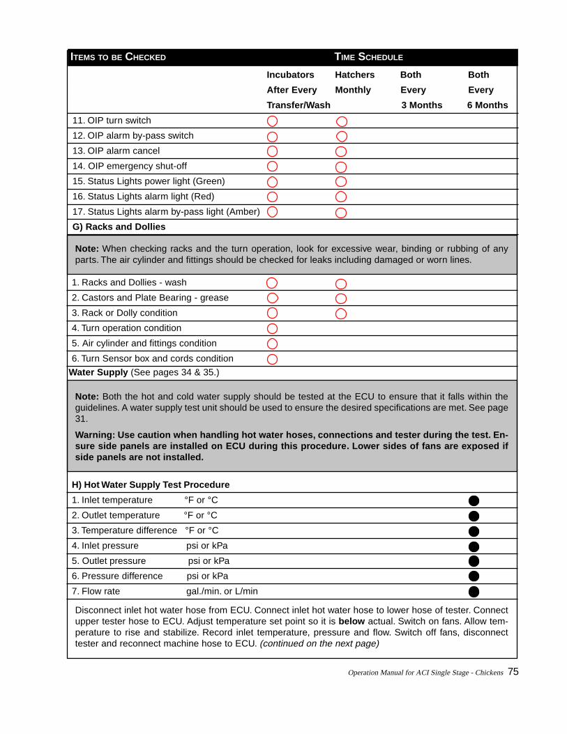
Operation Manual for ACI Single Stage - Chickens 75
ITEMS TO BE CHECKED TIME SCHEDULE
Incubators Hatchers Both Both
After Every Monthly Every Every
Transfer/Wash 3 Months 6 Months
11. OIP turn switch
12. OIP alarm by-pass switch
13. OIP alarm cancel
14. OIP emergency shut-off
15. Status Lights power light (Green)
16. Status Lights alarm light (Red)
17. Status Lights alarm by-pass light (Amber)
G) Racks and Dollies
Note: When checking racks and the turn operation, look for excessive wear, binding or rubbing of anyparts. The air cylinder and fittings should be checked for leaks including damaged or worn lines.
1. Racks and Dollies - wash
2. Castors and Plate Bearing - grease
3. Rack or Dolly condition
4. Turn operation condition
5. Air cylinder and fittings condition
6. Turn Sensor box and cords condition
Water Supply (See pages 34 & 35.)
Note: Both the hot and cold water supply should be tested at the ECU to ensure that it falls within theguidelines. A water supply test unit should be used to ensure the desired specifications are met. See page31.
Warning: Use caution when handling hot water hoses, connections and tester during the test. En-sure side panels are installed on ECU during this procedure. Lower sides of fans are exposed ifside panels are not installed.
H) Hot Water Supply Test Procedure
1. Inlet temperature °F or °C
2. Outlet temperature °F or °C
3. Temperature difference °F or °C
4. Inlet pressure psi or kPa
5. Outlet pressure psi or kPa
6. Pressure difference psi or kPa
7. Flow rate gal./min. or L/min
Disconnect inlet hot water hose from ECU. Connect inlet hot water hose to lower hose of tester. Connectupper tester hose to ECU. Adjust temperature set point so it is below actual. Switch on fans. Allow tem-perature to rise and stabilize. Record inlet temperature, pressure and flow. Switch off fans, disconnecttester and reconnect machine hose to ECU. (continued on the next page)
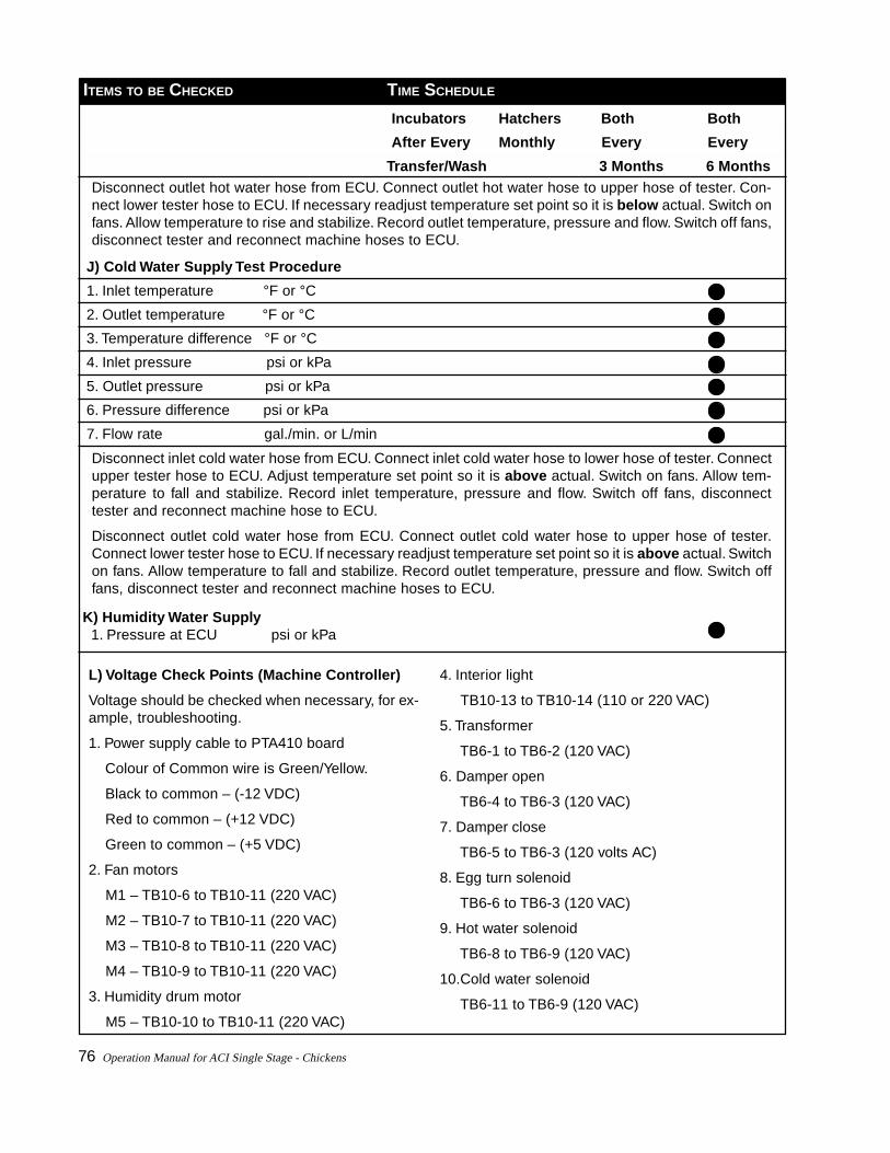
76 Operation Manual for ACI Single Stage - Chickens
ITEMS TO BE CHECKED TIME SCHEDULE
Incubators Hatchers Both Both
After Every Monthly Every Every
Transfer/Wash 3 Months 6 Months
J) Cold Water Supply Test Procedure
1. Inlet temperature °F or °C
2. Outlet temperature °F or °C
3. Temperature difference °F or °C
4. Inlet pressure psi or kPa
5. Outlet pressure psi or kPa
6. Pressure difference psi or kPa
7. Flow rate gal./min. or L/min
L) Voltage Check Points (Machine Controller)
Voltage should be checked when necessary, for ex-ample, troubleshooting.
1. Power supply cable to PTA410 board
Colour of Common wire is Green/Yellow.
Black to common – (-12 VDC)
Red to common – (+12 VDC)
Green to common – (+5 VDC)
2. Fan motors
M1 – TB10-6 to TB10-11 (220 VAC)
M2 – TB10-7 to TB10-11 (220 VAC)
M3 – TB10-8 to TB10-11 (220 VAC)
M4 – TB10-9 to TB10-11 (220 VAC)
3. Humidity drum motor
M5 – TB10-10 to TB10-11 (220 VAC)
4. Interior light
TB10-13 to TB10-14 (110 or 220 VAC)
5. Transformer
TB6-1 to TB6-2 (120 VAC)
6. Damper open
TB6-4 to TB6-3 (120 VAC)
7. Damper close
TB6-5 to TB6-3 (120 volts AC)
8. Egg turn solenoid
TB6-6 to TB6-3 (120 VAC)
9. Hot water solenoid
TB6-8 to TB6-9 (120 VAC)
10.Cold water solenoid
TB6-11 to TB6-9 (120 VAC)
Disconnect outlet hot water hose from ECU. Connect outlet hot water hose to upper hose of tester. Con-nect lower tester hose to ECU. If necessary readjust temperature set point so it is below actual. Switch onfans. Allow temperature to rise and stabilize. Record outlet temperature, pressure and flow. Switch off fans,disconnect tester and reconnect machine hoses to ECU.
Disconnect inlet cold water hose from ECU. Connect inlet cold water hose to lower hose of tester. Connectupper tester hose to ECU. Adjust temperature set point so it is above actual. Switch on fans. Allow tem-perature to fall and stabilize. Record inlet temperature, pressure and flow. Switch off fans, disconnecttester and reconnect machine hose to ECU.
Disconnect outlet cold water hose from ECU. Connect outlet cold water hose to upper hose of tester.Connect lower tester hose to ECU. If necessary readjust temperature set point so it is above actual. Switchon fans. Allow temperature to fall and stabilize. Record outlet temperature, pressure and flow. Switch offfans, disconnect tester and reconnect machine hoses to ECU.
K) Humidity Water Supply 1. Pressure at ECU psi or kPa

Operation Manual for ACI Single Stage - Chickens 77
6. Chick Development & Troubleshooting Hatchability
• chicken embryology
• analysing chick residue

78 Operation Manual for ACI Single Stage - Chickens

Operation Manual for ACI Single Stage - Chickens 79
CHICK DEVELOPMENT ANDTROUBLESHOOTINGHATCHABILITY
CHICKEN EMBRYOLOGY, THE TIMINGOF MAJOR EMBRYONIC DEVELOP-MENTS
BEFORE EGG LAYING
Fertilization
Division and growth of living cells
Segregation of cells into groups of special func-tion (gastrulation)
BETWEEN LAYING AND INCUBATION
No growth, state of inactive embryonic life
DURING INCUBATION
DAY 1
Development of area pellucids and area opaca ofblastoderm
Major developments visible under microscope
18 hours, Appearance of alimentary tract
19 hours, Beginning of brain crease
20 hours, Appearance of vertebral column
21 hours, Beginning of formation of brain andnervous system
22 hours, Beginning of formation of head
23 hours, Appearance of blood islands
24 hours, Beginning of formation of eyes
DAY 2
Embryo begins to turn on left side
Blood vessels appear in the yolk sac
Major developments visible under microscope:
25 hours, Beginning of formation of veins andheart
30 hours, Second, third and fourth vesicles of brainclearly defined, as is heart, which now starts tobeat
35 hours, Beginning of formation of ear pits
36 hours, First sign of amnion
46 hours, Formation of throat
DAY 3
Beginning of formation of nose, wings, legs, al-lantois
Amnion completely surrounds embryo

80 Operation Manual for ACI Single Stage - Chickens
DAY 4
Beginning of formation of tongue
Embryo completely separates from yolk sac andturned on left side
Allantois breaks through amnion
DAY 5
Preventriculus and gizzard formed
Formation of reproductive organs - sex division
DAY 6
Beginning of formation of beak and eggtooth
Main division of legs and wings
Voluntary movement begins
DAY 7
Indication of digits in legs and wings
Abdomen more prominent due to development ofviscera
DAY 8
Beginning of formation of feathers
DAY 9
Embryo begins to look bird-like
Mouth opening appears
DAY 10
Beak start to harden
Skin pores visible to naked aye
Digits completely separated
DAY 12
Toes fully formed
First few visible feathers
DAY 13
Appearance of scales and claws
Body fairly well covered with feathers
DAY 14
Embryo turns its heat towards blunt end of egg
DAY 15
Small intestines taken into body
DAY 16
Scales, claws, and beak becoming firm and horny
Embryo fully covered with feathers
Albumen nearly gone, yolk increasingly importantas nutriment
DAY 17
Beak turns toward air cell, amniotic fluid de-creases, and embryo begins preparation for hatch-ing
DAY 18
Growth of embryo nearly complete
DAY 19
Yolk sac draws into body cavity through umbili-cus
Embryo occupies most of space with in egg ex-cept air cell
DAY 20
Yolk sac completely drawn into body cavity
Embryo becomes chick, breaks amnion, startsbreathing in air cell
Allantois ceases to function and starts to dry up
DAY 21
Chick hatches

Operation Manual for ACI Single Stage - Chickens 81
ANALYSING HATCH RESIDUE
Analysing hatch residue is a useful hatchery manage-ment tool that will provide valuable information in iso-lating problems in both the breeder and the hatcheryprograms.
The following is a list of problems that may be ob-served and there possible cause(s).
1. CHICKS HATCH LATE
Possible causes:
Variable room temperature
Large eggs
Old eggs
Incorrect thermometer
Temperature to low, 1 to 19 days
Humidity too low, 1 to 19 days
Temperature too low in hatchery
2. FULLY DEVELOPED EMBRYO WITH BEAK NOT INAIR CELL
Possible causes:
Inadequate breeder ration
Temperature too high, 1 to 10 days
Humidity too high, 19th day
3. FULLY DEVELOPED EMBRYO WITH BEAK IN AIR
CELL
Possible causes:
Inadequate breeder ration
Incubator air circulation poor
Temperature too high, 20 to 21 days
Humidity too high, 20 to 21 days
Shell quality
4. CHICKS PIPPING EARLY
Possible causes:
Temperature too high, 1 to 19 days
Humidity too low, 1 to 19 days
5. CHICK DEAD AFTER PIPPING SHELL
Possible causes:
Inadequate breeder ration
Lethal genes
Disease in breeder flock
Eggs incubated small end up
Thin-shelled eggs
Eggs not turned first two weeks
Eggs transferred too late
Inadequate air circulation, 20 to 21 days
CO2 content of air too high, 20 to 21 days
Incorrect temperature, 1 to 19 days
Temperature too high, 20 to 21 days
Humidity too low, 20 to 21 days
6. MALPOSITIONS
Possible causes:
Inadequate breeder ration
Egg set small end up
Odd-shaped eggs set
Inadequate turning
7. STICKY CHICKS (ALBUMEN STICKING TO CHICKS)Possible causes:
Eggs transferred too late
Temperature too high, 20 to 21 days
Humidity too low, 20 to 21 days
Down collectors not adequate

82 Operation Manual for ACI Single Stage - Chickens
8. STICKY CHICKS (ALBUMEN STICKING TO DOWN)Possible causes:
Old eggs
Air speed too slow, 20 to 21 days
Inadequate air in incubator
Temperature too high, 20 to 21 days
Humidity too high, 20 to 21 days
Down collectors inadequate
9. CHICKS COVERED WITH EGG REMNANTS
Possible causes:
Nutrition
Humidity too high
Temperature too low
10. EGGS EXPLODING
Possible causes:
Bacterial contamination of eggs
Dirty eggs
Improperly washed eggs
Incubator infection
11. CLEAR EGGS
Possible causes:
Infertile
Eggs held improperly
Too much egg fumigation
Very early embryonic mortality
Immature males
Male-female ratio
Females fat
Parasites
Nutrition
Overcrowding flock
12. BLOOD RING (EMBRYONIC DEATH 2-4 DAYS)Possible causes:
Heredity
Diseased breeding flock
Old eggs
Rough handling of hatching eggs
Incubating temperature too high
Incubating temperature too low
Holding temperature
Contamination
Shell quality
Young flock
Nutrition
Humidity
Fumigation
Insufficient turning of eggs
13. DEAD EMBRYOS, 2ND WEEK OF INCUBATION
Possible causes:
Inadequate breeder ration
Disease in breeder flock
Eggs not cooled prior to incubation
Temperature too high in incubator
Temperature too low in incubator
Electrical power failure
Eggs not turned
Too much CO2 in air (inadequate ventilation)
Genetics
Contamination
Shell quality
Humidity

Operation Manual for ACI Single Stage - Chickens 83
14. AIR CELL TOO SMALL
Possible causes:
Inadequate breeder ration
Large eggs
Humidity too high, 1 to 19 days
15. AIR CELL TOO LARGE
Possible causes:
Small eggs
Humidity too low, 1 to 19 days
16. CHICKS HATCH EARLY
Possible causes:
Small eggs
Leghorn eggs versus meat-type eggs
Incorrect thermometer
Temperature too high, 1 to 19 days
Humidity too low, 1 to 19 days
17. CHICKS TOO SMALL
Possible causes:
Eggs produced in hot weather
Small eggs
Thin, porous eggshells
Humidity too low, 1 to 19 days
18. CHICKS TOO LARGE
Possible causes:
Large eggs
Humidity too high, 1 to 19 days
19. TRAYS NOT UNIFORM IN HATCH OR CHICK
QUALITY
Possible causes:
Eggs from different breeds
Eggs of different sizes
Eggs of different ages when set
Disease or stress in some breeder flocks
Inadequate incubation air circulation & heat dis-tribution
20. SOFT CHICKS
Possible causes:
Unsanitary incubator conditions
Temperature too low, 1 to 19 days
Humidity too high, 20 to 21 days
21. CHICKS DEHYDRATED
Possible causes:
Eggs set too early
Humidity too low, 20 to 21 days
Chicks left in hatcher too long after hatching com-pleted
22. MUSHY CHICKS
Possible cause:
Unsanitary incubator conditions
23. UNHEALED NAVEL, DRY
Possible causes:
Inadequate breeder ration
Temperature too low, 20 to 21 days
Wide temperature variation in incubator
Humidity too high, 20 to 21 days
Humidity not lowered after hatching completed

84 Operation Manual for ACI Single Stage - Chickens
24. UNHEALED NAVEL, WET AND WITH ODOUR
Possible cause:
Omphalitis
Unsanitary hatchery and incubators
25. CHICKS CANNOT STAND
Possible causes:
Breeder ration inadequate
Improper temperature, 1 to 21 days, overheating
Humidity too high, 1 to 19 days
Inadequate ventilation, 1 to 21 days
26. CRIPPLED CHICKS
Possible causes:
Inadequate breeder ration
Variation in temperature, 1 to 21 days
Malpositions
27. CROOKED TOES
Possible causes:
Inadequate breeder ration
Improper temperature, 1 to 19 days
28. SPRADDLE LEGS
Possible cause:
Hatchery trays too smooth
29. SHORT DOWN
Possible causes:
Inadequate breeder ration
High temperature
30. CLOSED EYES
Possible causes:
Temperature too high, 20 to 21 days
Humidity too low, 20 to 21 days
Loose down in hatcher
Down collectors not adequate

Operation Manual for ACI Single Stage - Chickens 85
7. Appendices• operator’s interface panel configuration menu
• carbon dioxide sensor operating instructions
• the importance of egg & chick transportation
• give day old chicks the best start
• hatchery sanitation concepts, logistics & assessment
• practical hatchery sanitation guidelines
• what to do with hatchery waste
• breakout analyses guide for hatcheries

86 Operation Manual for ACI Single Stage - Chickens

Operation Manual for ACI Single Stage - Chickens 87
APPENDICES
APPENDIX I: OPERATOR’S INTERFACEPANEL CONFIGURATION MENU
If a PTA537 Operator’s Interface Panel, which incor-porates an LCD display, is used with machine control-ler software PTA453 version 1.27 or later then thefollowing features are available:
• Sensor Calibration,
• Alarm Viewing, and
• Setpoints Adjustments.
TO ACCESS THESE FEATURES
1. Activate the ALARM BYPASS key switch and
2. Simultaneously press down the TURN and ALARM
CANCEL button.
The display will change to CALIBRATION? on the firstline.
The second line shows the available menu options.
TO SELECT THE AVAILABLE MENU OPTIONS
They can be selected using the following three but-tons on the panel:
TURN - to choose the left item
Lights - to choose the centre item
ALARM CANCEL - to choose the right item
Normal operation of these three buttons is suspendedwhile the menu is active. Pressing the LIGHTS buttonfor example will not turn on the interior light whenthe menus are active.
If the TURN and ALARM CANCEL buttons are pressedwith the ALARM BYPASS key deactivated, the displaywill change to the secondary information screen whichshows the machine address, profile day in cycle, and
other machine type dependent information. Use thesame two buttons to switch to the regular temperatureand humidity readout.
TO START THE CALIBRATION FUNCTION
The first menu function is CALIBRATION? It will showYES EXIT NO as the available menu options.
TO START THE CALIBRATION FUNCTION
Press the TURN button to select YES, or
Press ALARM CANCEL to select NO and view more func-tions. The ALARMS? function will appear. Choosing NO
again will show SETPOINTS?. Choosing NO again willreturn to the Calibration Menu.
Choose EXIT to return to the regular temperature andhumidity readout display.
CALIBRATION
When the calibration menu is selected, you will beasked to calibrate temperature or humidity.
• Press TURN to calibrate temperature, or
• Press ALARM CANCEL to calibrate humidity.
In both cases, use the TURN button ( + ) to adjust thereading higher and the ALARM CANCEL ( - ) to adjust itlower.
The buttons can be held down to change it morequickly. The readings will also shift higher and loweras the machine’s sensor readings change.
Once the reading matches the thermometer orelectrotherm press the LIGHTS button to continue.
TO KEEP THE NEW SETTINGS
• Press TURN (Yes) to change the offset, or
• Press ALARM CANCEL (No) to leave the offset un-changed. The ALARM BYPASS could also be turnedoff to cancel the changes.
Note: The menus can be exited at any time byturning off the ALARM BYPASS key switch.

88 Operation Manual for ACI Single Stage - Chickens
Note: If the humidity setpoint is changed in degreeswet bulb units, it may not be possible to choose thedesired value if this change is to be followed by alarge dry bulb change.
Change the dry bulb setpoint first, then change thewet bulb setpoint.
When the dry bulb setting is changed by a largeamount, the current wet bulb setting may be out ofrange which causes the machine to give a NOVRAM/RTC FAILURE alarm and use default setpoints. Thisalarm will go away once the wet bulb setpoint ischanged to a valid number.
Always check afterwards that the machine is oper-ating with the correct setpoints.
ALARMS
This function allows you to see all active alarms onthe machine. The display continually cycles throughthe alarms until the screen is exited.
The ALARM CANCEL button can be pressed to acknowl-edge the alarms.
You will be asked whether to enable alarm override.
• Press TURN (Yes) to activate alarm override.
• Press ALARM CANCEL (No) to acknowledge alarms.
Note: Calibration always takes place in units as se-lected on the master display panel.
If the machine uses a relative humidity sensor andit is calibrated in wet bulb units (or vice versa), makesure that the dry bulb temperature has been cali-brated at least 5 minutes prior because the conver-sion routines are affected by the dry bulbtemperature. Also the conversion routines may addsome error.
Note: Acknowledged alarms will not be shown untilthey return to the alarming state. The alarm over-ride functionality is available in software version 1.28or later.
SETPOINTS
This function allows you to set the temperature, hu-midity, and damper setpoint. It is equivalent to usingthe CHANGE SETPOINT function on the Sentry displaypanel, thus if a profile is active it will be cancelled.
TO USE SETPOINTS
The procedure to use this function is similar to cali-bration.
• Use the TURN button ( + ) to increase the setpoint.
• Use the ALARM CANCEL ( -) to decrease it.
The number will stop when it has reached the maxi-mum or minimum allowed point.

Operation Manual for ACI Single Stage - Chickens 89
APPENDIX II: CARBON DIOXIDESENSOR OPERATING INSTRUCTIONS
INSTALLATION
The cable from the carbon dioxide sensor is hookedup as shown below:
Wire Colour Machine Controller Sensor BoardWhite TB1-28 J2-5
Brown TB1-29 J2-4
Green TB1-30 J2-3
Red TB1-31 J2-1
Black TB1-32 J2-2
Replace the eprom in the machine controller and Sen-try display panels with version 1.30 or greater.
In the machine controller the eprom part number isPTA453 and can be found on the PTA410 board.
In the display panel the eprom part number is PTA452and can be found on the PTA411 board.
TO REPLACE THE EPROM
• Remove power from the machine or display panel.
• Carefully pry the old chip from its socket.
• Insert the new chip into the socket, with the notchoriented the same as the old chip.
• When upgrading from a software version lower than1.30, reconfigure the network for the display panel torecognize the new software. Otherwise you will notbe able to use the carbon dioxide setup function.
USING THE CARBON DIOXIDE SENSOR
The machine controller automatically recognizes thecarbon dioxide sensor on any Sentry controlled ma-chine.
• Remove the protective bottle from the unit for propersensor operation.
• Place the protective bottle over the sensor when-ever the machine is washed to avoid damage to thesensor.
MACHINE STATE
This screen will display the carbon dioxide readingfrom the sensor.
The reading can be displayed in parts per million (ppm)or % gas concentration, as selected in the display menu.The actual carbon dioxide reading will not go below0.01% (100 ppm). A reading of 0 indicates there is aproblem with the sensor.
On ACI machines the damper can be controlled usingthe carbon dioxide reading. The damper setting itemwill be replaced by a carbon dioxide setpoint when itis active. The auto damper function is automaticallydisabled when a carbon dioxide setpoint is in effect.
TO CHANGE SETPOINTS
• On ACI machines you may enter a carbon dioxidevalue into the damper field. Accepted range is 300 to10000 ppm, or 0.03 to 1.0% CO
2.
Once the cursor is moved up or down the value en-tered is automatically displayed in units selected inthe preferences screen. The values entered must bemultiples of 100 ppm (0.01%), the program will auto-matically round down to the closest multiple if neces-sary.
• To enter a normal damper setpoint, enter a wholenumber between 0 and 100. With a carbon dioxidesetpoint active the machine will open and close thedamper to regulate the CO
2 level.
EDIT PROFILE
Profiles can also be programmed to control damperusing carbon dioxide. If a value in the range shownabove is entered into the damper field the machinewill control to the selected carbon dioxide value.
A profile may contain a mix of regular dampersetpoints or carbon dioxide setpoints in any order. Themachine controller differentiates automatically be-tween the two depending on what kind of number isentered. Be careful when copying profiles to anothermachine to make sure that a profile is not copied to amachine which does not have a carbon dioxide sensorinstalled, a NOVRAM/RTC alarm will be displayed ifsuch a machine encounters a carbon dioxide setpoint.
90 Operation Manual for ACI Single Stage - Chickens
SAFETY DAMPER STARTS AT DAY
This parameter determines at what profile day in cy-cle the minimum safety damper takes effect. The ac-cepted range is 0 to 50 days.
This setting has an effect only if the machine is usinga carbon dioxide setpoint.
SETPOINT CONTROL HYSTERESIS
When a machine uses a carbon dioxide setpoint:
• The damper will start to open when the actual read-ings goes the specified amount above the setpoint.
• The damper closes when the actual goes the speci-fied amount below the setpoint.
Lower values for this parameter result in more damperactivity. The accepted range is 0.01 to 0.10% (100 to1000 ppm).
DAMPER DUTY CYCLE
This parameter controls the amount of time the damperis allowed to open or close during a one minute pe-riod. It is specified as a percentage of one minute.
As an example, if it is set to 25% the damper will op-erate for 15 seconds, stop for 45 seconds, then startagain. This repeats until the carbon dioxide actual re-turns to the hysteresis window.
Increasing this number allows the damper to adjustmore quickly to control carbon dioxide levels but tendsto cause more instability.
Lower numbers keep the carbon dioxide more stableat the expense of slow reaction to large changes in thecarbon dioxide.
CHANGE CALIBRATION
Use this function to calibrate the carbon dioxide sen-sor.
The familiar temperature and humidity calibrationscreen will appear.
Press the Enter key without changing any values. Thenext screen will contain two new options:
• To calibrate the zero.
CARBON DIOXIDE SETUP
This function can be found in the machine setup menu.Through the use of a dialog box, you may change anyof the parameters listed below.
CONCENTRATION OF SPAN GAS
When calibrating the sensor, the machine needs toknow what concentration of calibration gas is used tocalibrate the span (the high point of a two step cali-bration).
This value:
• Defaults to 0.48% (4800 ppm).
• Can be changed to any value between 0.10 to 1.00%(1000 to 10000 ppm).
• Use certified calibration gases to calibrate the car-bon dioxide sensor.
HIGH CARBON DIOXIDE ALARM
This field specifies at what carbon dioxide reading analarm is generated. The acceptable range is 0.10 to1.25% (1000 to 12500 ppm).
This alarm cannot be programmed in the alarm setupscreen, it has a fixed delay before alarming delay ofone minute.
• To disable the high carbon dioxide alarm set thisvalue to its maximum.
MINIMUM SAFETY DAMPER OPENING
This parameter ensures that the machine will not com-pletely close the damper in case of abnormal condi-tions or sensor failure.
The range for this parameter is 0 to 100% open.
This setting has an effect only if:
• The machine is using a carbon dioxide setpoint.
• The profile day in cycle is greater than or equal tothe next parameter below.

Operation Manual for ACI Single Stage - Chickens 91
• To calibrate span points of the sensor.
TO CALIBRATE THE ZERO POINT
• Ensure that pure nitrogen gas is flowing into the sen-sor’s calibration hose for approximately 30 secondswith a flow rate of 300 ml/minute.
• Select CALIBRATE CO2 ZERO.
• Press the ENTER key.
TO CALIBRATE THE SENSOR SPAN
• Ensure that the span gas concentration in the Car-bon Dioxide screen is correctly programmed.
• Ensure that certified CO2 calibration gas is flowing
into the sensor’s calibration hose.
• Select CALIBRATE CO2
SPAN.
• Press the ENTER button.
It is recommended that the sensor calibration bechecked at least once a month.
CARBON DIOXIDE UNITS
This function can be found in the display menu, al-lowing the user to select whether carbon dioxide val-ues are displayed in parts per million (ppm) or % gasconcentration.
ALARMS
There are two new carbon dioxide related alarms:
HIGH CARBON DIOXIDE will be displayed when the ac-tual readings exceeds the High carbon dioxide alarmsetting in the carbon dioxide setup screen.
CARBON DIOXIDE SENSOR is displayed on the machineonly if:
• The machine is using a carbon dioxide setpoint.
• The sensor is sending an invalid reading to the ma-chine or is not responding.
Warning: Do not attempt to calibrate the sen-sors when no calibration gas is flowing intothe sensor, readings will be unpredictable un-til the sensor is properly recalibrated.
When no setpoint is in effect a reading of 0 ppm onscreen indicates a sensor failure.
These two alarms cannot be programmed in the alarmsetup screen, they have a fixed alarm delay of 1 minute.
OPERATOR INTERFACE PANEL DISPLAY
The display on the front of the machine displays thecurrent carbon dioxide actual and setpoint.
TO ACCESS THIS SCREEN
• Turn the ALARM BYPASS key to the off position.
• Press and release both the TURN and ALARM CAN-CEL buttons simultaneously.
This will display the secondary screen.
• Press and release the TURN and ALARM CANCEL but-tons again to show the carbon dioxide screen.
• Press the two buttons once more to return to thenormal screen displaying temperature and humidity.
TO CALIBRATE THE CARBON DIOXIDE SENSOR
• Turn on the Alarm Bypass key.
• Press and release the TURN and ALARM CANCEL but-tons.
This will bring up the function menu.
• Select YES in response to CALIBRATION?
• Press the centre button to calibrate CO2.
The screen will now display the current carbon diox-ide reading.
• Ensure the calibration gas is flowing at a rate of300 ml/minute.
• Press ZERO or SPAN as appropriate.
The new calibrated actual reading will appear approxi-mately 10 seconds later.
Warning: Do not attempt to calibrate the sen-sors when no calibration gas is flowing intothe sensor, readings will be unpredictable un-til the sensor is properly recalibrated.

92 Operation Manual for ACI Single Stage - Chickens
Operation Manual for ACI Single Stage - Chickens 93
APPENDIX III: THE IMPORTANCE OFEGG AND CHICK TRANSPORTATION
by Ron Meijerhof, Centre for Applied Poultry Research,“Het Spelderholt”, Beerbergen, The Netherlands
The necessary task of transporting hatching eggsand chicks to and from the hatchery is a very deli-cate process. Therefore it is wise to be familiar withthe elements which determine optimal transporta-tion conditions.
In modern poultry production, transportation is animportant issue. It is often associated with conveyingbroilers to the processing plant, and is viewed as criti-cal. However, the transportation process of both hatch-ing eggs from breeder farms to hatchery and day-oldchicks from hatchery to grow-out can also affect tech-nical results.
If breeder farms and grow-outs are located far awayfrom the hatchery, transportation conditions are espe-cially important, although transport covering shorterdistances should also be given attention. To determineoptimal transportation conditions, it is important toknow the requirements of eggs or chicks and to un-derstand how they are influenced by climactic condi-tions.
BACTERIAL CONTAMINATION
A transportation process with a high impact on tech-nical results occurs directly after lay, in the laying nest.At the moment of lay, an egg is wet, warm and theshell is more or less fragile. After lay, the egg dries,cools down and the shell gets more rigid. Under influ-ence of the cooling process, the egg content shrinksand a vacuum is formed, forcing an air stream into theegg. When microorganisms are present at the surfaceof the egg at this time, the risk of contamination of theeggs is obvious. Bacterial contamination has a detri-mental effect on hatchability and chick quality. Forthis reason, nest material must be kept as clean as pos-sible and floor eggs should be avoided.
TEMPERATURE CONTROL
After collection, eggs are stored for several days atthe farm and then transported to the hatchery. Wheneggs are collected twice a week from the breeder farm,storage temperatures of 16-18°C are often used. Dur-
ing transportation, it is important to keep the tempera-ture as uniform as possible in order to prevent con-densation (sweating), which occurs when cold eggsare placed in a warm environment, especially whenrelative humidity is high. During the summer, sweat-ing can occur when eggs are stored under controlledconditions but transportation trucks are not climacti-cally controlled. It is also sometimes observed whilesetting the eggs, especially when they are stored oncardboard trays, which cause the eggs to adapt to tem-perature changes very slowly. This may result in eggsin the centre of the container retaining the tempera-ture of the cold store room, even though the eggs havealready been transported and placed at another tem-perature for several hours.
AVOID TEMPERATURE SHOCKS
Climactic control is also important during the winterbecause major temperature shocks should be avoided.It is a common occurrence for transportation vehiclesto be temperature controlled, but, during egg loadingand unloading, especially at breeder farms, mistakesare made. Eggs adapt to temperature changes veryquickly, especially when there is much air movement.Therefore, when eggs are loaded in wintertime, espe-cially when the wind is blowing, the containers shouldnot be placed outside for long periods of time. Whenweather conditions are bad, it is suggested to cover upthe containers with plastic shelters, removing themwhen transportation is completed so eggs can adapt tothe new temperature. However, use of these covers isnot advisable in very sunny weather because direct sunradiation on the cover will create a dramatic tempera-ture rise directly under the cover.
RELATIVE HUMIDITY
Hatching eggs are normally stored under high relativehumidity to prevent moisture loss. Under normal con-ditions, it is not necessary to have high relative hu-midity during transportation because, with a shorttransport time, moisture loss is limited. In this situa-tion, a high relative humidity might even be negativebecause it increases the risk of contamination by sweat-ing when the egg room is colder than the transporta-tion vehicle. Even when eggs are transported overlonger distances or by air freight, increasing the hu-midity is normally unnecessary.

94 Operation Manual for ACI Single Stage - Chickens
MOTION
Theoretically, vibration of the egg due to transport hasa negative effect on hatchability. In earlier experiments,a relationship between transportation movements andsome embryonic abnormalities were reported. How-ever, in modern transportation vehicles, this influencewill be small or non-existent if the driver is skilledand loading and unloading is done with care. Also, thenumber of cracks will be very limited when eggs arepacked and transported correctly.
TRANSPORTATION OF DAY-OLD CHICKS
After pulling the hatch, the chicks are processed,packed in cardboard or plastic boxes of 50 or 100 each,and transported to the grower. Often, this type of trans-portation is done in trucks over limited distances. It isobvious that with increasing distances and time oftransportation, more demands on the transportationconditions should be made. Although many countrieslimit chick transportation time to hours, transporta-tion times of 24 hours or more do occur—when theparent stock is transported, for example.
Under optimal conditions, chicks can withstand trans-portation of over 48 hours without any significantmortality increase because of energy obtained fromthe yolk sac. In the first days, the yolk sacs providechicks with all necessary nutrients. Research has shownthat holding chicks for 24 hours without feed and wa-ter can even improve performance, probably becausethe birds have more time to utilise the nutrients fromthe yolk sac. Holding the chicks for 48 hours or longerresulted in a slightly decreased performance, althoughmortality was still not significantly altered.
The two key factors that will have a negative influ-ence on chick quality during transportation are over-heating and dehydration. This indicates that ventilationand climactic conditions such as temperature and hu-midity should be carefully considered.
CONTROL TEMPERATURE AND HUMIDITY
The optimal transportation temperature is between 24and 26°C. Although this is much lower than the tem-perature in the house, within the chick boxes, betweenthe birds, it is adequate for transportation. Overheat-ing can have especially negative effects on the chicks.
As mentioned earlier, it is important to avoid dehydra-tion and, at first glance, increasing humidity in the truckappears to be a practical method of preventing it. Inreality, this method is ineffective because humidity inthe chick boxes is rather high, due to moisture produc-tion of the chicks and limited ventilation, and increas-ing outside humidity does not improve the situation.
Increasing humidity when transporting in cardboardboxes can have an especially negative effect becausethe boxes get weak and cold and stacks may collapse.So, in practise, humidity is often uncontrolled in trans-portation trucks. However, dehydration can occur ifthe ventilation rate is too high. To avoid dehydration,preventing overheating is the first step. When chicksare transported over extended periods of time, an in-jection of moisture is often given during chick process-ing.
GIVING ENOUGH VENTILATION
Probably the biggest problem during transportation isproviding the chicks with enough ventilation. Boxescontaining 50 or 100 chicks produce a lot of heat anduse a lot of oxygen. Placing the stacks of boxes farenough apart will encourage sufficient air flow, leav-ing only the concern of desired temperature. However,economics forces us to increase the number of chicksper truck and, therefore, place the stacks more tightly.This will result in a more restricted ventilation betweenand in the stacks and an increased demand for totalamount of ventilation. In this situation it is very im-portant to pay enough attention to providing the chickswith adequate ventilation. This begins with choosingboxes that allow enough air flow, but also by ascer-taining that the pre-stamped holes of the carton boxesare punched out while packing. Nonoptimal transpor-tation conditions do not always result in an increasednumber of dead chicks, but will hurt the bird’s begin-ning and, therefore, performance. The transportationtruck should be designed to provide all chicks withenough ventilation. This can be achieved by placingventilation ducts in the truck, providing sufficient airflow at specific places. Also, the orientation of thestacks of boxes in the vehicle should be taken intoconsideration. To prevent stacks from moving duringtransportation and disturbing the desired ventilationpattern, stacks must be fixed at the floor position. Thetruck should also be equipped with an alarm systemthat warns the driver if the ventilation system is down

Operation Manual for ACI Single Stage - Chickens 95
and the temperature rises. If the trucks do not have anadequate ventilation system and outside temperaturesare high, the number of chicks per box should be low-ered.
PREPARING FOR THE FLIGHT
Careful packing of the chicks for air transportation isespecially important, and utilisation of space is criti-cal. This is a special situation, with very strict ways ofstacking the boxes on pallets. Another important as-pect of air transportation is timing, because hatcherymanagers do not want their chicks to wait at the air-port for hours and so plan their hatch and transporta-tion as tightly as possible, given an expected departuretime. Unexpected strikes, skipped flights, delays andtraffic jams are difficult to deal with if you plan yourhatch date and hour more than three weeks in advance.It is especially important to plan direct flights, avoid-ing uncontrolled transfers at airports, where palletswith chicks might be left in the sun or cold.

96 Operation Manual for ACI Single Stage - Chickens

Operation Manual for ACI Single Stage - Chickens 97
APPENDIX IV: GIVE DAY-OLD CHICKSTHE BEST START
by Dr. V Raghavan, Sin Heng Chan Berhad, Malaysia
Optimisation of the hatchery process is vital in pro-ducing quality day-old chicks. To maintain the qual-ity the chicks need a good start in life ranging fromreception at the farm, stage in brooding, stress con-trol, feeding and management. Aiming for the bestresults in better economic return and lower produc-tion costs.
The first few days of a chick’s life are very crucial,and they need full attention and maximum care fromthe farmer. If not, problems will develop at later stages.Giving the chicks the best start in life will help it growinto a best broiler or an efficient layer or breeder. Anyslackness or laziness may prove costly as poultry is atimely and expensive operation. Any delay in adopt-ing any of the operations will increase the severity ofthe problem.
Chick quality is the subject of frequent concern to thepoultry industry as field performance is often linkedto substandard chick quality. There is no national stand-ard for routine assessment of chick quality, and actualcauses of problems are often undermined. A chick ofgood quality must satisfy the following criteria:
• Clean, dry and free from dirt and contamination.
• Clear and bright eyes.
• Free from deformities.
• Completely sealed navel, clean, and dried up. Noyolk sac or dried membranes should protrude fromthe naval area.
• Firm body to touch.
• Absence of any sign of stress - panting respira-tory distress.
• Alert and interested in its environment and re-sponding to sound.
• Normal conformation of legs, no hock swelling,skin lesions, etc.
• Well formed beak, not soft.
• Straight toes.
It all starts with good parent stock manage-ment
The basis for a quality chick lies in the stage be-fore the hatchery: a good parent stock is impor-tant, so that a quality chick can be produced.Parent breeders must be from disease freegrandparent stock. They must be grown to rec-ommended body weight, and of good uniformity.All required vaccinations suitable for the areamust be given with minimum stress to allow op-timum disease resistance development. Do nottry to push production onset by increasing feedamounts, only increase feed with production orthe birds will be overweight which leads to poorlay persistency. Good breeder nutrition is essen-tial for hatchability and chick quality, and in hotclimates, more attention should be paid to theuse of a higher level of vitamins. Antibioticsshould be used sparingly and only when abso-lutely necessary during the entire breeder life.
Do not have more that 9.5% males in tunnelhouses and 11% in open sided houses at 25weeks of age. Excess males and over matingcauses egg yolk peritonitis resulting in chick qual-ity problems.
Check dehydration by examining the skin over theshanks and over the back. Dry skin and too loose is asign of dehydration. Besides physical examination, amicrobiological examination on a small number ofchicks can also be done. For this test yolk sac culturesare used, and results recorded as either no growth or1+, 2+. For Aspergilloses the right lung of each chickis removed and deposited in dextrose agar for fungalgrowth. For Salmonella the intestinal cleo Ceco-Colic-Junction is removed and transferred to tetrathionatebrilliant green for culture of Salmonella species.
ARRIVAL OF THE CHICKS
You have got a date for receiving the chicks from yourhatchery. So get ready to receive them. See that thehouse is properly disinfected and also all the equip-ment like brooders, feeders, waterers. Make sure thatthe curtains are in position and the litter material isclean and dry.
When the chicks arrive the brooding begins. The term‘brooding’ originates from the German word ‘Brod’which means to heat. Brooding refers to the rearing ofday-old chicks to an age of 6-8 weeks protecting them

98 Operation Manual for ACI Single Stage - Chickens
from all inclement weather, predators and other prob-lems. Baby chicks are homeothermic, which meansthat their body temperature remains the same (unlikebirds which are poikilothermic, their body tempera-ture changes accordingly to environmental tempera-ture). The thermo-regulatory system in chicks has notdeveloped yet, which makes them vulnerable to chill-ing or wind. They need some system which can pro-vide heat up till the time when they can regulate theirbody temperature. Thereafter they will be independ-ent.
Natural brooding is the system of rearing chicks by ahen and is still very much practised in areas wherepoultry is kept as a backyard activity. The hen pro-vides warmth to the chicks by keeping them under herwings, and protects them from chilling. This systemwill not work on a large scale as the hen can brood alimited number of chicks only and if she is sick thedisease will be transmitted to the baby chicks, and alsothe chicks can easily be infested by ectoparasites.
So artificial brooding is needed with the help of somesort of heater. The advantages are that a large numberof chicks can be reared at one time, temperature canbe regulated and it can be done at any time of the year.Various methods are: Hover type brooding, hot air/gas type brooding and battery brooding. The broodingtemperature assists chicks in absorption of the yolkand protects them from chilling. It also regulates thesystem of the chicks to digest the feed.
Brooder houses should be airy and protect the chicksfrom wind and cold. It should be expected to be readyby 5-7 days before arrival of the chicks. It should bethoroughly disinfected and the required equipmentshould be installed after thorough disinfection. A thinlayer (2.5 to 5 cm) of clean, soft, and dry beddingmaterial is required to cover the floor. It should ab-sorb moisture from the droppings of the chicks.
MORTALITY DURING BROODING
During brooding not all chicks will survive. There areseveral reasons why mortality occurs. It can be due toexhaustion (high temperature, poor ventilation, highintensity of light), stress of transportation, impaction(litter eating), pasty vents (chick quality, looseness ofgut), or yolk sac infection (check with hatchery).
After arrival of the chicks take the chick boxes directly
to the brooder house. Open the boxes and put the chicksunder the brooder. Check the initial temperature of thebrooder, it should be around 90°F or 32°C. Due to trans-port chicks will be under stress, so only provide themwith clean drinking water with electrolytes or glucose.Burn empty chick boxes. According to season and ageof the chicks brooding temperature must be main-tained. The temperature should be around 95°F or 33°Cduring the first week, then it should be reduced by 5°For 2.7°C every week up to 7 weeks of age when tem-perature remains at 65-70°F or 18-21°C. Record thetemperature daily by hanging a thermometer at chicklevel.
HYGIENE AND HEALTH
The single most important factor in keeping chickshealthy is maintaining good hygiene - it is your insur-ance policy. Healthy breeders and hygienic hatcherymanagement contribute greatly to disease free chicks.If good hygiene standards are maintained on the farmthe chicks can achieve uninterrupted growth and pro-duction aided by appropriate vaccination and medica-tion. Hygiene does not mean just a choice of the rightdisinfectant. It is a total concept dedicated to main-taining the highest and cleanest standards.
Over the past 25 years an enormous amount of knowl-edge has been gained about control of diseases in poul-try, and it is essential that emphasis is put first andforemost to disease prevention in chicks rather thantreatment. Once a disease has broken out on a farmunit it may be difficult to stop. It is not always easy torecognise the onset of a disease, diagnose the cause ortake corrective action. Treatment may be very expen-sive and mass medication methods inevitably treathealthy as well as diseased flock, adding to the finan-cial burden.
When disease does occur it is vital to begin remedialaction as soon as possible. Carefully observing thedaily routine can provide an early indication of trou-ble. Keep checking on chick appearance, behaviourand general well being, feed and water consumptionand mortality pattern.
CONTROL OF WET DROPPINGS
Wet droppings are a serious problem, especially inbroiler chicks during the first 10 days of their life. Itpredisposes the chicks to infection by the litter mois-

Operation Manual for ACI Single Stage - Chickens 99
ture being too high, presence of ammonia, etc. Farm-ers often have to change litter. Factors affecting wetdroppings are infectious agents, parasites and toxins,nutrition and husbandry.
To manage the occurrence of wet litter everything mustbe done to keep moisture levels down (dry basic ma-terial, ventilation, and heating), modify salt levels inthe feed, use nipple drinkers, and check water quality.The use of various items like zeolite, bentonite can beconsidered through the feed, to reduce litter moisture.
Having had a quality chick the next point is to controlthe various forms of stress. Stress factors like boxing,packing, beak trimming, vaccination, transport couldbe minimised by liaising with the hatchery managerto hold the chicks for a longer time in the hatchery inorder to allow them to settle down instead of sendingthem abruptly to the farm. Care must be taken to trans-port the chick during the evening or during the coolerparts of the day.
WATER BEFORE FEED
Do not introduce any feed for the first four hours afterarrival of the chicks, just give clean water with elec-trolytes or specific liquid nutrients. Let the chicks set-tle down and overcome stress. Introduce either a startermash or crumble. Each chick should get a minimumof 5 cm linear space of feeding up to 2-3 weeks. Theproper feeding of the chicks contributes to a uniformgrowth. The feed must be properly balanced to con-tain all the nutrient requirements for growth and pro-duction, and should be free of toxins.
Pasty vents are due to poor quality chicks or loose-ness in the gut. Do not pick away the pasted faecalmaterial - it may cause injury and encourage canni-balism. Clean the areas gently with a moist cloth orcotton. Swab and dip in mild antiseptic solutions likepotassium permanganate. If the chicks are too smalland too pasty, cull them.

100 Operation Manual for ACI Single Stage - Chickens

Operation Manual for ACI Single Stage - Chickens 101
APPENDIX V: HATCHERY SANITATION:CONCEPTS, LOGISTICSAND ASSESSMENT
By M.K. Eckman, Ph.D. Professor and Avian Patholo-gist, ACES Department of Poultry Science, AuburnUniversity, Alabama, USA
Variation in sanitation programmes, product selec-tion procedures and implementation is commonamong modern day broiler hatcheries. However,certain basic concepts, cardinal rules and facilitydesigns characterise the better programmes.
It is not uncommon for the hatchery labour force toexpend 70 percent of their time on various types ofsanitation activities. In contrast, the cost of sanitationchemicals, regardless of form (i.e. sanitizers, disin-fectants, detergents, etc.), is estimated to constituteonly 5 percent of the total sanitation programme.Therefore, a major consideration should be placed onpurchasing the best products available as they are aminor portion of the total programme expenditure.Moreover, the use of sanitation chemicals is but onephase in a comprehensive programme. Equipment, ap-plication, surface type, product flow (chicken, eggs)traffic patterns, ventilation, rolling stock (vehicles) andmicrobiological monitoring impact the selection ofsanitation chemicals with regard to their label claimsand expected performance (Table 1).
An area of great significance in hatchery sanitation isthe quality of the breeder programme. Egg pack clean-liness and shell quality determine the origin and ex-tent of microbiological loads that enter the hatcheryon a continual basis. Dirty eggs, marginal shell qual-
ity, aging or infected breeder flocks and weather ex-tremes place tremendous pressures on quality at alllevels of incubation (setters, hatchers, chick pull). Inessence, hatchery sanitation programmes, like all otherareas of live production, are expected to produce aquality product (chick) within the economic constraintsof the integrated operation. The following material willnot detail chemical selection and/or specific proce-dures, but rather stress concepts, basic biological prin-ciples and operational guidelines for developinglong-term, sound programmes in hatchery sanitation.
QUALITY CONTROL PROGRAMMES
As previously mentioned, hatchery sanitation includesmore than the simple application of selected chemi-cals.
Operational procedures, facility design and construc-tion, product transport and flow, from the breeder phasethrough to chick placement must be considered in thetotal sanitation programme. Additionally, an inclusivequality control programme (QAC) that assesses boththe breeder and hatchery phase objectives is manda-tory for the implementation of a successful programme(Table 2). Many times, the objective of a programmein different phases (i.e. hatching eggs, egg storage,incubation, hatching, etc.) cannot be limited to the sim-ple application of a sanitation product in a space, on asurface or piece of equipment, but rather involves ablend of product application, management and opera-tional procedures on a continual basis.
Table 2 - Basic QAC Programme*
1. Egg Handling and Breakout – Twice Monthlya. 7 to 14 – days and residueb. 450 – 750 Egg Samplec. True Fertilityd. Embryonic Mortalitye. Culls, cracks and pipsf. Shell cleanlinessg. Internal contaminationh. Point-Spreadi. Establish standard by flock age.
2. Microbiological Monitoring – Twice Monthlya. Open plates (Non-selective agars)b. Swabs (Transport)c. Touch plates (Selective agars)
3. Shell Quality – as neededa. 180 egg sampleb. Specific gravity 1.075, 1.080, 1.085.c. Establish standard by flock age.
*Detailed Programme – Eckman, M.K. 1990.
Table 1 - Sanitation Chemicals: Significant Factors
1. ph – use dilution2. Water hardness3. Chemical compatibility4. Temperature5. Application method6. Organic matter7. Surface and porosity8. Microbiological load9. Product flow (hatchery)10. Activity of area11. Chemical concentration12. Contact time13. Corrosiveness

102 Operation Manual for ACI Single Stage - Chickens
The following areas, procedures, principles, conceptsand methods of assessment are basic to and will char-acterize a comprehensive sanitation programme fromthe hatching egg through chick placement.
Breeder Phase: Farm level
1. Egg pack cleanliness
2. Shell quality
3. Egg handling and storage
4. Egg transport
5. Egg sanitation - course spray, foaming, washing.
MINIMISE CONTAMINATION
Floor and nest litter quality must be maintained in or-der to limit bacterial and fungal loads on fresh hatch-ing eggs. Automatic nest systems limit exposure towet faecal material but often result in a fine coat ofdust on the eggs. Prior to grading, storage, transportor sanitizing, such eggs must be blown free of dustand debris with a pressurized air source. Plastic cov-ers on egg buggies are optional, however, they limitmicrobial exposure during storage and transport. Wash-ing, course spraying and foaming are reasonably com-mon practices and are most effective when doneimmediately upon collection of eggs. A variety ofchemicals are available and label directions are bestobtained from the suppliers. However, many produc-ers continue to rely on quality management for a cleanegg-pack and do not “sanitize” hatching eggs withchemical application. Proper handling of hatching eggslimits breakage and subsequent penetration with ei-ther bacterial or fungal species. Also, the rapid changesin ambient temperatures during storage, transport andhatching must be avoided to prevent “sweating” orcondensation on shell surfaces. The negative impactof condensation on hatching eggs is magnified whenshell quality is marginal or below standard. Obviously,once eggs are laid they do not remain sterile. Limitingmicrobial exposure in combination with shell qualityis the key for effective hatching egg sanitation.
Hatchery Phase:
1. Egg holding room
2. Incubators (setters)
3. Setter rooms
4. Hatchers
5. Hatcher rooms
6. Chick pull area
7. Chick processing
8. Chick delivery
9. Ventilation systems
10. Wash room
11. Vaccine preparation area
12. Chemical storage
PREVENTION THROUGH DESIGN
The primary objectives of any hatchery sanitation pro-gramme are to limit the entry and/or multiplication ofbacterial and/or fungal populations on the premise, ina space, on equipment, in vaccines and ultimately incontact with eggs and chicks. Facility design and ma-terials will impact programme effectiveness. Explo-sion-proof electrical systems, non-porous surfaces andproper traffic patterns will also impact programmeeffectiveness. Newer hatcheries have been designedfor maximum cleaning and disinfection; in contrast,older facilities may compromise sanitation proceduresas a result of both inadequate design and materials.The increased size typical of modern-day hatcheries(i.e. 750,000 to 1,500,000 chick pull/week), and theoperational demands for scheduled chick deliveries,likewise pressure sanitation programmes and may limitthoroughness of procedures. Operationally, the idealflow in any hatchery from egg to chick will correlatefrom clean to dirty.
In other words, the bloom of microorganisms will in-crease as hatching commences and chick pull andprocessing proceeds. As opposed to the incubationphase, however, all areas from hatching through chickprocessing will be eventually emptied of product andthoroughly cleaned.

Operation Manual for ACI Single Stage - Chickens 103
With substantial efforts and planning, the egg roomcan be emptied of eggs and thoroughly cleaned anddisinfected. In contrast, most incubators are continu-ally operational and must be sanitized while still con-taining the egg (ovic embryo). Although hatchers arethoroughly cleaned and disinfected prior to transfer ofeggs, they possess the highest microbial bloom duringpipping of any location in the hatchery. Therefore, traf-fic flow through hatcher rooms should be minimizedwhen at all possible during the hatching process. Fol-lowing clean-up and disinfection, hatchers should beallowed to dry prior to transfer.
CHEMICAL CONTROL
Most chemical applications for disinfection in the eggroom(s), setters, setter rooms, hatchers and hatcherrooms are routine and a variety of active ingredientsand products are available (Table 3). However, prod-uct choice will be a blend of preferences by the hatch-ery manager, and factors will include product efficacy,safety, user friendliness and cost.
Information pertinent to product selection will origi-nate as label claims, safety data sheets, technical bul-letins and past experience. Product selection, if doneproperly, should involve a careful review of label claimsan information provided in writing by the supplier.Information on product application, disposal and userfriendliness should be readily available through thebasic supplier or distributor and will be a reflection ofproduct stewardship at the user level.
Chemical applications in the chick processing area areusually less stringent as clean-up and disinfection areconducted on an all-in, all-out basis when activitiesare completed and product (i.e. chick) is not present.
Table 3 - General Disinfectants: Chemical Category
1. Aldehydes2. Quaternary Ammonium Compounds3. Phenolics4. Alcohols5. Potassium, salts6. Halogens7. Peroxide8. Ozone9. Imidazoles10. Others11. Combinations
Rolling stock (egg trucks, chick buses) must be con-sidered an extension of the hatchery and should becleaned and disinfected at a level similar to the eggroom or incubators. Another area that is often over-looked with regard to sanitation is the water supply.Although water hardness (i.e. mineral deposits) mayaffect equipment, the primary factor is and thermalfogging, course spraying and fumigation for surfaceand space disinfection. Broad generalizations regard-ing safety in application are usually inadequate andmay vary among products. It is strongly recommendedthat safety procedures should be strictly adhered tofor each product on the basis of label instructions andsafety data sheets. All sanitation programmes shouldbe in writing and revised as necessary. Additional useof pesticides, in most instances, should be by or underthe direction of certified pesticide applicators.
The assessment of the effectiveness of sanitation pro-grammes involves measuring operational proceduresand chemical efficacy in both the breeder and hatch-ery phases. Standard procedures for assessing shellquality, egg cleanliness, shell breakage and microbio-logical contamination of space, surface, equipment andvaccines have been published. In summary, an effec-tive sanitation programme is a combination of bothchemical application and management practices thatlimit the entry and magnif ication of microbialpopulations in the process of producing day-old broil-ers. The following factors, procedures and principlesshould be considered the most significant:
1. Hatching egg quality
• Shell
• Cleanliness
2. Facility design and materials
3. Chemical selection
4. Chemical application
5. Chemical safety and product stewardship
6. Labour education - product application
7. Basic programme in-writing
8. QAC programme for assessment
Management must support the implementation of com-prehensive sanitation programmes and their assess-ment. Although cost will always be a consideration in

104 Operation Manual for ACI Single Stage - Chickens
all phases of live production, quality programmes interms of sanitation will continue to pay dividends inthe hatching and delivery of the modern-day broilerchick. The role of the broiler-hatchery phases withregard to food-safety in the processed broiler will in-crease as microbial reduction and assessment will beexpected to commence with the day-old placement ofparent breeders and continue through the hatcheryphase and broiler grow-out.

Operation Manual for ACI Single Stage - Chickens 105
APPENDIX VI: PRACTICAL HATCHERYSANITATION GUIDELINES TO ASSUREQUALITY
An effective hatchery sanitation program is the cor-nerstone to maximising chick quality, performanceand hatchability. There are sound financial reasonsfor maintaining consistent chick quality, and a goodsanitation and monitoring program proves this.
By Donna Hill, DVM, MAM, Dilplomate ACPV, Mary-land, USA.
The purpose of the sanitation/disinfection program isto maintain an environment that consistently minimisesdetrimental bacterial or mould impacts on the egg orthe chick. This definition leads to the concept that asanitation program should include more than just whichdisinfectant to use and how to use it. In this vein, asanitation program should:
• Institute practices that prevent problems from en-tering or multiplying in the hatchery, such as in-coming egg standards.
• Define an effective program for each facility. Thisshould include not only the types of products used,but also how they are to be used.
• Routinely monitor the process for consistent effi-cacy and identify problems before they are evi-dent in the field.
• Problem solving if the monitoring process indi-cates a problem.
• Correlate hatchery baselines with bottom line fieldperformance measures to determine the true re-sults of your sanitation program.
PREVENT PROBLEMS FROM ENTERING OR
MULTIPLYING
The success of a hatchery sanitation program is equallydependent of the sanitation and egg handling programof the hatching egg producer. There is no disinfectionprogram that will return a dirty or sweated egg to thequality that is necessary to hatch a quality chick. Yolksac infection will be high in chicks hatched from theseeggs no matter how good the hatchery sanitation pro-
gram is. In addition to the impact that these eggs haveon the chicks that hatch from them, they are also asource of contamination to the hatchery and all otherhatches.
Bacteria that are able to penetrate the egg shell, multi-ply in the last phase of incubation. You can signifi-cantly decrease egg borne contamination by institutinghatching egg quality standards. Once the guidelinesare established and agreed to by the breeder managerand the hatchery manager, each load of eggs shouldbe inspected before they are set. If they do not meetthe agreed upon standard, they are rejected. The hatch-ery manager should notify the breeder manager im-mediately so that action can be taken at the flock level.The specific egg pack guidelines that are agreed toare not as critical as communication is to the successof this program. A program that provides an assess-ment of the quality of all egg lots, both good and bad,will over time, prevent incoming egg quality from com-promising the hatchery sanitation program. Sincecracked eggs are an ideal environment for bacterialand mould growth, they need to be removed at set andtransfer. Institute programs that monitor cracked eggs.A cracked egg is much more of a problem than just adecrease in hatch.
Site selection is another area of outside influence onthe bacteria and mould levels within a hatchery. Ahatchery that is near a feed mill or a processing plantwill always have a more difficult time controlling bac-terial and mould challenges. Hatcheries should notbe sited near these facilities.
Since incoming air is a source of contamination in anyfacility, proper cleaning and disinfection of any airhandling equipment is critical to any hatchery sanita-tion program. These areas are often the source of abacterial and mould bloom when they are not properlycleaned before utilization with seasonal changes.
Another common problem in hatchery design is a dirtyarea exhaust that is not adequately isolated from a cleanarea air intake. These problems must be rectified toprevent recontamination of clean areas.
DEFINE AN EFFECTIVE PROGRAM FOR EACH
FACILITY
There are many effective sanitisers and disinfectantson the market today. The choice of sanitising/ disin-

106 Operation Manual for ACI Single Stage - Chickens
fecting products is based on matching the job that mustbe done and the properties of the products available.A knowledgeable salesperson can provide products thatfit your sanitation program and are compatible witheach other. The effectiveness of the disinfectant/sani-tiser is dependent on a number of factors:
• Absence of organic matter from the area to be sani-tised.
• The type of surface that the sanitiser is applied to.
• The diluent properties that the sanitiser/disinfect-ant is diluted to in working strength
• The length of time that the sanitiser/disinfectantis in contact with the surface to be sanitised
• The temperature of the disinfectant solution andsurface to be cleaned.
• Use of an effective concentration of disinfectant/sanitiser to insure proper killing action.
• Compatibility between the cleaners and disinfect-ants which are used.
The hardest part of any sanitation program is to con-sistently remove all organic matter from the surfacesto allow exposure of microorganisms to the disinfect-ant and sanitiser. Organic matter, such as fluff, blood,shells, meconium, and dirt render disinfectants inac-tive.
To have a consistent sanitation program, establish veryspecific standard operating practices for all cleaning,sanitising, and disinfecting activities in each facility.When exact procedures and time schedules are out-lined, people will not need to interpret what they thinkis the best method. The ideas of the associates actu-ally performing the job should be used to develop theoperating procedures. Take the ideas that have beenoffered and test them in the facility. Are they the bestway to get an effective job done? Provide rodac platesand swabs to associates to test the effectiveness of theirprocedures. This way you develop in the associate aconfidence and an understanding of the process.
THE EFFECTIVENESS OF A SANITISER AND DISIN-FECTANT
The method of disinfection application is critical. Al-ways follow manufacturer’s recommendations. This
ensures efficacy and safety during use. Many hatcher-ies are using foaming techniques to increase the expo-sure time. Not all disinfectants have been formulatedto be used with a foamer. The effectiveness of a sani-tiser and disinfectant is influenced by the compatibil-ity of the cleaner used with it. This is critical when thesurface is not completely rinsed prior to applicationof the sanitiser. For best results there should be ioniccompatibility between the detergent or cleaner and thesanitiser. If they are not compatible, the sanitiser isineffective.
Many hatcheries will spray disinfectants into hatchersduring hatch. This should only be done if it doesn’tadd excess humidity to the machine. With the de-creased shell conductance in today’s high yieldingbreeds, anything that adds extra humidity during hatchor disrupts air flow negatively impacts chick quality.A better solution is to fog the room and allow the ma-chines to pull the disinfectant in as normal airflow.
There is some work demonstrating the need for a sani-tation program to incorporate a system of rotationalsanitisers to prevent the development of resistant mi-crobes. They demonstrated that microorganisms be-come resistant over time when exposed to the samedisinfectant continually. When different compounds(acidic and alkaline) which were chemically compat-ible were rotated, less resistance developed. This re-search also showed that this strategy may be moreeffective in combating biofilms.
Standard operating procedures for vaccine mixing,administration, and equipment sanitation must be in-stituted to prevent contamination of the chick via vac-cine administration.
ROUTINELY MONITOR THE PROCESS
A routine monitoring program is necessary to ensurethat the sanitation program is consistently effective.Monitoring should be done on a monthly basis at aminimum.
• A monitoring program should:
• Not be complicated.
• Be objective.
• Quick.
• Easy to evaluate, understand and track over time.

Operation Manual for ACI Single Stage - Chickens 107
• Be random within a system of priortization.
• Have clear goals
• Able to be carried out in a hatchery by hatcherypersonnel.
• Be done at the appropriate time in the cycle tocheck cleaning and disinfection.
There are many different suggestions for sanitationmonitoring programs in the literature. I have adoptedmany of these ideas and developed a sanitation indexthat can be applied in an objective manner. This al-lows hatcheries to compare their performance withother hatcheries in the same company system. It alsoallows them over time to develop a pass/fail perform-ance standard within their system. In conjunction withfield chick mortality surveys and one-week mortalityover time, you can determine the scores that will in-sure that hatchery sanitation is not a part of a chickmortality or performance problem.
HATCHERY MONITORING PROGRAM
The sanitation index includes a microbiological sam-pling of fifty critical control points in the hatchery(Figure 1). The sampling includes twenty-five air sam-ples, ten vaccine samples (1cc), and fifteen contactsamples. Air samples are done with TSA plates ex-
Figure 1: Sanitation index of 50 bacteria and mould sampling points
Three Marek’s vaccine at mix samples.One spray vaccine at mix sample.Six Marek’s vaccines at injection samples.Two setter hall air samples.Nine setter air samples.One hatcher hall air sample.Nine hatcher air samples.Five hatching tray contact samples.One hatcher wall contact sample.One hatcher door contact sample.One hatcher ceiling contact sample.One hatcher nozzle contact sample.One hatcher fan contact sample.One vaccine room air sample.Two chick room air samples.Three chick belt samples.Two chick slide samples.One egg room air sample.
posed for ten minutes. Vaccine sampling is done withTSA plates and 1 cc of vaccine. Contact sampling isdone with Rodac Deneutralizing agar plates exposedto the surface being tested for 15 seconds. Incubate allplates for 48 hours at 100 °F for total bacterial colonycounts. Then leave all plates at room temperature foran additional 24 hours for total mould colony counts.
All plates are counted for total plate count and mouldnumbers (see Table 1). The total score is based 50/50on mould and bacteria counts. The total number ofplates ranked as heavy growth are weighted with a fac-tor of four, moderate growth with a factor of three,light growth with a factor of two and no growth with afactor of one. With this scoring system, a perfect scorewould be a sum total of 100 since there are 100 plateassessments and no growth has a weight of one. A per-fect score would mean that there was no bacterial ormould growth in any critical control point sampled inthe hatchery.
THE 50 CRITICAL SAMPLING POINTS
By using 50 critical control points a generic monitor-ing program could be developed that has worked wellin a field situation. You will probably want to custom-ise your own system to emphasise critical points thatyou have identified in your program. With a systemthat uses a weighted index, a simple line graph can beused to share the results with associates on a monthlybasis. When you begin a monitoring program, you willprobably find that there is fairly large spread betweenthe top and the bottom hatcheries. With time on theprogram, the hatcheries on the bottom will learn howto use the system to improve their sanitation program.The program is a success when there is a very smallspread between all hatcheries on the program and yolksac infection is not a significant cause of mortality inthe chicks.
With the movement away from formaldehyde disin-fection, Pseudomonas spp. have emerged as the mostchallenging of bacterial microorganisms to control.Since this is primarily a water borne problem, it is pru-dent to monitor water sources independently of yournormal hatchery sanitation program. Since findingpseudomonas in a water source is a significant find-ing in a hatchery, the objective of this program is toidentify it before it becomes a problem and the hatch-ery is forced to resume using formaldehyde. At least

108 Operation Manual for ACI Single Stage - Chickens
once a month all humidifiers, the incoming water sup-ply, evaporative coolers, and a representative samplingof the hatcher and setter spray nozzles and moisturepans in the incubators should be sampled for pseu-domonas. Any finding of pseudomonas in the watertesting or the routine hatchery monitoring should beinvestigated as a problem.
PROBLEM SOLVING IF THERE IS ONE
If there is a deviation to the normal seasonal baselineor a problem area is noted in the routine monitoringprogram, the program needs to be expanded to inves-tigate the problem. Key diagnostic questions are:
• Is the program effective?
• Is the program being applied consistently?
• Is there a problem in the process such as the traywasher or the correct mixing of disinfectant?
• Are the associates adequately removing organicdebris in all areas consistently? * Has the incom-ing egg quality changed?
• Is there a sweating egg problem?
• Has the water supply become contaminated?
• Is the problem recontamination?
A good monitoring program can be expanded to an-swer these questions, it is usually just an expansion insample numbers over time that is needed.
DETERMINE THE TRUE RESULTS
The ultimate measure of your process is in the chicksin the field. A chick mortality survey will give you anunbiased assessment of your performance. In a chickmortality survey, a representative sample of the mor-tality in chicks from 1 to 7 days is evaluated. In gen-eral, causes of mortality are yolk sac infection,dehydration, trauma, bacteria other than yolk sac in-fection, and leg problems. This mortality profile needsto be done seasonally to establish a baseline of per-formance as it relates to your hatchery scores. If theone week mortality is high and yolk sac is a large per-centage of the mortality, then the hatchery or egg sani-tation needs to be improved. If dehydration is theprimary cause of mortality, then set/pull times andhatchery ventilation need to be investigated, not sani-tation.
Culturing the yolk sacs of field mortality can also be avery good problem solving tool in a hatchery sanita-tion investigation. In some cases, such as pseudomonas,the hatchery and the chick cultures will be the same.
Maintaining chick quality is an investment that paysoff in performance. Commonly hatcheries are notthought of a profit centers, but rather cost centers, inintegrated broiler production. Despite the fact that thereturn on investment is not as directly measurable asin a processing plant, there is a handsome pay-back inmaintaining consistent chick quality. To do this requiresan investment in monitoring and effective sanitationprograms. Chick quality pays, it doesn’t cost. A goodsanitation and monitoring program proves this.
Table 1: Determining the final sanitation index score
Colony ranking: Bacteria Mould Weight FactorNone 0 colonies 0 colonies 1Light 1-10 colonies 1-2 colonies 2Moderate 11-49 colonies 3-5 colonies 3Heavy >50 colonies >5 colonies 4

Operation Manual for ACI Single Stage - Chickens 109
htworGlairetcaB setalP# % rotcaFthgieW latoT
yvaeH =4x
muideM =3x
thgiL =2x
enoN =1x
latoT
htworGdluoM setalP# % rotcaFthgieW latoT
yvaeH =4x
muideM =3x
thgiL =2x
enoN =1x
latoT
erocS
erocSairetcaB = =05.x
erocSdluoM = =05.x
erocSlatoT
yrehctaH yaD etaD emiT
Hatchery Audit
Colony Ranking
0 = None1-10 = light11-49 = Moderate>50 = Heavy
Colony Ranking
1-2 = light3-5 = Moderate>5 = Heavy
Example Worksheet for Hatchery Sanitation Audit

110 Operation Manual for ACI Single Stage - Chickens

Operation Manual for ACI Single Stage - Chickens 111
APPENDIX VII:WHAT TO DO WITH HATCHERY WASTE
By Eddie Loftin, Division Manager and Anthony DeLee,Breeder/Hatchery Manager, Sanderson Farms, Inc.,McComb, Mississippi, USA
The beauty of hatching eggs is that, after awhile,many tiny, yellow, fluffy birds emerge from theirshells. A significant drawback is the waste they leavebehind. How can waste be processed and what canbe done with it?
Handling and disposal of hatchery waste continues tobe a problem for the hatchery manager. One problemis the large volume of waste accumulation - one poundof hatchery waste (egg shell, unhatched eggs, cullchicks) results from each 38 chicks placed in the field.In today’s huge hatcheries, there is consistently 10,000to 12,000 pounds of hatchery waste per pull. Of thisweight, approximately 60% is liquid and 40% solid.
Another problem with hatchery waste is its obviouslyodorous and unsanitary qualities. It needs to be re-moved from the hatchery as quickly as possible, storedwith minimal leakage and spreading of odour, anddumped into a transport vehicle quickly and with mini-mal human contact.
SYSTEMS TO REMOVE WASTE
The systems used to remove hatchery waste from thehatchery to some type of holding container can bebroadly grouped into three categories: manual system,auger system, and vacuum system.
In using the manual system, chicks are removed fromthe tray, and the waste is dumped into a trash can,bucket, rolling bin, etc. When this container is full, itis manually moved into the holding container. Thisdumpster is then either picked up and dumped into atransport vehicle or augered into it. This system isnecessarily labour intensive and not very efficient. Theonly hatcheries that are still using this system are thosewhich hatch out a small number of birds. They cannotjustify the costs of upgrading their disposal systemsdue to the small numbers of birds they hatch.
The auger system utilizes dump hoppers at the trans-fer window. After the chicks are taken off and thrownthrough the window, the hatchery waste is dumped intothe dump hopper immediately below the window. The
hatchery waste then runs through the pipe and augerat the bottom of the dump hopper into the holding con-tainer outside the hatchery. While much better thanthe manual system, the auger system requires moremaintenance than the vacuum system and, because ofthis, more and more people are going to the vacuumsystem for waste removal.
VACUUM DISPOSAL
The best system for hatchery waste removal and stor-age is vacuum waste removal. The main componentsof such a vacuum disposal system are as follows:
• Dump hopper with gate valve (air operated) at eachtransfer window.
• Stainless steel transport pipe (4-1/2 inch O.D.) tocarry waste from dump hopper to holding con-tainer.
• Outdoor holding container.
• 6 inch PVC pipe running from the holding con-tainer to the vacuum pump.
• 20 HP vacuum pump.
After the chicks are thrown through the take-off win-dow, the hatchery waste is dumped into the dump hop-per. With two or more take-off stations, the gate valvesat the bottom of the hopper alternately open and closeto remove waste from each hopper. This waste travelsto the holding container where it is stored. The trans-port air travels out of the holding tank, through the 6"PVC tubing and into the vacuum pump, which createsthe vacuum.
As long as paper and other foreign objects are keptout of the dump hopper, the system will transport thehatchery waste to the holding container relatively trou-ble-free. There can, however, be some problems inemptying the holding container after it is full.
It is important that the holding container be emptiedcompletely each day. Any eggshells or yolk left adher-ing to the side of the container will continue to trapwaste product on each successive day. In order to pre-vent this occurrence, whoever is responsible for emp-tying the holding container must closely observe forsticking material. If sticking does occur, the hatcherywaste must be removed and the holding containerwashed down to prevent sticking next time. Some
112 Operation Manual for ACI Single Stage - Chickens
hatcheries utilize an automatic washing system so thata person does not have to climb to the top of the hold-ing container and manually wash down the container.
WHAT TO DO WITH WASTE
The decision of what to do with hatchery waste - ei-ther landfill dumping or rendering - is an economic orregulatory decision. In most cases, rendering the hatch-ery waste will be the most economical if a renderingoperation is available for the hatchery to utilize. Us-ing a rendering process will require a hatchery man-ager to take better care of his hatchery waste than if hewas dumping in a landfill. The biggest problem forthe hatchery waste renderer is heat, which causes ex-plosive bacterial growth and coagulation of waste liq-uids. The problem is not in the bacteria themselves(the product undergoes a Pasteurization process dur-ing rendering), but the liquid coagulation, which in-terferes with the filtering that is necessary duringprocessing. To keep this spoilage to a minimum, hatch-ery waste should be collected as quickly as possibleafter chicks are pulled. In addition, any hatchery wastegenerated on days that chicks aren’t pulled (transfercracks, eggs broken during traying, dropped cases)should be stored in a sealed container and kept underrefrigeration, not to be put into the hatchery wastesystem until just before collection of hatchery wastefor rendering. Hatchery management must also keepall paper and foreign objects out of the hatchery wastein order to utilize rendering.
PREMIUM PET FOOD
The rendered hatchery waste products are utilized inpremium pet foods. This market will remain healthyand rendering will continue to be an outlet for hatch-ery waste.
The question of hatchery waste disposal need not be adilemma for hatchery management. If the hatchery isequipped to remove hatchery waste quickly and effi-ciently to the outside; if it is stored outside in a con-tainer preventing leakage and spread of odour; and ifit is transported from the hatchery in a timely manner,then hatchery waste disposal will not be a tremendousburden on hatchery management.

Operation Manual for ACI Single Stage - Chickens 113
APPENDIX VIII: BREAKOUT ANALYSISGUIDE FOR HATCHERIES
By Dr. Joseph M. Mauldin, University of Georgia,Cooperative Extension Service, Athens, USA
Breakout analyses are useful hatchery managementprocedures that provide valuable information in iso-lating problems in the breeder and hatchery pro-gram. The brief amount of time involved inperforming breakouts will pay large dividends byincreasing reproductive efficiency. There are threeprocedures for breakout analysis which can easilybe implemented by a quality control person to trou-ble shoot hatchery or breeder flock problems. Eachmethod has advantages and disadvantages whencompared to other methods.
Problems in the breeder and hatchery program can beisolated by using breakout analyses from the hatch-ery. There are three types of breakout analyses thatcan be performed on hatching eggs. The first oppor-tunity for a breakout analysis is with fresh hatchingeggs. The second opportunity occurs with candlingeggs at 7 to 12 days of incubation. The final breakoutcomes at hatch time. All three methods are fairly sim-ple, and each one provides a powerful means of prob-lem solving that can strengthen a hatchery-breederquality control program.
FRESH EGG BREAKOUT
The fresh egg breakout has the advantage of being thequickest way to estimate fertility in the breeder flock.It is useful when a flock begins to lay eggs or if aflock has been treated for a disease or fertility prob-lem. Fertility can’t be determined on the day the eggsare laid rather than having to wait until after the eggstorage time and the incubation time for the opportu-nity for candling or hatch day breakout. For example,if there is a storage time of one week and fertility isdetermined by hatch day breakout analysis, then theinformation regarding flock fertility is four weeksbehind the flock performance. Management changes,in this case, will take a long time to incorporate. How-ever, there are numerous disadvantages associated withthe fresh egg breakout.
The most serious disadvantage of a fresh egg breakoutis that it only provides information on fertility esti-
mates. A company relying on the fresh egg breakoutanalysis will not gain valuable information on otherimportant sources of reproductive failure such as em-bryonic mortality, contamination, pips, hatch offertiles, and many others. A second disadvantage isthe loss of valuable hatching eggs due to the proce-dure. However, a relatively small sample size is nor-mally used for fresh egg breakouts. Because valuablehatching eggs must be used, the sample size rarelyexceeds 100 eggs, resulting in the third disadvantage,errors of prediction. Rarely are samples of fresh eggslarge enough to provide an adequate sample size, lead-ing to sampling error. The other two methods ofbreakout require the evaluation of several hundredeggs, but only problem eggs in a sample are evalu-ated. A fourth disadvantage of a fresh egg breakout isthat it is more difficult to distinguish between fertilityand infertility in fresh eggs than when eggs have beenincubated for several days. Distinguishing fertiles frominfertiles is certainly not impossible after a little prac-tice. To correctly distinguish the differences in fertileand infertile eggs, the egg contents must be pouredout and the germinal disc must be found.
The germinal disc in an infertile egg will contain awhite, opaque area inside the circular disc. The opaquearea may or may not be in the centre of the disc. Referto illustration below.
Infertile egg - arrow denotes germinal discwhich appears white and opaque.
Sometimes the white, opaque area is granulated. Thegerminal disc of a fertile egg will appear as a dough-nut with a thick, white circle around the outer perim-eter of the disc. Although this thick circle is white, itis never as bright as the white, opaque material foundin the germinal disc of an infertile egg. During a fresh

114 Operation Manual for ACI Single Stage - Chickens
egg breakout, it is important to have a sample size ofat least 100 eggs per flock. Because of the disadvan-tages involved in the fresh egg breakout, use of thisprocedure is not recommended unless a quick fertilitycheck is desired. Candling and/or hatch day breakoutsshould be done more routinely (every one or twoweeks).
mitted, and eggs set upside down or cracked are mucheasier to distinguish than with the mass candler. It isimportant to record the information of eggs set upsidedown, farm cracks and cull eggs. All companies havevarying qualities of hatching egg producers. The pro-ducers that are not careful about sending the hatchingeggs to the hatchery with the blunt end up cost thecompany a lot of money in lost hatchability and chickquality. It is important to identify these individuals witha candling breakout analysis so that they can be en-couraged to be more careful. The knowledge that ahatchery is enumerating upside down eggs will, inmany cases, be enough to justify more careful egg col-lection.
For the candling and breakout procedure to be accu-rate, a sufficient sample size of eggs must be used forcandling. A minimum of four trays per breeder flockis needed to ensure that estimates for fertility, eggs setupside down, farm cracks, and cull eggs are meaning-ful. Also, it is often suggested that candling estimatesof fertility are the “true fertility”. This is not correct.Candling samples of eggs only provides an estimateof true fertility. The only way to obtain the informa-tion of true fertility would be to candle every tray in asetting of a breeder flock. To do this would not be timeefficient. Table 1 is an example form that may be usedfor the candling procedure. Included is an example ofa candling breakout analysis. Examining these data itis revealed that fertility was excellent at 97.69 percentand that early embryonic mortality was good at 2.47percent.
However, egg collection and selection on the breederfarm appeared to be a little sloppy because farm cracks,upside down and cull egg percentages were all greaterthan 0.50 percent.
HATCH DAY BREAKOUT
The hatch day breakout analysis involves samplingunhatched eggs from breeder flocks, and classifyingthem into the various causes of reproductive failure.The procedures for this valuable management tool aredescribed below.
The hatch day breakout analysis should be performedat least once every two weeks on samples of eggs fromall breeder flocks, regardless of hatchability perform-ance or flock age. Even good hatching flocks shouldbe monitored to get a true picture of hatchery and re-
CANDLING BREAKOUT ANALYSIS
The candling breakout analysis offers the most accu-racy in determining fertility. It is also useful in deter-mining other sources of breeder flock or hatcheryfailures, such as percentages of eggs set upside down,cracked, and embryos that have died early. Many hatch-ery managers incorporate the candling breakout pro-cedure into their quality control program to monitorthe week-to-week status of their breeders throughoutthe life of the flocks. Candling can be done as early asfive days of incubation, but errors in candling oftenoccur at this time. Because of the rapid growth rate ofthe embryos during the second week of incubation,very few, if any, candling errors are made on the ninthor tenth day of incubation. There are two methods ofcandling that may be used. The fastest method involvesthe use of a table or mass candler. An entire tray ofhatching eggs may be placed on the mass candler andexamined with one observation. Clear eggs consist ofinfertiles and eggs with early dead embryos and emitmore light than eggs with viable embryos. Clear eggsare removed from the tray to be broken out. Candlingwith a spot candler is a little slower, but it is moreaccurate for several reasons. By examining each eggindividually with a spot candler, less errors are com-
Fertile egg - arrow denotes germinal disc whichappears as a donut with an opaque outer circle.

Operation Manual for ACI Single Stage - Chickens 115
productive efficiency. Breakout analysis on all breederflocks is critical in pinpointing problems in setters andhatchers; comparing breeder companies; evaluatingflock or farm management; and compiling flock his-tories for production, fertility, hatchability and repro-ductive failure. Breakouts are also beneficial fortrouble-shooting problems in production, egg handlingand storage. For example, high numbers of early deadsmay indicate prolonged storage or storage at elevatedtemperatures, or inadequate egg collection procedures.In most hatcheries, the breakout should be performedon two consecutive hatch days to ensure that all breederflocks are sampled.
Table 1 - 7-12 Day Candling and Breakdown Analysis Form
Date: 10/14/96 Company: Big Bird Hatchery Location: Athens
Breeder Flock
Flock #: 24 Test: No Test Hatch Date: 12/27/95
Male Female
Breed: X Y Age (wks): 38
#yarT yart/sgge elitrefniylraedaed
mrafskcar
edispunwod
sggelluc
1 261 3 5 1 2 1
5 261 5 5 2
01 261 4 3 2 2 1
51 261 3 3 1 1
:slatoT 846 51 61 4 4 5
:stnesreP 13.2 74.2 26.0 26.0 77.0
Fertility = 100 - % infertile = 97.69%
Other Observations
BREAKOUT PROCEDURE:1. Immediately after the chicks are pulled, collect a
minimum of four trays of eggs per breeder flockfrom different parts of a single setter.
2. Remove all unhatched eggs, including pips, fromthe hatching tray. Place them in filler flats withthe large end up and record the flock number.
3. Record the number of cull and dead chicks left inthe tray.
4. Break out the eggs and classify them into the ap-propriate categories of reproductive failure listedin Table 2 and Table 5.
The best procedure is to break and peel the large endof the eggs since embryonic devel-opment will most often be locatedthere. The alternative method ofcracking the eggs over a pan is notas accurate because the embryo orgerminal disc often rotates beneaththe yolk and is difficult to locate.Cracking eggs also increases thelikelihood of rupturing the yolkmembrane (these membranes areweak after 21 days of incubation).When the yolk membrane ruptures,it is difficult to know if that egg con-tained an early dead embryo or wasinfertile.
EMBRYO MORTALITY DETERMINA-TION
There are some cases when the em-bryo or the blastodisc will not ap-pear on the top of the yolk. Whenthis occurs, rotate the egg and pouroff some albumen so that the ger-minal disc (fertile or infertile) willappear at the top. If the embryonicdevelopment is still not found, theyolk may then be poured into anempty pan and examined.
The classifications of embryonicdeath may be as detailed as thehatchery manager wishes. It must bekept in mind when starting a

116 Operation Manual for ACI Single Stage - Chickens
breakout program that the quality control person neednot be an embryologist. In most cases, sufficient in-formation is obtained by classifying the dead embryosby the week that death occurred (i.e., first, second, orthird). This is easily done after a few practice runs.
The clarity of the development is not as good in eggsbroken after 21 days of incubation as when eggs arebroken while the embryos are still alive. However, withpractice one can conduct an accurate breakout analy-sis by judging the embryos according to size and look-ing for some of the obvious changes in thedevelopmental sequence (Table 3). A good trainingtechnique for someone not previously involved inbreakout analyses would be to examine live embryosat different stages of development and compare themto the dead embryos obtained from unhatched 21-dayincubated eggs, or embryos pictured in poster publi-cations.
IDENTIFYING FERTILITY
Fertility of a 21- day incubated egg can be identifiedby looking for signs of development, and by examin-ing yolk colour and albumen consistency. The twostatements that follow relate to the identification ofvery early deads, positive development, and infertileeggs after 21 days of incubation.
• “Generally speaking, an infertile yolk will be abrighter yellow than a fertile yolk.”
• “The albumen of infertile eggs is thicker than thealbumen of fertile eggs. An infertile yolk is heldin the centre of the egg while a fertile yolk willsink near the point end.”
Although these statements are correct, there maybe instances when they are not fail safe. To accu-rately classify the egg, the presence or absence ofearly embryonic development must be established.Most eggs can be classified as soon as the tops ofthe shells are peeled back. Others require closer in-spection. Be careful not to let blood spots, meatspots, or yolk mottling result in classifying an in-fertile egg as fertile.
Table 3 - Signs of Embryonic Development
Day Signs
1. Appearance of primitive streak and first somite.
2. Appearance of amniotic folds; heart beats; bloodcirculation.
3. Amnion completely encircles embryo; embryo ro-tates to lest side.
4. Eye pigment; leg buds larger than wing.
5. Appearance of elbows and knees.
6. Appearance of beak; voluntary movement; demar-cation of digits and toes.
7. Comb growth begins; appearance of egg tooth.
8. Feather tracts prominent; upper and lower beakequal in length.
9. Bird-like appearance; mouth opening appears.
10. Digits completely separated; toe nails.
11. Comb serrated clearly; tail feathers apparent; eyelid oval.
12. Eyelids almost closed and elliptical.
13. Appearance of overlapping scales; embryo coveredwith down; eye lid slit opening.
14. Embryo aligned with long axis.
15. Small intestines taken into abdomen.
16. Feathers cover body.
17. Head between legs.
18. Head under right wing.
19. Amniotic fluid disappears (embryo swallows it); yolksac half withdrawn.
20. Yolk sac completely drawn into body; beak pipsinto air cell.
21. Shell pipping; normal hatching.
Table 2 - Data Collection – Hatch Day Breakout
General Reproductive FailuresFlock number InfertilesFlock age Embryo mortalityMale breed Pipped, unhatchedFemale breed Cull eggsSample size, sample index Farm and transfercracksSetter number Contaminated eggsManagement type (test) Cull chicksHatchability Upside down
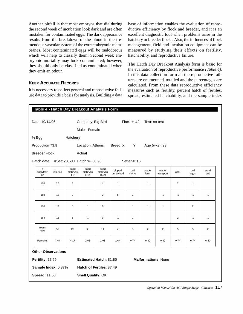
Operation Manual for ACI Single Stage - Chickens 117
Another pitfall is that most embryos that die duringthe second week of incubation look dark and are oftenmistaken for contaminated eggs. The dark appearanceresults from the breakdown of the blood in the tre-mendous vascular system of the extraembryonic mem-branes. Most contaminated eggs will be malodorouswhich will help to classify them. Second week em-bryonic mortality may look contaminated; however,they should only be classified as contaminated whenthey emit an odour.
KEEP ACCURATE RECORDS
It is necessary to collect general and reproductive fail-ure data to provide a basis for analysis. Building a data
base of information enables the evaluation of repro-ductive efficiency by flock and breeder, and it is anexcellent diagnostic tool when problems arise in thehatchery or breeder flocks. Also, the influences of flockmanagement, field and incubation equipment can bemeasured by studying their effects on fertility,hatchability, and reproductive failure.
The Hatch Day Breakout Analysis form is basic forthe evaluation of reproductive performance (Table 4).In this data collection form all the reproductive fail-ures are enumerated, totalled and the percentages arecalculated. From these data reproductive efficiencymeasures such as fertility, percent hatch of fertiles,spread, estimated hatchability, and the sample index
Table 4 - Hatch Day Breakout Analysis Form
Date: 10/14/96 Company: Big Bird Flock #: 42 Test: no test
Male Female
% Egg Hatchery
Production 73.8 Location: Athens Breed: X Y Age (wks): 38
Breeder Flock Actual
Hatch date: #Set: 28,600 Hatch %: 80.98 Setter #: 16
#-yart/sgge
puelitrefni
daedsoyrbme
7-1
daedsoyrbme
41-8
daedsoyrbme
12-51
deppipdehctahnu
llucskcihc
skcarcmraf
skcarctropsnart
tnocllucsgge
llamsdne
861 02 8 4 1 1 2 1
861 31 9 2 5 2 1 1 1 1
861 11 5 1 6 1 1 1 2
861 61 6 1 3 1 2 2 1 1
:slatoT676
05 82 2 41 7 5 2 2 5 5 2
:stnecreP 44.7 71.4 80.2 80.2 40.1 47.0 03.0 03.0 47.0 47.0 03.0
Other Observations
Fertility: 92.56 Estimated Hatch: 81.85 Malformations: None
Sample Index: 0.87% Hatch of Fertiles: 87.49
Spread: 11.58 Shell Quality: OK

118 Operation Manual for ACI Single Stage - Chickens
can be generated (Table 5). The example calculationsgenerated in Table 5 were taken from the example dataprovided in Table 4.
By examining the results of the example provided, ananalysis of the problem areas of Flock #42 can be un-derstood. This 38 week old flock should have hatchedconsiderably higher than 80.98 percent. First, the fer-tility of 92.56 percent should be about 4 percent higherfor this age flock. Also, the percent hatch of fertileswas too low at 87.49 percent. This was caused by theelevated percentages noted for early deads (4.17 per-cent); contaminated (0.74 percent); and cull eggs (0.74percent). It is obvious that the problems of lowhatchability of Flock #42 stem from both breeder flockand hatchery. The low sample index of 0.87 reveals
that the sample was reliable in providing an estimateof true performance.
The sample index listed in Table 5 is a valuable meas-ure of how representative your sample is of the truereproductive performance of the entire setting of eggs.A large sample index (greater than 3.0) would indi-cate that the sample was not a good representation ofactual performance. Small sample sizes will result ingreater variation in the sample index. Calculating thesemeasures is necessary in interpreting results and tak-ing corrective action.
Figures 1 and 2 depict how building a data base on thelife of the flock can be useful in evaluating reproduc-tive efficiency. Notice how the age of a flock causesconsiderable variation in fertility, hatchability andembryonic mortality. Plotting these data enables flockevaluations over time, and enables a manager to deter-mine the genetic potential of breeding stock by usingthe best hatching flocks as examples.
Table 5 - Examples for Calculating Reproductive Efficiency Values
Formula:% Fertility = 100 – (# infertiles ÷ sample size) x100Example:100 – (50 ÷ 672) x 100 = 92.56%
Formula:% Hatchability = (# Hatched ÷ # Set) x 100Example:(23,160 ÷ 28,600) x 100 = 80.98%
Formula:% Hatch of Fertiles = (Hatchability ÷ Fertility) x100Example:(80.98 ÷ 92.56) x 100 = 87.49
Formula:Spread = Fertility - HatchabilityExample:92.56 – 80.98 = 11.58
Formula:% Estimated Hatchability = 100 - %Reproductive FailuresExample:100 – (7.44 + 4.17 + 0.30 + 2.08 + 1.04 + 0.74 +0.30 + 0.30 + 0.74 + 0.74 + 0.30) = 81.85%
Formula:Sample Index = % Estimated Hatchability - %HatchabilityExample:81.85 – 80.98 = 0.87
Figure 1: Influence of flock age on reproductiveperformance
Figure 2: Influence of flock age on embryo mortality

Operation Manual for ACI Single Stage - Chickens 119
GLOSSARY
Air Space: in eggs, is critical for the hatching chick.The air space is located at the broad end of theeggs, between shell membranes and provides thechick with air prior to chipping of the shell. It alsois a measure of quality in table eggs.
Albumen: The chief protein constituent of plant andanimal tissues. The white of an egg, which is se-creted around the yolk in the oviduct, is almostpure albumen. When an egg is broken out it canbe seen as two layers, inner and outer albumen.This is an important measure of quality. Both theinner and outer albumen should be free from in-clusions. In fresh eggs, from healthy stock, theyshould “stand up” well, only spreading out over asmall area. “Watery whites” are indicators of stale-ness and/or respiratory diseases. The albumen rep-resents about 60 percent by weight of an egg.
Blood ring: This usually refers to the candled appear-ance of an egg in which the embryo has died at ayoung age.
Breed: A population of a species that have distinctcharacteristics that differentiate them from otherpopulations in that species. Individuals within thatpopulation that reproduce with another individualof the population will produce offspring that arerecognizable as members of that population.Breeds can further be divided into varieties basedon differences within the breed. (See Species.)
Breeder Flock: A flock of chickens used to producefertile eggs intended for hatching.
Broiler: This term normally applies to young chick-ens, but is also used to describe other forms oflivestock that are reared intensively for meat. Dueto their efficient conversion of about 2:1, chick-ens can undercut other high-quality meats. Mostare killed between 35 and 42 days and weights,expected by major breeders, range from 3.3 to
6.8 lbs. (1.5 to 3.1 kg) for males and 2.6 to 5.3 lbs.(1.2 to 2.4 kg) for females. Separate-sex growingenables more precise weights to be achieved andallows more efficient use of feed. This term is alsoapplied to a chicken that is 35 days old or older.Fryer is old terminology.
Candling: is the process of examining eggs with abright light for the purpose of detecting flaws.Candling will show cracks in the shell, some in-ternal faults, like blood spots, and meat spots. Inthe case of incubated eggs, detected infertile clearsand dead-in-shell can be removed after 8-10 daysor during the transfer from incubator to hatcher.Large candling booths are darkened and the eggsare rotated automatically over a group of electriclights. All eggs should be candled to removecracks, before being sold to consumers and to re-move infertile eggs during incubation.
Chick: The young of birds, particularly chickens andgamebirds.
Cracks: indicate cracked eggs and is the main causeof downgrading. Cage floor design and slope, cal-cium intake, age and breed of bird, packaging andhandling are all critical factors in determining thepercentage of cracks.
Day Old: An abbreviation to describe day-old chicks.Chicks normally leave the hatchery on the daythey are hatched. Before leaving, they are culled,sexed and vaccinated as appropriate. The mainbrooding requirements of all day-olds are clean,draught-free quarters, temperatures of 90 to100°F(32 to 38°C) under the brooder, easy access toclean water and balanced feed in the form ofcrumbs. Chicks, which are sent out not separatedby sex, are termed “as hatched”.
De-Beaking: is a rather less extreme measure than itsname suggests. It is the trimming of the end of theupper and lower beak by a red-hot blade whichcuts and cauterizes in one movement.

120 Operation Manual for ACI Single Stage - Chickens
Dry Bulb Temperature: The temperature measuredwith a standard thermometer or electronic sensor.
Egg: The reproductive element of birds. Millions ofchicken eggs are produced each year in the UnitedStates for human consumption. Hatching eggsrefer to fertile eggs that will be set by a hen orhatched in an incubator. A chicken egg must beincubated for 21 days.
An averaged-sized chicken egg weighs about 2.2oz. (62 g) of which the shell accounts for about 12percent by mass. Its contents consist of 12.1 per-cent protein, 10.5 percent fat, 65.6 percent waterand 11.8percent minerals, vitamins and carbohy-drates. The weight of the white (albumen) is abouttwice the weight of the yolk. Vitamins contained,A, B, D, E and K, are mainly in the yolk. Egg pro-tein is of the highest quality and is the standardagainst which all other proteins are judged. (Seeair space and albumen)
ECU: The Environmental Control Unit is the air han-dling unit which maintains heat exchange and hu-midity. See page 19.
Embryo: Development of the embryo in the egg startsat 80.6°F (27°C) for chickens. Therefore, hatch-ing eggs should normally be kept cool before in-cubation. Development to hatching normally takes21 days for chickens. (See incubation).
Fertility: Normal range of the percentage of fertileeggs produced is from 70 to nearly 100 percent.The percentage rises through broilers, brown lay-ers and white layers. Main factors affecting fertil-ity are heredity, health, age, nutrition and ratio ofmales to females. In heavy breeds, breeding andthus fertility is achieved by artificial insemination.
Fumigation: Formaldehyde is the gas given off dur-ing fumigation of housing, equipment or eggs. Itis active against a wide range of pathogens and isproduced by heating paraformaldehyde crystals or
adding formalin to potassium permanganate.
Green: describes chicks which have recently hatchedand are still wet or at least plump.
Hairline Crack: Fine cracks in the egg shell. In fresheggs, they can only be detected by candling. Asthey get older, they become more apparent.
Hatch of Fertiles: The percentage of fertile eggs whichhatch (hopefully above 90percent).
Hatch, Percent Hatch, Hatching Percent, or Hatchof Total: The percentage of all eggs set whichhatch, whether they were fertile or not. A typicalhatch might be 80 to 90 percent.
Hatcher: A machine used to maintain proper condi-tions for embryos during the final few (usuallythree) days before hatching.
Hatchery: A facility in which eggs are hatched. Mod-ern hatcheries are usually equipped with large in-cubators (setters) and hatchers for incubation andhatching. As well as sexing and boxing the sale-able chicks, many hatcheries now vaccinate as re-quired.
Hen: after 12 months of lay a pullet becomes a hen.This is the current definition for censuses and hassuperseded "after the first moult", as the length ofthe first laying period varies widely.
Humidity: This is the amount of moisture in the air.During incubation humidity is an important fac-tor and should be adjusted to obtain optimummoisture loss from the egg.
HVAC System: Heating, Ventilation and Air Condi-tioning System.

Operation Manual for ACI Single Stage - Chickens 121
Hybrid: also known as a crossbred. A hybrid is theresult of purposeful crossing of two species to pro-duce offspring with a unique set of characteris-tics. Hybrids often exhibit hybrid vigour and thusare superior to either of their parents. But the ef-fect of crossing pure lines is variable, and breed-ers have and do experiment with many differentcrosses to find the best combination. Today, mostcommercial stock is hybrid. Mating two hybridbirds will not produce offspring with the samecharacteristics of the parents. (See Breed).
Incubation Time: The time between setting of eggsand pulling of chicks.
Incubation: The process of warming and maintain-ing eggs, under conditions favourable for embry-onic development or hatching. Small still-airincubators are operated at the higher temperatureof 101°F (38.4°C) whereas 98.6°F (37°C) is thenorm for chicken eggs in cabinet incubators. Incabinet incubators, eggs are trayed broad end upand turned automatically to 45° each side of thevertical. Incubator and hatcher are usually sepa-rate and air flow is controlled. In still-air machines,eggs are usually placed on their sides and rolledan odd number of times daily through 180 degrees.(See embryo.)
Incubator: A machine designed for warming andmaintaining eggs under conditions favourable forembryonic development. See incubation above.Also known as setter.
Keyes Trays: These trays are made of moulded pulpor plastic, most are for 30 eggs. Used mainly fortransporting eggs from the farm to storage area.
Layer: A bird kept for egg production. Most are hy-brids. Common layer breeds such as Leghornchickens have been developed to lay many eggsand generally do not set a nest well. They performbest in laying cages and their average productionimproves every year through genetic selection andbetter management techniques. (See Meat Breeds.)
Malpositions: An embryo in any position except headunder right wing positioned in the large end of theshell. Examples of malpositions are head underleft wing or head between legs.
Meat Breeds: Breeds of chickens developed for theirquick growth and heavy muscles. These breeds aredeveloped for eating.
Pip: An egg in which the chick has broken the shell inan attempt to hatch.
Pipping: Breaking of shell by the chick to allow it toescape.
Pre-Incubation: Premature development of the em-bryo before storage.
Pre-Warming: Warming of eggs after storage but be-fore setting in incubators.
Pull: Removal of chicks from hatchers when the hatchis complete.
Relative Humidity (RH): The amount of moisture inthe air at a given temperature compared to themaximum amount of moisture the air, at the sametemperature, can hold. It is expressed as a percent-age.

122 Operation Manual for ACI Single Stage - Chickens
Set: Group of eggs placed in an incubator at one time.
Setter: Incubator used for first 18 to 19 days of incu-bation. (See incubator.)
Setting: Placing of a group of eggs in the incubator.
Sexing: Males and females can be sexed at a day-oldby vent sexing, feather development or down col-our. The first can be applied to all day-olds; slow/fast feathering is a sex-linked characteristic bredinto some broiler stocks; and most brown eggershave sex-linked feather colour. An increasingnumber of meat birds are reared sex separate toimprove feed efficiency and for control over finalweights.
Sex-link: A genetic trait that creates a difference, (usu-ally in colour) between males and females. Mostoften this is used to refer to traits that make chicksof different genders visibly distinct for ease ofsexing. The term may apply to the gene or charac-teristic, or is often applied to hybrid crosses thatdisplay this characteristic such as the Golden Sex-link.
Soft-Shelled Eggs: occur mainly when pullets arecoming into lay rapidly before the egg-shellingmechanism has settled down. But if they occur inassociation with thinner and weaker shells in olderbirds, then calcium intake may be too low or arespiratory disease present.
Species: A distinction for a specific type of animals.For example, chickens are a species. There maybe many breeds of each species. Typically, spe-cies cannot interbreed successfully, for example achicken and a goose cannot produce offspring to-gether. If species can cross, the offspring are typi-cally sterile like a mule (horse x donkey).
Spread: The difference between, fertility and hatch.(A 10 to 12 percent spread is typical for chickeneggs.)
Sweating: Condensation of water vapour on surfaceof eggs which are cooler than the “dew point” ofambient air.
Transfer: Movement of eggs from incubators (setters)to hatchers. This process may also involvecandling.
True Fertility: The percentage of hatching eggs whichare fertile. This can only be determined by incu-bation, candling and breakout of the clears to de-termine which eggs were fertile or by breakingout potentially fertile eggs to examine the germi-nal disc (e.g. a sample might be examined to esti-mate fertility of a flock).
Washing Eggs: Machines range from batch/buckettypes to continuous flow, spray-wash designs han-dling thousands an hour.
Wet Bulb Temperature: The temperature measuredby a standard thermometer equipped with a wetsock over the bulb. For accurate measurements airmust be moving over the wet sock to provide evapo-ration. A sling psychrometer can be used to meas-ure wet and dry-bulb temperature. Electronicsensors are now available to measure humidity ofair in incubators and egg storage rooms.
Yolk: (See Eggs.)