
Chen Xiaoyong_TOMEJ AS754 - Bentham Open
6
Send Orders for Reprints to [email protected] 416 The Open Mechanical Engineering Journal, 2015, 9, 416-421 1874-155X/15 2015 Bentham Open Open Access Experimental Study and Numerical Simulation of Injection Molding Pro- cess for Special-shaped Plastic Part Chen Xiaoyong * and Wang Qian Department of Mechanical and Electrical Engineering, Hangzhou Polytechnic, Hangzhou, Zhejiang, 311402, P.R. China Abstract: Taking the special-shaped plastic part as the research object, experimental study and numerical simulation of injection molding process were performed using numerical simulation technology, orthogonal experiment method, soft- ware Moldflow, injection machine and coordinate measuring machine (CMM). The better feeding system and optimal molding process parameters were proposed and qualified products were produced. The research results show that the effi- ciency of the simulation guidance would be significantly improved by combining the CAE technology and production ex- perience. Keywords: Experimental study, Numerical simulation, Orthogonal experiment, Injection molding, CAE. 1. INTRODUCTION During injection molding process, wide application of CAE technology has significantly improved the quality of injection parts. However, numerical simulation software is often developed based on a large number of simplification and assumptions. Deviation between the simulation result and actual production data will appear which would greatly influence the software use efficiency, So comparison be- tween them should be executed in order to improve the ac- curacy and applicability of the simulation results. In this paper, taking the special-shaped plastic part as the research object, numerical simulation and experimental study of injection molding process were performed using numerical simulation technology, orthogonal experiment method, software Moldflow, injection machine and CMM. Based on the analysis and comparison of the numerical simulation results with actual experiment results, application examples and experiences were presented for production enterprises in order to improve use efficiency of the software Moldflow. 2. STRUCTURE ANALYSIS OF THE SPECIAL- SHAPED PLASTIC PART The special-shaped plastic part, as shown in Fig. (1), was used as a machine installation tool. It was connected to the machine positioning hole through the cone at the end of small cylindrical surface in order to ensure the machine is in the horizontal position. The plastic part was mainly consisted of a large approxi- mate cuboid, some small approximate cuboids, and a cylin- der with small cone. The cone was composed of two sym- metrical parts with 0.3 mm gap between them. When assem- bling, the gap was compressed and elastic deformation of the *Address correspondence to this author at Department of Mechanical and Electrical Engineering, Hangzhou Polytechnic, Hangzhou, Zhejiang, 311402, P.R. China; Tel: Tel: +86 571 28287453; E-mail: [email protected] Fig. (1). The special-shaped plastic part. cone would be produced, so the plastic part and matched part would be connected reliably. During injection molding process, the cone was at the farthest place of the plastic part, so large warpage would be produced. Undoubtedly, too large warpage would cause dis- appearance of the gap and unqualified products. Therefore, the size of the gap was an important dimension and the max- imum warpage of the gap should be smaller than 0.15 mm. In theory, the mold structure often depends on the prod- uct structure. The structure of the special-shaped plastic part was simple and its surface quality requirements was lower, So a two-cavity mold structure with rectangle side gate was adopted. In order to optimize the mold structure and improve the quality of injection molded parts effectively, numerical simulation of injection molding process was performed based on CAE Technology. 3. NUMERICAL SIMULATION OF INJECTION MOLDING After having completed 3D modeling of the special- shaped plastic part and converted it into STL format in soft-
-
Upload
khangminh22 -
Category
Documents
-
view
0 -
download
0
Transcript of Chen Xiaoyong_TOMEJ AS754 - Bentham Open

Send Orders for Reprints to [email protected] 416 The Open Mechanical Engineering Journal, 2015, 9, 416-421
1874-155X/15 2015 Bentham Open
Open Access Experimental Study and Numerical Simulation of Injection Molding Pro-cess for Special-shaped Plastic Part
Chen Xiaoyong* and Wang Qian
Department of Mechanical and Electrical Engineering, Hangzhou Polytechnic, Hangzhou, Zhejiang, 311402, P.R. China
Abstract: Taking the special-shaped plastic part as the research object, experimental study and numerical simulation of injection molding process were performed using numerical simulation technology, orthogonal experiment method, soft-ware Moldflow, injection machine and coordinate measuring machine (CMM). The better feeding system and optimal molding process parameters were proposed and qualified products were produced. The research results show that the effi-ciency of the simulation guidance would be significantly improved by combining the CAE technology and production ex-perience.
Keywords: Experimental study, Numerical simulation, Orthogonal experiment, Injection molding, CAE.
1. INTRODUCTION
During injection molding process, wide application of CAE technology has significantly improved the quality of injection parts. However, numerical simulation software is often developed based on a large number of simplification and assumptions. Deviation between the simulation result and actual production data will appear which would greatly influence the software use efficiency, So comparison be-tween them should be executed in order to improve the ac-curacy and applicability of the simulation results.
In this paper, taking the special-shaped plastic part as the research object, numerical simulation and experimental study of injection molding process were performed using numerical simulation technology, orthogonal experiment method, software Moldflow, injection machine and CMM. Based on the analysis and comparison of the numerical simulation results with actual experiment results, application examples and experiences were presented for production enterprises in order to improve use efficiency of the software Moldflow.
2. STRUCTURE ANALYSIS OF THE SPECIAL-SHAPED PLASTIC PART
The special-shaped plastic part, as shown in Fig. (1), was used as a machine installation tool. It was connected to the machine positioning hole through the cone at the end of small cylindrical surface in order to ensure the machine is in the horizontal position.
The plastic part was mainly consisted of a large approxi-mate cuboid, some small approximate cuboids, and a cylin-der with small cone. The cone was composed of two sym-metrical parts with 0.3 mm gap between them. When assem-bling, the gap was compressed and elastic deformation of the
*Address correspondence to this author at Department of Mechanical and Electrical Engineering, Hangzhou Polytechnic, Hangzhou, Zhejiang, 311402, P.R. China; Tel: Tel: +86 571 28287453; E-mail: [email protected]
Fig. (1). The special-shaped plastic part.
cone would be produced, so the plastic part and matched part would be connected reliably.
During injection molding process, the cone was at the farthest place of the plastic part, so large warpage would be produced. Undoubtedly, too large warpage would cause dis-appearance of the gap and unqualified products. Therefore, the size of the gap was an important dimension and the max-imum warpage of the gap should be smaller than 0.15 mm.
In theory, the mold structure often depends on the prod-uct structure. The structure of the special-shaped plastic part was simple and its surface quality requirements was lower, So a two-cavity mold structure with rectangle side gate was adopted.
In order to optimize the mold structure and improve the quality of injection molded parts effectively, numerical simulation of injection molding process was performed based on CAE Technology.
3. NUMERICAL SIMULATION OF INJECTION MOLDING
After having completed 3D modeling of the special-shaped plastic part and converted it into STL format in soft-

Experimental Study and Numerical Simulation of Injection Molding Process The Open Mechanical Engineering Journal, 2015, Volume 9 417
ware Pro/E, the STL file is imported to the software Mold-flow to generate the mesh. Then preliminary filling analysis should be executed after the gate location analysis had been completed.
3.1. Analysis of the Best Gate Location
Firstly, the Cycolac G364 ABS plastic is selected which is produced by USA GE company as the material for injec-tion molding in the software Moldflow. Then the best gate location analysis of the plastic part should be executed. Re-sult of the best gate location analysis is shown in the Fig. (2). Obviously, best gate location was in the middle part on the side of the two plastic parts.
Fig. (2). Result of the best gate location analysis.
3.2. Optimization Design of Feeding System 3.2.1. Preliminary Design of Feeding System
Taking the result of the best gate location analysis and structure characteristics of the plastic into account, two feed-ing systems were designed as shown in Figs. (3 and 4). In order to determine the better feeding system, filling analyses for two feeding systems based on software Moldflow should be performed.
Fig. (3). Feeding system of the first scheme.
Fig. (4). Feeding system of the second scheme.
Rectangular side gates having the size of 3 mm × 2 mm × 0.8 mm were used in both feeding systems. Side gates of the first scheme were arranged on the large front plane of the plastic parts. Length of the main runner was 45 mm with 2 degrees cone angle and the small diameter of it was 3 mm. The second branch runner was located between the two side gates and the first branch runner. Cross-sectional shape of the first branch runner was cylindrical with 20 mm long and 5 mm in diameter, while the cross-sectional shape of the second branch runner was cylindrical with 10 mm long and 4 mm in diameter.
Side gates of the second scheme was arranged on the side of the plastic parts. Length of the main runner was 45 mm with 2 degrees cone angle and the small diameter of it was 3 mm, The first branch runner was located between the two side gates and the main runner. Cross-sectional shape of the first branch runner was cylindrical with 8 mm long and 4 mm in diameter. 3.2.2. Numerical Simulation of Feeding System
In order to reduce the adverse effects of other factors, the same parameters were selected for the simulation of the two feeding system in software Moldflow. Parameters were set as follows: mold temperature at 60 degrees Celsius, melt temperature at 210 degrees Celsius, filling control method at automatic, velocity/pressure switching mode at 100% filling volume, holding pressure control mode at filling pressure and time control mode, pack pressure at 80% of the maxi-mum injection pressure, and maintenance time at 10 seconds.
Analysis result of filling time of the first scheme is shown in Fig. (5). The filling finished at the time of 1.819 seconds. The last filled area was cylindrical ends of the plas-tic parts and edges of the four top square hole. Filled time of the cylindrical ends was at 1.662 seconds while filled time of the top was at 1.819 seconds. Difference between the two filled time was 0.157 seconds, so the unbalance rate was 8.63%. Obviously, the unbalance rate of the first scheme can meet the need of injection molding.
Analysis result of the pressure at the end of filling of the first scheme is shown in Fig. (6). The maximum pressure at the end of filling was 29.30 Mpa. It was at the top of the main runner. The allowable value of the injection molding

418 The Open Mechanical Engineering Journal, 2015, Volume 9 Xiaoyong and Qian
machine which used in the analysis was 280 Mpa, so the maximum pressure did not exceed the allowable value of the injection molding machine.
Fig. (5). Filling time of the first scheme.
Fig. (6). Pressure at the end of filling of the first scheme.
Fig. (7). Filling time of the second scheme.
Analysis result of filling time of the second scheme is shown in Fig. (7). The filling finished at the time of 1.911 seconds. The last filled area was the same as that of the first scheme. Filled time of the cylindrical ends was at 1.677 se-conds while filled time of the top was at 1.911 seconds. Dif-
ference between the two filled time was 0.334 seconds and unbalance rate was 17.47%. Generally, excessive unbalanced flow will cause unbalanced pressure at both ends of the plas-tic part and create over packing pressure which will have a greater impact on the quality of the products, so filling un-balance rate should be less than 5%. Obviously, the unbal-ance rate of the second scheme cannot meet the need of in-jection molding.
Analysis result of the pressure at the end of filling of the second scheme is shown in Fig. (8). The maximum pressure at the end of filling was 30.36 Mpa. It also did not exceed the allowable value of the injection molding machine.
Fig. (8). Pressure at the end of filling of the second scheme.
From the comprehensive comparison of the simulation results for the two feeding system scheme, it is found that the first scheme is the better plan. The filling unbalance rate of the first scheme was only 8.63%. It could be reduced to 5% by means of appropriate adjustment measures so as to meet the need of injection molding. However, the filling unbal-ance rate of the second scheme was 17.47%. It would cause large warpage deformation and could not meet the require-ments of molding plastic parts. On the other hand, the pres-sure at the end of the filling of the first scheme was 29.30 Mpa while that of the second scheme was 30.36MPa, so clamping force of the first scheme was relatively small. It means that it is easy to suit the requirements of the injection molding machine. In addition, there were not much more differences between the remaining parameter values of two schemes such as weld lines, air pockets etc. Therefore, the first scheme should be selected as the mold feeding system.
4. EXPERIMENTAL STUDY OF INJECTION MOLD-ING
A recent study by our group presented the optimal pa-rameters of the injection molding process based on software Moldflow and orthogonal experimental method. The optimal injection molding process parameters of the special-shaped plastic part were composed of 210 degrees Celsius melt tem-perature, 60 degrees Celsius mold temperature, 2.2 seconds injection time, 31 Mpa packing pressure and 20 seconds packing time [1]. Among them, mold temperature was the most important parameter of the five process parameters which influence the warpage, followed by melt temperature
Experimental Study and Numerical Simulation of Injection Molding Process The Open Mechanical Engineering Journal, 2015, Volume 9 419
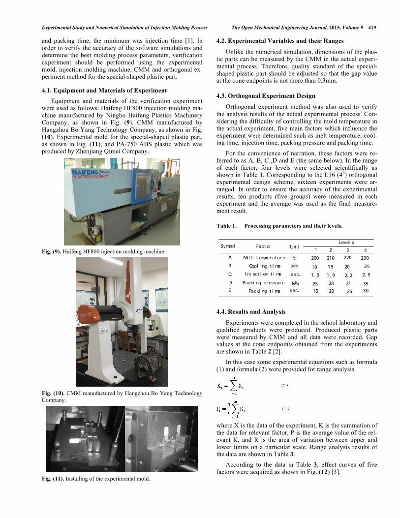
and packing time, the minimum was injection time [1]. In order to verify the accuracy of the software simulations and determine the best molding process parameters, verification experiment should be performed using the experimental mold, injection molding machine, CMM and orthogonal ex-periment method for the special-shaped plastic part.
4.1. Equipment and Materials of Experiment Equipment and materials of the verification experiment
were used as follows: Haifeng HF800 injection molding ma-chine manufactured by Ningbo Haifeng Plastics Machinery Company, as shown in Fig. (9). CMM manufactured by Hangzhou Bo Yang Technology Company, as shown in Fig. (10). Experimental mold for the special-shaped plastic part, as shown in Fig. (11), and PA-750 ABS plastic which was produced by Zhenjiang Qimei Company.
Fig. (9). Haifeng HF800 injection molding machine.
Fig. (10). CMM manufactured by Hangzhou Bo Yang Technology Company.
Fig. (11). Installing of the experimental mold.
4.2. Experimental Variables and their Ranges
Unlike the numerical simulation, dimensions of the plas-tic parts can be measured by the CMM in the actual experi-mental process. Therefore, quality standard of the special-shaped plastic part should be adjusted so that the gap value at the cone endpoints is not more than 0.3mm.
4.3. Orthogonal Experiment Design
Orthogonal experiment method was also used to verify the analysis results of the actual experimental process. Con-sidering the difficulty of controlling the mold temperature in the actual experiment, five main factors which influence the experiment were determined such as melt temperature, cool-ing time, injection time, packing pressure and packing time.
For the convenience of narration, these factors were re-ferred to as A, B, C ,D and E (the same below). In the range of each factor, four levels were selected scientifically as shown in Table 1. Corresponding to the L16 (45) orthogonal experimental design scheme, sixteen experiments were ar-ranged. In order to ensure the accuracy of the experimental results, ten products (five groups) were measured in each experiment and the average was used as the final measure-ment result.
Table 1. Processing parameters and their levels.
Symbol Fact or
Mel t t emperat ur eA
I nj ect i on t i me
Packi ng pressureD
E
B Cool i ng t i me
C
Uni t
℃
sec.
MPa
sec.
Level s
10
200
1
Packi ng t i me
1. 5
25sec. 15
210
2. 5
2520
230220432
3530
15
1. 9
28
20
2. 2
31
25
4.4. Results and Analysis
Experiments were completed in the school laboratory and qualified products were produced. Produced plastic parts were measured by CMM and all data were recorded. Gap values at the cone endpoints obtained from the experiments are shown in Table 2 [2].
In this case some experimental equations such as formula (1) and formula (2) were provided for range analysis.
where X is the data of the experiment, K is the summation of the data for relevant factor, P is the average value of the rel-evant K, and R is the area of variation between upper and lower limits on a particular scale. Range analysis results of the data are shown in Table 3.
According to the data in Table 3, effect curves of five factors were acquired as shown in Fig. (12) [3].

420 The Open Mechanical Engineering Journal, 2015, Volume 9 Xiaoyong and Qian
Table 2. Experimental matrix and experimental data.
Desi gn paramet ers
2
3
4
5
6
7
EA B C DEXP. NO.
Resul t s(mm)
11
12
13
14
0. 2631
0. 2368
0. 1246
0. 14880. 1672
0. 2298
0. 1686
0. 2196
0. 2406
0. 1426
0. 1608
0. 06430. 1691
0. 2176
0. 2302
0. 1523
1
8
9
10
16
15
200
200
200
200
210
210
210
210
220
220
220
220
230
230
230
230
10
15
20
25
10
15
20
25
10
15
20
25
10
15
20
25
1. 5
1. 9
2. 2
2. 5
1. 5
1. 9
2. 2
2. 5
1. 9
1. 5
2. 5
2. 2
1. 9
1. 5
2. 5
2. 2
25
28
31
35
28
25
35
31
31
35
25
28
35
31
28
25
15
20
25
30
20
15
30
25
30
25
20
15
25
30
15
20
Table 3. Result of range analysis.
AVal ue
K1
K2
K3
K4P1
P2
P3P4
RPri mary andOpt imal Level
EDCBLevel s
0. 7733
0. 7852
0. 6083
0. 7692
0. 1933
0. 1963
0. 1521
0. 19230. 0442
0. 8400
0. 8468
0. 6842
0. 5850
0. 2100
0. 2121
0. 1711
0. 1463
0. 0658
0. 7905 0. 7790 0. 7874
0. 8763
0. 50980. 7594
0. 1976
0. 2191
0. 1275
0. 18990. 0916
0. 6985
0. 8024
0. 6291
0. 1948
0. 1724
0. 2006
0. 15730. 0433
0. 7971
0. 6559
0. 7756
0. 1969
0. 1993
0. 16400. 1939
0. 0353
A2 B2 C2 E2D3C、B、A、D、E
From the range analysis results in the Table 3 and Fig. (12), it is found that optimal process parameters are A2, B2, C2, D3 and E2. The best process parameters are as follows: melt temperature at 210 degrees Celsius, cooling time at 1.5 seconds, injection time at 1.9 seconds, packing pressure at 31 Mpa and packing time at 20 seconds. Comparing the simula-tion results with the actual production data, it can be seen that the results of melt temperature, packing pressure and packing time are exactly the same while injection time is changed to 1.9 seconds and cooling time is changed to 1.5 seconds.
Therefore, analysis results of the software Moldflow are basically correct and can be used in actual production pro-cess. But reasonable adjustments should be taken in the ap-plications according to the actual production conditions.
In addition, from the analysis results in Table 3, we can draw a conclusion that influencing order of the process pa-rameters is C, B, A, D, E and injection time is the most sig-nificant parameter which influences the gap value, followed
by cooling time and melt temperature, the minimum is pack-ing time.
5. CONCLUSION
In this study, numerical simulation and experimental study of the injection molding process were performed and qualified products were produced. Based on the results ob-tained from the analysis and experimental data, the following conclusions can be drawn: (1) Comprehensive comparison of numerical simulation and
experimental study indicates that analysis results of the software Moldflow are basically correct and can be used in actual production process. Reasonable adjustments should be taken in the applications according to the actu-al production conditions.
(2) Compared experiment of the two feeding system scheme shows that the first scheme is the better plan. The filling unbalance rate of the first scheme is only 8.63%. It can be reduced to 5% by means of appropriate adjustment measures so as to meet the need of injection molding.
(3) According to the range analysis results in the Table 3, optimal parameters of the injection molding process are composed of 210 degrees Celsius melt temperature, 1.5 seconds cooling time, 1.9 seconds injection time, 31 Mpa packing pressure and 20 seconds packing time. Injection time is the most significant parameter which influences on the gap value.
CONFLICT OF INTEREST
The authors confirm that this article content has no con-flict of interest.
ACKNOWLEDGEMENTS
Declared none.
0
0. 15
0. 05
0. 10
0. 20
0. 25
1. 5 2. 21. 9 2. 5
i nj ect i on t i me(sec. )
0
0. 15
0. 05
0. 10
0. 20
0. 25
200 210 220 230
mel t t emperat ure(℃)
0
0. 15
0. 05
0. 10
0. 20
0. 25
15 20 25 30
packi ng t i me(sec. )
packi ng pressure(MPa)
cool i ng t i me(sec. )
0
0. 15
0. 05
0. 10
0. 20
0. 25
10 15 20 25
0
0. 15
0. 05
0. 10
0. 20
0. 25
25 28 31 35
Fig. (12). Effect curves of the processing parameters.

Experimental Study and Numerical Simulation of Injection Molding Process The Open Mechanical Engineering Journal, 2015, Volume 9 421
REFERENCES [1] Chen Xiaoyong, “An Optimized Design of Injection Molding Pro-
cess Parameters for Supporting-foot Plastic Part Based on CAE,” Advanced Materials Research, Vol. 721, pp. 648-651, 2013.
[2] Yu Junbo, Zhou Xiaolin, Deng Changle, “Optimization of Injection Molding Process of Bearing Stand Based on BP Network Method,”
Transactions of Nanjing University of Aeronautics and Astro-nautics, Vol. 31, no. 2, pp. 190-195,2014.
[3] S.Pal, S. K. Malviya, S. K. Pal, A.K.Samantaray, “Optimization of quality characteristics parameters in a pulsed metal inert gas weld-ing process using grey-based Taguchi method”, Int J Adv Manuf Technol, Vol. 44, pp. 1250-1260, 2009.
Received: May 26, 2015 Revised: July 14, 2015 Accepted: August 10, 2015
© Xiaoyong and Qian; Licensee Bentham Open.
This is an open access articles licensed under the terms of the Creative Commons Attribution-Non-Commercial 4.0 International Public License (CC BY-NC 4.0) (https://creativecommons.org/licenses/by-nc/4.0/legalcode), which permits unrestricted, non-commercial use, distribution and reproduction in any medium, provided that the work is properly cited.