Chapter No 12. Current Electricity (Conceptual Questions)
46
Chapter No 12. Current Electricity (Conceptual Questions) 1: Why it is not possible to measure the drift speed of electron by timing their travel along a conductor? Statement: It is not possible to measure the drift speed of electron by timing their travel along a conductor. Reason: When a potential difference is applied across the ends of a conductor, an electric field is set up at every point of the conductor. The free electron now feels drifted opposite to the direction of the applied field. During the motion of free electrons, atoms of the lattice of the conductor come in their way. The collisions with the atoms of the conductor continuously change the path of the electrons. They move in different unpredictable directions. Therefore, their path of motion is quite inconsistent. In order to reach the other end of the conductor, different electrons take different paths inside the conductor depending upon their interaction (collisions) with the atoms. Conclusion: So we can’t say an electron about the speed of electron by timing their motion from one end to the other of the conductor. ~~~~~~~~~~~~~~~ Prepared by : Ms Nazia ~~~~~~~~~~~~~~~~
-
Upload
khangminh22 -
Category
Documents
-
view
0 -
download
0
Transcript of Chapter No 12. Current Electricity (Conceptual Questions)
Chapter No 12. Current Electricity (Conceptual Questions) 1: Why it is not possible to measure the drift speed of electron by timing their travel
along a conductor?
Statement: It is not possible to measure the drift speed of electron by timing their travel along a conductor.
Reason: When a potential difference is applied across the ends of a conductor, an electric field is set up at every point of the conductor. The free electron now feels drifted opposite to the direction of the applied field. During the motion of free electrons, atoms of the lattice of the conductor come in their way. The collisions with the atoms of the conductor continuously change the path of the electrons. They move in different unpredictable directions. Therefore, their path of motion is quite inconsistent. In order to reach the other end of the conductor, different electrons take different paths inside the conductor depending upon their interaction (collisions) with the atoms.
Conclusion: So we can’t say an electron about the speed of electron by timing their motion from one end to the other of the conductor. ~~~~~~~~~~~~~~~ Prepared by : Ms Nazia ~~~~~~~~~~~~~~~~
2: The relationship R = V/I tells us that the resistance of a conductor is directly proportional to the potential difference applied to it. What do you think on this proportion?
Ohm’s Law : Ohm’s law is one of the basic laws of current electricity. The law shows the ratio of the applied voltage of a conductor to the current flowing in it is constant. This proportionality constant is called resistance of conductor denoted by R .
Factors of R: The constant depends upon the nature of the conductor, its dimensions and state of temperature..
V/I for Ohmic conducter: Conductors which obey ohm’s law are called ohmic conductor. The ratio between V and I is constant.
V/I for Non Ohmic conductor: Some conductors do not follow Ohm’s law. Such conductors are called non-ohmic conductors. In such conductors, the ratio between V and I is not constant; it either increases or decreases with increasing the voltage.
3: A heavy duty battery of a truck maintains a current of 3 A for 24 hours. How much charge flows from the battery during this time? Given: Current = I= 3A Time = t = 24hours To find: Charge = Q = ? Calculaion: t = 24x3600 = 86400 sec By using Q = I x t Put values Q = 3 x 86400 = 2.59 x 10³ C Result: The charge flowing from the battery during 24 hours will be 2.592 x 10³ C ~~~~~~~~~~~~~~Prepared by: Ms Nazia ~~~~~~~~~~~~~~~~~
4: While analyzing a circuit, the internal resistance of emf sources is ignored. Why?
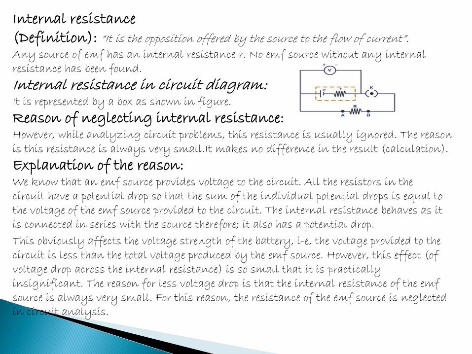
Internal resistance (Definition): “It is the opposition offered by the source to the flow of current”. Any source of emf has an internal resistance r. No emf source without any internal resistance has been found.
Internal resistance in circuit diagram: It is represented by a box as shown in figure.
Reason of neglecting internal resistance: However, while analyzing circuit problems, this resistance is usually ignored. The reason is this resistance is always very small.It makes no difference in the result (calculation).
Explanation of the reason: We know that an emf source provides voltage to the circuit. All the resistors in the circuit have a potential drop so that the sum of the individual potential drops is equal to the voltage of the emf source provided to the circuit. The internal resistance behaves as it is connected in series with the source therefore; it also has a potential drop.
This obviously affects the voltage strength of the battery, i-e, the voltage provided to the circuit is less than the total voltage produced by the emf source. However, this effect (of voltage drop across the internal resistance) is so small that it is practically insignificant. The reason for less voltage drop is that the internal resistance of the emf source is always very small. For this reason, the resistance of the emf source is neglected in circuit analysis.
5: Under what circumstances can the terminals P.D of a battery exceeds its emf? The terminal potential difference of a battery is related is to its emf by the relation V = - Ir ………….. (1) This relation shows that the terminal P.D is less than the emf of the battery. In such case the current in the battery flow from – ve to +ve terminals and battery will discharge. But if in the electrical circuit, the current in the battery start flow from +ve to negative terminals, the electric current in such case by sign convection is taken with negative sign to which the equation (1) will be V = ε - (-I)r V = ε + Ir This relation shows that terminal P.D of battery is greater than its emf and battery in case will be charged. ~~~~~~~~~~~~~ Prepared by ; Ms Nazia~~~~~~~~~~~~~~~~~
ε
Emf P.D
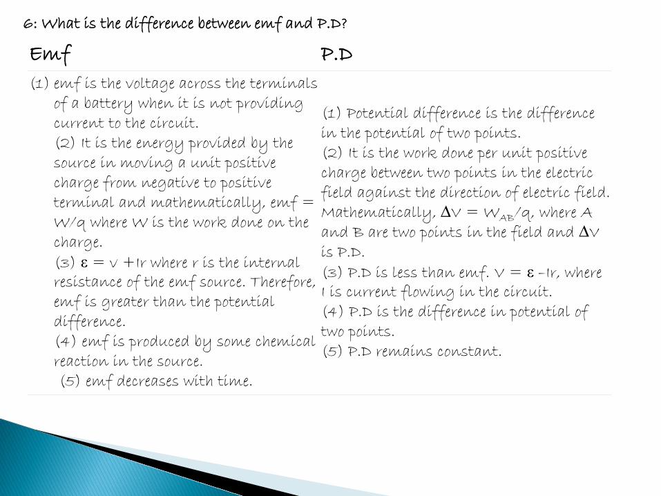
(1) emf is the voltage across the terminals of a battery when it is not providing current to the circuit. (2) It is the energy provided by the source in moving a unit positive charge from negative to positive terminal and mathematically, emf = W/q where W is the work done on the charge. (3) ε = v +Ir where r is the internal resistance of the emf source. Therefore, emf is greater than the potential difference. (4) emf is produced by some chemical reaction in the source.
(5) emf decreases with time.
(1) Potential difference is the difference in the potential of two points. (2) It is the work done per unit positive charge between two points in the electric field against the direction of electric field. Mathematically, ∆V = WAB/q, where A and B are two points in the field and ∆V is P.D. (3) P.D is less than emf. V = ε –Ir, where I is current flowing in the circuit. (4) P.D is the difference in potential of two points. (5) P.D remains constant.
6: What is the difference between emf and P.D?
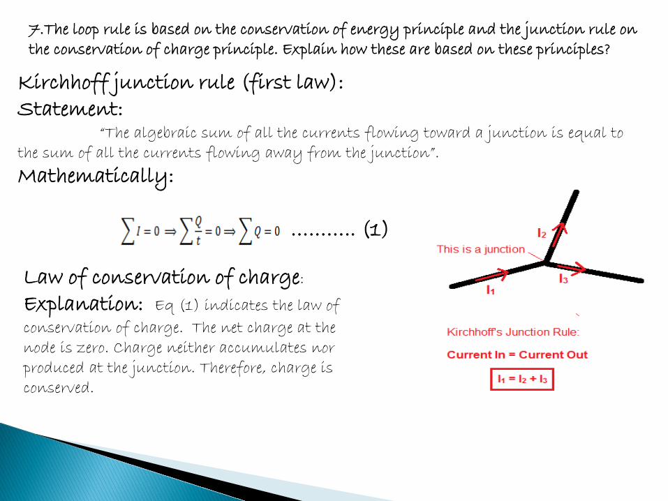
Kirchhoff junction rule (first law): Statement: “The algebraic sum of all the currents flowing toward a junction is equal to the sum of all the currents flowing away from the junction”.
Mathematically: ……….. (1)
7.The loop rule is based on the conservation of energy principle and the junction rule on the conservation of charge principle. Explain how these are based on these principles?
Law of conservation of charge:
Explanation: Eq (1) indicates the law of
conservation of charge. The net charge at the node is zero. Charge neither accumulates nor produced at the junction. Therefore, charge is conserved.
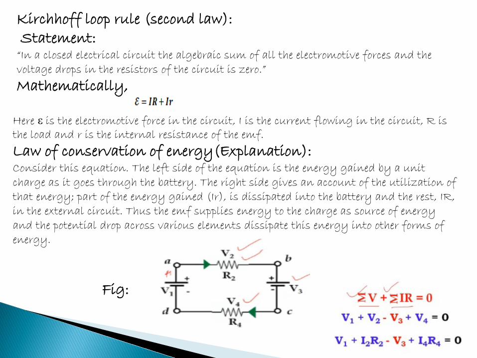
Here ε is the electromotive force in the circuit, I is the current flowing in the circuit, R is the load and r is the internal resistance of the emf.
Law of conservation of energy(Explanation): Consider this equation. The left side of the equation is the energy gained by a unit charge as it goes through the battery. The right side gives an account of the utilization of that energy; part of the energy gained (Ir), is dissipated into the battery and the rest, IR, in the external circuit. Thus the emf supplies energy to the charge as source of energy and the potential drop across various elements dissipate this energy into other forms of energy.
Fig:
Kirchhoff loop rule (second law): Statement: “In a closed electrical circuit the algebraic sum of all the electromotive forces and the voltage drops in the resistors of the circuit is zero.”
Mathematically,
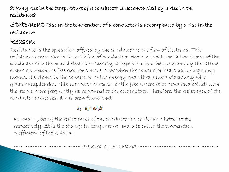
8: Why rise in the temperature of a conductor is accompanied by a rise in the resistance?
Reason: Resistance is the opposition offered by the conductor to the flow of electrons. This resistance comes due to the collision of conduction electrons with the lattice atoms of the conductor and the bound electrons. Clearly, it depends upon the space among the lattice atoms on which the free electrons move. Now when the conductor heats up through any means, the atoms in the conductor gains energy and vibrate more vigorously with greater amplitudes. This narrows the space for the free electrons to move and collide with the atoms more frequently as compared to the colder state. Therefore, the resistance of the conductor increases. It has been found that
R1 and R2 being the resistances of the conductor in colder and hotter state, respectively, ∆t is the change in temperature and α is called the temperature coefficient of the resistor. ~~~~~~~~~~~~~~ Prepared by :Ms Nazia ~~~~~~~~~~~~~~~~~
Statement:Rise in the temperature of a conductor is accompanied by a rise in the
resistance:

No,the direction of emf provided by a battery doesn’t depend on the direction of the current flowing through the battery.
9: Does the direction of emf provided by a battery depend on the direction of the current flowing through the battery?
Reason: The electric current flows from negative to the positive terminal while in the battery (source) the current by positive ions flows from negative to the positive terminal at the cost of energy.
Explanation: The source of emf can be thought of as a pump (device) which raises the electric potential energy of the mobile charges at the expense of work being done which in the case of the battery is the chemical reaction whereas for a water pump it might be you turning a handle or the electrical energy from the line. Within a source of emf ( like a battery) a chemical reaction occurs which moves the mobile charge carriers from a region where they have low electric potential energy to a region where they have a higher electric potential energy.(like water raised by a pump from lower potential to a higher potential at the cost of electricity etc). However, in the circuit when connected to a load, the current flows from higher potential to lower potential (like water flows from the water tank at the roof to the tape in the kitchen).
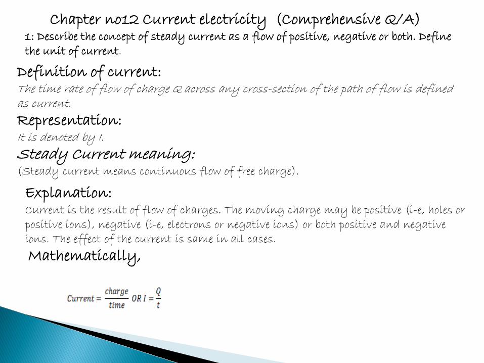
Chapter no12 Current electricity (Comprehensive Q/A) 1: Describe the concept of steady current as a flow of positive, negative or both. Define the unit of current.
Definition of current: The time rate of flow of charge Q across any cross-section of the path of flow is defined as current.
Representation: It is denoted by I.
Steady Current meaning: (Steady current means continuous flow of free charge).
Explanation: Current is the result of flow of charges. The moving charge may be positive (i-e, holes or positive ions), negative (i-e, electrons or negative ions) or both positive and negative ions. The effect of the current is same in all cases.
Mathematically,
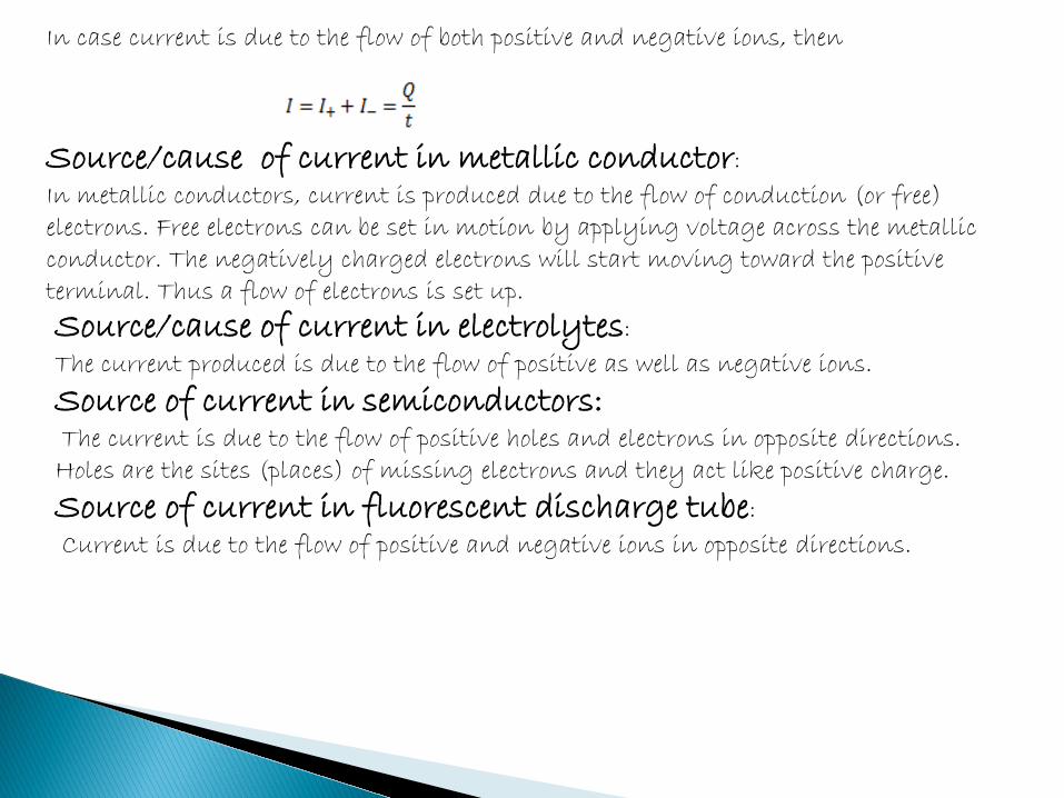
In case current is due to the flow of both positive and negative ions, then
Source/cause of current in metallic conductor:
In metallic conductors, current is produced due to the flow of conduction (or free) electrons. Free electrons can be set in motion by applying voltage across the metallic conductor. The negatively charged electrons will start moving toward the positive terminal. Thus a flow of electrons is set up.
Source/cause of current in electrolytes:
The current produced is due to the flow of positive as well as negative ions.
Source of current in semiconductors: The current is due to the flow of positive holes and electrons in opposite directions. Holes are the sites (places) of missing electrons and they act like positive charge.
Source of current in fluorescent discharge tube:
Current is due to the flow of positive and negative ions in opposite directions.
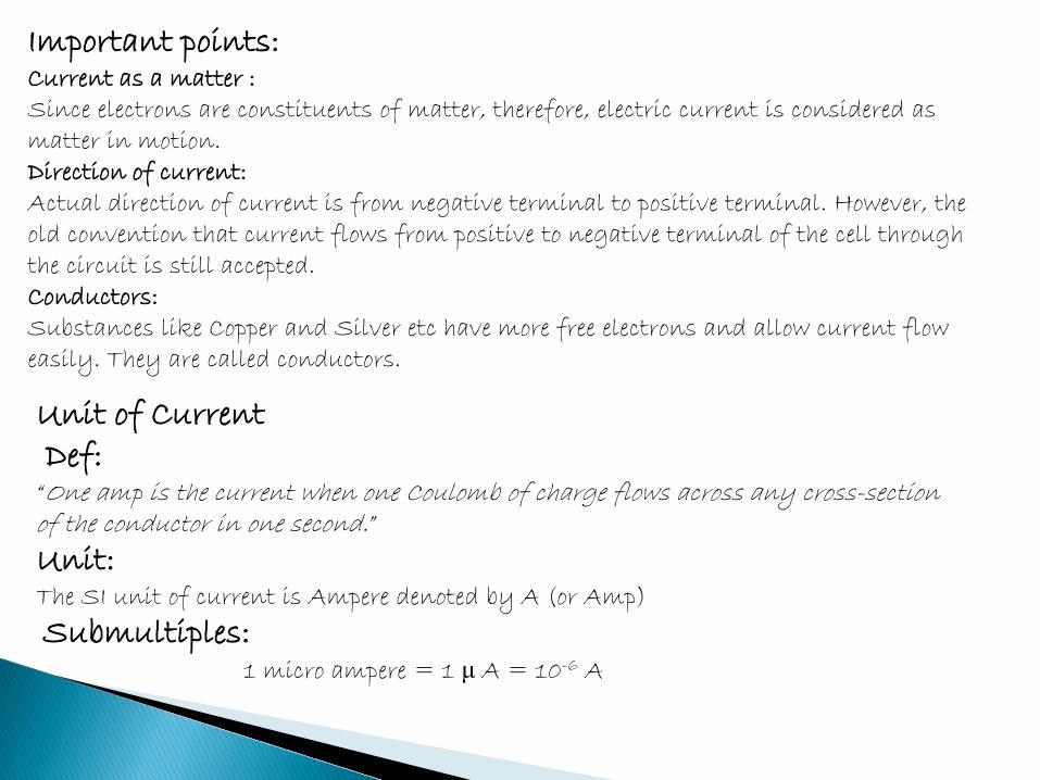
Important points: Current as a matter : Since electrons are constituents of matter, therefore, electric current is considered as matter in motion. Direction of current: Actual direction of current is from negative terminal to positive terminal. However, the old convention that current flows from positive to negative terminal of the cell through the circuit is still accepted. Conductors: Substances like Copper and Silver etc have more free electrons and allow current flow easily. They are called conductors.
Unit of Current Def: “One amp is the current when one Coulomb of charge flows across any cross-section of the conductor in one second.”
Unit: The SI unit of current is Ampere denoted by A (or Amp)
Submultiples: 1 micro ampere = 1 μ A = 10-6 A
2: Explain the electronic current in a metallic wire as due to the drift of free electrons in the wire.
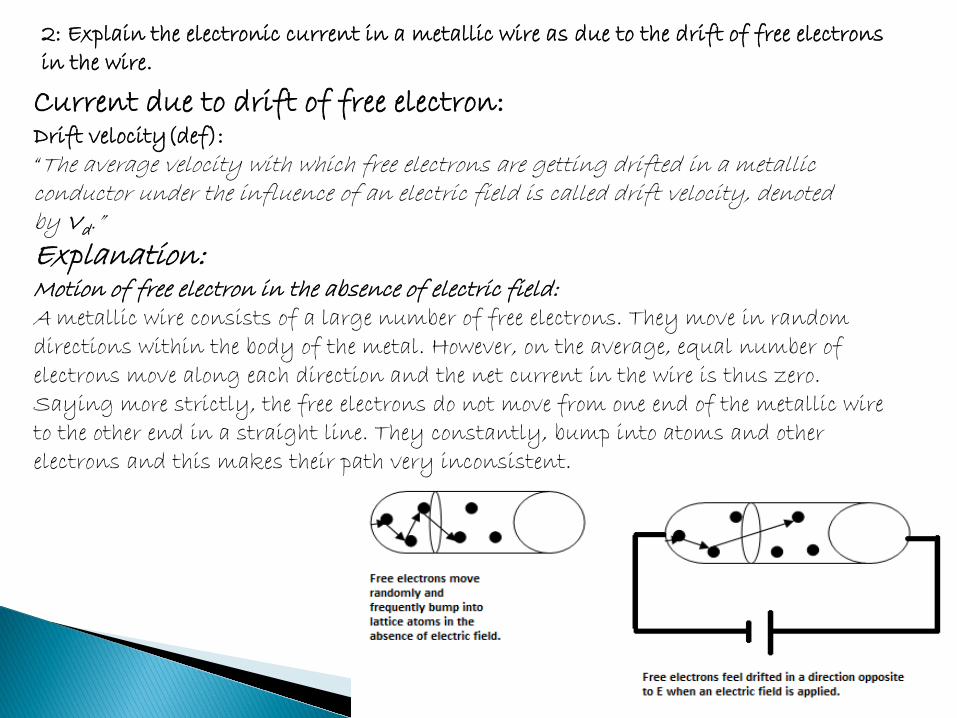
Current due to drift of free electron: Drift velocity(def): “The average velocity with which free electrons are getting drifted in a metallic conductor under the influence of an electric field is called drift velocity, denoted by Vd.”
Explanation: Motion of free electron in the absence of electric field: A metallic wire consists of a large number of free electrons. They move in random directions within the body of the metal. However, on the average, equal number of electrons move along each direction and the net current in the wire is thus zero. Saying more strictly, the free electrons do not move from one end of the metallic wire to the other end in a straight line. They constantly, bump into atoms and other electrons and this makes their path very inconsistent.
Motion of electrons in the presence of field : If the ends of the wire are connected to some source of potential difference, an electric field is set up at every point within the wire. Consequently, the electrons feel a force in the direction opposite to the direction of the electric intensity.
Drifting of electrons: As a result of the force, and collisions with the lattice atoms, the electrons start drifting with a certain velocity, called drift velocity. Though they are deflected left and right or even backwards, eventually they make to the other end.
Comparasion of velocities: Although their instantaneous velocity is high, it will take them much longer to battle their way to the other end of the conductor. So the drift velocity is very low. Drift velocity is found to be of the order of 10-5 m/s whereas the velocity of a free electron is several hundred kilometers per second.
3: State Ohm’s law. Discuss its scope and validity (a) Discuss resistivity and conductivity of a material (b) How does resistance change with temperature? Information:
George Simon Ohm experimentally established a fundamental relation between the voltage and the current in a metallic conductor, called Ohm’s Law.
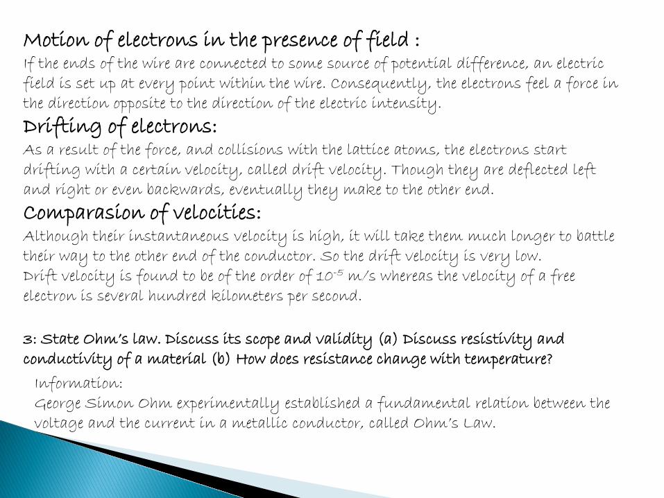
Statement: “The current I in a metal wire is directly proportional to the voltage V applied across its ends, provided the physical state such as the temperature of the conductor is kept constant.”
Mathematically, V = IR Here R is a constant known as the resistance of the conducting material.
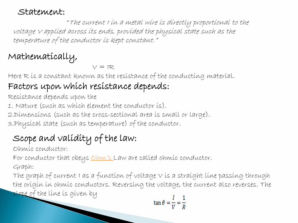
Factors upon which resistance depends: Resistance depends upon the 1. Nature (such as which element the conductor is). 2.Dimensions (such as the cross-sectional area is small or large). 3.Physical state (such as temperature) of the conductor. Scope and validity of the law: Ohmic conductor: For conductor that obeys Ohm’s Law are called ohmic conductor. Graph: The graph of current I as a function of voltage V is a straight line passing through the origin in ohmic conductors. Reversing the voltage, the current also reverses. The slope of the line is given by
However, it is noted that Ohm’s law is not valid for all conducting material.
Non Ohmic conductors: Certain conductors are found not obeying Ohm’s law. They are called non-ohmic material.
Graph: For non-ohmic conductors, the I-V graph is not a straight line or it may not pass through the origin. They may also conduct poorly or not at all when the voltage is reversed. Some of the examples of non-ohmic conductors are described below.
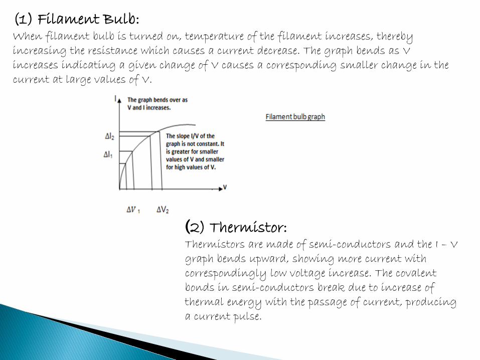
(1) Filament Bulb: When filament bulb is turned on, temperature of the filament increases, thereby increasing the resistance which causes a current decrease. The graph bends as V increases indicating a given change of V causes a corresponding smaller change in the current at large values of V.
(2) Thermistor: Thermistors are made of semi-conductors and the I – V graph bends upward, showing more current with correspondingly low voltage increase. The covalent bonds in semi-conductors break due to increase of thermal energy with the passage of current, producing a current pulse.
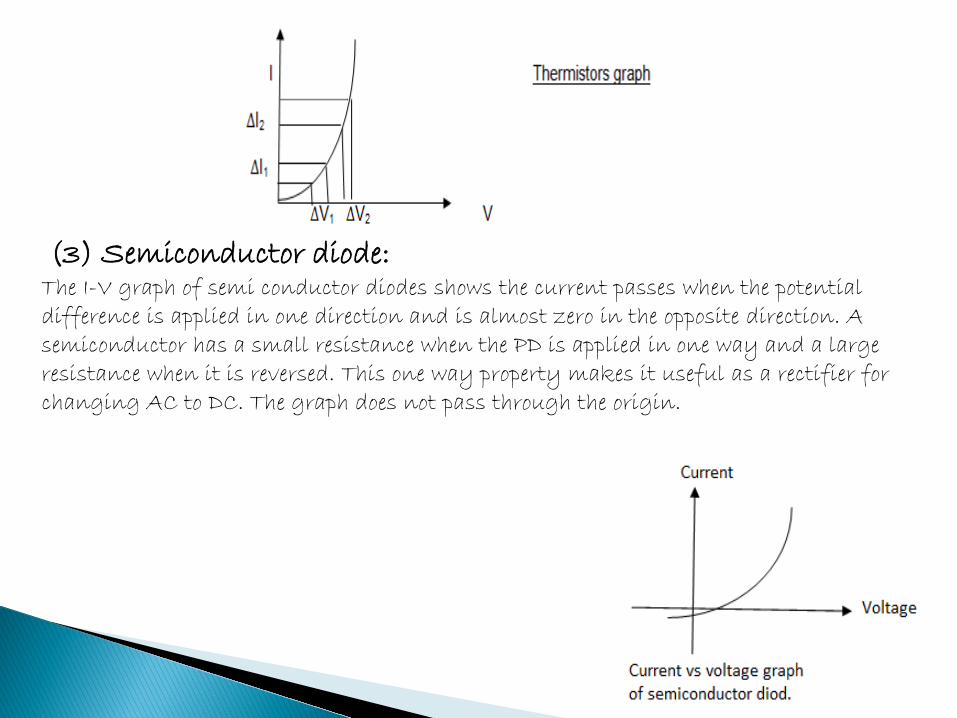
(3) Semiconductor diode: The I-V graph of semi conductor diodes shows the current passes when the potential difference is applied in one direction and is almost zero in the opposite direction. A semiconductor has a small resistance when the PD is applied in one way and a large resistance when it is reversed. This one way property makes it useful as a rectifier for changing AC to DC. The graph does not pass through the origin.

Resistivity or specific resistance of a material Def: “Resistivity is the resistance of a conductor having unit cross section and unit length.” It is denoted by ρ
Explanation Resistivity of a material depends on the nature, dimensions and temperature of the material. At constant temperature, R is found to vary directly with its length L and inversely with its cross sectional area A.
ρ is the resistivity or specific resistance of the material.
Unit: (Ω .m2/m) = Ω -m.
1.Resistivity of metals and alloys: It is small. Therefore, metals and alloys are good conductor of current. 2.Resistivity of insulators: It is very large. Therefore, they almost do not conduct any current. 3.Resistivity of semi-conductors: It is is in between the conductors and insulators. 4.Resistivity of different substances : It varies over a wide range from 10-4 Ω m to 104 Ω m.
Conductivity of a substance: Conductivity, like resistivity, describes the electrical properties of the material. It is reciprocal of resistivity and is denoted by σ.
σ = 1/ρ = L/RA
Unit: Its unit is moh/m or Siemens /m. Greater conductivity, less resistivity, and a good conductor the material is.
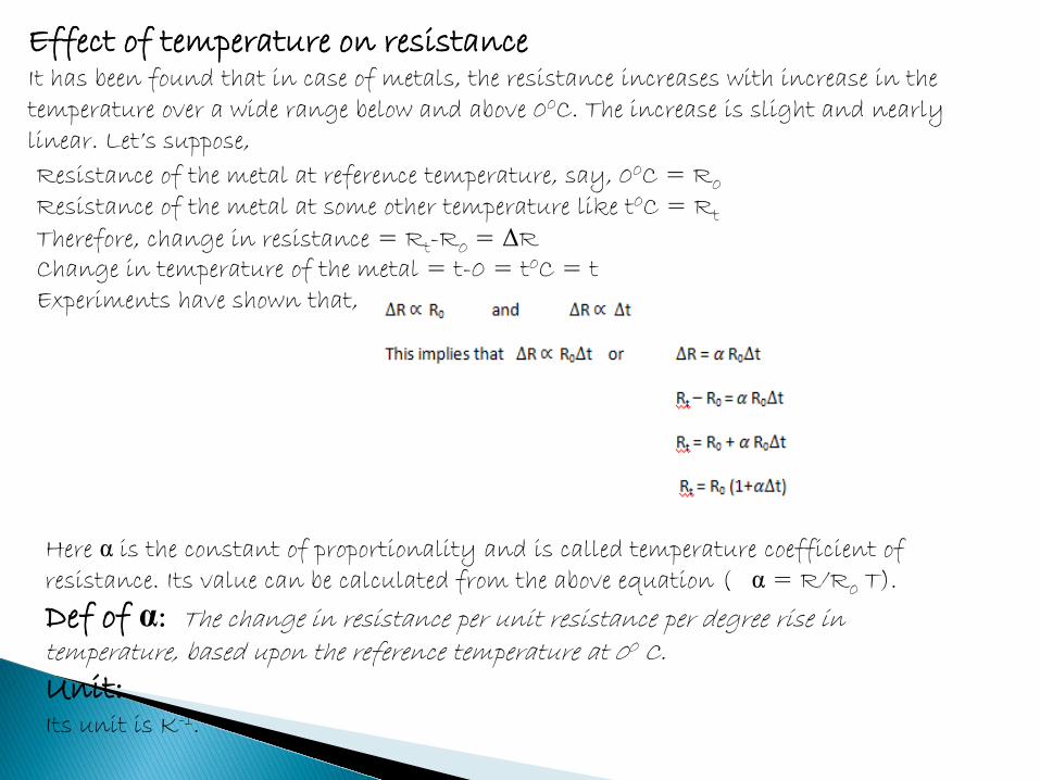
Effect of temperature on resistance It has been found that in case of metals, the resistance increases with increase in the temperature over a wide range below and above 00C. The increase is slight and nearly linear. Let’s suppose,
Resistance of the metal at reference temperature, say, 00C = R0 Resistance of the metal at some other temperature like t0C = Rt Therefore, change in resistance = Rt-R0 = ΔR Change in temperature of the metal = t-0 = t0C = t Experiments have shown that,
Here α is the constant of proportionality and is called temperature coefficient of resistance. Its value can be calculated from the above equation ( α = R/R0 T).
Def of α: The change in resistance per unit resistance per degree rise in temperature, based upon the reference temperature at 00 C.
Unit: Its unit is K-1.
4: Explain the terms: emf, internal resistance and terminal potential difference of a battery.
Electromotive force (emf) Def: The energy per unit charge supplied by a source to move the charge from the negative terminal to the positive terminal of the source (from lower to higher potential) is called the emf of the source.
Explanation: To maintain a steady current in the conductor, a steady potential difference across the conductor should be applied. This is possible only when some device changes some other form of energy into electrical energy; car battery converts chemical energy into electrical energy as an example.
Source of emf: “A device which converts non-electrical energy into electrical energy is called a source of electromotive force”. Function of source: The source does work on the charge entering its negative terminal, driving it up the potential gradient, through itself. At higher potential point, i-e, positive terminal, it gains energy W. This energy is equal to the work done on the charge by the source and called emf of the source, denoted by ε.
Unit of Emf and PD: These are measured in the same units, volt (1 joule/coulomb); however, emf is a special kind of PD which arises through the transformation of some other form of energy to electrical energy.
emf sources 1.Electrical cells or batteries convert chemical energy into electrical energy. 2.Electric generator converts mechanical energy into electrical energy. 3.Solar cells convert light energy into electrical energy. 4.Thermocouples convert heat energy into electrical energy.
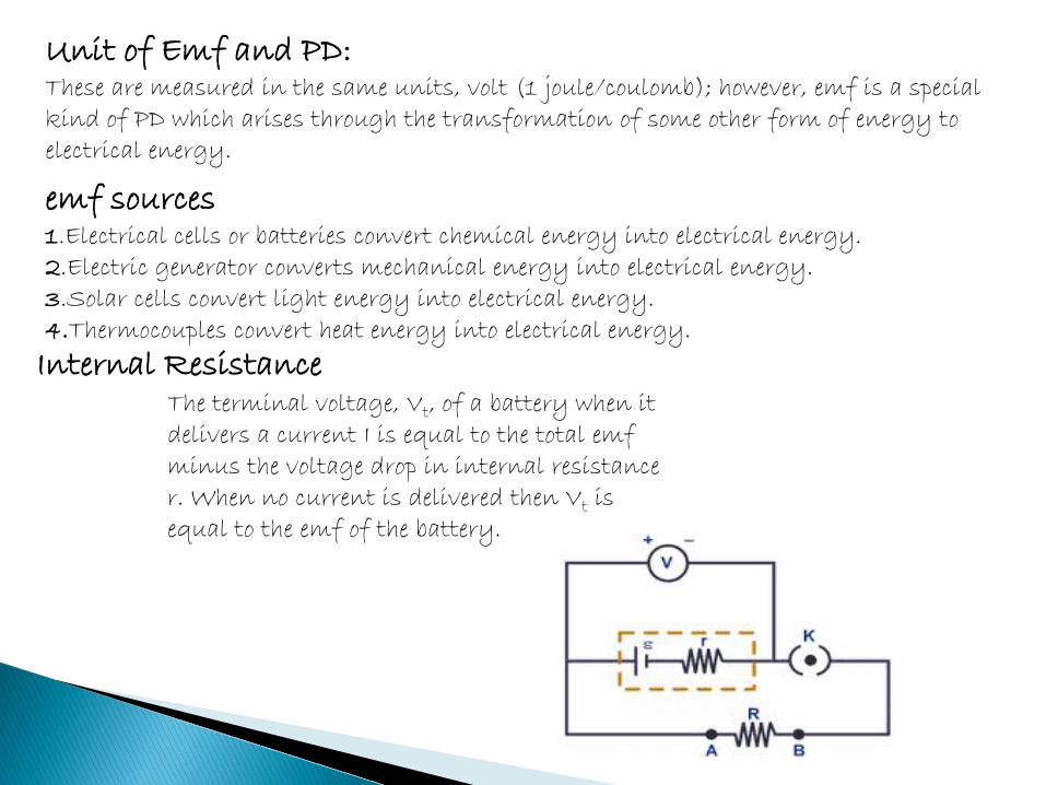
The terminal voltage, Vt, of a battery when it delivers a current I is equal to the total emf minus the voltage drop in internal resistance r. When no current is delivered then Vt is equal to the emf of the battery.
Internal Resistance
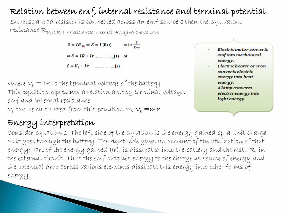
Relation between emf, internal resistance and terminal potential Suppose a load resistor is connected across an emf source ε then the equivalent resistance Req is R + r (resistances in series). Applying Ohm’s Law,
Where Vt = IR is the terminal voltage of the battery. This equation represents a relation among terminal voltage, emf and internal resistance. Vt can be calculated from this equation as, Vt =ε-Ir
Energy interpretation Consider equation 1. The left side of the equation is the energy gained by a unit charge as it goes through the battery. The right side gives an account of the utilization of that energy; part of the energy gained (Ir), is dissipated into the battery and the rest, IR, in the external circuit. Thus the emf supplies energy to the charge as source of energy and the potential drop across various elements dissipate this energy into other forms of energy.
5: Explain the construction of rheostat. How is it used as (a) control the current (b) as potential divider?
Wire – Wound Resistor: A special type of resistance wire wrapped around an insulating core is called a wire-wound resistor. As resistance of a resistor is directly proportional to the length and resistivity of the wire, a suitable wire (like Manganin) of suitable length can be used for this purpose. Tungsten, Constantan and Eureka are other alloys used for this purpose.
Rheostat or Potential dividers : Def: An electrical instrument used to control a current by varying the resistance.
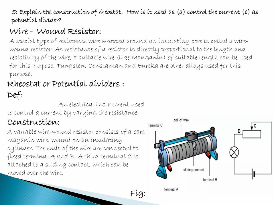
Construction: A variable wire-wound resistor consists of a bare maganin wire, wound on an insulating cylinder. The ends of the wire are connected to fixed terminal A and B. A third terminal C is attached to a sliding contact, which can be moved over the wire.
Fig:
Rheostat as current control: It makes use of the variable resistor as a current control device. The resistance depends upon the length of the resistor. The sliding terminal C provides a variable length of the resistor and hence a variable resistance when inserted in the circuit. When the C is slid toward A, the length is decreased and the resistance is also decreased. Similarly, moving it away from the terminal A, making use of more length and hence the resistance also increases. In this way the current is controlled in the circuit
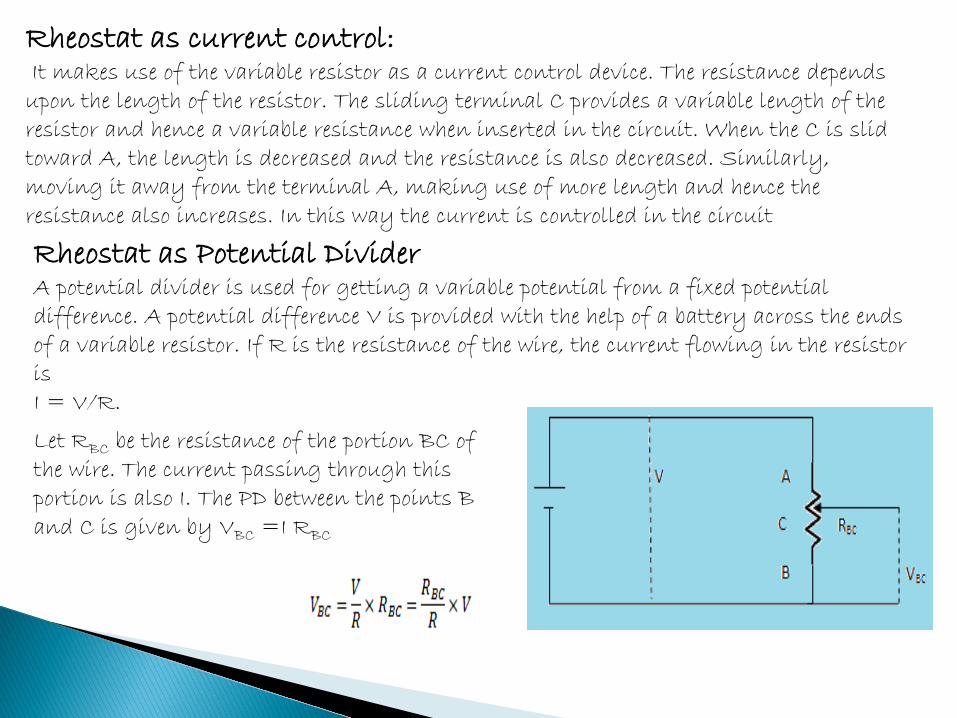
Rheostat as Potential Divider A potential divider is used for getting a variable potential from a fixed potential difference. A potential difference V is provided with the help of a battery across the ends of a variable resistor. If R is the resistance of the wire, the current flowing in the resistor is I = V/R.
Let RBC be the resistance of the portion BC of the wire. The current passing through this portion is also I. The PD between the points B and C is given by VBC =I RBC
RBC increases as we go away from A and decreases as C comes close to A. This changes the ratio RBC to R and hence a variable voltage can be obtained. If V is regarded as input PD to the potential divider and VBC as the output PD, then VBC can be tapped off and applied to another circuit. 6: What is wheat stone bridge? Explain with diagram the balancing, the principle and the working of this bridge.
Invention: It was invented by Samuel Hunter Christie in the year 1833, which was later popularized by Sir Charles Wheatstone in 1843.
Def: Wheatstone bridge,is used to calculate the unknown resistance by balancing two legs of the bridge circuit, of which one leg includes the component of unknown resistance. Other name: Resistance bridge Construction: It consists of a battery, Galvanometer and two fixed resistances R1 and R2 and one variable resistance R3 and the unknown resistance Rx which is to be found.
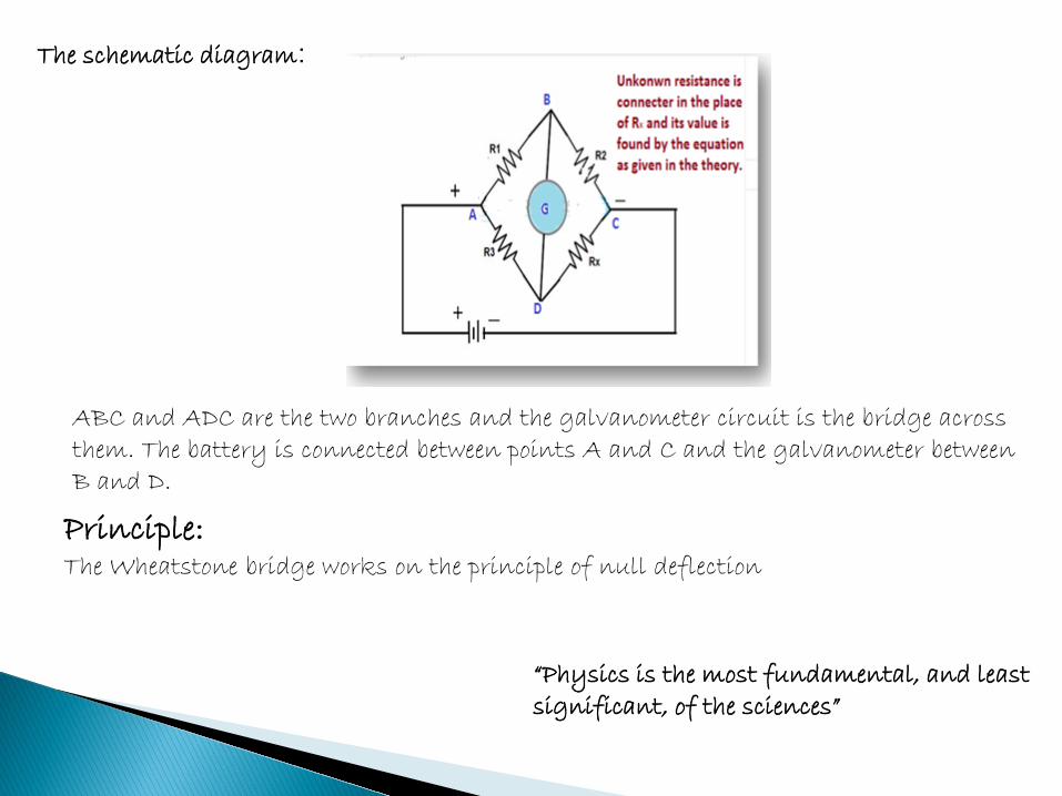
The schematic diagram:
ABC and ADC are the two branches and the galvanometer circuit is the bridge across them. The battery is connected between points A and C and the galvanometer between B and D.
Principle: The Wheatstone bridge works on the principle of null deflection
“Physics is the most fundamental, and least significant, of the sciences”
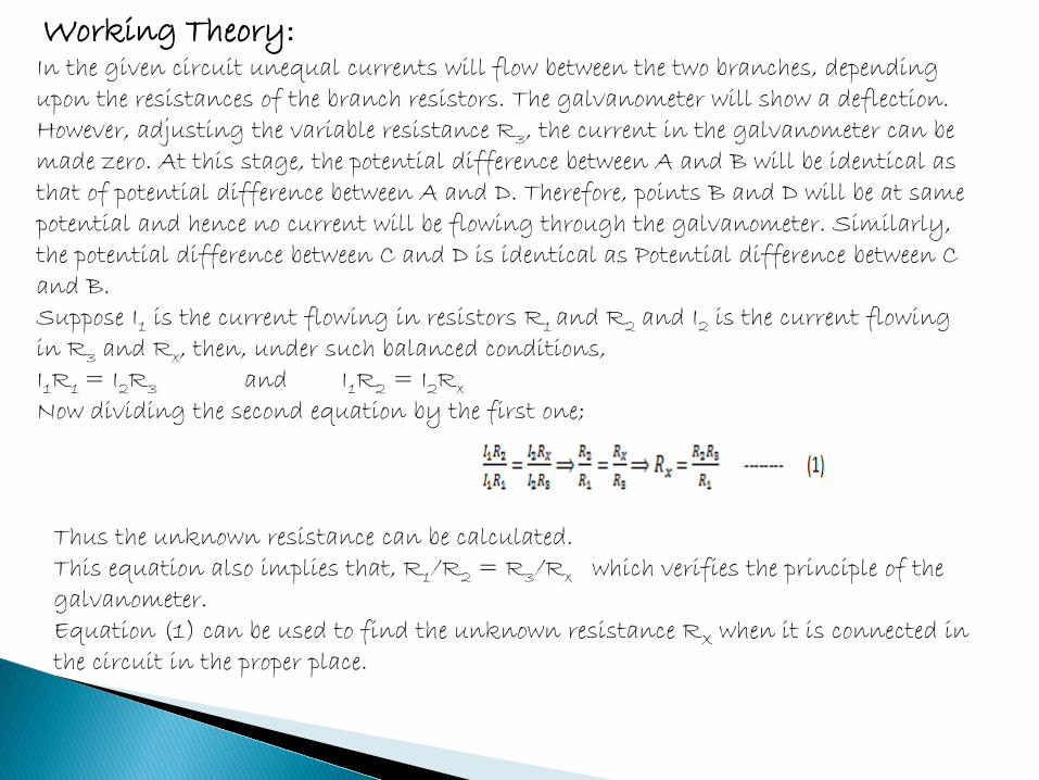
Working Theory: In the given circuit unequal currents will flow between the two branches, depending upon the resistances of the branch resistors. The galvanometer will show a deflection. However, adjusting the variable resistance R3, the current in the galvanometer can be made zero. At this stage, the potential difference between A and B will be identical as that of potential difference between A and D. Therefore, points B and D will be at same potential and hence no current will be flowing through the galvanometer. Similarly, the potential difference between C and D is identical as Potential difference between C and B. Suppose I1 is the current flowing in resistors R1 and R2 and I2 is the current flowing in R3 and Rx, then, under such balanced conditions, I1R1 = I2R3 and I1R2 = I2Rx Now dividing the second equation by the first one;
Thus the unknown resistance can be calculated. This equation also implies that, R1/R2 = R3/Rx which verifies the principle of the galvanometer. Equation (1) can be used to find the unknown resistance RX when it is connected in the circuit in the proper place.
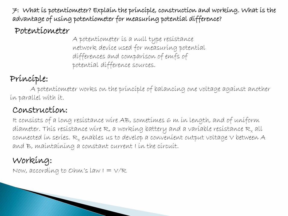
7: What is potentiometer? Explain the principle, construction and working. What is the advantage of using potentiometer for measuring potential difference?
Potentiometer A potentiometer is a null type resistance network device used for measuring potential differences and comparison of emfs of potential difference sources.
Principle: A potentiometer works on the principle of balancing one voltage against another in parallel with it.
Construction: It consists of a long resistance wire AB, sometimes 6 m in length, and of uniform diameter. This resistance wire R, a working battery and a variable resistance Rx all connected in series. Rx enables us to develop a convenient output voltage V between A and B, maintaining a constant current I in the circuit.
Working: Now, according to Ohm’s law I = V/R
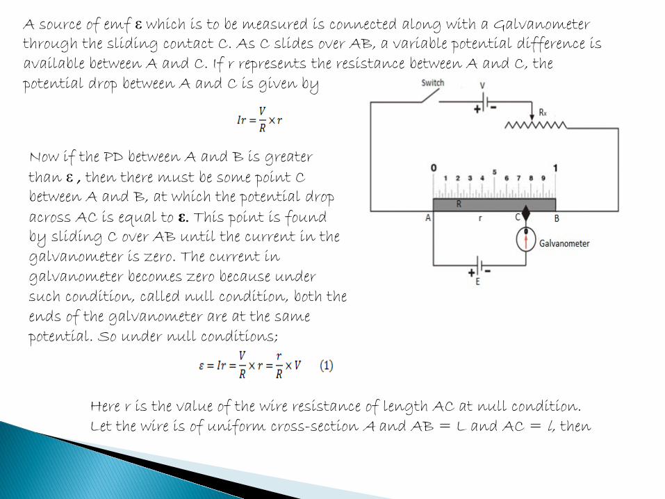
A source of emf ε which is to be measured is connected along with a Galvanometer through the sliding contact C. As C slides over AB, a variable potential difference is available between A and C. If r represents the resistance between A and C, the potential drop between A and C is given by Now if the PD between A and B is greater than ε , then there must be some point C between A and B, at which the potential drop across AC is equal to ε. This point is found by sliding C over AB until the current in the galvanometer is zero. The current in galvanometer becomes zero because under such condition, called null condition, both the ends of the galvanometer are at the same potential. So under null conditions;
Here r is the value of the wire resistance of length AC at null condition. Let the wire is of uniform cross-section A and AB = L and AC = l, then
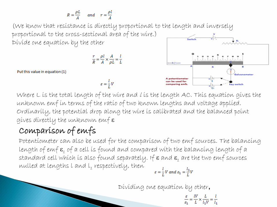
(We know that resistance is directly proportional to the length and inversely proportional to the cross-sectional area of the wire.) Divide one equation by the other
Where L is the total length of the wire and l is the length AC. This equation gives the unknown emf in terms of the ratio of two known lengths and voltage applied. Ordinarily, the potential drop along the wire is calibrated and the balanced point gives directly the unknown emf ε Comparison of emfs Potentiometer can also be used for the comparison of two emf sources. The balancing length of emf ε1 of a cell is found and compared with the balancing length of a standard cell which is also found separately. If ε and ε1 are the two emf sources nulled at lengths l and l1 respectively, then
Dividing one equation by other,
Applications of potentiometer: •Ammeters and voltmeters are calibrated with the help of potentiometer. •Comparing emfs of two cells. •Measurements of current and resistance. •Measurements of small and high emfs.
Advantages: 1. The errors due to line drop don’t occur as at null condition, the potentiometer draws no current from the source of emf to be tested. 2. The actual emf is obtained and not the terminal potential difference.
8: What is thermocouple? Explain the working of thermocouple by drawing its diagram. By sketching curve explain the variation in thermoelectric emf with temperature.
Def: Thermocouple is pair of wires of two dissimilar metals that convert heat energy directly into electrical energy.
Experiment of Seebeck: In 1821, Thomas Seebeck performed an experiment by joining the two wires to make a circuit. He placed one junction of the wires at constant temperature of 0oC and the other in a beaker whose temperature was gradually raised by burning a flame beneath it.

Detection of current: A galvanometer was provided in the circuit to observe the current.
Deflection of glavanometer: At the same temperature of the junctions, the galvanometer showed no deflection.
Seebeck Effect : However when the temperature of one junction was gradually increased, he noticed the current increasing with the temperature. This is called Seebeck Effect. He kept on increasing the temperature of one end. The current also increased to a maximum value. After that maximum value, the current began to decrease with further increase in the temperature.
Neutral temperature: The temperature of the hot junction when the current is maximum is called Neutral temperature. Neutral temperature is independent of the temperature of the cold junction.
Uses: Thermocouples are low cost and simple in use. Therefore, they are widely used in the industries.
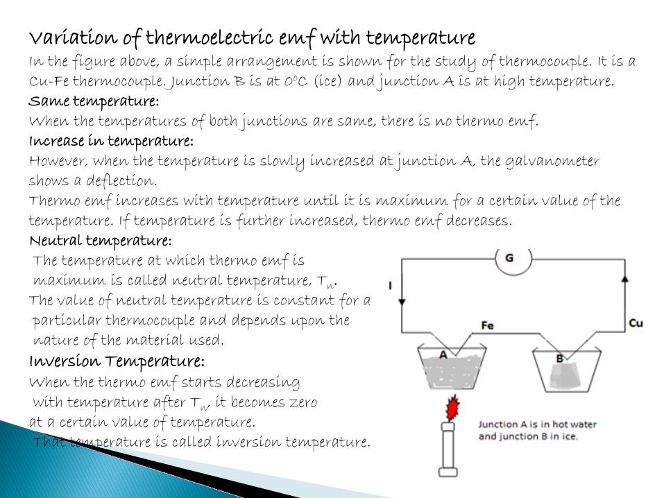
Variation of thermoelectric emf with temperature In the figure above, a simple arrangement is shown for the study of thermocouple. It is a Cu-Fe thermocouple. Junction B is at 0oC (ice) and junction A is at high temperature. Same temperature: When the temperatures of both junctions are same, there is no thermo emf. Increase in temperature: However, when the temperature is slowly increased at junction A, the galvanometer shows a deflection. Thermo emf increases with temperature until it is maximum for a certain value of the temperature. If temperature is further increased, thermo emf decreases. Neutral temperature: The temperature at which thermo emf is maximum is called neutral temperature, Tn. The value of neutral temperature is constant for a particular thermocouple and depends upon the nature of the material used.
Inversion Temperature: When the thermo emf starts decreasing with temperature after Tn, it becomes zero at a certain value of temperature. That temperature is called inversion temperature.
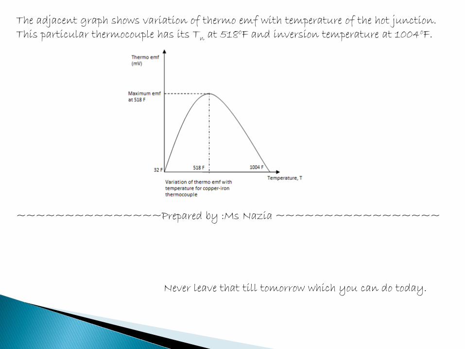
The adjacent graph shows variation of thermo emf with temperature of the hot junction. This particular thermocouple has its Tn at 518oF and inversion temperature at 1004oF. ~~~~~~~~~~~~~~~Prepared by :Ms Nazia ~~~~~~~~~~~~~~~~~
Never leave that till tomorrow which you can do today.
CURRENT ELECTRICITY (Theory)
ELECTRIC CURRENT
(Definition) ELECTRIC CURRENT The amount of electric charge that flows through a cross section of a conductor per
unit time is known as electric current.
Mathematical Expression: If ∆Q is the amount of charge flow through a cross-section in time ∆t, then the electric current I is described mathematically as:I = ∆Q / ∆t
It is a base quantity and its unit is ampere. (Definition) AMPERE: If one coulomb charge flows through a cross-section of a conductor in one second
then the current will be one ampere.
Education is the key to unlock the golden door of freedom.
CURRENT DIRECTION Earlier, it was thought that the current flow through a conductor is due to positive
charges from higher potential to lower potential in any external circuit. But later on, it was found that the flow of current in metallic conductor is due to the flow of electrons from the point of lower potential to the point of higher potential.
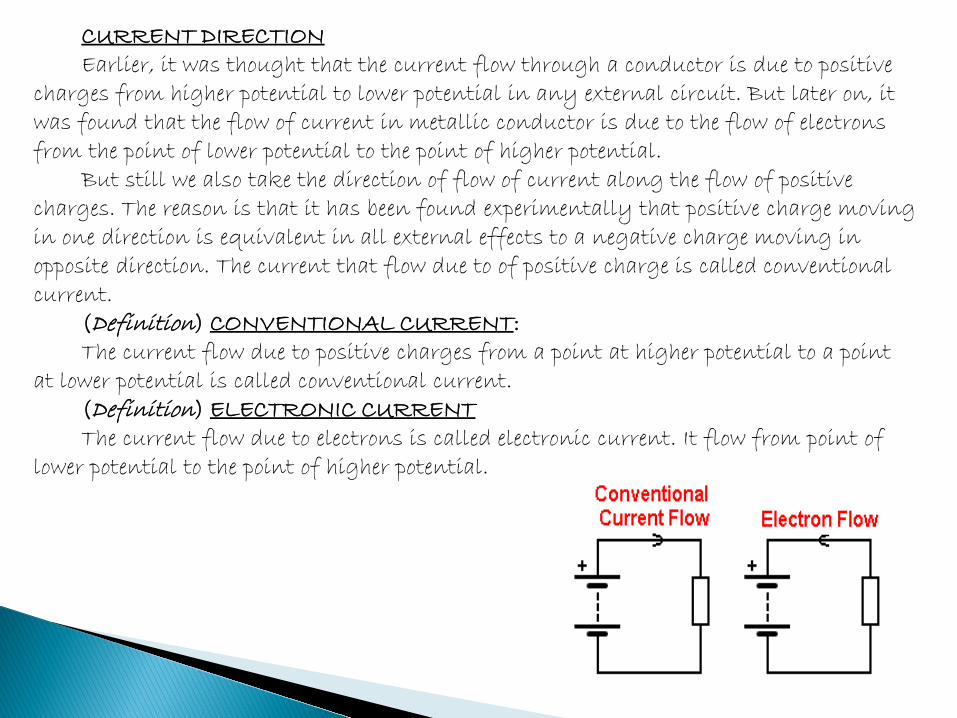
But still we also take the direction of flow of current along the flow of positive charges. The reason is that it has been found experimentally that positive charge moving in one direction is equivalent in all external effects to a negative charge moving in opposite direction. The current that flow due to of positive charge is called conventional current.
(Definition) CONVENTIONAL CURRENT: The current flow due to positive charges from a point at higher potential to a point
at lower potential is called conventional current. (Definition) ELECTRONIC CURRENT The current flow due to electrons is called electronic current. It flow from point of
lower potential to the point of higher potential.
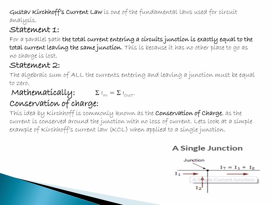
Gustav Kirchhoff’s Current Law is one of the fundamental laws used for circuit analysis.
Statement 1: For a parallel path the total current entering a circuits junction is exactly equal to the total current leaving the same junction. This is because it has no other place to go as no charge is lost.
Statement 2: The algebraic sum of ALL the currents entering and leaving a junction must be equal to zero.
Mathematically: Σ IIN = Σ IOUT.
Conservation of charge: This idea by Kirchhoff is commonly known as the Conservation of Charge, as the current is conserved around the junction with no loss of current. Lets look at a simple example of Kirchhoff’s current law (KCL) when applied to a single junction.
Example: Here in this simple single junction example, the current IT leaving the junction is the algebraic sum of the two currents, I1 and I2 entering the same junction.
That is IT = I1 + I2. Note that we could also write this correctly as the algebraic sum of: IT - (I1 + I2) = 0. So if I1 equals 3 amperes and I2 is equal to 2 amperes, then the total current, IT leaving the junction will be 3 + 2 = 5 amperes, and we can use this basic law for any number of junctions or nodes as the sum of the currents both entering and leaving will be the same. Also, if we reversed the directions of the currents, the resulting equations would still hold true for I1 or I2. As I1 = IT - I2 = 5 - 2 = 3 amps, and I2 = IT - I1 = 5 - 3 = 2 amps. Thus we can think of the currents entering the junction as being positive (+), while the ones leaving the junction as being negative (-).
Conclusion: Then we can see that the mathematical sum of the currents either entering or leaving the junction and in whatever direction will always be equal to zero, and this forms the basis of Kirchhoff’s Junction Rule, more commonly known as Kirchhoff’s Current Law, or (KCL).

However, sometimes in complex circuits such as bridge or T networks, we can not simply use Ohm’s Law alone to find the voltages or currents circulating within the circuit. For these types of calculations we need certain rules which allow us to obtain the circuit equations and for this we can use Kirchhoffs Circuit Law. Information: In 1845, a German physicist, Gustav Kirchhoff developed a pair or set of rules or laws which deal with the conservation of current and energy within electrical circuits. These two rules are commonly known as: Kirchhoffs Circuit Laws with one of Kirchhoffs laws dealing with the current flowing around a closed circuit, Kirchhoffs Current Law, (KCL) while the other law deals with the voltage sources present in a closed circuit, Kirchhoffs Voltage Law, (KVL). Kirchhoffs First Law – The Current Law, (KCL) Def 1. Kirchhoffs Current Law or KCL, states that the “total current or charge entering a junction or node is exactly equal to the charge leaving the node as it has no other place to go except to leave, as no charge is lost within the node“. Def 2: The algebraic sum of ALL the currents entering and leaving a node must be equal to zero, Mathematically: I(exiting) + I(entering) = 0. This idea by Kirchhoff is commonly known as the Conservation of Charge.
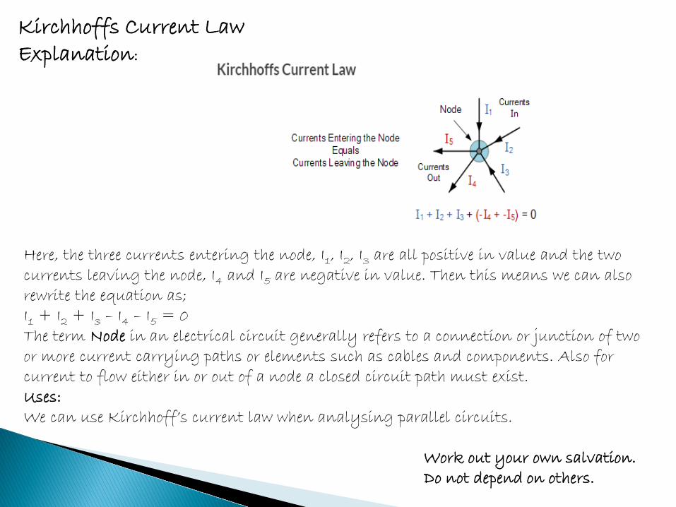
Here, the three currents entering the node, I1, I2, I3 are all positive in value and the two currents leaving the node, I4 and I5 are negative in value. Then this means we can also rewrite the equation as; I1 + I2 + I3 – I4 – I5 = 0 The term Node in an electrical circuit generally refers to a connection or junction of two or more current carrying paths or elements such as cables and components. Also for current to flow either in or out of a node a closed circuit path must exist. Uses: We can use Kirchhoff’s current law when analysing parallel circuits.
Kirchhoffs Current Law Explanation:
Work out your own salvation. Do not depend on others.
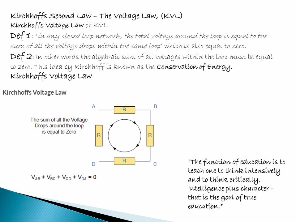
Kirchhoffs Second Law – The Voltage Law, (KVL) Kirchhoffs Voltage Law or KVL
Def 1: “in any closed loop network, the total voltage around the loop is equal to the sum of all the voltage drops within the same loop” which is also equal to zero.
Def 2: In other words the algebraic sum of all voltages within the loop must be equal
to zero. This idea by Kirchhoff is known as the Conservation of Energy.
Kirchhoffs Voltage Law
“The function of education is to teach one to think intensively and to think critically. Intelligence plus character - that is the goal of true education.”
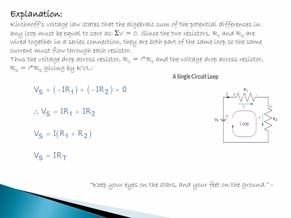
Explanation: Kirchhoff’s voltage law states that the algebraic sum of the potential differences in any loop must be equal to zero as: ΣV = 0. Since the two resistors, R1 and R2 are wired together in a series connection, they are both part of the same loop so the same current must flow through each resistor. Thus the voltage drop across resistor, R1 = I*R1 and the voltage drop across resistor, R2 = I*R2 giving by KVL:
“Keep your eyes on the stars, and your feet on the ground.” –

“I do not believe in taking the right decision, I take a decision and make it right.” “Think a hundred times before you take a decision, but once that decision is taken, stand by it as one man.” “There are two powers in the world; one is the sword and the other is the pen. ~~~~~~~~~~~~~ Prepared By : Ms Nazia ~~~~~~~~~~~~~~ (Msc Physics & M.Ed)