chapter – i - working of stations - South Eastern Railway
292
CHAPTER – I WORKING OF STATIONS Railway Stations, world wide, are located in prime city centres, as railways were started at a time when expansion of cities was yet to start. Railway station continues to be the focal point of central business district in all cities in the world. All description of rail business is transacted at the station, passengers start journey or complete it, outward parcels are booked and inward parcel consignments received and kept ready for delivery. At stations having attached goods shed, outward and inward freight cargo is handled there. In their historic evolution, the stations now have catering establishments, resting facilities in retiring rooms or a budget hotel. A world-class station may look or in fact be more like a mall with shops and catering establishments with attendant information, ticketing and reservation counters. Station Master is in overall charge of the station and includes Station Superintendent/Station Manager. Duty List of Staff : The duties to be performed by different categories of staff in connection with movement of trains are detailed below. These duties must be read in conjunction with the Station Working Rules of the station, General & Subsidiary Rule Book, Chapter II of Operating Manual dealing with “Working of Trains” and Block working Manual as amended from time to time. I. Responsibility of Station Master (supervisory)/Station Manager i) Station Master is responsible for the efficient discharge of duties by different members of staff at his Station. (General Rules 5.01) ii) Ensuring that the general working of the Station is being carried out in strict accordance with the current rules, procedures and instructions. iii) Providing prompt and courteous service with utmost safety and security of passengers and employees. iv) Availability, helpfulness and good conduct of station porters. v) He shall be responsible for general up-keep of the station. vi) He shall be responsible for keeping the safety and operating literature including circulars, pamphlets, gazette etc. up to date and these must be explained to the staff working under him and got noted by them. vii) He shall be responsible for maintaining Accident register and Accident charts and keeping these up to date. viii) He shall maintain figures in respect of the stock and get them relayed to the control in time.
-
Upload
khangminh22 -
Category
Documents
-
view
0 -
download
0
Transcript of chapter – i - working of stations - South Eastern Railway

CHAPTER – I
WORKING OF STATIONS
Railway Stations, world wide, are located in prime city centres, as railways were started at a time when expansion of cities was yet to start. Railway station continues to be the focal point of central business district in all cities in the world.
All description of rail business is transacted at the station, passengers start journey or complete it, outward parcels are booked and inward parcel consignments received and kept ready for delivery. At stations having attached goods shed, outward and inward freight cargo is handled there.
In their historic evolution, the stations now have catering establishments, resting facilities in retiring rooms or a budget hotel. A world-class station may look or in fact be more like a mall with shops and catering establishments with attendant information, ticketing and reservation counters.
Station Master is in overall charge of the station and includes Station Superintendent/Station Manager.
Duty List of Staff : The duties to be performed by different categories of staff in connection with movement of
trains are detailed below. These duties must be read in conjunction with the Station Working Rules of the station, General & Subsidiary Rule Book, Chapter II of Operating Manual dealing with “Working of Trains” and Block working Manual as amended from time to time.
I. Responsibility of Station Master (supervisory)/Station Manager i) Station Master is responsible for the efficient discharge of duties by different
members of staff at his Station. (General Rules 5.01)
ii) Ensuring that the general working of the Station is being carried out in strict accordance with the current rules, procedures and instructions.
iii) Providing prompt and courteous service with utmost safety and security of passengers and employees.
iv) Availability, helpfulness and good conduct of station porters.
v) He shall be responsible for general up-keep of the station.
vi) He shall be responsible for keeping the safety and operating literature including circulars, pamphlets, gazette etc. up to date and these must be explained to the staff working under him and got noted by them.
vii) He shall be responsible for maintaining Accident register and Accident charts and keeping these up to date.
viii) He shall maintain figures in respect of the stock and get them relayed to the control in time.
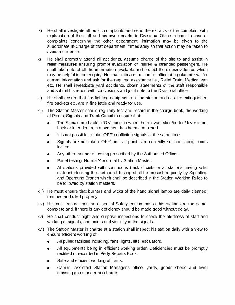
ix) He shall investigate all public complaints and send the extracts of the complaint with explanation of the staff and his own remarks to Divisional Office in time. In case of complaints concerning the other department, intimation may be given to the subordinate In-Charge of that department immediately so that action may be taken to avoid recurrence.
x) He shall promptly attend all accidents, assume charge of the site to and assist in relief measures ensuring prompt evacuation of injured & stranded passengers. He shall take note of all the information available and protect the clues/evidence, which may be helpful in the enquiry. He shall intimate the control office at regular interval for current information and ask for the required assistance i.e., Relief Train, Medical van etc. He shall investigate yard accidents, obtain statements of the staff responsible and submit his report with conclusions and joint note to the Divisional office.
xi) He shall ensure that fire fighting equipments at the station such as fire extinguisher, fire buckets etc. are in fine fettle and ready for use.
xii) The Station Master should regularly test and record in the charge book, the working of Points, Signals and Track Circuit to ensure that: The Signals are back to ‘ON’ position when the relevant slide/button/ lever is put
back or intended train movement has been completed. It is not possible to take ‘OFF’ conflicting signals at the same time. Signals are not taken ‘OFF’ until all points are correctly set and facing points
locked. Any other manner of testing prescribed by the Authorised Officer. Panel testing: Normal/Abnormal by Station Master. At stations provided with continuous track circuits or at stations having solid
state interlocking the method of testing shall be prescribed jointly by Signalling and Operating Branch which shall be described in the Station Working Rules to be followed by station masters.
xiii) He must ensure that burners and wicks of the hand signal lamps are daily cleaned, trimmed and oiled properly.
xiv) He must ensure that the essential Safety equipments at his station are the same, complete and, if there is any deficiency should be made good without delay.
xv) He shall conduct night and surprise inspections to check the alertness of staff and working of signals, and points and visibility of the signals.
xvi) The Station Master in charge at a station shall inspect his station daily with a view to ensure efficient working of– All public facilities including, fans, lights, lifts, escalators, All equipments being in efficient working order. Deficiencies must be promptly
rectified or recorded in Petty Repairs Book. Safe and efficient working of trains. Cabins, Assistant Station Manager’s office, yards, goods sheds and level
crossing gates under his charge.
Reservation Enquiry, Public Address system, Public Information Display System, booking offices, Ticket Checking, catering and vending stalls etc.
Drinking Water availability.
xvii) He shall see that train signal register, station Diary, Inspection Note Book, reference books and other station record is property maintained and preserved for a minimum period as prescribed later in this chapter.
xviii) At the bigger stations Health Inspector is incharge of sanitation the Station Manager shall conduct daily inspections and bring out deficiencies. He shall conduct daily inspections of waiting rooms, bath rooms, lavatories, refreshment rooms and catering trollies, platforms, tracks and other station premises from sanitation point of view and ensure that arrangements in this regard are adequate and effective. Availability of safe drinking water to passengers & employees is joint responsibility of JE/SE (works) and health department he should check that same is available.
xix) He shall ensure that sufficient stock is available for the requirement of the day. He shall keep in touch with the running of trains so that, in case of late running of connecting train, scratch rake can be turned out, if necessary. He shall also keep a check - on reserved stock available/allotted to his station.
xx) He shall take personal interest in arranging quick clearance of reserved carriages of troops, public, prisoners, treasuries etc.
xxi) Whenever special trains are arranged to run from his station, he shall ensure that stock for the same is secured and certified placed on the proper line in time.
xxii) He shall fix up responsibility in case of detention to trains outside or at the station and submit full report to DRM office.
xxiii) He shall be responsible to ensure that all the operating staff working under him are relieved in time for their periodical NVT/Competency/Safety camp and special competency programmes. No one, overdue NVT/Competency shall be allowed to perform his normal duties.
II. Deputy Station Master (Outdoor) : i) The Deputy Station Manager shall be responsible for general up-keep and proper
working of the station as under
ii) He shall maintain safety literature, rule books, safety record. He shall counsel staff regarding rules and safety-systems
iii) He shall deal with public complaints and counsel commercial staff for courteous behaviour.
iv) He shall ensure right time placement and removal of terminating/originating trains and keep records in this regard and also keep a watch on Shunting operations.
v) He shall inspect gate, panel, station, regularly during his shift. vi) He shall maintain close contact and co-ordination with Panel ASM and Log ASM for
smooth running of trains and for better planning of operational work and will assist in case of any abnormal working.
vii) He shall promptly attend to any incident or accident and assist in relief measures during his duty. He shall collect all information and inform the Control office for required assistance, i.e., Relief Train, Medical Van etc. He shall also inform the local civil authorities as required and safe guard the clues or evidences which may be helpful in enquiry.
viii) In case of abnormal working, he shall be responsible for manual operation (Hand Cranking) of Points and piloting of trains.
ix) He shall ensure that all coaching trains scheduled to stop at the station, start within their allowed time.
x) Whenever Special trains are arranged to run from his station, during his duty, he shall ensure that stock for the same is secured and placed on the proper line in time.
xi) He shall keep close supervision on sanitation. He shall inspect the platforms, waiting halls, waiting rooms & the track and see that the same are cleaned properly by the sanitary staff.
xii) He shall keep close watch on passenger amenities provided at station and their up keep.
xiii) He shall look after any other work assigned to him by Station Manager, from time to time.
xiv) In case of emergency he shall also perform duty on Panel/Log. xv) All instructions received from superiors shall be recorded in an Order Book. Senior
officers should confirm these through a control order to avoid ambiguity. All such instructions shall be implemented, provided these do not violate safety rules & procedures.
xvi) He will perform all the duties of SS in his absence.
III. Log ASM/Block ASM :
i) He shall handle the block instrument himself when on duty and shall not permit any unauthorized person to manipulate or handle the block panel/block instrument & block telephone.
ii) He shall keep the Station Manager’s control keys of block instruments in his personal custody whenever, he is required to leave his office even for a short duration.
iii) He shall maintain TSR and other connected record/documents in good shape and ensure that all entries are completed and are upto date.
iv) He shall attend the control and give arrival departure of trains promptly and shall carry out instructions given by superiors provided these do not violate safety rules & procedures.
v) He shall inform the ESM/MSM through a written message, any failure of block working etc. and invariably enter these failures in signal failure register.
vi) In case of any accident, he shall inform promptly the section controller Station Manager/Station Master/ Dy. SM immediately. He shall give all the information available with him in regard to the nature, places, cause and assistance etc. in respect of the accident.
vii) He shall communicate reasons for late start of out going trains and late arrival of incoming trains to control.
viii) He shall come on duty after taking complete rest and shall not perform his duty under the influence of liquor, drugs, or intoxicants.
ix) He shall keep his reference books upto date, posted with latest correction slips and shall keep himself fully conversant with the extant rules. He shall keep his books readily available for inspection when asked to do so.
x) He shall not absent himself from duty without prior permission of his superiors. He shall not leave his duty unless properly relieved by his relief and shall not exchange his duty without prior permission from his supervisors.
xi) He shall not consider himself relieved of duty unless he has completed transactions of trains for which he has given/obtained line clear till the complete arrival of such trains.
xii) He shall always obey the lawful orders of his superiors so long as they do not contravene any of the extant rules in force.
xiii) In case of any abnormal working, he shall also perform the duties assigned to Panel ASM.
xiv) He shall advise the descriptions of the train to which he had granted line clear or obtained line clear to panel ASM.
1.01 He shall promptly advise the section controller of any defects in signals, points, interlocking installations and Block Instruments at the stations and also of any defects in weigh bridge.
1.02 Accident or Abnormal Occurrence to be reported.— In the event of accidents or any untoward incidents involving obstruction of running line or lines, or in any way
affecting the safety of train working, full details shall be furnished by the Station Master to Control indicating the nature of assistance required.
IV. Panel ASM : i) When on duty or when called upon to do so, in case of emergency, he shall be
responsible for obtaining and granting line clear to trains or for shunting movements as per SWR & GR.
ii) He shall handle the control panel himself when on duty and shall not permit any unauthorized person to manipulate panel.
iii) He shall keep the SM’s control keys of control panel in his personal custody whenever, he is required to leave his office even for a short duration.
iv) While coming on duty, he shall ensure that all points and signals are in good working order and all the registers, records, pertaining to train passage are completed in all respect before taking over the charge.
v) He shall personally ensure that conditions for taking ‘off’ the reception signals are fulfilled and the clearance of line is verified as per SWRs before actually pressing the relevant button for taking off the signals.
vi) He shall ensure from indications available in the panel that the signals are burning correctly and are giving correct indications.
vii) He shall maintain complete and up to date record of the Engg. Restrictions. He shall responsible for bringing forward the caution order register every Monday and ensure restrictions on notice board as well.
viii) He shall responsible for ensuring delivery of proper caution orders to all trains.
ix) He shall ensure that all Shunting operations are carried out as per extant orders and GR 5.19 and SRs thereof.
x) He shall inform the ESM/MSM in writing or through a written message, any failure of track/signals/points/keys or panels etc. and shall invariably enter these failures in signal failure register.
xi) He shall allow shunting in between the arrival/departure of trains or during slack period as frequently as possible to the maximum extent.
xii) He shall come on duty after taking complete rest and shall not perform his duty under the influence of drugs, or intoxicants.
xiii) He shall keep his reference books upto date, posted with latest correction slips and shall keep himself fully conversant with the extant rules. He shall keep his books, readily available for inspection when asked to do so.
xiv) He shall not absent himself from duty without prior permission of his superiors. He shall not leave his duty unless properly relieved by his relief and shall not exchange his duty without prior permission from his superiors.
xv) He shall not consider himself relieved of duty unless he has completed transactions of trains for which he has given/obtained line clear till the complete arrival of such trains.
xvi) He shall always obey the lawful orders of his superiors so long as they do not contravene any of the extant rules in force.
xvii) He shall ensure that proper indications of points, signals, track, circuits, crank handle, level crossing gate etc., are displayed at their proper places.
xviii) He shall be responsible for issuing required papers to trains entering/leaving the yard under the instructions of log ASM.
xix) He shall issue shunting order for shunting operations as per extant rules.
xx) He shall keep a watch on the working of shunting staff.
xxi) He shall ensure clearance of running lines in case of failure of their track circuits.
xxii) He shall maintain log book regarding train and shunting movement.
xxiii) He shall be responsible for giving complete arrival of all trains to log ASM supported by a private No.
xxiv) In case of abnormal working he shall be responsible for cranking pad locking of points and piloting of trains in absence of Deputy Station Manager/out door.

1.3. At stations where only one ASM/SM is posted in each shift, all the duties and responsibilities of Panel ASM, Log ASM and relevant portion of Deputy Station Master (outdoor) will devolve on him.
V. Pointsman/Shuntman : i) He shall obey all lawful orders of the ASM on duty or official in-charge supervising the
shunting during the course of shunting operations including coupling or uncoupling of vehicles of wagons. Fixing rubber washers, closing wagon doors, displaying hand signals etc.
ii) He shall exhibit danger signal to the official supervising the shunting should the crossing be fouled during the shunting operation.
iii) He shall pilot the trains in case of abnormal working and when ordered by the SM on duty.
iv) He shall be in proper neat and clean uniform while on duty.
v) He shall come on duty after taking complete rest and shall not perform duty under the influence of liquor, drugs, or intoxicants.
vi) Neither shall he absent himself from duty nor shall he exchange his duty without prior permission of his superiors.
vii) He shall not leave his duty unless properly relieved or authorized by his superiors.
viii) He shall set the points properly in non-interlocked yard and man them for all shunting movements and shall not interfere with the points while the vehicles are standing and, or passing over them.
ix) He shall be responsible to see that fouling marks are kept clear after completion of shunting.
x) He shall always commence his duty equipped with hand signal lamps during night and flags during day.
xi) He shall verify the correct setting of route before delivering required papers to the loco pilot either through taking ‘OFF’ the relevant shunt signal or by personal observation.
xii) In case of track failure he shall assist the SM to ascertain the clearance of line.
xiii) He shall be responsible for lighting up of the indicators in the evening and putting out in the morning time fixed by DRM office and ensuring that these are burn brightly at night.
xiv) He shall be responsible for cleaning and oiling the burners and trimming wicks during day time under the supervision of Station Manger/Deputy Station Manager.
1.4. These duties will also devolve on Token porters where they perform the duties of Pointsman/Shuntman.
VI. Gateman : i) He shall be responsible for proper operation of the gate as per SWRs for the passage
of trains.
ii) He shall ensure that no train suffers any detention on account of late closing of the gate.
iii) He shall keep the channels of check-rails clean and shall clean the road within the railway limits and water the area regularly.
iv) He shall clean the gate lamps and hand signal lamps daily. He shall ensure that the wicks of the burners are trimmed so that these are lighted properly and kept burning continuously from sun set to sunrise.
v) He shall keep the surroundings of his gate lodge clean tidy and neatly planted with shrubs, plants etc.
vi) He shall remain alert on duty till properly relieved. If he is required to leave the gate in an emergency he shall close and lock the gate booms against the road traffic before leaving the gate.
vii) He shall ensure that the equipment at Level crossing are complete and in working orders.
viii) He shall produce the public complaint book when required by public for lodging complaint and to the railway officials for inspection.
ix) He shall ensure that road traffic is not unnecessarily held up at the gate.
x) He shall stand in attention near the gate lodge facing the track and be prepared to repeat any signal which the guard may intend to convey to the loco pilot or show caution or danger signal should anything appear to be wrong with the train itself as if passes.
xi) He shall be polite and courteous in his behaviour towards the public.
xii) He shall report any defect in the gate to the ASM on duty without delay.
xiii) He shall close the gate on sighting a train or when ordered by the ASM on panel duty.
xiv) He shall attack the attention of the loco pilots and guards by shouting and gesticulating instead of showing danger signal in case of train parting.
xv) He shall obey all lawful orders of the SM on duty. xvi) In case of any obstruction, accident or damage to the gates, he shall protect the
gate/obstruction as per instructions and rules in force.
VII Duty list and hours of duty: 1) Sr. DPO/DPO shall fix the duty hours for the staff at stations in accordance with the
(Hours of employment regulations in consultation with Sr. DOM/DOM. Copies of these duty hours (roaster) must be displayed at each station.
2) Station staff shall handover change at the end of their hours of duty as prescribed at the station only when properly relieved. Such duty hours shall not be exchanged without the permission of the Station Master.
3) Daily Mustering of Staff: The Station Master or the person authorised in this behalf shall fill in the attendance of staff at his station in Attendance Register.
1.5. The staff should sign in the attendance register themselves at the time of reporting duty. In case of illiterate staff his attendance should be listed by the Station Master on duty.
SM’s responsibility for assurance: Station Master’s responsibility before allowing employees to take independent charge–
1) Station Master must not allow any employees to take independent charge of a post connected with train working without satisfying himself after detailed oral examination about the knowledge of concerned staff. He must satisfy that the employee– (a) Possesses the requisite Certificate of Competency. (b) Has understood the working rules of the Station and is fully conversant with the
duties he has to perform.
2) Before an employee takes independent charge of a post connected with train working for the first time, the pickup period in generally laid down by the DRM(Safety). However, following guidelines can be observed on first posting or when there is change of system/means of working of trains– (a) Junction stations with marshalling yard and lobby – 10 days (b) Terminal stations with marshalling yard and lobby – 8 days (c) Large stations or junction stations – 5 days (d) Medium stations & Road side stations – 3 days
(e) Road side stations * – 2 days *
If a employee fails to give declaration in fixed period, he must be directed for Refresher Training at his expense.
* This is applicable for stations under “One train only system”, “Train staff and Ticket system ”and also for night closing stations.
He must read station working rules and must witness the actual performance of these duties for the time specified as pick up time. In emergencies, however and cases where the duties are of a simple character and similar to those already performed by an employee at stations where he has worked before, this pick up period may be reduced by the Sr. DOM. It must cover pickup in all the shifts
(Minimum one day for each shift)
Home Address Register: 1) Every Station Master must maintain a Register containing the name and up-to-date
address including telephone /mobile phone no. of each member of the staff employed at his station.
2) A separate Register containing list of all shopkeepers, licensed vendors, licensed coolies, contractors coolies or any other persons working at station other than railway employees must be maintained along with their up to date address and telephone nos, blood group if available and office copy of their Photo Identity cards. Entry of such persons into station area will be permitted only after checking the I Card.
Public and Staff notices for exhibition : The following Notices and Publications, besides those, which may be ordered from time to
time, shall be exhibited at each station in conspicuous places. 1) Notice Board showing current running of trains in the waiting hall, or at the entrance. 2) Notices regarding hours of business of goods, luggage and parcels - outside the
respective offices. 3) Notices regarding restrictions in Goods Booking.
4) Notices regarding Allotment of Wagons. 5) Rules regarding occupation/use of Waiting Rooms - Inside the waiting rooms. 6) Notice regarding date of payment of staff. 7) Duty Rosters and Classification lists of staff employed at stations. 8) Extract of Railways Act (24 of 1989) and payment of wages act. 9) A list of nearest Doctors and Hospitals, with telephone nos. 10) Rules for the occupation of Rest Houses and Rest Rooms. 11) A list of home addresses with telephone nos. of staff in Station Master’s office. 12) List of persons with telephone nos. from whom conveyance can be requisitioned in
emergency; list of tent houses. 13) List of nearest Fire Stations, Bus depots, Airports, OIL companies etc. with telephone
numbers. 14) List of telephone numbers of Civil, Police, Military and Railway officials. 15) Other prescribed notices. 16) The List of Staff qualified in First Aid. 17) Blood groups of staff The Station Manager must be careful to see that out dated timetables and notices are
removed and replaced with current ones. He should also ensure that the telephone nos. are updated from time to time.
Exhibition of public advertisements: 1) Public advertisements in the form of Boards, Posters, Showcases, Models, Neon-signs, or
in any other form should not be allowed to be exhibited at any place within the station limit or premises without the written permission of the competent officer of commercial publicity branch etc. The Station Master will maintain a register showing full particulars of each advertisement exhibited at the station in the prescribed form.
2) Station Masters and other railway staff including Guards and Loco pilots of any train must not permit the display of advertisement matters on engines, passenger coaches and other rolling stock, unless the prior permission of the Divisional Railway Manager concerned has been obtained.
Rule Books, Manuals etc. at Stations: 1) The Station Master is personally responsible to see that rules books are kept up-to-
date and are available to staff for reference. (G&SR 2.01, 5.02 and 5.03.)
2) Station Master is also responsible to see that all registers, forms and charts are properly and neatly maintained and that they are not used for purposes other than those for which they are printed and supplied.
3) Station Masters are responsible for general accuracy of all periodical returns and for their submission in time.
4) Destructions of obsolete records shall be recorded in a register.
Station Records:

1) Each book/Register, when completed must be stocked in a bundle with a cover showing dates of commencement and completion.
2) Records must be placed on shelves and almirahs in dry and secure places, where they shall be safe from irregular handling or removal by any unauthorised person.
3) Periods for which Station records must be kept at Stations are given at the end of this chapter. Any records pertaining to court cases/enquiries must not be destroyed until the DRM’s permission is obtained.
Books and Notices at Level Crossing Gates: The following books and notices are maintained at a level crossing gate provided with
Gatelodge. Where Gate-lodges are not provided, the books shall be maintained in the Station Master’s office.
1) A Book showing the list of equipments. 2) Duty Rosters. 3) A copy of duty list with translation in regional language. 4) Level crossing working instructions, which should appear as separate appendix to
SWR. (In English, Hindi & regional language).
1.6. In addition to the above the following shall be maintained at Gate lodges.
1) Protection diagram board.
2) PN Book.
Hand Book for Gateman : 1) Extract of the Station Working Rules. 2) Public Complaint Book. 3) Vision test and Competency Certificate of the Gateman. 4) Results of last Traffic Census. 5) Inspection Books.
Filing of Operating Circulars: 1) Every Station must maintain files of circulars etc. subject wise. 2) Each circular must be got noted by members of the staff concerned. In case of Group
‘D’ moderately literate staff, Station Master must record that circulars etc. have been correctly explained:
Instructions for Guards: Instructions for Guards issued from time to time must be kept in one file at Guards
Headquarter stations. Guards must make themselves thoroughly acquainted with these instructions and should sign the circulars and assurance register of safety literature file, while “signing on” for duty.
Correspondence:
1) All official correspondence must be attended to by the Station Master, who must open all covers and see that all letters are replied without delay.
2) All inward letters must be registered in the inward letters register showing the dates & letter no. of reply with a copy placed in a file.
3) Station Masters are responsible for the accuracy of the information contained in all outgoing letters, which they must sign personally.
4) The Station’s name must be stamped on all returns and letters and on envelopes in which they are despatched.
5) Every outward letter must be numbered, dated and must also bear reference no. of the subject. This must be adhered to in all subsequent correspondence when replying to correspondence; reference must be made to the letter number under reply.
6) Letters from the public asking for information must be replied to as promptly as possible. If there is any difficulty in supplying the required information, the receipt of the letter must be acknowledged and matter referred to the DRM,
7) SR.DOM shall provide model draft of letters, which are frequently received at stations, using a model draft will ensure that language used is polite, respectful and courteous. It should be written legibly at stations not having computers
8) When forwarding letters or complaints from staff working under them, Station Masters must submit their own remarks, while forwarding such letters.
9) Letters received by the Station Master, pertaining to departments under him- e.g. Goods Shed, Booking/Parcel offices etc. may be marked by the Station Master for the In charge concerned, but the Station Master shall be personally responsible for the early compliance of such letters.
Playing of Bands and presentation of Guards of Honour etc. on Station platform: The playing of bands and presentation of Guard of Honour etc., on the Station Platform is
prohibited, except with the prior permission of the DRM.
Prohibition against Photography/Film shooting on railway premises: Such Photography/Film shooting is strictly prohibited within Station limits and on the railway
lines, except with the permission of the officers authorised by railway administration.
Religious Edifices within the railway limits: Employees are forbidden to occupy any place in station area for praying holding religious
functions speeches, discourses etc., to erect religious structures, either permanent or temporary, or to add or alter any existing religious structures on railway land, without the sanction of the General Manager.
Station Masters will keep close watch and promptly report any violation of this instruction.
1.7. Station bell signal for incoming and outgoing trains.— The following signals are to be given on the station bell for trains carrying passengers for information of the
public :—
Line clear given Warning, train left Train Before Starting for a train to the last station in rear. approaching. Station in rear.

Up trains Sharp continuous ** ** ** ** ** beats for 3 seconds followed by :- (Two pause, (Two pause two * *(Two strokes). two strokes) pause, two strokes).
Down trains Sharp continuous *** (Three strokes). *** *** *** beats for 3 seconds (Three pause, three followed by :- pause, three strokes). (One stroke). ____________________________________________________________________________________________________ Note : (i) No bell is required for non-stopping passenger carrying trains or special trains. (ii) At stations having public announcement arangements, particulars of trains leaving the station in rear, the
time at which they left and the departure of outgoing trains shall be announced through Loud speaker. In this case there is no need for ringing the bell.
1.8 Points not to be altered under moving vehicles.— Station Master/Yard Master must carefully train their staff like Pointsmen, Token Porters, Cabinman and
switchman etc. and impress upon them that they must not alter the points, even if they have set the points wrongly, while vehicles or engines are moving over them, but must show a danger signal to warn the Loco Pilot and the Guard so as to bring the engine/Trains to a halt.
1.9 Inspection of Guards' equipment by Supervisors and Officers.— (a) The articles of personal equipment in the possession of Guards must be carefully inspected at least once
in three months by the SS/CYM/Station Master/Yard Master of their headquarters station and a report submitted to the Sr. Divinl. Operations Manager/Divisional Operations Manager by the 10th of the following month. Any deficiency must be made good immediately, raising debit against the staff at fault in case of loss or damage.
(b) Inspectors and Officers must check up the equipment of Guards as frequently as possible and take up cases of deficiencies.
1.10 Care of passenger carriages.— (a) Station Master must see that carriages cut off at stations are swept and cleaned at once and the doors and
windows are closed and locked immediately after they are vacated. The coaches detached or attached at a station shall not be allowed to be occupied by the passengers beyond the periods prescribed in local orders to be issued by the Divisional Railway Manager.
(b) The cleaning of all coaching vehicles at stations where Train Examining staff are posted must be done by the Train Examiner's staff, but the Station Master must see that the work has been duly and efficiently performed, and must bring any case of neglect to the notice of the Divisional Mechanical Engineer and the Divisional Commercial Manager.
All refuse cotton, jute, hay etc. should be swept out of coaching stock properly before they are attached to train or before allowing the rake for outward movement.
(c) Carriage cleaners and fitters are deputed to travel by a few important trains. It is the duty of the Guard, Conductors and Station Master to ensure that they attend to the cleaning of carriages and minor repairs to carriages and electric fittings in coaches on the run and at stopping stations, as required.
(d) The C&W staff will be responsible for switching off the electric lights and fans, also for closing and locking of the doors and windows of empty coaching stock stable at stations or before allowing the empty stock to run. In case the passenger coach is detached or rake is stabled at a station not provided with TXR staff, the Station Master is responsible to ensure this. No person shall be allowed to stay in empty coaching stock or travel therein.
(e) Whenever any upper class carriage is not occupied the conductor and Travelling Ticket Examiner shall arrange to close the doors and windows and switch off the electric fans, and shall also see that no unauthorised person travels therein.
(f) RPF staff have been specially deputed on certain sections to guard the coaches and fittings on run and in stations yards.
1.11 Closing and securing of doors of goods stock.—

The main responsibility to ensure the closing and securing of doors of goods stock before any wagon is attached to train or shunted lies with the Station Master or Yard Master as the case may be. At a station or in a siding where goods Clerk or Goods Supervisor is posted, he will be responsible for ensuring that the doors of wagons are properly closed and secured immediately on completion of loading/unloading. The Train Examiner will also be responsible to see before issuing the certificate at the examination point of the train that the doors are properly closed and secured. Guards before starting the train from the originating station must ensure that the doors of all the wagons are properly closed and secured. Guards of all pilots, work trains etc, before drawing out wagons from the siding shall also ensure that the doors are closed and secured. If any wagon(s) is/are observed by the Guard in door-open condition after starting from a Station/Yard/Siding and likely to cause unsafe condition, the train should be stopped immediately and door(s)closed/secured. In case, closing/securing of door(s) is/are not possible, the train may be taken carefully with such restricted speed as considered necessary by the Loco Pilot and Guard to the next station where steps should be taken to have the door(s) closed/secured properly.
1.12 Obstruction on running line.— (a) Station Masters will not allow any packages or material to be so unloaded as to interfere with any signal
rodding or wires or running line. Any consignment unloaded should be well away from the platform copying, running line and signal rodding or wire so that there is no change of its infringing the moving dimensions either where unloaded or by shifting due to vibration. They will make the staff understand the importance of this precaution and ensure it. In Goods sheds and Parcels sidings the Goods Clerk/Parcel Clerk will be responsible for ensuring this.
(b) In a Private siding where the Goods Clerk/Goods Supervisor is provided, he will be responsible to see all the packages/materials are kept well away from the line so that there is no charge of infringement of moving dimensions. The siding authority will be responsible to ensure this aspect where no railway staff is posted.
1.13 Responsibility of Station Masters and others for Railway property (Carriage and wagon materials).— (a) Station Masters of stations where there is no Train Examining staff must assist in collecting all wagon
materials that may be lying about their yards and forwarding the same with the least possible delay to the nearest Train Examiner.
(b) Wagon fittings or other Railway materials must on no account be sent to the Lost Property Office. (c) In order to avoid loss in transit, Carriage and wagon materials picked up in yards or received from
SSE/SE/JE(P.Way) or Guards are to be despatched to SSE/SE/JE(C&W) under Free Service Way Bill. (d) All inspectorial staff when visiting stations will make it a special item of their check to see that any rolling
stock material or couplings which may be lying about on the platform or in the yard are sent to the nearest SSE/SE/JE(C&W) without delay.
(e) The Permanent Way staff and trolly holders will specially look for wagon fittings like brake blocks, dynamo, belts, etc. falling off on the run, while working/trollying, collect the same and make them over to the nearest Station Master to be disposed of as per sub-clause (c) above.
(f) All Railway staff must do all in their power to stop theft of fittings of vehicles/wagons/Track/and to prevent trespassers from entering yards and station limits. The assistance of the RPF/Police should be taken whenever required.
1.14 Fire drill :—
(i) Fire drills will be held every Saturday in order to make the staff more disciplined, conversant with fire fighting technique and to infuse consciousness about fire hazards.
(ii) Station Masters and respective supervisors will be responsible for holding fire drills. (iii) The R.P.F. personnel must join the drill and assist with their technical advice to make the drill a success. (iv) A record of each fire drill conducted is to be maintained in a register/diary by the Station
Masters/Supervisors.
Normal period for which Station Operating Registers and Records are required to be preserved:
S.No. of Period of preservation the Book/ Description of the Book/Form from the date of Form completion
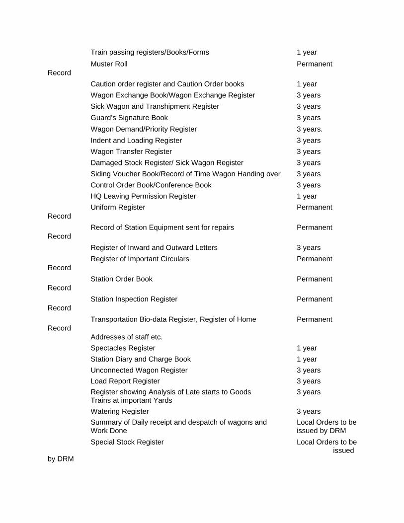
Train passing registers/Books/Forms 1 year Muster Roll Permanent Record Caution order register and Caution Order books 1 year Wagon Exchange Book/Wagon Exchange Register 3 years Sick Wagon and Transhipment Register 3 years Guard’s Signature Book 3 years Wagon Demand/Priority Register 3 years. Indent and Loading Register 3 years Wagon Transfer Register 3 years Damaged Stock Register/ Sick Wagon Register 3 years Siding Voucher Book/Record of Time Wagon Handing over 3 years Control Order Book/Conference Book 3 years HQ Leaving Permission Register 1 year Uniform Register Permanent Record Record of Station Equipment sent for repairs Permanent Record Register of Inward and Outward Letters 3 years Register of Important Circulars Permanent Record Station Order Book Permanent Record Station Inspection Register Permanent Record Transportation Bio-data Register, Register of Home Permanent Record Addresses of staff etc. Spectacles Register 1 year Station Diary and Charge Book 1 year Unconnected Wagon Register 3 years Load Report Register 3 years Register showing Analysis of Late starts to Goods 3 years Trains at important Yards Watering Register 3 years Summary of Daily receipt and despatch of wagons and Local Orders to be Work Done issued by DRM Special Stock Register Local Orders to be issued by DRM
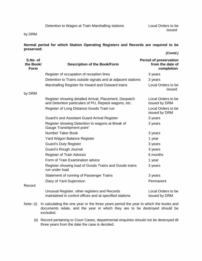
Detention to Wagon at Train Marshalling stations Local Orders to be issued by DRM
Normal period for which Station Operating Registers and Records are required to be preserved:
(Contd.)
S.No. of Period of preservation the Book/ Description of the Book/Form from the date of Form completion Register of occupation of reception lines 3 years Detention to Trains outside signals and at adjacent stations 3 years Marshalling Register for Inward and Outward trains Local Orders to be issued by DRM Register showing detailed Arrival, Placement, Despatch Local Orders to be and Detention particulars of PU, Repack wagons, etc. issued by DRM Register of Long Distance Goods Train run Local Orders to be issued by DRM Guard’s and Assistant Guard Arrival Register 3 years Register showing Detention to wagons at Break of 3 years Gauge Transhipment point’ Number Taker Book 3 years Yard Wagon Balance Register 1 year Guard’s Duty Register 3 years Guard’s Rough Journal 3 years Register of Train Advices 6 months Form of Train Examination advice 1 year Register showing load of Goods Trains and Goods trains 3 years run under load Statement of running of Passenger Trains 3 years Diary of Yard Supervisor. Permanent Record Unusual Register, other registers and Records Local Orders to be maintained in control offices and at specified stations issued by DRM
Note:- (i) In calculating the one year or the three years period the year to which the books and documents relate, and the year in which they are to be destroyed should be excluded.
(ii) Record pertaining to Court Cases, departmental enquiries should not be destroyed till three years from the date the case is decided.
(iii) Record pertaining to public claims etc., or those under reference from Home or other railways, should not be destroyed without permission from DRM concerned.
Most of these registers can be computerised, clubbed & some can be eliminated.
CHAPTER – II
WORKING OF TRAINS
GENERAL
No person shall drive a train unless he is in possession of a valid certificate of competency issued by an authorized officer.
No Loco Pilot, Assistant Loco Pilot or loco pilot of any self propelled vehicle shall be booked to work a train or to drive a vehicle until he has learnt the road and shall give a declaration that he is fully acquainted with it.
For this purpose he will be booked to work three round trips on each section including one during night before being put to work the train/vehicle independently.
Examination of Trains Each train shall be examined by competent person from the rolling stock/electrical
maintenance department before being offered for passenger, goods/or any other service. The purpose of the examination is to ensure that all functions of the train and its
constituent carriages/wagons etc. are working correctly, particularly safety devices including brake systems, passenger alarm -etc. to be listed by competent authority.
The competent staff shall sign a certificate of safety test indicating duration of its validity.
Classification of Trains: Trains are either scheduled as shown in the Working Time Table or non scheduled trains
and are run on the following account:–
Traffic Account: (a) Mail / Express / Passenger Trains. (b) Commuter trains EMU/DMU/for Suburban, regional passengers. (c) Military Specials including troop trains. (d) Parcel trains of carriage of coaching traffic only. (e) Goods trains for movement of conventional freight cargo. (f) Container Trains. (g) Mixed trains carrying both passengers and freight. Other trains to include Exhibition Trains, Mobile Hospital on wheels etc.
Engineering Account : 1) Ultrasonic and other track testing trains:
(a) Material trains. (b) Track maintenance trains like Tie Tamping Machines, Rail grinding trains PQRS,
BCM, DGS etc., (c) Wiring Special / Tower wagons.
Miscellaneous Account: (a) Staff shuttles. (b) Water specials. (c) Workmen’s specials. (d) Accident Relief Train (ARTs) (e) Accident Relief Medical Equipment (ARMEs). (f) Crane Specials.
Train Ordering: Scheduled passenger trains do not require train ordering. Train advice is necessary only when these are required to be cancelled, put back or there
is any change in the schedule shown in the Public / Working Time Table.
In case of unscheduled trains, train advice should be issued.
Trains are ordered by CTNL in conjunction with the Power Control and or Lobby Supervisor.
Train Preparation: The time at which train is required to be in readiness in all respects for departure from the
starting station will be laid down by the Divisional Railway Manager/SR.DOM.
In case of passenger trains, the rake duly examined and fit in all respects with full compliment of coaches (at least to meet reservation requirements fully) should be placed on the platform well in time to allow all pre departure functions to be completed.
These include– Loading of mails, booked luggage, and parcels Loading of linen Pantry car provisions Watering Cooling of AC coaches Display of reservation charts Deployment of train staff Attaching of locomotive
To facilitate passengers boarding, generally an important long distance passenger train should be placed on the platform 30 minutes/15 minutes before its scheduled departure, depending upon the terminal layout.
2.1 In case of goods trains adequate time should be allowed for carriage examination, detaching of wagons marked sick, if any, after such examination or for detaching excess or wrong wagon or for correcting wrong marshalling, testing of vacuum etc.
Every Loco pilot of a train while starting from the starting station must verify adequacy of brake power as certified in train examination document In addition, he must conduct a “feel test” to ensure that train brakes respond to brake application. In case of failure, he will report to the control and bring his train to a stop as directed by the Control. The train shall move only after the defect has been rectified.
2.2 Measures to improve punctuality.— A. Station Masters must ensure that—
i) Trains are not held up for such avoidable reasons as delay in obtaining ‘‘Line clear’’ or giving permission to start, detention at signals due to light extinguished, signal drooping or taken off late, shunting in the yard, absence or late arrival of a railway servant at the foot of a defective stop signal to pilot the train, etc;
ii) there should be no delay in handing over the correct authority to proceed to the Loco Pilot; iii) Mails and packages for loading should be kept in proper position and promptly loaded and those
for unloading promptly unloaded; iv) Warners should be taken off as per rules for run through trains; and v) shunting should be completed as early as possible.
B. Guards should.— i) attend their trains in time and start them right time; ii) exchange all-right signals with the Loco Pilot after the train starts from a station in absence of
which the Loco Pilot is likely to come to a stop; iii) make over and take over packages and cash promptly at stations; iv) where necessary seek the co-operation of the Control to ensure that trains are not detained
unnecessarily.
C. Loco Pilot must.— i) attend their duties in time according to rules; ii) see that the Ball Tokens are not missed; iii) ensure that there is no time loss or engine failure; iv) see that extra time is not taken for loco requirements at stations, and v) try to make up lost time on the run without disregarding any of the speed restrictions or exceeding
the maximum permissible speed.
2.3 Attendance of Guards.— (a) It must be distinctly understood that Guards are liable to be called upon for duty at any time. (b) The putting of the names of Guards in the Station Roster will be considered sufficient intimation that their
services are required at short notice. (c) Guards, though they may be scheduled to work a certain train, should not absent themselves from Railway
Quarters or their fixed residence on the strength of such schedule without giving the Station Master/Chief Controller/Yard Master (who may be controlling the Guards) notice of where they may be found if required in any emergency. The Guard booked for any train should be prepared to work any other train, should it be necessary.
(d) When unable to go out with a train for which they may be in turn owing to sickness, they must give timely notice( at least four hours before the scheduled departure of their train or the expected time of Call Book/Call Notice of the fact to the Station Master/Yard Master/Chief Controller in order that arrangements may be made to fill their places. Reporting sick on the Call Book/Call Notice when sent to warn them for duty will not be considered timely notice.
(e) Guards remaining absent from duty without leave or medical certificate from a Railway Medical Officer, will render themselves liable to punishment.
(f) Guard must undergo breathlyser test at the lobby at the time of signing ‘ON’ and signing ‘OFF’ duty.
2.4 Duties of Guards when taking over charge of a train.— All Guards while taking over charge of trains in addition to the stipulation in G.R.4.34 and S.R. thereto shall
ensure that— (a) The vehicle guidance/Wagon Way bill of the train is collected and personally satisfy by actual check that the
vehicles/wagons as per vehicle guidance/wagon way bill are correct on train and lablels of wagons, seals and rivets of sealed wagons are intact.
(b) The doors of all goods wagons are properly closed/secured and fastened. (c) All the screw couplings on train are tightened properly without slackness. (d) The brakevan is fitted with air pressure gauge and Pressure available as mentioned in Para 23.02 of this
Manual. (e) The train is provided with prescribed brake power as indicated in Para 23.04 of this Manual. (f) The train is not wrongly marshalled. In case of any defect or deficiency with the train or wagon/vehicle, it
must atonce be brought to the notice of the Station Master or Yard Master as the case may be and the defect/deficiency made good. If the defect or deficiency is such as would interfere with the safe running/working of the train, the train shall not be allowed to leave the Station/Yard until the defect/deficiency has been removed or the wagon/vehicle concerned has been detached. Refer G.R. 4.35 and S.R. thereto.
2.5 Guard's duties in respect of vehicles/wagons attached/detached.— Guards in charge of trains shall enter the number, owning Railway and description of all vehicles/wagons
attached to their trains and the names of the stations to and from which booked, in their Rough Journal and on the reverse of their Train Report in the space for remarks. Those particulars must be taken by Guards direct from the labels affixed to the vehicles/wagons on their trains and not merely copied from the Wagon Way bills prepared by the Trains Clerk. Guards shall further carefully check the entries in the Wagons Way bills with the particulars shown in the labels and see that the labels contain necessary particulars and that there is a label on each side, and that the door seals and rivets on both sides of sealed wagons are intact. Should any mistake or deficiency be discovered the Station Master or the Trains Clerk shall be asked to rectify the same and until this is done the train must not be started. Similarly, the Guard must record in the Wagon Way bills the particulars of wagons detached and also record the same on the reverse of the Train Report.
2.6 Guards, responsibility in respect of train papers.— (a) The Guard in charge of the train will be responsible to maintain the Guard's Rough Journal book and keep
it up-to date during the journey of the train. At guard-changing station, the Wagon Way Bill/Vehicle consists, DRS cards, Way-bills, Summaries etc, must be carefully examined by the Guards when handing over and taking over charge, and any discrepancy or remarks recorded should be jointly signed by the relieving and the relieved Guard. The Guards should make out their train reports on the journey and complete immediately on arrival of their train at destination. Three copies of Train report (T.34 HF) must be handed over by the Guard to the Loco Pilot/Assistant Loco Pilot of the train at Guard or crew changing station or at terminal station as the case may be. The Loco Pilot should ensure to depute his Assistant Loco Pilot to collect the train report from the Guard. In case of no assistant to the Loco Pilot, the Guard will be responsible to hand over the train report personally to the Loco Pilot. Under no circumances must such handing over be delayed involving detention to trains.
(b) Reports at destination— (i) Guards shall prepare and hand over at the end of their journey (before they go off duty) to the
Control office, Station Master or Trains Clerk, Roster Clerk according to the local orders in force, the following train paper and obtain signature in their Rough Journal books :—
For Goods Trains ... Wagon Way Bill/Vehicle guidance consist, Train report.
For Tranship Trains ... Wagon Way Bill/Vehicle guidance consists, road van summaries and Tranship Guard's journal.
For Coaching Trains (viz, Mail, Express, Passengers, Mixed and Local Trains) ... Wagon Way Bill/Vehicle guidance consist,
Train report. (ii) In addition the Guards of coaching trains shall hand over the Summaries of Parcels and Luggage
etc, to the Station Master/Parcel Clerk/Booking Clerk at the destination station. (iii) In case of local trains, such as those running between Kharagpur and Midnapore, Howrah and
Panskura or any intermediate station or any other trains tuned to make short trips, the train reports may be made out for each round trip.
(iv) While preparing the train report the Guard must also indicate if any special load on train, such as live stock, perishable or oversize, Inspection Carriage or reserved carriage etc. or any unusual occurrence or any deficiency in rolling stock, weather condition, shunting by train engine etc.
(v) The train report of material train should be prepared after a day's work is finished and handed over to the Station Master/Train Clerk/Roster Clerk as the case may be at stabling station.
(vi) At the close of each day these documents must be submitted duly entered in transmit memo to the official concerned. All concerned must take special care in preparing and submission of these documents.
(c) At stabling or Guard changing stations : The Guard shall hand over all the relevant records to the on duty SM at the station where his train is stabled and to the reliving Guard at Guard changing stations.
2.7 Attendance of Crew at Sheds.— (a) It must be distinctly understood that engine crew are liable to be called up at any time for duty. (b) The booking of engine crew in the "Shed duty list" exhibited in the running shed, will be considered
sufficient intimation that their services are required. (c) Engine crew, though scheduled to work a certain train, should not absent themselves from Railway
premises or their fixed residence on the strength of such schedule without giving the SSE/SE(Loco) or the Crew Controller or SSE/SE(Elect.) notice of where they may be found if required in an emergency. The Loco crew booked by a certain train should be prepared to work any other train, when called upon to do so by the SSE/SE(Loco)/SSE/SE(Elect.), Crew Controller or the Power Controller on duty.
(d) When unable to go out with a train for which he may be in turn owing to sickness, etc., they must give timely notice (at least four hours) of the fact to the Foreman, in order that arrangements may be made to fill their places. Signing sick on the Call Book when sent to warn them for duty will not be considered timely notice.
(e) Engine crew absent from duty, without leave or medical certificate from a Railway Medical Officer, will render themselves liable to punishment.
(f) Crew must undergo breathlyser test at the lobby both at the time of signing ‘ON’ and signing ‘OFF’ duty.
2.8 Time allowed to Loco Pilots for examining/making over engines.— Loco Pilots must examine their engines before leaving the Shed. The time allowed to outgoing Loco Pilots for
examining the engines before departure from the "Bahar" line and to incoming Loco Pilots to make over their engines after return to the Loco limits will be prescribed for each Shed by the Divisional Railway Manager. The Loco Pilots must ensure that the time is not exceeded. Refer S.R.4.04.03 in this connection.
2.9 Time allowed for the engines between Shed and yard.— (a) Each Divisional Railway Manager will prescribe the time allowed for outgoing engine to travel from "Bahar"
line to the train and the incoming engine to travel from the train to the "Bahar" line. The Loco Pilots must ensure that the time is not exceeded.
(b) It will be the responsibility of the Station Master/Yard Master on duty responsible for movement of engine to ensure that an outgoing engine is taken out of the "Bahar" line immediately it comes and the incoming train engine due to go to Shed is released for Shed and reach the "Bahar" line without undue delay.
(c) Arrangements for recording the time of arrival at the "Bahar" line or the time of returning to Loco limits have been made at the junction of Traffic and Loco limits. The Loco Pilots must record thereon the time of arrival and also detention, if any, for being taken out of "Bahar" line or release for Shed.
(d) The time ahead of the scheduled departure of trains by which the outgoing engine is to be placed on "Bahar" line is prescribed for each Shed. The Loco Pilots must ensure that the outgoing engines are placed in the "Bahar" line within the time prescribed. Any failure to turn up at the 'Bahar" line with the engine in time must be recorded in the "Bahar" line Register with the reasons therefor.
(e) The movement of engines in big yards will be controlled by Shunt signals and other signals. The Loco Pilots must make themselves conversant with the same and move their engines accordingly.
Note: Further details about the duties and responsibilities of Loco Pilots have been given in Loco Pilots' Rule Book.
2.10 Attaching engine on train.— Whenever any engine with or without vehicle/vehicles is to be attached on to a train enroute or during shunting
at road-side station, care must be taken to come on to the train/vehicle with great caution and to avoid bump. Refer S.R.4.32.01 and S.R.5.13.04.
2.11 Custody and responsibility of trains.— (a) The Guard is fully responsible for the train he works. Guards of Passenger, Mixed and Goods trains which
do not have separate staff to deal with such work of Luggage, Parcels and Goods will be in full charge of such work also.
(b) On a Passenger train having a Train Conductor, the Guard will be relived of such duties and responsibilities as are assigned to the Conductor. All staff on the train such as Train Conductor, Ticket Examiners, Brakesmen, Loco Pilots, Fireman/Assistant Loco Pilots, R.P.F. staff etc. shall obey the lawful orders of the Head Quarters and shall assist him when called upon to do so in the safe and punctual running of trains and when there is want on alarm chain pulling.
2.12 Recording of loads.— (a) The load of each train, before its departure from the starting station shall be recorded in the Trains Clerk's
Hand Book, wherein full particulars of each vehicle must be entered neatly and legibly. On arrival of a train at its engine-changing or terminal station, the load of the train shall be recorded in the Inward Trains Clerk's Hand Book. Separate Trains Clerk's Hand Books shall be maintained for Passenger and Goods Trains and for incoming and outgoing trains. In the hand Books the composition of the trains must be recorded from engine down wards to the last vehicle.
(b) In the case of Passenger trains the block rake number of the train service coaches must also be clearly indicated and in the case of Goods trains, the type of special stock, if any, as well as any other stock as ordered by the Divisional Railway Manager whether loaded or empty shall be clearly shown.
(c) In the case of outgoing trains, as soon as the numbers have been taken, the Vehicle Guidance must be prepared, and after the Guard has checked over his train with it, he must sign for it in the Trains Clerk's Hand Book. Any alterations or corrections in this book to be valid, must be initialled by the outgoing Guard.
(d) The details as mentioned above should be entered into the FOIS by Operating/Commercial staff manning the FOIS terminal at the train originating point.
2.13 Transmission of load reports to Control.— (a) On the departure of a train from the starting station, its load should be repeated to the Control on control
sections and sent message to the Divisional Railway Manager and to the next engine changing and terminal stations on non-controlled sections. The load report should be in the marshal order from engine to brakevan.
(b) In the case of Goods trains and other trains the load of which is required to be adjusted in the engine-changing or the terminal station the Controller shall transmit the load report to such stations also.
2.14 Carriage of Passengers and others in Brake Van.— 1. The following instructions should be observed for permitting travel of persons other than those authorised
to do so, in brakevans of Goods trains— (a) Requests for permission to travel in the brake van of a Goods train should be obtained in writing by the
Station Master from the person concerned indicating the special emergent circumstances warranting this facility.
(b) (i) On controlled sections the Station Master shall obtain the prior sanction of the Deputy Chief Controller on duty before giving permission to any person to travel in the brakevan of Goods trains.
(ii) On non-controlled section or during the failure of communication with controls, the Station Master on duty may himself grant such permission.
(c) (i) Permission to travel in the brakevan of a Goods train should be granted only in exceptional emergent circumstances and not as a matter of routine.
(ii) Such permission may, in the said circumstances, be given only if no suitable Passenger train is available.
(d) No lady will be permitted to travel in the brakevan of a Goods train. (e) (i) As a rule, permission shall not be given for travelling in the brakevan of Through Goods Trains,
except for journeys between stations where these trains normally stop for operational reasons. (ii) If it is necessary to stop a Goods train out of course for this purpose, an "out of course" stoppage
memo will be given to the Loco Pilot of the Goods train indicating where it is required to be stopped for the purpose of entrainment and/or detrainment.
(f) (i) The person should purchase a first class ticket or should be in possession of a first class season ticket to cover the journey involved.
(ii) He should also execute an Indemnity Bond.
(g) The Station Master on duty should give him a certificate of emergency in the form given below at the station from which he wishes to entrain. Such certificate together with the first class ticket/season ticket will constitute the authority to travel in the brakevan of the specified Goods train between the stations specified.
(h) The certificate of emergency should be shown to the Guard of the Goods train by which the passenger desires to travel and should be surrendered to the Station Master of the destination station along with the ticket. The Guard shall also make a proper entry in the journal (T-34 HF) whenever such passenger travels in his brakevan.
(i) In the case of Members of Parliament, the same procedure will apply except that instead of the Ticket, the First Class Pass-cum-Identity Card issued to the Member will be sufficient. The Member of Parliament will give the usual journey voucher at the destination.
(j) The number of persons permitted to travel in a Brakevan in addition to the Guard, should not exceed five. An exception to this rule may, however, be made, when in emergent circumstances, staff of the security services, Police, repair gang of S&T department, staff of medical department and other railway departments have to travel on duty. In such cases, it should be ensured that the Guard of the train is not handicapped in performing his duties.
(k) The Station Masters of the stations between which a person is allowed to travel in the brakevan of a Goods train will keep a record of the journeys in a suitable register.
CERTIFICATE OF EMERGENCY .........................................................is authorised to travel in the brake-van of Goods Train No.................... from.................... to............................... on..................... He holds First Class Ticket/First Class Pass No............................
Station...................... Date.......................... Station Master. 2. The following additional instructions shall be observed for permitting travel of persons other than the
guard of the train, in brake van of passenger carrying trains— (a) In exceptional circumstances crew/guard, maintenance or security staff or a patient in critical state
may be permitted to travel in the guard’s brake van. (b) The entraining and detraining of staff should be completed within the scheduled stoppage of the
train. (c) In case the train is to be stopped out of course, the prior permission of Sr. DOM of the concerned
Division shall be obtained.
2.15 Detention to Train Engines at engine-changing/terminal stations after arrival.— (a) If train engines after arrival at destination are detained for any purpose, a detention memo for the whole
period calculated from the time of arrival of the train to the time the engine is released, should be given to the Loco Pilot to serve the purpose of calculating his rest.
(b) In these cases, the reasons for the detention must be explained in the remarks column of the shunting and detention memo.
2.16 Engines ordered but not used or Trains put back.— (a) If any engine is lit on "Train Order" but not used, a minimum allowance of three hours or 15 miles (25Km) is
to be made to the locomotive department as shunting Mileage/Kilometreage, for which a shunting and detention memo must be given.
(b) If the order for an engine is cancelled finally by giving notice to the SSE/SE/JE-(Loco) or Crew Controller not less than one and a half hours before the train is booked to start, there shall be no charge for such engine, but if at any time after an order for an engine has been given, advice is sent to the SSE/SE/JE-(Loco) or Crew Controller that a train will be required to run to a later timing than originally ordered, a shunting and detention memo should be given for the period the engine is so detained i.e. from the time of departure of the train originally ordered to the time of departure of the train subsequently received.
2.17 Positioning of Stores department line distributing van.— On arrival of the van at the Station, the Stores Line Distributer will at once issue a memo to the Trains Clerk
attending the train or in absence of any Trains Clerk to the Station Master on duty taking signature on the carbon (duplicate) copy. The memo must show clearly by what time and where the van is to be positioned.
Should the line Distributor subsequently require the van to be removed from the first position to some other position in the yard, he will issue a fresh memo in the same manner and deliver it to the subordinate official in charge of the yard obtaining signature on the carbon copy.
2.18 Repairs to vehicle standing on traffic lines.— No repairs are to be done to vehicles standing on traffic lines unless the sanction of the Station Master/Yard
Master has been obtained in writing. When such sanction has been obtained for blocking the line the Train Examiner must place a red banner flag or suitable indication board across the siding on which the vehicle for repair is standing, as near to the points as possible, and if the siding is a through one and not a dead end siding, a banner flag or suitable indication board must be put up at both ends so that traffic shunting staff will be able to see it and not shunt wagons into that siding. The employee of the Carriage Department in charge of the work will be held responsible for any accident that may happen due to the absence of red banner flags or other indications boards although the Station Master/Yard Master may have given orders for the siding to be closed.
2.19 Hot Axles.— A) (i) Attention of all Railway servants is drawn to the danger which result from allowing a vehicle to run with a
hot axle. (ii) An employee who notices a hot axle must immediately attempt to stop the train and bring the fact to the
notice of the Guard and the Loco Pilot. If this is not possible he must report it to a responsible person such as Station Master, who must take steps to have it examined.
(iii) If necessary the vehicle must be cut off. On running trains and at stations other than train examining stations, a hot axle must be dealt with in accordance with GR 4.29 and SRs thereto.
B) It is a serious offence knowingly to allow a hot box to remain in use unless under the supervision of the Train Examining staff. It is dangerous to commit any act, such as stealing waste or removing a cover, which will cause an axle box to become unsafe and any person detected in such act is liable to be prosecuted.
C) (i) Hot boxes on trains, if not detected in time, constitute a grave danger to trains in motion and the attention of Station Master and their staff is drawn to GR 4.42 and SRs thereto which requires them to observe the condition of vehicles on trains passing their stations.
(ii) The attention of the train staff (Crew and Guard) is drawn to G.R.4.41 and 4.43 which require that the Guard shall keep a sharp look-out and the Loco Pilot and the Asstt. Loco Pilot shall frequently look back to see that the train is proceeding in a safe and proper manner.
D) The greatest danger exists when on axle runs hot en-route on a non-stopping train. Station staff and Cabinmen must keep a sharp look out and arrange to send ahead the 'stop and examine' signals if a hot axle is detected or suspected. On a controlled section, the Station Master must advise the Controller on duty of the fact so that he can take immediate action.
E) The various signs of an axle running hot are given below :— (i) The box commences to warm up and can only be detected in this stage by feeling with the hand, which
should be placed on the side of the box face cover. (ii) There is a strong smell of heated oil and waste, which can be detected at some distance from the
vehicle. (iii) A whistling noise may commence at any time during the process of heating. A box which is whistling
must be examined. (iv) When the box becomes sufficiently hot to ignite the waste flames and smoke can be seen emanating
from the box and the metal of the axle becomes red hot. In this condition, the axle may break within a few kilometres.
F) At road-side stations where there are no Train Examining staff, before a wagon is despatched, the axle boxes must be examined. If the covers are deficient, it is simple matter to see if the box contains waste or not. If any box is empty, the wagon must be detained and message to be sent to the nearest SSE/SE/JE(C&W) who will arrange to pack it. Station Master must see that these orders are made known to all the class IV staff at their stations.
G) Water must not be thrown on an axle box or axle when hot. After a vehicle is cut off, the Station Master must send a message to the nearest SSE/SE/JE(C&W), stating its number and the owning Railway.
2.20 Marking of sick vehicles.— A) To enable the Traffic staff to distinguish readily vehicle that are unfit to run, such vehicles will be marked with a
small white Maltese cross, on the buckle of the spring immediately below the pocket label holders in the case of broad gauge stock, and on the panel near the pocket label holder in the case of narrow gauge stock.
B) The stencilled cross will be made by the Train Examiner when vehicles are unfit to run, and will be removed by him when vehicles are handed back to traffic as fit to run.
C) The special marking will be in addition to the use of the red labels and prescribed forms. D) Sick vehicles that are to be sent to shops or to any other destinations for repairs will be stencilled with a white
Maltese cross and the words "Shops" or the code initials of the stations to which the wagons are to be sent. E) Station Master and Yard Master should be careful to explain to the yard staff the significance of these special
marks. F) When coaches are sent into shops the Train Examiners should paste the damaged labels on the inside of one
of the windows in such a manner as to be readable from outside.
2.21 Application for repairs to vehicles at road-side stations.— A) When vehicles are not fit to run from any cause and have to be cut off, advice for repairs is to be given to the
nearest SSE/SE/JE(C&W). B) When a vehicle or wagon has been marked sick for placement in a sick siding, the Train Examiner will send a
written memo giving the number of vehicles, owning railway, time and date marked sick and reason, and send it to the Station Master, Yard Master or Trains Clerk concerned. A register will be maintained in the Station Master's or Yard Master's office in which particulars of sick vehicles will be maintained and also the date and time at which a vehicle marked fit for traffic.
The Trains Clerk, Yard Master and Assistant Yard Master as they come on duty will examine this register and initial it.
C) All wagons marked sick shall be detached in a siding set apart for sick wagons and placed into the sick siding or Tranship shed as required, without delay. If an inward load is marked sick at the destination station, the wagon must be placed in the sick line after unloading the wagon.
D) There is no excuse for loading vehicles that are marked "damaged". Staff are warned that every case that occurs of the Train Examining staff's intimation being disregarded, shall be made the subject of serious notice.
E) The SSE/SE/JE(C&W), the Guard, the Yard Master, the Assistant Yard Master, and the Trains Clerk are jointly responsible to see that no sick vehicle is worked away until certified fit to run. After the repairs are carried out, the stencil marks & labels must be removed.
2.22 Screw Couplings.— (a) Under no circumstances must bent screw couplings or couplings too long to admit of vehicles being
closely coupled together be used; all such couplings must be replaced. Loose screw couplings i.e. screw couplings not secured to the drawbar by means of a shackle and pin should not be used.
(b) Broken Screw Couplings.— Whenever a screw coupling is broke in a station yard in course of shunting or starting, the Station Master must send a message to the Sr. Divisional Mechanical Engineer, reporting the matter, in the case of a way-side station giving the engine number, train number and date, and in the case of coupling broken during shunting operation at large yards, giving the engine number and date.
Station Masters and Yard Masters must instal into their staff the necessity of invariably reporting to them all cases that occur.
(c) When it is discovered by the station staff that a coupling is deficient or defective on a vehicle that has to be attached to a train at a station where no SSE/SE/JE(C&W) is posted, the Station Master must bring the matter to the notice of the Loco Pilot of the train to which it is required to attach the vehicle, and the Loco Pilot will arrange to fix a coupling or to remedy the defect. (d) (i) In the event of a spare coupling being required on the road or at road-side stations the front
engine coupling should be used. The Station Master will give the Loco Pilot a memo to this effect quoting the wagon No. for which the coupling was required.
(ii) On arrival at a Train Examining station the Loco Pilot will hand over this memo to the Train Examiner who will issue a fresh coupling. The SSE/SE/JE(C&W) will also be responsible that the coupling fitted to the wagon is properly rivetted on.
(e) Station Masters, Guards and Yard staff should be very careful when attaching vehicles to a train to see that the screw coupling are in all cases screwed up to the extent required.
Neglect in this matter may lead to a serious accident by a train parting on the road. Under no circumstances may couplings that do not admit of vehicles being closely coupled up, be used. The Guard's responsibility in this matter is clearly defined in GR 4.34.
2.23 Proper locking of centre buffer couplers— (a) Ordinarily if Centre Buffer Couplers are properly coupled, train parting cases should not take place, and in
the cases where train parting has taken place, the knuckles might not have been properly locked and trains started from the originating stations in that condition. The possibility of knuckles, once properly locked, to get uncoupled due to jerks and jolts of the vehicle is extremely remote.
(b) In order to ensure that such cases do not occur, the following instructions are to be observed. (i) Yard staff while performing shunting on stock fitted with C.B. couplers shall ensure that the
knuckles are properly locked ; this can be ensured by seeing that the lock has dropped in which case the toggle is visible below the coupler head. Also a distinct sound is heared when the lock drops. In case of Transition couplers, a locking pin is also provided, which should be inserted in the slot coupler head. This further ensures that the lock has dropped.
(ii) In case of shunting at wayside stations and sidings, proper locking of the knuckle will be ensured by the Guard in charge of shunting operations. The Guard of a train or a pilot must make sure that C.B. couplings on all the wagons are adequately secured.
(c) If, however, the breakage takes place between two stations the train engine crew shall load up the broken material on the engine and hand over the same to the SSE/SE/JE(Loco) at the destination. The Guard will furnish the full particulars of vehicle to the Loco Pilot and record the same in his T34 H.F.
2.24 Breakage of Couplings.— (a) In all cases of train parting due to breakage of couplings the broken materials are required to be jointly
examined by the SSE/SE/JE(C&W) and the SSE/SE/JE(Loco) in order to fix responsibility for breakage. (b) In the event of a train parting due to breakage of Rolling Stock Draw Gear, the broken material shall be
taken charge of by the Station Master in cases where the parting takes place at a station. It shall not remain in charge of any of the train staff.
(c) If, however, the breakage takes place between two stations the train engine crew shall load up the broken material which the Guard shall make over to the Station Master of the station at which the train stops. In doing so, the Guard shall supply the Station Master with full particulars of the vehicle from which the broken material was removed obtaining signature for it.
2.25 Wagon way Bills (Forms OP/T.437) (Vehicle Guidance Memo) : (a) The Guard in charge of every train must be furnished with a wagon way bill, properly filled in at the station
from which the train starts. The wagon way bill at each terminal or starting station must be prepared direct from the Trains Clerk's hand book in which the Trains Clerk must record the number of each individual vehicle composing the train from the vehicles themselves. The numbers are not to be copied out from one wagon way bill into another.
(b) The Wagon Way bill must be carefully and legibly prepared in ink or carbon process at the starting station and all the columns of the Wagon Way bill should be filled up by the Trains Clerk at the starting stations. The Wagon Way bill must be signed by the Trains Clerk preparing it.
(c) Wagon Way bill for through Goods Trains must be prepared in duplicate, one copy must be made over to the Station Master of the terminal station of the Division and the original copy should go through as far as the destination of the train. These through wagon way bills are to be transferred from Guard to Guard where trains are not terminated and are pooled through. Guards handing over the through wagon way bills will obtain acknowledgement in their Rough journal Book of having done so; otherwise they will be held responsible if the wagon way bill is lost. In case of the through train passing over more than one Division before reaching the Division in which destination station is situated, a copy of the Wagon way bill must be kept at the terminal station of each Division, the additional copy required for the purpose being made by the Guard working the train upto such terminal station from the original wagon way bill.
(d) Before starting, the Guard shall be responsible for checking the load on the train with the entries on the wagon way bill of wagon numbers, booking and destination stations, type of vehicle open or covered, four wheeler, bogies or special types, tare weights, weights of contents and gross weights etc. When vehicles are attached or detached at intermediate stations, the Guard is responsible for seeing them entered on his way bill or signed for, as the case may be and for checking the correctness of all particulars entered, including those of the weight of the wagons.
(e) Only one vehicle is to be entered on each line of the way bill. Vehicles are to be entered in the order in which they are placed from the engine at starting station. Subsequent entries en-route are to be made below those comprising starting load.
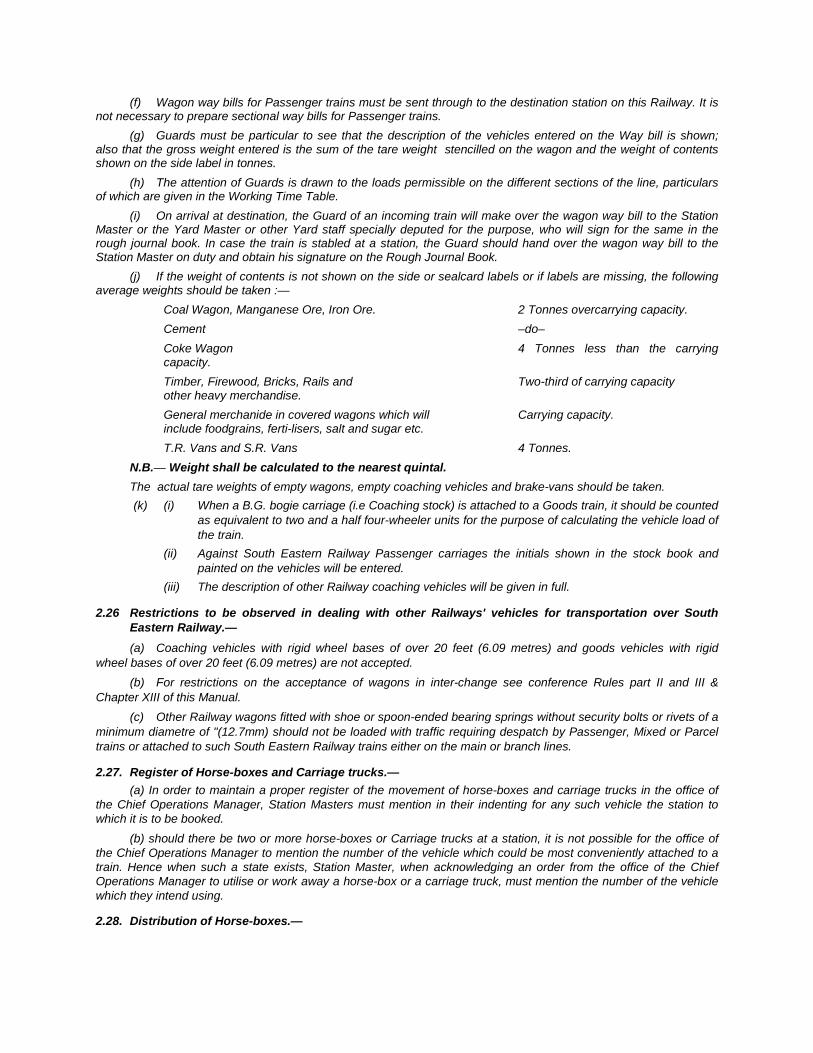
(f) Wagon way bills for Passenger trains must be sent through to the destination station on this Railway. It is not necessary to prepare sectional way bills for Passenger trains.
(g) Guards must be particular to see that the description of the vehicles entered on the Way bill is shown; also that the gross weight entered is the sum of the tare weight stencilled on the wagon and the weight of contents shown on the side label in tonnes.
(h) The attention of Guards is drawn to the loads permissible on the different sections of the line, particulars of which are given in the Working Time Table.
(i) On arrival at destination, the Guard of an incoming train will make over the wagon way bill to the Station Master or the Yard Master or other Yard staff specially deputed for the purpose, who will sign for the same in the rough journal book. In case the train is stabled at a station, the Guard should hand over the wagon way bill to the Station Master on duty and obtain his signature on the Rough Journal Book.
(j) If the weight of contents is not shown on the side or sealcard labels or if labels are missing, the following average weights should be taken :—
Coal Wagon, Manganese Ore, Iron Ore. 2 Tonnes overcarrying capacity. Cement –do– Coke Wagon 4 Tonnes less than the carrying capacity. Timber, Firewood, Bricks, Rails and Two-third of carrying capacity other heavy merchandise. General merchanide in covered wagons which will Carrying capacity. include foodgrains, ferti-lisers, salt and sugar etc. T.R. Vans and S.R. Vans 4 Tonnes.
N.B.— Weight shall be calculated to the nearest quintal. The actual tare weights of empty wagons, empty coaching vehicles and brake-vans should be taken.
(k) (i) When a B.G. bogie carriage (i.e Coaching stock) is attached to a Goods train, it should be counted as equivalent to two and a half four-wheeler units for the purpose of calculating the vehicle load of the train.
(ii) Against South Eastern Railway Passenger carriages the initials shown in the stock book and painted on the vehicles will be entered.
(iii) The description of other Railway coaching vehicles will be given in full.
2.26 Restrictions to be observed in dealing with other Railways' vehicles for transportation over South Eastern Railway.— (a) Coaching vehicles with rigid wheel bases of over 20 feet (6.09 metres) and goods vehicles with rigid
wheel bases of over 20 feet (6.09 metres) are not accepted. (b) For restrictions on the acceptance of wagons in inter-change see conference Rules part II and III &
Chapter XIII of this Manual. (c) Other Railway wagons fitted with shoe or spoon-ended bearing springs without security bolts or rivets of a
minimum diametre of "(12.7mm) should not be loaded with traffic requiring despatch by Passenger, Mixed or Parcel trains or attached to such South Eastern Railway trains either on the main or branch lines.
2.27. Register of Horse-boxes and Carriage trucks.— (a) In order to maintain a proper register of the movement of horse-boxes and carriage trucks in the office of
the Chief Operations Manager, Station Masters must mention in their indenting for any such vehicle the station to which it is to be booked.
(b) should there be two or more horse-boxes or Carriage trucks at a station, it is not possible for the office of the Chief Operations Manager to mention the number of the vehicle which could be most conveniently attached to a train. Hence when such a state exists, Station Master, when acknowledging an order from the office of the Chief Operations Manager to utilise or work away a horse-box or a carriage truck, must mention the number of the vehicle which they intend using.
2.28. Distribution of Horse-boxes.—
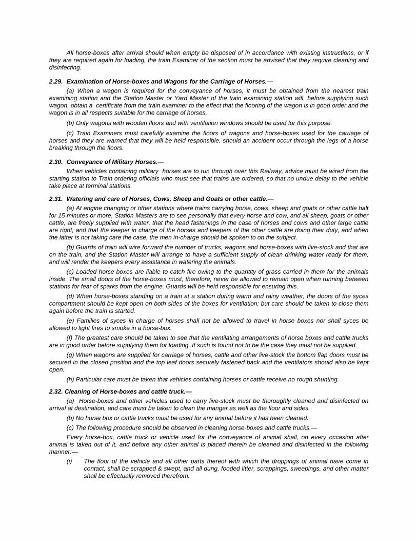
All horse-boxes after arrival should when empty be disposed of in accordance with existing instructions, or if they are required again for loading, the train Examiner of the section must be advised that they require cleaning and disinfecting.
2.29. Examination of Horse-boxes and Wagons for the Carriage of Horses.— (a) When a wagon is required for the conveyance of horses, it must be obtained from the nearest train
examining station and the Station Master or Yard Master of the train examining station will, before supplying such wagon, obtain a certificate from the train examiner to the effect that the flooring of the wagon is in good order and the wagon is in all respects suitable for the carriage of horses.
(b) Only wagons with wooden floors and with ventilation windows should be used for this purpose. (c) Train Examiners must carefully examine the floors of wagons and horse-boxes used for the carriage of
horses and they are warned that they will be held responsible, should an accident occur through the legs of a horse breaking through the floors.
2.30. Conveyance of Military Horses.— When vehicles containing military horses are to run through over this Railway, advice must be wired from the
starting station to Train ordering officials who must see that trains are ordered, so that no undue delay to the vehicle take place at terminal stations.
2.31. Watering and care of Horses, Cows, Sheep and Goats or other cattle.— (a) At engine changing or other stations where trains carrying horse, cows, sheep and goats or other cattle halt
for 15 minutes or more, Station Masters are to see personally that every horse and cow, and all sheep, goats or other cattle, are freely supplied with water, that the head fastenings in the case of horses and cows and other large cattle are right, and that the keeper in charge of the horses and keepers of the other cattle are doing their duty, and when the latter is not taking care the case, the men in-charge should be spoken to on the subject.
(b) Guards of train will wire forward the number of trucks, wagons and horse-boxes with live-stock and that are on the train, and the Station Master will arrange to have a sufficient supply of clean drinking water ready for them, and will render the keepers every assistance in watering the animals.
(c) Loaded horse-boxes are liable to catch fire owing to the quantity of grass carried in them for the animals inside. The small doors of the horse-boxes must, therefore, never be allowed to remain open when running between stations for fear of sparks from the engine. Guards will be held responsible for ensuring this.
(d) When horse-boxes standing on a train at a station during warm and rainy weather, the doors of the syces compartment should be kept open on both sides of the boxes for ventilation; but care should be taken to close them again before the train is started.
(e) Families of syces in charge of horses shall not be allowed to travel in horse boxes nor shall syces be allowed to light fires to smoke in a horse-box.
(f) The greatest care should be taken to see that the ventilating arrangements of horse boxes and cattle trucks are in good order before supplying them for loading. If such is found not to be the case they must not be supplied.
(g) When wagons are supplied for carriage of horses, cattle and other live-stock the bottom flap doors must be secured in the closed position and the top leaf doors securely fastened back and the ventilators should also be kept open.
(h) Particular care must be taken that vehicles containing horses or cattle receive no rough shunting.
2.32. Cleaning of Horse-boxes and cattle truck.— (a) Horse-boxes and other vehicles used to carry live-stock must be thoroughly cleaned and disinfected on
arrival at destination, and care must be taken to clean the manger as well as the floor and sides. (b) No horse box or cattle trucks must be used for any animal before it has been cleaned. (c) The following procedure should be observed in cleaning horse-boxes and cattle trucks.— Every horse-box, cattle truck or vehicle used for the conveyance of animal shall, on every occasion after
animal is taken out of it, and before any other animal is placed therein be cleaned and disinfected in the following manner:—
(i) The floor of the vehicle and all other parts thereof with which the droppings of animal have come in contact, shall be scrapped & swept, and all dung, fooded litter, scrappings, sweepings, and other matter shall be effectually removed therefrom.

(ii) The floor and sides of the vehicles, and other parts thereof with which the head of any discharge from the mouth or nostrils of the animal has come in contact, shall be thoroughly washed with water by means of a sponge, brush or other instrument. 1) The whole of the box area and fittings are to be thoroughly scrubbed with water by means of a
sponge, or brush and then rinsed with a solution of phenyle or other disinfectant and a coating of lime wash applied; care being taken not to disfigure the outside of the vehicle.
The manger is to be cleaned by :— Firstly, scraping so that all clogging of dirt, dust or nasal discharge may be removed. Secondly, scrubbing with a brush and boiling water and rinsing with phenyle solution in the
preparation of one quart (1.4 litres) to ten gallons (45.46 litres) of water, and Thirdly, by lime washing in the proportion of 1 maund (37 Kgs.) of good fresh lime to 20 gallons
(90.92 litres) of water. N.B:— It is useless to apply the disinfectant solution or lime wash until after a thorough cleaning. 2) After horse-boxes have been thoroughly cleaned and lime washed, the lime wash should be
allowed to dry and should then be carefully brushed off. If this precaution be not observed, the eyes and nostrils of animals subsequently occupying the vehicle are liable to suffer.
3) The scrapping and sweepings from the vehicle and all dung, fooder, lifter and other matter removed there from, shall be forthwith burnt or well mixed with quicklime and be effectually removed from contact with animals.
4) As to the quantity of quicklime necessary to disinfect any given quantity of refuse, no definite scale can be laid down, but a solution consisting of 1 lb.(453 grams) of quick lime to each gallon (4.54 litres) of water would prove effectual in disinfecting refuse of horse-boxes.
(iii) One gallon of this solution would be sufficient to cleanse 200 square feet (18.58 sq.metres) of wall or boarding, and five gallons (22.70 litres) should sufficient to disinfect 100 cubic feet (2.83 cubic metres) of refuse. If, however, any disease is known to exist in the neighbourhood from which horses are being conveyed, the safer course would be to burn all litter and refuse, etc.
(iv) The Carriage and Wagon department undertake the cleaning and disinfecting of horse-boxes and cattle trucks, but every Station Master will be held responsible for seeing that no vehicle is used unless it is quite clean.
(v) Should the horse-box or cattle truck be unloaded at other than a train examining station, the Train Examiner of the section will be notified by the Station Master, and he must, as soon as possible, take steps to have the vehicle cleaned if it is to be reloaded from the station at which it has arrived. Otherwise, it should be forwarded by first train to the next train examining station for proper cleaning.
(vi) If a Station Master has reason to suspect that any animal that has been conveyed, or is about to be conveyed by railway, is suffering from an infectious disease, he must if at the despatching station, where the animals are loaded, warn the destination station, by the quickest available communication and the destination Station Master must specially advise the SSE/SE/JE(C&W). If there is no SSE/SE/JE(C&W) at the destination station, the vehicle will be worked empty to the nearest train examining station, and the SSE/SE/JE(C&W) notified suitably by the Station Master.
(vii) At principal stations where a train halts any time, Station Masters should see that the horse-boxes on the train containing horses are cleaned out through the trap doors in front and rear, before an engine is attached to the train. At train examining stations this duty devolves on the SSE/SE/JE(C&W).
(viii) At train examining stations, SSE/SE/JE/(C&W)s will examine all horse-boxes on arrival to ascertain if they require cleaning.
(ix) When covered wagons are used for cattle, horses or other animals, immediately on unloading, whether at a train examining station or not, the SSE/SE/JE/(C&W) of the section must be advised, so that the vehicles may be cleaned.
(x) On application to the Station Master of any station Civil Veterinary Officers should forthwith be allowed to inspect any or all vehicles used for the conveyance of live-stock which may at the time be standing at the station.
2.33. Labelling of Horse-boxes and Cattle wagons.— Horse-boxes and cattle wagons shall be correctly labelled and the route of journey entered on the label.
Interchange of Rolling Stock
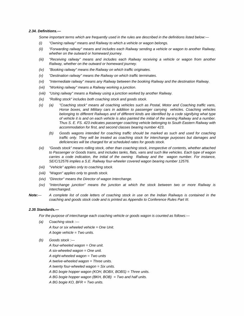
2.34. Definitions.— Some important terms which are frequently used in the rules are described in the definitions listed below:— (i) "Owning railway" means and Railway to which a vehicle or wagon belongs. (ii) "Forwarding railway" means and includes each Railway sending a vehicle or wagon to another Railway,
whether on the outward or homeward journey. (iii) "Receiving railway" means and includes each Railway receiving a vehicle or wagon from another
Railway, whether on the outward or homeward journey. (iv) "Booking railway" means the Railway on which traffic originates. (v) "Destination railway" means the Railway on which traffic terminates. (vi) "Intermediate railway" means any Railway between the booking Railway and the destination Railway. (vii) "Working railway" means a Railway working a junction. (viii) "Using railway" means a Railway using a junction worked by another Railway. (ix) "Rolling stock" includes both coaching stock and goods stock.
(x) (a) "Coaching stock" means all coaching vehicles such as Postal, Motor and Coaching traffic vans, Horse boxes, and Military cars in addition to passenger carrying vehicles. Coaching vehicles belonging to different Railways and of different kinds are identified by a code signifying what type of vehicle it is and on each vehicle is also painted the initial of the owning Railway and a number. Thus S. E. FS. 423 indicates passenger coaching vehicle belonging to South Eastern Railway with accommodation for first, and second classes bearing number 423.
(b) Goods wagons intended for coaching traffic should be marked as such and used for coaching traffic only. They will be treated as coaching stock for interchange purposes but damages and deficiencies will be charged for at scheduled rates for goods stock.
(xi) "Goods stock" means rolling stock, other than coaching stock, irrespective of contents, whether attached to Passenger or Goods trains, and includes tanks, flats, vans and such like vehicles. Each type of wagon carries a code indication, the initial of the owning Railway and the wagon number. For instance, SE/C/12576 implies a S.E. Railway four-wheeler covered wagon bearing number 12576.
(xii) "Vehicle" applies only to coaching stock. (xiii) "Wagon" applies only to goods stock. (xiv) "Director" means the Director of wagon Interchange. (xv) "Interchange junction" means the junction at which the stock between two or more Railway is
interchanged. Note:— A complete list of code letters of coaching stock in use on the Indian Railways is contained in the
coaching and goods stock code and is printed as Appendix to Conference Rules Part III.
2.35 Standards.— For the purpose of interchange each coaching vehicle or goods wagon is counted as follows:—
(a) Coaching stock :— A four or six wheeled vehicle = One Unit. A bogie vehicle = Two units.
(b) Goods stock :— A four-wheeled wagon = One unit. A six-wheeled wagon = One unit. A eight-wheeled wagon = Two units A twelve-wheeled wagon = Three units. A twenty four-wheeled wagon = Six units. A BG bogie hopper wagon (KOH, BOBX, BOBS) = Three units. A BG bogie hopper wagon (BKH, BOB) = Two and half units. A BG bogie KO, BFR = Two units.
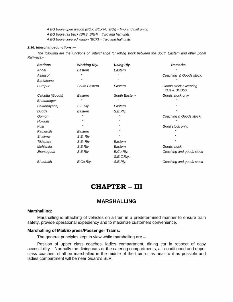
A BG bogie open wagon (BOX, BOX'N', BOI) =Two and half units. A BG bogie rail truck (BRS, BRH) = Two and half units. A BG bogie covered wagon (BCX) = Two and half units.
2.36. Interchange junctions.— The following are the junctions of interchange for rolling stock between the South Eastern and other Zonal
Railways:–
Stations Working Rly. Using Rly. Remarks. Andal Eastern Eastern " Asansol " " Coaching & Goods stock. Barkakana " " " Burnpur South Eastern Eastern Goods stock excepting KOs & BOBSs. Calcutta (Goods) Eastern South Eastern Goods stock only Bhattanager " " " Bakranayabaj S.E.Rly Eastern " Dugda Eastern S.E.Rly. " Gomoh " " Coaching & Goods stock. Howrah " " " Kulti " " Good stock only. Patherdih Eastern " " Shalimar S.E. Rly. " " Tikiapara S.E. Rly. Eastern " Mohishila S.E.Rly. Eastern Goods stock Jharsuguda S.E.Rly. E.Co.Rly. Coaching and goods stock S.E.C.Rly. Bhadrakh E.Co.Rly. S.E.Rly. Coaching and goods stock
CHAPTER – III
MARSHALLING
Marshalling: Marshalling is attaching of vehicles on a train in a predetermined manner to ensure train
safety, provide operational expediency and to maximize customers convenience.
Marshalling of Mail/Express/Passenger Trains: The general principles kept in view while marshalling are – Position of upper class coaches, ladies compartment, dining car in respect of easy
accessibility– Normally the dining cars or the catering compartments, air-conditioned and upper class coaches, shall be marshalled in the middle of the train or as near to it as possible and ladies compartment will be near Guard’s SLR.
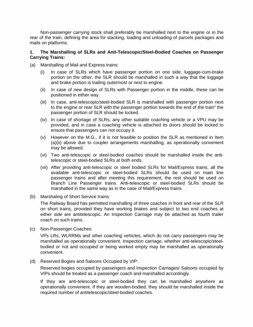
Non-passenger carrying stock shall preferably be marshalled next to the engine or in the rear of the train, defining the area for stacking, loading and unloading of parcels packages and mails on platforms.
1. The Marshalling of SLRs and Anti-Telescopic/Steel-Bodied Coaches on Passenger Carrying Trains: (a) Marshalling of Mail and Express trains:
(i) In case of SLRs which have passenger portion on one side, luggage-cum-brake portion on the other, the SLR should be marshalled in such a way that the luggage and brake portion is trailing outermost or next to engine.
(ii) In case of new design of SLRs with Passenger portion in the middle, these can be positioned in either way.
(iii) In case, anti-telescopic/steel-bodied SLR is marshalled with passenger portion next to the engine or rear SLR with the passenger portion towards the end of the train” the passenger portion of SLR should be locked.
(iv) In case of shortage of SLRs, any other suitable coaching vehicle or a VPU may be provided, and in case a coaching vehicle is attached its doors should be locked to ensure that passengers can not occupy it.
(v) However on the M.G., if it is not feasible to position the SLR as mentioned in Item (a)(ii) above due to coupler arrangements marshalling, as operationally convenient may be allowed.
(vi) Two anti-telescopic or steel-bodied coaches should be marshalled inside the anti-telescopic or steel-bodied SLRs at both ends.
(vii) After providing anti-telescopic or steel bodied SLRs for Mail/Express trains, all the available anti-telescopic or steel-bodied SLRs should be used on main line passenger trains and after meeting this requirement, the rest should be used on Branch Line Passenger trains. Anti-telescopic or steel-bodied SLRs should be marshalled in the same way as in the case of Mail/Express trains.
(b) Marshaling of Short Service trains: The Railway Board has permitted marshalling of three coaches in front and rear of the SLR
on short trains, provided they have working brakes and subject to two end coaches at either side are antitelescopic. An Inspection Carriage may be attached as fourth trailer coach on such trains.
(c) Non-Passenger Coaches: VPs LRs, WLRRMs and other coaching vehicles, which do not carry passengers may be
marshalled as operationally convenient. Inspection carriage, whether anti-telescopic/steel-bodied or not and occupied or being worked empty may be marshalled as operationally convenient.
(d) Reserved Bogies and Saloons Occupied by VIP: Reserved bogies occupied by passengers and Inspection Carriages/ Saloons occupied by
VIPs should be treated as a passenger coach and marshalled accordingly.
If they are anti-telescopic or steel-bodied they can be marshalled anywhere as operationally convenient. If they are wooden-bodied, they should be marshalled inside the required number of antitelescopic/steel-bodied coaches.
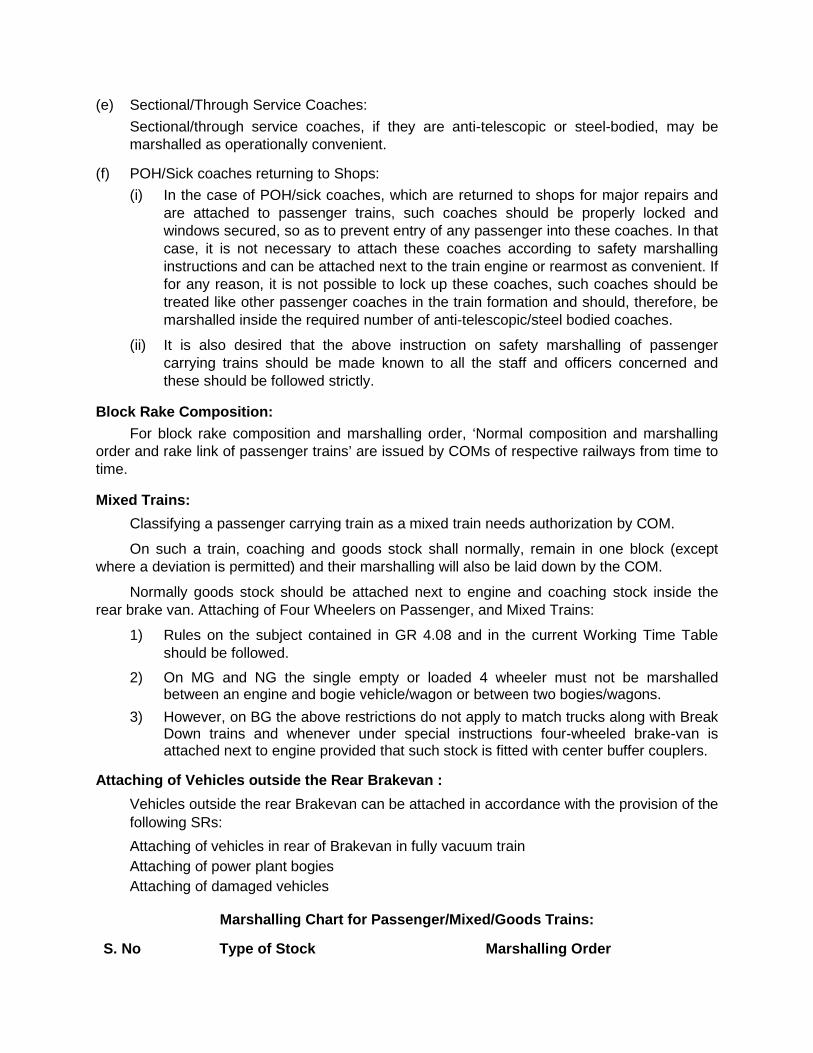
(e) Sectional/Through Service Coaches: Sectional/through service coaches, if they are anti-telescopic or steel-bodied, may be
marshalled as operationally convenient.
(f) POH/Sick coaches returning to Shops: (i) In the case of POH/sick coaches, which are returned to shops for major repairs and
are attached to passenger trains, such coaches should be properly locked and windows secured, so as to prevent entry of any passenger into these coaches. In that case, it is not necessary to attach these coaches according to safety marshalling instructions and can be attached next to the train engine or rearmost as convenient. If for any reason, it is not possible to lock up these coaches, such coaches should be treated like other passenger coaches in the train formation and should, therefore, be marshalled inside the required number of anti-telescopic/steel bodied coaches.
(ii) It is also desired that the above instruction on safety marshalling of passenger carrying trains should be made known to all the staff and officers concerned and these should be followed strictly.
Block Rake Composition: For block rake composition and marshalling order, ‘Normal composition and marshalling
order and rake link of passenger trains’ are issued by COMs of respective railways from time to time.
Mixed Trains: Classifying a passenger carrying train as a mixed train needs authorization by COM.
On such a train, coaching and goods stock shall normally, remain in one block (except where a deviation is permitted) and their marshalling will also be laid down by the COM.
Normally goods stock should be attached next to engine and coaching stock inside the rear brake van. Attaching of Four Wheelers on Passenger, and Mixed Trains:
1) Rules on the subject contained in GR 4.08 and in the current Working Time Table should be followed.
2) On MG and NG the single empty or loaded 4 wheeler must not be marshalled between an engine and bogie vehicle/wagon or between two bogies/wagons.
3) However, on BG the above restrictions do not apply to match trucks along with Break Down trains and whenever under special instructions four-wheeled brake-van is attached next to engine provided that such stock is fitted with center buffer couplers.
Attaching of Vehicles outside the Rear Brakevan : Vehicles outside the rear Brakevan can be attached in accordance with the provision of the
following SRs: Attaching of vehicles in rear of Brakevan in fully vacuum train Attaching of power plant bogies Attaching of damaged vehicles
Marshalling Chart for Passenger/Mixed/Goods Trains:
S. No Type of Stock Marshalling Order
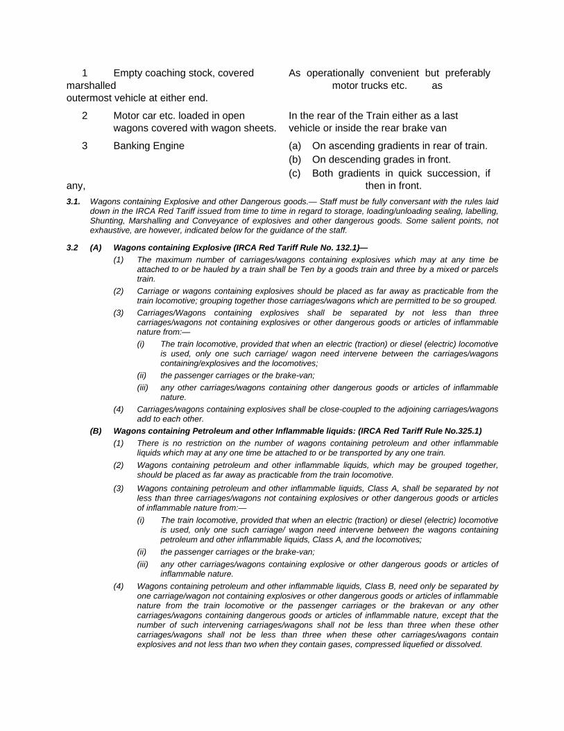
1 Empty coaching stock, covered As operationally convenient but preferably marshalled motor trucks etc. as outermost vehicle at either end.
2 Motor car etc. loaded in open In the rear of the Train either as a last wagons covered with wagon sheets. vehicle or inside the rear brake van
3 Banking Engine (a) On ascending gradients in rear of train. (b) On descending grades in front. (c) Both gradients in quick succession, if any, then in front. 3.1. Wagons containing Explosive and other Dangerous goods.— Staff must be fully conversant with the rules laid
down in the IRCA Red Tariff issued from time to time in regard to storage, loading/unloading sealing, labelling, Shunting, Marshalling and Conveyance of explosives and other dangerous goods. Some salient points, not exhaustive, are however, indicated below for the guidance of the staff.
3.2 (A) Wagons containing Explosive (IRCA Red Tariff Rule No. 132.1)— (1) The maximum number of carriages/wagons containing explosives which may at any time be
attached to or be hauled by a train shall be Ten by a goods train and three by a mixed or parcels train.
(2) Carriage or wagons containing explosives should be placed as far away as practicable from the train locomotive; grouping together those carriages/wagons which are permitted to be so grouped.
(3) Carriages/Wagons containing explosives shall be separated by not less than three carriages/wagons not containing explosives or other dangerous goods or articles of inflammable nature from:— (i) The train locomotive, provided that when an electric (traction) or diesel (electric) locomotive
is used, only one such carriage/ wagon need intervene between the carriages/wagons containing/explosives and the locomotives;
(ii) the passenger carriages or the brake-van; (iii) any other carriages/wagons containing other dangerous goods or articles of inflammable
nature. (4) Carriages/wagons containing explosives shall be close-coupled to the adjoining carriages/wagons
add to each other. (B) Wagons containing Petroleum and other Inflammable liquids: (IRCA Red Tariff Rule No.325.1)
(1) There is no restriction on the number of wagons containing petroleum and other inflammable liquids which may at any one time be attached to or be transported by any one train.
(2) Wagons containing petroleum and other inflammable liquids, which may be grouped together, should be placed as far away as practicable from the train locomotive.
(3) Wagons containing petroleum and other inflammable liquids, Class A, shall be separated by not less than three carriages/wagons not containing explosives or other dangerous goods or articles of inflammable nature from:— (i) The train locomotive, provided that when an electric (traction) or diesel (electric) locomotive
is used, only one such carriage/ wagon need intervene between the wagons containing petroleum and other inflammable liquids, Class A, and the locomotives;
(ii) the passenger carriages or the brake-van; (iii) any other carriages/wagons containing explosive or other dangerous goods or articles of
inflammable nature. (4) Wagons containing petroleum and other inflammable liquids, Class B, need only be separated by
one carriage/wagon not containing explosives or other dangerous goods or articles of inflammable nature from the train locomotive or the passenger carriages or the brakevan or any other carriages/wagons containing dangerous goods or articles of inflammable nature, except that the number of such intervening carriages/wagons shall not be less than three when these other carriages/wagons shall not be less than three when these other carriages/wagons contain explosives and not less than two when they contain gases, compressed liquefied or dissolved.
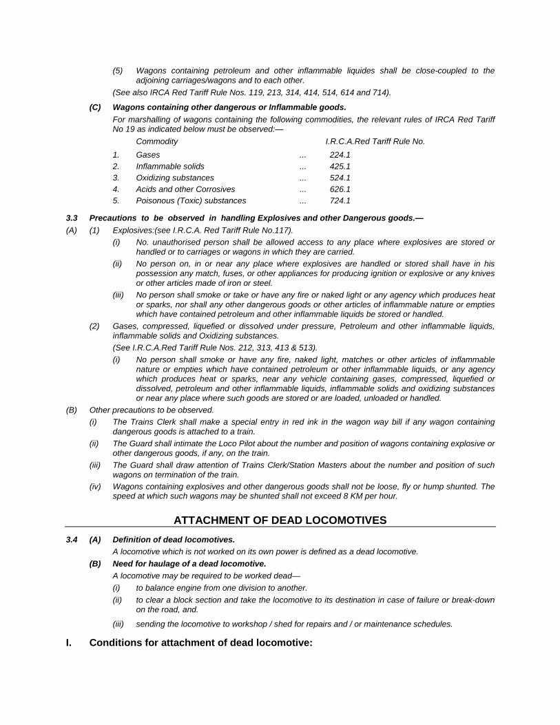
(5) Wagons containing petroleum and other inflammable liquides shall be close-coupled to the adjoining carriages/wagons and to each other.
(See also IRCA Red Tariff Rule Nos. 119, 213, 314, 414, 514, 614 and 714).
(C) Wagons containing other dangerous or Inflammable goods. For marshalling of wagons containing the following commodities, the relevant rules of IRCA Red Tariff
No 19 as indicated below must be observed:— Commodity I.R.C.A.Red Tariff Rule No. 1. Gases ... 224.1 2. Inflammable solids ... 425.1 3. Oxidizing substances ... 524.1 4. Acids and other Corrosives ... 626.1 5. Poisonous (Toxic) substances ... 724.1
3.3 Precautions to be observed in handling Explosives and other Dangerous goods.— (A) (1) Explosives:(see I.R.C.A. Red Tariff Rule No.117).
(i) No. unauthorised person shall be allowed access to any place where explosives are stored or handled or to carriages or wagons in which they are carried.
(ii) No person on, in or near any place where explosives are handled or stored shall have in his possession any match, fuses, or other appliances for producing ignition or explosive or any knives or other articles made of iron or steel.
(iii) No person shall smoke or take or have any fire or naked light or any agency which produces heat or sparks, nor shall any other dangerous goods or other articles of inflammable nature or empties which have contained petroleum and other inflammable liquids be stored or handled.
(2) Gases, compressed, liquefied or dissolved under pressure, Petroleum and other inflammable liquids, inflammable solids and Oxidizing substances.
(See I.R.C.A.Red Tariff Rule Nos. 212, 313, 413 & 513). (i) No person shall smoke or have any fire, naked light, matches or other articles of inflammable
nature or empties which have contained petroleum or other inflammable liquids, or any agency which produces heat or sparks, near any vehicle containing gases, compressed, liquefied or dissolved, petroleum and other inflammable liquids, inflammable solids and oxidizing substances or near any place where such goods are stored or are loaded, unloaded or handled.
(B) Other precautions to be observed. (i) The Trains Clerk shall make a special entry in red ink in the wagon way bill if any wagon containing
dangerous goods is attached to a train. (ii) The Guard shall intimate the Loco Pilot about the number and position of wagons containing explosive or
other dangerous goods, if any, on the train. (iii) The Guard shall draw attention of Trains Clerk/Station Masters about the number and position of such
wagons on termination of the train. (iv) Wagons containing explosives and other dangerous goods shall not be loose, fly or hump shunted. The
speed at which such wagons may be shunted shall not exceed 8 KM per hour.
ATTACHMENT OF DEAD LOCOMOTIVES
3.4 (A) Definition of dead locomotives. A locomotive which is not worked on its own power is defined as a dead locomotive. (B) Need for haulage of a dead locomotive. A locomotive may be required to be worked dead—
(i) to balance engine from one division to another. (ii) to clear a block section and take the locomotive to its destination in case of failure or break-down
on the road, and.
(iii) sending the locomotive to workshop / shed for repairs and / or maintenance schedules.
I. Conditions for attachment of dead locomotive:
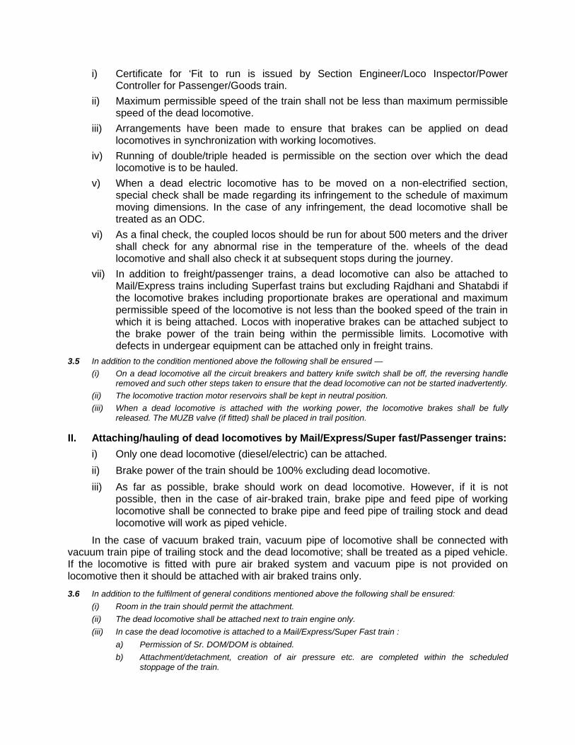
i) Certificate for ‘Fit to run is issued by Section Engineer/Loco Inspector/Power Controller for Passenger/Goods train.
ii) Maximum permissible speed of the train shall not be less than maximum permissible speed of the dead locomotive.
iii) Arrangements have been made to ensure that brakes can be applied on dead locomotives in synchronization with working locomotives.
iv) Running of double/triple headed is permissible on the section over which the dead locomotive is to be hauled.
v) When a dead electric locomotive has to be moved on a non-electrified section, special check shall be made regarding its infringement to the schedule of maximum moving dimensions. In the case of any infringement, the dead locomotive shall be treated as an ODC.
vi) As a final check, the coupled locos should be run for about 500 meters and the driver shall check for any abnormal rise in the temperature of the. wheels of the dead locomotive and shall also check it at subsequent stops during the journey.
vii) In addition to freight/passenger trains, a dead locomotive can also be attached to Mail/Express trains including Superfast trains but excluding Rajdhani and Shatabdi if the locomotive brakes including proportionate brakes are operational and maximum permissible speed of the locomotive is not less than the booked speed of the train in which it is being attached. Locos with inoperative brakes can be attached subject to the brake power of the train being within the permissible limits. Locomotive with defects in undergear equipment can be attached only in freight trains.
3.5 In addition to the condition mentioned above the following shall be ensured — (i) On a dead locomotive all the circuit breakers and battery knife switch shall be off, the reversing handle
removed and such other steps taken to ensure that the dead locomotive can not be started inadvertently. (ii) The locomotive traction motor reservoirs shall be kept in neutral position. (iii) When a dead locomotive is attached with the working power, the locomotive brakes shall be fully
released. The MUZB valve (if fitted) shall be placed in trail position.
II. Attaching/hauling of dead locomotives by Mail/Express/Super fast/Passenger trains: i) Only one dead locomotive (diesel/electric) can be attached. ii) Brake power of the train should be 100% excluding dead locomotive. iii) As far as possible, brake should work on dead locomotive. However, if it is not
possible, then in the case of air-braked train, brake pipe and feed pipe of working locomotive shall be connected to brake pipe and feed pipe of trailing stock and dead locomotive will work as piped vehicle.
In the case of vacuum braked train, vacuum pipe of locomotive shall be connected with vacuum train pipe of trailing stock and the dead locomotive; shall be treated as a piped vehicle. If the locomotive is fitted with pure air braked system and vacuum pipe is not provided on locomotive then it should be attached with air braked trains only. 3.6 In addition to the fulfilment of general conditions mentioned above the following shall be ensured:
(i) Room in the train should permit the attachment. (ii) The dead locomotive shall be attached next to train engine only. (iii) In case the dead locomotive is attached to a Mail/Express/Super Fast train :
a) Permission of Sr. DOM/DOM is obtained. b) Attachment/detachment, creation of air pressure etc. are completed within the scheduled
stoppage of the train.
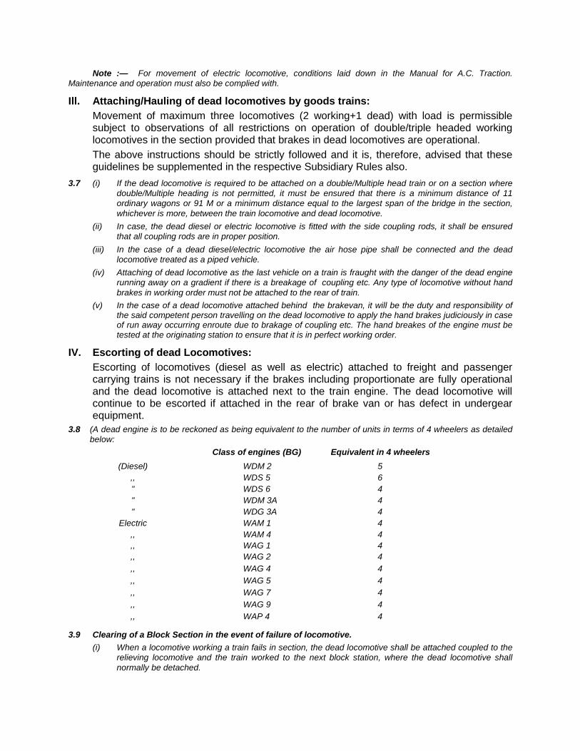
Note :— For movement of electric locomotive, conditions laid down in the Manual for A.C. Traction. Maintenance and operation must also be complied with.
Ill. Attaching/Hauling of dead locomotives by goods trains: Movement of maximum three locomotives (2 working+1 dead) with load is permissible
subject to observations of all restrictions on operation of double/triple headed working locomotives in the section provided that brakes in dead locomotives are operational.
The above instructions should be strictly followed and it is, therefore, advised that these guidelines be supplemented in the respective Subsidiary Rules also.
3.7 (i) If the dead locomotive is required to be attached on a double/Multiple head train or on a section where double/Multiple heading is not permitted, it must be ensured that there is a minimum distance of 11 ordinary wagons or 91 M or a minimum distance equal to the largest span of the bridge in the section, whichever is more, between the train locomotive and dead locomotive.
(ii) In case, the dead diesel or electric locomotive is fitted with the side coupling rods, it shall be ensured that all coupling rods are in proper position.
(iii) In the case of a dead diesel/electric locomotive the air hose pipe shall be connected and the dead locomotive treated as a piped vehicle.
(iv) Attaching of dead locomotive as the last vehicle on a train is fraught with the danger of the dead engine running away on a gradient if there is a breakage of coupling etc. Any type of locomotive without hand brakes in working order must not be attached to the rear of train.
(v) In the case of a dead locomotive attached behind the brakevan, it will be the duty and responsibility of the said competent person travelling on the dead locomotive to apply the hand brakes judiciously in case of run away occurring enroute due to brakage of coupling etc. The hand breakes of the engine must be tested at the originating station to ensure that it is in perfect working order.
IV. Escorting of dead Locomotives: Escorting of locomotives (diesel as well as electric) attached to freight and passenger
carrying trains is not necessary if the brakes including proportionate are fully operational and the dead locomotive is attached next to the train engine. The dead locomotive will continue to be escorted if attached in the rear of brake van or has defect in undergear equipment.
3.8 (A dead engine is to be reckoned as being equivalent to the number of units in terms of 4 wheelers as detailed below:
Class of engines (BG) Equivalent in 4 wheelers (Diesel) WDM 2 5 ,, WDS 5 6 " WDS 6 4 " WDM 3A 4 " WDG 3A 4 Electric WAM 1 4 ,, WAM 4 4 ,, WAG 1 4 ,, WAG 2 4 ,, WAG 4 4 ,, WAG 5 4 ,, WAG 7 4 ,, WAG 9 4 ,, WAP 4 4
3.9 Clearing of a Block Section in the event of failure of locomotive. (i) When a locomotive working a train fails in section, the dead locomotive shall be attached coupled to the
relieving locomotive and the train worked to the next block station, where the dead locomotive shall normally be detached.

(ii) In case the dead locomotive is not detached but the train is worked double headed with the dead locomotive upto the destination not more than 1 dead locomotives with break operative shall be attached to a goods train. In such case the total length of the train with locomotives shall not exceed 725 M.
(iii) In all the above cases the total number of locomotives including the dead one, shall not exceed three, provided double heading of the locomotive is permitted on the section.
(iv) If double heading is not permitted in section where no banker is used in general, the train shall be pushed by the relieving locomotive observing the precautions laid down in GR 4.13 and SR there to, to clear the block section and at the next block station marshalling of the locomotive may be done, and it is ensured that they are not coupled together and there is a minimum distance of 11 ordinary wagons or 91M between them.
(v) In sections where double heading is not permitted and banking engine is in use, concerned Divisional Engineer shall be referred to in regard to the location of the relieving locomotive who will after examining the presence of bridges in the section and the span, give instructions regarding the marshalling order.
3.10 Dead Engine belonging to another Railway travelling over this Railway.— The engine, before being put on a train, must be passed by the nearest SSE(Loco)/SSE(Electric) as fit to run
and a certificate granted accordingly. This certificate should be sent, attached to the Guard's wagon way bill or through the Asstt. Loco Pilot on the engine to the destination of the engine and the certificate given at the station of despatch for the journey over this railway. A competent Asstt. Loco Pilot must also accompany the engine to look after the lubrication en-route.
Medical Relief Van: Can be run without brake van (Local SR should be followed for Ghat Section)
Inspection Carriages attached to Light Engine: Maximum three inspection carriages occupied by the officers can be attached. In case
more than 3 Inspection carriages are attached, rules regarding running of goods trains without brake van will apply.
Attaching of Travelling Cranes: Provisions of G&SR 4.27 should be followed.
3.11 Horse-boxes and Carriage Trucks.— (a) Horse-boxes or vehicle used for carriage of animals must, as a general rule, be marshalled in the rear of
trains, and wagons containing live-stock when required to be attached at road-side stations where proper facilities do not exist, must be attached with atleast 7 wagons intervening between them and the engine.
(b) Horse-boxes and Carriage trucks may, when time will be saved in shunting, be attached behind the rear brake-van of a Passenger train.
(c) A bogie Horse-Box fit to run by Mail/Express may be attached beyond the rear brakevan of a Mail/Express. In such circumstances, the instructions laid down in GR 4.24 and 4.24.01 must be strictly complied with.
3.12 Horse-boxes and Carriage Trucks booked to Road side stations.— Horse-boxes, carriage trucks etc. when being sent empty should not be attached to Passenger trains unless
absolutely necessary; but foreign railways coaching vehicles loaded or empty should as a rule be moved on Passenger trains.
CHAPTER – III(A)
SHUNTING AND SECURING OF VEHICLES
3A.01. Shunting— Miscellaneous rules on.—

(a) Signals for shunting:— General and subsidiary Rules 3.56, SR 3.56.01 and 3.56.2 should be observed for exhibiting shunting signals.
(i) When two engines or vehicles are approaching the same pair of points from two different lines, or where there is like hood of this occurring, both should be brought to a stand by exhibiting danger signals and after ensuring both have come to a stop, the person in charge of the engine or vehicle, which it is intended to allow over the points first, must be told verbally first and then signalled to move forward; while a danger signal and a verbal order not to move must be given to the other.
(ii) Wagons with end flaps let down, if empty, must have their flaps put up before being shunted. (iii) Air Hose Pipe:—
(a) When un-coupling vehicles fitted with the Air brake-gear, the air hose pipes must be placed on the dummy plugs before the screw coupling is unhooked.
(b) Care must be taken in shunting operations to guard against screw couplings hitting the air hose pipe couplings. The couplings of air hose pipes when not in use must be placed on the dummy plugs provided for the purpose. If the couplings are allowed to hang down loose, the plugs are likely to be broken when struck by the screw coupling. The couplings, when not engaged are to be fixed on the hooks provided.
This matter must also receive the special attention of the staff engaged in shunting operations. (c) On running trains the Guards will be responsible for ensuring that air hose pipes do not hang
loose, and when vehicles are being attached to a train the Guard must see that the hose pipes are properly secured in accordance with sub-para (b).
(iv) Electrically fitted vehicles, shunting of.— Vehicles electrically equipped should not be submitted to rough shunting of any description as such shunting may cause damages to galss cells.
(v) Shunting of entire train or rear portion of train.— Whenever the entire train has to be shunted, and whenever it is necessary to shunt off the rear portion of the train, the brakes of all brake-vans attached to the trains, must be manned by train staff during these operations.
3A.02. Shunting and Detention memo.— (i) All shunting done by Loco Pilots will be recorded in the reverse of form T. 34 H.F. (ii) For purpose of reference and check, Station Masters will make a note in their station diaries of the shunting
done at their stations. The number of the engine and also of the train and the time taken for shunting should be recorded.
(iii) For statistical purposes the shunting hours of train engines shunting during the run, are requires to be devided between coaching and goods in the ratio of the number of coaching and goods vehicles shunted. Guards must fill in the number of coaching and goods vehicles shunted by each train. The number of vehicles should be reckoned in units.
3A.03. Shunting done by train engines.— (i) Shunting enroute with train engine.—
(a) For shunting performed by train engines before and after working trains at engine changing and terminal stations and at stations enroute, the actual time of shunting performed will be recorded on the reverse of form T. 34. H.F.
(b) The time occupied in shunting is to count from the time shunting is commenced until shunting operations are completed.
When shunting operations cannot be started immediately on arrival of a train at a roadside station due to crossing of trains the time so spent should be included in "standing".
Examples:— Train arrives at 4 hrs. and shunting begins at 4.10 hrs. and ends at 4.50 hrs. Shunting time of 40 minutes should be recorded.
(ii) If the shunting operations have to be suspended owing to the reception of another train in the yard, the broken period between the two periods of shunting is to be included but the cause and the time so lost should be noted in the remark column.
Examples:— Trains arrives at 4 hrs, shunting commences at 4.10 hrs. stops at 4.30 hrs. and starts again at 4.50 hrs. and ends at 5.20 hrs.The shunting time to be recorded wil l be as fol lows:—
Shunting:— 1 hrs. 19 mts. Remarks—20 mts. Shunting suspended for crossing.................... Up/ Dn train. (iii) stopping of through trains out of course for shunting:—
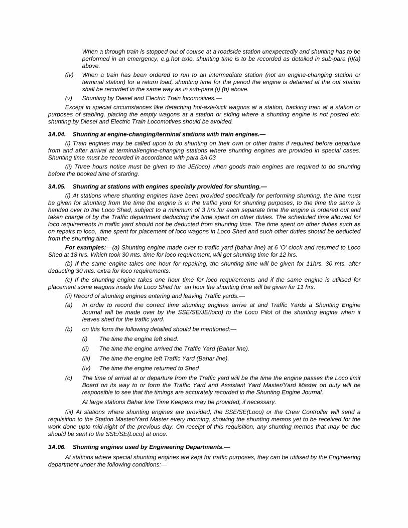
When a through train is stopped out of course at a roadside station unexpectedly and shunting has to be performed in an emergency, e.g.hot axle, shunting time is to be recorded as detailed in sub-para (i)(a) above.
(iv) When a train has been ordered to run to an intermediate station (not an engine-changing station or terminal station) for a return load, shunting time for the period the engine is detained at the out station shall be recorded in the same way as in sub-para (i) (b) above.
(v) Shunting by Diesel and Electric Train locomotives.— Except in special circumstances like detaching hot-axle/sick wagons at a station, backing train at a station or
purposes of stabling, placing the empty wagons at a station or siding where a shunting engine is not posted etc. shunting by Diesel and Electric Train Locomotives should be avoided.
3A.04. Shunting at engine-changing/terminal stations with train engines.— (i) Train engines may be called upon to do shunting on their own or other trains if required before departure
from and after arrival at terminal/engine-changing stations where shunting engines are provided in special cases. Shunting time must be recorded in accordance with para 3A.03
(ii) Three hours notice must be given to the JE(loco) when goods train engines are required to do shunting before the booked time of starting.
3A.05. Shunting at stations with engines specially provided for shunting.— (i) At stations where shunting engines have been provided specifically for performing shunting, the time must
be given for shunting from the time the engine is in the traffic yard for shunting purposes, to the time the same is handed over to the Loco Shed, subject to a minimum of 3 hrs.for each separate time the engine is ordered out and taken charge of by the Traffic department deducting the time spent on other duties. The scheduled time allowed for loco requirements in traffic yard should not be deducted from shunting time. The time spent on other duties such as on repairs to loco, time spent for placement of loco wagons in Loco Shed and such other duties should be deducted from the shunting time.
For examples:—(a) Shunting engine made over to traffic yard (bahar line) at 6 'O' clock and returned to Loco Shed at 18 hrs. Which took 30 mts. time for loco requirement, will get shunting time for 12 hrs.
(b) If the same engine takes one hour for repairing, the shunting time will be given for 11hrs. 30 mts. after deducting 30 mts. extra for loco requirements.
(c) If the shunting engine takes one hour time for loco requirements and if the same engine is utilised for placement some wagons inside the Loco Shed for an hour the shunting time will be given for 11 hrs.
(ii) Record of shunting engines entering and leaving Traffic yards.— (a) In order to record the correct time shunting engines arrive at and Traffic Yards a Shunting Engine
Journal will be made over by the SSE/SE/JE(loco) to the Loco Pilot of the shunting engine when it leaves shed for the traffic yard.
(b) on this form the following detailed should be mentioned:— (i) The time the engine left shed. (ii) The time the engine arrived the Traffic Yard (Bahar line). (iii) The time the engine left Traffic Yard (Bahar line). (iv) The time the engine returned to Shed
(c) The time of arrival at or departure from the Traffic yard will be the time the engine passes the Loco limit Board on its way to or form the Traffic Yard and Assistant Yard Master/Yard Master on duty will be responsible to see that the timings are accurately recorded in the Shunting Engine Journal.
At large stations Bahar line Time Keepers may be provided, if necessary. (iii) At stations where shunting engines are provided, the SSE/SE(Loco) or the Crew Controller will send a
requisition to the Station Master/Yard Master every morning, showing the shunting memos yet to be received for the work done upto mid-night of the previous day. On receipt of this requisition, any shunting memos that may be due should be sent to the SSE/SE(Loco) at once.
3A.06. Shunting engines used by Engineering Departments.— At stations where special shunting engines are kept for traffic purposes, they can be utilised by the Engineering
department under the following conditions:—
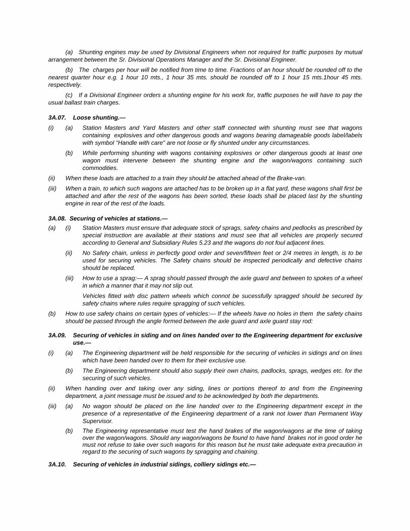
(a) Shunting engines may be used by Divisional Engineers when not required for traffic purposes by mutual arrangement between the Sr. Divisional Operations Manager and the Sr. Divisional Engineer.
(b) The charges per hour will be notified from time to time. Fractions of an hour should be rounded off to the nearest quarter hour e.g. 1 hour 10 mts., 1 hour 35 mts. should be rounded off to 1 hour 15 mts.1hour 45 mts. respectively.
(c) If a Divisional Engineer orders a shunting engine for his work for, traffic purposes he will have to pay the usual ballast train charges.
3A.07. Loose shunting.— (i) (a) Station Masters and Yard Masters and other staff connected with shunting must see that wagons
containing explosives and other dangerous goods and wagons bearing damageable goods label/labels with symbol "Handle with care" are not loose or fly shunted under any circumstances.
(b) While performing shunting with wagons containing explosives or other dangerous goods at least one wagon must intervene between the shunting engine and the wagon/wagons containing such commodities.
(ii) When these loads are attached to a train they should be attached ahead of the Brake-van.
(iii) When a train, to which such wagons are attached has to be broken up in a flat yard, these wagons shall first be attached and after the rest of the wagons has been sorted, these loads shall be placed last by the shunting engine in rear of the rest of the loads.
3A.08. Securing of vehicles at stations.— (a) (i) Station Masters must ensure that adequate stock of sprags, safety chains and pedlocks as prescribed by
special instruction are available at their stations and must see that all vehicles are properly secured according to General and Subsidiary Rules 5.23 and the wagons do not foul adjacent lines.
(ii) No Safety chain, unless in perfectly good order and seven/fifteen feet or 2/4 metres in length, is to be used for securing vehicles. The Safety chains should be inspected periodically and defective chains should be replaced.
(iii) How to use a sprag:— A sprag should passed through the axle guard and between to spokes of a wheel in which a manner that it may not slip out.
Vehicles fitted with disc pattern wheels which connot be sucessfully spragged should be secured by safety chains where rules require spragging of such vehicles.
(b) How to use safety chains on certain types of vehicles:— If the wheels have no holes in them the safety chains should be passed through the angle formed between the axle guard and axle guard stay rod:
3A.09. Securing of vehicles in siding and on lines handed over to the Engineering department for exclusive use.—
(i) (a) The Engineering department will be held responsible for the securing of vehicles in sidings and on lines which have been handed over to them for their exclusive use.
(b) The Engineering department should also supply their own chains, padlocks, sprags, wedges etc. for the securing of such vehicles.
(ii) When handing over and taking over any siding, lines or portions thereof to and from the Engineering department, a joint message must be issued and to be acknowledged by both the departments.
(iii) (a) No wagon should be placed on the line handed over to the Engineering department except in the presence of a representative of the Engineering department of a rank not lower than Permanent Way Supervisor.
(b) The Engineering representative must test the hand brakes of the wagon/wagons at the time of taking over the wagon/wagons. Should any wagon/wagons be found to have hand brakes not in good order he must not refuse to take over such wagons for this reason but he must take adequate extra precaution in regard to the securing of such wagons by spragging and chaining.
3A.10. Securing of vehicles in industrial sidings, colliery sidings etc.—
(i) Users of assisted and private sidings and outlying railway sidings are responsible for the safety of the vehicles placed at such sidings intended for them (for loading or unloading) and the derailment or damage.
(ii) The responsibility of the user beigns from the time the railway locomotive leaves the sidings after placing the vehicles. The user's representative will thereafter take necessary precautions.
(iii) During the season when storms are prevalent the users shall adopt the following special precautions:— (a) The hand-brake of all wagons must be firmly applied and the levers pinned down. (b) The end vehicles should be secured by safety chains. (c) Hand shunting should not be performed during storm. (d) Doors of covered wagons should not be kept open during a storm. (e) Before commencing hand shunting the hand brakes of the wagons must be tested to see that they are in
good working order. If not, men with sprags/wedges should be deputed to prevent any vehicle getting out of control. Before hand shunting it must also be seen that no one is taking shelter under the vehicles. A responsible person must always supervise hand shunting.
(f) Wagons should not be uncoupled unless required to be moved. Before uncoupling wagons the hose pipes must first be uncoupled placed on their dummy plags.
(g) Particular care must be taken to remove the chains and sprags before the wagons are coupled up to the train. The user's representative will remove the chains and sprags if any used just before the railway engine enters the siding but the brakes of all the wagons must be kept on. He must also see that there is no one either under the wagons or in any position where he is likely to be injured by the movement of the wagons.
(iv) Procedure for securing of vehicles and precautions against accidental escape as indicated above should be incorporated in the working procedure of siding as appendix to SWR and copy of the Appendix should be sent to siding authority for taking necessary precaution.
CHAPTER – IV
FREIGHT OPERATION
IMPORTANCE OF FREIGHT OPERATION: The freight business is the major source of revenue for the Indian Railway. Main activity centres of Freight operation include terminals, yards, control office and
stations.
I. Broad Classification of Goods Trains: 1) End to End:
Trains generally run from the train-originating Terminal to the final destination. This is an express stream of freight trains and does not require any stoppage en route, except for crew change.
Such trains will normally include container trains, air braked block rakes for single destination. These trains are planned to run like non stop Rajdhani trains and may have a fixed timetable and guaranteed transit time. This group may include trains of private freight operators.
Other through trains – Are also block rakes or may have two or more destinations on the same or adjacent section. These may have conventional bogie stock
2) Work Trains, Shunting Trains, Pilots etc. :
These train movements are for short distances for clearance of damaged wagons made fit or for supply/removal of rakes to and from the sidings or important terminals served by a yard.
3) Departmental trains: These include Material Trains, Track maintenance trains, Ballast trains, Relief Trains,
Wiring Special, Crane Specials etc. are known as departmental trains.
4.1 Definition of Goods stock.— "Goods stock" means and includes all goods wagons, i.e. all rolling stock other than coaching stock.
4.2 Goods stock.— (i) A "Unit" of Goods is one-four wheeled wagon. (ii) The goods stock is divided into the following four categories:—
(a) Pooled wagons.— are those wagons which have been contributed to the wagon pool and therefore can be used freely on the Railways which is a party to the wagon pool till the wagon becomes due for periodical overhaul.
(b) Non-pooled wagons.— are those which have not been contributed to the wagons pool and marked with letters "NP" in a circle on the both sides of the wagon. Such wagons can be used freely over the owning Railway and under certain conditions on the foreign Railways.
(c) "Local loading only" or "Local traffic wagons".— are those wagons which are excluded from the wagon pool. These are intended exclusively for local traffic and not accepted in inter-change. They have the words "For Local Traffic only" or "Lt" painted on both sides of the wagon.
(d) Departmental wagons.— are those wagons which have been placed at the disposal of one or the other department of the Railway for its exclusive use.
Note : Detailed particulars of different types of wagons are available in the table at the end of this chapter.
II. Complexity of Freight operations: Freight operation is generally more complex than passenger train operations for the
following reasons:
1) The changing pattern and fluctuations in demand for rakes/wagons due to changes in the level of production, changes in the pattern of distribution and changed consumption centres.
2) The variety of commodities to be moved, with different characteristics & type of wagons required.
3) Preferential traffic schedules, rationalisation scheme& other public policy regulations. (i) Seasonal variations in demand. (ii) Time taken in loading/unloading-whether manual or mechanical. (iii) Train examination Systems.
• End to End/Intensive Examination.
• Premium end to end.
• C.C. rake.
This in turn results in -Sick Wagon detachments & attachment of fit wagons for completing the rake composition.
4) Following is the series of operations for empty rakes being offered for loading:
• Examination
• Supply/placement
• Loading
• Despatch
5) For inward loaded trains which after placement and release have to be back loaded at the same terminal or at other location, withdrawal from loading points may require an outward examination unless the rake is fit for round trip or for a prescribed distance.
Once the train is fit in all respects and commercial formalities have been complete a set of activities are initiated these include –
• Preparation of train documents
• Train ordering,
• Arranging train crew & locomotive
• Monitoring train movement
• Arrival at the destination
This cyclic operation requires constant monitoring and co-ordination.
4.3 Distribution of Goods Stock.— The distribution of Goods stock between the various Divisions on the Railway rests with the Chief Operations
manager. Target for wagon holding for each Division are laid down taking into account the following factors:— (i) Inward traffic. (ii) Cross traffic (iii) Outward traffic. (iv) Operating difficulties & special feature of working. If requirements of outward traffic are more than the inward wagon receipts on a Division, empties are worked to
that Division from other Divisions where the inward receipts are relatively more than the requirement of traffic in that area.
III. Ordering of Goods Train: a) Each freight Train is required to be ordered to run under a unique number /name or Train
ID for monitoring its movement through intermediate divisions, zones etc as also to facilitate all processes at control offices, yards, C&W depots station and Crew/Guard booking Lobby Power Controller/Traction Loco Controller.
b) The message from Divisional Control that a train is scheduled to leave from a Station or Yard at a certain time. is known as the Train Notice. The message is, in turn further conveyed to all concerned. The availability of suitable (i) Load (ii) Locomotive (iii) Crew/Guard and (iv) Path has to be kept in view for ordering of goods trains.
c) Co-ordination between the Traffic Controller/and the Power Controller (the shed, if fresh power is required) ; the Yard/Station, C&W staff and the Crew/Guard booking lobby is thus required.
d) Regular conference with yards, terminals, and the adjoining Division is held by the Control for exchange of information regarding forecast of trains in yards; completion of loading/unloading at sidings etc. and interchange with adjoining Divisions. This monitoring should be enforced through FOIS so that time of staff spent on phone is reduced and more productive work is done by better planning.

e) Constant monitoring for expediting loading/unloading at major sidings/goods sheds is also done by Control and the Station Staff for ensuring the availability of load.
4.4 Ordering and cancellation of trains.— (a) Train ordering messages will be prefixed "T.O." and in the address the Code initials of stations in the
section on which the train will run will be given. Station Masters or Roster Clerks/Booking Clerks at each station, to which a train ordering message is addressed, will be responsible for delivering copies of the "T.O." message to the staff concerned posted at their stations. Mail, Express, Passenger and Mixed trains will run as laid down in the Time Tables. All other trains will be ordered as required. The train ordering message shall be serially numbered and recorded in a separate register.
(b) When the Train Controller is in operation the "T.O" will be repeated to the person deputed or SM at stations concerned by the Section Controller over the Control phone. The Station Master or person deputed will take them down in the Control Order Book. In the event of the Train Control being out of order the Chief Controller will send the message by any other available means of communication.
(c) Delivery of Train Ordering Messages:— Roster Clerks/Booking Clerk and Station Masters will be held responsible for the prompt delivery of copies of train ordering messages to the officials concerned.
Whenever it is necessary to advise any official of the running or cancellation of trains, his official designation will be shown in the address of the train notice by the train ordering official.
The running of all Goods and Special trains must be notified to the station staff by the Station Master or Yard Master.
Station Masters, Guards, Loco Pilots, SSE/SE/JE(Works), SSE/SE/JE(Signals) and SSE/SE/JE(P.Way) must peruse with great care and attention the Working Time Table, Special Train Time Table and T.O. Messages so that they may be thoroughly conversant with the running of trains.
If Engineering Officers should require copies of train ordering messages to be sent to them or to their subordinates, they should advise the Sr. Divisional Operations Manager of the Division concerned of their requirements.
On Divisions on which construction work is in progress, Train ordering Messages must be delivered to Engineering officials concerned with the construction work also.
IV. Planning of Locomotives: a) Power Plan: The power plan indicates the daily average number of locos required and planned for
freight services section wise for each division. This bare requirement of Locos for Traffic use is calculated on the basis of the traffic turn
round and average number of trains run on each section. This represents the average number of locos needed on the Division.
4.5 Loads of Goods trains.— Different types of heavy Diesel and Electric locomotives (where available) are utilised for hauling Goods trains.
The maximum load for each class of engine is shown in the Working Time Table. In order to get the optimum use of motive power, it is essential that each engine is given a load approximating to the maximum permissible.
4.6 Power for Goods train.— Power for working a Goods train will be nominated by the Power Controller. In the case of Diesel and Electric
powers, the necessity for sending the power to the Shed should not normally arise except for the purpose of fuelling, for schedules or for minor repairs, etc. The Power Controller and the Deputy Chief Controller on duty should keep in view the time when the Diesel and Electric locomotives will be available from shed off schedule and arrange to order out trains with such locomotives accordingly to avoid idling. At outstations, the nomination of locomotives will be done by the Control for working the return train. While nominating powers for Goods trains both at Home or at Outstation, the need for prompt train ordering and the need to avoid undue detention to locomotive must always be kept in view.
Sufficient notice for provision of powers should be given to the Loco Shed. The notice period will be specified jointly by the Sr. Divisional Operations Manager and the Sr. Divisional Mechanical Engineer/Sr. Divisional Electrical Engineer (Rolling Stock) for each Shed and for each type of locomotive viz. Electric & Diesel.
b) Loco Outage and Loco Utilisation: Loco Outage means the average number of locos available to traffic use in a day (24
hours). Since the Diesel and Electric Locos have long extended runs and may cover many divisions in a day, the position may be maintained graphically for the entire duration (0 to 24 hours) the loco is on line on the Division. Different colour graphic representation on Bar Chart can represent the time spent by each Loco to serve as a good Management Information System e.g. (a) time taken by running train (b) time taken for Crew Changing (c) time for Fuelling (Diesel Locos) (d) time taken for Loco inspection (e) time for repairs on line (f) time for Light Engine running (g) time taken for Shunting (h) time spent at terminal/ destination (i) en-route detention.
Thus, the total hours for which the various Locos were available for Traffic use divided by 24 (number of hours in a day) would give the Loco outage.
Engine Hours for traffic use 24
Loco outage can be prepared service-wise/shed-wise/railway-wise, traction wise etc. The actual Loco outage should generally be around the target fixed for each Division.
However, it should be appreciated that while the target is based on average, the actual requirement of Locos may fluctuate due to bunching of train increase in traffic or due to bottlenecks on account of operational reasons, equipment failure or after effect of interruption to traffic.
c) Control of Operating Department on Loco running:
Electric and Diesel Locos are maintained by the respective Loco Sheds and Locos once turned out of shed are available for utilisation for a number of days till prescribed maintenance/inspection schedule is due in the shed or the locos require out of course repairs. Thus, while the operating staff has the operational control over utilisation of Locos as well as flexibility of using the Locos as per operational requirement, they have to keep in view the maintenance/inspection schedules of the Locos and send the Locos to the Shed well in time. Overdue running of locos should be avoided by suitably planning the train running. Similarly, all out efforts should be made to send the dead locos or locos requiring attention in the home shed. The hauling capacity of the Locos and special restrictions as jointly agreed to by the officers of operations and loco departments should also be adhered to.
While operating department has to optimise the work done by each Loco i.e. moving maximum traffic with the minimum number of Locos by adoption of operational strategies and improving the efficiency, the Shed and the Loco organisation should provide optimum number of Locos in good fettle, keeping in view the traffic needs as shortage of Locos can lead to transport bottlenecks and inability to move the existing and potential traffic.
Along with the availability, reliability, safety and predictability have to be aimed. Loco failures, Loco troubles en-route and ineffective locos should be kept to the bare minimum.
Balancing of Locos is also required to be done i.e. Locos without loads may be sent to other Divisions where they are required.
Reduction in terminal detentions and increasing average speed of goods trains would substantially improve engine utilisation.
d) Availability of Engine Crew and Guard:
Running staff for Goods operations are generally booked on the principle of first in and first out.
Balancing of Crews/Guards by sending staff spare is also required to be done in case the running of trains is not even in both directions on a section.
4.07 The SSE/SE(Loco) of the Home Shed concerned is responsible for providing all Crew for engines ordered out, while the Deputy Chief Controller on behalf of the Chief Controller is responsible for seeing that Guards including Brakesmen/ Asst. Guards where necessary are available for all trains. The Deputy Chief Controller is also responsible for ensuring that Engine crew and Guards are available in time at the outstations to work trains back. Detention to engines or trains at outstations for non-availability of crew and Guard should be avoided, and Crew and Guard should be balanced in advance.
e) Availability of Path: Theoretically, on a double line section, a Goods Train can always be run when load, power
and crew are available and the next block section is clear.
On single line sections despatching a train out of path, will be counter productive, due to Mail/Express Blocks, Peak timings of Suburban or Commuter traffic. Readiness of the interchange point or the terminal to accept the trains are to be kept in view before pushing a goods train ahead. It is better to have directional flow if possible.
Master Charts incorporating all Passenger carrying trains and realistic goods train paths are prepared in consultation with Operating Officers, Controllers, Yard Staff, Power Controller, Station Masters of important stations etc. in order to:
i) Find out line capacity of the section. ii) To highlight the set of suitable paths for guidance of Control, which can be used for,
goods train ordering also. iii) To prepare tentative goods train time table for selected express stream of trains.
f) Lobby System: A Lobby is like a Control Office in the field. It is established with the twin aim of reducing
engine detention and crew detention in a Yard or a Crew or engine changing station by realistic ordering of trains and Crew/Guard booking.
It is advantageous to have a combined Crew and Guard booking lobby so that both are available simultaneously. The lobby supervisors/staff can take forecast of a train running from the Deputy Controller/Section Controller along with details regarding the names of Crew, Guard and their signing in time, loco particulars, last C&W examination etc.
They can verify the dates of Loco Schedules from the Chart available with them and keep liaison with the Power Controller/TLC. They also keep’ watch on “expect” of train formation, examination, readiness etc. and by constant chasing, planning and updating of information, trains are ordered on realistic expect, Trains may be put back or cancelled, if required and Crew booking and ‘engine allocation changed promptly.
Some overlapping Crew/Guard may also be kept in the Lobby to take care of the last minute absenteeism. Shunters may also be kept in the Lobby of big yards/junctions to attach, detach, and run round locos or to pull the Train from Yards upto the Crew changing points, so as to avoid wastage of main line Loco pilots.
The pre-departure detention to the Crew, Crew hours balancing, rescheduling of Locos and Yard detentions to Locos can be thoroughly monitored by the Lobby and remedial measures taken.
V. Role of Various Agencies in Freight Operation: Large number of agencies play important role in freight operation. Marshalling Yards, Train
Examination, Locomotives and Lobbies have been discussed elsewhere in this Manual. Role of a few agencies is discussed below with special reference to freight operations.
i) Control Office: The main function of the Control Office is planning, execution and review with all the three
activities going on simultaneously.
ii) Planning is aimed at forecasting and optimising the following: 1) Interchange. 2) Trains to be run section-wise. 3) Supply of rakes/for bulk loading. 4) Release of inward loaded rakes placed for Unloading.
Information regarding the following items is generally required for this purpose: (a) Analysis of divisional wagon holding. (b) Power availability. (c) Availability of loads. (d) Disposal of empty rakes. (e) Demands for loading.
The plan is made by Control in the early hours of morning and reviewed by Operating Officers. Changes in the plan, as deemed necessary are made at various stages on the basis of updated information received from the activity centres, adjacent divisions and instructions received from the Head Quarters.
4.08 Station stock Reports.— (i) Every stations must submit a Daily Stock Report to the Control office in respect of the position obtaining at
23.59 hours or such other time as may be prescribed by local instructions. These stock Reports must contain the following items of information as well as any other items that may be required from time to time:—
A) (a) Loading during previous 24 hours (full loads). (1) From Station (2) To Station (3) Commodities with wagon No.
type and owning (b) Smalls, Road vans Cv. Spl.
(c) Total B) Opening balance of loaded wagons " C) Opening balance of empty wagons " D) No. of loaded wagons received during previous 24 hours " E) No. of empty wagons received during previous 24 hours " F) No. of loaded wagons cleared during previous 24 hours "
G) No. of empty wagons cleared during previous 24 hours " H) Spare empties on hand " I) No. of wagons detained over 48 hours indicating unconnected, if any " J) Requirement of empties to meet the allotment " Up Down K) No. of wagons to be cleared. Cv. Open Cv.Open Spl. Qts. Spl.Qts L) No. of packages to be cleared
(ii) Repacking stations shall include in their Stock Reports the following additional particulars:— (a) Opening balance. Cv. Open Spl (1) Repacking " (2) Checking " (3) Adjustment " (4) Transhipment " (b) No. of vans placed during previous 24 hours for repacking, Checking adjustment & transhipment " (c) No. of vans cleared during previous 24 hours for repacking, checking, adjustment & transhipment " (d) Closing balance " (e) Fresh empties placed for repacking & transhipment. " (f) No. of vans repacked or transhipped during previous 24 hours. " (g) No of vans awaiting repacking adjustment, checking & transhipment at the end of the day. (h) Unconnected. " (i) Crane consignments "
4.09 Divisional Stock Reports.— Each Divisional control office must prepare daily a Divisional Stock Reports based on station stock Reports
and on other data regarding Marshalling yard operation, transhipment operation and interchange transactions. This Divisional Stock Report shall contain the following information:—
(a) Interchange with other Railway and adjoining Divisions. (b) Wagon holdings. (c) Break down of coal indent and allotment and supply. (d) Break down of indents, allotment and supply of other goods. (e) Break down of outstanding indents via various routes. (f) Break down of short supply, if any (g) Inward loads received and placed for release. (h) Number of unconnected wagons. (i) Loads on the Division for different destinations. (j) Position of Crane consignments. (k) Interchange with Steel Works. (l) Worksite balance. (m) Yard balance of important yards. (n) Transhipment position of various transhipment sheds. (o) Goods shed position of important Goods, loading stations. (p) Class-wise general merchandise loading. (q) Break down of outstanding indents.
(r) Empties on hand on the Division. (s) Empties made over to adjoining Divisions and other Railways. (t) Empties received from adjoining Divisions and other Railways. (u) Particulars of trains stabled. (v) Position of sick wagons. (w) Mineral loading for steel works.
Note:— Item (c), (k), (l) and (w) refer only to Divisions which have Steel Plants and/or load coal and raw materials to Steel Works.
4.10 Headquarters Stock Position Report.— From the detailed information received through the Divisional Stock Reports a summarised report for the entire
Railway is prepared in Central Control, Garden Reach for General Manager, Chief Operations Manager and other concerned Operating Officers of the Headquarters Office. Each item of this Stock Report is analysed in Headquarters Office and the salient points of the Operating position are discussed daily by the nominated officers at the Headquarters according to their respective spheres of working with the Divisional Operations manager. Asstt. Operations manager or the Chief Controller of the Divisions.
iii) Execution: The goods operation plan is executed on the basis of actual materialisation. of the forecast
with suitable adjustments made for short falls /excesses. Yards, Loco Sheds, Stations, Terminals, Lobbies and TXR depots are actively involved in
execution of the plan.
iv) Review: The trend of the day’s position is reviewed by the Chief Controllers and Officers in the
afternoon. Detailed review of the previous day’s performance is carried out early in the morning by the Operating Officers with the following objectives:
1) Analysing shortfalls of previous day to take remedial measures and pin-point weak spots.
2) Provide data for planning for the current day.
The main features of performance, which can be reviewed, include: • Interchange failures.
• Divisional Wagon Balance (Wagons on Division).
• Train Running.
• Disposition of empties.
• Loading at important terminals - and incase of shortfall, reason for the same.
• Review of unusual occurrences.
• Examination of Control Charts.
• Particulars of stabled loads.
• Yard performance.
• Unloading on Division.
• Registrations and Loading.
• Power position, utilisation of Locos & Terminal detention.
• Sick line working.
• Special type of stock.
• Clearance of piecemeal wagons (sick or otherwise) from roadside stations.
4.11 Watch over movement of special type stock.— To avoid delays in movement and to ensure regular supply at important loading points a special watch is kept
over the special type of stock in the Divisional and Headquarters office. In order to watch the day-to-day position of special type stock link cards are maintained for each special type
and registers are posted indicating the position from day-to-day. Special type stock being limited, the loading and unloading of such stock should be done without undue detention and their transit, whether loaded or empty, must be carried out with all speed.
4.12 Divisional Control.— The Executive Officer-in-charge of Goods operation of the Division is the Sr. Divisional Operations
Manager/Divisional Operations Manager who may have one or more Divisional Operations manager(s)/Assistant Operations Manager(s) to help in this work. The responsibility of the Sr. Divisional Operations Manager in Goods Operation can be summarised as under:—
(i) To accept and move expeditiously the traffic received from adjoining Divisions and Railways. (ii) To maintain the loading on his Division at the maximum level depending on the resources available to
meet the traffic demands. (iii) To meet the commitments that he may have with regard to handling over empties to adjoining Railways
or Divisions and with regard to marshalling of through trains. (iv) To maintain the various targets of operating efficiency fixed by the Headquarters. Towards this aim, he has to— (a) Keep an intensive watch over the working of Marshalling, Terminal and other important yards. (b) Supervise the ordering and working of Goods trains; (c) maintain an affective control on the utilisation and movement of Goods trains engines from the time it
leaves the Home Shed till it returns to the Home Shed; (d) arrange supply of empty stock to various loading points in conformity with the directives issued by the
Headquarters daily; and (e) watch the detention to wagons in Marshalling Yards, Terminal Deports, stations, transhipment points and
in other yards.
4.13 Advice of Loads of trains.— As soon as a train has left, the Deputy Chief Controller will arrange to have the T.N. message repeated over
the Control phone to the adjacent control office to enable the official there to repeat it to the yard to arrange onward movement.
Note:— Wagons containing explosives and dangerous goods, Q.T.S. traffic, perishable cattle wagons and empty or loaded petrol benzol and kero-sene oil tank wagons and such other mineral oil tanks must be mentioned separately in the T.N. message.
VI. Head Quarter’s Role in Freight Operations: The Division’s Freight Operations generally require close co-ordination and assistance
from other Divisions and Railways. While direct contact is also maintained by the Control and Operating Officers of various Divisions, the Zonal Head Quarters play a pivotal role in this respect. Some of the functions performed by the Head Quarters are summarised below:
VII. Management Information System: 1) Important information concerning the position of Freight Operations on various
Divisions of Railways is obtained through line and stock report daily telephonically or through FOIS or Teleprinter or FAX to the Head Quarters (Central Control) from

Divisional Control. Now more and more zones and Railway Board are shifting to FOIS generated reports.
This includes, loading and stock position, particulars of old outstanding and fresh registration of indents, category wise position of unloading, transhipment, Yard balances, important yards and wagons on Divisions, Train Running on each section, average speed, interchange position, Locomotive position and Locomotive utilization etc.
The position is reviewed and analyzed by the COM/CFTM/ Dy.COM (Goods), STM (Goods) CMPE(R&L) and CELE. The important position pertaining to various Departments is conveyed to the Departments concerned as well as the General Manager. The Head Quarter Office also obtains the Statements at the end of each month or whenever required and the performance is compared with (i) The Targets (ii) The figures of the previous month (iii) The figures of the corresponding month of the previous year and (iv) the best ever record etc.
In addition, the Statistical Branch also provides Data to the General Manager and the Departments concerned with Operations for detailed analysis and review.
2) Head Quarters plays an important part in planning and co-ordinating freight operations. After detailed conference with the Operating Officers, and in terms of Railway Boards current-operating directives Head Quarters issues directions and instructions regarding the following items: (a) Interchange transactions (category wise). (b) Loading and Unloading. (c) Traffic insight from other Railways/Divisions. This information is now available
on FOIS terminal where a pipe line can be seen from end to end and expected arrival of train at destination is also estimated by FOIS system.
(d) Conveying priorities for the day and setting quantified objectives to be achieved. (e) Reviewing the work done at the important activity centres like Yards, Terminals
etc. (f) Train and Traffic regulation in case of accidents etc. (g) Certain items of Goods Operation are directly controlled by Head Quarters e.g.
Co-ordination and directions regarding rake Loading of programmed and committed traffic, movement of special type of stock, movement of over dimensioned consignments, out of turn allotments and allotment despite restrictions etc.
VIII. Railway Board’s Control on Freight Operations: The Railway Board provides Unity of Control and direction for the freight operations. It also
has the important role of supervision and co-ordination, which is very much essential for a big network like Indian Railways. The Railway Board’s Control Office also remains in contact with the Head Quarter (Central Controls) of the Zonal Head Quarters and watches loading and movement of important streams of traffic, like coal, raw material for steel plants (iron ore), cement, food grains, fertilisers, POL, sugar, export ores, container traffic etc. It also watches loading, interchange, power position, goods train running on important sections etc. to ensure that each Railway fulfils its obligation and optimises the use of various assets. The items

watched are more or less the same as those watched by the Zonal Head Quarters in respect of the Divisions, but the perspective is wider. Railway Board plays an important co-ordinating role between various Railways and other Central Government Departments and vital sectors of Economy connected with Railways. Policy formulation and Planning, which have important bearing on Freight Operations is also the major function of the Railway board.
4.14 Operating Restrictions.— (i) Restriction orders issued from Headquarters when congestions take place and there are no other means of
getting the congestions resolved. Such orders are also issued when due to accidents, floods etc, there is a breach of Railway communications or when due to festivals or melas requiring running of extra trains for passengers, Goods traffic has to be restricted. Such restrictions are known as Operating restrictions. All concerned must observe these restrictions without fail.
(ii) Divisions are not authorised to impose restrictions in booking and movement of traffic from and to other Divisions, If imposition of a booking restriction in necessary, the Head Office must be approached to impose restrictions on booking and movement of traffic.
IX. Role of Some Other Departments: The Commercial Department plays an important role in canvassing for Traffic, improving
marketing, customer relations in general, booking of traffic, expediting loading/unloading of wagons. quick disposal of unconnected wagons and transhipment of Wagon detached out of course for Hot Axles etc. The various other Departments like Mechanical, Electrical, Civil Engineering and S&T provide and maintain various assets and infrastructure (track, wagons, engines, S&T Network etc.). These departments also ensure sufficient availability, reliability, predictability, safety and reduction in equipment failures; promptness in restoration in case of breakdowns and accidents should also be ensured. They also endeavour for the achievements in technology upgradation’ along with the operating strategies and determine the level of excellence in Railway Operations to a great extent. In nutshell, all the functionaries have to work as a dedicated team.
X. Some Indices of Freight Operation and Efficiency: The important Operating Statistics, most of which are indices of Operating efficiency, have been discussed in detail later in this Manual (Operating Statistics). Some Indices of Freight Operations and efficiency are highlighted below:
XI. Wagon Holding: For a given amount of originating loading and receipts of loaded wagons from other
Railways and making an allowance for percentage of stock out of commission for repairs, etc., there is an optimum number of wagons that a Railway, and separately its constituent divisions, should hold to maintain the fluidity of transport system. More wagons than the optimum number might lead to increase in the repairs and maintenance percentage, heavier detentions to wagons and trains and transport bottlenecks, i.e. more congestion in sidings, yards and sections without a proportionate increase in the tonnes lifted, or in the efficiency of operations. Similarly, excessive shortage of Wagons may lead to loss of traffic. Proper estimation and projection of requirement, proper planning and working at various stages of freight operations is necessary for keeping wagon holding low. “Ineffective Stock” percentage should also be kept minimum.
4.15 Periodical Overhaul (POH) Wagons.— (i) (a) A wagon becomes "due overhaul" during the month of the year indicated by the word "Return" stencilled
on the end panels of a wagon.
(b) All wagons are stencilled with the word "Return..." followed by the month and year. This indicates that the wagon is required by the owning Railway during the month of the year stencilled on the sides of the wagon for periodical overhaul in order to keep it fit for moving and in good condition.
(c) After the last date of the month of the year stencilled on the end panel of the wagon it will be called an "Overdue Overhaul or Time Expired Wagon".
(d) No wagon due periodical overhaul may be loaded, except to, or in the direction of the owning Railway. (ii) The Director of Wagon Interchange may on representation from a Railway, exempt wagons belonging to that
Railway due periodical overhaul from being returned to the owning Railway and may permit such wagons being retained in the pool service for a period not exceeding 6 months.
4.16 Wagon census.— (a) B.G. wagon census including brakevans is held every year and any differences found as a result of each
census shall be adjusted by the joint Director (Computer services)/Railway Board. (b) After the census, enumerations are checked with the records of individual railways, it often happens that
some wagons remain untraced. These generally come under the following categories:— (i) Stock in existence but not enumerated. (ii) Stock not in existence but enumerated. (iii) Duplicate enumeration. Such irregularities are rectified in the computer Services/Railway Board as far as possible after scrutiny of
records of each Railway. (c) The results of each census shall be taken as the opening figures for each railway and hire charges adjusted
by adding or deducting, as the case may be, the net daily difference in interchange and carrying forward day by day the aggregate debit or credit of each railway. Settlement shall be made monthly. The current wagon/brakevan balance shall be adjusted in accordance with the census results.
(d) The result of the census are notified in two stages, one as preliminary and the other as final. Immediately the total number of wagons after enumeration railway-wise is known, preliminary census balance is announced. The final census results are announced after a through check is made to trace the wagons which have either missed enumeration or have been enumerated incorrectly.
After finalisation of the census result in computer services/Railway Board, if any wagon is found missing for two successive census they are deleted from the existing stock of individual Railway. The list of such wagons are circulated by Joint Director (Computer Services)/Railway Board.
4.17. Hire.— (i) Hire charges for different type BG wagons are fixed by the Board from time to time. (ii) Hire charges shall be calculated by taking the daily aggregate balances at each junction at midnight. (iii) The hire levied on debtor Railways will be divided among creditor Railways in proportion to their credits,
debits being raised and credits being allowed on gross figures for the month. (iv) The Director shall communicate monthly to the Accounts Officer to be appointed for the purpose the
aggregate debits or credits on account of hire charges for adjustment with the Railways concerned.
i) Interchange Balance: Maintenance of the interchange target is an indication of a Railway’s overall operating performance and its efforts to meet inter railway obligations, hence interchange balance should not be very high, even when maximum trains are interchanged. However, attempts should be made to see that on busy sections, interchange is not only confined to few hours of the day but uniformly distributed. 4.18 Rules for interchange of Goods stock.—
There are different types of Goods stock:— (a) Pooled wagons which include
(i) General service wagons viz. the wagons of all Railways irrespective of ownership and which are available for loading from any station to any station.
(ii) Brake-vans which are also interchangeable. (b) Non-pooled wagons which are excluded from the pool mentioned in para (a) above and which are
marked "NP" in a circle adjacent to the number on both sides of the wagons. The inter-change of such wagons is in accordance with the rules described in para (e) below.
(c) Local traffic wagons:— Wagons marked for "Local traffic only" are also marked "NP" as in para(b) above. These wagons are not used for interchange traffic generally. By mutual agreement, however, between 2 or 3 Railways, they may be permitted for short distance traffic during a specified period.
(d) Point of interchange:— All goods stock without exception shall be considered and interchanged on arrival at the junction from the using Railway and on departure from the junction to the using Railway.
(e) Foreign Railway "NP" Wagons:— (i) Foreign Railway wagons marked "NP" may be loaded by the receiving Railway to a Station
either— (a) on the route via which received, or (b) on the owning Railway.
(ii) Diversion of "NP" wagons to secure a load:—Empty wagons marked "NP" may not be diverted by other than owning Railway to secure a load except by special arrangement and with the approval of the Director of wagon interchange.
(iii) Return of empty "NP" wagons:— If loads are not available for "NP" wagons, they shall be returned to the owning Railway by the shortest route.
(iv) Re-booking of loaded "NP" wagons:— If goods loaded in a "NP" wagon, are required to be re-booked to another destination, the consignment may be sent on in the original wagon.
(v) Hold up of wagon due to interruption in through communication:—In the event of interruption of through communication from any cause whatsoever, the Railway on which the interruption occurs shall, within 48 hours of the occurrence, despatch telegraphic advice of the fact to all Railways whose wagons are detained on account of the interruption.
(vi) The owning Railway shall bring to the notice of the adjoining Railways whenever "NP" wagons are booked in contravention of clause (e).
Note:— Information regarding the Railway on which a particular wagon is moving can be furnished by the Director on request.
4.19 Restrictions on the acceptance in Interchange of certain descriptions of Board Gauge wagons.— (a) Listed below are the types of BG wagons which are not accepted in interchange.
1) Local traffic wagons— 2) Pooled or "NP" wagons due to for overhaul i.e. on the expiry of the month shown in the return
date. Note : (i) Pooled and "NP" wagons loaded prior to the expiry of the return date they bear should be
accepted in interchange. (ii) In order to avoid transhipment, a time-expired wagon, if loaded may be allowed to run up to the
destination, if it is safe to run or can be made so, provided it was loaded within one month from the expiry of the returns date.
(iii) Pooled and NP wagons loaded with Coal, Coke, Manganese ore, live stock, perishable goods, explosives, dangerous goods, articles which require crane for transhipment and tank wagons should be accepted in interchange provided the wagons are not loaded not later than a month from the date of expiry of the return date or booked to the parent line.
3) Any other goods stock notified by the Railway Board from time to time. (b) When on account of the non-observance of the restriction notified in (a) above a loaded wagon is
received at the point of interchange or at a stations beyond and it becomes necessary to tranship the loaded wagons, the matter should be reported by the transhipping Railway to the loading Railway.
4.20 Neutral Control Examination of wagons.— (a) At certain junctions of interchange Neutral Control Train Examining staff are posted by the I. R .C. A. These
staff do the examination of trains on arrival and before departure for interchange. The object is to carry out an impartial examination of trains for interchange in order to avoid disputes between Railways as to the fitness or otherwise of a wagon.
(b) The main principles of Neutral Control Examination of wagons are as under:— (i) Trains on arrival from the using Railway:—Trains on arrival from the using Railway will be subjected to a
preliminary examination by Neutral staff who will indicate to the using Railway by chalk-marking all deficiencies, damages and loose fittings, wagons or vehicles found unfit and liable to be rejected. On the expiry of the time allowed for repair the Neutral staff will examine the trains, record damages and deficiencies and bill the same against the using Railway.
(ii) Trains for despatch to the using Railway:— On receipt of the trains ordering advice, trains for despatch to the using Railway will be subjected to a preliminary examination by Neutral staff who will indicate to the working Railway by chalk-marking all deficiencies damages and loose fittings. On the expiry of the time allowed for repairs, the Neutral staff will again examine the trains, record damages and deficiencies and bill the same against the working Railway, wagons or vehicles found unfit being rejected. The Neutral Train Examiner will obtain the signature of the working Railway repair staff, in token of petty repairs having been completed by himself, and sign the same in token of his having completed the billing. He will then obtain the Loco Pilot's signature on the using Railway vacuum brake memo, one copy of which will be handed over to the Loco Pilot, one copy being sent to the Head Train Examiner of the using Railway and one copy being retained by the Head Neutral Train Examiner for record. The Neutral Train Examiner, after obtaining the Loco Pilot's signature, will issue a Fit Certificate to the working Railway Transportation Department retaining the signed acknowledgement foil for record.
(iii) For the purpose of fixing responsibility in case of accidents, the Neutral Train Examining staff shall be considered as belonging to the accepting Railway.
(c) Junction at which Neutral Control Examination is in force:— The junctions at which the Neutral Control Examination is in force and the working rules at these points are given in Conference Rules Part-III.
(d) The Neutral Control staff are posted at workshops, Marshalling Yards, Sick lines and wagon Repair Depots for the purpose of examining the repaired wagons and ensuring that the repairs are carried out in accordance with the standard laid down in Conference Rules Part III so that such wagons may be fit to pass in interchange.
ii) Load of trains:
A train is a unit of transport. Depending upon the load, suitable loco is provided for its haulage. In order to get the optimum use of motive power and to increase the capacity utilisation and throughput, each Locomotive is given a load approximately to the maximum hauling capacity, unless operating necessity requires utilisation of a loco for lesser load. The stations should also ensure that wagons are loaded to the carrying capacity or the minimum weight prescribed for some commodities.
iii) Loading and Unloading:
To optimise the loading is one of the most important items in freight operations because it is through loading that Railway earns the maximum revenue. Similarly, unloading is necessary so that wagon becomes available for next loading. Reducing the time taken for loading/unloading by technology upgradation and other strategies in co-ordination with the customers has to be endeavored.
4.21 Loading of wagons.— The following instructions should be strictly followed for loading wagons:— (i) The permissible moving dimensions must not be exceeded. (ii) Wagon should be evenly loaded so that the load bears equally on all springs, no overloading beyond
permissible limits laid down being allowed under any circumstances. (iii) Bulky articles like furniture, machinery parts, etc. that are likely to shift in transit should be properly secured
to avoid such shifting. (iv) Goods in bulk such as coal, ores, etc. should be evenly loaded upto the prescribed load lines so that there
is no hazard due to overloading.
4.22 Rolling stock which is unevenly loaded or overloaded must be damage labelled by the Train Examiner and arrangements must be made for it to be attended to. After the defect has been rectified a fit memo must be issued.
4.23 Loading of Heavy, Bulky and Long articles.— (a) Rails and other long articles must not be loaded on trucks without sides unless they are fitted with the
bolsters and stanchions and the rails, etc. securely lashed with chains in the prescribed fashion.
(b) The loading of rails projecting over one end of a medium or low-sided truck is objectionable and Station Masters and Guards are authorised to refuse trucks so loaded. If a truck of this kind is loaded with 30 rails,15 should project over one end at the corners and 15 over the other end in the centre.
(c) Four-wheeled vehicles fitted with lashing chains but not with bolsters.— (i) Guards must particularly note and draw the attention of Station Masters to any missing chains and note
such case in their Train reports. (ii) The mode of lashing timber on the four-wheeled vehicles that are not fitted with bolsters is as follows:— At the end of each chain there is a larger link called an eye; the eye at the end of one chain is oblong, and the
eye of the opposite chain is round. The oblong eye should be passed through the round one and the chain drawn tight and tied by looping or knotting. The chains must then be further tightened by a Spanish windlass, the lever of which must not exceed 0.76 metre (2 feet 6 inches) is length, otherwise the chains are liable to be damaged.
(d) Steel plates loaded in open trucks:— (i) Steel plates longer than the distance between two stanchions should always be placed above small
sheets so that the weight of the longer sheets will prevent smaller sheets moving and falling off the wagons.
(ii) Where sheets do not extend in length across two stanchions a lashing chain should be fixed at the end of the sheet furthest away from the stanchion, so as to prevent any possibility of small sheets falling off the wagon.
(iii) Guards must see to the loading of such wagon on their trains at intervals and if necessary have the lashing retightened, Station Masters should render the Guards every assistance in doing this. If a Guard finds that he cannot properly secure the load of a wagon, such wagon should be detached from the train for adjustment and the matter reported to the Divisional Commercial Manager for necessary action.
(iv) "BFR"/"BRN" bogie wagon (including BRH type wagons) without stanchions should not be used for loading steel plates.
(v) Steel plates and sheets must be evenly stacked in four corners.
4.24 Precautions to be taken to prevent accidents.— To prevent accidents, Station Master or Goods Clerk deputed by him, must, specially inspect all trucks loaded
with long timber,girders, machinery, rails or bulky articles. Should any truck be found to be loosely loaded or beyond running dimensions the contents must be re-secured before the train leaves, or the truck must be cut off. Each case of bad loading must be reported to the Sr. Divisional Commercial Manager.
The lashing chains must be of the standard length and on no account should two links of a lashing chain be secured by means of a wire.
4.25 Securing motor cars, etc. in open trucks & motor vans.— (a) Conveyance trucks which have cross bars and screw clamps, shall be used, as far as possible, for loading
carriages and motor cars. (b) Conveyance and motor cars when loaded in open trucks, shall be covered by tarpaulins firmly lashed to the
sides and ends of the trucks. (c) When loading motor cars, the staff should request the owner of the car place the gear in the reverse after
the car is loaded, as by doing so it helps very materially to keep the car stationary when the train is in motion. (d) Every loaded truck shall before being attached to a train at the sending station, be examined by the Train
Examiner who shall issue the usual certificate of correct loading. The vehicle shall not be attached to a train until it is examined and certified as fit to run.
(e) Should a truck be marked sick enroute by the Train Examining staff for any purpose whatever, the Station Master shall immediately arrange to detach it and without delay arrange to adjust the load or tranship the contents to the satisfaction of the JE(C&W).
iv) Empty Running: Ideally it is waste of transport capacity to run a wagon empty or with light load, but much of empty running is inescapable on account of the unbalanced nature and quantity of outward and inward traffic at terminals and necessity of supplying empty wagons. Certain special type of wagons for POL, Steel, Coal, Natural Gas, Ammonia, LPG etc. have to be generally run empty
to the loading points. Operating skill lies in avoiding or reducing the extent of empty haulage and cross movements of similar type of empty stock.
v) Despatch in Block Rakes : Despatching of wagons in small numbers always means transit delay while a block load
can go direct to the farthest destination skipping many yards, thereby eliminating detention that the wagons might have suffered in the intermediate yards. Piecemeal wagons passing through a number of marshalling yards, where they have to be combined with other wagons to form train loads, cause huge amount of work for the staff and result in loss of efficiency, avoidable delay, anxiety and uncertainty regarding their arrival at destination. Unit train movement, i.e. a train load consigned by single consignee to single consignor, is ideal. Consignees can also be motivated to club their Indents to get trainload and block rakes.
Also two points loading on same engine run can improve wagon usage. Close circuit rake movement can also be resorted to between selected pair of stations or rakes. Maintaining the purity of freight rakes has also to be ensured.
vi) Long Distance Trains : It is an age-old principle of operations that full train loads should be formed at the earliest
point for the longest possible distance. Long distance trains should have least stoppages like long distance passenger trains. Trains can also be run as “crack trains” or Link Train.
A crack train/Link Train is a train when the same crew (and engine if possible) instead of “Signing off’ at the intermediate crew changing point works a train to farther junction. Thus, a train running from Ujjain to Godhra or vice versa without Crew/Guard change at Ratlam can be run as X ‘Crack’. The Crew can also be utilised on ‘Crack’ basis when the same Crew perform a round trip without “Signing off’ at the outstation and is promptly provided a load so that Crew returns to its Head Quarters within normal duty hours.
vii) Wagon Turn Round : The interval between two successive loadings calculated from the time a wagon is placed
for loading till the time it again becomes available for reloading is the actual turn round. As the calculations for individual wagons in the manner stated above are not practicable, the following statistical formula is generally used:
Where ‘S’ stand for the effective daily wagon holding or midnight wagon balance of a day (excluding sick, POH wagons in or waiting for shops, like departmental wagons, wagons lent for departmental use, and the wagons used for coaching traffic). ‘L’ stands for the total number of wagons loaded on the Division/Railways plus the wagons loaded at Transhipment Point, ‘R’ stands for the total number of loaded wagons received from other Railway/Divisions. Thus, for example, if a Division loads 350 Wagons on BG (including 50 BG Wagons loaded through transhipment of MG Wagons), 150 inward loaded wagons are received from other Divisions and its effective wagon holding at the end of the day (midnight) is 2250 wagons, the Divisional Wagon turn round will be 4.5 days.
2250 2250 i.e. ———— = –––– = 4.5 days WTR (Wagon Turn Round) 350+150 500
4.26 Notice regarding irrepairably damaged Wagon.—
When wagons of other than the owning Railway are irrepairably damaged on any Railway, notice in general terms stating how and when the damage took place and the nature of it, shall be sent within one month by the damaging Railway to the owning Railway, a copy of the notice being forwarded by the damaging Railway to the Director (Computer Services)/ Railway Board who will adjust wagon balances accordingly.
4.27 Alteration in equipment of wagon. etc.— When Railways make any alterations in the equipment of wagons or change the design of any gear or decide
to treat as obsolete any wagon fittings affecting interchange transactions, they should intimate the Director General/RDSO who will advise all concerned.
viii) Detention to Trains and Wagons: (a) Detention to Trains: A check on the detention to trains (1) outside signals or at stations adjacent to Goods
Terminals, (2) in shunting operations at road side stations and (3) enroute detentions for various reasons should be exercised regularly.
(b) Detention to Wagons: Close watch should be kept on the areas, e.g. Marshalling Yards, Goods Terminals,
Stabling Points etc., where wagons are likely to suffer avoidable detention during various phases. Although this is watched through periodical data, special attention should be paid to pockets, where piecemeal Wagons suffer prolonged detention and often remain out of sight.
ix) Engine Utilisation : Engines being costly resources their utilization have to be carefully monitored. Some of the
measures for improving Engine Utilizations are as under: (a) Running of the Goods Trains on proper path: For this, the Master Charts have to be
properly framed and consolidated. (b) Proper co-ordination between Control and Line Staff. (c) Reduction in Terminal detention of Locos by proper monitoring co-ordination and
working of Yard Staff, C&W Staff etc. (d) Judicious ordering of Trains and Right time starts of Goods Trains. (e) Proper controlling, judicious crossings and preferences. (f) Loop Lines on critical block sections should not be generally blocked. (g) Stabling and picking up of load should be judicious and properly planned. (h) Loco pilot should run at maximum permissible speed subject to restrictions. (i) Light Engines can be coupled or attached to trains in order to save path and energy. (j) Light Engines (Single or Couple) should run at maximum permissible speed; for
which they are fit, subject to speed restrictions (k) Signals must be taken off promptly at Stations. Distant/Warner Signals must always
be taken off promptly. (I) Tangible authority to proceed should be handed over at the appointed place instead
of getting the train slowed down in front of the Station for handing over the Authority from the Platform.
(m) Trains should be run through Main Line (as far as possible) since looping results in extra time on run.
(n) Locomotives should be in good working order and staff should be well versed in Loco operations and trouble shooting.
(o) Hauling capacity of the Locomotives should be properly utilised. (p) Engineering speed restrictions should be regularly reviewed and reduced by
maximising the output of the Engineering staff and machines. Due care and foresight in offering blocks for track maintenance should be exercised.
(q) Regular foot plating by officers and staff involved in operations, motivates train crew and alerts the line staff.
(r) Effective control over traffic yards to reduce other engine hours, detention to locos at important loading/unloading points and industrial sidings.
(s) The factors adversely affecting the Locomotive utilisation, speed of goods train, terminal detention etc. should be got analysed by suitable multi departmental teams and remedial measures taken.
(t) Incentive schemes for motivation of staff connected with Goods Operation, so as to improve Engine utilisation Special watch on Loco pilots loosing time on run and not running on maximum permissible speed.
4.28 Inability of Engine to keep time.— At any station, when a Loco Pilot finds that his engine through any defect is likely to lose time on the road, he
must inform the Station Master and the Guard how much time in his opinion, will be lost in running to the next station. The Station Master will consult the Section Controller and will start the train or detain it as advised by the Section Controller.
4.29 Inability of Engine to take full load.— (a) When a Loco Pilot is unable for any reason to take the full load he must give a written statement to that
effect to the Station Master of the station where the wagons are refused. The Station Master must send the Loco Pilot's statement to the Divisional Operations Manager. The Guard must note the occurrence in his train report.
(b) In case of failure of an engine from any cause at station the Loco Pilot shall, if the station is connected with Control phone, report the fact to the Power Controller personally, and inform him about the nature and cause of the failure. In case the station is not connected with Control phone, the Driver shall hand over the necessary message to the Station Master for despatch to the nearest Crew Controller and Power Controller.
4.30 Assisting Engines.— Whenever an assisting engine for any reason has to be attached to a train, the following procedure shall be
observed:— (i) On section where double heading of engine is prohibited, an assisting engine shall be attached in the
rear of the train. (ii) On sections where double heading of engine is not prohibited:—
(a) An Assisting engine can be attached in the rear of a train for the purpose of banking. If however, the assisting engine has to run on long sections right upto the next engine changing station or upto the destinating of the train, it should be attached to the train engine and its hose pipe should also be connected to the hose pipe of the train.
(b) All bank pilot engines assisting trains moving over up gradients on specified sections (specified by DRM) covering one or more block sections should be attached in rear of the Last Vehicle of the train. In case of goods trains the vacuum/air pressure hose pipe of the engine will not be connected to the hose pipe of the last vehicle. But in case of passenger train continuity of vacuum /air pressure right upto the bank engine should be maintained for better banking.
In case of goods trains, when the vacuum/air pressure hose pipe of the banking engine is not to be connected to that of the last vehicle the co-ordination between train driver and banking engine loco pilot while starting or stopping should be maintained by using the code of whistle specified in SR 4.50.01 and instructions given in S.R. to GR.3.84.
Note:— Refer working Time-Table for the sections over which double heading is permitted. Assisting Engines to be attached along with Train Engines on Ghat sections when required.
x) Average Speed of Goods Trains:
The average speed of goods trains is calculated by the following formula: No. of Goods Trains X Distance travelled by each train in 24 hrs.
Total time taken by all the Goods Trains run. The distance and the time taken are calculated from the Control Charts. Thus all detention to Goods Trains enroute enters into calculation and has the effect of bringing down the average speed. Almost all the factors affecting engine utilisation play part in the average speed of goods trains, the difference being that in the calculation of average speed of goods trains, the detention at originating point and terminating point as well as the Light Engine Running are not taken into consideration.
4.31 Time allowed for repairing, billing and examination of Goods Trains.— (i) Trains from the using Railway:— On arrival of a train from the using Railway the time allowed to that
Railway for petty repairs shall be one hour 45 minutes per train with an additional 15 minutes for completion of billing. Note:–When the time available is more than 2 hours the Transportation staff should advise the Train Examining
staff and when extra time is allowed at least 30 minutes' notice must be given of the time the train is required by the Transportation staff so as to enable billing to be completed. When the Transportation staff require work to be performed is less than the normal time, they must, in each case, advise the Train Examining staff so that special arrangements can be made to comply with their requirements. In such cases the minimum time for repairs and billing shall be 1 hour.
(ii) Train from the working Railway:— Trains from the working Railway will be attended to immediately on arrival at an interchange station by the staff of that Railway who will not damage of label any vehicle or wagon unfit to run. The time allowed for examination on arrival shall be 45 minutes.
(iii) Trains to the using Railway:— Trains for despatch to the using Railway must be ready and made available to the Train Examining staff of the working Railway 2 hours and 15 minutes before the advertised time of departure. Normally the limit of 2 hours and 15 minutes for petty repairs and billing should be worked to. The train engine shall be attached 30 minutes before the departure time to enable the vacuum test to be carried out and, during the first 15 minutes of this period, billing must be completed.
Note:— When the Transportation staff can allow more than 2 hours and 15 minutes, they must advise the train Examining staff of the increase in time permitted.
When the transportation staff require work to be performed in less than the normal time, they must, in each case advise the Train Examining staff so that special arrangements can be made to comply with their requirements. In such cases the minimum time for repairs and billing shall be one hour.
(iv) Trains to the working Railway:— Trains for despatch to the Working Railway must be ready and made available to the Train Examining staff of that Railway one hour before the advertised time of departure. The train engine shall be attached 30 minutes before the advertised time of departure to enable the vacuum test to be carried out.
4.32 Stopping of goods trains outside Signals.— At certain station Goods trains are prohibited from stopping at the Outer/Home signal on account of steep
rising gradient. A list of such station shall be notified by the Divisional Railway Manager concerned to the staff of the Loco, Transportation, Engineering and Signal & Tele-com. Departments. In the Station Working Rules of such stations this will be mentioned.
If for any unavoidable reasons it becomes absolutely necessary to stop a train at the Outer/Home signal of such station the following procedure shall be adopted:—
(i) On approaching such a station, Loco Pilots must bring their trains to a stand at the "STOP BOARD" fixed at the grade and the train will remain there till the signal is taken off or the train is piloted in.
(ii) Should the Loco Pilot be stopped on the up grade on account of signals not being given, the Guard will immediately apply his van brake.
(iii) Before starting again, the Loco Pilot must decide whether he can safely move his train forward or not.
(iv) If he considers he cannot re-start his train without breaking a coupling or drawbar, he should back his train intact observing SR 6.04.02 and then if he is unable to proceed, divide this train after having personally seen to the pining down of sufficient number of brake (SR 6.04.02).
(v) If he considers he can safely move foreward on the signal being lowered he must first allow his train to case back on to the brake-van, warn his Guard by sounding one long and one short engine whistle as per SR 4.50.01 (3)(b) and then start very cautiously. It is essential to avoid any jerk.
(vi) In all cases of such stoppage the Guard should make a special note in his Train Report (T.34 HF). (vii) No backing is allowed on Automatic section, and as in SR 3.75.03.
4.33 Stopping Goods trains out of course.— (a) To pick up Railway employee on duty.— No train may be stopped out of course without the permission of
the Section Controller who will give a Control Order, correctly numbered. The Station Masters or the Assistant Station Master concerned will hand over to the Guard a memo giving the names and designations of the staff to be entrained and the Control Order No. The Guard will check the passes and make a suitable endorsement on the Guard's Train Report which will be checked in the Control Office with the Control Orders.
(b) To attach or detach wagons.— Normally no wagons will be attached or detached by a through train at rode-side stations. In cases of emergency such as breaches, floods, accident etc., however, wagons may be attached by a through train for a station at which there is no scheduled stoppage. In such cases the SM/ASM/ will give a memo to the Guard & Loco Pilot at the previous stopping station, requesting him to stop at the station named. Before advising the Loco Pilot and Guard, the SM/ASM must obtain order from Controller in this respect.
(c) Between stations for loading and unloading materials of any department during daylight hours only and in case of emergency.—
(i) The departmental Officer who requires the train to be stopped will inform the Divisional Operations manager and the Chief Controller of the nature and extent of the work to be done, the place or places, and the probable time that will be occupied. The Divisional Operations Manager or the Chief Controller will then arrange and advise the officer of the date and train fixed, giving at least 24 hours' notice to enable him to provide the necessary labour. Only one such stop which should not normally exceed half an hour, will be provided for each train.
(ii) The Station Masters concerned on receiving the intimation of the arrangement, will issue a Caution Order to this effect.
(iii) Guards are required to enter all such stoppages in their train reports and record particulars as to kilometreage and time of detention.
(iv) Through Goods trains shall not be utilised for the purpose.
4.34 Work trains.— (a) Work trains are trains which run from one nominated station to another for supply and clearance of wagons
to and from stations situated on the run of the trains, as well as for loading/unloading of small consignments. (b) These trains are formed at the starting stations with loaded and empty wagons booked to intermediate
stations on the run. Normally the wagons shall be grouped in station order, these for the nearest station being next to the engine. If there is room on the train after allowing for clearance enroute, wagons for the next terminal station and beyond may be attached mixed, but in one group, next to the brakevan. Long distance wagons shall not be attached to these trains unless otherwise ordered by Control.
(c) Wagons left behind by trains.— Station Master shall report to the Control, the number of all wagons not cleared by work trains with reasons and also all cases of wagons standing under load for 24 hours. If room is available, Guards shall not refuse to clear wagons even if no entry has been made in the Work Order. Loaded wagons must be cleared if it is necessary to detach surplus empties on the train for making room for loaded wagons and also if it is necessary in so doing to refuse the clearance of empties at some other station.
(d) The Station Masters of the road-side stations shall intimate the Section Controller about clearance of wagons and smalls from their stations. The Section Controller shall intimate the yard to leave room by shunting and van goods train to effect clearance from road-side stations. The Yard Master or the Station Master on duty shall hand over the Work Order to the Guard and the Guard shall intimate to the Loco Pilot the names of the stations from where clearance is to be done.
(e) At the commencement of the run, the Guard must study the composition of the train and the Sectional Work Order carefully and ensure that the work is properly planned so that there is no avoidable detention to the train and the work is completed within the prescribed time.
XII. Staff Supervision : Excellence in freight operations requires that the staff offer their willing co-operation. To
achieve this proper training for constantly developing the knowledge, skills and commitment is essential.
XIII. Targets and Statistics: One of the important means to utilise fully and efficiently the existing carrying capacity of a
railway is to set measurable and specific targets for the various performances after taking into consideration all the local conditions. Once the targets are laid down, all possible efforts must be made to attain them.
The targets should be set sufficiently high and reviewed constantly with a view to improving the performance further. Details regarding Statistics pertaining to Railway Operations are given in chapter on Operating Statistics where targets are not attained within a reasonable period, the causes must be traced and effective remedial action taken, if necessary, revised targets should be laid down.
4.35 Registration of Goods.— (a) The Station Master at a Station unless some other representative is nominated by the Divisional Operations
Manager shall accept indents from the indentors. (b) All requests for wagons should be made on Form T. 193. The number of wagons required, the commodity, the
weight of each consignment, the destination station and the route by which the consignment is to be booked are to be recorded by the indentor is governed by quota limitations in force.
(c) Station will copy the indents serially into a register on form T. 191. Indents for free destinations can be accepted without any ceiling limit.
(d) Except where otherwise specially notified, registrations will continue to be accepted even when temporary operational restrictions are in force.
(e) Registration shall not be accepted in contravention of:— (i) Rationalisation schemes. (ii) Civil or any other bans. (iii) In excess of prescribed limits for vegetable, oil tanks and Petroleum and other oil tanks and such like.
ALLOTMENT
4.36 Submission of indents and allotment of wagons.— (A) The Station Masters will allot wagons for free destinations in accordance with the procedure detailed below:—
(i) The Station Master or Goods Clerk-in-charge at the end of each day will tabulate the indent registered at his station in the following manner:—
Indents for— (a) free destinations. (b) quota limitations, and (c) restricted destinations.
(ii) The Station Master will also tabulate the indents under three different heads, viz ore traffic, bamboo and other general goods. The applications in Form T.-193 and the T-191 Register will remain in the custody of the Station Master.
(iii) The Station Master will advise the Section Controller or the Deputy Wagon Check every day at 14.00 hours or at any other convenient time that may be fixed by the Divisional Operations Manager, (a) the number of indents outstanding, (b) the number of indents that have been received and (c) the total number indents for ore, bamboos and general goods and also indicate the number of indents for via BHC, via JSG, via Chitpur, via Tikiapara, K.P. Docks, via Gomoh, via Asansol and other local stations. These particulars furnished to the Control should be given to the Deputy Wagon check who will issue instructions for supply of wagons after obtaining orders from the Sr. Divisional Operations
Manager/Divisional Operations Manager or in his absence the Assistant Operations Manager. The Station Master shall send a confirmation copy of this advice by dak the next day to the Divisional office.
(iv) Indents will be treated as having been met only after the wagons have been supplied. Allotment will be given by the Station Master depending on the instructions issued by the Control in regard to the number of empties or inward loads that would be worked into the station for unloading. The Station Master shall not allot wagons when he has not been given any indication of what empties are being worked to the Station.
(B) In case of destinations governed by quota, indents accepted by the Station Master in form T.191 will be submitted daily for allotment of wagons to the Senior Divisional Operations Manager/Divisional Operations Manager on form T. 570 (OP/T 419, 'A' Foil).
On receipt of daily report from stations, the Allotment Section of the Sr. Divisional Operations Manager's office will copy these indents in a register and will then put up to the Officer who makes allotment every day. On receipt of the allotment, the stations will be advised accordingly.
The allotment given by the Divisional Office shall have precedence over the allotment given by the Station Master in regard to supply of wagons as mentioned in (A) (iv) above but maintaining the priority.
4.37 Advice of daily allotment and restriction.— The Station Master shall post the daily allotment and the restrictions that are inforce on the day, on the Notice
Board at his station or Goods Shed.
LOADING
4.38 Supply and loading of wagons.— (a) The first call on the Railways in the matter of Supply of wagons is for all movement under item 'A'. After
meeting demands under 'A' to 'D' available empties are distributed to traffic falling under item 'E', For the significance of items 'A', 'B', 'C', 'D' & 'E' (see para 5.1).
(b) Covered wagons should normally not be supplied for traffic which should normally move in open. If, however, the operating conditions permit, covered wagons may be supplied for traffic which would normally move in opens, provided the indents indicate that either covered or open, whichever is available, would be loaded.
(c) Submission of loading report.— Wagons loaded at stations are recorded in the daily loading reports (in T. 570 'C') submitted by station giving full particulars of wagons loaded to each destination, commodity and weight of the consignment and the allotment order number and date against which such loading is done.
(d) Station Masters will submit daily loading statements on form T. 570 'C' on the next day of loading so as to reach the Divisional Office not later than the third day from the date of loading the wagon(s). Such loading statements will also be submitted for wagons allotted by the Station Masters themselves. In addition, they will submit a ten-day loading report on form T. 267 to the Divisional office for each ten-day period, i.e. 10th, 20th and the last day of the month. This loading report should reach the Divisional office by the third day after the close of the period.
(e) Checking of goods loading.— Regular systematic checks are to be exercised in the wagon Analysis Branch of the Allotment Section in the Divisional Office on the loading at station with a view to detecting irregularities mentioned below:—
Stringent and deterrent action should be taken against the staff responsible for such irregularities as:— (i) Loading without allotment orders. (ii) Not loading in accordance with allotment orders. (iii) loading a commodity other than that allotted. (iv) Change of destination or commodity. (v) Loading of wagon(s) in excess of allotment. (vi) Loading in contravention of the restriction orders. (vii) Supply of wagons in violation of seniority in registration under respective items of priority in accordance
with the preference schedule vide paras 5.1. (viii) Splitting up of consignments to circumvent class and other restrictions.
4.39 Cancellation of indents.— If a consignor fails to commence loading of a wagon or wagons placed in position for loading, within the free
time permissible on the wagon or wagons in accordance with the rules contained in the Goods Tariff and /or other extant rules, the indents should be cancelled by the Station Master unless the consignor requests the Station Master in writing to detain the wagon beyond the free time as may be admissible in accordance with the rules. The Station
Master in such cases, i.e. when the indent is cancelled, will allot such wagon or wagons against the next indent in turn of priority at his station. The free time permissible on different types of wagons is notified from time to time through special circulars.
4.40 Returns and Statements to be submited by Railways and the Director.— (A) From Head Offices:—
(i) Tri-monthly:— Traffic reports showing the total number of wagons loaded with commodities, for each 10 day period in the month.
(ii) Monthly:— (a) Statement of wagons temporarily out of services on the line daily as found on actual count.
(b) Statements of additions and alterations to goods stock. (B) From the Director/Railway Board:— The following statements will be submitted to the Railways and Railway
Board:— (i) Tri- monthly:—(a) Advices of wagon balances on the 10th, 20th and last day of each month. (b) Traffic report showing loading position. (ii) Monthly:— Wagon performance statement.
4.41 Correction letters.— (a) Every Railway shall submit to the other Railway concerned and the Director (Computer Services) Railway
Board advices of all corrections and omissions detected in the process of documentation at the interchange station. This should be done immediately the omissions are detected. All such claims for adjustment must be submitted within 6 months of the date of interchange after which they will not be accepted.
(b) Any adjustment in hire charges and wagon balances/brake-van balances that may be necessary on account of correction letters will be made during the month in which they are received.
CHAPTER – IV(A)
PASSENGER TRAIN OPERATION AND TIME TABLING
4A.1 Introductory.— Railway Operating work is divided into two main branches, viz. Passenger Train operation and Goods Train
Operation. The public judge the efficiency of a Railway by the punctual and safe running of passenger services. Late running of trains is not only a cause of irritation and inconvenience to passengers but also involves wasteful expenditure. As a Commercial enterprise and public utility service, the Railway should ensure that the passenger services are comfortable, convenient, safe and punctual.
4A.2 Classification of Passenger Services.— As a public utility service the Railways have to the various needs of the public. The following types of Coaching
trains are run:— (a) Mail & Express trains:— These are high speed services which carry passengers and postal mail over
long distances stopping only at important stations. (b) Local Passenger trains:— These trains cover relatively short distances generally stop at every station. (c) Mixed trains:— On unimportant Branch Line sections where enough passenger or goods traffic does not
offer for the running of separate Passenger and Goods trains, Mixed trains are provided to reduce the cost of operation. Such trains stop at all stations and are essentially slow.
(d) Suburban trains:— These are light trains of greater frequency serving the suburban area of metropolitan cities.
4A.3 Time Tables.— The Time Tables are changed once on 1st July every year. Consequently the following types of Time Tables
are published on this Railway and issued once in every year to come into force on the above mentioned dates: (a) Public Time Tables:— These are handy volumes for use by the public and are printed in English and in
regional languages. In additions to the time schedules they contain a variety of useful information for passengers including fare tables.
(b) Suburban Time Tables:— These are printed in English and in Bengali and are of pocket size, They contain in detail the timings of all suburban services as well as of other passenger services running over the suburban section and also abstract timings of other main line passenger trains.
(c) Sheet Time Tables :— These are exhibited on the notice boards of stations, platforms and passenger waiting halls. They are printed in English and also in regional languages and contain the schedules of various coaching services, tabulated and brought together on a large sheet for ready public reference.
(d) Staff copy of the Time Table:— This is a copy of public time table meant for use by Railway staff. (e) Working Time Tables:— These are issued separately for each Division for the information and guidance
of all Railway staff, especially the running staff, station and control staff. These Time Tables contain the schedules of all coaching trains as well as of Goods trains, and other valuable information such as load tables of Goods trains, Headquarters of Divisional staff, permanent and Semi-permanent, Engineering restrictions and special working instructions. Along with the Working Time Tables, an Appendix to the working Time Tables is issued for the use of Railway staff. This contains a variety of information and instructions for the staff e.g. composition of trains, rake links, speeds over turn-outs, particulars of Relief trains, conversion tables etc.
4A.4 Committees associated with the make-up or revision of the Public Time Table.— Suggestions are invited from M.Ps, M.L.As, Chambers of Commerce and Members of
Zonal/Divisional/Suburban Railway users' Consultative Committee and Members of Time Table Committee, Individual suggestion from public are entertained before framing the Time Table.
(a) Zonal Railway Users' Consultative Committee (Z.R.U.C.C.):—This Committee functions at the Railway Headquarters office at Garden Reach, Calcutta consisting of members appointed by the Railway Ministry to represent railway users in the territory served by the Railway and includes elected non-official members of the Divisional
Railway Users' Consultative Committees. The General Manager is the Chairman of the Committee and the Dy. General Manager (G) functions as the Secretary to the Committee.
(b) Divisional Railway Users' Consultative Committee (D.R.U.C.C.):— This Committee functions on each Division and consists of members representing the railway users of the area. The Divisional Railway Manager is the Chairman of the Committee and the Sr. Divisional Commercial manager functions as the Secretary. The Committee holds a meeting in advance of the meeting of the Time Table Committee (T.T.C) (See sub-para(d) below).
(c) Suburban Railway Users' Consultative Committee:— This is a committee formed by representatives of the various recognised Suburban Passenger Associations to advise the Railway regarding the requirements of suburban Passengers. One or two members of the Committee are also associated in the deliberations of the Time Table Committee. The Chief Operations Manager is the Chairman of the Committee and the Dy. General Manager (G) is the Secretary.
(d) Time Table Committee (T.T.C.):— This committee advises the Railway Administration on matters connected with the Time Table and meets about 3 months before the Time Table become due for revision.
The constitution of the committee is as follows:— (i) Chairman:— Chief Operations manager. (ii) Secretary:— Chief Passenger Transportation Manager/Deputy Chief Operations manager (Coaching). (iii) Official Members:— Chief Commercial Manager, Chief Mechanical Engineer, and Chief Electrical Engineer. (iv) Non-official Members:— Chief Representatives of the Zonal Railway Users' Consultative Committee, the
Divisional Railway Users' Consultative Committees', Passenger Associations including the suburban passenger Associations & members of the parliament.
(v) Postal Deptt. Members:— Representatives of the Postal Department also attend the meeting so that their requirements are presented.
Before the Time Table Committee meeting is held the Divisional Officers meet at Headquarters and discuss various suggestions and difficulties relating to their Divisions for the Time Table.
Before the Time Table is revised in Inter-Railway Time Table co-ordination meeting is held and the Chief Passenger Traffic manager/Deputy Chief Operations manager (Coaching) of all the Railways discuss the timings and arrive at agreement in handing over the inter-railway trains at junctions. The feasibility of introducing any new trains or extending a train is also gone into in consultation with the Railway Board's representatives.
4A.5 Speed and running time.— (a) Maximum permissible speed:— The maximum permissible speed over different sections is approved by the
Commissioner of Railway Safety taking into consideration the condition of track, bridges, curvature and gradient. This speed limit may not be exceeded under any circumstances.
Maximum permissible speed for each type of locomotive is also fixed for different sections and notified in the Working Time Table.
Maximum permissible speed for each passenger carrying train is also fixed and notified in the working Time-table. This is fixed according to the class of the trains. The Loco Pilot has to run his train at this speed, subject to other restrictions in force.
(b) Booked speed:— The booked speed of a train is generally fixed at 8% to 12% less than the maximum permissible speed of the particular train. On the basis of this speed Loco Recovery Time is calculated.
(c) Minimum permissible Running time:— The minimum permissible running time between stations is fixed on the basis of maximum permissible speed. A Loco Pilot should not cover the run between two stations in less than the minimum running time published in the Working Time Table.
(d) Normal Running time:— The normal running time for a particular train between stations is fixed on the basis of the maximum permissible speed of that particular train. While fixing the normal running time due consideration is given to speed, acceleration, declaration and Engineering restrictions.
(e) Time allowance for stop and start:— The time allowances are indicated in the working time table for different types of trains.
(f) Time allowance to cover Temporary Engineering speed restrictions:— Time allowance to cover temporary Engineering speed restrictions is provided on each section, based on the work proposed to be carried out by the Engineering department.
(g) Recovery time:— This time allowance is provided to compensate for time lost by a train due to unforeseen reasons such as alarm chain pulling, points and signal failures, fog, storms etc. Generally recovery time is provided at the last lap of run of Passenger trains.
(h) Time allowance of Junction station:— Time allowance at junction stations for maintaining connection with other trains and for other public requirements should be judiciously fixed and tedious halts avoided. The authorised permissible detentions to trains at junction stations are shown in the Working Time Table.
4A.6 Platform facilities at Terminal and Junction stations.— When working out the timings for passenger services it is essential to keep in view the platform facilities
available at terminal and junction stations.
4A.7 Sectional and Through Service Coaches.— These coaches are run on certain passenger services for the convenience of passengers. Sectional Coaches are coaches which are run on selected trains between two important stations on the direct
route of the train. These coaches provide additional accommodation as well as reservation facilities for passengers travelling between the two stations on the outward as well as on the return trips of the coaches.
Through Service Coaches are coaches which are transferred from one train to another at a junction station to reach a destination not served by the original train.
4A.8 Rake Links.— Block Rakes are run according to links framed by the Chief Operations manager Office with the object of
optimum utilisation of passenger coaches consistent with proper maintenance.
4A.9 Engine Links.— Selected locomotives of prescribed classes of different traction are used for the coaching services. These
engines are linked in such a way as to ensure that optimum utilisation. 4A.10 Overload and Double heading.—
(a) The normal composition and the maximum load of each train is shown in the Appendix to Working Time Table. If it become necessary to attach an extra coach by a Passenger train prior permission of the Chief Operations manager should be obtained.
(b) (i) The double heading of Passenger train is not allowed without the permission of the Chief Operations manager.
(ii) The arrangement of banking and double heading of coaching train is shown in the Appendix to Working Time Table.
(iii) On sections where there is no restriction on double heading when the prior permission of the Chief Operations manager cannot be obtained, the Seniormost Divisional Operations manager of the Division concerned may permit double heading.
4A.11 Duplication, Diversion and cancellation of train.— (a) A duplicate Passenger train may be run if the original train is running abnormal late to the extent of causing
serious inconvenience to passengers and up-setting connection with other important trains. (b) A passenger train may be diverted by another route due to serious accidents or floods or breaches causing
dislocation of traffic and blocking of normal route. (c) No Passenger train shall be cancelled unless there is a serious accident such as flood, breaches and
interruption of through communication for a considerably long period or when running of original train is not considered necessary due to duplicate train being run. For cancellation of Passenger train prior permission of the Chief Operations Manager must be obtained.
However, in case of emergency when prior permission of the Chief Operations Manager cannot be obtained, the Senior Divisional Operations Manager of the Division concerned shall issue the orders for cancellation of passenger train and report the cancellation to Dy. Chief Operations Manager (Coaching)/Chief Passenger Transportation Manager for Chief Operations Manager's confirmation.
4A.12 Punctuality of Passenger trains:— (a) The efficiency of passenger train operation is judged by the punctuality of passenger services.
Endeavour should be made to achieve 100% punctuality for all trains not only at destination but at intermediate stations also.
(b) Efforts to be made to ensure punctual running of trains:— (i) Station and Running staff and Control must understand clearly their duty to ensure punctuality in
train running. Efforts must be made by all concerned to make up time at stations when a train is running late.
(ii) Loco Pilot must be on the alert and ready to start their trains immediately on receipt of the Guard's signal. They must satisfy themselves that the signal have been taken 'off' and that they are in possession of correct and relevant authority to proceed, if any, before starting.
(iii) In order to ensure punctual running, Station Masters must devote close attention to the prompt loading and unloading of parcels.
(iv) Packages intended for loading should be kept at the spot on the platform where the van usually comes to a stand.
(v) Guard must assist Station Masters to avoid detentions by advising Control in advance when they have a number of bulky parcels for a station. The fully complement of Ticket Collectors, Parcel and Luggage Clerks and Hamals booked for duty must be on the platform ready to commence their respective duties immediately the train arrives, and the Station Master concerned is responsible to ensure that this is done.
(c) Making up of time at Refreshment Room Stations:—Every endeavour should be made to make up time by a Passenger train running late, at the refreshment Room station where the halt of the train is 15 minutes or more. The Refreshment Room Managers are to be intimated beforehand so that they will be in a position to serve the passengers expeditiously to avoid delay. The Passengers are to be intimated about the approximate departure of the train. No time should be made up by a train with a Halt of less than 15 minutes.
(d) Running of Passenger trains before times:— (i) Passenger trains should not arrive more than 15 minutes before time. (ii) No Passenger train should be started from a station earlier than the departure time shown in the
Public Time Table. (e) Trains carrying postal sorters to wait for postal Mails:—
(i) Trains carrying Mail should not normally be detained at the stations for postal Mails. In very exceptional cases trains may be detained on the written request from the sorter in-charge for a few minutes, not exceeding 3 minutes in any case.
(ii) All such detentions on this account should be carefully booked in the Guard's Train Report (T 34 HF) and the Mail Sorter's initial obtained against such entries.
(iii) Form T 34 HF should be filled in by Guards of Mail, Express and Passenger trains and handed to the relieving Guards on arrival at Guard changing stations.
4A.13 Stoppage of Mail, Express and other Passenger Trains out of course.— (a) No Mail, Express or other Passenger trains shall be stopped out of course without prior permission from the
Senior Divisional Operations manager. (b) Any train may be stopped out of course by a Station Master on written request from a Magistrate or a police
Officer not below the rank of Deputy Superintendent proceeding on duty to attend very serious case of crime or for maintenance of law and order. The Station Master must obtain permission of the Senior Divisional Operations Manager for such stoppage.
(c) This requisition must be forwarded by the Station Master with full particulars of detention, to the Senior Divisional Operations Manager concerned without delay.
4A.14 Examination of couplings of Mail, Express and Passenger trains at engine changing station.— (a) Guards shall examine the couplings of Mail, Express and passenger trains while such trains are standing
at engine changing station, and be responsible for seeing that any coupling found slack, is tightened to the extent required. (b)(i) Bogie vehicles should be carefully coupled up so as to avoid undue compression of the buffers. Coupling
should be tightened only to the extent that buffer faces come in contact and are only slightly compressed.
(ii) The consequence of tightly coupling up bogie vehicles with buffer compressed is that any slight difference in the buffers levels causes undue weight on the bogies
4A.15 Control of Coaching Stock.— (a) Coaching Movement section:— The Coaching Movement section in the Operating branch of the
Headquarters office at Garden Reach exercises control on holding and movement of coaching stock over the entire Railway. For effective control on utilisation and movement of stock, the following information should be supplied by the Divisions daily to the Coaching Control at Headquarters:—
(i) The coaches spare in fit condition typewise, coaches marked sick on Electrical and Mechanical account with the oldest date.
(ii) The position of coaching trains running in the Divisions with the actual composition of the train, the individual number and type of coaches and the marshalling order.
(iii) The coaching stock categorywise waiting movement to shops for POH and/or special repairs, indicating the individual number and type of coaches.
(iv) The interchange with workshops indicating the types and individual number of coaches handed over to and taken over from the shops.
(v) The daily movement of the trial trains from point to point.
(vi) The movement of coaches to and from other Railways.
(b) Link Cards:—(i) On the basis of the information obtained by the Coaching Movement Section, Garden Reach from the Divisions, Link Cards should be maintained indicating the day-to-day position of individual coaches so that on ready reference to the Card, the position of each coach on a particular date can be located.
(ii) Kardex Cabinet:— In respect of certain coaches which need special attention from Headquarters Cardex Cabinet is maintained in the Headquarters office. Kardex system of card maintenance is confined only to coaches requiring special attention, such as:—
(A) Coaches sent to Kharagpur Workshop for POH and heavy repairs.
(B) Sick coaches.
(C) Coaches on a Division which have gone to other Divisions or other Zonal Railways for party moves and other special moves.
(D) Coaches of one Division detached from set rakes and detained on another Division or detained on other Zonal Railways.
(c) Shopping Programme:— (i) Every month a Shopping programme is drawn up for coaches to be sent to shops for POH and special repairs. The programme is charted out one month in advance at a meeting held every month in the Works Manager (C)'s office at Kharagpur/CRSE's Office/GRC which is attended by Asstt. Transportation Manager (Coaching)/GRC. At this meeting the progress of modification, vestibuling, re-wiring of coaches, side filling arrangements etc. is also discussed and laid down.
(ii) Coaches booked to Kharagpur shops for special repairs:— When a coach needs special repairs at Kharagpur shops a master work card should first be filled up and sent to the Works Manager (C) by the Division concerned. When a 'Call' is received from the Works Manager-in-charge for such coaches, they should be despatched to Kharagpur earmarked 'For Kharagpur Workshops'. The coach should be stencilled as follows:—
"Sent to Kharagpur Workshops for special repairs.
Ref: WM (C)'s No................... Dated................... Master Card sent on.............................................. "
Any coach sent to Shops for heavy repairs without master workcard and a certificate by WM (C) is a very serious irregularity.
4A.16 Design of Coaches.— Broad gauge coaches are divided into two groups as follows:—
(i) Conventional coaches,
(ii) Integral coaches.
Conventional coaches are built with wooden bodies on steel underframes.
Integral coaches have no separate underframes and the roof, wall and floor form an integrated tabular steel structure. These coaches are anti-telescopic and in an accident only the end lavatory portion gets crushed without seriously effecting the intermediate portion containing passenger compartments.
In general, a policy has been adopted to manufacture only integral Passenger carrying coaching stock in future
4A.17 Attaching of goods vehicle on Passenger trains.— (a) No Goods vehicle shall be attached to Passenger, Mixed and Parcel Express train except in emergency
and unless the wagon has been previously examined and certified fit for this purpose by the train examiner.
(b) No goods vehicles fitted with spring shackle pins secured by split pins is permitted on Passenger, Mixed and Parcel Express trains. Only wagons with shackle pins secured by split cotters may be attached to such trains.
(c) Mail, Express and Passenger trains on the South Eastern Railway are equipped with automatic air brake and no vehicle either coaching or goods not fitted with automatic brake gear—(vehicles with train pipe only are not so equipped) may be attached to Mail and Express trains. Only one coaching vehicle fitted with train pipe only may, however, be attached to passenger trains provided this vehicle is protected by one or more vehicles fitted with automatic air brake gear being attached in rear of it.
No goods vehicle fitted with train pipe only is permitted to be attached to Passenger trains. Vehicle both coaching and goods fitted with train pipe only may be attached to troop trains and special trains conveying military stores, etc. but not more than one-third of the total load of such trains may consist of goods and coaching vehicles fitted with train pipe only.
(d) In the marshalling of mixed trains the first and second class carriages must be placed next, in front of the rear brakevan.
A carriage truck or horse box when attached to such trains may, however, be marshalled between the rear brakevan and upper class carriages.
4A.18 Special Troop trains.— (a) For movement of troop by Special Troop trains over this Railway, the Chief Operations Manager will send
out a Time Table for the special troop train. All communications in regard to the troop movements must be kept secret by all concerned.
(b) The Divisional Operations Manager of the Division from which the train will start will provide carriages, brake-vans etc. and order engine power and running staff over his Division in accordance with the orders issued by the Chief Operations Manager.
(c) All vehicles used in the composition of a special troop train and vehicle set aside for the accommodation of troop on ordinary trains will be specially inspected by the Divisional Transportation Inspector and the Carriage & Wagon Inspector. The Divisional Transportation Inspector will superintend entraining and despatching of the troop.
(d) All damages to, and deficiencies in the vehicles or their fittings will be carefully noted in a memo, which will be shown to the Officer in command of the party, who should be invited to inspect the vehicles and see that the memo is correct. He will sign the memo in token of the check up of the condition of the vehicles.
(e) The memo will then be handed over to the Guard in charge, who will give a receipt for the memo. He will copy it in his rough journal book and take a receipt for it in his book when handing over his train at the Guard changing or terminal station.
(f) The original memo will accompany the special train or carriages through to destination, being handed over by one Guard to the other through the Station Masters of guards changing stations.
(g) On arrival at destination the vehicles will again be carefully inspected by a Train Examiner, and any new damages or deficiencies will be paid for by the officer-in-charge, on presentation of a bill which must be prepared at the rates given in the book of Rules for Train Examiners. No time should be lost in making the inspection, or in the preparation of the bill as the matter must be settled before the troop leave the Railway premises. Should any damages occur, the cost of which is not included in the book, the Train Examiner should assess the value in conjunction with the Station Master.
4A.19 Carrying Passengers by goods vehicles.— No goods stock should be used for carrying Passenger traffic without the previous sanction of the General
Manager. Horse-boxes must never be used for the conveyance of passengers other than grooms or attendants travelling in charge of horses.
4A.20 Running of V.I.P specials.— Detailed procedure to be observed for running VIP specials is laid down from time to time in Chief Operations
Manager secret Circular. In case of running of V. I.P. Specials the specific secret circular to be issued by the Divisional Railway Manager to the staff concerned is to be referred to for guidance
4A.21 Guard's responsibility regarding equipment.— (a) Every Guard before taking over a train shall ensure that his equipment and brakevan equipment (in case of
train carrying Passengers) are complete and in good condition. The loss, damage or deficiency of any item as mentioned in G.R. 4.19 and S.R. thereto must be promptly reported by the Guard to the Chief Controller/Station Master/Chief Yard Master/Yard Master concerned.

(b) It will be the personal responsibility of the Guard to keep his Rule books corrected upto date. (c) Following are the complement of Brake Van equipment for Coaching trains :—
Item No Maintained/supplied by 1. Portable Control Telephone 2 Jr. Eng. (Tele) 2. Portable trains lighting equipment 1 Jr. Eng. (Elec.G) 3. Portable fire extinguisher 2 Jr. Eng. (C&W) 4. Wooden wedges/skids 2 Jr. Eng. (C&W) 5. Stretcher 1 SS/SM
Equipment would be loaded and run on end to end basis and will be kept in the Cup Board provided in the Brake Van in locked condition by universal key.
No Coaching train shall start without full complement of Brake Van equipment. Proper arrangement in the form of closed Cup Board would be provided in the SLR by Mechanical Deptt. for
keeping the Brake Van equipment in locked condition. In case of non-availability of Guard in the front Guard Van it would be pad locked and the key should be kept
with the Guard of the train to avoid application of Brakes by outsiders.
4A.22 Guard's duties in regard to lost articles.— (a) On arrival of a Passenger train at its destination, the incoming Guard or Assistant Guard shall, in company
with the RPF examine all carriages to see if any property has been left behind by passengers, and, if so, hand it over to the Station Master, who must give the Guard a receipt for the same, which will be attached to his Train Report. In the case of Goods vehicles all locks, seals and rivets must be carefully examined and necessary seal memo obtained from the RPF staff.
(b) Whenever any lost property is found in a carriage on a train at a road-side station, it is the duty of the Guard incharge of the train to report the matter to the Station Master in writing, and then take the article in his van to the next Guard-changing or terminal station where it should be handed over to the Station Master who will enter it in the Station Lost property Register, and get the signature of the Guard against the entry.
(c) Guards working sidings in the colliery or industrial areas and on other sections of the line must pick up and make over to the nearest Station Master and articles of Railway material that may be found lying around the sidings and all such materials must promptly be forwarded to the nearest Train Examiner. The train should not, however, be stopped out of course for the purpose except in the case of materials of great value. Information, in other cases, may be given to the Station Master of the next station for advising the Permanent Way gang.
4A.23 Travelling on foot-boards of trains in motion.— (a) Under no circumstances is any one to ride on,or walk along the foot-board of any Passenger train when the
same is in motion. The Train Guard and the TTEs on the trains and the Station Masters on duty at starting and stopping stations must ensure this.
(b) Staff and licensed coolies are forbidden to jump on to the foot-boards of carriages or to run along side trains entering stations; they must take up their proper position on the platform and wait there until the train comes to a stand. The Station Master on duty at the station will ensure this.
4A.24 Safety of passengers.— (a) The Station Master must impress upon their subordinate staff as far as possible, the urgency of advising the
passengers not to entrain or detrain when the train is in motion. (b) Passengers must be prohibited from crossing the line in the face of an approaching train. At stations having
over-bridges/subways, crossing the lines must not be allowed. At stations not having over-bridges/sub-ways, only the "authorised crossing place" at the end of the platform ramps where sleeper-paths are provided shall be used.
(c) Announcement through Loud Speaker for the purpose of item (a) and (b) above should be done whenever such facility is available.
(d) A Railway employee must not, under any circumstances, assist in or connive at, any infringement. But all Railway employees must exercise discretion in interference is with persons who may appear to be about to place themselves in danger by breaking the rules laid down for the public safety. When any interfering likely to increase the risk to which they have exposed themselves, the action on behalf of the Railway servant must be confined to such precautions as will minimise the risk. But after the danger is over, steps should be taken, as far as possible, for the punishment of the offender.
For example, if a passenger about to enter a vehicle in motion has approached so near to it that interference with him seems to be dangerous, he must be left alone, but if he succeeds in entering the train unhurt, such particulars must be sent forward as will facilitate his detention and punishment.
It is noticed that a passenger, while attempting to enter the train, misses his footing or is otherwise in imminent peril, the train must be stopped immediately, and the passengeer assisted, if possible, to a position of safety; but nothing must be done to confuse him or in any other way add to his risk.
Similarly, when prompt action will stop a passenger alighting from a vehicle in motion, without adding to the danger of his position, such action may be taken; otherwise he must not be interfered with till he has alighted, after which steps must be taken for his prosecution.
(e) Whenever platforms, buildings, approach roads, etc. are under repairs, and there is any possibility of passengers or others failling into openings or against temporary obstructions, red lamps should be placed around those parts by the staff employed on the work. The openings should be fenced around. The area should be adequately lighted. Under no circumstances should trolleys, ladders or other things likely to interfere with or injure the passengers moving on the platforms be kept collected at a corner away from the place where the passengers entrain or detrain. The Station Master will remove the parcels/goods unloaded from trains promptly to the shed or else keep them stacked in one corner away from the portions of the platforms used by passengers for entraining or detraining.
(f) The Conductor and Travelling Ticket Examiners of the trains must keep a vigilant look-out at all halting station on upper class carriages, especially at night, and any suspicious characters found loitering on the platform or off the platform should be tactfully and politely questioned, their tickets checked, etc. to find out their bonafide. In addition, the Conductor should also occasionally peep out on the side opposite to the platform through any of the compartments of the train and satisfy himself that there is no doubtful character loitering about.
(g) The Station Staff, Assistant Station Masters, Trains Examining Staff and other staff of the station should also be on the look out and defect doubtful characters loitering either on or off the platforms. No persons other than the Railway staff on duty should be permitted at night time to be on the off side of the train.
(h) The Guard, Loco Pilot and other Railway staff working the train should also keep a vigilant look out in this respect as far as possible and without any detriment to their normal duties.
(i) At stations having GRP out posts, it is the duty of the GRP in-charge to post constables to guard the off-side of stopping Passenger trains. The Station Master should follow up with the officer-in-charge if this is not being done.
(j) Attendants have been provided in Air-conditioned and corridor coaches. The Conductor, Guard, Station Master and other supervisory staff, Inspectors and Officers must ensure by frequent checks that they are vigilant and do not allow any unauthorised person to travel in the compartments.
(k) All supervisors should emphasise upon the station staff at stations and upon the running staff of the trains concerned that it is the duty of every Railway staff to do everything possible to ensure the safe journey of the passengers.
4A.25 Safety of Female Passengers.— (a) Gurads of Passenger carrying trains will examine fastenings of windows and doors of 'LADIES'
compartments when taking over their trains and will ensure that any defects observed are brought to the notice of the Carriage Staff, and put right or secured in a manner to ensure safety before the train starts.
(b) Guards of trains are required to pay special attention, whenever time permits, to all 'LADIES' compartments, and at the request of the occupants, to lock the doors of such compartments at night, and be on the alert to open the same when required. The Conductors by Mail and Express trains must pay particular attention to the ladies compartments at stopping stations.
(c) Guards shall inform the Travelling Beat Constable if any, in the train by making an entry in his beat book, about the train number, date and the number or numbers of carriages in which accommodation is reserved for ladies,and initial the entry so that the constable can keep special watch over the same. The Guard must similarly advise the RPF staff, if any, escorting the train of the ladies compartments on the train and advise them to keep a special watch. The Guard should also advise the constable or RPF staff to keep particular watch on the ladies' compartments if any safety fitting of any such compartment is defective or not woking properly.
(d) The Travelling Ticket Examining staff will be particularly vigilant to ensure that no male person entres or travels in the ladies' compartment.
4A.26 Rules for interchange of coaching stock.—
(a) There are certain rules laid down for interchange of coaching stock Individual Railway, however, may enter into mutual arrangements between themselves for the interchange of coaching stock other than in accordance with these rules.
(b) The General Rules for interchange, however provide that an empty coaching vehicles shall be returned to its owning Railway by the shortest route.
(c) Coaching vehicles may be returned loaded by the received Railways to a station:— (i) on the shortest route back to the owning Railway,
or (ii) on the route via which received.
or (iii) on the owning Railway. (d) (i) A vehicle which has been dealt with in contravention of para (c) above shall be returned to the owning
Railway by the shortest route unless reloaded to or via the owning Railway when it shall be sent to the owning Railway by the booked route.
(ii) Special vans i.e. luggage parcel, motor vans and horse boxes booked by the owning Railway to another Railway shall be returned to the owning Railway as quickly as possible but in any case not exceeding the total period calculated as specified in sub-para (iii) below unless otherwise ordered.
(iii) Special vans i.e. luggage, parcel, motor vans and horse boxes booked by the owning Railway to another Railway, shall be returned to the owning Railway as quickly as possible but in any case not exceeding the total period calculated as specified in sub-para (iii) below unless otherwise ordered.
(iv) A day for every 121 kilometres or part 121 kilometres from the interchange junction to the destination station plus 2 days at the destination. For example, if the distance between the interchange junction and the destination is 300 kilometres, the total time allowed for the vehicle to be returned is plus 2 = 5 days.
(e) In the event of interruption of through communication form any cause whatever, the Railway on which the interruption occurs shall within 48 hours of the occurrence, despatch message mentioning the fact to all Railways whose vehicles are detained on account of the interruption.
(f) If a Railway affixes any fittings on interchange stock in respect of which special instructions are necessary, it must send copies of such instructions to the Railways with which such stock is interchanged.
4A.27 Damages caused by Passengers or troop.— Prior to the departure of any troop or special train or before attaching to a train, the individual carriages
reserved or chartered for troop, individuals or parties, a statement must be prepared by the C&W officials to show the existing damages or deficiencies if any or NIL in the internal fittings of the stock. One copy of the statement will be retained by the despatching station, one copy will be handed over to the Guard of the train for transmission through to destination and one copy will be given to the officer-in-charge of the troop or the person chartering the special, or in the case of individual carriage the person reserving such carriage. On arrival at destination all damages if any must be reported without delay to the Guard and the Station Master, in order that the cost may be recovered from the officer-in-charge of the troop train or from the person concerned.
4A.28 Postal Vans withdrawn for Repairs.— (a) When a Postal-van or other carriage containing fitted accomodation for sorting, is to be withdrawn for
repairs, painting, etc. timely notice must be given to the Superintendent, Railway Mail Service. (b) In cases of accidents when previous notice cannot be given, information should at once be sent to the
Superintendent Railway Mail Service, that the van is damaged and cannot be used. (c) In all cases the approximate period during which the vans are likely to be in shop or under repairs should
be intimated to the Superintendent Railway Mail Service and in view of the disorganisation of the work of the Railway Mail Service sorters concerned, caused by the temporary withdrawal of the regular fitted accommodation, postal vans should be withdrawn only when they can be most conveniently spared, and care should be taken that they are not unnecessarily detained.
(d) If vans are available at other stations, they should be utilised to replace those withdrawn. (e) When a postal van has to be detached from its train urgently on account of a hot axle box or some similar
casualty, the Divisional Operations Manager will advise the local Railway Mail Service Superintendent. (f) When a third class compartment has to be reserved for the Railway Mail Service, the compartment must be
conspicuously indicated on both sides by means of special boards or prominent labels. As far as possible, this compartment should be alloted on the fifth vehicle from the engine.
4A.29 Conveyance of Treasure Vans.— (a) When a Police escort travels in charge of treasure van— (i) The carriage or compartment in which the escort is accommodated should be one as near to the
treasure vans as possible, so that the watch over the vans en-route can be kept without unnecessary inconvenience. The doors of the compartments occupied by the escort must never be locked.
(ii) Shunting of treasure vans should be avoided unless absolutely necessary, but when shunting is unavoidable, the official in charge of the Police escort must be advised before the vans are moved, so that he may arrange to have the vans watched during the shunting operations.
(iii) Station Masters and Guards of trains to which treasure vans are attached will be held responsible for the strict observance of this order.
(b) Conveyance of Treasure and Specie Vans without Police Escort— (i) When treasure and specie vans are conveyed without a Police escort such must be sent through by Mail
or Passenger trains. (ii) The van doors must be sealed and padlocked and the padlocks must be bound with cloth and sealed. If
the doors are not padlocked by the sender, the Station Master of the despatching station must padlock them.
(iii) The marks on the seals and locks must be clearly entered in the Vehicle Guidance or Way Bill of the train to which the vans are attached.
(iv) If the padlocks are put on by the Station Master of the despatching station, the keys of padlocks must be sent to the receiving station, or if the receiving station is on a foreign line, to the junction station in a sealed cover, booked under free service way bill, by the train by which the vans are despatched. When there are more than one van on the train the keys of each van must be placed in a separate sealed cover. The sealed covers or cover, as the case may be, must be in charge of the train Guard.
(v) A special Guard must be deputed to travel with the train to which the vans are attached. This Guard must travel in a compartment or brake-van, as near the treasure or specie vans as possible, and it will be his duty and personal responsibility to keep a careful watch on the vans in order to prevent the vans from being tempered with in any way or approached by unauthorised persons.
(vi) The special Guard must satisfy himself that the seals and locks are in order and secure and all axle boxes complete with covers properly fastened.
(vii) Before leaving a train examining station this Guard must have the axle boxes of the treasure or specie vans opened and examined in his presence by the Train Examiner and must obtain a special certificate from the Train Examiner that the vans are in good running order and all axle boxes properly packed and lubricated.
(viii) When the special Guard makes the vans over to his reliever he must in his rough journal book take a receipt in which the condition of locks, seals and axle box covers and mark on seals and locks must be clearly stated. At Guard changing stations the Station Master on duty must personally supervise the transfer of the van from one Guard to another and must countersign the receipt obtained by the relieved Guard.
(ix) At all stopping stations the special Guard should feel the axle boxes and if there is any indication of warmth, he must atonce ask the Loco Pilot of the train to attend to the box, the Loco Pilot's decision should be final as to whether the box or boxes are unsafe to run or can be worked on to the nearest train examining station.
(x) Should a treasure or specie van run hot or meet with any other minor mishap on route, every effort must be made to take it into the next terminal station and not to detach it at a road side station.
(xi) When a treasure or specie van is detached short of destination, the special Guard in charge must take receipt for it from the Station Master. This receipt must show the condition of seals, locks and axle boxes and the marks on seals and locks, and the Station Master must place the van in a safe position in the yard under the Railway Protection Force. The sealed cover containing the keys of the detached van must be made over to the Station Master of the Station where the van is detached and must be locked up in the station cash safe.
(xii) Station Master must in all cases advise the Dy. Chief Operations manager (Coaching) and Dy. Chief Commercial manager (General), the Superintendent and the Circle Inspector, Security Deptt, the Inspector and Sub-Inspector, Govt.Railway police and the Divisional Operations Manager and the Divisional Commercial Manager by sending message when a treasure or specie van is detached short of destination. Station Masters of the starting and terminal stations will convey messages through their stations to the above officials.
TRAIN LIGHTING
4A.30. Electrical Equipment in Coaching stock.— (a) Coaching stock is generally provided with lights and passenger coaches are provided with fans also. Some
coaches are fitted with generator equipment such as Alternator/Dynamos and batteries whereas other coaches are unequipped. While each light or fan has its switch inside the coach, equipped coaches have also a control switch fixed at the end of each coach.
(b) All defects in the lighting of trains are attended to by Electric Fitters of the train Lighting section posted at certain base stations and also at certain intermediate stations en-route.
(c) Flying Squad Fitters are provided in certain Mail and Express trains in addition to the Train Lighting staff in the Train Lighting Depots and the stations en-route. Guards are to ensure proper accommodate for Flying Squad Fitters and report any defects in the train to them in order to get the defects rectified while on run.
(d) Following is the list of stations at which Train Examiners (Electrical) and Train lighting staff are posted over this Railway:— Howrah Kharagpur Santragachi Bankura Balasore Rupsa Tatanagar Chakradharpur Rourkela Jharsuguda Adra Ranchi Hatia Bokaro Steel City Muri Purulia
4A.31. Marshalling of coaches.— (i) Rakes should be marshalled in such a manner that equipped coaches and unequipped coaches are
distributed evenly over the train so that two unequipped coaches are not marshalled side by side. On a rake not less than 80% of the total number of coaches should be equipped coaches. Non-electrified coaches should not be marshalled inside a block rake. Parcel Vans also should be marshalled outside the passenger coaches.
(ii) If for any reason any coach is marked sick or booked for repairs, the coach after being repaired should go back to the same rake. When for any cause a coach is detached from a Mail, Express or a Passenger train, the Station detaching it should at once send a message to the next station where spare coaching stocks are based, as also the concerned control advising the class and type of vehicle detached, so that steps may be taken to replace the vehicle on the rake at the earliest possible opportunity.
(iii) With the technical developments and the superiority over the conventional 24 Volts system, certain rakes are working on same principle but at different voltage. When any coach working 24 Volts is required to be marshalled, it should be so marshalled that continuity of original system is not disturbed. Further as far as possible all the 24 Volts coaches, on such trains should be marshalled together at one end, to make it easy to connect them together in the case of failure of generating equipments on these coaches.
4A.32. Control of Lights and Fans.— (a) With a view to preventing an undue drain on batteries, lights and fans on train service coaches are to be
switched on as follows — (i) Local or branch line trains :— Half an hour before starting time. (ii) Mail, Express and Passenger trains :— As soon as the rake is backed on the platform line or one hour
before the departure of the train whichever is later. (b) On termination of a train, after the passengers alight the Train lighting staff must switch off the fans and
lights.
4A.33 Guard's duties.— (a) On taking over a train, the Guard must satisfy himself that the lights and fans and the side and tail lamps
are in working order. (b) To avoid wastage of electrical energy, in the morning when there is clear day light, the lights and fans must
be switched off and then fans only switched on if required.
4A.34. Failure of Lights and Fans on coaches.—
If the train lighting staff or Carriage and Wagon staff cannot rectify a defect before the departure of the train, they will inform the respective Divisional Electrical Engineer and the Train Lighting staff at the station ahead by sending message. The Guard will advise the Section Controller through the Station Master. In case of failure of lights and fans enroute the Guard should take necessary action as far as practicable to rectify the fault. If he fails, he should inform the Train Lighting staff at the station ahead over walkie-talkie set or through ASM on duty on control phone.
4A.35. Duties of Station Masters/Yard Masters/Station Supdt/Chief Yard Master.— (i) At Stations where coach/coaches or complete rakes are detached/stabled and if no Train examining staff
and no Electrical staff are posted there, it will be the duty of the Yard Masters/Station Masters/Station Supdt./Chief Yard Masters in order to prevent wastage of current and theft of fittings to see that all lights and fans are switched 'off', the doors and windows are locked and the compartments are not occupied by unauthorised persons. Similar action should be taken in regard to electrically equipped spare stock in station yards. The doors of the compartments are to be padlocked.
(ii) It is extremely important that blocked rackes are not split up or coaches interchanged. Should a coaches in any rake be marked sick, it should be replaced by one of the spare coaches. A coach belonging to a particular block rake should not be used to replace a 'sick' coach of another rake unless absolutely unavoidable.
(iii) When any dynamo and battery fitted vehicle forming part of a block rake is cut off en-route, an advice should be sent immediately to the nearest Train Lighting Examiner, the Divisional Electrical Engineer concerned and the Divisional Operations Manager stating where the vehicle has been detached. At train examining stations this advice will be sent by the JE(C&W) and at other stations by the Station Master.
4A.36. Movement of Equipped coaches, Generator Cars and A. C. Coaches.— Coaches provided with costly equipments shall be moved by Passenger trains only. Movement by Goods trains
should not be allowed (i) to avoid thefts and pilferage of costly equipments (ii) for putting back these coaches into service after the earliest possible attention to avoid loss of Revenue. Controllers and other operating officials should ensure that such coaches move by passenger trains only. But the coaches with such equipment from and to shops should be moved by "Shop special" or "Goods train" with RPF protections. In unavoidable circumstances when the coaches with costly equipments are despatched by Mixed/Parcel train, they should be provided with escort.
4A.37. Fire on Electrically fitted carriage.— (a) In the event of electrical fittings in a coach catching fire, the Guard/Driver/any other on duty staff on train
shall take all possible actions to stop the train and the Guard shall— (i) remove the battery fuse; (ii) remove the dynamo belt; (iii) see that the fire is extinguished; (iv) remove loosely hanging wires if any. (b) If there is any Generator Car marshalled in the rake, the Guard should ask the staff accompanying the
Generator Car to shut down the Generator and cut off the supply. (c) In case of wood work of the coach catching fire, all possible steps with available means shall be taken to
prevent it from spreading and to extinguish it. In this connection the stipulation of G. R. 6.10 and S.R. 6.10.01(a) and 6.10.02 should also be followed.
(d) In case of fire on train in mid-section, the Guard/Loco Pilot of the train shall give immediate intimation to the controller and other concerned over portable Telephone or other means if the fire cannot be extinguished at the initial stage.
4A.38. Special equipment on Pantry Cars, Air conditioned coaches and Inspection Carriages.— (a) Pantry cars are provided with special switches by which their own installations are fed from their own
equipment not assisting the rest of the equipped coaches on the rake. (b) All Inspection Carriages are provided with special switches. If the Guard receives a complaint that the lights
and fans have failed he should advise the electrical Train Examiner. (c) Air-conditioned coaches are normally accompanied by attendants who should attend to the defects and
failures, if any.
4A.39 Breakage of cells.— (a) In the event of any battery fitted coach being subjected to rough shunting or a bump or being derailed the
staff present on the spot must see whether any liquid is dropping from the battery box. If any liquid is found dropping this matter must be reported at once to the Yard Master or the Station Master concerned who will arrange to have the

electrical equipment examined by the Train Lighting staff and obtain full report. If there is no Train Lighting staff provided at the station, the nearest Train Lighting staff must be informed by the quickest possible means.
(b) Whenever Air-conditioned Coaches and Inspection Carriages are sent to base station or Kharagpur Workshops for repairs to electrical equipment, the keys of padlocks locking the doors must always be sent with such carriages.
4A.40. Emergency lighting equipment in Brake-van of passenger carrying trains.— (a) All trains carrying passengers except EMU shall carry Emergency lighting equipment in portable sealed box
in the brakevan. (b) The emergency Lighting Equipment consists of the following items :
(i) Tripod Stand. (ii) Platform with 2 Automobile Headlights and a 3-pin socket. (iii) One hand lamp and Kent Coupler socket wired with 2 core TRS cable. (iv) One kent coupler socket and 3-pin plug with connecting TRS cable.
(c) Procedure for assembling :— (i) Tripod stand is to be fixed in position. (ii) Automobile Head lights would be installed fixing them in the direction to be focused according to
circumstances. (iii) Plug is to be fixed in the socket provided at the Tripod stand and kent coupler to the kent coupling
socket of the coach. (iv) The emergency light should be coupled up or connected to the coach which has its batteries in
good condition. In case there is no coupler or no current in the coupler, the wire may be directly connected to the battery.
(v) The hand lamp may be used for illuminating any place where the projector light does not give adequate illumination or where close inspection is necessary.
(d) Training to the Guards:— The Guards are trained at the Zonal Training Centre during their initial and Refresher course of training in the use of emergency lighting equipment in the event of accident to a Passenger carrying train. It is the duty of every Guard to be fully acquainted with the technique and procedure for using these lights and to bring these lights into use when necessary.
(e) The Guard should personally satisfy himself that the equipment is in good working order before taking over from the Train Lighting staff/Station Masters/Guards at originating or interchanging or Guards changing stations and should sign in the register maintained at the station and make an endorsement in the Guard's ticket. He is personally responsible for loss or damage to the equipment during the period the equipment under his custody. The TAR(Elect) while handing over the E.L.Box to the Guards will test the same in their presence.
( f ) Custody of the emergency lighting equipment:—The emergency lighting equipment is distributed by the SSE/SE/JE (Electrical) of base stations wherever SSE/SE/JE (Electrical) are posted. At those stations where SSE/SE/JE (Electrical) or TLMs are not posted, it will be in the custody of the Station Master. The JE/SE/SSE(Elect)/Station Master will be responsible for the safe custody of the emergency lighting equipment in his care.
(g) Handing over the equipment at the originating or interchanging stations:— Before a train leaves its originating/interchanging station, the SSE/SE/JE (Electrical)/Station Master will
handover the emergency lighting equipment to the Guard of the train and take an acknowledgement of the Guard in a register which must be opened separately for this purpose.
(h) Handing over of the equipment from the Guard to Guard:— When the Guard of the train changes, the emergency lighting equipment should be handed over to the
outgoing Guard by the incoming Guard with acknowledgement duly signed.
(i) Handing over of the equipment at the terminal stations:— At the terminal station, the emergency lighting equipment will be taken over from the Guard by the SSE/SE/JE
(Electrical) in case of those stations where SSE/SE/JE (Electrical) are posted or by the Station Master in respect of other stations. The SSE/SE/JE (Electrical) or the Station Master shall hand over the emergency lighting equipment of the Guard on the pairing rake on its return trip duly taking acknowledgement in the register.
( j ) Handing over the equipment at the junction interchange point with other Railways:— In the case of rakes which continue their run on other Railways, the emergency lighting equipment will be
removed at the junction interchange station and handed back to the Guard of the return train.
For the maintenance and proper watch over the movement of the emergency lighting equipment, a register will be maintained by the SSE/SE/JE (Electrical)/Station Master at the originating / Terminating/junction inter-change station showing the movement of emergency lighting sets.
(k) Branch line train:— For branch line train service for which the same rake returns after a short halt at the terminal station, the
emergency lighting equipment should not be removed at terminal station. The equipment will be in the custody of the Guard till it is returned by the Guard at the base station.
(l) Breaking of seal:— The equipment will be handed over to the Guard in sealed condition. In case any necessity arises for breaking
the seal, the Guard concerned should make an entry in the journal kept inside the box giving reasons for breaking the seal. The Guard should while handing over such equipment to either originating or interchange or terminal stations, also sign in the register maintained at the station for having handed over the equipment with the seal in broken condition. The SSE/SE/JE(Electrical) should check and test the equipment thoroughly before putting fresh seal on such boxes. At stations where the equipment is handled by the Station Masters, the concerned Station Master should inform the Electrical staff of having received the equipment with the seal broken and the Electrical staff after thoroughly checking and testing the equipment should seal the same.
(m) If for any reason, any train is terminated at an intermediate station, the Station Master shall be responsible to return the equipment to the SSE/SE/JE (Electrical)/ Station Master of the base station in consultation with the Section Controller and Guard of the train.
(n) If any special train is arranged, the Station Master of the station concerned should make arrangement for providing the emergency lighting equipment for the train, by contacting the concerned officials at the Divisional Head Quarters in advance.
(o) Instructions issued by the Electrical & Operating Departments from time to time should be studied by the Guard thoroughly and he should act accordingly.
(p) In case any E.L. Box is not received back by the pairing train, the SSE/SE/JE (Elect)/Station Master shall take immediate action to trace out the box and restore it to service. In case of loss of E.L. boxes, the matter should be reported and responsibility fixed.
4A.41. Maintenance and testing of the equipment.— (a) The equipment whether in the custody of SSE/SE/JE (Electrical) or the Station Master will be tested
periodically at intervals of not exceeding 10 days by the electrical staff nominated for the purpose who should sign the journal kept inside the box and record the proper functioning or otherwise of the equipment. The maintenance of light boxes should normally be carried out by the Electrical staff at the base station.
(b) All Electrical Officers, while on inspection, have instructions to specially spot check the emergency lighting equipment to ensure correct maintenance at all times and to deal severely with irregularities if any.
(c) Divisional Safety and Operating Officers must also carry out similar checks.
4A.42. Wax Heater.— All Postal Vans are provided with Wax Heaters. The postal staff should ensure that these Wax Heaters are in
working order. The Guard, on being informed of any defect should intimate the Train Lighting staff at the next station provided with train lighting staff to have the same rectified.
4A.43. Engine Head Lights.— (a) The Loco Pilot should carry with him, a spare Engine Head Light bulb. In the event of the bulb fusing, the
Loco Pilot should replace it. The Loco Pilot should ensure that the train is not detained abnormally on this account. (b) The Loco Pilot should not tamper with the Engine head light wiring and fittings for temporary lighting in the
locomotive since such temporary lighting causes failure.
4A.44. Electric failure in Corridor type first Class coaches.— ICF Corridor type 1st Class coaches are provided with attendants. The attendants are trained in the attention to
minor repairs in their coaches like replacement of bulbs, fuses, etc. The attendants should have the full complement of tools and spares for such purposes and they are to attend to such minor repairs.
4A.45. DRS Cards.— The deficiencies of electrical fittings in Passenger carrying trains are recorded in these Cards.

Guards should ensure that the train leaves with the DRS Cards. He should return the DRS Cards at the destination station to the Electrical staff. In case DRS Cards are not provided, the Guard should obtain a certificate from the Electrical staff and record the same in his ticket with reasons for not receiving DRS Cards.
CHAPTER – V
PREFERENTIAL SCHEDULE
Movement of wagon load traffic, is regulated by what is known as the Schedule of Preferential Traffic, laid down by the Central Government (Railway Board) under Section 71 of the Railways Act ,1989 and is designed to ensure that certain essential commodities and urgent movements are accorded necessary preference at a time when the available transport is not adequate to meet with all the demands. Traffic is classified into 4 categories viz., A, B, C, and D. Commodities registered in the lower categories cannot have preference over those registered in the higher categories although the former may have been registered much earlier.
(a) This Priority Schedule is decided by Traffic Transportation Directorate of Railway Board.
(b) It lists the Sponsoring Authority and Accepting Authority for programmed traffic. (Copy of Priority Schedule can be obtained from Indian Railways website).
RATIONALIZATION ORDER
Under section 71 of Indian Railways Act 1989, Railway Board has been empowered to charge freight over route, which may not be the shortest between alighting point and destination. The Rationalization order indicating the route through which the freight is to be charged is issued by traffic transportation branch, Railway Board.
Revised rule 125 of IRCA Goods Tariff Part I (Volume-I) vide Board’s letter no. ECR 1125/94/3 dated 6110/94 through which it has been that directed unless there is specific instruction in writing from the center or his authorized agent to the contrary, goods will be despatched by the route optionally feasible and freight charges will be levied by the shortest route. However, charging of freight by shortest route is subject to any instructions issued under rationalities order issued from time to time.
5.1 Preferential and non-preferential traffic.— (a) Special preference to any particular consignment or commodity otherwise than as mentioned above can
only be accorded under orders from the Railway Board. (b) The Priority Schedule does not, however, apply to "smalls" which should be accepted and booked subject
to the restrictions in force and to the quotas that may be fixed for each station.
(5.2) 12.02. Sponsored movements.— (a) A list of Officers authorised to sponsor movement is circulated from time to time by the Chief Operations
Manager indicating their names and official designations. Movement of consignments will become entitled under a higher class of priority only when the letter sponsoring the movement is signed by the official notified under his own signature.
(b) When an indent is placed by a Station Master relating to a sponsored programme notified by the Chief Operations Manager, the serial number and the programme number shall be clearly quoted in the records maintained at that station and also in the invoice as well as wagon and bracket labels.
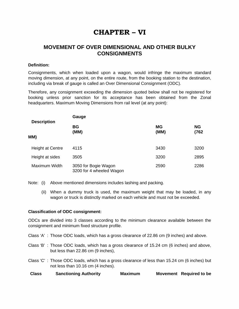
CHAPTER – VI
MOVEMENT OF OVER DIMENSIONAL AND OTHER BULKY CONSIGNMENTS
Definition:
Consignments, which when loaded upon a wagon, would infringe the maximum standard moving dimension, at any point, on the entire route, from the booking station to the destination, including via break of gauge is called an Over Dimensional Consignment (ODC).
Therefore, any consignment exceeding the dimension quoted below shall not be registered for booking unless prior sanction for its acceptance has been obtained from the Zonal headquarters. Maximum Moving Dimensions from rail level (at any point):
Gauge Description BG MG NG (MM) (MM) (762 MM) Height at Centre 4115 3430 3200
Height at sides 3505 3200 2895
Maximum Width 3050 for Bogie Wagon 2590 2286 3200 for 4 wheeled Wagon
Note: (i) Above mentioned dimensions includes lashing and packing.
(ii) When a dummy truck is used, the maximum weight that may be loaded, in any wagon or truck is distinctly marked on each vehicle and must not be exceeded.
Classification of ODC consignment:
ODCs are divided into 3 classes according to the minimum clearance available between the consignment and minimum fixed structure profile.
Class ‘A’ : Those ODC loads, which has a gross clearance of 22.86 cm (9 inches) and above.
Class ‘B’ : Those ODC loads, which has a gross clearance of 15.24 cm (6 inches) and above, but less than 22.86 cm (9 inches),
Class ‘C’ : Those ODC loads, which has a gross clearance of less than 15.24 cm (6 inches) but not less than 10.16 cm (4 inches).
Class Sanctioning Authority Maximum Movement Required to be

Permissible During Day escorted by Sanctioned or Night Speed
Within Division: DRM Inter Division of the same zone COM Sectional speed Day & Night – A Inter Rly.: COM of the Zone and COM of concerned Railway.
Local : BG-40 KMPH * B DRM MG-25 KMPH Day & Night TXR Inter Div/fgn.Rly.: COM NG-15 KMPH
BG-25 KMPH ** SE (C&W) C CRS MG-25 KMPH Day SE(P.Way) TI NG-15 KMPH
6.1 * A further speed restriction of 15 KMPH should be observed while passing stations, yards, curves and turnouts throughout the run in general and subject to observance of such special restrictions as may be stipulated by the Sanctioning Authority. The train carrying 'B' class loads will be required to pass such tight structures having net clearance of less than 15.24 CM/6" or gross clearance of less than 22.86 c.m/9" excluding curve allowance (if the structure is situated on curve) with speed restriction of 8 KMPH. The train with 'B' class loads will be examined and checked at the interchanged points and in the yards where intensive/safe to run examination exists. The load should be attached next to engine of a goods train alongwith an additional brakevan just after the load when/wherever train examiner will accompany the load.
* * In addition to these precautions, a speed restriction of 8 KM per hour should be observed for all structures having net clearance of less than 15.24.c.m (6")but more than 7.82.c.m/(3"). For structures having net clearance less than 7.62c.m.(3") but not less than 2.54c.m.(1")the load should be stopped short of the structures, the dimension should be checked and adjusted, if necessary, and then the load should be piloted through the structure at walking speed by a representative of the Engineering Department not below the rank of JE(P.Way).
6.2 The speed of the train carrying a C class ODC shall be restricted to 8 kmph while passing through stations, yards, curves, gradiants and turnouts.
Net Clearance: The net clearance shall be worked out as under:
The net clearance between the consignment as loaded in the train and any fixed structure should be calculated after making an allowance of 75 mm (3 inches) for lurch (horizontal) and 7.62 cm (3 inches) bounce (vertical) on the straight together with following additional factors applicable only when the structure in question is situated on a curve.
1. Horizontal Clearance: (a) Allowance for lean due to super-elevation and over hang due to curvature.
The lean should be calculated for that point on the profile of the load which is likely to have the smallest clearance from fixed structure the formula being :–
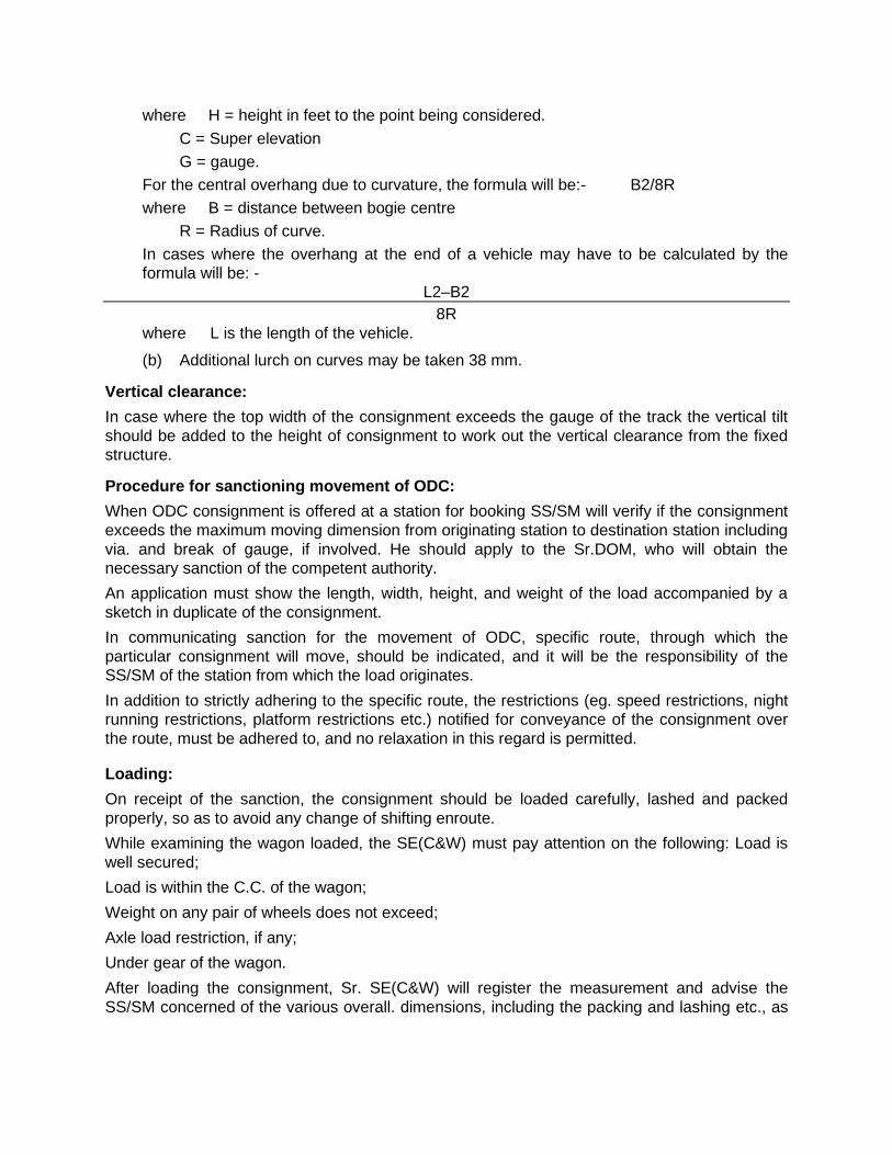
where H = height in feet to the point being considered. C = Super elevation G = gauge. For the central overhang due to curvature, the formula will be:- B2/8R where B = distance between bogie centre R = Radius of curve.
In cases where the overhang at the end of a vehicle may have to be calculated by the formula will be: -
L2–B2 8R
where L is the length of the vehicle.
(b) Additional lurch on curves may be taken 38 mm.
Vertical clearance: In case where the top width of the consignment exceeds the gauge of the track the vertical tilt should be added to the height of consignment to work out the vertical clearance from the fixed structure.
Procedure for sanctioning movement of ODC: When ODC consignment is offered at a station for booking SS/SM will verify if the consignment exceeds the maximum moving dimension from originating station to destination station including via. and break of gauge, if involved. He should apply to the Sr.DOM, who will obtain the necessary sanction of the competent authority. An application must show the length, width, height, and weight of the load accompanied by a sketch in duplicate of the consignment. In communicating sanction for the movement of ODC, specific route, through which the particular consignment will move, should be indicated, and it will be the responsibility of the SS/SM of the station from which the load originates. In addition to strictly adhering to the specific route, the restrictions (eg. speed restrictions, night running restrictions, platform restrictions etc.) notified for conveyance of the consignment over the route, must be adhered to, and no relaxation in this regard is permitted.
Loading: On receipt of the sanction, the consignment should be loaded carefully, lashed and packed properly, so as to avoid any change of shifting enroute. While examining the wagon loaded, the SE(C&W) must pay attention on the following: Load is well secured; Load is within the C.C. of the wagon; Weight on any pair of wheels does not exceed; Axle load restriction, if any; Under gear of the wagon. After loading the consignment, Sr. SE(C&W) will register the measurement and advise the SS/SM concerned of the various overall. dimensions, including the packing and lashing etc., as
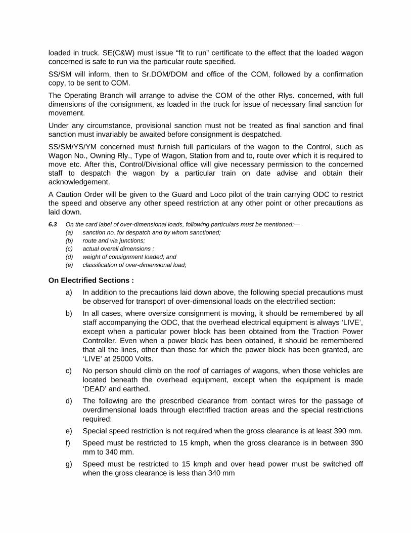
loaded in truck. SE(C&W) must issue “fit to run” certificate to the effect that the loaded wagon concerned is safe to run via the particular route specified.
SS/SM will inform, then to Sr.DOM/DOM and office of the COM, followed by a confirmation copy, to be sent to COM.
The Operating Branch will arrange to advise the COM of the other Rlys. concerned, with full dimensions of the consignment, as loaded in the truck for issue of necessary final sanction for movement.
Under any circumstance, provisional sanction must not be treated as final sanction and final sanction must invariably be awaited before consignment is despatched.
SS/SM/YS/YM concerned must furnish full particulars of the wagon to the Control, such as Wagon No., Owning Rly., Type of Wagon, Station from and to, route over which it is required to move etc. After this, Control/Divisional office will give necessary permission to the concerned staff to despatch the wagon by a particular train on date advise and obtain their acknowledgement.
A Caution Order will be given to the Guard and Loco pilot of the train carrying ODC to restrict the speed and observe any other speed restriction at any other point or other precautions as laid down. 6.3 On the card label of over-dimensional loads, following particulars must be mentioned:— (a) sanction no. for despatch and by whom sanctioned; (b) route and via junctions; (c) actual overall dimensions ; (d) weight of consignment loaded; and (e) classification of over-dimensional load;
On Electrified Sections : a) In addition to the precautions laid down above, the following special precautions must
be observed for transport of over-dimensional loads on the electrified section: b) In all cases, where oversize consignment is moving, it should be remembered by all
staff accompanying the ODC, that the overhead electrical equipment is always ‘LIVE’, except when a particular power block has been obtained from the Traction Power Controller. Even when a power block has been obtained, it should be remembered that all the lines, other than those for which the power block has been granted, are ‘LIVE’ at 25000 Volts.
c) No person should climb on the roof of carriages of wagons, when those vehicles are located beneath the overhead equipment, except when the equipment is made ‘DEAD’ and earthed.
d) The following are the prescribed clearance from contact wires for the passage of overdimensional loads through electrified traction areas and the special restrictions required:
e) Special speed restriction is not required when the gross clearance is at least 390 mm. f) Speed must be restricted to 15 kmph, when the gross clearance is in between 390
mm to 340 mm. g) Speed must be restricted to 15 kmph and over head power must be switched off
when the gross clearance is less than 340 mm

h) No consignment with less than 100 mm gross clearance from the over head contact wire will be permitted over electrified section.
i) A representative of the Traction Department should also accompany all ODC having clearance as specified in item (b) and (c) of sub para (3) above, over electrified section.
j) A representative of the Traction Department should accompany all ODC loads having width of more than 1981 mm for BG and 1910 mm for MG from the centre line of the track.
k) Section Controllers and Traction Power Controller must co-ordinate, while an ODC moves on electrified area.
l) A list of structures, where the clearances are restricted on the electric traction area and also the clearance available under overbridges should be with the Section Controllers and Traction Power Controllers.
Despatch of ODCs: 1) At the originating station the ODC wagon will be moved when final approval has been
obtained from the competent authority. 2) At the originating point the number of wagon/wagons carrying ODC should be
entered by the Train Clerk/SM in the vehicle guidance in red ink to be handed over to the Guard of the train.
3) SS/SM should advise the Section Controller on duty, before starting the train and while asking line clear, describe the train number with letter ‘X’ suffixed on it.
4) It will be the duty of the Dy. Chief Controller to keep adjoining Control Office informed about the movement of such ODC, till such time, it is handed over to the adjoining division by specified train. Also ensure that the consignment is moved strictly by the authorised route.
5) Shunting of train with an ODC should be avoided. Loose and rough shunting of ODC wagon and against such wagon is prohibited.
6) When any ODC wagon is detached from the train at any station, SM and Guard are responsible to ensure safe placement and securing of wagon/load.
7) Facility for accompanying staff for extra wagon/brake van should be provided if so required.
8) When a load is so long that it cannot be accommodated in two trucks (i.e. two 8 wheelers), it must be loaded in three trucks so that the entire weight is carried on the centre vehicle and the end trucks are idlers. The load must be placed on packing in the centre truck, so that it is clear of the floor of the end trucks by not less 152 mm and there must not be less than 304 mm up side clearance in the end trucks between each of load and side of truck.
If the weight of the load is such that it cannot be carried on the centre truck, then the load must be carried as equally as possible on the trucks and the centre vehicle must be an idler.
6.4 In addition to the above the following shall be ensured– (i) Over-dimensional loads should move by through trains and not by work trains or shunting trains.
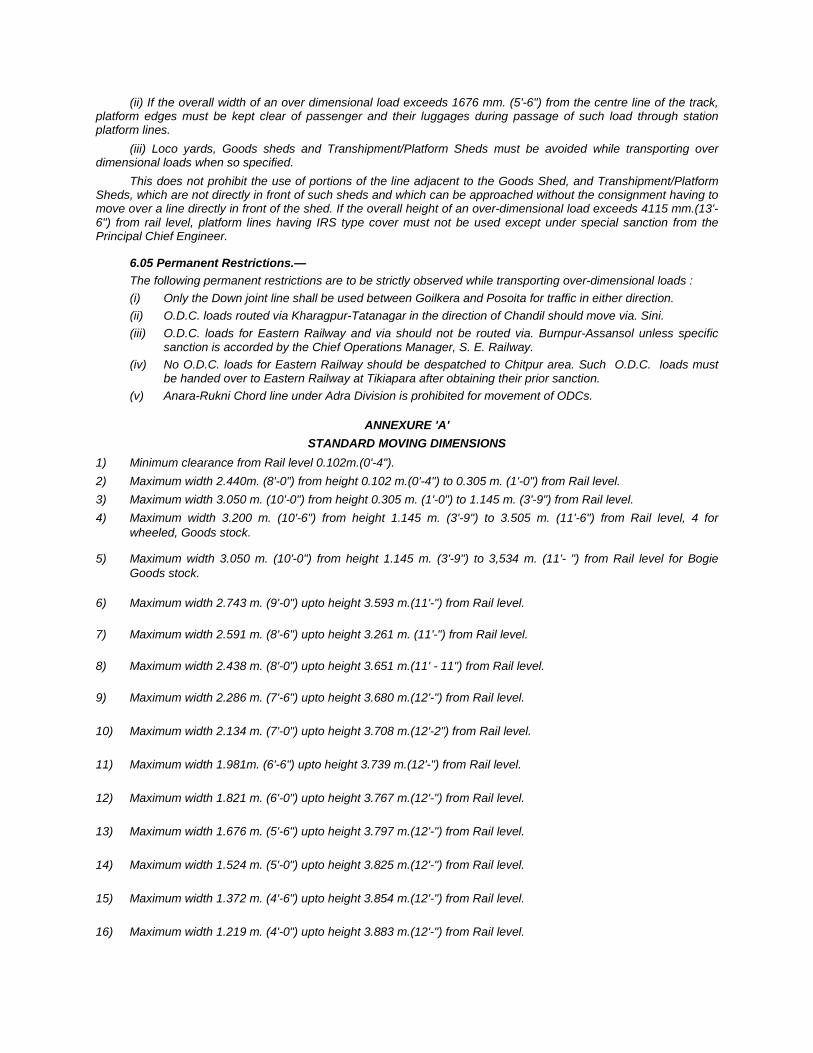
(ii) If the overall width of an over dimensional load exceeds 1676 mm. (5'-6") from the centre line of the track, platform edges must be kept clear of passenger and their luggages during passage of such load through station platform lines.
(iii) Loco yards, Goods sheds and Transhipment/Platform Sheds must be avoided while transporting over dimensional loads when so specified.
This does not prohibit the use of portions of the line adjacent to the Goods Shed, and Transhipment/Platform Sheds, which are not directly in front of such sheds and which can be approached without the consignment having to move over a line directly in front of the shed. If the overall height of an over-dimensional load exceeds 4115 mm.(13'-6") from rail level, platform lines having IRS type cover must not be used except under special sanction from the Principal Chief Engineer.
6.05 Permanent Restrictions.— The following permanent restrictions are to be strictly observed while transporting over-dimensional loads : (i) Only the Down joint line shall be used between Goilkera and Posoita for traffic in either direction. (ii) O.D.C. loads routed via Kharagpur-Tatanagar in the direction of Chandil should move via. Sini. (iii) O.D.C. loads for Eastern Railway and via should not be routed via. Burnpur-Assansol unless specific
sanction is accorded by the Chief Operations Manager, S. E. Railway. (iv) No O.D.C. loads for Eastern Railway should be despatched to Chitpur area. Such O.D.C. loads must
be handed over to Eastern Railway at Tikiapara after obtaining their prior sanction. (v) Anara-Rukni Chord line under Adra Division is prohibited for movement of ODCs.
ANNEXURE 'A' STANDARD MOVING DIMENSIONS
1) Minimum clearance from Rail level 0.102m.(0'-4"). 2) Maximum width 2.440m. (8'-0") from height 0.102 m.(0'-4") to 0.305 m. (1'-0") from Rail level. 3) Maximum width 3.050 m. (10'-0") from height 0.305 m. (1'-0") to 1.145 m. (3'-9") from Rail level. 4) Maximum width 3.200 m. (10'-6") from height 1.145 m. (3'-9") to 3.505 m. (11'-6") from Rail level, 4 for
wheeled, Goods stock.
5) Maximum width 3.050 m. (10'-0") from height 1.145 m. (3'-9") to 3,534 m. (11'- ") from Rail level for Bogie Goods stock.
6) Maximum width 2.743 m. (9'-0") upto height 3.593 m.(11'-") from Rail level.
7) Maximum width 2.591 m. (8'-6") upto height 3.261 m. (11'-") from Rail level.
8) Maximum width 2.438 m. (8'-0") upto height 3.651 m.(11' - 11") from Rail level.
9) Maximum width 2.286 m. (7'-6") upto height 3.680 m.(12'-") from Rail level.
10) Maximum width 2.134 m. (7'-0") upto height 3.708 m.(12'-2") from Rail level.
11) Maximum width 1.981m. (6'-6") upto height 3.739 m.(12'-") from Rail level.
12) Maximum width 1.821 m. (6'-0") upto height 3.767 m.(12'-") from Rail level.
13) Maximum width 1.676 m. (5'-6") upto height 3.797 m.(12'-") from Rail level.
14) Maximum width 1.524 m. (5'-0") upto height 3.825 m.(12'-") from Rail level.
15) Maximum width 1.372 m. (4'-6") upto height 3.854 m.(12'-") from Rail level.
16) Maximum width 1.219 m. (4'-0") upto height 3.883 m.(12'-") from Rail level.
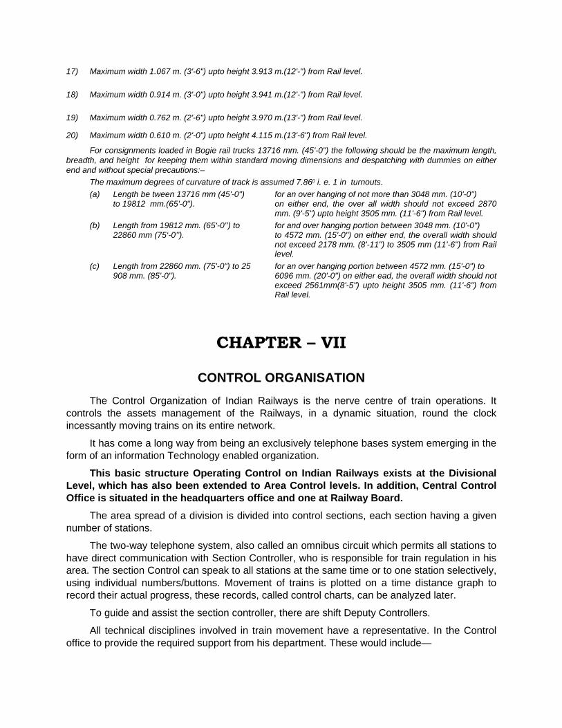
17) Maximum width 1.067 m. (3'-6") upto height 3.913 m.(12'-") from Rail level.
18) Maximum width 0.914 m. (3'-0") upto height 3.941 m.(12'-") from Rail level.
19) Maximum width 0.762 m. (2'-6") upto height 3.970 m.(13'-") from Rail level.
20) Maximum width 0.610 m. (2'-0") upto height 4.115 m.(13'-6") from Rail level.
For consignments loaded in Bogie rail trucks 13716 mm. (45'-0") the following should be the maximum length, breadth, and height for keeping them within standard moving dimensions and despatching with dummies on either end and without special precautions:–
The maximum degrees of curvature of track is assumed 7.860 i. e. 1 in turnouts. (a) Length be tween 13716 mm (45'-0") for an over hanging of not more than 3048 mm. (10'-0") to 19812 mm.(65'-0"). on either end, the over all width should not exceed 2870
mm. (9'-5") upto height 3505 mm. (11'-6") from Rail level. (b) Length from 19812 mm. (65‘-0’’) to for and over hanging portion between 3048 mm. (10'-0") 22860 mm (75‘-0’’). to 4572 mm. (15'-0") on either end, the overall width should
not exceed 2178 mm. (8'-11") to 3505 mm (11'-6") from Rail level.
(c) Length from 22860 mm. (75'-0") to 25 for an over hanging portion between 4572 mm. (15'-0") to 908 mm. (85'-0"). 6096 mm. (20'-0") on either ead, the overall width should not
exceed 2561mm(8'-5") upto height 3505 mm. (11'-6") from Rail level.
CHAPTER – VII
CONTROL ORGANISATION
The Control Organization of Indian Railways is the nerve centre of train operations. It controls the assets management of the Railways, in a dynamic situation, round the clock incessantly moving trains on its entire network.
It has come a long way from being an exclusively telephone bases system emerging in the form of an information Technology enabled organization.
This basic structure Operating Control on Indian Railways exists at the Divisional Level, which has also been extended to Area Control levels. In addition, Central Control Office is situated in the headquarters office and one at Railway Board.
The area spread of a division is divided into control sections, each section having a given number of stations.
The two-way telephone system, also called an omnibus circuit which permits all stations to have direct communication with Section Controller, who is responsible for train regulation in his area. The section Control can speak to all stations at the same time or to one station selectively, using individual numbers/buttons. Movement of trains is plotted on a time distance graph to record their actual progress, these records, called control charts, can be analyzed later.
To guide and assist the section controller, there are shift Deputy Controllers.
All technical disciplines involved in train movement have a representative. In the Control office to provide the required support from his department. These would include—
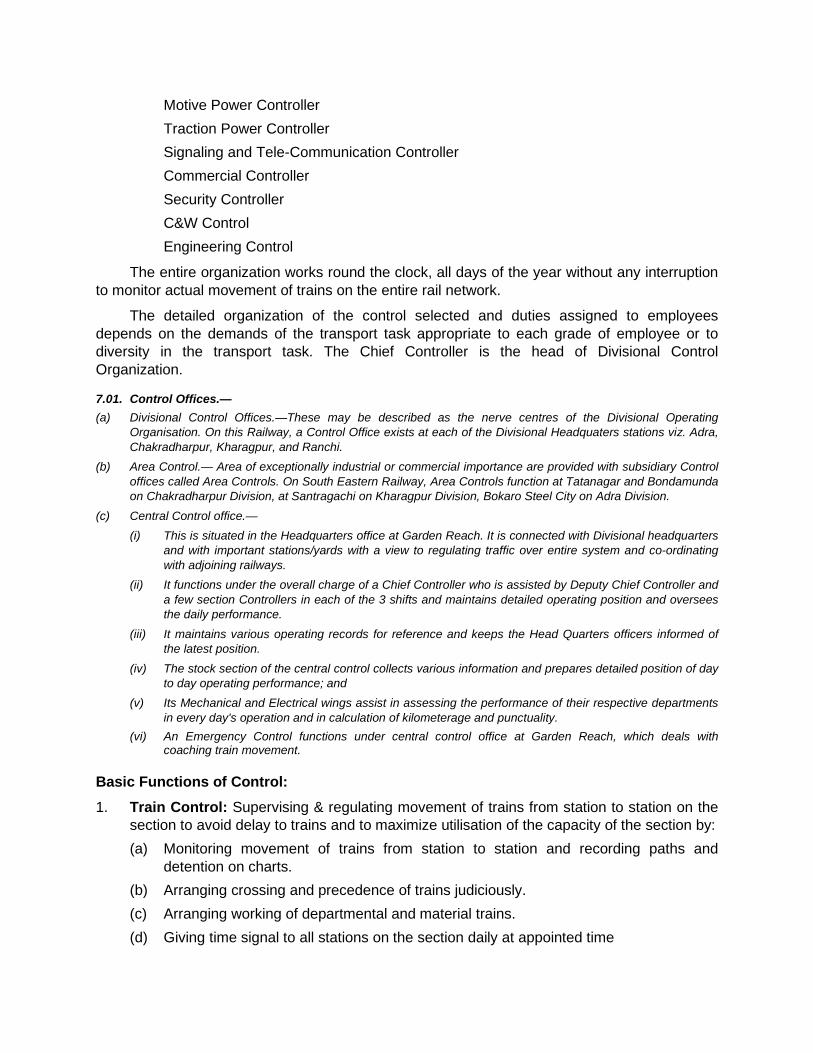
Motive Power Controller Traction Power Controller Signaling and Tele-Communication Controller Commercial Controller Security Controller C&W Control Engineering Control
The entire organization works round the clock, all days of the year without any interruption to monitor actual movement of trains on the entire rail network.
The detailed organization of the control selected and duties assigned to employees depends on the demands of the transport task appropriate to each grade of employee or to diversity in the transport task. The Chief Controller is the head of Divisional Control Organization.
7.01. Control Offices.— (a) Divisional Control Offices.—These may be described as the nerve centres of the Divisional Operating
Organisation. On this Railway, a Control Office exists at each of the Divisional Headquaters stations viz. Adra, Chakradharpur, Kharagpur, and Ranchi.
(b) Area Control.— Area of exceptionally industrial or commercial importance are provided with subsidiary Control offices called Area Controls. On South Eastern Railway, Area Controls function at Tatanagar and Bondamunda on Chakradharpur Division, at Santragachi on Kharagpur Division, Bokaro Steel City on Adra Division.
(c) Central Control office.— (i) This is situated in the Headquarters office at Garden Reach. It is connected with Divisional headquarters
and with important stations/yards with a view to regulating traffic over entire system and co-ordinating with adjoining railways.
(ii) It functions under the overall charge of a Chief Controller who is assisted by Deputy Chief Controller and a few section Controllers in each of the 3 shifts and maintains detailed operating position and oversees the daily performance.
(iii) It maintains various operating records for reference and keeps the Head Quarters officers informed of the latest position.
(iv) The stock section of the central control collects various information and prepares detailed position of day to day operating performance; and
(v) Its Mechanical and Electrical wings assist in assessing the performance of their respective departments in every day's operation and in calculation of kilometerage and punctuality.
(vi) An Emergency Control functions under central control office at Garden Reach, which deals with coaching train movement.
Basic Functions of Control: 1. Train Control: Supervising & regulating movement of trains from station to station on the
section to avoid delay to trains and to maximize utilisation of the capacity of the section by: (a) Monitoring movement of trains from station to station and recording paths and
detention on charts. (b) Arranging crossing and precedence of trains judiciously. (c) Arranging working of departmental and material trains. (d) Giving time signal to all stations on the section daily at appointed time
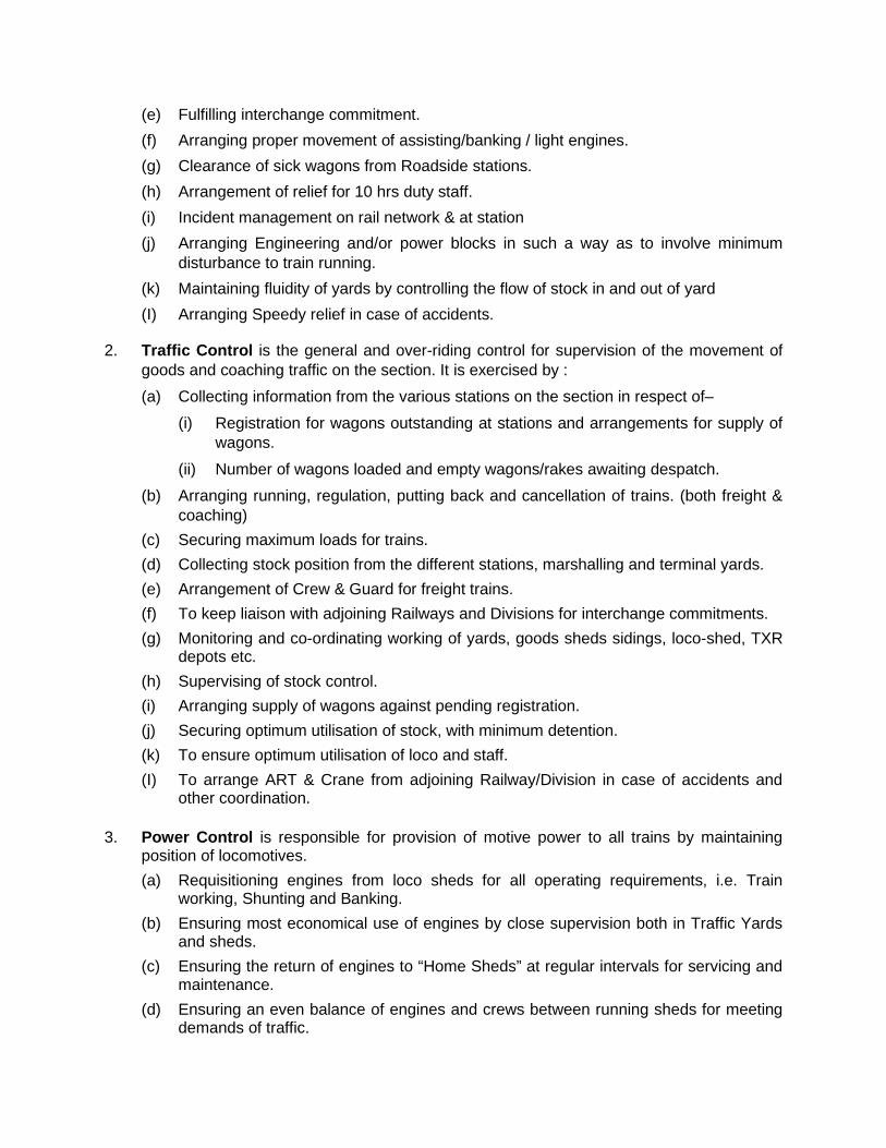
(e) Fulfilling interchange commitment. (f) Arranging proper movement of assisting/banking / light engines. (g) Clearance of sick wagons from Roadside stations. (h) Arrangement of relief for 10 hrs duty staff. (i) Incident management on rail network & at station (j) Arranging Engineering and/or power blocks in such a way as to involve minimum
disturbance to train running. (k) Maintaining fluidity of yards by controlling the flow of stock in and out of yard (I) Arranging Speedy relief in case of accidents.
2. Traffic Control is the general and over-riding control for supervision of the movement of goods and coaching traffic on the section. It is exercised by : (a) Collecting information from the various stations on the section in respect of–
(i) Registration for wagons outstanding at stations and arrangements for supply of wagons.
(ii) Number of wagons loaded and empty wagons/rakes awaiting despatch. (b) Arranging running, regulation, putting back and cancellation of trains. (both freight &
coaching) (c) Securing maximum loads for trains. (d) Collecting stock position from the different stations, marshalling and terminal yards. (e) Arrangement of Crew & Guard for freight trains. (f) To keep liaison with adjoining Railways and Divisions for interchange commitments. (g) Monitoring and co-ordinating working of yards, goods sheds sidings, loco-shed, TXR
depots etc. (h) Supervising of stock control. (i) Arranging supply of wagons against pending registration. (j) Securing optimum utilisation of stock, with minimum detention. (k) To ensure optimum utilisation of loco and staff. (I) To arrange ART & Crane from adjoining Railway/Division in case of accidents and
other coordination.
3. Power Control is responsible for provision of motive power to all trains by maintaining position of locomotives. (a) Requisitioning engines from loco sheds for all operating requirements, i.e. Train
working, Shunting and Banking. (b) Ensuring most economical use of engines by close supervision both in Traffic Yards
and sheds. (c) Ensuring the return of engines to “Home Sheds” at regular intervals for servicing and
maintenance. (d) Ensuring an even balance of engines and crews between running sheds for meeting
demands of traffic.
(e) Ensuring that light engine kilometres is kept to the minimum. (f) Providing guidance to running staff for troubleshooting.
4. Carriage and Wagon Control is responsible to assist the train and traffic control and to– (a) Ensure timely examination and fitness of all trains. (b) To keep a watch over the detachment of sick wagons/coaches and to arrange for
their early repair and fitness. (c) Keeping a watch over availability of vital C&W components, like Air Hoses, Washers,
Clamps etc. and efficient working of equipments &machines in C&W depot to avoid detention to trains.
(d) To keep a watch over placement of wagons/coaches in sick line and their release. (e) To keep account of detention to trains on C&W account and take remedial action. (f) To provide guidance to running staff for trouble shooting. (g) For Electrical Multiple Units, this function is performed by EMU controller. (h) Monitor the movement of POH due stock to workshops.
5. Commercial Control assists the Traffic and Train Control. (a) To expeditiously dispose off unclaimed and unconnected wagons, parcel
consignments.
(b) To keep a watch on detention to trains on Commercial account like Alarm Chain Pulling. Carriage watering, Parcel working etc; and take remedial measures.
(c) To ensure quick transhipment of sick wagons by arranging matching stock and labour.
(d) To keep a watch over submission of station returns. (e) Monitoring of public complaints lodged at the stations. (f) To ensure proper maintenance of public amenities available at stations. (g) Any other job entrusted by Sr. DCM/DCM.
6. Traction Power Control is provided to assist in Traffic and Train Control for – (a) Arranging maintenance blocks for OHE. (b) Arranging alternative power supply in case of tripping etc., through remote control. (c) Monitoring OHE failures and taking remedial action. (d) Monitoring detention of trains on OHE accounts. (e) Guiding running / station staff in trouble shooting.
7. Engineering Control Monitors imposition & cancellation of Engineering Restrictions, Working of track machines
& monitoring integrated maintainable blocks. To co-ordinate works during maintenance blocks Running of Material trains.
8. Signal Control assists Traffic and Train Control and is responsible –
a) To keep a watch over the S&T failures and take remedial action. b) To ensure efficient working of communication channels.
9. Security Control is responsible for prevention of theft of property and assists passengers in trains/stations.
10. Functions of Control: The main functions of Traffic Control are: a) Continuous supervision of the movement of all traffic in the controlled area with a
view to achieve the maximum possible operating efficiency. b) Systematic maintenance of accurate charts of train movements and the
arrangements of crossing and precedence to the greatest advantage. c) Analysis of detentions to trains d) Planning, ordering and running of goods trains to the best possible paths. e) Maintaining the fluidity of marshalling yards/freight terminals. f) Taking remedial action in the event of yard/terminal congestion. g) Elimination of avoidable detentions to goods stock at loading and unloading points
and at transhipment stations. h) Allotment and distribution of goods stock to stations, i) Supply of information to adjoining controls, terminals and engine changing stations
regarding the movements of trains to enable adequate timely arrangements for their reception and onward despatch.
j) Arranging of engineering and other departments blocks with minimum detention to traffic.
k) Running of material trains and other track machines, tower wagons etc. I) Arranging relief for engine crews and Guards. m) Ensuring maximum utilisation of locomotives. n) Issuing instructions for train working in case of equipment failures and whenever
abnormal methods or working have to be resorted to. o) Speedy arrangements for relief rescue and restoration in the event of accident. p) To assist in the realistic planning of time tables and punctual running of passenger
trains in co-ordination with various departments, other divisions and other railways. q) To keep a watch over damaged stock at road side stations, yards and sick lines and
to ensure that they are promptly attended to r) To rectify immediately the irregularities on the part of line staff and provide them
necessary guidance. s} To provide operations management information. t) To ensure smooth functioning of FOIS and other IT applications.
Telecommunication Facilities in Control: Extensive, efficient and reliable communication network is necessary for the efficient
functioning of the Control organisation. The following telecommunication network is available in control offices.
1. FOIS Network 2. Hot lines are provided between:
(a) Headquarter and Divisions (b) Adjoining Divisions and Railways (c) Intercom facility to various Officers and other functionaries concerned with the control
is connected with important work centres with STD or Trunk Exchanges.
3. Deputy Control Lines: This circuit is provided between various functionaries in the control office, stations and
important work centres like yards, loco sheds, crew booking lobbies.
4. Section control circuit: This circuit is connected to all the stations and the section controller, Chief controller etc.
5. Traction Power Control circuit: This additional telephone circuit is available on the electrified sections; this is connected to
T.P.C. in OHE remote control centre, all stations, control-offices and selected work places. The section controller or T.P.C. can also be contacted from the emergency socket provided over the sections of line by means of portable telephone of the control point with indication on the electric mast, direction wise, to the nearest circuit.
6. Section Control Board: The Section Controller of each section is provided with control board with
Telecommunication facilities for coaching stations, certain important cabins, big freight terminals, loco shed etc. over a section. For the guidance of section controller, the lay out of all the stations and sidings is painted on a large board.
The station lay out diagram is also provided with details of holding capacity of each of the running & non-running lines, gradients and signals. In electrified area, OHE sectioning diagram is provided. This depicts elementary sections in different colours & other details of sectioning post (SP) and Sub-sectioning post (SSP).
7. Graphs and Plotting: i) Trains are plotted on control graphs which consist of horizontal and vertical lines
representing distance and time respectively. Along side the vertical lines stations are spaced to a uniform scale. Each one hour is first divided into 6 units of 10 minutes each and each unit is further sub-divided into 5 smaller units of 2 minutes each.
ii) Each control graph at the end of the shift may have the following information on it: (a) Name and total distance of the section in Kilometres. (b) Distance in Kms. between each station on the section. (c) State of weather in each shift. (d) Engineering restrictions on the section. (e) Code names of each station of the section. (f) Time lost by each train on loco, traffic or engineering account at or between
stations. (g) Section Controller’s remarks against item (d). (h) Time made up by each train on loco, traffic or engineering account.
(i) Guard’s record of time lost on loco, traffic or engineering account at or between stations and remarks.
(j) General remarks. (k) Signal failures
iii) In plotting various types of trains the coloured pencils shall be used as per extant convention. All up trains are plotted from the bottom of the chart upwards and from the left diagonally towards the right; and all down trains are plotted from the top of the chart downwards and also diagonally from the left towards the right.
iv) For judicious crossing and precedence, it is necessary to have plotting of passenger trains at least one hour in advance depending on traffic density in easily erasable lines. Now through computerized charting this is automated. On certain selected controls, this function has been automated.
7.02. Train Control Charts.— In plotting the paths of various classes of trains, pencils of the following colours shall be used:— (i) Red — for Mails, Expresses and other trains requiring top priority. (ii) Blue — for other trains carrying passengers. (iii) Green — for Military special and Crack-Specials, Fast Goods, S.Q.T. and working trains and other
important goods trains. (iv) Black — or other Goods trains.
8. Master Charts: For every section, Master Charts indicating trains run in 24 hours are prepared which show
the running of each Mail, Express or passenger trains over the sections according to its scheduled running. In between the running of trains carrying passengers, paths for goods trains are worked out and plotted. They are helpful in revision of time tables and planning the running of any extra train and guidance of section controllers and should be displayed on the boards to which they refer.
7.03. Forecast.— It is an information conveyed in advance by adjoining control offices, adjoining railways and MIL rail about the
availability of stock indicating train, direction, commodity, type of stock (if there is need for stock of some particular description), and break of gauge transhipment.
7.04. Declaration.— (a) Before staff are allowed to work independently as Controllers, they shall be required to pick up duties on the
boards they would be required to work. This learning must be under the guidance of the section controller on duty. The period of learning would depend on the aptitude for control work which the staff possesses but in any case, it must not exceed 5 days in each shift for each board.
(b) In case the Chief Controller observes that an employee would require more than 5 days for each shift on the board, he must bring the fact to the notice of the Assistant/Divisional Operations Manager and take his special sanction for extension of the learning period.
(c) After the employee has taken learning, he shall write and sign the following declaration in a register specially maintained for the purposes;
"I hereby declare that I have taken learning on Board/boards to my entire satisfaction and can, now work independently as a Section Controller on this/these board/boards".
The Chief Controller shall write the following remarks below the above declaration and sign it : "Shri............................................................................was given learning on.......................... board/boards
from............................ to .................................I have watched progress and consider him fit to work independently on the board(s)".
The Chief Controller may also test the employees before allowing them to work independently.
(d) Deputy Chief Controllers shall also be required to give similar declarations, but in their case the period of learning in each shift should not exceed 3 days. If this period is likely to exceed, the Chief Controller shall take action as mentioned in sub-para(b) above.
(e) The Chief Controller shall also append a certificate similar to the one mentioned in sub-para(c), below the Deputy Chief Controller's declaration.
(f) In case of sub-control offices where the Chief Controller is not posted, the duties herein assigned to the Chief Controller shall devolve on the seniormost Deputy Chief Controller.
Duties of Control Staff: 1. Duties of controllers: The main duties of control staff are as under: These are only guidelines to their day to day working and are not exhaustive. (a) Chief Controller (In-charge). The Chief controller is in- overall charge of control office and is responsible for the total
transportation of the Division on day to day basis. His duties include.
(i) A review of previous day’s performance to confirm that all forecasts made have been fully met. For shortfalls, cogent reasons have to be pinpointed to prevent recurrence.
(ii) Prepare current forecast indicating assistance needed from Headquarters, adjoining Divisions, railways.
(iii) These will generally relate to interchange, loading and locomotive utilisation.
(iv) Checking control charts and bringing to the notice of the Senior Divisional Operations Manager/Divisional Operations Manger all avoidable detention to trains.
(v) Punctuality performance with particular reference to trains which lost punctuality.
(vi) Maintaining statistics regarding the punctuality of passenger trains.
(vii) Scrutiny of stock papers, Monitoring interchange obligations.
(viii) Watching detention to stock at stations and terminals.
(ix) Watching the work of marshalling yards/freight terminals.
(x) Maintaining liaison with neighbouring Divisions.
(xi) Watching utilisation of loco and their terminal detention.
(xii) Checking duty hours of running staff and balancing of crews.
(xiii) Granting engineering blocks, power blocks etc.,
(xiv) Attending control office in cases of accident.
(xv) Establishment work of control office.
(b) Chief controller (Movement)/ Dy. Chief Controller / Shift duty: He is responsible for: (i) Running of goods trains, preparing interchange forecast, and monitoring the same,
loco utilisation and passenger and goods train operations in general.
(ii) Allotting empty stock/rakes to loading stations in accordance with current priority regulations along with Dy. Chief Controller (Stock) maintaining constant touch with adjacent divisions through regular conference to facilitate the smooth flow of traffic.
(iii) Dealing immediately with significant detentions or transport bottlenecks and other unusuals.
(iv) Keeping constant touch with the working of major terminals & Marshalling yards and taking timely action to deal with congestion.
(v) Giving advice of serious accidents to all concerned, and taking, charge of the affected sections.
(vi) Supervising the running of oversized consignments.
(vii) Maintaining liaison with the Power Controller.
(viii) Co-ordinate the work of various Section Controllers.
(ix) Maintain discipline among control staff in the absence of Chief Controller.
(x) Maintain co-ordination and liaison with various functionaries involved in train running.
(c) Chief Controller (stock) / Dy. Chief Controller: He is responsible for:
(i) Scrutinising the indent register in details with regard to the oldest date of registration, nature of goods and type of stock required for lifting goods as per the oldest date of registration.
(ii) Checking Divisional stock report and position of empties. (iii) Checking of different stock reports received from the various points and planning in
advance the supply of stock, loading and clearance keeping in view interchange obligation and orders received.
(iv) Checking transhipment activity. (v) Chasing movements of stock as per supply order issued on the previous day. (vi) Keeping a close watch over hot axle, special type and unconnected wagons. (vii) Cross checking the daily Restriction Bulletin with Restriction Messages received from
HQ office and issuing the same. (viii) Assisting the Sr. DOM/DOM in allotments. (ix) Keeping a close watch over the movements of seasonal perishable traffic and supply
of suitable stock for its clearance. (x) Watching movements of damaged loaded stock in sick line and yards on their
division. (xi) Informing all major customers about their inward trains’ expected arrival based on
FOIS pipe line, Optimising loading, unloading, transhipment etc.
Duties of Deputy Chief Controller (Punctuality) (i) Ensuring punctuality of passenger trains in system (ii) Ensuring punctuality at the start of all outgoing passenger train (iii) Maintaining Detention Reports of Coaching trains (iv) Ensure that late running trains make up time
(d) Section Controller:
The Section Controller shall be responsible for: (i) Reporting for duty at the prescribed time and ascertaining the position of the section
from his reliever. (ii) Recording the movement of trains on the ‘Control’ graph including crossing,
connections and shunting reasons for detentions etc. (iii) Arranging for the supply and clearance of stock as ordered by Dy. Controller. (iv) Advising stations in advance of the work to be done on trains on move (v) Informing sheds and stations about the late running of trains to avoid the calling of
Crew and Guards earlier than necessary or to put back trains wherever advisable. (vi) Informing major stations and concerned Section Controller about the current running
of trains on the section and their anticipated arrivals well in time (vii) Keeping in close touch with Engineering-blocks and working of material trains so as
to give the maximum possible time with least detention to other traffic. (viii) Incident management to include adjusting movements of trains in view of the likely
impact of the incident, informing all concerned (ix) Keeping a watch over damaged vehicles detached at road side stations and
arranging repairs or transhipment of their contents and proper attention on the part of the train examining staff.
(x) Arrangement of ART & M/Van in case of accident. (xi) Eliminating all possible detention to train and stock. (xii) Watching the working of marshalling yards & major terminals. (xiii) Making timely arrangements for the relief of Guards /loco pilots whose duty hours are
likely to exceed enroute. (xiv) Recording stock report (where stock clerks are not posted).
(e) Power Controller/Traction Loco Controller: (i) Planning and directing engine movements so as to ensure efficient engine utilization
and maintaining the prescribed charts, and regular statistics. (ii) Co-ordination with sheds and Dy. Chief Controllers (movement) for sending overdue
engines and obtaining time of engines coming out of shed. (iii) Making timely arrangement for the relief of crew whose duty hours are likely to be
exceeded enroute (iv) Taking timely action to balance crew so as to prevent cancellation or putting back of
trains on account of shortage of crew. (v) Arranging relief in case of accidents as per chapter IV to VIII of Accident Manual. (vi) Maintaining charts indicating engine position/utilisation. (vii) Rendering advice and assistance to locomotive running staff regarding trouble
shooting. (viii) Carrying out any other duties allotted to him by the Sr.DME/DME or Sr.DEE/DEE
from time to time. (ix) Monitoring day-to-day stock position of diesel fuel at RDIs and watching movement of
diesel fuel tank wagons (for power controllers only) Note : For detailed information ACTM may be refered.
(f) Traction Power Controller: Traction Power Controller shall be responsible for
(i) While taking over shift duty acquaint himself with the prevailing position of the entire section, including the working of the Remote Control equipment position of all transformers, current breaker’s interrupters and isolators, sections under power block, position of tower wagons and break down vehicle etc.
(ii) Maintaining continuous contact with the Traffic Section Controllers in regard to power supply affecting train movements, imposing power blocks etc.
(iii) Taking prompt action for restoration of supply in the event of power supply interruptions or other failures.
(iv) Imposing and removing power blocks in consultation with Traffic Section Controller. (v) Advising promptly the concerned officials in case of accidents, OHE breakdown,
failure of power supply and keeping them posted with all important developments.
Note : For detailed informations ACTM may be refered.
Operating Discipline (i) Line Staff to obey orders of control: Station staff, Shed staff, Crew and Guards etc must obey orders issued by the
Control as long as these orders are consistent with the General and Subsidiary Rules, extant instructions and the instructions contained in this Manual.
7.5 A section Controller has no authority to deviate from any Rules, Standing Orders and instructions. If any orders are issued which contravene or appear to conflict with extant rules, Standing orders, instructions etc. such orders shall not be carried out by staff or running staff who shall promptly report the matter to the Deputy Chief Controller, Chief Controller and Divisional Operations manager.
(ii) ‘Control order register’:
Important instructions from control will first be recorded in a register maintained in the control office and serially numbered, commencing with number 1 after midnight each day. These will be issued as messages indicating the time of issue
All such orders received by the Station Masters or Running staff and Guards’ lobby from Control should be entered in the control order register by the staff. Each entry must be initialled with time.
At the end of each turn of duty the relieved as well as the relieving Station Master or Crew Controller must sign their name in full below the last entry in the register. On days when no orders are received from control, “Nil” entry must be recorded and signed as prescribed above. When a station Master or Crew Controller has received an order from the control and entered it in his register, he may repeat it to the control in order to satisfy himself and the control that he has understood it correctly.
(iii) No Terminal Station should start a goods or unscheduled train or block the section without the permission of the Controller.
(iv) Every Station on the section must report the movement of every train- passenger, goods, special, departmental, light engines, TTMs, Tower Wagons, trollies etc. to the controller.
(v) When the control is in function, Line Clear must be asked from the station ahead for every train unless orders to stop it are given by the Controller.
(vi) The Controller’s permission must be obtained before stopping a train that should run through except to avert an accident or dangerous condition.
(vii) No station should allow a train, which has been stopped out of course, to proceed, without first informing the controller that the train has been so stopped and receiving his further orders.
(viii) Station Master must advise the controller of any unauthorised or undue detention to trains at their stations with full explanation.
(ix) Whenever a train, either passenger or goods is detained at a station for longer than the booked halt without the orders of the Controller, on its departure, the Station Master must immediately inform the brief cause of the detention to the Controller.
(x) Whenever any damaged wagon is detached out of course at a station, the Station Master on duty should inform the Controller.
(xi) Station Master must promptly advise the Controller of any defects of signals, points, interlocking apparatus and line clear instruments at their stations. Information should also be given of any defects in any other station machinery such as cranes, wagon weigh bridges, turn tables, water columns, hydrants etc.
(xii) Starting stations to report particulars of outgoing train:
As soon as a train leaves a train starting station, the Station Master must intimate the following particulars to the control office:
Number and description of train, Engine number and class, Loco pilot’s name, Guard’s name, load of the train (in tonnes and vehicles) particulars of shunting to be done on the journey, time of departure, brief reasons of late start, time of SIO of crew fuel balance etc.
(xiii) Intermediate stations to report arrival and departure time of trains:
Station Master of intermediate station must communicate to the Control as early as possible, the following information in regard to every train dealt with: (a) In case the train has run through, the time it passed the station. (b) If it is a stopping train, the time, or arrival and departure along with the
explanation for every detention beyond the scheduled stoppage. (c) If any shunting has been performed, the number of vehicles attached and
detached. (d) if any extra time has been taken in loading and unloading of packages, the
number of such packages and name of the loading station.
(xiv) Terminating stations to report the particulars of incoming trains. Station Masters of terminal and engine changing station must, as soon as possible,
after the arrival of a train, communicate to the control the time of arrival and the load of the train, particulars of loco detached/attached.
(xv) Engine Movements to and from sheds to be reported.
Loco foreman must communicate to control the time at which train engine leaves from or returns to the shed ‘Bahar line’.
This is no way, relieves the Station Master of the responsibility for issuing necessary all concerned messages regarding engine failures and engine trouble enroute. The Controller, shall record the duration of such defects in his chart, diary and registers.
(xvi) Time to be checked with control.
Station Master, Crew Controller and Lobbies must check their time with control at appointed hours every day when control gives a general ring for setting their watches/clocks at 16:00 hrs.
Shift must obtain Station Master’s permission before speaking to Controller.
(xvii) Mode of using the control phone:
The Control telephone is to be used for operational purposes. The field staff wanting to talk to control will give their identity and wall for their turn to communicate. As this network is intensively used, the conversion should be brief, meaningful and polite. Discussions, disputes and arguments must be avoided.
(a) Station Master and others must start to speak to control unless they have ascertained by lifting the receiver and listening in, that the line is free. They must then announce the name of the station shed, lobby or site from where they are speaking and wait for its being repeated by the controller before beginning the conversation.
(b) When, however an urgent message has to be conveyed and the line happens to be engaged, the station name must be called indicating Emergency. The Controller will immediately attend to the Station having an emergency. Station Masters must attend ‘Control Call’ promptly.
7.6. Guards and Loco Pilots on duty can, with the permission of the Station Master, use the Section Control telephone when they have any report to make to the Section Controller.
Co-ordination between Control and Stations. 1. Asking line clear: In order to avoid the detention to passenger trains for crossing a less important train, line clear enquiry for the less important train must not be asked until the train is ready to leave and until the Section Controller’s permission has been obtained. The Station Master receiving the line clear enquiry must immediately ask the Controller’s permission to give line clear before giving the reply. The Station Master on duty is entirely responsible for seeing that the necessary General and Subsidiary rules and Station Working Rules are observed before giving Line Clear.
2. When a Station Master for any reason finds it difficult to carry out Controller’s arrangement to receive the train in yard/station due to yard/station constraints, he must explain his reasons clearly and fully to the Controller.
3. Work at stations: The permission of the Controller must be obtained before the performance of any shunting; Controller must be informed of the likely duration of shunting to enable him to arrange crossing and precedence of trains. In the event of Station Master being unable to start a train on receipt of line clear, he must at once report the circumstances to the Controller.
4. Control order regarding crossings etc.: The Section Controller will give definite instruction for crossing or precedence and will not
change them except under unavoidable circumstance because last minute change of order will
result in confusion and unsafe operation. The Station Master is entirely responsible for seeing that the crossing is effected safely and strictly in accordance with the rules. The Controller must see that sufficient time is available for the necessary operations to be carried out. If the Controller fails to do so, the Station Master should represent that delay may occur, but it does not allow him to disregard any rules in order to avoid such delay.
7.7. Para 4.02 of the existing SER Optg. Manual to be reproduced.
General Order of Precedence of Trains: Unless specific orders to the contrary are issued by the COM or by those acting on his
behalf, the following general orders of precedence shall be observed by control and stations. 1. ARME, ART proceeding to the site of accident. 2. President’s and VIP’s specials (Unless otherwise specified in the Time Table). 3. Suburban train in peak rush direction. 4. Super fast trains like Shatabdi, Rajdhani etc. 5. Mail/Express trains. 6. Military personnel special, if instructed by emergency control/DOM. 7. Fast Passenger train 8. Special engaged by the public. (Precedence order may be revised) 9. Passenger trains. 10. Mixed trains. 11. Military stores special. 12. Express or special goods train. 13. Through goods train. 14. Accident relief train returning from the site of accident (unless otherwise ordered). 15. Shunting and van goods train. 16. Departmental trains.
Note:– The following general principles are mentioned for the guidance of Controllers but it must be distinctly understood that nothing in these instructions modifies the safety precautions laid down in the rules (General and Subsidiary Rules, Station Working Rules etc.).
(i) A Passenger train nearing the end of its run should not normally be detained in preference to a train which has a longer run before it, as the latter train is more likely to make up time and reach its destination punctually than the former.
(ii) A train running to time should not be detained more than 30 minutes to effect crossing on single line. (This should be decided by the Division based on actual condition.)
(iii) A train running late due to defective engine, or defect in rolling stock or any other cause which is likely to continue to operate against it and prevent it from making up time, should generally give way to a train running properly.
7.8. Due consideration must also be given to Down Passenger trains entering Panskura—Howrah Suburban area on their scheduled paths as, late running in the suburban area is likely to disorganise seriously the heavy suburban services and platform arrangements at Howrah.
Accidents:

Controllers and other staff should thoroughly understand and act on the guidelines contained in G & SR and Accident Manual. Saving of lives and rescue of injured and mitigating hardship to passengers must be given the topmost priority.
Working of Trains when Control is interrupted: When the control is interrupted and no communication with the Controller is possible,
Station Masters will be responsible for the working and regulating of trains, keeping in view the instructions issued by the railway administration.
7.9. Failure of Operating Control system.— (a) When the Control working is interrupted and no communication with the Section Controller is possible, the
Station Masters will be responsible for the working of trains. Due regard must be given to all orders which may be received from the Controller. The daily stock position shall be sent by Station Masters to the Chief Controller by any other available means of communication when Control working is suspended.
(b) When Train Control breaks down, the Signal & Telecom. staff in the Test Room of the Control office will immediately take action to carry out the necessary test. The Section Controller must give all assistance to the S&T staff to help them to test the section and to locate the fault.
Books/Documents and basic records to be kept in Control Office: 1. Station Working Rules of all stations. 2. Working facilities available on the transhipment sheds. 3. Schedule of shunting engines in the various yards. 4. Link diagrams of rakes and engines working the passenger services and also of goods
trains where laid down. 5. Crew link diagram of the various services, for the running staff. 6. Details of maximum moving dimensions permitted on the various section of the railway. 7. Map showing the maximum permissible axle load on all the railways with which traffic is
interchanged. 8. Charts showing line capacity of the various sections. 9. Index sections and plans of the various sections of the jurisdiction and details of train
watering, Engine fuelling etc. 10. Master charts depicting all trains indicated in the working time table in force. 11. Charts showing jurisdiction of the various officials details of :
(a) of the maintenance branch of the post and Telegraph department responsible for maintaining control circuit wires in good condition.
(b) of the various departments of the railways. (c) Zone and telephone numbers of Civil, Police, Military authorities. (d) List of various hospitals with Telephone Numbers. (e) List of stations Civil, district-wise. (f) OHE Sectioning diagram.
12. Diagrams showing the layout of line wires of the Control Circuit. 13. Line patrol chart 14. A calendar of returns 15. Cranes and Wagon weigh bridges.
16. Turn tables and Triangles. 17. List of spare coaches based in the division as well as slip coaches running on and across
the division. 18. List of coaching Rakes allotted to the division and those passing over the division. 7.10. In addition to the above following Books/Documents shall also be kept:
1. G & SR. Book 2. BWM 3. Accident Manual 4. OPM 5. AC Traction Manual. 6. Current WTT. 7. Current Gazette File. 8. A road map of jeepable roads in the division. 9. An other documents that may be ordered to be kept from time to time.
Registers generally maintained in Control:
1. By the Section controller: (a) Section controller’s diary and charge book. (b) Inward message book. (c) Sick wagon register. (d) Yard report registers. (e) In-coming and out-going trains RD (Running Diary) (other than passenger). (f) Train Advice (T. A Book). (g) Caution Order Register. (h) Caution Order Message Book. (i) Morning (6.0 clock) Position Register (j) Engine Book. (k) Interchange Register. (I) Load Register. (m) Incoming and Outgoing passenger Train Running Diary. (n) Points and S&T Failure Register. (o) Important Yard Balance Register. (p) Control Failure Register.
7.11. In addition to the above the following registers shall be maintained by section controller.
(1) Private Number Book. (2) Work Order Book.
7.12. Explanations.—
(i) Section Controller's Diary— A record shall be kept by the Section Controller of all important items affecting the running of trains and the
movement of traffic, which be requires to bring to the notice of his reliever for guidance. He shall also note down the action he has taken in regard to these items and indicate items left unattended. In this register the section Controller shall enter the orders he issues to the Station Masters. The orders shall be numbered consecutively and shall commence with No. 1 after midnight each day;
(ii) Inward Message Book:— All important communications from Station Masters and messages given by Guards or Loco Pilots on the section shall be recorded in this book and necessary action taken;
(iii) Damage Wagon Register:— In this register, necessary particulars of damaged wagons detached from trains at road-side stations shall be recorded; the action taken to have them repaired, the time repairs are completed and the time the wagons are cleared shall also be noted;
(iv) Work Order Book:— This books which is also called the 'Supply and Clearance Register' is maintained to evaluate the performance of Sectional Work Trains'. It shall show the empty wagons to be supplied to road-side stations against indents/allotments, loaded and empty wagons and packages to be cleared, wagons on trains to be detached on section and packages to be unloaded and the actual supply and clearance effected by these trains;
(v) Incoming and Outgoing T.N. Register:— These registers are maintained separately for incoming and outgoing Coaching and Goods trains. They shall show the detailed composition of each train together with load, engine number, LP's name and Guard's name;
(vi) Out-station Train Ordering (T.O.) Book:— This shall show what trains are ordered by the contiguous Divisional Control office to run over the section and with what power and staff;
(vii) Yard State Register:— In this register, the state of important station yards on the Section shall be recorded at the appointed time;
(viii) Caution Order Register:— The Section Controller shall take the messages from the stations about imposition and cancellation of Engineering Restrictions on his section and record them in the Caution Order Register;
(ix) Private Number Book:—This book contains printed numbers of two digits in a series, whenever any Private Number is issued, the Section Controller shall record the reasons and the station/shed etc. to which issued.
2. By the Chief Controller (Movement), (Coaching)/Dy. Chief Controller: (a) Yard Running Balance Register. (b) Dy. Chief Controller’s Diary & Charge Book. (c) Train Advise Book. (d) Forecast and Acceptance Book. (e) Train Ordering Book. (f) Punctuality Register. (g) Accident Register. (h) HQ’s Conference Register. (i) Goods Train Performance Register. (j) GM’s Unusual Occurrence Register. (k) CTNL (Movement)/(Coaching)/Dy TNL’s Order Book. (I) ODC Register. (m) Rajdhani Express (and similar trains) Caution Order Register. (n) Emergency and General Control Office Message Register (Inward). (o) Engine Book. (p) Emergency and General Control Office Message Register (Outward.) (q) Interchange Register.
7.13. In addition to the above the following register shall be maintained by Chief Controller/Dy.CHC. (1) Work Order Book. (2) Night Order Book. (3) Unsatisfactory failure Register. (4) Marshalling Yard Position Register.
7.14. Explanations:—
(i) Yard Running Balance Register:—All the important yards shall repeat to the Control every four hours i.e. at 00 hrs, 4 hours, 8 hours, 12 hours, 16 hours and 20 hours daily the stock position of the yard indicating also the stock arriving by incoming trains and despatched by outgoing trains;
(ii) Deputy Chief Controller's Diary:—The Deputy Chief Controller shall maintain a running diary of all events affecting the working of trains and traffic.
(iii) Order Number Book:— The book shall be used for orders emanating from the Chief Controller and shall be maintained in the same manner as described in para 2.12(a)(i).
(iv) Forecast and Acceptance Book:— Once every eight hours or as frequently as necessary, the Deputy Chief Controller shall give under a serial number, a forecast of Goods trains he proposes to run contiguous divisions. The forecast messages and the acceptance to the messages received in reply shall be recorded in this book.
(v) Train Ordering Book:— The Deputy Chief Controller shall enter in this book, train ordering messages for all outgoing trains or light engines he prepares to order from his Division. These messages shall be serially numbered and shall be repeated to the originating Loco Sheds, marshalling yards and stations well in advance so that the necessary power and crew can be arranged by Loco Sheds and the trains can be formed in time with nominated load. Private Numbers shall be exchanged for each massage;
(vi) Goods trains Performance Register:—This register will show the actual departure of trains from the originating stations and the actual arrival at the destinations, with late starts, if any, and detention enroute;
(vii) Passenger Trains Performance Register:— A daily record will be maintained of all coaching trains i.e. Mail, Express, Passenger and Mixed train with full particulars of detentions, if any, in the Division.
(viii) Unsatisfactory Features Register:— A running record of all unsatisfactory features will be recorded in this register for transmission to the Central Control office every morning. The report of unsatisfactory feature should be impartial & fair and without any touch of "Departmental"bias;
(ix) Night Order Book:— In this book, the Chief Controller will enter the instructions that the Deputy Chief Controller and the Control staff are to carry out during his absence;
(x) Accident Register:— As soon as an accident message is received the Dy. Chief Controller shall make an entry in this register and shall start a chronological log, as per instructions laid down in the Accident Manual;
(xi) Marshalling yards Posetion Register:— A record of the state of marshalling yards will be maintained at intervals of every four hours, showing the nature of occupation or otherwise of each line in the reception, sorting and despatch yards;
(xii) O.D.C. Register:— When there is any Over Dimensional Consignment or out-of-gauge load over the Division, the load with full Particulars will be entered in the register giving the particulars of the sanction granted for its movement by the Divisional Railway or the Chief Operations manager, as the case may be, and the precautions or restrictions to be observed on its run enroute.
3. By the Power Controller: (a) Power Position Book. (b) Out Station Loco pilot Register. (c) Power Controller’s Diary. (d) Engine Link. (e) Crew Link. (f) Crew Position Register. (g) Register of Movement and Diversion of departmental/ Diesel/cube oil Fuel Tank
Wagons. (h) Register showing Undue and Abnormal Detention. (i) Shed Conference Register. (j) Fuel Balance Register. (k) Schedule Dates of Locos.
7.15. In addition to the above following registars shall also be maintained.– (1) Engine failure Register. (2) Q.T. Register.
7.16. (c) Explanations.— (i) Power Position Book— This books shall be maintained by the power Controller every 8 hours showing the
disposition of every locomotive in the Division; (ii) Out-station Loco Pilot Roster— A roster of all the Home shed Loco Pilots who are at out-stations shall be
maintained separately for each out-station shed; (iii) Power Controller's Diary— The Power Controller shall maintain a running diary of all important events in
regard to his sphere of duties. In this diary he shall also make a note of matters requiring his reliever's attention; (iv) Engine Link Cards.— A link card will be maintained for each engine separately so as to show the day-to
day position and the turn-round time of every engine; (v) Engine Failure Register.— This register will be maintained to show all the unsatisfactory features in train
operation due to engine failures or failures of rolling stock equipment; (vi) Washout and Schedule Register.—This register will indicate the engines undergoing washout or schedule
examination and the engines due or becoming due washout and schedule examination. The disposition of the engine will also be indicated;
Note:— Similar register will also be maintained by the Traction Power Controller showing the engines due for undergoing repair in the shed and their disposition.
(vii) Q.T. Register.—This will indicate particulars of movement of wheels and other materials from workshop to Shed or Shed to shed;
(viii) Crew Position Register; (ix) Register of movement and diversion of Diesel fuel tank wagons; and (x) Register showing undue and abnormal detention for engine changing at engine changing stations and for
carriage and wagon examination at examination stations.
Additional Guidelines: Additional information and guidelines regarding control are given in various other chapters of the Manual, particularly the chapters on goods train and passenger train operation.
CHAPTER – VIII
COMMAND, CONTROL AND CO-ORDINATION OF EMERGENCY RESCUE OPERATIONS ON THE OPEN LINE
Purpose
(i) The purpose of this Standard Operating Procedure (SOP) is to delineate responsibilities and procedures for the control and coordination of all responses to emergency situations on the mainline.
(ii) To provide step by step guidance on how to deal with incidents should they happen.
(iii) Particular note should be taken of the need to provide suitable training to keep staff aware of what needs to be done in the event of a serious incident.
1. Objectives of incident Management Plan
In Order of priority these are:–
(i) Save lives and alleviate suffering.
(ii) Provide help to stranded passengers and arrange their prompt evacuation.
(iii) Instil a sense of security amongst all concerned by providing accurate information.
(iv) Protect Railway property.
(v) Ascertain the cause of accident, preserving clues by cordoning of incident site etc.
(vi) Expedite restoration of train operation.
There is a difference between a disaster and an accident. All disasters need not be the outcome of train accidents, neither are all accidents classified as disasters.
Accidents are occurrences where safety has been affected.
Disasters are those situations, which cause acute distress to passengers, employees and outsiders and may even be caused by external factors and unless promptly managed the distress levels are likely to increase with time.
2. List of serious incidents requiring use of this plan (i) Fire, smoke emission, explosion in railway premises including trains.
(ii) Derailment of a passenger carrying train.
(iii) Collision of a train/trains.
(iv) Security threats/Terrorist attacks, widespread violence, bomb explosion.
(v) Release of Chemical or biological gas in trains, stations or tunnels.
(vi) Natural calamities like cyclone, floods and earth quakes.
3. Definitions In the context of Indian Railways, unusual events are classified as under:
(i) Incidents - which cause delay to trains (ii) Accidents - which have the potential or do actually cause loss of life and or injury and
damage to property (iii) Emergency/Serious Accidents/Disasters - these may or may not necessarily be the
outcome of train accidents but have the potential to cause loss of life and/or injury to human beings causing further death/injury and wide spread and prolonged distress to all those involved unless tackled in an effective manner.
(iv) Disaster Management Team (A team of Railway officials earmarked to reach incident site by first available means & take over site management) at Zonal, Divisional and area/major station levels.
4. Scope This SOP is applicable to all IR personnel working on the Open Line.
5. Responsibility
• The Assistant Operations Manager Divisional Control Office, or designated Divisional Control Office Supervisor, is responsible for the overall control and coordination of emergency situations on the mainline.
• The OCS (officer in charge site) is responsible for overall control and coordination of all activities at the incident scene under instructions of Divisional Control.
• Traction, Track and Structure, Signalling, and Telecommunication, fire service & security personnel are responsible for providing technical assistance to Divisional Control Office & OC site.
• Rolling Stock Department is responsible for providing technical assistance to Divisional Control Office and OCS, as required and managing site restoration work.
• Station Operations & Commercial personnel are responsible for making appropriate station announcements, and providing information, rendering first aid, mobilizing medical & fire services & assistance from civil administration, including police and providing all other assistance in alleviating suffering and hardship to passengers and others.
• The Guards in charge &Loco pilot in the area affected by the incident are responsible for: – Providing their passengers with up-to-date and timely information regarding the
situation’s status and/or progress; and – Operating their trains in compliance with applicable rules and procedures and
Divisional Control Office instructions.
• Government Railway Police and Railway Protection personnel are responsible for securing the incident scene and for performing/directing investigation activities in compliance with existing procedures. (in case of incidents caused by criminal acts)
• The senior Police official at the scene is responsible for controlling and coordinating all police activities at all times. In doing so, this official has final authority to determine when these activities are complete and shall coordinate these activities with the OCS and the senior Fire services official.
• Security personnel will assist Metro Police; Fire services personnel, medical services or station staff as directed by OCS.
6. General The following is the list of personnel authorized to act as Officer-in-Charge site (OCS). This
list also indicates the probable change of command at the scene. (a) Train Superintendent or Guard of the affected train (b) Loco pilot (c) Station Manager/Station Master (d) Rail Operations Supervisor or Traffic Inspector (e) Any Railway Officer either on duty, off duty or on leave, present at the site of incident (f) Members of Division Disaster Management Team
When none of the above mentioned personnel are present at the scene; DIVISIONAL CONTROL OFFICE shall appoint an OCS as directed by DRM from the personnel available.
Guards in charge, Loco pilot and Station Manager must assume and carry out the responsibilities of the OCS until relieved.
The first Guard in Charge /Loco pilot, on the scene, shall act as the OCS until he/she is relieved by the first senior personnel /Rail Operations Supervisor to arrive.
The Rail Operations Supervisor shall continue acting as the OCS until he/she is relieved by an authorized senior official or released by DIVISIONAL CONTROL OFFICE after another OCS has been designated. However, it is the responsibility of DIVISIONAL CONTROL OFFICE to select the most qualified person, for the type of incident, to act as the OCS.
The mere presence or arrival of an authorized senior official at the scene shall not indicate his/her assumption of command as OCS. Such senior official shall remain in an evaluating capacity unless he/she specifically assumes command.
The method of managing an emergency situation will be in compliance with the applicable Zonal Railway Rules and Procedures contained in Accident Manual, Disaster Management Manual or as directed by DIVISIONAL CONTROL OFFICE during incidents not covered by Rules or Procedures.
The OCS has the authority and the responsibility to command the presence of any personnel and equipment required at the scene and to command the removal of any unnecessary personnel or equipment from the scene. This does not apply to police or Fire Department personnel.
Entry into the incident area by the news media or other visitors must be authorized by the CPRO and shall be coordinated with DIVISIONAL CONTROL OFFICE, DIVISIONAL Rail Manager, and OCS and Metro Police.
When it is necessary to notify the Fire Services, and/or to seek medical assistance the following information shall be provided: (a) Identification or caller; (b) Nature of problem (give in plain English/Hindi e.g., fire, flood, smoke, injuries); (c) Type of assistance requested; be specific; (d) Specific location of the problem and the best access points;
7. Procedure The Chief Controller/Operations Manager of DIVISIONAL CONTROL OFFICE, or
designated DIVISIONAL CONTROL OFFICE Supervisor shall: (a) Ensure that ARME & ART is turned out on time; (b) Appoint the initial OCS; (c) Coordinate all field activities and requests through the OCS; (d) Notify members of Disaster Management Team and all departments and personnel,
as required; (e) Coordinate and direct the safe movement of all trains, to include those trains which
may be involved in the incident; (f) Request Police/RPF assistance in critical stations for crowd control; (g) Keep Loco pilots and Station Managers informed of system status and instruct them
to make appropriate announcements to their passengers;
(h) Ensure that system-wide public address announcements are made frequently to provide patrons with up-to-date information concerning Rail System status;
(i) Coordinate and assist OCS with restoration activities; (j) Provide and obtain, from OCS frequent updates on events; (k) Inform Commissioner Rail Safety and local civil authorities as per procedures in
vogue in the event of train accidents like, derailment; Collision fire, terrorist attack etc., of a passenger carrying train or any other accident relating to train operation resulting in death and/or grievous injury (as per Railway Act provision).
The OCS shall: (a) Ensure that the safety of passengers and personnel at the incident scene is
maintained; ascertaining that all injured and stranded passengers have been safely evacuated. Till evacuation is complete necessary succour in the form of drinking water, tea & edibles are made available to stranded passengers.
(b) Ensure that all personnel involved, at the scene, work efficiently to restore rail service as quickly and safely as possible;
(c) Control and coordinate all field activities with personnel at the scene. (d) Coordinate all police related activities and requirements with the senior police official
at the scene. (e) Coordinate activities with the senior Fire Department official at the scene and, when
available, provide the Fire Department Command Post with a knowledgeable employee, to act as a communications link to Divisional and Central Control and to the OCS.
(f) to the senior official at the scene; (g) and activities at the incident site and keep DIVISIONAL CONTROL OFFICE informed
of progress; (h) Establish a command post, at the incident scene. Direct all inquiries and/or requests
made by jurisdictional police officials. Appoint individual (s) to provide public address announcements, at five (5) minute intervals, to passengers of the incident train and/or inside the incident station;
(i) Direct all inquiries and/or request made by the news media to the CPRO Office; (j) Maintain a chronological log of all events.
Station Operations/Commercial personnel shall:
• Make appropriate station announcements;
• Assist Police with crowd control; and
• Make every effort to identify and retain knowledgeable witnesses or to obtain their testimony along with their address.
Guards and Loco pilots shall: (a) Operate their trains in compliance with applicable rules and procedures; and (b) Keep their passengers informed by making frequent announcements regarding
system and delay status.
All Rail personnel at the incident scene shall honour the requests of and obey the directions of the OCS.
Emergency Control in the Zonal Office : Emergency Control shall be manned by designated officers as per procedure laid down. It shall take prompt action to inform concerned officers; Plan all assistance to the Division; Mobilize resources and manpower.
Seek GM/COM’s approval to relay the information to Railway Board; Regulate traffic on the affected line, on adjoining Divisions and Zonal railways, to include train cancellation, diversion rerouting, road bridging, and air lifting of stranded passengers.
CPRO will continuously brief media to inform passengers of the current status of rail situation.
DUTIES OF COMMERCIAL STAFF IN CASE OF ACCIDENT
(1) On receipt of information of accident from the Operating Emergency Control, following Officials of Commercial department at HQ will be informed by the Commercial Control of the headquarter:-(Designations of HODs and Dy HODs may differ from zone to zone.) (a) CCM (b) CCM/G&R (c) CCO (d) CCM/Services & Marketing (e) Dy. CCM/General (f) Dy. CCM/Catering (g) SCM/General
(2) Nominated Commercial officials (para no. 3) on receipt of information of train accident would proceed to the site of accident by the quickest available means.
In case of serious accidents involving passenger trains, CCO (in absence of CCO, CCM (S&M) or CCM/IT will proceed to the site of accident. CCM/G will remain in Commercial Control.
(3) Centers of Activity: (A) Headquarters (B) Divisional Commercial Control (C) Site of Accident.
(A) Headquarter (i) Commercial Control will have DOT and railway Telephones, FAX, photocopier
machine and a PC with an Internet. The details are as under: Telephone Nos. P&T Rly. Fax
(ii) Commercial Control office in Headquarter would be manned by officers round the clock basis. In case of serious accident of passenger carrying trains, CCM/G will immediately come to Control office. In his absence, CCM(IT)/CCM(S&M) and Dy.CCM/G will come to the Control office. If Dy.CCM/G is not available, SCM/G will attend. Thereafter, Control duties will be assigned as per roster for manning the
Control office round the clock. Besides regular staff manning commercial control at least one officer and one inspector will remain in the control round the clock. Officer deputed will be responsible for proper functioning of the control.
(iii) Headquarter Commercial Control would collect following information:
(a) Time and place of accident from Operating Emergency Control.
(b) Details of dead/injured Passengers, rescue operations, helps/assistance being rendered at the site of accident, enroute etc. from the divisional Commercial control/control at the site of accident.
(c) Details of specials being run to the accident site and officials accompanying from Operating Emergency Control.
(d) CCM/IT will get the reservation charts printed and supplied to control. In addition the addresses as per requisition slips shall also be get collected by CCM/IT & supplied to Commercial control, and Divisional Control.
(iv) Commercial control at HQ will maintain:
(a) Telephone and FAX numbers of the control at accident site manned by Commercial officer.
(b) Names and phone numbers of hospitals where injured are admitted/ (i) with names of passengers and (ii) location of dead bodies identified (iii) digital photographs of all injured and dead transmitted through computer network to be displayed and at sites or telecast & all enquiry offices.
(c) Telephone and FAX numbers of enquiry offices that would have been set up at various stations including at other Zonal Railway.
(v) Commercial control in the Headquarters office would constantly monitor the information relayed from the divisions and other railways regarding the dead and injured persons and enquiry offices opened at important stations.
(vi) Commercial control in the HQ office will monitor/coordinate regarding assistance required by the division from other divisions/other railways in terms of deployment of material, staff arid officers.
(vii) In case of confirmation of death/injury, the Commercial control will inform the concerned division/railway (Commercial control) to convey the information to the family of affected passengers.
(viii) Maintain a log of events.
(B) Divisional Control (i) Control Offices will have DOT/Rly. Telephones, FAX, photocopier machine and a PC
with an Internet connection. The details of telephones and faxes of all the divisions should also be kept:
(ii) Commercial Control in Division would be manned by officers on round the clock basis. In case of serious accident of passenger carrying trains, DCM in his absence, DCM/Catering, where available or one of the ACMs will immediately come to the Control. Thereafter, Control duties will be assigned as per roster for manning the Control office. Second senior most commercial officer of the division will work as incharge of the Commercial control.
(iii) Divisional Commercial Control would collect the following information from Divisional Emergency Control/accident site: (a) Time and place of accident from Operating Emergency Control office. (b) Details of causalities - dead/injured and safe passengers from operating
emergency control office. (c) Details of specials being run to accident site and officials accompanying from
Operating Emergency Control office and monitor their arrangements. (d) Details of rescue operations and assistance being rendered to the affected
passengers. (iv) Information collected should be relayed to all concerned including HQ Commercial
Control, Enquiry Offices opened at stations through phone, fax, etc. without delay. (v) Commercial Control in Division will maintain:
(a) Telephone and FAX numbers of the accident site. (b) Names and phone numbers of hospitals where injured are admitted and dead
bodies shifted, and (c) Telephone and FAX numbers of enquiry offices that would be set up at various
stations including at other Zonal Railways. (d) Name of Commercial Officer(s) deployed in each hospital.
(vi) Divisional control will advise headquarters commercial control, details of assistance required from Headquarter or the adjoining divisions.
(vii) Maintain a log off events
(C) Site of Accident Sr. DCM in his absence, DCM will attend site of accident and work as site in charge of the
Commercial department.
I. Setting of Control Office at the site (i) Division would set up a control office at the site with telephone, FAX and Public
Announcement System (PAS) to be manned by Commercial, Security and Medical departments.
(ii) Announcement would be made for registering the names of injured passengers, and the list would be verified by Doctor to be relayed to the Control, offices at the division and headquarters. Separately indicating the extent of injury viz. Trivial, simple & grievous.
(iii) Control office at the site will be manned by Assistant Commercial Officers on round the clock basis.
(iv) The site control office would maintain a log book. Flow of information both incoming and outgoing would be recorded along with the time and names of the officers / staff who were given information to keep track of chronology of events.
(v) Commercial Officers/personnel at site will NOT interact with the press. (vi) All necessary arrangements for refund as per rules should be made.
(vii) A manual/guide be made available with train crew like; TTEs, AC Coach Attendants, AC Pantry Car Staff, which will inter-alia to include DOs and DONTs for them in case of accidents.
(viii) Commercial Control will ensure that at stations where trains are • Delayed, • Diverted, or • Terminated.
Additional alphabetical list of passengers on board with their current status must be available and displayed at enquiry counters for quicker dissemination of information. It will be ensured by CCM/IT and Divisional Control and divisional Commercial Officers.
II. Rescue Sr. DCM will ensure the following functions.
(i) Sufficient number of TTEs/TCs and licensed porters in uniform would be rushed to the site. The required personnel would be mobilized from the affected division and the neighboring divisions by the quickest available means. For this purpose TTEs from the divisional squad should be utilized. Requirement of staff could be continuously reviewed and augmented depending on the assessment of the officer in charge of site.
(ii) Arrangements will be made for speedy dispersal of stranded passengers of the train(s) involved in the accident, as well as of trains regulated or terminated as a result of the accident in association with operating Department. In case of non availability of rail services, adequate arrangements should be made to disperse them by arranging road vehicles etc. This would be done by site in charge.
(iii) Depending upon the need, accommodation in hotels/Dharamshalas would be hired for accommodating passengers and providing resting facilities to officials working at the site.
(iv) Make arrangements to inform the next of kith & kin of the deceased/injured persons involved in accident. It will be done free of cost.
(v) TTEs of the affected train will not leave site of accident till ordered by the site in charge.
(vi) Train Superintendent or Conductor or senior most Ticket Checking staff till a commercial officer from division reaches to the site of accident, will allot duties to each available ticket Checking/other Commercial staff/volunteers in a manner to ensure maximum help to passengers under the prevalent circumstances. This function will be taken over by a Commercial officer as soon as he reaches to the site, of accident.
(vii) Duties of ticket checking staff on board will be: (a) Collect Railway staff, Doctors and volunteers on the train or near the accident
site for obtaining assistance. (b) Provide assistance to Guard in making quick assessment of assistance
required. (c) To carry out the duties assigned to them by Guard/Senior official present at the
site of the accident.

(d) Take action to save lives and render First Aid and organise relief operations with the available assistance.
(viii) In case of involvement of Goods Train, following actions will be taken promptly: (a) Arrangements of adequate labour by mobilising resources available at other
stations as well as from the market locally, for unloading of material from the wagons involved in accident.
(b) Adequate tarpaulins to cover the contents so that these are saved from rains etc.
(c) Arrangements of gunny bags etc. for retrieval of loose materials lying at the site of accident.
(d) Consignor/consignee would be informed regarding involvement of their consignments in accident besides intimating forwarding/destination station. The information will be conveyed through the Commercial Control of the division/HQ as the case may be. Also to make arrangements for delivery of the consignments at the site of accident if they desire.
(e) Arrangements of road transport for evacuation of the contents from the site of accident.
(f) To coordinate with the Operating branch for supply of adequate empty stock for transshipment /disposal of the contents.
(g) Till such time, the consignment involved in the accident is not removed/transported; the same shall be made over to RPF Incharge for security purposes.
(ix) Staff using their personal mobile phones in connection with the accident will be eligible for a lump sum grant of Rs.200/- without any clerical work to be performed in accidents
(x) In case of bodies, which remain unclaimed/unidentified, the division shall get such bodies photographed by hiring a photographer. Each body Will be given a number, which can be displayed, on the body of the dead for subsequent identification.
III. Safety of Passengers/Passengers luggage (i) Separate tent for packages/bags and belongings of the injured and dead should be
arranged and guarded with the help of RPF at site. (ii) A list of each item with distinguishing marks should be made. (iii) Luggage claimed should be handed over on the satisfactory proof of ownership. (iv) Unclaimed items will be safely transferred to one of the stations and for this purpose,
if need be, road vehicles will be utilized/hired. Their personal belongings are useful in establishing identify of deceased/missing.
IV. Catering Arrangements It will be ensured by the site incharge.
(i) Sr. DCM will ensure that adequate eatables, water etc. is available at the site of accident in case of involvement of a passenger carrying train in an accident. This arrangement will be made for the passengers free of charge at the site of accident and at roadside station where train involved in the accident is stabled temporarily.
(ii) Gas stoves, Gas cylinders, drinking water, provisions for preparation of meals, etc., should be rushed to site for left over stranded passengers and officials involved in rescue operations. This will be augmented later, if necessary. Sufficient cooks and catering staff from departmental catering or catering contractor would be ensured at the site for arranging tea, biscuits, packed meals like poories and vegetables to the stranded passengers, and staff engaged in rescue and restoration.
(iii) Sr. DCMs would prepare advance section-wise nomination of catering agencies both departmental and private for rushing to site.
(iv) To supplement railways catering arrangements, nearby Dhabas and hotels should be contacted and arrangements made for opening up stalls at the site.
V. Hospitals (i) One assistant officer each in the hospitals will be deputed to look after where injured
passengers are admitted or dead passengers are kept. In case of non-availability of assistant officer, one CMI/ inspector/Sr. supervisor will be deputed by Sr. DCM. All dead bodies must be photographed after wiping their faces to establish identify.
(ii) The nominated officer will work in close coordination with doctors and render required help.
(iii) Officer incharge of the hospital will assist kith and kin of the passengers involved, in disposal of dead bodies, release injured passengers.
(iv) Deputed official will obtain details like name, address, etc. of hospitalized/dead passengers. He will also obtain the details of injured, nature of injuries with the help of doctors and convey it to the divisional Commercial control.
VI. Payment of ex-gratia (i) Payment of ex-gratia at the site as well as in the hospitals will be arranged on the
basis of the identification of injuries by the doctors. (ii) Sr.DCM/DCM will ensure availability of sufficient cash for payment of ex-gratia. (iii) CCO will also depute claims officials at the site/hospitals to assist the relatives of the
injured/dead passengers regarding filing of claims for compensation. (iv) If some injured passengers/kith & kin of deceased involved in accident have not been
paid ex-gratia at the site of accident or in the hospital, arrangements should be made to pay at their residence by deputing officials of the division or seeking help of the other divisions/railway. Such payment will be witnessed by the Pardhan or Sarpanch or any other responsible official of the area.
VII. Enquiry offices at the important stations enroute. This function will be ensured by the incharge available in divisional control.
(i) Emergency offices would be opened at important stations as per the route of the train. On the basis of need, enquiry offices would be opened at other important stations also.
(ii) All these enquiry offices should have DOT and Railway telephones with STD facility, Fax machine, photocopier and a PC with Internet connection. Identical telephone numbers will be preferred.
(iii) These enquiry offices would be manned on round the clock basis by deputing additional staff. It will be supervised by a Commercial officer, where feasible/commercial inspector/CIT.
(iv) These control offices should constantly keep in touch with the divisional Commercial Control.
(v) Emergency offices would display the list of dead and injured passengers at the notice board at stations.
(vi) Officers attending these emergency offices would not interact with the press. (vii) Sr.DCMs will prepare their own contingency plan on similar lines. (viii) Withdrawal of Money from station earnings: Money withdrawn from station earnings will also be used for relief operations like purchase
of items immediately required, hiring of vehicles and other equipments directly.
CHAPTER – IX
MARSHALLING YARDS AND FREIGHT TERMINALS
I. Introduction and Definition: A Yard can be defined by the functions it performs. It is the place or the activity centre on a Railway system, where the trains or rolling stock or group of rolling stocks are received, reformed into trains or loads after marshalling and are despatched to their destinations. A Yard is, thus, a classifying and distributing machine with facilities for receiving, sorting and despatching the wagons to their various destinations, after the prescribed attention. This necessarily involves detention to trains and wagons, but it is inherent in railway working to have Marshalling Yards.
A Yard is a specified area laid out with a network of tracks divided into several grids for receiving sorting, forming and despatching of trains.
II. Necessity and Significance of Marshalling Yards: Though Yards perform very important functions, yet the work done in a Marshalling Yard is only indirectly productive. Yards are operational necessity and are even considered as necessary evils. The ingenuity of the operating man consists in putting in the minimum number of the wagons into the minimum possible number of Marshalling Yards by forming trains for the farthest common points subject to rules and regulations. If the control is analogous to brain of the operating system, a large Marshalling Yard is a kin to the heart and its working to be planned and monitored with considerable care. Constant vigilance and intelligent and efficient work in day-to-day functions is required as it is one of the important factors governing the capacity and the output of a section. A Marshalling Yard affects not only the traffic it deals with, but also the entire train running on the section, in particular and the working of Railway system in general. The Yard gets easily congested if treated as a holding Yard and if more trains are put in than taken out.
III. Classification of Yards: Yards can be classified as:
1) Terminal Yard
2) Marshalling Yard.
IV. Terminal Yard: Terminal Yard means the Yard attached to terminal goods sheds where large number of wagons are loaded and/or unloaded. This term is also used for every goods Yard, where a goods train terminates.
V. Marshalling Yard: Yards are nominated as Marshalling Yards on the basis of the work done and wagons dealt with. The Yard which receive and despatch trains without any shunting on them are classified Transit Yard. In such Yard generally change of Crew, Engine or C&W examination etc. only take place in addition to formations of a few loads. During the last 50 years such yards have become anachronistic and have given way to modern freight terminals the world over. Therefore, this description has value (1) as a historical document (2) as also as guidelines for efficient working of modern freight terminals, described at the end of this chapter.
(i) Objectives of Marshalling Yards: 1. Quick Transit viz.
(a) Accepting trains without detention at adjacent station outside the Yard. (b) Minimising the detention to wagons in the Yard. (c) Timely supply and placement/removal of wagons to the goods shed, transhipment
shed, repacking shed, sidings, carriage and wagons depots etc. served by the Yards. (d) Forming block loads for the farthest destination. (e) Ensuring convenient Marshalling of wagons from the operational efficiency point of
view. (f) Ensuring right time start to outgoing trains.
2. Economy: (a) Maximising productivity of resources and minimising the detention to Train
Engine/Light Engine, Shunting Engine, crew and other connected staff. (b) Optimising the Trailing load of the trains: (c) Optimising shunting engine utility.
3. Safety: (a) Ensuring minimum damage to wagons and consignments loaded on the wagons
during the shunting operations. (b) Ensuring safe Marshalling and C&W pattern of examination. (c) Elimination of Yard accidents.
(ii) Kinds of Yards: Marshalling Yard can be classified under three groups on the basis of the method of
sorting out trains:
1) Flat Yard : Flat Yards are generally laid on flat or level land where shunting operations are carried out with the help of engine by push and pull method. Such
Yard is economical in space but slow in working and wasteful in shunting engine hours.
2) Hump Yard : Hump Yards are constructed by providing gradients between reception and the sorting and despatch lines and the grids. The gradients are created by constructing an artificial hump suitable for the purpose. The gradient of the hump is constructed in such a manner that the wagons roll down of their own to specified sorting lines from the summit(apex) of the hump after having been pushed up by the shunting engine. The load is pushed up by engine towards the hump from one side of the hump so that the uncoupled portion of the load rolls away towards another side of the hump in sorting/despatch line. There are generally two humps one for ‘Down’ and one for ‘Up’ Yard. These Yards are economical in shunting engine hours as compared to flat Yards.
3) Gravity Yard : Gravity Yards are constructed where the natural contour of land permits a suitable falling gradient stretched over a sufficient length. The falling gradient makes it possible to use the Yard to the fullest extent in Marshalling wagons/trains thus minimising the use of engine power. Therefore gravity Yards are more economical than flat Yards but the layout of it dependent on the availability of plenty of land with the required topography which is seldom possible.
(iii) Some Terms Concerning Marshalling Yards and its Components: Some of the components of Marshalling Yards are explained below:
1) Reception Yard: Reception Yard comprises of the lines on which the incoming trains are received and stand clear of other running lines while waiting their turn to be dealt with. Incoming trains may be composed of wagons which are to go through after changing of power, Crew and Guard or of wagons requiring sorting and Marshalling. Separate grids may be provided in the reception Yard one for through trains and another for terminating trains. Separate reception Yards may be provided for trains coming from different directions. The grids for through trains bye passes the hump.
2) Sorting Yards: It is a Yard in which the trains are broken up on the different sorting lines for various directions or specified destinations, as per Marshalling order so as to form them into trains and prepare them for correct Marshalling.
3) Marshalling Lines: The lines in which sorted wagons are separated first, if necessary, according to commodity, type of vehicle, Marshalling order, direction and secondly reformed into trains in special order to meet the requirements of the section ahead or any other special transportation requirement.
4) Departure Yard: In which load can be held ready for departing trains. Separate, departure Yards for trains for different directions are provided in large Marshalling Yard.
5) Shunting Neck: It is a line in a Yard leading to sorting lines on which the actual shunting of the trains maybe done clear of any running lines.
6) Gathering lines: It is a line on which the turn outs to other lines are arranged.
7) Transfer lines: These lines are meant for transferring wagons, generally from up Yard to down Yard or vice versa, in case of two separate Marshalling or hump Yards.
8) By pass or avoiding lines: It is a line, which skirts the hump, and its object is to avoid engine going over the hump. It joins the shunting neck at one end and the main
hump line short of the king point at the other. It is also used for vehicles, which cannot be passed over the hump into the sorting Yard due to various reasons.
9) Engine Run Round Line: It is the line reserved for movements of incoming and outgoing train engines to and from the Yard or the loco shed, or for independent movement of shunting engines.
10) Engine Escape Line: It is the line meant for engine movements to and from the loco shed from and to Yard so that engine returning to loco sheds do not interfere with engines, going out of the loco shed, or with any other movements in the Yard.
11) King Points: The first pair of points a wagon meets with after passing over the hump are called ‘King Points’. They divide the sorting Yard into two portions.
12) Queen Points: The second pair of points a wagon meets with on its way downwards are called Queen Points, which further divide the sorting Yards into four portions.
13) Jack Points: The third pair of points a wagon meets are called the jack points and these serve to divert the rolling wagons into the different grids of the sorting Yard. Points beyond jack points called ‘Ten points’.
Note: In a hump Yard there are usually a pair of ‘king points’ two pair of ‘Queen points’ and four pairs of ‘Jack points’.
14) Retarders: One of the main problems in the working of a hump Yard is to adjust suitably the speed of the humped wagons rolling down so that they may not cause damage by humping down against wagons already standing on the same line. The speed of the humped wagons varies according to the force of the push given by the engine, the height of the hump, the weight the nature of the axle box (viz. roller bearing or plain bearing) as also on the weather prevailing.
In mechanised Yards, retarders or rail brakes are installed to reduce and keep the speed of the humped vehicles under control. The retarders may be automatic or manually operated.
15) Skids: At Yards, where mechanical retarders are not provided skids are placed on the sorting lines to control the speed of the humped wagons. These skids are placed by skid porters and the skids automatically come out of runways, where provided, or/and are removed after the wagon has come to stop.
16) Brake van siding: In this siding, brakevans of incoming terminating trains etc. may be detached for subsequent attachment to originating trains.
17) Special stock siding: These are provided for keeping for special type stock, cattle wagons containing commodities like explosives which can not be humped.
18) Stabling Lines: In large Yard, ballast, material or POH special, empty military special trains are sometimes required to be stabled. Moreover there are heavy accumulations of certain classes of stock for various reasons. The stabling accommodation in the Yard should, therefore be ample so that the Yard may retain its mobility inspite of any accumulation of wagons or other set backs.
19) Sick lines: Normally sick wagons are sorted out in the sorting Yard, then sent in the sick line. As the time taken in placing wagons into and withdrawing them from a sick line is usually several times the time spent in actual repairs. Provisions should be made to carry out whatever repairs are possible in the sorting Yard itself by providing sick lines.

(iv) Telecom Equipment of Marshalling Yards: A Marshalling Yard should necessarily have the best possible telecom facility for proper
functioning and efficient supervision of work:
1) Telecommunication arrangement: Since a ‘Marshalling Yard covers a considerably big area, the distance between its different points and portions becomes naturally long. Therefore extensive telecom network, through an electronic exchange and intercoms between all-important points in the Yard, is imperative so that instructions to the supervisory staff can be conveyed quickly over telephone. The Yard should also have direct dialling trunk facilities and Control Telephones, so that instructions to the supervisory staff can be communicated properly and promptly.
2) Paging and talk-back arrangement: Major Marshalling Yards are provided with Paging and talk-back sets, through which orders and instructions are issued to the staff concerned, working in different spheres in the Yard, from one central point. Similarly, the staff can also convey any information to the central points. This helps coordination between different spheres of the Yard.
3) Loud speakers: are also provided at convenient points so that instructions can be conveyed to different staff working in the same area. For example, loudspeakers are provided in the Sorting Yard, so that the incharge of the hump can convey instructions relating to Hump cabin and the skid Porters regarding the line on to which wagons are being shunted. Similarly, arrival and despatch of trains can be monitored.
4) Extensive use of good walkie-talkies will also go a long way in improving the efficiency of the Yards.
(v) Yard Organisation: Yard working is controlled by a Chief Yard Master, though small Yards may be controlled
by Yard Master. Bigger Yards may be under the control of Area Officer. The Yard in charge has two organisations under him.
1) Field staff: It includes the Chief Yard Masters, who is overall Incharge of the Yard and Yard Masters in each shift are responsible for operational work. In dual yard system, there may be more than one Yard Masters, e.g. one for Down Yard and another for Up Yard, on the other hand, where the traffic is comparatively low, Yard Masters may be replaced by Assistant Yard Masters. The next level of supervision is generally related to the shunting engines. Each shunting engine may have an Assistant Yard Master/Shunting Master, attached to it, who controls the movements of the shunting engine. Shunting Jamadar may be included in the organisation to assist them for dealing with the shunting work allotted to each engine. Where the shunting work is not heavy or comparatively unimportant, the Shunting Jamadar may be incharge instead of Yard Master. Each shunting engine generally has a batch of three or four Pointsmen, whose duties are usually as under: (a) For Uncoupling the wagons. (b) For Braking of wagons. (c) For Relaying of signals. (d) For operating the points.
The above staff from the organisation for sorting work besides other staff are also required for various auxiliary functions - cabin staff, call boys, box boys (brake or skid porters in hump Yards) etc. apart from the staff of other departments.
2) Trains Branch: CTNC or Head TNC, has over all responsibility for the efficient working of the trains branch. Below them, there are Head TNCs/ Sr.TNCs/TNCs, who may be on shift duties or during day duty only, depending on the work load of the Yard. These Trains Clerks are entrusted with comparatively important work in the trains branch like preparation of Marshalling Yard statistics, maintenance of the Yard Balance Register, Daily Stock Taking etc. The TNCs in shift duties take stock of trains in Reception and Despatching Yard. They also maintain Wagon Exchange Registers, Phasewise Detention Register and stock on line position. The number of TNCs in a Yard will depend on the number of wagons, trains dealt with in a Yard.
3) Yard Working Instructions: For proper and efficient working of each Yard, general directions for working in each shift should be laid down in the Yard Working instructions. The instructions should deal with all important aspects of working in detail other than the procedure for reception and despatch of trains, etc., which are required to be given in the Station Working Rules to be useful for the general guidance of staff working in the Yard as well as to the new and the relieving staff. The Yard Working instructions should be prepared generally under the following heads:
a) Full description of the Yard including no. of lines with’, their holding capacity etc. b) Strength of the Yard Staff in each shift. c) Quantum of inward, outward and internal traffic required to be dealt with by the
Yard and their timings.
d) Marshalling Orders in force. e) Shunting engines available in each shift and their utilisation, generally.
f) Procedure of work to be carried out, generally in each shift. g) Directions to Shunting Jamadars and Yard Masters on arrival on duty, in
general, in regard to advance planning of the work during their shift.
h) Directions to Shunting Jamadars and Yard Masters in regard to position of the Yard at the time of handing over the charge.
i) Important Safety Precautions j) Miscellaneous instructions.
4. Main Works required to be performed by Yards: Generally a large Yard is required to perform the following work with due regard to
efficiency, reliability, economy and safety: a) To pass through trains after changing of engine and carriage examination and
detaching sick wagons, if any, and adjusting load of the train if necessary. b) To break up and sort out terminating trains and loads and the local loads
originating in the Yard. c) To form originating through trains for the farthest point possible in accordance
with long distance Marshalling orders laid down by the HQ office. d) To form shunting and van trains for the different sections served by the Yard. e) To hold back trains and wagons until they are able to go out. f) To keep wagon detention to the minimum while planning item No. (1) to (5). g) To move train engines and pilots between the Yard/Loco Shed and sidings.
h) Placement and removal of inward loaded wagons for the goods depots, loco shed, private sidings etc. served by the Marshalling Yard.
i) Placement and removal of wagons from the repacking shed to the Yard. j) Placement and removal of Sick/Fit wagons from the sick lines. k) Assessment of room by the nominated shunting trains for roadside stations. I) Arrangements for supply of stock as per Indent Register and ODR required by
the road side station in accordance with the orders received from the CTNL (Stock).
m) Weighment of wagons in certain nominated Yards as and when required. n) Maintenance of the correct tally of the daily output of the Yard. o) Maintenance of record of detentions to other kinds of stock such as local loaded,
sick wagons, empties and special stock etc.
9.01. Yard Records.— Charts and records will be maintained in each yard in accordance wiith the local orders in force. The following
are the principal records which shall be maintained in each yard:—
(a) Runing Balance Register:— This will be maintained by the Head Trains Clerk or Trains Clerk-in-charge personnally. All stock entering into the yard i.e. received by incoming trains or from shed, tranship shed, sidings including departmental sidings, should be posted with blue or blue black pencil showing date, train No, time, loads or empties against different columns directionwise as directed by the Divisional Operations manager or the Chief Controller of the Division, While this will be done by the red pencil for the out-going trains or when stock will be leaving the traffic yard for placement in shed, sidings departmental siding and trainship shed etc. The posting will be done from time to time commencing from 00-00 hours and every 4 hours the balance will be closed after adding the incoming stock while the departing stock is substracted and the balance repeated to the control for the purpose of train ordering and controlling of incoming trains as necessary. This register forms the basic record to show at any time the condition of the yard controlling the loads and empties offering for ordering out trains, the trend of traffic and loads held up as well as to prepare certain statements and statistical figures.
(b) Wagon Link Cards:— Wagon link cards contain particulars of each wagon dealt with in a yard namely, owning railway, wagon number, load/empty and type wagon, from and to station, including its arrival and despatch timings and total detention. Link cards should be maintained in 10 groups digitwise as follows:— Wagons whose numbers end in '0' will be one group. " " " '1' " 2nd group. " " " '2' " 3rd group. and so on.
Example: Suppose wagon Nos. SE 34970, ER 25311 and NR 32932 have been detached at a station/yard from a train. The wagon SE 34970 will be entered in the link card for digit 'o' ER 253331 in the link card for digit 1 and NR 32932 in the link card for digit 2.
Separate link cards should be maintained for loaded and empty wagons, as well as for special type stock. In orders to keep a watch on loaded wagons detained in the yard, separate link cards are also maintained for:—
Wagon detained over 24 hours Wagon detained over 48 hours Wagon detained over 72 hours
(c) Trains Clerks's Hand Book:— Particulars of all wagons entering or leaving the marshalling yard area must be recorded in the Trains Clerk's hand Book directly from the trains by which they are received or despatched. Wagons works into or out of the yard and to outlying shed and sidings by pilots are to be treated in the same way as wagons arriving or leaving by trains. Separate Trains Clerk's Hand Books must be maintained for incoming and outgoing trains, each book being earmarked for a particular direction. These Hand Books from the basic records from which the Running Balance Register and the Wagon Link Cards are posted.
(d) Register showing receipt and despatch of wagons:— A register is maintained in form OP/T442 to show the detention at different stages i.e. from arrival to placement, release and despatch of all wagons dealt with at a station. From this register details of detention to goods stock in goods sheds, sidings, tranship sheds, sick lines and
departmental sidings can be checked. The register is jointly maintained by the Operating/Commercial, Carriage & Wagon staff as the case may be.
(e) Loaded wagons Detention Register:— This register is maintained direction-wise to watch the detention to through loaded wagons. The register is provided with the following columns:—
Total Average Excess detention detention detention Total No. in hours Remarks Date Direction Standard of loads detention despatched
H M H M H M
1 2 3 4 5 6 7 8
From this register the Y.D. (Yard detention) return is submitted to the Divisional Operations Manager with a copy to the Chief Operations Manager at the end of each ten day period ending viz.periods ending on the 10th, 20th and the last day of the month.
(f) Shunting Engine Log Book:— A Log book for each shunting engine should be maintained by the Yard Master or the Shunting Jamadar in charge of each engine. In this book the daily performance of the shunting engine should be recorded with timings from the time it arrives into the traffic yard till the time it leaves the traffic yard for the Loco Shed with the detentions in the yard on Loco account e.g. temporary repairs, defective brakes etc.
(g) Yard performances Register:— Yard Performance Registers must be maintained at all marshalling yards. The columns of the this register are shown below:—
In entering up the various columns the instruction given in para S11.08 below in respect of monthly marshalling yard statistics should be followed.
(h) Graphs:— A graphical record of the following items should be maintained:— (i) Daily average wagon holding at 0-0 hour. (ii) Average number of wagons dealt with monthly. (iii) Average number of wagons dealt with per shunting engine hour. (iv) Daily average number of wagons received and average number of wagons despatched. (v) Daily percentage of right time starts to trains originating from the yard. (vi) Average number of wagons marked sick daily. (vii) Daily average detention to through loaded wagons.
(viii) Average detention to all wagons.
5. Some Factors Affecting Working of the Yards: a) Lack of proper advance planning and co-ordination between the Control and the
Yards, and want of proper co-operation between the Yard staff, loco shed staff and carriage and wagon staff, affects Yard working adversely. For efficient Yard
working it is necessary that the Yard staff must plan their work in advance in consultation with control and adjacent Yards, if necessary the different members of the Yard staff should extend co-operation in the efficient working of the-Yard as a matter of team sprit.
b) Sometimes, while breaking up the terminating trains, local wagons are not properly collected in specified lines and they remain scattered in the sorting and Marshalling lines or other parts of the Yards thereby causing undue delay in the Yard operations. Endeavour should always be made to collect these wagons in lines specified for the purpose.
c) Late or irregular removal of loads from local areas affecting timely placement of wagons in their appropriate sidings is often a chronic cause of trouble in the working of the Yard. Therefore endeavour must always be made to adhere to the schedules for placement and removal of wagons in the different areas of the Yard in accordance with Yard working instructions.
d) Empty stock should not be allowed to lie scattered all over the Yard. As far as possible empties should be sorted out in the groups in which they are generally required to be worked out, keeping as far as possible special type of stock separately from general wagons. All empties stock so grouped preferably be kept separate in specified lines.
e) Sick wagons and wagons for adjustment of loads and transhipment of contents often lie scattered through out the Yard thus hampering the Yard operations. Even if the number of sick wagons exceeds the repair capacity, these must invariably be kept collected in the specified lines and sick lines placement and removal should be done strictly according to the schedule. Wagons required adjustments of loads and transhipment or contents must always be placed in the appropriate line and attended to with the least possible delay. Where adjustment of loads can possibly be done in the Yard itself, this must be resorted to.
f) Any tendency on the part of shunting engine Loco pilots to waste time on loco requirements should be curbed. Shunting engine must not be allowed more than the specified time for loco requirements at fixed intervals.
g) Higher wagons balance in a Yard affects its mobility. It is therefore very necessary that proper analysis of the highest wagon balance beyond which mobility of the Yard is seriously affected, should be worked out and proper co-ordination between the Yard Master, Assistant Station Master, Control and adjacent Yard should be maintained all the time. To prevent excessive inflow of wagons, which seriously affects mobility of the Yard, an eternal watch should be kept on the Yard Balance and steps taken to keep within the working capacity of the Yard.
h) Efficiency of the Yard shunting engine is one of the most important factors on which the working of the Yard depends. Requirement of a better shunting engine or an additional shunting engine during the busy periods, may therefore be found necessary for better working of a Yard. In big Yards, efficiency and sufficiency of the Yard shunting engines should be periodically examined and if frequent engine trouble is reported, supervisors of loco should be posted temporarily with them until the cause of the trouble is removed.
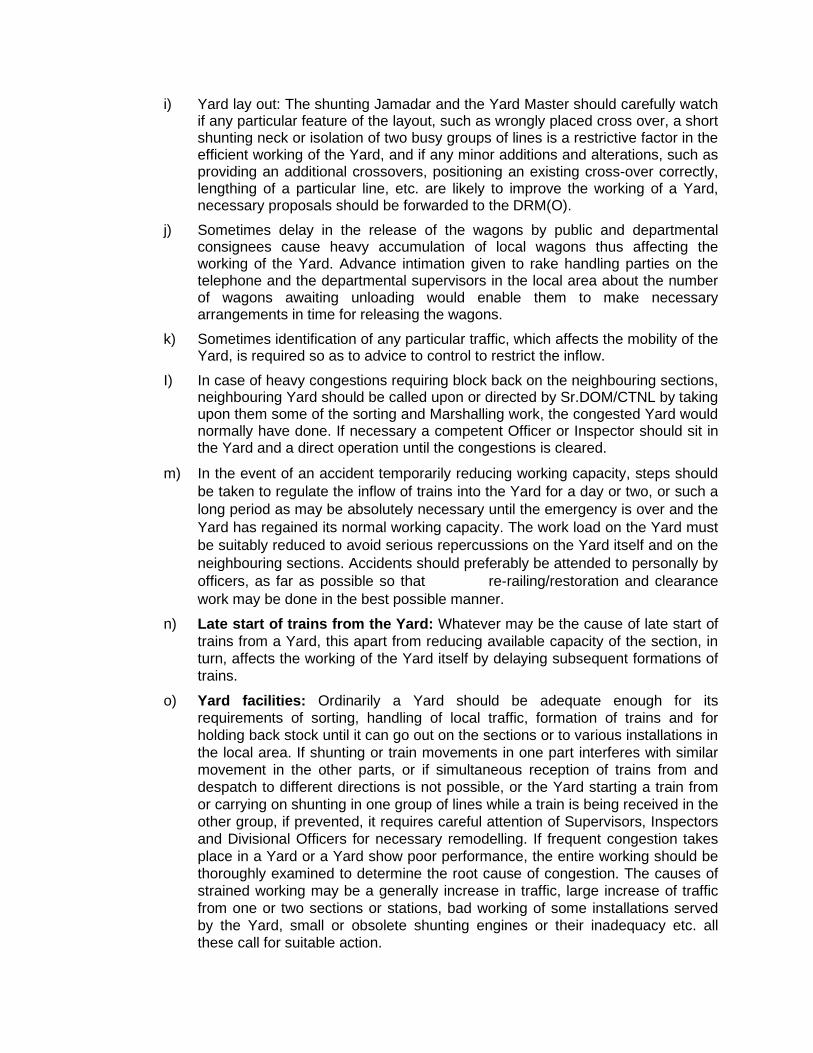
i) Yard lay out: The shunting Jamadar and the Yard Master should carefully watch if any particular feature of the layout, such as wrongly placed cross over, a short shunting neck or isolation of two busy groups of lines is a restrictive factor in the efficient working of the Yard, and if any minor additions and alterations, such as providing an additional crossovers, positioning an existing cross-over correctly, lengthing of a particular line, etc. are likely to improve the working of a Yard, necessary proposals should be forwarded to the DRM(O).
j) Sometimes delay in the release of the wagons by public and departmental consignees cause heavy accumulation of local wagons thus affecting the working of the Yard. Advance intimation given to rake handling parties on the telephone and the departmental supervisors in the local area about the number of wagons awaiting unloading would enable them to make necessary arrangements in time for releasing the wagons.
k) Sometimes identification of any particular traffic, which affects the mobility of the Yard, is required so as to advice to control to restrict the inflow.
I) In case of heavy congestions requiring block back on the neighbouring sections, neighbouring Yard should be called upon or directed by Sr.DOM/CTNL by taking upon them some of the sorting and Marshalling work, the congested Yard would normally have done. If necessary a competent Officer or Inspector should sit in the Yard and a direct operation until the congestions is cleared.
m) In the event of an accident temporarily reducing working capacity, steps should be taken to regulate the inflow of trains into the Yard for a day or two, or such a long period as may be absolutely necessary until the emergency is over and the Yard has regained its normal working capacity. The work load on the Yard must be suitably reduced to avoid serious repercussions on the Yard itself and on the neighbouring sections. Accidents should preferably be attended to personally by officers, as far as possible so that re-railing/restoration and clearance work may be done in the best possible manner.
n) Late start of trains from the Yard: Whatever may be the cause of late start of trains from a Yard, this apart from reducing available capacity of the section, in turn, affects the working of the Yard itself by delaying subsequent formations of trains.
o) Yard facilities: Ordinarily a Yard should be adequate enough for its requirements of sorting, handling of local traffic, formation of trains and for holding back stock until it can go out on the sections or to various installations in the local area. If shunting or train movements in one part interferes with similar movement in the other parts, or if simultaneous reception of trains from and despatch to different directions is not possible, or the Yard starting a train from or carrying on shunting in one group of lines while a train is being received in the other group, if prevented, it requires careful attention of Supervisors, Inspectors and Divisional Officers for necessary remodelling. If frequent congestion takes place in a Yard or a Yard show poor performance, the entire working should be thoroughly examined to determine the root cause of congestion. The causes of strained working may be a generally increase in traffic, large increase of traffic from one or two sections or stations, bad working of some installations served by the Yard, small or obsolete shunting engines or their inadequacy etc. all these call for suitable action.
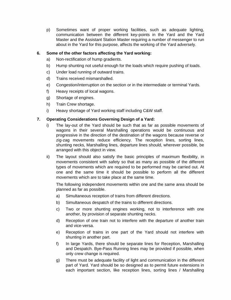
p) Sometimes want of proper working facilities, such as adequate lighting, communication between the different key-points in the Yard and the Yard Master and the Assistant Station Master requiring a number of messenger to run about in the Yard for this purpose, affects the working of the Yard adversely.
6. Some of the other factors affecting the Yard working: a) Non-rectification of hump gradients. b) Hump shunting not useful enough for the loads which require pushing of loads. c) Under load running of outward trains. d) Trains received mismarshalled. e) Congestion/interruption on the section or in the intermediate or terminal Yards. f) Heavy receipts of local wagons. g) Shortage of engines. h) Train Crew shortage. i) Heavy shortage of Yard working staff including C&W staff.
7. Operating Considerations Governing Design of a Yard: i) The lay-out of the Yard should be such that as far as possible movements of
wagons in their several Marshalling operations would be continuous and progressive in the direction of the destination of the wagons because reverse or zig-zag movements reduce efficiency. The reception lines, sorting lines, shunting necks, Marshalling lines, departure lines should, wherever possible, be arranged with this object in view.
ii) The layout should also satisfy the basic principles of maximum flexibility, in movements consistent with safety so that as many as possible of the different types of movements which are required to be performed may be carried out. At one and the same time it should be possible to perform all the different movements which are to take place at the same time.
The following independent movements within one and the same area should be planned as far as possible. a) Simultaneous reception of trains from different directions. b) Simultaneous despatch of the trains to different directions. c) Two or more shunting engines working, not to interference with one
another, by provision of separate shunting necks. d) Reception of one train not to interfere with the departure of another train
and vice-versa. e) Reception of trains in one part of the Yard should not interfere with
shunting in another part. f) In large Yards, there should be separate lines for Reception, Marshalling
and Despatch. Bye-Pass Running lines may be provided if possible, when only crew change is required.
g) There must be adequate facility of light and communication in the different part of Yard. Yard should be so designed as to permit future extensions in each important section, like reception lines, sorting lines / Marshalling

group etc. in the next 25 years though on consideration of economy, requirements of the next five years only may the first instance be provided.
9. Marshalling Yard Statistics: (Manual of Statistical Instructions Volume-I) (Railway Board has decided that statistics shall be maintained in terms of 8-wheeler
units. Same be incorporated by the railways)
General Instructions:
a) The Marshalling Yard statistics should be prepared for selected Yards generally dealing with 8000 eight-wheeler wagons and over per month in respect of BG Yards and 5000 eight wheeler wagons and over per month in respect of MG Yards, prior approval of the Railway Board should however, be obtained for addition or deletion of any Yard.
b) Brake vans are to be included.
c) The area of each Marshalling Yard is to be carefully defined and no extra allowance is to be made for any work done within that area. A diagram showing the Marshalling Yard area clearly demarcated should be prepared for the Yards for which statistics are requires to be compiled by the Railway for the Board. This diagram should be readily available at the stations to enable any inspecting officer to obtain a clear indication of the extent of the Marshalling Yard.
d) Sick lines and repacking sheds, transhipment. points, goods sheds, departmental sidings and the industrial sidings etc., may as a general rule, be treated as lying outside Marshalling Yards for purpose of calculation of Marshalling Yard statistics.
e) At places, where there are points like the Goods terminal station and/or Brake-of gauge transhipment point etc., continuous to the Marshalling Yard, and the detention statistics for each of these Yards are compiled separately either for submission to the Railway Board or for inclusion in the Railway’s own Domestic Statistics. The sum total of detention in each Yard should accord with the total detention from arrival of a wagon till its final despatch from that station. To ensure this, the supervisory staff incharge should exercise a check, at least once in a month, on a random sampling basis. This check should be broad based covering not only the important categories of wagons e.g. four wheelers, BOX wagons, oil tanks etc. but also the main stream of movement of wagons to and from different directions. This exercise should cover at least 10% of the total number of local wagons dealt with in the Marshalling Yard during the previous month and the records of such checks should be properly maintained to be available for scrutiny by inspecting personnel.
f) In the case of wagons whose detention or despatch particulars are not available, their detention should not be omitted but reckoned on the basis of the average detention during the month for similar type of stock while working out the average detention per wagon. The number of such wagons should be indicated separately under through loaded and all wagons for each Yard in a foot-note to the statement.
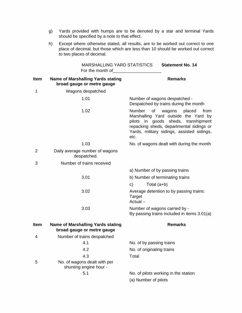
g) Yards provided with humps are to be denoted by a star and terminal Yards should be specified by a note to that effect.
h) Except where otherwise stated, all results, are to be worked out correct to one place of decimal, but those which are less than 10 should be worked out correct to two places of decimal.
MARSHALLING YARD STATISTICS Statement No. 14 For the month of____________________
Item Name of Marshalling Yards stating Remarks broad gauge or metre gauge
1 Wagons despatched
1.01 Number of wagons despatched - Despatched by trains during the month 1.02 Number of wagons placed from
Marshalling Yard outside the Yard by pilots in goods sheds, transhipment repacking sheds, departmental sidings or Yards, military sidings, assisted sidings, etc.
1.03 No. of wagons dealt with during the month 2 Daily average number of wagons despatched. 3 Number of trains received a) Number of by passing trains 3.01 b) Number of terminating trains c) Total (a+b) 3.02 Average detention to by passing trains: Target Actual – 3.03 Number of wagons carried by - By passing trains included in items 3.01(a)
Item Name of Marshalling Yards stating Remarks broad gauge or metre gauge 4 Number of trains despatched 4.1 No. of by passing trains 4.2 No. of originating trains 4.3 Total 5 No. of wagons dealt with per shunting engine hour - 5.1 No. of pilots working in the station (a) Number of pilots
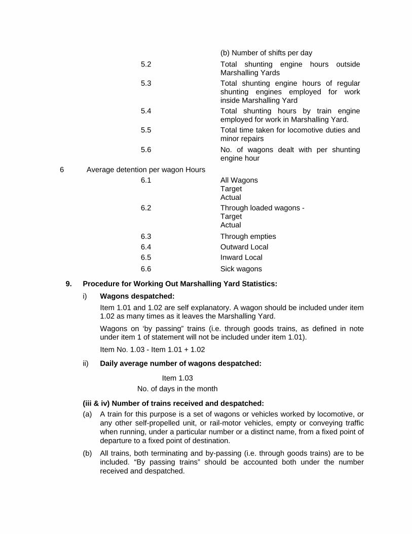
(b) Number of shifts per day 5.2 Total shunting engine hours outside
Marshalling Yards 5.3 Total shunting engine hours of regular
shunting engines employed for work inside Marshalling Yard
5.4 Total shunting hours by train engine employed for work in Marshalling Yard.
5.5 Total time taken for locomotive duties and minor repairs
5.6 No. of wagons dealt with per shunting engine hour
6 Average detention per wagon Hours 6.1 All Wagons Target Actual 6.2 Through loaded wagons - Target Actual 6.3 Through empties 6.4 Outward Local 6.5 Inward Local 6.6 Sick wagons
9. Procedure for Working Out Marshalling Yard Statistics: i) Wagons despatched: Item 1.01 and 1.02 are self explanatory. A wagon should be included under item
1.02 as many times as it leaves the Marshalling Yard.
Wagons on ‘by passing” trains (i.e. through goods trains, as defined in note under item 1 of statement will not be included under item 1.01).
Item No. 1.03 - Item 1.01 + 1.02
ii) Daily average number of wagons despatched:
Item 1.03 No. of days in the month
(iii & iv) Number of trains received and despatched: (a) A train for this purpose is a set of wagons or vehicles worked by locomotive, or
any other self-propelled unit, or rail-motor vehicles, empty or conveying traffic when running, under a particular number or a distinct name, from a fixed point of departure to a fixed point of destination.
(b) All trains, both terminating and by-passing (i.e. through goods trains) are to be included. “By passing trains” should be accounted both under the number received and despatched.
v) Number of wagons dealt with per shunting engine hour: Item 1.03 Items 5.03 + 5.04
Note: (i) While compiling shunting engine hours under item 5.3 and 5.4 the following instructions should be kept in view.
(a) Shunting engine hours are to include the shunting hours of regular shunting engines and train engines before and after working a train or during its run when employed in shunting goods wagons only in the Marshalling Yard area. The shunting time within the Marshalling Yard area should only be taken into account and not the time spent outside its limits.
(b) Shunting engine hours are to be reckoned from the time of arrival of the shunting engines in the Marshalling Yard upto the time of their departure from the Yard on the basis of shunting vouchers. The time spent on locomotive duties whether in the Yard itself or outside the Yard is to be included. However, any extra time taken over the normal time prescribed for carrying out legitimate locomotive duties should be excluded, the normal time being determined by the individual railway taking into account the local conditions and indicated in the operating manuals.
If shunting engine is required to be repaired in the Yard itself, the extra time beyond 30 minutes spent on such repairs in a shift should also be excluded.
(c) The time spent in the Marshalling Yard for change of crew and/or fuelling, should be accounted for in the same manner as on locomotive duties referred to in Note (1)(b) above.
(d) Since shunting engines shunt both coaching and goods vehicles, the allocation of shunting engine hours to goods and coaching stock may be fixed for each Yard on % percentage basis after an examination of the work done. This percentage is to b rechecked at least once a year and also when any change occurs in the type of traffic passing through that Yard. Where daily records are kept of the working of shunter engines according to hours spent (i) inside the Marshalling Yard (ii) outside the Marshalling Yard and (iii) in shunting coaching vehicles, it will not be necessary to a percentage, as the actual hours spent in the Marshalling Yard in shunting goods vehicles will be available. Time taken by shunting engine in placing wagons in silines is to be included in shunting hours when such lines form the part of Marshalling Yard area.
Note: (ii) Time spent for locomotive duties recorded separately under item 5.5 will include under 5.3 also. Item 5.5 will include the time taken by shunting locomotive duties and minor repairs upto 30 minutes per shift as per Note (i)(b) under Item 5.
vi) Average detention per wagon: (a) The detention time should have reference only to the detention within the
Marshalling Yard territory as defined in para (iv) of General Instructions and the incoming and outgoing wagons from and to the local outlying sheds, sidings, etc. should be counted as many times as they enter the Yard. This will include detention to sick wagons in the Marshalling Yard although their detention is separately shown against item 6.6.
(b) The average detention is to be obtained by recording in the wagon exchange register or similar record, the hours of detention to each wagon, that is the interval between its arrival and departure. At the end of the month under different types must be totalled, and both detentions and number of wagons for each type must be multiplied by the factor of equivalence to four wheeler and then consolidated to work out the average detention per wagon, the following example will illustrate the method of calculation of the average detention per wagons.
Example: Suppose Yard A has despatched 100 four wheelers with a total detention of 400 hours, 20 bogie wagons (Equivalent to 40 four wheelers) with a total detention of 200 hours and 10 Box wagons (equivalent to twenty five four-wheelers) with a total detention of 150 hours. Average detention per wagon will be –
400 x 1 + 200 x 2 + 150 x 2.5 100 x 1 + 20 x 2 +10 x 2.5
The detention of wagons arriving in one month and despatched in the next will be shown in the month in which they are despatched, but the time must be reckoned from the date of arrival. Stations which maintain a wagon card index may obtain the figures therefore instead of from the wagon exchange register. The number and detention of Brakevans will be excluded for the purpose of this item.
(c) The ‘target’ detention hours will be fixed by the Railway Board from time to time having regard to the past performance of each Yard and also materialisation of different streams of traffic, Marshalling commitments and the facilities available. A pointer to the correct level of a target would be the best result achieved in the past one or two years, assuming that there has been no noticeable improvement or deterioration in the operating conditions and methods. The target should be somewhat better than the actual recorded performance so that it may call for better effort on the part of the staff concerned to achieve the margin of improvement remaining between the actual and the target.
Item 6.1 - All wagons - The term ‘all wagons’ includes through loaded, through empty, local loaded, local empty and departmental wagons, wagons on ‘through trains’ (as defined in item 1.01 & 1.02) sick and damage wagons will be excluded. Sick and damaged wagons will be included wherever the sick lines form part of the Marshalling Yard area.
In respect of the Yards which may as well be depots for holding empties, such empties should not be included for the purpose of this item. These Yards should, however, be denoted by a suitable footnote - specifying therein the average daily holding of the depot.
The “exit” and “re-entrance” timings may be fixed on the basis of sample observations made once a year. These fixed timings may be rechecked annually and also when any major change occurs in the working of the Marshalling Yard.
Item 6.2 - Through loaded wagons - The term “loaded wagons” mean loaded wagons which neither originate nor terminate at the station, but which are dealt within the Yard and are not on “bypassing” trains (as defined in item 1:01. and 1.02).
Item 6.3 - Through empty wagons - The terms “empty wagons” means empty wagons which neither originate nor terminate at the stations, but which are dealt in the Yard and are not on ‘by-passing” trains (as defined in items 1.01 and 1.02).
Item 6.4 - Outward Local - This item will include detention to local wagons despatched by trains from the Marshalling Yard i.e. from the time of their entry into the Marshalling Yard from the outlying sheds and sidings till their despatch by trains.
Item 6.5 - Inward Local - This will include the detention to local wagons from the time of their arrival in the Marshalling Yard till their placement into the local sidings.
Item 6.6 - Sick Wagons - Detention to sick wagons in the Marshalling Yard will be included under this item as also under “all wagons”. In case the sick lines form part of the Marshalling Yard the detention in the sick lines will also be included under this item. If the sick lines are outside the Yard, such detention will be excluded.
vii) Present Status and the Road Ahead: Closure of conventional marshalling yards was an outcome of
a) Unit train movement
b) Advent of containers
The container revolution ensured that an universal flat rail car could move all description of traffic of varying cargo size - train load, full container load or less than container load. It can quickly eliminate shunting operations, which was replaced by gantry or road mobile trains; picking up containers and repositioning them - the equivalent of tortous shunting as detailed above. It ensured that freight customer does not have to register a wagon or rake, he has to ask for simply a given number of containers which are sent to his premises for loading/unloading and are brought back to modern freight terminals. The exorbitant cost involved in taking freight consignments to railway goods shed and unloading in inward consignment there and carting them to customers’ premises are totally eliminated and inter modal operation ensures door to door service, which till now was the hallmark of road transport, which had captured nearly 80% of making Indian Railways the second largest mode of transit movement.
Rightly enough the era of modern freight terminals has began. These are world class facilities and include:
i) An ICD for export/import cargo with customs clearance facility.
ii) Appointed warehouse to facilitate custom duty being paid as an when the cargo is needed.
iii) Large warehouses where cargo can be stuffed/restuffed/stored and moved as per customers’ instruction.
iv) Road, rail and air transport connectivity on demand.
v) Cold chain for refrigerated cargo .
vi) Banks.
vii) Fax, Telex & Telephone Internet connectivity.
viii) Continuous cargo tracking globally.
Freight terminal operating company and some of the railroad company who have a customer services centre working round the clock to receive customers instructions for change of destinations, rebooking of cargo etc. and this new environment the freight customer may visits the commercial office to execute agreements or long term contracts. The freight terminal is like a factory where the cargo goes and goes out. Process for bringing about this business like cause is already on way with private operators managing their terminals, running their own trains, serving their customers in an entirely business like environment. In this scenario the erstwhile marshalling yard are in the following areas– i) Providing rail substitute to road. ii) Serving large production units like steel plants & refineries. iii) Major customers like thermal powerhouse, fertiliser plants, cement plants,
ensuring availability of inputs and clearance of their outward cargo. iv) Major carriage wagon depots for freight rolling stock. v) Crew and loco changing locations. vi) ICDs of IR’s subsidiary CONCOR.
The transition from conventional; goods shed and marshalling yards of freight terminals have equipped railway system worldwide to win back high profit yielding, finished production from road to rail cum road system which reduces cost to the economy and the customers, substantially reducing the adverse environment impacts of road transport, paving the way for sustainable transport. The future manifestation of railway yards is likely to be as Logistics Park as railways strives to become a logistics provider rather than a mere transporter.
The future manifestation of railway yards is a logistic park, essential for Railways as it shifts towards being a logistic provider from a mere transporter.
CHAPTER – X
CONTAINER TRAIN OPERATION
With a view to increasing railway’s share of container traffic and introducing competition in railway container transport services in India, Ministry of Railways decided to grant eligible parties the right to require the Railway Administration to haul their Container trains on Indian Railway network for movement of both Export and Import Traffic as well as Domestic Traffic subject to various terms and conditions contained in an Agreement. This Agreement sets out in detail their mutual relationship and the terms and conditions, which shall govern the right of the Concessionaires to offer their Container trains for movement to Railway Administration and the obligation of Railway Administration to move the trains. The salient features of this Agreement as well as of related instructions with respect to train operations are given below. The salient features of the Concession Agreement with Container Train Operators and of other related instructions are indicative in nature and for guidance only. For actual provisions, the Concession Agreement and the Circulars and Railway Board’s letters mentioned above should be referred to. 1) Concessionaires have a non-exclusive right to require the Railway Administration to haul
the Concessionaire’s Trains subject to the Concessionaire establishing/ensuring access to Rail Terminals and acquiring a minimum number of Wagons including brake vans to form a Block Rake for the commencement of operations and for transportation of containers.
2) The term of this Agreement shall be for a period of 20 years starting from the Commercial Operations Date.
3) In the event the Concessionaire fails to operate its Container Trains in accordance with the requirements of this Agreement within three (3) years from the date of award of the In Principle Approval, Railway Administration shall have the right to terminate the Agreement.
4) The rights of the Concessionaire shall include the following: (i) The right to undertake the business of collecting, storing and loading onto Wagons,
consignments of goods from any third party; (ii) The right to determine, charge, collect, retain and appropriate all the fees that it
charges from the consigners; (iii) The right to obtain access to Rail Terminals and develop, own, operate and maintain
Rail Terminals, including inland container depots; (iv) The right to procure and own/lease Wagons and containers.
5) The concessionaire will be responsible for loading and unloading operations at both the origin and destination Rail Terminals
6) The Railway Administration shall haul the Concessionaire Trains on the payment of prevalent haulage charges as notified from time to time. The present haulage charges are contained in Board’s letter no. 2008/TTIII/73/8 dated 1-7-2008.
7) The Central Government (Ministry of Railways) shall have the right to specify certain commodities, which ordinarily move in railway wagons in trainload as notified commodities, which may be subjected to different tariff and conditions for haulage. At present as per
Board’s letter no. 2008/TTIII/73/8 dated 1-7-2008, carriage of coal, coke, minerals and ores in containers is prohibited.
8) The existing incentives/schemes extended to rail customers or that may be introduced in future shall not ipso facto apply to the Concessionaires. Upon request of the Concessionaire(s), Railway administration may consider extending such schemes to the Concessionaire to the extent possible in a non-discriminatory manner.
9) All commercial rules like that contained in Commercial Manual, as amended from time to time and as applicable to other freight traffic moving on Indian Railways shall apply to the Container traffic, except rules specially covered in this Agreement in a non-discriminatory manner amongst similarly placed entities.
10) It shall be the Concessionaire’s sole responsibility to procure the requisite approval/authority for the Concessionaire’s Train and/or a Railway Administration locomotive to enter into and utilize the origin and destination Rail Terminal(s).
11) Each concessionaire is required to set up two rail linked inland container terminals within three years of obtaining the license to operate or have access to inland container terminals.
12) Use of Railway freight terminals (Goods sheds) as Container Rail Terminals (CRT) has been permitted by the Railways in terms of Rates Circular 10 of 2008.
13) Each Rail Terminal, other than a Railway owned Terminal, that is used by the Concessionaire shall conform to the following: (i) Each Rail Terminal shall have rail facilities for handling Concessionaire Trains along
with locomotive in conformity with siding rules prescribed by Railway Administration from time to time.
(ii) Be equipped with a RDSO approved in-motion weigh bridge of prescribed standards for weighing of Wagons with and without containers of the Concessionaire’s Train.
(iii) Be equipped with TMS and such other facilities as may be required to interface with, and ensure transfer of data online to, FOIS of Railway Administration.
14) The Concessionaire shall declare the weight of each Wagon/container prior to departure of the Concessionaire’s Train.
15) The Concessionaire shall procure by way of purchase, lease or hire, Wagons including Brake Vans and Containers required for the purposes of operating the Concessionaire’s Trains. However, till such time as the Concessionaire procures the required Brake Vans, Railway Administration may provide its own Brake Vans (provided they are available), on non-discriminatory basis, at a reasonable charge, notified by the Railway Administration from time to time.
16) In the event any of the Wagons of the Concessionaire are lying idle (“Idle Wagons”), the Concessionaire may offer to the Railway Administration or other Concessionaires, use of any such Idle Wagons. However, Railway Administration shall be under no obligation to accept such an offer of the Concessionaire for use of any Idle Wagons and may levy a Stabling Charge as specified.
17) In the event of an Emergency, Railway Administration shall have the right, to temporarily assume control and make use of the Wagons of the Concessionaire. For any such Emergency Use, Railway Administration shall pay to the Concessionaire, a reasonable rent/charge to cover the cost of provisions, maintenance and operation of the Wagon.

18) The Concessionaire shall at all times conform to the maintenance standards specified by the Railway Administration in accordance with Good Industry Practice for the Concessionaire’s Containers, rail related equipment and tracks.
19) The Concessionaire’s Wagons shall be maintained by the Railway Administration in accordance with the maintenance schedule notified by the Railway Administration. Such maintenance shall, inter alia, include intensive examination, routine overhaul (“ROH”) and periodic overhaul (“POH”). The Concessionaire will provide and maintain the requisite Wagon examination facilities (as specified by railway Administration) inside the Rail Terminal and bear a one time capital cost for tools and plants as specified by Railway Administration and approved by RDSO.
20) Wagon maintenance charges for maintenance by Railway administration of the Concessionaire’s Wagons shall be included in the Haulage Charges. The present Haulage Charges - include 5% thereof by way of maintenance charges.
21) Railway Administration shall normally complete the intensive train examination within a period of 6 hours from the time the Concessionaire’s Wagons (in empty Rake formation) are handed over by the Concessionaire for such examination. Provided however, that the minimum interval between two successive Rakes offered for intensive train examination shall be at least 6 hours. Alternatively, the Railway Administration may examine the Concessionaire’s Wagons at suitable point enroute its destination where the facilities for such examination exists. The time stipulated for maintenance shall not be applicable vis-a-vis such Concessionaire’s Wagons that are declared sick during the course of examination and are required to be detached from the Concessionaire’s Train for sick line/ workshop attention.
22) In the event of the Railway Administration’s inability to conform to the time schedule specified for intensive train examination, it shall pay to the Concessionaire for every 24 hours of delay (inclusive of initial 6 hours) so caused, an amount equal to the Stabling Charges payable for such period of delay.
23) The Concessionaire may undertake maintenance of the Concessionaire’s Wagons through any other entity including the Concessionaire on such terms and conditions as specified by the Railway Administration from time to time provided however, that the maintenance is carried out as per maintenance schedules and various stages of inspection as may be notified by Railway Administration and pre-departure certification of such Wagons shall be issued by the Railway Administration for which the prescribed charges shall be paid by the Concessionaire.
24) The Concessionaire shall hand over empty Concessionaire’s Wagons, in rake formation, to Railway Administration for carrying out maintenance as per the schedule specified by the Railway Administration.
25) The haulage charges for moving the Wagons, in rake formation, from a Rail Terminal to the workshop/maintenance depot/train examination point of the Railway Administration and back shall be borne by the Railway Administration, provided however, that the scheduled haulage charges shall be payable by the Concessionaire in the event maintenance is carried out by an entity other than the Railway Administration and inspection is carried out by the Railway Administration at the location of maintenance.
26) In the event wagon maintenance is undertaken by the Concessionaire, or any other party (other than Railway Administration in accordance- with the provisions of this Agreement) a proportionate rebate in haulage charges (equivalent to the built in maintenance charges) shall be given to the Concessionaire.
27) Subject to any operational constraints, Railway administration will provide locomotives to haul the Concessionaire’s Trains on a non-discriminatory and non exclusive basis vis-a-vis other Concessionaires only.
28) At least four (4) hours prior to the planned departure of Concessionaire’s Train, the Concessionaire shall submit an indent (“Indent for Locomotive”) for supply of locomotive. The existing incentive schemes if any or incentive schemes that may be introduced in future for supply of locomotives may be extended to the Concessionaire’s Trains with suitable modifications such that it is applied in a non discriminatory manner among different concessionaires.
29) The Concessionaire may, anytime prior to arrival of a locomotive cancel its Indent provided however, the Concessionaire shall be liable to pay to Railway Administration indent cancellation charges equivalent to one (1) hour Locomotive Detention Charges. In the event, indent for cancellation of locomotive is received by Railway Administration after the loco is dispatched for the Rail Terminal, the Concessionaire in addition to indent cancellation charges, shall also be liable to pay to Railway Administration such charges as may be prescribed by Railway Administration for the infructuous movement of locomotive both ways. Such charges, however, shall not exceed the charges levied for the movement of the locomotive for the distance from the nearest locomotive shed.
30) If after arrival of the locomotive at the Rail Terminal from where the train is required to depart, or the Rail Terminal where the train is required to terminate, as the case may be, the Concessionaire’s Train, for whatsoever reason not attributable to Railway Administration, is not attached or detached and released (as the case may be), prior to expiry of the Free Waiting Time of two hours (entry to exit), the Concessionaire shall be liable to pay to Railway Administration, Locomotive Detention Charges for every hour (or part thereof) for which the locomotive is detained beyond the Free Waiting Time. Provided however, if a locomotive is detained for a period of more than eight (8) hours at any Rail Terminal (either the Rail Terminal of origin or of termination, as the case may be), then, without prejudice to the Concessionaire’s liability to pay to Railway Administration the Locomotive Detention Charges, Railway Administration shall have the right, but not the obligation, to withdraw and/remove the locomotive from such Rail Terminal. In case Railway Administration withdraws and/or remove the locomotive from the Rail Terminal after detention of 8 hours, the detention along with movement charges shall be levied without granting any free time. In the event Railway Administration withdraws the locomotive then, the Indent for locomotive shall deemed to have lapsed, with no further effect. These provisions shall also apply to the situation where the locomotive arrives at a Rail Terminal where the train is scheduled to terminate, but is denied entry into such Rail Terminal for reasons attributable to the Concessionaire and /or the Rail Terminal operator.
31) Locomotive Detention Charges payable by the Concessionaire for detention of a locomotive beyond the Free Waiting Time shall be at the rates as prescribed for Diesel/Electric Train Engines by the Railway Administration from time to time. The current Locomotive Detention Charges are contained in Rates Circular No. 18 of 2008.
32) Railway Administration shall, in the event of delayed supply of locomotive beyond 12 hours from the indented schedule time of departure of the Concessionaire’s Train, be liable to give to the Concessionaire a one time rebate equal to two (2) percent of the haulage charges payable by the Concessionaire for the Booked Route. This rebate shall, however, not be admissible in contingencies such as interruption of traffic due to accidents or any other similar unavoidable reasons beyond the control of Railway Administration.

33) Transportation of the Concessionaire’s trains shall be in Block Rakes. In the event a Concessionaire’s Train operates with lesser number of Wagons/Containers than those prescribed in the Block Rakes (“Non-Block Rake Trains”), the haulage charges for such Non-Block Rake Trains shall be recovered on the basis of the minimum composition of Block Rake as specified by Railway Administration. Provided, however, in the event a Concessionaire’s Train has less than half the Wagons required to constitute a Block Rake, the Railway Administration shall have the right to refuse to haul the Concessionaire’s train comprising less than half a Block Rake. The Railway Administration may however, at its sole discretion extend the facility of two point rakes for Container Trains during specified periods and on specified routes.
34) The Concessionaire’s Trains to be hauled by Railway Administration pursuant to this Agreement shall be booked by the shortest route possible (the “Booked Route”) and the haulage charges shall be determined with reference to such Booked Route. Provided however, in case of any accident or other operational exigencies on, or affecting, the Booked Routes, Railway Administration shall, in its sole discretion, be entitled to transport the Concessionaire’s Train by an alternative route (“Alternate Route”). The Concessionaire shall be liable to pay haulage charges only for the Booked Route even when Concessionaire’s Train is transported by an Alternate Route. Provided that in case the Concessionaire’s Trains are carried by a longer route in pursuance of the Rationalisation Scheme of MOR (under section 71 of the Railway Act 1989), the Concessionaire shall be liable to pay charges accordingly.
35) The Concessionaire shall, at least 7 (seven) days prior to any calendar week in which it proposes to operate any Concessionaire’s Train, inform (“Weekly Advance Scheduling Notice”) Railway Administration of the number of Concessionaire’s Trains, it requires to be moved, the proposed routes and the likely departure dates (“Weekly Advance Schedule”).
36) Notwithstanding anything to the contrary, the Concessionaire shall, at least twenty four (24) hours prior to the day of programmed loading (excluding the day of loading itself) of a Concessionaire’s Train, confirm to Railway Administration the departure schedule of such Concessionaire’s Train, provided that such notices shall not in any way be binding and shall be only indicative of the Concessionaire’s operations schedule for the following week / day.
37) Railway Administration shall maintain a level playing field among all Concessionaires and shall devise and implement a transparent and non-discriminatory system for dispatch of Concessionaire’s Trains on a first come first served basis.
38) Notwithstanding anything to the contrary contained in the Agreement, dispatch of locomotives and Concessionaire’s Train(s) shall be subject to any operational exigencies and/or system restrictions.
39) Railway Administration shall make all efforts to ensure minimum enroute detention of the Concessionaire’s Trains.
40) Subject to any operational and capacity restrictions of Railway Administration, there shall be no restriction on the number and frequency of Concessionaire’s Trains that the Concessionaire may require Railway Administration to haul pursuant to this Agreement.
41) The Concessionaire may request the Railway Administration to accept, at any time after the departure of a Concessionaire’s Train, the diversion/re-diversion of such Concessionaire’s Train to any other Rail Terminal, in accordance with the various terms and conditions (including but not limited to payment of haulage charges and other charges) and procedures specified by Railway Administration from time to time subject to its
operational exigencies and/or for system restrictions. It is clarified that the Railway Administration shall not be under a legal obligation to comply with such request.
42) The Concessionaire shall be liable to pay to Railway Administration Stabling Charges, in the following events: (i) In case the Concessionaire’s Train suffers detention at the serving station for reasons
attributable to the Concessionaire or when the Concessionaire either declines to accept Wagons inside the Rail Terminal, scheduled to be the terminating Rail Terminal or is not in a position to receive placement of subsequent Wagons; or
(ii) In case of non acceptance of trains inside any port by the port authority concerned; or (iii) At any of the stations en route due to any reason attributable to the Concessionaire. (iv) Provided however that Stabling Charges shall be levied only where the detention of
the Concessionaire’s Train is for a period in excess of 4 hours. Stabling Charges shall be payable at the rates notified by Railway Administration from time to time and the Railway Administration shall have the right to revise the Stabling Charges on an annual basis; provided that any increase in charges in any Financial Year during the term of this Agreement, shall not exceed 10% (ten percent) of the charges payable in the preceding year. The current Stabling Charges are contained in Railway Board’s letter no. TC-1/98/201/4 dated 17.1.2008.
CHAPTER – XI
CUSTOMER INTERFACE AND ROLE OF COMMERCIAL STAFF
The physical movement of both passengers and freight cargo is handled by operating staff but it is the commercial staff, who interacts with our customers.
Passenger Platform Ticket Checking staff:– Their foremost duty is to enforce rigid access control in station area to prevent ticket less travel and entry of undesirable elements in station premises.
1. Occupation of waiting rooms and waiting sheds – (a) Except under special orders from the Div. Railway Manager, passengers must not be
allowed to use the waiting rooms at stations as rest houses, but passengers arriving at Road side stations at night may be allowed to occupy the waiting rooms or waiting halls between trains or until the morning. At junction stations passengers may use waiting rooms and waiting halls when waiting for connecting trains.
(b) To ensure that bona fide use of waiting rooms is being made, they shall be checked by a ticket checking staff every eight hours.
2. Booking staff: –
(a) To issue tickets, release and display reservation slips and charts in time to avoid detention of trains in boarding of passengers.
(b) To advise all commercial figures and occupation report of trains to Divisional office and SM on duty as required.
(c) Station Master or Parcel Clerk shall ensure:- Parcel, luggage, goods and vendors’ trays and barrows shall not be placed on passenger platforms within 3 meters of the edge of the platform. When parcels or luggage are loaded on platform, the barrows must be kept outside this distance at a point opposite where the vehicle, into which they are to be loaded is likely to stop. Packages unloaded from a train must be removed as quickly as possible to the usual place of stacking outside this distance, if they are not taken away into luggage and parcel offices or the goods shed. Under no circumstances should drums and barrels be left on the platform in such a position that they may roll into the track.
3. Precautions before starting a train carrying passengers:– (a) Control of electric lights and fans in coaches:- Switching ‘On’ and ‘OFF’ of lights and
fans circuits in a rake is effected by operating rotary switches or MCBs in the Junction box provided inside individual coaches. Operation of these circuits is the duty of train lighting staff deputed at important stations. Individual switches regulators of lights and fans are to be operated by passengers themselves.
(b) Conductor or TTEs are responsible for ensuring that the electrical equipments and fittings of all coaches are functioning satisfactorily. Where any defect or deficiency is noticed they should inform the electric staff on duty of AC coaches or advise through control to the next station where electrical staff is provided.
(c) Conductor or TTE shall, before the train leaves the starting station, request the occupants of those compartments to test if the locking devices on doors and windows are in working order. In case of any defect, they shall arrange to have the defects put right by the TXR staff under advice to SM either at the starting station or at the next train examining station.
(d) Travelling Ticket Examiners are to note that doors on both sides of carriages on a train carrying passengers shall never remain locked at the same time, except in the case of compartments reserved for ladies which may be locked at the request of the occupants.
(e) Conductor and TTEs must see that passengers are not getting in and out of carriage when trains are about to start and that no one is travelling on the roofs of carriage.
(f) Segregation of passengers suffering from infections or contagious diseases: - For greater safety of the travelling public, passengers suffering from infections or contagious diseases should be segregated from other passengers by TTE with the help of security forces.
(g) Passengers to be courteously treated.- All passengers, irrespective of the class of tickets they hold, shall be courteously treated and all possible assistance and protection afforded to them while on Railway Premises.
(h) Female passengers particularly when unaccompanied by males, friends or relatives shall be given special attention at all times
(i) Each member of staff who has to deal with passengers must be acquainted with the time of arrival and departure from their stations of all trains carrying passengers to answer in prompt and civil manner any question put to them by the public.
4. Precautions during journey:– (a) In cases of long distance through trains coming from or going to other railways, which
have yet to journey through the following night, the guard or conductor or TTE shall, at a convenient station some time during the day, approach the occupants of upper class and second class ladies compartments, and request them to check up if the door latches and window catches are in good working order; when the train arrives at a station where the TXR staff is required to attend to the safety catches, the TXR staff should be ready with the necessary material and should themselves check up the locking devices and put right any deficiencies detected by them or reported to them by passengers.
(b) The Conductor or TTE should also make it a point to warn the passengers at convenient stations between 21 and 22 hrs to apply the locking devices, if not already done.
(c) Should it be found that the alarm chain has been pulled mischievously or for an unjustifiable cause or the hose pipe has been disconnected by some miscreants, the Conductor or TTE in charge must ascertain the name of the person who pulled the chain or disconnected the hose pipe. His name and address with those of other occupants must be obtained and the Conductor or TTE should make a report regarding the alarm chain pulling or the hose pipe disconnection incident and hand over the same to SM/ASM of the station at which the incident occurs, if time permits or at the next stopping station, who will take action in lodging the report with the GRP of the station in whose jurisdiction the incident has occurred.
(d) Calling out name of station – Travelling Ticket Examiners where employed and at Ticket Checking stations, the Ticket Examiners are required to give this information to passengers as they go from compartment to compartment checking tickets and at junction stations they shall advise passengers to change, if necessary.
5. Waking up passengers:– (a) Passenger of all classes occupying reserved accommodation shall not be roused for
tickets, to be rechecked between the hours 22 and 6 except when there are reasons to believe that a certain passenger is travelling without a ticket or otherwise irregularly.
(b) TTE,s of Mail Express and passenger trains are to arouse Air Conditioned and First Class Passengers at night at any station when requested by the passengers to do so and will be assisted by the coach attendant. The Ticket Checking staff to whom such a request is made by a passenger shall enter in the “wake up memo” the name of the passengers, the number and the class of the carriage occupied and the name of station at which the passenger is to be called.
(c) The Ticket Checking staff when intimating the arrival of the train at a station where a passenger has been noted to alight shall take care of that other passengers are not unnecessarily disturbed.
(d) Passengers shall not be placed in carriages of a higher class than that for which tickets are held except on payment of additional fares as per extant rules or on automatic upgradation.
6. Ladies travelling alone at night:–
(a) In no case, whatever, shall a male passenger (except a boy under twelve years of age) be allowed to travel in a compartment reserved for Ladies in any train.
(b) A lady travelling alone or with children under 12 years of age at night in a first class compartment reserved for ladies may take with her in the same compartment in which she is travelling, one women attendant holding a second class ticket for that portion of the journey which is performed between the hours 8 p.m. and 6 a.m. This rule may also apply when two or more ladies are travelling in the same compartment with out any objection and any inconvenience.
(c) A lady travelling alone or with children under 12 years of age in a first class compartment may take with her compartment one dog on payment of the dog-box rate, provided that if another lady enters the compartment, the dog shall only be allowed to remain in the compartment with the permission of the other passenger.
7. Medical Aid :– (a) It will be the duty of the train manning staff or station staff to render first aid to any
injured person within Railway premises immediately.
(b) If the case is serious one, the senior most official available on the spot must arrange to summon medical aid from the nearest available source, whether Railway, Civil, Military or private.
8. Murder or serious Assaults :– (a) If a crime of serious nature such as a murder or a serious assault be committed in a
Railway carriage on a running train, the following action shall be taken by the staff with a view to helping the Police Officials in their investigation.
(b) The Conductor or TTE of the train shall have the compartment emptied and locked up after all shutters have been raised from outside immediately the commission of such an Offence is known so that blood stains, marks of struggle, foot prints, finger impressions etc. may remain undisturbed.
11.01. Procedure to be adopted in cases of murder or serious assaults in Railway carriages.— If a crime of a serious nature such as a murder or serious assault be committed in a Railway carriage on a
running trains, the following action shall be taken by the staff with a view to helping the police Officials in their investigation.
(a) The Guard of the train shall have the compartment emptied and locked up after all shutters have been closed from outside immediately the commission of such an offence is known so that blood strains, marks of struggle, foot prints, finger impressions etc. may remain undisturbed.
(b) If the crime took place in a second class compartment the carriage shall be detached at the station where the crime was detected and kept under watch till the police arrive to take over the case.
(c) If the crime took place in an upper class compartment, the compartment shall be immediately locked up and the carriage allowed to proceed to the nearest station where it can be replaced. If no Government Railway Police staff are available at this station, a number of the Railway staff must watch it, until a Police Officer comes upon the scene.
(d) No one, either Railway Employee or out sider, shall be allowed to enter the compartment until the police arrive except in as far as is necessary to attend to injure persons unable to leave the compartment without assistance.
(e) The Railway Police Station concerned shall be advised at what station the carriage has been or will be detached. After the carriage is taken over by the Police, it shall not be removed or otherwise utilised without the written authority from the Police releasing the carriage.
9. Passenger trains overshooting Platform:–
When any portion of a passenger train over shoots a platform, or when a platform is’s too short to accommodate a full train, at night, passengers who are obliged to alight on ballast should be told that they should alight carefully as there is no platform. If a carriage at the end of a train is off the platform, the Guard should also call out a similar caution to the passengers.
10. Duties of Conductor:–
(i) He shall report to the train guard for his appearance and the time of his appearance shall be noted down by the train guard in the Constitution Report. The Conductors shall sign this entry and the train guard shall countersign it.
(ii) See that the window catches and other safety devices fitted in II Class compartments reserved for ladies are in perfect working order and get the deficiencies repaired.
(iii) See that the passenger carriages are thoroughly cleaned and filled with water.
(iv) Look after the safety and comfort of passengers of all classes and more particularly, of women and children, attend to complaints of passengers regarding cleanliness of carriages, water supply in lavatories, lights and fans and any other complaints and have them promptly attended to.
(v) Make it a practice to walk along his train at stations to see if passengers want any assistance or information and keep a careful look out for irregularities of any kind, specially at night.
(vi) Before a train begins a night journey, ensure that the safety bolts provided on the inside of windows and doors of Upper Class carriages and ladies compartment are in working order.
(vii) Arrange for the meals of passengers when requested to
(viii) Wake up upper class passengers alighting at night if requested;
(ix) See, in so far as is possible that there is no irregular or unauthorized travel by trains in contravention of any rules in force. All infringement of rules by passengers should be brought to the notice of the station master on duty.
(x) Note the Coach, which is to be detached short of the destination of the train, must see that such carriages are not occupied by passengers who have tickets for beyond the station to which they are booked. He must arrange that, if any passengers are allowed to ride in such coaches they are warned before starting that they shall have to vacate the coaches on arrival at the station at which they are to be detached.
(xi) Conductor must see that passengers are not getting in and out of carriages when trains are about to start and that no one is travelling on the roof of carriages.
Duties and Responsibilities of TTEs : (i) He shall see that all doors, bolts, windows and catches etc. of all the coaches
particularly upper class and ladies compartments are in perfect working order and also that all through and sectional coaches are provided with proper destination boards.
(ii) If there are defects in the working of any of the fans and lights, he shall get them rectified by the train lighting staff.
(iii) He shall see that, where arrangements exist, the compartment are properly cleaned, dusted, and watered and shall make necessary enquiries from passengers in this connection.
(iv) He shall see that lights, fans and other fittings, and water in the carriages are not misused.
(v) He shall check Attendant compartments and ensures that only bonafide attendants of upper class passengers occupy them.
(vi) He shall check Vendors and G.R.P/RPF compartments to ensure their correct use. (vii) He shall receive reservation charts well in time before the departure of the train, see
that the same are completed in all respects and that the reservation labels are intact so that there is no hitch in providing berths to passengers.
(viii) He shall look after the safety and comforts of passengers in general and of upper class and women passengers in particulars.
(ix) He shall assist all classes of passengers in securing accommodation either reserved or available for them.
(x) During the course of the journey, he shall keep special watch on compartments; occupied by women passengers without causing any annoyance to occupants. He shall, where halt permits; walk on platforms, to see that ladies compartment that everything is well. While inspecting a train in this manner, he should be ready to answer queries and receive complaints from all classes of passengers and complaints of special nature and action taken by him should be recorded.
(xi) During the night, he shall awake upper class passengers who express their desire to be called at a particular station and in the event of his change of duty en route, ask his reliever to do so.
(xii) He shall ascertain from Passengers their meal requirements and arrange it either from the Dining Cars running with the train or the next Refreshment Room station.
(xiii) He shall assist Refreshment Room bearers in finding out space for return of empty meals crockery, trays or thalies.
(xiv) He shall see that no suspicious characters attempt to enter upper class compartments and compartments reserved for women.
(xv) He shall not interfere with or annoy passengers by talking, smoking or slamming doors while entering, or leaving compartments.
(xvi) He shall keep an eye on vendors and licensed porters charging passengers excessively and promptly intervene where necessary. All such cases must be reported to the Divisional Commercial Manager concerned under intimation to the Station Master concerned.
(xvii) He shall see that vendors do not shout their wares at station during night. (xviii)In the event of any passenger being found molested, a passenger’s property being
stolen or tempered with, he shall, promptly, take action in conjunction with the guard in-charge of the train, or the station master as the case may be and see that police is advised immediately. The passenger’s name, address and ticket numbers of those who are allegedly responsible for the trouble and also the same particulars of some respectable witnesses, should be taken and full report submitted to the Divisional Commercial Manager concerned.
(xix) When alarm chain is pulled or hose pipe is disconnected, the disc at the end of the reserved coach should be returned to normal position (thereby closing the Clappet Valve) and FIR to be lodged to GRP under advice to Guard / Station Master
(xx) Similarly hose pipe disconnected should be reconnected by Asstt. Loco Pilot.
11.02. Wearing of Uniform.— (a) Every Railway servant who is provided with uniform, must appear in full uniform when on duty and
attending any enquiry or Training School or appearing before selection Board.Those who have not been supplied with uniform, must come on duty properly and clearly dressed.
(b) Guards of all trains before coming on the platform/yard for taking charge of trains shall wear their uniforms as prescribed by the administration.
(c) Station and other staff must be neatly and cleanly dressed in full uniform particularly at the time of passing trains of any kind.
(d) It is the duty and responsibility of each railway servant to get their uniform properly cleaned and ironed before use.
11.03. Passengers to be courteously treated.— (a) All passengers shall be treated with utmost courtesy and every assistance and protection afforded to them
while on Railway premises. Every supervisory staff must impress upon his subordinates the importance of this and take stern action against any staff failing to comply with the same.
(b) Public complaint books have been provided at stations and also with the Conductor Guards. The same should be made available to the public as required. The complaints recorded should be attended to at once and causes of complaints removed. It must be the endeavour of every Railway employee to avoid public complaint, but should an occasion arise for any passenger to record a complaint, he must be given all facilities to record the same and the complaints recorded dealt with as per extent orders issued by the Chief Commercial Manager.
(c) Railway employees shall give their names and designation when asked to do so. The staff scheduled to wear badges or scrolls must have them on without fail when on duty. The staff dealing with the public must be in prescribed uniform.
(d) Station Masters shall see that each member of the staff under their control having dealings with passengers is acquainted with the times of arrival at and departure from their stations of all Passenger trains and also stoppages enroute and instruct them that they should answer any query on the subject by the public in a prompt and courtious manner. The Passenger Guides posted at the station must specially look to the difficulties of lower class passengers confused in the maze of multiple trains by moving up and down at busy stations. All supervisory staff, Inspectors and Officers must pay particular attention to ensure that the staff perform the duties enumerated above creditably.
(e) The Station Masters shall ensure that the Railway staff vendors or licensed porters do not make any unnecessary noise on platforms, particularly at night.
(f) The Station Master on duty and the Guards of the Passenger carrying trains shall see that specified stopping time is allowed at the stations to enable Passengers to alight and entrain safety. In case the specified time is considered insufficient, they should submit a special report in this regard to the seniormost Divisional Operations Manager of the Division.
11.04. Supply of drinking water to passengers.—
The necessity for the prompt supply of clean drinking water to passengers cannot be over emphasised. Every station must keep adequate store of clean drinking water before a Passenger train arrives. Taps are provided at frequent intervals on the platform and tubewells are available on the platform at some stations. At major stations water filters/coolers are also provided Station Master in charge of the stations must ensure that the taps, tubewells and filters/coolers are in proper working order.
CHAPTER – XII
INSPECTIONS
Objects of Inspections:– The Railway network is spread over a vast area. It is estimated that for running a train over
a section, co-operation and co-ordination of about (2000) thousand Railway staff is essential. A vast organisation, such as the Indian Railway system functions on the basis of a carefully arranged system of selective Autonomy, Accountability and Responsibility. Rules and instructions lay down the procedure of work and the staff are properly trained and the officials at various levels monitor, supervise and direct the staff from time to time by different means. Inspection is an important function of management, particularly in the field of Railway Operations to ensure efficient working at all levels.
Following objects shall be borne in mind while conducting inspection:
1) Verify whether every Railway employee is fully conversant with rules, instructions and procedures relating to his duties.
2) Ascertain that the staff is performing their duties according to rules, instructions and the procedure in force.
3) Detect undesirable shortcuts, irregularities or unsafe practices being resorted to by the staff taking remedial action which may be: (a) Educative, in case these are resorted to out of ignorance. (b) Corrective, if there is something wrong in the working conditions, or there are system
deficiencies. (c) Punitive, if resorted to wilfully or negligently and persisting even after repeated
guidance and counselling. 4) Observe the conditions actually prevailing at the work spots to understand the difficulties
experienced by staff including their personal grievances and seeking on the spot redressal. 5) Ensure that full complement of staff and equipment is available and staff have knowledge
of its operation. 6) Ascertain that registers, documents and other records are being maintained and preserved
according to instructions. 7) monitor the behaviour of staff towards customers, particularly promptness of response and
willingness to help. 8) Assess as far as possible that the interest of the public and the Railways are kept in view
and safeguarded. 9) Inculcate discipline and build up the morale of the workers. 10) Check the compliance of previous inspection reports. 11) Analyse efficiency targets vis-a-vis performance.
Inspections, thus provide the means to achieve efficiency and effectiveness through spot checks and personal contact with the staff on line. In order to accomplish these objectives, inspections have to be carried out at officer’s and Supervisor’s level. The inspecting official has to command the respect and obedience of staff, for his inspection to be effective and beneficial and as such his conduct should be exemplary.
Types of Inspections: The following inspections have to be carried out by operating and safety officials:
Regular Inspection (six monthly) :– Each station on the division must be inspected in details at least once in every six months
i.e. January to June and July to December covering the various aspects of safety, operations and allied matters including staff matters. The inspection shall be carried out by the Sr.DOM/DOM/Sr.DSO/DSO/ AOM /ARM/SS/SM/DTI/TI etc. While minor stations are inspected by the TI concerned, the DRM will nominate important stations (including all such stations which do not fall within the jurisdiction of TI, that is those which have SS/SM in grade equivalent to or higher than those of TI of the section) to be inspected by the nominate officers. Each officers will be allotted at least two such a stations. The officials concern shall also spend the night at the station. Regular inspections have to be comprehensive in nature.
Safety Inspections (monthly) :– Safety inspections are basically meant to be preventive by detecting short cut methods
and unsafe practices resorted to by train passing, running and maintenance staff. The irregularities noticed must be personally brought to the notice of the Station Master and remedial measures initiated promptly. In case of any serious irregularity, the inspecting officials must at once inform Sr.DSO/DSO or Sr.DOM/DOM concerned personally or telephonically beside making a written report.
Surprise Inspection (Monthly) :– Such inspections must have an element of surprise. Officers and Inspectors may inspect a
station either while passing through it or during the short time at their disposal or when they want to check some aspect at the station without prior notice. Apart from any special aspect, they intend to check; they must also observe and take note of the irregularities / deficiencies or good work being done which may come to their notice. They may check as many items as possible as time permits. Minimum 6 such inspections in a month shall be conducted by the sectional TI.
In the automatic signalling territory, besides surprise inspections, ambush checks should also be conducted to check whether the Loco pilots / Motormen are observing the rules regarding passing of automatic signal at ‘ON’ position etc. Similarly loco pilots’ whistling at whistle boards on approach of LC gates also needs to be checked.
Night Inspection (fortnightly) :– Night inspection must be carried out by the Officers and Supervisors frequently to
appreciate the working conditions as well as to detect the irregularities. Surprise night inspection may be carried out between 00 hrs. to 4 hrs. because during this
period, the staff is likely to be lethargic and negligent in duties. Similarly, instances of staff sleeping on duty, dim signal lamps and indicators, unauthorised absence from duty and many other irregularities, unsafe and undesirable practices may come to notice between 00 hrs. to 4 hrs. Frequent night inspections are a must and SS/SM must conduct surprise night inspections fortnightly of their station between 00 to 4 hrs. and take remedial measures to rectify the irregularities and deficiencies noticed.
Level Crossing Inspections :– Level crossing gates should be inspected in detail with a view to ensure safety of rail and
road traffic, availability of safety equipments, knowledge of Gatemen regarding rules pertaining to his duties and loco pilot’s whistling while passing the LC gates.
Surprise Inspection by Road :– These inspections have an element of surprise in them. To create a sense of alertness
amongst the staff the road inspection should be carried out without informing anybody.
Footplate Inspections :– Footplate Inspections are carried out by travelling on the engine of running trains. These
afford an opportunity to the inspecting official to observe and check certain aspect of working on the engine, along the track and at the stations which can not be checked otherwise. To achieve the purpose for which footplate inspections are carried out, it is essential that these are done by day and by night, in clear weather and when the visibility is poor due to thick, foggy or tempestuous weather.
Joint Footplate Inspections :– These are carried out jointly with officials of Mechanical, Electrical (Running), Permanent
Way and Signalling branches e.g checking the visibility of the signals, their locations, operations, lighting up, speed restrictions and caution boards rail wheel interaction and loco pilots’ and assistant loco pilots’ operating behaviour.
Surprise Speed checks :– In order to ensure the maximum permissible speed are not exceeded, permanent and
temporary speed restrictions are correctly observed and limits of speed over turnouts and facing points are observed, surprise speed checks should be conducted as per schedule.
Running Rooms Inspections :– During regular, safety, surprise and night inspections opportunity should also be taken to
inspect running rooms to ensure that running staff are able to get proper food and resting facilities. Running rooms should also be jointly inspected by the team of officers as nominated and prescribed.
Ambush checks :– It is essential to ensure rigid observation of rules when automatic stop signals are passed
in ‘ON’ position. The inspecting officials should carry out ambush checks with the help of signalling officials who will arrange to put an automatic stop signal to ‘ON’ position Such checks should be arranged in consultation with Sr.DOM/DOM.
Running Trains Inspections :– Whenever an operating officer or an inspector is travelling by a train on duty, he must pay
special attention in observing the performance of duties by Guards. Loco pilots, Station staff, Gatemen and others.
Loco shed inspections :– One loco shed shall be inspected once in 3 months individually as well as jointly.
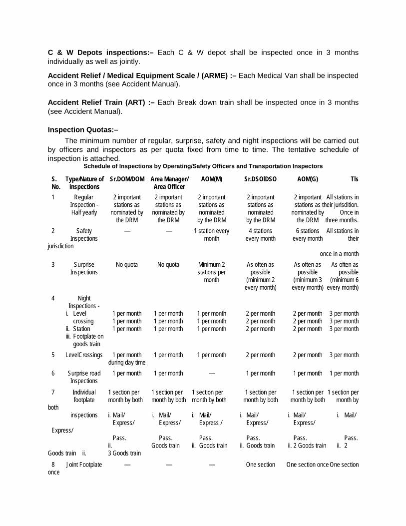
C & W Depots inspections:– Each C & W depot shall be inspected once in 3 months individually as well as jointly.
Accident Relief / Medical Equipment Scale / (ARME) :– Each Medical Van shall be inspected once in 3 months (see Accident Manual).
Accident Relief Train (ART) :– Each Break down train shall be inspected once in 3 months (see Accident Manual).
Inspection Quotas:– The minimum number of regular, surprise, safety and night inspections will be carried out
by officers and inspectors as per quota fixed from time to time. The tentative schedule of inspection is attached.
Schedule of Inspections by Operating/Safety Officers and Transportation Inspectors
S. Type/Nature of Sr.DOM/DOM Area Manager/ AOM(M) Sr.DSOlDSO AOM(G) Tls No. inspections Area Officer
1 Regular 2 important 2 important 2 important 2 important 2 important All stations in Inspection - stations as stations as stations as stations as stations as their jurisdition. Half yearly nominated by nominated by nominated nominated nominated by Once in the DRM the DRM by the DRM by the DRM the DRM three months. 2 Safety — — 1 station every 4 stations 6 stations All stations in Inspections month every month every month their jurisdiction once in a month 3 Surprise No quota No quota Minimum 2 As often as As often as As often as Inspections stations per possible possible possible month (minimum 2 (minimum 3 (minimum 6 every month) every month) every month) 4 Night Inspections - i. Level 1 per month 1 per month 1 per month 2 per month 2 per month 3 per month crossing 1 per month 1 per month 1 per month 2 per month 2 per month 3 per month ii. Station 1 per month 1 per month 1 per month 2 per month 2 per month 3 per month iii. Footplate on goods train 5 LevelCrossings 1 per month 1 per month 1 per month 2 per month 2 per month 3 per month during day time 6 Surprise road 1 per month 1 per month — 1 per month 1 per month 1 per month Inspections 7 Individual 1 section per 1 section per 1 section per 1 section per 1 section per 1 section per footplate month by both month by both month by both month by both month by both month by both inspections i. Mail/ i. Mail/ i. Mail/ i. Mail/ i. Mail/ i. Mail/ Express/ Express/ Express / Express/ Express/ Express/ Pass. Pass. Pass. Pass. Pass. Pass. ii. Goods train ii. Goods train ii. Goods train ii. 2 Goods train ii. 2 Goods train ii. 3 Goods train 8 Joint Footplate — — — One section One section once One section once
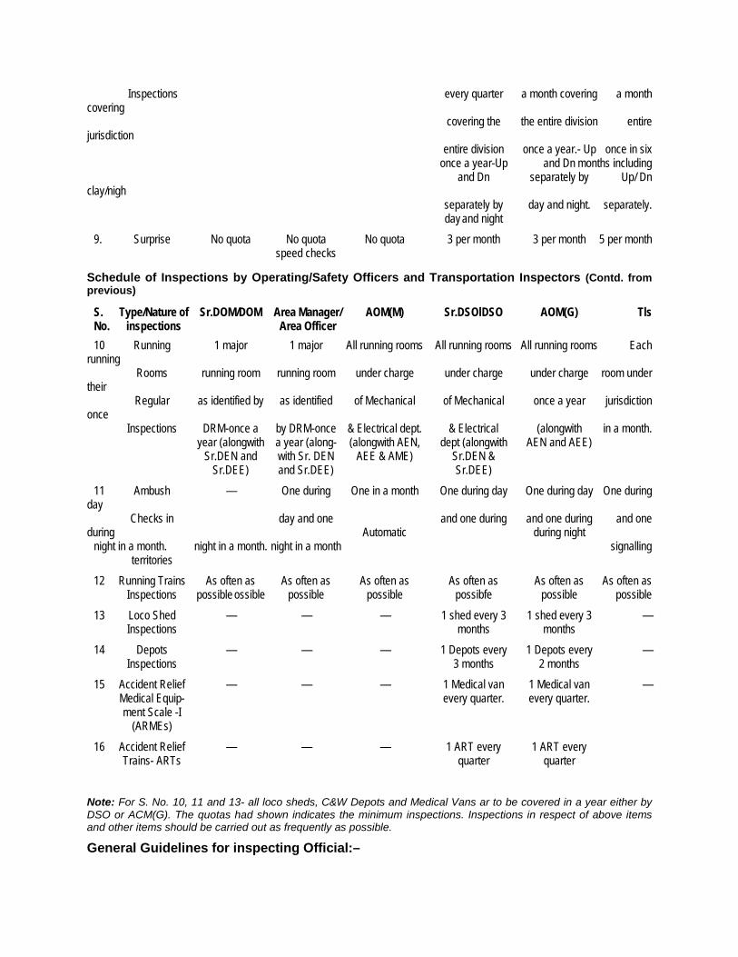
Inspections every quarter a month covering a month covering covering the the entire division entire jurisdiction entire division once a year.- Up once in six once a year-Up and Dn months including and Dn separately by Up/ Dn clay/nigh separately by day and night. separately. day and night 9. Surprise No quota No quota No quota 3 per month 3 per month 5 per month speed checks
Schedule of Inspections by Operating/Safety Officers and Transportation Inspectors (Contd. from previous)
S. Type/Nature of Sr.DOM/DOM Area Manager/ AOM(M) Sr.DSOlDSO AOM(G) Tls No. inspections Area Officer 10 Running 1 major 1 major All running rooms All running rooms All running rooms Each running Rooms running room running room under charge under charge under charge room under their Regular as identified by as identified of Mechanical of Mechanical once a year jurisdiction once Inspections DRM-once a by DRM-once & Electrical dept. & Electrical (alongwith in a month. year (alongwith a year (along- (alongwith AEN, dept (alongwith AEN and AEE) Sr.DEN and with Sr. DEN AEE & AME) Sr.DEN & Sr.DEE) and Sr.DEE) Sr.DEE) 11 Ambush — One during One in a month One during day One during day One during day Checks in day and one and one during and one during and one during Automatic during night night in a month. night in a month. night in a month signalling territories 12 Running Trains As often as As often as As often as As often as As often as As often as Inspections possible ossible possible possible possibfe possible possible 13 Loco Shed — — — 1 shed every 3 1 shed every 3 — Inspections months months 14 Depots — — — 1 Depots every 1 Depots every — Inspections 3 months 2 months 15 Accident Relief — — — 1 Medical van 1 Medical van — Medical Equip- every quarter. every quarter. ment Scale -I (ARMEs) 16 Accident Relief — — — 1 ART every 1 ART every Trains- ARTs quarter quarter
Note: For S. No. 10, 11 and 13- all loco sheds, C&W Depots and Medical Vans ar to be covered in a year either by DSO or ACM(G). The quotas had shown indicates the minimum inspections. Inspections in respect of above items and other items should be carried out as frequently as possible. General Guidelines for inspecting Official:–
1) Before commencing the inspection all inspection books should be called for and the notes made by other inspecting official should be carefully persued to check whether the staff have complied with their instructions. If any of these instructions have not been carried out written explanation of the Station Master should be obtained.
2) It shall not be enough merely to point out the irregularly of the staff, matters must be put right personally while at the extent possible.
3) All books and registers inspected must be initialled and dated. Technique of Inspections:– It requires both expertise and experience to carry out intelligent inspections. To evolve a sound technique of inspections an inspecting official should: 1) Have a clear understanding of the station lay out, its signalling, special features of working
and the instructions in regard to reception, despatch, crossing, shunting and running through of trains. For this he should have a good knowledge of not only General & Subsidiary Rules but also of Station Working Rules.
2) Select the feature of working which he intends to check during his inspection and should have a clear conception about them in his mind. For instance he may like to emphasise on the correct reception and despatch of trains and observance of safety rules by the staff or on utilisation of stock detention to passenger or goods train, knowledge of staff etc.
3) Inspect the aspect of working by thorough inspection of books, registers, forms and equipments used for operations and secondly by means of personal observation of actual operations.
Be selective in choosing:– 1) (a) The time and operations of personal observation.
(b) The documents, registers and forms for checks and cross checks. (c) The equipments for checking, its availability, adequacy, maintenance and its use.
2) Select specific periods for checking registers books and forms keeping in view the purpose of inspection and time of inspections and time of disposal, should be subjected to concentrated, minute and probing checks and cross checks. It may be worth while to select two or more separate periods. One of these being that immediately preceding the day of inspection. This will help him in not only detecting the irregularities being committed but also whether these have been continuing for the past some time.
3) Discuss the irregularities or lapses noticed during inspection with the staff actually doing the work as well as those supervising their work. Such a discussion will prove to be educative and produce useful results.
4) Discuss, as far as possible, the points common to two or more branches, like the Signalling interlocking branch or Loco Train Examining, Civil Engineering and Commercial Branches jointly for objectivity and acceptable solutions. This will help in not only arriving as correct conclusions and forming sound views but also in avoiding unnecessary correspondence.
12.01. Quota of Inspections for operating officers at the Zonal headquarters.—
Grade Monthly Quota Areas of Inspections
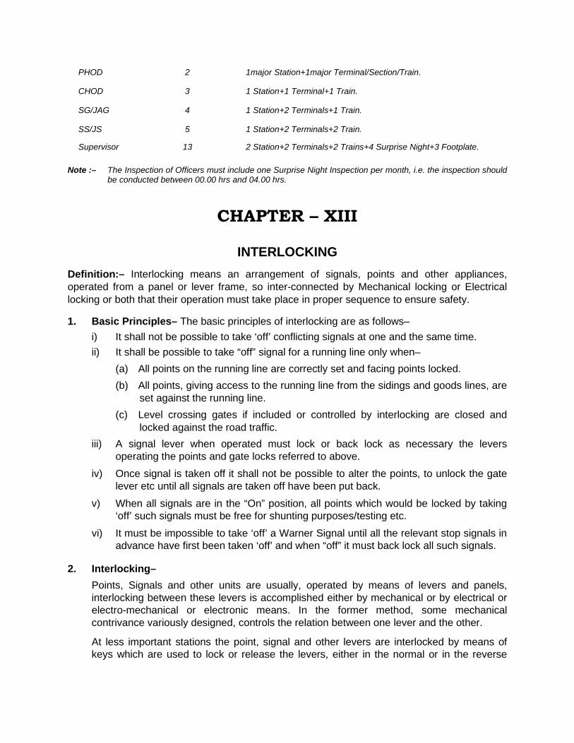
PHOD 2 1major Station+1major Terminal/Section/Train.
CHOD 3 1 Station+1 Terminal+1 Train.
SG/JAG 4 1 Station+2 Terminals+1 Train.
SS/JS 5 1 Station+2 Terminals+2 Train.
Supervisor 13 2 Station+2 Terminals+2 Trains+4 Surprise Night+3 Footplate.
Note :– The Inspection of Officers must include one Surprise Night Inspection per month, i.e. the inspection should be conducted between 00.00 hrs and 04.00 hrs.
CHAPTER – XIII
INTERLOCKING
Definition:– Interlocking means an arrangement of signals, points and other appliances, operated from a panel or lever frame, so inter-connected by Mechanical locking or Electrical locking or both that their operation must take place in proper sequence to ensure safety.
1. Basic Principles– The basic principles of interlocking are as follows– i) It shall not be possible to take ‘off’ conflicting signals at one and the same time. ii) It shall be possible to take “off” signal for a running line only when–
(a) All points on the running line are correctly set and facing points locked. (b) All points, giving access to the running line from the sidings and goods lines, are
set against the running line. (c) Level crossing gates if included or controlled by interlocking are closed and
locked against the road traffic. iii) A signal lever when operated must lock or back lock as necessary the levers
operating the points and gate locks referred to above. iv) Once signal is taken off it shall not be possible to alter the points, to unlock the gate
lever etc until all signals are taken off have been put back.
v) When all signals are in the “On” position, all points which would be locked by taking ‘off’ such signals must be free for shunting purposes/testing etc.
vi) It must be impossible to take ‘off’ a Warner Signal until all the relevant stop signals in advance have first been taken ‘off’ and when “off” it must back lock all such signals.
2. Interlocking– Points, Signals and other units are usually, operated by means of levers and panels,
interlocking between these levers is accomplished either by mechanical or by electrical or electro-mechanical or electronic means. In the former method, some mechanical contrivance variously designed, controls the relation between one lever and the other.
At less important stations the point, signal and other levers are interlocked by means of keys which are used to lock or release the levers, either in the normal or in the reverse
position, as required. At other stations the levers are interlocked by means of tappets inside a box of the lever frame, which is normally kept covered and sealed.
3. Types of Interlocking– (i) Mechanical Interlocking (ii) Panel Interlocking (Relay) (iii) Route Relay Interlocking. (iv) Solid State Interlocking.
i) Mechanical Interlocking:– The era of Interlocking started with mechanical frames. In mechanical signalling, since the
functions are operated by levers, the relationship that should exist between the functions can be transferred to exist between the levers. To ensure that the signal can be taken ‘OFF’ only after the point is correctly set, we can arrange the interlocking between the signal lever and point lever to be such that the signal lever can be reversed only after the point lever is in the correct position, viz. ‘Normal’ or ‘Reverse’, as the case may be.
As the size of yards & train movements increased, size of lever frames also increased. These lever frames not only increased in size occupying more space but also required intensive maintenance.
ii) Panel Interlocking:– With the advent of Electro-mechanical relays, lever frames gave way to relay interlocking
based installations. This development resulted in relatively faster operation, fail-safe operation and reduced size of buildings required for housing of interlocking installations. With further increase in traffic and expansion of railway network, panel interlocking installations were commissioned.
iii) Route Relay Interlocking:– Route Relay interlocking is same as Panel Interlocking with Electro Mechanical Relays
doing the interlocking except that it can be employed for big yards, the interlocking is done between one route and another route. Another important feature in terms of operating point of view is that the SM has to only press two buttons, Signal button & Route Button (entry-exit system). He doesn’t have to individually operate the points to the required position.
iv) Solid State Interlocking (SSI):– Computer based interlocking uses thousands of Electro-mechanical relays requiring
complex wiring and inter-communications. The wiring diagrams for such installations run into hundreds of sheets. Individual relays, wiring and interconnections along with thousands of shouldered joints are required to be physically examined and certified. This exercise requires traffic blocks of long durations and large manpower to manage the traffic during blocks.
Even for small yard re-modelling like addition of a loop line, all the above activities are required to be redone. Therefore, the advantages of relay based interlocking installations are being nullified.
The SSI system occupies considerably less space, consumes less power, is more reliable and is easy to install and maintain. Also, initial commissioning & changes due to yard re-
modeling can be carried out in negligible time requiring skeleton manpower for traffic management during the blocks.
Unlike PI or RRI, Microprocessors (IC’S) are doing the Interlocking based on pre determined logic circuits.
Advantages of SSI:– Increase in section capacity. Faster operation. User friendly operation. Fail safe technique Multiple mode operation.
Significance of SSI for operating staff:– Reduces man power Centralised operation Multiple mode of operation Control cum indication panel Video display unit (P.C) CTC (Centralised Traffic Control) permits remote control Significant reduction in traffic block time Easier & simple operation
Indirect and Direct Interlocking:– (a) Indirect interlocking means that the points are set and locked from one place and the
signals are operated from another place and another lever frame; the interlocking is effected by means of keys carried from one place to the other.
(b) Direct interlocking means that all levers, viz. the point, the point locks and the signal levers are concentrated in one lever frame and worked therefrom; the interlocking is effected by means of rigid connections between levers without the use of keys.
Standards of Signaling and Interlocking:– Interlocking at stations is standardized into four different classes viz. I(R), II(R), III(R) and IV(R). The regulations prescribing the four standards have been drawn up primarily to meet the needs of crossing stations on the single line but, with such modifications as may be necessary in regard to the equipment of signals; these are also applicable to other stations both on single and double lines. The standards are as follows: -
Note: - For details see para 170 to 174 of “Indian Railway Signal Engineering Manual”.
Two aspect signalling :–
(a) Standard I(R) (i) Speed - 50 kms. Per hour. (ii) Isolation - Isolation of the main line is recommended, but is not essential. (iii) Points - the facing points should be provided with key locks, locking both switches
independently and the switches detected independently by relative signals. (iv) Interlocking - Interlocking between points and signals may be carried out indirectly by
means of key locks.
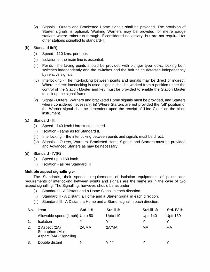
(v) Signals - Outers and Bracketted Home signals shall be provided. The provision of Starter signals is optional. Working Warners may be provided for metre gauge stations where trains run through, if considered necessary, but are not required for other stations signalled to standard- I.
(b) Standard II(R) (i) Speed - 110 kms. per hour. (ii) Isolation of the main line is essential. (iii) Points - the facing points should be provided with plunger type locks, locking both
switches independently and the switches and the bolt being detected independently by relative signals.
(iv) Interlocking - The interlocking between points and signals may be direct or indirect. Where indirect interlocking is used, signals shall be worked from a position under the control of the Station Master and key must be provided to enable the Station Master to lock up the signal frame.
(v) Signal - Outers, Warners and bracketed Home signals must be provided, and Starters where considered necessary; (ii) Where Starters are not provided the “off’ position of the Warner signal shall be dependent upon the receipt of ‘Line Clear’ on the block instrument.
(c) Standard - III. (i) Speed - 140 km/h Unrestricted speed. (ii) Isolation - same as for Standard II. (iii) Interlocking: - the interlocking between points and signals must be direct. (iv) Signals. - Outers, Warners, Bracketed Home Signals and Starters must be provided
and Advanced Starters as may be necessary.
(d) Standard - IV(R) (i) Speed upto 160 km/h (ii) Isolation - as per Standard III
Multiple aspect signalling :– The Standards, their speeds, requirements of isolation equipments of points and
requirements of interlocking between points and signals are the same as in the case of two aspect signalling. The Signalling, however, should be as under:–
(i) Standard I - A Distant and a Home Signal in each direction. (ii) Standard II - A Distant, a Home and a Starter Signal in each direction. (iii) Standard III - A Distant, a Home and a Starter signal in each direction.
No. Item Std. I ® Std.ll ® Std.lll ® Std. IV ® Allowable speed (kmph) Upto 50 Upto110 Upto140 Upto160 1. Isolation Y Y Y Y 2. 2 Aspect (2A) 2A/MA 2A/MA MA MA Semaphore/Multi Aspect (MA) Signalling
3. Double distant N Y * * Y Y
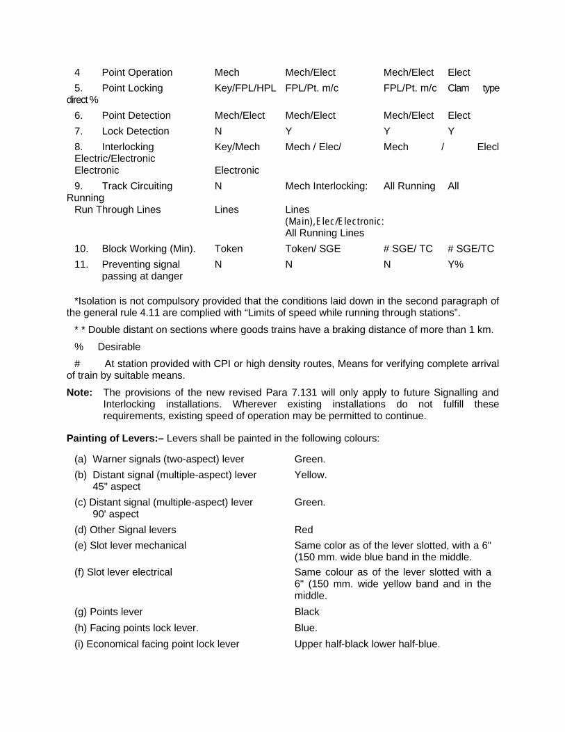
4 Point Operation Mech Mech/Elect Mech/Elect Elect 5. Point Locking Key/FPL/HPL FPL/Pt. m/c FPL/Pt. m/c Clam type direct % 6. Point Detection Mech/Elect Mech/Elect Mech/Elect Elect 7. Lock Detection N Y Y Y 8. Interlocking Key/Mech Mech / Elec/ Mech / Elecl Electric/Electronic Electronic Electronic 9. Track Circuiting N Mech Interlocking: All Running All Running Run Through Lines Lines Lines (Main),Elec/Electronic: All Running Lines 10. Block Working (Min). Token Token/ SGE # SGE/ TC # SGE/TC 11. Preventing signal N N N Y% passing at danger
*Isolation is not compulsory provided that the conditions laid down in the second paragraph of the general rule 4.11 are complied with “Limits of speed while running through stations”.
* * Double distant on sections where goods trains have a braking distance of more than 1 km.
% Desirable # At station provided with CPI or high density routes, Means for verifying complete arrival of train by suitable means.
Note: The provisions of the new revised Para 7.131 will only apply to future Signalling and Interlocking installations. Wherever existing installations do not fulfill these requirements, existing speed of operation may be permitted to continue.
Painting of Levers:– Levers shall be painted in the following colours:
(a) Warner signals (two-aspect) lever Green. (b) Distant signal (multiple-aspect) lever Yellow. 45" aspect (c) Distant signal (multiple-aspect) lever Green. 90' aspect (d) Other Signal levers Red (e) Slot lever mechanical Same color as of the lever slotted, with a 6"
(150 mm. wide blue band in the middle. (f) Slot lever electrical Same colour as of the lever slotted with a
6" (150 mm. wide yellow band and in the middle.
(g) Points lever Black (h) Facing points lock lever. Blue. (i) Economical facing point lock lever Upper half-black lower half-blue.
(j) Station Master’s control lever Upper half white lower half-black. (k) Lever-crossing gate control lever Chocolate.
(I) Release lock lever Black, with a 6" (150 mm) wide blue band in the middle.
(m) Setting lever, “List and Morse” signalling Blue with a 6" (150 mm) wide black band in the middle.
(n) Detector lever (D.W.) Red and blue bands 6" (150 mm.) wide alternately.
(o) Route lever. Upper half red, lower half black. (p) Siding key control lever Black. (q) King lever Red and white bands 6" (150 mm.) wide
alternately. (r) Spare lever White
Numbering of levers in frames. 1) All levers, including spares, are numbered consecutively through the frame from left to
right. Each lever is provided with a name plate showing its function and the number of the other levers in the order of operation which must precede to release it.
2) The levers are broadly classified into three groups : (i) Up signal levers/slotting levers. (ii) Down signal levers/slotting levers. (iii) Point, lock, shunt signal and other levers.
3) The group to which the lever connected to the first approach signal, or Warner signal, situated to the left, or the person working the levers, belongs is allotted the first set of consecutive levers, lying to the left of the frame. The second set of consecutive levers is allotted to group (iii), and the third set of fevers lying to the right is allotted to the remaining group. All levers, including spares/spaces, of each group are, then numbered consecutively, starting from the first lever on the left. The relative position of the levers of each group, the first lever on the left. The relative position of the levers of each group, generally, corresponds to the relative position of the units they operate.
Isolation:- A line is said to be isolated from the adjacent line or lines when no movement on the adjoining lines can foul it. Isolation can be achieved by any of the following methods.
(a) Snag dead end, (b) sand hump, (c) trap points, (d) setting of points (e) permanently locked points, (f) Scotch Block and (g) Hay’s Derail. (h) Derailing Switch.
Note:- For the purpose of definition of Isolation (f) scotch block and (g) Hay’s derail are not means of Isolation. Otherwise Definition of Isolation may be changed as ‘isolated from the adjacent line or lines as well as any movement on same line.”
(a) Snag Dead End : (i) This is an extended portion of track with an erected obstruction with buffers at the
end. (ii) The length is at least 180 metres. (iii) This is used to isolate main line from loop line.
(iv) This is an efficient substitute for signal overlap.
(b) Sand Hump : Sand hump is an extended portion of rail embedded in sand. It is total 60 m in length, with
increasing gradient of 1 in 60, of which the first 30 m is laid with normal track embedded in sand and remaining 30 m is an earthen lump of uniform 4 m width.
(c) Trap Points : (i) This is a single rail cut. (ii) This rail cut will be away from the adjacent line. (iii) To provide isolation, the trap point will be open. (iv) When it is open and if a vehicle moves the vehicle will derail. (v) This is provided to isolate running line from non-running line and main line from loop
line. (d) By setting of points: At interlocked stations, isolation can also be obtained by setting of points. (e) Permanently locked points : Certain points, including traps are kept permanently locked and
(ii) The keys for these points are kept in on duty station Master custody. (iii) These points have to remain set and locked in normal position. (iv) These keys are handed over, when these points are required to be worked.
(f) Scotch Block : (i) A lump of log covered with iron sheets and coloured red. (ii) This will be connected with a chain tied up on the earth. (iii) This is a place across the rail and locked to prevent vehicles moving away. (v) If the vehicle moves the vehicle will derail. (vi) This is used normally to isolate running line from non-running line.
(g) Hayes Derail : It is a device designed to limit the movement of free rolling, uncontrolled wagons / vehicles.
This is accomplished by grinding the flange of a wheel up and over the railhead, dropping the wheel clear of the rail on outside of the rails. The wheels lodging in the tie, cribbing and ballast halt movement of wagons / vehicles.
(h) Derailing Switch : This is an extended portion of track ending with some sand.
• The distance from the points is about 15 feet.
• This is used to isolate main line from loop line
• This is an efficient substitute for signal overlap under approved special instructions.
• The normal setting of points is for derailing switch.
• If the vehicle moves, the vehicle will derail on the sand at the end of the derailing switch.
• Simultaneous reception is possible with CRS permission.
• This should not be obstructed.
13.01. Explanation of certain terms : (i) Track circuit:— The running rails are used as conductor or electric circuit. The current is fed from one end
and a track relay is connected to the rails at the other end of the track. There are two types of track circuits—closed and open. In the closed track circuit which is normally employed in yards the relay is normally kept energised. When a train enters the track circuited section the axle of wheel provides an easier path for the current with the result the track relay drops, thereby replacing the relevant signals. The open track circuits are usually of shorter lengths, being provided for release of Block Instrument locks, occupation of wagon-axle completes the circuit thereby actuating the track relay. Ref.GR 1.02(57).
(ii) Standard type Siding and Succession locking:—The sketch below shows the general arrangements for securing the points and derail of a standard type of siding and succession locks:—
(iii) Normally as shown above the siding points and the derail remain set and locked for straight and for the derail respectively. The derail is fitted with two single locks and the siding points with one single lock. To operate the siding, the Siding Control key must be inserted to its respective single lock at the derail. This releases the derail point to be operated to closed position when the succession key can be extracted from the other single lock at the derail. The succession key in turn when inserted in the single lock fitted on the siding points releases the points to be set for the siding. In this arrangement the derail stands locked in either position when the respective key is out.
To restore the siding points for the running line, the keys must be in used reversed order, so that the Control key may be taken out from the derail to release the signal frame.
(iv) Locking Facing points with Route Indication Keys at non-interlocked stations:— Each running line in a station will be designated by a fixed number; the road nearest the platfrom will be known as No. 1 Route, the next No.2. Route and so on.
All points leading to two diverging routes will be fitted with triple locks, the middle lock will be the Release Lock, the two Outer Locks will be the Points Locking Locks.
The key of each lock will bear on the handle an inscription indicating its function. The keys of the Points Locking locks will normally be secured in their locks. These keys cannot be turned and
removed unless the points are first correctly set and the Released Lock then unlocked. The removal of either Points Locking Key will back-lock the Release key in its lock.
The Release Keys of the Outer most points will be known as the Up and Down keys. These keys must normally be in the personal charge of the Station Master on duty.
When there are more than one set of facing points on the same line, the key of the Points Locking Lock of the outer facing points when set for the direction of the inner points becomes the Release Key of the next set of inner facing points.
In setting the Points for a specified route, the locking must begin from the outermost facing Points. When the points have to be set and locked for the reception of a train, the Station Master on duty will make
over to the Points Locker (usually a Pointsman at such stations) the Up or Down Key, as the case may be, for the direction from which the train is expected and will give him clear instruction as to the running line on which the train will be received. The Points Locker will proceed to the outermost facing points and set and lock them for the specified route removing the Points Locking Key which, if there are no inner facing points to be set and locked, will be taken to the Station Master on duty. The inscription on the handle of this key will indicate the running line or route for which the points have been set and locked.
If there are inner facing points to be locked, the Points Locking key removed from the Outer facing Points will be the Release Key for the inner points.
After the innermost facing points on the specified route have been locked, the Points Locking Key removed from those Points will be taken to the Station Master on duty. The inscription on the handle of this key will indicate the running line or route for which all the facing points have been set and locked.
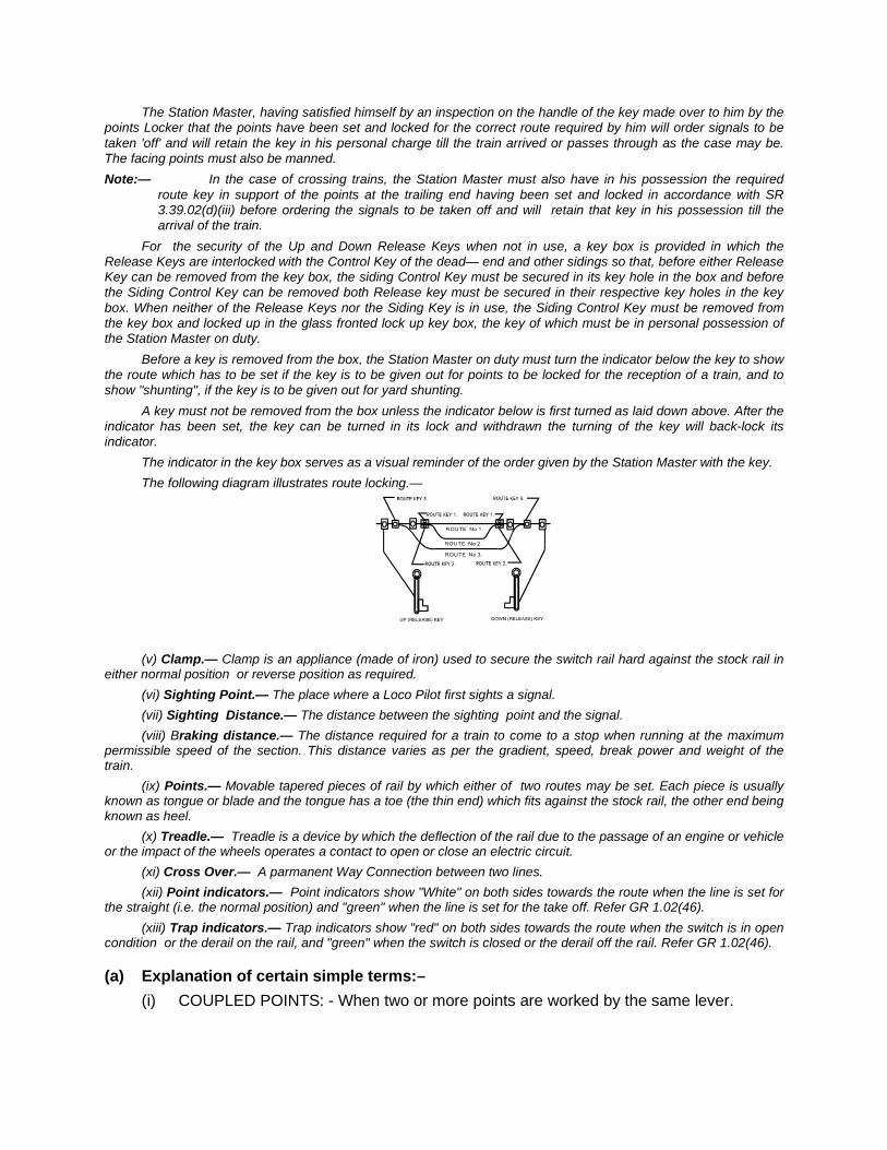
The Station Master, having satisfied himself by an inspection on the handle of the key made over to him by the points Locker that the points have been set and locked for the correct route required by him will order signals to be taken 'off' and will retain the key in his personal charge till the train arrived or passes through as the case may be. The facing points must also be manned. Note:— In the case of crossing trains, the Station Master must also have in his possession the required
route key in support of the points at the trailing end having been set and locked in accordance with SR 3.39.02(d)(iii) before ordering the signals to be taken off and will retain that key in his possession till the arrival of the train.
For the security of the Up and Down Release Keys when not in use, a key box is provided in which the Release Keys are interlocked with the Control Key of the dead— end and other sidings so that, before either Release Key can be removed from the key box, the siding Control Key must be secured in its key hole in the box and before the Siding Control Key can be removed both Release key must be secured in their respective key holes in the key box. When neither of the Release Keys nor the Siding Key is in use, the Siding Control Key must be removed from the key box and locked up in the glass fronted lock up key box, the key of which must be in personal possession of the Station Master on duty.
Before a key is removed from the box, the Station Master on duty must turn the indicator below the key to show the route which has to be set if the key is to be given out for points to be locked for the reception of a train, and to show "shunting", if the key is to be given out for yard shunting.
A key must not be removed from the box unless the indicator below is first turned as laid down above. After the indicator has been set, the key can be turned in its lock and withdrawn the turning of the key will back-lock its indicator.
The indicator in the key box serves as a visual reminder of the order given by the Station Master with the key. The following diagram illustrates route locking.—
(v) Clamp.— Clamp is an appliance (made of iron) used to secure the switch rail hard against the stock rail in either normal position or reverse position as required.
(vi) Sighting Point.— The place where a Loco Pilot first sights a signal. (vii) Sighting Distance.— The distance between the sighting point and the signal. (viii) Braking distance.— The distance required for a train to come to a stop when running at the maximum
permissible speed of the section. This distance varies as per the gradient, speed, break power and weight of the train.
(ix) Points.— Movable tapered pieces of rail by which either of two routes may be set. Each piece is usually known as tongue or blade and the tongue has a toe (the thin end) which fits against the stock rail, the other end being known as heel.
(x) Treadle.— Treadle is a device by which the deflection of the rail due to the passage of an engine or vehicle or the impact of the wheels operates a contact to open or close an electric circuit.
(xi) Cross Over.— A parmanent Way Connection between two lines. (xii) Point indicators.— Point indicators show "White" on both sides towards the route when the line is set for
the straight (i.e. the normal position) and "green" when the line is set for the take off. Refer GR 1.02(46). (xiii) Trap indicators.— Trap indicators show "red" on both sides towards the route when the switch is in open
condition or the derail on the rail, and "green" when the switch is closed or the derail off the rail. Refer GR 1.02(46).
(a) Explanation of certain simple terms:– (i) COUPLED POINTS: - When two or more points are worked by the same lever.
(ii) CROSSINGS: - The appliances provided at the Junctions where two lines cross or join one and other.
(iii) COMPENSATOR: - It is an appliance provided to compensate for difference in length of roddings and wires due to variations in temperature.
(iv) CRANK: - It is an appliance fitted with the rodding to change the direction of the motion given by the lever.
(v) DETECTOR:- It is an electrical or mechanical device which prevents the signals from being taken ‘OFF’ unless the points are correctly set.
(vi) ECONOMICAL POINT LOCK OR S.L.M. (Switch & Lock Movement):- When the facing points and the facing point lock are worked by the same lever, it is called “Economical Point Lock” or “S.L.M.”
(vii) FACING POINT LOCK:- It is a plunger bolt provided at facing points, which ensures that the points are correctly set and locked to prevent them from being moved.
(viii) FACING POINT LOCK BAR: - It is a bar provided at facing points is connected with a facing point lock, which prevents facing point lock being moved while a vehicle is passing or standing over it.
(ix) FOULING BAR:- It is a bar provided at the fouling points between two diverging roads which prevents points being set and locked and signal being taken ‘OFF’ for one road while a train is standing short of clearance on the other road.
(x) LOCKING: - A lever is said to be locked when in the normal position it cannot be pulled over. A lever is said to be locking another lever when owing to the farmer’s remaining or in the normal or reverse position the latter cannot be pulled over.
(xi) RELEASE: - A lever releases another lever, when due to its operation the later can be pulled. If lever No. 2 can only be pulled over when lever No. 1 is pulled then lever No. 1 is said to be de-releasing lever No. 2.
(xii) SLOT: - It is an electrical or mechanical arrangement where by a signal can only be lowered only by the joint operation by two or more persons, but can be put back to ‘ON’ by any one of them.
(xiii) TONGUE RAILS: - These are rails with tapered movable ends which controls the setting of the route.
(b) PANEL BUTTONS :
1. Signal buttons GN
2. Route buttons UN
3. Point buttons WN
4. Calling on signal buttons COGN
5. Emergency buttons EGGN, EUYN, EUUYN, EWN 6. Reminder collors XT RES PB+A/C RES KEY, POWER FAIL, ACK,
SYS, HL/SL MECR FAILEDFAIL, ACK 7. Point group buttons WWN 8. Gate signal buttons LXN
9. Slot release, slot lock buttons
(c) PANEL BUZZERS 1) Button hold bazzer 2) Signal filament failure buzzer 3) Power fail buzzer 4) System fail buzzer 5) Block release buzzer, train entry buzzer 6) False feed buzzer.
(d) PANEL COUNTERS 1) Emergency signal replacement counter (EGRN) 2) Emergency route release counter (EUUYN) 3) Calling on signal counter (COGGN) 4) Emergency route cancellation counter (EUYN) 5) Emergency point operation counter (EWN) 6) Emergency overlap release counter (OYN)
13.03. Types of Fixed Signals.— The following types of fixed signals are in use on this Railways:— (a) Colour Light signals:—
(i) Manually operated Multiple aspect signals. (ii) Multiple aspect Semi-Automatic signals. (iii) Multiple Aspect Automatic signals. (iv) Manually operated lower quadarant semaphore arm type signals.
(b) Subsidiary Signals:— (i) Supplementary signals:—
(a) Calling-on signals. (b) Co-acting signals. (c) Repeating signals.
(ii) Shunt signals:— (a) Position lights type. (b) Miniative arm type. (c) Disc type.
13.04. Commissioning or re-erection of signals.— (a) For commissioning or re-erection of signals, the instructions contained in GR 3.26 and SR thereto shall be
followed.
(b) The Divisional Signal & Telecom. Engineer or Assistant Signal and Telecom. Engineer will, whenever necessary, requisition the services of a Sighting Committee.

(c) The Sighting Committee having decided on the site and determined the height of the proposed signal or signals, all the members will sign the certificate in the prescribed form and the same will be forwarded to Sr. Divl. Signal & Telecom Engineer/ Divisional Signal &Telecom. Engineer.
(d) On the date that the new signals are first brought into use, the Divisional Transportation Inspector, the Locomotive Inspector and the SSE/SE/JE(Sig) will attend and jointly send message to the Divisional Engineer, Divisional Mechanical Engineer, Divisional Operations Manager and Divisional Signal &Tele Communication Engineer stating whether the signals are satisfactory or otherwise, both by day and night. On receipt of this message the Divisional Signal and Tele-communication Engineer will endorse on the space provided on the Sighting Certificate already received.
(e) While deciding the site and determining the height of the signal the minimum visibility distance as indicated in SR 3.16.01, infringement to schedule of dimensions and the visibility of signals not being obscured by OHE masts in electrified section should be taken into consideration by the Sighting Committee.
(f) Minor alteration to signals:— When minor alterations to signals are required in order to provide better sighting such as increasing the height
or moving the signal post other than on the right hand side of the track, the Divisional Railway Manager may approve the work. Sr. DSTE/DSTE will advise the Sr. DOM/Sr.DSO/DSO of the time and date on which the alteration will be made and manner in which it will be carried out. The Sr. DOM/Sr.DSO/DSO will then arrange to issue a memorandum detailing the work as information to all concerned staff.
Note : Any work involving movement of a signal accross the track will require sanction of the Authorised Officer of the Railway.
13.05. Responsibility for repairing, maintenance and replacement of signals.— (a) The signal and Tele-communication department is responsible for repair, maintenance and replacement of
signals, signal lamps and their fittings. In case of any damage to the signal, signal lamps and their fittings— the Station Master must intimate the SSE/SE/JE(Sig) and signal Maintainer concerned for necessary action.
(b) Proper care must be exercised by the Traffic staff in working slots/Signals/Block Instruments as per the working procedure. The slot/slide must be put back to “normal” after the concerned signal is put back to “on”. A slot or slide or signal lever should not be kept in the pulled condition after passage of a train. This may cause an accident or failure. Refer GR 3.36 and SR thereto.
Similar procedure as indicated above should be followed in case of lamp of all other indicators provided at the station and yard.
13.06. Examination of Hand Signal Lamps, Flags and their replacement.— At a fixed hour daily the station Master will examine all the Hand Signal Lamps and Flags in use and see that
they are in proper order. He should take immediate action also for the replacement and repair of the Hand Signal Lamps and Flags. Any deficiency of Hand Signal Lamps and flags must be immediately brought to the notice of the Divisional Safety Officer and Divisional Transportation Inspector.
13.07. Warning Boards.— (a) Warning Boards are provided with a view to warn the Loco Pilot of an approaching train that he is
approaching the first stop signal of a station or an intermediate block stop signal or a gate stop signal, so as to enable him to bring his train under control and be prepared to stop at the signal, unless the 'off' aspect of the signal has been sighted by him authorising him to proceed past the signal.
(b) There are two types of warning Boards as follows:—
(c) Goods Warning Boards are provided at a distance of 1.4 KMs in rear of the first stop signal of a station or an intermediate block stop signal or a gate stop signal which is not prewarned by the provision of a Warner/Distant signal located at a distance of not less than 1.4 Kms, and these are applicable to all goods trains and also to all passenger carrying trains on high speed section (Howrah— Jharsuguda). The Loco Pilot of a passenger carrying train with high speed on Howrah— Jharsuguda section will bring his train under control from the goods warning Board unless the 'off' aspect of the first stop signal or the clear aspect of the Distant signal has been sighted by him.
(d) Passenger warning Boards are provided at a distance of 1 KM in rear of the first stop signal of a station, intermediate block stop signal or a gate stop signal, which is not prewarned by the provision of a Warner/Distant signal located at a distance not less than 1 KM from it. These are provided on the routes where the maximum permissible speed of Passenger carrying trains does not exceed 100 KMPH.
(e) The distance mentioned in paras (c) and (d) above should be suitably increased if the approch to a station is on a falling gradient.
(f) Where the sectional speed ranges from 50 to 72 KMPH on the board gauge, passenger warning boards should be provided only at stations where the first Stop signal is not visible from an adequate distance i,e.800 metres.
(g) Where, however, the sectional speed of a passenger carrying train is more than 100 KMPH, the goods warnings Board will be applicable to such trains. The Loco Pilot of such high speed train will bring the train under control from the goods warning boards unless the off aspect of the first stop signal or clear aspect of the distant signal has been sighted by him.
13.08. Custody of the Key of Cabin Basement/Relay Rooms locks.— At every station, the cabin basement/Relay room should be kept locked with two separate locks, the
arrangement should be such that one key is kept with the on duty Station Master and the other key with the signal maintainer. When ever required the Station Master shall hand over the key to the maintainer with proper acknowledgement in the basement/relay room key register. The maintainer on receipt of the key from the Station Master may use the same and the key in his custody to open the basement/relay room by inserting the keys one after another separately into the earmarked locks.
After completion of the work, the Cabin basement/relay room is to be locked using both the keys separately and designated key should be handed over to the Station Master.
The details of transaction is to be properly recorded in the basement/relay room key register maintained at the Station and duly signed by the Station Master and Maintainer respectively.
13.09. Situation in which disconnection notice need not be issued provided suitable precautions are taken;
(A) CLEANING AND/OR; LUBRICATING/GRAPHITING WITHOUT AFFECTING ANY PHYSICAL/ELECTRICAL DISCONNECTION. i) Lever frame basement. ii) Relay room and battery room. iii) Apparatus case/battery box/goomty. iv) Lifting barrier mechanism including winch. v) Lever lock and circuit controller without opening cover. vi) Inspection and cleaning of inside equipment by opening the covers point machines, signal motors,
reversers, apparatus cases and detectors. vii) Point, facing point lock and lock bar. viii) Cranks, compensators, pullies, wheels, roller stands, counter weights & levers. ix) Power supply equipment. x) Insulation joints. xi) Lens/roundels of signal, point indicator, trap indicator & shunt permitting indicator provided covering
lenses prevent phantom indication to driver of an incoming train.
(B) TESTING OF : i) Track locking, approach locking, back locking, indication locking, route release. ii) Checking various parameters of axle counter without disconnecting the equipment. iii) Power supply equipment. iv) Lever frame, SM's control frame, signal operation, point operation, level crossing gate & slot circuits. v) Point by obstruction test for lock only. vi) Checking and testing of track circuit parameters when the track is unoccupied.
vii) Focussing of colour light signal provided phantom indication to driver of an incoming train is prevented by covering lenses.
(C) ADJUSTMENT OF : i) Wire transmission except double wire operated point transmission. ii) Tightening of terminals using insulated tools without causing any shorts on adjacent terminals.
(D) REPLACEMENT OF : i) Electric signal lamp provided covering lenses prevent phantom indication to loco pilot of an incoming
train. ii) Bond Wire, one at a time. iii) Plug in relay in case traffic condition permits. iv) Indicator lamps. v) Push button/switch/key of panel. vi) Lock bar clips/bar stop, one at a time. vii) G. D. tubes. viii) Fuse, one at a time. ix) Pulley, bottom roller/top roller in wire and rod transmission one at a time and split pins. x) Batteries/cells without affecting dis-connection of supply to main equipment.
13.10. Non-interlocked points.— (a) Locks and Bolts for points:—At stations where the points are not interlocked with the signals, each set of
points must be provided with a safety lock or a clamp of the approved type or screw locking bolts with nut and cotter and a padlock so as to secure the switch or tongue rail to the stock rail. In this position the switch is said to be closed. This should be ensured before allowing any movement over the point(s). Points of the marshalling yard over which trains are neither received nor despatched are not provided with padlocks. (Refer S.R. 3.39.03, 5.14.03 and 5.14.07 (a) (b).)
(b) Keys of points lock.—The keys of points locks must not be kept in bunches, as when a bunch of keys is sent out to unlock points there may be other keys in the bunch which should be with the Station Master, and in such case it might be in the power of the pointsman or porter to unlock points that should be kept locked.
(c) Padlocking of points.— The clamp must be properly tightened to hold the tongue and stock rails together before being padlocked. Where bolts, nuts and cotters are provided the bolt should be passed through the tongue and stock rails near the nose of the closed switch, then the nut should be screwed on tightly, cottered and padlocked. If the nut cannot be screwed sufficiently tight so as to hold the tongue and stock rails together without a gap, the bolts etc, should be renewed at once.
When keys are removed from locks, care must be taken to place the key hole shields over the keyholes so as to prevent rain and dust getting into the locks.
13.11. Use of Crank Handle for Motor operated points.— At stations where points are operated by electric Motors, the following procedure shall be observed in case of
failure of such point(s). These procedure should be incorporated in Appendix 'B' of the 'Station Working Rules' at stations where motor-operated points are provided.
(a) At stations where points are worked by means of electrical points motors as in the case of Panel/Route Relay interlocking, in the event of their failure the point can be operated locally by using crank handle(s). For this purpose, separate crank handle for each point or a common handle for group of points will be provided according to the design of interlocking at the stations. These crank handles are interlocked with the signals and are housed in the appropriate interlocking box(s) or electrical apparatus. In the event of failure of point/motor, to set the point(s) manually, Emergency Crank Handle may be taken out from the interlocking box(s) or electrical apparatus.
(b) In the event of failure/defect of electrically operated point(s) trains may be received/despatched on signals after manual operation of points by the emergency crank handle(s), which is/are interlocked with the signals, provided—
The Station Master deputes a responsible operating official not below the rank of a Pointsman with the Crank handle to operate the defective motor operated point manually. The emergency crank handle can either be personally handed over or electrically transmitted to him (when such facility is provided) by the Station Master/Assistant Station Master/Switchman/Leverman on duty with instructions to set the defective point(s) to the desired position (viz. normal or reverse) and clamp and padlock the same. Both the ends of a cross-over must be set in correspondence (viz. normal or reverse), the facing and trailing points must be clamped and padlocked. The operating official so deputed,

after complying with such instructions should return the emergency crank handle either personally or transmit electrically to the Station Master/Asstt. Station Master/Switchman/Leverman on duty, incharge of operation.
(c) The Station Master/Asstt. Station Master/Switchman/Leverman on duty should verify from the visual indication available on the panel/other means that the points are set to the desired position as instructed by him (normal or reverse) and thereafter return the crank handle received by him to the appropriate interlocking box.
(d) He should also verify from the operating official deputed to set the defective point(s) that the same is also clamped and padlocked, supported by a Private Number in case of electrical transmission of the crank handles or by obtaining the signature of the operating official in the crank handle register.
(e) The Station Master/Asstt. Station Master/ Switchman/Leverman on duty after ensuring the correct setting of defective point(s) as required in paras (b), (c), (d) above can take off the concerned signals for movement of the trains over the said point(s).
(f) If even after complying with the instructions contained in paras (b) to (e) by Station Master/ Switchman/Leverman on duty, the correct setting of the defective points to the desired position is not indicated in the visual indication provided, the train will be piloted in and out in terms of SRs 3.69.01, 3.69.02, 3.69.03, 3.70.01 and 3.70.02. Note:— (a) The cases of failures of motor operated point(s) should be promptly reported to the JE(Main)/SE/JE(Signal) concerned for immediate rectification of the same.
(b) Whenever an emergency crank handle is required to be used by a Signal official for maintenance work or in the event of failures, the signal officials will give a disconnection memo to the Station Master on duty and after making necessary entries in the Emergency Crank Handle Register, the Station master on duty will obtain the acknowledgement of the Signal official in the Emergency Crank Handle Register and then hand over to him the Emergency Crank handle (s) for the points concerned. The concerned points will be treated as defective till the Emergency Crank Handle (s) is/are returned to the Station Master on duty.
(c) Whenever Emergency Crank Handle(s) is/are handed over to a signal official for maintenance work or for rectification of failure, the points for the affected lines should be treated as non-interlocked and the Station Master on duty is responsible for introduction of non interlocked working and trains will be piloted 'in' and 'out' after clamping and padlocking the points over which the train is to pass as per SRs 3.69.01, 3.69.02, 3.69.03, 3.70.01 and 3.70.02.
(d) An Emergency Crank Handle Register should be maintained in the following proforma by the Station Master on duty wherein the particulars of the usage of Emergency Crank Handle must be recorded:—
(1) Date. (2) Point No. which failed or is required to be tested. (3) Time of failure. (4) Disconnection Memo No. received from S&T staff. (5) Signature of Pointsman/Signal official to whom the Emergency Crane Handle is handed
over/Transmitted. (6) Time Emergency Crane Handle is sent out/Transmitted. (7) Signature/P.N. of the Pointsman to ensure correct setting, clamping and padlocking of the points. (8) Date and time fault rectified. (9) Time Emergency Crank Handle received back by the Station Master on duty. (10) Signature and designation of the signal official who rectified the fault. (11) Remarks. 13.12. At station having Motor points, the SM shall ensure that every point is operated through crank handle at
least once in three months by operating staff. Defects or deficiencies noticed during crank handle operation should be promptly reported to concerned signal maintenance staff for rectification.
CHAPTER – XIV
STATION WORKING RULES (SWRs) AND TEMPORARY WORKING ORDER
General Rules 5.06, stipulates
“(1) In addition to General Rules for Indian Railways and Subsidiary Rules of a Railway each station shall be provided with Station Working Rules, applicable to the station, issued under special instructions.
(2) A copy of the Station Working Rules or relevant extract thereof shall be kept at stations, cabins and level crossings concerned.
SWRs shall be issued in Bi-lingual i.e. in English and Hindi (Devnagri script) form. (1) Object: The object of issuing SWR is to inform all staff concerned with working of trains about the special features of the station to ensure safe train operations at & between stations including level crossings, depending on local conditions.
(2) Authority to issue SWRs: i) Under the provisions of GR 5.06, the authority to issue SWRs rests with the
Authorised Officer of Railway. The power to issue SWRs has further been delegated to the Sr.DOM/DOM and Sr.DSTE/DSTE jointly for all stations within the Division.
ii) SWRs are issued in conformity with the G&SR and can not, in any way supersede them. In case of any conflict, the provisions of G&SR will prevail.
(3) SWRs requiring sanction of Commissioner of Railway Safety (CRS): i) At stations where relaxation has been obtained from provisions of General Rules
under approved special instructions, the approval of CRS already obtained shall find place in the SWRs.
ii) Railway administration must obtain sanction of the CRS, when the SWRs are revised as a result of any work listed in para 1302 of the Indian Railway’s P.Way Manual.
iii) Works requiring the sanction of Commissioner of Railway Safety and notice thereof (See Appendix B to Ch. XV of G&SRs).
iv) SWRs of Special Class Stations.
(4) Procedure for Preparation of SWR : i) The Sr.DSTE/DSTE will prepare/amend the Rule Diagram on the basis of signalling
plan/appendices and send the Rule Diagram and also signalling plan/appendices in case of interlocked station, to the Sr.DOM/DOM for framing Station Working Rules.
ii) Since the Rule Diagram has a vital bearing on the preparation of the SWRs, the Sr.DOM/DOM will scrutinise the Rule Diagram and the Signalling Appendices, if any, and have these checked at the site.
iii) The Sr.DOM/DOM will arrange for preparation of the Draft Working Rules by the Transportation Inspector in the Standard Format, after which these will be checked and approved by the Sr.DOM/DOM personally. In case of interlocked stations the Draft Working Rules shall be checked and approved by Sr.DSTE/DSTE. Sr.DEE/DEE (TRD) shall also be associated in electrified sections.
iv) If there is a ‘D’ (Flag Station) and ‘DK’ (station with siding) between two Block Stations, the SWRs of the Block Stations on either side shall contain a reference to such D/DK class Station (in Appendix ‘F’ of the SWR). In the case of a DK class Station, the special instructions for working the siding shall also be incorporated in the SWRs of the Block Stations situated on either side of the ‘DK’ class Station. A copy of
these special instructions along with the Rule Diagram shall be made available at such DK class Stations.
v) LC Gates controlled by the Stations and rules for their working shall be incorporated in Appendix A of SWR.
vi) The detailed working instructions of Ghat ;sections shall also be appended on Appendix to the SWRs of adjacent block stations of Ghat section.
(5) Responsibility of the Officers signing the SWRs : i) SWRs are the functional rules governing the working of stations. These need to be
prepared with care and attention as any deficiency in these rules can endanger safety ,in which case the officers signing the SWRs shall also be held responsible along with other staff for breach of safety rules.
ii) It is obligatory that the rule diagram of the ground conditions are compared at site to confirm accuracy of R.D. In absence of officials signing the SWR having verified it personally, the Transportation Inspector and the SE (Signal) will, after having jointly inspected the site shall certify in writing that the actual layout conforms to what is shown in the Rule Diagram and the number of points and signals quoted therein are correct.
14.1 All Station Working Rules and their amendments will be prepared in the Divisions and issued under the joint signatures of the Sr. DOM/DOM and the Sr. DSTE/DSTE at interlocked stations and by Sr. DOM/DOM and Sr.DEN/DEN at Non-interlocked stations on each page. In case of new S & T construction work, the DSTE (Con)/ Dy. CSTE (Con) or DSTE(RE)/Dy. CSTE(RE) may sign the SWR in place of DSTE." Each copy of the Working Rules must be signed in ink by the officers issuing them. The Working Rules must be scrutinised carefully before issue, to ensure that they are correct in every respect and conform to the conditions of working at the station prevailing at the time of issue. Note:— The Station Working Rules or any portion thereof, shall not be brought into effect in anticipation of any
works or at a date subsequent to that on which the Station Working Rules concerned are brought into force.
(6) Reviewing of SWRs : The SWRs should be reviewed once in every five years. In case the review brings out the
necessity of carrying out changes, the SWRs should be re-issued. In the event of more than five correction slips having to be issued, the SWRs should be re-issued without waiting for the periodical review to be conducted every five years as mentioned above.
(7) Method of correcting SWRs : Whenever any addition/amendment is required to be made in the said rules, the entire
page/pages duly signed by concerned officers on which the provisions requiring addition/amendment appears should be replaced. The method of pasting correction slips by hand in the SWRs is not permitted.
14.2 Corrections to the Station Working Rules should be made personally by the SS/CYM/Station Master/Yard Master who will enter correction/amendment in a register of "Correction slips" to be appended at the end of the Station Working Rules. This appendix to the Station Working Rules should indicate the para of the Station Working Rules which has been corrected or amended, the number of correction slip, the reference number of the Divisional Office and the authority issuing the correction slip.
(8) Responsibility of Transportation Inspectors (TI):
i) The Transportation Inspector is responsible to see that SWRs of stations on his section are correct and upto date. He will also be responsible to ensure that the station staff viz. Station Supdt., Station Master, Switchman, Cabinman, Pointsman, Gateman and any other staff who are in any way connected with train passing duties, possess correct knowledge of the Rule Diagram and the SWRs and observe them strictly.
ii) Transportation Inspector will also check the SWRs and Rule Diagram and point out irregularities, if any, detected by him. If he finds that certain rules are impracticable thereby forcing the staff to infringe them, he shall immediately bring this matter to the notice of the Sr.DOM/DOM. If he detects any error or omissions which, in any way, affect safe running of trains, he shall take immediate steps at the spot as necessary for safe working of trains and report the matter to the Sr.DOM/DOM concerned for necessary amendment/ modification in the SWRs.
(9) Responsibilities of Station Manger/Station master in charge: The Station Superintendent/Station Master on receipt of the SWRs must immediately
check to ensure that these conform to the local conditions at their stations. If he finds any discrepancy in the said rules, he shall immediately bring such discrepancies and difficulties to the notice of the Sr.DOM/DOM and Transportation Inspector of the section. The Station Manager in charge shall see that all staff having definite responsibilities in train passing at their stations correctly understand and follow the SWR.
(10) Assurance of staff: i) All the staff who are in any way associated with train passing duties, must sign a
declaration in the Assurance Register in token of having studied the SWRs, Rule Diagram and other instructions pertaining to their duties and understood the same and that they are in a position to take up duties independently at the Station. In case of illiterate staff, the Station Manager in charge/Yard Master/Assistant Station Master shall personally explain the SWRs, Rule Diagram and their duties and obtain their acknowledgements in the Assurance Register as a token of their having understood the instructions. The SS/YM/SM/ASM shall also certify that the staff concerned has understood the instructions pertaining to their duties.
14.3 – All class- III staff should sign in form ‘A’ and class- IV staff should sign in form ‘B’ of Assurance Register.
14.4 The duplicate copies of the Assurance Register on form "A" & "B" attached to the Station Working Rules bearing the signature or thumb impression of the staff shall be kept under the personal custody of the Station Master/Yard Master/ Station Superintendent/Chief Yard Master.
ii) Fresh assurance shall be obtained in the Assurance Register from the staff concerned when - (a) He joins at the station as a new member, (b) There is any change in the Station Working Rules, (c) He resumes duty at the station after an absence of 15 consecutive days or
more.
(11) Distribution of Station Working Rules : Copies of SWRs shall be distributed as per current instructions .

14.5 (a) Copies of Station Working Rules shall be distributed as follows:— (i) Station and each cabin One copy each, (one more copy to be kept in SM's Confidential file).
Note:— Each Block/Non-Block Cabin concerned to reception/despatch/other movement of trains shall be supplied with the Station Working Rules or copy of the working rules pertaining to the Cabin concerned.
(ii) Guard's Hd. Qrs. Station 1. (one extra copy for Guard's Reference file) (iii) Loco Shed 2. (one for Loco Pilot's Reference file and one for
SSE/SE(Loco)/SSE/SE(Traction) (iv) Divl Transport. Inspector 1 copy for each station in his jurisdiction. (v) SSE/SE(Signal) 1 —do— (vi) SSE/SE(P. Way) 1 —do— (vii) SSE/SE(Loco) 1 —do— (viii) Divisional Office 1 Copy for DOM 1 Copy for DEN 1 Copy for DSTE 1 Copy for DME 1 Copy for Chief Controller 1 Copy for Safety Section 1 Copy for Sr. DEE (Op) or Sr. DEE (Tr.D). (ix) COM's Office 1 Copy. (x) Principal, Zonal Railway Training Institute 1 Copy. (xi) Commissioner of Rly Safety 1 Copy. (xii) CSTE's Office 1 Copy. (xiii) CME's Office 1 Copy. (xiv) CSO's Office 1 Copy
(b) Copies of the Station Working Rules supplied to stations and cabins may be typed or cyclostyled or computer typed.
(12) Standardisation of SWRs : To maintain uniformity in the SWRs, the following format shall be used while
framing/revising the Station Working Rules for stations. Care may, however, be taken to ensure that –
a) The SWRs framed as per the format are self-contained, brief, precise to the point and written in simple spoken language and
b) General and Subsidiary Rules need not be reproduced in the SWRs. Relevant GR/SR number, may be mentioned in bracket against each para when required.
c) Sr.DOM/DOM and Sr.DSTE/DSTE and Sr.DEE/DEE (TRD) are required to add those special items or features having a bearing on safety in operation at the concerned Station, which is not covered by the format given below (This format has been fixed by RLY Bd) :
...............RAILWAY
No....................... ............ DIVISION
STATION WORKING RULES OF —————— (Name of the station)
................(BG/MG/NG) Date of issue: ———————— Date brought in force ————
NOTE:
(i) The Station working rules (SWR) must be read in conjunction with General & subsidiary Rules and Block Working Manual. These rules do not in any way supersede any rule in the above books. The language of SWR should be simple, brief and unambiguous applying provision of rules to the specific conditions at the relevant station. These rules must be in simple language intelligible to ordinary railwaymen. However, relevant GR/SR Numbers may be mentioned in the brackets.
(ii) The SWR must be page numbered with the station name code written on each page and signed by the Divisional Operations Manager and Divisional Signal & Telecom Engineer at interlocked stations and at non-interlocked stations by Divisional Operations Manager and Divisional Engineer should sign each page.
(iii) The SWR should be issued afresh after every five years or after issue of five amendment slips and reviewed as and when required.
(iv) Any new innovations introduced to facilitate train operation should be incorporated in SWR.
(1) Station working rule diagram : SWR Diagram No. ————— based on CSTE/—— Railway and Signal Inter locking Plan
No. ——— should show the complete layout of the, yard, Points, Signals, gradients and interlocking arrangements of the station including the non-interlocked sidings, exact and actual holding capacity of all the individual lines in metres, actual inter signal (demarcation point) distances, names of adjacent stations and IBH signals, where provided, on either side of the station with their respective distances from the centre line of the station building to the central line of the adjacent stations and any other information necessary in the day to day operation of trains. The particulars of date up to which it is corrected should also be mentioned. SWR diagram should show actual distances and not the minimum prescribed. It should be signed by the Divisional Operations Manager. Divisional Signal & Telecom Engineer and Divisional Engineer. The detection table, Lever Collar Chart and Pull Sheet may be provided in Appendix ‘B’. Pull Sheet should be reproduced on a board brightly painted in the cabins to be placed above the Lever Frames.
(2) Description of station : 2.1 General (Location) ————(Name of the station) is a ——— class station on the —————— (name of the
section) double/single line Electrified/non-electrified (BG/MG/NG) section of ———— Railway on ——————— route. It is situated at KM ——— from——( a nominated point on the Railway). The number of cabins should be furnished.
2.2 BLOCK STATIONS, IBH, IBS ON EITHER SIDE AND THEIR DISTANCE AND OUTLYING SIDINGS.
———-Station is situated between ———— (Name of adjacent station on one side) in the ————(North/South/ East/West) side at a distance of —— km and ————— ( Name of
adjacent station on the other side) in the ———— (North/South/ East/West) at a distance of ——— km.
In case of IBS signal being provided in the adjacent section the mention of the same need to be made as follows: The section between ——— ——— (name of the section on which the IBS is provided) has been split into two Block sections by providing Track Circuit/Axle Counters and Intermediate Block Stop Signal at Km. ———— and Km. ———— on Up and Dn lines respectively, which are controlled by Track Circuit/Electronic Axle Counter and Double Line Block Instrument.
In case the adjacent section is provided with the automatic signals, necessary mention of the same need to be made in the SWR literature.
In case of outlying sidings/DK station taking off from the section its name and Km in Up/Dn direction should be mentioned. Their detailed working instructions should be given in Appendix ‘F’.
2.3. BLOCK SECTION LIMITS ON EITHER SIDE OF THE STATION ON DIFFERENT DIRECTIONS
Points up to which block section in rear terminates and the point from which the block section in advance starts should be indicated in the following tabular format :
Between The point from which the The point at which the Stations. “Block Section” commences “Block Section” ends 2.4
2.4. GRADIENTS IF ANY The gradients in the yard and the adjacent block sections should be mentioned with their
locations. Any gradient which are steep enough to warrant special precaution in train operation should be mentioned.
2.5 LAY OUT
Under this head, information pertaining to the number of running lines in the main yard, (namely UP Loop, UP Main, DN Main and Common Loop etc.), Goods sheds/siding, Hot Axle siding, passing sidings, engineering sidings, sidings taking off from the yard with the details whether electrified/non-electrified etc. and how they are isolated from the running lines should be mentioned. The information in relation to provision of low/high level platforms on the running lines/goods sidings should be given.
2.5.1 RUNNING LINES DIRECTION OF MOVEMENT & HOLDING CAPACITY IN CSR
The direction of movements on all the lines and Clear Standing Room of running lines in terms of metres need to be specified.
2.5.2 NON RUNNING LINES AND THEIR CAPACITY IN CSR
2.5.3 ANY SPECIAL FEATURE IN THE LAYOUT.
Any special feature of the yard such as catch siding, slip siding, non-standard turnouts, curves, spring points etc. having bearing on the operation of trains need to be mentioned.
2.6 LEVEL CROSSINGS:
Detailed working of the gate along with the particulars regarding LC gate No., location, class, normal position, whether interlocked or non-interlocked, whether communication provided or not and whether Train Actuated Warning Device (TAWD) provided or not, how the gate is operated etc, need to be mentioned in Appendix ‘A’.
(3) SYSTEM AND MEANS OF WORKING :
System of working in force - Absolute/Automatic by using Double line/ Single line Token/Tokenless Block Instruments, whether co-operative or non-co-operative, the staff responsible for their operation and custody of keys should be clearly mentioned. Mention should also be made of the availability of block telephone at the station and Telephone provided at IBS posts to establish contact by the Loco pilot with Station Master in rear, in case of any necessity.
4. SYSTEM OF SIGNALLING AND INTERLOCKING :
4.1 The Standard of interlocking, type of signalling (MLQ/TALQ/MAUQ/MACLS), method of operating the signals/points from Lever Frames/Control Panel/VDU/CTC, provision of axle counters/track circuits on running lines, Calling-On Signals/IBS, special signalling features such as fixed Warner, stop boards at terminal stations, emergency cross-overs, permanently locked points, motor operated points at an otherwise mechanically worked stations, emergency/crank handle keys and their custody, indications(electric/banner type) of points/trap points/signals/track circuits/axle counters need to be mentioned. The detailed description of the Lever Frame/control panel/Video Display Unit for route setting using point/signal/gate control switches, individual operation of points, operations of gates within the station limits, setting of points using the crank handle and the maintenance of proper records of emergency operation counters provided on the panel need to be mentioned here. Procedure for working of stations provided with Train Protection and Warning System and Anti Collision Device need to be mentioned. The procedure for resetting of the system in case of failure of Axle counter on berthing portion as well as IBS section, emergency operation of points, emergency route cancellation, clearing of block etc also need to be mentioned from operations point of view.
(Details of signalling and interlocking should, however, be given in Appendix ’B’ and details of Anti Collision Device, if provided, be given in Appendix ’C’).
4.2 CUSTODY OF RELAY ROOM KEY AND PROCEDURE FOR ITS HANDING OVER AND TAKING OVER BETWEEN STATION MASTER AND S&T MAINTENANCE STAFF.
4.3 POWER SUPPLY
The sources of Power supply for Signalling such as Dn AT/Up AT/ Local supply (State Electricity Board)/Diesel Generator/UPS/Integrated Power Supply etc. should be mentioned here. It should be clearly mentioned whether the changeover from one source of supply to the other shall be automatic or manual in case of failure of normal source of supply. The procedure for manual changeover should be described.
5. TELECOMMUNICATION :
The availability of the telecommunication facilities at the station and their operational aspects should be clearly defined:

i) Section Control/Dy. Control/Traction Power Control Telephone, etc.
ii) Auto/DOT Telephones,
iii) Magneto Telephone with the cabins/gates,
iv) IBS Telephone with IBS at Km. ———
v) Telephone with Axle Counter reset boxes,
vi) Telephone for yard communication,
vii) VHF Sets, and
viii) Mobile Train Radio Communication (MTRC)
The action to be taken in case of failure of communication given above to be clearly spelt out.
(Details of working should be given in appendix ‘B’)
6. SYSTEM OF TRAIN WORKING :
6.1 DUTIES OF TRAIN WORKING STAFF The duties of the train working operational staff such as Station Master, Switchman,
Cabinman, Leverman, Pointsman, Platform Porter, Gateman for train operation should be mentioned in detail in Appendix ‘D’ giving specific references to the G&SR of the Railway and the Block Working Manual.
6.1.1 TRAIN WORKING STAFF IN EACH SHIFT
The availability of above operation staff provided at the Station in each shift with their duties for working of trains should be mentioned in Appendix ‘D’.
6.1.2 RESPONSIBILITY FOR ASCERTAINING CLEARANCE OF THE LINES AND ZONES OF RESPONSIBILITY. Responsibility for ascertaining clearance of lines and zones of responsibility of each of the
staff on duty should be clearly mentioned here. Mention should be made that Private Number Book should be under the custody of train passing staff who is authorised to use it.
6.1.3 ASSURANCE OF STAFF IN THE ASSURANCE REGISTER Every train passing staff posted newly at the station or leave reserve staff at the station or
regular staff who has resumed his duties after more than 15 days absence must go through Station Working Rules in force and give assurance in the prescribed Assurance Register.
6.2 CONDITIONS FOR GRANTING LINE CLEAR : Under this head, principles of the System of Working in force on the station should be
described briefly and clearly as applicable to the station. Specific points on the track up to which the line is required to be kept clear must be indicated. Mention of outlying sidings; if involved, may also be made.
6.2.1 Any Special Conditions To Be Observed While Receiving Or Despatching a Train 6.2.1.1 Setting of points against block line.
6.2.1.2 Reception of train on blocked line. 6.2.1.3 Reception of train on non-signalled line. 6.2.1.4 Despatch of train from non-signalled line. 6.2.1.5 Despatch of train from line provided with common starter signal. 6.2.1.6 Any other special conditions should be mentioned giving reference to the G&SR.
6.3 Conditions for taking ‘off’ approach signals : This needs to be mentioned here giving reference to the relevant provisions of the G&SR.
6.3.1 Responsibility of station master for restoration of signals to ‘on’. Station master should ensure that signal is put back to ‘ON’ after passage of the train as
per GR 3.36.2 (b).
6.4 Simultaneous Reception/Despatch, Crossing And Precedence of Trains: This should mention the specific setting of points and traps for the purpose of achieving
the desired signal overlaps/isolations to Sand Humps/sidings etc. while receiving trains simultaneously, crossing and giving precedence to trains at the station.
6.5 Complete Arrival of Trains :
Responsibility for verification of complete arrival of trains before closing the block section should be made clear. In case Block Proving by Axle Counter (BPAC) installed on the section, the procedure of block working should be mentioned, giving reference to the relevant provisions of G&SR and Block Working Manual.
6.6 Despatch of trains :
Particulars regarding starting of trains from running lines, non-signalled lines, issue of caution orders etc should be mentioned giving reference to the provision of G&SR and Block Working Manual. In case IBS is provided, the procedure for despatch of trains up to the IBS and thereafter to the next station should be clearly defined.
6.7 Trains running through :
The provisions given in G&SR should be mentioned.
6.8 Working in case of failure :
Working in case of failure of track circuits, points, signals, block instruments, axle counters, Axle Counter Block, procedure for working over damaged points, reception of trains on obstructed lines, non-signalled line including failure to read the occupation of line by trolley or light engine etc. should be mentioned in detail here.
6.9 Provisions for working of trolleys/motor trolleys/material lorries:
Some of the precautions such as given below should be mentioned: (i) The section where axle counters are provided in lieu of track circuits, Trolleys, Motor
Trolleys, Lorries etc., which are not insulated, shall not be allowed to run except on line clear.
(ii) Motor trolleys/Tower Wagon/Material Lorries are not likely to actuate the Axle counter correctly. When they are to run over the section split by Axle counters, the whole section to be treated as one and next train to be started after the last train has arrived complete.
(iii) In all other respects the working of a light Motor trolley shall conform to the rules laid down for ordinary trolleys while running without block protection and to those laid down for motor trolleys while running under block protection or following another light motor trolley or a motor trolley.
(iv) Any other restriction on movement of trolleys/motor trolleys/material lorries/tower wagons etc.
7. BLOCKING OF LINE : The precautions to be taken by the Station Master, when lines are blocked by stabled
vehicles or otherwise for maintenance works to be detailed here.
8. SHUNTING : 8.1 General precautions. 8.2 Shunting in the face of approaching train. 8.3 Prohibition of shunting, special features if any. 8.4 Shunting on single line. Within station section. Between Last Stop Signal and opposite First Stop Signal. Beyond opposite First Stop Signal. During failure of block instrument on single line.
8.5 Shunting on double line. Block back Block forward Following a train travelling away Upto IBS Beyond IBS During failure of block instrument on double line.
8.6 Shunting in the siding taking off from station yard/goods yard.
9. ABNORMAL CONDITIONS :
(a) The Rules To Be Observed In The Event of Abnormal Conditions. The procedure to be followed in the event of following abnormal conditions should be
specifically mentioned. (i) During partial interruption / failure of Electrical communication instrument. (ii) The authority to proceed in the occupied block section in case of obstruction of
line or accident etc. (iii) Trains delayed in block section.
(iv) Failure/passing of intermediate block stop signal at ‘ON’. (v) Failure of Axle Counter Block/BPAC (vi) Failure of MTRC.
(b) Procedure For Emergency Operation Of Points By Crank Handle. (i) The detailed procedure for emergency crank handle operation of motor operated
points at different lines at the station from operation point of view should be mentioned here.
(ii) Procedure for Emergency operation of point with point zone axle counter/ track circuit failure and emergency route release, giving reference to GR 3.39 and GR 3.77 should be mentioned here.
(c) Certification Of Clearance Of Track Before Calling On Signal Operation Is Initiated. Mention should be made that before taking off Calling-on Signal during failure of track
circuit/axle counter, the route and the clearance of the track over which train would pass to be verified by SM / ASM.
(d) Reporting Failure Of Points, Track Circuit/Axle Counter And Interlocking. (i) Mention should be made that whenever there is a failure of points, track
circuit/Axle Counter or any other interlocking gear at the station, the failure should be reported by SM/ASM on duty to the concerned Signalling Maintenance Staff on duty responsible for attending to the failure and only after receipt of the written memo from the Signalling Maintainer for rectification of the fault, SM/ASM should restore the normal working.
(ii) The entries in failure register to be done with message to the Section Controller.
9.1 TOTAL FAILURE OF COMMUNICATION
Provision of the SR and instructions laid down in Block Working Manual relating to the working of trains during total failure of communication at the station should be briefly summed up giving the action to be taken and by whom and what precaution to be taken giving reference to the relevant provisions of the G&SR.
9.2 TEMPORARY SINGLE LINE WORKING ON DOUBLE LINE SECTION
9.3 DESPATCH OF TRAIN UNDER AUTHORITY TO PROCEED WITHOUT LINE CLEAR OR TO
ASSIST THE CRIPPLED TRAIN.
10. VISIBILITY TEST OBJECT : Position of the Visibility Test Object in each Zone of operation and the officials authorised
to check the V.T.O. from a nominated place at the station should be mentioned here.
11. ESSENTIAL EQUIPMENTS AT THE STATION : This list of the essential equipment should be given in Appendix- ‘E’.
12. FOG SIGNAL MEN NOMINATED TO BE CALLED IN CASE OF FOG :
In Foggy or tempestuous weather or in dust storm when V.T.O. cannot be seen from the SM’s Office, the SM shall send trained men to act as fog signalmen. Instructions regarding their selection from Traffic and Engineering Departments, entry of their names in the Fog Signal Register and taking assurance by the SM to be mentioned clearly.
14.6. The following should be added below item 12 –
13. SPECIAL RESTRICTIONS:
The details of special restrictions to be observed during granting line clear receiving/dispatching a train, shunting operations, working of Motor trolleys and TT machines etc. should be mentioned here.
LIST OF APPENDICES
APPENDIX ‘A’ WORKING OF LEVEL CROSSING GATES
APPENDIX ‘B’ SYSTEM OF SIGNALLING AND INTERLOCKING AND COMMUNICATION ARRANGEMENTS AT THE STATION -
APPENDIX ‘C’ ANTI COLLISION DEVICE (RAKSHA KAVACH)
APPENDIX ‘D’ DUTIES OF TRAIN PASSING STAFF AND STAFF IN EACH SHIFT.
APPENDIX ‘E’ LIST OF ESSENTIAL EQUIPMENTS PROVIDED AT THE STATION
APPENDIX ‘F’ RULES FOR WORKING OF DK STATIONS, HALTS, IBH, IBS, AND OUTLYING SIDINGS
APPENDIX ‘G’ RULES FOR WORKING OF TRAINS IN ELECTRIFIED SECTIONS.
(To be jointly signed by Divisional Operations Manager and Divisional Electrical Engineer)
TEMPORARY WORKING ORDER (Details of N.I. Working are given in a later chapter)
Temporary Working order or TWO is an embodiment of detailed instructions issued and circulated by the Sr.DOM/DOM whenever any pre-planned work of signalling, electrical (OHE) or engineering department is to be executed, requiring special safety precautions to be observed by staff.
I. Circumstances under which ‘TWO’ is to be issued: 1) When the nature of work is such, that it will require the imposition of speed restriction
for more than one day. 2) In all the cases when addition or alteration in the layout of the yard or to permanent
signalling and interlocking arrangements are to be made. 3) Overhauling of the signal and lever frames. 4) The nature of the work involves temporary cessation of working of the trains. 5) For construction of all new installations on or near the track, such as new station, foot
over bridge, OHE, renewal of track, providing temporary diversions, etc.
II. Procedure for preparation of Temporary Working Order/Instructions:
The draft of TWO is prepared by the supervisor concerned viz. SE(P.Way) for engineering works, by the SE(Signal) for signalling and interlocking work and the SE(Elec.) For electrified sections etc. for electrical works detailing the requirement of the work and precaution to be observed. This preplanning of the work is known as Draft of TWO.
Draft TWO is submitted by the SE(P.Way)/SE(Signal)/SE(Elec.) to their Divisional Officers i.e Sr.DEN/DEN/ Sr.DSTE/DSTE/Sr.DEE/DEE. After the draft TWO is checked and justified by the divisional officer of department concerned. Sr.DEN/DEN/ Sr.DSTE/DSTE/Sr.DEE/DEE will send the draft TWO to the Sr.DOM/DOM who will include instructions for regulation of Traffic during the execution of work and will issue the TWO with detailed instructions including the safety precautions to be observed during execution of work.
CHAPTER – XV
NON - INTERLOCKED WORKING OF STATION
Non Interlocking : i) N.I. Working means temporary disconnection of points, signals, track circuits, axle
counters and other signaling gadgets for any designated works. This kind of working is normally resorted to works such as over hauling of lever frames, yard remodeling, introduction of panel/RRI working, cable etc.,
ii) In another sense, at an interlocked station when points and signals become defective, station becomes non-interlocked for the purpose of working.
In both the cases the safeguards ingrained through normal functioning of various signaling equipment are missing and as such responsibility of the part of staff increases manifold. N.I. working puts staff under severe strain and hence prone for lapses. Unflagging attention from every quarter is the need of the hour so that safety is ensured.
Non - Interlocked working entails not only slowing down of train operations; it is also a less safe system as compared to interlocked working. Since it is desirable to avoid NI altogether, both from safety as also customer convenience point of view, attempt must be made at the project proposal stage itself to dispense with NI altogether and undertake the work by means of traffic blocks.
Instructions given below are in addition to existing rules for Non - Interlocked working such as issue of Green Notice etc. They must be read together with existing provisions in G&SR, Block Working Manual etc.
(A) Requirement of Non - Interlocked Working: The following guidelines are laid down for a correct assessment of whether NI working is
required in the first place or whether it can be dispensed with altogether.
a) NI working should not be resorted to as far as possible, in case of installation of new S&T gears. NI is unavoidable only if modifications are to be made to existing S&T gears.
b) For new S&T gears, there is no need of NI and the work can be managed through well planned pre-change over works (insertions of point & crossing etc). The final change over to new gears can be carried out under partial or complete traffic block.
c) At the project proposal stage itself, S&T department should make it clear whether the project requires NI or not; and if it does, the duration of such NI. This fact must be mentioned in the check list on the original tracing itself.
d) Sr. DOM & Sr. DCM must quantify the actual impact of such NI, and deduce it to monetary terms, by calculating anticipated losses both on account of passenger and freight traffic. These should include losses on account of cancellation, short termination, diversion, rescheduling, detention to trains and imposition of restriction on booking/movement of freight traffic.
e) Expenses likely to be incurred on account of TA/DA of temporary NI staff, and other administrative costs should also be added to arrive at the traffic cost of proposed NI working.
f) This traffic cost of NI should be communicated to S&T, who will evaluate if new gears can be installed without resorting to NI for less than the expected cost of proposed NI, if necessary by constructing a new building etc. as the case may be.
g) If new gears can be installed in a new building and commissioned under traffic block at a cost that is comparatively less than the overall traffic cost of proposed NI, then the project should be recorded as one to be taken up without NI.
h) This entire exercise must be carried out under the personal supervision of DRM, who will ensure that all estimates are reasonable and no figures are unrealistic both with regard to duration of NI or the anticipated traffic cost.
i) Thus, NI will be undertaken only if found to be unavoidable, and this fact will be recorded on the original tracing, to be signed by branch officers concerned, and the DRM.
1) Guidelines given below should be followed for deciding whether NI working is required or not. NI working is not required and the work can be managed by traffic block in following cases: (i) Replacement of Mechanical lever frame by another Mechanical lever
(ii) Replacement of Mechanical lever frame by panel. (iii) Replacement of Panel by RRI. (iv) Replacement of RRI by RRI. (v) Commissioning of new SSI/RRI. (vi) Amalgamation of newly constructed double line portion into existing conventional
double line.
2) NI working is required only for following cases : (i) Overhauling of cabins. (ii) Replacement of Panel by Panel at road side stations. (iii) Meggering of cables. (iv) Changes in yard layouts.
3) NI working can be divided into 2 distinct categories, namely minor and major works.
(i) Minor works - Overhauling of cabins at road side stations. (ii) Major works - Changes in yard layouts, overhauling of cabins etc. at comparatively
bigger terminals and junction stations.
MINOR WORKS (A) Procedure to be followed for Non - Interlocked Working for Minor Works : Road side stations on double line having up to 2 lines in each direction, and on single line
having up to one main line and 2 loop lines are covered under this heading of Minor Works.
(C1) Duration of NI working for Minor Works : 1) A road side station would normally have about 21 lever in each end cabin (including spare
levers). 2) S&T department must suitably augment the strength of their NI gang so that each cabin
can be completed in one day. 3) NI working at the 1st cabin should start at 8/- hrs. in the morning and by 18/- hrs. the
same must be interlocked and handed back to traffic. 4) The same procedure should be repeated the next day for the 2nd cabin.
(C2) General Instructions for Train Operation : 1) Speed restriction of 15 kmph. shall be imposed over all facing points. 2) No train/wagon should be stabled on any running line of the NI station. 3) The common line should not be used for reception of trains coming from opposite
directions. 4) Emergency and other crossovers including sidings taking off from the station should be set
for normal position and clamped and padlocked. The keys of all padlocked points must be kept in the personal custody of the overall in-charge of NI working to prevent their being used even by mistake.
(C3) Train Running on double line section during NI working : 1) Twin single line should be suspended during the duration of NI working and section
worked as conventional double line only. 2) No temporary single line working should be introduced during NI period, except in case of
an accident or blockade of through communication. 3) At road side stations on double line, route must be set for platform line in each direction
and clamped and padlocked. 4) In case there is more than one platform in each direction, route must be set for one
nominated platform. 5) At all such stations no precedence should be arranged. 6) During the NI period station should basically function as a halt station.
(C4) Train Running on single line section during NI working : 1) Ideally, if possible, only one platform line should be nominated for train running. 2) The route must be set for this platform line in each direction and clamped and padlocked. 3) No precedence or crossing should be arranged at this station.
4) In case it is not possible to nominate only one line, then 2 specific lines should be nominated for Up and Down movement.
5) In that case, while crossings would have to take place, no precedence should be arranged at this station.
(C5) Staff requirement : 1) Sectional TI and SI will be overall in-charge of NI working at the station. 2) Additional staff if required should be managed locally.
MAJOR WORKS (B) Procedure to be followed for Non - Interlocked Working for Major Works : Changes in yard layouts, overhauling of cabins etc. at comparatively bigger terminals and
junction stations are covered under this heading of Major Works.
(D1) Duration of Non Interlocked Working : 1) NI working must not be simultaneously introduced at more than one station in a Division.
2) NI must be planned during temperate weather, to avoid wrong actions on account of harsh and inclement weather.
3) Period of Non - interlocked working must be kept to the bare minimum as it is a potential safety hazard.
4) Staff of all departments must work round the clock in three shifts so that the work can be completed at the earliest.
5) For NI working of up to 3 days, plans will be finalized in consultation with DRM, Branch Officers and concerned HOD of Construction/RE Organization.
6) For NI working of more than 3 days, plans will be finalized in consultation with CTPM, CPTM and HOD of RE/Construction Organization at Zonal level to assess the duration and arrangements of NI working.
7) For more than 3 days NI, plans should be worked out for cancellation, diversion, rescheduling, short termination or even extension of trains as the case may be.
8) For NI working of more than 7 days personal approval of the General Manager must be obtained.
9) No NI working should last for more than 14 days.
(D2) Sanctions, clearances and preparatory works : 1) Signal Plan must be finalised in Hdqrts. at least 45 days in advance.
2) All plans and clearances including CRS sanctions that are required for NI working must be available at least 1 month before commencement of NI working.
3) Under no circumstances should this period of 1 month be relaxed.
4) NI working must be postponed in order to provide for 1 clear month before start of NI either in case of : (i) Delay in receipt of above clearances / sanctions etc. (ii) Last minute modifications to Signal Plan.
5) All pre - NI work that can be carried out without non - interlocking must be completed before actual NI working begins. These include changes in yard layout, insertion / removal of points & crossings etc. Changing / installation of new point machines must be done in advance.
6) Preparatory work in connection with OHE work must also be done in advance, including shifting of neutral section, if required.
7) Lessons learnt during previous Nls must be gone through in detail so that shortcomings of earlier occasions are avoided.
(D3) Level of Supervision/Responsibility : 1) Responsibility to ensure availability of proper arrangement for NI working shall be of
Construction/RE organization.
2) Though the responsibility to provide necessary arrangement will be of Construction/RE organization, concerned branch officers from open line shall be responsible to ensure its availability and functioning during train operation. For this he shall be the coordinating officer for the department concerned.
3) PERT chart should be made out detailing various activities to be completed on a day-to-day basis.
4) For round the clock working PERT chart should be made out detailing various activities to be completed on a shift to shift basis.
5) Dy. CSTE/Dy. CE/Dy. CEE as applicable shall make themselves available in non-interlocked area where the work is being undertaken.
6) The concerned Project in-charge (XEN, DSTE/Con. etc) shall camp near the non-interlocked area till completion of non-interlocked working.
7) Overall in charge for NI working will be Sr. DOM/DOM as the case may be for both Safety and Operations.
(D4) Green Notice : 1) Construction officials responsible for carrying out the work should send a ‘circular notice’ to
the Sr. DOM/Sr. DSO at least two months in advance.
2) They will advise as to when the work will be undertaken with a request to issue special instructions. A copy of the notice shall also to be sent to SS of the station concerned.
3) Sr. DOM/Sr. DSO on receiving such ‘circular notice’ get special instructions prepared for that station. These are then issued to all concerned.
4) Green notice is to be issued by Sr. DOM. It should incorporate the following : (i) Details of existing yard layout and its various provisions. (ii) List of all works to be completed by Civil Engg./S&T/EIec. before start of NI. (iii) List of all works to be undertaken by Civil Engg./S&T/EIec. during NI period. (iv) Additional facilities to be made available after commissioning of new works. (v) Existing facilities that are to be dismantled. (vi) Details of yard layout to be made available after completion of NI.
5) Signalling Plan must indicate permissible routings and simultaneous movement facilities to be made available.
6) Signalling Plan must invariably indicate whether any of existing facilities for train movement are to be (i) either curtailed, (ii) modified or (iii) restricted.
(D5) Time Tabling change : For, assessing the impact of NI working at a bigger terminal or at a Junction station, a
detailed exercise has to be undertaken as indicated below.
1) During the course of NI working changing of points manually after passage of a train and after completing all formalities takes about 10 minutes time.
2) The capacity of the junction station to handle maximum number of trains during a particular time period has to be worked out keeping in mind the above constraints.
3) Every possible train movement of reception and despatch must be clearly documented, (i) Along with time of movement. (ii) With exact sequence of points, whether in normal or reverse.
4) For time-tabled moves, trains demanding same point either at the same time or within 10 minutes must be identified since this is the time required before an existing setting of points can be changed. In case of conflicting moves, the less important moves have to be cancelled, rescheduled or diverted.
5) Crossing and precedence must be restricted to the bare minimum with few specific routes being selected for most movements.
6) As a thumb rule, only 80% of the reduced capacity as worked out should be utilized since unforeseen failures such as ACP, equipment failures etc. are likely to take up the remaining 20% of the available capacity.
7) In all such planning it is better to keep adequate cushion in train operations and initially cancel, reschedule or divert more number of trains than what may be required. In case NI working progresses smoothly without major detentions and it is felt that some of the cancelled trains can be restored, the same may be done after a week or so.
8) Clear corridor for freight must be charted out, with exact number of moves possible, and extra freight trains that cannot be handled should be planned to be diverted to other routes. In case diversion is not possible then operating restrictions must be imposed.
9) More time must be spent in precise planning of each move during NI period, such that the station is not brought under pressure at any time.
10) Changes in PRS reservation system for cancellation, diversion, rescheduling etc. must be done in advance as per advance period of reservation.
(D6) Advance preparation for Train Running : Stoppages on Platform :
1) Duration of stoppages of Mail/Express trains must be reduced to the extent feasible. 2) Loading/unloading of parcels should be reduced to the bare minimum. If possible handling
of parcels should be suspended giving due publicity in the Press and other media. 3) Running of trains with single SLR must be prohibited. 4) Shunting operations must be restricted to the bare minimum and preferably avoided
altogether as far as possible. 5) Booking of through carriages, inspection carriages, etc. to the NI station must be restricted.
6) Quick watering of coaches must be ensured by deputing additional staff as required. 7) Nominated stations for watering of coaches may also be changed if alternate stations are
available. 8) Extra TXR staff on platforms for attending to defects in rolling stock and promptly attending
to complaints. 9) Extra train lighting staff must also be deputed on platform duty for promptly attending to
complaints. 10) Special squads of commercial and RPF staff must be deputed on platform duty for checking ACP etc. 11) All efforts must be made to minimize detentions.
Crew Changing :
1) Loco Supervisor must be kept on round the clock duty on the platform for quick change over of crews.
2) If possible crew changing for through passing trains may be planned at adjoining stations. 3) If necessary, Lls may be deputed to accompany the loco pilot from one station before NI
station till one station after NI station. 4) Traffic Supervisor must be kept on round the clock duty on the platform for quick change
over of guards. 5) At notice stations, computerized print out of caution orders must be used for saving time.
6) Similarly, extra porters should be deputed for delivering these caution orders to loco pilot and guard.
Locomotives :
1) Engine changing for through trains must be curtailed.
2) Locomotives must be freely extendable beyond territorial jurisdiction.
3) If it is unavoidable, then changing of locos may be done at either side of NI station.
4) For avoiding changing of locos from Diesel to Electric and vice versa, train routings may be changed during the duration of NI working.
5) For traction changing, half shunt of locos may be freely resorted to.
6) Attaching of locos in rear should be resorted to in case of stations where trains reverse.
7) Sending of light engines to sheds must be restricted. For this purpose, an out pit may be opened, if necessary.
Controlling of Trains :
1) In case of major terminal stations, a mini control office may be opened at the station. This mini control will liasion with divisional control office for purposes of train running. The jurisdiction of this mini control office would be the NI station itself, and 2 - 3 stations on either side in each direction.
2) Station under going NI must not be permitted to be brought under any pressure whatsoever at any time during NI working.
3) All relevant notices must be issued in advance.
(D7) Goomty Arrangements : Location and number of goomties is an extremely important aspect of advance planning for
NI. Sr. DOM/Sr. DSO should personally approve final arrangements regarding goomties.
1) Cabins should not be used as goomties. 2) For a group of maximum of three sets of points operated from the ground, one goomty
should be made.
3) Ideally, only 2 sets of points should be controlled from a single goomty. 4) Each goomty should be provided close to the group of points that it controls. This will
ensure that physical movement of staff is reduced to the bare minimum.
5) A group of 3 - 4 goomties at one end of the yard should be put in one zone. 6) Under no circumstances should 2 ends of the same points/crossings be with
different goomties. This must be specially ensured for diamonds with single slips and also with double slips. Each such diamond must be under the same zonal in-charge.
7) Location of each goomty as also number of points that are controlled from it should be tentatively marked out in yard diagram. This should then be physically cross checked at site by visiting the station yard.
8) At site it must be ensured that staff are not required to walk long distances for setting of points.
9) Both ends of each point must be clearly visible from the goomty itself.
10) A goomty must be provided near the first stop signal for prompt issue of OPT forms etc. as required. Another goomty must be provided at the last stop signal to ensure correct dispatch of trains.
(D8) Staff Arrangements : Staff Requirement :
1) Each goomty should have one ASM and two Pointsman in each shift. These extra ASMs posted in goomties shall be called goomty ASMs. ASM posted with indoor ASM will be termed as co-ordinating ASM.
2) For cabin operated points, extra commensurate staff as required (ASM/cabinman/ pointsman) should be provided. However, cabins should not be used as goomties as far as possible.
3) Goomty ASMs during their duty hours shall be fully in-charge of working of points/levers under their charge. They shall discharge all obligations of the cabin man/pointsman working at the station/cabin. They shall work under the direct supervision and instructions of the coordinating ASM on duty.
4) A group of four goomties or more at each end of the station should be put in one zone. Each zone should be under the charge of a TI in each shift’, TI will periodically keep moving about amongst the goomties within his zone. He will check up and monitor the working of group of goomties under his charge.
5) For non-interlocking work at major terminal stations, necessary arrangement for additional staff should be made, if necessary, from adjoining divisions, before undertaking NI working.
6) Under no circumstances should NI working be started unless full complement of staff is available at the station as per above norm and adequate training has been imparted to them.
7) Preferably those staff should be drawn from outstation who have (i) Adequate knowledge of NI working. (ii) Previous experience of the same.
8) Boarding and lodging of outstation staff is an important aspect of NI preparation. Dormitory type arrangement would be ideal, if these can be arranged. At major junctions these can be taken care of by stabling a few coaches at sidings. However, facilities will have to be arranged for electrical charging, watering, cleaning of bathrooms, sanitation etc.
9) On divisions where separate non - interlocking gangs are already in existence their strength may be adjusted accordingly. However, composition of such NI gangs should be periodically changed by inducting fresh faces and with drawing earlier ones.
10) Round the clock engineering gangs with crow-bars and handles should be available to move points in emergency. One gangman should be available with each goomty in each shift for this purpose.
11) At each non-interlocked station one Asst. Scale officer of operating department will be nominated for over all supervision.
(D9) HOER : 1) Under no circumstances HOER violation should be permitted during NI working. As far as
possible duty hours of staff should be restricted to 8 hrs. duty per shift in continuous roster.
2) For catering to unexpected casualties such as leave, sickness etc. during the NI period, RG and LR staff must invariably be provided for.
3) RG and LR must be made available shift wise. The standard of RG and LR should be the same as that of regular duty cadre staff for that shift as stipulated.
(D10) Duty Rosters shift wise : Meticulous detailed planning must be carried out for drawing up roster of staff to be
deputed for NI working. While drawing up roster of staff for various shift duties, following guidelines must be followed:
1) Duty rosters must be drawn up as per guidelines given below. 2) These should be drawn up for the entire duration of NI period. 3) Duty rosters drawn up should be openly displayed and given wide publicity. 4) No staff shall be permitted to mutually exchange his duty roster with any other staff,
without prior permission of his departmental officer at site. 5) Level ‘N + 1’ shall be responsible for ensuring that level ‘N’ has followed all instructions,
etc. as laid down above.
Last Night Shift Duty :
1) Regular staff permanently posted at the NI station must be rostered during the last night shift.
2) Second preference should be for staff who have previously worked at that station.
3) Best and most competent supervisors should be deployed for last night shift duty.
First Night Shift Duty :
1) Regular staff permanently posted at the NI station, if still available for deployment after covering last night shift, should be rostered for first night shift duty.
2) Second preference should be for staff who have previously worked at that station. 3) Amongst outstation staff preference should be as follows :
(i) Senior staff having previous experience of NI working. (ii) Staff who are presently posted at major junctions.
Day Shift Duty:
1) Comparatively junior inexperienced staff from outstation should be deputed for day shift working.
2) Teams for different goomties should be so formed as to include at least one staff having previous experience of NI working.
3) For day shift working, more number of staff may be deputed per goomty, if required, to cater for comparatively inexperienced staff.
(D11) Temporary Working Instructions (TWI) : 1) When NI is undertaken, inter - locking provisions stipulated in SWR are no longer
available. So the SWR in its existing form becomes invalid. 2) TWI is basically meant to replace some portion of Station Working Rules of the station
during the period of NI working. While they need not’ be as detailed as the original SWR of the station, nevertheless, they must cover all aspects of train operation that are included in the existing SWR.
3) Static information of SWR will continue to be valid. These include : (i) Inter-station distances. (ii) Description of yard layout. (iii) Level crossing gates.
4) TWI is to be read in conjunction with G&SR, Operating Manual, Block Working Manual. It must also be read along with existing SWR of the station.
5) Portions of SWR that will get replaced pertain to : (i) Ensuring clearance of running lines. (ii) Granting of line clear. (iii) Reception/despatch of trains. (iv) Working of level crossing gates. (v) All checks that are done by means of :
(a) Slots. (b) Lock bars. (c) Point locks. (d) Signals.
All these checks have to be taken care of manually.
6) TWI should list out: (i) Number of goomties. (ii) Portions of yard that each goomty would control. (iii) Which goomties are to be involved for reception/departure of a train on/from different
lines.
7) TWI should list out different conditions required to be fulfilled for receptiondespatch of train : (i) How line clear is to be granted/obtained. (ii) How clearance of nominated line is to be ensured. (iii) Procedure for closure of level crossing gates, if any. (iv) How the route is to be set. (v) What are the series of points involved. (vi) Which one of them are to be in normal position and which ones in reverse. (vii) How signals are to be lowered. (viii) Which staff would do what.
(D12) Field level Advance Preparation : 1) Detailed working instructions clearly specifying the zone of responsibility of each and every
staff and supervisor along with temporary working instructions must be issued well in advance of the NI working. In any case these should be ready at least 15 days in advance of NI working.
2) Station Superintendent/Traffic Inspector who is overall in-charge should be fully aware of their responsibilities/duties. Temporary working instructions should clearly stipulate these unambiguously.
3) Each Station Masters/Assist. Station Master, Cabin Man and point man deployed on shift duty should be supplied with copies of temporary working instructions. In addition SM/ASM and Cabin Man shall be supplied with yard layout diagrams and pull charts for their guidance.
4) The temporary working instruction shall be supplied to SS/ASM/Cabinman and Pointsman in advance for study by them and for explaining to illiterate staff.
5) The instruction should be prepared in Hindi, English and Vernacular language and assurance to the fact that they have understood shall be obtained.
6) Ready made pull charts indicating normal and reverse position of points for specific routes must be prepared goomty wise. All such pull charts should be prepared at least 15 days in advance.
7) TI should be entrusted with the job of personally checking each and every pull chart. Compliance report must be submitted by TI at least 10 days in advance.
8) These pull charts must be printed, laminated and displayed in goomties as also given to each staff concerned.
9) Draft instructions and pull sheets must be computerized and prepared in advance. Thereafter these should be revised on a day to day basis. Actual revision should take into account the progress of work as per the original time schedule.
10) A checklist of items to be inspected jointly by Traffic, Signal and Permanent Way Inspector should be drawn and controlling officers should monitor that instructions in the checklist are complied with.
11) The exact location on the stock rail where clamps are to be fixed must be marked with white paint and clamps should actually be fitted to check that there are no obstructions. Clamps should be actually fitted to check that there are no obstructions.
12) It may not be possible to fix clamps on motor operated, points provided with second leading stretcher bar. In all such cases provision must be made for cotter bolting of points.
13) In any case, cotter bolting of points must always be preferred as compared to clamping and padlocking since it is a much faster method.
14) Normal/reverse position of points should be painted on tongue rail to indicate position of the road.
(D13) Mock Drill and Staff Assurance : 1) Before the SM/ASM/Cabinman/Pointsman and other staff connected with train passing
work are allowed independent duty, the Station Superintendent shall obtain their verbal assurance that they have understood the same.
2) With regard to semi - literate and illiterate staff : (i) SS/TI should explain detailed working. (ii) Test their knowledge. (iii) Satisfy himself that they can work independently.
3) Before starting actual non-interlocked working, a “mock drill” or “hands-on” demonstration/training should be given to all staff for at least 1 to 3 days in advance (depending on the size of the station) to familiarize them thoroughly with the type of work they have to handle.
4) This should be carried out in all the 3 shifts to ascertain difficulties, if any, which may be encountered during NI working.
5) Teams already formed for different shifts should be deputed as per roster. 6) “Mock drills” should be carried out without actually disconnecting signal gears, points etc. 7) Whatever deficiencies are noticed during this period should be rectified before introduction
of actual NI. This experience should also be used to accurately estimate capacity to be available during N.I. and the number of trains planned to handled should be accordingly revised.
8) Written assurances are required to be obtained before staff connected with train passing duties are allowed to work independently.
9) This written assurance should be taken from the staff only after : (i) They have participated in the “mock drill”. (ii) Worked independently as per their laid down roster. (iii) Successfully carried out all responsibilities entrusted to them during the “mock drill”.
10) No staff should be deployed unless proper entries are made in the “Assurance Register” and relevant signatures obtained.
(D14) Dissemination of information :
1) All aspects of working during NI, and changes post-NI should be clearly documented and explained at all Loco pilot/Guard lobbies, whose staff pass through that yard.
2) For this purpose loco/traffic inspectors, senior subordinates will be nominated to visit these lobbies, with yard plans and camp at these lobbies.
3) Assurance of each and every running staff regarding these changes should be recorded in respective lobby assurance registers, and complete report submitted to Sr. DOM/Sr. DSO/Sr. DME/Sr. DEE on return.
4) Adjoining divisions/railways including notice stations and inter-change points should also be intimated of the detailed program pertaining to NI working.
5) All control staff including CHC, Dy. CHC, Section controllers, Power controllers, TLCs, TXR control etc. should be appropriately briefed.
6) The section controllers working on control boards must be fully conversant with the proposed changes pre-NI, restricted movement during the course of NI working and post-NI facilities to be made available.
7) Adequate publicity must be given through newspaper advertisements, electronic media, announcements at stations etc. informing the public of the likely repercussions on train running.
(D15) Telecommunication, Lighting and Medical : 1) Absolutely foolproof arrangements must be made regarding communication between the
station and two adjoining stations on either side so that under no circumstances should there be a situation of total failure of communication between these stations.
2) Satisfactory arrangements for telephonic communication between station (indoor), Cabins, Goomty and Level Crossings Gates should be made to ensure efficient functioning of telephones provided at various locations.
3) Additional fail safe communication between control office and the NI station must be provided as a backup to existing section control channels.
4) Arrangements for public address system should also be made so that the same can be used for warning the public etc.
5) Loud speakers must be provided on each goomty for making announcements regarding train movement.
6) Walkie - Talkie sets must be provided to all supervisors working at site. 7) Gangmen, Keymen and Patrolmen in 2 block sections on either side of the NI station must
be provided with walkie - talkie sets, electronic hand signal lamps etc. 8) Arrangements of staff and recharging facilities should be available for charging of batteries
of telecom equipment including walkie - talkies. 9) General lighting in yard should be adequate. 10) Separate lighting should be provided in each point zone. Lighting should be adequate so
as to ensure that each point controlled from a goomty is clearly visible to the ASM/Cabinman in charge of that goomty.
11) Adequate generator backup should be provided. Spare bulbs should also be provided at each location.
12) Round-the-clock medical post with doctor and para-medical staff must be provided. They should be equipped for handling first aid and crush injuries. Anti-snake venom (Covalent)
should be available. Road ambulance should be permanently stationed for quick transportation if needed.
(D16) Safety Equipment : 1) Safety equipment required for each location such as goomty, cabin, level crossing gate
etc. must be spelt out in detail and full complement arranged. 2) Adequate spares must be arranged for safety equipment such as of hand signal flags,
detonators, fusees, clamps and pad locks etc. 3) LED based flashing Hand Signal Lamp must be provided to each such location for better
visibility. 4) Cotter bolts, cotter pins and clamps & padlocks must be thoroughly tested to be in proper
working condition. 5) Spare numbered crank handles must be provided in goomties where point machines are
predominantly working. 6) Each goomty must be provided with the following safety equipment:
(i) Clamps, padlocks, detonators, fuses. (ii) Flags, hand signal lamps etc. (iii) Relevant pull sheets, yard diagrams etc. duly laminated. (iv) Torches, emergency light, in addition to normal lighting. (v) Umbrellas, caps, raincoats as required. (vi) Cotton Gloves for staff handling points etc. (vii) Table, chairs in tent or covered area. (viii) Containers and glasses for drinking water. (ix) Thermos for tea/coffee and provision of snacks and meals for staff deployed from
other station or /headquarters. (x) Mosquito/insect repellant creams. (xi) Magneto and VHF walkie talkies, Public Address Equipment. (xii) Private number books, paper, pens.
(D17) Security arrangements : 1) Adequate RPF security staff round the clock must be arranged at following locations :
(i) ASM’s office. (ii) Central place at the station. (iii) Level crossing gates. (iv) Outer most goomties on either end.
(D18) Introduction of NI working : 1) Before permitting introduction of NI working DRM/ADRM will satisfy himself regarding
arrangement of staff, safety equipment, lighting, telecommunication and ground position.’ 2) On the day of commencement of NI working, branch officers concerned from
Operating/Safety, Engineering, Signal, Electrical and Mechanical along with DRM/ADRM will visit the place of work. They shall satisfy themselves of availability of necessary arrangement as per standard before permitting introduction of non-interlocking.
3) On the notified day, for introduction of NI working, Signal Inspector concerned shall give a general disconnection memo for gears proposed for NI, working.

(D19) Train Operation during NI period :
Working of Signals : 1) Speed restriction of 15 kmph. must be in force over all points and crossings. Speed
restriction Board of 15 kmph. must be exhibited at the foot of the first stop signal. 2) The following signals should be provided with caution aspect:
(i) In case of colour light signals, a common NI home signal without route indicator. (ii) In case of MAUQ/TALQ, single arm NI home signal. (iii) Warner signals, if any are to be put out of commission by putting 2 cross bars.
3) NI Home/Starter signal can be taken off only after ensuring that : (i) All points on the route are correctly set, both facing and trailing points clamped and
padlocked. (ii) In addition to correct setting, clamping and padlocking of facing points, they must also
be manned. (iii) Level crossing gates on the route have been closed against road traffic.
4) Last stop signal should not be disconnected throughout NI working except at the fag end. 5) Movement of trains to and from the block sections should be controlled by taking off the
last stop signal. 6) Normally, no Paper Line Clear should be issued to the loco pilots as authority to proceed in
the block section. 7) A traffic block of 2 - 3 hrs. should be taken for disconnecting the last stop signal and block
instrument and reconnecting the new last stop signal and new block instrument.
Train Running :
1) Each train movement must be announced well in advance on the loudspeaker: (i) Along with the number of the goomty involved. (ii) Sequence of points required to be set and locked in normal or reverse condition.
2) Trains must be allowed to enter cautiously at 15 kmph. 3) Loco pilot of an incoming train must not under any circumstances pass the outermost
facing points even though signals have been taken off: (i) Unless he also sees that the points are manned. (ii) A proceed hand signal is exhibited towards him from the points.
(D20) Failures : 1) All indicative accidents during the period of NI working must be immediately reported to the
site in charge in order to ensure prompt corrective action and avoidance in future. 2) Details regarding such cases must be promptly intimated to DRM and Sr. DSO. 3) A register must be opened at each goomty in which before handing over charge, staff will
enter details of whatever difficulties they have faced during their shift. The person in charge of NI working at that station must scrutinize this register daily.
4) Cases of bursting of NI target should be appropriately dealt with and individual responsibility should be fixed up.
(D21) Revised Station Working Rules :
1) After completion of NI working, new works are to be commissioned. 2) Since the yard layout, facilities etc. have changed, the previous SWR is no longer valid. 3) A new SWR duly approved by CRS is to be brought into effect after completion of NI. 4) Staff assurances for the revised SWR must be taken afresh.
(D22) Completion of NI Working : 1) NI working must not be terminated unless and until each and every item originally
scheduled for completion has been successfully complied with. 2) Designated operating officer must visit the NI station and verify the following:
(i) Completion of work as per program. (ii) Correspondence of yard layout as per SWR. (iii) Correspondence of movements permitted as per SWR.
3) The installation shall jointly be tested by Traffic, S&T and Engg. officials and for their correct functioning. (i) The lever/knobs, signals, points and connections work freely and properly and that
the installation fulfils its objective. (ii) Signals are properly focussed, the indications on the panel correspond with the signal
aspect and point position at site. (iii) Engineering officials shall check the proper housing of points gauge level etc.
4) Before issue of Safety certificate and taking over of stations, the Transportation/Safety Officer shall instruct the station staff responsible or working the interlocking installation and test them in their knowledge of the signalling arrangement.
5) Engineering and S&T officers shall give a certificate stating that all works as per the approved plan are completed.
6) Staff concerned shall be notified through Station Order Book, Control Order Book and their acknowledgement obtained. All inspectors and other supervisors shall ensure strict compliance and report any deviation or violation with prompt to notify then and there.
7) On the day of completion of work, branch officers concerned shall visit the work site to ensure completion of work as per program.
(D23) Post NI analysis : 1) Within 7 days of completion of NI, a brain storming session should be held with all the
senior supervisors involved for taking stock of lessons learnt. 2) These lessons learnt should be compiled at one place for successive Nls, so that they are
available for future reference. 3) A copy of the same may also be sent to other divisions for reference purposes.
CHAPTER – XVI
OPERATING STATISTICS
16.01 Definition.—
Statistics is a "study of methods applied in collecting, analysing and interpreting quantitative data in any department of enquiry "Statistics are also" numerical statements of facts", placed in relation to each other.
16.02. Function.— The function of statistics is:— (i) to simplify a mass of complex data, (ii) to compare these simplified data, viz. the efficiency and performance indices and to judge their
relationship, and (iii) to serve as eyes of the administration, so that effective supervision and control on the management,
expenditure and operation of public undertakings, of which the Railways are one, can be exercised.
16.03 Types of Statistics— Railway statistics, broadly speaking, can be divided into two, namely, (i) descriptive and (ii) analytic statistics. (i) Descriptive statistics:— Descriptive statistics comprise such primary information as (a) the length of the
track, in terms of different gauges and other sub-divisions (Route, Track, Siding, K.M., percentages of gradients and curvatures), (b) number of stations classified according to signalling equipments and commercial stand points, (c) ownership and holding of rolling stock e.g., locomotives by traction and type, coaching vehicles by classes and types, freight cars by types, (d) strength of staff, (e) Capital outlay etc.
It also includes other information pertaining to the work done by the Railways, such as (a) the number of wagons loaded, (b) passengers booked and carried, (c) freight tonnes lifted and the earnings derived therefrom.
(ii) Analytical statistics:— Under this group are included figures and units combining two or more concepts. As in any other department of enquiry, Railway statistics are influenced by a multiple of causes and factors, each of which is distinctly different from the other. Interplay of these different factors and phenomena, make the Railway's working composite. For instance, locomotives are employed to haul the traffic with the help of vehicles moving over the track. In order to measure and reflect the usage of as many of these multiple factors as possible joint concept statistics, such as, the gross tonne or net tonne kilometre per day, engine and wagon kilometres per route kilometre, etc. are complied. These analytical units are called the derivatives, units of costs and efficiency, statistical co-efficients, etc. These units reflect the standard of efficiency and economy with which the Railways are worked.
Railway Statistics: Essential for planning prioritizing and exceeding activities connected with operation.
The railway statistics are based on four factors – Quantity Distance Duration and service.
In Railway environment these relate to–
(1) Primary Units: (a) Quantity – Expressed as tonnes and number of passenger carried and
earnings derived. (b) Distance – Expressed in kilometres. (c) Duration – Expressed in minutes, hours & days (d) Service performed – Expressed in terms of trains, vehicles, wagons Engines.
(2) Fundamental Units : Relationship between primary units, expressed in composite terms is called ‘Fundamental units’. The fundamental units express two primary ideas in their relationship to one another viz. Tonne-kms,
Passenger kilometres, Train-kilometres, Wagon-kilometres, Engine hours, Wagon days etc.
(3) Derived Units : Expresses the relationship that exists between two sets of primary or fundamental units and the results thus arrived is termed ‘Derived Units’. The process by which this relationship is ascertained is as illustrated in the following examples.
(a) Passenger earning (Primary): Passenger carried (Primary) = Earning per passenger (b) Passenger earning (Primary): Passenger kilometres (fundamental) = Earning per
passenger kilometre. (c) Passenger kilometer (fundamental): Number of passenger (Primary) = Average
distance travelled by a passenger also called lead of passenger traffic. (d) Wagon kilometres (fundamental): Wagon days (fundamental) = Wagon kilometres per
wagon day. These ‘Derived Units’ highlight special features of transportation output and are useful in evolving suitable management strategies
Classification of Railway Statistics : The principal heads under which the railway statistics are generally grouped are indicated below:
Economic and financial statistics : Under this head are to be included detailed statistics relating to the advance statement of gross earning and traffic handled i.e.the number of passenger booked and tonnage lifted and wagons loaded for current information and the statistics of revenue and expenditure as booked in monthly and yearly accounts.
Operating statistics : Operating statistics are broadly divided into
(i) Traffic (ii) Power (iii) Rolling Stock :
(i) The traffic statistics include statistics of wagons loaded, wagon mobility, wagon usage, train loads, train mobility, productive and unproductive services, wagon detention, marshalling yard, terminal goods station and punctuality.
(ii) The power statistics include engine usage, fuel and energy consumption, and engine failure statistics etc.
(iii) Rolling stock holding & availability, repairs & maintenance % age.
Commercial Statistics: Coaching and freight revenue and volumes and earnings by class of passengers, for different commodities, claims paid for compensation of goods and parcels lost or damaged.
Rolling stock and workshop repair statistics :

Under this head are grouped statistics dealing with POH of coaches, wagons, locomotives and other information relating to workshop activity.
Administrative statistics : These statistics relating the staff matters, numbers, by categories and classes of staff.
Other statistics : Number of stations by Class Halt stations. Standard of interlocking Medical statistics relate to sickness of staff etc
Engineering statistics : give details of track and bridges requiring attention - ultra sonic tests done or overdue, track renewals, distress bridges etc.
Compilation of Railway Statistics : (1) Compilation of statistics of Indian Railways falls broadly under two categories, namely (i) the statistics required to be compiled by the railways for submission to the Railway Board in order to keep the Board generally informed about the different activities of the Indian Railways and (ii) further detailed Railway statistics which individual railway may undertake for their own respective domestic requirements.
(2) The statistical compilation work on the zonal Railways is in the charge of a Statistical Officer working under Finance deptt. The format and the methods of compilation of the monthly Statistical statements and the Annual Statistics required to be submitted to the Board are detailed in the Manual Statistical Instructions, Volumes I and ll respectively. 16.04. Basic documents (Primary data) :— (A) Monthly statistics:—
(i) Commercial:— Passenger— (a) Passenger classifications. (b) Blank Paper ticket and Excess Fare Ticket returns. Goods — (a) "To-pay","paid" invoices. (b) "Weight Only" Forwarding Notes. The traffic accounting system on the Indian Government Railways has been mechanised and integrated with
the processing of the Commercial statistics. The mechanical side of both traffic accounting and statistical processing is done in the Statistical office with the help of data processing machines.
(ii) Operating— (a) 'Guards and Loco Pilots' combined Train Report (T34 HF/new) (b) Shunting Vouchers.
Due care should be taken by staff concerned in preparing these basic documents, as incorrect primary information contained in these returns would affect the end results. (B) Tri-monthly statistics:—
(i) Statement of Approximate Gross Earnings and traffic handled: (a) ST.5 returns prepared by stations/booking points showing earnings against principal items of
passenger and goods traffic. The term approximate is used as these returns are prepared from unaudited documents. These returns are due to reach the Statistical Office by the 4th day following each ten-day period through courier service.
(b) "Weight only" bills received from the Accounts office. (ii) Statement of Commodity Wagon Loading:— Wagon loading statements on form OPT/107B returns submitted by the Divisions to the Statistical Office, not
later than 6th day following every ten-day period, through courier service.
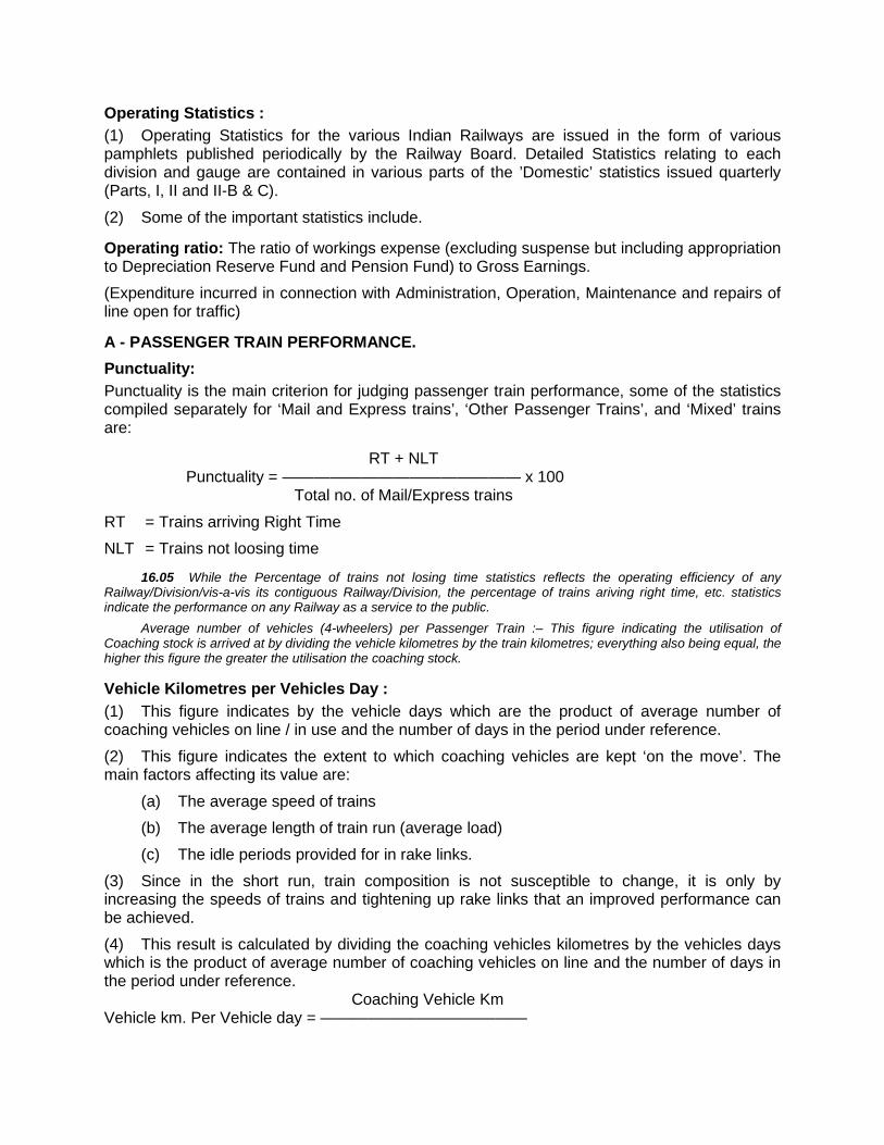
Operating Statistics : (1) Operating Statistics for the various Indian Railways are issued in the form of various pamphlets published periodically by the Railway Board. Detailed Statistics relating to each division and gauge are contained in various parts of the ’Domestic’ statistics issued quarterly (Parts, I, II and II-B & C).
(2) Some of the important statistics include.
Operating ratio: The ratio of workings expense (excluding suspense but including appropriation to Depreciation Reserve Fund and Pension Fund) to Gross Earnings. (Expenditure incurred in connection with Administration, Operation, Maintenance and repairs of line open for traffic)
A - PASSENGER TRAIN PERFORMANCE. Punctuality: Punctuality is the main criterion for judging passenger train performance, some of the statistics compiled separately for ‘Mail and Express trains’, ‘Other Passenger Trains’, and ‘Mixed’ trains are:
RT + NLT Punctuality = ——————————————— x 100 Total no. of Mail/Express trains
RT = Trains arriving Right Time NLT = Trains not loosing time
16.05 While the Percentage of trains not losing time statistics reflects the operating efficiency of any Railway/Division/vis-a-vis its contiguous Railway/Division, the percentage of trains ariving right time, etc. statistics indicate the performance on any Railway as a service to the public.
Average number of vehicles (4-wheelers) per Passenger Train :– This figure indicating the utilisation of Coaching stock is arrived at by dividing the vehicle kilometres by the train kilometres; everything also being equal, the higher this figure the greater the utilisation the coaching stock.
Vehicle Kilometres per Vehicles Day : (1) This figure indicates by the vehicle days which are the product of average number of coaching vehicles on line / in use and the number of days in the period under reference.
(2) This figure indicates the extent to which coaching vehicles are kept ‘on the move’. The main factors affecting its value are:
(a) The average speed of trains (b) The average length of train run (average load) (c) The idle periods provided for in rake links.
(3) Since in the short run, train composition is not susceptible to change, it is only by increasing the speeds of trains and tightening up rake links that an improved performance can be achieved.
(4) This result is calculated by dividing the coaching vehicles kilometres by the vehicles days which is the product of average number of coaching vehicles on line and the number of days in the period under reference. Coaching Vehicle Km Vehicle km. Per Vehicle day = —————————————
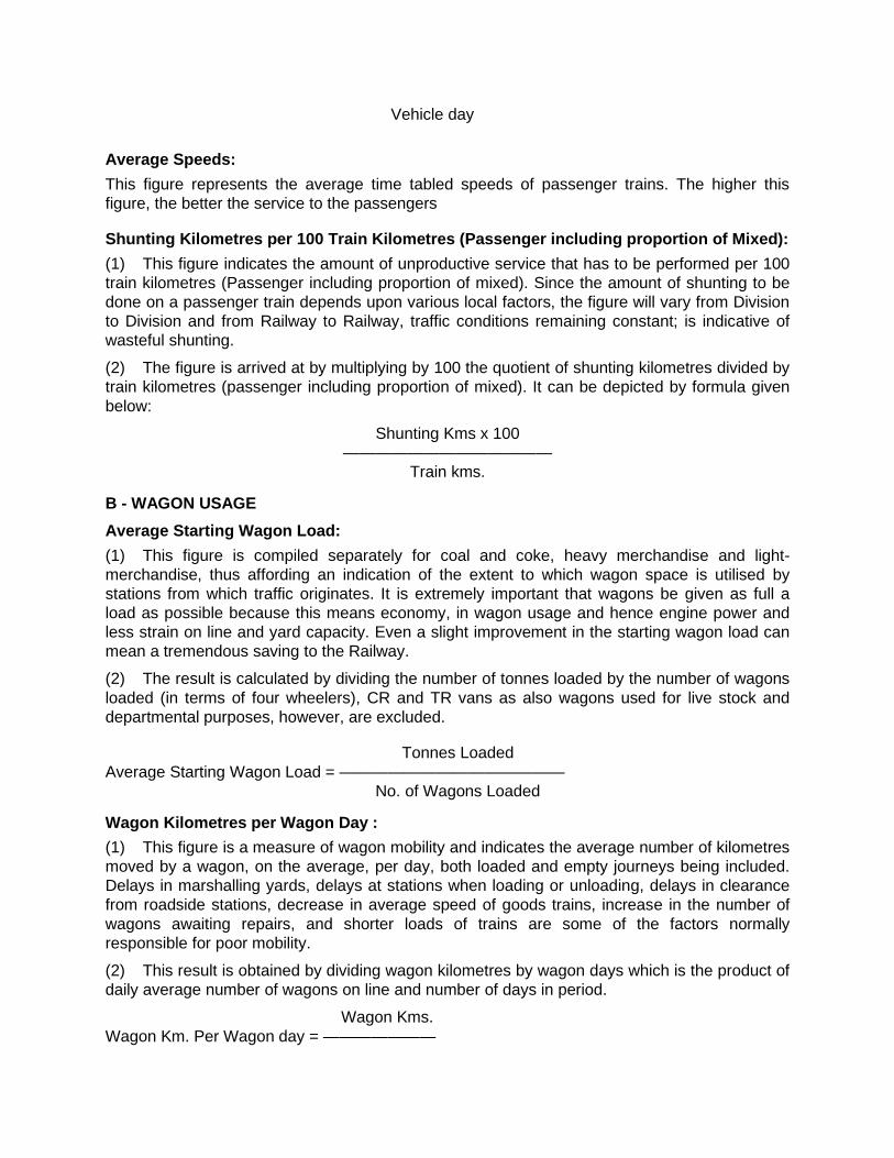
Vehicle day
Average Speeds: This figure represents the average time tabled speeds of passenger trains. The higher this figure, the better the service to the passengers
Shunting Kilometres per 100 Train Kilometres (Passenger including proportion of Mixed): (1) This figure indicates the amount of unproductive service that has to be performed per 100 train kilometres (Passenger including proportion of mixed). Since the amount of shunting to be done on a passenger train depends upon various local factors, the figure will vary from Division to Division and from Railway to Railway, traffic conditions remaining constant; is indicative of wasteful shunting.
(2) The figure is arrived at by multiplying by 100 the quotient of shunting kilometres divided by train kilometres (passenger including proportion of mixed). It can be depicted by formula given below:
Shunting Kms x 100 —————————————
Train kms.
B - WAGON USAGE
Average Starting Wagon Load: (1) This figure is compiled separately for coal and coke, heavy merchandise and light-merchandise, thus affording an indication of the extent to which wagon space is utilised by stations from which traffic originates. It is extremely important that wagons be given as full a load as possible because this means economy, in wagon usage and hence engine power and less strain on line and yard capacity. Even a slight improvement in the starting wagon load can mean a tremendous saving to the Railway.
(2) The result is calculated by dividing the number of tonnes loaded by the number of wagons loaded (in terms of four wheelers), CR and TR vans as also wagons used for live stock and departmental purposes, however, are excluded.
Tonnes Loaded Average Starting Wagon Load = —————————————— No. of Wagons Loaded
Wagon Kilometres per Wagon Day : (1) This figure is a measure of wagon mobility and indicates the average number of kilometres moved by a wagon, on the average, per day, both loaded and empty journeys being included. Delays in marshalling yards, delays at stations when loading or unloading, delays in clearance from roadside stations, decrease in average speed of goods trains, increase in the number of wagons awaiting repairs, and shorter loads of trains are some of the factors normally responsible for poor mobility.
(2) This result is obtained by dividing wagon kilometres by wagon days which is the product of daily average number of wagons on line and number of days in period.
Wagon Kms. Wagon Km. Per Wagon day = ———————
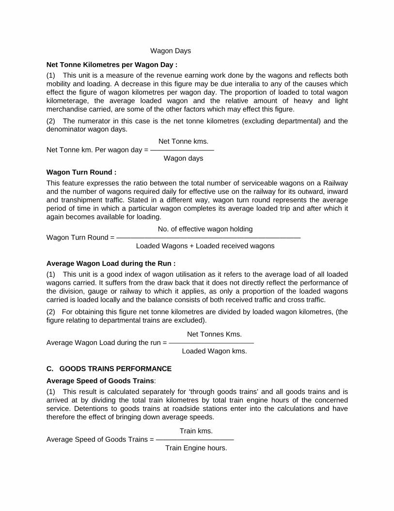
Wagon Days
Net Tonne Kilometres per Wagon Day : (1) This unit is a measure of the revenue earning work done by the wagons and reflects both mobility and loading. A decrease in this figure may be due interalia to any of the causes which effect the figure of wagon kilometres per wagon day. The proportion of loaded to total wagon kilometerage, the average loaded wagon and the relative amount of heavy and light merchandise carried, are some of the other factors which may effect this figure. (2) The numerator in this case is the net tonne kilometres (excluding departmental) and the denominator wagon days.
Net Tonne kms. Net Tonne km. Per wagon day = ————————— Wagon days
Wagon Turn Round : This feature expresses the ratio between the total number of serviceable wagons on a Railway and the number of wagons required daily for effective use on the railway for its outward, inward and transhipment traffic. Stated in a different way, wagon turn round represents the average period of time in which a particular wagon completes its average loaded trip and after which it again becomes available for loading.
No. of effective wagon holding Wagon Turn Round = —————————————————————————— Loaded Wagons + Loaded received wagons
Average Wagon Load during the Run : (1) This unit is a good index of wagon utilisation as it refers to the average load of all loaded wagons carried. It suffers from the draw back that it does not directly reflect the performance of the division, gauge or railway to which it applies, as only a proportion of the loaded wagons carried is loaded locally and the balance consists of both received traffic and cross traffic.
(2) For obtaining this figure net tonne kilometres are divided by loaded wagon kilometres, (the figure relating to departmental trains are excluded).
Net Tonnes Kms. Average Wagon Load during the run = ———————————— Loaded Wagon kms.
C. GOODS TRAINS PERFORMANCE Average Speed of Goods Trains: (1) This result is calculated separately for ‘through goods trains’ and all goods trains and is arrived at by dividing the total train kilometres by total train engine hours of the concerned service. Detentions to goods trains at roadside stations enter into the calculations and have therefore the effect of bringing down average speeds.
Train kms. Average Speed of Goods Trains = ——————————— Train Engine hours.
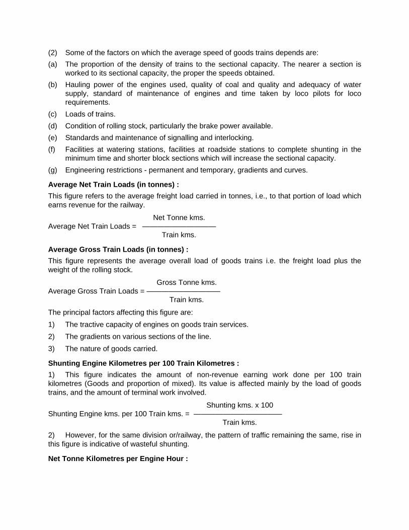
(2) Some of the factors on which the average speed of goods trains depends are: (a) The proportion of the density of trains to the sectional capacity. The nearer a section is
worked to its sectional capacity, the proper the speeds obtained. (b) Hauling power of the engines used, quality of coal and quality and adequacy of water
supply, standard of maintenance of engines and time taken by loco pilots for loco requirements.
(c) Loads of trains. (d) Condition of rolling stock, particularly the brake power available. (e) Standards and maintenance of signalling and interlocking. (f) Facilities at watering stations, facilities at roadside stations to complete shunting in the
minimum time and shorter block sections which will increase the sectional capacity. (g) Engineering restrictions - permanent and temporary, gradients and curves.
Average Net Train Loads (in tonnes) : This figure refers to the average freight load carried in tonnes, i.e., to that portion of load which earns revenue for the railway.
Net Tonne kms. Average Net Train Loads = —————————— Train kms.
Average Gross Train Loads (in tonnes) : This figure represents the average overall load of goods trains i.e. the freight load plus the weight of the rolling stock.
Gross Tonne kms. Average Gross Train Loads = —————————— Train kms.
The principal factors affecting this figure are: 1) The tractive capacity of engines on goods train services. 2) The gradients on various sections of the line. 3) The nature of goods carried.
Shunting Engine Kilometres per 100 Train Kilometres : 1) This figure indicates the amount of non-revenue earning work done per 100 train kilometres (Goods and proportion of mixed). Its value is affected mainly by the load of goods trains, and the amount of terminal work involved.
Shunting kms. x 100 Shunting Engine kms. per 100 Train kms. = ———————————— Train kms.
2) However, for the same division or/railway, the pattern of traffic remaining the same, rise in this figure is indicative of wasteful shunting.
Net Tonne Kilometres per Engine Hour :

The figure of net tonne kilometres per Engine hour is a very useful index of the efficiency of freight working on a division. Net tonne kilometres indicate the amount of revenue earning work done while engine hour measure the cost of if doing it.
Net Tonne kms. Net Tonne Kilometers per Engine Hours = ————————— Engine hours
A decrease in net tonne Kilometres per engine hour may be due to factors such as: 1) Shunting engine hours not using cut down in proportion to the decrease in traffic offering. 2) Increase in departmental, assistance required, assisting hot required and light engine
running. 3) Decreasing in the average train and or the average speed of goods train. 4) Decrease in the average starting wagon load or in the wagon loads of wagons received
from other divisions. 5) Increase in the proportion of unbalanced traffic. 6) The type of traffic carried heavy or light.
Average Detention per Wagon : 1) All wagons
2) Through loaded wagons:
Detention suffered by stock in a yard depends, interalia, on the layout of the yard and on the number of trains per day that can be despatched in various directions. Target figures have been laid down for each yard for detentions to all wagons and through loaded wagons. Such targets take into consideration the condition of work and facilities available in the yard concerned. Detentions in excess of this figure indicate inefficient yard work. Lesser detentions mean lesser cost of handling wagons in yards.
Total Detention Hours Average Detention per Wagon = ———————————————— No. of Wagons despatched
Number of Wagons Dealt with per Shunting Engine Hour : The number of wagons that a given yard can deal with per shunting hour depends, interalia, on its layout. Accordingly a target figure has been prescribed for each yard to enable the efficiency of yard work to be gauged. As shunting involves cost, the higher this result, greater the efficiency of the yard.
No, of Wagons dealt with No. of wagons dealt with per shunting engine hour = ————————————— Shunting Engine hours
Locomotive Performance
Engine Kilometres per Day per Engine in Use : This figure is compiled separately for passenger, mixed and goods train services as well as for all services refers to engines in use’. This is affected by such factors as:
1) The average run of trains.
2) The average speed of trains.
3) The engine links.
4) The location of engine shed with respect to the stations which they serve.
Engine kms. Engine kms. per day per engine in use = —————————— Engine days in use
Engine Kilometres per Day per Engine on Line : This figure is also compiled by services and for all services put together. The proportion that this figure bears to the corresponding figure of ‘engine kilometres per engine day per engine in use’ indicates the proportion of available engines ‘on line’ that were put to effective use during the period in question.
Engine kms. Engine kms. per day per engine on line = ——————————— Engine days on line
Quantity of Fuel Consumed per Engine Kilometre by Service : This figure indicates the fuel consumption in relation to engine kilometres only and does not reflect the tonnes hauled.
Quantity of Fuel Consumed Quantity of fuel consumed per engine km by service = ——————————— Engine kms. Quantity of Fuel Consumed per 1000 Gross Tonne Kilometres by Services : This figure indicates the fuel consumption in relation to the work done and is, therefore, a better index of fuel consumption than the quantity of fuel consumed per engine kilometer figure. The main factor that influences this result is the gross load of the train. It is derived by the formula given below: Quantity of Fuel Consumed Gross Tonne kms. x 1000 Traction Energy consumption per engine km and per 1000 gross tonne kms is worked out exactly in the same way, replacing 1000 litres of diesel by kwhs.
16.06. Locomotive Performance.— (i) Cubic decimetres of lubricating oil per 100 engine kilometres by services:— This figures to the consumption of
lubricating oil used on engines. In general the condition of the locomotive and the quantity of the lubricant affect this figure. This is particularly so in the case of diesel locomotives.
(ii) Cubic decimetres of lubricating oil per 1000 vehicle kilometres:— This figure refers to the consumption of lubricating oil used on vehicles and is an index of maintenance standards and oil quality.
SECTION CAPACITY 16.07. Definition.—
Section capacity means the number of trains that can be run each way over a given section of the Railway in 24 hours.
16.08. Calculation of theoretical capacity.—

(a) Scott's Formula :—
for Double line sections.
and for Single line sections. Where—N represents the number of trains each way in 24 hours, 24x60 represents the number of minutes in a
day. R — represents the running time of a goods train in minutes over the ruling section (i.e. the section
over which the running time is the longest). 5 — represents the time in minutes allowed for 'block working'. — represents the efficiency factor( to cater for delays due to human element and for the effects of
irregular distribution of trains over the day). (b) Indian Railways Formula for Goods trains:— S (Number of Goods trains both way) Where—'Ld' and 'Lu' represent the running time in minutes of the slowest Up and Down goods trains respectively
over the ruling section. 't' represents the station time which is assumed to be 3 minutes. 'p' represents the total running time in minutes of the existing Up and Down coaching trains over the ruling
section. represents the efficiency factor. (c) South Eastern Railway Formula:— (i) Single Line:— N(Number of trains each way): Where—'A'—represents the combined running time in minutes of Up and Down goods trains over the ruling
section (which may be different for Up and Down trains). 'B'— represents the time in minutes allowed for "block working". This is assumed to be: 5 minutes at stations provided with tokenless block instruments. minutes on the Single line at interlocked stations. 10 minutes on the single line of non-interlocked stations. 'C'— represents the 'Stop and Start' allowance. This is taken as 5 minutes of which 2 minutes are for
deceleration and 3 minutes for acceleration —represent the efficiency factor.
(ii) Double Line:— N(Number of trains each way) =
Where— 'A'— represents the running time in minutes of a goods train over the ruling section in the Up or Down direction as the case may be.
'B'— represents the time in minutes allowed for 'block working' which is taken as 5 minutes in all cases.
'C'— represents the 'Stop and Start' allowance which is the same as on single line. Note:— No 'stop and start' allowance need be taken into account when one of the stations of the ruling
section is a watering or notice or terminal or starting station.
16.09. Limitations of the formula method of calculation of section capacity.— (a) It does not take into account the total length of the section for which the section capacity has to be
worked out. It is generally seen that the longer the section, the lesser usually is its section capacity, other conditions remaining equal.
(b) It does not take into account the spacing of the block stations. The larger the number of long block section, the less will be the section capacity.
(c) It is assumed that all trains will run at a uniform speed. (d) It assumes as a rule that on the single line, when a train arrives at a block station, another train will be
ready to leave in the opposite direction. In actual practice, this is not always so. (e) It does not take into consideration the following factors which effect the section capacity:—
(i) Number and length of crossing loops, (ii) The number of watering and notice station,

(iii) Whether stations are interlocked or non-interlocked and if interlocked, the standard of interlocking, (iv) The number of reception lines at the terminal or junction station; (v) Whether simultaneous reception and despatch facilities are provided at stations.
16.10. Determining the section capacity by means of a "Master Chart".— The calculation of the section capacity by means of any formula gives only a rough estimate of the number of
trains that can be accommodated in a given section in 24 hours. It is, therefore, best to determine the section capacity by actually plotting the paths of trains on a Master Chart (see para 2.08).In this process the advertised paths of all coaching trains should be plotted first and the goods train paths then interpolated so asto make the maximum use of the section capacity. While doing so the facilities provided at the different block stations as also the terminal facilities should be taken into account.
16.11. Various methods of improving the section capacity.— The following are some of the methods for improving the capacity of a Section:— (a) Having staff properly trained in their duties. (b) Intelligent scheduling of goods trains. (c) Close and constant supervision. (d) Keeping a watch on engineering restrictions which should be imposed for the minimum possible period. (e) Reduction of stopping time at stations by speeding up loading and unloading, shunting and marshalling
of trains etc. (f) Efficient train control. (g) Running of more through trains with loads for the furthest point, so that such trains may be passed
through intermediate yards without any further handling. (h) Reducing the lengths or long block sections by providing additional crossing stations on single line and
'C' class stations or Intermediate Block Posts on double line. (i) Improving facilities at terminal yards. (j) Improvement at road-side stations, such as—
(i) facilities for simultaneous reception of trains from opposite directions on single line sections, (ii) facilities for simultaneous reception and despatch of trains in the same direction, for single and
double line section. (iii) Provision of independent shunting facilities so that the use of the main or running lines for
shunting purposes may be avoided and shunting movements isolated from trains movements, (iv) Provision of longer turn-outs. High speed turnouts of 1 in 16 or longer will increase the speed of
trains through stations and thereby reduce the running time, and. (v) Providing additional crossing loops at strategic stations.
(k) Improvements in signalling & interlocking, such as— (i) Provision of standard III interlocking, (ii) Provision of Block Instruments at all block stations. On the single line, the use of tokenless Block
Instruments considerably reduces the 'block working' time. (iii) Provision of warners where necessary, (iv) Provision of Manually operated Multiple Aspect signals or Modified Lower quarant signals to
enable Loco Pilots to maintain higher average speeds, (v) Introduction of Automatic Block system of working on double line sections, and (vi) Provision of Power installations with Electric Control Panels and Route Relay interlocking
to help in reducing the time taken in setting and locking points and in taking off' signals. (l) Centralised Traffic Control (CTC) can considerably increase the section capacity on a single line section.
CTC combines Automatic Block signalling and interlocking at station, Protection and direction of trains and a train despatching system into an integrated operating tool which can be used by one central authority from a Cntralised Control office. The actual operation of points and signals on the section covered by CTC is remotely controlled from a Centralised control office, by means of switches arranged on an illuminated control panel, which gives the whole lay-out of the section controlled as well as the stations on the section. This panel gives the Controller a constant view of the trains on his section and their movements as these are indicated on the Panel by means of strip lights.
16.12. Through-put.—

While section capacity represents the number of trains that can be passed over a particulars length of line in 24 hours, throughput represents the actual volumes of traffic moved over that length of line in 24 hours.
Any increase in section capacity naturally enables a higher throughput to be achieved. It can, however, be increased quite independently of section capacity by running longer trains or by using wagons of higher capacity.
CHAPTER – XVII
FREIGHT OPERATIONS INFORMATION SYSTEM (FOIS) I. INTRODUCTION :
In keeping with global trend, there has been a long outstanding demand of the industry & trade for transparency in sharing of information to give the customers an up-to date business like environment. Railways in this millennium have decided not only to perform the traditional tasks of carrying passengers and goods efficiently, but also to change the mindset of working as a closed system. The great concern to improve on its market share has prompted Railways to have a multi pronged approach to its freight policy.
Continuous Cargo Visibility has always been a critical component of the Supply Chain Distribution Management System.
To achieve this, out of the stated multi pronged new freight policy, a lot of emphasis has been laid on establishing a computerized FREIGHT OPERATIONS INFORMATIONS SYSTEMS (FOIS). The system indigenously developed is fully functional in the B.G. system of Indian Railways being the first of its kind in South East Asia.
(1) Freight Operations Information Systems Mission – FOIS : To give a total transparent system with continuous Cargo visibility and an up-to date
business environment to the Customers with instant access to information regarding their consignments in transit for just in time inventory.
FOIS is an On-line Real-Time system based on absolute current State of Art Technology and efficient Communication system.
A management tool to optimize utilization of costly assets and resources by improving the distribution of Rakes/Wagons & Locos, and also scheduling and Routing Traffic in an optimized cost effective manner.
Provides Continuous Cargo Visibility and enables the Freight customers to have instant access to information regarding the current status of their consignments in transit for just in time inventory.
(2) Strategic Advantages Derived From The FOIS System : Extension of the current business practice from bulk movement of freight traffic in
train load formations to piecemeal traffic by clubbing and moving together similar type of stock in ‘Hub & Spoke’ arrangement to increase its market share by re diverting high profit yielding piecemeal cargo from road to rail.
Global tracking of consignments in real time Rakes or individual wagons.
The insight and pipeline of consignments thus captured on the entire BG network is made available for timely planning and just in time inventory management on a time span cargo movement which may extend to 2 to 5 days from origin to destination...
Facilitate acceptance (customer’s Orders), billing and cash accountal of freight traffic from identified nodal customer centers which may not necessarily be the handling terminals.
Extension of such facilities to customer’s premises and introduction of e-commerce, benefitting both IR and the trade & industry, by eliminating manual transactions which necessarily add to the burden of logistics management.
Providing requisite Foundation for a total logistics system furnishing real time information of the chain of physical distribution, an essential element in reducing inventory costs.
(3) Scope of FOIS Systems : Presently two subsystems of FOIS are already in use after extensive field trials and
validation.
RMS TMS.
a) Rake Management Systems - RMS – Rake based consignment tracking and pipeline – Train/Rake operation – Stock Holding in terms of summary of wagon types – Train and stock Interchange – Terminal Handling Performance. – Loco holding, outage and power on-line – Reporting to take care of Train/Load on summary basis – Invoice based consignment tracking – Wagon wise Stock Holding – Reporting of consist Wagon wise – Invoice based loading originating tonnage and revenues. – Wagon wise Interchange – Statement of missing Wagons/wrongly delivered.
b) Terminal Management Systems TMS – Computerized booking and delivery of consignment – Station Accounting – RR generation/Transmission – Improved Customer Interface
(4) Crew Management has been developed & is under implementation. Control charting of trains currently being done manually will also be integrated with FOIS.
The above two sub systems have been fully developed and tested and are ready for implementation.
(5) FOIS Design Architecture :
FOIS is designed and developed in conformity with the state of art technology which is scaleable, maintainable, with open systems architecture and is based on the Indian Railways organizational hierarchy, its present and future requirements. Based on the business processes that are being adopted, the business model developed in the FOIS - IT architecture is based on the assumptions:
The current business practice of bulk movement in rake formation is the accepted norm for future also. Around 80 to 85% of traffic already moves in Rake, majority of which comprises similar type of rolling stock.
Global perception is more important, with respect to tracking of consignment and Rakes rather than of individual wagon, locomotive and train. The insight and pipeline of consignment and rakes should be seamlessly available. Railways would like to share information on booking and movement of consignments with individual customers also.
The operations and data capturing, will remain control centric for train, rake, locomotive and stock management and terminal centric for booking, loading, unloading, and delivery. Taking into account the spatial distribution of activities, which need to be captured.
Integrity of Operation and Commercial data is an absolute necessity. RMS and TMS application are conceptualized, to provide the integration with the other subsystems as and when these are developed.
FOIS ultimately expects an event driven integrated reporting in real time, beginning with the tendering of Forwarding note to loading and generation of invoice, followed by load consists, train ordering and departure/arrival of load destination, unloading and delivery. The data thus captured is used for generating associated managerial reports on-line information (MIS). The data will also be used for expanding the scope to cover other functional areas of the remaining modules and can easily integrate with RMS/TMS using appropriate middle ware Technology for sharing information locally. Therefore, a strategic approach has been adopted to computerize IR operations by implementing RMS/TMS systems in a phased manner using modular approach.
(6) FOIS System Architecture : Key components of the System Architecture–
Intelligent terminals will be placed at the field locations to capture the data from the place of activity namely control offices, yards, goods sheds, C & W depot, Loco sheds etc., and connected to the identified Application Server through reliable communication links for transaction processing.
Application servers are centrally placed at CRIS office. These servers are connected to the Zonal Hd. Qrs., Divisional Control Offices, yards, interchange points, and good sheds etc., with a reliable and integrated network. The servers are networked amongst themselves and to the central server for global level transactions.
The central Server provides management Reports at board level and acts as repository of all the global data and also provides global services to maintain referential integrity of the databases including master files.]
(7) Network Topology : In view of the Centralized application architecture, a star based network topology has been
designed. However, in order to provide alternate paths ( to meet the up time requirement of
99.9%) from reporting locations, a mesh has been created with in each zone so that every location has at least two paths to reach CRIS. Each zonal HQ has been connected to central location (CRIS) on high bandwidth pipes. In addition to this, another zonal location has been connected to CRIS using high capacity link. Hence these two high bandwidth links shall cater to the entire transaction load generated by a zone. Railway telecommunication network, leased lines, DOT, VSAT Technology as communication media has been provided for reliable and fast means of data transfer.
(8) Phased Implementation - Approach : i) In case implementation is attempted for events of all the functions to be reported in
real time, concurrently from day one, then the reporting sites to be readied, the associated communication requirements and the number of staff to be trained assume enormous proportions. To ensure that the implementation effort is within manageable limits, one way is to take up, one by one, only limited portions of geographical territory for computerization at any given time. On the other hand, if the territory is small, instances of repetitive data entry increase; resulting in redundant expenditure on reporting infrastructure that will have no use as the territory expands. At the same time, if the MIS requirements are to be met in totality, the territorial expansion must ensure that a function is implemented on end to end basis as quickly as possible, otherwise only a truncated picture will be available to various levels of users and the benefits of computerization remain postponed till the entire Indian Railways have been covered.
ii) The FOIS comprises several subsets of functions each meeting a distinct set of objectives. Certain FOIS subsets presuppose others to be operational before they can be implemented. Loco and wagon based functions presuppose load/train/rake functions to be operational. Goods shed functions expect wagon-based functions to be in place before they can be implemented. With these assumptions the FOIS / RMS systems have been designed in a modular structure which could be taken up for implementation in a phased manner.
For example :–
Phase I (PI module)
Provides facility for reporting load summary with only wagon type and number of units. Phase II (PII module) Provides facility for reporting the consists with details of wagon numbers. Phase III (PIII module) TMS provides facility for good shed functions and generation of RR.
(9) Implementation Strategy : Realizing that functional phasing is the only way to keep the implementation effort within
manageable limit and yet remain meaningful at every stage, FOIS software has been developed as above in three modules such that functions of global utility are implemented faster from fewer sites. It also takes into account that the beginning is made from the control offices where computer awareness is of a high order. The implementation can grow on need basis driven by the Railways themselves.

For timely completion of field implementation, the total involvement and commitment of Railways is very essential from day one. Therefore, COM’s of Railways have been given the total responsibility and charge of implementation of FOIS, to provide for the following:
– Railways to get staff identified and train them to work on PCs – Railways to prepare the sites for installation of hardware including provision of
electrical and civil facilities. – Maintenance of channels & data com equipment has been given to CSR of the
zones. – CRIS would provide specifications for the same. For facilitating this process the organization of CAO/FOIS has been strengthened and
made responsible for coordination, implementation on All - India-basis. The software implementation and maintenance shall remain the responsibility of CRIS. Pre
implementation training of the required number of staff (consisting of Core Implementers and Telecom Inspectors from each of the divisions), in RMS - phase 1 has been completed by CRIS for all the zonal railways and their divisions. However, Railways will be required to make arrangements through the Zonal Training Schools to train the remaining staff of the concerned categories.
(10) Benefits : i) Continuous Cargo Visibility.
Rake based consignment tracking and pipeline. Invoice based loading - Originating Tonnage & Revenue. Information on trains on the run, the ETA at next point and the work to be performed. Vehicle guidance of all trains on run. Daily report describing the performance of all through trains operated in a controlled
territory for the day. Actual/Estimated arrival and departure particulars for a particular train at any or all the
reporting points Yard or on the run delay information. Train & stock Interchange. Wagon wise Interchange.
ii) Optimised Asset Utilisation. Improved Locomotive Utilization by reduction in Light Engine running and reduced in
effectives. Statement of missing or wrongly delivered wagons and finally its elimination. Elimination of unconnected wagons. Increased Availability of Repair Capacity . Stock Holding. Loco Holding.
iii) Increased Revenue.
Savings in wagon fleet would result in corresponding saving in the recurring cost of maintenance of wagons.
Reduced Locomotive power and Rolling Stock Maintenance Cost. Savings in Time & Cost of handling in yards, cost of empty haulage. Ensures optimal crew management and monitors statutory limits for running duty and
overtime payments. Reduction in staff cost per unit of transportation due to improved productivity of the
available manpower.
iv) Improved Productivity per/man Year.
Accuracy of reporting -In the Head &Hand system collecting data on telephones results in sizeable error levels, which need to be reconciled &corrected periodically FOIS data with built in validation systems has Zero errors.
Drudgery of manual processes like maintenance of registers etc. is eliminated. Particulars of crew on train with hours spent on duty. Re-deployment of major portion of staff involved in wagon tracing and accounts
checking activities. Improved Customer service and satisfaction. Facilitation of acceptance (customer’s Orders), billing and cash accountals from
identified. nodal customer services centers and not necessarily at the handling terminals.
E-Commerce will facilitate the customers to operate from their premises for the above requirements of billing and cash accountal and thus reduce’ the burden of logistics management, and in addition drastically bring down the inventory costs. in the entire chain of physical distribution system.
Quick settlement of Claims. Just in Time Inventory.
v) Goods shed Operations. Arrival particulars of Wagons. Placement and Release Particulars. Information on demands registered and pending Indents. Preparation of Railway Receipts. Information on Demurrage and Wharfage. Loading Particulars. Goods Shed Earning. Information on delayed wagons and Wagons awaiting Placement/Release.
II. Application/Software : RMS module has been developed with GUI interface which is highly interactive, very user
friendly. The software is totally menu driven and navigation is through logically linked tasks. The application and front end forms for reporting events has been developed in Visual Basic and
resides in the client machine located at the reporting location. Data is stored in the central server locate at CRIS.
(1) General Concepts A Rake is a very generalized term, which refers to any set of wagons moving together and
has been identified in the system as rake. Wagons can be attached/detached to a Rake. A Rake is identified by a uniquely defined ID number, which remains unchanged through various Load/Empty cycles & movements. A Rake, when given a destination, is known as a Load. A Load, when given a loco, is known as a Train. Thus, there can be no Train without a Load & no Load without a Rake (except where a load is mixed and is not identified in the system as a rake). With a clear understanding of these terms, you enter data through clearly defined “tasks”.
The RMS software has two identifiable cycles–
Train cycle: It starts the moment a load is identified as a train and the following tasks are used for online reporting:– Train Ordering: TO/Call between two crew-changing points. Train Departure: reports departure. Train Arrival: reports arrival. Train Run-through: reports through runs. Train rerouting.
Yard Cycle: It starts as soon as a terminating load a terminating load arrives at its destination or a train is cancelled. (i.e. the load is sent to load planning) and the following tasks are used for various online reporting:–
Load Related Tasks. Inward Number Taking: destination validates consist. Load Planning: initial activity, following rake assignment. Load Stabling: run/ordering termination is reported through this. Load Diversion/Termination/Extension: reports changes in planned load destinations Load Yarding: takes a load-to-load planning screen, but will not reflect in stabled position. Vehicle Guidance Related Tasks Consist Reporting: originating station reports summary details. (Guidance is also called as
Consist). Rake Related Tasks Rake Formation Details: form/modify rake consist. Movement order: facility to give advance assignments to rake. Rake Placement/Release: reporting Load/Empty cycle. Rake Dissipation: for generating piecemeal out of rake or for doing away with a
rake which has no wagons left. After a load is made ready, loco attached and train ordered. Again the train cycle begins. Loco Related Tasks
Attachment/Detachment of Locos. Loco Reporting: reporting shed activities of loco. Light Engine: reports light engine movements. Given above is the list of tasks that are to be performed on real-time basis i.e. as soon as
the event takes place. Demand:– This function is to be reported at station where the party/consignor registers his
Demand for supply of Rake/Piecemeal wagon for loading of goods. The following tasks are used for reporting this activity:
New demand Modify demand Add/delete demand Fulfilling demand Forefeiture/Withdrawl of demand
Interchange forecast:– In the system as the trains are planned, a pipeline is generated from Originating Station to destination and the position can be viewed at any point in its route. Forecast can be reported by selecting trains from the pipeline shown at the interchange point. The task used is interchange forecast reporting task. Given below is a summarized list of entity related tasks:– Rake Related Tasks. Rake Formation Details: form/modify rake consist. Movement order : facility to give advance assignments to rake. Rake Placement/Release: reporting Load/Empty cycle. Rake Merging: moving wagons from one to another rake. Rake Dissipation: for generating piecemeal out of rake or for doing away with a rake which
has no wagons left. Load Related Tasks Load Planning: initial activity, following rake assignment. Load Stabling: run/ordering termination is reported through this. Inward Number Taking: destination validates consist. Load Diversion/Termination/Extension: reports changes in planned load destinations. Load Yarding: similar to stabling, but will not reflect in stabled position. Cut-in by Arrival/Departure: was useful when there were non-computerized territories also. Train Related Tasks. Train Ordering: TO/Call between two crew-changing points. Train Departure: reports departure. Train Arrival: reports arrival. Train Run-through: reports through runs. Loco Related Tasks. Attachment/Detachment of Loco: reporting loco failure on run. Loco Reporting: reporting shed activities of loco.
Light Engine: reports light engine movements. Roadside/Piecemeal Wagons Related Tasks. Attachment/Detachment of Wagons en route: load & consist are automatically modified in
this task. Piecemeal Placement/Release: reports piecemeal activities. Piecemeal Sick/Fit Reporting: reports sick/fit. Clearance of Detached Wagons: clears detached wagons. Demand: reports indents for a good shed type of loading. Vehicle Guidance Related Tasks. Consist Reporting: originating station reports summary details. (Guidance is also called as
Consist) Detentions Related Tasks. Train Detention en route: reports unscheduled stoppages. Pre departure Detentions: reports detentions suffered by loads/trains at yards/stations. Other Tasks Interchange Forecast: reports daily targets, which should be frozen by noon. BPC & Crew Details: reports these details. Modify ETA: changes ETA for a train. Re-routing: changes path of a train while on run. As you realize, these are all routine tasks. Besides this the divisions have to carry out
some systemic tasks which help in generating MIS reports (name for reports which are not generated on online data) and some time specific reports.
TSS (Terminal Sub-Systems)
TSS (Terminal Sub-Systems) is a generic word used in FOIS to refer to PCs, Printers & UPS. This PC is used for entering (and retrieving) data. Following are the important guidelines for users.
Power Connection: Please make sure that a data entry PC or a “Reporting Terminal” is always kept in the ‘ON’ condition. The power lead required is met through a 5A dedicated socket. Please make sure that all the different PCs & Printers have a separate 5A socket. Don’t use multi-plug adapters. Also check up with the Electrical personnel as to whether your sockets have Earthing arrangement is absence of the same, your PC may get damaged. The earthing to neutral voltage not be more than 2-3V. It is also better to have a MCS attached to main power supply point/board. Your AC connection & PC supply must be on different phases. This saves from fluctuations. Your PC is not connected to the mains directly. Instead, the Power supply is routed through a UPS (Uninterrupted Power Supply). Please ensure that this is always done. This saves your PC

from power fluctuations as well as gives a power from batteries for about 20 minutes, in case of power failure. There should be a power back up, either through AT (OHE) or through Diesel Generator. The change over switch should be close to you (care to be taken that earthing is proper). It is a healthy practice to ensure that various power chords feeding your PC, Printer etc. are neatly tied together, rather than strewn all over. If you locate your UPS very close to your monitor, the display will wobble. Please ensure that UPS & Monitor are separated by at least 24 inches. When the PC is ON don’t try to change any connection. This applies equally to not only power connections, but also to various chords connecting different equipments, LAN Cables etc. When turning the PC ON (if need arises) follow this sequence Mains→ UPS → Monitor → Printer → CPU. The reverse is followed when switching off.
Environment: If an AC is provided, make sure that it is working properly. AC should be on a phase different from the one feeding your PC. The room should be kept as clean as possible. Dust, smoke particles & moisture cause maximum damage to your PC. So, don’t allow any smoking, eating or drinking at the workstation. Never clean your PC using an organic solvent (such as Colin). Always use a soft, damp, dirt-free cloth. When the PC is not in use, keep it covered with ‘Dust Covers’. Make sure that the Keyboard has been supplied with a “Skin” - a fight fitting plastic covering for Keyboard, which does not stop usage. Your PC should not face direct sunlight. Nor should it be placed so close to window where rains can affect it. CPU (Central Processing Unit) & Monitor should not be placed in such a way that the fans/outlets at the rear of these equipment get blocked by walls/other objects.
Virus Protection : Virus come to your PC through pirated softwares of games & utilities that you load. Yet another source is downloading of flies from internet. Once a virus is on a single PC of a network, it spreads on its own to the entire network. Therefore, you must not load plated software of download walpapers etc from internet. Make sure that Virus protection files are loaded on your PC. Please enable virus scans on data transfers, floppy drive files & CD files. Please schedule your Virus software to run every day at a fixed time. To do this, open “My Computer” Double Click on “Scheduled Tasks” Folder Double Click on “Add Schedule Task”. This will activate “Schedule Task Wizard”. Click next & select the name of the Anti-Virus program given to you. Keep following the simple steps to schedule your Anti-Virus to run daily. Once scheduling is done, your PC will automatically run the program everyday at a given time, as specified by you.

There is an arrangement whereby we get updated Anti-Virus flies every 3-months. These CDs are available at your Divisional HQ through OCC. You must update your anti-virus programs to enable it to take care of new viruses. There are tell tale signs of virus on your PC. Please be on lookout for these signs, which are listed below:
• Unexplained disk drive activity light or floppy drive light.
• Reduction in RAM Availability.
• “File Copied” message appears without copying anything. • Failure of a memory resident program to operate properly.
• System behaves slowly or in a chaotic, manner.
• Bad clusters on the disk. • Increased number of files on disk.
• Increase in size of executable programs.
• Change in file’s date and time stamp, without modification. • Program running slower; taking more time.
• Program/Data file corruption/disappearance .
Internet Connections: There should be no Internet connection on your PC. This restriction is applicable to everything related with Internet -email, chat, surfing etc.
Further, your PC should not have access to another network - such as Railnet. This makes the network prone to hackers & Viruses. Since the information available on FOIS is confidential, therefore hackers have to be prevented from entering our network. This is the reason for having separate LAN and Routers for FOIS.
Important Files (Software): You work with Windows 98 (Second Edition). A quick restore CD is also available with you, along with Anti-Virus software & RMS. Also windows back up files are normally available in the cab folder. Please ensure that none of the following files are tampered.
COMMAND.COM IO.SYS MSDOS.SYS Similarly, ensure that RMS file - which resides in Program Folder of your Hard Disk - is never tampered.
Datacom Equipment & Connectivity : In this chapter, we shall deal with some pertinent issues regarding Connectivity. Your PC
is connected not only to adjacent PC but also to each & every PC on FOIS. (Each PC on the network, therefore, has a unique identification or Address - known as IP address). This has been achieved by using leased lines, ISDN connections & VSATs for data transfer. This data transfer rate is higher than PRS system. Also, unlike PRS terminal, your terminal is a full-fledged independent machine. The interface is Windows, unlike text type processing in PRS.

Your PC is connected to FOIS through a Router, which is a junction between LAN (Local Area Network - connecting all PCs in your premises) & WAN (Wide Area Network - a bigger network which connects all PCs on the system). A Router does this mostly through Channels - which are connected to it using Modems (A channel has two ends. One end is connected to Router through a Modem in your premises The other end is again connected through a Modem to the equipment of Channel Provider, at his premises. This can be S&T or BSNL or any other telephone company). Finally, a Router will have connections with your LAN (through Hub/Switch), Modems (one for each channel), ISDN Connections (directly to Router) & VSAT (directly to Router). Ail this equipment is collectively referred to as Datacom Equipment.
Routers: A Router routes the data that you want to send/receive. It is an intelligent device, unlike
Hubs & Modems. The data is sent & received in data packets. A LAN works below a Router. Data sharing between various PCs connected on a LAN is automatic & Router has no role. It is only when the data requires being sent/accessed from a remote PC/Server - i.e. accessing WAN terminals - that Router’s role assumes significance. Its IP Number specifies each Router - like all intelligent devices on a network- This IP Number actually identifies its Ethernet port. A Router may have WAN, LAN, & VOICE port. A port is actually a point where a channel (through Modem) or LAN or ISDN or VSAT connection can connect to Router. On Railways, we have two makes of Routers supplied - Cisco & Motorola.
Router has to remain “ON” at all times. Also ensure that the power feed is having a proper earthing arrangement. The earthing
norm of 2-3V to be maintained. Power supply to Router should be routed through a UPS. Never operate a Router without
a UPS. Also, wide fluctuations in input voltage can damage the Router. There should be a power back up, in addition to Normal Power Supply. This could be
through Auxiliary Transformers (AT) in OHE area or through a Diesel Generator Set (DG Set). The change over switch should be accessible easily.
The Router should be kept in a dust, smoke & moisture free environment. Please use Racks provided to house the Router. Since Router is expensive & sensitive equipment - which does not require daily maintenance - therefore, it is better to leave the equipment undisturbed.
Essentially provide Air-conditioning for routers. A Router, along with Modems should be placed at a location where it is always accessible
to the user. You actually don’t have to do anything with Router, but just by looking at various displays & reporting the same, you will be participating in troubleshooting. For this reason, you must have Router under your control and not locate it in Test Room.
Some of the Routers have a specialized Port for ISDN. (Not all Routers have it). Unlike all other terminating leads on a Router, ISDN connection gives a higher voltage (≈ 100 V). Therefore, if ISDN lead is connected to any other port, that port will burn down. Be careful.
Firm connections of all chords to Router are to be ensured. Nothing should be placed on Router. Router should not be dragged.
Modems: Modem (Modulator/Demodulator) is the device through which a channel connects to your
Router (& through it, to your PCs on LAN). It is a very sturdy & maintenance free device. It also
requires a dust & smoke free environment. It is normally housed in a Rack along with Router. A lot of information is available on its front display.
We have two types of Modems on Railway - G703 (at service provider’s premises) & V35 (at our premises, with Router).
When the channel connected to a Modem is working properly, you will find both “RD” & “TD” glowing & blinking. If it is not so, then there is some problem with channel.
As always, you have to ensure that Modem is always kept “ON”. Also ensure that the power feed is having a proper earthing arrangement. Never use a metallic brush to clean the surface. Organic solvents are also not permitted. Since one end of a channel always resides at the channel provider’s premises, therefore
you must also know some simple checks to analyse the channel position. Some of these steps you take in tandem with the operator at other end, who is observing his Modem. These steps, which are invoked when the channel is down (i.e. “line protocol” is down), are
Make “LL” (Local Loop) switch “ON”. This gives the status of the Modem & Router. If “TD”, “RD” blinks, then local equipment is OK. If it doesn’t, then the problem is with Modem/Router.
In the next step, we make “RL” (Remote Loop) switch “ON”. This checks the local lead condition between Modems. However, to get the response of this action, there should be an observer at the other end. If everything is OK, then at the remote end, “RD” & “TD” will blink. Similarly, remote end can also give a “RL”, in which you will get blinking “RD” & “TD” on your Modem, if everything is OK between two Modems.
If both “RL” & “LL” give OK results, then the problem is beyond the Modem at service provider’s end. You have to take a docket number after registering the fault with service provider (i.e. S&T or BSNL).
If Modem at the other end is not able to execute “LL” successfully then Modem at that end is defective/improperly connected.
If all loops show positive result & line protocol is still down, try initialising Modem by switching it off & then on.
If everything gives OK & data is still not able to pass through then there may be problem with Router. Inform Divisional Control.
Always ensure that all leads are firmly connected. However, no lead should be checked with power at “ON” position.
Channels: A Channel refers to a leased line dedicated channel for data transmission. You have two
types of channels - Railway & BSNL. However, as a user you don’t see a difference. Though technically a Channel refers to a leased line channel, in this section we will also cover ISDN & VSAT in it. A channel connects your system through Modems & Routers. In addition to leased channels, you also have ISDN connections & VSAT (Very Small Aperture Terminal) connections to enhance your Connectivity. Connectivity refers to the immediate links that your PCs on LAN (at a Node) has with neighbouring nodes. It has been planned that ideally each node has a minimum of two links, each giving a different route to your data - so that data transmission can continue even if one, fink is down. This is technically known as Route Diversity.
Unless a Channel is available, data will not transmit. If your node is connected through two channels & one of them is down, you will not know the difference. However, with one channel down, you are in a very precarious position as data entry will stop as soon as the second channel even flickers. It is therefore important for you to take active interest in knowing the state

of a channel. This can be done through “pinging”. Pinging is the name given to sending & receiving a test data packet from one computer to another remote PCI Router or to any intelligent device. However, you can ping only if you know the (IP) address to remote PC or Router. These are listed in Annexure I. You can ping by following command.
Start Run Ping [IP Address of Remote Router] OK Only an entry like “Request Timed Out” or “ttl expired in transit” indicates failure. VSAT connections can also be pinged. Some other important points for VSATs are as
follows. The data is transferred directly to CRIS SERVER. This is a sturdy system, which once
stabilized, works trouble-freely. The earthing resistance should be less than 1 ohm. Neutral to earth leakage should be 2V. It should never work without UPS & CVT. Air-conditioning is a must. The antennae base structure should be firmly fixed and clamped. At the time of installation,
it should be ensured that ODU is having its protective laminated cover (to protect it from water and dust) OR at least the rubber cap of Radio Frequency (RF) unit is in place.
There should be one ladder for antennae access. There should be a routine of checking the equipments. It should be ensured that rubber
cap of RF unit is in place and the cord going to indoor unit is firmly in place. Similarly, ISDN connections can directly pass the data, bypassing Router (or more
accurately, bypassing Router at that node but connecting to a remote Router). Only in such ISDN connections where Router are not provided, you will not know the status of channel through pinging.
Please ensure that ISDN connections are always with power ‘ON’. Also ensure that ISDN connections are not STD barred.
Though it is not possible for you to know as through which particular channel your PC is transferring data, the same is always very accurately known to Router. Depending on the channel availability, if keeps on defining the route dynamically. Thus, if ISDN is available & all other channels are down; Router shall use ISDN to transmit data. (ISDN connection can also be assigned a higher priority by configuring the Router). As soon as any of the other channels becomes stable for a predefined time interval, it again resumes data transfer through that channel, shutting off ISDN. This is what is known as programming of Router.
ISDN is a secondary channel and since its usage is very expensive so it should be used very judiciously.
LAN : LAN connects all your PCs available at a location. However, it need not be confined to a
building, it can be extended to a few kelometers (up to 6 km) also. Such extension is normally through a LAN Extender. Even if PCs are connected through LAN Extender, there is no role of Router in shunting of data among these PCs.
LAN is achieved by using the network card available on your PC. An identical work group is to be defined on each PC on the LAN so that they are “visible” to all other PCs.

While defining Network Properties on your PC, make sure that only one Gateway (i.e. IP address of your Router) is defined. Disable DNS.
A PC may be visible on a LAN. However, other PCs can use only those flies, folders, drives etc of that PC which the owner of that PC has decided to “Share”. To share a file, single click on the file name, followed by right click. Select “Properties”, followed by “Sharing” tab. Share to the extent you desire. You can decide to allow other users to even write on your Hard disk. However, you cannot differentiate between your co-users on LAN & other users on WAN!
You can also share some scarce resources - such as Printers - through this scheme. LAN wiring consists of two parts - first, a CAT5 structured cabling from Router/Hub to I/O
box (a 3” x 3” x 2” white box) & second a flexible cable from I/O box to your PC. Please ensure that at PCs at a locate are connected on LAN.
Ensure that CAT5 cable is mounted on wall properly & is not hanging loosely. Ensure that flexible chord is not stretched. Also ensure that I/O box is located close to your
PC. Hubs/Switches are devices for connecting additional PCs to Router’s LAN port. Please
ensure that these are properly mounted on wall.
Uptime: It refers to the time when a node or a channel remains available for data entry. As
explained earlier, it is of utmost importance to know the status of availability of equipment for user.
You should keep records both of Channel Uptime & Node Uptime. It is easier to maintain record of Node uptime. Simply record in a register the daily position of availability of a node.
(Along with the reasons of failure for doing analysis.) It is very essential to keep check on the health of secondary channel when primary channel is up.
Give summary position of the entire day to your Zonal OCC at odd hours. For finding the channel uptime, you have to schedule task of pinging, even if your Node is
up. Ideally, every 4 hours, you should ping to adjacent Routers & note the result. This, compiled over entire day, will give channel availability of each channel at your Node. Record this also in a register, giving message to Zonal OCC through Messaging Feature of RMS.
There should a fixed regime of reporting of failure to be in place so that in case of a failure trouble shooting is fast.
A list of phone numbers of service provider should be readily available both at div headquarters and zonal headquarters.
You also have to keep tab on the time taken by various service providers to attend to your reports of breakdowns of Routers, Modems, UPS, Printers, PCs etc. This should be in a separate register, which is not to be reported daily to your headquarters
Other Applications: Do not use your FOIS network for any other regular data transfer programs. This can
cause virus threats, slowing down of application, vitiate OCC tasks & mis-programming of Routers.
Within LAN, you can share information occasionally. However, running regular & heavy program may reduce the availability of system for data entry to FOIS. Please don’t run any heavy or regular programs on your LAN.
Unless you procure genuine copies of software that you intend to use on a single PC, please don’t load it. In any case, this should never be done on a “Reporting Terminal”.
Other Networks: Your PC should not have access to another network - such as Rail net. This makes the
network prone to hackers & Viruses. Since the information available on FOIS is confidential, therefore hackers have to be prevented from entering our network. This is the reason for having separate LAN and Routers for FOIS.
Do not allow any Internet connectivity.
SYSTEM ADMINISTRATION
Operational Control Center (OCC) For successful implementation of FOIS over Indian Railways each zone shall have to
undertake following responsibilities towards FOIS.
Real time updating of system data
Management of Network Maintenance of equipment - PCs, Printers, UPS, RAS, LAN extender, Routers, Switches,
Hubs and associated accessories.
Replacement of manual information system. In service training
To achieve this each zone should deploy personnel to set up an Operational Control Centre (sufficient work charged posts have been provided and adequate staff has been trained by CRIS).
OCC will be the empowered body for prescribing and enforcing working procedures. It will also monitor performance and take appropriate (pre-emptive and remedial) measures to ensure cent percent availability of system.
OCC shall be manned round the clock to operate NMS and to provide proactive support to field reporting units (help desk) in every respect. It will have additional functionaries during day shift for management support for maintenance, analysis of system efficacy, up gradation of procedures, and escalation as may be required.
Real time updating of system data. Procedures, roles and responsibilities should be prescribed to ensure that data is entered
into the system as soon as the physical event has occurred but definitely before the next event takes place these delays can be monitored with help of Transaction log.
(Query Operation Control Exception task Transaction log) Procedures should be location specific and further device specific i.e. functionary specific.
Specific office orders to be issued covering every possible eventuality on a given territory with the sole objective of not allowing any data element to escape.
Participation of train staff to deliver data though train documents for both normal and abnormal working will be prescribed as local procedures. In case, when abnormal working has been introduced on account of failures, OCC to co-ordinate for proxy reporting and restoration of normal working.
Each division should nominate a Sr. supervisor who shall be responsible for timely update over his division and accountable to OCC. Reporting terminals have been provided at divisional and sub control offices, in yard locations, (terminals are provided at the place where all the information required to be input is available). Control Office will report for non-device locations. The entire gamut of reporting to the system is to be engineered around these terminals, which must be manned round the clock.
Procedures should also be prescribed for reporting in case any failure affects data entry from the nominated device beyond two hours.
Each division shall have a predetermined reporting regime in case of failure. In such cases data should be entered from a pre-defined alternative device at that location/site or from the reporting devices at another location by following the mechanism of proxy reporting. Proxy reporting will be possible through the permission of zonal OCC who will enable the nominated device to report for the failed location/site. Proxy reporting regime can be devised on the following lines:
a) If at a location, terminal/s have failed, reporting will be done through remaining terminals at that location/site.
b) As a location there may be several sites. If a particular site has failed, proxy reporting will be done through a nominated site.
c) In case of failure at yard - Divisional Control or sub control office will report. d) In case of failure at Division - Zonal OCC will report e) In case of failure of complete Zone - Disaster management will come in use.
Management of Network: Having route/media diversity and adequate spare equipment has provided sufficient
redundancy. It should always be ensured that reddundancies are always in working order. Monitoring the functioning of Network with the help of NMS software installed is also the function of zonal OCC that has to be manned round the clock on a continuous basis. It will include -
Ensuring that primary and secondary data and voice channels are in working condition. If your mode is connected through two channels down, you are in a very precarious
position, as data entry will stop as soon as the second channel even flickers. It is therefore important for you to take active interest in knowing the state of a channel. This can be done through “pinging”. Pinging is the name given to sending & receiving a test data packet from one computer to another remote PC/Router or to any intelligent device. However, you can ping only if you know the (IP) address of remote PC or Router. List of IP addresses of your zone should be available with OCC. You can ping by following command.
Start Run Ping [IP Address of Device] OK For finding the channel uptime, you have to schedule task of pinging, even if your Node is
up. Ideally, every 4 hours, you should ping to adjacent Routers & note the result. This, compiled over entire day, will give channel availability of each channel at your Node.
Registering complaints for channels that are not working and following up for rectification. Liaison with both BSNL and railways for the above.
Routers have been configured to route data on a predetermined priority. Rerouting and load balancing will have to be done through OSPF (Open Shortest Pathfinder) on the NMS and need basis.
Analysis of network failures for identifying problematic links for up gradation. Monitoring payment processes of rentals of communication channels. Trouble shooting for other equipment failures in association with central OCC and ordering
its replacement from the spares.
Maintenance of equipment: Regarding maintenance of equipments, OCC shall keep a record of hardware components
provided at each locations/sites and their failures at zonal headquarters and its division. Repairs will be through maintenance contracts.
A PC breakdown (either Monitor or CPU or UPS) is crucial as it affects data entry. However, you must first make sure that there is no such problem, which cannot be fixed locally. Please check for power chord, operating system & RMS program. (A step-by-step procedure is given in Annexure - III. If all of these are there & still your PC does not respond, bring it to the knowledge of Divisional HQ. At each site you have one extra PC, complete in all respects, to take care of such eventually. Replace the defective PC with this stand by. Finally, report the failure to concerned vendor or as prescribed by the maintenance practice of that div./zone. Address of vendors should be readily available.
OCC should prescribe spare maintenance practices on their respective zones. The following points should be kept in mind before prescribing any spare maintenance
practice:-
– Uptime requirement of location. – Accessibility of vendor from a location. – Sourcing of spares may be done from a central point ideally a big city were vendor
services are available readily.
In house skills would be confined to troubleshooting and to replacement of equipment out of spares. NMS software also helps in troubleshooting Vendors with whom AMC has been drawn and entered can then repair defective pieces.
Replacement of manual information System: Suspension of parallel manual system will be the biggest challenge. It has to be gradual.
First of all it will have to be explained to operations managers that value lies in using application in an interactive mode. Dependence on fixed time reports should be minimized. Fixed time reports should be more in the nature of exception reports to reflect failures.
It would be prudent to prioritize this effort in the following order. Interchange Stock and Demand Loco inventory OCC will in consultation with CCM prescribe a schedule for identified manual reports and
bring systems stability in terms of data capturing in those areas first.
OCC will also involve a mechanism to analyze systems usage at every step and match it with expected returns. Returns can be terms of savings in efforts, accuracy of information, avoidance of disputes, less correspondence and cross references, more time for planning productivity (redeployment achieved, overtime curtailed), reduction in work pressure amongst staff, less diversions etc.
From the analysis of application by OCC, it is expected that items for up gradation of application further will get identified. However before undertaking development OCC will weigh every new requirement for its return justifies it and then only forwards it to agencies responsible for application development.
In service training: It is very essential that concurrently a programme be made by each railway to disseminate
the learning to rest of the cadre. The training should be institutionalized taking the help of zonal training schools. The components of training will comprise exposure to revised ground procedures for data collection and maintenance, reporting tasks of the application and OCC functions.
The participation of all those in the field who are associated with operations taken together will only ensure sustained upkeep and usage of the system. The FOIS training should be made a part of the induction and refreshers courses of TNC, OC, SM, TXR, Trains, Power, C&W and commercial Controllers, Guards and Loco pilots.
In case of those who have to man OCC and perform its functions an extended module will be prescribed in addition to training in procedures and application tasks.
There will also be an element. This training is essentially for understanding of procedures and application in addition to training in procedures and application tasks.
OCC of each railway will nominate trainers from their existing cadre strength who in turn will be trained by CRIS to establish training processes on their railways and train others. OCC will thereafter monitor progress of training on their railways and ensure that regularly is maintained.
Miscellaneous issues : Printing Reports:
All reports, which are available on display, can also be printed. You should decide as to which reports are most useful & which require printing.
You can print either the view shown (through F7) or you can choose which columns & rows you want (by clicking them) & then print your selection by passing F11.
For printing, you should have a Dot Matrix Printer attached either to Network or attached to a PC & “Shared”.
You must plan in advance for your-requirement of paper & ribbons.
Messaging Feature: This is a very powerful communication tool that should be used for meaningful works only.
Don’t allow it to become a general-purpose e-mail feature. Since the addressee is not a filter, the entire list of messages for a station increases exponentially. However, use it freely & liberally for communicating messages related to freight operations, FOIS messages & emergent non-personal messages.
Passwords:
The RMS package has a concept of passwords. For each user, who enters data, such passwords can be defined. Once a password is given by CRIS, you can change your password on your own by going to Access > Password. As a supervisor, you must also ensure that anyone who is going away from FOIS work (on transfer etc) should be struck off from user list & his password is disabled by CRIS. Assigning passwords gives responsibility to user. This password helps in keeping the security trail i.e. the reporting done carry the ID of the user.
Password management task is being passed on the zones so that they can manage password on their own without getting CRIS involved. Besides RMS password there is Windows password, which you use at the time of logging in your PC, if you are using this password then all the users of that device should know it.
Reports available in RMS module :
CONFERENCE SET
Interchange forecast summary: gives desktop summarized view of forecast & interchange of current and arr. /dep reporting task.
Running interchange: gives detailed view of forecast & interchange and also gives running position of trains forecasted. It is undated by I/C forecast and arr. /dep. reporting task.
Current interchange: gives summary information of interchange with break-up of empties and loaded stock, stock (4w) interchanged. It also provides summary of jumbo and box rakes interchange. It is updated by I/C forecast and arr. / dep. reporting task.
Likely shortfall : gives summarized view of interchange along with trains likely to shortfall along with the reasons of their shortfall. It is updated by I/C forecast and arr. /dep. reporting and I/C shortfall reporting task.
Train interchange shortfall: gives shortfall /excess of yesterday interchange along with reason of shortfall in despatch. It is updated by I/C forecast and arr. /dep. report task.
Stream wise pipe line : provides pipeline between two nominated stations and also pipeline for a via. It is updated by Load planning, Train ordering, arrival / departure reporting tasks.
Loads on run : this is an unstructured query for all loads on run in the system. There are different filters available for viewing loads according to users requirements.
It is updated by Load planning, Train ordering, arrival / departure reporting tasks.
Traffic flow : gives information regarding likely traffic flowter change points upto 3 days in advance. It is updated by Load planning, Train ordering, arrival / departure reporting tasks.
Outward train railway wise: gives division wise destination railway wise view of all outward trains on a zone. Filters for rake types, commodity are also available.
It is updated by Load planning, arrival / departure reporting tasks.
Terminal position: displays total rakes at the terminals as well as the insight for those terminals. On selecting a cell relevant details rake wise are displayed.
It is updated by arrival / departure reporting, I/w no. taking, Rake placement/rel tasks.
Terminal performance : gives terminal performance for a selected period
It is updated by arrival / departure reporting, I/W no. taking, Rake placement / rel tasks.
Terminal history: gives details of individual rakes handled at the terminal for a selected period At is updated by arrival / departure reporting,
I/W no. taking, Rake placement / rel tasks.
Terminal performance and running position: gives status of load at terminal along with its insight
It is updated by arrival /departure reporting,
I/W no. asking, rake placement/rel tasks.
ODR wise rake outstanding (details): gives ODR wise outstanding demand details.
It is updated by demand reporting task.
Rake performance: gives performance of rakes for the period they were in the division /zone along with total kms ran in the division.
It is updated by arrival / departure reporting, rake Formation/dissipation,
I/W no taking, Rake placement /rel tasks.
Rake position: gives break up of rakes over a division/zone Under following heads: U/R, U/L, O/W, I/W and Empty. It is updated by arrival / departure reporting,
l/W no. taking, Rake placement / rel tasks.
Rakeintegrity: gives details of all attachment/detachment/sick reporting on a individual rake on the selected zone. The examination & dissipation if done) is also shown. Further details can be seen after selecting a cell and pressing enter.
It is updated by all rake reporting, consist reporting, and TXR examination.
Current traffic flow: holding of each railway is shown in terms of I/W, O/W and empties the flows between the railways are shown by arrows for both loaded & empty rakes.
Details of individual rakes can be seen on selecting the desired cell and, pressing enter. It is updated by all rake & load reporting.
Terminal management planning: for a selected group rake type, division wise, outstanding rake demands, rakes on hand and pipeline of terminating loads are displayed.
On selection of cell & pressing enter, details relevant to that cell are displayed.
It is updated by Demand, rake placement / rel and arrival/departure task.

All stock: current rake holding of zone is shown division wise, specifying loaded empties, at terminal, cross traffic (through), originating for foreign railway, local and terminating received from other Railways.
Facility to see details of individual rakes on selecting any cell is also available. Other stock icon in the conference set run on the same query BCN, BCX, CRT, BOXN, BOX, SHERPA SHERPAN, CONTAINER, TANKS)
It is updated by load planning, consist reporting, Placement /release tasks.
Loco position: this query displays all the locos for the selected Division, location wise. A type wise summary is also displayed.
It is updated by loco reporting, arrival/departure, loco attachment/detachment task.
MANAGERIAL REPORT
Interchange : Yesterday
Yesterday Interchange: This query displays the information of the trains actually interchanged in terms of the Loads and Light Engines at the divisional interchange point., The shortfall and excess columns display direction wise summary of loads that were short or excess vis a vis the forecast for the previous day. Receipts and dispatches are shown separately for each of the I/C point.
It is updated by the Interchange forecast and Arrival/Departure Reporting tasks. Current Interchange monitoring this query gives view of current I/C, giving the Status of
forecasted trains and also the trains, which are not forecasted, but are likely to go in the I/C. It is updated by train forecast, arrival/dep tasks.
Rake & Terminal Position Yesterday
24:00 Hrs Terminal Position: gives status of load at terminal alongwith its insight at 24 hrs. It is updated by arrival/dep. reporting.
I/W no. taking, Rake placement / rel tasks. Current
Optimised movement of rakes: This query displays movement of rakes originating from the logged in zone and available in the database till the queried date. It shows empty and loaded runs of the rakes and the kms clocked by them and time taken for a run. It has the facility for displaying the detention details of the rake Filters are provided to view details of specific commodities and stock types. This information is updated by the arrival/departure, rake formation / dissipation, placements/release-reporting tasks.
CC rakes BPC Position: this query gives running details of close circuit rakes which are running in the system on the logged in date for the logged in Zone/div. or selected BPC station of that zone. Option is available for selecting a rake type also if the rakes of a specific rake type are to be seen.

It is updated by BPC details, train arr/drake formation/dissipation tasks.
Movement of a rake It shows empty and loaded runs of the rake on entering the ID of the rake the kms clocked by them and time taken for a run. It has the facility for displaying the detention details of the rake Filters are provided to view details of specific commodities and stock types.
This information is updated by the arrival/departure, rake formation/dissipation, placements/release-reporting tasks.
Demand & Loading Yesterday Commodity wise loading and outstanding This query displays loading information for
a Division/zone against particular station in terms of the no. of rakes 4w, piece meal, 4w, and the total tonnage and freight. The user can use options for (a specific consignee or all consignees or excluding a consignee) and for a (specific commodity, or all commodities, or excluding a commodity). These options are mutually exclusive and can be used in any combination.
Load Planning, Consist Reporting, Loading tasks, updates this query. Yesterday Loading.
Terminal wise loading of rake demand: This query gives the terminal wise rake loading performance of a zone/div. along with demand details and handling activity details. views of commodity wise and destination rly wise summary are also available.
Option is also available for viewing terminal wise unloading details in term of balances. Arrival/departure, rake formation /dissipation, placements/release-reporting tasks updates this query.
Loading performance: This query displays loading information for a Division/zone against particular station in terms of the no. of rakes 4w, piece meal, 4w, and the total tonnage and freight. The user can use options for (a specific consignee or all consignees or excluding a consignee) and for a (specific commodity, or all commodities, or excluding a commodity).These options are mutually exclusive and can be used in any combination.
In this query there is submenu for O/S loading division wise and commodity wise loading and o/s.
Demand reporting and placement/rel. tasks, update this query. Current
Type wise stock position this query gives break up of all rake types or selected rake type over the zone (in terms of rake/pm).on selecting a row and pressing enter
Details of the highlighted wagon type are shown. This query is updated by arrival/departure, rake formation, dissipation, and consist
reporting tasks. Piecemeal outstanding summary: gives destination wise details of piecemeal o/s over a
zone with ODR Demand reporting and Piecemeal placement / release tasks update this query.
Loco
Power interchange gives summary of Zonal loco I/C and also a summary of holding of locos type wise over a zone.
Arrival/departure and loco reporting tasks update this query.
OPERATIONS CONTROL
Interchange
Yesterday Train wise interchange This query displays I/C load wise of a division I/C point wise for
specified date. View is available for specified I/C point and direction. The details of loads, like load name, UE, type, loco, unit, I/C date/time for handed over and taken over is listed separately. This information is updated by load planning, arrival/ departure tasks.
Load interchange analysis This query displays I/C load wise of a division I/C point wise for specified period. View is available for specified I/C point and direction. The details of loads, like load name, L/E, type, loco, unit, I/C date/time for handed over and taken over is listed separately. There are filters provided for originating zone/div/station and terminating zone/div/ station so that various analysis can be done on L/C data. This information is updated by the arrival/departure and I/C reporting tasks.
Stock interchange load wise This query displays summarized information of receipts and dispatches of stock at divisional level for a specific type of stock. Loaded stock classified in terms of through and terminating. Empty stock is shown separately. This query displays and distribute output fields like No./units for each classification with total (No./Unit), for both receipts and for every I/C point.
This information is updated by the arrival/departure and I/C reporting tasks.
Current
Stock forecast The query displays summarized information of receipts and dispatches of stock at Divisional level for a specific type of stock. Loaded stock classified in terms of through And terminating. Empty stock is shown separately. This query displays output fields like No./Unit, for both receipts and dispatches for every I/C point. The train I/C forecast reporting task updates this information.
Stock interchange (summary) An online query which gives forecast and actual trains ran till the time of viewing the report, along with stock interchanged in terms of L/E in 4w units I/C point wise. Summary of I/C is also given rly wise.
I/C forecast and arrival /dep update this query.
LOAD & PIPELINE
Yesterday
Change in load destination The query gives information on the loads for loaded/empty/mixed/All within Zone/Division with revised change of destination and the station where the change was effected with the message No. and the functionary who authorized the change of destination. The reports can be obtained selectively for a specific commodity, for

consignee or for a specific destination. This information is updated by the change in Load destination tasks.
Stabled loads at 24.00 hrs. This query gives information on the loads for both loaded/empty stabled with date and time, reason as at odd hrs. This information is updated by load planning arr/dep and train stabling tasks.
Current Type wise Terminating load in sight The query gives information of terminating loads for a
station/division. The loads details along with the current location and status with the expected arr/dep time and date at the I/C station and destination. Are displayed. This query is updated from Load Planning, train ordering, Train Arrival/Departure tasks.
Outgoing loads gives details of loads which have originated from the logged zone/div /station. It also gives the I/C time of that load and also its expected time at its destination. Load planning, placement /release, arrival /dep, tasks update this query. Running position optimized destination wise. This query displays rakes loaded from a zone and are running on that date. It gives loading details and I/C date and time, its current status. filters are provided for stock type commodity and unloading zone. Load planning, placement /release, arrival /dep, tasks update this query.
STOCK
Yesterday
Rake performance: gives performance of rakes for the period they were in the division /zone along with total kms ran in the division. (query picks rake from their date of exit from zone/div) It is updated by arrival / dep reporting, rake Formation/dissipation, I/W no. taking, Rake placement /rel tasks
Stock holding: The query displays yesterday position of the total holding for the zone for all Wagon types, loaded and empty, separately for piecemeal, Rakes and DVS Stock. Details of a stock can be seen by selecting that stock type by clicking and pressing enter. This query is updated by Inward No. taking, departure, consist reporting, rake formation/dissipation, and attachment/ detachment of wagons enroute reporting tasks.
Rakes at 24 hours: The query displays information of rakes at 24 hrs on yesterday. Rakes group type wise or rake type wise for a specific commodity included, or commodity excluded, or all types and for a specific consignee included, or a specific consignee excluded or all consignees for a zone. This query is updated by Inward No. taking, Arrival/departure, consist reporting, rake formation/dissipation and placement/release tasks Current.
Rake Position : The query displays information of rakes on real-time basis. Rakes group type wise or rake type wise for a specific commodity included, or commodity excluded, or all types and for a specific consignee included, or a specific consignee excluded or all consignees for a zone. Inward No. taking, Arrival/departure, consist reporting, rake formation/dissipation and placement/release tasks
Destination Rly Wise Outstanding displays demand details of a zone, division wise, clubbed on destination railway basis. Gives details of commodity and no. of units indented filters are provided for viewing rake/piecemeal wise demands, commodity and consignor can be selected.
This query is updated by demand and placement / release tasks.
I/W traffic shows handling details of inward loads of a specified terminal on current date basis. Arrival/departure and placement/release tasks update this query.
O/W traffic shows handling details of outward loads of a specified terminal on current date basis. Arrival/departure and placement/release tasks update this query.
MISCELLANEOUS
Load Wise Route – This query gives the complete route details for the selected load (selection is made by entering the load name) like load from-to, load direction, load type, units, stn, Arrl/Dep. Date/Time, Inward Dren, Outward Direction of the selected load. This information is updated by the load planning, Train ordering, arrival/departure tasks.
Load Wise Train Details – This query gives the details of all the trains ordered for a particular load’s journey (selection is made by entering the load name). The load is recalled by giving departure time from the originating station details of each train leg are also available including the Loco details. The train details show all the stations en route and the reporting, if any, made during that run.
This information is updated by the Train ordering and arrival/departure tasks. Train Schedule – This query shows all train schedules in the system between any pair of
stations. The details show all the stations in the train schedule, including indicators for zonal, divisional and sectional interchange. This information is updated by static database in the system.
Route display – This query shows the default load route between any pair of stations. The inward and outward details are shown against each interchange station on the route. This information is updated by static database in the system.
Invoice details – Gives details of invoices made generated in a division/station for a period. This query gives RR details and freight and weight of loading done.
This information is updated by demand registration, placement/release and RR reporting tasks.
Station Help – This Query provides help regarding station code or name/. In case only part of either station name or station code are known, the system shows all stations in the database having the input name as a part. This information is updated by static database in the system.
Booking profile – This query gives the booking profile of the selected station as given in the Alphabetical List of IRCA This information is updated by static database in the system.
EXCEPTION TASKS
Transaction log this task is provided to monitor the delay in reporting Taking place. This can be viewed for a date and for a division/station. There are filters to view train and rake reporting tasks separately.
Train and rake reporting tasks update this.
Statistical Report (Reports) :
INTERCHANGE
I/C Summary gives I/C summary in terms of no. of loads Interchanged vis a vis forecast and shortfall Forecast and arrival / dep tasks update this query
LOAD & PIPELINE
Reason wise stabling gives details of load stabled during a specified period along with load details, reasons of stabling and the time when that load was lifted Stabling, load planning and arrival/dep tasks updates this query.
Diversion register gives diversion details for a specified period Filters available for originating station commodity, i/e Diversion task updates this query.
Maintenance procedures for FOIS :
CHECK LIST FOR DAILY MAINTENANCE OF HVNET VSAT PREREQUISITES
1) Minimum 1 KVA On line UPS - dedicated to VSAT.
2) Dedicated Electronic earth less then 1 ohm.
3) Earth to neutral Voltage should be less than 2 volts.
4) Air-conditioned dust free environment with clearance of at least 8" in front and rear of indoor unit. This provides airflow and prevents overheating.
5) AC input requirements-230v+10%v VAC 47-63 Hz for PES.
6) Grounding of VSATs antenna and unit is a must resistance should be less than 10 ohm.
7) AC input voltage to PES must be derived from UPS output only (Live to neutral 230 VAC Live to Earth 230 V Neutral to Earth OV).
8) Do not allow moisture to enter in the RF unit. Plastic tape should be put on all the Connectors at the ODU. A properly designed rain protection cover can also be used to prevent the same.
ON-OFF PROCEDURE
9 1. Do not put off the power supply. Keep if continuously “on” because Hub is always polling each location for status and control signals must be received at any time from the Hub.
2. If PES is switched off and subscriber switches it on, in this case PES will take nearly 40 minutes to get ready for normal working provided it is ON continuously for that period.
3. Observation of the LEDs should be recorded during this period and it may be conveyed to HUB if PES does not come to normal position i.e. dots do not flash on all cards of PES.
10 Single phase 230 ohms 50Hz with input circuit breaker of 3 amps for protection.
PRECAUTIONS
11 Do not disconnect the IFL cable from DIU without switching power supply off. This may damage equipment.
12 Protect your antenna / FL cabIe / ODU from tampering by unauthorized person. 13 To prevent damage to the DIU turn power off before connecting/disconnecting any
telephone failure to remove power may damage the VDPC card.
14 Do not use rotary telephones with VSATs. Use only Touch tone (DTMF) telephones. 15 Do not place equipment, which produce dust near the DIU (Certain copier of computer
primers produce carbon dust, which can cause malfunction).
16 Prevent moisture from getting inside DIU. 17 Limit the distance between VSATs DIU to telephone instrument 15 meter for proper
operation.
18 For normal operation the VSATs should be displaying, flashing dots in all the cards i.e. IFM, VDPC and MPC. Any other display is an abnormal condition.
In case of difficulty contact. HUB numbers: (To be taken from CRIS). Specify the display of all the three PES cards. PES = Power Earth Station. ODU = Out door unit. DIU = Digital Indoor Unit. IFM = lntermediate Frequency Module. VDPC = Voice Data Port Card . MPC = Multiport Port Control.
CHAPTER – XVII(A)
INTEGRATED COACHING MANAGEMENT SYSTEMS – AN OVERVIEW 1) MODULES IN ICMS
i) Punctuality Module (PAM): For Post facto analysis of punctuality loss and its causes (not an on-line system), Captures train running at Originating / Terminating and interchange points and the causes of detention. Data input predominantly at Divisional HQ level. Status: Implemented.
ii) Coaching Operations Information System (COIS): Captures events on Coaches/Rakes, Generates Reports for Management of Coaching Stock. Data input predominantly at Station/Coaching Yard level. Status: Implemented.
iii) COIS Data Entry Module: Support module of ICMS, to maintain database pertaining to the information of Rake Links, Yard Infrastructure, Coach Master, Train Schedules etc. Data input at Zonal HQ level. Status: Implemented.
iv) Coaching Maintenance Module: To capture depot activities related to coaching maintenance operations, Utility tool for managers looking after mechanical and electrical maintenance, Includes module for Material Management and Manpower data (gang strength per shifts etc), Data input at CDO level. Status : Under system study.
v) Time-tabling Module: For simulating the suitable timings for running of all kinds of trains, simulating the best available path for planning a train keeping in view all variables, simulating optimum utilization of rake link, generating all time-tabling documents. Data input at Zonal HQ level. Status : Under system study.
2) ICMS-SYSTEM ARCHITECTURE
• User connects through browser interface (like Internet Explorer).
• Separate URL for PAMS, COIS and DATA modules ( for ex: http/.../cois , http.... /pam, http/.../data and so on).
• Users have Thin clients at location.
• Back-end: RDBMS (Oracle based). 3) ICMS-DATA FEEDING
i) Master Data: Common Master database for PAMs and COIS, includes Infrastructure data: (of more permanent nature like List of Stations, Platforms, washing lines) and Other Master Data: (of less permanent nature like Rake Link Data, Time Table data, Coach Master etc).
ii) Running Data: Separate and independent running database for PAMS and COIS. a) PAM:
• Feeding mostly at divisional level, Interchange owning division controls the data feeding for handing over or taking over, Zonal client does the responsibility fixing (deciding the trains “lost in punctuality”).
• Activities include:
• Originating terminating, interchange timings.
• Detention Reports,
• Cause wise logging,
• Fixing Responsibility.
b) COIS: Unlike PAM - no concept of data “feeding” in COIS. Instead working on the system at
station/yard level leads to generation of required data (and memos for the operator).This works as input for MIS.
All station/yard activities from arrival to departure of rake are captured: Yard stock entry Dispute Resolve Yard Position Sick Marking Rake formation Sickline Placement Sickline Operation
Modify consist Shop Marking Movement Shop Placement Movement (Yard to yard) Remove fit available coaches Rake Examination Search Feedbacks Departure Reporting Send Feedbacks En route Attachments/Detachments Generate memo Arrival Reporting
(iii) ICMS-MIS-REPORTS a) PAM : Reports for Management at Divisional Level, HQ level, Board level like:
• Railway Punctuality Performance for a date for a Division. • Movement of Trains (Division wise) in a Zone. • Punctuality percentage of Mail/Express. • Cause wise/Gauge Wise breakup of Lost Trains between dates. • Division wise analysis of Cause of Lost Trains on Date in a Zone. • Railway Punctuality performance for a date in a Zone. • Cause wise breakup of Trains lost in a period. • Summary of Monitored trains daily Run and Lost. • Section wise/Cause wise analysis for all trains on a date. • Zone wise/Cause wise analysis for all trains on a date, etc.
b) COIS: Reports for Management at Station Level, Divisional Level, HQ, RB level like:
• Yard Stock Position (Line position). • Vehicle Guidance. • Zonal Stock Balance sheet (type wise details of Bare Requirement, allotment,
running in service, ineffective etc). • Coaches on way from/to shop. • Foreign Railway Coaches. • Ineffective Coaches. • Coach History. • Rake Link Information ZonaI/Divisional Coaching Stock allotment/availability,
etc.
CHAPTER – XVIII
CONTROL OFFICE APPLICATION
1) Introduction – General Information.
1.1 What is Control Office Application?
Control Office Application (COA) is comprehensive software for the automation of Control Charting at a railway divisional control office. COA is intended to replace the tedious manual plotting of running trains on a chart. The core functionality of the control charting with ergonomics is intended to provide the Traffic Controllers d good look-and-feel and user-friendly work environment. The benefits of COA II/auld include- better planning and decision-making in train operations and thus contribute to increased operational efficiency.
COA is designed to form the core application to drive the existing allied systems like FOIS. NTES and COIS. The integration with allied systems will be facilitated through a Central Application Server at CRIS.
The flow of data on real time basis to adjoining divisions will mark a significant breakthrough in the train operations without dependency on human interference.
1.2 Scope of COA:
COA covers the following core functionalities Control Office Operations. They include:–
• Train Ordering.
• Maintain Train Information.
• Manage Train Movement (Abnormal Working, Stabling, Banker Movement).
• Report Unusual Occurrences.
• Management of Maintenance Blocks.
• Caution Orders.
• Plot Graph.
• Advance Plotting System / Manual.
• Maintain referential data.
• MIS Reports.
• Yard Management Siding.
• Miscellaneous Functions.
• View Station Layout.
The application will have interfacing capability with Data Logger to capture data pertaining to train movements in the final version of the product.
1.3 Intended Audience:
• Operations Managers.
• Train Controllers.
• Key functionaries of sister departments.
1.4 Benefits:
• Fully Automated work environment.
• As an aid to the controller in terms of efficiency, precision & time management.
• Leverage to Controller’s Experience in decision making through manual forecast.
• Real time information on train operation without human dependence.
• To serve as a backbone system for sharing of data between allied systems.
CHAPTER – XIX
ANTI COLLISION DEVICE
Anti Collision Device (ACD) is a fully integrated Electronic Control System designed to minimize collisions and increase safety on Railway system. It is a non signaling system and provides additional cover of safety in train operations to prevent dangerous train collisions caused due to human errors or limitations and equipment failure. Being the non-signaling and inter locking system it does not replace any existing signaling and interlocking system and does not alter any procedures of train operations in vogue.
ACD is a Network of Anti -Collision Devices (ACDs) comprising of a variety of devices such as onboard (Mobile). ACDs for Locomotives and Guard vans and track-side (Stationery) ACDs, Level OCrossing ACDs, Loco Shed ACDs. Sensor based ACOs and ACO Repeaters. All these work on the principle of distributed control systems. All ACDs along the ACD route communicate with each other through radio communication when they are within a radial range of at least 3 kms. On board computers use inputs from Global Positioning System (GPS) for determination of train location, speed, course of travel and time. Both mobile and stationary components of ACO system exchange information and take decisions based on train working rules and embedded software to apply brakes automatically without any input from the users. If two ACOs are deemed to be at a risk of collision, the ACD system activates automatic braking operation to prevent collisions. Loco ACO is designed to interface with various types of braking system of locomotives.
System provides audio-visual “Train Approach” warning to road users at level crossings. At Manned LC Gates, when approaching Loco ACD detects “Gate Open” condition, the speed of the train/loco is reduced and kept under a pre-defined speed. Similarly, it can also provide
warning and regulate speed in case of movements of land slopes in deep cuttings that are “sensed” through Inclinometer grids, embedded in such slopes. ACD system does not interfere with normal working of train operations.
More than 2,000 Anti Collision Devices have already been installed over 2,700 Route Kms of track on Indian Railway system out of which about 1900 Route Kms are on North east Frontier Railway and balance are on Konkan Railway. Further proliferation of this safety device on the balance BG network of Indian Railways is being planned.
CHAPTER – XX
DERAILMENT INVESTIGATIONS
“Accident investigations – a toot to prevent recurrence”. In most case on Indian Railways, cause of the accident is not clearly established. This results in repetitive failures. Pinpointing the scientific causes of accidents, therefore, becomes a preventive strategy.
Site investigation: 1) Condition of track with special reference to gauge cross level, super elevation. Gauge of
the track to be checked under the load and for a distance of 45 meters on either side of point of mount, if cause is indisputably known otherwise for a distance of 90 meters ahead of the point of mount. In case of sabotage or suspected sabotage nothing to be disturbed except to rescue life till ok from police.
2) A rough sketch showing the position of derailed vehicles marks on sleepers should be made. Paint of drop/mount to be indicated.
3) Locomotive speed records/graph. 4) Condition of rolling stock with special reference to brake power; marshalling of trains and
engine details as also breakage of components like brake blocks underframe assemblies having caused obstructions.
5) The position of block instruments, signals, points indicators. 6) At stations with panel interlocking position of switches & indicators to be recorded
preferably by two officers or two Sr. Subordinates of different branches and relay room to be sealed;
7) Position of important relays. 8) Seize & freeze all records as laid down in accident manual. 9) The statement of the concerned staff available at site should be recorded for finding the
cause of accident. 10) To give the prima-facie cause of the accident with expected time of restoration. 11) Marshalling of the train, with regard to anti-telescopic coaches; 12) Arrange to take photographs from different angles to assist in reconstructing the scene of
the accident;

13) The dates as given in the accident reporting form must be recorded for locomotive to produce before the Accident Enquiry Committee. The track and coach/wagon is to be examined jointly and the data and information collected are to be recorded jointly signed by the Sr. Subordinates available at the site.
Following operating features must be checked while investigating into a derailment. • Speed of the train just before the accident. • Uneven load/shifted load/load in all the vehicles must be checked to get an idea of
loading and lashing/securing loads. • Application of brakes. • Brake power of the train and location of vehicles without brake power. • Whether all hand brakes are in released condition.
• How was the train received or dispatched by the station master. Whether station staff adopted any abnormal method of working.
• Sudden reversal of points.
• S&T failure reported before the accident - how and when was it set right. It is always useful to look into all aspects connected with the derailment. Sometimes
important clues get neglected due to preconceived ideas and if becomes very difficult to properly arrive at the cause of derailment.
Accidents involving collision, passing signal at danger, rolling back of a train etc. are generally caused by violation of train operation rules and it is not very difficult to trace the irregularities committed. The most difficult accidents, from investigation point of view, are the ones where wheel leaves the rail. Such accidents can be categorized in four types:
1) When one or both of the same wheel-set fall inside the track. 2) When the wheel derail without any mark on the rail table. 3) When the wheel derails with single flange mark on the rail table 4) When a number of wheels derail with multiple flange marks on the rail table.
Type -1: When one or both wheels of the same wheel-set fall inside the track: In such derailments the cause of accident is very clear, i.e., spread gauge or may be a
remote possibility of shifting of wheel disc on the axle or breakage of axle or journal. It is generally seen that in such cases of wheel/wheels falling inside the track, the affected rolling stock is lifted with the help of jacks and the rolling stock can be lowered and moved on the same track.
In the case of spread gauge, special care has to be taken for recording the condition of track fittings. Loose keys, signs of rail-chairs shifting on the sleeper, condition of elastic clamps, tie rod cotters etc. must be carefully examined and recorded. If a wheel starts mounting the rail, its tread lose contact with the rail and entire weight is shifted to this point of contact on the flange. At this particular moment, the arrangement of forces is as follows:–
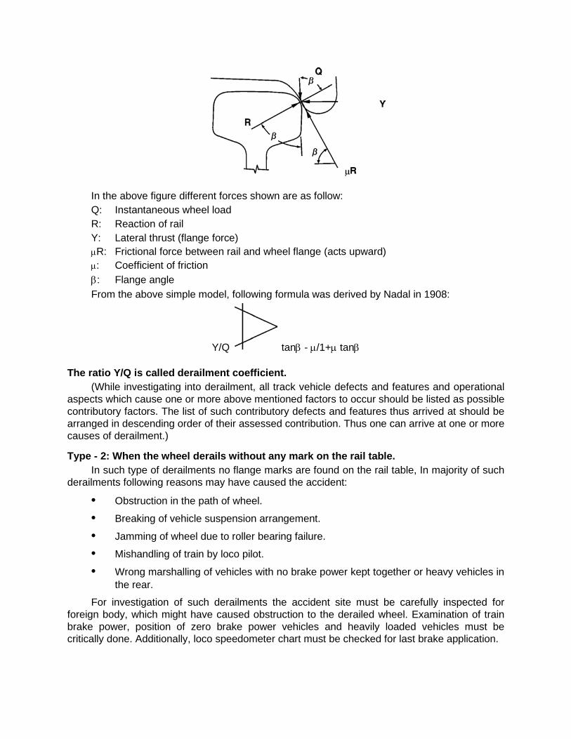
In the above figure different forces shown are as follow: Q: Instantaneous wheel load R: Reaction of rail Y: Lateral thrust (flange force) µR: Frictional force between rail and wheel flange (acts upward) µ: Coefficient of friction β: Flange angle From the above simple model, following formula was derived by Nadal in 1908:
Y/Q tanβ - µ/1+µ tanβ
The ratio Y/Q is called derailment coefficient. (While investigating into derailment, all track vehicle defects and features and operational
aspects which cause one or more above mentioned factors to occur should be listed as possible contributory factors. The list of such contributory defects and features thus arrived at should be arranged in descending order of their assessed contribution. Thus one can arrive at one or more causes of derailment.)
Type - 2: When the wheel derails without any mark on the rail table. In such type of derailments no flange marks are found on the rail table, In majority of such
derailments following reasons may have caused the accident:
• Obstruction in the path of wheel.
• Breaking of vehicle suspension arrangement.
• Jamming of wheel due to roller bearing failure.
• Mishandling of train by loco pilot.
• Wrong marshalling of vehicles with no brake power kept together or heavy vehicles in the rear.
For investigation of such derailments the accident site must be carefully inspected for foreign body, which might have caused obstruction to the derailed wheel. Examination of train brake power, position of zero brake power vehicles and heavily loaded vehicles must be critically done. Additionally, loco speedometer chart must be checked for last brake application.
Type - 3: When the wheel derails with single flange mark on the rail table. This is the most interesting category of derailment and requires detailed examination of
track, vehicles, loading condition and train operating conditions. First the wheel mount mark itself has to be properly ascertained. The length of flange mark gives a clue to reasons for derailment. The following factors must be considered after seeing the flange mark:
• Long flange mark suggests that the wheel load reduced considerably for a long period.
• Short flange mark suggests that the lateral thrust increased to a considerably high value.
• The weight of the vehicle and speed of the train at the time of accident affect the impression of flange mark on the rail.
In a number of cases an empty derailed wagon had been pulled to a very long distance and the wheel mount mark was found but disputed due to ignorance of the investigating officials. In all the cases, one must ascertain the first wheel drop mark and then trace back the mount mark. After locating the mount mark, next step is to match it with the wheel that derailed first. For this matching of damages on sleepers and position of vehicles after derailment will have to be done.
After identifying the point of mount and drop, detailed examination and recording of track geometry, rolling stock parameters, condition of loads in derailed as well as non-derailed vehicles and operating conditions has to be done. This record reveals reasons for the accident. The analysis has to be done with a view to find out reasons for increase in thrust and reduction in instantaneous wheel load.
Type - 4 : When a number of wheels derail with several flange marks on the rail table. In this category of derailment the probable reasons for derailment can be as follows: • Obstructions in the path of wheels
• Disturbed track (work being done on the track or sabotage) • Rail failure
• Serious track defect-twist misalignment or formation failure
• Buckling of track
In such cases, if there is no obvious reason like obstructions or rail failure, track parameters are of particular relevance and sufficient care has to be taken in recording them. Readings of track geometry is of great importance in establishing the behaviour of vehicle just before the derailment. In addition to the readings taken after derailments, records of previous maintenance (rail renewal, de-stressing etc.) must be perused to assess the amount of work done in the last few days.
DERAILMENTS AT POINTS AND CROSSINGS: Points and crossings are meant for changing the road of a train and it has some
discontinuities thereby making it a weak link in track structure. In a point there are two tongue rails connected together by stretcher bars and this assembly is called switch. A pull rod from some distance operates this switch. Today, most of the points are operated by motors and they have some interlocking arrangement. The interlocking for motor operated points is done with a lock bar and it has a detection device also to detect proper housing of points.
Tongue rails forming the switch are hinged onto the heel blocks in the rear. The bolts, provided for hinging the tongue rails, are kept loose for easy operation of switch. After the switch arrangement, another important part is the nose of crossing. Here all the wheels traverse the path shown by the switch.
Most of the derailments at points and crossings either initiate at the toe of the tongue rail or near the nose of the crossing. Whenever a derailment takes place on a point the following checks must be done:-
Gauge of point must be checked at four locations:
• 305 mm in advance of nose of tongue rail. • 152 mm inside the tongue rail for straight road and turn out. • At heel for tongue rail for straight road and turn out. • At middle of tongue rail for straight road and turn out.
The Gauge must be correct at all places except at the toe where it may be 6 mm slack for housing the tongue rail.
It can be appreciated that conditions created by slack gauge’ are not permitted near the switch. IRPWM-1985, Para 237 (8) (a) and (b) is reproduced below:
“(8) Gauge and Super-elevation in turnouts– (a) It is a good practice to maintain uniform gauge over turnouts. (b) If gauge of track adjoining the points and crossings is maintained wider/tighter than the
gauge on the points and crossings, the gauge on the adjoining track must be brought to the same gauge as in points and crossings and run out at the rate of I mm in 3 metres to the requisite extent. It should, however, be ensured that the same gauge as applicable to the points and crossings is maintained for at least one rail length on either side of point and crossings.”
In case of derailment suspected to have started near the switch of the turnout the following points need to be carefully examined:
• The condition of tongue rail-whether broken, chipped or bent. • Whether the damage is old or new. • Height of the tip of the switch from top of stock rail. • Thickness of the tongue rail. • Any gap between the tongue rail and stock rail. • Any damage to stretcher bar. • In case of interlocked points, the slackness between the locking bar slot and slide
should be recorded. • The condition of brackets holding the stock rail. • Whether the switch jumps up when a wheel passes on its heel.
If the derailment is suspected to have started near the crossing the following points must be carefully checked:
• Condition of nose-wear, breakage, chipped, bent. • Reduction in the level of nost as compared with wing rails. • Clearance between wing rail and stock rail (near the nose) on both sides.
• Clearance between guard rail and stock rail. • Alignment of turnout to be measured for checking smoothness (with 6 metre chord at
1.5 metre intervals). IRPWM has specified a check-list for complete examination of points and crossings. There is one potentially dangerous structure called diamond crossing, which is generally
not provided on the main line. A simple diamond crossing has four noses (two acute angle and two obtuse angle), which require a critical watch. Even a slight damage to these noses or disturbance to the clearance between stock rails and guardrails make this diamond crossing unsafe. The problem is further compounded if a diamond crossing has one or two slips also. The curvature of the slip is generally so high that these structure are not fit for speeds above 8 to 10 kmph. It is advisable to avoid use of these structures.
Some Important Defects (A) Permanent Way
• Spread gauge • Gaping in points • Tipping of the toe of switch • Worn out & broken tongue Rail • Excessive clearances of check rail opposite to the nose of the crossing • Loose or slack points connections • Sharp curves with kinking alignments • Worn out Rails • Abrupt introduction of super elevation • Super elevation not corresponding to speed of the train • Buckling of track • Shearing of fish plate bolts • Subsidence of track • Uneven Cross level • Condition of Ballast • Security fastening deficient/loose Track defects have a vital role in the accident and therefore it is very essential to check the
various parameters of the track. The following parameters must be checked thoroughly to pin point the defects in the track:
(1) Gauge - It is the shortest distance between the two rails of the track. Rail Gauge– The standard gauge is 1676 mm.
(2) Permissible Variations • Straight line 6 mm tight to 6 mm slack ± 6 mm • On curve with radius 350 Mtrs or more-6 mm tight to 15 mm slack (-6 to +15) • On curve with radius less than 350 Mtrs-Slack up to 20 mm (correction slip No. 10 Rly
Bd. L.No. 94/CE/II/TSG/l Dt. 20/24-6-96 of P. Way, manual)
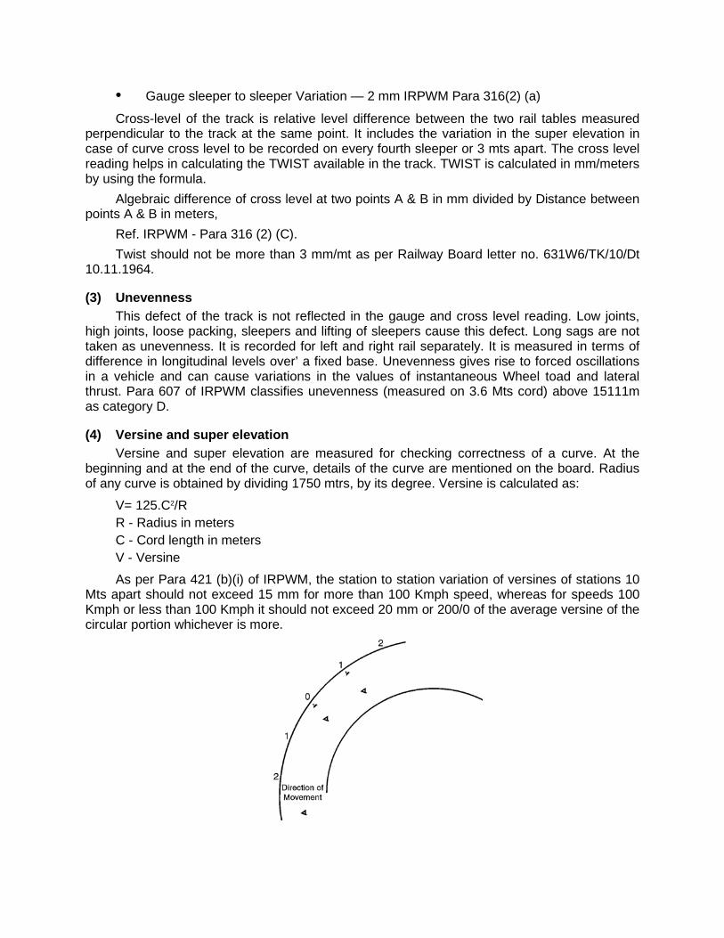
• Gauge sleeper to sleeper Variation — 2 mm IRPWM Para 316(2) (a)
Cross-level of the track is relative level difference between the two rail tables measured perpendicular to the track at the same point. It includes the variation in the super elevation in case of curve cross level to be recorded on every fourth sleeper or 3 mts apart. The cross level reading helps in calculating the TWIST available in the track. TWIST is calculated in mm/meters by using the formula.
Algebraic difference of cross level at two points A & B in mm divided by Distance between points A & B in meters,
Ref. IRPWM - Para 316 (2) (C). Twist should not be more than 3 mm/mt as per Railway Board letter no. 631W6/TK/10/Dt
10.11.1964.
(3) Unevenness This defect of the track is not reflected in the gauge and cross level reading. Low joints,
high joints, loose packing, sleepers and lifting of sleepers cause this defect. Long sags are not taken as unevenness. It is recorded for left and right rail separately. It is measured in terms of difference in longitudinal levels over’ a fixed base. Unevenness gives rise to forced oscillations in a vehicle and can cause variations in the values of instantaneous Wheel toad and lateral thrust. Para 607 of IRPWM classifies unevenness (measured on 3.6 Mts cord) above 15111m as category D.
(4) Versine and super elevation Versine and super elevation are measured for checking correctness of a curve. At the
beginning and at the end of the curve, details of the curve are mentioned on the board. Radius of any curve is obtained by dividing 1750 mtrs, by its degree. Versine is calculated as:
V= 125.C2/R R - Radius in meters C - Cord length in meters V - Versine
As per Para 421 (b)(i) of IRPWM, the station to station variation of versines of stations 10 Mts apart should not exceed 15 mm for more than 100 Kmph speed, whereas for speeds 100 Kmph or less than 100 Kmph it should not exceed 20 mm or 200/0 of the average versine of the circular portion whichever is more.
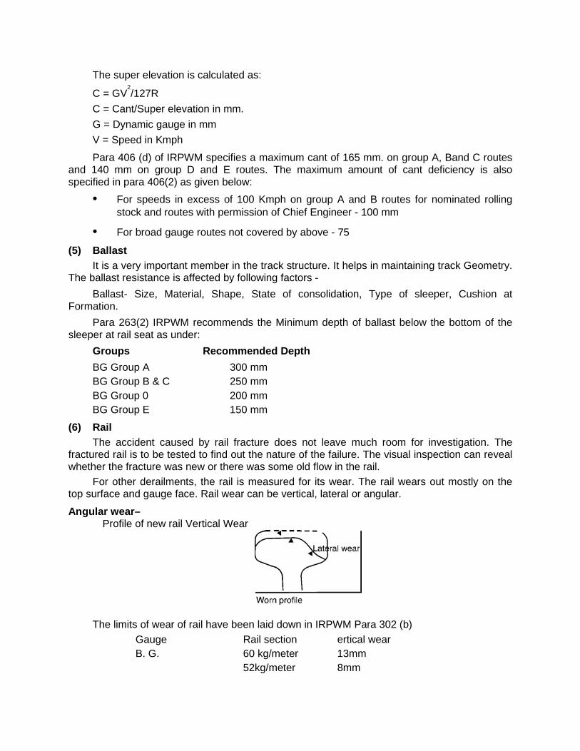
The super elevation is calculated as:
C = GV2/127R
C = Cant/Super elevation in mm. G = Dynamic gauge in mm V = Speed in Kmph
Para 406 (d) of IRPWM specifies a maximum cant of 165 mm. on group A, Band C routes and 140 mm on group D and E routes. The maximum amount of cant deficiency is also specified in para 406(2) as given below:
• For speeds in excess of 100 Kmph on group A and B routes for nominated rolling stock and routes with permission of Chief Engineer - 100 mm
• For broad gauge routes not covered by above - 75
(5) Ballast It is a very important member in the track structure. It helps in maintaining track Geometry.
The ballast resistance is affected by following factors - Ballast- Size, Material, Shape, State of consolidation, Type of sleeper, Cushion at
Formation. Para 263(2) IRPWM recommends the Minimum depth of ballast below the bottom of the
sleeper at rail seat as under: Groups Recommended Depth BG Group A 300 mm BG Group B & C 250 mm BG Group 0 200 mm BG Group E 150 mm
(6) Rail The accident caused by rail fracture does not leave much room for investigation. The
fractured rail is to be tested to find out the nature of the failure. The visual inspection can reveal whether the fracture was new or there was some old flow in the rail.
For other derailments, the rail is measured for its wear. The rail wears out mostly on the top surface and gauge face. Rail wear can be vertical, lateral or angular.
Angular wear– Profile of new rail Vertical Wear
The limits of wear of rail have been laid down in IRPWM Para 302 (b) Gauge Rail section ertical wear B. G. 60 kg/meter 13mm 52kg/meter 8mm

90R 5mm Lateral wear limits have been given in para 302 (b)
Section Gauge Category of work Lateral wear Curves B.G. I Group A & B routes 8 mm Curves B.G. I Group C & D routes 10 mm Straight B.G Group A & B routes 6 mm Group C & D routes 8 mm (7) Sleepers
If sleeper suffer any damage or loss in property, it can cause derailment. While recording the gauge and level readings the condition of each sleeper must be carefully sleepers near point of mount.
(8) Rail Fasteners For different - type of sleepers, the rail fasteners are different Wooden sleepers - Dog
spikes, Round head spikes, Steel keys Steel trough sleeper - steel keys. Prestressed concrete sleepers— elastic clips with liners between the foot of rail and clip. Condition of all fasteners should be recorded while taking track reading.
(9) Creep
This is a silent but very dangerous phenomenon of the track. Creep is a longitudinal displacement of track and is caused by
• Temperature variation causing expansion and contraction of the rail.
• The tractive forces of locomotive to push the rail backward.
• Braking forces of train trying to push the rail forward. The effect of the above forces is accelerated if the rail fasteners are not able to hold the rails properly to the sleepers or rail seat on the sleepers is a damaged or bad joint in the track with out proper expansion gap.
Para 242 (6) of IRPWM specifies maximum about of creep permitted as 150mm. In LWR and CWR creep indication point are provided at a distance of 50 meters and 100 meters SEJ (Switch Expansion Joint) on either end of LWR/CWR.
(10) Buckling When a section of track buckles, about one or two rails length of the track leaves its place
and moves side way. This also happens due to the rise in temperature and other reasons similar to the creep. The buckling may be horizontal of vertical. Buckling normally happens in the 2nd half of the day mostly, when the track has absorbed max. heat and also near the bridges, level crossings etc. where the track is firmly held in ground.
(B) Defects of Rolling Stock
• Defects in wheel and Axle Broken & Hanging fittings. • Defects in Bolster and Assemblies. • Defects in spring gear, axle ground and trolley. • Defects in Brake gear. • Excessive Clearance in side bearer, pivot etc.

• Hot box/Roller bearing failure. • Under frame and under frame members out of alignment. • Poor brake power. • Broken or disengaged Baffle plates in the empty/unloaded tank wagons. • Defective draw gear, CBC gear and Buffling gear, Train parting & subsequent
collision - ‘alliance 2’ - couplets opening automatically. Defects of Locomotives are very similar to defects of Rolling Stock.
CHAPTER – XXI
CONCEPTS OF ELECTRIC TRACTION
Power Supply
25 kV, ac, 50 Hz single phase power supply for electric traction is derived from the grid system of State Electricity Boards through traction sub-stations located along the route of the electrified sections at distances of 35 to 50 km apart. The distance between adjacent sub-stations may however be even less depending on intensity of traffic and load of trains.
Sectioning of OHE:–
To ensure rapid isolation of faults on the OHE and to facilitate maintenance work ‘the OHE is sectioned at intervals of 10 to 15 km along the route. At each such point a ‘switching station interruptors’ usually rated at 600A are provided. The shortest section of the OHE which can be isolated by opening interruptors atone is called a ‘sub-sector’. Each sub-sector is further sub-divided into smaller ‘elementary sections’ by provision of off-load type manually operated isolator switches.
At some stations with large yards, alternative feeding arrangements are provided so that the power for feeding and yards may be drawn from alternative routes. Normally the switch is locked in one position, being changed to the other when required after taking necessary precautions.
To meet requirements at electric loco running sheds, isolator with an earthing device in the ‘off position is provided. At watering stations manually operated interrupters and isolator with earthing heels are provided to enable switching off of the power supply locally and earthing the OHE to enable working on roofs of rolling-stock. There are several types of switching stations as detailed in the following paras.
Feeding Post (FP): It is a supply control post, where the incoming feeder link from grid substation are terminated.
Each feeder supplies the OHE on one side of the feeding post through interrupters controlling supply to the individual lines. Thus, for a two track line, there will be four interrupters at each feeding post.
Sectioning and Paralleling Post (SP) These posts are situated approximately midway between feeding posts marking the
demarcating point of two zones fed from different phases a ‘paralleling interrupter’ is provided at each ‘SP’ to parallel the OHE of the up and down tracks of a double track section, ‘bridging interrupters’ are also provided to permit one feeding post to feed beyond the sectioning post upto the next FP if its 25 kV supply is interrupted for some reasons. These bridging interrupters are normally kept open and should only be closed after taking special precautions as detailed in these rules.
Sub-Sectioning and Paralleling Post (SSP) One or more SSPs are provided between each FP and adjacent SP depending upon the
distance between them. In a double track section, normally three interrupters are provided at each SSP i.e. two connecting the adjacent sub-sectors of up and down tracks. Sub-Sectioning Post (SS)
These are provided only occasionally. They are similar to SSPs with provision for sectioning of the OHE but not paralleling.
Neutral Section: It is a short section of insulated and dead overhead equipment which separates the area fed by adjacent substation or feeding post.
A neutral section is provided to make it impossible for the pantograph of an electric locomotive or EMU train to bridge the different phases of 25 KV supply, while passing from the zone fed from one sub-station to the next one. Since the neutral section remains ‘dead’, warning boards are provided in advance to warn and remind the Loco pilot of an approaching electric locomotive/EMU to open locomotive circuit breaker (DJ) before approaching the ‘neutral section’, to coast through it and then switch ‘on’ on the other side. Special care is taken in fixing the location of neutral sections, on level tangent tracks far away from signals, level crossing gates etc. to ensure that the train coasts through the neutral section at a sufficiently high speed, to obviate the possibility of its stopping and getting stuck within the neutral section.
Other Important Equipment at Switching Stations Certain equipments are installed at various points to protect the lines, to monitor the
availability of power supply and provide other facilities. These are generally as under:
1) Lightning arresters are provided to protect every sub-sector against voltage surges. 2) Auxiliary transformers are provided at all the posts and also at certain intermediate
points to supply ac at 240 V, 50 Hz required for signalling and operationally essential lighting installations. To ensure a fairly steady voltage, automatic voltage regulators are also provided where required.
3) Potential transformers are provided at the various switching stations for monitoring supply to each sub-sector.
4) A small masonry cubicle is provided to accommodate remote control equipment, control panel, telephone and batteries and battery chargers required for the control of interruptors and other similar equipments.

OVERHEAD EQUIPMENT
Catenary and Contact Wires
1) The overhead equipment above the tracks comprises of the following:–
a) A stranded cadmium copper wire of about 65 mm2 section or stranded aluminium alloy wire of about 116 mm2 section for catenary.
b) A grooved hard drawn copper contact wire of 107 mm2 cross-section (when new) supported from the catenary by means of droppers of 5 mm diameter spaced not more than 9 m apart.
2) The catenary and contact wire together have an equivalent copper section of 157 mm2. The current normally permissible on a single track is 600 A approximately, because of equivalent cross sectional area of OHE. This current limit is based on the temperature limit of 85°C in contact wire. Certain sections in Waltair-Kirandul section have the catenary and contact wires together having an equivalent copper section of 200 mm2.
3) For loop lines, sidings, yards and spur lines excluding the main running lines and first loop or lines taking off from main running line, tramway type OHE having only grooved hard drawn copper contact wire of 107 mm2 section is provided.
Height of Contact Wire The normal height of contact wire for regulated OHE is 5.60 m (with 10 cm pre-sag for 72
m span) above rail level. For unregulated OHE in areas with a temperature range of 4°C to 65° C, this figure is 5.75 m and in areas with a temperature range of 15 °C to 65 °C, it is 5.65 m. In certain cases, such as under over-line structures, the height may be as low as 4.65 m on BG and 4.02 m on MG. For passing oversize consignments on such lines, special precautions have to be taken.
Span of Supporting Mast/Structures
The span normally used for supporting the OHE from masts/structure using the cantilever type bracket assembly varies from maximum 72m on straight track to 27 m on curved track, the spans depending upon the degree of curvature. The catenary system is normally supported on straight tracks at maximum intervals of 72m (63m on MG) by cantilever type arms fixed to galvanized broad flange or I section steel masts or fabricated steel structures. On curves the catenary is supported at closer intervals, the spans adopted depending upon the degree of curvature.
Stagger The contact wire is staggered so that as the pantograph glides along, the contact wire
sweeps across the current collecting strips of the pantograph upto a distance of 200 mm on either side of the centre line on straight runs and 300 mm on one side on curves. This ensures a uniform wear of the current collecting strips of the pantographs.
Overlaps: The OHE conductors are terminated at intervals of about 1.5 km with an overlap generally as shown in Fig. 2.02, the conductor height being so adjusted that the pantograph glides from one conductor to the other smoothly.
There are two types of overlap spans as under:–
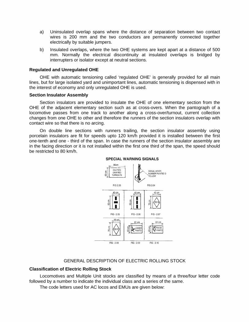
a) Uninsulated overlap spans where the distance of separation between two contact wires is 200 mm and the two conductors are permanently connected together electrically by suitable jumpers.
b) Insulated overlaps, where the two OHE systems are kept apart at a distance of 500 mm. Normally the electrical discontinuity at insulated overlaps is bridged by interrupters or isolator except at neutral sections.
Regulated and Unregulated OHE
OHE with automatic tensioning called ‘regulated OHE’ is generally provided for all main lines, but for large isolated yard and unimportant lines, automatic tensioning is dispensed with in the interest of economy and only unregulated OHE is used. Section Insulator Assembly
Section insulators are provided to insulate the OHE of one elementary section from the OHE of the adjacent elementary section such as at cross-overs. When the pantograph of a locomotive passes from one track to another along a cross-over/turnout, current collection changes from one OHE to other and therefore the runners of the section insulators overlap with contact wire so that there is no arcing.
On double line sections with runners trailing, the section insulator assembly using porcelain insulators are fit for speeds upto 120 km/h provided it is installed between the first one-tenth and one - third of the span. In case the runners of the section insulator assembly are in the facing direction or it is not installed within the first one third of the span, the speed should be restricted to 80 km/h.
GENERAL DESCRIPTION OF ELECTRIC ROLLING STOCK
Classification of Electric Rolling Stock Locomotives and Multiple Unit stocks are classified by means of a three/four letter code
followed by a number to indicate the individual class and a series of the same. The code letters used for AC locos and EMUs are given below:
The first letter denotes the Gauge: ‘W’ for BG and ‘Y’ for MG. The second (middle) letters ‘A’ denotes the system of power supply for which it is suitable -
A for AC & C for DC, CA for DC & AC. The third fetter for locos indicates the class of service - ‘M’ for mixed traffic locos suitable for both passenger and freight services, ‘G’ for Freight (Goods) service locos, ‘P’ for Passenger services locos, and ‘S’ for Shunting locos. Multiple Unit Stock is denoted by the letter ‘U’. The various classes of ac locos and EMUs at present in service on Indian Railway are as
under: (a) AC Locos– WAG1, WAG2, WAG3, WAG4, WAG5, WAG6, WAG7, WAG9, WAG9M (b) WAP1, WAP2, WAP3, WAM1, WAM2, WAM3, WAM4, WAP4, WAP 5, YAM1 (c) AC/DC Locos– WCAM1, (d) AC EMUs– WAU1, WAU2, WAU3, WAU4, YAU.
In addition two types of BG DC EMUs converted for AC working are in use on the Eastern Railway. Important Equipment of Electric Loco/EMU
1) Pantograph For collecting power from 25 kV ac contact wire pantographs are mounted on the roof of
the traction vehicles. AM 12 pantograph of Faively design has been adopted by Indian Railways for 25 kV ac electric locomotives and EMUs. These pantographs are provided with steel strips for current collection. The raising and lowering of the pantograph is by means of a pneumatically operated servo motor. This pantograph is a single pan design having two o-springs mounted on it. For keeping the pantograph in the lowered condition, main springs have been used. The suspension of pan is on plungers.
This pantograph is suitable for operation upto 140 km/h. For increasing the speed potential, improved pantograph with lower dynamic mass and independent pan heads have been used. Further, in order to improve the life of the contact wire, use of carbon strips has also been tried. Use of carbon strips for current collection has already been adopted in European countries.
Use of carbon strips necessitates change in the design of the pantograph; the pan head which is more or less rigid in case of steel strip pantograph needs to be made more flexible in the vertical, horizontal and transverse movement for carbon strip pantographs. This is achieved by improved suspension of the pan head. The speed potential of such a pantograph is of the order of 250 km/h. 2) Circuit Breaker
— Air Blast Circuit breaker — Vacuum Circuit breaker
These breakers are designed for isolation of power to the traction vehicle in the event of faults.
Vacuum Circuit Breakers were introduced on electric locomotives on Indian Rlys. in the year 1985. The VCB is a simplified design with fewer number of parts (260 Nos.), have a simplified control block and self - contained interrupting medium that is vacuum. Due to these features, the life of the main contact achievable is as high as 1 lakh electrical operations as
against 20,000 operations for air blast circuit breakers. As a result, the periodicity of replacement of main contact is second POH for VCB and IOH for Air Blast Circuit Breakers. Besides, these factors, VCB also offers the advantages of reduced size, reduced weight and reduced maintenance cost as compared to these for air blast circuit breakers. The total trip-time for VCB is less than 60 milli-seconds while the same is of the order of 100 milli-seconds for air blast circuit breakers. The air blast circuit breaker is only capable of breaking the fault current with breaking capacity of 250 MVA. The VCB, besides having breaking capacity is also designed for making capacity of the same rating, i.e. 250 MVA and can handle the same level of fault current during closing also.
3) Transformer Power to the traction vehicles is available at 25 kV ac single phase from the contact wire.
In order to step down the voltage as well as to control the same for feeding to the traction motors, the traction power transformers are provided on the traction vehicles.
These transformers generally have a primary winding, a regulating winding, traction secondary windings and auxiliary windings. The regulating winding is designed for choosing appropriate voltage for the traction motors. The auxiliary winding is required for feeding the auxiliary motors on the locomotive.
In order to increase the h.p. of the locomotives, the traction transformers have been uprated from time to time keeping the overall dimensions unchanged on account of space constraint. The upratings have been achieved by using increased copper section of the conductor used, improved insulation scheme and in certain cases adoption of aluminium foil wound construction for minimizing the losses.
With the introduction of thyristorised converters, the design of the traction transformer has undergone simplification with the deletion of regulating winding. The transformer for thyristorised converter becomes a two limb construction and traction secondary winding split into 4 windings for two step sequence control.
The traction transformer necessarily has to have forced oil circulation and forced air cooling. For this purpose oil pump, oil cooler and blower form an integral part of the traction transformer.
Tap Changer Tap changer is provided on 25 kV (HT) regulating winding of locomotive transformer for
controlling the voltage input to main transformer.
Traction Motor In case of traction motor great emphasis is being given on improving power to weight ratio,
keeping in view the limited space available on locomotive for mounting the same. There is continuous effort to improve the performance of traction motor by making, them lighter/compact, at the same time more reliable. Indian Railways have been adopting the latest technology available for design and manufacture of traction motor. Over a period of years the traction motors have become now 2.5 times lighter specially for EMU application.
Arno Converter Arno Converter is a special duty machine for conversion of single phase in-coming supply
into 3 phase out- put supply. 3 phase supply is essentially required on most of the electrical locomotives for driving certain auxiliary equipment like blowers and compressors. The function of Amo Converter is to supply 3 phase power required for these auxiliaries.
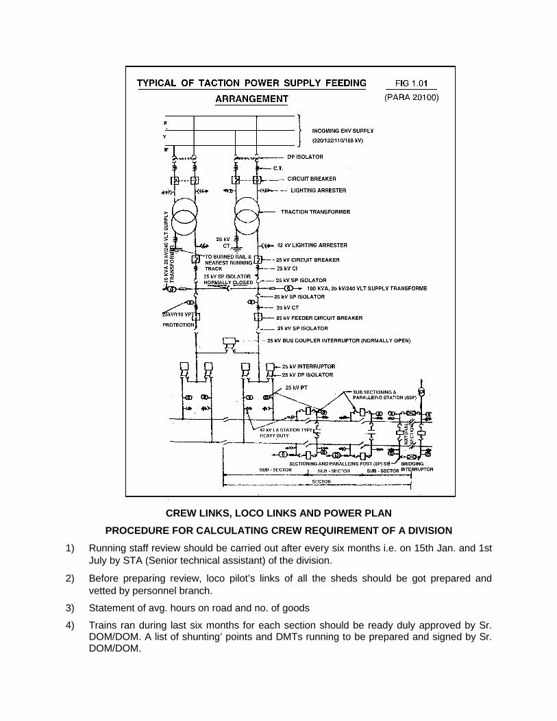
CREW LINKS, LOCO LINKS AND POWER PLAN
PROCEDURE FOR CALCULATING CREW REQUIREMENT OF A DIVISION
1) Running staff review should be carried out after every six months i.e. on 15th Jan. and 1st July by STA (Senior technical assistant) of the division.
2) Before preparing review, loco pilot’s links of all the sheds should be got prepared and vetted by personnel branch.
3) Statement of avg. hours on road and no. of goods
4) Trains ran during last six months for each section should be ready duly approved by Sr. DOM/DOM. A list of shunting’ points and DMTs running to be prepared and signed by Sr. DOM/DOM.
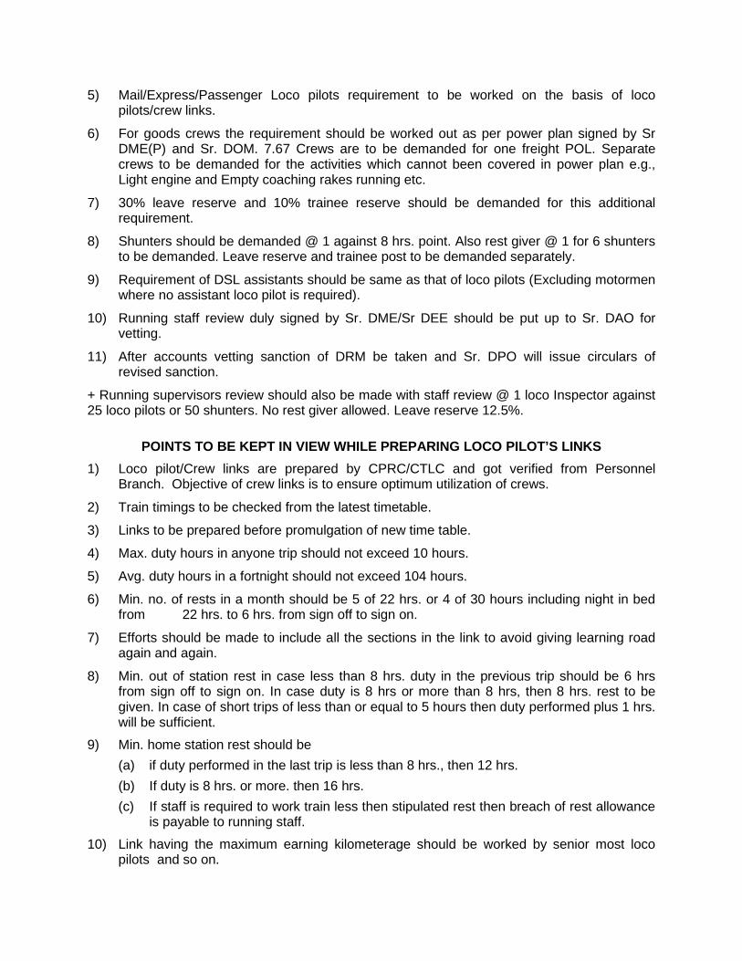
5) Mail/Express/Passenger Loco pilots requirement to be worked on the basis of loco pilots/crew links.
6) For goods crews the requirement should be worked out as per power plan signed by Sr DME(P) and Sr. DOM. 7.67 Crews are to be demanded for one freight POL. Separate crews to be demanded for the activities which cannot been covered in power plan e.g., Light engine and Empty coaching rakes running etc.
7) 30% leave reserve and 10% trainee reserve should be demanded for this additional requirement.
8) Shunters should be demanded @ 1 against 8 hrs. point. Also rest giver @ 1 for 6 shunters to be demanded. Leave reserve and trainee post to be demanded separately.
9) Requirement of DSL assistants should be same as that of loco pilots (Excluding motormen where no assistant loco pilot is required).
10) Running staff review duly signed by Sr. DME/Sr DEE should be put up to Sr. DAO for vetting.
11) After accounts vetting sanction of DRM be taken and Sr. DPO will issue circulars of revised sanction.
+ Running supervisors review should also be made with staff review @ 1 loco Inspector against 25 loco pilots or 50 shunters. No rest giver allowed. Leave reserve 12.5%.
POINTS TO BE KEPT IN VIEW WHILE PREPARING LOCO PILOT’S LINKS 1) Loco pilot/Crew links are prepared by CPRC/CTLC and got verified from Personnel
Branch. Objective of crew links is to ensure optimum utilization of crews.
2) Train timings to be checked from the latest timetable.
3) Links to be prepared before promulgation of new time table.
4) Max. duty hours in anyone trip should not exceed 10 hours.
5) Avg. duty hours in a fortnight should not exceed 104 hours.
6) Min. no. of rests in a month should be 5 of 22 hrs. or 4 of 30 hours including night in bed from 22 hrs. to 6 hrs. from sign off to sign on.
7) Efforts should be made to include all the sections in the link to avoid giving learning road again and again.
8) Min. out of station rest in case less than 8 hrs. duty in the previous trip should be 6 hrs from sign off to sign on. In case duty is 8 hrs or more than 8 hrs, then 8 hrs. rest to be given. In case of short trips of less than or equal to 5 hours then duty performed plus 1 hrs. will be sufficient.
9) Min. home station rest should be (a) if duty performed in the last trip is less than 8 hrs., then 12 hrs. (b) If duty is 8 hrs. or more. then 16 hrs. (c) If staff is required to work train less then stipulated rest then breach of rest allowance
is payable to running staff.
10) Link having the maximum earning kilometerage should be worked by senior most loco pilots and so on.
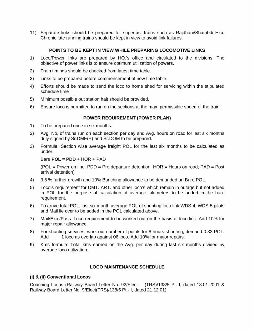
11) Separate links should be prepared for superfast trains such as Rajdhani/Shatabdi Exp. Chronic late running trains should be kept in view to avoid link failures.
POINTS TO BE KEPT IN VIEW WHILE PREPARING LOCOMOTIVE LINKS 1) Loco/Power links are prepared by HQ.’s office and circulated to the divisions. The
objective of power links is to ensure optimum utilization of powers.
2) Train timings should be checked from latest time table. 3) Links to be prepared before commencement of new time table. 4) Efforts should be made to send the loco to home shed for servicing within the stipulated
schedule time
5) Minimum possible out station halt should be provided. 6) Ensure loco is permitted to run on the sections at the max. permissible speed of the train.
POWER REQUIREMENT (POWER PLAN) 1) To be prepared once in six months. 2) Avg. No, of trains run on each section per day and Avg. hours on road for last six months
duly signed by Sr.DME(P) and Sr.DOM to be prepared.
3) Formula: Section wise average freight POL for the last six months to be calculated as under:
Bare POL = PDD + HOR + PAD (POL = Power on line; PDD = Pre departure detention; HOR = Hours on road; PAD = Post
arrival detention)
4) 3.5 % further growth and 10% Bunching allowance to be demanded an Bare POL. 5) Loco’s requirement for DMT. ART. and other loco’s which remain in outage but not added
in POL for the purpose of calculation of average kilometers to be added in the bare requirement.
6) To arrive total POL. last six month average POL of shunting loco link WDS-4, WDS-5 pilots and Mail lie over to be added in the POL calculated above.
7) Mail/Exp./Pass. Loco requirement to be worked out on the basis of loco link. Add 10% for major repair allowance.
8) For shunting services, work out number of points for 8 hours shunting, demand 0.33 POL. Add 1 loco as overlap against 06 loco. Add 10% for major repairs.
9) Kms formula: Total kms earned on the Avg. per day during last six months divided by average loco utilization.
LOCO MAINTENANCE SCHEDULE
(i) & (ii) Conventional Locos
Coaching Locos (Railway Board Letter No. 92/Elect. (TRS)/138/5 Pt. I, dated 18.01.2001 & Railway Board Letter No. 9/Elect(TRS)/138/5 Pt.-II, dated 21.12.01)

Maintenance Periodicity Duration schedule Trip Inspection (TI) After 3000 kms or one trip, whichever is later 2 hrs. IA 40 ± 3days 4 hrs. IB 80 ± 3days 6 hrs. IC 120 ± 3days 8 hrs. AOH 12 months ± 15 days 6 days IOH 36 months ± 1 months or 4(6 lakh for wAP-1/4 loco) lakh kms. whichever is earlier 9 days POH 6 years ± 3 months or 8 lakh kms (12 lakh for WP-1/4 loco) whichever is earlier 28 days
Freight Locos
Railway Board Letter No. 92/Elect (TRS)/138/5 Pt. I, dated 18.01.2001)
Maintenance Periodicity Duration schedule Trip Inspection(TI) 15 days (Fitted with TAO TMs) 2 hrs 20 days (fitted with Hitachi TMs) IA 45 ± 3 days 4 hrs IB 90 ± 3 days 6 hrs IC 135 ± 3 days 8 hrs AOH 18 months ± 10 days 6 working days IOH 54 months ± 1 monthly or 6 lakh kms 9 working whichever is earlier days POH 9 years ± 3 months or 12 lakh kms 28 working whichever earlier days (iii) 3-Ph.ABB Locomotives
(Railway Board Letter No.97/Elect (TRS)/440/18144 (3Ph, dated 23.02.07) Coaching Locos (WAP5/WAP7 Locos)
Maintenance Periodicity Duration schedule

Trip Inspection 3000 kms or one trip, whichever is later 2 hrs
IA 90 days 6 hrs
IB 180 days 6 hrs
IC 270 days 8 hrs
MOH 18 months 6 working days
IOH 4.5 years ± 6 months or 12 lakh kms. whichever 11 working is earlier days
POH 9 years ± 6 months or 24 lakh kms. whichever is earlier 28 working days
Freight Locos (WAG9 / WAG9H Locos)
Maintenance Periodicity Duration schedule
Trip inspection 45 days 4 hrs
IA 90 days 6 hrs
IB 180 days 6 hrs
IC 270 days 8 hrs
MOH 18 months 2nd MOH
IOH 6 years ± 6 months or 12 lakh kms. whichever 11 working is earlier days
POH 12 years ± 6 months or 24 lakh kms. whichever 28 working is earlier days
DIESEL LOCO SCHEDULE & DURATION
Schedule WDM2 WDM3 WDM3A/B/C/D WDG3A WDG3A WDP1/3A A/B/C/D (30 days) (30 days)
T-1 15 days 20 days 20 days As per lin
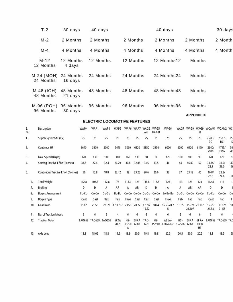
T-2 30 days 40 days 40 days 30 days
M-2 2 Months 2 Months 2 Months 2 Months 2 Months 2 Months
M-4 4 Months 4 Months 4 Months 4 Months 4 Months 4 Months
M-12 12 Months 12 Months 12 Months 12 Months12 Months 12 Months 4 days
M-24 (MOH) 24 Months 24 Months 24 Months 24 Months24 Months 24 Months 16 days
M-48 (IOH) 48 Months 48 Months 48 Months 48 Months48 Months 48 Months 21 days
M-96 (POH) 96 Months 96 Months 96 Months 96 Months96 Months 96 Months 30 days
APPENDEIX
ELECTRIC LOCOMOTIVE FEATURES
S. Description WAM4 WAP1 WAP4 WAP5 WAP6 WAP7 WAG5 WAG5 WAG6 WAG7 WAG9 WAG9 WCAM1 WCAM2 WCA No. A/B HA/HB H
1. Supply System-AC(KV) 25 25 25 25 25 25 25 25 25 25 25 25 25/1.5 25/1.5 25/ DC DC D
2. Continous HP 3640 3800 5000 5440 5060 6120 3850 3850 6000 5000 6120 6120 3640/ 4715/ 500 2930 2916 460
3. Max. Speed (kmph) 120 130 140 160 160 130 80 80 120 100 100 90 120 120 10
4. Starting Tractive Effort (Tonnes) 33.8 22.4 32.4 26.29 30.8 32.88 33.5 33.5 46 44 46.89 52 33.84/ 33.5/ 40 23.2 26.0 26
5. Continuous Tractive Effort (Tonnes) 56 13.8 18.8 22.42 19 23.23 20.6 20.6 32 27 33.12 46 16.8/ 23.8/ 22.6 24.6 26
6. Total Weight 112.8 108.3 112.8 78 113.2 123 118.8 118.8 123 123 123 123 112.8 117 12
7. Braking D D A AR A AR D D A A AR AR D D D
8. Bogies Arrangement Co-Co Co-Co Co-Co Bo-Bo Co-Co Co-Co Co-Co Co-Co Bo-Bo-Bo Co-Co Co-Co Co-Co Co-Co Co-Co Co-
9. Bogies Type Cast Cast Flexi Fab Flexi Cast Cast Cast Flexi Fab Fab Fab Cast Fab Fa
10. Gear Ratio 15.62 21.58 23.59 17:35:67 23.58 20.72 17.77/ 18.64 16.63/20.7 16.65 15.77/ 21.107 16.61/ 15.62/ 18. 15.62 5 21.107 21.58 21.58
11. No. of Traction Motors 6 6 6 4 6 6 6 6 6 6 6 6 6 6 6
12. Traction Motor TAO659 TAO659 TAO659 6FXA HS- 6FRA TAO- HS- ASEA- HS- 6FRA 6FRA TAO659 TAO659 TAO 7059 15250 6088 659 15250A L3M450-2 15250A 6068 6068 A HT
13. Axle Load 18.8 18.05 18.8 19.5 18.9 20.5 19.8 19.8 20.5 20.5 20.5 20.5 18.8 19.5 20
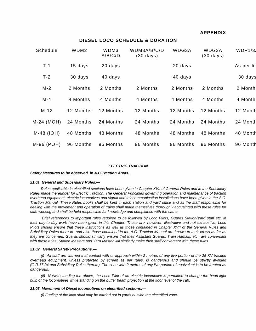
APPENDIX DIESEL LOCO SCHEDULE & DURATION
Schedule WDM2 WDM3 WDM3A/B/C/D WDG3A WDG3A WDP1/3A A/B/C/D (30 days) (30 days)
T-1 15 days 20 days 20 days As per lin
T-2 30 days 40 days 40 days 30 days
M-2 2 Months 2 Months 2 Months 2 Months 2 Months 2 Months
M-4 4 Months 4 Months 4 Months 4 Months 4 Months 4 Months
M-12 12 Months 12 Months 12 Months 12 Months 12 Months 12 Month
M-24 (MOH) 24 Months 24 Months 24 Months 24 Months 24 Months 24 Month
M-48 (IOH) 48 Months 48 Months 48 Months 48 Months 48 Months 48 Month
M-96 (POH) 96 Months 96 Months 96 Months 96 Months 96 Months 96 Month
ELECTRIC TRACTION
Safety Measures to be observed in A.C.Traction Areas.
21.01. General and Subsidiary Rules.— Rules applicable in electrified sections have been given in Chapter XVII of General Rules and in the Subsidiary
Rules made thereunder for Electric Traction. The General Principles governing operation and maintenance of traction overhead equipment, electric locomotives and signal and telecommunication installations have been given in the A.C. Traction Manual. These Rules books shall be kept in each station and yard office and all the staff responsible for dealing with the movement and operation of trains shall make themselves thoroughly acquainted with these rules for safe working and shall be held responsible for knowledge and compliance with the same.
Brief references to important rules required to be followed by Loco Pilots, Guards Station/Yard staff etc. in their day-to day work have been given in this Chapter. These are, however, illustrative and not exhaustive, Loco Pilots should ensure that these instructions as well as those contained in Chapter XVII of the General Rules and Subsidiary Rules there to and also those contained in the A.C. Traction Manual are known to their crews as far as they are concerned. Guards should similarly ensure that their Assistant Guards, Train Hamals, etc., are conversant with these rules. Station Masters and Yard Master will similarly make their staff conversant with these rules.
21.02. General Safety Precautions.— (i) All staff are warned that contact with or approach within 2 metres of any live portion of the 25 KV traction
overhead equipment, unless protected by screen as per rules, is dangerous and should be strictly avoided (G.R.17.04 and Subsidiary Rules thereto). The zone with 2 metres of any live portion of equivalent is to be treated as dangerous.
(ii) Notwithstanding the above, the Loco Pilot of an electric locomotive is permitted to change the head-light bulb of the locomotives while standing on the buffer beam projection at the floor level of the cab.
21.03. Movement of Diesel locomotives on electrified sections.— (i) Fueling of the loco shall only be carried out in yards outside the electrified zone.

(ii) Watering of carriages:— Normally, all passenger carriages to move on the electrified sections, should be fitted with the side filling arrangement so that the water can be filled in the tanks from the ground level only.
In the case of coaches equipped with conventional arrangements for filling of water from the roof only, the filling of water in the coaches shall be resorted to only on the non-electrified lines. However, the watering of such coaches suitable for filling from the top only, may be done at specific places where special sectioning arrangements for overhead equipment are provided and authorised traction staff posted for according 'Permit to work'.
21.04. Unwired tracks.— No electric locomotives with pantograph raised shall under any circumstances be taken to an unwired section.
All levers in cabins giving access to an unwired lines have a yellow point mark warning the Levermen against setting the unwired lines for electric locos.
21.05. Power block:— (i) The detailed procedure for obtaining power blocks has been given in G & SR 17.04 and Subsidiary
Rules there to and this must be rigidly followed.
(ii) The sequence of switching operations for granting and cancelling the power block for particular sections is included as an Annexure to the appendix of Station Working Rules under 25 KV A.C. Traction. These should be strictly followed by all staff. Failure to follow the sequence indicated is likely to lead to dangerous consequences. When any isolator switch is changed from its normal position, for staff to work on overhead equipment, a danger Board shall be exhibited on the switch with the caption 'Danger, Men working'. An adequate number of such Danger boards are provided at each station.
21.06. Section Insulators.— In order to isolate Up and Down running lines and also sometimes Main and Loop lines or different grids in the
yard, the cross-overs connecting Up and Down lines or cross-overs/turnouts connecting main and loop lines or different grids of the yard are provided with section insulators so that when one line or grid is made electrically dead or there be any fault on the same, the other line/grid is not affected. The speed of the electric locomotive with pantograph raised over such section insulators shall not exceed 30KM per hour subject to any other speed restriction which may be in force.
When one of the two sections separated by a section insulator is dead, the pantograph of the electric locomotive on the live section shall not proceed closer than 10 metres towards the section insulator marking the end of the dead section.
21.07. Fire.— Regarding fire on or adjacent to any electrical equipment, GR 6.10 and SRs thereto may be referred.
21.08. Power supply to Colour Light Signalling.— (i) Power supply for colour light signalling on each station on the electrified stations is arranged from two
independent sources as under:—
(a) One from Traction Overhead Equipment by means of step down auxiliary transformer for allowing the Voltage from 25000 Volts to 230 Volts other from another traction overhead equipment or from local supply.
(b) Where the station is not electrified and there is no local electric supply available, both the sources (the primary as well as the duplicate) will be from the Traction Overhead Equipment by means of step down transformers. The two sources will, however, be tapped from the traction overhead equipment belonging to two different independent sections so that the outage of both the sources at the same time is reduced to the minimum.
(c) The Change over from main supply to stand-by may be automatic or manual. In case of manual change over arrangement the SM on duty well operate the change over switch to the stand-by Power supply in the case of interruptions to the main power supply and vice-versa wherever such switch is provided to indicate the availability of both main as well as stand by power supply.
(ii) The Station Master shall be guided by the general procedures embodied in the Station Working Rules in restoring power supply to colour light signals at the respective stations. The Station Master shall ensure that power supply for the colour light signals will be switched over to the duplicate source in the case of power failure of the local supply or power block on their traction overhead equipment.
Power blocks should be imposed after giving due consideration to the effect of the power blocks on power supply to the colour light signals, when the power is tapped from traction overhead equipment.
While permitting Power blocks on either of the OHEs, it is to be ascertained that the alternative power supply is available so that the supply to the colour light signals is not interrupted thereby causing all signal light to go off.
CHAPTER – XXII
WORKING OF MATERIAL TRAINS, TROLLIES HEAVY DUTY ON TRACK,
TIE TAMPERS AND CRANES A. MATERIAL TRAIN
22.01. Application for Material train.— (a) Applications for Material trains working on open line are to be made by Divisional Engineers or Divisional
Electrical Engineers (Tr.D) to the Senior Divisional Operations Manager/Divisional Operations Manager; such applications must contain the following information:—
(i) Date, hour and station at which work is to commence. (ii) Number and class of wagons, exclusive of brake-van, required. (iii) Limits between which the train is required to work until further notice. (iv) Name, etc. of the Engineering/Traction official under whose orders the train will work. (v) The name the SE/JE (P. Way) or the SE/JE (OHE) who will examine the train with the SE/JE (C&W)
before it commences work. (b) As far as practicable, a Material train should commence its first trip from, and be finally cancelled at a
terminal station or at a station having a loco shed. (c) For each Material train, a suitable programme should be drawn up by the Divisional Engineer/Divisional
Electrical Engineer (Tr. D) in consultation with the Divisional Mechanical Engineer and this should be supplied to the Senior Divisional Operations Manager at least a week before commencement of work.
(d) The Divisional Engineer or the Divisional Electrical Engineer (Tr.D) will also furnish to the Senior Divisional Operations manager/Divisional Operations Manager a programme for the following quarter a month in advance of the quarter i.e. on the 1st December for the period January-March, on the 1st March for the period April-June and so on.
22.02. Ordering and cancellation of Material trains.— (a) The Senior Divisional Operations Manager/ Divisional Operations Manager will issue orders for the working
of the Material trains and will intimate the Divisional Engineer or the Divisional Electrical Engineer(Tr.D) and those named by him in his application for the train, with copies of these orders.
(b) The Senior Divisional Operations Manager/ Divisional Operations Manager will also issue orders for the final cancellation and disposal of Material trains on the requisition of the Divisional Engineer or the Divisional Electrical Engineer (Tr.D) only.
(c) The traffic department may utilise the engine, brake or vehicles of Material trains for emergent purpose, but if the Senior Divisional Operations Manager/Divisional Operations Manager requires the wagons for public traffic, he must give the Divisional Engineer or the Divisional Electrical Engineer (Tr.D) 7 days notice of his intention to cancel the train.
(d) When it is necessary to cancel a Material train temporarily on request of Engineering/Electrical department, the Guard at the request of the Material train official-in-charge, will inform the Sr. Divisional Operations Manager, Train Ordering officials, JE(Loco), Divisional Engineer or Divisional Electrical Engineer (Tr. D) and other officials concerned as follows:—
"Material train No........................................... temporarily cancelled on.................................. (date) and will probably resume work on .................................(date)."
(e) When Material train is cancelled for 48 hours and under, at a station nearer to an engine-changing station than its headquarters, the engine should be run light to the nearest engine-changing station, the Engineering department or Electrical department as the case may be, being debited, with the kilometreage.
(f) When a Material train is cancelled for more than 48 hours the engine should be run light to its own headquarters station and run back light when required again, both trips being debited to the Engineering or the Electrical department as the case may be.
(g) Guard's report:— Guards of all Material trains must submit a Train Report to the Senior Divisional Operations Manager/Divisional Operations Manager daily, giving the number of the wagons. Each trip must be shown separately.
(h) The Material train Guard must, at the close of the day's work, programme for the next day's work in consultation with control and the Material Train Controller where there is one. Such programme shall not be cancelled excepting in emergency, so that labour may not be wasted.
The working hours of the Material train shall be so arranged that the train can complete the work and return before night fall to the station at which it is to be stabled in accordance with Material train programme.
Statistics of the daily work done shall be maintained by the Material train Controller so that a watch can be kept on the utilisation of Material train.
(i) Material train— Contents of vehicles.— Guards working Material trains should note in the remarks column of their reports the description of the materials carried in the train. The note should be made thus:—
1) Trucks sand. 2) Wagons wooden sleepers. 3) Trucks moorum ballast. 4) Wagon bricks. 5) Trucks bridge girders and so on. (j) The Senior Divisional Operations Manager/Divisional Operations Manager office while preparing the
Material train bill should reproduce these particulars in the remarks column against each entry in the bills.
22.03. Loco requirement and carriage examination.— Unless it becomes absolutely necessary a Material engine shall not be allowed to go to shed for loco
requirement before completing a fortnight's work. This interval however is not rigid and has to be fixed with other considerations in view also like the examination of rolling stock and the periodic rest of labour. The date should be so fixed that all these items dovetail into each other thus preventing idling of the loco or wastage of labour. 22.04. Working of Material train.—
(a) A Material train shall have sufficient vehicles fitted with hand brakes to control the train, taking into consideration the ruling grade on the section it is working on. Each brake-van or hand braked vehicle shall be attended by a person competent to apply the hand brake in case of train parting. A brake-van shall always be attached to the rear of the train except in emergent circumstances and in such cases SR 4.62.06(d) shall be followed.
(b) The Material train Guard shall be responsible for seeing that the brakes of all vehicles on his train are applied as necessary. When working on sections of the line where the gradient is steeper than 1 in 150, the Loco Pilot before moving his train, shall see that sufficient number of hand brakes have been applied to enable him to control his train.
(c) A Material train containing labourers shall not be allowed to run or work on line during fog or after sunset, except for the purpose of proceeding to the first station where stabling accommodation is available or when proceeding to attend an accident.
Night working of a Material train with labourers may, however, be permitted with the personal approval of the Divisional Railway Manager (See G & SR 4.62.03).
22.05. Oil for Material train lamps.— Oil for Material train lamps should be supplied by ordinarily at the starting station and in any emergency may
be replenished at other stations on the passing of a receipt, for the quantity drawn by the Guard or the Loco Pilot, to the Station Master. The Station Master shall send a report to the Senior Divisional Operations Manager/Divisional Operations Manager who shall raise debit against Mechanical branch for the oil supplied by the Traffic branch.
22.06. Joint Inspection of Vehicles.— (a) Before a train commences work, and after completing work when finally cancelled, a joint examination of all
wagons will be made by the SE/JE(C&W) and the SE/JE(P.Way) or the SE/JE(OHE) concerned; both of them will
sign the report which is to be submitted to the Divisional Mechanical Engineer or to the Divisional Electrical Engineer as the case may be. (b) (i) Whenever a Material train happens to be or is stabled at a Train Examining station it will be
examined daily in the same manner as any other train arriving there. The examination will be made by the SE/JE(C&W) in conjunction with the authorised representative of the Engineering branch or the Electrical branch and the SE/JE(C&W) will enter any damages discovered in the joint Register memo, the duplicate copy of which will be forwarded to the Sr. Divisional Mechanical Engineer's office or the Sr. Divisional Electrical Engineer's office. The examination and adjustment of brakes must be made at least once in a week.
(ii) In addition to the above examination, all material trains will be worked to a train examining station once in every month, as far as possible, for through examination and repair.
While the responsibility for this purpose will devolve on Sr, DEN (Line)/DEN or Sr. DEE/DEE concerned, who will arrange to get it done regularly in conjunction with the Sr, DME/DME, it is the responsibility of the Sr. DOM/DOM to see that the train is moved within the quickest possible time and it is the responsibility of the Sr. DME/DME to see that the detention for train examination does not exceed 24 hours.
The same procedure as laid down in paragraph (b) (i) above will be adopted for recording damages. (c) Whenever there is an interchange of a vehicle or vehicles between the Engineering or Electrical and Traffic
departments, the SE/JE(P.Way) or the SE/JE(OHE) shall advise the SE/JE(C&W) concerned to enable the latter to jointly survey the vehicles before the interchange takes place.
(d) After the usual joint examination by the Train Examiner and the SE/JE(P.Way) or the SE/JE(OHE) of a Material Train, when the material train is no longer required, the SE/JE(C&W) will enter any damages discovered in the Joint Register memo and label and mark the wagons requiring repairs, giving intimation of the same to the Station Master concerned, who will then arrange to work the wagons into Carriage and Wagon Depots in groups as room on trains permit.
(e) The cost of repairs to Material wagons should be charged to Abstract 'C'—Carriage and Wagon expenses. (f) The charges to be billed against the Engineering branch or the Electrical branch for a Material Train should
include the cost of repairs based on estimates in Abstract 1. Note:— When the brake -van of a Material train is being examined as required by the above rule, the Material train
Guard must be present at the examination and sign the report as to the condition of the brake-van.
22.07. Charge for damages.— The Engineering or Electrical branch will accept all charges raised by the Mechanical branch (carriage &
wagon) for damages done to wagons which have been in commission on Material trains and will recover the cost of damages accepted from the Material train contractor concerned.
22.08. Charges for supply of rolling stock.— The rate to be charged for supply of rolling stock will be as laid down in I.R.C.A. Goods Tariff.
22.09. Material train bills.— (a) The Guard's Train Report will be the sole authority for the preparation of Material train bills and the time for
which it shows the train to have worked must be accepted as final. Guards of Material trains must submit the following documents:—
(i) To the Engineering representative present:— Two copies of report on Form ED 9-11. (ii) To the Senior Divisional Operations manager/ Divisional Operations manager concerned:— Two copies
of report form T.34 HF (New). (iii) To the Driver of the Material train:— Two copies of report on from T.34 HF(New) for transmission of one
copy to the Statistical Officer through the SE/JE(Loco) concerned. (b) An abstract on the Train Report in the form below must be signed by the Loco Pilot and Material Train
official-in-charge as well as by the Guard:— Train Commenced work at...........................
or Engine released to go to shed at.................
(c) The Material train bills will be prepared in the office of Senior Divisional Operations Manager/Divisional Operations Manager on form OP/T470 monthly in triplicate by carbon process, one copy being sent to the Accounts
Officer concerned and two copies direct to the Divisional Engineer or the Divisional Electrical Engineer (Tr.D) concerned.
22.10. Material train running through.— A Material train running from one station to another without stopping in the Block Section or at intermediate
stations enroute runs in respect as a Goods train.
22.11. Material trains working on Ghat section and on other sections on which heavy gradient of 1 in 400 and steeper exist.—
Material trains when working on such sections are to have their engines below them i.e. at the end of the train in the direction in which grade falls.
22.12. Combining the different works by the same Material train.— To get maximum use out of a Material train working on a section and to avoid movement of Multiple Material
trains on the same section, the Senior Divisional Operations Manager/Divisional Operations Manager shall in consultation with the Divisional Engineer and the Divisional Electrical Engineer (Tr. D) plan out the different works to be undertaken in the same section by one Material train, to the extent possible. The Guard of the Material train shall in such case record specifically in their Train Report the particulars of work done on account of different department and the time spent on each. The Divisional Railway Manager's office shall allocate to the different departments the Material train charges on the basis of the time spent on the different works,any residue being debited to the department at whose instance the Material train is commissioned.
22.13. Provision of First Aid Box on Material train.— Material train which programmed to work with labour should be provided with First Aid Box with approved
contents, Train Inspector will ensure that it carries the First Aid Box; and the Guard of the Train will also see that the First Aid Box is carried on Train.
22.14. In addition to the rules of this Chapter, the General Rules 4.62, 4.63, 4.64 and SR thereto shall also be observed for working and running of Material train.
B. TROLLIES AND HEAVY DUTY ON TRACK TIE TAMPERS 22.15. Introductory.—
Rules and instructions contained in this Chapter are ancilliary to General and Subsidiary Rules 15.18 to 15.23. The following rules shall be followed for conveyance of push and motor trollies:— (a) No motor or push trolly shall be carried by Mail and Express trains save with the permission of the
Divisional Operations Manager. (b) Loading/unloading of Motor or Push trolley may be allowed by Super express, Express or Crack Goods
trains at stations where schedule halts are provided for such trains and the loading/unloading must be completed within the Schedule halts.
(c) In Narrow Gauge sections motor or push trollies may be loaded/unloaded on or from any train at any station if loading/unloading can be done within the schedule halt.
(d) Trollies must not be placed on the top of Parcels, luggage or goods and must be removed if the space occupied is required for booked traffic of any kind.
(e) Should Guards refuse to take trollies for any reason, the Station Master must, after satisfying himself that there is no room in the brake-van or other vehicle, take charge of the trolly and send it by the next train. If he finds that there is room in the train, the trolly must be loaded and the matter reported to the Divisional Operations Manager.
22.16. Loading of Motor trolly with petrol.— When loading a motor trolly with petrol in the tank, rules 328.1 & 328.3 of the Red Tariff as applicable to motor
vehicle should be adhered to by the trolly holder:—
Quantity of petrol not exceeding 9.00 litres may be left in the tank of Fairmont type motor trollies and 4.5 litres in the tank of Royal Enfield type motor trollies provided that:—
(i) the flow of petrol to the carburettor has been cut off;
(ii) any pressure has been released from the tank;
(iii) the tank is in sound condition and closed by a well fitting cap ; and,

(iv) the engine has been run by the person incharge untill the carburettor has become exhausted and the engine stops automatically.
22.17. Use of trollies by non-railway Government officials.— (a) A non-railway Government official permitted to travel on a trolly as a passenger will be required to execute
a stamped Indemnity Bond in the prescribed form described below.
(b) Contractors and their agents may be conveyed on a trolly in connection with works, provided they have executed Stamped Indemnity Bond similar to the one mentioned below.
Indemnity Bond in connection with the permission granted to travel on a Railway.
............................................ Trolly.
In consideration of my being granted permission to travel between.................... and...................... on South Eastern Railway..................... trolly, I...............................hereby, undertake and agree that the railway shall be free from all responsibility for any delay or detention or for any injury or loss to me or to any property or liability of whatsoever kind accompanying me occasioned during the journey for which the permission is granted or whilst I am or the said property is within Railway limits.
I further undertake that I shall not interfere with or obstruct.................................in his duties and shall obey all reasonable direction he shall give me to be subject to the bye-laws and other general regulations of the Railway.
I further undertake to indemnify and keep indemnified and save harmless the Railway Administration for and against any loss of or damage to the property of the Railway through an act or omission or my part or on the part of my agents or servants while so travelling on the trolly.
Dated................. Name...................................
Witness:— Designation..........................
1........................ Address................................
2......................... .............................................
22.18. Procedure to be followed before allowing a motor trolly to enter Block section.— (a) When a motor trolly holder required an "authority to proceed" into a Block section, he must apprise the
Station Master whether the trolly will proceed direct or stop in mid-section for the purpose of inspection etc. before granting line clear the Station Master should take care to see that the Section Controller is advised and his approval obtained.
(b) Should it be necessary to stop in the section, the Station Master must be informed how long it will take the trolly to clear section and the Station Master should in turn advise the Section Controller. The Officer-in-charge of the trolly will be responsible to see that the time allowance agreed to by the Section Controller is not exceeded.
22.19. Rules for driving and operating Heavy Duty On-Track Tie Tampers.— (a) Description:— (i) The Heavy Duty on-Track Tie Tamper machine has been specially designed for packing of ballast,
travelling and lining the Track during maintenance as well as track renewals. This is a 4-wheeled self-propelled which having the following units— Tamping, Track lifting, levelling and living unit. It is fitted with a powerful electric head light and two parking lights on either sides. Efficient push button horns are provided at several suitable points. These horns will give a warning if anything is wrong with the machines also a red light indication will appear on the driving dash board. One powerful swivelling light is provided on the tamping unit to facilitate tamping work during night. The vehicle can run both forward and backward. This is also provided with a turntable and set off equipment and with the help of the same, the machine can be turned 1800 in both directions. The unit can run both by day and night at a maximum speed of 40 KMPH either engine or tamper foremost, subject to any other lower speed restriction in force. The speed over points and crossings must not exceed 15 KMPH.
(ii) The Heavy Duty on-Track Tie Tamper machine shall be treated as Train for all proposes and shall run under the system of working applicable. The unit shall display marker lights in the direction of movement as prescribed in G & SR Nos. 4.14, 4.14,01 to 4.14.03.
(b) Supervision:— The Heavy Duty on-Track Tie Tamper machines will work under the direct supervision of an Engineering official not below the rank of JE(P.Way), who will be responsible for taking the traffic block and for protection of the line while the work is in progress. While the machine will be in overall charge of a Foreman-in-
charge, each machine will be in direct charge of an operator. This complement of staff with each machine will normally be, one Operator, one Chargeman, one Machanic and one Khalasi. The unit must not be normally attached to any train or light engine and will run without any other unit or vehicle attached. Before starting, the Operator should ensure that the machine is in a sound condition to run i.e. with good breakpower, adequate fuel and running and working gears in good condition. The Operator of the unit must be a qualified person competent to hold charge of the machine on the main line and also certified to be qualified in the rules and actual driving and working of the unit efficiently. The operator must be conversant with the section over which the unit has to run or work.
(c) Competency certificate for persons authorised to drive Heavy Duty on-Track Tie Tamper Machine.— No person shall be permitted to drive a "Heavy Duty on Track Tie Tamper" macine unless he has satisfied the following conditions:—
(i) He has passed a written and oral examination. The Divisional Railway Manager may himself examine the applicant for this purpose or authorise a competent officer under him to do so, both for the oral and written examinations.
(ii) He holds a competency certificate issued by the Divisional Railway Manager to the effect that he has passed written and oral examinations.
(iii) Such Competency certificates should be revalidated by the Divisional Railway Manager every three years after holding written and oral examinations in the same manner as in the case of issuing a new certificate.
(iv) The above certificate should indicate that the Operator/Loco Pilot is throughly acquaited with the rules a safe working and has passed an examination on this Railway.
(v) He should possess a certificate of medical fitness under A3 category.
(d) Equipment:— The following equipment should be carried by the Operator-in-charge of the unit.— (i) One copy of combined General & Subsidiary Rules book. (ii) One copy each of Accident Manual and Operating Manual. (iii) One copy of Working Time Table. (iv) One Portable field telephone (for electrified and non-electrified sections separately). (v) One watch. (vi) Three green hand signal flags Three red hand signal flags in a case (vii) One pair of red and green slides. (viii) Two (tri-colour) hand signal lamps. (ix) One tail lamp. (x) 10 detonators. (xi) Two banner flags. (xii) One powerful electric torch. (xiii) One padlock with key and chain. (xiv) One pair of spare spectacles—if permitted to use glasses. (xv) Such other equipment and stores as may be prescribed by the Engineering Depatment.
22.20. Working of Heavy Duty on-Track Tie Tamper machine:— The Heavy Duty on-Track Tie Tamper machine shall be considered as a train as per G & SR 1.02 (58)
(a) When the Heavy Duty on-Track Tie Tamper machine is required to work between two Block stations, the following procedure must be followed:—
(i) The person-in-charge of the unit, must inform the Station Master in writing, where he intends to stop in the mid-section for packing and levelling work and whether he will proceed to the next station or return to the starting station. He must also mention the time required in section i.e. total time including transit to and from and the working time. A caution order will be issued to the incharge of each machine wherein the Station Master will notify the time at which the Block Section must be cleared and whether the unit will proceed to the next Station or return to the starting station. Separate "authority to proceed" must be given for each trip. Time will be checked by the person-in-charge with the Station Master before leaving for the Block Section. The Station Master will varify that the block is given
according to the Green Notice issued by the Divisional Operations Manager. On double/multiple line sections, the trains running on the adjacent lines should be cautioned by the Station Master by a Caution Order to the effect that Heavy Duty on-Track Tie Tamper machine is working on the Up/Down line as the case may be. The exact site of work, if known should be mentioned in the Caution Order. The person-in-charge of the unit must ensure this and he will be responsible to see that the adjoining line is not fouled at any time during the course of tamping and levelling operation. In case of fouling, he must immediately arrange to protect the adjoining track as per GR 6.03.
When Heavy Duty on-Track Tie Tamper is/are required to remain stationary between two stations for any time exceeding 15" or while working, it/they must be protected by red banner flags stretched across the line between poles not less than1.52 metres in height. Such banner flags must be placed at an adequate distance on either side of Heavy Duty on-track tie tampers as specified in GR15.09(1)(a).
(ii) On arrival at the station, the person-in-charge of the unit must sign the Complete Arrival register, if necessary, in token of complete arrival of the unit or units of Heavy Duty on-Track Tie Tamper.
(iii) On arrival of the Heavy Duty On-Track Tie Tamper machine at the block station after completion of work the person-in-charge shall certify that the Heavy Duty on-Track Tie Tamper machine has arrived complete and the section is clear of all obstructions.
(iv) Before sending the "train out of section/ block removal" report the Station Master shall satisfy himself by seeing the last vehicle indicator and by obtaining from the person-in-charge a written certificate of the complete arrival of the Heavy Duty on- Track Tie Tamper machine as described in para 9.05(a) (i) that it has arrived complete and the Block section has been cleared. In case of working of two or more machines, this should be ensured for each machine.
(v) Not more than 5 such machines shall be allowed to work between two block stations at a time. (vi) Before allowing such machines to work between block stations, the Station Masters of both end block
stations shall exchange messages with comlete particulars regarding working of all the machines supported by private numbers. Station Master shall also exchange message supported by private number with the Cabin Master or CLM, to this effect at the station where end cabins are provided. All necessary safety precautions shall be taken at both end stations to prevent entry of trains in to the concerned section during the working of these machines, such as, using lever/button collars, setting of points against the blocked line and making suitable entries in red ink in TSR and station diary.
(vii) The followng authority to proceed shall be handed over to the Driver of the machine, when only one such machine is allowed to work between two block stations :
When working on double line section, the section shall be blocked forward or blocked back as the case may be as per GR 1.02(8) & (9). The authority to roceed for the leading machine shall be the caution order itself as mentioned in item (i) of this clause with the following endorsement:
“The section between................(station) and............ (station) has been blocked back/forward. Private Number obtained from the other end block station is..............”
When working on a single line section, the leading machine shall be given the Authority to proceed as per the system of working in force.
(b) Working of two or more units of Heavy Duty on-Track Tie Tamper in one block section at a time:— It is permissible to allow two or more such machines to work in one block section at a time under the following
procedure subject to the observance of all other relevant instructions as mentioned in item (a) above. (i) The leading machine shall be given an authority to proceed as per instructions contained in item (vii) in
clause (a) above. (ii) The second or subsequent machines may be allowed on the authority of block ticket, i.e. T 602 or T/C
912, as the case may be. A cautuon order indicating the programmes of the machines clearly, i.e. number of machines working with location of each and instructions given to each of such machines, whether to proceed to next station or return to the same station etc. shall be handed over to each machine along with the Block Ticket.
(iii) The Person-in-charges of the machines will personally supervise the movement by travelling in the machines to keep the same at a minimum safety margin of 180 m. in the same direction.
(iv) To and from movement of the machines while moving to and from the site of work is not permitted. (v) Caution Order as indicated above shall be handed over to the Person-in-charge of each machine and
their acknowledgement obtained. Similarly, the Block Ticket should be issued to the Person-in-charge of second or subsequent machine obtaining their acknowledgement.
(vi) Before issuing Block Tieket for the second or subsequent machine, the SM on duty of the sending station must obtain the details of kilometreage from the Person-in-charge where each machine will work, exchange message with the SM on duty at the other end of block section with private numbers. The Person-in-charge must exercise vigilance and look out for safe running and working of the machine in all respects.
(vii) SM on duty at both the station should make a suitable entry in train register in red ink for second or subsequent machine(s) in addition to normal entry of the leading machine.
(viii) At stations provided with end Cabins and worked by SWM/CLM, the SM on duty at the station must intimate the SWM/CLM under exchange of Private Numbers regarding the working of 2nd and 3rd machine(s) on Block Ticket(s).
(ix) On arrival of the Machines at the station, the SM on duty must obtain signature of Person-in-charge on the complete arrival register in token of complete arrival of the units and the section is clear of all obstructions.
(x) On Single line section, the authority to Proceed (a Token or line Clear Ticket) must be handed over to the Person-in- charge of the leading machine and he must not hand over the authority to Proceed on arrival at the station on completion of work, till such time the second or subsequent machine(s) has/have arrived complete.
(xi) Before sending the "Train out of section/Block removal report", the SM and SWM on duty (where provided) must satisfy that all Machines have arrived complete, Block Ticket(s) collected and cancelled and, assurance of Person-in-charge is taken as indicated in item (ix) above..
(c) Working procedure for Heavy Duty on-Track Tie Tamper in automatic signalling system— (i) Automatic signalling system between the proposed stations of work should be suspended by the SMs on
duty under exchange of messages with private numbers ensuring the section concerned is clear of all trains and in consultation with the section controller.
(ii) Procedure indicated in clause (a) and (b) above shall be followed except that on single line, the leading machine shall be allowed with a 'Paper line clear ticket'. The SM of sending station will take line clear from the SM of the station at the other end of the section concerned before issuing the PLCT.
(iii) 2nd and subsequent machines may be allowed to work as per the procedure indicated in item(b)(ii) above.
(iv) Normal working should be resumed on completion of work under exchange of messages with Private Numbers after taking assurance vide item (ix) and (xii) of (b) above.
(d)(i) The Operator shall be responsible to see at the time of commencement of the journey that the Heavy Duty on-Track Tie Tamper machine is fit in all respects to undertake the intended journey i.e. its brakes and horns are in efficiently working order and the equipment as detailed in para (d) of Rule No. 22.19 are complete and in good order. While approaching level crossings and curves, horns should be freely sounded to warn pedestrains, cattle etc.
(ii) No Heavy Duty on-Track Tie Tamper machine should work on the line during fog, dust-storm or in such weather conditions as blur the visibility and prevent a good lookout being kept.
(iii) Heavy Duty On— Track Tie Tamper machine shall, as far as possible, be kept stabled at a point nearest to the site of work so that unnecessary and idle running of Machine is avoided.
22.21. Control of running and stabling of Heavy Duty on-Track Tie Tamper Machine.— (a) The running and stabling of a Heavy Duty on-Track Tie Tamper machine shall be arranged by the Station
Master in consultation with the Section Controller. In case of suspension of control working the Station Master in consultation with the Station Masters of adjoining station shall, arrange running of Heavy Duty on-Track Tie Tamper machine provided that no trains are detained.
(b) The Heavy Duty on-Track Tie Tampermachine shall not be permitted to work during total interruption of communication.
(c) Whenever Heavy Duty on-Track Tie Tamper machine is a running line at a station, the mechanical hand brake shall be applied and the machine shall be securly chained to the rails in accordance with General & Subsidiary Rules 5.23. Lever collars must be used as per General and Subsidiary Rules 5.04.01.
(d) No unauthorised person shall be allowed on the Heavy Duty on-Track Tie Tamper machine. (e) In case of machine is stabled in the siding, in addition to securing of the same as mentioned above, the
siding points should be set in their normal position, clamped and padlocked. Key of the padlock should be kept with the SM on duty. No shunt movement should be allowed over the machine when stabled.
22.22. Shunting movement.— The unit shall not be moved into/from or inside the traffic yard without the written authority of the Station Master
on duty and unless hand signalled by traffic staff.
22.23. Accidents.— Failure of the Heavy Duty on— Track Tie Tamper machine and other accidents shall be treated in the same
manner as train accidents and action taken as described in Chapter-VI of General and Subsidiary Rules and in the Accident Manual.
22.24. Failure of Heavy Duty on-Track Tie Tamper machine.— In cases of failure of a Heavy Duty on-Track Tie Tamper machine in a Block Section the Person-in-charge,
may decide to push the disabled unit to the nearest station provided the brake power is in good condition; otherwise intimation should be sent to the nearest Station Master through a special messenger and to control through portable telephone asking for a light engine to two the unit from the engine end by means of chain so as to clear the section.
In the event of break down, the unit must be protected as per General & Subsidiary Rules 6.03. The speed of the locomotive when hauling a Heavy Duty on-Track Tie Tamper machine shall not exceed 15
KMPH on straights and 10 KMPH, on curves. On arrival of the Heavy-Duty on-Track Tie Tamper machine with the locomotive at the nearest Block Station
the Person-in-charge must certify in writing that the Block section has been cleared and nothing has been left over to cause obstructions.
C. CRANE
22.25. Introductory.— (a) The following types of cranes are in use on this Railway:—
(i) Diesel (Rail) cranes;
(ii) Diesel (Road) cranes;
(iii) MFD equipment; and
(b) The cranes are under the control of different departments as follows:—
(i) Loco coal Grab cranes in Loco sheds under the control of the Mechanical Department;
(ii) Cranes operating inside the Workshop at Kharagpur under the Mechanical Department;
(iii) Cranes working in sick lines and carriage and wagon depots under the Mechanical Department;
(iv) Cranes working in Traffic Yards such as Transhipment points, Transit Sheds etc. under the Traffic Department.
(v) Cranes working inside the Sini Engineering work shop and also this 'Rhinoceros' Crane used for bridge work under the civil Engineering Department; and
(vi) Cranes working in Store Depots, scrap yard and Reclamation Yard under the Stores Department.
Note:— The instructions contained in this Operating Manual do apply to Workshop Cranes under the Mechanical and Civil Engineering Departments working within the limits of Workshops and Cranes under the Stores Department save when such cranes are in use on the open line. The Working of Cranes within the Workshops or Stores Yards or depots etc., will be governed by local instructions issued by the head of Department concerned.
22.26. Use of Cranes under Mechanical Department by the other Departments.— (a) Break-down cranes must always be kept in readiness to be turned out at a moment's notice in the event of
accidents, and stabled in such a position as to minimise the amount of shunting required to get them into the traffic yard. Coal bunkers, water tanks and-boilers of these Cranes must always be kept filled and Breakdown Cranes should invariably be worked by their own trained gangs earmarked for them.
(b) Except in cases of accidents, demand for use of Breakdown Cranes for traffic or engineering purpose must be made on the Senior most Divisional Mechanical Engineer, if the Crane is to be used within the Division and to the Dy. Chief Mechanical Engineer (Loco) if the Crane is required to leave the Division and work in another Division.
(c) In all cases except accidents, the date and time at which the Crane is required to be at work, the probable length of time for which the Crane will be required and the purpose for which the crane is required, must be stated.

(d) Requisitions for Cranes should be made by letters, and a week's notice being given except in cases of emergency, to enable the Dy. Chief Mechanical Engineer (Loco) or the Divisional Mechanical Engineer to decide the order of preference, in case more than one demand is pending. The Divisional Operations Manager will make the necessary arrangements for despatch of the Crane to and from Headquarters on receipt of the sanction from Dy. Chief Mechanical Engineer (Loco)/ Divisional Mechanical Engineer.
(e) Working away or Break-down Crane for other purposes is to be discouraged. Divisional Officers should see that the Break-down Crane is not requisitioned, unless it is absolutely necessary. If the Relief Van is also required, it should be mentioned in the indent.
(f) Diesel/Cranes will be sent out in charge of the Loco Pilots of the Crane and Hand Cranes in charge of a certified Crane Muccadum. The Divisional Mechanical Engineer will decide whether a Crane Supervisor will also be required depending on the job to be undertaken.
(g) The Diesel Cranes of 40-tonne capacity or above are not permitted to pass over weighbridges.
22.27. Operation.— (a) All instructions for the proper operation of Crane at the site of accidents and for its subsequent
arrangements shall be given to the SSE/SE(Loco) by the Sr. DME/ DME/ AME. The SSE/SE(Loco) shall give the necessary order to the Loco Pilot who is incharge of the Crane and its staff. In the absence of the SSE/SE(Loco), the necessary orders shall be given to the Loco Pilot incharge by the Sr. DME/ DME/AME.
(b) No person other than the Sr. DME/ DME/ AME/ SSE/SE(Loco) will issue any order to the Driver incharge of the Crane at site of accident.
(c) However, in case of Crane attached to OHE Relief train, necessary orders for working the same may be issued to the Loco Pilot in charge by the SSE(OHE) or SE(OHE), or Divisional Electrical Engineer (Traction- Distribution) or Assistant Electrical Engineer (Traction Distribution).
(d) The Loco Pilot-in-charge is responsible for the safety of the Crane and its staff and will himself decide whether out-reggers or dogs shall be used and what other precautions must be taken. He must be afforded every assistance in strictly carrying out the rules laid down for the use of Cranes, whether in actual work or being moved to the site of accident with the dummy truck removed.
(e) Relief vans and Cranes working at the site of accident should on no account be moved without the consent of the Senior Locomotive representative at the spot.
(f) No Diesel Crane or hand crane shall be worked near or adjacent to traction overhead equipment, unless such overhead equipment is made dead and earthed. The movement of the crane jibs shall be done with care so as not to foul the traction overhead equipment. Wherever possible, the direct blast from the Crane funnel to the overhead lines or insulators, shall be avoided.
(g) When cranes are required to be worked adjacent to traction overhead equipment, the person-in charge of the work shall give a prior intimation to the traction Power Controller who will make arrangements for overhead line staff to stand by for the purpose of Power Block etc. whenever required.
22.28. Attaching Crane to a train.— (A) Before attaching a crane to a train, the jib should be lowered on to the Crane track and locked to prevent it
from swinging while in motion, and it should be certified that it is in proper running order. In the absence of Train examiner, the Crane Muccadum will be the duly authorised person to issue certificate as required vide G.R.4.27. Except in unavoidable circumstances the jib must point towards the rear of the train.
(B) The Chimney must be lowered to the running position. (C) The spring relieving serews to be released and secured so that they cannot work down. (D) The crane should as a rule, be placed four vehicles from the engine, but when proceeding to a breakdown
the rule may be relaxed. (E) The Loco Pilot-in-charge must travel with the Crane and will be responsible for oiling and safety of the
crane throughout its journey. (F) The speed of the train carrying crane shall be restricted as indicated in S.R. 4.27.03. The speed of 10-
tonnes Diesel "Orton" cranes is restricted to 25 KMPH. The maximum permissible speed on curves to be decided on the basis of existing provisions of the Indian
railways permanent way Manual. (G) Working of the crane:–
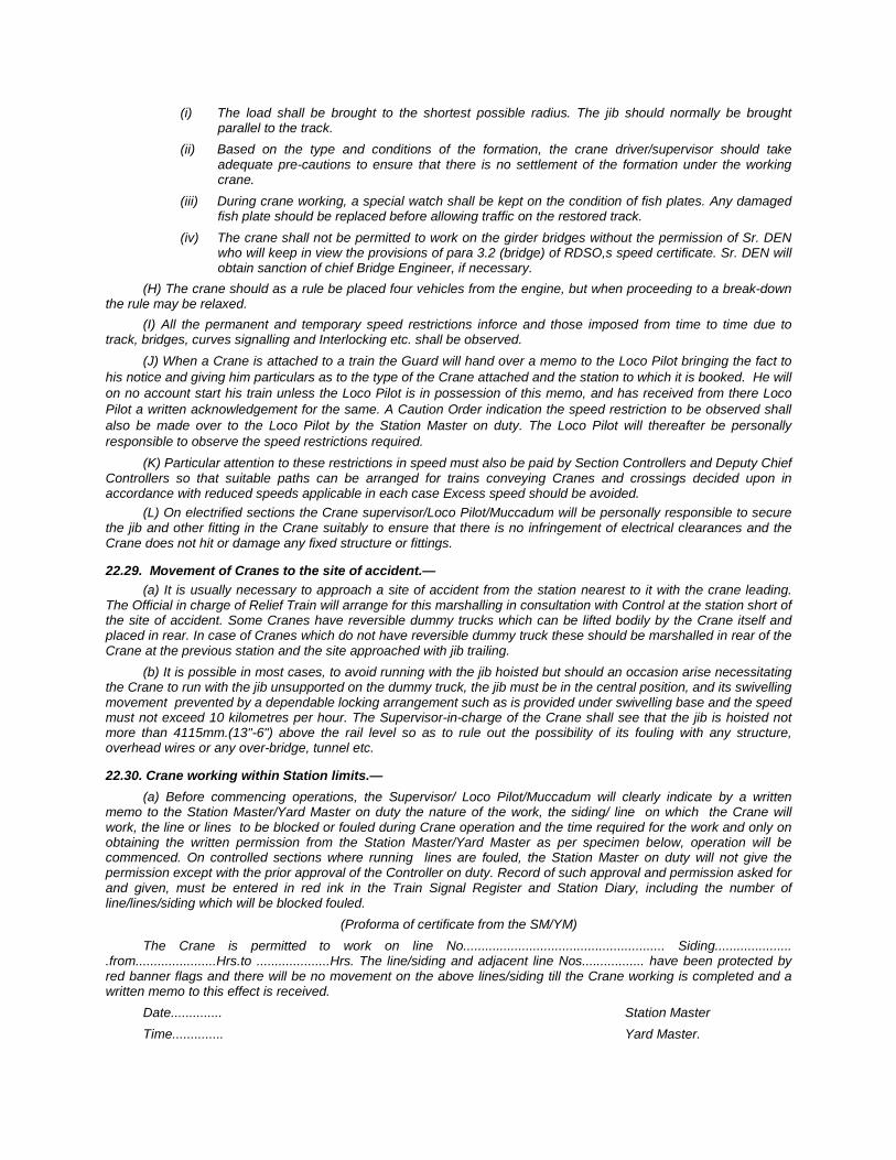
(i) The load shall be brought to the shortest possible radius. The jib should normally be brought parallel to the track.
(ii) Based on the type and conditions of the formation, the crane driver/supervisor should take adequate pre-cautions to ensure that there is no settlement of the formation under the working crane.
(iii) During crane working, a special watch shall be kept on the condition of fish plates. Any damaged fish plate should be replaced before allowing traffic on the restored track.
(iv) The crane shall not be permitted to work on the girder bridges without the permission of Sr. DEN who will keep in view the provisions of para 3.2 (bridge) of RDSO,s speed certificate. Sr. DEN will obtain sanction of chief Bridge Engineer, if necessary.
(H) The crane should as a rule be placed four vehicles from the engine, but when proceeding to a break-down the rule may be relaxed.
(I) All the permanent and temporary speed restrictions inforce and those imposed from time to time due to track, bridges, curves signalling and Interlocking etc. shall be observed.
(J) When a Crane is attached to a train the Guard will hand over a memo to the Loco Pilot bringing the fact to his notice and giving him particulars as to the type of the Crane attached and the station to which it is booked. He will on no account start his train unless the Loco Pilot is in possession of this memo, and has received from there Loco Pilot a written acknowledgement for the same. A Caution Order indication the speed restriction to be observed shall also be made over to the Loco Pilot by the Station Master on duty. The Loco Pilot will thereafter be personally responsible to observe the speed restrictions required.
(K) Particular attention to these restrictions in speed must also be paid by Section Controllers and Deputy Chief Controllers so that suitable paths can be arranged for trains conveying Cranes and crossings decided upon in accordance with reduced speeds applicable in each case Excess speed should be avoided.
(L) On electrified sections the Crane supervisor/Loco Pilot/Muccadum will be personally responsible to secure the jib and other fitting in the Crane suitably to ensure that there is no infringement of electrical clearances and the Crane does not hit or damage any fixed structure or fittings.
22.29. Movement of Cranes to the site of accident.— (a) It is usually necessary to approach a site of accident from the station nearest to it with the crane leading.
The Official in charge of Relief Train will arrange for this marshalling in consultation with Control at the station short of the site of accident. Some Cranes have reversible dummy trucks which can be lifted bodily by the Crane itself and placed in rear. In case of Cranes which do not have reversible dummy truck these should be marshalled in rear of the Crane at the previous station and the site approached with jib trailing.
(b) It is possible in most cases, to avoid running with the jib hoisted but should an occasion arise necessitating the Crane to run with the jib unsupported on the dummy truck, the jib must be in the central position, and its swivelling movement prevented by a dependable locking arrangement such as is provided under swivelling base and the speed must not exceed 10 kilometres per hour. The Supervisor-in-charge of the Crane shall see that the jib is hoisted not more than 4115mm.(13"-6") above the rail level so as to rule out the possibility of its fouling with any structure, overhead wires or any over-bridge, tunnel etc.
22.30. Crane working within Station limits.— (a) Before commencing operations, the Supervisor/ Loco Pilot/Muccadum will clearly indicate by a written
memo to the Station Master/Yard Master on duty the nature of the work, the siding/ line on which the Crane will work, the line or lines to be blocked or fouled during Crane operation and the time required for the work and only on obtaining the written permission from the Station Master/Yard Master as per specimen below, operation will be commenced. On controlled sections where running lines are fouled, the Station Master on duty will not give the permission except with the prior approval of the Controller on duty. Record of such approval and permission asked for and given, must be entered in red ink in the Train Signal Register and Station Diary, including the number of line/lines/siding which will be blocked fouled.
(Proforma of certificate from the SM/YM) The Crane is permitted to work on line No....................................................... Siding.....................
.from......................Hrs.to ....................Hrs. The line/siding and adjacent line Nos................. have been protected by red banner flags and there will be no movement on the above lines/siding till the Crane working is completed and a written memo to this effect is received. Date.............. Station Master Time.............. Yard Master.
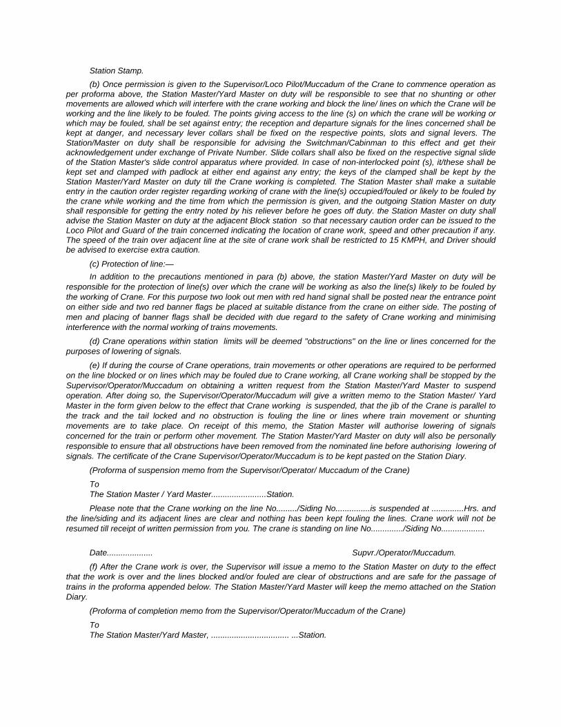
Station Stamp. (b) Once permission is given to the Supervisor/Loco Pilot/Muccadum of the Crane to commence operation as
per proforma above, the Station Master/Yard Master on duty will be responsible to see that no shunting or other movements are allowed which will interfere with the crane working and block the line/ lines on which the Crane will be working and the line likely to be fouled. The points giving access to the line (s) on which the crane will be working or which may be fouled, shall be set against entry; the reception and departure signals for the lines concerned shall be kept at danger, and necessary lever collars shall be fixed on the respective points, slots and signal levers. The Station/Master on duty shall be responsible for advising the Switchman/Cabinman to this effect and get their acknowledgement under exchange of Private Number. Slide collars shall also be fixed on the respective signal slide of the Station Master's slide control apparatus where provided. In case of non-interlocked point (s), it/these shall be kept set and clamped with padlock at either end against any entry; the keys of the clamped shall be kept by the Station Master/Yard Master on duty till the Crane working is completed. The Station Master shall make a suitable entry in the caution order register regarding working of crane with the line(s) occupied/fouled or likely to be fouled by the crane while working and the time from which the permission is given, and the outgoing Station Master on duty shall responsible for getting the entry noted by his reliever before he goes off duty. the Station Master on duty shall advise the Station Master on duty at the adjacent Block station so that necessary caution order can be issued to the Loco Pilot and Guard of the train concerned indicating the location of crane work, speed and other precaution if any. The speed of the train over adjacent line at the site of crane work shall be restricted to 15 KMPH, and Driver should be advised to exercise extra caution.
(c) Protection of line:— In addition to the precautions mentioned in para (b) above, the station Master/Yard Master on duty will be
responsible for the protection of line(s) over which the crane will be working as also the line(s) likely to be fouled by the working of Crane. For this purpose two look out men with red hand signal shall be posted near the entrance point on either side and two red banner flags be placed at suitable distance from the crane on either side. The posting of men and placing of banner flags shall be decided with due regard to the safety of Crane working and minimising interference with the normal working of trains movements.
(d) Crane operations within station limits will be deemed "obstructions" on the line or lines concerned for the purposes of lowering of signals.
(e) If during the course of Crane operations, train movements or other operations are required to be performed on the line blocked or on lines which may be fouled due to Crane working, all Crane working shall be stopped by the Supervisor/Operator/Muccadum on obtaining a written request from the Station Master/Yard Master to suspend operation. After doing so, the Supervisor/Operator/Muccadum will give a written memo to the Station Master/ Yard Master in the form given below to the effect that Crane working is suspended, that the jib of the Crane is parallel to the track and the tail locked and no obstruction is fouling the line or lines where train movement or shunting movements are to take place. On receipt of this memo, the Station Master will authorise lowering of signals concerned for the train or perform other movement. The Station Master/Yard Master on duty will also be personally responsible to ensure that all obstructions have been removed from the nominated line before authorising lowering of signals. The certificate of the Crane Supervisor/Operator/Muccadum is to be kept pasted on the Station Diary.
(Proforma of suspension memo from the Supervisor/Operator/ Muccadum of the Crane)
To The Station Master / Yard Master........................Station.
Please note that the Crane working on the line No........./Siding No...............is suspended at ..............Hrs. and the line/siding and its adjacent lines are clear and nothing has been kept fouling the lines. Crane work will not be resumed till receipt of written permission from you. The crane is standing on line No............../Siding No...................
Date.................... Supvr./Operator/Muccadum.
(f) After the Crane work is over, the Supervisor will issue a memo to the Station Master on duty to the effect that the work is over and the lines blocked and/or fouled are clear of obstructions and are safe for the passage of trains in the proforma appended below. The Station Master/Yard Master will keep the memo attached on the Station Diary.
(Proforma of completion memo from the Supervisor/Operator/Muccadum of the Crane)
To The Station Master/Yard Master, .................................. ...Station.
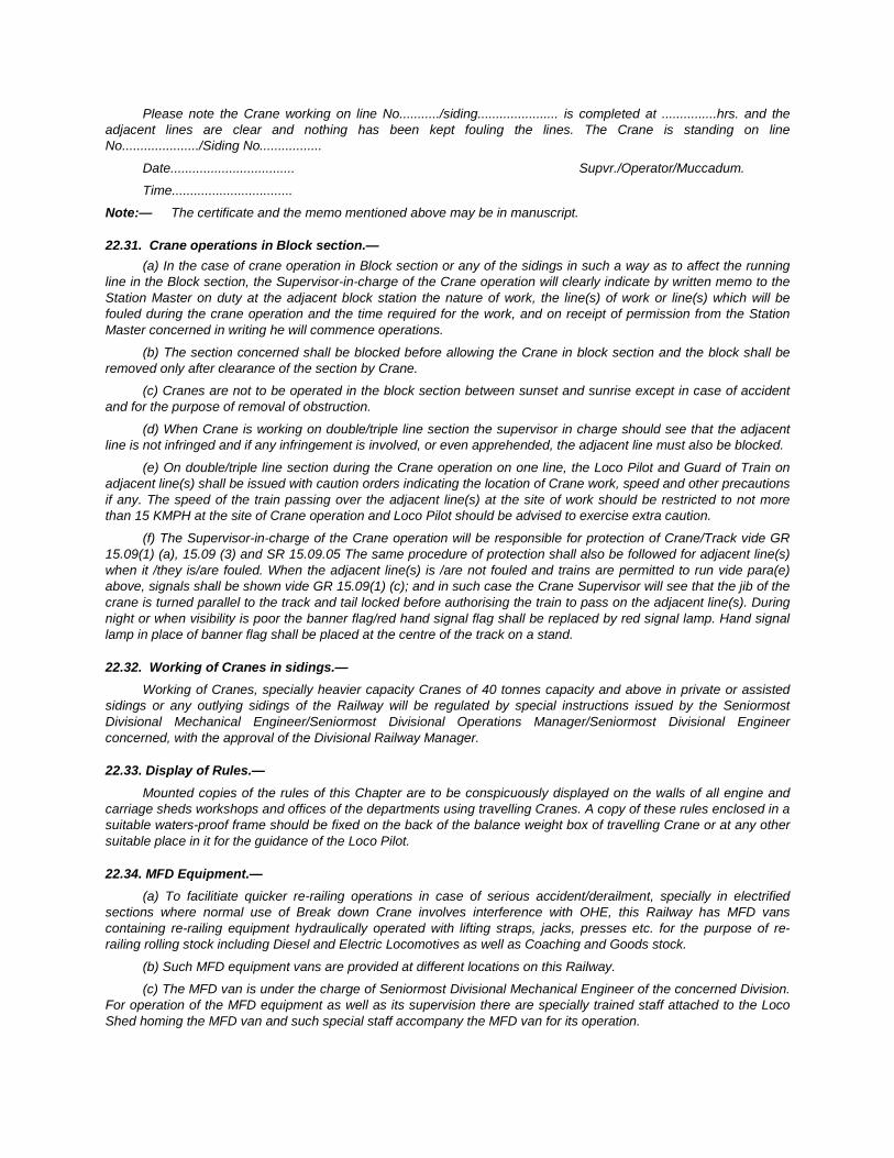
Please note the Crane working on line No.........../siding...................... is completed at ...............hrs. and the adjacent lines are clear and nothing has been kept fouling the lines. The Crane is standing on line No...................../Siding No.................
Date.................................. Supvr./Operator/Muccadum.
Time.................................
Note:— The certificate and the memo mentioned above may be in manuscript.
22.31. Crane operations in Block section.— (a) In the case of crane operation in Block section or any of the sidings in such a way as to affect the running
line in the Block section, the Supervisor-in-charge of the Crane operation will clearly indicate by written memo to the Station Master on duty at the adjacent block station the nature of work, the line(s) of work or line(s) which will be fouled during the crane operation and the time required for the work, and on receipt of permission from the Station Master concerned in writing he will commence operations.
(b) The section concerned shall be blocked before allowing the Crane in block section and the block shall be removed only after clearance of the section by Crane.
(c) Cranes are not to be operated in the block section between sunset and sunrise except in case of accident and for the purpose of removal of obstruction.
(d) When Crane is working on double/triple line section the supervisor in charge should see that the adjacent line is not infringed and if any infringement is involved, or even apprehended, the adjacent line must also be blocked.
(e) On double/triple line section during the Crane operation on one line, the Loco Pilot and Guard of Train on adjacent line(s) shall be issued with caution orders indicating the location of Crane work, speed and other precautions if any. The speed of the train passing over the adjacent line(s) at the site of work should be restricted to not more than 15 KMPH at the site of Crane operation and Loco Pilot should be advised to exercise extra caution.
(f) The Supervisor-in-charge of the Crane operation will be responsible for protection of Crane/Track vide GR 15.09(1) (a), 15.09 (3) and SR 15.09.05 The same procedure of protection shall also be followed for adjacent line(s) when it /they is/are fouled. When the adjacent line(s) is /are not fouled and trains are permitted to run vide para(e) above, signals shall be shown vide GR 15.09(1) (c); and in such case the Crane Supervisor will see that the jib of the crane is turned parallel to the track and tail locked before authorising the train to pass on the adjacent line(s). During night or when visibility is poor the banner flag/red hand signal flag shall be replaced by red signal lamp. Hand signal lamp in place of banner flag shall be placed at the centre of the track on a stand.
22.32. Working of Cranes in sidings.— Working of Cranes, specially heavier capacity Cranes of 40 tonnes capacity and above in private or assisted
sidings or any outlying sidings of the Railway will be regulated by special instructions issued by the Seniormost Divisional Mechanical Engineer/Seniormost Divisional Operations Manager/Seniormost Divisional Engineer concerned, with the approval of the Divisional Railway Manager.
22.33. Display of Rules.— Mounted copies of the rules of this Chapter are to be conspicuously displayed on the walls of all engine and
carriage sheds workshops and offices of the departments using travelling Cranes. A copy of these rules enclosed in a suitable waters-proof frame should be fixed on the back of the balance weight box of travelling Crane or at any other suitable place in it for the guidance of the Loco Pilot.
22.34. MFD Equipment.— (a) To facilitiate quicker re-railing operations in case of serious accident/derailment, specially in electrified
sections where normal use of Break down Crane involves interference with OHE, this Railway has MFD vans containing re-railing equipment hydraulically operated with lifting straps, jacks, presses etc. for the purpose of re-railing rolling stock including Diesel and Electric Locomotives as well as Coaching and Goods stock.
(b) Such MFD equipment vans are provided at different locations on this Railway.
(c) The MFD van is under the charge of Seniormost Divisional Mechanical Engineer of the concerned Division. For operation of the MFD equipment as well as its supervision there are specially trained staff attached to the Loco Shed homing the MFD van and such special staff accompany the MFD van for its operation.
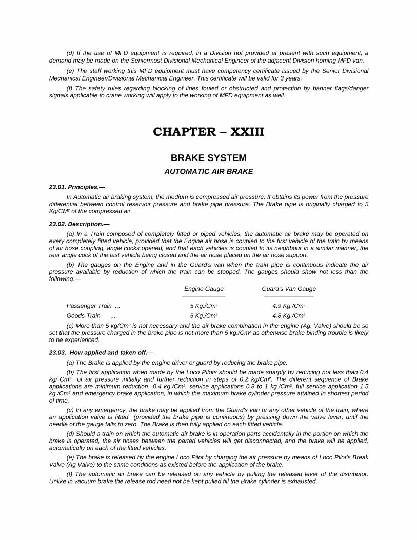
(d) If the use of MFD equipment is required, in a Division not provided at present with such equipment, a demand may be made on the Seniormost Divisional Mechanical Engineer of the adjacent Division homing MFD van.
(e) The staff working this MFD equipment must have competency certificate issued by the Senior Divisional Mechanical Engineer/Divisional Mechanical Engineer. This certificate will be valid for 3 years.
(f) The safety rules regarding blocking of lines fouled or obstructed and protection by banner flags/danger signals applicable to crane working will apply to the working of MFD equipment as well.
CHAPTER – XXIII
BRAKE SYSTEM AUTOMATIC AIR BRAKE
23.01. Principles.— In Automatic air braking system, the medium is compressed air pressure. It obtains its power from the pressure
differential between control reservoir pressure and brake pipe pressure. The Brake pipe is originally charged to 5 Kg/CM2 of the compressed air.
23.02. Description.— (a) In a Train composed of completely fitted or piped vehicles, the automatic air brake may be operated on
every completely fitted vehicle, provided that the Engine air hose is coupled to the first vehicle of the train by means of air hose coupling, angle cocks opened, and that each vehicles is coupled to its neighbour in a similar manner, the rear angle cock of the last vehicle being closed and the air hose placed on the air hose support.
(b) The gauges on the Engine and in the Guard's van when the train pipe is continuous indicate the air pressure available by reduction of which the train can be stopped. The gauges should show not less than the following:—
Engine Gauge Guard's Van Gauge ——————— ————————
Passenger Train ... 5 Kg./Cm2 4.9 Kg./Cm2 Goods Train ... 5 Kg./Cm2 4.8 Kg./Cm2 (c) More than 5 kg/Cm2 is not necessary and the air brake combination in the engine (Ag. Valve) should be so
set that the pressure charged in the brake pipe is not more than 5 kg./Cm2 as otherwise brake binding trouble is likely to be experienced.
23.03. How applied and taken off.— (a) The Brake is applied by the engine driver or guard by reducing the brake pipe. (b) The first application when made by the Loco Pilots should be made sharply by reducing not less than 0.4
kg/ Cm2 of air pressure initially and further reduction in steps of 0.2 kg/Cm2. The different sequence of Brake applications are minimum reduction 0.4 kg./Cm2, service applications 0.8 to 1 kg./Cm2, full service application 1.5 kg./Cm2 and emergency brake application, in which the maximum brake cylinder pressure attained in shortest period of time.
(c) In any emergency, the brake may be applied from the Guard's van or any other vehicle of the train, where an application valve is fitted (provided the brake pipe is continuous) by pressing down the valve lever, until the needle of the gauge falls to zero. The Brake is then fully applied on each fitted vehicle.
(d) Should a train on which the automatic air brake is in operation parts accidentally in the portion on which the brake is operated, the air hoses between the parted vehicles will get disconnected, and the brake will be applied, automatically on each of the fitted vehicles.
(e) The brake is released by the engine Loco Pilot by charging the air pressure by means of Loco Pilot's Break Valve (Ag Valve) to the same conditions as existed before the application of the brake.
(f) The automatic air brake can be released on any vehicle by pulling the released lever of the distributor. Unlike in vacuum brake the release rod need not be kept pulled till the Brake cylinder is exhausted.
(g) The Brake gear should be properly adjusted so that the brake blocks firmly grip the wheel treads in the brake applied condition, the test for which may be done by sounding the brake blocks with a hammer.
23.04. Specification.— (a) The air hose coupling between the Engine and the first vehicle and between each piped or fully braked
vehicle and its neighbour must be properly connected. The rear air hose of the piped or fully Braked vehicle forming the last of the sequence from the engines must be engaged on air hose support and the angle cock closed carefully.
( b ) When the air hose couplings have been connected, and the angle cocks are opened, the engine Loco Pilot must charge the required air pressure 5Kg./Cm2 and maintain it through out the journey.
(c) Examination of trains before starting should be done as per general rule 4.30,4.31, 4.32,4.33 and subsidiary rules thereto.
(d) Guard and Loco Pilots shall ensure at the time of taking over charge of a train, that their trains have the prescribed minimum brake power as laid down below.
1) For Goods Trains:— (i) For the purpose of working out of the percentage of operative pistons on trains, piped vehicle should be
deemed to have in-operative cylinder/cylinders. The percentage has not been expressed in terms of vehicles or four wheeler units but only in terms of brake cylinders, since bogie wagons have two cylinders and four wheelers have one cylinder.
(ii) An active brake cylinder is one in which the air pressure can be admitted through the auxiliary reservoir when the pressure in the brake pipe is reduced by control from the engine and which, moreover, satisfies the stipulation that its piston would remain in pushed-out position for not less than 30 minutes after the air pressure in the brake pipe is reduced.
(iii) On steep gradient sections 90% of the brake cylinders must be operative.
(iv) Brake power of freight trains :—
Description — Originating station Freight trains — a) C.C. Rakes — 95% b) Other goods train — 85%
Not less than 95% of total number of cylinders in case of C.C. rakes and 85% in case of other goods trains shall be in working condition in case of train originating/examination point. There may be however, certain amount of deterioration in the brake power while the train is on run due to wear and tear. Taking into account the practical conditions, the goods trains including C. C. rakes may be worked with 75% active cylinders enroute. For the purpose of this rules "piped vehicle" (i.e. fitted with trains pipes and having no vacuum cylinder or other brake fittings) should be deemed to have in operative cylinder(s). In case, however, a driver feels that the brake power is not upto even this level (i.e. 75%), he shall suitably control the speed of the train and worked the train to the next station or next train examining station for necessary examination by train examining staff.
(v) No audible leak is permissible in the air brake system along the train. (vi) There should be atleast 4 fully air braked vehicles including brake van with operative cylinders at the
rear end of the train. (vii) The position of Empty/ Load Box handle on wagon should be placed on the appropriate position either
Empty/Load according to the loaded condition of the wagon. 2) For Passenger Carrying Train :— (i) From an originating station the train must have all vehicles with active air brake cylinders. (ii) At intermediate stations not more than 10% of in-operative cylinders. (Subject to maximum of 2 cylinders
only) can be permitted. (e) When the engine is attached to the train, the Loco Pilot must see that the air hose coupling on the engine is
properly connected to that on the train. Both angle cocks to be closed before detaching their hose couplings of the engine and front vehicles and air hoses are engaged on respective air hose supports.
(f) The Loco Pilot must test the engine automatic air brake apparatus before leaving the shed. Should there by any difficulty in charging and maintaining the required air pressure, after coupling to the train, steps should be taken to locate and remedy the fault, failing which the defective vehicle should be detached without infringing safety. Loco Pilots should ensure that the specified main reservoir Pressure is maintained.
23.05 Recording and testing of Air pressure indication by Guards.— (a) (i) The Guard must record in the appropriate column in the Guard's rough journal book and Guard's train
report (T 34 HF) what air pressure is indicated in the brakevan gauge every time the train starts after a halt. He will not give starting signal to the Loco Pilot unless the air pressure as indicated in rule 17.24(b) is registered in his gauge or unless he is authorised by a representative of Mechanical Department to start at lower air pressure than prescribed.
(ii) At the first starting station and at all stations where the engine or any vehicles are detached from the train or any vehicles are attached to the train, before starting when the Loco Pilot has charged the air pressure, the Guard must reduce 0.4 Kg./Cm2 air pressure by operating his brake van valve observing the indication needle and then replace his valve to normal and allow the Loco Pilot to charge the remained air pressure. Without doing the Guard must not give the starting signal to the Loco Pilot.
(iii) If the indicator is not registering correct air pressure as given in rule 17.24(b) the fact must be brought to the notice of either the Train Examiner or the Loco Pilot.
(b) Air pressure tightness test for Locomotives by Loco Pilots :— I) Engine :— Engine should be tested for leakage test as follows :— (A) Open the Loco angle cocks in front and in rear to allow the dirt or water to blow out and apply master
gauge on rear air hose couplings. Close the front angle cock of the engine. (B) Charge the brake pipe pressure to 5 Kg./Cm2 Ensure 5 Kg./Cm2 pressure is registered in the Engine
brake power pressure gauge as well as in master gauge. (C) Drop a pressure 1 Kg./Cm2 by keeping the Loco Pilot's brake valve handle in application position. (D) Keep the cut-out cock in 'OUT' position. Wait for 60 seconds. (E) Note, there should not be any drop in the pressure gauge in the next 60 seconds. (F) Any drop in pressure indicates the leakage in the Engine. (G) Again charge the brake pipe pressure to 5 Kg./Cm2 and ensure pressure is restored instantaneously. II) On Trains :— (A) Couple up engine air hose to the train air hose. (B) Open rear angle cock of the brake van to allow the dirt or water to blow out and apply master gauge. (C) Charge the brake pipe pressure to 5 Kg./Cm2 Ensure the same amount of pressure is registered in the
brake van pressure gauge and master gauge. (D) Drop a pressure by 1 Kg./Cm2 by Loco Pilots, brake valve. (E) Keep the cut-out cock in the loco brake valve in out position and wait for 60 seconds. (F) A drop of 0.2 Kg./Cm2 (0.3 Kg./Cm2 on longer trains) is permissible. (G) Any excess leakage noticed is to be attended to. (H) Again re-charge the brake pipe pressure to 5 Kg./Cm2 and ensure the pressure restores
instantaneously in brake van. (I) Close the rear angle cock of brake van and engage the respective air hose on support.
24.06. During Journey.— (a) Loco Pilots and Guards must unscrew their hand brakes fully off before starting. (b) Loco Pilots will be guided in the use of their air brakes and hand brakes by the orders in force. (c) If during the journey the Guard of any train finds that the gauge in his Brakevan shows less than the
required air pressure (unless he is satisfied that such is caused by an application of brakes) he must be prepared to apply his hand brake if required and advise the Loco Pilot of the defect at the next stopping station.
(d) The Loco Pilot and the guard must report to the Train Examining staff at the next train examining station any irregularity or defect in connection with the working of the automatic air brake which may have occurred, and the Guard must in addition, note the particulars in his journal.
(e) When fitted or piped vehicles on which the automatic air brakes are being operated have to be parted for any purpose, the angle cocks of the vehicles where they have to be uncoupled must be closed so that there may be no delay in coupling and the men put on the job are not injured.
(f) In case of failure of the automatic air brake on any train during the journey, if the defect cannot at once be remedied, the train must proceed cautiously to the next convenient station, where the defective vehicle can be
remarshalled, detached or otherwise dealt with, the speed of the train being so regulated as to enable the Driver to have full control of the train by the hand brakes. In all such cases the Guards must be on the alert and assist in stopping the train with the hand brakes.
(g) (i) When two engines are employed to draw a train, the Loco Pilot of the leading engine will be held responsible for the working of automatic air brake. The Loco Pilot of the second engine must, however in case of emergency, assist in stopping or reducing the speed of the train by applying the automatic air brake, or hand brake, as may be required, but he must not maintain or recharge the air pressure.
(ii) When an additional engine or engines are employed to push a train, the Loco Pilots thereon must not interfere with the working of air brake which shall be under the control of the leading engine Loco Pilot as laid down in para (g)(i) above.
(iii) Loco Pilot of all additional engines will at all times keep the handles of the Loco Pilots brake valve in the release position.
(iv) In the event Loco Pilots of the engine in rear requiring in any emergency to attract the attention of the leading engine Loco Pilot, he shall give whistle code as laid down in G.R.4.50 and S.R.4.50.01.
Note :— These rules are laid down to avoid the serious danger which would arise if the Guard or the Loco Pilots of additional engines were to put the brake on, while the leading Loco Pilot was trying to recharge air pressure.
23.07. Stopping.— (a) Before the train is brought to a stand, the Loco Pilot will release the brake slightly to prevent a rebound of
the vehicles and an undue strain on the couplings. (b) In case of a train becoming divided, the Guard in the rear van must put his hand brake hard on and secure
it with the chain or sprag, where provided. He must also take any other precaution that may be necessary to prevent the rear portion moving, before going back to protect his train.
(c) In controlling trains on descending long and heavy grades, Loco Pilots are cautioned against the exhaustibility of the air brake system. Loco Pilots should know what is called the sensitive brake application and should take extreme care in avoiding the fading of the brake power. After repeated brake applications care should be taken that auxiliary reservoirs where the brake cylinders are fed from, are recharged to the original capacity (5 Kg./Cm2). Neglect of this rule may lead to the train going out of control.
(d) On long and heavily graded sections, when trains are braked only by compressed air pressure, it is essential that trains be stopped at suitable time intervals during the run for recoupling lost air pressure in auxiliary reservoir and to ensure that train be kept under control and hence halts may be provided on such heavily graded sections either at station or in mid sections for recoupling air pressure in the auxiliary reservoir and these halts wherever provided are shown in the working Time Tables. Loco Pilots while working air brake trains must ensure that they strictly observe these halts regardless of whether they are given through signals or not.
(e) The fact that after the brake has been applied the air pressure in the control reservoir gradually decreases due to leakage and that in less than half an hour the brakes may leak off altogether must not be forgotten when a train is brought to a stand on a gradient steeper than 1 in 150. In all such cases measures must be taken to guard against the possibility of a run-away. For this purpose, precautions mentioned in SR.6.04.02(d) must be observed strictly.
The Guard and the Brakesman must always be vigilant and be prepared to assist the Loco Pilot by applying hand brakes, if called upon to do so by the Loco Pilot and if necessary in an emergency. If the Loco Pilot requires additional brake power, the Guard and Assistant Loco Pilot shall pin down hand brakes on as many vehicles as the Loco Pilot may consider necessary.
23.08. Passenger Train Stopping Apparatus.— (a) Passenger carriages are fitted with an apparatus enabling passengers, in case of emergency, to partially
apply the automatic air brakes and so to attract the attention of the Loco Pilot and the Guard of the train except such particular carriages/trains as may be exempted vide GR. 4.18.
(b) On noticing the drop of pressure in the brake pipe pressure gauge, the Guard, Loco Pilot, Motorman, Asstt. Loco Pilot and Brakesman will take necessary action as laid down in SR.4.18.01 and 4.18.02.
(c) To reset the apparatus to enable the train to proceed, it is only necessary for the Guard/Brakesman or Asstt. Loco Pilot to push one of the discs to its socket or to turn the disc through 90° as the case may be, which will cause both disc to resume their normal position and the brake blocks to get released.
23.09. General.—

(a) Air Hose couplings must not be left hanging loose but must be properly secured on the air hose support provided for the purpose.
(b) To couple the air hoses, they must be taken one in each hand and lifted sufficiently high to enable the palm ends of both air hoses to be coupled together and when lowered the coupling packing ring of one plam end will fall in the coupling case of the other end and hold in position with the stop-pin.
(c) To uncouple the air hoses, they must be lifted straight up, when the coupling packing ring of one palm end will come out of the coupling case of the other plam end and air hose palm ends will separate.
(d) When connecting and dis-connecting Air hoses, staff must be extremely careful. When the Air brake system is under charging, there will be a pressure of 5kg/cm2 in Air Hose and hence before handling them, respective angle cocks should be closed and after uncoupling/coupling angle cocks should be opened.
(e) Care must be taken in un-coupling air hose Palm ends that the MU washers are not displaced or lost. (f) Shunting staff and other when passing between vehicles must not step on the air hose coupling interfering
with or damaging them. (g) When automatic air brake vehicles are placed in siding or stabled with in the station limits, the brakes must
be released, and vehicles kept from moving by the application of the hand brakes if fitted, or by sprags or chains on the required number of vehicles if necessary.
(h) Guards and other concerned staff must take care that articles are not placed in Guard's vans in such a position as to come in the way of the lever of the Guard emergency valve.
23.10. Instructions to Loco Pilot, Guard and Assistant Guard on the use of Air Brakes.— Loco Pilots, Guards and Asst. Guard are being instructed in the training Centre during their initial and refresher
training period regarding the air brake system and its use. They must be well acquainted with all the instructions of this chapter and ensure strict observance.
23.11. Recording of Air Brake particulars by Guards.— (a) The Guards must be careful to show in their journals and on the copy handed to the Loco Pilot the
particulars of air pressure and number of vehicles with active/in-active cylinders on train. (b) In all cases where the active cylinder is made in-operative or vice-versa, during the journey, the change and
stations where it took place must be noted by the Guard in his journal and on the copy handed by him to the Loco Pilot.
23.12. Locomotive Loco Pilot to blow through.— In order to prevent the accumulation of Moisture and dirt in the pipes of automatic air brake apparatus Loco
Pilots are instructed that before leaving shed with their engine to work a train, a good blow through should be given with the Loco Pilots brake valve by opening the front and rear angle cocks. A through blow should be given by opening the dummy plug of main reservoir also. The accumulated moisture and oil will be drained out. Likewise before engine is attached to the train, the rear hose should be opened and blow-through given. After the engine is attached to the train and the rear air hose of the engine and the air hose of the first wagon of the train air hose coupled, the blow-through should be given by opening the rear angle cock of the last vehicle.
23.13. Other responsibility of staff.— (a) The working of automatic air brake by the engine Loco Pilot will not relieve the Guard of any responsibility
as to the braking of the train. Guards must therefore keep, a good look-out and be prepared to apply the automatic air brake or hand brake should any necessity arise.
(b) Engine Loco Pilot must satisfy themselves that the automatic air brake is in proper working order before starting and at each station where any vehicle is attached or detached. They must also test the brakes before descending steep inclines and while approaching any danger signal or terminal station; the speed of the train must be reduced if necessary so as to stop the train at the proper place. Guards must watch the speed of the train and assist the engine Loco Pilot by the use of their Air Brake and Hand brake when necessary.
(c) Unless the automatic air brake is working properly while the train is on run, the engine Loco Pilot must whistle for the Guard's hand brakes, stop the train and inform the Guard that the automatic Air Brake is out of order and that the hand brakes must be relied upon for working the train to the next convenient station.
(d) In the case of failure of the automatic air brake on any vehicle during the journey, and if the defect cannot at once be remedied, the train must proceed cautiously to the next convenient station where the defective vehicle can be remarshalled detached or otherwise dealt with. The speed of the train should be so regulated as to enable the LP to have full control of the train. In all such cases the Guards must be on the alert, and assist in stopping the train.
23.14. How to locate leakage in Air pressure.—
Normally, the leakages are at the joints of the Air Hoses couplings namely at the palm ends and at nipples, at angle cock spindles, at the grip seal joints on main brake pipe, branch pipe etc. The leakage is usually detected by hissing sound produced by the air blowing-off. For detection of minor leaks, soap solution can be applied at joints where bubbles will be formed if leakage exists.
23.15. Trains with air brakes.— (a) Normally, trains must run fully air braked.
(b) In case of emergency when a passenger train, for any reason has to run non-air braked, the speed must not exceed 40 KMPH and for mixed and goods train must not exceed 30 KMPH subject to any lower speed restriction which may have been imposed over a particular section for any reason. In any case, a passenger train must not run non-air braked over any portion of the line without the permission of the Chief Operations Manager. However, running of non-air braked goods train in emergency may be permitted by the DRM.
(c) In such case, the load of the trains must be reduced and the Loco Pilot and Guard of the train shall be responsible to see that the train is under control to stop wherever required.
23.16. Air pressure for Ghat section.— (a) In addition to the specification on air pressure requirements and all other instruction laid down for goods
trains in the earlier paras, it should be further ensured that a minimum of 90% of total No.of cylinders are fully operative on train on ghat section.
(b) If the required brake power, as defined above is not available or if the Driver doubts whether the brake power is sufficient or not, he has to stop and sufficient number of hand brakes have to be pinned down to ensure control on a down gradient.
23.17. Attaching of vehicles not fitted with automatic air brakes to coaching trains.— (a) Mail, Express and passenger trains fitted with automatic air brakes, brake piped vehicles (vehicles fitted
with only brake pipe and not with distributor valve, brake cylinder, brake rigging etc.) may be attached not more than one. Such vehicle attached on a passenger train should be-protected by one or more vehicles fitted with automatic air brakes attached in rear of it.
(b) No goods vehicle fitted with brake pipe only is permitted to be attached to a coaching train. Vehicles, both coaching & goods, fitted with brake pipe only, may be attached to troop trains and special trains conveying military stores etc., but the specification of brake power laid down in para 23.04 must be followed except if any relaxation is permitted by CME/Sr. DME/DME in case of emergency.
23.18. Dis-connection of means of communication:— If disconnection of means of communication to prevent misuse is permitted vide G.R. 4.18, the procedure and
precaution laid down in the said G.R & S.R. thereto should be followed.
23.19. Testing of communications and alarm chains on running trains.— (a) The communication provided in passenger carriages for stopping trains in case of emergency, must be
tested by Divl. Optn. manager, and Divl, Mech. Engineers, their Assistants and also by the Divisional Transportation Inspectors and C & W and Loco Inspectors in running train at least once a month. The test must be made by pulling the chains in one of the passenger carriages on the train, while the train is on the move but the test should be avoided while a train is ascending an incline or when a train is running late. Divisional Safety Officer shall also make similar checks.
(b) The result of the test must be recorded by the testing officials and reported to the Divisional Operations Manager or Divisional Safety Officer and the Divisional Mechanical Engineer at once. the following particulars are to be recorded:—
(i) Date, time train Number and the number and class of the Carriage in which the chain was pulled. (ii) Time that was taken to stop the train after the chain was pulled. (iii) Whether signals were properly exchanged between the Guard and the Loco Pilot. (iv) The time that elapsed before the Guard came to the carriage from which the chain was pulled. (v) Total duration of the halt. (vi) Approximate estimated speed of the train at the time of test.

23.20. Application of automatic air brake from the brake van.— The Automatic air brake may be applied from the brakevan in an emergency only. The application of Automatic
air brake must, in such cases, be gradual, as there is risk of the train parting owing to sudden application of the air brake from the rear.
23.21 Blanking "off" automatic air brake distributor valve.— When an automatic air brake distributor valve or its brake cylinder on a vehicle is out of order, the distributor
valve and brake cylinder must be put out of action. The brakes of the individual wagon can be isolated by shutting off the isolating cock. This isolating cock is either fitted on the distributor valve itself, or on the branch pipe connecting the brake pipe to the distributor valve.
23.22. Empty/load handle on special type bogie fitted wagons.— (a) The special type bogie fitted wagon with higher carrying capacity are provided with a mechanical device
known as empty/load box, by the manipulation of which, the brake power of a wagon can be increased or decreased. (b) This equipment has been provided to ensure that the train has adequate brake power in the empty as well
as loaded condition of the wagon to enable it to be kept under proper control at all times. (c) When the wagon is loaded, its brake power must be increased and this is done by operating a small
Empty/Load Box handle (provided at the side of the wagon just below floor), from the "Empty" position to the "loaded position". These two positions are clearly marked on the plate on which the handle is fixed, by legend and also by colour.
(d) When, however, the wagon is empty and as such increased brake power is not necessary, the Empty/Load Box handle MUST BE set at the "Empty" position.
(e) If the Empty/Load Box handle is not set in the correct position, a serious accident can happen, as in the loaded condition the train will have inadequate brake power, on the other hand, when it is empty, severe application of brake will skid the wheels and cause them irrepairable damage.
(f) All station and yard staff both operating and commercial, also train examining and running staff should be fully acquainted with the operation of the Empty/Load Box device fitted on special type bogie fitted wagons. The following instructions should be strictly observed :—
(i) The handle of Empty/Load Box should be at the "Empty" position when the wagon is empty or when it is loaded with light materials like bamboo etc., so that the gross weight of the wagon is not likely to exceed 50 tonnes. The handle should be set to "loaded" position when the wagon is fully loaded or if the gross weight is above 50 tonnes.
(ii) The Train Examiner will be responsible for the correct setting of the Empty/Load Box handle at all originating stations where the train is examined and certified fit by the Carriage & Wagon staff and at stations where the trains are passed by them. This should be recorded in the Air pressure brake certificate also.
(iii) The Guard will be responsible for the correct setting of Empty/Load Box handle at Wayside stations where any shunting is done or when a stabled train is picked up. The Guard must, however, be vigilant to see that when his train is detained at a station for any length of time, no unauthorised person interferes with the handle. This caution is to be exercised particularly when the train is running empty.
(iv) The staff responsible for loading or unloading of the wagons should also ensure that the handle of Empty/Load Box is correctly set after loading or unloading. Just before unloading commences, the Empty/Load Box handle should be changed to "Empty" position.
—————
CHAPTER – XXIV
MISCELLANEOUS 24.01. Use of Portable Control Telephones.— (a) (i) Portable Control Telephone forms a part of brakevan equipment and must be supplied to every Mail,
Express and Passenger train, except for EMU suburban locals running between Howrah-Kharagpur sec. (ii) The portable control Telephone is be used by the Guard of Passenger train to relay information to
control in case of any accident to train, obstruction or other case occurring in the mid-section, so as to arrange prompt relief measure, by the Control and other concerned.
(iii) Portable Control Telephones should be supplied by the staff of S&T department at the originating station of passenger trains and collected at the destination station of the trains. In case of inter-railway Mail, Express and Passenger trains, supply and collection of Portable Control Telephones are to be made by the respective railways run within their jurisdiction.
(iv) Guard of every Passenger train must make it a point to see before the starting of his train from originating station that Portable Control Telephone is supplied to the brakevan along with other brakevan equipment. In case of non-supply of the same, he should immediately bring it to the notice of Station Master on duty and obtain a memo from him for non-supply with the reasons thereof.
(b) Description of Portable Control Telephone.— A sealed metallic or wooden box containing a portable control type telephone is kept in a leather case. It is of
socket type.
Socket type.— Socket type portable control telephone is used for electrified section. A sealed metallic or wooden box
containing a portable control telephone is connected with wire and six pin plug to connect with the socket provided on a post with a small iron box fitted with plug points, at every three fourth Kilometre. In addition every alternative overhead must is stencilled with legend of telephone in the direction where the circuit posts are located
How to use.— The flexible wire connected should be inserted on the six pin socket of Pressed switch socket of the small post
located for the purpose. After connecting the handle of the portable control telephone and call Traction Power Controller who shall connect the section Controller if required. (c) Training to staff for use of portable Control telephones.—
(i) Every Guard is imparted training at Zonal Training Centre, Sini during initial and refresher course, as to how to use the portable control telephone.
(ii) Loco Pilots working Electric trains are also trained in use of socket type Portable Control telephone before they are allowed to work in sections by their respective supervisors and during the course of initial and refresher training at the respective system training schools.
(d) Procedure for checking and testing of portable Control phones and maintenance of stock. (i) Every portable control telephone in the Division shall be neatly marked with serial number, Name of
base station and Division, Inspector maintaining the telephone, and the rake link on which a telephone is required to work. Portable control telephones for special train should be supplied from the buffer stock of the signal or Telecom. Inspector and normal supply for rake links should not be disturbed.
(ii) Sufficient number of Portable Telephones should be kept in good fettle at the following places— (a) Starting stations of trains; (b) Terminal stations.
(iii) In order to ensure satisfactory working of Portable Control telephone, each telephone must be tested jointly at least once every fortnight by the Electrical Signal Maintainer/Telecom. Maintainer and the Station Master at the base station of the Portable Telephones. The result of the joint test should be recorded in a separate register maintained by the Electrical Signal/Telecom Maintainer at the base station, allotting separate pages for each telephone to contain the following information.
(a) Date of testing ; (b) Defect noticed ; (c) Action taken to rectify; (d) Names of Maintainer and SM ; (e) Signatures of Maintainer and Station Master.
(iv) In the case of electrified areas, the socket type telephone should be tested by plugging into a test socket, ensuring that satisfactory communication is possible both ways from the telephone to the Controller.
(v) In addition the Electrical Signal Maintainer/Telecom Maintainer should also test the portable control telephone every time it is handed over to the Guard of the train and make an entry to that effect in the register to be maintained for this purpose at the base station. Each time the telephone is loaded or unloaded, the Guards signature should be obtain in the register in token of verification of intactness of the seal of the telephone box. In case the seal is broken, the outgoing Guard should accept the telephone with suitable remarks. In case the seal is broken when the telephone is received by an incoming train, the Guard must make an entry to this effect while signing the register.
(vi) At every point the Guard/Loco Pilot is changed, the intactness of the seal of the portable control telephone box should be checked by the Guard taking over duty. When a Guard or Loco Pilot is relieved by another Guard/Loco Pilot the signature of his reliever must be obtained in the Guard's Rough Journal Book/Loco Pilot's Note book.
(vii) Whenever a portable control telephone fails at the time of emergency use, mention must be made in the Guard's Journal which is to be conveyed to control. This Telephone on arrival at the base station shall be subjected to a joint test by the Operating and S & T Supervisors or by the Supervisors of the Loco department and S & T department in the case of electric engine.
(viii) Each Guard shall be trained and examined every three years at the Zonal Railway Training Institute, Sini regarding the use of portable Control Telephone in detail and on being satisfied on the proficiency of the Guard in the use of such telephone, the Principal shall issue a certificate of competency to each Guard. In addition to this examination made by the Principal, Zonal Training Centre, Sini, the Divisional Transportation Inspectors, Telecommunication Inspectors and Safety Counsellors should check the proficiency of the Guards in the use of portable Control Telephone as frequently as possible and report deficiency, if any to the Divisional Safety Officer for suitable action.
(e) Portable Telephone for Electric Locomotives:— (i) All electric locomotives in use on this Railway are provided with Portable Telephone to be used by the
Loco Pilots for connecting the Emergency Control circuits to relay information to control in case of any accident, failure, obstruction or any other cases occurring in the mid-section.
(ii) For this purpose, sufficient number of spare telephones and cells shall be made available in the Loco Shed by the electrical department. Soldering of cells for connecting to the circuit will be done by the S & T staff.
(iii) Periodical examination, testing and repair shall be conducted by the S & T staff so that sufficient number of Telephones in good working order are available at any time. This Periodical examination and testing shall be done at least once in a week. In addition, such periodical test should also be done by the JE/SE(Electrical).
(iv) Each Loco Pilot before taking charge of the Loco as well as the JE/SE(Electrical) immediately prior to its issue must check the Telephone irrespective of the periodical testing being done by the S & T staff. They shall ensure before commencement of journey of the locomotive that the telephone is in proper working order. In case of the Telephone does not confirm to the above standard, a spare tested telephone shall be handed over to the Loco Pilot and arrangement shall be made by the JE/SE(Electrical) for rectification of the defective telephone. All defective phones shall be stacked separately in the Shed under a clear distinguishable indicator lable "Defective".
(v) A register will be maintained in the office of the JE/SE(Electrical) regarding the test of the Portable Telephones allotting separate pages for each telephone to contain the following information:— (a) Telephone No. (b) Date of testing, (c) Defect noticed. (d) Action taken to rectify.
(e) Names of JE/SE(Electrical)/S&T official, (f) Signature of JE/SE/(Electrical)/S&T Officials.
(vi) Each Loco Pilot shall be trained and examined during the Refresher Course of training at the Electric Loco Training Centre, Tatanagar and System Technical Centre, Kharagpur regarding the use of Portable control Telephone in detail and on being satisfied on the proficiency of the Loco Pilot in the use of such Telephone, the Principal shall issue a certificate of competency to each Loco Pilot. In addition to this examination made by the Principal, the Inspectors of Loco department, Telecommunication Inspectors and Safety Counsellors should check the proficiency of the Loco Pilots in the use of portable Control Telephone as frequently as possible and report deficiency, if any, to the Sr. DEE/DEE (RS) or DME as the case may be.
24.02. Weather Warning.— (1) Arrangements exist with the Offices of the Mateorological department of the Government of India for issuing
warning message whenever storms, gales or heavy rainfall are expected. (2) A list indicating the Divisions and Railway officials to whom weather warning telegrams addressed by offices of
the Metereological department, is appended below:—
Sl Divsion Postal address of official to whom Regional Metero logical No. warning message should be addressed Centre issuing warning
1 2 3 4
1. KGP Principal Chief Engineer, Calcutta ADA S.E.Rly., Calcutta-43. RNC Chief Operations Manager, S.E.Rly., Calcutta-43 Chief Elec.Engineer., S.E.Rly., Calcutta-43 Chief Controller and Chief Traction Power Controller of the Divisions.
2. CKP Principal Chief Engineer, Bhubaneswar– Orissa S.E.Rly., Calcutta-43and Jharkhand portion. Chief Operations Manager, Calcutta for West Bengal S.E.Rly., Calcutta-43. portion. Chief Elec. Engineer, S.E.Rly., Calcutta-43. Chief Traction Power Controller, S.E.Rly., Chakradharpur. Chief Controller, S.E.Railway, Chakradharpur
(3) Action to be taken on receipt of weather warning message. (A) By the Central Control Office.
(i) The Chief Controller or in his absence the deputy chief Controller must immediately repeat the weather warning message verbatim on the telephone or by a written message to the Secy. to PCE and EA to COM for the information of PCE & COM, and then circulate the contents of the message to the Officers concerned in the Headquarters Office.
(ii) He should also verify with the divisional Control that such weather/cyclone warning messages received by him, have also been received by the Divisional Chief Controllers of the concerned divisions, so that lapses can be remedied then and there.
(B) By the Divisional Control Office. (i) The chief Controller or in his absence the Deputy Chief Controller should immediately repeat the
weather warning message verbatim on the telephone or by a written message to the Divisional Railway
Manager, Senior Divisional Operations manager/Divisional Operations manager, Senior Divisional Engineering (Coordination)/Senior Divisional Engineer(Line)/Divisional Engineer and the Assistant Engineer (if he is headquartered at the divisional head quarters).
(ii) Simultaneously, the Chief Controller or, in his absence the Deputy Chief Controller must immediately arrange for the transmission of the weather warning message verbatim on the Control phone to the concerned Station Master/Officials-in-charge of the Station/Station Master on duty. The controller repeating the messages should record the initials of the Station Master/Official-in-charge of the Station/Station Master on duty to whom the Message has been repeated.
(iii) In respect of sections which are not controlled or when the Control Telephone is interrupted, an "XXR"(immediate) message should be issued by the Chief Controller or in his absence by the Dy. Chief Controller, to the Station Masters/Officials-in-charge of the stations, through any other available means of communications.
(iv) The preamble of the weather warning message and the text as received from the Metereological Department should be reproduced verbatim in the text of 'XXR' message; the text of the message should be worded as shown below :
Regional Metereogical Centre...................................... .....................(here enter the name of the Metereological Centre)XXW/000 (insert whichever class is used by the Meterological Department) coded.............................................(insert Code time of the original message) date................................................ ( date of original message) reads................................................... (reproduce the text of the Metereological message verbatim).
(v) A register should be maintained in each Control Office showing full particulars of the receipt and action taken on the weather warning message showing the date and time of receipt of warning message, the full text of the message, and the date and time of despatch of telephonic advice to the officials concerned and the initials of the Station Masters/Officials-in-Charge of the Stations/Station Master on duty to whom the message has been repeated.
(vi) The Chief Traction Power Controller (CTPC) or, in his absence the Traction Power Controller (TPC), must immediately repeat the weather warning message verbataim on the telephone or by a written message to the Divisional Railway Manager, Senior Divisional Electrical Engineer/Divisional Electrical Engineer (Traction Distribution) and the Assistant Electrical Engineer (Traction Distribution) at the head quarters of the division.
(vii) The CTPC or, in his absence, the TPC should also ensure that the contents of the weather warning message are conveyed to the Assistant Electrical Engineer/Traction Distribution and the JE(OHE) of the concerned sections.
(C) By the JE(OHE)-in-charge of the Depot.
(i) The JE(OHE) on receipt of the weather warning message should immediately mobilise their resources and alert their staff so that they will be in readiness for any eventualities.
(ii) The JE(OHE) should also make sure that staff/gang already engaged in maintenance work are specially alerted to speed up the work so that availability of staff for contingencies is ensured.
(D) Action by the ASM on duty or Station Master/Official-in-Charge of the Station. (i) The Station Master/Official-in-charge of the Station or ASM on duty where AENs/JE/SE/SSE(Engg.)s are
headquartered should immediately handover to the parties a copy of the verbatim message received from the Controller and must obtain an acknowledgement. If the AEN/JE/SE/SSE(Engg.) is out of headquarters, the Station Master/Official-in-Charge of the Station should advise the Controller on duty, who will then be responsible for ensuring that the contents of the message are communicated verbatim to the Engineering Officers at the stations concerned.
(ii) The Station Master/Official-in-Charge of the Station should also send for the P.W. Supervisor/Gangmate of the Station Yard gang, explain to him the contents of the message and obtain his acknowledgement.
(iii) A register should be maintained at each Station in the proforma given below:—
Date and Text of Name and designation Date and Signature of the time of the message of officials time of Station Master receipt of in full to whom message repeating Official-in-Charge message was repeated. of the message. of the Station
1 2 3 4 5
(iv) The office copy of the message on which an acknowledgement has been taken should also be pasted in the register. The register maintained in the railway stations should be inspected daily by the Station Superintendent/Station Master, and in their absence by the General ASM.
(E) Precautions to be taken by the Station Master, Loco Pilot and Guard— regarding controlling of trains. (i) When a weather warning message has been received forecasting heavy or cyclonic storm and high
winds, or floods or heavy rains, and there is reasonable doubt that a severe storm and high winds are going to break out, or floods and/or very heavy rains are even imminent, that may endanger the safety of passengers/trains, the Station Master, in consultation with the Guard and the Loco Pilot, shall detain the train until the storm and high winds, flood, rainfall abate and till it is considered safe for the train to proceed ahead.
(ii) Inspite of the action outlined in (i) above, should the Loco Pilot be still caught on run in a storm and high winds, floods, or very heavy rains of an intensity which, in his opinion, are likely to endanger the safety of the passenger/ trains, he should bring his train with the least delay to a halt, avoiding such stoppage at places like sharp curves, high embankments, cuttings and bridges. The train may be started again thereafter by the Loco Pilot in consultation with the Guard only after the storm and high winds, flood, rainfall abate and it is considered safe for the train to proceed ahead.
(F) Action to be taken by the SSE(P.Way) SE(P.Way) and JE(P.Way) on receipt of weather/cyclone warning telegram/message. (i) During the Non-Monsoon (fair) season:
(a) They shall advice the gangmates to extra vigilant and to undertake gang patrol as per para 514 of the Indian Railways Way and Works Manual.
(b) They should be out on their section by trolley during the period of warning and for 48 hours thereafter, and ensure that the gangmates are carrying out their prescribed duties.
(ii) During the Monsoon season: (a) On sections where monsoon patrolling is not in force: Action should be taken on the same lines as specified for Non-monsoon (fair) season, vide (i)
above.
(b) On sections where monsoon patrolling is in force: They should advise monsoon patrollers, Watchmen at vulnerable locations and bridges, and
gangmates to be extra vigilant and the gangmates to also undertake gang patrol as per para 514 of IRPWM.
They should be out on their section by trolley during the period of warning and for 48 hrs. thereafter, and ensure that the monsoon patrollers, watchmen at vulnerable locations and bridges, and gangmates, are carrying out their prescribed duties.
(G) Action by the Gangmate: During both the monsoon and non-monsoon (fair) seasons. (a) On receipt of weather/cyclone warning advice from the official-in-charge of the Station,
SSE/SE/JE(P.Way) (as the case may be) should be extra vigilant and carry out gangpatrol as per para 514 of the Indian Railways Permanent Way Manual.
Explanatory Note: Gang patrolling (as per para 514 of IRPWM shall commence immediately on receipt of the Weather/cyclone warning message. This patrolling shall extend for 48 hours beyond the duration specified in such Weather/Cyclone warning message.
These instructions are applicable all through the year.
Exception: In the monsoon season in sections where regular monsoon patrolling is in force, this patrolling will commence with the occurrence of rainfall/cyclone and extend for 48 hours beyond the duration of such rainfall/cyclone/storm.
(b) Should there be a sudden severe storm or hurricane or cyclone or abnormal rainfall or floods, in the day or night, whether or not he has received any advice of weather/cyclone warning from the Official-in-charge of the Station, the SSE/SE/JE(P.Way) and whether or not monsoon patrolmen/ Stationary watchman at vulnerable locations and bridges are on duty, he should, on his own initiative, organise,
patrolling of his ganglength, as per para 514 of the Indian Railways Permanent Way Manual. Such patrolling should be extended for 48 hours beyond the duration of such severe storm/hurricane/cyclone/abnormal rainfall/flood.
(H) Action taken on every weather warning message must be reviewed periodically by the DRM/Sr. DSO/DSO/Sr. DEN/DEN of the divisions. Inspecting Officers must call for the registers being maintained at the stations (vide(d)(iii) above) and ensure that the prescribed procedures are being followed.
FIRE FIGHTING
24.03. Introductory.— Safety against fire hazards of passengers and goods entrusted to the Railway is of the utmost importance and
Railway staff should ensure that all precautions are taken to avoid losses caused by fire.
24.04. (A) Civil Fire stations :– Civil fire services are available at :– Garden Reach, Shalimar, Ramkistopur, Santragachi, Kharagpur, Balasore, Tatanagar & Ranchi.
(B) Fire fighting appliances such as chemical fire extinguishers, fire hydrants, hydrant equipments and fire buckets are provided at certain stations.
(C) At other stations only fire buckets are provided. A chart showing the respective Railway and P&T telephone unmbers, fire appliances and the sources of water supply available for fighting fires should be exhibited conspicuously at all stations, yards, sheds offices etc.
In the event of a fire, information shall be sent to the nearest civil fire station expeditiously. Railway staff should take the help of all available fire fighting equipment to extinguish the fire. They should also render full assistance to the civil fire brigade for extinguishing the fire.
24.05. Fire Fighting equipments.— (a) DCPT fire extinguisher. This is dry chemical powder type fire extinguisher, 5kgs weight, IS: 2171/1985 dry
chemical powder to IS: 4308/1982, Gas catridge for fire extinguisher to IS: 4947/1982. The fire extinguisher should be completed with dry chemical powder, catridge and fitted with high pressure discharge hose with brass nozzle and gun metal cap.
(b)(i) Fire fighting appliances should be kept in places easily accessible and the the staff must know the location where the fire appliances like hydrant hose-pipe, extinguishers, buckets, etc are installed.
(ii) All Station Masters and Supervisors concerned shall maintain a list of the fire fighting equipment available at their station/sheds offices and all the staff working under them must be conversant with the use of the same.
(iii) The Station Master and Supervisors concerned shall see that the Water buckets and sand buckets are properly kept filled with water and sand respectively. They should give prompt information to the official in charge of the (Fire station) of the jurisdiction whenever the fire extinguisher is used or in case of any defect or dificiency in fire fighting appliances.
24.06. Fire Prevention.— (a) Most fires are caused primarily due to negligence in one form or the other. If not detected and
extinguished in their incipient stage, these may result in heavy loss of life property. It shall therefore, be the responsibility of all Railway employee to observe such precautions against fire as may be necessary and to take immediate action to extinguish it in its early stage by making proper use of first aid fire fighting appliances provided on the premises or available nearby.
(b) Some important precautions against fires which should be kept in mind and observed, are given below:— (i) Smoking or lighting a flame at places where it is prohibited should be strictly avoided. (ii) Ash trays should be provided and use at places where smoking is not prohibited. (iii) Burning Cigarettes, Biris etc. or Match sticks should not be thrown out without ensuring that they have
been completely extinguished. (iv) Places of work should be kept clean and free from waste paper, cuttings, scrap, Rubbish etc. (v) Dust bins must be provided for throwing seraps and combustible waste materials and these should be
kept at a safe distance from the building. (vi) Overloading of electric circuit should be avoided and electrical installations should be checked
periodically.
(vii) Petrol, paints, explosive materials and gases should not be kept in stores and godown which do not conform to the standard specification for such storage as specified in IRCA Red Tariff.
(viii) Adequate number of fire buckets and fire extinguishers for offices, stores, workshops and shed etc, should be provided.
(ix) Fire fighting appliances should be periodically checked and all staff trained in their proper use. (x) Rules for marshalling and shunting of inflammables, explosives and other dangerous goods as laid
down in the IRCA Red Tariff and Chapter VI of the Operating Manual should be strictly observed. (xi) Supervisory staff should ensure that the staff working under them are conscious of fire hazards.
Posters issued from time to time for prevention of fire should be exhibited conspicuously. Circulars and standing orders issued from time to time on this subject are to be read, noted and strictly followed by the railway staff.
(xii) Supervisory staff must ensure that while dealing with wagons containing explosives, petroleum, kerosene and other dangerous or inflammable goods, the rules in this regard contained in the IRCA Red Traiff are stricly adhered to.
24.07. Fire extinguishers in Coaching trains.— (a) Fire extinguishers are provided in each brakevan of all coaching trains, RMS Vans, Dining Cars, A.C.
Coaches and Inspection Carriages. (b) In brake van of coaching trains:—
(i) The SSE/SE/JE(C&W) at originating station shall be responsible for the maintenance of required stock in good condition and supply of fire extinguishers in brakevan of passenger carrying trains. Each brakevan (SLR) shall be provided with 2 numbers DCPT type Fire extinguishers.
(ii) A serial number with the depot station code should be painted on each fire extinguisher. (iii) A register for the fire extinguisters of the brakevan should be maintained at the respective base station.
The particulars of movement of fire extinguishers and servicing should be entered in this register. (iv) The SSE/SE/JE(C&W) will take signature of the Guard in a register maintained at the originating station
while handing over the fire extinguishers in the brakevan. Similarly, the Guard will also take the signature of SSE/SE/JE(C&W) while returning them.
(v) Guards working coaching trains must verify before starting their trains from the originating station that the fire extinguishers are supplied and seems to be in working order. In case of any defect or deficiency, the Guard must bring it to the notice of SS/SM/GASM/Train Inspector who will arrange for immediate replacement. If a passenger carrying train leaves the originating station without fire extinguishers the SM/SMR should send a report to Sr. DOM/DOM for immediate further action.
(vi) When the Guard of the train changes, the fire extinguishers should be handed over to the out going Guard by the incoming Guard with acknowledgement duly signed. But at interchange point with other Railways, the fire extinguishers should be taken over by the SSE/SE/JE(C&W) from the incoming Guard and handed over to the Guard of the pairing train. To keep such particulars of taking over and handing over, a register should be maintained and Guard's signature obtained therein.
(vii) A spare stock of fire extinguishers should be maintained by the SM/SS of all base stations so that in case of any fire extinguisher found defective or deficient it may be replaced readily.
(viii) The sectional DTI, Safety Counsellor, Fire Inspector and other officials will frequently conduct check in regard to provision of fire extinguishers in Brakevan.
(ix) In case a coaching train terminates at an intermediate station for any reason, the SSE/SE/JE(C&W) will arrange to take over the fire extinguishers from the Guard and send them to the base station in consultation with the Sectional Controller.
(x) The case of non-receipt of fire extinguishers at the Terminal/originating station or at junction/interchange Point, though supplied to the brakevan should be reported by the SS/SM of Terminal/originating station to all concerned officials for necessary action.
(c) In RMS Van, A.C. Coach, Inspection Carriage and Dining Car. (i) Train Examiners at the originating stations are responsible for the maintenance of required stock in
good condition and supply of the fire extinguisher in RMS Van, A.C. Coach, Inspection Carriage and Dining Car.
(ii) The Train Examiner at the originating station shall make an entry in the DRS card regarding the supply of fire extinguisher in above mentioned coaches.

(iii) At interchange points with other Zonal Railways, the SE/JE(C&W) should see that the fire extinguishers are removed from the RMS Van & despatched by the pairing train. The fire extinguishers in A.C. Coaches, Inspection carriages and Dining Cars will continue to be pooled through in the custody of Caretakers, Saloon attendents, Dining Car Manager etc.
(iv) If the Postal vans are vacated by the postal staff at an intermadiate station for any reason the SE/JE(C&W) on duty will check up the fire extinguisher, take it over and send it to the base station. In case such intermediate station is not provided with SE/JE(C&W) this responsibility will devolve on the Station Master.
(v) Procedure indicated in item b(ii), b(iii) and b(x) of this rule should be followed for these extinguishers. But SE/JE(C&W) will be responsible for such maintenance job.
(vi) So long the fire extinguishers are in the RMS Van, A.C. Coach, Inspection Carriage and Dining Car, the official-in-charge of these coaches will be the custodiun of the extinguishers. They will be responsible to see that the extinguishers are kept carefully and ready for use. If any defect is noticed, the matter must be reported promptly to the official concerned for early action.
(vii) The SE/JE(C&W) in-charge while taking over the fire extinguishers from RMS Van, A.C. Coach, Inspection Carriage and Dining Car must examine the proper condition of the same and take immediate action in case any defect is noticed.
(viii) Provision of Fire Extinguishers in different locations :– (A) DCPT fire Extinguishers to be provided in the trains in scale given below :–
1) Each Elec./Diesel Loco : 4 Nos., (2 in each Cabin Elec.) 2) Each brakevan (Fornt and rear) : 2 Nos. each. 3) In AC Coaches : 2 Nos. 4) Each Pantry Car : 4 Nos. 5) Each Generator Car : 4 Nos. 6) Each Motorman Cabin of EMU Coaches & MEMU coaches : 2 Nos.
(B) The provision of Fire Extinguishers at static locations :– Nature of occupancies have been classified into LH-Low Hazard, HH-High Hazard and SH-Spl. Hazard
and OH-ordinary Hazard categories and fire risk have been classified into A, B, C and D categories. As per these classifications the recommended scale of equipment to be installed at different locations is as follows:—
Class of Nature of Typical examples Scale of equipment to be fire risk occupancies installed
A LH (i) Lodging Houses, Private Dwellings, Dermitories, Apartment Houses, Flats, Hotels, etc.
(ii) Vocational Training Institutes, Commercial Institutes. (iii) Small printing presses. (iv) Exhibition Halls, Club rooms,
Restaurants, Assembly Halls, having accomodation of less than 300 persons.
OH (i) Multistoried Buildings, High Risk Buildings, etc.
(ii) Schools and Colleges. (iii) Hospitals. (iv) Theatres, Assembly Halls, Exhibition
Halls, Museums, Resturants, PI aces of Worship, Club Room, Dance Halls, etc. having seating capacity of less than 1000 persons.
HH (i) Theatres, Assembly Halls, exhibition Halls Museums, Resturants, PIaces of Worship, Club Rooms, Dance Halls, etc. having seating capacity of over 1000 persons.
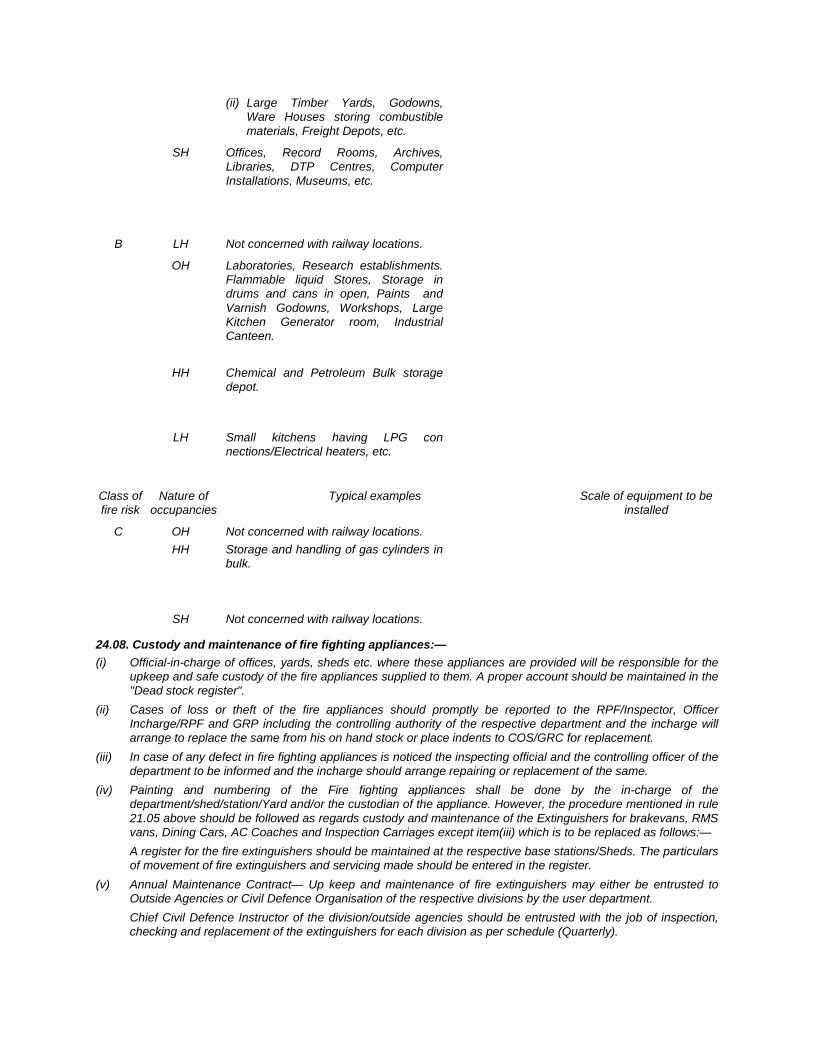
(ii) Large Timber Yards, Godowns, Ware Houses storing combustible materials, Freight Depots, etc.
SH Offices, Record Rooms, Archives, Libraries, DTP Centres, Computer Installations, Museums, etc.
B LH Not concerned with railway locations.
OH Laboratories, Research establishments. Flammable liquid Stores, Storage in drums and cans in open, Paints and Varnish Godowns, Workshops, Large Kitchen Generator room, Industrial Canteen.
HH Chemical and Petroleum Bulk storage depot.
LH Small kitchens having LPG con nections/Electrical heaters, etc.
Class of Nature of Typical examples Scale of equipment to be fire risk occupancies installed
C OH Not concerned with railway locations. HH Storage and handling of gas cylinders in
bulk.
SH Not concerned with railway locations.
24.08. Custody and maintenance of fire fighting appliances:— (i) Official-in-charge of offices, yards, sheds etc. where these appliances are provided will be responsible for the
upkeep and safe custody of the fire appliances supplied to them. A proper account should be maintained in the "Dead stock register".
(ii) Cases of loss or theft of the fire appliances should promptly be reported to the RPF/Inspector, Officer Incharge/RPF and GRP including the controlling authority of the respective department and the incharge will arrange to replace the same from his on hand stock or place indents to COS/GRC for replacement.
(iii) In case of any defect in fire fighting appliances is noticed the inspecting official and the controlling officer of the department to be informed and the incharge should arrange repairing or replacement of the same.
(iv) Painting and numbering of the Fire fighting appliances shall be done by the in-charge of the department/shed/station/Yard and/or the custodian of the appliance. However, the procedure mentioned in rule 21.05 above should be followed as regards custody and maintenance of the Extinguishers for brakevans, RMS vans, Dining Cars, AC Coaches and Inspection Carriages except item(iii) which is to be replaced as follows:—
A register for the fire extinguishers should be maintained at the respective base stations/Sheds. The particulars of movement of fire extinguishers and servicing made should be entered in the register.
(v) Annual Maintenance Contract— Up keep and maintenance of fire extinguishers may either be entrusted to Outside Agencies or Civil Defence Organisation of the respective divisions by the user department.
Chief Civil Defence Instructor of the division/outside agencies should be entrusted with the job of inspection, checking and replacement of the extinguishers for each division as per schedule (Quarterly).
24.09. Arrangements necessary for effective fire fighting:— (i) Sketch plan showing the arrangement of water supply should be exhibited at administrative buildings, stations,
yards, sheds and offices. (ii) Water supply arrangements should be made promptly as required by the fire service. (iii) Water reserved for fire fighting must not be used for any other purposes. (iv) The approach road to the water supply point must be kept clear. (v) The water supply points should be inspected twice in a month by the SSE/SE/JE(Works) or his assistant. The
hydrants inside the workshops should be inspected similarly by the foreman or his assistant.
24.10. Training in Fire Fighting:— Staff attending Zonal Railway Training Institute/Sini, System Training Centre/KGP and Electric Loco
Centre/TATA should be imparted training on fire fighting though lectures and practical demonstrations. Principal/ZRTI/STC/ELTC shall co-ordinate with the Sr. DSO/DSO or Sr. DSC/DSC of division to requisition Civil Defence Instructors or qualified RPF staff, from the division to impart such training as per requirement. They should also nominate instructors to undergo training on fire fighting in nominated Training Centres, in co-rodination with Personal Department. These trained instructors shall conduct fire-fighting training for trainees. Necessary fire fighting equipment, for the purpose of practical demonstrations, shall be collected by Principal ZRTI/STC/ELTC from the KGP stores.
For the staff, who do not attend the Training Centres/Schools necessary training programme may be chalked out by concerned departmental officers of the division in co-ordination with Sr. DSO/DSO/Sr.DSC/DSC from time to time.
24.11. Fire drill :— (i) Fire drills will be held every Saturday in order to make the staff more disciplined, conversant with fire fighting
technique and to infuse consciousness about fire hazards. (ii) Station Masters and respective supervisors will be responsible for holding fire drills. (iii) The R.P. F. personnel must join the drill and assist with their technical advice to make the drill a success. (iv) A record of each fire drill conducted is to be maintained in a register/diary by the Station Masters/Supervisors.
24.12. Fire alarms.— A proper fire alarm is the quickest means to warn staff about the out break of fire. On noticing a fire, the alarm
is to be rung or sounded at once. As soon as a fire breaks out, any of the following fire alarm as provided shall be used immediately:—
(i) Electric Siren for 5 minutes. Should be sounded continuously (ii) Shed Hooter -do- -do- (iii) Engine Whistle -do- -do- (iv) Hand Bell (made of B.G. Rail piece) -do- -do- (v) Electric Fire Bell Button should be pressed to 'ON' to ring the fire alarm bell continuously for 3 minutes.
24.13. Action to be taken in case of fire:— (a) Any staff whether on or off duty noticing fire shall:—
(i) Raise the fire alarm immediately. (ii) Take all possible action to extinguish the fire without any loss of time, (iii) Use the available fire extinguishing appliances properly and promptly, (iv) Inform the nearest "Civil Fire Station" by the quickest means about the exact location and type of
property involved. (b) Immediate information should also be given to police Station, RPF post, SSE/SE(Works) and concerned
Railway officials of the department whose property is involved in the fire. (c) The seniormost Railway official present at the site of fire, shall see that every action is being taken to
extinguish the fire also to prevent theft and other miscreant activities. RPF/Police official present at the site of fire will be responsible to guard the property during the occurrence and after. The seniormost fire fighting official present at the site of fire, will ensure proper utilisation of the Fire fighting facilities.
(d) As far as practicable, the documents and all moveable property adjacent to the fire, should be removed to a safer place under the direction of the responsible staff of the department concerned. A list of the property/documents so removed should be prepared in duplicate.
(e) In case of fire in a sealed wagon, the seals, locks/rivets should be immediately broken (in absence of key of the lock) and the door opened in presence of Station Master /Yard Master/Goods Supervisor/Goods Clerk as the case may be or in presence of Guard when fire on a wagon is in mid-section.
(f) As soon as fire breaks out in the yard, all shunting operation in the vicinity of the affected area should be stopped except for removal of all coaches and wagons from either side of the affected wagon(s)/Coaches(s). Wherever possible, the affected wagon(s)/ Coach(s) should be immediately drawn out and placed under the water column or nearest to the hydrant.
(g) In case of fire on train or on sleeper, the train staff and Station Master on duty shall also take the action as mentioned in GR 6.10,SR 6.10.01 or SR 6.10.02 as the case may be.
(h) In the event of fire on any part of traction electrical equipment or electrical engine, action as indicated in GR 6.10, SR 6.10.03, 6.10.04, 6.10.05 shall be taken. ————