Chapter 6. Supercharging
32
SHROFF S. R. ROTARY INSTITUTE OF CHEMICAL TECHNOLOGY (SRICT) DEPARTMENT OF MECHANICAL ENGINEERING. Subject: Internal Combustion Engine Chapter 6. Supercharging 1
-
Upload
khangminh22 -
Category
Documents
-
view
4 -
download
0
Transcript of Chapter 6. Supercharging

SHROFF S. R. ROTARY INSTITUTE OF CHEMICAL TECHNOLOGY (SRICT)
DEPARTMENT OF MECHANICAL ENGINEERING.
Subject: Internal Combustion Engine
Chapter 6. Supercharging
1

Chapter 6. Supercharging
6.1 Need for supercharging
6.2 Effect of supercharging
6.3 Types of Supercharger
6.4 Method of supercharging
6.5 Thermodynamic analysis of supercharging engine
6.6 Limitation of supercharging
6.7 Turbo charging methods
Outline
2

6.1 Need for supercharging
3
The rate of fuel burned depends upon the air capacity of the
engine, that is the amount of air which the engine is capable
of drawing per unit time.
Also, air capacity is practically unaffected by the presence
of fuel.
Increasing the energy input requires the induction of more
charge per cycle.
Also at high engine speed, volumetric efficiency decreases
so the induction. Engine speed is also limited by thermal
stresses.

6.1 Need for supercharging
4
At high altitude due to less density, available induction
charge is less. Also while climbing hill, racing and air craft
it is necessary to produce more power with less density.
“supercharging is used to increase the power output by
forcing the charge into the engine at pressure above
atmospheric”
It increase volumetric efficiency, performance, reduce
knocking, overheating or failure of some part.

6.2 Effect of supercharging
5
Output Power
It increase the power output of engine without increase its
weight and size.
Due to high inlet pressure, it compresses the residue gases
and facilitate more charger to fill.
It reduces gas exchange work. Because during suction work
is done by gas on the piston.
With more air, it facilitates more combustion.

6.2 Effect of supercharging
6
Fuel consumption
The brake specific fuel consumption for CI engine is somewhat
less than that for naturally aspirated engines due to better fuel
distribution, improved combustion and increased mechanical
efficiency.
Mechanical efficiency
An increase in the intake pressure increase the gas load, hence
large bearing area and heavier components are needed. Thus, the
friction losses are increased.
However, the increase in friction losses is less than the power
gained by supercharging. Therefore, the mechanical efficiency of
the engine is also increased by supercharging.

6.2 Effect of supercharging
7
Volumetric efficiency
Residual gases are compressed by inducted charge due to high
pressure in clearance volume.
The rate of increase of volume efficiency becomes progressively
less as the supercharging is increased, since the contraction of the
residuals becomes proportionately less.
Also increase in volumetric efficiency with the increase in the
intake pressure is higher at low C.R. ratio, since under these
conditions the volume occupied by the residuals is more and the
possibility of contraction is more.

6.3 Types of Supercharger
8
Lobe shape to rotor rotate in
opposite direction, fixed in
common casing
Both have contact with one
another and also with casing
Air trapped in the recesses (pocket) between the rotor and
housing is carried towards the delivery port without a
significant change in volume.
Roots blower

9
As these recesses open to the
delivery line, since the suction
side is closed, the trapped air
is suddenly compressed by the
backflow from the higher
pressure delivery line.
6.3 Types of Supercharger
Intermittent delivery produces pressure pulses.
Suitable for small pressure ratio 1.2
Three lobes rotor gives more uniform flow that two lobe
rotor.
Roots blower

6.3 Types of Supercharger
10
Positive displacement type,
It has a cylindrical rotor
mounted eccentrically with
respect to the fixed cylindrical
casing.
Deep slot are cut into the rotor to accommodate thin
rectangular vanes which are free radially.
Vane blower

6.3 Types of Supercharger
11
Vane blower
Two blades with rotor and
casing make closed pocket.
As rotor moves the volume of
pocket decrease from inlet side
to outlet side which compress
the air trapped in that pocket.
RPM 4000-5000 rpm.
Pressure 1.3 bar or above.

6.3 Types of Supercharger
12
It consist inlet pipe, impeller,
stationary diffuser, volute
casing and outlet pipe.
It primarily coupled with the
exhaust driven turbine in a
turbocharger.
20,000-30,000 rpm
Pressure ratio 2-3
Application Aircraft engines.
Centrifugal compressor

6.4 Method of supercharging
13
Turbo charging
A compressor and turbine mounted on a single shaft is used
to increase inlet air density.
The exhaust gases from the engine having sufficient energy
drive the turbine. So, turbine drives the compressor.
Fig. (b) most commonly used arrangement, simple
Mechanical supercharging:
Blower or compressor driven by engine shown in Fig.(a)

6.4 Method of supercharging
14
Turbo charging
Fig (c), Large marine engine
Fig (d) Very high boost pressure 4 to 7 bar

6.4 Method of supercharging
15
Turbo charging
Fig (e) Second turbine used to increase the power of engine
Fig (f) Cooling increase the volumetric efficiency during
induction.

6.5 Thermodynamic analysis of supercharging
16
The ideal dual combustion cycle of mechanically driven
supercharged engine and naturally aspirated engine are
shown in fig.

6.5 Thermodynamic analysis of supercharging
17
Net Work given by supercharged engine.
Wsc = Engine work output + Gas Exchange work –
Supercharged work
It is be noted that positive gas exchange area may be
greater than negative supercharged area.
It is to be kept in mind that with increase in supercharging
pressure the negative work, will also increase and therefore
there will be a limit for supercharging.

18
6.5 Thermodynamic analysis of supercharging
The ideal efficiency of supercharged engine will decrease
with increase in supercharging pressure.
However, it is to be understood that the not increase in
power output is due to increase in mass of charge.
For adiabatic compression the work done on the
supercharger
Considering efficiency of compressor,
,

19
6.6 Limitation of supercharging
Increased charge density, increase burning and so temperature.
It creates cooling and knocking problems.
Also due to high peak pressure, high strength of cylinder
required.
It can be reduced by: lengthening ignition delay, lower C.R., too
lean or rich mixture, injection of water in inlet manifold, use of
high Octane fuel.
Considering above factors, the SI engines are rarely
supercharged, except when more output power is prime important
against efficiency and economy.
Supercharging of SI engine

20
6.6 Limitation of supercharging
Supercharging of CI engine
It can be safely supercharged without any combustion
difficulties
Still at high pressure, violent pounding noise known as
diesel knock is produced.
So, it is essential to keep temperature of supercharge as low
as possible in order to get high volumetric and thermal
efficiency.
Supercharging of CI is limited by thermal and mechanical
loading, while SI is limited by knocking.

21
6.6 Limitation of supercharging
Due to high thermal load, we have to use better coolant and
engine material
Large bearing and heavier engine component required to
withstand mechanical stresses.
SI engine is limited with supercharging due to the high
knocking tendency at high pressure and temperature.
More valve overlap may be used to overcome these problems.
Durability, reliability and fuel economy are the main
considerations that limit the degree of supercharging of an
engine.

22
It is possible to use turbocharger alone in 4 stroke contrast
to 2 stroke to turbocharger for supply of air to the engine.
The main types of turbo charging methods namely (1)
Constant Pressure (2) Pulse (Buchi) operation (3) Pulse
converter.
6.7 Turbo charging methods

23
6.7 Turbo charging methods
Exhaust into a common manifold at high pressure.
Exhaust gases expands to an approximately constant
pressure.
So, internal energy produce work in exhaust turbine
(Reaction Turbine)
Recovery of blow down is higher if the pressure ratio is high
Constant Pressure

24
6.7 Turbo charging methods
Advantages
At high pressure ratio, very efficient, low fuel consumption.
When the number of cylinder is divisible by 3 and turbine
pressure ratio is 3:1 or more, it operates at constant pressure
and temperature which gives high efficiency.
Exhaust piping is very simple for multi cylinder.
Engine speed is not limited by the pressure waves in the
exhaust pipes.
Constant Pressure

25
6.7 Turbo charging methods
Disadvantages
Large exhaust pipes, increases the size of engine.
Response of this system to load changes is poor.
Due to high pressure drop across the turbine, scavenging
is not proper.
Constant Pressure

26
6.7 Turbo charging methods
Considerable part of the blow down energy is converted
into exhaust pulses as soon as the exhaust valve opens.
These pulses are led through narrow exhaust pipes by the
shortest possible route to the turbine where this energy is
utilized.
A large proportion of energy is thus recovered.
Pulse Turbo charging

27
6.7 Turbo charging methods
Pulse Turbo charging
Separate exhaust pipes are used so that exhaust process of
various cylinders do not interface with one another.
A common pipe is used for these cylinders whose exhaust
cycles do not overlap significantly in terms of time.
The turbine has separate inlets and nozzle segments for
each exhaust pipe.
Widely used for low pressure turbines where rapid
acceleration is needed.

28
6.7 Turbo charging methods
Pulse Turbo charging
Advantages
Recovery of the exhaust blow down energy is quite
efficient.
Rapid acceleration of the turbocharger to a high speed,
almost no delay.
Less space required
Better scavenging

29
6.7 Turbo charging methods
Pulse Turbo charging
Disadvantages
High throttling losses
Recovery of energy is poor when the pressure ratio is high
For multi cylinder, inlet and exhaust pipe arrangement
becomes complicated.
Poor turbine efficiency is obtained in case of one or two
cylinders.
If the waves take too long to travel to the turbine the
scavenging process is disturbed. Thus the length of the pipe or
engine speed is limited.
30
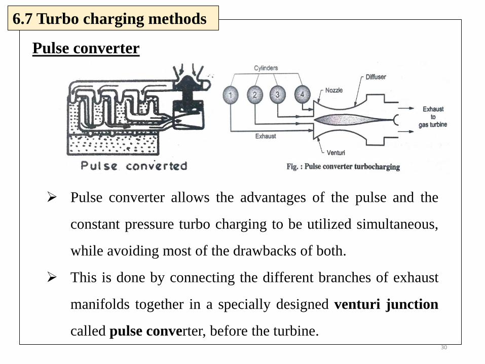
6.7 Turbo charging methods
Pulse converter allows the advantages of the pulse and the
constant pressure turbo charging to be utilized simultaneous,
while avoiding most of the drawbacks of both.
This is done by connecting the different branches of exhaust
manifolds together in a specially designed venturi junction
called pulse converter, before the turbine.
Pulse converter

31
6.7 Turbo charging methods
Pulse converter
Turbo charging turbine is a constant pressure machine and
for maximum efficiency requires steady flow conditions.
With pulse charging the turbine operates at relatively
lower efficiency due to partial admission operation.
Moreover, the low level of available exhaust energy
especially at part load required operation with pulse
charging for efficient utilization of this energy and good
scavenging. For this reason a combination of the two
system is needed for good efficiency of the turbine.

32