Chapter 296-24 WAC GENERAL SAFETY AND HEALTH ...
456
Chapter 296-24 WAC GENERAL SAFETY AND HEALTH STANDARDS Last Update: 6/2/20 WAC PART A-1 PURPOSE AND SCOPE 296-24-003 Subsections, subdivisions, items, subitems, and segments. 296-24-005 Purpose and scope. 296-24-012 Definitions applicable to all sections of this chapter. PART A-2 PERSONAL PROTECTIVE EQUIPMENT RESERVE Note: Personal protective equipment requirements have been moved to WAC 296-800-160. Note: Electrical protective equipment requirements have been moved to WAC 296-24-980. PART A-3 LATE NIGHT RETAIL WORKER CRIME PROTECTION Note: Late night retail worker crime protection has been moved to chapter 296-832 WAC. PART A-4 SAFETY PROCEDURES Note: Safety procedures have been moved to chapter 296-803 WAC. PART B-2 SAFETY COLOR CODE FOR MARKING PHYSICAL HAZARDS, ETC., WINDOW WASHING Note: Safety color code for marking physical hazards, etc., window washing has been moved to WAC 296-800-11045 and chapter 296-878 WAC. PART C MACHINERY AND MACHINE GUARDING Note: Machinery and machine guarding has been moved to chapter 296-806 WAC. PART D MATERIALS HANDLING AND STORAGE, INCLUDING CRANES, DERRICKS, ETC., AND RIGGING Handling and Storage—Cranes, Derricks, Etc. 296-24-215 Materials handling and storage—Handling materials—General. 296-24-21501 Use of mechanical equipment. 296-24-21509 Clearance limits. 296-24-21511 Rolling railroad cars. 296-24-21513 Guarding. 296-24-235 Overhead and gantry cranes. 296-24-23501 Definitions. 296-24-23503 General requirements. 296-24-23505 Cabs. 296-24-23507 Footwalks and ladders. 296-24-23509 Stops, bumpers, rail sweeps, and guards. 296-24-23511 Brakes. 296-24-23513 Electric equipment. 296-24-23515 Hoisting equipment. 296-24-23517 Warning device. 296-24-23519 Inspection. 296-24-23521 Testing. 296-24-23523 Maintenance. 296-24-23525 Rope inspection. 296-24-23527 Handling the load. 296-24-23529 Operators. 296-24-23531 Other requirements—General. 296-24-23533 Crane and derrick suspended personnel (work) platforms. 296-24-237 Construction, operation and maintenance—Chain and electric hoists. 296-24-238 Air hoists. 296-24-240 Crawler locomotive and truck cranes. 296-24-24001 Definitions. 296-24-24003 General requirements. 296-24-24005 Load ratings. 296-24-24007 Inspection classification. 296-24-24009 Testing. 296-24-24011 Maintenance procedure. 296-24-24013 Rope inspection. 296-24-24015 Handling the load. 296-24-24017 Other requirements. 296-24-24019 Operating near overhead electric power lines. 296-24-245 Derricks. 296-24-24501 Definitions. 296-24-24503 General requirements. 296-24-24505 Load ratings. 296-24-24507 Inspection. Certified on 11/24/2020 Page 1
-
Upload
khangminh22 -
Category
Documents
-
view
0 -
download
0
Transcript of Chapter 296-24 WAC GENERAL SAFETY AND HEALTH ...
Chapter 296-24 WACGENERAL SAFETY AND HEALTH STANDARDS
Last Update: 6/2/20WAC
PART A-1PURPOSE AND SCOPE
296-24-003 Subsections, subdivisions, items, subitems, and segments.296-24-005 Purpose and scope.296-24-012 Definitions applicable to all sections of this chapter.
PART A-2PERSONAL PROTECTIVE EQUIPMENT
RESERVENote: Personal protective equipment requirements have been moved to WAC 296-800-160.Note: Electrical protective equipment requirements have been moved to WAC 296-24-980.
PART A-3LATE NIGHT RETAIL WORKER CRIME PROTECTION
Note: Late night retail worker crime protection has been moved to chapter 296-832 WAC.
PART A-4SAFETY PROCEDURES
Note: Safety procedures have been moved to chapter 296-803 WAC.
PART B-2SAFETY COLOR CODE FOR MARKING PHYSICAL HAZARDS, ETC., WINDOW WASHING
Note: Safety color code for marking physical hazards, etc., window washing has been moved to WAC 296-800-11045 and chapter 296-878 WAC.
PART CMACHINERY AND MACHINE GUARDING
Note: Machinery and machine guarding has been moved to chapter 296-806 WAC.
PART DMATERIALS HANDLING AND STORAGE, INCLUDING CRANES, DERRICKS, ETC., AND RIGGING
Handling and Storage—Cranes, Derricks, Etc.296-24-215 Materials handling and storage—Handling materials—General.296-24-21501 Use of mechanical equipment.296-24-21509 Clearance limits.296-24-21511 Rolling railroad cars.296-24-21513 Guarding.296-24-235 Overhead and gantry cranes.296-24-23501 Definitions.296-24-23503 General requirements.296-24-23505 Cabs.296-24-23507 Footwalks and ladders.296-24-23509 Stops, bumpers, rail sweeps, and guards.296-24-23511 Brakes.296-24-23513 Electric equipment.296-24-23515 Hoisting equipment.296-24-23517 Warning device.296-24-23519 Inspection.296-24-23521 Testing.296-24-23523 Maintenance.296-24-23525 Rope inspection.296-24-23527 Handling the load.296-24-23529 Operators.296-24-23531 Other requirements—General.296-24-23533 Crane and derrick suspended personnel (work) platforms.296-24-237 Construction, operation and maintenance—Chain and electric hoists.296-24-238 Air hoists.296-24-240 Crawler locomotive and truck cranes.296-24-24001 Definitions.296-24-24003 General requirements.296-24-24005 Load ratings.296-24-24007 Inspection classification.296-24-24009 Testing.296-24-24011 Maintenance procedure.296-24-24013 Rope inspection.296-24-24015 Handling the load.296-24-24017 Other requirements.296-24-24019 Operating near overhead electric power lines.296-24-245 Derricks.296-24-24501 Definitions.296-24-24503 General requirements.296-24-24505 Load ratings.296-24-24507 Inspection.
Certified on 11/24/2020 Page 1
296-24-24509 Testing.296-24-24511 Maintenance.296-24-24513 Rope inspection.296-24-24515 Operations of derricks.296-24-24517 Handling the load.296-24-24519 Other requirements.296-24-293 "A" frames.296-24-294 Rigging.296-24-29401 Wire rope.296-24-29403 Hemp rope.296-24-29405 Hemp and wire rope slings.296-24-29407 Guys.296-24-29409 Thimbles.296-24-29411 Blocks and falls.296-24-29413 Chains and cables.296-24-29415 Slings.296-24-29417 Definitions.296-24-29419 Safe operating practices.296-24-29421 Inspections.296-24-29423 Alloy steel chain slings.296-24-29425 Wire rope slings.296-24-29427 Metal mesh slings.296-24-29429 Natural and synthetic fiber rope slings.296-24-29431 Synthetic web slings.
PART EHAZARDOUS MATERIALS, FLAMMABLE LIQUIDS, SPRAY FINISHING
Hazardous Materials296-24-295 Compressed gases (general requirements).296-24-29501 Inspection of compressed gas cylinders.296-24-29503 Compressed gases.296-24-29505 Safety relief devices for compressed gas containers.296-24-310 Acetylene.296-24-31001 Cylinders.296-24-31003 Piped systems.296-24-31005 Generators and filling cylinders.296-24-315 Hydrogen.296-24-31501 General.296-24-31503 Gaseous hydrogen systems.296-24-31505 Liquefied hydrogen systems.296-24-320 Oxygen.296-24-32001 Scope.296-24-32003 Bulk oxygen systems.296-24-325 Nitrous oxide.296-24-330 Flammable liquids.296-24-33001 Definitions.296-24-33003 Scope.296-24-33005 Tank storage.296-24-33007 Piping, valves, and fittings.296-24-33009 Container and portable tank storage.296-24-33011 Industrial plants.296-24-33013 Bulk plants.296-24-33015 Service stations.296-24-33017 Processing plants.296-24-33019 Refineries, chemical plants, and distilleries.296-24-370 Spray finishing using flammable materials.296-24-37001 Definitions.296-24-37003 Spray booths.296-24-37005 Electrical and other sources of ignition.296-24-37007 Ventilation.296-24-37009 Flammable liquids and liquids with a flashpoint greater than 199.4°F (93°C).296-24-37011 Protection.296-24-37013 Operations and maintenance.296-24-37015 Fixed electrostatic apparatus.296-24-37017 Electrostatic hand spraying equipment.296-24-37019 Drying, curing, or fusion apparatus.296-24-37021 Automobile undercoating in garages.296-24-37023 Powder coating.296-24-37025 Organic peroxides and dual component coatings.296-24-37027 Scope.296-24-450 Chlorine cylinders used in chlorinator systems.
PART F-1STORAGE AND HANDLING OF LIQUEFIED PETROLEUM GASES
296-24-475 Storage and handling of liquefied petroleum gases.296-24-47501 Definitions.296-24-47503 Scope.296-24-47505 Basic rules.296-24-47507 Cylinder systems.296-24-47509 Systems utilizing containers other than DOT containers.296-24-47511 Liquefied petroleum gas as a motor fuel.296-24-47513 Storage of containers awaiting use or resale.296-24-47517 Liquefied petroleum gas service stations.
Certified on 11/24/2020 Page 2
PART F-2STORAGE AND HANDLING OF ANHYDROUS AMMONIA
Note: Storage and handling of anhydrous ammonia has been moved to chapter 296-826 WAC.
PART G-1MEANS OF EGRESS
296-24-55001 Definitions.296-24-56525 Automatic sprinkler systems.296-24-56527 Fire alarm signaling systems.296-24-567 Employee emergency plans and fire prevention plans.296-24-56701 Appendix.
PART G-2FIRE PROTECTION
296-24-585 Fire protection.296-24-58501 Definitions applicable to fire protection.296-24-58503 Scope, application and definitions applicable.
PART G-3FIRE SUPPRESSION EQUIPMENT
296-24-592 Portable fire extinguishers.296-24-59201 Scope and application.296-24-59212 Hydrostatic testing.296-24-59215 Appendix A—Portable fire extinguishers.296-24-602 Standpipe and hose systems.296-24-60201 Scope and application.296-24-60203 Protection of standpipes.296-24-60205 Equipment.296-24-60207 Water supply.296-24-60209 Tests and maintenance.296-24-60299 Appendix A—Standpipe and hose systems.296-24-607 Automatic sprinkler systems.296-24-60701 Scope and application.296-24-60703 Exemptions.296-24-60705 General requirements.296-24-60799 Appendix A—Automatic sprinkler systems.296-24-617 Fixed extinguishing systems, general.296-24-61701 Scope and application.296-24-61703 General requirements.296-24-61705 Total flooding systems with potential health and safety hazards to employees.296-24-61799 Appendix A—Fixed extinguishing systems, general.296-24-622 Fixed extinguishing systems, dry chemical.296-24-62201 Scope and application.296-24-62203 Specific requirements.296-24-62299 Appendix A—Fixed extinguishing systems, dry chemical.296-24-623 Fixed extinguishing systems, gaseous agent.296-24-62301 Scope and application.296-24-62303 Specific requirements.296-24-62399 Appendix A—Fixed extinguishing systems, gaseous agent.296-24-627 Fixed extinguishing systems, water spray and foam.296-24-62701 Scope and application.296-24-62703 Specific requirements.296-24-62799 Appendix A—Fixed extinguishing systems, water spray and foam.296-24-629 Fire detection systems.296-24-62901 Scope and application.296-24-62903 Installation and restoration.296-24-62905 Maintenance and testing.296-24-62907 Protection of fire detectors.296-24-62909 Response time.296-24-62911 Number, location and spacing of detecting devices.296-24-62999 Appendix A—Fire detection systems.296-24-63299 Appendix B—National consensus standards.296-24-63399 Appendix C—Fire protection references for further information.296-24-63599 Appendix E—Test methods for protective clothing.
PART H-2SAFE PRACTICES AND VENTILATION OF ABRASIVE BLASTING OPERATIONS
Note: Safe practices and ventilation of abrasive blasting operations have been moved to chapter 296-818 WAC.
PART IWELDING, CUTTING AND BRAZING
296-24-680 Welding, cutting, and brazing.296-24-68001 Definitions.296-24-682 Installation and operation of oxygen fuel gas systems for welding and cutting.296-24-68201 General requirements.296-24-68203 Cylinders and containers.296-24-68205 Manifolding of cylinders.296-24-68207 Service piping systems.296-24-68209 Protective equipment, hose, and regulators.296-24-68211 Acetylene generators.296-24-68213 Calcium carbide storage.
Certified on 11/24/2020 Page 3

296-24-68215 Public exhibitions and demonstrations.296-24-685 Application, installation, and operation of arc welding and cutting equipment.296-24-68501 General.296-24-68503 Application of arc welding equipment.296-24-68505 Installation of arc welding equipment.296-24-68507 Operation and maintenance.296-24-690 Installation and operation of resistance welding equipment.296-24-69001 General.296-24-69003 Spot and seam welding machines (nonportable).296-24-69005 Portable welding machines.296-24-69007 Flash welding equipment.296-24-69009 Hazards and precautions.296-24-69011 Maintenance.296-24-695 Fire prevention and protection.296-24-69501 Basic precautions.296-24-69503 Special precautions.296-24-69505 Welding or cutting containers.296-24-69507 Confined spaces.296-24-700 Protection of employees.296-24-70001 General.296-24-70003 Eye protection.296-24-70005 Protective clothing.296-24-70007 Work in confined spaces.296-24-715 Health protection and ventilation.296-24-71501 General.296-24-71503 Ventilation for general welding and cutting.296-24-71505 Local exhaust hoods and booths.296-24-71507 Ventilation in confined spaces.296-24-71509 Fluorine compounds.296-24-71511 Zinc.296-24-71513 Lead.296-24-71515 Beryllium.296-24-71517 Cadmium.296-24-71519 Mercury.296-24-71521 Cleaning compounds.296-24-71523 Cutting of stainless steels.296-24-71525 First-aid equipment.296-24-720 Industrial applications.296-24-72001 Transmission pipeline.296-24-72003 Mechanical piping systems.296-24-722 Welding, cutting, and heating in way of preservative coatings.
PART J-1WORKING SURFACES, GUARDING FLOORS AND WALL OPENINGS
Note: Requirements relating to portable ladders and fixed ladders have been moved to chapter 296-876 WAC, Ladders, portable and fixed.296-24-735 Walking-working surfaces.296-24-73501 Scope.296-24-73502 Definitions.296-24-73505 General requirements.296-24-740 Stairways.296-24-74005 General requirements for all stairs.296-24-74010 Standard stairs.296-24-74015 Handrail, stair rail, and guardrail system requirements.296-24-74020 Spiral stairs.296-24-74025 Ship stairs.296-24-74030 Alternating tread-type stairs.296-24-7500 Other working surfaces.296-24-75006 Dockboards (bridge plates).
PART J-2SCAFFOLDS
296-24-862 Nonmandatory appendices.PART J-3
POWERED PLATFORMSNote: Powered platforms have been moved to chapters 296-869 and 296-870 WAC.
PART KCOMPRESSED GAS AND COMPRESSED GAS EQUIPMENT
296-24-920 Inspection of compressed gas cylinders.296-24-92001 Definitions.296-24-92003 General requirements.296-24-92005 Inspection of low-pressure cylinders exempt from the hydrostatic test including acetylene
cylinders.296-24-92007 Low-pressure cylinders subject to hydrostatic testing.296-24-92009 High-pressure cylinders.296-24-92011 Internal inspection.296-24-930 Safety relief devices for compressed gas cylinders.296-24-93001 Definitions.296-24-93003 General requirements.296-24-935 Safety relief devices for cargo and portable tanks storing compressed gases.296-24-93501 Definitions.296-24-93503 General requirements.
Certified on 11/24/2020 Page 4

296-24-940 Air receivers.296-24-94001 General requirements.296-24-94003 Installation and equipment requirements.
PART LELECTRICAL
296-24-957 Electrical.296-24-95701 Electric utilization systems.296-24-95703 General requirements.296-24-95705 Wiring design and protection.296-24-95707 Wiring methods, components, and equipment for general use.296-24-95709 Specific purpose equipment and installations.296-24-95711 Hazardous (classified) locations.296-24-95713 Special systems.296-24-95799 Appendices.296-24-960 Working on or near exposed energized parts.296-24-965 Safety-related work practices.296-24-970 Training.296-24-975 Selection and use of work practices.296-24-980 Safeguards for personnel protection.296-24-985 Use of equipment.296-24-990 Definitions.
DISPOSITION OF SECTIONS FORMERLY CODIFIED IN THIS CHAPTER296-24-001 Foreword. [Statutory Authority: Chapter 49.17 RCW. WSR 94-15-096 (Order 94-07), §
296-24-001, filed 7/20/94, effective 9/20/94; Order 73-5, § 296-24-001, filed 5/9/73 and Order 73-4, § 296-24-001, filed 5/7/73.] Repealed by WSR 01-11-038, filed 5/9/01, effec-tive 9/1/01. Statutory Authority: RCW 49.17.010, [49.17].040, and [49.17].050.
296-24-006 Equipment approval by nonstate agency or organization. [Statutory Authority: Chapter 49.17 RCW. WSR 94-15-096 (Order 94-07), § 296-24-006, filed 7/20/94, effective 9/20/94; Order 73-5, § 296-24-006, filed 5/9/73 and Order 73-4, § 296-24-006, filed 5/7/73.] Re-pealed by WSR 01-11-038, filed 5/9/01, effective 9/1/01. Statutory Authority: RCW 49.17.010, [49.17].040, and [49.17].050.
296-24-007 Incorporation of standards of national organization. [Statutory Authority: Chapter 49.17 RCW. WSR 94-20-057 (Order 94-16), § 296-24-007, filed 9/30/94, effective 11/20/94; Order 73-5, § 296-24-007, filed 5/9/73 and Order 73-4, § 296-24-007, filed 5/7/73.] Repealed by WSR 01-11-038, filed 5/9/01, effective 9/1/01. Statutory Authority: RCW 49.17.010, [49.17].040, and [49.17].050.
296-24-008 Incorporation of standards of federal agency. [Order 73-5, § 296-24-008, filed 5/9/73 and Order 73-4, § 296-24-008, filed 5/7/73.] Repealed by WSR 01-11-038, filed 5/9/01, effec-tive 9/1/01. Statutory Authority: RCW 49.17.010, [49.17].040, and [49.17].050.
296-24-010 Variance and procedure. [Statutory Authority: Chapter 49.17 RCW. WSR 94-15-096 (Order 94-07), § 296-24-010, filed 7/20/94, effective 9/20/94; WSR 91-24-017 (Order 91-07), § 296-24-010, filed 11/22/91, effective 12/24/91; Order 74-27, § 296-24-010, filed 5/7/74; Order 73-5, § 296-24-010, filed 5/9/73 and Order 73-4, § 296-24-010, filed 5/7/73.] Re-pealed by WSR 01-11-038, filed 5/9/01, effective 9/1/01. Statutory Authority: RCW 49.17.010, [49.17].040, and [49.17].050.
296-24-015 Education and first-aid standards. [Statutory Authority: Chapter 49.17 RCW. WSR 94-15-096 (Order 94-07), § 296-24-015, filed 7/20/94, effective 9/20/94. Statutory Authority: RCW 49.17.040, 49.17.050, 49.17.240, chapters 43.22 and 42.30 RCW. WSR 80-17-015 (Order 80-21), § 296-24-015, filed 11/13/80; Order 73-5, § 296-24-015, filed 5/9/73 and Order 73-4, § 296-24-015, filed 5/7/73.] Repealed by WSR 01-11-038, filed 5/9/01, effective 9/1/01. Statutory Authority: RCW 49.17.010, [49.17].040, and [49.17].050.
296-24-020 Management's responsibility. [Statutory Authority: Chapter 49.17 RCW. WSR 94-20-057 (Or-der 94-16), § 296-24-020, filed 9/30/94, effective 11/20/94; WSR 91-24-017 (Order 91-07), § 296-24-020, filed 11/22/91, effective 12/24/91; WSR 91-03-044 (Order 90-18), § 296-24-020, filed 1/10/91, effective 2/12/91; WSR 90-03-029 (Order 89-20), § 296-24-020, filed 1/11/90, effective 2/26/90. Statutory Authority: RCW 49.17.040, 49.17.050, 49.17.240 and chapters 42.30 and 43.22 RCW. WSR 78-12-017 (Order 78-22), § 296-24-020, filed 11/13/78; Order 74-27, § 296-24-020, filed 5/7/74; Order 73-5, § 296-24-020, filed 5/9/73 and Order 73-4, § 296-24-020, filed 5/7/73.] Repealed by WSR 01-11-038, filed 5/9/01, effective 9/1/01. Statutory Authority: RCW 49.17.010, [49.17].040, and [49.17].050.
296-24-025 Employee's responsibility. [Order 74-27, § 296-24-025, filed 5/7/74; Order 73-5, § 296-24-025, filed 5/9/73 and Order 73-4, § 296-24-025, filed 5/7/73.] Repealed by WSR 01-11-038, filed 5/9/01, effective 9/1/01. Statutory Authority: RCW 49.17.010, [49.17].040, and [49.17].050.
296-24-040 Accident prevention programs. [Statutory Authority: RCW 49.17.010, [49.17].040 and [49.17].050. WSR 99-17-093, § 296-24-040, filed 8/17/99, effective 12/1/99. Statutory Au-thority: Chapter 49.17 RCW. WSR 94-15-096 (Order 94-07), § 296-24-040, filed 7/20/94, ef-fective 9/20/94. Statutory Authority: RCW 49.17.040, 49.17.050, 49.17.240 and chapters 42.30 and 43.22 RCW. WSR 78-12-017 (Order 78-22), § 296-24-040, filed 11/13/78; Order 74-27, § 296-24-040, filed 5/7/74; Order 73-5, § 296-24-040, filed 5/9/73 and Order 73-4, § 296-24-040, filed 5/7/73.] Repealed by WSR 01-11-038, filed 5/9/01, effective 9/1/01. Statutory Authority: RCW 49.17.010, [49.17].040, and [49.17].050.
296-24-045 Safety and health committee plan. [Statutory Authority: Chapter 49.17 RCW. WSR 94-15-096 (Order 94-07), § 296-24-045, filed 7/20/94, effective 9/20/94. Statutory Authority: RCW 49.17.040, 49.17.050, 49.17.240, chapters 42.30 and 43.22 RCW. WSR 80-17-014 (Order 80-20), § 296-24-045, filed 11/13/80; WSR 78-12-017 (Order 78-22), § 296-24-045, filed 11/13/78.] Repealed by WSR 01-11-038, filed 5/9/01, effective 9/1/01. Statutory Authori-ty: RCW 49.17.010, [49.17].040, and [49.17].050.
Certified on 11/24/2020 Page 5

296-24-055 Safety bulletin board. [Order 73-5, § 296-24-055, filed 5/9/73 and Order 73-4, § 296-24-055, filed 5/7/73.] Repealed by WSR 01-11-038, filed 5/9/01, effective 9/1/01. Statutory Authority: RCW 49.17.010, [49.17].040, and [49.17].050.
296-24-060 First-aid training and certification. [Statutory Authority: Chapter 49.17 RCW. WSR 94-15-096 (Order 94-07), § 296-24-060, filed 7/20/94, effective 9/20/94. Statutory Au-thority: RCW 49.17.040, 49.17.050 and 49.17.240. WSR 81-13-053 (Order 81-9), § 296-24-060, filed 6/17/81. Statutory Authority: RCW 49.17.040, 49.17.050, 49.17.240, chapters 42.30 and 43.22 RCW. WSR 80-17-014 (Order 80-20), § 296-24-060, filed 11/13/80; WSR 78-12-017 (Order 78-22), § 296-24-060, filed 11/13/78; Order 74-27, § 296-24-060, filed 5/7/74; Order 73-5, § 296-24-060, filed 5/9/73 and Order 73-4, § 296-24-060, filed 5/7/73.] Repealed by WSR 98-06-061, filed 3/2/98, effective 6/1/98. Statutory Authority: Chapter 49.17 RCW.
296-24-061 First-aid requirements. [Statutory Authority: Chapter 49.17 RCW. WSR 98-06-061, § 296-24-061, filed 3/2/98, effective 6/1/98.] Repealed by WSR 01-11-038, filed 5/9/01, ef-fective 9/1/01. Statutory Authority: RCW 49.17.010, [49.17].040, and [49.17].050.
296-24-06105 What workplaces does this rule apply to? [Statutory Authority: RCW 49.17.040. WSR 99-02-023, § 296-24-06105, filed 12/30/98, effective 3/30/99. Statutory Authority: Chap-ter 49.17 RCW. WSR 98-06-061, § 296-24-06105, filed 3/2/98, effective 6/1/98.] Repealed by WSR 01-11-038, filed 5/9/01, effective 9/1/01. Statutory Authority: RCW 49.17.010, [49.17].040, and [49.17].050.
296-24-06110 What is the purpose of this rule? [Statutory Authority: Chapter 49.17 RCW. WSR 98-06-061, § 296-24-06110, filed 3/2/98, effective 6/1/98.] Repealed by WSR 01-11-038, filed 5/9/01, effective 9/1/01. Statutory Authority: RCW 49.17.010, [49.17].040, and [49.17].050.
296-24-06115 What definitions apply to this section? [Statutory Authority: Chapter 49.17 RCW. WSR 98-06-061, § 296-24-06115, filed 3/2/98, effective 6/1/98.] Repealed by WSR 01-11-038, filed 5/9/01, effective 9/1/01. Statutory Authority: RCW 49.17.010, [49.17].040, and [49.17].050.
296-24-06120 How must an employer ensure that first-aid assistance is available in the workplace? [Statutory Authority: Chapter 49.17 RCW. WSR 98-06-061, § 296-24-06120, filed 3/2/98, ef-fective 6/1/98.] Repealed by WSR 01-11-038, filed 5/9/01, effective 9/1/01. Statutory Au-thority: RCW 49.17.010, [49.17].040, and [49.17].050.
296-24-06125 How many employees must be trained in first aid? [Statutory Authority: Chapter 49.17 RCW. WSR 98-06-061, § 296-24-06125, filed 3/2/98, effective 6/1/98.] Repealed by WSR 01-11-038, filed 5/9/01, effective 9/1/01. Statutory Authority: RCW 49.17.010, [49.17].040, and [49.17].050.
296-24-06130 What must first-aid training cover? [Statutory Authority: Chapter 49.17 RCW. WSR 98-06-061, § 296-24-06130, filed 3/2/98, effective 6/1/98.] Repealed by WSR 01-11-038, filed 5/9/01, effective 9/1/01. Statutory Authority: RCW 49.17.010, [49.17].040, and [49.17].050.
296-24-06135 How often must employees complete first-aid training? [Statutory Authority: Chapter 49.17 RCW. WSR 98-06-061, § 296-24-06135, filed 3/2/98, effective 6/1/98.] Repealed by WSR 01-11-038, filed 5/9/01, effective 9/1/01. Statutory Authority: RCW 49.17.010, [49.17].040, and [49.17].050.
296-24-06140 How must an employer document first-aid training? [Statutory Authority: Chapter 49.17 RCW. WSR 98-06-061, § 296-24-06140, filed 3/2/98, effective 6/1/98.] Repealed by WSR 01-11-038, filed 5/9/01, effective 9/1/01. Statutory Authority: RCW 49.17.010, [49.17].040, and [49.17].050.
296-24-06145 What is the requirement for first-aid supplies? [Statutory Authority: Chapter 49.17 RCW. WSR 98-06-061, § 296-24-06145, filed 3/2/98, effective 6/1/98.] Repealed by WSR 01-11-038, filed 5/9/01, effective 9/1/01. Statutory Authority: RCW 49.17.010, [49.17].040, and [49.17].050.
296-24-06150 What is the requirement to provide a first-aid station? [Statutory Authority: Chapter 49.17 RCW. WSR 98-06-061, § 296-24-06150, filed 3/2/98, effective 6/1/98.] Repealed by WSR 01-11-038, filed 5/9/01, effective 9/1/01. Statutory Authority: RCW 49.17.010, [49.17].040, and [49.17].050.
296-24-06155 APPENDIX 1 Evaluation worksheet for the first-aid response plan. [Statutory Authority: Chapter 49.17 RCW. WSR 98-06-061, § 296-24-06155, filed 3/2/98, effective 6/1/98.] Re-pealed by WSR 01-11-038, filed 5/9/01, effective 9/1/01. Statutory Authority: RCW 49.17.010, [49.17].040, and [49.17].050.
296-24-06160 APPENDIX 2—First-aid kit guidance. [Statutory Authority: Chapter 49.17 RCW. WSR 98-06-061, § 296-24-06160, filed 3/2/98, effective 6/1/98.] Repealed by WSR 01-11-038, filed 5/9/01, effective 9/1/01. Statutory Authority: RCW 49.17.010, [49.17].040, and [49.17].050.
296-24-065 First-aid kit. [Statutory Authority: Chapter 49.17 RCW. WSR 94-15-096 (Order 94-07), § 296-24-065, filed 7/20/94, effective 9/20/94; WSR 91-03-044 (Order 90-18), § 296-24-065, filed 1/10/91, effective 2/12/91; Order 74-27, § 296-24-065, filed 5/7/74; Order 73-5, § 296-24-065, filed 5/9/73 and Order 73-4, § 296-24-065, filed 5/7/73.] Repealed by WSR 98-06-061, filed 3/2/98, effective 6/1/98. Statutory Authority: Chapter 49.17 RCW.
296-24-067 First-aid station. [Order 73-5, § 296-24-067, filed 5/9/73 and Order 73-4, § 296-24-067, filed 5/7/73.] Repealed by WSR 98-06-061, filed 3/2/98, effective 6/1/98. Statutory Au-thority: Chapter 49.17 RCW.
296-24-070 First-aid room. [Statutory Authority: RCW 49.17.040, 49.17.050 and 49.17.240. WSR 81-13-053 (Order 81-9), § 296-24-070, filed 6/17/81; Order 73-5, § 296-24-070, filed 5/9/73 and Order 73-4, § 296-24-070, filed 5/7/73.] Repealed by WSR 98-06-061, filed 3/2/98, effective 6/1/98. Statutory Authority: Chapter 49.17 RCW.
296-24-073 Safe place standards. [Statutory Authority: Chapter 49.17 RCW. WSR 94-15-096 (Order 94-07), § 296-24-073, filed 7/20/94, effective 9/20/94. Statutory Authority: RCW 49.17.040 and 49.17.050. WSR 85-01-022 (Order 84-24), § 296-24-073, filed 12/11/84; Order 74-27, § 296-24-073, filed 5/7/74; Order 73-5, § 296-24-073, filed 5/9/73 and Order 73-4,
Certified on 11/24/2020 Page 6
§ 296-24-073, filed 5/7/73.] Repealed by WSR 01-11-038, filed 5/9/01, effective 9/1/01. Statutory Authority: RCW 49.17.010, [49.17].040, and [49.17].050.
296-24-075 Personal protective equipment. [Order 73-5, § 296-24-075, filed 5/9/73 and Order 73-4, § 296-24-075, filed 5/7/73.] Repealed by WSR 01-11-038, filed 5/9/01, effective 9/1/01. Statutory Authority: RCW 49.17.010, [49.17].040, and [49.17].050.
296-24-07501 General requirements. [Statutory Authority: RCW 49.17.010, [49.17].040 and [49.17].050. WSR 99-10-071, § 296-24-07501, filed 5/4/99, effective 9/1/99. Statutory Authority: Chap-ter 49.17 RCW. WSR 94-20-057 (Order 94-16), § 296-24-07501, filed 9/30/94, effective 11/20/94; Order 73-5, § 296-24-07501, filed 5/9/73 and Order 73-4, § 296-24-07501, filed 5/7/73.] Repealed by WSR 01-11-038, filed 5/9/01, effective 9/1/01. Statutory Authority: RCW 49.17.010, [49.17].040, and [49.17].050.
296-24-078 Eye and face protection. [Order 73-5, § 296-24-078, filed 5/9/73 and Order 73-4, § 296-24-078, filed 5/7/73.] Repealed by WSR 01-11-038, filed 5/9/01, effective 9/1/01. Statutory Authority: RCW 49.17.010, [49.17].040, and [49.17].050.
296-24-07801 General. [Statutory Authority: RCW 49.17.040, [49.17.]050 and [49.17.]060. WSR 97-11-055, § 296-24-07801, filed 5/20/97, effective 8/1/97. Statutory Authority: Chapter 49.17 RCW. WSR 94-20-057 (Order 94-16), § 296-24-07801, filed 9/30/94, effective 11/20/94; Order 73-5, § 296-24-07801, filed 5/9/73 and Order 73-4, § 296-24-07801, filed 5/7/73.] Re-pealed by WSR 01-11-038, filed 5/9/01, effective 9/1/01. Statutory Authority: RCW 49.17.010, [49.17].040, and [49.17].050.
296-24-081 Respiratory protection. [Order 73-5, § 296-24-081, filed 5/9/73 and order 73-4, § 296-24-081, filed 5/7/73.] Repealed by WSR 81-16-016 (order 81-19), filed 7/27/81. Statu-tory Authority: RCW 49.17.040, 49.17.050 and 49.17.240. Later promulgation, see chapter 296-62 WAC.
296-24-08101 Permissible practice. [Order 73-5, § 296-24-08101, filed 5/9/73 and Order 73-4, § 296-24-08101, filed 5/7/73.] Repealed by WSR 81-16-016 (Order 81-19), filed 7/27/81. Statutory Authority: RCW 49.17.040, 49.17.050 and 49.17.240.
296-24-08103 Requirements for a minimal acceptable program. [Statutory Authority: RCW 49.17.040, 49.17.050, and 49.17.240. WSR 80-11-010 (Order 80-14), § 296-24-08103, filed 8/8/80; Or-der 73-5, § 296-24-08103, filed 5/9/73 and Order 73-4, § 296-24-08103, filed 5/7/73.] Re-pealed by WSR 81-16-016 (Order 81-19), filed 7/27/81. Statutory Authority: RCW 49.17.040, 49.17.050 and 49.17.240.
296-24-08105 Selection of respirators. [Order 73-5, § 296-24-08105, filed 5/9/73 and Order 73-4, § 296-24-08105, filed 5/7/73.] Repealed by WSR 81-16-016 (Order 81-19), filed 7/27/81. Statutory Authority: RCW 49.17.040, 49.17.050 and 49.17.240.
296-24-08107 Air quality. [Statutory Authority: RCW 49.17.040, 49.17.050, and 49.17.240. WSR 80-11-010 (Order 80-14), § 296-24-08107, filed 8/8/80; Order 73-5, § 296-24-08107, filed 5/9/73 and Order 73-4, § 296-24-08107, filed 5/7/73.] Repealed by WSR 81-16-016 (Order 81-19), filed 7/27/81. Statutory Authority: RCW 49.17.040, 49.17.050 and 49.17.240.
296-24-08109 Use of respirators. [Statutory Authority: RCW 49.17.040, 49.17.050, and 49.17.240. WSR 80-11-010 (Order 80-14), § 296-24-08109, filed 8/8/80; Order 73-5, § 296-24-08109, filed 5/9/73 and Order 73-4, § 296-24-08109, filed 5/7/73.] Repealed by WSR 81-16-016 (Order 81-19), filed 7/27/81. Statutory Authority: RCW 49.17.040, 49.17.050 and 49.17.240.
296-24-08111 Maintenance and care of respirators. [Order 73-5, § 296-24-08111, filed 5/9/73 and Order 73-4, § 296-24-08111, filed 5/7/73.] Repealed by WSR 81-16-016 (Order 81-19), filed 7/27/81. Statutory Authority: RCW 49.17.040, 49.17.050 And 49.17.240.
296-24-08113 Identification of gas mask canisters. [Order 73-5, § 296-24-08113, filed 5/9/73 and Order 73-4, § 296-24-08113, filed 5/7/73.] Repealed by WSR 81-16-016 (Order 81-19), filed 7/27/81. Statutory Authority: RCW 49.17.040, 49.17.050 and 49.17.240.
296-24-084 Occupational head protection. [Statutory Authority: RCW 49.17.040, [49.17.]050 and [49.17.]060. WSR 97-11-055, § 296-24-084, filed 5/20/97, effective 8/1/97. Statutory Au-thority: Chapter 49.17 RCW. WSR 96-09-030, § 296-24-084, filed 4/10/96, effective 6/1/96; WSR 94-20-057 (Order 94-16), § 296-24-084, filed 9/30/94, effective 11/20/94; WSR 91-03-044 (Order 90-18), § 296-24-084, filed 1/10/91, effective 2/12/91; Order 74-27, § 296-24-084, filed 5/7/74; Order 73-5, § 296-24-084, filed 5/9/73 and Order 73-4, § 296-24-084, filed 5/7/73.] Repealed by WSR 01-11-038, filed 5/9/01, effective 9/1/01. Statutory Authority: RCW 49.17.010, [49.17].040, and [49.17].050.
296-24-086 Personal flotation devices. [Order 76-6, § 296-24-086, filed 3/1/76.] Repealed by WSR 01-11-038, filed 5/9/01, effective 9/1/01. Statutory Authority: RCW 49.17.010, [49.17].040, and [49.17].050.
296-24-088 Occupational foot protection. [Statutory Authority: RCW 49.17.040, [49.17.]050 and [49.17.]060. WSR 97-11-055, § 296-24-088, filed 5/20/97, effective 8/1/97. Statutory Au-thority: Chapter 49.17 RCW. WSR 94-20-057 (Order 94-16), § 296-24-088, filed 9/30/94, ef-fective 11/20/94; WSR 94-15-096 (Order 94-07), § 296-24-088, filed 7/20/94, effective 9/20/94; Order 73-5, § 296-24-088, filed 5/9/73 and Order 73-4, § 296-24-088, filed 5/7/73.] Repealed by WSR 01-11-038, filed 5/9/01, effective 9/1/01. Statutory Authority: RCW 49.17.010, [49.17].040, and [49.17].050.
296-24-090 Hand protection. [Statutory Authority: Chapter 49.17 RCW. WSR 94-20-057 (Order 94-16), § 296-24-090, filed 9/30/94, effective 11/20/94.] Repealed by WSR 01-11-038, filed 5/9/01, effective 9/1/01. Statutory Authority: RCW 49.17.010, [49.17].040, and [49.17].050.
296-24-092 Electrical protective equipment. [Statutory Authority: Chapter 49.17 RCW. WSR 96-09-030, § 296-24-092, filed 4/10/96, effective 6/1/96; WSR 94-20-057 (Order 94-16), § 296-24-092, filed 9/30/94, effective 11/20/94; Order 73-5, § 296-24-092, filed 5/9/73 and Order 73-4, § 296-24-092, filed 5/7/73.] Repealed by WSR 01-11-038, filed 5/9/01, effective 9/1/01. Statutory Authority: RCW 49.17.010, [49.17].040, and [49.17].050.
296-24-094 Lighting and illumination. [Order 74-27, § 296-24-094, filed 5/7/74.] Repealed by WSR 01-11-038, filed 5/9/01, effective 9/1/01. Statutory Authority: RCW 49.17.010, [49.17].040, and [49.17].050.
296-24-096 Appendix A to Part A-2—References for further information (nonmandatory). [Statutory Au-thority: Chapter 49.17 RCW. WSR 94-20-057 (Order 94-16), § 296-24-096, filed 9/30/94, ef-
Certified on 11/24/2020 Page 7

fective 11/20/94.] Repealed by WSR 01-11-038, filed 5/9/01, effective 9/1/01. Statutory Authority: RCW 49.17.010, [49.17].040, and [49.17].050.
296-24-098 Appendix B to Part A-2—Nonmandatory compliance guidelines for hazard assessment and per-sonal protective equipment selection. [Statutory Authority: Chapter 49.17 RCW. WSR 94-20-057 (Order 94-16), § 296-24-098, filed 9/30/94, effective 11/20/94.] Repealed by WSR 01-11-038, filed 5/9/01, effective 9/1/01. Statutory Authority: RCW 49.17.010, [49.17].040, and [49.17].050.
296-24-102 Scope and application. [Statutory Authority: Chapter 49.17 RCW. WSR 90-03-029 (Order 89-20), § 296-24-102, filed 1/11/90, effective 2/26/90.] Repealed by WSR 02-16-087, filed 8/7/02, effective 10/1/02. Statutory Authority: RCW 49.17.010, [49.17].040, [49.17].050, and [49.17].060. Later promulgation, see chapter 296-832 WAC.
296-24-10203 General requirements. [Statutory Authority: RCW 49.17.010, [49.17].040, and [49.17].050. WSR 01-11-038, § 296-24-10203, filed 5/9/01, effective 9/1/01. Statutory Authority: Chap-ter 49.17 RCW. WSR 90-03-029 (Order 89-20), § 296-24-10203, filed 1/11/90, effective 2/26/90.] Repealed by WSR 02-16-087, filed 8/7/02, effective 10/1/02. Statutory Authori-ty: RCW 49.17.010, [49.17].040, [49.17].050, and [49.17].060. Later promulgation, see chapter 296-832 WAC.
296-24-110 The control of hazardous energy (lockout/tagout). [Statutory Authority: Chapter 49.17 RCW. WSR 90-20-091 (Order 90-14), § 296-24-110, filed 10/1/90, effective 11/15/90.] Re-pealed by WSR 04-15-105, filed 7/20/04, effective 11/1/04. Statutory Authority: RCW 49.17.010, 49.17.040, 49.17.050, and 49.17.060.
296-24-11001 Scope, application, and purpose. [Statutory Authority: Chapter 49.17 RCW. WSR 94-06-068 (Order 93-17), § 296-24-11001, filed 3/2/94, effective 3/1/95. Statutory Authority: Chap-ter 49.17 RCW and RCW 49.17.040, [49.17].050 and [49.17].060. WSR 92-22-067 (Order 92-06), § 296-24-11001, filed 10/30/92, effective 12/8/92. Statutory Authority: Chapter 49.17 RCW. WSR 91-11-070 (Order 91-01), § 296-24-11001, filed 5/20/91, effective 6/20/91; WSR 90-20-091 (Order 90-14), § 296-24-11001, filed 10/1/90, effective 11/15/90.] Repealed by WSR 04-15-105, filed 7/20/04, effective 11/1/04. Statutory Authority: RCW 49.17.010, 49.17.040, 49.17.050, and 49.17.060.
296-24-11003 Definitions applicable to this part. [Statutory Authority: Chapter 49.17 RCW. WSR 93-19-142 (Order 93-04), § 296-24-11003, filed 9/22/93, effective 11/1/93. Statutory Au-thority: Chapter 49.17 RCW and RCW 49.17.040, [49.17].050 and [49.17].060. WSR 92-22-067 (Order 92-06), § 296-24-11003, filed 10/30/92, effective 12/08/92. Statutory Authority: Chapter 49.17 RCW. WSR 91-11-070 (Order 91-01), § 296-24-11003, filed 5/20/91, effective 6/20/91; WSR 90-20-091 (Order 90-14), § 296-24-11003, filed 10/1/90, effective 11/15/90.] Repealed by WSR 04-15-105, filed 7/20/04, effective 11/1/04. Statutory Authority: RCW 49.17.010, 49.17.040, 49.17.050, and 49.17.060.
296-24-11005 General. [Statutory Authority: Chapter 49.17 RCW and RCW 49.17.040, [49.17].050 and [49.17].060. WSR 92-22-067 (Order 92-06), § 296-24-11005, filed 10/30/92, effective 12/8/92. Statutory Authority: Chapter 49.17 RCW. WSR 91-11-070 (Order 91-01), § 296-24-11005, filed 5/20/91, effective 6/20/91; WSR 90-20-091 (Order 90-14), § 296-24-11005, filed 10/1/90, effective 11/15/90.] Repealed by WSR 04-15-105, filed 7/20/04, effective 11/1/04. Statutory Authority: RCW 49.17.010, 49.17.040, 49.17.050, and 49.17.060.
296-24-11007 Application of control. [Statutory Authority: Chapter 49.17 RCW and RCW 49.17.040, [49.17].050 and [49.17].060. WSR 92-22-067 (Order 92-06), § 296-24-11007, filed 10/30/92, effective 12/8/92. Statutory Authority: Chapter 49.17 RCW. WSR 91-11-070 (Order 91-01), § 296-24-11007, filed 5/20/91, effective 6/20/91; WSR 90-20-091 (Order 90-14), § 296-24-11007, filed 10/1/90, effective 11/15/90.] Repealed by WSR 04-15-105, filed 7/20/04, effective 11/1/04. Statutory Authority: RCW 49.17.010, 49.17.040, 49.17.050, and 49.17.060.
296-24-11009 Release from lockout or tagout. [Statutory Authority: Chapter 49.17 RCW and RCW 49.17.040, [49.17].050 and [49.17].060. WSR 92-22-067 (Order 92-06), § 296-24-11009, filed 10/30/92, effective 12/8/92. Statutory Authority: Chapter 49.17 RCW. WSR 91-11-070 (Order 91-01), § 296-24-11009, filed 5/20/91, effective 6/20/91; WSR 90-20-091 (Order 90-14), § 296-24-11009, filed 10/1/90, effective 11/15/90.] Repealed by WSR 04-15-105, filed 7/20/04, effective 11/1/04. Statutory Authority: RCW 49.17.010, 49.17.040, 49.17.050, and 49.17.060.
296-24-11011 Additional requirements. [Statutory Authority: Chapter 49.17 RCW and RCW 49.17.040, [49.17].050 and [49.17].060. WSR 92-22-067 (Order 92-06), § 296-24-11011, filed 10/30/92, effective 12/8/92. Statutory Authority: Chapter 49.17 RCW. WSR 91-11-070 (Order 91-01), § 296-24-11011, filed 5/20/91, effective 6/20/91; WSR 90-20-091 (Order 90-14), § 296-24-11011, filed 10/1/90, effective 11/15/90.] Repealed by WSR 04-15-105, filed 7/20/04, effective 11/1/04. Statutory Authority: RCW 49.17.010, 49.17.040, 49.17.050, and 49.17.060.
296-24-11013 Reserved. [Statutory Authority: Chapter 49.17 RCW and RCW 49.17.040, [49.17].050 and [49.17].060. WSR 92-22-067 (Order 92-06), § 296-24-11013, filed 10/30/92, effective 12/8/92. Statutory Authority: Chapter 49.17 RCW. WSR 91-11-070 (Order 91-01), § 296-24-11013, filed 5/20/91, effective 6/20/91; WSR 90-20-091 (Order 90-14), § 296-24-11013, filed 10/1/90, effective 11/15/90.] Repealed by WSR 04-15-105, filed 7/20/04, effective 11/1/04. Statutory Authority: RCW 49.17.010, 49.17.040, 49.17.050, and 49.17.060.
296-24-11015 Reserved. [Statutory Authority: Chapter 49.17 RCW and RCW 49.17.040, [49.17].050 and [49.17].060. WSR 92-22-067 (Order 92-06), § 296-24-11015, filed 10/30/92, effective 12/8/92. Statutory Authority: Chapter 49.17 RCW. WSR 91-11-070 (Order 91-01), § 296-24-11015, filed 5/20/91, effective 6/20/91; WSR 90-20-091 (Order 90-14), § 296-24-11015, filed 10/1/90, effective 11/15/90.] Repealed by WSR 04-15-105, filed 7/20/04, effective 11/1/04. Statutory Authority: RCW 49.17.010, 49.17.040, 49.17.050, and 49.17.060.
296-24-11017 Reserved. [Statutory Authority: Chapter 49.17 RCW and RCW 49.17.040, [49.17].050 and [49.17].060. WSR 92-22-067 (Order 92-06), § 296-24-11017, filed 10/30/92, effective 12/8/92. Statutory Authority: Chapter 49.17 RCW. WSR 91-11-070 (Order 91-01), §
Certified on 11/24/2020 Page 8

296-24-11017, filed 5/20/91, effective 6/20/91; WSR 90-20-091 (Order 90-14), § 296-24-11017, filed 10/1/90, effective 11/15/90.] Repealed by WSR 04-15-105, filed 7/20/04, effective 11/1/04. Statutory Authority: RCW 49.17.010, 49.17.040, 49.17.050, and 49.17.060.
296-24-119 Appendices. [Statutory Authority: Chapter 49.17 RCW and RCW 49.17.040, [49.17].050 and [49.17].060. WSR 92-22-067 (Order 92-06), § 296-24-119, filed 10/30/92, effective 12/8/92. Statutory Authority: Chapter 49.17 RCW. WSR 91-11-070 (Order 91-01), § 296-24-119, filed 5/20/91, effective 6/20/91; WSR 90-20-091 (Order 90-14), § 296-24-119, filed 10/1/90, effective 11/15/90.] Repealed by WSR 04-15-105, filed 7/20/04, effective 11/1/04. Statutory Authority: RCW 49.17.010, 49.17.040, 49.17.050, and 49.17.060.
296-24-120 Sanitation. [Statutory Authority: RCW 49.17.010, 49.17.040, 49.17.050, and 49.17.060. WSR 03-18-090, § 296-24-120, filed 9/2/03, effective 11/1/03; Order 73-5, § 296-24-120, filed 5/9/73 and Order 73-4, § 296-24-120, filed 5/7/73.] Repealed by WSR 04-07-161, filed 3/23/04, effective 6/1/04. Statutory Authority: RCW 49.17.010, 49.17.040, 49.17.050, and 49.17.060.
296-24-12001 Scope. [Statutory Authority: RCW 49.17.010, [49.17].040, and [49.17].050. WSR 01-11-038, § 296-24-12001, filed 5/9/01, effective 9/1/01. Statutory Authority: RCW 49.17.010, [49.17].050 and [49.17].060. WSR 95-22-015, § 296-24-12001, filed 10/20/95, effective 1/16/96. Statutory Authority: Chapter 49.17 RCW. WSR 94-06-068 (Order 93-17), § 296-24-12001, filed 3/2/94, effective 3/1/95; Order 74-27, § 296-24-12001, filed 5/7/74; Order 73-5, § 296-24-12001, filed 5/9/73 and Order 73-4, § 296-24-12001, filed 5/7/73.] Repealed by WSR 03-18-090, filed 9/2/03, effective 11/1/03. Statutory Authority: RCW 49.17.010, 49.17.040, 49.17.050, and 49.17.060. Later promulgation, see chapter 296-800 WAC.
296-24-12002 Definitions. [Statutory Authority: RCW 49.17.010, [49.17].040 and [49.17].050. WSR 99-17-094, § 296-24-12002, filed 8/17/99, effective 12/1/99. Statutory Authority: Chapter 49.17 RCW. WSR 91-11-070 (Order 91-01), § 296-24-12002, filed 5/20/91, effective 6/20/91; Order 74-27, § 296-24-12002, filed 5/7/74.] Repealed by WSR 03-18-090, filed 9/2/03, ef-fective 11/1/03. Statutory Authority: RCW 49.17.010, 49.17.040, 49.17.050, and 49.17.060. Later promulgation, see chapter 296-800 WAC.
296-24-12003 General requirements. [Order 74-27, § 296-24-12003, filed 5/7/74; Order 73-5, § 296-24-12003, filed 5/9/73 and Order 73-4, § 296-24-12003, filed 5/7/73.] Repealed by WSR 01-11-038, filed 5/9/01, effective 9/1/01. Statutory Authority: RCW 49.17.010, [49.17].040, and [49.17].050.
296-24-12005 Water supply. [Statutory Authority: RCW 49.17.040 and 49.17.050. WSR 82-13-045 (Order 82-22), § 296-24-12005, filed 6/11/82; Order 74-27, § 296-24-12005, filed 5/7/74; Order 73-5, § 296-24-12005, filed 5/9/73 and Order 73-4, § 296-24-12005, filed 5/7/73.] Re-pealed by WSR 01-11-038, filed 5/9/01, effective 9/1/01. Statutory Authority: RCW 49.17.010, [49.17].040, and [49.17].050.
296-24-12007 Toilet facilities. [Statutory Authority: Chapter 49.17 RCW. WSR 87-24-051 (Order 87-24), § 296-24-12007, filed 11/30/87. Statutory Authority: RCW 49.17.040 and 49.17.050. WSR 82-02-003 (Order 81-32), § 296-24-12007, filed 12/24/81. Statutory Authority: RCW 49.17.040, 49.17.050, 49.17.240, chapters 43.22 and 42.30 RCW. WSR 80-17-015 (Order 80-21), § 296-24-12007, filed 11/13/80; Order 74-27, § 296-24-12007, filed 5/7/74; Order 73-5, § 296-24-12007, filed 5/9/73 and Order 73-4, § 296-24-12007, filed 5/7/73.] Re-pealed by WSR 01-11-038, filed 5/9/01, effective 9/1/01. Statutory Authority: RCW 49.17.010, [49.17].040, and [49.17].050.
296-24-12009 Washing facilities. [Statutory Authority: Chapter 49.17 RCW. WSR 90-03-029 (Order 89-20), § 296-24-12009, filed 1/11/90, effective 2/26/90. Statutory Authority: RCW 49.17.040 and 49.17.050. WSR 82-08-026 (Order 82-10), § 296-24-12009, filed 3/30/82. Statutory Authori-ty: RCW 49.17.040, 49.17.050, 49.17.240, chapters 43.22 and 42.30 RCW. WSR 80-17-015 (Or-der 80-21), § 296-24-12009, filed 11/13/80; Order 74-27, § 296-24-12009, filed 5/7/74; Order 73-5, § 296-24-12009, filed 5/9/73 and Order 73-4, § 296-24-12009, filed 5/7/73.] Repealed by WSR 01-11-038, filed 5/9/01, effective 9/1/01. Statutory Authority: RCW 49.17.010, [49.17].040, and [49.17].050.
296-24-12010 Showers. [Statutory Authority: RCW 49.17.010, [49.17].040, and [49.17].050. WSR 01-11-038, § 296-24-12010, filed 5/9/01, effective 9/1/01.] Repealed by WSR 03-18-090, filed 9/2/03, effective 11/1/03. Statutory Authority: RCW 49.17.010, 49.17.040, 49.17.050, and 49.17.060. Later promulgation, see chapter 296-800 WAC.
296-24-12011 Change rooms. [Order 74-27, § 296-24-12011, filed 5/7/74; Order 73-5, § 296-24-12011, filed 5/9/73 and Order 73-4, § 296-24-12011, filed 5/7/73.] Repealed by WSR 03-18-090, filed 9/2/03, effective 11/1/03. Statutory Authority: RCW 49.17.010, 49.17.040, 49.17.050, and 49.17.060. Later promulgation, see chapter 296-800 WAC.
296-24-12013 Lunchrooms. [Order 73-5, § 296-24-12013, filed 5/9/73 and Order 73-4, § 296-24-12013, filed 5/7/73.] Repealed by Order 74-27, filed 5/7/74.
296-24-12015 Food handling. [Order 73-5, § 296-24-12015, filed 5/9/73 and Order 73-4, § 296-24-12015, filed 5/7/73.] Repealed by Order 74-27, filed 5/7/74.
296-24-12017 Consumption of food and beverages on the premises. [Order 76-6, § 296-24-12017, filed 3/1/76; Order 74-27, § 296-24-12017, filed 5/7/74.] Repealed by WSR 03-18-090, filed 9/2/03, effective 11/1/03. Statutory Authority: RCW 49.17.010, 49.17.040, 49.17.050, and 49.17.060. Later promulgation, see chapter 296-800 WAC.
296-24-12019 Waste disposal. [Order 74-27, § 296-24-12019, filed 5/7/74.] Repealed by WSR 01-11-038, filed 5/9/01, effective 9/1/01. Statutory Authority: RCW 49.17.010, [49.17].040, and [49.17].050.
296-24-12021 Vermin control. [Order 74-27, § 296-24-12021, filed 5/7/74.] Repealed by WSR 01-11-038, filed 5/9/01, effective 9/1/01. Statutory Authority: RCW 49.17.010, [49.17].040, and [49.17].050.
296-24-125 Temporary labor camps. [Order 73-5, § 296-24-125, filed 5/9/73 and Order 73-4, § 296-24-125, filed 5/7/73.] Repealed by WSR 02-23-073, filed 11/19/02, effective 1/1/03. Statutory Authority: RCW 49.17.010, 49.[17.]040, 49.[17.]050, and 49.[17.]060. Later promulgation, see chapter 296-833 WAC.
Certified on 11/24/2020 Page 9

296-24-12501 What requirements apply to camp sites? [Statutory Authority: RCW 49.17.040. WSR 98-24-096, § 296-24-12501, filed 12/1/98, effective 3/1/99; Order 73-5, § 296-24-12501, filed 5/9/73 and Order 73-4, § 296-24-12501, filed 5/7/73.] Repealed by WSR 02-23-073, filed 11/19/02, effective 1/1/03. Statutory Authority: RCW 49.17.010, 49.[17.]040, 49.[17.]050, and 49.[17.]060. Later promulgation, see chapter 296-833 WAC.
296-24-12503 How must camp shelters be constructed? [Statutory Authority: RCW 49.17.040. WSR 98-24-096, § 296-24-12503, filed 12/1/98, effective 3/1/99; Order 73-5, § 296-24-12503, filed 5/9/73 and Order 73-4, § 296-24-12503, filed 5/7/73.] Repealed by WSR 02-23-073, filed 11/19/02, effective 1/1/03. Statutory Authority: RCW 49.17.010, 49.[17.]040, 49.[17.]050, and 49.[17.]060. Later promulgation, see chapter 296-833 WAC.
296-24-12504 What electricity must be provided for temporary labor camps? [Statutory Authority: RCW 49.17.040. WSR 98-24-096, § 296-24-12504, filed 12/1/98, effective 3/1/99.] Repealed by WSR 02-23-073, filed 11/19/02, effective 1/1/03. Statutory Authority: RCW 49.17.010, 49.[17.]040, 49.[17.]050, and 49.[17.]060. Later promulgation, see chapter 296-833 WAC.
296-24-12505 What requirements apply to the water supply? [Statutory Authority: RCW 49.17.040. WSR 98-24-096, § 296-24-12505, filed 12/1/98, effective 3/1/99; Order 73-5, § 296-24-12505, filed 5/9/73 and Order 73-4, § 296-24-12505, filed 5/7/73.] Repealed by WSR 02-23-073, filed 11/19/02, effective 1/1/03. Statutory Authority: RCW 49.17.010, 49.[17.]040, 49.[17.]050, and 49.[17.]060. Later promulgation, see chapter 296-833 WAC.
296-24-12507 Must an employer provide toilet facilities for the camp? [Statutory Authority: RCW 49.17.040. WSR 98-24-096, § 296-24-12507, filed 12/1/98, effective 3/1/99; Order 73-5, § 296-24-12507, filed 5/9/73 and Order 73-4, § 296-24-12507, filed 5/7/73.] Repealed by WSR 02-23-073, filed 11/19/02, effective 1/1/03. Statutory Authority: RCW 49.17.010, 49.[17.]040, 49.[17.]050, and 49.[17.]060. Later promulgation, see chapter 296-833 WAC.
296-24-12509 Must sewer lines connect to public sewers? [Statutory Authority: RCW 49.17.040. WSR 98-24-096, § 296-24-12509, filed 12/1/98, effective 3/1/99; Order 73-5, § 296-24-12509, filed 5/9/73 and Order 73-4, § 296-24-12509, filed 5/7/73.] Repealed by WSR 02-23-073, filed 11/19/02, effective 1/1/03. Statutory Authority: RCW 49.17.010, 49.[17.]040, 49.[17.]050, and 49.[17.]060. Later promulgation, see chapter 296-833 WAC.
296-24-12511 What facilities must an employer provide for laundry, handwashing, and bathing? [Statuto-ry Authority: RCW 49.17.040. WSR 98-24-096, § 296-24-12511, filed 12/1/98, effective 3/1/99. Statutory Authority: Chapter 49.17 RCW. WSR 94-15-096 (Order 94-07), § 296-24-12511, filed 7/20/94, effective 9/20/94; Order 73-5, § 296-24-12511, filed 5/9/73 and Order 73-4, § 296-24-12511, filed 5/7/73.] Repealed by WSR 02-23-073, filed 11/19/02, effective 1/1/03. Statutory Authority: RCW 49.17.010, 49.[17.]040, 49.[17.]050, and 49.[17.]060. Later promulgation, see chapter 296-833 WAC.
296-24-12513 What lighting must an employer provide for camp buildings? [Statutory Authority: RCW 49.17.040. WSR 98-24-096, § 296-24-12513, filed 12/1/98, effective 3/1/99; Order 73-5, § 296-24-12513, filed 5/9/73 and Order 73-4, § 296-24-12513, filed 5/7/73.] Repealed by WSR 02-23-073, filed 11/19/02, effective 1/1/03. Statutory Authority: RCW 49.17.010, 49.[17.]040, 49.[17.]050, and 49.[17.]060. Later promulgation, see chapter 296-833 WAC.
296-24-12515 What requirements apply to refuse disposal? [Statutory Authority: RCW 49.17.040. WSR 98-24-096, § 296-24-12515, filed 12/1/98, effective 3/1/99; Order 73-5, § 296-24-12515, filed 5/9/73 and Order 73-4, § 296-24-12515, filed 5/7/73.] Repealed by WSR 02-23-073, filed 11/19/02, effective 1/1/03. Statutory Authority: RCW 49.17.010, 49.[17.]040, 49.[17.]050, and 49.[17.]060. Later promulgation, see chapter 296-833 WAC.
296-24-12517 What cooking and food-handling facilities must be provided in temporary labor camps? [Statutory Authority: RCW 49.17.040. WSR 98-24-096, § 296-24-12517, filed 12/1/98, effec-tive 3/1/99; Order 73-5, § 296-24-12517, filed 5/9/73 and Order 73-4, § 296-24-12517, filed 5/7/73.] Repealed by WSR 02-23-073, filed 11/19/02, effective 1/1/03. Statutory Au-thority: RCW 49.17.010, 49.[17.]040, 49.[17.]050, and 49.[17.]060. Later promulgation, see chapter 296-833 WAC.
296-24-12519 Must an employer provide insect and rodent control? [Statutory Authority: RCW 49.17.040. WSR 98-24-096, § 296-24-12519, filed 12/1/98, effective 3/1/99; Order 73-5, § 296-24-12519, filed 5/9/73 and Order 73-4, § 296-24-12519, filed 5/7/73.] Repealed by WSR 02-23-073, filed 11/19/02, effective 1/1/03. Statutory Authority: RCW 49.17.010, 49.[17.]040, 49.[17.]050, and 49.[17.]060. Later promulgation, see chapter 296-833 WAC.
296-24-12521 What first-aid facilities must be available in the camp? [Statutory Authority: RCW 49.17.040. WSR 98-24-096, § 296-24-12521, filed 12/1/98, effective 3/1/99; Order 73-5, § 296-24-12521, filed 5/9/73 and Order 73-4, § 296-24-12521, filed 5/7/73.] Repealed by WSR 02-23-073, filed 11/19/02, effective 1/1/03. Statutory Authority: RCW 49.17.010, 49.[17.]040, 49.[17.]050, and 49.[17.]060. Later promulgation, see chapter 296-833 WAC.
296-24-12523 When must an employer report communicable diseases in a camp? [Statutory Authority: RCW 49.17.040. WSR 98-24-096, § 296-24-12523, filed 12/1/98, effective 3/1/99; Order 73-5, § 296-24-12523, filed 5/9/73 and Order 73-4, § 296-24-12523, filed 5/7/73.] Repealed by WSR 02-23-073, filed 11/19/02, effective 1/1/03. Statutory Authority: RCW 49.17.010, 49.[17.]040, 49.[17.]050, and 49.[17.]060. Later promulgation, see chapter 296-833 WAC.
296-24-130 Nonwater carriage disposal systems. [Order 73-5, § 296-24-130, filed 5/9/73 and Order 73-4, § 296-24-130, filed 5/7/73.] Repealed by WSR 82-08-026 (Order 82-10), filed 3/30/82. Statutory Authority: RCW 49.17.040 And 49.17.050.
296-24-13001 Acceptable industrial disposal systems. [Order 73-5, § 296-24-13001, filed 5/9/73 and Or-der 73-4, § 296-24-13001, filed 5/7/73.] Repealed by WSR 82-08-026 (Order 82-10), filed 3/30/82. Statutory Authority: RCW 49.17.040 and 49.17.050.
296-24-13003 Privy specifications. [Order 73-5, § 296-24-13003, filed 5/9/73 and Order 73-4, § 296-24-13003, filed 5/7/73.] Repealed by WSR 82-08-026 (Order 82-10), filed 3/30/82. Statutory Authority: RCW 49.17.040 and 49.17.050.
296-24-13005 Chemical toilet specifications. [Order 73-5, § 296-24-13005, filed 5/9/73 and Order 73-4, § 296-24-13005, filed 5/7/73.] Repealed by WSR 82-08-026 (Order 82-10), filed 3/30/82. Statutory Authority: RCW 49.17.040 and 49.17.050.
Certified on 11/24/2020 Page 10
296-24-13007 Seepage pit construction. [Order 73-5, § 296-24-13007, filed 5/9/73 and Order 73-4, § 296-24-13007, filed 5/7/73.] Repealed by WSR 82-08-026 (Order 82-10), filed 3/30/82. Statutory Authority: RCW 49.17.040 and 49.17.050.
296-24-13009 Combustion toilet. [Order 73-5, § 296-24-13009, filed 5/9/73 and Order 73-4, § 296-24-13009, filed 5/7/73.] Repealed by WSR 82-08-026 (Order 82-10), filed 3/30/82. Statutory Authority: RCW 49.17.040 and 49.17.050.
296-24-13011 Recirculating toilet specifications. [Order 73-5, § 296-24-13011, filed 5/9/73 and Order 73-4, § 296-24-13011, filed 5/9/73.] Repealed by WSR 82-08-026 (Order 82-10), filed 3/30/82. Statutory Authority: RCW 49.17.040 and 49.17.050.
296-24-13013 Portable toilet construction. [Order 73-5, § 296-24-13013, filed 5/9/73 and Order 73-4, § 296-24-13013, filed 5/7/73.] Repealed by WSR 82-08-026 (Order 82-10), filed 3/30/82. Statutory Authority: RCW 49.17.040 and 49.17.050.
296-24-135 Safety color code for marking physical hazards. [Order 73-5, § 296-24-135, filed 5/9/73 and Order 73-4, § 296-24-135, filed 5/7/73.] Repealed by WSR 04-18-080, filed 8/31/04, effective 11/1/04. Statutory Authority: RCW 49.17.010, 49.17.040, 49.17.050, 49.17.060.
296-24-13501 Color identification. [Statutory Authority: RCW 49.17.010, [49.17].050 and [49.17].060. WSR 95-22-015, § 296-24-13501, filed 10/20/95, effective 1/16/96. Statutory Authority: RCW 49.17.040 and 49.17.050. WSR 82-13-045 (Order 82-22), § 296-24-13501, filed 6/11/82; Order 73-5, § 296-24-13501, filed 5/9/73 and Order 73-4, § 296-24-13501, filed 5/7/73.] Repealed by WSR 04-18-080, filed 8/31/04, effective 11/1/04. Statutory Authority: RCW 49.17.010, 49.17.040, 49.17.050, 49.17.060.
296-24-13503 Color specifications. [Order 73-5, § 296-24-13503, filed 5/9/73 and Order 73-4, § 296-24-13503, filed 5/7/73.] Repealed by WSR 83-15-017 (Order 83-19), filed 7/13/83, ef-fective 9/12/83. Statutory Authority: RCW 49.17.040 and 49.17.050.
296-24-140 Specifications for accident prevention signs and tags. [Order 73-5, § 296-24-140, filed 5/9/73 and Order 73-4, § 296-24-140, filed 5/7/73.] Repealed by WSR 04-18-080, filed 8/31/04, effective 11/1/04. Statutory Authority: RCW 49.17.010, 49.17.040, 49.17.050, 49.17.060.
296-24-14001 Scope. [Statutory Authority: RCW 49.17.010, [49.17].040, [49.17].050. WSR 02-12-098, § 296-24-14001, filed 6/5/02, effective 8/1/02; Order 76-6, § 296-24-14001, filed 3/1/76; Order 73-5, § 296-24-14001, filed 5/9/73 and Order 73-4, § 296-24-14001, filed 5/7/73.] Repealed by WSR 04-18-080, filed 8/31/04, effective 11/1/04. Statutory Authority: RCW 49.17.010, 49.17.040, 49.17.050, 49.17.060.
296-24-14003 Definitions. [Order 73-5, § 296-24-14003, filed 5/9/73 and Order 73-4, § 296-24-14003, filed 5/7/73.] Repealed by WSR 04-18-080, filed 8/31/04, effective 11/1/04. Statutory Au-thority: RCW 49.17.010, 49.17.040, 49.17.050, 49.17.060.
296-24-14005 Classification of signs according to use. [Order 73-5, § 296-24-14005, filed 5/9/73 and Order 73-4, § 296-24-14005, filed 5/7/73.] Repealed by WSR 04-18-080, filed 8/31/04, ef-fective 11/1/04. Statutory Authority: RCW 49.17.010, 49.17.040, 49.17.050, 49.17.060.
296-24-14007 Sign design and colors. [Statutory Authority: RCW 49.17.010, [49.17].040, and [49.17].050. WSR 01-11-038, § 296-24-14007, filed 5/9/01, effective 9/1/01. Statutory Au-thority: RCW 49.17.040 and 49.17.050. WSR 82-13-045 (Order 82-22), § 296-24-14007, filed 6/11/82; Order 73-5, § 296-24-14007, filed 5/9/73 and Order 73-4, § 296-24-14007, filed 5/7/73.] Repealed by WSR 04-18-080, filed 8/31/04, effective 11/1/04. Statutory Authori-ty: RCW 49.17.010, 49.17.040, 49.17.050, 49.17.060.
296-24-14009 Sign wordings. [Statutory Authority: Chapter 49.17 RCW. WSR 94-15-096 (Order 94-07), § 296-24-14009, filed 7/20/94, effective 9/20/94; Order 73-5, § 296-24-14009, filed 5/9/73 and Order 73-4, § 296-24-14009, filed 5/7/73.] Repealed by WSR 04-18-080, filed 8/31/04, effective 11/1/04. Statutory Authority: RCW 49.17.010, 49.17.040, 49.17.050, 49.17.060.
296-24-14011 Accident prevention tags. [Statutory Authority: RCW 49.17.010, [49.17].050 and [49.17].060. WSR 95-22-015, § 296-24-14011, filed 10/20/95, effective 1/16/96. Statutory Authority: Chapter 49.17 RCW. WSR 94-15-096 (Order 94-07), § 296-24-14011, filed 7/20/94, effective 9/20/94; WSR 94-06-068 (Order 93-17), § 296-24-14011, filed 3/2/94, effective 3/1/95. Statutory Authority: RCW 49.17.050(2) and 49.14.040 [49.17.040]. WSR 87-07-022 (Order 87-01), § 296-24-14011, filed 3/12/87; Order 76-6, § 296-24-14011, filed 3/1/76; Order 73-5, § 296-24-14011, filed 5/9/73 and Order 73-4, § 296-24-14011, filed 5/7/73.] Repealed by WSR 04-18-080, filed 8/31/04, effective 11/1/04. Statutory Authority: RCW 49.17.010, 49.17.040, 49.17.050, 49.17.060.
296-24-145 Window washing. [Order 73-5, § 296-24-145, filed 5/9/73 and Order 73-4, § 296-24-145, filed 5/7/73.] Repealed by WSR 02-22-027, filed 10/28/02, effective 1/1/03. Statutory Au-thority: RCW 49.17.010, 49.17.040, 49.17.050, and 49.17.060. Later promulgation, see chapter 296-878 WAC.
296-24-14501 Definitions. [Order 73-5, § 296-24-14501, filed 5/9/73 and Order 73-4, § 296-24-14501, filed 5/7/73.] Repealed by WSR 02-22-027, filed 10/28/02, effective 1/1/03. Statutory Au-thority: RCW 49.17.010, 49.17.040, 49.17.050, and 49.17.060. Later promulgation, see chapter 296-878 WAC.
296-24-14503 Application. [Order 73-5, § 296-24-14503, filed 5/9/73 and Order 73-4, § 296-24-14503, filed 5/7/73.] Repealed by WSR 02-22-027, filed 10/28/02, effective 1/1/03. Statutory Au-thority: RCW 49.17.010, 49.17.040, 49.17.050, and 49.17.060. Later promulgation, see chapter 296-878 WAC.
296-24-14505 Protection of persons engaged at window cleaning. [Order 73-5, § 296-24-14505, filed 5/9/73 and Order 73-4, § 296-24-14505, filed 5/7/73.] Repealed by WSR 02-22-027, filed 10/28/02, effective 1/1/03. Statutory Authority: RCW 49.17.010, 49.17.040, 49.17.050, and 49.17.060. Later promulgation, see chapter 296-878 WAC.
296-24-14507 General. [Statutory Authority: Chapter 49.17 RCW. WSR 94-15-096 (Order 94-07), § 296-24-14507, filed 7/20/94, effective 9/20/94; Order 73-5, § 296-24-14507, filed 5/9/73 and Order 73-4, § 296-24-14507, filed 5/7/73.] Repealed by WSR 02-22-027, filed 10/28/02, effective 1/1/03. Statutory Authority: RCW 49.17.010, 49.17.040, 49.17.050, and 49.17.060. Later promulgation, see chapter 296-878 WAC.
Certified on 11/24/2020 Page 11
296-24-14509 Belt terminals, anchors and bolts. [Statutory Authority: Chapter 49.17 RCW. WSR 94-15-096 (Order 94-07), § 296-24-14509, filed 7/20/94, effective 9/20/94; Order 73-5, § 296-24-14509, filed 5/9/73 and Order 73-4, § 296-24-14509 filed 5/7/73.] Repealed by WSR 02-22-027, filed 10/28/02, effective 1/1/03. Statutory Authority: RCW 49.17.010, 49.17.040, 49.17.050, and 49.17.060. Later promulgation, see chapter 296-878 WAC.
296-24-14511 Belts. [Order 73-5, § 296-24-14511, filed 5/9/73 and Order 73-4, § 296-24-14511, filed 5/7/73.] Repealed by WSR 02-22-027, filed 10/28/02, effective 1/1/03. Statutory Authori-ty: RCW 49.17.010, 49.17.040, 49.17.050, and 49.17.060. Later promulgation, see chapter 296-878 WAC.
296-24-14513 Anchor installations. [Statutory Authority: Chapter 49.17 RCW. WSR 94-15-096 (Order 94-07), § 296-24-14513, filed 7/20/94, effective 9/20/94; Order 73-5, § 296-24-14513, filed 5/9/73 and Order 73-4, § 296-24-14513, filed 5/7/73.] Repealed by WSR 02-22-027, filed 10/28/02, effective 1/1/03. Statutory Authority: RCW 49.17.010, 49.17.040, 49.17.050, and 49.17.060. Later promulgation, see chapter 296-878 WAC.
296-24-14515 Reversible and pivot windows. [Statutory Authority: Chapter 49.17 RCW. WSR 94-15-096 (Or-der 94-07), § 296-24-14515, filed 7/20/94, effective 9/20/94; Order 73-5, § 296-24-14515, filed 5/9/73 and Order 73-4, § 296-24-14515, filed 5/7/73.] Repealed by WSR 02-22-027, filed 10/28/02, effective 1/1/03. Statutory Authority: RCW 49.17.010, 49.17.040, 49.17.050, and 49.17.060. Later promulgation, see chapter 296-878 WAC.
296-24-14517 Ladders. [Order 73-5, § 296-24-14517, filed 5/9/73 and Order 73-4, § 296-24-14517, filed 5/7/73.] Repealed by WSR 02-22-027, filed 10/28/02, effective 1/1/03. Statutory Authori-ty: RCW 49.17.010, 49.17.040, 49.17.050, and 49.17.060. Later promulgation, see chapter 296-878 WAC.
296-24-14519 Boatswain's chairs. [Statutory Authority: RCW 49.17.010, [49.17].040, and [49.17].050. WSR 00-08-078, § 296-24-14519, filed 4/4/00, effective 7/1/00. Statutory Authority: Chap-ter 49.17 RCW. WSR 94-15-096 (Order 94-07), § 296-24-14519, filed 7/20/94, effective 9/20/94; Order 73-5, § 296-24-14519, filed 5/9/73 and Order 73-4, § 296-24-14519, filed 5/7/73.] Repealed by WSR 02-22-027, filed 10/28/02, effective 1/1/03. Statutory Authori-ty: RCW 49.17.010, 49.17.040, 49.17.050, and 49.17.060. Later promulgation, see chapter 296-878 WAC.
296-24-150 Machinery and machine guarding—General requirements for all machines—Scope and applica-tion. [Statutory Authority: Chapter 49.17 RCW. WSR 91-03-044 (Order 90-18), § 296-24-150, filed 1/10/91, effective 2/12/91; WSR 89-11-035 (Order 89-03), § 296-24-150, filed 5/15/89, effective 6/30/89; Order 74-27, § 296-24-150, filed 5/7/74; Order 73-5, § 296-24-150, filed 5/9/73 and Order 73-4, § 296-24-150, filed 5/7/73.] Repealed by WSR 04-14-028, filed 6/29/04, effective 1/1/05. Statutory Authority: RCW 49.17.010, 49.17.040, 49.17.050, and 49.17.060.
296-24-15001 Machine guarding. [Statutory Authority: Chapter 49.17 RCW. WSR 94-15-096 (Order 94-07), § 296-24-15001, filed 7/20/94, effective 9/20/94; WSR 91-03-044 (Order 90-18), § 296-24-15001, filed 1/10/91, effective 2/12/91; WSR 90-03-029 (Order 89-20), § 296-24-15001, filed 1/11/90, effective 2/26/90; WSR 89-11-035 (Order 89-03), § 296-24-15001, filed 5/15/89, effective 6/30/89; Order 74-27, § 296-24-15001, filed 5/7/74; Order 73-5, § 296-24-15001, filed 5/9/73 and Order 73-4, § 296-24-15001, filed 5/7/73.] Repealed by WSR 04-14-028, filed 6/29/04, effective 1/1/05. Statutory Authority: RCW 49.17.010, 49.17.040, 49.17.050, and 49.17.060.
296-24-15003 Anchoring fixed machinery. [Statutory Authority: Chapter 49.17 RCW. WSR 91-03-044 (Order 90-18), § 296-24-15003, filed 1/10/91, effective 2/12/91; Order 73-5, § 296-24-15003, filed 5/9/73 and Order 73-4, § 296-24-15003, filed 5/7/73.] Repealed by WSR 04-14-028, filed 6/29/04, effective 1/1/05. Statutory Authority: RCW 49.17.010, 49.17.040, 49.17.050, and 49.17.060.
296-24-15005 Means to prevent slipping. [Statutory Authority: Chapter 49.17 RCW. WSR 94-15-096 (Order 94-07), § 296-24-15005, filed 7/20/94, effective 9/20/94; Order 73-5, § 296-24-15005, filed 5/9/73 and Order 73-4, § 296-24-15005, filed 5/7/73.] Repealed by WSR 04-14-028, filed 6/29/04, effective 1/1/05. Statutory Authority: RCW 49.17.010, 49.17.040, 49.17.050, and 49.17.060.
296-24-15007 Machines shall be stopped when making repairs. [Order 74-27, § 296-24-15007, filed 5/7/74.] Repealed by WSR 04-14-028, filed 6/29/04, effective 1/1/05. Statutory Authority: RCW 49.17.010, 49.17.040, 49.17.050, and 49.17.060.
296-24-15009 Counterweights. [Order 74-27, § 296-24-15009, filed 5/7/74.] Repealed by WSR 04-14-028, filed 6/29/04, effective 1/1/05. Statutory Authority: RCW 49.17.010, 49.17.040, 49.17.050, and 49.17.060.
296-24-165 Fixed and portable power tool requirements. [Statutory Authority: Chapter 49.17 RCW. WSR 91-24-017 (Order 91-07), § 296-24-165, filed 11/22/91, effective 12/24/91. Statutory Au-thority: RCW 49.17.040 and 49.17.050. WSR 83-15-017 (Order 83-19), § 296-24-165, filed 7/13/83, effective 9/12/83; Order 76-6, § 296-24-165, filed 3/1/76; Order 73-5, § 296-24-165, filed 5/9/73 and Order 73-4, § 296-24-165, filed 5/7/73.] Repealed by WSR 04-14-028, filed 6/29/04, effective 1/1/05. Statutory Authority: RCW 49.17.010, 49.17.040, 49.17.050, and 49.17.060.
296-24-16501 Definitions. [Order 73-5, § 296-24-16501, filed 5/9/73 and Order 73-4, § 296-24-16501, filed 5/7/73.] Repealed by WSR 04-14-028, filed 6/29/04, effective 1/1/05. Statutory Au-thority: RCW 49.17.010, 49.17.040, 49.17.050, and 49.17.060.
296-24-16503 Machine construction general. [Statutory Authority: Chapter 49.17 RCW. WSR 89-11-035 (Or-der 89-03), § 296-24-16503, filed 5/15/89, effective 6/30/89. Statutory Authority: RCW 49.17.040 and 49.17.050. WSR 83-15-017 (Order 83-19), § 296-24-16503, filed 7/13/83, ef-fective 9/12/83; WSR 82-13-045 (Order 82-22), § 296-24-16503, filed 6/11/82; Order 73-5, § 296-24-16503, filed 5/9/73 and Order 73-4, § 296-24-16503, filed 5/7/73.] Repealed by WSR 04-14-028, filed 6/29/04, effective 1/1/05. Statutory Authority: RCW 49.17.010, 49.17.040, 49.17.050, and 49.17.060.
296-24-16505 Machine controls and equipment. [Statutory Authority: Chapter 49.17 RCW. WSR 94-15-096 (Order 94-07), § 296-24-16505, filed 7/20/94, effective 9/20/94; Order 73-5, § 296-24-16505, filed 5/9/73 and Order 73-4, § 296-24-16505, filed 5/7/73.] Repealed by WSR
Certified on 11/24/2020 Page 12
04-14-028, filed 6/29/04, effective 1/1/05. Statutory Authority: RCW 49.17.010, 49.17.040, 49.17.050, and 49.17.060.
296-24-16507 Hand-fed ripsaws. [Statutory Authority: Chapter 49.17 RCW. WSR 90-03-029 (Order 89-20), § 296-24-16507, filed 1/11/90, effective 2/26/90; Order 73-5, § 296-24-16507, filed 5/9/73 and Order 73-4, § 296-24-16507, filed 5/7/73.] Repealed by WSR 04-14-028, filed 6/29/04, effective 1/1/05. Statutory Authority: RCW 49.17.010, 49.17.040, 49.17.050, and 49.17.060.
296-24-16509 Hand-fed crosscut table saws. [Order 73-5, § 296-24-16509, filed 5/9/73 and Order 73-4, § 296-24-16509, filed 5/7/73.] Repealed by WSR 04-14-028, filed 6/29/04, effective 1/1/05. Statutory Authority: RCW 49.17.010, 49.17.040, 49.17.050, and 49.17.060.
296-24-16511 Circular resaws. [Order 73-5, § 296-24-16511, filed 5/9/73 and Order 73-4, § 296-24-16511, filed 5/7/73.] Repealed by WSR 04-14-028, filed 6/29/04, effective 1/1/05. Statutory Authority: RCW 49.17.010, 49.17.040, 49.17.050, and 49.17.060.
296-24-16513 Self-feed circular saws. [Statutory Authority: RCW 49.17.040 and 49.17.050. WSR 83-15-017 (Order 83-19), § 296-24-16513, filed 7/13/83, effective 9/12/83; Order 73-5, § 296-24-16513, filed 5/9/73 and Order 73-4, § 296-24-16513, filed 5/7/73.] Repealed by WSR 04-14-028, filed 6/29/04, effective 1/1/05. Statutory Authority: RCW 49.17.010, 49.17.040, 49.17.050, and 49.17.060.
296-24-16515 Swing cutoff saws. [Statutory Authority: Chapter 49.17 RCW. WSR 90-03-029 (Order 89-20), § 296-24-16515, filed 1/11/90, effective 2/26/90; Order 73-5, § 296-24-16515, filed 5/9/73 and Order 73-4, § 296-24-16515, filed 5/7/73.] Repealed by WSR 04-14-028, filed 6/29/04, effective 1/1/05. Statutory Authority: RCW 49.17.010, 49.17.040, 49.17.050, and 49.17.060.
296-24-16517 Radial saws. [Statutory Authority: Chapter 49.17 RCW. WSR 90-03-029 (Order 89-20), § 296-24-16517, filed 1/11/90, effective 2/26/90; WSR 89-11-035 (Order 89-03), § 296-24-16517, filed 5/15/89, effective 6/30/89; Order 73-5, § 296-24-16517, filed 5/9/73 and Order 73-4, § 296-24-16517, filed 5/7/73.] Repealed by WSR 04-14-028, filed 6/29/04, effective 1/1/05. Statutory Authority: RCW 49.17.010, 49.17.040, 49.17.050, and 49.17.060.
296-24-16519 Bandsaws and band resaws. [Order 73-5, § 296-24-16519, filed 5/9/73 and Order 73-4, § 296-24-16519, filed 5/7/73.] Repealed by WSR 04-14-028, filed 6/29/04, effective 1/1/05. Statutory Authority: RCW 49.17.010, 49.17.040, 49.17.050, and 49.17.060.
296-24-16521 Jointers. [Statutory Authority: RCW 49.17.040 and 49.17.050. WSR 83-15-017 (Order 83-19), § 296-24-16521, filed 7/13/83, effective 9/12/83; Order 73-5, § 296-24-16521, filed 5/9/73 and Order 73-4, § 296-24-16521, filed 5/7/73.] Repealed by WSR 04-14-028, filed 6/29/04, effective 1/1/05. Statutory Authority: RCW 49.17.010, 49.17.040, 49.17.050, and 49.17.060.
296-24-16523 Tenoning machines. [Order 76-6, § 296-24-16523, filed 3/1/76; Order 73-5, § 296-24-16523, filed 5/9/73 and Order 73-4, § 296-24-16523, filed 5/7/73.] Repealed by WSR 04-14-028, filed 6/29/04, effective 1/1/05. Statutory Authority: RCW 49.17.010, 49.17.040, 49.17.050, and 49.17.060.
296-24-16525 Boring and mortising machines. [Order 73-5, § 296-24-16525, filed 5/9/73 and Order 73-4, § 296-24-16525, filed 5/7/73.] Repealed by WSR 04-14-028, filed 6/29/04, effective 1/1/05. Statutory Authority: RCW 49.17.010, 49.17.040, 49.17.050, and 49.17.060.
296-24-16527 Shapers and similar equipment. [Statutory Authority: RCW 49.17.040 and 49.17.050. WSR 83-15-017 (Order 83-19), § 296-24-16527, filed 7/13/83, effective 9/12/83; Order 73-5, § 296-24-16527, filed 5/9/73 and Order 73-4, § 296-24-16527, filed 5/7/73.] Repealed by WSR 04-14-028, filed 6/29/04, effective 1/1/05. Statutory Authority: RCW 49.17.010, 49.17.040, 49.17.050, and 49.17.060.
296-24-16529 Planing, molding, sticking, and matching machines. [Order 73-5, § 296-24-16529, filed 5/9/73 and Order 73-4, § 296-24-16529, filed 5/7/73.] Repealed by WSR 04-14-028, filed 6/29/04, effective 1/1/05. Statutory Authority: RCW 49.17.010, 49.17.040, 49.17.050, and 49.17.060.
296-24-16531 Profile and swing-head lathes and heel turning machine. [Statutory Authority: Chapter 49.17 RCW. WSR 91-03-044 (Order 90-18), § 296-24-16531, filed 1/10/91, effective 2/12/91. Statutory Authority: RCW 49.17.040 and 49.17.050. WSR 83-15-017 (Order 83-19), § 296-24-16531, filed 7/13/83, effective 9/12/83; Order 73-5, § 296-24-16531, filed 5/9/73 and Order 73-4, § 296-24-16531, filed 5/7/73.] Repealed by WSR 04-14-028, filed 6/29/04, effective 1/1/05. Statutory Authority: RCW 49.17.010, 49.17.040, 49.17.050, and 49.17.060.
296-24-16533 Sanding machines. [Order 73-5, § 296-24-16533, filed 5/9/73 and Order 73-4, § 296-24-16533, filed 5/7/73.] Repealed by WSR 04-14-028, filed 6/29/04, effective 1/1/05. Statutory Authority: RCW 49.17.010, 49.17.040, 49.17.050, and 49.17.060.
296-24-16535 Veneer cutters and wringers. [Order 73-5, § 296-24-16535, filed 5/9/73 and Order 73-4, § 296-24-16535, filed 5/7/73.] Repealed by WSR 04-14-028, filed 6/29/04, effective 1/1/05. Statutory Authority: RCW 49.17.010, 49.17.040, 49.17.050, and 49.17.060.
296-24-16537 Miscellaneous machines. [Statutory Authority: RCW 49.17.040 and 49.17.050. WSR 83-15-017 (Order 83-19), § 296-24-16537, filed 7/13/83, effective 9/12/83; Order 73-5, § 296-24-16537, filed 5/9/73 and Order 73-4, § 296-24-16537, filed 5/7/73.] Repealed by WSR 04-14-028, filed 6/29/04, effective 1/1/05. Statutory Authority: RCW 49.17.010, 49.17.040, 49.17.050, and 49.17.060.
296-24-16539 Inspection and maintenance of machinery. [Statutory Authority: Chapter 49.17 RCW. WSR 94-15-096 (Order 94-07), § 296-24-16539, filed 7/20/94, effective 9/20/94. Statutory Au-thority: RCW 49.17.040 and 49.17.050. WSR 83-15-017 (Order 83-19), § 296-24-16539, filed 7/13/83, effective 9/12/83; WSR 82-13-045 (Order 82-22), § 296-24-16539, filed 6/11/82; Order 73-5, § 296-24-16539, filed 5/9/73 and Order 73-4, § 296-24-16539, filed 5/7/73.] Repealed by WSR 04-14-028, filed 6/29/04, effective 1/1/05. Statutory Authority: RCW 49.17.010, 49.17.040, 49.17.050, and 49.17.060.
296-24-170 Cooperage machinery. [Order 73-5, § 296-24-170, filed 5/9/73 and Order 73-4, § 296-24-170, filed 5/7/73.] Repealed by WSR 82-13-045 (Order 82-22), filed 6/11/82. Statu-tory Authority: RCW 49.17.040 and 49.17.050.
Certified on 11/24/2020 Page 13

296-24-17001 Definitions. [Order 73-5, § 296-24-17001, filed 5/9/73 and Order 73-4, § 296-24-17001, filed 5/7/73.] Repealed by WSR 82-13-045 (Order 82-22), filed 6/11/82. Statutory Authori-ty: RCW 49.17.040 and 49.17.050.
296-24-17003 Heading bolt sawing machine. [Order 73-5, § 296-24-17003, filed 5/9/73 and Order 73-4, § 296-24-17003, filed 5/7/73.] Repealed by WSR 82-13-045 (Order 82-22), filed 6/11/82. Statutory Authority: RCW 49.17.040 and 49.17.050.
296-24-17005 Bolt, equalizer, stave, and heading saws (tilting table style). [Order 73-5, § 296-24-17005, filed 5/9/73 and Order 73-4, § 296-24-17005, filed 5/7/73.] Repealed by WSR 82-13-045 (Order 82-22), filed 6/11/82. Statutory Authority: RCW 49.17.040 and 49.17.050.
296-24-17007 Barrel stave saws (cylindrical saws). [Order 73-5, § 296-24-17007, filed 5/9/73 and Order 73-4, § 296-24-17007, filed 5/7/73.] Repealed by WSR 82-13-045 (Order 82-22), filed 6/11/82. Statutory Authority: RCW 49.17.040 and 49.17.050.
296-24-17009 Hand-fed ripsaws. [Order 73-5, § 296-24-17009, filed 5/9/73 and Order 73-4, § 296-24-17009, filed 5/7/73.] Repealed by WSR 82-13-045 (Order 82-22), filed 6/11/82. Statutory Authority: RCW 49.17.040 and 49.17.050.
296-24-17011 Self-feed stave and heading equalizer saws. [Order 73-5, § 296-24-17011, filed 5/9/73 and Order 73-4, § 296-24-17011, filed 5/7/73.] Repealed by WSR 82-13-045 (Order 82-22), filed 6/11/82. Statutory Authority: RCW 49.17.040 and 49.17.050.
296-24-17013 Stave and heading planers (single and double heads). [Order 73-5, § 296-24-17013, filed 5/9/73 and Order 73-4, § 296-24-17013, filed 5/7/73.] Repealed by WSR 82-13-045 (Order 82-22), filed 6/11/82. Statutory Authority: RCW 49.17.040 and 49.17.050.
296-24-17015 Stave jointing machines (wheel). [Order 73-5, § 296-24-17015, filed 5/9/73 and Order 73-4, § 296-24-17015, filed 5/7/73.] Repealed by WSR 82-13-045 (Order 82-22), filed 6/11/82. Statutory Authority: RCW 49.17.040 and 49.17.050.
296-24-17017 Heading jointer and doweler machine (wheel). [Order 73-5, § 296-24-17017, filed 5/9/73 and Order 73-4, § 296-24-17017, filed 5/7/73.] Repealed by WSR 82-13-045 (Order 82-22), filed 6/11/82. Statutory Authority: RCW 49.17.040 and 49.17.050.
296-24-17019 Heading rounder. [Order 73-5, § 296-24-17019, filed 5/9/73 and Order 73-4, § 296-24-17019, filed 5/7/73.] Repealed by WSR 82-13-045 (Order 82-22), filed 6/11/82. Statutory Authority: RCW 49.17.040 and 49.17.050.
296-24-17021 Power windlass machine. [Order 73-5, § 296-24-17021, filed 5/9/73 and Order 73-4, § 296-24-17021, filed 5/7/73.] Repealed by WSR 82-13-045 (Order 82-22), filed 6/11/82. Statutory Authority: RCW 49.17.040 and 49.17.050.
296-24-17023 Crozing machine (stationary heads). [Order 73-5, § 296-24-17023, filed 5/9/73 and Order 73-4, § 296-24-17023, filed 5/7/73.] Repealed by WSR 82-13-045 (Order 82-22), filed 6/11/82. Statutory Authority: RCW 49.17.040 and 49.17.050.
296-24-17025 Heading-up machine. [Order 73-5, § 296-24-17025, filed 5/9/73 and Order 73-4, § 296-24-17025, filed 5/7/73.] Repealed by WSR 82-13-045 (Order 82-22), filed 6/11/82. Statutory Authority: RCW 49.17.040 and 49.17.050.
296-24-17027 Head charring machine. [Order 73-5, § 296-24-17027, filed 5/9/73 and Order 73-4, § 296-24-17027, filed 5/7/73.] Repealed by WSR 82-13-045 (Order 82-22), filed 6/11/82. Statutory Authority: RCW 49.17.040 and 49.17.050.
296-24-17029 Bilge truss hoop ring removing machine. [Order 73-5, § 296-24-17029, filed 5/9/73 and Or-der 73-4, § 296-24-17029, filed 5/7/73.] Repealed by WSR 82-13-045 (Order 82-22), filed 6/11/82. Statutory Authority: RCW 49.17.040 and 49.17.050.
296-24-17031 Hoop elevators and conveyors. [Order 73-5, § 296-24-17031, filed 5/9/73 and Order 73-4, § 296-24-17031, filed 5/7/73.] Repealed by WSR 82-13-045 (Order 82-22), filed 6/11/82. Statutory Authority: RCW 49.17.040 and 49.17.050.
296-24-17033 Barrel sanding machine. [Order 73-5, § 296-24-17033, filed 5/9/73 and Order 73-4, § 296-24-17033, filed 5/7/73.] Repealed by WSR 82-13-045 (Order 82-22), filed 6/11/82. Statutory Authority: RCW 49.17.040 and 49.17.050.
296-24-17035 Hoop drivers and trussers. [Order 73-5, § 296-24-17035, filed 5/9/73 and Order 73-4, § 296-24-17035, filed 5/7/73.] Repealed by WSR 82-13-045 (Order 82-22), filed 6/11/82. Statutory Authority: RCW 49.17.040 and 49.17.050.
296-24-17037 Head sanding machine. [Order 73-5, § 296-24-17037, filed 5/9/73 and Order 73-4, § 296-24-17037, filed 5/7/73.] Repealed by WSR 82-13-045 (Order 82-22), filed 6/11/82. Statutory Authority: RCW 49.17.040 and 49.17.050.
296-24-17039 Hand jointer. [Order 73-5, § 296-24-17039, filed 5/9/73 and Order 73-4, § 296-24-17039, filed 5/7/73.] Repealed by WSR 82-13-045 (Order 82-22), filed 6/11/82. Statutory Authori-ty: RCW 49.17.040 and 49.17.050.
296-24-17041 Hoop punching and coiling machine. [Order 73-5, § 296-24-17041, filed 5/9/73 and Order 73-4, § 296-24-17041, filed 5/7/73.] Repealed by WSR 82-13-045 (Order 82-22), filed 6/11/82. Statutory Authority: RCW 49.17.040 and 49.17.050.
296-24-17043 Hoop riveting machine. [Order 73-5, § 296-24-17043, filed 5/9/73 and Order 73-4, § 296-24-17043, filed 5/7/73.] Repealed by WSR 82-13-045 (Order 82-22), filed 6/11/82. Statutory Authority: RCW 49.17.040 and 49.17.050.
296-24-17045 Hoop flaring and expanding machine. [Order 73-5, § 296-24-17045, filed 5/9/73 and Order 73-4, § 296-24-17045, filed 5/7/73.] Repealed by WSR 82-13-045 (Order 82-22), filed 6/11/82. Statutory Authority: RCW 49.17.040 and 49.17.050.
296-24-17047 Inspection and maintenance of cooperage machinery. [Order 73-5, § 296-24-17047, filed 5/9/73 and order 73-4, § 296-24-17047, filed 5/7/73.] Repealed by WSR 82-13-045 (order 82-22), filed 6/11/82. Statutory Authority: RCW 49.17.040 and 49.17.050.
296-24-180 Abrasive wheel machinery. [Order 73-5, § 296-24-180, filed 5/9/73 and Order 73-4, § 296-24-180, filed 5/7/73.] Repealed by WSR 04-14-028, filed 6/29/04, effective 1/1/05. Statutory Authority: RCW 49.17.010, 49.17.040, 49.17.050, and 49.17.060.
296-24-18001 Definitions. [Order 73-5, § 296-24-18001, filed 5/9/73 and Order 73-4, § 296-24-18001, filed 5/7/73.] Repealed by WSR 04-14-028, filed 6/29/04, effective 1/1/05. Statutory Au-thority: RCW 49.17.010, 49.17.040, 49.17.050, and 49.17.060.
Certified on 11/24/2020 Page 14
296-24-18003 General requirements. [Order 73-5, § 296-24-18003, filed 5/9/73; Order 73-4, § 296-24-18003, filed 5/7/73.] Repealed by WSR 04-14-028, filed 6/29/04, effective 1/1/05. Statutory Authority: RCW 49.17.010, 49.17.040, 49.17.050, and 49.17.060.
296-24-18005 Guarding of abrasive wheel machinery. [Statutory Authority: RCW 49.17.010, [49.17].040 and [49.17].050. WSR 98-02-028, § 296-24-18005, filed 12/31/97, effective 1/31/98; Order 76-6, § 296-24-18005, filed 3/1/76; Order 73-5, § 296-24-18005, filed 5/9/73 and Order 73-4, § 296-24-18005, filed 5/7/73.] Repealed by WSR 04-14-028, filed 6/29/04, effective 1/1/05. Statutory Authority: RCW 49.17.010, 49.17.040, 49.17.050, and 49.17.060.
296-24-18007 Flanges. [Order 73-5, § 296-24-18007, filed 5/9/73 and Order 73-4, § 296-24-18007, filed 5/7/73.] Repealed by WSR 04-14-028, filed 6/29/04, effective 1/1/05. Statutory Authority: RCW 49.17.010, 49.17.040, 49.17.050, and 49.17.060.
296-24-18009 Mounting. [Order 73-5, § 296-24-18009, filed 5/9/73 and Order 73-4, § 296-24-18009, filed 5/7/73.] Repealed by WSR 04-14-028, filed 6/29/04, effective 1/1/05. Statutory Authority: RCW 49.17.010, 49.17.040, 49.17.050, and 49.17.060.
296-24-190 Mills and calenders in the rubber and plastics industries. [Order 73-5, § 296-24-190, filed 5/9/73 and Order 73-4, § 296-24-190, filed 5/7/73.] Repealed by WSR 04-14-028, filed 6/29/04, effective 1/1/05. Statutory Authority: RCW 49.17.010, 49.17.040, 49.17.050, and 49.17.060.
296-24-19001 Definitions. [Order 73-5, § 296-24-19001, filed 5/9/73 and Order 73-4, § 296-24-19001, filed 5/7/73.] Repealed by WSR 04-14-028, filed 6/29/04, effective 1/1/05. Statutory Au-thority: RCW 49.17.010, 49.17.040, 49.17.050, and 49.17.060.
296-24-19003 General requirements. [Statutory Authority: Chapter 49.17 RCW. WSR 91-24-017 (Order 91-07), § 296-24-19003, filed 11/22/91, effective 12/24/91. Statutory Authority: RCW 49.17.040 and 49.17.050. WSR 85-10-004 (Order 85-09), § 296-24-19003, filed 4/19/85; Or-der 76-6, § 296-24-19003, filed 3/1/76; Order 73-5, § 296-24-19003, filed 5/9/73 and Or-der 73-4, § 296-24-19003, filed 5/7/73.] Repealed by WSR 04-14-028, filed 6/29/04, effec-tive 1/1/05. Statutory Authority: RCW 49.17.010, 49.17.040, 49.17.050, and 49.17.060.
296-24-19005 Mill safety controls. [Order 73-5, § 296-24-19005, filed 5/9/73 and Order 73-4, § 296-24-19005, filed 5/7/73.] Repealed by WSR 04-14-028, filed 6/29/04, effective 1/1/05. Statutory Authority: RCW 49.17.010, 49.17.040, 49.17.050, and 49.17.060.
296-24-19007 Calender safety controls. [Order 73-5, § 296-24-19007, filed 5/9/73 and Order 73-4, § 296-24-19007, filed 5/7/73.] Repealed by WSR 04-14-028, filed 6/29/04, effective 1/1/05. Statutory Authority: RCW 49.17.010, 49.17.040, 49.17.050, and 49.17.060.
296-24-19009 Protection by location. [Order 73-5, § 296-24-19009, filed 5/9/73 and Order 73-4, § 296-24-19009, filed 5/7/73.] Repealed by WSR 04-14-028, filed 6/29/04, effective 1/1/05. Statutory Authority: RCW 49.17.010, 49.17.040, 49.17.050, and 49.17.060.
296-24-19011 Trip and emergency switches. [Order 73-5, § 296-24-19011, filed 5/9/73 and Order 73-4, § 296-24-19011, filed 5/7/73.] Repealed by WSR 04-14-028, filed 6/29/04, effective 1/1/05. Statutory Authority: RCW 49.17.010, 49.17.040, 49.17.050, and 49.17.060.
296-24-19013 Stopping limits. [Order 73-5, § 296-24-19013, filed 5/9/73 and Order 73-4, § 296-24-19013, filed 5/7/73.] Repealed by WSR 04-14-028, filed 6/29/04, effective 1/1/05. Statutory Authority: RCW 49.17.010, 49.17.040, 49.17.050, and 49.17.060.
296-24-19015 Alarm. [Order 73-5, § 296-24-19015, filed 5/9/73 and Order 73-4, § 296-24-19015, filed 5/7/73.] Repealed by WSR 04-14-028, filed 6/29/04, effective 1/1/05. Statutory Authority: RCW 49.17.010, 49.17.040, 49.17.050, and 49.17.060.
296-24-195 Mechanical power presses. [Statutory Authority: Chapter 49.17 RCW. WSR 89-11-035 (Order 89-03), § 296-24-195, filed 5/15/89, effective 6/30/89; Order 76-6, § 296-24-195, filed 3/1/76; Order 73-5, § 296-24-195, filed 5/9/73 and Order 73-4, § 296-24-195, filed 5/7/73.] Repealed by WSR 04-14-028, filed 6/29/04, effective 1/1/05. Statutory Authority: RCW 49.17.010, 49.17.040, 49.17.050, and 49.17.060.
296-24-19501 Definitions. [Statutory Authority: RCW 49.17.040, [49.17].050 and [49.17].060. WSR 95-17-036, § 296-24-19501, filed 8/9/95, effective 9/25/95. Statutory Authority: Chapter 49.17 RCW. WSR 94-15-096 (Order 94-07), § 296-24-19501, filed 7/20/94, effective 9/20/94; WSR 88-23-054 (Order 88-25), § 296-24-19501, filed 11/14/88; Order 76-6, § 296-24-19501, filed 3/1/76; Order 73-5, § 296-24-19501, filed 5/9/73 and Order 73-4, § 296-24-19501, filed 5/7/73.] Repealed by WSR 04-14-028, filed 6/29/04, effective 1/1/05. Statutory Au-thority: RCW 49.17.010, 49.17.040, 49.17.050, and 49.17.060.
296-24-19503 General requirements. [Order 76-6, § 296-24-19503, filed 3/1/76; Order 73-5, § 296-24-19503, filed 5/9/73 and Order 73-4, § 296-24-19503, filed 5/7/73.] Repealed by WSR 04-14-028, filed 6/29/04, effective 1/1/05. Statutory Authority: RCW 49.17.010, 49.17.040, 49.17.050, and 49.17.060.
296-24-19505 Mechanical power press guarding and construction, general. [Statutory Authority: Chapter 49.17 RCW. WSR 91-03-044 (Order 90-18), § 296-24-19505, filed 1/10/91, effective 2/12/91; Order 76-6, § 296-24-19505, filed 3/1/76; Order 74-27, § 296-24-19505, filed 5/7/74; Or-der 73-5, § 296-24-19505, filed 5/9/73 and Order 73-4, § 296-24-19505, filed 5/7/73.] Re-pealed by WSR 04-14-028, filed 6/29/04, effective 1/1/05. Statutory Authority: RCW 49.17.010, 49.17.040, 49.17.050, and 49.17.060.
296-24-19507 Safeguarding the point of operation. [Statutory Authority: Chapter 49.17 RCW. WSR 94-15-096 (Order 94-07), § 296-24-19507, filed 7/20/94, effective 9/20/94; WSR 88-23-054 (Order 88-25), § 296-24-19507, filed 11/14/88. Statutory Authority: RCW 49.17.040, 49.17.050, 49.17.240, chapters 43.22 and 42.30 RCW. WSR 80-17-015 (Order 80-21), § 296-24-19507, filed 11/13/80; Order 76-6, § 296-24-19507, filed 3/1/76; Order 73-5, § 296-24-19507, filed 5/9/73 and Order 73-4, § 296-24-19507, filed 5/7/73.] Repealed by WSR 04-14-028, filed 6/29/04, effective 1/1/05. Statutory Authority: RCW 49.17.010, 49.17.040, 49.17.050, and 49.17.060.
296-24-19509 Design, construction, setting and feeding of dies. [Statutory Authority: Chapter 49.17 RCW. WSR 91-03-044 (Order 90-18), § 296-24-19509, filed 1/10/91, effective 2/12/91. Stat-utory Authority: RCW 49.17.040 and 49.17.050. WSR 82-02-003 (Order 81-32), § 296-24-19509, filed 12/24/81; Order 76-6, § 296-24-19509, filed 3/1/76; Order 73-5, § 296-24-19509, filed 5/9/73 and Order 73-4, § 296-24-19509, filed 5/7/73.] Repealed by WSR
Certified on 11/24/2020 Page 15
04-14-028, filed 6/29/04, effective 1/1/05. Statutory Authority: RCW 49.17.010, 49.17.040, 49.17.050, and 49.17.060.
296-24-19511 Inspection, maintenance and modification of presses. [Order 76-6, § 296-24-19511, filed 3/1/76; Order 73-5, § 296-24-19511, filed 5/9/73 and Order 73-4, § 296-24-19511, filed 5/7/73.] Repealed by WSR 04-14-028, filed 6/29/04, effective 1/1/05. Statutory Authority: RCW 49.17.010, 49.17.040, 49.17.050, and 49.17.060.
296-24-19513 Operation of power presses. [Statutory Authority: Chapter 49.17 RCW. WSR 94-15-096 (Order 94-07), § 296-24-19513, filed 7/20/94, effective 9/20/94; Order 76-6, § 296-24-19513, filed 3/1/76; Order 73-5, § 296-24-19513, filed 5/9/73 and Order 73-4, § 296-24-19513, filed 5/7/73.] Repealed by WSR 04-14-028, filed 6/29/04, effective 1/1/05. Statutory Au-thority: RCW 49.17.010, 49.17.040, 49.17.050, and 49.17.060.
296-24-19514 Reports of injuries to employees operating mechanical power presses. [Statutory Authori-ty: RCW 49.17.040, [49.17].050 and [49.17].060. WSR 95-17-036, § 296-24-19514, filed 8/9/95, effective 9/25/95.] Repealed by WSR 04-14-028, filed 6/29/04, effective 1/1/05. Statutory Authority: RCW 49.17.010, 49.17.040, 49.17.050, and 49.17.060.
296-24-19515 Reports of point of operation injuries—Mechanical power presses. [Order 76-6, § 296-24-19515, filed 3/1/76.] Repealed by WSR 88-14-108 (Order 88-11), filed 7/6/88. Stat-utory Authority: Chapter 49.17 RCW.
296-24-19517 Presence sensing device initiation (PSDI). [Statutory Authority: RCW 49.17.040, [49.17].050 and [49.17].060. WSR 95-17-036, § 296-24-19517, filed 8/9/95, effective 9/25/95. Statutory Authority: Chapter 49.17 RCW. WSR 94-15-096 (Order 94-07), § 296-24-19517, filed 7/20/94, effective 9/20/94; WSR 92-17-022 (Order 92-06), § 296-24-19517, filed 8/10/92, effective 9/10/92; WSR 88-23-054 (Order 88-25), § 296-24-19517, filed 11/14/88.] Repealed by WSR 04-14-028, filed 6/29/04, effective 1/1/05. Statutory Authority: RCW 49.17.010, 49.17.040, 49.17.050, and 49.17.060.
296-24-197 Compactors. [Order 74-27, § 296-24-197, filed 5/7/74.] Repealed by WSR 04-14-028, filed 6/29/04, effective 1/1/05. Statutory Authority: RCW 49.17.010, 49.17.040, 49.17.050, and 49.17.060.
296-24-200 Forging machines. [Statutory Authority: Chapter 49.17 RCW. WSR 91-03-044 (Order 90-18), § 296-24-200, filed 1/10/91, effective 2/12/91; Order 73-5, § 296-24-200, filed 5/9/73 and Order 73-4, § 296-24-200, filed 5/7/73.] Repealed by WSR 04-14-028, filed 6/29/04, effec-tive 1/1/05. Statutory Authority: RCW 49.17.010, 49.17.040, 49.17.050, and 49.17.060.
296-24-20001 Definitions. [Order 73-5, § 296-24-20001, filed 5/9/73 and Order 73-4, § 296-24-20001, filed 5/7/73.] Repealed by WSR 04-14-028, filed 6/29/04, effective 1/1/05. Statutory Au-thority: RCW 49.17.010, 49.17.040, 49.17.050, and 49.17.060.
296-24-20003 General requirements. [Statutory Authority: Chapter 49.17 RCW. WSR 94-15-096 (Order 94-07), § 296-24-20003, filed 7/20/94, effective 9/20/94; Order 76-6, § 296-24-20003, filed 3/1/76; Order 73-5, § 296-24-20003, filed 5/9/73 and Order 73-4, § 296-24-20003, filed 5/7/73.] Repealed by WSR 04-14-028, filed 6/29/04, effective 1/1/05. Statutory Au-thority: RCW 49.17.010, 49.17.040, 49.17.050, and 49.17.060.
296-24-20005 Hammers, general. [Order 73-5, § 296-24-20005, filed 5/9/73 and Order 73-4, § 296-24-20005, filed 5/7/73.] Repealed by WSR 04-14-028, filed 6/29/04, effective 1/1/05. Statutory Authority: RCW 49.17.010, 49.17.040, 49.17.050, and 49.17.060.
296-24-20007 Presses. [Order 73-5, § 296-24-20007, filed 5/9/73 and Order 73-4, § 296-24-20007, filed 5/7/73.] Repealed by WSR 04-14-028, filed 6/29/04, effective 1/1/05. Statutory Authority: RCW 49.17.010, 49.17.040, 49.17.050, and 49.17.060.
296-24-20009 Power-driven hammers. [Order 73-5, § 296-24-20009, filed 5/9/73 and Order 73-4, § 296-24-20009, filed 5/7/73.] Repealed by WSR 04-14-028, filed 6/29/04, effective 1/1/05. Statutory Authority: RCW 49.17.010, 49.17.040, 49.17.050, and 49.17.060.
296-24-20011 Gravity hammers. [Order 73-5, § 296-24-20011, filed 5/9/73 and Order 73-4, § 296-24-20011, filed 5/7/73.] Repealed by WSR 04-14-028, filed 6/29/04, effective 1/1/05. Statutory Authority: RCW 49.17.010, 49.17.040, 49.17.050, and 49.17.060.
296-24-20013 Forging presses. [Order 73-5, § 296-24-20013, filed 5/9/73 and Order 73-4, § 296-24-20013, filed 5/7/73.] Repealed by WSR 04-14-028, filed 6/29/04, effective 1/1/05. Statutory Authority: RCW 49.17.010, 49.17.040, 49.17.050, and 49.17.060.
296-24-20015 Trimming presses. [Order 73-5, § 296-24-20015, filed 5/9/73 and Order 73-4, § 296-24-20015, filed 5/7/73.] Repealed by WSR 04-14-028, filed 6/29/04, effective 1/1/05. Statutory Authority: RCW 49.17.010, 49.17.040, 49.17.050, and 49.17.060.
296-24-20017 Upsetters. [Order 73-5, § 296-24-20017, filed 5/9/73 and Order 73-4, § 296-24-20017, filed 5/7/73.] Repealed by WSR 04-14-028, filed 6/29/04, effective 1/1/05. Statutory Au-thority: RCW 49.17.010, 49.17.040, 49.17.050, and 49.17.060.
296-24-20019 Other forging equipment. [Order 73-5, § 296-24-20019, filed 5/9/73 and Order 73-4, § 296-24-20019, filed 5/7/73.] Repealed by WSR 04-14-028, filed 6/29/04, effective 1/1/05. Statutory Authority: RCW 49.17.010, 49.17.040, 49.17.050, and 49.17.060.
296-24-20021 Other forge facility equipment. [Order 73-5, § 296-24-20021, filed 5/9/73 and Order 73-4, § 296-24-20021, filed 5/7/73.] Repealed by WSR 04-14-028, filed 6/29/04, effective 1/1/05. Statutory Authority: RCW 49.17.010, 49.17.040, 49.17.050, and 49.17.060.
296-24-205 Safeguarding power transmission parts. [Statutory Authority: RCW 49.17.010, [49.17.]040 and [49.17.]050. WSR 98-10-073, 98-24-120 and 99-12-091, § 296-24-205, filed 5/4/98, 12/2/98 and 6/1/99, effective 1/1/00; Order 73-5, § 296-24-205, filed 5/9/73 and Order 73-4, § 296-24-205, filed 5/7/73.] Repealed by WSR 04-14-028, filed 6/29/04, effective 1/1/05. Statutory Authority: RCW 49.17.010, 49.17.040, 49.17.050, and 49.17.060.
296-24-20501 What is an employer's duty to protect employees from hazards of power transmission parts? [Statutory Authority: RCW 49.17.010, [49.17].040 and [49.17].050. WSR 99-19-112, § 296-24-20501, filed 9/21/99, effective 1/1/00; WSR 98-10-073, 98-24-120 and 99-12-091, § 296-24-20501, filed 5/4/98, 12/2/98 and 6/1/99, effective 1/1/00. Statutory Authority: Chapter 49.17 RCW. WSR 89-11-035 (Order 89-03), § 296-24-20501, filed 5/15/89, effective 6/30/89; Order 73-5, § 296-24-20501, filed 5/9/73 and Order 73-4, § 296-24-20501, filed 5/7/73.] Repealed by WSR 04-14-028, filed 6/29/04, effective 1/1/05. Statutory Authority: RCW 49.17.010, 49.17.040, 49.17.050, and 49.17.060.
Certified on 11/24/2020 Page 16
296-24-20503 What requirements must guards meet? [Statutory Authority: RCW 49.17.010, [49.17].040 and [49.17].050. WSR 99-19-112, § 296-24-20503, filed 9/21/99, effective 1/1/00; WSR 98-10-073, 98-24-120 and 99-12-091, § 296-24-20503, filed 5/4/98, 12/2/98 and 6/1/99, ef-fective 1/1/00. Statutory Authority: Chapter 49.17 RCW. WSR 90-03-029 (Order 89-20), § 296-24-20503, filed 1/11/90, effective 2/26/90; WSR 89-11-035 (Order 89-03), § 296-24-20503, filed 5/15/89, effective 6/30/89; Order 73-5, § 296-24-20503, filed 5/9/73 and Order 73-4, § 296-24-20503, filed 5/7/73.] Repealed by WSR 04-14-028, filed 6/29/04, effective 1/1/05. Statutory Authority: RCW 49.17.010, 49.17.040, 49.17.050, and 49.17.060.
296-24-20505 What requirements must devices meet? [Statutory Authority: RCW 49.17.010, [49.17].040 and [49.17].050. WSR 99-19-112, § 296-24-20505, filed 9/21/99, effective 1/1/00; WSR 98-10-073, 98-24-120 and 99-12-091, § 296-24-20505, filed 5/4/98, 12/2/98 and 6/1/99, ef-fective 1/1/00; Order 73-5, § 296-24-20505, filed 5/9/73 and Order 73-4, § 296-24-20505, filed 5/7/73.] Repealed by WSR 04-14-028, filed 6/29/04, effective 1/1/05. Statutory Au-thority: RCW 49.17.010, 49.17.040, 49.17.050, and 49.17.060.
296-24-20507 What requirements must safeguarding by distance meet? [Statutory Authority: RCW 49.17.010, [49.17].040 and [49.17].050. WSR 99-19-112, § 296-24-20507, filed 9/21/99, ef-fective 1/1/00; WSR 98-10-073, 98-24-120 and 99-12-091, § 296-24-20507, filed 5/4/98, 12/2/98 and 6/1/99, effective 1/1/00; Order 73-5, § 296-24-20507, filed 5/9/73 and Order 73-4, § 296-24-20507, filed 5/7/73.] Repealed by WSR 04-14-028, filed 6/29/04, effective 1/1/05. Statutory Authority: RCW 49.17.010, 49.17.040, 49.17.050, and 49.17.060.
296-24-20509 What requirements must safeguarding by location meet? [Statutory Authority: RCW 49.17.010, [49.17].040 and [49.17].050. WSR 99-19-112, § 296-24-20509, filed 9/21/99, ef-fective 1/1/00; WSR 98-10-073, 98-24-120 and 99-12-091, § 296-24-20509, filed 5/4/98, 12/2/98 and 6/1/99, effective 1/1/00; Order 73-5, § 296-24-20509, filed 5/9/73 and Order 73-4, § 296-24-20509, filed 5/7/73.] Repealed by WSR 04-14-028, filed 6/29/04, effective 1/1/05. Statutory Authority: RCW 49.17.010, 49.17.040, 49.17.050, and 49.17.060.
296-24-20511 What other responsibilities beyond safeguarding does an employer have to protect employ-ees from power transmission parts? [Statutory Authority: RCW 49.17.010, [49.17].040 and [49.17].050. WSR 99-19-112, § 296-24-20511, filed 9/21/99, effective 1/1/00; WSR 98-10-073, 98-24-120 and 99-12-091, § 296-24-20511, filed 5/4/98, 12/2/98 and 6/1/99, ef-fective 1/1/00. Statutory Authority: Chapter 49.17 RCW. WSR 94-15-096 (Order 94-07), § 296-24-20511, filed 7/20/94, effective 9/20/94; Order 73-5, § 296-24-20511, filed 5/9/73 and Order 73-4, § 296-24-20511, filed 5/7/73.] Repealed by WSR 04-14-028, filed 6/29/04, effective 1/1/05. Statutory Authority: RCW 49.17.010, 49.17.040, 49.17.050, and 49.17.060.
296-24-20513 When may a guardrail be used as a safeguard? [Statutory Authority: RCW 49.17.010, [49.17].040 and [49.17].050. WSR 99-19-112, § 296-24-20513, filed 9/21/99, effective 1/1/00; WSR 98-10-073, 98-24-120 and 99-12-091, § 296-24-20513, filed 5/4/98, 12/2/98 and 6/1/99, effective 1/1/00; Order 73-5, § 296-24-20513, filed 5/9/73 and Order 73-4, § 296-24-20513, filed 5/7/73.] Repealed by WSR 04-14-028, filed 6/29/04, effective 1/1/05. Statutory Authority: RCW 49.17.010, 49.17.040, 49.17.050, and 49.17.060.
296-24-20515 What are the additional requirements for flywheels? [Statutory Authority: RCW 49.17.010, [49.17].040 and [49.17].050. WSR 99-19-112, § 296-24-20515, filed 9/21/99, effective 1/1/00; WSR 98-10-073, 98-24-120 and 99-12-091, § 296-24-20515, filed 5/4/98, 12/2/98 and 6/1/99, effective 1/1/00; Order 73-5, § 296-24-20515, filed 5/9/73 and Order 73-4, § 296-24-20515, filed 5/7/73.] Repealed by WSR 04-14-028, filed 6/29/04, effective 1/1/05. Statutory Authority: RCW 49.17.010, 49.17.040, 49.17.050, and 49.17.060.
296-24-20517 What are the additional requirements for shafting? [Statutory Authority: RCW 49.17.010, [49.17].040 and [49.17].050. WSR 99-19-112, § 296-24-20517, filed 9/21/99, effective 1/1/00; WSR 98-10-073, 98-24-120 and 99-12-091, § 296-24-20517, filed 5/4/98, 12/2/98 and 6/1/99, effective 1/1/00; Order 73-5, § 296-24-20517, filed 5/9/73 and Order 73-4, § 296-24-20517, filed 5/7/73.] Repealed by WSR 04-14-028, filed 6/29/04, effective 1/1/05. Statutory Authority: RCW 49.17.010, 49.17.040, 49.17.050, and 49.17.060.
296-24-20519 What are the additional requirements for pulleys? [Statutory Authority: RCW 49.17.010, [49.17.]040 and [49.17.]050. WSR 98-10-073, 98-24-120 and 99-12-091, § 296-24-20519, filed 5/4/98, 12/2/98 and 6/1/99, effective 1/1/00; Order 73-5, § 296-24-20519, filed 5/9/73 and Order 73-4, § 296-24-20519, filed 5/7/73.] Repealed by WSR 04-14-028, filed 6/29/04, effective 1/1/05. Statutory Authority: RCW 49.17.010, 49.17.040, 49.17.050, and 49.17.060.
296-24-20521 What are the additional requirements for belt and rope drives? [Statutory Authority: RCW 49.17.010, [49.17].040 and [49.17].050. WSR 99-19-112, § 296-24-20521, filed 9/21/99, ef-fective 1/1/00; WSR 98-10-073, 98-24-120 and 99-12-091, § 296-24-20521, filed 5/4/98, 12/2/98 and 6/1/99, effective 1/1/00; Order 73-5, § 296-24-20521, filed 5/9/73 and Order 73-4, § 296-24-20521, filed 5/7/73.] Repealed by WSR 04-14-028, filed 6/29/04, effective 1/1/05. Statutory Authority: RCW 49.17.010, 49.17.040, 49.17.050, and 49.17.060.
296-24-20523 What are the additional requirements for gears? [Statutory Authority: RCW 49.17.010, [49.17.]040 and [49.17.]050. WSR 98-10-073, 98-24-120 and 99-12-091, § 296-24-20523, filed 5/4/98, 12/2/98 and 6/1/99, effective 1/1/00; Order 73-5, § 296-24-20523, filed 5/9/73 and Order 73-4, § 296-24-20523, filed 5/7/73.] Repealed by WSR 04-14-028, filed 6/29/04, effective 1/1/05. Statutory Authority: RCW 49.17.010, 49.17.040, 49.17.050, and 49.17.060.
296-24-20525 What are the additional requirements for belt shifters? [Statutory Authority: RCW 49.17.010, [49.17].040 and [49.17].050. WSR 99-19-112, § 296-24-20525, filed 9/21/99, ef-fective 1/1/00; WSR 98-10-073, 98-24-120 and 99-12-091, § 296-24-20525, filed 5/4/98, 12/2/98 and 6/1/99, effective 1/1/00. Statutory Authority: Chapter 49.17 RCW. WSR 94-15-096 (Order 94-07), § 296-24-20525, filed 7/20/94, effective 9/20/94; Order 76-6, § 296-24-20525, filed 3/1/76; Order 73-5, § 296-24-20525, filed 5/9/73 and Order 73-4, § 296-24-20525, filed 5/7/73.] Repealed by WSR 04-14-028, filed 6/29/04, effective 1/1/05. Statutory Authority: RCW 49.17.010, 49.17.040, 49.17.050, and 49.17.060.
296-24-20527 What are the additional requirements for sewing machines? [Statutory Authority: RCW 49.17.010, [49.17].040 and [49.17].050. WSR 99-19-112, § 296-24-20527, filed 9/21/99, ef-
Certified on 11/24/2020 Page 17
fective 1/1/00; WSR 98-10-073, 98-24-120 and 99-12-091, § 296-24-20527, filed 5/4/98, 12/2/98 and 6/1/99, effective 1/1/00; Order 73-5, § 296-24-20527, filed 5/9/73 and Order 73-4, § 296-24-20527, filed 5/7/73.] Repealed by WSR 04-14-028, filed 6/29/04, effective 1/1/05. Statutory Authority: RCW 49.17.010, 49.17.040, 49.17.050, and 49.17.060.
296-24-20529 Reserve. [Statutory Authority: RCW 49.17.010, [49.17.]040 and [49.17.]050. WSR 98-10-073, 98-24-120 and 99-12-091, § 296-24-20529, filed 5/4/98, 12/2/98 and 6/1/99, effective 1/1/00; Order 73-5, § 296-24-20529, filed 5/9/73 and Order 73-4, § 296-24-20529, filed 5/7/73.] Repealed by WSR 04-14-028, filed 6/29/04, effective 1/1/05. Statutory Authority: RCW 49.17.010, 49.17.040, 49.17.050, and 49.17.060.
296-24-20531 Reserve. [Statutory Authority: RCW 49.17.010, [49.17.]040 and [49.17.]050. WSR 98-10-073, 98-24-120 and 99-12-091, § 296-24-20531, filed 5/4/98, 12/2/98 and 6/1/99, effective 1/1/00; Order 76-6, § 296-24-20531, filed 3/1/76; Order 73-5, § 296-24-20531, filed 5/9/73 and Order 73-4, § 296-24-20531, filed 5/7/73.] Repealed by WSR 04-14-028, filed 6/29/04, effective 1/1/05. Statutory Authority: RCW 49.17.010, 49.17.040, 49.17.050, and 49.17.060.
296-24-20533 Reserve. [Statutory Authority: RCW 49.17.010, [49.17.]040 and [49.17.]050. WSR 98-10-073, 98-24-120 and 99-12-091, § 296-24-20533, filed 5/4/98, 12/2/98 and 6/1/99, effective 1/1/00. Statutory Authority: RCW 49.17.040, 49.17.050, 49.17.240, chapters 43.22 and 42.30 RCW. WSR 80-17-015 (Order 80-21), § 296-24-20533, filed 11/13/80; Order 73-5, § 296-24-20533, filed 5/9/73 and Order 73-4, § 296-24-20533, filed 5/7/73.] Repealed by WSR 04-14-028, filed 6/29/04, effective 1/1/05. Statutory Authority: RCW 49.17.010, 49.17.040, 49.17.050, and 49.17.060.
296-24-20699 Appendices A through D are added to Part C of chapter 296-24 WAC, to describe the federal procedures for third-party validation and certification of presence sensing devices on mechanical power presses. [Statutory Authority: Chapter 49.17 RCW. WSR 88-23-054 (Order 88-25), § 296-24-20699, filed 11/14/88.] Repealed by WSR 04-14-028, filed 6/29/04, effec-tive 1/1/05. Statutory Authority: RCW 49.17.010, 49.17.040, 49.17.050, and 49.17.060.
296-24-20700 Appendix A to WAC 296-24-195. [Statutory Authority: Chapter 49.17 RCW. WSR 92-17-022 (Or-der 92-06), § 296-24-20700, filed 8/10/92, effective 9/10/92; WSR 91-24-017 (Order 91-07), § 296-24-20700, filed 11/22/91, effective 12/24/91; WSR 90-09-026 (Order 90-01), § 296-24-20700, filed 4/10/90, effective 5/25/90; WSR 88-23-054 (Order 88-25), § 296-24-20700, filed 11/14/88.] Repealed by WSR 04-14-028, filed 6/29/04, effective 1/1/05. Statutory Authority: RCW 49.17.010, 49.17.040, 49.17.050, and 49.17.060.
296-24-20710 Appendix B to WAC 296-24-195. [Statutory Authority: Chapter 49.17 RCW. WSR 88-23-054 (Or-der 88-25), § 296-24-20710, filed 11/14/88.] Repealed by WSR 04-14-028, filed 6/29/04, effective 1/1/05. Statutory Authority: RCW 49.17.010, 49.17.040, 49.17.050, and 49.17.060.
296-24-20720 Appendix C to WAC 296-24-195. [Statutory Authority: Chapter 49.17 RCW. WSR 88-23-054 (Or-der 88-25), § 296-24-20720, filed 11/14/88.] Repealed by WSR 04-14-028, filed 6/29/04, effective 1/1/05. Statutory Authority: RCW 49.17.010, 49.17.040, 49.17.050, and 49.17.060.
296-24-20730 Appendix D to WAC 296-24-195. [Statutory Authority: Chapter 49.17 RCW. WSR 92-17-022 (Or-der 92-06), § 296-24-20730, filed 8/10/92, effective 9/10/92; WSR 88-23-054 (Order 88-25), § 296-24-20730, filed 11/14/88.] Repealed by WSR 04-14-028, filed 6/29/04, effec-tive 1/1/05. Statutory Authority: RCW 49.17.010, 49.17.040, 49.17.050, and 49.17.060.
296-24-21503 Secure storage. [Order 73-5, § 296-24-21503, filed 5/9/73 and Order 73-4, § 296-24-21503, filed 5/7/73.] Repealed by WSR 01-11-038, filed 5/9/01, effective 9/1/01. Statutory Au-thority: RCW 49.17.010, [49.17].040, and [49.17].050.
296-24-21505 Housekeeping. [Order 73-5, § 296-24-21505, filed 5/9/73 and Order 73-4, § 296-24-21505, filed 5/7/73.] Repealed by WSR 01-11-038, filed 5/9/01, effective 9/1/01. Statutory Au-thority: RCW 49.17.010, [49.17].040, and [49.17].050.
296-24-21507 Drainage. [Order 73-5, § 296-24-21507, filed 5/9/73 and Order 73-4, § 296-24-21507, filed 5/7/73.] Repealed by WSR 01-11-038, filed 5/9/01, effective 9/1/01. Statutory Authority: RCW 49.17.010, [49.17].040, and [49.17].050.
296-24-21515 Conveyors. [Statutory Authority: Chapter 49.17 RCW. WSR 94-15-096 (Order 94-07), § 296-24-21515, filed 7/20/94, effective 9/20/94; Order 74-27, § 296-24-21515, filed 5/7/74; Order 73-5, § 296-24-21515, filed 5/9/73 and Order 73-4, § 296-24-21515, filed 5/7/73.] Repealed by WSR 06-05-027, filed 2/7/06, effective 4/1/06. Statutory Authority: RCW 49.17.010, 49.17.040, 49.17.050, 49.17.060.
296-24-217 Servicing multipiece and single-piece rim wheels. [Statutory Authority: RCW 49.17.040 and 49.17.050. WSR 84-17-099 (Order 84-18), § 296-24-217, filed 8/21/84. Statutory Authority: RCW 49.17.040, 49.17.050, 49.17.240, chapters 42.30 and 43.22 RCW. WSR 80-17-014 (Order 80-20), § 296-24-217, filed 11/13/80.] Repealed by WSR 07-03-163, filed 1/24/07, effec-tive 4/1/07. Statutory Authority: RCW 49.17.010, 49.17.040, 49.17.050, 49.17.060.
296-24-21701 Scope. [Statutory Authority: Chapter 49.17 RCW. WSR 88-14-108 (Order 88-11), § 296-24-21701, filed 7/6/88. Statutory Authority: RCW 49.17.040 and 49.17.050. WSR 84-17-099 (Order 84-18), § 296-24-21701, filed 8/21/84. Statutory Authority: RCW 49.17.040, 49.17.050, 49.17.240, chapters 42.30 and 43.22 RCW. WSR 80-17-014 (Order 80-20), § 296-24-21701, filed 11/13/80.] Repealed by WSR 04-20-079, filed 10/5/04, effec-tive 2/1/05. Statutory Authority: RCW 49.17.010, 49.17.040, 49.17.050, 49.17.060. Later promulgation, see chapter 296-864 WAC.
296-24-21703 Definitions. [Statutory Authority: Chapter 49.17 RCW. WSR 89-11-035 (Order 89-03), § 296-24-21703, filed 5/15/89, effective 6/30/89. Statutory Authority: RCW 49.17.040 and 49.17.050. WSR 84-17-099 (Order 84-18), § 296-24-21703, filed 8/21/84. Statutory Authori-ty: RCW 49.17.040, 49.17.050, 49.17.240, chapters 42.30 and 43.22 RCW. WSR 80-17-014 (Or-der 80-20), § 296-24-21703, filed 11/13/80.] Repealed by WSR 04-20-079, filed 10/5/04, effective 2/1/05. Statutory Authority: RCW 49.17.010, 49.17.040, 49.17.050, 49.17.060. Later promulgation, see chapter 296-864 WAC.
296-24-21705 Employee training. [Statutory Authority: Chapter 49.17 RCW. WSR 94-15-096 (Order 94-07), § 296-24-21705, filed 7/20/94, effective 9/20/94. Statutory Authority: RCW 49.17.040 and 49.17.050. WSR 86-03-064 (Order 86-02), § 296-24-21705, filed 1/17/86; WSR 84-17-099 (Or-
Certified on 11/24/2020 Page 18

der 84-18), § 296-24-21705, filed 8/21/84. Statutory Authority: RCW 49.17.040, 49.17.050, 49.17.240, chapters 42.30 and 43.22 RCW. WSR 80-17-014 (Order 80-20), § 296-24-21705, filed 11/13/80.] Repealed by WSR 04-20-079, filed 10/5/04, effective 2/1/05. Statutory Authority: RCW 49.17.010, 49.17.040, 49.17.050, 49.17.060. Later promulgation, see chap-ter 296-864 WAC.
296-24-21707 Tire servicing equipment. [Statutory Authority: Chapter 49.17 RCW. WSR 89-11-035 (Order 89-03), § 296-24-21707, filed 5/15/89, effective 6/30/89; WSR 88-11-021 (Order 88-04), § 296-24-21707, filed 5/11/88. Statutory Authority: RCW 49.17.040 and 49.17.050. WSR 86-03-064 (Order 86-02), § 296-24-21707, filed 1/17/86; WSR 84-17-099 (Order 84-18), § 296-24-21707, filed 8/21/84. Statutory Authority: RCW 49.17.040, 49.17.050, 49.17.240, chapters 42.30 and 43.22 RCW. WSR 80-17-014 (Order 80-20), § 296-24-21707, filed 11/13/80.] Repealed by WSR 04-20-079, filed 10/5/04, effective 2/1/05. Statutory Authori-ty: RCW 49.17.010, 49.17.040, 49.17.050, 49.17.060. Later promulgation, see chapter 296-864 WAC.
296-24-21709 Wheel component acceptability. [Statutory Authority: RCW 49.17.040 and 49.17.050. WSR 84-17-099 (Order 84-18), § 296-24-21709, filed 8/21/84. Statutory Authority: RCW 49.17.040, 49.17.050, 49.17.240, chapters 42.30 and 43.22 RCW. WSR 80-17-014 (Order 80-20), § 296-24-21709, filed 11/13/80.] Repealed by WSR 04-20-079, filed 10/5/04, effec-tive 2/1/05. Statutory Authority: RCW 49.17.010, 49.17.040, 49.17.050, 49.17.060. Later promulgation, see chapter 296-864 WAC.
296-24-21711 Safe operating procedure—Multipiece rim wheels. [Statutory Authority: Chapter 49.17 RCW. WSR 94-15-096 (Order 94-07), § 296-24-21711, filed 7/20/94, effective 9/20/94. Statutory Authority: RCW 49.17.040 and 49.17.050. WSR 86-03-064 (Order 86-02), § 296-24-21711, filed 1/17/86; WSR 84-17-099 (Order 84-18), § 296-24-21711, filed 8/21/84. Statutory Au-thority: RCW 49.17.040, 49.17.050, 49.17.240, chapters 42.30 and 43.22 RCW. WSR 80-17-014 (Order 80-20), § 296-24-21711, filed 11/13/80.] Repealed by WSR 04-20-079, filed 10/5/04, effective 2/1/05. Statutory Authority: RCW 49.17.010, 49.17.040, 49.17.050, 49.17.060. Later promulgation, see chapter 296-864 WAC.
296-24-21713 Safe operating procedure—Single-piece rim wheels. [Statutory Authority: Chapter 49.17 RCW. WSR 89-11-035 (Order 89-03), § 296-24-21713, filed 5/15/89, effective 6/30/89. Stat-utory Authority: RCW 49.17.040 and 49.17.050. WSR 84-17-099 (Order 84-18), § 296-24-21713, filed 8/21/84.] Repealed by WSR 04-20-079, filed 10/5/04, effective 2/1/05. Statutory Authority: RCW 49.17.010, 49.17.040, 49.17.050, 49.17.060. Later promulgation, see chapter 296-864 WAC.
296-24-220 Indoor general storage. [Order 73-5, § 296-24-220, filed 5/9/73 and Order 73-4, § 296-24-220, filed 5/7/73.] Repealed by Order 74-27, filed 5/7/74.
296-24-22001 Definitions. [Order 73-5, § 296-24-22001, filed 5/9/73 and Order 73-4, § 296-24-22001, filed 5/7/73.] Repealed by Order 74-27, filed 5/7/74.
296-24-22003 General requirements. [Order 73-5, § 296-24-22003, filed 5/9/73 and Order 73-4, § 296-24-22003, filed 5/7/73.] Repealed by Order 74-27, filed 5/7/74.
296-24-22005 Piling procedures and precautions. [Order 73-5, § 296-24-22005, filed 5/9/73 and Order 73-4, § 296-24-22005, filed 5/7/73.] Repealed by Order 74-27, filed 5/7/74.
296-24-22007 Fire protection requirements. [Order 73-5, § 296-24-22007, filed 5/9/73 and Order 73-4, § 296-24-22007, filed 5/7/73.] Repealed by Order 74-27, filed 5/7/74.
296-24-22009 Mechanical handling equipment. [Order 73-5, § 296-24-22009, filed 5/9/73 and Order 73-4, § 296-24-22009, filed 5/7/73.] Repealed by Order 74-27, filed 5/7/74.
296-24-22011 Building service equipment. [Order 73-5, § 296-24-22011, filed 5/9/73 and Order 73-4, § 296-24-22011, filed 5/7/73.] Repealed by Order 74-27, filed 5/7/74.
296-24-230 Powered industrial trucks. [Order 73-5, § 296-24-230, filed 5/9/73 and Order 73-4, § 296-24-230, filed 5/7/73.] Repealed by WSR 04-19-051, filed 9/14/04, effective 2/1/05. Statutory Authority: RCW 49.17.010, 49.17.040, 49.17.050, 49.17.060.
296-24-23001 Definition. [Statutory Authority: RCW 49.17.010, [49.17].040 and [49.17].050. WSR 00-01-176, § 296-24-23001, filed 12/21/99, effective 3/1/00. Statutory Authority: Chapter 49.17 RCW. WSR 88-23-054 (Order 88-25), § 296-24-23001, filed 11/14/88; Order 74-27, § 296-24-23001, filed 5/7/74; Order 73-5, § 296-24-23001, filed 5/9/73 and Order 73-4, § 296-24-23001, filed 5/7/73.] Repealed by WSR 04-19-051, filed 9/14/04, effective 2/1/05. Statutory Authority: RCW 49.17.010, 49.17.040, 49.17.050, 49.17.060.
296-24-23003 General requirements. [Statutory Authority: RCW 49.17.010, [49.17].040, [49.17].050. WSR 02-12-098, § 296-24-23003, filed 6/5/02, effective 8/1/02; WSR 00-01-176, § 296-24-23003, filed 12/21/99, effective 3/1/00; Order 76-6, § 296-24-23003, filed 3/1/76; Order 74-27, § 296-24-23003, filed 5/7/74; Order 73-5 § 296-24-23003, filed 5/9/73 and Order 73-4, § 296-24-23003, filed 5/7/73.] Repealed by WSR 04-19-051, filed 9/14/04, effective 2/1/05. Statutory Authority: RCW 49.17.010, 49.17.040, 49.17.050, 49.17.060.
296-24-23005 Designations. [Statutory Authority: RCW 49.17.010, [49.17].040 and [49.17].050. WSR 00-01-176, § 296-24-23005, filed 12/21/99, effective 3/1/00; Order 73-5, § 296-24-23005, filed 5/9/73 and Order 73-4, § 296-24-23005, filed 5/7/73.] Repealed by WSR 04-19-051, filed 9/14/04, effective 2/1/05. Statutory Authority: RCW 49.17.010, 49.17.040, 49.17.050, 49.17.060.
296-24-23007 Designated locations. [Statutory Authority: RCW 49.17.010, [49.17].040 and [49.17].050. WSR 00-01-176, § 296-24-23007, filed 12/21/99, effective 3/1/00. Statutory Authority: Chapter 49.17 RCW. WSR 91-24-017 (Order 91-07), § 296-24-23007, filed 11/22/91, effective 12/24/91; Order 73-5, § 296-24-23007, filed 5/9/73 and Order 73-4, § 296-24-23007, filed 5/7/73.] Repealed by WSR 04-19-051, filed 9/14/04, effective 2/1/05. Statutory Authority: RCW 49.17.010, 49.17.040, 49.17.050, 49.17.060.
296-24-23009 Converted industrial trucks. [Statutory Authority: RCW 49.17.010, [49.17].040 and [49.17].050. WSR 00-01-176, § 296-24-23009, filed 12/21/99, effective 3/1/00; Order 73-5, § 296-24-23009, filed 5/9/73 and Order 73-4, § 296-24-23009, filed 5/7/73.] Repealed by WSR 04-19-051, filed 9/14/04, effective 2/1/05. Statutory Authority: RCW 49.17.010, 49.17.040, 49.17.050, 49.17.060.
Certified on 11/24/2020 Page 19

296-24-23011 Safety guards. [Statutory Authority: RCW 49.17.010, [49.17].040 and [49.17].050. WSR 00-01-176, § 296-24-23011, filed 12/21/99, effective 3/1/00; Order 73-5, § 296-24-23011, filed 5/9/73 and Order 73-4, § 296-24-23011, filed 5/7/73.] Repealed by WSR 04-19-051, filed 9/14/04, effective 2/1/05. Statutory Authority: RCW 49.17.010, 49.17.040, 49.17.050, 49.17.060.
296-24-23013 Fuel handling and storage. [Statutory Authority: RCW 49.17.010, [49.17].040 and [49.17].050. WSR 00-01-176, § 296-24-23013, filed 12/21/99, effective 3/1/00; Order 73-5, § 296-24-23013, filed 5/9/73 and Order 73-4, § 296-24-23013, filed 5/7/73.] Repealed by WSR 04-19-051, filed 9/14/04, effective 2/1/05. Statutory Authority: RCW 49.17.010, 49.17.040, 49.17.050, 49.17.060.
296-24-23015 Changing and charging storage batteries. [Statutory Authority: RCW 49.17.010, [49.17].040 and [49.17].050. WSR 00-01-176, § 296-24-23015, filed 12/21/99, effective 3/1/00; Order 73-5, § 296-24-23015, filed 5/9/73 and Order 73-4, § 296-24-23015, filed 5/7/73.] Re-pealed by WSR 04-19-051, filed 9/14/04, effective 2/1/05. Statutory Authority: RCW 49.17.010, 49.17.040, 49.17.050, 49.17.060.
296-24-23017 Lighting for operating areas. [Statutory Authority: RCW 49.17.010, [49.17].040 and [49.17].050. WSR 00-01-176, § 296-24-23017, filed 12/21/99, effective 3/1/00; Order 73-5, § 296-24-23017, filed 5/9/73 and Order 73-4, § 296-24-23017, filed 5/7/73.] Repealed by WSR 04-19-051, filed 9/14/04, effective 2/1/05. Statutory Authority: RCW 49.17.010, 49.17.040, 49.17.050, 49.17.060.
296-24-23019 Control of noxious gases and fumes. [Statutory Authority: RCW 49.17.010, [49.17].040 and [49.17].050. WSR 00-01-176, § 296-24-23019, filed 12/21/99, effective 3/1/00; Order 73-5, § 296-24-23019, filed 5/9/73 and Order 73-4, § 296-24-23019, filed 5/7/73.] Repealed by WSR 04-19-051, filed 9/14/04, effective 2/1/05. Statutory Authority: RCW 49.17.010, 49.17.040, 49.17.050, 49.17.060.
296-24-23021 Dockboards (bridge plates). [Statutory Authority: RCW 49.17.010, [49.17].040 and [49.17].050. WSR 00-01-176, § 296-24-23021, filed 12/21/99, effective 3/1/00; Order 73-5, § 296-24-23021, filed 5/9/73 and Order 73-4, § 296-24-23021, filed 5/7/73.] Repealed by WSR 04-19-051, filed 9/14/04, effective 2/1/05. Statutory Authority: RCW 49.17.010, 49.17.040, 49.17.050, 49.17.060.
296-24-23023 Trucks and railroad cars. [Statutory Authority: RCW 49.17.010, [49.17].040 and [49.17].050. WSR 00-01-176, § 296-24-23023, filed 12/21/99, effective 3/1/00. Statutory Authority: Chapter 49.17 RCW. WSR 91-03-044 (Order 90-18), § 296-24-23023, filed 1/10/91, effective 2/12/91; Order 73-5, § 296-24-23023, filed 5/9/73 and Order 73-4, § 296-24-23023, filed 5/7/73.] Repealed by WSR 04-19-051, filed 9/14/04, effective 2/1/05. Statutory Authority: RCW 49.17.010, 49.17.040, 49.17.050, 49.17.060.
296-24-23025 Operator training. [Statutory Authority: RCW 49.17.010, [49.17].040 and [49.17].050. WSR 00-01-176, § 296-24-23025, filed 12/21/99, effective 3/1/00; Order 73-5, § 296-24-23025, filed 5/9/73 and Order 73-4, § 296-24-23025, filed 5/7/73.] Repealed by WSR 04-19-051, filed 9/14/04, effective 2/1/05. Statutory Authority: RCW 49.17.010, 49.17.040, 49.17.050, 49.17.060.
296-24-23027 Powered industrial truck operations. [Statutory Authority: RCW 49.17.010, [49.17].040, and [49.17].050. WSR 00-08-078, § 296-24-23027, filed 4/4/00, effective 7/1/00; WSR 00-01-176, § 296-24-23027, filed 12/21/99, effective 3/1/00. Statutory Authority: Chapter 49.17 RCW. WSR 91-03-044 (Order 90-18), § 296-24-23027, filed 1/10/91, effective 2/12/91; Order 74-27, § 296-24-23027, filed 5/7/74; Order 73-5, § 296-24-23027, filed 5/9/73 and Order 73-4, § 296-24-23027, filed 5/7/73.] Repealed by WSR 04-19-051, filed 9/14/04, ef-fective 2/1/05. Statutory Authority: RCW 49.17.010, 49.17.040, 49.17.050, 49.17.060.
296-24-23029 Traveling. [Statutory Authority: RCW 49.17.010, [49.17].040 and [49.17].050. WSR 00-01-176, § 296-24-23029, filed 12/21/99, effective 3/1/00; Order 73-5, § 296-24-23029, filed 5/9/73 and Order 73-4, § 296-24-23029, filed 5/7/73.] Repealed by WSR 04-19-051, filed 9/14/04, effective 2/1/05. Statutory Authority: RCW 49.17.010, 49.17.040, 49.17.050, 49.17.060.
296-24-23031 Loading. [Statutory Authority: RCW 49.17.010, [49.17].040 and [49.17].050. WSR 00-01-176, § 296-24-23031, filed 12/21/99, effective 3/1/00; Order 73-5, § 296-24-23031, filed 5/9/73 and Order 73-4, § 296-24-23031, filed 5/7/73.] Repealed by WSR 04-19-051, filed 9/14/04, effective 2/1/05. Statutory Authority: RCW 49.17.010, 49.17.040, 49.17.050, 49.17.060.
296-24-23033 Operation of the truck. [Statutory Authority: RCW 49.17.010, [49.17].040 and [49.17].050. WSR 00-01-176, § 296-24-23033, filed 12/21/99, effective 3/1/00; Order 73-5, § 296-24-23033, filed 5/9/73 and Order 73-4, § 296-24-23033, filed 5/7/73.] Repealed by WSR 04-19-051, filed 9/14/04, effective 2/1/05. Statutory Authority: RCW 49.17.010, 49.17.040, 49.17.050, 49.17.060.
296-24-23035 Maintenance of industrial trucks. [Statutory Authority: RCW 49.17.010, [49.17].040 and [49.17].050. WSR 00-01-176, § 296-24-23035, filed 12/21/99, effective 3/1/00; Order 73-5, § 296-24-23035, filed 5/9/73 and Order 73-4, § 296-24-23035, filed 5/7/73.] Repealed by WSR 04-19-051, filed 9/14/04, effective 2/1/05. Statutory Authority: RCW 49.17.010, 49.17.040, 49.17.050, 49.17.060.
296-24-23037 Appendix 1 stability of powered industrial trucks nonmandatory appendix. [Statutory Au-thority: RCW 49.17.010, [49.17].040 and [49.17].050. WSR 00-01-176, § 296-24-23037, filed 12/21/99, effective 3/1/00.] Repealed by WSR 04-19-051, filed 9/14/04, effective 2/1/05. Statutory Authority: RCW 49.17.010, 49.17.040, 49.17.050, 49.17.060.
296-24-233 Motor vehicle trucks and trailers. [Statutory Authority: RCW 49.17.010, 49.17.040, 49.17.050, 49.17.060. WSR 04-20-079, § 296-24-233, filed 10/5/04, effective 2/1/05. Stat-utory Authority: Chapter 49.17 RCW. WSR 94-15-096 (Order 94-07), § 296-24-233, filed 7/20/94, effective 9/20/94; Order 76-29, § 296-24-233, filed 9/30/76; Order 76-6, § 296-24-233, filed 3/1/76; Order 75-11, § 296-24-233, filed 4/4/75; Order 74-27, § 296-24-233, filed 5/7/74; Order 73-5, § 296-24-233, filed 5/9/73 and Order 73-4, § 296-24-233, filed 5/7/73.] Repealed by WSR 05-17-059, filed 8/10/05, effective 10/1/05. Statutory Authority: RCW 49.17.010, 49.17.040, 49.17.050, 49.17.060. Later promulgation, see chapter 296-865 WAC.
Certified on 11/24/2020 Page 20

296-24-260 Helicopters. [Statutory Authority: RCW 49.17.010, [49.17].040, and [49.17].050. WSR 01-17-033, § 296-24-260, filed 8/8/01, effective 9/1/01. Statutory Authority: Chapter 49.17 RCW. WSR 94-15-096 (Order 94-07), § 296-24-260, filed 7/20/94, effective 9/20/94; WSR 89-11-035 (Order 89-03), § 296-24-260, filed 5/15/89, effective 6/30/89; Order 76-28, § 296-24-260, filed 9/28/76.] Repealed by WSR 04-09-099, filed 4/20/04, effective 9/1/04. Statutory Authority: RCW 49.17.010, 49.17.040, 49.17.050, and 49.17.060. Later promulga-tion, see chapter 296-829 WAC.
296-24-405 Dip tanks containing flammable or combustible liquids. [Order 73-5, § 296-24-405, filed 5/9/73 and Order 73-4, § 296-24-405, filed 5/7/73.] Repealed by WSR 02-15-102, filed 7/17/02, effective 10/1/02. Statutory Authority: RCW 49.17.010, [49.17].040, and [49.17].050.
296-24-40501 Definitions. [Statutory Authority: Chapter 49.17 RCW. WSR 88-23-054 (Order 88-25), § 296-24-40501, filed 11/14/88; Order 73-5, § 296-24-40501, filed 5/9/73 and Order 73-4, § 296-24-40501, filed 5/7/73.] Repealed by WSR 02-15-102, filed 7/17/02, effective 10/1/02. Statutory Authority: RCW 49.17.010, [49.17].040, and [49.17].050.
296-24-40503 Ventilation. [Order 73-5, § 296-24-40503, filed 5/9/73 and Order 73-4, § 296-24-40503, filed 5/7/73.] Repealed by WSR 02-15-102, filed 7/17/02, effective 10/1/02. Statutory Au-thority: RCW 49.17.010, [49.17].040, and [49.17].050.
296-24-40505 Construction of dip tanks. [Order 73-5, § 296-24-40505, filed 5/9/73 and Order 73-4, § 296-24-40505, filed 5/7/73.] Repealed by WSR 02-15-102, filed 7/17/02, effective 10/1/02. Statutory Authority: RCW 49.17.010, [49.17].040, and [49.17].050.
296-24-40507 Liquids used in dip tanks, storage and handling. [Order 73-5, § 296-24-40507, filed 5/9/73 and Order 73-4, § 296-24-40507, filed 5/7/73.] Repealed by WSR 02-15-102, filed 7/17/02, effective 10/1/02. Statutory Authority: RCW 49.17.010, [49.17].040, and [49.17].050.
296-24-40509 Electrical and other sources of ignition. [Statutory Authority: Chapter 49.17 RCW. WSR 91-24-017 (Order 91-07), § 296-24-40509, filed 11/22/91, effective 12/24/91. Statutory Authority: RCW 49.17.040 and 49.17.050. WSR 85-10-004 (Order 85-09), § 296-24-40509, filed 4/19/85; Order 76-6, § 296-24-40509, filed 3/1/76; Order 73-5, § 296-24-40509, filed 5/9/73 and Order 73-4, § 296-24-40509, filed 5/7/73.] Repealed by WSR 02-15-102, filed 7/17/02, effective 10/1/02. Statutory Authority: RCW 49.17.010, [49.17].040, and [49.17].050.
296-24-40511 Operations and maintenance. [Order 73-5, § 296-24-40511, filed 5/9/73 and Order 73-4, § 296-24-40511, filed 5/7/73.] Repealed by WSR 02-15-102, filed 7/17/02, effective 10/1/02. Statutory Authority: RCW 49.17.010, [49.17].040, and [49.17].050.
296-24-40513 Extinguishment. [Statutory Authority: RCW 49.17.010, [49.17].040, and [49.17].050. WSR 01-11-038, § 296-24-40513, filed 5/9/01, effective 9/1/01. Statutory Authority: RCW 49.17.040 and 49.17.050. WSR 82-02-003 (Order 81-32), § 296-24-40513, filed 12/24/81; Or-der 73-5, § 296-24-40513, filed 5/9/73 and Order 73-4, § 296-24-40513, filed 5/7/73.] Re-pealed by WSR 02-15-102, filed 7/17/02, effective 10/1/02. Statutory Authority: RCW 49.17.010, [49.17].040, and [49.17].050.
296-24-40515 Special dip tank applications. [Order 76-6, § 296-24-40515, filed 3/1/76; Order 74-27, § 296-24-40515, filed 5/7/74; Order 73-5, § 296-24-40515, filed 5/9/73 and Order 73-4, § 296-24-40515, filed 5/7/73.] Repealed by WSR 02-15-102, filed 7/17/02, effective 10/1/02. Statutory Authority: RCW 49.17.010, [49.17].040, and [49.17].050.
296-24-47515 LP-gas system installations on commercial vehicles. [Statutory Authority: Chapter 49.17 RCW. WSR 94-15-096 (Order 94-07), § 296-24-47515, filed 7/20/94, effective 9/20/94; Order 76-6, § 296-24-47515, filed 3/1/76; Order 73-5, § 296-24-47515, filed 5/9/73 and Order 73-4, § 296-24-47515, filed 5/7/73.] Repealed by WSR 99-17-094, filed 8/17/99, effective 12/1/99. Statutory Authority: RCW 49.17.010, [49.17].040 and [49.17].050.
296-24-510 Storage and handling of anhydrous ammonia. [Order 73-5, § 296-24-510, filed 5/9/73 and Order 73-4, § 296-24-510, filed 5/7/73.] Repealed by WSR 06-10-067, filed 5/2/06, effec-tive 9/1/06. Statutory Authority: RCW 49.17.010, 49.17.040, 49.17.050, 49.17.060. Later promulgation, see chapter 296-826 WAC.
296-24-51001 Scope. [Order 73-5, § 296-24-51001, filed 5/9/73 and Order 73-4, § 296-24-51001, filed 5/7/73.] Repealed by WSR 06-10-067, filed 5/2/06, effective 9/1/06. Statutory Authority: RCW 49.17.010, 49.17.040, 49.17.050, 49.17.060. Later promulgation, see chapter 296-826 WAC.
296-24-51003 General. [Order 73-5, § 296-24-51003, filed 5/9/73 and Order 73-4, § 296-24-51003, filed 5/7/73.] Repealed by WSR 06-10-067, filed 5/2/06, effective 9/1/06. Statutory Authority: RCW 49.17.010, 49.17.040, 49.17.050, 49.17.060. Later promulgation, see chapter 296-826 WAC.
296-24-51005 Definitions. [Statutory Authority: RCW 49.17.010, [49.17].040 and [49.17].050. WSR 99-10-071, § 296-24-51005, filed 5/4/99, effective 9/1/99. Statutory Authority: Chapter 49.17 RCW. WSR 94-15-096 (Order 94-07), § 296-24-51005, filed 7/20/94, effective 9/20/94; Order 74-27, § 296-24-51005, filed 5/7/74; Order 73-5, § 296-24-51005, filed 5/9/73 and Order 73-4, § 296-24-51005, filed 5/7/73.] Repealed by WSR 06-10-067, filed 5/2/06, ef-fective 9/1/06. Statutory Authority: RCW 49.17.010, 49.17.040, 49.17.050, 49.17.060. Lat-er promulgation, see chapter 296-826 WAC.
296-24-51007 Use of water in emergencies. [Order 73-5, § 296-24-51007, filed 5/9/73 and Order 73-4, § 296-24-51007, filed 5/7/73.] Repealed by WSR 06-10-067, filed 5/2/06, effective 9/1/06. Statutory Authority: RCW 49.17.010, 49.17.040, 49.17.050, 49.17.060. Later promulgation, see chapter 296-826 WAC.
296-24-51009 Basic rules. [Statutory Authority: RCW 49.17.010, [49.17].040, [49.17].050. WSR 02-12-098, § 296-24-51009, filed 6/5/02, effective 8/1/02; WSR 99-10-071, § 296-24-51009, filed 5/4/99, effective 9/1/99. Statutory Authority: Chapter 49.17 RCW. WSR 91-24-017 (Order 91-07), § 296-24-51009, filed 11/22/91, effective 12/24/91; WSR 88-23-054 (Order 88-25), § 296-24-51009, filed 11/14/88. Statutory Authority: RCW 49.17.040, 49.17.050, 49.17.240, chapters 43.22 and 42.30 RCW. WSR 80-17-015 (Order 80-21), § 296-24-51009, filed 11/13/80; Order 76-6, § 296-24-51009, filed 3/1/76; Order 74-27, § 296-24-51009, filed 5/7/74; Order 73-5, § 296-24-51009, filed 5/9/73 and Order 73-4, § 296-24-51009,
Certified on 11/24/2020 Page 21
filed 5/7/73.] Repealed by WSR 06-10-067, filed 5/2/06, effective 9/1/06. Statutory Au-thority: RCW 49.17.010, 49.17.040, 49.17.050, 49.17.060. Later promulgation, see chapter 296-826 WAC.
296-24-51011 Systems utilizing stationary, pier-mounted or skid-mounted aboveground or underground, nonrefrigerated storage. [Statutory Authority: RCW 49.17.010, [49.17].040, [49.17].050. WSR 02-12-098, § 296-24-51011, filed 6/5/02, effective 8/1/02; Order 76-6, § 296-24-51011, filed 3/1/76; Order 73-5, § 296-24-51011, filed 5/9/73 and Order 73-4, § 296-24-51011, filed 5/7/73.] Repealed by WSR 06-10-067, filed 5/2/06, effective 9/1/06. Statutory Authority: RCW 49.17.010, 49.17.040, 49.17.050, 49.17.060. Later promulgation, see chapter 296-826 WAC.
296-24-51013 Refrigerated storage. [Statutory Authority: Chapter 49.17 RCW. WSR 88-23-054 (Order 88-25), § 296-24-51013, filed 11/14/88. Statutory Authority: RCW 49.17.040, 49.17.050, 49.17.240, chapters 43.22 and 42.30 RCW. WSR 80-17-015 (Order 80-21), § 296-24-51013, filed 11/13/80; Order 76-6, § 296-24-51013, filed 3/1/76; Order 73-5, § 296-24-51013, filed 5/9/73 and Order 73-4, § 296-24-51013, filed 5/7/73.] Repealed by WSR 06-10-067, filed 5/2/06, effective 9/1/06. Statutory Authority: RCW 49.17.010, 49.17.040, 49.17.050, 49.17.060. Later promulgation, see chapter 296-826 WAC.
296-24-51015 Systems utilizing portable DOT containers. [Statutory Authority: RCW 49.17.010, [49.17].040, [49.17].050. WSR 02-12-098, § 296-24-51015, filed 6/5/02, effective 8/1/02; Order 73-5, § 296-24-51015, filed 5/9/73 and Order 73-4, § 296-24-51015, filed 5/7/73.] Repealed by WSR 06-10-067, filed 5/2/06, effective 9/1/06. Statutory Authority: RCW 49.17.010, 49.17.040, 49.17.050, 49.17.060. Later promulgation, see chapter 296-826 WAC.
296-24-51017 Systems mounted on trucks, semi-trailers, and trailers for transportation of ammonia. [Statutory Authority: RCW 49.17.010, [49.17].040 and [49.17].050. WSR 99-17-094, § 296-24-51017, filed 8/17/99, effective 12/1/99. Statutory Authority: RCW 49.17.040, 49.17.050, 49.17.240, chapters 43.22 and 42.30 RCW. WSR 80-17-015 (Order 80-21), § 296-24-51017, filed 11/13/80; Order 76-6, § 296-24-51017, filed 3/1/76; Order 73-5, § 296-24-51017, filed 5/9/73 and Order 73-4, § 296-24-51017, filed 5/7/73.] Repealed by WSR 06-10-067, filed 5/2/06, effective 9/1/06. Statutory Authority: RCW 49.17.010, 49.17.040, 49.17.050, 49.17.060. Later promulgation, see chapter 296-826 WAC.
296-24-51019 Systems mounted on farm wagons (implements of husbandry) for the transportation of ammo-nia. [Order 73-5, § 296-24-51019, filed 5/9/73 and Order 73-4, § 296-24-51019, filed 5/7/73.] Repealed by WSR 06-10-067, filed 5/2/06, effective 9/1/06. Statutory Authority: RCW 49.17.010, 49.17.040, 49.17.050, 49.17.060. Later promulgation, see chapter 296-826 WAC.
296-24-51021 Systems mounted on farm equipment (implements of husbandry) for the application of ammo-nia. [Statutory Authority: RCW 49.17.040, 49.17.050, 49.17.240, chapters 43.22 and 42.30 RCW. WSR 80-17-015 (Order 80-21), § 296-24-51021, filed 11/13/80; Order 73-5, § 296-24-51021, filed 5/9/73 and Order 73-4, § 296-24-51021, filed 5/7/73.] Repealed by WSR 06-10-067, filed 5/2/06, effective 9/1/06. Statutory Authority: RCW 49.17.010, 49.17.040, 49.17.050, 49.17.060. Later promulgation, see chapter 296-826 WAC.
296-24-51099 Appendix C—Availability of reference material. [Statutory Authority: Chapter 49.17 RCW. WSR 94-15-096 (Order 94-07), § 296-24-51099, filed 7/20/94, effective 9/20/94; Order 76-6, § 296-24-51099, filed 3/1/76.] Repealed by WSR 06-10-067, filed 5/2/06, effective 9/1/06. Statutory Authority: RCW 49.17.010, 49.17.040, 49.17.050, 49.17.060. Later prom-ulgation, see chapter 296-826 WAC.
296-24-550 Means of egress. [Statutory Authority: Chapter 49.17 RCW. WSR 90-03-029 (Order 89-20), § 296-24-550, filed 1/11/90, effective 2/26/90; Order 73-5, § 296-24-550, filed 5/9/73 and Order 73-4, § 296-24-550, filed 5/7/73.] Repealed by WSR 01-11-038, filed 5/9/01, effec-tive 9/1/01. Statutory Authority: RCW 49.17.010, [49.17].040, and [49.17].050.
296-24-55003 General requirements. [Order 73-5, § 296-24-55003, filed 5/9/73 and Order 73-4, § 296-24-55003, filed 5/7/73.] Repealed by WSR 01-11-038, filed 5/9/01, effective 9/1/01. Statutory Authority: RCW 49.17.010, [49.17].040, and [49.17].050.
296-24-55005 Fundamental requirements. [Order 74-27, § 296-24-55005, filed 5/7/74; Order 73-5, § 296-24-55005, filed 5/9/73 and Order 73-4, § 296-24-55005, filed 5/7/73.] Repealed by WSR 01-11-038, filed 5/9/01, effective 9/1/01. Statutory Authority: RCW 49.17.010, [49.17].040, and [49.17].050.
296-24-55007 Protection of employees exposed by construction and repair operations. [Order 73-5, § 296-24-55007, filed 5/9/73 and Order 73-4, § 296-24-55007, filed 5/7/73.] Repealed by WSR 01-11-038, filed 5/9/01, effective 9/1/01. Statutory Authority: RCW 49.17.010, [49.17].040, and [49.17].050.
296-24-55009 Maintenance. [Order 73-5, § 296-24-55009, filed 5/9/73 and Order 73-4, § 296-24-55009, filed 5/7/73.] Repealed by WSR 01-11-038, filed 5/9/01, effective 9/1/01. Statutory Au-thority: RCW 49.17.010, [49.17].040, and [49.17].050.
296-24-565 Means of egress, general. [Order 73-5, § 296-24-565, filed 5/9/73 and Order 73-4, § 296-24-565, filed 5/7/73.] Repealed by WSR 01-11-038, filed 5/9/01, effective 9/1/01. Statutory Authority: RCW 49.17.010, [49.17].040, and [49.17].050.
296-24-56501 Permissible exit components. [Order 73-5, § 296-24-56501, filed 5/9/73 and Order 73-4, § 296-24-56501, filed 5/7/73.] Repealed by WSR 01-11-038, filed 5/9/01, effective 9/1/01. Statutory Authority: RCW 49.17.010, [49.17].040, and [49.17].050.
296-24-56503 Protective enclosure of exits. [Order 73-5, § 296-24-56503, filed 5/9/73 and Order 73-4, § 296-24-56503, filed 5/7/73.] Repealed by WSR 01-11-038, filed 5/9/01, effective 9/1/01. Statutory Authority: RCW 49.17.010, [49.17].040, and [49.17].050.
296-24-56505 Width and capacity of means of egress. [Order 73-5, § 296-24-56505, filed 5/9/73 and Or-der 73-4, § 296-24-56505, filed 5/7/73.] Repealed by WSR 01-11-038, filed 5/9/01, effec-tive 9/1/01. Statutory Authority: RCW 49.17.010, [49.17].040, and [49.17].050.
296-24-56507 Egress capacity and occupant load. [Order 73-5, § 296-24-56507, filed 5/9/73 and Order 73-4, § 296-24-56507, filed 5/7/73.] Repealed by WSR 01-11-038, filed 5/9/01, effective 9/1/01. Statutory Authority: RCW 49.17.010, [49.17].040, and [49.17].050.
Certified on 11/24/2020 Page 22

296-24-56509 Arrangement of exits. [Order 73-5, § 296-24-56509, filed 5/9/73 and Order 73-4, § 296-24-56509, filed 5/7/73.] Repealed by WSR 01-11-038, filed 5/9/01, effective 9/1/01. Statutory Authority: RCW 49.17.010, [49.17].040, and [49.17].050.
296-24-56511 Access to exits. [Order 73-5, § 296-24-56511, filed 5/9/73 and Order 73-4, § 296-24-56511, filed 5/7/73.] Repealed by WSR 01-11-038, filed 5/9/01, effective 9/1/01. Statutory Authority: RCW 49.17.010, [49.17].040, and [49.17].050.
296-24-56513 Exterior ways of exit access. [Statutory Authority: Chapter 49.17 RCW. WSR 88-23-054 (Or-der 88-25), § 296-24-56513, filed 11/14/88; Order 73-5, § 296-24-56513, filed 5/9/73 and Order 73-4, § 296-24-56513, filed 5/7/73.] Repealed by WSR 01-11-038, filed 5/9/01, ef-fective 9/1/01. Statutory Authority: RCW 49.17.010, [49.17].040, and [49.17].050.
296-24-56515 Discharge from exits. [Statutory Authority: Chapter 49.17 RCW. WSR 94-15-096 (Order 94-07), § 296-24-56515, filed 7/20/94, effective 9/20/94; Order 73-5, § 296-24-56515, filed 5/9/73 and Order 73-4, § 296-24-56515, filed 5/7/73.] Repealed by WSR 01-11-038, filed 5/9/01, effective 9/1/01. Statutory Authority: RCW 49.17.010, [49.17].040, and [49.17].050.
296-24-56517 Headroom. [Order 73-5, § 296-24-56517, filed 5/9/73 and Order 73-4, § 296-24-56517, filed 5/7/73.] Repealed by WSR 01-11-038, filed 5/9/01, effective 9/1/01. Statutory Authority: RCW 49.17.010, [49.17].040, and [49.17].050.
296-24-56519 Changes in elevation. [Order 73-5, § 296-24-56519, filed 5/9/73 and Order 73-4, § 296-24-56519, filed 5/7/73.] Repealed by WSR 01-11-038, filed 5/9/01, effective 9/1/01. Statutory Authority: RCW 49.17.010, [49.17].040, and [49.17].050.
296-24-56521 Maintenance and workmanship. [Order 73-5, § 296-24-56521, filed 5/9/73 and Order 73-4, § 296-24-56521, filed 5/7/73.] Repealed by WSR 01-11-038, filed 5/9/01, effective 9/1/01. Statutory Authority: RCW 49.17.010, [49.17].040, and [49.17].050.
296-24-56523 Furnishings and decorations. [Order 73-5, § 296-24-56523, filed 5/9/73 and Order 73-4, § 296-24-56523, filed 5/7/73.] Repealed by WSR 01-11-038, filed 5/9/01, effective 9/1/01. Statutory Authority: RCW 49.17.010, [49.17].040, and [49.17].050.
296-24-56529 Fire retardant paints. [Order 73-5, § 296-24-56529, filed 5/9/73 and Order 73-4, § 296-24-56529, filed 5/7/73.] Repealed by WSR 01-11-038, filed 5/9/01, effective 9/1/01. Statutory Authority: RCW 49.17.010, [49.17].040, and [49.17].050.
296-24-56531 Exit marking. [Order 73-5, § 296-24-56531, filed 5/9/73 and Order 73-4, § 296-24-56531, filed 5/7/73.] Repealed by WSR 01-11-038, filed 5/9/01, effective 9/1/01. Statutory Au-thority: RCW 49.17.010, [49.17].040, and [49.17].050.
296-24-58505 Fire brigades. [Statutory Authority: RCW 49.17.040. WSR 99-05-080, § 296-24-58505, filed 2/17/99, effective 6/1/99. Statutory Authority: RCW 49.17.040 and 49.17.050. WSR 82-02-003 (Order 81-32), § 296-24-58505, filed 12/24/81.] Repealed by WSR 06-01-073, filed 12/20/05, effective 3/1/06. Statutory Authority: RCW 49.17.010, 49.17.040, 49.17.050, 49.17.060. Later promulgation, see chapter 296-811 WAC.
296-24-58507 Organization. [Statutory Authority: RCW 49.17.040 and 49.17.050. WSR 82-02-003 (Order 81-32), § 296-24-58507, filed 12/24/81.] Repealed by WSR 06-01-073, filed 12/20/05, ef-fective 3/1/06. Statutory Authority: RCW 49.17.010, 49.17.040, 49.17.050, 49.17.060. Lat-er promulgation, see chapter 296-811 WAC.
296-24-58509 Training and education. [Statutory Authority: RCW 49.17.040 and 49.17.050. WSR 82-02-003 (Order 81-32), § 296-24-58509, filed 12/24/81.] Repealed by WSR 06-01-073, filed 12/20/05, effective 3/1/06. Statutory Authority: RCW 49.17.010, 49.17.040, 49.17.050, 49.17.060. Later promulgation, see chapter 296-811 WAC.
296-24-58511 Firefighting equipment. [Statutory Authority: RCW 49.17.040 and 49.17.050. WSR 82-02-003 (Order 81-32), § 296-24-58511, filed 12/24/81.] Repealed by WSR 06-01-073, filed 12/20/05, effective 3/1/06. Statutory Authority: RCW 49.17.010, 49.17.040, 49.17.050, 49.17.060. Later promulgation, see chapter 296-811 WAC.
296-24-58513 Protective clothing. [Statutory Authority: RCW 49.17.010, 49.17.040, 49.17.050, 49.17.060. WSR 05-03-093, § 296-24-58513, filed 1/18/05, effective 3/1/05. Statutory Au-thority: RCW 49.17.010, [49.17].040, and [49.17].050. WSR 01-11-038, § 296-24-58513, filed 5/9/01, effective 9/1/01; WSR 99-10-071, § 296-24-58513, filed 5/4/99, effective 9/1/99. Statutory Authority: Chapter 49.17 RCW. WSR 94-15-096 (Order 94-07), § 296-24-58513, filed 7/20/94, effective 9/20/94; WSR 92-23-017 (Order 92-13), § 296-24-58513, filed 11/10/92, effective 12/18/92; WSR 90-03-029 (Order 89-20), § 296-24-58513, filed 1/11/90, effective 2/26/90; WSR 88-14-108 (Order 88-11), § 296-24-58513, filed 7/6/88; WSR 87-24-051 (Order 87-24), § 296-24-58513, filed 11/30/87. Statutory Authority: RCW 49.17.040 and 49.17.050. WSR 82-02-003 (Order 81-32), § 296-24-58513, filed 12/24/81.] Repealed by WSR 06-01-073, filed 12/20/05, effective 3/1/06. Statutory Authority: RCW 49.17.010, 49.17.040, 49.17.050, 49.17.060. Later prom-ulgation, see chapter 296-811 WAC.
296-24-58515 Respiratory protection devices. [Statutory Authority: RCW 49.17.010, 49.17.040, 49.17.050, 49.17.060. WSR 05-03-093, § 296-24-58515, filed 1/18/05, effective 3/1/05. Statutory Authority: RCW 49.17.010, [49.17].040 and [49.17].050. WSR 99-10-071, § 296-24-58515, filed 5/4/99, effective 9/1/99. Statutory Authority: Chapter 49.17 RCW. WSR 94-15-096 (Order 94-07), § 296-24-58515, filed 7/20/94, effective 9/20/94. Statutory Au-thority: RCW 49.17.040 and 49.17.050. WSR 82-02-003 (Order 81-32), § 296-24-58515, filed 12/24/81.] Repealed by WSR 06-01-073, filed 12/20/05, effective 3/1/06. Statutory Author-ity: RCW 49.17.010, 49.17.040, 49.17.050, 49.17.060. Later promulgation, see chapter 296-811 WAC.
296-24-58516 Procedures for interior structural firefighting. [Statutory Authority: RCW 49.17.010, [49.17].040 and [49.17].050. WSR 99-10-071, § 296-24-58516, filed 5/4/99, effective 9/1/99.] Repealed by WSR 06-01-073, filed 12/20/05, effective 3/1/06. Statutory Authori-ty: RCW 49.17.010, 49.17.040, 49.17.050, 49.17.060. Later promulgation, see chapter 296-811 WAC.
296-24-58517 Appendix A—Fire brigades. [Statutory Authority: RCW 49.17.010, 49.17.040, 49.17.050, 49.17.060. WSR 05-03-093, § 296-24-58517, filed 1/18/05, effective 3/1/05. Statutory Au-thority: RCW 49.17.010, [49.17].040, and [49.17].050. WSR 01-11-038, § 296-24-58517,
Certified on 11/24/2020 Page 23

filed 5/9/01, effective 9/1/01; WSR 99-10-071, § 296-24-58517, filed 5/4/99, effective 9/1/99. Statutory Authority: Chapter 49.17 RCW. WSR 94-15-096 (Order 94-07), § 296-24-58517, filed 7/20/94, effective 9/20/94. Statutory Authority: RCW 49.17.040 and 49.17.050. WSR 82-02-003 (Order 81-32), § 296-24-58517, filed 12/24/81.] Repealed by WSR 06-01-073, filed 12/20/05, effective 3/1/06. Statutory Authority: RCW 49.17.010, 49.17.040, 49.17.050, 49.17.060. Later promulgation, see chapter 296-811 WAC.
296-24-590 Portable fire suppression equipment—Portable fire extinguishers. [Order 73-5, § 296-24-590, filed 5/9/73 and Order 73-4, § 296-24-590, filed 5/7/73.] Repealed by WSR 88-11-021 (Order 88-04), filed 5/11/88. Statutory Authority: Chapter 49.17 RCW.
296-24-59001 General requirements. [Order 73-5, § 296-24-59001, filed 5/9/73 and Order 73-4, § 296-24-59001, filed 5/7/73.] Repealed by WSR 87-24-051 (Order 87-24), filed 11/30/87. Statutory Authority: Chapter 49.17 RCW.
296-24-59003 Selection of extinguishers. [Order 74-27, § 296-24-59003, filed 5/7/74; Order 73-5, § 296-24-59003, filed 5/9/73 and Order 73-4, § 296-24-59003, filed 5/7/73.] Repealed by WSR 87-24-051 (Order 87-24), filed 11/30/87. Statutory Authority: Chapter 49.17 RCW.
296-24-59005 Distribution of portable fire extinguishers. [Order 73-5, § 296-24-59005, filed 5/9/73 and Order 73-4, § 296-24-59005, filed 5/7/73.] Repealed by WSR 87-24-051 (Order 87-24), filed 11/30/87. Statutory Authority: Chapter 49.17 RCW.
296-24-59007 Inspection, maintenance, and hydrostatic tests. [Order 74-27, § 296-24-59007, filed 5/7/74; Order 73-5, § 296-24-59007, filed 5/9/73 and Order 73-4, § 296-24-59007, filed 5/7/73.] Repealed by WSR 87-24-051 (Order 87-24), filed 11/30/87. Statutory Authority: Chapter 49.17 RCW.
296-24-59203 Exemptions. [Statutory Authority: RCW 49.17.040 and 49.17.050. WSR 82-02-003 (Order 81-32), § 296-24-59203, filed 12/24/81.] Repealed by WSR 01-17-033, filed 8/8/01, effec-tive 9/1/01. Statutory Authority: RCW 49.17.010, [49.17].040, and [49.17].050.
296-24-59205 General requirements. [Statutory Authority: RCW 49.17.040 and 49.17.050. WSR 82-02-003 (Order 81-32), § 296-24-59205, filed 12/24/81.] Repealed by WSR 01-11-038, filed 5/9/01, effective 9/1/01. Statutory Authority: RCW 49.17.010, [49.17].040, and [49.17].050.
296-24-59207 Selection and distribution. [Statutory Authority: RCW 49.17.040 and 49.17.050. WSR 82-02-003 (Order 81-32), § 296-24-59207, filed 12/24/81.] Repealed by WSR 01-11-038, filed 5/9/01, effective 9/1/01. Statutory Authority: RCW 49.17.010, [49.17].040, and [49.17].050.
296-24-59209 Inspection, maintenance and testing. [Statutory Authority: RCW 49.17.040 and 49.17.050. WSR 82-02-003 (Order 81-32), § 296-24-59209, filed 12/24/81.] Repealed by WSR 01-11-038, filed 5/9/01, effective 9/1/01. Statutory Authority: RCW 49.17.010, [49.17].040, and [49.17].050.
296-24-59211 Hydrostatic testing. [Statutory Authority: Chapter 49.17 RCW. WSR 92-23-017 (Order 92-13), § 296-24-59211, filed 11/10/92, effective 12/18/92; WSR 87-24-051 (Order 87-24), § 296-24-59211, filed 11/30/87. Statutory Authority: RCW 49.17.040 and 49.17.050. WSR 82-02-003 (Order 81-32), § 296-24-59211, filed 12/24/81.] Repealed by WSR 01-11-038, filed 5/9/01, effective 9/1/01. Statutory Authority: RCW 49.17.010, [49.17].040, and [49.17].050.
296-24-59213 Training and education. [Statutory Authority: RCW 49.17.040 and 49.17.050. WSR 82-02-003 (Order 81-32), § 296-24-59213, filed 12/24/81.] Repealed by WSR 01-11-038, filed 5/9/01, effective 9/1/01. Statutory Authority: RCW 49.17.010, [49.17].040, and [49.17].050.
296-24-600 Standpipe and hose systems. [Order 73-5, § 296-24-600, filed 5/9/73 and Order 73-4, § 296-24-600, filed 5/7/73.] Repealed by WSR 87-24-051 (Order 87-24), filed 11/30/87. Stat-utory Authority: Chapter 49.17 RCW.
296-24-60001 General requirements. [Order 73-5, § 296-24-60001, filed 5/9/73 and Order 73-4, § 296-24-60001, filed 5/7/73.] Repealed by WSR 87-24-051 (Order 87-24), filed 11/30/87. Statutory Authority: Chapter 49.17 RCW.
296-24-60003 Hose outlets. [Order 74-27, § 296-24-60003, filed 5/7/74; Order 73-5, § 296-24-60003, filed 5/9/73 and Order 73-4, § 296-24-60003, filed 5/7/73.] Repealed by WSR 87-24-051 (Order 87-24), filed 11/30/87. Statutory Authority: Chapter 49.17 RCW.
296-24-60005 Water supplies. [Order 73-5, § 296-24-60005, filed 5/9/73 and Order 73-4, § 296-24-60005, filed 5/7/73.] Repealed by WSR 87-24-051 (Order 87-24), filed 11/30/87. Statutory Author-ity: Chapter 49.17 RCW.
296-24-60007 Tests and maintenance. [Order 73-5, § 296-24-60007, filed 5/9/73 and Order 73-4, § 296-24-60007, filed 5/7/73.] Repealed by WSR 87-24-051 (Order 87-24), filed 11/30/87. Statutory Authority: Chapter 49.17 RCW.
296-24-605 Fixed fire suppression equipment—Automatic sprinkler systems. [Order 73-5, § 296-24-605, filed 5/9/73 and Order 73-4, § 296-24-605, filed 5/7/73.] Repealed by WSR 88-11-021 (Or-der 88-04), filed 5/11/88. Statutory Authority: Chapter 49.17 RCW.
296-24-60501 General requirements. [Order 73-5, § 296-24-60501, filed 5/9/73 and Order 73-4, § 296-24-60501, filed 5/7/73.] Repealed by WSR 87-24-051 (Order 87-24), filed 11/30/87. Statutory Authority: Chapter 49.17 RCW.
296-24-60503 Fire department connections. [Order 73-5, § 296-24-60503, filed 5/9/73 and Order 73-4, § 296-24-60503, filed 5/7/73.] Repealed by WSR 87-24-051 (Order 87-24), filed 11/30/87. Statutory Authority: Chapter 49.17 RCW.
296-24-60505 Sprinkler alarms. [Order 73-5, § 296-24-60505, filed 5/9/73 and Order 73-4, § 296-24-60505, filed 5/7/73.] Repealed by WSR 87-24-051 (Order 87-24), filed 11/30/87. Statutory Authority: Chapter 49.17 RCW.
296-24-60507 Maintenance of sprinkler system. [Order 76-6, § 296-24-60507, filed 3/1/76; Order 73-5, § 296-24-60507, filed 5/9/73 and Order 73-4, § 296-24-60507, filed 5/7/73.] Repealed by WSR 87-24-051 (Order 87-24), filed 11/30/87. Statutory Authority: Chapter 49.17 RCW.
296-24-60509 Sprinkler head clearance. [Order 73-5, § 296-24-60509, filed 5/9/73 and Order 73-4, § 296-24-60509, filed 5/7/73.] Repealed by WSR 87-24-051 (Order 87-24), filed 11/30/87. Statutory Authority: Chapter 49.17 RCW.
Certified on 11/24/2020 Page 24

296-24-615 Fixed dry chemical extinguishing systems. [Order 73-5, § 296-24-615, filed 5/9/73 and Or-der 73-4, § 296-24-615, filed 5/7/73.] Repealed by WSR 87-24-051 (Order 87-24), filed 11/30/87. Statutory Authority: Chapter 49.17 RCW.
296-24-61501 General requirements. [Order 73-5, § 296-24-61501, filed 5/9/73 and Order 73-4, § 296-24-61501, filed 5/7/73.] Repealed by WSR 87-24-051 (Order 87-24), filed 11/30/87. Statutory Authority: Chapter 49.17 RCW.
296-24-61503 Alarms and indicators. [Order 74-27, § 296-24-61503, filed 5/7/74; Order 73-5, § 296-24-61503, filed 5/9/73 and Order 73-4, § 296-24-61503, filed 5/7/73.] Repealed by WSR 87-24-051 (Order 87-24), filed 11/30/87. Statutory Authority: Chapter 49.17 RCW.
296-24-61505 Inspection and maintenance. [Order 76-6, § 296-24-61505, filed 3/1/76; Order 73-5, § 296-24-61505, filed 5/9/73 and Order 73-4, § 296-24-61505, filed 5/7/73.] Repealed by WSR 87-24-051 (Order 87-24), filed 11/30/87. Statutory Authority: Chapter 49.17 RCW.
296-24-620 Carbon dioxide extinguishing systems. [Order 73-5, § 296-24-620, filed 5/9/73 and Order 73-4, § 296-24-620, filed 5/7/73.] Repealed by WSR 87-24-051 (Order 87-24), filed 11/30/87. Statutory Authority: Chapter 49.17 RCW.
296-24-62001 General requirements. [Order 73-5, § 296-24-62001, filed 5/9/73 and Order 73-4, § 296-24-62001, filed 5/7/73.] Repealed by WSR 87-24-051 (Order 87-24), filed 11/30/87. Statutory Authority: Chapter 49.17 RCW.
296-24-62003 Inspection and maintenance. [Order 74-27, § 296-24-62003, filed 5/7/74; Order 73-5, § 296-24-62003, filed 5/9/73 and Order 73-4, § 296-24-62003, filed 5/7/73.] Repealed by WSR 87-24-051 (Order 87-24), filed 11/30/87. Statutory Authority: Chapter 49.17 RCW.
296-24-625 Local fire alarm signaling systems. [Order 74-27, § 296-24-625, filed 5/7/74.] Repealed by WSR 87-24-051 (Order 87-24), filed 11/30/87. Statutory Authority: Chapter 49.17 RCW.
296-24-631 Employee alarm systems. [Statutory Authority: RCW 49.17.040 and 49.17.050. WSR 82-02-003 (Order 81-32), § 296-24-631, filed 12/24/81.] Repealed by WSR 01-17-033, filed 8/8/01, effective 9/1/01. Statutory Authority: RCW 49.17.010, [49.17].040, and [49.17].050.
296-24-63101 Scope and application. [Statutory Authority: RCW 49.17.040 and 49.17.050. WSR 82-02-003 (Order 81-32), § 296-24-63101, filed 12/24/81.] Repealed by WSR 01-17-033, filed 8/8/01, effective 9/1/01. Statutory Authority: RCW 49.17.010, [49.17].040, and [49.17].050.
296-24-63103 General requirements. [Statutory Authority: RCW 49.17.040 and 49.17.050. WSR 82-02-003 (Order 81-32), § 296-24-63103, filed 12/24/81.] Repealed by WSR 01-17-033, filed 8/8/01, effective 9/1/01. Statutory Authority: RCW 49.17.010, [49.17].040, and [49.17].050.
296-24-63105 Installation and restoration. [Statutory Authority: RCW 49.17.040 and 49.17.050. WSR 82-02-003 (Order 81-32), § 296-24-63105, filed 12/24/81.] Repealed by WSR 01-17-033, filed 8/8/01, effective 9/1/01. Statutory Authority: RCW 49.17.010, [49.17].040, and [49.17].050.
296-24-63107 Maintenance and testing. [Statutory Authority: RCW 49.17.040 and 49.17.050. WSR 82-02-003 (Order 81-32), § 296-24-63107, filed 12/24/81.] Repealed by WSR 01-17-033, filed 8/8/01, effective 9/1/01. Statutory Authority: RCW 49.17.010, [49.17].040, and [49.17].050.
296-24-63109 Manual operation. [Statutory Authority: RCW 49.17.040 and 49.17.050. WSR 82-02-003 (Order 81-32), § 296-24-63109, filed 12/24/81.] Repealed by WSR 01-17-033, filed 8/8/01, effec-tive 9/1/01. Statutory Authority: RCW 49.17.010, [49.17].040, and [49.17].050.
296-24-63199 Appendix A—Employee alarm systems. [Statutory Authority: RCW 49.17.040 and 49.17.050. WSR 82-02-003 (Order 81-32), § 296-24-63199, filed 12/24/81.] Repealed by WSR 01-17-033, filed 8/8/01, effective 9/1/01. Statutory Authority: RCW 49.17.010, [49.17].040, and [49.17].050.
296-24-63499 Appendix D—Availability of publications incorporated by references in WAC 296-24-58505—Fire brigades. [Statutory Authority: RCW 49.17.010, [49.17].040, [49.17].050. WSR 02-12-098, § 296-24-63499, filed 6/5/02, effective 8/1/02. Statutory Authority: Chapter 49.17 RCW. WSR 94-15-096 (Order 94-07), § 296-24-63499, filed 7/20/94, effective 9/20/94. Statutory Authority: RCW 49.17.040 and 49.17.050. WSR 82-02-003 (Order 81-32), § 296-24-63499, filed 12/24/81.] Repealed by WSR 18-03-159, filed 1/23/18, effective 2/23/18. Statutory Authority: RCW 49.17.010, 49.17.040, 49.17.050, and 49.17.060.
296-24-650 Hand and portable powered tools and equipment—General. [Order 73-5, § 296-24-650, filed 5/9/73 and Order 73-4, § 296-24-650, filed 5/7/73.] Repealed by WSR 03-09-009, filed 4/4/03, effective 8/1/03. Statutory Authority: RCW 49.17.010, [49.17].040, [49.17].050, and [49.17].060. Later promulgation, see chapter 296-807 WAC.
296-24-65001 General requirements. [Order 73-5, § 296-24-65001, filed 5/9/73 and Order 73-4, § 296-24-65001, filed 5/7/73.] Repealed by WSR 01-11-038, filed 5/9/01, effective 9/1/01. Statutory Authority: RCW 49.17.010, [49.17].040, and [49.17].050.
296-24-65003 Compressed air used for cleaning. [Order 73-5, § 296-24-65003, filed 5/9/73 and Order 73-4, § 296-24-65003, filed 5/7/73.] Repealed by WSR 03-09-009, filed 4/4/03, effective 8/1/03. Statutory Authority: RCW 49.17.010, [49.17].040, [49.17].050, and [49.17].060. Later promulgation, see chapter 296-807 WAC.
296-24-65005 Compressed air tools. [Order 73-5, § 296-24-65005, filed 5/9/73 and Order 73-4, § 296-24-65005, filed 5/7/73.] Repealed by WSR 03-09-009, filed 4/4/03, effective 8/1/03. Statutory Authority: RCW 49.17.010, [49.17].040, [49.17].050, and [49.17].060. Later promulgation, see chapter 296-807 WAC.
296-24-65007 Air hammer. [Order 73-5, § 296-24-65007, filed 5/9/73 and Order 73-4, § 296-24-65007, filed 5/7/73.] Repealed by WSR 03-09-009, filed 4/4/03, effective 8/1/03. Statutory Au-thority: RCW 49.17.010, [49.17].040, [49.17].050, and [49.17].060. Later promulgation, see chapter 296-807 WAC.
296-24-655 Guarding of portable powered tools. [Order 73-5, § 296-24-655, filed 5/9/73 and Order 73-4, § 296-24-655, filed 5/7/73.] Repealed by WSR 03-09-009, filed 4/4/03, effective 8/1/03. Statutory Authority: RCW 49.17.010, [49.17].040, [49.17].050, and [49.17].060. Later promulgation, see chapter 296-807 WAC.
296-24-65501 Portable powered tools. [Statutory Authority: RCW 49.17.010, [49.17].040, and [49.17].050. WSR 01-11-038, § 296-24-65501, filed 5/9/01, effective 9/1/01. Statutory Au-thority: Chapter 49.17 RCW. WSR 94-15-096 (Order 94-07), § 296-24-65501, filed 7/20/94,
Certified on 11/24/2020 Page 25

effective 9/20/94; WSR 91-24-017 (Order 91-07), § 296-24-65501, filed 11/22/91, effective 12/24/91. Statutory Authority: RCW 49.17.040, 49.17.050, 49.17.240, chapters 43.22 and 42.30 RCW. WSR 80-17-015 (Order 80-21), § 296-24-65501, filed 11/13/80; Order 74-27, § 296-24-65501, filed 5/7/74; Order 73-5, § 296-24-65501, filed 5/9/73 and Order 73-4, § 296-24-65501, filed 5/7/73.] Repealed by WSR 03-09-009, filed 4/4/03, effective 8/1/03. Statutory Authority: RCW 49.17.010, [49.17].040, [49.17].050, and [49.17].060. Later promulgation, see chapter 296-807 WAC.
296-24-657 Pneumatic powered tools and hose. [Order 73-5, § 296-24-657, filed 5/9/73 and Order 73-4, § 296-24-657, filed 5/7/73.] Repealed by WSR 03-09-009, filed 4/4/03, effective 8/1/03. Statutory Authority: RCW 49.17.010, [49.17].040, [49.17].050, and [49.17].060. Later promulgation, see chapter 296-807 WAC.
296-24-65701 Portable tools. [Order 73-5, § 296-24-65701, filed 5/9/73 and Order 73-4, § 296-24-65701, filed 5/7/73.] Repealed by WSR 03-09-009, filed 4/4/03, effective 8/1/03. Statutory Au-thority: RCW 49.17.010, [49.17].040, [49.17].050, and [49.17].060. Later promulgation, see chapter 296-807 WAC.
296-24-65703 Airhose. [Order 73-5, § 296-24-65703, filed 5/9/73 and Order 73-4, § 296-24-65703, filed 5/7/73.] Repealed by WSR 03-09-009, filed 4/4/03, effective 8/1/03. Statutory Authority: RCW 49.17.010, [49.17].040, [49.17].050, and [49.17].060. Later promulgation, see chapter 296-807 WAC.
296-24-660 Portable abrasive wheels. [Order 73-5, § 296-24-660, filed 5/9/73 and Order 73-4, § 296-24-660, filed 5/7/73.] Repealed by WSR 03-09-009, filed 4/4/03, effective 8/1/03. Statutory Authority: RCW 49.17.010, [49.17].040, [49.17].050, and [49.17].060. Later promulgation, see chapter 296-807 WAC.
296-24-66001 Abrasive wheel terms. [Order 73-5, § 296-24-66001, filed 5/9/73 and Order 73-4, § 296-24-66001, filed 5/7/73.] Repealed by WSR 03-09-009, filed 4/4/03, effective 8/1/03. Statutory Authority: RCW 49.17.010, [49.17].040, [49.17].050, and [49.17].060. Later promulgation, see chapter 296-807 WAC.
296-24-66003 General requirements. [Order 74-27, § 296-24-66003, filed 5/7/74; Order 73-5, § 296-24-66003, filed 5/9/73 and Order 73-4, § 296-24-66003, filed 5/7/73.] Repealed by WSR 03-09-009, filed 4/4/03, effective 8/1/03. Statutory Authority: RCW 49.17.010, [49.17].040, [49.17].050, and [49.17].060. Later promulgation, see chapter 296-807 WAC.
296-24-66005 Cup wheels. [Order 73-5, § 296-24-66005, filed 5/9/73 and Order 73-4, § 296-24-66005, filed 5/7/73.] Repealed by WSR 03-09-009, filed 4/4/03, effective 8/1/03. Statutory Au-thority: RCW 49.17.010, [49.17].040, [49.17].050, and [49.17].060. Later promulgation, see chapter 296-807 WAC.
296-24-66007 Vertical portable grinders. [Order 73-5, § 296-24-66007, filed 5/9/73 and Order 73-4, § 296-24-66007, filed 5/7/73.] Repealed by WSR 03-09-009, filed 4/4/03, effective 8/1/03. Statutory Authority: RCW 49.17.010, [49.17].040, [49.17].050, and [49.17].060. Later promulgation, see chapter 296-807 WAC.
296-24-66009 Other portable grinders. [Order 73-5, § 296-24-66009, filed 5/9/73 and Order 73-4, § 296-24-66009, filed 5/7/73.] Repealed by WSR 03-09-009, filed 4/4/03, effective 8/1/03. Statutory Authority: RCW 49.17.010, [49.17].040, [49.17].050, and [49.17].060. Later promulgation, see chapter 296-807 WAC.
296-24-66011 Mounting and inspection of abrasive wheels. [Order 74-27, § 296-24-66011, filed 5/7/74; Order 73-5, § 296-24-66011, filed 5/9/73 and Order 73-4, § 296-24-66011, filed 5/7/73.] Repealed by WSR 03-09-009, filed 4/4/03, effective 8/1/03. Statutory Authority: RCW 49.17.010, [49.17].040, [49.17].050, and [49.17].060. Later promulgation, see chapter 296-807 WAC.
296-24-662 Safety requirements for explosive-actuated fastening tools. [Order 73-5, § 296-24-662, filed 5/9/73 and Order 73-4, § 296-24-662, filed 5/7/73.] Repealed by WSR 79-08-115 (Or-der 79-9), filed 7/31/79. Statutory Authority: RCW 49.17.040, 49.17.150, and 49.17.240.
296-24-66201 Scope. [Order 73-5, § 296-24-66201, filed 5/9/73 and Order 73-4, § 296-24-66201, filed 5/7/73.] Repealed by WSR 79-08-115 (Order 79-9), filed 7/31/79. Statutory Authority: RCW 49.17.040, 49.17.150, and 49.17.240.
296-24-66203 Purpose. [Order 73-5, § 296-24-66203, filed 5/9/73 and Order 73-4, § 296-24-66203, filed 5/7/73.] Repealed by WSR 79-08-115 (Order 79-9), filed 7/31/79. Statutory Authority: RCW 49.17.040, 49.17.150, and 49.17.240.
296-24-66205 Definitions. [Order 73-5, § 296-24-66205, filed 5/9/73 and Order 73-4, § 296-24-66205, filed 5/7/73.] Repealed by WSR 79-08-115 (Order 79-9), filed 7/31/79. Statutory Authori-ty: RCW 49.17.040, 49.17.150, and 49.17.240.
296-24-66207 Design requirements—High velocity tools. [Order 73-5, § 296-24-66207, filed 5/9/73 and Order 73-4, § 296-24-66207, filed 5/7/73.] Repealed by WSR 79-08-115 (Order 79-9), filed 7/31/79. Statutory Authority: RCW 49.17.040, 49.17.150, and 49.17.240.
296-24-66209 Low velocity piston tools. [Order 73-5, § 296-24-66209, filed 5/9/73 and Order 73-4, § 296-24-66209, filed 5/7/73.] Repealed by WSR 79-08-115 (Order 79-9), filed 7/31/79. Stat-utory Authority: RCW 49.17.040, 49.17.150, and 49.17.240.
296-24-66211 Hammer-operated piston tools—Low velocity type. [Order 73-5, § 296-24-66211, filed 5/9/73 and Order 73-4, § 296-24-66211, filed 5/7/73.] Repealed by WSR 79-08-115 (Order 79-9), filed 7/31/79. Statutory Authority: RCW 49.17.040, 49.17.150, and 49.17.240.
296-24-66213 Requirements for loads and fasteners. [Order 73-5, § 296-24-66213, filed 5/9/73 and Order 73-4, § 296-24-66213, filed 5/7/73.] Repealed by WSR 79-08-115 (Order 79-9), filed 7/31/79. Statutory Authority: RCW 49.17.040, 49.17.150, and 49.17.240.
296-24-66215 Approvals. [Order 73-5, § 296-24-66215, filed 5/9/73 and Order 73-4, § 296-24-66215, filed 5/7/73.] Repealed by WSR 79-08-115 (Order 79-9), filed 7/31/79. Statutory Authori-ty: RCW 49.17.040, 49.17.150, and 49.17.240.
296-24-66217 Operation. [Order 73-5, § 296-24-66217, filed 5/9/73 and Order 73-4, § 296-24-66217, filed 5/7/73.] Repealed by WSR 79-08-115 (Order 79-9), filed 7/31/79. Statutory Authori-ty: RCW 49.17.040, 49.17.150, and 49.17.240.
Certified on 11/24/2020 Page 26

296-24-66219 Servicing. [Order 73-5, § 296-24-66219, filed 5/9/73 and Order 73-4, § 296-24-66219, filed 5/7/73.] Repealed by WSR 79-08-115 (Order 79-9), filed 7/31/79. Statutory Authori-ty: RCW 49.17.040, 49.17.150, and 49.17.240.
296-24-66221 Qualification and certification of operators. [Order 73-5, § 296-24-66221, filed 5/9/73 and Order 73-4, § 296-24-66221, filed 5/7/73.] Repealed by WSR 79-08-115 (Order 79-9), filed 7/31/79. Statutory Authority: RCW 49.17.040, 49.17.150, and 49.17.240.
296-24-66223 Storage of explosive-actuated tools, instruction books, cleaning kits, and tools. [Order 73-5, § 296-24-66223, filed 5/9/73 and Order 73-4, § 296-24-66223, filed 5/7/73.] Re-pealed by WSR 79-08-115 (Order 79-9), filed 7/31/79. Statutory Authority: RCW 49.17.040, 49.17.150, and 49.17.240.
296-24-66225 Use low velocity tools when possible. [Order 73-5, § 296-24-66225, filed 5/9/73 and Order 73-4, § 296-24-66225, filed 5/7/73.] Repealed by WSR 79-08-115 (Order 79-9), filed 7/31/79. Statutory Authority: RCW 49.17.040, 49.17.150, and 49.17.240.
296-24-663 Safety requirements for powder actuated fastening systems. [Statutory Authority: RCW 49.17.040, 49.17.150, and 49.17.240. WSR 79-08-115 (Order 79-9), § 296-24-663, filed 7/31/79.] Repealed by WSR 03-09-009, filed 4/4/03, effective 8/1/03. Statutory Authority: RCW 49.17.010, [49.17].040, [49.17].050, and [49.17].060. Later promulgation, see chapter 296-807 WAC.
296-24-66301 Scope. [Statutory Authority: RCW 49.17.040, 49.17.150, and 49.17.240. WSR 79-08-115 (Or-der 79-9), § 296-24-66301, filed 7/31/79.] Repealed by WSR 03-09-009, filed 4/4/03, ef-fective 8/1/03. Statutory Authority: RCW 49.17.010, [49.17].040, [49.17].050, and [49.17].060. Later promulgation, see chapter 296-807 WAC.
296-24-66303 Purpose. [Statutory Authority: RCW 49.17.040, 49.17.150, and 49.17.240. WSR 79-08-115 (Order 79-9), § 296-24-66303, filed 7/31/79.] Repealed by WSR 03-09-009, filed 4/4/03, effective 8/1/03. Statutory Authority: RCW 49.17.010, [49.17].040, [49.17].050, and [49.17].060. Later promulgation, see chapter 296-807 WAC.
296-24-66305 Definitions applicable to this section. [Statutory Authority: Chapter 49.17 RCW. WSR 94-15-096 (Order 94-07), § 296-24-66305, filed 7/20/94, effective 9/20/94. Statutory Au-thority: RCW 49.17.040, 49.17.150, and 49.17.240. WSR 79-08-115 (Order 79-9), § 296-24-66305, filed 7/31/79.] Repealed by WSR 03-09-009, filed 4/4/03, effective 8/1/03. Statutory Authority: RCW 49.17.010, [49.17].040, [49.17].050, and [49.17].060. Later promulgation, see chapter 296-807 WAC.
296-24-66307 Requirements. [Statutory Authority: RCW 49.17.040, 49.17.150, and 49.17.240. WSR 79-08-115 (Order 79-9), § 296-24-66307, filed 7/31/79.] Repealed by WSR 03-09-009, filed 4/4/03, effective 8/1/03. Statutory Authority: RCW 49.17.010, [49.17].040, [49.17].050, and [49.17].060. Later promulgation, see chapter 296-807 WAC.
296-24-66309 Power loads. [Statutory Authority: RCW 49.17.040, 49.17.150, and 49.17.240. WSR 79-08-115 (Order 79-9), § 296-24-66309, filed 7/31/79.] Repealed by WSR 03-09-009, filed 4/4/03, effective 8/1/03. Statutory Authority: RCW 49.17.010, [49.17].040, [49.17].050, and [49.17].060. Later promulgation, see chapter 296-807 WAC.
296-24-66311 Fasteners. [Statutory Authority: RCW 49.17.040, 49.17.150, and 49.17.240. WSR 79-08-115 (Order 79-9), § 296-24-66311, filed 7/31/79.] Repealed by WSR 03-09-009, filed 4/4/03, effective 8/1/03. Statutory Authority: RCW 49.17.010, [49.17].040, [49.17].050, and [49.17].060. Later promulgation, see chapter 296-807 WAC.
296-24-66313 Operation. [Statutory Authority: Chapter 49.17 RCW. WSR 89-11-035 (Order 89-03), § 296-24-66313, filed 5/15/89, effective 6/30/89. Statutory Authority: RCW 49.17.040, 49.17.150, and 49.17.240. WSR 79-08-115 (Order 79-9), § 296-24-66313, filed 7/31/79.] Re-pealed by WSR 03-09-009, filed 4/4/03, effective 8/1/03. Statutory Authority: RCW 49.17.010, [49.17].040, [49.17].050, and [49.17].060. Later promulgation, see chapter 296-807 WAC.
296-24-66315 Limitations of use. [Statutory Authority: RCW 49.17.040, 49.17.150, and 49.17.240. WSR 79-08-115 (Order 79-9), § 296-24-66315, filed 7/31/79.] Repealed by WSR 03-09-009, filed 4/4/03, effective 8/1/03. Statutory Authority: RCW 49.17.010, [49.17].040, [49.17].050, and [49.17].060. Later promulgation, see chapter 296-807 WAC.
296-24-66317 Maintenance and storage. [Statutory Authority: RCW 49.17.040, 49.17.150, and 49.17.240. WSR 79-08-115 (Order 79-9), § 296-24-66317, filed 7/31/79.] Repealed by WSR 03-09-009, filed 4/4/03, effective 8/1/03. Statutory Authority: RCW 49.17.010, [49.17].040, [49.17].050, and [49.17].060. Later promulgation, see chapter 296-807 WAC.
296-24-66319 Authorized instructor. [Statutory Authority: Chapter 49.17 RCW. WSR 94-15-096 (Order 94-07), § 296-24-66319, filed 7/20/94, effective 9/20/94. Statutory Authority: RCW 49.17.040, 49.17.150, and 49.17.240. WSR 79-08-115 (Order 79-9), § 296-24-66319, filed 7/31/79.] Repealed by WSR 03-09-009, filed 4/4/03, effective 8/1/03. Statutory Authority: RCW 49.17.010, [49.17].040, [49.17].050, and [49.17].060. Later promulgation, see chapter 296-807 WAC.
296-24-66321 Qualified operator. [Statutory Authority: Chapter 49.17 RCW. WSR 94-15-096 (Order 94-07), § 296-24-66321, filed 7/20/94, effective 9/20/94. Statutory Authority: RCW 49.17.040, 49.17.150, and 49.17.240. WSR 79-08-115 (Order 79-9), § 296-24-66321, filed 7/31/79.] Re-pealed by WSR 03-09-009, filed 4/4/03, effective 8/1/03. Statutory Authority: RCW 49.17.010, [49.17].040, [49.17].050, and [49.17].060. Later promulgation, see chapter 296-807 WAC.
296-24-665 Power lawnmowers. [Order 73-5, § 296-24-665, filed 5/9/73 and Order 73-4, § 296-24-665, filed 5/7/73.] Repealed by WSR 03-09-009, filed 4/4/03, effective 8/1/03. Statutory Au-thority: RCW 49.17.010, [49.17].040, [49.17].050, and [49.17].060. Later promulgation, see chapter 296-807 WAC.
296-24-66501 Terms. [Order 73-5, § 296-24-66501, filed 5/9/73 and Order 73-4, § 296-24-66501, filed 5/7/73.] Repealed by WSR 03-09-009, filed 4/4/03, effective 8/1/03. Statutory Authority: RCW 49.17.010, [49.17].040, [49.17].050, and [49.17].060. Later promulgation, see chapter 296-807 WAC.
296-24-66503 General requirements. [Order 76-6, § 296-24-66503, filed 3/1/76; Order 73-5, § 296-24-66503, filed 5/9/73 and Order 73-4, § 296-24-66503, filed 5/7/73.] Repealed by WSR
Certified on 11/24/2020 Page 27

03-09-009, filed 4/4/03, effective 8/1/03. Statutory Authority: RCW 49.17.010, [49.17].040, [49.17].050, and [49.17].060. Later promulgation, see chapter 296-807 WAC.
296-24-66505 Walk-behind and riding rotary mowers. [Order 74-27, § 296-24-66505, filed 5/7/74; Order 73-5, § 296-24-66505, filed 5/9/73 and Order 73-4, § 296-24-66505, filed 5/7/73.] Re-pealed by WSR 03-09-009, filed 4/4/03, effective 8/1/03. Statutory Authority: RCW 49.17.010, [49.17].040, [49.17].050, and [49.17].060. Later promulgation, see chapter 296-807 WAC.
296-24-66507 Walk-behind rotary mowers. [Order 74-27, § 296-24-66507, filed 5/7/74; Order 73-5, § 296-24-66507, filed 5/9/73 and Order 73-4, § 296-24-66507, filed 5/7/73.] Repealed by WSR 03-09-009, filed 4/4/03, effective 8/1/03. Statutory Authority: RCW 49.17.010, [49.17].040, [49.17].050, and [49.17].060. Later promulgation, see chapter 296-807 WAC.
296-24-66509 Riding rotary mowers. [Order 74-27, § 296-24-66509, filed 5/7/74; Order 73-5, § 296-24-66509, filed 5/9/73 and Order 73-4, § 296-24-66509, filed 5/7/73.] Repealed by WSR 03-09-009, filed 4/4/03, effective 8/1/03. Statutory Authority: RCW 49.17.010, [49.17].040, [49.17].050, and [49.17].060. Later promulgation, see chapter 296-807 WAC.
296-24-670 Jacks. [Order 73-5, § 296-24-670, filed 5/9/73 and Order 73-4, § 296-24-670, filed 5/7/73.] Repealed by WSR 03-09-009, filed 4/4/03, effective 8/1/03. Statutory Authority: RCW 49.17.010, [49.17].040, [49.17].050, and [49.17].060. Later promulgation, see chapter 296-807 WAC.
296-24-67001 Jack terms. [Order 73-5, § 296-24-67001, filed 5/9/73 and Order 73-4, § 296-24-67001, filed 5/7/73.] Repealed by WSR 03-09-009, filed 4/4/03, effective 8/1/03. Statutory Au-thority: RCW 49.17.010, [49.17].040, [49.17].050, and [49.17].060. Later promulgation, see chapter 296-807 WAC.
296-24-67003 Loading and marking. [Order 73-5, § 296-24-67003, filed 5/9/73 and Order 73-4, § 296-24-67003, filed 5/7/73.] Repealed by WSR 03-09-009, filed 4/4/03, effective 8/1/03. Statutory Authority: RCW 49.17.010, [49.17].040, [49.17].050, and [49.17].060. Later promulgation, see chapter 296-807 WAC.
296-24-67005 Operation and maintenance. [Statutory Authority: Chapter 49.17 RCW. WSR 94-15-096 (Order 94-07), § 296-24-67005, filed 7/20/94, effective 9/20/94; Order 73-5, § 296-24-67005, filed 5/9/73 and Order 73-4, § 296-24-67005, filed 5/7/73.] Repealed by WSR 03-09-009, filed 4/4/03, effective 8/1/03. Statutory Authority: RCW 49.17.010, [49.17].040, [49.17].050, and [49.17].060. Later promulgation, see chapter 296-807 WAC.
296-24-675 Safe practices of abrasive blasting operations. [Order 73-5, § 296-24-675, filed 5/9/73 and Order 73-4, § 296-24-675, filed 5/7/73.] Repealed by WSR 06-12-074, filed 6/6/06, ef-fective 9/1/06. Statutory Authority: RCW 49.17.010, 49.17.040, 49.17.050, 49.17.060.
296-24-67501 Purpose. [Statutory Authority: RCW 49.17.040, [49.17].050 and [49.17].060. WSR 98-02-006, § 296-24-67501, filed 12/26/97, effective 3/1/98; Order 73-5, § 296-24-67501, filed 5/9/73 and Order 73-4, § 296-24-67501, filed 5/7/73.] Repealed by WSR 06-12-074, filed 6/6/06, effective 9/1/06. Statutory Authority: RCW 49.17.010, 49.17.040, 49.17.050, 49.17.060.
296-24-67503 Application. [Order 73-5, § 296-24-67503, filed 5/9/73 and Order 73-4, § 296-24-67503, filed 5/7/73.] Repealed by WSR 06-12-074, filed 6/6/06, effective 9/1/06. Statutory Au-thority: RCW 49.17.010, 49.17.040, 49.17.050, 49.17.060.
296-24-67505 Selection of abrasives and equipment. [Statutory Authority: RCW 49.17.040, [49.17].050 and [49.17].060. WSR 98-02-006, § 296-24-67505, filed 12/26/97, effective 3/1/98; Order 73-5, § 296-24-67505, filed 5/9/73 and Order 73-4, filed 5/7/73.] Repealed by WSR 06-12-074, filed 6/6/06, effective 9/1/06. Statutory Authority: RCW 49.17.010, 49.17.040, 49.17.050, 49.17.060.
296-24-67507 Definitions. [Statutory Authority: RCW 49.17.010, [49.17].040 and [49.17].050. WSR 99-10-071, § 296-24-67507, filed 5/4/99, effective 9/1/99. Statutory Authority: RCW 49.17.040, [49.17].050 and [49.17].060. WSR 98-02-006, § 296-24-67507, filed 12/26/97, effective 3/1/98. Statutory Authority: Chapter 49.17 RCW. WSR 94-15-096 (Order 94-07), § 296-24-67507, filed 7/20/94, effective 9/20/94; Order 73-5, § 296-24-67507, filed 5/9/73 and Order 73-4, § 296-24-67507, filed 5/7/73.] Repealed by WSR 06-12-074, filed 6/6/06, effective 9/1/06. Statutory Authority: RCW 49.17.010, 49.17.040, 49.17.050, 49.17.060.
296-24-67509 Dust hazards from abrasive blasting. [Statutory Authority: RCW 49.17.040, [49.17].050 and [49.17].060. WSR 98-02-006, § 296-24-67509, filed 12/26/97, effective 3/1/98. Statutory Authority: Chapter 49.17 RCW. WSR 91-24-017 (Order 91-07), § 296-24-67509, filed 11/22/91, effective 12/24/91; Order 73-5, § 296-24-67509, filed 5/9/73 and Order 73-4, § 296-24-67509, filed 5/7/73.] Repealed by WSR 06-12-074, filed 6/6/06, effective 9/1/06. Statutory Authority: RCW 49.17.010, 49.17.040, 49.17.050, 49.17.060.
296-24-67511 Blast cleaning enclosures. [Statutory Authority: RCW 49.17.040, [49.17].050 and [49.17].060. WSR 98-02-006, § 296-24-67511, filed 12/26/97, effective 3/1/98; Order 73-5, § 296-24-67511, filed 5/9/73 and Order 73-4, § 296-24-67511, filed 5/7/73.] Repealed by WSR 06-12-074, filed 6/6/06, effective 9/1/06. Statutory Authority: RCW 49.17.010, 49.17.040, 49.17.050, 49.17.060.
296-24-67513 Construction and maintenance of the exhaust ventilation systems. [Statutory Authority: RCW 49.17.010, [49.17].040, [49.17].050. WSR 02-12-098, § 296-24-67513, filed 6/5/02, ef-fective 8/1/02. Statutory Authority: RCW 49.17.040, [49.17].050 and [49.17].060. WSR 98-02-006, § 296-24-67513, filed 12/26/97, effective 3/1/98; Order 73-5, § 296-24-67513, filed 5/9/73 and Order 73-4, § 296-24-67513, filed 5/7/73.] Repealed by WSR 06-12-074, filed 6/6/06, effective 9/1/06. Statutory Authority: RCW 49.17.010, 49.17.040, 49.17.050, 49.17.060.
296-24-67515 Personal protective equipment. [Statutory Authority: RCW 49.17.010, 49.17.040, 49.17.050, 49.17.060. WSR 05-03-093, § 296-24-67515, filed 1/18/05, effective 3/1/05. Statutory Au-thority: RCW 49.17.010, [49.17].040, [49.17].050. WSR 02-12-098, § 296-24-67515, filed 6/5/02, effective 8/1/02; WSR 01-11-038, § 296-24-67515, filed 5/9/01, effective 9/1/01; WSR 99-10-071, § 296-24-67515, filed 5/4/99, effective 9/1/99. Statutory Authority: RCW 49.17.040, [49.17].050 and [49.17].060. WSR 98-02-006, § 296-24-67515, filed 12/26/97, effective 3/1/98. Statutory Authority: Chapter 49.17 RCW. WSR 94-15-096 (Order 94-07), § 296-24-67515, filed 7/20/94, effective 9/20/94; Order 73-5, § 296-24-67515, filed 5/9/73
Certified on 11/24/2020 Page 28

and Order 73-4, § 296-24-67515, filed 5/7/73.] Repealed by WSR 06-12-074, filed 6/6/06, effective 9/1/06. Statutory Authority: RCW 49.17.010, 49.17.040, 49.17.050, 49.17.060.
296-24-67517 Air supply and air compressors. [Statutory Authority: RCW 49.17.010, 49.17.040, 49.17.050, 49.17.060. WSR 05-03-093, § 296-24-67517, filed 1/18/05, effective 3/1/05. Statutory Authority: RCW 49.17.010, [49.17].040 and [49.17].050. WSR 99-10-071, § 296-24-67517, filed 5/4/99, effective 9/1/99. Statutory Authority: RCW 49.17.040, [49.17].050 and [49.17].060. WSR 98-02-006, § 296-24-67517, filed 12/26/97, effective 3/1/98; Order 73-5, § 296-24-67517, filed 5/9/73 and Order 73-4, § 296-24-67517, filed 5/7/73.] Repealed by WSR 06-12-074, filed 6/6/06, effective 9/1/06. Statutory Authority: RCW 49.17.010, 49.17.040, 49.17.050, 49.17.060.
296-24-67519 Operational procedures and general safety. [Statutory Authority: RCW 49.17.040, [49.17].050 and [49.17].060. WSR 98-02-006, § 296-24-67519, filed 12/26/97, effective 3/1/98; Order 73-5, § 296-24-67519, filed 5/9/73 and Order 73-4, § 296-24-67519, filed 5/7/73.] Repealed by WSR 06-12-074, filed 6/6/06, effective 9/1/06. Statutory Authority: RCW 49.17.010, 49.17.040, 49.17.050, 49.17.060.
296-24-67520 Ventilation. [Statutory Authority: RCW 49.17.040, [49.17].050 and [49.17].060. WSR 98-02-006, § 296-24-67520, filed 12/26/97, effective 3/1/98.] Repealed by WSR 06-12-074, filed 6/6/06, effective 9/1/06. Statutory Authority: RCW 49.17.010, 49.17.040, 49.17.050, 49.17.060.
296-24-67521 Appendix 1. [Statutory Authority: RCW 49.17.040, [49.17].050 and [49.17].060. WSR 98-02-006, § 296-24-67521, filed 12/26/97, effective 3/1/98.] Repealed by WSR 06-12-074, filed 6/6/06, effective 9/1/06. Statutory Authority: RCW 49.17.010, 49.17.040, 49.17.050, 49.17.060.
296-24-677 Ventilation. [Order 73-5, § 296-24-677, filed 5/9/73 and Order 73-4, § 296-24-677, filed 5/7/73.] Repealed by WSR 98-02-006, filed 12/26/97, effective 3/1/98. Statutory Authori-ty: RCW 49.17.040, [49.17].050 and [49.17].060.
296-24-67701 Scope. [Order 73-5, § 296-24-67701, filed 5/9/73 and Order 73-4, § 296-24-67701, filed 5/7/73.] Repealed by WSR 98-02-006, filed 12/26/97, effective 3/1/98. Statutory Authori-ty: RCW 49.17.040, [49.17].050 and [49.17].060.
296-24-73503 Housekeeping. [Order 74-27, § 296-24-73503, filed 5/7/74; Order 73-5, § 296-24-73503, filed 5/9/73 and Order 73-4, § 296-24-73503, filed 5/7/73.] Repealed by WSR 01-11-038, filed 5/9/01, effective 9/1/01. Statutory Authority: RCW 49.17.010, [49.17].040, and [49.17].050.
296-24-73507 Covers and guardrails. [Statutory Authority: RCW 49.17.010, 49.17.040, 49.17.050, and 49.17.060. WSR 15-24-100, § 296-24-73507, filed 12/1/15, effective 1/5/16. Statutory Au-thority: RCW 49.17.040, 49.17.150, and 49.17.240. WSR 79-08-115 (Order 79-9), § 296-24-73507, filed 7/31/79; Order 74-27, § 296-24-73507, filed 5/7/74; Order 73-5, § 296-24-73507, filed 5/9/73 and Order 73-4, § 296-24-73507, filed 5/7/73.] Repealed by WSR 20-09-146, filed 4/21/20, effective 10/1/20. Statutory Authority: RCW 49.17.010, 49.17.040, 49.17.050, 49.17.060 and chapter 49.17 RCW.
296-24-73509 Floor loading protection. [Statutory Authority: Chapter 49.17 RCW. WSR 94-15-096 (Order 94-07), § 296-24-73509, filed 7/20/94, effective 9/20/94; Order 73-5, § 296-24-73509, filed 5/9/73 and Order 73-4, § 296-24-73509, filed 5/7/73.] Repealed by WSR 01-11-038, filed 5/9/01, effective 9/1/01. Statutory Authority: RCW 49.17.010, [49.17].040, and [49.17].050.
296-24-73511 Steam pipes. [Statutory Authority: RCW 49.17.010, 49.17.040, 49.17.050, and 49.17.060. WSR 15-24-100, § 296-24-73511, filed 12/1/15, effective 1/5/16; Order 74-27, § 296-24-73511, filed 5/7/74.] Repealed by WSR 20-09-146, filed 4/21/20, effective 10/1/20. Statutory Authority: RCW 49.17.010, 49.17.040, 49.17.050, 49.17.060 and chapter 49.17 RCW.
296-24-73513 Buildings—Floors. [Order 74-27, § 296-24-73513, filed 5/7/74.] Repealed by WSR 01-11-038, filed 5/9/01, effective 9/1/01. Statutory Authority: RCW 49.17.010, [49.17].040, and [49.17].050.
296-24-750 Guarding floor and wall openings and holes. [Order 73-5, § 296-24-750, filed 5/9/73 and Order 73-4, § 296-24-750, filed 5/7/73.] Repealed by WSR 20-09-146, filed 4/21/20, effec-tive 10/1/20. Statutory Authority: RCW 49.17.010, 49.17.040, 49.17.050, 49.17.060 and chapter 49.17 RCW.
296-24-75001 Terms. [Statutory Authority: RCW 49.17.010, 49.17.040, 49.17.050, and 49.17.060. WSR 15-24-100, § 296-24-75001, filed 12/1/15, effective 1/5/16. Statutory Authority: Chapter 49.17 RCW. WSR 94-15-096 (Order 94-07), § 296-24-75001, filed 7/20/94, effective 9/20/94; Order 73-5, § 296-24-75001, filed 5/9/73 and Order 73-4, § 296-24-75001, filed 5/7/73.] Repealed by WSR 20-09-146, filed 4/21/20, effective 10/1/20. Statutory Authority: RCW 49.17.010, 49.17.040, 49.17.050, 49.17.060 and chapter 49.17 RCW.
296-24-75003 Protection for floor openings. [Statutory Authority: RCW 49.17.010, 49.17.040, 49.17.050, and 49.17.060. WSR 15-24-100, § 296-24-75003, filed 12/1/15, effective 1/5/16. Statutory Authority: RCW 49.17.010, [49.17].040, and [49.17].050. WSR 01-17-033, § 296-24-75003, filed 8/8/01, effective 9/1/01; Order 74-27, § 296-24-75003, filed 5/7/74; Order 73-5, § 296-24-75003, filed 5/9/73 and Order 73-4, § 296-24-75003, filed 5/7/73.] Repealed by WSR 20-09-146, filed 4/21/20, effective 10/1/20. Statutory Authority: RCW 49.17.010, 49.17.040, 49.17.050, 49.17.060 and chapter 49.17 RCW.
296-24-75005 Protection for wall openings and holes. [Statutory Authority: RCW 49.17.010, 49.17.040, 49.17.050, and 49.17.060. WSR 15-24-100, § 296-24-75005, filed 12/1/15, effective 1/5/16; Order 73-5, § 296-24-75005, filed 5/9/73 and Order 73-4, § 296-24-75005, filed 5/7/73.] Repealed by WSR 20-09-146, filed 4/21/20, effective 10/1/20. Statutory Authority: RCW 49.17.010, 49.17.040, 49.17.050, 49.17.060 and chapter 49.17 RCW.
296-24-75007 Protection of open-sided runways. [Statutory Authority: RCW 49.17.010, 49.17.040, 49.17.050, and 49.17.060. WSR 15-24-100, § 296-24-75007, filed 12/1/15, effective 1/5/16. Statutory Authority: RCW 49.17.010, [49.17].040, and [49.17].050. WSR 01-17-033, § 296-24-75007, filed 8/8/01, effective 9/1/01; Order 76-6, § 296-24-75007, filed 3/1/76; Order 73-5, § 296-24-75007, filed 5/9/73 and Order 73-4, § 296-24-75007, filed 5/7/73.]
Certified on 11/24/2020 Page 29

Repealed by WSR 20-09-146, filed 4/21/20, effective 10/1/20. Statutory Authority: RCW 49.17.010, 49.17.040, 49.17.050, 49.17.060 and chapter 49.17 RCW.
296-24-75009 Stairway railings and guards. [Statutory Authority: Chapter 49.17 RCW. WSR 91-03-044 (Or-der 90-18), § 296-24-75009, filed 1/10/91, effective 2/12/91; WSR 90-03-029 (Order 89-20), § 296-24-75009, filed 1/11/90, effective 2/26/90; Order 73-5, § 296-24-75009, filed 5/9/73 and Order 73-4, § 296-24-75009, filed 5/7/73.] Repealed by WSR 01-17-033, filed 8/8/01, effective 9/1/01. Statutory Authority: RCW 49.17.010, [49.17].040, and [49.17].050.
296-24-75011 Railing, toeboards, and cover specifications. [Statutory Authority: RCW 49.17.010, 49.17.040, 49.17.050, and 49.17.060. WSR 18-03-159, § 296-24-75011, filed 1/23/18, effec-tive 2/23/18; WSR 15-24-100, § 296-24-75011, filed 12/1/15, effective 1/5/16; WSR 04-07-161, § 296-24-75011, filed 3/23/04, effective 6/1/04. Statutory Authority: Chapter 49.17 RCW. WSR 91-03-044 (Order 90-18), § 296-24-75011, filed 1/10/91, effective 2/12/91; WSR 89-11-035 (Order 89-03), § 296-24-75011, filed 5/15/89, effective 6/30/89. Statutory Authority: RCW 49.17.040, 49.17.150, and 49.17.240. WSR 79-08-115 (Order 79-9), § 296-24-75011, filed 7/31/79; Order 73-5, § 296-24-75011, filed 5/9/73 and Order 73-4, § 296-24-75011, filed 5/7/73.] Repealed by WSR 20-09-146, filed 4/21/20, effective 10/1/20. Statutory Authority: RCW 49.17.010, 49.17.040, 49.17.050, 49.17.060 and chapter 49.17 RCW.
296-24-765 Stairways. [Order 73-5, § 296-24-765, filed 5/9/73 and Order 73-4, § 296-24-765, filed 5/7/73.] Amended and decodified by WSR 20-09-146, filed 4/21/20, effective 10/1/20. Stat-utory Authority: RCW 49.17.010, 49.17.040, 49.17.050, and 49.17.060 and chapter 49.17 RCW. Recodified as § 246-24-740.
296-24-76501 Terms. [Statutory Authority: RCW 49.17.010, 49.17.040, 49.17.050, and 49.17.060. WSR 15-24-100, § 296-24-76501, filed 12/1/15, effective 1/5/16; Order 73-5, § 296-24-76501, filed 5/9/73 and Order 73-4, § 296-24-76501, filed 5/7/73.] Repealed by WSR 20-09-146, filed 4/21/20, effective 10/1/20. Statutory Authority: RCW 49.17.010, 49.17.040, 49.17.050, 49.17.060 and chapter 49.17 RCW.
296-24-76503 Application of requirements. [Statutory Authority: Chapter 49.17 RCW. WSR 90-03-029 (Or-der 89-20), § 296-24-76503, filed 1/11/90, effective 2/26/90; Order 73-5, § 296-24-76503, filed 5/9/73 and Order 73-4, § 296-24-76503, filed 5/7/73.] Repealed by WSR 20-09-146, filed 4/21/20, effective 10/1/20. Statutory Authority: RCW 49.17.010, 49.17.040, 49.17.050, 49.17.060 and chapter 49.17 RCW.
296-24-76505 Where fixed stairs are required. [Order 73-5, § 296-24-76505, filed 5/9/73 and Order 73-4, § 296-24-76505, filed 5/7/73.] Repealed by WSR 01-11-038, filed 5/9/01, effective 9/1/01. Statutory Authority: RCW 49.17.010, [49.17].040, and [49.17].050.
296-24-76507 Stair strength. [Statutory Authority: RCW 49.17.010, 49.17.040, 49.17.050, and 49.17.060. WSR 15-24-100, § 296-24-76507, filed 12/1/15, effective 1/5/16; Order 73-5, § 296-24-76507, filed 5/9/73 and Order 73-4, § 296-24-76507, filed 5/7/73.] Repealed by WSR 20-09-146, filed 4/21/20, effective 10/1/20. Statutory Authority: RCW 49.17.010, 49.17.040, 49.17.050, 49.17.060 and chapter 49.17 RCW.
296-24-76509 Stair width. [Statutory Authority: RCW 49.17.010, 49.17.040, 49.17.050, and 49.17.060. WSR 15-24-100, § 296-24-76509, filed 12/1/15, effective 1/5/16; Order 73-5, § 296-24-76509, filed 5/9/73 and Order 73-4, § 296-24-76509, filed 5/7/73.] Repealed by WSR 20-09-146, filed 4/21/20, effective 10/1/20. Statutory Authority: RCW 49.17.010, 49.17.040, 49.17.050, 49.17.060 and chapter 49.17 RCW.
296-24-76511 Angle of stairway rise. [Statutory Authority: RCW 49.17.010, 49.17.040, 49.17.050, and 49.17.060. WSR 18-03-159, § 296-24-76511, filed 1/23/18, effective 2/23/18; WSR 15-24-100, § 296-24-76511, filed 12/1/15, effective 1/5/16. Statutory Authority: Chapter 49.17 RCW. WSR 89-11-035 (Order 89-03), § 296-24-76511, filed 5/15/89, effective 6/30/89; Order 73-5, § 296-24-76511, filed 5/9/73 and Order 73-4, § 296-24-76511, filed 5/7/73.] Repealed by WSR 20-09-146, filed 4/21/20, effective 10/1/20. Statutory Authority: RCW 49.17.010, 49.17.040, 49.17.050, 49.17.060 and chapter 49.17 RCW.
296-24-76513 Stair treads. [Statutory Authority: RCW 49.17.010, 49.17.040, 49.17.050, and 49.17.060. WSR 18-03-159, § 296-24-76513, filed 1/23/18, effective 2/23/18; WSR 15-24-100, § 296-24-76513, filed 12/1/15, effective 1/5/16; Order 73-5, § 296-24-76513, filed 5/9/73 and Order 73-4, § 296-24-76513, filed 5/7/73.] Repealed by WSR 20-09-146, filed 4/21/20, effective 10/1/20. Statutory Authority: RCW 49.17.010, 49.17.040, 49.17.050, 49.17.060 and chapter 49.17 RCW.
296-24-76515 Spiral stairs. [Statutory Authority: RCW 49.17.010, 49.17.040, 49.17.050, and 49.17.060. WSR 15-24-100, § 296-24-76515, filed 12/1/15, effective 1/5/16; Order 73-5, § 296-24-76515, filed 5/9/73 and Order 73-4, § 296-24-76515, filed 5/7/73.] Amended and de-codified by WSR 20-09-146, filed 4/21/20, effective 10/1/20. Statutory Authority: RCW 49.17.010, 49.17.040, 49.17.050, and 49.17.060 and chapter 49.17 RCW. Recodified as § 246-24-74020.
296-24-76517 Railings and handrails. [Order 73-5, § 296-24-76517, filed 5/9/73 and Order 73-4, § 296-24-76517, filed 5/7/73.] Repealed by WSR 01-11-038, filed 5/9/01, effective 9/1/01. Statutory Authority: RCW 49.17.010, [49.17].040, and [49.17].050.
296-24-76519 Vertical clearance. [Statutory Authority: RCW 49.17.010, 49.17.040, 49.17.050, and 49.17.060. WSR 15-24-100, § 296-24-76519, filed 12/1/15, effective 1/5/16; Order 73-5, § 296-24-76519, filed 5/9/73 and Order 73-4, § 296-24-76519, filed 5/7/73.] Repealed by WSR 20-09-146, filed 4/21/20, effective 10/1/20. Statutory Authority: RCW 49.17.010, 49.17.040, 49.17.050, 49.17.060 and chapter 49.17 RCW.
296-24-76521 Open risers. [Order 73-5, § 296-24-76521, filed 5/9/73 and Order 73-4, § 296-24-76521, filed 5/7/73.] Repealed by WSR 20-09-146, filed 4/21/20, effective 10/1/20. Statutory Au-thority: RCW 49.17.010, 49.17.040, 49.17.050, 49.17.060 and chapter 49.17 RCW.
296-24-76523 General. [Order 73-5, § 296-24-76523, filed 5/9/73 and Order 73-4, § 296-24-76523, filed 5/7/73.] Repealed by WSR 20-09-146, filed 4/21/20, effective 10/1/20. Statutory Authori-ty: RCW 49.17.010, 49.17.040, 49.17.050, 49.17.060 and chapter 49.17 RCW.
296-24-76555 Alternating tread-type stairs. [Statutory Authority: RCW 49.17.010, 49.17.040, 49.17.050, and 49.17.060. WSR 15-24-100, § 296-24-76555, filed 12/1/15, effective 1/5/16. Statutory
Certified on 11/24/2020 Page 30

Authority: Chapter 49.17 RCW. WSR 92-17-022 (Order 92-06), § 296-24-76555, filed 8/10/92, effective 9/10/92; WSR 91-03-044 (Order 90-18), § 296-24-76555, filed 1/10/91, effective 2/12/91.] Amended and decodified by WSR 20-09-146, filed 4/21/20, effective 10/1/20. Statutory Authority: RCW 49.17.010, 49.17.040, 49.17.050, and 49.17.060 and chapter 49.17 RCW. Recodified as § 246-24-74030.
296-24-780 Portable wood ladders. [Order 73-5, § 296-24-780, filed 5/9/73 and Order 73-4, § 296-24-780, filed 5/7/73.] Repealed by WSR 05-20-068, filed 10/4/05, effective 1/1/06. Statutory Authority: RCW 49.17.010, 49.17.040, 49.17.050, 49.17.060.
296-24-78003 Application of requirements. [Statutory Authority: RCW 49.17.010, [49.17].040, and [49.17].050. WSR 01-17-033, § 296-24-78003, filed 8/8/01, effective 9/1/01; Order 73-5, § 296-24-78003, filed 5/9/73 and Order 73-4, § 296-24-78003, filed 5/7/73.] Repealed by WSR 05-20-068, filed 10/4/05, effective 1/1/06. Statutory Authority: RCW 49.17.010, 49.17.040, 49.17.050, 49.17.060.
296-24-78005 Materials. [Statutory Authority: RCW 49.17.010, [49.17].040, and [49.17].050. WSR 01-17-033, § 296-24-78005, filed 8/8/01, effective 9/1/01; Order 73-5, § 296-24-78005, filed 5/9/73 and Order 73-4, § 296-24-78005, filed 5/7/73.] Repealed by WSR 05-20-068, filed 10/4/05, effective 1/1/06. Statutory Authority: RCW 49.17.010, 49.17.040, 49.17.050, 49.17.060.
296-24-78007 Construction requirements. [Statutory Authority: Chapter 49.17 RCW. WSR 90-03-029 (Order 89-20), § 296-24-78007, filed 1/11/90, effective 2/26/90; Order 73-5, § 296-24-78007, filed 5/9/73 and Order 73-4, § 296-24-78007, filed 5/7/73.] Repealed by WSR 05-20-068, filed 10/4/05, effective 1/1/06. Statutory Authority: RCW 49.17.010, 49.17.040, 49.17.050, 49.17.060.
296-24-78009 Ladder tests. [Statutory Authority: RCW 49.17.010, [49.17].040, and [49.17].050. WSR 01-17-033, § 296-24-78009, filed 8/8/01, effective 9/1/01. Statutory Authority: Chapter 49.17 RCW. WSR 94-15-096 (Order 94-07), § 296-24-78009, filed 7/20/94, effective 9/20/94; WSR 88-11-021 (Order 88-04), § 296-24-78009, filed 5/11/88. Statutory Authority: RCW 49.17.040, 49.17.150 and 49.17.240. WSR 79-08-115 (Order 79-9), § 296-24-78009, filed 7/31/79; Order 76-6, § 296-24-78009, filed 3/1/76; Order 73-5, § 296-24-78009, filed 5/9/73 and Order 73-4, § 296-24-78009, filed 5/7/73.] Repealed by WSR 05-20-068, filed 10/4/05, effective 1/1/06. Statutory Authority: RCW 49.17.010, 49.17.040, 49.17.050, 49.17.060.
296-24-795 Portable metal ladders. [Order 73-5, § 296-24-795, filed 5/9/73 and Order 73-4, § 296-24-795, filed 5/7/73.] Repealed by WSR 05-20-068, filed 10/4/05, effective 1/1/06. Statutory Authority: RCW 49.17.010, 49.17.040, 49.17.050, 49.17.060.
296-24-79501 Terms. [Order 73-5, § 296-24-79501, filed 5/9/73 and Order 73-4, § 296-24-79501, filed 5/7/73.] Repealed by WSR 05-20-068, filed 10/4/05, effective 1/1/06. Statutory Authority: RCW 49.17.010, 49.17.040, 49.17.050, 49.17.060.
296-24-79503 Requirements. [Order 73-5, § 296-24-79503, filed 5/9/73 and Order 73-4, § 296-24-79503, filed 5/7/73.] Repealed by WSR 05-20-068, filed 10/4/05, effective 1/1/06. Statutory Au-thority: RCW 49.17.010, 49.17.040, 49.17.050, 49.17.060.
296-24-79505 Testing. [Statutory Authority: Chapter 49.17 RCW. WSR 94-15-096 (Order 94-07), § 296-24-79505, filed 7/20/94, effective 9/20/94; Order 73-5, § 296-24-79505, filed 5/9/73 and Order 73-4, § 296-24-79505, filed 5/7/73.] Repealed by WSR 05-20-068, filed 10/4/05, effective 1/1/06. Statutory Authority: RCW 49.17.010, 49.17.040, 49.17.050, 49.17.060.
296-24-79507 Care and maintenance and use of ladders. [Statutory Authority: Chapter 49.17 RCW. WSR 94-15-096 (Order 94-07), § 296-24-79507, filed 7/20/94, effective 9/20/94; WSR 91-24-017 (Order 91-07), § 296-24-79507, filed 11/22/91, effective 12/24/91; Order 76-6, § 296-24-79507, filed 3/1/76; Order 73-5, § 296-24-79507, filed 5/9/73 and Order 73-4, § 296-24-79507, filed 5/7/73.] Repealed by WSR 01-11-038, filed 5/9/01, effective 9/1/01. Statutory Authority: RCW 49.17.010, [49.17].040, and [49.17].050.
296-24-810 Fixed ladders. [Order 73-5, § 296-24-810, filed 5/9/73 and Order 73-4, § 296-24-810, filed 5/7/73.] Repealed by WSR 06-16-020, filed 7/24/06, effective 12/1/06. Statutory Au-thority: RCW 49.17.010, 49.17.040, 49.17.050, 49.17.060.
296-24-81001 Definitions. [Statutory Authority: Chapter 49.17 RCW. WSR 94-15-096 (Order 94-07), § 296-24-81001, filed 7/20/94, effective 9/20/94; Order 73-5, § 296-24-81001, filed 5/9/73 and Order 73-4, § 296-24-81001, filed 5/7/73.] Repealed by WSR 06-16-020, filed 7/24/06, effective 12/1/06. Statutory Authority: RCW 49.17.010, 49.17.040, 49.17.050, 49.17.060.
296-24-81003 Design requirements. [Statutory Authority: Chapter 49.17 RCW. WSR 90-03-029 (Order 89-20), § 296-24-81003, filed 1/11/90, effective 2/26/90; Order 73-5, § 296-24-81003, filed 5/9/73 and Order 73-4, § 296-24-81003, filed 5/7/73.] Repealed by WSR 06-16-020, filed 7/24/06, effective 12/1/06. Statutory Authority: RCW 49.17.010, 49.17.040, 49.17.050, 49.17.060.
296-24-81005 Specific features. [Statutory Authority: Chapter 49.17 RCW. WSR 90-03-029 (Order 89-20), § 296-24-81005, filed 1/11/90, effective 2/26/90; Order 73-5, § 296-24-81005, filed 5/9/73 and Order 73-4, § 296-24-81005, filed 5/7/73.] Repealed by WSR 06-16-020, filed 7/24/06, effective 12/1/06. Statutory Authority: RCW 49.17.010, 49.17.040, 49.17.050, 49.17.060.
296-24-81007 Clearance. [Order 73-5, § 296-24-81007, filed 5/9/73 and Order 73-4, § 296-24-81007, filed 5/7/73.] Repealed by WSR 06-16-020, filed 7/24/06, effective 12/1/06. Statutory Au-thority: RCW 49.17.010, 49.17.040, 49.17.050, 49.17.060.
296-24-81009 Special requirements. [Statutory Authority: Chapter 49.17 RCW. WSR 94-15-096 (Order 94-07), § 296-24-81009, filed 7/20/94, effective 9/20/94; Order 73-5, § 296-24-81009, filed 5/9/73 and Order 73-4, § 296-24-81009, filed 5/7/73.] Repealed by WSR 06-16-020, filed 7/24/06, effective 12/1/06. Statutory Authority: RCW 49.17.010, 49.17.040, 49.17.050, 49.17.060.
296-24-81011 Pitch. [Statutory Authority: RCW 49.17.040, 49.17.050, 49.17.240, chapters 43.22 and 42.30 RCW. WSR 80-17-015 (Order 80-21), § 296-24-81011, filed 11/13/80; Order 73-5, § 296-24-81011, filed 5/9/73 and Order 73-4, § 296-24-81011, filed 5/7/73.] Repealed by WSR 06-16-020, filed 7/24/06, effective 12/1/06. Statutory Authority: RCW 49.17.010, 49.17.040, 49.17.050, 49.17.060.
Certified on 11/24/2020 Page 31
296-24-81013 Maintenance and use. [Statutory Authority: Chapter 49.17 RCW. WSR 94-15-096 (Order 94-07), § 296-24-81013, filed 7/20/94, effective 9/20/94; Order 76-6, § 296-24-81013, filed 3/1/76; Order 73-5, § 296-24-81013, filed 5/9/73 and Order 73-4, § 296-24-81013, filed 5/7/73.] Repealed by WSR 06-16-020, filed 7/24/06, effective 12/1/06. Statutory Au-thority: RCW 49.17.010, 49.17.040, 49.17.050, 49.17.060.
296-24-825 Safety requirements for scaffolding. [Order 73-5, § 296-24-825, filed 5/9/73 and Order 73-4, § 296-24-825, filed 5/7/73.] Repealed by WSR 00-08-078, filed 4/4/00, effective 7/1/00. Statutory Authority: RCW 49.17.010, [49.17].040, and [49.17].050.
296-24-82501 Definitions. [Statutory Authority: Chapter 49.17 RCW. WSR 94-15-096 (Order 94-07), § 296-24-82501, filed 7/20/94, effective 9/20/94; Order 73-5, § 296-24-82501, filed 5/9/73 and Order 73-4, § 296-24-82501, filed 5/7/73.] Repealed by WSR 00-08-078, filed 4/4/00, effective 7/1/00. Statutory Authority: RCW 49.17.010, [49.17].040, and [49.17].050.
296-24-82503 General requirements for all scaffolds. [Statutory Authority: Chapter 49.17 RCW. WSR 94-15-096 (Order 94-07), § 296-24-82503, filed 7/20/94, effective 9/20/94; WSR 90-03-029 (Order 89-20), § 296-24-82503, filed 1/11/90, effective 2/26/90; Order 74-27, § 296-24-82503, filed 5/7/74; Order 73-5, § 296-24-82503, filed 5/9/73 and Order 73-4, § 296-24-82503, filed 5/7/73.] Repealed by WSR 00-08-078, filed 4/4/00, effective 7/1/00. Statutory Authority: RCW 49.17.010, [49.17].040, and [49.17].050.
296-24-82505 General requirements for wood pole scaffolds. [Order 73-5, § 296-24-82505, filed 5/9/73 and Order 73-4, § 296-24-82505, filed 5/7/73.] Repealed by WSR 00-08-078, filed 4/4/00, effective 7/1/00. Statutory Authority: RCW 49.17.010, [49.17].040, and [49.17].050.
296-24-82507 Tube and coupler scaffolds. [Statutory Authority: RCW 49.17.040, 49.17.150, and 49.17.240. WSR 79-08-115 (Order 79-9), § 296-24-82507, filed 7/31/79; Order 73-5, § 296-24-82507, filed 5/9/73 and Order 73-4, § 296-24-82507, filed 5/7/73.] Repealed by WSR 00-08-078, filed 4/4/00, effective 7/1/00. Statutory Authority: RCW 49.17.010, [49.17].040, and [49.17].050.
296-24-82509 Tubular welded frame scaffolds. [Statutory Authority: RCW 49.17.040, 49.17.150, and 49.17.240. WSR 79-08-115 (Order 79-9), § 296-24-82509, filed 7/31/79; Order 73-5, § 296-24-82509, filed 5/9/73 and Order 73-4, § 296-24-82509, filed 5/7/73.] Repealed by WSR 00-08-078, filed 4/4/00, effective 7/1/00. Statutory Authority: RCW 49.17.010, [49.17].040, and [49.17].050.
296-24-82511 Outrigger scaffolds. [Order 73-5, § 296-24-82511, filed 5/9/73 and Order 73-4, § 296-24-82511, filed 5/7/73.] Repealed by WSR 00-08-078, filed 4/4/00, effective 7/1/00. Statutory Authority: RCW 49.17.010, [49.17].040, and [49.17].050.
296-24-82513 Masons' adjustable multiple-point suspension scaffolds. [Statutory Authority: Chapter 49.17 RCW. WSR 94-15-096 (Order 94-07), § 296-24-82513, filed 7/20/94, effective 9/20/94; WSR 88-23-054 (Order 88-25), § 296-24-82513, filed 11/14/88; Order 73-5, § 296-24-82513, filed 5/9/73 and Order 73-4, § 296-24-82513, filed 5/7/73.] Repealed by WSR 00-08-078, filed 4/4/00, effective 7/1/00. Statutory Authority: RCW 49.17.010, [49.17].040, and [49.17].050.
296-24-82515 Two-point suspension scaffolds (swinging scaffolds). [Statutory Authority: Chapter 49.17 RCW. WSR 94-15-096 (Order 94-07), § 296-24-82515, filed 7/20/94, effective 9/20/94; WSR 88-23-054 (Order 88-25), § 296-24-82515, filed 11/14/88. Statutory Authority: RCW 49.17.040, 49.17.050, and 49.17.240. WSR 80-11-010 (Order 80-14), § 296-24-82515, filed 8/8/80. Statutory Authority: RCW 49.17.040, 49.17.150, and 49.17.240. WSR 79-08-115 (Or-der 79-9), § 296-24-82515, filed 7/31/79; Order 73-5, § 296-24-82515, filed 5/9/73 and Order 73-4, § 296-24-82515, filed 5/7/73.] Repealed by WSR 00-08-078, filed 4/4/00, ef-fective 7/1/00. Statutory Authority: RCW 49.17.010, [49.17].040, and [49.17].050.
296-24-82517 Stone setters' adjustable multiple-point suspension scaffolds. [Statutory Authority: Chapter 49.17 RCW. WSR 88-23-054 (Order 88-25), § 296-24-82517, filed 11/14/88. Statutory Authority: RCW 49.17.040, 49.17.150, and 49.17.240. WSR 79-08-115 (Order 79-9), § 296-24-82517, filed 7/31/79; Order 73-5, § 296-24-82517, filed 5/9/73 and Order 73-4, § 296-24-82517, filed 5/7/73.] Repealed by WSR 00-08-078, filed 4/4/00, effective 7/1/00. Statutory Authority: RCW 49.17.010, [49.17].040, and [49.17].050.
296-24-82519 Single-point adjustable suspension scaffolds. [Statutory Authority: Chapter 49.17 RCW. WSR 94-15-096 (Order 94-07), § 296-24-82519, filed 7/20/94, effective 9/20/94; WSR 88-23-054 (Order 88-25), § 296-24-82519, filed 11/14/88; Order 73-5, § 296-24-82519, filed 5/9/73 and Order 73-4, § 296-24-82519, filed 5/7/73.] Repealed by WSR 00-08-078, filed 4/4/00, effective 7/1/00. Statutory Authority: RCW 49.17.010, [49.17].040, and [49.17].050.
296-24-82521 Boatswain's chairs. [Statutory Authority: Chapter 49.17 RCW. WSR 94-15-096 (Order 94-07), § 296-24-82521, filed 7/20/94, effective 9/20/94. Statutory Authority: RCW 49.17.040, 49.17.050, and 49.17.240. WSR 80-11-010 (Order 80-14), § 296-24-82521, filed 8/8/80. Statutory Authority: RCW 49.17.040, 49.17.150, and 49.17.240. WSR 79-08-115 (Order 79-9), § 296-24-82521, filed 7/31/79; Order 73-5, § 296-24-82521, filed 5/9/73 and Order 73-4, § 296-24-82521, filed 5/7/73.] Repealed by WSR 00-08-078, filed 4/4/00, effective 7/1/00. Statutory Authority: RCW 49.17.010, [49.17].040, and [49.17].050.
296-24-82523 Carpenters' bracket scaffolds. [Statutory Authority: RCW 49.17.040, 49.17.150, and 49.17.240. WSR 79-08-115 (Order 79-9), § 296-24-82523, filed 7/31/79; Order 76-6, § 296-24-82523, filed 3/1/76; Order 73-5, § 296-24-82523, filed 5/9/73 and Order 73-4, § 296-24-82523, filed 5/7/73.] Repealed by WSR 00-08-078, filed 4/4/00, effective 7/1/00. Statutory Authority: RCW 49.17.010, [49.17].040, and [49.17].050.
296-24-82525 Bricklayers' square scaffolds. [Order 73-5, § 296-24-82525, filed 5/9/73 and Order 73-4, § 296-24-82525, filed 5/7/73.] Repealed by WSR 00-08-078, filed 4/4/00, effective 7/1/00. Statutory Authority: RCW 49.17.010, [49.17].040, and [49.17].050.
296-24-82527 Horse scaffolds. [Statutory Authority: RCW 49.17.040, 49.17.150, and 49.17.240. WSR 79-08-115 (Order 79-9), § 296-24-82527, filed 7/31/79; Order 73-5, § 296-24-82527, filed 5/9/73 and Order 73-4, § 296-24-82527, filed 5/7/73.] Repealed by WSR 00-08-078, filed 4/4/00, effective 7/1/00. Statutory Authority: RCW 49.17.010, [49.17].040, and [49.17].050.
Certified on 11/24/2020 Page 32
296-24-82529 Needle beam scaffold. [Statutory Authority: Chapter 49.17 RCW. WSR 94-15-096 (Order 94-07), § 296-24-82529, filed 7/20/94, effective 9/20/94. Statutory Authority: RCW 49.17.040, 49.17.150, and 49.17.240. WSR 79-08-115 (Order 79-9), § 296-24-82529, filed 7/31/79; Order 73-5, § 296-24-82529, filed 5/9/73 and Order 73-4, § 296-24-82529, filed 5/7/73.] Repealed by WSR 00-08-078, filed 4/4/00, effective 7/1/00. Statutory Authority: RCW 49.17.010, [49.17].040, and [49.17].050.
296-24-82531 Plasterers', decorators', and large area scaffolds. [Statutory Authority: RCW 49.17.040, 49.17.150, and 49.17.240. WSR 79-08-115 (Order 79-9), § 296-24-82531, filed 7/31/79; Or-der 73-5, § 296-24-82531, filed 5/9/73 and Order 73-4, § 296-24-82531, filed 5/7/73.] Re-pealed by WSR 00-08-078, filed 4/4/00, effective 7/1/00. Statutory Authority: RCW 49.17.010, [49.17].040, and [49.17].050.
296-24-82533 Interior hung scaffolds. [Statutory Authority: RCW 49.17.040, 49.17.150, and 49.17.240. WSR 79-08-115 (Order 79-9), § 296-24-82533, filed 7/31/79; Order 73-5, § 296-24-82533, filed 5/9/73 and Order 73-4, § 296-24-82533, filed 5/7/73.] Repealed by WSR 00-08-078, filed 4/4/00, effective 7/1/00. Statutory Authority: RCW 49.17.010, [49.17].040, and [49.17].050.
296-24-82535 Ladder-jack scaffolds. [Order 73-5, § 296-24-82535, filed 5/9/73 and Order 73-4, § 296-24-82535, filed 5/7/73.] Repealed by WSR 00-08-078, filed 4/4/00, effective 7/1/00. Statutory Authority: RCW 49.17.010, [49.17].040, and [49.17].050.
296-24-82537 Window-jack scaffolds. [Statutory Authority: Chapter 49.17 RCW. WSR 94-15-096 (Order 94-07), § 296-24-82537, filed 7/20/94, effective 9/20/94; Order 73-5, § 296-24-82537, filed 5/9/73 and Order 73-4, § 296-24-82537, filed 5/7/73.] Repealed by WSR 00-08-078, filed 4/4/00, effective 7/1/00. Statutory Authority: RCW 49.17.010, [49.17].040, and [49.17].050.
296-24-82539 Roofing brackets. [Order 73-5, § 296-24-82539, filed 5/9/73 and Order 73-4, § 296-24-82539, filed 5/7/73.] Repealed by WSR 00-08-078, filed 4/4/00, effective 7/1/00. Statutory Authority: RCW 49.17.010, [49.17].040, and [49.17].050.
296-24-82541 Crawling boards or chicken ladders. [Order 73-5, § 296-24-82541, filed 5/9/73 and Order 73-4, § 296-24-82541, filed 5/7/73.] Repealed by WSR 00-08-078, filed 4/4/00, effective 7/1/00. Statutory Authority: RCW 49.17.010, [49.17].040, and [49.17].050.
296-24-82543 Float or ship scaffolds. [Statutory Authority: Chapter 49.17 RCW. WSR 94-15-096 (Order 94-07), § 296-24-82543, filed 7/20/94, effective 9/20/94; Order 73-5, § 296-24-82543, filed 5/9/73 and Order 73-4, § 296-24-82543, filed 5/7/73.] Repealed by WSR 00-08-078, filed 4/4/00, effective 7/1/00. Statutory Authority: RCW 49.17.010, [49.17].040, and [49.17].050.
296-24-82545 Scope. [Order 73-5, § 296-24-82545, filed 5/9/73 and Order 73-4, § 296-24-82545, filed 5/7/73.] Repealed by WSR 00-08-078, filed 4/4/00, effective 7/1/00. Statutory Authority: RCW 49.17.010, [49.17].040, and [49.17].050.
296-24-840 Manually propelled mobile ladder stands and scaffolds (towers). [Order 73-5, § 296-24-840, filed 5/9/73 and Order 73-4, § 296-24-840, filed 5/7/73.] Repealed by WSR 00-08-078, filed 4/4/00, effective 7/1/00. Statutory Authority: RCW 49.17.010, [49.17].040, and [49.17].050.
296-24-84001 Definitions. [Statutory Authority: Chapter 49.17 RCW. WSR 94-15-096 (Order 94-07), § 296-24-84001, filed 7/20/94, effective 9/20/94; Order 73-5, § 296-24-84001, filed 5/9/73 and Order 73-4, § 296-24-84001, filed 5/7/73.] Repealed by WSR 00-08-078, filed 4/4/00, effective 7/1/00. Statutory Authority: RCW 49.17.010, [49.17].040, and [49.17].050.
296-24-84003 General requirements. [Statutory Authority: RCW 49.17.040, 49.17.150, and 49.17.240. WSR 79-08-115 (Order 79-9), § 296-24-84003, filed 7/31/79; Order 73-5, § 296-24-84003, filed 5/9/73 and Order 73-4, § 296-24-84003, filed 5/7/73.] Repealed by WSR 00-08-078, filed 4/4/00, effective 7/1/00. Statutory Authority: RCW 49.17.010, [49.17].040, and [49.17].050.
296-24-84005 Mobile tubular welded frame scaffolds. [Statutory Authority: Chapter 49.17 RCW. WSR 94-15-096 (Order 94-07), § 296-24-84005, filed 7/20/94, effective 9/20/94; Order 73-5, § 296-24-84005, filed 5/9/73 and Order 73-4, § 296-24-84005, filed 5/7/73.] Repealed by WSR 00-08-078, filed 4/4/00, effective 7/1/00. Statutory Authority: RCW 49.17.010, [49.17].040, and [49.17].050.
296-24-84007 Mobile tubular welded sectional folding scaffolds. [Statutory Authority: Chapter 49.17 RCW. WSR 94-15-096 (Order 94-07), § 296-24-84007, filed 7/20/94, effective 9/20/94; Order 73-5, § 296-24-84007, filed 5/9/73 and Order 73-4, § 296-24-84007, filed 5/7/73.] Re-pealed by WSR 00-08-078, filed 4/4/00, effective 7/1/00. Statutory Authority: RCW 49.17.010, [49.17].040, and [49.17].050.
296-24-84009 Mobile tube and coupler scaffolds. [Statutory Authority: Chapter 49.17 RCW. WSR 94-15-096 (Order 94-07), § 296-24-84009, filed 7/20/94, effective 9/20/94; Order 73-5, § 296-24-84009, filed 5/9/73 and Order 73-4, § 296-24-84009, filed 5/7/73.] Repealed by WSR 00-08-078, filed 4/4/00, effective 7/1/00. Statutory Authority: RCW 49.17.010, [49.17].040, and [49.17].050.
296-24-84011 Mobile work platforms. [Order 73-5, § 296-24-84011, filed 5/9/73 and Order 73-4, § 296-24-84011, filed 5/7/73.] Repealed by WSR 00-08-078, filed 4/4/00, effective 7/1/00. Statutory Authority: RCW 49.17.010, [49.17].040, and [49.17].050.
296-24-84013 Mobile ladder stands. [Order 73-5, § 296-24-84013, filed 5/9/73 and Order 73-4, § 296-24-84013, filed 5/7/73.] Repealed by WSR 00-08-078, filed 4/4/00, effective 7/1/00. Statutory Authority: RCW 49.17.010, [49.17].040, and [49.17].050.
296-24-855 Other working surfaces. [Order 73-5, § 296-24-855, filed 5/9/73 and Order 73-4, § 296-24-855, filed 5/7/73.] Decodified by WSR 20-09-146, filed 4/21/20, effective 10/1/20. Statutory Authority: RCW 49.17.010, 49.17.040, 49.17.050, and 49.17.060 and chapter 49.17 RCW. Recodified as § 246-24-7500.
296-24-85501 Dockboards (bridge plates). [Statutory Authority: RCW 49.17.010, 49.17.040, 49.17.050, and 49.17.060. WSR 15-24-100, § 296-24-85501, filed 12/1/15, effective 1/5/16; Order 73-5, § 296-24-85501, filed 5/9/73 and Order 73-4, § 296-24-85501, filed 5/7/73.] Amended and decodified by WSR 20-09-146, filed 4/21/20, effective 10/1/20. Statutory Authority:
Certified on 11/24/2020 Page 33
RCW 49.17.010, 49.17.040, 49.17.050, and 49.17.060 and chapter 49.17 RCW. Recodified as § 246-24-75006.
296-24-85503 Forging machine area. [Statutory Authority: RCW 49.17.010, 49.17.040, 49.17.050, and 49.17.060. WSR 15-24-100, § 296-24-85503, filed 12/1/15, effective 1/5/16. Statutory Au-thority: RCW 49.17.040, 49.17.150, and 49.17.240. WSR 79-08-115 (Order 79-9), § 296-24-85503, filed 7/31/79; Order 73-5, § 296-24-85503, filed 5/9/73 and Order 73-4, § 296-24-85503, filed 5/7/73.] Repealed by WSR 20-09-146, filed 4/21/20, effective 10/1/20. Statutory Authority: RCW 49.17.010, 49.17.040, 49.17.050, 49.17.060 and chapter 49.17 RCW.
296-24-85505 Veneer machinery. [Statutory Authority: RCW 49.17.010, 49.17.040, 49.17.050, and 49.17.060. WSR 15-24-100, § 296-24-85505, filed 12/1/15, effective 1/5/16. Statutory Au-thority: Chapter 49.17 RCW. WSR 94-15-096 (Order 94-07), § 296-24-85505, filed 7/20/94, effective 9/20/94; Order 73-5, § 296-24-85505, filed 5/9/73 and Order 73-4, § 296-24-85505, filed 5/7/73.] Repealed by WSR 20-09-146, filed 4/21/20, effective 10/1/20. Statutory Authority: RCW 49.17.010, 49.17.040, 49.17.050, 49.17.060 and chapter 49.17 RCW.
296-24-860 Scaffolds. [Statutory Authority: RCW 49.17.010, [49.17].040, and [49.17].050. WSR 00-08-078, § 296-24-860, filed 4/4/00, effective 7/1/00.] Repealed by WSR 05-01-054, filed 12/7/04, effective 3/1/05. Statutory Authority: RCW 49.17.010, 49.17.040, 49.17.050, 49.17.060.
296-24-86005 Definitions applicable to this part. [Statutory Authority: RCW 49.17.010, [49.17].040, and [49.17].050. WSR 00-08-078, § 296-24-86005, filed 4/4/00, effective 7/1/00.] Repealed by WSR 05-01-054, filed 12/7/04, effective 3/1/05. Statutory Authority: RCW 49.17.010, 49.17.040, 49.17.050, 49.17.060.
296-24-86010 General requirements. [Statutory Authority: RCW 49.17.010, [49.17].040, and [49.17].050. WSR 00-08-078, § 296-24-86010, filed 4/4/00, effective 7/1/00.] Repealed by WSR 05-01-054, filed 12/7/04, effective 3/1/05. Statutory Authority: RCW 49.17.010, 49.17.040, 49.17.050, 49.17.060.
296-24-86015 Additional requirements applicable to specific types of scaffolds. [Statutory Authority: RCW 49.17.010, [49.17].040, and [49.17].050. WSR 00-08-078, § 296-24-86015, filed 4/4/00, effective 7/1/00.] Repealed by WSR 05-01-054, filed 12/7/04, effective 3/1/05. Statutory Authority: RCW 49.17.010, 49.17.040, 49.17.050, 49.17.060.
296-24-86020 Training. [Statutory Authority: RCW 49.17.010, [49.17].040, and [49.17].050. WSR 00-08-078, § 296-24-86020, filed 4/4/00, effective 7/1/00.] Repealed by WSR 05-01-054, filed 12/7/04, effective 3/1/05. Statutory Authority: RCW 49.17.010, 49.17.040, 49.17.050, 49.17.060.
296-24-861 Manually propelled mobile ladder stands and scaffolds (towers). [Statutory Authority: RCW 49.17.010, [49.17].040, and [49.17].050. WSR 00-08-078, § 296-24-861, filed 4/4/00, ef-fective 7/1/00.] Repealed by WSR 05-01-054, filed 12/7/04, effective 3/1/05. Statutory Authority: RCW 49.17.010, 49.17.040, 49.17.050, 49.17.060.
296-24-86105 General requirements. [Statutory Authority: RCW 49.17.010, [49.17].040, and [49.17].050. WSR 00-08-078, § 296-24-86105, filed 4/4/00, effective 7/1/00.] Repealed by WSR 05-01-054, filed 12/7/04, effective 3/1/05. Statutory Authority: RCW 49.17.010, 49.17.040, 49.17.050, 49.17.060.
296-24-86110 Mobile tubular welded frame scaffolds. [Statutory Authority: RCW 49.17.010, [49.17].040, and [49.17].050. WSR 00-08-078, § 296-24-86110, filed 4/4/00, effective 7/1/00.] Repealed by WSR 05-01-054, filed 12/7/04, effective 3/1/05. Statutory Authority: RCW 49.17.010, 49.17.040, 49.17.050, 49.17.060.
296-24-86115 Mobile tubular welded sectional folding scaffolds. [Statutory Authority: RCW 49.17.010, [49.17].040, and [49.17].050. WSR 00-08-078, § 296-24-86115, filed 4/4/00, effective 7/1/00.] Repealed by WSR 05-01-054, filed 12/7/04, effective 3/1/05. Statutory Authority: RCW 49.17.010, 49.17.040, 49.17.050, 49.17.060.
296-24-86120 Mobile tube and coupler scaffolds. [Statutory Authority: RCW 49.17.010, [49.17].040, and [49.17].050. WSR 00-08-078, § 296-24-86120, filed 4/4/00, effective 7/1/00.] Repealed by WSR 05-01-054, filed 12/7/04, effective 3/1/05. Statutory Authority: RCW 49.17.010, 49.17.040, 49.17.050, 49.17.060.
296-24-86125 Mobile work platforms. [Statutory Authority: RCW 49.17.010, [49.17].040, and [49.17].050. WSR 00-08-078, § 296-24-86125, filed 4/4/00, effective 7/1/00.] Repealed by WSR 05-01-054, filed 12/7/04, effective 3/1/05. Statutory Authority: RCW 49.17.010, 49.17.040, 49.17.050, 49.17.060.
296-24-86130 Mobile ladder stands. [Statutory Authority: RCW 49.17.010, [49.17].040, and [49.17].050. WSR 00-08-078, § 296-24-86130, filed 4/4/00, effective 7/1/00.] Repealed by WSR 05-01-054, filed 12/7/04, effective 3/1/05. Statutory Authority: RCW 49.17.010, 49.17.040, 49.17.050, 49.17.060.
296-24-870 Power platforms for exterior building maintenance. [Statutory Authority: Chapter 49.17 RCW. WSR 90-09-026 (Order 90-01), § 296-24-870, filed 4/10/90, effective 5/25/90; Order 73-5, § 296-24-870, filed 5/9/73 and Order 73-4, § 296-24-870, filed 5/7/73.] Repealed by WSR 00-08-078, filed 4/4/00, effective 7/1/00. Statutory Authority: RCW 49.17.010, [49.17].040, and [49.17].050.
296-24-87001 Definitions. [Statutory Authority: Chapter 49.17 RCW. WSR 94-15-096 (Order 94-07), § 296-24-87001, filed 7/20/94, effective 9/20/94; WSR 90-09-026 (Order 90-01), § 296-24-87001, filed 4/10/90, effective 5/25/90; Order 73-5, § 296-24-87001, filed 5/9/73 and Order 73-4, § 296-24-87001, filed 5/7/73.] Repealed by WSR 00-08-078, filed 4/4/00, effective 7/1/00. Statutory Authority: RCW 49.17.010, [49.17].040, and [49.17].050.
296-24-87003 General requirements. [Order 76-6, § 296-24-87003, filed 3/1/76; Order 73-5, § 296-24-87003, filed 5/9/73 and Order 73-4, § 296-24-87003, filed 5/7/73.] Repealed by WSR 90-09-026 (Order 90-01), filed 4/10/90, effective 5/25/90. Statutory Authority: Chapter 49.17 RCW.
296-24-87005 Type F powered platforms. [Order 76-6, § 296-24-87005, filed 3/1/76; Order 73-5, § 296-24-87005, filed 5/9/73 and Order 73-4, § 296-24-87005, filed 5/7/73.] Repealed by WSR
Certified on 11/24/2020 Page 34
90-09-026 (Order 90-01), filed 4/10/90, effective 5/25/90. Statutory Authority: Chapter 49.17 RCW.
296-24-87007 Type T powered platforms. [Order 73-5, § 296-24-87007, filed 5/9/73 and Order 73-4, § 296-24-87007, filed 5/7/73.] Repealed by WSR 90-09-026 (Order 90-01), filed 4/10/90, ef-fective 5/25/90. Statutory Authority: Chapter 49.17 RCW.
296-24-87009 Inspections and tests. [Statutory Authority: Chapter 49.17 RCW. WSR 90-09-026 (Order 90-01), § 296-24-87009, filed 4/10/90, effective 5/25/90; Order 73-5, § 296-24-87009, filed 5/9/73 and Order 73-4, § 296-24-87009, filed 5/7/73.] Repealed by WSR 00-08-078, filed 4/4/00, effective 7/1/00. Statutory Authority: RCW 49.17.010, [49.17].040, and [49.17].050.
296-24-87011 Powered platform installations—Affected parts of buildings. [Statutory Authority: Chap-ter 49.17 RCW. WSR 91-24-017 (Order 91-07), § 296-24-87011, filed 11/22/91, effective 12/24/91; WSR 90-09-026 (Order 90-01), § 296-24-87011, filed 4/10/90, effective 5/25/90.] Repealed by WSR 00-08-078, filed 4/4/00, effective 7/1/00. Statutory Authority: RCW 49.17.010, [49.17].040, and [49.17].050.
296-24-87013 Powered platform installations—Equipment. [Statutory Authority: Chapter 49.17 RCW. WSR 94-15-096 (Order 94-07), § 296-24-87013, filed 7/20/94, effective 9/20/94; WSR 90-09-026 (Order 90-01), § 296-24-87013, filed 4/10/90, effective 5/25/90.] Repealed by WSR 00-08-078, filed 4/4/00, effective 7/1/00. Statutory Authority: RCW 49.17.010, [49.17].040, and [49.17].050.
296-24-87015 Maintenance. [Statutory Authority: Chapter 49.17 RCW. WSR 94-15-096 (Order 94-07), § 296-24-87015, filed 7/20/94, effective 9/20/94; WSR 90-09-026 (Order 90-01), § 296-24-87015, filed 4/10/90, effective 5/25/90.] Repealed by WSR 00-08-078, filed 4/4/00, effective 7/1/00. Statutory Authority: RCW 49.17.010, [49.17].040, and [49.17].050.
296-24-87017 Operations. [Statutory Authority: Chapter 49.17 RCW. WSR 90-09-026 (Order 90-01), § 296-24-87017, filed 4/10/90, effective 5/25/90.] Repealed by WSR 00-08-078, filed 4/4/00, effective 7/1/00. Statutory Authority: RCW 49.17.010, [49.17].040, and [49.17].050.
296-24-87019 Personal fall protection. [Statutory Authority: Chapter 49.17 RCW. WSR 90-09-026 (Order 90-01), § 296-24-87019, filed 4/10/90, effective 5/25/90.] Repealed by WSR 00-08-078, filed 4/4/00, effective 7/1/00. Statutory Authority: RCW 49.17.010, [49.17].040, and [49.17].050.
296-24-87031 Appendix A—Guidelines (advisory). [Statutory Authority: Chapter 49.17 RCW. WSR 94-15-096 (Order 94-07), § 296-24-87031, filed 7/20/94, effective 9/20/94; WSR 90-09-026 (Order 90-01), § 296-24-87031, filed 4/10/90, effective 5/25/90.] Repealed by WSR 00-08-078, filed 4/4/00, effective 7/1/00. Statutory Authority: RCW 49.17.010, [49.17].040, and [49.17].050.
296-24-87033 Appendix B—Exhibits (advisory). [Statutory Authority: Chapter 49.17 RCW. WSR 90-09-026 (Order 90-01), § 296-24-87033, filed 4/10/90, effective 5/25/90.] Repealed by WSR 00-08-078, filed 4/4/00, effective 7/1/00. Statutory Authority: RCW 49.17.010, [49.17].040, and [49.17].050.
296-24-87035 Appendix C—Personal fall arrest system (Part I—Mandatory; Parts II and III—Nonmandato-ry). [Statutory Authority: Chapter 49.17 RCW. WSR 91-03-044 (Order 90-18), § 296-24-87035, filed 1/10/91, effective 2/12/91; WSR 90-09-026 (Order 90-01), § 296-24-87035, filed 4/10/90, effective 5/25/90.] Repealed by WSR 00-08-078, filed 4/4/00, effective 7/1/00. Statutory Authority: RCW 49.17.010, [49.17].040, and [49.17].050.
296-24-87037 Appendix D—Existing installations (mandatory). [Statutory Authority: Chapter 49.17 RCW. WSR 90-09-026 (Order 90-01), § 296-24-87037, filed 4/10/90, effective 5/25/90.] Repealed by WSR 00-08-078, filed 4/4/00, effective 7/1/00. Statutory Authority: RCW 49.17.010, [49.17].040, and [49.17].050.
296-24-875 Elevating work platforms. [Statutory Authority: RCW 49.17.010, [49.17].040, and [49.17].050. WSR 00-08-078, § 296-24-875, filed 4/4/00, effective 7/1/00.] Repealed by WSR 06-19-073, filed 9/19/06, effective 1/1/07. Statutory Authority: RCW 49.17.010, 49.17.040, 49.17.050, 49.17.060.
296-24-87505 Self-propelled elevating work platforms. [Statutory Authority: RCW 49.17.010, [49.17].040, and [49.17].050. WSR 00-08-078, § 296-24-87505, filed 4/4/00, effective 7/1/00.] Repealed by WSR 06-19-073, filed 9/19/06, effective 1/1/07. Statutory Authority: RCW 49.17.010, 49.17.040, 49.17.050, 49.17.060.
296-24-87510 Boom supported elevating work platforms. [Statutory Authority: RCW 49.17.010, [49.17].040, and [49.17].050. WSR 00-08-078, § 296-24-87510, filed 4/4/00, effective 7/1/00.] Repealed by WSR 06-19-073, filed 9/19/06, effective 1/1/07. Statutory Authority: RCW 49.17.010, 49.17.040, 49.17.050, 49.17.060.
296-24-87515 Aerial lifts. [Statutory Authority: RCW 49.17.010, [49.17].040, and [49.17].050. WSR 00-08-078, § 296-24-87515, filed 4/4/00, effective 7/1/00.] Repealed by WSR 06-19-073, filed 9/19/06, effective 1/1/07. Statutory Authority: RCW 49.17.010, 49.17.040, 49.17.050, 49.17.060.
296-24-880 Power platforms for exterior building maintenance. [Statutory Authority: RCW 49.17.010, [49.17].040, and [49.17].050. WSR 00-08-078, § 296-24-880, filed 4/4/00, effective 7/1/00.] Repealed by WSR 06-19-073, filed 9/19/06, effective 1/1/07. Statutory Authority: RCW 49.17.010, 49.17.040, 49.17.050, 49.17.060.
296-24-88005 Definitions. [Statutory Authority: RCW 49.17.010, [49.17].040, and [49.17].050. WSR 00-08-078, § 296-24-88005, filed 4/4/00, effective 7/1/00.] Repealed by WSR 06-19-073, filed 9/19/06, effective 1/1/07. Statutory Authority: RCW 49.17.010, 49.17.040, 49.17.050, 49.17.060.
296-24-88010 Inspections and tests. [Statutory Authority: RCW 49.17.010, [49.17].040, and [49.17].050. WSR 00-08-078, § 296-24-88010, filed 4/4/00, effective 7/1/00.] Repealed by WSR 06-19-073, filed 9/19/06, effective 1/1/07. Statutory Authority: RCW 49.17.010, 49.17.040, 49.17.050, 49.17.060.
296-24-88015 Powered platform installations—Affected parts of buildings. [Statutory Authority: RCW 49.17.010, [49.17].040, and [49.17].050. WSR 00-08-078, § 296-24-88015, filed 4/4/00, ef-
Certified on 11/24/2020 Page 35
fective 7/1/00.] Repealed by WSR 06-19-073, filed 9/19/06, effective 1/1/07. Statutory Authority: RCW 49.17.010, 49.17.040, 49.17.050, 49.17.060.
296-24-88020 Powered platform installations—Equipment. [Statutory Authority: RCW 49.17.010, 49.17.040, 49.17.050, and 49.17.060. WSR 04-14-028, § 296-24-88020, filed 6/29/04, effec-tive 1/1/05. Statutory Authority: RCW 49.17.010, [49.17].040, and [49.17].050. WSR 00-08-078, § 296-24-88020, filed 4/4/00, effective 7/1/00.] Repealed by WSR 06-19-073, filed 9/19/06, effective 1/1/07. Statutory Authority: RCW 49.17.010, 49.17.040, 49.17.050, 49.17.060.
296-24-88025 Maintenance. [Statutory Authority: RCW 49.17.010, [49.17].040, and [49.17].050. WSR 00-08-078, § 296-24-88025, filed 4/4/00, effective 7/1/00.] Repealed by WSR 06-19-073, filed 9/19/06, effective 1/1/07. Statutory Authority: RCW 49.17.010, 49.17.040, 49.17.050, 49.17.060.
296-24-88030 Operations. [Statutory Authority: RCW 49.17.010, [49.17].040, and [49.17].050. WSR 00-08-078, § 296-24-88030, filed 4/4/00, effective 7/1/00.] Repealed by WSR 06-19-073, filed 9/19/06, effective 1/1/07. Statutory Authority: RCW 49.17.010, 49.17.040, 49.17.050, 49.17.060.
296-24-88035 Personal fall protection. [Statutory Authority: RCW 49.17.010, [49.17].040, and [49.17].050. WSR 00-08-078, § 296-24-88035, filed 4/4/00, effective 7/1/00.] Repealed by WSR 06-19-073, filed 9/19/06, effective 1/1/07. Statutory Authority: RCW 49.17.010, 49.17.040, 49.17.050, 49.17.060.
296-24-88040 Appendix A—Guidelines (advisory). [Statutory Authority: RCW 49.17.010, [49.17].040, and [49.17].050. WSR 00-08-078, § 296-24-88040, filed 4/4/00, effective 7/1/00.] Repealed by WSR 06-19-073, filed 9/19/06, effective 1/1/07. Statutory Authority: RCW 49.17.010, 49.17.040, 49.17.050, 49.17.060.
296-24-88045 Appendix B—Exhibits (advisory). [Statutory Authority: RCW 49.17.010, [49.17].040, and [49.17].050. WSR 00-08-078, § 296-24-88045, filed 4/4/00, effective 7/1/00.] Repealed by WSR 06-19-073, filed 9/19/06, effective 1/1/07. Statutory Authority: RCW 49.17.010, 49.17.040, 49.17.050, 49.17.060.
296-24-88050 Appendix C—Personal fall arrest system (Part I—Mandatory; Parts II and III—Nonmandato-ry). [Statutory Authority: RCW 49.17.010, 49.17.040, 49.17.050, and 49.17.060. WSR 18-03-159, § 296-24-88050, filed 1/23/18, effective 2/23/18; WSR 15-24-100, § 296-24-88050, filed 12/1/15, effective 1/5/16. Statutory Authority: RCW 49.17.010, [49.17].040, and [49.17].050. WSR 00-08-078, § 296-24-88050, filed 4/4/00, effective 7/1/00.] Repealed by WSR 20-12-091, filed 6/2/20, effective 10/1/20. Statutory Authority: RCW 49.17.010, 49.17.040, 49.17.050, 49.17.060, and chapter 49.17 RCW.
296-24-88055 Appendix D—Existing installations (mandatory). [Statutory Authority: RCW 49.17.010, [49.17].040, and [49.17].050. WSR 00-08-078, § 296-24-88055, filed 4/4/00, effective 7/1/00.] Repealed by WSR 06-19-073, filed 9/19/06, effective 1/1/07. Statutory Authority: RCW 49.17.010, 49.17.040, 49.17.050, 49.17.060.
296-24-885 Vehicle-mounted elevating and rotating work platforms. [Order 76-6, § 296-24-885, filed 3/1/76; Order 73-5, § 296-24-885, filed 5/9/73 and Order 73-4, § 296-24-885, filed 5/7/73.] Repealed by WSR 00-08-078, filed 4/4/00, effective 7/1/00. Statutory Authority: RCW 49.17.010, [49.17].040, and [49.17].050.
296-24-88501 Definitions. [Statutory Authority: Chapter 49.17 RCW. WSR 94-15-096 (Order 94-07), § 296-24-88501, filed 7/20/94, effective 9/20/94; Order 76-6, § 296-24-88501, filed 3/1/76; Order 73-5, § 296-24-88501, filed 5/9/73 and Order 73-4, § 296-24-88501, filed 5/7/73.] Repealed by WSR 00-08-078, filed 4/4/00, effective 7/1/00. Statutory Authority: RCW 49.17.010, [49.17].040, and [49.17].050.
296-24-88503 General requirements. [Statutory Authority: Chapter 49.17 RCW. WSR 91-24-017 (Order 91-07), § 296-24-88503, filed 11/22/91, effective 12/24/91; Order 76-6, § 296-24-88503, filed 3/1/76; Order 73-5, § 296-24-88503, filed 5/9/73 and Order 73-4, § 296-24-88503, filed 5/7/73.] Repealed by WSR 00-08-078, filed 4/4/00, effective 7/1/00. Statutory Au-thority: RCW 49.17.010, [49.17].040, and [49.17].050.
296-24-88505 Specific requirements. [Statutory Authority: Chapter 49.17 RCW. WSR 94-15-096 (Order 94-07), § 296-24-88505, filed 7/20/94, effective 9/20/94; Order 76-6, § 296-24-88505, filed 3/1/76.] Repealed by WSR 00-08-078, filed 4/4/00, effective 7/1/00. Statutory Au-thority: RCW 49.17.010, [49.17].040, and [49.17].050.
296-24-900 Manlifts. [Order 73-5, § 296-24-900, filed 5/9/73 and Order 73-4, § 296-24-900, filed 5/7/73.] Repealed by WSR 06-19-073, filed 9/19/06, effective 1/1/07. Statutory Authority: RCW 49.17.010, 49.17.040, 49.17.050, 49.17.060.
296-24-90001 Definitions. [Statutory Authority: RCW 49.17.010, [49.17].040, and [49.17].050. WSR 00-08-078, § 296-24-90001, filed 4/4/00, effective 7/1/00. Statutory Authority: Chapter 49.17 RCW. WSR 94-15-096 (Order 94-07), § 296-24-90001, filed 7/20/94, effective 9/20/94; Order 73-5, § 296-24-90001, filed 5/9/73 and Order 73-4, § 296-24-90001, filed 5/7/73.] Repealed by WSR 06-19-073, filed 9/19/06, effective 1/1/07. Statutory Authority: RCW 49.17.010, 49.17.040, 49.17.050, 49.17.060.
296-24-90003 General requirements. [Statutory Authority: RCW 49.17.010, 49.17.040, 49.17.050, and 49.17.060. WSR 04-14-028, § 296-24-90003, filed 6/29/04, effective 1/1/05. Statutory Au-thority: RCW 49.17.010, [49.17].040, and [49.17].050. WSR 00-08-078, § 296-24-90003, filed 4/4/00, effective 7/1/00. Statutory Authority: Chapter 49.17 RCW. WSR 91-24-017 (Order 91-07), § 296-24-90003, filed 11/22/91, effective 12/24/91; Order 76-6, § 296-24-90003, filed 3/1/76; Order 73-5, § 296-24-90003, filed 5/9/73 and Order 73-4, § 296-24-90003, filed 5/7/73.] Repealed by WSR 06-19-073, filed 9/19/06, effective 1/1/07. Statutory Authority: RCW 49.17.010, 49.17.040, 49.17.050, 49.17.060.
296-24-90005 Mechanical requirements. [Statutory Authority: RCW 49.17.010, [49.17].040, and [49.17].050. WSR 00-08-078, § 296-24-90005, filed 4/4/00, effective 7/1/00. Statutory Au-thority: Chapter 49.17 RCW. WSR 94-15-096 (Order 94-07), § 296-24-90005, filed 7/20/94, effective 9/20/94; WSR 91-24-017 (Order 91-07), § 296-24-90005, filed 11/22/91, effective 12/24/91; Order 74-27, § 296-24-90005, filed 5/7/74; Order 73-5, § 296-24-90005, filed 5/9/73 and Order 73-4, § 296-24-90005, filed 5/7/73.] Repealed by WSR 06-19-073, filed
Certified on 11/24/2020 Page 36

9/19/06, effective 1/1/07. Statutory Authority: RCW 49.17.010, 49.17.040, 49.17.050, 49.17.060.
296-24-90007 Operating rules. [Statutory Authority: RCW 49.17.010, [49.17].040, and [49.17].050. WSR 00-08-078, § 296-24-90007, filed 4/4/00, effective 7/1/00; Order 73-5, § 296-24-90007, filed 5/9/73 and Order 73-4, § 296-24-90007, filed 5/7/73.] Repealed by WSR 06-19-073, filed 9/19/06, effective 1/1/07. Statutory Authority: RCW 49.17.010, 49.17.040, 49.17.050, 49.17.060.
296-24-90009 Periodic inspection. [Statutory Authority: RCW 49.17.010, [49.17].040, and [49.17].050. WSR 00-08-078, § 296-24-90009, filed 4/4/00, effective 7/1/00. Statutory Authority: Chap-ter 49.17 RCW. WSR 94-15-096 (Order 94-07), § 296-24-90009, filed 7/20/94, effective 9/20/94; Order 73-5, § 296-24-90009, filed 5/9/73 and Order 73-4, § 296-24-90009, filed 5/7/73.] Repealed by WSR 06-19-073, filed 9/19/06, effective 1/1/07. Statutory Authority: RCW 49.17.010, 49.17.040, 49.17.050, 49.17.060.
296-24-950 Electrical—Application. [Order 74-27, § 296-24-950, filed 5/7/74.] Repealed by WSR 83-24-013 (Order 83-34), filed 11/30/83. Statutory Authority: RCW 49.17.040 and 49.17.050.
296-24-955 National electrical code. [Statutory Authority: RCW 49.17.040, 49.17.050, 49.17.240, chapters 42.30 and 43.22 RCW. WSR 80-17-015 (Order 80-21), § 296-24-955, filed 11/13/80; WSR 78-12-017 (Order 78-22), § 296-24-955, filed 11/13/78; Order 77-12, § 296-24-955, filed 7/11/77; Order 74-27, § 296-24-955, filed 5/7/74.] Repealed by WSR 82-08-026 (Order 82-10), filed 3/30/82. Statutory Authority: RCW 49.17.040 and 49.17.050.
296-24-956 Electrical. [Statutory Authority: RCW 49.17.040 and 49.17.050. WSR 82-08-026 (Order 82-10), § 296-24-956, filed 3/30/82.] Repealed by WSR 12-16-064, filed 7/31/12, effective 9/1/12. Statutory Authority: RCW 49.17.010, 49.17.040, 49.17.050, 49.17.060, and chapter 49.17 RCW.
296-24-95601 Definitions applicable to WAC 296-24-956 through 296-24-985. [Statutory Authority: Chap-ter 49.17 RCW. WSR 94-15-096 (Order 94-07), § 296-24-95601, filed 7/20/94, effective 9/20/94; WSR 91-24-017 (Order 91-07), § 296-24-95601, filed 11/22/91, effective 12/24/91; WSR 88-23-054 (Order 88-25), § 296-24-95601, filed 11/14/88; WSR 87-24-051 (Order 87-24), § 296-24-95601, filed 11/30/87. Statutory Authority: RCW 49.17.040 and 49.17.050. WSR 82-08-026 (Order 82-10), § 296-24-95601, filed 3/30/82.] Repealed by WSR 12-16-064, filed 7/31/12, effective 9/1/12. Statutory Authority: RCW 49.17.010, 49.17.040, 49.17.050, 49.17.060, and chapter 49.17 RCW.
296-24-95603 Electric utilization systems. [Statutory Authority: RCW 49.17.010, 49.17.040, 49.17.050, and 49.17.060. WSR 04-07-161, § 296-24-95603, filed 3/23/04, effective 6/1/04. Statutory Authority: Chapter 49.17 RCW. WSR 91-24-017 (Order 91-07), § 296-24-95603, filed 11/22/91, effective 12/24/91; WSR 87-24-051 (Order 87-24), § 296-24-95603, filed 11/30/87. Statutory Authority: RCW 49.17.040 and 49.17.050. WSR 82-08-026 (Order 82-10), § 296-24-95603, filed 3/30/82.] Repealed by WSR 12-16-064, filed 7/31/12, effective 9/1/12. Statutory Authority: RCW 49.17.010, 49.17.040, 49.17.050, 49.17.060, and chapter 49.17 RCW.
296-24-95605 General requirements. [Statutory Authority: Chapter 49.17 RCW. WSR 94-15-096 (Order 94-07), § 296-24-95605, filed 7/20/94, effective 9/20/94; WSR 87-24-051 (Order 87-24), § 296-24-95605, filed 11/30/87. Statutory Authority: RCW 49.17.040 and 49.17.050. WSR 82-08-026 (Order 82-10), § 296-24-95605, filed 3/30/82.] Repealed by WSR 12-16-064, filed 7/31/12, effective 9/1/12. Statutory Authority: RCW 49.17.010, 49.17.040, 49.17.050, 49.17.060, and chapter 49.17 RCW.
296-24-95607 Wiring design and protection. [Statutory Authority: RCW 49.17.010, [49.17].040, and [49.17].050. WSR 01-11-038, § 296-24-95607, filed 5/9/01, effective 9/1/01. Statutory Au-thority: Chapter 49.17 RCW. WSR 91-24-017 (Order 91-07), § 296-24-95607, filed 11/22/91, effective 12/24/91; WSR 87-24-051 (Order 87-24), § 296-24-95607, filed 11/30/87. Statuto-ry Authority: RCW 49.17.040 and 49.17.050. WSR 82-08-026 (Order 82-10), § 296-24-95607, filed 3/30/82.] Repealed by WSR 12-16-064, filed 7/31/12, effective 9/1/12. Statutory Au-thority: RCW 49.17.010, 49.17.040, 49.17.050, 49.17.060, and chapter 49.17 RCW.
296-24-95609 Wiring methods, components, and equipment for general use. [Statutory Authority: Chapter 49.17 RCW. WSR 94-15-096 (Order 94-07), § 296-24-95609, filed 7/20/94, effective 9/20/94; WSR 87-24-051 (Order 87-24), § 296-24-95609, filed 11/30/87. Statutory Authority: RCW 49.17.040 and 49.17.050. WSR 82-08-026 (Order 82-10), § 296-24-95609, filed 3/30/82.] Re-pealed by WSR 12-16-064, filed 7/31/12, effective 9/1/12. Statutory Authority: RCW 49.17.010, 49.17.040, 49.17.050, 49.17.060, and chapter 49.17 RCW.
296-24-95611 Specific purpose equipment and installations. [Statutory Authority: Chapter 49.17 RCW. WSR 91-03-044 (Order 90-18), § 296-24-95611, filed 1/10/91, effective 2/12/91; WSR 87-24-051 (Order 87-24), § 296-24-95611, filed 11/30/87. Statutory Authority: RCW 49.17.040 and 49.17.050. WSR 82-08-026 (Order 82-10), § 296-24-95611, filed 3/30/82.] Re-pealed by WSR 12-16-064, filed 7/31/12, effective 9/1/12. Statutory Authority: RCW 49.17.010, 49.17.040, 49.17.050, 49.17.060, and chapter 49.17 RCW.
296-24-95613 Hazardous (classified) locations. [Statutory Authority: Chapter 49.17 RCW. WSR 94-15-096 (Order 94-07), § 296-24-95613, filed 7/20/94, effective 9/20/94; WSR 87-24-051 (Order 87-24), § 296-24-95613, filed 11/30/87. Statutory Authority: RCW 49.17.040 and 49.17.050. WSR 82-08-026 (Order 82-10), § 296-24-95613, filed 3/30/82.] Repealed by WSR 12-16-064, filed 7/31/12, effective 9/1/12. Statutory Authority: RCW 49.17.010, 49.17.040, 49.17.050, 49.17.060, and chapter 49.17 RCW.
296-24-95615 Special systems. [Statutory Authority: RCW 49.17.040 and 49.17.050. WSR 82-08-026 (Order 82-10), § 296-24-95615, filed 3/30/82.] Repealed by WSR 12-16-064, filed 7/31/12, effec-tive 9/1/12. Statutory Authority: RCW 49.17.010, 49.17.040, 49.17.050, 49.17.060, and chapter 49.17 RCW.
296-24-95617 Reserved. [Statutory Authority: Chapter 49.17 RCW. WSR 91-24-017 (Order 91-07), § 296-24-95617, filed 11/22/91, effective 12/24/91. Statutory Authority: RCW 49.17.040 and 49.17.050. WSR 82-08-026 (Order 82-10), § 296-24-95617, filed 3/30/82.] Repealed by WSR 12-16-064, filed 7/31/12, effective 9/1/12. Statutory Authority: RCW 49.17.010, 49.17.040, 49.17.050, 49.17.060, and chapter 49.17 RCW.
Certified on 11/24/2020 Page 37
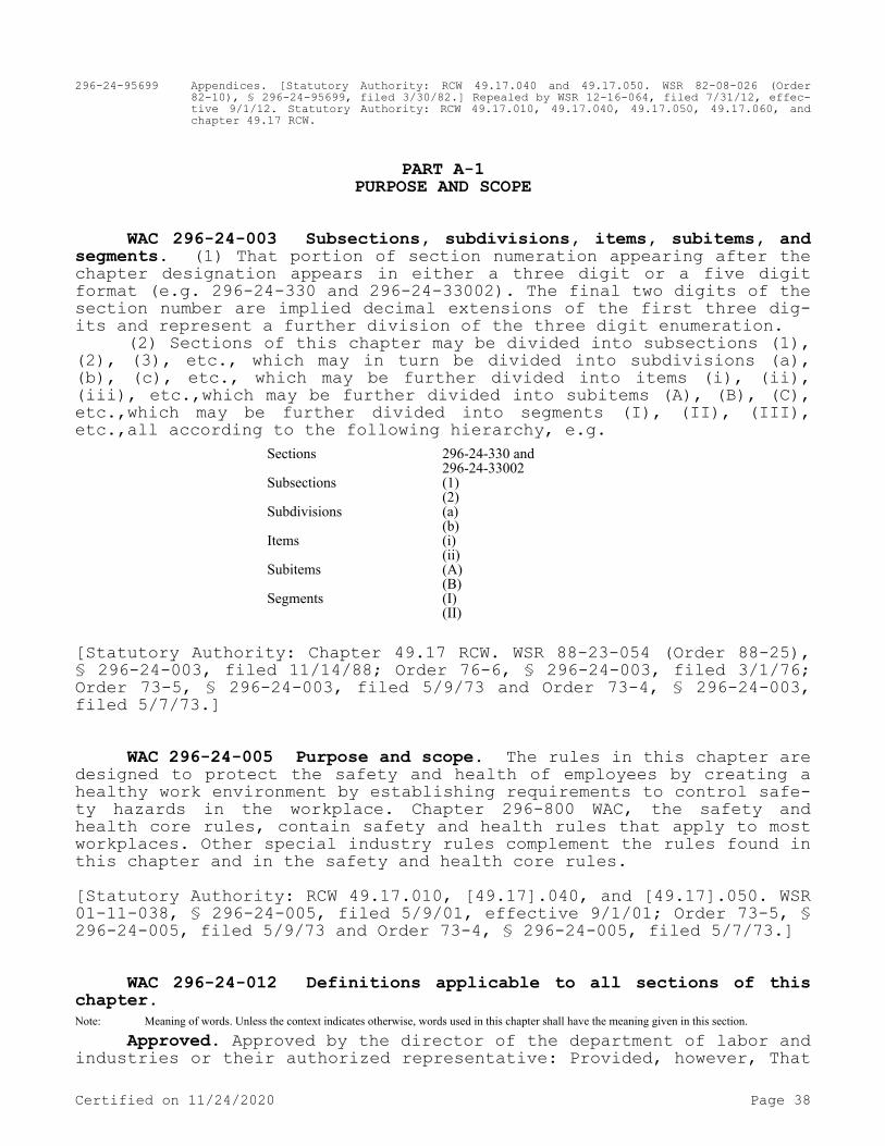
296-24-95699 Appendices. [Statutory Authority: RCW 49.17.040 and 49.17.050. WSR 82-08-026 (Order 82-10), § 296-24-95699, filed 3/30/82.] Repealed by WSR 12-16-064, filed 7/31/12, effec-tive 9/1/12. Statutory Authority: RCW 49.17.010, 49.17.040, 49.17.050, 49.17.060, and chapter 49.17 RCW.
PART A-1PURPOSE AND SCOPE
WAC 296-24-003 Subsections, subdivisions, items, subitems, and segments. (1) That portion of section numeration appearing after the chapter designation appears in either a three digit or a five digit format (e.g. 296-24-330 and 296-24-33002). The final two digits of the section number are implied decimal extensions of the first three dig-its and represent a further division of the three digit enumeration.
(2) Sections of this chapter may be divided into subsections (1), (2), (3), etc., which may in turn be divided into subdivisions (a), (b), (c), etc., which may be further divided into items (i), (ii), (iii), etc.,which may be further divided into subitems (A), (B), (C), etc.,which may be further divided into segments (I), (II), (III), etc.,all according to the following hierarchy, e.g.
Sections 296-24-330 and296-24-33002
Subsections (1)(2)
Subdivisions (a)(b)
Items (i)(ii)
Subitems (A)(B)
Segments (I)(II)
[Statutory Authority: Chapter 49.17 RCW. WSR 88-23-054 (Order 88-25), § 296-24-003, filed 11/14/88; Order 76-6, § 296-24-003, filed 3/1/76; Order 73-5, § 296-24-003, filed 5/9/73 and Order 73-4, § 296-24-003, filed 5/7/73.]
WAC 296-24-005 Purpose and scope. The rules in this chapter are designed to protect the safety and health of employees by creating a healthy work environment by establishing requirements to control safe-ty hazards in the workplace. Chapter 296-800 WAC, the safety and health core rules, contain safety and health rules that apply to most workplaces. Other special industry rules complement the rules found in this chapter and in the safety and health core rules.[Statutory Authority: RCW 49.17.010, [49.17].040, and [49.17].050. WSR 01-11-038, § 296-24-005, filed 5/9/01, effective 9/1/01; Order 73-5, § 296-24-005, filed 5/9/73 and Order 73-4, § 296-24-005, filed 5/7/73.]
WAC 296-24-012 Definitions applicable to all sections of this chapter.Note: Meaning of words. Unless the context indicates otherwise, words used in this chapter shall have the meaning given in this section.
Approved. Approved by the director of the department of labor and industries or their authorized representative: Provided, however, That
Certified on 11/24/2020 Page 38

should a provision of this chapter state that approval by an agency or organization other than the department of labor and industries is re-quired, such as Underwriters' Laboratories or the Mine Safety and Health Administration (MSHA) and the National Institute for Occupa-tional Safety and Health (NIOSH), the provisions of WAC 296-800-360 must apply.
Authorized person. A person approved or assigned by the employer to perform a specific type of duty or duties or to be at a specific location or locations at the job site.
Competent person. One who is capable of identifying existing and predictable hazards in the surroundings or working conditions which are unsanitary, hazardous, or dangerous to employees, and who has au-thorization to take prompt corrective action to eliminate them.
Department. The department of labor and industries.Director. The director of the department of labor and industries,
or designated representative.Employer. Any person, firm, corporation, partnership, business
trust, legal representative, or other business entity which engages in any business, industry, profession, or activity in this state and em-ploys one or more employees or who contracts with one or more persons, the essence of which is the personal labor of such person or persons and includes the state, counties, cities, and all municipal corpora-tions, public corporations, political subdivisions of the state, and charitable organizations: Provided, That any person, partnership, or business entity not having employees, and who is covered by the indus-trial insurance act must be considered both an employer and an employ-ee.
First aid. For purposes of this section, the extent of treatment that could be expected to be given by a person trained in basic first aid, using supplies from a first-aid kit. Tests, such as X-rays, must not be confused with treatment.
Hazard. That condition, potential or inherent, which can cause injury, death, or occupational disease.
Hospitalization. To be admitted to a hospital or an equivalent medical facility on an emergent in-patient basis requiring an over-night stay.
Must. Mandatory.Qualified. One who, by possession of a recognized degree, certif-
icate, or professional standing, or who by extensive knowledge, train-ing, and experience, has successfully demonstrated the ability to solve or resolve problems relating to the subject matter, the work, or the project.
Safety and health standard. A standard which requires the adop-tion or use of one or more practices, means, methods, operations, or processes reasonably necessary or appropriate to provide safe or healthful employment and places of employment.
Safety factor. The ratio of the ultimate breaking strength of a member or piece of material or equipment to the actual working stress or safe load when in use.
Should. Recommended.Standard safeguard. A device designed and constructed with the
object of removing the hazard of accident incidental to the machine, appliance, tool, building, or equipment to which it is attached.
Standard safeguards must be constructed of either metal or wood or other suitable material or a combination of these. The final deter-mination of the sufficiency of any safeguard rests with the director of the department of labor and industries.
Certified on 11/24/2020 Page 39

Suitable. That which fits, or has the qualities or qualifications to meet a given purpose, occasion, condition, function, or circum-stance.
Work place. Any plant, yard, premises, room, or other place where an employee or employees are employed for the performance of labor or service over which the employer has the right of access or control, and includes, but is not limited to, all work places covered by indus-trial insurance under Title 51 RCW, as now or hereafter amended.
Worker, personnel, person, employee, (and other terms of like meaning, unless the context of the provision containing such term in-dicates otherwise). An employee of an employer who is employed in the business of their employer whether by way of manual labor or otherwise and every person in this state who is engaged in the employment of or who is working under an independent contract the essence of which is their personal labor for an employer whether by manual labor or other-wise.
Working day. A calendar day, except Saturdays, Sundays, and legal holidays as set forth in RCW 1.16.050, as now or hereafter amended, and for the purposes of the computation of time within which an act is to be done under the provisions of this chapter, must be computed by excluding the first working day and including the last working day.
Abbreviations used in this chapter:ANSI. American National Standards Institute.API. American Petroleum Institute.ASA. American Standards Association.ASAE. American Society of Agricultural Engineers.ASHRE. American Society of Heating and Refrigeration Engineers.ASME. American Society for Mechanical Engineers.ASTM. American Society for Testing and Materials.AWS. American Welding Society.BTU. British thermal unit.BTUH. British thermal unit per hour.CFM. Cubic feet per minute.C.F.R. Code of Federal Regulations.CGA. Compressed Gas Association.CIE. Commission Internationale de l' Eclairage.DOSH. Division of occupational safety and health.DOT. Department of transportation.FRP. Fiberglass reinforced plastic.GPM. Gallons per minute.ICC. Interstate Commerce Commission.ID. Inside diameter.LPG. Liquefied petroleum gas.MCA. Manufacturing Chemist Association. (New name: Chemical Manu-
facturers Association.)NBFU. National Board of Fire Underwriters.NEMA. National Electrical Manufacturing Association.NFPA. National Fire Protection Association.NTP. Normal temperature and pressure.OD. Outside diameter.PSI. Pounds per square inch.PSIA. Pounds per square inch atmospheric.PSIG. Pounds per square inch gauge.RMA. Rubber Manufacturers Association.SAE. Society of Automotive Engineers.TFI. The Fertilizer Institute.TSC. Trailer Standard Code.
Certified on 11/24/2020 Page 40

UL. Underwriters' Laboratories, Inc.USASI. United States of America Standards Institute.U.S.C. United States Code.USCG. United States Coast Guard.WAC. Washington Administrative Code.WISHA. Washington Industrial Safety and Health Act of 1973.
[Statutory Authority: RCW 49.17.010, 49.17.040, 49.17.050, and 49.17.060. WSR 15-24-100, § 296-24-012, filed 12/1/15, effective 1/5/16; WSR 09-01-158, § 296-24-012, filed 12/23/08, effective 3/1/09; WSR 04-07-161, § 296-24-012, filed 3/23/04, effective 6/1/04. Statuto-ry Authority: RCW 49.17.010, [49.17].040, [49.17].050. WSR 02-12-098, § 296-24-012, filed 6/5/02, effective 8/1/02. Statutory Authority: Chapter 49.17 RCW. WSR 94-15-096 (Order 94-07), § 296-24-012, filed 7/20/94, effective 9/20/94; WSR 89-11-035 (Order 89-03), § 296-24-012, filed 5/15/89, effective 6/30/89; Order 73-5, § 296-24-012, filed 5/9/73 and Order 73-4, § 296-24-012, filed 5/7/73.]
PART A-2PERSONAL PROTECTIVE EQUIPMENT
RESERVENote: Personal protective equipment requirements have been moved to WAC 296-800-160.Note: Electrical protective equipment requirements have been moved to WAC 296-24-980.
PART A-3LATE NIGHT RETAIL WORKER CRIME PROTECTION
Note: Late night retail worker crime protection has been moved to chapter 296-832 WAC.
PART A-4SAFETY PROCEDURES
Note: Safety procedures has been moved to chapter 296-803 WAC.
PART B-2SAFETY COLOR CODE FOR MARKING PHYSICAL HAZARDS, ETC., WINDOW WASHING
Note: Safety color code for marking physical hazards, etc., window washing has been moved to WAC 296-800-11045 and chapter 296-878 WAC.
PART CMACHINERY AND MACHINE GUARDING
Note: Machinery and machine guarding has been moved to chapter 296-806 WAC.
PART D
Certified on 11/24/2020 Page 41

MATERIALS HANDLING AND STORAGE, INCLUDING CRANES, DERRICKS, ETC., AND RIGGING
Handling and Storage—Cranes, Derricks, etc.
WAC 296-24-215 Materials handling and storage—Handling materi-als—General.[Order 73-5, § 296-24-215, filed 5/9/73 and Order 73-4, § 296-24-215, filed 5/7/73.]
WAC 296-24-21501 Use of mechanical equipment. You must allow sufficient safe clearances for aisles, at loading docks, through door-ways and wherever turns or passage must be made where mechanical han-dling equipment is used. You must keep aisles and passageways clear and in good repair, with no obstruction across or in aisles that could create a hazard. You must ensure that aisles and passageways are ap-propriately marked.[Statutory Authority: RCW 49.17.010, 49.17.040, 49.17.050, and 49.17.060. WSR 15-24-100, § 296-24-21501, filed 12/1/15, effective 1/5/16; Order 73-5, § 296-24-21501, filed 5/9/73 and Order 73-4, § 296-24-21501, filed 5/7/73.]
WAC 296-24-21509 Clearance limits. You must provide clearance signs to warn of clearance limits.[Statutory Authority: RCW 49.17.010, 49.17.040, 49.17.050, and 49.17.060. WSR 15-24-100, § 296-24-21509, filed 12/1/15, effective 1/5/16; Order 73-5, § 296-24-21509, filed 5/9/73 and Order 73-4, § 296-24-21509, filed 5/7/73.]
WAC 296-24-21511 Rolling railroad cars. (1) You must ensure that derail and/or bumper blocks are provided on spur railroad tracks where a rolling car could contact other cars being worked, enter a building, work or traffic area. This does not apply to cars being moved by a locomotive, switch engine, donkey engine, or a car puller, but only to cars which are "cut loose." The standard does not apply to "cut loose" cars in railroad yards where trains are made up using gravity feed arrangements.
(2) You must employ a clearly audible warning system when cars are being moved by car pullers or locomotives, and when the person re-sponsible for the moving does not have assurance that the area is clear, and it is safe to move the car or cars.[Statutory Authority: RCW 49.17.010, 49.17.040, 49.17.050, and 49.17.060. WSR 15-24-100, § 296-24-21511, filed 12/1/15, effective 1/5/16. Statutory Authority: Chapter 49.17 RCW. WSR 89-11-035 (Order 89-03), § 296-24-21511, filed 5/15/89, effective 6/30/89; Order 74-27, § 296-24-21511, filed 5/7/74; Order 73-5, § 296-24-21511, filed 5/9/73 and Order 73-4, § 296-24-21511, filed 5/7/73.]
Certified on 11/24/2020 Page 42
WAC 296-24-21513 Guarding. You must provide covers and/or guardrails to protect personnel from the hazards of open pits, tanks, vats, ditches, etc.[Statutory Authority: RCW 49.17.010, 49.17.040, 49.17.050, and 49.17.060. WSR 15-24-100, § 296-24-21513, filed 12/1/15, effective 1/5/16; Order 73-5, § 296-24-21513, filed 5/9/73 and Order 73-4, § 296-24-21513, filed 5/7/73.]
WAC 296-24-235 Overhead and gantry cranes.[Order 73-5, § 296-24-235, filed 5/9/73 and Order 73-4, § 296-24-235, filed 5/7/73.]
WAC 296-24-23501 Definitions. ANSI. The American National Standards Institute.
Appointed. Assigned specific responsibilities by the employer or the employer's representative.
Automatic crane. A crane which when activated operates through a preset cycle or cycles.
Auxiliary hoist. A supplemental hoisting unit of lighter capacity and usually higher speed than provided for the main hoist.
Brake. A device used for retarding or stopping motion by friction or power means.
Bridge. That part of a crane consisting of girders, trucks, end ties, footwalks, and drive mechanism which carries the trolley or trollies.
Bridge travel. The crane movement in a direction parallel to the crane runway.
Bumper (buffer). An energy absorbing device for reducing impact when a moving crane or trolley reaches the end of its permitted trav-el; or when two moving cranes or trolleys come in contact.
Cab. The operator's compartment on a crane.Cab-operated crane. A crane controlled by an operator in a cab
located on the bridge or trolley.Cantilever gantry crane. A gantry or semigantry crane in which
the bridge girders or trusses extend transversely beyond the crane runway on one or both sides.
Clearance. The distance from any part of the crane to a point of the nearest obstruction.
Collectors (current). Contacting devices for collecting current from runway or bridge conductors.
Conductors, bridge. The electrical conductors located along the bridge structure of a crane to provide power to the trolley.
Conductors, runway (main). The electrical conductors located along a crane runway to provide power to the crane.
Control braking. A method of controlling crane motor speed when in an overhauling condition.
Controller, spring return. A controller which when released will return automatically to a neutral position.
Countertorque. A method of control by which the power to the mo-tor is reversed to develop torque in the opposite direction.
Crane. A machine for lifting and lowering a load and moving it horizontally, with the hoisting mechanism and integral part of the ma-chine. Cranes whether fixed or mobile are driven manually or by power.
Certified on 11/24/2020 Page 43

Designated. Selected or assigned by the employer or the employ-er's representative as being qualified to perform specific duties.
Drag brake. A brake which provides retarding force without exter-nal control.
Drift point. A point on a travel motion controller which releases the brake while the motor is not energized. This allows for coasting before the brake is set.
Drum. The cylindrical member around which the ropes are wound for raising or lowering the load.
Dynamic. A method of controlling crane motor speeds when in the overhauling condition to provide a retarding force.
Emergency stop switch. A manually or automatically operated elec-tric switch to cut off electric power independently of the regular op-erating controls.
Equalizer. A device which compensates for unequal length or stretch of a rope.
Exposed. Capable of being contacted inadvertently. Applied to hazardous objects not adequately guarded or isolated.
Fail-safe. A provision designed to automatically stop or safely control any motion in which a malfunction occurs.
Floor-operated crane. A crane which is pendant or nonconductive rope controlled by an operator on the floor or an independent plat-form.
Footwalk. The walkway with handrail, attached to the bridge or trolley for access purposes.
Gantry crane. A crane similar to an overhead crane except that the bridge for carrying the trolley or trolleys is rigidly supported on two or more legs running on fixed rails or other runway.
Hoist. An apparatus which may be a part of a crane, exerting a force for lifting or lowering.
Hoist chain. The load bearing chain in a hoist.Note: Chain properties do not conform to those shown in ANSI B30.9-1971, Safety Code for Slings.
Hoist motion. That motion of a crane which raises and lowers a load.
Holding brake. A brake that automatically prevents motion when power is off.
Hot metal handling crane. An overhead crane used for transporting or pouring molten material.
Limit switch. A switch which is operated by some part or motion of a power-driven machine or equipment to alter the electric circuit associated with the machine or equipment.
Load. The total superimposed weight on the load block or hook.Load block. The assembly of hook or shackle, swivel, bearing,
sheaves, pins, and frame suspended by the hoisting rope.Magnet. An electromagnetic device carried on a crane hook to pick
up loads magnetically.Main hoist. The hoist mechanism provided for lifting the maximum
rated load.Main switch. A switch controlling the entire power supply to the
crane.Man trolley. A trolley having an operator's cab attached thereto.Master switch. A switch which dominates the operation of contrac-
tors, relays, or other remotely operated devices.Mechanical. A method of control by friction.
Certified on 11/24/2020 Page 44

Overhead crane. A crane with a movable bridge carrying a movable or fixed hoisting mechanism and traveling on an overhead fixed runway structure.
Power-operated crane. A crane whose mechanism is driven by elec-tric, air, hydraulic, or internal combustion means.
Pulpit-operated crane. A crane operated from a fixed operator station not attached to the crane.
Rated load. The maximum load for which a crane or individual hoist is designed and built by the manufacturer and shown on the equipment nameplate(s).
Regenerative. A form of dynamic braking in which the electrical energy generated is fed back into the power system.
Remote-operated crane. A crane controlled by an operator not in a pulpit or in the cab attached to the crane, by any method other than pendant or rope control.
Rope. Refers to wire rope, unless otherwise specified.Running sheave. A sheave which rotates as the load block is
raised or lowered.Runway. An assembly of rails, beams, girders, brackets, and
framework on which the crane or trolley travels.Semigantry crane. A gantry crane with one end of the bridge rig-
idly supported on one or more legs that run on a fixed rail or runway, the other end of the bridge being supported by a truck running on an elevated rail or runway.
Side pull. That portion of the hoist pull acting horizontally when the hoist lines are not operated vertically.
Span. The horizontal distance center to center of runway rails.Standby crane. A crane which is not in regular service but which
is used occasionally or intermittently as required.Stop. A device to limit travel of a trolley or crane bridge. This
device normally is attached to a fixed structure and normally does not have energy absorbing ability.
Storage bridge crane. A gantry type crane of long span usually used for bulk storage of material; the bridge girders or trusses are rigidly or nonrigidly supported on one or more legs. It may have one or more fixed or hinged cantilever ends.
Switch. A device for making, breaking, or for changing the con-nections in an electric circuit.
Trolley. The unit which travels on the bridge rails and carries the hoisting mechanism.
Trolley travel. The trolley movement at right angles to the crane runway.
Truck. The unit consisting of a frame, wheels, bearings, and axles which supports the bridge girders or trolleys.
Wall crane. A crane having a jib with or without trolley and sup-ported from a side wall or line of columns of a building. It is a traveling type and operates on a runway attached to the side wall or columns.[Statutory Authority: RCW 49.17.010, 49.17.040, 49.17.050, and 49.17.060. WSR 15-24-100, § 296-24-23501, filed 12/1/15, effective 1/5/16; Order 73-5, § 296-24-23501, filed 5/9/73 and Order 73-4, § 296-24-23501, filed 5/7/73.]
WAC 296-24-23503 General requirements. (1) Application. This section applies to overhead and gantry cranes, including semigantry,
Certified on 11/24/2020 Page 45

cantilever gantry, wall cranes, storage bridge cranes, and others hav-ing the same fundamental characteristics. These cranes are grouped be-cause they all have trolleys and similar travel characteristics.
(2) New and existing equipment. You must ensure that all new overhead and gantry cranes constructed and installed on or after the effective date of these standards meet the design specifications of the American National Standards Institute, Safety Code for Overhead and Gantry Cranes, ANSI B30.2.0-1967. Overhead and gantry cranes con-structed before the effective date of these standards, should be modi-fied to conform to those design specifications, unless it can be shown that the crane cannot feasibly or economically be altered and that the crane substantially complies with the requirements of this section. (See chapter 296-900 WAC, Administrative rules, for information on ap-plying for a variance.)
(3) Modifications. Cranes may be modified and rerated provided such modifications and the supporting structure are checked thoroughly for the new rated load by a qualified engineer or the equipment manu-facturer. You must test the crane in accordance with WAC 296-24-23521(2). You must display new rated load in accordance with (5) of this section.
(4) Wind indicators and rail clamps.(a) You must provide outdoor storage bridges with automatic rail
clamps. You must provide a wind-indicating device which will give a visible or audible alarm to the bridge operator at a predetermined wind velocity. If the clamps act on the rail heads, you must ground off any beads or weld flash on the rail heads.
(b) You must base calculations for wind pressure on outside over-head traveling cranes on not less than 30 pounds per square foot of exposed surface.
(5) Rated load marking. You must plainly mark the rated load of the crane on each side of the crane, and if the crane has more than one hoisting unit, each hoist must have its rated load marked on it or its load block. You must ensure that the rated load marking is clearly legible from the ground or floor.
(6) Clearance from obstruction.(a) You must provide and maintain minimum clearance of 3 inches
overhead and 2 inches laterally between crane and obstructions in con-formity with Specification No. 61 Crane Manufactures Association of America, Inc., 8720 Red Oak Blvd., Suite 201, Charlotte, NC 28217.
(b) Where passageways or walkways are provided you must not place obstructions so that safety of personnel will be jeopardized by move-ments of the crane.
(7) Clearance between parallel cranes. If the runways of two cranes are parallel, and there are no intervening walls or structure, you must ensure that there is adequate clearance provided and main-tained between the two bridges.
(8) Designated personnel. You must ensure that only designated personnel are permitted to operate a crane covered by this section.[Statutory Authority: RCW 49.17.010, 49.17.040, 49.17.050, and 49.17.060. WSR 18-03-159, § 296-24-23503, filed 1/23/18, effective 2/23/18; WSR 15-24-100, § 296-24-23503, filed 12/1/15, effective 1/5/16; WSR 07-03-163, § 296-24-23503, filed 1/24/07, effective 4/1/07. Statutory Authority: RCW 49.17.010, [49.17].040, and [49.17].050. WSR 01-11-038, § 296-24-23503, filed 5/9/01, effective 9/1/01. Statutory Authority: Chapter 49.17 RCW. WSR 94-15-096 (Order 94-07), § 296-24-23503, filed 7/20/94, effective 9/20/94; Order 74-27,
Certified on 11/24/2020 Page 46

§ 296-24-23503, filed 5/7/74; Order 73-5, § 296-24-23503, filed 5/9/73 and Order 73-4, § 296-24-23503, filed 5/7/73.]
WAC 296-24-23505 Cabs. (1) Cab location.(a) You must ensure that the general arrangement of the cab and
the location of control and protective equipment is such that all op-erating handles are within convenient reach of the operator when fac-ing the area to be served by the load hook, or while facing the direc-tion of travel of the cab. The arrangement must allow the operator a full view of the load hook in all positions.
(b) You must locate the cab to afford a minimum of 3 inches clearance from all fixed structures within its area of possible move-ment.
(c) You must ensure that the clearance of the cab above the work-ing floor or passageway is not less than seven feet.
(2) Access to crane. You must provide access to the cab and/or bridge walkway by a conveniently placed fixed ladder, stairs, or plat-form, requiring no step over any gap exceeding 12 inches. You must en-sure that fixed ladders are in conformance with the American National Standards Institute, Safety Code for Fixed Ladders, ANSI A14.3-1956.
(3) Fire extinguisher. A carbon dioxide, dry-chemical, or equiva-lent hand fire extinguisher should be kept in the cab. You must not use carbon tetrachloride extinguishers.Note: For additional requirements relating to portable fire extinguishers see WAC 296-800-300.
(4) Lighting. You must ensure that light in the cab is sufficient to enable the operator to see clearly enough to perform the work.[Statutory Authority: RCW 49.17.010, 49.17.040, 49.17.050, and 49.17.060. WSR 15-24-100, § 296-24-23505, filed 12/1/15, effective 1/5/16. Statutory Authority: RCW 49.17.010, [49.17].040, and [49.17].050. WSR 01-17-033, § 296-24-23505, filed 8/8/01, effective 9/1/01. Statutory Authority: Chapter 49.17 RCW. WSR 94-15-096 (Order 94-07), § 296-24-23505, filed 7/20/94, effective 9/20/94; Order 73-5, § 296-24-23505, filed 5/9/73 and Order 73-4, § 296-24-23505, filed 5/7/73.]
WAC 296-24-23507 Footwalks and ladders. (1) Location of foot-walks.
(a) If sufficient headroom is available on cab-operated cranes, you must provide a footwalk on the drive side along the entire length of the bridge of all cranes having the trolley running on the top of the girders. To give sufficient access to the opposite side of the trolley, you should provide either a footwalk mounted on the trolley, a suitable footwalk or platform in the building, or a footwalk on the opposite side of the crane at least twice the length of the trolley.
(b) You must ensure that footwalks are located to give a headroom not less than 78 inches. You must provide a minimum of 48 inches. If you cannot provide 48 inches of headroom, you should omit footwalks from the crane and build a stationary platform or landing stage for workers making repairs.
(2) Construction of footwalks.(a) You must ensure that footwalks are of rigid construction and
designed to sustain a distributed load of at least 50 pounds per square foot.
Certified on 11/24/2020 Page 47

(b) You must ensure that footwalks have a walking surface of an-tislip type.Note: Wood will meet this requirement.
(c) You must ensure that footwalks are continuous and permanently secured.
(d) Footwalks should have a clear passageway at least 18 inches wide except opposite the bridge motor, where they should be not less than 15 inches. The inner edge must extend at least to the line of the outside edge of the lower cover plate or flange of the girder.
(3) Toeboards and handrails for footwalks. Toeboards and hand-rails must be in compliance with WAC 296-24-750 through 296-24-75011 and WAC 296-800-260.
(4) Ladders and stairways.(a) You must provide gantry cranes with ladders or stairways ex-
tending from the ground to the footwalk or cab platform.(b) You must equip stairways with rigid and substantial metal
handrails. You must ensure that walking surfaces are of an antislip type.
(c) You must permanently and securely fasten ladders in place and ensure that they are constructed in compliance with chapter 296-876 WAC, Ladders, portable and fixed.[Statutory Authority: RCW 49.17.010, 49.17.040, 49.17.050, and 49.17.060. WSR 15-24-100, § 296-24-23507, filed 12/1/15, effective 1/5/16; WSR 06-16-020, § 296-24-23507, filed 7/24/06, effective 12/1/06. Statutory Authority: RCW 49.17.010, [49.17].040, and [49.17].050. WSR 01-11-038, § 296-24-23507, filed 5/9/01, effective 9/1/01. Statutory Authority: Chapter 49.17 RCW. WSR 94-15-096 (Order 94-07), § 296-24-23507, filed 7/20/94, effective 9/20/94; Order 73-5, § 296-24-23507, filed 5/9/73 and Order 73-4, § 296-24-23507, filed 5/7/73.]
WAC 296-24-23509 Stops, bumpers, rail sweeps, and guards. (1) Trolley stops.
(a) You must ensure that stops are provided at the limits of travel of the trolley.
(b) You must ensure that stops are fastened to resist forces ap-plied when contacted.
(c) You must ensure that a stop engaging the tread of the wheel is of a height at least equal to the radius of the wheel.
(2) Bridge bumpers.You must ensure that a crane is provided with bumpers or other
automatic means providing equivalent effect, unless the crane travels at a slow rate of speed and has a faster deceleration rate due to the use of sleeve bearings, or is not operated near the ends of bridge and trolley travel, or is restricted to a limited distance by the nature of the crane operation and there is no hazard of striking any object in this limited distance or is used in similar operating conditions. The bumpers must be capable of stopping the crane (not including the lifted load) at an average rate of deceleration not to exceed 3 feet per second squared when traveling in either direction at 20% of the rated load speed.
(a) The bumpers must have sufficient energy absorbing capacity to stop the crane when traveling at a speed of at least 40% of rated load speed.
Certified on 11/24/2020 Page 48

(b) The bumpers must be so mounted that there is no direct shear on bolts.
(c) Bumpers must be so designed and installed as to minimize parts falling from the crane in case of breakage.
(3) Trolley bumpers.(a) You must ensure that a trolley is provided with bumpers or
other automatic means of equivalent effect, unless the trolley travels at a slow rate of speed, or is not operated near the ends of bridge and trolley travel, or is restricted to a limited distance of the run-way and there is no hazard of striking any object in this limited dis-tance, or is used in similar operating conditions. The bumpers must be capable of stopping the trolley (not including the lifted load) at an average rate of deceleration not to exceed 4.7 feet per second squared when traveling in either direction at one-third of the rated load speed.
When more than one trolley is operated on the same bridge, each must be equipped with bumpers or equivalent on their adjacent ends.
(b) Bumpers or equivalent must be designed and installed to mini-mize parts falling from the trolley in case of age.
(4) Rail sweeps. You must ensure that bridge trucks are equipped with sweeps which extend below the top of the rail and project in front of the truck wheels.
(5) Guards for hoisting ropes.(a) If hoisting ropes run near enough to other parts to make
fouling or chafing possible, you must install guards to prevent this condition.
(b) You must provide a guard to prevent contact between bridge conductors and hoisting ropes if they could come into contact.
(6) Guards for moving parts.(a) You must ensure that exposed moving parts such as gears, set
screws, projecting keys, chains, chain sprockets, and reciprocating components which might constitute a hazard under normal operating con-ditions are guarded.
(b) You must ensure that guards are securely fastened.(c) You must ensure that each guard is capable of supporting
without permanent distortion the weight of a 200-pound person unless the guard is located where it is impossible for a person to step on it.[Statutory Authority: RCW 49.17.010, 49.17.040, 49.17.050, and 49.17.060. WSR 15-24-100, § 296-24-23509, filed 12/1/15, effective 1/5/16. Statutory Authority: RCW 49.17.040, 49.17.050, 49.17.240, chapters 43.22 and 42.30 RCW. WSR 80-17-015 (Order 80-21), § 296-24-23509, filed 11/13/80; Order 74-27, § 296-24-23509, filed 5/7/74; Order 73-5, § 296-24-23509, filed 5/9/73 and Order 73-4, § 296-24-23509, filed 5/7/73.]
WAC 296-24-23511 Brakes. (1) Brakes for hoists.(a) You must ensure that each independent hoisting unit of a
crane is equipped with at least one self-setting brake, hereafter re-ferred to as a holding brake, applied directly to the motor shaft or some part of the gear train.
(b) You must ensure that each independent hoisting unit of a crane, except worm-geared hoists, the angle of whose worm is such as to prevent the load from accelerating in the lowering direction is, in
Certified on 11/24/2020 Page 49

addition to a holding brake, equipped with control braking means to prevent overspeeding.
(2) Holding brakes.(a) Holding brakes for hoist motors must have not less than the
following percentage of the full load hoisting torque at the point where the brake is applied.
(i) 125% when used with a control braking means other than me-chanical.
(ii) 100% when used in conjunction with a mechanical control braking means.
(iii) 100% each if two holding brakes are provided.(b) Holding brakes on hoists must have ample thermal capacity for
the frequency of operation required by the service.(c) Holding brakes on hoists must be applied automatically when
power is removed.(d) Where necessary holding brakes must be provided with adjust-
ment means to compensate for wear.(e) The wearing surface of all holding-brake drums or discs must
be smooth.(f) Each independent hoisting unit of a crane handling hot metal
and having power control braking means must be equipped with at least two holding brakes.
(3) Control braking means.(a) You must ensure that a power control braking means such as
regenerative, dynamic or countertorque braking, or a mechanically con-trolled braking means is capable of maintaining safe lowering speeds of rated loads.
(b) You must ensure that the control braking means has ample thermal capacity for the frequency of operation required by service.
(4) Brakes for trolleys and bridges.(a) You must ensure that foot operated brakes do not require an
applied force of more than 70 pounds to develop manufacturer's rated brake torque.
(b) Brakes may be applied by mechanical, electrical, pneumatic, hydraulic, or gravity means.
(c) Where necessary you must provide brakes with adjustment means to compensate for wear.
(d) You must ensure that the wearing surface of all brake drums or discs are smooth.
(e) All foot-brake pedals must be constructed so that the opera-tor's foot will not easily slip off the pedal.
(f) Foot-operated brakes must be equipped with automatic means for positive release when pressure is released from the pedal.
(g) You must ensure that brakes for stopping the motion of the trolley or bridge are of sufficient size to stop the trolley or bridge within a distance in feet equal to 10% of full load speed in feet per minute when traveling at full speed with full load.
(h) If holding brakes are provided on the bridge or trolley(s), you must ensure that they do not prohibit the use of a drift point in the control circuit.
(i) You must ensure that brakes on trolleys and bridges have am-ple thermal capacity for the frequency of operation required by the service to prevent impairment of functions from overheating.
(5) Application of trolley brakes.(a) On cab-operated cranes with cab on trolley, a trolley brake
is required as specified under (4) of this section.
Certified on 11/24/2020 Page 50

(b) A drag brake may be applied to hold the trolley in a desired position on the bridge and to eliminate creep with the power off.
(6) Application of bridge brakes.(a) On cab-operated cranes with cab on bridge, a bridge brake is
required as specified under (4) of this section.(b) On cab-operated cranes with cab on trolley, you must use a
bridge brake of the holding type.(c) On all floor, remote and pulpit-operated crane bridge drives,
you must provide a brake or noncoasting mechanical drive.[Statutory Authority: RCW 49.17.010, 49.17.040, 49.17.050, and 49.17.060. WSR 15-24-100, § 296-24-23511, filed 12/1/15, effective 1/5/16; Order 73-5, § 296-24-23511, filed 5/9/73 and Order 73-4, § 296-24-23511, filed 5/7/73.]
WAC 296-24-23513 Electric equipment. (1) General.(a) Wiring and equipment must comply with chapter 296-24 WAC Part
L, and WAC 296-800-280.(b) The control circuit voltage must not exceed 600 volts for
a.c. or d.c. current.(c) The voltage at pendant pushbuttons must not exceed 150 volts
for a.c. and 300 volts for d.c.(d) Where multiple conductor cable is used with a suspended push-
button station, the station must be supported in a manner that will protect the electrical conductors against strain.
(e) Pendant control boxes must be constructed to prevent electri-cal shock and must be clearly marked for identification of functions.
(2) Equipment.(a) You must ensure that electrical equipment is located or en-
closed so that live parts will not be exposed to accidental contact under normal operating conditions.
(b) You must ensure that electric equipment is protected from dirt, grease, oil, and moisture.
(c) You must ensure that guards for live parts are substantial and located so that they cannot be accidentally deformed so as to make contact with the live parts.
(3) Controllers.(a) You must provide cranes not equipped with spring-return con-
trollers or momentary contact pushbuttons with a device which will disconnect all motors from the line on failure of power and will not permit any motor to be restarted until the controller handle is brought to the "off" position, or a reset switch or button is operat-ed.
(b) You must provide lever operated controllers with a notch or latch which in the "off" position prevents the handle from being inad-vertently moved to the "on" position. An "off" detent or spring return arrangement is acceptable.
(c) You must ensure that the controller operating handle is loca-ted within convenient reach of the operator.
(d) You must ensure that as far as practicable, the movement of each controller handle is in the same general directions as the resul-tant movements of the load.
(e) You must ensure that the control for the bridge and trolley travel is located so that the operator can readily face the direction of travel.
Certified on 11/24/2020 Page 51
(f) For floor-operated cranes, you must ensure that the control-ler or controllers if rope operated, automatically returns to the "off" position when released by the operator.
(g) You must ensure that pushbuttons in pendant stations return to the off position when pressure is released by the crane operator.
(h) You must ensure that automatic cranes are designed so that all motions shall fail-safe if any malfunction of operation occurs.
(i) You must ensure that remote-operated cranes function so that if the control signal for any crane motion becomes ineffective the crane motion must stop.
(4) Resistors.(a) You must ensure that enclosures for resistors have openings
to provide adequate ventilation, and are installed to prevent the ac-cumulation of combustible matter near hot parts.
(b) You must ensure that resistor units are supported so as to be free as possible from vibration.
(c) You must put in place a provision to prevent broken parts or molten metal falling upon the operator or from the crane.
(5) Switches.(a) You must ensure that the power supply to the runway conduc-
tors is controlled by a switch or circuit breaker located on a fixed structure, accessible from the floor, and arranged to be locked in the open position.
(b) You must ensure that on cab-operated cranes a switch or cir-cuit breaker of the enclosed type, with provision for locking in the open position is provided in the leads from the runway conductors. A means of opening this switch or circuit breaker must be located within easy reach of the operator.
(c) You must ensure that on floor-operated cranes, a switch or circuit breaker of the enclosed type, with provision for locking in the open position, is provided in the leads from the runway conduc-tors. This disconnect must be mounted on the bridge or footwalk near the runway collectors. You must provide one of the following types of floor operated disconnects:
(i) Nonconductive rope attached to the main disconnect switch.(ii) An undervoltage trip for the main circuit breaker operated
by an emergency stop button in the pendant pushbutton station.(iii) A main line contactor operated by a switch or pushbutton in
the pendant pushbutton station.(d) You must ensure that the hoisting motion of all electric
traveling cranes is provided with an overtravel limit switch in the hoisting direction.
(e) You must ensure that all cranes using a lifting magnet must have a magnet circuit switch of the enclosed type with provision for locking in the open position. You must provide means for discharging the inductive load of the magnet.
(6) Runway conductors. You must ensure that conductors of the open type mounted on the crane runway beams or overhead (sometimes known as "runway conductors") are located or guarded so that persons entering or leaving the cab or crane footwalk normally could not come into contact with them.
(7) Extension lamps. If a service receptacle is provided in the cab or on the bridge of cab-operated cranes, it must be a grounded three-prong type permanent receptacle, not exceeding 300 volts.
(8) Floor operated cranes.
Certified on 11/24/2020 Page 52

(a) You must maintain an unobstructed aisle not less than three feet wide for travel of the operator except in such cases where the control handles are hung from the trolleys of traveling cranes.
(b) You must ensure that the handles of control ropes are dis-tinctly different in contour so that, without looking, the operator will know which is the hoisting and which is the lowering handle. You must clearly indicate the direction of all movements of the crane in some manner so that the operator can easily become familiar with them.
(c) When repairing runways, repairpersons must place rail stops and warning signs or signals so as to protect both ends of the section to be repaired.
(d) Repairpersons must take care to prevent loose parts from falling or being thrown upon the floor beneath.[Statutory Authority: RCW 49.17.010, 49.17.040, 49.17.050, and 49.17.060. WSR 15-24-100, § 296-24-23513, filed 12/1/15, effective 1/5/16. Statutory Authority: RCW 49.17.010, [49.17].040, and [49.17].050. WSR 01-11-038, § 296-24-23513, filed 5/9/01, effective 9/1/01. Statutory Authority: Chapter 49.17 RCW. WSR 91-24-017 (Order 91-07), § 296-24-23513, filed 11/22/91, effective 12/24/91; Order 73-5, § 296-24-23513, filed 5/9/73 and Order 73-4, § 296-24-23513, filed 5/7/73.]
WAC 296-24-23515 Hoisting equipment. (1) Sheaves.(a) You must ensure that sheave grooves are smooth and free from
surface defects which could cause rope damage.(b) You must provide sheaves carrying ropes which can be momen-
tarily unloaded with close-fitting guards or other suitable devices to guide the rope back into the groove when the load is applied again.
(c) You must ensure that the sheaves in the bottom block are equipped with close-fitting guards that will prevent ropes from becom-ing fouled when the block is laying on the ground with ropes loose.
(d) You must ensure that pockets and flanges of sheaves used with hoist chains are of such dimensions that the chain does not catch or bind during operation.
(e) You must ensure that all running sheaves are equipped with means for lubrication. Permanently lubricated, sealed and/or shielded bearings meet this requirement.
(2) Ropes.(a) In using hoisting ropes, you must follow the crane manufac-
turer's recommendation. The rated load divided by the number of parts of rope must not exceed 20% of the nominal breaking strength of the rope.
(b) You must ensure that socketing is done in the manner speci-fied by the manufacturer of the assembly.
(c) You must secure rope to the drum as follows:(i) No less than two wraps of rope must remain on the drum when
the hook is in its extreme low position.(ii) Rope end must be anchored by a clamp securely attached to
the drum, or by a socket arrangement approved by the crane or rope manufacturer.
(d) You must ensure that rope clips attached with U-bolts have the U-bolts on the dead or short end of the rope. Spacing and number of all types of clips must be in accordance with (2)(e) of this sec-tion. Clips must be drop-forged steel in all sizes manufactured com-
Certified on 11/24/2020 Page 53

mercially. When a newly installed rope has been in operation for an hour, all nuts on the clip bolts must be retightened.
(e)Diameterof Rope
Number of Clips Required
Space Between Clips
1 1/2 inch 8 10 inches1 3/8 inch 7 9 inches1 1/4 inch 6 8 inches1 1/8 inch 5 7 inches1 inch 5 6 inches 7/8 inch 5 5 1/4 inches 3/4 inch 5 4 1/2 inches
3/8 to 5/8 inch 4 3 inches
(f) You must apply swaged or compressed fittings as recommended by the rope or crane manufacturer.
(g) Wherever exposed to temperatures, at which fiber cores would be damaged, you must use rope having an independent wire-rope or wire-strand core, or other temperature-damage resistant core.
(h) You must ensure that replacement rope is the same size, grade, and construction as the original rope furnished by the crane manufacturer, unless otherwise recommended by a wire rope manufacturer due to actual working condition requirements.
(3) Equalizers. You must ensure that the tension in the parts is equalized if a load is supported by more than one part of rope.
(4) Hooks. You must ensure that hooks meet the manufacturer's recommendations and are not overloaded. Safety latch-type hooks must be used or the hook must be moused.[Statutory Authority: RCW 49.17.010, 49.17.040, 49.17.050, and 49.17.060. WSR 15-24-100, § 296-24-23515, filed 12/1/15, effective 1/5/16. Statutory Authority: RCW 49.17.040, 49.17.050, 49.17.240, chapters 43.22 and 42.30 RCW. WSR 80-17-015 (Order 80-21), § 296-24-23515, filed 11/13/80. Statutory Authority: RCW 49.17.040, 49.17.150, and 49.17.240. WSR 79-08-115 (Order 79-9), § 296-24-23515, filed 7/31/79; Order 73-5, § 296-24-23515, filed 5/9/73 and Order 73-4, § 296-24-23515, filed 5/7/73.]
WAC 296-24-23517 Warning device. You must provide a gong or other effective warning signal for each crane equipped with a powered traveling mechanism except for floor operated cranes.[Statutory Authority: RCW 49.17.010, 49.17.040, 49.17.050, and 49.17.060. WSR 15-24-100, § 296-24-23517, filed 12/1/15, effective 1/5/16; Order 73-5, § 296-24-23517, filed 5/9/73 and Order 73-4, § 296-24-23517, filed 5/7/73.]
WAC 296-24-23519 Inspection. (1) Inspection classification.(a) Initial inspection. You must perform an initial inspection
prior to initial use all new and altered cranes to ensure compliance with the provisions of these standards.
(b) Inspection procedure for cranes in regular service is divided into two general classifications based upon the intervals at which in-
Certified on 11/24/2020 Page 54

spection should be performed. The intervals in turn are dependent upon the nature of the critical components of the crane and the degree of their exposure to wear, deterioration, or malfunction. The two general classifications are herein designated as "frequent" and "periodic" with respective intervals between inspections as defined below:
(i) Frequent inspection - Daily to monthly intervals.(ii) Periodic inspection - 1 to 12 month intervals.(2) Frequent inspection. You must inspect the following items for
defects at intervals as defined in (1)(b) of this section or as spe-cifically indicated, including observation during operation for any defects which might appear between regular inspections. All deficien-cies such as listed must be carefully examined and determination made as to whether they constitute a safety hazard:
(a) All functional operating mechanisms for maladjustment inter-fering with proper operation. Daily.
(b) Deterioration or leakage in lines, tanks, valves, drain pumps, and other parts of air or hydraulic systems. Daily.
(c) Hooks with deformation or cracks. Visual inspection daily; monthly inspection with signed reports. For hooks with cracks or hav-ing more than 15% in excess of normal throat opening or more than 10° twist from the plane of the unbent hook refer to WAC 296-24-23523 (3)(c)(i).
(d) Hoist or load attachment chains, including end connections, for excessive wear, twist, distorted links interfering with proper function, or stretch beyond manufacturer's recommendations. Visual in-spection daily; monthly inspection with signed report.
(e) Rope slings, including end connections, for excessive wear, broken wires, stretch, kinking, or twisting. Visual inspection daily; monthly inspection with signed report.
(f) All functional operating mechanisms for excessive wear of components.
(g) Rope reeving for noncompliance with manufacturer's recommen-dations.
(3) Periodic inspection. You must complete inspections of the crane at intervals as generally defined in (l)(b)(ii) of this section, depending upon its activity, severity of service, and environment, or as specifically indicated below. These inspections must include the requirements of (2) of this section and in addition, the following items. Any deficiencies such as listed shall be carefully examined and determination made as to whether they constitute a safety hazard:
(a) Deformed, cracked, or corroded members.(b) Loose bolts or rivets.(c) Cracked or worn sheaves and drums.(d) Worn, cracked or distorted parts such as pins, bearings,
shafts, gears, rollers, locking and clamping devices.(e) Excessive wear on brake system parts, linings, pawls, and
ratchets.(f) Load, wind, and other indicators over their full range, for
any significant inaccuracies.(g) Gasoline, diesel, electric, or other powerplants for improper
performance or noncompliance with applicable safety requirements.(h) Excessive wear of chain drive sprockets and excessive chain
stretch.(i) Crane hooks. Magnetic particle or other suitable crack de-
tecting inspection should be performed at least once each year.(j) Electrical apparatus, for signs of pitting or any deteriora-
tion of controller contactors, limit switches and pushbutton stations.
Certified on 11/24/2020 Page 55
(4) Cranes not in regular use.(a) You must inspect a crane which has been idle for a period of
1 month or more, but less than 6 months, in conformance with require-ments of (2) of this section and WAC 296-24-23525(2), before placing in service.
(b) You must completely inspect a crane which has been idle for a period of over 6 months in conformance with requirements of (2) and (3) of this section and WAC 296-24-23525(2) before placing in service.
(c) You must inspect standby cranes at least semi-annually in ac-cordance with requirements of (2) of this section and WAC 296-24-23525(2). Standby cranes exposed to adverse environment should be inspected more frequently.[Statutory Authority: RCW 49.17.010, 49.17.040, 49.17.050, and 49.17.060. WSR 15-24-100, § 296-24-23519, filed 12/1/15, effective 1/5/16; Order 73-5, § 296-24-23519, filed 5/9/73 and Order 73-4, § 296-24-23519, filed 5/7/73.]
WAC 296-24-23521 Testing. (1) Operational tests.(a) Prior to initial use you must test all new and altered cranes
to insure compliance with this section including the following func-tions:
(i) Hoisting and lowering.(ii) Trolley travel.(iii) Bridge travel.(iv) Limit switches, locking and safety devices.(b) You must determine the trip setting of hoist limit switches
by tests with an empty hook traveling in increasing speeds up to the maximum speed. You must ensure that the actuating mechanism of the limit switch is located so that it will trip the switch, under all conditions, in sufficient time to prevent contact of the hook or hook block with any part of the trolley.
(2) Rated load test. Prior to initial use all new, extensively repaired, and altered cranes should be tested by or under the direc-tion of an appointed or authorized person, confirming the load rating of the crane. The load rating should not be more than 80% of the maxi-mum load sustained during the test. Test loads must not be more than 125% of the rated load unless otherwise recommended by the manufactur-er. You must place the tests reports on file where readily available to appointed personnel.[Statutory Authority: RCW 49.17.010, 49.17.040, 49.17.050, and 49.17.060. WSR 15-24-100, § 296-24-23521, filed 12/1/15, effective 1/5/16; Order 73-5, § 296-24-23521, filed 5/9/73 and Order 73-4, § 296-24-23521, filed 5/7/73.]
WAC 296-24-23523 Maintenance. (1) Preventive maintenance. You must establish a preventive maintenance program based on the crane manufacturer's recommendations.
(2) Maintenance procedure.(a) Before adjustments and repairs are started on a crane you
must take the following precautions:(i) The crane to be repaired must be run to a location where it
will cause the least interference with other cranes and operations in the area.
Certified on 11/24/2020 Page 56

(ii) All controllers must be at the off position.(iii) The main or emergency switch must be open and locked in the
open position.(iv) Warning or "out of order" signs must be placed on the crane,
also on the floor beneath or on the hook where visible from the floor.(v) Where other cranes are in operation on the same runway, rail
stops or other suitable means must be provided to prevent interference with the idle crane.
(vi) Where temporary protective rail stops are not available, or practical, a signalperson should be placed at a visual vantage point for observing the approach of an active crane and warning its operator when reaching the limit of safe distance from the idle crane.
(b) After adjustments and repairs have been made you must not op-erate the crane until all guards have been reinstalled, safety devices reactivated and maintenance equipment removed.
(3) Adjustments and repairs.(a) You must correct any unsafe conditions disclosed by the in-
spection requirements of WAC 296-24-23519 before operation of the crane is resumed. You must ensure that adjustments and repairs are done only by designated personnel.
(b) You must maintain adjustments to assure correct functioning of components. The following are examples:
(i) All functional operating mechanisms.(ii) Limit switches.(iii) Control systems.(iv) Brakes.(v) Power plants.(c) You must provide repairs or replacements promptly as needed
for safe operation. The following are examples:(i) You must carefully examine accessory components, such as
hooks, periodically and at the time of annual examination and inspec-tion. You must discard cracked or deformed hooks immediately and not reused on any equipment subject to the provisions of this code.
(ii) Load attachment chains and rope slings showing defects de-scribed in WAC 296-24-23519 (2)(d) and (e) respectively.
(iii) All critical parts which are cracked, broken, bent, or ex-cessively worn.
(iv) You must keep pendant control stations clean and function labels kept legible.[Statutory Authority: RCW 49.17.010, 49.17.040, 49.17.050, and 49.17.060. WSR 15-24-100, § 296-24-23523, filed 12/1/15, effective 1/5/16. Statutory Authority: Chapter 49.17 RCW. WSR 94-15-096 (Order 94-07), § 296-24-23523, filed 7/20/94, effective 9/20/94; Order 73-5, § 296-24-23523, filed 5/9/73 and Order 73-4, § 296-24-23523, filed 5/7/73.]
WAC 296-24-23525 Rope inspection. (1) Running ropes. You must perform a thorough inspection of all ropes at least once a month and keep a full written, dated, and signed report of rope condition on file where readily available to appointed personnel. You must careful-ly note any deterioration, resulting in appreciable loss of original strength, such as described below, and determine whether further use of the rope would constitute a safety hazard:
Certified on 11/24/2020 Page 57

(a) Reduction of rope diameter below nominal diameter due to loss of core support, internal or external corrosion, or wear of outside wires.
(b) A number of broken outside wires and the degree of distribu-tion or concentration of such broken wires.
(c) Worn outside wires.(d) Corroded or broken wires at end connections.(e) Corroded, cracked, bent, worn, or improperly applied end con-
nections.(f) Severe kinking, crushing, cutting, or unstranding.(2) Other ropes. You must thoroughly inspect all rope which has
been idle for a period of a month or more due to shutdown or storage of a crane on which it is installed before it is placed in service. You must inspect for all types of deterioration and you must ensure that the inspection is performed by an appointed person whose approval must be required for further use of the rope. You must make available for inspection a written and dated report of the rope condition.[Statutory Authority: RCW 49.17.010, 49.17.040, 49.17.050, and 49.17.060. WSR 15-24-100, § 296-24-23525, filed 12/1/15, effective 1/5/16. Statutory Authority: RCW 49.17.040, 49.17.050, 49.17.240, chapters 43.22 and 42.30 RCW. WSR 80-17-015 (Order 80-21), § 296-24-23525, filed 11/13/80; Order 73-5, § 296-24-23525, filed 5/9/73 and Order 73-4, § 296-24-23525, filed 5/7/73.]
WAC 296-24-23527 Handling the load. (1) Size of load. You must ensure that the crane is not loaded beyond its rated load except for test purposes as provided in WAC 296-24-23521.
(2) Attaching the load.(a) You must ensure that the hoist chain or hoist rope is free
from kinks or twists and is not be wrapped around the load.(b) The load must be attached to the load block hook by means of
slings or other approved devices.(c) You must take care to make certain that the sling clears all
obstacles.(3) Moving the load.(a) You must ensure that the load is well secured and properly
balanced in the sling or lifting device before it is lifted more than a few inches.
(b) Before starting to hoist you must note the following condi-tions:
(i) Hoist rope must not be kinked.(ii) Multiple part lines must not be twisted around each other.(iii) The hook must be brought over the load in such a manner as
to prevent swinging.(c) During hoisting you must take care that:(i) There is no sudden acceleration or deceleration of the moving
load.(ii) The load does not contact any obstructions.(d) You must ensure that cranes are not used for side pulls ex-
cept when specifically authorized by a responsible person who has de-termined that the stability of the crane is not thereby endangered and that various parts of the crane will not be overstressed.
(e) While any employee is on the load or hook, you must ensure that there is no hoisting, lowering, or traveling.
Certified on 11/24/2020 Page 58

(f) The employer must require that the operator avoid carrying loads over people.
(g) The operator must test the brakes each time a load approach-ing the rated load is handled. You must test the brakes by raising the load a few inches and applying the brakes.
(h) The load must not be lowered below the point where less than two full wraps of rope remain on the hoisting drum.
(i) When two or more cranes are used to lift a load one qualified responsible person must be in charge of the operation. The qualified person must analyze the operation and instruct all personnel involved in the proper positioning, rigging of the load, and the movements to be made.
(j) The employer must assure that the operator does not leave the control position while the load is suspended.
(k) When starting the bridge and when the load or hook approaches near or over personnel, you must sound the warning signal.
(4) Hoist limit switch.(a) At the beginning of each operator's shift, the operator must
try out the upper limit switch of each hoist under no load. Extreme care must be exercised; the block must be "inched" into the limit or run in at slow speed. If the switch does not operate properly, the ap-pointed person must be immediately notified.
(b) You must never use the hoist limit switch which controls the upper limit of travel of the load block as an operating control.[Statutory Authority: RCW 49.17.010, 49.17.040, 49.17.050, and 49.17.060. WSR 15-24-100, § 296-24-23527, filed 12/1/15, effective 1/5/16. Statutory Authority: Chapter 49.17 RCW. WSR 94-15-096 (Order 94-07), § 296-24-23527, filed 7/20/94, effective 9/20/94; Order 73-5, § 296-24-23527, filed 5/9/73 and Order 73-4, § 296-24-23527, filed 5/7/73.]
WAC 296-24-23529 Operators. (1) You must ensure that cranes are operated only by regular crane operators, authorized substitutes who have had adequate experience and training under the supervision of a competent operator, or by crane repairmen or inspectors.
(2) You must ensure that crane operators are able to communicate with others at the worksite sufficiently to understand the signs, no-tices, operation instructions, and the signal code in use to ensure safe operation of the crane.
(3) You must ensure that no minor under eighteen years of age is employed in occupations involving the operation of any power-driven hoisting apparatus or assisting in such operations by work such as hooking on, loading slings, rigging gear, etc.
(4) You must ensure that no person is permitted to operate a crane whose hearing or eye-sight is impaired, or who may be suffering from heart disease or similar ailments. The following physical quali-fications must be minimum requirements for overhead and gantry crane operators and trainees:
(a) They must have vision of at least 20/30 in one eye, and 20/50 in the other, with or without corrective lenses.
(b) They must be able to distinguish colors, regardless of posi-tion of colors, if color differential is required for operation.
(c) Their hearing, with or without hearing aid, must be adequate for a specific operation.
Certified on 11/24/2020 Page 59
(d) They must have sufficient strength, endurance, agility, coor-dination, and speed of reaction to meet the demands of equipment oper-ation.
(e) They must have normal depth perception, field of vision, re-action time, manual dexterity, coordination and no tendencies to diz-ziness or similar undesirable characteristics.
(f) Evidence of physical defects, or emotional instability which could render the operator or trainee a hazard to their self or others, or could interfere with their safe performance may be sufficient cause for disqualification. In such cases, you must require specialized clinical or medical judgments or tests (which include annual medical certification for recovered heart attack patients).
(g) Evidence that an operator or trainee is subject to seizures or loss of physical control must be sufficient reason for disqualifi-cation. You must require specialized medical tests to substantiate these conditions.
(5) Persons who have recovered from a heart attack must be exemp-ted from the provisions of subsection (4) of this section, as it per-tains to their heart condition, provided:
(a) A medical release is obtained from their attending medical doctor.
(b) The release must state that the operation of a crane will not present a hazard to their self or others.
(c) An examination by a medical doctor, and renewal of the work release certification is required annually.
(6) The operator must be fully familiar with all crane rules and with the crane mechanism and its proper care. Needed adjustments or repairs must be reported at once to the proper authority.
(7) The operator must not eat, smoke or read while actually en-gaged in the operation of the crane, or operate the crane when physi-cally unfit.
(8) The operator or someone especially designated must properly lubricate all working parts of the crane.
(9) You must keep cranes clean.(10) You must ensure that whenever the operator finds the main or
emergency switch open, it is not closed, even when starting on regular duty, until it is determined that no one is on or about the crane. You must not oil or repair the crane unless the main switch is open.
(11) If the power goes off, the operator must immediately throw all controllers to "off" position until the power is again available.
(12) The operator must make sure that all controllers are in "off" position until the power is again available before closing the main switch.
(13) You must ensure that the operator recognizes signals only from the employee who is supervising the lift. Operating signals must follow an established standard. Whistle signals may be used where only one crane is in operation.
(14) You must ensure that bumping into runway stops or other cranes is avoided. When the operator is ordered to engage with or push other cranes, it must be done with special care for the safety of per-sons on or below cranes.
(15) You must ensure that when lowering a load, the operator pro-ceeds carefully and makes sure the load is under safe control.
(16) You must ensure that when leaving the cage the operator throws all controllers to "off" position and opens the main switch.
Certified on 11/24/2020 Page 60

(17) You must ensure that if the crane is located out-of-doors the operator locks the crane in a secure position to prevent it from being blown along or off the track by a severe wind.
(18) Operators must not permit anyone to ride on the load or hooks, unless using a lifeline or safety device approved by the de-partment.[Statutory Authority: RCW 49.17.010, 49.17.040, 49.17.050, and 49.17.060. WSR 18-03-159, § 296-24-23529, filed 1/23/18, effective 2/23/18; WSR 15-24-100, § 296-24-23529, filed 12/1/15, effective 1/5/16. Statutory Authority: RCW 49.17.010, [49.17].040 and [49.17].050. WSR 99-17-094, § 296-24-23529, filed 8/17/99, effective 12/1/99. Statutory Authority: Chapter 49.17 RCW. WSR 94-15-096 (Order 94-07), § 296-24-23529, filed 7/20/94, effective 9/20/94. WSR 89-11-035 (Order 89-03), § 296-24-23529, filed 5/15/89, effective 6/30/89; Order 73-5, § 296-24-23529, filed 5/9/73 and Order 73-4, § 296-24-23529, filed 5/7/73.]
WAC 296-24-23531 Other requirements—General. (1) Ladders.(a) The employer must ensure that hands are free from encumbran-
ces while personnel are using ladders.(b) You must lift and lower articles which are too large to be
carried in pockets or belts by hand line.(2) Cabs.(a) You must store necessary clothing and personal belongings in
such a manner as not to interfere with access or operation.(b) You must store tools, oil cans, waste, extra fuses, and other
necessary articles in the tool box, and you must not permit them to lie loose in or about the cab.
(3) Fire extinguishers. You must ensure that operators are famil-iar with the operation and care of fire extinguishers provided.[Statutory Authority: RCW 49.17.010, 49.17.040, 49.17.050, and 49.17.060. WSR 15-24-100, § 296-24-23531, filed 12/1/15, effective 1/5/16; Order 73-5, § 296-24-23531, filed 5/9/73 and Order 73-4, § 296-24-23531, filed 5/7/73.]
WAC 296-24-23533 Crane and derrick suspended personnel (work) platforms. (1) Scope and application. This standard applies to the design, construction, testing, use and maintenance of personnel plat-forms, and the hoisting of personnel platforms on the load lines of cranes or derricks.
(2) Definitions. For the purposes of this section, the following definitions apply:
Failure. Load refusal, breakage, or separation of components.Hoist (or hoisting). All crane or derrick functions such as low-
ering, lifting, swinging, booming in and out or up and down, or sus-pending a personnel platform.
Load refusal. The point where the ultimate strength is exceeded.Maximum intended load. The total load of all employees tools, ma-
terials, and other loads reasonably anticipated to be applied to a personnel platform or personnel platform component at any one time.
Runway. A firm, level surface designed, prepared, and designated as a path of travel for the weight and configuration of the crane be-
Certified on 11/24/2020 Page 61
ing used to lift and travel with the crane suspended platform. An ex-isting surface may be used as long as it meets these criteria.
(3) General requirements. The use of a crane or derrick to hoist employees on a personnel platform is prohibited, except when the erec-tion, use, and dismantling of conventional means of reaching the work-site, such as a personnel hoist, ladder, stairway, aerial lift, ele-vating work platform or scaffold, would be more hazardous, or is not possible because of structural design or worksite conditions.
(4) Operational criteria.(a) You must perform hoisting of the personnel platform in a
slow, controlled, cautious manner with no sudden movements of the crane or derrick, or the platform.
(b) You must ensure that load lines are capable of supporting, without failure, at least 7 times the maximum intended load, except that where rotation resistant rope is used, the lines must be capable of supporting without failure, at least 10 times the maximum intended load. The required design factor is achieved by taking the current safety factor of 3.5 and applying the 50% derating of the crane ca-pacity.
(c) You must engage load and boom hoist drum brakes, swing brakes, and locking devices such as pawls or dogs when the occupied personnel platform is in a stationary working position.
(d) You must equip cranes and derricks with variable angle booms with a boom angle indicator, readily visible to the operator.
(e) You must equip cranes with telescoping booms with a device to indicate clearly to the operator, at all times, the boom's extended length, or you must make an accurate determination of the load radius to be used during the lift prior to hoisting personnel.
(f) You must use a positive acting device which prevents contact between the load block or overhaul ball and the boom tip (anti-two-blocking device), or you must use a system which deactivates the hoisting action before damage occurs in the event of a two-blocking situation (two block damage prevention feature).
(g) You must ensure that the load line hoist drum has a system or device on the power train, other than the load hoist brake, which reg-ulates the lowering rate of speed of the hoist mechanism (controlled load lowering). Free fall is prohibited.
(h) You must ensure that the crane is uniformly level within 1% of level grade and located on firm footing. You must ensure that cranes equipped with outriggers have them all fully deployed following manufacturer's specifications, insofar as applicable, when hoisting employees.
(i) You must ensure that the total weight of the loaded personnel platform and related rigging does not exceed 50% of the rated capacity for the radius and configuration of the crane or derrick.
(j) The use of machines having live booms (booms in which lower-ing is controlled by a brake without aid from other devices which slow the lowering speeds) is prohibited.
(k) Multiple-part line block: When a multiple-part line block is in use, you must use a substantial strap between the crane hook and common ring, shackle, or other equivalent device, to eliminate employ-ee exposure to the lines running through the block, and to the block itself.
(5) Rigging.(a) Lifting bridles on box-type platforms must consist of four
legs of equal length, with one end securely shackled to each corner of the platform and the other end securely attached to a common ring,
Certified on 11/24/2020 Page 62
shackle, or other equivalent device to accommodate the crane hook, or a strap to the crane hook.
(b) You must secure shackle bolts used for rigging of personnel platforms against displacement.
(c) A substantial safety line must pass through the eye of each leg of the bridle adjacent to the common ring, shackle, or equivalent device and be securely fastened with a minimum amount of slack to the lift line above the headache ball or to the crane hook itself.
(d) All eyes in wire rope sling must be fabricated with thimbles.(e) Wire rope, shackles, rings, master links, and other rigging
hardware must be capable of supporting, without failure, at least 5 times the maximum intended load applied or transmitted to that compo-nent. Where rotation resistant wire rope is used for slings, they must be capable of supporting without failure at least 10 times the maximum intended load.
(f) Hooks on headache ball assemblies, lower load blocks, or oth-er attachment assemblies must be of a type that can be closed and locked, eliminating the hook throat opening. Alternatively, an alloy anchor type shackle with a bolt, nut, and retaining pin must be used.
(g) You must only use bridles and associated rigging for attach-ing the personnel platform to the hoist line for the platform and the necessary employees, their tools and the materials necessary to do their work, and you must not use them for any other purpose when not hoisting personnel.
(6) Personnel platforms - Design criteria.(a) The personnel platform and suspension system must be designed
by a qualified engineer or a qualified person competent in structural design.
(b) The suspension system must be designed to minimize tipping of the platform due to movement of employees occupying the platform.
(c) The personnel platform itself, except the guardrail system and body belt/harness anchorages, must be capable of supporting, with-out failure, its own weight and at least 5 times the maximum intended load based on a minimum allowance of 500 pounds for the first person with light tools, and an additional 250 pounds for each additional person.
(d) The personnel platform must be conspicuously posted with a plate or other permanent marking which indicates the weight of the platform and its rated load capacity or maximum intended load.
(7) Platform specifications.(a) You must equip each personnel platform with a guardrail sys-
tem which meets the requirements of WAC 296-24-75011, and is enclosed at least from the toeboard to mid-rail with either solid construction or expanded metal having openings no greater than 1/2 inch (1.27 cm).
(b) You must install a grab rail inside the entire perimeter of the personnel platform.
(c) You must ensure that access gates, if installed, do not swing outward during hoisting.
(d) You must equip access gates, including sliding or folding gates, with a restraining device to prevent accidental opening.
(e) You must provide headroom which allows employees to stand up-right in the platform.
(f) In addition to the use of hard hats, you must protect employ-ees by overhead protection on the personnel platform when employees are exposed to falling objects.
Certified on 11/24/2020 Page 63
(g) You must surface or smooth all rough edges exposed to contact by employees in order to prevent injury to employees from punctures or lacerations.
(h) You must ensure that all welding of the personnel platform and its components is performed by a qualified welder familiar with the weld grades, types, and material specified in the platform design.
(i) Occupants of all personnel platforms must wear a safety belt or harness and lanyard which meets the requirements of ANSI A10.14-1975.
(j) Box-type platform: The workers lanyard must be secured to the work platform or guardrail of the work platform.
(k) Rescue platform:(i) If the platform is used as a rescue vehicle, the injured
worker must be strapped into the stretcher or basket.(ii) The basket must then be secured by lanyard to an anchorage
within the platform.(l) Boatswains chair: You must ensure that the workers lanyard is
secured to the lift line above the headache ball or to the crane hook itself.
(m) Barrel-type platform:(i) The workers lanyard must be secured to the lift line above
the headache ball or to the crane hook itself.(ii) A solid bar or rod must be substantially attached in a rigid
position to the bottom or side of the platform.(iii) The side bar or rod must extend a minimum of 8 feet above
the floor of the work platform.(iv) The bottom of the barrel-type platform must be of a convex
shape to cause the platform to lay on its side when lowered to the ground or floor.
(v) Workers must enter and exit from barrel-type platforms only when they are in an upright position, stable, and securely attached to the load line.
(vi) The employer must use methods or devices which allow employ-ees to safely enter or exit barrel-type platforms.
(8) Personnel platform loading.(a) You must ensure that the personnel platform is not loaded in
excess of its rated load capacity.(b) You must ensure that the number of employees occupying the
personnel platform does not exceed the number required for the work being performed.
(c) You must ensure that the personnel platforms are used only for employees, their tools, and the materials necessary to do their work, and are not used to hoist only materials or tools when not hoisting personnel.
(d) You must secure materials and tools for use during a person-nel lift to prevent displacement.
(e) You must evenly distribute materials and tools for use during a personnel lift within the confines of the platform while the plat-form is suspended.
(9) Trial lift, inspection, and prooftesting.(a) You must make a trial lift with the unoccupied personnel
platform loaded at least to the anticipated liftweight from ground level, or any other location where employees will enter the platform, to each location at which the personnel platform is to be hoisted and positioned. You must perform this trial lift immediately prior to placing personnel on the platform. The operator must determine that all systems, controls, and safety devices are activated and function-
Certified on 11/24/2020 Page 64

ing properly; that no interferences exist; and that all configurations necessary to reach those work locations will allow the operator to re-main under the 50% limit of the hoist's rated capacity. Materials and tools to be used during the actual lift can be loaded in the platform, as provided in subsection (8)(d) and (e) of this section for the trial lift. A single trial lift may be performed at one time for all loca-tions that are to be reached from a single set-up position.
(b) You must repeat the trial lift prior to hoisting employees whenever the crane or derrick is moved and set up in a new location or returned to a previously used location. Additionally, you must repeat the trial lift when the lift route is changed unless the operator de-termines that the route change is not significant (i.e., the route change would not affect the safety of hoisted employees).
(c) After the trial lift, and just prior to hoisting personnel, you must hoist the platform a few inches and inspect it to ensure that it is secure and properly balanced. You must not hoist employees un-less the following conditions are determined to exist:
(i) Hoist ropes must be free of kinks;(ii) Multiple part lines must not be twisted around each other;(iii) The primary attachment must be centered over the platform;
and(iv) The hoisting system must be inspected if the load rope is
slack to ensure all ropes are properly stated on drums and in sheaves.(d) A competent person must conduct a visual inspection of the
crane or derrick, rigging, personnel platform, and the crane or der-rick base support or ground immediately after the trial lift to deter-mine whether the testing has exposed any defect or produced any ad-verse effect upon any component or structure.
(e) You must correct any defects found during inspections which create a safety hazard before hoisting personnel.
(f) At each job site, prior to hoisting employees on the person-nel platform, and after any repair or modification, you must prooftest the platform and rigging to 125% of the platform's rated capacity by holding it in a suspended position for 5 minutes with the test load evenly distributed on the platform (this may be done concurrently with the trial lift). After prooftesting, a competent person must inspect the platform and rigging. You must correct any deficiencies found and conduct another prooftest. You must not conduct personnel hoisting un-til the prooftesting requirements are satisfied.
(g) The employer must retain at the job site and produce when re-quested, documentation such as lift capacity information, verifying that the requirements of this standard have been met.
(10) Work practices.(a) Employees must keep all parts of the body inside the platform
during raising, lowering, and positioning. This provision does not ap-ply to an occupant of the platform performing the duties of a signal person.
(b) Before employees exit or enter a hoisted personnel platform that is not landed, you must secure the platform to the structure where the work is to be performed, unless securing to the structure creates an unsafe situation.
(c) You must use tag lines unless their use creates an unsafe condition.
(d) The crane or derrick operator must remain at the controls at all times when the crane engine is running and the platform is occu-pied.
Certified on 11/24/2020 Page 65

(e) You must promptly discontinue hoisting of employees upon in-dication of any dangerous weather conditions or other impending dan-ger.
(f) Employees being hoisted must remain in continuous sight of and in direct communication with the operator or signal person. In those situations where direct visual contact with the operator is not possible, and the use of a signal person would create a greater hazard for that person, direct communication alone such as by radio may be used.
(g) Hand signals to the operator must be in accordance with those prescribed by the applicable ANSI standard for the type of crane or lift in use unless voice communication equipment is utilized. Signals must be discernable or audible at all times.
(h) Except over water, employees occupying the personnel platform must use a body belt/harness system with lanyard appropriately attach-ed to the lower load block or overhaul ball, or to a structural member within the personnel platform capable of supporting a fall impact for employees using the anchorage.
(i) Lifts must not be made on another of the crane's or derrick's load lines while personnel are suspended on a platform.
(11) Traveling.(a) Hoisting of employees while the crane is traveling is pro-
hibited except for portal, tower and locomotive cranes, or where the employer demonstrates that there is no less hazardous way to perform the work.
(b) Under any circumstances where a crane would travel while hoisting personnel, the employer must implement the following proce-dures to safeguard employees:
(i) Crane travel must be restricted to a fixed track or runway;(ii) Travel must be limited to the load radius of the boom used
during the lift; and(iii) The boom must be parallel to the direction of travel.(c) You must perform a complete trial run to test the route of
travel before employees are allowed to occupy the platform. This trial run can be performed at the same time as the trial lift required by subsection (9)(a) of this section which tests the route of the lift.
(d) If travel is done with a rubber tired-carrier, you must check the condition and air pressure of the tires. You must use the chart capacity for lifts on rubber for application of the 50% reduction of rated capacity. Notwithstanding subsection (4)(i) of this section, outriggers may be partially retracted as necessary for travel.
(12) Prelift meeting.(a) You must hold a meeting attended by the crane or derrick op-
erator, signal person(s) (if necessary for the lift), employee(s) to be lifted, and the person responsible for the task to be performed to review the appropriate requirements of this section and the procedures to be followed.
(b) You must hold this meeting prior to the trial lift at each new location, and repeat it for any employees newly assigned to the operation.[Statutory Authority: RCW 49.17.010, 49.17.040, 49.17.050, and 49.17.060. WSR 15-24-100, § 296-24-23533, filed 12/1/15, effective 1/5/16. Statutory Authority: RCW 49.17.010, [49.17].040, and [49.17].050. WSR 00-08-078, § 296-24-23533, filed 4/4/00, effective 7/1/00. Statutory Authority: Chapter 49.17 RCW. WSR 96-09-030, §
Certified on 11/24/2020 Page 66

296-24-23533, filed 4/10/96, effective 6/1/96; WSR 91-03-044 (Order 90-18), § 296-24-23533, filed 1/10/91, effective 2/12/91.]
WAC 296-24-237 Construction, operation and maintenance—Chain and electric hoists. (1) You must ensure that chain and electric hoists are of what is known as "all steel construction." No cast iron may be used in parts subject to tension except drums, bearings or brake shoes.
(2) You must ensure that the chains are made of the best quality steel or iron with welded links.
(3) You must ensure that chain and electric hoists have a factor of safety of at least 5.
(4) You must ensure that chain and electric hoists are equipped with an approved device which will automatically lock the load when hoisting is stopped.
(5) You must ensure that electric hoists are provided with an ap-proved limit stop to prevent the hoist block from traveling too far in case the operating handle is not released in time.[Statutory Authority: RCW 49.17.010, 49.17.040, 49.17.050, and 49.17.060. WSR 15-24-100, § 296-24-237, filed 12/1/15, effective 1/5/16; Order 73-5, § 296-24-237, filed 5/9/73 and Order 73-4, § 296-24-237, filed 5/7/73.]
WAC 296-24-238 Air hoists. (1) You must prevent piston rod lock nuts from becoming loose and allowing rod to drop when supporting a load. A lock nut must be secured to piston rod by a castellated nut and cotter-pin.
(2) You must use a clevis or other means to prevent hoists cylin-der becoming detached from hanger.[Statutory Authority: RCW 49.17.010, 49.17.040, 49.17.050, and 49.17.060. WSR 15-24-100, § 296-24-238, filed 12/1/15, effective 1/5/16; Order 73-5, § 296-24-238, filed 5/9/73 and Order 73-4, § 296-24-238, filed 5/7/73.]
WAC 296-24-240 Crawler locomotive and truck cranes.[Order 73-5, § 296-24-240, filed 5/9/73 and Order 73-4, § 296-24-240, filed 5/7/73.]
WAC 296-24-24001 Definitions. Accessory. A secondary part or assembly of parts which contributes to the overall function and use-fulness of a machine.
Angle indicator (boom). An accessory which measures the angle of the boom to the horizontal.
ANSI. The American National Standards Institute.Appointed. Assigned specific responsibilities by the employer or
the employer's representative.Axis of rotation. The vertical axis around which the crane super-
structure rotates.
Certified on 11/24/2020 Page 67

Axle. The shaft or spindle with which or about which a wheel ro-tates. On truck- and wheel-mounted cranes it refers to an automotive type of axle assembly including housings, gearing, differential, bear-ings, and mounting appurtenances.
Axle (bogie). Two or more automotive-type axles mounted in tandem in a frame so as to divide the load between the axles and permit ver-tical oscillation of the wheels.
Base (mounting). The traveling base or carrier on which the ro-tating superstructure is mounted such as a car, truck, crawlers, or wheel platform.
Boom (crane). A member hinged to the front of the rotating super-structure with the outer end supported by ropes leading to a gantry or "A" frame and used for supporting the hoisting tackle.
Boom angle. The angle between the longitudinal centerline of the boom and the horizontal. The boom longitudinal centerline is a straight line between the boom foot pin (heel pin) centerline and boom point sheave pin centerline.
Boom hoist. A hoist drum and rope reeving system used to raise and lower the boom. The rope system may be all live reeving or a com-bination of live reeving and pendants.
Boom stop. A device used to limit the angle of the boom at the highest position.
Brake. A device used for retarding or stopping motion by friction or power means.
Cab. Housing which covers the rotating superstructure machinery and/or operator's station. On truck crane trucks a separate cab covers the driver's station.
Clutch. A friction, electromagnetic, hydraulic, pneumatic, or positive mechanical device for engagement or disengagement of power.
Counterweight. A weight used to supplement the weight of the ma-chine in providing stability for lifting working loads.
Crawler crane. A rotating superstructure with power plant, oper-ating machinery, and boom, mounted on a base, equipped with crawler treads for travel. Its function is to hoist and swing loads at various radii.
Designated. Selected or assigned by the employer or the employ-er's representative as being qualified to perform specific duties.
Drum. The cylindrical members around which ropes are wound for raising and lowering the load or boom.
Dynamic (loading). Loads introduced into the machine or its com-ponents by forces in motion.
Gantry (A-frame). A structural frame, extending above the super-structure, to which the boom supports ropes are reeved.
Jib. An extension attached to the boom point to provide added boom length for lifting specified loads. The jib may be in line with the boom or offset to various angles.
Load (working). The external load, in pounds, applied to the crane, including the weight of load-attaching equipment such as load blocks, shackles, and slings.
Load block (lower). The assembly of hook or shackle, swivel, sheaves, pins, and frame suspended by the hoisting ropes.
Load block (upper). The assembly of hook or shackle, swivel, sheaves, pins, and frame suspended from the boom point.
Load hoist. A hoist drum and rope reeving system used for hoist-ing and lowering loads.
Load ratings. Crane ratings in pounds established by the manufac-turer in accordance with WAC 296-24-24005.
Certified on 11/24/2020 Page 68
Locomotive crane. A rotating superstructure with power plant, op-erating machinery and boom, mounted on a base or car equipped for travel on railroad track. It may be self-propelled or propelled by an outside source. Its function is to hoist and swing loads at various radii.
Outriggers. Extendable or fixed metal arms, attached to the mounting base, which rest on supports at the outer ends.
Rail clamp. A tong-like metal device, mounted on a locomotive crane car, which can be connected to the track.
Reeving. A rope system in which the rope travels around drums and sheaves.
Rope. Refers to a wire rope unless otherwise specified.Side loading. A load applied at an angle to the vertical plane of
the boom.Standby crane. A crane which is not in regular service but which
is used occasionally or intermittently as required.Standing (guy) rope. A supporting rope which maintains a constant
distance between the points of attachment to the two components con-nected by the rope.
Structural competence. The ability of the machine and its compo-nents to withstand the stresses imposed by applied loads.
Superstructure. The rotating upper frame structure of the machine and the operating machinery mounted thereon.
Swing. The rotation of the superstructure for movement of loads in a horizontal direction about the axis of rotation.
Swing mechanism. The machinery involved in providing rotation of the superstructure.
Tackle. An assembly of ropes and sheaves arranged for hoisting and pulling.
Transit. The moving or transporting of a crane from one job site to another.
Travel. The functions of the machine moving from one location to another, on a job site.
Travel mechanism. The machinery involved in providing travel.Truck crane. A rotating superstructure with power plant, operat-
ing machinery and boom, mounted on an automotive truck equipped with a power plant for travel. Its function is to hoist and swing loads at various radii.
Wheel mounted crane (wagon crane). A rotating superstructure with power plant, operating machinery and boom, mounted on a base or plat-form equipped with axles and rubber-tired wheels for travel. The base is usually propelled by the engine in the superstructure, but it may be equipped with a separate engine controlled from the superstructure. Its function is to hoist and swing loads at various radii.
Wheelbase. The distance between centers of front and rear axles. For a multiple axle assembly the axle center for wheelbase measurement is taken as the midpoint of the assembly.
Whipline (auxiliary hoist). A separate hoist rope system of lighter load capacity and higher speed than provided by the main hoist.
Winch head. A power driven spool for handling of loads by means of friction between fiber or wire rope and spool.[Statutory Authority: RCW 49.17.010, 49.17.040, 49.17.050, and 49.17.060. WSR 15-24-100, § 296-24-24001, filed 12/1/15, effective 1/5/16; Order 73-5, § 296-24-24001, filed 5/9/73 and Order 73-4, § 296-24-24001, filed 5/7/73.]
Certified on 11/24/2020 Page 69

WAC 296-24-24003 General requirements. (1) Application. This section applies to crawler cranes, locomotive cranes, wheel mounted cranes of both truck and self-propelled wheel type, and any variations thereof which retain the same fundamental characteristics. This sec-tion includes only cranes of the above types, which are basically pow-ered by internal combustion engines or electric motors and which uti-lize drums and ropes. Cranes designed for railway and automobile wreck clearances are excepted. The requirements of these standards are ap-plicable only to machines when used as lifting cranes.
(2) New and existing equipment. All new crawler, locomotive, and truck cranes constructed and utilized on or after the effective date of these standards, must meet the design specifications of the Ameri-can National Standard Safety Code for Crawler, Locomotive, and Truck Cranes, ANSI B 30.5-1968. Crawler, locomotive, and truck cranes con-structed prior to the effective date of these standards should be modified to conform to those design specifications by December 31, 1973, unless it can be shown that the crane cannot feasibly or econom-ically be altered and that the crane substantially complies with the requirements of this section. Replacement parts must be of equal or better quality than the original equipment and suitable for the pur-pose. Repairs or modifications must be such as to render the equipment equal to or better than the original construction or design.
(3) Designated personnel. You must ensure that only designated personnel are permitted to operate a crane covered by this section.[Statutory Authority: RCW 49.17.010, 49.17.040, 49.17.050, and 49.17.060. WSR 15-24-100, § 296-24-24003, filed 12/1/15, effective 1/5/16; Order 74-27, § 296-24-24003, filed 5/7/74; Order 73-5, § 296-24-24003, filed 5/9/73 and Order 73-4, § 296-24-24003, filed 5/7/73.]
WAC 296-24-24005 Load ratings. (1) Load ratings—Where stabili-ty governs lifting performance.
(a) The margin of stability for determination of load ratings, with booms of stipulated lengths at stipulated working radii for the various types of crane mountings is established by taking a percentage of the loads which will produce a condition of tipping or balance with the boom in the least stable direction, relative to the mounting. The load ratings must not exceed the following percentages for cranes, with the indicated types of mounting under conditions stipulated in (1)(b) and (c) of this section.
Type of crane mounting:
Maximum load ratings
(% of tipping loads)
Locomotive, without outriggers; Booms 60 feet or less . . . . . . . . . . . . . . 85 Booms over 60 feet . . . . . . . . . . . . . . . . 851
Locomotive, using outriggers fully extended . 80Crawler, without outriggers . . . . . . . . . . . . . . 75Crawler, using outriggers fully extended . . . . 85Truck and wheel mounted without outriggers or using outriggers fully extended . . . . 85
Certified on 11/24/2020 Page 70

1 Unless this results in less than 30,000 pound-feet net stabilizing moment about the rail, which must be minimum with such booms.
(b) The following stipulation must govern the application of the values in (1)(a) of this section for locomotive cranes:
(i) Tipping with or without the use of outriggers occurs when half of the wheels farthest from the load leave the rail.
(ii) The crane must be standing on track which is level within 1% grade.
(iii) Radius of the load is the horizontal distance from a pro-jection of the axis of rotation to the rail support surface, before loading, to the center of vertical hoist line or tackle with load ap-plied.
(iv) Tipping loads from which ratings are determined must be ap-plied under static conditions only, i.e., without dynamic effect of hoisting, lowering, or swinging.
(v) The weight of all auxiliary handling devices such as hoist blocks, hooks, and slings must be considered a part of the load rat-ing.
(c) Stipulations governing the application of the values in (1)(a) of this section for crawler, truck, and wheel-mounted cranes must be in accordance with Crane Load-Stability Test Code. Society of Automotive Engineers (SAE) J765.Note: The effectiveness of these preceding stability factors will be influenced by such additional factors as freely suspended loads, track, wind, or
ground conditions, condition and inflation of rubber tires, boom lengths, proper operating speeds for existing conditions, and, in general, careful and competent operation. All of these must be taken into account by the user.
(2) Rated capacity chart. You must post a chart indicating the manufacturer's rated capacity at all operating radii for all permissi-ble boom lengths and jib lengths with alternate ratings for optional equipment affecting such ratings in all mobile type cranes. Rated ca-pacity charts must be readily visible to the operator in the normal operating position.
(3) Inspection classification. Initial inspection. You must in-spect all new and altered cranes prior to initial use to ensure com-pliance with provisions of these standards.
(4) You must ensure that all hooks are of the safety latch-type or the hook must be moused.[Statutory Authority: RCW 49.17.010, 49.17.040, 49.17.050, and 49.17.060. WSR 15-24-100, § 296-24-24005, filed 12/1/15, effective 1/5/16. Statutory Authority: Chapter 49.17 RCW. WSR 94-15-096 (Order 94-07), § 296-24-24005, filed 7/20/94, effective 9/20/94. Statutory Authority: RCW 49.17.040, 49.17.150, and 49.17.240. WSR 79-08-115 (Or-der 79-9), § 296-24-24005, filed 7/31/79; Order 73-5, § 296-24-24005, filed 5/9/73 and Order 73-4, § 296-24-24005, filed 5/7/73.]
WAC 296-24-24007 Inspection classification. (1) Regular inspec-tion. Inspection procedure for cranes in regular service is divided into two general classifications based upon the intervals at which in-spection should be performed. The intervals in turn are dependent upon the nature of the critical components of the crane and the degree of their exposure to wear, deterioration, or malfunction. The two general classifications are herein designated as "frequent" and "periodic" with respective intervals between inspections as defined below:
(a) Frequent inspection: Daily to monthly intervals.(b) Periodic inspection: One- to 12-month intervals, or as spe-
cifically recommended by the manufacturer.
Certified on 11/24/2020 Page 71
(2) Frequent inspection. You must inspect items such as the fol-lowing for defects at intervals as defined in subsection (1)(a) of this section or as specifically indicated including observation during operation for any defects which might appear between regular inspec-tion. Any deficiencies such as listed must be carefully examined and determination made as to whether they constitute a safety hazard:
(a) All control mechanisms for maladjustment interfering with proper operation: Daily.
(b) All control mechanisms for excessive wear of components and contamination by lubricants or other foreign matter.
(c) All safety devices for malfunction.(d) Deterioration or leakage in air or hydraulic systems: Daily.(e) Crane hooks with deformations or cracks. For hooks with
cracks or having more than 15% in excess of normal throat opening or more than 10° twist from the plane of the unbent hook.
(f) Rope reeving for noncompliance with manufacturer's recommen-dations.
(g) Electrical apparatus for malfunctioning, signs of excessive deterioration, dirt, and moisture accumulation.
(3) Periodic inspection. You must perform complete inspections of the crane at intervals as generally defined in subsection (1)(b) of this section depending upon its activity, severity of service, and en-vironment, or as specifically indicated below. These inspections must include the requirements of subsection (2) of this section and in ad-dition, items such as the following. You must carefully examine any deficiencies such as listed and determine whether they constitute a safety hazard:
(a) Deformed, cracked, or corroded members, in the crane struc-ture and boom.
(b) Loose bolts or rivets.(c) Cracked or worn sheaves and drums.(d) Worn, cracked, or distorted parts such as pins, bearings,
shafts, gears, rollers and locking devices.(e) Excessive wear on brake and clutch system parts, linings,
pawls, and ratchets.(f) Load, boom angle, and other indicators over their full range,
for any significant inaccuracies.(g) Gasoline, diesel, electric, or other power plants for improp-
er performance or noncompliance with safety requirements.(h) Excessive wear of chain-drive sprockets and excessive chain
stretch.(i) Travel steering, braking, and locking devices, for malfunc-
tion.(j) Excessively worn or damaged tires.(4) Cranes not in regular use.(a) A crane which has been idle for a period of one month or
more, but less than 6 months, must be given an inspection conforming with requirements of subsection (2) of this section and WAC 296-24-24013 (2)(b) before placing in service.
(b) A crane which has been idle for a period of 6 months must be given a complete inspection conforming with requirements of subsection (2) and (3) of this section and WAC 296-24-24013 (2)(b) before placing in service.
(c) You must inspect standby cranes at least semi-annually in ac-cordance with requirements of subsection (2) of this section and WAC 296-24-24013 (2)(b). Such cranes which are exposed to adverse environ-ment should be inspected more frequently.
Certified on 11/24/2020 Page 72

(5) Inspection records. You must make written, dated, and signed inspection reports and records monthly on critical items in use such as brakes, crane hooks, and ropes. You must keep records readily available.[Statutory Authority: RCW 49.17.010, 49.17.040, 49.17.050, and 49.17.060. WSR 18-03-159, § 296-24-24007, filed 1/23/18, effective 2/23/18; WSR 15-24-100, § 296-24-24007, filed 12/1/15, effective 1/5/16; Order 73-5, § 296-24-24007, filed 5/9/73 and Order 73-4, § 296-24-24007, filed 5/7/73.]
WAC 296-24-24009 Testing. (1) Operational tests.(a) In addition to prototype tests and quality-control measures,
the user of each new production crane must require that it be tested and related data supplied by the manufacturer to the extent necessary to assure compliance with the operational requirements of this subsec-tion including functions such as the following:
(i) Load hoisting and lowering mechanisms(ii) Boom hoisting and lower mechanisms(iii) Swinging mechanism(iv) Travel mechanism(v) Safety devices(b) You must conduct such tests at final assembly where the com-
plete production crane is not supplied by one manufacturer.(c) You must make certified production-crane test results availa-
ble.(2) Rated load test.(a) You must make written reports available showing test proce-
dures and confirming the adequacy of repairs or alterations.(b) Test loads must not exceed 110% of the rated load at any se-
lected working radius.(c) Where rerating is necessary:(i) You must test crawler, truck, and wheel-mounted cranes in ac-
cordance with SAE Recommended Practice, Crane Load Stability Test Code J765 (April 1961).
(ii) You must locate test crawler cranes in accordance with WAC 296-24-24005 (1)(a) and (b).
(iii) You must make rerating test report readily available.(d) You must not rerate cranes in excess of the original load
ratings unless such rating changes are approved by the crane manufac-turer or final assembler.[Statutory Authority: RCW 49.17.010, 49.17.040, 49.17.050, and 49.17.060. WSR 15-24-100, § 296-24-24009, filed 12/1/15, effective 1/5/16. Statutory Authority: Chapter 49.17 RCW. WSR 94-15-096 (Order 94-07), § 296-24-24009, filed 7/20/94, effective 9/20/94; Order 73-5, § 296-24-24009, filed 5/9/73 and Order 73-4, § 296-24-24009, filed 5/7/73.]
WAC 296-24-24011 Maintenance procedure. (1) You must correct any unsafe conditions disclosed by the inspection requirements of this section before operation of the crane is resumed. Adjustments and re-pairs must be done only by designated personnel.
Certified on 11/24/2020 Page 73

(2) You must not operate the crane until all guards have been re-installed, safety devices reactivated, and maintenance equipment re-moved after adjustments and repairs have been made.[Statutory Authority: RCW 49.17.010, 49.17.040, 49.17.050, and 49.17.060. WSR 15-24-100, § 296-24-24011, filed 12/1/15, effective 1/5/16; Order 73-5, § 296-24-24011, filed 5/9/73 and Order 73-4, § 296-24-24011, filed 5/7/73.]
WAC 296-24-24013 Rope inspection. (1) Running ropes. You must perform a thorough inspection of all ropes in use at least once a month and keep a full written, dated, and signed report of rope condi-tion on file where readily available. All inspections must be per-formed by an appointed or authorized person. You must carefully note any deterioration, resulting in appreciable loss of original strength, such as described below, and make a determination as to whether fur-ther use of the rope would constitute a safety hazard:
(a) Reduction of rope diameter below nominal diameter due to loss of core support, internal, or external corrosion or wear of outside wires.
(b) A number of broken outside wires and the degree of distribu-tion of concentration of such broken wires.
(c) Worn outside wires.(d) Corroded or broken wires at end connections.(e) Corroded, cracked, bent, worn, or improperly applied end con-
nections.(f) Severe kinking, crushing, cutting, or unstranding.(2) Other ropes.(a) Heavy wear and/or broken wires may occur in sections in con-
tact with equalizer sheaves or other sheaves where rope travel is limited, or with saddles. You must take particular care to inspect ropes at these locations.
(b) You must give a thorough inspection of all rope which has been idle for a period of a month or more due to shut down or storage of a crane on which it is installed before it is placed in service. This inspection must be for all types of deterioration and must be performed by an appointed or authorized person whose approval is re-quired for further use of the rope. You must make a written and dated report of the rope condition available.
(c) You must take particular care in the inspection of nonrotat-ing rope.[Statutory Authority: RCW 49.17.010, 49.17.040, 49.17.050, and 49.17.060. WSR 15-24-100, § 296-24-24013, filed 12/1/15, effective 1/5/16; Order 73-5, § 296-24-24013, filed 5/9/73 and Order 73-4, § 296-24-24013, filed 5/7/73.]
WAC 296-24-24015 Handling the load. (1) Size of load.(a) You must not load any crane beyond the rated load, except for
test purposes as provided in WAC 296-24-24009.(b) When loads which are limited by structural competence rather
than by stability are to be handled, you must ascertain that the weight of the load has been determined within plus or minus 10% before it is lifted.
(2) Attaching the load.
Certified on 11/24/2020 Page 74

(a) You must ensure that the hoist rope is not wrapped around the load.
(b) You must ensure that the load is attached to the hook by means of slings or other approved devices.
(3) Moving the load.(a) The employer must ensure that:(i) The crane is level and where necessary blocked properly.(ii) The load is well secured and properly balanced in the sling
or lifting device before it is lifted more than a few inches.(b) Before starting to hoist, you must note the following condi-
tions:(i) Hoist rope must not be kinked.(ii) Multiple part lines must not be twisted around each other.(iii) The hook must be brought over the load in such a manner as
to prevent swinging.(iv) If there is a slack rope condition, it should be determined
that the rope is properly seated on the drum and in the sheaves.(c) During hoisting you must take care that:(i) There is no sudden acceleration or deceleration of the moving
load.(ii) The load does not contact any obstructions.(d) You must ensure that side loading of booms is limited to
freely suspended loads. You must not use cranes for dragging loads sideways.
(e) You must not do any hoisting, lowering, swinging, or travel-ing while anyone is on the load or hook.
(f) The operator should avoid carrying loads over people.(g) On truck mounted cranes, you must not lift any loads over the
front area except as approved by the crane manufacturer.(h) The operator must test the brakes each time a load approach-
ing the rated load is handled by raising it a few inches and applying the brakes.
(i) You must use outriggers when the load to be handled at that particular radius exceeds the rated load without outriggers as given by the manufacturer for that crane. Where floats are used they must be securely attached to the outriggers. Wood blocks used to support out-riggers must:
(i) Be strong enough to prevent crushing.(ii) Be free from defects.(iii) Be of sufficient width and length to prevent shifting or
toppling under load.(j) You must not lower either the load or the boom below the
point where less than two full wraps of rope remain on their respec-tive drums.
(k) Before lifting loads with locomotive cranes without using outriggers, you must apply means to prevent the load from being car-ried by the truck springs.
(l) When two or more cranes are used to lift one load, one desig-nated person must be responsible for the operation. The designated person must be required to analyze the operation and instruct all per-sonnel involved in the proper positioning, rigging of the load, and the movements to be made.
(m) In transit you must exercise the following additional precau-tions.
(i) The boom must be carried in line with the direction of mo-tion.
Certified on 11/24/2020 Page 75

(ii) The superstructure must be secured against rotation, except when negotiating turns when there is an operator in the cab or the boom is supported on a dolly.
(iii) The empty hook must be lashed or otherwise restrained so that it cannot swing freely.
(n) Before traveling a crane with load, a designated person must be responsible for determining and controlling safety. Decisions such as position of load, boom location, ground support, travel route, and speed of movement must be in accord with their determinations.
(o) You must not travel a crane with or without load with the boom so high that it may bounce back over the cab.
(p) When rotating the crane, you must avoid sudden starts and stops. You must ensure that rotational speed is such that the load does not swing out beyond the radii at which it can be controlled. You must use a tag or restraint line when rotation of the load is hazard-ous.
(q) When a crane is to be operated at a fixed radius, you must engage the boom-hoist pawl or other positive locking device.
(r) You must ensure that ropes are not be handled on a winch head without the knowledge of the operator.
(s) While a winch head is being used, the operator must be within convenient reach of the power unit control lever.
(4) Holding the load.(a) The operator must not be permitted to leave the control posi-
tion while the load is suspended.(b) No person should be permitted to stand or pass under a load
on the hook.(c) If the load must remain suspended for any considerable length
of time, the operator must hold the drum from rotating in the lowering direction by activating the positive controllable means of the opera-tor's station.[Statutory Authority: RCW 49.17.010, 49.17.040, 49.17.050, and 49.17.060. WSR 15-24-100, § 296-24-24015, filed 12/1/15, effective 1/5/16. Statutory Authority: Chapter 49.17 RCW. WSR 94-15-096 (Order 94-07), § 296-24-24015, filed 7/20/94, effective 9/20/94; Order 73-5, § 296-24-24015, filed 5/9/73 and Order 73-4, § 296-24-24015, filed 5/7/73.]
WAC 296-24-24017 Other requirements. (1) Rail clamps. You must ensure that rail clamps are not used as a means of restraining tipping of a locomotive crane.
(2) Ballast or counterweight. You must ensure that cranes are not operated without the full amount of any ballast or counterweight in place as specified by the maker, but truck cranes that have dropped the ballast or counterweight may be operated temporarily with special care and only for light loads without full ballast or counterweight in place. The ballast or counterweight in place specified by the manufac-turer must not be exceeded.
(3) Cabs.(a) You must store necessary clothing and personal belongings in
such a manner as to not interfere with access or operation.(b) You must store tools, oil cans, waste, extra fuses, and other
necessary articles in the tool box, and they must not be permitted to lie loose in or about the cab.
(4) Refueling.
Certified on 11/24/2020 Page 76

(a) You must ensure that refueling with small portable containers is done with an approved safety type can equipped with an automatic closing cap and flame arrester. Refer to WAC 296-24-58501 for defini-tion of approved.
(b) You must not refuel machines with the engine running.(5) Fire extinguishers.(a) You must keep a carbon dioxide, dry chemical, or equivalent
fire extinguisher in the cab or vicinity of the crane.(b) You must familiarize operating and maintenance personnel with
the use and care of the fire extinguishers provided.(6) Swinging locomotive cranes. You must ensure that a locomotive
crane is not swung into a position where railway cars on an adjacent track might strike it, until it has been ascertained that cars are not being moved on the adjacent track and proper flag protection has been established.[Statutory Authority: RCW 49.17.010, 49.17.040, 49.17.050, and 49.17.060. WSR 15-24-100, § 296-24-24017, filed 12/1/15, effective 1/5/16. Statutory Authority: Chapter 49.17 RCW. WSR 88-23-054 (Order 88-25), § 296-24-24017, filed 11/14/88; Order 73-5, § 296-24-24017, filed 5/9/73 and Order 73-4, § 296-24-24017, filed 5/7/73.]
WAC 296-24-24019 Operating near overhead electric power lines. (1) For operations near overhead electric lines see chapter 296-24 WAC Part L.
(2) Boom guards. Cage-type boom guards, insulating links, or proximity warning devices may be used on cranes, but the use of such devices must not operate to alter the requirements of (1) of this sec-tion.
(3) Notification. Before the commencement of operations near electrical lines, you must notify the owners of the lines or their au-thorized representative and provide them with all pertinent informa-tion. You must request the cooperation of the owner.
(4) Overhead wires. You must consider any overhead wire to be an energized line unless and until the person owning such line or the electrical utility authorities indicate that it is not an energized line.[Statutory Authority: RCW 49.17.010, 49.17.040, 49.17.050, and 49.17.060. WSR 15-24-100, § 296-24-24019, filed 12/1/15, effective 1/5/16. Statutory Authority: Chapter 49.17 RCW. WSR 91-24-017 (Order 91-07), § 296-24-24019, filed 11/22/91, effective 12/24/91; Order 73-5, § 296-24-24019, filed 5/9/73 and Order 73-4, § 296-24-24019, filed 5/7/73.]
WAC 296-24-245 Derricks.[Order 73-5, § 296-24-245, filed 5/9/73 and Order 73-4, § 296-24-245, filed 5/7/73.]
WAC 296-24-24501 Definitions. A-frame derrick. A derrick in which the boom is hinged from a cross member between the bottom ends of two upright members spread apart at the lower ends and joined at
Certified on 11/24/2020 Page 77

the top; the boom point secured to the junction of the side members, and the side members are braced or guyed from this junction point.
A-FRAMEANSI. The American National Standards Institute.Appointed. Assigned specific responsibilities by the employer or
the employer's representative.Basket derrick. A derrick without a boom, similar to a gin pole
with its base supported by ropes attached to corner posts or other parts of the structure. The base is at a lower elevation than its sup-ports. The location of the base of a basket derrick can be changed by varying the length of the rope supports. The top of the pole is se-cured with multiple reeved guys to position the top of the pole to the desired location by varying the length of the upper guy lines. The load is raised and lowered by ropes through a sheave or block secured to the top of the pole.
BASKETBoom. A timber or metal section or strut, pivoted or hinged at
the heel (lower end) at a location fixed in height on a frame or mast or vertical member, and with its point (upper end) supported by chains, ropes, or rods to the upper end of the frame mast, or vertical
Certified on 11/24/2020 Page 78

member. A rope for raising and lowering the load is reeved through sheaves or a block at the boom point. The length of the boom must be taken as the straight line distance between the axis of the foot pin and the axis of the boom point sheave pin, or where used, the axis of the upper load block attachment pin.
Boom harness. The block and sheave arrangement on the boom point to which the topping lift cable is reeved for lowering and raising the boom.
Boom point. Is outward end of the top section of the boom.Breast derrick. A derrick without boom. The mast consists of two
side members spread farther apart at the base than at the top and tied together at top and bottom by rigid members. The mast is prevented from tipping forward by guys connected to its top. The load is raised and lowered by ropes through a sheave or block secured to the top crosspiece.
BREASTChicago boom derrick. A boom which is attached to a structure,
and outside upright member of the structure serving as the mast, and the boom being stepped in a fixed socket clamped to the upright. The derrick is complete with load, boom, and boom point swing line falls.
Certified on 11/24/2020 Page 79

CHICAGO BOOMDerrick. An apparatus consisting of a mast or equivalent member
held at the head by guys or braces, with or without a boom, for use with a hoisting mechanism and operating ropes.
Derrick bullwheel. A horizontal ring or wheel, fastened to the foot of a derrick, for the purpose of turning the derrick by means of ropes leading from this wheel to a powered drum.
Designated. Selected or assigned by the employer or employer's representative as being qualified to perform specific duties.
Eye. A loop formed at the end of a rope by securing the dead end to the live end at the base of the loop.
Fiddle block. A block consisting of two sheaves in the same plane held in place by the same cheek plates.
Foot bearing or foot block (sill block). The lower support on which the mast rotates.
Gin pole derrick. A derrick without a boom. Its guys are so ar-ranged from its top as to permit leaning the mast in any direction. The load is raised and lowered by ropes reeved through sheaves or blocks at the top of the mast.
Certified on 11/24/2020 Page 80

GIN POLEGudgeon pin. A pin connecting the mast cap to the mast allowing
rotation of the mast.Guy. A rope used to steady or secure the mast or other member in
the desired position.Guy derrick. A fixed derrick consisting of a mast capable of be-
ing rotated, supported in a vertical position by guys, and a boom whose bottom end is hinged or pivoted to move in a vertical plane with a reeved rope between the head of the mast and the boom point for raising and lowering the boom, and a reeved rope from the boom point for raising and lowering the load.
GUYLoad block, lower. The assembly of sheaves, pins, and frame sus-
pended by the hoisting rope.Load block, upper. The assembly of sheaves, pins, and frame sus-
pended from the boom.Load, working. The external load, in pounds, applied to the der-
rick, including the weight of load attaching equipment such as load blocks, shackles, and slings.
Mast. The upright member of the derrick.
Certified on 11/24/2020 Page 81
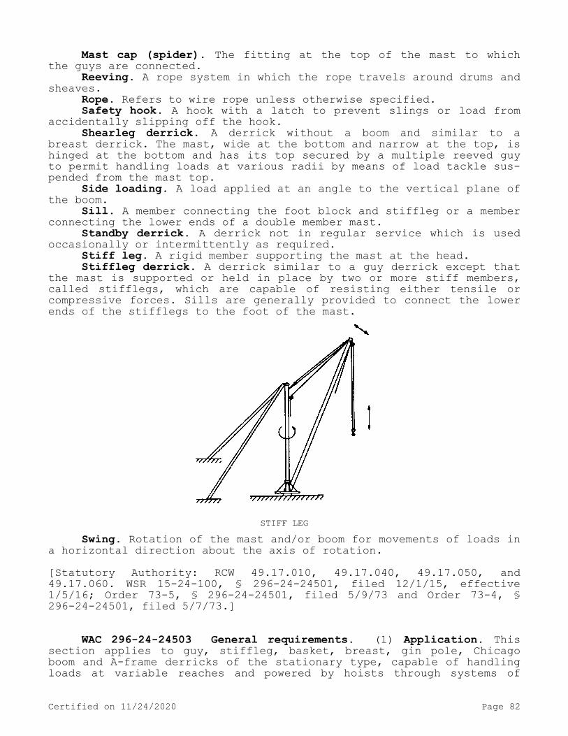
Mast cap (spider). The fitting at the top of the mast to which the guys are connected.
Reeving. A rope system in which the rope travels around drums and sheaves.
Rope. Refers to wire rope unless otherwise specified.Safety hook. A hook with a latch to prevent slings or load from
accidentally slipping off the hook.Shearleg derrick. A derrick without a boom and similar to a
breast derrick. The mast, wide at the bottom and narrow at the top, is hinged at the bottom and has its top secured by a multiple reeved guy to permit handling loads at various radii by means of load tackle sus-pended from the mast top.
Side loading. A load applied at an angle to the vertical plane of the boom.
Sill. A member connecting the foot block and stiffleg or a member connecting the lower ends of a double member mast.
Standby derrick. A derrick not in regular service which is used occasionally or intermittently as required.
Stiff leg. A rigid member supporting the mast at the head.Stiffleg derrick. A derrick similar to a guy derrick except that
the mast is supported or held in place by two or more stiff members, called stifflegs, which are capable of resisting either tensile or compressive forces. Sills are generally provided to connect the lower ends of the stifflegs to the foot of the mast.
STIFF LEGSwing. Rotation of the mast and/or boom for movements of loads in
a horizontal direction about the axis of rotation.[Statutory Authority: RCW 49.17.010, 49.17.040, 49.17.050, and 49.17.060. WSR 15-24-100, § 296-24-24501, filed 12/1/15, effective 1/5/16; Order 73-5, § 296-24-24501, filed 5/9/73 and Order 73-4, § 296-24-24501, filed 5/7/73.]
WAC 296-24-24503 General requirements. (1) Application. This section applies to guy, stiffleg, basket, breast, gin pole, Chicago boom and A-frame derricks of the stationary type, capable of handling loads at variable reaches and powered by hoists through systems of
Certified on 11/24/2020 Page 82

rope reeving, used to perform lifting hook work, single or multiple line bucket work, grab, grapple, and magnet work. Derricks may be per-manently installed for temporary use as in construction work. The re-quirements of this section also apply to any modification of these types which retain their fundamental features, except for floating derricks.
(2) New and existing equipment. You must ensure that all new der-ricks constructed and installed on or after the effective date of these standards meet the design specifications of the "American Na-tional Standards Institute, Safety Code for Derricks, ANSI B30.6-1969." Derricks constructed prior to the effective date of these standards should be modified to conform to these design specifications by December 31, 1973 unless it can be shown that the derrick cannot feasibly or economically be altered and that the derrick substantially complies with the requirements of this section.
(a) You must mark operating controls or post an explanation of the controls in full view of the operator.
(b) You must ensure that the radius or boom angle indicator has been installed on all cranes or derricks having a movable working boom. This must be located where the operator can readily read it from the normal operating position.
(c) Top of boom painted. You must ensure that the top six feet of the boom or jib are painted bright yellow.
(3) Designated personnel. You must ensure that only designated personnel are permitted to operate a derrick covered by this section.[Statutory Authority: RCW 49.17.010, 49.17.040, 49.17.050, and 49.17.060. WSR 15-24-100, § 296-24-24503, filed 12/1/15, effective 1/5/16. Statutory Authority: Chapter 49.17 RCW. WSR 94-15-096 (Order 94-07), § 296-24-24503, filed 7/20/94, effective 9/20/94; Order 76-6, § 296-24-24503, filed 3/1/76; Order 73-5, § 296-24-24503, filed 5/9/73 and Order 73-4, § 296-24-24503, filed 5/7/73.]
WAC 296-24-24505 Load ratings. (1) Rated load marking. You must provide a substantial, durable, and clearly legible rating chart with each derrick and securely affixed where it is visible to personnel re-sponsible for the safe operation of the equipment for permanently in-stalled derricks with fixed lengths of boom, guy, and mast. The chart must include the following data:
(a) Manufacturer's approved load ratings at corresponding ranges of boom angle or operating radii.
(b) Specific lengths of components on which the load ratings are based.
(c) Required parts for hoist reeving. Size and construction of rope may be shown either on the rating chart or in the operating man-ual.
(2) Nonpermanent installations. You must provide sufficient in-formation from which capacity charts can be prepared for the particu-lar installation for nonpermanent installations. The capacity charts must be located at the derricks or the job site office.[Statutory Authority: RCW 49.17.010, 49.17.040, 49.17.050, and 49.17.060. WSR 15-24-100, § 296-24-24505, filed 12/1/15, effective 1/5/16; Order 73-5, § 296-24-24505, filed 5/9/73 and Order 73-4, § 296-24-24505, filed 5/7/73.]
Certified on 11/24/2020 Page 83

WAC 296-24-24507 Inspection. (1) Inspection classification.(a) Prior to initial use you must inspect all new and altered
derricks to insure compliance with the provisions of these standards.(b) Inspection procedure for derricks in regular service is divi-
ded into two general classifications based upon the intervals at which inspection should be performed. The intervals in turn are dependent upon the nature of the critical components of the derrick and the de-gree of their exposure to wear, deterioration, or malfunction. The two general classifications are herein designated as frequent and periodic with respective intervals between inspections as defined below:
(i) Frequent inspection - Daily to monthly intervals.(ii) Periodic inspection - One- to 12-month intervals, or as
specified by the manufacturer.(2) Frequent inspection. You must inspect items such as the fol-
lowing for defects at intervals as defined in (1)(b)(i) of this sec-tion or as specifically indicated, including observation during opera-tion for any defects which might appear between regular inspections. You must carefully examine deficiencies for any safety hazard.
(a) All control mechanisms: Inspect daily for adjustment, wear, and lubrication.
(b) All chords and lacing: Inspect daily, visually.(c) Tension in guys: Daily.(d) Plumb of the mast.(e) Deterioration or leakage in air or hydraulic systems: Daily.(f) Derrick hooks for deformations or cracks; for hooks with
cracks or having more than 15% in excess of normal throat opening or more than 10° twist from the plane of the unbent hook, refer to WAC 296-24-24511 (3)(c).
(g) Rope reeving; visual inspection for noncompliance with der-rick manufacturer's recommendations.
(h) Hoist brakes, clutches, and operating levers: Check daily for proper functioning before beginning operations.
(i) Electrical apparatus for malfunctioning, signs of excessive deterioration, dirt, and moisture accumulation.
(3) Periodic inspection.(a) You must perform complete inspections of the derrick at in-
tervals as generally defined in (1)(b)(ii) of this section depending upon its activity, severity of service, and environment, or as specif-ically indicated below. These inspections must include the require-ments of (2) of this section and in addition, items such as the fol-lowing. You must carefully examine deficiencies and determine whether they constitute a safety hazard:
(i) Structural members for deformations, cracks, and corrosion.(ii) Bolts or rivets for tightness.(iii) Parts such as pins, bearings, shafts, gears, sheaves,
drums, rollers, locking and clamping devices, for wear, cracks, and distortion.
(iv) Gudgeon pin for cracks, wear, and distortion each time the derrick is to be erected.
(v) Power plants for proper performance and compliance with ap-plicable safety requirements.
(vi) Hooks: Magnetic particle or other suitable crack detecting inspection should be performed at least once each year.
(b) Foundation or supports must be inspected for continued abili-ty to sustain the imposed loads.
(4) Derricks not in regular use.
Certified on 11/24/2020 Page 84

(a) You must inspect a derrick which has been idle for a period of one month or more, but less than 6 months, in conformance with re-quirements of (2) of this section and WAC 296-24-24513(2) before plac-ing in service.
(b) You must completely inspect a derrick which has been idle for a period of over 6 months in conformance with requirements of (2) and (3) of this section and WAC 296-24-24513(3) before placing in service.
(c) Standby derricks must be inspected at least semiannually in accordance with requirements of (2) of this section and WAC 296-24-24513(3). Those exposed to adverse environment should be in-spected more frequently.[Statutory Authority: RCW 49.17.010, 49.17.040, 49.17.050, and 49.17.060. WSR 15-24-100, § 296-24-24507, filed 12/1/15, effective 1/5/16; Order 73-5, § 296-24-24507, filed 5/9/73 and Order 73-4, § 296-24-24507, filed 5/7/73.]
WAC 296-24-24509 Testing. (1) Operational tests. Prior to ini-tial use you must test all new and altered derricks to ensure compli-ance with this section including the following functions:
(a) Load hoisting and lowering.(b) Boom up and down.(c) Swing.(d) Operation of clutches and brakes of hoist.(2) Anchorages. The appointed person must approve all anchorages
by the appointed person. Rock and hairpin anchorages may require spe-cial testing.[Statutory Authority: RCW 49.17.010, 49.17.040, 49.17.050, and 49.17.060. WSR 15-24-100, § 296-24-24509, filed 12/1/15, effective 1/5/16; Order 73-5, § 296-24-24509, filed 5/9/73 and Order 73-4, § 296-24-24509, filed 5/7/73.]
WAC 296-24-24511 Maintenance. (1) Preventive maintenance. You must establish a preventive maintenance program based on the derrick manufacturer's recommendations.
(2) Maintenance procedure.(a) Before adjustments and repairs are started on a derrick you
must take the following precautions:(i) You must arrange the derrick to be repaired so it will cause
the least interference with other equipment and operations in the area.
(ii) You must engage all hoist drum dogs.(iii) You must lock the main or emergency switch in the open po-
sition, if an electric hoist is used.(iv) You must place warning or out of order signs on the derrick
and hoist.(v) You must make the repairs of booms or derricks either when
the booms are lowered and adequately supported or safely tied off.(vi) You must set up a good communication system between the
hoist operator and the appointed individual in charge of the derrick operations before any work on the equipment is started.
(vii) Welding repairs must be approved by an appointed person.
Certified on 11/24/2020 Page 85

(b) After adjustments and repairs have been made you must not op-erate the derrick until all guards have been reinstalled, safety devi-ces reactivated, and maintenance equipment removed.
(3) Adjustments and repairs.(a) You must correct any unsafe conditions disclosed by inspec-
tion before operation of the derrick is resumed.(b) You must maintain adjustments to assure correct functioning
of components.(c) You must provide repairs or replacements promptly as needed
for safe operation. The following are examples of conditions requiring prompt repair or replacement:
(i) Hooks showing defects described in WAC 296-24-24507 (2)(f) must be discarded.
(ii) All critical parts which are cracked, broken, bent, or ex-cessively worn.
(iii) Pitted or burned electrical contacts should be corrected only by replacement and in sets. Controller parts should be lubricated as recommended by the manufacturer.
(iv) All replacement and repaired parts must have at least the original safety factor.[Statutory Authority: RCW 49.17.010, 49.17.040, 49.17.050, and 49.17.060. WSR 15-24-100, § 296-24-24511, filed 12/1/15, effective 1/5/16; Order 73-5, § 296-24-24511, filed 5/9/73 and Order 73-4, § 296-24-24511, filed 5/7/73.]
WAC 296-24-24513 Rope inspection. (1) Running ropes. You must make a thorough inspection of all ropes in use at least once a month and a full written, dated, and signed report of rope condition kept on file where readily available. You must carefully note any deteriora-tion, resulting in appreciable loss of original strength, such as de-scribed below, and make a determination as to whether further use of the rope would constitute a safety hazard:
(a) Reduction of rope diameter below nominal diameter due to loss of core support, internal or external corrosion, or wear of outside wires.
(b) A number of broken outside wires and the degree of distribu-tion or concentration of such broken wires.
(c) Worn outside wires.(d) Corroded or broken wires at end connections.(e) Corroded, cracked, bent, worn, or improperly applied end con-
nections.(f) Severe kinking, crushing, cutting, or unstranding.(2) Idle ropes. You must ensure that all rope which has been idle
for a period of a month or more due to shutdown or storage of derrick on which it is installed is given a thorough inspection before it is placed in service. This inspection must be for all types of deteriora-tion. You must make a written and dated report of the rope condition available.
(3) Nonrotating ropes. You must ensure that particular care is taken in the inspection of nonrotating rope.Note: Limited travel ropes. Heavy wear and/or broken wires may occur in sections in contact with equalizer sheaves or other sheaves where rope
travel is limited, or with saddles. You must take particular care to inspect ropes at these locations.
[Statutory Authority: RCW 49.17.010, 49.17.040, 49.17.050, and 49.17.060. WSR 15-24-100, § 296-24-24513, filed 12/1/15, effective
Certified on 11/24/2020 Page 86

1/5/16; Order 73-5, § 296-24-24513, filed 5/9/73 and Order 73-4, § 296-24-24513, filed 5/7/73.]
WAC 296-24-24515 Operations of derricks. You must ensure that derrick operation is directed only by the individual specifically des-ignated for that purpose.[Statutory Authority: RCW 49.17.010, 49.17.040, 49.17.050, and 49.17.060. WSR 15-24-100, § 296-24-24515, filed 12/1/15, effective 1/5/16; Order 73-5, § 296-24-24515, filed 5/9/73 and Order 73-4, § 296-24-24515, filed 5/7/73.]
WAC 296-24-24517 Handling the load. (1) Size of load.(a) You must not load any derrick beyond the rated load.(b) When loads approach the maximum rating of the derrick, you
must ascertain that the weight of the load has been determined within plus or minus 10% before it is lifted.
(2) Attaching the load.(a) You must ensure that the hoist rope is not wrapped around the
load.(b) You must attach the load to the hook by means of slings or
other suitable devices.(3) Moving the load.(a) You must secure the load well and properly balance it in the
sling or lifting device before it is lifted more than a few inches.(b) Before starting to hoist, you must note the following condi-
tions:(i) You must ensure that the hoist rope shall not be kinked.(ii) You must ensure that multiple part lines are not twisted
around each other.(iii) You must bring the hook over the load in such a manner as
to prevent swinging.(iv) If there is a slack rope condition, you should be determine
that the rope is properly seated on the drum and in the sheaves.(c) During hoisting, you must take care that:(i) There is no sudden acceleration or deceleration of the moving
load.(ii) Load does not contact any obstructions.(d) You must not use a derrick for side loading except when spe-
cifically authorized by a responsible person who has determined that the various structural components will not be overstressed.
(e) You must not do any hoisting, lowering, or swinging while anyone is on the load or hook.
(f) The operator must avoid carrying loads over people.(g) The operator must test the brakes each time a load approach-
ing the rated load is handled by raising it a few inches and applying the brakes.
(h) You must not lower either the load or boom below the point where less than two full wraps of rope remain on their respective drums.
(i) When rotating a derrick, you must avoid sudden starts and stops. You must ensure that rotational speed is such that the load does not swing out beyond the radius at which it can be controlled.
(j) You must ensure that boom and hoisting rope systems are not twisted.
Certified on 11/24/2020 Page 87

(4) Holding the load.(a) You must not allow the operator to leave the control position
while the load is suspended.(b) You should not permit people to stand or pass under a load on
the hook.(c) If the load must remain suspended for any considerable length
of time, you must use a dog, or pawl and ratchet, or other equivalent means, rather than the brake alone, to hold the load.
(5) Use of winch heads.(a) You must not handle ropes on a winch head without the knowl-
edge of the operator.(b) While a winch head is being used, the operator must be within
convenient reach of the power unit control lever.(6) Securing boom. You must ensure that dogs, pawls, or other
positive holding mechanism on the hoist are engaged. When not in use, you must:
(a) Lay the derrick boom down;(b) Secure the derrick boom to a stationary member, as nearly un-
der the head as possible, by attachment of a sling to the load block; or
(c) Hoist the derrick boom to a vertical position and secured to the mast.[Statutory Authority: RCW 49.17.010, 49.17.040, 49.17.050, and 49.17.060. WSR 15-24-100, § 296-24-24517, filed 12/1/15, effective 1/5/16. Statutory Authority: Chapter 49.17 RCW. WSR 94-15-096 (Order 94-07), § 296-24-24517, filed 7/20/94, effective 9/20/94; Order 73-5, § 296-24-24517, filed 5/9/73 and Order 73-4, § 296-24-24517, filed 5/7/73.]
WAC 296-24-24519 Other requirements. (1) Guards.(a) You must ensure that exposed moving parts, such as gears,
ropes, setscrews, projecting keys, chains, chain sprockets, and recip-rocating components, which constitute a hazard under normal operating conditions are guarded.
(b) You must ensure that guards are securely fastened.(c) You must ensure that each guard is capable of supporting
without permanent distortion, the weight of a two hundred-pound person unless the guard is located where it is impossible for a person to step on it.
(2) Hooks.(a) You must ensure that hooks meet the manufacturer's recommen-
dations and shall not be overloaded.(b) You must use safety latch type hooks or you must mouse the
hooks.(3) Fire extinguishers.(a) You must keep a carbon dioxide, dry chemical, or equivalent
fire extinguisher in the immediate vicinity of the derrick.(b) Operating and maintenance personnel must be familiar with the
use and care of the fire extinguishers proved.(4) Refueling.(a) You must do refueling with portable containers using approved
safety type containers equipped with automatic closing spout and flame arrester. Refer to WAC 296-24-58501(19) for definition of approved.
(b) You must not refuel machines with the engine running.
Certified on 11/24/2020 Page 88
(5) Operating near electric powerlines. For operations near over-head electric lines see chapter 296-24 WAC Part L.
(6) Cab or operating enclosure.(a) You must store necessary clothing and personal belongings in
such a manner as to not interfere with access or operation.(b) You must store tools, oilcans, waste, extra fuses, and other
necessary articles in the toolbox, and you must not permit them to lie loose in or about the cab or operating enclosure.[Statutory Authority: RCW 49.17.010, 49.17.040, 49.17.050, and 49.17.060. WSR 15-24-100, § 296-24-24519, filed 12/1/15, effective 1/5/16. Statutory Authority: Chapter 49.17 RCW. WSR 91-24-017 (Order 91-07), § 296-24-24519, filed 11/22/91, effective 12/24/91; WSR 88-23-054 (Order 88-25), § 296-24-24519, filed 11/14/88. Statutory Au-thority: RCW 49.17.040, 49.17.150, and 49.17.240. WSR 79-08-115 (Order 79-9), § 296-24-24519, filed 7/31/79; Order 73-5, § 296-24-24519, filed 5/9/73 and Order 73-4, § 296-24-24519, filed 5/7/73.]
WAC 296-24-293 "A" frames. (1) You must ensure that all timbers for "A" frames are of correct size, length, and condition to sustain the maximum contemplated loads.
(2) You must ensure that "A" frame timbers are braced with two spreaders spaced one-quarter the length of the "A" frame from each end. Cross bracing must cross between the two spreaders. Bracing mate-rial must be not less than 2/3rds of the rated strength of the "A" frame timbers.
(3) You must use tie rods (staybolts) of not less than 1/12th the diameter of the main "A" frame timbers. You must place tie rods di-rectly above the upper spreader and directly below the lower spreader. Ends of bolts must be secured at each end with malleable washers and nuts.
(4) You must securely anchor the base of the "A" frame. You must set elevating type "A" frames in pinion-type sockets. You must secure-ly anchor pinion bases.
(5) You must ensure that guy lines are of sufficient strength to carry the load imposed upon them and they must be securely fastened in place.[Statutory Authority: RCW 49.17.010, 49.17.040, 49.17.050, and 49.17.060. WSR 15-24-100, § 296-24-293, filed 12/1/15, effective 1/5/16; Order 73-5, § 296-24-293, filed 5/9/73 and Order 73-4, § 296-24-293, filed 5/7/73.]
WAC 296-24-294 Rigging.[Order 73-5, § 296-24-294, filed 5/9/73 and Order 73-4, § 296-24-294, filed 5/7/73.]
WAC 296-24-29401 Wire rope. (1) Safe loads. Whenever used in connection with work, employment, occupations or uses to which these standards are applicable, you must not subject wire rope to loads in excess of 1/5th the breaking load as given in the schedule of the ca-ble manufacturer. Except as required in standard for material hoists.
Certified on 11/24/2020 Page 89

(2) Condemned. You must discontinue use of cables when they dete-riorate through rust, wear, broken wires, undue strain or other condi-tions to the extent of 15% of their original strength.
(3) Straps and ribbons. You must not use the strap or steel rib-bon type of cable in the suspension of scaffolding.
(4) Inspections. You must perform inspection of all wire rope in use at least monthly, and all wire rope must be inspected before put into use.
(5) Fastening. You must adhere to the following methods of fas-tening and attaching wire rope:
(a) Sockets. The end of wire rope to be set into socket fittings held securely with molten babbitt or zinc (not lead). The wires of the cable must be frayed out and each wire bent toward the outside of socket, so that the end of each wire projects well into the depth of the socket. This method of fastening cables should be left in the hands of experienced workers in this kind of work.
(b) Wrapping. Thimbles spliced into rope and the splice securely wrapped.
(c) Bolted. Thimbles inserted and held in place by at least a 3 bolt clamp or three U-bolt clips. Clamps must be of standard size for the sizes of the cable in use.
(d) Lashing. For temporary work, by-passing rope at least twice around large object such as a post, avoiding sharp points and carrying the end back several feet and securing it by clamps, clips or lashing to the cable.[Statutory Authority: RCW 49.17.010, 49.17.040, 49.17.050, and 49.17.060. WSR 15-24-100, § 296-24-29401, filed 12/1/15, effective 1/5/16. Statutory Authority: Chapter 49.17 RCW. WSR 94-15-096 (Order 94-07), § 296-24-29401, filed 7/20/94, effective 9/20/94; Order 76-29, § 296-24-29401, filed 9/30/76; Order 73-5, § 296-24-29401, filed 5/9/73 and Order 73-4, § 296-24-29401, filed 5/7/73.]
WAC 296-24-29403 Hemp rope. (1) Quality. Whenever hemp rope is used it must be first grade long fiber Manila hemp rope.
(2) Strength. You must ensure that rope is not used to support loads in excess of those given in table for hemp and Manila rope.
(3) Lashed. You must ensure that supporting ropes are double lashed at each point of suspension.
(4) Pads. You must ensure that where supporting ropes are brought over sharp corners of steel, stone, or other material liable to cut the rope, or are in any other way subject to abrasion, they are pro-tected at such points by the use of bagging, wooden blocks or other protective padding.
(5) Knot ends. You must ensure that rope knots have their loose and free ends lashed to the standing part in order to prevent their becoming untied.
(6) Inspection. You must inspect all ropes before used.(7) Defective rope. You must condemn and destroy rope that is
badly frayed, rotted, exposed to the action of acid or caustic, or otherwise defective and unsafe, to avoid all possibility of future use by mistake.[Statutory Authority: RCW 49.17.010, 49.17.040, 49.17.050, and 49.17.060. WSR 15-24-100, § 296-24-29403, filed 12/1/15, effective
Certified on 11/24/2020 Page 90
1/5/16; Order 73-5, § 296-24-29403, filed 5/9/73 and Order 73-4, § 296-24-29403, filed 5/7/73.]
WAC 296-24-29405 Hemp and wire rope slings. (1) Inspection. You must inspect all rope slings thoroughly and regularly at intervals of not more than one month, and when not in use, must be stored in a dry place.
(2) Pads. You must protect rope slings with pads or blocks when wrapped around sharp edges of structural shapes, casting, etc.
(3) Slip-noose. You must not use slings in single strand slip-noose form.
(4) Acids. You must not use hemp rope as slings for handling ob-jects contaminated with acid.
(5) How attached. You must ensure that hand-ropes (guide-ropes) are not attached to slings but to hoisting tackle, or (only when nec-essary) attached to the object handled.
(6) Strength. You must ensure that all slings are of sufficient strength for handling the imposed loads. See tables given for hemp and wire ropes.
(7) Double slings. You must use double slings on all horizontal loads over twelve feet in length, and the distance between the points where slings are attached must be sufficient to prevent the load from tipping up endwise.
(8) Spreaders. You must use spreaders where there is a danger of sling ends or "hitches" slipping together.
(9) Defective—Destroyed. You must destroy defective and unsafe slings in order to avoid possibility of their being used by mistake.[Statutory Authority: RCW 49.17.010, 49.17.040, 49.17.050, and 49.17.060. WSR 15-24-100, § 296-24-29405, filed 12/1/15, effective 1/5/16; Order 73-5, § 296-24-29405, filed 5/9/73 and Order 73-4, § 296-24-29405, filed 5/7/73.]
WAC 296-24-29407 Guys. You must ensure that guy wires and ropes are of sufficient strength to carry the load imposed upon them and that they are securely fastened in place.[Statutory Authority: RCW 49.17.010, 49.17.040, 49.17.050, and 49.17.060. WSR 15-24-100, § 296-24-29407, filed 12/1/15, effective 1/5/16; Order 73-5, § 296-24-29407, filed 5/9/73 and Order 73-4, § 296-24-29407, filed 5/7/73.]
WAC 296-24-29409 Thimbles. Wherever rope is permanently fas-tened by a single wrap to a metal object less in diameter or shortest measurement than three times the diameter of the rope, you must insert a galvanized thimble (of size intended for the rope) between the ob-ject and the loop of the rope.[Statutory Authority: RCW 49.17.010, 49.17.040, 49.17.050, and 49.17.060. WSR 15-24-100, § 296-24-29409, filed 12/1/15, effective 1/5/16; Order 73-5, § 296-24-29409, filed 5/9/73 and Order 73-4, § 296-24-29409, filed 5/7/73.]
Certified on 11/24/2020 Page 91

WAC 296-24-29411 Blocks and falls. You must carefully inspect blocks and falls before being used. You must ensure that blocks are of substantial construction and maintained in good condition while in use. You must ensure that blocks fit the sizes of ropes they carry and do not chafe or abrade the ropes running through them.[Statutory Authority: RCW 49.17.010, 49.17.040, 49.17.050, and 49.17.060. WSR 15-24-100, § 296-24-29411, filed 12/1/15, effective 1/5/16; Order 73-5, § 296-24-29411, filed 5/9/73 and Order 73-4, § 296-24-29411, filed 5/7/73.]
WAC 296-24-29413 Chains and cables. (1) You must discard any three foot length of chain if at any time it is found to have stretch-ed 1/3rd the length of a link.
(2) You must not place bolts or nails between two links to short-en chains.
(3) You must not splice broken chains by inserting a bolt between two links with the heads of the bolt and the nut sustaining the load, or pass one link through another and insert a bolt or nail to hold it.
(4) You must ensure that annealing of chains is done in properly equipped annealing furnaces and under the direct supervision of a com-petent person thoroughly versed in heat treating wherever annealing of chains is attempted.
(5) You must periodically inspect cables. You must file a copy of the report of the inspections of each running cable in a place readily accessible to the department, or authorized representative.
Certified on 11/24/2020 Page 92

CRANE SIGNALS1. You must not remove the load or the crane unless you understand the
floor signal clearly.2. You must be careful that the load does not swing to injure your hook-
on man/woman or other floorpersons; make certain they are in the clear.
3. When raising or lowering the load, you must see that it will safely clear adjacent stockpiles or machinery.
4. You must never pick up a load greater than the capacity of your crane. In case of doubt, call your foreperson.
5. You must never do ANYTHING that is not safe.6. You must cooperate with your hook-on or floorperson. You and
he/she are a team handling a valuable piece of equipment—Never let it become a hazard.
[Statutory Authority: RCW 49.17.010, 49.17.040, 49.17.050, and 49.17.060. WSR 15-24-100, § 296-24-29413, filed 12/1/15, effective 1/5/16. Statutory Authority: RCW 49.17.040, 49.17.050, 49.17.240, chapters 43.22 and 42.30 RCW. WSR 80-17-015 (Order 80-21), § 296-24-29413, filed 11/13/80; Order 73-5, § 296-24-29413, filed 5/9/73 and Order 73-4, § 296-24-29413, filed 5/7/73.]
WAC 296-24-29415 Slings. This section applies to slings used in conjunction with other material handling equipment for the movement of
Certified on 11/24/2020 Page 93

material by hoisting, in employments covered by this chapter. The types of slings covered are those made from alloy steel chain, wire rope, metal mesh, natural or synthetic fiber rope (conventional three strand construction), and synthetic web (nylon, polyester, and poly-propylene).[Order 76-6, § 296-24-29415, filed 3/1/76.]
WAC 296-24-29417 Definitions. Angle of loading. The inclination of a leg or branch of a sling measured from the horizontal or vertical plane as shown in Fig. D-5: Provided, That an angle of loading of five degrees or less from the vertical may be considered a vertical angle of loading.
Basket hitch. A sling configuration whereby the sling is passed under the load and has both ends, end attachments, eyes or handles on the hook or a single master link.
Braided wire rope. A wire rope formed by plaiting component wire ropes.
Bridle wire rope sling. A sling composed of multiple wire rope legs with the top ends gathered in a fitting that goes over the lift-ing hook.
Cable laid endless sling-mechanical joint. A wire rope sling made endless by joining the ends of a single length of cable laid rope with one or more metallic fittings.
Cable laid grommet-hand tucked. An endless wire rope sling made from one length of rope wrapped six times around a core formed by hand tucking the ends of the rope inside the six wraps.
Cable laid rope. A wire rope composed of six wire ropes wrapped around a fiber or wire rope core.
Cable laid rope sling-mechanical joint. A wire rope sling made from a cable laid rope with eyes fabricated by pressing or swagging one or more metal sleeves over the rope junction.
Choker hitch. A sling configuration with one end of the sling passing under the load and through an end attachment, handle or eye on the other end of the sling.
Coating. An elastomer or other suitable material applied to a sling or to a sling component to impart desirable properties.
Cross rod. A wire used to join spirals of metal mesh to form a complete fabric. (See Fig. D-2.)
Designated. Selected or assigned by the employer or the employ-er's representative as being qualified to perform specific duties.
Equivalent entity. A person or organization (including an employ-er) which, by possession of equipment, technical knowledge and skills, can perform with equal competence the same repairs and tests as the person or organization with which it is equated.
Fabric (metal mesh). The flexible portion of a metal mesh sling consisting of a series of transverse coils and cross rods.
Female handle (choker). A handle with a handle eye and a slot of such dimension as to permit passage of a male handle thereby allowing the use of a metal mesh sling in a choker hitch. (See Fig. D-1.)
Handle. A terminal fitting to which metal mesh fabric is attach-ed. (See Fig. D-1.)
Handle eye. An opening in a handle of a metal mesh sling shaped to accept a hook, shackle or other lifting device. (See Fig. D-1.)
Hitch. A sling configuration whereby the sling is fastened to an object or load, either directly to it or around it.
Certified on 11/24/2020 Page 94

Link. A single ring of a chain.Male handle (triangle). A handle with a handle eye.Master coupling link. An alloy steel welded coupling link used as
an intermediate link to join alloy steel chain to master links. (See Fig. D-3.)
Master link or gathering ring. A forged or welded steel link used to support all members (legs) of an alloy steel chain sling or wire rope sling. (See Fig. D-3.)
Mechanical coupling link. A nonwelded, mechanically closed steel link used to attach master links, hooks, etc., to alloy steel chain.
Proof load. The load applied in performance of a proof test.Proof test. A nondestructive tension test performed by the sling
manufacturer or an equivalent entity to verify construction and work-manship of a sling.
Rated capacity or working load limit. The maximum working load permitted by the provisions of this section.
Reach. The effective length of an alloy steel chain sling meas-ured from the top bearing surface of the upper terminal component to the bottom bearing surface of the lower terminal component.
Selvage edge. The finished edge of synthetic webbing designed to prevent unraveling.
Sling. An assembly which connects the load to the material han-dling equipment.
Sling manufacturer. A person or organization that assembles sling components into their final form for sale to users.
Spiral. A single transverse coil that is the basic element from which metal mesh is fabricated. (See Fig. D-2.)
Strand laid endless sling-mechanical joint. A wire rope sling made endless from one length of rope with the ends joined by one or more metallic fittings.
Strand laid grommet-hand tucked. An endless wire rope sling made from one length of strand wrapped six times around a core formed by hand tucking the ends of the strand inside the six wraps.
Strand laid rope. A wire rope made with strands (usually six or eight) wrapped around a fiber core, wire strand core, or independent wire rope core (IWRC).
Vertical hitch. A method of supporting a load by a single, verti-cal part or leg of the sling. (See Fig. D-4.)[Statutory Authority: RCW 49.17.010, 49.17.040, 49.17.050, and 49.17.060. WSR 15-24-100, § 296-24-29417, filed 12/1/15, effective 1/5/16; Order 76-6, § 296-24-29417, filed 3/1/76.]
WAC 296-24-29419 Safe operating practices. Whenever any sling is used, you must observe the following practices:
(1) You must not use slings that are damaged or defective.(2) You must ensure that slings are not shortened with knots or
bolts or other makeshift devices.(3) You must ensure that sling legs are not kinked.(4) Employers must not load a sling in excess of its recommended
safe working load as prescribed by the sling manufacturer on the iden-tification markings permanently affixed to the sling.
(5) You must balance the loads of slings used in a basket hitch to prevent slippage.
(6) You must securely attach slings to their loads.
Certified on 11/24/2020 Page 95

(7) You must ensure that slings are padded or protected from the sharp edges of their loads.
(8) You must keep suspended loads clear of all obstructions.(9) You must ensure that all employees are kept clear of loads
about to be lifted and of suspended loads.(10) You must ensure that hands or fingers are not placed between
the sling and its load while the sling is being tightened around the load.
(11) You must not engage shock loading.(12) You must not pull a sling from under a load when the load is
resting on the sling.(13) You must not use slings without affixed and legible identi-
fication markings.[Statutory Authority: RCW 49.17.010, 49.17.040, 49.17.050, and 49.17.060. WSR 15-24-100, § 296-24-29419, filed 12/1/15, effective 1/5/16. Statutory Authority: RCW 49.17.010, 49.17.040, 49.17.050, 49.17.060 and chapter 49.17 RCW. WSR 12-24-071, § 296-24-29419, filed 12/4/12, effective 1/4/13; Order 76-6, § 296-24-29419, filed 3/1/76.]
WAC 296-24-29421 Inspections. Each day before being used, you must ensure that the sling and all fastenings and attachments are in-spected for damage or defects by a competent person designated by the employer. Additional inspections must be performed during sling use, where service conditions warrant. You must immediately remove damaged or defective slings from service.[Statutory Authority: RCW 49.17.010, 49.17.040, 49.17.050, and 49.17.060. WSR 15-24-100, § 296-24-29421, filed 12/1/15, effective 1/5/16; Order 76-6, § 296-24-29421, filed 3/1/76.]
WAC 296-24-29423 Alloy steel chain slings. (1) Sling identifi-cation. You must ensure that alloy steel chain slings have permanently affixed durable identification stating size, grade, rated capacity and reach.
(2) Attachments.(a) You must ensure that hooks, rings, oblong links, pear shaped
links, welded or mechanical coupling links or other attachments have a rated capacity at least equal to that of the alloy steel chain with which they are used or you must not use the sling in excess of the rated capacity of the weakest component.
(b) You must not use the makeshift links or fasteners formed from bolts or rods, or other such attachments.
(3) Inspections.(a) In addition to the inspection required by WAC 296-24-29421,
you must perform a thorough periodic inspection of alloy steel chain slings in use on a regular basis, to be determined on the basis of:
(i) Frequency of sling use;(ii) Severity of service conditions;(iii) Nature of lifts being made; and(iv) Experience gained on the service life of slings used in sim-
ilar circumstances. Such inspections must in no event be at intervals greater than once every 12 months.
Certified on 11/24/2020 Page 96
(b) You must make and maintain a record of the most recent month in which each alloy steel chain sling was thoroughly inspected, and you must make such record available for examination.
(c) The thorough inspection of alloy steel chain slings must be performed by a competent person designated by the employer, and must include a thorough inspection for wear, defective welds, deformation and increase in length. Where such defects or deterioration are present, you must immediately remove the sling from service.
(4) Proof testing. You must ensure that before use, each new, re-paired, or reconditioned alloy steel chain sling, including all welded components in the sling assembly, is proof tested by the sling manu-facturer or equivalent entity, in accordance with paragraph 5.2 of the American Society of Testing and Materials Specification A391-65 (ANSI G61.1-1968). You must retain a certificate of the proof test and shall make it available for examination.
(5) Safe operating temperatures. You must permanently remove an alloy steel-chain sling from service if it is heated above 1000°F. When exposed to service temperatures in excess of 600°F, employers must reduce the maximum working load limits permitted by the chain manufacturer in accordance with the chain or sling manufacturer's rec-ommendations.
(6) Repairing and reconditioning alloy steel chain slings.(a) You must not use worn or damaged alloy steel chain slings or
attachments until repaired. When welding or heat testing is performed, you must not use slings unless repaired, reconditioned and proof tes-ted by the sling manufacturer or an equivalent entity.
(b) You must not use mechanical coupling links or low carbon steel repair links to repair broken lengths of chain.
(7) Effects of wear. If the chain size at any point of any links is less than that stated in Table D-1, you must ensure the sling is removed from service.
(8) Deformed attachments.(a) You must remove alloy steel chain sling with cracked or de-
formed master links, coupling links or other components from service.(b) You must remove slings from service if hooks are cracked,
have been opened more than 15% of the normal throat opening measured at the narrowest point or twisted more than 10 degrees from the plane of the unbent hook.[Statutory Authority: RCW 49.17.010, 49.17.040, 49.17.050, and 49.17.060. WSR 15-24-100, § 296-24-29423, filed 12/1/15, effective 1/5/16. Statutory Authority: RCW 49.17.010, 49.17.040, 49.17.050, 49.17.060 and chapter 49.17 RCW. WSR 12-24-071, § 296-24-29423, filed 12/4/12, effective 1/4/13; Order 76-29, § 296-24-29423, filed 9/30/76; Order 76-6, § 296-24-29423, filed 3/1/76.]
WAC 296-24-29425 Wire rope slings. (1) Sling use. You must use only wire rope slings that have permanently affixed and legible iden-tification markings as prescribed by the manufacturer, and that indi-cate the recommended safe working load for the type(s) of hitch(es) used, the angle upon which it is based, and the number of legs if more than one.
(2) Minimum sling lengths.(a) You must ensure that cable laid and 6x19 and 6x37 slings have
a minimum clear length of wire rope 10 times the component rope diame-ter between splices, sleeves or end fittings.
Certified on 11/24/2020 Page 97
(b) You must ensure that braided slings have a minimum clear length of wire rope 40 times the component rope diameter between the loops or end fittings.
(c) Cable laid grommets, strand laid grommets and endless slings must have a minimum circumferential length of 96 times their body di-ameter.
(3) Safe operating temperatures. You must permanently remove fi-ber core wire rope slings of all grades from service if they are ex-posed to temperatures in excess of 200°F. When nonfiber core wire rope slings of any grade are used at temperatures above 400°F or below mi-nus 60°F, recommendations of the sling manufacturer regarding use at that temperature must be followed.
(4) End attachments.(a) You must perform welding of end attachments, except covers to
thimbles, prior to the assembly of the sling.(b) You must not use all welded end attachments unless proof tes-
ted by the manufacturer or equivalent entity at twice their rated ca-pacity prior to initial use. You must retain a certificate of the proof test, and make it available for examination.
(5) Removal from service. You must immediately remove wire rope slings from service if any of the following conditions are present:
(a) Ten randomly distributed broken wires in one rope lay, or five broken wires in one strand in one rope lay.
(b) Wear or scraping of one-third the original diameter of out-side individual wires.
(c) Kinking, crushing, bird caging or any other damage resulting in distortion of the wire rope structure.
(d) Evidence of heat damage.(e) End attachments that are cracked, deformed or worn.(f) Hooks that have been opened more than 15% of the normal
throat opening measured at the narrowest point or twisted more than 10 degrees from the plane of the unbent hook.
(g) Corrosion of the rope or end attachments.[Statutory Authority: RCW 49.17.010, 49.17.040, 49.17.050, and 49.17.060. WSR 15-24-100, § 296-24-29425, filed 12/1/15, effective 1/5/16. Statutory Authority: RCW 49.17.010, 49.17.040, 49.17.050, 49.17.060 and chapter 49.17 RCW. WSR 12-24-071, § 296-24-29425, filed 12/4/12, effective 1/4/13. Statutory Authority: RCW 49.17.040, 49.17.150, and 49.17.240. WSR 79-08-115 (Order 79-9), § 296-24-29425, filed 7/31/79; Order 76-6, § 296-24-29425, filed 3/1/76.]
WAC 296-24-29427 Metal mesh slings. (1) Sling marking. You must ensure that each metal mesh has permanently affixed to it a durable marking that states the rated capacity for vertical basket hitch and choker hitch loadings.
(2) Handles. You must ensure that handles have a rated capacity at least equal to the metal fabric and exhibit no deformation after proof testing.
(3) Attachments of handles to fabric. You must ensure that the fabric and handles are joined so that:
(a) The rated capacity of the sling is not reduced.(b) The load is evenly distributed across the width of the fab-
ric.(c) Sharp edges will not damage the fabric.
Certified on 11/24/2020 Page 98

(4) Sling coatings. You must not apply coatings which diminish the rated capacity of a sling.
(5) Sling testing. You must not use any new or repaired metal mesh slings, including handles, unless proof tested by the manufactur-er or equivalent entity at a minimum of 1-1/2 times their rated ca-pacity. You must proof test elastomer impregnated slings before coat-ing.
(6) Safe operating temperatures. You may use mesh slings which are not impregnated with elastomers in a temperature range from minus 20°F to plus 550°F without decreasing the working load limit. You may use metal mesh slings impregnated with polyvinyl chloride or neoprene only in a temperature range from zero degrees to plus 200°F. For oper-ations outside these temperature ranges or for metal mesh slings im-pregnated with other materials, you must follow the sling manufactur-er's recommendations.
(7) Repairs.(a) You must not use metal mesh slings which are repaired unless
repaired by a metal mesh sling manufacturer or an equivalent entity.(b) Once repaired, you must permanently mark or tag each sling,
or a written record maintained, to indicate the date and nature of the repairs and the person or organization that performed the repairs. You must make records of repairs available for examination.
(8) Removal from service. You must immediately remove metal mesh slings from service if any of the following conditions are present:
(a) A broken weld or broken brazed joint along the sling edge.(b) Reduction in wire diameter of 25% due to abrasion or 15% due
to corrosion.(c) Lack of flexibility due to distortion of the fabric.(d) Distortion of the female handle so that the depth of the slot
is increased more than 10%.(e) Distortion of either handle so that the width of the eye is
decreased more than 10%.(f) A 15% reduction of the original cross sectional area of metal
at any point around the handle eye.(g) Distortion of either handle out of its plane.
[Statutory Authority: RCW 49.17.010, 49.17.040, 49.17.050, and 49.17.060. WSR 15-24-100, § 296-24-29427, filed 12/1/15, effective 1/5/16. Statutory Authority: RCW 49.17.010, 49.17.040, 49.17.050, 49.17.060 and chapter 49.17 RCW. WSR 12-24-071, § 296-24-29427, filed 12/4/12, effective 1/4/13; Order 76-6, § 296-24-29427, filed 3/1/76.]
WAC 296-24-29429 Natural and synthetic fiber rope slings. (1) Sling use.
(a) You must use natural and synthetic fiber rope slings that have permanently affixed and legible identification markings stating the rated capacity for the type(s) of hitch(es) used and the angle upon which it is based, type of fiber material, and the number of legs if more than one.
(b) You must ensure that fiber rope slings have a diameter of curvature meeting at least the minimums specified in Figs. D-4 and D-5.
(c) You must use slings not included in these tables only in ac-cordance with the manufacturer's recommendations.
(2) Safe operating temperatures. You may use natural and synthet-ic fiber rope slings, except for wet frozen slings, in a temperature
Certified on 11/24/2020 Page 99

range from minus 20°F to plus 180°F without decreasing the working load limit. For operations outside this temperature range and for wet frozen slings, you must follow the sling manufacturer's recommenda-tions.
(3) Splicing. You must not use spliced fiber rope slings unless they have been spliced in accordance with the following minimum re-quirements and in accordance with any additional recommendations of the manufacturer:
(a) In manila rope, eye splices must consist of at least three full tucks, and short splices must consist of at least 6 full tucks, three on each side of the splice center line.
(b) In synthetic fiber rope, eye splices must consist of at least four full tucks, and short splices must consist of at least eight full tucks, four on each side of the center line.
(c) You must not trim strand end tails flush with the surface of the rope immediately adjacent to the full tucks. This applies to all types of fiber rope and both eye and short splices. For fiber rope un-der one inch in diameter, the tail must project at least six rope di-ameters beyond the last full tuck. For fiber rope one inch in diameter and larger, the tail must project at least six inches beyond the last full tuck. Where a projecting tail interferes with the use of the sling, you must taper and splice the tail into the body of the rope using at least two additional tucks (which will require a tail length of approximately six rope diameters beyond the last full tuck).
(d) You must ensure that fiber rope slings have a minimum clear length of rope between eye splices equal to 10 times the rope diame-ter.
(e) You must not use knots in lieu of splices.(f) You must not use clamps not designed specifically for fiber
ropes for splicing.(g) For all eye splices, you must ensure that the eye is of such
size to provide an included angle of not greater than 60 degrees at the splice when the eye is placed over the load or support.
(4) End attachments. You must not use fiber rope slings if end attachments in contact with the rope have sharp edges or projections.
(5) Removal from service. You must immediately remove natural and synthetic fiber rope slings from service if any of the following con-ditions are present:
(a) Abnormal wear.(b) Powdered fiber between strands.(c) Broken or cut fibers.(d) Variations in the size or roundness of strands.(e) Discoloration or rotting.(f) Distortion of hardware in the sling.(6) Repairs. You must only use fiber rope slings made from new
rope. Use of repaired or reconditioned fiber rope slings is prohibi-ted.[Statutory Authority: RCW 49.17.010, 49.17.040, 49.17.050, and 49.17.060. WSR 15-24-100, § 296-24-29429, filed 12/1/15, effective 1/5/16. Statutory Authority: RCW 49.17.010, 49.17.040, 49.17.050, 49.17.060 and chapter 49.17 RCW. WSR 12-24-071, § 296-24-29429, filed 12/4/12, effective 1/4/13; Order 76-6, § 296-24-29429, filed 3/1/76.]
Certified on 11/24/2020 Page 100

WAC 296-24-29431 Synthetic web slings. (1) Sling identifica-tion. You must mark or code each sling to show the rated capacities for each type of hitch and type of synthetic web material.
(2) Webbing. You must ensure that synthetic webbing is of uniform thickness and width and selvage edges are not split from the webbing's width.
(3) Fittings. Fittings must be:(a) Of a minimum breaking strength equal to that of the sling;
and(b) Free of all sharp edges that could in any way damage the web-
bing.(4) Attachment of end fittings to webbing and formation of eyes.
Stitching must be the only method used to attach end fittings to web-bing and to form eyes. You must ensure that the thread is in an even pattern and contains a sufficient number of stitches to develop the full breaking strength of the sling.
(5) Environmental conditions. When synthetic web slings are used, you must take the following precautions:
(a) You must not use nylon web slings where fumes, vapors, sprays, mists or liquids of acids or phenolics are present.
(b) You must not use polyester and polypropylene web slings where fumes, vapors, sprays, mists or liquids of caustics are present.
(c) You must not use web slings with aluminum fittings where fumes, vapors, sprays, mists or liquids of caustics are present.
(6) Safe operating temperatures. You must not use synthetic web slings of polyester and nylon at temperatures in excess of 180°F. You must not use polypropylene web slings at temperatures in excess of 200°F.
(7) Repairs.(a) You must not use synthetic web slings which are repaired un-
less repaired by a sling manufacturer or an equivalent entity.(b) Each repaired sling must be proof tested by the manufacturer
or equivalent entity to twice the rated capacity prior to its return to service. You must retain a certificate of the proof test and make it available for examination.
(c) You must not use slings, including webbing and fittings, which have been repaired in a temporary manner.
(8) Removal from service. You must immediately remove synthetic web slings from service if any of the following conditions are present:
(a) Acid or caustic burns;(b) Melting or charring of any part of the sling surface;(c) Snags, punctures, tears or cuts;(d) Broken or worn stitches; or(e) Distortion of fittings.
Certified on 11/24/2020 Page 101

Figure D-1Metal Mesh Sling (Typical)
Figure D-2Metal Mesh Construction
Certified on 11/24/2020 Page 102

Figure D-3Major Components of a Quadruple Sling
TABLE D-1MINIMUM ALLOWABLE CHAIN SIZE
AT ANY POINT OF LINKChain Size,
Inches Minimum Allowable
Chain Size, Inches 1/4. . . . . . . . . . . . . . . . . . . . . . . . . . . . . . . . . . . . . . 13/64 3/8. . . . . . . . . . . . . . . . . . . . . . . . . . . . . . . . . . . . . . 19/64 1/2. . . . . . . . . . . . . . . . . . . . . . . . . . . . . . . . . . . . . . 25/64 5/8. . . . . . . . . . . . . . . . . . . . . . . . . . . . . . . . . . . . . . 31/64 3/4. . . . . . . . . . . . . . . . . . . . . . . . . . . . . . . . . . . . . . 19/32 7/8. . . . . . . . . . . . . . . . . . . . . . . . . . . . . . . . . . . . . . 45/64 1 . . . . . . . . . . . . . . . . . . . . . . . . . . . . . . . . . . . . . . . . . . 13/16 1- 1/8. . . . . . . . . . . . . . . . . . . . . . . . . . . . . . . . . . . . . . 29/32 1- 1/4. . . . . . . . . . . . . . . . . . . . . . . . . . . . . . . . . . . . 1 1- 3/8. . . . . . . . . . . . . . . . . . . . . . . . . . . . . . . . . . . . 1- 3/32 1- 1/2. . . . . . . . . . . . . . . . . . . . . . . . . . . . . . . . . . . . 1- 3/16 1- 3/4. . . . . . . . . . . . . . . . . . . . . . . . . . . . . . . . . . . . 1-13/32
Notes: Angles of 5° or less from the vertical may be considered vertical angles.
Certified on 11/24/2020 Page 103
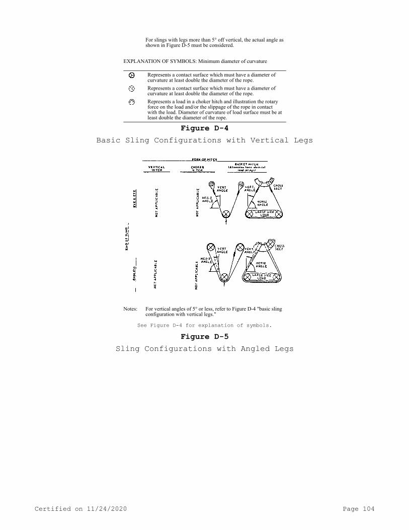
For slings with legs more than 5° off vertical, the actual angle as shown in Figure D-5 must be considered.
EXPLANATION OF SYMBOLS: Minimum diameter of curvature
Represents a contact surface which must have a diameter of curvature at least double the diameter of the rope.
Represents a contact surface which must have a diameter of curvature at least double the diameter of the rope.
Represents a load in a choker hitch and illustration the rotary force on the load and/or the slippage of the rope in contact with the load. Diameter of curvature of load surface must be at least double the diameter of the rope.
Figure D-4Basic Sling Configurations with Vertical Legs
Notes: For vertical angles of 5° or less, refer to Figure D-4 "basic sling configuration with vertical legs."
See Figure D-4 for explanation of symbols.
Figure D-5Sling Configurations with Angled Legs
Certified on 11/24/2020 Page 104

Figure D-6Basic Synthetic Web Sling Constructions
[Statutory Authority: RCW 49.17.010, 49.17.040, 49.17.050, and 49.17.060. WSR 15-24-100, § 296-24-29431, filed 12/1/15, effective 1/5/16. Statutory Authority: RCW 49.17.010, 49.17.040, 49.17.050, 49.17.060 and chapter 49.17 RCW. WSR 12-24-071, § 296-24-29431, filed 12/4/12, effective 1/4/13; Order 76-6, § 296-24-29431, filed 3/1/76.]
PART E
Certified on 11/24/2020 Page 105

HAZARDOUS MATERIALS, FLAMMABLE LIQUIDS, SPRAY FINISHINGHazardous Materials
WAC 296-24-295 Compressed gases (general requirements).[Order 73-5, § 296-24-295, filed 5/9/73 and Order 73-4, § 296-24-295, filed 5/7/73.]
WAC 296-24-29501 Inspection of compressed gas cylinders. You must determine that compressed gas cylinders under your control are in a safe condition to the extent that this can be determined by visual inspection. You must conduct visual and other inspections as prescri-bed in the hazardous materials regulations of the department of trans-portation (49 C.F.R. Parts 171-179 and 14 C.F.R. Part 103). Where those regulations are not applicable, you must conduct visual and oth-er inspections in accordance with Compressed Gas Association Pamphlets C-6-1968 and C-8-1962.[Statutory Authority: RCW 49.17.010, 49.17.040, 49.17.050, and 49.17.060. WSR 15-24-100, § 296-24-29501, filed 12/1/15, effective 1/5/16. Statutory Authority: Chapter 49.17 RCW. WSR 94-15-096 (Order 94-07), § 296-24-29501, filed 7/20/94, effective 9/20/94; Order 73-5, § 296-24-29501, filed 5/9/73 and Order 73-4, § 296-24-29501, filed 5/7/73.]
WAC 296-24-29503 Compressed gases. You must ensure that the in-plant handling, storage, and utilization of all compressed gases in cylinders, portable tanks, rail tankcars, or motor vehicle cargo tanks is in accordance with Compressed Gas Association Pamphlet P-1-1965.[Statutory Authority: RCW 49.17.010, 49.17.040, 49.17.050, and 49.17.060. WSR 15-24-100, § 296-24-29503, filed 12/1/15, effective 1/5/16; Order 73-5, § 296-24-29503, filed 5/9/73 and Order 73-4, § 296-24-29503, filed 5/7/73.]
WAC 296-24-29505 Safety relief devices for compressed gas con-tainers. You must ensure that compressed gas cylinders, portable tanks, and cargo tanks have pressure relief devices installed and maintained in accordance with Compressed Gas Association Pamphlets S-1.1-1963 and 1965 addenda and S-1.2-1963.[Statutory Authority: RCW 49.17.010, 49.17.040, 49.17.050, and 49.17.060. WSR 15-24-100, § 296-24-29505, filed 12/1/15, effective 1/5/16; Order 73-5, § 296-24-29505, filed 5/9/73 and Order 73-4, § 296-24-29505, filed 5/7/73.]
WAC 296-24-310 Acetylene.[Order 73-5, § 296-24-310, filed 5/9/73 and Order 73-4, § 296-24-310, filed 5/7/73.]
Certified on 11/24/2020 Page 106

WAC 296-24-31001 Cylinders. You must ensure that the in-plant transfer, handling, storage, and use of acetylene in cylinders comply with the provisions of CGA Pamphlet G-1-2009 (Acetylene) (Compressed Gas Association, Inc., 12th ed., 2009).[Statutory Authority: RCW 49.17.010, 49.17.040, 49.17.050, and 49.17.060. WSR 15-24-100, § 296-24-31001, filed 12/1/15, effective 1/5/16. Statutory Authority: RCW 49.17.010, 49.17.040, 49.17.050, 49.17.060, and chapter 49.17 RCW. WSR 12-16-063, § 296-24-31001, filed 7/31/12, effective 9/1/12; WSR 10-09-089, § 296-24-31001, filed 4/20/10, effective 7/1/10; Order 73-5, § 296-24-31001, filed 5/9/73 and Order 73-4, § 296-24-31001, filed 5/7/73.]
WAC 296-24-31003 Piped systems. (1) You must comply with Chap-ter 9 (Acetylene Piping) of NFPA 51A-2006 (Standard for Acetylene Charging Plants) (National Fire Protection Association, 2006 ed., 2006).
(2) When employers can demonstrate that the facilities, equip-ment, structures, or installations used to generate acetylene or to charge (fill) acetylene cylinders were installed prior to February 16, 2006, these employers may comply with the provisions of Chapter 7 (Acetylene Piping) of NFPA 51A-2001 (Standard for Acetylene Charging Plants) (National Fire Protection Association, 2001 ed., 2001).
(3) The provisions of subsection (2) of this section also apply when the facilities, equipment, structures, or installations used to generate acetylene or to charge (fill) acetylene cylinders were ap-proved for construction or installation prior to February 16, 2006, but constructed and installed on or after that date.Note: For additional information on acetylene piping systems, see CGA G-1.2-2006, Part 3 (Acetylene Piping) (Compressed Gas Association, Inc.,
3rd ed., 2006).
[Statutory Authority: RCW 49.17.010, 49.17.040, 49.17.050, and 49.17.060. WSR 15-24-100, § 296-24-31003, filed 12/1/15, effective 1/5/16. Statutory Authority: RCW 49.17.010, 49.17.040, 49.17.050, 49.17.060, and chapter 49.17 RCW. WSR 10-09-089, § 296-24-31003, filed 4/20/10, effective 7/1/10; Order 73-5, § 296-24-31003, filed 5/9/73 and Order 73-4, § 296-24-31003, filed 5/7/73.]
WAC 296-24-31005 Generators and filling cylinders. (1) You must ensure that facilities, equipment, structures, or installations used to generate acetylene or to charge (fill) acetylene cylinders comply with the provisions of NFPA 51A-2006 (Standard for Acetylene Charging Plants) (National Fire Protection Association, 2006 ed., 2006).
(2) When employers can demonstrate that the facilities, equip-ment, structures, or installations used to generate acetylene or to charge (fill) acetylene cylinders were constructed or installed prior to February 16, 2006, these employers may comply with the provisions of NFPA 51A-2001 (Standard for Acetylene Charging Plants) (National Fire Protection Association, 2001 ed., 2001).
(3) The provisions of subsection (2) of this section also apply when the facilities, equipment, structures, or installations were ap-proved for construction or installation prior to February 16, 2006, but constructed and installed on or after that date.
Certified on 11/24/2020 Page 107

[Statutory Authority: RCW 49.17.010, 49.17.040, 49.17.050, and 49.17.060. WSR 15-24-100, § 296-24-31005, filed 12/1/15, effective 1/5/16. Statutory Authority: RCW 49.17.010, 49.17.040, 49.17.050, 49.17.060, and chapter 49.17 RCW. WSR 10-09-089, § 296-24-31005, filed 4/20/10, effective 7/1/10; Order 73-5, § 296-24-31005, filed 5/9/73 and Order 73-4, § 296-24-31005, filed 5/7/73.]
WAC 296-24-315 Hydrogen.[Order 73-5, § 296-24-315, filed 5/9/73 and Order 73-4, § 296-24-315, filed 5/7/73.]
WAC 296-24-31501 General. (1) Definitions as used in this sec-tion.
Approved. Unless otherwise indicated, listed or approved by a na-tionally recognized testing laboratory. Refer to federal regulation 29 C.F.R. 1910.7 for definition of nationally recognized testing labora-tory.
ASME. American Society of Mechanical Engineers.DOT regulations. See WAC 296-24-315.DOT specifications. Regulations of the department of transporta-
tion published in 49 C.F.R. Chapter I.Gaseous hydrogen system. One in which the hydrogen is delivered,
stored and discharged in the gaseous form to consumer's piping. The system includes stationary or movable containers, pressure regulators, safety relief devices, manifolds, interconnecting piping and controls. The system terminates at the point where hydrogen at service pressure first enters the consumer's distribution piping.
Listed. See "approved."(2) Scope.(a) Gaseous hydrogen systems.(i) WAC 296-24-31503 applies to the installation of gaseous hy-
drogen systems on consumer premises where the hydrogen supply to the consumer premises originates outside the consumer premises and is de-livered by mobile equipment.
(ii) WAC 296-24-31503 does not apply to gaseous hydrogen systems having a total hydrogen content of less than 400 cubic feet, nor to hydrogen manufacturing plants or other establishments operated by the hydrogen supplier or their agent for the purpose of storing hydrogen and refilling portable containers, trailers, mobile supply trucks, or tank cars.
(b) Liquefied hydrogen systems.(i) WAC 296-24-31505 applies to the installation of liquefied hy-
drogen systems on consumer premises.(ii) WAC 296-24-31505 does not apply to liquefied hydrogen porta-
ble containers of less than 150 liters (39.63 gallons) capacity; nor to liquefied hydrogen manufacturing plants or other establishments op-erated by the hydrogen supplier or supplier's agent for the sole pur-pose of storing liquefied hydrogen and refilling portable containers, trailers, mobile supply trucks or tank cars.[Statutory Authority: RCW 49.17.010, 49.17.040, 49.17.050, and 49.17.060. WSR 15-24-100, § 296-24-31501, filed 12/1/15, effective 1/5/16. Statutory Authority: Chapter 49.17 RCW. WSR 94-15-096 (Order
Certified on 11/24/2020 Page 108
94-07), § 296-24-31501, filed 7/20/94, effective 9/20/94; WSR 88-23-054 (Order 88-25), § 296-24-31501, filed 11/14/88; Order 73-5, § 296-24-31501, filed 5/9/73 and Order 73-4, § 296-24-31501, filed 5/7/73.]
WAC 296-24-31503 Gaseous hydrogen systems. (1) Design.(a) Containers.(i) You must ensure that hydrogen containers comply with one of
the following:(A) Designed, constructed, and tested in accordance with appro-
priate requirements of ASME Boiler and Pressure Vessel Code, Section VIII—Unfired Pressure Vessels—1968.
(B) Designed, constructed, tested and maintained in accordance with U.S. Department of Transportation specifications and regulations.
(ii) You must provide permanently installed containers with sub-stantial noncombustible supports on firm noncombustible foundations.
(iii) You must legibly mark each portable container with the name "hydrogen" in accordance with "marking compressed gas containers to identify the material contained" ANSI Z48.1-1954. You must legibly mark each manifolded hydrogen supply unit with the name hydrogen or a legend such as "this unit contains hydrogen."
(b) Safety relief devices.(i) You must ensure that hydrogen containers are equipped with
safety relief devices as required by the ASME Boiler and Pressure Ves-sel Code, Section VIII Unfired Pressure Vessels, 1968 or the DOT spec-ifications and regulations under which the container is fabricated.
(ii) You must arrange safety relief devices to discharge upward and unobstructed to the open air in such a manner as to prevent any impingement of escaping gas upon the container, adjacent structure of personnel. This requirement does not apply to DOT specification con-tainers having an internal volume of 2 cubic feet or less.
(iii) You must design or locate safety relief devices or vent piping so that moisture cannot collect and freeze in a manner which would interfere with proper operation of the device.
(c) Piping, tubing, and fittings.(i) You must ensure that piping, tubing, and fittings are suita-
ble for hydrogen service and for the pressures and temperatures in-volved. You must not use case iron pipe and fittings.
(ii) You must ensure that piping and tubing conforms to Section 2—"Industrial Gas and Air Piping"—Code for Pressure Piping, ANSI B31.1-1967 with addenda B31.1-1969.
(iii) Joints in piping and tubing may be made by welding or braz-ing or by use of flanged, threaded, socket, or compression fittings. You must ensure that gaskets and thread sealants are suitable for hy-drogen service.
(d) Equipment assembly.(i) You must ensure that valves, gauges, regulators, and other
accessories are suitable for hydrogen service.(ii) Installation of hydrogen systems must be supervised by per-
sonnel familiar with proper practices with reference to their con-struction and use.
(iii) You must make storage containers, piping, valves, regulat-ing equipment, and other accessories readily accessible, and ensure they are protected against physical damage and against tampering.
Certified on 11/24/2020 Page 109

(iv) You must adequately ventilate cabinets or housings contain-ing hydrogen control or operating equipment.
(v) You must adequately secure each mobile hydrogen supply unit used as part of a hydrogen system to prevent movement.
(vi) You must electrically bond mobile hydrogen supply units to the system before discharging hydrogen.
(e) Marking. You must permanently placard hydrogen storage loca-tion as follows: "HYDROGEN—FLAMMABLE GAS—NO SMOKING—NO OPEN FLAMES," or equiv-alent.
(f) Testing. After installations, you must test all piping, tub-ing, and fittings and prove it to be hydrogen gas tight at maximum op-erating pressure.
(2) Location.(a) General.(i) You must locate the system so that it is readily accessible
to delivery equipment and to authorized personnel.(ii) You must locate the systems above ground.(iii) You must not locate the systems beneath electric power
lines.(iv) You must not locate the systems close to flammable liquid
piping or piping of other flammable gases.(v) You must locate the systems near aboveground flammable liquid
storage on ground higher than the flammable liquid storage except when dikes, diversion curbs, grading, or separating solid walls are used to prevent accumulation of flammable liquids under the system.
(b) Specific requirements.(i) You must ensure that the location of a system, as determined
by the maximum total contained volume of hydrogen, is in the order of preference as indicated by Roman numerals in Table H-1.
TABLE H-1
Nature of locationSize of
hydrogen system
Lessthan
3,000CF
3,000CF to 15,000
CF
Inexcess of15,000
CFOutdoors ————————— I ———— I ——— I.In a separate building ———— II ———— II ——— II.In a special room —————— III ———— III ——— Not
per-mitted.
Inside buildings not ina special room andexposed to other
Notper-
mitted. ———
Notper-
mitted.occupancies —————— IV ———
(ii) The minimum distance in feet from a hydrogen system of indi-cated capacity located outdoors, in separate buildings or in special rooms to any specified outdoor exposure must be in accordance with Ta-ble H-2.
(iii) The distances in Table H-2 Items 1, 14, and 3 to 10 inclu-sive do not apply where protective structures such as adequate fire walls are located between the system and the exposure.
(iv) Hydrogen systems of less than 3,000 CF when located inside buildings and exposed to other occupancies must be situated in the building so that the system will be as follows:
(A) In an adequately ventilated area as in (3)(b)(ii) of this section.
Certified on 11/24/2020 Page 110

(B) Twenty feet from stored flammable materials or oxidizing gases.
(C) Twenty-five feet from open flames, ordinary electrical equip-ment or other sources of ignition.
(D) Twenty-five feet from concentrations of people.(E) Fifty feet from intakes of ventilation or air-conditioning
equipment and air compressors.(F) Fifty feet from other flammable gas storage.(G) Protected against damage or injury due to falling objects or
working activity in the area.(H) More than one system of 3,000 CF or less may be installed in
the same room, provided the systems are separated by at least 50 feet. Each such system shall meet all of the requirements of this section.
(3) Design consideration at specific locations.(a) Outdoor locations.(i) Where protective walls or roofs are provided, you must ensure
that they are constructed of noncombustible materials.(ii) Where the enclosing sides adjoin each other, you must ensure
that the area is properly ventilated.(iii) You must ensure that electrical equipment meets the re-
quirements for Class I, Division 2 hazardous locations of WAC 296-24-95613.
(b) Separate buildings.(i) Separate buildings must be built of at least noncombustible
construction. Windows and doors must be located so as to be readily accessible in case of emergency. Windows must be of glass or plastic in metal frames.
(ii) Adequate ventilation to the outdoors must be provided. Inlet openings must be located near the floor in exterior walls only. Outlet openings must be located at the high point of the room in exterior walls or roof. Inlet and outlet openings must each have minimum total area of one square foot per 1,000 cubic feet of room volume. Discharge from outlet openings must be directed or conducted to a safe location.
(iii) Explosion venting must be provided in exterior walls or roof only. The venting area must be equal to not less than 1 square foot per 30 cubic feet of room volume and may consist of any one or any combination of the following: Walls of light noncombustible mate-rial, preferably single thickness, single strength glass; lightly fas-tened hatch covers; lightly fastened swinging doors in exterior walls opening outward; lightly fastened walls or roof designed to relieve at a maximum pressure of 25 pounds per square foot.
(iv) There must be no sources of ignition from open flames, elec-trical equipment, or heating equipment.
(v) Electrical equipment must meet the requirements of chapter 296-24 WAC Part L.
(vi) Heating, if provided, must be by steam, hot water, or other indirect means.
(c) Special rooms.(i) Floor, walls, and ceiling must have a fire-resistance rating
of at least 2 hours. Walls or partitions must be continuous from floor to ceiling and must be securely anchored. At least one wall must be an exterior wall. Openings to other parts of the building must not be permitted. Windows and doors must be in exterior walls and must be lo-cated so as to be readily accessible in case of emergency. Windows must be of glass or plastic in metal frames.
(ii) Ventilation must be as provided in (3)(b)(ii) of this sec-tion.
Certified on 11/24/2020 Page 111
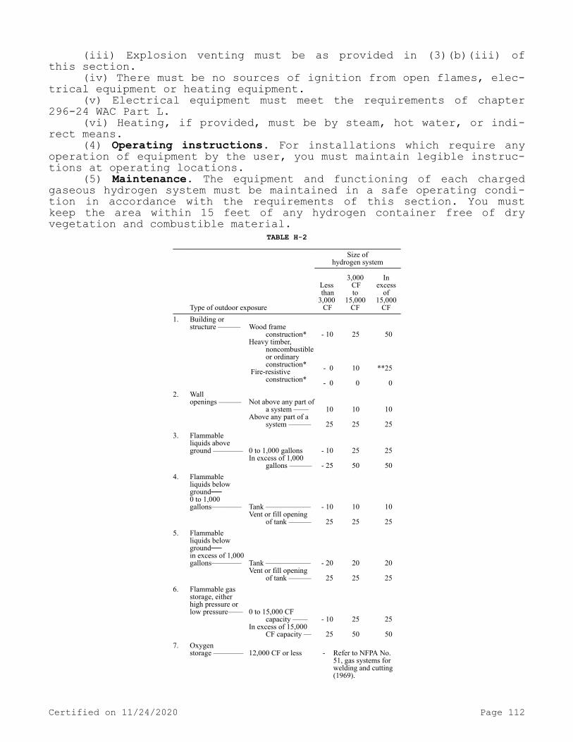
(iii) Explosion venting must be as provided in (3)(b)(iii) of this section.
(iv) There must be no sources of ignition from open flames, elec-trical equipment or heating equipment.
(v) Electrical equipment must meet the requirements of chapter 296-24 WAC Part L.
(vi) Heating, if provided, must be by steam, hot water, or indi-rect means.
(4) Operating instructions. For installations which require any operation of equipment by the user, you must maintain legible instruc-tions at operating locations.
(5) Maintenance. The equipment and functioning of each charged gaseous hydrogen system must be maintained in a safe operating condi-tion in accordance with the requirements of this section. You must keep the area within 15 feet of any hydrogen container free of dry vegetation and combustible material.
TABLE H-2
Size ofhydrogen system
Type of outdoor exposure
Less than3,000 CF
3,000 CFto
15,000CF
Inexcess
of15,000
CF1. Building or
structure ——— Wood frame
construction*Heavy timber,
noncombustible or ordinary construction*
Fire-resistive construction*
- 10
- 0
- 0
25
10 0
50
**25 0
2. Wallopenings ———
Not above any part of
a system ——Above any part of a
system ———
10
25
10
25
10
25
3. Flammableliquids aboveground ————
0 to 1,000 gallonsIn excess of 1,000
gallons ———
- 10
- 25
25
50
25
50
4. Flammableliquids belowground──0 to 1,000gallons————
Tank ——————Vent or fill opening
of tank ———
- 10
25
10
25
10
25
5. Flammableliquids belowground──in excess of 1,000gallons————
Tank ——————Vent or fill opening
of tank ———
- 20
25
20
25
20
25
6. Flammable gasstorage, eitherhigh pressure orlow pressure——
0 to 15,000 CF
capacity ——In excess of 15,000
CF capacity —
- 10
25
25
50
25
50
7. Oxygenstorage ————
12,000 CF or less
-
Refer to NFPA No. 51, gas systems for welding and cutting (1969).
Certified on 11/24/2020 Page 112

Size ofhydrogen system
Type of outdoor exposure
Less than3,000 CF
3,000 CFto
15,000CF
Inexcess
of15,000
CF More than 12,000 CF -
Refer to NFPA No. 566, bulk oxygen systems at consumer sites (1969).
8. Fast burningsolids such asordinary lumber,excelsior or paper ————————— 50
50
25
9. Slow burning solidssuch as heavy timberor coal ————————————— 25
25
25
10. Open flames and othersources of ignition ———————— 25
25
50
11. Air compressor intakesor inlets to ventilatingor air-conditionequipment———————————— 50
50
50
12. Concentration of people*** ————— 25 50 50 13. Public sidewalks ————————— 15 15 15 14. Line of adjoining
property which may bebuilt upon ———————————— 5
5
5
* Refer to NFPA No. 220 standard types of building construction for definitions of various types of construction. (1969 Ed.)
** But not less than one-half the height of adjacent side wall of the structure.
*** In congested areas such as offices, lunchrooms, locker rooms, time-clock areas, and places of public assembly.
[Statutory Authority: RCW 49.17.010, 49.17.040, 49.17.050, and 49.17.060. WSR 15-24-100, § 296-24-31503, filed 12/1/15, effective 1/5/16. Statutory Authority: Chapter 49.17 RCW. WSR 91-24-017 (Order 91-07), § 296-24-31503, filed 11/22/91, effective 12/24/91; WSR 88-23-054 (Order 88-25), § 296-24-31503, filed 11/14/88. Statutory Au-thority: RCW 49.17.040 and 49.17.050. WSR 85-10-004 (Order 85-09), § 296-24-31503, filed 4/19/85; Order 76-6, § 296-24-31503, filed 3/1/76; Order 73-5, § 296-24-31503, filed 5/9/73 and Order 73-4, § 296-24-31503, filed 5/7/73.]
WAC 296-24-31505 Liquefied hydrogen systems. (1) Design.(a) Containers.(i) You must ensure that hydrogen containers comply with the fol-
lowing: Storage containers be designed, constructed, and tested in ac-cordance with appropriate requirements of the ASME Boiler and Pressure Vessel Code, Section VIII—Unfired Pressure Vessels (1968) or applica-ble provisions of API Standard 620, Recommended Rules for Design and Construction of Large, Welded, Low-Pressure Storage Tanks, Second Edi-tion (June 1963) and Appendix R (April 1965).
(ii) You must ensure that portable containers are designed, con-structed and tested in accordance with DOT specifications and regula-tions.
(b) Supports. You must provide permanently installed containers with substantial noncombustible supports securely anchored on firm noncombustible foundations. You must ensure that steel supports in ex-
Certified on 11/24/2020 Page 113
cess of 18 inches in height are protected with a protective coating having a 2-hour fire-resistance rating.
(c) Marking. You must legibly mark each container to indicate "LIQUEFIED HYDROGEN—FLAMMABLE GAS."
(d) Safety relief devices.(i) You must equip stationary liquefied hydrogen containers with
safety relief devices sized in accordance with CGA Pamphlet S-1-1966, Part 3, Safety Relief Device Standards for Compressed Gas Storage Con-tainers.
(A) Portable liquefied hydrogen containers complying with the U.S. Department of Transportation regulations must be equipped with safety relief devices as required in the U.S. Department of Transpor-tation specifications and regulations. Safety relief devices must be sized in accordance with the requirements of CGA Pamphlet S-1-1966, Safety Relief Device Standards, Part 1, Compressed Gas Cylinders and Part 2, Cargo and Portable Tank Containers.
(ii) You must ensure that safety relief devices are arranged to discharge unobstructed to the outdoors and in such a manner as to pre-vent impingement of escaping liquid or gas upon the container, adja-cent structures or personnel. See (2)(a)(vi) of this section for vent-ing of safety relief devices in special locations.
(iii) You must design or locate relief devices or vent piping so that moisture cannot collect and freeze in a manner which would inter-fere with proper operation of the device.
(iv) You must provide safety relief devices in piping wherever liquefied hydrogen could be trapped between closures
(e) Piping, tubing, and fittings.(i) Piping, tubing, and fittings and gasket and thread sealants
must be suitable for hydrogen service at the pressures and tempera-tures involved. You must give consideration to the thermal expansion and contraction of piping systems when exposed to temperature fluctua-tions of ambient to liquefied hydrogen temperatures.
(ii) Gaseous hydrogen piping and tubing (above—20°F) must con-form to the applicable sections of Pressure Piping Section 2—Indus-trial Gas and Air Piping, ANSI B31.1-1967 with addenda B31.1-1969. De-sign of liquefied hydrogen or cold (-20°F or below) gas piping must use Petroleum Refinery Piping ANSI B31.3-1966 or Refrigeration Piping ANSI B31.5-1966 with addenda B31.5a-1968 as a guide.
(iii) Joints in piping and tubing must preferably be made by welding or brazing; flanged, threaded, socket, or suitable compression fittings may be used.
(iv) You must provide means to minimize exposure of personnel to piping operating at low temperatures and to prevent air condensate from contacting piping, structural members, and surfaces not suitable for cryogenic temperatures. Only those insulating materials which are rated nonburning in accordance with ASTM Procedures D1692-68 may be used. Other protective means may be used to protect personnel. The in-sulation must be designed to have a vapor-tight seal in the outer cov-ering to prevent the condensation of air and subsequent oxygen enrich-ment within the insulation. The insulation material and outside shield must also be of adequate design to prevent attrition of the insulation due to normal operating conditions.
(v) You must not install uninsulated piping and equipment which operate at liquefied-hydrogen temperature above asphalt surfaces or other combustible materials in order to prevent contact of liquid air
Certified on 11/24/2020 Page 114

with such materials. Drip pans may be installed under uninsulated pip-ing and equipment to retain and vaporize condensed liquid air.
(f) Equipment assembly.(i) Valves, gauges, regulators, and other accessories must be
suitable for liquefied hydrogen service and for the pressures and tem-peratures involved.
(ii) Installation of liquefied hydrogen systems must be super-vised by personnel familiar with proper practices and with reference to their construction and use.
(iii) You must ensure that storage containers, piping, valves, regulating equipment, and other accessories are readily accessible and protected against physical damage and against tampering. A shutoff valve must be located in liquid product withdrawal lines as close to the container as practical. On containers of over 2,000 gallons ca-pacity, this shutoff valve shall be of the remote control type with no connections, flanges, or other appurtenances (other than a welded man-ual shutoff valve) allowed in the piping between the shutoff valve and its connection to the inner container.
(iv) Cabinets or housings containing hydrogen control equipment must be ventilated to prevent any accumulation of hydrogen gas.
(g) Testing.(i) After installation, you must test all field-erected piping
and prove it to be hydrogen gas-tight at operating pressure and tem-perature.
(ii) Containers if out of service in excess of one year must be inspected and tested as outlined in (1) of this section. You must check the safety relief devices to determine if they are operable and properly set.
(h) Liquefied hydrogen vaporizers.(i) You must anchor the vaporizer and ensure that its connecting
piping is sufficiently flexible to provide for the effect of expansion and contraction due to temperature changes.
(ii) You must ensure that the vaporizer and its piping are ade-quately protected on the hydrogen and heating media sections with safety relief devices.
(iii) You must indirectly supply heat used in a liquefied hydro-gen vaporizer utilizing media such as air, steam, water, or water sol-utions.
(iv) You must provide a low temperature shutoff switch in the va-porizer discharge piping to prevent flow of liquefied hydrogen in the event of the loss of the heat source.
(i) Electrical systems.(i) You must ensure that electrical wiring and equipment located
within 3 feet of a point where connections are regularly made and dis-connected, meet the requirements of chapter 296-24 WAC Part L for Class I, Division 1 locations.
(ii) You must ensure that except as provided in (l) of this sec-tion, electrical wiring, and equipment located within 25 feet of a point where connections are regularly made and disconnected or within 25 feet of a liquid hydrogen storage container, must meet the require-ments of chapter 296-24 WAC Part L for Class I, Division 2 locations. When equipment approved for Class I, environments is not commercially available, the equipment may be:
(A) Purged or ventilated in accordance with NFPA No. 496-1967, Standard for Purged Enclosures for Electrical Equipment in Hazardous Locations,
(B) Intrinsically safe, or
Certified on 11/24/2020 Page 115

(C) Approved for Class I, Group C atmospheres. This requirement does not apply to electrical equipment which is installed on mobile supply trucks or tank cars from which the storage container is filled.
(j) Bonding and grounding. You must electrically bond and ground the liquefied hydrogen container and associated piping.
(2) Location of liquefied hydrogen storage.(a) General requirements.(i) You must locate the storage containers so that they are read-
ily accessible to mobile supply equipment at ground level and to au-thorized personnel.
(ii) You must ensure that the containers are not exposed by elec-tric power lines, flammable liquid lines, flammable gas lines, or lines carrying oxidizing materials.
(iii) When locating liquefied hydrogen storage containers near above-ground flammable liquid storage or liquid oxygen storage, locate the liquefied hydrogen container on ground higher than flammable liq-uid storage or liquid oxygen storage.
(iv) Where it is necessary to locate the liquefied hydrogen con-tainer on ground that is level with or lower than adjacent flammable liquid storage or liquid oxygen storage, you must take suitable pro-tective means (such as by diking, diversion, curbs, grading), with re-spect to the adjacent flammable liquid storage or liquid oxygen stor-age, to prevent accumulation of liquids within 50 feet of the lique-fied hydrogen container.
(v) You must fence and post storage sites to prevent entrance by unauthorized personnel. You must also placard sites as follows: "Liq-uefied hydrogen—Flammable gas—No smoking—No open flames."
(vi) If liquefied hydrogen is located in (as specified in Table H-3) a separate building, in a special room, or inside buildings when not in a special room and exposed to other occupancies, you must en-sure that containers have the safety relief devices vented unobstruc-ted to the outdoors at a minimum elevation of 25 feet above grade to a safe location as required in (l)(d)(ii) of this section.
(b) Specific requirements.(i) You must ensure that the location of liquefied hydrogen stor-
age, as determined by the maximum total quantity of liquefied hydro-gen, is in the order of preference as indicated by Roman numerals in the following Table H-3.
TABLE H-3MAXIMUM TOTAL QUANTITY OF LIQUEFIED HYDROGEN STORAGE PERMITTED
Size ofhydrogen storage
(capacity ingallons)
Nature of location
39.63(150 liters)
to 50
51to
300
301to
600
Inexcessof 600
Outdoors —— I —— I —— I—— I In a separate building —— II —— II —— II——
Notper-
mitted. In a special room —— III —— III ——
Notper-
mitted
Notper-
mitted.Inside buildings not in a special room and exposed to other occupancies —— IV ——
Notper-
mitted
Notper-
mitted
Notper-
mitted.
Note: This table does not apply to the storage in dewars of the type generally used in laboratories for experimental purposes.
Certified on 11/24/2020 Page 116
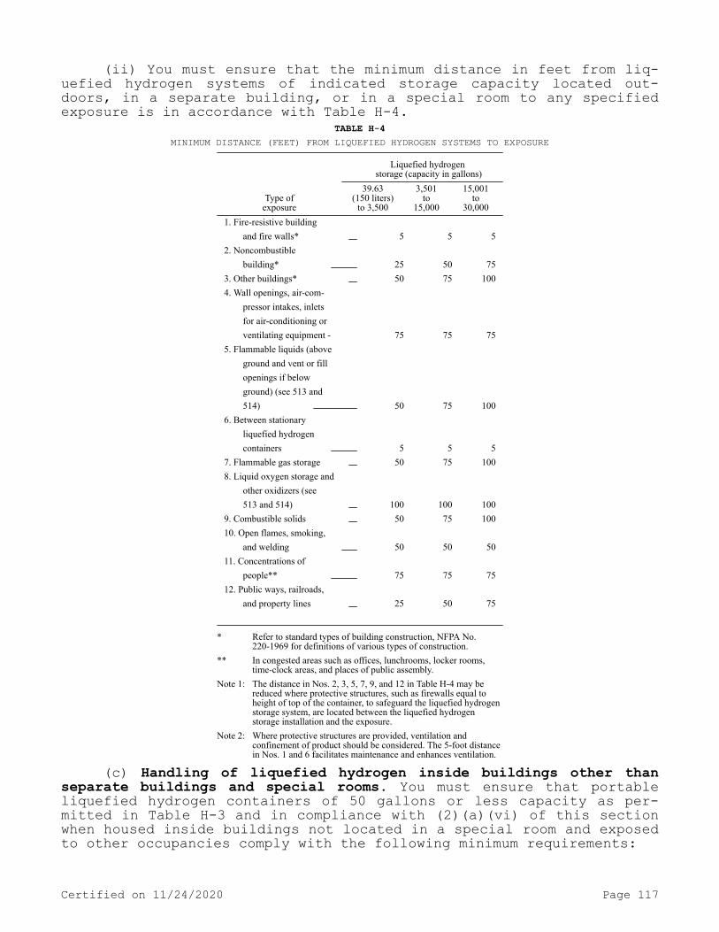
(ii) You must ensure that the minimum distance in feet from liq-uefied hydrogen systems of indicated storage capacity located out-doors, in a separate building, or in a special room to any specified exposure is in accordance with Table H-4.
TABLE H-4MINIMUM DISTANCE (FEET) FROM LIQUEFIED HYDROGEN SYSTEMS TO EXPOSURE
Liquefied hydrogen storage (capacity in gallons)
Type ofexposure
39.63(150 liters)
to 3,500
3,501to
15,000
15,001to
30,0001. Fire-resistive building and fire walls* 5 5 52. Noncombustible building* 25 50 753. Other buildings* 50 75 1004. Wall openings, air-com- pressor intakes, inlets for air-conditioning or ventilating equipment - 75 75 755. Flammable liquids (above ground and vent or fill openings if below ground) (see 513 and 514) 50 75 1006. Between stationary liquefied hydrogen containers 5 5 57. Flammable gas storage 50 75 1008. Liquid oxygen storage and other oxidizers (see 513 and 514) 100 100 1009. Combustible solids 50 75 10010. Open flames, smoking, and welding 50 50 5011. Concentrations of people** 75 75 7512. Public ways, railroads, and property lines 25 50 75
* Refer to standard types of building construction, NFPA No. 220-1969 for definitions of various types of construction.
** In congested areas such as offices, lunchrooms, locker rooms, time-clock areas, and places of public assembly.
Note 1: The distance in Nos. 2, 3, 5, 7, 9, and 12 in Table H-4 may be reduced where protective structures, such as firewalls equal to height of top of the container, to safeguard the liquefied hydrogen storage system, are located between the liquefied hydrogen storage installation and the exposure.
Note 2: Where protective structures are provided, ventilation and confinement of product should be considered. The 5-foot distance in Nos. 1 and 6 facilitates maintenance and enhances ventilation.
(c) Handling of liquefied hydrogen inside buildings other than separate buildings and special rooms. You must ensure that portable liquefied hydrogen containers of 50 gallons or less capacity as per-mitted in Table H-3 and in compliance with (2)(a)(vi) of this section when housed inside buildings not located in a special room and exposed to other occupancies comply with the following minimum requirements:
Certified on 11/24/2020 Page 117

(i) Be located 20 feet from flammable liquids and readily combus-tible materials such as excelsior or paper.
(ii) Be located 25 feet from ordinary electrical equipment and other sources of ignition including process or analytical equipment.
(iii) Be located 25 feet from concentrations of people.(iv) Be located 50 feet from intakes of ventilation and air-con-
ditioning equipment or intakes of compressors.(v) Be located 50 feet from storage of other flammable-gases or
storage of oxidizing gases.(vi) Containers must be protected against damage or injury due to
falling objects or work activity in the area.(vii) Containers must be firmly secured and stored in an upright
position.(viii) Welding or cutting operations, and smoking must be pro-
hibited while hydrogen is in the room.(ix) The area must be adequately ventilated. Safety relief devi-
ces on the containers must be vented directly outdoors or to a suita-ble hood. See (1)(d)(ii) of this section and (2)(a)(vi) of this sec-tion.
(3) Design at specific locations.(a) Outdoor locations.(i) Outdoor location means outside of any building or structure,
and includes locations under a weather shelter or canopy provided such locations are not enclosed by more than two walls set at right angles and are provided with vent-space between the walls and vented roof or canopy.
(ii) Roadways and yard surfaces located below liquefied hydrogen piping, from which liquid air may drop, must be constructed of noncom-bustible materials.
(iii) If protective walls are provided, they must be constructed of noncombustible materials and in accordance with the provisions of (3)(a)(i) of this section as applicable.
(iv) Electrical wiring and equipment must comply with chapter 296-24 WAC Part L.
(v) You must provide adequate lighting for nighttime transfer op-eration.
(b) Separate buildings.(i) Separate buildings must be of light noncombustible construc-
tion on a substantial frame. Walls and roofs must be lightly fastened and designed to relieve at a maximum internal pressure of 25 pounds per square foot. Windows must be of shatterproof glass or plastic in metal frames. Doors must be located in such a manner that they will be readily accessible to personnel in an emergency.
(ii) You must provide adequate ventilation to the outdoors. Inlet openings must be located near the floor level in exterior walls only. Outlet openings must be located at the high point of the room in exte-rior walls or roof. Both the inlet and outlet vent openings must have a minimum total area of 1 square foot per 1,000 cubic feet of room volume. Discharge from outlet openings must be directed or conducted to a safe location.
(iii) You must ensure that there are no sources of ignition.(iv) Electrical wiring and equipment must comply with chapter
296-24 WAC Part L.(v) Heating, if provided, must be by steam, hot water, or other
indirect means.(c) Special rooms.
Certified on 11/24/2020 Page 118
(i) Floors, walls, and ceilings must have a fire resistance rat-ing of at least 2 hours. Walls or partitions must be continuous from floor to ceiling and must be securely anchored. At least one wall must be an exterior wall. Openings to other parts of the building must not be permitted. Windows and doors must be in exterior walls and doors shall be located in such a manner that they will be accessible in an emergency. Windows must be of shatterproof glass or plastic in metal frames.
(ii) You must ensure that ventilation is as provided in (3)(b)(ii) of this section.
(iii) You must provide explosion venting in exterior walls or roof only. The venting area must be equal to not less than 1 square foot per 30 cubic feet of room volume and may consist of any one or any combination of the following: Walls of light noncombustible mate-rial; lightly fastened hatch covers; lightly fastened swinging doors opening outward in exterior walls; lightly fastened walls or roofs de-signed to relieve at a maximum pressure of 25 pounds per square foot.
(iv) You must ensure that there are no sources of ignition.(v) Electrical wiring and equipment must comply with chapter
296-24 WAC Part L.(vi) Heating, if provided, must be steam, hot water, or by other
indirect means.(4) Operating instructions.(a) Written instructions. For installation which require any op-
eration of equipment by the user, you must maintain legible instruc-tions at operating locations.
(b) Attendant. A qualified person must be in attendance at all times while the mobile hydrogen supply unit is being unloaded.
(c) Security. You must adequately secure each mobile liquefied hydrogen supply unit used as part of a hydrogen system to prevent movement.
(d) Grounding. You must ground the mobile liquefied hydrogen sup-ply unit for static electricity.
(5) Maintenance. The equipment and functioning of each charged liquefied hydrogen system shall be maintained in a safe operating con-dition in accordance with the requirements of this section. You must not permit weeds or similar combustibles within 25 feet of any lique-fied hydrogen equipment.[Statutory Authority: RCW 49.17.010, 49.17.040, 49.17.050, and 49.17.060. WSR 15-24-100, § 296-24-31505, filed 12/1/15, effective 1/5/16. Statutory Authority: Chapter 49.17 RCW. WSR 91-24-017 (Order 91-07), § 296-24-31505, filed 11/22/91, effective 12/24/91; WSR 88-23-054 (Order 88-25), § 296-24-31505, filed 11/14/88. Statutory Au-thority: RCW 49.17.040 and 49.17.050. WSR 85-10-004 (Order 85-09), § 296-24-31505, filed 4/19/85; Order 76-6, § 296-24-31505, filed 3/1/76; Order 73-5, § 296-24-31505, filed 5/9/73 and Order 73-4, § 296-24-31505, filed 5/7/73.]
WAC 296-24-320 Oxygen.[Order 73-5, § 296-24-320, filed 5/9/73 and Order 73-4, § 296-24-320, filed 5/7/73.]
Certified on 11/24/2020 Page 119

WAC 296-24-32001 Scope. This section applies to the installa-tion of bulk oxygen systems on industrial and institutional consumer premises. This section does not apply to oxygen manufacturing plants or other establishments operated by the oxygen supplier or supplier's agent for the purpose of storing oxygen and refilling portable con-tainers, trailers, mobile supply trucks, or tank cars, nor to systems having capacities less than those stated in WAC 296-24-32003(1).[Statutory Authority: Chapter 49.17 RCW. WSR 94-15-096 (Order 94-07), § 296-24-32001, filed 7/20/94, effective 9/20/94; Order 73-5, § 296-24-32001, filed 5/9/73 and Order 73-4, § 296-24-32001, filed 5/7/73.]
WAC 296-24-32003 Bulk oxygen systems. (1) Definitions. As used in this section: A bulk oxygen system is an assembly of equipment, such as oxygen storage containers, pressure regulators, safety devi-ces, vaporizers, manifolds, and interconnecting piping, which has storage capacity of more than 13,000 cubic feet of oxygen, normal tem-perature and pressure (NTP), connected in service or ready for serv-ice, or more than 25,000 cubic feet of oxygen (NTP) including uncon-nected reserves on hand at the site. The bulk oxygen system terminates at the point where oxygen at service pressure first enters the supply line. The oxygen containers may be stationary or movable, and the oxy-gen may be stored as gas or liquid.
(2) Location.(a) General. You must locate bulk oxygen storage systems shall be
located above ground out of doors, or in a building of noncombustible construction, adequately vented, and used for that purpose exclusive-ly. The location selected must be such that containers and associated equipment must not be exposed by electric power lines, flammable liq-uid or gas lines.
(b) Accessibility. The system must be located so that it is read-ily accessible to mobile supply equipment at ground level and to au-thorized personnel.
(c) Leakage. Where oxygen is stored as a liquid, you must provide noncombustible surfacing in an area in which any leakage of liquid oxygen might fall during operation of the system and filling of a storage container. For purposes of these standards, asphaltic or bitu-minous paving is considered to be combustible.
(d) Elevation. When locating bulk oxygen systems near above ground flammable liquid storage which may be either indoors or out-doors, it is advisable to locate the system on ground higher than the flammable liquid storage.
(e) Dikes. Where it is necessary to locate a bulk oxygen system on ground lower than adjacent flammable liquid storage you must take suitable means (such as by diking, diversion curbs, or grading) with respect to the adjacent flammable liquid storage to prevent accumula-tion of liquids under the bulk oxygen system.
(3) Distance between systems and exposures.(a) General. You must ensure that the minimum distance from any
bulk oxygen storage container to exposures, measured in the most di-rect line except as indicated in (f) and (g) of this subsection are as indicated in (b) through (r) of this subsection inclusive.
(b) Combustible structures. 50 feet from any combustible struc-tures.
Certified on 11/24/2020 Page 120

(c) Fire resistive structures. 25 feet from any structures with fire-resistive exterior walls or sprinklered buildings or other con-struction, but not less than one-half the height of adjacent side wall of the structure.
(d) Openings. At least 10 feet from any opening in adjacent walls of fire resistive structures. You must ensure that spacing from such structures is adequate to permit maintenance, but not less than one foot.
(e) Flammable liquid storage above ground.Distance
(feet)Capacity(gallons)
50 0-1000 90 1001 or more
(f) Flammable liquid storage below ground.Distance
measuredhorizontallyfrom oxygen
storagecontainer toflammableliquid tank
(feet)
Distancefrom oxygen
storagecontainer tofilling and
vent connections or openings to flammable
liquid tank (feet)
Capacity gallons
15 50 0-1000 30 50 1001 or more
(g) Flammable liquid storage above ground.Distance
(feet) Capacity
(gallons) 25 0-1000
50 1001 or more
(h) Flammable liquid storage below ground.Distance measured horizontally from oxygen storage
container to flammable liquid
tank (feet)
Distance from oxygen storage container to
filling and vent connections or
openings to flammable liquid
tank (feet) 15 40
(i) Flammable gas storage. (Such as compressed flammable gases, liquefied flammable gases and flammable gases in low pressure gas holders):
Distance(feet)
Capacity(cu. ft. NTP)
50 Less than 500090 5000 or more
(j) Highly combustible materials. 50 feet from solid materials which burn rapidly, such as excelsior or paper.
(k) Slow-burning materials. 25 feet from solid materials which burn slowly, such as coal and heavy timber.
(l) Ventilation. 75 feet in one direction and 35 feet in approxi-mately 90° direction from confining walls (not including firewalls less than twenty feet high) to provide adequate ventilation in court-yards and similar confining areas.
(m) Congested areas. 25 feet from congested areas such as offi-ces, lunchrooms, locker rooms, time clock areas, and similar locations where people may congregate.
(n) Public areas. 50 feet from places of public assembly.
Certified on 11/24/2020 Page 121
(o) Patients. 50 feet from areas occupied by nonambulatory pa-tients.
(p) Sidewalks. 10 feet from any public sidewalk.(q) Adjacent property. 5 feet from any line of adjoining proper-
ty.(r) Exceptions. The distances in (b), (c), (e) through (k) inclu-
sive, and (p) and (q) of this subsection do not apply where protective structures such as firewalls of adequate height to safeguard the oxy-gen storage systems are located between the bulk oxygen storage in-stallation and the exposure. In such cases, the bulk oxygen storage installation may be a minimum distance of one foot from the firewall.
(4) Storage containers.(a) Foundations and supports. You must provide permanently in-
stalled containers with substantial noncombustible supports on firm noncombustible foundations.
(b) Construction—Liquid. Liquid oxygen storage containers must be fabricated from materials meeting the impact test requirements of paragraph UG-84 of ASME Boiler and Pressure Vessel Code, Section VIII—Unfired Pressure Vessels—1968. Containers operating at pressures above fifteen pounds per square inch gage (p.s.i.g.) must be designed, constructed, and tested in accordance with appropriate requirements of ASME Boiler and Pressure Vessel Code, Section VII—Unfired Pressure Vessels—1968. Insulation surrounding the liquid oxygen container must be noncombustible.
(c) Construction—Gaseous. High-pressure gaseous oxygen contain-ers must comply with one of the following:
(i) Designed, constructed, and tested in accordance with appro-priate requirements of ASME Boiler and Pressure Vessel Code, Section VIII—Unfired Pressure Vessels—1968.
(ii) Designed, constructed, tested, and maintained in accordance with DOT specifications and regulations.
(5) Piping, tubing, and fittings.(a) Selection. You must ensure that piping, tubing, and fittings
are suitable for oxygen service and for the pressures and temperatures involved.
(b) Specification. Piping and tubing must conform to Section 2—Gas and Air Piping Systems of Code for Pressure Piping, ANSI, B31.1-1967 with addenda B31.10a-1969.
(c) Fabrication. Piping or tubing for operating temperatures be-low -20°F must be fabricated from materials meeting the impact test requirements of paragraph UG-84 of ASME Boiler and Pressure Vessel Code, Section VIII—Unfired Pressure Vessels—1968, when tested at the minimum operating temperature to which the piping may be subjected in service.
(6) Safety relief devices.(a) General. Bulk oxygen storage containers, regardless of design
pressure must be equipped with safety relief devices as required by the ASME code or the DOT specifications and regulations.
(b) DOT containers. Bulk oxygen storage containers designed and constructed in accordance with DOT specification must be equipped with safety relief devices as required thereby.
(c) ASME containers. Bulk oxygen storage containers designed and constructed in accordance with the ASME Boiler and Pressure Vessel Code, Section VIII—Unfired Pressure Vessel—1968 must be equipped with safety relief devices meeting the provisions of the Compressed Gas As-
Certified on 11/24/2020 Page 122
sociation Pamphlet "Safety Relief Device Standards for Compressed Gas Storage Containers," S-1, Part 3.
(d) Insulation. Insulation casings on liquid oxygen containers must be equipped with suitable safety relief devices.
(e) Reliability. You must ensure that all safety relief devices are designed or located so that moisture cannot collect and freeze in a manner which would interfere with proper operation of the device.
(7) Liquid oxygen vaporizers.(a) Mounts and couplings. You must anchor the vaporizer and its
connecting piping is sufficiently flexible to provide for the effect of expansion and contraction due to temperature changes.
(b) Relief devices. You must adequately protect the vaporizer and its piping on the oxygen and heating medium sections with safety re-lief devices.
(c) Heating. You must indirectly supply heat used in an oxygen vaporizer only through media such as steam, air, water, or water solu-tions which do not react with oxygen.
(d) Grounding. If electric heaters are used to provide the pri-mary source of heat, you must electrically ground the vaporizing sys-tem.
(8) Equipment assembly and installation.(a) Cleaning. You must clean equipment making up a bulk oxygen
system in order to remove oil, grease or other readily oxidizable ma-terials before placing the system in service.
(b) Joints. Joints in piping and tubing may be made by welding or by use of flanged, threaded, slip, or compression fittings. Gaskets or thread sealants must be suitable for oxygen service.
(c) Accessories. Valves, gages, regulators, and other accessories must be suitable for oxygen service.
(d) Installation. Installation of bulk oxygen systems shall be supervised by personnel familiar with proper practices with reference to their construction and use.
(e) Testing. After installation all field erected piping must be tested and proved gas tight at maximum operating pressure. Any medium used for testing shall be oil free and nonflammable.
(f) Security. You must protect storage containers, piping, valves, regulating equipment, and other accessories against physical damage and against tampering.
(g) Venting. Any enclosure containing oxygen control or operating equipment must be adequately vented.
(h) Placarding. You must permanently placard the bulk oxygen storage location to indicate: "OXYGEN—NO SMOKING—NO OPEN FLAMES," or an equiva-lent warning.
(i) Electrical wiring. Bulk oxygen installations are not hazard-ous locations as defined and covered by chapter 296-24 WAC Part L. Therefore, general purpose or weatherproof types of electrical wiring and equipment are acceptable depending upon whether the installation is indoors or outdoors. You must install such equipment according to chapter 296-24 WAC Part L.
(9) Operating instructions. For installations which require any operation of equipment by the user, you must maintain legible instruc-tions at operating locations.
(10) Maintenance. You must maintain the equipment and functioning of each charged bulk oxygen system in a safe operating condition in accordance with the requirements of this section. You must cut back wood and long dry grass within fifteen feet of any bulk oxygen storage container.
Certified on 11/24/2020 Page 123

[Statutory Authority: RCW 49.17.010, 49.17.040, 49.17.050, and 49.17.060. WSR 15-24-100, § 296-24-32003, filed 12/1/15, effective 1/5/16. Statutory Authority: RCW 49.17.010, 49.17.040, 49.17.050, 49.17.060 and 29 C.F.R. 1910 Subpart Z. WSR 14-07-086, § 296-24-32003, filed 3/18/14, effective 5/1/14. Statutory Authority: Chapter 49.17 RCW. WSR 91-24-017 (Order 91-07), § 296-24-32003, filed 11/22/91, ef-fective 12/24/91. Statutory Authority: RCW 49.17.040 and 49.17.050. WSR 85-10-004 (Order 85-09), § 296-24-32003, filed 4/19/85; Order 76-6, § 296-24-32003, filed 3/1/76; Order 73-5, § 296-24-32003, filed 5/9/73 and Order 73-4, § 296-24-32003, filed 5/7/73.]
WAC 296-24-325 Nitrous oxide. You must ensure that the piped systems for the in-plant transfer and distribution of nitrous oxide are designed, installed, maintained, and operated in accordance with Compressed Gas Association Pamphlet G8.1-1964.[Statutory Authority: RCW 49.17.010, 49.17.040, 49.17.050, and 49.17.060. WSR 15-24-100, § 296-24-325, filed 12/1/15, effective 1/5/16; Order 73-5, § 296-24-325, filed 5/9/73 and Order 73-4, § 296-24-325, filed 5/7/73.]
WAC 296-24-330 Flammable liquids.[Statutory Authority: RCW 49.17.010, 49.17.040, 49.17.050, 49.17.060 and 29 C.F.R. 1910 Subpart Z. WSR 14-07-086, § 296-24-330, filed 3/18/14, effective 5/1/14; Order 73-5, § 296-24-330, filed 5/9/73 and Order 73-4, § 296-24-330, filed 5/7/73.]
WAC 296-24-33001 Definitions. The following definitions are ap-plicable to all sections of this chapter which include WAC 296-24-330 in the section number.
Aerosol. A material which is dispensed from its container as a mist, spray, or foam by a propellant under pressure.
Approved. Unless otherwise indicated, approved, or listed by a nationally recognized testing laboratory. Refer to federal regulation 29 C.F.R. 1910.7 for definition of nationally recognized testing labo-ratory.
Atmospheric tank. A storage tank which has been designed to oper-ate at pressures from atmospheric through 0.5 p.s.i.g.
Automotive service station. That portion of property where flam-mable liquids used as motor fuels are stored and dispensed from fixed equipment into the fuel tanks of motor vehicles and shall include any facilities available for the sale and service of tires, batteries, and accessories, and for minor automotive maintenance work. Major automo-tive repairs, painting, body and fender work are excluded.
Barrel. A volume of forty-two United States gallons.Basement. A story of a building or structure having one-half or
more of its height below ground level and to which access for fire-fighting purposes is unduly restricted.
Boiling point. The boiling point of a liquid at a pressure of 14.7 pounds per square inch absolute (p.s.i.a.) (760 mm.). Where an accurate boiling point is unavailable for the material in question, or for mixtures which do not have a constant boiling point, for purposes
Certified on 11/24/2020 Page 124

of this section the 10% point of a distillation performed in accord-ance with the Standard Method of Test for Distillation of Petroleum Products, ASTM D-86-62, may be used as the boiling point of the liq-uid.
Boilover. The expulsion of crude oil (or certain other liquids) from a burning tank. The light fractions of the crude oil burnoff pro-ducing a heat wave in the residue, which on reaching a water strata may result in the expulsion of a portion of the contents of the tank in the form of froth.
Bulk plant. That portion of a property where flammable liquids are received by tank vessel, pipelines, tank car, or tank vehicle, and are stored or blended in bulk for the purpose of distributing such liquids by tank vessel, pipeline, tank car, tank vehicle, or contain-er.
Chemical plant. A large integrated plant or that portion of such a plant other than a refinery or distillery where flammable liquids are produced by chemical reactions or used in chemical reactions.
Closed container. A container as herein defined, so sealed by means of a lid or other device that neither liquid nor vapor will es-cape from it at ordinary temperatures.
Container. Any can, barrel, or drum.Crude petroleum. Hydrocarbon mixtures that have a flash point be-
low 150°F and which have not been processed in a refinery.Distillery. A plant or that portion of a plant where flammable
liquids produced by fermentation are concentrated, and where the con-centrated products may also be mixed, stored, or packaged.
Fire area. An area of a building separated from the remainder of the building by construction having a fire resistance of at least one hour and having all communicating openings properly protected by an assembly having a fire resistance rating of at least one hour.
Fire resistance or fire resistive construction. Construction to resist the spread of fire.
Flammable aerosol. A flammable aerosol as defined under WAC 296-901-14024, Appendix B—Physical hazard criteria. For the purposes of WAC 296-24-33009, such aerosols are considered Category 1 flammable liquids.
Flammable liquid. Any liquid having a flashpoint at or below 199.4°F (93°C). Flammable liquids are divided into four categories as follows:
(a) Category 1 includes liquids having flashpoints below 73.4°F (23°C) and having a boiling point at or below 95°F (35°C).
(b) Category 2 includes liquids having flashpoints below 73.4°F (23°C) and having a boiling point above 95°F (35°C).
(c) Category 3 includes liquids having flashpoints at or above 73.4°F (23°C) and at or below 140°F (60°C). When a Category 3 liquid with a flashpoint at or above 100°F (37.8°C) is heated for use to within 30°F (16.7°C) of its flashpoint, it must be handled in accord-ance with the requirements for a Category 3 liquid with a flashpoint below 100°F (37.8°C).
(d) Category 4 must include liquids having flashpoints above 140°F (60°C) and at or below 199.4°F (93°C). When a Category 4 flamma-ble liquid is heated for use to within 30°F (16.7°C) of its flash-point, it must be handled in accordance with the requirements for a Category 3 liquid with a flashpoint at or above 100°F (37.8°C).
(e) When liquid with a flashpoint greater than 199.4°F (93°C) is heated for use to within 30°F (16.7°C) of its flashpoint, it must be
Certified on 11/24/2020 Page 125

handled in accordance with the requirements for a Category 4 flammable liquid.
Flashpoint. The minimum temperature at which a liquid gives off vapor within a test vessel in sufficient concentration to form an ig-nitable mixture with air near the surface of the liquid, and shall be determined as follows:
(a) For a liquid which has a viscosity of less than 45 SUS at 100°F (37.8°C), does not contain suspended solids, and does not have a tendency to form a surface film while under test, the procedure speci-fied in the Standard Method of Test for Flashpoint by Tag Closed Test-er (ASTM D-56-70), WAC 296-901-14024, Appendix B—Physical hazard cri-teria, shall be used.
(b) For a liquid which has a viscosity of 45 SUS or more at 100°F (37.8°C), or contains suspended solids, or has a tendency to form a surface film while under test, the Standard Method of Test for Flash-point by Pensky-Martens Closed Tester (ASTM D-93-71) or an equivalent method as defined by WAC 296-901-14024, Appendix B—Physical hazard criteria, shall be used, except that the methods specified in Note 1 to section 1.1 of ASTM D-93-71 may be used for the respective materi-als specified in the note.
(c) For a liquid that is a mixture of compounds that have differ-ent volatilities and flashpoints, its flashpoint shall be determined by using the procedure specified in (a) or (b) of this subsection on the liquid in the form it is shipped.
(d) Organic peroxides, which undergo autoaccelerating thermal de-composition, are excluded from any of the flashpoint determination methods specified in this section.
Hotel. Buildings or groups of buildings under the same management in which there are sleeping accommodations for hire primarily used by transients who are lodged with or without meals including but not limited to inns, clubs, motels, and apartment hotels.
Institutional occupancy. The occupancy or use of a building or structure or any portion thereof by persons harbored or detained to receive medical, charitable or other care or treatment, or by persons involuntarily detained.
Liquid. For the purpose of these standards, any material which has a fluidity greater than that of 300 penetration asphalt when tes-ted in accordance with ASTM Test for Penetration for Bituminous Mate-rials, D-5-65. When not otherwise identified, the term liquid shall include both flammable liquids.
Listed. See "Approved."Low-pressure tank. A storage tank which has been designed to op-
erate at pressures above 0.5 p.s.i.g. but not more than 15 p.s.i.g.Marine service station. That portion of a property where flamma-
ble liquids used as fuels are stored and dispensed from fixed equip-ment on shore, piers, wharves, or floating docks into the fuel tanks or self-propelled craft, and shall include all facilities used in con-nection therewith.
Mercantile occupancy. The occupancy or use of a building or structure or any portion thereof for the displaying, selling, or buy-ing of goods, wares, or merchandise.
Office occupancy. The occupancy or use of a building or structure or any portion thereof for the transaction of business, or the render-ing or receiving of professional services.
Portable tank. A closed container having a liquid capacity over sixty United States gallons and not intended for fixed installation.
Certified on 11/24/2020 Page 126

Pressure vessel. A storage tank or vessel which has been designed to operate at pressures above 15 p.s.i.g.
Protection for exposure. Adequate fire protection for structures on property adjacent to tanks, where there are employees of the estab-lishment.
Refinery. A plant in which flammable liquids are produced on a commercial scale from crude petroleum, natural gasoline, or other hy-drocarbon sources.
Safety can. An approved container, of not more than five gallons capacity, having a spring-closing lid and spout cover and so designed that it will safely relieve internal pressure when subjected to fire exposure.
Storage. Flammable liquids must be stored in a tank or in a con-tainer that complies with WAC 296-24-33009(2).
SUS. Saybolt Universal Seconds as determined by the Standard Method of Test for Saybolt Viscosity (ASTM D-88-56), and may be deter-mined by use of the SUS conversion tables specified in ASTM Method D2161-66 following determination of viscosity in accordance with the procedures specified in the Standard Method of Test for Viscosity of Transparent and Opaque Liquids (ASTM D445-65).
Unstable (reactive) liquid. A liquid which in the pure state or as commercially produced or transported will vigorously polymerize, decompose, condense, or will become self-reactive under conditions of shocks, pressure, or temperature.
Vapor pressure. The pressure, measured in pounds per square inch (absolute) exerted by a volatile liquid as determined by the "Standard Method of Test for Vapor Pressure of Petroleum Products (Reid Meth-od)," American Society for Testing and Materials ASTM D323-68.
Ventilation. As specified in these standards is for the preven-tion of fire and explosion. It is considered adequate if it is suffi-cient to prevent accumulation of significant quantities of vapor-air mixtures in concentration over one-fourth of the lower flammable lim-it.
Viscous. A viscosity of 45 SUS or more.Note: The volatility of liquids is increased when artificially heated to temperatures equal to or higher than their flashpoints. When so heated Category
3 and 4 liquids must be subject to the applicable requirements for Category 1 and 2 liquids. These standards may also be applied to high flashpoint liquids when so heated even though these same liquids when not heated are outside of its scope.
[Statutory Authority: RCW 49.17.010, 49.17.040, 49.17.050, and 49.17.060. WSR 17-02-066, § 296-24-33001, filed 1/3/17, effective 2/3/17; WSR 15-24-100, § 296-24-33001, filed 12/1/15, effective 1/5/16. Statutory Authority: RCW 49.17.010, 49.17.040, 49.17.050, 49.17.060 and 29 C.F.R. 1910 Subpart Z. WSR 14-07-086, § 296-24-33001, filed 3/18/14, effective 5/1/14. Statutory Authority: Chapter 49.17 RCW. WSR 88-23-054 (Order 88-25), § 296-24-33001, filed 11/14/88. Statutory Authority: RCW 49.17.040 and 49.17.050. WSR 82-08-026 (Order 82-10), § 296-24-33001, filed 3/30/82. Statutory Authority: RCW 49.17.040, 49.17.050, 49.17.240, chapters 43.22 and 42.30 RCW. WSR 80-17-015 (Order 80-21), § 296-24-33001, filed 11/13/80; Order 76-29, § 296-24-33001, filed 9/30/76; Order 76-6, § 296-24-33001, filed 3/1/76; Order 74-27, § 296-24-33001, filed 5/7/74; Order 73-5, § 296-24-33001, filed 5/9/73 and Order 73-4, § 296-24-33001, filed 5/7/73.]
Certified on 11/24/2020 Page 127

WAC 296-24-33003 Scope. This section applies to the handling, storage, and use of flammable liquids with a flash point at or below 199.4°F (93°C). This section does not apply to:
(1) Bulk transportation of flammable liquids;(2) Storage, handling, and use of fuel oil tanks and containers
connected with oil burning equipment;(3) Storage of flammable liquids on farms.(4) Liquids without flashpoints that may be flammable under some
conditions, such as certain halogenated hydrocarbons and mixtures con-taining halogenated hydrocarbons;
(5) Mists, sprays, or foams, except flammable aerosols covered in WAC 296-24-33009; or
(6) Installations made in accordance with requirements of the following standards:
(a) National Fire Protection Association Standard for Drycleaning Plants, NFPA No. 32-1970;
(b) National Fire Protection Association Standard for the Manu-facture of Organic Coatings, NFPA No. 35-1970;
(c) National Fire Protection Association Standard for Solvent Ex-traction Plants, NFPA No. 36-1967; or
(d) National Fire Protection Association Standard for the Instal-lation and Use of Stationary Combustion Engines and Gas Turbines, NFPA No. 37-1970.[Statutory Authority: RCW 49.17.010, 49.17.040, 49.17.050, 49.17.060 and 29 C.F.R. 1910 Subpart Z. WSR 14-07-086, § 296-24-33003, filed 3/18/14, effective 5/1/14. Statutory Authority: RCW 49.17.010, [49.17].050 and [49.17].060. WSR 95-22-015, § 296-24-33003, filed 10/20/95, effective 1/16/96. Statutory Authority: Chapter 49.17 RCW. WSR 94-06-068 (Order 93-17), § 296-24-33003, filed 3/2/94, effective 3/1/95; Order 73-5, § 296-24-33003, filed 5/9/73 and Order 73-4, § 296-24-33003, filed 5/7/73.]
WAC 296-24-33005 Tank storage. (1) Design and construction of tanks.
(a) Materials.(i) Tanks must be built of steel except as provided in (a)(ii)
through (v) of this subsection.(ii) Tanks may be built of materials other than steel for instal-
lation underground or if required by the properties of the liquid stored. Tanks located above ground or inside buildings must be of non-combustible construction.
(iii) Tanks built of materials other than steel must be designed to specifications embodying principles recognized as good engineering design for the material used.
(iv) Unlined concrete tanks may be used for storing flammable liquids having a gravity of 40°API or heavier. Concrete tanks with special lining may be used for other services provided the design is in accordance with sound engineering practice.
(v) Tanks may have combustible or noncombustible linings.(vi) You must require special engineering consideration if the
specific gravity of the liquid to be stored exceeds that of water or if the tanks are designed to contain flammable liquids at a liquid temperature below 0°F.
(b) Fabrication.
Certified on 11/24/2020 Page 128
(i) Tanks may be of any shape or type consistent with sound engi-neering design.
(ii) Metal tanks must be welded, riveted, and caulked, brazed, or bolted, or constructed by use of a combination of these methods. Fill-er metal used in brazing must be nonferrous metal or an alloy having a melting point above 1000°F and below that of the metal joined.
(c) Atmospheric tanks.(i) Atmospheric tanks must be built in accordance with acceptable
good standards of design. Atmospheric tanks may be built in accordance with:
(A) Underwriters' Laboratories, Inc., Subjects No. 142, Standard for Steel Aboveground Tanks for Flammable and Combustible Liquids, 1968; No. 58, Standards for Steel Underground Tanks for Flammable and Combustible Liquids, Fifth Edition, December 1961; or No. 80, Standard for Steel Inside Tanks for Oil-Burner Fuel, September 1963.
(B) American Petroleum Institute Standards No. 650, Welded Steel Tanks for Oil Storage, Third Edition, 1966.
(C) American Petroleum Institute Standards No. 12B, Specification for Bolted Production Tanks, Eleventh Edition, May 1958, and Supple-ment 1, March 1962; No. 12D, Specification for Large Welded Production Tanks, Seventh Edition, August 1957; or No. 12F, Specification for Small Welded Production Tanks, Fifth Edition, March 1961. Tanks built in accordance with these standards must be used only as production tanks for storage of crude petroleum in oil-producing areas.
(ii) Tanks designed for underground service not exceeding 2,500 gallons capacity may be used aboveground.
(iii) Low-pressure tanks and pressure vessels may be used as at-mospheric tanks.
(iv) You must not use atmospheric tanks for the storage of a flammable liquid at a temperature at or above its boiling point.
(d) Low pressure tanks.(i) The normal operating pressure of the tank must not exceed the
design pressure of the tank.(ii) Low-pressure tanks must be built in accordance with accepta-
ble standards of design. Low-pressure tanks may be built in accordance with:
(A) American Petroleum Institute Standard No. 620, Recommended Rules for the Design and Construction of Large, Welded, Low-Pressure Storage Tanks, Third Edition, 1966.
(B) The principles of the Code for Unfired Pressure Vessels, Sec-tion VIII of the ASME Boiler and Pressure Vessels Code, 1968.
(iii) Atmospheric tanks built according to the Underwriters' Lab-oratories, Inc., requirements in (c)(i) of this subsection may be used for operating pressures not exceeding 1 p.s.i.g. and must be limited to 2.5 p.s.i.g. under emergency venting conditions. Pressure vessels may be used as low-pressure tanks.
(e) Pressure vessels.(i) The normal operating pressure of the vessel must not exceed
the design pressure of the vessel.(ii) Pressure vessels must be built in accordance with the Code
for Unfired Pressure Vessels, Section VIII of the ASME Boiler and Pressure Vessel Code, 1968.
(f) Provisions for internal corrosion. When tanks are not de-signed in accordance with the American Petroleum Institute, American Society of Mechanical Engineers, or the Underwriters' Laboratories, Inc.'s standards, or if corrosion is anticipated beyond that provided for in the design formulas used, you must provide additional metal
Certified on 11/24/2020 Page 129

thickness or suitable protective coatings or linings to compensate for the corrosion loss expected during the design life of the tank.
(2) Installation of outside aboveground tanks.(a) Location with respect to property lines and public ways.(i) Every aboveground tank for the storage of flammable liquids,
except those liquids with boil-over characteristics and unstable liq-uids, operating at pressures not in excess of 2.5 p.s.i.g. and equip-ped with emergency venting which will not permit pressures to exceed 2.5 p.s.i.g. must be located in accordance with Table H-5.
(ii) Every aboveground tank for the storage of flammable liquids, except those liquids with boil-over characteristics and unstable flam-mable liquids, operating at pressures exceeding 2.5 p.s.i.g. or equip-ped with emergency venting which will permit pressures to exceed 2.5 p.s.i.g. must be located in accordance with Table H-6.
(iii) Every aboveground tank for the storage of flammable liquids with boil-over characteristics must be located in accordance with Ta-ble H-7.
(iv) Every aboveground tank for the storage of unstable liquids must be located in accordance with Table H-8.
(v) Reference minimum distances for use in Tables H-5 to H-8 in-clusive.
(vi) Where end failure or horizontal pressure tanks and vessels may expose property, you must place the tank with the longitudinal ax-is parallel to the nearest important exposure.
TABLE H-5
Type of tank
Protection
Minimum distance in feet fromproperty line which may be built upon, including theopposite side of a public way.
Minimum distance in feet from nearest side of any public way or fromnearest important building and shall be not less than 5 feet.
Floatingroof ———
Protection for exposures.
1/2 times diameter of tank but need not exceed 90 ft.
1/6 times diameter of tank but need not exceed 30 ft.
None ———— Diameter of tank but need not exceed 175 ft.
1/6 times diameter of tank but need not exceed 30 ft.
Vertical with weak roof to shell seam
Approved foam or inerting system on the tank.
1/2 times diameter of tank but need not exceed 90 ft. and shall not be less than 5 ft.
1/6 times diameter of tank but need not exceed 30 ft.
Protection for exposures.
Diameter of tank but need not exceed 175 ft.
1/3 times diameter of tank but need not exceed 60 ft.
None ———— 2 times diameter of tank but need not exceed 350 ft.
1/3 times diameter of tank but need not exceed 60 ft.
Horizontal and vertical, with emergency relief venting to limit pressures to 2.5 p.s.i.g.
Approved inerting system on the tank or approved foam system on vertical tanks.
1/2 times Table H-9 but shall not be less than 5 ft.
1/2 times Table H-9.
Protection for exposures.
Table H-9 ——— Table H-9
None ———— 2 times table —— Table H-9
TABLE H-6
Certified on 11/24/2020 Page 130

Type oftank
Protection
Minimum distance in feet fromproperty line which may be built upon, including theopposite side of a public way.
Minimum distancein feet fromnearest side ofany public way or from nearestimportant building.
Any type - Protection for exposures.
1 1/2 times Table H-9 but shall not be less than 25 ft.
1 1/2 times Table H-9 but shall not be less than 25 ft.
None ———— 3 times Table H-9 but shall not be less than 50 ft.
1 1/2 times Table H-9 but shall not be less than 25 ft.
TABLE H-7
Type of tank Protection
Minimum distance in feet fromproperty line which may be built upon, including theopposite side of a public way.
Minimum distance in feet from nearest side of any public way or fromnearest important building.
Floatingroof ———
Protection for exposures.
Diameter of tank but need not exceed 175 ft.
1/3 times diameter of tank but need not exceed 60 ft.
None ———— 2 times diameter of tank but need not exceed 350 ft.
1/3 times diameter of tank but need not exceed 60 ft.
Fixedroof ———
Approved foam or inerting system.
Diameter of tank but need not exceed 175 ft.
1/3 times diameter of tank but need not exceed 60 ft.
Protectionfor exposures.
2 times diameter of tank but need not exceed 350 ft.
2/3 times diameter of tank but need not exceed 120 ft.
None ———— 4 times diameter of tank but need not exceed 350 ft.
2/3 times diameter of tank but need not exceed 120 ft.
TABLE H-8
Type of tank Protection
Minimum distance in feet fromproperty line which may be built upon, including theopposite side of a public way.
Minimum distance in feet from nearest side of any public way or fromnearest important building.
Floatingroof ———
Protection for exposures.
Diameter of tank but need not exceed 175 ft.
1/3 times diameter of tank but need not exceed 60 ft.
None ———— 2 times diameter of tank but need not exceed 350 ft.
1/3 times diameter of tank but need not exceed 60 ft.
Fixedroof ———
Approved foam or inerting system.
Diameter of tank but need not exceed 175 ft.
1/3 times diameter of tank but need not exceed 60 ft.
Protectionfor exposures.
2 times diameter of tank but need not exceed 350 ft.
2/3 times diameter of tank but need not exceed 120 ft.
None ———— 4 times diameter of tank but need not exceed 350 ft.
2/3 times diameter of tank but need not exceed 120 ft.
TABLE H-9
Capacity tank gallons
Minimum distancein feet fromproperty line which may be built upon, including theopposite side of a public way.
Minimum distance in feet fromnearest side of any public way or from nearest important building.
275 or less ————— 5 5
Certified on 11/24/2020 Page 131

Capacity tank gallons
Minimum distancein feet fromproperty line which may be built upon, including theopposite side of a public way.
Minimum distance in feet fromnearest side of any public way or from nearest important building.
276 to 750 ——— 10 5 751 to 12,000 ——— 15 5
12,001 to 30,000 ——— 20 5 30,001 to 50,000 ——— 30 10 50,001 to 100,000 ——— 50 15
100,001 to 500,000 ——— 80 25 500,001 to 1,000,000 ——— 100 35
1,000,001 to 2,000,000 ——— 135 45 2,000,001 to 3,000,000 ——— 165 55 3,000,001 or more ———— 175 60
(b) Spacing (shell-to-shell) between aboveground tanks.(i) The distance between any two flammable liquid storage tanks
must not be less than three feet.(ii) Except as provided in (b)(iii) of this subsection, the dis-
tance between any two adjacent tanks must not be less than one-sixth the sum of their diameters. When the diameter of one tank is less than one-half the diameter of the adjacent tank, the distance between the two tanks must not be less than one-half the diameter of the smaller tank.
(iii) Where crude petroleum in conjunction with production fa-cilities are located in noncongested areas and have capacities not ex-ceeding 126,000 gallons (3,000 barrels), the distance between such tanks must not be less than three feet.
(iv) Where unstable flammable liquids are stored, the distance between such tanks must not be less than one-half the sum of their di-ameters.
(v) When tanks are compacted in three or more rows or in an ir-regular pattern, you must provide greater spacing or other means so that inside tanks are accessible for firefighting purposes.
(vi) The minimum separation between a liquefied petroleum gas container and a flammable liquid storage tank must be twenty feet, ex-cept in the case of flammable liquid tanks operating at pressures ex-ceeding 2.5 p.s.i.g. or equipped with emergency venting which will permit pressures to exceed 2.5 p.s.i.g. in which case the provisions of (b)(i) and (ii) of this subsection must apply. You must take suita-ble means to prevent the accumulation of flammable liquids under adja-cent liquefied petroleum gas containers such as by diversion curbs or grading. When flammable liquid storage tanks are within a diked area, the liquefied petroleum gas containers must be outside the diked area and at least ten feet away from the centerline of the wall of the diked area. The foregoing provisions must not apply when liquefied pe-troleum gas containers of 125 gallons or less capacity are installed adjacent to fuel oil supply tanks of 550 gallons or less capacity.
(c) Location of outside aboveground tanks with respect to impor-tant buildings on same property. You must separate every outside aboveground tank from important buildings on the same property by dis-tances not less than those specified in (a)(i) through (iv) of this subsection, whichever is applicable. The appropriate distance column in Tables H-5, H-6, H-7, H-8, or H-9, that you must use is the one
Certified on 11/24/2020 Page 132
reading: "Minimum distance in feet from nearest side of any public way or from nearest important building."
(d) Normal venting for aboveground tanks.(i) You must adequately vent atmospheric storage tanks to prevent
the development of vacuum or pressure sufficient to distort the roof of a cone roof tank or exceed the design pressure in the case of other atmospheric tanks, as a result of filling or emptying, and atmospheric temperature changes.
(ii) Normal vents must be sized either in accordance with: (A) The American Petroleum Institute Standard 2000 (1968), Venting Atmos-pheric and Low-Pressure Storage Tanks; or (B), other accepted stand-ard; or (C) must be at least as large as the filling or withdrawal connection, whichever is larger but in no case less than 1 1/4 inch nominal inside diameter.
(iii) You must adequately vent low-pressure tanks and pressure vessels to prevent development of pressure or vacuum, as a result of filling or emptying and atmospheric temperature changes, from exceed-ing the design pressure of the tank or vessel. Protection must also be provided to prevent over-pressure from any pump discharging into the tank or vessel when the pump discharge pressure can exceed the design pressure of the tank or vessel.
(iv) If any tank or pressure vessel has more than one fill or withdrawal connection and simultaneous filling or withdrawal can be made, the vent size must be based on the maximum anticipated simulta-neous flow.
(v) Unless the vent is designed to limit the internal pressure 2.5 p.s.i. or less, the outlet of vents and vent drains must be ar-ranged to discharge in such a manner as to prevent localized overheat-ing of any part of the tank in the event vapors from such vents are ignited.
(vi) Tanks and pressure vessels storing Category 1 flammable liq-uids must be equipped with venting devices which must be normally closed except when venting to pressures or vacuum conditions. Tanks and pressure vessels storing Category 2 flammable liquids and Category 3 flammable liquids with a flashpoint below 100°F (37.8°C) liquids must be equipped with venting devices which must be normally closed except when venting under pressure or vacuum conditions, or with ap-proved flame arresters.Exemption: Tanks of 3,000 bbls. (barrels) capacity or less containing crude petroleum in crude-producing areas; and, outside aboveground
atmospheric tanks under 1,000 gallons capacity containing other than Category 1 flammable liquids may have open vents. (See (2)(f)(ii) of this section.)
(vii) Flame arresters or venting devices required in (e)(vi) of this subsection may be omitted for Category 2 flammable liquids and Category 3 flammable liquids with a flashpoint below 100°F (37.8°C) where conditions are such that their use may, in case of obstruction, result in tank damage.
(e) Emergency relief venting for fire exposure for aboveground tanks.
(i) Every aboveground storage tank must have some form of con-struction or device that will relieve excessive internal pressure caused by exposure fires.
(ii) In a vertical tank the construction referred to in (e)(i) of this subsection may take the form of a floating roof, lifter roof, a weak roof-to-shell seam, or other approved pressure relieving con-struction. The weak roof-to-shell seam must be constructed to fail preferential to any other seam.
Certified on 11/24/2020 Page 133

(iii) Where entire dependence for emergency relief is placed upon pressure relieving devices, the total venting capacity of both normal and emergency vents must be enough to prevent rupture of the shell or bottom of the tank if vertical, or of the shell or heads if horizon-tal. If unstable liquids are stored, you must take into account the effects of heat or gas resulting from polymerization, decomposition, condensation, or self-reactivity. The total capacity of both normal and emergency venting devices must be not less than that derived from Table H-10 except as provided in (e)(v) and (vi) of this subsection. Such device may be a self-closing manhole cover, or one using long bolts that permit the cover to lift under internal pressure, or an ad-ditional or larger relief valve or valves. You must calculate the wet-ted area of the tank on the basis of 55% of the total exposed area of a sphere or spheroid, 75% of the total exposed area of a horizontal tank and the first thirty feet above grade of the exposed shell area of a vertical tank.
TABLE 10WETTED AREA VERSUS CUBIC FEET
FREE AIR PER HOUR(14.7 psia and 60°F)
Squarefeet CFH
Squarefeet CFH
Squarefeet CFH
20 21,100 200 211,000 1,000 524,000 30 31,600 250 239,000 1,200 557,000 40 42,100 300 265,000 1,400 587,000 50 52,700 350 288,000 1,600 614,000 60 63,200 400 312,000 1,800 639,000 70 73,700 500 354,000 2,000 662,000 80 84,200 600 392,000 2,400 704,000 90 94,800 700 428,000 2,800 742,000
100 105,000 800 462,000 and 120 126,000 900 493,000 over 140 147,000 1,000 524,000 160 168,000 180 190,000 200 211,000
(iv) For tanks and storage vessels designed for pressure over 1 p.s.i.g., you must determine the total rate of venting in accordance with Table H-10, except that when the exposed wetted area of the sur-face is greater than 2,800 square feet, you must calculate the total rate of venting by the following formula:
CFH = 1,107A0.82
Where: CFH = Venting requirement, in cubic feet of free air
per hour.A = Exposed wetted surface, in square feet.
Note: The foregoing formula is based on Q = 21,000A0.82.
(v) The total emergency relief venting capacity for any specific stable liquid may be determined by the following formula:
Cubic feet of free air per hour = V
V = 1337 L M
V = Cubic feet of free air per hour from Table H-10.
Certified on 11/24/2020 Page 134
L = Latent heat of vaporization of specific liquid in B.t.u. per pound.
M = Molecular weight of specific liquids.
(vi) The required airflow rate of (e)(iii) or (v) of this subsec-tion may be multiplied by the appropriate factor listed in the follow-ing schedule when protection is provided as indicated. Only one factor may be used for any one tank.
0.5 for drainage in accordance with (2)(g)(ii) of this section for tanks over 200 square feet of wetted area.
0.3 for approved water spray.0.3 for approved insulation.0.15 for approved water spray with approved insulation.
(vii) You must arrange the outlet of all vents and vent drains on tanks equipped with emergency venting to permit pressures exceeding 2.5 p.s.i.g. to discharge in such a way as to prevent localized over-heating of any part of the tank, in the event vapors from such vents are ignited.
(viii) Each commercial tank venting device must have stamped on it the opening pressure, the pressure at which the valve reaches the full open position, and the flow capacity at the latter pressure, ex-pressed in cubic feet per hour of air at 60°F and at a pressure of 14.7 p.s.i.a.
(ix) You must determine the flow capacity of tank venting devices 12 inches and smaller in nominal pipe size by actual test of each type and size of vent. These flow tests may be conducted by the manufactur-er if certified by a qualified impartial observer, or may be conducted by an outside agency. The flow capacity of tank venting devices larger than twelve inches nominal pipe size, including manhole covers with long bolts or equivalent, may be calculated provided that the opening pressure is actually measured, the rating pressure and corresponding free orifice area are stated, the word "calculated" appears on the nameplate, and the computation is based on a flow coefficient of 0.5 applied to the rated orifice area.
(f) Vent piping for aboveground tanks.(i) Vent piping must be constructed in accordance with WAC
296-24-33007 of this section.(ii) Where vent pipe outlets for tanks storing Category 1 or 2
flammable liquids, or Category 3 flammable liquids with a flashpoint below 100°F (37.8°C), are adjacent to buildings or public ways, you must locate them so that the vapors are released at a safe point out-side of buildings and not less than twelve feet above the adjacent ground level. In order to aid their dispersion, vapors must be dis-charged upward or horizontally away from closely adjacent walls. Vent outlets must be located so that flammable vapors will not be trapped by eaves or other obstructions and must be at least 5 feet from build-ing openings.
(iii) When tank vent piping is manifolded, pipe sizes must be such as to discharge within the pressure limitations of the system, the vapors they may be required to handle when manifolded tanks are subject to the same fire exposure.
(g) Drainage, dikes, and walls for aboveground tanks.(i) Drainage and diked areas. You must provide the area surround-
ing a tank or a group of tanks with drainage as in (g)(ii) of this subsection, or you must dike as provided in (g)(iii) of this subsec-
Certified on 11/24/2020 Page 135
tion, to prevent accidental discharge of liquid from endangering ad-joining property or reaching waterways.
(ii) Drainage. Where protection of adjoining property or water-ways is by means of a natural or man-made drainage system, such sys-tems must comply with the following:
(A) You must provide a slope of not less than 1% away from the tank toward the drainage system.
(B) The drainage system must terminate in vacant land or other area or in an impounding basin having a capacity not smaller than that of the largest tank served. This termination area and the route of the drainage system must be so located that, if the flammable liquids in the drainage system are ignited, the fire will not seriously expose tanks or adjoining property.
(C) The drainage system, including automatic drainage pumps, must not discharge to adjoining property, natural water courses, public sewers, or public drains unless the discharge of flammable liquids would not constitute a hazard, or the system is so designed that it will not permit flammable liquids to be released.
(iii) Diked areas. Where protection of adjoining property or wa-terways is accomplished by retaining the liquid around the tank by means of a dike, the volume of the diked area must comply with the following requirements:
(A) Except as provided in (g)(iii)(B) of this subsection, the volumetric capacity of the diked area must not be less than the great-est amount of liquid that can be released from the largest tank within the diked area, assuming a full tank. You must calculate the capacity of the diked area enclosing more than one tank by deducting the volume of the tanks other than the largest tank below the height of the dike.
(B) For a tank or group of tanks with fixed roofs containing crude petroleum with boilover characteristics, the volumetric capacity of the diked area must be not less than the capacity of the largest tank served by the enclosure, assuming a full tank. You must calculate the capacity of the diked enclosure by deducting the volume below the height of the dike of all tanks within the enclosure.
(C) Walls of the diked area must be of earth, steel, concrete or solid masonry designed to be liquidtight and to withstand a full hy-drostatic head. Earthen walls three feet or more in height must have a flat section at the top not less than two feet wide. The slope of an earthen wall must be consistent with the angle of repose of the mate-rial of which the wall is constructed.
(D) You must restrict the walls of the diked area to an average height of six feet above interior grade.
(E) Where provision is made for draining water from diked areas, you must provide drainage at a uniform slope of not less than 1% away from tanks toward a sump, drainbox, or other safe means of disposal located at the greatest practical distance from the tank. You must normally control such drains in a manner so as to prevent flammable liquids from entering natural water courses, public sewers, or public drains, if their presence would constitute a hazard. Control of drain-age must be accessible under fire conditions.
(F) You must not permit any loose combustible material, empty or full drum or barrel, within the diked area.
(G) You must subdivide each diked area containing two or more tanks preferably by drainage channels or at least by intermediate curbs in order to prevent spills from endangering adjacent tanks with-in the diked area as follows:
Certified on 11/24/2020 Page 136

(I) When storing normally stable liquids in vertical cone roof tanks constructed with weak roof-to-shell seam or approved floating roof tanks or when storing crude petroleum in producing areas in any type of tank, one subdivision for each tank in excess of 10,000 bbls. and one subdivision for each group of tanks (no tank exceeding 10,000 bbls. capacity) having an aggregate capacity not exceeding 15,000 bbls.
(II) When storing normally stable flammable liquids in tanks not covered in (g)(iii)(G)(I) of this subsection, one subdivision for each tank in excess of 100,000 gallons (2,500 bbls.) and one subdivision for each group of tanks (no tank exceeding 100,000 gallons capacity) having an aggregate capacity not exceeding 150,000 gallons (3,570 bbls.).
(III) When storing unstable liquids in any type of tank, one sub-division for each tank except that tanks installed in accordance with the drainage requirements of NFPA 15-1969, Standard for Water Spray Fixed Systems for Fire Protection must require no additional subdivi-sion.
(IV) The drainage channels or intermediate curbs must be located between tanks so as to take full advantage of the available space with due regard for the individual tank capacities. Intermediate curbs, where used, must be not less than eighteen inches in height.
(h) Tank openings other than vents for aboveground tanks.(i) Connections for all tank openings must be vaportight and liq-
uidtight. Vents are covered in (d) through (f) of this subsection.(ii) You must provide each connection to an aboveground tank
through which liquid can normally flow with an internal or an external valve located as close as practical to the shell of the tank. Such valves, when external, and their connections to the tank must be of steel except when the chemical characteristics of the liquid stored are incompatible with steel. When materials other than steel are nec-essary, they must be suitable for the pressures, structural stresses, and temperatures involved, including fire exposures.
(iii) You must provide each connection below the liquid level through which liquid does not normally flow with a liquidtight clo-sure. This may be a valve, plug, or blind, or a combination of these.
(iv) You must provide openings for gaging with a vapor tight cap or cover.
(v) For Category 2 flammable liquids and Category 3 flammable liquids with a flashpoint below 100°F (37.8°C), other than crude oils, gasolines, and asphalts, you must design and install the fill pipe so as to minimize the possibility of generating static electricity. A fill pipe entering the top of a tank must terminate within six inches of the bottom of the tank and must be installed to avoid excessive vi-bration.
(vi) You must locate filling and emptying connections which are made and broken outside of buildings at a location free from any source of ignition and not less than five feet away from any building opening. Such connection must be closed and liquidtight when not in use. The connection must be properly identified.
(3) Installation of underground tanks.(a) Location. You must do excavation for underground storage
tanks with due care to avoid undermining of foundations of existing structures. You must locate underground tanks or tanks under buildings with respect to existing building foundations and supports that the loads carried by the latter cannot be transmitted to the tank. The distance from any part of a tank storing Category 1 or 2 flammable
Certified on 11/24/2020 Page 137

liquids, or Category 3 flammable liquids with a flashpoint below 100°F (37.8°C), to the nearest wall of any basement or pit must be not less than one foot, and to any property line that may be built upon, not less than 3 feet. The distance from any part of a tank storing Catego-ry 3 flammable liquids with a flashpoint at or above 100°F (37.8°C) or Category 4 flammable liquids to the nearest wall of any basement, pit or property line must not be less than one foot.
(b) Depth and cover. You must set underground tanks on firm foun-dations and surrounded with at least 6 inches of noncorrosive, inert materials such as clean sand, earth, or gravel well tamped in place. You must place the tank in the hole with care since dropping or roll-ing the tank into the hole can break a weld, puncture or damage the tank, or scrape off the protective coating of coated tanks. You must cover tanks with a minimum of 2 feet of earth or with not less than one foot of earth, on top of which must be placed a slab of reinforced concrete not less than 4 inches thick. When underground tanks are, or are likely to be, subject to traffic, you must protect them against damage from vehicles passing over them by at least 3 feet of earth cover, or 18 inches of well-tamped earth, plus 6 inches of reinforced concrete or 8 inches of asphaltic concrete. When asphaltic or rein-forced concrete paving is used as part of the protection, it must ex-tend at least one foot horizontally beyond the outline of the tank in all directions.
(c) Corrosion protection. You must provide corrosion protection for the tank and its piping by one or more of the following methods:
(i) Use of protective coatings or wrappings;(ii) Cathodic protection; or,(iii) Corrosion resistant materials of construction.(d) Vents.(i) Location and arrangement of vents for Category 1 or 2 flamma-
ble liquids, or Category 3 flammable liquids with a flashpoint below 100°F (37.8°C). Vent pipes from tanks storing Category 1 or 2 flamma-ble liquids, or Category 3 flammable liquids with a flashpoint below 100°F (37.8°C), must be located so that the discharge point is outside of buildings, higher than the fill pipe opening, and not less than 12 feet above the adjacent ground level. Vent pipes must discharge only upward in order to disperse vapors. Vent pipes 2 inches or less in nominal inside diameter must not be obstructed by devices that will cause excessive back pressure. Vent pipe outlets must be located so that flammable vapors will not enter building openings, or be trapped under eaves or other obstructions. If the vent pipe is less than 10 feet in length, or greater than 2 inches in nominal inside diameter, the outlet must be provided with a vacuum and pressure relief device or there must be an approved flame arrester located in the vent line at the outlet or within the approved distance from the outlet.
(ii) Size of vents. You must vent each tank shall be vented through piping adequate in size to prevent blow-back of vapor or liq-uid at the fill opening while the tank is being filled. Vent pipes must be not less than one and one-fourth inch nominal inside diameter.
TABLE H-11VENT LINE DIAMETERS
Certified on 11/24/2020 Page 138

Maximum flowGPM
Pipe length* 50 feet 100 feet 200 feet
Inches Inches Inches100 ————— 1 1/4 1 1/4 1 1/4200 ————— 1 1/4 1 1/4 1 1/4300 ————— 1 1/4 1 1/4 1 1/2400 ————— 1 1/4 1 1/2 2500 ————— 1 1/2 1 1/2 2600 ————— 1 1/2 2 2700 ————— 2 2 2800 ————— 2 2 3900 ————— 2 2 3
1,000 ————— 2 2 3
* Vent lines of 50 ft., 100 ft., and 200 ft. of pipe plus 7 ells.
(iii) Location and arrangement of vents for Category 3 flammable liquids with a flashpoint at or above 100°F (37.8°C) or Category 4 flammable liquids. Vent pipes from tanks storing Category 3 flammable liquids with a flashpoint at or above 100°F (37.8°C) or Category 4 flammable liquids must terminate outside of the building and higher than the fill pipe opening. Vent outlets must be above normal snow level. They may be fitted with return bends, coarse screens or other devices to minimize ingress of foreign material.
(iv) Vent piping must be constructed in accordance with WAC 296-24-33007. Vent pipes must be laid so as to drain toward the tank without sags or traps in which liquid can collect. You must locate them so that they will not be subjected to physical damage. The tank end of the vent pipe must enter the tank through the top.
(v) When tank vent piping is manifolded, pipe sizes must be such as to discharge, within the pressure limitations of the system, the vapors they may be required to handle when manifolded tanks are filled simultaneously.
(e) Tank openings other than vents.(i) Connections for all tank openings must be vapor or liquid
tight.(ii) You must provide openings for manual gaging, if independent
of the fill pipe, with a liquid-tight cap or cover. If inside a build-ing, you must protect each such opening against liquid overflow and possible vapor release by means of a spring-loaded check valve or oth-er approved device.
(iii) Fill and discharge lines must enter tanks only through the top. Fill lines must be sloped toward the tank.
(iv) For Category 2 flammable liquids and Category 3 flammable liquids with a flashpoint below 100°F (37.8°C), other than crude oils, gasolines, and asphalts, you must design and install the fill pipe so as to minimize the possibility of generating static electricity by terminating within six inches of the bottom of the tank.
(v) You must locate filling and emptying connections which are made and broken outside of buildings at a location free from any source of ignition and not less than five feet away from any building opening. Such connection must be closed and liquidtight when not in use. The connection must be properly identified.
(4) Installation of tanks inside of buildings.(a) Location. You must not permit tanks inside of buildings ex-
cept as provided in WAC 296-24-33011 and 296-24-33015 through 296-24-33019.
Certified on 11/24/2020 Page 139

(b) Vents. Vents for tanks inside of buildings must be as provi-ded in subsections (2)(d), (e), (f)(ii) and (3)(d) of this section, except that emergency venting by the use of weak roof seams on tanks must not be permitted. Vents must discharge vapors outside the build-ings.
(c) Vent piping. Vent piping must be constructed in accordance with WAC 296-24-33007.
(d) Tank openings other than vents.(i) Connections for all tank openings must be vapor or liquid-
tight. Vents are covered in (b) of this subsection.(ii) You must provide each connection to a tank inside of build-
ings through which liquid can normally flow with an internal or an ex-ternal valve located as close as practical to the shell of the tank. Such valves, when external, and their connections to the tank must be of steel except when the chemical characteristics of the liquid stored are incompatible with steel. When materials other than steel are nec-essary, they must be suitable for the pressures, structural stresses, and temperatures involved, including fire exposures.
(iii) You must provide flammable liquid tanks located inside of buildings, except in one-story buildings designed and protected for flammable liquid storage, with an automatic-closing heat-actuated valve on each withdrawal connection below the liquid level, except for connections used for emergency disposal, to prevent continued flow in the event of fire in the vicinity of the tank. This function may be incorporated in the valve required in (d)(ii) of this subsection, and if a separate valve, must be located adjacent to the valve required in (d)(ii) of this subsection.
(iv) You must provide openings for manual gaging, if independent of the fill pipe (see (d)(vi) of this subsection), with a vaportight cap or cover. You must protect each such opening against liquid over-flow and possible vapor release by means of a spring loaded check valve or other approved device.
(v) For Category 2 flammable liquids and Category 3 flammable liquids with a flashpoint below 100°F (37.8°C) liquids other than crude oils, gasolines, and asphalts, you must design and install the fill pipe so as to minimize the possibility of generating static elec-tricity by terminating within 6 inches of the bottom of the tank.
(vi) You must install the fill pipe inside of the tank to avoid excessive vibration of the pipe.
(vii) The inlet of the fill pipe must be located outside of buildings at a location free from any source of ignition and not less than five feet away from any building opening. You must close the in-let of the fill pipe and ensure it is liquidtight when not in use. You must properly identify the fill connection.
(viii) You must equip tanks inside buildings with a device, or other means must be provided, to prevent overflow into the building.
(5) Supports, foundations, and anchorage for all tank locations.(a) General. You must install tank supports on firm foundations.
Tank supports must be of concrete, masonry, or protected steel. Single wood timber supports (not cribbing) laid horizontally may be used for outside aboveground tanks if not more than 12 inches high at their lowest point.
(b) Fire resistance. You must protect steel supports or exposed piling by materials having a fire resistance rating of not less than 2 hours, except that steel saddles need not be protected if less than 12 inches high at their lowest point. Water spray protection or its
Certified on 11/24/2020 Page 140

equivalent may be used in lieu of fire-resistive materials to protect supports.
(c) Spheres. You must give the design of the supporting structure for tanks such as spheres special engineering consideration.
(d) Load distribution. Every tank must be so supported as to pre-vent the excessive concentration of loads on the supporting portion of the shell.
(e) Foundations. Tanks must rest on the ground or on foundations made of concrete, masonry, piling, or steel. You must design tank foundations to minimize the possibility of uneven settling of the tank and to minimize corrosion in any part of the tank resting on the foun-dation.
(f) Flood areas. Where a tank is located in an area that may be subjected to flooding, you must observe the applicable precautions outlined in (f) of this subsection.
(i) You must not locate any aboveground vertical storage tank containing a flammable liquid so that the allowable liquid level with-in the tank is below the established maximum flood stage, unless the tank is provided with a guiding structure such as described in (f)(xiii), (xiv) and (xv) of this subsection.
(ii) You must provide independent water supply facilities at lo-cations where there is no ample and dependable public water supply available for loading partially empty tanks with water.
(iii) In addition to the preceding requirements, you must safe-guard each tank so located that more than 70%, but less than 100%, of its allowable liquid storage capacity will be submerged at the estab-lished maximum flood stage, by one of the following methods: You must raise the tank, or you must increase its height, until its top extends above the maximum flood stage a distance equivalent to 30% or more of its allowable liquid storage capacity: Provided, however, That the submerged part of the tank must not exceed 2 1/2 times the diameter. Or, as an alternative to the foregoing, you must provide adequate non-combustible structural guides, designed to permit the tank to float vertically without loss of product.
(iv) You must ensure that each horizontal tank so located that more than 70% of its storage capacity will be submerged at the estab-lished flood stage, is anchored, attached to a foundation of concrete or of steel and concrete, of sufficient weight to provide adequate load for the tank when filled with flammable liquid and submerged by flood waters to the established flood stage, or adequately secured by other means.
(v) You must protect spherical and spheroidal tanks by applicable methods as specified for either vertical or horizontal tanks.
(vi) At locations where there is no ample and dependable water supply, or where filling of underground tanks with liquid is impracti-cable because of the character of their contents, their use, or for other reasons, you must safeguard each tank against movement when emp-ty and submerged by high groundwater or flood waters by anchoring, weighting with concrete or other approved solid loading material, or securing by other means. Each such tank must be so constructed and in-stalled that it will safely resist external pressures due to high groundwater or flood waters.
(vii) You must ensure that at locations where there is an ample and dependable water supply available, underground tanks containing flammable liquids, so installed that more than 70% of their storage capacity will be submerged at the maximum flood stage, are so anch-ored, weighted, or secured by other means, as to prevent movement of
Certified on 11/24/2020 Page 141
such tanks when filled with flammable liquids, and submerged by flood waters to the established flood stage.
(viii) You must provide pipe connections below the allowable liq-uid level in a tank with valves or cocks located as closely as practi-cable to the tank shell. Such valves and their connections to tanks must be of steel or other material suitable for use with the liquid being stored. You must not use iron.
(ix) At locations where an independent water supply is required, it must be entirely independent of public power and water supply. In-dependent source of water must be available when flood waters reach a level not less than 10 feet below the bottom of the lowest tank on a property.
(x) You must locate or design self-contained power and pumping unit so that pumping into tanks may be carried on continuously throughout the rise in flood waters from a level 10 feet below the lowest tank to the level of the potential flood stage.
(xi) Capacity of the pumping unit must be such that the rate of rise of water in all tanks must be equivalent to the established po-tential average rate of rise of flood waters at any stage.
(xii) You must test each independent pumping unit periodically to ensure that it is in satisfactory operating condition.
(xiii) You must ensure that structural guides for holding float-ing tanks above their foundations are designed so that there will be no resistance to the free rise of a tank, and that they are construc-ted of noncombustible material.
(xiv) The strength of the structure must be adequate to resist lateral movement of a tank subject to a horizontal force in any direc-tion equivalent to not less than 25 pounds per square foot acting on the projected vertical cross-sectional area of the tank.
(xv) Where tanks are situated on exposed points or bends in a shoreline where swift currents in flood waters will be present, the structures must be designed to withstand a unit force of not less than 50 pounds per square foot.
(xvi) The filling of a tank to be protected by water loading must be started as soon as flood waters reach a dangerous flood stage. The rate of filling must be at least equal to the rate of rise of the floodwaters (or the established average potential rate of rise).
(xvii) Sufficient fuel to operate the water pumps must be availa-ble at all times to insure adequate power to fill all tankage with wa-ter.
(xviii) All valves on connecting pipelines must be closed and locked in closed position when water loading has been completed.
(xix) Where structural guides are provided for the protection of floating tanks, all rigid connections between tanks and pipelines must be disconnected and blanked off or binded before the floodwaters reach the bottom of the tank, unless control valves and their connections to the tank are of a type designed to prevent breakage between the valve and the tank shell.
(xx) All valves attached to tanks other than those used in con-nection with water loading operations must be closed and locked.
(xxi) If a tank is equipped with a swing line, the swing pipe must be raised to and secured at its highest position.
(xxii) Inspections. The director or their designated representa-tive must make periodic inspections of all plants where the storage of flammable liquids is such as to require compliance with the foregoing requirements, in order to assure the following:
Certified on 11/24/2020 Page 142

(A) That all flammable liquid storage tanks are in compliance with these requirements and so maintained.
(B) That detailed printed instructions of what to do in flood emergencies are properly posted.
(C) That station operators and other employees depended upon to carry out such instructions are thoroughly informed as to the location and operation of such valves and other equipment necessary to effect these requirements.
(g) Earthquake areas. In areas subject to earthquakes, the tank supports and connections must be designed to resist damage as a result of such shocks.
(6) Sources of ignition. In locations where flammable vapors may be present, you must take precautions to prevent ignition by eliminat-ing or controlling sources of ignition. Sources of ignition may in-clude open flames, lightning, smoking, cutting and welding, hot surfa-ces, frictional heat, sparks (static, electrical, and mechanical), spontaneous ignition, chemical and physical-chemical reactions, and radiant heat.
(7) Testing.(a) General. You must perform strength testing on all tanks,
whether shop built or field erected, before they are placed in service in accordance with the applicable sections of the code under which they were built. The American Society of Mechanical Engineers (ASME) code stamp. American Petroleum Institute (API) monogram, or the label of the Underwriters' Laboratories, Inc., on a tank must be evidence of compliance with this strength test. You must perform strength testing on tanks not marked in accordance with the above codes before they are placed in service in accordance with good engineering principles and you must make reference to the sections on testing in the codes listed in (l)(c)(i), (d)(ii) or (e)(ii) of this section.
(b) Strength. When the vertical length of the fill and vent pipes is such that when filled with liquid the static head imposed upon the bottom of the tank exceeds ten pounds per square inch, you must test the tank and related piping hydrostatically to a pressure equal to the static head thus imposed.
(c) Tightness. In addition to the strength test called for in (a) and (b) of this subsection, you must test all tanks and connections for tightness. Except for underground tanks, you must make this tight-ness test at operating pressure with air, inert gas, or water prior to placing the tank in service. In the case of field-erected tanks the strength test may be considered to be the test for tank tightness. You must test underground tanks and piping, before being covered, en-closed, or placed in use, for tightness hydrostatically, or with air pressure at not less than three pounds per square inch and not more than five pounds per square inch.
(d) Repairs. You must correct all leaks or deformations in an ac-ceptable manner before the tank is placed in service. Mechanical caulking is not permitted for correcting leaks in welded tanks except pinhole leaks in the roof.
(e) Derated operations. Tanks to be operated at pressures below their design pressure may be tested by the applicable provisions of (a) or (b) of this subsection based upon the pressure developed under full emergency venting of the tank.[Statutory Authority: RCW 49.17.010, 49.17.040, 49.17.050, and 49.17.060. WSR 18-03-159, § 296-24-33005, filed 1/23/18, effective 2/23/18; WSR 15-24-100, § 296-24-33005, filed 12/1/15, effective
Certified on 11/24/2020 Page 143

1/5/16. Statutory Authority: RCW 49.17.010, 49.17.040, 49.17.050, 49.17.060 and 29 C.F.R. 1910 Subpart Z. WSR 14-07-086, § 296-24-33005, filed 3/18/14, effective 5/1/14. Statutory Authority: RCW 49.17.010, 49.17.040, 49.17.050, 49.17.060. WSR 06-05-027, § 296-24-33005, filed 2/7/06, effective 4/1/06. Statutory Authority: Chapter 49.17 RCW. WSR 94-15-096 (Order 94-07), § 296-24-33005, filed 7/20/94, effective 9/20/94; WSR 88-23-054 (Order 88-25), § 296-24-33005, filed 11/14/88; Order 76-6, § 296-24-33005, filed 3/1/76; Order 73-5, § 296-24-33005, filed 5/9/73 and Order 73-4, § 296-24-33005, filed 5/7/73.]
WAC 296-24-33007 Piping, valves, and fittings. (1) General.(a) Design. The design (including selection of materials) fabri-
cation, assembly, test, and inspection of piping systems containing flammable liquids must be suitable for the expected working pressures and structural stresses. Conformity with the applicable provisions of Pressure Piping, ANSI B31-1967 series and the provisions of this sec-tion, must be considered prima facie evidence of compliance with the foregoing provisions.
(b) Exceptions. This section does not apply to any of the follow-ing:
(i) Tubing or casing on any oil or gas wells and any piping con-nected directly thereto.
(ii) Motor vehicle, aircraft, boat, or portable or stationary en-gines.
(iii) Piping within the scope of any applicable boiler and pres-sures vessel code.
(c) Definitions. As used in this section, piping systems consist of pipe, tubing flanges, bolting, gaskets, valves, fittings, the pres-sure containing parts of other components such as expansion joints and strainers, and devices which serve such purposes as mixing, separat-ing, snubbing, distributing, metering, or controlling flow.
(2) Materials for piping, valves, and fittings.(a) Required materials. Materials for piping, valves, or fittings
must be steel, nodular iron or malleable iron, except as provided in (b), (c), and (d) of this subsection.
(b) Exceptions. Materials other than steel, nodular iron, or malleable iron may be used underground, or if required by the proper-ties of the flammable liquid handled. Material other than steel, nodu-lar iron, or malleable iron must be designed to specifications embody-ing principles recognized as good engineering practices for the mate-rial used.
(c) Linings. Piping, valves, and fittings may have combustible or noncombustible linings.
(d) Low-melting materials. When low-melting point materials such as aluminum and brass or materials that soften on fire exposure such as plastics, or nonductile materials such as cast iron, are necessary, you must give special consideration to their behavior on fire expo-sure. If such materials are used in aboveground piping systems or in-side buildings, they must be suitably protected against fire exposure or so located that any spill resulting from the failure of these mate-rials could not unduly expose persons, important buildings or struc-tures or can be readily controlled by remote valves.
(3) Pipe joints. You must make joints liquid tight. You must use welded or screwed joints or approved connectors. You must make up threaded joints and connections tight with a suitable lubricant or piping compound. You must not use pipe joints dependent upon the fric-
Certified on 11/24/2020 Page 144

tion characteristics of combustible materials for mechanical continui-ty of piping inside buildings. You may use them outside of buildings above or below ground. If used aboveground, you must either secure the piping to prevent disengagement at the fitting or you must design the piping system so that any spill resulting from such disengagement could not unduly expose persons, important buildings or structures, and could be readily controlled by remote valves.
(4) Supports. Piping systems shall be substantially supported and protected against physical damage and excessive stresses arising from settlement, vibration, expansion, or contraction.
(5) Protection against corrosion. All piping for flammable liq-uids, both aboveground and underground, where subject to external cor-rosion, must be painted or otherwise protected.
(6) Valves. Piping systems must contain a sufficient number of valves to operate the system properly and to protect the plant. Piping systems in connection with pumps must contain a sufficient number of valves to control properly the flow of liquid in normal operation and in the event of physical damage. You must provide each connection to pipelines, by which equipment such as tankcars or tank vehicles dis-charge liquids by means of pumps into storage tanks, with a check valve for automatic protection against backflow if the piping arrange-ment is such that backflow from the system is possible.
(7) Testing. You must hydrostatically test all piping before be-ing covered, enclosed, or placed in use to 150% of the maximum antici-pated pressure of the system, or pneumatically tested to 110% of the maximum anticipated pressure of the system, but not less than five pounds per square inch gage at the highest point of the system. You must maintain this test for a sufficient time to complete visual in-spection of all joints and connections, but for at least ten minutes.[Statutory Authority: RCW 49.17.010, 49.17.040, 49.17.050, and 49.17.060. WSR 15-24-100, § 296-24-33007, filed 12/1/15, effective 1/5/16. Statutory Authority: RCW 49.17.010, 49.17.040, 49.17.050, 49.17.060 and 29 C.F.R. 1910 Subpart Z. WSR 14-07-086, § 296-24-33007, filed 3/18/14, effective 5/1/14; Order 76-6, § 296-24-33007, filed 3/1/76; Order 73-5, § 296-24-33007, filed 5/9/73 and Order 73-4, § 296-24-33007, filed 5/7/73.]
WAC 296-24-33009 Container and portable tank storage. (1) Scope.
(a) General. This section must apply only to the storage of flam-mable liquids in drums or other containers (including flammable aero-sols) not exceeding 60 gallons individual capacity and those portable tanks not exceeding 660 gallons individual capacity.
(b) Exceptions. This section must not apply to the following:(i) Storage of containers in bulk plants, service stations, re-
fineries, chemical plants, and distilleries;(ii) Category 1, 2, or 3 flammable liquids in the fuel tanks of a
motor vehicle, aircraft, boat, or portable or stationary engine;(iii) Flammable or combustible paints, oils, varnishes, and simi-
lar mixtures used for painting or maintenance when not kept for a pe-riod in excess of thirty days;
(iv) Beverages when packaged in individual containers not exceed-ing 1 gallon in size.
(2) Design, construction, and capacity of containers.
Certified on 11/24/2020 Page 145

(a) General. You must use only approved containers and portable tanks. Metal containers and portable tanks meeting the requirements of and containing products authorized by Chapter I, Title 49 of the Code of Federal Regulations - October 1, 1972, (regulations issued by the hazardous materials regulations board, department of transportation), must be deemed to be acceptable.
(b) Emergency venting. You must provide each portable tank with one or more devices installed in the top with sufficient emergency venting capacity to limit internal pressure under fire exposure condi-tions to 10 p.s.i.g., or 30% of the bursting pressure of the tank, whichever is greater. The total venting capacity must be not less than that specified in WAC 296-24-33005 (2)(e)(iii) or (v). You must use at least one pressure-actuated vent having a minimum capacity of six thousand cubic feet of free air (14.7 p.s.i.a. and 60°F). You must set it to open at not less than 5 p.s.i.g. If fusible vents are used, they must be actuated by elements that operate at a temperature not exceed-ing 300°F.
TABLE H-12 MAXIMUM ALLOWABLE SIZE OF
CONTAINERS AND PORTABLE TANKS FOR FLAMMABLE LIQUIDS
Container type Category 1 Category 2Category 3
and 4Glass or approved plastic 1 pt 1 qt 1 galMetal (other than DOT drums) 1 gal 5 gal 5 galSafety cans 2 galMetal drums (DOT specifications) 60 gal 60 gal 60 galApproved portable tanks 660 gal 660 gal 660 gal
Container exemptions:(c) Medicines, beverages, foodstuffs, cosmetics and other common
consumer items, when packaged according to commonly accepted practi-ces, must be exempt from the requirements of subsection (4)(a) and (b) of this section.
(d) Size. Flammable liquid containers must be in accordance with Table H-12, except that glass or plastic containers of no more than 1-gallon capacity may be used for a Category 1 or 2 flammable liquid if:
(i) Such liquid either would be rendered unfit for its intended use by contact with metal or would excessively corrode a metal con-tainer so as to create a leakage hazard; and
(ii) The user's process either would require more than 1 pint of Category 1 flammable liquid or more than 1 quart of a Category 2 flam-mable liquid of a single assay lot to be used at one time, or would require the maintenance of an analytical standard liquid of a quality which is not met by the specified standards of liquids available, and the quantity of the analytical standard liquid required to be used in any one control process exceeds one-sixteenth the capacity of the con-tainer allowed under Table H-12 for the category of liquid; or
(iii) The containers are intended for direct export outside the United States.
(3) Design, construction, and capacity of storage cabinets.(a) Maximum capacity. Not more than 60 gallons of Category 1, 2,
or 3 flammable liquids, nor more than 120 gallons of Category 4 flam-mable liquids may be stored in a storage cabinet.
(b) Fire resistance. Storage cabinets must be designed and con-structed to limit the internal temperature to not more than 325°F when
Certified on 11/24/2020 Page 146

subjected to a ten-minute fire test using the standard time-tempera-ture curve as set forth in Standard Methods of Fire Tests of Building Construction and Materials, NFPA 251-1969. All joints and seams must remain tight and the door must remain securely closed during the fire test. You must label cabinets "Flammable—Keep fire away."
(i) Metal cabinets constructed in the following manner must be deemed to be in compliance. The bottom, top, door, and sides of cabi-net must be at least No. 18 gage sheet iron and double walled with 1 1/2 inch air space. Joints must be riveted, welded or made tight by some equally effective means. The door must be provided with a three-point lock, and the door sill must be raised at least two inches above the bottom of the cabinet.
(ii) Wooden cabinets constructed in the following manner must be deemed in compliance. The bottom, sides, and top must be constructed of an approved grade of plywood at least one inch in thickness, which must not break down or delaminate under fire conditions. All joints must be rabbetted and must be fastened in two directions with flathead woodscrews. When more than one door is used, there must be a rabbetted overlap of not less than one inch. Hinges must be mounted in such a manner as not to lose their holding capacity due to loosening or burn-ing out of the screws when subjected to the fire test.
(4) Design and construction of inside storage rooms.(a) Construction. Inside storage rooms must be constructed to
meet the required fire-resistive rating for their use. Such construc-tion must comply with the test specifications set forth in Standard Methods of Fire Tests of Building Construction and Materials, NFPA 251-1969. Where an automatic sprinkler system is provided, the system must be designed and installed in an acceptable manner. You must pro-vide openings to other rooms or buildings with noncombustible liquid-tight raised sills or ramps at least 4 inches in height, or the floor in the storage area shall be at least 4 inches below the surrounding floor. You must provide openings with approved self-closing fire doors. The room must be liquid tight where the walls join the floor. A permissible alternate to the sill or ramp is an open-grated trench in-side of the room which drains to a safe location. Where other portions of the building or other properties are exposed, you must protect win-dows as set forth in the Standard for Fire Doors and Windows, NFPA No. 80-1968, for Class E or F openings. Wood at least one inch nominal thickness may be used for shelving, racks, dunnage, scuffboards, floor overlay, and similar installations.
(b) Rating and capacity. Storage in inside storage rooms must comply with Table H-13.
TABLE H-13STORAGE IN INSIDE ROOMS
Fireprotection*provided
Fireresistance
Maximumsize
Totalallowablequantities (gals./sq. Ft./floor
area)Yes ————— 2 hours ———— 500 sq. ft. ——————— 10No ————— 2 hours ———— 500 sq. ft. ——————— 4Yes ————— 1 hour ————— 150 sq. ft. ——————— 5No ————— 1 hour ————— 150 sq. ft. ——————— 2* Fire protection system must be sprinkler, water spray, carbon dioxide,
or other system.
Certified on 11/24/2020 Page 147

(c) Wiring. Electrical wiring and equipment located inside stor-age rooms used for Category 1 or 2 flammable liquids, or Category 3 flammable liquids with a flashpoint below 100°F (37.8°C), must comply with the provisions of chapter 296-24 WAC Part L for Class I, Division 2 Hazardous Locations; for Category 3 flammable liquids with a flash-point at or above 100°F (37.8°C) and Category 4 flammable liquids, must be approved for general use.
(d) Ventilation. You must provide every inside storage room with either a gravity or a mechanical exhaust ventilation system. Such sys-tem must be designed to provide for a complete change of air within the room at least six times per hour. If a mechanical exhaust system is used, it must be controlled by a switch located outside of the door. You must operate the ventilating equipment and any lighting fix-tures by the same switch. You must install a pilot light adjacent to the switch if Category 1 or 2 flammable liquids, or Category 3 flamma-ble liquids with a flashpoint below 100°F (37.8°C), are dispensed within the room. Where gravity ventilation is provided, the fresh air intake, as well as the exhaust outlet from the room, must be on the exterior of the building in which the room is located.
(e) Storage in inside storage rooms. In every inside storage room you must maintain one clear aisle at least 3 feet wide. You must not stack containers over 30 gallons capacity one upon the other. Dispens-ing must be by approved pump or self-closing faucet only.
(5) Storage inside building.(a) Egress. You must not store flammable liquids, including stock
for sale, so as to limit use of exits, stairways, or areas normally used for the safe egress of people.
(b) Containers. The storage of flammable liquids in containers or portable tanks must comply with subsection (4)(c) through (e) of this section.
(c) Office occupancies. You must prohibit storage except that which is required for maintenance and operation of building and opera-tion of equipment. You must keep such storage in closed metal contain-ers stored in a storage cabinet or in safety cans or in an inside storage room not having a door that opens into that portion of the building used by the public.
(d) Mercantile occupancies and other retail stores.(i) In rooms or areas accessible to the public, you must limit
storage to quantities needed for display and normal merchandising pur-poses but must not exceed 2 gallons per square foot of gross floor area. You must consider the gross floor area used for computing the maximum quantity permitted as that portion of the store actually being used for merchandising flammable liquids.
(ii) Where the aggregate quantity of additional stock exceeds 60 gallons of Category 1, or 120 gallons of Category 2, or 180 gallons of Category 3 liquids with a flash point below 100°F (37.8°C), or 240 gallons of Category 3 liquids with a flash point at or above 100°F (37.8°C) and below 140°F (60°C), or 500 gallons of Category 4 liquids, or any combination of Category 1, 2, and 3 liquids exceeding 240 gal-lons, you must store it in a room or portion of the building that com-plies with the construction provisions for an inside storage room as prescribed in subsection (4) of this section. For water miscible liq-uids, these quantities may be doubled.
(iii) You must not stack containers in a display area more than 3 feet or two containers high, whichever is the greater, unless the stacking is done on fixed shelving or is otherwise satisfactorily se-cured.
Certified on 11/24/2020 Page 148

(iv) Shelving must be of stable construction, of sufficient depth and arrangement such that containers displayed thereon must not be easily displaced.
(v) You must remove leaking containers to a storage room or taken to a safe location outside the building and the contents transferred to an undamaged container.
(e) General purpose public warehouses. Storage must be in accord-ance with Table H-14 or H-15 and in buildings or in portions of such buildings cut off by standard firewalls. Material creating no fire ex-posure hazard to the flammable liquids may be stored in the same area.
TABLE H-14INDOOR CONTAINER STORAGE
Categoryliquid
Storagelevel
Protectedstorage
maximumper pile
Unprotectedstorage
maximumper pile
Gal. Ht. Gal. Ht.1 —— Ground and upper
floors —————— 2,750 3 ft. 660 3 ft. (50) (1) (12) (1)
Basement ————— Not permitted Not permitted2 ——— Ground and upper
floors —————— 5,500 6 ft. 1,375 3 ft. (100) (2) (25) (1)Basement ———— Not permitted Not permitted
3 (with flashpoint <100°F)
Ground and upper floors —————— 16,500 6 ft. 4,125 3 ft. (300) (2) (75) (1)Basement ———— Not permitted Not permitted
3 (with flashpoint ≥100°F)
Ground and upper floors —————— 16,500 9 ft. 4,125 9 ft. (300) (3) (75) (3)
Basement ———— 5,500(100)
9 ft.(3) Not permitted
4 ——— Ground and upper floors —————— 55,000 15 ft. 13,750 12 ft. (1,000) (5) (250) (4)
Basement ———— 8,250(450)
9 ft.(3) Not permitted
Note 1: When 2 or more categories of materials are stored in a single pile, the maximum gallonage permitted in that pile must be the smallest of the 2 or more separate maximum gallonages.
Note 2: You must provide aisles so that no container is more than 12 ft. from an aisle. Main aisles shall be at least 8 ft. wide and side aisles at least 4 ft. wide.
(Numbers in parentheses indicate corresponding number of 55-gal. drums.)
Note 3: Each pile must be separated from each other by at least 4 ft.
TABLE H-15 INDOOR PORTABLE TANK STORAGE
Categoryliquid
Storagelevel
Protectedstorage
maximumper pile
Unprotectedstorage
maximumper pile
Gal. Ht. Gal. Ht.1 ——— Ground and
upper floors ——— Not permitted Not permittedBasement ————— Not permitted Not permitted
2 ——— Ground and upper floors ——— 20,000 7ft. 2,000 7 ft.Basement ————— Not permitted Not permitted
Certified on 11/24/2020 Page 149

Categoryliquid
Storagelevel
Protectedstorage
maximumper pile
Unprotectedstorage
maximumper pile
Gal. Ht. Gal. Ht.3 (with flashpoint <100°F)
Ground and upper floors ——— 40,000 14 ft 5,500 7 ft.Basement ————— Not permitted Not permitted
3 (with flashpoint ≥100°F)
Ground and upper floors ——— 40,000 14 ft. 5,500 7 ft.Basement ————— 20,000 7 ft. Not permitted
4 ———
Ground and upper floors ——— 60,000 14 ft. 22,000 7 ft.Basement ————— 20,000 7 ft. Not permitted
Note 1: When 2 or more categories of materials are stored in a single pile, the maximum gallonage permitted in that pile must be the smallest of the 2 or more separate maximum gallonages.
Note 2: You must provide aisles so that no portable tank is more than 12 ft. from an aisle. Main aisles shall be at least 8 ft. wide and side aisles at least 4 ft. wide.
Note 3: Each pile must be separated from each other by at least 4 ft.
(f) Flammable liquid warehouses or storage buildings.(i) If the storage building is located 50 feet or less from a
building or line of adjoining property that may be built upon, the ex-posing wall must be a blank wall having a fire-resistance rating of at least 2 hours.
(ii) The total quantity of liquids within a building must not be restricted, but the arrangement of storage must comply with Table H-14 or H-15.
(iii) You must separate containers in piles by pallets or dunnage where necessary to provide stability and to prevent excessive stress on container walls.
(iv) Portable tanks stored over one tier high must be designed to nest securely, without dunnage and adequate materials handling equip-ment must be available to handle tanks safely at the upper tier level.
(v) No pile must be closer than three feet to the nearest beam, chord, girder, or other obstruction, and must be 3 feet below sprin-kler deflectors or discharge orifices of water spray, or other over-head fire protection systems.
(vi) You must provide aisles of at least 3 feet wide where neces-sary for reasons of access to doors, windows or standpipe connections.
(6) Storage outside buildings.(a) General. Storage outside buildings must be in accordance with
Table H-16 or H-17, and (b) and (d) of this subsection.TABLE H-16
OUTDOOR CONTAINER STORAGE
1Category
2Maximum
per pile(see note 1)
3Distancebetween
piles(see
note 2)
4Distance
topropertyline thatcan bebuiltupon
(see notes3 & 4)
5Distance
tostreet,alley,publicway
(see note4)
gal. ft. ft. ft. 1 —————— 1,100 5 20 10 2 —————— 2,200 5 20 10 3 (with flashpoint <100˚F) ——— 4,400 5
20
10
Certified on 11/24/2020 Page 150

1Category
2Maximum
per pile(see note 1)
3Distancebetween
piles(see
note 2)
4Distance
topropertyline thatcan bebuiltupon
(see notes3 & 4)
5Distance
tostreet,alley,publicway
(see note4)
3 (with flashpoint ≥100°F) ——— 8,800 5
10
5
4 —————— 22,000 5 10 5
Note 1: When 2 or more categories of materials are stored in a single pile, the maximum gallonage in that pile must be the smallest of the 2 or more separate gallonages.
Note 2: Within 200 ft. of each container, there must be 12-ft. wide access way to permit approach of fire control apparatus.
Note 3: The distances listed apply to properties that have protection for exposures as defined. If there are exposures, and such protection for exposures does not exist, the distances in column 4 must be doubled.
Note 4: When total quantity stored does not exceed 50 % of maximum per pile, the distances in columns 4 and 5 may be reduced 50 %, but not less than 3 ft.
(b) Maximum storage. A maximum of 1,100 gallons of flammable liq-uids may be located adjacent to buildings located on the same premises and under the same management provided the provisions of (b)(i) and (ii) of this subsection are complied with.
(i) The building must be a one-story building devoted principally to the handling and storing of flammable liquids or the building must have 2-hour fire-resistive exterior walls having no opening within ten feet of such storage.
(ii) Where quantity stored exceeds 1,100 gallons, or provisions of (b)(i) of this subsection cannot be met, you must maintain a mini-mum distance of 10 feet between buildings and nearest container of flammable liquid.
TABLE H-17OUTDOOR PORTABLE TANK STORAGE
1Category
2Maximum
per pile
3Distancebetween
piles
4Distance
topropertyline thatcan bebuiltupon
5Distance
tostreet,alley,publicway
gal. ft. ft. ft.1 ——————— 2,200 5 20 102 ——————— 4,400 5 20 103 (with flashpoint <100°F ———— 8,800 5 20 103 (with flashpoint ≥100°F ———— 17,600 5 10 54 ——————— 44,000 5 10 5
Note 1: When 2 or more categories of materials are stored in a single pile, the maximum gallonage in that pile must be the smallest of the 2 or more separate gallonages.
Note 2: Within 200 ft. of each portable tank, there must be a 12-ft. wide access way to permit approach of fire control apparatus.
Note 3: The distances listed apply to properties that have protection for exposures as defined. If there are exposures, and such protection for exposures does not exist, the distances in column 4 must be doubled.
Note 4: When total quantity stored does not exceed 50 % of maximum per pile, the distances in columns 4 and 5 may be reduced 50 %, but not less than 3 ft.
Certified on 11/24/2020 Page 151

(c) Spill containment. You must grade the storage area in a man-ner to divert possible spills away from buildings or other exposures or surround it by a curb at least 6 inches high. When curbs are used, you must make provisions for draining of accumulations of ground or rain water or spills of flammable liquids. Drains must terminate at a safe location and must be accessible to operation under fire condi-tions.
(d) Security. You must protect the storage area against tampering or trespassers where necessary and keep it free of weeds, debris and other combustible material not necessary to the storage.
(7) Fire control.(a) Extinguishers. You must make available suitable fire control
devices, such as small hose or portable fire extinguishers, at loca-tions where flammable liquids are stored.
(i) At least one portable fire extinguisher having a rating of not less than 12-B units must be located outside of, but not more than 10 feet from, the door opening into any room used for storage.
(ii) At least one portable fire extinguisher having a rating of not less than 12-B units must be located not less than 10 feet, nor more than 25 feet, from any Category 1, 2, or 3 flammable liquid stor-age area located outside of a storage room but inside a building.Note: For additional requirements relating to portable fire extinguishers see WAC 296-800-300.
(b) Sprinklers. When sprinklers are provided, you must install them in accordance with chapter 296-24 WAC, Part G-3.
(c) Open flames and smoking. You must not permit open flames and smoking in flammable liquid storage areas.
(d) Water reactive materials. You must not store materials which will react with water in the same room with flammable liquids.[Statutory Authority: RCW 49.17.010, 49.17.040, 49.17.050, and 49.17.060. WSR 17-02-066, § 296-24-33009, filed 1/3/17, effective 2/3/17; WSR 15-24-100, § 296-24-33009, filed 12/1/15, effective 1/5/16. Statutory Authority: RCW 49.17.010, 49.17.040, 49.17.050, 49.17.060 and 29 C.F.R. 1910 Subpart Z. WSR 14-07-086, § 296-24-33009, filed 3/18/14, effective 5/1/14. Statutory Authority: RCW 49.17.010, 49.17.040, 49.17.050, 49.17.060. WSR 04-18-080, § 296-24-33009, filed 8/31/04, effective 11/1/04. Statutory Authority: RCW 49.17.010, [49.17].040, and [49.17].050. WSR 01-17-033, § 296-24-33009, filed 8/8/01, effective 9/1/01. Statutory Authority: Chapter 49.17 RCW. WSR 94-15-096 (Order 94-07), § 296-24-33009, filed 7/20/94, effective 9/20/94; WSR 91-24-017 (Order 91-07), § 296-24-33009, filed 11/22/91, effective 12/24/91. Statutory Authority: RCW 49.17.040 and 49.17.050. WSR 85-10-004 (Order 85-09), § 296-24-33009, filed 4/19/85; Order 76-6, § 296-24-33009, filed 3/1/76; Order 74-27, § 296-24-33009, filed 5/7/74; Order 73-5, § 296-24-33009, filed 5/9/73 and Order 73-4, § 296-24-33009, filed 5/7/73.]
WAC 296-24-33011 Industrial plants. (1) Scope.(a) Application. This section applies to those industrial plants
where:(i) The use of flammable liquids is incidental to the principal
business, or(ii) Where flammable liquids are handled or used only in unit
physical operations such as mixing, drying, evaporating, filtering, distillation, and similar operations which do not involve chemical re-
Certified on 11/24/2020 Page 152

action. This section does not apply to chemical plants, refineries or distilleries.
(b) Exceptions. Where portions of such plants involve chemical reactions such as oxidation, reduction, halogenation, hydrogenation, alkylation, polymerization, and other chemical processes, those por-tions of the plant must be in accordance with WAC 296-24-33017.
(2) Incidental storage or use of flammable liquids.(a) Application. This must be applicable to those portions of an
industrial plant where the use and handling of flammable liquids is only incidental to the principal business, such as automobile assem-bly, construction of electronic equipment, furniture manufacturing, or other similar activities.
(b) Containers. Flammable liquids must be stored in tanks or closed containers.
(i) Except as provided in (b)(ii) and (iii) of this subsection all storage shall comply with WAC 296-24-33009 (3) or (4).
(A) When the only operation involved is the storage of flammables in containers or tanks that are closed and remain closed throughout the storage, WAC 296-24-33009(5) and tables H-14 and H-15 will apply.
(B) When the procedure involved is mixing, transferring, or other exposure of liquids to vaporization through operational procedures in which containers or tanks do not remain closed in the storage area, you must use WAC 296-24-33009(4) and table H-13 to determine permissi-ble quantities.
(ii) The quantity of liquid that may be located outside of an in-side storage room or storage cabinet in a building or in any one fire area of a building must not exceed:
(A) 25 gallons of Category 1 flammable liquids in containers.(B) 120 gallons of Category 2, 3, or 4 flammable liquids in con-
tainers.(C) 660 gallons of Category 2, 3, or 4 flammable liquids in a
single portable tank.(iii) Where large quantities of flammable liquids are necessary,
storage may be in tanks which must comply with the applicable require-ments of WAC 296-24-33005.
(c) Separation and protection. You must separate areas in which flammable liquids are transferred from one tank or container to anoth-er container from other operations in the building by adequate dis-tance or by construction having adequate fire resistance. You must provide drainage or other means to control spills. You must provide adequate natural or mechanical ventilation.
(d) Handling liquids at point of final use.(i) You must keep Category 1 or 2 flammable liquids, or Category
3 flammable liquids with a flashpoint below 100°F (37.8°C), in covered containers when not actually in use.
(ii) Where flammable liquids are used or handled, except in closed containers, you must provide means to dispose promptly and safely of leakage or spills.
(iii) Category 1 or 2 flammable liquids, or Category 3 flammable liquids with a flashpoint below 100°F (37.8°C), may be used only where there are no open flames or other sources of ignition within the pos-sible path of vapor travel.
(iv) You must draw flammable liquids from or transferred into vessels, containers, or portable tanks within a building only through a closed piping system, from safety cans, by means of a device drawing through the top, or from a container or portable tanks by gravity
Certified on 11/24/2020 Page 153

through an approved self-closing valve. You must prohibit transferring by means of air pressure on the container or portable tanks.
(3) Unit physical operations.(a) Application. This subsection (3) must be applicable in those
portions of industrial plants where flammable liquids are handled or used in unit physical operations such as mixing, drying, evaporating, filtering, distillation, and similar operations which do not involve chemical change. Examples are plants compounding cosmetics, pharma-ceuticals, solvents, cleaning fluids, insecticides, and similar types of activities.
(b) Location. Industrial plants must be located so that each building or unit of equipment is accessible from at least one side for firefighting and fire control purposes. Buildings must be located with respect to lines of adjoining property which may be built upon as set forth in WAC 296-24-33017 (2)(a) and (b) except that the blank wall referred to in WAC 296-24-33017 (2)(b) must have a fire resistance rating of at least 2 hours.
(c) Chemical processes. You must separate areas where unstable liquids are handled or small scale unit chemical processes are carried on from the remainder of the plant by a fire wall of two-hour minimum fire resistance rating.
(d) Drainage.(i) You must provide emergency drainage systems to direct flamma-
ble liquid leakage and fire protection water to a safe location. This may require curbs, scuppers, or special drainage systems to control the spread of fire; see WAC 296-24-33005 (2)(g)(ii).
(ii) Emergency drainage systems, if connected to public sewers or discharged into public waterways, must be equipped with traps or sepa-rators.
(iii) The industrial plant must be designed and operated to pre-vent the normal discharge of flammable liquids into public waterways, public sewers, or adjoining property.
(e) Ventilation.(i) Areas as defined in subsection (1)(a) of this section using
Category 1 or 2 flammable liquids, or Category 3 flammable liquids with a flashpoint below 100°F (37.8°C), must be ventilated at a rate of not less than one cubic foot per minute per square foot of solid floor area. This must be accomplished by natural or mechanical venti-lation with discharge or exhaust to a safe location outside of the building. You must make a provision for introduction of makeup air in such a manner as not to short circuit the ventilation. You must ar-range ventilation to include all floor areas or pits where flammable vapors may collect.
(ii) Equipment used in a building and the ventilation of the building must be designed so as to limit flammable vapor-air mixtures under normal operating conditions to the interior of equipment, and to not more than five feet from equipment which exposes Category 1 or 2 flammable liquids, or Category 3 flammable liquids with a flashpoint below 100°F (37.8°C), to the air. Examples of such equipment are dis-pensing stations, open centrifuges, plate and frame filters, open vac-uum filters, and surfaces of open equipment.
(f) Storage and handling. The storage, transfer, and handling of liquid must comply with WAC 296-24-33017(4).
(4) Tank vehicle and tank car loading and unloading.You must separate tank vehicle and tank car loading or unloading
facilities from aboveground tanks, warehouses, other plant buildings or nearest line of adjoining property which may be built upon by a
Certified on 11/24/2020 Page 154

distance of 25 feet for Category 1 or 2 flammable liquids, or Category 3 flammable liquids with a flashpoint below 100°F (37.8°C), and fif-teen feet for Category 3 flammable liquids with a flashpoint at or above 100°F (37.8°C) and Category 4 flammable liquids, measured from the nearest position of any fill stem. Buildings for pumps or shelters for personnel may be a part of the facility. Operations of the facili-ty must comply with the appropriate portions of WAC 296-24-33013(3).
(5) Fire control.(a) Portable and special equipment. You must provide portable
fire extinguishment and control equipment in such quantities and types as are needed for the special hazards of operation and storage.
(b) Water supply. Water must be available in volume and at ade-quate pressure to supply water hose streams, foam-producing equipment, automatic sprinklers, or water spray systems as the need is indicated by the special hazards of operation, dispensing and storage.
(c) Special extinguishers. You must provide special extinguishing equipment such as that utilizing foam, inert gas, or dry chemical as the need is indicated by the special hazards of operation dispensing and storage.
(d) Special hazards. Where the need is indicated by special haz-ards of operation, you must protect flammable liquid processing equip-ment, major piping, and supporting steel by approved water spray sys-tems, deluge systems, approved fire-resistant coatings, insulation, or any combination of these.
(e) Maintenance. You must adequately maintain and periodically inspect and test plant fire protection facilities to make sure they are always in satisfactory operating condition, and they will serve their purpose in time of emergency.
(6) Sources of ignition.(a) General. You must take adequate precautions to prevent the
ignition of flammable vapors. Sources of ignition include but are not limited to open flames; lightning; smoking; cutting and welding; hot surfaces; frictional heat; static, electrical and mechanical sparks; spontaneous ignition, including heat-producing chemical reactions; and radiant heat.
(b) Grounding. You must not dispense Category 1 or 2 flammable liquids, or Category 3 flammable liquids with a flashpoint below 100°F (37.8°C), into containers unless the nozzle and container are electri-cally interconnected. Where the metallic floorplate on which the con-tainer stands while filling is electrically connected to the fill stem or where the fill stem is bonded to the container during filling oper-ations by means of a bond wire, the provisions of these standards must be deemed to have been complied with.
(7) Electrical.(a) You must install all electrical wiring and equipment shall be
installed according to chapter 296-24 WAC Part L.(b) Locations where flammable vapor-air mixtures may exist under
normal operations must be classified Class I, Division 1 according to the requirements of chapter 296-24 WAC Part L. For those pieces of equipment installed in accordance with the requirements of subsection (3)(e)(ii) of this section, the Division 1 area must extend five feet in all directions from all points of vapor liberation. All areas with-in pits must be classified Division 1 if any part of the pit is within a Division 1 or 2 classified area, unless the pit is provided with me-chanical ventilation.
(c) Locations where flammable vapor-air mixtures may exist under abnormal conditions and for a distance beyond Division 1 locations
Certified on 11/24/2020 Page 155

must be classified Division 2 according to the requirements of chapter 296-24 WAC Part L. These locations include an area within twenty feet horizontally, three feet vertically beyond a Division 1 area, and up to three feet above floor or grade level within twenty-five feet, if indoors, or ten feet if outdoors, from any pump, bleeder, withdrawal fitting, meter, or similar device handling Category 1 or 2 flammable liquids, or Category 3 flammable liquids with a flashpoint below 100°F (37.8°C). Pits provided with adequate mechanical ventilation within a Division 1 or 2 area must be classified Division 2. If only Category 3 flammable liquids with a flashpoint at or above 100°F (37.8°C) or Cat-egory 4 flammable liquids are handled, then ordinary electrical equip-ment is satisfactory though care must be used in locating electrical apparatus to prevent hot metal from falling into open equipment.
(d) Where the provisions of (a), (b), and (c) of this subsection require the installation of electrical equipment suitable for Class I, Division 1 or Division 2 locations, ordinary electrical equipment in-cluding switchgear may be used if installed in a room or enclosure which is maintained under positive pressure with respect to the haz-ardous area. Ventilation makeup air must be uncontaminated by flamma-ble vapors.
(8) Repairs to equipment. You must only permit hot work, such as welding or cutting operations, use of spark-producing power tools, and chipping operations under supervision of an individual in responsible charge. The individual in responsible charge must make an inspection of the area to be sure that it is safe for the work to be done and that safe procedures will be followed for the work specified.
(9) Housekeeping.(a) General. Maintenance and operating practices must be in ac-
cordance with established procedures which will tend to control leak-age and prevent the accidental escape of flammable liquids. You must clean up spills promptly.
(b) Access. You must maintain adequate aisles for unobstructed movement of personnel and so that fire protection equipment can be brought to bear on any part of flammable liquid storage, use, or any unit physical operation.
(c) Waste and residue. You must keep combustible waste material and residues in a building or unit operating area to a minimum, stored in covered metal receptacles and disposed of daily.
(d) Clear zone. You must keep ground area around buildings and unit operating areas free of weeds, trash, or other unnecessary com-bustible materials.[Statutory Authority: RCW 49.17.010, 49.17.040, 49.17.050, and 49.17.060. WSR 15-24-100, § 296-24-33011, filed 12/1/15, effective 1/5/16. Statutory Authority: RCW 49.17.010, 49.17.040, 49.17.050, 49.17.060 and 29 C.F.R. 1910 Subpart Z. WSR 14-07-086, § 296-24-33011, filed 3/18/14, effective 5/1/14. Statutory Authority: Chapter 49.17 RCW. WSR 94-15-096 (Order 94-07), § 296-24-33011, filed 7/20/94, ef-fective 9/20/94; WSR 91-24-017 (Order 91-07), § 296-24-33011, filed 11/22/91, effective 12/24/91; WSR 89-11-035 (Order 89-03), § 296-24-33011, filed 5/15/89, effective 6/30/89. Statutory Authority: RCW 49.17.040 and 49.17.050. WSR 85-10-004 (Order 85-09), § 296-24-33011, filed 4/19/85; Order 76-6, § 296-24-33011, filed 3/1/76; Order 73-5, § 296-24-33011, filed 5/9/73 and Order 73-4, § 296-24-33011, filed 5/7/73.]
Certified on 11/24/2020 Page 156
WAC 296-24-33013 Bulk plants. (1) Storage.(a) Category 1 or 2 flammable liquids, or Category 3 flammable
liquids with a flashpoint below 100°F (37.8°C). You must store Catego-ry 1 or 2 flammable liquids, or Category 3 flammable liquids with a flashpoint below 100°F (37.8°C), in closed containers, or in storage tanks above ground outside of buildings, or underground in accordance with WAC 296-24-33005.
(b) Category 3 flammable liquids with a flashpoint at or above 100°F (37.8°C) and Category 4 flammable liquids. You must store Cate-gory 3 flammable liquids with a flashpoint at or above 100°F (37.8°C) and Category 4 flammable liquids in containers, or in tanks within buildings or above ground outside of buildings, or underground in ac-cordance with WAC 296-24-33005.
(c) Piling containers. You must separate containers of flammable liquids when piled one upon the other by dunnage sufficient to provide stability and to prevent excessive stress on container walls. The height of the pile must be consistent with the stability and strength of containers.
(2) Buildings.(a) Exits. Rooms in which flammable liquids are stored or handled
by pumps must have exit facilities arranged to prevent occupants from being trapped in the event of fire.
(b) Heating. Rooms in which Category 1 or 2 flammable liquids, or Category 3 flammable liquids with a flashpoint below 100°F (37.8°C), are stored or handled must be heated only by means not constituting a source of ignition, such as steam or hot water. Rooms containing heat-ing appliances involving sources of ignition must be located and ar-ranged to prevent entry of flammable vapors.
(c) Ventilation.(i) You must provide ventilation for all rooms, buildings, or en-
closures in which Category 1 or 2 flammable liquids, or Category 3 flammable liquids with a flashpoint below 100°F (37.8°C), are pumped or dispensed. Design of ventilation systems must take into account the relatively high specific gravity of the vapors. Ventilation may be provided by adequate openings in outside walls at floor level unob-structed except by louvers or course screens. Where natural ventila-tion is inadequate, you must provide mechanical ventilation.
(ii) You must not store or handle Category 1 or 2 flammable liq-uids, or Category 3 flammable liquids with a flashpoint below 100°F (37.8°C), within a building having a basement or pit into which flam-mable vapors may travel, unless such area is provided with ventilation designed to prevent the accumulation of flammable vapors therein.
(iii) You must not draw from or fill containers of Category 1 or 2 flammable liquids, or Category 3 flammable liquids with a flashpoint below 100°F (37.8°C), within buildings unless provision is made to prevent the accumulation of flammable vapors in hazardous concentra-tions. Where mechanical ventilation is required, you must keep it in operation while flammable liquids with a flashpoint below 100°F (37.8°C) are being handled.
(3) Loading and unloading facilities.(a) Separation. You must separate tank vehicle and tank car load-
ing or unloading facilities from aboveground tanks, warehouses, other plant buildings or nearest line of adjoining property that may be built upon by a distance of twenty-five feet for Category 1 or 2 flam-mable liquids, or Category 3 flammable liquids with a flashpoint below 100°F (37.8°C), and fifteen feet for Category 3 flammable liquids with a flashpoint at or above 100°F (37.8°C) and Category 4 flammable liq-
Certified on 11/24/2020 Page 157

uids measured from the nearest position of any fill spout. Buildings for pumps or shelters for personnel may be a part of the facility.
(b) Category restriction. You must not use equipment such as pip-ing, pumps, and meters used for the transfer of Category 1 or 2 flam-mable liquids, or Category 3 flammable liquids with a flashpoint below 100°F (37.8°C), between storage tanks and the fill stem of the loading rack for the transfer of Category 3 flammable liquids with a flash-point at or above 100°F (37.8°C) or Category 4 flammable liquids.
(c) Valves. Valves used for the final control for filling tank vehicles must be of the self-closing type and manually held open ex-cept where automatic means are provided for shutting off the flow when the vehicle is full or after filling of a preset amount.
(d) Static protection.(i) You must provide bonding facilities for protection against
static sparks during the loading of tank vehicles through open domes:(A) Where Category 1 or 2 flammable liquids, or Category 3 flam-
mable liquids with a flashpoint below 100°F (37.8°C), are loaded; or(B) Where Category 3 flammable liquids with a flashpoint at or
above 100°F (37.8°C) or Category 4 flammable liquids are loaded into vehicles which may contain vapors from previous cargoes of Category 1 or 2 flammable liquids, or Category 3 flammable liquids with a flash-point below 100°F (37.8°C).
(ii) Protection as required in (d)(i) of this subsection must consist of a metallic bond wire permanently electrically connected to the fill stem or to some part of the rack structure in electrical con-tact with the fill stem. The free end of such wire must be provided with a clamp or equivalent device for convenient attachment to some metallic part in electrical contact with the cargo tank of the tank vehicle.
(iii) Such bonding connection must be made fast to the vehicle or tank before dome covers are raised and must remain in place until filling is completed and all dome covers have been closed and secured.
(iv) Bonding as specified in (d)(i), (ii) and (iii) of this sub-section is not required:
(A) Where vehicles are loaded exclusively with products not hav-ing a static accumulating tendency, such as asphalt, most crude oils, residual oils, and water soluble liquids;
(B) Where no Category 1 or 2 flammable liquids, or Category 3 flammable liquids with a flashpoint below 100°F (37.8°C), are handled at the loading facility and the tank vehicles loaded are used exclu-sively for Category 3 flammable liquids with a flashpoint at or above 100°F (37.8°C) and Category 4 flammable liquids; and
(C) Where vehicles are loaded or unloaded through closed bottom or top connections.
(v) Filling through open domes into the tanks of tank vehicles or tank cars, that contain vapor-air mixtures within the flammable range or where the liquid being filled can form such a mixture, must be by means of a downspout which extends near the bottom of the tank. This precaution is not required when loading liquids which are nonaccumula-tors of static charges.
(e) Stray currents. You must protect tank car loading facilities where Category 1 or 2 flammable liquids, or Category 3 flammable liq-uids with a flashpoint below 100°F (37.8°C), are loaded through open domes against stray currents by bonding the pipe to at least one rail and to the rack structure if of metal. You must electrically bond mul-tiple lines entering the rack area shall be electrically bonded to-gether. In addition, in areas where excessive stray currents are known
Certified on 11/24/2020 Page 158
to exist, you must provide all pipe entering the rack area with insu-lating sections to electrically isolate the rack piping from the pipe-lines. No bonding between the tank car and the rack or piping is re-quired during either loading or unloading of Category 3 flammable liq-uids with a flashpoint at or above 100°F (37.8°C) or Category 4 flam-mable liquids.
(f) Container filling facilities. Category 1 or 2 flammable liq-uids, or Category 3 flammable liquids with a flashpoint below 100°F (37.8°C), must not be dispensed into containers unless the nozzle and container are electrically interconnected. Where the metallic floor-plate on which the container stands while filling is electrically con-nected to the fill stem or where the fill stem is bonded to the con-tainer during filling operations by means of a bond wire, the provi-sions of these standards must be deemed to have been complied with.
(4) Wharves.(a) Definition, application. The term wharf must mean any wharf,
pier, bulkhead, or other structure over or contiguous to navigable wa-ter used in conjunction with a bulk plant, the primary function of which is the transfer of flammable liquid cargo in bulk between the bulk plant and any tank vessel, ship, barge, lighter boat, or other mobile floating craft; and this subparagraph must apply to all such installations except marine service stations as covered in WAC 296-24-33015.
(b) Package cargo. Package cargo of flammable liquids, including full and empty drums, bulk fuel, and stores may be handled over a wharf and at such times and places as may be agreed upon by the wharf superintendent and the senior deck officer on duty.
(c) Location. Wharves at which flammable liquid cargoes are to be transferred in bulk quantities to or from tank vessels must be at least 100 feet from any bridge over a navigable waterway, or from an entrance to or superstructure of any vehicular or railroad tunnel un-der a waterway. The termination of the wharf loading or unloading fixed piping must be at least 200 feet from a bridge or from an en-trance to or superstructure of a tunnel.
(d) Design and construction. Substructure and deck must be sub-stantially designed for the use intended. Deck may employ any material which will afford the desired combination of flexibility, resistance to shock, durability, strength, and fire resistance. Heavy timber con-struction is acceptable.
(e) Tanks. Tanks used exclusively for ballast water or Category 3 or Category 4 liquids may be installed on suitably designed wharves.
(f) Pumps. You must provide loading pumps capable of building up pressures in excess of the safe working pressure of cargo hose or loading arms with bypasses, relief valves, or other arrangement to protect the loading facilities against excessive pressure. You must test relief devices at not more than yearly intervals to determine that they function satisfactorily at the pressure at which they are set.
(g) Hoses and couplings. You must inspect all pressure hoses and couplings at intervals appropriate to the service. You must test the hose and couplings with the hose extended and using the "inservice maximum operating pressures." You must withdraw any hose showing mate-rial deteriorations, signs of leakage, or weakness in its carcass or at the couplings from service and repair or discard it.
(h) Piping and fittings. Piping, valves, and fittings must be in accordance with WAC 296-24-33007 with the following exceptions and ad-ditions:
Certified on 11/24/2020 Page 159

(i) You must ensure flexibility of piping by appropriate layout and arrangement of piping supports so that motion of the wharf struc-ture resulting from wave action, currents, tides, or the mooring of vessels will not subject the pipe to repeated strain beyond the elas-tic limit.
(ii) You must not use pipe joints depending upon the friction characteristics of combustible materials or grooving of pipe ends for mechanical continuity of piping.
(iii) Swivel joints may be used in piping to which hoses are con-nected, and for articulated swivel-joint transfer systems, provided that the design is such that the mechanical strength of joint will not be impaired if the packing material should fail, as by exposure to fire.
(iv) Piping systems must contain a sufficient number of valves to operate the system properly and to control the flow of liquid in nor-mal operation and in the event of physical damage.
(v) In addition to the requirements of (4)(h)(iv), you must pro-vide each line conveying Category 1 or 2 flammable liquids, or Catego-ry 3 flammable liquids with a flashpoint below 100°F (37.8°C), leading to a wharf with a readily accessible block valve located on shore near the approach to the wharf and outside of any diked area. Where more than one line is involved, you must group the valves in one location.
(vi) You must provide means of easy access for cargo line valves located below the wharf deck.
(vii) You must adequately bond and ground pipelines on flammable liquids wharves. If excessive stray currents are encountered, you must install insulating points. Bonding and grounding connections on all pipelines must be located on wharfside of hose-riser insulating flang-es, if used, and must be accessible for inspection.
(viii) Hose or articulated swivel-joint pipe connections used for cargo transfer must be capable of accommodating the combined effects of change in draft and maximum tidal range, and you must keep mooring lines adjusted to prevent the surge of the vessel from placing stress on the cargo transfer system.
(ix) You must support hose so as to avoid kinking and damage from chafing.
(i) Fire protection. Suitable portable fire extinguishers with a rating of not less than 12-BC must be located with 75 feet of those portions of the facility where fires are likely to occur, such as hose connections, pumps, and separator tanks.
(i) Where piped water is available, you must provide ready-con-nected fire hose in size appropriate for the water supply so that manifolds where connections are made and broken can be reached by at least one hose stream.
(ii) You must not place material on wharves in such a manner as to obstruct access to firefighting equipment, or important pipeline control valves.
(iii) Where the wharf is accessible to vehicle traffic, you must maintain an unobstructed roadway to the shore end of the wharf for ac-cess of firefighting apparatus.
(j) Operations control. You must not commence loading or dis-charging until the wharf superintendent and officer in charge of the tank vessel agree that the tank vessel is properly moored and all con-nections are properly made. You must not perform mechanical work on the wharf during cargo transfer, except under special authorization by a delegated person or the delegated persons authorized representative
Certified on 11/24/2020 Page 160
based on a review of the area involved, methods to be employed, and precaution necessary.
(5) Electrical equipment.(a) Application. This subsection applies to areas where Category
1 or 2 flammable liquids, or Category 3 flammable liquids with a flashpoint below 100°F (37.8°C), are stored or handled. For areas where Category 3 flammable liquids with a flashpoint at or above 100°F (37.8°C) or Category 4 flammable liquids are stored or handled, the electrical equipment may be installed according to chapter 296-24 WAC Part L for ordinary locations.
(b) Conformance. All electrical equipment and wiring must be of a type specified by and you must install it according to chapter 296-24 WAC Part L.
(c) Classification. So far as it applies Table H-18 must be used to delineate and classify hazardous areas for the purpose of installa-tion of electrical equipment under normal circumstances. In Table H-18 a classified area must not extend beyond an unpierced wall, roof, or other solid partition. The area classifications listed must be based on the premise that the installation meets the applicable requirements of this section in all respects.
TABLE H-18ELECTRICAL EQUIPMENT HAZARDOUS
AREAS—BULK PLANTS
Location
Class IGroup Ddivision
Extent ofclassified
areaTank vehicle and tank
car:1 Loadingthrough opendome —————————
1 Within 3 feet of edge of dome, extending in all directions.
2 Area between 3 feet and 5 feet from edge of dome, extending in all directions.
Loading through bottom connections with atmosphericventing ————————
1 Within 3 feet of point of venting to atmosphere, extending in all directions.
2 Area between 3 feet and 5 feet from point of venting to atmosphere, extending in all directions. Also up to 18 inches above grade within a horizontal radius of 10 feet from point of loading connection.
Loading through closeddome withatmosphericventing ————————
1 Within 3 feet of open end of vent, extending in all directions.
Certified on 11/24/2020 Page 161
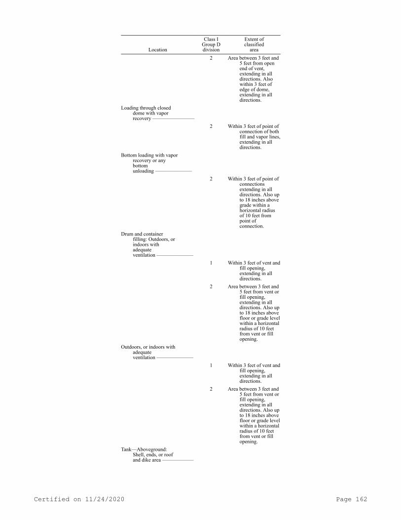
Location
Class IGroup Ddivision
Extent ofclassified
area 2 Area between 3 feet and
5 feet from open end of vent, extending in all directions. Also within 3 feet of edge of dome, extending in all directions.
Loading through closeddome with vaporrecovery ————————
2 Within 3 feet of point of connection of both fill and vapor lines, extending in all directions.
Bottom loading with vapor recovery or anybottomunloading ———————
2 Within 3 feet of point of connections extending in all directions. Also up to 18 inches above grade within a horizontal radius of 10 feet from point of connection.
Drum and containerfilling: Outdoors, orindoors withadequateventilation ———————
1 Within 3 feet of vent and fill opening, extending in all directions.
2 Area between 3 feet and 5 feet from vent or fill opening, extending in all directions. Also up to 18 inches above floor or grade level within a horizontal radius of 10 feet from vent or fill opening.
Outdoors, or indoors with adequateventilation ———————
1 Within 3 feet of vent and fill opening, extending in all directions.
2 Area between 3 feet and 5 feet from vent or fill opening, extending in all directions. Also up to 18 inches above floor or grade level within a horizontal radius of 10 feet from vent or fill opening.
Tank—Aboveground:Shell, ends, or roofand dike area ——————
Certified on 11/24/2020 Page 162

Location
Class IGroup Ddivision
Extent ofclassified
area 2 Within 10 feet from
shell, ends, or roof of tank, area inside dikes to level of top of dike.
Vent ————————— 1 Within 5 feet of open end of vent, extending in all directions.
2 Area between 5 feet and 10 feet from open end of vent, extending in all directions.
Floating roof —————— 1 Area above the roof and within the shell.
Pits:Without mechanicalventilation ———————
1 Entire area within pit if any part is within a Division 1 or 2 classified area.
With mechanicalventilation ———————
2 Entire area within pit if any part is within a Division 1 or 2 classified area.
Containing valves,fittings or piping, and notwithin a Division 1 or 2classified area —————
2 Entire pit.Pumps, bleeders,
withdrawal fittings,meters and similardevices:Indoors ————————
2 Within 5 feet of any edge of such devices, extending in all directions. Also up to 3 feet above floor or grade level within 25 feet horizontally from any edge of such devices.
Outdoors ——————— 2 Within 3 feet of any edge of such devices, extending in all directions. Also up to 18 inches above grade level within 10 feet horizontally from any edge of such devices.
Storage and repair garagefor tankvehicles ————————
1 All pits or spaces below floor level.
2 Area up to 18 inches above floor or grade level for entire storage or repair garage.
Certified on 11/24/2020 Page 163

Location
Class IGroup Ddivision
Extent ofclassified
areaDrainage ditches,
separators,impoundingbasins —————————
2 Area up to 18 inches above ditch, separator or basin. Also up to 18 inches above grade within 15 feet horizontally from any edge.
Garages for other thantank vehicles ——————
Ordinary If there is any opening to these rooms within the extent of an outdoor classified area, the entire room must be classified the same as the area classification at the point of the opening.
Outdoor drum storage ———— Ordinary Indoor warehousing where
there is noflammable liquidtransfer ————————
Ordinary If there is any opening to these rooms within the extent of an indoor classified area, the room must be classified the same as if the wall, curb or partition did not exist.
Office and rest rooms ————— Ordinary
1 When classifying the extent of the area, you must give consideration to the fact that tank cars or tank vehicles may be spotted at varying points. Therefore, you must use the extremities of the loading or unloading positions.
(6) Sources of ignition. You must not handle, draw, or dispense Category 1 or 2 flammable liquids, or Category 3 flammable liquids with a flashpoint below 100°F (37.8°C), where flammable vapors may reach a source of ignition. You must prohibit smoking except in desig-nated localities. You must conspicuously post "No smoking" signs where hazard from flammable liquid vapors is normally present.
(7) Drainage and waste disposal. You must make provisions to pre-vent flammable liquids which may be spilled at loading or unloading points from entering public sewers and drainage systems, or natural waterways. You must provide connection to such sewers, drains, or wa-terways by which flammable liquids might enter with separator boxes or other approved means whereby such entry is precluded. You must not dump crankcase drainings and flammable liquids into sewers, but you must store them in tanks or tight drums outside of any building until removed from the premises.
(8) Fire control. Suitable fire-control devices, such as small hose or portable fire extinguishers, must be available to locations where fires are likely to occur. Additional fire-control equipment may be required where a tank of more than 50,000 gallons individual ca-
Certified on 11/24/2020 Page 164

pacity contains Category 1 or 2 flammable liquids, or Category 3 flam-mable liquids with a flashpoint below 100°F (37.8°C), and where an un-usual exposure hazard exists from surrounding property. Such addition-al fire-control equipment shall be sufficient to extinguish a fire in the largest tank. The design and amount of such equipment must be in accordance with approved engineering standards.[Statutory Authority: RCW 49.17.010, 49.17.040, 49.17.050, and 49.17.060. WSR 17-02-066, § 296-24-33013, filed 1/3/17, effective 2/3/17; WSR 15-24-100, § 296-24-33013, filed 12/1/15, effective 1/5/16. Statutory Authority: RCW 49.17.010, 49.17.040, 49.17.050, 49.17.060 and 29 C.F.R. 1910 Subpart Z. WSR 14-07-086, § 296-24-33013, filed 3/18/14, effective 5/1/14. Statutory Authority: Chapter 49.17 RCW. WSR 94-15-096 (Order 94-07), § 296-24-33013, filed 7/20/94, ef-fective 9/20/94; WSR 91-24-017 (Order 91-07), § 296-24-33013, filed 11/22/91, effective 12/24/91. Statutory Authority: RCW 49.17.040 and 49.17.050. WSR 85-10-004 (Order 85-09), § 296-24-33013, filed 4/19/85; Order 76-6, § 296-24-33013, filed 3/1/76; Order 73-5, § 296-24-33013, filed 5/9/73 and Order 73-4, § 296-24-33013, filed 5/7/73.]
WAC 296-24-33015 Service stations. (1) Storage and handling.(a) General provisions.(i) You must store liquids in approved closed containers not ex-
ceeding 60 gallons capacity, in tanks located underground, in tanks in special enclosures as described in (b) of this subsection, or in aboveground tanks as provided for in subsection (3)(b)(i), (ii), (iii), and (iv) of this section.
(ii) Aboveground tanks, located in an adjoining bulk plant, may be connected by piping to service station underground tanks if, in ad-dition to valves at aboveground tanks, a valve is also installed with-in control of service station personnel.
(iii) Apparatus dispensing Category 1 or 2 flammable liquids, or Category 3 flammable liquids with a flashpoint below 100°F (37.8°C), into the fuel tanks of motor vehicles of the public must not be loca-ted at a bulk plant unless separated by a fence or similar barrier from the area in which bulk operations are conducted.
(iv) The provisions of subsection (1) of this section must not prohibit the dispensing of flammable liquids with a flashpoint below 100°F (37.8°C) in the open from a tank vehicle to a motor vehicle. You must permit such dispensing provided:
(A) The tank vehicle complies with the requirements covered in the Standard on Tank Vehicles for Flammable Liquids, NFPA 385-1966.
(B) The dispensing is done on premises not open to the public.(C) The dispensing hose does not exceed 50 feet in length.(D) The dispensing nozzle is a listed automatic-closing type
without a latch-open device.(v) You must not store or handle Category 1 or 2 flammable liq-
uids, or Category 3 flammable liquids with a flashpoint below 100°F (37.8°C), within a building having a basement or pit into which flam-mable vapors may travel, unless such area is provided with ventilation designed to prevent the accumulation of flammable vapors therein.
(vi) You must maintain and reconcile accurate inventory records on all Class I liquid storage tanks for possible indication of leakage from tanks or piping.
(b) Special enclosures.
Certified on 11/24/2020 Page 165

(i) When installation of tanks in accordance with WAC 296-24-33005(3) is impractical because of property or building limita-tions, tanks for flammable liquids may be installed in buildings if properly enclosed.
(ii) The enclosure must be substantially liquid and vaportight without backfill. Sides, top, and bottom of the enclosure must be of reinforced concrete at least six inches thick, with openings for in-spection through the top only. Tank connections must be so piped or closed that neither vapors nor liquid can escape into the enclosed space. You must provide means whereby portable equipment may be em-ployed to discharge to the outside any liquid or vapors which might accumulate should leakage occur.
(iii) At automotive service stations provided in connection with tenant or customer parking facilities at or below grade level in large buildings of commercial, mercantile, or residential occupancy, tanks containing Class I liquids, installed of necessity in accordance with (b)(ii) of this subsection, must not exceed 6,000 gallons individual or 18,000 gallons aggregate capacity.
(c) Inside buildings.(i) Except where stored in tanks as provided in (b) of this sub-
section, you must not store any Category 1 or 2 flammable liquids, or Category 3 flammable liquids with a flashpoint below 100°F (37.8°C), within any service station building except in closed containers of ag-gregate capacity not exceeding 60 gallons. One container not exceeding 60 gallons capacity equipped with an approved pump is permitted.
(ii) Category 1 or 2 flammable liquids, or Category 3 flammable liquids with a flashpoint below 100°F (37.8°C), may be transferred from one container to another in lubrication or service rooms of a service station building provided the electrical installation complies with Table H-19 and provided that any heating equipment complies with subsection (5) of this section.
(iii) Category 3 flammable liquids with a flashpoint at or above 100°F (37.8°C) and Category 4 flammable liquids may be stored and dis-pensed inside service station buildings from tanks of not more than 120 gallons capacity each.
(d) Labeling. You must not make any sale or purchase of any Class I, II, or III liquids in containers unless such containers are clearly marked with the name of the product contained therein.
(e) Dispensing into portable containers. You must not make any delivery of any Category 1 or 2 flammable liquids, or Category 3 flam-mable liquids with a flashpoint below 100°F (37.8°C), into portable containers unless the container is constructed of metal, has a tight closure with screwed or spring cover, and is fitted with a spout or so designed that the contents can be poured without spilling.
(2) Dispensing systems.(a) Location. Dispensing devices at automotive service stations
must be so located that all parts of the vehicle being served will be on the premises of the service station.
(b) Inside location. Approved dispensing units may be located in-side of buildings. You must separate the dispensing area from other areas in an approved manner. You must mount the dispensing unit and its piping either on a concrete island or protected against collision damage by suitable means and located in a position where it cannot be struck by a vehicle descending a ramp or other slope out of control. You must provide the dispensing area with an approved mechanical or gravity ventilation system. When dispensing units are located below grade, you must use only approved mechanical ventilation and you must
Certified on 11/24/2020 Page 166

protect the entire dispensing area by an approved automatic sprinkler system. Ventilating systems must be electrically interlocked with gas-oline dispensing units so that the dispensing units cannot be operated unless the ventilating fan motors are energized.
(c) Emergency power cutoff. You must provide a clearly identified and easily accessible switch(es) or a circuit breaker(s) at a location remote from dispensing devices, including remote pumping systems, to shut off the power to all dispensing devices in the event of an emer-gency.
(d) Dispensing units.(i) You must transfer Category 1 or 2 flammable liquids, or Cate-
gory 3 flammable liquids with a flashpoint below 100°F (37.8°C), from tanks by means of fixed pumps so designed and equipped as to allow control of the flow and to prevent leakage or accidental discharge.
(ii) Only listed devices may be used for dispensing Category 1 or 2 flammable liquids, or Category 3 flammable liquids with a flashpoint below 100°F (37.8°C). No such device may be used if it shows evidence of having been dismantled.
(iii) Every dispensing device for Category 1 or 2 flammable liq-uids, or Category 3 flammable liquids with a flashpoint below 100°F (37.8°C), installed after December 31, 1978, must contain evidence of listing so placed that any attempt to dismantle the device will result in damage to such evidence, visible without disassembly or dismounting of the nozzle.
(iv) You must not dispense Category 1 or 2 flammable liquids, or Category 3 flammable liquids with a flashpoint below 100°F (37.8°C), by pressure from drums, barrels, and similar containers. You must use approved pumps taking suction through the top of the container or ap-proved self-closing faucets.
(v) You must mount the dispensing units, except those attached to containers, either on a concrete island or protect them against colli-sion damage by suitable means.
(e) Remote pumping systems.(i) This subdivision must apply to systems for dispensing Catego-
ry 1 or 2 flammable liquids, or Category 3 flammable liquids with a flashpoint below 100°F (37.8°C), where such liquids are transferred from storage to individual or multiple dispensing units by pumps loca-ted elsewhere than at the dispensing units.
(ii) Pumps must be designed or equipped so that no part of the system will be subjected to pressures above its allowable working pressure. Pumps installed above grade, outside of buildings, must be located not less than ten feet from lines of adjoining property which is/or may be built upon, and not less than five feet from any building opening. When an outside pump location is impractical, pumps may be installed inside of buildings, as provided for dispensers in (b) of this subsection, or in pits as provided in (e)(iii) of this subsec-tion. You must substantially anchor pumps and protect them against physical damage by vehicles.
(iii) Pits for subsurface pumps or piping manifolds of submersi-ble pumps must withstand the external forces to which they may be sub-jected without damage to the pump, tank, or piping. The pit must be no larger than necessary for inspection and maintenance and must be pro-vided with a fitted cover.
(iv) You must provide a control that will permit the pump to op-erate only when a dispensing nozzle is removed from its bracket on the dispensing unit and the switch on this dispensing unit is manually ac-
Certified on 11/24/2020 Page 167

tuated. This control must also stop the pump when all nozzles have been returned to their brackets.
(v) You must properly install an approved impact valve, incorpo-rating a fusible link, designed to close automatically in the event of severe impact or fire exposure in the dispensing supply line at the base of each individual dispensing device.
(vi) Testing. After the completion of the installation, including any paving, you must test that section of the pressure piping system between the pump discharge and the connection for the dispensing fa-cility for at least 30 minutes at the maximum operating pressure of the system. You must repeat such tests at 5-year intervals thereafter.
(f) Delivery nozzles.(i) You must provide a listed manual or automatic-closing type
hose nozzle valve on dispensers used for the dispensing of Category 1 or 2 flammable liquids, or Category 3 flammable liquids with a flash-point below 100°F (37.8°C).
(ii) You must hold manual-closing type valves open manually dur-ing dispensing. Automatic-closing type valves may be used in conjunc-tion with an approved latch-open device.
(g) Special type dispensers.(i) You must install emergency controls at an acceptable loca-
tion, but controls must not be more than one hundred feet from dis-pensers.
(ii) You must conspicuously post instructions for the operation of dispensers.
(3) Marine service stations.(a) Dispensing.(i) The dispensing area must be located away from other struc-
tures so as to provide room for safe ingress and egress of craft to be fueled. Dispensing units must in all cases be at least 20 feet from any activity involving fixed sources of ignition.
(ii) Dispensing must be by approved dispensing units with or without integral pumps and may be located on open piers, wharves, or floating docks or on shore or on piers of the solid fill type.
(iii) Dispensing nozzles must be automatic-closing without a hold-open latch.
(b) Tanks and pumps.(i) Tanks, and pumps not integral with the dispensing unit, must
be on shore or on a pier of the solid fill type, except as provided below.
(ii) Where shore location would require excessively long supply lines to dispensers, tanks may be installed on a pier provided that applicable portions of WAC 296-24-33005 relative to spacing, diking, and piping are complied with and the quantity so stored does not ex-ceed 1,100 gallons aggregate capacity.
(iii) Shore tanks supplying marine service stations may be loca-ted above ground, where rock ledges or high water table make under-ground tanks impractical.
(iv) Where tanks are at an elevation which would produce gravity head on the dispensing unit, the tank outlet must be equipped with a pressure control valve positioned adjacent to and outside the tank block valve specified in WAC 296-24-33005 (2)(h)(ii), so adjusted that liquid cannot flow by gravity from the tank in case of piping or hose failure.
(c) Piping.(i) Piping between shore tanks and dispensing units must be as
described in WAC 296-24-33007, except that, where dispensing is from a
Certified on 11/24/2020 Page 168

floating structure, suitable lengths of oil-resistant flexible hose may be employed between the shore piping and the piping on the float-ing structure as made necessary by change in water level or shoreline.
(ii) You must provide a readily accessible valve to shut off the supply from shore in each pipeline at or near the approach to the pier and at the shore end of each pipeline adjacent to the point where flexible hose is attached.
(iii) Piping must be located so as to be protected from physical damage.
(iv) You must ground piping handling Category 1 or 2 flammable liquids, or Category 3 flammable liquids with a flashpoint below 100°F (37.8°C) shall be grounded to control stray currents.
(4) Electrical equipment.(a) Application. This subsection applies to areas where Category
1 or 2 flammable liquids, or Category 3 flammable liquids with a flashpoint below 100°F (37.8°C), are stored or handled. For areas where Category 3 flammable liquids with a flashpoint at or above 100°F (37.8°C) or Category 4 flammable liquids are stored or handled the electrical equipment may be installed according to the provisions of chapter 296-24 WAC Part L for ordinary locations.
(b) All electrical equipment and wiring must be of a type speci-fied by and must be installed according to chapter 296-24 WAC Part L.
(c) So far as it applies, Table H-19 must be used to delineate and classify hazardous areas for the purpose of installation of elec-trical equipment under normal circumstances. A classified area must not extend beyond an unpierced wall, roof, or other solid partition.
(d) The area classifications listed must be based on the assump-tion that the installation meets the applicable requirements of this section in all respects.
TABLE H-19ELECTRICAL EQUIPMENT HAZARDOUS
AREAS—SERVICE STATIONS
LocationClass I,
Group Ddivision
Extent ofclassified
areaUnderground tank:
Fill opening ———————
1 Any pit, box or space below grade level, any part of which is within the Division 1 or 2 classified area.
2 Up to 18 inches above grade level within a horizontal radius of 10 feet from a loose fill connection and within a horizontal radius of 5 feet from a tight fill connection.
Vent─Discharging upward ————————
1 Within 3 feet of open end of vent, extending in all directions.
Certified on 11/24/2020 Page 169
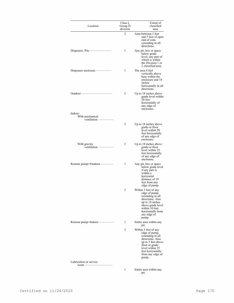
LocationClass I,
Group Ddivision
Extent ofclassified
area 2 Area between 3 feet
and 5 feet of open end of vent, extending in all directions.
Dispenser: Pits ——————— 1 Any pit, box or space below grade level, any part of which is within the Division 1 or 2 classified area.
Dispenser enclosure ————— 1 The area 4 feet vertically above base within the enclosure and 18 inches horizontally in all directions.
Outdoor —————————— 2 Up to 18 inches above grade level within 20 feet horizontally of any edge of enclosure.
Indoor:With mechanical
ventilation —————
2 Up to 18 inches above grade or floor level within 20 feet horizontally of any edge of enclosure.
With gravityventilation —————
2 Up to 18 inches above grade or floor level within 25 feet horizontally of any edge of enclosure.
Remote pump─Outdoor ———— 1 Any pit, box or space below grade level if any part is within a horizontal distance of 10 feet from any edge of pump.
2 Within 3 feet of any edge of pump, extending in all directions. Also up to 18 inches above grade level within 10 feet horizontally from any edge of pump.
Remote pump─Indoor ————— 1 Entire area within any pit.
2 Within 5 feet of any edge of pump, extending in all directions. Also up to 3 feet above floor or grade level within 25 feet horizontally from any edge of pump.
Lubrication or serviceroom —————————
1 Entire area within any pit.
Certified on 11/24/2020 Page 170

LocationClass I,
Group Ddivision
Extent ofclassified
area 2 Area up to 18 inches
above floor or grade level within entire lubrication room.
Dispenser for Class Iliquids —————————
2 Within 3 feet of any fill or dispensing point, extending in all directions.
Special enclosure insidebuilding perWAC 296-24-33013(1)(b) —————————
1 Entire enclosure.Sales, storage and rest
rooms —————————
(1) If there is any opening to these rooms within the extent of a Division 1 area, the entire room must be classified as Division 1.
Footnote (1) Ordinary.
(5) Heating equipment.(a) Conformance. You must install heating equipment as provided
in (b) through (e) of this subsection.(b) Application. Heating equipment may be installed in the con-
ventional manner in an area except as provided in (c), (d) or (e) of this subsection.
(c) Special room. Heating equipment may be installed in a special room separated from an area classified by Table H-19 by walls having a fire resistance rating of at least one hour and without any openings in the walls within eight feet of the floor into an area classified in Table H-19. You must not use this room for combustible storage and all air for combustion purposes must come from outside the building.
(d) Work areas. Heating equipment using gas or oil fuel may be installed in the lubrication, sales, or service room where there is no dispensing or transferring of Category 1 or 2 flammable liquids or Category 3 flammable liquids with a flashpoint below 100°F (37.8°C), provided the bottom of the combustion chamber is at least eighteen in-ches above the floor and the heating equipment is protected from phys-ical damage by vehicles. Heating equipment using gas or oil fuel lis-ted for use in garages may be installed in the lubrication or service room where Category 1 or 2 flammable liquids, or Category 3 flammable liquids with a flashpoint below 100°F (37.8°C), are dispensed provided the equipment is installed at least eight feet above the floor.
(e) Electric heat. Electrical heating equipment must conform to subsection (4) of this section.
(6) Drainage and waste disposal. You must make provisions in the area where Category 1 or 2 flammable liquids, or Category 3 flammable liquids with a flashpoint below 100°F (37.8°C), are dispensed to pre-vent spilled liquids from flowing into the interior of service station buildings. Such provision may be by grading driveways, raising door sills, or other equally effective means. You must not dump crankcase drainings and flammable liquids into sewers but you must store them in
Certified on 11/24/2020 Page 171
tanks or drums outside of any building until removed from the prem-ises.
(7) Sources of ignition. In addition to the previous restrictions of this section, the following must apply: You must ensure that there is no smoking or open flames in the areas used for fueling, servicing fuel systems for internal combustion engines, receiving or dispensing of flammable liquids. You must post conspicuous and legible signs pro-hibiting smoking within sight of the customer being served. You must shut off motors of all equipment being fueled during the fueling oper-ation.
(8) Fire control. You must provide each service station with at least one fire extinguisher having a minimum approved classification of 6 B, C located so that an extinguisher will be within 75 feet of each pump, dispenser, underground fill pipe opening, and lubrication or service room.Note: For additional requirements relating to portable fire extinguishers see WAC 296-800-300.
[Statutory Authority: RCW 49.17.010, 49.17.040, 49.17.050, and 49.17.060. WSR 15-24-100, § 296-24-33015, filed 12/1/15, effective 1/5/16. Statutory Authority: RCW 49.17.010, 49.17.040, 49.17.050, 49.17.060 and 29 C.F.R. 1910 Subpart Z. WSR 14-07-086, § 296-24-33015, filed 3/18/14, effective 5/1/14. Statutory Authority: RCW 49.17.010, [49.17].040, and [49.17].050. WSR 01-17-033, § 296-24-33015, filed 8/8/01, effective 9/1/01. Statutory Authority: Chapter 49.17 RCW. WSR 91-24-017 (Order 91-07), § 296-24-33015, filed 11/22/91, effective 12/24/91. Statutory Authority: RCW 49.17.040 and 49.17.050. WSR 85-10-004 (Order 85-09), § 296-24-33015, filed 4/19/85; WSR 83-24-013 (Order 83-34), § 296-24-33015, filed 11/30/83; Order 76-6, § 296-24-33015, filed 3/1/76; Order 73-5, § 296-24-33015, filed 5/9/73 and Order 73-4, § 296-24-33015, filed 5/7/73.]
WAC 296-24-33017 Processing plants. (1) Scope. This section ap-plies to those plants or buildings which contain chemical operations such as oxidation, reduction, halogenation, hydrogenation, alkylation, polymerization, and other chemical processes but does not apply to chemical plants, refineries or distilleries.
(2) Location.(a) Classification. You must base the location of each processing
vessel upon its flammable liquid capacity. You must locate processing vessels, with respect to distances to lines of adjoining property which may be built upon, in accordance with Table H-20, except when the processing plant is designed in accordance with (b) of this sub-section.
TABLE H-20Processing vessels with emergency relief venting to permit pressure Stable liquids Unstable liquidsNot in excess of2.5 p.s.i.g.
Table H-9 2 1/2 timesTable H-9.
Over 2.5. p.s.i.g. 1 1/2 timesTable H-9.
4 timesTable H-9.
(b) Exception. The distances required in (a) of this subsection may be waived when the vessels are housed within a building and the exterior wall facing the line of adjoining property which may be built upon is a blank wall having a fire-resistance rating of not less than
Certified on 11/24/2020 Page 172

4 hours. When Class IA or unstable liquids are handled, the blank wall must have explosion resistance in accordance with good engineering practice, see subsection (3)(d) of this section.
(3) Processing building.(a) Construction.(i) Processing buildings must be of fire-resistance or noncombus-
tible construction, except heavy timber construction with load-bearing walls may be permitted for plants utilizing only stable Category 3 flammable liquids with a flashpoint at or above 100°F (37.8°C) or Cat-egory 4 flammable liquids. Except as provided in subsection (2)(b) of this section or in the case of explosion resistant walls used in con-junction with explosion relieving facilities, see (d) of this subsec-tion, loadbearing walls are prohibited. Buildings must be without basements or covered pits.
(ii) Areas must have adequate exit facilities arranged to prevent occupants from being trapped in the event of fire. Exits must not be exposed by the drainage facilities described in (b) of this subsec-tion.
(b) Drainage.(i) You must provide emergency drainage systems to direct flamma-
ble liquid leakage and fire protection water to a safe location. This may require curbs, scuppers, or special drainage systems to control the spread of fire, see WAC 296-24-33005 (2)(g)(ii).
(ii) Emergency drainage systems, if connected to public sewers or discharged into public waterways, must be equipped with traps or sepa-rators.
(iii) You must ensure that the processing plant is designed and operated to prevent the normal discharge of flammable liquids to pub-lic waterways, public sewers, or adjoining property.
(c) Ventilation.(i) Enclosed processing buildings must be ventilated at a rate of
not less than one cubic foot per minute per square foot of solid floor area. You must accomplish this by natural or mechanical ventilation with discharge or exhaust to a safe location outside of the building. You must make provisions for introduction of makeup air in such a man-ner as not to short circuit the ventilation. You must arrange ventila-tion to include all floor areas or pits where flammable vapors may collect.
(ii) Equipment used in a building and the ventilation of the building must be designed so as to limit flammable vapor-air mixtures under normal operating conditions to the interior of equipment, and to not more than five feet from equipment which exposes Category 1 or 2 flammable liquids, or Category 3 flammable liquids with a flashpoint below 100°F (37.8°C), to the air. Examples of such equipment are dis-pensing stations, open centrifuges, plate and frame filters, open vac-uum filters, and surfaces of open equipment.
(d) Explosion relief. Areas where Category 1 or unstable liquids are processed must have explosion venting through one or more of the following methods:
(i) Open air construction.(ii) Lightweight walls and roof.(iii) Lightweight wall panels and roof hatches.(iv) Windows of explosion venting type.(4) Liquid handling.(a) Storage.
Certified on 11/24/2020 Page 173
(i) You must ensure that the storage of flammable liquids in tanks is in accordance with the applicable provisions of WAC 296-24-33005.
(ii) If the storage of flammable liquids in outside aboveground or underground tanks is not practical because of temperature or pro-duction considerations, tanks may be permitted inside of buildings or structures in accordance with the applicable provisions of WAC 296-24-33005.
(iii) You must only permit storage tanks inside of buildings in areas at or above grade which have adequate drainage and are separated from the processing area by construction having a fire resistance rat-ing of at least two hours.
(iv) You must ensure that the storage of flammable liquids in containers is in accordance with the applicable provisions of WAC 296-24-33009.
(b) Piping, valves, and fittings.(i) You must ensure that piping, valves, and fittings are in ac-
cordance with WAC 296-24-33007.(ii) Approved flexible connectors may be used where vibration ex-
ists or where frequent movement is necessary. Approved hose may be used at transfer stations.
(iii) You must identify piping containing flammable liquids.(c) Transfer.(i) The transfer of large quantities of flammable liquids must be
through piping by means of pumps or water displacement. Except as re-quired in process equipment, you must not use gravity flow. The use of compressed air as a transferring medium is prohibited.
(ii) You must provide positive displacement pumps with pressure relief discharging back to the tank or to pump suction.
(d) Equipment.(i) Equipment must be designed and arranged to prevent the unin-
tentional escape of liquids and vapors and to minimize the quantity escaping in the event of accidental release.
(ii) Where the vapor space of equipment is usually within the flammable range, the probability of explosion damage to the equipment can be limited by inerting, by providing an explosion suppression sys-tem, or by designing the equipment to contain the peak explosion pres-sure which may be modified by explosion relief. Where the special haz-ards of operation, sources of ignition, or exposures indicate a need, you must give consideration to providing protection by one or more of the above means.
(5) Tank vehicle and tank car loading and unloading. You must separate tank vehicle and tank car loading or unloading facilities from aboveground tanks, warehouses, other plant buildings, or nearest line of adjoining property which may be built upon by a distance of 25 feet for Category 1 or 2 flammable liquids, or Category 3 flammable liquids with a flashpoint below 100°F (37.8°C), and 15 feet for Cate-gory 3 flammable liquids with a flashpoint at or above 100°F (37.8°C) and Category 4 flammable liquids measured from the nearest position of any fill stem. Buildings for pumps or shelters for personnel may be a part of the facility. Operations of the facility must comply with the appropriate portions of WAC 296-24-33013(3).
(6) Fire control.(a) Portable extinguishers. You must provide approved portable
fire extinguishers of appropriate size, type and number.
Certified on 11/24/2020 Page 174

(b) Other controls. Where the special hazards of operation or ex-posure indicate a need, you must provide the following fire control provision.
(i) A reliable water supply must be available in pressure and quantity adequate to meet the probable fire demands.
(ii) You must provide hydrants in accordance with accepted good practice.
(iii) You must install hose connected to a source of water so that all vessels, pumps, and other equipment containing flammable liq-uids can be reached with at least one hose stream. You must provide nozzles that are capable of discharging a water spray.
(iv) You must protect processing plants by an approved automatic sprinkler system or equivalent extinguishing system. If special extin-guishing systems including but not limited to those employing foam, carbon dioxide, or dry chemical are provided, you must use approved equipment and installed in an approved manner.
(c) Alarm systems. You must provide an approved means for prompt notification of fire to those within the plant and any public fire de-partment available. It may be advisable to connect the plant system with the public system where public fire alarm system is available.
(d) Maintenance. You must adequately maintain and periodically inspect and test all plant fire protection facilities to make sure they are always in satisfactory operating condition and that they will serve their purpose in time of emergency.
(7) Sources of ignition.(a) General.(i) You must take precautions to prevent the ignition of flamma-
ble vapors. Sources of ignition include but are not limited to open flames; lightning; smoking; cutting and welding; hot surfaces; fric-tional heat; static, electrical, any mechanical sparks; spontaneous ignition, including heat-producing chemical reactions; and radiant heat.
(ii) You must not dispense Category 1 or 2 flammable liquids, or Category 3 flammable liquids with a flashpoint below 100°F (37.8°C), into containers unless the nozzle and container are electrically in-terconnected. Where the metallic floorplate on which the container stands while filling is electrically connected to the fill stem or where the fill stem is bonded to the container during filling opera-tions by means of a bond wire, the provisions of this section must be deemed to have been complied with.
(b) Maintenance and repair.(i) When necessary to do maintenance work in a flammable liquid
processing area, the work must be authorized by a responsible repre-sentative of the employer.
(ii) You must only permit hot work such as welding or cutting op-erations, use of spark-producing power tools, and chipping operations under supervision of an individual in responsible charge who must make an inspection of the area to be sure that it is safe for the work to be done and that safe procedures will be followed for the work speci-fied.
(c) Electrical.(i) You must install all electrical wiring and equipment within
storage or processing areas according to chapter 296-24 WAC Part L.(ii) Locations where flammable vapor-air mixtures may exist under
normal operations must be classified Category 1 or 2 flammable liq-uids, or Category 3 flammable liquids with a flashpoint below 100°F (37.8°C), Division 1 according to the requirements of chapter 296-24
Certified on 11/24/2020 Page 175

WAC Part L. For those pieces of equipment installed in accordance with subsection (3)(c)(ii) of this section, the Division 1 area must extend five feet in all directions from all points of vapor liberation. All areas within pits must be classified Division 1 if any part of the pit is within a Division 1 or 2 classified area, unless the pit is provi-ded with mechanical ventilation.
(iii) Locations where flammable vapor-air mixtures may exist un-der abnormal conditions and for a distance beyond Division 1 locations must be classified Division 2 according to the requirements of chapter 296-24 WAC Part L. These locations include an area within 20 feet hor-izontally, 3 feet vertically beyond a Division 1 area, and up to 3 feet above floor or grade level within 25 feet, if indoors, or 10 feet if outdoors, from any pump, bleeder, withdrawal fittings, meter, or similar device handling Category 1 or 2 flammable liquids, or Category 3 flammable liquids with a flashpoint below 100°F (37.8°C). Pits pro-vided with adequate mechanical ventilation within a Division 1 or 2 area must be classified Division 2. If Category 3 flammable liquids with a flashpoint at or above 100°F (37.8°C) or Category 4 flammable liquids only are handled, then ordinary electrical equipment is satis-factory though care must be used in locating electrical apparatus to prevent hot metal from falling into open equipment.
(iv) Where the provisions of (c)(i), (ii), and (iii) of this sub-section require the installation of explosion-proof equipment, ordina-ry electrical equipment including switchgear may be used if installed in a room or enclosure which is maintained under positive pressure with respect to the hazardous area. Ventilation makeup air must be un-contaminated by flammable vapors.
(8) Housekeeping.(a) General. Maintenance and operating practices must be in ac-
cordance with established procedures which will tend to control leak-age and prevent the accidental escape of flammable liquids. You must clean up spills promptly.
(b) Access. You must maintain adequate aisles for unobstructed movement of personnel and so that fire protection equipment can be brought to bear on any part of the processing equipment.
(c) Waste and residues. You must keep combustible waste material and residues in a building or operating area to a minimum, stored in closed metal waste cans, and disposed of daily.
(d) Clear zone. You must keep ground area around buildings and operating areas free of tall grass, weeds, trash, or other combustible materials.[Statutory Authority: RCW 49.17.010, 49.17.040, 49.17.050, and 49.17.060. WSR 15-24-100, § 296-24-33017, filed 12/1/15, effective 1/5/16. Statutory Authority: RCW 49.17.010, 49.17.040, 49.17.050, 49.17.060 and 29 C.F.R. 1910 Subpart Z. WSR 14-07-086, § 296-24-33017, filed 3/18/14, effective 5/1/14. Statutory Authority: Chapter 49.17 RCW. WSR 91-24-017 (Order 91-07), § 296-24-33017, filed 11/22/91, ef-fective 12/24/91. Statutory Authority: RCW 49.17.040 and 49.17.050. WSR 85-10-004 (Order 85-09), § 296-24-33017, filed 4/19/85; Order 76-6, § 296-24-33017, filed 3/1/76; Order 73-5, § 296-24-33017, filed 5/9/73 and Order 73-4, § 296-24-33017, filed 5/7/73.]
WAC 296-24-33019 Refineries, chemical plants, and distilleries. (1) Storage tanks. You must store flammable liquids in tanks, in con-tainers, or in portable tanks. You must install tanks in accordance
Certified on 11/24/2020 Page 176

with WAC 296-24-33005. You must locate tanks for the storage of flam-mable liquids in tank farms and in locations other than process areas in accordance with WAC 296-24-33005 (2)(a) and (b).
(2) Wharves. Wharves handling flammable liquids must be in ac-cordance with WAC 296-24-33013(4).
(3) Fired and unfired pressure vessels.(a) Fired vessels. You must construct fired pressure vessels in
accordance with the Code for Fired Pressure Vessels, section I of the ASME Boiler and Pressure Vessel Code—1968.
(b) You must construct unfired vessels in accordance with the Code for Unfired Pressure Vessels, section VIII of the ASME Boiler and Pressure Vessel Code—1968.
(4) Location of process units. You must locate process units so that they are accessible from at least one side for the purpose of fire control. Where topographical conditions are such that flammable liquids may flow from a processing area so as to constitute a fire hazard to property of others, you must make provisions to divert or impound the flow by curbs, drains, or other suitable means.
(5) Fire control.(a) Portable equipment. You must provide portable fire extin-
guishment and control equipment in such quantities and types as are needed for the special hazards of operation and storage.
(b) Water supply. Water must be available in volume and at ade-quate pressure to supply water hose streams, foam producing equipment, automatic sprinklers, or water spray systems as the need is indicated by the special hazards of operation and storage.
(c) Special equipment. You must provide special extinguishing equipment such as that utilizing foam, inert gas, or dry chemical as the need is indicated by the special hazards of operation and storage.[Statutory Authority: RCW 49.17.010, 49.17.040, 49.17.050, and 49.17.060. WSR 15-24-100, § 296-24-33019, filed 12/1/15, effective 1/5/16. Statutory Authority: RCW 49.17.010, 49.17.040, 49.17.050, 49.17.060 and 29 C.F.R. 1910 Subpart Z. WSR 14-07-086, § 296-24-33019, filed 3/18/14, effective 5/1/14; Order 73-5, § 296-24-33019, filed 5/9/73 and Order 73-4, § 296-24-33019, filed 5/7/73.]
WAC 296-24-370 Spray finishing using flammable materials.[Statutory Authority: RCW 49.17.010, 49.17.040, 49.17.050, 49.17.060 and 29 C.F.R. 1910 Subpart Z. WSR 14-07-086, § 296-24-370, filed 3/18/14, effective 5/1/14; Order 73-5, § 296-24-370, filed 5/9/73 and Order 73-4, § 296-24-370, filed 5/7/73.]
WAC 296-24-37001 Definitions. Aerated solid powders. Aerated powders shall mean any powdered material used as a coating material which shall be fluidized within a container by passing air uniformly from below. It is common practice to fluidize such materials to form a fluidized powder bed and then dip the part to be coated into the bed in a manner similar to that used in liquid dipping. Such beds are also used as sources for powder spray operations.
Approved. Shall mean approved and listed by a nationally recog-nized testing laboratory. Refer to federal regulation 29 CRF 1910.7 for definition of nationally recognized testing laboratory.
Certified on 11/24/2020 Page 177

Dry spray booth. A spray booth not equipped with a water washing system as described in this section. A dry spray booth may be equipped with (a) distribution or baffle plates to promote an even flow of air through the booth or cause the deposit of overspray before it enters the exhaust duct; or (b) overspray dry filters to minimize dusts; or (c) overspray dry filters to minimize dusts or residues entering ex-haust ducts; or (d) overspray dry filter rolls designed to minimize dusts or residues entering exhaust ducts; or (e) where dry powders are being sprayed, with powder collection systems so arranged in the ex-haust to capture oversprayed material.
Electrostatic fluidized bed. A container holding powder coating material which is aerated from below so as to form an air-supported expanded cloud of such material which is electrically charged with a charge opposite to the charge of the object to be coated; such object is transported through the container immediately above the charged and aerated materials in order to be coated.
Fluidized bed. A container holding powder coating material which is aerated from below so as to form an air-supported expanded cloud of such material through which the preheated object to be coated is im-mersed and transported.
Listed. See "approved" in this section.Spray booth. A power-ventilated structure provided to enclose or
accommodate a spraying operation to confine and limit the escape of spray, vapor, and residue, and to safely conduct or direct them to an exhaust system.
Spraying area. Any area in which dangerous quantities of flamma-ble vapors or mists, or combustible residues, dusts, or deposits are present due to the operation of spraying processes.
Waterwash spray booth. A spray booth equipped with a water wash-ing system designed to minimize dusts or residues entering exhaust ducts and to permit the recovery of overspray finishing material.[Statutory Authority: RCW 49.17.010, 49.17.040, 49.17.050, and 49.17.060. WSR 15-24-100, § 296-24-37001, filed 12/1/15, effective 1/5/16. Statutory Authority: Chapter 49.17 RCW. WSR 88-23-054 (Order 88-25), § 296-24-37001, filed 11/14/88; Order 76-6, § 296-24-37001, filed 3/1/76; Order 73-5, § 296-24-37001, filed 5/9/73 and Order 73-4, § 296-24-37001, filed 5/7/73.]
WAC 296-24-37003 Spray booths. (1) Construction. Spray booths must be substantially constructed of steel, securely and rigidly sup-ported, or of concrete or masonry except that aluminum or other sub-stantial noncombustible material may be used for intermittent or low volume spraying. Spray booths must be designed to sweep air currents toward the exhaust outlet.
(2) Interiors. The interior surfaces of spray booths must be smooth and continuous without edges and otherwise designed to prevent pocketing of residues and facilitate cleaning and washing without in-jury.
(3) Floors. You must cover the floor surface of a spray booth and operator's working area, if combustible, with noncombustible material of such character as to facilitate the safe cleaning and removal of residues.
(4) Distribution or baffle plates. Distribution or baffle plates, if installed to promote an even flow of air through the booth or cause the deposit of overspray before it enters the exhaust duct, must be of
Certified on 11/24/2020 Page 178

noncombustible material and readily removable or accessible on both sides for cleaning. Such plates must not be located in exhaust ducts.
(5) Dry type overspray collectors—(Exhaust air filters). In con-ventional dry type spray booths, overspray dry filters or filter rolls, if installed, must conform to the following:
(a) You must design, install, and maintain the spraying opera-tions except electrostatic spraying operations so that the average air velocity over the open face of the booth (or booth cross section dur-ing spraying operations) is not less than 100 linear feet per minute. Electrostatic spraying operations may be conducted with an air veloci-ty over the open face of the booth of not less than 60 linear feet per minute, or more, depending on the volume of the finishing material be-ing applied and its flammability and explosion characteristics. You must install visible gauges or audible alarm or pressure activated de-vices to indicate or ensure that the required air velocity is main-tained. Dry spray booths equipped with a filter roll which is automat-ically advanced when the air velocity is reduced to that specified in this section should be arranged to cause shutdown of spraying opera-tions if the filter roll fails to advance automatically. Maintenance procedures should be established to assure replacing filter pads be-fore excessive restriction to airflow occurs. Filter pads should be inspected after each period of use and clogged filter pads discarded and replaced. You must inspect filter rolls to ensure proper replace-ment of filter media.
(b) You must immediately remove all discarded filter pads and filter rolls to a safe, well-detached location or placed in a water-filled metal container and disposed of at the close of the day's oper-ation unless maintained completely in water.
(c) The location of filters in a spray booth must be so as to not reduce the effective booth enclosure of the articles being sprayed.
(d) You must protect space within the spray booth on the down-stream and upstream sides of filters with an approved automatic sprin-kler system meeting one of the following requirements:
(i) An automatic sprinkler system as defined in WAC 296-24-607; or
(ii) A fixed dry chemical extinguishing system as defined in WAC 296-24-622; or
(iii) A fixed carbon dioxide gaseous agent system as defined in WAC 296-24-623.
(e) You must not use filters or filter rolls when applying a spray material known to be highly susceptible to spontaneous heating and ignition.
(f) Clean filters or filter rolls must be noncombustible or of a type having a combustibility not in excess of Class 2 filters as lis-ted by Underwriters' Laboratories, Inc. You must not alternately use filters and filter rolls for different types of coating materials, where the combination of materials may be conducive to spontaneous ig-nition. See also WAC 296-24-37013(6).
(6) Frontal area. Each spray booth having a frontal area larger than 9 square feet must have a metal deflector or curtain not less than 2 1/2 inches deep installed at the upper outer edge of the booth over the opening.
(7) Conveyors. Where conveyors are arranged to carry work into or out of spray booths, the openings therefor must be as small as practi-cal.
Certified on 11/24/2020 Page 179

(8) Separation of operations. You must separate each spray booth from other operations by not less than 3 feet, or by a greater dis-tance, or by such partition or wall as to reduce the danger from jux-taposition of hazardous operations. See also WAC 296-24-37005(1).
(9) Cleaning. You must install spray booths so that all portions are readily accessible for cleaning. You must keep a clear space of not less than 3 feet on all sides free from storage or combustible construction.
(10) Illumination. When spraying areas are illuminated through glass panels or other transparent materials, you must use only fixed lighting units as a source of illumination. Panels must effectively isolate the spraying area from the area in which the lighting unit is located, and must be of a noncombustible material of such a nature or so protected that breakage will be unlikely. You must arrange panels so that normal accumulations of residue on the exposed surface of the panel will not be raised to a dangerous temperature by radiation or conduction from the source of illumination.[Statutory Authority: RCW 49.17.010, 49.17.040, 49.17.050, and 49.17.060. WSR 15-24-100, § 296-24-37003, filed 12/1/15, effective 1/5/16. Statutory Authority: Chapter 49.17 RCW. WSR 89-11-035 (Order 89-03), § 296-24-37003, filed 5/15/89, effective 6/30/89; Order 76-6, § 296-24-37003, filed 3/1/76; Order 73-5, § 296-24-37003, filed 5/9/73 and Order 73-4, § 296-24-37003, filed 5/7/73.]
WAC 296-24-37005 Electrical and other sources of ignition. (1) Conformance. All electrical equipment, open flames and other sources of ignition must conform to the requirements of this section, except as follows:
(a) Electrostatic apparatus must conform to the requirements of WAC 296-24-37015 and 296-24-37017.
(b) Drying, curing, and fusion apparatus must conform to the re-quirements of WAC 296-24-37019.
(c) Automobile undercoating spray operations in garages must con-form to the requirements of WAC 296-24-37021.
(d) Powder coating equipment must conform to the requirements of WAC 296-24-37023.
(2) Minimum separation. You must ensure that there is no open flame or spark producing equipment in any spraying area nor within 20 feet thereof, unless separated by a partition.
(3) Hot surfaces. You must not locate space-heating appliances, steampipes, or hot surfaces in a spraying area where deposits of com-bustible residues may readily accumulate.
(4) Wiring conformance. Electrical wiring and equipment must con-form to the provisions of this section and chapter 296-24 WAC Part L.
(5) Combustible residues, areas. Unless specifically approved for locations containing both deposits of readily ignitable residue and explosive vapors, there must be no electrical equipment in any spray-ing area, whereon deposits of combustible residues may readily accumu-late, except wiring in rigid conduit or in boxes or fittings contain-ing no taps, splices, or terminal connections.
(6) Wiring type approved. Electrical wiring and equipment not subject to deposits of combustible residues but located in a spraying area as herein defined must be of explosion-proof type approved for Class I, Group D locations and conform to the provisions of chapter 296-24 WAC Part L, for Class I, Division 1, hazardous locations. Elec-
Certified on 11/24/2020 Page 180
trical wiring, motors, and other equipment outside of but within 20 feet of any spraying area, and not separated therefrom by partitions, must not produce sparks under normal operating conditions and conform to the provisions of chapter 296-24 WAC Part L for Class I, Division 2, hazardous locations.
(7) Lamps. Electric lamps outside of, but within 20 feet of any spraying area, and not separated therefrom by a partition, must be to-tally enclosed to prevent the falling of hot particles and you must protect them from mechanical injury by suitable guards or by location.
(8) Portable lamps. You must not use portable electric lamps in any spraying area during spraying operations. Portable electric lamps, if used during cleaning or repairing operations, must be of the type approved for hazardous Class I locations.
(9) Grounding.(a) You must properly electrically ground all metal parts of
spray booths, exhaust ducts, and piping systems conveying flammable liquids or liquids with a flashpoint greater than 199.4°F (93°C) or aerated solids in an effective and permanent manner.
(b) "Airless" high-fluid pressure spray guns and any conductive object being sprayed should be properly electrically grounded.[Statutory Authority: RCW 49.17.010, 49.17.040, 49.17.050, and 49.17.060. WSR 15-24-100, § 296-24-37005, filed 12/1/15, effective 1/5/16. Statutory Authority: RCW 49.17.010, 49.17.040, 49.17.050, 49.17.060 and 29 C.F.R. 1910 Subpart Z. WSR 14-07-086, § 296-24-37005, filed 3/18/14, effective 5/1/14. Statutory Authority: Chapter 49.17 RCW. WSR 91-24-017 (Order 91-07), § 296-24-37005, filed 11/22/91, ef-fective 12/24/91. Statutory Authority: RCW 49.17.040 and 49.17.050. WSR 85-10-004 (Order 85-09), § 296-24-37005, filed 4/19/85; Order 76-6, § 296-24-37005, filed 3/1/76; Order 73-5, § 296-24-37005, filed 5/9/73 and Order 73-4, § 296-24-37005, filed 5/7/73.]
WAC 296-24-37007 Ventilation. (1) Conformance. Ventilating and exhaust systems must be in accordance with the Standard for Blower and Exhaust Systems for Vapor Removal, NFPA No. 91-1961, where applicable and must also conform to the provisions of this section.
(2) General. You must provide all spraying areas with mechanical ventilation adequate to remove flammable vapors, mists or powders to a safe location and to confine and control combustible residues so that life is not endangered. You must keep mechanical ventilation in opera-tion at all times while spraying operations are being conducted and for a sufficient time thereafter to allow vapors from drying coated articles and drying finishing material residue to be exhausted.
(3) Independent exhaust. Each spray booth must have an independ-ent exhaust duct system discharging to the exterior of the building, except that multiple cabinet spray booths in which identical spray finishing material is used with a combined frontal area of not more than 18 square feet may have a common exhaust. If more than one fan serves one booth, all fans must be interconnected so that one fan can-not operate without all fans being operated.
(4) Fan-rotating element. The fan-rotating element must be non-ferrous or nonsparking or the casing must consist of or be lined with such material. There must be ample clearance between the fan-rotating element and the fan casing to avoid a fire by friction, necessary al-lowance being made for ordinary expansion and loading to prevent con-tact between moving parts and the duct or fan housing. Fan blades must
Certified on 11/24/2020 Page 181

be mounted on a shaft sufficiently heavy to maintain perfect alignment even when the blades of the fan are heavily loaded, the shaft prefera-bly to have bearings outside the duct and booth. All bearings must be of the self-lubricating type, or lubricated from the outside duct.
(5) Electric motors. You must not place electric motors driving exhaust fans inside booths or ducts. See also WAC 296-24-37005.
(6) Belts. Belts must not enter the duct or booth unless the belt and pulley within the duct or booth are thoroughly enclosed.
(7) Exhaust ducts. Exhaust ducts must be constructed of steel and must be substantially supported. Exhaust ducts without dampers are preferred; however, if dampers are installed, you must maintain them so that they will be in a full open position at all times the venti-lating system is in operation.
(a) You must protect exhaust ducts against mechanical damage and have a clearance from unprotected combustible construction or other combustible material of not less than 18 inches.
(b) If combustible construction is provided with the following protection applied to all surfaces within 18 inches, clearances may be reduced to the distances indicated:
(i) 8-gauge sheet metal on 1/4-inch 12 inches.asbestos mill board.
(ii) 28-gauge sheet metal on 1/8-inch 9 inches.asbestos mill board spaced out 1 inch on noncombustible spacers.
(iii) 22-gauge sheet metal on 1-inch 3 inches.rockwool batts reinforced with wire mesh or the equivalent.
(iv) Where ducts are protected with an approved automatic sprin-kler system, properly maintained, the clearance required in (7)(a) of this section may be reduced to 6 inches.
(8) Discharge clearance. Unless the spray booth exhaust duct ter-minal is from a water-wash spray booth, the terminal discharge point must be not less than 6 feet from any combustible exterior wall or roof nor discharge in the direction of any combustible construction or unprotected opening in any noncombustible exterior wall within 25 feet.
(9) Air exhaust. You must not direct air exhaust from spray oper-ations so that it will contaminate makeup air being introduced into the spraying area or other ventilating intakes, nor directed so as to create a nuisance. You must not recirculate air exhausted from spray operations.
(10) Access doors. When necessary to facilitate cleaning, you must provide exhaust ducts with an ample number of access doors.
(11) Room intakes. Air intake openings to rooms containing spray finishing operations must be adequate for the efficient operation of exhaust fans and must be so located as to minimize the creation of dead air pockets.
(12) Drying spaces. You must only dry freshly sprayed articles in spaces provided with adequate ventilation to prevent the formation of explosive vapors. In the event adequate and reliable ventilation is not provided you must consider such drying spaces a spraying area. (See also WAC 296-24-37019.)[Statutory Authority: RCW 49.17.010, 49.17.040, 49.17.050, and 49.17.060. WSR 15-24-100, § 296-24-37007, filed 12/1/15, effective 1/5/16; Order 76-6, § 296-24-37007, filed 3/1/76; Order 73-5, § 296-24-37007, filed 5/9/73 and Order 73-4, § 296-24-37007, filed 5/7/73.]
Certified on 11/24/2020 Page 182

WAC 296-24-37009 Flammable liquids and liquids with a flashpoint greater than 199.4°F (93°C). (1) Conformance. The storage of flamma-ble liquids with a flashpoint greater than 199.4°F (93°C) in connec-tion with spraying operations must conform to the requirements of WAC 296-24-330, where applicable.
(2) Quantity. The quantity of flammable liquids or liquids with a flashpoint greater than 199.4°F (93°C) kept in the vicinity of spray-ing operations must be the minimum required for operations and should ordinarily not exceed a supply for one day or one shift. Bulk storage of portable containers of flammable liquids or liquids with a flash-point greater than 199.4°F (93°C) must be in a separate, constructed building detached from other important buildings or cut off in a standard manner.
(3) Containers. You must use original closed containers, approved portable tanks, approved safety cans or a properly arranged system of piping for bringing flammable liquids or liquids with a flashpoint greater than 199.4°F (93°C) into spray finishing room. You must not use open or glass containers.
(4) Transferring liquids. Except as provided in subsection (5) of this section, the withdrawal of flammable liquids and liquids with a flashpoint greater than 199.4°F (93°C) from containers having a ca-pacity of greater than 60 gallons must be by approved pumps. You must only perform the withdrawal of flammable liquids or liquids with a flashpoint greater than 199.4°F (93°C) from containers and the filling of containers, including portable mixing tanks, in a suitable mixing room or in a spraying area when the ventilating system is in opera-tion. You must take adequate precautions to protect against liquid spillage and sources of ignition.
(5) Spraying containers. Containers supplying spray nozzles must be of closed type or provided with metal covers kept closed. Contain-ers not resting on floors must be on metal supports or suspended by wire cables. Containers supplying spray nozzles by gravity flow must not exceed 10 gallons capacity. Original shipping containers must not be subject to air pressure for supplying spray nozzles. Containers un-der air pressure supplying spray nozzles must be of limited capacity, not exceeding that necessary for one day's operation; must be designed and approved for such use; must be provided with a visible pressure gage; and must be provided with a relief valve set to operate in con-formance with the requirements of the Code for Unfired Pressure Ves-sels, Section VIII of the ASME Boiler and Pressure Vessel Code—1968. Containers under air pressure supplying spray nozzles, air-storage tanks and coolers must conform to the standards of the Code for Un-fired Pressure Vessels, Section VIII of the ASME Boiler and Pressure Vessel Code—1968 for construction, tests, and maintenance.
(6) Pipes and hoses.(a) You must provide all containers or piping to which is attach-
ed a hose or flexible connection with a shutoff valve at the connec-tion. You must keep such valves shut when spraying operations are not being conducted.
(b) When a pump is used to deliver products, you must provide au-tomatic means to prevent pressure in excess of the design working pressure of accessories, piping, and hose.
(c) You must inspect all pressure hose and couplings at regular intervals appropriate to this service. You must test the hose and cou-plings with the hose extended, and using the "inservice maximum oper-ating pressures." You must withdraw any hose showing material deterio-
Certified on 11/24/2020 Page 183

rations, signs of leakage, or weakness in its carcass or at the cou-plings, from service and repaired or discarded.
(d) Piping systems conveying flammable liquids or liquids with a flashpoint greater than 199.4°F (93°C) must be of steel or other mate-rial having comparable properties of resistance to heat and physical damage. You must properly bond and ground systems.
(7) Spray liquid heaters. Electrically powered spray liquid heat-ers must be approved and listed for the specific location in which used (see WAC 296-24-37005). You must not locate heaters in spray booths nor other locations subject to the accumulation of deposits or combustible residue. Agitators, if used, should preferably be driven by compressed air, water, or low-pressure steam. If an electric motor is used, (see WAC 296-24-37005).
(8) Pump relief. If flammable liquids or liquids with a flash-point greater than 199.4°F (93°C) are supplied to spray nozzles by positive displacement pumps, you must provide the pump discharge line with an approved relief valve discharging to a pump suction or a safe detached location, or a device provided to stop the prime mover if the discharge pressure exceeds the safe operating pressure of the system.
(9) Grounding. Whenever flammable liquids or liquids with a flashpoint greater than 199.4°F (93°C) are transferred from one con-tainer to another, you must effectively bond and ground both contain-ers to prevent discharge sparks of static electricity.[Statutory Authority: RCW 49.17.010, 49.17.040, 49.17.050, and 49.17.060. WSR 15-24-100, § 296-24-37009, filed 12/1/15, effective 1/5/16. Statutory Authority: RCW 49.17.010, 49.17.040, 49.17.050, 49.17.060 and 29 C.F.R. 1910 Subpart Z. WSR 14-07-086, § 296-24-37009, filed 3/18/14, effective 5/1/14; Order 73-5, § 296-24-37009, filed 5/9/73 and Order 73-4, § 296-24-37009, filed 5/7/73.]
WAC 296-24-37011 Protection. (1) Conformance. In sprinklered buildings, the automatic sprinkler system in rooms containing spray finishing operations must conform to the requirements of WAC 296-24-607. In unsprinklered buildings where sprinklers are installed only to protect spraying areas, the installation must conform to such standards insofar as they are applicable. You must locate sprinkler heads so as to provide water distribution throughout the entire booth.
(2) Valve access. Automatic sprinklers protecting each spray booth (together with its connecting exhaust) must be under an accessi-bly located separate outside stem and yoke (OS&Y) subcontrol valve.
(3) Cleaning of heads. You must keep sprinklers protecting spray-ing areas as free from deposits as practical by cleaning daily if nec-essary. (See also WAC 296-24-37013.)
(4) Portable extinguishers. You must install an adequate supply of suitable portable fire extinguishers near all spraying areas.[Statutory Authority: RCW 49.17.010, 49.17.040, 49.17.050, and 49.17.060. WSR 15-24-100, § 296-24-37011, filed 12/1/15, effective 1/5/16. Statutory Authority: RCW 49.17.040 and 49.17.050. WSR 82-02-003 (Order 81-32), § 296-24-37011, filed 12/24/81; Order 73-5, § 296-24-37011, filed 5/9/73 and Order 73-4, § 296-24-37011, filed 5/7/73.]
Certified on 11/24/2020 Page 184

WAC 296-24-37013 Operations and maintenance. (1) Spraying. You must not conduct spraying outside of predetermined spraying areas.
(2) Cleaning. You must keep all spraying areas as free from the accumulation of deposits of combustible residues as practical, with cleaning conducted daily if necessary. Scrapers, spuds, or other such tools used for cleaning purposes shall be of nonsparking material.
(3) Residue disposal. You must immediately remove residue scrap-ings and debris contaminated with residue from the premises and prop-erly disposed of. You must provide approved metal waste cans wherever rags or waste are impregnated with finishing material and all such rags or waste deposited therein immediately after use. You must prop-erly dispose of the contents of waste cans at least once daily or at the end of each shift.
(4) Clothing storage. You must not leave spray finishing employ-ees' clothing on the premises overnight unless kept in metal lockers.
(5) Cleaning solvents. You must restrict the use of solvents for cleaning operations to those having flashpoints not less than 100°F; however, for cleaning spray nozzles and auxiliary equipment, solvents having flashpoints not less than those normally used in spray opera-tions may be used. You must conduct such cleaning inside spray booths and ventilating equipment operated during cleaning.
(6) Hazardous materials combinations. You must not alternately use spray booths for different types of coating materials, where the combination of the materials may be conducive to spontaneous ignition, unless all deposits of the first used material are removed from the booth and exhaust ducts prior to spraying with the second used materi-al.
(7) "No smoking" signs. You must conspicuously post "No smoking" signs in large letters on contrasting color background at all spraying areas and paint storage rooms.[Statutory Authority: RCW 49.17.010, 49.17.040, 49.17.050, and 49.17.060. WSR 15-24-100, § 296-24-37013, filed 12/1/15, effective 1/5/16; WSR 04-18-080, § 296-24-37013, filed 8/31/04, effective 11/1/04; Order 73-5, § 296-24-37013, filed 5/9/73 and Order 73-4, § 296-24-37013, filed 5/7/73.]
WAC 296-24-37015 Fixed electrostatic apparatus. (1) Conform-ance. Where installation and use of electrostatic spraying equipment is used, such installation and use must conform to all other require-ments contained in WAC 296-24-370 through 296-24-37027.
(2) Type approval. Electrostatic apparatus and devices used in connection with coating operations must be of approved types.
(3) Location. You must locate transformers, power packs, control apparatus, and all other electrical portions of the equipment, with the exception of high-voltage grids, electrodes, and electrostatic atomizing heads and their connections, outside of the spraying area, or they must otherwise conform to the requirements of WAC 296-24-37005.
(4) Support. You must adequately support electrodes and electro-static atomizing heads in permanent locations and you must effectively insulate them from the ground. Electrodes and electrostatic atomizing heads which are permanently attached to their bases, supports, or re-ciprocators, must be deemed to comply with this section. Insulators must be nonporous and noncombustible.
Certified on 11/24/2020 Page 185
(5) Insulators, grounding. You must properly insulate and protect high-voltage leads to electrodes from mechanical injury or exposure to destructive chemicals. You must effectively and permanently support electrostatic atomizing heads on suitable insulators and you must ef-fectively guard them against accidental contact or grounding. You must provide an automatic means for grounding the electrode system when it is electrically deenergized for any reason. You must keep all insula-tors clean and dry.
(6) Safe distance. You must maintain a safe distance between goods being painted and electrodes or electrostatic atomizing heads or conductors of at least twice the sparking distance. You must conspicu-ously post a suitable sign indicating this safe distance near the as-sembly.
(7) Conveyors required. Goods being painted using this process are to be supported on conveyors. You must arrange the conveyors so as to maintain safe distances between the goods and the electrodes or electrostatic atomizing heads at all times. You must rigidly support any irregularly shaped or other goods subject to possible swinging or movement to prevent such swinging or movement which would reduce the clearance to less than that specified in (6) of this section.
(8) Prohibition. This process is not acceptable where goods being coated are manipulated by hand. When finishing materials are applied by electrostatic equipment which is manipulated by hand, see WAC 296-24-37017 for applicable requirements. (Rev. 1-23-76)
(9) Fail-safe controls. You must equip electrostatic apparatus with automatic controls which will operate without time delay to dis-connect the power supply to the high voltage transformer and to signal the operator under any of the following conditions:
(a) Stoppage of ventilating fans or failure of ventilating equip-ment from any cause.
(b) Stoppage of the conveyor carrying goods through the high voltage field.
(c) Occurrence of a ground or of an imminent ground at any point on the high voltage system.
(d) Reduction of clearance below that specified in (6) of this section.
(10) Guarding. You must place adequate booths, fencing, railings, or guards about the equipment that they, either by their location or character or both, assure that a safe isolation of the process is maintained from plant storage or personnel. Such railings, fencing, and guards must be of conducting material, adequately grounded.
(11) Ventilation. Where electrostatic atomization is used the spraying area must be so ventilated as to insure safe conditions from a fire and health standpoint.
(12) Fire protection. You must protect all areas used for spray-ing, including the interior of the booth, by automatic sprinklers where this protection is available. Where this protection is not available, you must provide other approved automatic extinguishing equipment.[Statutory Authority: RCW 49.17.010, 49.17.040, 49.17.050, and 49.17.060. WSR 15-24-100, § 296-24-37015, filed 12/1/15, effective 1/5/16; Order 76-6, § 296-24-37015, filed 3/1/76; Order 73-5, § 296-24-37015, filed 5/9/73 and Order 73-4, § 296-24-37015, filed 5/7/73.]
Certified on 11/24/2020 Page 186

WAC 296-24-37017 Electrostatic hand spraying equipment. (1) Ap-plication. This section must apply to any equipment using electrostat-ically charged elements for the atomization and/or, precipitation of materials for coatings on articles, or for other similar purposes in which the atomizing device is hand held and manipulated during the spraying operation.
(2) Conformance. Electrostatic hand spraying equipment must con-form with the other provisions of WAC 296-24-370 through 296-24-37027.
(3) Equipment approval and specifications. Electrostatic hand spray apparatus and devices used in connection with coating operations must be of approved types. The equipment should be so designed that the maximum surface temperature of the equipment in the spraying area must not exceed 150°F under any condition. The high voltage circuits must be designed so as to not produce a spark of sufficient intensity to ignite any vapor-air mixtures nor result in appreciable shock haz-ard upon coming in contact with a grounded object under all normal op-erating conditions. The electrostatically charged exposed elements of the handgun must be capable of being energized only by a switch which also controls the coating material supply.
(4) Electrical support equipment. You must locate transformers, powerpacks, control apparatus, and all other electrical portions of the equipment, with the exception of the handgun itself and its con-nections to the powder supply outside of the spraying area or they must otherwise conform to the requirements of WAC 296-24-37005.
(5) Spray gun ground. You must electrically connect the handle of the spraying gun to ground by a metallic connection and to be so con-structed that the operator in normal operating position is in intimate electrical contact with the grounded handle.
(6) Grounding—General. You must adequately ground all electri-cally conductive objects in the spraying area. This requirement must apply to paint containers, wash cans, and any other objects or devices in the area. The equipment must carry a prominent permanently instal-led warning regarding the necessity for this grounding feature.
(7) Maintenance of grounds. You must maintain objects being pain-ted or coated in metallic contact with the conveyor or other grounded support. You must regularly clean hooks to ensure this contact and areas of contact must be sharp points or knife edges where possible. You must conceal points of support of the object from random spray where feasible and where the objects being sprayed are supported from a conveyor, you must locate the point of attachment to the conveyor so as to not collect spray material during normal operation.
(8) Interlocks. The electrical equipment must be so interlocked with the ventilation of the spraying area that the equipment cannot be operated unless the ventilation fans are in operation.
(9) Ventilation. The spraying operation must take place within a spray area which is adequately ventilated to remove solvent vapors re-leased from the operation.[Statutory Authority: RCW 49.17.010, 49.17.040, 49.17.050, and 49.17.060. WSR 15-24-100, § 296-24-37017, filed 12/1/15, effective 1/5/16; Order 73-5, § 296-24-37017, filed 5/9/73 and Order 73-4, § 296-24-37017, filed 5/7/73.]
WAC 296-24-37019 Drying, curing, or fusion apparatus. (1) Con-formance. Drying, curing, or fusion apparatus in connection with spray
Certified on 11/24/2020 Page 187

application of flammable and combustible finishes must conform to the Standard for Ovens and Furnaces, NFPA 86A-1969, where applicable and must also conform with the following requirements of this section.
(2) Alternate use prohibited. You must not alternately use spray booths, rooms, or other enclosures used for spraying operations for the purpose of drying by any arrangement which will cause a material increase in the surface temperature of the spray booth, room, or en-closure.
(3) Adjacent system interlocked. Except as specifically provided in (4) of this section, you must not install drying, curing, or fusion units utilizing a heating system having open flames or which may pro-duce sparks in a spraying area, but may be installed adjacent thereto when equipped with an interlocked ventilating system arranged to:
(a) Thoroughly ventilate the drying space before the heating sys-tem can be started;
(b) Maintain a safe atmosphere at any source of ignition;(c) Automatically shut down the heating system in the event of
failure of the ventilating system.(4) Alternate use permitted. Automobile refinishing spray booths
or enclosures, otherwise installed and maintained in full conformity with this section, may alternately be used for drying with portable electrical infrared drying apparatus when conforming with the follow-ing:
(a) You must keep interior (especially floors) of spray enclo-sures free of overspray deposits.
(b) During spray operations, you must not locate the drying appa-ratus and electrical connections and wiring thereto within spray en-closure nor in any other location where spray residues may be depos-ited thereon.
(c) You must equip the spraying apparatus, the drying apparatus, and the ventilating system of the spray enclosure with suitable inter-locks so arranged that:
(i) The spraying apparatus cannot be operated while the drying apparatus is inside the spray enclosure.
(ii) The spray enclosure will be purged of spray vapors for a pe-riod of not less than 3 minutes before the drying apparatus can be energized.
(iii) The ventilating system will maintain a safe atmosphere within the enclosure during the drying process and the drying process apparatus will automatically shut off in the event of failure of the ventilating system.
(d) All electrical wiring and equipment of the drying apparatus must conform with the applicable sections of chapter 296-24 WAC Part L. Only equipment of a type approved for Class I, Division 2 hazardous locations must be located within 18 inches of floor level. All metal-lic parts of the drying apparatus must be properly electrically bonded and grounded.
(e) The drying apparatus must contain a prominently located, per-manently attached warning sign indicating that ventilation should be maintained during the drying period and that spraying should not be conducted in the vicinity that spray will deposit on apparatus.[Statutory Authority: RCW 49.17.010, 49.17.040, 49.17.050, and 49.17.060. WSR 15-24-100, § 296-24-37019, filed 12/1/15, effective 1/5/16. Statutory Authority: Chapter 49.17 RCW. WSR 91-24-017 (Order 91-07), § 296-24-37019, filed 11/22/91, effective 12/24/91. Statutory Authority: RCW 49.17.040 and 49.17.050. WSR 85-10-004 (Order 85-09), §
Certified on 11/24/2020 Page 188

296-24-37019, filed 4/19/85; Order 76-6, § 296-24-37019, filed 3/1/76; Order 73-5, § 296-24-37019, filed 5/9/73 and Order 73-4, § 296-24-37019, filed 5/7/73.]
WAC 296-24-37021 Automobile undercoating in garages. Automobile undercoating spray operations in garages, conducted in areas having adequate natural or mechanical ventilation, are exempt from the re-quirements pertaining to spray finishing operations, when using under-coating materials not more hazardous than kerosene (as listed by Un-derwriters' Laboratories in respect to fire hazard rating 30-40) or undercoating materials using only solvents listed as having a flash point in excess of 100°F. Undercoating spray operations not conforming to these provisions are subject to all requirements of WAC 296-24-370 through 296-24-37027, pertaining to spray finishing operations.[Order 73-5, § 296-24-37021, filed 5/9/73 and Order 73-4, § 296-24-37021, filed 5/7/73.]
WAC 296-24-37023 Powder coating. (1) Electrical and other sour-ces of ignition. Electrical equipment and other sources of ignition must conform to the requirements of WAC 296-24-37005 and chapter 296-24 WAC Part L.
(2) Ventilation.(a) In addition to the provisions of WAC 296-24-37007, where ap-
plicable, exhaust ventilation must be sufficient to maintain the at-mosphere below the lowest explosive limits for the materials being ap-plied. You must safely remove all nondeposited air-suspended powders via exhaust ducts to the powder recovery cyclone or receptacle. You must design and operate each installation to meet the foregoing per-formance specification.
(b) You must not release powders to the outside atmosphere.(3) Drying, curing, or fusion equipment. The provisions of the
Standard for Ovens and Furnaces, NFPA No. 86A-1969 must apply where applicable.
(4) Operation and maintenance.(a) You must keep all areas free of the accumulation of powder
coating dusts, particularly such horizontal surfaces as ledges, beams, pipes, hoods, booths, and floors.
(b) You must clean surfaces in such manner as to avoid scattering dust to other places or creating dust clouds.
(c) You must conspicuously post "No smoking" signs in large let-ters on contrasting color background at all powder coating areas and powder storage rooms.
(5) Fixed electrostatic spraying equipment. The provisions of WAC 296-24-37015 and other subsections of this section must apply to fixed electrostatic equipment, except that electrical equipment not covered therein must conform to (1) of this section.
(6) Electrostatic hand spraying equipment. The provisions of WAC 296-24-37017 and other subsections of this section, must apply to electrostatic handguns when used in powder coating, except that elec-trical equipment not covered therein must conform to (1) of this sec-tion.
(7) Electrostatic fluidized beds.(a) Electrostatic fluidized beds and associated equipment must be
of approved types. The maximum surface temperature of this equipment
Certified on 11/24/2020 Page 189
in the coating area must not exceed 150°F. You must design the high voltage circuits so as to not produce a spark of sufficient intensity to ignite any powder-air mixtures nor result in appreciable shock haz-ard upon coming in contact with a grounded object under normal operat-ing conditions.
(b) You must locate transformers, powerpacks, control apparatus, and all other electrical portions of the equipment, with the exception of the charging electrodes and their connections to the power supply outside of the powder coating area or they must otherwise conform to the requirements of (1) of this section.
(c) You must adequately ground all electrically conductive ob-jects within the charging influence of the electrodes. The powder coating equipment must carry a prominent, permanently installed warn-ing regarding the necessity for grounding these objects.
(d) You must maintain objects being coated in contact with the conveyor or other support in order to insure proper grounding. You must regularly clean hangers to ensure effective contact and areas of contact must be sharp points or knife edges where possible.
(e) The electrical equipment must be so interlocked with the ven-tilation system that the equipment cannot be operated unless the ven-tilation fans are in operation.[Statutory Authority: RCW 49.17.010, 49.17.040, 49.17.050, and 49.17.060. WSR 15-24-100, § 296-24-37023, filed 12/1/15, effective 1/5/16. Statutory Authority: Chapter 49.17 RCW. WSR 91-24-017 (Order 91-07), § 296-24-37023, filed 11/22/91, effective 12/24/91. Statutory Authority: RCW 49.17.040 and 49.17.050. WSR 85-10-004 (Order 85-09), § 296-24-37023, filed 4/19/85; Order 76-6, § 296-24-37023, filed 3/1/76; Order 73-5, § 296-24-37023, filed 5/9/73 and Order 73-4, § 296-24-37023, filed 5/7/73.]
WAC 296-24-37025 Organic peroxides and dual component coatings. (1) Conformance. You must conduct all spraying operations involving the use of organic peroxides and other dual component coatings in ap-proved sprinklered spray booths meeting the requirements of this sec-tion.
(2) Smoking. You must prohibit smoking and prominently display "no smoking" signs and use only nonsparking tools in any area where organic peroxides are stored, mixed or applied.[Statutory Authority: RCW 49.17.010, 49.17.040, 49.17.050, and 49.17.060. WSR 15-24-100, § 296-24-37025, filed 12/1/15, effective 1/5/16; Order 73-5, § 296-24-37025, filed 5/9/73 and Order 73-4, § 296-24-37025, filed 5/7/73.]
WAC 296-24-37027 Scope. This section applies to flammable and combustible finishing materials when applied as a spray by compressed air, "airless" or "hydraulic atomization," steam, electrostatic meth-ods, or by any other means in continuous or intermittent processes. The section also covers the application of combustible powders by pow-der spray guns, electrostatic powder spray guns, fluidized beds, or electrostatic fluidized beds. The section does not apply to outdoor spray application of buildings, tanks or other similar structures, nor to small portable spraying apparatus not used repeatedly in the same location.
Certified on 11/24/2020 Page 190

[Order 73-5, § 296-24-37027, filed 5/9/73 and Order 73-4, § 296-24-37027, filed 5/7/73.]
WAC 296-24-450 Chlorine cylinders used in chlorinator systems. Ventilation, storage of tanks and use of tanks must meet specifica-tions of The Chlorine Manual, The Chlorine Institute, Inc., fifth edi-tion, 1986.[Statutory Authority: RCW 49.17.010, 49.17.040, 49.17.050, and 49.17.060. WSR 15-24-100, § 296-24-450, filed 12/1/15, effective 1/5/16. Statutory Authority: Chapter 49.17 RCW. WSR 91-03-044 (Order 90-18), § 296-24-450, filed 1/10/91, effective 2/12/91; Order 74-27, § 296-24-450, filed 5/7/74.]
PART F-1STORAGE AND HANDLING OF LIQUEFIED PETROLEUM GASES
WAC 296-24-475 Storage and handling of liquefied petroleum gases.[Order 73-5, § 296-24-475, filed 5/9/73 and Order 73-4, § 296-24-475, filed 5/7/73.]
WAC 296-24-47501 Definitions. API-ASME container. A container constructed in accordance with the requirements of WAC 296-24-47505 (3)(a).
Approved. Unless otherwise indicated, listing or approval by a nationally recognized testing laboratory. Refer to 29 C.F.R. 1910.7 for definition of nationally recognized testing laboratory.
ASME container. A container constructed in accordance with the requirements of WAC 296-24-47505 (3)(a).
Container assembly. An assembly consisting essentially of the container and fittings for all container openings, including shutoff valves, excess flow valves, liquid-level gaging devices, safety relief devices, and protective housing.
Containers. All vessels, such as tanks, cylinders, or drums, used for transportation or storing liquefied petroleum gases.
DOT. Department of transportation.DOT container. A container constructed in accordance with the ap-
plicable requirements of 49 C.F.R. chapter 1.DOT cylinders. Cylinders meeting the requirements of 49 C.F.R.
chapter I.DOT regulations. See WAC 296-24-47501(16).DOT requirements. See WAC 296-24-47501(16).DOT specifications. Regulations of the department of transporta-
tion published in 49 C.F.R. chapter I.Liquefied petroleum gases. LPG and LP-gas. Any material which is
composed predominantly of any of the following hydrocarbons, or mix-tures of them; propane, propylene, butanes (normal butane or iso-bu-tane), and butylenes.
Listed. See "approved."
Certified on 11/24/2020 Page 191

Movable fuel storage tenders or farm carts. Containers not in ex-cess of 1,200 gallons water capacity, equipped with wheels to be towed from one location of usage to another. They are basically nonhighway vehicles, but may occasionally be moved over public roads or highways. They are used as a fuel supply for farm tractors, construction machi-nery and similar equipment.
P.S.I.A. Pounds per square inch absolute.P.S.I.G. Pounds per square inch gauge.Systems. An assembly of equipment consisting essentially of the
container or containers, major devices such as vaporizers, safety re-lief valves, excess flow valves, regulators, and piping connecting such parts.
Vaporizer-burner. An integral vaporizer-burner unit, dependent upon the heat generated by the burner as the source of heat to vapor-ize the liquid used for dehydrators or dryers.
Ventilation, adequate. When specified for the prevention of fire during normal operation, ventilation shall be considered adequate when the concentration of the gas in a gas-air mixture does not exceed 25% of the lower flammable limit.[Statutory Authority: RCW 49.17.010, 49.17.040, 49.17.050, and 49.17.060. WSR 15-24-100, § 296-24-47501, filed 12/1/15, effective 1/5/16. Statutory Authority: Chapter 49.17 RCW. WSR 88-23-054 (Order 88-25), § 296-24-47501, filed 11/14/88; Order 73-5, § 296-24-47501, filed 5/9/73 and Order 73-4, § 296-24-47501, filed 5/7/73.]
WAC 296-24-47503 Scope. (1) Application.(a) WAC 296-24-47505 applies to installations made in accordance
with the requirements of WAC 296-24-47507 through 296-24-47511, 296-24-47515 and 296-24-47517, except as noted in each of those sec-tions.
(b) WAC 296-24-47507 through 296-24-47517 apply as provided in each of those sections.
(2) Inapplicability. These sections do not apply to:(a) Marine and pipeline terminals, natural gas processing plants,
refineries, or tank farms other than those at industrial sites.(b) LP-gas refrigerated storage systems;(c) LP-gas when used with oxygen. The requirements of WAC
296-24-680 through 296-24-722 must apply to such use;(d) LP-gas when used in utility gas plants. The National Fire
Protection Association Standard for the Storage and Handling of Lique-fied Petroleum Gases at Utility Gas Plants, NFPA No. 59-1968, must ap-ply to such use;
(e) Low-pressure (not in excess of one-half pound per square inch or 14 inches water column) LP-gas piping systems, and the installation and operation of residential and commercial appliances including their inlet connections, supplied through such systems. For such systems, the National Fire Protection Association Standard for the Installation of Gas Appliances and Gas Piping, NFPA 54-1969 must apply.
(3) Retroactivity. Unless otherwise stated, it is not intended that the provisions of these sections be retroactive.
(a) Existing plants, appliances, equipment, buildings, struc-tures, and installations for the storage, handling or use of LP-gas, which were in compliance with the current provisions of the National Fire Protection Association Standard for the Storage and Handling of Liquefied Petroleum Gases NFPA No. 58-1972, 1973 at the time of manu-
Certified on 11/24/2020 Page 192
facture or installation may be continued in use, if such continued use does not constitute a recognized hazard that is causing or is likely to cause death or serious physical harm to employees.
(b) Stocks of equipment and appliances on hand in such locations as manufacturers' storage, distribution warehouses, and dealers' stor-age and showrooms, which were in compliance with the current provi-sions of the National Fire Protection Association Standard for the Storage and Handling of Liquefied Petroleum Gases, NFPA No. 58-1972, 1973, at the time of manufacture, may be placed in service, if such use does not constitute a recognized hazard that is causing or is likely to cause death or serious physical harm to employees.[Statutory Authority: RCW 49.17.010, 49.17.040, 49.17.050, and 49.17.060. WSR 15-24-100, § 296-24-47503, filed 12/1/15, effective 1/5/16; Order 73-5, § 296-24-47503, filed 5/9/73 and Order 73-4, § 296-24-47503, filed 5/7/73.]
WAC 296-24-47505 Basic rules. (1) Odorizing gases.(a) You must effectively odorize all liquefied petroleum gases by
an approved agent of such character as to indicate positively, by dis-tinct odor, the presence of gas down to concentration in air of not over one-fifth the lower limit of flammability. Odorization, however, is not required if harmful in the use of further processing of the liquefied petroleum gas, or if odorization will serve no useful pur-pose as a warning agent in such use or further processing.
(b) The odorization requirement of (a) of this subsection will be considered to be met by the use of 1.0 pounds of ethyl mercaptan, 1.0 pounds of thiophane or 1.4 pounds of amyl mercaptan per 10,000 gallons of LP-gas. However, this listing of odorants and quantities must not exclude the use of other odorants that meet the odorization require-ments of (a) of this subsection.
(2) Approval of equipment and systems.(a) Each system utilizing DOT containers in accordance with 49
C.F.R. Part 178 must have its container valves, connectors, manifold valve assemblies, and regulators approved.
(b) Each system for domestic or commercial use utilizing contain-ers of two thousand gallons or less water capacity, other than those constructed in accordance with 49 C.F.R. Part 178, must consist of a container assembly and one or more regulators, and may include other parts. You must individually list the system as a unit or the contain-er assembly as a unit, and the regulator or regulators.
(c) In systems utilizing containers of over two thousand gallons water capacity, each regulator, container, valve, excess flow valve, gaging device, and relief valve installed on or at the container, must have its correctness as to design, construction, and performance de-termined by listing by a nationally recognized testing laboratory. Re-fer to federal regulation 29 C.F.R. 1910.7 for definition of national-ly recognized testing laboratory.
(d) You must not construe the provisions of subsection (3)(a) of this section as prohibiting the continued use or reinstallation of containers constructed and maintained in accordance with the standard for the Storage and Handling of Liquefied Petroleum Gases NFPA No. 58 in effect at the time of fabrication.
(e) Containers used with systems embodied in this section and WAC 296-24-47509 (3)(c) and 296-24-47513, must be constructed, tested, and
Certified on 11/24/2020 Page 193

stamped in accordance with DOT specifications effective at the date of their manufacture.
(3) Requirements for construction and original test of contain-ers.
(a) You must design, construct, and test containers used with systems embodied in WAC 296-24-47509, 296-24-47513 through 296-24-47517, except as provided in WAC 296-24-47511 (3)(c), in ac-cordance with the Rules for Construction of Unfired Pressure Vessels, section VIII, Division 1, American Society of Mechanical Engineers (ASME) Boiler and Pressure Vessel Code, 1968 edition.
(b) Containers constructed according to the 1949 and earlier edi-tions of the ASME Code do not have to comply with U-2 through U-10 and U-19 thereof. Containers constructed according to U-70 in the 1949 and earlier editions do not meet the requirements of this section.
(c) Containers designed, constructed, and tested prior to July 1, 1961, according to the Code for Unfired Pressure Vessels for Petroleum Liquids and Gases, 1951 edition with 1954 Addenda, of the American Pe-troleum Institute and the American Society of Mechanical Engineers will be considered in conformance. Containers constructed according to API-ASME Code do not have to comply with section I or with appendix to section I. W-601 to W-606 inclusive in the 1943 and earlier editions do not apply.
(4) Welding of containers.(a) You must perform welding to the shell, head, or any other
part of the container subject to internal pressure, in compliance with the code under which the tank was fabricated. Other welding is permit-ted only on saddle plates, lugs, or brackets attached to the container by the tank manufacturer.
(b) Where repair or modification involving welding of DOT con-tainers is required, you must return the container to a qualified man-ufacturer making containers of the same type, and the repair or modi-fication made in compliance with DOT regulations.
(5) Markings on container.(a) You must mark each container covered in subsection (3)(a) of
this section except as provided in subsection (2)(d) of this section as specified in the following:
(i) With a marking identifying compliance with, and other mark-ings required by, the rules of the reference under which the container is constructed; or with the stamp and other markings required by the laws, rules or regulations as administered by the state of Washington, department of labor and industries pertaining to such containers.
(ii) With notation as to whether the container is designed for underground or aboveground installation or both. If intended for both and different style hoods are provided, the marking must indicate the proper hood for each type of installation.
(iii) With the name and address of the supplier of the container, or with the trade name of the container.
(iv) With the water capacity of the container in pounds or gal-lons, United States standard.
(v) With the pressure in p.s.i.g., for which the container is de-signed.
(vi) With the wording "This container must not contain a product having a vapor pressure in excess of—p.s.i.g. at 100°F," see WAC 296-24-47509, Table H-31.
Certified on 11/24/2020 Page 194

(vii) With the tare weight in pounds or other identified unit of weight for containers with a water capacity of three hundred pounds or less.
(viii) With marking indicating the maximum level to which the container may be filled with liquid at temperatures between 20°F and 130°F, except on containers provided with fixed maximum level indica-tors or which are filled by weighing. Markings must be increments of not more than 20°F. This marking may be located on the liquid level gaging device.
(ix) With the outside surface area in square feet.(b) Markings specified must be on a metal nameplate attached to
the container and located in such a manner as to remain visible after the container is installed.
(c) When LP-gas and one or more other gases are stored or used in the same area, you must mark the containers to identify their content. Marking must be in compliance with American National Standard Z48.1-1954, "Method of Marking Portable Compressed Gas Containers to Identify the Material Contained."
(6) Location of containers and regulating equipment.(a) You must locate containers, and first stage regulating equip-
ment if used, outside of buildings, except under one or more of the following:
(i) In buildings used exclusively for container charging, vapori-zation pressure reduction, gas mixing, gas manufacturing, or distribu-tion.
(ii) When portable use is necessary and in accordance with WAC 296-24-47507(5).
(iii) LP-gas fueled stationary or portable engines in accordance with WAC 296-24-47511 (11) or (12).
(iv) LP-gas fueled industrial trucks used in accordance with WAC 296-24-47511(13).
(v) LP-gas fueled vehicles garaged in accordance with WAC 296-24-47511(14).
(vi) Containers awaiting use or resale when stored in accordance with WAC 296-24-47513.
(b) You must locate each individual container with respect to the nearest important building or group of buildings or line of adjoining property which may be built on in accordance with Table H-23.
TABLE H-23 Minimum distances
Watercapacity per
container
Containers Between above-ground
containers Under-ground
Above-ground
Less than125 gals1
10 feet None None
125 to 250 gallons
10 feet 10 feet None.
251 to 500 gallons
10 feet 10 feet 3 feet.
501 to2,000gallons
25 feet2 25 feet2 3 feet.2,001 to 30,000gallons 50 feet 50 feet 5 feet.
Certified on 11/24/2020 Page 195

Minimum distances
Watercapacity per
container
Containers Between above-ground
containers Under-ground
Above-ground
30,001 to70,000gallons
50 feet
75 feet
1/4 ofsum dia-meters of adjacent contain-ers.
70,001 to90,000gallons
50 feet
100 feet
1 If the aggregate water capacity of a multicontainer installation at a consumer site is five hundred one gallons or greater, the minimum distance must comply with the appropriate portion of this table, applying the aggregate capacity rather than the capacity per container. If more than one installation is made, each installation must be separated from another installation by at least twenty-five feet. Do not apply the MINIMUM DISTANCES BETWEEN ABOVE-GROUND CONTAINERS to such installations.
2Note: The above distance requirements may be reduced to not less than ten feet for a single container of one thousand two hundred gallons water capacity or less, providing such a container is at least twenty-five feet from any other LP-gas container of more than one hundred twenty-five gallons water capacity.
(c) You must not stack containers installed for use one above the other.
(d) In industrial installations involving containers of one hun-dred eighty thousand gallons aggregate water capacity or more, where serious mutual exposures between the container and adjacent properties prevail, firewalls or other means of special protection designed and constructed in accordance with good engineering practices are re-quired.
(e) In the case of buildings devoted exclusively to gas manufac-turing and distributing operations, the distances required by Table H-23 may be reduced provided that in no case you locate containers of water capacity exceeding 500 gallons be located closer than 10 feet to such gas manufacturing and distributing buildings.
(f) You must remove readily ignitible material such as weeds and long dry grass within 10 feet of any container.
(g) The minimum separation between liquefied petroleum gas con-tainers and flammable liquid tanks must be 20 feet, and the minimum separation between a container and the centerline of the dike must be 10 feet. The foregoing provision must not apply when LP-gas containers of 125 gallons or less capacity are installed adjacent to Category 4 flammable liquid tanks of 275 gallons or less capacity.
(h) You must take suitable means to prevent the accumulation of flammable liquids under adjacent liquefied petroleum gas containers, such as by diking, diversion curbs, or grading.
(i) When dikes are used with flammable liquid tanks, you must not locate any liquefied petroleum gas containers within the diked area.
(7) Container valves and container accessories.(a) Valves, fittings, and accessories connected directly to the
container including primary shutoff valves, must have a rated working pressure of at least 250 p.s.i.g. and must be of material and design suitable for LP-gas service. You must not use cast iron for container valves, fittings, and accessories. This does not prohibit the use of container valves made of malleable or nodular iron.
(b) Connections to containers, except safety relief connections, liquid level gaging devices, and plugged openings, must have shutoff valves located as close to the container as practicable.
(c) Excess flow valves, where required must close automatically at the rated flows of vapor or liquid as specified by the manufactur-
Certified on 11/24/2020 Page 196
er. The connections or line including valves, fittings, etc., being protected by an excess flow valve must have a greater capacity than the rated flow of the excess flow valve.
(d) Liquid level gaging devices which are so constructed that outward flow of container contents must not exceed that passed by a No. 54 drill size opening, need not be equipped with excess flow valves.
(e) Openings from container or through fittings attached directly on container to which pressure gage connection is made, need not be equipped with shutoff or excess flow valves if such openings are re-stricted to not larger than No. 54 drill size opening.
(f) Except as provided in WAC 296-24-47507 (5)(a)(ii), you must locate excess flow and back pressure check valves where required by this section inside of the container or at a point outside where the line enters the container; in the latter case, you must install in such manner that any undue strain beyond the excess flow or back pres-sure check valve will not cause breakage between the container and such valve.
(g) You must design excess flow valves with a bypass, not to ex-ceed a No. 60 drill size opening to allow equalization of pressures.
(h) You must equip containers of more than 30 gallons water ca-pacity and less than two thousand gallons water capacity, filled on a volumetric basis, and manufactured after December 1, 1963, for filling into the vapor space.
(8) Piping—Including pipe, tubing, and fittings.(a) Pipe, except as provided in WAC 296-24-47511 (6)(a) must be
wrought iron or steel (black or galvanized), brass, copper, or alumi-num alloy. Aluminum alloy pipe must be at least Schedule 40 in accord-ance with the specifications for Aluminum Alloy Pipe, American Nation-al Standards Institute (ANSI) H38.7-1969 (ASTM, B241-1969), except that the use of alloy 5456 is prohibited and must be suitably marked at each end of each length indicating compliance with American Nation-al Standard Institute specifications. You must protect aluminum alloy pipe against external corrosion when it is in contact with dissimilar metals other than galvanized steel, or its location is subject to re-peated wetting by such liquids as water (except rain water), deter-gents, sewage, or leaking from other piping, or it passes through flooring, plaster, masonry, or insulation. Galvanized sheet steel or pipe, galvanized inside and out, may be considered suitable protec-tion. The maximum nominal pipe size for aluminum pipe must be 3/4 inch and must not be used for pressures exceeding 20 p.s.i.g. You must not install aluminum alloy pipe within 6 inches of the ground.
(i) Vapor piping with operating pressures not exceeding 125 p.s.i.g. must be suitable for a working pressure of at least 125 p.s.i.g. Pipe must be at least Schedule 40 ASTM A-53-69, Grade B Elec-tric Resistance Welded and Electric Flash Welded Pipe or equal.
(ii) Vapor piping with operating pressures over 125 p.s.i.g. and all liquid piping must be suitable for a working pressure of at least 250 p.s.i.g. Pipe must be at least Schedule 80 if joints are threaded or threaded and back welded. You must use at least Schedule 40 (ASTM A-53-1969 Grade B Electric Resistance Welded and Electric Flash Welded Pipe or equal) if joints are welded, or welded and flanged.
(b) Tubing must be seamless and of copper, brass, steel, or alu-minum alloy. Copper tubing must be of Type K or L or equivalent as covered in the Specification for Seamless Copper Water Tube, ANSI H23.1-1970 (ASTM B88-1969). Aluminum alloy tubing must be of Type A or
Certified on 11/24/2020 Page 197

B or equivalent as covered in Specification ASTM B210-1968 and must be suitably marked every eighteen inches indicating compliance with ASTM specifications. The minimum nominal wall thickness of copper tubing and aluminum alloy tubing must be as specified in Table H-24 and Table H-25.
TABLE H-24WALL THICKNESS OF COPPER TUBING1
Note: The standard size by which tube is designated is one-eighth-inch smaller than its nominal outside diameter.
Standardsize
(inches)
NominalO.D.
(inches)
Nominal wallthickness (inches)
Type K Type L 1/4 0.375 0.035 0.030 3/8 0.500 0.049 0.035 1/2 0.625 0.049 0.040 5/8 0.750 0.049 0.042 3/4 0.875 0.065 0.045 1 1.125 0.065 0.050 1 1/4 1.375 0.065 0.055 1 1/2 1.625 0.072 0.060 2 2.125 0.083 0.070
1 Based on data in Specification for Seamless Copper Water Tubing, ANSI H23.1-1970 (ASTM B-88-69).
TABLE H-25WALL THICKNESS OF ALUMINUM ALLOY TUBING1
Outsidediameter (inches)
Nominal wall thickness(inches)
Type A Type B3/8 0.035 0.0491/2 0.035 0.0495/8 0.042 0.0493/4 0.049 0.058
1 Based on data in Standard Specification for Aluminum-Alloy Drawn Seamless Coiled Tubes for Special Purpose Applications, ASTM B210-68.
You must protect aluminum alloy tubing against external corrosion when it is in contact with dissimilar metals other than galvanized steel, or its location is subject to repeated wetting by liquids such as wa-ter (except rainwater), detergents, sewage, or leakage from other pip-ing, or it passes through flooring, plaster, masonry, or insulation. Galvanized sheet steel or pipe, galvanized inside and out, may be con-sidered suitable protection. The maximum outside diameter for aluminum alloy tubing must be 3/4 inch and must not be used for pressures ex-ceeding 20 p.s.i.g. You must not install aluminum alloy tubing within six inches of the ground.
(c) In systems where the gas in liquid form without pressure re-duction enters the building, you must use only heavy walled seamless brass or copper tubing with an internal diameter not greater than 3/32 inch, and a wall thickness of not less than three sixty-fourths inch. This requirement does not apply to research and experimental laborato-ries, buildings, or separate fire divisions of buildings used exclu-sively for housing internal combustion engines, and to commercial gas plants or bulk stations where containers are charged, nor to industri-al vaporizer buildings, nor to buildings, structures, or equipment un-der construction or undergoing major renovation.
Certified on 11/24/2020 Page 198

(d) Pipe joints may be screwed, flanged, welded, soldered, or brazed with a material having a melting point exceeding 1,000°F. Joints on seamless copper, brass, steel, or aluminum alloy gas tubing must be made by means of approved gas tubing fittings, or soldered or brazed with a material having a melting point exceeding 1,000°F.
(e) For operating pressures of 125 p.s.i.g. or less, fittings must be designed for a pressure of at least 125 p.s.i.g. For operating pressures above 125 p.s.i.g., fittings must be designed for a minimum of 250 p.s.i.g.
(f) The use of threaded cast iron pipe fittings such as ells, tees, crosses, couplings, and unions is prohibited. You must use alu-minum alloy fittings with aluminum alloy pipe and tubing. You must use insulated fittings where aluminum alloy pipe or tubing connects with a dissimilar metal.
(g) Strainers, regulators, meters, compressors, pumps, etc., are not to be considered as pipe fittings. This does not prohibit the use of malleable, nodular, or higher strength gray iron for such equip-ment.
(h) All materials such as valve seats, packing, gaskets, dia-phragms, etc., must be of such quality as to be resistant to the ac-tion of liquefied petroleum gas under the service conditions to which they are subjected.
(i) You must test all piping, tubing, or hose after assembly and proved free from leaks at not less than normal operating pressures. After installation, you must test piping and tubing of all domestic and commercial systems and prove it to be free of leaks using a manom-eter or equivalent device that will indicate a drop in pressure. Test must not be made with a flame.
(j) You must make provisions to compensate for expansion, con-traction, jarring, and vibration, and for settling. This may be accom-plished by flexible connections.
(k) Piping outside buildings may be buried, above ground, or both, but must be well supported and protected against physical dam-age. Where soil conditions warrant, you must protect all piping against corrosion. Where condensation may occur, you must pitch the piping back to the container, or provide suitable means for revapori-zation of the condensate.
(9) Hose specifications.(a) Hose must be fabricated of materials that are resistant to
the action of LP-gas in the liquid and vapor phases. If wire braid is used for reinforcing the hose, it must be of corrosion-resistant mate-rial such as stainless steel.
(b) You must mark any hose subject to container pressure "LP-gas" or "LPG" at not greater than ten-foot intervals.
(c) Hose subject to container pressure must be designed for a bursting pressure of not less than 1,250 p.s.i.g.
(d) Hose subject to container pressure must have its correctness as to design construction and performance determined by being listed (see WAC 296-24-47501(15)).
(e) Hose connections subject to container pressure must be capa-ble of withstanding, without leakage, a test pressure of not less than 500 p.s.i.g.
(f) Hose and hose connections on the low-pressure side of the regulator or reducing valve must be designed for a bursting pressure of not less than 125 p.s.i.g. or five times the set pressure of the relief devices protecting that portion of the system, whichever is higher.
Certified on 11/24/2020 Page 199

(g) Hose may be used on the low-pressure side of regulators to connect to other than domestic and commercial gas appliances under the following conditions:
(i) The appliances connected with hose must be portable and need a flexible connection.
(ii) For use inside buildings the hose must be of minimum practi-cal length, but must not exceed 6 feet except as provided in WAC 296-24-47507 (5)(a)(vii) and must not extend from one room to another, nor pass through any walls, partitions, ceilings, or floors. You must not conceal such hose from view or used in a concealed location. For use outside of buildings, the hose may exceed this length but you must keep it as short as practical.
(iii) The hose must be approved and you must not use it where it is likely to be subjected to temperatures above 125°F. You must se-curely connect the hose to the appliance and you must not permit the use of rubber slip ends.
(iv) The shutoff valve for an appliance connected by hose must be in the metal pipe or tubing and not at the appliance end of the hose. When shutoff valves are installed close to each other, you must take precautions to prevent operation of the wrong valve.
(v) You must protect hose used for connecting to wall outlets from physical damage.
(10) Safety devices.(a) You must provide every container except those constructed in
accordance with DOT specifications and every vaporizer (except motor fuel vaporizers and except vaporizers described in subsection (11)(b)(iii) of this section and WAC 296-24-47509 (4)(e)(i)) whether heated by artificial means or not, with one or more safety relief valves of spring-loaded or equivalent type. You must arrange these valves to afford free vent to the outer air with discharge not less than five feet horizontally away from any opening into the building which is below such discharge. The rate of discharge must be in ac-cordance with the requirements of (b) or (d) of this subsection in the case of vaporizers.
(b) Minimum required rate of discharge in cubic feet per minute of air at 120% of the maximum permitted start to discharge pressure for safety relief valves to be used on containers other than those constructed in accordance with DOT specification must be as follows:
Surface area
(sq. ft.) Flow rateCFM air
20 or less . . . . . . . . . . . . . . . . . . . . . . . . . . . . 62625 . . . . . . . . . . . . . . . . . . . . . . . . . . . . . . . . . 75130 . . . . . . . . . . . . . . . . . . . . . . . . . . . . . . . . . 87235 . . . . . . . . . . . . . . . . . . . . . . . . . . . . . . . . . 99040 . . . . . . . . . . . . . . . . . . . . . . . . . . . . . . . . . 1,10045 . . . . . . . . . . . . . . . . . . . . . . . . . . . . . . . . . 1,22050 . . . . . . . . . . . . . . . . . . . . . . . . . . . . . . . . . 1,33055 . . . . . . . . . . . . . . . . . . . . . . . . . . . . . . . . . 1,43060 . . . . . . . . . . . . . . . . . . . . . . . . . . . . . . . . . 1,54065 . . . . . . . . . . . . . . . . . . . . . . . . . . . . . . . . . 1,64070 . . . . . . . . . . . . . . . . . . . . . . . . . . . . . . . . . 1,75075 . . . . . . . . . . . . . . . . . . . . . . . . . . . . . . . . . 1,85080 . . . . . . . . . . . . . . . . . . . . . . . . . . . . . . . . . 1,95085 . . . . . . . . . . . . . . . . . . . . . . . . . . . . . . . . . 2,05090 . . . . . . . . . . . . . . . . . . . . . . . . . . . . . . . . . 2,150
Certified on 11/24/2020 Page 200

Surface area
(sq. ft.) Flow rateCFM air
95 . . . . . . . . . . . . . . . . . . . . . . . . . . . . . . . . . 2,240100 . . . . . . . . . . . . . . . . . . . . . . . . . . . . . . . . . 2,340105 . . . . . . . . . . . . . . . . . . . . . . . . . . . . . . . . . 2,440110 . . . . . . . . . . . . . . . . . . . . . . . . . . . . . . . . . 2,530115 . . . . . . . . . . . . . . . . . . . . . . . . . . . . . . . . . 2,630120 . . . . . . . . . . . . . . . . . . . . . . . . . . . . . . . . . 2,720125 . . . . . . . . . . . . . . . . . . . . . . . . . . . . . . . . . 2,810130 . . . . . . . . . . . . . . . . . . . . . . . . . . . . . . . . . 2,900135 . . . . . . . . . . . . . . . . . . . . . . . . . . . . . . . . . 2,990140 . . . . . . . . . . . . . . . . . . . . . . . . . . . . . . . . . 3,080145 . . . . . . . . . . . . . . . . . . . . . . . . . . . . . . . . . 3,170150 . . . . . . . . . . . . . . . . . . . . . . . . . . . . . . . . . 3,260155 . . . . . . . . . . . . . . . . . . . . . . . . . . . . . . . . . 3,350160 . . . . . . . . . . . . . . . . . . . . . . . . . . . . . . . . . 3,440165 . . . . . . . . . . . . . . . . . . . . . . . . . . . . . . . . . 3,530170 . . . . . . . . . . . . . . . . . . . . . . . . . . . . . . . . . 3,620175 . . . . . . . . . . . . . . . . . . . . . . . . . . . . . . . . . 3,700180 . . . . . . . . . . . . . . . . . . . . . . . . . . . . . . . . . 3,790185 . . . . . . . . . . . . . . . . . . . . . . . . . . . . . . . . . 3,880190 . . . . . . . . . . . . . . . . . . . . . . . . . . . . . . . . . 3,960195 . . . . . . . . . . . . . . . . . . . . . . . . . . . . . . . . . 4,050200 . . . . . . . . . . . . . . . . . . . . . . . . . . . . . . . . . 4,130210 . . . . . . . . . . . . . . . . . . . . . . . . . . . . . . . . . 4,300220 . . . . . . . . . . . . . . . . . . . . . . . . . . . . . . . . . 4,470230 . . . . . . . . . . . . . . . . . . . . . . . . . . . . . . . . . 4,630240 . . . . . . . . . . . . . . . . . . . . . . . . . . . . . . . . . 4,800250 . . . . . . . . . . . . . . . . . . . . . . . . . . . . . . . . . 4,960260 . . . . . . . . . . . . . . . . . . . . . . . . . . . . . . . . . 5,130270 . . . . . . . . . . . . . . . . . . . . . . . . . . . . . . . . . 5,290280 . . . . . . . . . . . . . . . . . . . . . . . . . . . . . . . . . 5,450290 . . . . . . . . . . . . . . . . . . . . . . . . . . . . . . . . . 5,610300 . . . . . . . . . . . . . . . . . . . . . . . . . . . . . . . . . 5,760310 . . . . . . . . . . . . . . . . . . . . . . . . . . . . . . . . . 5,920320 . . . . . . . . . . . . . . . . . . . . . . . . . . . . . . . . . 6,080330 . . . . . . . . . . . . . . . . . . . . . . . . . . . . . . . . . 6,230340 . . . . . . . . . . . . . . . . . . . . . . . . . . . . . . . . . 6,390350 . . . . . . . . . . . . . . . . . . . . . . . . . . . . . . . . . 6,540360 . . . . . . . . . . . . . . . . . . . . . . . . . . . . . . . . . 6,690370 . . . . . . . . . . . . . . . . . . . . . . . . . . . . . . . . . 6,840380 . . . . . . . . . . . . . . . . . . . . . . . . . . . . . . . . . 7,000390 . . . . . . . . . . . . . . . . . . . . . . . . . . . . . . . . . 7,150400 . . . . . . . . . . . . . . . . . . . . . . . . . . . . . . . . . 7,300450 . . . . . . . . . . . . . . . . . . . . . . . . . . . . . . . . . 8,040500 . . . . . . . . . . . . . . . . . . . . . . . . . . . . . . . . . 8,760550 . . . . . . . . . . . . . . . . . . . . . . . . . . . . . . . . . 9,470600 . . . . . . . . . . . . . . . . . . . . . . . . . . . . . . . . . 10,170650 . . . . . . . . . . . . . . . . . . . . . . . . . . . . . . . . . 10,860700 . . . . . . . . . . . . . . . . . . . . . . . . . . . . . . . . . 11,550750 . . . . . . . . . . . . . . . . . . . . . . . . . . . . . . . . . 12,220800 . . . . . . . . . . . . . . . . . . . . . . . . . . . . . . . . . 12,880850 . . . . . . . . . . . . . . . . . . . . . . . . . . . . . . . . . 13,540900 . . . . . . . . . . . . . . . . . . . . . . . . . . . . . . . . . 14,190950 . . . . . . . . . . . . . . . . . . . . . . . . . . . . . . . . . 14,830
1,000 . . . . . . . . . . . . . . . . . . . . . . . . . . . . . . . . . 15,470
Certified on 11/24/2020 Page 201
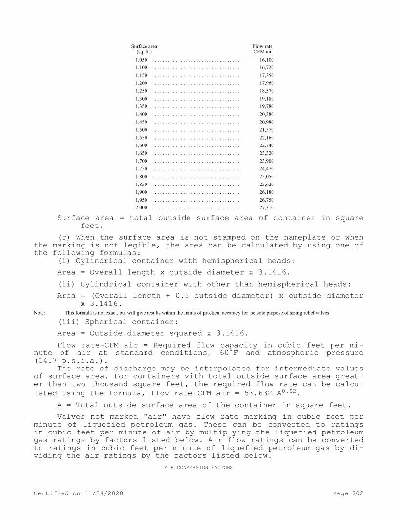
Surface area
(sq. ft.) Flow rateCFM air
1,050 . . . . . . . . . . . . . . . . . . . . . . . . . . . . . . . . . 16,1001,100 . . . . . . . . . . . . . . . . . . . . . . . . . . . . . . . . . 16,7201,150 . . . . . . . . . . . . . . . . . . . . . . . . . . . . . . . . . 17,3501,200 . . . . . . . . . . . . . . . . . . . . . . . . . . . . . . . . . 17,9601,250 . . . . . . . . . . . . . . . . . . . . . . . . . . . . . . . . . 18,5701,300 . . . . . . . . . . . . . . . . . . . . . . . . . . . . . . . . . 19,1801,350 . . . . . . . . . . . . . . . . . . . . . . . . . . . . . . . . . 19,7801,400 . . . . . . . . . . . . . . . . . . . . . . . . . . . . . . . . . 20,3801,450 . . . . . . . . . . . . . . . . . . . . . . . . . . . . . . . . . 20,9801,500 . . . . . . . . . . . . . . . . . . . . . . . . . . . . . . . . . 21,5701,550 . . . . . . . . . . . . . . . . . . . . . . . . . . . . . . . . . 22,1601,600 . . . . . . . . . . . . . . . . . . . . . . . . . . . . . . . . . 22,7401,650 . . . . . . . . . . . . . . . . . . . . . . . . . . . . . . . . . 23,3201,700 . . . . . . . . . . . . . . . . . . . . . . . . . . . . . . . . . 23,9001,750 . . . . . . . . . . . . . . . . . . . . . . . . . . . . . . . . . 24,4701,800 . . . . . . . . . . . . . . . . . . . . . . . . . . . . . . . . . 25,0501,850 . . . . . . . . . . . . . . . . . . . . . . . . . . . . . . . . . 25,6201,900 . . . . . . . . . . . . . . . . . . . . . . . . . . . . . . . . . 26,1801,950 . . . . . . . . . . . . . . . . . . . . . . . . . . . . . . . . . 26,7502,000 . . . . . . . . . . . . . . . . . . . . . . . . . . . . . . . . . 27,310
Surface area = total outside surface area of container in square feet.
(c) When the surface area is not stamped on the nameplate or when the marking is not legible, the area can be calculated by using one of the following formulas:
(i) Cylindrical container with hemispherical heads:Area = Overall length x outside diameter x 3.1416.(ii) Cylindrical container with other than hemispherical heads:Area = (Overall length + 0.3 outside diameter) x outside diameter
x 3.1416.Note: This formula is not exact, but will give results within the limits of practical accuracy for the sole purpose of sizing relief valves.
(iii) Spherical container:Area = Outside diameter squared x 3.1416.Flow rate-CFM air = Required flow capacity in cubic feet per mi-
nute of air at standard conditions, 60°F and atmospheric pressure (14.7 p.s.i.a.).
The rate of discharge may be interpolated for intermediate values of surface area. For containers with total outside surface area great-er than two thousand square feet, the required flow rate can be calcu-lated using the formula, flow rate-CFM air = 53.632 A0.82.
A = Total outside surface area of the container in square feet.Valves not marked "air" have flow rate marking in cubic feet per
minute of liquefied petroleum gas. These can be converted to ratings in cubic feet per minute of air by multiplying the liquefied petroleum gas ratings by factors listed below. Air flow ratings can be converted to ratings in cubic feet per minute of liquefied petroleum gas by di-viding the air ratings by the factors listed below.
AIR CONVERSION FACTORS
Certified on 11/24/2020 Page 202

Container type. . . . . . . . . . 100 125 150 175 200Air conversion factor. . . . 1.162 1.142 1.113 1.078 1.010
(d) Minimum required rate of discharge for safety relief valves for liquefied petroleum gas vaporizers (steam heated, water heated, and direct fired).
You must determine the minimum required rate of discharge for safety relief valves as follows:
(i) Obtain the total surface area by adding the surface area of vaporizer shell in square feet directly in contact with LP-gas and the heat exchanged surface area in square feet directly in contact with LP-gas.
(ii) Obtain the minimum required rate of discharge in cubic feet of air per minute, at 60°F and 14.7 p.s.i.a. from (b) of this subsec-tion, for this total surface area.
(e) You must set container and vaporizer safety relief valves to start-to-discharge, with relation to the design pressure of the con-tainer, in accordance with Table H-26.
TABLE H-26
ContainersMinimum
(%) Maximum
(%)ASME Code; Par. U-68, U-69— 1949 and earlier editions . . . . . . . . 110
1125ASME Code; Par. U-200, U-201— 1949 edition . . . . . . . . 88
1100ASME Code—1950, 1952, 1956, 1959, 1962, 1965 and 1968 (Division I) editions . . . . . . . . 88
1100API—ASME Code— all editions . . . . . . . . 88
1100
DOT—As prescribed in 49 C.F.R. Chapter I
1 Manufacturers of safety relief valves are allowed a plus tolerance not exceeding 10% of the set pressure marked on the valve.
(f) Safety relief devices used with systems employing containers other than those constructed according to DOT specifications must be so constructed as to discharge at not less than the rates shown in (b) of this subsection, before the pressure is in excess of 120% of the maximum (not including the 10% referred to in (e) of this subsection) permitted start to discharge pressure setting of the device.
(g) In certain locations sufficiently sustained high temperatures prevail which require the use of a lower vapor pressure product to be stored or the use of a higher designed pressure vessel in order to prevent the safety valves opening as the result of these temperatures. As an alternative the tanks may be protected by cooling devices such as by spraying, by shading, or other effective means.
(h) You must arrange safety relief valves so that the possibility of tampering will be minimized. If pressure setting or adjustment is external, you must provide the relief valves with approved means for sealing adjustment.
(i) You must not install shutoff valves between the safety relief devices and the container, or the equipment or piping to which the safety relief device is connected except that a shutoff valve may be
Certified on 11/24/2020 Page 203
used where the arrangement of this valve is such that full required capacity flow through the safety relief device is always afforded.
(j) Safety relief valves must have direct communication with the vapor space of the container at all times.
(k) You must plainly and permanently mark each container safety relief valve used with systems covered by WAC 296-24-47509, 296-24-47511, and 296-24-47517, except as provided in WAC 296-24-47511 (3)(c) with the following: "Container type" of the pressure vessel on which the valve is designed to be installed; the pressure in p.s.i.g. at which the valve is set to discharge; the actual rate of discharge of the valve in cubic feet per minute of air at 60°F and 14.7 p.s.i.a.; and the manufacturer's name and catalog number, for example: T200-250-4050 AIR—indicating that the valve is suitable for use on a Type 200 container, that it is set to start to discharge at 250 p.s.i.g.; and that its rate of discharge is four thousand fifty cubic feet per minute of air as determined in (b) of this subsection.
(l) Safety relief valve assemblies, including their connections, must be of sufficient size so as to provide the rate of flow required for the container on which they are installed.
(m) You must install a hydrostatic relief valve between each pair of shutoff valves on liquefied petroleum gas liquid piping so as to relieve into a safe atmosphere. The start-to-discharge pressure set-ting of such relief valves must not be in excess of 500 p.s.i.g. The minimum setting on relief valves installed in piping connected to oth-er than DOT containers must not be lower than 140% of the container relief valve setting and in piping connected to DOT containers not lower than 400 p.s.i.g. Such a relief valve should not be installed in the pump discharge piping if the same protection can be provided by installing the relief valve in the suction piping. The start-to-dis-charge pressure setting of such a relief valve, if installed on the discharge side of a pump, must be greater than the maximum pressure permitted by the recirculation device in the system.
(n) The discharge from any safety relief device must not termi-nate in or beneath any building, except relief devices covered by sub-section (6)(a)(i) through (vi) of this section, or WAC 296-24-47507 (4)(a) or (5).
(o) You must not locate container safety relief devices and regu-lator relief vents less than 5 feet in any direction from air openings into sealed combustion system appliances or mechanical ventilation air intakes.
(11) Vaporizer and housing.(a) You must construct and install indirect fired vaporizers uti-
lizing steam, water, or other heating medium as follows:(i) You must construct vaporizers in accordance with the require-
ments of subsection (3)(a) through (c) of this section and you must permanently mark them as follows:
(A) With the code marking signifying the specifications to which the vaporizer is constructed.
(B) With the allowable working pressure and temperature for which the vaporizer is designed.
(C) With the sum of the outside surface area and the inside heat exchange surface area expressed in square feet.
(D) With the name or symbol of the manufacturer.(ii) Vaporizers having an inside diameter of six inches or less
exempted by the ASME Unfired Pressure Vessel Code, Section VIII of the
Certified on 11/24/2020 Page 204

ASME Boiler and Pressure Vessel Code—1968 must have a design pressure not less than 250 p.s.i.g. and need not be permanently marked.
(iii) You must not install heating or cooling coils inside a storage container.
(iv) Vaporizers may be installed in buildings, rooms, sheds, or lean-tos used exclusively for gas manufacturing or distribution, or in other structures of light, noncombustible construction or equivalent, well ventilated near the floor line and roof.
When vaporizing and/or mixing equipment is located in a structure or building not used exclusively for gas manufacturing or distribu-tion, either attached to or within such a building, you must separate such structure or room from the remainder of the building by a wall designed to withstand a static pressure of at least one hundred pounds per square foot. This wall must have no openings or pipe or conduit passing through it. You must provide such structure or room with ade-quate ventilation and it must have a roof or at least one exterior wall of lightweight construction.
(v) Vaporizers must have, at or near the discharge, a safety re-lief valve providing an effective rate of discharge in accordance with subsection (10)(d) of this section, except as provided in WAC 296-24-47509 (4)(e)(i).
(vi) You must provide the heating medium lines into and leaving the vaporizer with suitable means for preventing the flow of gas into the heat systems in the event of tube rupture in the vaporizer. You must provide vaporizers with suitable automatic means to prevent liq-uid passing through the vaporizers to the gas discharge piping.
(vii) The device that supplies the necessary heat for producing steam, hot water, or other heating medium may be installed in a build-ing, compartment, room, or lean-to which must be ventilated near the floorline and roof to the outside. You must separate the device loca-tion from all compartments or rooms containing liquefied petroleum gas vaporizers, pumps, and central gas mixing devices by a wall designed to withstand a static pressure of at least one hundred pounds per square foot. This wall must have no openings or pipes or conduit pass-ing through it. This requirement does not apply to the domestic water heaters which may supply heat for a vaporizer in a domestic system.
(viii) You must equip gas-fired heating systems supplying heat exclusively for vaporization purposes with automatic safety devices to shut off the flow of gas to main burners, if the pilot light should fail.
(ix) Vaporizers may be an integral part of a fuel storage con-tainer directly connected to the liquid section or gas section or both.
(x) You must not equip vaporizers with fusible plugs.(xi) Vaporizer houses must not have unprotected drains to sewers
or sump pits.(b) You must install atmospheric vaporizers employing heat from
the ground or surrounding air as follows:(i) Buried underground, or(ii) Located inside the building close to a point at which pipe
enters the building provided the capacity of the unit does not exceed one quart.
(iii) Vaporizers of less than one quart capacity heated by the ground or surrounding air, need not be equipped with safety relief valves provided that adequate tests demonstrate that the assembly is safe without safety relief valves.
Certified on 11/24/2020 Page 205

(c) You must construct, mark, and install direct gas-fired vapor-izers as follows:
(i) In accordance with the requirements of the American Society of Mechanical Engineers Boiler and Pressure Vessel Code—1968 that are applicable to the maximum working conditions for which the vaporizer is designed.
(ii) With the name of the manufacturer; rated BTU input to the burner; the area of the heat exchange surface in square feet; the out-side surface of the vaporizer in square feet; and the maximum vaporiz-ing capacity in gallons per hour.
(iii) Vaporizers may be connected to the liquid section or the gas section of the storage container, or both; but in any case there must be at the container a manually operated valve in each connection to permit completely shutting off when desired, of all flow of gas or liquid from container to vaporizer.
(iv) You must locate vaporizers with capacity not exceeding 35 gallons per hour at least 5 feet from container shutoff valves. You must locate vaporizers having capacity of more than 35 gallons but not exceeding 100 gallons per hour at least 10 feet from the container shutoff valves. You must locate vaporizers having a capacity greater than 100 gallons per hour at least 15 feet from container shutoff valves.
(v) Vaporizers may be installed in buildings, rooms, housings, sheds, or lean-tos used exclusively for vaporizing or mixing of lique-fied petroleum gas. Vaporizing housing structures must be of noncom-bustible construction, well ventilated near the floorline and the highest point of the roof. When vaporizer and/or mixing equipment is located in a structure or room attached to or within a building, you must separate such structure or room from the remainder of the build-ing by a wall designed to withstand a static pressure of at least one hundred pounds per square foot. This wall must have no openings or pipes or conduit passing through it. You must provide such structure or room with adequate ventilation, and it must have a roof or at least one exterior wall of lightweight construction.
(vi) Vaporizers must have at or near the discharge, a safety re-lief valve providing an effective rate of discharge in accordance with subsection (10)(d) of this section. You must locate the relief valve so as not to be subjected to temperatures in excess of 140°F.
(vii) You must provide vaporizers with suitable automatic means to prevent liquid passing from the vaporizer to the gas discharge pip-ing of the vaporizer.
(viii) You must provide vaporizers with means for manually turn-ing off the gas to the main burner and pilot.
(ix) You must equip vaporizers with automatic safety devices to shut off the flow of gas to main burners if the pilot light should fail. When the flow through the pilot exceeds 2,000 B.T.U. per hour, you must also equip the pilot with an automatic safety device to shut off the flow of gas to the pilot should the pilot flame be extinguish-ed.
(x) You must separate pressure regulating and pressure reducing equipment if located within 10 feet of a direct fired vaporizer from the open flame by a substantially airtight noncombustible partition or partitions.
(xi) Except as provided in (c)(v) of this subsection, you must maintain the following minimum distances between direct fired vaporiz-
Certified on 11/24/2020 Page 206

ers and the nearest important building or group of buildings or line of adjoining property which may be built upon:
(A) 10 feet for vaporizers having a capacity of 15 gallons per hour or less vaporizing capacity.
(B) 25 feet for vaporizers having a vaporizing capacity of 16 to 100 gallons per hour.
(C) 50 feet for vaporizers having a vaporizing capacity exceeding 100 gallons per hour.
(xii) Direct fired vaporizers must not raise the product pressure above the design pressure of the vaporizer equipment nor must they raise the product pressure within the storage container above the pressure shown in the second column of Table H-31. (See WAC 296-24-47509.)
(xiii) You must not provide vaporizers with fusible plugs.(xiv) Vaporizers must not have unprotected drains to sewers or
sump pits.(d) You must construct and install direct gas-fired tank heaters,
as follows:(i) You must only install direct gas-fired tank heaters, and
tanks to which they are applied, above ground.(ii) You must permanently mark tank heaters with the name of the
manufacturer, the rated B.T.U. input to the burner, and the maximum vaporizing capacity in gallons per hour.Note: Tank heaters may be an integral part of a fuel storage container directly connected to the container liquid section, or vapor section, or both.
(iii) You must provide tank heaters with a means for manually turning off the gas to the main burner and pilot.
(iv) You must equip tank heaters with an automatic safety device to shut off the flow of gas to main burners, if the pilot light should fail. When flow through pilot exceeds 2,000 B.T.U. per hour, you must also equip the pilot with an automatic safety device to shut off the flow of gas to the pilot should the pilot flame be extinguished.
(v) You must separate pressure regulating and pressure reducing equipment if located within 10 feet of a direct fired tank heater from the open flame by a substantially airtight noncombustible partition.
(vi) You must maintain the following minimum distances between a storage tank heated by a direct fired tank heater and the nearest im-portant building or group of buildings or line of adjoining property which may be built upon:
(A) 10 feet for storage containers of less than 500 gallons water capacity.
(B) 25 feet for storage containers of 500 to 1,200 gallons water capacity.
(C) 50 feet for storage containers of over 1,200 gallons water capacity.
(vii) No direct fired tank heater must raise the product pressure within the storage container over 75% of the pressure set out in the second column of Table H-31. (See WAC 296-24-47509.)
(e) You must locate the vaporizer section of vaporizer-burners used for dehydrators or dryers outside of buildings; they must be con-structed and installed as follows:
(i) Vaporizer-burners must have a minimum design pressure of 250 p.s.i.g. with a factor of safety of 5.
(ii) Manually operated positive shutoff valves must be located at the containers to shut off all flow to the vaporizer-burners.
(iii) Minimum distances between storage containers and vaporizer-burners must be as follows:
Certified on 11/24/2020 Page 207
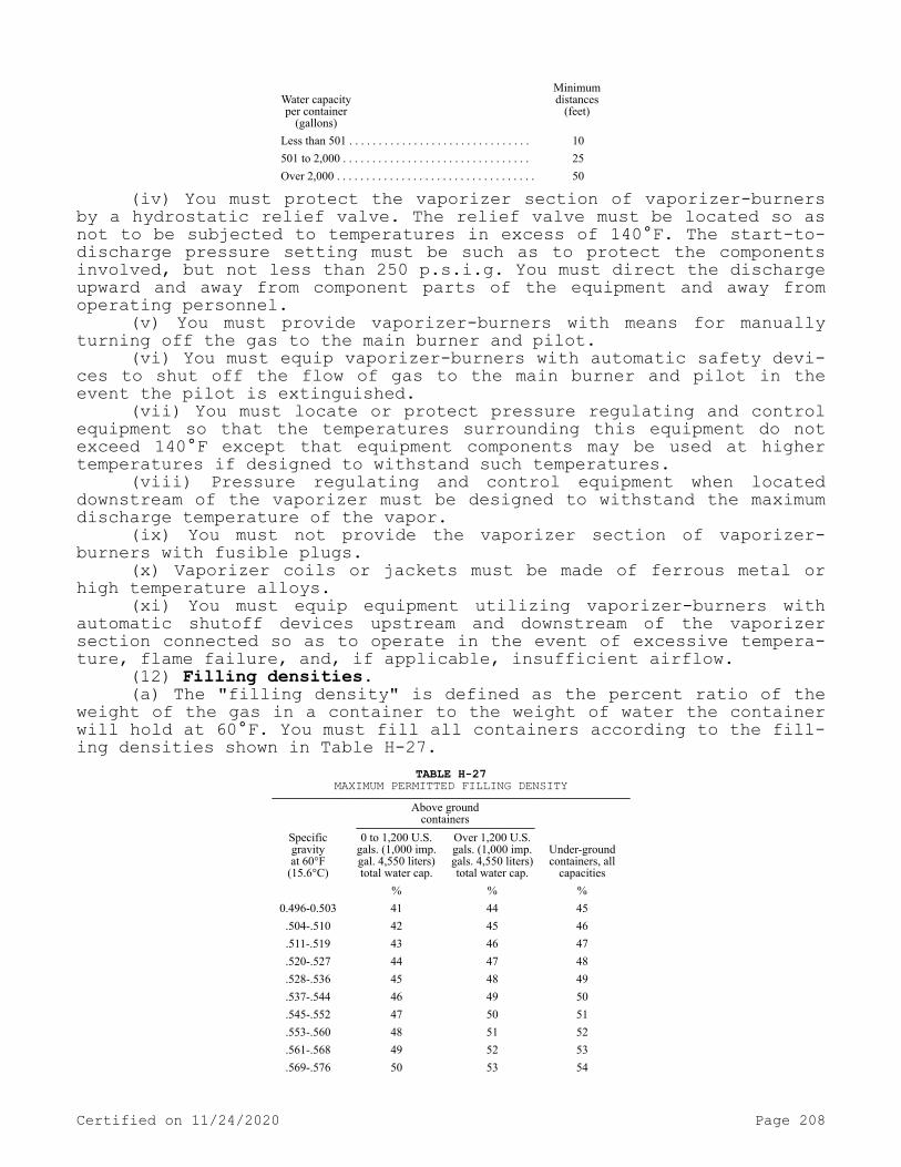
Water capacityper container
(gallons)
Minimumdistances
(feet)
Less than 501 . . . . . . . . . . . . . . . . . . . . . . . . . . . . . . . 10 501 to 2,000 . . . . . . . . . . . . . . . . . . . . . . . . . . . . . . . . 25 Over 2,000 . . . . . . . . . . . . . . . . . . . . . . . . . . . . . . . . . . 50
(iv) You must protect the vaporizer section of vaporizer-burners by a hydrostatic relief valve. The relief valve must be located so as not to be subjected to temperatures in excess of 140°F. The start-to-discharge pressure setting must be such as to protect the components involved, but not less than 250 p.s.i.g. You must direct the discharge upward and away from component parts of the equipment and away from operating personnel.
(v) You must provide vaporizer-burners with means for manually turning off the gas to the main burner and pilot.
(vi) You must equip vaporizer-burners with automatic safety devi-ces to shut off the flow of gas to the main burner and pilot in the event the pilot is extinguished.
(vii) You must locate or protect pressure regulating and control equipment so that the temperatures surrounding this equipment do not exceed 140°F except that equipment components may be used at higher temperatures if designed to withstand such temperatures.
(viii) Pressure regulating and control equipment when located downstream of the vaporizer must be designed to withstand the maximum discharge temperature of the vapor.
(ix) You must not provide the vaporizer section of vaporizer-burners with fusible plugs.
(x) Vaporizer coils or jackets must be made of ferrous metal or high temperature alloys.
(xi) You must equip equipment utilizing vaporizer-burners with automatic shutoff devices upstream and downstream of the vaporizer section connected so as to operate in the event of excessive tempera-ture, flame failure, and, if applicable, insufficient airflow.
(12) Filling densities.(a) The "filling density" is defined as the percent ratio of the
weight of the gas in a container to the weight of water the container will hold at 60°F. You must fill all containers according to the fill-ing densities shown in Table H-27.
TABLE H-27MAXIMUM PERMITTED FILLING DENSITY
Above groundcontainers
Specificgravityat 60°F
(15.6°C)
0 to 1,200 U.S. gals. (1,000 imp. gal. 4,550 liters) total water cap.
Over 1,200 U.S. gals. (1,000 imp. gals. 4,550 liters) total water cap.
Under-groundcontainers, all
capacities
% % % 0.496-0.503 41 44 45 .504-.510 42 45 46 .511-.519 43 46 47 .520-.527 44 47 48 .528-.536 45 48 49 .537-.544 46 49 50 .545-.552 47 50 51 .553-.560 48 51 52 .561-.568 49 52 53 .569-.576 50 53 54
Certified on 11/24/2020 Page 208

Above groundcontainers
Specificgravityat 60°F
(15.6°C)
0 to 1,200 U.S. gals. (1,000 imp. gal. 4,550 liters) total water cap.
Over 1,200 U.S. gals. (1,000 imp. gals. 4,550 liters) total water cap.
Under-groundcontainers, all
capacities
.577-.584 51 54 55 .585-.592 52 55 56 .593-.600 53 56 57
(b) Except as provided in (c) of this subsection, you must charge any container including mobile cargo tanks and portable tank contain-ers regardless of size or construction, shipped under DOT jurisdiction or constructed in accordance with 49 C.F.R. Chapter I specifications according to 49 C.F.R. Chapter I requirements.
(c) Portable containers not subject to DOT jurisdiction (such as, but not limited to, motor fuel containers on industrial and lift trucks, and farm tractors covered in subsection (5) of this section, or containers recharged at the installation) may be filled either by weight, or by volume using a fixed length dip tube gaging device.
(13) LP-gas in buildings.(a) You must pipe vapor into buildings at pressures in excess of
20 p.s.i.g. only if the buildings or separate areas thereof,(i) Are constructed in accordance with this section;(ii) Are used exclusively to house equipment for vaporization,
pressure reduction, gas mixing, gas manufacturing, or distribution, or to house internal combustion engines, industrial processes, research and experimental laboratories, or equipment and processes using such gas and having similar hazard;
(iii) Buildings, structures, or equipment under construction or undergoing major renovation.
(b) Liquid may be permitted in buildings as follows:(i) Buildings, or separate areas of buildings, used exclusively
to house equipment for vaporization, pressure reduction, gas mixing, gas manufacturing, or distribution, or to house internal combustion engines, industrial processes, research and experimental laboratories, or equipment and processes using such gas and having similar hazard; and when such buildings, or separate areas thereof are constructed in accordance with this section.
(ii) Buildings, structures, or equipment under construction or undergoing major renovation provided the temporary piping meets the following conditions:
(A) Liquid piping inside the building must conform to the re-quirements of subsection (8) of this section, and must not exceed 3/4 iron pipe size. Copper tubing with an outside diameter of 3/4 inch or less may be used provided it conforms to Type K of Specifications for Seamless Water Tube, ANSI H23.1-1970 (ASTM B88-1969) (see WAC 296-24-47505 Table H-24). You must protect all such piping against construction hazards. You must keep liquid piping inside buildings to a minimum. You must securely fasten such piping to walls or other sur-faces so as to provide adequate protection from breakage and so loca-ted as to subject the liquid line to lowest ambient temperatures.
(B) You must install a shutoff valve in each intermediate branch line where it takes off the main line and it must be readily accessi-ble. You must also place a shutoff valve at the appliance end of the intermediate branch line. Such shutoff valve must be upstream of any flexible connector used with the appliance.
Certified on 11/24/2020 Page 209

(C) You must install suitable excess flow valves in the container outlet line supplying liquid LP-gas to the building. You must install a suitable excess flow valve immediately downstream of each shutoff valve. You must install suitable excess flow valves where piping size is reduced and it must be sized for the reduced size piping.
(D) You must install hydrostatic relief valves in accordance with subsection (10)(m) of this section.
(E) You must prohibit the use of hose to carry liquid between the container and the building or at any point in the liquid line, except at the appliance connector.
(F) Where flexible connectors are necessary for appliance instal-lation, such connectors must be as short as practicable and must com-ply with subsection (8)(b) or (9) of this section.
(G) You must minimize release of fuel when any section of piping or appliances is disconnected by either of the following methods:
(I) Using an approved automatic quick-closing coupling (a type closing in both directions when coupled in the fuel line), or
(II) Closing the valve nearest to the appliance and allowing the appliance to operate until the fuel in the line is consumed.
(III) You must not take portable containers into buildings except as provided in subsection (6)(a) of this section.
(14) Transfer of liquids. You must ensure that:(a) At least one attendant must remain close to the transfer con-
nection from the time the connections are first made until they are finally disconnected, during the transfer of the product.
(b) You must fill or use containers only upon authorization of the owner.
(c) You must not refill or reuse containers manufactured in ac-cordance with specifications of 49 C.F.R. Part 178 and authorized by 49 C.F.R. Chapter 1 as a "single trip" or "nonrefillable container" in LP-gas service.
(d) Gas or liquid must not be vented to the atmosphere to assist in transferring contents of one container to another, except as provi-ded in WAC 296-24-47511 (5)(d) and except that this must not preclude the use of listed pump utilizing LP-gas in the vapor phase as a source of energy and venting such gas to the atmosphere at a rate not to ex-ceed that from a No. 31 drill size opening and provided that such venting and liquid transfer must be located not less than 50 feet from the nearest important building.
(e) Filling of fuel containers for industrial trucks or motor ve-hicles from industrial bulk storage containers must be performed not less than 10 feet from the nearest important masonry-walled building or not less than 25 feet from the nearest important building or other construction and, in any event, not less than 25 feet from any build-ing opening.
(f) You must perform filling of portable containers, containers mounted on skids, fuel containers on farm tractors, or similar appli-cations, from storage containers used in domestic or commercial serv-ice, not less than 50 feet from the nearest important building.
(g) The filling connection and the vent from the liquid level ga-ges in containers, filled at point of installation, must not be less than 10 feet in any direction from air openings into sealed combustion system appliances or mechanical ventilation air intakes.
(h) You must gauge and charge fuel supply containers only in the open air or in buildings especially provided for that purpose.
(i) The maximum vapor pressure of the product at 100°F which may be transferred into a container must be in accordance with WAC
Certified on 11/24/2020 Page 210

296-24-47509(2) and 296-24-47511(3). (For DOT containers use DOT re-quirements.)
(j) Marketers and users must exercise precaution to assure that only those gases for which the system is designed, examined, and lis-ted, are employed in its operation, particularly with regard to pres-sures.
(k) Pumps or compressors must be designed for use with LP-gas. When compressors are used they must normally take suction from the va-por space of the container being filled and discharge to the vapor space of the container being emptied.
(l) Pumping systems, when equipped with a positive displacement pump, must include a recirculating device which must limit the differ-ential pressure on the pump under normal operating conditions to the maximum differential pressure rating of the pump. You must protect the discharge of the pumping system so that pressure does not exceed 350 p.s.i.g. If a recirculation system discharges into the supply tank and contains a manual shutoff valve, you must incorporate an adequate sec-ondary safety recirculation system which has no means of rendering it inoperative. You must keep manual shutoff valves in recirculation sys-tems open except during an emergency or when repairs are being made to the system.
(m) When necessary, you must provide unloading piping or hoses with suitable bleeder valves for relieving pressure before disconnec-tion.
(n) You must shut down agricultural air moving equipment, includ-ing crop dryers, when supply containers are being filled unless the air intakes and sources of ignition on the equipment are located fifty feet or more from the container.
(o) You must shut down agricultural equipment employing open flames or equipment with integral containers, such as flame cultiva-tors, weed burners, and, in addition, tractors, during refueling.
(15) Tank car or transport truck loading or unloading points and operations.
(a) The track of tank car siding must be relatively level.(b) You must install a "tank car connected" sign, as covered by
DOT rules, at the active end or ends of the siding while the tank car is connected.
(c) While cars are on side track for loading or unloading, you must block the wheels at both ends on the rails.
(d) You must ensure that an employee is in attendance at all times while the tank car, cars, or trucks are being loaded or unloa-ded.
(e) You must install a backflow check valve, excess-flow valve, or a shutoff valve with means of remote closing, to protect against uncontrolled discharge of LP-gas from storage tank piping close to the point where the liquid piping and hose or swing joint pipe is connec-ted.
(f) Where practical, the distance of the unloading or loading point must conform to the distances in subsection (6)(b) of this sec-tion.
(16) Instructions. You must properly train personnel performing installation, removal, operation, and maintenance work in such func-tion.
(17) Electrical equipment and other sources of ignition.(a) Electrical equipment and wiring must be of a type specified
by and you must install it according to chapter 296-24 WAC Part L, for
Certified on 11/24/2020 Page 211

ordinary locations except that fixed electrical equipment in classi-fied areas must comply with subsection (18) of this section.
(b) You must not permit open flames or other sources of ignition in vaporizer rooms (except those housing direct-fired vaporizers), pumphouses, container charging rooms or other similar locations. Di-rect-fired vaporizers shall not be permitted in pumphouses or contain-er charging rooms.Note: Liquefied petroleum gas storage containers do not require lightning protection. Since liquefied petroleum gas is contained in a closed system of
piping and equipment, the system need not be electrically conductive or electrically bonded for protection against static electricity (see NFPA No. 77-1972-1973, Recommended Practice for Static Electricity).
(c) You must not open flames (except as provided for in (b) of this subsection), cutting or welding, portable electric tools, and ex-tension lights capable of igniting LP-gas, within classified areas specified in Table H-28 of this section unless the LP-gas facilities have been freed of all liquid and vapor, or special precautions ob-served under carefully controlled conditions.
(18) Fixed electrical equipment in classified areas. Fixed elec-trical equipment and wiring installed within classified areas must comply with Table H-28 of this section and must be installed according to chapter 296-24 WAC Part L. This provision does not apply to fixed electrical equipment at residential or commercial installations of LP-gas systems or to systems covered by WAC 296-24-47511.
(19) Liquid-level gaging device.(a) You must equip each container manufactured after December 31,
1965, and filled on a volumetric basis with a fixed liquid-level gage to indicate the maximum permitted filling level as provided in (e) of this subsection. Each container manufactured after December 31, 1969, must have permanently attached to the container adjacent to the fixed level gage a marking showing the percentage full that will be shown by that gage. When a variable liquid-level gage is also provided, the fixed liquid-level gage will also serve as a means for checking the variable gage. You must use these gages in charging containers as re-quired in subsection (12) of this section.
(b) You must arrange all variable gauging devices so that the maximum liquid level for butane, for a 50/50 mixture of butane and propane, and for propane, to which the container may be charged is readily determinable. The markings indicating the various liquid lev-els from empty to full must be on the system nameplate or gauging de-vice or part may be on the system nameplate and part on the gauging device. Dials of magnetic or rotary gauges must show whether they are for cylindrical or spherical containers and whether for aboveground or underground service. You must mark the dials of gauges intended for use only on aboveground containers of over 1,200 gallons water capaci-ty.
(c) Gauging devices that require bleeding of the product to the atmosphere, such as the rotary tube, fixed tube, and slip tube, must be designed so that the bleed valve maximum opening is not larger than a No. 54 drill size, unless provided with excess flow valve.
(d) Gauging devices must have a design working pressure of at least 250 p.s.i.g.
(e) Length of tube or position of fixed liquid-level gauge must be designed to indicate the maximum level to which the container may be filled for the product contained. You must base this level on the volume of the product at 40°F at its maximum permitted filling density for aboveground containers and at 50°F for underground containers. You must calculate the filling point for which the fixed liquid level gage is designed according to the method in this subsection.
Certified on 11/24/2020 Page 212
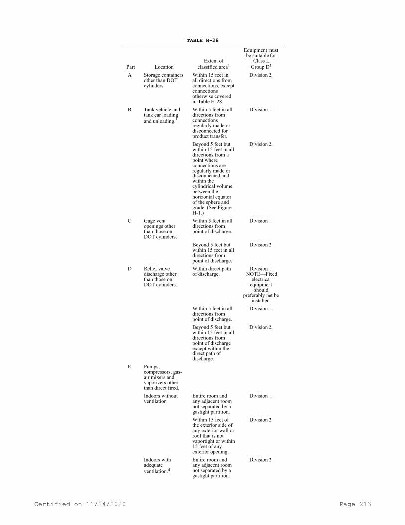
TABLE H-28
Part LocationExtent of
classified area1
Equipment mustbe suitable for
Class I,Group D2
A Storage containers other than DOT cylinders.
Within 15 feet in all directions from connections, except connections otherwise covered in Table H-28.
Division 2.
B Tank vehicle and tank car loading and unloading.3
Within 5 feet in all directions from connections regularly made or disconnected for product transfer.
Division 1.
Beyond 5 feet but within 15 feet in all directions from a point where connections are regularly made or disconnected and within the cylindrical volume between the horizontal equator of the sphere and grade. (See Figure H-1.)
Division 2.
C Gage vent openings other than those on DOT cylinders.
Within 5 feet in all directions from point of discharge.
Division 1.
Beyond 5 feet but within 15 feet in all directions from point of discharge.
Division 2.
D Relief valve discharge other than those on DOT cylinders.
Within direct path of discharge.
Division 1. NOTE—Fixed
electrical equipment
should preferably not be
installed. Within 5 feet in all
directions from point of discharge.
Division 1.
Beyond 5 feet but within 15 feet in all directions from point of discharge except within the direct path of discharge.
Division 2.
E Pumps, compressors, gas-air mixers and vaporizers other than direct fired.
Indoors without ventilation
Entire room and any adjacent room not separated by a gastight partition.
Division 1.
Within 15 feet of the exterior side of any exterior wall or roof that is not vaportight or within 15 feet of any exterior opening.
Division 2.
Indoors with adequateventilation.4
Entire room and any adjacent room not separated by a gastight partition.
Division 2.
Certified on 11/24/2020 Page 213

Part LocationExtent of
classified area1
Equipment mustbe suitable for
Class I,Group D2
Outdoors in open air at or abovegrade.
Within 15 feet in all directions from this equipment and within the cylindrical volumebetween the horizontal equator of the sphere and grade. See Figure H-1.
Division 2.
F Service station dispensing units.
Entire space within dispenser enclosure, and 18 inches horizontally from enclosure exterior up to an elevation 4 ft. above dispenser base. Entire pit or open space beneath dispenser.
Division 1.
Up to 18 inches abovegrade within 20 ft. horizontally from any edge of enclosure.
Division 2.
NOTE: For pits within this area, see Part F of this table.
G Pits or trenches containing or located beneath LP-gas valves, pumps, compressors, regulators, and similar equipment.
Without mechanical ventilation.
Entire pit or trench Division 1.
Entire room and any adjacent room not separated by a gastight partition.
Division 2.
Within 15 feet in all directions from pit or trench when located outdoors.
Division 2.
With adequate mechanical ventilation.
Entire pit or trench Division 2
Entire room and any adjacent room not separated by a gastight partition.
Division 2.
Within 15 feet in all directions from pit or trench when located outdoors.
Division 2.
H Special buildings or rooms for storage of portable containers.
Entire room Division 2.
I
Pipelines and connections containing operational bleeds, drips, vents or drains.
Within 5 ft. in all directions from point of discharge.
Division 1.
Beyond 5 ft. from point of discharge, same as Part E of this table.
Certified on 11/24/2020 Page 214

Part LocationExtent of
classified area1
Equipment mustbe suitable for
Class I,Group D2
J Container filling: Indoors without ventilation.
Entire room Division 1.
Indoors with adequate ventilation.4
Within 5 feet in all directions from connections regularly made or disconnected for product transfer.
Division 1.
Beyond 5 feet and entire room
Division 2.
Outdoors in open air
Within 5 feet in all directions from connections regularly made or disconnected for product transfer.
Division 1.
Beyond 5 feet but within 15 feet in all directions from a point where connections areregularly made or disconnected and within the cylindrical volume between thehorizontal equator of the sphere and grade (See Fig. H-1.)
Division 2.
1 The classified area must not extend beyond an unpierced wall, roof, or solid vaportight partition.
2 See chapter 296-46 WAC, and chapter 296-24 WAC Part L.3 When classifying extent of hazardous area, you must give
consideration to possible variations in the spotting of tank cars and tank vehicles at the unloading points and the effect these variations of actual spotting point may have on the point of connection.
4 Ventilation, either natural or mechanical, is considered adequate when the concentration of the gas in a gas-air mixture does not exceed 25% of the lower flammable limit under normal operating conditions.
Figure H-1Note: It is impossible to set out in a table the length of a fixed dip tube for various capacity tanks because of the varying tank diameters and lengths
and because the tank may be installed either in a vertical or horizontal position. Knowing the maximum permitted filling volume in gallons, however, the length of the fixed tube can be determined by the use of a strapping table obtained from the container manufacturer. The length of the fixed tube should be such that when its lower end touches the surface of the liquid in the container, the contents of the container will be the maximum permitted volume as determined by the following formula:
Certified on 11/24/2020 Page 215

Water capacity (gals.) of container* x filling density**
=
Maximumvolumeof LP-gasSpecific gravity of
LP-gas* x volumecorrection factor*** x 100
* Measure at 60°F.** From subsection (12)(a) of this section "filling densities."
*** For aboveground containers the liquid temperature is assumed to be 40°F and for underground containers the liquid temperature is assumed to be 50°F. To correct the liquid volumes at these temperatures to 60°F you must use the following factors.
(i) Formula for determining maximum volume of liquefied petroleum gas for which a fixed length of dip tube must be set:
TABLE H-29VOLUME CORRECTION FACTORS
Specific gravity Aboveground Underground0.500 1.033 1.017.510 1.031 1.016.520 1.029 1.015.530 1.028 1.014.540 1.026 1.013.550 1.025 1.013.560 1.024 1.012.570 1.023 1.011.580 1.021 1.011.590 1.020 1.010
(ii) The maximum volume of LP-gas which can be placed in a con-tainer when determining the length of the dip tube expressed as a per-centage of total water content of the container is calculated by the following formula.
(iii) The maximum weight of LP-gas which may be placed in a con-tainer for determining the length of a fixed dip tube is determined by multiplying the maximum volume of liquefied petroleum gas obtained by the formula in (e)(i) of this subsection by the pounds of liquefied petroleum gas in a gallon at 40°F for aboveground and at 50°F for un-derground containers. For example, typical pounds per gallon are specified below:
Example: Assume a one hundred-gallon total water capacity tank for aboveground storage of propane having a specific gravity of 0.510 of 60°F.
100 (gals.) x 42 (filling density from (12)(a) of this subsection)
=
4200
0.510 x 1.031 (correction factor from Table H-29) x 100
52.6
4200
=79.8 gallons propane, the maximumamount permitted to be placed ina 100-gallon total water capacityaboveground container equippedwith a fixed dip tube.
52.6
Maximum volume ofLP-gas (from formulain (e)(i) ofthis subsection) x 100
=
Maximum%of LP-gasTotal water content
of container ingallons.
Certified on 11/24/2020 Page 216
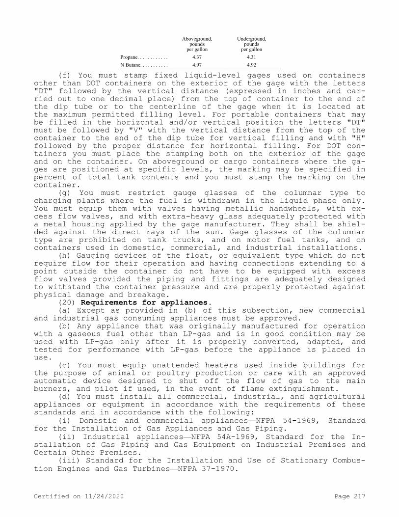
Aboveground,pounds
per gallon
Underground,pounds
per gallonPropane. . . . . . . . . . . . 4.37 4.31N Butane. . . . . . . . . . . 4.97 4.92
(f) You must stamp fixed liquid-level gages used on containers other than DOT containers on the exterior of the gage with the letters "DT" followed by the vertical distance (expressed in inches and car-ried out to one decimal place) from the top of container to the end of the dip tube or to the centerline of the gage when it is located at the maximum permitted filling level. For portable containers that may be filled in the horizontal and/or vertical position the letters "DT" must be followed by "V" with the vertical distance from the top of the container to the end of the dip tube for vertical filling and with "H" followed by the proper distance for horizontal filling. For DOT con-tainers you must place the stamping both on the exterior of the gage and on the container. On aboveground or cargo containers where the ga-ges are positioned at specific levels, the marking may be specified in percent of total tank contents and you must stamp the marking on the container.
(g) You must restrict gauge glasses of the columnar type to charging plants where the fuel is withdrawn in the liquid phase only. You must equip them with valves having metallic handwheels, with ex-cess flow valves, and with extra-heavy glass adequately protected with a metal housing applied by the gage manufacturer. They shall be shiel-ded against the direct rays of the sun. Gage glasses of the columnar type are prohibited on tank trucks, and on motor fuel tanks, and on containers used in domestic, commercial, and industrial installations.
(h) Gauging devices of the float, or equivalent type which do not require flow for their operation and having connections extending to a point outside the container do not have to be equipped with excess flow valves provided the piping and fittings are adequately designed to withstand the container pressure and are properly protected against physical damage and breakage.
(20) Requirements for appliances.(a) Except as provided in (b) of this subsection, new commercial
and industrial gas consuming appliances must be approved.(b) Any appliance that was originally manufactured for operation
with a gaseous fuel other than LP-gas and is in good condition may be used with LP-gas only after it is properly converted, adapted, and tested for performance with LP-gas before the appliance is placed in use.
(c) You must equip unattended heaters used inside buildings for the purpose of animal or poultry production or care with an approved automatic device designed to shut off the flow of gas to the main burners, and pilot if used, in the event of flame extinguishment.
(d) You must install all commercial, industrial, and agricultural appliances or equipment in accordance with the requirements of these standards and in accordance with the following:
(i) Domestic and commercial appliances—NFPA 54-1969, Standard for the Installation of Gas Appliances and Gas Piping.
(ii) Industrial appliances—NFPA 54A-1969, Standard for the In-stallation of Gas Piping and Gas Equipment on Industrial Premises and Certain Other Premises.
(iii) Standard for the Installation and Use of Stationary Combus-tion Engines and Gas Turbines—NFPA 37-1970.
Certified on 11/24/2020 Page 217

(iv) Standard for the Installation of Equipment for the Removal of Smoke and Grease-Laden Vapors from Commercial Cooking Equipment, NFPA 96-1970.[Statutory Authority: RCW 49.17.010, 49.17.040, 49.17.050, and 49.17.060. WSR 17-02-066, § 296-24-47505, filed 1/3/17, effective 2/3/17; WSR 15-24-100, § 296-24-47505, filed 12/1/15, effective 1/5/16. Statutory Authority: RCW 49.17.010, [49.17].040 and [49.17].050. WSR 99-17-094, § 296-24-47505, filed 8/17/99, effective 12/1/99. Statutory Authority: Chapter 49.17 RCW. WSR 91-24-017 (Order 91-07), § 296-24-47505, filed 11/22/91, effective 12/24/91; WSR 88-23-054 (Order 88-25), § 296-24-47505, filed 11/14/88. Statutory Au-thority: RCW 49.17.040 and 49.17.050. WSR 85-10-004 (Order 85-09), § 296-24-47505, filed 4/19/85; Order 76-6, § 296-24-47505, filed 3/1/76; Order 73-5, § 296-24-47505, filed 5/9/73 and Order 73-4, § 296-24-47505, filed 5/7/73.]
WAC 296-24-47507 Cylinder systems. (1) Application. This sec-tion applies specifically to systems utilizing containers constructed in accordance with DOT specifications. All requirements of WAC 296-24-47505 apply to this section unless otherwise noted in WAC 296-24-47505.
(2) Marking of containers. You must mark containers in accordance with DOT regulations. Additional markings not in conflict with DOT regulations may be used.
(3) Description of a system. A system must include the container base or bracket, containers, container valves, connectors, manifold valve assembly, regulators, and relief valves.
(4) Containers and regulating equipment installed outside of buildings or structures.
(a) You must not bury containers below ground. However, this must not prohibit the installation in a compartment or recess below grade level, such as a niche in a slope or terrace wall which is used for no other purpose, providing that the container and regulating equipment are not in contact with the ground and the compartment or recess is drained and ventilated horizontally to the outside air from its lowest level, with the outlet at least three feet away from any building opening which is below the level of such outlet.
Except as provided in WAC 296-24-47505 (10)(n), you must not lo-cate the discharge from safety relief devices less than 3 feet hori-zontally away from any building opening which is below the level of such discharge and it must not terminate beneath any building unless such space is well ventilated to the outside and is not enclosed on more than two sides.
(b) You must set containers upon firm foundation or otherwise firmly secured; you must guard the possible effect on the outlet pip-ing of settling against by a flexible connection or special fitting.
(5) Containers and equipment used inside of buildings or struc-tures.
(a) When operational requirements make portable use of containers necessary and their location outside of buildings or structures is im-practicable, containers and equipment are permitted to be used inside of buildings or structures in accordance with (a)(i) through (xii) of this subsection, and, in addition, such other provisions of this sec-tion as are applicable to the particular use or occupancy.
(i) Containers in use means connected for use.
Certified on 11/24/2020 Page 218

(ii) You must equip systems utilizing containers having a water capacity greater than two and one-half pounds (nominal one pound LP-gas capacity) with excess flow valves. Such excess flow valves must be either integral with the container valves or in the connections to the container valve outlets. In either case, you must install an excess flow valve in such a manner that any undue strain beyond the excess flow valve will not cause breakage between the container and the ex-cess flow valve. You must take into account the type of valve protec-tion provided during the installation of excess flow valves.
(iii) Regulators, if used, must be either directly connected to the container valves or to manifolds connected to the container valves. The regulator must be suitable for use with LP-gas. Manifolds and fittings connecting containers to pressure regulator inlets must be designed for at least 250 p.s.i.g. service pressure.
(iv) Valves on containers having a water capacity greater than 50 pounds (nominal 20 pounds LP-gas capacity) must be protected while in use.
(v) You must mark containers in accordance with WAC 296-24-47505 (5)(c) and subsection (2) of this section.
(vi) Pipe or tubing must conform to WAC 296-24-47505(8) except that you must not use aluminum pipe or tubing.
(vii) Hose must be designed for a working pressure of at least 250 p.s.i.g. Hose and hose connections must have their correctness as to design, construction and performance determined by listing by a na-tionally recognized testing laboratory.
(A) The hose length may exceed the length specified in WAC 296-24-47505 (9)(g)(ii), but must be as short as practicable. Refer to federal regulation 29 C.F.R. 1910.7 for definition of nationally rec-ognized testing laboratory.
(B) Hose must be long enough to permit compliance with spacing provisions of this section without kinking or straining or causing hose to be so close to a burner as to be damaged by heat.
(viii) You must equip portable heaters, including salamanders, with an approved automatic device to shut off the flow of gas to the main burner, and pilot if used, in the event of flame extinguishment. You must equip such heaters having inputs above 50,000 B.t.u. manufac-tured on or after May 17, 1967, and such heaters having inputs above 100,000 B.t.u. manufactured before May 17, 1967, with either:
(A) A pilot which must be lighted and proved before the main burner can be turned on; or
(B) An electric ignition system. The provisions of (a)(viii) of this subsection do not apply to tar kettle burners, torches, melting pots, nor do they apply to portable heaters under 7,500 B.t.u.h. input when used with containers having a maximum water capacity of two and one-half pounds. You must not use container valves, connectors, regu-lators, manifolds, piping, and tubing as structural supports for heat-ers.
(ix) You must locate containers, regulating equipment, manifolds, pipe, tubing, and hose so as to minimize exposure to abnormally high temperatures (such as may result from exposure to convection or radia-tion from heating equipment or installation in confined spaces), phys-ical damage, or tampering by unauthorized persons.
(x) You must locate and use heat producing equipment so as to minimize the possibility of ignition of combustibles.
(xi) Containers having water capacity greater than two and one-half pounds (nominal one pound LP-gas capacity) connected for use,
Certified on 11/24/2020 Page 219

must stand on a firm and substantially level surface and, when neces-sary, you must secure it in an upright position.
(xii) You must install containers, including the valve protective devices, so as to minimize the probability of impingement of discharge of safety relief devices upon containers.
(b) Containers having a maximum water capacity of two and one-half pounds (nominal one pound LP-gas capacity) are permitted to be used inside of buildings as part of approved self-contained hand torch assemblies or similar appliances.
(c) Containers having a maximum water capacity of twelve pounds (nominal five pounds LP-gas capacity) are permitted to be used tempo-rarily inside of buildings for public exhibition or demonstration pur-poses, including use for classroom demonstrations.
(d) When buildings frequented by the public are open to the pub-lic, containers are permitted to be used for repair or minor renova-tion as follows:
(i) The maximum water capacity of individual containers must be 50 pounds (nominal 20 pounds LP-gas capacity).
(ii) The number of LP-gas containers must not exceed the number of workers assigned to using the LP-gas.
(iii) You must not leave containers having a water capacity of greater than 2 1/2 pounds (nominal one pound LP-gas capacity) unatten-ded in such buildings.
(e) When buildings frequented by the public are not open to the public, containers are permitted to be used for repair or minor reno-vations, as follows:
The provisions of (f) of this subsection apply except that you must not leave containers having a water capacity greater than 2 1/2 pounds (nominal one pound LP-gas capacity) unattended in such build-ings.
(f) Containers are permitted to be used in buildings or struc-tures under construction or undergoing major renovation when such buildings or structures are not occupied by the public, as follows:
(i) The maximum water capacity of individual containers must be 245 pounds (nominal 100 pounds LP-gas capacity).
(ii) For temporary heating such as curing concrete, drying plas-ter and similar applications, heaters (other than integral heater-con-tainer units) must be located at least 6 feet from any LP-gas contain-er. This must not prohibit the use of heaters specifically designed for attachment to the container or to a supporting standard, provided they are designed and installed so as to prevent direct or radiant heat application from the heater onto the container. You must not di-rect blower and radiant type heater toward any LP-gas container within 20 feet.
(iii) If two or more heater-container units, of either the inte-gral or nonintegral type, are located in an unpartitioned area on the same floor, you must separate the container or containers of each unit from the container or containers of any other unit by at least twenty feet.
(iv) When heaters are connected to containers for use in an un-partitioned area on the same floor, the total water capacity of con-tainers manifolded together for connection to a heater or heaters must not be greater than 735 pounds (nominal 300 pounds LP-gas capacity). Such manifolds must be separated by at least 20 feet.
(v) On floors on which heaters are not connected for use, con-tainers are permitted to be manifolded together for connection to a heater or heaters on another floor, provided:
Certified on 11/24/2020 Page 220

(A) The total water capacity of containers connected to any one manifold is not greater than two thousand four hundred fifty pounds (nominal one thousand pounds LP-gas capacity) and;
(B) Where more than one manifold having a total water capacity greater than 735 pounds (nominal three hundred pounds LP-gas capacity) are located in the same unpartitioned area, you must separate them by at least 50 feet.
(vi) Storage of containers awaiting use must be in accordance with WAC 296-24-47513.
(g) Containers are permitted to be used in industrial occupancies for processing, research, or experimental purposes as follows:
(i) The maximum water capacity of individual containers must be 245 pounds (nominal 100 pounds LP-gas capacity).
(ii) Containers connected to a manifold must have a total water capacity not greater than 735 pounds (nominal 300 pounds LP-gas ca-pacity) and not more than one such manifold may be located in the same room unless separated at least 20 feet from a similar unit.
(iii) You must limit the amount of LP-gas in containers for re-search and experimental use to the smallest practical quantity.
(h) Containers are permitted to be used in industrial occupancies with essentially noncombustible contents where portable equipment for space heating is essential and where a permanent heating installation is not practical, as follows: Containers and heaters must comply with and be used in accordance with (f) of this subsection.
(i) Containers are permitted to be used in buildings for tempora-ry emergency heating purposes, if necessary to prevent damage to the buildings or contents, when the permanent heating system is temporari-ly out of service, as follows:
(i) Containers and heaters must comply with and be used in ac-cordance with (f) of this subsection.
(ii) You must not leave the temporary heating equipment unatten-ded.
(j) Containers are permitted to be used temporarily in buildings for training purposes related in installation and use of LP-gas sys-tems, as follows:
(i) The maximum water capacity of individual containers must be 245 pounds (nominal 100 pounds LP-gas capacity), but the maximum quan-tity of LP-gas that may be placed in each container must be 20 pounds.
(ii) If more than one such container is located in the same room, you must separate the containers by at least 20 feet.
(iii) You must remove containers from the building when the training class has terminated.
(6) Container valves and accessories.(a) You must arrange valves in the assembly of multiple container
systems so that replacement of containers can be made without shutting off the flow of gas in the system.Note: This provision is not to be construed as requiring an automatic changeover device.
(b) You must rigidly attach regulators and low-pressure relief devices to the cylinder valves, cylinders, supporting standards, the building walls or otherwise rigidly secured and you must install or protect them so that the elements (sleet, snow, or ice) will not af-fect their operation.
(c) You must protect valves and connections to the containers while in transit, in storage, and while being moved into final uti-lization, as follows:
Certified on 11/24/2020 Page 221

(i) By setting into the recess of the container to prevent the possibility of their being struck if the container is dropped upon a flat surface, or
(ii) By ventilated cap or collar, fastened to the container capa-ble of withstanding a blow from any direction equivalent to that of a thirty-pound weight dropped four feet. Construction must be such that a blow will not be transmitted to the valve or other connection.
(d) When containers are not connected to the system, you must keep the outlet valves tightly closed or plugged, even though contain-ers are considered empty.
(e) You must provide containers having a water capacity in excess of 50 pounds (approximately 21 pounds LP-gas capacity), recharged at the installation, with excess flow or backflow check valves to prevent the discharge of container contents in case of failure of the filling or equalizing connection.
(7) Safety devices.(a) You must provide containers with safety devices as required
by DOT regulations.(b) You must equip a final stage regulator of an LP-gas system
(excluding any appliance regulator) on the low-pressure side with a relief valve which is set to start to discharge within the limits specified in Table H-30.
TABLE H-30
Regulatory delivery pressure
Relief valve start to dischargepressure setting (percent ofregulator deliver pressure)
Minimum Maximum1 p.s.i.g. or less ———————— 200 300Above 1 p.s.i.g. but not over 3 p.s.i.g. ———————— 140 200Above 3 p.s.i.g. ——————— 125 200
(c) When a regulator or pressure relief valve is used inside a building for other than purposes specified in WAC 296-24-47505 (6)(a)(i) through (vi), the relief valve and the space above the regu-lator and relief valve diaphragms must be vented to the outside air with the discharge outlet located not less than three feet horizontal-ly away from any building opening which is below such discharge. These provisions do not apply to individual appliance regulators when pro-tection is otherwise provided nor to subsection (5) of this section and WAC 296-24-47505 (10)(n). In buildings devoted exclusively to gas distribution purposes, the space above the diaphragm need not be ven-ted to the outside.
(8) Reinstallation of containers. You must not reinstall contain-ers unless they are requalified in accordance with DOT regulations.
Permissible product. You must not place a product in a container marked with a service pressure less than four-fifths of the maximum vapor pressure of product at 130°F.[Statutory Authority: RCW 49.17.010, 49.17.040, 49.17.050, and 49.17.060. WSR 15-24-100, § 296-24-47507, filed 12/1/15, effective 1/5/16. Statutory Authority: RCW 49.17.010, [49.17].040 and [49.17].050. WSR 99-17-094, § 296-24-47507, filed 8/17/99, effective 12/1/99. Statutory Authority: Chapter 49.17 RCW. WSR 94-15-096 (Order 94-07), § 296-24-47507, filed 7/20/94, effective 9/20/94; WSR 88-23-054 (Order 88-25), § 296-24-47507, filed 11/14/88; Order 73-5, §
Certified on 11/24/2020 Page 222
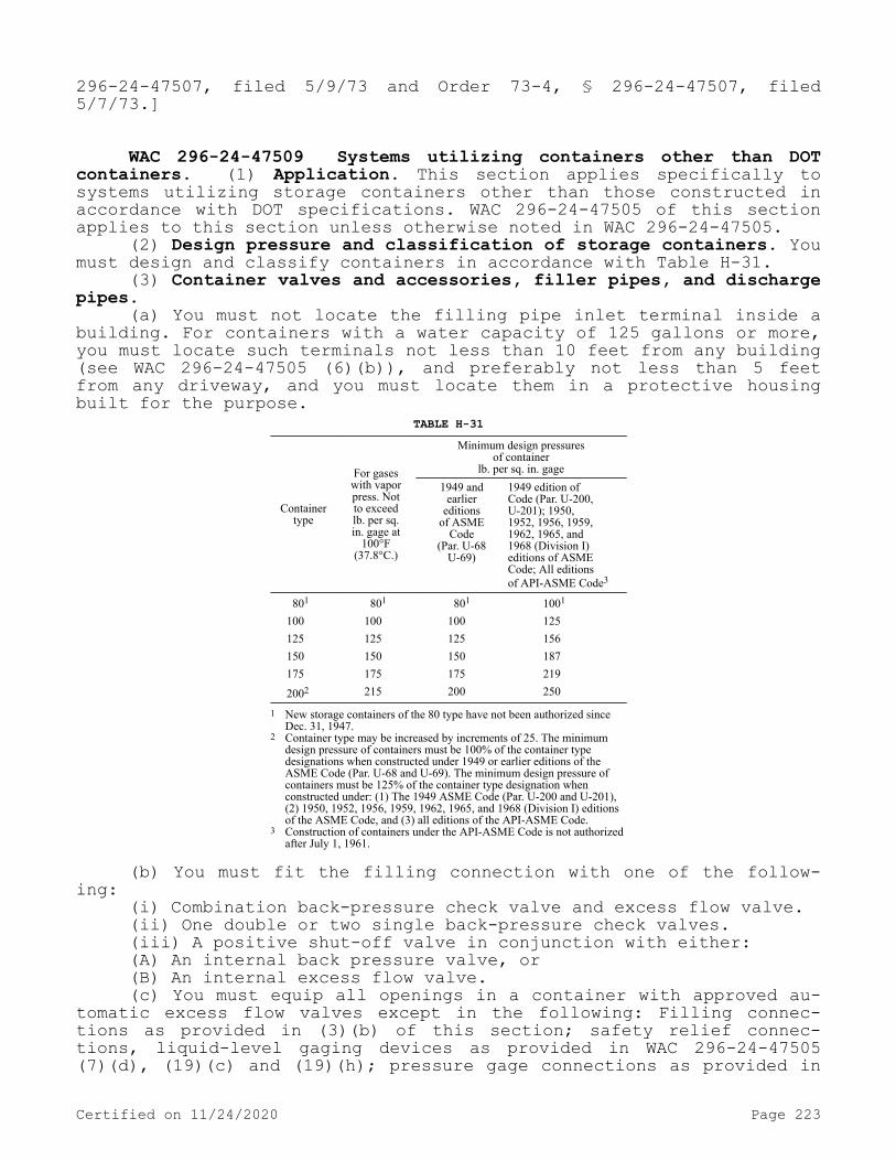
296-24-47507, filed 5/9/73 and Order 73-4, § 296-24-47507, filed 5/7/73.]
WAC 296-24-47509 Systems utilizing containers other than DOT containers. (1) Application. This section applies specifically to systems utilizing storage containers other than those constructed in accordance with DOT specifications. WAC 296-24-47505 of this section applies to this section unless otherwise noted in WAC 296-24-47505.
(2) Design pressure and classification of storage containers. You must design and classify containers in accordance with Table H-31.
(3) Container valves and accessories, filler pipes, and discharge pipes.
(a) You must not locate the filling pipe inlet terminal inside a building. For containers with a water capacity of 125 gallons or more, you must locate such terminals not less than 10 feet from any building (see WAC 296-24-47505 (6)(b)), and preferably not less than 5 feet from any driveway, and you must locate them in a protective housing built for the purpose.
TABLE H-31
Containertype
For gaseswith vaporpress. Notto exceedlb. per sq.in. gage at
100°F(37.8°C.)
Minimum design pressuresof container
lb. per sq. in. gage1949 and
earliereditions
of ASMECode
(Par. U-68U-69)
1949 edition ofCode (Par. U-200,U-201); 1950,1952, 1956, 1959,1962, 1965, and1968 (Division I)editions of ASMECode; All editionsof API-ASME Code3
801 801 801 1001
100 100 100 125 125 125 125 156 150 150 150 187 175 175 175 219 2002 215 200 250
1 New storage containers of the 80 type have not been authorized since Dec. 31, 1947.
2 Container type may be increased by increments of 25. The minimum design pressure of containers must be 100% of the container type designations when constructed under 1949 or earlier editions of the ASME Code (Par. U-68 and U-69). The minimum design pressure of containers must be 125% of the container type designation when constructed under: (1) The 1949 ASME Code (Par. U-200 and U-201), (2) 1950, 1952, 1956, 1959, 1962, 1965, and 1968 (Division I) editions of the ASME Code, and (3) all editions of the API-ASME Code.
3 Construction of containers under the API-ASME Code is not authorized after July 1, 1961.
(b) You must fit the filling connection with one of the follow-ing:
(i) Combination back-pressure check valve and excess flow valve.(ii) One double or two single back-pressure check valves.(iii) A positive shut-off valve in conjunction with either:(A) An internal back pressure valve, or(B) An internal excess flow valve.(c) You must equip all openings in a container with approved au-
tomatic excess flow valves except in the following: Filling connec-tions as provided in (3)(b) of this section; safety relief connec-tions, liquid-level gaging devices as provided in WAC 296-24-47505 (7)(d), (19)(c) and (19)(h); pressure gage connections as provided in
Certified on 11/24/2020 Page 223
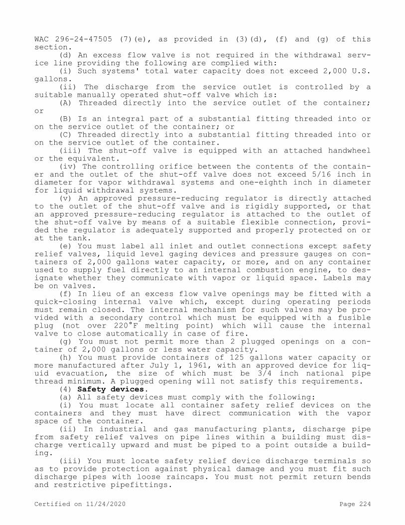
WAC 296-24-47505 (7)(e), as provided in (3)(d), (f) and (g) of this section.
(d) An excess flow valve is not required in the withdrawal serv-ice line providing the following are complied with:
(i) Such systems' total water capacity does not exceed 2,000 U.S. gallons.
(ii) The discharge from the service outlet is controlled by a suitable manually operated shut-off valve which is:
(A) Threaded directly into the service outlet of the container; or
(B) Is an integral part of a substantial fitting threaded into or on the service outlet of the container; or
(C) Threaded directly into a substantial fitting threaded into or on the service outlet of the container.
(iii) The shut-off valve is equipped with an attached handwheel or the equivalent.
(iv) The controlling orifice between the contents of the contain-er and the outlet of the shut-off valve does not exceed 5/16 inch in diameter for vapor withdrawal systems and one-eighth inch in diameter for liquid withdrawal systems.
(v) An approved pressure-reducing regulator is directly attached to the outlet of the shut-off valve and is rigidly supported, or that an approved pressure-reducing regulator is attached to the outlet of the shut-off valve by means of a suitable flexible connection, provi-ded the regulator is adequately supported and properly protected on or at the tank.
(e) You must label all inlet and outlet connections except safety relief valves, liquid level gaging devices and pressure gauges on con-tainers of 2,000 gallons water capacity, or more, and on any container used to supply fuel directly to an internal combustion engine, to des-ignate whether they communicate with vapor or liquid space. Labels may be on valves.
(f) In lieu of an excess flow valve openings may be fitted with a quick-closing internal valve which, except during operating periods must remain closed. The internal mechanism for such valves may be pro-vided with a secondary control which must be equipped with a fusible plug (not over 220°F melting point) which will cause the internal valve to close automatically in case of fire.
(g) You must not permit more than 2 plugged openings on a con-tainer of 2,000 gallons or less water capacity.
(h) You must provide containers of 125 gallons water capacity or more manufactured after July 1, 1961, with an approved device for liq-uid evacuation, the size of which must be 3/4 inch national pipe thread minimum. A plugged opening will not satisfy this requirements.
(4) Safety devices.(a) All safety devices must comply with the following:(i) You must locate all container safety relief devices on the
containers and they must have direct communication with the vapor space of the container.
(ii) In industrial and gas manufacturing plants, discharge pipe from safety relief valves on pipe lines within a building must dis-charge vertically upward and must be piped to a point outside a build-ing.
(iii) You must locate safety relief device discharge terminals so as to provide protection against physical damage and you must fit such discharge pipes with loose raincaps. You must not permit return bends and restrictive pipefittings.
Certified on 11/24/2020 Page 224

(iv) If desired, discharge lines from two or more safety relief devices located on the same unit, or similar lines from two or more different units, may be run into a common discharge header, provided that the cross-sectional area of such header be at least equal to the sum of the cross-sectional area of the individual discharge lines, and that the setting of safety relief valves are the same.
(v) You must provide each storage container of over 2,000 gallons water capacity with a suitable pressure gauge.
(vi) You must equip a final stage regulator of an LP-gas system (excluding any appliance regulator) on the low-pressure side with a relief valve which is set to start to discharge within the limits specified in Table H-30.
(vii) When a regulator or pressure relief valve is installed in-side a building, the relief valve and the space above the regulator and relief valve diaphragms must be vented to the outside air with the discharge outlet located not less than 3 feet horizontally away from any opening into the building which is below such discharge. (These provisions do not apply to individual appliance regulators when pro-tection is otherwise provided. In buildings devoted exclusively to gas distribution purposes, the space above the diaphragm need not be ven-ted to the outside.)
(b) You must provide safety devices for aboveground containers as follows:
(i) Containers of 1,200 gallons water capacity or less which may contain liquid fuel when installed above ground must have the rate of discharge required by WAC 296-24-47505 (10)(b) provided by a spring-loaded relief valve or valves. In addition to the required spring-loa-ded relief valve(s) suitable fuse plug(s) may be used provided the to-tal discharge area of the fuse plug(s) for each container does not ex-ceed 0.25 square inch.
(ii) The fusible metal of the fuse plugs must have a yield tem-perature of 208°F minimum and 220°F maximum. Relief valves and fuse plugs must have direct communication with the vapor space of the con-tainer.
(iii) On a container having a water capacity greater than 125 gallons, but not over 2,000 gallons, the discharge from the safety re-lief valves must be vented away from the container vertically upwards and unobstructed to the open air in such a manner as to prevent any impingement of escaping gas upon the container; you must use loose-fitting rain caps. You must make suitable provision for draining con-densate which may accumulate in the relief valve or its discharge pipe.
(iv) On containers of 125 gallons water capacity or less, the discharge from safety relief devices must be located not less than 5 feet horizontally away from any opening into the building below the level of such discharge.
(v) On a container having a water capacity greater than 2,000 gallons, the discharge from the safety relief valves must be vented away from the container vertically upwards to a point at least 7 feet above the container, and unobstructed to the open air in such a manner as to prevent any impingement of escaping gas upon the container; you must use loose-fitting rain caps. You must make suitable provision so that any liquid or condensate that may accumulate inside of the safety relief valve or its discharge pipe will not render the valve inopera-tive. If a drain is used, you must provide a means to protect the con-tainer, adjacent containers, piping, or equipment against impingement of flame resulting from ignition of product escaping from the drain.
Certified on 11/24/2020 Page 225

(c) On all containers which are installed underground and which contain no liquid fuel until buried and covered, the rate of discharge of the spring-loaded relief valve installed thereon may be reduced to a minimum of 30% of the rate of discharge specified in WAC 296-24-47505 (10)(b). You must not uncover containers so protected af-ter installation until the liquid fuel has been removed therefrom. Containers which may contain liquid fuel before being installed under ground and before being completely covered with earth are to be con-sidered aboveground containers when determining the rate of discharge requirement of the relief valves.
(d) On underground containers of more than 2,000 gallons water capacity, the discharge from safety relief devices must be piped ver-tically and directly upward to a point at least 7 feet above the ground.
Where there is a probability of the manhole or housing becoming flooded, the discharge from regulator vent lines must be above the highest probable water level. You must provide all manholes or hous-ings with ventilated louvers or their equivalent, the area of such openings equaling or exceeding the combined discharge areas of the safety relief valves and other vent lines which discharge their con-tent into the manhole housing.
(e) You must provide safety devices for vaporizers as follows:(i) Vaporizers of less than 1 quart total capacity, heated by the
ground or the surrounding air, need not be equipped with safety relief valves provided that adequate tests certified by any of the authori-ties referred to in WAC 296-24-47505(2), demonstrate that the assembly is safe without safety relief valves.
(ii) You must not equip any vaporizer with fusible plugs.(iii) In industrial and gas manufacturing plants, safety relief
valves on vaporizers within a building must be piped to a point out-side the building and be discharged upward.
(5) Reinstallation of containers. Containers may be reinstalled if they do not show any evidence of harmful external corrosion or oth-er damage. Where containers are reinstalled underground, you must put the corrosion resistant coating in good condition (see (7)(f) of this section). Where containers are reinstalled above ground, the safety devices and gaging devices must comply with (4) of this section and WAC 296-24-47505(19) respectively for aboveground containers.
(6) Capacity of containers. A storage container must not exceed 90,000 gallons water capacity.
(7) Installation of storage containers.(a) You must provide containers installed above ground, except as
provided in (7)(g) of this section, with substantial masonry or non-combustible structural supports on firm masonry foundation.
(b) Aboveground containers must be supported as follows:(i) You must mount horizontal containers on saddles in such a
manner as to permit expansion and contraction. Structural metal sup-ports may be employed when they are protected against fire in an ap-proved manner. You must provide suitable means of preventing corrosion on that portion of the container in contact with the foundations or saddles.
(ii) Containers of 2,000 gallons water capacity or less may be installed with nonfireproofed ferrous metal supports if mounted on concrete pads or footings, and if the distance from the outside bottom of the container shell to the concrete pad, footing, or the ground does not exceed 24 inches.
Certified on 11/24/2020 Page 226

(c) Any container may be installed with nonfireproofed ferrous metal supports if mounted on concrete pads or footings, and if the distance from the outside bottom of the container to the ground does not exceed 5 feet, provided the container is in an isolated location.
(d) Containers may be partially buried providing the following requirements are met:
(i) The portion of the container below the surface and for a ver-tical distance not less than 3 inches above the surface of the ground is protected to resist corrosion, and the container is protected against settling and corrosion as required for fully buried contain-ers.
(ii) Spacing requirements must be as specified for underground tanks in WAC 296-24-47505 (6)(b).
(iii) Relief valve capacity must be as required for aboveground containers.
(iv) Container is located so as not to be subject to vehicular damage, or is adequately protected against such damage.
(v) Filling densities must be as required for aboveground con-tainers as specified in Table H-27. See WAC 296-24-47505.
(e) You must place containers buried underground so that the top of the container is not less than 6 inches below grade. Where an un-derground container might be subject to abrasive action or physical damage due to vehicular traffic or other causes, then you must:
(i) Place it not less than 2 feet below grade, or(ii) Otherwise protect it against such physical damage.It will not be necessary to cover the portion of the container to
which manhole and other connections are affixed; however, where neces-sary, you must provide protection against vehicular damage. When nec-essary to prevent floating, you must securely anchor or weight con-tainers.
(f) You must give containers a protective coating before being placed underground. This coating must be equivalent to hot-dip galva-nizing or to two coatings of red lead followed by a heavy coating of coal tar or asphalt. In lowering the container into place, you must exercise care to prevent damage to the coating. You must repair any damage to the coating before backfilling.
You must set containers on a firm foundation (firm earth may be used) and surrounded with earth or sand firmly tamped in place. Back-fill should be free of rocks or other abrasive materials.
(g) You must design, install, and use containers with foundations attached (portable or semiportable containers with suitable steel "runners" or "skids" and popularly known in the industry as "skid tanks") in accordance with these rules subject to the following provi-sions:
(i) If they are to be used at a given general location for a tem-porary period not to exceed 6 months they need not have fire-resisting foundations or saddles but must have adequate ferrous metal supports.
(ii) You must not locate them with the outside bottom of the con-tainer shell more than 5 feet above the surface of the ground unless fire-resisting supports are provided.
(iii) The bottom of the skids must not be less than 2 inches or more than 12 inches below the outside bottom of the container shell.
(iv) You must protect flanges, nozzles, valves, fittings, and the like, having communication with the interior of the container, against physical damage.
(v) When not permanently located on fire-resisting foundations, piping connections must be sufficiently flexible to minimize the pos-
Certified on 11/24/2020 Page 227

sibility of breakage or leakage of connections if the container set-tles, moves, or is otherwise displaced.
(vi) You must secure skids, or lugs for attachment of skids, to the container in accordance with the code or rules under which the container is designed and built (with a minimum factor of safety of four) to withstand loading in any direction equal to four times the weight of the container and attachments when filled to the maximum permissible loaded weight.
(h) Where necessary you must make field welding only on saddle plates or brackets which were applied by the manufacturer of the tank.
(i) For aboveground containers, you must provide secure anchorage or adequate pier height against possible container flotation wherever sufficiently high floodwater might occur.
(j) When permanently installed containers are interconnected, you must make provisions to compensate for expansion, contraction, vibra-tion, and settling of containers, and interconnecting piping. Where flexible connections are used, they must be of an approved type and must be designed for a bursting pressure of not less than five times the vapor pressure of the product at 100°F. The use of nonmetallic hose is prohibited for permanently interconnecting such containers.
(k) Container assemblies listed for interchangeable installation above ground or under ground must conform to the requirements for aboveground installations with respect to safety relief capacity and filling density. For installation above ground all other requirements for aboveground installations must apply. For installation under ground all other requirements for underground installations must ap-ply.
(8) Protection of container accessories.(a) You must protect valves, regulating, gaging, and other con-
tainer accessory equipment against tampering and physical damage. You must also protect such accessories during the transit of containers intended for installation underground.
(b) On underground or combination aboveground-underground con-tainers, the service valve handwheel, the terminal for connecting the hose, and the opening through which there can be a flow from safety relief valves must be at least 4 inches above the container and this opening must be located in the dome or housing. You must install un-derground systems so that all the above openings, including the regu-lator vent, are located above the normal maximum water table.
(c) You must locate all connections to the underground containers within a substantial dome, housing, or manhole and with access thereto protected by a substantial cover.
(9) Drips for condensed gas. Where vaporized gas on the low-pres-sure side of the system may condense to a liquid at normal operating temperatures and pressures, you must provide suitable means for reva-porization of the condensate.
(10) Damage from vehicles. When damage to LP-gas systems from ve-hicular traffic is a possibility, you must take precautions against such damage.
(11) Pits and drains. Every effort should be made to avoid the use of pits, except pits fitted with automatic flammable vapor detect-ing devices. You must not direct any drains or blowoff lines into or in proximity to sewer systems used for other purposes.
(12) General provisions applicable to systems in industrial plants (of 2,000 gallons water capacity and more) and to bulk filling plants.
Certified on 11/24/2020 Page 228

(a) When standard watch service is provided, it must be extended to the LP-gas installation and personnel properly trained.
(b) If loading and unloading are normally done during other than daylight hours, you must provide adequate lights to illuminate storage containers, control valves, and other equipment.
(c) You must provide suitable roadways or means of access for ex-tinguishing equipment such as wheeled extinguishers or fire department apparatus.
(d) To minimize trespassing or tampering, you must enclose the area which includes container appurtenances, pumping equipment, load-ing and unloading facilities, and cylinder-filling facilities with at least a 6-foot-high industrial type fence unless otherwise adequately protected. There must be at least 2 means of emergency access.
(13) Container-charging plants.(a) You must locate the container-charging room not less than:(i) 10 feet from bulk storage containers.(ii) 25 feet from line of adjoining property which may be built
upon.(b) You must locate the tank truck filling station outlets not
less than:(i) 25 feet from line of adjoining property which may be built
upon.(ii) 10 feet from pumps and compressors if housed in one or more
separate buildings.(c) The pumps or compressors may be located in the container-
charging room or building, in a separate building, or outside of buildings. When housed in separate building, such building (a small noncombustible weather cover is not to be construed as a building) must be located not less than:
(i) 10 feet from bulk storage tanks.(ii) 25 feet from line of adjoining property which may be built
upon.(iii) 25 feet from sources of ignition.(d) When a part of the container-charging building is to be used
for a boiler room or where open flames or similar sources of ignition exist or are employed, you must separate the space to be so occupied from container charging room by a partition wall or walls of fire-re-sistant construction continuous from floor to roof or ceiling. Such separation walls must be without openings and must be joined to the floor, other walls, and ceiling or roof in a manner to effect a perma-nent gas-tight joint.
(e) Electrical equipment and installations must conform with WAC 296-24-47505 (17) and (18).
(14) Fire protection.(a) You must provide each bulk plant with at least one approved
portable fire extinguisher having a minimum rating of 12-B, C.Note: For additional requirements relating to portable fire extinguishers see WAC 296-800-300.
(b) In industrial installations involving containers of 150,000 gallons aggregate water capacity or more, you must make provisions for an adequate supply of water at the container site for fire protection in the container area, unless other adequate means for fire control are provided. Water hydrants must be readily accessible and so spaced as to provide water protection for all containers. You must provide sufficient lengths of firehose at each hydrant location on a hose cart, or other means provided to facilitate easy movement of the hose in the container area. It is desirable to equip the outlet of each
Certified on 11/24/2020 Page 229
hose line with a combination fog nozzle. You must provide a shelter to protect the hose and its conveyor from the weather.
(15) Painting. You must keep aboveground containers properly painted.
(16) Lighting. Electrical equipment and installations must con-form to WAC 296-24-47505 (17) and (18).
(17) Vaporizers for internal combustion engines. The provisions of WAC 296-24-47511(8) apply.
(18) Gas regulating and mixing equipment for internal combustion engines. The provisions of WAC 296-24-47511(9) apply.[Statutory Authority: RCW 49.17.010, 49.17.040, 49.17.050, and 49.17.060. WSR 15-24-100, § 296-24-47509, filed 12/1/15, effective 1/5/16. Statutory Authority: RCW 49.17.010, [49.17].040, and [49.17].050. WSR 01-17-033, § 296-24-47509, filed 8/8/01, effective 9/1/01; Order 73-5, § 296-24-47509, filed 5/9/73 and Order 73-4, § 296-24-47509, filed 5/7/73.]
WAC 296-24-47511 Liquefied petroleum gas as a motor fuel. (1) Application.
(a) This section applies to internal combustion engines, fuel containers, and pertinent equipment for the use of liquefied petroleum gases as a motor fuel on easily movable, readily portable units in-cluding self-propelled vehicles.
(b) Fuel containers and pertinent equipment for internal combus-tion engines using liquefied petroleum gas where installation is of the stationary type are covered by WAC 296-24-47509. This section does not apply to containers for transportation of liquefied petroleum gases nor to marine fuel use. All requirements of WAC 296-24-47505 ap-ply to this section, unless otherwise noted in WAC 296-24-47505.
(2) General.(a) Fuel may be used from the cargo tank of a truck while in
transit, but not from cargo tanks on trailers or semitrailers. The use of fuel from the cargo tanks to operate stationary engines is permit-ted providing wheels are securely blocked.
(b) You must not fuel passenger-carrying vehicles while passen-gers are on board.
(c) Reserved.(d) LP-gas fueled industrial trucks must comply with the Standard
for Type Designations, Areas of Use, Maintenance and Operation of Pow-ered Industrial Trucks, NFPA 505-1969.
(e) You must shut down engines on vehicles while fueling if the fueling operation involves venting to the atmosphere.
(3) Design pressure and classification of fuel containers.(a) Except as covered in (3)(b) and (c) of this section, contain-
ers must be in accordance with Table H-32.(b) Reserved.
TABLE H-32
Certified on 11/24/2020 Page 230

Minimum design pressureof container lb. per sq.
in. gageContainer
typeFor gases with vapor
press. Not to exceed lb. per sq. in. gage at
100°F. (37.8°C.)
1949 and earlier
editions of ASME Code (Par. U-68,
U-69)
1949 edition of ASME Code (Par. U-200, 1U-201);
1950, 1952, 1956, 1959, 1962, 1965, and 1968 (Division
I) editions of ASME Code; All editions of API-ASME Code2
2001 215 200 250
1 Container type may be increased by increments of 25. The minimum design pressure of containers must be 100% of the container type designation when constructed under 1949 or earlier editions of the ASME Code (Par. U-68 and U-69). The minimum design pressure of containers must be 125% of the container type designation when constructed under: (1) The 1949 ASME Code (Par. U-200 and U-201), (2) 1950, 1952, 1956, 1959, 1962, 1965, and 1968 (Division I) editions of the ASME Code, and (3) all editions of the API-ASME Code.
2 Construction of containers under the API-ASME Code is not authorized after July 1, 1961.
(c) Containers manufactured and maintained under DOT specifica-tions and regulations may be used as fuel containers. When so used they must conform to all requirements of this section.
(d) You must label all container inlets and outlets except safety relief valves and gaging devices to designate whether they communicate with vapor or liquid space. (Labels may be on valves.)
(4) Installation of fuel containers.(a) You must locate containers in a place and in a manner to min-
imize the possibility of damage to the container. Containers located in the rear of trucks and buses, when protected by substantial bump-ers, will be considered in conformance with this requirement. You must install fuel containers on passenger-carrying vehicles as far from the engine as is practicable, and you must seal the passenger space and any space containing radio equipment from the container space to pre-vent direct seepage of gas to these spaces. The container compartment must be vented to the outside. In case the fuel container is mounted near the engine or the exhaust system, the container must be shielded against direct heat radiation.
(b) You must install containers with as much clearance as practi-cable but never less than the minimum road clearance of the vehicle under maximum spring deflection. This minimum clearance must be to the bottom of the container or to the lowest fitting on the container or housing, whichever is lower.
(c) You must securely mount permanent and removable fuel contain-ers to prevent jarring loose, slipping, or rotating, and the fasten-ings must be designed and constructed to withstand static loading in any direction equal to twice the weight of the tank and attachments when filled with fuel using a safety factor of not less than four based on the ultimate strength of the material to be used. Field weld-ing, when necessary, must be made only on saddle plates, lugs or brackets, originally attached to the container by the tank manufactur-er.
(d) You must permanently install fuel containers on buses.(e) You must install and equip containers from which vapor only
is to be withdrawn with suitable connections to minimize the acciden-tal withdrawal of liquid.
(5) Valves and accessories.
Certified on 11/24/2020 Page 231
(a) Container valves and accessories must have a rated working pressure of at least 250 p.s.i.g., and must be of a type suitable for liquefied petroleum gas service.
(b) You must fit the filling connection with an approved double back-pressure check valve, or a positive shutoff in conjunction with an internal back-pressure check valve. On a removable container the filler valve may be a hand operated shutoff valve with an internal ex-cess flow valve. Main shutoff valves on the container on liquid and vapor must be readily accessible.
(c) With the exceptions of (5)(d)(iii) of this section, you must equip filling connections equipped with approved automatic back-pres-sure check valves, and safety relief valves, and all connections to the containers having openings for the flow of gas in excess of a No. 54 drill size with approved automatic excess flow valves to prevent discharge of content in case connections are broken.
(d) Liquid-level gaging devices:(i) You must not use variable liquid-level gages which require
the venting of fuel to the atmosphere on fuel containers of industrial trucks (including lift trucks).
(ii) On portable containers that may be filled in the vertical and/or horizontal position, the fixed liquid-level gage must indicate maximum permitted filling level for both vertical and horizontal fill-ing with the container oriented to place the safety relief valve in communication with the vapor space.
(iii) In the case of containers used solely in farm tractor serv-ice and charged at a point at least 50 feet from any important build-ing, the fixed liquid-level gaging device may be so constructed that the outward flow of container content exceeds that passed by a No. 54 drill size opening, but in no case must the flow exceed that passed by a No. 31 drill-size opening. An excess flow valve is not required. You must mark fittings equipped with such restricted drill size opening and container on which they are used to indicate the size of the open-ing.
(iv) You must adequately protect all valves and connections on containers to prevent damage due to accidental contact with stationary objects or from loose objects thrown up from the road, and you must safeguard all valves against damage due to collision, overturning or other accident. For farm tractors where parts of the vehicle provide such protection to valves and fittings, the foregoing requirements must be considered fulfilled. However, on removable type containers you must permanently attach the protection for the fittings to the container.
(v) (Exchange of removable fuel containers preferably should be done outdoors but may be done indoors.) When removable fuel containers are used, you must provide means in the fuel system to minimize the escape of fuel when the containers are exchanged. This must be accom-plished by one of the following methods:
(A) Using an approved automatic quick-closing coupling (a type closing in both directions when uncoupled) in the fuel line, or
(B) Closing the valve at the fuel container and allowing the en-gine to run until the fuel in the line is consumed.
(6) Piping—Including pipe, tubing, and fittings.(a) Pipe from fuel container to first-stage regulator must be not
less than schedule 80 wrought iron or steel (black or galvanized), brass or copper; or seamless copper, brass, or steel tubing. Steel tubing must have a minimum wall thickness of 0.049 inch. You must ade-
Certified on 11/24/2020 Page 232

quately protect steel pipe or tubing against exterior corrosion. Cop-per tubing must be types K or L or equivalent having a minimum wall thickness of 0.032 inch. Approved flexible connections may be used be-tween container and regulator or between regulator and gas-air mixer within the limits of approval. The use of aluminum pipe or tubing is prohibited. In the case of removable containers you must use an ap-proved flexible connection between the container and the fuel line.
(b) You must install all piping, braced, and supported so as to reduce to a minimum the possibility of vibration strains or wear.
(7) Safety devices.(a) You must use spring-loaded internal type safety relief valves
on all motor fuel containers.(b) You must locate the discharge outlet from safety relief
valves on the outside of enclosed spaces and as far as practicable from possible sources of ignition, and vented upward within 45 degrees of the vertical in such a manner as to prevent impingement of escaping gas upon containers, or parts of vehicles, or on vehicles in adjacent lines of traffic. You must use a rain cap or other protector to keep water and dirt from collecting in the valve.
(c) When a discharge line from the container safety relief valve is used, the line must be metallic, other than aluminum, and must be sized, located, and maintained so as not to restrict the required flow of gas from the safety relief valve. Such discharge line must be able to withstand the pressure resulting from the discharge of vapor when the safety relief valve is in the full open position. When flexibility is necessary, you must use flexible metal hose or tubing.
(d) Portable containers equipped for volumetric filling may be filled in either the vertical or horizontal position only when orien-ted to place the safety relief valve in communication with the vapor space.
(e) WAC 296-24-47505 (10)(l) for hydrostatic relief valves shall apply.
(8) Vaporizers.(a) Vaporizers and any part thereof and other devices that may be
subjected to container pressure must have a design pressure of at least 250 p.s.i.g.
(b) Each vaporizer must have a valve or suitable plug which will permit substantially complete draining of the vaporizer. You must lo-cate it at or near the lowest portion of the section occupied by the water or other heating medium.
(c) You must securely fasten vaporizers so as to minimize the possibility of becoming loosened.
(d) You must permanently mark each vaporizer at a visible point as follows:
(i) With the design pressure of the fuel-containing portion in p.s.i.g.
(ii) With the water capacity of the fuel-containing portion of the vaporizer in pounds.
(e) You must equip devices to supply heat directly to a fuel con-tainer with an automatic device to cut off the supply of heat before the pressure inside the fuel container reaches 80% of the start to discharge pressure setting of the safety relief device on the fuel container.
(f) Engine exhaust gases may be used as a direct source of heat supply for the vaporization of fuel if the materials of construction of those parts of the vaporizer in contact with exhaust gases are re-
Certified on 11/24/2020 Page 233

sistant to the corrosive action of exhaust gases and the vaporizer system is designed to prevent excessive pressures.
(g) You must not equip vaporizers with fusible plugs.(9) Gas regulating and mixing equipment.(a) You must install approved automatic pressure reducing equip-
ment in a secure manner between the fuel supply container and gas-air mixer for the purpose of reducing the pressure of the fuel delivered to the gas-air mixer.
(b) You must provide an approved automatic shutoff valve in the fuel system at some point ahead of the inlet of the gas-air mixer, de-signed to prevent flow of fuel to the mixer when the ignition is off and the engine is not running. In the case of industrial trucks and engines operating in buildings other than those used exclusively to house engines, the automatic shutoff valve must be designed to operate if the engine should stop. Atmospheric type regulators (zero gover-nors) will be considered adequate as an automatic shutoff valve only in cases of outdoor operation such as farm tractors, construction equipment, irrigation pump engines, and other outdoor stationary en-gine installations.
(c) You must completely isolate the source of the air for combus-tion from the passenger compartment, ventilating system, or air-condi-tioning system.
(10) Stationary engines in buildings. Stationary engines and gas turbines installed in buildings, including portable engines used in-stead of or to supplement stationary engines, must comply with the Standard for the Institution and Use of Stationary Combustion Engines and Gas Turbines, NFPA 37-1970, and the appropriate provisions of WAC 296-24-47505 through 296-24-47509.
(11) Portable engines in buildings.(a) Portable engines may be used in buildings only for emergency
use, except as provided by (11) of this section.(b) You must discharge exhaust gases to outside the building or
to an area where they will not constitute a hazard.(c) You must make provisions to supply sufficient air for combus-
tion and cooling.(d) You must provide an approved automatic shutoff valve in the
fuel system ahead of the engine, designed to prevent flow of fuel to the engine when the ignition is off or if the engine should stop.
(e) The capacity of LP-gas containers used with such engines must comply with the applicable occupancy provision of WAC 296-24-47507(5).
(12) Industrial trucks inside buildings.(a) Reserved.(b) Reserved.(c) Reserved.(d) You must not leave trucks unattended in areas occupied by the
public.(e) Reserved.(13) Garaging LP-gas-fueled vehicles.(a) LP-gas-fueled vehicles may be stored or serviced inside ga-
rages provided there are no leaks in the fuel system and the fuel tanks are not filled beyond the maximum filling capacity specified in WAC 296-24-47505 (12)(a).
(b) You must close the container shutoff valve on LP-gas-fueled vehicles being repaired in garages except when fuel is required for engine operation.
Certified on 11/24/2020 Page 234

(c) You must not park such vehicles near sources of heat, open flames, or similar sources of ignition or near open pits unless such pits are adequately ventilated.[Statutory Authority: RCW 49.17.010, 49.17.040, 49.17.050, and 49.17.060. WSR 15-24-100, § 296-24-47511, filed 12/1/15, effective 1/5/16; WSR 04-19-051, § 296-24-47511, filed 9/14/04, effective 2/1/05. Statutory Authority: RCW 49.17.010, [49.17].040 and [49.17].050. WSR 99-17-094, § 296-24-47511, filed 8/17/99, effective 12/1/99; Order 73-5, § 296-24-47511, filed 5/9/73 and Order 73-4, § 296-24-47511, filed 5/7/73.]
WAC 296-24-47513 Storage of containers awaiting use or resale. (1) Application. This section applies to the storage of portable con-tainers not in excess of one thousand pounds water capacity, filled or partially filled, at user location but not connected for use, or in storage for resale by dealers or resellers. This section does not ap-ply to containers stored at charging plants or at plants devoted pri-marily to the storage and distribution of LP-gas or other petroleum products.
(2) General.(a) You must locate containers in storage so as to minimize expo-
sure to excessive temperature rise, physical damage, or tampering by unauthorized persons.
(b) When stored inside, you must not locate containers near ex-its, stairways, or in areas normally used or intended for the safe ex-it of people.
(c) You must protect container valves while in storage as fol-lows:
(i) By setting into recess of container to prevent the possibili-ty of their being struck if the container is dropped upon a flat sur-face, or
(ii) By ventilated cap or collar, fastened to container capable of withstanding blow from any direction equivalent to that of a thir-ty-pound weight dropped four feet. Construction must be such that a blow will not be transmitted to a valve or other connection.
(d) You must close the outlet valves of containers in storage must be closed.
(e) Empty containers which have been in LP-gas service should preferably be stored in the open. When stored inside, you must consid-er them as full containers for the purpose of determining the maximum quantity of LP-gas permitted by this section.
(3) Storage within buildings frequented by the public.(a) DOT specification containers having a maximum individual wa-
ter capacity of two and one-half pounds, used with completely self-contained hand torches and similar applications, are permitted to be stored or displayed in a building frequented by the public. You must limit the display of such containers to a total of twenty-four units of each brand and size. The total quantity on display and in storage must not exceed two hundred pounds LP-gas.
(b) You must not permit storage as provided in subsection (5) of this section within or attached to such a building.
(4) Storage within buildings not frequented by the public (such as industrial buildings).
Certified on 11/24/2020 Page 235

(a) The quantity of LP-gas stored must not exceed three hundred pounds (approximately two thousand five hundred fifty cubic feet in vapor form) except as provided in subsection (5) of this section.
(b) Containers carried as a part of service equipment on highway mobile vehicles are not to be considered in the total storage capacity in (a) of this subsection provided such vehicles are stored in private garages, and are limited to one container per vehicle with an LP-gas capacity of not more than one hundred pounds. You must close all con-tainer valves.
(5) Storage within special buildings or rooms.(a) The quantity of LP-gas stored in special buildings or rooms
must not exceed 10,000 pounds.(b) The walls, floors, and ceilings of container storage rooms
that are within or adjacent to other parts of the building must be constructed of material having at least a two-hour fire resistance rating.
(c) A portion of the exterior walls or roof having an area not less than 10% of that of the combined area of the enclosing walls and roof must be of explosion relieving construction.
(d) You must protect each opening from such storage rooms to oth-er parts of the building by a one and one-half-hour "(B)" fire door listed by a nationally recognized testing laboratory. Refer to federal regulation 29 C.F.R. 1910.7 for definition of nationally recognized testing laboratory.
(e) Such rooms must have no open flames for heating or lighting.(f) You must adequately ventilate such rooms both top and bottom
to the outside only. The openings from such vents must be at least 5 feet away from any other opening into any building.
(g) The floors of such rooms must not be below ground level. Any space below the floor must be of solid fill or properly ventilated to the open air.
(h) You must not locate such storage rooms adjoining the line of property occupied by schools, churches, hospitals, athletic fields or other points of public gathering.
(i) You must install fixed electrical equipment in accordance with WAC 296-24-47505(18).
(6) Storage outside of buildings.(a) You must locate storage outside of buildings, for containers
awaiting use or resale, in accordance with Table H-33 with respect to:(i) The nearest important building or group of buildings;(ii) The line of adjoining property which may be built upon;(iii) Busy thoroughfares;(iv) The line of adjoining property occupied by schools, church-
es, hospitals, athletic fields, or other points of public gathering.TABLE H-33
Quantity of LP-Gas Stored: Distance500 pounds or less —————————————— 0501 to 2,500 pounds ———————————— 0*
2,501 to 6,000 pounds ———————————— 10 feet6,001 to 10,000 pounds ———————————— 20 feetOver 10,000 pounds ———————————— 25 feet
* Container or containers must be at least ten feet from any building on adjoining property, any sidewalk, or any of the exposures described in (a)(iii) or (iv) of this subsection.
(b) Containers must be in a suitable enclosure or otherwise pro-tected against tampering.
Certified on 11/24/2020 Page 236

(7) Fire protection. You must provide storage locations other than supply depots separated and located apart from dealer, reseller, or user establishments with at least one approved portable fire extin-guisher having a minimum rating of 8-B, C.Note: For additional requirements relating to portable fire extinguishers see WAC 296-800-300.
[Statutory Authority: RCW 49.17.010, 49.17.040, 49.17.050, and 49.17.060. WSR 15-24-100, § 296-24-47513, filed 12/1/15, effective 1/5/16. Statutory Authority: RCW 49.17.010, [49.17].040, and [49.17].050. WSR 01-17-033, § 296-24-47513, filed 8/8/01, effective 9/1/01. Statutory Authority: Chapter 49.17 RCW. WSR 88-23-054 (Order 88-25), § 296-24-47513, filed 11/14/88. Statutory Authority: RCW 49.17.040, 49.17.050, 49.17.240, chapters 43.22 and 42.30 RCW. WSR 80-17-015 (Order 80-21), § 296-24-47513, filed 11/13/80; Order 76-6, § 296-24-47513, filed 3/1/76; Order 73-5, § 296-24-47513, filed 5/9/73 and Order 73-4, § 296-24-47513, filed 5/7/73.]
WAC 296-24-47517 Liquefied petroleum gas service stations. (1) Application. This section applies to storage containers, and dispens-ing devices, and pertinent equipment in service stations where LP-gas is stored and is dispensed into fuel tanks of motor vehicles. See WAC 296-24-47511 for requirements covering use of LP-gas as a motor fuel. All requirements of WAC 296-24-47505 apply to this section unless oth-erwise noted.
(2) Design pressure and classification of storage containers. You must design and classify containers in accordance with Table H-34.
(3) Container valves and accessories.(a) You must fit a filling connection on the container with one
of the following:(i) A combination back-pressure check and excess flow valve.(ii) One double or two single back-pressure valves.(iii) A positive shutoff valve, in conjunction with either:(A) An internal back-pressure valve, or(B) An internal excess flow valve.In lieu of an excess flow valve, filling connections may be fit-
ted with a quick-closing internal valve, which must remain closed ex-cept during operating periods. The mechanism for such valves may be provided with a secondary control which will cause it to close auto-matically in case of fire. When a fusible plug is used its melting point must not exceed 220°F.
TABLE H-34 Minimum design pressure of
container, lb. per sq. in gageContainer
typeFor gases with vapor press. not to exceed lb. per sq. in. gage at 100°F. (37.8°C.)
1949 and earlier editions of ASME Code
(Par. U-68, U-69)
1949 edition of ASME Code (Par.
U-200, U-201); 1950, 1952 1956, 1959, 1962, 1965, and 1968 (Division I) editions of ASME Code; All editions
of API-ASME Code2
2001 215 200 250
Certified on 11/24/2020 Page 237

1 Container type may be increased by increments of 25. The minimum design pressure of containers must be 100% of the container type designation when constructed under 1949 or earlier editions of ASME Code (Par. U-68 and U-69). The minimum design pressure of containers must be 125% of the container type designation when constructed under: (1) The 1949 ASME Code (Par. U-200 and U-201), (2) 1950, 1952, 1956, 1959, 1962, 1965, and 1968 (Division I) editions of the ASME Code, and (3) all editions of the API-ASME Code.
2 Construction of containers under the API-ASME Code is not authorized after July 1, 1961.
(b) You must fit a filling pipe inlet terminal not on the con-tainer with a positive shutoff valve in conjunction with either:
(i) A back pressure check valve, or(ii) An excess flow check valve.(c) You must equip all openings in the container except those
listed below with approved excess flow check valves:(i) Filling connections as provided in (3)(a) of this section.(ii) Safety relief connections as provided in WAC 296-24-47505
(7)(b).(iii) Liquid-level gaging devices as provided in WAC 296-24-47505
(7)(d) and (19)(d).(iv) Pressure gage connections as provided in WAC 296-24-47505
(7)(e).(d) You must label all container inlets and outlets except those
listed below to designate whether they connect with vapor or liquid (labels may be on valves):
(i) Safety relief valves.(ii) Liquid-level gaging devices.(iii) Pressure gages.(e) You must provide each storage container with a suitable pres-
sure gage.(4) Safety-relief valves.(a) You must install all safety-relief devices as follows:(i) On the container and directly connected with the vapor space.(ii) You must protect safety-relief valves and discharge piping
against physical damage. You must provide the outlet with loose-fit-ting rain caps. There must be no return bends or restrictions in the discharge piping.
(iii) The discharge from two or more safety relief valves having the same pressure settings may be run into a common discharge header. The cross-sectional area of such header must be at least equal to the sum of the individual discharges.
(iv) Discharge from any safety relief device must not terminate in any building nor beneath any building.
(b) You must provide aboveground containers with safety relief valves as follows:
(i) The rate of discharge, which may be provided by one or more valves, must be not less than that specified in WAC 296-24-47505 (10)(b).
(ii) You must vent the discharge from safety relief valves to the open air unobstructed and vertically upwards in such a manner as to prevent any impingement of escaping gas upon the container; you must use loose-fitting rain caps. On a container having a water capacity greater than 2,000 gallons, you must vent the discharge from the safe-ty relief valves away from the container vertically upwards to a point at least 7 feet above the container. You must make suitable provisions so that any liquid or condensate that may accumulate inside of the re-lief valve or its discharge pipe will not render the valve inopera-tive. If a drain is used, you must provide a means to protect the con-
Certified on 11/24/2020 Page 238

tainer, adjacent containers, piping, or equipment against impingement of flame resulting from ignition of the product escaping from the drain.
(c) You must provide underground containers with safety relief valves as follows:
(i) The discharge from safety-relief valves must be piped verti-cally upward to a point at least 10 feet above the ground. The dis-charge lines or pipes must be adequately supported and protected against physical damage.
(ii) Where there is a probability of the manhole or housing be-coming flooded, the discharge from regulator vent lines should be above the highest probable water level.
(iii) If no liquid is put into a container until after it is bur-ied and covered, the rate of discharge of the relief valves may be re-duced to not less than 30% of the rate shown in WAC 296-24-47505 (10)(b). If liquid fuel is present during installation of containers, the rate of discharge must be the same as for aboveground containers. You must not uncover such containers until emptied of liquid fuel.
(5) Capacity of liquid containers. Individual storage containers must not exceed 30,000 gallons water capacity.
(6) Installation of storage containers.(a) Each storage container used exclusively in service station
operation must comply with the following table which specifies minimum distances to a building, groups of buildings, and adjoining property lines which may be built upon.
Minimum distancesWater capacity per container (gallons)
Abovegroundand
underground
(feet)
Betweenaboveground
containers(feet)
Up to 2,000 ——————————— 25 3Over 2,000 ——————————— 50 5
Note: The above distances may be reduced to not less than 10 feet for service station buildings of other than wood frame construction.
(i) You must remove readily ignitible material including weeds and long dry grass, within 10 feet of containers.
(ii) The minimum separation between LP-gas containers and flamma-ble liquid tanks must be 20 feet and the minimum separation between a container and the centerline of the dike shall be 10 feet.
(iii) You must protect LP-gas containers located near flammable liquid containers against the flow or accumulation of flammable liq-uids by diking, diversion curbs, or grading.
(iv) You must not locate LP-gas containers within diked areas for flammable liquid containers.
(v) Field welding is permitted only on saddle plates or brackets which were applied by the container manufacturer.
(vi) When permanently installed containers are interconnected, you must make provisions to compensate for expansion, contraction, vi-bration, and settling of containers and interconnecting piping. Where flexible connections are used, they must be of an approved type and must be designed for a bursting pressure of not less than five times the vapor pressure of the product at 100°F. The use of nonmetallic hose is prohibited for interconnecting such containers.
(vii) Where high water table or flood conditions may be encoun-tered you must provide protection against container flotation.
Certified on 11/24/2020 Page 239

(b) You must install aboveground containers in accordance with this section.
(i) Containers may be installed horizontally or vertically.(ii) You must protect containers by crash rails or guards to pre-
vent physical damage unless they are so protected by virtue of their location. You must not service vehicles within 10 feet of containers.
(iii) Container foundations must be of substantial masonry or other noncombustible material. You must mount containers on saddles that permit expansion and contraction, and provide against the exces-sive concentration of stresses. You must provide corrosion protection for tank-mounting areas. You must protect structural metal container supports against fire. This protection is not required on prefabrica-ted storage and pump assemblies, mounted on a common base, with con-tainer bottom not more than 24 inches above ground and whose water ca-pacity is 2,000 gallons or less if the piping connected to the storage and pump assembly is sufficiently flexible to minimize the possibility of breakage or leakage in the event of failure of the container sup-ports.
(c) You must install underground containers in accordance with this section.
(i) You must give containers a protective coating before being placed under ground. This coating must be equivalent to hot-dip galva-nizing or to two coatings of red lead followed by a heavy coating of coal tar or asphalt. In lowering the container into place, you must exercise care to minimize abrasion or other damage to the coating. You must repair damage to the coating before back-filling.
(ii) You must set containers on a firm foundation (firm earth may be used) and surrounded with earth or sand firmly tamped in place. Backfill should be free of rocks or other abrasive materials.
(iii) You must provide a minimum of 2 feet of earth cover. Where ground conditions make compliance with this requirement impractical, you must provide equivalent protection against physical damage. The portion of the container to which manhole and other connections are attached need not be covered. If the location is subjected to vehicu-lar traffic, you must protect containers by a concrete slab or other cover adequate to prevent the weight of a loaded vehicle imposing con-centrated direct loads on the container shell.
(7) Protection of container fittings. You must protect valves, regulators, gages, and other container fittings against tampering and physical damage.
(8) Transport truck unloading point.(a) During unloading, you must not park the transport truck on
public thoroughfares and shall be at least 5 feet from storage con-tainers and it must be positioned so that shutoff valves are readily accessible.
(b) You must not locate the filling pipe inlet terminal within a building nor within 10 feet of any building or driveway. You must pro-tect it against physical damage.
(9) Piping, valves, and fittings.(a) Piping may be underground, above ground, or a combination of
both. It must be well supported and protected against physical damage and corrosion.
(b) You must install piping laid beneath driveways to prevent physical damage by vehicles.
(c) Piping must be wrought iron or steel (black or galvanized), brass or copper pipe; or seamless copper, brass, or steel tubing and must be suitable for a minimum pressure of 250 p.s.i.g. Pipe joints
Certified on 11/24/2020 Page 240

may be screwed, flanged, brazed, or welded. The use of aluminum alloy piping or tubing is prohibited.
(d) All shutoff valves (liquid or gas) must be suitable for liq-uefied petroleum gas service and designed for not less than the maxi-mum pressure to which they may be subjected. Valves which may be sub-jected to container pressure must have a rated working pressure of at least 250 p.s.i.g.
(e) All materials used for valve seats, packing, gaskets, dia-phragms, etc., must be resistant to the action of LP-gas.
(f) Fittings must be steel, malleable iron, or brass having a minimum working pressure of 250 p.s.i.g. You must not use cast iron pipe fittings, such as ells, tees and unions.
(g) You must test all piping after assembly and prove it to be free from leaks at not less than normal operating pressures.
(h) You must make provisions for expansion, contraction, jarring, and vibration, and for settling. This may be accomplished by flexible connections.
(10) Pumps and accessories. All pumps and accessory equipment must be suitable for LP-gas service, and designed for not less than the maximum pressure to which they may be subjected. Accessories must have a minimum rated working pressure of 250 p.s.i.g. You must equip positive displacement pumps with suitable pressure actuated bypass valves permitting flow from pump discharge to storage container or pump suction.
(11) Dispensing devices.(a) Meters, vapor separators, valves, and fittings in the dis-
penser must be suitable for LP-gas service and must be designed for a minimum working pressure of 250 p.s.i.g.
(b) You must make provisions for venting LP-gas contained in a dispensing device to a safe location.
(c) You must equip pumps used to transfer LP-gas to allow control of the flow and to prevent leakage or accidental discharge. You must provide means outside the dispensing device to readily shut off the power in the event of fire or accident.
(d) You must install a manual shutoff valve and an excess flow check valve downstream of the pump and ahead of the dispenser inlet.
(i) Dispensing hose must be resistant to the action of LP-gas in the liquid phase and designed for a minimum bursting pressure of 1,250 p.s.i.g.
(ii) You must install an excess flow check valve or automatic shutoff valve at the terminus of the liquid line at the point of at-tachment of the dispensing hose.
(e) You must locate LP-gas dispensing devices not less than 10 feet from aboveground storage containers greater than 2,000 gallons water capacity. The dispensing devices must not be less then 20 feet from any building (not including canopies), basement, cellar, pit, or line of adjoining property which may be built upon and not less than 10 feet from sidewalks, streets, or thoroughfares. You must not direct any drains or blowoff lines into or in proximity to the sewer systems used for other purposes.
(i) You must install LP-gas dispensing devices on a concrete foundation or as part of a complete storage and dispensing assembly mounted on a common base, and you must adequately protect them from physical damage.
(ii) You must not install LP-gas dispensing devices within a building except that they may be located under a weather shelter or canopy provided this area is not enclosed on more than two sides. If
Certified on 11/24/2020 Page 241

the enclosing sides are adjacent to each other, you must properly vent the area.
(f) The dispensing of LP-gas into the fuel container of a vehicle must be performed by a competent attendant who must remain at the LP-gas dispenser during the entire transfer operation.
(12) Additional standards. you must not smoke on the driveway of service stations in the dispensing areas or transport truck unloading areas. You must post conspicuous signs prohibiting smoking within sight of the customer being served. Letters on such signs must not be less than 4 inches high. You must shut off the motors of all vehicles being fueled during the fueling operations.
(13) Electrical. Electrical equipment and installations must con-form to WAC 296-24-47505 (17) and (18).
(14) Fire protection. You must provide each service station with at least one approved portable fire extinguisher having at least an 8-B, C, rating.Note: For additional requirements relating to portable fire extinguishers see WAC 296-800-300.
[Statutory Authority: RCW 49.17.010, 49.17.040, 49.17.050, and 49.17.060. WSR 15-24-100, § 296-24-47517, filed 12/1/15, effective 1/5/16. Statutory Authority: RCW 49.17.010, [49.17].040, and [49.17].050. WSR 01-17-033, § 296-24-47517, filed 8/8/01, effective 9/1/01; Order 73-5, § 296-24-47517, filed 5/9/73 and Order 73-4, § 296-24-47517, filed 5/7/73.]
PART F-2STORAGE AND HANDLING OF ANHYDROUS AMMONIA
Note: Storage and handling of anhydrous ammonia has been moved to chapter 296-826 WAC
PART G-1MEANS OF EGRESS
WAC 296-24-55001 Definitions. Approved. For the purposes of chapter 296-24 WAC, Parts G-1, G-2 and G-3, approved means listed or approved equipment by a nationally recognized testing laboratory. Re-fer to WAC 296-24-58503 (3)(c)(iv)(A) for definition of listed, and federal regulation 29 C.F.R. 1910.7 for nationally recognized testing laboratory.
Emergency action plan. A plan for a workplace, or parts thereof, describing what procedures the employer and employees must take to en-sure employee safety from fire or other emergencies.
Emergency escape route. The route that employees are directed to follow in the event they are required to evacuate the workplace or seek a designated refuge area.[Statutory Authority: RCW 49.17.010, 49.17.040, 49.17.050, and 49.17.060. WSR 15-24-100, § 296-24-55001, filed 12/1/15, effective 1/5/16. Statutory Authority: RCW 49.17.010, [49.17].040, and [49.17].050. WSR 01-17-033, § 296-24-55001, filed 8/8/01, effective 9/1/01. Statutory Authority: Chapter 49.17 RCW. WSR 94-15-096 (Order 94-07), § 296-24-55001, filed 7/20/94, effective 9/20/94; WSR
Certified on 11/24/2020 Page 242
88-23-054 (Order 88-25), § 296-24-55001, filed 11/14/88. Statutory Au-thority: RCW 49.17.040 and 49.17.050. WSR 82-02-003 (Order 81-32), § 296-24-55001, filed 12/24/81; Order 73-5, § 296-24-55001, filed 5/9/73 and Order 73-4, § 296-24-55001, filed 5/7/73.]
WAC 296-24-56525 Automatic sprinkler systems. You must ensure that all automatic sprinkler systems are continuously maintained in reliable operating condition at all times, and such periodic inspec-tions and tests are made as are necessary to assure proper mainte-nance.[Statutory Authority: RCW 49.17.010, 49.17.040, 49.17.050, and 49.17.060. WSR 15-24-100, § 296-24-56525, filed 12/1/15, effective 1/5/16; Order 73-5, § 296-24-56525, filed 5/9/73 and Order 73-4, § 296-24-56525, filed 5/7/73.]
WAC 296-24-56527 Fire alarm signaling systems. You must ensure that fire alarm signaling systems are maintained and tested in accord-ance with the requirements of WAC 296-800-31080.[Statutory Authority: RCW 49.17.010, 49.17.040, 49.17.050, and 49.17.060. WSR 15-24-100, § 296-24-56527, filed 12/1/15, effective 1/5/16; WSR 04-07-161, § 296-24-56527, filed 3/23/04, effective 6/1/04. Statutory Authority: RCW 49.17.040 and 49.17.050. WSR 82-02-003 (Order 81-32), § 296-24-56527, filed 12/24/81; Order 73-5, § 296-24-56527, filed 5/9/73 and Order 73-4, § 296-24-56527, filed 5/7/73.]
WAC 296-24-567 Employee emergency plans and fire prevention plans. (1) Emergency action plan.
(a) Scope and application. This subdivision applies to all emer-gency action plans required by a particular DOSH standard. You must put the emergency action plan in writing, and it must cover those des-ignated actions employers and employees must take to ensure employee safety from fire and other emergencies.
(b) Elements. You must include the following elements, at a mini-mum, in the plan:
(i) Emergency escape procedures and emergency escape route as-signments;
(ii) Procedures to be followed by employees who remain to operate critical plant operations before they evacuate;
(iii) Procedures to account for all employees after emergency evacuation has been completed;
(iv) Rescue and medical duties for those employees who are to perform them;
(v) The preferred means of reporting fires and other emergencies; and
(vi) Names or regular job titles of persons or departments who can be contacted for further information or explanation of duties un-der the plan.
(c) Alarm systems.You must establish an employee alarm system which complies with
WAC 296-800-310. The employee alarm system must provide warning for necessary emergency action as called for in your emergency action
Certified on 11/24/2020 Page 243

plan. The employee alarm must be distinctive and recognizable as a signal to perform actions designed under the emergency action plan.
(d) Evacuation. You must establish in the emergency action plan the types of evacuation to be used in emergency circumstances.
(e) Training.(i) Before implementing the emergency action plan, you must des-
ignate and train a sufficient number of persons to assist in the safe and orderly emergency evacuation of employees.
(ii) The employer shall review the plan with each employee cov-ered by the plan at the following times:
(A) Initially when the plan is developed;(B) Whenever the employee's responsibilities or designated ac-
tions under the plan change; and(C) Whenever the plan is changed.(iii) You must review with each employee upon initial assignment
those parts of the plan which the employee must know to protect the employee in the event of an emergency. You must keep the written plan at the workplace and made available for employee review.
(2) Fire prevention plan.(a) Scope and application. This subsection applies to all fire
prevention plans required by a particular DOSH standard. You must put the fire prevention plan in writing.
(b) Elements. You must include the following elements, at a mini-mum, in the fire prevention plan:
(i) A list of the major workplace fire hazards and their proper handling and storage procedures, potential ignition sources (such as welding, smoking and others) and their control procedures, and the type of fire protection equipment or systems which can control a fire involving them;
(ii) Names or regular job titles of those personnel responsible for maintenance of equipment and systems installed to prevent or con-trol ignitions or fires; and
(iii) Names or regular job titles of those personnel responsible for control of fuel source hazards.
(c) Housekeeping. You must control accumulations of flammable and combustible waste materials and residues so that they do not contrib-ute to a fire emergency. You must include the housekeeping procedures in the written fire prevention plan.
(d) Training.(i) You must apprise employees of the fire hazards of the materi-
als and processes to which they are exposed.(ii) You must review with each employee upon initial assignment
those parts of the fire prevention plan which the employee must know to protect the employee in the event of an emergency. You must keep the written plan in the workplace and made available for employee re-view.
(e) Maintenance. You must regularly and properly maintain, ac-cording to established procedures, equipment and systems installed on heat producing equipment to prevent accidental ignition of combustible materials. You must include the maintenance procedures in the written fire prevention plan.[Statutory Authority: RCW 49.17.010, 49.17.040, 49.17.050, and 49.17.060. WSR 15-24-100, § 296-24-567, filed 12/1/15, effective 1/5/16. Statutory Authority: RCW 49.17.010, [49.17].040, and [49.17].050. WSR 01-11-038, § 296-24-567, filed 5/9/01, effective 9/1/01. Statutory Authority: Chapter 49.17 RCW. WSR 89-11-035 (Order
Certified on 11/24/2020 Page 244

89-03), § 296-24-567, filed 5/15/89, effective 6/30/89. Statutory Au-thority: RCW 49.17.040 and 49.17.050. WSR 82-02-003 (Order 81-32), § 296-24-567, filed 12/24/81.]
WAC 296-24-56701 Appendix. This appendix serves as a nonmanda-tory guideline to assist employers in complying with the appropriate requirements.
(1) Employee emergency plans. Emergency action plan elements. The emergency action plan should address emergencies that the employer may reasonably expect in the workplace. Examples are: Fire, toxic chemical releases; hurricanes; tornadoes; blizzards; floods; and others. The elements of the emergency action plan presented in WAC 296-24-567 (1)(b) can be supplemented by the following to more effectively ach-ieve employee safety and health in an emergency. The employer should list in detail the procedures to be taken by those employees who have been selected to remain behind to care for essential plant operations until their evacuations become absolutely necessary. Essential plant operations may include the monitoring of plant power supplies, water supplies, and other essential services which cannot be shut down for every emergency alarm. Essential plant operations may also include chemical or manufacturing processes which must be shut down in stages or steps where certain employees must be present to assure that safe shut down procedures are completed.
The use of floor plans or workplace maps which clearly show the emergency escape routes should be included in the emergency action plan. Color coding will aid employees in determining their route as-signments.
The employer should also develop and explain in detail what res-cue and medical first-aid duties are to be performed and by whom. All employees are to be told what actions they are to take in these emer-gency situations that the employer anticipates may occur in the work-place.
(2) Emergency evacuation. At the time of an emergency, employees should know what type of evacuation is necessary and what their role is in carrying out the plan. In some cases where the emergency is very grave, total and immediate evacuation of all employees is necessary. In other emergencies, a partial evacuation of nonessential employees with a delayed evacuation of others may be necessary for continued plant operation. In some cases, only those employees in the immediate area of the fire may be expected to evacuate or move to a safe area such as when a local application fire suppression system discharge em-ployee alarm is sounded. Employees must be sure that they know what is expected of them in all such emergency possibilities which have been planned in order to provide assurance of their safety from fire or other emergency.
The designation of refuge or safe areas for evacuation should be determined and identified in the plan. In a building divided into fire zones by fire walls, the refuge area may still be within the same building but in a different zone from where the emergency occurs.
Exterior refuge or safe areas may include parking lots, open fields or streets which are located away from the site of the emergen-cy and which provide sufficient space to accommodate the employees. Employees should be instructed to move away from the exit discharge doors of the building, and to avoid congregating close to the building where they may hamper emergency operations.
Certified on 11/24/2020 Page 245

(3) Emergency action plan training. The employer should assure that an adequate number of employees are available at all times during working hours to act as evacuation wardens so that employees can be swiftly moved from the danger location to the safe areas. Generally, one warden for each twenty employees in the workplace should be able to provide adequate guidance and instruction at the time of a fire emergency. The employees selected or who volunteer to serve as wardens should be trained in the complete workplace layout and the various al-ternative escape routes from the workplace. All wardens and fellow em-ployees should be made aware of handicapped employees who may need ex-tra assistance, such as using the buddy system, and of hazardous areas to be avoided during emergencies. Before leaving, wardens should check rooms and other enclosed spaces in the workplace for employees who may be trapped or otherwise unable to evacuate the area.
After the desired degree of evacuation is completed, the wardens should be able to account for or otherwise verify that all employees are in the safe areas.
In buildings with several places of employment, employers are en-couraged to coordinate their plans with the other employers in the building. A building-wide or standardized plan for the whole building is acceptable provided that the employers inform their respective em-ployees of their duties and responsibilities under the plan. The standardized plan need not be kept by each employer in the multiem-ployer building provided there is an accessible location within the building where the plan can be reviewed by affected employees. When multiemployer, building-wide plans are not feasible, employers should coordinate their plans with the other employers within the building to assure that conflicts and confusion are avoided during time of emer-gencies. In multistory buildings where more than one employer is on a single floor, it is essential that these employers coordinate their plans with each other to avoid conflicts and confusion.
(4) Fire prevention housekeeping. The standard calls for the con-trol of accumulations of flammable and combustible waste materials.
It is the intent of this standard to assure that hazardous accu-mulations of combustible waste materials are controlled so that a fast developing fire, rapid spread of toxic smoke, or an explosion will not occur. This does not necessarily mean that each room has to be swept each day. Employers and employees should be aware of the hazardous properties of materials in their workplaces, and the degree of hazard each poses. Certainly, oil soaked rags have to be treated differently than general paper trash in office areas. However, large accumulations of waste paper or corrugated boxes, etc., can pose a significant fire hazard. Accumulations of materials which can cause large fires or gen-erate dense smoke that are easily ignited or may start from spontane-ous combustion, are the types of materials with which this standard is concerned. Such combustible materials may be easily ignited by match-es, welder's sparks, cigarettes, and similar low level energy ignition sources.
(5) Maintenance of equipment under the fire prevention plan. Cer-tain equipment is often installed in workplaces to control heat sour-ces or to detect fuel leaks. An example is a temperature limit switch often found on deep-fat food fryers found in restaurants. There may be similar switches for high temperature dip tanks, or flame failure and flashback arrester devices on furnaces and similar heat producing equipment. If these devices are not properly maintained or if they be-come inoperative, a definite fire hazard exists. Again employees and supervisors should be aware of the specific type of control devices on
Certified on 11/24/2020 Page 246

equipment involved with combustible materials in the workplace and should make sure, through periodic inspection or testing, that these controls are operable. Manufacturers' recommendations should be fol-lowed to assure proper maintenance procedures.[Statutory Authority: RCW 49.17.040 and 49.17.050. WSR 82-02-003 (Or-der 81-32), § 296-24-56701, filed 12/24/81.]
PART G-2FIRE PROTECTION
WAC 296-24-585 Fire protection.[Order 73-5, § 296-24-585, filed 5/9/73 and Order 73-4, § 296-24-585, filed 5/7/73.]
WAC 296-24-58501 Definitions applicable to fire protection. Class A fires. Fires in ordinary combustible materials, such as wood, cloth, paper, and rubber.
Class B fires. Fires in flammable liquids, gases, and greases.Class C fires. Fires which involve energized electrical equipment
where the electrical nonconductivity of the extinguishing media is of importance. (When electrical equipment is deenergized, extinguisher for Class A or B fires may be used safely.)
Class D fires. Fires in combustible metals, such as magnesium, titanium, zirconium, sodium, and potassium.
Classification of portable fire extinguishers: Portable fire ex-tinguishers are classified for use on certain classes of fires and rated for relative extinguishing effectiveness at a temperature of plus 70°F by nationally recognized testing laboratories. This is based upon the preceding classification of fires and the fire extinguishment potentials as determined by fire tests.Note: The classification and rating system described in this section is that used by Underwriters' Laboratories, Inc. and Underwriters' Laboratories of
Canada and is based on extinguishing preplanned fires of determined size and description as follows:
Class A rating—Wood and excelsior fires excluding deep-seated conditions.
Class B rating—Two-inch depth gasoline fires in square pans.Class C rating—No fire test. Agent must be a nonconductor of
electricity.Class D rating—Special tests on specific combustible metal
fires.Light hazard. A situation where the amount of combustibles or
flammable liquids present is such that fires of small size may be ex-pected. These may include offices, schoolrooms, churches, assembly halls, telephone exchanges, etc.
Ordinary hazard. A situation where the amount of combustibles or flammable liquids present is such that fires of moderate size may be expected. These may include mercantile storage and display, auto show-rooms, parking garages, light manufacturing, warehouses not classified as extra hazard, school shop areas, etc.
Extra hazard. A situation where the amount of combustibles or flammable liquids present is such that fires of severe magnitude may be expected. These may include woodworking, auto repair, aircraft
Certified on 11/24/2020 Page 247

servicing, warehouses with high-piled (14 feet or higher) combusti-bles, and processes such as flammable liquid handling, painting, dip-ping, etc.
Sprinkler system. For fire protection purposes, is an integrated system of underground and overhead piping designed in accordance with fire protection engineering standards. The system includes a suitable water supply, such as a gravity tank, fire pump, reservoir, or pres-sure tank and/or connection by underground piping to a city main. The portion of the sprinkler system above ground is a network of specially sized or hydraulically designed piping installed in a building, struc-ture or area, generally overhead, and to which sprinklers are connec-ted in a systematic pattern. The system includes a controlling valve and a device for actuating an alarm when the system is in operation. The system is usually activated by heat from a fire and discharges wa-ter over the fire area.Note: The design and installation of water supply facilities such as gravity tanks, fire pumps, reservoirs, or pressure tanks, and underground piping
are covered by NFPA Standards No. 22-1970, Water Tanks for Private Fire Protection; No. 20-1970, Installation of Centrifugal Fire Pumps and No. 24-1970, Outside Protection.
Sprinkler alarm unit. An assembly of apparatus approved for the service and so constructed and installed that any flow of water from a sprinkler system equal to or greater than that from a single automatic sprinkler will result in an audible alarm signal on the premises.
Class of service—Standpipe systems: Standpipe systems are grou-ped into three general classes of service for the intended use in the extinguishment of fire.
Class I: For use by fire departments and those trained in han-dling heavy fire streams (2 1/2 inch hose).
Class II: For use primarily by the building occupants until the arrival of the fire department (small hose).
Class III: For use by either fire departments and those trained in handling heavy hose streams or by the building occupants.
Class I service. A standpipe system capable of furnishing the ef-fective fire streams required during the more advanced stages of fire on the inside of buildings or for exposure fire.
Class II service. A standpipe system which affords a ready means for the control of incipient fires by the occupants of buildings dur-ing working hours and by watchperson and those present during the night time and holidays.
Class III service. A standpipe system capable of furnishing the effective fire streams required during the more advanced stages of fire on the inside of buildings as well as providing a ready means for the control of fires by the occupants of the building.
Standpipe systems. Usually of the following types:- A wet standpipe system having a supply valve open and water
pressure maintained at all times.- A standpipe system so arranged through the use of approved de-
vices as to admit water to the system automatically by opening a hose valve.
- A standpipe system arranged to admit water to the system through manual operation of approved remote control devices located at each hose station.
- Dry standpipe having no permanent water supply. See also (11) of this section.
Type I storage. That in which combustible commodities or noncom-bustible commodities involving combustible packaging or storage aids are stored over 15 feet but not more than 21 feet high in solid piles or over 12 feet but not more that 21 feet high in piles that contain
Certified on 11/24/2020 Page 248

horizontal channels. Minor quantities of commodities of hazard greater than ordinary combustibles may be included without affecting this gen-eral classification.
Type II storage. That in which combustible commodities or noncom-bustible commodities involving combustible packaging or storage aids are stored not over 15 feet high in solid piles or not over 12 feet high in piles that contain horizontal channels. Minor quantities of commodities of hazard greater than ordinary combustibles may be inclu-ded without affecting this general classification.
Type III storage. That in which the stored commodities, packag-ing, and storage aids are noncombustible or contain only a small con-centration of combustibles which are incapable of producing a fire that would cause appreciable damage to the commodities stored or to noncombustible wall, floor or roof construction. Ordinary combustible commodities in completely sealed noncombustible containers may qualify in this classification. General commodity storage that is subject to frequent changing and storage of combustible packaging and storage aids is excluded from this category.
Approved. Listed or approved by: (a) At least one of the follow-ing nationally recognized testing laboratories: Factory Mutual Engi-neering Corp.; Underwriters' Laboratories, Inc., or (b) federal agen-cies such as Mine Safety and Health Administration (MSHA); the Nation-al Institute for Occupational Safety and Health (NIOSH); Department of Transportation; or U.S. Coast Guard, which issue approvals for such equipment.[Statutory Authority: RCW 49.17.010, 49.17.040, 49.17.050, and 49.17.060. WSR 15-24-100, § 296-24-58501, filed 12/1/15, effective 1/5/16. Statutory Authority: Chapter 49.17 RCW. WSR 94-15-096 (Order 94-07), § 296-24-58501, filed 7/20/94, effective 9/20/94; Order 74-27, § 296-24-58501, filed 5/7/74; Order 73-5, § 296-24-58501, filed 5/9/73 and Order 73-4, § 296-24-58501, filed 5/7/73.]
WAC 296-24-58503 Scope, application and definitions applicable. (1) Scope. This section contains requirements for fire brigades, and all portable and fixed fire suppression equipment, fire detection sys-tems, and fire or employee alarm systems installed to meet the fire protection requirements of this chapter.
(2) Application. This section applies to all employments except for maritime, construction and agriculture.
(3) Definitions applicable to this section.After flame. The time a test specimen continues to flame after
the flame source has been removed.Aqueous film forming foam (AFFF). A fluorinated surfactant with a
foam stabilizer which is diluted with water to act as a temporary bar-rier to exclude air from mixing with the fuel vapor by developing an aqueous film on the fuel surface of some hydrocarbons which is capable of suppressing the generation of fuel vapors.
Approved. Acceptable to the director under the following crite-ria:
- If it is accepted, or certified, or listed, or labeled or oth-erwise determined to be safe by a nationally recognized testing labo-ratory; or
- With respect to an installation or equipment of a kind which no nationally recognized testing laboratory accepts, certifies, lists, labels, or determines to be safe, if it is inspected or tested by an-
Certified on 11/24/2020 Page 249

other federal agency and found in compliance with the provisions of the applicable National Fire Protection Association Fire Code; or
- With respect to custom-made equipment or related installations which are designed, fabricated for, and intended for use by its manu-facturer on the basis of test data which the employer keeps and makes available for inspection to the director; and
- For the purposes of (c) of this subsection:- Equipment is listed if it is of a kind mentioned in a list
which is published by a nationally recognized testing laboratory which makes periodic inspections of the production of such equipment and which states that such equipment meets nationally recognized standards or has been tested and found safe for use in a specified manner;
- Equipment is labeled if there is attached to it a label, sym-bol, or other identifying mark of a nationally recognized testing lab-oratory which makes periodic inspections of the production of such equipment and whose labeling indicates compliance with nationally rec-ognized standards or tests to determine safe use in a specified man-ner;
- Equipment is accepted if it has been inspected and found by a nationally recognized testing laboratory to conform to specified plans or to procedures of applicable codes;
- Equipment is certified if it has been tested and found by a na-tionally recognized testing laboratory to meet nationally recognized standards or to be safe for use in a specified manner or is of a kind whose production is periodically inspected by a nationally recognized testing laboratory, and if it bears a label, tag, or other record of certification; and
- Refer to federal regulation 29 C.F.R. 1910.7 for definition of nationally recognized testing laboratory.
Automatic fire detection device. A device designed to automati-cally detect the presence of fire by heat, flame, light, smoke or oth-er products of combustion.
Buddy-breathing device. An accessory to self-contained breathing apparatus which permits a second person to share the same air supply as that of the wearer of the apparatus.
Carbon dioxide. A colorless, odorless, electrically nonconductive inert gas (chemical formula CO2) that is a medium for extinguishing fires by reducing the concentration of oxygen or fuel vapor in the air to the point where combustion is impossible.
Class A fire. A fire involving ordinary combustible materials such as paper, wood, cloth, and some rubber and plastic materials.
Class B fire. A fire involving flammable liquids, flammable gases, greases and similar materials, and some rubber and plastic ma-terials.
Class C fire. A fire involving energized electrical equipment where safety to the employee requires the use of electrically noncon-ductive extinguishing media.
Class D fire. A fire involving combustible metals such as magne-sium, titanium, zirconium, sodium, lithium and potassium.
Dry chemical. An extinguishing agent composed of very small par-ticles of chemicals such as, but not limited to, sodium bicarbonate, potassium bicarbonate, urea-based potassium bicarbonate, potassium chloride, or monoammonium phosphate supplemented by special treatment to provide resistance to packing and moisture absorption (caking) as well as to provide proper flow capabilities. Dry chemical does not in-clude dry powders.
Certified on 11/24/2020 Page 250

Dry powder. A compound used to extinguish or control Class D fires.
Education. The process of imparting knowledge or skill through systematic instruction. It does not require formal classroom instruc-tion.
Enclosed structure. A structure with a roof or ceiling and at least two walls which may present fire hazards to employees, such as accumulations of smoke, toxic gases and heat similar to those found in buildings.
Extinguisher classification. The letter classification given an extinguisher to designate the class or classes of fire on which an ex-tinguisher will be effective.
Extinguisher rating. The numerical rating given to an extinguish-er which indicates the extinguishing potential of the unit based on standardized tests developed by Underwriters' Laboratories, Inc.
Fixed extinguishing system. A permanently installed system that either extinguishes or controls a fire at the location of the system.
Flame resistance. The property of materials, or combinations of component materials, to retard ignition and restrict the spread of flame.
Foam. A stable aggregation of small bubbles which flow freely over a burning liquid surface and form a coherent blanket which seals combustible vapors and thereby extinguishes the fire.
Gaseous agent. A fire extinguishing agent which is in the gaseous state at normal room temperature and pressure. It has low viscosity, can expand or contract with changes in pressure and temperature, and has the ability to diffuse readily and to distribute itself uniformly throughout an enclosure.
Halon 1211. A colorless, faintly sweet smelling, electrically nonconductive liquefied gas (chemical formula CBrC1F2) which is a me-dium for extinguishing fires by inhibiting the chemical chain reaction of fuel and oxygen. It is also known as bromochlorodifluoromethane.
Halon 1301. A colorless, odorless, electrically nonconductive gas (chemical formula CBrF3) which is a medium for extinguishing fires by inhibiting the chemical chain reaction of fuel and oxygen. It is also known as bromotrifluoromethane.
Helmet. A head protective device consisting of a rigid shell, en-ergy absorption system and chin strap intended to be worn to provide protection for the head or portions thereof, against impact, flying or falling objects, electric shock, penetration, heat and flame.
Incipient stage fire. A fire which is in the initial or beginning stage and which can be controlled or extinguished by portable fire ex-tinguishers, Class II standpipe or small hose systems without the need for protective clothing or breathing apparatus.
Industrial fire brigade. An organized group of employees whose primary employment is other than firefighting who are knowledgeable, trained and skilled in specialized operations based on site-specific hazards present at a single commercial facility or facilities under the same management.
Inspection. A visual check of fire protection systems and equip-ment to ensure that they are in place, charged, and ready for use in the event of a fire.
Interior structural firefighting. The physical activity of fire suppression, rescue or both, inside of buildings or enclosed struc-tures which are involved in a fire situation beyond the incipient stage.
Certified on 11/24/2020 Page 251

Lining. A material permanently attached to the inside of the out-er shell of a garment for the purpose of thermal protection and pad-ding.
Local application system. A fixed fire suppression system which has a supply of extinguishing agent, with nozzles arranged to automat-ically discharge extinguishing agent directly on the burning material to extinguish or control a fire.
Maintenance. The performance of services on fire protection equipment and systems to assure that they will perform as expected in the event of a fire. Maintenance differs from inspection in that main-tenance requires the checking of internal fitting, devices and agent supplies.
Multipurpose dry chemical. A dry chemical which is approved for use on Class A, Class B and Class C fires.
Outer shell. The exterior layer of material on the fire coat and protective trousers which forms the outermost barrier between the firefighter and the environment. It is attached to the vapor barrier and liner and is usually constructed with a storm flap, suitable clo-sures, and pockets.
Positive-pressure breathing apparatus. Self-contained breathing apparatus in which the pressure in the breathing zone is positive in relation to the immediate environment during inhalation and exhala-tion.
Predischarge employee alarm. An alarm which will sound at a set time prior to actual discharge of an extinguishing system so that em-ployees may evacuate the discharge area prior to system discharge.
Quick disconnect valve. A device which starts the flow of air by inserting of the hose (which leads from the facepiece) into the regu-lator of self-contained breathing apparatus, and stops the flow of air by disconnection of the hose from the regulator.
Sprinkler alarm. An approved device installed so that any water-flow from a sprinkler system equal to or greater than that from single automatic sprinkler will result in an audible alarm signal on the premises.
Sprinkler system. A system of piping designed in accordance with fire protection engineering standards and installed to control or ex-tinguish fires. The system includes an adequate and reliable water supply, and a network of specially sized piping and sprinklers which are interconnected. The system also includes a control valve and a de-vice for actuating an alarm when the system is in operation.
Standpipe systems:Class I standpipe system. A two and one-half-inch (6.3 cm) hose
connection for use by fire departments and those trained in handling heavy fire streams.
Class II standpipe system. A one and one-half-inch (3.8 cm) hose system which provides a means for the control or extinguishment of in-cipient stage fires.
Class III standpipe system. A combined system of hose which is for the use of employees trained in the use of hose operations and which is capable of furnishing effective water discharge during the more advanced stages of fire (beyond the incipient stage) in the inte-rior of workplaces. Hose outlets are available for both one and one-half-inch (3.8 cm) and two and one-half-inch (6.3 cm) hose.
Small hose system. A system of hose ranging in diameter from five-eighths-inch (1.6 cm) up to one and one-half-inch (3.8 cm) which is for the use of employees and which provides a means for the control and extinguishment of incipient stage fires.
Certified on 11/24/2020 Page 252
Total flooding system. A fixed suppression system which is ar-ranged to automatically discharge a predetermined concentration of agent into an enclosed space for the purpose of fire extinguishment or control.
Training. The process of making proficient through instruction and hands-on practice in the operation of equipment, including respi-ratory protection equipment, that is expected to be used in the per-formance of assigned duties.
Vapor barrier. That material used to prevent or substantially in-hibit the transfer of water, corrosive liquids and steam or other hot vapors from the outside of a garment to the wearer's body.[Statutory Authority: RCW 49.17.010, 49.17.040, 49.17.050, and 49.17.060. WSR 18-03-159, § 296-24-58503, filed 1/23/18, effective 2/23/18; WSR 15-24-100, § 296-24-58503, filed 12/1/15, effective 1/5/16. Statutory Authority: RCW 49.17.040. WSR 99-05-080, § 296-24-58503, filed 2/17/99, effective 6/1/99. Statutory Authority: RCW 49.17.010, [49.17].050 and [49.17].060. WSR 95-22-015, § 296-24-58503, filed 10/20/95, effective 1/16/96. Statutory Authority: Chapter 49.17 RCW. WSR 94-06-068 (Order 93-17), § 296-24-58503, filed 3/2/94, effective 3/1/95; WSR 88-23-054 (Order 88-25), § 296-24-58503, filed 11/14/88; WSR 87-24-051 (Order 87-24), § 296-24-58503, filed 11/30/87. Statutory Authority: RCW 49.17.040 and 49.17.050. WSR 82-02-003 (Order 81-32), § 296-24-58503, filed 12/24/81.]
PART G-3FIRE SUPPRESSION EQUIPMENT
WAC 296-24-592 Portable fire extinguishers. All sections of this chapter which include WAC 296-24-592 in the section number apply to portable fire extinguishers.[Statutory Authority: RCW 49.17.040 and 49.17.050. WSR 82-02-003 (Or-der 81-32), § 296-24-592, filed 12/24/81.]
WAC 296-24-59201 Scope and application. The requirements of this section apply to the hydrostatic testing of portable fire extin-guishers provided for the use of employees.[Statutory Authority: RCW 49.17.010, [49.17].040, and [49.17].050. WSR 01-11-038, § 296-24-59201, filed 5/9/01, effective 9/1/01. Statutory Authority: RCW 49.17.040 and 49.17.050. WSR 82-02-003 (Order 81-32), § 296-24-59201, filed 12/24/81.]
WAC 296-24-59212 Hydrostatic testing. (1) You must ensure that an internal examination of cylinders and shells to be tested is made prior to the hydrostatic tests in addition to an external visual ex-amination.
(2) You must ensure that portable fire extinguishers are hydro-statically tested whenever they show new evidence of corrosion or me-chanical injury.
(3) You must ensure that hydrostatic tests are performed on ex-tinguisher hose assemblies which are equipped with a shut-off nozzle
Certified on 11/24/2020 Page 253
at the discharge end of the hose. The test interval shall be the same as specified for the extinguisher on which the hose is installed.
(4) You must ensure that carbon dioxide hose assemblies with a shut-off nozzle are hydrostatically tested at 1,250 psi (8,620 kPa).
(5) You must ensure that dry chemical and dry powder hose assem-blies with a shut-off nozzle are hydrostatically tested at 300 psi (2,070 kPa).
(6) Hose assemblies passing a hydrostatic test do not require any type of recording or stamping.
(7) You must ensure that hose assemblies for carbon dioxide ex-tinguishers that require a hydrostatic test are tested within a pro-tective cage device.
(8) You must ensure that carbon dioxide extinguishers and nitro-gen or carbon dioxide cylinders used with wheeled extinguishers are tested every five years at 5/3 of the service pressure as stamped into the cylinder. Nitrogen cylinders which comply with 29 C.F.R. 173.34 (e)(15) may be hydrostatically tested every ten years.
(9) You must ensure that all stored pressure and Halon 1211 types of extinguishers are hydrostatically tested at the factory test pres-sure not to exceed two times the service pressure.
(10) You must ensure that acceptable self-generating type soda acid and foam extinguishers are tested at 350 psi (2,410 kPa).
(11) You must not use air or gas pressure for hydrostatic test-ing.
(12) You must remove from service and from the workplace extin-guisher shells, cylinders, or cartridges which fail a hydrostatic pressure test, or which are not fit for testing.
(13) You must meet the following requirements for gas cylinders:(a) The equipment for testing compressed gas type cylinders must
be of the water-jacket type. The equipment must be provided with an expansion indicator which operates with an accuracy within 1% of the total expansion or 0.1 cc (.1 mL) of liquid.
(b) The equipment for testing noncompressed gas type cylinders must consist of the following:
(i) A hydrostatic test pump, hand or power operated, capable of producing not less than 150% of the test pressure, which must include appropriate check valves and fittings;
(ii) A flexible connection for attachment to fittings to test through the extinguisher nozzle, test bonnet, or hose outlet, as is applicable; and
(iii) A protective cage or barrier for personal protection of the tester, designed to provide visual observation of the extinguisher un-der test.[Statutory Authority: RCW 49.17.010, 49.17.040, 49.17.050, and 49.17.060. WSR 15-24-100, § 296-24-59212, filed 12/1/15, effective 1/5/16. Statutory Authority: RCW 49.17.010, [49.17].040, and [49.17].050. WSR 01-11-038, § 296-24-59212, filed 5/9/01, effective 9/1/01.]
WAC 296-24-59215 Appendix A—Portable fire extinguishers. (1) Scope and application. The scope and application of this section is written to apply to three basic types of workplaces. First, there are those workplaces where the employer has chosen to evacuate all employ-ees from the workplace at the time of a fire emergency. Second, there
Certified on 11/24/2020 Page 254

are those workplaces where the employer has chosen to permit certain employees to fight fires and to evacuate all other nonessential em-ployees at the time of a fire emergency. Third, there are those work-places where the employer has chosen to permit all employees in the workplace to use portable fire extinguishers to fight fires.
The section also addresses two kinds of work areas. The entire workplace can be divided into outside (exterior) work areas and inside (interior) work areas. This division of the workplace into two areas is done in recognition of the different types of hazards employees may be exposed to during firefighting operations. Fires in interior work-places, pose a greater hazard to employees; they can produce greater exposure to quantities of smoke, toxic gases, and heat because of the capability of a building or structure to contain or entrap these prod-ucts of combustion until the building can be ventilated. Exterior work areas, normally open to the environment, are somewhat less hazardous, because the products of combustion are generally carried away by the thermal column of the fire. Employees also have a greater selection of evacuation routes if it is necessary to abandon firefighting efforts.
In recognition of the degree of hazard present in the two types of work areas, the standards for exterior work areas are somewhat less restrictive in regards to extinguisher distribution. WAC 296-800-300 explains this by specifying which sections apply.
(2) Portable fire extinguisher exemptions. In recognition of the three options given to employers in regard to the amount of employee evacuation to be carried out, the standards permit certain exemptions based on the number of employees expected to use fire extinguishers.
Where the employer has chosen to totally evacuate the workplace at the time of a fire emergency and when fire extinguishers are not provided, the requirements of this section do not apply to that work-place.
Where the employer has chosen to partially evacuate the workplace or the effected area at the time of a fire emergency and has permitted certain designated employees to remain behind to operate critical plant operations or to fight fires with extinguishers, then the em-ployer is exempt from the distribution requirements of this section. Employees who will be remaining behind to perform incipient firefight-ing or members of a fire brigade must be trained in their duties. The training must result in the employees becoming familiar with the loca-tions of fire extinguishers. Therefore, the employer must locate the extinguishers in convenient locations where the employees know they can be found. For example, they could be mounted in the fire truck or cart that the fire brigade uses when it responds to a fire emergency. They can also be distributed as set forth in the National Fire Protec-tion Association's Standard No. 10, "Portable Fire Extinguishers."
Where the employer has decided to permit all employees in the workplace to use fire extinguishers, then the entire DOSH standard ap-plies.
(3) Portable fire extinguisher mounting. Previous standards for mounting fire extinguishers have been criticized for requiring specif-ic mounting locations. In recognition of this criticism, the standard has been rewritten to permit as much flexibility in extinguisher mounting as is acceptable to assure that fire extinguishers are avail-able when needed and that employees are not subjected to injury haz-ards when they try to obtain an extinguisher.
It is the intent of DOSH to permit the mounting of extinguishers in any location that is accessible to employees without the use of portable devices such as a ladder. This limitation is necessary be-
Certified on 11/24/2020 Page 255

cause portable devices can be moved or taken from the place where they are needed and, therefore, might not be available at the time of an emergency.
Employers are given as much flexibility as possible to assure that employees can obtain extinguishers as fast as possible. For exam-ple, an acceptable method of mounting extinguishers in areas where fork lift trucks or tow-motors are used is to mount the units on re-tractable board which, by means of counterweighting, can be raised above the level where they could be struck by vehicular traffic. When needed, they can be lowered quickly for use. This method of mounting can also reduce vandalism and unauthorized use of extinguishers. The extinguishers may also be mounted as outlined in the National Fire Protection Association's Standard No. 10, "Portable Fire Extinguish-ers."
(4) Selection and distribution. The employer is responsible for the proper selection and distribution of fire extinguishers and the determination of the necessary degree of protection. The selection and distribution of fire extinguishers must reflect the type and class of fire hazards associated with a particular workplace.
Extinguishers for protecting Class A hazards may be selected from the following types: Water, foam, loaded stream, or multipurpose dry chemical. Extinguishers for protecting Class B hazards may be selected from the following types: Halon 1301, Halon 1211, carbon dioxide, dry chemicals, foam, or loaded stream. Extinguishers for Class C hazards may be selected from the following types: Halon 1301, Halon 1211, car-bon dioxide, or dry chemical.
Combustible metal (Class D hazards) fires pose a different type of fire problem in the workplace. Extinguishers using water, gas, or certain dry chemicals cannot extinguish or control this type of fire. Therefore, certain metals have specific dry powder extinguishing agents which can extinguish or control this type of fire. Those agents which have been specifically approved for use on certain metal fires provide the best protection; however, there are also some "universal" type agents which can be used effectively on a variety of combustible metal fires if necessary. The "universal" type agents include: Foundry flux, Lith-X powder, TMB liquid, pyromet powder, TEC powder, dry talc, dry graphite powder, dry sand, dry sodium chloride, dry soda ash, lithium chloride, zirconium silicate, and dry dolomite.
Water is not generally accepted as an effective extinguishing agent for metal fires. When applied to hot burning metal, water will break down into its basic atoms of oxygen and hydrogen. This chemical breakdown contributes to the combustion of the metal. However, water is also a good universal coolant and can be used on some combustible metals, but only under proper conditions and application, to reduce the temperature of the burning metal below the ignition point. For ex-ample, automatic deluge systems in magnesium plants can discharge such large quantities of water on burning magnesium that the fire will be extinguished. The National Fire Protection Association has specific standards for this type of automatic sprinkler system. Further infor-mation on the control of metal fires with water can be found in the National Fire Protection Association's Fire Protection Handbook.
An excellent source of selection and distribution criteria is found in the National Fire Protection Association's Standard No. 10. Other sources of information include the National Safety Council and the employer's fire insurance carrier.
(5) Substitution of standpipe systems for portable fire extin-guishers. The employer is permitted to substitute acceptable standpipe
Certified on 11/24/2020 Page 256

systems for portable fire extinguishers under certain circumstances. It is necessary to assure that any substitution will provide the same coverage that portable units provide. This means that fire hoses, be-cause of their limited portability, must be spaced throughout the pro-tected area so that they can reach around obstructions such as col-umns, machinery, etc., and so that they can reach into closets and other enclosed areas.
(6) Inspection, maintenance and testing. The ultimate responsi-bility for the inspection, maintenance and testing of portable fire extinguishers lies with the employer. The actual inspection, mainte-nance, and testing may, however, be conducted by outside contractors with whom the employer has arranged to do the work. When contracting for such work, the employer should assure that the contractor is capa-ble of performing the work that is needed to comply with this stand-ard.
If the employer should elect to perform the inspection, mainte-nance, and testing requirements of this section in-house, then the em-ployer must make sure that those persons doing the work have been trained to do the work and to recognize problem areas which could cause an extinguisher to be inoperable. The National Fire Protection Association provides excellent guidelines in its standard for portable fire extinguishers. The employer may also check with the manufacturer of the unit that has been purchased and obtain guidelines on inspec-tion, maintenance, and testing. Hydrostatic testing is a process that should be left to contractors or individuals using suitable facilities and having the training necessary to perform the work.
Any time the employer has removed an extinguisher from service to be checked or repaired, alternate equivalent protection must be provi-ded. Alternate equivalent protection could include replacing the ex-tinguisher with one or more units having equivalent or equal ratings, posting a fire watch, restricting the unprotected area from employee exposure, or providing a hose system ready to operate.
(7) Hydrostatic testing. As stated before, the employer may con-tract for hydrostatic testing. However, if the employer wishes to pro-vide the testing service, certain equipment and facilities must be available. Employees should be made aware of the hazards associated with hydrostatic testing and the importance of using proper guards and water pressures. Severe injury can result if extinguisher shells fail violently under hydrostatic pressure.
Employers are encouraged to use contractors who can perform ade-quate and reliable service. Firms which have been certified by the Ma-terials Transportation Board (MTB) of the United States Department of Transportation (DOT), or state licensed extinguisher servicing firms, or recognized by the National Association of Fire Equipment Distribu-tors in Chicago, Illinois, are generally acceptable for performing this service.
(8) Training and education. This part of the standard is of the utmost importance to employers and employees if the risk of injury or death due to extinguisher use is to be reduced. If an employer is go-ing to permit an employee to fight a workplace fire of any size, the employer must make sure that the employee knows everything necessary to assure the employee's safety.
Training and education can be obtained through many channels. Of-ten, local fire departments in larger cities have fire prevention bu-reaus or similar organizations which can provide basic fire prevention training programs. Fire insurance companies will have data and infor-mation available. The National Fire Protection Association and the Na-
Certified on 11/24/2020 Page 257

tional Safety Council will provide, at a small cost, publications that can be used in a fire prevention program.
Actual firefighting training can be obtained from various sources in the country. The Texas A and M University, the University of Mary-land's Fire and Rescue Institute, West Virginia University's Fire Service Extension, Iowa State University's Fire Service Extension and other state training schools and land grant colleges have firefighting programs directed to industrial applications. Some manufacturers of extinguishers, such as the Ansul Company and Safety First, conduct fire schools for customers in the proper use of extinguishers. Several large corporations have taken time to develop their own on-site train-ing programs which expose employees to the actual "feeling" of fire-fighting. Simulated fires for training of employees in the proper use of extinguishers are also an acceptable part of a training program.
In meeting the requirements of this section, the employer may al-so provide educational materials, without classroom instruction, through the use of employee notice campaigns using instruction sheets or flyers or similar types of informal programs. The employer must make sure that employees are trained and educated to recognize not on-ly what type of fire is being fought and how to fight it, but also when it is time to get away from it and leave fire suppression to more experienced firefighters.[Statutory Authority: RCW 49.17.010, 49.17.040, 49.17.050, and 49.17.060. WSR 15-24-100, § 296-24-59215, filed 12/1/15, effective 1/5/16. Statutory Authority: RCW 49.17.010, [49.17].040, and [49.17].050. WSR 01-11-038, § 296-24-59215, filed 5/9/01, effective 9/1/01. Statutory Authority: Chapter 49.17 RCW. WSR 94-15-096 (Order 94-07), § 296-24-59215, filed 7/20/94, effective 9/20/94. Statutory Authority: RCW 49.17.040 and 49.17.050. WSR 82-02-003 (Order 81-32), § 296-24-59215, filed 12/24/81.]
WAC 296-24-602 Standpipe and hose systems. This section estab-lishes design and installation criteria for standpipe systems.[Statutory Authority: RCW 49.17.040 and 49.17.050. WSR 82-02-003 (Or-der 81-32), § 296-24-602, filed 12/24/81.]
WAC 296-24-60201 Scope and application. (1) Scope. This section applies to all small hose, Class II and Class III standpipe systems installed to meet the requirements of a particular DOSH standard.
(2) Exception. This section does not apply to Class I standpipe systems.[Statutory Authority: RCW 49.17.010, 49.17.040, 49.17.050, and 49.17.060. WSR 15-24-100, § 296-24-60201, filed 12/1/15, effective 1/5/16. Statutory Authority: RCW 49.17.040 and 49.17.050. WSR 82-02-003 (Order 81-32), § 296-24-60201, filed 12/24/81.]
WAC 296-24-60203 Protection of standpipes. You must ensure that standpipes are located or otherwise protected against mechanical dam-age. You must repair damaged standpipes promptly.
Certified on 11/24/2020 Page 258

[Statutory Authority: RCW 49.17.010, 49.17.040, 49.17.050, and 49.17.060. WSR 15-24-100, § 296-24-60203, filed 12/1/15, effective 1/5/16. Statutory Authority: RCW 49.17.040 and 49.17.050. WSR 82-02-003 (Order 81-32), § 296-24-60203, filed 12/24/81.]
WAC 296-24-60205 Equipment. (1) Reels and cabinets. Where reels or cabinets are provided to contain fire hose, you must ensure that they are designed to facilitate prompt use of the hose valves, the hose, and other equipment at the time of a fire or other emergency. You must ensure that the reels and cabinets are conspicuously identi-fied and used only for fire equipment.
(2) Hose outlets and connections.(a) You must ensure that hose outlets and connections are located
high enough above the floor to avoid being obstructed and to be acces-sible to employees.
(b) You must standardize screw threads or provide appropriate adapters throughout the system and assure that the hose connections are compatible with those used on the supporting fire equipment.
(3) Hose.(a) You must ensure that every one and one-half inch (3.8 cm) or
smaller hose outlet used to meet this standard is equipped with hose connected and ready for use. In extremely cold climates where such in-stallation may result in damaged equipment, the hose may be stored in another location provided it is readily available and can be connected when needed.
(b) You must equip standpipe systems installed after July 1, 1982, for use by employees, with lined hose. Unlined hose may remain in use on existing systems. However, after the effective date of this standard, you must replace unlined hose which becomes unserviceable with lined hose.
(c) Employers must provide hose of sufficient length so that friction, resulting from water flowing through the hose, does not de-crease the pressure at the nozzle below 30 psi (210 kPa). The dynamic pressure at the nozzle must be within the range of 30 psi (210 kPa) to 125 psi (860 kPa).
(4) Nozzles. Employers must make sure that standpipe hoses are equipped with shut-off type nozzles.[Statutory Authority: RCW 49.17.010, 49.17.040, 49.17.050, and 49.17.060. WSR 15-24-100, § 296-24-60205, filed 12/1/15, effective 1/5/16. Statutory Authority: RCW 49.17.010, [49.17].040, [49.17].050. WSR 02-12-098, § 296-24-60205, filed 6/5/02, effective 8/1/02. Statu-tory Authority: RCW 49.17.040 and 49.17.050. WSR 82-02-003 (Order 81-32), § 296-24-60205, filed 12/24/81.]
WAC 296-24-60207 Water supply. You must ensure that the minimum water supply for standpipe and hose systems, which are provided for the use of employees, are sufficient to provide 100 gallons per minute (6.3 l/s) for a period of at least thirty minutes.[Statutory Authority: RCW 49.17.010, 49.17.040, 49.17.050, and 49.17.060. WSR 15-24-100, § 296-24-60207, filed 12/1/15, effective 1/5/16. Statutory Authority: RCW 49.17.040 and 49.17.050. WSR 82-02-003 (Order 81-32), § 296-24-60207, filed 12/24/81.]
Certified on 11/24/2020 Page 259

WAC 296-24-60209 Tests and maintenance. (1) Acceptance tests.(a) You must ensure that the piping of Class II and Class III
systems installed after July 1, 1982, including yard piping, is hydro-statically tested for a period of at least two hours at not less than 200 psi (1,380 kPa), or at least 50 psi (340 kPa) in excess of normal pressure when such pressure is greater than 150 psi (1,030 kPa).
(b) You must ensure that hose on all standpipe systems installed after July 1, 1982, is hydrostatically tested with couplings in place, at a pressure of not less than 200 psi (1,380 kPa), before it is placed in service. You must maintain this pressure for at least 15 seconds and not more than one minute during which time the hose must not leak nor must any jacket thread break during the test.
(2) Maintenance.(a) You must ensure that water supply tanks are kept filled to
the proper level except during repairs. When pressure tanks are used, you must ensure that proper pressure is maintained at all times except during repairs.
(b) You must ensure that valves in the main piping connections to the automatic sources of water supply are kept fully open at all times except during repair.
(c) You must ensure that hose systems are inspected at least an-nually and after each use to assure that all of the equipment and hose are in place, available for use, and in serviceable condition.
(d) When the system or any portion thereof is found not to be serviceable, you must remove it from service immediately and replace it with equivalent protection such as extinguishers and fire watches.
(e) You must ensure that hemp or linen hose on existing systems is unracked, physically inspected for deterioration, and reracked us-ing a different fold pattern at least annually. You must ensure that defective hose is replaced in accordance with WAC 296-24-60205 (3)(b).
(f) You must designate trained persons to conduct all inspections required under this section.[Statutory Authority: RCW 49.17.010, 49.17.040, 49.17.050, and 49.17.060. WSR 15-24-100, § 296-24-60209, filed 12/1/15, effective 1/5/16. Statutory Authority: RCW 49.17.040 and 49.17.050. WSR 82-02-003 (Order 81-32), § 296-24-60209, filed 12/24/81.]
WAC 296-24-60299 Appendix A—Standpipe and hose systems. (1) Scope and application. This section has been written to provide ade-quate coverage of those standpipe and hose systems that an employer may install in the workplace to meet the requirements of a particular DOSH standard. For example, DOSH permits the substitution of hose sys-tems for portable fire extinguishers in WAC 296-24-592. If an employer chooses to provide hose systems instead of portable Class A fire ex-tinguishers, then those hose systems used for substitution would have to meet the applicable requirements of WAC 296-24-592. All other standpipe and hose systems not used as a substitute would be exempt from these requirements.
The section specifically exempts Class I large hose systems. By large hose systems, DOSH means those two and one-half inch hose lines that are usually associated with fire departments of the size that provide their own water supply through fire apparatus. When the fire gets to the size that outside protection of that degree is necessary, DOSH believes that in most industries employees will have been evacu-
Certified on 11/24/2020 Page 260

ated from the fire area and the "professional" firefighters will take control.
(2) Protection of standpipes. Employers must make sure that standpipes are protected so that they can be relied upon during a fire emergency. This means protecting the pipes from mechanical and physi-cal damage. There are various means for protecting the equipment such as, but not limited to, enclosing the supply piping in the construc-tion of the building, locating the standpipe in an area which is inac-cessible to vehicles, or locating the standpipe in a stairwell.
(3) Hose covers and cabinets. The employer should keep fire pro-tection hose equipment in cabinets or inside protective covers which will protect it from the weather elements, dirt or other damaging sources. The use of protective covers must be easily removed or opened to assure that hose and nozzle are accessible. When the employer pla-ces hose in a cabinet, the employer must make sure that the hose and nozzle are accessible to employees without subjecting them to injury. In order to make sure that the equipment is readily accessible, the employer must also make sure that the cabinets used to store equipment are kept free of obstructions and other equipment which may interfere with the fast distribution of the fire hose stored in the cabinet.
(4) Hose outlets and connections. The employer must ensure that employees who use standpipe and hose systems can reach the hose rack and hose valve without the use of portable equipment such as ladders. Hose reels are encouraged for use because one employee can retrieve the hose, charge it, and place it into service without much difficul-ty.
(5) Hose. When the employer elects to provide small hose in lieu of portable fire extinguishers, those hose stations being used for the substitution must have hose attached and ready for service. However, if more than the necessary amount of small hose outlets are provided, the hose does not have to be attached to those outlets that would pro-vide redundant coverage. Further, where the installation of hose on outlets may expose the hose to extremely cold climates, the employer may store the hose in houses or similar protective areas and connect it to the outlet when needed.
There is approved lined hose available that can be used to re-place unlined hose which is stored on racks in cabinets. The lined hose is constructed so that it can be folded and placed in cabinets in the same manner as unlined hose.
Hose is considered to be unserviceable when it deteriorates to the extent that it can no longer carry water at the required pressure and flow rates. Dry rotted linen or hemp hose, cross threaded cou-plings, and punctured hose are examples of unserviceable hose.
(6) Nozzles. Variable stream nozzles can provide useful varia-tions in water flow and spray patterns during firefighting operations and they are recommended for employee use. It is recommended that 100 psi nozzle pressure be used to provide good flow patterns for variable stream nozzles. The most desirable attribute for nozzles is the abili-ty of the nozzle person to shut off the water flow at the nozzle when it is necessary. This can be accomplished in many ways. For example, a shut-off nozzle with a lever or rotation of the nozzle to stop flow would be effective, but in other cases a simple globe valve placed be-tween a straight stream nozzle and the hose could serve the same pur-pose. For straight stream nozzles, 50 psi nozzle pressure is recommen-ded. The intent of the standard is to protect the employee from "run-away" hoses if it becomes necessary to drop a pressurized hose line and retreat from the fire front and other related hazards.
Certified on 11/24/2020 Page 261
(7) Design and installation. Standpipe and hose systems designed and installed in accordance with NFPA Standard No. 14-1976, "Standpipe and Hose Systems," are considered to be in compliance with this stand-ard.[Statutory Authority: RCW 49.17.010, 49.17.040, 49.17.050, and 49.17.060. WSR 15-24-100, § 296-24-60299, filed 12/1/15, effective 1/5/16. Statutory Authority: RCW 49.17.040 and 49.17.050. WSR 82-02-003 (Order 81-32), § 296-24-60299, filed 12/24/81.]
WAC 296-24-607 Automatic sprinkler systems. The design and in-stallation criteria for automatic sprinkler systems is contained in this section.[Statutory Authority: RCW 49.17.040 and 49.17.050. WSR 82-02-003 (Or-der 81-32), § 296-24-607, filed 12/24/81.]
WAC 296-24-60701 Scope and application. (1) The requirements of this section apply to all automatic sprinkler systems installed to meet a particular DOSH standard.
(2) For automatic sprinkler systems used to meet DOSH require-ments and installed prior to the effective date of this standard, com-pliance with the National Fire Protection Association (NFPA) or the National Board of Fire Underwriters (NBFU) standard in effect at the time of the system's installation will be acceptable as compliance with this section.[Statutory Authority: RCW 49.17.010, 49.17.040, 49.17.050, and 49.17.060. WSR 15-24-100, § 296-24-60701, filed 12/1/15, effective 1/5/16. Statutory Authority: RCW 49.17.040 and 49.17.050. WSR 82-02-003 (Order 81-32), § 296-24-60701, filed 12/24/81.]
WAC 296-24-60703 Exemptions. Automatic sprinkler systems in-stalled in workplaces, but not required by DOSH are exempt from the requirements of this section.[Statutory Authority: RCW 49.17.010, 49.17.040, 49.17.050, and 49.17.060. WSR 15-24-100, § 296-24-60703, filed 12/1/15, effective 1/5/16. Statutory Authority: RCW 49.17.040 and 49.17.050. WSR 82-02-003 (Order 81-32), § 296-24-60703, filed 12/24/81.]
WAC 296-24-60705 General requirements. (1) Design.(a) All automatic sprinkler designs used to comply with this
standard must provide the necessary discharge patterns, densities, and water flow characteristics for complete coverage in a particular work-place or zoned subdivision of the workplace.
(b) You must ensure that only approved equipment and devices are used in the design and installation of automatic sprinkler systems used to comply with this standard.
(2) Maintenance. You must properly maintain an automatic sprin-kler system installed to comply with this section. You must ensure that a main drain flow test is performed on each system annually. You
Certified on 11/24/2020 Page 262

must open the inspector's test valve at least every two years to as-sure that the sprinkler system operates properly.
(3) Acceptance tests. You must conduct proper acceptance tests on sprinkler systems installed for employee protection after July 1, 1982, and record the dates of such tests. Proper acceptance tests in-clude the following:
(a) Flushing of underground connections;(b) Hydrostatic tests of piping in system;(c) Air tests in dry-pipe systems;(d) Dry-pipe valve operation; and(e) Test of drainage facilities.(4) Water supplies. You must ensure that every automatic sprin-
kler system is provided with at least one automatic water supply capa-ble of providing design water flow for at least 30 minutes. You must provide an auxiliary water supply or equivalent protection when the automatic water supply is out of service, except for systems of twenty or fewer sprinklers.
(5) Hose connections for firefighting use. The employer may at-tach hose connections for firefighting use to wet pipe sprinkler sys-tems provided that the water supply satisfies the combined design de-mand for sprinklers and standpipes.
(6) Protection of piping. You must ensure that automatic sprin-kler system piping is protected against freezing and exterior surface corrosions.
(7) Drainage. You must ensure that all dry sprinkler pipes and fittings are installed so that the systems may be totally drained.
(8) Sprinklers.(a) You must ensure that only approved sprinklers are used on
systems.(b) The employer may not use older style sprinklers to replace
standard sprinklers without a complete engineering review of the al-tered part of the system.
(c) You must ensure that sprinklers are protected from mechanical damage.
(9) Sprinkler alarms. On all sprinkler systems having more than 20 sprinklers, you must ensure that a local water-flow alarm is provi-ded which sounds an audible signal on the premises upon water flow through the system equal to the flow from a single sprinkler.
(10) Sprinkler spacing. You must ensure that sprinklers are spaced to provide a maximum protection area per sprinkler, a minimum of interference to the discharge pattern by building or structural members or building contents and suitable sensitivity to possible fire hazards. The minimum vertical clearance between sprinklers and materi-al below must be 18 inches.
(11) Hydraulically designed systems. You must ensure that hy-draulically designed automatic sprinkler systems or portions thereof are identified and that the location, number of sprinklers in the hy-draulically designed section, and the basis of the design is indica-ted. Central records may be used in lieu of signs at sprinkler valves provided the records are available for inspection and copying by the director.[Statutory Authority: RCW 49.17.010, 49.17.040, 49.17.050, and 49.17.060. WSR 15-24-100, § 296-24-60705, filed 12/1/15, effective 1/5/16. Statutory Authority: RCW 49.17.040 and 49.17.050. WSR 82-02-003 (Order 81-32), § 296-24-60705, filed 12/24/81.]
Certified on 11/24/2020 Page 263
WAC 296-24-60799 Appendix A—Automatic sprinkler systems. (1) Scope and application. This section contains the minimum requirements for design, installation and maintenance of sprinkler systems that are needed for employee safety. The occupational safety and health admin-istration is aware of the fact that the National Board of Fire Under-writers is no longer an active organization, however, sprinkler sys-tems still exist that were designed and installed in accordance with that organization's standards. Therefore, DOSH will recognize sprin-kler systems designed to, and maintained in accordance with, NBFU and earlier NFPA standards.
(2) Exemptions. In an effort to assure that employers will con-tinue to use automatic sprinkler systems as the primary fire protec-tion system in workplaces, DOSH is exempting from coverage those sys-tems not required by a particular DOSH standard and which have been installed in workplaces solely for the purpose of protecting property. Many of these types of systems are installed in areas or buildings with little or no employee exposure. An example is those warehouses where employees may enter occasionally to take inventory or move stock. Some employers may choose to shut down those systems which are not specifically required by DOSH rather than upgrade them to comply with the standards. DOSH does not intend to regulate such systems. DOSH only intends to regulate those systems which are installed to comply with a particular DOSH standard.
(3) Design. There are two basic types of sprinkler system design. Pipe schedule designed systems are based on pipe schedule tables de-veloped to protect hazards with standard sized pipe, number of sprin-klers, and pipe lengths. Hydraulic designed systems are based on an engineered design of pipe size which will produce a given water densi-ty or flow rate at any particular point in the system. Either design can be used to comply with this standard.
The National Fire Protection Association's Standard No. 13, "Au-tomatic Sprinkler Systems," contains the tables needed to design and install either type of system. Minimum water supplies, densities, and pipe sizes are given for all types of occupancies.
The employer may check with a reputable fire protection engineer-ing consultant or sprinkler design company when evaluating existing systems or designing a new installation.
With the advent of new construction materials for the manufacture of sprinkler pipe, materials, other than steel, have been approved for use as sprinkler pipe. Selection of pipe material should be made on the basis of the type of installation and the acceptability of the ma-terial to local fire and building officials where such systems may serve more than one purpose.
Before new sprinkler systems are placed into service, an accept-ance test is to be conducted. The employer should invite the instal-ler, designer, insurance representative, and a local fire official to witness the test. Problems found during the test are to be corrected before the system is placed into service.
(4) Maintenance. It is important that any sprinkler system main-tenance be done only when there is minimal employee exposure to the fire hazard. For example, if repairs or changes to the system are to be made, they should be made during those hours when employees are not working or are not occupying that portion of the workplace protected by the portion of the system which has been shut down.
The procedures for performing a flow test via a main drain test or by the use of an inspector's test valve can be obtained from the
Certified on 11/24/2020 Page 264
employer's fire insurance company or from the National Fire Protection Association's Standard No. 13A, "Sprinkler System, Maintenance."
(5) Water supplies. The water supply to a sprinkler system is one of the most important factors an employer should consider when evalu-ating a system. Obviously, if there is no water supply, the system is useless. Water supplies can be lost for various reasons such as im-properly closed valves, excessive demand, broken water mains, and bro-ken fire pumps. The employer must be able to determine if or when this type of condition exists either by performing a main drain test or visual inspection. Another problem may be an inadequate water supply. For example, a light hazard occupancy may, through rehabilitation or change in tenants, become an ordinary or high hazard occupancy. In such cases, the exiting water supply may not be able to provide the pressure or duration necessary for proper protection. Employers must assure that proper design and tests have been made to assure an ade-quate water supply. These tests can be arranged through the employer's fire insurance carrier or through a local sprinkler maintenance compa-ny or through the local fire prevention organization.
Any time the employer must shut down the primary water supply for a sprinkler system, the standard requires that equivalent protection be provided. Equivalent protection may include a fire watch with ex-tinguishers or hose lines in place and manned, or a secondary water supply such as a tank truck and pump, or a tank or fire pond with fire pumps, to protect the areas where the primary water supply is limited or shut down. The employer may also require evacuation of the work-place and have an emergency action plan which specifies such action.
(6) Protection of piping. Piping which is exposed to corrosive atmospheres, either chemical or natural, can become defective to the extent that it is useless. Employers must assure that piping is pro-tected from corrosion by its material of construction, e.g., stainless steel, or by a protective coating, e.g., paint.
(7) Sprinklers. When an employer finds it necessary to replace sprinkler system components or otherwise change a sprinkler's design, employer should make a complete fire protection engineering survey of that part of the system being changed. This review should assure that the changes to the system will not alter the effectiveness of the sys-tem as it is presently designed. Water supplies, densities and flow characteristics should be maintained.
(8) Protection of sprinklers. All components of the system must be protected from mechanical impact damage. This can be achieved with the use of mechanical guards or screens or by locating components in areas where physical contact is impossible or limited.
(9) Sprinkler alarms. The most recognized sprinkler alarm is the water-motor gong or bell that sounds when water begins to flow through the system. This is not however, the only type of acceptable water flow alarm. Any alarm that gives an indication that water is flowing through the system is acceptable. For example, a siren, a whistle, a flashing light, or similar alerting device which can transmit a signal to the necessary persons would be acceptable. The purpose of the alarm is to alert persons that the system is operating, and that some type of planned action is necessary.
(10) Sprinkler spacing. For a sprinkler system to be effective there must be an adequate discharge of water spray from the sprinkler head. Any obstructions which hinder the designed density or spray pat-tern of the water may create unprotected areas which can cause fire to spread. There are some sprinklers that, because of the system's de-sign, are deflected to specific areas. This type of obstruction is ac-
Certified on 11/24/2020 Page 265
ceptable if the system's design takes it into consideration in provid-ing adequate coverage.[Statutory Authority: RCW 49.17.010, 49.17.040, 49.17.050, and 49.17.060. WSR 15-24-100, § 296-24-60799, filed 12/1/15, effective 1/5/16. Statutory Authority: RCW 49.17.040 and 49.17.050. WSR 82-02-003 (Order 81-32), § 296-24-60799, filed 12/24/81.]
WAC 296-24-617 Fixed extinguishing systems, general. This sec-tion applies to criteria required for fixed extinguisher systems and all sections of this chapter having number WAC 296-24-617 in the sec-tion number apply.[Statutory Authority: RCW 49.17.010, 49.17.040, 49.17.050, and 49.17.060. WSR 15-24-100, § 296-24-617, filed 12/1/15, effective 1/5/16. Statutory Authority: RCW 49.17.040 and 49.17.050. WSR 82-02-003 (Order 81-32), § 296-24-617, filed 12/24/81.]
WAC 296-24-61701 Scope and application. (1) This section ap-plies to all fixed extinguishing systems installed to meet a particu-lar DOSH standard except for automatic sprinkler systems which are covered by WAC 296-24-607.
(2) This section also applies to fixed systems not installed to meet a particular DOSH standard, but which, by means of their opera-tion, may expose employees to possible injury, death, or adverse health consequences caused by the extinguishing agent. Such systems are only subject to the requirements of WAC 296-24-61703 (4) through (7) and 296-24-61705.
(3) Systems otherwise covered in subsection (2) of this section which are installed in areas with no employee exposure are exempted from the requirements of this section.[Statutory Authority: RCW 49.17.010, 49.17.040, 49.17.050, and 49.17.060. WSR 15-24-100, § 296-24-61701, filed 12/1/15, effective 1/5/16. Statutory Authority: RCW 49.17.040 and 49.17.050. WSR 82-02-003 (Order 81-32), § 296-24-61701, filed 12/24/81.]
WAC 296-24-61703 General requirements. (1) You must ensure that fixed extinguishing system components and agents are designed and ap-proved for use on the specific fire hazards they are expected to con-trol or extinguish.
(2) You must notify employees and take the necessary temporary precautions to assure their safety until the system is restored to op-erating order if for any reason a fixed extinguishing system becomes inoperable. Any defects or impairments must be properly corrected by trained personnel.
(3) You must provide a distinctive alarm or signaling system which complies with WAC 296-800-310, and is capable of being perceived above ambient noise or light levels, on all extinguishing systems in those portions of the workplace covered by the extinguishing system to indicate when the extinguishing system is discharging. Discharge alarms are not required on systems where discharge is immediately rec-ognizable.
Certified on 11/24/2020 Page 266

(4) You must provide effective safeguards to warn employees against entry into discharge areas where the atmosphere remains haz-ardous to employee safety or health.
(5) You must post hazard warning or caution signs at the entrance to, and inside of, areas protected by fixed extinguishing systems which use agents in concentrations known to be hazardous to employee safety and health.
(6) You must ensure that fixed systems are inspected annually by a person knowledgeable in the design and function of the system to as-sure that the system is maintained in good operating condition.
(7) You must ensure that the weight and pressure of refillable containers is checked at least semiannually. If the container shows a loss in net content or weight of more than 5%, or a loss in pressure of more than 10%, it must be subjected to maintenance.
(8) You must ensure that factory charged nonrefillable containers which have no means of pressure indication are weighed at least semi-annually. If a container shows a loss in net weight of more than 5 percent it must be replaced.
(9) You must ensure that inspection and maintenance dates are re-corded on the container, on a tag attached to the container, or in a central location. A record of the last semiannual check must be main-tained until the container is checked again or for the life of the container, whichever is less.
(10) You must train employees designated to inspect, maintain, operate, or repair fixed extinguishing systems and annually review their training to keep them up-to-date in the functions they are to perform.
(11) You must not use chlorobromomethane or carbon tetrachloride as an extinguishing agent where employees may be exposed.
(12) You must ensure that systems installed in the presence of corrosive atmospheres are constructed of noncorrosive material or oth-erwise protected against corrosion.
(13) You must ensure that automatic detection equipment is ap-proved, installed and maintained in accordance with WAC 296-24-629.
(14) You must ensure that all systems designed for and installed in areas with climatic extremes operate effectively at the expected extreme temperatures.
(15) You must ensure that at least one manual station is provided for discharge activation of each fixed extinguishing system.
(16) You must ensure that manual operating devices are identified as to the hazard against which they will provide protection.
(17) You must provide and assure the use of the personal protec-tive equipment needed for immediate rescue of employees trapped in hazardous atmospheres created by an agent discharge.[Statutory Authority: RCW 49.17.010, 49.17.040, 49.17.050, and 49.17.060. WSR 15-24-100, § 296-24-61703, filed 12/1/15, effective 1/5/16; WSR 04-07-161, § 296-24-61703, filed 3/23/04, effective 6/1/04. Statutory Authority: RCW 49.17.040 and 49.17.050. WSR 82-02-003 (Order 81-32), § 296-24-61703, filed 12/24/81.]
WAC 296-24-61705 Total flooding systems with potential health and safety hazards to employees. (1) You must provide an emergency action plan in accordance with WAC 296-24-567 for each area within a workplace that is protected by a total flooding system which provides agent concentrations exceeding the maximum safe levels.
Certified on 11/24/2020 Page 267

(2) Systems installed in areas where employees cannot enter dur-ing or after the system's operation are exempt from the requirements of this section.
(3) On all total flooding systems the employer must provide a predischarge employee alarm which will give employees time to safely exit from the discharge area prior to system discharge.
(a) Your predischarge employee alarm systems must:(i) Provide enough warning to allow employees to safely escape
from the workplace or the immediate work area or both;(ii) Be capable of being perceived above ambient noise or light
levels by all employees in the affected portions of the workplace be-fore system discharge;
(iii) Be distinctive and recognizable as a signal to evacuate the work area;
(iv) Be kept in operating condition except when undergoing re-pairs or maintenance.
(b) You must explain to each employee how to report emergencies in your workplace. Methods of reporting emergencies include manual pull box alarms, public address systems, radio, or telephones. Post emergency telephone numbers near telephones, or employee notice boards, or other conspicuous locations if you use telephones to report emergencies.
(c) If you use a communication system that also serves as an em-ployee alarm system, all emergency messages must have priority over all nonemergency messages.
(4) You must provide automatic actuation of total flooding sys-tems by means of an approved fire detection device installed and in-terconnected with a predischarge employee alarm system to give employ-ees time to safely exit from the discharge area prior to system dis-charge.[Statutory Authority: RCW 49.17.010, 49.17.040, 49.17.050, and 49.17.060. WSR 15-24-100, § 296-24-61705, filed 12/1/15, effective 1/5/16. Statutory Authority: RCW 49.17.010, [49.17].040, and [49.17].050. WSR 01-11-038, § 296-24-61705, filed 5/9/01, effective 9/1/01. Statutory Authority: RCW 49.17.040 and 49.17.050. WSR 82-02-003 (Order 81-32), § 296-24-61705, filed 12/24/81.]
WAC 296-24-61799 Appendix A—Fixed extinguishing systems, gener-al. (1) Scope and application. This section contains the general re-quirements that are applicable to all fixed extinguishing systems in-stalled to meet DOSH standards. It also applies to those fixed extin-guishing systems, generally total flooding, which are not required by DOSH, but which, because of the agent's discharge, may expose employ-ees to hazardous concentrations of extinguishing agents or combustion by-products. Employees who work around fixed extinguishing systems must be warned of the possible hazards associated with the system and its agent. For example, fixed dry chemical extinguishing systems may generate a large enough cloud of dry chemical particles that employees may become visually disoriented. Certain gaseous agents can expose em-ployees to hazardous by-products of combustion when the agent comes into contact with hot metal or other hot surface. Some gaseous agents may be present in hazardous concentrations when the system has totally discharged because an extra rich concentration is necessary to extin-guish deep-seated fires. Certain local application systems may be de-
Certified on 11/24/2020 Page 268

signed to discharge onto the flaming surface of a liquid, and it is possible that the liquid can splatter when hit with the discharging agent. All of these hazards must be determined before the system is placed into operation, and must be discussed with employees.
Based on the known toxicological effects of agents such as carbon tetrachloride and chlorobromomethane, DOSH is not permitting the use of these agents in areas where employees can be exposed to the agent or its side effects. However, chlorobromomethane has been accepted and may be used as an explosion suppression agent in unoccupied spaces. DOSH is permitting the use of this agent only in areas where employees will not be exposed.
(2) Distinctive alarm signals. A distinctive alarm signal is re-quired to indicate that a fixed system is discharging. Such a signal is necessary on those systems where it is not immediately apparent that the system is discharging. For example, certain gaseous agents make a loud noise when they discharge. In this case, no alarm signal is necessary. However, where systems are located in remote locations or away from the general work area and where it is possible that a system could discharge without anyone knowing that it is doing so, then a distinctive alarm is necessary to warn employees of the hazards that may exist. The alarm can be a bell, gong, whistle, horn, flashing light, or any combination of signals as long as it is identifiable as a discharge alarm.
(3) Maintenance. The employer is responsible for the maintenance of all fixed systems, but this responsibility does not preclude the use of outside contractors to do such work. New systems should be sub-jected to an acceptance test before placed in service. The employer should invite the installer, designer, insurance representative and others to witness the test. Problems found during the test need to be corrected before the system is considered operational.
(4) Manual discharge stations. There are instances, such as for mechanical reasons and others, where the standards call for a manual backup activation device. While the location of this device is not specified in the standard, the employer should assume that the device should be located where employees can easily reach it. It could, for example, be located along the main means of egress from the protected area so that employees could activate the system as they evacuate the work area.
(5) Personal protective equipment. The employer is required to provide the necessary personal protective equipment to rescue employ-ees who may be trapped in a totally flooded environment which may be hazardous to their health. The equipment would normally include a pos-itive-pressure self-contained breathing apparatus and any necessary first-aid equipment. In cases where the employer can assure the prompt arrival of the local fire department or plant emergency personnel which can provide the equipment, this can be considered as complying with the standards.[Statutory Authority: RCW 49.17.010, 49.17.040, 49.17.050, and 49.17.060. WSR 15-24-100, § 296-24-61799, filed 12/1/15, effective 1/5/16. Statutory Authority: RCW 49.17.040 and 49.17.050. WSR 82-02-003 (Order 81-32), § 296-24-61799, filed 12/24/81.]
WAC 296-24-622 Fixed extinguishing systems, dry chemical. The design and installation requirements specifically applicable to fixed
Certified on 11/24/2020 Page 269

extinguishing systems, using dry chemical as the extinguishing agent, are contained in this section.[Statutory Authority: RCW 49.17.040 and 49.17.050. WSR 82-02-003 (Or-der 81-32), § 296-24-622, filed 12/24/81.]
WAC 296-24-62201 Scope and application. This section applies to all fixed extinguishing systems using dry chemical as the extinguish-ing agent, installed to meet a particular DOSH standard. These systems must also comply with WAC 296-24-617.[Statutory Authority: RCW 49.17.010, 49.17.040, 49.17.050, and 49.17.060. WSR 15-24-100, § 296-24-62201, filed 12/1/15, effective 1/5/16. Statutory Authority: RCW 49.17.040 and 49.17.050. WSR 82-02-003 (Order 81-32), § 296-24-62201, filed 12/24/81.]
WAC 296-24-62203 Specific requirements. (1) You must ensure that dry chemical agents are compatible with any foams or wetting agents with which they are used.
(2) You may not mix together dry chemical extinguishing agents of different compositions. You must ensure that dry chemical systems are refilled with the chemical stated on the approval nameplate or an equivalent compatible material.
(3) You must provide a predischarge employee alarm which will give employees time to safely exit from the discharge area prior to system discharge when dry chemical discharge may obscure.
(a) Your predischarge employee alarm systems must:(i) Provide enough warning to allow employees to safely escape
from the workplace or the immediate work area or both.(ii) Be capable of being perceived above ambient noise or light
levels by all employees in the affected portions of the workplace be-fore system discharge.
(iii) Be distinctive and recognizable as a signal to evacuate the work area.
(iv) Be kept in operating condition except when undergoing re-pairs or maintenance.
(b) You must explain to each employee how to report emergencies in your workplace. Methods of reporting emergencies include manual pull box alarms, public address systems, radio, or telephones. Post emergency telephone numbers near telephones, or employee notice boards, or other conspicuous locations if you use telephones to report emergencies.
(c) If you use a communication system that also serves as an em-ployee alarm system, all emergency messages must have priority over all nonemergency messages.
(4) You must sample the dry chemical supply of all but stored pressure systems at least annually to assure that the dry chemical supply is free of moisture which may cause the supply to cake or form lumps.
(5) You must ensure that the rate of application of dry chemicals is such that the designed concentration of the system will be reached within thirty seconds of initial discharge.[Statutory Authority: RCW 49.17.010, 49.17.040, 49.17.050, and 49.17.060. WSR 15-24-100, § 296-24-62203, filed 12/1/15, effective
Certified on 11/24/2020 Page 270

1/5/16. Statutory Authority: RCW 49.17.010, [49.17].040, and [49.17].050. WSR 01-11-038, § 296-24-62203, filed 5/9/01, effective 9/1/01. Statutory Authority: RCW 49.17.040 and 49.17.050. WSR 82-02-003 (Order 81-32), § 296-24-62203, filed 12/24/81.]
WAC 296-24-62299 Appendix A—Fixed extinguishing systems, dry chemical. (1) Scope and application. The requirements of this section apply only to dry chemical systems. These requirements are to be used in conjunction with the requirements of WAC 296-24-617.
(2) Maintenance. The employer is responsible for assuring that dry chemical systems will operate effectively. To do this, periodic maintenance is necessary. One test that must be conducted during the maintenance check is one which will determine if the agent has re-mained free of moisture. If an agent absorbs any moisture, it may tend to cake and thereby clog the system. An easy test for acceptable mois-ture content is to take a lump of dry chemical from the container and drop it from a height of four inches. If the lump crumbles into fine particles, the agent is acceptable.[Statutory Authority: RCW 49.17.010, 49.17.040, 49.17.050, and 49.17.060. WSR 15-24-100, § 296-24-62299, filed 12/1/15, effective 1/5/16. Statutory Authority: RCW 49.17.040 and 49.17.050. WSR 82-02-003 (Order 81-32), § 296-24-62299, filed 12/24/81.]
WAC 296-24-623 Fixed extinguishing systems, gaseous agent. This section contains the design and installation requirements for fixed extinguishing systems using gaseous agents.[Statutory Authority: RCW 49.17.040 and 49.17.050. WSR 82-02-003 (Or-der 81-32), § 296-24-623, filed 12/24/81.]
WAC 296-24-62301 Scope and application. (1) Scope. This section applies to all fixed extinguishing systems, using a gas as the extin-guishing agent, installed to meet a particular DOSH standard. These systems must also comply with WAC 296-24-617. In some cases, the gas may be in a liquid state during storage.
(2) Application. The requirements of WAC 296-24-61703 (2) and (4) through (7) apply only to total flooding systems.[Statutory Authority: RCW 49.17.010, 49.17.040, 49.17.050, and 49.17.060. WSR 15-24-100, § 296-24-62301, filed 12/1/15, effective 1/5/16. Statutory Authority: RCW 49.17.040 and 49.17.050. WSR 82-02-003 (Order 81-32), § 296-24-62301, filed 12/24/81.]
WAC 296-24-62303 Specific requirements. (1) You must ensure that agents used for initial supply and replenishment are of the type approved for the system's application. Carbon dioxide obtained by dry ice conversion to liquid is not acceptable unless it is processed to remove excess water and oil.
(2) You must ensure that except during overhaul, that the de-signed concentration of gaseous agents is maintained until the fire has been extinguished or is under control.
Certified on 11/24/2020 Page 271

(3) You must ensure that employees are not exposed to toxic lev-els of gaseous agent or its decomposition products.
(4) You must ensure that the designed extinguishing concentration is reached within thirty seconds of initial discharge except for Halon systems which must achieve design concentration within ten seconds.
(5) You must provide a distinctive predischarge employee alarm capable of being perceived above ambient light or noise levels when agent design concentrations exceed the maximum safe level for employee exposure. A predischarge employee alarm for alerting employees before system discharge must be provided on Halon 1211 and carbon dioxide systems with a design concentration of 4% or greater, and for Halon 1301 systems with a design concentration of 10% or greater. The pre-discharge employee alarm must provide employees time to safely exit the discharge area prior to system discharge.
(6) Halon 1301:(a) Where egress from an area cannot be accomplished within one
minute, you must not use Halon 1301 in concentrations greater than 7%.(b) Where egress takes greater than thirty seconds but less than
one minute, you must not use Halon 1301 in a concentration greater than 10%.
(c) Halon 1301 concentrations greater than 10% are only permitted in areas not normally occupied by employees provided that any employee in the area can escape within thirty seconds. You must ensure that no unprotected employees enter the area during agent discharge.[Statutory Authority: RCW 49.17.010, 49.17.040, 49.17.050, and 49.17.060. WSR 15-24-100, § 296-24-62303, filed 12/1/15, effective 1/5/16. Statutory Authority: RCW 49.17.040 and 49.17.050. WSR 82-02-003 (Order 81-32), § 296-24-62303, filed 12/24/81.]
WAC 296-24-62399 Appendix A—Fixed extinguishing systems, gas-eous agent. (1) Scope and application. This section applies only to those systems which use gaseous agents. The requirements of WAC 296-24-617 also apply to the gaseous agent systems covered in this section.
(2) Design concentrations. Total flooding gaseous systems are based on the volume of gas which must be discharged in order to pro-duce a certain designed concentration of gas in an enclosed area. The concentration needed to extinguish a fire depends on several factors including the type of fire hazard and the amount of gas expected to leak away from the area during discharge. At times it is necessary to "super-saturate" a work area to provide for expected leakage from the enclosed area. In such cases, employers must assure that the flooded area has been ventilated before employees are permitted to reenter the work area without protective clothing and respirators.
(3) Toxic decomposition. Certain halogenated hydrocarbons will break down or decompose when they are combined with high temperatures found in the fire environment. The products of the decomposition can include toxic elements or compounds. For example, when Halon 1211 is placed into contact with hot metal it will break down and form bromide or fluoride fumes. The employer must find out which toxic products may result from decomposition of a particular agent from the manufacturer, and take the necessary precautions to prevent employee exposure to the hazard.
Certified on 11/24/2020 Page 272

[Statutory Authority: RCW 49.17.010, 49.17.040, 49.17.050, and 49.17.060. WSR 15-24-100, § 296-24-62399, filed 12/1/15, effective 1/5/16. Statutory Authority: RCW 49.17.040 and 49.17.050. WSR 82-02-003 (Order 81-32), § 296-24-62399, filed 12/24/81.]
WAC 296-24-627 Fixed extinguishing systems, water spray and foam. This section contains the design and installation requirements for extinguishing systems using water or foam solution as the extin-guishing agent.[Statutory Authority: RCW 49.17.040 and 49.17.050. WSR 82-02-003 (Or-der 81-32), § 296-24-627, filed 12/24/81.]
WAC 296-24-62701 Scope and application. This section applies to all fixed extinguishing systems, using water or foam solution as the extinguishing agent, installed to meet a particular DOSH standard. These systems must also comply with WAC 296-24-617. This section does not apply to automatic sprinkler systems which are covered under WAC 296-24-607.[Statutory Authority: RCW 49.17.010, 49.17.040, 49.17.050, and 49.17.060. WSR 15-24-100, § 296-24-62701, filed 12/1/15, effective 1/5/16. Statutory Authority: RCW 49.17.040 and 49.17.050. WSR 82-02-003 (Order 81-32), § 296-24-62701, filed 12/24/81.]
WAC 296-24-62703 Specific requirements. (1) You must ensure that foam and water spray systems are designed to be effective in at least controlling fire in the protected area or on protected equip-ment.
(2) You must ensure that drainage of water spray systems is di-rected away from areas where employees are working and that no emer-gency egress is permitted through the drainage path.[Statutory Authority: RCW 49.17.010, 49.17.040, 49.17.050, and 49.17.060. WSR 15-24-100, § 296-24-62703, filed 12/1/15, effective 1/5/16. Statutory Authority: RCW 49.17.040 and 49.17.050. WSR 82-02-003 (Order 81-32), § 296-24-62703, filed 12/24/81.]
WAC 296-24-62799 Appendix A—Fixed extinguishing systems, water spray and foam. (1) Scope and application. This section applies to those systems that use water spray or foam. The requirements of WAC 296-24-617 also apply to this type of system.
(2) Characteristics of foams. When selecting the type of foam for a specific hazard, the employer should consider the following limita-tions of some foams.
(a) Some foams are not acceptable for use on fires involving flammable gases and liquefied gases with boiling points below ambient workplace temperatures. Other foams are not effective when used on fires involving polar solvent liquids.
(b) Any agent using water as part of the mixture should not be used on fire involving combustible metals unless it is applied under
Certified on 11/24/2020 Page 273

proper conditions to reduce the temperature of burning metal below the ignition temperature. The employer should use only those foams that have been tested and accepted for this application by a recognized in-dependent testing laboratory.
(c) Certain types of foams may be incompatible and break down when they are mixed together.
(d) For fires involving water miscible solvents, employers should use only those foams tested and approved for such use. Regular protein foams may not be effective on such solvents.
Whenever employers provide a foam or water spray system, drainage facilities must be provided to carry contaminated water or foam over-flow away from the employee work area and egress routes. This drainage system should drain to a central impounding area where it can be col-lected and disposed of properly. Other government agencies may have regulations concerning environmental considerations.[Statutory Authority: RCW 49.17.010, 49.17.040, 49.17.050, and 49.17.060. WSR 15-24-100, § 296-24-62799, filed 12/1/15, effective 1/5/16. Statutory Authority: RCW 49.17.040 and 49.17.050. WSR 82-02-003 (Order 81-32), § 296-24-62799, filed 12/24/81.]
WAC 296-24-629 Fire detection systems. The requirements for in-stallation, restoration, maintenance, testing and protection of fire detection systems and the criteria for response time can be found in this section.[Statutory Authority: RCW 49.17.040 and 49.17.050. WSR 82-02-003 (Or-der 81-32), § 296-24-629, filed 12/24/81.]
WAC 296-24-62901 Scope and application. This section applies to all automatic fire detection systems installed to meet the require-ments of a particular DOSH standard.[Statutory Authority: RCW 49.17.010, 49.17.040, 49.17.050, and 49.17.060. WSR 15-24-100, § 296-24-62901, filed 12/1/15, effective 1/5/16. Statutory Authority: RCW 49.17.040 and 49.17.050. WSR 82-02-003 (Order 81-32), § 296-24-62901, filed 12/24/81.]
WAC 296-24-62903 Installation and restoration. (1) You must en-sure that all devices and equipment constructed and installed to com-ply with this standard are approved for the purpose for which they are intended.
(2) You must restore all fire detection systems and components to normal operating condition as promptly as possible after each test or alarm. Spare detection devices and components which are normally de-stroyed in the process of detecting fires must be available on the premises or from a local supplier in sufficient quantities and loca-tions for prompt restoration of the system.[Statutory Authority: RCW 49.17.010, 49.17.040, 49.17.050, and 49.17.060. WSR 15-24-100, § 296-24-62903, filed 12/1/15, effective 1/5/16. Statutory Authority: RCW 49.17.040 and 49.17.050. WSR 82-02-003 (Order 81-32), § 296-24-62903, filed 12/24/81.]
Certified on 11/24/2020 Page 274

WAC 296-24-62905 Maintenance and testing. (1) You must maintain all systems in an operable condition except during repairs or mainte-nance.
(2) You must ensure that fire detectors and fire detection sys-tems are tested and adjusted as often as needed to maintain proper re-liability and operating condition except that factory calibrated de-tectors need not be adjusted after installation.
(3) You must ensure that pneumatic and hydraulic operated detec-tion systems installed after July 1, 1982, are equipped with super-vised systems.
(4) You must ensure that the servicing, maintenance and testing of fire detection systems, including cleaning and necessary sensitivi-ty adjustments are performed by a trained person knowledgeable in the operations and functions of the system.
(5) You must also ensure that fire detectors that need to be cleaned of dirt, dust, or other particulates in order to be fully op-erational are cleaned at regular periodic intervals.[Statutory Authority: RCW 49.17.010, 49.17.040, 49.17.050, and 49.17.060. WSR 15-24-100, § 296-24-62905, filed 12/1/15, effective 1/5/16. Statutory Authority: RCW 49.17.040 and 49.17.050. WSR 82-02-003 (Order 81-32), § 296-24-62905, filed 12/24/81.]
WAC 296-24-62907 Protection of fire detectors. (1) You must en-sure that fire detection equipment installed outdoors or in the pres-ence of corrosive atmospheres be protected from corrosion. The employ-er shall provide a canopy, hood, or other suitable protection for de-tection equipment requiring protection from the weather.
(2) You must locate or otherwise protect detection equipment so that it is protected from mechanical or physical impact which might render it inoperable.
(3) You must ensure that detectors are supported independently of their attachment to wires or tubing.[Statutory Authority: RCW 49.17.010, 49.17.040, 49.17.050, and 49.17.060. WSR 15-24-100, § 296-24-62907, filed 12/1/15, effective 1/5/16. Statutory Authority: RCW 49.17.040 and 49.17.050. WSR 82-02-003 (Order 81-32), § 296-24-62907, filed 12/24/81.]
WAC 296-24-62909 Response time. (1) You must ensure that fire detection systems installed for the purpose of actuating fire extin-guishment or suppression systems shall be designed to operate in time to control or extinguish a fire.
(2) You must ensure that fire detection systems installed for the purpose of employee alarm and evacuation be designed and installed to provide a warning for emergency action and safe escape of employees.
(3) You must not delay alarms or devices initiated by fire detec-tor actuation for more than thirty seconds unless such delay is neces-sary for the immediate safety of employees. When such delay is neces-sary, it must be addressed in an emergency action plan meeting the re-quirements of WAC 296-24-567.[Statutory Authority: RCW 49.17.010, 49.17.040, 49.17.050, and 49.17.060. WSR 15-24-100, § 296-24-62909, filed 12/1/15, effective
Certified on 11/24/2020 Page 275
1/5/16. Statutory Authority: RCW 49.17.040 and 49.17.050. WSR 82-02-003 (Order 81-32), § 296-24-62909, filed 12/24/81.]
WAC 296-24-62911 Number, location and spacing of detecting devi-ces. You must ensure that the number, spacing and location of fire detectors is based upon design data obtained from field experience, or tests, engineering surveys, the manufacturer's recommendations, or a recognized testing laboratory listing.[Statutory Authority: RCW 49.17.010, 49.17.040, 49.17.050, and 49.17.060. WSR 15-24-100, § 296-24-62911, filed 12/1/15, effective 1/5/16. Statutory Authority: RCW 49.17.040 and 49.17.050. WSR 82-02-003 (Order 81-32), § 296-24-62911, filed 12/24/81.]
WAC 296-24-62999 Appendix A—Fire detection systems. (1) In-stallation and restoration. Fire detection systems must be designed by knowledgeable engineers or other professionals, with expertise in fire detection systems and when the systems are installed, there should be an acceptance test performed on the system to insure it operates prop-erly. The manufacturer's recommendations for system design should be consulted. While entire systems may not be approved, each component used in the system is required to be approved. Custom fire detection systems should be designed by knowledgeable fire protection or elec-trical engineers who are familiar with the workplace hazards and con-ditions. Some systems may only have one or two individual detectors for a small workplace, but good design and installation is still im-portant. An acceptance test should be performed on all systems, in-cluding these smaller systems.
DOSH has a requirement that spare components used to replace those which may be destroyed during an alarm situation be available in sufficient quantities and locations for prompt restoration of the sys-tem. This does not mean that the parts or components have to be stored at the workplace. If the employer can assure that the supply of parts is available in the local community or the general metropolitan area of the workplace, then the requirements for storage and availability have been met. The intent is to make sure that the alarm system is fully operational when employees are occupying the workplace, and that when the system operates it can be returned to full service the next day or sooner.
(2) Supervision. Fire detection systems should be supervised. The object of supervision is detection of any failure of the circuitry, and the employer should use any method that will assure that the sys-tem's circuits are operational. Electrically operated sensors for air pressure, fluid pressure, or electrical circuits, can provide effec-tive monitoring and are the typical types of supervision.
(3) Protection of fire detectors. Fire detectors must be protec-ted from corrosion either by protective coating, by being manufactured from noncorrosive materials or by location. Detectors must also be protected from mechanical impact damage, either by suitable cages or metal guards where such hazards are present, or by locating them above or out of contact with materials or equipment which may cause damage.
(4) Number, location, and spacing of detectors. This information can be obtained from the approval listing for detectors or NFPA stand-ards. It can also be obtained from fire protection engineers or con-
Certified on 11/24/2020 Page 276

sultants or manufacturers of equipment who have access to approval listing and design methods.[Statutory Authority: RCW 49.17.010, 49.17.040, 49.17.050, and 49.17.060. WSR 15-24-100, § 296-24-62999, filed 12/1/15, effective 1/5/16. Statutory Authority: RCW 49.17.040 and 49.17.050. WSR 82-02-003 (Order 81-32), § 296-24-62999, filed 12/24/81.]
WAC 296-24-63299 Appendix B—National consensus standards. The following table contains a cross-reference listing of those current national consensus standards which contains information and guidelines that would be considered acceptable in complying with requirements in the specific sections.
Section National Consensus StandardWAC 296-24-592 . . ANSI/NFPA No. 10, Portable Fire Extinguishers.WAC 296-24-602 . . ANSI/NFPA No. 18, Wetting Agents.
ANSI/NFPA No. 20, Centrifugal Fire Pumps.NFPA No. 21, Steam Fire Pumps.ANSI/NFPA No. 22, Water Tanks.NFPA No. 24, Outside Protection.NFPA No. 26, Supervision of Valves.NFPA No. 13E, Fire Department Operations in
Properties Protected by Sprinkler, Standpipe Systems.
ANSI/NFPA No. 194, Fire Hose Connections.NFPA No. 197, Initial Fire Attack, Training for.NFPA No. 1231, Water Supplies for Suburban and
Rural Firefighting.
WAC 296-24-607 . . ANSI/NFPA No. 13, Sprinkler Systems.NFPA No. 13A, Sprinkler Systems, Maintenance.ANSI/NFPA No. 18, Wetting Agents.ANSI/NFPA No. 20, Centrifugal Fire Pumps.ANSI/NFPA No. 22, Water Tanks.NFPA No. 24, Outside Protection.NFPA No. 26, Supervision of Valves.ANSI/NFPA No. 72B, Auxiliary Signaling
Systems.NFPA No. 1231, Water Supplies for Suburban and
Rural Firefighting.
WAC 296-24-617 . . ANSI/NFPA No. 11, Foam Systems.ANSI/NFPA No. 11A, High Expansion Foam
Extinguishing Systems.ANSI/NFPA No. 11B, Synthetic Foam and
Combined Agent Systems.ANSI/NFPA No. 12, Carbon Dioxide Systems.ANSI/NFPA No. 12A, Halon 1301 Systems.ANSI/NFPA No. 12B, Halon 1211 Systems.ANSI/NFPA No. 15, Water Spray Systems.ANSI/NFPA No. 16, Foam-Water Spray Systems.ANSI/NFPA No. 17, Dry Chemical Systems.ANSI/NFPA No. 69, Explosion Suppression
Systems.
WAC 296-24-622 . . ANSI/NFPA No. 11B, Synthetic Foam and Combined Agent Systems.
ANSI/NFPA No. 17, Dry Chemical Systems.
WAC 296-24-623 . . ANSI/NFPA No. 12, Carbon Dioxide Systems.ANSI/NFPA No. 12A, Halon 1211 Systems.ANSI/NFPA No. 12B, Halon 1301 Systems.ANSI/NFPA No. 69, Explosion Suppression
Systems.
WAC 296-24-627 . . ANSI/NFPA No. 11, Foam Extinguishing Systems.ANSI/NFPA No. 11A, High Expansion Foam
Extinguishing Systems.ANSI/NFPA No. 11B, Synthetic Foam and
Combined Agent Systems.ANSI/NFPA No. 15, Water Spray Fixed Systems.ANSI/NFPA No. 16, Foam-Water Spray Systems.ANSI/NFPA No. 18, Wetting Agents.NFPA No. 26, Supervision of Valves.
Certified on 11/24/2020 Page 277

Section National Consensus StandardWAC 296-24-629 . . ANSI/NFPA No. 71, Central Station Signaling
Systems.ANSI/NFPA No. 72A, Local Protective Signaling
Systems.ANSI/NFPA No. 72B, Auxiliary Signaling
Systems.ANSI/NFPA No. 72D, Proprietary Protective
Signaling Systems.ANSI/NFPA No. 72E, Automatic Fire Detectors.ANSI/NFPA No. 101, Life Safety Code.
Metric Conversion . . ANSI/ASTM NSo. E380, American National Standard for Metric Practice.
NFPA standards are available from the National Fire Protection Association; Batterymarch Park, Quincy, MA 02269-9101.
ANSI Standards are available from the American National Standards Institute; 11 West 42nd Street; New York, NY 10036.[Statutory Authority: RCW 49.17.010, 49.17.040, 49.17.050, and 49.17.060. WSR 18-03-159, § 296-24-63299, filed 1/23/18, effective 2/23/18. Statutory Authority: Chapter 49.17 RCW. WSR 94-15-096 (Order 94-07), § 296-24-63299, filed 7/20/94, effective 9/20/94. Statutory Authority: RCW 49.17.040 and 49.17.050. WSR 82-02-003 (Order 81-32), § 296-24-63299, filed 12/24/81.]
WAC 296-24-63399 Appendix C—Fire protection references for fur-ther information. (1) Appendix general references. The following ref-erences provide information which can be helpful in understanding the requirements contained in all of the sections of Part G:
(a) Fire Protection Handbook, National Fire Protection Associa-tion, Batterymarch Park, Quincy, MA 02269-9101.
(b) Accident Prevention Manual for Industrial Operations, Nation-al Safety Council, 444 North Michigan Avenue, Chicago, IL 60611.
(c) Various associations also publish information which may be useful in understanding these standards. Examples of these associa-tions are: Fire Equipment Manufacturers Association (FEMA) of Cleve-land, OH 44115-2851, and the National Association of Fire Equipment Distributors (NAFED) of Chicago, IL 60611-4267.
(2) Appendix references applicable to individual sections. The following references are grouped according to individual sections con-tained in Part G. These references provide information which may be helpful in understanding and implementing the standards of each sec-tion of Part G.
(a) WAC 296-24-592 - Portable fire extinguishers:(i) Standard for Portable Fire Extinguishers, ANSI/NFPA 10; Na-
tional Fire Protection Association, Batterymarch Park, Quincy, MA 02269.
(ii) Methods for Hydrostatic Testing of Compressed-Gas Cylinders, C-1; Compressed Gas Association, 1725 Jefferson Davis Highway, Arling-ton, VA 22202-4100.
(iii) Recommendations for the Disposition of Unserviceable Com-pressed-Gas Cylinders, C-2; Compressed Gas Association, 1725 Jefferson Davis Highway, Arlington, VA 22202-4100.
(iv) Standard for Visual Inspection of Compressed-Gas Cylinders, C-6; Compressed Gas Association, 1725 Jefferson Davis Highway, Arling-ton, VA 22202-4100.
Certified on 11/24/2020 Page 278
(v) Portable Fire Extinguisher Selection Guide, National Associa-tion of Fire Equipment Distributors, 401 North Michigan Avenue Chica-go, IL 60611-4267.
(b) WAC 296-24-602 - Standpipe and hose systems:(i) Standard for the Installation of Sprinkler Systems, ANSI/NFPA
13; National Fire Protection Association, Batterymarch Park, Quincy, MA 02269-9101.
(ii) Standard of the Installation of Standpipe and Hose Systems, ANSI/NFPA 14; National Fire Protection Association, Batterymarch Park, Quincy, MA 02269-9101.
(iii) Standard for the Installation of Centrifugal Fire Pumps, ANSI/NFPA 20; National Fire Protection Association, Batterymarch Park, Quincy, MA 02269-9101.
(iv) Standard for Water Tanks for Private Fire Protection, ANSI/NFPA 22; National Fire Protection Association, Batterymarch Park, Quincy, MA 02269-9101.
(v) Standard for Screw Threads and Gaskets for Fire Hose Connec-tions, ANSI/NFPA 194; National Fire Protection Association, Battery-march Park, Quincy, MA 02269-9101.
(vi) Standard for Fire Hose, NFPA 196; National Fire Protection Association, Batterymarch Park, Quincy, MA 02269-9101.
(vii) Standard for the Care of Fire Hose, NFPA 198; National Fire Protection Association, Batterymarch Park, Quincy, MA 02269-9101.
(c) WAC 296-24-607 - Automatic sprinkler systems:(i) Standard of the Installation of Sprinkler Systems, ANSI/NFPA
13; National Fire Protection Association, Batterymarch Park, Quincy, MA 02269-9101.
(ii) Standard for the Care and Maintenance of Sprinkler Systems, ANSI/NFPA 13A; National Fire Protection Association, Batterymarch Park, Quincy, MA 02269-9101.
(iii) Standard for the Installation of Standpipe and Hose Sys-tems, ANSI/NFPA 14; National Fire Protection Association, Batterymarch Park, Quincy, MA 02269-9101.
(iv) Standard for the Installation of Centrifugal Fire Pumps, AN-SI/NFPA 20; National Fire Protection Association, Batterymarch Park, Quincy, MA 02269-9101.
(v) Standard for Water Tanks for Private Fire Protection, ANSI/NFPA 22; National Fire Protection Association, Batterymarch Park, Quincy, MA 02269-9101.
(vi) Standard for Indoor General Storage, ANSI/NFPA 231; National Fire Protection Association, Batterymarch Park, Quincy, MA 02269-9101.
(vii) Standard for Rack Storage of Materials, ANSI/NFPA 231C; Na-tional Fire Protection Association, Batterymarch Park, Quincy, MA 02269-9101.
(d) WAC 296-24-617 - Fixed extinguishing systems, general infor-mation:
(i) Standard for Foam Extinguishing Systems, ANSI/NFPA 11; Na-tional Fire Protection Association, Batterymarch Park, Quincy, MA 02269-9101.
(ii) Standard for Hi-Expansion Foam Systems, ANSI/NFPA 11A; Na-tional Fire Protection Association, Batterymarch Park, Quincy, MA 02269-9101.
(iii) Standard on Synthetic Foam and Combined Agent Systems, AN-SI/NFPA 11B; National Fire Protection Association, Batterymarch Park, Quincy, MA 02269-9101.
Certified on 11/24/2020 Page 279

(iv) Standard on Carbon Dioxide Extinguishing Systems, ANSI/NFPA 12; National Fire Protection Association, Batterymarch Park, Quincy, MA 02269-9101.
(v) Standard on Halon 1301, ANSI/NFPA 12A; National Fire Protec-tion Association, Batterymarch Park, Quincy, MA 02269-9101.
(vi) Standard on Halon 1211, ANSI/NFPA 12B; National Fire Protec-tion Association, Batterymarch Park, Quincy, MA 02269-9101.
(vii) Standard for Water Spray Systems, ANSI/NFPA 15; National Fire Protection Association, Batterymarch Park, Quincy, MA 02269-9101.
(viii) Standard for Foam-Water Sprinkler Systems and Foam-Water Spray Systems, ANSI/NFPA 16; National Fire Protection Association, Batterymarch Park, Quincy, MA 02269-9101.
(ix) Standard for Dry Chemical Extinguishing Systems, ANSI/NFPA 17; National Fire Protection Association, Batterymarch Park, Quincy, MA 02269-9101.
(e) WAC 296-24-622 - Fixed extinguishing systems, dry chemical:(i) Standard for Dry Chemical Extinguishing Systems, ANSI/NFPA
17; National Fire Protection Association, Batterymarch Park, Quincy, MA 02269-9101.
(ii) National Electrical Code, ANSI/NFPA 70; National Fire Pro-tection Association, Batterymarch Park, Quincy, MA 02269-9101.
(iii) Standard for the Installation of Equipment for the Removal of Smoke and Grease-Laden Vapor from Commercial Cooling Equipment, NFPA 96; National Fire Protection Association, Batterymarch Park, Quincy, MA 02269-9101.
(f) WAC 296-24-623 - Fixed extinguishing systems, gaseous agents:(i) Standard on Carbon Dioxide Extinguishing Systems, ANSI/NFPA
12; National Fire Protection Association, Batterymarch Park, Quincy, MA 02269-9101.
(ii) Standard on Halon 1301, ANSI/NFPA 12B; National Fire Protec-tion Association, Batterymarch Park, Quincy, MA 02269-9101.
(iii) Standard on Halon 1211, ANSI/NFPA 12B; National Fire Pro-tection Association, Batterymarch Park, Quincy, MA 02269-9101.
(iv) Standard on Explosion Prevention Systems, ANSI/NFPA 69; Na-tional Fire Protection Association, Batterymarch Park, Quincy, MA 02269-9101.
(v) National Electrical Code, ANSI/NFPA 70; National Fire Protec-tion Association, Batterymarch Park, Quincy, MA 02269-9101.
(vi) Standard on Automatic Fire Detectors, ANSI/NFPA 72E; Nation-al Fire Protection Association, Batterymarch Park, Quincy, MA 02269-9101.
(vii) Determination of Halon 1301/1211 Threshold Extinguishing Concentrations Using the Cup Burner Method, Riley and Olson, Ansul Re-port AL-530-A.
(g) WAC 296-24-627 - Fixed extinguishing systems, water spray and foam agents:
(i) Standard for Foam Extinguisher Systems, ANSI/NFPA 11; Nation-al Fire Protection Association, Batterymarch Park, Quincy, MA 02269-9101.
(ii) Standard for High-Expansion Foam Systems, ANSI/NFPA 11A; Na-tional Fire Protection Association, Batterymarch Park, Quincy, MA 02269-9101.
(iii) Standard for Water Spray Fixed Systems for Fire Protection, ANSI/NFPA 15; National Fire Protection Association, Batterymarch Park, Quincy, MA 02269-9101.
Certified on 11/24/2020 Page 280

(iv) Standard for the Installation of Foam-Water Sprinkler Sys-tems and Foam-Water Spray Systems, ANSI/NFPA 16; National Fire Protec-tion Association, Batterymarch Park, Quincy, MA 02269-9101.
(h) WAC 296-24-629 - Fire detection systems:(i) National Electrical Code, ANSI/NFPA 70; National Fire Protec-
tion Association, Batterymarch Park, Quincy, MA 02269-9101.(ii) Standard for Central Station Signaling Systems, ANSI/NFPA
71; National Fire Protection Association, Batterymarch Park, Quincy, MA 02269-9101.
(iii) Standard on Automatic Fire Detectors, ANSI/NFPA 72E; Na-tional Fire Protection Association, Batterymarch Park, Quincy, MA 02269-9101.
(i) Reserved.(j) WAC 296-800-310 - Employee alarm systems:(i) National Electrical Code, ANSI/NFPA 70; National Fire Protec-
tion Association, Batterymarch Park, Quincy, MA 02269-9101.(ii) Standard for Central Station Signaling Systems, ANSI/NFPA
71; National Fire Protection Association, Batterymarch Park, Quincy, MA 02269-9101.
(iii) Standard for Local Protective Signaling Systems, ANSI/NFPA 72A; National Fire Protection Association, Batterymarch Park, Quincy, MA 02269-9101.
(iv) Standard for Auxiliary Protective Signaling Systems, ANSI/NFPA 72B; National Fire Protection Association, Batterymarch Park, Quincy, MA 02269-9101.
(v) Standard for Remote Station Protective Signaling Systems, AN-SI/NFPA 72C; National Fire Protection Association, Batterymarch Park, Quincy, MA 02269-9101.
(vi) Standard for Proprietary Protective Signaling Systems, ANSI/NFPA 72D; National Fire Protection Association, Batterymarch Park, Quincy, MA 02269-9101.
(vii) Vocal Emergency Alarms in Hospitals and Nursing Facilities: Practice and Potential, National Institute of Standards and Technolo-gy, Quince Orchard and Clopper Roads, Gaithersburg, MD 20899-0011, Ju-ly, 1977.
(viii) Fire Alarm and Communication Systems, National Institute of Standards and Technology, Quince Orchard and Clopper Roads, Gai-thersburg, MD 20899-0011, April, 1976.[Statutory Authority: RCW 49.17.010, 49.17.040, 49.17.050, and 49.17.060. WSR 18-03-159, § 296-24-63399, filed 1/23/18, effective 2/23/18; WSR 15-24-100, § 296-24-63399, filed 12/1/15, effective 1/5/16; WSR 04-07-161, § 296-24-63399, filed 3/23/04, effective 6/1/04. Statutory Authority: Chapter 49.17 RCW. WSR 94-15-096 (Order 94-07), § 296-24-63399, filed 7/20/94, effective 9/20/94; WSR 92-23-017 (Order 92-13), § 296-24-63399, filed 11/10/92, effective 12/18/92; WSR 88-14-108 (Order 88-11), § 296-24-63399, filed 7/6/88; WSR 87-24-051 (Order 87-24), § 296-24-63399, filed 11/30/87. Statutory Authority: RCW 49.17.040 and 49.17.050. WSR 82-02-003 (Order 81-32), § 296-24-63399, filed 12/24/81.]
WAC 296-24-63599 Appendix E—Test methods for protective cloth-ing. This appendix contains test methods which must be used to deter-mine if protective clothing affords the required level of protection as specified in chapter 296-811 WAC - fire brigades.
Certified on 11/24/2020 Page 281
(1) Puncture resistance test method for foot protection.(a) Apparatus. You must perform the puncture resistance test on a
testing machine having a movable platform adjusted to travel at one-quarter-inch per minute (0.1 cm/sec). You must prepare two blocks of hardwood, metal, or plastic as follows: The blocks must be of such size and thickness as to insure a suitable rigid test ensemble and al-low for at least one-inch of the pointed end of an 8D nail to be ex-posed for the penetration. One block must have a hole drilled to hold an 8D common nail firmly at an angle of 98°. The second block must have a maximum one-half inch (1.3 cm) diameter hole drilled through it so that the hole will allow free passage of the nail after it pene-trates the insole during the test.
(b) Procedure. You must place the test ensemble consisting of the sample unit, the two prepared blocks, a piece of leather outsole 10 to 11 irons thick and a new 8D nail, as follows: The 8D nail in the hole, the sample of outsole stock superimposed above the nail, the area of the sole plate to be tested placed on the outsole, and the second block with hole so placed as to allow for free passage of the nail af-ter it passes through the outsole stock and sole plate in that order. You must start the machine and the pressure, in pounds required for the nail to completely penetrate the outsole and sole plate, recorded to the nearest 5 pounds. You must make two determinations on each sole plate and the results averaged. A new nail shall be used for each de-termination.
(c) Source. These test requirements are contained in "Military Specification For Fireman's Boots," MIL-B-2885D (1973 and amendment dated 1975) and are reproduced for your convenience.
(2) Test method for determining the strength of cloth by tearing:(a) Test specimen. The specimen must be a rectangle of cloth
three-inches by six-inches (7.6 cm by 15.2 cm). The long dimension must be parallel to the warp for warp tests and parallel to the fill-ing for filling tests. No two specimens for warp tests must contain the same warp yarns, nor must any two specimens for filling tests con-tain the same filling yarns. You must take the specimen no nearer the selvage than 1/10 the width of the cloth. You must mark an isosceles trapezoid having an altitude of three inches (7.6 cm) and bases of one inch (2.5 cm) and four inches (10.2 cm) in length, respectively, on each specimen, preferably with the aid of a template. You must then make a cut approximately three-eighths inch (1 cm) in length in the center of a perpendicular to the one inch (2.5 cm) edge.
(b) Apparatus.(i) You must use 6 ounce (.17 kg) weight tension clamps so de-
signed that the six ounces (.17 kg) of weight are distributed evenly across the complete width of the sample.
(ii) The machine must consist of three main parts: Straining mechanism, clamps for holding specimen, and load and elongation re-cording mechanisms.
(iii) You must use a machine wherein the specimen is held between 2 clamps and strained by a uniform movement of the pulling clamp.
(iv) You must adjust the machine so that the pulling clamp shall have a uniform speed of 12 ± 10.5 inches per minute (0.5 ± .02 cm/sec).
(v) The machine must have 2 clamps with 2 jaws on each clamp. The design of the 2 clamps must be such that one gripping surface or jaw may be an integral part of the rigid frame of the clamp or be fastened to allow a slight vertical movement, while the other gripping surface or jaw must be completely moveable. The dimension of the immovable jaw
Certified on 11/24/2020 Page 282

of each clamp parallel to the application of the load shall measure one inch, and the dimension of the jaw perpendicular to this direction must measure 3 inches or more. The face of the moveable jaw of each clamp must measure one inch by 3 inches.
Each jaw face must have a flat, smooth, gripping surface. You must round all edges which might cause a cutting action to a radius of not over 1/64 inch (.04 cm). In cases where a cloth tends to slip when being tested, the jaws may be faced with rubber or other material to prevent slippage. The distance between the jaws (gage length) must be one inch at the start of the test.
(vi) You must use calibrated dial; scale or chart to indicate ap-plied load and elongation. You must adjust or set the machine, so that the maximum load required to break the specimen will remain indicated on the calibrated dial or scale after the test specimen has ruptured.
(vii) The machine must be of such capacity that the maximum load required to break the specimen must be not greater than 85% or less than 15% of the rated capacity.
(viii) The error of the machine must not exceed 2% up to and in-cluding a fifty-pound load (22.6 kg) and 1% over a 50 pound load (22.6 kg) at any reading within its loading range.
(ix) You must disengage machine attachments for determining maxi-mum loads during this test.
(c) Procedure.(i) You must clamp the specimen in the machine along the nonpar-
allel sides of the trapezoid so that these sides lie along the lower edge of the upper clamp and the upper edge of the lower clamp with the cut halfway between the clamps. The short trapezoid base must be held taut and the long trapezoid base must lie in the folds.
(ii) You must start the machine and you must observe the force necessary to tear the cloth by means of an autographic recording de-vice. The speed of the pulling clamp must be 12 inches ± 0.5-inch per minute (0.5 ± .02 cm/sec).
(iii) If a specimen slips between the jaws, breaks in or at the edges of the jaws, or if for any reason attributable to faulty techni-que, an individual measurement falls markedly below the average test results for the sample unit, you must discard such result and test an-other specimen.
(iv) The tearing strength of the specimen must be the average of the five highest peak loads of resistance registered for three inches (7.6 cm) of separation of the tear.
(d) Report.(i) You must test five specimens in each of the warp and filling
direction must be tested from each sample unit.(ii) The tearing strength of the sample unit must be the average
of the result obtained from the specimens tested in each of the warp and filling directions and you must report separately to the nearest 0.1 pound (.05 kg).
(e) Source. These test requirements are contained in "Federal Test Method Standard 191, Method 5136," and are reproduced for your convenience.
(3) Test method for determining flame resistance of cloth; verti-cal.
(a) Test specimen. The specimen must be a rectangle of cloth two and three-quarter inches (7.0 cm) by twelve inches (30.5 cm) with the long dimension parallel to either the warp or filling direction of the cloth. No two warp specimens must contain the same warp yarns, and no two filling specimens must contain the same filling yarn.
Certified on 11/24/2020 Page 283

(b) Number of determinations. You must test five specimens from each of the warp and filling directions from each sample unit.
(c) Apparatus.(i) Cabinet. You must fabricate a cabinet and accessories in ac-
cordance with the requirements specified in Figures L-1, L-2, and L-3. You must use galvanized sheet metal or other suitable metal. You must paint the entire inside back wall of the cabinet black to facilitate the viewing of the test specimen and pilot flame.
(ii) Burner. The burner must be equipped with a variable orifice to adjust the flame height, a barrel having a 3/8 inch (9.5 mm) inside diameter and a pilot light.
(A) The burner may be constructed by combining a 3/8 inch (1 cm) inside diameter barrel 3 ± 1/4-inches (7.6 ± .6 cm) long from a fixed orifice burner with a base from a variable orifice burner.
(B) The pilot light tube must have a diameter of approximately 1/16 inch (.2 cm) and must be spaced 1/8 inch (.3 cm) away from the burner edge with a pilot flame 1/8 inch (.3 cm) long.
(C) The necessary gas connections and the applicable plumbing must be as specified in Figure L-4 except that a solenoid valve may be used in lieu of the stopcock valve to which the burner is attached. The stopcock valve or solenoid valve, whichever is used, must be capa-ble of being fully opened or fully closed in 0.1 second.
(D) On the side of the barrel of the burner, opposite the pilot light there must be a metal rod of approximately 1/8 inch (.3 cm) di-ameter spaced 1/2 inch (1.3 cm) from the barrel and extending above the burner. The rod must have 2 5/16 inch (.8 cm) prongs marking the distances of 3/4 inch (1.9 cm), and one and 1/2 inches (3.8 cm) above the top of the burner.
(E) The burner must be fixed in a position so that the center of the barrel of the burner is directly below the center of the specimen.
(iii) There must be a control valve system with a delivery rate designed to furnish gas to the burner under a pressure of 2-1/2 ± 1/4 (psi) (17.5 ± 1.8 kPa) at the burner inlet. You must include the manu-facturer's recommended delivery rate for the valve system in the re-quired pressure.
(iv) A synthetic gas mixture must be of the following composition within the following limits (analyzed at standard conditions): 55 ± 3% hydrogen, 24 ± 1% methane, 3 ± 1% ethane, and 18 ± 1% carbon monoxide which will give a specific gravity of 0.365 ± 0.018 (air = 1) and a B.T.U. content of 540 ± 20 per cubic foot (20.1 ± 3.7 kJL) (dry basis) at 69.8 F (21 C).
(v) There must be metal hooks and weights to produce a series of total loads to determine length of char. The metal hooks must consist of No. 19 gage steel wire or equivalent and must be made from 3 inch (7.6 cm) lengths of wire and bent 1/2 inch (1.3 cm) from one end to a 45-degree hook. You must fasten one end of the hook shall be fastened around the neck of the weight to be used.
(vi) There must be a stop watch or other device to measure the burning time 0.2 second.
(vii) There must be a scale, graduated in 0.1 inch (.3 cm) to measure the length of char.
(d) Procedure.(i) You must evaluate the material undergoing test for the char-
acteristics of after-flame time and char length on each specimen.(ii) All specimens to be tested must be at moisture equilibrium
under standard atmospheric conditions in accordance with subsection (3)(c) of this appendix. You must expose each specimen to be tested to
Certified on 11/24/2020 Page 284
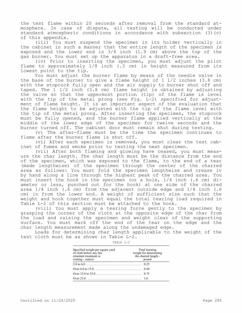
the test flame within 20 seconds after removal from the standard at-mosphere. In case of dispute, all testing will be conducted under standard atmospheric conditions in accordance with subsection (3)(c) of this appendix.
(iii) You must suspend the specimen in its holder vertically in the cabinet in such a manner that the entire length of the specimen is exposed and the lower end is 3/4 inch (1.9 cm) above the top of the gas burner. You must set up the apparatus in a draft-free area.
(iv) Prior to inserting the specimen, you must adjust the pilot flame to approximately 1/8 inch (.3 cm) in height measured from its lowest point to the tip.
You must adjust the burner flame by means of the needle valve in the base of the burner to give a flame height of 1 1/2 inches (3.8 cm) with the stopcock fully open and the air supply to burner shut off and taped. The 1 1/2 inch (3.8 cm) flame height is obtained by adjusting the valve so that the uppermost portion (tip) of the flame is level with the tip of the metal prong (see Fig. L-2) specified for adjust-ment of flame height. It is an important aspect of the evaluation that the flame height to be adjusted with the tip of the flame level with the tip of the metal prong. After inserting the specimen, the stopcock must be fully opened, and the burner flame applied vertically at the middle of the lower edge of the specimen for twelve seconds and the burner turned off. The cabinet door must remain shut during testing.
(v) The after-flame must be the time the specimen continues to flame after the burner flame is shut off.
(vi) After each specimen is removed, you must clear the test cab-inet of fumes and smoke prior to testing the next specimen.
(vii) After both flaming and glowing have ceased, you must meas-ure the char length. The char length must be the distance from the end of the specimen, which was exposed to the flame, to the end of a tear (made lengthwise) of the specimen through the center of the charred area as follows: You must fold the specimen lengthwise and crease it by hand along a line through the highest peak of the charred area. You must insert the hook in the specimen (or a hole, 1/4 inch (.6 cm) di-ameter or less, punched out for the hook) at one side of the charred area 1/4 inch (.6 cm) from the adjacent outside edge and 1/4 inch (.6 cm) in from the lower end. A weight of sufficient size such that the weight and hook together must equal the total tearing load required in Table L-2 of this section must be attached to the hook.
(viii) You must apply a tearing force gently to the specimen by grasping the corner of the cloth at the opposite edge of the char from the load and raising the specimen and weight clear of the supporting surface. You must mark off the end of the tear on the edge and the char length measurement made along the undamaged edge.
Loads for determining char length applicable to the weight of the test cloth must be as shown in Table L-2.
TABLE L-2
Specified weight per square yardof cloth before any fireretardant treatment orcoating - ounces
Total learningweight for determining
the charred length -pound
2.0 to 6.0 . . . . . . . . . . . . . . . . . . . . . . . . . . . . . . . . . . . . 0.25 Over 6.0 to 15.0 . . . . . . . . . . . . . . . . . . . . . . . . . . . . . . 0.50 Over 15.0 to 23.0 . . . . . . . . . . . . . . . . . . . . . . . . . . . . . 0.75 Over 23.0 . . . . . . . . . . . . . . . . . . . . . . . . . . . . . . . . . . . 1.0
Certified on 11/24/2020 Page 285

To change into S.I. (System International) units, 1 ounce =28.35 grams, 1 pound = 453 grams, 1 yard = .91 metre.
(ix) You must record the after-flame time of the specimen to the nearest 0.2 second and the char length to the nearest 0.1 inch (.3 cm).
(e) Report.(i) The after-flame time and char length of the sample unit must
be the average of the results obtained from the individual specimens tested. You must record all values obtained from the individual speci-mens.
(ii) You must report the after-flame time in the nearest 0.2 sec-ond and the char length to the nearest 0.1 inch (.3 cm).
(f) Source. These test requirements are contained in "Federal Test Method Standard 191, Method 5903 (1971)," and are reproduced for your convenience.
Figure L-1 - Vertical flame resistance textile apparatus. All given dimensions are in inches. System International (S.I.) unit: 1 inch = 2.54 cm.
Figure L-2 - Vertical flame resistance textile apparatus, door and top view w/baffle. All given dimensions are in inches. System Internation-al (S.I.) unit: 1 inch = 2.54 cm.
Certified on 11/24/2020 Page 286
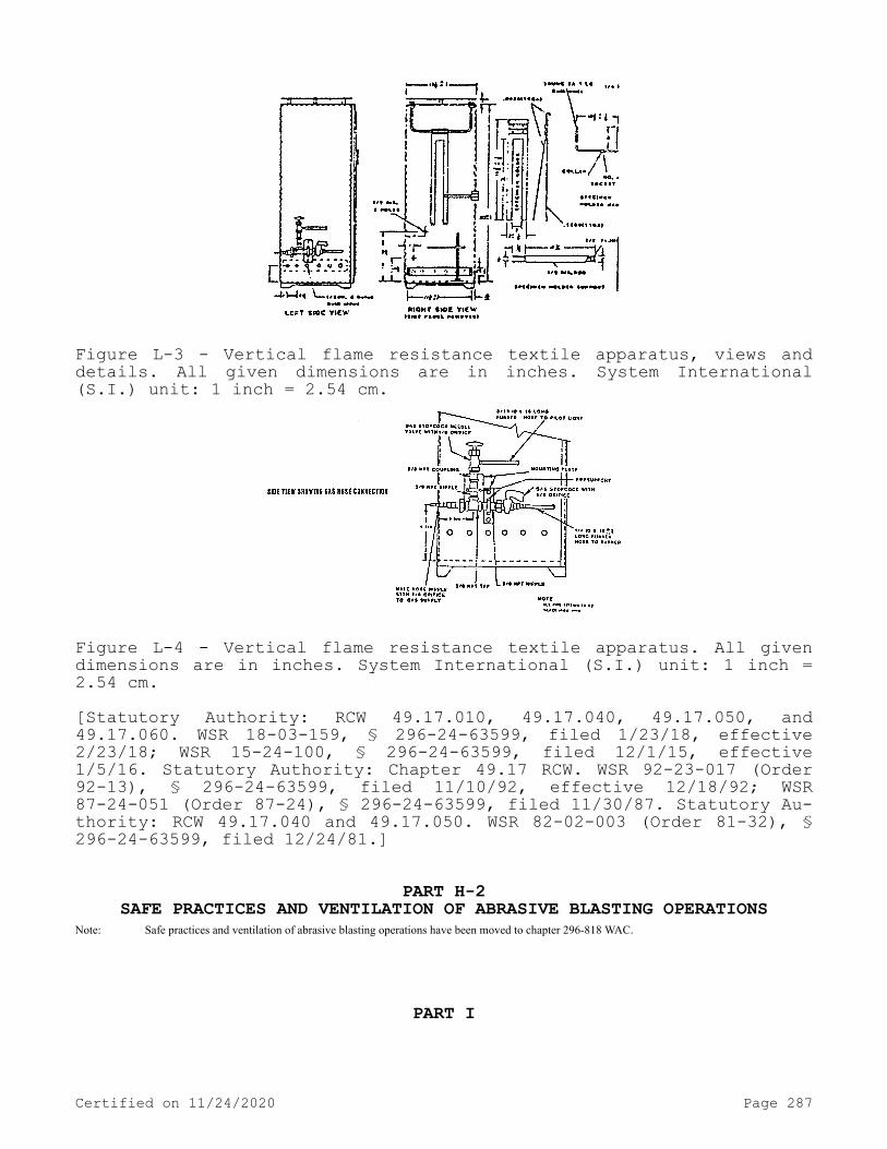
Figure L-3 - Vertical flame resistance textile apparatus, views and details. All given dimensions are in inches. System International (S.I.) unit: 1 inch = 2.54 cm.
Figure L-4 - Vertical flame resistance textile apparatus. All given dimensions are in inches. System International (S.I.) unit: 1 inch = 2.54 cm.[Statutory Authority: RCW 49.17.010, 49.17.040, 49.17.050, and 49.17.060. WSR 18-03-159, § 296-24-63599, filed 1/23/18, effective 2/23/18; WSR 15-24-100, § 296-24-63599, filed 12/1/15, effective 1/5/16. Statutory Authority: Chapter 49.17 RCW. WSR 92-23-017 (Order 92-13), § 296-24-63599, filed 11/10/92, effective 12/18/92; WSR 87-24-051 (Order 87-24), § 296-24-63599, filed 11/30/87. Statutory Au-thority: RCW 49.17.040 and 49.17.050. WSR 82-02-003 (Order 81-32), § 296-24-63599, filed 12/24/81.]
PART H-2SAFE PRACTICES AND VENTILATION OF ABRASIVE BLASTING OPERATIONS
Note: Safe practices and ventilation of abrasive blasting operations have been moved to chapter 296-818 WAC.
PART I
Certified on 11/24/2020 Page 287

WELDING, CUTTING AND BRAZING
WAC 296-24-680 Welding, cutting, and brazing. You must protect employees from exposure to hexavalent chromium during the stainless steel welding process. See WAC 296-62-08003, Hexavalent chromium for specific criteria.[Statutory Authority: RCW 49.17.010, 49.17.040, 49.17.050, and 49.17.060. WSR 15-24-100, § 296-24-680, filed 12/1/15, effective 1/5/16; WSR 06-16-106, § 296-24-680, filed 8/1/06, effective 9/1/06; Order 73-5, § 296-24-680, filed 5/9/73 and Order 73-4, § 296-24-680, filed 5/7/73.]
WAC 296-24-68001 Definitions. Welder and welding operator. Any operator of electric or gas welding and cutting equipment.
Approved. Listed or approved by a nationally recognized testing laboratory. Refer to WAC 296-24-58501(19) for definitions of listed and approved, and federal regulation 29 C.F.R. 1910.7 for nationally recognized testing laboratory.
All other welding terms are used in accordance with American Welding Society-Terms and Definitions-A3.0-1969.[Statutory Authority: RCW 49.17.010, 49.17.040, 49.17.050, and 49.17.060. WSR 15-24-100, § 296-24-68001, filed 12/1/15, effective 1/5/16. Statutory Authority: Chapter 49.17 RCW. WSR 88-23-054 (Order 88-25), § 296-24-68001, filed 11/14/88; Order 73-5, § 296-24-68001, filed 5/9/73 and Order 73-4, § 296-24-68001, filed 5/7/73.]
WAC 296-24-682 Installation and operation of oxygen fuel gas systems for welding and cutting.[Order 73-5, § 296-24-682, filed 5/9/73 and Order 73-4, § 296-24-682, filed 5/7/73.]
WAC 296-24-68201 General requirements. (1) Flammable mixture. You must guard against mixtures of fuel gases and air or oxygen may be explosive and. You must not allow any device or attachment facilitat-ing or permitting mixtures of air or oxygen with flammable gases prior to consumption, except at the burner or in a standard torch, unless approved for the purpose.
(2) Maximum pressure. You must not, under any condition generate, pipe (except in approved cylinder manifolds), or utilize acetylene at a pressure in excess of 15 p.s.i. gage pressure or 30 p.s.i. absolute pressure. (The 30 p.s.i. absolute pressure limit is intended to pre-vent unsafe use of acetylene in pressurized chambers such as caissons, underground excavations or tunnel construction.) This requirement does not apply to storage of acetylene dissolved in a suitable solvent in cylinders manufactured and maintained according to U.S. Department of Transportation requirements, or to acetylene for chemical use. You must not use liquid acetylene.
(3) Apparatus. You must use only approved apparatus such as torches, regulators or pressure-reducing valves, acetylene generators, and manifolds. Use of replacement tips will not nullify the "approved
Certified on 11/24/2020 Page 288
apparatus" status of a torch, if such replacement tips are made to the same specifications as the original tip of the torch at the time of approval by the nationally recognized testing laboratory, or if the use of such tips in conjunction with convertor/adaptors results in the same specifications as the original tip at the time of approval by the nationally recognized testing laboratory.
(4) Personnel. You must instruct and judge competent workers in charge of the oxygen or fuel-gas supply equipment, including genera-tors, and oxygen or fuel-gas distribution piping systems for this im-portant work before being left in charge. Rules and instructions cov-ering the operation and maintenance of oxygen or fuel-gas supply equipment including generators, and oxygen or fuel-gas distribution piping systems must be readily available.[Statutory Authority: RCW 49.17.010, 49.17.040, 49.17.050, and 49.17.060. WSR 15-24-100, § 296-24-68201, filed 12/1/15, effective 1/5/16. Statutory Authority: Chapter 49.17 RCW. WSR 94-15-096 (Order 94-07), § 296-24-68201, filed 7/20/94, effective 9/20/94; WSR 89-11-035 (Order 89-03), § 296-24-68201, filed 5/15/89, effective 6/30/89; Order 73-5, § 296-24-68201, filed 5/9/73 and Order 73-4, § 296-24-68201, filed 5/7/73.]
WAC 296-24-68203 Cylinders and containers. (1) Approval and marking. All portable cylinders used for the storage and shipment of compressed gases must be constructed and maintained in accordance with the regulations of the United States Department of Transportation, 49 C.F.R. Parts 171-179.
(a) You must legibly mark compressed gas cylinders, for the pur-pose of identifying the gas content, with either the chemical or the trade name of the gas. Such marking must be by means of stenciling, stamping, or labeling, and must not be readily removable. Whenever practical, you must locate the marking on the shoulder of the cylin-der.Note: This method conforms to the American National Standard Method for Marking Portable Compressed Gas Containers to Identify the Material
Contained, ANSI Z 48.1-1954.
(b) Compressed gas cylinders must be equipped with connections complying with the American National Standard Compressed Gas Cylinder Valve Outlet and Inlet Connections, ANSI B 57.1-1965.
(c) All cylinders with a water weight capacity of over thirty pounds must be equipped with means of connecting a valve protection cap or with a collar or recess to protect the valve.
(2) Storage of cylinders - General.(a) You must keep cylinders away from radiators and other sources
of heat.(b) Inside of buildings, you must store cylinders in a well-pro-
tected, well-ventilated, dry location, at least twenty feet from high-ly combustible materials such as oil or excelsior. Cylinders should be stored in definitely assigned places away from elevators, stairs, or gangways. You must locate assigned storage spaces where cylinders will not be knocked over or damaged by passing or falling objects, or sub-ject to tampering by unauthorized persons. You must not keep cylinders in unventilated enclosures such as lockers and cupboards.
(c) You must close the valves on all empty cylinders.(d) Valve protection caps, where cylinder is designed to accept a
cap, must always be in place, hand-tight, except when cylinders are in use or connected for use.
Certified on 11/24/2020 Page 289
(3) Fuel-gas cylinder storage. Inside a building, you must limit cylinders, except those in actual use or attached ready for use, to a total gas capacity of two thousand cubic feet or three hundred pounds of liquefied petroleum gas.
(a) For storage in excess of two thousand cubic feet total gas capacity of cylinders or three hundred pounds of liquefied petroleum gas, you must provide a separate room or compartment conforming to the requirements specified in WAC 296-24-68211 (6)(h) and (i), or you must keep cylinders outside or in a special building. Special buildings, rooms or compartments must have no open flame for heating or lighting and must be well ventilated. They may also be used for storage of cal-cium carbide in quantities not to exceed six hundred pounds, when con-tained in metal containers complying with WAC 296-24-68213 (1)(a) and (b). Signs should be conspicuously posted in such rooms reading, "Dan-ger—No smoking, matches or open lights," or other equivalent wording.
(b) You must store acetylene cylinders valve end up.(4) Oxygen storage.(a) You must not store oxygen cylinders near highly combustible
material, especially oil and grease; or near reserve stocks of carbide and acetylene or other fuel-gas cylinders, or near any other substance likely to cause or accelerate fire; or in an acetylene generator com-partment.
(b) You must separate oxygen cylinders stored in outside genera-tor houses from the generator or carbide storage rooms by a noncombus-tible partition having a fire-resistance rating of at least one hour. This partition must be without openings and must be gastight.
(c) You must separate oxygen cylinders in storage from fuel-gas cylinders or combustible materials (especially oil or grease), a mini-mum distance of twenty feet or by a noncombustible barrier at least five feet high having a fire-resistance rating of at least one-half hour. (Cylinders "in-use," secured to a hand truck or structural mem-ber, with regulators, hoses, and torch temporarily removed for securi-ty purposes overnight or weekends, are not considered "in-storage.")
(d) Where a liquid oxygen system is to be used to supply gaseous oxygen for welding or cutting and the system has a storage capacity of more than 13,000 cubic feet of oxygen (measured at 14.7 psi(a) and 70°F), connected in service or ready for service, or more than twenty-five thousand cubic feet of oxygen (measured at 14.7 psi(a) and 70°F), including unconnected reserves on hand at the site, it must comply with the provisions of the Standard for Bulk Oxygen Systems at Consum-er Sites, NFPA No. 566-1965.
(5) Operating procedures.(a) You must keep cylinders, cylinder valves, couplings, regula-
tors, hose, and apparatus free from oily or greasy substances. You must not handle oxygen cylinders or apparatus with oily hands or gloves. A jet of oxygen must never be permitted to strike an oily sur-face, greasy clothes, or enter a fuel oil or other storage tank.
(b) When transporting cylinders by a crane or derrick, you must use a cradle, boat, or suitable platform. You must not use slings or electric magnets for this purpose. Valve-protection caps, where cylin-der is designed to accept a cap, must always be in place.
(c) You must not drop or strike cylinders, nor must you permit them to strike each other violently.
(d) You must not use valve-protection caps for lifting cylinders from one vertical position to another. You must not use bars under valves or valve-protection caps to pry cylinders loose when frozen to
Certified on 11/24/2020 Page 290

the ground or otherwise fixed; the use of warm (not boiling) water is recommended. Valve-protection caps are designed to protect cylinder valves from damage.
(e) Unless cylinders are secured on a special truck, you must re-move regulators and you must put valve-protection caps in place, when provided for, before cylinders are moved.
(f) Cylinders not having fixed hand wheels must have keys, han-dles, or nonadjustable wrenches on valve stems while these cylinders are in service. In multiple cylinder installations only one key or handle is required for each manifold.
(g) You must close cylinder valves before moving cylinders.(h) You must close cylinder valves when work is finished.(i) You must close valves of empty cylinders.(j) You must keep cylinders far enough away from the actual weld-
ing or cutting operation so that sparks, hot slag, or flame will not reach them, or you must provide fire-resistant shields.
(k) You must not place cylinders where they might become part of an electric circuit. You must avoid contacts with third rails, trolley wires, etc. You must keep cylinders away from radiators, piping sys-tems, layout tables, etc., that may be used for grounding electric circuits such as for arc welding machines. You must prohibit any prac-tice such as the tapping of an electrode against a cylinder to strike an arc.
(l) You must never use cylinders as rollers or supports, whether full or empty.
(m) You must not tamper with the numbers and markings stamped in-to cylinders.
(n) You must not attempt to mix gases in a cylinder unless you are a gas supplier. You must not refill a cylinder unless you are the owner of the cylinder or the person authorized by the owner.
(o) You must not tamper with safety devices in cylinders or valves.
(p) You must not drop or otherwise roughly handle cylinders.(q) Unless connected to a manifold, you must not use oxygen from
a cylinder without first attaching an oxygen regulator to the cylinder valve. Before connecting the regulator to the cylinder valve, you must open the valve slightly for an instant and then close it. (Always stand to one side of the outlet when opening the cylinder valve.)
(r) You must not use a hammer or wrench to open cylinder valves. If valves cannot be opened by hand, you must notify the supplier.
(s) You must not tamper with or make any attempt to repair cylin-der valves. If trouble is experienced, the supplier should be sent a report promptly indicating the character of the trouble and the cylin-der's serial number. You must follow supplier's instructions as to its disposition.
(t) You must avoid complete removal of the stem from a diaphragm-type cylinder valve.
(u) You must place fuel-gas cylinders with valve end up whenever they are in use. You must store and ship liquefied gases with the valve end up.
(v) You must handle cylinders carefully. You must not subject cylinders to rough handling, knocks, or falls which are liable to dam-age the cylinder, valve or safety devices and cause leakage.
(w) Before connecting a regulator to a cylinder valve, you must open the valve slightly and closed immediately. You must open the valve while standing to one side of the outlet; never in front of it.
Certified on 11/24/2020 Page 291

You must not crack fuel-gas cylinder valves near other welding work or near sparks, flame, or other possible sources of ignition.
(x) Before a regulator is removed from a cylinder valve, you must close the cylinder valve and release the gas from the regulator.
(y) You must not place anything on top of an acetylene cylinder when in use which may damage the safety device or interfere with the quick closing of the valve.
(z) If cylinders are found to have leaky valves or fittings which cannot be stopped by closing of the valve, you must take the cylinders outdoors away from sources of ignition and slowly emptied.
(aa) A warning should be placed near cylinders having leaking fuse plugs or other leaking safety devices not to approach them with a lighted cigarette or other source of ignition. Such cylinders should be plainly tagged; the supplier should be promptly notified and you must follow instructions provided by the supplier as to their return.
(bb) You must not tamper with safety devices.(cc) You must not use fuel-gas from cylinders through torches or
other devices equipped with shutoff valves without reducing the pres-sure through a suitable regulator attached to the cylinder valve or manifold.
(dd) You must always open the cylinder valve slowly.(ee) You must not open an acetylene cylinder valve more than 1
1/2 turns of the spindle, and preferably no more than 3/4 of a turn.(ff) Where a special wrench is required you must leave it in po-
sition on the stem of the valve while the cylinder is in use so that the fuel-gas flow can be quickly turned off in case of emergency. In the case of manifolded or coupled cylinders at least one such wrench must always be available for immediate use.
(gg) When cylinders are transported by powered vehicle you must secure them in a vertical position.
(hh) You must use a suitable cylinder truck, chain, or other steadying device shall be used to prevent cylinders from being knocked over while in use.[Statutory Authority: RCW 49.17.010, 49.17.040, 49.17.050, and 49.17.060. WSR 15-24-100, § 296-24-68203, filed 12/1/15, effective 1/5/16. Statutory Authority: Chapter 49.17 RCW. WSR 91-03-044 (Order 90-18), § 296-24-68203, filed 1/10/91, effective 2/12/91; WSR 88-11-021 (Order 88-04), § 296-24-68203, filed 5/11/88; Order 73-5, § 296-24-68203, filed 5/9/73 and Order 73-4, § 296-24-68203, filed 5/7/73.]
WAC 296-24-68205 Manifolding of cylinders. (1) Fuel-gas mani-folds.
(a) You must approve manifolds either separately for each compo-nent part or as an assembled unit.
(b) Except as provided in (1)(c) of this section you must limit fuel-gas cylinders connected to one manifold inside a building to a total capacity not exceeding 300 pounds of liquefied petroleum gas or 3,000 cubic feet of other fuel-gas. More than one such manifold with connected cylinders may be located in the same room provided the mani-folds are at least 50 feet apart or separated by a noncombustible bar-rier at least 5 feet high having a fire-resistance rating of at least one-half hour.
(c) You must locate fuel-gas cylinders connected to one manifold having an aggregate capacity exceeding 300 pounds of liquefied petro-
Certified on 11/24/2020 Page 292

leum gas or 3,000 cubic feet of other fuel-gas outdoors, or in a sepa-rate building or room constructed in accordance with WAC 296-24-68211 (6)(h) and (i).
(d) Separate manifold buildings or rooms may also be used for the storage of drums of calcium carbide and cylinders containing fuel gases as provided in WAC 296-24-68203(3). Such buildings or rooms must have no open flames for heating or lighting and must be well-ventila-ted.
(e) You must provide high-pressure fuel-gas manifolds with ap-proved pressure regulating devices.
(2) High-pressure oxygen manifolds (for use with cylinders having a department of transportation service pressure above 200 p.s.i.g.).
(a) You must approve manifolds either separately for each compo-nent or as an assembled unit.
(b) You must not locate oxygen manifolds in an acetylene genera-tor room. You must separate oxygen manifolds from fuel-gas cylinders or combustible materials (especially oil or grease), a minimum dis-tance of 20 feet or by a noncombustible barrier at least 5 feet high having a fire-resistance rating of at least one-half hour.
(c) Except as provided in WAC 296-24-68205 (2)(d) you must limit oxygen cylinders connected to one manifold to a total gas capacity of 6,000 cubic feet. More than one such manifold with connected cylinders may be located in the same room provided the manifolds are at least 50 feet apart or separated by a noncombustible barrier at least 5 feet high having a fire-resistance rating of at least one-half hour.
(d) An oxygen manifold, to which cylinders having an aggregate capacity of more than 6,000 cubic feet of oxygen are connected, should be located outdoors or in a separate noncombustible building. You must locate such a manifold, if located inside a building having other oc-cupancy, in a separate room of noncombustible construction having a fire-resistance rating of at least 1/2 hour or in an area with no com-bustible material within 20 feet of the manifold.
(e) An oxygen manifold or oxygen bulk supply system which has storage capacity of more than 13,000 cubic feet of oxygen (measured at 14.7 p.s.i.a. and 70°F), connected in service or ready for service, or more than 25,000 cubic feet of oxygen (measured at 14.7 p.s.i.a. and 70°F), including unconnected reserves on hand at the site, must comply with the provisions of the Standard for Bulk Oxygen Systems at Consum-er Sites, NFPA No. 566-1965.
(f) You must provide high-pressure oxygen manifolds with approved pressure-regulating devices.
(3) Low-pressure oxygen manifolds (for use with cylinders having a department of transportation service pressure not exceeding 200 p.s.i.g.).
(a) Manifolds must be of substantial construction suitable for use with oxygen at a pressure of 250 p.s.i.g. They must have a minimum bursting pressure of 1,000 p.s.i.g. and you must protect them by a safety relief device which will relieve at a maximum pressure of 500 p.s.i.g.Note: DOT-4L200 cylinders have safety devices which relieve at a maximum pressure of 250 p.s.i.g. (or 235 p.s.i.g. if vacuum insulation is used).
(b) Hose and hose connections subject to cylinder pressure must comply with WAC 296-24-68209(5). Hose must have a minimum bursting pressure of 1,000 p.s.i.g.
(c) You must test the assembled manifold including leads and prove them to be gas-tight at a pressure of 300 p.s.i.g. The fluid
Certified on 11/24/2020 Page 293

used for testing oxygen manifolds must be oil-free and not combusti-ble.
(d) The location of manifolds must comply with WAC 296-24-68205 (2)(b), (c), (d) and (e).
(e) You must conspicuously post the following sign at each mani-fold:
Low-Pressure ManifoldDo Not Connect High-Pressure Cylinders
Maximum Pressure—250 P.S.I.G.(4) Portable outlet headers.(a) You must not use portable outlet headers indoors except for
temporary service where the conditions preclude a direct supply from outlets located on the service piping system.
(b) You must equip each outlet on the service piping from which oxygen or fuel-gas is withdrawn to supply a portable outlet header with a readily accessible shutoff valve.
(c) Hose and hose connections used for connecting the portable outlet header to the service piping must comply with WAC 296-24-68209(5).
(d) You must provide master shutoff valves for both oxygen and fuel-gas at the entry end of the portable outlet header.
(e) You must provide portable outlet headers for fuel-gas service with an approved hydraulic back-pressure valve installed at the inlet and preceding the service outlets, unless an approved pressure-reduc-ing regulator, an approved backflow check valve, or an approved hy-draulic back-pressure valve is installed at each outlet. Outlets pro-vided on headers for oxygen service may be fitted for use with pres-sure-reducing regulators or for direct hose connection.
(f) You must provide each service outlet on portable outlet head-ers with a valve assembly that includes a detachable outlet seal cap, chained or otherwise attached to the body of the valve.
(g) Materials and fabrication procedures for portable outlet headers must comply with WAC 296-24-68207 (1), (2) and (5).
(h) You must provide portable outlet headers with frames which will support the equipment securely in the correct operating position and protect them from damage during handling and operation.
(5) Manifold operating procedures.(a) You must install cylinder manifolds under the supervision of
someone familiar with the proper practices with reference to their construction and use.
(b) You must approve all component parts used in the methods of manifolding described in (1)(a) through (e) of this section as to ma-terials, design and construction either separately or as an assembled unit.
(c) You must use all manifolds and parts used in methods of mani-folding only for the gas or gases for which they are approved.
(d) When acetylene cylinders are coupled, you must install ap-proved flash arresters between each cylinder and the coupler block. For outdoor use only, and when the number of cylinders coupled does not exceed three, one flash arrester installed between the coupler block and regulator is acceptable.
(e) Each fuel-gas cylinder lead should be provided with a back-flow check valve.
Certified on 11/24/2020 Page 294
(f) The aggregate capacity of fuel-gas cylinders connected to a portable manifold inside a building must not exceed 3,000 cubic feet of gas.
(g) You must manifold acetylene and liquefied fuel-gas cylinders in a vertical position.
(h) The pressure in the gas cylinders connected to and discharged simultaneously through a common manifold must be approximately equal.[Statutory Authority: RCW 49.17.010, 49.17.040, 49.17.050, and 49.17.060. WSR 15-24-100, § 296-24-68205, filed 12/1/15, effective 1/5/16; Order 73-5, § 296-24-68205, filed 5/9/73 and Order 73-4, § 296-24-68205, filed 5/7/73.]
WAC 296-24-68207 Service piping systems. (1) Materials and de-sign. (a) Piping and fittings must comply with Section 2, Industrial Gas and Air Piping Systems, of the American National Standard Code for Pressure Piping, ANSI B 31.1-1967, insofar as it does not conflict with WAC 296-24-68207 (1)(b) and (c).
(b) Pipe must be at least Schedule 40 and fittings must be at least standard weight in sizes up to and including 6-inch nominal.
(c) Copper tubing must be Types K or L in accordance with the Standard Specification for Seamless Copper Water Tube, ASTM B88-66a.
(d) Piping must be steel, wrought iron, brass or copper pipe, or seamless copper, brass or stainless steel tubing, except as provided in WAC 296-24-68207 (1)(e), (f), (g), (h) and (i).
(e) Oxygen piping and fittings at pressures in excess of 700 p.s.i.g., must be stainless steel or copper alloys.
(f) Hose connections and hose complying with WAC 296-24-68209(5) may be used to connect the outlet of a manifold pressure regulator to piping providing the working pressure of the piping is 250 p.s.i.g. or less and the length of the hose does not exceed 5 feet. Hose must have a minimum bursting pressure of 1,000 p.s.i.g.
(g) When oxygen is supplied to a service piping system from a low-pressure oxygen manifold without an intervening pressure regulat-ing device, the piping system must have a minimum design pressure of 250 p.s.i.g. You must use a pressure regulating device at each station outlet when the connected equipment is for use at pressures less than 250 p.s.i.g.
(h) Piping for acetylene or acetylenic compounds must be steel or wrought iron.
(i) You must not use unalloyed copper for acetylene or acetylenic compounds except in listed equipment.
(2) Piping joints.(a) You must weld, thread, or flange joints in steel or wrought
iron piping. Fittings, such as ells, tees, couplings, and unions, may be rolled, forged or cast steel, malleable iron or nodular iron. Gray or white cast iron fittings are prohibited.
(b) You must weld, braze, thread, or flange joints in brass or copper pipe. If of the socket type, you must braze them with silver-brazing alloy or similar high melting point (not less than 800°F) filler metal.
(c) Joints in seamless copper, brass, or stainless steel tubing must be approved gas tubing fittings or you must braze the joints. If of the socket type, they shall be brazed with silver-brazing alloy or similar high melting point (not less than 800°F) filler metal.
(3) Installation.
Certified on 11/24/2020 Page 295

(a) You must install and maintain distribution lines in a safe operating condition.
(b) Piping located inside or outside of buildings may be placed above or below ground. You must run all piping as directly as practi-cable, protected against physical damage, proper allowance being made for expansion and contraction, jarring and vibration. You must locate pipe laid underground in earth below the frost line and protected against corrosion. After assembly, you must thoroughly blow out piping with air or nitrogen to remove foreign materials. For oxygen piping, you must use only oil-free air, oil-free nitrogen, or oil-free carbon dioxide.
(c) You must install only piping which has been welded or brazed in tunnels, trenches or ducts. Shutoff valves must be located outside such conduits. Oxygen piping may be placed in the same tunnel, trench or duct with fuel-gas pipelines, provided there is good natural or forced ventilation.
(d) You must drain low points in piping carrying moist gas into drip pots constructed so as to permit pumping or draining out the con-densate at necessary intervals. You must install drain valves for this purpose having outlets normally closed with screw caps or plugs. You must not use any open end valves or petcocks, except that in drips lo-cated out of doors, underground, and not readily accessible, valves may be used at such points if they are equipped with means to secure them in the closed position. You must case or jacket pipes leading to the surface of the ground where necessary to prevent loosening or breaking.
(e) You must provide gas cocks or valves for all buildings at points where they will be readily accessible for shutting off the gas supply to these buildings in any emergency. Underground valve boxes or manholes should be avoided wherever possible. You must also provide a shutoff valve in the discharge line from the generator, gas holder, manifold or other source of supply.
(f) You must not install shutoff valves in safety relief lines in such a manner that the safety relief device can be rendered ineffec-tive.
(g) You must examine fittings and lengths of pipe internally be-fore assembly and, if necessary, freed from scale or dirt. You must wash out oxygen piping and fittings with a suitable solution which will effectively remove grease and dirt but will not react with oxy-gen.Note: Hot water solutions of caustic soda or trisodium phosphate are effective cleaning agents for this purpose.
(h) You must thoroughly blow out piping after assembly to remove foreign materials. For oxygen piping, you must use oil-free air, oil-free nitrogen, or oil-free carbon dioxide. For other piping, air or inert gas may be used.
(i) When flammable gas lines or other parts of equipment are be-ing purged of air or gas, you must not permit open lights or other sources of ignition near uncapped openings.
(j) You must not perform any welding or cutting on an acetylene or oxygen pipeline, including the attachment of hangers or supports, until the line has been purged. You must use only oil-free air, oil-free nitrogen, or oil-free carbon dioxide to purge oxygen lines.
(4) Painting and signs.(a) You must cover or paint underground pipe and tubing and out-
door ferrous pipe and tubing with a suitable material for protection against corrosion.
Certified on 11/24/2020 Page 296
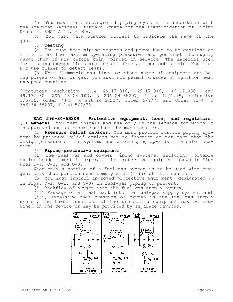
(b) You must mark aboveground piping systems in accordance with the American National Standard Scheme for the Identification of Piping Systems, ANSI A 13.1-1956.
(c) You must mark station outlets to indicate the name of the gas.
(5) Testing.(a) You must test piping systems and prove them to be gastight at
1 1/2 times the maximum operating pressure, and you must thoroughly purge them of air before being placed in service. The material used for testing oxygen lines must be oil free and noncombustible. You must not use flames to detect leaks.
(b) When flammable gas lines or other parts of equipment are be-ing purged of air or gas, you must not permit sources of ignition near uncapped openings.[Statutory Authority: RCW 49.17.010, 49.17.040, 49.17.050, and 49.17.060. WSR 15-24-100, § 296-24-68207, filed 12/1/15, effective 1/5/16; Order 73-5, § 296-24-68207, filed 5/9/73 and Order 73-4, § 296-24-68207, filed 5/7/73.]
WAC 296-24-68209 Protective equipment, hose, and regulators. (1) General. You must install and use only in the service for which it is approved and as recommended by the manufacturer.
(2) Pressure relief devices. You must protect service piping sys-tems by pressure relief devices set to function at not more than the design pressure of the systems and discharging upwards to a safe loca-tion.
(3) Piping protective equipment.(a) The fuel-gas and oxygen piping systems, including portable
outlet headers must incorporate the protective equipment shown in Fig-ures Q-1, Q-2, and Q-3.
When only a portion of a fuel-gas system is to be used with oxy-gen, only that portion need comply with (3)(a) of this section.
(b) You must install approved protective equipment (designated PF in Figs. Q-1, Q-2, and Q-3) in fuel-gas piping to prevent:
(i) Backflow of oxygen into the fuel-gas supply system;(ii) Passage of a flash back into the fuel-gas supply system; and(iii) Excessive back pressure of oxygen in the fuel-gas supply
system. The three functions of the protective equipment may be com-bined in one device or may be provided by separate devices.
Certified on 11/24/2020 Page 297
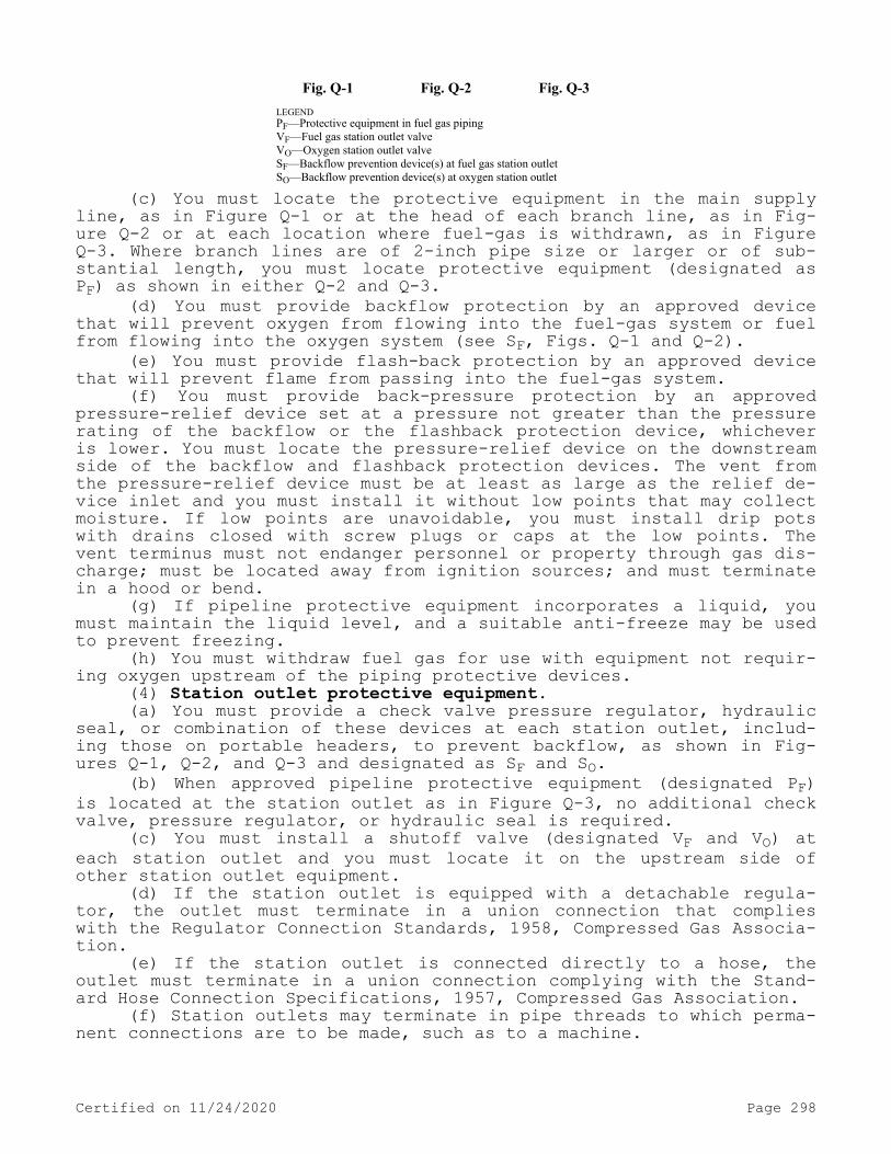
Fig. Q-1 Fig. Q-2 Fig. Q-3 LEGEND PF—Protective equipment in fuel gas piping VF—Fuel gas station outlet valve VO—Oxygen station outlet valve SF—Backflow prevention device(s) at fuel gas station outlet SO—Backflow prevention device(s) at oxygen station outlet
(c) You must locate the protective equipment in the main supply line, as in Figure Q-1 or at the head of each branch line, as in Fig-ure Q-2 or at each location where fuel-gas is withdrawn, as in Figure Q-3. Where branch lines are of 2-inch pipe size or larger or of sub-stantial length, you must locate protective equipment (designated as PF) as shown in either Q-2 and Q-3.
(d) You must provide backflow protection by an approved device that will prevent oxygen from flowing into the fuel-gas system or fuel from flowing into the oxygen system (see SF, Figs. Q-1 and Q-2).
(e) You must provide flash-back protection by an approved device that will prevent flame from passing into the fuel-gas system.
(f) You must provide back-pressure protection by an approved pressure-relief device set at a pressure not greater than the pressure rating of the backflow or the flashback protection device, whichever is lower. You must locate the pressure-relief device on the downstream side of the backflow and flashback protection devices. The vent from the pressure-relief device must be at least as large as the relief de-vice inlet and you must install it without low points that may collect moisture. If low points are unavoidable, you must install drip pots with drains closed with screw plugs or caps at the low points. The vent terminus must not endanger personnel or property through gas dis-charge; must be located away from ignition sources; and must terminate in a hood or bend.
(g) If pipeline protective equipment incorporates a liquid, you must maintain the liquid level, and a suitable anti-freeze may be used to prevent freezing.
(h) You must withdraw fuel gas for use with equipment not requir-ing oxygen upstream of the piping protective devices.
(4) Station outlet protective equipment.(a) You must provide a check valve pressure regulator, hydraulic
seal, or combination of these devices at each station outlet, includ-ing those on portable headers, to prevent backflow, as shown in Fig-ures Q-1, Q-2, and Q-3 and designated as SF and SO.
(b) When approved pipeline protective equipment (designated PF) is located at the station outlet as in Figure Q-3, no additional check valve, pressure regulator, or hydraulic seal is required.
(c) You must install a shutoff valve (designated VF and VO) at each station outlet and you must locate it on the upstream side of other station outlet equipment.
(d) If the station outlet is equipped with a detachable regula-tor, the outlet must terminate in a union connection that complies with the Regulator Connection Standards, 1958, Compressed Gas Associa-tion.
(e) If the station outlet is connected directly to a hose, the outlet must terminate in a union connection complying with the Stand-ard Hose Connection Specifications, 1957, Compressed Gas Association.
(f) Station outlets may terminate in pipe threads to which perma-nent connections are to be made, such as to a machine.
Certified on 11/24/2020 Page 298

(g) You must equip station outlets with a detachable outlet seal cap secured in place. You must use this cap to seal the outlet except when a hose, a regulator, or piping is attached.
(h) Where station outlets are equipped with approved backflow and flashback protective devices, as many as four torches may be supplied from one station outlet through rigid piping, provided each outlet from such piping, is equipped with a shutoff valve and provided the fuel-gas capacity of any one torch does not exceed 15 cubic feet per hour. This rule does not apply to machines.
(5) Hose and hose connections.(a) Hose for oxy-fuel gas service must comply with the Specifica-
tion for Rubber Welding Hose, 1958, Compressed Gas Association and Rubber Manufacturers Association.
(b) The generally recognized colors are red for acetylene and other fuel-gas hose, green for oxygen hose, and black for inert-gas and air hose.
(c) When parallel lengths of oxygen and acetylene hose are taped together for convenience and to prevent tangling, you must cover not more than 4 inches out of 12 inches by tape.
(d) Hose connections must comply with the Standard Hose Connec-tion Specifications, 1957, Compressed Gas Association.
(e) You must clamp or otherwise securely fasten connections in a manner that will withstand, without leakage, twice the pressure to which they are normally subjected in service, but in no case less than a pressure of 300 p.s.i. You must use oil-free air or an oil-free in-ert gas for the test.
(f) You must repair or replace hose showing leaks, burns, worn places, or other defects rendering it unfit for service.
(6) Pressure-reducing regulators.(a) You must use pressure-reducing regulators only for the gas
and pressures for which they are intended. The regulator inlet connec-tions must comply with Regulator Connection Standards, 1958, Com-pressed Gas Association.
(b) When regulators or parts of regulators, including gages, need repair, the work must be performed by skilled mechanics who have been properly instructed.
(c) You must mark gauges on oxygen regulators "USE NO OIL."(d) You must inspect union nuts and connections on regulators be-
fore use to detect faulty seats which may cause leakage of gas when the regulators are attached to the cylinder valves. You must destroy damaged nuts or connections.[Statutory Authority: RCW 49.17.010, 49.17.040, 49.17.050, and 49.17.060. WSR 15-24-100, § 296-24-68209, filed 12/1/15, effective 1/5/16; Order 73-5, § 296-24-68209, filed 5/9/73 and Order 73-4, § 296-24-68209, filed 5/7/73.]
WAC 296-24-68211 Acetylene generators. (1) Approval and mark-ing.
(a) Generators must be of approved construction and you must plainly mark them with the maximum rate of acetylene in cubic feet per hour for which they are designed; the weight and size of carbide nec-essary for a single charge; the manufacturer's name and address; and the name or number of the type of generator.
(b) Carbide must be of the size marked on the generator name-plate.
Certified on 11/24/2020 Page 299

(2) Rating and pressure limitations.(a) The total hourly output of a generator must not exceed the
rate for which it is approved and marked. Unless specifically approved for higher ratings, carbide-feed generators must be rated at 1 cubic foot per hour per pound of carbide required for a single complete charge.
(b) You must regularly operate relief valves to ensure proper functioning. You must set relief valves for generating chambers to open at a pressure not in excess of 15 p.s.i.g. You must set relief valves for hydraulic back pressure valves to open at a pressure not in excess of 20 p.s.i.g.
(c) You must not use nonautomatic generators for generating ace-tylene at pressures exceeding 1 p.s.i.g., and all water overflows must be visible.
(3) Location. The space around the generator be ample for free, unobstructed operation and maintenance and permit ready adjustment and charging.
(4) Stationary acetylene generators (automatic and nonautomatic).(a) You must arrange the foundation so that the generator will be
level and so that no excessive strain will be placed on the generator or its connections. You must ground acetylene generators.
(b) You must place generators where water will not freeze. The use of common salt (sodium chloride) or other corrosive chemicals for protection against freezing is not permitted. (For heating systems see WAC 296-24-68211 (6)(k).)
(c) Except when generators are prepared in accordance with WAC 296-24-68211 (7)(i), you must prohibit sources of ignition in outside generator houses or inside generator rooms.
(d) You must not supply water through a continuous connection to the generator except when the generator is provided with an adequate open overflow or automatic water shutoff which will effectively pre-vent overfilling of the generator. Where a noncontinuous connection is used, the supply line must terminate at a point not less than 2 inches above the regularly provided opening for filling so that the water can be observed as it enters the generator.
(e) Unless otherwise specifically approved, generators must not be fitted with continuous drain connections leading to sewers, but must discharge through an open connection into a suitably vented out-door receptacle or residue pit which may have such connections. An open connection for the sludge drawoff is desirable to enable the gen-erator operator to observe leakage of generating water from the drain valve or sludge cock.
(f) You must provide each generator with a vent pipe of Schedule 40 galvanized iron or steel, except that outside of buildings, vent pipes larger than 4 inches in diameter may be not less than 14 gage galvanized tubing or sheet steel.
(g) You must rigidly install escape or relief pipe without traps and so that any condensation will drain back to the generator.
(h) You must carry the escape or relief pipe full size to a suit-able point outside the building. It must terminate in a hood or bend located at least 12 feet above the ground, preferably above the roof, and as far away as practicable from windows or other openings into buildings and as far away as practicable from sources of ignition such as flues or chimneys and tracks used by locomotives. Generating cham-ber relief pipes must not be inter-connected but must be separately led to the outside air. The hood or bend must be so constructed that
Certified on 11/24/2020 Page 300

it will not be obstructed by rain, snow, ice, insects, or birds. The outlet must be at least 3 feet from combustible construction.
(i) Gas holders must be constructed on the gasometer principle, the bell being suitably guided. The gas bell must move freely without tendency to bind and must have a clearance of at least 2 inches from the shell.
(j) The gas holder may be located in the generator room, in a separate room or out of doors. In order to prevent collapse of the gas bell or infiltration of air due to a vacuum caused by the compressor or booster pump or cooling of the gas, a compressor or booster cutoff must be provided at a point 12 inches or more above the landing point of the bell. When the gas holder is located indoors, the room must be ventilated in accordance with WAC 296-24-68211 (6)(j) and heated and lighted in accordance with WAC 296-24-68211 (6)(k) and (1).
(k) When the gas holder is not located within a heated building, you must protect gas holder seals against freezing.
(l) You must provide means to stop the generator-feeding mecha-nism before the gas holder reaches the upper limit of its travel.
(m) When the gas holder is connected to only one generator, the gas capacity of the holder must be not less than 1/3 of the hourly rating of the generator.
(n) If acetylene is used from the gas holder without increase in pressure at some points but with increase in pressure by a compressor or booster pump at other points, you must install approved piping pro-tective devices in each supply line. You must locate the low-pressure protective device between the gas holder and the shop piping, and you must locate the medium-pressure protective device between the compres-sor or booster pump and the shop piping (see Figure Q-4). Approved protective equipment (designated PF) is used to prevent: Backflow of oxygen into the fuel-gas supply system; passage of a flashback into the fuel-gas supply system; and excessive back pressure of oxygen in the fuel-gas supply system. The three functions of the protective equipment may be combined in one device or may be provided by separate devices.
Figure Q-4
(o) The compressor or booster system must be of an approved type.(p) Wiring and electrical equipment in compressor or booster pump
rooms or enclosures must conform to the provisions of chapter 296-24 WAC Part L for Class I, Division 2 locations.
Certified on 11/24/2020 Page 301

(q) You must locate compressors and booster pump equipment in well-ventilated areas away from open flames, electrical or mechanical sparks, or other ignition sources.
(r) You must provide compressor or booster pumps with pressure relief valves which will relieve pressure exceeding 15 p.s.i.g. to a safe outdoor location as provided in WAC 296-24-68211 (2)(b), or by returning the gas to the inlet side or to the gas supply source.
(s) You must provide compressor or booster pump discharge outlets with approved protective equipment. (See WAC 296-24-68211 (4)(e).)
(5) Portable acetylene generators.(a) All portable generators must be of a type approved for porta-
ble use.(b) You must not use portable generators within 10 feet of com-
bustible material other than the floor.(c) You must not use portable generators in rooms of total volume
less than 35 times the total gas-generating capacity per charge of all generators in the room. You must not use generators in rooms having a ceiling height of less than 10 feet. (To obtain the gas-generating ca-pacity in cubic feet per charge, multiply the pounds of carbide per charge by 4.5.)
(d) You must protect portable generators against freezing. The use of salt or other corrosive chemical to prevent freezing is pro-hibited.
(e) You must clean and recharge generators and the air mixture blown off outside buildings.
(f) When charged with carbide, you must not move portable genera-tors by crane or derrick.
(g) When not in use, you must not store portable generators in rooms in which open flames are used unless the generators contain no carbide and have been thoroughly purged of acetylene. Storage rooms must be well ventilated.
(h) When portable acetylene generators are to be transported and operated on vehicles, you must securely anchor them to the vehicles. If transported by truck, you must turn off the motor during charging, cleaning, and generating periods.
(i) You must locate portable generators at a safe distance from the welding position so that they will not be exposed to sparks, slag, or misdirection of the torch flame or overheating from hot materials or processes.
(6) Outside generator houses and inside generator rooms for sta-tionary acetylene generators.
(a) You must not locate any opening in any outside generator house within 5 feet of any opening in another building.
(b) Walls, floors and roofs of outside generator houses must be of noncombustible construction.
(c) When a part of the generator house is to be used for the storage or manifolding of oxygen cylinders, you must separate the space to be so occupied from the generator carbide storage section by partition walls continuous from floor to roof or ceiling, of the type of construction stated in WAC 296-24-68211 (6)(h). Such separation walls must be without openings and must be joined to the floor, other walls and ceiling or roof in a manner to effect a permanent gas-tight joint.
(d) You must locate exit doors so as to be readily accessible in case of emergency.
(e) You must provide explosion venting for outside generator houses and inside generator rooms in exterior walls or roofs. The
Certified on 11/24/2020 Page 302
venting areas must be equal to not less than 1 square foot per 50 cu-bic feet of room volume and may consist of any one or any combination of the following: Walls of light, noncombustible material preferably single-thickness, single-strength glass; lightly fastened hatch cov-ers; lightly fastened swinging doors in exterior walls opening out-ward; lightly fastened walls or roof designed to relieve at a maximum pressure of 25 pounds per square foot.
(f) You must restrict the installation of acetylene generators within buildings to buildings not exceeding one story in height: Pro-vided, however, That this will not be construed as prohibiting such installations on the roof or top floor of a building exceeding such height.
(g) You must enclose generators installed inside buildings in a separate room of ample size.
(h) The walls, partitions, floors, and ceilings of inside genera-tor rooms must be of noncombustible construction having a fire-resist-ance rating of at least one hour. The walls or partitions must be con-tinuous from floor to ceiling and must be securely anchored. At least one wall of the room must be an exterior wall.
(i) You must protect openings from an inside generator room to other parts of the building by a swinging type, self-closing fire door for a Class B opening and having a rating of at least one hour. Win-dows in partitions must be wired glass and approved metal frames with fixed sash. Installation must be in accordance with the Standard for the Installation of Fire Doors and Windows, NFPA 80-1970.
(j) Inside generator rooms or outside generator houses must be well ventilated with vents located at floor and ceiling levels.
(k) Heating must be by steam, hot water, enclosed electrically heated elements or other indirect means. You must prohibit heating by flames or fires in outside generator houses or inside generator rooms, or in any enclosure communicating with them.
(l) Generator houses or rooms must have natural light during day-light hours. Where artificial lighting is necessary you must restrict it to electric lamps installed in a fixed position. Unless specifical-ly approved for use in atmospheres containing acetylene, you must pro-vide such lamps with enclosures of glass or other noncombustible mate-rial so designed and constructed as to prevent gas vapors from reach-ing the lamp or socket and to resist breakage. You must use rigid con-duit with threaded connections.
(m) Lamps installed outside of wired-glass panels set in gas-tight frames in the exterior walls or roof of the generator house or room are acceptable.
(n) You must locate electric switches, telephones, and all other electrical apparatus which may cause a spark, unless specifically ap-proved for use inside acetylene generator rooms, outside the generator house or in a room or space separated from the generator room by a gas-tight partition, except that where the generator system is de-signed so that no carbide fill opening or other part of the generator is open to the generator house or room during the operation of the generator, and so that residue is carried in closed piping from the residue discharge valve to a point outside the generator house or room, electrical equipment in the generator house or room must conform to the provisions of the chapter 296-24 WAC Part L for Class I, Divi-sion 2 locations.
(7) Maintenance and operation.(a) You must not permit unauthorized persons in outside generator
houses or inside generator rooms.
Certified on 11/24/2020 Page 303

(b) You must post operating instructions in a conspicuous place near the generator or kept in a suitable place available for ready reference.
(c) When recharging generators you must follow the order of oper-ations specified in the instructions supplied by the manufacturer.
(d) In the case of batch-type generators, when the charge of car-bide is exhausted and before additional carbide is added, you must al-ways flush out the generating chamber with water, renewing the water supply in accordance with the instruction card furnished by the manu-facturer.
(e) You must not discharge the water-carbide residue mixture drained from the generator into sewer pipes or stored in areas near open flames. Clear water from residue settling pits may be discharged into sewer pipes.
(f) The carbide added each time the generator is recharged must be sufficient to refill the space provided for carbide without ramming the charge. You must not use steel or other ferrous tools in distrib-uting the charge.
(g) You must keep generator water chambers filled to proper level at all times except while draining during the recharging operation.
(h) Whenever repairs are to be made or the generator is to be charged or carbide is to be removed, you must fill the water chamber to the proper level.
(i) Previous to making repairs involving welding, soldering, or other hot work or other operations which produce a source of ignition, you must completely remove the carbide charge and feed mechanism. You must expel all acetylene by completely flooding the generator shell with water and you must disconnect the generator from the piping sys-tem. You must keep the generator filled with water, if possible, or position it to hold as much water as possible.
(j) You must not make hot repairs in a room where there are other generators unless all the generators and piping have been purged of acetylene. Hot repairs should preferably be made out of doors.[Statutory Authority: RCW 49.17.010, 49.17.040, 49.17.050, and 49.17.060. WSR 15-24-100, § 296-24-68211, filed 12/1/15, effective 1/5/16. Statutory Authority: Chapter 49.17 RCW. WSR 91-24-017 (Order 91-07), § 296-24-68211, filed 11/22/91, effective 12/24/91; Order 73-5, § 296-24-68211, filed 5/9/73 and Order 73-4, § 296-24-68211, filed 5/7/73.]
WAC 296-24-68213 Calcium carbide storage. (1) Packaging.(a) You must contain calcium carbide in metal packages of suffi-
cient strength to prevent rupture. The packages must be provided with a screw top or equivalent. These packages must be constructed water- and air-tight. You must not use solder in such a manner that the pack-age will fail if exposed to fire.
(b) You must conspicuously mark packages containing calcium car-bide "calcium carbide-dangerous if not kept dry" or with equivalent warning.
(c) Caution: Metal tools, even the so-called spark resistant type may cause ignition of an acetylene and air mixture when opening car-bide containers.
(d) You must not install sprinkler systems in carbide storage rooms.
(2) Storage indoors.
Certified on 11/24/2020 Page 304

(a) Calcium carbide in quantities not to exceed 600 pounds may be stored indoors in dry, waterproof, and well-ventilated locations.
(b) Calcium carbide not exceeding 600 pounds may be stored in-doors in the same room with fuel-gas cylinders.
(c) You must keep packages of calcium carbide, except for one of each size, sealed. You must not break the seals when there is carbide in excess of one pound in any other unsealed package of the same size of carbide in the room.
(d) You must store calcium carbide exceeding 600 pounds but not exceeding 5,000 pounds:
(i) In accordance with (2)(e) of this section.(ii) In an inside generator room or outside generator house; or(iii) In a separate room in a one-story building which may con-
tain other occupancies, but without cellar or basement beneath the carbide storage section. Such rooms must be constructed in accordance with WAC 296-24-68211 (6)(h) and (i) and ventilated in accordance with WAC 296-24-68211 (6)(j). You must not use these rooms for any other purpose.
(e) You must store calcium carbide in excess of 5,000 pounds in one-story buildings without cellar or basement and used for no other purpose, or in outside generator houses. The location of such storage buildings must be away from congested mercantile and manufacturing districts. If the storage building is of noncombustible construction, it may adjoin other one-story buildings if separated therefrom by un-pierced firewalls; if it is detached less than 10 feet from such building or buildings, there must be no opening in any of the mutually exposing sides of such buildings within 10 feet. If the storage build-ing is of combustible construction, it must be at least 20 feet from any other one- or two-story building, and at least 30 feet from any other building exceeding two stories.
(3) Storage outdoors.(a) Calcium carbide in unopened metal containers may be stored
outdoors.(b) You must examine carbide containers to be stored outdoors to
make sure that they are airtight and watertight. You must make period-ic reexaminations for rusting or other damage to a container that might affect its water or air tightness.
(c) You must place the bottom tier of each row on wooden planking or equivalent so that the containers will not come in contact with the ground or groundwater.
(d) Storage areas must be at least 10 feet from lines of adjoin-ing property that may be built upon.
(e) You must use containers of carbide which have been in storage the longest first.[Statutory Authority: RCW 49.17.010, 49.17.040, 49.17.050, and 49.17.060. WSR 15-24-100, § 296-24-68213, filed 12/1/15, effective 1/5/16; Order 73-5, § 296-24-68213, filed 5/9/73 and Order 73-4, § 296-24-68213, filed 5/7/73.]
WAC 296-24-68215 Public exhibitions and demonstrations. (1) In-stallation requirements. Installation and operation of welding, cut-ting, and related equipment must be done by, or under the supervision of, a competent operator to insure the personal protection of viewers and demonstrators as well as the protection from fire, of materials in and around the site and the building itself.
Certified on 11/24/2020 Page 305
(2) Procedures.(a) You must not charge cylinders containing compressed gases for
use at the site in excess of 1/2 their maximum permissible content. (You must not charge cylinders of nonliquefied gases and acetylene to more than 1/2 their maximum permissible charged pressure in p.s.i.g. You must not charge cylinders of liquefied gases to more than 1/2 the maximum permissible capacity in pounds.)
(b) You must connect cylinders located at the site for use except that enough additional cylinders may be stored at the site to furnish approximately 1 day's consumption of each gas used. You must store other cylinders, in an approved storage area, preferably outdoors, but this storage area must not be located near a building exit.
(c) You must carry cylinders in excess of 40 pounds total weight being transported to or from the site on a hand or motorized truck.
(d) The site must be constructed, equipped, and operated in such a manner that the demonstration will be carried out so as to minimize the possibility of injury to viewers.
(e) Sites involving the use of compressed gases must be located so as not to interfere with the egress of people during an emergency.
(f) You must notify the fire department in advance of such use of the site.
(g) You must provide each site with a portable fire extinguisher of appropriate size and type and with a pail of water.Note: For additional requirements relating to portable fire extinguishers see WAC 296-800-300.
(h) You must protect the public and combustible materials at the site from flames, sparks, and molten metal.
(i) You must locate and protect hoses so that they will not be physically damaged.
(j) You must close cylinder valves shall be closed when equipment is unattended.
(k) Where caps are provided for valve protection, such caps must be in place except when the cylinders are in service or connected ready for service.
(l) You must locate and secure cylinders so that they cannot be knocked over.[Statutory Authority: RCW 49.17.010, 49.17.040, 49.17.050, and 49.17.060. WSR 15-24-100, § 296-24-68215, filed 12/1/15, effective 1/5/16. Statutory Authority: RCW 49.17.010, [49.17].040, and [49.17].050. WSR 01-17-033, § 296-24-68215, filed 8/8/01, effective 9/1/01; Order 73-5, § 296-24-68215, filed 5/9/73 and Order 73-4, § 296-24-68215, filed 5/7/73.]
WAC 296-24-685 Application, installation, and operation of arc welding and cutting equipment.[Order 73-5, § 296-24-685, filed 5/9/73 and Order 73-4, § 296-24-685, filed 5/7/73.]
WAC 296-24-68501 General. (1) Equipment selection. You must choose welding equipment for safe application to the work to be done as specified in WAC 296-24-68503.
(2) Installation. You must install welding equipment safely as specified by WAC 296-24-68505.
Certified on 11/24/2020 Page 306

(3) Instruction. Workers designated to operate arc welding equip-ment must have been properly instructed and qualified to operate such equipment as specified in WAC 296-24-68507.[Statutory Authority: RCW 49.17.010, 49.17.040, 49.17.050, and 49.17.060. WSR 15-24-100, § 296-24-68501, filed 12/1/15, effective 1/5/16. Statutory Authority: Chapter 49.17 RCW. WSR 94-15-096 (Order 94-07), § 296-24-68501, filed 7/20/94, effective 9/20/94; Order 73-5, § 296-24-68501, filed 5/9/73 and Order 73-4, § 296-24-68501, filed 5/7/73.]
WAC 296-24-68503 Application of arc welding equipment.Note: Assurance of consideration of safety in design is obtainable by choosing apparatus complying with the Requirements for Electric Arc-Welding
Apparatus, NEMA EW-1-1962, National Electrical Manufacturers Association or the Safety Standard for Transformer-Type Arc-Welding Machines, ANSI C33.2-1956, Underwriters' Laboratories.
(1) Environmental conditions.(a) Standard machines for arc welding service must be designed
and constructed to carry their rated load with rated temperature rises where the temperature of the cooling air does not exceed 40°C (104°F) and where the altitude does not exceed 3,300 feet, and must be suita-ble for operation in atmospheres containing gases, dust, and light rays produced by the welding arc.
(b) Unusual service conditions may exist, and in such circumstan-ces machines must be especially designed to safely meet the require-ments of the service. Chief among these conditions are exposure to:
(i) Unusually corrosive fumes.(ii) Steam or excessive humidity.(iii) Excessive oil vapor.(iv) Flammable gases.(v) Abnormal vibration or shock.(vi) Excessive dust.(vii) Weather.(viii) Unusual seacoast or shipboard conditions.(2) Voltage. Open circuit (no load) voltages of arc welding and
cutting machines should be as low as possible consistent with satis-factory welding or cutting being done. You must not exceed the follow-ing limits:
(a) Alternating-current machines.(i) Manual arc welding and cutting—80 volts.(ii) Automatic (machine or mechanized) arc welding and cutting—
100 volts.(b) Direct-current machines.(i) Manual arc welding and cutting—100 volts.(ii) Automatic (machine or mechanized) arc welding and cutting—
100 volts.(c) When special welding and cutting processes require values of
open circuit voltages higher than the above, you must provide means to prevent the operator from making accidental contact with the high voltage by adequate insulation or other means.Note: For a.c. welding under wet conditions or warm surroundings where perspiration is a factor, the use of reliable automatic controls for reducing
no load voltage is recommended to reduce the shock hazard.
(3) Design.(a) A controller integrally mounted in an electric motor driven
welder must have capacity for carrying rated motor current, must be capable of making and interrupting stalled rotor current of the motor, and may serve as the running overcurrent device if provided with the
Certified on 11/24/2020 Page 307

number of over-current units as specified by chapter 296-24 WAC Part L, and WAC 296-800-280. Starters with magnetic undervoltage release should be used with machines installed more than one to a circuit to prevent circuit overload caused by simultaneously starting of several motors upon return of voltage.
(b) On all types of arc welding machines, control apparatus must be enclosed except for the operating wheels, levers, or handles.Note: Control handles and wheels should be large enough to be easily grasped by a gloved hand.
(c) Input power terminals, tap change devices and live metal parts connected to input circuits must be completely enclosed and ac-cessible only by means of tools.
(d) Terminals for welding leads should be protected from acciden-tal electrical contact by employees or by metal objects i.e., vehi-cles, crane hooks, etc. Protection may be obtained by use of: Dead-front receptacles for plug connections; recessed openings with nonre-movable hinged covers; heavy insulating sleeving or taping or other equivalent electrical and mechanical protection. If a welding lead terminal which is intended to be used exclusively for connection to the work is connected to the grounded enclosure, it must be done by a conductor at least two AWG sizes smaller than the grounding conductor and the terminal must be marked to indicate that it is grounded.
(e) No connections for portable control devices such as push but-tons to be carried by the operator must be connected to an a.c. cir-cuit of higher than 120 volts. Exposed metal parts of portable control devices operating on circuits above 50 volts must be grounded by a grounding conductor in the control cable.
(f) You must not use auto transformers or a.c. reactors to draw welding current directly from any a.c. power source having a voltage exceeding 80 volts.[Statutory Authority: RCW 49.17.010, 49.17.040, 49.17.050, and 49.17.060. WSR 15-24-100, § 296-24-68503, filed 12/1/15, effective 1/5/16. Statutory Authority: RCW 49.17.010, [49.17].040, and [49.17].050. WSR 01-11-038, § 296-24-68503, filed 5/9/01, effective 9/1/01. Statutory Authority: Chapter 49.17 RCW. WSR 91-24-017 (Order 91-07), § 296-24-68503, filed 11/22/91, effective 12/24/91; Order 73-5, § 296-24-68503, filed 5/9/73 and Order 73-4, § 296-24-68503, filed 5/7/73.]
WAC 296-24-68505 Installation of arc welding equipment. (1) General. Installation including power supply must be according to the requirements of chapter 296-24 WAC Part L, and WAC 296-800-280.
(2) Grounding.(a) You must ground the frame or case of the welding machine (ex-
cept engine-driven machines) under the conditions and according to the methods prescribed in chapter 296-24 WAC Part L, and WAC 296-800-280.
(b) You must not use conduits containing electrical conductors for completing a work-lead circuit. You must not use pipelines as a permanent part of a work-lead circuit, but may be used during con-struction, extension or repair providing current is not carried through threaded joints, flanged bolted joints, or caulked joints and that special precautions are used to avoid sparking at connection of the work-lead cable.
(c) You must not use chains, wire ropes, cranes, hoists, and ele-vators to carry welding current.
Certified on 11/24/2020 Page 308

(d) Where a structure, conveyor, or fixture is regularly employed as a welding current return circuit, you must bond joints or provide them with adequate current collecting devices and appropriate periodic inspection should be conducted to ascertain that no condition of elec-trolysis or shock, or fire hazard exists by virtue of such use.
(e) You must check all ground connections to determine that they are mechanically strong and electrically adequate for the required current.
(3) Supply connections and conductors.(a) You must provide a disconnecting switch or controller at or
near each welding machine which is not equipped with such a switch or controller mounted as an integral part of the machine. The switch must be according to chapter 296-24 WAC Part L, and WAC 296-800-280. You must provide overcurrent protection as specified in chapter 296-24 WAC Part L, and WAC 296-800-280. You must provide a disconnect switch with overload protection or equivalent disconnect and protection means, permitted by chapter 296-24 WAC Part L, and WAC 296-800-280, for each outlet intended for connection to a portable welding machine.
(b) For individual welding machines, the rated current-carrying capacity of the supply conductors must be not less than the rated pri-mary current of the welding machines.
(c) For groups of welding machines, the rated current-carrying capacity of conductors may be less than the sum of the rated primary currents of the welding machines supplied. You must determine the con-ductor rating in each case according to the machine loading based on the use to be made of each welding machine and the allowance permissi-ble in the event that all the welding machines supplied by the conduc-tors will not be in use at the same time.
(d) In operations involving several welders on one structure, d.c. welding process requirements may require the use of both polari-ties; or supply circuit limitations for a.c. welding may require dis-tribution of machines among the phases of the supply circuit. In such cases no load voltages between electrode holders will be 2 times nor-mal in d.c. or 1, 1.4, 1.73, or 2 times normal on a.c. machines. Simi-lar voltage differences will exist if both a.c. and d.c. welding are done on the same structure.
(i) You must connect all d.c. machines with the same polarity.(ii) You must connect all a.c. machines to the same phase of the
supply circuit and with the same instantaneous polarity.[Statutory Authority: RCW 49.17.010, 49.17.040, 49.17.050, and 49.17.060. WSR 15-24-100, § 296-24-68505, filed 12/1/15, effective 1/5/16. Statutory Authority: RCW 49.17.010, [49.17].040, and [49.17].050. WSR 01-11-038, § 296-24-68505, filed 5/9/01, effective 9/1/01. Statutory Authority: Chapter 49.17 RCW. WSR 91-24-017 (Order 91-07), § 296-24-68505, filed 11/22/91, effective 12/24/91; Order 73-5, § 296-24-68505, filed 5/9/73 and Order 73-4, § 296-24-68505, filed 5/7/73.]
WAC 296-24-68507 Operation and maintenance. (1) General. Work-ers assigned to operate or maintain arc welding equipment must be ac-quainted with the requirements of WAC 296-24-68501 through 296-24-68505, 296-24-69501 through 296-24-69507, 296-24-70001 through 296-24-70007 and 296-24-71501 through 296-24-71525; if doing gas-shielded arc welding, also Recommended Safe Practices for Gas-Shielded Arc Welding, A6.1-1966, American Welding Society.
Certified on 11/24/2020 Page 309
(2) Machine hook up. Before starting operations you must check all connections to the machine to make certain they are properly made. You must firmly attach the work lead to the work; you must free mag-netic work clamps from adherent metal particles of spatter on contact surfaces. You must spread coiled welding cable out before use to avoid serious overheating and damage to insulation.
(3) Grounding. You must check grounding of the welding machine frame. You must give special attention to safety ground connections of portable machines.
(4) Leaks. There must be no leaks of cooling water, shielding gas or engine fuel.
(5) Switches. You must determine that proper switching equipment for shutting down the machine is provided.
(6) Manufacturers' instructions. You must strictly follow printed rules and instructions covering operation of equipment supplied by the manufacturers.
(7) Electrode holders. You must place electrode holders when not in use so that they cannot make electrical contact with persons, con-ducting objects, fuel or compressed gas tanks.
(8) Electric shock. You must not use cables with splices within 10 feet of the holder. The welder should not coil or loop welding electrode cable around parts of the body.
(9) Maintenance.(a) The operator should report any equipment defect or safety
hazard to the supervisor and you must discontinue the use of the equipment until its safety has been assured. Repairs must be made only by qualified personnel.
(b) You must thoroughly dry and test machines which have become wet before being used.
(c) Work and electrode lead cables should be frequently inspected for wear and damage. You must replace cables with damaged insulation or exposed bare conductors. Joining lengths of work and electrode ca-bles must be done by the use of connecting means specifically intended for the purpose. The connecting means must have insulation adequate for the service conditions.[Statutory Authority: RCW 49.17.010, 49.17.040, 49.17.050, and 49.17.060. WSR 15-24-100, § 296-24-68507, filed 12/1/15, effective 1/5/16. Statutory Authority: Chapter 49.17 RCW. WSR 94-15-096 (Order 94-07), § 296-24-68507, filed 7/20/94, effective 9/20/94; Order 73-5, § 296-24-68507, filed 5/9/73 and Order 73-4, § 296-24-68507, filed 5/7/73.]
WAC 296-24-690 Installation and operation of resistance welding equipment.[Order 73-5, § 296-24-690, filed 5/9/73 and Order 73-4, § 296-24-690, filed 5/7/73.]
WAC 296-24-69001 General. (1) Installation. All equipment must be installed by a qualified electrician in conformance with chapter 296-24 WAC Part L, and WAC 296-800-280. There must be a safety-type disconnecting switch or a circuit breaker or circuit interrupter to open each power circuit to the machine, conveniently located at or
Certified on 11/24/2020 Page 310

near the machine, so that the power can be shut off when the machine or its controls are to be serviced.
(2) Thermal protection. Ignitron tubes used in resistance welding equipment must be equipped with a thermal protection switch.
(3) Personnel. Workers designated to operate resistance welding equipment must have been properly instructed and judged competent to operate such equipment.
(4) Guarding. You must arrange or guard controls of all automatic or air and hydraulic clamps to prevent the operator from accidentally activating them.[Statutory Authority: RCW 49.17.010, 49.17.040, 49.17.050, and 49.17.060. WSR 15-24-100, § 296-24-69001, filed 12/1/15, effective 1/5/16. Statutory Authority: RCW 49.17.010, [49.17].040, and [49.17].050. WSR 01-11-038, § 296-24-69001, filed 5/9/01, effective 9/1/01. Statutory Authority: Chapter 49.17 RCW. WSR 94-15-096 (Order 94-07), § 296-24-69001, filed 7/20/94, effective 9/20/94; WSR 91-24-017 (Order 91-07), § 296-24-69001, filed 11/22/91, effective 12/24/91; Order 73-5, § 296-24-69001, filed 5/9/73 and Order 73-4, § 296-24-69001, filed 5/7/73.]
WAC 296-24-69003 Spot and seam welding machines (nonportable). (1) Voltage. All external weld initiating control circuits must oper-ate on low voltage, not over 120 volts.
(2) Capacitor welding. You must suitably insulate or protect stored energy or capacitor discharge type of resistance welding equip-ment and control panels involving high voltage (over 550 volts) by complete enclosures, all doors of which you must provide with suitable interlocks and contacts wired into the control circuit (similar to el-evator interlocks). Such interlocks or contacts must be so designed as to effectively interrupt power and short circuit all capacitors when the door or panel is open. You must install a manually operated switch or suitable positive device, in addition to the mechanical interlocks or contacts, as an added safety measure assuring absolute discharge of all capacitors.
(3) Interlocks. You must keep all doors and access panels of all resistance welding machines and control panels locked and interlocked to prevent access, by unauthorized persons, to live portions of the equipment.
(4) Guarding. You must effectively safeguard all press welding machine operations, where there is a possibility of the operator's fingers being under the point of operation, according to the machine safety requirements in WAC 296-806-20044 through 296-806-20054. You must protect all chains, gears, operating bus linkage, and belts by adequate guards, in accordance with the machine safety requirements in WAC 296-806-20042.
(5) Shields. The hazard of flying sparks must be, wherever prac-tical, eliminated by installing a shield guard of safety glass or suitable fire-resistant plastic at the point of operation. You must install additional shields or curtains as necessary to protect passing persons from flying sparks. (See WAC 296-24-70003 (1)(c).)
(6) Foot switches. You must guard all foot switches to prevent accidental operation of the machine.
(7) Stop buttons. You must provide two or more safety emergency stop buttons on all special multispot welding machines, including 2-post and 4-post weld presses.
Certified on 11/24/2020 Page 311

(8) Safety pins. On large machines, you must provide four safety pins with plugs and receptacles (one in each corner) so that when safety pins are removed and inserted in the ram or platen, the press becomes inoperative.
(9) Grounding. Where technically practical, you must ground the secondary of all welding transformers used in multispot, protection and seam welding machines. This may be done by permanently grounding one side of the welding secondary current circuit. Where not techni-cally practical, a center tapped grounding reactor connected across the secondary or the use of a safety disconnect switch in conjunction with the welding control are acceptable alternates. You must arrange safety disconnect to open both sides of the line when welding current is not present.[Statutory Authority: RCW 49.17.010, 49.17.040, 49.17.050, and 49.17.060. WSR 15-24-100, § 296-24-69003, filed 12/1/15, effective 1/5/16; WSR 04-14-028, § 296-24-69003, filed 6/29/04, effective 1/1/05; Order 73-5, § 296-24-69003, filed 5/9/73 and Order 73-4, § 296-24-69003, filed 5/7/73.]
WAC 296-24-69005 Portable welding machines. (1) Counter-bal-ance. All portable welding guns must have suitable counter-balanced devices for supporting the guns, including cables, unless the design of the gun or fixture makes counterbalancing impractical or unnecessa-ry.
(2) Safety chains. All portable welding guns, transformers and related equipment that is suspended from overhead structures, eye beams, trolleys, etc., must be equipped with safety chains or cables. Safety chains or cables must be capable of supporting the total shock load in the event of failure of any component of the supporting sys-tem.
(3) Clevis. When trolleys are used to support portable welding equipment, they must be equipped with suitable forged steel clevis for the attachment of safety chains. Each clevis must be capable of sup-porting the total shock load of the suspended equipment in the event of trolley failure.
(4) Switch guards. All initiating switches, including retraction and dual schedule switches, located on the portable welding gun must be equipped with suitable guards capable of preventing accidental ini-tiation through contact with fixturing, operator's clothing, etc. Ini-tiating switch voltage must not exceed 24 volts.
(5) Moving holder. The movable holder, where it enters the gun frame, must have sufficient clearance to prevent the shearing of fin-gers carelessly placed on the operating movable holder.
(6) Grounding. The secondary and case of all portable welding transformers must be grounded. Secondary grounding may be by center tapped secondary or by a center tapped grounding reactor connected across the secondary.[Statutory Authority: RCW 49.17.010, 49.17.040, 49.17.050, and 49.17.060. WSR 15-24-100, § 296-24-69005, filed 12/1/15, effective 1/5/16; Order 73-5, § 296-24-69005, filed 5/9/73 and Order 73-4, § 296-24-69005, filed 5/7/73.]
Certified on 11/24/2020 Page 312
WAC 296-24-69007 Flash welding equipment. (1) Ventilation and flash guard. Flash welding machines must be equipped with a hood to control flying flash. In cases of high production, where materials may contain a film of oil and where toxic elements and metal fumes are given off, you must provide ventilation in accordance with WAC 296-24-71501 through 296-24-71525.
(2) Fire curtains. For the protection of the operators of nearby equipment, you must set up fire-resistant curtains or suitable shields around the machine and in such a manner that the operator's movements are not hampered.
(3) If the welding process cannot be isolated, you must properly protect all persons who may be exposed to the hazard of arc flash.[Statutory Authority: RCW 49.17.010, 49.17.040, 49.17.050, and 49.17.060. WSR 15-24-100, § 296-24-69007, filed 12/1/15, effective 1/5/16; Order 74-27, § 296-24-69007, filed 5/7/74; Order 73-5, § 296-24-69007, filed 5/9/73 and Order 73-4, § 296-24-69007, filed 5/7/73.]
WAC 296-24-69009 Hazards and precautions. You must ensure that a job hazard analysis is made, by qualified personnel, of the opera-tions to be performed on each welding machine to determine the safe-guards and personal protective equipment that must be used for each job.[Statutory Authority: RCW 49.17.010, 49.17.040, 49.17.050, and 49.17.060. WSR 15-24-100, § 296-24-69009, filed 12/1/15, effective 1/5/16; Order 73-5, § 296-24-69009, filed 5/9/73 and Order 73-4, § 296-24-69009, filed 5/7/73.]
WAC 296-24-69011 Maintenance. Periodic inspection must be made by qualified maintenance personnel, and records of the same main-tained. You must instruct the operator to report any equipment defects to the supervisor and you must discontinue the use of the equipment until safety repairs have been completed.[Statutory Authority: RCW 49.17.010, 49.17.040, 49.17.050, and 49.17.060. WSR 15-24-100, § 296-24-69011, filed 12/1/15, effective 1/5/16. Statutory Authority: Chapter 49.17 RCW. WSR 94-15-096 (Order 94-07), § 296-24-69011, filed 7/20/94, effective 9/20/94; Order 73-5, § 296-24-69011, filed 5/9/73 and Order 73-4, § 296-24-69011, filed 5/7/73.]
WAC 296-24-695 Fire prevention and protection.[Order 73-5, § 296-24-695, filed 5/9/73 and Order 73-4, § 296-24-695, filed 5/7/73.]
WAC 296-24-69501 Basic precautions. For elaboration of these basic precautions and of the special precautions of WAC 296-24-69503 as well as a delineation of the fire protection and prevention respon-sibilities of welders and cutters, their supervisors (including out-side contractors) and those in management on whose property cutting
Certified on 11/24/2020 Page 313
and welding is to be performed, see, Standard for Fire Prevention in Use of Cutting and Welding Processes, NFPA Standard 51B, 1962. The ba-sic precautions for fire prevention in welding or cutting work are:
(1) Fire hazards. If the object to be welded or cut cannot readi-ly be moved, you must take all movable fire hazards in the vicinity to a safe place.
(2) Guards. If the object to be welded or cut cannot be moved and if all the fire hazards cannot be removed, then you must use guards to confine the heat, sparks, and slag, and to protect the immovable fire hazards.
(3) Restrictions. If the requirements stated in WAC 296-24-69501 (1) and (2) cannot be followed then you must not perform welding and cutting.[Statutory Authority: RCW 49.17.010, 49.17.040, 49.17.050, and 49.17.060. WSR 15-24-100, § 296-24-69501, filed 12/1/15, effective 1/5/16; Order 73-5, § 296-24-69501, filed 5/9/73 and Order 73-4, § 296-24-69501, filed 5/7/73.]
WAC 296-24-69503 Special precautions. When the nature of the work to be performed falls within the scope of WAC 296-24-69501(2) certain additional precautions may be necessary:
(1) Combustible material. Wherever there are floor openings or cracks in the flooring that cannot be closed, you must take precau-tions so that no readily combustible materials on the floor below will be exposed to sparks which might drop through the floor. You must ob-serve the same precautions with regard to cracks or holes in walls, open doorways and open or broken windows.
(2) Fire extinguishers. You must maintain suitable fire extin-guishing equipment in a state of readiness for instant use. Such equipment may consist of pails of water, buckets of sand, hose or portable extinguishers depending upon the nature and quantity of the combustible material exposed.
(3) Fire watch.(a) Fire watchers must be required whenever welding or cutting is
performed in locations where other than a minor fire might develop, or any of the following conditions exist:
(i) Appreciable combustible material, in building construction or contents, closer than 35 feet to the point of operation.
(ii) Appreciable combustibles are more than 35 feet away but are easily ignited by sparks.
(iii) Wall or floor openings within a 35-foot radius expose com-bustible material in adjacent areas including concealed spaces in walls or floors.
(iv) Combustible materials are adjacent to the opposite side of metal partitions, walls, ceilings, or roofs and are likely to be igni-ted by conduction or radiation.
(b) Fire watchers must have fire extinguishing equipment readily available and be trained in its use. They must be familiar with fa-cilities for sounding an alarm in the event of a fire. They must watch for fires in all exposed areas, try to extinguish them only when obvi-ously within the capacity of the equipment available, or otherwise sound the alarm. A fire watch must be maintained for at least 1/2 hour after completion of welding or cutting operations to detect and extin-guish possible smoldering fires.
Certified on 11/24/2020 Page 314

(4) Authorization. Before cutting or welding is permitted, the area must be inspected by the individual responsible for authorizing cutting and welding operations. The responsible individual must desig-nate precautions to be followed in granting authorization to proceed, preferably in the form of a written permit.
(5) Floors. Where combustible materials such as paper clippings, wood shavings, or textile fibers are on the floor, you must sweep the floor clean for a radius of 35 feet. You must keep combustible floors wet, covered with damp sand, or protected by fire-resistant shields. Where floors have been wet down, you must protect personnel operating arc welding or cutting equipment from possible shock.
(6) Prohibited areas. You must not permit cutting or welding in the following situations:
(a) In areas not authorized by management.(b) In sprinklered buildings while such protection is impaired.(c) In the presence of explosive atmospheres (mixtures of flamma-
ble gases, vapors, liquids, or dusts with air), or explosive atmos-pheres that may develop inside uncleaned or improperly prepared tanks or equipment which have previously contained such materials, or that may develop in areas with an accumulation of combustible dusts.
(d) In areas near the storage of large quantities of exposed, readily ignitable materials such as bulk sulphur, baled paper, or cot-ton.
(7) Relocation of combustibles. Where practicable, you must relo-cate all combustibles at least 35 feet from the work site. Where relo-cation is impracticable, you must protect combustibles with flameproo-fed covers or otherwise shielded with metal or curtains. Edges of cov-ers at the floor should be tight to prevent sparks from going under them. This precaution is also important at overlaps where several cov-ers are used to protect a large pile.
(8) Ducts. You must suitably protect or shut down ducts and con-veyor systems that might carry sparks to distant combustibles.
(9) Combustible walls. Where cutting or welding is done near walls, partitions, ceiling or roof of combustible construction, you must provide fire-resistant shields or guards to prevent ignition.
(10) Noncombustible walls. If welding is to be done on a metal wall, partition, ceiling or roof, you must take precautions to prevent ignition of combustibles on the other side, due to conduction or radi-ation, preferably by relocating combustibles. Where combustibles are not relocated, you must provide a fire watch on the opposite side from the work.
(11) Combustible cover. You must not attempt welding on a metal partition, wall, ceiling or roof having a combustible covering nor on walls or partitions of combustible sandwich-type panel construction.
(12) Pipes. You must not undertake cutting or welding on pipes or other metal in contact with combustible walls, partitions, ceilings or roofs if the work is close enough to cause ignition by conduction.
(13) Management. Management must recognize its responsibility for the safe usage of cutting and welding equipment on its property and:
(a) Based on fire potentials of plant facilities, establish areas for cutting and welding, and establish procedures for cutting and welding, in other areas.
(b) Designate an individual responsible for authorizing cutting and welding operations in areas not specifically designed for such processes.
Certified on 11/24/2020 Page 315
(c) Insist that cutters or welders and their supervisors are suitably trained in the safe operation of their equipment and the safe use of the process.
(d) Advise all contractors about flammable materials or hazardous conditions of which they may not be aware.
(14) Supervisor. The supervisor:(a) Must be responsible for the safe handling of the cutting or
welding equipment and the safe use of the cutting or welding process.(b) Must determine the combustible materials and hazardous areas
present or likely to be present in the work location.(c) Must protect combustibles from ignition by the following:(i) Have the work moved to a location free from dangerous combus-
tibles.(ii) If the work cannot be moved, have the combustibles moved to
a safe distance from the work or have the combustibles properly shiel-ded against ignition.
(iii) See that cutting and welding are so scheduled that plant operations that might expose combustibles to ignition are not started during cutting or welding.
(d) Must secure authorization for the cutting or welding opera-tions from the designated management representative.
(i) Must determine that the cutter or welder secures their appro-val that conditions are safe before going ahead.
(ii) Must determine that fire protection and extinguishing equip-ment are properly located at the site.
(iii) Must ensure fire watches are available at the site when re-quired.
(15) Fire prevention precautions. You must permit cutting or welding only in areas that are or have been made fire safe. Within the confines of an operating plant or building, cutting and welding should preferably be done in a specific area designed for such work, such as a maintenance shop or a detached outside location. Such areas should be of noncombustible or fire-resistive construction, essentially free of combustible and flammable contents, and suitably segregated from adjacent areas. When work cannot be moved practically, as in most con-struction work, you must make the area safe by removing combustibles or protecting combustibles from ignition sources.[Statutory Authority: RCW 49.17.010, 49.17.040, 49.17.050, and 49.17.060. WSR 18-03-159, § 296-24-69503, filed 1/23/18, effective 2/23/18; WSR 15-24-100, § 296-24-69503, filed 12/1/15, effective 1/5/16. Statutory Authority: Chapter 49.17 RCW. WSR 94-15-096 (Order 94-07), § 296-24-69503, filed 7/20/94, effective 9/20/94; Order 73-5, § 296-24-69503, filed 5/9/73 and Order 73-4, § 296-24-69503, filed 5/7/73.]
WAC 296-24-69505 Welding or cutting containers. (1) Used con-tainers. You must not perform any welding, cutting, or other hot work on used drums, barrels, tanks or other containers until they have been cleaned so thoroughly as to make absolutely certain that there are no flammable materials present or any substances such as greases, tars, acids, or other materials which when subjected to heat, might produce flammable or toxic vapors. You must disconnect or blank any pipe lines or connections to the drum or vessel.
Certified on 11/24/2020 Page 316

(2) Venting and purging. All hollow spaces, cavities or contain-ers must be vented to permit the escape of air or gases before pre-heating, cutting or welding. Purging with inert gas is recommended.[Statutory Authority: RCW 49.17.010, 49.17.040, 49.17.050, and 49.17.060. WSR 15-24-100, § 296-24-69505, filed 12/1/15, effective 1/5/16; Order 73-5, § 296-24-69505, filed 5/9/73 and Order 73-4, § 296-24-69505, filed 5/7/73.]
WAC 296-24-69507 Confined spaces. (1) Accidental contact. When arc welding is to be suspended for any substantial period of time such as during lunch or overnight, you must remove all electrodes from the holders and the holders carefully located so that accidental contact cannot occur and the machine be disconnected from the power source.
(2) Torch valve. In order to eliminate the possibility of gas es-caping through leaks or improperly closed valves, when gas welding or cutting, you must close the torch valves and the gas supply to the torch positively shut off at some point outside the confined area whenever the torch is not to be used for a substantial period of time, such as during lunch hour or overnight. Where practicable, you must also remove the torch and hose from the confined space.[Statutory Authority: RCW 49.17.010, 49.17.040, 49.17.050, and 49.17.060. WSR 15-24-100, § 296-24-69507, filed 12/1/15, effective 1/5/16; Order 73-5, § 296-24-69507, filed 5/9/73 and Order 73-4, § 296-24-69507, filed 5/7/73.]
WAC 296-24-700 Protection of employees.[Order 73-5, § 296-24-700, filed 5/9/73 and Order 73-4, § 296-24-700, filed 5/7/73.]
WAC 296-24-70001 General. (1) Railing. You must protect a weld-er or helper working on platforms, scaffolds, or runways against fall-ing. This may be accomplished by the use of railings, safety belts, life lines, or some other equally effective safeguards.
(2) Welding cable. Welders must place welding cable and other equipment so that it is clear of passageways, ladders, and stairways.[Statutory Authority: RCW 49.17.010, 49.17.040, 49.17.050, and 49.17.060. WSR 15-24-100, § 296-24-70001, filed 12/1/15, effective 1/5/16; Order 73-5, § 296-24-70001, filed 5/9/73 and Order 73-4, § 296-24-70001, filed 5/7/73.]
WAC 296-24-70003 Eye protection. (1) Selection.(a) You must use helmets or hand shields during all arc welding
or arc cutting operations, excluding submerged arc welding.Goggles should also be worn during arc welding or cutting opera-
tions to provide protection from injurious rays from adjacent work, and from flying objects. The goggles may have either clear or colored glass, depending upon the amount of exposure to adjacent welding oper-ations. You must provide helpers or attendants with proper eye protec-tion.
Certified on 11/24/2020 Page 317

(b) You must use goggles or other suitable eye protection during all gas welding or oxygen cutting operations. Spectacles without side shields, with suitable filter lenses are permitted for use during gas welding operations on light work, for torch brazing or for inspection.
(c) All operators and attendants of resistance welding or resist-ance brazing equipment must use transparent face shields or goggles, depending on the particular job, to protect their faces or eyes, as required.
(d) You must provide eye protection in the form of suitable gog-gles where needed for brazing operations not covered in (1)(a), (b) and (c) of this section.
(2) Specifications for protectors.(a) Helmets and hand shields must be made of a material which is
an insulator for heat and electricity. Helmets, shields and goggles must be not readily flammable and must be capable of understanding sterilization.
(b) You must arrange helmets and hand shields to protect the face, neck and ears from direct radiant energy from the arc.
(c) You must provide helmets with filter plates and cover plates designed for easy removal.
(d) All parts must be constructed of a material which will not readily corrode or discolor the skin.
(e) Goggles must be ventilated to prevent fogging of the lenses as much as practicable.
(f) Cover lenses or plates should be provided to protect each helmet, hand shield or goggle filter lens or plate.
(g) All glass for lenses must be tempered, substantially free from striae, air bubbles, waves and other flaws. Except when a lens is ground to provide proper optical correction for defective vision, the front and rear surfaces of lenses and windows must be smooth and par-allel.
(h) Lenses must bear some permanent distinctive marking by which the source and shade may be readily identified.
(i) The following is a guide for the selection of the proper shade numbers. These recommendations may be varied to suit the indi-vidual's needs.
Filter Lenses for Protection against Radi-ant Energy
Weldingoperation
Electrode Size 1/32 (inches)
Minimum protective
arc currentShade
numberShielded metal arc welding
Less than 3
Less than 60
10
3-5 60-160 10 5-8 160-250 12 More than
8250-550 14
Gas shielded arc welding (nonferrous)
2, 3, 4, 5 11
Gas shielded arc welding (ferrous)
2, 3, 4, 5 12
Gas metal arc welding
Less than 60
7
60-160 10
Certified on 11/24/2020 Page 318

Weldingoperation
Electrode Size 1/32 (inches)
Minimum protective
arc currentShade
number 160-250 10 250-500 10Flux cored arc welding
Less than 60
7
60-160 10 160-250 10 250-500 10Gas tungsten arc welding
Less than 50
8
50-150 8 150-500 10Air carbon— lightLight
Less than 500
10
Arc cutting—heavy
500-1000 11
Carbon arc welding
14
Plasma arc welding
Less than 20
6
20-100 8 100-400 10 400-800 11Plasma arc cutting
Less than 300 (light)
8
300-400 (medium)
9
400-800 (heavy)
10
Atomic hydrogen welding
10-14
Torch soldering
2
Torch brazing 3 or 4Gas welding Light Under 1/8 Under 3.2 3 or 4
Note: In gas welding or oxygen cutting where the torch produces a high yellow light, it is desirable to use a filter or lens that absorbs the yellow or sodium line in the visible light of the operation.
(j) All filter lenses and plates must meet the test for transmis-sion of radiant energy prescribed in ANSI Z 87.1-1968—American Na-tional Standard Practice for Occupational and Educational Eye and Face Protection.
(3) Protection from arc welding rays. Where the work permits, the welder should be enclosed in an individual booth painted with a finish of low-reflectivity such as zinc oxide (an important factor for ab-sorbing ultraviolet radiations) and lamp black; or must be enclosed with noncombustible screens similarly painted. Booths and screens must permit circulation of air at floor level. You must protect workers or other persons adjacent to the welding areas from the rays by noncom-
Certified on 11/24/2020 Page 319

bustible or flameproof screens or shields or they must be required to wear appropriate goggles.[Statutory Authority: RCW 49.17.010, 49.17.040, 49.17.050, and 49.17.060. WSR 15-24-100, § 296-24-70003, filed 12/1/15, effective 1/5/16. Statutory Authority: RCW 49.17.010, [49.17].040, and [49.17].050. WSR 01-11-038, § 296-24-70003, filed 5/9/01, effective 9/1/01; Order 73-5, § 296-24-70003, filed 5/9/73 and Order 73-4, § 296-24-70003, filed 5/7/73.]
WAC 296-24-70005 Protective clothing. (1) General requirements. You must protect employees exposed to the hazards created by welding, cutting, or brazing operations by personal protective equipment in ac-cordance with the requirements of chapter 296-24 WAC, Part I, and WAC 296-800-160. Appropriate protective clothing required for any welding operation will vary with the size, nature and location of the work to be performed.
(2) Specified protective clothing. Protective means which may be employed are as follows:
(a) Except when engaged in light work, all welders should wear flameproof gauntlet gloves.
(b) Flameproof aprons made of leather, asbestos, or other suita-ble material may also be desirable as protection against radiated heat and sparks.
(c) Woolen clothing preferable to cotton because it is not so readily ignited and helps protect the welder from changes in tempera-ture. Cotton clothing, if used, should be chemically treated to reduce its combustibility. All outer clothing such as jumpers or overalls should be reasonably free from oil or grease.
(d) Sparks may lodge in rolled-up sleeves or pockets of clothing, or cuffs of overalls or trousers. It is therefore recommended that sleeves and collars be kept buttoned and pockets be eliminated from the front of overalls and aprons. Trousers or overalls should not be turned up on the outside.Note: For heavy work, fire-resistant leggings, high boots, or other equivalent means should be used.
(e) In production work a sheet metal screen in front of the work-er's legs can provide further protection against sparks and molten metal in cutting operations.
(f) Capes or shoulder covers made of leather or other suitable materials should be worn during overhead welding or cutting opera-tions. Leather skull caps may be worn under helmets to prevent head burns.
(g) For overhead welding and cutting, or welding and cutting in extremely confined spaces, ear protection is sometimes desirable.
(h) Where there is exposure to sharp or heavy falling objects, or a hazard of bumping in confined spaces, hard hats or head protectors must be used.[Statutory Authority: RCW 49.17.010, 49.17.040, 49.17.050, and 49.17.060. WSR 15-24-100, § 296-24-70005, filed 12/1/15, effective 1/5/16. Statutory Authority: RCW 49.17.010, [49.17].040, and [49.17].050. WSR 01-11-038, § 296-24-70005, filed 5/9/01, effective 9/1/01. Statutory Authority: Chapter 49.17 RCW. WSR 94-20-057 (Order 94-16), § 296-24-70005, filed 9/30/94, effective 11/20/94; Order 73-5,
Certified on 11/24/2020 Page 320

§ 296-24-70005, filed 5/9/73 and Order 73-4, § 296-24-70005, filed 5/7/73.]
WAC 296-24-70007 Work in confined spaces. (1) General. As used herein confined space is intended to mean a relatively small or re-stricted space such as a tank, boiler, pressure vessel, or small com-partment of a ship.
(2) Ventilation. Ventilation is a prerequisite to work in con-fined spaces. For ventilation requirements see WAC 296-24-71501 through 296-24-71525.
(3) Securing cylinders and machinery. When welding or cutting is being performed in any confined spaces you must leave the gas cylin-ders and welding machines on the outside. Before operations are star-ted, you must securely block heavy portable equipment mounted on wheels to prevent accidental movement.
(4) Lifelines. Where a welder must enter a confined space through a manhole or other small opening, you must provide means for quickly removing the welder in case of emergency. When safety belts and life-lines are used for this purpose you must attach them in a manner so that the welder's body cannot be jammed in a small exit opening. An attendant with a preplanned rescue procedure must be stationed outside to observe the welder at all times and be capable of putting rescue operations into effect.
(5) Electrode removal. When arc welding is to be suspended for any substantial period of time, such as during lunch or overnight, you must remove all electrodes from the holders and carefully locate the holders so that accidental contact cannot occur and the machine dis-connected from the power source.
(6) Gas cylinder shutoff. In order to eliminate the possibility of gas escaping through leaks or improperly closed valves, when gas welding or cutting, you must close the torch valves and positively shut off the fuel-gas and oxygen supply to the torch at some point outside the confined area whenever the torch is not to be used for a substantial period of time, such as during lunch hour or overnight. Where practicable you must also remove the torch and hose from the confined space.
(7) Warning sign. After welding operations are completed, the welder must mark the hot metal or provide some other means of warning other workers.[Statutory Authority: RCW 49.17.010, 49.17.040, 49.17.050, and 49.17.060. WSR 15-24-100, § 296-24-70007, filed 12/1/15, effective 1/5/16. Statutory Authority: Chapter 49.17 RCW. WSR 94-15-096 (Order 94-07), § 296-24-70007, filed 7/20/94, effective 9/20/94; Order 73-5, § 296-24-70007, filed 5/9/73 and Order 73-4, § 296-24-70007, filed 5/7/73.]
WAC 296-24-715 Health protection and ventilation.[Order 73-5, § 296-24-715, filed 5/9/73 and Order 73-4, § 296-24-715, filed 5/7/73.]
WAC 296-24-71501 General. (1) Contamination. The requirements in this section have been established on the basis of the following
Certified on 11/24/2020 Page 321

three factors in arc and gas welding which govern the amount of con-tamination to which welders may be exposed:
(a) Dimensions of space in which welding is to be done (with spe-cial regard to height of ceiling).
(b) Number of welders.(c) Possible evolution of hazardous fumes, gases, or dust accord-
ing to the metals involved.(2) Ventilation. It is recognized that in individual instances
other factors may be involved in which case ventilation or respiratory protective devices should be provided as needed to meet the equivalent requirements of this section. Such factors would include:
(a) Atmospheric conditions.(b) Heat generated.(c) Presence of volatile solvents.(3) Screens. When welding must be performed in a space entirely
screened on all sides, you must arrange the screens so that no serious restriction of ventilation exists. It is desirable to have the screens so mounted that they are about 2 feet above the floor unless the work is performed at so low a level that the screen must be extended nearer to the floor to protect nearby workers from the glare of welding.
(4) Maximum allowable concentration. You must provide and arrange local exhaust or general ventilating systems to keep the amount of toxic fumes, gases, or dusts below the maximum allowable concentration as specified in chapter 296-62 WAC.Note: A number of potentially hazardous materials are employed in fluxes, coatings, coverings, and filler metals used in welding and cutting or are
released to the atmosphere during welding and cutting. These include but are not limited to the materials itemized in WAC 296-24-71509 through 296-24-71523.
(5) Hazard communication. You must include the potentially haz-ardous materials employed in fluxes, coatings, coverings, and filler metals, all of which are potentially used in welding and cutting, or are released to the atmosphere during welding and cutting, in the pro-gram established to comply with the Hazard Communication Standard (HCS), WAC 296-901-140. You must ensure that each employee has access to labels on containers of such materials and safety data sheets, and is trained in accordance with the provisions of WAC 296-901-14014. Po-tentially hazardous materials include, but are not limited to, the ma-terials itemized in WAC 296-24-71509 through 296-24-71523.
(a) Additional considerations for hazard communication in weld-ing, cutting, and brazing.
(i) The suppliers must determine and must label in accordance with WAC 296-901-140 any hazards associated with the use of their ma-terials in welding, cutting, and brazing.
(ii) In addition to any requirements imposed by WAC 296-901-140, all filler metals and fusible granular materials must carry the fol-lowing notice, at a minimum, on tags, boxes, or other containers:
Do not use in areas without adequate ventilation. See ANSI Z49.1-1967 Safety in Welding, Cutting, and Allied Processes published by the American Welding Society.
(iii) Where brazing (welding) filler metals contain cadmium in significant amounts, the labels must indicate the hazards associated with cadmium including cancer, lung and kidney effects, and acute tox-icity effects.
(iv) Where brazing and gas welding fluxes contain fluorine com-pounds, the labels must indicate the hazards associated with fluorine compounds including eye and respiratory tract effects.
Certified on 11/24/2020 Page 322
(b) Prior to June 1, 2015, employers may include the following information on labels in lieu of the labeling requirements in (a) of this subsection:
(i) All filler metals and fusible granular materials must carry the following notice, as a minimum, on tags, boxes, or other contain-ers:
CAUTION
Welding may produce fumes and gases hazardous to health. Avoid breathing these fumes and gases. Use adequate ventilation. See ANSI Z 49.1-1967 Safety in Welding and Cutting published by the American Welding Society.
(ii) Brazing (welding) filler metals containing cadmium in sig-nificant amounts must carry the following notice on tags, boxes, or other containers:
WARNINGCONTAINS CADMIUM—POISONOUS FUMES MAY BE FORMED
ON HEATING
Do not breathe fumes. Use only with adequate ventilation such as fume collectors, exhaust ventilators, or air-supplied respirators. See ANSI Z49.1-1967.
If chest pain, cough, or fever develops after use call physician immediately.
Keep children away when using.(iii) Brazing and gas welding fluxes containing fluorine com-
pounds must have a cautionary wording to indicate that they contain fluorine compounds. One such cautionary wording recommended by the American Welding Society for brazing and gas welding fluxes reads as follows:
CAUTIONCONTAINS FLUORIDES
This flux when heated gives off fumes that may irritate eyes, nose and throat.
(A) Avoid fumes - Use only in well-ventilated spaces.(B) Avoid contact of flux with eyes or skin.(C) Do not take internally.
[Statutory Authority: RCW 49.17.010, 49.17.040, 49.17.050, and 49.17.060. WSR 15-24-100, § 296-24-71501, filed 12/1/15, effective 1/5/16. Statutory Authority: RCW 49.17.010, 49.17.040, 49.17.050, 49.17.060 and 29 C.F.R. 1910 Subpart Z. WSR 14-07-086, § 296-24-71501, filed 3/18/14, effective 5/1/14; Order 73-5, § 296-24-71501, filed 5/9/73 and Order 73-4, § 296-24-71501, filed 5/7/73.]
WAC 296-24-71503 Ventilation for general welding and cutting. (1) General. You must provide mechanical ventilation when welding or cutting is done on metals not covered in WAC 296-24-71509 through 296-24-71523. (For specific material, see the ventilation requirements of WAC 296-24-71509 through 296-24-71523.)
(a) In a space of less than 10,000 cubic feet per welder.(b) In a room having a ceiling height of less than 16 feet.(c) In confined spaces or where the welding space contains parti-
tions, balconies, or other structural barriers to the extent that they significantly obstruct cross ventilation.
Certified on 11/24/2020 Page 323
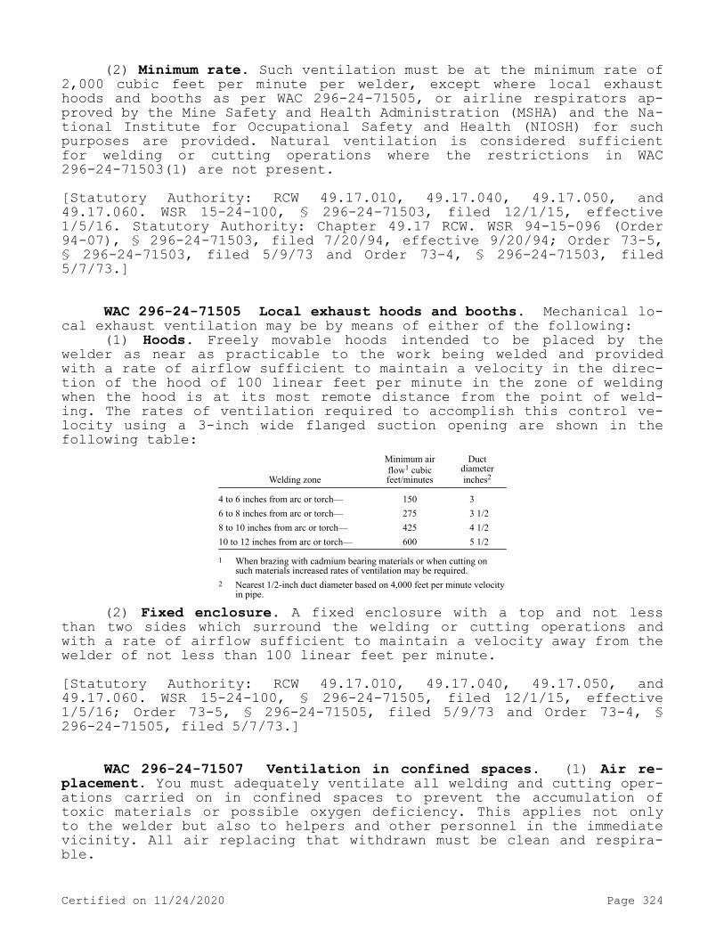
(2) Minimum rate. Such ventilation must be at the minimum rate of 2,000 cubic feet per minute per welder, except where local exhaust hoods and booths as per WAC 296-24-71505, or airline respirators ap-proved by the Mine Safety and Health Administration (MSHA) and the Na-tional Institute for Occupational Safety and Health (NIOSH) for such purposes are provided. Natural ventilation is considered sufficient for welding or cutting operations where the restrictions in WAC 296-24-71503(1) are not present.[Statutory Authority: RCW 49.17.010, 49.17.040, 49.17.050, and 49.17.060. WSR 15-24-100, § 296-24-71503, filed 12/1/15, effective 1/5/16. Statutory Authority: Chapter 49.17 RCW. WSR 94-15-096 (Order 94-07), § 296-24-71503, filed 7/20/94, effective 9/20/94; Order 73-5, § 296-24-71503, filed 5/9/73 and Order 73-4, § 296-24-71503, filed 5/7/73.]
WAC 296-24-71505 Local exhaust hoods and booths. Mechanical lo-cal exhaust ventilation may be by means of either of the following:
(1) Hoods. Freely movable hoods intended to be placed by the welder as near as practicable to the work being welded and provided with a rate of airflow sufficient to maintain a velocity in the direc-tion of the hood of 100 linear feet per minute in the zone of welding when the hood is at its most remote distance from the point of weld-ing. The rates of ventilation required to accomplish this control ve-locity using a 3-inch wide flanged suction opening are shown in the following table:
Welding zone
Minimum airflow1 cubicfeet/minutes
Ductdiameterinches2
4 to 6 inches from arc or torch— 150 36 to 8 inches from arc or torch— 275 3 1/28 to 10 inches from arc or torch— 425 4 1/210 to 12 inches from arc or torch— 600 5 1/2
1 When brazing with cadmium bearing materials or when cutting on such materials increased rates of ventilation may be required.
2 Nearest 1/2-inch duct diameter based on 4,000 feet per minute velocity in pipe.
(2) Fixed enclosure. A fixed enclosure with a top and not less than two sides which surround the welding or cutting operations and with a rate of airflow sufficient to maintain a velocity away from the welder of not less than 100 linear feet per minute.[Statutory Authority: RCW 49.17.010, 49.17.040, 49.17.050, and 49.17.060. WSR 15-24-100, § 296-24-71505, filed 12/1/15, effective 1/5/16; Order 73-5, § 296-24-71505, filed 5/9/73 and Order 73-4, § 296-24-71505, filed 5/7/73.]
WAC 296-24-71507 Ventilation in confined spaces. (1) Air re-placement. You must adequately ventilate all welding and cutting oper-ations carried on in confined spaces to prevent the accumulation of toxic materials or possible oxygen deficiency. This applies not only to the welder but also to helpers and other personnel in the immediate vicinity. All air replacing that withdrawn must be clean and respira-ble.
Certified on 11/24/2020 Page 324

(2) Airline respirators. In such circumstances where it is impos-sible to provide such ventilation, you must use airline respirators or hose masks approved for this purpose by the National Institute for Oc-cupational Safety and Health (NIOSH) under 42 C.F.R. Part 84.
(3) Self-contained units. In areas immediately hazardous to life, you must use a full-facepiece, pressure-demand, self-contained breath-ing apparatus or a combination full-facepiece, pressure-demand sup-plied-air respirator with an auxiliary, self-contained air supply cer-tified by NIOSH under 42 C.F.R. Part 84.
(4) Outside helper. Where welding operations are carried on in confined spaces and where welders and helpers are provided with hose masks, hose masks with blowers or self-contained breathing equipment approved by the Mine Safety and Health Administration (MSHA) and the National Institute for Occupational Safety and Health (NIOSH), a work-er must be stationed on the outside of such confined spaces to ensure the safety of those working within.
(5) Oxygen for ventilation. You must not use oxygen for ventila-tion.[Statutory Authority: RCW 49.17.010, 49.17.040, 49.17.050, and 49.17.060. WSR 15-24-100, § 296-24-71507, filed 12/1/15, effective 1/5/16. Statutory Authority: RCW 49.17.010, [49.17].040 and [49.17].050. WSR 99-10-071, § 296-24-71507, filed 5/4/99, effective 9/1/99. Statutory Authority: Chapter 49.17 RCW. WSR 94-15-096 (Order 94-07), § 296-24-71507, filed 7/20/94, effective 9/20/94; Order 73-5, § 296-24-71507, filed 5/9/73 and Order 73-4, § 296-24-71507, filed 5/7/73.]
WAC 296-24-71509 Fluorine compounds. General. In confined spaces, you must perform welding or cutting involving fluxes, cover-ings, or other materials which contain fluorine compounds in accord-ance with WAC 296-24-71507 (1) through (5). A fluorine compound is one that contains fluorine, as an element in chemical combination, not as a free gas.Note: Maximum allowable concentration. The need for local exhaust ventilation or airline respirators for welding or cutting in other than confined
spaces will depend upon the individual circumstances. However, experience has shown such protection to be desirable for fixed-location production welding and for all production welding on stainless steels. Where air samples taken at the welding location indicate that the fluorides liberated are below the maximum allowable concentration, such protection is not necessary.
[Statutory Authority: RCW 49.17.010, 49.17.040, 49.17.050, and 49.17.060. WSR 15-24-100, § 296-24-71509, filed 12/1/15, effective 1/5/16; Order 73-5, § 296-24-71509, filed 5/9/73 and Order 73-4, § 296-24-71509, filed 5/7/73.]
WAC 296-24-71511 Zinc. (1) Confined spaces. In confined spaces you must perform welding or cutting involving zinc-bearing base or filler metals or metals coated with zinc-bearing materials in accord-ance with WAC 296-24-71507 (1) through (5).
(2) Indoors. Indoors, you must perform welding or cutting involv-ing zinc-bearing base or filler metals coated with zinc-bearing mate-rials in accordance with WAC 296-24-71505 (1) and (2).[Statutory Authority: RCW 49.17.010, 49.17.040, 49.17.050, and 49.17.060. WSR 15-24-100, § 296-24-71511, filed 12/1/15, effective
Certified on 11/24/2020 Page 325

1/5/16; Order 73-5, § 296-24-71511, filed 5/9/73 and Order 73-4, § 296-24-71511, filed 5/7/73.]
WAC 296-24-71513 Lead. (1) Confined spaces. In confined spaces, you must perform welding involving lead-base metals (erroneously called lead-burning) in accordance with WAC 296-24-71507 (1) through (5).
(2) Indoors. Indoors, you must perform welding involving lead-base metals in accordance with WAC 296-24-71505 (1) and (2).
(3) Local ventilation. In confined spaces or indoors, you must perform welding or cutting operations involving metals containing lead, other than as an impurity, or involving metals coated with lead-bearing materials, including paint using local exhaust ventilation or airline respirators. You must perform such operations, when done out-doors, using respirators, certified for this purpose by NIOSH under 42 C.F.R. Part 84. In all cases, you must protect workers in the immedi-ate vicinity of the cutting operation as necessary by local exhaust ventilation or airline respirators.Note: See chapter 296-62 WAC for additional requirements on lead.
[Statutory Authority: RCW 49.17.010, 49.17.040, 49.17.050, and 49.17.060. WSR 15-24-100, § 296-24-71513, filed 12/1/15, effective 1/5/16. Statutory Authority: RCW 49.17.010, [49.17].040 and [49.17].050. WSR 99-10-071, § 296-24-71513, filed 5/4/99, effective 9/1/99. Statutory Authority: Chapter 49.17 RCW. WSR 94-15-096 (Order 94-07), § 296-24-71513, filed 7/20/94, effective 9/20/94; Order 73-5, § 296-24-71513, filed 5/9/73 and Order 73-4, § 296-24-71513, filed 5/7/73.]
WAC 296-24-71515 Beryllium. You must ensure that welding or cutting indoors, outdoors, or in confined spaces involving beryllium-containing base or filler metals is done using local exhaust ventila-tion and airline respirators unless atmospheric tests under the most adverse conditions have established that the workers' exposure is within the acceptable concentrations defined by chapter 296-841 WAC. In all cases, you must protect workers in the immediate vicinity of the welding or cutting operations as necessary by local exhaust venti-lation or airline respirators.[Statutory Authority: RCW 49.17.010, 49.17.040, 49.17.050, and 49.17.060. WSR 15-24-100, § 296-24-71515, filed 12/1/15, effective 1/5/16; WSR 05-03-093, § 296-24-71515, filed 1/18/05, effective 3/1/05; Order 73-5, § 296-24-71515, filed 5/9/73 and Order 73-4, § 296-24-71515, filed 5/7/73.]
WAC 296-24-71517 Cadmium. (1) General. In confined spaces or indoors, you must perform welding or cutting operations involving cad-mium-bearing or cadmium-coated base metals using local exhaust venti-lation or airline respirators unless atmospheric tests under the most adverse conditions show that employee exposure is within the accepta-ble concentrations specified by chapter 296-62 WAC. You must perform such operations, when done outdoors, using respirators, such as fume
Certified on 11/24/2020 Page 326

respirators, certified for this purpose by NIOSH under 42 C.F.R. Part 84.
(2) Confined space. You must perform welding (brazing) involving cadmium-bearing filler metals using ventilation as prescribed in WAC 296-24-71505 or 296-24-71507 if the work is to be done in a confined space.Note: See chapter 296-62 WAC for additional requirements on cadmium.
[Statutory Authority: RCW 49.17.010, 49.17.040, 49.17.050, and 49.17.060. WSR 15-24-100, § 296-24-71517, filed 12/1/15, effective 1/5/16. Statutory Authority: RCW 49.17.010, [49.17].040 and [49.17].050. WSR 99-10-071, § 296-24-71517, filed 5/4/99, effective 9/1/99. Statutory Authority: Chapter 49.17 RCW. WSR 94-15-096 (Order 94-07), § 296-24-71517, filed 7/20/94, effective 9/20/94; Order 73-5, § 296-24-71517, filed 5/9/73 and Order 73-4, § 296-24-71517, filed 5/7/73.]
WAC 296-24-71519 Mercury. In confined spaces or indoors, you must perform welding or cutting operations involving metals coated with mercury-bearing materials, including paint, using local exhaust ventilation or airline respirators unless atmospheric tests under the most adverse conditions show that employee exposure is within the ac-ceptable concentrations specified by chapter 296-841 WAC. You must perform such operations, when done outdoors, using respirators certi-fied for this purpose by NIOSH under 24 C.F.R. Part 84.[Statutory Authority: RCW 49.17.010, 49.17.040, 49.17.050, and 49.17.060. WSR 15-24-100, § 296-24-71519, filed 12/1/15, effective 1/5/16; WSR 05-03-093, § 296-24-71519, filed 1/18/05, effective 3/1/05. Statutory Authority: RCW 49.17.010, [49.17].040 and [49.17].050. WSR 99-10-071, § 296-24-71519, filed 5/4/99, effective 9/1/99. Statutory Authority: Chapter 49.17 RCW. WSR 94-15-096 (Order 94-07), § 296-24-71519, filed 7/20/94, effective 9/20/94; Order 73-5, § 296-24-71519, filed 5/9/73 and Order 73-4, § 296-24-71519, filed 5/7/73.]
WAC 296-24-71521 Cleaning compounds. (1) Manufacturer's in-structions. In the use of cleaning materials, because of their possi-ble toxicity of flammability, you must follow appropriate precautions such as manufacturer's instructions.
(2) Degreasing. You must locate degreasing or other cleaning op-erations involving chlorinated hydrocarbons so that no vapors from these operations will reach or be drawn into the atmosphere surround-ing any welding operation. In addition, trichloroethylene and per-chlorethylene should be kept out of atmospheres penetrated by the ul-traviolet radiation of gas-shielded welding operations.[Statutory Authority: RCW 49.17.010, 49.17.040, 49.17.050, and 49.17.060. WSR 15-24-100, § 296-24-71521, filed 12/1/15, effective 1/5/16; Order 73-5, § 296-24-71521, filed 5/9/73 and Order 73-4, § 296-24-71521, filed 5/7/73.]
Certified on 11/24/2020 Page 327
WAC 296-24-71523 Cutting of stainless steels. You must ensure that oxygen cutting, using either a chemical flux or iron powder or gas-shielded arc cutting of stainless steel, is done using mechanical ventilation adequate to remove the fumes generated.[Statutory Authority: RCW 49.17.010, 49.17.040, 49.17.050, and 49.17.060. WSR 15-24-100, § 296-24-71523, filed 12/1/15, effective 1/5/16; Order 73-5, § 296-24-71523, filed 5/9/73 and Order 73-4, § 296-24-71523, filed 5/7/73.]
WAC 296-24-71525 First-aid equipment. You must ensure that first-aid equipment is available at all times. On every shift of weld-ing operations there should be present employees trained to render first aid. You must report all injuries as soon as possible for medi-cal attention. You must render first aid until medical attention can be provided.[Statutory Authority: RCW 49.17.010, 49.17.040, 49.17.050, and 49.17.060. WSR 15-24-100, § 296-24-71525, filed 12/1/15, effective 1/5/16; Order 73-5, § 296-24-71525, filed 5/9/73 and Order 73-4, § 296-24-71525, filed 5/7/73.]
WAC 296-24-720 Industrial applications.[Order 73-5, § 296-24-720, filed 5/9/73 and Order 73-4, § 296-24-720, filed 5/7/73.]
WAC 296-24-72001 Transmission pipeline. (1) General. You must observe the requirements of WAC 296-24-68501 through 296-24-68507, 296-24-70001 through 296-24-70007, and 296-24-71501 through 296-24-71525.
(2) Field shop operations. Where field shop operations are in-volved for fabrication of fittings, river crossings, road crossings, and pumping and compressor stations you must observe the requirements of WAC 296-24-68001, 296-24-68501 through 296-24-68507, 296-24-69501 through 296-24-69507, 296-24-70001 through 296-24-70007 and 296-24-71501 through 296-24-71525.
(3) Electric shock. When arc welding is performed in wet condi-tions, or under conditions of high humidity, you must supply special protection against electric shock.
(4) Pressure testing. In pressure testing of pipelines, you must protect the workers and the public against injury by the blowing out of closures or other pressures restraining devices. Also, you must provide protection against expulsion of loose dirt that may have be-come trapped in the pipe.
(5) Construction standards. You must conduct the welded construc-tion of transmission pipelines in accordance with the Standard for Welding Pipe Lines and Related Facilities, API Std. 1104-1968.
(6) Flammable substance lines. You must perform the connection, by welding, of branches to pipelines carrying flammable substances in accordance with Welding or Hot Tapping on Equipment Containing Flamma-bles, API Std. PSD No. 2201-1963.
(7) X-ray inspection. You must carry out the use of X-rays and radioactive isotopes for the inspection of welded pipeline joints out
Certified on 11/24/2020 Page 328

in conformance with the American National Standard Safety Standard for Nonmedical X-ray and Sealed Gamma-Ray Sources, ANSI Z 54.1-1963.[Statutory Authority: RCW 49.17.010, 49.17.040, 49.17.050, and 49.17.060. WSR 15-24-100, § 296-24-72001, filed 12/1/15, effective 1/5/16; Order 73-5, § 296-24-72001, filed 5/9/73 and Order 73-4, § 296-24-72001, filed 5/7/73.]
WAC 296-24-72003 Mechanical piping systems. (1) General. You must observe the requirements of WAC 296-24-68001, 296-24-68501 through 296-24-68507, 296-24-69501 through 296-24-69507, 296-24-70001 through 296-24-70007 and 296-24-71501 through 296-24-71525.
(2) X-ray inspection. The use of X-rays and radioactive isotopes for the inspection of welded piping joints must be in conformance with the American National Standard Safety Standard for Nonmedical X-ray and Sealed Gamma-Ray Sources, ANSI Z 54.1-1963.[Statutory Authority: RCW 49.17.010, 49.17.040, 49.17.050, and 49.17.060. WSR 15-24-100, § 296-24-72003, filed 12/1/15, effective 1/5/16; Order 73-5, § 296-24-72003, filed 5/9/73 and Order 73-4, § 296-24-72003, filed 5/7/73.]
WAC 296-24-722 Welding, cutting, and heating in way of preserva-tive coatings. (1) You must ensure that before welding, cutting, or heating is commenced on any surface covered by a preservative coating whose flammability is not known, a test is made by a competent person to determine its flammability. You must consider preservative coatings to be highly flammable when scrapings burn with extreme rapidity.
(2) You must ensure that precautions are taken to prevent igni-tion of highly flammable hardened preservative coatings. When coatings are determined to be highly flammable, you must strip them from the area to be heated to prevent ignition.
(3) Protection against toxic preservative coatings:(a) In enclosed spaces, you must strip all surfaces covered with
toxic preservatives of all toxic coatings for a distance of at least 4 inches from the area of heat application, or you must protect the em-ployees by air line respirators, meeting the requirements specified in these rules for this type of work.
(b) In the open air, you must protect employees by a respirator, suitable for the type of work being done.
(4) You must ensure that the preservative coatings are removed a sufficient distance from the area to be heated to ensure that the tem-perature of the unstripped metal will not be appreciably raised. Arti-ficial cooling of the metal surrounding the heating area may be used to limit the size of the area required to be cleaned.[Statutory Authority: RCW 49.17.010, 49.17.040, 49.17.050, and 49.17.060. WSR 15-24-100, § 296-24-722, filed 12/1/15, effective 1/5/16; Order 73-5, § 296-24-722, filed 5/9/73 and Order 73-4, § 296-24-722, filed 5/7/73.]
PART J-1WORKING SURFACES, GUARDING FLOORS AND WALL OPENINGS
Certified on 11/24/2020 Page 329

Note: Requirements relating to portable ladders and fixed ladders have been moved to chapter 296-876 WAC, Ladders, portable and fixed.
WAC 296-24-735 Walking-working surfaces.[Order 73-5, § 296-24-735, filed 5/9/73 and Order 73-4, § 296-24-735, filed 5/7/73.]
WAC 296-24-73501 Scope. This section applies to all permanent places of employment, except where domestic, mining, or agricultural work only is performed. Construction work is not to be deemed as a permanent place of employment. This section covers all walking-working surfaces unless specifically excluded by an individual paragraph of this section. Where used in Part J of this chapter.[Statutory Authority: RCW 49.17.010, 49.17.040, 49.17.050, 49.17.060 and chapter 49.17 RCW. WSR 20-09-146, § 296-24-73501, filed 4/21/20, effective 10/1/20. Statutory Authority: RCW 49.17.010, [49.17].050 and [49.17].060. WSR 95-22-015, § 296-24-73501, filed 10/20/95, effective 1/16/96. Statutory Authority: Chapter 49.17 RCW. WSR 94-06-068 (Order 93-17), § 296-24-73501, filed 3/2/94, effective 3/1/95; Order 73-5, § 296-24-73501, filed 5/9/73 and Order 73-4, § 296-24-73501, filed 5/7/73.]
WAC 296-24-73502 Definitions. As used in Part J of this chap-ter, the following definitions apply:
Alternating tread-type stair. A type of stairway consisting of a series of treads that are usually attached to a center support in an alternating manner such that an employee typically does not have both feet on the same level while using the stairway.
Dockboard. A portable or fixed device that spans a gap or compen-sates for a difference in elevation between a loading platform and a transport vehicle. Dockboards include, but are not limited to, bridge plates, dock plates, and dock levelers.
Failure. A load refusal, breakage, or separation of component parts. A load refusal is the point at which the ultimate strength of a component or object is exceeded.
Grab bar. An individual horizontal or vertical handhold installed to provide access above the height of the ladder.
Guardrail system. A barrier erected along an unprotected or ex-posed side, edge, or other area of a walking-working surface to pre-vent employees from falling to a lower level. For dimension require-ments (rail heights, etc.), see the unified fall protection rule (chapter 296-880 WAC).
Handrail. Means a rail used to provide employees with a handhold for support.
Lower level. A surface or area to which an employee could fall. Such surfaces or areas include, but are not limited to, ground levels, floors, roofs, ramps, runways, excavations, pits, tanks, materials, water, equipment, and similar surfaces and structures, or portions thereof.
Maximum intended load. The total load (weight and force) of all employees, equipment, vehicles, tools, materials, and other loads the
Certified on 11/24/2020 Page 330

employer reasonably anticipates to be applied to a walking-working surface at any one time.
Nose, nosing. That portion of a tread projecting beyond the face of the riser immediately below.
Open riser. The gap or space between treads of stairways that do not have upright or inclined members (risers).
Platform. A walking-working surface that is elevated above the surrounding area.
Qualified. Describes a person who, by possession of a recognized degree, certificate, or professional standing, or who by extensive knowledge, training, and experience has successfully demonstrated the ability to solve or resolve problems relating to the subject matter, the work, or the project.
Railing. A vertical barrier erected along exposed sides of stair-ways and platforms to prevent falls of persons. The top member of railing usually serves as a handrail.
Ramp. An inclined walking-working surface used to access another level.
Rise. The vertical distance from the top of a tread to the top of the next higher tread.
Riser. The upright (vertical) or inclined member of a stair that is located at the back of a stair tread or platform and connects close to the front edge of the next higher tread, platform, or landing.
Runway. An elevated walking-working surface, such as a catwalk, a foot walk along shafting, or an elevated walkway between buildings.
Ship stair (ship ladder). A stairway that is equipped with treads, stair rails, and open risers, and has a slope that is between 50 and 70 degrees from the horizontal.
Spiral stairs. A series of treads attached to a vertical pole in a winding fashion, usually within a cylindrical space.
Stair platform. An extended step or landing breaking a continuous run of stairs.
Stair rail or stair rail system. A barrier erected along the ex-posed or open side of stairways to prevent employees from falling to a lower level.
Stairway (stairs). Risers and treads that connect one level with another, and includes any landings and platforms in between those lev-els. Stairways include standard, spiral, alternating tread-type, and ship stairs.
Standard stairs. A fixed or permanently installed stairway. Ship, spiral, and alternating tread-type stairs are not considered standard stairs.
Tread. A horizontal member of a stair or stairway, but does not include landings or platforms.
Unprotected sides and edges. Mean any side or edge of a walking-working surface (except at entrances and other points of access) where there is no wall, guardrail system, or stair rail system to protect an employee from falling to a lower level. For requirements relating to unprotected sides and edges, see the unified fall protection rule (chapter 296-880 WAC).
Walking-working surface. Any surface, whether horizontal or ver-tical on which an employee walks, works, or gains access to a work area or workplace location. Walking-working surfaces include, but are not limited to, floors, the ground, roofs, ramps, bridges, runways, stairs, dockboards, formwork and concrete reinforcing steel.
Certified on 11/24/2020 Page 331

[Statutory Authority: RCW 49.17.010, 49.17.040, 49.17.050, 49.17.060 and chapter 49.17 RCW. WSR 20-09-146, § 296-24-73502, filed 4/21/20, effective 10/1/20.]
WAC 296-24-73505 General requirements. (1) Surface conditions. You must ensure:
(a) All places of employment, passageways, storerooms, service rooms, and walking-working surfaces are kept in a clean, orderly, and sanitary condition.Note: Sanitary condition covers hazard exposures other than slips, trips, and falls. Examples of this include the prevention of illness/disease, and the
prevention of fire and explosion resulting from combustible dust accumulations.
(b) The floor of each workroom is maintained in a clean and, to the extent feasible, in a dry condition. When wet processes are used, drainage must be maintained and, to the extent feasible, dry standing places, such as false floors, platforms, and mats must be provided.
(c) Walking-working surfaces are maintained free of hazards such as sharp or protruding objects, loose boards, corrosion, leaks, spills, snow, and ice.
(2) You must ensure that each walking-working surface can support the maximum intended load for that surface.
(3) You must provide, and ensure each employee uses, a safe means of access and egress to and from walking-working surfaces.
(4) Inspection, maintenance, and repair. You must ensure:(a) Walking-working surfaces are inspected, regularly and as nec-
essary, and maintained in a safe condition.(b) Hazardous conditions on walking-working surfaces are correc-
ted or repaired before an employee uses the walking-working surface again. If the correction or repair cannot be made immediately, the hazard must be guarded to prevent employees from using the walking-working surface until the hazard is corrected or repaired.
(c) When any correction or repair involves the structural integ-rity of the walking-working surface, a qualified person performs or supervises the correction or repair.[Statutory Authority: RCW 49.17.010, 49.17.040, 49.17.050, 49.17.060 and chapter 49.17 RCW. WSR 20-09-146, § 296-24-73505, filed 4/21/20, effective 10/1/20. Statutory Authority: RCW 49.17.010, 49.17.040, 49.17.050, and 49.17.060. WSR 15-24-100, § 296-24-73505, filed 12/1/15, effective 1/5/16. Statutory Authority: Chapter 49.17 RCW. WSR 94-15-096 (Order 94-07), § 296-24-73505, filed 7/20/94, effective 9/20/94; WSR 89-11-035 (Order 89-03), § 296-24-73505, filed 5/15/89, effective 6/30/89; Order 73-5, § 296-24-73505, filed 5/9/73 and Order 73-4, § 296-24-73505, filed 5/7/73.]
WAC 296-24-740 Stairways. This section contains specifications for the safe design and construction of fixed general industrial stairs. This classification includes interior and exterior stairs around machinery, tanks, and other equipment, and stairs leading to or from floors, platforms, or pits. This section does not apply to stairs used for fire exit purposes, construction operations, stairs on scaf-folds, stairs designed into machines or equipment, articulated stairs, such as may be installed on floating roof tanks or on dock facilities, the angle of which changes with the rise and fall of the base support, or to stairs on self-propelled motorized equipment.
Certified on 11/24/2020 Page 332

[Statutory Authority: RCW 49.17.010, 49.17.040, 49.17.050, 49.17.060 and chapter 49.17 RCW. WSR 20-09-146, amended and recodified as § 296-24-740, filed 4/21/20, effective 10/1/20; Order 73-5, § 296-24-765, filed 5/9/73 and Order 73-4, § 296-24-765, filed 5/7/73.]
WAC 296-24-74005 General requirements for all stairs. In addi-tion to the requirements in WAC 296-24-735, you must ensure:
(1) Handrails, stair rail systems, and guardrail systems are pro-vided in accordance with WAC 296-24-74015.Note: For guardrail system requirements, see the unified fall protection rule (chapter 296-880 WAC).
(2) Vertical clearance above any stair tread to any overhead ob-struction is at least 6 feet 8 inches (203 cm), as measured from the leading edge of the tread. Spiral stairs must meet the vertical clear-ance requirements in WAC 296-24-74015.
(3) Stairs have uniform riser heights and tread depths between landings.
(4) Stairway landings and stair platforms are at least the width of the stair and at least 30 inches (76 cm) in depth; as measured in the direction of travel.
(5) When a door or a gate opens directly on a stairway, a stair platform is provided, and the swing of the door or gate does not re-duce the stair platform's effective usable depth to:
(a) Less than 20 inches (51 cm) for stair platforms installed be-fore October 1, 2020; and
(b) Less than 22 inches (56 cm) for stair platforms installed on or after October 1, 2020 (see Figure D-7 of this section).
(6) Each stair can support at least five times the normal antici-pated live load, but never less than a concentrated load of 1,000 pounds (454 kg) applied at any point.
(7) Standard stairs are used to provide access from one walking-working surface to another when operations necessitate regular and routine (once per week) travel between levels, including access to op-erating platforms for equipment. Winding stairways may be used on tanks and similar round structures when the diameter of the tank or structure is at least 5 feet (1.5 m).
(8) Spiral, ship, or alternating tread-type stairs are used only when the employer can demonstrate that it is not feasible to provide standard stairs.
(9) When subsection (8) of this section allows the use of spiral, ship, or alternating tread-type stairs, they are installed, used, and maintained in accordance with manufacturer's instructions.
Figure D-7 - Door or Gate Opening on Stairway
(10) Each tread and the top landing of a stairway, where risers are used, should have a nose which extends .5 inch to 1 inch beyond the face of the lower riser.
(11) Stair tread noses should have an even leading edge.
Certified on 11/24/2020 Page 333

[Statutory Authority: RCW 49.17.010, 49.17.040, 49.17.050, 49.17.060 and chapter 49.17 RCW. WSR 20-09-146, § 296-24-74005, filed 4/21/20, effective 10/1/20.]
WAC 296-24-74010 Standard stairs. In addition to WAC 296-24-74005, you must also ensure standard stairs:
(1) Are installed at angles between 30 to 50 degrees from the horizontal.
(2) Have a maximum riser height of 9.5 inches (24 cm).(3) Have a minimum tread depth of 9.5 inches (24 cm).(4) Have a minimum width of 22 inches (56 cm) between vertical
barriers (see Figure D-8 of this section).EXCEPTION: Subsections (2) and (3) of this section do not apply to standard stairs installed prior to October 1, 2020, provided those stairs meet the
dimension requirements specified in Table D-1 of this section or they use a combination that achieves the angle requirements of subsection (1) of this section.
TABLE D-1Angle to
HorizontalRise
(in inches)Tread Run(in inches)
30°35' . . . . . . . . . . . . . . . . . . . . . . . . . 6 1/2 1132°08' . . . . . . . . . . . . . . . . . . . . . . . . . 6 3/4 10 3/433°41' . . . . . . . . . . . . . . . . . . . . . . . . . 7 10 1/235°16' . . . . . . . . . . . . . . . . . . . . . . . . . 7 1/4 10 1/436°52' . . . . . . . . . . . . . . . . . . . . . . . . . 7 1/2 1038°29' . . . . . . . . . . . . . . . . . . . . . . . . . 7 3/4 9 3/440°08' . . . . . . . . . . . . . . . . . . . . . . . . . 8 9 1/241°44' . . . . . . . . . . . . . . . . . . . . . . . . . 8 1/4 9 1/443°22' . . . . . . . . . . . . . . . . . . . . . . . . . 8 1/2 945°00' . . . . . . . . . . . . . . . . . . . . . . . . . 8 3/4 8 3/446°38' . . . . . . . . . . . . . . . . . . . . . . . . . 9 8 1/248°16' . . . . . . . . . . . . . . . . . . . . . . . . . 9 1/4 8 1/449°54' . . . . . . . . . . . . . . . . . . . . . . . . . 9 1/2 8
Figure D-8
Certified on 11/24/2020 Page 334

[Statutory Authority: RCW 49.17.010, 49.17.040, 49.17.050, 49.17.060 and chapter 49.17 RCW. WSR 20-09-146, § 296-24-74010, filed 4/21/20, effective 10/1/20.]
WAC 296-24-74015 Handrail, stair rail, and guardrail system re-quirements. Handrail and stair rail systems must meet the following criteria:Note: For guardrail system requirements, see the unified fall protection rule (chapter 296-880 WAC).
(1) Handrails are not less than 30 inches (76 cm) and not more than 38 inches (97 cm), as measured from the leading edge of the stair tread to the top surface of the handrail (see Figure D-12 of this sec-tion).
Figure D-12 - Handrail Measurement(2) The height of stair rail systems meets the following:(a) The height of stair rail systems installed before October 1,
2020, is not less than 30 inches (76 cm) from the leading edge of the stair tread to the top surface of the top rail; and
(b) The height of stair rail systems installed on or after Octo-ber 1, 2020, is not less than 42 inches (107 cm) from the leading edge of the stair tread to the top surface of the top rail. This 42 inch height requirement intentionally conflicts with the requirement above the handrail heights be between 30 to 38 inches above the stair tread. Handrails and stair rails constructed after the effective date above must be separate (see Figure D-13b of this section).
(3) The top rail of a stair rail system installed before October 1, 2020, may serve as a handrail only when:
(a) The height of the stair rail system is not less than 36 in-ches (91 cm) and not more than 38 inches (97 cm) as measured at the leading edge of the stair tread to the top surface of the top rail (see Figure D-13a of this section); and
(b) The top rail of the stair rail system meets the other hand-rail requirements in (f) of this subsection.
Certified on 11/24/2020 Page 335

Figure D-13a - Combination Handrail and Stair Rail Installed prior to
October 1, 2020
Figure D-13b - Combination Handrail and Stair Rail Installed after
October 1, 2020
(4) Finger clearance. The minimum clearance between handrails and any other object is 2.25 inches (5.7 cm).
(5) Surfaces. Handrail/stair rail systems are smooth-surfaced to protect employees from injury, such a punctures or lacerations, and to prevent catching or snagging of clothing.
(6) Openings in stair rails. No opening in a stair rail system exceeds 19 inches (48 cm) at its least dimension.
(7) Handholds. Handrails have the shape and dimension necessary so that employees can grasp the handrail firmly.
(8) Projection hazards. The ends of handrails and stair rail sys-tems do not present any projection hazards.
Certified on 11/24/2020 Page 336

(9) Strength criteria. Handrails and the top rails of stair rail systems are capable of withstanding, without failure, a force of at least 200 pounds (890 N) applied in any downward or outward direction within 2 inches (5 cm) of any point along the top edge of the rail.Note: Table D-3 below is informational only. Table D-3 is provided for employers and employees to quickly review and contrast various railing
regulations (DOSH, federal OSHA, and International Building Code) in effect at the date of publication of this rule, October 1, 2020. Refer to referenced rule itself for details relating to scope, intent, definitions, application, etc.
Table D-3 – Informational Summary of Railing Requirements
StandardStair Rail
HeightHand Rail
HeightStair Rail as Hand Rail Mid Rail Toe Board
Chapter 296-880 WAC N/A 30" - 38" N/A Halfway 43.5"29 C.F.R. 1910.29 42" min. 30" - 38" 36" - 38"* Midway 2.5"-3.5"29 C.F.R. 1926.502/1926.1052 36" min. 30" - 37" 36" - 37" Between 3.5" min.IBC (2018) 1014/1015(per RCW 19.27.031)
42" min. 34" - 38" 34" - 38" (Group F)
Openings < 21" Openings < 4"
* If installed prior to October 1, 2020, otherwise prohibited in WAC 296-24-74015 (2)(b).
[Statutory Authority: RCW 49.17.010, 49.17.040, 49.17.050, 49.17.060 and chapter 49.17 RCW. WSR 20-09-146, § 296-24-74015, filed 4/21/20, effective 10/1/20.]
WAC 296-24-74020 Spiral stairs. In addition to WAC-296-24-74005, you must also ensure spiral stairs:
(1) Have a minimum clear width of 26 inches (66 cm);(2) Have a maximum riser height of 9.5 inches (24 cm);(3) Have a minimum headroom above spiral stair treads of at least
6 feet 6 inches (2 m), measured from the leading edge of the tread;(4) Have a minimum tread depth of 7.5 inches (19 cm), measured at
a point of 12 inches (30 cm) from the narrower edge; and(5) Have a uniform tread size.
[Statutory Authority: RCW 49.17.010, 49.17.040, 49.17.050, 49.17.060 and chapter 49.17 RCW. WSR 20-09-146, amended and recodified as § 296-24-74020, filed 4/21/20, effective 10/1/20. Statutory Authority: RCW 49.17.010, 49.17.040, 49.17.050, and 49.17.060. WSR 15-24-100, § 296-24-76515, filed 12/1/15, effective 1/5/16; Order 73-5, § 296-24-76515, filed 5/9/73 and Order 73-4, § 296-24-76515, filed 5/7/73.]
WAC 296-24-74025 Ship stairs. In addition to WAC 296-24-74005, you must also ensure ship stairs (see Figure D-9 of this section):
(1) Are installed at a slope of 50 to 70 degrees from the hori-zontal;
(2) Have open risers with a vertical rise between tread surfaces of 6.5 to 12 inches (17 to 30 cm);
(3) Have minimum tread depth of 4 inches (10 cm); and(4) Have a minimum tread width of 18 inches (46 cm).
Certified on 11/24/2020 Page 337
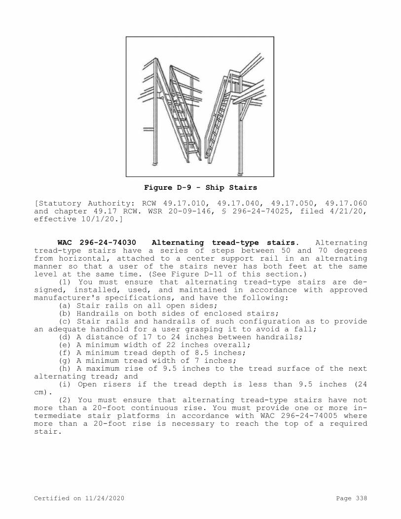
Figure D-9 - Ship Stairs[Statutory Authority: RCW 49.17.010, 49.17.040, 49.17.050, 49.17.060 and chapter 49.17 RCW. WSR 20-09-146, § 296-24-74025, filed 4/21/20, effective 10/1/20.]
WAC 296-24-74030 Alternating tread-type stairs. Alternating tread-type stairs have a series of steps between 50 and 70 degrees from horizontal, attached to a center support rail in an alternating manner so that a user of the stairs never has both feet at the same level at the same time. (See Figure D-11 of this section.)
(1) You must ensure that alternating tread-type stairs are de-signed, installed, used, and maintained in accordance with approved manufacturer's specifications, and have the following:
(a) Stair rails on all open sides;(b) Handrails on both sides of enclosed stairs;(c) Stair rails and handrails of such configuration as to provide
an adequate handhold for a user grasping it to avoid a fall;(d) A distance of 17 to 24 inches between handrails;(e) A minimum width of 22 inches overall;(f) A minimum tread depth of 8.5 inches;(g) A minimum tread width of 7 inches;(h) A maximum rise of 9.5 inches to the tread surface of the next
alternating tread; and(i) Open risers if the tread depth is less than 9.5 inches (24
cm).(2) You must ensure that alternating tread-type stairs have not
more than a 20-foot continuous rise. You must provide one or more in-termediate stair platforms in accordance with WAC 296-24-74005 where more than a 20-foot rise is necessary to reach the top of a required stair.
Certified on 11/24/2020 Page 338

Angle Type≤ 30° Ramps
30° - 50° Standard Stairs50° - 70° Ship Stairs50° - 70° Alternating Tread-Type Stairs60° - 90° Ladders
Figure D-10 - Angles for Stairs, Ramps, and Ladders
Certified on 11/24/2020 Page 339

Figure D-11[Statutory Authority: RCW 49.17.010, 49.17.040, 49.17.050, 49.17.060 and chapter 49.17 RCW. WSR 20-09-146, amended and recodified as § 296-24-74030, filed 4/21/20, effective 10/1/20. Statutory Authority: RCW 49.17.010, 49.17.040, 49.17.050, and 49.17.060. WSR 15-24-100, § 296-24-76555, filed 12/1/15, effective 1/5/16. Statutory Authority: Chapter 49.17 RCW. WSR 92-17-022 (Order 92-06), § 296-24-76555, filed 8/10/92, effective 9/10/92; WSR 91-03-044 (Order 90-18), § 296-24-76555, filed 1/10/91, effective 2/12/91.]
WAC 296-24-7500 Other working surfaces.[Statutory Authority: RCW 49.17.010, 49.17.040, 49.17.050, 49.17.060 and chapter 49.17 RCW. WSR 20-09-146, recodified as § 296-24-7500, filed 4/21/20, effective 10/1/20; Order 73-5, § 296-24-855, filed 5/9/73 and Order 73-4, § 296-24-855, filed 5/7/73.]
WAC 296-24-75006 Dockboards (bridge plates). You must ensure:
Certified on 11/24/2020 Page 340

(1) Portable and powered dockboards are strong enough to carry the load imposed on them.
(2) Dockboards put into initial service on or after October 1, 2020, are designed, constructed, and maintained to prevent employees from running off the dockboard edge.EXCEPTION: When the employer demonstrates there is no hazard of employees running off the dockboard edge, WAC 296-24-75005(1) does not
apply.
(3) Portable dockboards are secured by anchoring them in place or using equipment or devices that prevent the dockboard from moving out of a safe position. When the employer demonstrates that securing the dockboard is not feasible, the employer must ensure there is suffi-cient contact between the dockboard and the surface to prevent the dockboard from moving out of a safe position.
(4) Powered dockboards are designed and constructed in accordance with Commercial Standard CS202-56 (1961) "Industrial Lifts and Hinged Loading Ramps" published by the U.S. Department of Commerce, or newer standards as effective as the code such as:
(a) American National Standards Institute (ANSI)/Industrial Truck Standards Development Foundation (ITSDF) B56.1-2012, Trucks, Low and High Lift, Safety Standard (B56.1-2012).
(b) ASME/ANSI MH14.1-1987, Loading Dock Levelers and Dockboards (MH14.1-1987) (Ex. 371).
(c) ANSI MH30.1-2007, National Standard for the Safety Perform-ance, and Testing of Dock Loading Devices (MH30.1-2007) (Ex. 372).
(d) ANSI MH30.2-2005, Portable Dock Loading Devices: Standards, Performance, and Testing (MH30.2-2005) (Ex. 20).
(5) Positive protective measures, such as wheel chocks or sand shoes, are used to prevent the transport vehicle (e.g., a truck, semi-trailer, trailer, or rail car) or container on which a dockboard is placed, from moving while employees are on the dockboard.
(6) You must ensure that handholds, or other effective means, are provided on portable dockboards to permit safe handling.[Statutory Authority: RCW 49.17.010, 49.17.040, 49.17.050, 49.17.060 and chapter 49.17 RCW. WSR 20-09-146, amended and recodified as § 296-24-75006, filed 4/21/20, effective 10/1/20. Statutory Authority: RCW 49.17.010, 49.17.040, 49.17.050, and 49.17.060. WSR 15-24-100, § 296-24-85501, filed 12/1/15, effective 1/5/16; Order 73-5, § 296-24-85501, filed 5/9/73 and Order 73-4, § 296-24-85501, filed 5/7/73.]
PART J-2SCAFFOLDS
WAC 296-24-862 Nonmandatory appendices. Nonmandatory Appendix A to Part J-2, Scaffold Specifications.
This Appendix provides nonmandatory guidelines to assist employ-ers in complying with the requirements of Part J-2 of this chapter. An employer may use these guidelines and tables as a starting point for designing scaffold systems. However, the guidelines do not provide all the information necessary to build a complete system, and the employer is still responsible for designing and assembling these components in such a way that the completed system will meet the requirements of WAC 296-24-86010(1). Scaffold components which are not selected and loaded in accordance with this Appendix, and components for which no specific
Certified on 11/24/2020 Page 341

guidelines or tables are given in this Appendix (e.g., joints, ties, components for wood pole scaffolds more than 60 feet in height, compo-nents for heavy-duty horse scaffolds, components made with other mate-rials, and components with other dimensions, etc.) must be designed and constructed in accordance with the capacity requirements of WAC 296-24-86010(1), and loaded in accordance with WAC 296-24-86010 (4)(a).
Index to Appendix A for Part J-21. General guidelines and tables.2. Specific guidelines and tables.(a) Pole scaffolds:Single-pole wood pole scaffolds.Independent wood pole scaffolds.(b) Tube and coupler scaffolds.(c) Fabricated frame scaffolds.(d) Plasterers', decorators' and large area scaffolds.(e) Bricklayers' square scaffolds.(f) Horse scaffolds.(g) Form scaffolds and carpenters' bracket scaffolds.(h) Roof bracket scaffolds.(i) Outrigger scaffolds (one level).(j) Pump jack scaffolds.(k) Ladder jack scaffolds.(l) Window jack scaffolds.(m) Crawling boards (chicken ladders).(n) Step, platform and trestle ladder scaffolds.(o) Single-point adjustable suspension scaffolds.(p) Two-point adjustable suspension scaffolds.(q)(1) Stonesetters' multipoint adjustable suspension scaffolds.(q)(2) Masons' multipoint adjustable suspension scaffolds.(r) Catenary scaffolds.(s) Float (ship) scaffolds.(t) Interior hung scaffolds.(u) Needle beam scaffolds.(v) Multilevel suspension scaffolds.(w) Mobile scaffolds.(x) Repair bracket scaffolds.(y) Stilts.(z) Tank builders' scaffolds.1. General guidelines and tables.(a) The following tables, and the tables in Part 2—Specific
guidelines and tables, assume that all load-carrying timber members (except planks) of the scaffold are a minimum of 1,500 lb-f/in(2) (stress grade) construction grade lumber. All dimensions are nominal sizes as provided in the American Softwood Lumber Standards, dated January 1970, except that, where rough sizes are noted, only rough or undressed lumber of the size specified will satisfy minimum require-ments.
(b) Solid sawn wood used as scaffold planks must be selected for such use following the grading rules established by a recognized lum-ber grading association or by an independent lumber grading inspection agency. Such planks must be identified by the grade stamp of such as-sociation or agency. The association or agency and the grading rules under which the wood is graded must be certified by the Board of Re-view, American Lumber Standard Committee, as set forth in the American Softwood Lumber Standard of the U.S. Department of Commerce.
Certified on 11/24/2020 Page 342

(i) Allowable spans must be determined in compliance with the Na-tional Design Specification for Wood Construction published by the Na-tional Forest Products Association; paragraph 5 of ANSI A10.8-1988 Scaffolding-Safety Requirements published by the American National Standards Institute; or for 2 x 10 inch (nominal) or 2 x 9 inch (rough) solid sawn wood planks, as shown in the following table:
Maximum intended
nominal load (lb/ft2)
Maximum permissible span
using full thickness
undressed lumber (ft)
Maximum permissible span using nominal
thickness lumber (ft)
25 10 850 8 675 6
(ii) The maximum permissible span for 1 1/4 x 9-inch or wider wood plank of full thickness with a maximum intended load of 50 lb/ft.(2) must be 4 feet.
(c) Fabricated planks and platforms may be used in lieu of solid sawn wood planks. Maximum spans for such units must be as recommended by the manufacturer based on the maximum intended load being calcula-ted as follows:
Rated load capacity Intended loadLight-duty *25 pounds per square foot
applied uniformly over the entire span area.
Medium-duty *50 pounds per square foot applied uniformly over the entire span area.
Heavy-duty *75 pounds per square foot applied uniformly over the entire span area.
One-person *250 pounds placed at the center of the span (total 250 pounds).
Two-person *250 pounds placed 18 inches to the left and right of the center of the span (total 500 pounds).
Three-person *250 pounds placed at the center of the span and 250 pounds placed 18 inches to the left and right of the center of the span (total 750 pounds).
Note: Platform units used to make scaffold platforms intended for light-duty use must be capable of supporting at least 25 pounds per square foot applied uniformly over the entire unit-span area, or a 250-pound point load placed on the unit at the center of the span, whichever load produces the greater shear force.
(d) Guardrails must be as follows:(i) Toprails must be equivalent in strength to 2 inch by 4 inch
lumber; or1 1/4 inch x 1/8 inch structural angle iron; or1 inch x .070 inch wall steel tubing; or 1.990 inch x .058 inch
wall aluminum tubing.(ii) Midrails must be equivalent in strength to 1 inch by 6 inch
lumber; or1 1/4 inch x 1 1/4 inch x 1/8 inch structural angle iron; or
Certified on 11/24/2020 Page 343

1 inch x .070 inch wall steel tubing; or1.990 inch x .058 inch wall aluminum tubing.(iii) Toeboards must be equivalent in strength to 1 inch by 4
inch lumber; or1 1/4 inch x 1 1/4 inch structural angle iron; or1 inch x .070 inch wall steel tubing; or1.990 inch x .058 inch wall aluminum tubing.(iv) Posts must be equivalent in strength to 2 inch by 4 inch
lumber; or1 1/4 inch x 1 1/4 inch x 1/8 structural angle iron; or1 inch x .070 inch wall steel tubing; or1.990 inch x .058 inch wall aluminum tubing.(v) Distance between posts must not exceed 8 feet.(e) Overhead protection must consist of 2 inch nominal planking
laid tight, or 3/4-inch plywood.(f) Screen installed between toeboards and midrails or toprails
must consist of No. 18 gauge U.S. Standard wire one inch mesh.2. Specific guidelines and tables.(a) Pole scaffolds.
Single Pole Wood Pole Scaffolds Light
duty up to 20 feet high
Light duty up to
60 feet high
Medium duty up to
60 feet high
Heavy duty up to
60 feet high
Maximum intended load (lbs/ft2) 25 25 50 75Poles or uprights 2 x 4 in. 4 x 4 in. 4 x 4 in. 4 x 6 in.Maximum pole spacing (longitudinal) 6 feet 10 feet 8 feet 6 feetMaximum pole spacing (transverse) 5 feet 5 feet 5 feet 5 feetRunners
1 x 4 in.1 1/4 x 9
in. 2 x 10 in. 2 x 10 in.Bearers and maximum spacing of bearers: 3 feet 2 x 4 in. 2 x 4 in.
2 x 10 in.or
3 x 4 in.
2 x 10 in.or
3 x 5 in.5 feet 2 x 6 in.
or3 x 4 in.
2 x 6 in.or
3 x 4 in.(rough)
2 x 10 in.or
3 x 4 in.
2 x 10 in.or
3 x 5 in.
6 feet — — 2 x 10 in.or
3 x 4 in.
2 x 10 in.or
3 x 5 in.8 feet — — 2 x 10 in.
or3 x 4 in.
Planking 1 1/4 x 9 in. 2 x 10 in. 2 x 10 in. 2 x 10 in.
Maximum vertical spacing of horizontal members 7 feet 9 feet 7 feet 6 ft. 6 in.Bracinghorizontal
1 x 4 in. 1 x 4 in.
1 x 6 in.or
1 1/4 x 4 in. 2 x 4 in.
Bracing diagonal 1 x 4 in. 1 x 4 in. 1 x 4 in. 2 x 4 in.Tie-ins 1 x 4 in. 1 x 4 in. 1 x 4 in. 1 x 4 in.
Certified on 11/24/2020 Page 344

Note: All members except planking are used on edge. All wood bearers must be reinforced with 3/16 x 2 inch steel strip, or the equivalent, secured to the lower edges for the entire length of the bearer.
Independent Wood Pole Scaffolds Light
duty up to 20 feet high
Light duty up to 60 feet high
Medium duty up to
60 feet high
Heavy duty up to
60 feet high
Maximum intended load 25 lbs/ft2 25 lbs/ft2 50 lbs/ft2 75 lbs/ft2
Poles or uprights 2 x 4 in. 4 x 4 in. 4 x 4 in. 4 x 4 in.Maximum pole spacing (longitudinal) 6 feet 10 feet 8 feet 6 feetMaximum (transverse) 6 feet 10 feet 8 feet 8 feetRunners 1 1/4 x 4
in.1 1/4 x 9
in. 2 x 10 in. 2 x 10 in.Bearers and maximum spacing of bearers: 3 feet 2 x 4 in. 2 x 4 in.
2 x 10 in.(rough) 2 x 10 in.
6 feet 2 x 6 in.or
3 x 4 in.
2 x 10 in.(rough)
or3 x 8 in.
2 x 10 in. 2 x 10 in.(rough)
8 feet 2 x 6 in.or
3 x 4 in.
2 x 10 in.(rough)
or3 x 8 in.
2 x 10 in.
10 feet 3 x 4 in. 2 x 6 in.(rough)
or3 x 3 in.
2 x 10 in.
Planking 1 1/4 x 9 in. 2 x 10 in. 2 x 10 in. 2 x 10 in.
Maximum vertical spacing of horizontal members 7 feet 7 feet 6 feet 6 feetBracinghorizontal
1 x 4 in. 1 x 4 in.
1 x 6 in.or
1 1/4 x 4 in. 2 x 4 in.
Bracing diagonal 1 x 4 in. 1 x 4 in. 1 x 4 in. 2 x 4 in.Tie-ins 1 x 4 in. 1 x 4 in. 1 x 4 in. 1 x 4 in.
Note: All members except planking are used on edge. All wood bearers must be reinforced with 3/16 x 2 inch steel strip, or the equivalent, secured to the lower edges for the entire length of the bearer.
(b) Tube and coupler scaffolds.Minimum Size of Members
Light duty Medium duty Heavy dutyMaximum intended load 25 lbs/ft2 50 lbs/ft2 75 lbs/ft2
Posts, runners and braces
Nominal 2 in. (1.90 inches) OD steel tube
or pipe.
Nominal 2 in. (1.90 inches)
OD steel tube or pipe.
Nominal 2 in. (1.90 inches)
OD steel tube or pipe.
Certified on 11/24/2020 Page 345
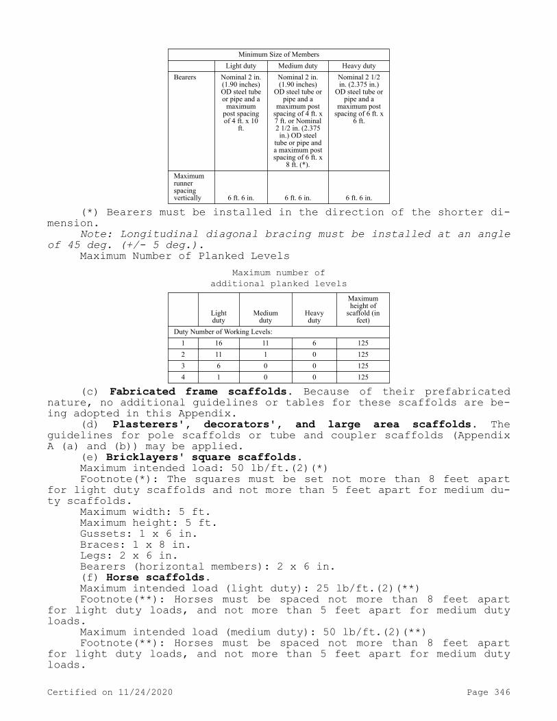
Minimum Size of Members Light duty Medium duty Heavy duty
Bearers Nominal 2 in. (1.90 inches) OD steel tube or pipe and a
maximum post spacing of 4 ft. x 10
ft.
Nominal 2 in. (1.90 inches)
OD steel tube or pipe and a
maximum post spacing of 4 ft. x 7 ft. or Nominal 2 1/2 in. (2.375 in.) OD steel
tube or pipe and a maximum post spacing of 6 ft. x
8 ft. (*).
Nominal 2 1/2 in. (2.375 in.)
OD steel tube or pipe and a
maximum post spacing of 6 ft. x
6 ft.
Maximum runner spacing vertically 6 ft. 6 in. 6 ft. 6 in. 6 ft. 6 in.
(*) Bearers must be installed in the direction of the shorter di-mension.
Note: Longitudinal diagonal bracing must be installed at an angle of 45 deg. (+/- 5 deg.).
Maximum Number of Planked LevelsMaximum number of
additional planked levels
Lightduty
Mediumduty
Heavyduty
Maximum height of
scaffold (in feet)
Duty Number of Working Levels:1 16 11 6 1252 11 1 0 1253 6 0 0 1254 1 0 0 125
(c) Fabricated frame scaffolds. Because of their prefabricated nature, no additional guidelines or tables for these scaffolds are be-ing adopted in this Appendix.
(d) Plasterers', decorators', and large area scaffolds. The guidelines for pole scaffolds or tube and coupler scaffolds (Appendix A (a) and (b)) may be applied.
(e) Bricklayers' square scaffolds.Maximum intended load: 50 lb/ft.(2)(*)Footnote(*): The squares must be set not more than 8 feet apart
for light duty scaffolds and not more than 5 feet apart for medium du-ty scaffolds.
Maximum width: 5 ft.Maximum height: 5 ft.Gussets: 1 x 6 in.Braces: 1 x 8 in.Legs: 2 x 6 in.Bearers (horizontal members): 2 x 6 in.(f) Horse scaffolds.Maximum intended load (light duty): 25 lb/ft.(2)(**)Footnote(**): Horses must be spaced not more than 8 feet apart
for light duty loads, and not more than 5 feet apart for medium duty loads.
Maximum intended load (medium duty): 50 lb/ft.(2)(**)Footnote(**): Horses must be spaced not more than 8 feet apart
for light duty loads, and not more than 5 feet apart for medium duty loads.
Certified on 11/24/2020 Page 346

Horizontal members or bearers:Light duty: 2 x 4 in.Medium duty: 3 x 4 in.Legs: 2 x 4 in.Longitudinal brace between legs: 1 x 6 in.Gusset brace at top of legs: 1 x 8 in.Half diagonal braces: 2 x 4 in.(g) Form scaffolds and carpenters' bracket scaffolds.(1) Brackets must consist of a triangular-shaped frame made of
wood with a cross-section not less than 2 inches by 3 inches, or of 1 1/4 inch x 1 1/4 inch x 1/8 inch structural angle iron.
(2) Bolts used to attach brackets to structures must not be less than 5/8 inches in diameter.
(3) Maximum bracket spacing must be 8 feet on centers.(4) No more than two employees must occupy any given 8 feet of a
bracket or form scaffold at any one time. Tools and materials must not exceed 75 pounds in addition to the occupancy.
(5) Wooden figure-four scaffolds:Maximum intended load: 25 lb/ft.(2)Uprights: 2 x 4 in. or 2 x 6 in.Bearers (two): 1 x 6 in.Braces: 1 x 6 in.Maximum length of bearers (unsupported): 3 ft. 6 in.(i) Outrigger bearers must consist of two pieces of 1 x 6 inch
lumber nailed on opposite sides of the vertical support.(ii) Bearers for wood figure-four brackets must project not more
than 3 feet 6 inches from the outside of the form support, and must be braced and secured to prevent tipping or turning. The knee or angle brace must intersect the bearer at least 3 feet from the form at an angle of approximately 45 degrees, and the lower end must be nailed to a vertical support.
(6) Metal bracket scaffolds:Maximum intended load: 25 lb/ft.(2)Uprights: 2 x 4 inchBearers: As designed.Braces: As designed.(7) Wood bracket scaffolds:Maximum intended load: 25 lb/ft.(2)Uprights: 2 x 4 in. or 2 x 6 in.Bearers: 2 x 6 in.Maximum scaffold width: 3 ft. 6 in.Braces: 1 x 6 in.(h) Roof bracket scaffolds. No specific guidelines or tables are
given.(i) Outrigger scaffolds (single level). No specific guidelines or
tables are given.(j) Pump jack scaffolds. Wood poles must not exceed 30 feet in
height. Maximum intended load — 500 lbs between poles; applied at the center of the span. Not more than two employees must be on a pump jack scaffold at one time between any two supports. When 2 x 4's are spliced together to make a 4 x 4 inch wood pole, they must be spliced with "10 penny" common nails no more than 12 inches center to center, staggered uniformly from the opposite outside edges.
(k) Ladder jack scaffolds. Maximum intended load — 25 lb/ft(2). However, not more than two employees must occupy any platform at any one time. Maximum span between supports must be 8 feet.
Certified on 11/24/2020 Page 347

(l) Window jack scaffolds. Not more than one employee must occupy a window jack scaffold at any one time.
(m) Crawling boards (chicken ladders). Crawling boards must be not less than 10 inches wide and 1 inch thick, with cleats having a minimum 1 x 1 1/2 inch cross-sectional area. The cleats must be equal in length to the width of the board and spaced at equal intervals not to exceed 24 inches.
(n) Step, platform, and trestle ladder scaffolds. No additional guidelines or tables are given.
(o) Single-point adjustable suspension scaffolds. Maximum inten-ded load — 250 lbs. Wood seats for boatswains' chairs must be not less than 1 inch thick if made of nonlaminated wood, or 5/8 inches thick if made of marine quality plywood.
(p) Two-point adjustable suspension scaffolds.(1) In addition to direct connections to buildings (except window
cleaners' anchors) acceptable ways to prevent scaffold sway include angulated roping and static lines. Angulated roping is a system of platform suspension in which the upper wire rope sheaves or suspension points are closer to the plane of the building face than the corre-sponding attachment points on the platform, thus causing the platform to press against the face of the building. Static lines are separate ropes secured at their top and bottom ends closer to the plane of the building face than the outermost edge of the platform. By drawing the static line taut, the platform is drawn against the face of the build-ing.
(2) On suspension scaffolds designed for a working load of 500 pounds, no more than two employees must be permitted on the scaffold at one time. On suspension scaffolds with a working load of 750 pounds, no more than three employees must be permitted on the scaffold at one time.
(3) Ladder-type platforms. The side stringer must be of clear straight-grained spruce. The rungs must be of straight-grained oak, ash, or hickory, at least 1 1/8 inches in diameter, with 7/8 inch te-nons mortised into the side stringers at least 7/8 inch. The stringers must be tied together with tie rods not less than 1/4 inch in diame-ter, passing through the stringers and riveted up tight against wash-ers on both ends. The flooring strips must be spaced not more than 5/8 inch apart, except at the side rails where the space may be 1 inch. Ladder-type platforms must be constructed in accordance with the fol-lowing table:
Schedule for Ladder-Type PlatformsLength of Platform 12 feet 14 & 16 feet 18 & 20 feet
Side stringers, minimum cross section (finished sizes):At ends 1 3/4 x 2 3/4 in. 1 3/4 x 2 3/4
in.1 3/4 x 3 in.
At middle 1 3/4 x 3 3/4 in. 1 3/4 x 3 3/4 in.
1 3/4 x 4
Reinforcing strip
(minimum)
A 1/8 x 7/8 inch steel reinforcing strip must be attached to the side or underside, full length.
Rungs Rungs must be 1 1/8 inch minimum diameter with at least 7/8 inch in diameter tenons, and the maximum
spacing must be 12 inches to center.Tie rods:Number
(minimum) 3 4 4Diameter
(minimum) 1/4 inch 1/4 inch 1/4 inch
Certified on 11/24/2020 Page 348

Length of Platform 12 feet 14 & 16 feet 18 & 20 feetFlooring, minimum
finished size 1/2 x 2 3/4 in. 1/2 x 2 3/4 in. 1/2 x 2 3/4 in.Length of Platform 22 & 24 ft. 28 & 30 ft.
Side stringers, minimum cross section (finished sizes):At ends 1 3/4 x 3 in. 1 3/4 x 3 1/2
in.
At middle 1 3/4 x 4 1/4 in. 1 3/4 x 5 in. Reinforcing
strip (minimum)
A 1/8 x 7/8 inch steel reinforcing strip must be attached to the side or underside, full length.
Rungs Rungs must be 1 1/8 inch minimum diameter with at least 7/8 inch in diameter with at least 7/8 inch in
diameter tenons, and the maximum spacing must be 12 inches to center.
Tie rods:Number
(minimum) 5 6 Diameter
(minimum) 1/4 in. 1/4 in. Flooring, minimum
finished size 1/2 x 2 3/4 in. 1/2 x 2 3/4 in.
(4) Plank-type platforms. Plank-type platforms must be composed of not less than nominal 2 x 8 inch unspliced planks, connected to-gether on the underside with cleats at intervals not exceeding 4 feet, starting 6 inches from each end. A bar or other effective means must be securely fastened to the platform at each end to prevent the plat-form from slipping off the hanger. The span between hangers for plank-type platforms must not exceed 10 feet.
(5) Beam-type platforms. Beam platforms must have side stringers of lumber not less than 2 x 6 inches set on edge. The span between hangers must not exceed 12 feet when beam platforms are used. The flooring must be supported on 2 x 6 inch cross beams, laid flat and set into the upper edge of the stringers with a snug fit, at intervals of not more than 4 feet, securely nailed to the cross beams. Floor-boards must not be spaced more than 1/2 inch apart.
(q)(1) Multipoint adjustable suspension scaffolds and stoneset-ters' multipoint adjustable suspension scaffolds. No specific guide-lines or tables are given for these scaffolds.
(q)(2) Masons' multipoint adjustable suspension scaffolds. Maxi-mum intended load — 50 lb/ft(2). Each outrigger beam must be at least a standard 7 inch, 15.3 pound steel I-beam, at least 15 feet long. Such beams must not project more than 6 feet 6 inches beyond the bear-ing point. Where the overhang exceeds 6 feet 6 inches, outrigger beams must be composed of stronger beams or multiple beams.
(r) Catenary scaffolds.(1) Maximum intended load — 500 lbs.(2) Not more than two employees must be permitted on the scaffold
at one time.(3) Maximum capacity of come-along must be 2,000 lbs.(4) Vertical pickups must be spaced not more than 50 feet apart.(5) Ropes must be equivalent in strength to at least 1/2 inch
(1.3 cm) diameter improved plow steel wire rope.(s) Float (ship) scaffolds.(1) Maximum intended load — 750 lbs.
Certified on 11/24/2020 Page 349

(2) Platforms must be made of 3/4 inch plywood, equivalent in rating to American Plywood Association Grade B-B, Group I, Exterior.
(3) Bearers must be made from 2 x 4 inch, or 1 x 10 inch rough lumber. They must be free of knots and other flaws.
(4) Ropes must be equivalent in strength to at least 1 inch (2.5 cm) diameter first grade manila rope.
(t) Interior hung scaffolds.Bearers (use on edge): 2 x 10 in.Maximum intended load: Maximum span25 lb/ft.(2): 10 ft.50 lb/ft.(2): 10 ft.75 lb/ft.(2): 7 ft.(u) Needle beam scaffolds.Maximum intended load: 25 lb/ft.(2)Beams: 4 x 6 in.Maximum platform span: 8 ft.Maximum beam span: 10 ft.(1) Ropes must be attached to the needle beams by a scaffold
hitch or an eye splice. The loose end of the rope must be tied by a bowline knot or by a round turn and a half hitch.
(2) Ropes must be equivalent in strength to at least 1 inch (2.5 cm) diameter first grade manila rope.
(v) Multilevel suspension scaffolds. No additional guidelines or tables are being given for these scaffolds.
(w) Mobile scaffolds. Stability test as described in the ANSI A92 series documents, as appropriate for the type of scaffold, can be used to establish stability for the purpose of WAC 296-24-86015 (23)(f)(ii).
(x) Repair bracket scaffolds. No additional guidelines or tables are being given for these scaffolds.
(y) Stilts. No specific guidelines or tables are given.(z) Tank builder's scaffold.(1) The maximum distance between brackets to which scaffolding
and guardrail supports are attached must be no more than 10 feet 6 in-ches.
(2) Not more than three employees must occupy a 10 feet 6 inch span of scaffold planking at any time.
(3) A taut wire or synthetic rope supported on the scaffold brackets must be installed at the scaffold plank level between the in-nermost edge of the scaffold platform and the curved plate structure of the tank shell to serve as a safety line in lieu of an inner guard-rail assembly where the space between the scaffold platform and the tank exceeds 12 inches (30.48 cm). In the event the open space on ei-ther side of the rope exceeds 12 inches (30.48 cm), a second wire or synthetic rope appropriately placed, or guardrails in accordance with WAC 296-24-86010 (7)(d), must be installed in order to reduce that open space to less than 12 inches (30.48 cm).
(4) Scaffold planks of rough full-dimensioned 2-inch (5.1 cm) x 12-inch (30.5 cm) Douglas Fir or Southern Yellow Pine of Select Struc-tural Grade must be used. Douglas Fir planks must have a fiber stress of at least 1900 lb/in(2) (130,929 n/cm(2)) and a modulus of elastici-ty of at least 1,900,000 lb/in(2) (130,929,000 n/cm(2)), while Yellow Pine planks must have a fiber stress of at least 2500 lb/in(2) (172,275 n/cm(2)) and a modulus of elasticity of at least 2,000,000 lb/in(2) (137,820,000 n/cm(2)).
(5) Guardrails must be constructed of a taut wire or synthetic rope, and must be supported by angle irons attached to brackets welded
Certified on 11/24/2020 Page 350
to the steel plates. These guardrails must comply with WAC 296-24-86010 (7)(d) guardrail supports must be located at no greater than 10 feet 6 inch intervals.
Nonmandatory Appendix C to Part J-2, List of National Consensus Standards.
ANSI/SIA A92.2-1990 Vehicle-Mounted Elevating and Rotating Aerial Devices
ANSI/SIA A92.3-1990 Manually Propelled Elevating Aerial PlatformsANSI/SIA A92.5-1990 Boom Supported Elevating Work PlatformsANSI/SIA A92.6-1990 Self-Propelled Elevating Work PlatformsANSI/SIA A92.7-1990 Airline Ground Support Vehicle-Mounted Verti-
cal Lift DevicesANSI/SIA A92.8-1993 Vehicle-Mounted Bridge Inspection and Mainte-
nance DevicesANSI/SIA A92.9-1993 Mast-Climbing Work PlatformsNonmandatory Appendix D to Part J-2, List of Training Topics for
Scaffold Erectors and Dismantlers.This Appendix D is provided to serve as a guide to assist employ-
ers when evaluating the training needs of employees erecting or dis-mantling supported scaffolds.
The Agency believes that employees erecting or dismantling scaf-folds should be trained in the following topics:
*General Overview of Scaffolding*regulations and standards*erection/dismantling planning*PPE and proper procedures*fall protection*materials handling*access*working platforms*foundations*guys, ties and braces*Tubular Welded Frame Scaffolds*specific regulations and standards*components*parts inspection*erection/dismantling planning*guys, ties and braces*fall protection*general safety*access and platforms*erection/dismantling procedures*rolling scaffold assembly*putlogs*Tube and Clamp Scaffolds*specific regulations and standards*components*parts inspection*erection/dismantling planning*guys, ties and braces*fall protection*general safety*access and platforms*erection/dismantling procedures*buttresses, cantilevers, & bridges*System Scaffolds*specific regulations and standards
Certified on 11/24/2020 Page 351

*components*parts inspection*erection/dismantling planning*guys, ties and braces*fall protection*general safety*access and platforms*erection/dismantling procedures*buttresses, cantilevers, & bridgesScaffold erectors and dismantlers should all receive the general
overview, and, in addition, specific training for the type of suppor-ted scaffold being erected or dismantled.
Nonmandatory Appendix E to Part J-2, Drawings and Illustrations.This Appendix provides drawings of particular types of scaffolds
and scaffold components, and graphic illustrations of bracing patterns and tie spacing patterns.
This Appendix is intended to provide visual guidance to assist the user in complying with the requirements of Part J-2, chapter 296-24 WAC.
Certified on 11/24/2020 Page 352

BRACING-TUBE & COUPLER SCAFFOLDS
Certified on 11/24/2020 Page 353
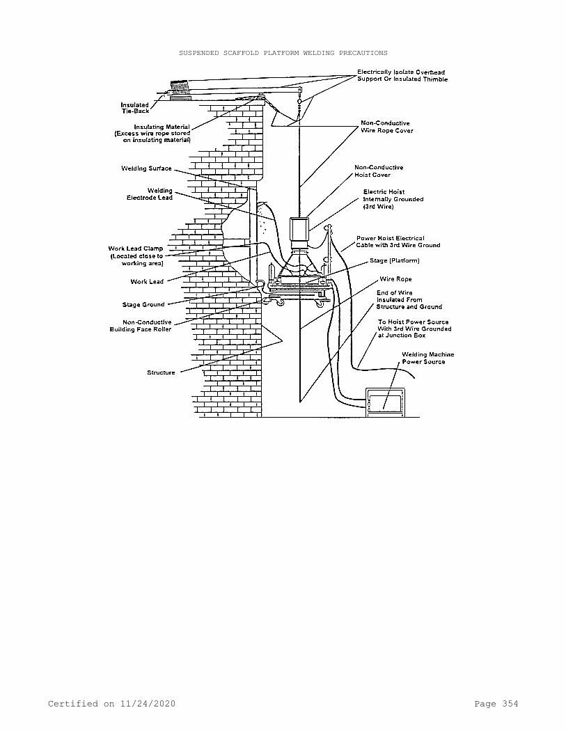
SUSPENDED SCAFFOLD PLATFORM WELDING PRECAUTIONS
Certified on 11/24/2020 Page 354

MAXIMUM VERTICAL TIE SPACING WIDER THAN 3'-0" BASES
Certified on 11/24/2020 Page 355

MAXIMUM VERTICAL TIE SPACING 3'-0" AND NARROWER BASES
Certified on 11/24/2020 Page 356
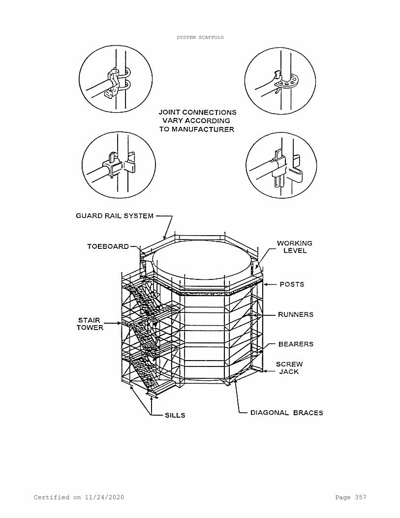
SYSTEM SCAFFOLD
Certified on 11/24/2020 Page 357

TUBE AND COUPLER SCAFFOLD
Certified on 11/24/2020 Page 358

SCAFFOLDING WORK SURFACES
Certified on 11/24/2020 Page 359

OUTRIGGER SCAFFOLD
[Statutory Authority: RCW 49.17.010, 49.17.040, 49.17.050, and 49.17.060. WSR 15-24-100, § 296-24-862, filed 12/1/15, effective 1/5/16. Statutory Authority: RCW 49.17.010, [49.17].040, and [49.17].050. WSR 00-08-078, § 296-24-862, filed 4/4/00, effective 7/1/00.]
PART J-3POWERED PLATFORMS
Note: Powered platforms have been moved to chapters 296-869 and 296-870 WAC.
PART KCOMPRESSED GAS AND COMPRESSED GAS EQUIPMENT
Certified on 11/24/2020 Page 360

WAC 296-24-920 Inspection of compressed gas cylinders.[Order 73-5, § 296-24-920, filed 5/9/73 and Order 73-4, § 296-24-920, filed 5/7/73.]
WAC 296-24-92001 Definitions. Corrosion or pitting. Corrosion or pitting in cylinders involving the loss of wall thickness by corro-sive media.Note: There are several kinds of pitting or corrosion to be considered.
Cuts, gouges, or digs (in cylinders). Deformations caused by con-tact with a sharp object in such a way as to cut into or upset the metal of the cylinder, decreasing the wall thickness at that point.
Dents (in cylinders). Deformations caused by the cylinder coming in contact with a blunt object in such a way that the thickness of metal is not materially impaired.
DOT. The U.S. Department of Transportation.General corrosion. Corrosion which covers considerable surface
areas of the cylinder.Note: It reduces the structural strength. It is often difficult to measure or estimate the depth of general corrosion because direct comparison with the
original wall cannot always be made. General corrosion is often accompanied by pitting.
High- and low-pressure cylinders. Those cylinders with a marked service pressure of 900 p.s.i. or greater; low-pressure cylinders are those with a marked service pressure less than 900 p.s.i.
Isolated pitting. Isolated pits of small cross-section which do not effectively weaken the cylinder wall but are indicative of possi-ble complete penetration and leakage.Note: Since the pitting is isolated the original wall is essentially intact.
Line corrosion. Pits which are not isolated but are connected or nearly connected to others in a narrow band or line.Note: This condition is more serious than isolated pitting. Line corrosion frequently occurs in the area of intersection of the footring and bottom of a
cylinder. This is sometimes referred to as "crevice corrosion."
Minimum allowable wall thickness. The minimum wall thickness re-quired by the specification under which the cylinder was manufactured.[Statutory Authority: RCW 49.17.010, 49.17.040, 49.17.050, and 49.17.060. WSR 15-24-100, § 296-24-92001, filed 12/1/15, effective 1/5/16; Order 73-5, § 296-24-92001, filed 5/9/73 and Order 73-4, § 296-24-92001, filed 5/7/73.]
WAC 296-24-92003 General requirements. (1) Application.(a) You must determine that compressed gas cylinders under the
employers control are in a safe condition to the extent that this can be determined by visual, and other inspection required by WAC 296-24-920 through 296-24-92011.
(b) The requirements contained in these standards are not inten-ded to apply to cylinders manufactured under specification DOT (ICC)-3HT (49 C.F.R. Ch.1). Separate requirements covering service life and standards for visual inspection of these cylinders are con-tained in Compressed Gas Association Pamphlet C-8, "Standard for Re-qualification of ICC-3HT Cylinders."
(2) Quality of inspection. Experience in the inspection of cylin-ders is an important factor in determining the acceptability of a giv-en cylinder for continued service.
Certified on 11/24/2020 Page 361

Note: Users lacking this experience and having doubtful cylinders should return them to a manufacturer of the same type of cylinders for reinspection.
[Statutory Authority: RCW 49.17.010, 49.17.040, 49.17.050, and 49.17.060. WSR 15-24-100, § 296-24-92003, filed 12/1/15, effective 1/5/16. Statutory Authority: Chapter 49.17 RCW. WSR 94-15-096 (Order 94-07), § 296-24-92003, filed 7/20/94, effective 9/20/94; Order 73-5, § 296-24-92003, filed 5/9/73 and Order 73-4, § 296-24-92003, filed 5/7/73.]
WAC 296-24-92005 Inspection of low-pressure cylinders exempt from the hydrostatic test including acetylene cylinders. (1) Applica-tion. This section covers cylinders of the type that are exempt from the hydrostatic retest requirements of the DOT by virtue of their ex-clusive use in certain noncorrosive gas service. They are not subject to internal corrosion and do not require internal shell inspection.
(2) Preparation for inspection. You must remove rust, scale, caked paint, etc., from the exterior surface so that the surface can be adequately observed. You must provide facilities for inverting the cylinder to facilitate inspection of the bottom. This is important be-cause experience has shown this area to be the most susceptible to corrosion.
(3) Exterior inspection. You must check cylinders as outlined be-low for corrosion, general distortion, or any other defect that might indicate a weakness which would render it unfit for service.
(a) To fix corrosion limits for all types, designs, and sizes of cylinders, and include them in this section is not practicable. Cylin-ders categorized by this section and subsection (1) of this section must meet the following requirements. Failure to meet any of these re-quirements is of itself cause for rejection of a cylinder. You must remove rejected cylinders from the work place. Rejected cylinders may be returned to the manufacturer for reinspection.
(i) You must reject a cylinder when the tare weight is less than 95% of the original tare weight marked on the cylinder. When determin-ing tare weight, be sure that the cylinder is empty.
(ii) You must reject a cylinder when the remaining wall in an area having isolated pitting only is less than 1/3 of the minimum al-lowable wall thickness as determined under (b) and (d) of this subsec-tion.
(iii) You must reject a cylinder when line corrosion on the cyl-inder is 3 inches in length or over and the remaining wall is less than 3/4 of the minimum allowable wall thickness or when line corro-sion is less than 3 inches in length and the remaining wall thickness is less than 1/2 the minimum allowable wall thickness as determined under (b) through (d) of this subsection.
(iv) You must reject a cylinder when the remaining wall in an area of general corrosion is less than 1/2 of the minimum allowable wall thickness as determined under (b) through (d) of this subsection.
(b) To use the criteria in (a) of this subsection, it is necessa-ry to know the original wall thickness of the cylinder or the minimum allowable wall thickness. Table M-1 lists the minimum allowable wall thickness under DOT specifications (49 C.F.R. Ch. 1) for a number of common size low-pressure cylinders.
TABLE M - 1
Certified on 11/24/2020 Page 362

Cylinder sizeO.D. x length
(inches)
DOTSpecification
marking
Nominalwater
capacity(pounds)
Minimumallowable
wallthickness(inches)
15 x 46 . . . . . . . . . . . . . . . . 4B2401 239 0.12814 13/16 x 47 . . . . . . . . . . 4E240 239 .14014 15/16 x 46 . . . . . . . . . . 4BA240 239 .08614 11/16 x 28 3/8 . . . . . . . 4BA240 143 .08611 29/32 x 32 11/16 . . . . . . 4BA240 95 .07811 29/32 x 18 11/32 . . . . . . 4BA240 48 .078
1Without longitudinal seam.
(c) When the wall thickness of the cylinder at manufacture is not known, and the actual wall thickness cannot be measured, you must re-ject this cylinder when the inspection reveals that the deepest pit in a general corrosion area exceeds 3/64 inch. This is arrived at by con-sidering that in no case must the pitting exceed 1/2 the minimum al-lowable wall thickness which is 0.064 inch. When a pit measures 0.043 inch (approximately 3/64 inch) in a corrosion area, general corrosion will already have removed 0.021 inch of the original wall and the to-tal pit depth as compared to the initial wall will be 0.064 inch.
(d) When the original wall thickness at manufacture is known, or the actual wall thickness is measured, this thickness less 1 1/2 times the maximum measured pit depth must be 0.064 inch or greater. If it is less, you must reject the cylinder.
(e) Dents are of concern where the metal deformation is sharp and confined, or where they are near a weld. Where metal deformation is not sharp, dents of larger magnitude can be tolerated.
(f) Where denting occurs so that any part of the deformation in-cludes a weld, the maximum allowable dent depth must be 1/4 inch.
(g) When denting occurs so that no part of the deformation in-cludes a weld, you must reject the cylinder if the depth of the dent is greater than 1/10 of the mean diameter of the dent.
(h) Cuts, gouges, or digs reduce the wall thickness of the cylin-der and in addition are considered to be stress raisers. Depth limits are set in these standards; however, you must reject cylinders at 1/2 of the limit set whenever the length of the defect is 3 inches or more.
(i) When the original wall thickness at manufacture is not known, and the actual wall thickness cannot be measured you must reject a cylinder if the cut, gouge, or dig exceeds 1/2 of the minimum allowa-ble wall thickness as determined under (b) through (d) of this subsec-tion.
(ii) When the original wall thickness at manufacture is known, or the actual wall thickness is measured, you must reject a cylinder if the original wall thickness minus the depth of the defect is less than 1/2 of the minimum allowable wall thickness as determined under (b) through (d) of this subsection.
(i) Leaks can originate from a number of sources, such as defects in a welded or brazed seam, defects at the threaded opening, or from sharp dents, digs, gouges, or pits.
(i) To check for leaks, the cylinder must be charged and careful-ly examined. You must coat all seams and pressure openings with a soap or other suitable solution to detect the escape of gas. Any leakage is cause for rejection.
Certified on 11/24/2020 Page 363

(ii) You must test safety relief devices as defined in WAC 296-24-93001(1) for leaks before a charged cylinder is shipped from the cylinder filling plant.
(j) After fire damage, you must carefully inspect cylinders for evidence of exposure to fire.
(i) Common evidences of exposure to fire are:(A) Charring or burning of the paint or other protective coat.(B) Burning or sintering of the metal.(C) Distortion of the cylinder.(D) Melted out fuse plugs.(E) Burning or melting of valve.(ii) The evaluation of fire damage by DOT regulations state that,
"a cylinder which has been subjected to the action of fire must not again be placed in service until it has been properly reconditioned," in accordance with 49 C.F.R. 173.34(f). The general intent of this re-quirement is to remove from service cylinders which have been subject to the action of fire which has changed the metallurgical structure or the strength properties of the steel, or in the case of acetylene cyl-inders caused breakdown of porous filler. This is normally determined by visual examination as covered above with particular emphasis to the condition of the protective coating. If the protective coating has been burnt off or if the cylinder body is burnt, warped, or distorted, it is assumed that the cylinder has been overheated and you must com-ply with 49 C.F.R. 173.34(f). If, however, the protective coating is only dirtied from smoke or other debris, and is found by examination to be intact underneath, you must not consider the cylinder affected within the scope of this requirement.
(k) Cylinders are manufactured with a reasonably symmetrical shape. You must remove cylinders which have definite visible bulges from service and evaluate them. You must reject cylinders when a var-iation of 1% or more is found in the measured circumferences or in pe-ripheral distances measured from the valve spud to the center seam (of equivalent fixed point).
(l) You must examine cylinder necks for serious cracks, folds, and flaws. Neck cracks are normally detected by testing the neck dur-ing charging operations with a soap solution.
(m) You must examine cylinder neck threads whenever the valve is removed from the cylinder. You must reject cylinders if the required number of effective threads are materially reduced, or if a gas tight seal cannot be obtained by reasonable valving methods. You must use gauges to measure the number of effective threads.
(n) If the valve is noticeably tilted you must reject the cylin-der.
(o) The footring and headring of cylinders may become so distor-ted through service abuse that they no longer perform their functions:
(i) To cause the cylinder to remain stable and upright.(ii) To protect the valve. You must examine rings for distortion;
for looseness, and for failure of welds. Appearances may often warrant rejection of the cylinder.[Statutory Authority: RCW 49.17.010, 49.17.040, 49.17.050, and 49.17.060. WSR 15-24-100, § 296-24-92005, filed 12/1/15, effective 1/5/16. Statutory Authority: Chapter 49.17 RCW. WSR 89-11-035 (Order 89-03), § 296-24-92005, filed 5/15/89, effective 6/30/89; Order 73-5, § 296-24-92005, filed 5/9/73 and Order 73-4, § 296-24-92005, filed 5/7/73.]
Certified on 11/24/2020 Page 364

WAC 296-24-92007 Low-pressure cylinders subject to hydrostatic testing. (1) Application. Cylinders covered in this section are low-pressure cylinders other than those covered in WAC 296-24-92005 through 296-24-92005 (3)(o)(ii). They differ essentially from such cylinders in that they require a periodic hydrostatic retest which in-cludes an internal and external examination. Defect limits for the ex-ternal examination are prescribed in WAC 296-24-92005 through 296-24-92005 (3)(o)(ii), with exceptions for aluminum cylinders shown in WAC 296-24-92007(4).
(2) Preparation for inspection. You must purge flammable gas cyl-inders before being examined with a light. Lamps used for flammable gas cylinder inspection must be explosion proof.
(3) Internal inspection. You must inspect cylinders internally at least every time the cylinder is periodically retested. You must per-form the examination with a light of sufficient intensity to clearly illuminate the interior walls.
(4) External inspection of aluminum cylinders. The inspection re-quirements of WAC 296-24-92005 through 296-24-92005 (3)(o)(ii) must be met, except as follows:
(a) You must reject aluminum cylinders when impairment to the surface (corrosion or mechanical defect) exceeds a depth where the re-maining wall is less than three-fourths of the minimum allowable wall thickness required by the specification under which the cylinder was manufactured.
(b) You must remove aluminum cylinders subjected to the action of fire from service.[Statutory Authority: RCW 49.17.010, 49.17.040, 49.17.050, and 49.17.060. WSR 15-24-100, § 296-24-92007, filed 12/1/15, effective 1/5/16; Order 73-5, § 296-24-92007, filed 5/9/73 and Order 73-4, § 296-24-92007, filed 5/7/73.]
WAC 296-24-92009 High-pressure cylinders. (1) Application. High-pressure cylinders are those with a marked service pressure of 900 p.s.i. or higher. They are seamless; no welding is permitted. The great bulk of such cylinders are of the 3A or 3AA types under DOT specifications (49 C.F.R. Ch. 1).
(2) Preparation for inspection.(a) You must clean cylinders for inspection so that the inside
and outside surfaces and all conditions can be observed. This must in-clude removal of scale and caked paint from the exterior and the thor-ough removal of internal scale. You must examine cylinders with inte-rior coating for defects in the coating. If the coating is defective, you must remove it.
(b) A good inspection light of sufficient intensity to clearly illuminate the interior wall is mandatory for internal inspection. You must purge flammable gas cylinders before being examined with a light. Lamps for flammable gas cylinder inspection must be explosion proof.
(3) Exterior inspection.(a) To fix corrosion limits for all types, designs, and sizes of
cylinders, and include them in this section, is not practicable. Con-siderable judgment is required in evaluating cylinders fit for serv-ice. Experience is a major factor, aside from strength considerations for high pressure cylinders.
(b) When the original wall thickness of the cylinder is not known, and the actual wall thickness cannot be measured, you must re-
Certified on 11/24/2020 Page 365
ject the cylinder if corrosion exceeds one thirty-second inch in depth. This is arrived at by subtracting from the minimum allowable wall at manufacture (0.221 inch), the limiting wall in service (0.195 inch), to give the maximum allowable corrosion limit of 0.026 inch, the equivalent of 1/32 inch.
(c) When the wall thickness is known, or the actual wall thick-ness is measured, the difference between this known wall and the lim-iting value establishes the maximum corrosion figure. The normal hot forged cylinder of this size will have a measured wall of about 0.250 inch. Comparison of this with the limiting wall thickness shows that defects up to about 1/16 inch are allowable provided, of course, that the actual wall is measured or is known.
(d) Cylinders with general corrosion are evaluated by subjecting them to a hydrostatic test. Thus, you must reject a cylinder with an elastic expansion of 227 cc. or greater. If areas of pronounced pit-ting are included within the general corrosion, the depth of such pit-ting should also be measured (with the high spots of the actual sur-face as a reference plane) and the criteria established in the first example apply. Thus, the maximum corrosion limit would be 1/32 inch when the wall was not known.
(e) Any defect of appreciable depth having a sharp bottom is a stress raiser and even though a cylinder may be acceptable from a stress standpoint, it is common practice to remove such defects. After any such repair operation, you must verify the cylinder strength and structure by a hydrostatic test of other suitable means.
(f) Dents can be tolerated when the cylinder wall is not deformed excessively or abruptly. Generally speaking, dents are accepted up to a depth of about 1/16 inch when the major diameter of the dent is equal to or greater than 32 times the depth of the dent. Sharper dents than this are considered too abrupt and must require rejection of the cylinder. On small diameter cylinders these general rules may have to be adjusted. Considerations of appearance play a major factor in the evaluation of dents.
(g) You must remove cylinders with arc or torch burns from serv-ice. Defects of this nature may be recognized by one of the following conditions:
(i) Removal of metal by scarfing or cratering.(ii) A sentering or burning of the base metal.(iii) A hardened heat affected zone. A simple method for verify-
ing the presence of small arc burns is to file the suspected area. The hardened zone will resist filing as compared to the softer base metal.
(h) Cylinders are normally produced with a symmetrical shape. You must remove cylinders with distinct visual bulges from service until the nature of the defect is determined. Some cylinders may have small discontinuities related to the manufacturing process - Mushroomed bot-toms, offset shoulders, etc. These usually can be identified and are not normally cause for concern.
(i) You must carefully inspect cylinders for evidences of expo-sure to fire. (See WAC 296-24-92005 (3)(j).)
(j) You must examine cylinder necks for serious cracks, folds, and flaws. (See WAC 296-24-92005 (3)(l) and (m).)[Statutory Authority: RCW 49.17.010, 49.17.040, 49.17.050, and 49.17.060. WSR 15-24-100, § 296-24-92009, filed 12/1/15, effective 1/5/16; Order 73-5, § 296-24-92009, filed 5/9/73 and Order 73-4, § 296-24-92009, filed 5/7/73.]
Certified on 11/24/2020 Page 366

WAC 296-24-92011 Internal inspection. (1) You must ensure that cylinders are inspected internally at least every time the cylinder is periodically retested. This examination must be made with a light of sufficient intensity to clearly illuminate the interior walls.
(2) A hammer test consists of tapping a cylinder a light blow with a suitably sized hammer. A cylinder, emptied of liquid content, with a clean internal surface, standing free, will have a clear ring. Cylinders with internal corrosion will give a duller ring dependent upon the amount of corrosion and accumulation of foreign material. You must investigate such cylinders. The hammer test is very sensitive and is an easy, quick, and convenient test that can be made without remov-ing the valve before each charging. It is an invaluable indicator of internal corrosion.[Statutory Authority: RCW 49.17.010, 49.17.040, 49.17.050, and 49.17.060. WSR 15-24-100, § 296-24-92011, filed 12/1/15, effective 1/5/16; Order 73-5, § 296-24-92011, filed 5/9/73 and Order 73-4, § 296-24-92011, filed 5/7/73.]
WAC 296-24-930 Safety relief devices for compressed gas cylin-ders.[Order 73-5, § 296-24-930, filed 5/9/73 and Order 73-4, § 296-24-930, filed 5/7/73.]
WAC 296-24-93001 Definitions. Approach channel. The passage or passages through which gas must pass from the cylinder to reach the operating parts of the safety relief device.
Combination frangible disc-fusible plug. A frangible disc in com-bination with a low melting point fusible metal, intended to prevent its bursting at its predetermined bursting pressure unless the temper-ature also is high enough to cause yielding or melting of the fusible metal.
Combination safety relief valve and fusible plug. A safety relief device utilizing a safety relief valve in combination with a fusible plug. This combination device may be an integral unit or separate units and is intended to open and to close at predetermined pressures or to open at a predetermined temperature.
Compressed gas in solution (acetylene). A nonliquefied gas which is dissolved in a solvent.
Discharge channel. The passage or passages beyond the operating parts through which gas must pass to reach the atmosphere exclusive of any piping attached to the outlet of the device.
DOT regulations. As used in these standards "DOT regulations" re-fers to the U.S. Department of Transportation Regulations for Trans-portation of Explosives and Other Dangerous Articles by Land and Water in Rail Freight, Express and Baggage Services and by Motor Vehicle (Highway) and Water, including Specifications for Shipping Containers, Code of Federal Regulations, Title 49, Parts 171 to 178.
Flow capacity. The capacity in cubic feet per minute of free air discharged at the required flow rating pressure of a safety relief de-vice.
Flow rating pressure. The pressure at which a safety relief de-vice is rated for capacity.
Certified on 11/24/2020 Page 367

Frangible disc. An operating part in the form of a disc, usually of metal and which is so held as to close the safety relief device channel under normal conditions. The disc is intended to burst at a predetermined pressure to permit the escape of gas.
Free air or free gas. Air or gas measured at a pressure of 14.7 pounds per square inch absolute and a temperature of 60°F.
Fusible plug. An operating part in the form of a plug of suitable low melting material, usually a metal alloy, which closes the safety relief device channel under normal conditions and is intended to yield or melt at a predetermined temperature to permit the escape of gas.
Liquefied compressed gas. A gas which, under the charging pres-sure, is partially liquid at a temperature of 70°F. A flammable com-pressed gas which is normally nonliquefied at 70°F but which is parti-ally liquid under the charging pressure and temperature, shall follow the requirements for liquefied compressed gases.
Nonliquefied compressed gas. A gas, other than a gas in solution which under the charging pressure, is entirely gaseous at a tempera-ture of 70°F.
Operating part. The part of a safety relief device that normally closes the safety discharge channel but when moved from this position as a result of the action of heat or pressure, or a combination of the two, permits escape of gas from the cylinder.
Pressure opening. The orifice against which the frangible disc functions.
Pressurized liquid compressed gas. A compressed gas other than a compressed gas in solution, which cannot be liquefied at a temperature of 70°F, and which is maintained in the liquid state at a pressure not less than 40 p.s.i.a. by maintaining the gas at a temperature less than 70°F.
Rated bursting pressure. The maximum pressure for which the disc is designed to burst when in contact with the pressure opening for which it was designed when tested.
Reinforced fusible plug. A fusible plug consisting of a core of suitable material having a comparatively high yield temperature sur-rounded by a low-melting point fusible metal of the required yield temperature.
Safety relief device. A "safety relief device" is a device inten-ded to prevent rupture of a cylinder under certain conditions of expo-sures. (The term as used herein shall include the approach channel, the operating parts, and the discharge channel.)
Safety relief device channel. The channel through which gas re-leased by operation of the device must pass from the cylinder to the atmosphere exclusive of any piping attached to the inlet or outlet of the device.
Safety relief valve. A safety relief device containing an operat-ing part that is held normally in a position closing the safety relief device channel by spring force and is intended to open and to close at predetermined pressures.
Set pressure. The pressure marked on the valve and at which it is set to start-to-discharge of a safety relief valve.
Start-to-discharge pressure. The pressure at which the first bub-ble appears through a water seal of not over 4 inches in the outlet of the safety relief valve.
Test pressure of the cylinder. The minimum pressure at which a cylinder must be tested as prescribed in DOT specifications for com-pressed gas cylinders 41 C.F.R. Ch. 1.
Certified on 11/24/2020 Page 368

Yield temperature. The temperature at which the fusible metal or alloy will yield when tested in a fusible plug.[Statutory Authority: RCW 49.17.010, 49.17.040, 49.17.050, and 49.17.060. WSR 15-24-100, § 296-24-93001, filed 12/1/15, effective 1/5/16; Order 73-5, § 296-24-93001, filed 5/9/73 and Order 73-4, § 296-24-93001, filed 5/7/73.]
WAC 296-24-93003 General requirements. (1) Application. You must ensure that compressed gas cylinder, portable tanks, and cargo tanks shall have pressure relief devices installed and maintained in accordance with Compressed Gas Association Pamphlets S-1.1-1963 and 1965 addenda and S-1.2-1963.
(2) Types of safety relief devices. Types of safety relief devi-ces as covered by this section are designated as follows:
(a) Type CG-1: Frangible disc.(b) Type CG-2: Fusible plug or reinforced fusible plug utilizing
a fusible alloy with yield temperature not over 170°F, nor less than 157°F (165°F nominal).
(c) Type CG-3: Fusible plug or reinforced fusible plug utilizing a fusible alloy with yield temperature not over 220°F, nor less than 208°F (212°F nominal).
(d) Type CG-4: Combination frangible disc-fusible plug, utilizing a fusible alloy with yield temperature not over 170°F, nor less than 157°F (165°F nominal).
(e) Type CG-5: Combination frangible disc-fusible plug, utilizing a fusible alloy with yield temperature not over 220°F, nor less than 208°F (212°F nominal).
(f) Type CG-7: Safety relief valve.(g) Type CG-8: Combination safety relief valve and fusible plug.(3) Specifications and tests. All safety relief devices covered
by this section must meet the design, construction, marking and test specification of the "Compressed Gas Association Safety Relief Device Standards Part 1-Cylinders for Compressed Gases: S1.1-1963."
(4) Specific requirements for safety relief devices.(a) Compressed gas cylinders, which under the regulations of the
department of transportation must be equipped with safety relief devi-ces, must be considered acceptable when equipped with devices of prop-er construction, location, and discharge capacity under the conditions prescribed in Table 1 of the Compressed Gas Associations Standard S-1.1-1963.
(b) You must only use replacement parts or assemblies provided by the manufacturer unless the advisability of interchange is proved by adequate tests.
(c) When a frangible disc is used with a compressed gas cylinder, the rated bursting pressure of the disc must not exceed the minimum required test pressure of the cylinder with which the device is used, except for DOT-3E cylinders (49 C.F.R. Ch. 1) the rated bursting pres-sure of the device must not exceed 4,500 pounds per square inch gage (p.s.i.g.).
(d) When a safety relief valve is used on a compressed gas cylin-der, the flow rating pressure must not exceed the minimum required test pressure of the cylinder on which the safety relief valve is in-stalled and the reseating pressure must not be less than the pressure in a normally charged cylinder at 130°F.
Certified on 11/24/2020 Page 369

(e) When fittings and piping are used on either the upstream or downstream side or both of a safety relief device or devices, the pas-sages must be so designed that the flow capacity of the safety relief device will not be reduced below the capacity required for the con-tainer on which the safety relief device assembly is installed, nor to the extent that the operation of the device could be impaired. Fit-tings, piping, and method of attachment must be designed to withstand normal handling and the pressures developed when the device or devices function.
(f) You must ensure that no shutoff valve is installed between the safety relief devices and the cylinder.
(5) Maintenance requirements for safety relief devices.(a) As a precaution to keep cylinder safety relief devices in re-
liable operating condition, you must take care in the handling or storing of compressed gas cylinders to avoid damage. You must also ex-ercise care to avoid plugging by paint or other dirt accumulation of safety relief device channels or other parts which could interfere with the functioning of the device. You must only allow qualified per-sonnel to service safety relief devices.
(b) Each time a compressed gas cylinder is received at a point for refilling, you must examine all safety relief devices externally for corrosion, damage, plugging of external safety relief device chan-nels, and mechanical defects such as leakage or extrusion of fusible metal. If there is any doubt regarding the suitability of the safety relief device for service you must not fill the cylinder until it is equipped with a suitable device.[Statutory Authority: RCW 49.17.010, 49.17.040, 49.17.050, and 49.17.060. WSR 15-24-100, § 296-24-93003, filed 12/1/15, effective 1/5/16; Order 73-5, § 296-24-93003, filed 5/9/73 and Order 73-4, § 296-24-93003, filed 5/7/73.]
WAC 296-24-935 Safety relief devices for cargo and portable tanks storing compressed gases.[Order 73-5, § 296-24-935, filed 5/9/73 and Order 73-4, § 296-24-935, filed 5/7/73.]
WAC 296-24-93501 Definitions. Cargo tank. Any container de-signed to be permanently attached to any motor vehicle or other high-way vehicle and in which is to be transported any compressed gas. The term "cargo tank" shall not be construed to include any tank used solely for the purpose of supplying fuel for the propulsion of the ve-hicle or containers fabricated under specifications for cylinders.
Code. Paragraph U-68, U-69, U-200, or U-201 of section VIII of the Boiler and Pressure Vessel Code of the American Society of Mechan-ical Engineers, 1949 Edition, or section VIII of the Boiler and Pres-sure Vessel Code of the American Society of Mechanical Engineers, 1950, 1952, 1956, 1959, and 1962 Editions; or the Code for Unfired Pressure Vessels for Petroleum Liquids and Gases of the American Pe-troleum Institute and the American Society of Mechanical Engineers (API-ASME), 1951 Edition.
DOT design pressure. The "DOT design pressure" is identical to the term "maximum allowable working pressure" as used in the "code" and is the maximum gage pressure at the top of the tank in its operat-
Certified on 11/24/2020 Page 370
ing position. To determine the minimum permissible thickness of physi-cal characteristics of the different parts of the vessel, the static head of the lading shall be added to the DOT design pressure to deter-mine the thickness of any specific part of the vessel. If vacuum insu-lation is used, the liquid container shall be designed for a pressure of 15 p.s.i. more than DOT design pressure, plus static head of the lading.EXCEPTION: For containers constructed in accordance with paragraph U-68 or U-69 of section VIII of the ASME Boiler and Pressure Vessel Code,
1949 Edition, the maximum allowable working pressure for the purpose of these standards is considered to be 125% of the design pressure as provided in 49 C.F.R. 173.315 of DOT regulations.
DOT regulations. Refers to department of transportation regula-tions for transportation of explosives and other dangerous articles by land and water in rail freight, express and baggage services and by motor vehicle (highway) and water, including specifications for ship-ping containers, Code of Federal Regulations, Title 49, Parts 171 to 178.
Flow capacity. The capacity in cubic feet per minute of free air discharged at the required flow rating pressure of a safety relief valve.
Flow rating pressure. The pressure at which a safety relief de-vice is rated for capacity.
Frangible disc. A safety relief device in the form of a disc, usually of metal, which is so held as to close the safety relief de-vice channel under normal conditions. The disc is intended to burst at a predetermined pressure to permit the escape of gas.
Free air or free gas. Air or gas measured at a pressure of 14.7 pounds per square inch absolute and a temperature of 60°F.
Fusible plug. A safety relief device in the form of a plug of suitable low-melting material, usually a metal alloy, which closes the safety relief device channel under normal conditions and is intended to yield or melt at a predetermined temperature to permit the escape of gas.
Portable tank. Any container designed primarily to be temporarily attached to a motor vehicle, other vehicle, railroad car other than tank car, or marine vessel, and equipped with skids, mountings, or ac-cessories to facilitate handling of the container by mechanical means, in which is to be transported any compressed gas. The term "portable tank" shall not be construed to include any cargo tank, any tank car tank or any tank of the DOT-106A and DOT-110A-W type.
Resealing pressure. The pressure at which leakage ceases through a water seal of not over 4 inches on the outlet of the safety relief valve.
Safety relief device. A device intended to prevent rupture of a container under certain conditions of exposure.
Safety relief valve. A safety relief device containing an operat-ing part that is held normally in a position closing the safety relief device channel by spring force and is intended to open and to close at predetermined pressures.
Set pressure. A safety relief valve is the pressure marked on the valve and at which the valve is set to start-to-discharge.
Start-to-discharge pressure. The pressure at which the first bub-ble appears through a water seal of not over 4 inches on the outlet of the safety relief valve.Note: When the nature of the service requires the use of a metal-to-metal seat safety relief valve, with or without secondary sealing means, the start-
to-discharge pressure may be considered the pressure at which an audible discharge occurs.
Certified on 11/24/2020 Page 371

[Statutory Authority: RCW 49.17.010, 49.17.040, 49.17.050, and 49.17.060. WSR 15-24-100, § 296-24-93501, filed 12/1/15, effective 1/5/16; Order 73-5, § 296-24-93501, filed 5/9/73 and Order 73-4, § 296-24-93501, filed 5/7/73.]
WAC 296-24-93503 General requirements. (1) Application. See WAC 296-24-93003(1).
(2) Specifications and tests. All safety relief devices covered by these standards must meet the design, construction, marking, and test specifications of the "Compressed Gas Association Safety Relief Device Standards Part 2-Cargo and Portable Tanks for Compressed Gases: S-1.2-1963."
(3) Specific requirements for safety relief devices.(a) You must provide each container with one or more safety re-
lief devices which, unless otherwise specified, must be safety relief valves of the spring-loaded type.
(b) You must set safety relief valves to start-to-discharge at a pressure not in excess of 110% of the DOT design pressure of the con-tainer nor less than the DOT design pressure of the container except as follows:
(i) If an overdesigned container is used, the set pressure of the safety relief valve may be between the minimum required DOT design pressure for the lading and 110% of the DOT design pressure of the container used.
(ii) For sulfur dioxide containers, a minimum set pressure of 120 and 110 p.s.i.g. is permitted for the 150 and 125 p.s.i.g. DOT design pressure containers, respectively.
(iii) For carbon dioxide (refrigerated), nitrous oxide (refrigerated), and pressurized liquid argon, nitrogen and oxygen, there must be no minimum set pressure.
(iv) For butadiene, inhibited, and liquefied petroleum gas con-tainers, a minimum set pressure of 90% of the minimum design pressure permitted for these ladings may be used.
(v) For containers constructed in accord with paragraph U-68 or U-69 of the Code 1949 Edition, the set pressure marked on the safety relief valve may be 125% of the original DOT design pressure of the container.
(c) You must only use replacement parts or assemblies provided by the manufacturer of the device unless the suitability of interchange is proved by adequate tests.
(d) Safety relief valves must have direct communication with the vapor space of the container.
(e) Any portion of liquid piping or hose which at any time may be closed at each end must be provided with a safety relief device to prevent excessive pressure.
(f) The additional restrictions of this subdivision apply to safety relief devices on containers for carbon dioxide or nitrous ox-ide which are shipped in refrigerated and insulated containers. The maximum operating pressure in the container may be regulated by the use of one or more pressure controlling devices, which devices must not be in lieu of the safety relief valve required in WAC 296-24-93503 (3)(a).
(g) You must install and locate all safety relief devices so that the cooling effect of the contents will not prevent the effective op-eration of the device.
Certified on 11/24/2020 Page 372

(h) In addition to the safety relief valves required by WAC 296-24-93503 (3)(a) each container for carbon dioxide may be equipped with one or more frangible disc safety relief devices of suitable de-sign set to function at a pressure not exceeding two times the DOT de-sign pressure of the container.
(i) Subject to conditions of 49 C.F.R. 173.315 (a)(1) (DOT regu-lations) for methyl chloride and sulfur dioxide optional portable tanks of 225 p.s.i.g. minimum DOT design pressure, one or more fusible plugs approved by the Bureau of Explosives, 50 "F" Street Northwest, Washington, D.C. 20001, may be used in lieu of safety relief valves of the spring-loaded type. If the container is over 30 inches long a safety relief device having the total required flow capacity must be at both ends.
(j) When storage containers for liquefied petroleum gas are per-mitted to be shipped in accordance with 49 C.F.R. 173.315(j) (DOT reg-ulations), they must be equipped with safety relief devices in compli-ance with the requirements for safety relief devices on above-ground containers as specified in the National Fire Protection Association Pamphlet No. 58-1969 "Standard for the Storage and Handling of Lique-fied Petroleum Gases."
(k) When containers are filled by pumping equipment which has a discharge capacity in excess of the capacity of the container safety relief devices, and which is capable of producing pressures in excess of DOT design pressure of the container, precautions should be taken to prevent the development of pressures in the container in excess of 120% of its DOT design pressure. This may be done by providing addi-tional capacity of the safety relief valves on the container, by pro-viding a bypass on the pump discharge, or by any other suitable meth-od.
(l) This additional requirement applies to safety relief devices on containers for liquefied hydrogen and pressurized liquid argon, ni-trogen, and oxygen. You must protect the liquid container by one or more safety relief valves and one or more frangible discs.
(m) You must arrange safety relief devices to discharge unob-structed to the open air in such a manner as to prevent any impinge-ment of escaping gas upon the container. You must arrange safety re-lief devices to discharge upward except this is not required for car-bon dioxide, nitrous oxide and pressurized liquid argon, nitrogen, and oxygen.
(n) You must not install any shutoff valves between the safety relief devices and the container except, in cases where two or more safety relief devices are installed on the same container, a shutoff valve may be used where the arrangement of the shutoff valve or valves is such as always to insure full required capacity flow through at least one safety relief device.
(4) Maintenance requirements for safety relief devices.(a) You must exercise care to avoid damage to safety relief devi-
ces. You must also exercise care to avoid plugging by paint or other dirt accumulation of safety relief device channels or other parts which could interfere with the functioning of the device.
(b) You must only allow qualified personnel to service safety re-lief devices. Any servicing or repairs which require resetting of safety relief valves must be done only by or after consultation with the valve manufacturer.
(c) You must periodically examine safety relief devices external-ly for corrosion damage, plugging of external safety relief device channels, and mechanical defects such as leakage or extrusion of fusi-
Certified on 11/24/2020 Page 373

ble metal. You must periodically inspect the seals of valves equipped with secondary resilient seals. If there is any doubt regarding the suitability of the safety relief device for service you must not fill the container until it is equipped with a suitable safety relief de-vice.[Statutory Authority: RCW 49.17.010, 49.17.040, 49.17.050, and 49.17.060. WSR 15-24-100, § 296-24-93503, filed 12/1/15, effective 1/5/16. Statutory Authority: Chapter 49.17 RCW. WSR 94-15-096 (Order 94-07), § 296-24-93503, filed 7/20/94, effective 9/20/94; Order 73-5, § 296-24-93503, filed 5/9/73 and Order 73-4, § 296-24-93503, filed 5/7/73.]
WAC 296-24-940 Air receivers.[Order 73-5, § 296-24-940, filed 5/9/73 and Order 73-4, § 296-24-940, filed 5/7/73.]
WAC 296-24-94001 General requirements. (1) Application. These standards apply to compressed air receivers, and other equipment used in providing and utilizing compressed air for performing operations such as cleaning, drilling, hoisting, and chipping. On the other hand, however, this section does not deal with the special problems created by using compressed air to convey materials nor the problems created when working in compressed air as in tunnels and caissons. These standards are not intended to apply to compressed air machinery and equipment used on transportation vehicles such as steam railroad cars, electric railway cars, and automotive equipment.
(2) New and existing equipment.(a) All new air receivers installed after the effective date of
these standards must be constructed in accordance with the 1968 Edi-tion of the A.S.M.E. Boiler and Pressure Vessel Code, section VIII.
(b) All safety valves used must be constructed, installed, and maintained in accordance with the A.S.M.E. Boiler and Pressure Vessel Code, section VIII edition 1968.[Statutory Authority: RCW 49.17.010, 49.17.040, 49.17.050, and 49.17.060. WSR 15-24-100, § 296-24-94001, filed 12/1/15, effective 1/5/16. Statutory Authority: Chapter 49.17 RCW. WSR 94-15-096 (Order 94-07), § 296-24-94001, filed 7/20/94, effective 9/20/94; Order 73-5, § 296-24-94001, filed 5/9/73 and Order 73-4, § 296-24-94001, filed 5/7/73.]
WAC 296-24-94003 Installation and equipment requirements. (1) Installation. Air receivers must be so installed that all drains, handholes, and manholes therein are easily accessible. Air receivers should be supported with sufficient clearance to permit a complete ex-ternal inspection and to avoid corrosion of external surfaces. You must not under any circumstances bury an air receiver underground or locate it in an inaccessible place. The receiver should be located as close to the compressor or after-cooler as is possible in order to keep the discharge pipe short.
(2) Drains and traps. All air receivers having an internal and external operating pressure exceeding 15 psi with no limitation on
Certified on 11/24/2020 Page 374
size, and air receivers having an inside diameter exceeding six in-ches, with no limitation on pressure, if subject to corrosion, must be supplied with a drain pipe and valve at the lowest point in the ves-sel; or a pipe may be used extending inward from any other location to within one-quarter inch of the lowest point. Adequate automatic traps may be installed in addition to drain valves. The drain valve on the air receiver must be opened and the receiver completely drained fre-quently and at such intervals as to prevent the accumulation of oil and water in the receiver.
(3) Gauges and valves.(a) Every air receiver must be equipped with an indicating pres-
sure gauge (so located as to be readily visible) and with one or more spring-loaded safety valves. The total relieving capacity of such safety valves must be such as to prevent pressure in the receiver from exceeding the maximum allowable working pressure of the receiver by more than 10%.
(b) You must ensure that no valve of any type is placed between the air receiver and its safety valve or valves.
(c) Safety appliances, such as safety valves, indicating devices and controlling devices, must be constructed, located, and installed so that they cannot be readily rendered inoperative by any means, in-cluding the elements.
(d) You must test all safety valves frequently and at regular in-tervals to determine whether they are in good operating condition.[Statutory Authority: RCW 49.17.010, 49.17.040, 49.17.050, and 49.17.060. WSR 15-24-100, § 296-24-94003, filed 12/1/15, effective 1/5/16. Statutory Authority: Chapter 49.17 RCW. WSR 89-11-035 (Order 89-03), § 296-24-94003, filed 5/15/89, effective 6/30/89; Order 73-5, § 296-24-94003, filed 5/9/73 and Order 73-4, § 296-24-94003, filed 5/7/73.]
PART LELECTRICAL
WAC 296-24-957 Electrical. This part addresses electrical safe-ty requirements that are necessary for the practical safeguarding of employees in their workplaces and is divided into four major divisions as follows:
(1) Design safety standards for electrical systems. These regula-tions are contained in WAC 296-24-95701 through 296-24-95713. Included in this category are all electric equipment and installations used to provide electric power and light for employee workplaces.
(2) Safety-related work practices. These regulations are con-tained in WAC 296-24-965.
(3) Definitions. Definitions applicable to each division are con-tained in WAC 296-24-990.[Statutory Authority: RCW 49.17.010, 49.17.040, 49.17.050, 49.17.060, and chapter 49.17 RCW. WSR 12-16-064, § 296-24-957, filed 7/31/12, ef-fective 9/1/12.]
WAC 296-24-95701 Electric utilization systems. (1) WAC 296-24-95701 through 296-24-95713 contain design safety standards for
Certified on 11/24/2020 Page 375
electric utilization systems, and cover electrical installations and utilization equipment installed or used within or on buildings, struc-tures, and other premises, including:
(a) Yards;(b) Carnivals;(c) Parking and other lots;(d) Mobile homes;(e) Recreational vehicles;(f) Industrial substations;(g) Conductors that connect the installations to a supply of
electricity; and(h) Other outside conductors on the premises.(2) Not covered. The provisions of WAC 296-24-95701 through
296-24-95713 do not cover:(a) Installations in ships, watercraft, railway rolling stock,
aircraft, or automotive vehicles other than mobile homes and recrea-tional vehicles;
(b) Installations underground in mines;(c) Installations of railways for generation, transformation,
transmission, or distribution of power used exclusively for operation of rolling stock or installations used exclusively for signaling and communication purposes;
(d) Installations of communication equipment under the exclusive control of communication utilities, located outdoors or in building spaces used exclusively for such installations; or
(e) Installations under the exclusive control of electric utilit-ies for the purpose of communication or metering; or for the genera-tion, control, transformation, transmission, and distribution of elec-tric energy located in buildings used exclusively by utilities for such purposes or located outdoors on property owned or leased by the utility or on public highways, streets, roads, etc., or outdoors by established rights on private property.
(3) Extent of application.(a) Requirements applicable to all installations. The following
requirements apply to all electrical installations and utilization equipment, regardless of when they were designed or installed:
WAC 296-24-95703 (3)(c), (4), (5), (6)(a), (b), and (c), and (7)(b);
WAC 296-24-95705 (1)(c), (6)(a)(i), (iv), and (v), and (7)(a)(ii) through (v), (d), (e), (f)(iv)(A) through (D), (f)(vi), and (h)(i);
WAC 296-24-95707 (7)(a) and (b)(ii) and (iii);WAC 296-24-95711, except as specified in WAC 296-24-95711(2).(b) Requirements applicable to installations made after March 15,
1972. Every electrical installation and all utilization equipment in-stalled or overhauled after March 15, 1972, must comply with the pro-visions in WAC 296-24-95701 through 296-24-95713, except as noted in subsections (3)(c) and (d) of this section.
(c) Requirements applicable only to installations made after April 16, 1981. The following requirements apply only to electrical installations and utilization equipment installed after April 16, 1981:
WAC 296-24-95703 (8)(d);WAC 296-24-95705 (6)(a)(vii) and (viii) and (7)(i)(i);WAC 296-24-95707 (10)(f)(ii)(D);WAC 296-24-95709 (3)(i), (9), and (10)(e);WAC 296-24-95713 (1)(a), (3)(c), and (4).
Certified on 11/24/2020 Page 376

(d) Requirements applicable only to installations made after Au-gust 13, 2007. The following requirements apply only to electrical in-stallations and utilization equipment installed after August 13, 2007:
WAC 296-24-95703 (6)(d) and (e), (7)(a)(iv) and (vii), and (8)(e)(vi);
WAC 296-24-95705 (2)(a) and (c), (6)(b)(i)(A) and (B) (but not the introductory text to WAC 296-24-95705 (6)(b)(i) and (iv)(A);
WAC 296-24-95707 (3)(c)(ii) and (e);WAC 296-24-95709 (1)(a)(ii), (3)(d), (e), (f), and (g),
(10)(a)(iii), and (11);WAC 296-24-95713 (1)(e)(v) and (vi)(B), (g), (2)(c), (3)(c), and
(6).(4) Applicability of requirements for disconnecting means. The
requirement in WAC 296-803-30005 that energy isolating devices be ca-pable of accepting a lockout device whenever replacement or major re-pair, renovation or modification of a machine or equipment is per-formed, and whenever new machines or equipment are installed after January 2, 1990, applies in addition to any requirements in WAC 296-24-95703 through 296-24-95713 that disconnecting means be capable of being locked in the open position under certain conditions.[Statutory Authority: RCW 49.17.010, 49.17.040, 49.17.050, and 49.17.060. WSR 15-24-100, § 296-24-95701, filed 12/1/15, effective 1/5/16. Statutory Authority: RCW 49.17.010, 49.17.040, 49.17.050, 49.17.060, and chapter 49.17 RCW. WSR 12-16-064, § 296-24-95701, filed 7/31/12, effective 9/1/12.]
WAC 296-24-95703 General requirements. (1) Approval. The con-ductors and equipment required or permitted by this part is acceptable only if approved, as defined in WAC 296-24-990.
(2) Examination, installation, and use of equipment.(a) Examination. Electric equipment must be free from recognized
hazards that are likely to cause death or serious physical harm to em-ployees. You must determine the safety of equipment using the follow-ing considerations:
(i) Suitability for installation and use in conformity with the provisions of this part;Note: Suitability of equipment for an identified purpose may be evidenced by listing or labeling for that identified purpose.
(ii) Mechanical strength and durability, including, for parts de-signed to enclose and protect other equipment, the adequacy of the protection thus provided;
(iii) Wire-bending and connection space;(iv) Electrical insulation;(v) Heating effects under all conditions of use;(vi) Arcing effects;(vii) Classification by type, size, voltage, current capacity,
and specific use; and(viii) Other factors that contribute to the practical safeguard-
ing of persons using or likely to come in contact with the equipment.(b) Installation and use. You must install and use listed or la-
beled equipment in accordance with any instructions included in the listing or labeling.
(c) Insulation integrity. Completed wiring installations must be free from short circuits and from grounds other than those required or permitted by this part.
Certified on 11/24/2020 Page 377

(d) Interrupting rating. Equipment intended to interrupt current at fault levels must have an interrupting rating sufficient for the nominal circuit voltage and the current that is available at the line terminals of the equipment. Equipment intended to interrupt current at other than fault levels must have an interrupting rating at nominal circuit voltage sufficient for the current that must be interrupted.
(e) Circuit impedance and other characteristics. You must select and coordinate the overcurrent protective devices, the total impe-dance, the component short-circuit current ratings, and other charac-teristics of the circuit to be protected to permit the circuit protec-tive devices used to clear a fault to do so without the occurrence of extensive damage to the electrical components of the circuit. You must assume this fault to be either between two or more of the circuit con-ductors, or between any circuit conductor and the grounding conductor or enclosing metal raceway.
(f) Deteriorating agents. Unless identified for use in the oper-ating environment, you must not locate any conductors or equipment in damp or wet locations; where exposed to gases, fumes, vapors, liquids, or other agents that have a deteriorating effect on the conductors or equipment; or where exposed to excessive temperatures.
(g) Mechanical execution of work. You must install electric equipment in a neat and workmanlike manner.
(i) You must effectively close unused openings in boxes, race-ways, auxiliary gutters, cabinets, equipment cases, or housings to af-ford protection substantially equivalent to the wall of the equipment.
(ii) You must rack conductors to provide ready and safe access in underground and subsurface enclosures that persons enter for installa-tion and maintenance.
(iii) Internal parts of electrical equipment, including busbars, wiring terminals, insulators, and other surfaces, may not be damaged or contaminated by foreign materials such as paint, plaster, cleaners, abrasives, or corrosive residues.
(iv) There must be no damaged parts that may adversely affect safe operation or mechanical strength of the equipment, such as parts that are broken, bent, cut, or deteriorated by corrosion, chemical ac-tion, or overheating.
(h) Mounting and cooling of equipment.(i) You must firmly secure electric equipment to the surface on
which it is mounted.Note: Wooden plugs driven into holes in masonry, concrete, plaster, or similar materials are not considered secure means of fastening electric
equipment.
(ii) You must install electric equipment that depends on the nat-ural circulation of air and convection principles for cooling of ex-posed surfaces so that room airflow over such surfaces is not preven-ted by walls or by adjacent installed equipment. For equipment de-signed for floor mounting, you must provide clearance between top sur-faces and adjacent surfaces to dissipate rising warm air.
(iii) You must install electric equipment provided with ventilat-ing openings so that walls or other obstructions do not prevent the free circulation of air through the equipment.
(3) Electrical connections.(a) General. Because of different characteristics of dissimilar
metals:(i) You must identify devices such as pressure terminal or pres-
sure splicing connectors and soldering lugs for the material of the conductor and you must properly install and use them;
Certified on 11/24/2020 Page 378

(ii) Conductors of dissimilar metals may not be intermixed in a terminal or splicing connector where physical contact occurs between dissimilar conductors (such as copper and aluminum, copper and copper-clad aluminum, or aluminum and copper-clad aluminum) unless the device is identified for the purpose and conditions of use; and
(iii) Materials such as solder, fluxes, inhibitors, and com-pounds, where employed, must be suitable for the use and must be of a type that will not adversely affect the conductors, installation, or equipment.
(b) Terminals.(i) Connection of conductors to terminal parts must ensure a good
connection without damaging the conductors and must be made by means of pressure connectors (including set-screw type), solder lugs, or splices to flexible leads. However, No. 10 or smaller conductors may be connected by means of wire binding screws or studs and nuts having upturned lugs or equivalent.
(ii) You must identify terminals for more than one conductor and terminals used to connect aluminum as such.
(c) Splices.(i) You must splice or join conductors with splicing devices
identified for the use or by brazing, welding, or soldering with a fu-sible metal or alloy. You must first splice or join soldered splices to be mechanically and electrically secure without solder and then soldered. You must cover all splices and joints and the free ends of conductors with an insulation equivalent to that of the conductors or with an insulating device identified for the purpose.
(ii) You must list wire connectors or splicing means installed on conductors for direct burial for such use.
(4) Arcing parts. You must enclose or separate and isolate parts of electric equipment that in ordinary operation produce arcs, sparks, flames, or molten metal from all combustible material.
(5) Marking.(a) Identification of manufacturer and ratings. Electric equip-
ment may not be used unless the following markings have been placed on the equipment:
(i) The manufacturer's name, trademark, or other descriptive marking by which the organization responsible for the product may be identified; and
(ii) Other markings giving voltage, current, wattage, or other ratings as necessary.
(b) Durability. The marking must be of sufficient durability to withstand the environment involved.
(6) Disconnecting means and circuits.(a) Motors and appliances. You must legibly mark each disconnect-
ing means required by this part for motors and appliances to indicate its purpose, unless located and arranged so the purpose is evident.
(b) Services, feeders, and branch circuits. You must legibly mark each service, feeder, and branch circuit, at its disconnecting means or overcurrent device, to indicate its purpose, unless located and ar-ranged so the purpose is evident.
(c) Durability of markings. The markings required by this section must be of sufficient durability to withstand the environment in-volved.
(d) Capable of accepting a lock. Disconnecting means required by this part must be capable of being locked in the open position.
(e) Marking for series combination ratings.
Certified on 11/24/2020 Page 379

(i) Where circuit breakers or fuses are applied in compliance with the series combination ratings marked on the equipment by the manufacturer, you must legibly mark the equipment enclosures in the field to indicate that the equipment has been applied with a series combination rating.
(ii) The marking required by (e)(i) of this subsection must be readily visible and must state "Caution—Series Combination System Rated Amperes. Identified Replacement Component Required."
(7) 600 Volts, nominal, or less. This subsection applies to elec-tric equipment operating at 600 volts, nominal, or less to ground.
(a) Space about electric equipment. You must provide and maintain sufficient access and working space about all electric equipment to permit ready and safe operation and maintenance of such equipment.
(i) Working space for equipment likely to require examination, adjustment, servicing, or maintenance while energized must comply with the following dimensions, except as required or permitted elsewhere in this part:
(A) The depth of the working space in the direction of access to live parts may not be less than indicated in Table S-1. You must meas-ure distances from the live parts if they are exposed or from the en-closure front or opening if they are enclosed;
(B) The width of working space in front of the electric equipment must be the width of the equipment or 30 inches, whichever is greater. In all cases, the working space must permit at least a 90-degree open-ing of equipment doors or hinged panels; and
(ii) Working space required by this standard may not be used for storage. When normally enclosed live parts are exposed for inspection or servicing, you must suitably guard the working space, if in a pas-sageway or general open space.
(iii) You must provide at least one entrance of sufficient area to give access to the working space about electric equipment.
(iv) For equipment rated 1200 amperes or more and over 6 feet wide, containing overcurrent devices, switching devices, or control devices, there must be one entrance not less than 24 inches wide and 6 feet 6 inches high at each end of the working space, except that:
(A) Where the location permits a continuous and unobstructed way of exit travel, one means of exit is permitted; or
(B) Where the working space required by (a)(i) of this subsection is doubled, only one entrance to the working space is required; howev-er, the entrance must be located so that the edge of the entrance nearest the equipment is the minimum clear distance given in Table S-1 away from such equipment.
(v) You must provide illumination for all working spaces about service equipment, switchboards, panelboards, and motor control cen-ters installed indoors. Additional lighting fixtures are not required where the working space is illuminated by an adjacent light source. In electric equipment rooms, the illumination may not be controlled by automatic means only.
(vi) The minimum headroom of working spaces about service equip-ment, switchboards, panelboards, or motor control centers must be as follows:
(A) For installations built before August 13, 2007, 6 feet 3 in-ches; and
(B) For installations built on or after August 13, 2007, 6 feet 6 inches, except that where the electrical equipment exceeds 6 feet 6
Certified on 11/24/2020 Page 380

inches in height, the minimum headroom may not be less than the height of the equipment.
Table S-1—Minimum Depth of Clear Working Space atElectric Equipment, 600 V or LessNominal voltage
to groundMinimum clear distance for
condition2, 3
Condition
ACondition
BCondition
C ft ft ft
0 - 150 13.0 13.0 3.0151 - 600 13.01 3.5 4.0
Notes to Table S-1:1 Minimum clear distances may be 2 feet 6 inches for installations built
before April 16, 1981.2 Conditions A, B, and C are as follows: Condition A—Exposed live parts on one side and no live or grounded
parts on the other side of the working space, or exposed live parts on both sides effectively guarded by suitable wood or other insulating material. Insulated wire or insulated busbars operating at not over 300 volts are not considered live parts.
Condition B—Exposed live parts on one side and grounded parts on the other side.
Condition C—Exposed live parts on both sides of the work space (not guarded as provided in Condition A) with the operator between.
3 Working space is not required in back of assemblies such as dead-front switchboards or motor control centers where there are no renewable or adjustable parts (such as fuses or switches) on the back and where all connections are accessible from locations other than the back. Where rear access is required to work on deenergized parts on the back of enclosed equipment, you must provide a minimum working space of 30 inches horizontally.
(vii) Switchboards, panelboards, and distribution boards instal-led for the control of light and power circuits, and motor control centers must be located in dedicated spaces and protected from damage.
(A) For indoor installation, the dedicated space must comply with the following:
(I) The space equal to the width and depth of the equipment and extending from the floor to a height of 6 feet above the equipment or to the structural ceiling, whichever is lower, must be dedicated to the electrical installation. Unless isolated from equipment by height or physical enclosures or covers that will afford adequate mechanical protection from vehicular traffic or accidental contact by unauthor-ized personnel or that complies with (a)(vii)(A)(II) of this subsec-tion, piping, ducts, or equipment foreign to the electrical installa-tion may not be located in this area;
(II) You must keep the space equal to the width and depth of the equipment clear of foreign systems unless protection is provided to avoid damage from condensation, leaks, or breaks in such foreign sys-tems. This area must extend from the top of the electric equipment to the structural ceiling;
(III) Sprinkler protection is permitted for the dedicated space where the piping complies with this section; and
(IV) Control equipment that by its very nature or because of oth-er requirements in this part must be adjacent to or within sight of its operating machinery is permitted in the dedicated space.Note: A dropped, suspended, or similar ceiling that does not add strength to the building structure is not considered a structural ceiling.
(B) Outdoor electric equipment must be installed in suitable en-closures and must be protected from accidental contact by unauthorized personnel, or by vehicular traffic, or by accidental spillage or leak-age from piping systems. No architectural appurtenance or other equip-
Certified on 11/24/2020 Page 381

ment may be located in the working space required by (a)(i) of this subsection.
(b) Guarding of live parts.(i) Except as elsewhere required or permitted by this standard,
you must guard live parts of electric equipment operating at 50 volts or more against accidental contact by use of approved cabinets or oth-er forms of approved enclosures or by any of the following means:
(A) By location in a room, vault, or similar enclosure that is accessible only to qualified persons;
(B) By suitable permanent, substantial partitions or screens so arranged so that only qualified persons will have access to the space within reach of the live parts. Any openings in such partitions or screens must be so sized and located that persons are not likely to come into accidental contact with the live parts or to bring conduct-ing objects into contact with them;
(C) By placement on a suitable balcony, gallery, or platform so elevated and otherwise located as to prevent access by unqualified persons; or
(D) By elevation of 8 feet or more above the floor or other work-ing surface.
(ii) In locations where electric equipment would be exposed to physical damage, you must arrange enclosures or guards and ensure that they are of such strength so as to prevent such damage.
(iii) You must mark entrances to rooms and other guarded loca-tions containing exposed live parts with conspicuous warning signs forbidding unqualified persons to enter.
(8) Over 600 volts, nominal.(a) General. Conductors and equipment used on circuits exceeding
600 volts, nominal, must comply with all applicable provisions of sub-sections (1) through (7) of this section and with the following provi-sions, which supplement or modify the preceding requirements. However, (b) through (d) of this subsection do not apply to the equipment on the supply side of the service point.
(b) Enclosure for electrical installations.(i) Electrical installations in a vault, room, or closet or in an
area surrounded by a wall, screen, or fence, access to which is con-trolled by lock and key or other approved means, are considered to be accessible to qualified persons only. The type of enclosure used in a given case must be designed and constructed according to the hazards associated with the installation.
(ii) For installations other than equipment described in (b)(v) of this subsection, you must use a wall, screen, or fence to enclose an outdoor electrical installation to deter access by persons who are not qualified. A wall, screen, or fence less than 8 feet in height is not considered to prevent access unless it has other features that provide a degree of isolation equivalent to an 8 foot fence.
(iii) The following requirements apply to indoor installations that are accessible to other than qualified persons:
(A) You must make the installations with metal-enclosed equipment or you must enclose them in a vault or in an area to which access is controlled by a lock;
(B) You must mark metal-enclosed switchgear, unit substations, transformers, pull boxes, connection boxes, and other similar associ-ated equipment with appropriate caution signs; and
(C) Openings in ventilated dry-type transformers and similar openings in other equipment must be designed so that foreign objects
Certified on 11/24/2020 Page 382

inserted through these openings will be deflected from energized parts.
(iv) Outdoor electrical installations having exposed live parts must be accessible to qualified persons only.
(v) The following requirements apply to outdoor enclosed equip-ment accessible to unqualified employees:
(A) Ventilating or similar openings in equipment must be so de-signed that foreign objects inserted through these openings will be deflected from energized parts;
(B) Where exposed to physical damage from vehicular traffic, you must provide suitable guards;
(C) Nonmetallic or metal-enclosed equipment located outdoors and accessible to the general public must be designed so that exposed nuts or bolts cannot be readily removed, permitting access to live parts;
(D) Where nonmetallic or metal-enclosed equipment is accessible to the general public and the bottom of the enclosure is less than 8 feet above the floor or grade level, you must keep the enclosure door or hinged cover locked; and
(E) Except for underground box covers that weigh over 100 pounds, you must lock, bolt, or screw on doors and covers of enclosures used solely as pull boxes, splice boxes, or junction boxes.
(c) Work space about equipment. You must provide and maintain sufficient space about electric equipment to permit ready and safe op-eration and maintenance of such equipment. Where energized parts are exposed, the minimum clear work space may not be less than 6 feet 6 inches high (measured vertically from the floor or platform) or less than 3 feet wide (measured parallel to the equipment). The depth must be as required in (e)(i) of this subsection. In all cases, the work space must be adequate to permit at least a 90-degree opening of doors or hinged panels.
(d) Entrance and access to work space.(i) You must provide at least one entrance not less than 24 in-
ches wide and 6 feet 6 inches high to give access to the working space about electric equipment.
(A) On switchboard and control panels exceeding 6 feet in width, there must be one entrance at each end of such boards unless the loca-tion of the switchboards and control panels permits a continuous and unobstructed way of exit travel, or unless the work space required in (e)(i) of this subsection is doubled.
(B) Where one entrance to the working space is permitted under the conditions described in (d)(i)(A) of this subsection, you must lo-cate the entrance so that the edge of the entrance nearest the switch-boards and control panels is at least the minimum clear distance given in Table S-2 away from such equipment.
(C) Where bare energized parts at any voltage or insulated ener-gized parts above 600 volts, nominal, to ground are located adjacent to such entrance, you must suitably guard them.
(ii) You must provide permanent ladders or stairways to give safe access to the working space around electric equipment installed on platforms, balconies, mezzanine floors, or in attic or roof rooms or spaces.
(e) Working space and guarding.(i) Except as elsewhere required or permitted in this part, the
minimum clear working space in the direction of access to live parts of electric equipment may not be less than specified in Table S-2. You must measure distances from the live parts, if they are exposed, or from the enclosure front or opening, if they are enclosed.
Certified on 11/24/2020 Page 383

(ii) If switches, cutouts, or other equipment operating at 600 volts, nominal, or less, are installed in a room or enclosure where there are exposed live parts or exposed wiring operating at over 600 volts, nominal, you must effectively separate the high-voltage equip-ment from the space occupied by the low-voltage equipment by a suita-ble partition, fence, or screen. However, switches or other equipment operating at 600 volts, nominal, or less, and serving only equipment within the high-voltage vault, room, or enclosure may be installed in the high-voltage enclosure, room, or vault if accessible to qualified persons only.
(iii) The following requirements apply to the entrances to all buildings, rooms, or enclosures containing exposed live parts or ex-posed conductors operating at over 600 volts, nominal:
(A) You must keep the entrances locked unless they are under the observation of a qualified person at all times; and
(B) You must provide permanent and conspicuous warning signs, reading substantially as follows: "DANGER—HIGH VOLTAGE—KEEP OUT."
(iv) You must provide illumination for all working spaces about electric equipment.
(A) You must arrange the lighting outlets so that persons chang-ing lamps or making repairs on the lighting system will not be endan-gered by live parts or other equipment.
(B) You must locate the points of control so that persons are prevented from contacting any live part or moving part of the equip-ment while turning on the lights.
(v) You must maintain unguarded live parts above working space at elevations not less than specified in Table S-3.
(vi) Pipes or ducts that are foreign to the electrical installa-tion and that require periodic maintenance or whose malfunction would endanger the operation of the electrical system may not be located in the vicinity of service equipment, metal-enclosed power switchgear, or industrial control assemblies. You must provide protection where nec-essary to avoid damage from condensation leaks and breaks in such for-eign systems.Note: Piping and other facilities are not considered foreign if provided for fire protection of the electrical installation.
Table S-2—Minimum Depth of Clear Working Space atElectric Equipment, Over 600 V
Nominal voltage to
groundMinimum clear distance for
condition2, 3
Condition
ACondition
BCondition
C ft ft ft
601-2500 V 3.0 4.0 5.02501-9000 V 4.0 5.0 6.09001 V-25 kV 5.0 6.0 9.0Over 25-75 kV1 6.0 8.0 10.0
Above 75 kV1 8.0 10.0 12.0
Notes to Table S-2:1 Minimum depth of clear working space in front of electric equipment with a nominal voltage to ground above 25,000 volts may be the same as that for
25,000 volts under Conditions A, B, and C for installations built before April 16, 1981.2 Conditions A, B, and C are as follows:
Certified on 11/24/2020 Page 384

Condition A—Exposed live parts on one side and no live or grounded parts on the other side of the working space, or exposed live parts on both sides effectively guarded by suitable wood or other insulating material. Insulated wire or insulated busbars operating at not over 300 volts are not considered live parts. Condition B—Exposed live parts on one side and grounded parts on the other side. Concrete, brick, and tile walls are considered as grounded surfaces. Condition C—Exposed live parts on both sides of the work space (not guarded as provided in Condition A) with the operator between.
3 Working space is not required in back of equipment such as dead-front switchboards or control assemblies that has no renewable or adjustable parts (such as fuses or switches) on the back and where all connections are accessible from locations other than the back. Where rear access is required to work on deenergized parts on the back of enclosed equipment, you must provide a minimum working space of 30 inches horizontally.
Table S-3—Elevation of Unguarded Live Parts Above Working SpaceNominal voltagebetween phases
Elevationft
601-7500 V 19.07501 V-35 kV 9.0Over 35 kV 9.0 + 0.37 in/kV over 35 kV
1 The minimum elevation may be 8 feet 6 inches for installations built before August 13, 2007. The minimum elevation may be 8 feet for installations built before April 16, 1981, if the nominal voltage between phases is in the range of 601-6600 volts.
[Statutory Authority: RCW 49.17.010, 49.17.040, 49.17.050, and 49.17.060. WSR 15-24-100, § 296-24-95703, filed 12/1/15, effective 1/5/16. Statutory Authority: RCW 49.17.010, 49.17.040, 49.17.050, 49.17.060, and chapter 49.17 RCW. WSR 12-16-064, § 296-24-95703, filed 7/31/12, effective 9/1/12.]
WAC 296-24-95705 Wiring design and protection. (1) Use and identification of grounded and grounding conductors.
(a) Identification of conductors.(i) A conductor used as a grounded conductor must be identifiable
and distinguishable from all other conductors.(ii) A conductor used as an equipment grounding conductor must be
identifiable and distinguishable from all other conductors.(b) Polarity of connections. No grounded conductor may be attach-
ed to any terminal or lead so as to reverse designated polarity.(c) Use of grounding terminals and devices. A grounding terminal
or grounding-type device on a receptacle, cord connector, or attach-ment plug may not be used for purposes other than grounding.
(2) Branch circuits.(a) Identification of multiwire branch circuits. Where more than
one nominal voltage system exists in a building containing multiwire branch circuits, you must identify each ungrounded conductor of a mul-tiwire branch circuit, where accessible, by phase and system. You must permanently post the means of identification at each branch-circuit panelboard.
(b) Receptacles and cord connectors.(i) Receptacles installed on 15- and 20-ampere branch circuits
must be of the grounding type except as permitted for replacement re-ceptacles in (b)(iv) of this subsection. You must only install ground-ing-type receptacles on circuits of the voltage class and current for which they are rated, except as provided in Table S-4 and Table S-5.
(ii) Receptacles and cord connectors having grounding contacts must have those contacts effectively grounded except for receptacles mounted on portable and vehicle-mounted generators in accordance with subsection (7)(c) of this section and replacement receptacles instal-led in accordance with (b)(iv) of this subsection.
(iii) You must ground the grounding contacts of receptacles and cord connectors shall be grounded by connection to the equipment grounding conductor of the circuit supplying the receptacle or cord
Certified on 11/24/2020 Page 385

connector. The branch circuit wiring method must include or provide an equipment grounding conductor to which the grounding contacts of the receptacle or cord connector must be connected.
(iv) Replacement of receptacles must comply with the following requirements:
(A) Where a grounding means exists in the receptacle enclosure or a grounding conductor is installed, you must use grounding-type recep-tacles and you must connect them to the grounding means or conductor;
(B) You must provide ground-fault circuit-interrupter protected receptacles where replacements are made at receptacle outlets that are required to be so protected elsewhere in this part; and
(C) Where a grounding means does not exist in the receptacle en-closure, the installation must comply with one of the following provi-sions:
(I) A nongrounding-type receptacle may be replaced with another nongrounding-type receptacle; or
(II) A nongrounding-type receptacle may be replaced with a ground-fault circuit-interrupter-type of receptacle that is marked "No Equipment Ground;" an equipment grounding conductor may not be connec-ted from the ground-fault circuit-interrupter-type receptacle to any outlet supplied from the ground-fault circuit-interrupter receptacle; or
(III) A nongrounding-type receptacle may be replaced with a grounding-type receptacle where supplied through a ground-fault cir-cuit-interrupter; you must mark the replacement receptacle "GFCI Pro-tected" and "No Equipment Ground;" an equipment grounding conductor may not be connected to such grounding-type receptacles.
(v) Receptacles connected to circuits having different voltages, frequencies, or types of current (AC or DC) on the same premises must be of such design that the attachment plugs used on these circuits are not interchangeable.
(c) Ground-fault circuit interrupter protection for personnel.(i) All 125-volt, single-phase, 15- and 20-ampere receptacles in-
stalled in bathrooms or on rooftops must have ground-fault circuit-in-terrupter protection for personnel.
(ii) The following requirements apply to temporary wiring instal-lations that are used during construction-like activities, including certain maintenance, remodeling, or repair activities, involving buildings, structures or equipment.
(A) All 125-volt, single-phase, 15-, 20-, and 30-ampere recepta-cle outlets that are not part of the permanent wiring of the building or structure and that are in use by personnel must have ground-fault circuit-interrupter protection for personnel.Note 1: A cord connector on an extension cord set is considered to be a receptacle outlet if the cord set is used for temporary electric power.Note 2: Cord sets and devices incorporating the required ground-fault circuit-interrupter that are connected to the receptacle closest to the source of
power are acceptable forms of protection.
(B) Receptacles other than 125 volt, single-phase, 15-, 20-, and 30-ampere receptacles that are not part of the permanent wiring of the building or structure and that are in use by personnel must have ground-fault circuit-interrupter protection for personnel.
(C) Where the ground-fault circuit-interrupter protection re-quired by (c)(ii)(B) of this subsection is not available for recepta-cles other than 125-volt, single-phase, 15-, 20-, and 30-ampere, you must establish and implement an assured equipment grounding conductor program covering cord sets, receptacles that are not a part of the building or structure, and equipment connected by cord and plug that
Certified on 11/24/2020 Page 386

are available for use or used by employees on those receptacles. This program must comply with the following requirements:
(I) A written description of the program, including the specific procedures adopted by the employer, must be available at the job site for inspection and copying by the director and their authorized repre-sentative, and any affected employee;
(II) You must designate one or more competent persons to imple-ment the program;
(III) You must visually inspect each cord set, attachment cap, plug, and receptacle of cord sets, and any equipment connected by cord and plug, except cord sets and receptacles which are fixed and not ex-posed to damage, before each day's use for external defects, such as deformed or missing pins or insulation damage, and for indications of possible internal damage. You must not use equipment found damaged or defective until repaired;
(IV) You must perform the following tests on all cord sets and receptacles which are not a part of the permanent wiring of the build-ing or structure, and cord- and plug-connected equipment required to be grounded:
• You must test all equipment grounding conductors for continuity and proven to be electrically continuous;
• You must test each receptacle and attachment cap or plug for correct attachment of the equipment grounding conductor. You must con-nect the equipment grounding conductor to its proper terminal; and
• You must perform all required tests before first use; before equipment is returned to service following any repairs; before equip-ment is used after any incident which can be reasonably suspected to have caused damage (for example, when a cord set is run over); and at intervals not to exceed three months, except that you must test cord sets and receptacles which are fixed and not exposed to damage at in-tervals not exceeding six months;
(V) You must not make available or permit the use by employees of any equipment which has not met the requirements of (c)(ii)(C) of this subsection; and
(VI) You must record tests performed as required in (c)(ii)(C) of this subsection. This test record must identify each receptacle, cord set, and cord- and plug-connected equipment that passed the test and must indicate the last date it was tested or the interval for which it was tested. You must keep this record by means of logs, color coding, or other effective means and you must maintain it until replaced by a more current record. You must make the record available on the job site for inspection by the assistant secretary and any affected em-ployee.
(d) Outlet devices. Outlet devices must have an ampere rating not less than the load to be served and must comply with the following provisions:
(i) Where connected to a branch circuit having a rating in excess of 20 amperes, lampholders must be of the heavy-duty type. A heavy-du-ty lampholder must have a rating of not less than 660 watts if of the admedium type and not less than 750 watts if of any other type; and
(ii) Receptacle outlets must comply with the following provi-sions:
(A) A single receptacle installed on an individual branch circuit must have an ampere rating of not less than that of the branch cir-cuit;
(B) Where connected to a branch circuit supplying two or more re-ceptacles or outlets, a receptacle may not supply a total cord- and
Certified on 11/24/2020 Page 387

plug-connected load in excess of the maximum specified in Table S-4; and
(C) Where connected to a branch circuit supplying two or more re-ceptacles or outlets, receptacle ratings must conform to the values listed in Table S-5; or, where larger than 50 amperes, the receptacle rating may not be less than the branch-circuit rating. However, recep-tacles of cord- and plug-connected arc welders may have ampere ratings not less than the minimum branch-circuit conductor ampacity.
(e) Cord connections. You must install a receptacle outlet wher-ever flexible cords with attachment plugs are used. Where flexible cords are permitted to be permanently connected, receptacles may be omitted.
Table S-4—Maximum Cord- and Plug-Connected Load to ReceptacleCircuit rating
(amperes)Receptacle
rating (amperes)Maximum load
(amperes)15 or 20 15 12
20 20 16 30 30 24
Table S-5—Receptacle Ratings for Various Size Circuits
Circuit rating (amperes)Receptacle rating
(amperes)15 Not over 1520 15 or 2030 3040 40 or 5050 50
(3) Outside conductors, 600 volts, nominal, or less. The follow-ing requirements apply to branch-circuit, feeder, and service conduc-tors rated 600 volts, nominal, or less and run outdoors as open con-ductors.
(a) Conductors on poles. Conductors on poles must have a separa-tion of not less than 1 foot where not placed on racks or brackets. Conductors supported on poles must provide a horizontal climbing space not less than the following:
(i) Power conductors below communication conductors—30 inches;(ii) Power conductors alone or above communication conductors:(A) 300 volts or less—24 inches;(B) Over 300 volts—30 inches.(iii) Communication conductors below power conductors—Same as
power conductors; and(iv) Communications conductors alone—No requirement.(b) Clearance from ground. Open conductors, open multiconductor
cables, and service-drop conductors of not over 600 volts, nominal, must conform to the minimum clearances specified in Table S-6.
Table S-6—Clearances From Ground
Certified on 11/24/2020 Page 388

Installations built before
August 13, 2007Installations built on or after
August 13, 2007Distance Maximum Voltage Conditions Voltage to ground Conditions10 feet < 600 V Above finished
grade or sidewalks, or from any platform or projection from which they might be reached. (If these areas are accessible to other than pedestrian traffic, then one of the other conditions applies.)
< 150 V Above finished grade or sidewalks, or from any platform or projection from which they might be reached. (If these areas are accessible to other than pedestrian traffic, then one of the other conditions applies.)
12 feet < 600 V Over areas, other than public streets, alleys, roads, and driveways, subject to vehicular traffic other than truck traffic.
< 300 V Over residential property and driveways. Over commercial areas subject to pedestrian traffic or to vehicular traffic other than truck traffic. (This category includes conditions covered under the 3.05 m (10.0 ft) category where the voltage exceeds 150 V.)
4.57 m (15.0 ft) < 600 V Over areas, other than public streets, alleys, roads, and driveways, subject to truck traffic.
301 to 600 V Over residential property and driveways. Over commercial areas subject to pedestrian traffic or to vehicular traffic other than truck traffic. (This category includes conditions covered under the 3.05 m (10.0 ft) category where the voltage exceeds 300 V.)
5.49 m (18.0 ft) < 600 V Over public streets, alleys, roads, and driveways.
< 600 V Over public streets, alleys, roads, and driveways. Over commercial areas subject to truck traffic. Other land traversed by vehicles, including land used for cultivating or grazing and forests and orchards.
(c) Clearance from building openings.(i) Service conductors installed as open conductors or multicon-
ductor cable without an overall outer jacket must have a clearance of not less than 3 feet from windows that are designed to be opened, doors, porches, balconies, ladders, stairs, fire escapes, and similar locations. However, conductors that run above the top level of a win-dow may be less than 3 feet from the window. You must maintain verti-cal clearance of final spans above, or within 3 feet measured horizon-tally of, platforms, projections, or surfaces from which they might be reached in accordance with (b) of this subsection.
(ii) Overhead service conductors may not be installed beneath openings through which materials may be moved, such as openings in farm and commercial buildings, and may not be installed where they will obstruct entrance to these building openings.
(d) Above roofs. Overhead spans of open conductors and open mul-ticonductor cables must have a vertical clearance of not less than 8 feet above the roof surface. You must maintain the vertical clearance
Certified on 11/24/2020 Page 389

above the roof level for a distance not less than 3 feet in all direc-tions from the edge of the roof.
(i) The area above a roof surface subject to pedestrian or vehic-ular traffic must have a vertical clearance from the roof surface in accordance with the clearance requirements in (b) of this subsection.
(ii) A reduction in clearance to 3 feet is permitted where the voltage between conductors does not exceed 300 and the roof has a slope of 4 inches in 12 inches or greater.
(iii) A reduction in clearance above only the overhanging portion of the roof to not less than 18 inches is permitted where the voltage between conductors does not exceed 300 if:
(A) The conductors do not pass above the roof overhang for a dis-tance of more than 6 feet, 4 feet horizontally; and
(B) The conductors are terminated at a through-the-roof raceway or approved support.
(iv) The requirement for maintaining a vertical clearance of 3 feet from the edge of the roof does not apply to the final conductor span, where the conductors are attached to the side of a building.
(4) Location of outdoor lamps. You must locate lamps for outdoor lighting below all energized conductors, transformers, or other elec-tric equipment, unless such equipment is controlled by a disconnecting means that can be locked in the open position, or unless adequate clearances or other safeguards are provided for relamping operations.
(5) Services.(a) Disconnecting means.(i) You must provide means to disconnect all conductors in a
building or other structure from the service-entrance conductors. The service disconnecting means must plainly indicate whether it is in the open or closed position and must be installed at a readily accessible location nearest the point of entrance of the service-entrance conduc-tors.
(ii) Each service disconnecting means must simultaneously discon-nect all ungrounded conductors.
(iii) Each service disconnecting means must be suitable for the prevailing conditions.
(b) Services over 600 volts, nominal. The following additional requirements apply to services over 600 volts, nominal.
(i) You must guard service-entrance conductors installed as open wires to make them accessible only to qualified persons.
(ii) You must post signs warning of high voltage where unquali-fied employees might come in contact with live parts.
(6) Overcurrent protection.(a) 600 volts, nominal, or less. The following requirements apply
to overcurrent protection of circuits rated 600 volts, nominal, or less.
(i) You must protect conductors and equipment from overcurrent in accordance with their ability to safely conduct current.
(ii) Except for motor running overload protection, overcurrent devices may not interrupt the continuity of the grounded conductor un-less all conductors of the circuit are opened simultaneously.
(iii) You must provide a disconnecting means on the supply side of all fuses in circuits over 150 volts to ground and cartridge fuses in circuits of any voltage where accessible to other than qualified persons so that each individual circuit containing fuses can be inde-pendently disconnected from the source of power. However, a current-limiting device without a disconnecting means is permitted on the sup-ply side of the service disconnecting means. In addition, a single
Certified on 11/24/2020 Page 390

disconnecting means is permitted on the supply side of more than one set of fuses as permitted by the exception in WAC 296-24-95707 (10)(d)(vi) for group operation of motors, and a single disconnecting means is permitted for fixed electric space-heating equipment.
(iv) Overcurrent devices must be readily accessible to each em-ployee or authorized building management personnel. These overcurrent devices may not be located where they will be exposed to physical dam-age or in the vicinity of easily ignitable material.
(v) Fuses and circuit breakers must be so located or shielded that employees will not be burned or otherwise injured by their opera-tion. Handles or levers of circuit breakers, and similar parts that may move suddenly in such a way that persons in the vicinity are like-ly to be injured by being struck by them, must be guarded or isolated.
(vi) Circuit breakers must clearly indicate whether they are in the open (off) or closed (on) position.
(vii) Where circuit breaker handles on switchboards are operated vertically rather than horizontally or rotationally, the up position of the handle must be the closed (on) position.
(viii) Circuit breakers used as switches in 120-volt and 277-volt, fluorescent lighting circuits must be listed and marked "SWD."
(ix) A circuit breaker with a straight voltage rating, such as 240 V or 480 V, may only be installed in a circuit in which the nomi-nal voltage between any two conductors does not exceed the circuit breaker's voltage rating. A two-pole circuit breaker may not be used for protecting a 3-phase, corner-grounded delta circuit unless the circuit breaker is marked 1Φ — 3Φ to indicate such suitability. A circuit breaker with a slash rating, such as 120/240 V or 480Y/277 V, may only be installed in a circuit where the nominal voltage of any conductor to ground does not exceed the lower of the two values of the circuit breaker's voltage rating and the nominal voltage between any two conductors does not exceed the higher value of the circuit break-er's voltage rating.
(b) Feeders and branch circuits over 600 volts, nominal. The fol-lowing requirements apply to feeders and branch circuits energized at more than 600 volts, nominal.
(i) Feeder and branch-circuit conductors must have overcurrent protection in each ungrounded conductor located at the point where the conductor receives its supply or at a location in the circuit deter-mined under engineering supervision;
(A) Circuit breakers used for overcurrent protection of three-phase circuits must have a minimum of three overcurrent relays operat-ed from three current transformers. On three-phase, three-wire cir-cuits, an overcurrent relay in the residual circuit of the current transformers may replace one of the phase relays. An overcurrent re-lay, operated from a current transformer that links all phases of a three-phase, three-wire circuit, may replace the residual relay and one other phase-conductor current transformer. Where the neutral is not grounded on the load side of the circuit, the current transformer may link all three phase conductors and the grounded circuit conductor (neutral); and
(B) If fuses are used for overcurrent protection, a fuse shall be connected in series with each ungrounded conductor;
(ii) Each protective device must be capable of detecting and in-terrupting all values of current that can occur at its location in ex-cess of its trip setting or melting point;
Certified on 11/24/2020 Page 391

(iii) You must coordinate the operating time of the protective device, the available short-circuit current, and the conductor used to prevent damaging or dangerous temperatures in conductors or conductor insulation under short-circuit conditions; and
(iv) The following additional requirements apply to feeders only:(A) The continuous ampere rating of a fuse may not exceed three
times the ampacity of the conductors. The long-time trip element set-ting of a breaker or the minimum trip setting of an electronically ac-tuated fuse may not exceed six times the ampacity of the conductor. For fire pumps, conductors may be protected for short circuit only; and
(B) Conductors tapped to a feeder may be protected by the feeder overcurrent device where that overcurrent device also protects the tap conductor.
(7) Grounding. This subsection contains grounding requirements for systems, circuits, and equipment.
(a) Systems to be grounded. You must ground systems that supply premises wiring as follows:
(i) You must ground the neutral conductor of all 3-wire DC sys-tems;
(ii) You must ground 2-wire DC systems operating at over 50 volts through 300 volts between conductors:
(A) They supply only industrial equipment in limited areas and are equipped with a ground detector;
(B) They are rectifier-derived from an AC system complying with (a)(iii) through (v) of this subsection; or
(C) They are fire-alarm circuits having a maximum current of 0.030 amperes;
(iii) You must ground AC circuits of less than 50 volts if they are installed as overhead conductors outside of buildings or if they are supplied by transformers and the transformer primary supply system is ungrounded or exceeds 150 volts to ground;
(iv) You must ground AC systems of 50 volts to 1000 volts under any of the following conditions, unless exempted by (a)(v) of this subsection:
(A) If the system can be so grounded that the maximum voltage to ground on the ungrounded conductors does not exceed 150 volts;
(B) If the system is nominally rated three-phase, four-wire wye connected in which the neutral is used as a circuit conductor;
(C) If the system is nominally rated three-phase, four-wire delta connected in which the midpoint of one phase is used as a circuit con-ductor; or
(D) If a service conductor is uninsulated;(v) AC systems of 50 volts to 1000 volts are not required to be
grounded under any of the following conditions:(A) If the system is used exclusively to supply industrial elec-
tric furnaces for melting, refining, tempering, and the like;(B) If the system is separately derived and is used exclusively
for rectifiers supplying only adjustable speed industrial drives;(C) If the system is separately derived and is supplied by a
transformer that has a primary voltage rating less than 1000 volts, provided all of the following conditions are met:
(I) The system is used exclusively for control circuits;(II) The conditions of maintenance and supervision ensure that
only qualified persons will service the installation;(III) Continuity of control power is required; and(IV) Ground detectors are installed on the control system;
Certified on 11/24/2020 Page 392

(D) If the system is an isolated power system that supplies cir-cuits in health care facilities; or
(E) If the system is a high-impedance grounded neutral system in which a grounding impedance, usually a resistor, limits the ground-fault current to a low value for 3-phase AC systems of 480 volts to 1000 volts provided all of the following conditions are met:
(I) The conditions of maintenance and supervision ensure that on-ly qualified persons will service the installation;
(II) Continuity of power is required;(III) Ground detectors are installed on the system; and(IV) Line-to-neutral loads are not served.(b) Conductor to be grounded. The conductor to be grounded for AC
premises wiring systems required to be grounded by (a) of this subsec-tion must be as follows:
(i) You must ground one conductor of a single-phase, 2-wire sys-tem;
(ii) You must ground the neutral conductor of a single-phase, 3-wire system;
(iii) You must ground the common conductor of a multiphase system having one wire common to all phases;
(iv) You must ground one phase conductor of a multiphase system where one phase is grounded; and
(v) You must ground the neutral conductor of a multiphase system in which one phase is used as a neutral conductor.
(c) Portable and vehicle-mounted generators.(i) The frame of a portable generator need not be grounded and
may serve as the grounding electrode for a system supplied by the gen-erator under the following conditions:
(A) The generator supplies only equipment mounted on the genera-tor or cord- and plug-connected equipment through receptacles mounted on the generator, or both; and
(B) The noncurrent-carrying metal parts of equipment and the equipment grounding conductor terminals of the receptacles are bonded to the generator frame.
(ii) The frame of a vehicle need not be grounded and may serve as the grounding electrode for a system supplied by a generator located on the vehicle under the following conditions:
(A) The frame of the generator is bonded to the vehicle frame;(B) The generator supplies only equipment located on the vehicle
and cord- and plug-connected equipment through receptacles mounted on the vehicle;
(C) The noncurrent-carrying metal parts of equipment and the equipment grounding conductor terminals of the receptacles are bonded to the generator frame; and
(D) The system complies with all other provisions of this subsec-tion.
(iii) You must bond a system conductor that is required to be grounded by the provisions in (b) of this subsection to the generator frame where the generator is a component of a separately derived sys-tem.
(d) Grounding connections.(i) For a grounded system, you must use a grounding electrode
conductor to connect both the equipment grounding conductor and the grounded circuit conductor to the grounding electrode. You must con-nect both the equipment grounding conductor and the grounding elec-trode conductor to the grounded circuit conductor on the supply side of the service disconnecting means or on the supply side of the system
Certified on 11/24/2020 Page 393

disconnecting means or overcurrent devices if the system is separately derived.
(ii) For an ungrounded service-supplied system, you must connect the equipment grounding conductor to the grounding electrode conductor at the service equipment. For an ungrounded separately derived system, you must connect the equipment grounding conductor to the grounding electrode conductor at, or ahead of, the system disconnecting means or overcurrent devices.
(iii) On extensions of existing branch circuits that do not have an equipment grounding conductor, grounding-type receptacles may be grounded to a grounded cold water pipe near the equipment if the ex-tension was installed before August 13, 2007. When any element of this branch circuit is replaced, the entire branch circuit must use an equipment grounding conductor that complies with all other provisions of this subsection.
(e) Grounding path. The path to ground from circuits, equipment, and enclosures must be permanent, continuous, and effective.
(f) Supports, enclosures, and equipment to be grounded.(i) You must ground metal cable trays, metal raceways, and metal
enclosures for conductors, except that:(A) Metal enclosures such as sleeves that are used to protect ca-
ble assemblies from physical damage need not be grounded; and(B) Metal enclosures for conductors added to existing installa-
tions of open wire, knob-and-tube wiring, and nonmetallic-sheathed ca-ble need not be grounded if all of the following conditions are met:
(I) Runs are less than 25 feet;(II) Enclosures are free from probable contact with ground,
grounded metal, metal laths, or other conductive materials; and(III) Enclosures are guarded against employee contact.(ii) You must ground metal enclosures for service equipment.(iii) You must ground frames of electric ranges, wall-mounted
ovens, counter-mounted cooking units, clothes dryers, and metal outlet or junction boxes that are part of the circuit for these appliances.
(iv) You must ground exposed noncurrent-carrying metal parts of fixed equipment that may become energized under any of the following conditions:
(A) If within 8 feet vertically or 5 feet horizontally of ground or grounded metal objects and subject to employee contact;
(B) If located in a wet or damp location and not isolated;(C) If in electrical contact with metal;(D) If in a hazardous (classified) location;(E) If supplied by a metal-clad, metal-sheathed, or grounded met-
al raceway wiring method; or(F) If equipment operates with any terminal at over 150 volts to
ground.(v) Notwithstanding the provisions of (f)(iv) of this subsection,
exposed noncurrent-carrying metal parts of the following types of fixed equipment need not be grounded:
(A) Enclosures for switches or circuit breakers used for other than service equipment and accessible to qualified persons only;
(B) Electrically heated appliances that are permanently and ef-fectively insulated from ground;
(C) Distribution apparatus, such as transformer and capacitor ca-ses, mounted on wooden poles, at a height exceeding 8 feet above ground or grade level; and
(D) Listed equipment protected by a system of double insulation, or its equivalent, and distinctively marked as such.
Certified on 11/24/2020 Page 394

(vi) You must ground exposed noncurrent-carrying metal parts of cord- and plug-connected equipment that may become energized under any of the following conditions:
(A) If in hazardous (classified) locations (see WAC 296-24-95711);
(B) If operated at over 150 volts to ground, except for guarded motors and metal frames of electrically heated appliances if the ap-pliance frames are permanently and effectively insulated from ground;
(C) If the equipment is of the following types:(I) Refrigerators, freezers, and air conditioners;(II) Clothes-washing, clothes-drying, and dishwashing machines,
sump pumps, and electric aquarium equipment;(III) Hand-held motor-operated tools, stationary and fixed motor-
operated tools, and light industrial motor-operated tools;(IV) Motor-operated appliances of the following types: Hedge
clippers, lawn mowers, snow blowers, and wet scrubbers;(V) Cord- and plug-connected appliances used in damp or wet loca-
tions, or by employees standing on the ground or on metal floors or working inside of metal tanks or boilers;
(VI) Portable and mobile X-ray and associated equipment;(VII) Tools likely to be used in wet and conductive locations;
and(VIII) Portable hand lamps.(vii) Notwithstanding the provisions of (f)(vi) of this subsec-
tion, the following equipment need not be grounded:(A) Tools likely to be used in wet and conductive locations if
supplied through an isolating transformer with an ungrounded secondary of not over 50 volts; and
(B) Listed or labeled portable tools and appliances protected by an approved system of double insulation, or its equivalent. If such a system is employed, you must distinctively mark the equipment to indi-cate that the tool or appliance utilizes an approved system of double insulation.
(g) Nonelectrical equipment. You must ground the metal parts of the following nonelectrical equipment: Frames and tracks of electri-cally operated cranes and hoists; frames of nonelectrically driven el-evator cars to which electric conductors are attached; hand-operated metal shifting ropes or cables of electric elevators; and metal parti-tions, grill work, and similar metal enclosures around equipment of over 750 volts between conductors.
(h) Methods of grounding fixed equipment.(i) You must ground noncurrent-carrying metal parts of fixed
equipment, if required to be grounded by this part, by an equipment grounding conductor that is contained within the same raceway, cable, or cord, or runs with or encloses the circuit conductors. For DC cir-cuits only, the equipment grounding conductor may be run separately from the circuit conductors.
(ii) Electric equipment is considered to be effectively grounded if it is secured to, and in electrical contact with, a metal rack or structure that is provided for its support and the metal rack or structure is grounded by the method specified for the noncurrent-car-rying metal parts of fixed equipment in (h)(i) of this subsection. Metal car frames supported by metal hoisting cables attached to or running over metal sheaves or drums of grounded elevator machines are also considered to be effectively grounded.
(iii) For installations made before April 16, 1981, electric equipment is also considered to be effectively grounded if it is se-
Certified on 11/24/2020 Page 395

cured to, and in metallic contact with, the grounded structural metal frame of a building. When any element of this branch circuit is re-placed, the entire branch circuit must use an equipment grounding con-ductor that complies with all other provisions of subsection (7) of this section.
(i) Grounding of systems and circuits of 1000 volts and over (high voltage). If high voltage systems are grounded, they must comply with all applicable provisions of (a) through (h) of this subsection as supplemented and modified by the following requirements:
(i) Systems supplying portable or mobile high voltage equipment, other than substations installed on a temporary basis, must comply with the following:
(A) The system must have its neutral grounded through an impe-dance. If a delta-connected high voltage system is used to supply the equipment, a system neutral must be derived.
(B) You must connect exposed noncurrent-carrying metal parts of portable and mobile equipment by an equipment grounding conductor to the point at which the system neutral impedance is grounded.
(C) You must provide ground-fault detection and relaying to auto-matically deenergize any high voltage system component that has devel-oped a ground fault. You must continuously monitor the continuity of the equipment grounding conductor so as to deenergize automatically the high voltage feeder to the portable equipment upon loss of con-tinuity of the equipment grounding conductor.
(D) The grounding electrode to which the portable equipment sys-tem neutral impedance is connected must be isolated from and separated in the ground by at least 20 feet from any other system or equipment grounding electrode, and there must be no direct connection between the grounding electrodes, such as buried pipe, fence, and so forth.
(ii) You must ground all noncurrent-carrying metal parts of port-able equipment and fixed equipment, including their associated fences, housings, enclosures, and supporting structures. However, equipment that is guarded by location and isolated from ground need not be grounded. Additionally, pole-mounted distribution apparatus at a height exceeding 8 feet above ground or grade level need not be groun-ded.[Statutory Authority: RCW 49.17.010, 49.17.040, 49.17.050, and 49.17.060. WSR 15-24-100, § 296-24-95705, filed 12/1/15, effective 1/5/16. Statutory Authority: RCW 49.17.010, 49.17.040, 49.17.050, 49.17.060, and chapter 49.17 RCW. WSR 12-16-064, § 296-24-95705, filed 7/31/12, effective 9/1/12.]
WAC 296-24-95707 Wiring methods, components, and equipment for general use. (1) Wiring methods. The provisions of this section do not apply to conductors that are an integral part of factory-assembled equipment.
(a) General requirements.(i) You must effectively bond metal raceways, cable trays, cable
armor, cable sheath, enclosures, frames, fittings, and other metal noncurrent-carrying parts that are to serve as grounding conductors, with or without the use of supplementary equipment grounding conduc-tors, where necessary to ensure electrical continuity and the capacity to conduct safely any fault current likely to be imposed on them. You must remove any nonconductive paint, enamel, or similar coating at
Certified on 11/24/2020 Page 396

threads, contact points, and contact surfaces or be connected by means of fittings designed so as to make such removal unnecessary.
(ii) Where necessary for the reduction of electrical noise (elec-tromagnetic interference) of the grounding circuit, an equipment en-closure supplied by a branch circuit may be isolated from a raceway containing circuits supplying only that equipment by one or more lis-ted nonmetallic raceway fittings located at the point of attachment of the raceway to the equipment enclosure. You must supplement the metal raceway by an internal insulated equipment grounding conductor instal-led to ground the equipment enclosure.
(iii) No wiring systems of any type may be installed in ducts used to transport dust, loose stock, or flammable vapors. No wiring system of any type may be installed in any duct used for vapor removal or for ventilation of commercial-type cooking equipment, or in any shaft containing only such ducts.
(b) Temporary wiring. Except as specifically modified in this subsection, all other requirements of this part for permanent wiring must also apply to temporary wiring installations.
(i) Temporary electrical power and lighting installations of 600 volts, nominal, or less may be used only as follows:
(A) During and for remodeling, maintenance, repair or demolition of buildings, structures, or equipment, and similar activities;
(B) For a period not to exceed ninety days for Christmas decora-tive lighting, carnivals, and similar purposes; or
(C) For experimental or development work, and during emergencies.(ii) You must remove temporary wiring immediately upon completion
of the project or purpose for which the wiring was installed.(iii) Temporary electrical installations of more than 600 volts
may be used only during periods of tests, experiments, emergencies, or construction-like activities.
(iv) The following requirements apply to feeders:(A) Feeders must originate in an approved distribution center.(B) Conductors must be run as multiconductor cord or cable assem-
blies. However, if installed as permitted in (b)(i)(C) of this subsec-tion, and if accessible only to qualified persons, feeders may be run as single insulated conductors.
(v) The following requirements apply to branch circuits:(A) Branch circuits must originate in an approved power outlet or
panelboard.(B) Conductors must be multiconductor cord or cable assemblies or
open conductors. If run as open conductors, they must be fastened at ceiling height every 10 feet.
(C) No branch-circuit conductor may be laid on the floor.(D) Each branch circuit that supplies receptacles or fixed equip-
ment must contain a separate equipment grounding conductor if run as open conductors.
(vi) Receptacles must be of the grounding type. Unless installed in a continuous grounded metallic raceway or metallic covered cable, each branch circuit must contain a separate equipment grounding con-ductor and all receptacles must be electrically connected to the grounding conductor.
(vii) No bare conductors nor earth returns may be used for the wiring of any temporary circuit.
(viii) You must install suitable disconnecting switches or plug connectors to permit the disconnection of all ungrounded conductors of each temporary circuit. You must provide multiwire branch circuits
Certified on 11/24/2020 Page 397

with a means to disconnect simultaneously all ungrounded conductors at the power outlet or panelboard where the branch circuit originated.Note: Circuit breakers with their handles connected by approved handle ties are considered a single disconnecting means for the purpose of this
requirement.
(ix) You must protect all lamps for general illumination from ac-cidental contact or breakage by a suitable fixture or lampholder with a guard. Brass shell, paper-lined sockets, or other metal-cased sock-ets may not be used unless the shell is grounded.
(x) You must protect flexible cords and cables from accidental damage, as might be caused, for example, by sharp corners, projec-tions, and doorways or other pinch points.
(xi) You must support cable assemblies and flexible cords and ca-bles in place at intervals that ensure that they will be protected from physical damage. Support must be in the form of staples, cables ties, straps, or similar type fittings installed so as not to cause damage.
(c) Cable trays.(i) Only the following wiring methods may be installed in cable
tray systems: Armored cable; electrical metallic tubing; electrical nonmetallic tubing; fire alarm cables; flexible metal conduit; flexi-ble metallic tubing; instrumentation tray cable; intermediate metal conduit; liquid tight flexible metal conduit; liquid tight flexible nonmetallic conduit; metal-clad cable; mineral-insulated, metal-sheathed cable; multiconductor service-entrance cable; multiconductor underground feeder and branch-circuit cable; multipurpose and communi-cations cables; nonmetallic-sheathed cable; power and control tray ca-ble; power-limited tray cable; optical fiber cables; and other facto-ry-assembled, multiconductor control, signal, or power cables that are specifically approved for installation in cable trays, rigid metal conduit, and rigid nonmetallic conduit.
(ii) In industrial establishments where conditions of maintenance and supervision assure that only qualified persons will service the installed cable tray system, the following cables may also be instal-led in ladder, ventilated-trough, or ventilated-channel cable trays:
(A) Single conductor cable; the cable must be No. 1/0 or larger and must be of a type listed and marked on the surface for use in ca-ble trays; where Nos. 1/0 through 4/0 single conductor cables are in-stalled in ladder cable tray, the maximum allowable rung spacing for the ladder cable tray must be 9 inches; where exposed to direct rays of the sun, you must identify cables as being sunlight resistant;
(B) Welding cables installed in dedicated cable trays;(C) Single conductors used as equipment grounding conductors;
these conductors, which may be insulated, covered, or bare, must be No. 4 or larger; and
(D) Multiconductor cable, Type MV; where exposed to direct rays of the sun, you must identify the cable as being sunlight resistant.
(iii) Metallic cable trays may be used as equipment grounding conductors only where continuous maintenance and supervision ensure that qualified persons will service the installed cable tray system.
(iv) Cable trays in hazardous (classified) locations may contain only the cable types permitted in such locations. (See WAC 296-24-95711.)
(v) Cable tray systems may not be used in hoistways or where sub-jected to severe physical damage.
(d) Open wiring on insulators.(i) Open wiring on insulators is only permitted on systems of 600
volts, nominal, or less for industrial or agricultural establishments,
Certified on 11/24/2020 Page 398

indoors or outdoors, in wet or dry locations, where subject to corro-sive vapors, and for services.
(ii) You must rigidly support conductors smaller than No. 8 on noncombustible, nonabsorbent insulating materials and may not contact any other objects. You must install supports as follows:
(A) Within 6 inches from a tap or splice;(B) Within 12 inches of a dead-end connection to a lamp-holder or
receptacle; and(C) At intervals not exceeding 4 feet 6 inches, and at closer in-
tervals sufficient to provide adequate support where likely to be dis-turbed.
(iii) In dry locations, where not exposed to severe physical dam-age, conductors may be separately enclosed in flexible nonmetallic tubing. The tubing must be in continuous lengths not exceeding 15 feet and secured to the surface by straps at intervals not exceeding 4 feet 6 inches.
(iv) You must separate open conductors from contact with walls, floors, wood cross members, or partitions through which they pass by tubes or bushings of noncombustible, nonabsorbent insulating material. If the bushing is shorter than the hole, you must insert a waterproof sleeve of nonconductive material in the hole and an insulating bushing slipped into the sleeve at each end in such a manner as to keep the conductors absolutely out of contact with the sleeve. You must carry each conductor through a separate tube or sleeve.
(v) Where open conductors cross ceiling joints and wall studs and are exposed to physical damage (for example, located within 7 feet of the floor), you must protect them.
(2) Cabinets, boxes, and fittings.(a) Conductors entering boxes, cabinets, or fittings.(i) You must protect conductors entering cutout boxes, cabinets,
or fittings from abrasion, and you must effectively close openings through which conductors enter.
(ii) You must effectively close unused openings in cabinets, box-es, and fittings.
(iii) Where cable is used, you must secure each cable to the cab-inet, cutout box, or meter socket enclosure. However, where cable with an entirely nonmetallic sheath enters the top of a surface-mounted en-closure through one or more nonflexible raceways not less than 18 in-ches or more than 10 feet in length, the cable need not be secured to the cabinet, box, or enclosure provided all of the following condi-tions are met:
(A) Each cable is fastened within 12 inches of the outer end of the raceway, measured along the sheath;
(B) The raceway extends directly above the enclosure and does not penetrate a structural ceiling;
(C) A fitting is provided on each end of the raceway to protect the cable from abrasion, and the fittings remain accessible after in-stallation;
(D) The raceway is sealed or plugged at the outer end using ap-proved means so as to prevent access to the enclosure through the raceway;
(E) The cable sheath is continuous through the raceway and ex-tends into the enclosure not less than 0.25 inches beyond the fitting;
(F) The raceway is fastened at its outer end and at other points as necessary; and
Certified on 11/24/2020 Page 399

(G) Where installed as conduit or tubing, the allowable cable fill does not exceed that permitted for complete conduit or tubing systems.
(b) Covers and canopies.(i) You must provide all pull boxes, junction boxes, and fittings
with covers identified for the purpose. If metal covers are used, you must ground them. In completed installations, each outlet box must have a cover, faceplate, or fixture canopy. You must provide covers of outlet boxes having holes through which flexible cord pendants pass with bushings designed for the purpose or they must have smooth, well-rounded surfaces on which the cords may bear.
(ii) Where a fixture canopy or pan is used, you must cover any combustible wall or ceiling finish exposed between the edge of the canopy or pan and the outlet box with noncombustible material.
(c) Pull and junction boxes for systems over 600 volts, nominal. In addition to other requirements in this section, the following re-quirements apply to pull and junction boxes for systems over 600 volts, nominal:
(i) Boxes must provide a complete enclosure for the contained conductors or cables.
(ii) You must close boxes by suitable covers securely fastened in place.Note: Underground box covers that weigh over 100 pounds meet this requirement.
(iii) Covers for boxes must be permanently marked "HIGH VOLTAGE." The marking must be on the outside of the box cover and must be readi-ly visible and legible.
(3) Switches.(a) Single-throw knife switches. You must place single-throw
knife switches so that gravity will not tend to close them. You must provide single-throw knife switches approved for use in the inverted position with a locking device that will ensure that the blades remain in the open position when so set.
(b) Double-throw knife switches. Double-throw knife switches may be mounted so that the throw will be either vertical or horizontal. However, if the throw is vertical, you must provide a locking device to ensure that the blades remain in the open position when so set.
(c) Connection of switches.(i) You must connect single-throw knife switches and switches
with butt contacts so that the blades are deenergized when the switch is in the open position.
(ii) You must connect single-throw knife switches, molded-case switches, switches with butt contacts, and circuit breakers used as switches so that the terminals supplying the load are deenergized when the switch is in the open position. However, blades and terminals sup-plying the load of a switch may be energized when the switch is in the open position where the switch is connected to circuits or equipment inherently capable of providing a backfeed source of power. For such installations, you must install a permanent sign on the switch enclo-sure or immediately adjacent to open switches that read, "WARNING—LOAD SIDE TERMINALS MAY BE ENERGIZED BY BACKFEED."
(d) Faceplates for flush-mounted snap switches. Snap switches mounted in boxes must have faceplates installed so as to completely cover the opening and seat against the finished surface.
(e) You must effectively ground snap switches, including dimmer switches, and you must provide a means to ground metal faceplates, whether or not a metal faceplate is installed. However, if no ground-
Certified on 11/24/2020 Page 400
ing means exists within the snap-switch enclosure, or where the wiring method does not include or provide an equipment ground, a snap switch without a grounding connection is permitted for replacement purposes only. You must provide such snap switches shall be provided with a faceplate of nonconducting, noncombustible material if they are loca-ted within reach of conducting floors or other conducting surfaces.
(4) Switchboards and panelboards.(a) Switchboards with exposed live parts. Switchboards that have
any exposed live parts must be located in permanently dry locations and must be accessible only to qualified persons.
(b) Panelboard enclosures. You must mount panelboards in cabi-nets, cutout boxes, or enclosures designed for the purpose and they must be dead front. However, panelboards other than the dead front ex-ternally operable type are permitted where accessible only to quali-fied persons.
(c) Knife switches mounted in switchboards or panelboards. Ex-posed blades of knife switches mounted in switchboards or panelboards must be dead when open.
(5) Enclosures for damp or wet locations.(a) Cabinets, cutout boxes, fittings, boxes, and panelboard en-
closures. You must install cabinets, cutout boxes, fittings, boxes, and panelboard enclosures in damp or wet locations so as to prevent moisture or water from entering and accumulating within the enclosures and you must mount them so there is at least 0.25 inches airspace be-tween the enclosure and the wall or other supporting surface. However, nonmetallic enclosures may be installed without the airspace on a con-crete, masonry, tile, or similar surface. The enclosures must be weatherproof in wet locations.
(b) Switches, circuit breakers, and switchboards. You must en-close switches, circuit breakers, and switchboards installed in wet locations in weatherproof enclosures.
(6) Conductors for general wiring.(a) Insulation. You must insulate all conductors used for general
wiring unless otherwise permitted in this part.(b) Type. The conductor insulation must be of a type that is ap-
proved for the voltage, operating temperature, and location of use.(c) Distinguishable. Insulated conductors must be distinguishable
by appropriate color or other suitable means as being grounded conduc-tors, ungrounded conductors, or equipment grounding conductors.
(7) Flexible cords and cables.(a) Use of flexible cords and cables.(i) Flexible cords and cables must be approved for conditions of
use and location.(ii) Flexible cords and cables may be used only for:(A) Pendants;(B) Wiring of fixtures;(C) Connection of portable lamps or appliances;(D) Portable and mobile signs;(E) Elevator cables;(F) Wiring of cranes and hoists;(G) Connection of stationary equipment to facilitate their fre-
quent interchange;(H) Prevention of the transmission of noise or vibration;(I) Appliances where the fastening means and mechanical connec-
tions are designed to permit removal for maintenance and repair;(J) Data processing cables approved as a part of the data pro-
cessing system;
Certified on 11/24/2020 Page 401
(K) Connection of moving parts; and(L) Temporary wiring as permitted in subsection (1)(b) of this
section.(iii) If used as permitted in (a)(ii)(C), (G), or (I) of this
subsection, the flexible cord must be equipped with an attachment plug and must be energized from an approved receptacle outlet.
(iv) Unless specifically permitted otherwise in (a)(ii) of this subsection, flexible cords and cables may not be used:
(A) As a substitute for the fixed wiring of a structure;(B) Where run through holes in walls, ceilings, or floors;(C) Where run through doorways, windows, or similar openings;(D) Where attached to building surfaces;(E) Where concealed behind building walls, ceilings, or floors;
or(F) Where installed in raceways, except as otherwise permitted in
this part.(v) Flexible cords used in show windows and showcases must be
Type S, SE, SEO, SEOO, SJ, SJE, SJEO, SJEOO, SJO, SJOO, SJT, SJTO, SJTOO, SO, SOO, ST, STO, or STOO, except for the wiring of chain-sup-ported lighting fixtures and supply cords for portable lamps and other merchandise being displayed or exhibited.
(b) Identification, splices, and terminations.(i) A conductor of a flexible cord or cable that is used as a
grounded conductor or an equipment grounding conductor must be distin-guishable from other conductors. You must durably mark Types S, SC, SCE, SCT, SE, SEO, SEOO, SJ, SJE, SJEO, SJEOO, SJO, SJT, SJTO, SJTOO, SO, SOO, ST, STO, and STOO flexible cords and Types G, G-GC, PPE, and W flexible cables on the surface at intervals not exceeding 24 inches with the type designation, size, and number of conductors.
(ii) Flexible cords may be used only in continuous lengths with-out splice or tap. Hard-service cord and junior hard-service cord No. 12 and larger may be repaired if spliced so that the splice retains the insulation, outer sheath properties, and usage characteristics of the cord being spliced.
(iii) You must connect flexible cords and cables to devices and fittings so that strain relief is provided that will prevent pull from being directly transmitted to joints or terminal screws.
(8) Portable cables over 600 volts, nominal. This subsection ap-plies to portable cables used at more than 600 volts, nominal.
(a) Conductor construction. Multiconductor portable cable for use in supplying power to portable or mobile equipment at over 600 volts, nominal, must consist of No. 8 or larger conductors employing flexible stranding. However, the minimum size of the insulated ground-check conductor of Type G-GC cables must be No. 10.
(b) Shielding. You must shield cables operated at over 2,000 volts for the purpose of confining the voltage stresses to the insula-tion.
(c) Equipment grounding conductors. You must provide grounding conductors.
(d) Grounding shields. You must ground all shields.(e) Minimum bending radii. The minimum bending radii for portable
cables during installation and handling in service must be adequate to prevent damage to the cable.
(f) Fittings. Connectors used to connect lengths of cable in a run must be of a type that lock firmly together. You must make provi-sions to prevent opening or closing these connectors while energized. You must provide strain relief at connections and terminations.
Certified on 11/24/2020 Page 402

(g) Splices. Portable cables may not be operated with splices un-less the splices are of the permanent molded, vulcanized, or other ap-proved type.
(h) Terminations. You must suitably mark termination enclosures with a high voltage hazard warning, and terminations must be accessi-ble only to authorized and qualified employees.
(9) Fixture wires.(a) General. Fixture wires must be approved for the voltage, tem-
perature, and location of use. You must identify a fixture wire which is used as a grounded conductor.
(b) Uses permitted. Fixture wires may be used only:(i) For installation in lighting fixtures and in similar equip-
ment where enclosed or protected and not subject to bending or twist-ing in use; or
(ii) For connecting lighting fixtures to the branch-circuit con-ductors supplying the fixtures.
(c) Uses not permitted. Fixture wires may not be used as branch-circuit conductors except as permitted for Class 1 power limited cir-cuits and for fire alarm circuits.
(10) Equipment for general use.(a) Lighting fixtures, lampholders, lamps, and receptacles.(i) Fixtures, lampholders, lamps, rosettes, and receptacles may
have no live parts normally exposed to employee contact. However, ro-settes and cleat-type lampholders and receptacles located at least 8 feet above the floor may have exposed terminals.
(ii) Handlamps of the portable type supplied through flexible cords must be equipped with a handle of molded composition or other material identified for the purpose, and a substantial guard must be attached to the lampholder or the handle. Metal shell, paper-lined lampholders may not be used.
(iii) Lampholders of the screw-shell type must be installed for use as lampholders only. Where supplied by a circuit having a grounded conductor, the grounded conductor must be connected to the screw shell. Lampholders installed in wet or damp locations must be of the weatherproof type.
(iv) Fixtures installed in wet or damp locations must be identi-fied for the purpose and must be so constructed or installed that wa-ter cannot enter or accumulate in wireways, lampholders, or other electrical parts.
(b) Receptacles, cord connectors, and attachment plugs (caps).(i) All 15- and 20-ampere attachment plugs and connectors must be
constructed so that there are no exposed current-carrying parts except the prongs, blades, or pins. The cover for wire terminations must be a part that is essential for the operation of an attachment plug or con-nector (dead-front construction). You must install attachment plugs so that their prongs, blades, or pins are not energized unless inserted into an energized receptacle. No receptacles may be installed so as to require an energized attachment plug as its source of supply.
(ii) Receptacles, cord connectors, and attachment plugs must be constructed so that no receptacle or cord connector will accept an at-tachment plug with a different voltage or current rating than that for which the device is intended. However, a 20-ampere T-slot receptacle or cord connector may accept a 15-ampere attachment plug of the same voltage rating.
(iii) Nongrounding-type receptacles and connectors may not be used for grounding-type attachment plugs.
Certified on 11/24/2020 Page 403
(iv) A receptacle installed in a wet or damp location must be suitable for the location.
(v) A receptacle installed outdoors in a location protected from the weather or in other damp locations must have an enclosure for the receptacle that is weatherproof when the receptacle is covered (at-tachment plug cap not inserted and receptacle covers closed).Note: A receptacle is considered to be in a location protected from the weather when it is located under roofed open porches, canopies, marquees, or
the like and where it will not be subjected to a beating rain or water runoff.
(vi) A receptacle installed in a wet location where the product intended to be plugged into it is not attended while in use (for exam-ple, sprinkler system controllers, landscape lighting, and holiday lights) must have an enclosure that is weatherproof with the attach-ment plug cap inserted or removed.
(vii) A receptacle installed in a wet location where the product intended to be plugged into it will be attended while in use (for ex-ample, portable tools) must have an enclosure that is weatherproof when the attachment plug cap is removed.
(c) Appliances.(i) Appliances may have no live parts normally exposed to contact
other than parts functioning as open-resistance heating elements, such as the heating elements of a toaster, which are necessarily exposed.
(ii) Each appliance must have a means to disconnect it from all ungrounded conductors. If an appliance is supplied by more than one source, you must group and identify the disconnecting means.
(iii) You must provide each electric appliance with a nameplate giving the identifying name and the rating in volts and amperes, or in volts and watts. If the appliance is to be used on a specific frequen-cy or frequencies, you must mark it so. Where motor overload protec-tion external to the appliance is required, the appliance shall be so marked.
(iv) You must locate marking so as to be visible or easily acces-sible after installation.
(d) Motors. This subsection applies to motors, motor circuits, and controllers.
(i) If specified that one piece of equipment must be "within sight of" another piece of equipment, the piece of equipment must be visible and not more than 50 feet from the other.
(ii) You must provide an individual disconnecting means for each controller. You must locate a disconnecting means within sight of the controller location. However, a single disconnecting means may be lo-cated adjacent to a group of coordinated controllers mounted adjacent to each other on a multimotor continuous process machine. The control-ler disconnecting means for motor branch circuits over 600 volts, nom-inal, may be out of sight of the controller, if the controller is marked with a warning label giving the location and identification of the disconnecting means that is to be locked in the open position.
(iii) The disconnecting means must disconnect the motor and the controller from all ungrounded supply conductors and must be so de-signed that no pole can be operated independently.
(iv) The disconnecting means must plainly indicate whether it is in the open (off) or closed (on) position.
(v) The disconnecting means must be readily accessible. If more than one disconnect is provided for the same equipment, only one need be readily accessible.
(vi) You must provide an individual disconnecting means for each motor, but a single disconnecting means may be used for a group of mo-tors under any one of the following conditions:
Certified on 11/24/2020 Page 404

(A) If a number of motors drive several parts of a single machine or piece of apparatus, such as a metal or woodworking machine, crane, or hoist;
(B) If a group of motors is under the protection of one set of branch-circuit protective devices; or
(C) If a group of motors is in a single room within sight of the location of the disconnecting means.
(vii) You must protect motors, motor-control apparatus, and motor branch-circuit conductors against overheating due to motor overloads or failure to start, and against short-circuits or ground faults. These provisions do not require overload protection that will stop a motor where a shutdown is likely to introduce additional or increased hazards, as in the case of fire pumps, or where continued operation of a motor is necessary for a safe shutdown of equipment or process and motor overload sensing devices are connected to a supervised alarm.
(viii) Where live parts of motors or controllers operating at over 150 volts to ground are guarded against accidental contact only by location, and where adjustment or other attendance may be necessary during the operation of the apparatus, you must provide suitable insu-lating mats or platforms so that the attendant cannot readily touch live parts unless standing on the mats or platforms.
(e) Transformers.(i) This subsection covers the installation of all transformers
except the following:(A) Current transformers;(B) Dry-type transformers installed as a component part of other
apparatus;(C) Transformers that are an integral part of an X-ray, high fre-
quency, or electrostatic-coating apparatus;(D) Transformers used with Class 2 and Class 3 circuits, sign and
outline lighting, electric discharge lighting, and power-limited fire-alarm circuits; and
(E) Liquid-filled or dry-type transformers used for research, de-velopment, or testing, where effective safeguard arrangements are pro-vided.
(ii) You must indicate the operating voltage of exposed live parts of transformer installations by signs or visible markings on the equipment or structure.
(iii) Dry-type, high fire point liquid-insulated, and askarel-in-sulated transformers installed indoors and rated over 35 kV must be in a vault.
(iv) You must install oil-insulated transformers indoors in a vault.
(v) You must safeguard combustible material, combustible build-ings and parts of buildings, fire escapes, and door and window open-ings from fires that may originate in oil-insulated transformers at-tached to or adjacent to a building or combustible material.
(vi) Transformer vaults must be constructed so as to contain fire and combustible liquids within the vault and to prevent unauthorized access. Locks and latches must be so arranged that a vault door can be readily opened from the inside.
(vii) Any pipe or duct system foreign to the electrical installa-tion may not enter or pass through a transformer vault.Note: Piping or other facilities provided for vault fire protection, or for transformer cooling, are not considered foreign to the electrical installation.
(viii) Material may not be stored in transformer vaults.(f) Capacitors.
Certified on 11/24/2020 Page 405
(i) You must provide all capacitors, except surge capacitors or capacitors included as a component part of other apparatus, with an automatic means of draining the stored charge after the capacitor is disconnected from its source of supply.
(ii) The following requirements apply to capacitors installed on circuits operating at more than 600 volts, nominal:
(A) You must use group-operated switches for capacitor switching and they must be capable of the following:
(I) Carrying continuously not less than 135% of the rated current of the capacitor installation;
(II) Interrupting the maximum continuous load current of each ca-pacitor, capacitor bank, or capacitor installation that will be switched as a unit;
(III) Withstanding the maximum inrush current, including contri-butions from adjacent capacitor installations; and
(IV) Carrying currents due to faults on the capacitor side of the switch;
(B) You must install a means to isolate from all sources of volt-age each capacitor, capacitor bank, or capacitor installation that will be removed from service as a unit. The isolating means must pro-vide a visible gap in the electric circuit adequate for the operating voltage;
(C) Isolating or disconnecting switches (with no interrupting rating) must be interlocked with the load interrupting device or you must provide it with prominently displayed caution signs to prevent switching load current; and
(D) For series capacitors, you must ensure the proper switching by use of at least one of the following:
(I) Mechanically sequenced isolating and bypass switches;(II) Interlocks; or(III) Switching procedure prominently displayed at the switching
location.(g) Storage batteries. You must make provisions for sufficient
diffusion and ventilation of gases from storage batteries to prevent the accumulation of explosive mixtures.[Statutory Authority: RCW 49.17.010, 49.17.040, 49.17.050, and 49.17.060. WSR 15-24-100, § 296-24-95707, filed 12/1/15, effective 1/5/16. Statutory Authority: RCW 49.17.010, 49.17.040, 49.17.050, 49.17.060, and chapter 49.17 RCW. WSR 12-16-064, § 296-24-95707, filed 7/31/12, effective 9/1/12.]
WAC 296-24-95709 Specific purpose equipment and installations. (1) Electric signs and outline lighting.
(a) Disconnecting means.(i) Each sign and outline lighting system, or feeder circuit or
branch circuit supplying a sign or outline lighting system, must be controlled by an externally operable switch or circuit breaker that will open all ungrounded conductors. However, a disconnecting means is not required for an exit directional sign located within a building or for cord-connected signs with an attachment plug.
(ii) Signs and outline lighting systems located within fountains must have the disconnect located at least 5 feet from the inside walls of the fountain.
(b) Location.
Certified on 11/24/2020 Page 406
(i) The disconnecting means must be within sight of the sign or outline lighting system that it controls. Where the disconnecting means is out of the line of sight from any section that may be ener-gized, the disconnecting means must be capable of being locked in the open position.
(ii) Signs or outline lighting systems operated by electronic or electromechanical controllers located external to the sign or outline lighting system may have a disconnecting means located within sight of the controller or in the same enclosure with the controller. The dis-connecting means must disconnect the sign or outline lighting system and the controller from all ungrounded supply conductors. It must be designed so no pole can be operated independently and must be capable of being locked in the open position.
(iii) You must provide either doors or covers giving access to uninsulated parts of indoor signs or outline lighting exceeding 600 volts and accessible to other than qualified persons with interlock switches to disconnect the primary circuit or you must fasten them so that the use of other than ordinary tools will be necessary to open them.
(2) Cranes and hoists. This subsection applies to the installa-tion of electric equipment and wiring used in connection with cranes, monorail hoists, hoists, and all runways.
(a) Disconnecting means for runway conductors. You must provide a disconnecting means between the runway contact conductors and the pow-er supply. Such disconnecting means must consist of a motor-circuit switch, circuit breaker, or molded case switch. The disconnecting means must open all ungrounded conductors simultaneously and must be:
(i) Readily accessible and operable from the ground or floor lev-el;
(ii) Arranged to be locked in the open position; and(iii) Placed within view of the runway contact conductors.(b) Disconnecting means for cranes and monorail hoists.(i) Except as provided in (b)(iv) of this subsection, you must
provide a motor-circuit switch, molded case switch, or circuit breaker in the leads from the runway contact conductors or other power supply on all cranes and monorail hoists.
(ii) The disconnecting means must be capable of being locked in the open position.
(iii) You must provide means at the operating station to open the power circuit to all motors of the crane or monorail hoist where the disconnecting means is not readily accessible from the crane or mono-rail hoist operating station.
(iv) The disconnecting means may be omitted where a monorail hoist or hand-propelled crane bridge installation meets all of the following conditions:
(A) The unit is controlled from the ground or floor level;(B) The unit is within view of the power supply disconnecting
means; and(C) No fixed work platform has been provided for servicing the
unit.(c) Limit switch. You must provide a limit switch or other device
to prevent the load block from passing the safe upper limit of travel of any hoisting mechanism.
(d) Clearance. The dimension of the working space in the direc-tion of access to live parts that may require examination, adjustment, servicing, or maintenance while alive must be a minimum of 2 feet 6
Certified on 11/24/2020 Page 407

inches. Where controls are enclosed in cabinets, the doors shall ei-ther open at least 90 degrees or be removable.
(3) Elevators, dumbwaiters, escalators, moving walks, wheelchair lifts, and stairway chair lifts. The following requirements apply to elevators, dumbwaiters, escalators, moving walks, wheelchair lifts, and stairway chair lifts.
(a) Disconnecting means. Elevators, dumbwaiters, escalators, mov-ing walks, wheelchair lifts, and stairway chair lifts must have a sin-gle means for disconnecting all ungrounded main power supply conduc-tors for each unit.
(b) Control panels. You must locate control panels not located in the same space as the drive machine in cabinets with doors or panels capable of being locked closed.
(c) Type. The disconnecting means must be an enclosed externally operable fused motor circuit switch or circuit breaker capable of be-ing locked in the open position. The disconnecting means must be a listed device.
(d) Operation. No provision may be made to open or close this disconnecting means from any other part of the premises. If sprinklers are installed in hoistways, machine rooms, or machinery spaces, the disconnecting means may automatically open the power supply to the af-fected elevators prior to the application of water. No provision may be made to close this disconnecting means automatically (that is, pow-er may only be restored by manual means).
(e) Location. You must locate the disconnecting means where it is readily accessible to qualified persons.
(i) On elevators without generator field control, you must locate the disconnecting means within sight of the motor controller. You must provide driving machines or motion and operation controllers not with-in sight of the disconnecting means with a manually operated switch installed in the control circuit adjacent to the equipment in order to prevent starting. Where the driving machine is located in a remote ma-chinery space, you must provide a single disconnecting means for dis-connecting all ungrounded main power supply conductors that is capable of being locked in the open position.
(ii) On elevators with generator field control, you must locate the disconnecting means within sight of the motor controller for the driving motor of the motor-generator set. You must provide driving ma-chines, motor-generator sets, or motion and operation controllers not within sight of the disconnecting means with a manually operated switch installed in the control circuit to prevent starting. You must install the manually operated switch adjacent to this equipment. Where the driving machine or the motor-generator set is located in a remote machinery space, you must provide a single means for disconnecting all ungrounded main power supply conductors that is capable of being locked in the open position.
(iii) On escalators and moving walks, you must install the dis-connecting means in the space where the controller is located.
(iv) On wheelchair lifts and stairway chair lifts, you must lo-cate the disconnecting means within sight of the motor controller.
(f) Identification and signs.(i) Where there is more than one driving machine in a machine
room, you must number the disconnecting means to correspond to the identifying number of the driving machine that they control.
(ii) You must provide the disconnecting means with a sign to identify the location of the supply-side overcurrent protective de-vice.
Certified on 11/24/2020 Page 408
(g) Single-car and multicar installations. On single-car and mul-ticar installations, you must provide equipment receiving electrical power from more than one source with a disconnecting means for each source of electrical power. The disconnecting means must be within sight of the equipment served.
(h) Warning sign for multiple disconnecting means. You must mount a warning sign on or next to the disconnecting means where multiple disconnecting means are used and parts of the controllers remain ener-gized from a source other than the one disconnected. The sign must be clearly legible and must read "WARNING—PARTS OF THE CONTROLLER ARE NOT DEENER-GIZED BY THIS SWITCH."
(i) Interconnection between multicar controllers. You must mount a warning sign worded as required in (h) of this subsection on or next to the disconnecting means where interconnections between controllers are necessary for the operation of the system on multicar installa-tions that remain energized from a source other than the one discon-nected.
(j) Motor controllers. Motor controllers may be located outside the spaces otherwise required by this subsection provided they are in enclosures with doors or removable panels capable of being locked closed and the disconnecting means is located adjacent to or is an in-tegral part of the motor controller. Motor controller enclosures for escalators or moving walks may be located in the balustrade on the side located away from the moving steps or moving treadway. If the disconnecting means is an integral part of the motor controller, it must be operable without opening the enclosure.
(4) Electric welders—Disconnecting means.(a) Arc welders. You must provide a disconnecting means in the
supply circuit for each arc welder that is not equipped with a discon-nect mounted as an integral part of the welder. The disconnecting means must be a switch or circuit breaker, and its rating may not be less than that necessary to accommodate overcurrent protection.
(b) Resistance welders. You must provide a switch or circuit breaker by which each resistance welder and its control equipment can be disconnected from the supply circuit. The ampere rating of this disconnecting means may not be less than the supply conductor ampaci-ty. The supply circuit switch may be used as the welder disconnecting means where the circuit supplies only one welder.
(5) Information technology equipment.(a) Disconnecting means. You must provide a means to disconnect
power to all electronic equipment in an information technology equip-ment room. There must also be a similar means to disconnect the power to all dedicated heating, ventilating, and air-conditioning (HVAC) systems serving the room and to cause all required fire/smoke dampers to close.
(b) Grouping. You must group and identify the control for these disconnecting means and they must be readily accessible at the princi-pal exit doors. A single means to control both the electronic equip-ment and HVAC system is permitted.
(c) Exception. Integrated electrical systems covered by WAC 296-24-95713(7) need not have the disconnecting means required by (a) of this subsection.
(6) X-ray equipment. This subsection applies to X-ray equipment.(a) Disconnecting means.(i) You must provide a disconnecting means in the supply circuit.
The disconnecting means must be operable from a location readily ac-
Certified on 11/24/2020 Page 409

cessible from the X-ray control. For equipment connected to a 120-volt branch circuit of 30 amperes or less, a grounding-type attachment plug cap and receptacle of proper rating may serve as a disconnecting means.
(ii) If more than one piece of equipment is operated from the same high-voltage circuit, you must provide each piece or each group of equipment as a unit with a high-voltage switch or equivalent dis-connecting means. The disconnecting means must be constructed, en-closed, or located so as to avoid contact by employees with its live parts.
(b) Control. The following requirements apply to industrial and commercial laboratory equipment:
(i) You must effectively enclose radiographic and fluoroscopic-type equipment or it must have interlocks that deenergize the equip-ment automatically to prevent ready access to live current-carrying parts; and
(ii) Diffraction- and irradiation-type equipment must have a pi-lot light, readable meter deflection, or equivalent means to indicate when the equipment is energized, unless the equipment or installation is effectively enclosed or is provided with interlocks to prevent ac-cess to live current-carrying parts during operation.
(7) Induction and dielectric heating equipment. This subsection applies to induction and dielectric heating equipment and accessories for industrial and scientific applications, but not for medical or dental applications or for appliances.
(a) Guarding and grounding.(i) You must completely contain the converting apparatus (includ-
ing the DC line) and high-frequency electric circuits (excluding the output circuits and remote-control circuits) within enclosures of non-combustible material.
(ii) All panel controls must be of dead-front construction.(iii) Doors or detachable panels must be employed for internal
access. Where doors are used giving access to voltages from 500 to 1000 volts AC or DC, either you must provide door locks or you must install interlocks. Where doors are used giving access to voltages of over 1000 volts AC or DC, you must provide either mechanical lockouts with a disconnecting means to prevent access until circuit parts with-in the cubicle are deenergized, or both door interlocking and mechani-cal door locks. You must fasten detachable panels not normally used for access to such parts in a manner that will make them difficult to remove (for example, by requiring the use of tools).
(iv) You must attach warning labels or signs that read "DANGER—HIGH VOLTAGE—KEEP OUT" to the equipment and they must be plainly visible where persons might contact energized parts when doors are opened or closed or when panels are removed from compartments containing over 250 volts AC or DC.
(v) You must protect induction and dielectric heating equipment as follows:
(A) You must use protective cages or adequate shielding to guard work applicators other than induction heating coils;
(B) You must protect induction heating coils by insulation or re-fractory materials or both;
(C) You must use interlock switches on all hinged access doors, sliding panels, or other such means of access to the applicator, un-less the applicator is an induction heating coil at DC ground poten-tial or operating at less than 150 volts AC; and
Certified on 11/24/2020 Page 410
(D) You must connect interlock switches in such a manner as to remove all power from the applicator when any one of the access doors or panels is open.
(vi) You must provide a readily accessible disconnecting means by which each heating equipment can be isolated from its supply circuit. The ampere rating of this disconnecting means may not be less than the nameplate current rating of the equipment. The supply circuit discon-necting means is permitted as a heating equipment disconnecting means where the circuit supplies only one piece of equipment.
(b) Remote control.(i) If remote controls are used for applying power, you must pro-
vide and interlock a selector switch to provide power from only one control point at a time.
(ii) You must provide switches operated by foot pressure with a shield over the contact button to avoid accidental closing of the switch.
(8) Electrolytic cells. This subsection applies to the installa-tion of the electrical components and accessory equipment of electro-lytic cells, electrolytic cell lines, and process power supply for the production of aluminum, cadmium, chlorine, copper, fluorine, hydrogen peroxide, magnesium, sodium, sodium chlorate, and zinc. Cells used as a source of electric energy and for electroplating processes and cells used for production of hydrogen are not covered by this subsection.
(a) Application. Installations covered by subsection (8) of this section must comply with all applicable provisions of this part, ex-cept as follows:
(i) Overcurrent protection of electrolytic cell DC process power circuits need not comply with the requirements of WAC 296-24-95705(6);
(ii) Equipment located or used within the cell line working zone or associated with the cell line DC power circuits need not comply with the provisions of WAC 296-24-95705(7); and
(iii) Electrolytic cells, cell line conductors, cell line attach-ments, and the wiring of auxiliary equipment and devices within the cell line working zone need not comply with the provisions of WAC 296-24-95705 or 296-24-95703 (2) and (3).
(b) Disconnecting means. If more than one DC cell line process power supply serves the same cell line, you must provide a disconnect-ing means on the cell line circuit side of each power supply to dis-connect it from the cell line circuit. Removable links or removable conductors may be used as the disconnecting means.
(c) Portable electric equipment.(i) The frames and enclosures of portable electric equipment used
within the cell line working zone may not be grounded, unless the cell line circuit voltage does not exceed 200 volts DC or the frames are guarded.
(ii) You must distinctively mark underground portable electric equipment and it must employ plugs and receptacles of a configuration that prevents connection of this equipment to grounding receptacles and that prevents inadvertent interchange of ungrounded and grounded portable electric equipment.
(d) Power supply circuits and receptacles for portable electric equipment.
(i) Circuits supplying power to ungrounded receptacles for hand-held, cord- and plug-connected equipment must meet the following re-quirements:
Certified on 11/24/2020 Page 411

(A) You must electrically isolate the circuits from any distribu-tion system supplying areas other than the cell line working zone and ensure that they are ungrounded;
(B) The circuits must be supplied through isolating transformers with primaries operating at not more than 600 volts between conductors and protected with proper overcurrent protection;
(C) The secondary voltage of the isolating transformers may not exceed 300 volts between conductors; and
(D) All circuits supplied from the secondaries must be ungrounded and must have an approved overcurrent device of proper rating in each conductor.
(ii) Receptacles and their mating plugs for ungrounded equipment may not have provision for a grounding conductor and must be of a con-figuration that prevents their use for equipment required to be groun-ded.
(iii) Receptacles on circuits supplied by an isolating transform-er with an ungrounded secondary:
(A) Must have a distinctive configuration;(B) Must be distinctively marked; and(C) May not be used in any other location in the facility.(e) Fixed and portable electric equipment.(i) The following need not be grounded:(A) AC systems supplying fixed and portable electric equipment
within the cell line working zone; and(B) Exposed conductive surfaces, such as electric equipment hous-
ings, cabinets, boxes, motors, raceways and the like that are within the cell line working zone.
(ii) You must connect auxiliary electric equipment, such as mo-tors, transducers, sensors, control devices, and alarms, mounted on an electrolytic cell or other energized surface to the premises wiring systems by any of the following means:
(A) Multiconductor hard usage or extra hard usage flexible cord;(B) Wire or cable in suitable nonmetallic raceways or cable
trays; or(C) Wire or cable in suitable metal raceways or metal cable trays
installed with insulating breaks such that they will not cause a po-tentially hazardous electrical condition.
(iii) Fixed electric equipment may be bonded to the energized conductive surfaces of the cell line, its attachments, or auxiliaries. If fixed electric equipment is mounted on an energized conductive sur-face, you must bond it to that surface.
(f) Auxiliary nonelectrical connections. Auxiliary nonelectrical connections such as air hoses, water hoses, and the like, to an elec-trolytic cell, its attachments, or auxiliary equipment may not have continuous conductive reinforcing wire, armor, braids, or the like. Hoses must be of a nonconductive material.
(g) Cranes and hoists.(i) The conductive surfaces of cranes and hoists that enter the
cell line working zone need not be grounded. You must insulate the portion of an overhead crane or hoist that contacts an energized elec-trolytic cell or energized attachments from ground.
(ii) Remote crane or hoist controls that may introduce hazardous electrical conditions into the cell line working zone must employ one or more of the following systems:
(A) Isolated and ungrounded control circuit;(B) Nonconductive rope operator;
Certified on 11/24/2020 Page 412

(C) Pendant pushbutton with nonconductive supporting means and with nonconductive surfaces or ungrounded exposed conductive surfaces; or
(D) Radio.(9) Electrically driven or controlled irrigation machines.(a) Lightning protection. If an irrigation machine has a station-
ary point, you must connect a grounding electrode system to the ma-chine at the stationary point for lightning protection.
(b) Disconnecting means.(i) You must locate the main disconnecting means for a center
pivot irrigation machine at the point of connection of electrical pow-er to the machine or you must ensure that they are visible and not more than 50 feet from the machine.
(ii) The disconnecting means must be readily accessible and capa-ble of being locked in the open position.
(iii) You must provide a disconnecting means for each motor and controller.
(10) Swimming pools, fountains, and similar installations. This subsection applies to electric wiring for and equipment in or adjacent to all swimming, wading, therapeutic, and decorative pools and foun-tains; hydro-massage bathtubs, whether permanently installed or stor-able; and metallic auxiliary equipment, such as pumps, filters, and similar equipment. Therapeutic pools in health care facilities are ex-empt from these provisions.
(a) Receptacles.(i) A single receptacle of the locking and grounding type that
provides power for a permanently installed swimming pool recirculating pump motor may be located not less than 5 feet from the inside walls of a pool. You must locate all other receptacles on the property at least 10 feet from the inside walls of a pool.
(ii) You must protect receptacles that are located within 15 feet, or 20 feet if the installation was built after August 13, 2007, of the inside walls of the pool by ground-fault circuit interrupters.
(iii) Where a pool is installed permanently at a dwelling unit, at least one 125-volt, 15- or 20-ampere receptacle on a general-pur-pose branch circuit must be located a minimum of 10 feet and not more than 20 feet from the inside wall of the pool. You must locate this receptacle not more than 6 feet 6 inches above the floor, platform, or grade level serving the pool.Note: In determining these dimensions, the distance to be measured is the shortest path the supply cord of an appliance connected to the receptacle
would follow without piercing a floor, wall, or ceiling of a building or other effective permanent barrier.
(b) Lighting fixtures, lighting outlets, and ceiling suspended (paddle) fans.
(i) In outdoor pool areas, lighting fixtures, lighting outlets, and ceiling-suspended (paddle) fans may not be installed over the pool or over the area extending 5 feet horizontally from the inside walls of a pool unless no part of the lighting fixture of a ceiling-suspen-ded (paddle) fan is less than 12 feet above the maximum water level. However, a lighting fixture or lighting outlet that was installed be-fore April 16, 1981, may be located less than 5 feet measured horizon-tally from the inside walls of a pool if it is at least 5 feet above the surface of the maximum water level and is rigidly attached to the existing structure. You must also protect it by a ground-fault circuit interrupter installed in the branch circuit supplying the fixture.
(ii) You must protect lighting fixtures and lighting outlets in-stalled in the area extending between 5 feet and 10 feet horizontally from the inside walls of a pool by a ground-fault circuit interrupter
Certified on 11/24/2020 Page 413
unless installed 5 feet above the maximum water level and rigidly at-tached to the structure adjacent to or enclosing the pool.
(c) Cord- and plug-connected equipment. Flexible cords used with the following equipment may not exceed 3 feet in length and must have a copper equipment grounding conductor with a grounding-type attach-ment plug:
(i) Cord- and plug-connected lighting fixtures installed within 16 feet of the water surface of permanently installed pools; and
(ii) Other cord- and plug-connected, fixed or stationary equip-ment used with permanently installed pools.
(d) Underwater equipment.(i) You must install a ground-fault circuit interrupter in the
branch circuit supplying underwater fixtures operating at more than 15 volts. You must identify equipment installed underwater for the pur-pose.
(ii) No underwater lighting fixtures may be installed for opera-tion at over 150 volts between conductors.
(iii) A lighting fixture facing upward must have the lens ade-quately guarded to prevent contact by any person.
(e) Fountains. You must protect all electric equipment, including power supply cords, operating at more than 15 volts and used with fountains by ground-fault circuit interrupters.
(11) Carnivals, circuses, fairs, and similar events. This subsec-tion covers the installation of portable wiring and equipment, includ-ing wiring in or on all structures, for carnivals, circuses, exhibi-tions, fairs, traveling attractions, and similar events.
(a) Protection of electric equipment. You must provide electric equipment and wiring methods in or on rides, concessions, or other units with mechanical protection where such equipment or wiring meth-ods are subject to physical damage.
(b) Installation.(i) You must install services in accordance with applicable re-
quirements of this part, and, in addition, they must comply with the following:
(A) Service equipment may not be installed in a location that is accessible to unqualified persons, unless the equipment is lockable; and
(B) You must mount service equipment on solid backing and instal-led so as to be protected from the weather, unless the equipment is of weatherproof construction.
(ii) You must maintain amusement rides and amusement attractions not less than 15 feet in any direction from overhead conductors oper-ating at 600 volts or less, except for the conductors supplying the amusement ride or attraction. Amusement rides or attractions may not be located under or within 15 feet horizontally of conductors operat-ing in excess of 600 volts.
(iii) You must list flexible cords and cables for extra-hard us-age. When used outdoors, you must also list flexible cords and cables for wet locations and must be sunlight resistant.
(iv) Single conductor cable must be size No. 2 or larger.(v) Open conductors are prohibited except as part of a listed as-
sembly or festoon lighting installed in accordance with WAC 296-24-95705(3).
(vi) Flexible cords and cables must be continuous without splice or tap between boxes or fittings. Cord connectors may not be laid on the ground unless listed for wet locations. Connectors and cable con-
Certified on 11/24/2020 Page 414

nections may not be placed in audience traffic paths or within areas accessible to the public unless guarded.
(vii) Wiring for an amusement ride, attraction, tent, or similar structure may not be supported by another ride or structure unless specifically identified for the purpose.
(viii) You must cover flexible cords and cables run on the ground, where accessible to the public, with approved nonconductive mats. You must arrange cables and mats so as not to present a tripping hazard.
(ix) You must install a box or fitting at each connection point, outlet, switch point, or junction point.
(c) Inside tents and concessions. You must securely install elec-trical wiring for temporary lighting, where installed inside of tents and concessions, and, where subject to physical damage, you must pro-vide it with mechanical protection. You must protect all temporary lamps for general illumination from accidental breakage by a suitable fixture or lampholder with a guard.
(d) Portable distribution and termination boxes. Employers may only use portable distribution and termination boxes that meet the following requirements:
(i) Boxes must be designed so that no live parts are exposed to accidental contact. Where installed outdoors, the box must be of weatherproof construction and mounted so that the bottom of the enclo-sure is not less than 6 inches above the ground;
(ii) Busbars must have an ampere rating not less than the over-current device supplying the feeder supplying the box. You must pro-vide busbar connectors where conductors terminate directly on busbars;
(iii) Receptacles must have overcurrent protection installed within the box. The overcurrent protection may not exceed the ampere rating of the receptacle, except as permitted in WAC 296-24-95707 (10)(d) for motor loads;
(iv) Where single-pole connectors are used, they must comply with the following:
(A) Where AC single-pole portable cable connectors are used, they must be listed and of the locking type. Where paralleled sets of cur-rent-carrying single-pole separable connectors are provided as input devices, you must prominently label them with a warning indicating the presence of internal parallel connections. The use of single-pole sep-arable connectors must comply with at least one of the following con-ditions:
(I) Connection and disconnection of connectors are only possible where the supply connectors are interlocked to the source and it is not possible to connect or disconnect connectors when the supply is energized; or
(II) Line connectors are of the listed sequential-interlocking type so that load connectors are connected in the following sequence:
• Equipment grounding conductor connection;• Grounded circuit-conductor connection, if provided; and• Ungrounded conductor connection; and so that disconnection is
in the reverse order; or(III) A caution notice is provided adjacent to the line connec-
tors indicating that plug connection must be in the following se-quence:
• Equipment grounding conductor connection;• Grounded circuit-conductor connection, if provided; and• Ungrounded conductor connection; and indicating that disconnec-
tion is in the reverse order; and
Certified on 11/24/2020 Page 415

(B) Single-pole separable connectors used in portable professio-nal motion picture and television equipment may be interchangeable for AC or DC use or for different current ratings on the same premises on-ly if they are listed for AC/DC use and marked to identify the system to which they are connected;
(v) You must provide overcurrent protection of equipment and con-ductors; and
(vi) You must bond the following equipment connected to the same source:
(A) Metal raceways and metal sheathed cable;(B) Metal enclosures of electrical equipment; and(C) Metal frames and metal parts of rides, concessions, trailers,
trucks, or other equipment that contain or support electrical equip-ment.
(e) Disconnecting means.(i) You must provide each ride and concession with a fused dis-
connect switch or circuit breaker located within sight and within 6 feet of the operator's station.
(ii) The disconnecting means must be readily accessible to the operator, including when the ride is in operation.
(iii) Where accessible to unqualified persons, the enclosure for the switch or circuit breaker must be of the lockable type.
(iv) A shunt trip device that opens the fused disconnect or cir-cuit breaker when a switch located in the ride operator's console is closed is a permissible method of opening the circuit.
(12) Safety procedure and protective equipment required for expo-sure to movie theater Xenon bulbs. Exposure also includes opening of the lamphouse where the bulb is installed. The following are minimum requirements for theater personnel or others who install, change, or dispose of Xenon bulbs and are exposed to potential explosion hazard:
(a) You must store all bulbs, new, used or subject to future dis-posal, in the protective jacket provided until time of use;
(b) You must furnish protective equipment at no cost to the em-ployee and the use shall be strictly enforced for any exposed employ-ee. Basic safety equipment required is:
(i) Full protective face shield with crown protector;(ii) Safety glasses for use under face shield (to meet required
impact resistance test of ANSI Z87.1);(iii) Impact resistant, long-sleeved jacket of a length adequate
to protect vital organs; and(iv) Impact resistant gloves.(c) A bulb subject to disposal should be removed with the regu-
lar, proper precautions, carefully placed in its protective jacket or cover and deliberately broken by dropping from a sufficient height. You must never dispose of an unbroken bulb as regular garbage or trash.
(d) You must handle bulbs only at room temperature. If they have been in operation, you must allow adequate time (at least ten minutes) for the bulb to cool to room temperature before handling.[Statutory Authority: RCW 49.17.010, 49.17.040, 49.17.050, and 49.17.060. WSR 15-24-100, § 296-24-95709, filed 12/1/15, effective 1/5/16. Statutory Authority: RCW 49.17.010, 49.17.040, 49.17.050, 49.17.060, and chapter 49.17 RCW. WSR 12-16-064, § 296-24-95709, filed 7/31/12, effective 9/1/12.]
Certified on 11/24/2020 Page 416
WAC 296-24-95711 Hazardous (classified) locations. (1) Scope.(a) Applicability. This section covers the requirements for elec-
tric equipment and wiring in locations that are classified depending on the properties of the flammable vapors, liquids or gases, or com-bustible dusts or fibers that may be present therein and the likeli-hood that a flammable or combustible concentration or quantity is present. Hazardous (classified) locations may be found in occupancies such as, but not limited to, the following: Aircraft hangars, gasoline dispensing and service stations, bulk storage plants for gasoline or other volatile flammable liquids, paint-finishing process plants, health care facilities, agricultural or other facilities where exces-sive combustible dusts may be present, marinas, boat yards, and petro-leum and chemical processing plants. You must consider each room, sec-tion or area individually in determining its classification.
(b) Classifications.(i) These hazardous (classified) locations are assigned the fol-
lowing designations:(A) Class I, Division 1;(B) Class I, Division 2;(C) Class I, Zone 0;(D) Class I, Zone 1;(E) Class I, Zone 2;(F) Class II, Division 1;(G) Class II, Division 2;(H) Class III, Division 1;(I) Class III, Division 2.(ii) For definitions of these locations, see WAC 296-24-990.(c) Other sections of this part. All applicable requirements in
this part apply to hazardous (classified) locations unless modified by provisions of this section.
(d) Division and zone classification. In Class I locations, an installation must be classified as using the division classification system meeting subsections (3) through (6) of this section or using the zone classification system meeting subsection (7) of this section. In Class II and Class III locations, an installation must be classi-fied using the division classification system meeting subsections (3) through (6) of this section.
(2) Documentation. You must properly document all areas designa-ted as hazardous (classified) locations under the class and zone sys-tem and areas designated under the class and division system estab-lished after August 13, 2007. This documentation must be available to those authorized to design, install, inspect, maintain, or operate electric equipment at the location.
(3) Electrical installations. Equipment, wiring methods, and in-stallations of equipment in hazardous (classified) locations must be intrinsically safe, approved for the hazardous (classified) location, or safe for the hazardous (classified) location. Requirements for each of these options are as follows:
(a) Intrinsically safe. Equipment and associated wiring approved as intrinsically safe is permitted in any hazardous (classified) loca-tion for which it is approved;
(b) Approved for the hazardous (classified) location.(i) Equipment must be approved not only for the class of loca-
tion, but also for the ignitable or combustible properties of the spe-cific gas, vapor, dust, or fiber that will be present.Note: NFPA 70, the National Electrical Code, lists or defines hazardous gases, vapors, and dusts by "Groups" characterized by their ignitable or
combustible properties.
Certified on 11/24/2020 Page 417

(ii) You must mark equipment to show the class, group, and oper-ating temperature or temperature range, based on operation in a 40 de-gree C ambient, for which it is approved. The temperature marking may not exceed the ignition temperature of the specific gas or vapor to be encountered. However, the following provisions modify this marking re-quirement for specific equipment:
(A) Equipment of the nonheat-producing type, such as junction boxes, conduit, and fittings, and equipment of the heat-producing type having a maximum temperature not more than 100ºC (212ºF) need not have a marked operating temperature or temperature range;
(B) Fixed lighting fixtures marked for use in Class I, Division 2 or Class II, Division 2 locations only need not be marked to indicate the group;
(C) Fixed general-purpose equipment in Class I locations, other than lighting fixtures, that is acceptable for use in Class I, Divi-sion 2 locations need not be marked with the class, group, division, or operating temperature;
(D) Fixed dust-tight equipment, other than lighting fixtures, that is acceptable for use in Class II, Division 2 and Class III loca-tions need not be marked with the class, group, division, or operating temperature; and
(E) You must mark electric equipment suitable for ambient temper-atures exceeding 40ºC (104ºF) with both the maximum ambient tempera-ture and the operating temperature or temperature range at that ambi-ent temperature; and
(c) Safe for the hazardous (classified) location. Equipment that is safe for the location must be of a type and design that the employ-er demonstrates will provide protection from the hazards arising from the combustibility and flammability of vapors, liquids, gases, dusts, or fibers involved.Note: The National Electrical Code, NFPA 70, contains guidelines for determining the type and design of equipment and installations that will meet
this requirement. Those guidelines address electric wiring, equipment, and systems installed in hazardous (classified) locations and contain specific provisions for the following: Wiring methods, wiring connections; conductor insulation, flexible cords, sealing and drainage, transformers, capacitors, switches, circuit breakers, fuses, motor controllers, receptacles, attachment plugs, meters, relays, instruments, resistors, generators, motors, lighting fixtures, storage battery charging equipment, electric cranes, electric hoists and similar equipment, utilization equipment, signaling systems, alarm systems, remote control systems, local loud speaker and communication systems, ventilation piping, live parts, lightning surge protection, and grounding.
(4) Conduits. All conduits must be threaded and must be made wrench-tight. Where it is impractical to make a threaded joint tight, you must utilize a bonding jumper.
(5) Equipment in Division 2 locations. Equipment that has been approved for a Division 1 location may be installed in a Division 2 location of the same class and group. General-purpose equipment or equipment in general-purpose enclosures may be installed in Division 2 locations if the employer can demonstrate that the equipment does not constitute a source of ignition under normal operating conditions.
(6) Protection techniques. The following are acceptable protec-tion techniques for electric and electronic equipment in hazardous (classified) locations:
(a) Explosionproof apparatus. This protection technique is per-mitted for equipment in the Class I, Division 1 and 2 locations for which it is approved.
(b) Dust ignitionproof. This protection technique is permitted for equipment in the Class II, Division 1 and 2 locations for which it is approved.
(c) Dust-tight. This protection technique is permitted for equip-ment in the Class II, Division 2 and Class III locations for which it is approved.
Certified on 11/24/2020 Page 418

(d) Purged and pressurized. This protection technique is permit-ted for equipment in any hazardous (classified) location for which it is approved.
(e) Nonincendive circuit. This protection technique is permitted for equipment in Class I, Division 2; Class II, Division 2; or Class III, Division 1 or 2 locations.
(f) Nonincendive equipment. This protection technique is permit-ted for equipment in Class I, Division 2; Class II, Division 2; or Class III, Division 1 or 2 locations.
(g) Nonincendive component. This protection technique is permit-ted for equipment in Class I, Division 2; Class II, Division 2; or Class III, Division 1 or 2 locations.
(h) Oil immersion. This protection technique is permitted for current-interrupting contacts in Class I, Division 2 locations as de-scribed in this part.
(i) Hermetically sealed. This protection technique is permitted for equipment in Class I, Division 2; Class II, Division 2; and Class III, Division 1 or 2 locations.
(j) Other protection techniques. Any other protection technique that meets subsection (3) of this section is acceptable in any hazard-ous (classified) location.
(7) Class I, Zone 0, 1, and 2 locations.(a) Scope. Employers may use the zone classification system as an
alternative to the division classification system for electric and electronic equipment and wiring for all voltage in Class I, Zone 0, Zone 1, and Zone 2 hazardous (classified) locations where fire or ex-plosion hazards may exist due to flammable gases, vapors, or liquids.
(b) Location and general requirements.(i) You must classify locations depending on the properties of
the flammable vapors, liquids, or gases that may be present and the likelihood that a flammable or combustible concentration or quantity is present. Where pyrophoric materials are the only materials used or handled, these locations need not be classified.
(ii) You must individually consider each room, section, or area in determining its classification.
(iii) All threaded conduit must be threaded with an NPT (National (American) Standard Pipe Taper) standard conduit cutting die that pro-vides 3/4 inch taper per foot. You must make the conduit wrench-tight to prevent sparking when fault current flows through the conduit sys-tem and to ensure the explosion proof or flameproof integrity of the conduit system where applicable.
(iv) You must install equipment provided with threaded entries for field wiring connection in accordance with subsection (7)(b)(iv)(A) or (B) of this section.
(A) For equipment provided with threaded entries for NPT threaded conduit or fittings, you must use listed conduit, conduit fittings, or cable fittings.
(B) For equipment with metric threaded entries, you must identify such entries as being metric, or you must provide listed adaptors to permit connection to conduit of NPT-threaded fittings with the equip-ment. You must use adaptors for connection to conduit or NPT-threaded fittings.
(c) Protection techniques. You must use one or more of the fol-lowing protection techniques for electric and electronic equipment in hazardous (classified) locations classified under the zone classifica-tion system.
Certified on 11/24/2020 Page 419

(i) Flameproof "d"—This protection technique is permitted for equipment in the Class I, Zone 1 locations for which it is approved.
(ii) Purged and pressurized—This protection technique is permit-ted for equipment in the Class I, Zone 1 or Zone 2 locations for which it is approved.
(iii) Intrinsic safety—This protection technique is permitted for equipment in the Class I, Zone 0 or Zone 1 locations for which it is approved.
(iv) Type of protection "n"—This protection technique is permit-ted for equipment in the Class I, Zone 2 locations for which it is ap-proved. Type of protection "n" is further subdivided into nA, nC, and nR.
(v) Oil immersion "o"—This protection technique is permitted for equipment in the Class I, Zone 1 locations for which it is approved.
(vi) Increased safety "e"—This protection technique is permitted for equipment in the Class I, Zone 1 locations for which it is ap-proved.
(vii) Encapsulation "m"—This protection technique is permitted for equipment in the Class I, Zone 1 locations for which it is ap-proved.
(viii) Powder Filling "q"—This protection technique is permitted for equipment in the Class I, Zone 1 locations for which it is ap-proved.
(d) Special precaution. This subsection requires equipment con-struction and installation that will ensure safe performance under conditions of proper use and maintenance.
(i) Classification of areas and selection of equipment and wiring methods must be under the supervision of a qualified registered pro-fessional engineer.
(ii) In instances of areas within the same facility classified separately, Class I, Zone 2 locations may abut, but not overlap, Class I, Division 2 locations. Class I, Zone 0 or Zone 1 locations may not abut Class I, Division 1 or Division 2 locations.
(iii) A Class I, Division 1 or Division 2 location may be reclas-sified as a Class I, Zone 0, Zone 1, or Zone 2 location only if all of the space that is classified because of a single flammable gas or va-por source is reclassified.Note: Low ambient conditions require special consideration. Electric equipment depending on the protection techniques described by (c)(i) of this
subsection may not be suitable for use at temperatures lower than -20 ºC (-4 ºF) unless they are approved for use at lower temperatures. However, at low ambient temperatures, flammable concentrations of vapors may not exist in a location classified Class I, Zone 0, 1, or 2 at normal ambient temperature.
(e) Listing and marking.(i) Equipment that is listed for a Zone 0 location may be instal-
led in a Zone 1 or Zone 2 location of the same gas or vapor. Equipment that is listed for a Zone 1 location may be installed in a Zone 2 lo-cation of the same gas or vapor.
(ii) You must mark equipment in accordance with (e)(ii)(A) and (B) of this subsection, except as provided in (e)(ii)(C) of this sub-section.
(A) Equipment approved for Class I, Division 1 or Class 1, Divi-sion 2 shall, in addition to being marked in accordance with subsec-tion (3)(b)(ii) of this section, be marked with the following:
(I) Class I, Zone 1 or Class I, Zone 2 (as applicable);(II) Applicable gas classification groups; and(III) Temperature classification; or
Certified on 11/24/2020 Page 420
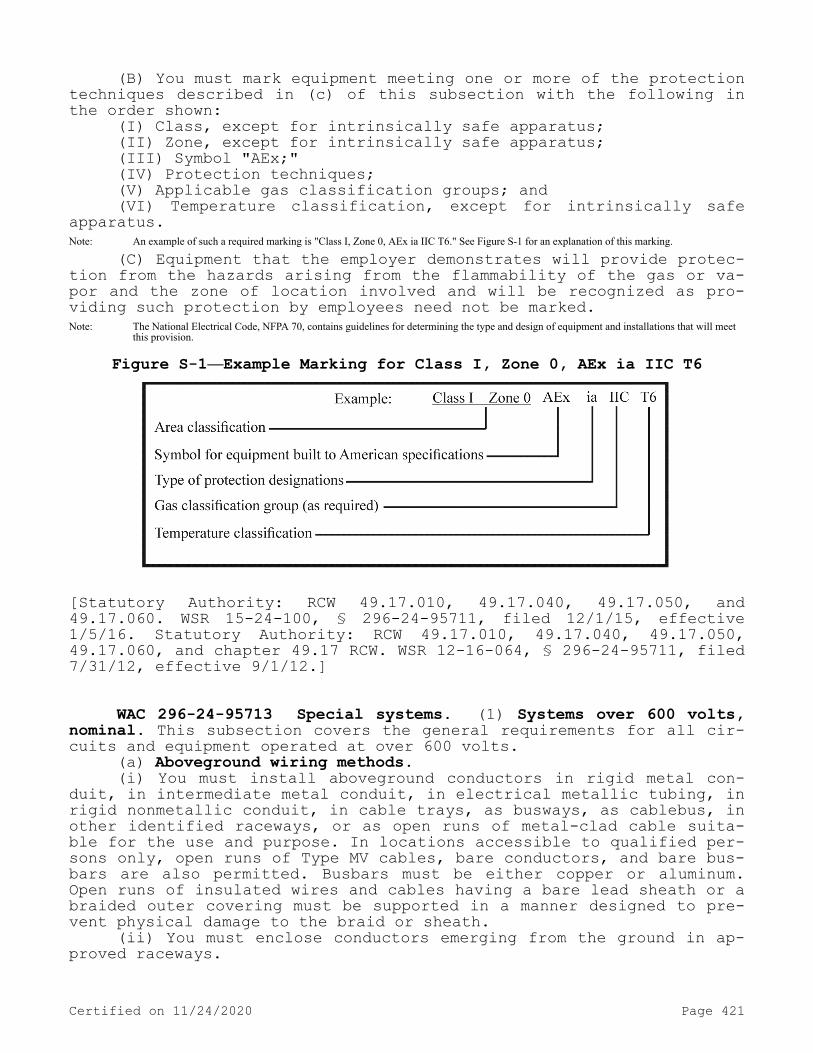
(B) You must mark equipment meeting one or more of the protection techniques described in (c) of this subsection with the following in the order shown:
(I) Class, except for intrinsically safe apparatus;(II) Zone, except for intrinsically safe apparatus;(III) Symbol "AEx;"(IV) Protection techniques;(V) Applicable gas classification groups; and(VI) Temperature classification, except for intrinsically safe
apparatus.Note: An example of such a required marking is "Class I, Zone 0, AEx ia IIC T6." See Figure S-1 for an explanation of this marking.
(C) Equipment that the employer demonstrates will provide protec-tion from the hazards arising from the flammability of the gas or va-por and the zone of location involved and will be recognized as pro-viding such protection by employees need not be marked.Note: The National Electrical Code, NFPA 70, contains guidelines for determining the type and design of equipment and installations that will meet
this provision.
Figure S-1—Example Marking for Class I, Zone 0, AEx ia IIC T6
[Statutory Authority: RCW 49.17.010, 49.17.040, 49.17.050, and 49.17.060. WSR 15-24-100, § 296-24-95711, filed 12/1/15, effective 1/5/16. Statutory Authority: RCW 49.17.010, 49.17.040, 49.17.050, 49.17.060, and chapter 49.17 RCW. WSR 12-16-064, § 296-24-95711, filed 7/31/12, effective 9/1/12.]
WAC 296-24-95713 Special systems. (1) Systems over 600 volts, nominal. This subsection covers the general requirements for all cir-cuits and equipment operated at over 600 volts.
(a) Aboveground wiring methods.(i) You must install aboveground conductors in rigid metal con-
duit, in intermediate metal conduit, in electrical metallic tubing, in rigid nonmetallic conduit, in cable trays, as busways, as cablebus, in other identified raceways, or as open runs of metal-clad cable suita-ble for the use and purpose. In locations accessible to qualified per-sons only, open runs of Type MV cables, bare conductors, and bare bus-bars are also permitted. Busbars must be either copper or aluminum. Open runs of insulated wires and cables having a bare lead sheath or a braided outer covering must be supported in a manner designed to pre-vent physical damage to the braid or sheath.
(ii) You must enclose conductors emerging from the ground in ap-proved raceways.
Certified on 11/24/2020 Page 421

(b) Braid-covered insulated conductors—Open installations. The braid on open runs of braid-covered insulated conductors must be flame retardant or must have a flame-retardant saturant applied after in-stallation. You must strip back this treated braid covering a safe distance at conductor terminals, according to the operating voltage.
(c) Insulation shielding.(i) You must remove metallic and semiconductor insulation shield-
ing components of shielded cables for a distance dependent on the cir-cuit voltage and insulation. You must provide stress reduction means at all terminations of factory-applied shielding.
(ii) You must ground metallic shielding components such as tapes, wires, or braids, or combinations thereof, and their associated con-ducting and semiconducting components.
(d) Moisture or mechanical protection for metal-sheathed cables. Where cable conductors emerge from a metal sheath and where protection against moisture or physical damage is necessary, the insulation of the conductors must be protected by a cable sheath terminating device.
(e) Interrupting and isolating devices.(i) Circuit breaker installations located indoors must consist of
metal-enclosed units or fire-resistant cell-mounted units. In loca-tions accessible only to qualified employees, open mounting of circuit breakers is permitted. You must provide a means of indicating the open and closed position of circuit breakers.
(ii) Where fuses are used to protect conductors and equipment, you must place a fuse in each ungrounded conductor. Two power fuses may be used in parallel to protect the same load, if both fuses have identical ratings, and if both fuses are installed in an identified common mounting with electrical connections that will divide the cur-rent equally. Power fuses of the vented type may not be used indoors, underground, or in metal enclosures unless identified for the use.
(iii) Fused cutouts installed in buildings or transformer vaults must be of a type identified for the purpose. Distribution cutouts may not be used indoors, underground, or in metal enclosures. They must be readily accessible for fuse replacement.
(iv) Where fused cutouts are not suitable to interrupt the cir-cuit manually while carrying full load, you must install an approved means to interrupt the entire load. Unless the fused cutouts are in-terlocked with the switch to prevent opening of the cutouts under load, you must place a conspicuous sign at such cutouts reading: "WARN-ING—DO NOT OPERATE UNDER LOAD."
(v) You must provide suitable barriers or enclosures to prevent contact with nonshielded cables or energized parts of oil-filled cut-outs.
(vi) Load interrupter switches may be used only if suitable fuses or circuits are used in conjunction with these devices to interrupt fault currents.
(A) Where these devices are used in combination, you must coordi-nate them electrically so that they will safely withstand the effects of closing, carrying, or interrupting all possible currents up to the assigned maximum short-circuit rating.
(B) Where more than one switch is installed with interconnected load terminals to provide for alternate connection to different supply conductors, you must provide each switch with a conspicuous sign read-ing: "WARNING—SWITCH MAY BE ENERGIZED BY BACKFEED."
(vii) You must provide a means (for example, a fuseholder and fuse designed for the purpose) to completely isolate equipment for in-
Certified on 11/24/2020 Page 422

spection and repairs. Isolating means that they are not designed to interrupt the load current of the circuit and must be either inter-locked with an approved circuit interrupter or provided with a sign warning against opening them under load.
(f) Mobile and portable equipment.(i) You must provide a metallic enclosure on the mobile machine
for enclosing the terminals of the power cable. The enclosure must in-clude provisions for a solid connection for the grounding terminal to effectively ground the machine frame. The method of cable termination used must prevent any strain or pull on the cable from stressing the electrical connections. The enclosure must have provision for locking so that only authorized qualified persons may open it and you must mark it with a sign warning of the presence of energized parts.
(ii) All energized switching and control parts must be enclosed in effectively grounded metal cabinets or enclosures. Circuit breakers and protective equipment must have the operating means projecting through the metal cabinet or enclosure so these units can be reset without locked doors being opened. You must lock enclosures and metal cabinets so that only authorized qualified persons have access and you must mark them with a sign warning of the presence of energized parts. You must guard collector ring assemblies on revolving-type machines (shovels, draglines, etc.).
(g) Tunnel installations. This subsection applies to installation and use of high-voltage power distribution and utilization equipment that is portable or mobile, such as substations, trailers, cars, mo-bile shovels, draglines, hoists, drills, dredges, compressors, pumps, conveyors, and underground excavators.
(i) You must install conductors in tunnels in one or more of the following:
(A) Metal conduit or other metal raceway;(B) Type MC cable; or(C) Other approved multiconductor cable.(ii) Multiconductor portable cable may supply mobile equipment.(iii) You must also locate or guard conductors and cables so as
to protect them from physical damage. You must run an equipment grounding conductor with circuit conductors inside the metal raceway or inside the multiconductor cable jacket. The equipment grounding conductor may be insulated or bare.
(iv) Bare terminals of transformers, switches, motor controllers, and other equipment must be enclosed to prevent accidental contact with energized parts.
(v) Enclosures for use in tunnels must be drip-proof, weather-proof, or submersible as required by the environmental conditions.
(vi) Switch or contactor enclosures may not be used as junction boxes or raceways for conductors feeding through or tapping off to other switches, unless special designs are used to provide adequate space for this purpose.
(vii) You must install a disconnecting means that simultaneously opens all ungrounded conductors at each transformer or motor location.
(viii) You must effectively ground and bond all nonenergized met-al parts of electric equipment and metal raceways and cable sheaths to all metal pipes and rails at the portal and at intervals not exceeding 1000 feet throughout the tunnel.
(2) Emergency power systems. This subsection applies to circuits, systems, and equipment intended to supply power for illumination and special loads in the event of failure of the normal supply.
Certified on 11/24/2020 Page 423

(a) Wiring methods. You must keep emergency circuit wiring en-tirely independent of all other wiring and equipment and may not enter the same raceway, cable, box, or cabinet or other wiring except either where common circuit elements suitable for the purpose are required, or for transferring power from the normal to the emergency source.
(b) Emergency illumination. Emergency illumination must include all required means of egress lighting, illuminated exit signs, and all other lights necessary to provide illumination. Where emergency light-ing is necessary, you must arrange the system so that the failure of any individual lighting element, such as the burning out of a light bulb, cannot leave any space in total darkness.
(c) Signs.(i) You must place a sign at the service entrance equipment indi-
cating the type and location of on-site emergency power sources. How-ever, a sign is not required for individual unit equipment.
(ii) Where the grounded circuit conductor connected to the emer-gency source is connected to a grounding electrode conductor at a lo-cation remote from the emergency source, there must be a sign at the grounding location that must identify all emergency and normal sources connected at that location.
(3) Class 1, Class 2, and Class 3 remote control, signaling, and power-limited circuits.
(a) Classification. Class 1, Class 2, and Class 3 remote control, signaling, or power-limited circuits are characterized by their usage and electrical power limitation that differentiates them from light and power circuits. These circuits are classified in accordance with their respective voltage and power limitations as summarized in (a)(i) through (iii) of this subsection.
(i) You must supply a Class 1 power-limited circuit from a source having a rated output of not more than 30 volts and 1000 volt-amperes.
(ii) A Class 1 remote control circuit or a Class 1 signaling cir-cuit must have a voltage not exceeding 600 volts; however, the power output of the source need not be limited.
(iii) The power source for a Class 2 or Class 3 circuit must be listed equipment marked as a Class 2 or Class 3 power source, except as follows:
(A) Thermocouples do not require listing as a Class 2 power source; and
(B) A dry cell battery is considered an inherently limited Class 2 power source, provided the voltage is 30 volts or less and the ca-pacity is less than or equal to that available from series-connected No. 6 carbon zinc cells.
(b) Marking. You must durably mark a Class 2 or Class 3 power supply unit where plainly visible to indicate the class of supply and its electrical rating.
(c) Separation from conductors of other circuits. Cables and con-ductors of Class 2 and Class 3 circuits may not be placed in any ca-ble, cable tray, compartment, enclosure, manhole, outlet box, device box, raceway, or similar fitting with conductors of electric light, power, Class 1, nonpower-limited fire alarm circuits, and medium power network-powered broadband communications cables unless a barrier or other equivalent form of protection against contact is employed.
(4) Fire alarm systems.(a) Classifications. You must classify fire alarm circuits either
as nonpower limited or power limited.(b) Power sources. The power sources for use with fire alarm cir-
cuits must be either power limited or nonpower limited as follows:
Certified on 11/24/2020 Page 424

(i) The power source of nonpower-limited fire alarm (NPLFA) cir-cuits must have an output voltage of not more than 600 volts, nominal; and
(ii) The power source for a power-limited fire alarm (PLFA) cir-cuit must be listed equipment marked as a PLFA power source.
(c) Separation from conductors of other circuits.(i) Nonpower-limited fire alarm circuits and Class 1 circuits may
occupy the same enclosure, cable, or raceway provided all conductors are insulated for maximum voltage of any conductor within the enclo-sure, cable, or raceway. Power supply and fire alarm circuit conduc-tors are permitted in the same enclosure, cable, or raceway only if connected to the same equipment.
(ii) Power-limited circuit cables and conductors may not be placed in any cable, cable tray, compartment, enclosure, outlet box, raceway, or similar fitting with conductors of electric light, power, Class 1, nonpower-limited fire alarm circuit conductors, or medium power network-powered broadband communications circuits.
(iii) You must separate power-limited fire alarm circuit conduc-tors at least 2 inches from conductors of any electric light, power, Class 1, nonpower-limited fire alarm, or medium power network-powered broadband communications circuits unless a special and equally protec-tive method of conductor separation is employed.
(iv) Conductors of one or more Class 2 circuits are permitted within the same cable, enclosure, or raceway with conductors of power-limited fire alarm circuits provided that the insulation of Class 2 circuit conductors in the cable, enclosure, or raceway is at least that needed for the power-limited fire alarm circuits.
(d) Identification. You must identify fire alarm circuits at ter-minal and junction locations in a manner that will prevent uninten-tional interference with the signaling circuit during testing and servicing. You must durably mark power-limited fire alarm circuits as such where plainly visible at terminations.
(5) Communications systems. This subsection applies to central-station-connected and noncentral-station-connected telephone circuits, radio and television receiving and transmitting equipment, including community antenna television and radio distribution systems, tele-graph, district messenger, and outside wiring for fire and burglar alarm, and similar central station systems. These installations need not comply with the provisions of WAC 296-24-95703 through 296-24-95713(4), except for WAC 296-24-95705 (3)(a) and 296-24-95711.
(a) Protective devices.(i) You must provide a listed primary protector on each circuit
run partly or entirely in aerial wire or aerial cable not confined within a block.
(ii) You must also provide a listed primary protector on each aerial or underground circuit when the location of the circuit within the block containing the building served allows the circuit to be ex-posed to accidental contact with electric light or power conductors operating at over 300 volts to ground.
(iii) In addition, where there exists a lightning exposure, you must protect each interbuilding circuit on premises by a listed pri-mary protector at each end of the interbuilding circuit.
(b) Conductor location.(i) You must keep lead-in or aerial-drop cables from a pole or
other support, including the point of initial attachment to a building or structure, away from electric light, power, Class 1, or nonpower-
Certified on 11/24/2020 Page 425

limited fire alarm circuit conductors so as to avoid the possibility of accidental contact.
(ii) You must maintain a separation of at least 6 feet between communications wires and cables on buildings and lightning conductors.
(iii) Where communications wires and cables and electric light or power conductors are supported by the same pole or run parallel to each other in-span, you must meet the following conditions:
(A) Where practicable, you must locate communication wires and cables on poles below the electric light or power conductors; and
(B) Communications wires and cables may not be attached to a crossarm that carries electric light or power conductors.
(iv) You must separate indoor communications wires and cables at least 2 inches from conductors of any electric light, power, Class 1, nonpower-limited fire alarm, or medium power network-powered broadband communications circuits, unless a special and equally protective meth-od of conductor separation, approved for the purpose, is employed.
(c) Equipment location. You must locate outdoor metal structures supporting antennas, as well as self-supporting antennas such as ver-tical rods or dipole structures, as far away from overhead conductors of electric light and power circuits of over 150 volts to ground as necessary to prevent the antenna or structure from falling into or making accidental contact with such circuits.
(d) Grounding.(i) If exposed to contact with electric light and power conduc-
tors, you must ground the metal sheath of aerial cables entering buildings or you must interrupt them close to the entrance to the building by an insulating joint or equivalent device. Where protective devices are used, you must ground them in an approved manner.
(ii) You must permanently and effectively ground masts and metal structures supporting antennas without splice or connection in the grounding conductor.
(iii) Transmitters must be enclosed in a metal frame or grill or separated from the operating space by a barrier, all metallic parts of which are effectively connected to ground. You must effectively ground all external metal handles and controls accessible to the operating personnel. Unpowered equipment and enclosures are considered to be grounded where connected to an attached coaxial cable with an effec-tively grounded metallic shield.
(6) Solar photovoltaic systems. This subsection covers solar pho-tovoltaic systems that can be interactive with other electric power production sources or can stand alone with or without electrical ener-gy storage such as batteries. These systems may have AC or DC output for utilization.
(a) Conductors of different systems. Photovoltaic source circuits and photovoltaic output circuits may not be contained in the same raceway, cable tray, cable, outlet box, junction box, or similar fit-ting as feeders or branch circuits of other systems, unless the con-ductors of the different systems are separated by a partition or are connected together.
(b) Disconnecting means. You must provide means to disconnect all current-carrying conductors of a photovoltaic power source from all other conductors in a building or other structure. Where a circuit grounding connection is not designed to be automatically interrupted as part of the ground-fault protection system, a switch or circuit breaker used as disconnecting means may not have a pole in the groun-ded conductor.
(7) Integrated electrical systems.
Certified on 11/24/2020 Page 426

(a) Scope. This subsection covers integrated electrical systems, other than unit equipment, in which orderly shutdown is necessary to ensure safe operation. An integrated electrical system as used in this section must be a unitized segment of an industrial wiring system where all of the following conditions are met:
(i) The conditions of maintenance and supervision ensure that on-ly qualified persons will service the system; and
(ii) Effective safeguards are established and maintained.(b) Location of overcurrent devices in or on premises. Overcur-
rent devices that are critical to integrated electrical systems need not be readily accessible to employees as required by WAC 296-24-95705 (6)(a)(iv) if they are located with mounting heights to ensure securi-ty from operation by nonqualified persons.[Statutory Authority: RCW 49.17.010, 49.17.040, 49.17.050, and 49.17.060. WSR 15-24-100, § 296-24-95713, filed 12/1/15, effective 1/5/16. Statutory Authority: RCW 49.17.010, 49.17.040, 49.17.050, 49.17.060, and chapter 49.17 RCW. WSR 12-16-064, § 296-24-95713, filed 7/31/12, effective 9/1/12.]
WAC 296-24-95799 Appendices. Appendix A - Reference documents. The following references provide information which can be helpful in understanding and complying with the requirements contained in WAC 296-24-957 through 296-24-985.ANSI/API RP 500-1998 (2002) Recommended Practice for Classification of
Locations for Electrical Installations at Petroleum Facilities Classified as Class I Division 1 and Division 2.
ANSI/API RP 505-1997 (2002) Recommended Practice for Classification of Locations for Electrical Installations at Petroleum Facilities Classified as Class I, Zone 0, Zone 1 and Zone 2.
ANSI/ASME A17.1-2004 Safety Code for Elevators, Dumbwaiters, Escala-tors and Moving Walks.
ANSI/ASME B30.2-2005 Overhead and Gantry Cranes (Top Running Bridge, Single or Multiple Girder, Top Running Trolley Hoist).
ANSI/ASME B30.3-2004 Construction Tower Cranes.ANSI/ASME B30.4-2003 Portal, Tower, and Pedestal Cranes.ANSI/ASME B30.5-2004 Mobile and Locomotive Cranes.ANSI/ASME B30.6-2003 Derricks.ANSI/ASME B30.7-2001 Base Mounted Drum Hoists.ANSI/ASME B30.8-2004 Floating Cranes and Floating Derricks.ANSI/ASME B30.11-2004 Monorails and Underhung Cranes.ANSI/ASME B30.12-2001 Handling Loads Suspended from Rotorcraft.ANSI/ASME B30.13-2003 Storage/Retrieval (S/R) Machines and Associated
Equipment.ANSI/ASME B30.16-2003 Overhead Hoists (Underhung).ANSI/ASME B30.22-2005 Articulating Boom Cranes.ANSI/ASSE Z244.1-2003 Control of Hazardous Energy Lockout/Tagout and
Alternative Methods.ANSI/ASSE Z490.1-2001 Criteria for Accepted Practices in Safety,
Health, and Environmental Training.ANSI/IEEE C2-2002 National Electrical Safety Code.ANSI K61.1-1999 Safety Requirements for the Storage and Handling of
Anhydrous Ammonia.
Certified on 11/24/2020 Page 427

ANSI/UL 913-2003 Intrinsically Safe Apparatus and Associated Apparatus for Use in Class I, II, and III, Division 1, Hazardous (Classified) Locations.ASTM D3176-1989 (2002) Standard Practice for Ultimate Analysis of Coal
and Coke.ASTM D3180-1989 (2002) Standard Practice for Calculating Coal and Coke
Analyses from as Determined to Different Bases.NFPA 20-2003 Standard for the Installation of Stationary Pumps for
Fire Protection.NFPA 30-2003 Flammable and Combustible Liquids Code.NFPA 32-2004 Standard for Drycleaning Plants.NFPA 33-2003 Standard for Spray Application Using Flammable or Combus-
tible Materials.NFPA 34-2003 Standard for Dipping and Coating Processes Using Flamma-
ble or Combustible Liquids.NFPA 35-2005 Standard for the Manufacture of Organic Coatings.NFPA 36-2004 Standard for Solvent Extraction Plants.NFPA 40-2001 Standard for the Storage and Handling of Cellulose Ni-
trate Film.NFPA 58-2004 Liquefied Petroleum Gas Code.NFPA 59-2004 Utility LP-Gas Plant Code.NFPA 70-2002 National Electrical Code (see also NFPA 70-2005).NFPA 70E-2000 Standard for the Electrical Safety Requirements for Em-
ployee Workplaces (see also NFPA 70E-2004).NFPA 77-2000 Recommended Practice on Static Electricity.NFPA 80-1999 Standard for Fire Doors and Windows.NFPA 88A-2002 Standard for Parking Structures.NFPA 91-2004 Standard for Exhaust Systems for Air Conveying of Vapors,
Gases, Mists, and Noncombustible Particulate Solids.NFPA 101-2006 Life Safety Code.NFPA 496-2003 Standard for Purged and Pressurized Enclosures for Elec-
trical Equipment.NFPA 497-2004 Recommended Practice for Classification of Flammable
Liquids, Gases, or Vapors and of Hazardous (Classified) Locations for Electrical Installations in Chemical Process Areas.
NFPA 505-2006 Fire Safety Standard for Powered Industrial Trucks In-cluding Type Designations, Areas of Use, Conversions, Mainte-nance, and Operation.
NFPA 820-2003 Standard for Fire Protection in Wastewater Treatment and Collection Facilities.NMAB 353-1-1979 Matrix of Combustion-Relevant Properties and Classifi-
cation of Gases, Vapors, and Selected Solids.NMAB 353-2-1979 Test Equipment for Use in Determining Classifications
of Combustible Dusts.NMAB 353-3-1980 Classification of Combustible Dusts in Accordance with
the National Electrical Code.[Statutory Authority: RCW 49.17.010, 49.17.040, 49.17.050, and 49.17.060. WSR 15-24-100, § 296-24-95799, filed 12/1/15, effective 1/5/16. Statutory Authority: RCW 49.17.010, 49.17.040, 49.17.050, 49.17.060, and chapter 49.17 RCW. WSR 12-16-064, § 296-24-95799, filed 7/31/12, effective 9/1/12.]
WAC 296-24-960 Working on or near exposed energized parts. (1) Application. This section applies to work performed on exposed live parts (involving either direct contact or contact by means of tools or
Certified on 11/24/2020 Page 428

materials) or near enough to them for employees to be exposed to any hazard they present.
(2) Work on energized equipment. Only qualified persons must work on electric circuit parts or equipment that have not been deenergized under the procedures of WAC 296-24-975(2). Such persons must be capa-ble of working safely on energized circuits and must be familiar with the proper use of special precautionary techniques, personal protec-tive equipment, insulating and shielding materials, and insulated tools.
(3) General requirements - High voltage lines.(a) Minimum clearance.(i) You must not perform any work, you must not pile, store, or
otherwise handle any material, you must not erect or dismantle any scaffolding, commercial signs, or structures, nor must you operate any tools, machinery or equipment within the specified minimum distances from any energized high voltage electrical conductor capable of ener-gizing the material or equipment; except where the electrical distri-bution and transmission lines have been deenergized and visibly groun-ded at point of work, or where insulating barriers not a part of or an attachment to the equipment have been erected, to prevent physical contact with the lines, you must operate equipment proximate to, un-der, over, by, or near powerlines only in accordance with the follow-ing:
(ii) For lines rated 50 kv. or below, minimum clearance between the lines and any part of the equipment or load must be 10 feet.
(iii) For lines rated over 50 kv. minimum, clearance between the lines and any part of the equipment or load must be 10 feet plus 0.4 inch for each 1 kv. over 50 kv., or twice the length of the line insu-lator but never less than 10 feet.
(b) Overhead electric lines. Where overhead electric conductors are encountered in proximity to a work area, you must be responsible for:
(i) Ascertaining the voltage and minimum clearance distance re-quired, and
(ii) Maintaining the minimum clearance distance, and(iii) Ensuring that the requirements of subsection (3) of this
section are complied with.(c) Not covered: Employees working under chapters 296-32 and
296-45 WAC.(4) Low voltage lines. When work is being carried out in proximi-
ty to energized electrical service conductors operating at 750 volts or less, you must perform such work in a manner to prevent contact by any worker with the energized conductors.
(5) Overhead lines. If work is to be performed near overhead lines, you must deenergize and ground the lines, or provide other pro-tective measures before work is started. If the lines are to be dee-nergized, you must make arrangements with the person or organization that operates or controls the electric circuits involved to deenergize and ground them. If protective measures, such as guarding, isolating, or insulating, these precautions must prevent employees from contact-ing such lines directly with any part of their body or indirectly through conductive materials, tools, or equipment.
(6) Unqualified persons. When an unqualified person is working in an elevated position, or on the ground, near overhead lines, the loca-tion must be such that the person and the longest conductive object he or she may contact cannot come closer to any unguarded, energized overhead line than the following distances:
Certified on 11/24/2020 Page 429

(a) For voltages to ground 50kV or below—10 ft.;(b) For voltages to ground over 50kV—10 ft. plus 0.4 inch for
every 1 kV over 50 kV.(7) Qualified persons. When a qualified person is working in the
vicinity of overhead lines, whether in an elevated position or on the ground, the person must not approach or take any conductive object without an approved insulating handle closer to exposed energized parts than shown in subsections (3) and (4) of this section unless:
(a) The person is insulated from the energized part (gloves, with sleeves if necessary, rated for the voltage involved are considered to be insulation of the person from the energized part on which work is performed); or
(b) The energized part is insulated both from all other conduc-tive objects at a different potential and from the person; or
(c) The person is insulated from all conductive objects at a po-tential different from that of the energized part.
(8) Vehicular and mechanical equipment.(a) You must operate any vehicle or mechanical equipment capable
of having parts of its structure elevated near energized overhead lines so that a clearance of 10 ft. is maintained. If the voltage is higher than 50kV, you must increase the clearance 0.4 inch for every 1kV over that voltage. However, under any of the following conditions, the clearance may be reduced:
(i) If the vehicle is in transit with its structure lowered, the clearance may be reduced to 4 ft. If the voltage is higher than 50kV, you must increase the clearance 0.4 inch for every 1kV over that volt-age.
(ii) If insulating barriers are installed to prevent contact with the lines, and if the barriers are rated for the voltage of the line being guarded and are not a part of or an attachment to the vehicle or its raised structure, the clearance may be reduced to a distance with-in the designed working dimensions of the insulating barrier.
(b) If the equipment is an aerial lift insulated for the voltage involved, and if the work is performed by a qualified person, the clearance (between the uninsulated portion of the aerial lift and the power line) may be reduced to the distance given in subsections (3) and (4) of this section.
(c) Employees standing on the ground must not contact the vehicle or mechanical equipment or any of its attachments, unless:
(i) The employee is using protective equipment rated for the voltage; or
(ii) The equipment is located so that no uninsulated part of its structure (that portion of the structure that provides a conductive path to employees on the ground) can come closer to the line than per-mitted in this section.
(d) If any vehicle or mechanical equipment capable of having parts of its structure elevated near energized overhead lines is in-tentionally grounded, employees working on the ground near the point of grounding must not stand at the grounding location whenever there is a possibility of overhead line contact. You must take additional precautions, such as the use of barricades or insulation, to protect employees from hazardous ground potentials, depending on earth resis-tivity and fault currents, which can develop within the first few feet or more outward from the grounding point.
(9) Illumination.
Certified on 11/24/2020 Page 430

(a) Employees must not enter spaces containing exposed energized parts, unless illumination is provided that enables the employees to perform the work safely.
(b) Where lack of illumination or an obstruction precludes obser-vation of the work to be performed, employees must not perform tasks near exposed energized parts. Employees must not reach blindly into areas which may contain energized parts.
(10) Confined or enclosed work spaces. When an employee works in a confined or enclosed space (such as a manhole or vault) that con-tains exposed energized parts, you must provide, and the employee must use, protective shields, protective barriers, or insulating materials as necessary to avoid inadvertent contact with these parts. Doors, hinged panels, and the like must be secured to prevent their swinging into an employee and causing the employee to contact exposed energized parts.
(11) Conductive materials and equipment. You must handle materi-als and equipment that are in contact with any part of an employee's body in a manner that will prevent them from contacting exposed ener-gized conductors or circuit parts. If an employee must handle long di-mensional conductive objects (such as ducts and pipes) in areas with exposed live parts, you must institute work practices (such as the use of insulation, guarding, and material handling techniques) which will minimize the hazard.
(12) Portable ladders. Portable ladders must have nonconductive siderails if they are used where the employee or the ladder could con-tact exposed energized parts.
(13) Conductive apparel. You must not wear conductive articles of jewelry and clothing (such as watch bands, bracelets, rings, key chains, necklaces, metalized aprons, cloth with conductive thread, or metal headgear) if they might contact exposed energized parts.
(14) Housekeeping duties.(a) Where live parts present an electrical contact hazard, em-
ployees must not perform housekeeping duties at such close distances to the parts that there is a possibility of contact, unless adequate safeguards (such as insulating equipment or barriers) are provided.
(b) You must not use electrically conductive cleaning materials (including conductive solids such as steel wool, metalized cloth, and silicon carbide, as well as conductive liquid solutions) in proximity to energized parts unless procedures are followed which will prevent electrical contact.
(15) Interlocks. Only a qualified person following the require-ments of this section may defeat an electrical safety interlock, and then only temporarily while he or she is working on the equipment. You must return the interlock system to its operable condition when this work is completed.[Statutory Authority: RCW 49.17.010, 49.17.040, 49.17.050, and 49.17.060. WSR 15-24-100, § 296-24-960, filed 12/1/15, effective 1/5/16. Statutory Authority: Chapter 49.17 RCW. WSR 94-15-096 (Order 94-07), § 296-24-960, filed 7/20/94, effective 9/20/94; WSR 91-24-017 (Order 91-07), § 296-24-960, filed 11/22/91, effective 12/24/91. Stat-utory Authority: RCW 49.17.040 and 49.17.050. WSR 82-13-045 (Order 82-22), § 296-24-960, filed 6/11/82; WSR 82-02-003 (Order 81-32), § 296-24-960, filed 12/24/81.]
Certified on 11/24/2020 Page 431

WAC 296-24-965 Safety-related work practices. (1) Scope. Cov-ered work by both qualified and unqualified persons. The provisions of WAC 296-24-960 through 296-24-985 cover electrical safety-related work practices for both qualified persons (those who have training in avoiding the electrical hazards of working on or near exposed ener-gized parts) and unqualified persons (those with little or no such training) working on, near, or with the following installations:
(a) Premises wiring. Installations of electric conductors and equipment within or on buildings or other structures, and on other premises such as yards, carnival, parking, and other lots, and indus-trial substations;
(b) Wiring for connection to supply. Installations of conductors that connect to the supply of electricity;
(c) Other wiring. Installations of other outside conductors on the premises; and
(d) Optical fiber cable. Installations of optical fiber cable where such installations are made along with electric conductors.Note: See WAC 296-24-95601 for the definition of "qualified person." See WAC 296-24-970 for training requirements that apply to qualified and
unqualified persons.
(2) Other covered work by unqualified persons. The provisions of WAC 296-24-960 through 296-24-985 also cover work performed by unqua-lified persons on, near, or with the installations listed in subsec-tion (3) of this section.
(3) Excluded work by qualified persons. The provisions of WAC 296-24-960 through 296-24-985 do not apply to work performed by quali-fied persons on or directly associated with the following installa-tions:
(a) Generation, transmission, and distribution installations. In-stallations for the generation, control, transformation, transmission, and distribution of electric energy (including communication and me-tering) located in buildings used for such purposes or located out-doors.Note 1: Work on or directly associated with installations of utilization equipment used for purposes other than generating, transmitting, or distributing
electric energy (such as installations which are in office buildings, warehouses, garages, machine shops, or recreational buildings, or other utilization installations which are not an integral part of a generating installation, substation, or control center) is covered under subsection (1)(a) of this section.
Note 2: Work on or directly associated with generation, transmission, or distribution installations includes: 1. Work performed directly on such installations, such as repairing overhead or underground distribution lines or repairing a feed-water pump
for the boiler in a generating plant. 2. Work directly associated with such installations, such as line-clearance tree trimming and replacing utility poles. 3. Work on electric utilization circuits in a generating plant provided that: a. Such circuits are commingled with installations of power generation equipment or circuits; and b. The generation equipment or circuits present greater electrical hazards than those posed by the utilization equipment or circuits (such as
exposure to higher voltages or lack of overcurrent protection).
(b) Communications installations. Installations of communication equipment to the extent that the work is covered under chapter 296-32 WAC.
(c) Installations in vehicles. Installations in ships, water-craft, railway rolling stock, aircraft, or automotive vehicles other than mobile homes and recreational vehicles.
(d) Railway installations. Installations of railways for genera-tion, transformation, transmission, or distribution of power used ex-clusively for operation of rolling stock or installations of railways used exclusively for signaling and communication purposes.[Statutory Authority: RCW 49.17.010, 49.17.040, 49.17.050, and 49.17.060. WSR 15-24-100, § 296-24-965, filed 12/1/15, effective 1/5/16. Statutory Authority: Chapter 49.17 RCW. WSR 91-24-017 (Order 91-07), § 296-24-965, filed 11/22/91, effective 12/24/91.]
Certified on 11/24/2020 Page 432
WAC 296-24-970 Training. (1) Scope. The training requirements contained in this section apply to employees who face a risk of elec-tric shock that is not reduced to a safe level by the electrical in-stallation requirements of WAC 296-24-95605 through 296-24-95615.Note: Employees in occupations listed in Table S-4 face such a risk and are required to be trained. Other employees who also may reasonably be
expected to face a comparable risk of injury due to electric shock or other electrical hazards must also be trained.
(2) Content of training.(a) Practices addressed in this standard. You must train and fa-
miliarize employees with the safety-related work practices required by WAC 296-24-960 through 296-24-985 that pertain to their respective job assignments.
(b) Additional requirements for unqualified persons. You must al-so train and familiarize employees who are covered by subsection (1) of this section but who are not qualified persons with any electrical-ly related safety practices not specifically addressed by WAC 296-24-960 through 296-24-985 but which are necessary for their safe-ty.
(c) Additional requirements for qualified persons. Qualified per-sons (i.e., those permitted to work on or near exposed energized parts) shall, at a minimum, be trained in and familiar with the fol-lowing:
(i) The skills and techniques necessary to distinguish exposed live parts from other parts of electric equipment;
(ii) The skills and techniques necessary to determine the nominal voltage of exposed live parts; and
(iii) The clearance distances specified in WAC 296-24-960 and the corresponding voltages to which the qualified person will be exposed.Note 1: For the purposes of WAC 296-24-960 through 296-24-985 a person must have the training required by (c) of this subsection in order to be
considered a qualified person.Note 2: Qualified persons whose work on energized equipment involves either direct contact or contact by means of tools or materials must also have
the training needed to meet WAC 296-24-960.
(3) Type of training. The training required by this section must be of the classroom or on-the-job type. The degree of training provi-ded must be determined by the risk to the employee.
TABLE S-4.—TYPICAL OCCUPATIONALCATEGORIES OF EMPLOYEES FACING A
HIGHER THAN NORMAL RISK OFELECTRICAL ACCIDENT
OccupationBlue collar supervisors.1
Electrical and electronic engineers.1
Electrical and electronic equipment assemblers.1
Electrical and electronic technicians.1
Electricians.Industrial machine operators.1
Material handling equipment operators.1
Mechanics and repairers.1
Painters.1
Riggers and roustabouts.1
Stationary engineers.1
Welders.1 Workers in these groups do not need to be trained if their work or the
work of those they supervise does not bring them or the employees they supervise close enough to exposed parts of electric circuits operating at 50 volts or more to ground for a hazard to exist.
Certified on 11/24/2020 Page 433
[Statutory Authority: RCW 49.17.010, 49.17.040, 49.17.050, and 49.17.060. WSR 15-24-100, § 296-24-970, filed 12/1/15, effective 1/5/16. Statutory Authority: Chapter 49.17 RCW. WSR 91-24-017 (Order 91-07), § 296-24-970, filed 11/22/91, effective 12/24/91.]
WAC 296-24-975 Selection and use of work practices. (1) Gener-al. You must employ safety-related work practices to prevent electric shock or other injuries resulting from either direct or indirect elec-trical contacts, when work is performed near or on equipment or cir-cuits which are or may be energized. The specific safety-related work practices must be consistent with the nature and extent of the associ-ated electrical hazards.
(a) Deenergized parts. You must deenergize live parts to which an employee may be exposed shall be deenergized before the employee works on or near them, unless the employer can demonstrate that deenergizing introduces additional or increased hazards or is infeasible due to equipment design or operational limitations. Live parts that operate at less than 50 volts to ground need not be deenergized if there will be no increased exposure to electrical burns or to explosion due to electric arcs.Note 1: Examples of increased or additional hazards include interruption of life support equipment, deactivation of emergency alarm systems,
shutdown of hazardous location ventilation equipment, or removal of illumination for an area.Note 2: Examples of work that may be performed on or near energized circuit parts because of infeasibility due to equipment design or operational
limitations include testing of electric circuits that can only be performed with the circuit energized and work on circuits that form an integral part of a continuous industrial process in a chemical plant that would otherwise need to be completely shut down in order to permit work on one circuit or piece of equipment.
Note 3: Work on or near deenergized parts is covered by subsection (2) of this section.
(b) Energized parts. If the exposed live parts are not deener-gized (i.e., for reasons of increased or additional hazards or infea-sibility), you must use other safety-related work practices to protect employees who may be exposed to the electrical hazards involved. Such work practices must protect employees against contact with energized circuit parts directly with any part of their body or indirectly through some other conductive object. The work practices that are used must be suitable for the conditions under which the work is to be per-formed and for the voltage level of the exposed electric conductors or circuit parts. Specific work practice requirements are detailed in WAC 296-24-960.
(2) Working on or near exposed deenergized parts.(a) Application. This subsection applies to work on exposed dee-
nergized parts or near enough to them to expose the employee to any electrical hazard they present. You must treat conductors and parts of electric equipment that have been deenergized but have not been locked out or tagged according to this subsection as energized parts, and WAC 296-24-960 applies to work on or near them.
(b) Lockout and tagging. While any employee is exposed to contact with parts of fixed electric equipment or circuits which have been deenergized, you must lock out or tag (or both) the circuits energiz-ing the parts according to the requirements of this section. You must follow the requirements in the order in which they are presented (i.e., (b)(i) of this subsection first, then (b)(ii) of this subsec-tion.Note 1: As used in this section, fixed equipment refers to equipment fastened in place or connected by permanent wiring methods.Note 2: Lockout and tagging procedures that comply with chapter 296-803 WAC, Lockout/tagout (control of hazardous energy) will also be deemed to
comply with (b) of this subsection provided that: 1. The procedures address the electrical safety hazards covered by this part; and 2. The procedures also incorporate the requirements of (b)(iii)(D) and (b)(iv)(B) of this subsection.
Certified on 11/24/2020 Page 434

(i) Procedures. You must maintain a written copy of the proce-dures outlined in (b) of this subsection and you must make it availa-ble for inspection by employees and by the director and their author-ized representatives.Note: The written procedures may be in the form of a copy of subsection (2) of this section.
(ii) Deenergizing equipment.(A) You must determine safe procedures for deenergizing circuits
and equipment before circuits or equipment are deenergized.(B) You must disconnect the circuits and equipment to be worked
on from all electric energy sources. You must not use control circuit devices, such as push buttons, selector switches, and interlocks, as the sole means for deenergizing circuits or equipment. You must not use interlocks for electric equipment as a substitute for lockout and tagging procedures.
(C) You must release stored electric energy which might endanger personnel. You must discharge capacitors and you must short-circuit and ground high capacitance elements, if the stored electric energy might endanger personnel.Note: If the capacitors or associated equipment are handled in meeting this requirement, you must treat them as energized.
(D) You must block stored nonelectrical energy in devices that could reenergize electric circuit parts or relieve it to the extent that the circuit parts could not be accidentally energized by the de-vice.
(iii) Application of locks and tags.(A) You must place a lock and a tag on each disconnecting means
used to deenergize circuits and equipment on which work is to be per-formed, except as provided in subitems (C) and (E) of this item. You must attach the lock to prevent persons from operating the disconnect-ing means unless they resort to undue force or the use of tools.
(B) Each tag must contain a statement prohibiting unauthorized operation of the disconnecting means and removal of the tag.
(C) If a lock cannot be applied, or if the employer can demon-strate that tagging procedures will provide a level of safety equiva-lent to that obtained by the use of a lock, a tag may be used without a lock.
(D) You must supplement a tag used without a lock, as permitted by subitem (C) of this item, by at least one additional safety measure that provides a level of safety equivalent to that obtained by the use of a lock. Examples of additional safety measures include the removal of an isolating circuit element, blocking of a controlling switch, or opening of an extra disconnecting device.
(E) A lock may be placed without a tag only under the following conditions:
(I) Only one circuit or piece of equipment is deenergized; and(II) The lockout period does not extend beyond the work shift;
and(III) Employees exposed to the hazards associated with reenergiz-
ing the circuit or equipment are familiar with this procedure.(iv) Verification of deenergized condition. You must meet the re-
quirements of this subsection before any circuits or equipment can be considered and worked as deenergized.
(A) A qualified person must operate the equipment operating con-trols or otherwise verify that the equipment cannot be restarted.
(B) A qualified person must use test equipment to test the cir-cuit elements and electrical parts of equipment to which employees will be exposed and must verify that the circuit elements and equip-
Certified on 11/24/2020 Page 435

ment parts are deenergized. The test must also determine if any ener-gized condition exists as a result of inadvertently induced voltage or unrelated voltage backfeed even though specific parts of the circuit have been deenergized and presumed to be safe. If the circuit to be tested is over 600 volts, nominal, the test equipment must be checked for proper operation immediately before and immediately after this test.
(v) Reenergizing equipment. You must meet these requirements, in the order given, before circuits or equipment are reenergized, even temporarily.
(A) A qualified person must conduct tests and visual inspections, as necessary, to verify that all tools, electrical jumpers, shorts, grounds, and other such devices have been removed, so that the cir-cuits and equipment can be safely energized.
(B) You must warn employees exposed to the hazards associated with reenergizing the circuit or equipment to stay clear of circuits and equipment.
(C) Each lock and tag must be removed by the employee who applied it or under their direct supervision. However, if this employee is ab-sent from the workplace, then the lock or tag may be removed by a qualified person designated to perform this task provided that:
(I) The employer ensures that the employee who applied the lock or tag is not available at the workplace; and
(II) The employer ensures that the employee is aware that the lock or tag has been removed before he or she resumes work at that workplace.
(D) You must provide a visual determination that all employees are clear of the circuits and equipment.[Statutory Authority: RCW 49.17.010, 49.17.040, 49.17.050, and 49.17.060. WSR 15-24-100, § 296-24-975, filed 12/1/15, effective 1/5/16; WSR 04-15-105, § 296-24-975, filed 7/20/04, effective 11/1/04. Statutory Authority: Chapter 49.17 RCW. WSR 94-15-096 (Order 94-07), § 296-24-975, filed 7/20/94, effective 9/20/94; WSR 91-24-017 (Order 91-07), § 296-24-975, filed 11/22/91, effective 12/24/91.]
WAC 296-24-980 Safeguards for personnel protection. (1) Use of protective equipment.
(a) Personal protective equipment.(i) You must provide employees working in areas where there are
potential electrical hazards with electrical protective equipment that is appropriate for the specific parts of the body to be protected and for the work to be performed, and you must ensure that they use such protective equipment.Note: Personal protective equipment requirements are contained in chapter 296-24 WAC Part L, and WAC 296-800-160.
(ii) You must maintain protective equipment in a safe, reliable condition and you must periodically inspect or test it, as required by chapter 296-24 WAC Part L, and WAC 296-800-160.
(iii) If the insulating capability of protective equipment may be subject to damage during use, you must protect the insulating materi-al. (For example, an outer covering of leather is sometimes used for the protection of rubber insulating material.)
(iv) Employees must wear nonconductive head protection wherever there is a danger of head injury from electric shock or burns due to contact with exposed energized parts.
Certified on 11/24/2020 Page 436

(v) Employees must wear protective equipment for the eyes or face wherever there is danger of injury to the eyes or face from electric arcs or flashes or from flying objects resulting from electrical ex-plosion.
(b) General protective equipment and tools.(i) When working near exposed energized conductors or circuit
parts, each employee must use insulated tools or handling equipment if the tools or handling equipment might make contact with such conduc-tors or parts. If the insulating capability of insulated tools or han-dling equipment is subject to damage, you must protect the insulating material.
(A) You must use fuse handling equipment, insulated for the cir-cuit voltage, to remove or install fuses when the fuse terminals are energized.
(B) Ropes and handlines used near exposed energized parts must be nonconductive.
(ii) You must use protective shields, protective barriers, or in-sulating materials to protect each employee from shock, burns, or oth-er electrically related injuries while that employee is working near exposed energized parts which might be accidentally contacted or where dangerous electric heating or arcing might occur. When normally en-closed live parts are exposed for maintenance or repair, they must be guarded to protect unqualified persons from contact with the live parts.
(2) Alerting techniques. You must use the following alerting techniques to warn and protect employees from hazards which could cause injury due to electric shock, burns, or failure of electric equipment parts:
(a) Safety signs and tags. You must use safety signs, safety sym-bols, or accident prevention tags where necessary to warn employees about electrical hazards which may endanger them.
(b) Barricades. You must use barricades in conjunction with safe-ty signs where it is necessary to prevent or limit employee access to work areas exposing employees to uninsulated energized conductors or circuit parts. Conductive barricades may not be used where they might cause an electrical contact hazard.
(c) Attendants. If signs and barricades do not provide sufficient warning and protection from electrical hazards, you must station an attendant to warn and protect employees.
(3) Design requirements. Insulating blankets, matting, covers, line hose, gloves, and sleeves made of rubber must meet the following requirements:
(a) Manufacture and marking.(i) Blankets, gloves, and sleeves must be produced by a seamless
process.(ii) Each item must be clearly marked as follows:(A) Class 0 equipment must be marked Class 0.(B) Class 1 equipment must be marked Class 1.(C) Class 2 equipment must be marked Class 2.(D) Class 3 equipment must be marked Class 3.(E) Class 4 equipment must be marked Class 4.(F) Nonozone-resistant equipment other than matting must be
marked Type I.(G) Ozone-resistant equipment other than matting must be marked
Type II.(H) Other relevant markings, such as the manufacturer's identifi-
cation and the size of the equipment, may also be provided.
Certified on 11/24/2020 Page 437

(iii) Markings must be nonconducting and must be applied in such a manner as not to impair the insulating qualities of the equipment.
(iv) Markings on gloves must be confined to the cuff portion of the glove.
(b) Electrical requirements.(i) Equipment must be capable of withstanding the a-c proof-test
voltage specified in Table A-2 or the d-c proof-test voltage specified in Table A-3.
(A) The proof-test must reliably indicate that the equipment can withstand the voltage involved.
(B) The test voltage must be applied continuously for three mi-nutes for equipment other than matting and must be applied continuous-ly for one minute for matting.
(C) Gloves must also be capable of withstanding the a-c proof-test voltage specified in Table A-2 after a sixteen-hour water soak. (See the note following (c)(ii)(B) of this subsection.)
(ii) When the a-c proof-test is used on gloves, the 60 hertz proof-test current may not exceed the values specified in Table A-2 at any time during the test period.
(A) If the a-c proof-test is made at a frequency other than 60 hertz, the permissible proof-test current must be computed from the direct ratio of the frequencies.
(B) For the test, gloves (right side out) must be filled with tap water and immersed in water to a depth that is in accordance with Ta-ble A-4. Water must be added to or removed from the glove, as necessa-ry, so that the water level is the same inside and outside the glove.
(C) After the sixteen-hour water soak specified in (b)(i)(C) of this subsection, the 60-hertz proof-test current may exceed the values given in Table A-2 by not more than 2 milliamperes.
(iii) Equipment that has been subjected to a minimum breakdown voltage test may not be used for electrical protection. (See the note following (c)(ii)(B) of this subsection.)
(iv) Material used for Type II insulating equipment must be capa-ble of withstanding an ozone test, with no visible effects. The ozone test must reliably indicate that the material will resist ozone expo-sure in actual use. Any visible signs of ozone deterioration of the material, such as checking, cracking, breaks, or pitting, is evidence of failure to meet the requirements for ozone-resistant material. (See the note following (c)(ii)(B) of this subsection.)
(c) Workmanship and finish.(i) Equipment must be free of harmful physical irregularities
that can be detected by the tests or inspections required under this section.
(ii) Surface irregularities that may be present on all rubber goods because of imperfections on forms or molds or because of inher-ent difficulties in the manufacturing process and that may appear as indentations, protuberances, or imbedded foreign material are accepta-ble under the following conditions:
(A) The indentation or protuberance blends into a smooth slope when the material is stretched.
(B) Foreign material remains in place when the insulating materi-al is folded and stretches with the insulating material surrounding it.Note: Rubber insulating equipment meeting the following national consensus standards is deemed to be in compliance with subsection (1) of this
section: American Society for Testing and Materials (ASTM) D 120-87, Specification for Rubber Insulating Gloves. ASTM D 178-93, Specification for Rubber Insulating Matting. ASTM D 1048-93, Specification for Rubber Insulating Blankets.
Certified on 11/24/2020 Page 438
ASTM D 1049-93, Specification for Rubber Insulating Covers. ASTM D 1050-90, Specification for Rubber Insulating Line Hose. ASTM D 1051-87, Specification for Rubber Insulating Sleeves. These standards contain specifications for conducting the various tests required in subsection (1) of this section. For example, the a-c and d-c
proof-tests, the breakdown test, the water soak procedure, and the ozone test mentioned in this paragraph are described in detail in the ASTM standards.
(4) In-service care and use.(a) You must maintain electrical protective equipment in a safe,
reliable condition.(b) The following specific requirements apply to insulating blan-
kets, covers, line hose, gloves, and sleeves made of rubber:(i) Maximum use voltages must conform to those listed in Table
A-5.(ii) You must inspect insulating equipment for damage before each
day's use and immediately following any incident that can reasonably be suspected of having caused damage. You must give insulating gloves an air test, along with the inspection.
(iii) Insulating equipment with any of the following defects must not be used:
(A) A hole, tear, puncture, or cut;(B) Ozone cutting or ozone checking (the cutting action produced
by ozone on rubber under mechanical stress into a series of interlac-ing cracks);
(C) An embedded foreign object;(D) Any of the following texture changes: Swelling, softening,
hardening, or becoming sticky or inelastic.(E) Any other defect that damages the insulating properties.(iv) You must remove insulating equipment found to have other de-
fects that might affect its insulating properties from service and re-turned for testing under (b)(viii) and (ix) of this subsection.
(v) You must clean insulating equipment as needed to remove for-eign substances.
(vi) You must store insulating equipment in such a location and in such a manner as to protect it from light, temperature extremes, excessive humidity, ozone, and other injurious substances and condi-tions.
(vii) You must wear protector gloves over insulating gloves.(viii) You must subject electrical protective equipment to peri-
odic electrical tests. Test voltages and the maximum intervals between tests must be in accordance with Table A-5 and Table A-6.
(ix) The test method used under (b)(viii) and (xi) of this sub-section must reliably indicate whether the insulating equipment can withstand the voltages involved.Note: Standard electrical test methods considered as meeting this requirement are given in the following national consensus standards: American Society for Testing and Materials (ASTM) D 120-87, Specification for Rubber Insulating Gloves. ASTM D 1048-93, Specification for Rubber Insulating Blankets. ASTM D 1049-93, Specification for Rubber Insulating Covers. ASTM D 1050-90, Specification for Rubber Insulating Line Hose. ASTM D 1051-87, Specification for Rubber Insulating Sleeves. ASTM F 478-92, Specification for In-Service Care of Insulating Line Hose and Covers. ASTM F 479-88a, Specification for In-Service Care of Insulating Blankets. ASTM F 496-93b, Specification for In-Service Care of Insulating Gloves and Sleeves.
(x) Employees must not use insulating equipment failing to pass inspections or electrical tests by employees, except as follows:
(A) Rubber insulating line hose could be used in shorter lengths with the defective portion cut off.
(B) Rubber insulating blankets could be repaired using a compati-ble patch that results in physical and electrical properties equal to those of the blanket.
(C) Rubber insulating blankets could be salvaged by severing the defective area from the undamaged portion of the blanket. The result-
Certified on 11/24/2020 Page 439

ing undamaged area must not be smaller than twenty-two inches by twen-ty-two inches (560 mm by 560 mm) for Class 1, 2, 3, and 4 blankets.
(xi) You must retest repaired insulating equipment before it may be used by employees.
(xii) You must certify that equipment has been tested in accord-ance with the requirements of (b)(viii), (ix), and (xi) of this sub-section. The certification must identify the equipment that passed the test and the date it was tested.Note: Marking of equipment and entering the results of the tests and the dates of testing onto logs are two acceptable means of meeting this
requirement.
Table A-2. -A-C Proof-Test
Requirements Maximum proof-test current, mA
(gloves only)Proof-test
voltage rms V267-mm (10.5-
in) glove356-mm (14-in)
glove406-mm (16-in)
glove 457-mm (18-in) gloveClass of
equipment
0 5,000 8 12 14 161 10,000 14 16 182 20,000 16 18 203 30,000 18 20 224 40,000 22 24
Table A-3. -D-C Proof-Test Requirements
Class of equipment
Proof-test voltage
0 20,000 1 40,000 2 50,000 3 60,000 4 70,000
Note: The d-c voltages listed in this table are not appropriate for proof-testing rubber insulating line hose or covers. For this equipment, d-c proof-tests must use a voltage high enough to indicate that the equipment can be safely used at the voltages listed in Table A-4. See ASTM D 1050-90 and ASTM D 1049-88 for further information on proof-tests for rubber insulating line hose and covers.
Table A-4. -GloveTests-Water
Level1, 2Class of glove mm.
A-C proof-test in. mm.
D-C proof-test
in.0 38 1.5 38 1.51 38 1.5 51 2.02 64 2.5 76 3.03 89 3.5 102 4.04 127 5.0 153 6.0
1 The water level is given as the clearance from the cuff of the glove to the water line, with a tolerance of 13 mm. (0.5 in.).2 If atmospheric conditions make the specified clearances impractical, the clearances may be increased by a maximum of 25 mm. (1 in.).
Table A-5. -Rubber Insulating
Equipment Voltage Requirements
Class of equipment
Maximum use voltage1
a-c-rms
Retest voltage2 a-c-
rms
Retest voltage2 d-c-
rms0 1,000 5,000 20,0001 7,500 10,000 40,0002 17,000 20,000 50,0003 26,500 30,000 60,0004 36,000 40,000 70,000
Note: You must only use rubber gloves on voltages of 5000 volts phase-to-phase or less.
Certified on 11/24/2020 Page 440

1The maximum use voltage is the a-c voltage (rms) classification of the protective equipment that designates the maximum nominal design/voltage of the energized system that may be safely worked. The nominal design voltage is equal to the phase-to-phase voltage on multiphase circuits. However, the phase-to-ground potential is considered to be the nominal design/voltage:
1. If there is no multiphase exposure in a system area and if the voltage exposure is limited to the phase-to-ground potential, or 2. If the electrical equipment and devices are insulated or isolated or both so that the multiphase exposure on a grounded wye circuit is
removed. 2 You must apply the proof-test voltage continuously for at least one minute, but no more than three minutes.
Table A-6. -Rubber Insulating Equipment Test Intervals Type of equipment When to test Rubber insulating
line hoseUpon indication that insulating value is suspect.
Rubber insulating covers
Upon indication that insulating value is suspect.
Rubber insulating blankets
Before first issue and every 12 months thereafter.1
Rubber insulating gloves
Before first issue and every 6 months thereafter.1
Rubber insulating sleeves
Before first issue and every 12 months thereafter.1
1 If the insulating equipment has been electrically tested but not issued for service, it may not be placed into service unless it has been electrically tested within the previous 12 months.
(5) Where switches or fuses of more than 150 volts to ground are not guarded during ordinary operations, you must provide suitable in-sulating floors, mats or platforms on which the operator must stand while handling the switches.[Statutory Authority: RCW 49.17.010, 49.17.040, 49.17.050, and 49.17.060. WSR 15-24-100, § 296-24-980, filed 12/1/15, effective 1/5/16; WSR 04-18-080, § 296-24-980, filed 8/31/04, effective 11/1/04. Statutory Authority: RCW 49.17.010, [49.17].040, and [49.17].050. WSR 01-11-038, § 296-24-980, filed 5/9/01, effective 9/1/01. Statutory Au-thority: Chapter 49.17 RCW. WSR 91-24-017 (Order 91-07), § 296-24-980, filed 11/22/91, effective 12/24/91.]
WAC 296-24-985 Use of equipment. (1) Portable electric equip-ment. This section applies to the use of cord- and plug-connected equipment, including flexible cord sets (extension cords).
(a) Handling. You must handle portable equipment in a manner which will not cause damage. You must not use flexible electric cords connected to equipment for raising or lowering the equipment. You must not fasten flexible cords with staples or otherwise hung in such a fashion as could damage the outer jacket or insulation.
(b) Visual inspection.(i) You must visually inspect portable cord- and plug-connected
equipment and flexible cord sets (extension cords) before use on any shift for external defects (such as loose parts, deformed and missing pins, or damage to outer jacket or insulation) and for evidence of possible internal damage (such as pinched or crushed outer jacket). Cord- and plug-connected equipment and flexible cord sets (extension cords) which remain connected once they are put in place and are not exposed to damage need not be visually inspected until they are relo-cated.
(ii) If there is a defect or evidence of damage that might expose an employee to injury, you must remove the defective or damaged item
Certified on 11/24/2020 Page 441
from service, and employees must not use it until repairs and tests necessary to render the equipment safe have been made.
(iii) When an attachment plug is to be connected to a receptacle (including any on a cord set), you must first check the relationship of the plug and receptacle contacts to ensure they are of proper mat-ing configurations.
(c) Grounding-type equipment.(i) A flexible cord used with grounding-type equipment must con-
tain an equipment grounding conductor.(ii) You must not connect or alter attachment plugs and recepta-
cles in a manner which would prevent proper continuity of the equip-ment grounding conductor at the point where plugs are attached to re-ceptacles. Additionally, you must not alter these devices to allow the grounding pole of a plug to be inserted into slots intended for con-nection to the current-carrying conductors.
(iii) You must not use adapters which interrupt the continuity of the equipment grounding connection.
(d) Conductive work locations. Portable electric equipment and flexible cords used in highly conductive work locations (such as those inundated with water or other conductive liquids), or in job locations where employees are likely to contact water or conductive liquids, must be approved for those locations.
(e) Connecting attachment plugs.(i) Employees' hands must not be wet when plugging and unplugging
flexible cords and cord- and plug-connected equipment, if energized equipment is involved.
(ii) You must only handle energized plug and receptacle connec-tions with insulating protective equipment if the condition of the connection could provide a conducting path to the employee's hand (if, for example, a cord connector is wet from being immersed in water).
(iii) You must properly secure locking-type connectors after con-nection.
(2) Electric power and lighting circuits.(a) Routine opening and closing of circuits. You must use load
rated switches, circuit breakers, or other devices specifically de-signed as disconnecting means for the opening, reversing, or closing of circuits under load conditions. You must not use cable connectors not of the load-break type, fuses, terminal lugs, and cable splice connections for such purposes, except in an emergency.
(b) Reclosing circuits after protective device operation. After a circuit is deenergized by a circuit protective device, you must not manually reenergize the circuit until it has been determined that the equipment and circuit can be safely energized. The repetitive manual reclosing of circuit breakers or reenergizing circuits through re-placed fuses is prohibited.Note: When it can be determined from the design of the circuit and the overcurrent devices involved that the automatic operation of a device was
caused by an overload rather than a fault condition, no examination of the circuit or connected equipment is needed before the circuit is reenergized.
(c) Overcurrent protection modification. You must not modify overcurrent protection of circuits and conductors, even on a temporary basis, beyond that allowed by chapter 296-24 WAC Part L the installa-tion safety requirements for overcurrent protection.
(3) Test instruments and equipment.(a) Use. Only qualified persons must perform testing work on
electric circuits or equipment.(b) Visual inspection. You must visually inspect test instruments
and equipment and all associated test leads, cables, power cords,
Certified on 11/24/2020 Page 442

probes, and connectors for external defects and damage before the equipment is used. If there is a defect or evidence of damage that might expose an employee to injury, you must remove the defective or damaged item from service, and no employee must use it until necessary repairs and tests to render the equipment safe have been made.
(c) Rating of equipment. Test instruments and equipment and their accessories must be rated for the circuits and equipment to which they will be connected and must be designed for the environment in which they will be used.
(4) Occasional use of flammable or ignitible materials. Where flammable materials are present only occasionally, you must not use electric equipment capable of igniting them, unless measures are taken to prevent hazardous conditions from developing. Such materials in-clude, but are not limited to: Flammable gases, vapors, or liquids; combustible dust; and ignitible fibers or flyings.Note: Electrical installation requirements for locations where flammable materials are present on a regular basis are contained in WAC
296-24-95613.
[Statutory Authority: RCW 49.17.010, 49.17.040, 49.17.050, and 49.17.060. WSR 15-24-100, § 296-24-985, filed 12/1/15, effective 1/5/16. Statutory Authority: Chapter 49.17 RCW. WSR 91-24-017 (Order 91-07), § 296-24-985, filed 11/22/91, effective 12/24/91.]
WAC 296-24-990 Definitions. Definitions applicable to WAC 296-24-956 through 296-24-985. Unless the context indicates otherwise, words used in this section must have the meaning given.
Acceptable. An installation or equipment is acceptable to the di-rector of labor and industries, and approved within the meaning of this section:
(a) If it is accepted, or certified, or listed, or labeled, or otherwise determined to be safe by a nationally recognized testing laboratory; or
(b) With respect to an installation or equipment of a kind which no nationally recognized testing laboratory accepts, certifies, lists, labels, or determines to be safe, if it is inspected or tested by an-other federal agency, or by a state, municipal, or other local author-ity responsible for enforcing occupational safety provisions of the National Electrical Code, and found in compliance with the provisions of the National Electrical Code as applied in this section; or
(c) With respect to custom-made equipment or related installa-tions which are designed, fabricated for, and intended for use by a particular customer, if it is determined to be safe for its intended use by its manufacturer on the basis of test data which the employer keeps and makes available for inspection to the director and their au-thorized representatives. Refer to federal regulation 29 C.F.R. 1910.7 for definition of nationally recognized testing laboratory.
Accepted. An installation is "accepted" if it has been inspected and found by a nationally recognized testing laboratory to conform to specified plans or to procedures of applicable codes.
Accessible. (As applied to wiring methods.) Capable of being re-moved or exposed without damaging the building structure of finish, or not permanently closed in by the structure or finish of the building. (See "concealed" and "exposed.")
Accessible. (As applied to equipment.) Admitting close approach; not guarded by locked doors, elevation, or other effective means. (See "readily accessible.")
Certified on 11/24/2020 Page 443

Ampacity. Current-carrying capacity of electric conductors ex-pressed in amperes.
Appliances. Utilization equipment, generally other than industri-al, normally built in standardized sizes or types, which is installed or connected as a unit to perform one or more functions such as clothes washing, air conditioning, food mixing, deep frying, etc.
Approved. Acceptable to the authority enforcing this section. The authority enforcing this section is the director of labor and indus-tries. The definition of "acceptable" indicates what is acceptable to the director and therefore approved within the meaning of this sec-tion.
Approved for the purpose. Approved for a specific purpose, envi-ronment, or application described in a particular standard require-ment.
Suitability of equipment or materials for a specific purpose, en-vironment or application may be determined by a nationally recognized testing laboratory, inspection agency or other organization concerned with product evaluation as part of its listing and labeling program. (See "labeled" or "listed.")
Armored cable. Type AC armored cable is a fabricated assembly of insulated conductors in a flexible metallic enclosure.
Askarel. A generic term for a group of nonflammable synthetic chlorinated hydrocarbons used as electrical insulating media. Askarels of various compositional types are used. Under arcing conditions the gases produced, while consisting predominantly of noncombustible hy-drogen chloride, can include varying amounts of combustible gases de-pending upon the askarel type.
Attachment plug (plug cap) (cap). A device which, by insertion in a receptacle, establishes connection between the conductors of the at-tached flexible cord and the conductors connected permanently to the receptacle.
Automatic. Self-acting, operating by its own mechanism when actu-ated by some impersonal influence, as, for example, a change in cur-rent strength, pressure, temperature, or mechanical configuration.
Bare conductor. See "conductor."Barrier. A physical obstruction that is intended to prevent con-
tact with equipment or live parts or to prevent unauthorized access to a work area.
Bathroom. An area including a basin with one or more of the fol-lowing: A toilet, a tub, or a shower.
Bonding. The permanent joining of metallic parts to form an elec-trically conductive path which will assure electrical continuity and the capacity to conduct safely any current likely to be imposed.
Bonding jumper. A reliable conductor to assure the required elec-trical conductivity between metal parts required to be electrically connected.
Branch circuit. The circuit conductors between the final overcur-rent device protecting the circuit and the outlet(s).
Building. A structure which stands alone or which is cut off from adjoining structures by fire walls with all openings therein protected by approved fire doors.
Cabinet. An enclosure designed either for surface or flush mount-ing, and provided with a frame, mat, or trim in which a swinging door or doors are or may be hung.
Cable tray system. A cable tray system is a unit or assembly of units or sections, and associated fittings, made of metal or other noncombustible materials forming a rigid structural system used to
Certified on 11/24/2020 Page 444

support cables. Cable tray systems include ladders, troughs, channels, solid bottom trays, and other similar structures.
Cablebus. Cablebus is an approved assembly of insulated conduc-tors with fittings and conductor terminations in a completely en-closed, ventilated, protective metal housing.
Cell line. An assembly of electrically interconnected electrolyt-ic cells supplied by a source of direct current power.
Cell line attachments and auxiliary equipment. Cell line attach-ments and auxiliary equipment include, but are not limited to, auxili-ary tanks, process piping, ductwork, structural supports, exposed cell line conductors, conduits and other raceways, pumps, positioning equipment, and cell cutout or bypass electrical devices. Auxiliary equipment also includes tools, welding machines, crucibles, and other portable equipment used for operation and maintenance within the elec-trolytic cell line working zone. In the cell line working zone, auxil-iary equipment includes the exposed conductive surfaces of ungrounded cranes and crane-mounted cell-servicing equipment.
Center pivot irrigation machine. A center pivot irrigation ma-chine is a multimotored irrigation machine which revolves around a central pivot and employs alignment switches or similar devices to control individual motors.
Certified. Equipment is "certified" if it: (a) Has been tested and found by a nationally recognized testing laboratory to meet na-tionally recognized standards or to be safe for use in a specified manner; or (b) is of a kind whose production is periodically inspected by a nationally recognized testing laboratory; and (c) it bears a la-bel, tag, or other record of certification.
Circuit breaker.(a) (600 volts nominal, or less.) A device designed to open and
close a circuit by nonautomatic means and to open the circuit automat-ically on a predetermined overcurrent without injury to itself when properly applied within its rating.
(b) (Over 600 volts, nominal.) A switching device capable of mak-ing, carrying, and breaking currents under normal circuit conditions, and also making, carrying for a specified time, and breaking currents under specified abnormal circuit conditions, such as those of short circuit.
Class I locations. Class I locations are those in which flammable gases or vapors are or may be present in the air in quantities suffi-cient to produce explosive or ignitible mixtures. Class I locations include the following:
(a) Class I, Division 1. A Class I, Division 1 location is a lo-cation:
(i) In which hazardous concentrations of flammable gases or va-pors may exist under normal operating conditions; or
(ii) In which hazardous concentrations of such gases or vapors may exist frequently because of repair or maintenance operations or because of leakage; or
(iii) In which breakdown or faulty operation of equipment or pro-cesses might release hazardous concentrations of flammable gases or vapors, and might also cause simultaneous failure of electric equip-ment.
Certified on 11/24/2020 Page 445
Note: This classification usually includes locations where volatile flammable liquids or liquefied flammable gases are transferred from one container to another; interiors of spray booths and areas in the vicinity of spraying and painting operations where volatile flammable solvents are used; locations containing open tanks or vats of volatile flammable liquids; drying rooms or compartments for the evaporation of flammable solvents; locations containing fat and oil extraction equipment using volatile flammable solvents; portions of cleaning and dyeing plants where flammable liquids are used; gas generator rooms and other portions of gas manufacturing plants where flammable gas may escape; inadequately ventilated pump rooms for flammable gas or for volatile flammable liquids; the interiors of refrigerators and freezers in which volatile flammable materials are stored in open, lightly stoppered, or easily ruptured containers; and all other locations where ignitible concentrations of flammable vapors or gases are likely to occur in the course of normal operations.
(b) Class I, Division 2. A Class I, Division 2 location is a lo-cation:
(i) In which volatile flammable liquids or flammable gases are handled, processed, or used, but in which the hazardous liquids, va-pors, or gases will normally be confined within closed containers or closed systems from which they can escape only in case of accidental rupture or breakdown of such containers or systems, or in case of ab-normal operation of equipment; or
(ii) In which hazardous concentrations of gases or vapors are normally prevented by positive mechanical ventilation, and which might become hazardous through failure or abnormal operations of the venti-lating equipment; or
(iii) That is adjacent to a Class I, Division 1 location, and to which hazardous concentrations of gases or vapors might occasionally be communicated unless such communication is prevented by adequate positive-pressure ventilation from a source of clean air, and effec-tive safeguards against ventilation failure are provided.Note: This classification usually includes locations where volatile flammable liquids or flammable gases or vapors are used, but which would become
hazardous only in case of an accident or of some unusual operating condition. The quantity of flammable material that might escape in case of accident, the adequacy of ventilating equipment, the total area involved, and the record of the industry or business with respect to explosions or fires are all factors that merit consideration in determining the classification and extent of each location.
Piping without valves, checks, meters, and similar devices would not ordinarily introduce a hazardous condition even though used for flammable liquids or gases. Locations used for the storage of flamma-ble liquids or a liquefied or compressed gases in sealed containers would not normally be considered hazardous unless also subject to oth-er hazardous conditions.
Electrical conduits and their associated enclosures separated from process fluids by a single seal or barrier are classed as a Divi-sion 2 location if the outside of the conduit and enclosures is a non-hazardous location.
(c) Class I, Zone 0. A Class I, Zone 0 location is a location in which one of the following conditions exists:
(i) Ignitable concentrations of flammable gases or vapors are present continuously; or
(ii) Ignitable concentrations of flammable gases or vapors are present for long periods of time.
Note to the definition of "Class I, Zone 0": As a guide in deter-mining when flammable gases or vapors are present continuously or for long periods of time, refer to Recommended Practice for Classification of Locations for Electrical Installations of Petroleum Facilities Classified as Class I, Zone 0, Zone 1 or Zone 2, API RP 505-1997; Electrical Apparatus for Explosive Gas Atmospheres, Classifications of Hazardous Areas, IEC 79-10-1995; Area Classification Code for Petrole-um Installations, Model Code—Part 15, Institute for Petroleum; and Electrical Apparatus for Explosive Gas Atmospheres, Classifications of Hazardous (Classified) Locations, ISA S12.24.01-1997.
(d) Class I, Zone 1. A Class I, Zone 1 location is a location in which one of the following conditions exists:
(i) Ignitable concentrations of flammable gases or vapors are likely to exist under normal operating conditions; or
Certified on 11/24/2020 Page 446
(ii) Ignitable concentrations of flammable gases or vapors may exist frequently because of repair or maintenance operations or be-cause of leakage; or
(iii) Equipment is operated or processes are carried on of such a nature that equipment breakdown or faulty operations could result in the release of ignitable concentrations of flammable gases or vapors and also cause simultaneous failure of electric equipment in a manner that would cause the electric equipment to become a source of igni-tion; or
(iv) A location that is adjacent to a Class I, Zone 0 location from which ignitable concentrations of vapors could be communicated, unless communication is prevented by adequate positive pressure venti-lation from a source of clean air and effective safeguards against ventilation failure are provided.
(e) Class I, Zone 2. A Class I, Zone 2 location is a location in which one of the following conditions exists:
(i) Ignitable concentrations of flammable gases or vapors are not likely to occur in normal operation and if they do occur will exist only for a short period; or
(ii) Volatile flammable liquids, flammable gases, or flammable vapors are handled, processed, or used, but in which the liquids, gases, or vapors are normally confined within closed containers or closed systems from which they can escape only as a result of acciden-tal rupture or breakdown of the containers or system or as the result of the abnormal operation of the equipment with which the liquids or gases are handled, processed, or used; or
(iii) Ignitable concentrations of flammable gases or vapors nor-mally are prevented by positive mechanical ventilation, but which may become hazardous as the result of failure or abnormal operation of the ventilation equipment; or
(iv) A location that is adjacent to a Class I, Zone 1 location, from which ignitable concentrations of flammable gases or vapors could be communicated, unless such communication is prevented by adequate positive-pressure ventilation from a source of clean air, and effec-tive safeguards against ventilation failure are provided.
Class II locations. Class II locations are those that are hazard-ous because of the presence of combustible dust. Class II locations include the following:
(a) Class II, Division 1. A Class II, Division 1 location is a location:
(i) In which combustible dust is or may be in suspension in the air under normal operating conditions, in quantities sufficient to produce explosives or ignitible mixtures; or
(ii) Where mechanical failure or abnormal operation of machinery or equipment might cause such explosive or ignitible mixtures to be produced, and might also provide a source of ignition through simulta-neous failure of electric equipment, operation of protection devices, or from other causes; or
(iii) In which combustible dusts of an electrically conductive nature may be present.Note: This classification may include areas of grain handling and processing plants, starch plants, sugar-pulverizing plants, malting plants, hay-
grinding plants, coal pulverizing plants, areas where metal dusts and powders are produced or processed, and other similar locations which contain dust producing machinery and equipment (except where the equipment is dust-tight or vented to the outside). These areas would have combustible dust in the air, under normal operating conditions, in quantities sufficient to produce explosive or ignitible mixtures. Combustible dusts which are electrically nonconductive include dusts produced in the handling and processing of grain and grain products, pulverized sugar and cocoa, dried egg and milk powders, pulverized spices, starch and pastes, potato and woodflour, oil meal from beans and seed, dried hay, and other organic materials which may produce combustible dusts when processed or handled. Dusts containing magnesium or aluminum are particularly hazardous and the use of extreme caution is necessary to avoid ignition and explosion.
Certified on 11/24/2020 Page 447

(b) Class II, Division 2. A Class II, Division 2 location is a location in which:
(i) Combustible dust will not normally be in suspension in the air in quantities sufficient to produce explosive or ignitible mix-tures; and dust accumulations are normally insufficient to interfere with the normal operation of electrical equipment or other apparatus; or
(ii) Dust may be in suspension in the air as a result of infre-quent malfunctioning of handling or processing equipment, and dust ac-cumulations resulting therefrom may be ignitible by abnormal operation or failure of electrical equipment or other apparatus.Note: This classification includes locations where dangerous concentrations of suspended dust would not be likely but where dust accumulations
might form on or in the vicinity of electric equipment. These areas may contain equipment from which appreciable quantities of dust would escape under abnormal operating conditions or be adjacent to a Class II, Division 1 location, as described above, into which an explosive or ignitible concentration of dust may be put into suspension under abnormal operating conditions.
Class III locations. Class III locations are those that are haz-ardous because of the presence of easily ignitible fibers or flyings but in which such fibers or flyings are not likely to be in suspension in the air in quantities sufficient to produce ignitible mixtures. Class III locations include the following:
(a) Class III, Division 1. A Class III, Division 1 location is a location in which easily ignitible fibers or materials producing com-bustible flyings are handled, manufactured, or used.Note: Such locations usually include some parts of rayon, cotton, and other textile mills; combustible fiber manufacturing and processing plants;
cotton gins and cottonseed mills; flax-processing plants; clothing manufacturing plants; woodworking plants and establishments; and industries involving similar hazardous processes or conditions.
Easily ignitible fibers and flyings include rayon, cotton (in-cluding cotton linters and cotton waste), sisal or henequen, istle, jute, hemp, tow, cocoa fiber, oakum, baled waste kapok, Spanish moss, excelsior, and other materials of similar nature.
(b) Class III, Division 2. A Class III, Division 2 location is a location in which easily ignitible fibers are stored or handled, ex-cept in process of manufacture.
Collector ring. A collector ring is an assembly of slip rings for transferring electrical energy from a stationary to a rotating member.
Competent person. One who is capable of identifying existing and predictable hazards in the surroundings or working conditions that are unsanitary, hazardous, or dangerous to employees and who has authori-zation to take prompt corrective measures to eliminate them.
Concealed. Rendered inaccessible by the structure or finish of the building. Wires in concealed raceways are considered concealed, even though they may become accessible by withdrawing them. See "Ac-cessible. (As applied to wiring methods.)"
Conductor.(a) Bare. A conductor having no covering or electrical insulation
whatsoever.(b) Covered. A conductor encased within material of composition
or thickness that is not recognized as electrical insulation.(c) Insulated. A conductor encased within material of composition
and thickness that is recognized as electrical insulation.Conduit body. A separate portion of a conduit or tubing system
that provides access through a removable cover(s) to the interior of the system at a junction of two or more sections of the system or at a terminal point of the system. Boxes such as FS and FD or larger cast or sheet metal boxes are not classified as conduit bodies.
Controller. A device or group of devices that serves to govern, in some predetermined manner, the electric power delivered to the ap-paratus to which it is connected.
Certified on 11/24/2020 Page 448

Cooking unit, counter-mounted. A cooking appliance designed for mounting in or on a counter and consisting of one or more heating ele-ments, internal wiring, and built-in or separately mountable controls. (See "oven, wall-mounted.")
Covered conductor. See "conductor."Cutout. (Over 600 volts, nominal.) An assembly of a fuse support
with either a fuseholder, fuse carrier, or disconnecting blade. The fuseholder or fuse carrier may include a conducting element (fuse link), or may act as the disconnecting blade by the inclusion of a nonfusible member.
Cutout box. An enclosure designed for surface mounting and having swinging doors or covers secured directly to and telescoping with the walls of the box proper. (See "cabinet.")
Damp location. See "location."Dead front. Without live parts exposed to a person on the operat-
ing side of the equipment.Deenergized. Free from any electrical connection to a source of
potential difference and from electrical charge; not having a poten-tial difference from that of the earth.
Device. A unit of an electrical system which is intended to carry but not utilize electric energy.
Dielectric heating. Dielectric heating is the heating of a nomi-nally insulating material due to its own dielectric losses when the materials are placed in a varying electric filed.
Disconnecting means. A device, or group of devices, or other means by which the conductors of a circuit can be disconnected from their source of supply.
Disconnecting (or isolating) switch. (Over 600 volts, nominal.) A mechanical switching device used for isolating a circuit or equipment from a source of power.
Dry location. See "location."Electric sign. Fixed, stationary, or portable self-contained,
electrically illuminated utilization equipment with words or symbols designed to convey information or attract attention.
Electrolytic cell line working zone. The cell line working zone is the space envelope wherein operation or maintenance is normally performed on or in the vicinity of exposed energized surfaces of elec-trolytic cell lines or their attachments.
Electrolytic cells. A tank or vat in which electrochemical reac-tions are caused by applying energy for the purpose of refining or producing usable materials.
Enclosed. Surrounded by a case, housing, fence or walls which will prevent persons from accidentally contacting energized parts.
Enclosure. The case or housing of apparatus, or the fence or walls surrounding an installation to prevent personnel from acciden-tally contacting energized parts, or to protect the equipment from physical damage.
Energized. Electrically connected to a source of potential dif-ference.
Equipment. A general term including material, fittings, devices, appliances, fixtures, apparatus, and the like, used as a part of, or in connection with, an electrical installation.
Equipment grounding conductor. See "grounding conductor, equip-ment."
Explosion-proof apparatus. Apparatus enclosed in a case that is capable of withstanding an explosion of a specified gas or vapor which may occur within it and of preventing the ignition of a specified gas
Certified on 11/24/2020 Page 449

or vapor surrounding the enclosure by sparks, flashes, or explosion of the gas or vapor within, and which operates at such an external tem-perature that it will not ignite a surrounding flammable atmosphere.
Exposed. (As applied to live parts.) Capable of being inadver-tently touched or approached nearer than a safe distance by a person. It is applied to parts not suitably guarded, isolated, or insulated. (See "accessible" and "concealed.")
Exposed. (As applied to wiring methods.) On or attached to the surface or behind panels designed to allow access. See "Accessible. (As applied to wiring methods.)"
Exposed. (For the purpose of WAC 296-24-95713(5), communications systems.) Where the circuit is in such a position that in case of failure of supports or insulation, contact with another circuit may result.
Externally operable. Capable of being operated without exposing the operator to contact with live parts.
Feeder. All circuit conductors between the service equipment, or the generator switchboard of an isolated plant, and the final branch-circuit overcurrent device.
Fitting. An accessory such as a locknut, bushing, or other part of a wiring system that is intended primarily to perform a mechanical rather than an electrical function.
Fountain. Fountains, ornamental pools, display pools, and reflec-tion pools.
Note to the definition of "fountain:" This definition does not include drinking fountains.
Fuse. (Over 600 volts, nominal.) An overcurrent protective device with a circuit opening fusible part that is heated and severed by the passage of overcurrent through it. A fuse comprises all the parts that form a unit capable of performing the prescribed functions. It may or may not be the complete device necessary to connect it into an elec-trical circuit.
Ground. A conducting connection, whether intentional or acciden-tal, between an electrical circuit or equipment and the earth, or to some conducting body that serves in place of the earth.
Grounded. Connected to earth or to some conducting body that serves in place of the earth.
Grounded, effectively. (Over 600 volts, nominal.) Permanently connected to earth through a ground connection of sufficiently low im-pedance and having sufficient ampacity that ground fault current which may occur cannot build up to voltages dangerous to personnel.
Grounded conductor. A system or circuit conductor that is inten-tionally grounded.
Grounding conductor. A conductor used to connect equipment or the grounded circuit of a wiring system to a grounding electrode or elec-trodes.
Grounding conductor, equipment. The conductor used to connect the noncurrent-carrying metal parts of equipment, raceways, and other en-closures to the system grounded conductor and/or the grounding elec-trode conductor at the service equipment or at the source of a sepa-rately derived system.
Grounding electrode conductor. The conductor used to connect the grounding electrode to the equipment grounding conductor and/or to the grounded conductor of the circuit at the service equipment or at the source of a separately derived system.
Ground-fault circuit-interrupter. A device whose function is to interrupt the electric circuit to the load when a fault current to
Certified on 11/24/2020 Page 450

ground exceeds some predetermined value that is less than that re-quired to operate the overcurrent protective device of the supply cir-cuit.
Guarded. Covered, shielded, fenced, enclosed, or otherwise pro-tected by means of suitable covers, casings, barriers, rails, screens, mats, or platforms to remove the likelihood of approach to a point of danger or contact by persons or objects.
Health care facilities. Buildings or portions of buildings and mobile homes that contain, but are not limited to, hospitals, nursing homes, extended care facilities, clinics, and medical and dental offi-ces, whether fixed or mobile.
Heating equipment. For the purposes of WAC 296-24-95611(7), the term "heating equipment" includes any equipment used for heating pur-poses if heat is generated by induction or dielectric methods.
Hoistway. Any shaftway, hatchway, well hole, or other vertical opening or space in which an elevator or dumbwaiter is designed to op-erate.
Identified. Identified, as used in reference to a conductor or its terminal, means that such conductor or terminal can be readily recognized as grounded.
Identified (as applied to equipment). Approved as suitable for the specific purpose, function, use, environment, or application, where described in a particular requirement.
Note to the definition of "identified (as applied to equipment):" Some examples of ways to determine suitability of equipment for a spe-cific purpose, environment, or application include investigations by a nationally recognized testing laboratory (through listing and label-ing), inspection agency, or other organization recognized under the definition of "acceptable."
Induction heating. Induction heating is the heating of a nominal-ly conductive material due to its own I2R losses when the material is placed in a varying electromagnetic field.
Insulated. Separated from other conducting surfaces by a dielec-tric (including air space) offering a high resistance to the passage of current.
Insulated conductor. See "conductor."Interrupter switch. (Over 600 volts, nominal.) A switch capable
of making, carrying, and interrupting specified currents.Irrigation machine. An irrigation machine is an electrically
driven or controlled machine, with one or more motors, not hand porta-ble, and used primarily to transport and distribute water for agricul-tural purposes.
Isolated. Not readily accessible to persons unless special means for access are used.
Isolated power system. A system comprising an isolating trans-former or its equivalent, a line isolation monitor, and its ungrounded circuit conductors.
Labeled. Equipment is "labeled" if there is attached to it a la-bel, symbol, or other identifying mark of a nationally recognized testing laboratory which: (a) Makes periodic inspections of the pro-duction of such equipment; and (b) whose labeling indicates compliance with nationally recognized standards or tests to determine safe use in a specified manner.
Lighting outlet. An outlet intended for the direct connection of a lampholder, a lighting fixture, or a pendant cord terminating in a lampholder.
Certified on 11/24/2020 Page 451

Line-clearance tree trimming. The pruning, trimming, repairing, maintaining, removing, or clearing of trees or cutting of brush that is within 10 feet of electric supply lines and equipment.
Listed. Equipment is "listed" if it is of a kind mentioned in a list which: (a) Is published by a nationally recognized laboratory which makes periodic inspection of the production of such equipment; and (b) states such equipment meets nationally recognized standards or has been tested and found safe for use in a specified manner.
Live parts. Energized conductive components.Location.(a) Damp location. Partially protected locations under canopies,
marquees, roofed open porches, and like locations, and interior loca-tions subject to moderate degrees of moisture, such as some basements, some barns, and some cold-storage warehouses.
(b) Dry location. A location not normally subject to dampness or wetness. A location classified as dry may be temporarily subject to dampness or wetness, as in the case of a building under construction.
(c) Wet location. Installations underground or in concrete slabs or masonry in direct contact with the earth, and locations subject to saturation with water or other liquids, such as vehicle-washing areas and locations exposed to weather and unprotected.
Medium voltage cable. Type MV medium voltage cable is a single or multiconductor solid dielectric insulated cable rated 2000 volts or higher.
Metal-clad cable. Type MC cable is a factory assembly of one or more conductors, each individually insulated and enclosed in a metal-lic sheath of interlocking tape, or a smooth or corrugated tube.
Mineral-insulated metal-sheathed cable. Type MI mineral-insulated metal-sheathed cable is a factory assembly of one or more conductors insulated with a highly compressed refractory mineral insulation and enclosed in a liquidtight and gastight continuous copper sheath.
Mobile X-ray. X-ray equipment mounted on a permanent base with wheels and/or casters for moving while completely assembled.
Motor control center. An assembly of one or more enclosed sec-tions having a common power bus and principally containing motor con-trol units.
Nonmetallic-sheathed cable. Nonmetallic-sheathed cable is a fac-tory assembly of two or more insulated conductors having an outer sheath of moisture resistant, flame-retardant, nonmetallic material. Nonmetallic sheathed cable is manufactured in the following types:
(a) Type NM. The overall covering has a flame-retardant and mois-ture-resistant finish.
(b) Type NMC. The overall covering is flame-retardant, moisture-resistant, fungus-resistant, and corrosion-resistant.
Oil (filled) cutout. (Over 600 volts, nominal.) A cutout in which all or part of the fuse support and its fuse link or disconnecting blade are mounted in oil with complete immersion of the contacts and the fusible portion of the conducting element (fuse link), so that arc interruption by severing of the fuse link or by opening of the con-tacts will occur under oil.
Open wiring on insulators. Open wiring on insulators is an ex-posed wiring method using cleats, knobs, tubes, and flexible tubing for the protection and support of single insulated conductors run in or on buildings, and not concealed by the building structure.
Outlet. A point on the wiring system at which current is taken to supply utilization equipment.
Certified on 11/24/2020 Page 452

Outline lighting. An arrangement of incandescent lamps or elec-tric discharge tubing to outline or call attention to certain features such as the shape of a building or the decoration of a window.
Oven, wall-mounted. An oven for cooking purposes designed for mounting in or on a wall or other surface and consisting of one or more heating elements, internal wiring, and built-in or separately mountable controls. (See "cooking unit, counter-mounted.")
Overcurrent. Any current in excess of the rated current of equip-ment or the ampacity of a conductor. It may result from overload (see definition), short circuit, or ground fault. A current in excess of rating may be accommodated by certain equipment and conductors for a given set of conditions. Hence the rules for overcurrent protection are specific for particular situations.
Overhaul. To perform a major replacement, modification, repair, or rehabilitation similar to that involved when a new building or fa-cility is built, a new wing is added, or an entire floor is renovated.
Overload. Operation of equipment in excess of normal, full load rating, or of a conductor in excess of rated ampacity which, when it persists for a sufficient length of time, would cause damage or dan-gerous overheating. A fault, such as a short circuit or ground fault, is not an overload. (See "overcurrent.")
Panelboard. A single panel or group of panel units designed for assembly in the form of a single panel; including buses, automatic overcurrent devices, and with or without switches for the control of light, heat, or power circuits; designed to be placed in a cabinet or cutout box placed in or against a wall or partition and accessible on-ly from the front. (See "switchboard.")
Permanently installed decorative fountains and reflection pools. Those that are constructed in the ground, on the ground, or in a building in such a manner that the pool cannot be readily disassembled for storage and are served by electrical circuits of any nature. These units are primarily constructed for their aesthetic value and not in-tended for swimming or wading.
Permanently installed swimming pools, wading and therapeutic pools. Those that are constructed in the ground, on the ground, or in a building in such a manner that the pool cannot be readily disassem-bled for storage whether or not served by electrical circuits of any nature.
Portable X-ray. X-ray equipment designed to be hand-carried.Power and control tray cable. Type TC power and control tray ca-
ble is a factory assembly of two or more insulated conductors, with or without associated bare or covered grounding conductors under a nonme-tallic sheath, approved for installation in cable trays, in raceways, or where supported by a messenger wire.
Power fuse. (Over 600 volts, nominal.) See "fuse."Power-limited tray cable. Type PLTC nonmetallic-sheathed power
limited tray cable is a factory assembly of two or more insulated con-ductors under a nonmetallic jacket.
Power outlet. An enclosed assembly which may include receptacles, circuit breakers, fuseholders, fused switches, buses and watt-hour me-ter mounting means; intended to supply and control power to mobile homes, recreational vehicles or boats, or to serve as a means for dis-tributing power required to operate mobile or temporarily installed equipment.
Premises wiring system. That interior and exterior wiring, in-cluding power, lighting, control, and signal circuit wiring together with all of its associated hardware, fittings, and wiring devices,
Certified on 11/24/2020 Page 453
both permanently and temporarily installed, which extends from the load end of the service drop, or load end of the service lateral con-ductors to the outlet(s). Such wiring does not include wiring internal to appliances, fixtures, motors, controllers, motor control centers, and similar equipment.
Qualified person. One familiar with the construction and opera-tion of the equipment and the hazards involved.Note 1: Whether an employee is considered to be a "qualified person" will depend upon various circumstances in the workplace. It is possible, and in
fact likely, for an individual to be considered "qualified" with regard to certain equipment in the workplace, but "unqualified" as to other equipment. (See WAC 296-24-970 for training requirements that specifically apply to qualified persons.)
Note 2: An employee who is undergoing on-the-job training and who, in the course of such training, has demonstrated an ability to perform duties safely at their level of training and who is under the direct supervision of a qualified person is considered to be a qualified person for the performance of those duties.
Raceway. A channel designed expressly for holding wires, cables, or busbars, with additional functions as permitted in this part. Race-ways may be of metal or insulating material, and the term includes rigid metal conduit, rigid nonmetallic conduit, intermediate metal conduit, liquidtight flexible metal conduit, flexible metallic tubing, flexible metal conduit, electrical metallic tubing, underfloor race-ways, cellular concrete floor raceways, cellular metal floor raceways, surface raceways, wireways, and busways.
Readily accessible. Capable of being reached quickly for opera-tion, renewal, or inspections, without requiring those to whom ready access is requisite to climb over or remove obstacles or to resort to portable ladders, chairs, etc. (See "accessible.")
Receptacle. A receptacle is a contact device installed at the outlet for the connection of a single attachment plug. A single recep-tacle is a single contact device with no other contact device on the same yoke. A multiple receptacle is a single device containing two or more receptacles.
Receptacle outlet. An outlet where one or more receptacles are installed.
Remote-control circuit. Any electric circuit that controls any other circuit through a relay or an equivalent device.
Sealable equipment. Equipment enclosed in a case or cabinet that is provided with a means of sealing or locking so that live parts can-not be made accessible without opening the enclosure. The equipment may or may not be operable without opening the enclosure.
Separately derived system. A premises wiring system whose power is derived from generator, transformer, or converter winding and has no direct electrical connection, including a solidly connected groun-ded circuit conductor, to supply conductors originating in another system.
Service. The conductors and equipment for delivering energy from the electricity supply system to the wiring system of the premises served.
Service cable. Service conductors made up in the form of a cable.Service conductors. The supply conductors that extend from the
street main or from transformers to the service equipment of the prem-ises supplied.
Service drop. The overhead service conductors from the last pole or other aerial support to and including the splices, if any, connect-ing to the service-entrance conductors at the building or other struc-ture.
Service-entrance cable. Service-entrance cable is a single con-ductor or multiconductor assembly provided with or without an overall covering, primarily used for services and of the following types:
Certified on 11/24/2020 Page 454

(a) Type SE, having a flame-retardant, moisture-resistant cover-ing, but not required to have inherent protection against mechanical abuse.
(b) Type USE, recognized for underground use, having a moisture-resistant covering, but not required to have a flame-retardant cover-ing or inherent protection against mechanical abuse. Single-conductor cables having an insulation specifically approved for the purpose do not require an outer covering.
Service-entrance conductors, overhead system. The service conduc-tors between the terminals of the service equipment and a point usual-ly outside the building, clear of building walls, where joined by tap or splice to the service drop.
Service-entrance conductors, underground system. The service con-ductors between the terminals of the service equipment and the point of connection to the service lateral. Where service equipment is loca-ted outside the building walls, there may be no service-entrance con-ductors, or they may be entirely outside the building.
Service equipment. The necessary equipment, usually consisting of a circuit breaker or switch and fuses, and their accessories, located near the point of entrance of supply conductors to a building or other structure, or an otherwise defined area, and intended to constitute the main control and means of cutoff of the supply.
Service raceway. The raceway that encloses the service-entrance conductors.
Shielded nonmetallic-sheathed cable. Type SNM, shielded nonmetal-lic-sheathed cable, is a factory assembly of two or more insulated conductors in an extruded core of moisture-resistant, flame-resistant nonmetallic material, covered with an overlapping spiral metal tape and wire shield and jacketed with an extruded moisture-resistant, flame-resistant, oil-resistant, corrosion-resistant, fungus-resistant, and sunlight-resistant nonmetallic material.
Show window. Any window used or designed to be used for the dis-play of goods or advertising material, whether it is fully or partly enclosed or entirely open at the rear and whether or not it has a platform raised higher than the street floor level.
Sign. See "electric sign."Signaling circuit. Any electric circuit that energizes signaling
equipment.Special permission. The written consent of the authority having
jurisdiction.Storable swimming or wading pool. A pool with a maximum dimension
of fifteen feet and a maximum wall height of three feet and is so con-structed that it may be readily disassembled for storage and reassem-bled to its original integrity.
Switchboard. A large single panel, frame, or assembly of panels which have switches, buses, instruments, overcurrent and other protec-tive devices mounted on the face or back or both. Switchboards are generally accessible from the rear as well as from the front and are not intended to be installed in cabinets. (See "panelboard.")
Switches.(a) General-use switch. A switch intended for use in general dis-
tribution and branch circuits. It is rated in amperes, and it is capa-ble of interrupting its rated current at its rated voltage.
(b) General-use snap switch. A form of general-use switch so con-structed that it can be installed in flush device boxes or on outlet box covers, or otherwise used in conjunction with wiring systems rec-ognized by this part.
Certified on 11/24/2020 Page 455
(c) Isolating switch. A switch intended for isolating an electric circuit from the source of power. It has no interrupting rating, and it is intended to be operated only after the circuit has been opened by some other means.
(d) Motor-circuit switch. A switch, rated in horsepower, capable of interrupting the maximum operating overload current of a motor of the same horsepower rating as the switch at the rated voltage.
Switching devices. (Over 600 volts, nominal.) Devices designed to close and/or open one or more electric circuits. Included in this cat-egory are circuit breakers, cutouts, disconnecting (or isolating) switches, disconnecting means, interrupter switches, and oil (filled) cutouts.
Transportable X-ray. X-ray equipment installed in a vehicle or that may readily be disassembled for transport in a vehicle.
Utilization equipment. Utilization equipment means equipment which utilizes electric energy for mechanical, chemical, heating, lighting, or similar useful purpose.
Utilization system. A utilization system is a system which pro-vides electric power and light for employee workplaces, and includes the premises wiring system and utilization equipment.
Ventilated. Provided with a means to permit circulation of air sufficient to remove an excess of heat, fumes, or vapors.
Volatile flammable liquid. A flammable liquid having a flash point below 38°C (100°F) or whose temperature is above its flash point.
Voltage (of a circuit). The greatest root-mean-square (effective) difference of potential between any two conductors of the circuit con-cerned.
Voltage, nominal. A nominal value assigned to a circuit or system for the purpose of conveniently designating its voltage class (as 120/240, 480Y/277, 600, etc.). The actual voltage at which a circuit operates can vary from the nominal within a range that permits satis-factory operation of equipment.
Voltage to ground. For grounded circuits, the voltage between the given conductor and that point or conductor of the circuit that is grounded; for undergrounded circuits, the greatest voltage between the given conductor and any other conductor of the circuit.
Watertight. So constructed that moisture will not enter the en-closure.
Weatherproof. So constructed or protected that exposure to the weather will not interfere with successful operation. Rainproof, rain-tight, or watertight equipment can fulfill the requirements for weath-erproof where varying weather conditions other than wetness, such as snow, ice, dust, or temperature extremes, are not a factor.
Wet location. See "location."Wireways. Wireways are sheet-metal troughs with hinged or remova-
ble covers for housing and protecting electric wires and cable and in which conductors are laid in place after the wireway has been instal-led as a complete system.[Statutory Authority: RCW 49.17.010, 49.17.040, 49.17.050, and 49.17.060. WSR 15-24-100, § 296-24-990, filed 12/1/15, effective 1/5/16. Statutory Authority: RCW 49.17.010, 49.17.040, 49.17.050, 49.17.060, and chapter 49.17 RCW. WSR 12-16-064, § 296-24-990, filed 7/31/12, effective 9/1/12.]
Certified on 11/24/2020 Page 456