Chapter 2 Part A: SOHC engines - Free
24
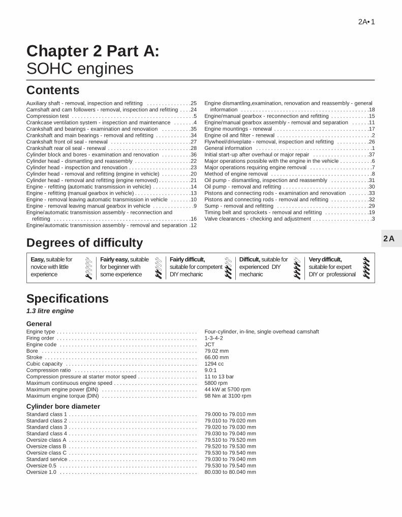
1.3 litre engine General Engine type . . . . . . . . . . . . . . . . . . . . . . . . . . . . . . . . . . . . . . . . . . . . . . . Four-cylinder, in-line, single overhead camshaft Firing order . . . . . . . . . . . . . . . . . . . . . . . . . . . . . . . . . . . . . . . . . . . . . . . 1-3-4-2 Engine code . . . . . . . . . . . . . . . . . . . . . . . . . . . . . . . . . . . . . . . . . . . . . . JCT Bore . . . . . . . . . . . . . . . . . . . . . . . . . . . . . . . . . . . . . . . . . . . . . . . . . . . . 79.02 mm Stroke . . . . . . . . . . . . . . . . . . . . . . . . . . . . . . . . . . . . . . . . . . . . . . . . . . . 66.00 mm Cubic capacity . . . . . . . . . . . . . . . . . . . . . . . . . . . . . . . . . . . . . . . . . . . . 1294 cc Compression ratio . . . . . . . . . . . . . . . . . . . . . . . . . . . . . . . . . . . . . . . . . 9.0:1 Compression pressure at starter motor speed . . . . . . . . . . . . . . . . . . . . 11 to 13 bar Maximum continuous engine speed . . . . . . . . . . . . . . . . . . . . . . . . . . . . 5800 rpm Maximum engine power (DIN) . . . . . . . . . . . . . . . . . . . . . . . . . . . . . . . . 44 kW at 5700 rpm Maximum engine torque (DIN) . . . . . . . . . . . . . . . . . . . . . . . . . . . . . . . . 98 Nm at 3100 rpm Cylinder bore diameter Standard class 1 . . . . . . . . . . . . . . . . . . . . . . . . . . . . . . . . . . . . . . . . . . . 79.000 to 79.010 mm Standard class 2 . . . . . . . . . . . . . . . . . . . . . . . . . . . . . . . . . . . . . . . . . . . 79.010 to 79.020 mm Standard class 3 . . . . . . . . . . . . . . . . . . . . . . . . . . . . . . . . . . . . . . . . . . . 79.020 to 79.030 mm Standard class 4 . . . . . . . . . . . . . . . . . . . . . . . . . . . . . . . . . . . . . . . . . . . 79.030 to 79.040 mm Oversize class A . . . . . . . . . . . . . . . . . . . . . . . . . . . . . . . . . . . . . . . . . . . 79.510 to 79.520 mm Oversize class B . . . . . . . . . . . . . . . . . . . . . . . . . . . . . . . . . . . . . . . . . . . 79.520 to 79.530 mm Oversize class C . . . . . . . . . . . . . . . . . . . . . . . . . . . . . . . . . . . . . . . . . . . 79.530 to 79.540 mm Standard service . . . . . . . . . . . . . . . . . . . . . . . . . . . . . . . . . . . . . . . . . . . 79.030 to 79.040 mm Oversize 0.5 . . . . . . . . . . . . . . . . . . . . . . . . . . . . . . . . . . . . . . . . . . . . . . 79.530 to 79.540 mm Oversize 1.0 . . . . . . . . . . . . . . . . . . . . . . . . . . . . . . . . . . . . . . . . . . . . . . 80.030 to 80.040 mm Chapter 2 Part A: SOHC engines Auxiliary shaft - removal, inspection and refitting . . . . . . . . . . . . . . .25 Camshaft and cam followers - removal, inspection and refitting . . . .24 Compression test . . . . . . . . . . . . . . . . . . . . . . . . . . . . . . . . . . . . . . . . .5 Crankcase ventilation system - inspection and maintenance . . . . . . .4 Crankshaft and bearings - examination and renovation . . . . . . . . . .35 Crankshaft and main bearings - removal and refitting . . . . . . . . . . . .34 Crankshaft front oil seal - renewal . . . . . . . . . . . . . . . . . . . . . . . . . . .27 Crankshaft rear oil seal - renewal . . . . . . . . . . . . . . . . . . . . . . . . . . . .28 Cylinder block and bores - examination and renovation . . . . . . . . . .36 Cylinder head - dismantling and reassembly . . . . . . . . . . . . . . . . . . .22 Cylinder head - inspection and renovation . . . . . . . . . . . . . . . . . . . . .23 Cylinder head - removal and refitting (engine in vehicle) . . . . . . . . . .20 Cylinder head - removal and refitting (engine removed) . . . . . . . . . . .21 Engine - refitting (automatic transmission in vehicle) . . . . . . . . . . . . .14 Engine - refitting (manual gearbox in vehicle) . . . . . . . . . . . . . . . . . . .13 Engine - removal leaving automatic transmission in vehicle . . . . . . .10 Engine - removal leaving manual gearbox in vehicle . . . . . . . . . . . . . .9 Engine/automatic transmission assembly - reconnection and refitting . . . . . . . . . . . . . . . . . . . . . . . . . . . . . . . . . . . . . . . . . . . . . .16 Engine/automatic transmission assembly - removal and separation .12 Engine dismantling,examination, renovation and reassembly - general information . . . . . . . . . . . . . . . . . . . . . . . . . . . . . . . . . . . . . . . . . . .18 Engine/manual gearbox - reconnection and refitting . . . . . . . . . . . . .15 Engine/manual gearbox assembly - removal and separation . . . . . .11 Engine mountings - renewal . . . . . . . . . . . . . . . . . . . . . . . . . . . . . . . .17 Engine oil and filter - renewal . . . . . . . . . . . . . . . . . . . . . . . . . . . . . . . .2 Flywheel/driveplate - removal, inspection and refitting . . . . . . . . . . .26 General information . . . . . . . . . . . . . . . . . . . . . . . . . . . . . . . . . . . . . . .1 Initial start-up after overhaul or major repair . . . . . . . . . . . . . . . . . . .37 Major operations possible with the engine in the vehicle . . . . . . . . . . .6 Major operations requiring engine removal . . . . . . . . . . . . . . . . . . . . .7 Method of engine removal . . . . . . . . . . . . . . . . . . . . . . . . . . . . . . . . . .8 Oil pump - dismantling, inspection and reassembly . . . . . . . . . . . . .31 Oil pump - removal and refitting . . . . . . . . . . . . . . . . . . . . . . . . . . . . .30 Pistons and connecting rods - examination and renovation . . . . . . .33 Pistons and connecting rods - removal and refitting . . . . . . . . . . . . .32 Sump - removal and refitting . . . . . . . . . . . . . . . . . . . . . . . . . . . . . . .29 Timing belt and sprockets - removal and refitting . . . . . . . . . . . . . . .19 Valve clearances - checking and adjustment . . . . . . . . . . . . . . . . . . . .3 2A•1 Specifications Contents 2A Easy, suitable for novice with little experience Fairly easy, suitable for beginner with some experience Fairly difficult, suitable for competent DIY mechanic Difficult, suitable for experienced DIY mechanic Very difficult, suitable for expert DIY or professional Degrees of difficulty
-
Upload
khangminh22 -
Category
Documents
-
view
1 -
download
0
Transcript of Chapter 2 Part A: SOHC engines - Free
1.3 litre engine
GeneralEngine type . . . . . . . . . . . . . . . . . . . . . . . . . . . . . . . . . . . . . . . . . . . . . . . Four-cylinder, in-line, single overhead camshaftFiring order . . . . . . . . . . . . . . . . . . . . . . . . . . . . . . . . . . . . . . . . . . . . . . . 1-3-4-2Engine code . . . . . . . . . . . . . . . . . . . . . . . . . . . . . . . . . . . . . . . . . . . . . . JCTBore . . . . . . . . . . . . . . . . . . . . . . . . . . . . . . . . . . . . . . . . . . . . . . . . . . . . 79.02 mmStroke . . . . . . . . . . . . . . . . . . . . . . . . . . . . . . . . . . . . . . . . . . . . . . . . . . . 66.00 mmCubic capacity . . . . . . . . . . . . . . . . . . . . . . . . . . . . . . . . . . . . . . . . . . . . 1294 ccCompression ratio . . . . . . . . . . . . . . . . . . . . . . . . . . . . . . . . . . . . . . . . . 9.0:1Compression pressure at starter motor speed . . . . . . . . . . . . . . . . . . . . 11 to 13 barMaximum continuous engine speed . . . . . . . . . . . . . . . . . . . . . . . . . . . . 5800 rpmMaximum engine power (DIN) . . . . . . . . . . . . . . . . . . . . . . . . . . . . . . . . 44 kW at 5700 rpmMaximum engine torque (DIN) . . . . . . . . . . . . . . . . . . . . . . . . . . . . . . . . 98 Nm at 3100 rpm
Cylinder bore diameterStandard class 1 . . . . . . . . . . . . . . . . . . . . . . . . . . . . . . . . . . . . . . . . . . . 79.000 to 79.010 mmStandard class 2 . . . . . . . . . . . . . . . . . . . . . . . . . . . . . . . . . . . . . . . . . . . 79.010 to 79.020 mmStandard class 3 . . . . . . . . . . . . . . . . . . . . . . . . . . . . . . . . . . . . . . . . . . . 79.020 to 79.030 mmStandard class 4 . . . . . . . . . . . . . . . . . . . . . . . . . . . . . . . . . . . . . . . . . . . 79.030 to 79.040 mmOversize class A . . . . . . . . . . . . . . . . . . . . . . . . . . . . . . . . . . . . . . . . . . . 79.510 to 79.520 mmOversize class B . . . . . . . . . . . . . . . . . . . . . . . . . . . . . . . . . . . . . . . . . . . 79.520 to 79.530 mmOversize class C . . . . . . . . . . . . . . . . . . . . . . . . . . . . . . . . . . . . . . . . . . . 79.530 to 79.540 mmStandard service . . . . . . . . . . . . . . . . . . . . . . . . . . . . . . . . . . . . . . . . . . . 79.030 to 79.040 mmOversize 0.5 . . . . . . . . . . . . . . . . . . . . . . . . . . . . . . . . . . . . . . . . . . . . . . 79.530 to 79.540 mmOversize 1.0 . . . . . . . . . . . . . . . . . . . . . . . . . . . . . . . . . . . . . . . . . . . . . . 80.030 to 80.040 mm
Chapter 2 Part A:SOHC engines
Auxiliary shaft - removal, inspection and refitting . . . . . . . . . . . . . . .25Camshaft and cam followers - removal, inspection and refitting . . . .24Compression test . . . . . . . . . . . . . . . . . . . . . . . . . . . . . . . . . . . . . . . . .5Crankcase ventilation system - inspection and maintenance . . . . . . .4Crankshaft and bearings - examination and renovation . . . . . . . . . .35Crankshaft and main bearings - removal and refitting . . . . . . . . . . . .34Crankshaft front oil seal - renewal . . . . . . . . . . . . . . . . . . . . . . . . . . .27Crankshaft rear oil seal - renewal . . . . . . . . . . . . . . . . . . . . . . . . . . . .28Cylinder block and bores - examination and renovation . . . . . . . . . .36Cylinder head - dismantling and reassembly . . . . . . . . . . . . . . . . . . .22Cylinder head - inspection and renovation . . . . . . . . . . . . . . . . . . . . .23Cylinder head - removal and refitting (engine in vehicle) . . . . . . . . . .20Cylinder head - removal and refitting (engine removed) . . . . . . . . . . .21Engine - refitting (automatic transmission in vehicle) . . . . . . . . . . . . .14Engine - refitting (manual gearbox in vehicle) . . . . . . . . . . . . . . . . . . .13Engine - removal leaving automatic transmission in vehicle . . . . . . .10Engine - removal leaving manual gearbox in vehicle . . . . . . . . . . . . . .9Engine/automatic transmission assembly - reconnection and
refitting . . . . . . . . . . . . . . . . . . . . . . . . . . . . . . . . . . . . . . . . . . . . . .16Engine/automatic transmission assembly - removal and separation .12
Engine dismantling,examination, renovation and reassembly - generalinformation . . . . . . . . . . . . . . . . . . . . . . . . . . . . . . . . . . . . . . . . . . .18
Engine/manual gearbox - reconnection and refitting . . . . . . . . . . . . .15Engine/manual gearbox assembly - removal and separation . . . . . .11Engine mountings - renewal . . . . . . . . . . . . . . . . . . . . . . . . . . . . . . . .17Engine oil and filter - renewal . . . . . . . . . . . . . . . . . . . . . . . . . . . . . . . .2Flywheel/driveplate - removal, inspection and refitting . . . . . . . . . . .26General information . . . . . . . . . . . . . . . . . . . . . . . . . . . . . . . . . . . . . . .1Initial start-up after overhaul or major repair . . . . . . . . . . . . . . . . . . .37Major operations possible with the engine in the vehicle . . . . . . . . . . .6Major operations requiring engine removal . . . . . . . . . . . . . . . . . . . . .7Method of engine removal . . . . . . . . . . . . . . . . . . . . . . . . . . . . . . . . . .8Oil pump - dismantling, inspection and reassembly . . . . . . . . . . . . .31Oil pump - removal and refitting . . . . . . . . . . . . . . . . . . . . . . . . . . . . .30Pistons and connecting rods - examination and renovation . . . . . . .33Pistons and connecting rods - removal and refitting . . . . . . . . . . . . .32Sump - removal and refitting . . . . . . . . . . . . . . . . . . . . . . . . . . . . . . .29Timing belt and sprockets - removal and refitting . . . . . . . . . . . . . . .19Valve clearances - checking and adjustment . . . . . . . . . . . . . . . . . . . .3
2A•1
Specifications
Contents
2A
Easy, suitable fornovice with littleexperience
Fairly easy, suitablefor beginner withsome experience
Fairly difficult,suitable for competentDIY mechanic
Difficult, suitable forexperienced DIYmechanic
Very difficult,suitable for expertDIY or professional
Degrees of difficulty
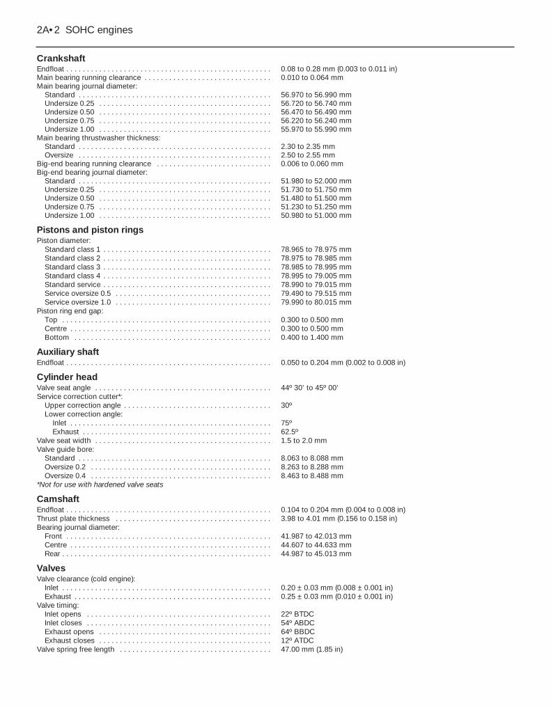
CrankshaftEndfloat . . . . . . . . . . . . . . . . . . . . . . . . . . . . . . . . . . . . . . . . . . . . . . . . . . 0.08 to 0.28 mm (0.003 to 0.011 in)Main bearing running clearance . . . . . . . . . . . . . . . . . . . . . . . . . . . . . . . 0.010 to 0.064 mmMain bearing journal diameter:
Standard . . . . . . . . . . . . . . . . . . . . . . . . . . . . . . . . . . . . . . . . . . . . . . . 56.970 to 56.990 mmUndersize 0.25 . . . . . . . . . . . . . . . . . . . . . . . . . . . . . . . . . . . . . . . . . . 56.720 to 56.740 mmUndersize 0.50 . . . . . . . . . . . . . . . . . . . . . . . . . . . . . . . . . . . . . . . . . . 56.470 to 56.490 mmUndersize 0.75 . . . . . . . . . . . . . . . . . . . . . . . . . . . . . . . . . . . . . . . . . . 56.220 to 56.240 mmUndersize 1.00 . . . . . . . . . . . . . . . . . . . . . . . . . . . . . . . . . . . . . . . . . . 55.970 to 55.990 mm
Main bearing thrustwasher thickness:Standard . . . . . . . . . . . . . . . . . . . . . . . . . . . . . . . . . . . . . . . . . . . . . . . 2.30 to 2.35 mmOversize . . . . . . . . . . . . . . . . . . . . . . . . . . . . . . . . . . . . . . . . . . . . . . . 2.50 to 2.55 mm
Big-end bearing running clearance . . . . . . . . . . . . . . . . . . . . . . . . . . . . 0.006 to 0.060 mmBig-end bearing journal diameter:
Standard . . . . . . . . . . . . . . . . . . . . . . . . . . . . . . . . . . . . . . . . . . . . . . . 51.980 to 52.000 mmUndersize 0.25 . . . . . . . . . . . . . . . . . . . . . . . . . . . . . . . . . . . . . . . . . . 51.730 to 51.750 mmUndersize 0.50 . . . . . . . . . . . . . . . . . . . . . . . . . . . . . . . . . . . . . . . . . . 51.480 to 51.500 mmUndersize 0.75 . . . . . . . . . . . . . . . . . . . . . . . . . . . . . . . . . . . . . . . . . . 51.230 to 51.250 mmUndersize 1.00 . . . . . . . . . . . . . . . . . . . . . . . . . . . . . . . . . . . . . . . . . . 50.980 to 51.000 mm
Pistons and piston ringsPiston diameter:
Standard class 1 . . . . . . . . . . . . . . . . . . . . . . . . . . . . . . . . . . . . . . . . . 78.965 to 78.975 mmStandard class 2 . . . . . . . . . . . . . . . . . . . . . . . . . . . . . . . . . . . . . . . . . 78.975 to 78.985 mmStandard class 3 . . . . . . . . . . . . . . . . . . . . . . . . . . . . . . . . . . . . . . . . . 78.985 to 78.995 mmStandard class 4 . . . . . . . . . . . . . . . . . . . . . . . . . . . . . . . . . . . . . . . . . 78.995 to 79.005 mmStandard service . . . . . . . . . . . . . . . . . . . . . . . . . . . . . . . . . . . . . . . . . 78.990 to 79.015 mmService oversize 0.5 . . . . . . . . . . . . . . . . . . . . . . . . . . . . . . . . . . . . . . 79.490 to 79.515 mmService oversize 1.0 . . . . . . . . . . . . . . . . . . . . . . . . . . . . . . . . . . . . . . 79.990 to 80.015 mm
Piston ring end gap:Top . . . . . . . . . . . . . . . . . . . . . . . . . . . . . . . . . . . . . . . . . . . . . . . . . . . 0.300 to 0.500 mmCentre . . . . . . . . . . . . . . . . . . . . . . . . . . . . . . . . . . . . . . . . . . . . . . . . . 0.300 to 0.500 mmBottom . . . . . . . . . . . . . . . . . . . . . . . . . . . . . . . . . . . . . . . . . . . . . . . . 0.400 to 1.400 mm
Auxiliary shaftEndfloat . . . . . . . . . . . . . . . . . . . . . . . . . . . . . . . . . . . . . . . . . . . . . . . . . . 0.050 to 0.204 mm (0.002 to 0.008 in)
Cylinder headValve seat angle . . . . . . . . . . . . . . . . . . . . . . . . . . . . . . . . . . . . . . . . . . . 44º 30’ to 45º 00’Service correction cutter*:
Upper correction angle . . . . . . . . . . . . . . . . . . . . . . . . . . . . . . . . . . . . 30ºLower correction angle:
Inlet . . . . . . . . . . . . . . . . . . . . . . . . . . . . . . . . . . . . . . . . . . . . . . . . . 75ºExhaust . . . . . . . . . . . . . . . . . . . . . . . . . . . . . . . . . . . . . . . . . . . . . . 62.5º
Valve seat width . . . . . . . . . . . . . . . . . . . . . . . . . . . . . . . . . . . . . . . . . . . 1.5 to 2.0 mmValve guide bore:
Standard . . . . . . . . . . . . . . . . . . . . . . . . . . . . . . . . . . . . . . . . . . . . . . . 8.063 to 8.088 mmOversize 0.2 . . . . . . . . . . . . . . . . . . . . . . . . . . . . . . . . . . . . . . . . . . . . 8.263 to 8.288 mmOversize 0.4 . . . . . . . . . . . . . . . . . . . . . . . . . . . . . . . . . . . . . . . . . . . . 8.463 to 8.488 mm
*Not for use with hardened valve seats
CamshaftEndfloat . . . . . . . . . . . . . . . . . . . . . . . . . . . . . . . . . . . . . . . . . . . . . . . . . . 0.104 to 0.204 mm (0.004 to 0.008 in)Thrust plate thickness . . . . . . . . . . . . . . . . . . . . . . . . . . . . . . . . . . . . . . 3.98 to 4.01 mm (0.156 to 0.158 in)Bearing journal diameter:
Front . . . . . . . . . . . . . . . . . . . . . . . . . . . . . . . . . . . . . . . . . . . . . . . . . . 41.987 to 42.013 mmCentre . . . . . . . . . . . . . . . . . . . . . . . . . . . . . . . . . . . . . . . . . . . . . . . . . 44.607 to 44.633 mmRear . . . . . . . . . . . . . . . . . . . . . . . . . . . . . . . . . . . . . . . . . . . . . . . . . . . 44.987 to 45.013 mm
ValvesValve clearance (cold engine):
Inlet . . . . . . . . . . . . . . . . . . . . . . . . . . . . . . . . . . . . . . . . . . . . . . . . . . . 0.20 ± 0.03 mm (0.008 ± 0.001 in)Exhaust . . . . . . . . . . . . . . . . . . . . . . . . . . . . . . . . . . . . . . . . . . . . . . . . 0.25 ± 0.03 mm (0.010 ± 0.001 in)
Valve timing:Inlet opens . . . . . . . . . . . . . . . . . . . . . . . . . . . . . . . . . . . . . . . . . . . . . 22º BTDCInlet closes . . . . . . . . . . . . . . . . . . . . . . . . . . . . . . . . . . . . . . . . . . . . . 54º ABDCExhaust opens . . . . . . . . . . . . . . . . . . . . . . . . . . . . . . . . . . . . . . . . . . 64º BBDCExhaust closes . . . . . . . . . . . . . . . . . . . . . . . . . . . . . . . . . . . . . . . . . . 12º ATDC
Valve spring free length . . . . . . . . . . . . . . . . . . . . . . . . . . . . . . . . . . . . . 47.00 mm (1.85 in)
2A•2 SOHC engines
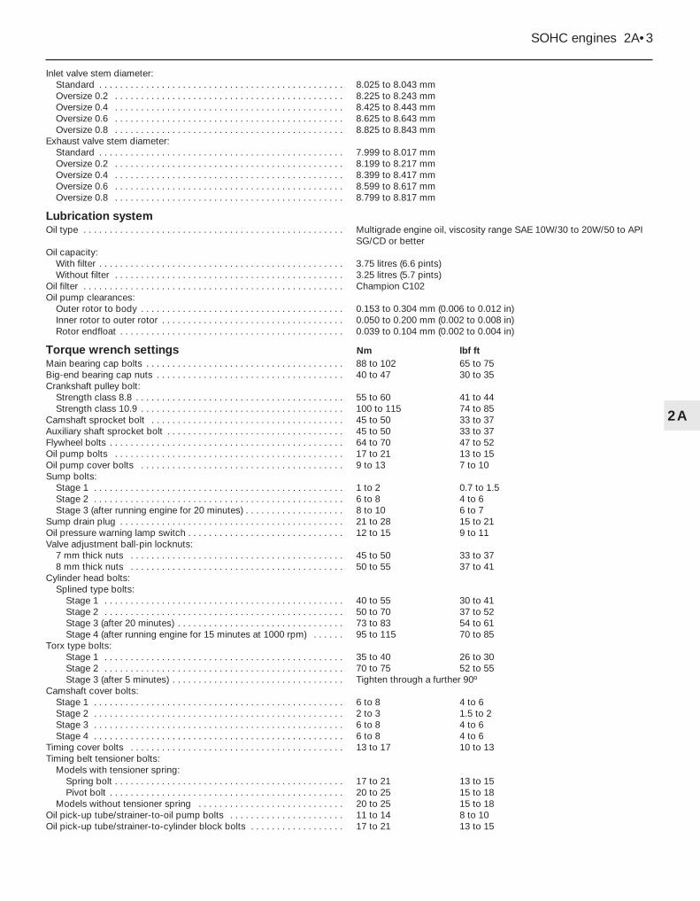
Inlet valve stem diameter:Standard . . . . . . . . . . . . . . . . . . . . . . . . . . . . . . . . . . . . . . . . . . . . . . . 8.025 to 8.043 mmOversize 0.2 . . . . . . . . . . . . . . . . . . . . . . . . . . . . . . . . . . . . . . . . . . . . 8.225 to 8.243 mmOversize 0.4 . . . . . . . . . . . . . . . . . . . . . . . . . . . . . . . . . . . . . . . . . . . . 8.425 to 8.443 mmOversize 0.6 . . . . . . . . . . . . . . . . . . . . . . . . . . . . . . . . . . . . . . . . . . . . 8.625 to 8.643 mmOversize 0.8 . . . . . . . . . . . . . . . . . . . . . . . . . . . . . . . . . . . . . . . . . . . . 8.825 to 8.843 mm
Exhaust valve stem diameter:Standard . . . . . . . . . . . . . . . . . . . . . . . . . . . . . . . . . . . . . . . . . . . . . . . 7.999 to 8.017 mmOversize 0.2 . . . . . . . . . . . . . . . . . . . . . . . . . . . . . . . . . . . . . . . . . . . . 8.199 to 8.217 mmOversize 0.4 . . . . . . . . . . . . . . . . . . . . . . . . . . . . . . . . . . . . . . . . . . . . 8.399 to 8.417 mmOversize 0.6 . . . . . . . . . . . . . . . . . . . . . . . . . . . . . . . . . . . . . . . . . . . . 8.599 to 8.617 mmOversize 0.8 . . . . . . . . . . . . . . . . . . . . . . . . . . . . . . . . . . . . . . . . . . . . 8.799 to 8.817 mm
Lubrication systemOil type . . . . . . . . . . . . . . . . . . . . . . . . . . . . . . . . . . . . . . . . . . . . . . . . . . Multigrade engine oil, viscosity range SAE 10W/30 to 20W/50 to API
SG/CD or betterOil capacity:
With filter . . . . . . . . . . . . . . . . . . . . . . . . . . . . . . . . . . . . . . . . . . . . . . . 3.75 litres (6.6 pints)Without filter . . . . . . . . . . . . . . . . . . . . . . . . . . . . . . . . . . . . . . . . . . . . 3.25 litres (5.7 pints)
Oil filter . . . . . . . . . . . . . . . . . . . . . . . . . . . . . . . . . . . . . . . . . . . . . . . . . . Champion C102Oil pump clearances:
Outer rotor to body . . . . . . . . . . . . . . . . . . . . . . . . . . . . . . . . . . . . . . . 0.153 to 0.304 mm (0.006 to 0.012 in)Inner rotor to outer rotor . . . . . . . . . . . . . . . . . . . . . . . . . . . . . . . . . . . 0.050 to 0.200 mm (0.002 to 0.008 in)Rotor endfloat . . . . . . . . . . . . . . . . . . . . . . . . . . . . . . . . . . . . . . . . . . . 0.039 to 0.104 mm (0.002 to 0.004 in)
Torque wrench settings Nm lbf ftMain bearing cap bolts . . . . . . . . . . . . . . . . . . . . . . . . . . . . . . . . . . . . . . 88 to 102 65 to 75Big-end bearing cap nuts . . . . . . . . . . . . . . . . . . . . . . . . . . . . . . . . . . . . 40 to 47 30 to 35Crankshaft pulley bolt:
Strength class 8.8 . . . . . . . . . . . . . . . . . . . . . . . . . . . . . . . . . . . . . . . . 55 to 60 41 to 44Strength class 10.9 . . . . . . . . . . . . . . . . . . . . . . . . . . . . . . . . . . . . . . . 100 to 115 74 to 85
Camshaft sprocket bolt . . . . . . . . . . . . . . . . . . . . . . . . . . . . . . . . . . . . . 45 to 50 33 to 37Auxiliary shaft sprocket bolt . . . . . . . . . . . . . . . . . . . . . . . . . . . . . . . . . . 45 to 50 33 to 37Flywheel bolts . . . . . . . . . . . . . . . . . . . . . . . . . . . . . . . . . . . . . . . . . . . . . 64 to 70 47 to 52Oil pump bolts . . . . . . . . . . . . . . . . . . . . . . . . . . . . . . . . . . . . . . . . . . . . 17 to 21 13 to 15Oil pump cover bolts . . . . . . . . . . . . . . . . . . . . . . . . . . . . . . . . . . . . . . . 9 to 13 7 to 10Sump bolts:
Stage 1 . . . . . . . . . . . . . . . . . . . . . . . . . . . . . . . . . . . . . . . . . . . . . . . . 1 to 2 0.7 to 1.5Stage 2 . . . . . . . . . . . . . . . . . . . . . . . . . . . . . . . . . . . . . . . . . . . . . . . . 6 to 8 4 to 6Stage 3 (after running engine for 20 minutes) . . . . . . . . . . . . . . . . . . . 8 to 10 6 to 7
Sump drain plug . . . . . . . . . . . . . . . . . . . . . . . . . . . . . . . . . . . . . . . . . . . 21 to 28 15 to 21Oil pressure warning lamp switch . . . . . . . . . . . . . . . . . . . . . . . . . . . . . . 12 to 15 9 to 11Valve adjustment ball-pin locknuts:
7 mm thick nuts . . . . . . . . . . . . . . . . . . . . . . . . . . . . . . . . . . . . . . . . . 45 to 50 33 to 378 mm thick nuts . . . . . . . . . . . . . . . . . . . . . . . . . . . . . . . . . . . . . . . . . 50 to 55 37 to 41
Cylinder head bolts:Splined type bolts:
Stage 1 . . . . . . . . . . . . . . . . . . . . . . . . . . . . . . . . . . . . . . . . . . . . . . 40 to 55 30 to 41Stage 2 . . . . . . . . . . . . . . . . . . . . . . . . . . . . . . . . . . . . . . . . . . . . . . 50 to 70 37 to 52Stage 3 (after 20 minutes) . . . . . . . . . . . . . . . . . . . . . . . . . . . . . . . . 73 to 83 54 to 61Stage 4 (after running engine for 15 minutes at 1000 rpm) . . . . . . 95 to 115 70 to 85
Torx type bolts:Stage 1 . . . . . . . . . . . . . . . . . . . . . . . . . . . . . . . . . . . . . . . . . . . . . . 35 to 40 26 to 30Stage 2 . . . . . . . . . . . . . . . . . . . . . . . . . . . . . . . . . . . . . . . . . . . . . . 70 to 75 52 to 55Stage 3 (after 5 minutes) . . . . . . . . . . . . . . . . . . . . . . . . . . . . . . . . . Tighten through a further 90º
Camshaft cover bolts:Stage 1 . . . . . . . . . . . . . . . . . . . . . . . . . . . . . . . . . . . . . . . . . . . . . . . . 6 to 8 4 to 6Stage 2 . . . . . . . . . . . . . . . . . . . . . . . . . . . . . . . . . . . . . . . . . . . . . . . . 2 to 3 1.5 to 2Stage 3 . . . . . . . . . . . . . . . . . . . . . . . . . . . . . . . . . . . . . . . . . . . . . . . . 6 to 8 4 to 6Stage 4 . . . . . . . . . . . . . . . . . . . . . . . . . . . . . . . . . . . . . . . . . . . . . . . . 6 to 8 4 to 6
Timing cover bolts . . . . . . . . . . . . . . . . . . . . . . . . . . . . . . . . . . . . . . . . . 13 to 17 10 to 13Timing belt tensioner bolts:
Models with tensioner spring:Spring bolt . . . . . . . . . . . . . . . . . . . . . . . . . . . . . . . . . . . . . . . . . . . . 17 to 21 13 to 15Pivot bolt . . . . . . . . . . . . . . . . . . . . . . . . . . . . . . . . . . . . . . . . . . . . . 20 to 25 15 to 18
Models without tensioner spring . . . . . . . . . . . . . . . . . . . . . . . . . . . . 20 to 25 15 to 18Oil pick-up tube/strainer-to-oil pump bolts . . . . . . . . . . . . . . . . . . . . . . 11 to 14 8 to 10Oil pick-up tube/strainer-to-cylinder block bolts . . . . . . . . . . . . . . . . . . 17 to 21 13 to 15
SOHC engines 2A•3
2A
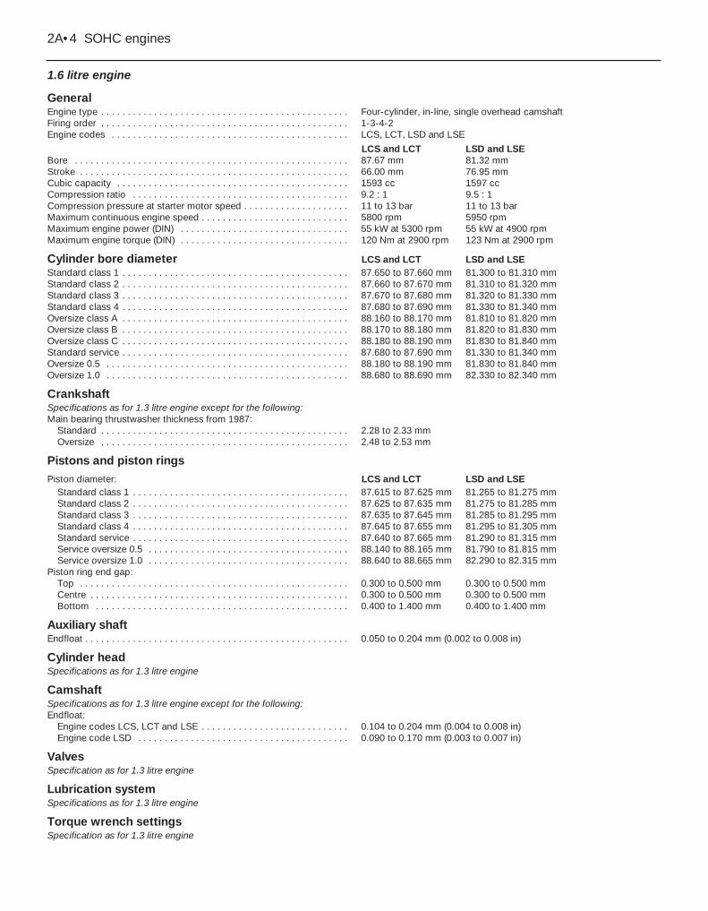
1.6 litre engine
GeneralEngine type . . . . . . . . . . . . . . . . . . . . . . . . . . . . . . . . . . . . . . . . . . . . . . . Four-cylinder, in-line, single overhead camshaftFiring order . . . . . . . . . . . . . . . . . . . . . . . . . . . . . . . . . . . . . . . . . . . . . . . 1-3-4-2Engine codes . . . . . . . . . . . . . . . . . . . . . . . . . . . . . . . . . . . . . . . . . . . . . LCS, LCT, LSD and LSE
LCS and LCT LSD and LSEBore . . . . . . . . . . . . . . . . . . . . . . . . . . . . . . . . . . . . . . . . . . . . . . . . . . . . 87.67 mm 81.32 mmStroke . . . . . . . . . . . . . . . . . . . . . . . . . . . . . . . . . . . . . . . . . . . . . . . . . . . 66.00 mm 76.95 mmCubic capacity . . . . . . . . . . . . . . . . . . . . . . . . . . . . . . . . . . . . . . . . . . . . 1593 cc 1597 ccCompression ratio . . . . . . . . . . . . . . . . . . . . . . . . . . . . . . . . . . . . . . . . . 9.2 : 1 9.5 : 1Compression pressure at starter motor speed . . . . . . . . . . . . . . . . . . . . 11 to 13 bar 11 to 13 barMaximum continuous engine speed . . . . . . . . . . . . . . . . . . . . . . . . . . . . 5800 rpm 5950 rpmMaximum engine power (DIN) . . . . . . . . . . . . . . . . . . . . . . . . . . . . . . . . 55 kW at 5300 rpm 55 kW at 4900 rpmMaximum engine torque (DIN) . . . . . . . . . . . . . . . . . . . . . . . . . . . . . . . . 120 Nm at 2900 rpm 123 Nm at 2900 rpm
Cylinder bore diameter LCS and LCT LSD and LSEStandard class 1 . . . . . . . . . . . . . . . . . . . . . . . . . . . . . . . . . . . . . . . . . . . 87.650 to 87.660 mm 81.300 to 81.310 mmStandard class 2 . . . . . . . . . . . . . . . . . . . . . . . . . . . . . . . . . . . . . . . . . . . 87.660 to 87.670 mm 81.310 to 81.320 mmStandard class 3 . . . . . . . . . . . . . . . . . . . . . . . . . . . . . . . . . . . . . . . . . . . 87.670 to 87.680 mm 81.320 to 81.330 mmStandard class 4 . . . . . . . . . . . . . . . . . . . . . . . . . . . . . . . . . . . . . . . . . . . 87.680 to 87.690 mm 81.330 to 81.340 mmOversize class A . . . . . . . . . . . . . . . . . . . . . . . . . . . . . . . . . . . . . . . . . . . 88.160 to 88.170 mm 81.810 to 81.820 mmOversize class B . . . . . . . . . . . . . . . . . . . . . . . . . . . . . . . . . . . . . . . . . . . 88.170 to 88.180 mm 81.820 to 81.830 mmOversize class C . . . . . . . . . . . . . . . . . . . . . . . . . . . . . . . . . . . . . . . . . . . 88.180 to 88.190 mm 81.830 to 81.840 mmStandard service . . . . . . . . . . . . . . . . . . . . . . . . . . . . . . . . . . . . . . . . . . . 87.680 to 87.690 mm 81.330 to 81.340 mmOversize 0.5 . . . . . . . . . . . . . . . . . . . . . . . . . . . . . . . . . . . . . . . . . . . . . . 88.180 to 88.190 mm 81.830 to 81.840 mmOversize 1.0 . . . . . . . . . . . . . . . . . . . . . . . . . . . . . . . . . . . . . . . . . . . . . . 88.680 to 88.690 mm 82.330 to 82.340 mm
CrankshaftSpecifications as for 1.3 litre engine except for the following:Main bearing thrustwasher thickness from 1987:
Standard . . . . . . . . . . . . . . . . . . . . . . . . . . . . . . . . . . . . . . . . . . . . . . . 2.28 to 2.33 mmOversize . . . . . . . . . . . . . . . . . . . . . . . . . . . . . . . . . . . . . . . . . . . . . . . 2.48 to 2.53 mm
Pistons and piston ringsPiston diameter: LCS and LCT LSD and LSE
Standard class 1 . . . . . . . . . . . . . . . . . . . . . . . . . . . . . . . . . . . . . . . . . 87.615 to 87.625 mm 81.265 to 81.275 mmStandard class 2 . . . . . . . . . . . . . . . . . . . . . . . . . . . . . . . . . . . . . . . . . 87.625 to 87.635 mm 81.275 to 81.285 mmStandard class 3 . . . . . . . . . . . . . . . . . . . . . . . . . . . . . . . . . . . . . . . . . 87.635 to 87.645 mm 81.285 to 81.295 mmStandard class 4 . . . . . . . . . . . . . . . . . . . . . . . . . . . . . . . . . . . . . . . . . 87.645 to 87.655 mm 81.295 to 81.305 mmStandard service . . . . . . . . . . . . . . . . . . . . . . . . . . . . . . . . . . . . . . . . . 87.640 to 87.665 mm 81.290 to 81.315 mmService oversize 0.5 . . . . . . . . . . . . . . . . . . . . . . . . . . . . . . . . . . . . . . 88.140 to 88.165 mm 81.790 to 81.815 mmService oversize 1.0 . . . . . . . . . . . . . . . . . . . . . . . . . . . . . . . . . . . . . . 88.640 to 88.665 mm 82.290 to 82.315 mm
Piston ring end gap:Top . . . . . . . . . . . . . . . . . . . . . . . . . . . . . . . . . . . . . . . . . . . . . . . . . . . 0.300 to 0.500 mm 0.300 to 0.500 mmCentre . . . . . . . . . . . . . . . . . . . . . . . . . . . . . . . . . . . . . . . . . . . . . . . . . 0.300 to 0.500 mm 0.300 to 0.500 mmBottom . . . . . . . . . . . . . . . . . . . . . . . . . . . . . . . . . . . . . . . . . . . . . . . . 0.400 to 1.400 mm 0.400 to 1.400 mm
Auxiliary shaftEndfloat . . . . . . . . . . . . . . . . . . . . . . . . . . . . . . . . . . . . . . . . . . . . . . . . . . 0.050 to 0.204 mm (0.002 to 0.008 in)
Cylinder headSpecifications as for 1.3 litre engine
CamshaftSpecifications as for 1.3 litre engine except for the following:Endfloat:
Engine codes LCS, LCT and LSE . . . . . . . . . . . . . . . . . . . . . . . . . . . . 0.104 to 0.204 mm (0.004 to 0.008 in)Engine code LSD . . . . . . . . . . . . . . . . . . . . . . . . . . . . . . . . . . . . . . . . 0.090 to 0.170 mm (0.003 to 0.007 in)
ValvesSpecification as for 1.3 litre engine
Lubrication systemSpecifications as for 1.3 litre engine
Torque wrench settingsSpecification as for 1.3 litre engine
2A•4 SOHC engines
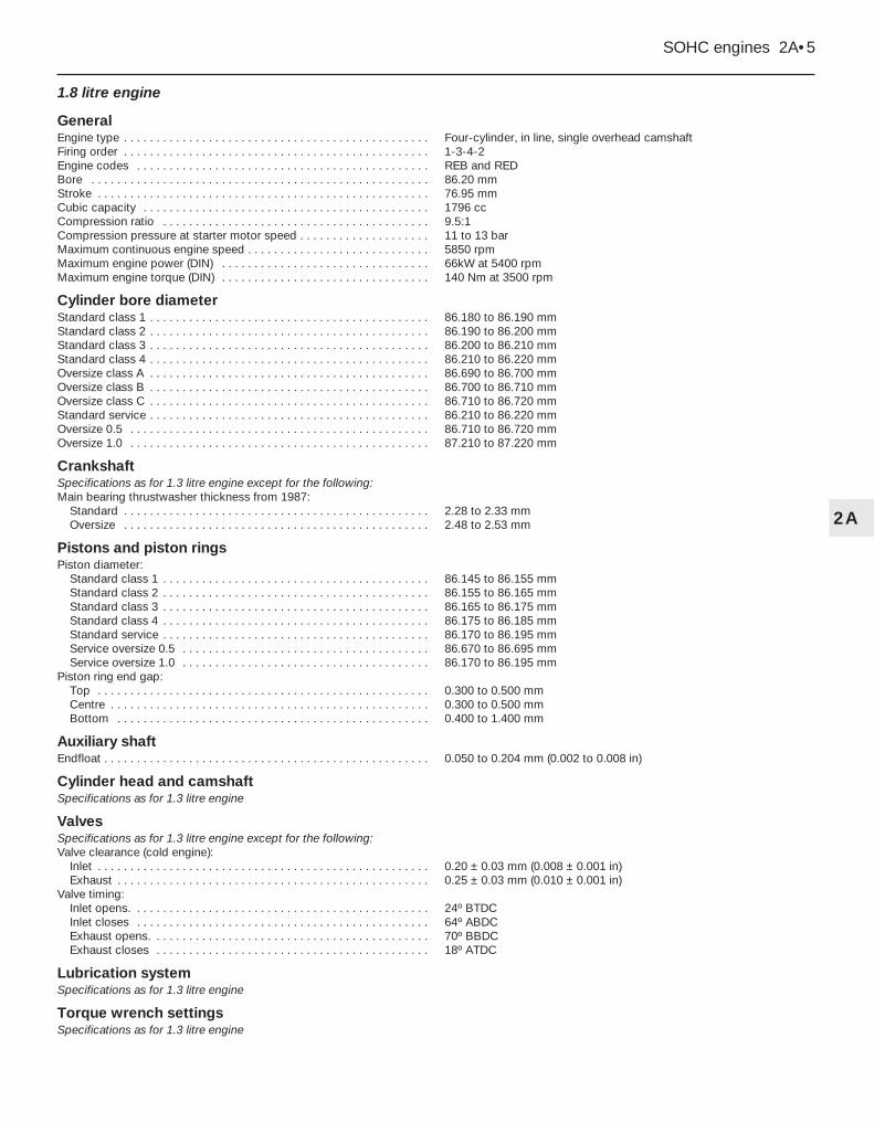
1.8 litre engine
GeneralEngine type . . . . . . . . . . . . . . . . . . . . . . . . . . . . . . . . . . . . . . . . . . . . . . . Four-cylinder, in line, single overhead camshaftFiring order . . . . . . . . . . . . . . . . . . . . . . . . . . . . . . . . . . . . . . . . . . . . . . . 1-3-4-2Engine codes . . . . . . . . . . . . . . . . . . . . . . . . . . . . . . . . . . . . . . . . . . . . . REB and REDBore . . . . . . . . . . . . . . . . . . . . . . . . . . . . . . . . . . . . . . . . . . . . . . . . . . . . 86.20 mmStroke . . . . . . . . . . . . . . . . . . . . . . . . . . . . . . . . . . . . . . . . . . . . . . . . . . . 76.95 mmCubic capacity . . . . . . . . . . . . . . . . . . . . . . . . . . . . . . . . . . . . . . . . . . . . 1796 ccCompression ratio . . . . . . . . . . . . . . . . . . . . . . . . . . . . . . . . . . . . . . . . . 9.5:1Compression pressure at starter motor speed . . . . . . . . . . . . . . . . . . . . 11 to 13 barMaximum continuous engine speed . . . . . . . . . . . . . . . . . . . . . . . . . . . . 5850 rpmMaximum engine power (DIN) . . . . . . . . . . . . . . . . . . . . . . . . . . . . . . . . 66kW at 5400 rpmMaximum engine torque (DIN) . . . . . . . . . . . . . . . . . . . . . . . . . . . . . . . . 140 Nm at 3500 rpm
Cylinder bore diameterStandard class 1 . . . . . . . . . . . . . . . . . . . . . . . . . . . . . . . . . . . . . . . . . . . 86.180 to 86.190 mmStandard class 2 . . . . . . . . . . . . . . . . . . . . . . . . . . . . . . . . . . . . . . . . . . . 86.190 to 86.200 mmStandard class 3 . . . . . . . . . . . . . . . . . . . . . . . . . . . . . . . . . . . . . . . . . . . 86.200 to 86.210 mmStandard class 4 . . . . . . . . . . . . . . . . . . . . . . . . . . . . . . . . . . . . . . . . . . . 86.210 to 86.220 mmOversize class A . . . . . . . . . . . . . . . . . . . . . . . . . . . . . . . . . . . . . . . . . . . 86.690 to 86.700 mmOversize class B . . . . . . . . . . . . . . . . . . . . . . . . . . . . . . . . . . . . . . . . . . . 86.700 to 86.710 mmOversize class C . . . . . . . . . . . . . . . . . . . . . . . . . . . . . . . . . . . . . . . . . . . 86.710 to 86.720 mmStandard service . . . . . . . . . . . . . . . . . . . . . . . . . . . . . . . . . . . . . . . . . . . 86.210 to 86.220 mmOversize 0.5 . . . . . . . . . . . . . . . . . . . . . . . . . . . . . . . . . . . . . . . . . . . . . . 86.710 to 86.720 mmOversize 1.0 . . . . . . . . . . . . . . . . . . . . . . . . . . . . . . . . . . . . . . . . . . . . . . 87.210 to 87.220 mm
CrankshaftSpecifications as for 1.3 litre engine except for the following:Main bearing thrustwasher thickness from 1987:
Standard . . . . . . . . . . . . . . . . . . . . . . . . . . . . . . . . . . . . . . . . . . . . . . . 2.28 to 2.33 mmOversize . . . . . . . . . . . . . . . . . . . . . . . . . . . . . . . . . . . . . . . . . . . . . . . 2.48 to 2.53 mm
Pistons and piston ringsPiston diameter:
Standard class 1 . . . . . . . . . . . . . . . . . . . . . . . . . . . . . . . . . . . . . . . . . 86.145 to 86.155 mmStandard class 2 . . . . . . . . . . . . . . . . . . . . . . . . . . . . . . . . . . . . . . . . . 86.155 to 86.165 mmStandard class 3 . . . . . . . . . . . . . . . . . . . . . . . . . . . . . . . . . . . . . . . . . 86.165 to 86.175 mmStandard class 4 . . . . . . . . . . . . . . . . . . . . . . . . . . . . . . . . . . . . . . . . . 86.175 to 86.185 mmStandard service . . . . . . . . . . . . . . . . . . . . . . . . . . . . . . . . . . . . . . . . . 86.170 to 86.195 mmService oversize 0.5 . . . . . . . . . . . . . . . . . . . . . . . . . . . . . . . . . . . . . . 86.670 to 86.695 mmService oversize 1.0 . . . . . . . . . . . . . . . . . . . . . . . . . . . . . . . . . . . . . . 86.170 to 86.195 mm
Piston ring end gap:Top . . . . . . . . . . . . . . . . . . . . . . . . . . . . . . . . . . . . . . . . . . . . . . . . . . . 0.300 to 0.500 mmCentre . . . . . . . . . . . . . . . . . . . . . . . . . . . . . . . . . . . . . . . . . . . . . . . . . 0.300 to 0.500 mmBottom . . . . . . . . . . . . . . . . . . . . . . . . . . . . . . . . . . . . . . . . . . . . . . . . 0.400 to 1.400 mm
Auxiliary shaftEndfloat . . . . . . . . . . . . . . . . . . . . . . . . . . . . . . . . . . . . . . . . . . . . . . . . . . 0.050 to 0.204 mm (0.002 to 0.008 in)
Cylinder head and camshaftSpecifications as for 1.3 litre engine
ValvesSpecifications as for 1.3 litre engine except for the following:Valve clearance (cold engine):
Inlet . . . . . . . . . . . . . . . . . . . . . . . . . . . . . . . . . . . . . . . . . . . . . . . . . . . 0.20 ± 0.03 mm (0.008 ± 0.001 in)Exhaust . . . . . . . . . . . . . . . . . . . . . . . . . . . . . . . . . . . . . . . . . . . . . . . . 0.25 ± 0.03 mm (0.010 ± 0.001 in)
Valve timing:Inlet opens. . . . . . . . . . . . . . . . . . . . . . . . . . . . . . . . . . . . . . . . . . . . . . 24º BTDCInlet closes . . . . . . . . . . . . . . . . . . . . . . . . . . . . . . . . . . . . . . . . . . . . . 64º ABDCExhaust opens. . . . . . . . . . . . . . . . . . . . . . . . . . . . . . . . . . . . . . . . . . . 70º BBDCExhaust closes . . . . . . . . . . . . . . . . . . . . . . . . . . . . . . . . . . . . . . . . . . 18º ATDC
Lubrication systemSpecifications as for 1.3 litre engine
Torque wrench settingsSpecifications as for 1.3 litre engine
SOHC engines 2A•5
2A
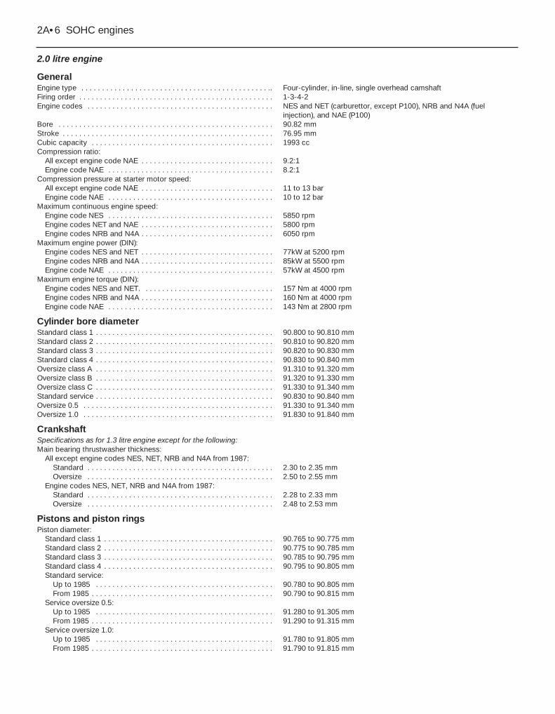
2.0 litre engine
GeneralEngine type . . . . . . . . . . . . . . . . . . . . . . . . . . . . . . . . . . . . . . . . . . . . . .. Four-cylinder, in-line, single overhead camshaftFiring order . . . . . . . . . . . . . . . . . . . . . . . . . . . . . . . . . . . . . . . . . . . . . . . 1-3-4-2Engine codes . . . . . . . . . . . . . . . . . . . . . . . . . . . . . . . . . . . . . . . . . . . . . NES and NET (carburettor, except P100), NRB and N4A (fuel
injection), and NAE (P100)Bore . . . . . . . . . . . . . . . . . . . . . . . . . . . . . . . . . . . . . . . . . . . . . . . . . . . . 90.82 mmStroke . . . . . . . . . . . . . . . . . . . . . . . . . . . . . . . . . . . . . . . . . . . . . . . . . . . 76.95 mmCubic capacity . . . . . . . . . . . . . . . . . . . . . . . . . . . . . . . . . . . . . . . . . . . . 1993 ccCompression ratio:
All except engine code NAE . . . . . . . . . . . . . . . . . . . . . . . . . . . . . . . . 9.2:1Engine code NAE . . . . . . . . . . . . . . . . . . . . . . . . . . . . . . . . . . . . . . . . 8.2:1
Compression pressure at starter motor speed:All except engine code NAE . . . . . . . . . . . . . . . . . . . . . . . . . . . . . . . . 11 to 13 barEngine code NAE . . . . . . . . . . . . . . . . . . . . . . . . . . . . . . . . . . . . . . . . 10 to 12 bar
Maximum continuous engine speed:Engine code NES . . . . . . . . . . . . . . . . . . . . . . . . . . . . . . . . . . . . . . . . 5850 rpmEngine codes NET and NAE . . . . . . . . . . . . . . . . . . . . . . . . . . . . . . . . 5800 rpmEngine codes NRB and N4A . . . . . . . . . . . . . . . . . . . . . . . . . . . . . . . . 6050 rpm
Maximum engine power (DIN):Engine codes NES and NET . . . . . . . . . . . . . . . . . . . . . . . . . . . . . . . . 77kW at 5200 rpmEngine codes NRB and N4A . . . . . . . . . . . . . . . . . . . . . . . . . . . . . . . . 85kW at 5500 rpmEngine code NAE . . . . . . . . . . . . . . . . . . . . . . . . . . . . . . . . . . . . . . . . 57kW at 4500 rpm
Maximum engine torque (DIN):Engine codes NES and NET. . . . . . . . . . . . . . . . . . . . . . . . . . . . . . . . 157 Nm at 4000 rpmEngine codes NRB and N4A . . . . . . . . . . . . . . . . . . . . . . . . . . . . . . . . 160 Nm at 4000 rpmEngine code NAE . . . . . . . . . . . . . . . . . . . . . . . . . . . . . . . . . . . . . . . . 143 Nm at 2800 rpm
Cylinder bore diameterStandard class 1 . . . . . . . . . . . . . . . . . . . . . . . . . . . . . . . . . . . . . . . . . . . 90.800 to 90.810 mmStandard class 2 . . . . . . . . . . . . . . . . . . . . . . . . . . . . . . . . . . . . . . . . . . . 90.810 to 90.820 mmStandard class 3 . . . . . . . . . . . . . . . . . . . . . . . . . . . . . . . . . . . . . . . . . . . 90.820 to 90.830 mmStandard class 4 . . . . . . . . . . . . . . . . . . . . . . . . . . . . . . . . . . . . . . . . . . . 90.830 to 90.840 mmOversize class A . . . . . . . . . . . . . . . . . . . . . . . . . . . . . . . . . . . . . . . . . . . 91.310 to 91.320 mmOversize class B . . . . . . . . . . . . . . . . . . . . . . . . . . . . . . . . . . . . . . . . . . . 91.320 to 91.330 mmOversize class C . . . . . . . . . . . . . . . . . . . . . . . . . . . . . . . . . . . . . . . . . . . 91.330 to 91.340 mmStandard service . . . . . . . . . . . . . . . . . . . . . . . . . . . . . . . . . . . . . . . . . . . 90.830 to 90.840 mmOversize 0.5 . . . . . . . . . . . . . . . . . . . . . . . . . . . . . . . . . . . . . . . . . . . . . . 91.330 to 91.340 mmOversize 1.0 . . . . . . . . . . . . . . . . . . . . . . . . . . . . . . . . . . . . . . . . . . . . . . 91.830 to 91.840 mm
CrankshaftSpecifications as for 1.3 litre engine except for the following:Main bearing thrustwasher thickness:
All except engine codes NES, NET, NRB and N4A from 1987:Standard . . . . . . . . . . . . . . . . . . . . . . . . . . . . . . . . . . . . . . . . . . . . . 2.30 to 2.35 mmOversize . . . . . . . . . . . . . . . . . . . . . . . . . . . . . . . . . . . . . . . . . . . . . 2.50 to 2.55 mm
Engine codes NES, NET, NRB and N4A from 1987:Standard . . . . . . . . . . . . . . . . . . . . . . . . . . . . . . . . . . . . . . . . . . . . . 2.28 to 2.33 mmOversize . . . . . . . . . . . . . . . . . . . . . . . . . . . . . . . . . . . . . . . . . . . . . 2.48 to 2.53 mm
Pistons and piston ringsPiston diameter:
Standard class 1 . . . . . . . . . . . . . . . . . . . . . . . . . . . . . . . . . . . . . . . . . 90.765 to 90.775 mmStandard class 2 . . . . . . . . . . . . . . . . . . . . . . . . . . . . . . . . . . . . . . . . . 90.775 to 90.785 mmStandard class 3 . . . . . . . . . . . . . . . . . . . . . . . . . . . . . . . . . . . . . . . . . 90.785 to 90.795 mmStandard class 4 . . . . . . . . . . . . . . . . . . . . . . . . . . . . . . . . . . . . . . . . . 90.795 to 90.805 mmStandard service:
Up to 1985 . . . . . . . . . . . . . . . . . . . . . . . . . . . . . . . . . . . . . . . . . . . 90.780 to 90.805 mmFrom 1985 . . . . . . . . . . . . . . . . . . . . . . . . . . . . . . . . . . . . . . . . . . . . 90.790 to 90.815 mm
Service oversize 0.5:Up to 1985 . . . . . . . . . . . . . . . . . . . . . . . . . . . . . . . . . . . . . . . . . . . 91.280 to 91.305 mmFrom 1985 . . . . . . . . . . . . . . . . . . . . . . . . . . . . . . . . . . . . . . . . . . . . 91.290 to 91.315 mm
Service oversize 1.0:Up to 1985 . . . . . . . . . . . . . . . . . . . . . . . . . . . . . . . . . . . . . . . . . . . 91.780 to 91.805 mmFrom 1985 . . . . . . . . . . . . . . . . . . . . . . . . . . . . . . . . . . . . . . . . . . . . 91.790 to 91.815 mm
2A•6 SOHC engines
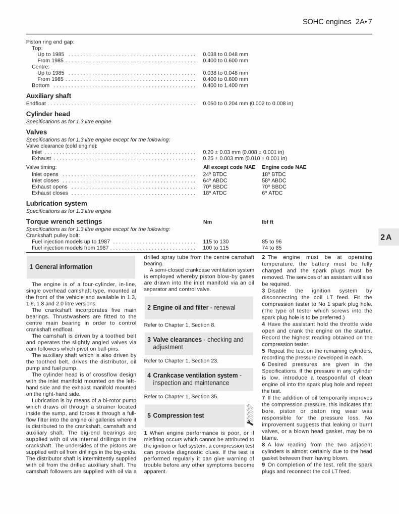
Piston ring end gap:Top:
Up to 1985 . . . . . . . . . . . . . . . . . . . . . . . . . . . . . . . . . . . . . . . . . . . 0.038 to 0.048 mmFrom 1985 . . . . . . . . . . . . . . . . . . . . . . . . . . . . . . . . . . . . . . . . . . . . 0.400 to 0.600 mm
Centre:Up to 1985 . . . . . . . . . . . . . . . . . . . . . . . . . . . . . . . . . . . . . . . . . . . 0.038 to 0.048 mmFrom 1985 . . . . . . . . . . . . . . . . . . . . . . . . . . . . . . . . . . . . . . . . . . . . 0.400 to 0.600 mm
Bottom . . . . . . . . . . . . . . . . . . . . . . . . . . . . . . . . . . . . . . . . . . . . . . . . 0.400 to 1.400 mm
Auxiliary shaftEndfloat . . . . . . . . . . . . . . . . . . . . . . . . . . . . . . . . . . . . . . . . . . . . . . . . . . 0.050 to 0.204 mm (0.002 to 0.008 in)
Cylinder headSpecifications as for 1.3 litre engine
Valves Specifications as for 1.3 litre engine except for the following:Valve clearance (cold engine):
Inlet . . . . . . . . . . . . . . . . . . . . . . . . . . . . . . . . . . . . . . . . . . . . . . . . . . . 0.20 ± 0.03 mm (0.008 ± 0.001 in)Exhaust . . . . . . . . . . . . . . . . . . . . . . . . . . . . . . . . . . . . . . . . . . . . . . . . 0.25 ± 0.003 mm (0.010 ± 0.001 in)
Valve timing: All except code NAE Engine code NAEInlet opens . . . . . . . . . . . . . . . . . . . . . . . . . . . . . . . . . . . . . . . . . . . . . 24º BTDC 18º BTDCInlet closes . . . . . . . . . . . . . . . . . . . . . . . . . . . . . . . . . . . . . . . . . . . . . 64º ABDC 58º ABDCExhaust opens . . . . . . . . . . . . . . . . . . . . . . . . . . . . . . . . . . . . . . . . . . 70º BBDC 70º BBDCExhaust closes . . . . . . . . . . . . . . . . . . . . . . . . . . . . . . . . . . . . . . . . . . 18º ATDC 6º ATDC
Lubrication systemSpecifications as for 1.3 litre engine
Torque wrench settings Nm lbf ftSpecifications as for 1.3 litre engine except for the following:Crankshaft pulley bolt:
Fuel injection models up to 1987 . . . . . . . . . . . . . . . . . . . . . . . . . . . . 115 to 130 85 to 96Fuel injection models from 1987 . . . . . . . . . . . . . . . . . . . . . . . . . . . . . 100 to 115 74 to 85
SOHC engines 2A•7
2A
The engine is of a four-cylinder, in-line,single overhead camshaft type, mounted atthe front of the vehicle and available in 1.3,1.6, 1.8 and 2.0 litre versions.
The crankshaft incorporates five mainbearings. Thrustwashers are fitted to thecentre main bearing in order to controlcrankshaft endfloat.
The camshaft is driven by a toothed beltand operates the slightly angled valves viacam followers which pivot on ball-pins.
The auxiliary shaft which is also driven bythe toothed belt, drives the distributor, oilpump and fuel pump.
The cylinder head is of crossflow designwith the inlet manifold mounted on the left-hand side and the exhaust manifold mountedon the right-hand side.
Lubrication is by means of a bi-rotor pumpwhich draws oil through a strainer locatedinside the sump, and forces it through a full-flow filter into the engine oil galleries where itis distributed to the crankshaft, camshaft andauxiliary shaft. The big-end bearings aresupplied with oil via internal drillings in thecrankshaft. The undersides of the pistons aresupplied with oil from drillings in the big-ends.The distributor shaft is intermittently suppliedwith oil from the drilled auxiliary shaft. Thecamshaft followers are supplied with oil via a
drilled spray tube from the centre camshaftbearing.
A semi-closed crankcase ventilation systemis employed whereby piston blow-by gasesare drawn into the inlet manifold via an oilseparator and control valve.
Refer to Chapter 1, Section 8.
Refer to Chapter 1, Section 23.
Refer to Chapter 1, Section 35.
1 When engine performance is poor, or ifmisfiring occurs which cannot be attributed tothe ignition or fuel system, a compression testcan provide diagnostic clues. If the test isperformed regularly it can give warning oftrouble before any other symptoms becomeapparent.
2 The engine must be at operatingtemperature, the battery must be fullycharged and the spark plugs must beremoved. The services of an assistant will alsobe required.3 Disable the ignition system bydisconnecting the coil LT feed. Fit thecompression tester to No 1 spark plug hole.(The type of tester which screws into thespark plug hole is to be preferred.)4 Have the assistant hold the throttle wideopen and crank the engine on the starter.Record the highest reading obtained on thecompression tester.5 Repeat the test on the remaining cylinders,recording the pressure developed in each.6 Desired pressures are given in theSpecifications. If the pressure in any cylinderis low, introduce a teaspoonful of cleanengine oil into the spark plug hole and repeatthe test.7 If the addition of oil temporarily improvesthe compression pressure, this indicates thatbore, piston or piston ring wear wasresponsible for the pressure loss. Noimprovement suggests that leaking or burntvalves, or a blown head gasket, may be toblame.8 A low reading from the two adjacentcylinders is almost certainly due to the headgasket between them having blown.9 On completion of the test, refit the sparkplugs and reconnect the coil LT feed.
5 Compression test
4 Crankcase ventilation system -inspection and maintenance
3 Valve clearances - checking andadjustment
2 Engine oil and filter - renewal
1 General information
The following operations can be carried outwithout removing the engine from the vehicle:a) Removal and servicing of the cylinder
headb) Removal of the camshaft after removal of
the cylinder headc) Removal of the timing belt and sprocketsd) Removal of the sumpe) Removal of the oil pumpf) Removal of the pistons and connecting
rodsg) Removal of the big-end bearingsh) Removal of the engine mountingsi) Removal of the clutch and flywheelj) Removal of crankshaft front and rear oil
sealsk) Removal of the auxiliary shaft
The following operations can only be carriedout after removing the engine from thevehicle:a) Removal of the crankshaft main bearingsb) Removal of the crankshaft
The engine may be lifted out either on itsown, or together with the manualgearbox/automatic transmission. Unless workis to be carried out on the manualgearbox/automatic transmission, it isrecommended that the engine is removed onits own. Where automatic transmission isfitted, the engine should where possible beremoved on its own due to the additionalweight of the transmission.
Note: The air conditioning system shouldalways be discharged by a Ford dealer or airconditioning specialist.Note: Refer to the warning in Section 8 beforeproceeding. A suitable hoist and lifting tacklewill be required for this operation.1 Disconnect the battery negative lead.2 Remove the bonnet.3 On carburettor models remove the air cleaner.4 On fuel injection models, disconnect thecrankcase ventilation hose from the air inlethose, then disconnect the air inlet hose fromthe throttle body. Depress the locking clip onthe airflow meter wiring plug and disconnectthe plug (pulling on the plug, not the wiring)then release the four securing clips and lift offthe air cleaner lid with the airflow meter andair inlet hose.5 Remove the four retaining clips andunscrew the two retaining screws, thenwithdraw the upper section of the cooling fanshroud from the radiator. Unclip and removethe lower section of the shroud.6 Remove the thermo-viscous cooling fan asdescribed in Chapter 3. 7 Drain the cooling system.8 Disconnect the upper radiator hose andwhere applicable, the expansion tank hosefrom the thermostat housing.9 Disconnect the coolant hoses from thecoolant pump, and where applicable from theinlet manifold and automatic choke. Unclipthe coolant hose from the bracket on theexhaust manifold hot air shroud/heat shield,or the camshaft cover, as applicable.10 On carburettor models, where applicabledisconnect the vacuum pipe from the enginemanagement module.11 Disconnect the brake servo vacuum pipefrom the inlet manifold.12 On carburettor models, disconnect the fuelhoses from the carburettor and whereapplicable the mechanical fuel pump and plugthe ends of the hoses to minimise petrolspillage. Remember to take adequate fireprecautions.13 On fuel injection models, disconnect thefuel feed line from the fuel pressure regulator,then disconnect the fuel supply hose from the
fuel rail. Position a suitable container beneaththe pressure regulator, then slowly loosen thefuel feed union to relieve the pressure in thefuel lines before disconnecting the union.Take adequate fire precautions. Plug the endsof the hoses to minimise petrol spillage.14 Disconnect the throttle cable, and whereapplicable remove its bracket.15 Disconnect the HT lead from the ignitioncoil.16 Disconnect the wiring from the followingcomponents as applicable depending onmodel:AlternatorStarter motorDistributorOil pressure warning lamp switchTemperature gauge senderEngine coolant temperature sensorAutomatic chokeAutomatic choke pull-down solenoidCarburettor anti-dieselling valveInlet manifold heaterCarburettor stepper motorFuel injection harnessDipstick
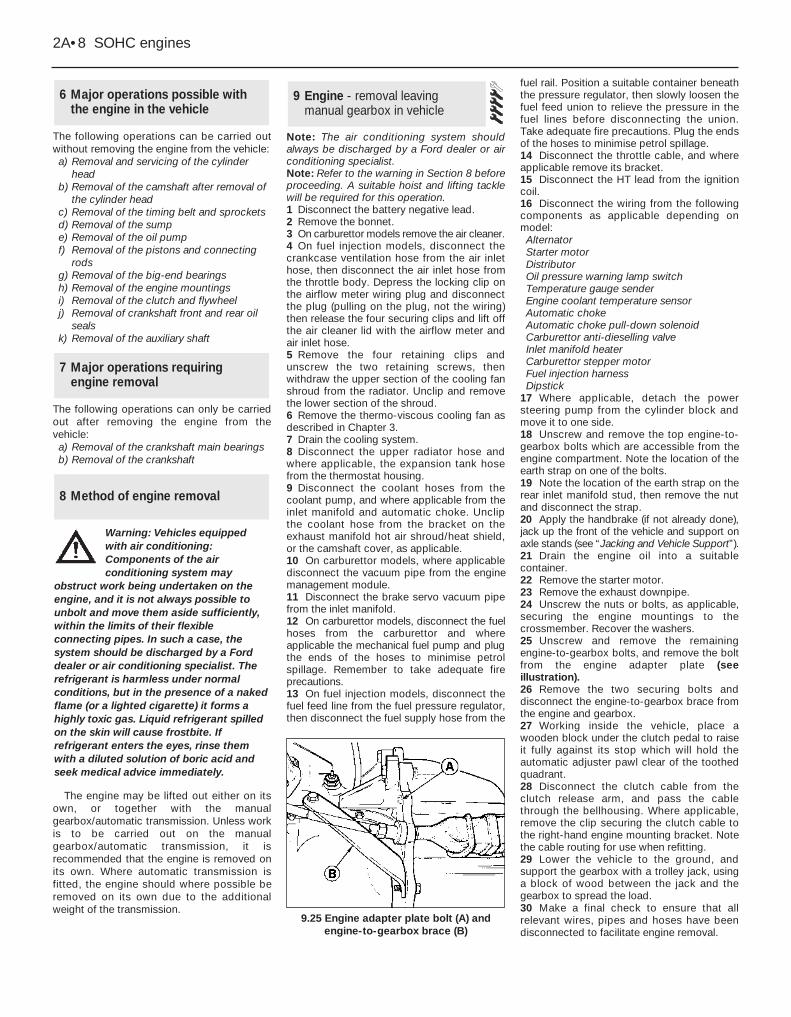
17 Where applicable, detach the powersteering pump from the cylinder block andmove it to one side.18 Unscrew and remove the top engine-to-gearbox bolts which are accessible from theengine compartment. Note the location of theearth strap on one of the bolts.19 Note the location of the earth strap on therear inlet manifold stud, then remove the nutand disconnect the strap.20 Apply the handbrake (if not already done),jack up the front of the vehicle and support onaxle stands (see “Jacking and Vehicle Support”).21 Drain the engine oil into a suitablecontainer.22 Remove the starter motor.23 Remove the exhaust downpipe.24 Unscrew the nuts or bolts, as applicable,securing the engine mountings to thecrossmember. Recover the washers.25 Unscrew and remove the remainingengine-to-gearbox bolts, and remove the boltfrom the engine adapter plate (seeillustration).26 Remove the two securing bolts anddisconnect the engine-to-gearbox brace fromthe engine and gearbox.27 Working inside the vehicle, place awooden block under the clutch pedal to raiseit fully against its stop which will hold theautomatic adjuster pawl clear of the toothedquadrant.28 Disconnect the clutch cable from theclutch release arm, and pass the cablethrough the bellhousing. Where applicable,remove the clip securing the clutch cable tothe right-hand engine mounting bracket. Notethe cable routing for use when refitting.29 Lower the vehicle to the ground, andsupport the gearbox with a trolley jack, usinga block of wood between the jack and thegearbox to spread the load.30 Make a final check to ensure that allrelevant wires, pipes and hoses have beendisconnected to facilitate engine removal.
9 Engine - removal leavingmanual gearbox in vehicle
8 Method of engine removal
7 Major operations requiringengine removal
6 Major operations possible withthe engine in the vehicle
2A•8 SOHC engines
9.25 Engine adapter plate bolt (A) andengine-to-gearbox brace (B)
Warning: Vehicles equippedwith air conditioning:Components of the airconditioning system may
obstruct work being undertaken on theengine, and it is not always possible tounbolt and move them aside sufficiently,within the limits of their flexibleconnecting pipes. In such a case, thesystem should be discharged by a Forddealer or air conditioning specialist. Therefrigerant is harmless under normalconditions, but in the presence of a nakedflame (or a lighted cigarette) it forms ahighly toxic gas. Liquid refrigerant spilledon the skin will cause frostbite. Ifrefrigerant enters the eyes, rinse themwith a diluted solution of boric acid andseek medical advice immediately.
31 Attach a suitable hoist to the engine liftingbrackets located at the front and rear of thecylinder head, and carefully take the weight ofthe engine. The engine should be supportedhorizontally, ie do not allow it to tilt front to rear.32 Raise the engine until the enginemountings are clear of the crossmember thenpull the engine forwards to disconnect it fromthe gearbox. Ensure that the gearbox isadequately supported, and take care not tostrain the gearbox input shaft. It may benecessary to rock the engine a little to releaseit from the gearbox.33 Once clear of the gearbox, lift the enginefrom the vehicle, taking care not to damagethe radiator fins.
Note: Refer to the warning in Section 8 beforeproceeding. A suitable hoist and lifting tacklewill be required for this operation.1 Proceed as described in Section 9,paragraphs 1 to 17 inclusive, but additionally,where applicable, disconnect the kickdowncable from the carburettor/inlet manifold. 2 Unscrew and remove the top engine-to-transmission bolts which are accessible fromthe engine compartment. Note the location ofthe earth strap, vacuum pipe bracket, andtransmission dipstick tube bracket.3 Proceed as described in Section 9,paragraphs 20 to 24 inclusive.4 Working through the starter motor aperture,unscrew the four torque converter-to-driveplate nuts. It will be necessary to turn thecrankshaft, using a suitable spanner on thecrankshaft pulley bolt, in order to gain accessto each nut in turn through the aperture.5 Unscrew and remove the remaining engine-to-transmission bolts, and remove the boltfrom the engine adapter plate. Whereapplicable pull the blanking plug from theadapter plate.6 Remove the two securing bolts anddisconnect the engine-to-transmission bracefrom the engine and transmission.7 Lower the vehicle to the ground, andsupport the transmission with a trolley jack,using a block of wood between the jack andthe transmission to spread the load.8 Proceed as described in Section 9,paragraphs 30 and 31.9 Raise the engine until the engine mountingsare clear of the crossmember, then pull theengine forwards to disconnect it from thetransmission. Ensure that the torque converteris held firmly in place in the transmissionhousing, otherwise it could fall out resulting influid spillage and possible damage. It may benecessary to rock the engine a little to releaseit from the transmission.10 Once clear of the transmission lift theengine from the vehicle, taking care not todamage the radiator fins.
Note: Refer to the warning in Section 8 beforeproceeding. A suitable hoist and lifting tacklewill be required for this operation.
Removal1 Proceed as described in Section 9,paragraphs 1 to 17 inclusive.2 Note the location of the earth strap on therear inlet manifold stud, then remove the nutand disconnect the strap.3 Working inside the vehicle, unscrew thegear lever knob and remove the centreconsole. Where a full length console is fitted,it is only necessary to remove the front tray.4 Detach the outer gaiter from the retainingframe and withdraw it over the gear lever.5 Unscrew the securing screws on earlymodels, or release the clips on later models,and remove the gaiter retaining frame andinner gaiter. 6 Using a suitable Torx key, remove thescrews securing the gear lever to the gearboxextension housing, and withdraw the gearlever. Note how the base of the gear leverlocates over the selector shaft.7 Jack up the vehicle and support on axlestands (see “Jacking and Vehicle Support”).Ensure that there is sufficient working roombeneath the vehicle.8 To improve access, disconnect the exhaustdownpipe from the manifold and remove theexhaust system.9 Remove the propeller shaft.10 Where applicable bend back the locktabs,then unscrew the two bolts in each casesecuring the two anti-roll bar U-clamps to thevehicle underbody. Lower the anti-roll bar asfar as possible.11 Proceed as described in Section 9,paragraphs 27 and 28. 12 Drain the engine oil into a container.13 Unscrew the nuts or bolts, as applicable,securing the engine mountings to thecrossmember. Recover the washers.14 Disconnect the wiring from the reversinglamp switch.15 Remove the retaining circlip, andwithdraw the speedometer cable from thegearbox extension housing.16 Support the gearbox with a trolley jack,using a block of wood between the jack andthe gearbox to spread the load.17 Unscrew the four bolts securing thegearbox crossmember to the vehicleunderbody. Unscrew the central bolt securingthe crossmember to the gearbox and removethe crossmember. Note the position of theearth strap, where applicable. Recover themounting cup and where applicable theexhaust mounting bracket and heat shield.18 Make a final check to ensure that allrelevant wires, pipes and hoses have beendisconnected to facilitate removal of the en-gine/gearbox assembly.
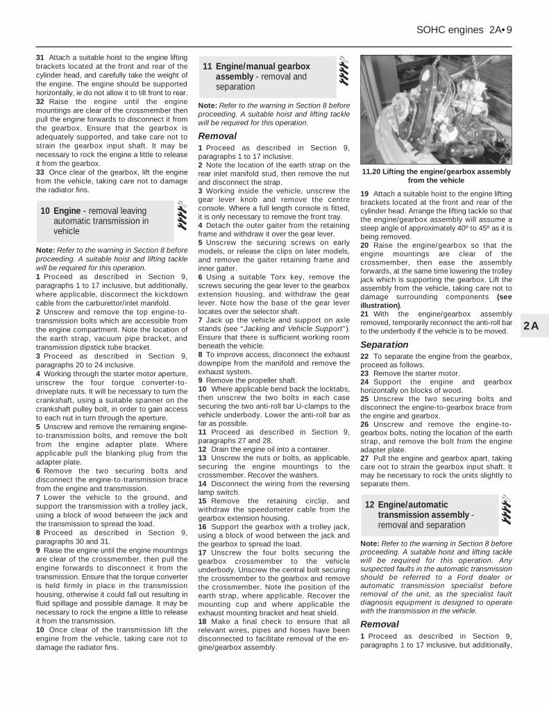
19 Attach a suitable hoist to the engine liftingbrackets located at the front and rear of thecylinder head. Arrange the lifting tackle so thatthe engine/gearbox assembly will assume asteep angle of approximately 40º to 45º as it isbeing removed.20 Raise the engine/gearbox so that theengine mountings are clear of thecrossmember, then ease the assemblyforwards, at the same time lowering the trolleyjack which is supporting the gearbox. Lift theassembly from the vehicle, taking care not todamage surrounding components (seeillustration).21 With the engine/gearbox assemblyremoved, temporarily reconnect the anti-roll barto the underbody if the vehicle is to be moved.
Separation22 To separate the engine from the gearbox,proceed as follows.23 Remove the starter motor.24 Support the engine and gearboxhorizontally on blocks of wood.25 Unscrew the two securing bolts anddisconnect the engine-to-gearbox brace fromthe engine and gearbox.26 Unscrew and remove the engine-to-gearbox bolts, noting the location of the earthstrap, and remove the bolt from the engineadapter plate.27 Pull the engine and gearbox apart, takingcare not to strain the gearbox input shaft. Itmay be necessary to rock the units slightly toseparate them.
Note: Refer to the warning in Section 8 beforeproceeding. A suitable hoist and lifting tacklewill be required for this operation. Anysuspected faults in the automatic transmissionshould be referred to a Ford dealer orautomatic transmission specialist beforeremoval of the unit, as the specialist faultdiagnosis equipment is designed to operatewith the transmission in the vehicle.
Removal1 Proceed as described in Section 9,paragraphs 1 to 17 inclusive, but additionally,
12 Engine/automatictransmission assembly -removal and separation
11 Engine/manual gearboxassembly - removal andseparation
10 Engine - removal leavingautomatic transmission invehicle
SOHC engines 2A•9
2A
11.20 Lifting the engine/gearbox assemblyfrom the vehicle
where applicable disconnect the kickdowncable from the carburettor/inlet manifold. 2 Note the location of the earth strap on therear inlet manifold stud, then remove the nutand disconnect the strap.3 Jack up the vehicle and support on axlestands (see “Jacking and Vehicle Support”).Ensure that there is sufficient working roombeneath the vehicle.4 To improve access, disconnect the exhaustdownpipe from the manifold and remove theexhaust system.5 Remove the propeller shaft.6 Where applicable bend back the locktabs,then unscrew the two bolts, in each casesecuring the two anti-roll bar U-clamps to thevehicle underbody. Lower the anti-roll bar asfar as possible.7 Unscrew the unions and disconnect thefluid cooler pipes from the transmission. Plugthe open ends of the pipes and thetransmission to prevent dirt ingress and fluidleakage. Remove the fluid cooler pipe bracketfrom the engine mounting bracket, and placeit to one side.8 Remove the two clips securing the selectorrod, and detach the selector rod from themanual selector lever, and the selector leveron the transmission.9 Disconnect the kickdown cable from thelever on the transmission, and whereapplicable, detach the cable from the bracketon the transmission. On C3 type transmissionsit will be necessary to unscrew the locknut inorder to remove the cable from the bracket.Withdraw the cable from the vehicle.10 Disconnect the wiring from the starterinhibitor/reversing lamp switch and whereapplicable, on A4LD type transmissions, thekickdown solenoid and the lock-up clutch.11 Remove the securing screw, anddisconnect the speedometer cable from thetransmission extension housing. Plug theopening in the transmission to prevent dirtingress.12 Disconnect the vacuum pipe from thevacuum diaphragm unit, and unclip the pipefrom its securing bracket on the transmissionhousing where applicable.13 Drain the engine oil into a suitablecontainer.14 Unscrew the nuts or bolts, as applicable,securing the engine mountings to thecrossmember. Recover the washers.15 Support the transmission with a trolleyjack, using a block of wood to spread the load.16 Unscrew the four bolts securing thetransmission crossmember to the vehicleunderbody. Note the position of the earthstrap, where applicable. Unscrew the centralbolt securing the crossmember to thetransmission and remove the crossmember.Recover the mounting cup and whereapplicable the exhaust mounting bracket.17 Make a final check to ensure that allrelevant wires, pipes and hoses have beendisconnected to facilitate removal of theengine/transmission assembly.
18 Attach a suitable hoist to the engine liftingbrackets located at the front and rear of thecylinder head. Arrange the lifting tackle so thatthe engine/transmission assembly will assumea steep angle of approximately 40º to 45º as itis being removed.19 Raise the engine/transmission so that theengine mountings are clear of thecrossmember, then ease the assemblyforwards, at the same time lowering the trolleyjack which is supporting the transmission. Liftthe assembly from the vehicle, taking care notto damage surrounding components.20 With the engine/transmission assemblyremoved, temporarily reconnect the anti-rollbar to the underbody if the vehicle is to bemoved.
Separation21 To separate the engine from thetransmission, proceed as follows. 22 Remove the starter motor.23 Support the engine and transmissionhorizontally on blocks of wood.24 Working through the starter motoraperture, unscrew the four torque converter-to-driveplate nuts. It will be necessary to turnthe crankshaft using a suitable spanner on thecrankshaft pulley bolt in order to gain accessto each nut in turn through the aperture.25 Unscrew the two securing bolts anddisconnect the engine-to-transmission bracefrom the engine and transmission.26 Unscrew and remove the engine-to-transmission bolts, noting the locations of theearth strap, vacuum pipe bracket, andtransmission dipstick tube bracket. Removethe bolt from the engine adapter plate, andwhere applicable pull the blanking plug fromthe adapter plate.27 Pull the engine and transmission apart,ensuring that the torque converter is heldfirmly in place in the transmission housing,otherwise it could fall out resulting in fluidspillage and possible damage. It may benecessary to rock the units slightly toseparate them.
1 Reverse the procedure described in Section9, noting the following points:2 Before attempting to refit the engine, checkthat the clutch friction disc is centralised. Thisis necessary to ensure that the gearbox inputshaft splines will pass through the splines inthe centre of the friction disc.3 Check that the clutch release arm andbearing are correctly fitted and lightly greasethe input shaft splines.4 Check that the engine adapter plate iscorrectly positioned on its locating dowels.5 Refit the exhaust downpipe.6 Reconnect the clutch cable to the releasearm, ensuring that it is routed as noted duringremoval.
7 Fill the engine with the correct grade andquantity of oil.8 Fill the cooling system.9 Check and if necessary adjust the tensionof the alternator and where applicable thepower steering pump drivebelt(s).10 Adjust the throttle cable.
1 Reverse the procedure described in Section10, noting the following points:2 Check that the engine adapter plate iscorrectly positioned on its locating dowels.3 As the torque converter is only looselyengaged in the transmission, care must betaken to prevent the torque converter fromfalling out forwards. When the torqueconverter hub is fully engaged with the fluidpump drivegear in the transmission, distance“A” in illustration 2.24 of Chapter 7B must beas specified. Incorrect installation of thetorque converter will result in damage to thetransmission.4 As the engine is installed, guide the torqueconverter studs through the holes in thedriveplate, noting that on the C3 typetransmission, the torque converter fluid drainplug must line up with the opening in thedriveplate (see illustration 2.25 in Chapter 7B).When the engine is positioned flush with theengine adapter plate and the transmissionhousing, check that the torque converter isfree to move axially a small amount beforerefitting and tightening the engine-to-transmission bolts.5 Do not tighten the torque converter-to-driveplate nuts until the lower engine-to-transmission bolts have been fitted andtightened.6 Refit the exhaust downpipe.7 Fill the engine with the correct grade andquantity of oil. 8 Fill the cooling system.9 Check and if necessary adjust the tensionof the alternator and where applicable thepower steering pump drivebelt(s).10 Adjust the throttle cable.11 Where applicable, adjust the kickdowncable.
1 Reverse the procedure described in Section11, noting the following points.2 Before attempting to reconnect the engineto the gearbox, check that the clutch frictiondisc is centralised. This is to ensure that thegearbox input shaft splines will pass throughthe splines in the centre of the friction disc.3 Check that the clutch release arm andbearing are correctly fitted, and lightly greasethe input shaft splines.
15 Engine/manual gearboxassembly - reconnection andrefitting
14 Engine - refitting (automatictransmission in vehicle)
13 Engine - refitting (manualgearbox in vehicle)
2A•10 SOHC engines
4 Check that the engine adapter plate iscorrectly positioned on its locating dowels.5 Refit the propeller shaft.6 Refit the exhaust system.7 Reconnect the clutch cable to the releasearm, ensuring that it is routed as noted duringremoval. 8 Fill the engine with the correct grade andquantity of oil.9 Fill the cooling system.10 Check and if necessary top-up thegearbox oil level.11 Check and if necessary adjust the tensionof the alternator and where applicable thepower steering pump drivebelt(s).12 Adjust the throttle cable.
1 Reverse the removal procedure describedin Section 12, noting the following points.2 Check that the engine adapter plate iscorrectly positioned on its locating dowels.3 As the torque converter is only looselyengaged in the transmission, care must betaken to prevent the torque converter fromfalling out forwards. When the torqueconverter hub is fully engaged with the fluidpump drivegear in the transmission, distance“A” in illustration 2.24 of Chapter 7B must beas shown. Incorrect installation of the torqueconverter will result in damage to thetransmission.4 As the engine and transmission arereconnected, guide the torque converter studsthrough the holes in the driveplate, noting thaton the C3 type transmission, the torqueconverter fluid drain plug must line up with theopening in the driveplate (see illustration 2.25in Chapter 7B). When the engine is positionedflush with the engine adapter plate and thetransmission housing, check that the torqueconverter is free to move axially a smallamount before refitting and tightening theengine-to-transmission bolts.5 Do not tighten the torque converter-to-driveplate nuts until the lower engine-to-transmission bolts have been fitted andtightened.6 Reconnect and adjust the selector rod.7 Refit the propeller shaft.
8 Refit the exhaust system.9 Fill the engine with the correct grade andquantity of oil. 10 Fill the cooling system.11 Check and if necessary top-up thetransmission fluid level.12 Check and if necessary adjust the tensionof the alternator and where applicable thepower steering pump drivebelt(s).13 Adjust the throttle cable.14 If applicable, adjust the kickdown cable.
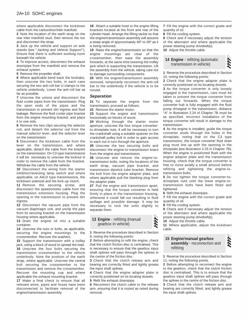
1 The engine mountings incorporatehydraulic dampers and must be renewed ifexcessive engine movement is evident.2 Working in the engine compartment,unscrew the central nuts securing the enginemounting brackets to the tops of themountings. Recover the washers whereapplicable.3 Remove the two bolts or the central nut andwasher (as applicable) in each case securingthe mountings to the crossmember.4 Raise the engine using a hoist and liftingtackle attached to the engine lifting brackets onthe cylinder head, or a jack with an interposedblock of wood under the sump, until themountings can be withdrawn (see illustration).5 Fit the new mountings, then lower theengine onto them.6 Fit the bolts or the nuts and washers (asapplicable) securing the mountings to thecrossmember, and tighten them.7 Fit and tighten the central nuts, and washersif applicable, securing the engine mountingbrackets to the tops of the mountings.
Dismantling1 It is best to mount the engine on adismantling stand but if this is not available,stand the engine on a strong bench at acomfortable working height. Failing this, it willhave to be stripped down on the floor.2 Cleanliness is most important, and if the
engine is dirty, it should be cleaned withparaffin while keeping it in an upright position.3 Avoid working with the engine directly on aconcrete floor, as grit presents a real sourceof trouble.4 As parts are removed, clean them in aparaffin bath. However, do not immerse partswith internal oilways in paraffin as it is difficultto remove, usually requiring a high pressurehose. Clean oilways with nylon pipe cleaners.5 It is advisable to have suitable containersavailable to hold small items according totheir use, as this will help when reassemblingthe engine and also prevent possible losses.6 Always obtain a complete set of newgaskets for use during engine reassembly, butretain the old gaskets with a view to usingthem as a pattern to make a replacement if anew one is not available.7 Where possible, refit securing nuts, bolts andwashers to their locations after removing therelevant components. This will help to protectthe threads and will also prevent losses.8 Retain unserviceable components in orderto compare them with the new parts supplied.9 Suitable splined sockets will be required forremoval of the oil pump bolts, the timing belttensioner bolts on early models (up to mid-1985), and the cylinder head bolts on earlymodels (up to early 1984) and a size T55 Torxsocket will be required to remove the cylinderhead bolts on later models (from early 1984).10 Before dismantling the main enginecomponents the following externally mountedancillary components can be removed, withreference to the relevant Chapters of thisManual and the relevant Sections of thisChapter, where applicable:Inlet manifold (and carburettor, where
applicable Exhaust manifoldFuel pump and operating pushrod (where
applicable)AlternatorDistributor, HT leads and spark plug Coolant pump, thermostat and housingTemperature gauge sender and oil pressure
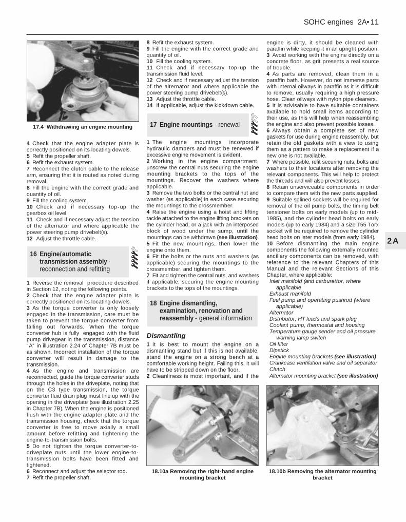
warning lamp switchOil filterDipstickEngine mounting brackets (see illustration)Crankcase ventilation valve and oil separatorClutchAlternator mounting bracket (see illustration)
18 Engine dismantling,examination, renovation andreassembly - general information
17 Engine mountings - renewal
16 Engine/automatictransmission assembly -reconnection and refitting
SOHC engines 2A•11
2A
18.10b Removing the alternator mountingbracket
18.10a Removing the right-hand enginemounting bracket
17.4 Withdrawing an engine mounting
Examination and renovation11 With the engine completely stripped,clean all the components and examine themfor wear. Each part should be checked, andwhere necessary renewed or renovated asdescribed in the relevant Sections. Renewmain and big end shell bearings as a matter ofcourse, unless it is known that they have hadlittle wear and are in perfect condition.12 If in doubt as to whether to renew acomponent which is still just serviceable,consider the time and effort which will beincurred should it fail at an early date.Obviously the age and expected life of thevehicle must influence the standards applied.13 Gaskets, oil seals and O-rings must all berenewed as a matter of routine. Flywheel andTorx type cylinder head bolts must berenewed because of the high stresses towhich they are subjected.14 Take the opportunity to renew the enginecore plugs while they are easily accessible.Knock out the old plugs with a hammer andchisel or punch. Clean the plug seats, smearthe new plugs with sealant and tap themsquarely into position.
Reassembly15 To ensure maximum life with minimumtrouble from a rebuilt engine, not only musteverything be correctly assembled, but it mustalso be spotlessly clean. All oilways must beclear, and locking washers and springwashers must be fitted where indicated. Oil allbearings and other working surfacesthoroughly with clean engine oil duringassembly.16 Before assembly begins, renew any boltsor studs with damaged threads.17 Gather together a torque wrench, oil can,clean rag, and a set of engine gaskets and oilseals, together with a new oil filter.18 If they have been removed, new Torx typecylinder head bolts and new flywheel bolts willbe required.19 After reassembling the main enginecomponents, refit the ancillary componentslisted, referring to the appropriate Chapterswhere necessary. Delicate items such as thealternator and distributor may be left until afterthe engine has been refitted if preferred.
20 If the crankcase ventilation oil separatorwas removed, apply a liquid sealing agent toits tube before pressing it into the cylinderblock.
Note: Refer to the warning in Section 8 beforeproceeding. On models from mid-1985(without a timing belt tensioner spring) the belttension should be checked using Ford specialtool No 21-113 after refitting. On models up tomid-1985 (with a tensioner spring), a suitablesplined socket will be required for thetensioner spring bolt. A suitable puller may berequired to remove the sprockets.
Removal1 If the engine is in the vehicle, carry out thefollowing operations:a) Disconnect the battery negative leadb) Remove the thermo-viscous cooling fanc) Remove the coolant
pump/alternator/power-steering pumpdrivebelt(s)
d) For improved access, remove the radiatorand disconnect the radiator top hose fromthe thermostat housing
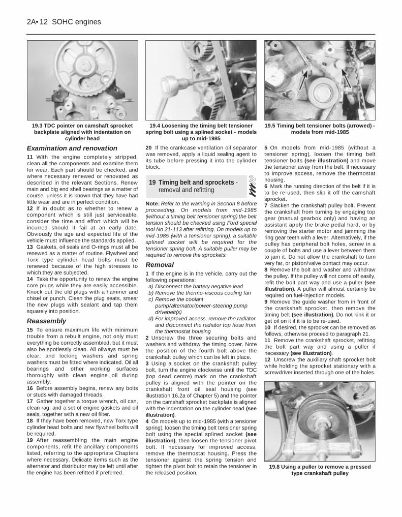
2 Unscrew the three securing bolts andwashers and withdraw the timing cover. Notethe position of the fourth bolt above thecrankshaft pulley which can be left in place.3 Using a socket on the crankshaft pulleybolt, turn the engine clockwise until the TDC(top dead centre) mark on the crankshaftpulley is aligned with the pointer on thecrankshaft front oil seal housing (seeillustration 16.2a of Chapter 5) and the pointeron the camshaft sprocket backplate is alignedwith the indentation on the cylinder head (seeillustration).4 On models up to mid-1985 (with a tensionerspring), loosen the timing belt tensioner springbolt using the special splined socket (seeillustration), then loosen the tensioner pivotbolt. If necessary for improved access,remove the thermostat housing. Press thetensioner against the spring tension andtighten the pivot bolt to retain the tensioner inthe released position.
5 On models from mid-1985 (without atensioner spring), loosen the timing belttensioner bolts (see illustration) and movethe tensioner away from the belt. If necessaryto improve access, remove the thermostathousing.6 Mark the running direction of the belt if it isto be re-used, then slip it off the camshaftsprocket.7 Slacken the crankshaft pulley bolt. Preventthe crankshaft from turning by engaging topgear (manual gearbox only) and having anassistant apply the brake pedal hard, or byremoving the starter motor and jamming thering gear teeth with a lever. Alternatively, if thepulley has peripheral bolt holes, screw in acouple of bolts and use a lever between themto jam it. Do not allow the crankshaft to turnvery far, or piston/valve contact may occur.8 Remove the bolt and washer and withdrawthe pulley. If the pulley will not come off easily,refit the bolt part way and use a puller (seeillustration). A puller will almost certainly berequired on fuel-injection models.9 Remove the guide washer from in front ofthe crankshaft sprocket, then remove thetiming belt (see illustration). Do not kink it orget oil on it if it is to be re-used.10 If desired, the sprocket can be removed asfollows, otherwise proceed to paragraph 21.11 Remove the crankshaft sprocket, refittingthe bolt part way and using a puller ifnecessary (see illustration).12 Unscrew the auxiliary shaft sprocket boltwhile holding the sprocket stationary with ascrewdriver inserted through one of the holes.
19 Timing belt and sprockets -removal and refitting
2A•12 SOHC engines
19.3 TDC pointer on camshaft sprocketbackplate aligned with indentation on
cylinder head
19.5 Timing belt tensioner bolts (arrowed) -models from mid-1985
19.8 Using a puller to remove a pressedtype crankshaft pulley
19.4 Loosening the timing belt tensionerspring bolt using a splined socket - models
up to mid-1985
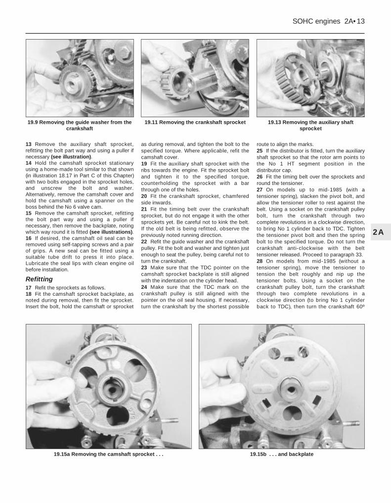
13 Remove the auxiliary shaft sprocket,refitting the bolt part way and using a puller ifnecessary (see illustration).14 Hold the camshaft sprocket stationaryusing a home-made tool similar to that shown(in illustration 18.17 in Part C of this Chapter)with two bolts engaged in the sprocket holes,and unscrew the bolt and washer.Alternatively, remove the camshaft cover andhold the camshaft using a spanner on theboss behind the No 6 valve cam.15 Remove the camshaft sprocket, refittingthe bolt part way and using a puller ifnecessary, then remove the backplate, notingwhich way round it is fitted (see illustrations).16 If desired, the camshaft oil seal can beremoved using self-tapping screws and a pairof grips. A new seal can be fitted using asuitable tube drift to press it into place.Lubricate the seal lips with clean engine oilbefore installation.
Refitting17 Refit the sprockets as follows.18 Fit the camshaft sprocket backplate, asnoted during removal, then fit the sprocket.Insert the bolt, hold the camshaft or sprocket
as during removal, and tighten the bolt to thespecified torque. Where applicable, refit thecamshaft cover.19 Fit the auxiliary shaft sprocket with theribs towards the engine. Fit the sprocket boltand tighten it to the specified torque,counterholding the sprocket with a barthrough one of the holes.20 Fit the crankshaft sprocket, chamferedside inwards.21 Fit the timing belt over the crankshaftsprocket, but do not engage it with the othersprockets yet. Be careful not to kink the belt.If the old belt is being refitted, observe thepreviously noted running direction.22 Refit the guide washer and the crankshaftpulley. Fit the bolt and washer and tighten justenough to seat the pulley, being careful not toturn the crankshaft.23 Make sure that the TDC pointer on thecamshaft sprocket backplate is still alignedwith the indentation on the cylinder head.24 Make sure that the TDC mark on thecrankshaft pulley is still aligned with thepointer on the oil seal housing. If necessary,turn the crankshaft by the shortest possible
route to align the marks.25 If the distributor is fitted, turn the auxiliaryshaft sprocket so that the rotor arm points tothe No 1 HT segment position in thedistributor cap.26 Fit the timing belt over the sprockets andround the tensioner.27 On models up to mid-1985 (with atensioner spring), slacken the pivot bolt, andallow the tensioner roller to rest against thebelt. Using a socket on the crankshaft pulleybolt, turn the crankshaft through twocomplete revolutions in a clockwise direction,to bring No 1 cylinder back to TDC. Tightenthe tensioner pivot bolt and then the springbolt to the specified torque. Do not turn thecrankshaft anti-clockwise with the belttensioner released. Proceed to paragraph 33.28 On models from mid-1985 (without atensioner spring), move the tensioner totension the belt roughly and nip up thetensioner bolts. Using a socket on thecrankshaft pulley bolt, turn the crankshaftthrough two complete revolutions in aclockwise direction (to bring No 1 cylinderback to TDC), then turn the crankshaft 60º
SOHC engines 2A•13
2A
19.13 Removing the auxiliary shaftsprocket
19.15b . . . and backplate19.15a Removing the camshaft sprocket . . .
19.11 Removing the crankshaft sprocket19.9 Removing the guide washer from thecrankshaft
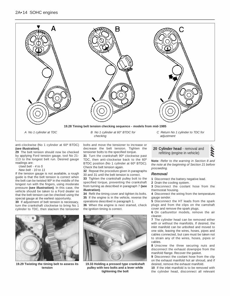
anti-clockwise (No 1 cylinder at 60º BTDC)(see illustration).29 The belt tension should now be checkedby applying Ford tension gauge, tool No 21-113 to the longest belt run. Desired gaugereadings are:
Used belt - 4 to 5New belt - 10 to 11
If the tension gauge is not available, a roughguide is that the belt tension is correct whenthe belt can be twisted 90º in the middle of thelongest run with the fingers, using moderatepressure (see illustration). In this case, thevehicle should be taken to a Ford dealer sothat the belt tension can be checked using thespecial gauge at the earliest opportunity.30 If adjustment of belt tension is necessary,turn the crankshaft clockwise to bring No 1cylinder to TDC, then slacken the tensioner
bolts and move the tensioner to increase ordecrease the belt tension. Tighten thetensioner bolts to the specified torque.31 Turn the crankshaft 90º clockwise pastTDC, then anti-clockwise back to the 60ºBTDC position (No 1 cylinder at 60º BTDC).Check the belt tension again.32 Repeat the procedure given in paragraphs30 and 31 until the belt tension is correct.33 Tighten the crankshaft pulley bolt to thespecified torque, preventing the crankshaftfrom turning as described in paragraph 7 (seeillustration).34 Refit the timing cover and tighten its bolts.35 If the engine is in the vehicle, reverse theoperations described in paragraph 1.36 When the engine is next started, checkthe ignition timing is correct.
Note: Refer to the warning in Section 8 andthe note at the beginning of Section 21 beforeproceeding.
Removal1 Disconnect the battery negative lead. 2 Drain the cooling system. 3 Disconnect the coolant hose from thethermostat housing. 4 Disconnect the wiring from the temperaturegauge sender. 5 Disconnect the HT leads from the sparkplugs and from the clips on the camshaftcover and remove the spark plugs.6 On carburettor models, remove the aircleaner.7 The cylinder head can be removed eitherwith or without the manifolds. If desired, theinlet manifold can be unbolted and moved toone side, leaving the wires, hoses, pipes andcables connected, but care must be taken notto strain any of the wires, hoses, pipes orcables.8 Unscrew the three securing nuts anddisconnect the exhaust downpipe from themanifold flange. Recover the gasket.9 Disconnect the coolant hose from the clipon the exhaust manifold hot air shroud, and ifdesired, remove the exhaust manifold.10 If the inlet manifold is to be removed withthe cylinder head, disconnect all relevant
20 Cylinder head - removal andrefitting (engine in vehicle)
2A•14 SOHC engines
19.33 Holding a pressed type crankshaftpulley with two bolts and a lever while
tightening the bolt
19.29 Twisting the timing belt to assess itstension
19.28 Timing belt tension checking sequence - models from mid-1985
A No 1 cylinder at TDC B No 1 cylinder at 60° BTDC forchecking
C Return No 1 cylinder to TDC foradjustment
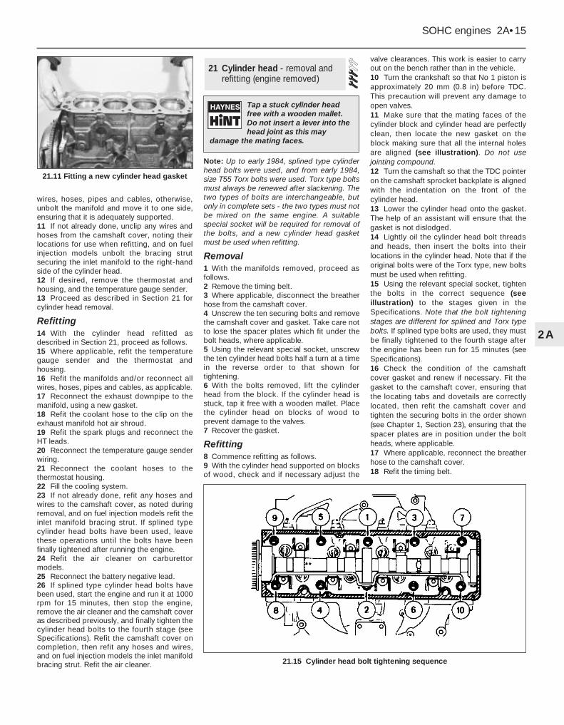
wires, hoses, pipes and cables, otherwise,unbolt the manifold and move it to one side,ensuring that it is adequately supported. 11 If not already done, unclip any wires andhoses from the camshaft cover, noting theirlocations for use when refitting, and on fuelinjection models unbolt the bracing strutsecuring the inlet manifold to the right-handside of the cylinder head.12 If desired, remove the thermostat andhousing, and the temperature gauge sender.13 Proceed as described in Section 21 forcylinder head removal.
Refitting14 With the cylinder head refitted asdescribed in Section 21, proceed as follows.15 Where applicable, refit the temperaturegauge sender and the thermostat andhousing.16 Refit the manifolds and/or reconnect allwires, hoses, pipes and cables, as applicable.17 Reconnect the exhaust downpipe to themanifold, using a new gasket.18 Refit the coolant hose to the clip on theexhaust manifold hot air shroud.19 Refit the spark plugs and reconnect theHT leads. 20 Reconnect the temperature gauge senderwiring. 21 Reconnect the coolant hoses to thethermostat housing.22 Fill the cooling system.23 If not already done, refit any hoses andwires to the camshaft cover, as noted duringremoval, and on fuel injection models refit theinlet manifold bracing strut. If splined typecylinder head bolts have been used, leavethese operations until the bolts have beenfinally tightened after running the engine.24 Refit the air cleaner on carburettormodels. 25 Reconnect the battery negative lead.26 If splined type cylinder head bolts havebeen used, start the engine and run it at 1000rpm for 15 minutes, then stop the engine,remove the air cleaner and the camshaft coveras described previously, and finally tighten thecylinder head bolts to the fourth stage (seeSpecifications). Refit the camshaft cover oncompletion, then refit any hoses and wires,and on fuel injection models the inlet manifoldbracing strut. Refit the air cleaner.
Note: Up to early 1984, splined type cylinderhead bolts were used, and from early 1984,size T55 Torx bolts were used. Torx type boltsmust always be renewed after slackening. Thetwo types of bolts are interchangeable, butonly in complete sets - the two types must notbe mixed on the same engine. A suitablespecial socket will be required for removal ofthe bolts, and a new cylinder head gasketmust be used when refitting.
Removal1 With the manifolds removed, proceed asfollows.2 Remove the timing belt.3 Where applicable, disconnect the breatherhose from the camshaft cover.4 Unscrew the ten securing bolts and removethe camshaft cover and gasket. Take care notto lose the spacer plates which fit under thebolt heads, where applicable.5 Using the relevant special socket, unscrewthe ten cylinder head bolts half a turn at a timein the reverse order to that shown fortightening. 6 With the bolts removed, lift the cylinderhead from the block. If the cylinder head isstuck, tap it free with a wooden mallet. Placethe cylinder head on blocks of wood toprevent damage to the valves.7 Recover the gasket.
Refitting8 Commence refitting as follows.9 With the cylinder head supported on blocksof wood, check and if necessary adjust the
valve clearances. This work is easier to carryout on the bench rather than in the vehicle.10 Turn the crankshaft so that No 1 piston isapproximately 20 mm (0.8 in) before TDC.This precaution will prevent any damage toopen valves.11 Make sure that the mating faces of thecylinder block and cylinder head are perfectlyclean, then locate the new gasket on theblock making sure that all the internal holesare aligned (see illustration). Do not usejointing compound.12 Turn the camshaft so that the TDC pointeron the camshaft sprocket backplate is alignedwith the indentation on the front of thecylinder head.13 Lower the cylinder head onto the gasket.The help of an assistant will ensure that thegasket is not dislodged.14 Lightly oil the cylinder head bolt threadsand heads, then insert the bolts into theirlocations in the cylinder head. Note that if theoriginal bolts were of the Torx type, new boltsmust be used when refitting.15 Using the relevant special socket, tightenthe bolts in the correct sequence (seeillustration) to the stages given in theSpecifications. Note that the bolt tighteningstages are different for splined and Torx typebolts. If splined type bolts are used, they mustbe finally tightened to the fourth stage afterthe engine has been run for 15 minutes (seeSpecifications). 16 Check the condition of the camshaftcover gasket and renew if necessary. Fit thegasket to the camshaft cover, ensuring thatthe locating tabs and dovetails are correctlylocated, then refit the camshaft cover andtighten the securing bolts in the order shown(see Chapter 1, Section 23), ensuring that thespacer plates are in position under the boltheads, where applicable.17 Where applicable, reconnect the breatherhose to the camshaft cover.18 Refit the timing belt.
21 Cylinder head - removal andrefitting (engine removed)
SOHC engines 2A•15
2A
21.15 Cylinder head bolt tightening sequence
21.11 Fitting a new cylinder head gasket
Tap a stuck cylinder headfree with a wooden mallet.Do not insert a lever into thehead joint as this may
damage the mating faces.

Note: A valve spring compressor will berequired during this procedure. New valvestem oil seals should be used on reassembly.
Dismantling1 With the cylinder head removed, removethe camshaft.2 Using a valve spring compressor, compressone of the valve springs until the split colletscan be removed from the groove in the valvestem. Release the compressor and removethe cap and spring, identifying them forlocation. If the cap is difficult to release, donot continue to tighten the compressor, butgently tap the top of the tool with a hammer.Always make sure that the compressor isfirmly located on the valve head and the cap.Withdraw the valve (see illustrations).3 Repeat the procedure given in paragraph 2for the remaining valves, keeping allcomponents identified for location so thatthey can be refitted in their original positions.4 Prise the valve stem oil seals from the topsof the valve guides (see illustration).5 Unscrew the cam follower ball-pins fromthe cylinder head, keeping them identified forlocation.
Reassembly6 Commence reassembly by refitting the camfollower ball-pins to their original locations,where applicable.7 Lubricate the valve stems and guides withSAE 80/90 hypoid oil, then insert the valvesinto their original guides.8 Wrap a thin layer of adhesive tape over thecollet groove of each valve, then smear thenew oil seals with a little SAE 80/90 hypoid oiland slide them down the valve stems onto theguides. If necessary use a suitable metal tubeto press the oil seals into the guides. Removethe adhesive tape.9 Working on each valve in turn, fit the valvespring and cap, then compress the springusing the valve spring compressor and fit thesplit collets to the groove in the valve stem.Release the compressor and tap the end ofthe valve stem with a soft-faced mallet to
settle the components. If the originalcomponents are being refitted, ensure thatthey are refitted in their original locations.10 Refit the camshaft.
Note: On engines fitted with hardened valveseats for use with unleaded petrol, valve andvalve seat grinding and recutting cannot becarried out without the use of specialistequipment. Consult a Ford dealer for furtheradvice.1 This operation will normally only berequired at comparatively high mileages.However, if persistent pre-ignition (“pinking”)occurs and performance has deterioratedeven though the engine adjustments arecorrect, de-carbonizing and valve grindingmay be required.2 With the cylinder head removed, use ascraper to remove the carbon from thecombustion chambers and ports. Remove alltraces of gasket from the cylinder headsurface, then wash it thoroughly with paraffin.3 Use a straight edge and feeler blade tocheck that the cylinder head surface is notdistorted. If it is, it must be resurfaced by asuitably equipped engineering works.4 If the engine is still in the vehicle, clean thepiston crowns and cylinder bore upper edges,but make sure that no carbon drops betweenthe pistons and bores. To do this, locate twoof the pistons at the top of their bores andseal off the remaining bores with paper and
masking tape. Press a little grease betweenthe two pistons and their bores to collect anycarbon dust; this can be wiped away whenthe piston is lowered. To prevent carbonbuild-up, polish the piston crown with metalpolish, but remove all traces of the polishafterwards.5 Examine the heads of the valves for pittingand burning, especially the exhaust valveheads. Renew any valve which is badly burnt.Examine the valve seats at the same time. Ifthe pitting is very slight, it can be removed bygrinding the valve heads and seats togetherwith coarse, then fine, grinding paste.6 Where excessive pitting has occurred, thevalve seats must be recut or renewed by asuitably equipped engineering works.7 Valve grinding is carried out as follows.Place the cylinder head upside down on abench on blocks of wood.8 Smear a trace of coarse carborundumpaste on the valve seat face and press asuction grinding tool onto the valve head.With a semi-rotary action, grind the valvehead to its seat, lifting the valve occasionallyto redistribute the grinding paste. When a dullmatt even surface is produced on the matingsurface of both the valve seat and the valve,wipe off the paste and repeat the process withfine carborundum paste as before. A lightspring placed under the valve head will greatlyease this operation. When a smooth unbrokenring of light grey matt finish is produced onthe mating surface of both the valve and seat,the grinding operation is complete.9 Scrape away all carbon from the valve headand stem, and clean away all traces ofgrinding compound. Clean the valves andseats with a paraffin soaked rag, then wipewith a clean rag.10 If the guides are worn they will needreboring for oversize valves or for fitting guideinserts. The valve seats will also needrecutting to ensure that they are concentricwith the stems. This work should be entrustedto a Ford dealer or local engineering works.11 Check that the free length of the valvesprings is as specified, and renew ifnecessary. Do not renew individual springs; ifany springs are excessively worn, renew allthe springs as a set.
23 Cylinder head - inspectionand renovation
22 Cylinder head - dismantlingand reassembly
2A•16 SOHC engines
22.2a Compressing a valve spring 22.2c Removing a valve
22.4 Removing a valve stem oil seal
22.2b Removing a valve spring and cap
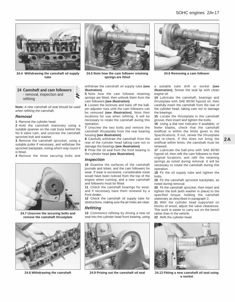
Note: A new camshaft oil seal should be usedwhen refitting the camshaft.
Removal1 Remove the cylinder head.2 Hold the camshaft stationary using asuitable spanner on the cast boss behind theNo 6 valve cam, and unscrew the camshaftsprocket bolt and washer.3 Remove the camshaft sprocket, using asuitable puller if necessary, and withdraw thesprocket backplate, noting which way round itis fitted.4 Remove the three securing bolts and
withdraw the camshaft oil supply tube (seeillustration).5 Note how the cam follower retainingsprings are fitted, then unhook them from thecam followers (see illustration).6 Loosen the locknuts and back off the ball-pin adjuster nuts until the cam followers canbe removed (see illustration). Note theirlocations for use when refitting. It will benecessary to rotate the camshaft during thisoperation.7 Unscrew the two bolts and remove thecamshaft thrustplate from the rear bearinghousing (see illustration).8 Carefully withdraw the camshaft from therear of the cylinder head taking care not todamage the bearings (see illustration).9 Prise the oil seal from the front bearing inthe cylinder head (see illustration).
Inspection10 Examine the surfaces of the camshaftjournals and lobes, and the cam followers forwear. If wear is excessive, considerable noisewould have been noticed from the top of theengine when running, and a new camshaftand followers must be fitted.11 Check the camshaft bearings for wear,and if necessary have them renewed by aFord dealer.12 Check the camshaft oil supply tube forobstructions, making sure the jet holes are clear.
Refitting13 Commence refitting by driving a new oilseal into the cylinder head front bearing, using
a suitable tube drift or socket (seeillustration). Smear the seal lip with cleanengine oil.14 Lubricate the camshaft, bearings andthrustplate with SAE 80/90 hypoid oil, thencarefully insert the camshaft from the rear ofthe cylinder head, taking care not to damagethe bearings.15 Locate the thrustplate in the camshaftgroove, then insert and tighten the bolts.16 Using a dial test indicator if available, orfeeler blades, check that the camshaftendfloat is within the limits given in theSpecifications. If not, renew the thrustplateand re-check. If this does not bring theendfloat within limits, the camshaft must berenewed.17 Lubricate the ball-pins with SAE 80/90hypoid oil, then refit the cam followers to theiroriginal locations, and refit the retainingsprings as noted during removal. It will benecessary to rotate the camshaft during thisoperation.18 Fit the oil supply tube and tighten thebolts.19 Fit the camshaft sprocket backplate, asnoted during removal.20 Fit the camshaft sprocket, then insert andtighten the bolt (with washer in place) to thespecified torque, holding the camshaftstationary as described in paragraph 2.21 With the cylinder head supported onblocks of wood, adjust the valve clearances.This work is easier to carry out on the benchrather than in the vehicle.22 Refit the cylinder head.
24 Camshaft and cam followers- removal, inspection andrefitting
SOHC engines 2A•17
2A
24.6 Removing a cam follower
24.13 Fitting a new camshaft oil seal usinga socket
24.9 Prising out the camshaft oil seal24.8 Withdrawing the camshaft
24.7 Unscrew the securing bolts andremove the camshaft thrustplate
24.5 Note how the cam follower retainingsprings are fitted
24.4 Withdrawing the camshaft oil supplytube
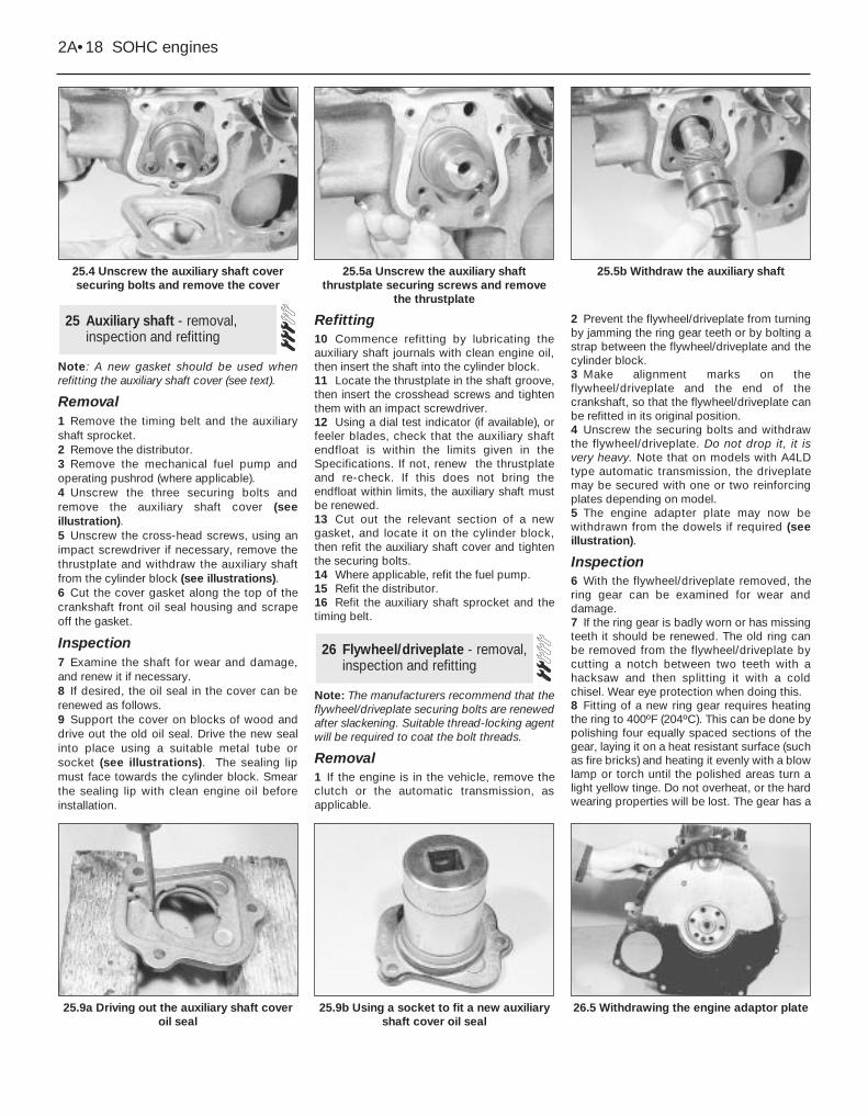
Note: A new gasket should be used whenrefitting the auxiliary shaft cover (see text).
Removal1 Remove the timing belt and the auxiliaryshaft sprocket.2 Remove the distributor.3 Remove the mechanical fuel pump andoperating pushrod (where applicable).4 Unscrew the three securing bolts andremove the auxiliary shaft cover (seeillustration).5 Unscrew the cross-head screws, using animpact screwdriver if necessary, remove thethrustplate and withdraw the auxiliary shaftfrom the cylinder block (see illustrations).6 Cut the cover gasket along the top of thecrankshaft front oil seal housing and scrapeoff the gasket.
Inspection7 Examine the shaft for wear and damage,and renew it if necessary. 8 If desired, the oil seal in the cover can berenewed as follows.9 Support the cover on blocks of wood anddrive out the old oil seal. Drive the new sealinto place using a suitable metal tube orsocket (see illustrations). The sealing lipmust face towards the cylinder block. Smearthe sealing lip with clean engine oil beforeinstallation.
Refitting10 Commence refitting by lubricating theauxiliary shaft journals with clean engine oil,then insert the shaft into the cylinder block.11 Locate the thrustplate in the shaft groove,then insert the crosshead screws and tightenthem with an impact screwdriver.12 Using a dial test indicator (if available), orfeeler blades, check that the auxiliary shaftendfloat is within the limits given in theSpecifications. If not, renew the thrustplateand re-check. If this does not bring theendfloat within limits, the auxiliary shaft mustbe renewed.13 Cut out the relevant section of a newgasket, and locate it on the cylinder block,then refit the auxiliary shaft cover and tightenthe securing bolts.14 Where applicable, refit the fuel pump.15 Refit the distributor.16 Refit the auxiliary shaft sprocket and thetiming belt.
Note: The manufacturers recommend that theflywheel/driveplate securing bolts are renewedafter slackening. Suitable thread-locking agentwill be required to coat the bolt threads.
Removal1 If the engine is in the vehicle, remove theclutch or the automatic transmission, asapplicable.
2 Prevent the flywheel/driveplate from turningby jamming the ring gear teeth or by bolting astrap between the flywheel/driveplate and thecylinder block.3 Make alignment marks on theflywheel/driveplate and the end of thecrankshaft, so that the flywheel/driveplate canbe refitted in its original position.4 Unscrew the securing bolts and withdrawthe flywheel/driveplate. Do not drop it, it isvery heavy. Note that on models with A4LDtype automatic transmission, the driveplatemay be secured with one or two reinforcingplates depending on model.5 The engine adapter plate may now bewithdrawn from the dowels if required (seeillustration).
Inspection6 With the flywheel/driveplate removed, thering gear can be examined for wear anddamage.7 If the ring gear is badly worn or has missingteeth it should be renewed. The old ring canbe removed from the flywheel/driveplate bycutting a notch between two teeth with ahacksaw and then splitting it with a coldchisel. Wear eye protection when doing this.8 Fitting of a new ring gear requires heatingthe ring to 400ºF (204ºC). This can be done bypolishing four equally spaced sections of thegear, laying it on a heat resistant surface (suchas fire bricks) and heating it evenly with a blowlamp or torch until the polished areas turn alight yellow tinge. Do not overheat, or the hardwearing properties will be lost. The gear has a
26 Flywheel/driveplate - removal,inspection and refitting
25 Auxiliary shaft - removal,inspection and refitting
2A•18 SOHC engines
25.4 Unscrew the auxiliary shaft coversecuring bolts and remove the cover
25.5b Withdraw the auxiliary shaft
26.5 Withdrawing the engine adaptor plate25.9b Using a socket to fit a new auxiliaryshaft cover oil seal
25.9a Driving out the auxiliary shaft coveroil seal
25.5a Unscrew the auxiliary shaftthrustplate securing screws and remove
the thrustplate
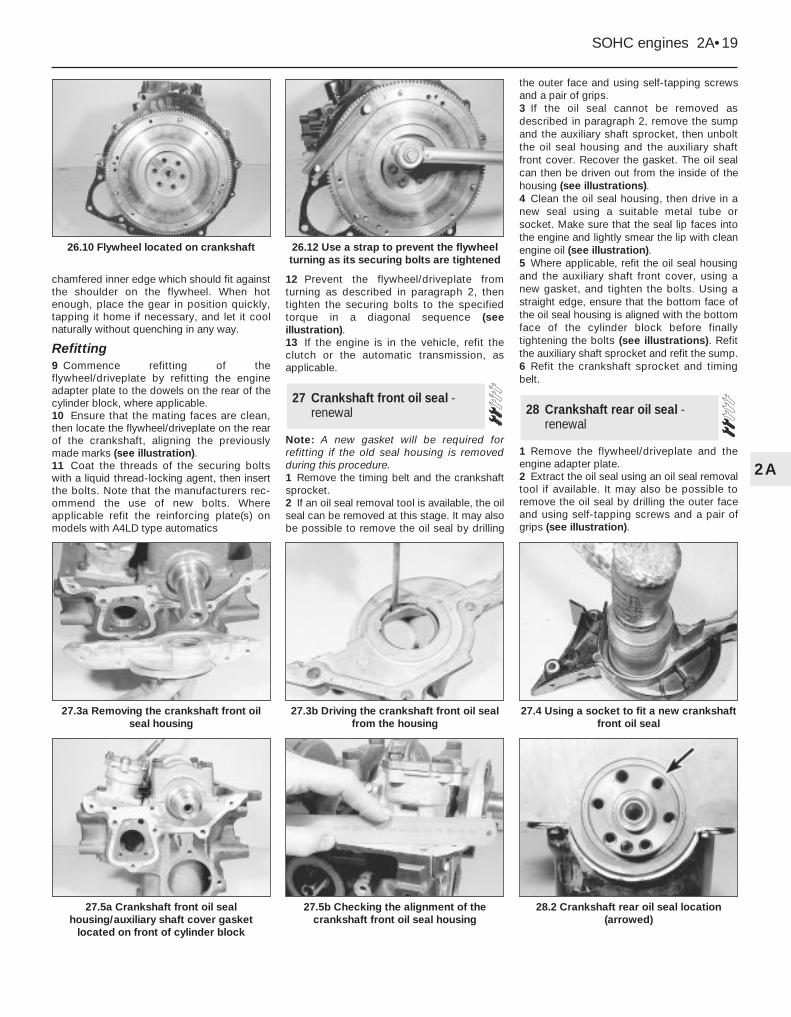
chamfered inner edge which should fit againstthe shoulder on the flywheel. When hotenough, place the gear in position quickly,tapping it home if necessary, and let it coolnaturally without quenching in any way.
Refitting9 Commence refitting of theflywheel/driveplate by refitting the engineadapter plate to the dowels on the rear of thecylinder block, where applicable.10 Ensure that the mating faces are clean,then locate the flywheel/driveplate on the rearof the crankshaft, aligning the previouslymade marks (see illustration).11 Coat the threads of the securing boltswith a liquid thread-locking agent, then insertthe bolts. Note that the manufacturers rec-ommend the use of new bolts. Whereapplicable refit the reinforcing plate(s) onmodels with A4LD type automatics
12 Prevent the flywheel/driveplate fromturning as described in paragraph 2, thentighten the securing bolts to the specifiedtorque in a diagonal sequence (seeillustration).13 If the engine is in the vehicle, refit theclutch or the automatic transmission, asapplicable.
Note: A new gasket will be required forrefitting if the old seal housing is removedduring this procedure.1 Remove the timing belt and the crankshaftsprocket.2 If an oil seal removal tool is available, the oilseal can be removed at this stage. It may alsobe possible to remove the oil seal by drilling
the outer face and using self-tapping screwsand a pair of grips.3 If the oil seal cannot be removed asdescribed in paragraph 2, remove the sumpand the auxiliary shaft sprocket, then unboltthe oil seal housing and the auxiliary shaftfront cover. Recover the gasket. The oil sealcan then be driven out from the inside of thehousing (see illustrations).4 Clean the oil seal housing, then drive in anew seal using a suitable metal tube orsocket. Make sure that the seal lip faces intothe engine and lightly smear the lip with cleanengine oil (see illustration).5 Where applicable, refit the oil seal housingand the auxiliary shaft front cover, using anew gasket, and tighten the bolts. Using astraight edge, ensure that the bottom face ofthe oil seal housing is aligned with the bottomface of the cylinder block before finallytightening the bolts (see illustrations). Refitthe auxiliary shaft sprocket and refit the sump.6 Refit the crankshaft sprocket and timingbelt.
1 Remove the flywheel/driveplate and theengine adapter plate.2 Extract the oil seal using an oil seal removaltool if available. It may also be possible toremove the oil seal by drilling the outer faceand using self-tapping screws and a pair ofgrips (see illustration).
28 Crankshaft rear oil seal -renewal
27 Crankshaft front oil seal -renewal
SOHC engines 2A•19
2A
27.3a Removing the crankshaft front oilseal housing
27.3b Driving the crankshaft front oil sealfrom the housing
28.2 Crankshaft rear oil seal location(arrowed)
27.5b Checking the alignment of thecrankshaft front oil seal housing
27.5a Crankshaft front oil sealhousing/auxiliary shaft cover gasket
located on front of cylinder block
27.4 Using a socket to fit a new crankshaftfront oil seal
26.12 Use a strap to prevent the flywheelturning as its securing bolts are tightened
26.10 Flywheel located on crankshaft
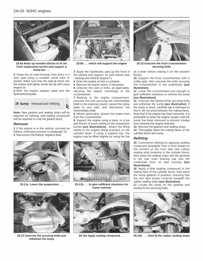
3 Clean the oil seal housing, then drive in anew seal using a suitable metal tube orsocket. Make sure that the seal lip faces intothe engine and lightly smear the lip with cleanengine oil.4 Refit the engine adapter plate and theflywheel/driveplate.
Note: New gaskets and sealing strips will berequired for refitting, and sealing compoundwill be required to coat the gasket faces.
Removal1 If the engine is in the vehicle, proceed asfollows, otherwise proceed to paragraph 12.2 Disconnect the battery negative lead.
3 Apply the handbrake, jack up the front ofthe vehicle and support on axle stands (see“Jacking and Vehicle Support”).4 Drain the engine oil into a container.5 Remove the starter motor, if necessary.6 Unscrew the nuts or bolts, as applicable,securing the engine mountings to thecrossmember.7 Working in the engine compartment,unscrew the bolt securing the intermediateshaft to the steering column, swivel the clampplate to one side, and disconnect theintermediate shaft.8 Where applicable, detach the brake linesfrom the crossmember.9 Support the engine using a hoist, or a barand blocks of wood resting on the suspensionturrets (see illustrations). Attach the liftingtackle to the engine lifting brackets on thecylinder head. If using a support bar, theengine may be lifted slightly by using the bar
as a lever before resting it on the woodenblocks.10 Support the front crossmember with atrolley jack, then unscrew the bolts securingthe crossmember to the underbody (seeillustration).11 Lower the crossmember just enough togive sufficient clearance to remove the sump(see illustrations).12 Unscrew the twenty-three securing boltsand withdraw the sump (see illustration). Ifthe sump is stuck, carefully tap it sideways tofree it. Do not prise between the mating faces.Note that if the engine has been removed, it ispreferable to keep the engine upright until thesump has been removed to prevent sludgefrom entering the engine internals.13 Recover the gaskets and sealing strips.14 Thoroughly clean the mating faces of thecylinder block and sump.
Refitting15 Commence refitting by applying sealingcompound (available from a Ford dealer) tothe corners of the front and rear rubbersealing strip locations in the cylinder block,then press the sealing strips into the groovesin the rear main bearing cap and thecrankshaft front oil seal housing (seeillustrations).16 Apply a little sealing compound to themating face of the cylinder block, then placethe sump gaskets in position, ensuring thatthe end tabs locate correctly beneath therubber sealing strips (see illustration).17 Locate the sump on the gaskets andloosely fit the securing bolts.
29 Sump - removal and refitting
2A•20 SOHC engines
29.9a Make up wooden blocks to fit thefront suspension turrets and support a
metal bar . . .
29.10 Unscrew the front crossmembersecuring bolts
29.15b . . . then fit the rubber sealing strips29.15a Apply sealing compound . . .29.12 Unscrew the securing bolts andwithdraw the sump
29.11b . . . to give sufficient clearance forsump removal
29.11a Lower the suspension . . .
29.9b . . . which will support the engine
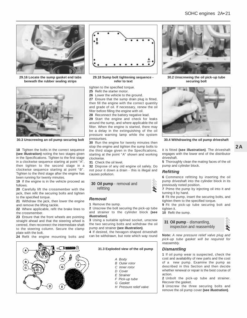
18 Tighten the bolts in the correct sequence(see illustration) noting the two stages givenin the Specifications. Tighten to the first stagein a clockwise sequence starting at point “A”,then tighten to the second stage in aclockwise sequence starting at point “B”.Tighten to the third stage after the engine hasbeen running for twenty minutes.19 If the engine is in the vehicle proceed asfollows.20 Carefully lift the crossmember with thejack, then refit the securing bolts and tightento the specified torque.21 Withdraw the jack, then lower the engineand remove the lifting tackle.22 Where applicable, refit the brake lines tothe crossmember.23 Ensure that the front wheels are pointingstraight ahead and that the steering wheel iscentred, then reconnect the intermediate shaftto the steering column. Secure the clampplate with the bolt.24 Refit the engine mounting bolts and
tighten to the specified torque.25 Refit the starter motor. 26 Lower the vehicle to the ground.27 Ensure that the sump drain plug is fitted,then fill the engine with the correct quantityand grade of oil. If necessary, renew the oilfilter before filling the engine with oil.28 Reconnect the battery negative lead.29 Start the engine and check for leaksaround the sump, and where applicable the oilfilter. When the engine is started, there maybe a delay in the extinguishing of the oilpressure warning lamp while the systempressurises.30 Run the engine for twenty minutes thenstop the engine and tighten the sump bolts tothe third stage given in the Specifications,starting at the point “A” shown and workingclockwise.31 Check the oil level.32 Dispose of any old engine oil safely. Donot pour it down a drain - this is illegal andcauses pollution.
Removal1 Remove the sump.2 Unscrew the bolt securing the pick-up tubeand strainer to the cylinder block (seeillustration).3 Using a suitable splined socket, unscrewthe two securing bolts and withdraw the oilpump and strainer (see illustration).4 If desired, the hexagon-shaped driveshaftcan be withdrawn, but note which way round
it is fitted (see illustration). The driveshaftengages with the lower end of the distributordriveshaft.5 Thoroughly clean the mating faces of the oilpump and cylinder block.
Refitting6 Commence refitting by inserting the oilpump driveshaft into the cylinder block in itspreviously noted position.7 Prime the pump by injecting oil into it andturning it by hand. 8 Fit the pump, insert the securing bolts, andtighten them to the specified torque.9 Fit the pick-up tube securing bolt andtighten it. 10 Refit the sump.
Note: A new pressure relief valve plug andpick-up tube gasket will be required forreassembly.
Dismantling1 If oil pump wear is suspected, check thecost and availability of new parts and the costof a new pump. Examine the pump asdescribed in this Section and then decidewhether renewal or repair is the best course ofaction.2 Unbolt the pick-up tube and strainer.Recover the gasket.3 Unscrew the three securing bolts andremove the oil pump cover (see illustration).
31 Oil pump - dismantling,inspection and reassembly
30 Oil pump - removal andrefitting
SOHC engines 2A•21
2A
30.2 Unscrewing the oil pick-up tubesecuring bolt
30.4 Withdrawing the oil pump driveshaft30.3 Unscrewing an oil pump securing bolt
29.18 Sump bolt tightening sequence -refer to text
29.16 Locate the sump gasket end tabsbeneath the rubber sealing strips
31.3 Exploded view of the oil pump
A BodyB Outer rotorC Inner rotorD CoverE StrainerF Pick-up tubeG GasketH Pressure relief valve
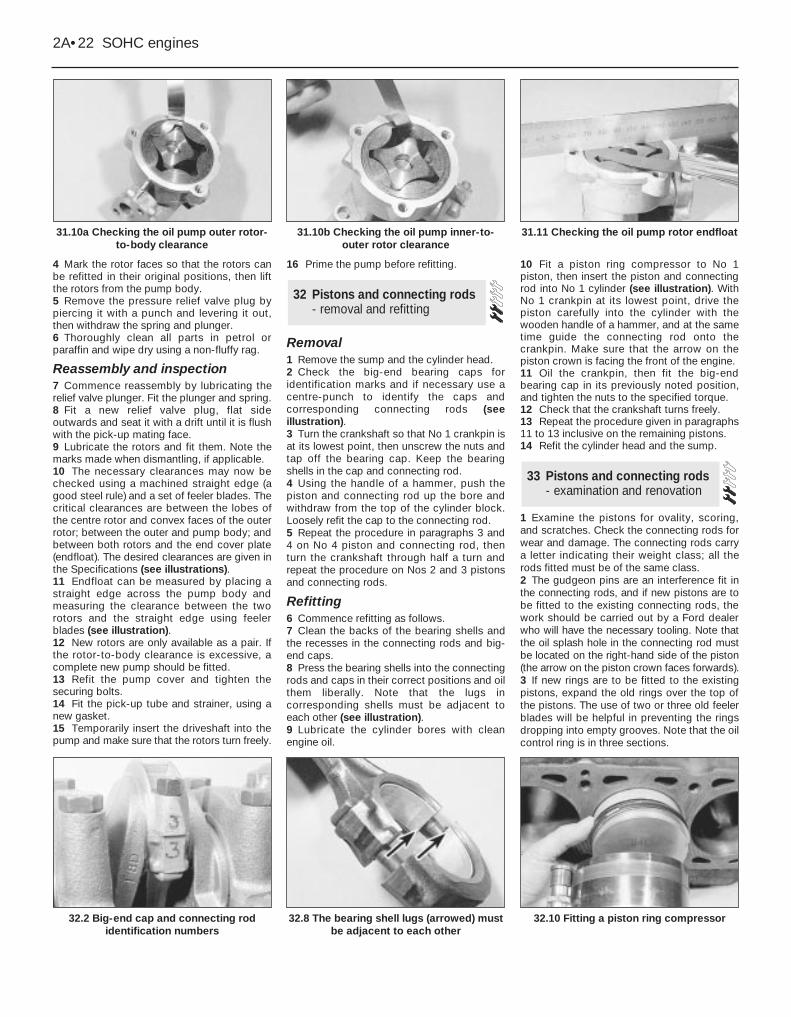
4 Mark the rotor faces so that the rotors canbe refitted in their original positions, then liftthe rotors from the pump body.5 Remove the pressure relief valve plug bypiercing it with a punch and levering it out,then withdraw the spring and plunger.6 Thoroughly clean all parts in petrol orparaffin and wipe dry using a non-fluffy rag.
Reassembly and inspection7 Commence reassembly by lubricating therelief valve plunger. Fit the plunger and spring.8 Fit a new relief valve plug, flat sideoutwards and seat it with a drift until it is flushwith the pick-up mating face.9 Lubricate the rotors and fit them. Note themarks made when dismantling, if applicable.10 The necessary clearances may now bechecked using a machined straight edge (agood steel rule) and a set of feeler blades. Thecritical clearances are between the lobes ofthe centre rotor and convex faces of the outerrotor; between the outer and pump body; andbetween both rotors and the end cover plate(endfloat). The desired clearances are given inthe Specifications (see illustrations).11 Endfloat can be measured by placing astraight edge across the pump body andmeasuring the clearance between the tworotors and the straight edge using feelerblades (see illustration).12 New rotors are only available as a pair. Ifthe rotor-to-body clearance is excessive, acomplete new pump should be fitted. 13 Refit the pump cover and tighten thesecuring bolts. 14 Fit the pick-up tube and strainer, using anew gasket. 15 Temporarily insert the driveshaft into thepump and make sure that the rotors turn freely.
16 Prime the pump before refitting.
Removal1 Remove the sump and the cylinder head. 2 Check the big-end bearing caps foridentification marks and if necessary use acentre-punch to identify the caps andcorresponding connecting rods (seeillustration). 3 Turn the crankshaft so that No 1 crankpin isat its lowest point, then unscrew the nuts andtap off the bearing cap. Keep the bearingshells in the cap and connecting rod.4 Using the handle of a hammer, push thepiston and connecting rod up the bore andwithdraw from the top of the cylinder block.Loosely refit the cap to the connecting rod.5 Repeat the procedure in paragraphs 3 and4 on No 4 piston and connecting rod, thenturn the crankshaft through half a turn andrepeat the procedure on Nos 2 and 3 pistonsand connecting rods.
Refitting6 Commence refitting as follows.7 Clean the backs of the bearing shells andthe recesses in the connecting rods and big-end caps.8 Press the bearing shells into the connectingrods and caps in their correct positions and oilthem liberally. Note that the lugs incorresponding shells must be adjacent toeach other (see illustration).9 Lubricate the cylinder bores with cleanengine oil.
10 Fit a piston ring compressor to No 1piston, then insert the piston and connectingrod into No 1 cylinder (see illustration). WithNo 1 crankpin at its lowest point, drive thepiston carefully into the cylinder with thewooden handle of a hammer, and at the sametime guide the connecting rod onto thecrankpin. Make sure that the arrow on thepiston crown is facing the front of the engine.11 Oil the crankpin, then fit the big-endbearing cap in its previously noted position,and tighten the nuts to the specified torque. 12 Check that the crankshaft turns freely. 13 Repeat the procedure given in paragraphs11 to 13 inclusive on the remaining pistons. 14 Refit the cylinder head and the sump.
1 Examine the pistons for ovality, scoring,and scratches. Check the connecting rods forwear and damage. The connecting rods carrya letter indicating their weight class; all therods fitted must be of the same class. 2 The gudgeon pins are an interference fit inthe connecting rods, and if new pistons are tobe fitted to the existing connecting rods, thework should be carried out by a Ford dealerwho will have the necessary tooling. Note thatthe oil splash hole in the connecting rod mustbe located on the right-hand side of the piston(the arrow on the piston crown faces forwards).3 If new rings are to be fitted to the existingpistons, expand the old rings over the top ofthe pistons. The use of two or three old feelerblades will be helpful in preventing the ringsdropping into empty grooves. Note that the oilcontrol ring is in three sections.
33 Pistons and connecting rods- examination and renovation
32 Pistons and connecting rods- removal and refitting
2A•22 SOHC engines
31.10a Checking the oil pump outer rotor-to-body clearance
31.11 Checking the oil pump rotor endfloat
32.10 Fitting a piston ring compressor32.8 The bearing shell lugs (arrowed) mustbe adjacent to each other
32.2 Big-end cap and connecting rodidentification numbers
31.10b Checking the oil pump inner-to-outer rotor clearance
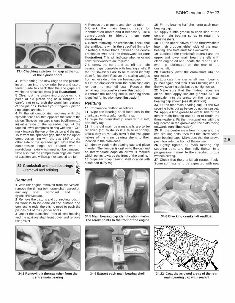
4 Before fitting the new rings to the pistons,insert them into the cylinder bore and use afeeler blade to check that the end gaps arewithin the specified limits (see illustration).5 Clean out the piston ring groove using apiece of old piston ring as a scraper. Becareful not to scratch the aluminium surfaceof the pistons. Protect your fingers - pistonring edges are sharp.6 Fit the oil control ring sections with thespreader ends abutted opposite the front of thepiston. The side ring gaps should be 25 mm (1.0in) either side of the spreader gap. Fit thetapered lower compression ring with the “TOP”mark towards the top of the piston and the gap150º from the spreader gap, then fit the uppercompression ring with the gap 150º on theother side of the spreader gap. Note that thecompression rings are coated with amolybdenum skin which must not be damaged.Note also that the compression rings are madeof cast iron, and will snap if expanded too far.
Removal1 With the engine removed from the vehicle,remove the timing belt, crankshaft sprocket,auxiliary shaft sprocket and theflywheel/driveplate.2 Remove the pistons and connecting rods. Ifno work is to be done on the pistons andconnecting rods, there is no need to push thepistons out of the cylinder bores.3 Unbolt the crankshaft front oil seal housingand the auxiliary shaft front cover and removethe gasket.
4 Remove the oil pump and pick-up tube.5 Check the main bearing caps foridentification marks and if necessary use acentre-punch to identify them (seeillustration).6 Before removing the crankshaft, check thatthe endfloat is within the specified limits byinserting a feeler blade between the centrecrankshaft web and the thrustwashers (seeillustration). This will indicate whether or notnew thrustwashers are required.7 Unscrew the bolts and tap off the mainbearing caps complete with bearing shells. Ifthe thrustwashers are to be re-used identifythem for location. Recover the sealing wedgesfrom either side of the rear bearing cap.8 Lift the crankshaft from the crankcase andremove the rear oil seal. Recover theremaining thrustwashers (see illustration).9 Extract the bearing shells, keeping themidentified for location (see illustration).
Refitting10 Commence refitting as follows.11 Wipe the bearing shell locations in thecrankcase with a soft, non-fluffy rag.12 Wipe the crankshaft journals with a soft,non-fluffy rag.13 If the old main bearing shells are to berenewed (not to do so is a false economy,unless they are virtually new) fit the five upperhalves of the main bearing shells to theirlocation in the crankcase.14 Identify each main bearing cap and placein order. The number is cast on to the cap andon intermediate caps an arrow is markedwhich points towards the front of the engine.15 Wipe each cap bearing shell location witha soft non-fluffy rag.
16 Fit the bearing half shell onto each mainbearing cap.17 Apply a little grease to each side of thecentre main bearing so as to retain thethrustwashers.18 Fit the upper halves of the thrustwashersinto their grooves either side of the mainbearing. The slots must face outwards.19 Lubricate the crankshaft journals and theupper and lower main bearing shells withclean engine oil and locate the rear oil seal(with lip lubricated) on the rear of thecrankshaft.20 Carefully lower the crankshaft into thecrankcase.21 Lubricate the crankshaft main bearingjournals again, and then fit No 1 bearing cap. Fitthe two securing bolts but do not tighten yet.22 Make sure that the mating faces areclean, then apply sealant (Loctite 518 orequivalent) to the areas on the rear mainbearing cap shown (see illustration).23 Fit the rear main bearing cap. Fit the twosecuring bolts but as before do not tighten yet.24 Apply a little grease to either side of thecentre main bearing cap so as to retain thethrustwashers. Fit the thrustwashers with thetag located in the groove and the slots facingoutwards (see illustration).25 Fit the centre main bearing cap and thetwo securing bolts, then refit the intermediatemain bearing caps. Make sure that the arrowspoint towards the front of the engine.26 Lightly tighten all main bearing capsecuring bolts and then fully tighten in aprogressive manner to the specified torquewrench setting. 27 Check that the crankshaft rotates freely.Some stiffness is to be expected with new
34 Crankshaft and main bearings- removal and refitting
SOHC engines 2A•23
2A
34.6 Checking crankshaft endfloat
34.22 Coat the arrowed areas of the rearmain bearing cap with sealant
34.9 Extract each main bearing shell34.8 Removing a thrustwasher from thecentre main bearing
34.5 Main bearing cap identification marks.The arrow points to the front of the engine
33.4 Checking a piston ring gap at the topof the cylinder bore
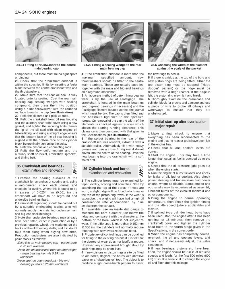
components, but there must be no tight spotsor binding.28 Check that the crankshaft endfloat iswithin the specified limits by inserting a feelerblade between the centre crankshaft web andthe thrustwashers.29 Make sure that the rear oil seal is fullylocated onto its seating. Coat the rear mainbearing cap sealing wedges with sealingcompound, then press them into positionusing a blunt screwdriver with the roundedred face towards the cap (see illustration).30 Refit the oil pump and pick-up tube.31 Refit the crankshaft front oil seal housingand the auxiliary shaft front cover using a newgasket, and tighten the securing bolts. Smearthe lip of the oil seal with clean engine oilbefore fitting; and using a straight edge, ensurethat the bottom face of the oil seal housing isaligned with the bottom face of the cylinderblock before finally tightening the bolts.32 Refit the pistons and connecting rods.33 Refit the flywheel/driveplate and theauxiliary shaft sprocket, crankshaft sprocket,and timing belt.
1 Examine the bearing surfaces of thecrankshaft for scratches or scoring and, usinga micrometer, check each journal andcrankpin for ovality. Where this is found to bein excess of 0.0254 mm (0.001 in) thecrankshaft will have to be reground andundersize bearings fitted.2 Crankshaft regrinding should be carried outby a suitable engineering works, who willnormally supply the matching undersize mainand big-end shell bearings.3 Note that undersize bearings may alreadyhave been fitted, either in production or by aprevious repairer. Check the markings on thebacks of the old bearing shells, and if in doubttake them along when buying new ones.Production undersizes are also indicated bypaint marks as follows:White line on main bearing cap - parent bore
0.40 mm oversizeGreen line on crankshaft front counterweight
- main bearing journals 0.25 mmundersize
Green spot on counterweight - big-endbearing journals 0.25 mm undersize
4 If the crankshaft endfloat is more than themaximum specified amount, newthrustwashers should be fitted to the centremain bearings. These are usually suppliedtogether with the main and big-end bearingson a reground crankshaft.5 An accurate method of determining bearingwear is by the use of Plastigage. Thecrankshaft is located in the main bearings(and big-end bearings if necessary) and thePlastigage filament located across the journalwhich must be dry. The cap is then fitted andthe bolts/nuts tightened to the specifiedtorque. On removal of the cap the width of thefilaments is checked against a scale whichshows the bearing running clearance. Thisclearance is then compared with that given inthe Specifications (see illustration).6 If the spigot bearing in the rear of thecrankshaft requires renewal, extract it with asuitable puller. Alternatively fill it with heavygrease and use a close fitting metal doweldriven into the centre of the bearing. Drive thenew bearing into the crankshaft with a softmetal drift.
1 The cylinder bores must be examined fortaper, ovality, scoring and scratches. Start byexamining the top of the bores; if these areworn, a slight ridge will be found which marksthe top of the piston ring travel. If the wear isexcessive, the engine will have had a high oilconsumption rate accompanied by bluesmoke from the exhaust.2 If available, use an inside dial gauge tomeasure the bore diameter just below theridge and compare it with the diameter at thebottom of the bore, which is not subject towear. If the difference is more than 0.152 mm(0.006 in), the cylinders will normally requirereboring with new oversize pistons fitted.3 Proprietary oil control rings can be obtainedfor fitting to the existing pistons if it is felt thatthe degree of wear does not justify a rebore.However, any improvement brought about bysuch rings may be short-lived.4 If new pistons or piston rings are to be fittedto old bores, deglaze the bores with abrasivepaper or a “glaze buster” tool. The object is toproduce a light cross-hatch pattern to assist
the new rings to bed in.5 If there is a ridge at the top of the bore andnew piston rings are being fitted, either thetop piston ring must be stepped (“ridgedodger” pattern) or the ridge must beremoved with a ridge reamer. If the ridge isleft, the piston ring may hit it and break.6 Thoroughly examine the crankcase andcylinder block for cracks and damage and usea piece of wire to probe all oilways andwaterways to ensure that they areunobstructed.
1 Make a final check to ensure thateverything has been reconnected to theengine and that no rags or tools have been leftin the engine bay. 2 Check that oil and coolant levels arecorrect.3 Start the engine. This may take a littlelonger than usual as fuel is pumped up to theengine.4 Check that the oil pressure light goes outwhen the engine starts.5 Run the engine at a fast tickover and checkfor leaks of oil, fuel or coolant. Also checkpower steering and transmission fluid coolerunions, where applicable. Some smoke andodd smells may be experienced as assemblylubricant burns off the exhaust manifold andother components.6 Bring the engine to normal operatingtemperature, then check the ignition timingand the idle speed (where applicable) andmixture.7 If splined type cylinder head bolts havebeen used, stop the engine after it has beenrunning for 15 minutes, then remove thecrankshaft cover and tighten the cylinderhead bolts to the fourth stage given in theSpecifications, in the correct order.8 When the engine has completely cooled,re-check the oil and coolant levels, andcheck, and if necessary adjust, the valveclearances.9 If new bearings, pistons etc have beenfitted, the engine should be run-in at reducedspeeds and loads for the first 500 miles (800km) or so. It is beneficial to change the engineoil and filter after this mileage.
37 Initial start-up after overhaul ormajor repair
36 Cylinder block and bores -examination and renovation
35 Crankshaft and bearings -examination and renovation
2A•24 SOHC engines
34.24 Fitting a thrustwasher to the centremain bearing cap
35.5 Checking the width of the filamentagainst the scale of the packet
34.29 Fitting a sealing wedge to the rearmain bearing cap