Chapter 2 - Background: Plant fibres and their composites
46
Chapter 2 Background: Plant fibres and their composites DU Shah Page | 17 2 BACKGROUND: PLANT FIBRES AND THEIR COMPOSITES * This chapter aims to provide a broad understanding of plant fibres and their composites, specifically commenting on critical factors influencing the mechanical properties of plant fibre composites, thereby dictating their applicability in structural components. In essence, this chapter serves as a relevant background and literature review to the work described in this thesis. 2.1 COMPOSITES: A CONCERN FOR THE ENVIRONMENT? Since the mid-20 th century, research and engineering interest has been shifting from monolithic materials to composite materials (Fig. 2.1) [1]. Fibre reinforced plastics (FRPs) – produced through a synthetic assembly of a (typically, petroleum-derived) polymer matrix with (typically, man-made) reinforcing fibres – have several advantages, predictably a combination of the main properties of the constituents. Due to the light-weight and high-performance capacity of FRPs, they are increasingly being exploited in all areas of engineering applications: from the performance-driven aerospace and automotive industries, to the cost-driven consumer goods market [2]. While the total global production of fibre reinforced plastics (FRPs) amounted to 5.9 million tonnes in 1999 [2], this figure increased to 8.7 million tonnes in 2011 [2]. With the increasing consumption of FRPs, environmental concerns relating not only to the energy-intensive unsustainable production processes of the reinforcing synthetic fibres and plastics [3, 4], but also to the limited recyclability and end-of-life disposal options of the FRPs have been highlighted [5, 6]. The perceived scale of the problem has even led to stringent government legislations, such as the EU Directive on Landfill of Waste (Directive 99/31/EC) and the End-of-life Vehicle Directive (Directive 2000/53/EC), which are seen as barriers to the development or even * This chapter is based on the peer-reviewed journal article: Shah DU. Developing plant fibre composites for structural applications by optimising composite parameters: a critical review. Journal of Materials Science, 2013, 48(18): p. 6083- 6107.
Transcript of Chapter 2 - Background: Plant fibres and their composites

Chapter 2 Background: Plant fibres and their composites
DU Shah Page | 17
2 BACKGROUND: PLANT FIBRES AND THEIR COMPOSITES*
This chapter aims to provide a broad understanding of plant fibres and their
composites, specifically commenting on critical factors influencing the mechanical
properties of plant fibre composites, thereby dictating their applicability in structural
components. In essence, this chapter serves as a relevant background and literature
review to the work described in this thesis.
2.1 COMPOSITES: A CONCERN FOR THE ENVIRONMENT?
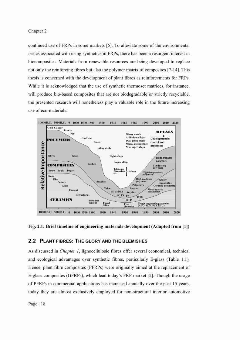
Since the mid-20th century, research and engineering interest has been shifting from
monolithic materials to composite materials (Fig. 2.1) [1]. Fibre reinforced plastics
(FRPs) – produced through a synthetic assembly of a (typically, petroleum-derived)
polymer matrix with (typically, man-made) reinforcing fibres – have several
advantages, predictably a combination of the main properties of the constituents. Due
to the light-weight and high-performance capacity of FRPs, they are increasingly
being exploited in all areas of engineering applications: from the performance-driven
aerospace and automotive industries, to the cost-driven consumer goods market [2].
While the total global production of fibre reinforced plastics (FRPs) amounted to 5.9
million tonnes in 1999 [2], this figure increased to 8.7 million tonnes in 2011 [2].
With the increasing consumption of FRPs, environmental concerns relating not only
to the energy-intensive unsustainable production processes of the reinforcing
synthetic fibres and plastics [3, 4], but also to the limited recyclability and end-of-life
disposal options of the FRPs have been highlighted [5, 6]. The perceived scale of the
problem has even led to stringent government legislations, such as the EU Directive
on Landfill of Waste (Directive 99/31/EC) and the End-of-life Vehicle Directive
(Directive 2000/53/EC), which are seen as barriers to the development or even
* This chapter is based on the peer-reviewed journal article:
Shah DU. Developing plant fibre composites for structural applications by optimising
composite parameters: a critical review. Journal of Materials Science, 2013, 48(18): p. 6083-
6107.
Chapter 2
Page | 18
continued use of FRPs in some markets [5]. To alleviate some of the environmental
issues associated with using synthetics in FRPs, there has been a resurgent interest in
biocomposites. Materials from renewable resources are being developed to replace
not only the reinforcing fibres but also the polymer matrix of composites [7-14]. This
thesis is concerned with the development of plant fibres as reinforcements for FRPs.
While it is acknowledged that the use of synthetic thermoset matrices, for instance,
will produce bio-based composites that are not biodegradable or strictly recyclable,
the presented research will nonetheless play a valuable role in the future increasing
use of eco-materials.
CERAMICS
Rela
tive I
mpo
rtan
ce
POLYMERS
COMPOSITES
METALS
Development in control and processing
‘Green’composites
Biodegradable polymers
Fig. 2.1: Brief timeline of engineering materials development (Adapted from [1])
2.2 PLANT FIBRES: THE GLORY AND THE BLEMISHES
As discussed in Chapter 1, lignocellulosic fibres offer several economical, technical
and ecological advantages over synthetic fibres, particularly E-glass (Table 1.1).
Hence, plant fibre composites (PFRPs) were originally aimed at the replacement of
E-glass composites (GFRPs), which lead today’s FRP market [2]. Though the usage
of PFRPs in commercial applications has increased annually over the past 15 years,
today they are almost exclusively employed for non-structural interior automotive

Background: Plant fibres and their composites
Page | 19
applications, primarily as a replacement to wood fibre composites [15, 16]. This is
attributable to the fact that the impressive theoretical properties of cellulose and
cellulose-based fibres have been difficult to exploit in practice. Researchers who
have worked with PFRPs agree that the major bottlenecks limiting their applications
are: i) the inferior (often performance-limiting) and naturally variable mechanical
properties of plant fibres, ii) the susceptibility of plant fibres and their composites to
moisture ingress, and iii) the supposedly weak fibre/matrix interface in PFRPs
impeding efficient property transfer of the fibres to the composite [17].
Nonetheless, there is a growing voice in the scientific community which suggests
that the properties of plant fibres can be exploited for even load-bearing applications
[11, 18-25]. Indeed, this is the objective and conclusion of this research study. With
directed research on maximising and optimising the reinforcing contribution of plant
fibres in polymer composites, significant headway has been made on the use of
PFRPs for performance-demanding applications. The progress includes: i) fibre
reinforcement development – from crop growth to fibre extraction and processing to
reinforcement optimisation for composites applicability [9, 12, 21, 24-33], ii)
composite manufacturing process development [9, 12, 16, 25, 34-37], and iii)
composite property characterisation – for instance, as a function of composite
parameters and loading conditions [8, 9, 12, 25]. This chapter will discuss some
factors that require consideration in developing PFRPs for structural applications.
2.3 MATERIALS SELECTION CRITERIA FOR STRUCTURAL APPLICATIONS
During product development, materials selection is a process where a range of
material properties are taken into consideration. Asbhy [38] describes a method to
compare the relative performance of a variety of materials for a specific constructive
element by using material performance indices – defined by the component function,
objective and constraint – as design criteria. Generally, minimising material weight
(density ρ) and/or cost are key objectives for industrial products. The key mechanical
parameters, defined by the component function and constraint, are typically stiffness
E and strength σ. Following Asbhy [38], the critical material performance indices
that need to be maximised for a beam/plate loaded in pure tension are specific tensile
Chapter 2
Page | 20
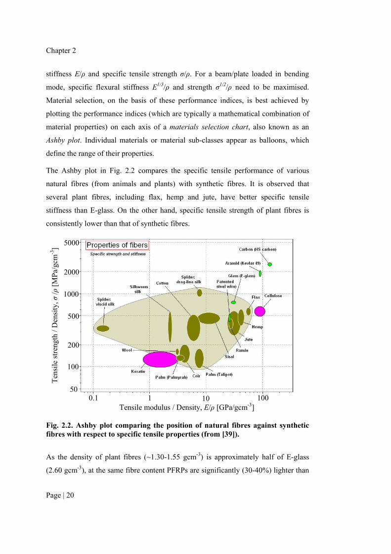
stiffness E/ρ and specific tensile strength σ/ρ. For a beam/plate loaded in bending
mode, specific flexural stiffness E1/3/ρ and strength σ1/2/ρ need to be maximised.
Material selection, on the basis of these performance indices, is best achieved by
plotting the performance indices (which are typically a mathematical combination of
material properties) on each axis of a materials selection chart, also known as an
Ashby plot. Individual materials or material sub-classes appear as balloons, which
define the range of their properties.
The Ashby plot in Fig. 2.2 compares the specific tensile performance of various
natural fibres (from animals and plants) with synthetic fibres. It is observed that
several plant fibres, including flax, hemp and jute, have better specific tensile
stiffness than E-glass. On the other hand, specific tensile strength of plant fibres is
consistently lower than that of synthetic fibres.
Fig. 2.2. Ashby plot comparing the position of natural fibres against synthetic fibres with respect to specific tensile properties (from [39]).
As the density of plant fibres (~1.30-1.55 gcm-3) is approximately half of E-glass
(2.60 gcm-3), at the same fibre content PFRPs are significantly (30-40%) lighter than
Tensile modulus / Density, E/ρ [GPa/gcm-3]
Ten
sile
str
engt
h / D
ensi
ty, σ
/ρ [
MPa
/gcm
-3]
50
100
200
500
1000
2000
5000
0.1 1 10 100

Background: Plant fibres and their composites
Page | 21
GFRPs [19]. A lower density gives PFRPs a good chance to compete against GFRPs
in terms of specific stiffness and strength. As the density of all plant fibres is fairly
similar [30], there are minimal opportunities to reduce the density of PFRPs further.
On the other hand, not only do plant fibre mechanical properties vary significantly
and are strongly influenced by several factors [29, 40] (such as fibre chemical
composition and structural morphology, plant growth conditions, fibre extraction and
processing conditions), but composite mechanical properties are also dependent on
several composite parameters (discussed in the next section). Hence, opportunities to
maximise composite stiffness and strength are plentiful. To establish PFRPs as
superior to GFRPs, with respect to the design criteria, PFRP mechanical properties
need to be maximised.
2.4 COMPOSITE MATERIAL PARAMETERS
FRPs are heterogeneous materials, consisting of reinforcing fibres embedded in a
continuous matrix. While the fibres provide strength and stiffness to the composite,
the matrix transmits externally applied loads, via shear stresses at the interface, to the
reinforcing fibres and protects the fibres from external damage. The advantage of
coupling the two distinct constituents is that the high strength and stiffness of the
fibres, which in practical situations would be difficult to realise, may be exploited.
Typically, composite properties are affected by the following parameters: I) the fibre
properties, II) the volumetric composition (where the sum of the volume fraction of
the fibres vf, matrix vm and voids vp is unity, i.e. vf + vm + vp = 1), III) the geometry of
the fibres and the fibre/matrix interface properties, IV) the packing arrangement,
orientation and stacking sequence of the fibre reinforcements, and V) the matrix
properties. The effect of all these parameters is elegantly demonstrated by the
fundamental equations in composites engineering: the generalised rule-of-mixtures
(ROM) model for the tensile modulus Ec (Eq. 2.1) and strength σc (Eq. 2.2) of
discontinuous fibre composites.
mmolEffc EvvEE += ηη Eq. 2.1
mmolSffc vv 'σηησσ += Eq. 2.2
Chapter 2
Page | 22
where, I) Ef and σf are the fibre modulus and fibre strength, II) vf and vm are the fibre
and matrix volume fraction, III) ηlE and ηlS are the reinforcement length efficiency
factors for stiffness and strength (incorporating the effect of fibre geometry and
interfacial properties), IV) ηo is the reinforcement orientation distribution factor
(incorporating the effect of packing arrangement and orientation of the fibre
reinforcements), and V) Em and σ’m are the matrix modulus and matrix tensile stress
at the fibre failure strain. Note that the order of the parameters of Eq. 2.1 and Eq. 2.2
are homologous to the order of the composite parameters defined previously.
The basic assumptions of the above micromechanical models include: i) all fibres
have identical geometry and properties, ii) homogenous and uniform distribution of
fibres in the matrix, iii) iso-strain conditions within the composite, iv) ideal
fibre/matrix interface, v) elastic deformation of the fibre and matrix, vi) no transverse
deformations (i.e. ignore Poisson’s contractions), vii) zero and maximum tensile
stress at the fibre ends and centre, respectively, and viii) no effect of porosity content
vp on composite properties (other than reducing vf and vm). Although many of these
simplifications and assumptions do not hold true for FRPs in general, the ROM
model has proved to be adequate for the prediction/estimation of the properties of
synthetic fibre composites and for the determination of the reinforcing potential of
the fibres (by ‘back-calculation’).
The simplicity of the generalised ROM model implies that it has become a widely
used model for PFRPs as well. Interestingly, as plant fibres are inherently
discontinuous, the ROM model can be used for PFRPs even if plant yarns/rovings
(i.e. ‘continuous’ reinforcements) are employed. Nonetheless, as plant fibres require
specific considerations, recent pioneering work has led to a modified ROM model
that has been shown to be more suitable for PFRPs [41, 42]. The modified ROM
model, presented in Eq. 2.3 and Eq. 2.4, includes i) a factor of (1 – vp)2 to simulate
the detrimental effect of porosity on the tensile properties of PFRPs [22, 43, 44], ii) a
fibre diameter distribution factor ηd to incorporate the effect of approximately linear
(Ef = Ef0 – m·df) decline in fibre tensile modulus with increasing fibre diameter df
[34, 41, 42, 45, 46], and iii) a fibre area correction factor κ to address the discrepancy
between the true (non-circular, irregular and variable) cross-sectional area of the

Background: Plant fibres and their composites
Page | 23
fibre and the apparent circular cross-sectional area calculated by the measurement of
the apparent fibre diameter [34, 41, 42, 47]. While these modifications to the general
ROM model have been validated with experimental results on PFRPs in the relevant
studies, they have been validated only for limited data sets. Therefore, the
applicability of the modified ROM model to PFRPs needs to be investigated further.
( )( )21 pmmdolEffc vEvvEE −+= κηηη Eq. 2.3
( )( )21' pmmolSffc vvv −+= σκηησσ Eq. 2.4
In Eq. 2.1 and Eq. 2.3, the length efficiency factor for stiffness ηlE can be estimated
by the Cox’s shear lag model (Eq. 2.5) [48], where lf is the fibre length, df is the fibre
diameter, Gm is the matrix shear stiffness, and vf,max,FRP is the maximum achievable
fibre volume fraction (dependent on fibre packing geometry; e.g. vf,max,FRP = π/4 for
square-packing arrangement). In Eq. 2.2 and Eq. 2.4, the length efficiency factor for
strength ηlS is given by the Kelly-Tyson’s model (Eq. 2.6) [49], where lc is the critical
or ineffective fibre length. Sub-critical length fibres (lf < lc) will not carry the
maximum load. If a composite has both sub-critical length (lf < lc) and super-critical
length (lf > lc) fibres, Eq. 2.6 can be expressed as a summation of the contribution
from different fibre lengths. It is useful to note that the critical fibre length is a
function of the fibre tensile strength σf, the fibre diameter df, and the interfacial shear
strength τ (Eq. 2.6). The length efficiency factors for stiffness and strength range
between 0 (for lf << df or lf << lc) and 1 (for lf >> df or lf >> lc). This is graphically
demonstrated in Fig. 2.3 using typical values for PFRPs. It can be inferred from the
graphs that as lf → 0.5 mm (lf/df → 25), the length efficiency factors increase rapidly
towards a value of about 0.80. Thereafter, the length efficiency factors
asymptotically approach unity as fibre length (or fibre aspect ratio) increases. Fig.
2.3b also demonstrates the effect of interfacial properties on the length efficiency
factor for strength ηlS; an increase in the fibre/matrix interfacial shear strength τ (and
a subsequent decrease in the critical fibre length lc) has a noticeable effect on ηlS for
short fibres (lf < 3 mm), but a negligible effect on ηlS if the fibre length is over 10
times the critical length (i.e. lf = 10lc) [50]. These observations are critical to
selecting the reinforcement form.

Chapter 2
Page | 24
( ) ]1,0[,/ln
2
2,
2
2tanh
1max,,
∈=
−= lE
fFRPff
m
f
ff
f
f
lEvvE
G
d
ll
l
l
ηβ
β
β
η Eq. 2.5
]1,0[,2
,2/
2/1∈=
≤
≥−= lS
ffc
cfcf
cffc
lS
dl
llforll
llforllη
τσ
η Eq. 2.6
0 2 4 6 8 100.0
0.2
0.4
0.6
0.8
1.00 100 200 300 400 500
Fibre aspect ratio, lf/df
Fibr
e le
ngth
eff
icie
ncy
fact
or fo
r sti
ffne
ss, η
lE
Fibre length, lf [mm]
a)
0 100 200 300 400 500
0.0
0.2
0.4
0.6
0.8
1.0
0 2 4 6 8 10
Fibre aspect ratio, lf/df
Fibr
e le
ngth
eff
icie
ncy
fact
or fo
r st
reng
th, η
lS
Fibre length, lf [mm]
τ = 30 MPa, lc = 0.333 mmτ = 15 MPa, lc = 0.667 mm
b)
Fig. 2.3. Predictions of the fibre length efficiency factors for a) stiffness ηlE and b) strength ηlS, based on Cox’s shear lag model (Eq. 2.5) and Kelly-Tyson’s model (Eq. 2.6), respectively. Typical values for flax reinforced PFRPs are used in the calculations: df = 20 μm, Gm = 1 GPa, Ef = 50 GPa, vf,max,FRP = π/4, vf = 0.30, σf = 1000 MPa and τ = 30 MPa or 15 MPa (lc = 0.333 mm or 0.667 mm, respectively).
The reinforcement orientation distribution factor ηo in Eq. 2.1-2.4 can be estimated
by the Krenchel orientation distribution factor (Eq. 2.7) [51], where an is the fraction
of fibre with orientation angle θn with respect to the axis of loading. The
reinforcement orientation distribution factor ranges between 0 (fibres aligned
transverse to the stress direction) and 1 (fibres aligned parallel to the stress direction).
]1,0[,1,cos4 ∈== on nn nno aa ηθη Eq. 2.7
Although the fibre diameter distribution factor ηd in Eq. 2.3 has not been formally
defined [34, 46], it may be a complex function of the fibre structure [46] or be
correlated to the probability density function of the fibre diameter [34, 45]. ηd ranges
between 0 and 1.
Coming to estimating the fibre area correction factor κ, while it is well known that
the cross-section of plant fibres is variable, irregular and non-circular, only recently
Background: Plant fibres and their composites
Page | 25
have researchers quantitatively estimated the deviation of the fibre cross-section
shape from circularity [42, 52, 53]. The studies suggest that calculating the cross-
section area AC, assuming a circular cross-section with an average fibre diameter df,
overestimates the true cross-section area AT by a fibre area correction factor κ (AC/AT)
of 1.42–2.55 [52-54]. Virk et al. [42] have shown that a fibre area correction factor
of κ = 1.42 for jute fibres offers a better prediction for the composite mechanical
properties (than assuming circular fibre cross-section, i.e. κ = 1).
Other than the fibre area correction factor κ, which is used to account for fibre area
measurement discrepancies, all parameters in Eq. 2.1-2.4 can be maximised to
achieve improvements in the mechanical properties of PFRPs, and FRPs in general.
If ηlE, ηlS, ηo and ηd are taken to be unity, the generalised and modified ROM models
(in Eq. 2.1-2.4) are equivalent to the Voigt ‘upper bound’ for continuous fibre
composites.
2.5 PLANT FIBRES AS STRUCTURAL REINFORCEMENTS
2.5.1 Plant fibre type
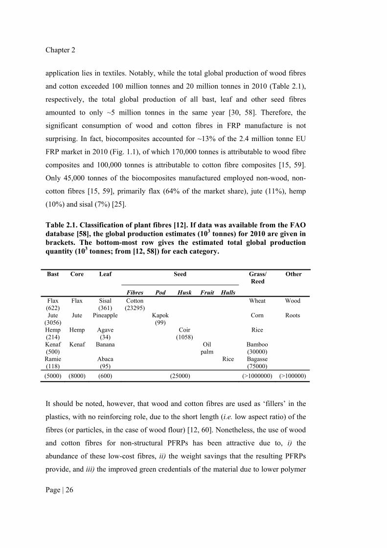
There are five basic types of plant fibres, classified as follows: i) bast fibres, from the
inner bark of the plant stems, iii) leaf fibres, iv) seed fibres, v) grass and reed fibres,
and vi) all other fibres (including wood fibres). Examples of the different fibre types
and their estimated annual global production values are shown in Table 2.1.
In terms of utilization, plant fibres can be classed as being from primary or secondary
plants. Primary plants (like flax, sisal, cotton, bamboo, hardwood/softwood trees) are
cultivated specifically for their fibre content, while fibres from secondary plants (like
pineapple leaf, coir, oil palm (empty fruit bunch), bagasse, rice straw) are a by-
product from some other primary utilization. Hence, although plant straws and stalks
(secondary source) are a potentially larger source of fibre than even wood fibres
(primary source) (Table 2.1), the former are predominantly used as livestock feed or
bio-fuel [55-57].
Other than wood fibres (including flour and pulp), commercially useful fibres come
mainly from the bast, leaf, and seed coverings of specific plants, whose principal
Chapter 2
Page | 26
application lies in textiles. Notably, while the total global production of wood fibres
and cotton exceeded 100 million tonnes and 20 million tonnes in 2010 (Table 2.1),
respectively, the total global production of all bast, leaf and other seed fibres
amounted to only ~5 million tonnes in the same year [30, 58]. Therefore, the
significant consumption of wood and cotton fibres in FRP manufacture is not
surprising. In fact, biocomposites accounted for ~13% of the 2.4 million tonne EU
FRP market in 2010 (Fig. 1.1), of which 170,000 tonnes is attributable to wood fibre
composites and 100,000 tonnes is attributable to cotton fibre composites [15, 59].
Only 45,000 tonnes of the biocomposites manufactured employed non-wood, non-
cotton fibres [15, 59], primarily flax (64% of the market share), jute (11%), hemp
(10%) and sisal (7%) [25].
Table 2.1. Classification of plant fibres [12]. If data was available from the FAO database [58], the global production estimates (103 tonnes) for 2010 are given in brackets. The bottom-most row gives the estimated total global production quantity (103 tonnes; from [12, 58]) for each category.
Bast Core Leaf Seed Grass/ Reed
Other
Fibres Pod Husk Fruit Hulls Flax (622)
Flax
Sisal (361)
Cotton (23295)
Wheat
Wood
Jute
(3056) Jute
Pineapple
Kapok (99)
Corn
Roots
Hemp (214)
Hemp
Agave (34)
Coir
(1058)
Rice
Kenaf (500)
Kenaf
Banana
Oil
palm
Bamboo (30000)
Ramie (118)
Abaca (95)
Rice
Bagasse (75000)
(5000) (8000) (600) (25000) (>1000000) (>100000)
It should be noted, however, that wood and cotton fibres are used as ‘fillers’ in the
plastics, with no reinforcing role, due to the short length (i.e. low aspect ratio) of the
fibres (or particles, in the case of wood flour) [12, 60]. Nonetheless, the use of wood
and cotton fibres for non-structural PFRPs has been attractive due to, i) the
abundance of these low-cost fibres, ii) the weight savings that the resulting PFRPs
provide, and iii) the improved green credentials of the material due to lower polymer
Background: Plant fibres and their composites
Page | 27
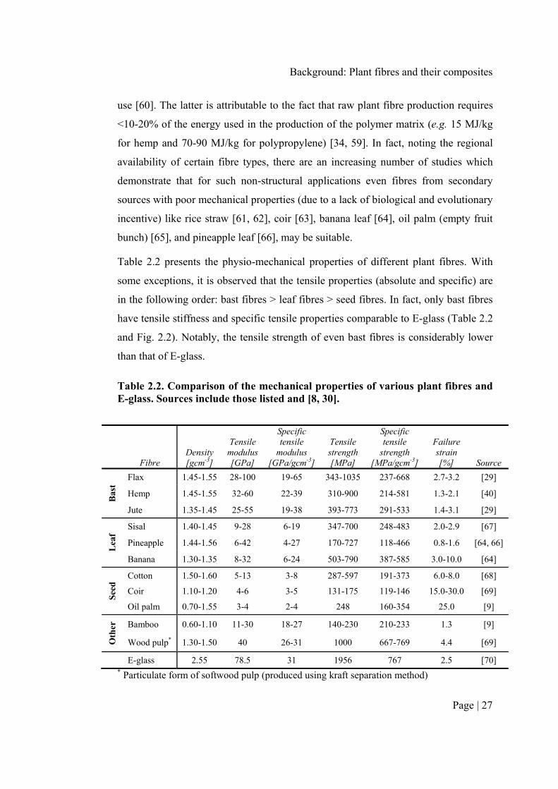
use [60]. The latter is attributable to the fact that raw plant fibre production requires
<10-20% of the energy used in the production of the polymer matrix (e.g. 15 MJ/kg
for hemp and 70-90 MJ/kg for polypropylene) [34, 59]. In fact, noting the regional
availability of certain fibre types, there are an increasing number of studies which
demonstrate that for such non-structural applications even fibres from secondary
sources with poor mechanical properties (due to a lack of biological and evolutionary
incentive) like rice straw [61, 62], coir [63], banana leaf [64], oil palm (empty fruit
bunch) [65], and pineapple leaf [66], may be suitable.
Table 2.2 presents the physio-mechanical properties of different plant fibres. With
some exceptions, it is observed that the tensile properties (absolute and specific) are
in the following order: bast fibres > leaf fibres > seed fibres. In fact, only bast fibres
have tensile stiffness and specific tensile properties comparable to E-glass (Table 2.2
and Fig. 2.2). Notably, the tensile strength of even bast fibres is considerably lower
than that of E-glass.
Table 2.2. Comparison of the mechanical properties of various plant fibres and E-glass. Sources include those listed and [8, 30].
Fibre Density [gcm-3]
Tensile modulus [GPa]
Specific tensile
modulus [GPa/gcm-3]
Tensile strength [MPa]
Specific tensile
strength [MPa/gcm-3]
Failure strain [%] Source
Bas
t
Flax 1.45-1.55 28-100 19-65 343-1035 237-668 2.7-3.2 [29]
Hemp 1.45-1.55 32-60 22-39 310-900 214-581 1.3-2.1 [40]
Jute 1.35-1.45 25-55 19-38 393-773 291-533 1.4-3.1 [29]
Lea
f
Sisal 1.40-1.45 9-28 6-19 347-700 248-483 2.0-2.9 [67]
Pineapple 1.44-1.56 6-42 4-27 170-727 118-466 0.8-1.6 [64, 66]
Banana 1.30-1.35 8-32 6-24 503-790 387-585 3.0-10.0 [64]
See
d Cotton 1.50-1.60 5-13 3-8 287-597 191-373 6.0-8.0 [68]
Coir 1.10-1.20 4-6 3-5 131-175 119-146 15.0-30.0 [69]
Oil palm 0.70-1.55 3-4 2-4 248 160-354 25.0 [9]
Oth
er
Bamboo 0.60-1.10 11-30 18-27 140-230 210-233 1.3 [9]
Wood pulp* 1.30-1.50 40 26-31 1000 667-769 4.4 [69]
E-glass 2.55 78.5 31 1956 767 2.5 [70] * Particulate form of softwood pulp (produced using kraft separation method)

Chapter 2
Page | 28
To observe the reinforcing effect of the different plant fibres in a composite, Table
2.3 presents typically reported mechanical properties of compression moulded
polypropylene (PP) composites reinforced with randomly-oriented short-fibre mats.
Table 2.3. Typically reported mechanical properties of compression moulded PP composites reinforced with various non-woven (randomly-oriented short-fibre) plant fibre mats. For comparison, the mechanical properties of neat PP and chopped strand E-glass mat reinforced PP are also given.
Fibre reinforcement
Fibre content*
[wt%]
Tensile modulus[GPa]
Specific tensile
modulus† [GPa/gcm-3]
Tensile strength[MPa]
Specific tensile
strength† [MPa/gcm-3] Source
PP 0 0.7-1.7 1.1-1.9 19-35 21-39 [40]
Bas
t
Flax 40 8.8 8.0 57 52 [71]
Hemp 40 6.9 6.3 52 47 [17]
Jute 40 3.7 3.5 27 25 [17]
Lea
f
Sisal 40 5.3 4.9 34 31 [17]
Pineapple 20 0.6 0.6 32 32 [72]
Banana 50 1.5 1.4 31 29 [73]
See
d Cotton 30 1.9 1.8 27 26 [74]
Coir 40 1.2 1.2 10 10 [17]
Oil palm 40 0.7 0.7 8 8 [75]
Oth
er
Bamboo 50 3.6 3.7 30 30 [76]
Wood fibre 35 1.4 1.3 21 19 [60]
E-glass 50 7.0 4.8 33 68 [77]
E-glass 42 6.2 4.9 89 23 [17] * Fibre content is approximate. † Estimated values. Composite density is estimated assuming no porosity and using fibre densities in Table 2.2 and a density for PP of 0.91 gcm-3.
Expectedly, it is observed that PP reinforced with bast fibres exhibit significantly
superior mechanical properties in comparison to leaf and seed fibre reinforced PP. In
fact, the tensile properties (absolute and specific) of leaf, seed and wood fibre
reinforced PP is barely comparable to unreinforced PP. On the other hand, bast fibre
reinforcements not only improve the tensile properties of the matrix considerably, but

Background: Plant fibres and their composites
Page | 29
the resulting composites can compete against even GFRPs in terms of (absolute and
specific) tensile stiffness and strength. Therefore, if certain structural requirements
need to be met, it is essential that bast fibres (or other selective fibres like sisal and
bamboo) are used as reinforcements (not fillers) in FRPs. Perhaps, this is why
composites reinforced with bast fibres are now replacing under-performing wood
fibre composites and GFRPs in automotive applications [15].
2.5.2 Plant fibre structure
While it is clear from the previous section that bast fibres have superior mechanical
properties in comparison to leaf and seed fibres, understanding the reasons behind
this may prove useful in developing structural PFRPs.
One approach is considering the role of the fibre in the living plant [12]. Bast fibres
(and some grass fibres like bamboo) provide rigidity and strength to the plant stems,
so they would be ideal in stiffening/strengthening composites. Leaf fibres experience
repetitive flexing from the wind, so they would be useful for toughening composites.
As seed fibres have no structural role, they would not reinforce a plastic effectively.
A more fundamental and quantitative approach involves understanding the influence
of the chemical and physical structure of plant fibres on their mechanical properties.
Each elementary plant fibre is a single cell with an elongated thick cell wall
surrounding a central luminal cavity (Fig. 2.4). While the cell wall is responsible for
the structural integrity of the living plant, the luminal cavity facilitates transportation
of nutrients. Although having a high aspect ratio, the cross-sectional shape and
dimensions of the cells are highly variable [30]. Typically, elementary plant fibres
are found in bundles (in the form of a technical fibre), where the middle lamella (a
pectin layer) cements the cell walls of two adjoining cells together (Fig. 2.4).
As depicted in Fig. 2.4, the cell wall has a hierarchical structure, including a thin
primary (P) cell wall, and a thick secondary (S) cell wall which exists in three sub-
layers (S1, S2, S3). Typically, the primary cell wall accounts for less than 2% of the
total cell wall thickness, while the secondary cell wall accounts for up to 90% of the
total cell wall thickness [78]. Notably, the S2 cell wall is the main sub-layer,
accounting for more than 80% of the total cell wall thickness [78]. The luminal

Chapter 2
Page | 30
cavity is typically up to 25% of the total cross-sectional area for non-wood plant
fibres [30, 79], and usually between 2-16% for bast fibres [78].
Plant fibres themselves can be referred to as composites as the cell wall composes of
reinforcing oriented semi-crystalline cellulose microfibrils which are embedded in a
two-phase (lignin-hemicellulose) amorphous matrix. The content of the three main
polymers (i.e. cellulose, hemicellulose and lignin) is known to vary between plant
fibre types [30]. The typical chemical composition of flax is given in Table 2.4.
Fig. 2.4. The structure of an elementary fibre (i.e. a unit cell) in a technical fibre bundle, where the middle lamella (M) glues adjacent cells together, and each unit cell composes of primary (P) and secondary (S) cell walls and a central lumen (L).
Cellulose, a non-branched macromolecule (Fig. 2.5), is usually the major component
of plant fibres (Table 2.4). Molecular chains of cellulose, comprising of about 10,000
pairs of covalent-bonded glucose units, are oriented in the fibre direction. Each
repeating glucose unit contains three hydroxyl groups, which enables cellulose to
form strong hydrogen bonds with its own chains to form fibrils, and with
L
L
LL
S3
S2
S1
P
M
M
P
S3
S2
S1

Background: Plant fibres and their composites
Page | 31
neighbouring chains to form microfibrils [80]. It is well known that cellulose has
both crystalline and amorphous regions, depending on whether the cellulose chains
are held in a highly ordered (crystalline) structure due to intermolecular hydrogen
bonding. Notably, crystalline and amorphous cellulose have very different
mechanical properties; for instance, the tensile stiffness of crystalline cellulose (in
the chain direction) is up to 15 times more than that of amorphous cellulose (Table
2.4). Furthermore, while amorphous cellulose is isotropic, the molecular linearity of
crystalline cellulose makes it very anisotropic [78]. Flax fibres, for instance,
comprise of 55-75 wt% cellulose, of which 53-70 % is crystalline (Table 2.4).
Fig. 2.5. Molecular structure of cellulose [22].
Table 2.4. Typical chemical composition of flax fibre, alongside the density and tensile stiffness of the various constituents. From [30, 78].
Crystalline cellulose
Amorphous cellulose
Hemicellulose Lignin Pectin
Content in flax [wt%]
30-50 20-30 14-18 2-3 2-3
Density [gcm-3]
1.6 1.42 1.4 1.4 -
Tensile modulus [GPa]
74-168 8-11 7-8 2-4 -
Cellulose microfibrils are helically wound around the cell wall, and thus are at an
angle with respect to the fibre axis (Fig. 2.4). The cell walls also consist of
heterogeneous, non-linear and highly-branched hemicellulose and lignin molecules.
It is agreed that the hemicellulose molecules are hydrogen bonded to the cellulose

Chapter 2
Page | 32
microfibrils and act as a cementing matrix between adjacent microfibrils. These
structural cellulose/hemicellulose units are then encapsulated by a lignin matrix.
Importantly, both the chemical composition and the orientation of the cellulose
microfibrils with respect to the fibre axis, vary between cell wall layers [30, 78]. As
the S2 cell wall layer is the thickest, it is the microfibril angle (MFA) of the S2 cell
wall that is of particular interest.
It is obvious that the chemical composition of a plant fibre would strongly affect its
properties. For instance, the hydrophilic nature of cellulose and hemicellulose
implies that plant fibres have a high moisture content (typically 5-15 wt% [10]) and
the resulting composites have poor moisture resistance. Furthermore, it is known [79]
that fibre chemical composition, cellulose crystallinity and density are correlated.
Four critical micro-structural parameters that affect the mechanical properties of
plant fibres include: i) cellulose content, ii) cellulose crystallinity, iii) microfibril
angle, and iv) fibre aspect ratio. Studies performed by McLaughlin and Tait [81] and
Satyanarayana et al. [82, 83] conclude that these four parameters are strongly
correlated to the tensile properties of plant fibres. Several studies on the prediction of
plant fibre tensile properties also incorporate these four parameters [78, 84, 85].
Table 2.4 presents the typical tensile modulus of the different chemical constituents
of a plant fibre. Crystalline cellulose has significantly better stiffness than all other
constituents. In fact, even the transverse stiffness of crystalline cellulose (about 27
GPa [78]) is over 3 times higher than the stiffness of amorphous cellulose,
hemicellulose and lignin. Hence, it is clear that not only high cellulose content, but
high cellulose crystallinity is also desirable, when selecting plant fibres for use as
reinforcements in structural applications. Furthermore, due to the highly anisotropic
nature of crystalline cellulose, a low MFA is desirable so that the cellulose
microfibrils are oriented in the fibre direction. Finally, several studies [84, 86]
confirm that for a constant test gauge length, the tensile modulus and strength of a
plant fibre increases with decreasing fibre diameter (i.e. increasing fibre aspect ratio).
A higher fibre aspect ratio is also desirable for improved load transfer capability in a
fibre reinforced composite.
Background: Plant fibres and their composites
Page | 33
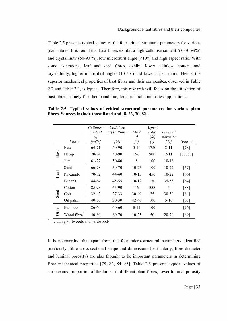
Table 2.5 presents typical values of the four critical structural parameters for various
plant fibres. It is found that bast fibres exhibit a high cellulose content (60-70 wt%)
and crystallinity (50-90 %), low microfibril angle (<10°) and high aspect ratio. With
some exceptions, leaf and seed fibres, exhibit lower cellulose content and
crystallinity, higher microfibril angles (10-50°) and lower aspect ratios. Hence, the
superior mechanical properties of bast fibres and their composites, observed in Table
2.2 and Table 2.3, is logical. Therefore, this research will focus on the utilisation of
bast fibres, namely flax, hemp and jute, for structural composites applications.
Table 2.5. Typical values of critical structural parameters for various plant fibres. Sources include those listed and [8, 23, 30, 82].
Fibre
Cellulose content
vx [wt%]
Cellulose crystallinity
[%]
MFA θ
[°]
Aspect ratio lf/df
[-]
Luminal porosity
[%] Source
Bas
t
Flax 64-71 50-90 5-10 1750 2-11 [78]
Hemp 70-74 50-90 2-6 900 2-11 [78, 87]
Jute 61-72 50-80 8 100 10-16
Lea
f
Sisal 66-78 50-70 10-25 100 10-22 [67]
Pineapple 70-82 44-60 10-15 450 10-22 [66]
Banana 44-64 45-55 10-12 150 35-53 [64]
See
d Cotton 85-93 65-90 46 1000 5 [88]
Coir 32-43 27-33 30-49 35 30-50 [64]
Oil palm 40-50 20-30 42-46 100 5-10 [65]
Oth
er
Bamboo 26-60 40-60 8-11 100 [76]
Wood fibre* 40-60 60-70 10-25 50 20-70 [89] * Including softwoods and hardwoods.
It is noteworthy, that apart from the four micro-structural parameters identified
previously, fibre cross-sectional shape and dimensions (particularly, fibre diameter
and luminal porosity) are also thought to be important parameters in determining
fibre mechanical properties [78, 82, 84, 85]. Table 2.5 presents typical values of
surface area proportion of the lumen in different plant fibres; lower luminal porosity
Chapter 2
Page | 34
would lead to better tensile properties. Several authors, for instance [34, 45, 46, 78,
84, 90], have reported that lower fibre diameter also leads to improved fibre tensile
stiffness. While there is no ready explanation in literature to explain this
phenomenon [78], Baley et al. [45, 84, 90] and Summerscales et al. [46] have
hypothesised that this may be due to the lumen size increasing with fibre diameter.
Placet et al. [78] and Gassan et al. [85] have also demonstrated through their models
on the elastic properties of bast fibres that an only an increase in surface area
proportion of the lumen (i.e. a reduction in the load-bearing area of the fibre), as a
function of fibre diameter, could justify a decrease in fibre stiffness. However, both
Placet et al. [78] and Summerscales et al. [46] acknowledge that this assumed
relationship of increasing lumen size with increasing fibre diameter is not currently
supported by morphological studies on hemp and jute fibres. Structural effects, such
as the microfibril angle being a function of the fibre diameter, have been deemed
unlikely to explain the diameter dependence of fibre modulus [46, 78].
Of interest is a recent analysis by Porter et al. [91] which shows that the fibre
diameter plays a key role in determining fibre properties for both natural and
synthetic polymer fibres. Applying Griffith observations, which combines fracture
mechanics and inelastic deformations, to a variety of fibres, Porter et al. [91] find
that the fibre fracture strength is directly proportional (R2 = 0.90) to the square root
of the ratio of the fibre stiffness to the fibre diameter, i.e. σf = √(G·Ef/df), where G is
the strain energy release rate (determined to be 1000 Jm-2), for a large range of
polymer fibres. As is suggested by the results of Porter et al. [91], for a given fibre
(with a given characteristic fibre strength), the fibre stiffness would thus be
characteristically inversely proportional to the fibre diameter. The latter is observed
by Virk et al. [46], inspiring them to define a fibre diameter distribution factor ηd for
the modified ROM model (discussed in Section 2.4). Other than the diameter
dependence of fibre tensile properties, Gassan et al. [85] have shown that the cross-
sectional shape of the fibre may affect the fibre tensile properties. In fact, the tensile
modulus is lower for circular cross-section shaped fibres than for elliptical cross-
sectional shaped fibres [85]. This is possibly due to higher transverse fibre aspect
ratio for elliptical cross-sectional shaped fibres.
Background: Plant fibres and their composites
Page | 35
2.5.3 Plant fibre processing
2.5.3.1 Plant growth and fibre extraction
Plant fibres, even of the same type, have highly variable properties. The variability in
properties can be ascribed to the variability in the previously described fibre micro-
structural parameters. Indeed, even for a given plant fibre type, the fibre micro-
structural parameters, which dictate the fibre quality, are themselves influenced by i)
plant growth conditions (including, plant species, geographic location, climate, soil
characteristics, crop cultivation), ii) fibre extraction and preparation (including, age
of plant, fibre location in plant, type of retting method, decortification and carding
processes), and iii) fibre processing (including, spinning to produce rovings from
slivers and yarns from rovings, and production of mats and textile preforms from
slivers/rovings/yarns). Several review articles and studies (for instance, [21, 23, 25-
27, 29, 31, 92-94]) have discussed the influence of these factors on the fibre and
composite properties. To ensure that the quality of their products is consistent (i.e.
the variability in properties is within acceptable limits) and independent of plant
growth conditions, suppliers of plant fibres/yarns typically use ‘batch-mixing’, across
several crops/harvests/years.
Regarding optimising fibre extraction and processing, the resounding message of
scientific studies is that an increasing number of mechanical processing steps leads to
an increase in defect count (in the form of kink bands, for instance), a reduction in
degree of polymerization of the cellulose chains, and a subsequent reduction in fibre
mechanical properties [26, 92]. Minimally-processed fibres that have undergone
retting and hackling produce high quality fibres and good quality composites [21, 25,
27]. However, to ensure full utilisation of fibre properties in a composite, a
continuous and aligned reinforcement product is required. Once fibres have been
carded or cottonised to produce a (typically coarse i.e. high linear density) sliver,
rovings can be produced through a wet-spinning process, and yarns can produced
through a dry-spinning process. Notably, the level of twist imparted to the product
increases at each stage [21]. As will be discussed in depth in Chapter 5, increasing
twist levels have various detrimental effects on composite properties, including

Chapter 2
Page | 36
hindered resin impregnation, reduced wettability, increased intra-yarn void formation
and a significant quantifiable drop in tensile properties, similar to an off-axis
composite, due to increased fibre misorientation [19, 21, 95]. Interestingly, structure-
property relations of twisted yarns imply that for the same twist level, yarns of fine
count (low linear density) have a smaller diameter than heavier yarns. The result is
that the twist angle in fine count yarns, and the induced reinforcement misorientation
and subsequent reduction in composite properties, is smaller [21]. Therefore, to
achieve a compromise between i) minimal fibre processing, ii) employing
aligned/continuous reinforcements, and iii) limiting the detrimental effects of yarn
twist, the order of preference for a reinforcement product is: slivers, followed by
rovings, followed by fine-count yarns [21, 25].
Complementary to the studies on the effect of fibre processing on fibre and
composite mechanical properties are life cycle assessment studies by Joshi et al. [3],
Dissanayake et al. [34, 96-98], Steger [4] and Le Duigou et al. [99]. Dissanayake et
al. [34, 96-98] quantified the energy required in the production of UK flax fibres, and
found that while the energy required for cultivating plant fibres is low (4-15 MJ/kg of
processed fibre), the use of agrochemicals and retting processes increases the energy
consumption significantly (by 38-110 MJ/kg of processed fibre). An independent
analysis by Le Duigou et al. [99] on French flax fibres, based on a different set of
assumptions, provides a similar conclusion. Water retting is found to be least energy
intensive, followed by dew retting and bio-retting [34, 96, 98]. Conversion from
fibres to semi-products through textile processes increases the energy consumption
further by 2-15 and 26-40 MJ/kg of processed fibre, for slivers and yarns respectively
[34, 96]. The total energy required is 54-118 MJ/kg for flax sliver and 81-146 MJ/kg
for flax yarn [34]. This compares to 55 MJ/kg for E-glass reinforcement mats and 90
MJ/kg for polypropylene fibres [34]. Hence, even in terms of minimising the
environmental impact of plant fibre reinforcements, minimal processing is attractive.
2.5.3.2 Fibre surface modification
The hydrophilic nature of plant fibres has led to the popular view, particularly
amongst researchers of PFRPs, regarding the vulnerability of plant fibres and their

Background: Plant fibres and their composites
Page | 37
composites to moisture absorption and the poor compatibility of highly polar plant
fibres with typically non-polar polymer matrices [17]. While the former is a concern
for the long-term durability of PFRPs, the latter is a concern for the general
mechanical performance of PFRPs. Not surprisingly, a significant amount of work
has been undertaken, reviewed by several authors in [9, 23, 33, 100, 101], to explore
various avenues in improving the fibre/matrix interfacial properties. The two
fundamental routes are fibre surface physical/chemical modification and matrix
modification. The former is usually preferred over the latter. The aim of physical
modification techniques, such as plasma treatment or mercerisation, is to roughen the
fibre surface topography and/or remove surface impurities (such as oils, waxes,
pectin), enabling improved mechanical adhesion between the fibre and the matrix. In
chemical modification techniques, a third material is introduced, as a compatibiliser
or coupling agent, between the fibre and the matrix.
The question is: Is fibre surface modification necessary to achieve good mechanical
properties in all PFRPs? In Section 2.4 it has been described that there is an
ineffective fibre length below which the fibre does not carry the maximum load. The
contribution of the fibre in reinforcing the composite (i.e. the length efficiency
factor) is determined by the ratio of the critical fibre length to the reinforcing fibre
length (Eq. 2.6). Notably, the critical fibre length is directly proportional to the ratio
of the fibre tensile strength and fibre/matrix interfacial shear strength (Eq. 2.6). An
interesting inference of these relationships is the following: assuming that i) a given
plant fibre has the same diameter as E-glass (which is true in the case of flax [30]),
and ii) a PFRP and GFRP are to be manufactured with reinforcing fibres of the same
length, then for the critical fibre length (and thus length efficiency factor) to be the
same in the PFRP and the GFRP, the ratio of the fibre strength to the interfacial shear
strength needs to be the same in PFRP and the GFRP. In essence, as plant fibres have
a lower tensile strength than E-glass, PFRPs require a proportionally lower interfacial
shear strength than GFRPs. Therefore, the common notion that PFRPs have poor
interfacial shear strength in comparison to GFRPs, is rather trivial.
Chapter 2
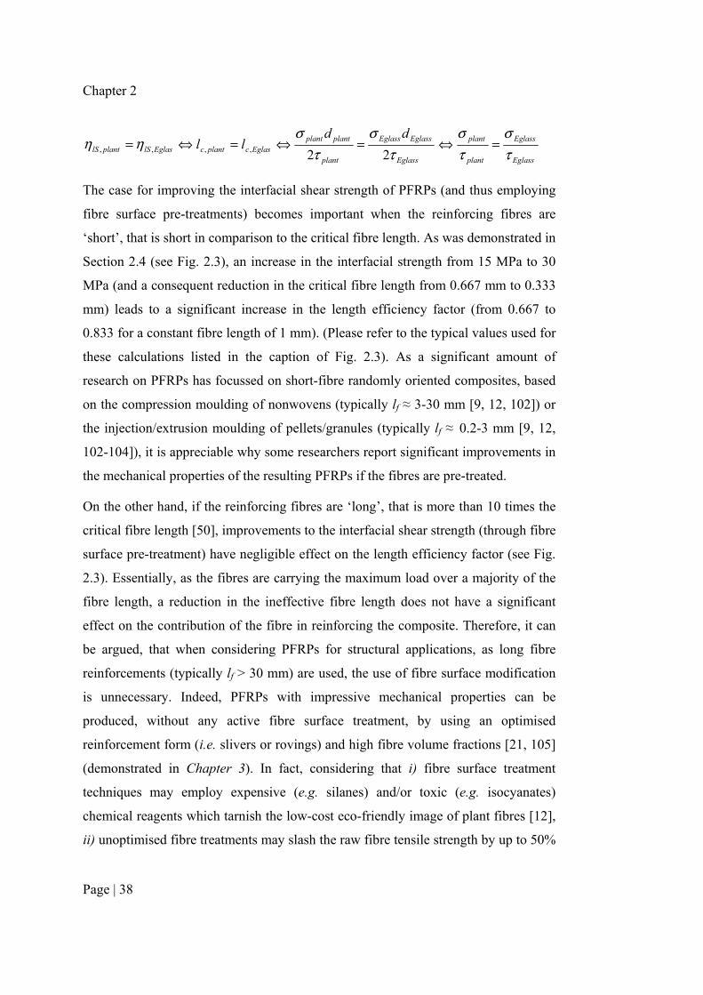
Page | 38
Eglass
Eglass
plant
plant
Eglass
EglassEglass
plant
plantplantEglascplantcEglaslSplantlS
ddll
τσ
τσ
τσ
τσ
ηη =⇔=⇔=⇔=22,,,,
The case for improving the interfacial shear strength of PFRPs (and thus employing
fibre surface pre-treatments) becomes important when the reinforcing fibres are
‘short’, that is short in comparison to the critical fibre length. As was demonstrated in
Section 2.4 (see Fig. 2.3), an increase in the interfacial strength from 15 MPa to 30
MPa (and a consequent reduction in the critical fibre length from 0.667 mm to 0.333
mm) leads to a significant increase in the length efficiency factor (from 0.667 to
0.833 for a constant fibre length of 1 mm). (Please refer to the typical values used for
these calculations listed in the caption of Fig. 2.3). As a significant amount of
research on PFRPs has focussed on short-fibre randomly oriented composites, based
on the compression moulding of nonwovens (typically lf ≈ 3-30 mm [9, 12, 102]) or
the injection/extrusion moulding of pellets/granules (typically lf ≈ 0.2-3 mm [9, 12,
102-104]), it is appreciable why some researchers report significant improvements in
the mechanical properties of the resulting PFRPs if the fibres are pre-treated.
On the other hand, if the reinforcing fibres are ‘long’, that is more than 10 times the
critical fibre length [50], improvements to the interfacial shear strength (through fibre
surface pre-treatment) have negligible effect on the length efficiency factor (see Fig.
2.3). Essentially, as the fibres are carrying the maximum load over a majority of the
fibre length, a reduction in the ineffective fibre length does not have a significant
effect on the contribution of the fibre in reinforcing the composite. Therefore, it can
be argued, that when considering PFRPs for structural applications, as long fibre
reinforcements (typically lf > 30 mm) are used, the use of fibre surface modification
is unnecessary. Indeed, PFRPs with impressive mechanical properties can be
produced, without any active fibre surface treatment, by using an optimised
reinforcement form (i.e. slivers or rovings) and high fibre volume fractions [21, 105]
(demonstrated in Chapter 3). In fact, considering that i) fibre surface treatment
techniques may employ expensive (e.g. silanes) and/or toxic (e.g. isocyanates)
chemical reagents which tarnish the low-cost eco-friendly image of plant fibres [12],
ii) unoptimised fibre treatments may slash the raw fibre tensile strength by up to 50%

Background: Plant fibres and their composites
Page | 39
[24], iii) there is a lack of consensus in literature on the surface treatment parameters
to use (e.g. concentration of reagent, treatment time, temperature) to achieve
improvements in PFRP mechanical properties [24], and iv) improvements in
interfacial properties often lead to a reduction in impact and toughness performance
(due to reduced fibre pull-out) [17], the use of fibre surface modification to
potentially improve the mechanical properties of structural PFRPs is discouraged.
2.6 FIBRE VOLUME FRACTION
As already mentioned, the mechanical properties of a composite are dependent not
only on the properties of the constituents, but more so on the volumetric composition
of the composite. In fact, the fibre volume fraction vf is the single-most important
factor in the rule of mixtures model (Eq. 2.1-2.4). For FRPs in general,
improvements in most mechanical properties, including stiffness (tensile, flexural,
compressive, shear) and strength (tensile, flexural, compressive, shear, impact), can
be made by simply increasing the fibre volume fraction [50]. Indeed, several studies,
particularly those employing aligned reinforcements, have shown this to be the case
for PFRPs (such as [105-107]).
To produce PFRPs with high fibre content, it is generally suggested that due to the
low compactability of plant fibre assemblies [12, 107], the plant fibre preforms need
to be compacted using external force. As the literature survey in Table 2.6 reveals,
compression moulding (including hot- and cold-pressing) has been the most popular
method so far. It is being used for the manufacture of both thermoplastic- and
thermoset-based PFRPs [9, 12]. Indeed, current commercial applications of PFRPs
are primarily based on compression moulded components (Fig. 1.1) [15, 59]. In the
case of liquid thermoset resins, a ‘leaky mould’ is typically used, where the excess
resin is forced out during mould compaction [12].
From Table 2.6 it is clearly observed that amongst thermoset-based PFRPs, hand lay-
up and vacuum infusion produce lower fibre content than compression moulding.
Comparing hand layup and compression moulding techniques in the manufacture of
flax/epoxy composites, Charlet et al. [108] find that the maximum achievable fibre
volume fractions were ~15% and ~40%, respectively. While compression moulding
Chapter 2
Page | 40
is suitable for high-volume part production at low-cycle times, the limitation with
compression moulding is the component size that can be manufactured. Large
structural components produced at a much lower rate, such as wind turbine blades,
are typically manufactured through vacuum infusion, resin transfer moulding (RTM)
or prepregging technology. The literature survey in Table 2.6 finds that fibre volume
fractions achievable through RTM and prepregging technology (up to 50%) are
comparable to compression moulding (up to 60%), noting that the latter is more
prone to porosity-related issues [50].
2.7 ASHBY PLOT FOR PFRPS
The construction of a materials selection chart (i.e. Ashby plot) relies heavily on a
large database that captures, and is representative of the variability in (i.e. range of),
typical properties. To generate such a database, an extensive literature survey was
conducted on the (absolute and specific) tensile properties of bast fibre reinforced
PFRPs. The literature survey is partly presented in the form of Table 2.6. The wide-
ranging database looks to particularly elucidate the effects of i) reinforcement
geometry and orientation (pellets, short-random nonwovens, and long-aligned fibres
for unidirectional and multiaxials), ii) matrix type (thermoplastic vs. thermoset), and
ii) manufacturing technique (injection moulding, compression moulding, hand lay-
up, vacuum infusion, resin transfer moulding and prepregging), on the tensile
properties of bast fibre reinforced PFRPs. While the specific effects of each will be
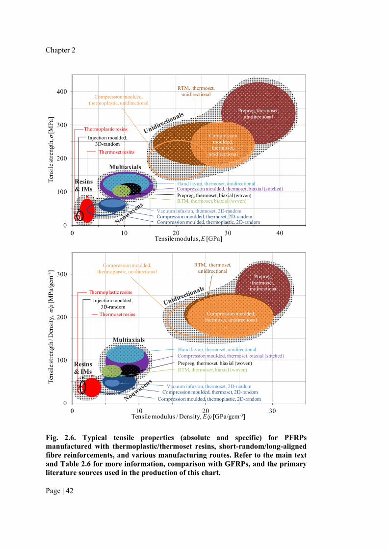
discussed in some detail in the following sections, here Ashby plots are presented for
the PFRP materials (Fig. 2.6), showing the absolute and specific tensile strength
plotted against the absolute and specific tensile stiffness, respectively. Note that the
fibre volume fraction of the PFRPs may be dissimilar.
Ashby plots, such as the ones presented in Fig. 2.6, are very useful for four key
reasons [38, 39]: i) they allow quick retrieval of the typical properties of a particular
material, ii) they allow quick comparison of the properties of different materials,
revealing their comparative efficiencies, iii) they facilitate the selection of the
materials/manufacturing processes during the product design stage, and iv) they
enable substitution studies exploring the potential of one material to replace another.

Background: Plant fibres and their composites
Page | 41
It is quite clear from the Ashby plots in Fig. 2.6 that PFRPs can be categorised into
four distinct sub-groups, with increasing tensile properties in the following order: i)
Injection-moulded PFRPs, whose mechanical properties are low and comparable to
the matrix material, ii) PFRPs based on nonwoven reinforcements (randomly-
oriented short fibres), iii) PFRPs based on textile reinforcements (woven and stitched
biaxials, for instance) and iv) unidirectional PFRPs. It is also observed that tensile
strength and stiffness tend to increase linearly with each other. Observing the
variation in properties within each sub-group, it is found that thermoset-based PFRPs
have better mechanical properties than thermoplastic-based PFRPs. Furthermore, the
manufacturing technique can have a noticeable effect on PFRP mechanical
properties, particularly in the case of unidirectional PFRPs.
The Asbhy plot in Fig. 2.6 can be expanded to include typical tensile properties of
various GFRPs to enable a comparison between properties achievable with GFRPs
and PFRPs. In fact, although the data has not been graphically shown in Fig. 2.6, the
literature survey of Table 2.6 includes example tensile properties of GFRPs. The
comparison reveals that when comparing short-fibre reinforced composites (i.e.
injection moulded and nonwoven composites), PFRPs have better tensile modulus
(specific and absolute) and comparable specific tensile strength than GFRPs. On the
other hand, when comparing long-fibre reinforced composites (i.e. textile and
unidirectional composites), PFRPs have better specific tensile modulus than GFRPs;
the specific tensile strength of PFRPs is only up to half that of GFRPs.
Although the Asbhy plot in Fig. 2.6 suggests that unidirectional PFRPs, for instance
provide 2 to 20 times better tensile properties than nonwoven PFRPs and up to 5
times better tensile properties than multiaxial PFRPs, this does not necessarily mean
that unidirectional PFRPs would be preferred over the other materials for all
structural applications. To truly enable substitution studies exploring the potential of
one material to replace another, other material properties, such as cost and fatigue
performance, may need to be taken into other, depending on the specific component
function, objectives and constraint for a given application.
Chapter 2
Page | 42
0
100
200
300
400
0 10 20 30 40
Ten
sile
str
engt
h, σ
[MP
a]
Tensile modulus, E [GPa]
Prepreg, thermoset, unidirectional
Compression moulded, thermoset,
unidirectional
RTM, thermoset,unidirectionalCompression moulded,
thermoplastic, unidirectional
Hand layup, thermoset, unidirectional
Vacuum infusion, thermoset, 2D-randomCompression moulded, thermoset, 2D-randomCompression moulded, thermoplastic, 2D-random
Injection moulded, 3D-random
Thermoset resins
Thermoplastic resins
Prepreg, thermoset, biaxial (woven)Compression moulded, thermoset, biaxial (stitched)
Multiaxials
RTM, thermoset, biaxial (woven)
Resins & IMs
0
100
200
300
0 10 20 30
Ten
sile
str
engt
h / D
ensi
ty, σ/ρ
[MP
a/gc
m-3
]
Tensile modulus / Density, E/ρ [GPa/gcm-3]
Prepreg, thermoset,
unidirectional
Compression moulded, thermoset, unidirectional
RTM, thermoset,unidirectional
Compression moulded, thermoplastic, unidirectional
Compression moulded, thermoset, biaxial (stitched)
Vacuum infusion, thermoset, 2D-randomCompression moulded, thermoset, 2D-random
Compression moulded, thermoplastic, 2D-random
Injection moulded, 3D-random
Thermoset resins
Thermoplastic resins
Hand layup, thermoset, unidirectional
Prepreg, thermoset, biaxial (woven)RTM, thermoset, biaxial (woven)
Multiaxials
Resins & IMs
Fig. 2.6. Typical tensile properties (absolute and specific) for PFRPs manufactured with thermoplastic/thermoset resins, short-random/long-aligned fibre reinforcements, and various manufacturing routes. Refer to the main text and Table 2.6 for more information, comparison with GFRPs, and the primary literature sources used in the production of this chart.
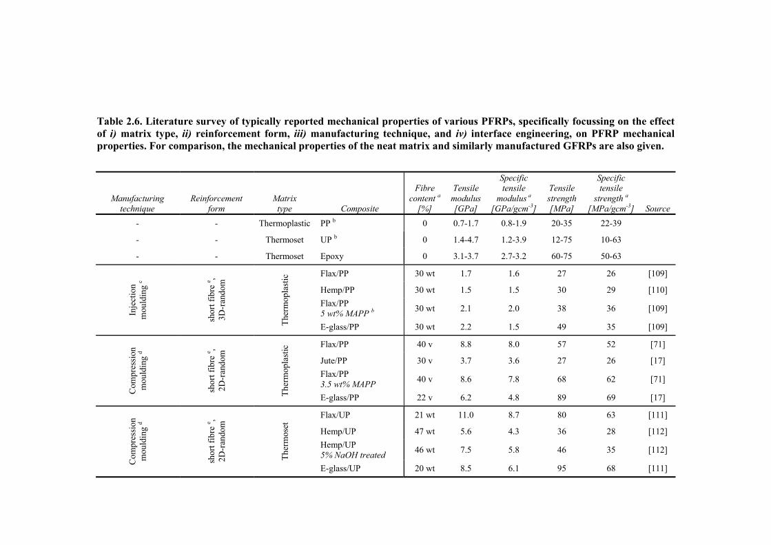
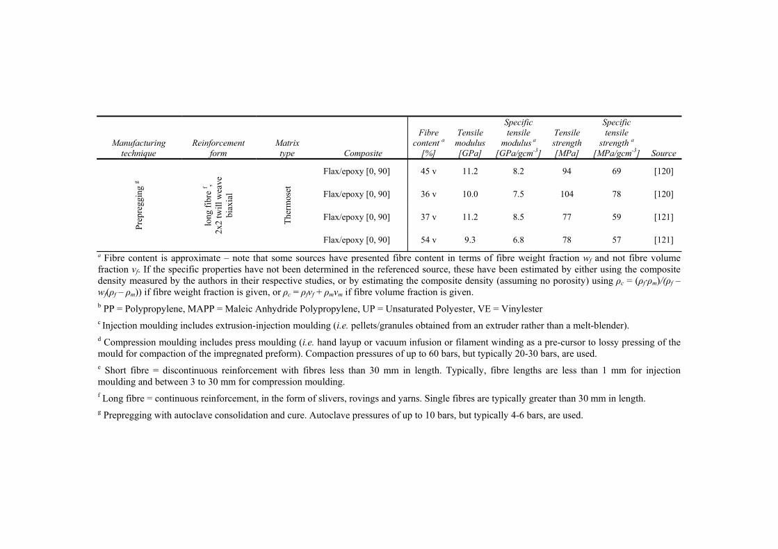
Table 2.6. Literature survey of typically reported mechanical properties of various PFRPs, specifically focussing on the effect of i) matrix type, ii) reinforcement form, iii) manufacturing technique, and iv) interface engineering, on PFRP mechanical properties. For comparison, the mechanical properties of the neat matrix and similarly manufactured GFRPs are also given.
Manufacturing technique
Reinforcement form
Matrix type Composite
Fibre content a
[%]
Tensile modulus [GPa]
Specific tensile
modulus a [GPa/gcm-3]
Tensile strength [MPa]
Specific tensile
strength a [MPa/gcm-3] Source
- - Thermoplastic PP b 0 0.7-1.7 0.8-1.9 20-35 22-39
- - Thermoset UP b 0 1.4-4.7 1.2-3.9 12-75 10-63
- - Thermoset Epoxy 0 3.1-3.7 2.7-3.2 60-75 50-63
Inje
ctio
n
mou
ldin
g c
shor
t fib
re e ,
3D-r
ando
m
The
rmop
last
ic Flax/PP 30 wt 1.7 1.6 27 26 [109]
Hemp/PP 30 wt 1.5 1.5 30 29 [110]
Flax/PP 5 wt% MAPP b
30 wt 2.1 2.0 38 36 [109]
E-glass/PP 30 wt 2.2 1.5 49 35 [109]
Com
pres
sion
m
ould
ing
d
shor
t fib
re e ,
2D-r
ando
m
The
rmop
last
ic Flax/PP 40 v 8.8 8.0 57 52 [71]
Jute/PP 30 v 3.7 3.6 27 26 [17]
Flax/PP 3.5 wt% MAPP
40 v 8.6 7.8 68 62 [71]
E-glass/PP 22 v 6.2 4.8 89 69 [17]
Com
pres
sion
m
ould
ing
d
shor
t fib
re e ,
2D-r
ando
m
The
rmos
et Flax/UP 21 wt 11.0 8.7 80 63 [111]
Hemp/UP 47 wt 5.6 4.3 36 28 [112]
Hemp/UP 5% NaOH treated
46 wt 7.5 5.8 46 35 [112]
E-glass/UP 20 wt 8.5 6.1 95 68 [111]

Manufacturing technique
Reinforcement form
Matrix type Composite
Fibre content a
[%]
Tensile modulus [GPa]
Specific tensile
modulus a [GPa/gcm-3]
Tensile strength [MPa]
Specific tensile
strength a [MPa/gcm-3] Source
Vac
uum
in
fusi
on
shor
t fib
re e ,
2D-r
ando
m
The
rmos
et
Flax/UP 30 v 6.3 5.2 61 50 [113]
Jute/UP 30 v 8.0 6.3 50 39 [113]
Flax/epoxy 1% NaOH treated
22 v 9.2 6.5 60 42 [114]
E-glass/UP 30 v 14.9 9.1 190 116 [113]
Com
pres
sion
m
ould
ing
d
long
fib
re f ,
unid
irec
tion
al
The
rmop
last
ic Flax/PP 43 v 26.9 23.6 251 220 [43]
Hemp/PP 42 v 21.1 18.2 215 185 [22]
Hemp/PP 0.2 wt% MAPP
40 v 20.1 17.5 208 181 [22]
E-glass/PP 35 v 26.5 17.4 700 461 [115]
Han
d la
yup
long
fib
re f ,
unid
irec
tion
al
The
rmos
et
Flax/UP 19 v 6.5 5.2 150 120 [108]
Flax/UP 28 v 14.0 10.8 140 108 [19]
Com
pres
sion
m
ould
ing
d
long
fib
re f ,
unid
irec
tion
al
The
rmos
et
Flax/UP 58 v 29.9 23.0 304 233 [116]
Jute/UP 56 v 35.0 28.2 248 200 [106]
Jute/epoxy 26% NaOH treated
40 v 24.0 18.8 220 172 [117]
E-glass/UP 42 v 30.6 16.9 695 384 [116]

Manufacturing technique
Reinforcement form
Matrix type Composite
Fibre content a
[%]
Tensile modulus [GPa]
Specific tensile
modulus a [GPa/gcm-3]
Tensile strength [MPa]
Specific tensile
strength a [MPa/gcm-3] Source
RT
M
(inc
ludi
ng
vacu
um
infu
sion
)
long
fib
re f ,
unid
irec
tiona
l
The
rmos
et Flax/epoxy 42 v 35.0 28.2 280 226 [105]
Flax/VE b 37 v 24.0 16.9 248 175 [19]
E-glass/epoxy 48 v 31.0 18.1 817 478 [105]
Pre
preg
ging
g
long
fib
re f ,
unid
irec
tion
al
The
rmos
et Flax/epoxy 42 v 39.9 31.3 378 296 [21]
Flax/epoxy 48 v 32.0 24.7 268 207 [24]
E-glass/epoxy 55 v 39.0 18.6 1080 514 [118]
Com
pres
sion
m
ould
ing
d
long
fib
re f , s
titch
ed
bala
nced
bia
xial
The
rmos
et
Flax/epoxy [0, 90] 44 v 14.3 11.2 170 133 [119]
E-glass/epoxy [0, 90] 43 v 21.9 12.2 380 212 [119]
Flax/epoxy [±45] 44 v 6.5 5.1 79 62 [119]
E-glass/epoxy [±45] 43 v 11.1 6.2 103 58 [119]
RT
M (
incl
udin
g va
cuum
infu
sion
)
long
fib
re f ,
plai
n w
eave
bia
xial
The
rmos
et
Flax/VE [0, 90] 33 v 7.3 4.8 81 54 [19]
Flax/VE [0, 90] 35 v 8.6 5.7 89 59 [19]
Jute/VE [0, 90] 41 v 10.0 6.7 111 74 [19]
E-glass/UP [0, 90] 51 v 33.0 12.8 483 189 [19]
Manufacturing technique
Reinforcement form
Matrix type Composite
Fibre content a
[%]
Tensile modulus [GPa]
Specific tensile
modulus a [GPa/gcm-3]
Tensile strength [MPa]
Specific tensile
strength a [MPa/gcm-3] Source
Pre
preg
ging
g
long
fib
re f ,
2x2
twill
wea
ve
biax
ial
The
rmos
et
Flax/epoxy [0, 90] 45 v 11.2 8.2 94 69 [120]
Flax/epoxy [0, 90] 36 v 10.0 7.5 104 78 [120]
Flax/epoxy [0, 90] 37 v 11.2 8.5 77 59 [121]
Flax/epoxy [0, 90] 54 v 9.3 6.8 78 57 [121]
a Fibre content is approximate – note that some sources have presented fibre content in terms of fibre weight fraction wf and not fibre volume fraction vf. If the specific properties have not been determined in the referenced source, these have been estimated by either using the composite density measured by the authors in their respective studies, or by estimating the composite density (assuming no porosity) using ρc = (ρf·ρm)/(ρf – wf(ρf – ρm)) if fibre weight fraction is given, or ρc = ρfvf + ρmvm if fibre volume fraction is given. b PP = Polypropylene, MAPP = Maleic Anhydride Polypropylene, UP = Unsaturated Polyester, VE = Vinylester c Injection moulding includes extrusion-injection moulding (i.e. pellets/granules obtained from an extruder rather than a melt-blender). d Compression moulding includes press moulding (i.e. hand layup or vacuum infusion or filament winding as a pre-cursor to lossy pressing of the mould for compaction of the impregnated preform). Compaction pressures of up to 60 bars, but typically 20-30 bars, are used. e Short fibre = discontinuous reinforcement with fibres less than 30 mm in length. Typically, fibre lengths are less than 1 mm for injection moulding and between 3 to 30 mm for compression moulding. f Long fibre = continuous reinforcement, in the form of slivers, rovings and yarns. Single fibres are typically greater than 30 mm in length. g Prepregging with autoclave consolidation and cure. Autoclave pressures of up to 10 bars, but typically 4-6 bars, are used.
Background: Plant fibres and their composites
Page | 47
2.8 REINFORCEMENT GEOMETRY AND ORIENTATION
2.8.1 Length efficiency factors
To ensure that the full reinforcing potential of plant fibres is realised, it is essential
that the highest reinforcement efficiency is utilised. As demonstrated by Fig. 2.3, the
reinforcement geometry (i.e. fibre length and aspect ratio) directly affects the length
efficiency factors for stiffness ηlE and strength ηlS (Eq. 2.5 and Eq. 2.6). ηlE and ηlS
can be maximised by using high aspect ratio fibres with fibre lengths significantly
longer than the critical fibre length. In fact, fibre aspect ratios of lf/df > 50 (i.e. fibre
lengths of lf > 1 mm) would yield ηlE > 0.93 [44] and provided that the fibre length is
about 10 times the critical length (lf/lc > 10), ηlS > 0.95 can be achieved [50]. This is
confirmed by the plots in Fig. 2.3.
Critical fibre lengths for bast fibre reinforced PFRPs have been measured to be in the
range of 0.2-3 mm [12, 16, 102-104, 122, 123]. While a majority of bast fibres are
typically >30 mm in length [23] and have high aspect ratios (between 100-2000;
Table 2.5), depending on the composite manufacturing route, the utilised fibre length
and aspect ratio can be much lower. For instance, injection moulding employs fibres
with lengths of 1.2-0.1 mm and aspect ratios <20 [103, 110, 124-126]; the resulting
length efficiency factors are thus <0.30 [103, 110, 124]. Bos et al. [103] have
determined the length efficiency factors to be in the range of 0.17-0.20 for injection
moulded flax composites. On the other hand, Sawpan et al. [122] determine ηlS to be
up to 0.9 for compression moulded hemp/polyester composites based on nonwoven
reinforcements (fibre length of l ≈ 2-3 mm). Finally, yarns/rovings compose of fibres
that are >30 mm in length [16, 27, 127], hence composites utilising textile or
unidirectional reinforcements yield length efficiency factors of approximately unity
[41, 42]. These results are summarised in Table 2.7.
2.8.2 Orientation distribution factors
Due to the anisotropic nature of many fibres, reinforcement orientation has a
significant effect on composite properties. The anisotropy of fibre reinforcements
may result from the natural structure of the fibre (as is the case of cellulose-based

Chapter 2
Page | 48
fibres) [128] and/or from the larger aspect ratio along the axis of the fibre in
comparison to the cross-sectional aspect ratio [50].
Table 2.7. Typical fibre length efficiency factors and fibre orientation distribution factors for various PFRP categories.
PFRP subgroup (see Fig. 2.6) Typical fibre length [mm]
ηlE or ηlS ηo ηl·ηo
Injection moulded (IM) <1 <0.3 ~0.20-0.37 <0.11 Nonwovens 3-30 0.5-0.9 ~0.38-0.40 0.19-0.36 Multiaxials >30 ~1.0 0.25-0.50 ~0.25-0.5 Unidirectionals >30 ~1.0 ~1.00 ~1.0
Once again, the composite manufacturing route can dictate the orientation
distribution that is likely in the resulting composite. For a 3D-random orientation of
the fibres, it can be shown that ηo = 1/5 (= 0.2). In injection moulded PFRPs, fibre
orientation is nominally 3D-random, but typically show a preferred orientation [125].
While Garkhail et al. [102] and Bos et al. [103] have found ηo to be 0.21-0.31,
Vallejos et al. [124] and Serrano et al. [125] have determined ηo to be in the range of
0.28-0.37, for injection moulded PFRPs. For a 2D-random orientation of the fibres, it
can be shown that ηo = 3/8 (= 0.375). Conventional nonwoven mat reinforced PFRPs
have a nominally 2D-random orientation, but may show a preferred orientation. Bos
et al. [103] have determined ηo to be ~0.40 for nonwoven PFRPs.
Composites reinforced with multiaxial textile fabrics may have a range of orientation
distribution factors, depending on the ply orientation. For composites with balanced
biaxial reinforcements in a [0,90] and [±45] stacking sequence, it can be shown that
ηo = 1/2 (= 0.5) and ηo = 1/4 (= 0.25), respectively. Finally, to ensure the orientation
distribution factor ηo is close to unity, unidirectional fibres are required. These results
are summarised in Table 2.7.
Table 2.7 presents the typical length efficiency factors ηl, orientation distribution
factors ηo and their product (i.e. ηl·ηo) for the four PFRP subgroups identified in the
Asbhy plot in Fig. 2.6. The product ηl·ηo is a good estimate of the reinforcing
contribution of the fibre to the composite (Eq. 2.1-2.4). The difference in the product

Background: Plant fibres and their composites
Page | 49
of the efficiency factors between the subgroups (Table 2.7) clearly demonstrates the
difference in properties of the materials (Fig. 2.6). Sub-critical length fibre reinforced
3D-random composites have tensile stiffness and strength in the range of 1.0-2.5 GPa
and 20-50 MPa, respectively. This is comparable to the tensile properties of the
polymer matrix. Short-fibre 2D-random composites have higher tensile stiffness and
strength in the range of 2.5-11.0 GPa and 25-80 MPa. Textile reinforcement based
PFRPs have tensile stiffness and strength in the range of 5-15 GPa and 75-175 MPa.
Barring the performance of aligned hand-layup PFRPs (with inherently low fibre
content), which is still better than that of 2D-random composites, unidirectional
PFRPs reinforced with slivers/yarns/rovings exhibit 3-5 times better tensile stiffness
and strength than 2D-random composites.
2.9 SELECTION OF MATRIX AND MANUFACTURING TECHNIQUE
2.9.1 Matrix type
A survey on the applications of PFRPs in the EU in 2010, showed that up to 30% of
the PFRPs were based on thermoset matrices, while the rest were based on
thermoplastic matrices (Fig. 1.1) [15]. There is a general trend, particularly in the
automotive industry, of diminishing use of thermoset matrices and increased use of
thermoplastic matrices [2, 15, 59]. This is primarily because the latter are faster to
process, are fabricated by a cleaner process (dry systems with no toxic by-products),
are easier to recycle, and are less expensive (for high volume production).
Nonetheless, thermosets may be more suitable for PFRPs in structural applications
for three key reasons. Firstly, thermoset matrices have better mechanical properties
than thermoplastics, due to the formation of a large cross-linked rigid three-
dimensional molecular structure upon curing. Consequently, as highlighted by the
literature survey in Table 2.6 and the graphical analysis in Fig. 2.6, thermoset-based
PFRPs consistently show better tensile properties (absolute and even specific) than
thermoplastic-based PFRPs. Secondly, the low processing temperatures (typically
below 100 °C) and viscosity (0.1-10 Pas) of thermoset matrices implies that plant
fibre mechanical properties are not degraded due to high temperature exposure
during composites manufacture, and resin impregnation and preform wettability are

Chapter 2
Page | 50
easier leading to lower void content and better interfacial properties. The low
viscosity of thermoset resins also raises the possibility of using liquid composite
moulding techniques, such as vacuum infusion and resin transfer moulding (RTM),
which are standard manufacturing procedures in the performance-demanding
aerospace, marine and wind energy industries. In contrast, the high processing
temperatures (up to 200 °C) and viscosity (100-10000 Pas) of thermoplastics are seen
as barriers in the development of optimised thermoplastic PFRPs [12]. Thirdly and
finally, thermosets have better shear properties than thermoplastics, and they form a
better interface with typically polar plant fibres than thermoplastics (which tend to be
non-polar).
It should be noted that in terms of end-of-life disposal, the use of thermosetting
matrices, rather than thermoplastic matrices, does not necessarily lower the eco-
performance of the PFRP produced. This is because the addition of plant fibres can
significantly reduce the recyclability and reusability of a thermoplastic system [9, 34,
129]. All PFRPs can be incinerated for energy recovery or re-used as fillers; the
additional option with thermoplastic-based PFRPs is that they can also be granulated
and re-processed into extrusion/injection moulded components [34]. Notably,
thermoplastic-based PFRPs that are recycled by remoulding into new parts exhibit
severely deteriorated mechanical properties due to repeated thermal exposure [129].
In fact, the ‘recyclability’ of PFRPs is an altogether different and unresolved issue.
2.9.2 Composite manufacture
Faruk et al. [9] and Summerscales et al. [34] have discussed the various
manufacturing techniques that have been utilised with PFRPs. The literature survey
in Table 2.6 and the graphical analysis in Fig. 2.6 eloquently present the mechanical
properties of PFRPs achievable when produced through a particular manufacturing
route. The analysis reveals that to produce PFRPs with optimum mechanical
properties, prepregging technology with autoclave consolidation is most suitable.
Compression moulding and infusion processes (RTM and vacuum infusion) produce
PFRPs with comparable specific tensile properties. Despite the use of aligned

Background: Plant fibres and their composites
Page | 51
reinforcements, hand layup produces composites with only moderate mechanical
properties. Injection moulded PFRPs have poorest mechanical properties.
The composite manufacturing technique is interrelated with three key composite
parameters, each of which has been discussed separately previously: i) volumetric
composition (maximum achievable fibre volume fraction and porosity), ii)
reinforcement form, and iii) matrix type. Indeed, the interactive effect of all these
parameters can, at least qualitatively, explain the variation in mechanical properties
of PFRPs produced through different manufacturing processes.
Firstly, the composite manufacturing technique affects the typical achievable fibre
volume fraction and porosity. For high composite mechanical properties, high fibre
volume fraction and low porosity are desirable. With increasing consolidation
pressure, achievable and typical fibre volume fraction tend to increase. As shown in
Table 2.8, consolidation pressures and thus typically achievable fibre volume
fractions increase in the following order: vacuum infusion/RTM, prepregging (with
autoclave consolidation), and compression moulding. This was also discussed in
previously in Section 2.6.
Table 2.8. Manufacturing technique is interrelated with other composite parameters. Here the maximum and typical values of various parameters for PFRPs are quoted. The values are from literatures referenced in Table 2.6.
Manufacturing technique
Consolidation pressure
[bar]
Fibre volume fraction
[%]
Porosity volume fraction
[%]
Matrix type useable
Injection moulding (IM)
>1000 bar Up to 45%
(typically 15-30%) - Thermoplastic
Compression moulding
Up to 40 bar (typically 20-30 bar)
Up to 85% (typically 25-50%)
Up to 25% (typically 2-8%)
Thermoplastic or Thermoset
Prepregging (with autoclave)
0-10 bar (typically 4-6 bar)
Up to 60% (typically 35-50%)
Up to 10% (typically 0-4%)
Thermoset
Vacuum infusion/RTM
0-4 bar (typically 0-2 bar)
Up to 60% (typically 25-50%)
Up to 10% (typically 1-4%)
Thermoset
Porosity, an almost inevitable phase in a composite material, has significant
detrimental effects on composite mechanical performance [50]. As indicated in the
modified ROM model (Eq. 2.3 and Eq. 2.4), Madsen et al. [44] suggest that the

Chapter 2
Page | 52
influence of porosity on PFRP tensile properties can be modelled by including a
factor of (1-vv)2 in the generalised ROM model (Eq. 2.1 and Eq. 2.2). Often, porosity
can be managed, if not eliminated, by optimising the manufacturing process [50].
Typically, void contents of <1% are required for aerospace applications, but void
contents of up to 5% are acceptable for other less demanding applications (e.g.
automotive and marine) [130-132]. In literature [43, 44, 133], PFRPs are often
quoted to have high void content. Typically, the void volume fraction is up to 5% for
PFRPs with a fibre volume fraction below 40% [28, 107, 113, 133-135]. However,
when the fibre volume fraction exceeds 40%, void content increases drastically and
can even approach 25% [107, 133-136]. Nonetheless, there are some studies [28,
106] which conclude that there is no obvious relationship between fibre volume
fraction and void volume fraction for PFRPs. From the literature survey, it is
suggested that issues of high porosity in PFRPs are usually related, but not confined,
to i) sisal fibre composites due to the large lumen size in sisal fibres which remain
unfilled after resin infusion [113, 136], ii) structural porosity in (particularly, high
weight fraction) compression-moulded thermoplastic PFRPs due to insufficient
amount of matrix to fill the free space between the yarns [133], and iii) randomly-
oriented short-fibre PFRPs. It is well known that void content in composites
manufactured through different routes is typically in the following order: Hand lay-
up > Compression moulding > Infusion processes (vacuum infusion > RTM >
vacuum assisted-RTM) > Prepregging (with autoclave consolidation) [50]. This is in
agreement with typical literature values observed for PFRPs (Table 2.8). Various
studies report that vacuum-infused PFRPs have a low void volume fraction of 0.5-
4.0% [113] and prepreg-based PFRPs have a typical void volume fraction of 0.0-
4.0% [120, 121], although it may be as high as 10% if low autoclave pressures (< 3
bar) are used [120, 121]. It is of interest to note that Madsen et al. [22] show that
porosity in hemp yarn reinforced thermoplastics increases linearly (R2 = 0.98) with
the logarithm of the matrix processing viscosity. As the viscosity of thermosets is
several orders of magnitude lower than that of thermoplastics, the significantly lower
void content in thermoset-based PFRPs is comprehendible. In addition, while
vacuum-infusion and prepregging techniques employ thermoset matrices,

Background: Plant fibres and their composites
Page | 53
compression moulding may employ thermoplastics; therefore, the higher void
content in the latter is conceivable.
Secondly, the manufacturing technique may affect the reinforcement form (length
and orientation). This is particularly the case of injection moulded compounds, where
the process implies that at each stage the fibre length reduces. For instance, initially
long fibres (of up to 20 mm in length) are first chopped in a blade mill to a nominal
length, of say 10 mm, followed by a melt-blending process where the fibre length
reduces to 0.3-0.9 mm, followed by the injection moulding process where the fibre
length reduces further to <0.3 mm [110]. Furthermore, the melt-blending process and
injection/extrusion moulding process results in mixing of the fibres to produce a
nominally 3D random fibre orientation. As discussed in Section 2.8, this leads to a
small product of length efficiency factor and orientation distribution factor for the
PFRPs (Table 2.7).
Thirdly and finally, the manufacturing technique is related to the matrix type that is
employed, the effects of which have been analysed previously.
2.10 CONCLUSIONS
From the literature review, several recommendations are made in developing PFRPs
for structural applications. The recommendations, related to maximising and
optimising various composite parameters, are as follows:
• Plant fibre type: Bast fibres are most suitable for reinforcing composites due to
their superior mechanical properties which derive from their chemical and
structural composition. Typically, fibres with high cellulose content, high
cellulose crystallinity, low micro-fibril angles, and high aspect ratios are
desirable.
• Plant fibre processing and preparation: Fibres processed specifically for
composites applications, rather than textile applications, are desirable to achieve
a compromise between i) minimal fibre processing, ii) employing
aligned/continuous reinforcements, and iii) limiting the detrimental effects of
yarn twist, the order of preference for a reinforcement product is: slivers,
Chapter 2
Page | 54
followed by rovings, followed by fine-count yarns. Furthermore, the use of fibre
surface modification to improve fibre/matrix adhesion is argued to be
unnecessary and possibly detrimental when utilising the previously mentioned
long fibre reinforcements.
• Fibre volume fraction: Increasing the fibre content is highly recommended for
improving composite properties.
• Reinforcement form: The tensile properties of unidirectional PFRPs are 3-5
times better than short-fibre randomly-oriented composites, due to enhanced
reinforcement efficiency. While plant fibres are naturally discontinuous, a
continuous product (in the form of slivers, wet-spun rovings and low-count
yarns) will ensure that the maximum fibre aspect ratios (or length) and a high
degree of alignment are employed. However, aligned plant fibre reinforcements
are up to 30 times more expensive than raw and nonwoven plant fibre
reinforcements.
• Manufacturing route: Prepregging technology (with autoclave consolidation) is
most suitable to produce high quality PFRPs. Compression moulding and
RTM/vacuum infusion are follow-up options to produce PFRPs with good
mechanical properties.
• Matrix type: Thermosets are more suitable than thermoplastics, due to the
formers i) capacity in high-performance applications, ii) lower viscosity and
processing temperatures and, iii) better compatibility with plant fibres.
Through the general literature survey a highly useful Ashby plot has been
constructed which will help in the material selection stage during product design of a
PFRP component. Data for other materials (e.g. GFRPs) can also be added to this
plot.
2.11 REFERENCES
1. Ashby M, Bush SF, Swindells N, Bullough R, Ellison G, Lindblom Y, Cahn RW, Barnes JF. Technology of the 1990s: Advanced materials and predictive design [and discussion]. Philosophical Transactions of the Royal Society A, 1987, 322: p. 393-407.
Background: Plant fibres and their composites
Page | 55
2. Reux F. Worldwide composites market: Main trends of the composites industry, in 5th Innovative Composites Summit - JEC ASIA 2012. 26-28 June 2012. Singapore.
3. Joshi S, Drzal LT, Mohanty AK, Arora S. Are natural fiber composites environmentally superior to glass fiber reinforced composites? Composites Part A: Applied Science and Manufacturing, 2004, 35: p. 371-376.
4. Steger J. Light weight! No matter what the costs? Plant fibres for light weight automotive applications. Journal of Biobased Materials and Bioenergy, 2010, 4(2): p. 181-184.
5. Pickering S. Recycling technologies for thermoset composite materials – current status. Composites Part A: Applied Science and Manufacturing, 2006, 37: p. 1206-1215.
6. Yang Y, Boom R, Irion B, van Heerden D, Kuiper P, de Wita H. Recycling of composite materials. Chemical Engineering and Processing: Process Intensification, 2012, 51: p. 53-68.
7. John M, Thomas S. Biofibres and biocomposites. Carbohydrate Polymers, 2008, 71: p. 343-364.
8. Bledzki A, Gassan J. Composites reinforced with cellulose based fibres. Progress in Polymer Science, 1999, 24: p. 221-274.
9. Faruk O, Bledzki AK, Fink HP, Sain M. Biocomposites reinforced with natural fibres: 2000-2010. Progress in Polymer Science, 2012, 37(11): p. 1552-1596.
10. Mohanty A, Misra M, Drzal LT, ed. Natural fibers, biopolymers and biocomposites. 2005. Taylor and Francis.
11. Riedel U. Biocomposites: Long natural fiber-reinforced biopolymers. Polymer Science: A Comprehensive Reference, 2012, 10(18): p. 295–315.
12. Pickering K, ed. Properties and performance of natural-fibre composites. 2008. CRC Press LLC: Boca Raton.
13. Khot S, Lascala JJ, Can E, Morye SS, Williams GI, Palmese GR, Kusefoglu SH, Wool RP. Development and application of triglyceride-based polymers and composites. Journal of Applied Polymer Science, 2000, 82(3): p. 702-723.
14. Wool R, Khot SN. Bio-based resins and natural fibers, in ASM Handbook: Composites, 2001. p. 184-193.
15. Carus M, Gahle C. Natural fibre reinforced plastics - material with future, 2008. nova-Institut GmbH: Huerth.
16. Bos H. The potential of flax fibres as reinforcement for composite materials. PhD, 2004. Technische Universiteit Eindhoven: Eindhoven, Netherlands.
17. Wambua P, Ivens J, Verpoest I. Natural fibres: can they replace glass in fibre reinforced plastics? Composites Science and Technology, 2003, 63: p. 1259-1264.
18. Ticoalu A, Aravinthan T, Cardona F. A review of current development in natural fiber composites for structural and infrastructure applications, in Southern Region Engineering Conference. 11-12 November 2010. Toowoomba, Australia.
19. Goutianos S, Peijs T, Nystrom B, Skrifvars M. Development of flax fibre based textile reinforcements for composite applications. Applied Composite Materials, 2006, 13(4): p. 199-215.
20. Riedel U, Nickel J. Natural fibre-reinforced biopolymers as construction materials – new discoveries. Die Angewandte Makromolekulare Chemie, 1999, 272: p. 34-40.
21. Baets J, Plastria D, Ivens J, Verpoest I. Determination of the optimal flax fibre preparation for use in UD-epoxy composites, in 4th International Conference on Sustainable Materials, Polymers and Composites. 6-7 July 2011. Birmingham, UK.
22. Madsen B. Properties of plant fibre yarn polymer composites - An experimental study. PhD, 2004. Technical University of Denmark: Lyngby, Denmark.
Chapter 2
Page | 56
23. Dittenber D, Gangarao HVS. Critical review of recent publications on use of natural composites in infrastructure. Composites Part A: Applied Science and Manufacturing, 2012, 43: p. 1419-1429.
24. Weyenberg I, Chitruong T, Vangrimde B, Verpoest I. Improving the properties of UD flax fibre reinforced composites by applying an alkaline fibre treatment. Composites Part A: Applied Science and Manufacturing, 2006, 37: p. 1368-1376.
25. Miao M, Finn N. Conversion of natural fibres into structural composites. Journal of Textile Engineering, 2008, 54(6): p. 165-177.
26. Hanninen T, Thygesen A, Mehmood S, Madsen B, Hughes M. Mechanical processing of bast fibres: The occurrence of damage and its effect on fibre structure. Industrial Crops and Products, 2012, 39: p. 7-11.
27. Weyenberg I, Ivens J, Coster A, Kino B, Baetens E, Verpoest I. Influence of processing and chemical treatment of flax fibres on their composites. Composites Science and Technology, 2003, 63: p. 1241-1246.
28. Zhang L, Miao M. Commingled natural fibre/polypropylene wrap spun yarns for structured thermoplastic composites. Composites Science and Technology, 2010, 70: p. 130-135.
29. Summerscales J, Dissanayake N, Virk AS, Hall W. A review of bast fibres and their composites. Part 1 – Fibres as reinforcements. Composites Part A: Applied Science and Manufacturing, 2010, 41(10): p. 1329-1335.
30. Lewin M. Handbook of fiber chemistry. Third ed, 2007. Boca Raton: CRC Press LLC.
31. Charlet K, Baley C, Morvan C, Jernot JP, Gomina M, Bréard J. Characteristics of Herme`s flax fibres as a function of their location in the stem and properties of the derived unidirectional composites. Composites Part A: Applied Science and Manufacturing, 2007, 28: p. 1912-1921.
32. Hepworth D, Hobson RN, Bruce DM, Farrent JW. The use of unretted hemp fibre in composite manufacture. Composites Part A: Applied Science and Manufacturing, 2000, 31: p. 1279-1283.
33. John M, Anandjiwala RD. Recent developments in chemical modification and characterization of natural fiber-reinforced composites. Polymer Composites, 2008: p. 187-207.
34. Summerscales J, Dissanayake N, Virk AS, Hall W. A review of bast fibres and their composites. Part 2 – Composites. Composites Part A: Applied Science and Manufacturing, 2010, 41(10): p. 1336-1344.
35. Malkapuram R, Kumar V, Negi YS. Recent development in natural fiber reinforced polypropylene composites. Journal of Reinforced Plastics and Composites, 2009, 28(10): p. 1169-1189.
36. Rouison D, Sain M, Couturier M. Resin transfer molding of natural fibre reinforced composites: Cure simulation and process optimization. Composites Science and Technology, 2003, 64: p. 629-644.
37. Rouison D, Sain M, Couturier M. Resin transfer molding of hemp fiber composites: optimization of the process and mechanical properties of the materials. Composites Science and Technology, 2006, 66(7-8): p. 895-906.
38. Ashby M. Materials selection in mechanical design, 1992. Oxford, UK: Pergamon Press.
39. Ashby M. The CES EduPack database of natural and man-made materials (MFA, 20/12/2007), 2007. Cambridge University and Granta Design: Cambridge, UK.
40. Shahzad A. Hemp fiber and its composites - A review. Journal of Composite Materials, 2012, 46(8): p. 973-986.

Background: Plant fibres and their composites
Page | 57
41. Summerscales J, Virk AS, Hall W. A review of bast fibres and their composites. Part 3 – Modelling. Composites Part A: Applied Science and Manufacturing, 2013, 44: p. 32–139.
42. Virk A, Hall W, Summerscales J. Modulus and strength prediction for natural fibre composites. Materials Science and Technology, 2012, 28(7): p. 864-871.
43. Madsen B, Lilholt H. Physical and mechanical properties of unidirectional plant fibre composites - an evaluation of the influence of porosity. Composites Science and Technology, 2003, 63: p. 1265-1272.
44. Madsen B, Thygesen, A, Liholt, H. Plant fibre composites - Porosity and stiffness. Composites Science and Technology, 2009, 69: p. 1057-1069.
45. Lamy B, Baley C. Stiffness prediction of flax fibers-epoxy composite materials. Journal of Materials Science Letters, 2000, 19: p. 979-980.
46. Summerscales J, Hall W, Virk AS. A fibre diameter distribution factor (FDDF) for natural fibre composites. Journal of Materials Science, 2011, 46(17): p. 5876-5880.
47. Thomason J, Gentles F, Brennan A. Natural fibre cross sectional area effects on the determination of fibre mechanical properties, in 15th European Conference on Composite Materials (ECCM-15). 2012. Venice, Italy.
48. Cox H. The elasticity and strength of paper and other fibrous materials. British Journal of Applied Physics, 1952, 3: p. 72-79.
49. Kelly A, Tyson WR. Tensile properties of fibre-reinforced metals: Copper/tungsten and copper/molybdenum. Journal of the Mechanics and Physics of Solids, 1965, 13(6): p. 329-350.
50. Harris B. Engineering composite materials, 1999. London: The Institute of Materials. 51. Krenchel H. Fibre reinforcement. Akademisk Forlag, 1964: p. 16-22. 52. Thomason J, Carruthers J, Kelly J, Johnson G. Fibre cross-section determination and
variability in sisal and flax and its effects on fibre performance characterisation. Composites Science and Technology, 2011, 71: p. 1008-1015.
53. d'Almeida J, Mauricio MHP, Paciornik S. Evaluation of the cross-section of lignocellulosic fibers using digital microscopy and image analysis. Journal of Composite Materials, 2012, 46(24): p. 3057-3065.
54. Virk A. Numerical models for natural fibre composites with stochastic properties. PhD, 2010. University of Plymouth: Plymouth, UK.
55. Kadam K, Forrest LH, Jacobson WA. Rice straw as a lignocellulosic resource: Collection, processing, transportation, and environmental aspects. Biomass and Bioenergy, 2000, 18: p. 369-389.
56. Putun A, Apaydin E, Putun E. Rice straw as a bio-oil source via pyrolysis and steam pyrolysis. Energy, 2004, 29: p. 2171-2180.
57. Steele P, El-Hissewy A, Badawi AEE. Agro-industrial use of rice straw - Exploring opportunities for making better use of rice residues in Egypt, 2009. Food and Agriculture Organization of the United Nations Regional Office for the Near East (Cairo, Egypt) and Ministry of Agriculture and Land Reclamation (Cairo, Egypt): Egypt.
58. FAOSTAT- Food and Agriculture Organization of the United Nations. 07 August 2012 [cited 2012; Available from: http://faostat.fao.org/site/567/DesktopDefault.aspx?PageID=567#ancor.
59. Carus M. Bio-composites: Technologies, applications and markets, in 4th International Conference on Sustainable Materials, Polymers and Composites. 6-7 July 2011. Birmingham, UK.
60. Wolcott M, Englund K. A technology review of wood-plastic composites, in 33rd International Particleboard / Composite Materials Symposium. 1999. Washington State University, Pullman.
Chapter 2
Page | 58
61. Ismail M, Yassen AAM, Afify MS. Mechanical properties of rice straw fiber-reinforced polymer composites. Fibers and Polymers, 2011, 12(5): p. 648-656.
62. Buzarovska A, Bogoeva-Gaceva G, Grozdanov A, Avella M, Gentile G, Errico M. Potential use of rice straw as filler in eco-composite materials. Australian Journal of Crop Science, 2008, 1(2): p. 37-42.
63. Harish S, Michael DP, Bensely A, Lal DM, Rajadurai A. Mechanical property evaluation of natural fiber coir composite. Materials Characterization, 2009, 60: p. 44-49.
64. Venkateshwaran N, Elayaperumal A. Banana fibre reinforced polymer composites - A review. Journal of Reinforced Plastics and Composites, 2010, 29: p. 2387-2396.
65. Hassan A, Salema AA, Ani FN, Bakar AA. A review on oil palm empty fruit bunch fiber-reinforced polymer composite materials. Polymer Composites, 2010, 31(12): p. 2079-2101.
66. Mishra S, Mohanty AK, Drzal LT, Misra M, Hinrichsen G. A review on pineapple leaf fibers, sisal fibers and their biocomposites. Macromolecular Materials and Engineering, 2004, 289: p. 955-974.
67. Li Y, Mai Y, Ye L. Sisal fibre and its composites: A review of recent developments. Composites Science and Technology, 2000, 60(11): p. 2037-2055.
68. Kamath M, Bhat GS, Parikh DV, Mueller D. Cotton fiber nonwovens for automotive composites. International Nonwovens Journal, 2005, 14(1): p. 34-40.
69. Zini E, Scandola M. Green composites: An overview. Polymer Composites, 2011, 32(12): p. 1905-1915.
70. Fu S, Lauke B, Mader E, Yue CY, Hu X. Tensile properties of short-glass-fiber- and short-carbon-fiber-reinforced polypropylene composites. Composites Part A: Applied Science and Manufacturing, 2007, 31: p. 1117-1125.
71. van den Oever M, Bos HL, van Kemenade MJJM. Influence of the physical structure of flax fibres on the mechanical properties of flax fibre reinforced polypropylene composites. Applied Composite Materials, 2000, 7: p. 387-402.
72. Arib R, Sapuan SM, Ahmad MMHM, Paridah MT, Zaman HMDK. Mechanical properties of pineapple leaf fibre reinforced polypropylene composites. Materials and Design, 2006, 27: p. 391-396.
73. Paul S, Joseph K, Mathew GDG, Pothen LA, Thomas S. Influence of polarity parameters on the mechanical properties of composites from polypropylene fiber and short banana fiber. Composites Part A: Applied Science and Manufacturing, 2010, 41: p. 1380-1387.
74. Rukmini K, Ramaraj B, Shetty SK, Taraiya A, Bandyopadhyay S, Siddaramaiah. Development of eco-friendly cotton fabric reinforced polypropylene composites: Mechanical, thermal, and morphological properties. Advances in Polymer Technology, 2013, 32(1): p. 1-9.
75. Rozman H, Tay GS, Kumar RN, Abusamah A, Ismail H, Ishak ZAM. Polypropylene–oil palm empty fruit bunch–glass fibre hybrid composites: a preliminary study on the flexural and tensile properties. European Polymer Journal, 2001, 37(6): p. 1283-1291.
76. Okuba K, Fujii T, Yamamoto Y. Development of bamboo-based polymer composites and their mechanical properties. Composites Part A: Applied Science and Manufacturing, 2004, 35: p. 377-383.
77. Lee N, Jang J. The effect of fibre content on the mechanical properties of glass fibre mat/polypropylene composites. Composites Part A: Applied Science and Manufacturing, 1999, 30: p. 815-822.
78. Placet V, Trivaudey F, Cisse O, Gucheret-Retel V, Boubakar ML. Diameter dependence of the apparent tensile modulus of hemp fibres: A morphological,
Background: Plant fibres and their composites
Page | 59
structural or ultrastructural effect? Composites Part A: Applied Science and Manufacturing, 2012, 43(2): p. 275-287.
79. Mwaikambo L, Ansell MP. The determination of porosity and cellulose content of plant fibers by density methods. Journal of Materials Science Letters, 2001, 20(23): p. 2095-2096.
80. Thygesen A. Properties of hemp fibre polymer composites - An optimisation of fibre properties using novel defibration methods and fibre characterisation. PhD, 2006. The Royal Agricultural and Veterinary University of Denmark: Roskilde, Denmark.
81. McLaughlin E, Tait RA. Fracture mechanism of plant fibres. Journal of Materials Science, 1980, 15: p. 89-95.
82. Mukherjee P, Satyanarayana KG. An empirical evaluation of structure-property relationships in natural fibres and their fracture behaviour. Journal of Materials Science, 1986, 21: p. 4162-4168.
83. Satyanarayana K, Pillai CKS, Sukumaran K, Pillai SGK, Rohatgi PK, Vijayan K. Structure property studies of fibres from various parts of the coconut tree. Journal of Materials Science, 1982, 17: p. 2453-2462.
84. Baley C. Analysis of the flax fibres tensile behaviour and analysis of the tensile stiffness increase. Composites Part A: Applied Science and Manufacturing, 2002, 33: p. 939-948.
85. Gassan J, Chate A, Bledzki AK. Calculation of elastic properties of natural fibers. Journal of Materials Science, 2001, 36: p. 3715-3720.
86. Charlet K, Jernot JP, Moussa G, Baley C, Bizet L, Breard J. Morphology and mechanical behaviour of a natural composite: the flax fiber, in 16th International Conference on Composite Materials (ICCM-16). 2007. Kyoto, Japan.
87. Thygesen A, Oddershede J, Liholt H, Thomsen AB, Stahl K. On the determination of crystallinity and cellulose content in plant fibres. Cellulose, 2005, 12: p. 563-576.
88. Parikh D, Thibodeaux DP, Condon B. X-ray crystallinity of bleached and crosslinked cottons. Textile Research Journal, 2007, 77(8): p. 612-616.
89. Sheng-zuo F, Wen-zhong Y, Xiang-xiang FU. Variation of microfibril angle and its correlation to wood properties in poplars. Journal of Forestry Research, 2004, 15(4): p. 261-267.
90. Bodros E, Baley C. Study of the tensile properties of stinging nettle fibres (Urtica dioica). Materials Letters, 2008, 62(14): p. 2143-2145.
91. Porter D, Guan J, Vollrath F. Spider silk: Super material or thin fibre? Advanced Materials, 2013, 25(9): p. 1275-1279.
92. Hughes M. Defects in natural fibres: their origin, characteristics and implications for natural fibre-reinforced composites. Journal of Materials Science, 2012, 47: p. 599-609.
93. Aslan M, Chinga-Carrasco G, Sørensen BF, Madsen B. Strength variability of single flax fibres. Journal of Materials Science, 2011, 46: p. 6344-6354.
94. Madsen B, Mehmood S, Aslan M. Variability in properties of natural fibres, in NATEX Workshop. 2012. Chesterfield, UK.
95. Goutianos S, Peijs T. The optimisation of flax fibre yarns for the development of high-performance natural fibre composites. Advanced Composites Letters, 2003, 12(6): p. 237-241.
96. Dissanayake N. Life cycle assessment of flax fibres for the reinforcement of polymer matrix composites. PhD, 2011. University of Plymouth: Plymouth, UK.
97. Dissanayake N, Summerscales J, Grove SM, Singh MM. Life cycle impact assessment of flax fibre for the reinforcement of composites. Journal of Biobased Materials and Bioenergy, 2009, 3(3): p. 1-4.
Chapter 2
Page | 60
98. Dissanayake N, Summerscales J, Grove SM, Singh MM. Energy use in the production of flax fiber for the reinforcement of composites. Journal of Natural Fibers, 2009, 6(4): p. 331-346.
99. Le Duigou A, Davies, P, Baley, C. Environmental impact analysis of the production of flax fibres to be used as composite material reinforcement. Journal of Biobased Materials and Bioenergy, 2011, 5(1): p. 153-165.
100. Kalia S, Kaith BS, Kaur I. Pretreatments of natural fibers and their application as reinforcing material in polymer composites - a review. Polymer Engineering and Science, 2009, 49(7): p. 1253-1272.
101. Kabir M, Wang H, Lau KT, Cardona F. Chemical treatments on plant-based natural fibre reinforced polymer composites: An overview. Composites: Part B, 2012, 43: p. 2883-2892.
102. Garkhail S, Heijenrath RWH, Peijs T. Mechanical properties of natural-fibre-mat-reinforced thermoplastics based on flax fibres and polypropylene. Applied Composite Materials, 2000, 7: p. 351-372.
103. Bos H, Mussig J, van den Oever MJA. Mechanical properties of short-flax-fibre reinforced compounds. Composites Part A: Applied Science and Manufacturing, 2006, 37: p. 1591-1604.
104. Awal A, Cescutti G, Ghosh SB, Mussig J. Interfacial studies of natural fibre/polypropylene composites using single fibre fragmentation test (SFFT). Composites Part A: Applied Science and Manufacturing, 2011, 42: p. 50-56.
105. Oksman K. High quality flax fibre composites manufactured by the resin transfer moulding process. Journal of Reinforced Plastics and Composites, 2001, 20(7): p. 621-627.
106. Roe P, Ansell MP. Jute-reinforced polyester composites. Journal of Materials Science, 1985, 20: p. 4015-4020.
107. Madsen B, Hoffmeyer P, Lilholt H. Hemp yarn reinforced composites – II. Tensile properties. Composites Part A: Applied Science and Manufacturing, 2007, 38: p. 2204-2215.
108. Charlet K, Jernot JP, Gomina M, Bizet L, Bréard J. Mechanical properties of flax fibers and of the derived unidirectional composites. Journal of Composite Materials, 2010, 44(24): p. 2887-2896.
109. Arbelaiz A, Fernandez B, Cantero G, Llano-Ponte R, Valea A, Mondragon I. Mechanical properties of flax fibre/polypropylene composites: Influence of fibre/matrix modification and glass fibre hybridization. Composites Part A: Applied Science and Manufacturing, 2005, 36: p. 1637-1644.
110. Mutje P, Girones J, Lopez A, Llop MF, Vilaseca F. Hemp strands: PP composites by injection molding: Effect of low cost physico-chemical treatments. Journal of Reinforced Plastics and Composites, 2006, 25: p. 313-327.
111. Beckwith S. Natural fiber reinforcement materials: Lower cost technology for composites applications, in Composites Fabrication, November/December 2003. p. 12-16.
112. Shahzad A. Effects of alkalization on tensile, impact, and fatigue properties of hemp fiber composites. Polymer Composites, 2012, 33(7): p. 1129-1140.
113. Rodríguez E, Petrucci R, Puglia D, Kenny JM, Vazquez A. Characterization of composites based on natural and glass fibers obtained by vacuum infusion. Journal of Composite Materials, 2005, 39(5): p. 265-282.
114. George J, Ivens J, Verpoest I. Mechanical properties of flax fibre reinforced epoxy composites. Die Angewandte Makromolekulare Chemie, 1999, 272(1): p. 41-45.
115. Gil R. Forming and consolidation of textile composites. PhD, 2003. The University of Nottingham: Nottingham, UK.
Background: Plant fibres and their composites
Page | 61
116. Hughes M, Carpenter J, Hill C. Deformation and fracture behaviour of flax fibre reinforced thermosetting polymer matrix composites. Journal of Materials Science, 2007, 42: p. 2499-2511.
117. Gassan J, Bledzki AK. Possibilities for improving the mechanical properties of jute/epoxy composites by alkali treatment of fibres. Composites Science and Technology, 1999, 59: p. 1303-1309.
118. Daniel M, Ishai O. Engineering mechanics of composite materials, 1994. Oxford: Oxford University Press.
119. Liang S, Gning, PB, Guillaumat, L. A comparative study of fatigue behaviour of flax/epoxy and glass/epoxy composites. Composites Science and Technology, 2012, 72(5): p. 535-543.
120. Phillips S, Baets J, Lessard L, Hubert P, Verpoest I. Characterization of flax/epoxy prepregs before and after cure. Journal of Reinforced Plastics and Composites, 2013, In Press. doi: 10.1177/0731684412473359.
121. Meredith J, Coles SR, Powe R, Collings E, Cozien-Cazuc S, Weager B, Müssig J, Kirwan K. On the static and dynamic properties of flax and Cordenka epoxy composites. Composites Science and Technology, 2013, 80: p. 31-38.
122. Sawpan M, Pickering KL, Fernyhough A. Analysis of mechanical properties of hemp fibre reinforced unsaturated polyester composites. Journal of Composite Materials, 2012, (In Press). doi:10.1177/0021998312449028.
123. Mwaikambo L, Tucker N, Clark AJ. Mechanical properties of hemp-fibre-reinforced euphorbia composites. Macromolecular Materials and Engineering, 2007, 292: p. 993-1000.
124. Vallejos M, Espinach FX, Julián F, Torres LI, Vilaseca F, Mutjé P. Micromechanics of hemp strands in polypropylene composites. Composites Science and Technology, 2012, 72: p. 1209-1213.
125. Serrano A, Espinach FX, Julian F, del Rey R, Mendez JA, Mutje P. Estimation of the interfacial shears strength, orientation factor and mean equivalent intrinsic tensile strength in old newspaper fiber/polypropylene composites. Composites Part B: Engineering, 2013, 50: p. 232-238.
126. Cabral H, Cisneros M, Kenny JM, Vazquez A, Bernal CR. Structure-properties relationship of short jute fiber-reinforced polypropylene composites. Journal of Composite Materials, 2005, 39: p. 51-65.
127. Franck R, ed. Bast and other plant fibres. 2005. CRC Press LLC: Boca Raton. 128. Cichocki JF, Thomason JL. Thermoelastic anisotropy of a natural fiber. Composites
Science and Technology, 2002, 62: p. 669-678. 129. Reussman T, Mieck P, Grützner R, Bayer R. The recycling of polypropylene
reinforced with natural fibres. Kunststoffe Plast Europe, 1999, 89: p. 80-84. 130. Boey F, Lye SW. Void reduction in autoclave processing of thermoset composites:
Part 1: High pressure effects on void reduction. Composites, 1992, 23(4): p. 261-265. 131. Anderson J, Altan MC. Properties of composite cylinders fabricated by bladder
assisted composite manufacturing. Journal of Engineering Materials and Technology, 2012, 134: p. 1-7.
132. Ghiorse S. Effect of void content on the mechanical properties of carbon/epoxy laminates, in SAMPE Quarterly, 1993. p. 54-59.
133. Madsen B, Thygesen A, Lilholt H. Plant fibre composites - Porosity and volumetric interaction. Composites Science and Technology, 2007, 67: p. 1584-1600.
134. Lee B, Kim HJ, Yu WR. Fabrication of long and discontinuous natural fiber reinforced polypropylene biocomposites and their mechanical properties. Fibers and Polymers, 2009, 10(1): p. 83-90.

Chapter 2
Page | 62
135. Zarate C, Aranguren MI, Reboredo MM. Influence of fiber volume fraction and aspect ratio in resol-sisal composites. Journal of Applied Polymer Science, 2003, 89: p. 2714-2722.
136. Oksman K, Wallstrom L, Berglund LA, Filho RDT. Morphology and mechanical properties of unidirectional sisal-epoxy composites. Journal of Applied Polymer Science, 2002, 84: p. 2358-2365.