Chaos Applications in Optical Communications
32
Chaos Applications in Optical Communications Apostolos Argyris and Dimitris Syvridis 25 Contents 25.1 Securing Communications by Cryptography 480 25.2 Security in Optical Communications ....... 481 25.2.1 Quantum Cryptography ............. 482 25.2.2 Chaos Encryption ................... 483 25.3 Optical Chaos Generation ................ 485 25.3.1 Semiconductor Lasers with Single-Mode Operation ......... 485 25.3.2 Nonlinear Dynamics of Semiconductor Lasers ............. 487 25.3.3 Novel Photonic Integrated Devices .... 490 25.4 Synchronization of Optical Chaos Generators .............................. 491 25.4.1 Chaos Synchronization of Semiconductor Lasers with Optical Feedback ............... 492 25.4.2 Types of Synchronization ............ 493 25.4.3 Measuring Synchronization .......... 495 25.4.4 Parameter Mismatch ................ 496 25.5 Communication Systems Using Optical Chaos Generators ........................ 497 25.5.1 Encoding and Decoding Techniques . . 497 25.5.2 Implementation of Chaotic Optical Communication Systems ............ 498 25.6 Transmission Systems Using Chaos Generators .............................. 499 25.6.1 In Situ Transmission Systems ......... 500 25.6.2 Field Demonstrators of Chaotic Fiber Transmission Systems .......... 505 25.7 Conclusions ............................. 507 References .................................... 507 e Authors .................................. 510 e first part of this chapter provides an introduc- tion to the cryptographic techniques applied in contemporary communication systems using algo- rithmic data encryption. However, there are several other techniques that may provide additional se- curity in the transmission line, taking advantage of the properties of the communication type and the transmission medium. Optical communication systems that exchange light pulses can exploit some properties in the physical layer for securing the communicating parts. Such properties lead to data encryption through methods such as quantum cryptography and chaos encryption, which are described in the second part. Since this chapter focuses on the chaos encryption technique, the third part describes the potential of optical emitters to generate complex chaotic signals using different techniques. Such chaotic carriers can be potentially used for broadband message encryption. e fourth part analyzes the phenomenon of synchronization between chaotic signals. A receiver capable of syn- chronizing with the emitted carrier can reject the carrier as well and recover the encrypted message. e fiſth part presents various message encryption techniques that can be applied for optical commu- nication systems that are able to operate on the basis of a chaotic carrier. Additionally, an example of a preliminary system that has been tested success- fully is presented. In the sixth part, contemporary systems based on all-optical or optoelectronic con- figurations are presented, incorporating also as the transmission medium fiber spools or installed fiber networks. Finally, the seventh part concludes with the potential of this method to guarantee secure optical communications. e contemporary structure of our society dic- tates the continual upgrade of the data transmission infrastructure, following the incessantly increasing 479 © Springer 2010 , Handbook of Information and Communication Security (Eds.) Peter Stavroulakis, Mark Stamp
-
Upload
independent -
Category
Documents
-
view
0 -
download
0
Transcript of Chaos Applications in Optical Communications
Chaos Applications in OpticalCommunications
Apostolos Argyris and Dimitris Syvridis
25
Contents
25.1 Securing Communications by Cryptography 480
25.2 Security in Optical Communications . . . . . . . 48125.2.1 Quantum Cryptography . . . . . . . . . . . . . 48225.2.2 Chaos Encryption . . . . . . . . . . . . . . . . . . . 483
25.3 Optical Chaos Generation . . . . . . . . . . . . . . . . 48525.3.1 Semiconductor Lasers
with Single-Mode Operation . . . . . . . . . 48525.3.2 Nonlinear Dynamics
of Semiconductor Lasers . . . . . . . . . . . . . 48725.3.3 Novel Photonic Integrated Devices . . . . 490
25.4 Synchronization of Optical ChaosGenerators . . . . . . . . . . . . . . . . . . . . . . . . . . . . . . 49125.4.1 Chaos Synchronization
of Semiconductor Laserswith Optical Feedback . . . . . . . . . . . . . . . 492
25.4.2 Types of Synchronization . . . . . . . . . . . . 49325.4.3 Measuring Synchronization . . . . . . . . . . 49525.4.4 Parameter Mismatch . . . . . . . . . . . . . . . . 496
25.5 Communication Systems Using OpticalChaos Generators . . . . . . . . . . . . . . . . . . . . . . . . 49725.5.1 Encoding and Decoding Techniques . . 49725.5.2 Implementation of Chaotic Optical
Communication Systems . . . . . . . . . . . . 498
25.6 Transmission Systems Using ChaosGenerators . . . . . . . . . . . . . . . . . . . . . . . . . . . . . . 49925.6.1 In Situ Transmission Systems . . . . . . . . . 50025.6.2 Field Demonstrators of Chaotic
Fiber Transmission Systems . . . . . . . . . . 505
25.7 Conclusions . . . . . . . . . . . . . . . . . . . . . . . . . . . . . 507
References . . . . . . . . . . . . . . . . . . . . . . . . . . . . . . . . . . . . 507
The Authors . . . . . . . . . . . . . . . . . . . . . . . . . . . . . . . . . . 510
The first part of this chapter provides an introduc-tion to the cryptographic techniques applied in
contemporary communication systems using algo-rithmic data encryption. However, there are severalother techniques that may provide additional se-curity in the transmission line, taking advantageof the properties of the communication type andthe transmission medium. Optical communicationsystems that exchange light pulses can exploit someproperties in the physical layer for securing thecommunicating parts. Such properties lead to dataencryption through methods such as quantumcryptography and chaos encryption, which aredescribed in the second part. Since this chapterfocuses on the chaos encryption technique, the thirdpart describes the potential of optical emitters togenerate complex chaotic signals using differenttechniques. Such chaotic carriers can be potentiallyused for broadband message encryption.The fourthpart analyzes the phenomenon of synchronizationbetween chaotic signals. A receiver capable of syn-chronizing with the emitted carrier can reject thecarrier as well and recover the encrypted message.The fifth part presents various message encryptiontechniques that can be applied for optical commu-nication systems that are able to operate on the basisof a chaotic carrier. Additionally, an example ofa preliminary system that has been tested success-fully is presented. In the sixth part, contemporarysystems based on all-optical or optoelectronic con-figurations are presented, incorporating also as thetransmission medium fiber spools or installed fibernetworks. Finally, the seventh part concludes withthe potential of this method to guarantee secureoptical communications.
The contemporary structure of our society dic-tates the continual upgrade of the data transmissioninfrastructure, following the incessantly increasing
479© Springer 2010
, Handbook of Information and Communication Security(Eds.)Peter Stavroulakis, Mark Stamp

480 25 Chaos Applications in Optical Communications
demand of data volume traffic for communicationservices. Optical communications is now a maturetechnology which supports the biggest part of thebandwidth-consuming worldwide communica-tions. Within the last 30 years, the transmissioncapacity of optical fibers has increased enormously.The rise in available transmission bandwidth perfiber has been even faster than, e.g., the increasein storage capacity of electronic memory chips,or than the increase in the computational powerof microprocessors. The transmission capacitywithin a fiber depends on the fiber length and thedata transfer bit rate. For short distances of a fewhundred meters or less (e.g., within storage-areanetworks), it is often more convenient to utilizemultimode fibers or even plastic fibers, as these arecheaper to install and easier to splice owing to theirlarge core diameters. Depending on the transmittertechnology and fiber length, they support datarates between a few hundred Mb�s and 10 Gb/s.Single-mode fibers are typically used for the longerdistances of backbone optical networks. Currentcommercial telecommunication systems typicallytransmit 10Gb�s per data channel over distancesof tens or hundreds of kilometers or more. Futuresystems may use higher data rates per channel of40 or even 160Gb�s, but currently the requiredtotal capacity is usually obtained by transmittingmany channels with slightly different wavelengthsthrough a solitary medium, using a technique calledwavelength division multiplexing. The total datarates using this technique can be several terabitsper second and even this capacity does not reach byfar the physical limit of an optical fiber. Even afterconsidering the rapid evolution of the bandwidth-consuming applications offered nowadays, thereshould be no concern that technical limitations tofiber-optic data transmission could become severein the foreseeable future. On the contrary, the factthat data transmission capacities can evolve fasterthan data storage and computational power has in-spired some people to predict that any transmissionlimitations will soon become obsolete, and largecomputation and storage facilities within high-ca-pacity data networks will be used extensively. Suchdevelopments may be more severely limited bysoftware and security issues than by the limitationsof data transmission. The latter is the issue that thepresent chapter focuses on, presenting a relativelynovel technique that shields the security and theprivacy of a counterpart communication between
two clients that utilize a fiber-optic communicationnetwork.
25.1 Securing Communicationsby Cryptography
Cryptography is the science of protecting the pri-vacy of information during communication undereavesdropping conditions. In the present era of in-formation technology and computer network com-munications, cryptography assumes special impor-tance. Cryptography is now routinely used to pro-tect datawhichmust be communicated and/or savedover long periods and to protect electronic fundtransfers and classified communications, indepen-dently of the physical medium used for the com-munication. Current cryptographic techniques arebased on number-theoretic or algebraic concepts.Several mechanisms, known collectively as publickey cryptography, they have been developed and im-plemented to protect sensitive data during transmis-sion over various channel types that support person-alized communication [25.1, 2]. Public key cryptog-raphy consists of message encryption, key exchange,digital signatures, and digital certificates [25.3]:1. Encryption is a process in which a crypto-
graphic algorithm is used to encode informa-tion to safeguard it from anyone except theintended recipient. Two types of keys used forencryption:
– Symmetric key encryption, where the samealgorithm – known as the “key” – is used toencrypt and decrypt the message. This formof encryption provides minimal security be-cause the key is simple, and therefore easyto decipher. However, transfer of data that isencrypted with a symmetric key is fast be-cause the computation required to encryptand decrypt the message is minimal.
– Public or private key encryption, also knownas “asymmetric key” encryption, involvesa pair of keys that are made up of publicand private components to encrypt anddecrypt messages. Typically, the messageis encrypted by the sender with a privatekey, and decrypted by the recipient with thesender’s public key, although this may vary.One can use a recipient’s public key to en-crypt a message and then use his private keyto decrypt the message.The algorithms used

25.2 Security in Optical Communications 481
to create public and private keys are morecomplex, and therefore harder to decipher.However, public/private key encryptionrequires more computation, sends moredata over the connection, and noticeablyslows data transfer.
2. The solution for reducing computational over-head and speeding transactions without sacri-ficing security is to use a combination of bothsymmetric key and public/private key encryp-tion in what is known as a “key exchange.” Forlarge amounts of data, a symmetric key is usedto encrypt the originalmessage.The sender thenuses either his private key or the recipient’s pub-lic key to encrypt the symmetric key. Both theencrypted message and the encrypted symmet-ric key are sent to the recipient. Depending onwhat key was used to encrypt themessage (pub-lic or private), the recipient uses the oppositetype of key to decrypt the symmetric key. Oncethe key has been exchanged, the recipient usesthe symmetric key to decrypt the message.
3. Digital signatures are used for detection of anytampering. They are created with a mathemat-ical algorithm that generates a unique, fixed-length string of numbers from a text message;the result is called a “hash” or “message digest.”To ensure message integrity, the message di-gest is encrypted by the signer’s private key andthen sent to the recipient along with informa-tion about the hashing algorithm. The recipientdecrypts the message with the signer’s publickey. This process also regenerates the originalmessage digest. If the digests match, the mes-sage proves to be intact and tamper-free. If theydo not match, the data has either beenmodifiedin transit, or the datawas signed by an impostor.Further, the digital signature provides nonrepu-diation – senders cannot deny, or repudiate, thatthey sent a message, because their private keyencrypted the message. Obviously, if the privatekey has been stolen or deciphered, the digitalsignature is worthless for nonrepudiation.
4. Digital certificates are like passports: once youhave been assigned one, the authorities have allyour identification information in the system.Like a passport, the certificate is used to verifythe identity of one entity (server, router, or Website) to another. An adaptive server uses twotypes of certificates: server certificates, which
authenticate the server that holds them, andcertification authority (CA) certificates (alsoknown as trusted root certificates); a number oftrusted CA certificates are loaded by the serverat start-up. Certificates are valid for a period oftime and can be revoked by the CA for variousreasons, such as when a security violation hasoccurred.
25.2 Security in OpticalCommunications
Beyond algorithmic cryptography that can be ap-plied and secure the upper layers of any type ofcommunication, the different physical nature of thetransmission medium (e.g., optical fibers in opti-cal communications, or air and physical obstaclesin wireless communications) may provide a greenfield of new methods to strengthen the security ofthe communication channel utilized.This is the casestudy of this chapter, and especially for physicalsystems that use fiber-optic links as the transmis-sion medium and prove to be capable of upgrad-ing the protection of the link. Despite the reputationof fiber-optic networks for being more secure thanstandard wiring or airwaves, the truth is that fibercabling is just as vulnerable to hackers as wired net-works using easily obtained commercial hardwareand software. Probably tapping into fiber-optic ca-bles originally fell into the realm of national intel-ligence. However, since the equipment required hasbecome relatively inexpensive and commonplace, anexperienced hacker can easily pull off a successful at-tack. It seems that setting up a fiber tap is no moredifficult than setting up equipment for any othertype of hack, wired or wireless. Optical network at-tacks are accomplished by extracting light from theultrathin glass fibers.The first, and often easiest, stepis to gain access to the targeted fiber-optic cable. Al-thoughmost of this cabling is difficult to access – it isunderground, undersea, encased in concrete, etc. –plenty of cables are readily accessible for eavesdrop-pers. Some cities, for example, have detailed maps oftheir fiber-optic infrastructure posted online in aneffort to attract local organizations to include them-selves in the network. After access has been gainedto the cable itself, the next step is to extract lightand, eventually, data from the cable. Bending seemsto be the easiest method, being practically unde-tectable since there is no interruption of the light sig-
482 25 Chaos Applications in Optical Communications
nal. Once the light signal has been accessed, the datais captured using a commercially available photode-tector. Splicing is another method but is not practi-cal; however, it may lead to potential detection ow-ing to the temporary interruption of the light signal.
Such potential hacking attempts on the fiber-optic infrastructure of optical networks have moti-vated the development of systems that provide trans-mission security: the component of this type of com-munications security results from the applicationof measures designed to protect transmissions frominterception and exploitation by means other thancryptanalysis. Twomain categories of this type of se-curity have been established so far: “quantum cryp-tography,” which exploits the quantum nature oflight, and “chaos encryption,” which exploits thepotential of the optical emitters to operate underchaotic conditions.
25.2.1 Quantum Cryptography
Quantum cryptography has been proposed as an al-ternative to software encryption [25.4–6]. It exploitsthe properties of quantum optics to exchange a se-cret key in the physical layer of communications. Ifan eavesdropper taps the communication channel,transmission errors occur owing to the quantum-mechanical nature of photons. The advantage ofquantum cryptography over traditional key ex-change methods is that the exchange of informationcan be considered absolutely secure in a very strongsense, without making assumptions about the in-tractability of certain mathematical problems. Evenwhen assuming hypothetical eavesdroppers withunlimited computing power, fundamental laws ofphysics guarantee that the secret key exchange willbe secure. Quantum cryptography offers a securemethod of sharing sequences of random numbersto be used as cryptographic keys. It can potentiallyeliminate many of the weaknesses of conventionalmethods of key distribution based on the followingclaims:
• The laws of quantum physics guarantee the secu-rity of sharing keys between two parties.The pro-cess cannot be compromised because informa-tion is encoded on single photons of light, whichare indivisible and cannot be copied.
• Uniquely, it provides a mechanism by which anyattempt at eavesdropping can be detected imme-diately.
• It provides a mechanism for sharing secret keysthat avoids both the administrative complexityand the vulnerabilities of the other approaches.Quantum cryptography has the potential to offerincreased trust and significant short-term oper-ational benefits, as well as providing protectionagainst threats which might be perceived as ofa longer-term nature.
Conventional data transmission uses electrical oroptical signals to represent a binary 1 or 0.These aresent as pulses through a transmission medium suchas an electrical wire or a fiber-optic cable. Each pulsecontains many millions of electrons or photons oflight. It is possible, therefore, for an eavesdropper topick off a small proportion of the signal and remainundetected. Quantum cryptography is quite differ-ent because it encodes a single bit of informationonto a single photon of light. The laws of quantumphysics protect this information because:
• Heisenberg’s uncertainty principle prevents any-one directly measuring the bit value without in-troducing errors that can be detected.
• A single photon is indivisible, which means thatan eavesdropper cannot split the quantum signalto make measurements covertly.
• The quantum ‘no-cloning’ theoremmeans that itis not possible to receive a single photon and copyit so that one could be allowed to pass and theother one measured.
A potential difficulty is that in real systems not all thephotons will be received, owing to inherent lossesin the transmission medium. A practical quantumcryptography protocol needs to incorporate somemethod of determining which photons have beencorrectly received and also of detecting any attemptby an eavesdropper to sit in the middle of the chan-nel and act as a relay. The first probably secure pro-tocol for quantum cryptography that resolved theseproblems is known as BB84, and is named after itsinventors, Bennett and Brassard [25.5], and the yearof its invention, 1984. This protocol employs twostages:
1. Quantum key distribution, using an encodingwhich introduces an intentional uncertainty byrandomly changing between two different po-larization bases (either 0°/90° or −45°/45°) torepresent a 1 and a 0 (i.e., four different polar-ization states in total).

25.2 Security in Optical Communications 483
2. A filtering process in which the communicat-ing parties use a normal communications linkto confirm when each of these two bases wasused. Information theory can then be used toreduce the potential information obtained byan eavesdropper to any arbitrary level. Typi-cal error correction methods calculate the errorrate and remove these errors from the key shar-ing process. Security proofs have been devel-oped to show that BB84 is absolutely secure pro-vided that the error rate is kept below a specifiedlevel.
Several other protocols are also being developed,such as:
• The B92 protocol [25.5], which uses only two po-larization states, 0° and 45°, to represent 0 and 1.This protocol is much easier to implement, butsecurity proofs have not yet been developed toshow that it is absolutely secure.
• The six state protocol [25.7], which uses threepairs of orthogonal polarization states to repre-sent the 0 and 1. It is less efficient in transmittingkeys but can cope with higher levels of error thanBB84 or B92.
Quantum cryptography belongs to the class ofhardware-key cryptography and thus can be usedonly to exchange a secret key and is not suitablefor encryption or message bit streams, at least upto now [25.8]. The reason is related to the lowbit rate (on the order of tens of kilohertz) andthe incompatibility with some key components(optical amplifiers) of the optical communicationsystems, which finally results in a limited-lengthcommunication link.
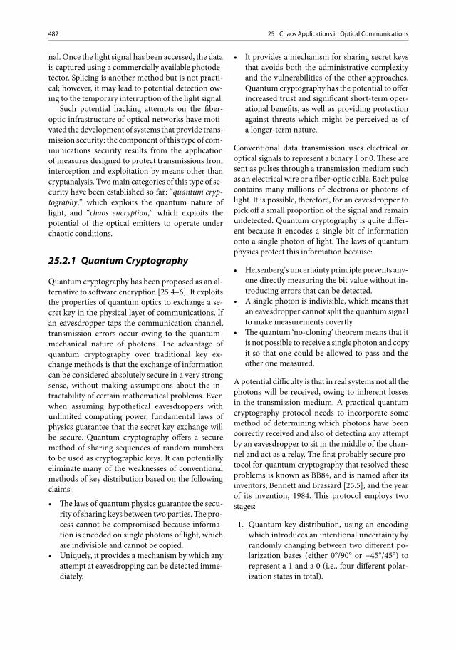
Chaotictransmitter
Chaoticreceiver
Fiber-optictransmission Subtraction
unit
Recovered data
Digital dataChaotic carrier
plus data Chaotic carrieronly
Fig. 25.1 An optical commu-nication system based on chaosencryption
25.2.2 Chaos Encryption
An alternative approach to improve the securityof optical high-speed data (on the order of Mb�sor Gb�s) can be realized by encoding the messageat the physical layer (hardware encryption) usingchaotic carriers generated by emitters operating inthe nonlinear regime. The objective of chaos hard-ware encryption is to encode the information signalwithin a chaotic carrier generated by componentswhose physical, structural, and operating param-eters form the secret key. Once the informationencoding has been carried out, the chaotic carrieris sent by conventional means to a receiver. Decod-ing is then achieved directly in real time througha so-called chaos-synchronization process.
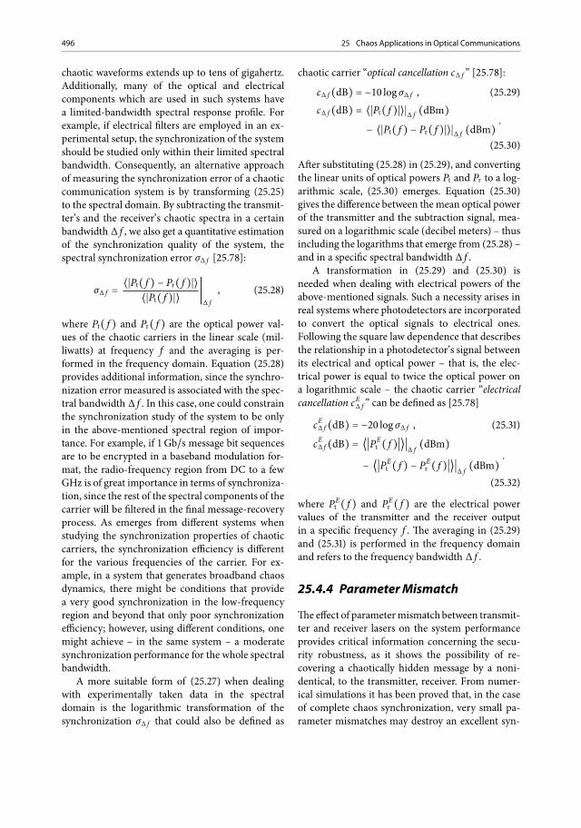
The principle of operation of chaos-based opticalcommunication systems is depicted schematically inFig. 25.1. In conventional communication systemsanopticaloscillator–usuallya semiconductor laser–generates a coherent optical carrier on which the in-formation is encoded using one of the many exist-ingmodulationschemes. Incontrast, in theproposedapproach of chaos-based communications the trans-mitter consists of the same oscillator forced to op-erate in the chaotic regime – e.g., by applying ex-ternal optical feedback – thus producing an opticalcarrierwith an extremely broadband spectrum(usu-ally tens of GHz). The information – typically basedon an on–off keying bit stream – is encoded on thischaotic carrier usingdifferent techniques (e.g., a sim-ple yet efficient method is to use an external opticalmodulator electrically driven by the information bitstream while the optical chaotic carrier is coupled atits input).The amplitude of the encryptedmessage inall cases is kept small with respect to the amplitude

484 25 Chaos Applications in Optical Communications
fluctuations of the chaotic carrier, so that it wouldbe practically impossible to extract this encoded in-formationusing conventional techniques suchas lin-ear filtering, frequency-domain analysis, and phase-space reconstruction. Especially, the latter assumesa high complexity of the chaotic carrier and is di-rectly dependent on the method by which the chaosdynamics are generated. At the receiver side of thesystem, a second chaotic oscillator is used, as “simi-lar” as possible to that of the transmitter. This “sim-ilarity” refers to the structural, emission (emittingwavelength, slope efficiency, current threshold, etc.),and intrinsic (linewidth enhancement factor, non-linear gain, photon lifetime, etc.) parameters of thesemiconductor laser, as well as to the feedback-loopcharacteristics (cavity length, cavity losses, possiblenonlinearity, etc.) and theoperatingparameters (biascurrents, feedback strength, etc.).
The above set of hardware-related parametersconstitutes the key of the encryption procedure.
The message-extraction procedure is based onthe so-called synchronization process. In the contextof the terminology of chaotic communications, syn-chronizationmeans that the irregular time evolutionof the chaotic emitter’s output in the optical power P(as shown in Fig. 25.1) can be perfectly reproducedby the receiver, provided that both the transmitterand the receiver chaotic oscillators are “similar” interms of the above set of parameters. Even minordiscrepancies (a few percent difference of these pa-rameters) between the two oscillators can result inpoor synchronization, i.e., poor quality of reproduc-ing the emitter’s chaotic carrier.
The key issue for efficient message decoding re-sides in the fact that the receiver synchronizes withthe chaotic oscillations of the emitter’s carrier with-out being affected by the encoded message, also re-ferred to in the literature as the “chaos-filtering ef-fect.” On the basis of the above considerations, thereceiver’s operation can be easily understood. Partof the incomingmessage with the encoded informa-tion is injected into the receiver. Assuming all thoseconditions that lead to a sufficiently good synchro-nization quality, the receiver generates at its outputa chaotic carrier almost identical to the injected car-rier, without the encoded information.Therefore, bysubtracting the chaotic carrier from the incomingchaotic signal with the encoded information, onecan reveal the transmitted information.
The major advantages of chaos-based securecommunication systems are the following:
1. Real-time high bit rate message encoding in thetransmission line. It is obvious from the oper-ating principle of chaos-based communicationsthat the information-encoding process does notintroduce any additional delay relative to that ofconventional optical communication systems.The same holds for the receiver at least for bitrates up to 10Gb�s since the synchronizationprocess relies on the ultrafast dynamics of semi-conductor lasers (in the all-optical case) or thetime response of the fast photodiodes and othernonlinear elements (in the optoelectronic ap-proach). This is a significant advantage relativeto the conventional software-based approaches,where real-time encoding of the bit stream –assuming the use of fast processors and a suf-ficiently long bit series key – would result ina much lower effective bit rate, increased com-plexity, and increased cost of the system. More-over, if necessary, chaos-based communicationscan be complementedwith software encryption,thus providing a higher security level. Com-pared with quantum cryptography, the chaos-based approach provides the apparent advan-tage of a much higher transmission speed.
2. Enhanced security. The potential eavesdropperhas two options to extract the chaos-encodedinformation:
– To reconstruct the chaotic attractor in thephase space using strongly correlated pointsdensely sampled in time. In this case, thenumber of samples needed increases expo-nentially with the chaos dimension. Takinginto account the attractor dimension of thechaotic optical carriers generated, for whichin some cases (optoelectronic approach) theLyapunov dimension is on the order of a fewhundred, and considering the characteristicsof today’s recording electronics (maximum40Gsamples�s and 15-GHz bandwidth),this solution seems to be impossible.
– To identify the key for reconstruction of thechaotic time series. In the case of chaos en-cryption, the key is the hardware used andthe full set of operating parameters. Thismeans that if a semiconductor laser coupledto an external cavity is, e.g., the chaotic oscil-lator in the emitter, the eavesdropper musthave an identical diode laser, with identi-cal external resonator providing the same

25.3 Optical Chaos Generation 485
amount of feedback and know the completeset of operating parameters.
3. Compatibility with the installed network infras-tructure. As opposed to the quantum-crypto-graphy approach, in chaos encryption systemsthere is no fundamental reason to preclude itsapplication on installed optical network infras-tructure. With proper compensation of fibertransmission impairments, the chaotic signalthat arrives at the receiver triggers the synchro-nization process successfully.Moreover, the firstfeasibility experiments have shown that the useof erbium-doped fiber amplifiers (EDFAs) doesnot prevent synchronization and informationextraction.
The concept of chaos synchronization was firstlyproposed theoretically by Pecora and Carroll [25.9]in 1990. This pioneering work triggered a burst ofactivities covering in the early 1990s mainly elec-tronic chaotic oscillators [25.10]. The first theoreti-cal work and preliminary reports on the possibilityof synchronization between optical chaotic systemscame out in the mid-1990s [25.11–13]. Since thenthe activities in the area of optical chaotic oscillatorshave increased exponentially. Numerous researchgroups worldwide have reported a large amount oftheoretical and experimental work, covering mainlyfundamental aspects related to synchronization ofoptical nonlinear dynamical systems [25.14–18].Special focus was given to semiconductor-laser-based systems [25.19, 20], but there was also workon fiber-ring laser systems [25.21] and optoelec-tronic schemes [25.22, 23].
Not until recently was the applicability of theconcept in optical communication systems provedby encoding and recovery of single-frequency tones,starting from frequencies of a few kilohertz [25.24]and going up to several gigahertz [25.25]. However,it is worth mentioning that single-frequency encod-ing is much less demanding in terms of chaos com-plexity than the pseudorandom bit sequences usedin conventional communication systems.
Lately, two research consortia have made signifi-cant advances in both the fundamental understand-ing and the technological capabilities pertinent tothe practical deployment of advanced communica-tion systems that exploit optical chaos.The first wasa US consortium; within this framework, a 2.5Gb�snon-return-to-zeropseudorandom bit sequence hasbeen reported to be masked in a chaotic carrier,
produced by a 1.3 μm distributed feedback (DFB)diode laser subjected to optoelectronic feedback,and recovered in a back-to-backconfigurationwith-out including any fiber transmission [25.26]. Thebit-error rates (BERs) achieved were on the order of10−4.The second initiativewaswithin an EU consor-tium [25.27].The results achievedwithin this projectinclude a successful encryption of a 3Gb�s pseu-dorandom message into a chaotic carrier, and thesystem’s decoding efficiency was characterized bylow BERs on the order of 10−9 [25.28]. In the sameproject, a 1.55 μmall-optical communication systemwith chaotic carriers was successfully developed andcharacterized by BER measurements at gigabit rates[25.29]. A transmission system based on the config-uration described above has been implemented inlaboratory conditions [25.30], as well as in an in-stalled optical fiber network with a length of over100 km [25.31].
These works provided chaos-based methods ap-propriate for high-bit-rate data encryption but notas an integrated and low-cost solution. The possi-bility of a realistic implementation of networks withadvanced security and privacy properties based onchaos encryption depends strongly on the availabil-ity of either hybrid optoelectronic or photonic in-tegrated components.This is exactly the future needcovered by newmethods of development of the tech-nology required for the fabrication of componentsappropriate for robust and secure chaotic communi-cation systems enabling crucial miniaturization andcost reduction as well.
25.3 Optical Chaos Generation
Since the technologyof optical communications andnetworks is based on emitters that are lasers fabri-cated from semiconductormaterials, our study is fo-cused on such compounds capable of emitting opti-cal signals with complex dynamics.
25.3.1 Semiconductor Laserswith Single-Mode Operation
The semiclassical approach used commonly inphysics to describe the nature of semiconductorma-terials that emit light deals with the electromagneticfield emitted by solid-state lasers throughMaxwell’sequations, whereas the semiconductor medium is
486 25 Chaos Applications in Optical Communications
described using the quantum-mechanical theory.This treatment works well for most of the conven-tional solid-state and gas lasers [25.32, 33]. Theclassical Maxwell equations generally describe thespatiotemporal evolution of the electromagneticfield:
∇� E = −∂B∂t
, (.)
∇�H = J +∂D∂t
, (.)
∇ ċ D = ρf , (.)∇ ċ B = 0 . (.)
The above set of equations express the interplay be-tween the electrical field vector E, the magnetic in-duction vectorB, the displacement vectorD, and themagnetic field vectorH. ρf is the free-charge densityand J is the free-current density related to the elec-trical field E via the Ohm law: J = σ ċ E, where σ isthe conductivity of the medium. For a nonmagneticmedium the Maxwell equations take the form
D = ε0E + P , (.)B = μ0H , (.)
where P is the dipole moment density in themedium, and ε0 and μ0 are the vacuum permit-tivity and permeability, bound together throughthe velocity of light in a vacuum: c−2 = ε0μ0. Thefundamental electromagnetic wave equation foroptical fields derives from the above equations as
ΔE −1c2E − μ0σ E = μ0 P +∇(∇ ċ E) . (.)
This wave equation describes the propagation of theelectrical field through a polarization term in the ac-tive medium.The electrical field term and the polar-ization field term can be decoupled to separate equa-tions of time-dependent and space-dependent com-ponents of the form
E(r, t) = �j
12�E j(t) eiωth t ċUj(r) + c.c.� , (.)
P(r, t) = �j
12�Pj(t) eiωth t ċUj(r) + c.c.� , (.)
where ωth is the laser’s cavity resonance frequencyand Uj(r) is the jth mode function, which includesforward and backward propagating components ofthe fields.
Since the optical fields oscillate with high fre-quencies, (.) and (.) may be simplified toa new form when using the slowly varying ampli-tude approximation, in which the temporal part ofthe electrical field is decoupled to a slowly varyingamplitude E(t) and a fast oscillating part [25.32, 33]according to the equation
E(z, t) =12�E(t)e ċ sin(kz)e iωth t + c.c.� . (.)
The polarization part of the field will be excludedfrom further investigation, since we consider edge-emitting semiconductor lasers that belong to the so-called B-class lasers where the polarization decayson a much shorter time scale than the electricalamplitude. In all the subsystems and configurationsbuilt for the applications of chaos data encryptionand presented in next paragraphs, the polarizationstate of the field for the semiconductor lasers stud-ied is always controlled through the correspondingdevices (polarization controllers) and the field is al-ways in a single polarization state. The above elec-trical field equation when considered for an activemediumwith two-level energy atoms degenerates tothe Maxwell–Bloch equations, which are also com-monly expressed as “rate equations” that describethe semiconductor laser dynamics.
Rate Equations
In edge-emitting semiconductor lasers simultane-ous emission in several longitudinal modes is verycommon. For this reason,many strategies have beendevised to guarantee single longitudinal mode op-eration. A large side-mode suppression ratio canbe achieved using DFB reflector lasers, distributedBragg reflector lasers, and vertical-cavity surface-emitting lasers. Even though the single longitudi-nal mode approximation is questionable in edge-emitting lasers, the aforementioned methods maylead to a single longitudinal mode operation.
The evolution of this solitary longitudinal modeamplitude of the electrical field emitted by a semi-conductor laser is described by means of a time-delayed rate equation. This field equation has to becomplemented by specifying the evolution of the to-tal carrier population N(t). The carrier equationdoes not need any modification with respect to thefree-running case. The detailed derivation of theseequations can be found in [25.34, 35]. In the case
25.3 Optical Chaos Generation 487
of single longitudinal mode operation, the evolutionof the field and carrier variables is governed by theequations
dE(t)dt
=1 − ia2ċ �G(t) − t−1p � ċ E(t) + FE(t) ,
(.)dN(t)dt
=Ie+N(t)tn−G(t) ċ E(t) + FN(t) ,
(.)
G(t) =g ċ (N(t) − N0)
1 + s ċ E(t)2, (.)
where E(t) is the complex slowly varying amplitudeof the electrical field at the oscillation frequency ω0,N(t) is the carrier number within the cavity, andtp is the photon lifetime of the laser. The physicalmeaning of the different terms in (.) is the fol-lowing: I�e is the number of electron–hole pairs in-jected by current-biasing the laser, tn is the rate ofspontaneous recombination (as also known as thecarrier lifetime), and G(t)E(t)2 describes the pro-cesses of the stimulated recombination. The aboveset of equations take into account gain suppressioneffects through the nonlinear gain coefficient s, andalso Langevin noise sources FE(t) and FN(t). Thesespontaneous emission processes are described bywhite Gaussian random numbers [25.36] with zeromean value,
FE(t) � = 0 , (.)
and delta-correlation in time,
�FE(t) ċ F�E (t′
) = 4 ċ t−1n ċ βsp ċ N ċ δ(t − t′
) .(.)
The spontaneous emission factor βsp represents thenumber of spontaneous emission events that couplewith the lasing mode. The noise term in the carrierequation, FN(t), coming from spontaneous emis-sion as well as the shot noise contribution, is gen-erally small and thus usually neglected.
25.3.2 Nonlinear Dynamicsof Semiconductor Lasers
Semiconductor lasers are very sensitive to externaloptical light. Even small external reflections andper-turbations may provide a sufficient cause that canlead to an unstable operating behavior [25.37, 38].This is the dominant reason why almost all types of
commercial semiconductor lasers that apply to stan-dard telecommunication systems are provided withan optical isolation stage that eliminates – or at leastminimizes – optical perturbations by the externalenvironment.However, in applicationswhere the in-crease of instabilities plays a key role, the isolationstage is omitted and the semiconductor lasers aredriven to unstable operation.
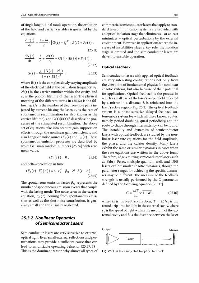
Optical Feedback
Semiconductor lasers with applied optical feedbackare very interesting configurations not only fromthe viewpoint of fundamental physics for nonlinearchaotic systems, but also because of their potentialfor applications. Optical feedback is the process inwhich a small part of the laser’s output field reflectedby a mirror in a distance L is reinjected into thelaser’s active region (Fig. 25.2).The optical feedbacksystem is a phase-sensitive delayed-feedback au-tonomous system for which all three known routes,namely, period doubling, quasi-periodicity, and theroute to chaos through intermittency, can be found.The instability and dynamics of semiconductorlasers with optical feedback are studied by the non-linear laser rate equations for the field amplitude,the phase, and the carrier density. Many lasersexhibit the same or similar dynamics in cases whenthe rate equations are written in the above form.Therefore, edge-emitting semiconductor lasers suchas Fabry–Perot, multiple-quantum-well, and DFBlasers exhibit similar chaotic dynamics, though theparameter ranges for achieving the specific dynam-ics may be different. The measure of the feedbackstrength is usually performed by the C parameter,defined by the following equation [25.37]:
C =kfTtin
�1 + a2 , (.)
where kf is the feedback fraction, T = 2L�cg is theround-trip time for light in the external cavity, wherecg is the speed of light within the medium of the ex-ternal cavity and L is the distance between the laser
Output Mirror
LaserL
Fig. 25.2 A laser subjected to optical feedback
488 25 Chaos Applications in Optical Communications
facet and the external mirror, α is the linewidth-enhancement factor that plays an important role insemiconductor lasers, and tin is the round-trip timeof light in the internal laser cavity. A semiconduc-tor laser with optical feedback shows various inter-esting dynamic behaviors depending on the systemparameters, and the instabilities of the laser can becategorized into the five regimes [25.39], dependingon the feedback fraction, as shown below:
• Regime I: When the feedback fraction of thefield amplitude of the laser is very small (lessthan 0.01%), it induces insignificant effects. Thelinewidth of the laser oscillation becomes broador narrow, depending on the feedback frac-tion.
• Regime II: When the feedback fraction is smallbut not negligible (less than 0.1%) and C � 1,generation of external cavity modes gives riseto mode hopping among internal and externalmodes.
• Regime III: For a narrow region around 0.1%feedback, the mode-hopping noise is sup-pressed and the laser may oscillate with a narrowlinewidth.
• Regime IV : By application of moderate to strongfeedback (around 1% and even up to 10% insome cases), the relaxation oscillation becomesundamped and the laser linewidth is greatlybroadened. The laser shows chaotic behaviorand evolves into unstable oscillations in theso-called coherence collapse regime. The noiselevel is enhanced greatly under this condition.
• Regime V : In the extremely strong feedbackregime, which is usually defined for a feedbackratio higher than 10%, the internal and externalcavities behave like a single cavity and the laseroscillates in a single mode. The linewidth of thelaser in this case is narrowed greatly.
The dynamics investigated were considered fora DFB laser with an emitting wavelength of 1.55 μm;thus, that above regions may be consistent for othertypes of lasers for different values of the feedbackfraction. However, the dynamics for other lasersalways show similar trends. Regime IV is in our casestudy of great significance, since for these values thelaser generates chaotic dynamics. A semiconductorlaser with optical feedback for regime IV is mod-eled by the Lang–Kobayashi equations [25.40–42],which include the optical feedback effects in thelaser rate equations model.
When C � 1, many modes for possible laser os-cillations are generated, and the laser becomes un-stable. The instabilities of semiconductor lasers de-pend on the number of excited modes, or equiva-lently the value of C. The stability and instability ofthe laser oscillations have been theoretically stud-ied in numerous works by the linear stability analy-sis around the stationary solutions for the laser vari-ables [25.43, 44].
The dynamics of semiconductor lasers with op-tical feedback depend on the system parameters;the key parameters which can be controlled are thefeedback strength kf , the length of the external cav-ity L formed between the front facet of the laserand the external mirror, as well as the bias injec-tion current I. For variation of the external mirrorreflectivity, the laser exhibits a typical chaotic bifur-cation very similar to a Hopf bifurcation; however,the route to chaos depends on the above-mentionedcrucial parameters [25.37]. Other types of instabili-ties produced by applying optical feedback are sud-den power dropouts and gradual power recovery inthe laser output power, the so-called low-frequencyfluctuations [25.45–49]. Low-frequency fluctuationsare typical phenomena observed in a low-bias injec-tion current condition, just above the threshold cur-rent of the laser. Usually this type of carrier consistsof frequencies up to 1 GHz at maximum; thus, mes-sage encryption could be applied only for such a lim-ited bandwidth.
On the other hand, the spectral distribution ofthe chaotic carrier depends on the relaxation oscilla-tion frequency of a semiconductor laser, which is di-rectly determined by the biasing current of the laser.By increasing the optical feedback, the chaotic car-rier expands beyond the relaxation frequency of thelaser, eventuating in a broadband fully developedchaotic carrier that may expand up to several tensof gigahertz. It has also been proved so far that thelaser oscillates stably for a higher-bias injection cur-rent.Thus, larger optical feedback strength is usuallyrequired to destabilize the laser at a higher-bias in-jection current.The external cavity length also playsan important role in the chaotic dynamics of semi-conductor lasers. There are several important scalesfor the length and change of the position of the ex-ternal mirror in the dynamics:
• Condition I: Chaotic dynamics may be observedeven for a small change of the external mirrorposition comparable to the optical wavelength

25.3 Optical Chaos Generation 489
λ [25.50]. For a small change, the laser outputshows periodic undulations (with a period ofλ�2) and exhibits a chaotic bifurcation withinthis period. When the external reflector isa phase-conjugate mirror, the phase is lockedto a fixed value and the laser appears to be in-sensitive to small changes in the external cavitylength, and its dynamics are only defined by theabsolute position of the external mirror [25.44].This is observed for every external mirror posi-tion as far as the coupling between the externaland the internal optical field is coherent.
• Condition II: When the external mirror is po-sitioned within a distance corresponding to therelaxation oscillation frequency (on the orderof several centimeters) and the mirror moveswithin a range of millimeters, the coupling be-tween the internal and external fields is strong(the C parameter is small and the number ofmodes excited is small) and the laser shows a sta-ble oscillation. A larger optical feedback is re-quired to destabilize the laser in this case. Forexample, power dropouts due to low-frequencyfluctuations occur irregularly in time for a largevalue of C, whereas periodic low-frequency fluc-tuations were observed for a large optical feed-back at a high injection current [25.51]. Thiscase is important from the point of view of prac-tical applications of semiconductor lasers suchas optical data storage and optical communica-tions. When the external cavity length is smallenough compared with the length of the inter-nal laser cavity, the behavior of the laser os-cillation is regularly governed by the externalcavity.
• Condition III: When the external mirror is posi-tioned in a larger distance than the equivalent tothe relaxation oscillation frequency of the laser,but always within the coherence length of thelaser (on the order of several centimeters to sev-eral meters), the laser is greatly affected by theexternal optical feedback. The number of the ex-cited cavity modes – related to the C parameter– is now greatly increased and the laser showsa complex dynamic behavior, even for moder-ate feedback rates [25.50]. This operating regionis of great importance for studying optical sys-tems with complex dynamics, since it is met inseveral practical systems and commercial devicesthat incorporate such cavity lengths. However,in most of these cases, complex or even chaos
dynamics are undesirable and need to be elim-inated.
• Condition IV : When the external mirror is posi-tioned at a distance beyond the coherence lengthof the semiconductor laser (more than severalmeters), it still exhibits chaotic oscillations, butthe effects have a partially coherent or incoher-ent origin [25.52]. Instabilities and chaos gener-ation are also induced by this type of incoherentfeedback, which can originate not only from thelaser itself but also from optical injection fromanother laser source.
The instabilities and chaos behavior discussedabove were applicable for edge-emitting semi-conductor lasers; however, there are a number ofdifferent structures for semiconductor lasers: self-pulsating lasers, vertical-cavity surface-emittinglasers, broad-area lasers, etc. Some of these lasers bydefault exhibit chaotic dynamics without the intro-duction of any external perturbations. Furthermore,they also show a variety of chaotic dynamics by op-tical feedback and injection current modulation.The detailed chaotic dynamics analysis depends onthe particular structure, but macroscopically thesame or similar dynamics as with edge-emittingsemiconductor lasers are also observed.
Considering the case of a relatively weak opticalfeedback, the rate equations that describe the semi-conductor laser can be altered appropriately to de-scribe also the external cavity. The carrier equationdoes not need any modification with respect to thefree-running case. In the case of single longitudinalmode operation and application of a weak opticalfeedback condition, the evolution of the field is nowgoverned by
dE(t)dt
=1 − ia2ċ �G(t) − t−1p � ċ E(t)
+ kf ċ E(t − T) ċ eiω0T + FE(t) .(.)
This basic equation, which includes the appliedoptical feedback, was introduced by Lang andKobayashi [25.42] in 1980. From the mathematicalpoint of view, a delay term in a differential equationyields an infinite-dimensional phase space, sincea function defined over a continuous interval [0, T]has to be specified as the initial condition. The un-derstanding of delayed feedback systems has beenboosted during the last few years using semicon-ductor lasers. Fundamental nonlinear dynamicalphenomena, such as period doubling and the quasi-

490 25 Chaos Applications in Optical Communications
periodic route to chaos, have been characterizedin these systems. Also high-dimensional chaoticattractors have been identified. Furthermore, theanalogy between delay differential equations andone-dimensional spatial extended systems has beenestablished [25.53] and exploited for the characteri-zation of the chaotic regimes [25.54].
Optical Injection
The optical injection system is a nonautonomoussystem that follows a period-doubling route tochaos. In this approach, the optical output of anindependent driving laser is fed into the laser ofimportance to destabilize it and under specificconditions force it to oscillate in the chaotic regime(Fig. 25.3) [25.55, 56]. Crucial parameters that de-termine the operation of this system are the opticalinjection strength of the optical field – with valuesthat are adequate to achieve the injection lockingcondition – and the frequency detuning betweenthe two lasers – which is usually in the region of�10GHz. Compared with the rate equations forthe solitary laser, an additional term representingthe injection field from the driving laser is addedto the field equation. This modification completelychanges the dynamics of the system by addingone more dimension to it. In contradiction to theoptical feedback case, in which the time-delayeddifferential equations provide infinite degrees offreedom, optical injection provides low-complexityattractors with dimension up to 3. In this case ofa weak optical injection condition, the evolution ofthe field is modified accordingly:
dE(t)dt
=1 − ia2ċ �G(t) − t−1p � ċ E(t)
+ kdr ċ Eext(t) + FE(t) ,(.)
where kdr is the coefficient of coupling of the driv-ing laser to the master laser and Eext is the injectedelectrical field of the driving laser.
OutputIsolator
Laser Drivinglaser
Fig.25.3 A laser subjected to optical injectionby a seconddriving laser
Output
Laser
Receiver
Amplifier
Fig. 25.4 A laser subjected to optoelectronic feedback
Optoelectronic Feedback
Use of a semiconductor laser with an applieddelayed optoelectronic feedback loop is also anefficient technique of broadband chaos genera-tion [25.57]. In such a configuration, a combinationof a photodetector and a broadband electrical am-plifier is used to convert the optical output of thelaser into an electrical signal that is fed back throughan electrical loop to the laser by adding it to the in-jection current (Fig. 25.4). Since the photodetectorresponds only to the intensity of the laser output,the feedback signal contains the information on thevariations of the laser intensity, disregarding anyphase information. Therefore, the phase of the laserfield is not part of the feedback loop dynamics andconsequently of the dynamics of this system. Thefact that part of the feedback loop is an electricalpathmeans that the bandwidth response of this pathmay provide a filtered feedback.This can be justifiedby the limited bandwidth of the photoreceiver,the electrical amplifier, as well as the electricalcables. Additionally, an electrical filter may also beincorporated within this path, with a preselectedtransfer function and bandwidth, thus enhancingthe number of parameters that determine the finalform of the generated chaotic output.
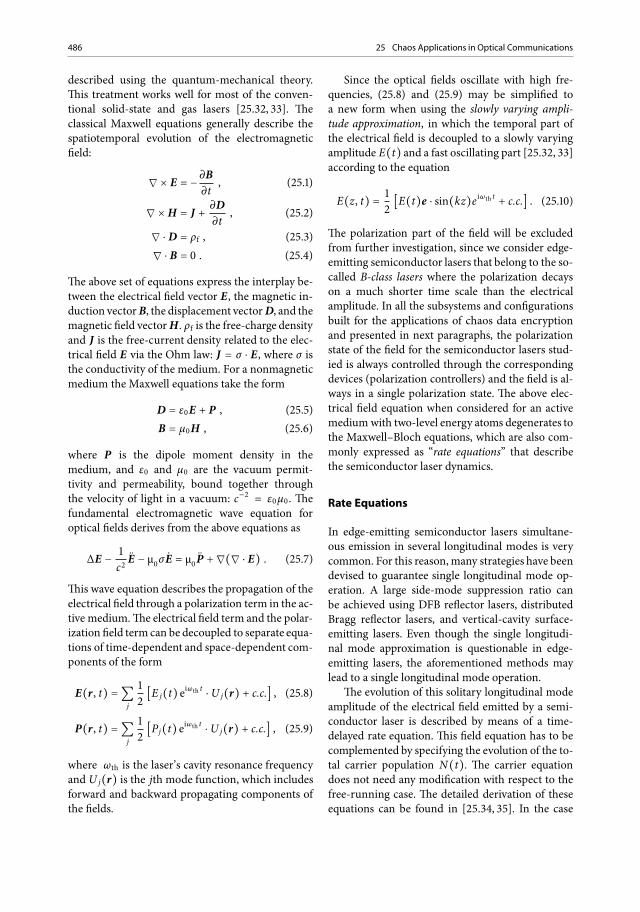
25.3.3 Novel Photonic IntegratedDevices
On the basis of the aforementioned techniques, var-ious configurations of transmitters have beenproposed and implemented, providing high-dimensional chaotic carriers capable of messageencryption. These systems take advantage of off-the-shelf fiber-optic technology, resulting in rathercumbersome devices, impractical for commercial

25.4 Synchronization of Optical Chaos Generators 491
R = 95% (1–R) = 5%
DFBlaser
Pout Pout Gain/absorption
section(G/As)
Phasesection(PHs)
Passivewaveguide
(PW)
High-reflectivecoating(HRC)
~Pback
300 μm 200 μm 150 μm 10,000 μm
Fig. 25.5 A photonic integrated chaos emitter for secure optical communication applications.DFB distributed feedback
use, since they are not fully adaptive in the platformsof existing operating optical networks.
The miniaturization of the above-mentionedconfigurations through photonic integration ap-pears very attractive, albeit scarce, considering theefficiency of specifically designed photonic inte-grated circuits to generate nonlinear dynamics.In [25.58], monolithic colliding-pulse mode-lockedlasers were reported to exhibit nonlinear behavior,from continuous-wave operation to self-pulsationsand mode-locking, for the full range of control pa-rameters. In [25.59], a semiconductor laser followedby a phase section and an active feedback elementwere reported to form a very short complex pho-tonic circuit that provides several types of dynamicsand bifurcations under optical feedback strengthand phase control. However, only multiple-mode-beating operation may transit the dynamics beyonda quasi-periodic route to chaos with possible chaoticcomponents. A simplified version of the aforemen-tioned photonic integrated circuit, omitting thoughthe active feedback element, was found to generateonly distinct-frequency self-pulsations [25.60]. Veryrecently, with use of an integrated colliding-pulsemode-locked semiconductor laser, the existence ofnonlinear dynamics and low-frequency chaos inphotonic integrated circuits was demonstrated bycontrolling only the laser injection current [25.61].A novel photonic integrated circuit capable of gen-erating high-dimensional broadband chaos wasalso very recently proposed, designed, and tested(Fig. 25.5) [25.62]. The dynamics can be easilycontrolled experimentally via the phase current andthe feedback strength, establishing therefore thisdevice as a compact integrated fully controllablechaos emitter. It consists of four successive sections:a DFB InGaAsP semiconductor laser, a gain/ab-sorption section, a phase section, and a 1-cm-longpassive waveguide. The overall resonator lengthis defined by the internal laser facet and the chip
facet of the waveguide, which has a highly reflectivecoating and provides an increased effective feedbackround-trip time, therefore enhancing the probabil-ity of encountering fully chaotic behavior. Since thedynamics are well identified, the advantages of theproposed photonic integrated device may be fullyexploited to our benefit with a fervent expectationfor applications to secure chaos-encoded opticalcommunications.
25.4 Synchronizationof Optical Chaos Generators
In chaos synchronization, when semiconductorlasers are employed as chaos generators, the dy-namical variables used for the driving signal are notalways separable from other variables and some aresimply not extractable from a laser.When the outputfield of the master laser is transmitted and coupledto the slave laser, both its magnitude and its phasecontribute to the receiver’s chaos generation. It isnot possible to transmit and couple only the magni-tude but not the phase, or only the phase but not themagnitude. Thus, for optical injection and opticalfeedback systems, the frequency, phase, and ampli-tude of the optical fields of both the transmitter andthe receiver lasers are all locked in synchronism.Therefore, unless the phase is not part of the dy-namics of the lasers, such as in the case of systemswith optoelectronic feedback, the synchronizationbetween two laser systems depends on the couplingof the two variables, the magnitude and phase ofthe laser field, at the same time. Furthermore, thecarrier density is not directly accessible externallyand therefore cannot be used as a driving signal tocouple lasers. However, in laser systems that exhibitchaotic dynamics, not only master–slave configu-rations but also mutually injected systems [25.63]can be used for chaos-synchronization systems. The

492 25 Chaos Applications in Optical Communications
latter are not suited for chaos communications andthus are beyond the scope of the present analysis.
Another issue that is of great interest but thatwill be dealt with in the next paragraphs is the factthat for a synchronized chaotic communicationsystem, the message-encoding process – whateverthis is – may have a significant impact on the qualityof synchronization and thus on the message recov-erability at the receiver end. It has been shown thathigh-quality synchronization can be maintainedonly when a proper encoding scheme that main-tains the symmetry between the transmitter and thereceiver is employed.
25.4.1 Chaos Synchronizationof Semiconductor Laserswith Optical Feedback
An indisputable condition that should always besatisfied for synchronizing chaotic waveforms pro-duced by two nonlinear systems is that the devia-tions of the corresponding parameters that charac-terize each system must be small. Two categories ofchaotic configurations of all-optical systems basedon their robustness have been developed for efficientsynchronization (Fig. 25.6) [25.15, 64]. The first oneconsists of two identical external-cavity semicon-ductor lasers for the transmitter and the receiver re-spectively (closed-loop scheme), whereas in the sec-ond approach, an external-cavity laser transmitter
Slavelaser
Masterlaser
Mirror Mirror
LL
Slaveoutput
Masteroutput
One-waysplitter
Slavelaser
Masterlaser
Mirror
L
Slaveoutput
Masteroutput
One-waysplitter
Fig. 25.6 A closed-loop synchronization configuration between two semiconductor lasers both subjected to opticalfeedback (top) and an open-loop synchronization configuration between two semiconductor lasers, with only the masterlaser being subjected to optical feedback (bottom)
produces the chaotic carrier and a single laser diodesimilar to the transmitter is used as the receiver(open-loop scheme) [25.15, 64–66].The closed-loopscheme proves to be more robust in terms of syn-chronization; however, it requires precise matchingof the external cavity of the lasers tomaintain a goodsynchronization quality [25.64, 65]. In contrast, theopen-loop scheme is less robust, with simpler re-ceiver architecture [25.15, 64, 65]. It requires a largecoupling strength between the transmitter and thereceiver; however, there is no requirement of per-fectly matched lasers and there is no external-cavityreceiver to be matched to an external-cavity trans-mitter.
The rate equations that describe the coupled be-havior between a transmitter and a receiver, basedon the Lang–Kobayashi model, are
dEi(t)dt
=1 − ia2ċ �Gi(t) − t−1p, i� ċ Ei(t)
+ kf, i ċ Ei(t − T) ċ eiω0T
+ kinj ċ Eext(t) + FE(t)
, (.)
dNi(t)dt
=Ie+Ni(t)tn , i
−Gi(t) ċ Ei(t) + FN(t) ,
(.)
Gi(t) =g ċ (Ni(t) − N0, i)
1 + s ċ Ei(t)2, (.)
where i = �t, r� denotes the solution for thetransmitter or the receiver, kinj is the electrical fieldinjection parameter applied to the receiver laser, and
25.4 Synchronization of Optical Chaos Generators 493
Eext is the amplitude of the injected electrical field.The term kinj ċ Eext(t) is applicable only in the rateequation of the receiver. For the case of an open loop,no optical feedback is applied on the receiver; thus,kf,r = 0.
25.4.2 Types of Synchronization
Following the form of the Lang–Kobayashi rateequations that describe the dynamical operation ofthe transmitter and the receiver, two different typesof synchronous responses of the receiver have beendistinguished, referring to the weak and the stronginjection condition, respectively [25.15, 64, 67].
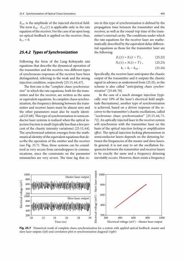
The first one is the “complete chaos synchroniza-tion” in which the rate equations, both for the trans-mitter and for the receiver, are written as the sameor equivalent equations. In complete chaos synchro-nization, the frequency detuning between the trans-mitter and receiver lasers must be almost zero andthe other parameters must also be nearly identi-cal [25.68].This type of synchronization in semicon-ductor laser systems is realized when the optical in-jection fraction is small (typically less than a fewper-cent of the chaotic intensity variations) [25.15, 64].The synchronized solution emerges from the math-ematical identity of the equivalent equations that de-scribe the operation of the emitter and the receiver(see Fig. 25.7). Thus, these systems can be consid-ered as very secure from eavesdroppers in commu-nications, since the constraints on the parametermismatches are very severe. The time lag that ex-
1000800600400200
1000800600400200
Elec
tric
al v
olta
ge (m
V)
Master laser output
Slave laser output
20 22 24 26 28 30Time (ns) El
ectr
ical
vol
tage
(mV
) – S
lave
lase
r out
put
1000
800
600
400
200
Electrical voltage (mV) – Master laser output200 400 600 800 1000
Fig. 25.7 Numerical result of complete chaos synchronization for a system with applied optical feedback: master andslave laser outputs (left) and correlation plot or synchronization diagonal (right)
ists in this type of synchronization is defined by thepropagation time between the transmitter and thereceiver, as well as the round-trip time of the trans-mitter’s external cavity.The conditions under whichthe rate equations for the receiver laser are mathe-matically described by the equivalent delay differen-tial equations as those for the transmitter laser arethe following:
Er(t) = Et(t + T) , (.)Nr(t) = Nt(t + T) , (.)
kr = kt − kinj . (.)
Specifically, the receiver laser anticipates the chaoticoutput of the transmitter and it outputs the chaoticsignal in advance as understood from (.), so thescheme is also called “anticipating chaos synchro-nization” [25.69, 70].
In the case of a much stronger injection (typi-cally over 10% of the laser’s electrical field ampli-tude fluctuations), another type of synchronizationis achieved, based on a driven response of the re-ceiver to the transmitter’s chaotic oscillations, called“isochronous chaos synchronization” [25.15, 64, 71,72]. An optically injected laser in the receiver systemwill synchronize with the transmitter laser on thebasis of the optical injection locking or amplificationeffect. The optical injection locking phenomenon insemiconductor lasers depends on the detuning be-tween the frequencies of the master and slave lasers.In general, it is not easy to set the oscillation fre-quencies between the transmitter and receiver lasersto be exactly the same and a frequency detuninginevitably occurs. However, there exists a frequency
494 25 Chaos Applications in Optical Communications
1000800600400200
1000800600400200
Elec
tric
al v
olta
ge (m
V)
Master laser output
Slave laser output
20 22 24 26 28 30Time (ns) El
ectr
ical
vol
tage
(mV
) – S
lave
lase
r out
put
1000
800
600
400
200
Electrical voltage (mV) – Master laser output200 400 600 800 1000
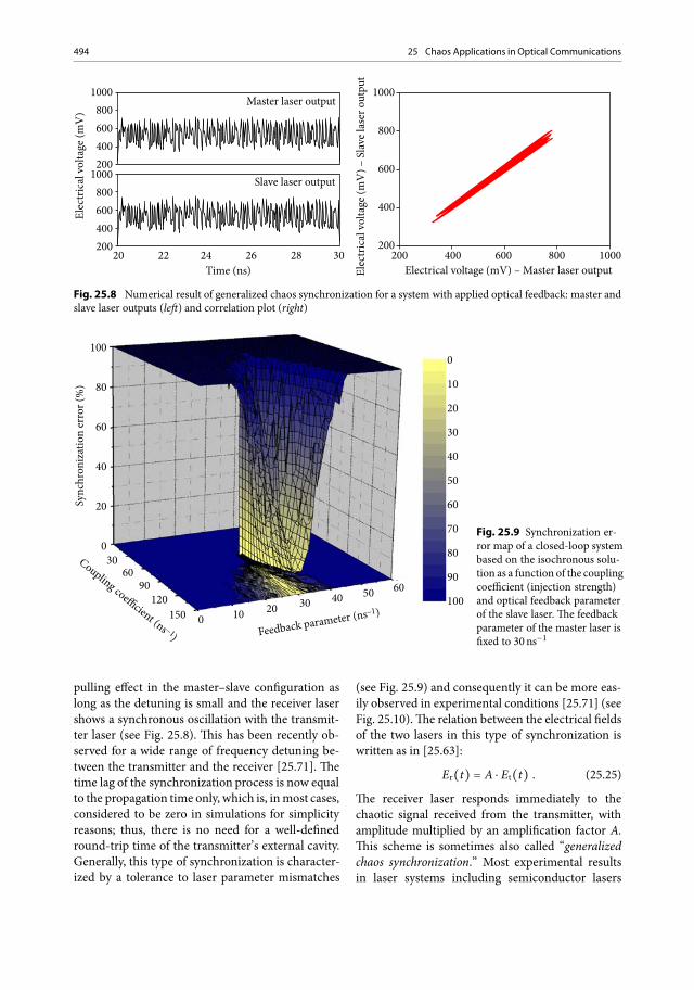
Fig. 25.8 Numerical result of generalized chaos synchronization for a system with applied optical feedback: master andslave laser outputs (left) and correlation plot (right)
100
80
60
40
20
030
6090
120150 0 10 20 30 40 50 60
Sync
hron
izat
ion
erro
r (%
)
Coupling coefficient (ns –1) Feedback parameter (ns–1)
0
10
20
30
40
50
60
70
80
90
100
Fig. 25.9 Synchronization er-ror map of a closed-loop systembased on the isochronous solu-tion as a function of the couplingcoefficient (injection strength)and optical feedback parameterof the slave laser. The feedbackparameter of the master laser isfixed to 30ns−1
pulling effect in the master–slave configuration aslong as the detuning is small and the receiver lasershows a synchronous oscillation with the transmit-ter laser (see Fig. 25.8). This has been recently ob-served for a wide range of frequency detuning be-tween the transmitter and the receiver [25.71]. Thetime lag of the synchronization process is now equalto the propagation time only, which is, inmost cases,considered to be zero in simulations for simplicityreasons; thus, there is no need for a well-definedround-trip time of the transmitter’s external cavity.Generally, this type of synchronization is character-ized by a tolerance to laser parameter mismatches
(see Fig. 25.9) and consequently it can be more eas-ily observed in experimental conditions [25.71] (seeFig. 25.10).The relation between the electrical fieldsof the two lasers in this type of synchronization iswritten as in [25.63]:
Er(t) = A ċ Et(t) . (.)
The receiver laser responds immediately to thechaotic signal received from the transmitter, withamplitude multiplied by an amplification factor A.This scheme is sometimes also called “generalizedchaos synchronization.” Most experimental resultsin laser systems including semiconductor lasers

25.4 Synchronization of Optical Chaos Generators 495
0.6
0.3
0.0
–0.3
–0.6
Elec
tric
al v
olta
ge (m
V)
0 5 10 15Time (ns)
Emitt
er o
utpu
t vol
tage
(V)
0.3
0.2
0.1
0.0
–0.1
–0.2
–0.3
Receiver output voltage (V)–0.3 –0.2 –0.1 0.0 0.1 0.2 0.3
Chaotic emitterChaotic receiver
Ccorr=95.5%
Fig. 25.10 Left: Synchronized experimental output time traces of a chaotic emitter and its matched receiver in an open-loop system based on the isochronous solution (the time series of the receiver is shifted vertically for viewing purposes).The correlation coefficient is estimated to be 95.5% for the case of kinj = 4 ċ kf,t . Right: Synchronization diagonal
reported up to now were based on this type ofchaos synchronization. However, in the final stageat the receiver, where message recovery is the key,the cancellation of the above-mentioned chaoticcarriers in a communication configuration can beeasily performed by attenuating the output of the re-ceiver laser by the same amount of the amplificationfactor A.
25.4.3 Measuring Synchronization
The most common approaches to quantitativelymeasure the synchronization quality of a chaoticsystem are the synchronization error σ and the cor-relation coefficient Ccorr . The synchronization errorbetween the transmitter and the receiver chaoticoutputs is defined as [25.66, 73, 74]
σ =Pt(t) − Pr(t)�Pt(t)�
, (.)
where Pt(t) and Pr(t) are the optical powers ofthe output waveforms of the transmitter and the re-ceiver, respectively, on a linear scale (mW). The av-eraging is performed in the time domain. Small val-ues of σ indicate low synchronization error and thushigh synchronization quality.
The correlation coefficient, on the other hand, isdefined as [25.64, 72, 73, 75]
C =[Pt(t) − Pt(t)�] ċ [Pr(t) − Pr(t)�]�
��Pt(t) − Pt(t)�2 ċ
��Pr(t)− Pr(t)�2
,
(.)
where the notation is the same as before. The cor-relation coefficient values lie between −1 and 1, solarge values of C indicate high synchronizationquality. In both these definitions it is assumed thatthere is no time lag between the chaotic outputs ofthe transmitter and the receiver, which means thatthe time traces must be temporally aligned beforethe synchronization quality is estimated. The latteris of great importance, since different types of syn-chronization (generalized and anticipating) corre-spond to different time lags between the chaotic car-riers [25.15, 16, 76, 77].
In all the theoretical works presented so far thatuse the Lang–Kobayashi approach based on the timeevolution of semiconductor laser nonlinear dynam-ics, the time step of the numerical methods imple-mented to simulate this model is usually as smallas 10−13 s, in order for the numerical methods toconverge. Since the bandwidth of chaotic carriersmay usually extend up to a few tens of gigahertz,all the spectral content of the carriers is includedin the time-series data by using such a time step.Consequently, if (.) is used to estimate the syn-chronization error of these theoretical data, a trust-worthy result on the system’s synchronization willemerge.
However in real chaotic communication sys-tems, the measurements and the recording ofchaotic waveforms in the time domain are per-formed with oscilloscopes of limited bandwidth.Obviously, this is a deteriorating factor in theaccuracy of the synchronization error measure-ments, since in many cases the bandwidth of the
496 25 Chaos Applications in Optical Communications
chaotic waveforms extends up to tens of gigahertz.Additionally, many of the optical and electricalcomponents which are used in such systems havea limited-bandwidth spectral response profile. Forexample, if electrical filters are employed in an ex-perimental setup, the synchronization of the systemshould be studied only within their limited spectralbandwidth. Consequently, an alternative approachof measuring the synchronization error of a chaoticcommunication system is by transforming (.)to the spectral domain. By subtracting the transmit-ter’s and the receiver’s chaotic spectra in a certainbandwidth Δ f , we also get a quantitative estimationof the synchronization quality of the system, thespectral synchronization error σΔ f [25.78]:
σΔ f =Pt( f ) − Pr( f )�Pt( f )�
�Δ f
, (.)
where Pt( f ) and Pr( f ) are the optical power val-ues of the chaotic carriers in the linear scale (mil-liwatts) at frequency f and the averaging is per-formed in the frequency domain. Equation (.)provides additional information, since the synchro-nization error measured is associated with the spec-tral bandwidth Δ f . In this case, one could constrainthe synchronization study of the system to be onlyin the above-mentioned spectral region of impor-tance. For example, if 1Gb�s message bit sequencesare to be encrypted in a baseband modulation for-mat, the radio-frequency region from DC to a fewGHz is of great importance in terms of synchroniza-tion, since the rest of the spectral components of thecarrier will be filtered in the final message-recoveryprocess. As emerges from different systems whenstudying the synchronization properties of chaoticcarriers, the synchronization efficiency is differentfor the various frequencies of the carrier. For ex-ample, in a system that generates broadband chaosdynamics, there might be conditions that providea very good synchronization in the low-frequencyregion and beyond that only poor synchronizationefficiency; however, using different conditions, onemight achieve – in the same system – a moderatesynchronization performance for the whole spectralbandwidth.
A more suitable form of (.) when dealingwith experimentally taken data in the spectraldomain is the logarithmic transformation of thesynchronization σΔ f that could also be defined as
chaotic carrier “optical cancellation cΔ f ” [25.78]:
cΔ f (dB) = −10 log σΔ f , (.)
cΔ f (dB) = Pt( f )�Δ f (dBm)
− Pt( f ) − Pr( f )�Δ f (dBm).
(.)
After substituting (.) in (.), and convertingthe linear units of optical powers Pt and Pr to a log-arithmic scale, (.) emerges. Equation (.)gives the difference between the mean optical powerof the transmitter and the subtraction signal, mea-sured on a logarithmic scale (decibel meters) – thusincluding the logarithms that emerge from (.) –and in a specific spectral bandwidth Δ f .
A transformation in (.) and (.) isneeded when dealing with electrical powers of theabove-mentioned signals. Such a necessity arises inreal systems where photodetectors are incorporatedto convert the optical signals to electrical ones.Following the square law dependence that describesthe relationship in a photodetector’s signal betweenits electrical and optical power – that is, the elec-trical power is equal to twice the optical power ona logarithmic scale – the chaotic carrier “electricalcancellation cEΔ f ” can be defined as [25.78]
cEΔ f (dB) = −20 log σΔ f , (.)
cEΔ f (dB) = ��PEt ( f )� �Δ f
(dBm)
− ��PEt ( f ) − P
Er ( f )� �Δ f
(dBm).
(.)
where PEt ( f ) and PE
r ( f ) are the electrical powervalues of the transmitter and the receiver outputin a specific frequency f . The averaging in (.)and (.) is performed in the frequency domainand refers to the frequency bandwidth Δ f .
25.4.4 ParameterMismatch
Theeffect of parametermismatchbetween transmit-ter and receiver lasers on the system performanceprovides critical information concerning the secu-rity robustness, as it shows the possibility of re-covering a chaotically hidden message by a noni-dentical, to the transmitter, receiver. From numer-ical simulations it has been proved that, in the caseof complete chaos synchronization, very small pa-rameter mismatches may destroy an excellent syn-

25.5 Communication Systems Using Optical Chaos Generators 497
Sync
hron
izat
ion
erro
r (%
) 30
10
20 5 10 15 20 25 30 35 40
No mismatch
kinj/kf,t
Δα=+25%Δα=+50%
Δα=–25%Δα=–50%
Fig. 25.11 Synchronizationerror estimated for anopen-loopchaos communication systemversus the optical injectionratio. Different α-parametermismatched conditions havebeen applied between themasterand the slave laser
chronization quality. This implies that for an effi-cient system operating on the basis of this type ofsynchronization, minimal deviations between theintrinsic parameters of the lasers – even less than1% – are desired. On the other hand, the allowancefor the parameter mismatches is rather large for thecase of generalized chaos synchronization. The effi-ciency of the synchronization is now worse than inthe case of complete chaos synchronization. How-ever, it gradually decreases for increased parame-ter mismatches, without the best synchronizationalways being attained at zero parameter mismat-ches [25.15]. In Fig. 25.11, the synchronization er-ror between a chaotic emitter and receiver is esti-mated for an open-loop configuration versus the op-tical injection ratio. In this case, all the internal pa-rameters of the lasers have been considered identi-cal except for the α parameter.These different valuesfor α-parameter mismatch between the master andthe slave laser provide a considerablyworse synchro-nization, indicating the best performance for a min-imized mismatch.
25.5 Communication SystemsUsing Optical Chaos Generators
25.5.1 Encoding and DecodingTechniques
Different encryptionmethods have been consideredso far as chaos encoding techniqueswhich have beentested numerically and experimentally. The majorconcern in all encoding schemes is not to disturb thesynchronization process since the encrypted mes-sage is always an unwanted perturbation in the frag-
ile stability of the synchronized system. All schemesdiffer in the way the message is encoded within thechaotic carrier, although the decoding process is thesame for all schemes, based on subtracting the out-put of the slave laser from the signal received.
Additive Chaos Modulation
In the additive chaos modulation method, the mes-sage m(t) is applied by externally modulating theelectrical field ETR of the chaotic carrier generatedby the master laser of the transmitter, according tothe expression
ETR = (1 +m(t)) ċ EM ċ eiϕM (.)
resembling the typical coherent amplitude modula-tion scheme [25.79–81].The phase ϕM of the chaoticcarrier with themessage encoded on it, part of whichis injected into the receiver for the synchronizationprocess, is the same as that of the chaotic carrierwithout any information. Thus, the presence of theencrypted message on the chaotic carrier producesonly a small perturbation of the amplitude andnot ofthe phase, which turns out to be crucial for the effi-cient synchronization process of a phase-dependentsystem. In such a case, themodulated signal does notcontribute or alter the chaotic dynamics of the trans-mitter.
Multiplicative Chaos Modulation
In this specific case of chaos modulation, the mes-sage is also appliedby externalmodulation; however,the modulation is applied within the external cavityof the transmitter, providing a message-dependentchaotic carrier generation process.

498 25 Chaos Applications in Optical Communications
Chaos Masking
In the chaosmaskingmethod, themessage is appliedon an independent optical carrier which is coupledwith the chaotic optical carrier [25.82]. Both carriersshould correspond to exactly the same wavelengthand the same polarization state and themessage car-rier should be suppressed enough with respect tothe chaotic carrier to ensure an efficientmessage en-cryption. The message is now a totally independentelectrical field which is added to the chaotic carrieraccording to the expression
EM ċ eiϕM + Emsg ċ eiϕmsg . (.)
The phase of the total electrical field now injectedinto the receiver consists of two independent com-ponents. The phase of the message ϕmsg acts, in thiscase, as a perturbation in the phase-matching con-dition of a well-synchronized system. The above-mentioned phase mismatch in the chaos maskingmethod results in a significant perturbation in thesynchronization process – even if the message am-plitude is very small with respect to the amplitude ofthe chaotic carrier – which proves this method to beinsufficient for chaotic carrier encoding.
Chaos Shift Keying
In the chaos shift keying method, the bias current ofthe master laser is modulated, resulting in two dif-ferent states of the same attractor associatedwith thetwo levels of the biasing current [25.80, 83].The cur-rent of the master laser is given by the equation
IM = IB +m(t) ċ Imsg , (.)
with m(t) = 1�2 (or −1�2) for a 1 (or a 0) bitand IB � Imsg. Different approaches have been pro-posed for the receiver architecture of such an encod-ing scheme, considering single or dual laser config-urations. In a single laser receiver configuration, theslave laser bias current could be equal to IB+1�2 Imsg
or equal to IB−1�2 Imsg. In this case, the receiver willbe synchronized either when the “1” bit or the “0” bitis detected, respectively. In the second case, themas-ter laser is never biased with the same current as theslave owing to the presence of the message, and thisinduces a fundamental synchronization error in thesystem. However, the amount of this synchroniza-tion error could be kept tomoderate values by mod-ulating the master laser current with less than 2%amplitude. In a dual laser receiver configuration, two
lasers that can be synchronized with the two bias-ing levels of the master laser are incorporated, eachone providing the corresponding decoded bit. Sucha receiver requires a more complicated system sincethree identical lasers – one for the emitter and twofor the receiver – must be identified and used.
Phase Shift Keying
The strong dependence of synchronization onthe relative phase between the external cavities ofthe master laser and the slave laser may be alsoemployed for message encoding [25.84]. Indeed,a phase variation of the master laser external cavitywhich is small enough to be undetectable by obser-vation of the chaotic waveform or of its spectrumcan substantially affect the correlation between thetwo laser outputs. Thus, if the master laser phase ismodulated by a message, the latter can be extractedby transferring the induced variation of the correla-tion coefficient into amplitude modulation.This canbe easily done by taking the difference between thephase-modulated chaotic waveform coming fromthe transmitter and the chaotic waveform from thereceiver, as in the standard masking scheme.
Subcarrier Chaos Encryption
All the above-mentioned encoding techniques re-ferred to baseband encryption within the chaoticcarriers. However, the power-spectral distributionof a generated chaotic carrier is not always suitablefor baseband message encryption. For example, incases where short external optical cavities are em-ployed, the most powerful spectral components ofthe carrier arise on the external cavity mode fre-quencies. By applying subcarrier message encryp-tion in those frequencies where the chaotic carrierhas powerful spectral components, one may applya higher signal-to-noise ratio of the encrypted sig-nal without compromising the quality of encryption,providing a bettermessage recovery performance incomparison with the baseband techniques [25.85].
25.5.2 Implementation of ChaoticOptical CommunicationSystems
Several configurations have been presented so farthat employ a good synchronization process be-tween chaotic emitters and receivers capable of

25.6 Transmission Systems Using Chaos Generators 499
a single tone message encryption and decryption.The pioneering chaotic laser system, developed byVan Wiggeren and Roy [25.14] employed chaoticcarriers with a bandwidth around 100MHz, whichyields a data rate comparable with that used in radio-frequency communications. However, the methodused to generate the chaos in that fiber laser systemcould lead to high-dimensional laser dynamics withthe appropriate alterations. In the proposed con-figuration, the transmitter consisted of a fiber-ringlaser made from erbium-doped fiber (Fig. 25.12).An optical signal was generated by an EDFA, andwas reinjected into the EDFA after circling thefiber ring. This means that the laser is driven by itsown output but at some time delay, which leads tochaotic and high-dimensional behavior. This typeof response is common to time-delayed dynamicalsystems of any kind. The message to be transmittedwas another optical signal coupled into the fiberring of the transmitter, and was injected into thelaser together with the time-delayed laser signal.This means that the information signal also drivesthe laser and so becomes mixed with the dynamicsof the whole transmitter. As the combined infor-mation/laser signal traveled around the transmitter
Coupler
Message generator
Laser MOD EDFA
Transmitter
EDFA
Coupler
Coupler
Oscilloscope
PDPD
EDFAReceiver
Fig. 25.12 The optical chaos communication setup pro-posed byVanWiggeren and Roy [25.14].MODmodulator,EDFA erbium-doped fiber amplifier, PD photodiode
ring, part of it was extracted and transmitted to thereceiver. At the receiver the signal is split into two.One part was fed into an EDFA almost identicalto the one used in the transmitter, which ensuresthat the signal is synchronized with the dynamicsof the fiber-ring laser in the transmitter. Then it wasconverted into an electrical signal by a photodiode,providing a duplicate of the pure laser signal atsome time delay.The other part was fed directly intoanother photodiode, providing a duplicate of thelaser-plus-information signal. After taking accountof the time delays, one can subtract the chaotic lasersignal from the signal containing the information,removing the chaos and leaving the initial message.In [25.14] the information applied was a 10-MHzsquare wave and finally the signal decoded by thereceiver matched well the transmitted signal.
Inmore recent works, researchershave increasedthe bandwidth of the chaotic carriers as well as theencrypted message bit rates. A sinusoidal messagetransmission up to 1.5GHz was performed on thebasis of synchronization of chaos in experimentalnonlinear systems of semiconductor lasers with op-tical feedback [25.86]. The message is almost en-tirely suppressed in the receiver output, even if themessage has nonnegligible power in the transmit-ter. Also encoding, transmission, and decoding ofa 3.5-GHz sinusoidal message in an external-cavitychaotic optical communication scheme operating at1550 nm has been demonstrated [25.25]. Beyondthese preliminary communication setups that em-ployed only periodic carriers to prove the princi-ple of operation of the chaos communication fun-damentals, contemporary optical chaotic systemstested with pseudorandom bit sequences have re-cently been demonstrated, also implying the feasi-bility of this encryption method to secure high-bit-rate optical links. The latter are in principle moredemanding in synchronization efficiency, since thechaotic carriers should be proficiently synchronizednot only in a single frequency but also in a widerspectral region – the one that covers the encryptedmessage. Such systems will be dealt with in the fol-lowing section.
25.6 Transmission SystemsUsingChaos Generators
What is remarkable about the chaos communicationsystems deployed so far is that they use commer-

500 25 Chaos Applications in Optical Communications
Coupler
Encodedmessage
Decodedmessage
Masterlaser
PC
PCOI
Reflector
Modulator
EDFA Filter
+
Slavelaser
Coupler
RFcouplerPD PD
inverter
Delayline OI OI ATT
PC
RFamplifier
RFfilter
Transmitter
Transmissionline
Receiver
Fig. 25.13 Experimental setup of an all-optical communication transmission system based on chaotic carriers. PC: po-larization controller, OI: optical isolator,ATT: attenuator
cially available optical telecommunication compo-nents and technology, can operate – as proved untilnow – at data rates beyond 1Gb�s, and can be fea-sibly integrated into existing underground systems,as well as become upgraded at any time without theoptical network infrastructure being altered. In thefollowing paragraphs such systems built in the lastfew years, based on either the all-optical or the op-toelectronic approach, are presented.
25.6.1 In Situ Transmission Systems
All-Optical Systems
An all-optical chaotic communication system builton the concept of an open-loop receiver is shownin Fig. 25.13 and is the basis of the system pre-sented in [25.31]. Two DFB lasers that were neigh-boring chips in the same fabrication wafer with al-most identical characteristics have been selected asthe transmitter and the receiver lasers. Both lasershad a threshold current at 8mA, emitted at exactlythe same wavelength of 1552.1 nm, and their relax-
ation frequency oscillation was at 3GHz when op-erated at current values of 9.6 and 9.1mA, respec-tively. The biasing of the lasers close to their thresh-old value ensures an intense chaotic carrier evenat the region of the very low frequencies and thusguarantees a sufficient encryption of the basebandmessage.
Transmitter The chaotic carrier was generatedwithin a 6-m-long fiber-optic external cavity formedbetween themaster laser and a digital variable reflec-tor that determined the amount of optical feedback.In the specific experiment, the feedback ratio wasset to 2% of the laser’s output optical power. Suchan optical feedback proves to be adequate to gener-ate broadband chaos dynamics. A polarization con-troller inside the cavity was used to adjust the po-larization state of the light reflected back from thereflector. The messages encrypted were non-return-to-zero pseudorandom sequences with small ampli-tudes and code lengths of at least 27 − 1 and up to231 − 1 by externally modulating the chaotic carrierusing a Mach–Zehnder LiNbO3 modulator (addi-tive chaos modulation encoding technique).

25.6 Transmission Systems Using Chaos Generators 501
Table 25.1 Transmission parameters of the fiber link
1st transmission module 2nd transmission module
SMF length 50,649.2m 49,424.3mSMF total dispersion 851.2 ps 837.9 psSMF losses 12.5 dB 10.5 dBDCF length 6191.8m 6045.4mDCF total dispersion −853.2 ps −852.5 psDCF losses 3.8 dB 3.7 dBEDFA gain 16.3 dB 14.2 dB
SMF: single-mode fiber,DCF: dispersion-compensation fiber,EDFA: erbium-doped fiber amplifier
Input OutputDCF SMF
EDFA Filter
Input OutputSMF DCF
EDFA Filter
a
b
Fig. 25.14 Optical transmis-sion modules: (a) precompen-sation and (b) postcompensa-tion dispersion configurations.SMF: single-mode fiber, DCF:dispersion-compensation fiber
Transmission Path The chaotic carrier with theencrypted message was optically amplified andtransmitted through a fiber span of total length100 km, formed by two transmission modules. Eachof them consisted of 50-km single-mode fiber (typeG.652), a dispersion-compensation fiber moduleused to eliminate the chromatic dispersion, anEDFA used to compensate the transmission losses,and an optical filter that rejected most of the am-plified spontaneous emission noise of the EDFA.Such configurations are the typical modules used inall long-haul optical links, with varying propertiesin terms of transmission length, dispersion-com-pensation, and gain requirements. For the setupdiscussed, the transmission characteristics of thetwo modules are show in Table 25.1 and are typ-ical for the contemporary built optical networks.Depending on the sequence of the transmissioncomponents used in the transmission modules,one can evaluate different dispersion managementtechniques: the precompensation technique, inwhich the dispersion-compensation fiber pre-cedes the single-mode fiber (Fig. 25.14a) and thepostcompensation technique, in which the disper-sion-compensation fiber follows the single-modefiber (Fig. 25.14b).
Receiver At the receiver’s side, the synchronizationprocess and the message extraction took place. Thetransmitted output was unidirectionally injectedinto the slave laser, to force the latter to synchronizeand reproduce the emitter’s chaotic waveform.The optical power of the signal injected into thereceiver’s laser diode was tested between 0.5mWand 1mW (several times the optical feedback ofthe emitter). Lower values of the optical injectionpower prove to be insufficient to force the receiverto synchronize satisfactorily, while higher values ofinjection power lead to reproduction not only ofthe chaotic carrier but of the message too. The useof a polarization controller in the injection path isalways critical, since the most efficient reproduc-tion of the chaotic carrier by the receiver can beachieved only for an appropriate polarization state.The chaotic waveforms of the transmitter and thereceiver were driven through a 50:50 coupler to twofast photodetectors that converted the optical inputinto an electronic signal. The photoreceiver usedto collect the optical signal emitted by the receiveradded a π-phase shift to the electrical output relatedto the optical signal. Consequently, by combiningwith a microwave coupler the two electrical chaoticsignals – the transmitter’s output and the inverted

502 25 Chaos Applications in Optical Communications
Fig. 25.15 Eye diagrams for a 231 − 1, 1Gb�s encrypted message with a bit-error rate (BER) of approximately 6 � 10−2(left) and a decrypted message with a BER of approximately 10−8 (right) in a back-to-back configuration
receiver’s output – one actually carries out an ef-fective subtraction. An optical variable attenuatorwas used in the transmitter’s optical path to achieveequal optical power between the two outputs, anda variable optical delay line in the receiver’s opticalpath determined the temporal alignment of bothsignal waveforms. The subtraction product fromsuch a system is the amplified message, along withthe residual high-frequency components of thechaotic carrier which are finally rejected by anelectrical filter of the appropriate bandwidth.
System performance The encrypted and the de-coded message BER values achieved for different bitrates with use of the above-described subsystemsand optimization of their operating conditions areshown in Fig. 25.15. After the generation process ofthe chaotic carrier has been fixed at the emitter, theencryption quality is determined for a given mes-sage bit rate by its amplitude. By adjusting the ap-plied modulation voltage Vmod, one sets the ampli-tude to such values that the filtered encrypted mes-sage at any point of the link and in the receiver’s in-put has a BER value of no less than 6 � 10−2. Lowermessage amplitudes would provide even better en-cryption quality.
For each bit rate studied, electrical filters of dif-ferent bandwidth have been employed to ensure anoptimized BER performance of the recovered mes-sage. The filter bandwidth Bf selection is crucial andis not only determined by the message bandwidth Bbut is also associatedwith the chaotic carrier cancel-lation that is achieved at the receiver. For example, atthe decoding process stage, if the chaos cancellationis not significant, the residual spectral componentsof the chaotic carriers will probably cover the largestpart of the decoded message spectrum. In this case,
the lowest BER value will emerge by using a filterthat rejects the chaotic components, even if it rejectssimultaneously part of themessage itself (Bf < B). Incontrast, for a very gooddecoding performancewithpowerless residual chaotic spectral components, thelowest BER value may emerge by using a filter withBf � B.
The lowest BER value measured so far for the re-covered message was 4 � 10−9, for a message bit rateof 0.8 Gb�s. As the bit rate is increased to a multi-gigabit per second scale, the BER values are also in-creased monotonically.This is partially attributed tothe filtering properties of themessage at the receiver.The message-filtering effect has been confirmed tobe larger for lower frequencies and decreases as themessage spectral components approach the relax-ation oscillation frequency of the laser in the gi-gahertz regime, similar to the response of steady-state injection-locked lasers to small-signal modu-lation. The above observation is consistent with theresults shown in Fig. 25.16. As the message rate ap-proaches the relaxation frequency of the receiver’slaser (approximately 3GHz) the deteriorated mes-sage filtering leads to decrypted signal BER valueshigher than 10−4. Another important reason thatjustifies this performance is that the decoding pro-cess is based on signal subtraction and not on signaldivision, since only the former can be implementedwith the traditional methods. The emitted signal isof the form [1 +m(t)] ċ Et(t), whereas the receiverreproduces the chaotic carrier: Er(t) = Et(t). Thus,the output is not the encryptedmessagem(t)but theproduct: m(t) ċ Et(t). The spectral components ofthe message are determined by the message bit rate,whereas the chaotic carrier spectral components ex-tend to tens of gigahertz. Thus, when low-bit-ratemessages are applied, after the appropriate filtering,

25.6 Transmission Systems Using Chaos Generators 503
Back-to-back encryptedBack-to-back decoded100 km decoded (No compensation)100 km decoded (Symmetrical map)100 km decoded (Pre-compensation map)
BER
0.5 1.0 1.5 2.0 2.5Bit Rate (Gb/s)
10–1
10–3
10–5
10–7
10–9
Fig. 25.16 BER measurementsof the encrypted, the back-to-back-decoded, and the decodedmessage after 100 km of trans-mission, for different compen-sation management techniquesversus message bit rate
the received product contains the whole power ofthe message and only a small part of the carrier. Ifthe message bit rate is increased – and consequentlythe bandwidth of the received product – the propor-tion between the power of the chaotic carrier and thepower of the message increases, deteriorating the fi-nal performance.
When a fiber transmission path of 100 km wasincluded, the BER values were slightly increasedwhen compared with the back-to-back configu-ration. Specifically, when no compensation of thechromatic dispersion is included in the transmissionpath – i.e., absence of the dispersion-compensationfiber in Fig. 25.14 – the BER values were increasedby over an order of magnitude (Fig. 25.16, circles).For a 0.8Gb�s message the best BER value attainedis now 10−7. Such an increase is attributed to theamplified spontaneous emission noise from theamplifiers, as well as to the nonlinear self-phasemodulation effects induced by the 4-mW trans-mitted signal. When dispersion compensation isapplied by including into the transmission modulesthe appropriate dispersion-compensation fibers, theBER curves reveal a slightly better system perfor-mance with respect to the case without dispersioncompensation as the message rate increases. Twodifferent dispersion-compensation configurationsthat are commonly used in optical communicationtransmission systems have been employed.The first,named “symmetric map,” consists of the transmis-
sion module shown in Fig. 25.14a followed by thetransmission module shown in Fig. 25.14b. Thesecond, named “precompensation map,” consists oftwo transmissionmodules shown in Fig. 25.14b.Thecorresponding BER values of these two configura-tions, for the different message rates, are presentedin Fig. 25.16 (upright and inverted triangles, re-spectively). For message bit rates up to 1.5 Gb�s,the decryption performance is nearly comparableto that in the case where dispersion compensationis not included. This is expected since the effect ofchromatic dispersion is insignificant in low-bit-ratemessages. If themessage rate is increased, chromaticdispersion has a more important effect on the finaldecoding performance, so by including differentdispersion compensation maps, one can achievea slight improvement of up to 2.5Gb�s.
Summarizing the above, the system presentedprovides good results in its decoding process as longas the message rates are kept in the region up to1Gb�s.
Optoelectronic Systems
Another system deployed is the one described byGastaud et al. [25.87], based on an optoelectronicconfiguration. In this setup the emitter was a laserdiode whose output was modulated in a stronglynonlinear way by an electro-optical feedbackloop through an integrated electro-optical Mach–

504 25 Chaos Applications in Optical Communications
+
π-shift
Message laser
Emitter CW laserEO Mach–Zehnder
modulator
RF amplifier
Coupler
PD
Fiberdelay line
Fiberdelay line
Variablecoupler
PD PD
RF coupler
Message
ReceiverCW laser
EO Mach–Zehndermodulator
RF amplifierPD
ReceiverTransmitter
Fig. 25.17 Experimental setup of an optoelectronic communication transmission system based on chaotic carriers EOelectro-optical, CW continuous wave
Zehnder interferometer, as shown in Fig. 25.17. Tomask the information within the chaotic waveformproduced by the electro-optical feedback loop, a bi-nary message was encoded on the beam producedby a third laser operating at the same wavelength.The message beam was coupled into the electro-optical chaos device using a 2 � 2 fiber coupler.Specifically, half of the message beam was coupleddirectly into the electro-optical feedback loop andhalf of it was sent to the receiver; additionally, halfof the CW emitter laser beam is combined with themessage and circulated around the feedback loop,while the other half is also sent to the receiver. Thereceiver of this communication system consisted ofan identical electro-optical feedback loop that hasbeen split apart. A fraction of the incoming signalwas sent to a photoreceiver and converted into avoltage.The rest of the signal propagated through anoptical fiber, which delayed the signal by an amountidentical to the delay produced by the long fiber inthe transmitter, and the resulting signal was usedto drive an identical Mach–Zehnder modulator. Anauxiliary laser beam passed through this modulatorand was converted to a voltage via a photoreceiver.This voltage was subtracted from the voltage pro-portional to the incoming signal. The resultingdifference signal contains the original message; thechaos part of the signal has been removed from thewaveform with high rejection efficiency.This type ofreceiver is also based on open-loop synchronizationarchitecture.
In this approach, the nonlinear medium is nota semiconductor laser, but theMach–Zehndermod-ulator. The system is known as a delay dynamicalsystem because the delay in the optical fiber is longin comparison with the response time of the mod-ulator [25.23, 24]. The architecture of this type ofchaotic system was inspired by the pioneering workof Ikeda [25.88]. In this configuration, the messageis combined with the chaotic carrier through thefiber coupler. The message must reside in the fre-quency region of the chaotic carrier, in order to beindistinguishable in the frequency domain. More-over, to avoid coherent interaction between themes-sage and chaos, the message and chaos polariza-tion states must be orthogonal to each other. Toprevent eavesdropping through polarization filter-ing, a fast polarization scrambler performing ran-dom polarization rotation should be used beforetransmitting the combined output. The system canbe mathematically described by differential differ-ence equations [25.88]. Specifically, the transmitterdynamics, including the applied message, obey thefollowing second-order differential difference equa-tion [25.89]:
x + τdxdt+1θ
t
�t0
x(s)ds
= β ċ �cos2(x(t − T) + ϕ) + d ċm(t − T)� ,
(.)

25.6 Transmission Systems Using Chaos Generators 505
where x(t) = πV(t)�(2Vπ) is the normalized volt-age applied to the radio-frequency electrode of theMach–Zehnder modulator and ϕ = πVB�(2Vπ ,DC)corresponds to the operation point of the Mach–Zehnder modulator determined by the voltage ap-plied to the bias electrode. The message d ċ P ċm(t)has power equal to zero for 0 bits and power d ċP for1 bits. The parameter d is a measure of the message-to-chaos relative power and determines the mask-ing efficiency of the system. The parameter β is theoverall feedback parameter of the system and is usu-ally called the bifurcation parameter. β values in therange between 2.5 and 10 lead to an intense non-linear dynamical operation of the Mach–Zehndermodulator, providing a hyperchaotic optical signalat the output of the transmitter. The bifurcation pa-rameter can be easily tuned within a wide rangeof values by tuning either the optical power of theemitter continuous-wave laser diode or the gain ofthe radio frequency amplified in the feedback loop.The parameters τ and θ are the high and low cutoffcharacteristic times, respectively, of the electroniccomponents of the feedback. The encrypted mes-sage is also a part of the signal entering into theoptoelectronic feedback, meaning that the chaoticoscillations will depend on the message variationsto such an extent determined by parameter d. Thechaotic receiver is also governed by a similar second-order differential difference equation, which wouldbe identical to (.) provided that the channel ef-fect is negligible and that the parameters of the com-ponents at the receiver side are identical to those ofthe transmitter module:
y + τdydt+1θ
t
�t0
y(s)ds = β ċ PR(t − T) , (.)
where PR is the output power, normalized to the re-ceived optical power P. In such a configuration, aslong as the transmission effects become significant,PR will differ from cos2(x(t − T) + ϕ) + d ċ m(t −T), which is the originally transmitted normalizedpower, and one can expect synchronization degra-dation and poor performance in terms of the signal-to-noise ratio of the decoded message.
An efficient temporal chaos replication betweenthe transmitter and the receiver has been observedusing this configuration, with an electrical cancella-tion of chaos equal to cEΔ f = 18 dB for the first 5 GHz.The message is obtained by directly modulating anexternal laser using a non-return-to-zero pseudo-
random bit sequence of 27 −1 bits up to 3Gb�s.Thisencryption scheme allows for a BER of the decodedmessage of 7 � 10−9 [25.87].
25.6.2 Field Demonstrators of ChaoticFiber Transmission Systems
On the basis of the experimental configurationsdescribed earlier, the next step taken was to testsuch encryption systems in real-world conditions,by sending chaos-encrypted data in a commerciallyavailable fiber network. Such an attempt was thetransmission experiment reported in [25.31], whichused the infrastructure of an installed optical net-work of a single-mode fiber that covers the widermetropolitan area of Athens, Greece, and had a totallength of 120 km. The topology of the link usedis shown in the map in Fig 25.18. The transmitterand the receiver were both at the same location,on the University of Athens campus, separated bythe optical fiber transmission link, which consistedof three fiber rings, coupled together at specificcross-connect points. The optical fiber used for thefield trial was temporarily free of network traffic,but was still installed and connected to the switchesof the network nodes. A dispersion-compensationfiber module, set at the beginning of the link (pre-compensation technique), canceled the chromaticdispersion induced by the single mode fiber trans-mission. Two amplification units that consistedof EDFAs and optical filters were used within theoptical link for compensation of the optical lossesand amplified spontaneous emission noise filtering,respectively.
The system’s efficiency on the encryption anddecryption performance was studied, as previously,by BER analysis of the encrypted/decoded mes-sage. The message amplitude was adjusted so thatthe BER values of the filtered encrypted messagedid not exceed in any case the value of 6 � 10−2,preventing any message extraction by linear filter-ing. In Fig. 25.19 (right), spectra of the encrypted(upper trace) and the decrypted – after the trans-mission link – (lower trace), 1 Gb�s message areshown. The good synchronization performance ofthe transmitter–receiver setup leads to an efficientchaotic carrier cancellation and hence to a satis-factory decoding process. The performance of thechaotic transmission system has been studied fordifferent message bit rates up to 2.4Gb�s and for

506 25 Chaos Applications in Optical Communications
Fig. 25.18 Topology of the120-km total transmission linkin the metropolitan area ofAthens
–20
–40
–60
–80–20
–40
–60
–80
Elec
tric
pow
er (d
Bm)
Encrypted message
Recovered message
0 0.5 1.0 1.5 2.0 2.5Frequency (GHz)
Bit-e
rror
rate
10–1
10–2
10–3
10–4
10–5
10–6
10–7
10–8
10–9
Data bit-rate (Gb/s)1.0 1.5 2.0 2.5
Encrypted dataRecovered data – in-situ setupRecovered data – 120 km transmission link
Fig. 25.19 Left: BER performance of encrypted (squares), back-to-back-decoded (circles), and after transmission linkdecoded (triangles) message. Right: Radio-frequency spectra of an encrypted and a recovered 1Gb�s pseudorandommessage
code lengths up to 223 − 1 (Fig. 25.19, left). All BERvalues were measured after filtering the electricalsubtraction signal, by using low-pass filters withthe bandwidth adjusted each time to the messagebit rate. For sub-gigahertz bit rates the recoveredmessage always exhibited BER values lower than
10−7, whereas for higher bit rates a relatively highincrease was observed. This behavior character-izes the back-to-back and the transmission setup,with relatively small differences in the BER values,revealing only a slight degradation of the systemperformance due to the transmission link.

References 507
25.7 Conclusions
Chaos data encryption in optical communicationsproves to be an efficient method of securing fibertransmission lines using a hardware cryptographictechnique. This new communication method uti-lizes – instead of avoiding – nonlinear effects in dy-namical systems that provide the carriers with fea-tures such as a noiselike time series and a broad-band spectrum. It uses emitter and transmitter chipswith the same fabrication characteristics, taken fromthe same wafer and usually being adjacent chips. Al-though mismatches in the intrinsic parameters ofthe semiconductor lasersmakes it impossible to syn-chronize efficiently, the chaotic carriers generatedby such subsystems provide the security required.However, even if fabrication technology could atsome time in the future provide a pack of lasers withexactly the same intrinsic and operating parameters,this could not cancel out the security provided bythe proposed method, since new approaches couldbe adopted, e.g., by using a key stream that would beapplied on some parameters of the physical layer ofthe system, such as the laser current or the phase ofthe external cavity, and would be used by the autho-rized parties using this communication platform.
The first systems deployed so far providestrong evidence of the feasibility of this methodto strengthen the security of fiber-based high-speednetworks. Error-free data decoding at bit ratesof 2.4Gb�s seems an easy short-term task to befulfilled, not only by using fiber chaos generatorsbut also using fully photonic integrated devicesthat could be easily adapted to emitter/receivercommercial network cards. One could also imagineseveral efficient scenarios of using this technique inmore complicated forms of communications, e.g.,between numerous users in multiple access net-works or even in wavelength division multiplexingsystems if increase of data speed transmission isneeded.
Chaos data encryption is a relatively newmethodfor securing optical communication networks in thehardware layer. Of course, this method is not a sub-stitute for the cryptographic methods developed sofar at an algorithmic level that shield efficiently anytype of communication nowadays.However, it couldprovide an additional level of transmission securitywhen fiber-optic networks are the physical mediumbetween the communicating parts.
Acknowledgements The authors would like to acknowl-edge the contribution of A. Bogris and K. E. Chlouverakisto this work through fruitful discussions.
References
25.1. R.L. Rivest, A. Shamir, L.M. Adleman: A methodfor obtaining digital signatures and public-keycryptosystems, Commun. ACM 21, 120–126(1978)
25.2. W. Diffie, M.E. Hellman: New directions in cryp-tography, IEEE Trans. Inf. Theory 22, 644–654(1976)
25.3. A. Menezes, P. van Oorschot, S. Vanstone: Hand-book of Applied Cryptography (CRCPress, Boca Ra-ton 1996)
25.4. S. Wiesner: Conjugate coding, Sigact News 15(1),78–88 (1983)
25.5. C.H. Bennett, G. Brassard: Quantum cryptogra-phy: public key distribution and coin tossing, Int.Conf. Computers, Systems & Signal Processing, In-dia (1984) pp. 175–179
25.6. N. Gisin, G. Ribordy, W. Tittel, H. Zbinden: Quan-tum Cryptography, Rev. Mod. Phys. 74, 145–195(2002)
25.7. D. Bruss: Optimal eavesdropping in quantumcryp-tography with six states, Phys. Rev. Lett. 81, 3018–3021 (1998)
25.8. R. Ursin, F. Tiefenbacher, T. Schmitt-Manderbach,H. Weier, T. Scheidl, M. Lindenthal, B. Blauen-steiner, T. Jennewein, J. Perdigues, P. Trojek,B. Ömer, M. Fürst, M. Meyenburg, J. Rarity,Z. Sodnik, C. Barbieri, H. Weinfurter, A. Zeilinger:Entanglement-based quantum communicationover 144 km, Nature Physics 3, 481–486 (2007)
25.9. L.M. Pecora, T.L. Carroll: Synchronization inchaotic systems, Phys. Rev. Lett.64, 821–824 (1990)
25.10. K.M. Cuomo, A.V. Oppenheim: Circuit implemen-tation of synchronized chaos with applications tocommunications, Phys. Rev. Lett. 71, 65–68 (1993)
25.11. P. Colet, R. Roy: Digital communication with syn-chronized chaotic lasers, Opt. Lett. 19, 2056–2058(1994)
25.12. V. Annovazzi-Lodi, S. Donati, A. Scire: Synchro-nization of chaotic injected laser systems and its ap-plication to optical cryptography, IEEE J. QuantumElectron. 32, 953–959 (1996)
25.13. C.R. Mirasso, P. Colet, P. Garcia-Fernandez: Syn-chronization of chaotic semiconductor lasers: Ap-plication to encoded communications, IEEE, Pho-ton. Technol. Lett. 8, 299–301 (1996)
25.14. G.D. VanWiggeren, R. Roy: Communications withchaotic lasers, Science 279, 1198–1200 (1998)
25.15. J. Ohtsubo: Chaos synchronization and chaotic sig-nal masking in semiconductor lasers with opticalfeedback, IEEE J. Quantum Electron. 38, 1141–1154 (2002)

508 25 Chaos Applications in Optical Communications
25.16. Y. Liu, H.F. Chen, J.M. Liu, P. Davis, T. Aida:Communication using synchronization of optical-feedback-induced chaos in semiconductor lasers,IEEE Trans. Circuits Syst. I. 48, 1484–1490 (2001)
25.17. A. Uchida, Y. Liu, P. Davis: Characteristics ofchaotic masking in synchronized semiconductorlasers, IEEE J. Quantum Electron. 39(8), 963–970(2003)
25.18. A. Argyris, D. Kanakidis, A. Bogris, D. Syvridis:Spectral Synchronization in Chaotic Optical Com-munication Systems, IEEE J. Quantum Electron.41, 892–897 (2005)
25.19. T. Heil, J. Mulet, I. Fischer, C.R. Mirasso, M. Peil,P. Colet, W. Elsasser: On/off phase shift-keying forchaos-encrypted communication using external-cavity semiconductor lasers, IEEE J. QuantumElectron. 38, 1162–1170 (2002)
25.20. S. Sivaprakasam, E.M. Shahverdiev, P.S. Spencer,K.A. Shore: Experimental demonstration of antic-ipating solution in chaotic semiconductor laserswith optical feedback, Phys. Rev. Lett. 87, 4101–4103 (2001)
25.21. H.D.I. Abarbanel, M.B. Kennel, M.C.T. Buhl Lewis:Chaotic dynamics in erbium-doped fiber ringlasers, Phys. Rev. A 60, 2360–2374 (1999)
25.22. H.D.I. Abarbanel, M.B. Kennel, L. Illing, S. Tang,J.M. Liu: Synchronization and communication us-ing semiconductor lasers with optoelectronic feed-back, IEEE J. Quantum Electron. 37, 1301–1311(2001)
25.23. J.-P. Goedgebuer, P. Levy, L. Larger, C.-C. Chen,W.T. Rhodes: Optical communication with syn-chronized hyperchaos generated electooptically,IEEE J. Quantum Electron. 38, 1178–1183 (2002)
25.24. L. Larger, J.-P. Goedgebuer, F. Delorme: Optical en-cryption system using hyperchaos generated by anoptoelectronic wavelength oscillator, Phys. Rev. E57, 6618–6624 (1998)
25.25. J. Paul, M.W. Lee, K.A. Shore: 3.5-GHz signal trans-mission in an all-optical chaotic communicationscheme using 1550-nm diode lasers, IEEE Photon.Technol. Lett. 17, 920–922 (2005)
25.26. J.-M. Liu, H.-F. Chen, S. Tang: Synchronizedchaotic optical communications at high bit-rates,IEEE J. Quantum Electron. 38, 1184–1196 (2002)
25.27. http://nova.uib.es/project/occult25.28. L. Larger, J.-P. Goedgebuer, V. Udaltsov: Ikeda-
based nonlinear delayed dynamics for applicationto secure optical transmission systems using chaos,C. R. Physique 5, 669–681 (2004)
25.29. A.Argyris,D.Kanakidis, A. Bogris,D. Syvridis: Ex-perimental evaluation of an open-loop all-opticalchaotic communication system, IEEE J. Sel. TopicsQuantum Electron. 10, 927–935 (2004)
25.30. A. Argyris, D. Kanakidis, A. Bogris, D. Syvridis:First Experimental Demonstration of an All-Optical Chaos Encrypted Transmission System,Proc. ECOC 2004 2(Tu4.5.1), 256–257 (2004)
25.31. A. Argyris, D. Syvridis, L. Larger, V. Annovazzi-Lodi, P. Colet, I. Fischer, J. García-Ojalvo, C.R. Mi-rasso, L. Pesquera, K.A. Shore: Chaos-based com-munications at high bit rates using commer-cial fiber-optic links, Nature 438(7066), 343–346(2005)
25.32. H. Haken: Laser Light Dynamics, Light, Vol. 2(North-Holland, Amsterdam 1985)
25.33. P. Mandel: Theoretical problems in cavity nonlinearoptics, Cambridge studies in modern optics (Cam-bridge Univ. Press, Cambridge 1997)
25.34. G.P. Agrawal, N. K.Dutta: Semiconductor lasers,2nd edn. (Kluwer, Massachusetts 2000)
25.35. M. Sargent III,M.O. Scully, J.E. Lamb: Laser physics(Addison-Wesley, Massachusetts 1974)
25.36. R. Toral, A. Chakrabarti: Generation of Gaussiandistributed random numbers by using a numericalinversion method, Comp. Phys. Commun. 74, 327(1993)
25.37. J. Ohtsubo: Feedback induced instability and chaosin semiconductor lasers and their applications,Opt. Rev. 6, 1–15 (1999)
25.38. G.H.M. van Tartwijk, G.P. Agrawal: Laser instabil-ities: A modern perspective, Prog. Quantum Elec-tron. 22(2), 43–122 (1998)
25.39. R.W. Tkach, A.R. Chraplyvy: Regimes of feed-back effects in 1.5 μm distributed feedback lasers,J. Lightwave Technol. LT-4, 1655–1661 (1986)
25.40. K. Petermann: Laser Diode Modulation and Noise(Kluwer, Dordrecht 1998)
25.41. G.P. Agrawal, N.K. Dutta: Semiconductor Lasers(Van Nostrand, New York 1993)
25.42. R. Lang, K. Kobayashi: External optical feedbackeffects on semiconductor injection laser properties,IEEE J. Quantum Electron. 16, 347 (1980)
25.43. B. Tromborg, J.H. Osmundsen, H. Olesen: Stabil-ity analysis for a semiconductor laser in an externalcavity, IEEE J. Quantum Electron. 20, 1023–1031(1984)
25.44. A. Murakami, J. Ohtsubo, Y. Liu: Stability analysisof semiconductor laser with phase-conjugate feed-back, IEEE J. Quantum Electron. 33, 1825–1831(1997)
25.45. J. Mork, B. Tromborg, P.L. Christiansen: Bistabilityand low-frequency fluctuations in semiconductorlasers with optical feedback: a theoretical analysis,IEEE J. Quantum Electron. 24, 123–133 (1998)
25.46. I. Fischer, G.H.M. Van Tartwijk, A.M. Levine,W. Elsasser, E. Gobel, D. Lenstra: Fast pulsing andchaotic itinerancy with a drift in the coherence col-lapse of semiconductor lasers, Phys. Rev. Lett. 76,220–223 (1996)
25.47. Y.H. Kao, N.M. Wang, H.M. Chen: Mode descrip-tion of routes to chaos in external-cavity coupledsemiconductor lasers, IEEE J. Quantum Electron.30, 1732–1739 (1994)
References 509
25.48. M.W. Pan, B.P. Shi, G.R. Gray: Semiconductor laserdynamics subject to strong optical feedback, Opt.Lett. 22, 166–168 (1997)
25.49. T. Sano: Antimode dynamics and chaotic itiner-ancy in the coherent collapse of semiconductor-lasers with optical feedback, Phys. Rev. A 50, 2719–2726 (1994)
25.50. Y. Ikuma, J. Ohtsubo: Dynamics in compound cav-ity semiconductor lasers induced by small externalcavity length change, IEEE J. Quantum Electron.34, 1240–1246 (1998)
25.51. T. Heil, I. Fisher, W. Elsäßer: Dynamics of semi-conductor lasers subject to delayed optical feed-back: The short cavity regime, Phys. Rev., Lett. 87,243901-1–243901-4 (2001)
25.52. Y. Takiguchi, Y. Liu, J. Ohtsubo: Low-frequencyfluctuation and frequency-locking in semiconduc-tor lasers with long external cavity feedback, Opt.Rev. 6, 399–401 (1999)
25.53. G. Giacomelli, A. Politi: Relationship between De-layed and Spatially Extended Dynamical Systems,Phys. Rev. Lett. 76, 2686–2689 (1996)
25.54. C. Masoller: Spatio-temporal dynamics in the co-herence collapsed regime of semiconductor laserswith optical feedback, Chaos 7, 455–462 (1997)
25.55. T.B. Simpson, J.M. Liu: Period-doubling cascadesand chaos in a semiconductor laser with optical in-jection, Phys. Rev. A 51(5), 4181–4185 (1995)
25.56. J.M. Liu, T.B. Simpson: Four-wave mixing and op-tical modulation in a semiconductor laser, IEEE J.Quantum Electron. 30, 957–965 (1994)
25.57. S. Tang, J.M. Liu: Message encoding-decoding at2.5 Gbits/s through synchronization of chaoticpulsing semiconductor lasers, Opt. Lett. 26, 1843–1845 (2001)
25.58. T. Franck, S.D. Brorson, A. Moller-Larsen,J.M. Nielsen, J. Mork: Synchronization phase dia-grams of monolithic colliding pulse mode-lockedlasers, IEEE Photonics Technol. Lett. 8, 40–42(1996)
25.59. S. Bauer, O. Brox, J. Kreissl, B. Sartorius, M. Radz-iunas, J. Sieber, H.-J. Wünsche, F. Henneberger:Nonlinear dynamics of semiconductor lasers withactive optical feedback, Phys. Rev. E 69, 016206(2004)
25.60. O. Ushakov, S. Bauer, O. Brox, H.-J. Wünsche,F. Henneberger: Self-organization in semiconduc-tor lasers with ultrashort optical feedback, Phys.Rev. Lett. 92, 043902 (2004)
25.61. M. Yousefi, Y. Barbarin, S. Beri, E.A.J.M. Bente,M.K. Smit, R. Nötzel, D. Lenstra: New role for non-linear dynamics and chaos in integrated semicon-ductor laser technology, Phys. Rev. Lett. 98, 044101(2007)
25.62. A. Argyris, M. Hamacher, K.E. Chlouverakis,A. Bogris, D. Syvridis: A photonic integrated devicefor chaos applications in communications, Phys.Rev. Lett. 100, 194101 (2008)
25.63. H. Fujino, J. Ohtsubo: Synchronization of chaoticoscillations in mutually coupled semiconductorlasers, Opt. Rev. 8, 351–357 (2001)
25.64. R. Vicente, T. Perez, C.R. Mirasso: Open- versusclose-loop performance of synchronized chaoticexternal-cavity semiconductor lasers, IEEE J.Quantum Electron. 38(9), 1197–1204 (2002)
25.65. H.-F. Chen, J.-M. Liu: Open-loop chaotic synchro-nization of injection-locked semiconductor laserswith gigahertz range modulation, IEEE J. QuantumElectron. 36, 27–34 (2000)
25.66. Y. Liu, H.F. Chen, J.M. Liu, P. Davis, T. Aida:Communication using synchronization of optical-feedback-induced chaos in semiconductor lasers,IEEE Trans. Circuits Syst. I. 48, 1484–1490 (2001)
25.67. A. Locquet, F. Rogister, M. Sciamanna, M. Megret,P. Blondel: Two types of synchronization in uni-directionally coupled chaotic external-cavity semi-conductor lasers, Phys. Rev. E 64, 045203(1)–(4)(2001)
25.68. A. Murakami, J. Ohtsubo: Synchronization offeedback-induced chaos in semiconductor lasersby optical injection, Phys. Rev. A 65, 033826-1–033826-7 (2002)
25.69. S. Sivaprakasam, E.M. Shahverdiev, P.S. Spencer,K.A. Shore: Experimental demonstration of antic-ipating solution in chaotic semiconductor laserswith optical feedback, Phys. Rev. Lett. 87, 4101–4103 (2001)
25.70. C. Masoller: Anticipation in the synchronizationof chaotic semiconductor lasers with optical feed-back, Phys. Rev. Lett. 86, 2782–2785 (2001)
25.71. Y. Liu, Y. Takiguchi, T. Aida, S. Saito, J.M. Liu:Injection locking and synchronization of periodicand chaotic signals in semiconductor lasers, IEEEJ. Quantum Electron. 39, 269–278 (2003)
25.72. A. Locquet, C. Massoler, C.R. Mirasso: Syn-chronization regimes of optical-feedback-inducedchaos in unidirectionally coupled semiconductorlasers, Phys. Rev. E 65, 205 (2002)
25.73. J.-M. Liu, H.-F. Chen, S. Tang: Synchronizedchaotic optical communications at high bit-rates,IEEE J. Quantum Electron. 38(9), 1184–1196(2002)
25.74. H.D.I. Abarbanel, M.B. Kennel, L. Illing, S. Tang,J.M. Liu: Synchronization and communication us-ing semiconductor lasers with optoelectronic feed-back, IEEE J. Quantum Electron. 37(10), 1301–1311 (2001)
25.75. S. Tang, J.M. Liu: Synchronization of high-frequency chaotic optical pulses, Opt. Lett. 26,596–598 (2001)
25.76. K. Kusumoto, J. Ohtsubo: Anticipating synchro-nization based on optical injection-locking inchaotic semiconductor lasers, IEEE J. QuantumElectron. 39(12), 1531–1536 (2003)
25.77. A. Locquet, C. Masoller, P. Megret, M. Blondel:Comparison of two types of synchronization of

510 25 Chaos Applications in Optical Communications
external-cavity semiconductor lasers, Opt. Lett. 27,31–33 (2002)
25.78. A. Argyris, D. Kanakidis, A. Bogris, D. Syvridis:Spectral Synchronization in Chaotic Optical Com-munications Systems, IEEE J. of Quantum Elec-tron. 41(6), 892–897 (2005)
25.79. C.W. Wu, L.O. Chua: A simple way to synchronizechaotic systems with applications to secure com-munication systems, Int. J. Bifurcation & Chaos 3,1619–1627 (1993)
25.80. U. Parlitz, L.O. Chua, L. Kocarev, K.S. Halle,A. Shang: Transmission of digital signals by chaoticsynchronization, Int. J. of Bifurcation & Chaos 2,973–977 (1992)
25.81. K.S. Halle, C.W. Wu, M. Itoh, L.O. Chua: Spreadspectrum communication through modulation ofchaos, Int. J. of Bifurcation & Chaos 3, 469–477(1993)
25.82. L. Kocarev, K.S. Halle, K. Eckert, L.O. Chua, U. Par-litz: Experimental demonstration of secure com-munications via chaotic synchronization, Int. J. ofBifurcation & Chaos 2, 709–713 (1992)
25.83. C.R. Mirasso, J. Mulet, C. Masoller: Chaos shiftkeying encryption in chaotic external-cavity semi-conductor lasers using a single-receiver scheme,
IEEE Photon. Technol. Lett. 14(4), 456–458(2002)
25.84. V. Annovazzi-Lodi, M. Benedetti, S. Merlo,T. Perez, P. Colet, C.R. Mirasso: Message Encryp-tion by phase modulation of a chaotic opticalcarrier, IEEE Photon. Technol. Lett. 19(2), 76–78(2007)
25.85. A. Bogris, K.E. Chlouverakis, A. Argyris,D. Syvridis: Subcarrier modulation in all-opticalchaotic communication systems, Opt. Lett. 32(16),2134–2136 (2007)
25.86. K. Kusumoto, J. Ohtsubo: 1.5-GHz message trans-missionbased on synchronizationof chaos in semi-conductor lasers, Opt. Lett. 27(12), 989–991 (2002)
25.87. N. Gastaud, S. Poinsot, L. Larger, J.-M. Merolla,M.Hanna, J.-P.Goedgebuer, F.Malassenet: Electro-optical chaos for multi-10 Gbit/s optical transmis-sions, Electr. Lett. 40(14), 898–899 (2004)
25.88. K. Ikeda: Multiple-valued stationary state and itsinstability of the transmitted light by a ring cavitysystem, Opt. Commun. 30, 257–261 (1979)
25.89. A. Bogris, A. Argyris, D. Syvridis: Analysis of theoptical amplifier noise effect on electroopticallygenerated hyperchaos, IEEE J. Quantum Electron.47(7), 552–559 (2007)
The Authors
Apostolos Argyris received a BS. degree in physics from the Aristotle University of Thessa-loniki, an MSc degree in microelectronics and optoelectronics from the University of Crete,and a PhDdegree in informatics and telecommunications fromNational &KapodistrianUni-versity of Athens. In 2006 he was nominated as “Top Young Innovator 2006 – TR35” by theTechnology Review magazine (MIT). His research interests include optical communicationssystems, laser dynamics, and chaos encryption.
Apostolos ArgyrisDepartment of Informatics & TelecommunicationsNational & Kapodistrian University of AthensPanepistimiopolis, IlissiaAthens 15784, [email protected]
Dimitris Syvridis has obtained a BSc degree in physics (1982), an MSc degree in telecom-munications (1984), and a PhD degree in physics (1988). He is currently a full professor inthe Department of Informatics, National & Kapodistrian University of Athens. He has par-ticipated in many European research projects in the field of optical communications. His re-search interests cover the areas of optical communications and networks, photonic devices,and subsystems, as well as photonic integration.
Dimitris SyvridisDepartment of Informatics & TelecommunicationsNational & Kapodistrian University of AthensPanepistimiopolis, IlissiaAthens 15784, [email protected]