ChannelAssignment with Access Contention Resolution for Cognitive Radio Networks
29
arXiv:1404.1674v1 [cs.IT] 7 Apr 2014 1 Channel Assignment with Access Contention Resolution for Cognitive Radio Networks Le Thanh Tan and Long Bao Le Abstract In this paper, we consider the channel allocation problem for throughput maximization in cognitive radio networks with hardware-constrained secondary users. Specifically, we assume that secondary users (SUs) exploit spectrum holes on a set of channels where each SU can use at most one available channel for communication. We present the optimal brute-force search algorithm and its complexity for this non-linear integer optimization problem. Since the optimal solution has exponential complexity with the numbers of channels and SUs, we develop two low-complexity channel assignment algorithms that can efficiently utilize spectrum opportunities on these channels. In the first algorithm, SUs are assigned distinct sets of channels. We show that this algorithm achieves the maximum throughput limit if the number of channels is sufficiently large. In addition, we propose an overlapping channel assignment algorithm, that can improve the throughput performance compared to the non- overlapping channel assignment counterpart. In addition, we design a distributed MAC protocol for access contention resolution and integrate it into the overlapping channel assignment algorithm. We also analyze the saturation throughput and the complexity of the proposed channel assignment algorithms. Moreover, we have presented several potential extensions including greedy channel assignment algorithms under max-min fairness criterion and throughput analysis considering sensing errors. Finally, numerical results are presented to validate the developed theoretical results and illustrate the performance gains due to the proposed channel assignment algorithms. Index Terms Channel assignment, MAC protocol, spectrum sensing, throughput maximization, cognitive radio. I. I NTRODUCTION Emerging broadband wireless applications have been demanding unprecedented increase in radio spec- trum resources. As a result, we have been facing a serious spectrum shortage problem. However, several recent measurements reveal very low spectrum utilization in most useful frequency bands [1]. Cognitive radio technology is a promising technology that can fundamentally improve the spectrum utilization of licensed frequency bands through secondary spectrum access. However, transmissions from primary users (PUs) should be satisfactorily protected from secondary spectrum access due to their strictly higher access priority. Protection of primary communications can be achieved through interference avoidance or interference control approach (i.e., spectrum overlay or spectrum underlay) [1]. For the interference control approach, transmission powers of SUs should be carefully controlled so that the aggregated interference they create at primary receivers does not severely affect ongoing primary communications [2]. In most practical scenarios where direct coordination between PUs and SUs is not possible and/or if distributed communications strategies are desired, it would be very difficult to maintain these interference constraints. The interference avoidance approach instead protects primary transmissions by requiring SUs to perform spectrum sensing to discover spectrum holes over which they can transmit data [3], [4]. This paper focuses on developing efficient channel assignment algorithms for a cognitive radio network with hardware-constrained secondary nodes using the interference avoidance spectrum sharing approach. In particular, we consider the scenario where each SU can exploit at most one available channel for communications. This can be the case if SUs are equipped with only one radio employing a narrow-band RF front end [5]. In addition, it is assumed that white spaces are so dynamic that it is not affordable for each SU to sense all channels to discover available ones and/or to exchange sensing results with one another. Under this setting, we are interested in determining a set of channels allocated to each SU in advance so that maximum network throughput can be achieved in a distributed manner. To the best of our knowledge, this important problem has not been considered before. The contributions of this paper can be summarized as follows. The authors are with INRS-EMT, University of Quebec, Montr´ eal, Qu´ ebec, Canada. Emails: {lethanh,long.le}@emt.inrs.ca.
Transcript of ChannelAssignment with Access Contention Resolution for Cognitive Radio Networks

arX
iv:1
404.
1674
v1 [
cs.IT
] 7
Apr
201
41
Channel Assignment with Access ContentionResolution for Cognitive Radio Networks
Le Thanh Tan and Long Bao Le
Abstract
In this paper, we consider the channel allocation problem for throughput maximization in cognitive radionetworks with hardware-constrained secondary users. Specifically, we assume that secondary users (SUs) exploitspectrum holes on a set of channels where each SU can use at most one available channel for communication.Wepresent the optimal brute-force search algorithm and its complexity for this non-linear integer optimizationproblem. Since the optimal solution has exponential complexity with the numbers of channels and SUs, wedevelop two low-complexity channel assignment algorithmsthat can efficiently utilize spectrum opportunitieson these channels.In the first algorithm, SUs are assigned distinct sets of channels. We show that this algorithmachieves the maximum throughput limit if the number of channels is sufficiently large. In addition, we proposean overlapping channel assignment algorithm, that can improve the throughput performance compared to the non-overlapping channel assignment counterpart. In addition,we design a distributed MAC protocol for access contentionresolution and integrate it into the overlapping channel assignment algorithm.We also analyze the saturationthroughput and the complexity of the proposed channel assignment algorithms. Moreover, we have presentedseveral potential extensions including greedy channel assignment algorithms under max-min fairness criterionand throughput analysis considering sensing errors. Finally, numerical results are presented to validate thedeveloped theoretical results and illustrate the performance gains due to the proposed channel assignment algorithms.
Index Terms
Channel assignment, MAC protocol, spectrum sensing, throughput maximization, cognitive radio.
I. INTRODUCTION
Emerging broadband wireless applications have been demanding unprecedented increase in radio spec-trum resources. As a result, we have been facing a serious spectrum shortage problem. However, severalrecent measurements reveal very low spectrum utilization in most useful frequency bands [1]. Cognitiveradio technology is a promising technology that can fundamentally improve the spectrum utilization oflicensed frequency bands through secondary spectrum access. However, transmissions from primary users(PUs) should be satisfactorily protected from secondary spectrum access due to their strictly higher accesspriority.
Protection of primary communications can be achieved through interference avoidance or interferencecontrol approach (i.e., spectrum overlay or spectrum underlay) [1]. For the interference control approach,transmission powers of SUs should be carefully controlled so that the aggregated interference they create atprimary receivers does not severely affect ongoing primarycommunications [2]. In most practical scenarioswhere direct coordination between PUs and SUs is not possible and/or if distributed communicationsstrategies are desired, it would be very difficult to maintain these interference constraints. The interferenceavoidance approach instead protects primary transmissions by requiring SUs to perform spectrum sensingto discover spectrum holes over which they can transmit data[3], [4]. This paper focuses on developingefficient channel assignment algorithms for a cognitive radio network with hardware-constrained secondarynodes using the interference avoidance spectrum sharing approach.
In particular, we consider the scenario where each SU can exploit at most one available channel forcommunications. This can be the case if SUs are equipped withonly one radio employing a narrow-bandRF front end [5]. In addition, it is assumed that white spacesare so dynamic that it is not affordablefor each SU to sense all channels to discover available ones and/or to exchange sensing results with oneanother. Under this setting, we are interested in determining a set of channels allocated to each SU inadvance so that maximum network throughput can be achieved in a distributed manner. To the best ofour knowledge, this important problem has not been considered before. The contributions of this papercan be summarized as follows.
The authors are with INRS-EMT, University of Quebec, Montr´eal, Quebec, Canada. Emails:lethanh,[email protected].
2
• We formulate the channel assignment problem for throughputmaximization as an integer optimizationproblem. We then derive user and total network throughput for the case SUs are assigned distinct setsof channels.We present the optimal brute-force search algorithm and analyze its complexity.
• We develop two greedy non-overlapping and overlapping channel assignment algorithms to solvethe underlying NP-hard problem. We prove that the proposed non-overlapping channel assignmentalgorithm achieves the maximum throughput as the number of channels is sufficiently large. For theoverlapping channel assignment algorithm, we design a MAC protocol for access contention resolutionand we integrate the MAC protocol overhead analysis into thechannel assignment algorithm.
• We analyze the saturation throughput and complexity of the proposed channel assignment algorithms.Moreover, we investigate the impact of contention collisions on the developed throughput analyticalframework.
• We show how to extend the proposed channel assignment algorithms when max-min fairnessis considered. We also extend the throughput analytical model to consider sensing errors andpropose an alternative MAC protocol that can relieve congestion on the control channel.
• We demonstrate through numerical studies the interactionsamong various MAC protocol parametersand suggest its configuration. We show that the overlapping channel assignment algorithm canachieve noticeable network throughput improvement compared to the non-overlapping counterpart.In addition, we present the throughput gains due to both proposed channel assignment algorithmscompared to the round-robin algorithms, which do not exploit the heterogeneity in the channelavailability probabilities.
The remaining of this paper is organized as follows. In Section II, we discuss important related workson spectrum sharing algorithms and MAC protocols. Section III describes the system model and problemformulation. We present the non-overlapping channel assignment algorithm and describe its performancein Section IV. The overlapping channel assignment and the corresponding MAC protocol are developedin Section V. Performance analysis of the overlapping channel assignment algorithm and the MACprotocol is presented in Section VI. Several potential extensions are discussed in Section VII. Section VIIIdemonstrates numerical results followed by concluding remarks in Section IX.
II. RELATED WORKS
Developing efficient spectrum sensing and access mechanisms for cognitive radio networks has beena very active research topic in the last several years [3], [6]-[19]. A great survey of recent works onMAC protocol design and analysis is given in [6]. In [3], it was shown that by optimizing the sensingtime, a significant throughput gain can be achieved for a SU. In [7], we extended the result in [3] to themulti-user setting where we design, analyze, and optimize aMAC protocol to achieve optimal tradeoffbetween sensing time and contention overhead. In fact, we assumed that each SU can use all availablechannels simultaneously in [7]. Therefore, the channel assignment problem and the exploitation of multi-user diversity do not exist in this setting, which is the topic of our current paper. Another related effortalong this line was conducted in [8] where sensing-period optimization and optimal channel-sequencingalgorithms were proposed to efficiently discover spectrum holes and to minimize the exploration delay.
In [9], a control-channel-based MAC protocol was proposed for secondary users to exploit white spacesin the cognitive ad hoc network setting. In particular, the authors of this paper developed both random andnegotiation-based spectrum sensing schemes and performedthroughput analysis for both saturation andnon-saturation scenarios. There exists several other synchronous cognitive MAC protocols, which rely ona control channel for spectrum negotiation and access including those in [10], [11], [12], [13], [14]. Asynchronous MAC protocols without using a control channel was proposed and studied in [15]. In [16],a MAC layer framework was developed to dynamically reconfigure MAC and physical layer protocols.Here, by monitoring current network metrics the proposed framework can achieve great performance byselecting the best MAC protocol and its corresponding configuration.
In [17], a power-controlled MAC protocol was developed to efficiently exploit spectrum access oppor-tunities while satisfactorily protecting PUs by respecting interference constraints. Another power controlframework was described in [18], which aims to meet the rate requirements of SUs and interference con-straints of PUs. A novel clustering algorithm was devised in[19] for network formation, topology control,and exploitation of spectrum holes in a cognitive mesh network. It was shown that the proposed clusteringmechanism can efficiently adapt to the changes in the networkand radio transmission environment.
Optimal sensing and access design for cognitive radio networks were designed by using optimalstopping theory in [21]. In [22], a multi-channel MAC protocol was proposed taking into account
3
the distance among users so that the white spaces can be efficiently exploited while satisfactorilyprotecting PUs. Different power and spectrum allocation algorithms were devised to maximize thesecondary network throughput in [23], [24], [25]. Optimization of spectrum sensing and access inwhich either cellular or TV bands can be employed was performed in [26].
In [27], cooperative sequential spectrum sensing and packet scheduling were designed forcognitive radios which are equipped with multiple spectrumsensors. Energy-efficient MAC protocolwas proposed for cognitive radio networks in [28]. Spectrumsensing, access, and power controlalgorithms were developed considering QoS protection for PUs and QoS provisioning for SUs in[29], [30]. Finally, a channel hopping based MAC protocol was proposed in [31] for cognitiveradio networks to alleviate the congestion problem in the fixed control channel design. All theseexisting works, however, did not consider the scenario where cognitive radios have hardwareconstraints which allows them to access at most one channel at any time. Moreover, exploitingthe multichannel diversity through efficient channel assignment is very critical to optimize thethroughput performance of the secondary network for this problem. We will investigate this problemconsidering its unique design issues in this paper.
III. SYSTEM MODEL AND PROBLEM FORMULATION
A. System ModelWe consider a collocated cognitive radio network in whichM SUs exploit spectrum opportunities in
N channels. We assume that any SU can hear the transmissions ofother SUs. In addition, each SU canuse at most one channel for its data transmission. In addition, time is divided fixed-size cycle where SUsperform sensing on assigned channels at the beginning of each cycle to explore available channels forcommunications. We assume that perfect sensing can be achieved with no sensing error. Extension tothe imperfect spectrum sensing will be discussed in SectionVII.B. It is assumed that SUs transmit at aconstant rate with the normalized value of one.
B. Problem FormulationWe are interested in performing channel assignment to maximize the system throughput. LetTi denote
the throughput achieved by SUi. Let xij describe the channel assignment decision wherexij = 1 ifchannelj is assigned to SUi and xij = 0, otherwise. The throughput maximization problem can beformally written as follows:
maxx
M∑
i=1
Ti. (1)
For non-overlapping channel assignments, we have following constraintsM∑
i=1
xij = 1, for all j. (2)
We can derive the throughput achieved by SUi for non-overlapping channel assignment as follows. LetSi be the set of channels solely assigned to SUi. Let pij be the probability that channelj is available atSU i. For simplicity, we assume thatpij are independent from one another. This assumption holds wheneach SU impacts different set of PUs on each channel. This canindeed be the case because spectrumholes depend on space. Note, however, that this assumption can be relaxed if the dependence structure ofthese probabilities is available. Under this assumption,Ti can be calculated as
Ti = 1−∏
j∈Si
pij = 1−N∏
j=1
(pij)xij (3)
wherepij = 1− pij is the probability that channelj is not available for SUi. In fact, 1−∏
j∈Sipij is the
probability that there is at least one channel available forSU i. Because each SU can use at most oneavailable channel, its maximum throughput is 1. In the overlapping channel assignment scheme, constraintsin (2) are not needed. From this calculation, it can be observed that the optimization problem (26)-(2) isa non-linear integer program, which is a NP-hard problem (interest readers can refer to Part VIII ofreference [35] for detailed treatment of this hardness result ).
4
C. Optimal Algorithm and Its ComplexityDue to the non-linear and combinatorial structure of the formulated channel assignment problem,
it would be impossible to explicitly determine its optimal closed form solution. However, we canemploy the brute-force search (i.e., exhaustive search) todetermine the best channel assignmentthat results in the maximum total throughput. Specifically, we can enumerate all possible channelassignment solutions then determine the best one by comparing their achieved throughput. Thissolution method requires a throughput analytical model that calculates the throughput for anyparticular channel assignment solution. We will develop such a model in Section VI-A of thispaper.
We now quantify the complexity of the optimal brute-force search algorithm, which is involved indetermining all potential channel assignments. Let us consider SU i (i.e., i ∈ 1, . . . ,M). Supposewe assign itk channels wherek ∈ 1, . . . , N). Then, there areCk
N ways to do so. Sincek can take
any values ink ∈ 1, . . . , N, the total number of ways to assign channels to SUi isN∑
k=0
CkN = 2N .
Hence, the total number of ways to assign channels to all SUs is(
2N)M
= 2NM . Recall that weneed to calculate the throughputs achieved byM SUs for each potential assignment to determinethe best one. Therefore, the complexity of the optimal brute-force search algorithm isO(2NM).
Given the exponentially large complexity required to find the optimal channel assignment solution,we will develop sub-optimal and low-complexity channel assignment algorithms in the followingsections. In particular, we consider two different channelassignment schemes. In the first scheme,SUs are assigned distinct sets of channels. This channel assignment scheme simplifies the spectrumsharing design because SUs do not compete for the same available channels. However, it overlooksthe potential diversity gain of the spectrum sharing problem. In the second scheme, we allow SUsto sense and operate on overlapping channels. When one particular channel is exploited by severalsecondary users, it is assumed that a MAC protocol is employed to resolve the channel contention.
IV. NON-OVERLAPPING CHANNEL ASSIGNMENT ALGORITHM
We develop a low-complexity algorithm for non-overlappingchannel assignment in this section. Recallthat Si is the set of channels solely assigned for SUi (i.e., Si ∩ Sj = ∅, i 6= j). The greedy channelassignment algorithm iteratively allocates channels to SUs that achieves the maximum increase in thethroughput. Detailed description of the proposed algorithm is presented in Algorithm 1. In each channelallocation iteration, each SUi calculates its increase in throughput if the best availablechannel (i.e.,channelj∗i = argmax
j∈Sa
pij) is allocated. This increase in throughput can be calculated as follows:
∆Ti = T ai − T b
i =
[
1−(
1− pij∗i)
∏
j∈Si
(1− pij)
]
−
[
1−∏
j∈Si
(1− pij)
]
= pij∗i
∏
j∈Si
(1− pij). (4)
It can be observed from (4) that∆Ti will quickly decrease over allocation iterations because∏
j∈Si
(1− pij)
tends to zero as the setSi is expanded. We have the following property for the resulting channel assignmentdue to Algorithm 1.Proposition 1: If we haveN >> M , then the throughput achieved by any SUi due to Algorithm 1 isvery close to the maximum value of 1.
Proof: This proposition can be proved by showing that if the number of channels is much larger thanthe number of SUs (i.e.,N >> M) then each SU will be assigned a large number of channels. Recallthat Algorithm 1 assigns channels to a particular SUi based on the increase-in-throughput metric∆Ti.This property can be proved by observing that if a particularSU i has been assigned a large number ofchannels, its∆Ti is very close to zero. Therefore, other SUs who have been assigned a small numberof channels will have a good chance to receive more channels.As a result, all SUs are assigned a largenumber of channels ifN >> M . According to (3), throughput achieved by SUi will reach its maximumvalue of 1 if its number of assigned channels is sufficiently large. Hence, we have proved the proposition.
In practice, we do not need a very large number of channels to achieve the close-to-maximum through-put. In particular, if each channel is available for secondary spectrum access with probability at least 0.8

5
Algorithm 1 NON-OVERLAPPING CHANNEL ASSIGNMENT
1: Initialize the set of available channelsSa := 1, 2, . . . , N andSi := ∅ for i = 1, 2, . . . ,M2: for i = 1 to M do3: j∗i = argmax
j∈Sa
pij
4: if Si 6= 0 then5: Find ∆Ti = T a
i −T bi , whereT a
i andT bi is the throughputs after and before assigning channelj∗i .
6: else7: Find ∆Ti = pij∗i ,8: end if9: end for
10: i∗ = argmaxi ∆Ti.11: Assign channelj∗i∗ to useri∗.12: UpdateSa = Sa\j
∗i∗.
13: If Sa is empty, terminate the algorithm. Otherwise, return to step 2.
then the throughput achieved by a SU assigned three channelsis not smaller than1− (1− 0.8)3 = 0.992,which is less than1% below the maximum throughput. Note that after running Algorithm 1, we can estab-lish the set of channels allocated to each SU, from which we calculate its throughput by using (3). Then,the total throughput of the secondary network can be calculated by summing the throughputs of all SUs.When the number of channel is not sufficiently large, we can potentially improve the system throughput byallowing overlapping channel assignment. We develop such an overlapping channel assignment algorithmin the next section.
V. OVERLAPPING CHANNEL ASSIGNMENT
Overlapping channel assignment can improve the network throughput by exploiting the multiuserdiversity gain. In particular, a channel assigned to only one SU cannot be exploited if it is being usedby a nearby primary user. However, if a particular channel isassigned to several SUs then it is morelikely that it can be exploited by at least one SU. However, when several SUs attempt to access the sameassigned channel, a MAC protocol is needed to resolve the access contention. This MAC protocol incursoverhead that offsets the throughput gain due to the multiuser diversity. Hence, a sophisticated channelassignment algorithm is needed to balance the protocol overhead and throughput gain.
A. MAC ProtocolLet Si be the set of channels solely assigned for SUi andScom
i be the set of channels assigned forSU i and some other SUs. Let denoteStot
i = Si ∪ Scomi , which is the set of all channels assigned to SU
i. Assume that there is one control channel, which is always available and used for access contentionresolution. We consider the following MAC protocol run by any particular SUi, which belongs the classof synchronized MAC protocol [20]. The MAC protocol is illustrated in Fig. 1 where synchronizationand sensing phases are employed before the channel contention and transmission phase in each cycle.A synchronization message is exchanged among SUs during thesynchronization phase to establish thesame starting epoch of each cycle. After sensing the assigned channels in the sensing phase, each SUi proceeds as follows. If there is at least one channel inSi available, then SUi chooses one of theseavailable channels randomly for communication. If this is not the case, SUi will choose one availablechannel inScom
i randomly (if there is any channel in this set available). Forbrevity, we simply callusersinstead ofSUswhen there is no confusion. Then, it chooses a random backoffvalue which is uniformlydistributed in the interval[0,W − 1] (i.e., W is the contention window) and starts decreasing its backoffcounter while listening on the control channel.
If it overhears transmissions of RTS/CTS from any other users, it will freeze from decreasing its backoffcounter until the control channel is free again. As soon as a user’s backoff counter reaches zero, its trans-mitter transmits an RTS message containing a chosen channelto its receiver. If the receiver successfullyreceives the RTS, it will reply with CTS and useri starts its communication on the chosen channel for theremaining of the cycle. If the RTS/CTS message exchange fails due to collisions, the corresponding userwill quit the contention and wait until the next cycle. In addition, by overhearing RTS/CTS messages of
6
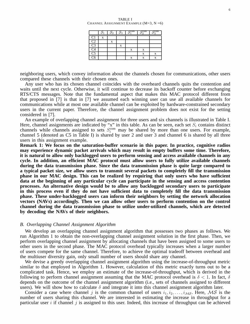
TABLE ICHANNEL ASSIGNMENTEXAMPLE (M=3, N =6)
S1 S2 S3 Scom1 Scom
2 Scom3
C1 xC2 xC3 xC4 x xC5 x xC6 x x x
neighboring users, which convey information about the channels chosen for communications, other userscompared these channels with their chosen ones.
Any user who has its chosen channel coincides with the overheard channels quits the contention andwaits until the next cycle. Otherwise, it will continue to decrease its backoff counter before exchangingRTS/CTS messages. Note that the fundamental aspect that makes this MAC protocol different fromthat proposed in [7] is that in [7] we assumed each winning user can use all available channels forcommunications while at most one available channel can be exploited by hardware-constrained secondaryusers in the current paper. Therefore, the channel assignment problem does not exist for the settingconsidered in [7].
An example of overlapping channel assignment for three users and six channels is illustrated in Table I.Here, channel assignments are indicated by “x” in this table. As can be seen, each setSi contains distinctchannels while channels assigned to setsScom
i may be shared by more than one users. For example,channel 5 (denoted as C5 in Table I) is shared by user 2 and user3 and channel 6 is shared by all threeusers in this assignment example.Remark 1: We focus on the saturation-buffer scenario in thispaper. In practice, cognitive radiosmay experience dynamic packet arrivals which may result in empty buffers some time. Therefore,it is natural to allow only backlogged users to perform sensing and access available channels in anycycle. In addition, an efficient MAC protocol must allow users to fully utilize available channelsduring the data transmission phase. Since the data transmission phase is quite large compared toa typical packet size, we allow users to transmit several packets to completely fill the transmissionphase in our MAC design. This can be realized by requiring that only users who have sufficientdata at the beginning of any particular cycle can participate in the sensing and access contentionprocesses. An alternative design would be to allow any backlogged secondary users to participatein this process even if they do not have sufficient data to completely fill the data transmissionphase. These under-backlogged users can inform their neighbors by setting the network allocationvectors (NAVs) accordingly. Then we can allow other users toperform contention on the controlchannel during the data transmission phase to utilize under-utilized channels, which are detectedby decoding the NAVs of their neighbors.
B. Overlapping Channel Assignment AlgorithmWe develop an overlapping channel assignment algorithm that possesses two phases as follows. We
run Algorithm 1 to obtain the non-overlapping channel assignment solution in the first phase. Then, weperform overlapping channel assignment by allocating channels that have been assigned to some users toother users in the second phase. The MAC protocol overhead typically increases when a larger numberof users compete for the same channel. Therefore, to achievethe optimal tradeoff between overhead andthe multiuser diversity gain, only small number of users should share any channel.
We devise a greedy overlapping channel assignment algorithm using the increase-of-throughput metricsimilar to that employed in Algorithm 1. However, calculation of this metric exactly turns out to be acomplicated task. Hence, we employ an estimate of the increase-of-throughput, which is derived in thefollowing to perform channel assignment assuming that the MAC protocol overhead isδ < 1. In fact, δdepends on the outcome of the channel assignment algorithm (i.e., sets of channels assigned to differentusers). We will show how to calculateδ and integrate it into this channel assignment algorithm later.
Consider a case where channelj is the common channel of usersi1, i2, . . . , iMS . Here,MS is thenumber of users sharing this channel. We are interested in estimating the increase in throughput for aparticular useri if channelj is assigned to this user. Indeed, this increase of throughput can be achieved
7
because useri may be able to exploit channelj if this channel is not available or not used by otherusersi1, i2, . . . , iMS . To estimate the increase of throughput, in the remaining ofthis paper we are onlyinterested in a practical scenario where allpij are close to 1 (e.g., at least 0.8). This would be a reasonableassumption given several recent measurements reveal that spectrum utilization of useful frequency bandsis very low (e.g., less that15%). Under this assumption, we will show that the increase-of-throughput foruseri can be estimated as
∆TMS,esti (j) = (1− 1/MS)(1− δ)pij
(
∏
h∈Si
pih
)
1−∏
h∈Scomi
pih
MS∑
k=1
[
pikj
(
MS∏
q=1,q 6=k
piqj
)]
(5)
+(1− δ)pij∏
h∈Si
pih∏
h∈Scomi
pih
MS∏
q=1
piqj
MS∏
q=1
1−∏
h∈Siq
piqh
(6)
+(1− 1/MS)(1− δ)pij∏
h∈Si
pih
1−∏
h∈Scomi
pih
MS∏
q=1
piqj
MS∏
q=1
1−∏
h∈Siq
piqh
. (7)
This estimation is obtained by listing all possible scenarios/events in which useri can exploit channelj to increase its throughput. Because the user throughput is bounded by 1, we only count events thatoccur with non-negligible probabilities. In particular, under the assumption thatpij are high (orpij aresmall) we only count events whose probabilities have at mosttwo such elementspij in the product. Inaddition, we can determine the increase of throughput for user i by comparing its achievable throughputbefore and after channelj is assigned to it. It can be verified we have the following events for which theaverage increases of throughput are significant.
• Channelj is available for all usersi and iq, q = 1, 2, . . . ,MS exceptik wherek = 1, 2, . . . ,MS.In addition, all channels inSi are not available and there is at least one channel inScom
i available foruseri. Useri can achieve a maximum average throughput of1− δ by exploiting channelj, while itsminimum average throughput before being assigned channeli is at least(1− δ)/MS (when userineeds to share the available channel inScom
i with MS other users). The increase of throughput forthis case is at most(1− 1/MS)(1− δ) and the upper-bound for the increase of throughput of useri is written in (5).
• Channelj is available for useri and all usersiq, q = 1, 2, . . . ,MS but each useriq uses otheravailable channel inSiq for his/her transmission. Moreover, there is no channel inS tot
i available. Inthis case, the increase of throughput for useri is 1 − δ and the average increase of throughput ofuseri is written in (6).
• Channelj is available for useri and all usersiq, q = 1, 2, . . . ,MS but each useriq uses otheravailable channel inSiq for his/her transmission. Moreover, there is at least one channel inScom
i
available. In this case, the increase of throughput for useri is upper-bounded by(1−1/MS)(1− δ)and the average increase of throughput of useri is written in (7).
Detailed description of the algorithm is given in Algorithm2. This algorithm has outer and inter loopswhere the outer loop increases the parameterh, which represents the maximum of users allowed to shareany particular channel (i.e.,MS in the above estimation of the increase of throughput) and the innerloop performs channel allocation for one particular value of h = MS. In each assignment iteration of theinner loop, we assign one “best” channelj to useri that achieves maximum∆T h,est
i (j). This assignmentcontinues until the maximum∆T h,est
i (j) is less than a pre-determined numberǫ > 0. As will be clear inthe throughput analysis developed later, it is beneficial tomaintain at least one channel in each setSi.This is because the throughput contributed by channels inSi constitutes a significant fraction of the totalthroughput. Therefore, we will maintain this constraint when running Algorithm 2.
C. Calculation of Contention WindowWe show how to calculate contention windowW so that collision probabilities among contending
secondary users are sufficiently small. In fact, there is a trade-off between collision probabilities and theaverage overhead of the MAC protocol, which depends onW . In particular, larger values ofW reducecollision probabilities at the cost of higher protocol overhead and vice versa. Because there can be several
8
collisions during the contention phase each of which occursif two or more users randomly choose thesame value of backoff time. In addition, the probability of the first collision is largest because the numberof contending users decreases for successive potential collisions.
Let Pc be the probability of the first collision. In the following, we determine contention windowW byimposing a constraintPc ≤ ǫP whereǫP controls the collision probability and overhead tradeoff.Let uscalculatePc as a function ofW assuming that there arem secondary users in the contention phase. Withoutloss of generality, assume that the random backoff times ofm users are ordered asr1 ≤ r2 ≤ . . . ≤ rm.The conditional probability of the first collision if there arem users in the contention stage can be writtenas
P(m)c =
m∑
j=2
Pr (j users collide)
=
m∑
j=2
W−2∑
i=0
Cjm
(
1
W
)j (W − i− 1
W
)m−j
(8)
where each term in the double-sum represents the probability that j users collide when they choose thesame backoff value equal toi. Hence, the probability of the first collision can be calculated as
Pc =
M∑
m=2
P(m)c × Pr m users contend , (9)
whereP(m)c is given in (8) andPr m users contend is the probability thatm users join the contention
phase. To computePc, we now derivePr m users contend. It can be verified that useri joins contentionif all channels inSi are busy and there is at least one channel inScom
i available. The probability of thisevent can be written as
P(i)con = Pr all channels inSi are busy, ∃! some channels inScom
i are available
=
(
∏
j∈Si
pij
)
1−∏
j∈Scomi
pij
. (10)
The probability of the event thatm users join the contention phase is
Pr m users contend =
CmM∑
n=1
(
∏
i∈Λn
P(i)con
)
∏
j∈ΛM\Λn
P(j)
con
(11)
whereΛn is one particular set ofm users,ΛM is the set of allM users (1, 2, . . . ,M). Substitute theresult in (11) into (9), we can calculatePc. Finally, we can determineW as
W = min W such thatPc(W ) ≤ ǫP (12)
where for clarity we denotePc(W ), which is given in (9) as a function ofW .
D. Calculation of MAC Protocol OverheadLet r be the average value of the backoff value chosen by any SU. Then, we haver = (W − 1)/2
because the backoff counter value is uniformly chosen in theinterval [0,W − 1]. As a result, averageoverhead can be calculated as follows:
δ (W ) =[W − 1] θ/2 + tRTS + tCTS + 3tSIFS + tSEN + tSYN
Tcycle
(13)
whereθ is the time corresponding to one backoff unit;tRTS, tCTS, tSIFS are the corresponding time of RTS,CTS and SIFS (i.e., short inter-frame space) messages;tSEN is the sensing time;tSYN is the transmissiontime of the synchronization message; andTcycle is the cycle time.
9
E. Updateδ inside Algorithm 2Because the overheadδ depends on the channel assignment outcome, which is not known when we
are running Algorithm 2. Therefore, in each allocation stepwe updateδ based on the current channelassignment outcome. Becauseδ does not change much in two consecutive allocation decisions, Algorithm2 runs smoothly in practice.
F. Practical Implementation IssuesTo perform channel assignment, we need to knowpij for all users and channels. Fortunately,
we only need to perform estimation ofpij once these values change, which would be infrequentin practice. These estimation and channel assignment taskscan be performed by one secondarynode or collaboratively performed by several of them. For example, for the secondary networksupporting communications betweenM secondary users and a single secondary BS, the BS cantake the responsibility of estimating pij and performing channel assignment. Once the channelassignment solution has been determined and forwarded to all secondary users, each secondaryuser will perform spectrum sensing and run the underlying MAC protocol to access the spectrumin each cycle.
It is emphasized again that while sensing and MAC protocol are performed and run in everycycle, estimating ofpij and performing channel assignment (given thesepij) are only performed ifthe values ofpij change, which should be infrequent. Therefore, it would be affordable to estimatepij accurately by employing sufficiently long sensing time. This is because for most spectrum sensingschemes including an energy detection scheme, mis-detection and false alarm probabilities tend tozero when sensing time increases for a given sampling frequency [4], [3].
VI. PERFORMANCE ANALYSIS
Suppose we have run Algorithm 2 and obtained the set of usersUj associated with each allocatedchannelj. From this, we have the corresponding setsSi and Scom
i for each useri. Given this channelassignment outcome, we derive the throughput in the following assuming that there is no collision dueto MAC protocol access contention. We will show that by appropriately choosing contention parametersfor the MAC protocol, the throughput analysis under this assumption achieves accurate results.
A. Throughput AnalysisBecause the total throughput is the sum of throughput of all users, it is sufficient to analyze the
throughput of one particular useri. We will perform the throughput analysis by considering allpossiblesensing outcomes performed by the considered useri for its assigned channels. We will have the followingcases, which correspond to different achievable throughput for the considered user.
• Case 1: If there is at least one channel inSi available, then useri will exploit this available channeland achieve the throughput of one. Here, we have
Ti Case 1 = Pr Case 1 = 1−∏
j∈Si
pij . (14)
• Case 2: If no channel inStoti is available for useri, then the achievable throughput of useri is zero.
This scenario occurs with following probability
Pr Case 2 =∏
j∈Stoti
pij. (15)
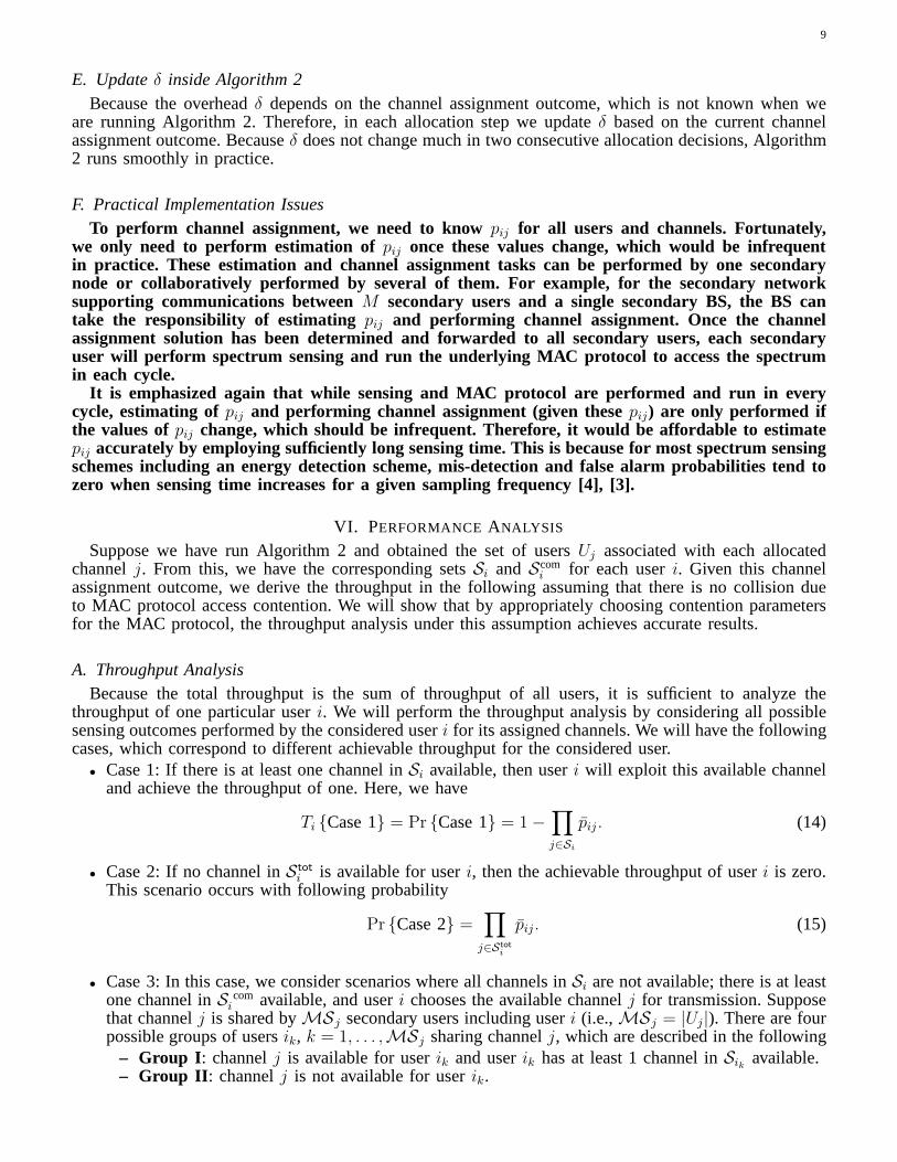
• Case 3: In this case, we consider scenarios where all channels in Si are not available; there is at leastone channel inS com
i available, and useri chooses the available channelj for transmission. Supposethat channelj is shared byMSj secondary users including useri (i.e.,MSj = |Uj|). There are fourpossible groups of usersik, k = 1, . . . ,MSj sharing channelj, which are described in the following
– Group I : channelj is available for userik and userik has at least 1 channel inSik available.– Group II : channelj is not available for userik.
10
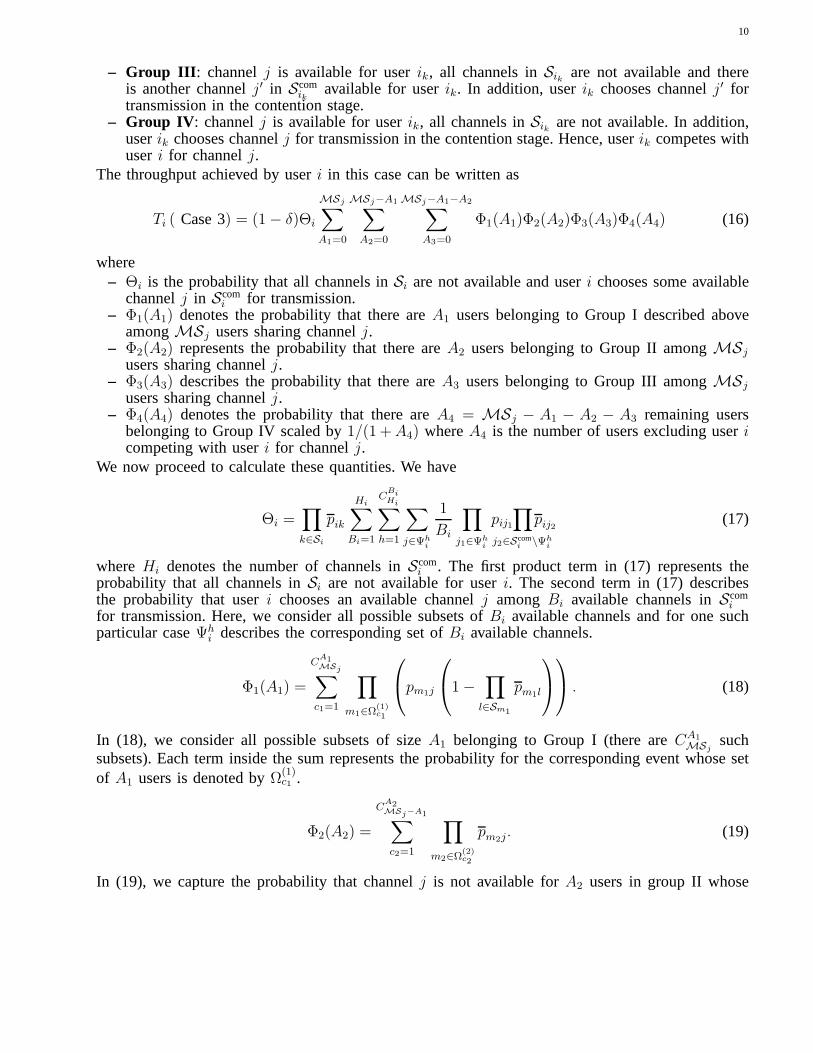
– Group III : channelj is available for userik, all channels inSik are not available and thereis another channelj′ in Scom
ikavailable for userik. In addition, userik chooses channelj′ for
transmission in the contention stage.– Group IV : channelj is available for userik, all channels inSik are not available. In addition,
userik chooses channelj for transmission in the contention stage. Hence, userik competes withuseri for channelj.
The throughput achieved by useri in this case can be written as
Ti ( Case 3) = (1− δ)Θi
MSj∑
A1=0
MSj−A1∑
A2=0
MSj−A1−A2∑
A3=0
Φ1(A1)Φ2(A2)Φ3(A3)Φ4(A4) (16)
where– Θi is the probability that all channels inSi are not available and useri chooses some available
channelj in Scomi for transmission.
– Φ1(A1) denotes the probability that there areA1 users belonging to Group I described aboveamongMSj users sharing channelj.
– Φ2(A2) represents the probability that there areA2 users belonging to Group II amongMSj
users sharing channelj.– Φ3(A3) describes the probability that there areA3 users belonging to Group III amongMSj
users sharing channelj.– Φ4(A4) denotes the probability that there areA4 = MSj − A1 − A2 − A3 remaining users
belonging to Group IV scaled by1/(1 +A4) whereA4 is the number of users excluding usericompeting with useri for channelj.
We now proceed to calculate these quantities. We have
Θi =∏
k∈Si
pik
Hi∑
Bi=1
CBiHi∑
h=1
∑
j∈Ψhi
1
Bi
∏
j1∈Ψhi
pij1∏
j2∈Scomi \Ψh
i
pij2 (17)
whereHi denotes the number of channels inScomi . The first product term in (17) represents the
probability that all channels inSi are not available for useri. The second term in (17) describesthe probability that useri chooses an available channelj amongBi available channels inScom
i
for transmission. Here, we consider all possible subsets ofBi available channels and for one suchparticular caseΨh
i describes the corresponding set ofBi available channels.
Φ1(A1) =
CA1MSj∑
c1=1
∏
m1∈Ω(1)c1
pm1j
1−∏
l∈Sm1
pm1l
. (18)
In (18), we consider all possible subsets of sizeA1 belonging to Group I (there areCA1MSj
suchsubsets). Each term inside the sum represents the probability for the corresponding event whose setof A1 users is denoted byΩ(1)
c1 .
Φ2(A2) =
CA2MSj−A1∑
c2=1
∏
m2∈Ω(2)c2
pm2j. (19)
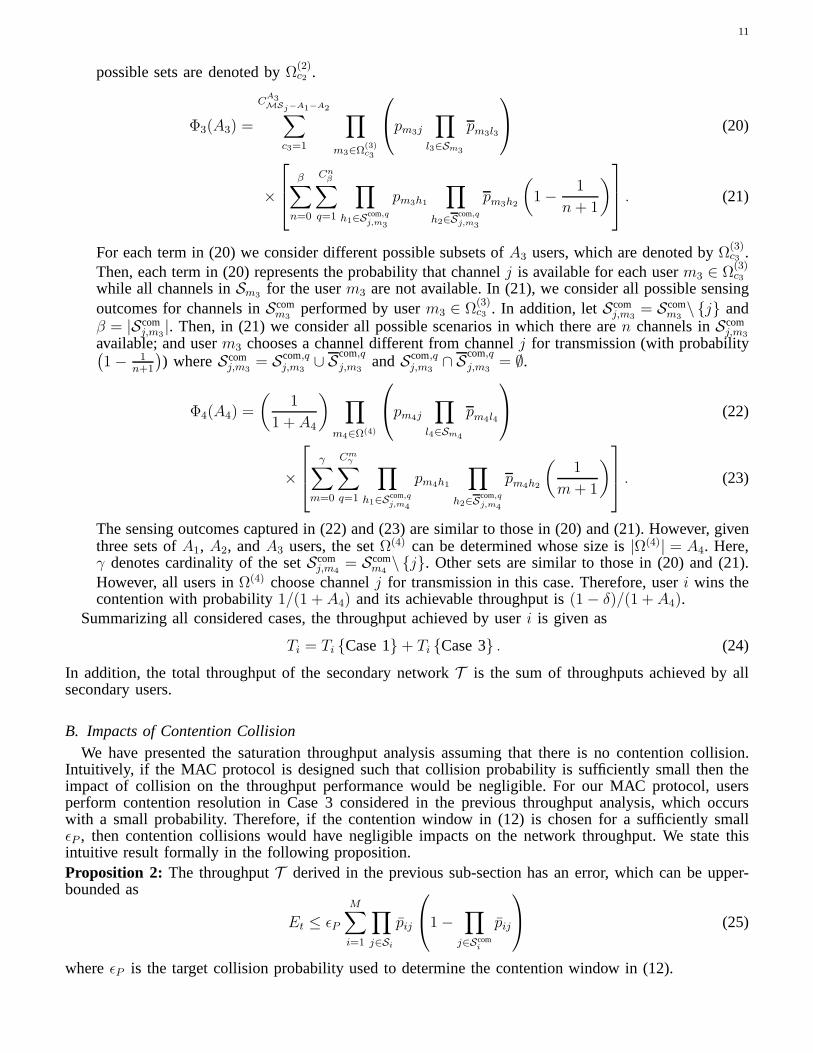
In (19), we capture the probability that channelj is not available forA2 users in group II whose
11
possible sets are denoted byΩ(2)c2 .
Φ3(A3) =
CA3MSj−A1−A2∑
c3=1
∏
m3∈Ω(3)c3
pm3j
∏
l3∈Sm3
pm3l3
(20)
×
β∑
n=0
Cnβ∑
q=1
∏
h1∈Scom,qj,m3
pm3h1
∏
h2∈Scom,qj,m3
pm3h2
(
1−1
n+ 1
)
. (21)
For each term in (20) we consider different possible subsetsof A3 users, which are denoted byΩ(3)c3 .
Then, each term in (20) represents the probability that channel j is available for each userm3 ∈ Ω(3)c3
while all channels inSm3 for the userm3 are not available. In (21), we consider all possible sensingoutcomes for channels inScom
m3performed by userm3 ∈ Ω
(3)c3 . In addition, letScom
j,m3= Scom
m3\ j and
β = |Scomj,m3
|. Then, in (21) we consider all possible scenarios in which there aren channels inScomj,m3
available; and userm3 chooses a channel different from channelj for transmission (with probability(
1− 1n+1
)
) whereScomj,m3
= Scom,qj,m3
∪ Scom,qj,m3
andScom,qj,m3
∩ Scom,qj,m3
= ∅.
Φ4(A4) =
(
1
1 + A4
)
∏
m4∈Ω(4)
pm4j
∏
l4∈Sm4
pm4l4
(22)
×
γ∑
m=0
Cmγ∑
q=1
∏
h1∈Scom,qj,m4
pm4h1
∏
h2∈Scom,qj,m4
pm4h2
(
1
m+ 1
)
. (23)
The sensing outcomes captured in (22) and (23) are similar tothose in (20) and (21). However, giventhree sets ofA1, A2, andA3 users, the setΩ(4) can be determined whose size is|Ω(4)| = A4. Here,γ denotes cardinality of the setScom
j,m4= Scom
m4\ j. Other sets are similar to those in (20) and (21).
However, all users inΩ(4) choose channelj for transmission in this case. Therefore, useri wins thecontention with probability1/(1 + A4) and its achievable throughput is(1− δ)/(1 + A4).
Summarizing all considered cases, the throughput achievedby useri is given as
Ti = Ti Case 1+ Ti Case 3 . (24)
In addition, the total throughput of the secondary networkT is the sum of throughputs achieved by allsecondary users.
B. Impacts of Contention CollisionWe have presented the saturation throughput analysis assuming that there is no contention collision.
Intuitively, if the MAC protocol is designed such that collision probability is sufficiently small then theimpact of collision on the throughput performance would be negligible. For our MAC protocol, usersperform contention resolution in Case 3 considered in the previous throughput analysis, which occurswith a small probability. Therefore, if the contention window in (12) is chosen for a sufficiently smallǫP , then contention collisions would have negligible impactson the network throughput. We state thisintuitive result formally in the following proposition.Proposition 2: The throughputT derived in the previous sub-section has an error, which can be upper-bounded as
Et ≤ ǫP
M∑
i=1
∏
j∈Si
pij
1−∏
j∈Scomi
pij
(25)
whereǫP is the target collision probability used to determine the contention window in (12).
12
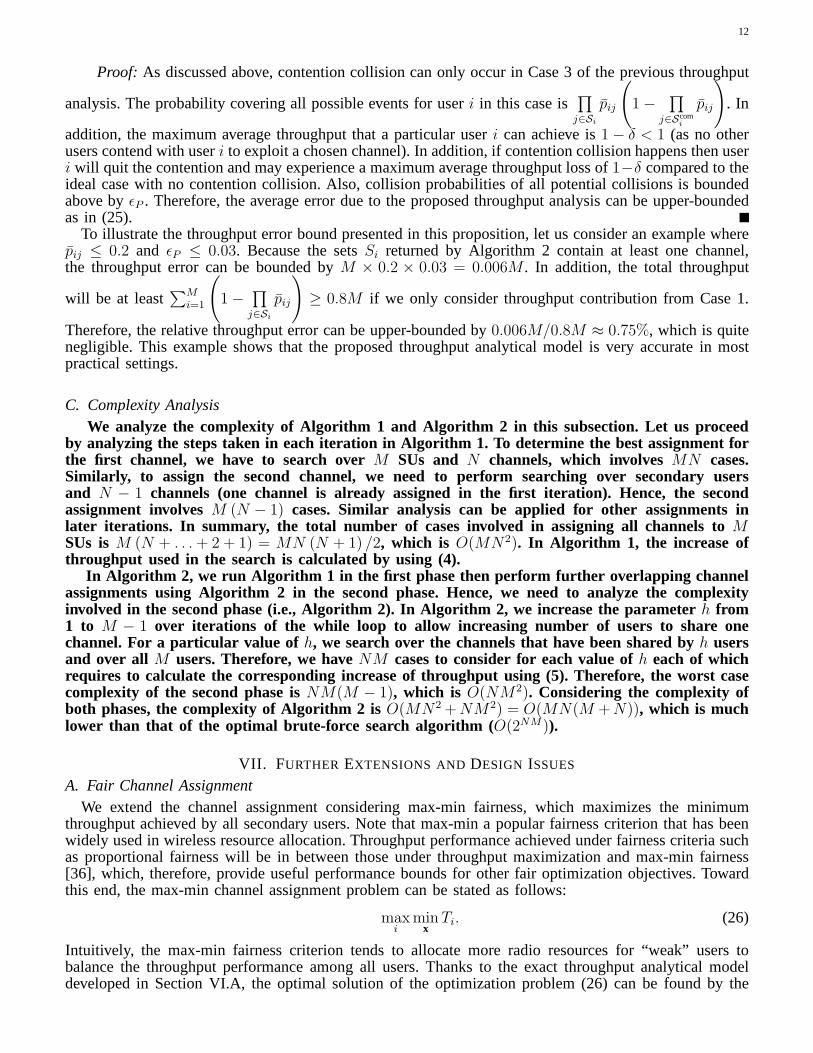
Proof: As discussed above, contention collision can only occur in Case 3 of the previous throughput
analysis. The probability covering all possible events foruseri in this case is∏
j∈Si
pij
(
1−∏
j∈Scomi
pij
)
. In
addition, the maximum average throughput that a particularuseri can achieve is1 − δ < 1 (as no otherusers contend with useri to exploit a chosen channel). In addition, if contention collision happens then useri will quit the contention and may experience a maximum average throughput loss of1−δ compared to theideal case with no contention collision. Also, collision probabilities of all potential collisions is boundedabove byǫP . Therefore, the average error due to the proposed throughput analysis can be upper-boundedas in (25).
To illustrate the throughput error bound presented in this proposition, let us consider an example wherepij ≤ 0.2 and ǫP ≤ 0.03. Because the setsSi returned by Algorithm 2 contain at least one channel,the throughput error can be bounded byM × 0.2 × 0.03 = 0.006M . In addition, the total throughput
will be at least∑M
i=1
(
1−∏
j∈Si
pij
)
≥ 0.8M if we only consider throughput contribution from Case 1.
Therefore, the relative throughput error can be upper-bounded by0.006M/0.8M ≈ 0.75%, which is quitenegligible. This example shows that the proposed throughput analytical model is very accurate in mostpractical settings.
C. Complexity AnalysisWe analyze the complexity of Algorithm 1 and Algorithm 2 in this subsection. Let us proceed
by analyzing the steps taken in each iteration in Algorithm 1. To determine the best assignment forthe first channel, we have to search overM SUs and N channels, which involvesMN cases.Similarly, to assign the second channel, we need to perform searching over secondary usersand N − 1 channels (one channel is already assigned in the first iteration). Hence, the secondassignment involvesM (N − 1) cases. Similar analysis can be applied for other assignments inlater iterations. In summary, the total number of cases involved in assigning all channels toMSUs isM (N + . . .+ 2 + 1) = MN (N + 1) /2, which is O(MN2). In Algorithm 1, the increase ofthroughput used in the search is calculated by using (4).
In Algorithm 2, we run Algorithm 1 in the first phase then perfo rm further overlapping channelassignments using Algorithm 2 in the second phase. Hence, weneed to analyze the complexityinvolved in the second phase (i.e., Algorithm 2). In Algorithm 2, we increase the parameterh from1 to M − 1 over iterations of the while loop to allow increasing number of users to share onechannel. For a particular value of h, we search over the channels that have been shared byh usersand over all M users. Therefore, we haveNM cases to consider for each value ofh each of whichrequires to calculate the corresponding increase of throughput using (5). Therefore, the worst casecomplexity of the second phase isNM(M − 1), which is O(NM2). Considering the complexity ofboth phases, the complexity of Algorithm 2 isO(MN2 +NM2) = O(MN(M +N)), which is muchlower than that of the optimal brute-force search algorithm (O(2NM)).
VII. FURTHER EXTENSIONS AND DESIGN ISSUES
A. Fair Channel AssignmentWe extend the channel assignment considering max-min fairness, which maximizes the minimum
throughput achieved by all secondary users. Note that max-min a popular fairness criterion that has beenwidely used in wireless resource allocation. Throughput performance achieved under fairness criteria suchas proportional fairness will be in between those under throughput maximization and max-min fairness[36], which, therefore, provide useful performance boundsfor other fair optimization objectives. Towardthis end, the max-min channel assignment problem can be stated as follows:
maxi
minx
Ti. (26)
Intuitively, the max-min fairness criterion tends to allocate more radio resources for “weak” users tobalance the throughput performance among all users. Thanksto the exact throughput analytical modeldeveloped in Section VI.A, the optimal solution of the optimization problem (26) can be found by the
13
exhaustive search. Specifically, we can enumerate all possible channel allocations and calculate theircorresponding throughput performance. Then, the optimal solution is the one that achieves the largest valuein (26). As being discussed before this exhaustive search has extremely high computational complexity.
To resolve this complexity issue, we devise greedy fair non-overlapping and overlapping channelassignment algorithms, which are described in Algorithm 3 and Algorithm 4, respectively. In Section VIII,we compare the performance of these algorithms with that of the optimal exhaustive search algorithm.These algorithms are different from Algorithm 1 and Algorithm 2 mainly in the way we choose the userto allocate one “best” channel in each iteration. In Algorithm 3, we find the set of users who achieve aminimum throughput in each iteration. For each user in this set, we find one available channel that resultsin the highest increase of throughput. Then, we assign the “best” channel that achieves the maximumincrease of throughput considering all throughput-minimum users. Therefore, this assignment attempts toincrease the throughput of a weak user while exploiting the multiuser diversity.
In Algorithm 4, we first run Algorithm 3 to obtain non-overlapping sets of channels for all users.Then, we seek to improve the minimum throughput by performing overlapping channel assignments. Inparticular, we find the minimum-throughput user and an overlapping channel assignment that results inthe largest increase in its throughput. The algorithm terminates when there is no such overlapping channelassignment. The search of an overlapping channel assignment in each iteration of Algorithm 4 is performedin Algorithm 5. Specifically, we sequentially search over channels which have already been allocated for asingle user or shared by several users (i.e., channels in separate and common sets, respectively). Then, weupdate the current temporary assignment with a better one (if any) during the search. This search requiresthroughput calculations for which we use the analytical model developed in Subsection VI-A with theMAC protocol overhead,δ < 1 derived in V-D. It can be observed that the proposed throughput analysisis very useful since it can be used to evaluate the performance of any channel assignment solution andto perform channel assignments in greedy algorithms.
B. Throughput Analysis under Imperfect SensingWe extend the throughput analysis considering imperfect sensing in this subsection. The same synchro-
nized MAC protocol described in Section V.A is assumed here.In addition, the MAC protocol overheadcan be calculated as presented in Section V-D where the contention windowW is determined as describedin Section V-C. There are two important performance measures, which are used to quantify the sensingperformance, namely detection and false alarm probabilities. LetP ij
d andP ijf be detection and false alarm
probabilities, respectively of SUi on channelj. In particular, detection event occurs when a secondarylink successfully senses a busy channel and false alarm represents the situation when a spectrum sensorreturns a busy state for an idle channel (i.e., a transmission opportunity is overlooked). Also, let us defineP ij
d = 1−Pij
d andPij
f = 1−P ijf . Under imperfect sensing, there are four possible scenarios for channel
j and secondary useri.• Scenario I: A spectrum sensor indicates that channelj is available and the nearby PU is not using
channelj (i.e., correct sensing). This scenario occurs with the probability Pij
f pij.• Scenario II: A spectrum sensor indicates that channelj is available and the nearby PU is using
channelj (i.e., mis-detection). This scenario occurs with the probability Pij
d pij . In this case, potentialtransmission of secondary useri will collide with that of the nearby primary user. We assume thatboth transmissions from SUi and the nearby PU fail.
• Scenario III: A spectrum sensor indicates that channelj is not available and the nearby PU is usingchannelj (i.e., correct detection). This scenario occurs with the probability P ij
d pij .• Scenario IV: A spectrum sensor indicates that channelj is not available and the nearby PU is not
using channelj (i.e., false alarm). This scenario occurs with the probability P ijf pij and the channel
opportunity is overlooked.Since SUs make channel access decisions based on their sensing outcomes, the first two scenarios can
result in spectrum access on channelj by SU i. Moreover, spectrum access in scenario one actually lead tosuccessful data transmission. Let us defineP ij
idle = Pij
f pij+Pij
d pij andP ijbusy= 1−P ij
idle as the probabilitiesunder which SUi may and may not access channelj, respectively. Since the total throughput is the sumof throughput of all users, it is sufficient to analyze the throughput of one particular useri. To analyzethe throughput of useri, we consider the following cases.
14
• Case 1: There is at least one channel inSi available and useri actually chooses one of these availablechannels for its transmission. Useri can achieve throughput of one in such a successful access, whichoccurs with the following probability
Ti Case 1 = Pr Case 1 =
|Si|∑
k1=1
Ck1|Si|∑
l1=1
∏
j1∈Sl1i
pij1∏
j2∈Si\Sl1i
pij2 (27)
k1∑
k2=1
Ck2k1∑
l2=1
∏
j3∈Sl2i
Pij3
f
∏
j4∈Sl1i \S
l2i
P ij4f (28)
|Si|−k1∑
k3=0
Ck3|Si|−k1∑
l3=1
k2k2 + k3
∏
j5∈Sl3i
Pij5d
∏
j6∈Si\Sl1i \S
l3i
P ij6d . (29)
The quantity (27) represents the probability that there arek1 actually available channels inSi (whichmay or may not be correctly sensed by SUi). Here, S l1
i denotes a particular set ofk1 actuallyavailable channels whose index isl1. In addition, the quantity (28) describes the probability thatthere arek2 available channels actually indicated by sensing (the remaining available channels areoverlooked due to sensing errors) whereS l2
i denotes thel2-th set withk2 available channels. For thequantity in (29),k3 denotes the number of channels that are not actually available but the sensingoutcomes indicate they are available (i.e., due to mis-detection). Moreover,k2/(k2 + k3) representsthe probability that SUi chooses the actually available channel for transmission given its sensingoutcomes indicatek2+k3 available channels. The remaining quantity in (29) describes the probabilitythat the sensing outcomes due to SUi incorrectly indicatesk3 available channels.
• Case 2: There can be some channels inStoti available for useri but the sensing outcomes indicate
that all channels are busy. As a result, useri does not attempt to access any channel. This scenariooccurs with following probability
Pr Case 2 =
|Stoti |∑
k1=0
Ck1
|Stoti |∑
l1=1
∏
j1∈Sl1i
P ij1f pij1
∏
j2∈Stoti \S
l1i
pij2 . (30)
The achievable throughput of useri is zero in this case.• Case 3: All channels inSi are indicated as not available by sensing; there is at least one channel
in S comi indicated as available by sensing, and useri chooses an actually available channelj for
transmission. Suppose that channelj is shared byMSj secondary users including useri (i.e.,MSj =|Uj|). There are four possible groups of usersik, k = 1, . . . ,MSj sharing channelj, which aredescribed in the following
– Group I : channelj is available for userik and userik has at least 1 channel inSik available asindicated by sensing.
– Group II : channelj is indicated as not available for userik by sensing.– Group III : channelj is available for userik, all channels inSik are not available and there
is another channelj′ in Scomik
available for userik as indicated by sensing. In addition, userikchooses channelj′ for transmission in the contention stage.
– Group IV : channelj is available for userik, all channels inSik are not available as indicated bysensing. In addition, userik chooses channelj for transmission in the contention stage. Hence,userik competes with useri for channelj.
The throughput achieved by useri in this case can be written as
Ti ( Case 3) = (1− δ)Θi
MSj∑
A1=0
MSj−A1∑
A2=0
MSj−A1−A2∑
A3=0
Φ1(A1)Φ2(A2)Φ3(A3)Φ4(A4). (31)
15
Here, we use the same notation as for the perfect sensing where– Θi is the probability that all channels inSi are indicated as not available by sensing and useri
chooses some available channelj in Scomi as indicated by sensing for transmission.
– Φ1(A1) denotes the probability that there areA1 users belonging to Group I described aboveamongMSj users sharing channelj.
– Φ2(A2) represents the probability that there areA2 users belonging to Group II amongMSj
users sharing channelj.– Φ3(A3) describes the probability that there areA3 users belonging to Group III amongMSj
users sharing channelj.– Φ4(A4) denotes the probability that there areA4 = MSj − A1 − A2 − A3 remaining users
belonging to Group IV scaled by1/(1 +A4) whereA4 is the number of users excluding usericompeting with useri for channelj.
We now proceed to calculate these quantities. We have
Θi =
|Si|∑
k1=0
Ck1|Si|∑
l1=1
∏
j1∈Sl1i
P ij1f pij1
∏
j2∈Si\Sl1i
pij2 (32)
Hi∑
k2=1
Ck2Hi∑
l2=1
∏
j3∈Ψl2i
pij3∏
j4∈Scomi \Ψ
l2i
pij4 (33)
k2∑
k3=1
Ck3k2∑
l3=1
∑
j∈Γk1
∏
j5∈Γl31
Pij5
f
∏
j6∈Ψl2i \Γ
l3i
P ij6f (34)
Hi−k2∑
k4=0
Ck4Hi−k2∑
l4=1
1
k3 + k4
∏
j7∈Γl42
Pij7d
∏
j8∈Scomi \Ψ
l2i \Γ
l42
P ij8d (35)
whereHi denotes the number of channels inScomi . The quantity in (32) is the probability that all
available channels inSi (if any) are overlooked by useri due to false alarms. Therefore, useridoes not access any channels inSi. The quantity in (33) describes the probability that there are k2actually available channels inScom
i andΨl2i denotes such a typical set withk2 available channels.
The quantity in (34) describes the probability that useri correctly detectsk3 channels out ofk2available channels. The last quantity in (35) excluding thefactor 1/(k3 + k4) denotes the probabilitythat useri mis-detectsk4 channels among the remainingHi − k2 busy channels inScom
i . Finally, thefactor 1/(k3 + k4) is the probability that useri correctly chooses one available channels inScom
i fortransmission out ofk3 + k4 channels which are indicated as being available by sensing.
Φ1(A1) =
CA1MSj∑
c1=1
∏
m1∈Ω(1)c1
Pm1jidle
1−∏
l∈Sm1
Pm1lbusy
. (36)
In (36), we consider all possible subsets of users of sizeA1 that belongs to Group I (there areCA1MSj
such subsets). Each term inside the sum represents the probability of the corresponding event whoseset ofA1 users is denoted byΩ(1)
c1 .
Φ2(A2) =
CA2MSj−A1∑
c2=1
∏
m2∈Ω(2)c2
Pm2jbusy. (37)
16
In (37), we capture the probability that channelj is indicated as not being available by sensing forA2 users in group II. Possible sets of these users are denoted byΩ
(2)c2 .
Φ3(A3) =
CA3MSj−A1−A2∑
c3=1
∏
m3∈Ω(3)c3
Pm3jidle
∏
l3∈Sm3
Pm3l3busy
(38)
×
β∑
n=0
Cnβ∑
q=1
∏
h1∈Scom,qj,m3
Pm3h1idle
∏
h2∈Scom,qj,m3
Pm3h2busy
(
1−1
n+ 1
)
. (39)
For each term in (38) we consider different possible subsetsof A3 users, which are denoted byΩ(3)c3 .
Then, each term in (38) represents the probability that channel j is indicated as available by sensingfor each userm3 ∈ Ω
(3)c3 while all channels inSm3 are indicated as not available by sensing. In (39),
we consider all possible sensing outcomes for channels inScomm3
performed by userm3 ∈ Ω(3)c3 . In
addition, letScomj,m3
= Scomm3
\ j and β = |Scomj,m3
|. Then, in (39) we consider all possible scenariosin which n channels inScom
j,m3are indicated as available by sensing; and userm3 chooses a channel
different from channelj for transmission (with probability(
1− 1n+1
)
) whereScomj,m3
= Scom,qj,m3
∪Scom,qj,m3
andScom,qj,m3
∩ Scom,qj,m3
= ∅.
Φ4(A4) =
(
1
1 + A4
)
∏
m4∈Ω(4)
Pm4jidle
∏
l4∈Sm4
Pm4l4busy
(40)
×
γ∑
m=0
Cmγ∑
q=1
∏
h1∈Scom,qj,m4
Pm4h1idle
∏
h2∈Scom,qj,m4
Pm4h2busy
(
1
m+ 1
)
. (41)
The sensing outcomes captured in (40) and (41) are similar tothose in (38) and (39). However, giventhree sets ofA1, A2, andA3 users, the setΩ(4) can be determined whose size is|Ω(4)| = A4. Here,γ denotes cardinality of the setScom
j,m4= Scom
m4\ j. Other sets are similar to those in (38) and (39).
However, all users inΩ(4) choose channelj for transmission in this case. Therefore, useri wins thecontention with probability1/(1 + A4) and its achievable throughput is(1− δ)/(1 + A4).
Summarize all considered cases, the throughput achieved byuseri is written as
Ti = Ti Case 1+ Ti Case 3 . (42)
And the total throughputT can be calculated by summing the throughputs of all secondary users.
C. Congestion of Control ChannelUnder our design, contention on the control channel is mild if the number of channelsN is relatively
large compared to the number of SUsM . In particular, there is no need to employ a MAC protocol if wehaveN >> M since distinct sets of channels can be allocated for SUs by using Algorithm 1. In contrast,if the number of channelsN is small compared to the number of SUsM then the control channel mayexperience congestion due to excessive control message exchanges. The congestion of the control channelin such scenarios can be alleviated if we allow RTS/CTS messages to be exchanged in parallel on severalchannels (i.e., multiple rendezvous [32]). Design of such aMAC protocol in the cognitive radio settingrequires extra care compared to traditional multi-channelsettings since PUs must be protected.
We describe potential design of a multiple-rendezvous MAC protocol in the following using similarideas of a multi-channel MAC protocol (McMAC) in [32], [31].We assume that each SU hops through allchannels by following a particular hopping pattern, which corresponds to a unique seed [32]. In addition,each SU puts its seed in every packets so that neighboring SUscan learn its hopping pattern. The samecycle structure as being described in Section V.A is employed here. Suppose SU A wishes to transmitdata SU B in a particular cycle. Then, SU A turns to the currentchannel of B and senses this channel as
17
well as its assigned channels inStotAB, which is the set of allocated channels for linkAB. If SU A’s sensing
outcomes indicate that the current channel of SU B is available then SU A sends RTS/CTS messageswith SU B containing a chosen available communication channel. Otherwise, SU A waits until the nextcycle to perform sensing and contention again. If the handshake is successful, SU A transmits data to SUB on the chosen channel in the data phase. Upon completing data transmission, both SUs A and B returnto their home hopping patterns.
It is worth noting that the throughput analysis performed inSection VI.A and Section VII.B is stillvalid here except that we have to derive the protocol overhead and choose an appropriate contentionwindow under this new design. In general, collisions among SUs are less frequent under a multiple-rendezvous MAC protocol since contentions can occur in parallel on different channels. As suggested by[32], it would not be possible to design a multi-channel MAC protocol that can work efficiently in alldifferent scenarios. Discussions on different potential designs of a multi-channel MAC protocol and theircorresponding pros/cons can be found in [32] and the references therein. We would like to emphasize thatthe focus of this paper is on the channel assignment issue; therefore, consideration of alternative designsof a MAC protocol is beyond its scope.
VIII. N UMERICAL RESULTS
We present numerical results to illustrate the throughput performance of the proposed channelassignment algorithms. To obtain the results, the probabilities pi,j are randomly realized in theinterval [0.7, 0.9]. We choose the length of control packetsas follows: RTS including PHY header288 bits, CTS including PHY header 240 bits, which correspond to tRTS = 48µs, tCTS = 40 µs fortransmission rate of 6Mbps, which is the basic rate of 802.11a/g standards. Other parameters arechosen as follows: cycle timeTcycle = 3ms; θ = 20 µs, tSIFS = 28 µs, target collision probability ǫP =0.03; tSEN and tSYN are assumed to be negligible so they are ignored. Note that these values ofθ andtSIFS are typical (interest readers can refer to Tables I and II for [33] for related information). Thevalue of cycle timeTcycle is chosen based on the fact that practical cognitive systemssuch as thoseoperating on the TV bands standardized in the 802.22 standard requires maximum evacuation timeof a few milliseconds [34].
A. MAC Protocol ConfigurationWe first investigate interactions between MAC protocol parameters and the achievable throughput
performance. In particular, we plot the average probability of the first collision, which is derived inSection V-C versus contention window in Fig. 2 when Algorithm 2 is used for channel assignment. Thisfigure shows that the collision probability first increases then decreases withN . This can be interpreted asfollows. WhenN is relatively small, Algorithm 2 tends to allow more overlapping channel assignments forincreasing number of channels. However, more overlapping channel assignments increase the contentionlevel because more users may want to exploit same channels, which results in larger collision probability.As N is sufficiently large, a few overlapping channel assignments is needed to achieve the maximumthroughput. Therefore, collision probability decreases with N .
We now consider the impact of target collision probabilityǫP on the total network throughput, which isderived in Section VI-A. Recall that in this analysis collision probability is not taken into account, whichis shown to have negligible errors in Proposition 2. Specifically, we plot the total network throughputversusǫP for M = 10 and different values ofN in Fig. 3. This figure shows that the total throughputslightly increases withǫP . However, the increase is quite marginal asǫP ≥ 0.03. In fact, the requiredcontention windowW given in (12) decreases with increasingǫP (as can be observed from Fig. 2), whichleads to decreasing MAC protocol overheadδ(W ) as confirmed by (13) and therefore the increase in thetotal network throughput. Moreover, the total throughput may degrade with increasingǫP because of theincreasing number of collisions. Therefore, choosingǫP = 0.03 would be reasonable to balance betweenthroughput gain due to moderate MAC protocol overhead and throughput loss due to contention collision.We will illustrate the throughput performance achieved by our proposed algorithms for this value of targetcollision probability in the next sub-section.
B. Comparisons of Proposed Algorithms versus Optimal AlgorithmsWe demonstrate the efficacy of the proposed algorithms by comparing their throughput perfor-
mances with those obtained by the optimal brute-force search algorithms for small values ofM and
18
N . Numerical results are presented for both throughput-maximization and max-min fair objectives.In Figs. 7 and 8, we compare the throughputs of the proposed and optimal algorithms for M = 2and M = 3 under the throughput-maximization objective. These figures confirm that Algorithm 2achieves very close to the optimal solutions for both valuesof M .
In Figs. 9, 10, we plot the throughputs achieved by our proposed algorithm and the optimalalgorithm for M = 2 and M = 3 under the max-min fair objective. Again Algorithm 4 achievesthroughput very close to the optimal throughput under this fair objective. These results are verypositive given that Algorithm 2 and Algorithm 4 have much lower complexity than those of theoptimal brute-force search algorithms. In addition, analytical results match simulation results verywell and non-overlapping channel assignment algorithms achieve noticeably lower throughputs thanthose by their overlapping counterparts.
C. Throughput Performance of Proposed AlgorithmsWe illustrate the total throughputT versus the number of channels obtained by both Algorithm 1 and
Algorithm 2 where each point is obtained by averaging the throughput over 30 different realizations ofpi,j in Fig. 4. Throughput curves due to Algorithms 1 and 2 are indicated as “P-ware” in this figure.In addition, for the comparison purposes, we also show the throughput performance achieved by “P-blind” algorithms, which simply allocate channels to usersin a round-robin manner without exploitingthe heterogeneity ofpi,j (i.e., multiuser diversity gain). For P-blind algorithms,we show the performanceof both non-overlapping and overlapping channel assignment algorithms. Here, the overlapping P-blindalgorithm allows at most five users to share one particular channel. We have observed through numericalstudies that allowing more users sharing one channel cannotachieve better throughput performance becauseof the excessive MAC protocol overhead.
As can be seen in Fig. 4, analytical and simulation results achieved by both proposed algorithms matcheach other very well. This validates the accuracy of our throughput analytical model developed in SectionVI-A. It also indicates that the total throughput reaches the maximum value, which is equal toM = 15 asthe number of channels becomes sufficiently large for both Algorithms 1 and 2. This confirms the resultstated in Proposition 1. In addition, Algorithm 2 achieves significantly larger throughput than Algorithm 1for low or moderate values ofN . This performance gain comes from the multiuser diversity gain, whicharises due to the spatial dependence of white spaces. For largeN (i.e., more than twice the number of usersM), the negative impact of MAC protocol overhead prevents Algorithm 2 from performing overlappedchannel assignments. Therefore, both Algorithms 1 and 2 achieve similar throughput performance.
Fig. 4 also indicates that both proposed algorithms outperform the round-robin channel assignmentcounterparts. In particular, Algorithm 1 improves the total throughput significantly compared to the round-robin algorithm under non-overlapping channel assignments. For the overlapping channel assignmentschemes, we show the throughput performance of the round-robin assignment algorithms when 5 usersare allowed to share one channel (denoted as 5-user sharing in the figure). Although this achieves largerthroughput for the round-robin algorithm, it still performs worse compared to the proposed algorithms.Moreover, we demonstrate the throughput gain due to Algorithm 2 compared to Algorithm 1 for differentvalues ofN andM in Fig. 5. This figure shows that performance gains up to5% can be achieved whenthe number of channels is small or moderate. Also, Fig. 6 presents the throughput gain due to Algorithm2 versus the P-blind algorithm with 5-user sharing. It can beobserved that a significant throughput gainof up to 10% can be achieved for these investigated scenarios.
Fig. 11 illustrates the throughput of Algorithms 3 and 4 where pij are chosen in the rangeof [0.5, 0.9]. It can be observed that the overlapping channel algorithm improves the throughputperformance compared to the non-overlapping counterpart in terms of the minimum throughput.Finally, we plot the throughputs achieved by Algorithms 1 and 2 under perfect and imperfectspectrum sensing forM = 5 in Fig. 12. This figure shows that sensing errors can significantly degradethe throughput performance of SUs. In addition, the presented results validate the throughputanalytical model described in Section VII.B.
IX. CONCLUSION
We have considered a channel assignment problem for cognitive radio networks with hardware-constrainedsecondary users in this paper. We have presented the optimalbrute-force search algorithm and analyzed
19
its complexity. To resolve the high complexity of the optimal search, we have developed two channelassignment algorithms for throughput maximization. The first algorithm performs non-overlapping channelassignment for secondary users, which was shown to achieve optimality if the number of channels issufficiently large. In the secondary algorithm, we have allowed overlapping channel assignments anddesigned a MAC protocol to resolve channel access contention when different users attempt to exploitthe same available channel. In addition, we have developed an analytical model to analyze the saturationthroughput achieved by Algorithm 2. We have presented several potential extensions including design ofmax-min fair channel assignment algorithms, throughput analysis considering imperfect spectrum sensing,and alternative MAC protocol design to relieve congestion of the control channel. We have validated ourresults via numerical studies and demonstrated significantthroughput gains of the overlapping channelassignment algorithm compared to the non-overlapping and round-robin channel assignment counterpartsin different network settings.
REFERENCES
[1] Q. Zhao and B.M. Sadler, “A survey of dynamic spectrum access,”IEEE Signal Processing Mag.,vol. 24, no. 3, pp. 79-89, May, 2007.
[2] L. B. Le and E. Hossain, “Resource allocation for spectrum underlay in cognitive radio networks,”IEEE Trans. Wireless Commun.,
vol. 7, no. 12, pp. 5306-5315, Dec. 2008.
[3] L. Ying-Chang, Z. Yonghong, E. C. Y. Peh and H. Anh Tuan, “Sensing-throughput tradeoff for cognitive radio networks”, IEEE Trans.
Wireless Commun., vol. 7, no. 4, pp. 1326-1337, April 2008.
[4] T. Yucek and H. Arslan, “A survey of spectrum sensing algorithms for cognitive radio applications,”IEEE Commun. Surveys Tutorials,
vol. 11, no. 1, pp. 116–130, 2009.
[5] J. So and N. H. Vaidya, “Multi-channel mac for ad hoc networks: handling multi-channel hidden terminals using a single transceiver,”
in Proc. ACM MobiHoc, 2004.
[6] C. Cormiob and K. R. Chowdhurya, “A survey on MAC protocols for cognitive radio networks,”Elsevier Ad Hoc Networks,vol. 7,
no. 7, pp. 1315-1329, Sept. 2009.
[7] L. T. Tan and L. B. Le, “Distributed MAC protocol for cognitive radio networks: Design, analysis, and optimization,”IEEE Trans.
Veh. Tech., vol. 60, no. 8, pp. 3990-4003, Oct. 2011.
[8] H. Kim and K. G. Shin, “Efficient discovery of spectrum opportunities with MAC-layer sensing in cognitive radio networks,” IEEE
Trans. Mobile Computing,vol. 7, no. 5, pp. 533-545, May 2008.
[9] H. Su and X. Zhang, “Cross-layer based opportunistic MACprotocols for QoS provisionings over cognitive radio wireless networks,”
IEEE J. Sel. Areas Commun., vol. 26, no. 1, pp. 118–129, Jan. 2008.
[10] H. Su and X. Zhang, “Opportunistic MAC protocols for cognitive radio based wireless networks,” inProc. CISS’2007.
[11] H. Nan, T.-I. Hyon, and S.-J. Yoo, “Distributed coordinated spectrum sharing MAC protocol for cognitive radio,” inProc. IEEE
DySPAN’2007.
[12] L. Le and E. Hossain, “OSA-MAC: A MAC protocol for opportunistic spectrum access in cognitive radio networks,” inProc. IEEE
WCNC’2008.
[13] C. Cordeiro and K. Challapali, “ C-MAC: A cognitive MAC protocol for multi-channel wireless networks,” inProc. IEEE DySPAN’2007.
[14] A. C. -C. Hsu, D. S. L. Weit, and C. -C. J. Kuo, “A cognitiveMAC protocol using statistical channel allocation for wireless ad-hoc
networks,” inProc. IEEE WCNC’2007.
[15] Y. R. Kondareddy and P. Agrawal, “Synchronized MAC protocol for multi-hop cognitive radio networks,” inProc. IEEE ICC’2008.
[16] C. Doerr, M. Neufeld, J. Fifield, T. Weingart, D. C. Sicker, and D. Grunwald, “MultiMAC: An adaptive MAC framework fordynamic
radio networking,” inProc. IEEE DySPAN’2005.
[17] H. Salameh, M. M. Krunz, and O. Younis, “MAC protocol foropportunistic cognitive radio networks with soft guarantees,” IEEE
Trans. Mobile Computing,vol. 8, no. 10, pp. 1339–1352, Oct. 2009.
20
[18] T. Shu, S. Cui, and M. Krunz, “Medium access control for multi-channel parallel transmission in cognitive radio networks,” in Proc.
IEEE GLOBECOM’2006.
[19] T. Chen, H. Zhang, G. M. Maggio, and I. Chlamtac, “CogMesh: A cluster-based cognitive radio network,” inProc. IEEE DySPAN’2007.
[20] J. Shi, E. Aryafar, T. Salonidis, and E. W. Knightly, “Synchronized CSMA contention: Model, implementation and evaluation”, in
Proc. IEEE INFOCOM, pp. 2052-2060, 2009.
[21] J. Jia, Q. Zhang, and X. Shen, “HC-MAC: A hardware-constrained cognitive MAC for efficient spectrum management,”IEEE J. Sel.
Areas Commun., vol. 26, no. 1, pp. 106–117, Jan. 2008.
[22] H. B. Salameh, M. Krunz, and O. Younis, “Cooperative adaptive spectrum sharing in cognitive radio networks,”IEEE/ACM Trans.
Networking,vol. 18, no. 4, pp. 1181–1194, Aug. 2010.
[23] T. Shu and M. Krunz, “Exploiting microscopic spectrum opportunities in cognitive radio networks via coordinated channel access,”
IEEE Trans. Mobile Computing, vol. 9, no. 11, pp. 1522–1534, Nov. 2010.
[24] W. Wang, K. G. Shin, and W. Wang,“Joint spectrum allocation and power control for multi-hop cognitive radio networks,” IEEE Trans.
Mobile Computing, vol. 10, no. 7, pp. 1042–1055, July 2011.
[25] X. Zhang and H. Su, “Opportunistic spectrum sharing schemes for CDMA-based uplink MAC in cognitive radio networks,” IEEE J.
Sel. Areas Commun., vol. 29, no. 4, pp. 716-730, April 2011.
[26] Y. -J. Choi and K. G. Shin, “Opportunistic access of TV spectrum using cognitive-radio-enabled cellular networks,” IEEE Trans. Veh.
Tech., vol. 60, no. 8, pp. 3853-3864, Oct. 2011.
[27] X. Zhang and H. Su, “CREAM-MAC: Cognitive radio-enabled multi-channel MAC protocol over dynamic spectrum access networks,”
IEEE J. Sel. Topics Signal Processing, vol. 5, no. 1, pp. 110-123, Feb. 2011.
[28] M. Timmers, S. Pollin, A. Dejonghe, L. Van der Perre, andF. Catthoor, “A distributed multichannel MAC protocol for multihop
cognitive radio networks,”IEEE Trans. Veh. Tech., vol. 59, no. 1, pp. 446–459, Jan. 2010
[29] W. Jeon, J. Han, and D. Jeong, “A novel MAC scheme for multi-channel cognitive radio ad hoc networks,”IEEE Trans. Mobile
Computing, to appear.
[30] S. C. Jha, U. Phuyal, M. M. Rashid, and V. K. Bhargava, “Design of OMC-MAC: An opportunistic multi-channel MAC with QoS
provisioning for distributed cognitive radio networks,”IEEE Trans. Wireless Commun.,vol. 10, no. 10, pp. 3414–3425 , Oct. 2011.
[31] H. Su and X. Zhang, “Channel-hopping based single transceiver MAC for cognitive radio networks,” inProc. CISS’2008.
[32] J. Mo, H. So, and J. Walrand, “Comparison of multichannel MAC protocols,” IEEE Trans. Mobile Computing, vol. 7, no. 1, pp. 50–65,
Jan. 2008.
[33] G. Bianchi, “Performance analysis of the IEEE 802.11 distributed coordination function”,IEEE J. Sel. Areas Commun., vol. 18, no. 3,
pp. 535-547 Mar. 2000.
[34] G. Ko, A. Franklin, S. -J. You, J. -S. Pak, M. -S. Song, andC. -J. Kim, “Channel management in IEEE 802.22 WRAN systems,” IEEE
Commun. Mag., vol. 48, no. 9, pp. 88–94, Sept. 2010.
[35] J. Lee and S. Leyffer eds., “Mixed integer nonlinear programming,” The IMA Volumes in Mathematics and its Applications, vol. 154,
Springer, 2012.
[36] L. Tassiulas and S. Sarkar, “Maxmin fair scheduling in wireless ad hoc networks,”IEEE J. Sel. Areas Commun., vol. 23, no. 1, pp.
163–173 , Jan. 2005.
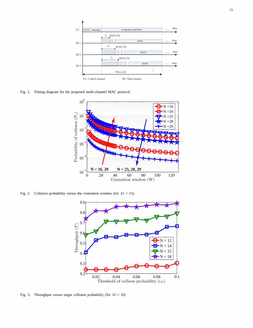
21
One cycle
timeSYN Contention and DATA . . .
DATA
DC1
DC2
DATA
DC3
. . .
DATA
CC: Control channel
. . .
. . .
. . .
time
time
time
CC
DC: Data channel
1r
2r
3r
CTSRTS
CTSRTS
CTSRTS
Sensing
Fig. 1. Timing diagram for the proposed multi-channel MAC protocol.
0 20 40 60 80 100 12010
−5
10−4
10−3
10−2
10−1
100
Contention window (W)
Pro
bability
ofco
llisio
n(P
c)
N =16N =20N =25N =28N =29
N = 16, 20 N = 25, 28, 29
Fig. 2. Collision probability versus the contention window(for M = 15).
0.02 0.04 0.06 0.08 0.19.2
9.3
9.4
9.5
9.6
9.7
9.8
9.9
Threshold of collison probability (ǫP )
Thro
ughput
(T)
N = 12N = 14N = 15N = 18
Fig. 3. Throughput versus target collision probability (for M = 10)
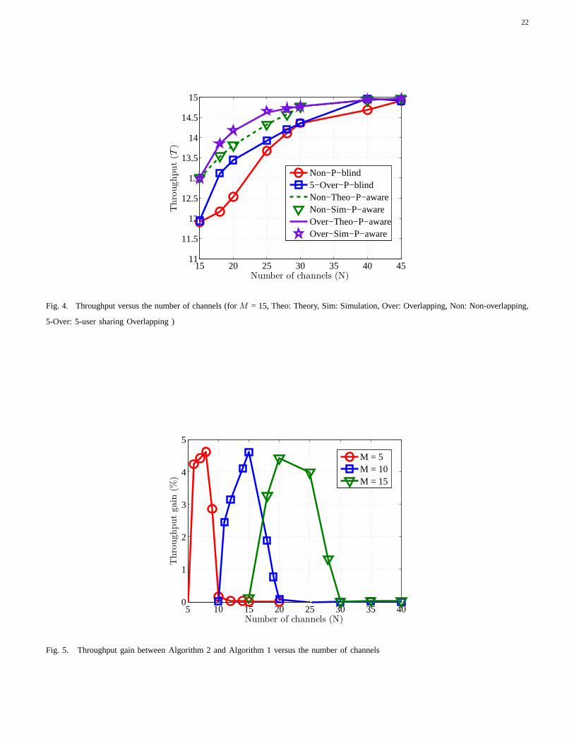
22
15 20 25 30 35 40 4511
11.5
12
12.5
13
13.5
14
14.5
15
Number of channels (N)
Thro
ughput
(T)
Non−P−blind5−Over−P−blindNon−Theo−P−awareNon−Sim−P−awareOver−Theo−P−awareOver−Sim−P−aware
Fig. 4. Throughput versus the number of channels (forM = 15, Theo: Theory, Sim: Simulation, Over: Overlapping, Non: Non-overlapping,
5-Over: 5-user sharing Overlapping )
5 10 15 20 25 30 35 400
1
2
3
4
5
Number of channels (N)
Thro
ughput
gain
(%)
M = 5M = 10M = 15
Fig. 5. Throughput gain between Algorithm 2 and Algorithm 1 versus the number of channels
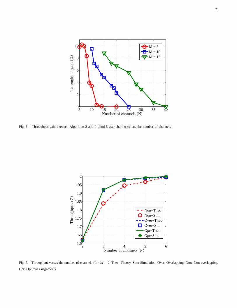
23
5 10 15 20 25 30 35 400
2
4
6
8
10
Number of channels (N)
Thro
ughput
gain
(%)
M = 5M = 10M = 15
Fig. 6. Throughput gain between Algorithm 2 and P-blind 5-user sharing versus the number of channels
2 3 4 5 61.6
1.65
1.7
1.75
1.8
1.85
1.9
1.95
2
Number of channels (N)
Thro
ughput
(T)
Non−TheoNon−SimOver−TheoOver−SimOpt−TheoOpt−Sim
Fig. 7. Throughput versus the number of channels (forM = 2, Theo: Theory, Sim: Simulation, Over: Overlapping, Non:Non-overlapping,
Opt: Optimal assignment).
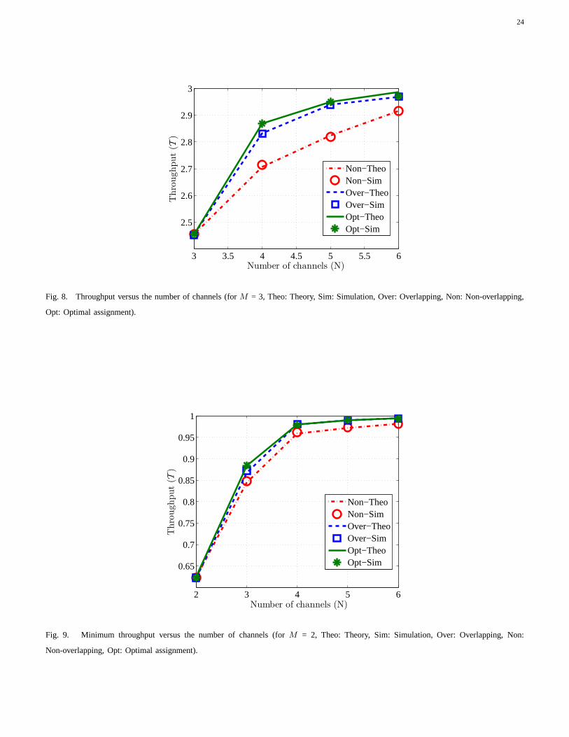
24
3 3.5 4 4.5 5 5.5 6
2.5
2.6
2.7
2.8
2.9
3
Number of channels (N)
Thro
ughput
(T)
Non−TheoNon−SimOver−TheoOver−SimOpt−TheoOpt−Sim
Fig. 8. Throughput versus the number of channels (forM = 3, Theo: Theory, Sim: Simulation, Over: Overlapping, Non:Non-overlapping,
Opt: Optimal assignment).
2 3 4 5 6
0.65
0.7
0.75
0.8
0.85
0.9
0.95
1
Number of channels (N)
Thro
ughput
(T)
Non−TheoNon−SimOver−TheoOver−SimOpt−TheoOpt−Sim
Fig. 9. Minimum throughput versus the number of channels (for M = 2, Theo: Theory, Sim: Simulation, Over: Overlapping, Non:
Non-overlapping, Opt: Optimal assignment).
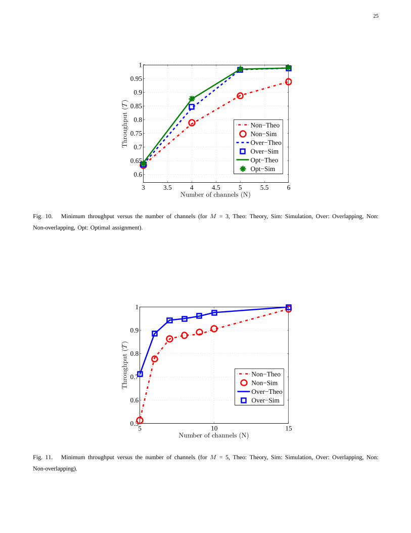
25
3 3.5 4 4.5 5 5.5 6
0.6
0.65
0.7
0.75
0.8
0.85
0.9
0.95
1
Number of channels (N)
Thro
ughput
(T)
Non−TheoNon−SimOver−TheoOver−SimOpt−TheoOpt−Sim
Fig. 10. Minimum throughput versus the number of channels (for M = 3, Theo: Theory, Sim: Simulation, Over: Overlapping, Non:
Non-overlapping, Opt: Optimal assignment).
5 10 150.5
0.6
0.7
0.8
0.9
1
Number of channels (N)
Thro
ughput
(T)
Non−TheoNon−SimOver−TheoOver−Sim
Fig. 11. Minimum throughput versus the number of channels (for M = 5, Theo: Theory, Sim: Simulation, Over: Overlapping, Non:
Non-overlapping).
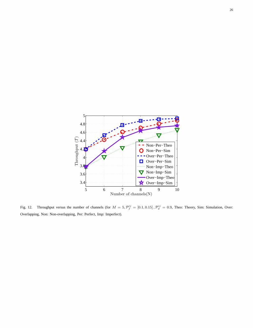
26
5 6 7 8 9 10
3.4
3.6
3.8
4
4.2
4.4
4.6
4.8
5
Number of channels(N)
Thro
ughput
(T)
Non−Per−TheoNon−Per−SimOver−Per−TheoOver−Per−SimNon−Imp−TheoNon−Imp−SimOver−Imp−TheoOver−Imp−Sim
Fig. 12. Throughput versus the number of channels (forM = 5,Pijf = [0.1, 0.15] ,Pij
d = 0.9, Theo: Theory, Sim: Simulation, Over:
Overlapping, Non: Non-overlapping, Per: Perfect, Imp: Imperfect).
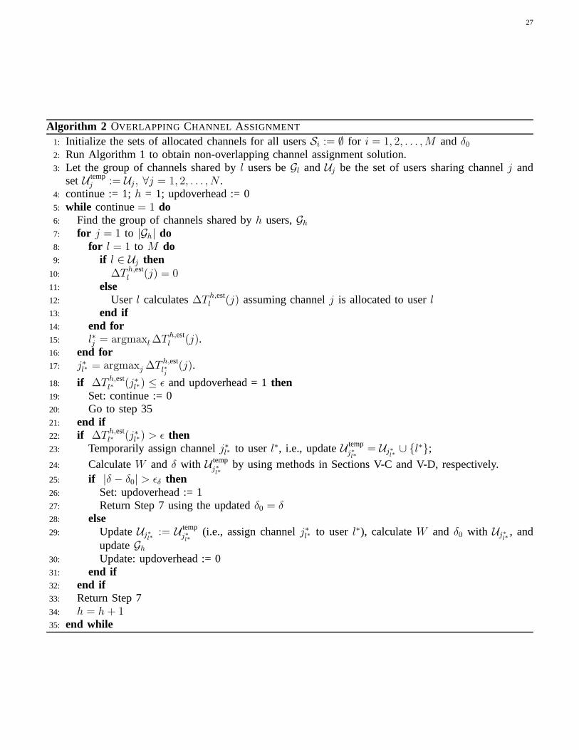
27
Algorithm 2 OVERLAPPING CHANNEL ASSIGNMENT
1: Initialize the sets of allocated channels for all usersSi := ∅ for i = 1, 2, . . . ,M andδ02: Run Algorithm 1 to obtain non-overlapping channel assignment solution.3: Let the group of channels shared byl users beGl andUj be the set of users sharing channelj and
setU tempj := Uj , ∀j = 1, 2, . . . , N .
4: continue := 1;h = 1; updoverhead := 05: while continue= 1 do6: Find the group of channels shared byh users,Gh
7: for j = 1 to |Gh| do8: for l = 1 to M do9: if l ∈ Uj then
10: ∆T h,estl (j) = 0
11: else12: User l calculates∆T h,est
l (j) assuming channelj is allocated to userl13: end if14: end for15: l∗j = argmaxl ∆T h,est
l (j).16: end for17: j∗l∗ = argmaxj ∆T h,est
l∗j(j).
18: if ∆T h,estl∗ (j∗l∗) ≤ ǫ and updoverhead = 1then
19: Set: continue := 020: Go to step 3521: end if22: if ∆T h,est
l∗ (j∗l∗) > ǫ then23: Temporarily assign channelj∗l∗ to userl∗, i.e., updateU temp
j∗l∗
= Uj∗l∗∪ l∗;
24: CalculateW andδ with U tempj∗l∗
by using methods in Sections V-C and V-D, respectively.25: if |δ − δ0| > ǫδ then26: Set: updoverhead := 127: Return Step 7 using the updatedδ0 = δ28: else29: UpdateUj∗
l∗:= U temp
j∗l∗
(i.e., assign channelj∗l∗ to userl∗), calculateW and δ0 with Uj∗l∗
, andupdateGh
30: Update: updoverhead := 031: end if32: end if33: Return Step 734: h = h + 135: end while

28
Algorithm 3 FAIR NON-OVERLAPPING CHANNEL ASSIGNMENT
1: Initialize SU i’s set of available channels,Sai := 1, 2, . . . , N andSi := ∅ for i = 1, 2, . . . ,M where
Si denotes the set of channels assigned for SUi.2: continue:= 13: while continue= 1 do4: Find the set of users who currently have minimum throughputSmin = argmin
i
T bi
whereSmin = i1, . . . , im ⊂ 1, . . . ,M is the set of minimum-throughput SUs.5: if OR
il∈Smin
(
Sail6= ∅)
then
6: For each SUil ∈ Smin and channeljil ∈ Sail, find ∆Til(jil) = T a
il− T b
il
whereT ail
andT bil
are the throughputs after and before assigning channeljil; and we set∆Til = 0if Sa
il= ∅.
7:
i∗l , j∗i∗l
= argmaxil∈Smin,jil∈S
ail
∆Til(jil)
8: Assign channelj∗i∗l
to SU i∗l .9: UpdateSi∗l
= Si∗l∪ j∗i∗l andSa
k = Sak\j
∗i∗l
for all k ∈ 1, . . . ,M.10: else11: Set continue:= 012: end if13: end while
Algorithm 4 FAIR OVERLAPPING CHANNEL ASSIGNMENT
1: Run Algorithm 3 and obtain the setsSi for all SU i. Initialize Scomi = ∅ for i.
2: continue := 1.3: while continue= 1 do4: Find i∗ = argmin
i∈1,...,M
T bi andTmin = T b
i∗ where ties are broken randomly.
5: SSepi∗ = ∪
i,i 6=i∗Si, SUni
i∗ = ∪iScomi \Scom
i∗ .
6: Run Algorithm 5.7: if OR
iScom,tempi 6= ∅ then
8: AssignScomi = Scom,temp
i andSi = S tempi .
9: else10: Set continue:= 0.11: end if12: end while
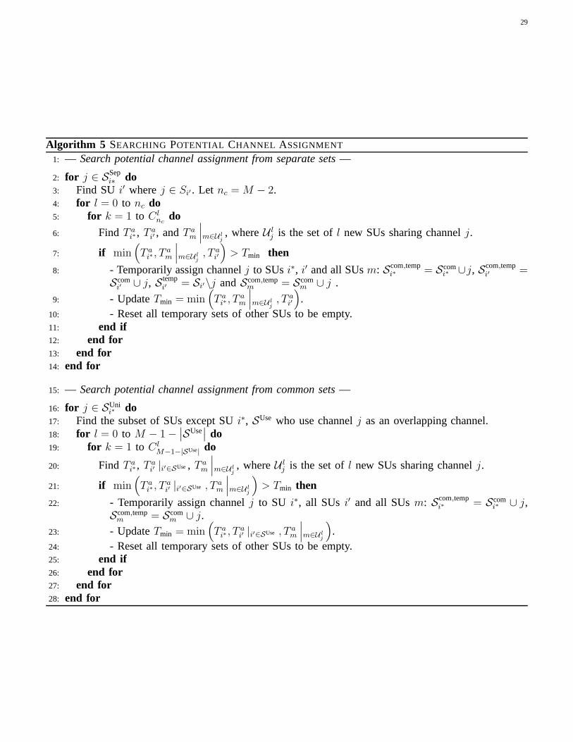
29
Algorithm 5 SEARCHING POTENTIAL CHANNEL ASSIGNMENT
1: — Search potential channel assignment from separate sets—
2: for j ∈ SSepi∗ do
3: Find SU i′ wherej ∈ Si′ . Let nc = M − 2.4: for l = 0 to nc do5: for k = 1 to C l
ncdo
6: Find T ai∗, T
ai′ , andT a
m
∣
∣
∣m∈U lj, whereU l
j is the set ofl new SUs sharing channelj.
7: if min(
T ai∗ , T
am
∣
∣
∣m∈U lj, T a
i′
)
> Tmin then
8: - Temporarily assign channelj to SUsi∗, i′ and all SUsm: Scom,tempi∗ = Scom
i∗ ∪j, Scom,tempi′ =
Scomi′ ∪ j, S temp
i′ = Si′\j andScom,tempm = Scom
m ∪ j .
9: - UpdateTmin = min(
T ai∗ , T
am
∣
∣
∣m∈U lj, T a
i′
)
.10: - Reset all temporary sets of other SUs to be empty.11: end if12: end for13: end for14: end for
15: — Search potential channel assignment from common sets—
16: for j ∈ SUnii∗ do
17: Find the subset of SUs except SUi∗, SUse who use channelj as an overlapping channel.18: for l = 0 to M − 1−
∣
∣SUse∣
∣ do19: for k = 1 to C l
M−1−|SUse| do
20: Find T ai∗, T
ai′ |i′∈SUse, T a
m
∣
∣
∣m∈U lj, whereU l
j is the set ofl new SUs sharing channelj.
21: if min(
T ai∗ , T
ai′ |i′∈SUse , T a
m
∣
∣
∣m∈U lj
)
> Tmin then
22: - Temporarily assign channelj to SU i∗, all SUs i′ and all SUsm: Scom,tempi∗ = Scom
i∗ ∪ j,Scom,tempm = Scom
m ∪ j.
23: - UpdateTmin = min(
T ai∗ , T
ai′ |i′∈SUse , T a
m
∣
∣
∣m∈U lj
)
.24: - Reset all temporary sets of other SUs to be empty.25: end if26: end for27: end for28: end for