Pneumonia in the Immunocompetent Child - Appropriateness ...
Upload
khangminh22Category
view
0download
0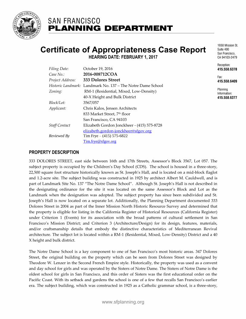
www.sfplanning.org
Certificate of Appropriateness Case Report HEARING DATE: FEBRUARY 1, 2017
Filing Date: October 19, 2016
Case No.: 2016-008712COA
Project Address: 333 Dolores Street
Historic Landmark: Landmark No. 137 – The Notre Dame School
Zoning: RM-1 (Residential, Mixed, Low-Density)
40-X Height and Bulk District
Block/Lot: 3567/057
Applicant: Chris Kalos, Jensen Architects
833 Market Street, 7th floor
San Francisco, CA 94103
Staff Contact Elizabeth Gordon Jonckheer - (415) 575-8728
[email protected] Reviewed By Tim Frye – (415) 575-6822
PROPERTY DESCRIPTION
333 DOLORES STREET, east side between 16th and 17th Streets, Assessor’s Block 3567, Lot 057. The
subject property is occupied by the Children’s Day School (CDS). The school is housed in a three-story,
22,500 square foot structure historically known as St. Joseph’s Hall, and is located on a mid-block flaglot
and 1.2-acre site. The subject building was constructed in 1925 by architect Albert M. Cauldwell, and is
part of Landmark Site No. 137 “The Notre Dame School”. Although St. Joseph’s Hall is not described in
the designating ordinance for the site it was located on the same Assessor’s Block and Lot as the
Landmark when the designation was adopted. The subject property has since been subdivided and St.
Joseph’s Hall is now located on a separate lot. Additionally, the Planning Department documented 333
Dolores Street in 2004 as part of the Inner Mission North Historic Resource Survey and determined that
the property is eligible for listing in the California Register of Historical Resources (California Register)
under Criterion 1 (Events) for its association with the broad patterns of cultural settlement in San
Francisco’s Mission District; and Criterion 3 (Architecture/Design) for its design, features, materials,
and/or craftsmanship details that embody the distinctive characteristics of Mediterranean Revival
architecture. The subject lot is located within a RM-1 (Residential, Mixed, Low-Density) District and a 40
X height and bulk district.
The Notre Dame School is a key component to one of San Francisco’s most historic areas. 347 Dolores
Street, the original building on the property which can be seen from Dolores Street was designed by
Theodore W. Lenzer in the Second French Empire style. Historically, the property was used as a convent
and day school for girls and was operated by the Sisters of Notre Dame. The Sisters of Notre Dame is the
oldest school for girls in San Francisco, and this order of Sisters was the first educational order on the
Pacific Coast. With its setback and gardens the school is one of a few that recalls San Francisco’s earlier
era. The subject building, which was constructed in 1925 as a Catholic grammar school, is a three-story,

Certificate of Appropriateness
February 1, 2017
2
Case Number 2016-008712COA
333 Dolores Street
reinforced-concrete building designed by architect Albert M. Cauldwell in the Mediterranean Revival
style. St. Joseph’s Hall served as the Sisters of Notre Dame grammar school for girls from 1925 until 1986.
The minimally-altered building continues be used as an elementary school by CDS. The primary façade
of the building faces south towards the school’s playgrounds and the interior of the block. The west
façade faces the driveway and can be seen from Dolores Street. The north and east façades abut several
adjoining properties along 16th and Guerrero streets.
Primary Façade Description1
The south façade has a narrow wing that projects outward at the left side. The wing is one bay wide and
capped by a hipped roof clad in red clay tiles. The main volume of the building is to the right of this
wing; it is nine bays wide and capped by a combination flat and pent roof clad in red clay tiles. At the
first floor level, a pergola spans the width of the building. The pergola is composed of a low stucco wall,
atop of which are single and paired columns. These columns, which are interspersed among narrow
sections of wall, support a trellis composed of heavy wood timbers. Access to the pergola is provided at
the far left, center, and far right by short concrete stairs. At the left side of the pergola, there is a concrete
wheelchair ramp and a stair with metal pipe rails, which leads from the far left side of the pergola to two
non-historic entrances located left of center. At the right side of the pergola, there is a large metal fire
escape, which leads to platforms and fire doors at the second and third floor levels. To the right of the
pergola is a wood stair and platform, with a wood balustrade and railings, which provides access to two
non-historic entrances and an outdoor utility closet. The central portion of the pergola is protected by a
canvas and metal-tube awning and the far right side of the pergola is covered by a corrugated metal roof.
The primary entrance of the building is located at the center (fifth bay) of the first-floor level of the
primary façade. It contains a contemporary fully-glazed, single-leaf metal door with a sidelight. Above
the entrance is a wooden sign affixed to the façade that reads “St. Joseph’s Hall 1925”. The remainder of
the fenestration at the first floor level is generally symmetrical, although non-historic alterations have
disrupted the south façade’s historical symmetry. The structural bays are paired, leaving a broader space
between the second and third and the seventh and eighth bays. At the first floor level, while each bay
historically contained a large multi-light window containing 12 four-light casement sashes, only the first,
fourth, sixth, and seventh bays retain this arrangement. The second and third bays now contain
contemporary anodized aluminum door systems with flanking sidelights. The eighth and ninth bays have
contemporary ten-light, single-leaf wood doors. At the second floor level, the fifth (center) bay, above the
primary entrance, has a multi-light window containing nine four-light casement sashes. The rest of the
bays have larger windows composed of 12 four-light casement sashes matching the first floor level. The
only exception is the eighth bay, where one of the original windows was modified in the 1950s to install a
metal fire door. The second floor level terminates with a narrow stringcourse molding. The third floor
level is lower than the first and second floor levels, and is slightly recessed behind the stringcourse
molding demarcating the second and third floor levels. At the fifth (center) bay there is a non-historic,
tripartite aluminum casement window. The first, second, third, fourth, and seventh bays retain their
original window configuration of two recessed pairs of ten-light casement sashes separated by an
engaged Composite-order column. At the sixth bay, the left casement sash has been replaced by a pair of
1 Primary Façade Description based on the Historic Resource Evaluation (HRE) Parts I & II prepared by VerPlanck
Historic Preservation Consultants dated August 30, 2016 (pages 14-18).

Certificate of Appropriateness
February 1, 2017
3
Case Number 2016-008712COA
333 Dolores Street
metal fire doors with a transom window. The eighth and ninth bays contain non-historic aluminum
windows. The third floor level of the primary façade terminates with a narrow band of rough concrete,
and overhanging eaves supported by shaped wooden rafter tails.
To the left of the primary façade is a side wing. Its east-facing side contains multi-light wood casement
windows at each floor level. The south-facing façade has three large, tripartite windows divided into
three sections consisting of a wider central window flanked by narrow windows. Like the rest of the
historic windows on the building, each window is articulated as a grid of nine or 12 casement sashes. At
the first floor level, square pillars capped by red tiles project from the right and left of the façade. The
wing terminates with a molded cornice.
Character-Defining Features
As noted above, 333 Dolores Street is not described in the designating ordinance for the site; therefore
character–defining features are not outlined for St. Joseph’s Hall. A Historic Resource Evaluation (HRE)
Parts I & II prepared by VerPlanck Historic Preservation Consultants on August 30, 2016 (attached)
delineates the character-defining elements and features for the site. The Department concurs with the
description below.
The character-defining features of 333 Dolores Street are those elements that were put in place between
1925 and 1976, including:
The building’s three-story height and L-plan footprint;
Compound roof with hipped, flat, and pent areas, including red terra cotta tile cladding;
Stucco cladding;
Ratio of solid to void at all four façades;
Typical window configuration of multi-light wood casement windows;
Location of the building’s two original entrances, at the south and west façades;
Engaged stucco columns at windows;
General arrangement of the open-air pergola, including low wall, columns, and heavy timber trellis;
Exposed shaped rafter tails;
Band of rough stucco beneath the eaves;
Stringcourse molding between the second and third floor levels, and slightly recessed façade profile
above this molding;
Interior arrangement of corridors along the north side of the building and classrooms along the south
side of the building;
Exposed wood truss system and shaped beam brackets.
PROJECT DESCRIPTION
The project proposes exterior improvements to the south façade of the existing building. Proposed work
includes seismic upgrade, removal of an existing fire escape, removal of the floor of the existing pergola
to create a new concrete slab porch with a continuous accessible grade across the front of the building,
and modifications to the openings on the pergola level to accommodate new accessible entrance doors.
Existing aluminum windows and metal fire doors are proposed to be replaced with units to match the

Certificate of Appropriateness
February 1, 2017
4
Case Number 2016-008712COA
333 Dolores Street
historic appearance during the period of significance. The existing clay tile roof is also proposed to be
replaced. Specific proposed work includes:
General: Improvements to the building's exterior for seismic performance and accessibility,
including entrances and path of travel -- there is no change of use or addition of floor area.
Roof: At the roof, the red terra cotta clay tiles would be removed and a 2" layer of rigid board
insulation laid atop a new layer of plywood roof sheathing. The purpose of the plywood is to
improve the building's seismic performance and the purpose of the insulation is to improve the
building's climate control systems. This new layer of insulation would be shaved down toward
the edge of the building to minimize visual changes to the building's roof profile. The existing tile
would be replaced in-kind. The tiles along the perimeter eave would be installed using a
traditional “two-piece” method to replicate existing conditions; otherwise new “S” tiles would be
used.
Replacement of existing retrofit windows and doors: The metal fire doors at the second and third
floor levels would be removed, along with their transoms. The area of the façade below the sills
where doors have been removed would be patched, and new wood casement windows that
match the building’s historic fenestration pattern would be installed. The aluminum replacement
windows at the fifth, eighth, and ninth bays of the third floor level would be removed and
replaced with new wood casement windows that match the building’s historic fenestration.
Fire Escape: The project proposes removal of the non-historic fire-escape that spans the full
height of the façade.
Pergola: At the first floor level of the south façade, the floor of the existing pergola is proposed to
be removed, including the concrete slab and the non-historic ramp, stair, and platform. A new
concrete slab porch would be poured 2’ above the original grade of the pergola floor, creating a
level, continuous grade across the front of the building. At the first (far left) bay, six four-light
casement windows would be removed, and paired glass entry doors would be installed in their
place. At the second and third bays, existing non-historic doors would be removed and replaced
with wood multi-light doors. At the fifth bay, the primary entrance door and the sign above it
that reads “St. Joseph’s Hall 1925” would be removed. The sill of the door opening would be
raised to match the new grade of the pergola floor and widened. New paired glass entry doors
would be installed in the opening. At the sixth bay, a portion of the multi-light window would be
removed and a multi-light wood door with a sidelight would be installed in the opening.
Access to the pergola from the schoolyard would be at three points – at left, center, and right –
corresponding with the existing gaps in the pergola wall. At the left, a concrete landing would be
constructed in front of the pergola, which would be accessed from the driveway/parking area by
a ramp and from the schoolyard by a short stair. This landing would include bike parking, and
the existing metal gate at the west perimeter of the schoolyard would be relocated to the right
side of this landing. At the center, the pergola would be accessed by a straight concrete stair. At
the right, the pergola would be accessed by a small landing, a ramp that runs alongside the
pergola, and a straight concrete stair. All new stairs would have ADA-compliant handrails and
children’s handrails. A new metal railing with metal balustrades would be installed on top of the
low pergola wall, between the existing columns.
Certificate of Appropriateness
February 1, 2017
5
Case Number 2016-008712COA
333 Dolores Street
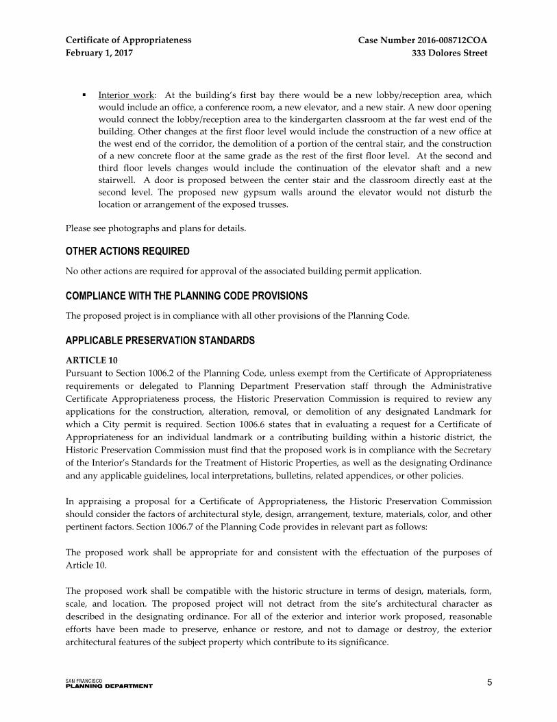
Interior work: At the building’s first bay there would be a new lobby/reception area, which
would include an office, a conference room, a new elevator, and a new stair. A new door opening
would connect the lobby/reception area to the kindergarten classroom at the far west end of the
building. Other changes at the first floor level would include the construction of a new office at
the west end of the corridor, the demolition of a portion of the central stair, and the construction
of a new concrete floor at the same grade as the rest of the first floor level. At the second and
third floor levels changes would include the continuation of the elevator shaft and a new
stairwell. A door is proposed between the center stair and the classroom directly east at the
second level. The proposed new gypsum walls around the elevator would not disturb the
location or arrangement of the exposed trusses.
Please see photographs and plans for details.
OTHER ACTIONS REQUIRED
No other actions are required for approval of the associated building permit application.
COMPLIANCE WITH THE PLANNING CODE PROVISIONS
The proposed project is in compliance with all other provisions of the Planning Code.
APPLICABLE PRESERVATION STANDARDS
ARTICLE 10
Pursuant to Section 1006.2 of the Planning Code, unless exempt from the Certificate of Appropriateness
requirements or delegated to Planning Department Preservation staff through the Administrative
Certificate Appropriateness process, the Historic Preservation Commission is required to review any
applications for the construction, alteration, removal, or demolition of any designated Landmark for
which a City permit is required. Section 1006.6 states that in evaluating a request for a Certificate of
Appropriateness for an individual landmark or a contributing building within a historic district, the
Historic Preservation Commission must find that the proposed work is in compliance with the Secretary
of the Interior’s Standards for the Treatment of Historic Properties, as well as the designating Ordinance
and any applicable guidelines, local interpretations, bulletins, related appendices, or other policies.
In appraising a proposal for a Certificate of Appropriateness, the Historic Preservation Commission
should consider the factors of architectural style, design, arrangement, texture, materials, color, and other
pertinent factors. Section 1006.7 of the Planning Code provides in relevant part as follows:
The proposed work shall be appropriate for and consistent with the effectuation of the purposes of
Article 10.
The proposed work shall be compatible with the historic structure in terms of design, materials, form,
scale, and location. The proposed project will not detract from the site’s architectural character as
described in the designating ordinance. For all of the exterior and interior work proposed, reasonable
efforts have been made to preserve, enhance or restore, and not to damage or destroy, the exterior
architectural features of the subject property which contribute to its significance.

Certificate of Appropriateness
February 1, 2017
6
Case Number 2016-008712COA
333 Dolores Street
THE SECRETARY OF THE INTERIOR’S STANDARDS
Rehabilitation is the act or process of making possible a compatible use for a property through repair,
alterations, and additions while preserving those portions or features that convey its historical, cultural,
or architectural values. The Rehabilitation Standards provide, in relevant part(s):
Standard 1.
A property shall be used for its historic purpose or be placed in a new use that requires minimal change
to the defining characteristics of the building and its site and environment.
The proposed project would not change the historic use of the building. 333 Dolores Street was constructed as a
school and will continue to be used as a school after the proposed project is completed.
Standard 2.
The historic character of a property shall be retained and preserved. The removal of historic materials or
alteration of features and spaces that characterize a property shall be avoided.
The project would retain and strengthen the historic use of the site as a school. The proposed project would make
changes to a very small proportion of the distinctive materials and features of 333 Dolores Street. At the roof, the
addition of a 2" layer of rigid board insulation would slightly alter the profile of the building's roof, but not to a
degree that it would to affect the building's overall proportions, or that it would alter the spatial relationship
between 333 Dolores Street and its surroundings, including the two public vantage points from Dolores Street and
16th/Guerrero Streets.
At the exterior, small areas of the first floor level of the south facade would be removed to install three new entrances,
altering both the ratio of solid-to-void and the fenestration pattern of the primary facade. These alterations would,
however, have a minimal effect on the historic character of the building because of the small area affected and because
the historic character of the upper stories of the primary facade would be restored and enhanced by the removal of the
non-historic fire-escape, fire doors, and aluminum windows; and the restoration of the wood casement windows
affected by the removal of the fire escape.
At the pergola, the original concrete floor slab, as well as the non-historic ramp, stair and platform, would be
removed and replaced by a continuous new slab that is 2’ higher than the original floor of the pergola, altering the
spatial relationship between the pergola and the building. Also, the construction of three new stairs, two ramps, and
two landings in front of the pergola would alter the spatial relationship between the pergola and the schoolyard. The
effect of these changes is minimized by the fact that the grade change to the pergola would be concealed behind the
low wall in front of the pergola, placing it out of direct view when looking at the building. Furthermore, the rest of
the pergola would remain intact, including the low wall, the columns, the higher walls, and the trellis, all of which
are character-defining features of the building.
The proposed project would not remove or alter any distinctive materials or make any changes to the spaces or
spatial relationships that characterize the interior of the building. The project would not remove the exposed wood
truss system and the general arrangement of classrooms inside the building.

Certificate of Appropriateness
February 1, 2017
7
Case Number 2016-008712COA
333 Dolores Street
Standard 3.
Each property will be recognized as a physical record of its time, place and use. Changes that create a
false sense of historical development, such as adding conjectural features or elements from other historic
properties, will not be undertaken.
The proposed project would not add any conjectural features or elements from other historic properties that would
create a false sense of historical development. Restoration of the windows at the second and third floor levels on the
primary facade will be based on both physical and documentary evidence, including the original drawings and
historic photographs. Furthermore, the project sponsor will use salvaged window sashes from the first floor level to
patch the voids where the metal fire doors will be removed. These changes would restore the historic appearance of
the second and third floor levels of the building’s primary façade. Newly introduced design elements, namely the two
double-leaf entrances at the first floor level, would be made of glass panels to ensure that it is understood that they
are contemporary features.
Standard 4.
Changes to a property that have acquired historic significance in their own right will be retained and
preserved.
No post-1925 alterations to 333 Dolores Street have acquired significance in their own right. Although the
aluminum windows on the south façade were installed during the building’s period of significance, they are not
significant features worthy of retention because of their clear divergence from the building’s historic fenestration –
most of which still survives.
Standard 5.
Distinctive materials, features, finishes, and construction techniques or examples of fine craftsmanship
that characterize a property will be preserved.
The proposed project would preserve the majority of 333 Dolores Street's distinctive materials, finishes, and
construction techniques, including the remaining historic windows, molded stucco columns and ornament, the wood
beams of the pergola's trellis, and the distinctive wooden trusses and rafters at the third floor level.
The only character-defining materials that would be removed are the red clay roof tiles. The existing tiles would be
removed in order to install the new roof diaphragm and the rigid board insulation. According to the project sponsor,
removal of the tiles would result in breakage of at least 10 percent of the tiles; therefore, there would not be enough to
reinstall. Instead of reusing the existing tile, the project sponsor plans to install new lighter-weight tiles that match
the original in terms of material, color, and profile. The new tiles are slightly wider to enable two points of
attachment, making them safer than the original. Each curved section is slightly wider than the existing and they
are slightly thinner as well, reducing their weight, which will improve the building's seismic performance. Because
they are the same material as the existing tile, once they have weathered, it is anticipated that the new tiles would
replicate the existing roof in appearance.
Standard 6.
Deteriorated historic features will be repaired rather than replaced. Where the severity of deterioration
requires replacement of a distinctive feature, the new feature will match the old in design, color, texture,

Certificate of Appropriateness
February 1, 2017
8
Case Number 2016-008712COA
333 Dolores Street
and, where possible, materials. Replacement of missing features will be substantiated by documentary
and physical evidence.
As discussed above under Rehabilitation Standard 5, for seismic safety reasons, the project sponsor intends to
replace the terra cotta roof tile in kind. The existing tile is too heavy for the proposed seismic retrofitting plan.
Instead of reusing the existing tile, the project sponsor has elected to use a thinner tile that otherwise matches the
original tile in terms of material, color, and texture. Due to the roof’s height, pitch, and distance from public rights-
of-way, the difference between existing conditions and post-construction conditions would be minimal. The
Architectural Resources Group (ARG) provided the Department with a Conditions Assessment for the existing clay
tile roof dated January 12, 2017. The Conditions Assessment (discussed in detail under Staff Analysis) found the
existing clay tiles to be in good-to fair-condition and well maintained. ARG recommended that during future roof
work, care should be taken to ensure replacement tiles match the original in color, color variation, size, and exposure.
Additionally, the use of brightly colored mortar should be avoided or, if patched, mortar should be colored to match
existing mortar in place. Gutters and downspouts should be repaired or replaced in-kind to ensure eave profiles
remain similar. Furthermore, ARG stated that deteriorated wood rafter tails and soffits should be repaired whenever
possible, otherwise they should be replaced in-kind; and roofs should be regularly inspected, cleaned of debris, and
paint coatings should be maintained.
Otherwise, the project sponsor plans to retain and repair any deteriorated historic features and materials, in
particular the existing wood casement windows on the south, west, and east facades. Replacement of missing
window sashes will make use of salvaged window sashes from the new door openings. What cannot not be replaced
with salvaged window sash materials will be fabricated to match what currently exists, as well as what appears on
original drawings and historic photographs.
Standard 7.
Chemical or physical treatments, if appropriate, will be undertaken using the gentlest means possible.
Treatments that cause damage to historic materials will not be used.
The proposed project does not include any chemical or physical treatments.
Standard 8.
Archeological resources will be protected and preserved in place. If such resources must be disturbed,
mitigation measures will be undertaken.
The proposed project would require very minimal subsurface excavation in the vicinity of the pergola.
Standard 9.
New additions, exterior alterations, or related new construction will not destroy historic materials,
features, and spatial relationships that characterize the property. The new work shall be differentiated
from the old and will be compatible with the historic materials, features, size, scale and proportion, and
massing to protect the integrity of the property and its environment.
As described in more detail under Rehabilitation Standards 2 and 5, exterior alterations would affect a very small
proportion of the building's area and it would protect the majority of the historic materials and features affected. The

Certificate of Appropriateness
February 1, 2017
9
Case Number 2016-008712COA
333 Dolores Street
proposed project would remove several previous alterations that currently detract from the building's historic
appearance, including the 1952 fire-escape and fire doors and the 1970 aluminum windows and restore the upper
floor levels of the south facade to their historic appearance with wood casement sashes from the new entrances at the
first floor level. The spatial relationship between the building and its surrounding context would not be affected by
the insertion of rigid board insulation and replacement tiles on the roof, or by the reconfiguration of the pergola floor
to match the grade of the first floor level. The two new entrances on the south facade would contain contemporary
glass doors, making them clearly differentiated.
Standard 10.
New additions and adjacent or related new construction will be undertaken in a manner that, if removed
in the future, the essential form and integrity of the historic property and its environment would be
unimpaired.
If the changes included in the proposed project were to be removed in the future, the affected areas -namely the roof
profile, the pergola, and the portions of the first floor level of the south facade where new door openings will be
inserted -could be reconstructed and/or patched to match the building's historic appearance, and the essential form
and integrity of the building would be unimpaired.
PUBLIC/NEIGHBORHOOD INPUT
The Department has received four letters of support for the project from the Grace Fellowship
Community Church, the Boys & Girls Clubs of San Francisco, St. Matthew’s Lutheran Church and Mercy
Housing.
ISSUES & OTHER CONSIDERATIONS
The Project Sponsor applied for a building permit (Application No. 201605046539) for the subject project
on October 19, 2016.
STAFF ANAYLSIS
Based on the requirements of Article 10 and the Secretary of Interior’s Standards, staff has determined
that the proposed work will not adversely affect the subject landmark site.
General Discussion
All of the proposed project's exterior changes would occur at the building's south façade facing the
interior of the lot and are not visible from the public right of way. The proposal would not entail the
removal, alteration or obstruction of any significant historic feature per the designating ordinance. The
proposed project does not change the historic use of the building nor diminish the existing character-
defining features. New features are compatible in scale and proportion with the existing historic features,
are not creating a false historicism, and are clearly differentiated. The proposed alterations, including the
removal of the existing fire escape, the new entrances to the building, restoration of the historic
appearance of the building’s south façade, and changes to the pergola to make it ADA-compliant are
modest changes that will not impact the historic appearance of the building. Moreover, the historic
character of the upper stories of the primary façade would be restored and enhanced by the removal of

Certificate of Appropriateness
February 1, 2017
10
Case Number 2016-008712COA
333 Dolores Street
the non-historic fire-escape, fire doors, and aluminum windows, and the restoration of the wood
casement windows affected by the removal of the fire escape. The essential form and integrity of the site
would remain intact. Within the interior, the character-defining spaces and spatial relationships are
limited to the exposed wood truss system and the general arrangement of classrooms along the south side
and a single-loaded corridor along the north side of the building. The proposed project would not
remove or alter any distinctive materials or make any changes to these spatial relationships.
The project removes the existing gate and fence perpendicular to the side wing and installs a new security
gate and fence further east at the right side of the new concrete landing in front of the pergola. Overall
the gate provides adequate transparency and visibility to the historic building. The fence is mounted on
the new landing, and is guided through the paired column. The two attachments to the main building are
minimal. The gate and fence are shown to be hot-dipped galvanized steel. Staff recommends the gate and
fence be treated with a powder-coated finish to better complement the character of the historic building.
Terra Cotta Clay Roof Tiles
The project also removes the red terra cotta clay roof tiles. The Project Sponsor proposes not to reuse the
existing tile for the following reasons: A) because it is too heavy and would compromise the proposed
seismic retrofit scheme, B) because these tiles have only one attachment point making it susceptible to
failure and possible injuries from falling tiles, and C) because breakage during the removal process
would result in there being too few tiles to replace upon completion of the seismic work.
Architectural Resources Group (ARG) provided the Planning Department with a Conditions Assessment
for the existing clay tile roof dated January 12, 2017. The Conditions Assessment found the existing clay
tiles to be in good-to-fair condition and well maintained. The Conditions Assessment noted that the
existing tiles are typically secured at the top with a single wire tie. The inspected ties were intact with no
signs of corrosion. Few tiles were broken or displaced and ridges and hips were well secured with intact
mortar. The roofing underlayment was spot-checked in two locations, and appeared to be in fair
condition. Flashing however, where exposed, was determined to be in fair-to-poor condition. Painted
gutters were also noted to be in fair condition with minor rust staining at gutter strap locations. The
decorative rafter tails and wood soffits also appeared to be in fair condition. The wood roof beams and
rafters exposed from below at the third floor appeared to be in good condition. ARG recommended that
during future roof work, care should be taken to ensure replacement tiles match the original in color,
color variation, size, and exposure. Additionally, the use of brightly colored mortar should be avoided or,
if patched, mortar should be colored to match existing mortar in place. Gutters and downspouts should
be repaired or replaced in-kind to ensure eave profiles remain similar. Furthermore, ARG stated that
deteriorated wood rafter tails and soffits should be repaired whenever possible, otherwise they should be
replaced in-kind; and roofs should be regularly inspected, cleaned of debris, and paint coatings should be
maintained.
Specifically in regard to the replacement of the clay tiles, in addition to the requirements of Article 10 and
the Secretary of Interior’s Standards, the project must be reviewed for compatibility with National Park
Service Preservation Brief 16: The Use of Substitute Materials on Historic Building Exteriors (attached). The
National Park Service brief on substitute materials states that “all preservation options should be

Certificate of Appropriateness
February 1, 2017
11
Case Number 2016-008712COA
333 Dolores Street
explored thoroughly before substitute materials are used” and calls out four circumstances that warrant
the consideration of substitute materials:
(1) The unavailability of historic materials;
(2) The unavailability of skilled craftsmen;
(3) Inherent flaws in the original materials; and
(4) Code-required changes (which in many cases can be extremely destructive of historic resources).
The Department believes the project meets the criteria of circumstances (3) and (4) as discussed below:
(3) Inherent flaws in the original materials: As noted in Preservation Brief 30: The Preservation and Repair of
Historic Clay Tile Roofs (attached), in general, clay tile has one of the longest life expectancies among
historic roofing materials—generally about 100 years, and often several hundred. Yet, a regularly
scheduled maintenance program is necessary to prolong the life of the roofing system. Otherwise
inherent flaws in the original materials may be exacerbated. As highlighted in Preservation Brief 30:
“…the deterioration of metal flashing, valleys, and gutters can [also] lead to the failure of a clay tile
roof.” Although the Conditions Assessment found the existing clay tiles, ties and mortar to be in good to
fair condition, the roofing underlayment, gutters, rafter tails and wood soffits appeared to be in fair
condition. Additionally, often clay tile is prone to diminished water-tightness and substandard
insulation. Per Preservation Brief 30:
“Another area of potential failure of a historic clay tile roof is the support system. Clay
tiles are heavy and it is important that the roof structure be sound. If gutters and down-
spouts are allowed to fill with debris, water can back up and seep under roofing tiles,
causing the eventual deterioration of roofing battens, the sheathing and fastening system,
or even the roof's structural members.”
One purpose of the proposed project’s roof replacement and addition of plywood roof sheathing is to
improve the building's climate control systems.
(4) Code-required changes: Due to the nature of the building as an elementary school, seismic retrofit
upgrades are required. As indicated above, the existing clay tiles are heavy, compromising the proposed
seismic retrofit process. The existing tile would be replaced in-kind with a safer, lighter-weight tile with
two attachment points thereby reducing potential failure and possible injuries from falling tiles during a
seismic event. Furthermore, because tile breakage would occur during the retrofit there may be too few
tiles to replace upon completion of the seismic work. Preservation Brief 30 notes that, “…unless matching
replacements can be obtained, if more than about 30 percent of the roofing tiles are lost, broken, or
irreparably damaged, it may be necessary to replace all of the historic tiles with new matching tiles.”
The project sponsor states that the removal of the tiles would result at minimum in breakage of 10 percent
of the tiles.
On balance, based on the above criteria, changes to the clay tile roof would be in consistent with two of
the circumstances that warrant the consideration of substitute material per Preservation Brief 16: The Use of
Substitute Materials on Historic Building Exteriors. Aside from being a thinner and lighter tile, the proposed

Certificate of Appropriateness
February 1, 2017
12
Case Number 2016-008712COA
333 Dolores Street
tile otherwise matches the historic tile in terms of material, color, and texture. Due to the roof’s height,
pitch, and distance from public rights-of-way, the difference between existing conditions and post-
construction conditions would be minor. Overall the changes to the roof would be in keeping with
character of the site and would not detract from the historic building and its setting.
Compatibility with Landmark Designation Report
The project is compatible with the character of the landmark site as described in the designation report
dated March 4, 1981 as discussed below.
The proposal will not entail the removal, alteration or obstruction of any significant character-
defining historic feature per the designating ordinance;
The proposed work would retain the historic school use of the historic property and would allow
it to continue to grow and meet the future needs of the student population.
Since the location of subject property is tucked behind the Notre Dame Senior Housing Complex
on Dolores Street and cannot be seen from the public right-of-way, there will be no significant
visual impact from the public view.
Conditions of Approval
1. Prior to approval of the Site Permit, the Project Sponsor shall submit a materials board/samples to
Planning Department Preservation staff to verify the final material choice and finish of all of the proposed
exterior materials including windows, doors and roof tiles. Specifically, replacement tiles should match the
original in color, color variation, size, and exposure. Additionally, the use of brightly colored mortar should
be avoided or, if patched, mortar should be colored to match existing mortar in place. Gutters and
downspouts should be repaired or replaced in-kind to ensure eave profiles remain similar.
2. Prior to approval of the Site Permit, the Project Sponsor shall submit additional information and final
details for the design, dimensions, attachment and installation of the ADA-compliant handrails and
children’s handrails as well as the new metal railing with metal balustrades that would be installed on top
of the low pergola wall between the existing columns of the new entry stair and handrail.
3. Prior to approval of the Site Permit, the Project Sponsor shall submit additional information and final
details for the security gate and fence. Specifically, the gate and fence should be revised to be treated with a
powder-coated finish.
4. Prior to approval of the Site Permit, the Project Sponsor shall submit specifications for the salvage of the
window sashes from the first floor level used to patch the voids where the metal fire doors will be removed.
ENVIRONMENTAL REVIEW STATUS
The Planning Department has determined that the proposed project is exempt/excluded from
environmental review, pursuant to CEQA Guideline Section 15301 (Class One-Minor Alteration of
Existing facility) because the project is a minor alteration of an existing structure and meets the Secretary
of the Interior’s Standards.

Certificate of Appropriateness
February 1, 2017
13
Case Number 2016-008712COA
333 Dolores Street
PLANNING DEPARTMENT RECOMMENDATION
Planning Department staff recommends APPROVAL WITH CONDITIONS of the proposed project as it
appears to meet the Secretary of the Interior Standards for Rehabilitation.
ATTACHMENTS
Draft Motion
Parcel Map
Sanborn Map
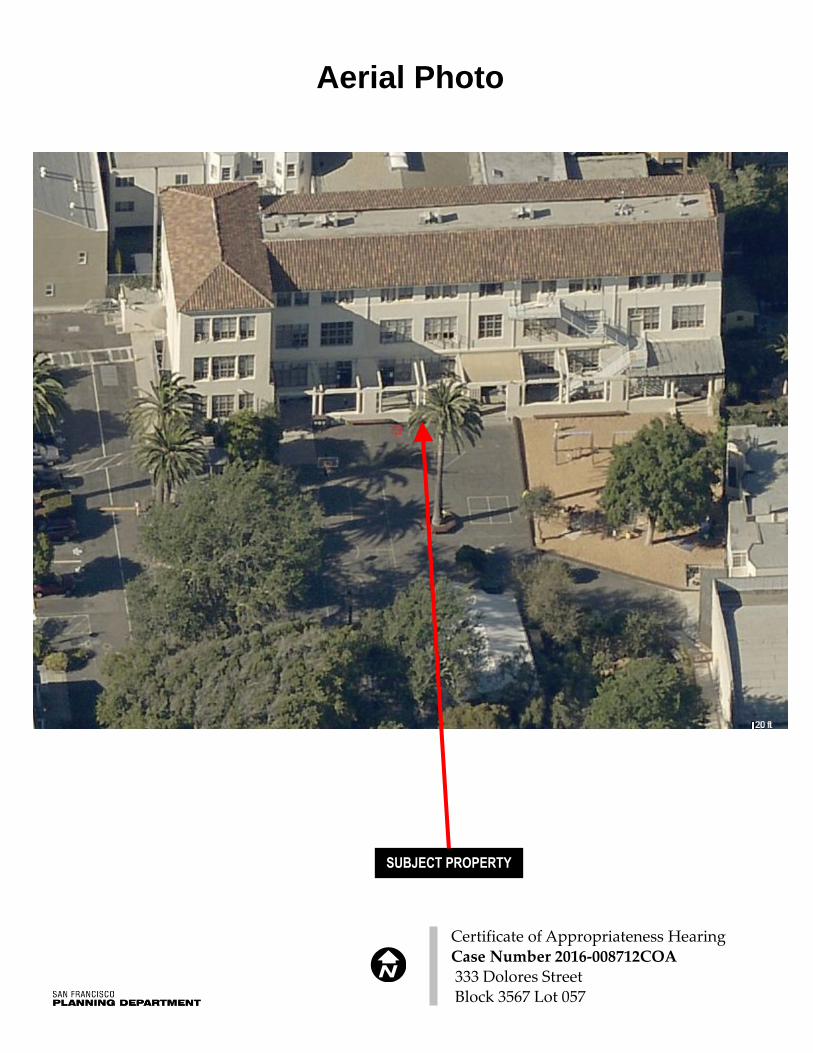
Aerial Photograph
Public Correspondence
Conditions Assessment for the clay tile roof prepared by Architectural Resources Group
Historic Resource Evaluation (HRE) Parts I & II prepared by VerPlanck Historic Preservation
Consultants
Designating Ordinance for Landmark No. 137 and Inner Mission North Survey Sheet for 333 Dolores
St.
Preservation Brief 16: The Use of Substitute Materials on Historic Building Exteriors (National Park Service;
Sept., 1988)
Preservation Brief 30: The Preservation and Repair of Historic Clay Tile Roofs
Plans
(* The HRE is provided without the bibliography and appendix. The full document can be found at:
https://spaces.hightail.com/receive/tNgie/ZWxpemFiZXRoLmdvcmRvbi1qb25ja2hlZXJAc2Znb3Yub3Jn.)

(This page intentionally left blank)

www.sfplanning.org
Historic Preservation Commission Draft Motion HEARING DATE: FEBRUARY 1, 2017
Filing Date: October 19, 2016
Case No.: 2016-008712COA
Project Address: 333 Dolores Street
Historic Landmark: Landmark No. 137 – The Notre Dame School
Zoning: RM-1 (Residential, Mixed, Low-Density)
40-X Height and Bulk District
Block/Lot: 3567/057
Applicant: Chris Kalos, Jensen Architects
833 Market Street, 7th floor
San Francisco, CA 94103
Staff Contact Elizabeth Gordon Jonckheer - (415) 575-8728
[email protected] Reviewed By Tim Frye – (415) 575-6822
ADOPTING FINDINGS FOR A CERTIFICATE OF APPROPRIATENESS FOR PROPOSED WORK
DETERMINED TO BE APPROPRIATE FOR AND CONSISTENT WITH THE PURPOSES OF
ARTICLE 10, TO MEET THE STANDARDS OF ARTICLE 10 AND TO MEET THE SECRETARY OF
INTERIOR’S STANDARDS FOR REHABILITATION, FOR THE PROPERTY LOCATED ON LOT 057
IN ASSESSOR’S BLOCK 3567, LANDMARK NO. 137, LOCATED WITHIN A RM-1 (RESIDENTIAL,
MIXED, LOW-DENSITY) DISTRICT AND A 40-X HEIGHT AND BULK DISTRICT.
PREAMBLE
WHEREAS, on October 19, 2016, Chris Kalos of Jensen Architects (Project Sponsor) filed an application
with the San Francisco Planning Department (hereinafter “Department”) for a Certificate of
Appropriateness for exterior improvements to the south façade of the existing subject building currently
occupied by the Children’s Day School. Proposed work includes removal of an existing fire escape,
removal of the floor of the existing pergola to create a new concrete slab porch with a continuous
accessible grade across the front of the building, and modifications to the openings on the pergola level to
accommodate new accessible entrance doors. Existing aluminum windows and metal fire doors are
proposed to be replaced with units to match the historic appearance during the period of significance.
The existing clay tile roof is also proposed to be replaced. Specific proposed work includes:
General: Improvements to the building's exterior for seismic performance and accessibility,
including entrances and path of travel -- there is no change of use or addition of floor area.
Roof: At the roof, the red terra cotta clay tiles would be removed and a 2" layer of rigid board
insulation laid atop a new layer of plywood roof sheathing. The purpose of the plywood is to
improve the building's seismic performance and the purpose of the insulation is to improve the

Motion No. XXXXX Case Number 2016-008712COA
Hearing Date: February 1, 2017 333 Dolores Street
2
building's climate control systems. This new layer of insulation would be shaved down toward
the edge of the building to minimize visual changes to the building's roof profile. The existing tile
would be replaced in-kind. The tiles along the perimeter eave would be installed using
traditional “two-piece” method to replicate existing conditions; otherwise new “S” tiles would be
used.
Replacement of existing retrofit windows and doors: The metal fire doors at the second and third
floor levels would also be removed, along with their transoms. The area of the façade below the
sills where doors have been removed would be patched, and new wood casement windows that
match the building’s historic fenestration pattern would be installed. The aluminum replacement
windows at the fifth, eighth, and ninth bays of the third floor level would be removed and
replaced with new wood casement windows that match the building’s historic fenestration.
Fire Escape: The project proposes removal of the non-historic fire-escape that spans the full
height of the façade.
Pergola: At the first floor level of the south façade, the floor of the existing pergola is proposed to
be removed, including the concrete slab and the non-historic ramp, stair, and platform. A new
concrete slab porch would be poured 2’ above the original grade of the pergola floor, creating a
level, continuous grade across the front of the building. At the first (far left) bay, six four-light
casement windows would be removed, and paired glass entry doors would be installed in their
place. At the second and third bays, existing non-historic doors would be removed and replaced
with wood multi-light doors. At the fifth bay, the primary entrance door and the sign above it
that reads “St. Joseph’s Hall 1925” would be removed. The sill of the door opening would be
raised to match the new grade of the pergola floor and widened. New paired glass entry doors
would be installed in the opening. At the sixth bay, a portion of the multi-light window would be
removed and a multi-light wood door with a sidelight would be installed in the opening.
Access to the pergola from the schoolyard would be at three points – at left, center, and right –
corresponding with the existing gaps in the pergola wall. At the left, a concrete landing would be
constructed in front of the pergola, which would be accessed from the driveway/parking area by
a ramp and from the schoolyard by a short stair. This landing would include bike parking, and
the existing metal gate at the west perimeter of the schoolyard would be relocated to the right
side of this landing. At the center, the pergola would be accessed by a straight concrete stair. At
the right, the pergola would be accessed by a small landing, a ramp that runs alongside the
pergola, and a straight concrete stair. All new stairs would have ADA-compliant handrails and
children’s handrails. A new metal railing with metal balustrades would be installed on top of the
low pergola wall, between the existing columns.
Interior work: At the building’s first bay there would be a new lobby/reception area, which
would include an office, a conference room, a new elevator, and a new stair. A new door opening
would connect the lobby/reception area to the kindergarten classroom at the far west end of the
building. Other changes at the first floor level would include the construction of a new office at
the west end of the corridor, the demolition of a portion of the central stair, and the construction
of a new concrete floor at the same grade as the rest of the first floor level. At the second and
third floor levels changes would include the continuation of the elevator shaft and a new

Motion No. XXXXX Case Number 2016-008712COA
Hearing Date: February 1, 2017 333 Dolores Street
3
stairwell. A door is proposed between the center stair and the classroom directly east at the
second level. The proposed new gypsum walls around the elevator would not disturb the
location or arrangement of the exposed trusses.
WHEREAS, the Project was determined by the Department to be categorically exempt from
environmental review. The Historic Preservation Commission (hereinafter “Commission”) has reviewed
and concurs with said determination.
WHEREAS, on February 1, 2017, the Commission conducted a duly noticed public hearing on the current
project, Case No. 2016-008712COA (“Project”) for its appropriateness.
WHEREAS, in reviewing the Application, the Commission has had available for its review and
consideration case reports, plans, and other materials pertaining to the Project contained in the
Department's case files, has reviewed and heard testimony and received materials from interested parties
during the public hearing on the Project.
MOVED, that the Commission hereby grants the Certificate of Appropriateness, in conformance with the
architectural plans dated received October 19, 2016 and labeled Exhibit A on file in the docket for Case
No. 2016-008712COA based on the following findings:
CONDITIONS OF APPROVAL
Prior to approval of the Site Permit, the Project Sponsor shall submit a materials board/samples to
Planning Department Preservation staff to verify the final material choice and finish of all of the
proposed exterior materials including windows, doors and roof tiles. Specifically, replacement
tiles should match the original in color, color variation, size, and exposure. Additionally, the use
of brightly colored mortar should be avoided or, if patched, mortar should be colored to match
existing mortar in place. Gutters and downspouts should be repaired or replaced in-kind to
ensure eave profiles remain similar.
Prior to approval of the Site Permit, the Project Sponsor shall submit additional information and
final details for the design, dimensions, attachment and installation of the ADA-compliant
handrails and children’s handrails as well as the new metal railing with metal balustrades that
would be installed on top of the low pergola wall between the existing columns of the new entry
stair and handrail.
Prior to approval of the Site Permit, the Project Sponsor shall submit additional information and
final details for the security gate and fence. Specifically, the gate and fence should be revised to
be treated with a powder-coated finish.
Prior to approval of the Site Permit, the Project Sponsor shall submit specifications for the salvage
of the window sashes from the first floor level used to patch the voids where the metal fire doors
will be removed.

Motion No. XXXXX Case Number 2016-008712COA
Hearing Date: February 1, 2017 333 Dolores Street
4
FINDINGS
Having reviewed all the materials identified in the recitals above and having heard oral testimony and
arguments, this Commission finds, concludes, and determines as follows:
1. The above recitals are accurate and also constitute findings of the Commission.
2. Findings pursuant to Article 10:
The Historical Preservation Commission has determined that the project is compatible with the
character of the landmark site as described in the designation report dated March 4, 1981 as
discussed below.
All of the proposed project's exterior changes would occur at the building's south façade
facing the interior of the lot and not visible from the public right of way. The proposal
will not entail the removal, alteration or obstruction of any significant character- defining
historic feature per the designating ordinance;
The proposed project does not change the historic use of the building nor, diminish the
existing character-defining features. New features are compatible in scale and proportion
with the existing historic features, are not creating a false historicism, and are clearly
differentiated;
The historic character of the upper stories of the primary façade would be restored and
enhanced by the removal of the non-historic fire-escape, fire doors, and aluminum
windows, and the restoration of the wood casement windows affected by the removal of
the fire escape;
The installation of the new security gate and provides adequate transparency and
visibility to the historic building. The fence is mounted on the new landing, and is
guided through the paired column and the two attachments to the main building are
minimal. Staff recommends the gate and fence be treated with a powder-coated finish to
better complement the character of the historic building;
The proposed alterations, including the removal of the existing fire escape, the new
entrances to the building, restoration of the historic appearance of the building’s south
façade, and changes to the pergola to make it ADA-compliant would not alter character-
defining features of the building;
The Project Sponsor proposes not to reuse the existing tile for the following reasons: A)
because it is too heavy and would compromise the proposed seismic retrofit scheme, B)
because these tiles have only one attachment point making it susceptible to failure and
possible injuries from falling tiles, and C) because breakage during the removal process
would result in there being too few tiles to replace upon completion of the seismic work.

Motion No. XXXXX Case Number 2016-008712COA
Hearing Date: February 1, 2017 333 Dolores Street
5
Architectural Resources Group (ARG) provided the Department with a Conditions
Assessment for the existing clay tile roof dated January 12, 2017. The Conditions
Assessment found the existing clay tiles to be in good-to fair-condition and well
maintained. The Conditions Assessment noted that the existing tiles are typically secured
at the top with a single wire tie. The inspected ties were intact with no signs of corrosion.
Few tiles were broken or displaced and ridges and hips were well secured with intact
mortar. The roofing underlayment was spot-checked in two locations, and appeared to
be in fair condition. Flashing however, where exposed, was determined to be in fair-to-
poor condition. Painted gutters were also noted to be in fair condition with minor rust
staining at gutter strap locations. The decorative rafter tails and wood soffits appeared to
be in fair condition. The wood roof beams and rafters exposed from below at the third
floor appeared to be in good condition. ARG recommended that during future roof work,
care should be taken to ensure replacement tiles match the original in color, color
variation, size, and exposure. Additionally, the use of brightly colored mortar should be
avoided or, if patched, mortar should be colored to match existing mortar in place.
Gutters and downspouts should be repaired or replaced in-kind to ensure eave profiles
remain similar. Furthermore, ARG stated that deteriorated wood rafter tails and soffits
should be repaired whenever possible, otherwise they should be replaced in-kind; and
roofs should be regularly inspected, cleaned of debris, and paint coatings should be
maintained.
On balance, the replacement of the proposed clay tile roof would be in consistent with
two of the circumstances that warrant the consideration of substitute material per
National Park Service Preservation Brief 16: The Use of Substitute Materials on Historic
Building Exteriors: #3 – Inherent flaws in the original materials, and #4 -- Code-required changes.
The Conditions Assessment found several roof elements in only satisfactory condition
and additionally, often clay tile is prone to diminished water-tightness and substandard
insulation. One purpose of the proposed project’s roof replacement and addition of
plywood roof sheathing is to improve the building's climate control systems.
Furthermore, due to the nature of the building as an elementary school, seismic retrofit
upgrades are required. The existing clay tiles are heavy, compromising the proposed
seismic retrofit process. The existing tile would be replaced in-kind with a safer, lighter-
weight tile with two attachment points thereby reducing potential failure and possible
injuries from falling tiles during a seismic event. Furthermore, because tile breakage
would occur during the retrofit there may be too few tiles to replace upon completion of
the seismic work. The project sponsor states that the removal of the tiles would result in
breakage of at least 10 percent of the tiles.
On balance, due to the roof’s height, pitch, and distance from public rights-of-way, the
difference between existing conditions and post-construction conditions would be minor.
The replacement of the proposed clay tile roof would have minimal visual impact to the
site upon its completion and the changes to the roof would be in keeping with the
character of the site and would not detract from the historic building and its setting;

Motion No. XXXXX Case Number 2016-008712COA
Hearing Date: February 1, 2017 333 Dolores Street
6
The proposed work would retain the historic school use of the historic property and
would allow it to continue to grow and meet the future needs of the student population.
The essential form and integrity of the site would remain intact.
The proposed project meets the following Secretary of the Interior’s Standards for
Rehabilitation:
Standard 1.
A property shall be used for its historic purpose or be placed in a new use that requires
minimal change to the defining characteristics of the building and its site and environment.
Standard 2.
The historic character of a property shall be retained and preserved. The removal of historic
materials or alteration of features and spaces that characterize a property shall be avoided.
Standard 3.
Each property will be recognized as a physical record of its time, place and use. Changes that
create a false sense of historical development, such as adding conjectural features or elements
from other historic properties, will not be undertaken.
Standard 4.
Changes to a property that have acquired historic significance in their own right will be
retained and preserved.
Standard 5.
Distinctive materials, features, finishes, and construction techniques or examples of fine
craftsmanship that characterize a property will be preserved.
Standard 6.
Deteriorated historic features will be repaired rather than replaced. Where the severity of
deterioration requires replacement of a distinctive feature, the new feature will match the old
in design, color, texture, and, where possible, materials. Replacement of missing features will
be substantiated by documentary and physical evidence.
Standard 7.
Chemical or physical treatments, if appropriate, will be undertaken using the gentlest means
possible. Treatments that cause damage to historic materials will not be used.
Standard 8.
Archeological resources will be protected and preserved in place. If such resources must be
disturbed, mitigation measures will be undertaken.
Standard 9.
New additions, exterior alterations, or related new construction will not destroy historic

Motion No. XXXXX Case Number 2016-008712COA
Hearing Date: February 1, 2017 333 Dolores Street
7
materials, features, and spatial relationships that characterize the property. The new work
shall be differentiated from the old and will be compatible with the historic materials,
features, size, scale and proportion, and massing to protect the integrity of the property and
its environment.
Standard 10.
New additions and adjacent or related new construction will be undertaken in a manner that,
if removed in the future, the essential form and integrity of the historic property and its
environment would be unimpaired.
3. General Plan Compliance. The proposed Certificate of Appropriateness is, on balance,
consistent with the following Objectives and Policies of the General Plan:
I. URBAN DESIGN ELEMENT
THE URBAN DESIGN ELEMENT CONCERNS THE PHYSICAL CHARACTER AND ORDER OF
THE CITY, AND THE RELATIONSHIP BETWEEN PEOPLE AND THEIR ENVIRONMENT.
GOALS
The Urban Design Element is concerned both with development and with preservation. It is a concerted
effort to recognize the positive attributes of the city, to enhance and conserve those attributes, and to
improve the living environment where it is less than satisfactory. The Plan is a definition of quality, a
definition based upon human needs.
OBJECTIVE 1 EMPHASIS OF THE CHARACTERISTIC PATTERN WHICH GIVES TO THE CITY AND ITS
NEIGHBORHOODS AN IMAGE, A SENSE OF PURPOSE, AND A MEANS OF ORIENTATION.
POLICY 1.3
Recognize that buildings, when seen together, produce a total effect that characterizes the city and its
districts.
OBJECTIVE 2
CONSERVATION OF RESOURCES WHICH PROVIDE A SENSE OF NATURE, CONTINUITY
WITH THE PAST, AND FREEDOM FROM OVERCROWDING.
POLICY 2.4
Preserve notable landmarks and areas of historic, architectural or aesthetic value, and promote the
preservation of other buildings and features that provide continuity with past development.
POLICY 2.5
Use care in remodeling of older buildings, in order to enhance rather than weaken the original character of
such buildings.

Motion No. XXXXX Case Number 2016-008712COA
Hearing Date: February 1, 2017 333 Dolores Street
8
POLICY 2.7
Recognize and protect outstanding and unique areas that contribute in an extraordinary degree to San
Francisco's visual form and character.
The goal of a Certificate of Appropriateness is to provide additional oversight for buildings and districts
that are architecturally or culturally significant to the City in order to protect the qualities that are
associated with that significance.
The proposed project qualifies for a Certificate of Appropriateness and therefore furthers these policies and
objectives by maintaining and preserving the character-defining features of Landmark No. 137, the Notre
Dame School, for or the future enjoyment and education of San Francisco residents and visitors.
4. The proposed project is generally consistent with the eight General Plan priority policies set forth
in Section 101.1 in that:
A) The existing neighborhood-serving retail uses will be preserved and enhanced and future
opportunities for resident employment in and ownership of such businesses will be
enhanced:
The proposed project would strengthen an existing school that primarily serves the Mission, Upper
Market, Noe Valley, Bernal Heights, and Potrero Hill neighborhoods.
B) The existing housing and neighborhood character will be conserved and protected in order to
preserve the cultural and economic diversity of our neighborhoods:
The proposed project will strengthen neighborhood character by respecting the character-defining
features of the landmark site in conformance with the Secretary of the Interior’s Standards.
C) The City’s supply of affordable housing will be preserved and enhanced:
The project will not reduce the affordable housing supply as the subject property is occupied by an
institutional use.
D) The commuter traffic will not impede MUNI transit service or overburden our streets or
neighborhood parking:
The proposed project will not result in commuter traffic impeding MUNI transit service or
overburdening the streets or neighborhood parking.
E) A diverse economic base will be maintained by protecting our industrial and service sectors
from displacement due to commercial office development. And future opportunities for
resident employment and ownership in these sectors will be enhanced:
The proposed will not have any impact on industrial and service sector jobs.

Motion No. XXXXX Case Number 2016-008712COA
Hearing Date: February 1, 2017 333 Dolores Street
9
F) The City will achieve the greatest possible preparedness to protect against injury and loss of
life in an earthquake.
Preparedness against injury and loss of life in an earthquake is improved by the proposed work. The
work will eliminate unsafe conditions at the site and all construction will be executed in compliance
with all applicable construction and safety measures.
G) That landmark and historic buildings will be preserved:
The proposed project is in conformance with Article 10 of the Planning Code and the Secretary of the
Interior’s Standards.
H) Parks and open space and their access to sunlight and vistas will be protected from
development:
The proposed project will not impact the access to sunlight or vistas for the parks and open space.
5. For these reasons, the proposal overall, is appropriate for and consistent with the purposes of
Article 10, meets the standards of Article 10, and the Secretary of Interior’s Standards for
Rehabilitation, General Plan and Prop M findings of the Planning Code.

Motion No. XXXXX Case Number 2016-008712COA
Hearing Date: February 1, 2017 333 Dolores Street
10
DECISION
That based upon the Record, the submissions by the Applicant, the staff of the Department and other
interested parties, the oral testimony presented to this Commission at the public hearings, and all other
written materials submitted by all parties, the Commission hereby GRANTS a Certificate of
Appropriateness for the property located at Lot 057 in Assessor’s Block 3567 for proposed work in
conformance with plans dated October 19, 2016 and labeled Exhibit A on file in the docket for Case No.
2016-008712COA.
APPEAL AND EFFECTIVE DATE OF MOTION: The Commission's decision on a Certificate of
Appropriateness shall be final unless appealed within thirty (30) days. Any appeal shall be made to
the Board of Appeals, unless the proposed project requires Board of Supervisors approval or is
appealed to the Board of Supervisors as a conditional use, in which case any appeal shall be made to
the Board of Supervisors (see Charter Section 4.135).
Duration of this Certificate of Appropriateness: This Certificate of Appropriateness is issued pursuant
to Article 10 of the Planning Code and is valid for a period of three (3) years from the effective date of
approval by the Historic Preservation Commission. The authorization and right vested by virtue of this
action shall be deemed void and canceled if, within 3 years of the date of this Motion, a site permit or
building permit for the Project has not been secured by Project Sponsor.
THIS IS NOT A PERMIT TO COMMENCE ANY WORK OR CHANGE OF OCCUPANCY UNLESS
NO BUILDING PERMIT IS REQUIRED. PERMITS FROM THE DEPARTMENT OF BUILDING
INSPECTION (and any other appropriate agencies) MUST BE SECURED BEFORE WORK IS
STARTED OR OCCUPANCY IS CHANGED.
I hereby certify that the Historical Preservation Commission ADOPTED the foregoing Motion on
February 1, 2017.
Jonas P. Ionin
Acting Commission Secretary
AYES:
NAYS:
ABSENT:
ADOPTED: February 1, 2017
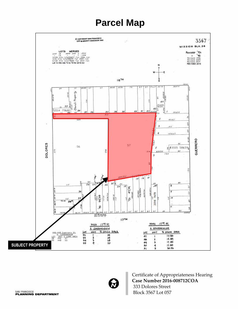
Parcel Map
Certificate of Appropriateness Hearing Case Number 2016-008712COA 333 Dolores Street Block 3567 Lot 057
SUBJECT PROPERTY

*The Sanborn Maps in San Francisco have not been updated since 1998, and this map may not accurately reflect existing conditions.
Sanborn Map*
Certificate of Appropriateness Hearing Case Number 2016-008712COA 333 Dolores Street Block 3567 Lot 057
SUBJECT PROPERTY

Aerial Photo
Certificate of Appropriateness Hearing Case Number 2016-008712COA 333 Dolores Street Block 3567 Lot 057
SUBJECT PROPERTY
Aerial Photo
Certificate of Appropriateness Hearing Case Number 2016-008712COA 333 Dolores Street Block 3567 Lot 057
SUBJECT PROPERTY

Aerial Photo (looking east)
Certificate of Appropriateness Hearing Case Number 2016-008712COA 333 Dolores Street Block 3567 Lot 057
SUBJECT PROPERTY

(This page intentionally left blank)

GRACE FELLOWSHIP COMMUI~IITY CHURCHSHARON HUEY Parrs Hone
Elizabeth Gordon Jonckheer
San Francisco Planning Department
1650 Mission Street, Suite 400
San Francisco, CA 94103
December 15, 2016
Re: support for seismic and ADA upgrades at 333 Dolores Street
Dear Ms. Jonckheer:
We write this letteY in support of the Children's Day School (CDS) upcoming
project at the school's building known as St. Joseph's Hall, at 333 Dolores Street
We understand the planned project will upgrade the seismic safety of this
building, as well as add an elevator and make addirional accessibility upgrades so
the building can be accessible to all.
Our church, located on 16~' Street on the same block as CDS, has had a mutually
beneficial relationship with them for the past several years, sharing facilities as the
need and occasion arises. The staff at CDS has been friendly and generous to us,
and we value the relarionship we have with them. They have kept us informed of
their plans and activiries, and we fully support their efforts to increase the seismic
safety and the accessibility of their building. We appreciate their concerns for the
safety of their students and staff, and recognize that these improvements are in
the best interests of all of the neighbors on our block.
Sincerely,
DOUG LEE
3265 SIXTEENTH STREET ♦SAN FRANCISCO, CA 94103 ~ PHotvE: (41 5) 703-6090 t [email protected]

mercyHOUSING
Elizabeth Gordon JonckheerSan Francisco Planning Department1650 Mission Street Suite 400San Francisco, CA 94103
December 13, 2016
Dear Ms. Jonckheer:
This letter is in support of the Children's Day School (CDS) upcomingproject. We understand the planned project will upgrade the seismicsafety of the school's building known as St. Joseph's Hall at 333Dolores Street. In addition, the project will add an elevator and makeadditional accessibility upgrades so the building can be accessible forall.
The CDS administrators consistently reach out to their neighbors.They keep us informed of their plans and activities. As an adjacentneighbor, our organization fully supports the school's efforts to makethese upgrades. We appreciate the school's concerns for the safety oftheir students and staff and recognize that these improvements are inthe best interest of all of the neiahbors on our block.
Sincerely,
Mercy Housing California
1360 Mission Street, Suite 300, San Francisco CA 94103 p ~ 415.355.7100
3120 Freeboard Drive, Suite 202, West Sacramento CA 95691 p ~ 916.414.4478
1500 South Grand Avenue, Suite 100, Los Angeles CA 90015 p ~ 213.473.5820
www.mercyhousingcalifornia.orgMercy Housing is sponsored by communities of Catholic Sisters LIVE IN HOPE

`~
~̀
BOYS & GIRLS CLUBSOF SAN FRANCISCO
January 4, 2017
Elizabeth Gordon JonckheerSan Francisco Planning Department1650 Mission Street Suite 400San Francisco, CA 94103
RE: Letter of Support for Seismic and ADA Upgrades at 333 Dolores Street
Dear Ms. Jonckheer:
This letter is in support of the Children's Day School (CDS) upcoming project. We
understand the planned project will upgrade the seismic safety of the school's building
known as St. Joseph's Hall at 333 Dolores Street. In addition, the project will add an
elevator and make additional accessibility upgrades so the building can be accessible for
all.
CDS administrators consistently reach out to their neighbors to keep us informed of their
plans and activities. As an adjacent neighbor, our organization fully supports theschool's efforts to make these upgrades. We appreciate the school's concerns for the
safety of their students and staff and recognize that these improvements are in the bestinterest of all of the neighbors on our block.
Sincerely,
Rob ConnollyPresidentBoys &Girls Clubs of San Francisco
John N. Callander Administrative Office 380 Fulton Street •San Francisco, CA 94102-4454 •Tel 415.445.KIDS (5437) •Fax 415.445.5435 www.kidsclub.org

St. Matthew's Lutheran ChurchQa ~o0o qo Evangelical Lutheran Church in America0 0 God'swork. Our hands.
Letter of Support for Seismic and ADA Upgrades at 333 Dolores
Elizabeth Gordon Jonckheer
San Francisco Planning Department
1650 Mission Street Suite 400
San Francisco, CA 94103
January 11, 2017
Dear Ms. Jonckheer:
This fetter is in support of the Children's Day School(CDS) upcoming project. We understand the plannedproject will upgrade the seismic safety of the school's building known as St. Joseph's Hall at 333 DoloresStreet. In addition, the project will add an elevator and make additional accessibility upgrades so the buildingcan be accessible for all.
The CDS administrators consistently reach out to St. Matthew's. They keep us informed of their plans andactivities. As an adjacent neighbor, our church fully supports the school's efforts to make these upgrades. Weappreciate the school's concerns for the safety of their students and staff and recognize that theseimprovements are in the best interest of all of the neighbors on our block.Sincerely,
Y - ~
~.
The Rev. Kerstin Weidmann3281 —16`~ Street San Francisco, CA 94103-3323Telephone: 415-863-6371 Web: ~~wu.stmatthews-sf.or~; E-mail: [email protected]

1
Memorandum To: Molly Huffman Children’s Day School
601 Dolores Street San Francisco, California 94110
Project: 333 Dolores Street Project No.: 16233 Date: January 12, 2017 Via: Email From: Lisa Yergovich, AIA, Principal Re: Clay Tile Roof Assessment Architectural Resources Group (ARG) was retained by the Children’s Day School to complete a conditions assessment of the clay tile roof at 333 Dolores Street in San Francisco. Background information including historic photos was provided by Jensen Architects. ARG staff conducted a visual assessment on-site December 28, 2016. Close-range inspection of the roof tiles, gutters, and underlayment was conducted where accessible from the central flat roof. 333 Dolores Street was constructed in 1924 as an annex building for Notre Dame High School. Known as St. Joseph’s Hall, it was located east of the main school building which fronts Dolores Street. Notre Dame High School ceased operation in 1981 and leased the building to Children’s Day School in 1987, which purchased the property in 2001. It was renovated in 2007 and 2008 and there are currently plans for a voluntary seismic upgrade. The main Notre Dame High School building is now used as Notre Dame Plaza − a senior housing facility operated by Mercy Housing. 333 Dolores is located in the center of the block, accessible from a driveway connecting west to Dolores Street. The three-story reinforced concrete
Children’s Day School is located in the center of the block bordered by Dolores Street, Guerrero Street, 16th Street, and 17th Street. (Google Maps, 2016)

structure is L-shaped, with the primary axis running east-west. A courtyard to the south and west includes a playground and parking. On the north and east, the building is bound by residences and businesses. View of the building from the public right-of-way is limited to the narrow view corridor down the Dolores Street driveway. The concrete structure is clad in stucco in a Mediterranean Revival style and appears to maintain a high level of historic integrity. Historic photographs indicate the building originally had a clay tile roof with perimeter gutters and exposed downspouts. Existing roof conditions closely match the historic photo with similar eave profiles and downspout locations. Due to the long life expectancy of clay tile and conditions found on-site, the majority of roof tiles are assumed to be original fabric. It is unknown whether other roof components are original. The hipped roof is clad in Straight Barrel Mission clay tile. The system is composed of two tiles the same size and curved shape – a pan tile on the bottom and a cover tile on top. The tiles are generally red in color with natural color variations from orange to brown. A small number of tiles have a brighter color and smoother texture, suggesting they are replacement tiles. In general, the clay tiles appear to be in good-to fair-condition and well maintained. Tiles are typically secured at the top with a single wire tie. Where inspected, the ties were intact with no signs of corrosion. Few tiles were broken or displaced and ridges and hips were
Historic Photograph, c. 1928-1941 (Source Unknown).
Roof looking west (ARG, 2016).
Tiles are secured at the top with a single wire tie (ARG, 2016).

well secured with intact mortar. A bright white mortar was found at several locations along the ridge and flat roof edge. At the flat roof edge, some tiles were also oriented with the anchorage hole exposed at the bottom. This is likely the result of a past re-roofing campaign at the flat roof, which would have required removal of the tiles. Roofs and gutters were kept well clean of debris and only minor biological growth was noted. The roofing underlayment was spot-checked in two locations, and appeared to be in fair condition; however, recent roof leaks have been reported. Flashing, where exposed, was in fair-to-poor condition. Painted gutters were in fair condition with minor rust staining at gutter strap locations. Decorative rafter tails and wood soffits appeared to be in fair condition with properly maintained paint coatings. At eaves, no end caps or screening was present. The wood roof beams and rafters are exposed from below at the third floor and appear to be in good condition. During future roof work, care should be taken to ensure replacement tiles match the original in color, color variation, size, and exposure. Use of brightly colored mortar should be avoided or, if patched, mortar should be colored to match existing mortar in place. Gutters and downspouts should be repaired or replaced in-kind to ensure eave profiles remain similar. Deteriorated wood rafter tails and soffits should be repaired whenever possible, otherwise they should be replaced in-kind. Roofs should be regularly inspected, cleaned of debris, and paint coatings should be maintained.
Typical field tile showing natural color variations. Note the bright white repair mortar at the ridge (ARG, 2016).
Typical rood edge. Painted gutters have rust staining aligning with gutter straps (ARG, 2016).
Exposed roof beams and rafters at the third floor (ARG, 2016).

Painted gutters are secured with roof straps (ARG, 2016).
Few instances of cracking was observed at mortar (ARG, 2016).
View from the south (ARG, 2016).
Several tiles at the edge of the flat roof are oriented with anchor holes at the bottom − likely the result of a past re-roofing campaign (ARG, 2016).
Underlayment visible below tile was in fair condition (ARG, 2016).

HISTORIC RESOURCE
EVALUATION
Children’s Day School
333 Dolores Street San Francisco, California
August 30, 2016
Prepared by

Historic Resource Evaluation 333 Dolores Street, San Francisco, CA
August 30, 2016
TABLE OF CONTENTS
I. Introduction .............................................................................................................................. 1
II. Methods ................................................................................................................................... 2
III. Regulatory Framework ....................................................................................................... 2
IV. Property Description ................................................................................. ….………….......5
V. Historical Context ...................................................................................... …….………......24
VI. Evaluation of Historical Status ................................................................. ….….………...50
VII. Evaluation of Project-specific Impacts ................................................ …….………...54
VIII. Conclusion ........................................................................................................................ 61
IX. Bibliography ........................................................................................................................ 62
X. Appendix............................................................................................................................... 65
A. Inner Mission North Historic Resource survey sheet for 333 Dolores Street B. Building Permits for 333 Dolores Street

Historic Resource Evaluation 333 Dolores Street, San Francisco, CA
August 30, 2016
1
I. Introduction
VerPlanck Historic Preservation Consulting prepared this Historic Resource Evaluation (HRE) Parts I and II for an educational-use property located at 333 Dolores Street, in San Francisco’s Mission District. This HRE describes and provides the history of the property and analyzes its potential eligibility for listing in the California Register of Historical Resources (California Register). The property, historically known as St. Jo-seph’s Hall, is located on the east side of Dolores Street, between 16th and 17th streets. The building occu-pies the northeast corner of a large, flag lot (Assessor’s Parcel 3567/057) that is accessed from Dolores Street by two driveways (Figure 1). The building, which was constructed in 1925 as a Catholic grammar school, is a three-story, reinforced-concrete building. Designed by architect Albert M. Cauldwell in the Mediterranean Revival style, St. Joseph’s Hall served as the Sisters of Notre Dame grammar school for girls from 1925 until 1986. The minimally-altered building is currently owned and operated by the Children’s Day School, which continues to use the building as an elementary school. The proposed project entails several components, including completing a seismic upgrade, replacing several missing windows and re-configuring two entrances on the primary façade, building an ADA-compliant wheelchair ramp, installing an elevator, and reconfiguring a portion of the first floor level for improved functionality and security.
Figure 1. San Francisco Assessor’s Block 3567, with Lot 057 outlined in red.
Source: San Francisco Property Information Map The San Francisco Planning Department classifies 333 Dolores Street as a historic resource. The Planning Department documented the property in 2004 as part of its Inner Mission North Historic Resource Survey and determined that the property is eligible for listing in the California Register of Historical Resources (California Register) under Criterion 1 (Events) for its association with the broad patterns of cultural set-tlement in San Francisco’s Mission District; and Criterion 3 (Architecture/Design) for its design, features, materials, and/or craftsmanship details that embody the distinctive characteristics of Mediterranean Re-vival architecture. This HRE concurs with these findings, building upon the survey with property-specific research and analysis. This HRE concludes that the proposed project complies with the Secretary of the
Historic Resource Evaluation 333 Dolores Street, San Francisco, CA
August 30, 2016
2
Interior’s Standards for Rehabilitation (Secretary’s Standards) and will not impact the eligibility of 333 Dolores Street for listing on the California Register.
II. Methods
Christopher VerPlanck and Stacy Farr visited the subject property on July 7, 2016, and photographed and surveyed the exterior and interior of the building, as well as the surrounding properties on the subject block. Stacy Farr then researched the property at various libraries and government offices, including the San Francisco Department of Building Inspection, the San Francisco Office of the Assessor-Recorder, the San Francisco Public Library, the California Historical Society, and Christopher VerPlanck’s own extensive in-house archive. In compliance with the San Francisco Planning Department’s Preservation Bulletin No. 16: CEQA Review Procedures for Historic Resources, this HRE includes an architectural description and historic context that describe the subject property’s evolution from the late nineteenth century to the present day, and an evaluation of the proposed project for compliance with the Secretary’s Standards. Stacy Farr, who has over eight years’ experience evaluating potential historic resources in San Francisco, is the primary author of this report. Christopher VerPlanck, who contributed research and reviewed and edited the report for accuracy and completeness, has over 18 years’ experience evaluating potential his-toric resources in San Francisco. Unless noted otherwise, all photographs in this report were taken by Stacy Farr.
III. Regulatory Framework
VerPlanck Historic Preservation Consulting searched federal, state, and local records to determine if 333 Dolores Street had been identified in any survey or listed in any other official register of historic resources. The specific surveys and registers consulted are described below.
A. Here Today Survey
Published in 1968 by the Junior League of San Francisco, Here Today: San Francisco’s Architectural Herit-age, is San Francisco’s earliest comprehensive historical resource inventory. Prepared by trained volun-teers, the survey provides a photograph and concise historical data on approximately 2,500 properties located throughout San Francisco. The survey was adopted in 1970 by the San Francisco Board of Super-visors under Resolution No. 268-70. The survey files are archived at the Koshland/San Francisco History Center, at the San Francisco Public Library. Although the Notre Dame School (now Notre Dame Plaza) at 347 Dolores Street is described and discussed in Here Today, 333 Dolores Street is not included in Here Today, either in the book or the accompanying survey files.1
B. San Francisco Planning Department Architectural Quality Survey
Between 1974 and 1976, the San Francisco Planning Department completed an inventory of architectur-ally significant buildings throughout San Francisco. An advisory committee consisting of architects and architectural historians assisted in the final rating of the roughly 10,000 buildings surveyed. The un-
1 347 Dolores Street is referred to as 351 Dolores Street in some older surveys, including Here Today.

Historic Resource Evaluation 333 Dolores Street, San Francisco, CA
August 30, 2016
3
published survey consists of 60 bound volumes of survey data on file at the San Francisco Planning De-partment. The survey includes both contemporary and older buildings, but historical associations were not considered. Planning staff assigned each surveyed building a numerical rating ranging from “0” (con-textual importance) to “5” (individual significance of the highest degree). The inventory assessed only architectural significance, which was defined as a combination of the following characteristics: design fea-tures, urban design context, and overall environmental significance. When completed, the Architectural Quality Survey was believed to represent the top 10 percent of the city’s building stock.2 Furthermore, in the estimation of survey participants, buildings rated “3” or higher represent approximately the top 2 percent of the city’s building stock. The survey was adopted in 1977 by the San Francisco Board of Super-visors under Resolution No. 7831. The Planning Department has been directed to use the survey, although the methodology is no longer consistent with CEQA Guidelines PRC 5024.1(g). Although the Notre Dame School at 347 Dolores Street was surveyed as part of the San Francisco Planning Department Architectural Quality Survey, 333 Dolores Street is not mentioned on the survey form and was not assigned a numerical rating.
C. San Francisco Architectural Heritage Surveys
San Francisco Architectural Heritage (Heritage) is the city’s oldest not-for-profit organization dedicated to increasing awareness of and advocating for the preservation of San Francisco’s unique architectural fabric. Heritage has completed several historic resource inventories in San Francisco, including Downtown, the South of Market Area, the Inner Richmond District, Chinatown, the Van Ness Corridor, the Northeast Wa-terfront, and Dogpatch. Heritage ratings range from “A” (highest importance) to “D” (minor or no im-portance) and are based on both architectural and historical significance. San Francisco Architectural Heritage has not surveyed the Mission District. Though occasionally it will have survey files for properties in unsurveyed areas, it does not have a survey file for 333 Dolores Street.
D. Article 10 of the San Francisco Planning Code
San Francisco City Landmarks are buildings, structures, sites, districts, and objects of “special character or special historical, architectural or aesthetic interest or value and (that) are an important part of the City’s historical and architectural heritage.” Adopted in 1967 as Article 10 of the San Francisco Planning Code, the San Francisco City Landmark program recognizes the significance of listed buildings and protects them from inappropriate alterations and demolition through review by the San Francisco Historic Preservation Commission. As of November 2011, there were 256 landmarked properties and 11 designated historic districts that are subject to Article 10. The Article 10 designation process originally used the Kalman Meth-odology, a qualitative and quantitative method for evaluating the significance of historic properties. As of 2000, Article 10 was amended to use National Register evaluation criteria. The San Francisco Board of Supervisors designated 347 Dolores Street, which adjoins 333 Dolores Street to the west, San Francisco City Landmark #137 on November 2, 1981.3 The building was constructed in 1907 as the Notre Dame School for Girls, and it is now a senior housing facility called Notre Dame Plaza. The Landmark Designation Report for 347 Dolores Street includes minimal information about the history
2 San Francisco Planning Department, San Francisco Preservation Bulletin No. 11 – Historic Resource Surveys (San Francisco: n.d.), 3. 3 347 Dolores Street is referred to as 351 Dolores Street in the Landmark Designation Report.

Historic Resource Evaluation 333 Dolores Street, San Francisco, CA
August 30, 2016
4
of the property, but describes the building as being historically significant for its excellent Second French Empire architecture, for its status as the oldest girls’ grammar school in San Francisco, and for its associ-ation with the Sisters of Notre Dame, the first Catholic educational order on the Pacific Coast.4 In 1981, when the City Landmark nomination was prepared, 347 and 333 Dolores Street occupied a single large parcel, which was later subdivided in 1996, putting each building on its own parcel (see Figure 1).5 Although the Sisters of Notre Dame built 333 Dolores Street in 1925 to serve as the grammar school for its popular and growing girls’ school, the 1981 City Landmark nomination does not include 333 Dolores Street. Therefore, 333 Dolores Street is not a City Landmark. Nor is it a contributor to any locally-desig-nated historic districts.
E. Inner Mission North Survey
The San Francisco Planning Department completed the Inner Mission North Survey as a background study to inform the Mission Area Plan. The Planning Department finished the first phase of the survey in 2005; this phase documented and evaluated more than 420 individual buildings and several historic districts.6 333 Dolores Street is located outside the boundary of the first phase of the survey, which was bounded by Duboce Avenue and 14th Street to the north, Dolores Street and Valencia Street to the west (Dolores Street north of 16th Street, and Valencia Street south of 16th Street), 20th Street to the south, and an irreg-ular line including Shotwell and Folsom streets to the east.7 As part of the second phase of the Inner Mission North Survey, the Planning Department’s staff and consultants expanded the survey area west to Dolores Street and south to 20th Street, and documented and evaluated more than 2,000 individual build-ings and several historic districts. 333 Dolores Street was included in the second phase of the Inner Mission North Survey, and it is one of approximately 836 properties recorded and evaluated on a Multiple Prop-erty Documentation form.8 Using an abbreviated evaluation methodology, the Planning Department as-sessed the property as being individually eligible for listing in the California Register under Criterion 1 (Events) for its association with the “broad patterns of cultural settlement in San Francisco’s Mission Dis-trict” and Criterion 3 (Architecture/Design) for its “design, architectural features, materials, and/or crafts-manship that together embody the distinctive characteristics of the Mediterranean Revival style of archi-tecture.”9 The San Francisco Historic Preservation Commission adopted the Inner Mission North Survey on June 1, 2011. Neither the Planning Department nor its consultants prepared a State of California Department of Parks and Recreation (DRP) 523A (Primary Record) form for 333 Dolores Street. The Inner Mission North Historic Resource inventory form for 333 Dolores Street is Appendix Item A.
4 Jonathan Malone, preparer, Notre Dame School Final Case Report, approved by the San Francisco Landmarks Preservation Advisory Board, March 4, 1981. 5 San Francisco Property Information Map, “333 Dolores Street.” 6 The San Francisco Property Information Map erroneously indicates that 333 Dolores Street is a contributor to the Mission Reconstruction Historic District, which was identified as part of the first phase of the Inner Mission North Survey, and updated when the survey was expanded in 2011. 333 Dolores Street, constructed 1925, is outside of the period of significance (1906-1913) of this register-eligible district and therefore not a contributor. 7 The San Francisco Property Information Map erroneously indicates that 333 Dolores Street was evaluated as part of the Inner Mission North Historic Resource Survey in January 2004. 8 San Francisco Planning Department, Inner Mission North Historic Resource Survey, Historic Preservation Commission Executive Summary of Historic Resource Survey Findings (San Francisco, April 27, 2011), 5. 9 San Francisco Planning Department, Historic Resource Survey (Mission District) Property Summary Report for 333 Dolores Street (San Fran-cisco: 2011).

Historic Resource Evaluation 333 Dolores Street, San Francisco, CA
August 30, 2016
5
F. California Historical Resources Information System
Properties listed in the California Historical Resources Information System’s (CHRIS) Historic Property Data File, or that are under review by the California Office of Historic Preservation (OHP), are assigned status codes of “1” to “7,” establishing a baseline record of historical significance. Properties with a status code of “1” are listed in the California Register or National Register. Properties with a status code of “2” have been formally determined eligible for listing in the California Register or National Register. Properties with a status code of “3” or “4” appear to be eligible for listing in either register through survey evaluation. Properties with a status code of “5” are typically locally significant or of contextual importance. Status codes of “6” indicate that the property has been found ineligible for listing in any register and a status code of “7” indicates that the property has not yet been evaluated. As mentioned previously, the Planning Department surveyed 333 Dolores Street in 2011 as part of its Inner Mission North Historic Resource Survey. The Planning Department determined the property to be individually eligible for listing in the California Register under Criterion 1 (Events) for its association with the broad patterns of cultural settlement in San Francisco’s Mission District; and Criterion 3 (Architec-ture/Design) for its design, architectural features, materials, and/or craftsmanship that together embody the distinctive characteristics of the Mediterranean Revival style of architecture. For this reason, the Of-fice of Historic Preservation assigned the property the California Historical Resource Status Code of “3CS,” indicating that it appears eligible for the California Register as an individual property through survey eval-uation.
IV. Property Description
A. Context
As previously mentioned, 333 Dolores Street is located on the east side of Dolores Street, on a large flag- lot at the center of the block. The building sits north and east of 347 Dolores Street, which was constructed in 1907 as the new home of the Notre Dame School for Girls (Figure 2). 347 Dolores Street replaced an older building with a similar footprint that was dynamited to create a fire-break to stop the fires that destroyed much of the northern Mission District in the aftermath of the 1906 Earthquake.10 347 Dolores Street is a three-story, L-shaped, wood-frame building designed in the Second Empire style. The building occupies the front portion of a 6,252-sf parcel that also contains a paved driveway, landscaping, and a formal garden and gazebo behind the building. The elaborate iron gates and fencing in front of the prop-erty along Dolores Street are believed to have survived the 1906 Earthquake and Fire.
10 Malone, Notre Dame School Final Case Report.

Historic Resource Evaluation 333 Dolores Street, San Francisco, CA
August 30, 2016
6
Figure 2. 347 Dolores Street, facing southeast.
Misión San Francisco de Asís (Mission Dolores) and Mission Dolores Basilica are located on the west side of Dolores Street, directly across from 333 and 347 Dolores Street. Mission Dolores, at 320 Dolores Street, was constructed between 1782 and 1791 and restored by architect Willis Polk in 1918 (Figure 3). The adobe church is the oldest surviving building in San Francisco. Mission Dolores Basilica was designed by architects Frank T. Shea and John O. Loftquist and constructed between 1913 and 1918 by the Archdiocese of San Francisco. It replaced a brick church at the site that had been destroyed in the 1906 Earthquake (Figure 4). The steel-frame, reinforced-concrete church was remodeled in 1926 with Churrigueresque or-nament inspired by Bertram Goodhue’s work at the California-Pacific Exposition in San Diego. In 1952, the Vatican designated the church a basilica, the first so-designated west of the Mississippi River and only the fifth in the United States. Presently the Mission Dolores property, which is bounded by 16th, Dolores, and Church streets; and Chula Lane, consists of the mission proper, the basilica, a cemetery, a playground, a rectory, a school, and an office building.

Historic Resource Evaluation 333 Dolores Street, San Francisco, CA
August 30, 2016
7
Figure 3. Mission Dolores, facing southwest.
Figure 4. Mission Dolores Basilica, fac-
ing northwest. Mission Dolores anchors a concentration of religious buildings along Dolores Street, between 15th and 20th streets. Dolores Street was an important thoroughfare running through the heart of the residential Mis-sion District, where many earthquake refugees settled after 1906. Buildings on the east side of Dolores Street, from Market Street south to 20th Street, were destroyed by the fire, which freed up many large corner lots typically favored by churches. With insurance money and proceeds from the sale of their older properties, many congregations were able to build substantial and well-designed churches in the fast-growing Mission District. The neighborhood surrounding Mission Dolores and the Notre Dame School attracted other Catholic in-stitutions, including Holy Family Day Home, at 299 Dolores Street, which is diagonally opposite Mission Dolores. The existing structure was constructed in 2005-07, replacing a reinforced-concrete building de-signed by architect Willis Polk that stood on the site from 1911 until it was demolished in 2000. Additional churches and religious buildings churches along this stretch of Dolores Street include: St. Matthew’s Lu-theran Church/St. Matthäus Kirche, at 3281 16th Street (1907); Mission Covenant Church/Swedish Taber-nacle, at 455 Dolores Street (1906-07; remodeled 1957); Congregation Sha’ar Zahav/First San Francisco Mennonite Church, at 290 Dolores Street (1917); Mission Congregational Church, at 601 Dolores Street (now Children’s Day School’s Upper School – 1910); and Second Church of Christ Scientist, at 651 Dolores Street (now the Light House Condominiums – 1915). Dolores Street is wider than most other streets in the Mission District, and it retains the landscaped me-dians containing palm trees that were installed by the Department of Public Works and the California Women’s Club between 1904 and 1910, creating what may have been San Francisco’s first “parkway.”11 In addition to the religious buildings previously described, the 300 block of Dolores Street between 16th and 17th streets includes a mix of single-family dwellings, flats, and residential-over-commercial buildings
11 “Promotion Work Benefits Mission,” San Francisco Chronicle, April 16, 1910; “More Parks Needed in the Section South of Market,” San Fran-cisco Call, March 26, 1910.

Historic Resource Evaluation 333 Dolores Street, San Francisco, CA
August 30, 2016
8
constructed between the late Victorian era and the present century.12 Properties on the block generally meet their lot lines and are two or three stories in height with street-level garages. Because the properties on the east side of Dolores Street were dynamited after the 1906 Earthquake to stop the fires from spread-ing to the west, the oldest properties on the west side of the 300 block of Dolores Street include several Victorian-era buildings designed in the Italianate, San Francisco Stick/Eastlake, and Queen Anne styles (Figures 5, 6). Later architectural styles represented on this block include the Dutch Colonial Revival, Craftsman, Classical Revival, and Mediterranean Revival (Figures 7, 8).
Figure 5. West side of Dolores Street, facing southwest to-
ward the intersection of Dolores and 17th streets.
Figure 6. West side of Dolores Street, including
Chula Lane on the right, facing west.
Figure 7: 381 Dolores Street, directly
south of 347 Dolores Street, facing east.
Figure 8. East side of Dolores Street, facing southeast toward the
intersection of Dolores and 17th streets.
12 The San Francisco Assessor’s Office assigns the construction date 1900 to properties that were constructed before the 1906 Earthquake and Fire, when the city’s building permit files were lost. Some properties that are assigned the 1900 construction date were constructed prior to 1900, while some were constructed between 1900 and 1906.

Historic Resource Evaluation 333 Dolores Street, San Francisco, CA
August 30, 2016
9
Because 333 Dolores Street is located on an interior lot, the property adjoins properties located on the following blocks: the south side of 16th Street, between Dolores and Guerrero streets; the north side of 17th Street, between Dolores and Guerrero streets; and Guerrero Street, between 16th and 17th streets. The buildings on the north side of 17th Street include a mix of flats and small apartment buildings ranging from two to four stories in height (Figure 9). Buildings here meet their front lot line, and most have street-level garages. Construction dates range from 1907 to 1994. Because they are east of Dolores Street, these buildings were all constructed after the 1906 Earthquake and consequently, all are designed in architec-tural styles popular during the post-quake era, including Craftsman, Classical Revival, and Mediterranean Revival.
Figure 9. North side of 17th Street between Dolores and Guerrero streets, facing northeast.
This residential pattern continues on the west side of Guerrero Street between 16th and 17th streets, with the exception of two non-residential properties. Located mid-block, 450 Guerrero Street contains a con-crete recreational building constructed in 1955. The building, which occupies the entirely of its 26,549-sf lot, is a Modernist style building housing the Boys and Girls Club of San Francisco (Figure 10). At the rear of the property is a gymnasium, which is also used by the Children’s Day School. At the southwest corner of Guerrero and 16th streets is a gas station that was constructed in 1962 (Figure 11). The asphalt-paved property is largely devoid of buildings and consequently provides a partial view of the utilitarian east and north façades of 333 Dolores Street.
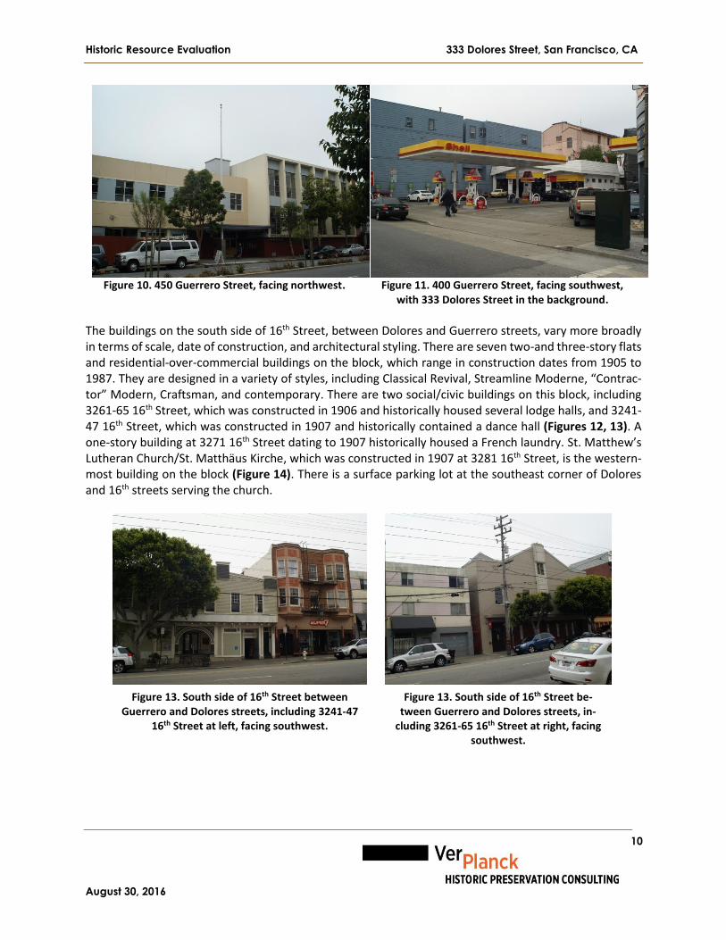
Historic Resource Evaluation 333 Dolores Street, San Francisco, CA
August 30, 2016
10
Figure 10. 450 Guerrero Street, facing northwest.
Figure 11. 400 Guerrero Street, facing southwest,
with 333 Dolores Street in the background. The buildings on the south side of 16th Street, between Dolores and Guerrero streets, vary more broadly in terms of scale, date of construction, and architectural styling. There are seven two-and three-story flats and residential-over-commercial buildings on the block, which range in construction dates from 1905 to 1987. They are designed in a variety of styles, including Classical Revival, Streamline Moderne, “Contrac-tor” Modern, Craftsman, and contemporary. There are two social/civic buildings on this block, including 3261-65 16th Street, which was constructed in 1906 and historically housed several lodge halls, and 3241-47 16th Street, which was constructed in 1907 and historically contained a dance hall (Figures 12, 13). A one-story building at 3271 16th Street dating to 1907 historically housed a French laundry. St. Matthew’s Lutheran Church/St. Matthäus Kirche, which was constructed in 1907 at 3281 16th Street, is the western-most building on the block (Figure 14). There is a surface parking lot at the southeast corner of Dolores and 16th streets serving the church.
Figure 13. South side of 16th Street between Guerrero and Dolores streets, including 3241-47
16th Street at left, facing southwest.
Figure 13. South side of 16th Street be-tween Guerrero and Dolores streets, in-
cluding 3261-65 16th Street at right, facing southwest.
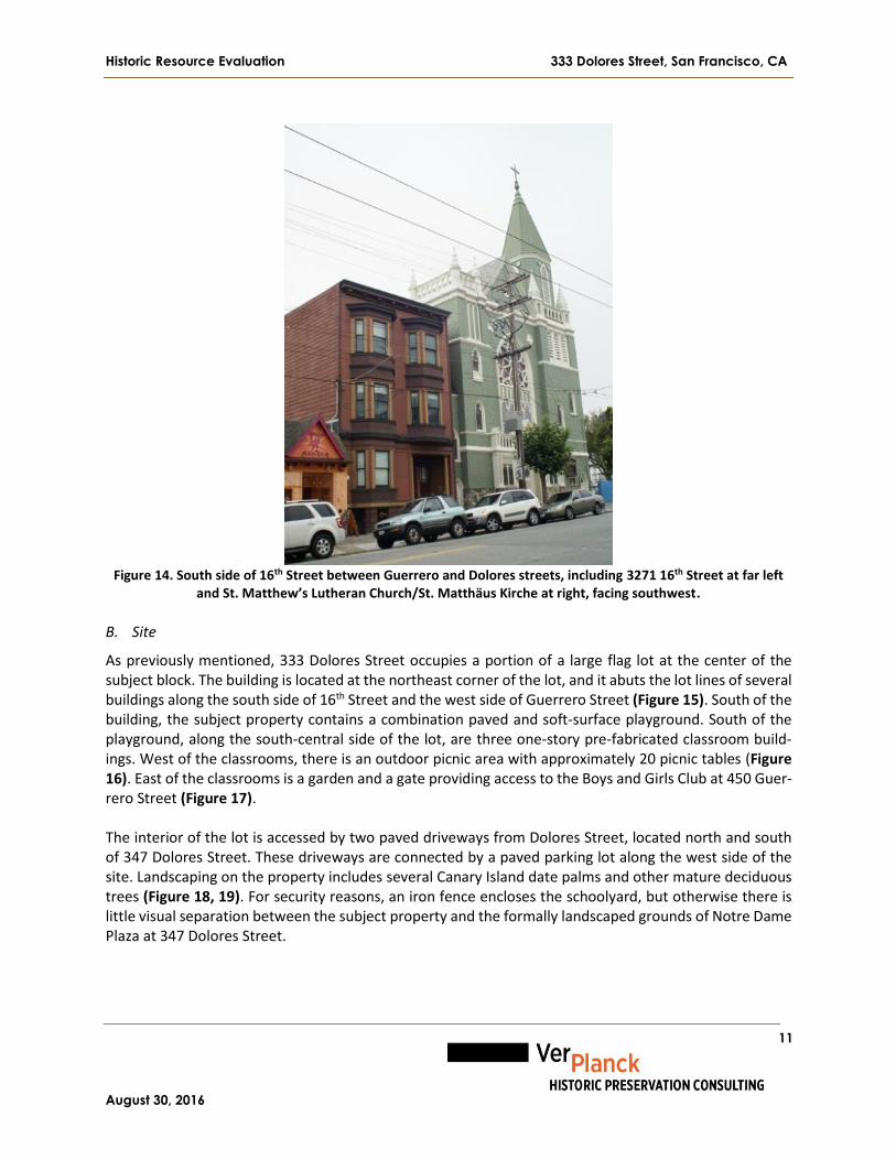
Historic Resource Evaluation 333 Dolores Street, San Francisco, CA
August 30, 2016
11
Figure 14. South side of 16th Street between Guerrero and Dolores streets, including 3271 16th Street at far left
and St. Matthew’s Lutheran Church/St. Matthäus Kirche at right, facing southwest.
B. Site
As previously mentioned, 333 Dolores Street occupies a portion of a large flag lot at the center of the subject block. The building is located at the northeast corner of the lot, and it abuts the lot lines of several buildings along the south side of 16th Street and the west side of Guerrero Street (Figure 15). South of the building, the subject property contains a combination paved and soft-surface playground. South of the playground, along the south-central side of the lot, are three one-story pre-fabricated classroom build-ings. West of the classrooms, there is an outdoor picnic area with approximately 20 picnic tables (Figure 16). East of the classrooms is a garden and a gate providing access to the Boys and Girls Club at 450 Guer-rero Street (Figure 17). The interior of the lot is accessed by two paved driveways from Dolores Street, located north and south of 347 Dolores Street. These driveways are connected by a paved parking lot along the west side of the site. Landscaping on the property includes several Canary Island date palms and other mature deciduous trees (Figure 18, 19). For security reasons, an iron fence encloses the schoolyard, but otherwise there is little visual separation between the subject property and the formally landscaped grounds of Notre Dame Plaza at 347 Dolores Street.

Historic Resource Evaluation 333 Dolores Street, San Francisco, CA
August 30, 2016
12
Figure 15. Site plan of 333 Dolores Street.
Figure 16. Outdoor dining area with soft-paved playground in the background, facing north-
east.
Figure 17. Garden with pre-fabricated classrooms in the background, fac-
ing west.
1. 333 Dolores Street 2. Paved playground 3. Soft-surface play-ground 4. Pre-fab classroom 5. Pre-fab classroom 6. Pre-fab classroom 7. Outdoor dining area 8. Garden 9. 450 Guerrero Street 10. Paved driveway 11. Paved driveway 12. Paved parking 13. 347 Dolores Street 14. Formally-land-scaped gardens

Historic Resource Evaluation 333 Dolores Street, San Francisco, CA
August 30, 2016
13
Figure 18. Mature Canary Island date palms and formally landscaped
garden behind 347 Dolores Street, facing west.
Figure 19. Mature deciduous trees and
parking lot between 333 and 347 Dolores Street, facing northeast.
C. General Description
333 Dolores Street is a three-story, reinforced concrete, school building with an L-shaped footprint and a compound roof consisting of hipped, pent, and flat areas. The building occupies a level site and has no basement. The building has a concrete perimeter foundation and is mainly finished in stucco, though it has some areas of painted, board-formed concrete. 333 Dolores Street was designed by architect Albert M. Cauldwell and constructed in 1925 for the Sisters of Notre Dame to serve as a grammar school for girls. 333 Dolores Street is used by the Children’s Day School as their Lower School. The primary façade faces south towards the school’s playgrounds and the interior of the block. The west façade faces the driveway and can be seen from Dolores Street. The north and east façades abut several adjoining properties along 16th and Guerrero streets and are not accessible by foot. Nonetheless, a portion of the north and east façades are visible from the intersection of 16th and Guerrero streets. The interior of 333 Dolores Street contains classrooms and offices on all three floors. At each floor, a single-loaded corridor along the north side of the building provides access to classrooms and offices along the south side. Vertical circulation is provided by three stairs, one at each end of the building and one at the center of the building. The building has undergone relatively few alterations and is in good condition. All windows are operable wood case-ment windows unless otherwise noted.

Historic Resource Evaluation 333 Dolores Street, San Francisco, CA
August 30, 2016
14
D. Exterior Description
South (Primary) Façade
As previously mentioned, the south (primary) façade of 333 Dolores Street faces south toward the center of the property. The south façade has a narrow wing that projects outward at the left side. Referred to in this report as an “ell,” it is one bay wide and capped by a hipped roof clad in red clay tiles (Figure 20). The main volume of the building is to the right of the ell; it is nine bays wide and capped by a combination flat and pent roof clad in red clay tiles (Figures 21, 22). This nine-bay portion of the primary façade is described first, followed by the ell.
Figure 20. Primary façade, ell, facing
northeast.
Figure 21. Primary façade, left por-
tion, facing northwest.
Figure 22. Primary façade, right portion, facing
north.
At the first floor level, a pergola spans the width of the main volume of the building. The pergola is com-posed of a low stucco wall, atop of which are single and paired Composite-order columns. These columns, which are interspersed among narrow sections of wall, support a trellis composed of heavy wood timbers (Figure 23).
Figure 23. Colonnade and trellis detail, facing northeast.

Historic Resource Evaluation 333 Dolores Street, San Francisco, CA
August 30, 2016
15
Access to the pergola is provided at the far left, center, and far right by short concrete stairs. At the left side of the pergola, there is a concrete wheelchair ramp and a stair with metal pipe rails, which leads from the far left side of the pergola to two non-historic entrances located left of center (Figure 24). At the right side of the pergola, there is a large metal fire escape, which leads to platforms and fire doors at the second and third floor levels (Figure 25). To the right of the pergola is a wood stair and platform, with a wood balustrade and railings, which provides access to two non-historic entrances and an outdoor utility closet (Figure 26). The central portion of the pergola is sheltered beneath a canvas and metal-tube awning and the far right side of the pergola is sheltered by a corrugated metal roof.
Figure 24. Concrete wheelchair
ramp and stair at the left side of the pergola, facing west.
Figure 25. Metal fire escape at the
right side of the pergola, facing east.
Figure 26. Wood stair and plat-form at the far right side of the
pergola, facing northeast. The primary entrance is located at the center (fifth bay) of the first-floor level of the primary façade. It contains is a contemporary fully-glazed, single-leaf metal door with a sidelight. Above the entrance is a wooden sign affixed to the façade that reads “St. Joseph’s Hall 1925” (Figure 27). The remainder of the fenestration at the first floor level is generally symmetrical, although non-historic alterations have disrupted the south façade’s historical symmetry. The structural bays are subtly paired, leaving a broader space between the second and third and the seventh and eighth bays. At the first floor level, while each bay historically contained a large multi-light window containing 12 four-light casement sashes, only the first, fourth, sixth, and seventh bays retain this arrangement. The second and third bays now contain contemporary anodized aluminum door systems with flanking sidelights (Figure 28). Mean-while, the eighth and ninth bays have contemporary ten-light, single-leaf wood doors (see Figure 26).

Historic Resource Evaluation 333 Dolores Street, San Francisco, CA
August 30, 2016
16
Figure 27. Primary entrance, facing
northeast.
Figure 28. Alterations at the third bay of the first floor level, facing
northwest.
At the second floor level, the fifth (center) bay, above the primary entrance, has a multi-light window containing nine four-light casement sashes. The rest of the bays have larger windows composed of 12 four-light casement sashes matching the first floor level (Figure 29). The only exception is the eighth bay, where one of the original windows was modified in the 1950s to install a metal fire door. The second floor level terminates with a narrow stringcourse molding.
Figure 29. Second floor level, window detail, showing the alterations in the eighth bay and the typical window
arrangement in the ninth bay, facing north.
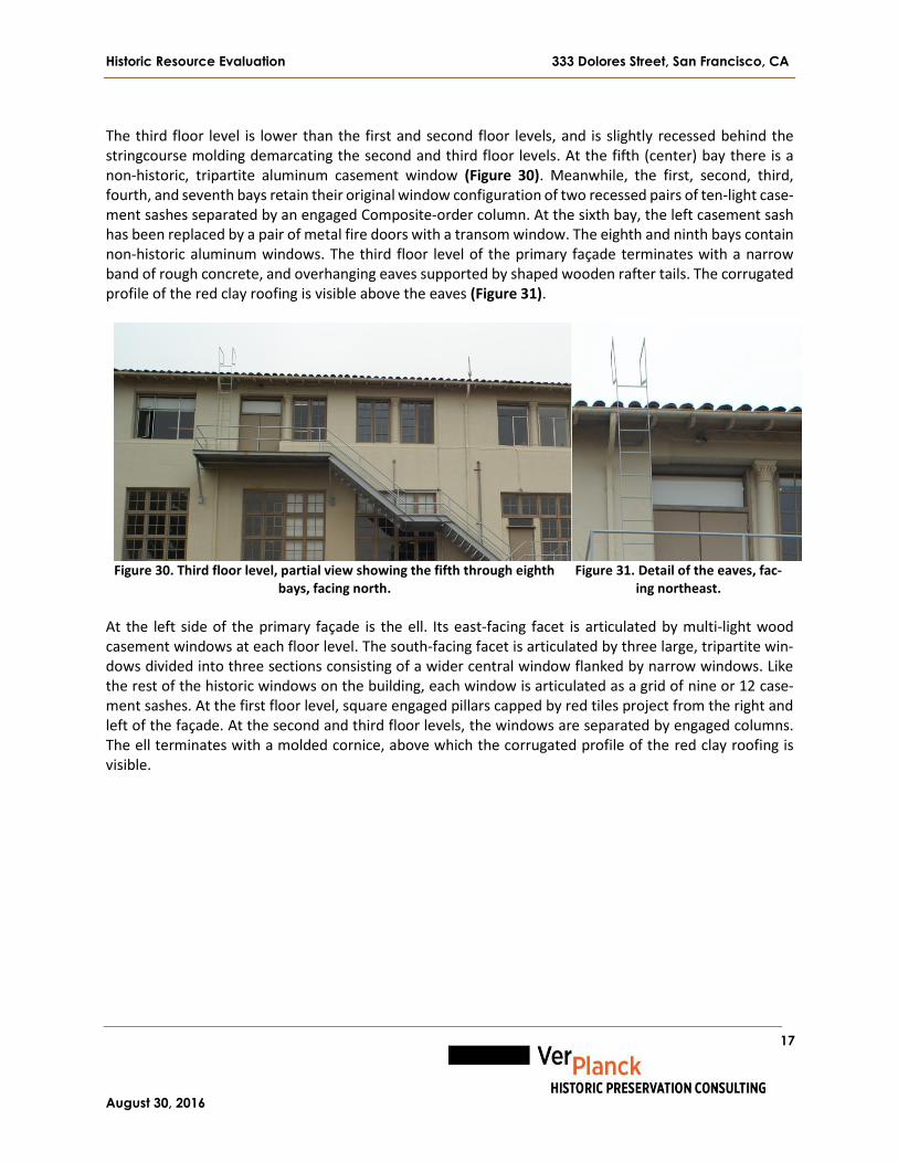
Historic Resource Evaluation 333 Dolores Street, San Francisco, CA
August 30, 2016
17
The third floor level is lower than the first and second floor levels, and is slightly recessed behind the stringcourse molding demarcating the second and third floor levels. At the fifth (center) bay there is a non-historic, tripartite aluminum casement window (Figure 30). Meanwhile, the first, second, third, fourth, and seventh bays retain their original window configuration of two recessed pairs of ten-light case-ment sashes separated by an engaged Composite-order column. At the sixth bay, the left casement sash has been replaced by a pair of metal fire doors with a transom window. The eighth and ninth bays contain non-historic aluminum windows. The third floor level of the primary façade terminates with a narrow band of rough concrete, and overhanging eaves supported by shaped wooden rafter tails. The corrugated profile of the red clay roofing is visible above the eaves (Figure 31).
Figure 30. Third floor level, partial view showing the fifth through eighth
bays, facing north.
Figure 31. Detail of the eaves, fac-
ing northeast. At the left side of the primary façade is the ell. Its east-facing facet is articulated by multi-light wood casement windows at each floor level. The south-facing facet is articulated by three large, tripartite win-dows divided into three sections consisting of a wider central window flanked by narrow windows. Like the rest of the historic windows on the building, each window is articulated as a grid of nine or 12 case-ment sashes. At the first floor level, square engaged pillars capped by red tiles project from the right and left of the façade. At the second and third floor levels, the windows are separated by engaged columns. The ell terminates with a molded cornice, above which the corrugated profile of the red clay roofing is visible.

Historic Resource Evaluation 333 Dolores Street, San Francisco, CA
August 30, 2016
18
Figure 32. The south-facing façade of the ell, facing northeast.
West Façade The west façade of 333 Dolores Street, which is only part of the building visible from Dolores Street, faces the paved driveway and parking lot within the interior of the block (Figure 33). The west façade is four bays wide. Within the first bay at the first floor level, a utilitarian boiler room addition projects outward from the building. The boiler room has a metal pedestrian door slightly below grade, which is accessed by a short cement stair with metal pipe railings. Otherwise, the west façade of the boiler room is without fenestration except for a pair of metal louvered vents. A metal vent pipe from the boiler room rises the full height of the building; it is attached to the west façade by metal struts. To the right of the boiler room, in the second bay, is a pair of paneled wood doors with brass hardware and paneled wood casings (Figure 34). The doors are recessed within a shallow vestibule accessed by a short concrete stair with metal pipe railings. The entrance is sheltered by a non-historic canvas awning. There is no fenestration at the rest of the first floor level, which is enclosed within a board fence containing trash bins.

Historic Resource Evaluation 333 Dolores Street, San Francisco, CA
August 30, 2016
19
Figure 33. West façade, facing east.
Figure 34. Main entrance on west fa-
çade, facing east.
The upper floor levels of the west façade are articulated by a random assemblage of large wood windows matching those found elsewhere on the building’s exterior. The windows on the left side of the west fa-çade are off-set between floor levels, reflecting their location at the landings of an interior stairwell. The third bay is blind, and the fourth bay includes one multi-light wood window at the third floor level of the ell. The west façade terminates with a simple molded cornice, above which the corrugated profile of the red clay roofing is visible. East Façade The east façade of 333 Dolores Street abuts the eastern lot line. There is no pedestrian access to this part of the property, with most of it is only visible from adjoining properties. The only portion of the east façade visible from a public right-of-way is a small section visible from the intersection of 16th and Guerrero streets. In contrast to the south and west façades, which are finished in stucco, most of the east façade is painted board-formed concrete. The only exception is the third floor level, which is finished in stucco, indicating that it was originally intended to be visible from the street (Figure 35). The right bay of the east façade contains a narrow, projecting gable-roofed oriel. The oriel is articulated by three multi-light wood casement windows. The windows are off-set from the floor levels inside, reflecting their location at the landings of an interior stairwell.

Historic Resource Evaluation 333 Dolores Street, San Francisco, CA
August 30, 2016
20
Figure 35. Partial view of the east and north façades of 333 Dolores Street, visible from Guerrero Street, facing
southwest. The only other fenestration visible on the east façade is a pair of three-light casement windows at the center of the third floor level. The east façade terminates with a stepped gable trimmed by red tile.
North Façade The north façade of 333 Dolores Street abuts the north lot line. Similar to the east façade, there is no pedestrian access to this part of the property, meaning that it is only visible from its neighbors on the south side of 16th Street. Nevertheless, a small portion is visible from the intersection of 16th and Guerrero streets, indicating that it is board-formed concrete at the first and second floor levels and finished in stucco at the third floor level. The first floor level has no fenestration. The second floor level has four steel industrial windows with operable casement sashes. The windows are fitted with wire glass. The third floor level has 13 pairs of ten-light steel casement windows fitted with wire glass. The north façade terminates with overhanging eaves supported by shaped wooden rafters, above which the profile of the red clay roofing is visible.
E. Interior Description
The interior of 333 Dolores Street consists of three full floor levels. At each level, classrooms and offices are arranged along the south side of the building, where they are accessed by a single-loaded corridor running along the north side of the building. A centrally-located stairwell which begins at the building’s primary entrance on the south façade provides access to the first and second floor levels. Stairwells at the east and west ends of the building provide access to all three floor levels. The primary entrance on the south side of the building accesses a stairwell which rises to the corridor at the first floor level. The corridor is articulated by a series of non-structural plaster arches and illuminated by contemporary suspended fluorescent fixtures (Figure 36). At the east end of the first-floor corridor are three toilet rooms and a utility closet. On the south side of the corridor, six solid-core wood doors punc-tuated with safety-glass windows and large transoms lead to three large classrooms. Paired clerestory windows provide additional light from the corridor to the classrooms. The classrooms retain some original

Historic Resource Evaluation 333 Dolores Street, San Francisco, CA
August 30, 2016
21
features including the windows and wood-paneled cloakrooms, but they have otherwise been incremen-tally updated with linoleum flooring, whiteboards, suspended fluorescent light fixtures, and wall-mounted radiators. The entire first floor level retains its 8” baseboards and some other simple redwood trim. A short flight of stairs at the west end of the first-floor corridor rises to a landing which provides access to the stairwell at the west end of the building. This area also contains a utility closet under the stairwell and a foyer opening off the building’s west entrance (Figure 37). Two wood doors at the south side of the foyer access a large classroom that fills the volume of the building’s ell.
Figure 36. First-floor level corridor, facing southeast.
Figure 37. First-floor level stairwell at the west side of the building, facing
west. The center stair and the stairs at the east and west sides of the building provide access to the second floor level (Figures 38, 39, 40). The stairs have concrete treads covered in rubber and scored, polished-concrete landings. The east stair has two wood handrails to accommodate children of different heights, while the center and west stairs have one set of handrails. The east stair has arched ceilings, and all three of the stairs are illuminated by pendant light fixtures.

Historic Resource Evaluation 333 Dolores Street, San Francisco, CA
August 30, 2016
22
Figure 38. East stair, taken from the third floor level, facing east.
Figure 39. Center stair, taken from
the second floor level, facing south.
Figure 40. West stair, taken from the first floor level, facing west.
At the second floor level, the corridor is articulated by eight non-structural plaster arches (Figure 41). The four window groups along the north side of the building are deeply recessed within beveled openings. There is a communal hand-washing sink along the north side of the corridor. Six solid-core wood doors with single safety-glass windows and transoms provide access to four classrooms along the south side of the building. Similar to the classrooms on the first floor level, these classrooms retain a mixture of original and newer materials and features (Figure 42). The second floor level classrooms are illuminated by 1950s-era pendant lights. At the west side of the second-floor corridor, a flight of three concrete steps provides access to the ell, where there is an office, a toilet room, and a classroom (Figure 43). This classroom retains some original wood flooring.

Historic Resource Evaluation 333 Dolores Street, San Francisco, CA
August 30, 2016
23
Figure 41. Second-floor level corri-
dor, facing west.
Figure 42. Wood-paneled cloak-
rooms typical of classrooms at the first and second floor levels.
Figure 43. Large classroom on sec-ond floor level of ell, facing south.
The third floor of the building, which was historically used as an auditorium, retains its original exposed wood trusses and rafters, though non-historic demising walls block the original sense of it being a single space (Figure 44). The north wall of the corridor is finished with unpainted wood paneling and articulated by 13 pairs of casement windows. Recessed pockets in the jambs likely contain sun shades or shutters. The south wall of the corridor is lined by a contemporary stud-frame and gypsum board wall lined with steel lockers. Four metal doors with single safety-glass windows access the four contemporary classrooms at this floor level. There is a pair of meeting rooms to the west of the classrooms. The classrooms are separated by contemporary stud-frame, gypsum-board walls with Plexiglas clerestories (Figure 45). The east end of the third-floor corridor has two toilet rooms with contemporary fixtures, and a utility closet. The third floor level, which was built out in 2009, is finished in contemporary materials, including linoleum flooring, whiteboards, suspended fluorescent light fixtures, ceiling fans, and wall-mounted radiators. At the west end of the third-floor corridor, a short flight of concrete steps provides access to the ell, where there is an office, a faculty toilet room, and a classroom used as a teachers’ lounge.

Historic Resource Evaluation 333 Dolores Street, San Francisco, CA
August 30, 2016
24
Figure 44. Third floor level corri-
dor, facing east.
Figure 45. Exposed wood trusses at third floor level, facing east.
V. Historical Context
A. Historical Background of the Mission District
Spanish Period (1776-1820) Mission Dolores is part of San Francisco’s sprawling Mission District – a generally level swath of the city traditionally bounded by Twin Peaks to the west, Bernal Heights to the south, Potrero Hill to the east, and Market Street and the South of Market Area to the north. The neighborhood takes its name from the eponymous mission located at the present-day intersection of 16th and Dolores streets. Founded in 1776 as Misíon San Francisco de Asís by Francisco Palóu and Pedro Cambón, the mission eventually took its popular name from nearby Laguna de los Dolores, a seasonal lake that would appear during the rainy season within an area defined by 15th Street, South Van Ness Avenue, 20th Street, and Guerrero Street. The first mission was little more than a brush chapel when the first mass was held on June 29, 1776. A more permanent adobe mission was completed in September 1776. Work on the third and final mission church did not begin until 1782.13 Mission Dolores was one in a chain of 21 missions established by the Franciscan Order in Alta California as a means to convert the indigenous people to Catholicism and create a population of Hispanicized resi-dents loyal to the Spanish crown. In conjunction with the missions, the Spanish government established military garrisons called presidios, and several civilian settlements called pueblos. The mission system was a disaster for the native inhabitants of California. Exposed to diseases to which they had no resistance, their religion and culture suppressed, and forced to work as laborers in the missions’ workshops and vast cattle ranches, thousands of native Californians died or fled. Mission Dolores was particularly ill-suited to agricultural production because of the San Francisco Peninsula’s inhospitable climate and poor soils. By 1823, due to widespread sickness among the neophytes, the majority of the population of Mission Dolores
13 Allen G. Pastron, Ph.D. and L. Dale Beevers, From Bullfights to Baseball: Archaeological Research Design and Treatment Plan for the Valencia Gardens Hope VI Project (Oakland: unpublished report, December 2002), 32.

Historic Resource Evaluation 333 Dolores Street, San Francisco, CA
August 30, 2016
25
was transferred to Misíon San Rafael Arcangel. By the late 1820s, Mission Dolores had fallen into a period of terminal decline (Figure 46).14
Figure 46. Mission Dolores, 1856.
Source: San Francisco Historical Photograph Collection, Photo ID# AAB-0675
Mexican Period (1821-1846) Mexico rebelled against three centuries of Spanish colonial rule in 1810, eventually winning independence in 1821. After the short-lived Empire of Mexico (1822-23), Mexico became a federal republic. Among the territories the new nation inherited from Spain was the remote northern colony of Alta California. Initially Mexico was unsure of what to do with the territory, at first using it as a penal colony. Later Mexico decided to follow the Spanish strategy of settling and fortifying Alta California as a bulwark against incursions from Russia, Britain, France, and the United States. Following independence, Mexico opened up California to trade and settlement. In 1833, Mexico passed the Secularization Act, which wrested control of the mission lands from the Catholic Church and began redistributing them to Mexican citizens, including to many veterans of the Mexican War of Independence. Other grantees included European and Anglo-American settlers who had converted to Catholicism, mar-ried local women, and become naturalized Mexican citizens. From 1834 onward, Mission Dolores was carved up into several ranchos, including Rancho Potrero Viejo (4,446 acres encompassing today’s Bernal Heights and Bayview-Hunters Point neighborhoods), which went to José Bernal in 1839; Rancho Potrero Nuevo (1,000 acres of today’s Potrero District), which was granted to Francisco and Ramon DeHaro in 1841; and Rancho San Miguel (4,443 acres comprising today’s Noe Valley, Twin Peaks, Glen Park, Miraloma Park, and others), which was acquired by José de Jesus Noe in 1845 (Figure 47). In contrast, the majority of the Mission Valley, an area large conterminous with the boundaries of today’s Mission District, largely remained under common ownership. The only substantial private landholding in the Mission Valley was the 18.5-acre Rancho Camaritas, which had been granted to José de Jesus Noe.15
14 Camille de Roquefeuil, “Camille de Roquefeuil-Navagitor,” in Francis J. Weber, ed., Mission Dolores: A Documentary History of San Francisco’s Mission (Hong Kong: 1979), 53. 15 Carey & Company, Inc., Revised Mission Dolores Neighborhood Survey (San Francisco: November 11, 2009), 20.

Historic Resource Evaluation 333 Dolores Street, San Francisco, CA
August 30, 2016
26
Cattle ranching and the production of hides and tallow were the primary economic activities of the Califor-nia ranchos during the Mexican period. European and American traders came from far and wide to trade manufactured goods for California’s products. During this time, a small settlement of merchants began to grow up along the shores of Yerba Buena Cove to serve the needs of the traders and whalers who dropped anchor there. Named Yerba Buena, this small village, which was recognized as a Mexican pueblo in 1835, would soon become the nucleus of the city of San Francisco.16
Figure 47. Lithograph showing the vicinity of Mission Dolores, ca. 1840.
Source: Bancroft Library, University of California, Berkeley Early American Period (1847-1860) Beginning in 1835, the American government attempted to purchase the San Francisco Bay Region from Mexico. American leaders recognized that San Francisco Bay would be an ideal base for the young nation’s growing trade with Asia. They also wished to prevent the strategic harbor from falling into the hands of England, France, or Russia. American expansionism received a boost in 1844 with the election of James K. Polk to the presidency of the republic. Polk provoked Mexico on numerous occasions, and after several illegal incursions of U.S. troops onto Mexican soil, Mexico attacked American forces on May 12, 1846. Given orders to immediately seize California upon the outbreak of hostilities, on July 9, 1846, Captain John B. Montgomery raised the American flag above the Custom House at Yerba Buena and Mexican rule came to an end in Northern California.17 Fighting continued in Southern California and Mexico proper, and after a year-and-a-half of fighting, the two nations signed the Treaty of Guadalupe-Hidalgo on February 2, 1848. By the terms of the treaty, Mexico ceded 525,000 square miles of its northern territory to the United States in exchange for a lump sum payment of $15 million and the assumption of $3.5 million in debt owed by Mexico to U.S. citizens.
16 The Overland Monthly (February 1869), 131-132. 17 Oscar Lewis, San Francisco: Mission to Metropolis (San Diego: Howell-North Books, rev. ed. 1980), 41.

Historic Resource Evaluation 333 Dolores Street, San Francisco, CA
August 30, 2016
27
On the eve of American conquest, the population of Yerba Buena numbered around 850 people of diverse nationalities in approximately 200 structures.18 Before departing, Captain Montgomery appointed Lieuten-ant Washington A. Bartlett as the first American alcalde of Yerba Buena, and one of Bartlett’s first actions was to rename the settlement San Francisco, which he did on January 30, 1847. In 1847 Bartlett hired Jasper O’Farrell to complete the city’s first official survey under American rule. O’Far-rell’s plan, which enlarged the settlement to almost 800 acres, extended the boundaries of old Mexican pueblo south to O’Farrell Street, west to Leavenworth Street, north to Francisco Street, and some distance eastward into Yerba Buena Cove. Anticipating the need for a direct route from San Francisco to Mission Dolores, O’Farrell laid out a 100-foot-wide thoroughfare running southwest from Yerba Buena Cove toward the mission. O’Farrell probably laid out Market Street on a diagonal alignment to avoid the marshlands that ringed Mission Bay.19 During the early days of San Francisco, travel between Yerba Buena Cove and Mission Dolores was chal-lenging. In addition to large sand dunes in the South of Market Area, there was an expansive marsh around the edges of Mission Bay that blocked direct access between the two nodes of settlement. Access im-proved with the completion of the Mission Plank Road, built by Charles Wilson in 1853 (Figure 48). Wilson obtained a franchise from the city to construct and operate the road, which was paved in heavy wood planks from Kearny and Market to Mission Dolores. The construction of the Folsom Plank Road (popularly known as the “New Mission Road”) two blocks east, in 1854, further improved access.20
Figure 48. Mission Plank Road, 1856.
Source: Annals of San Francisco
The discovery of Gold at Sutter’s Mill in January 1848 unleashed a population explosion in California as news of the discovery spread to ports in Central and South America, and eventually to Europe and the East Coast. By the end of 1848, thousands of gold-seekers from around the world – dubbed “Forty-niners” –
18 Allen G. Pastron, Ph.D., 869 Folsom Street, San Francisco, California: Archival Cultural Resources Evaluation (Albany, CA: unpublished report, September 1990), 20. 19 Ibid., 43. Some scholars believe that O’Farrell laid out the 100 vara blocks for agricultural use but others believe that they were intended for industrial use, for which in fact they proved to be useful. 20 Theodore H. Hittell, History of California, Volume III (San Francisco: N.J. Stone & Company, 1897), 343.

Historic Resource Evaluation 333 Dolores Street, San Francisco, CA
August 30, 2016
28
made their way to San Francisco. Between 1848 and 1852, the population of San Francisco grew from less than one thousand inhabitants to almost thirty-five thousand.21 Mission Dolores Neighborhood (1860-1906) During the waning years of Mexican rule, a small village had grown up around Mission Dolores. In contrast to the polyglot population of Yerba Buena, the village surrounding Mission Dolores was largely Spanish-speaking. The village was composed of humble adobe and wood-frame houses, and a few small commercial enterprises. Many former mission outbuildings were adapted by the villagers for residential and commer-cial use. Non-Hispanics living near Mission Dolores were mostly young English or American men who had married into local Californio and Mexican families. In 1846, several English-speaking Mormon families took up residence in several former mission buildings. 22 By the early 1860s, there were approximately 50 build-ings in the Mission Dolores area. The village itself extended from around 14th Street on the north to 19th Street at the south, and from Mission Street on the east to Church Street at the west.23 In 1858, President Buchanan signed a petition by the Archdiocese of San Francisco to give Mission Dolores, along with eight acres surrounding it, to the Archdiocese. During the 1860s and 1870s, the Archdiocese sold much of this land for development, retaining only the block bounded by 16th Street, Dolores Street, Chula Lane, and Church Street. Though it retained the mission, which was already recognized as being of great historical value, in the 1870s, the Archdiocese built the much larger brick St. Francis Catholic church next door to the mission, on the corner of 16th and Dolores streets. Despite its abundant level land and proximity to the growing city, the Mission Valley was not surveyed and subdivided for at least another decade after the passage of the Van Ness Ordinance of 1855, which had opened up much of the outlying former pueblo lands of Yerba Buena for orderly subdivision and develop-ment.24 Maps dating to the 1860s show the Mission Valley as an un-subdivided donut hole surrounded by the orderly gridirons of the Horner’s Addition, Potrero Nuevo, and South of Market surveys. Nevertheless, during this time most of the older Mexican and Californio landholdings in Mission Valley had been snapped up by Anglo-American investors, including George Treat and John Center. John Center grew rich by farming the rich bottomlands of the Mission Valley. Realizing that real estate development would be more profita-ble on a long-term basis than farming, Center organized the North Beach & Mission Railroad, a horse-drawn street railway linking Mission Dolores to downtown. Center also organized his own water company to make even more money from the new residents that he anticipated would flock to the area. 25 By the early 1870s, the Mission District – including the Mission Dolores neighborhood – steadily urbanized. Over a relatively short period of time, the wide-open spaces that had once been home to vegetable gar-dens, beer gardens, and natural creeks sprouted houses and businesses. Between 1860 and 1870, the population of the 11th Ward, which encompassed the Mission District, grew from 3,000 to 23,000 people. The rapid growth of residential and commercial development was aided in part by the extension of graded streets into the neighborhood, and the construction of transit lines along Mission and Valencia streets. By 1867, there were several horse-drawn omnibus lines operating between downtown and Mission Dolores, as well as a steam railroad line along Harrison Street. Meanwhile, residential development grew apace.
21 Rand Richards, Historic San Francisco. A Concise History and Guide (San Francisco: Heritage House Publishers, 2001), 77. 22 Randall Dean, “Technical Memorandum: Eastern Neighborhoods Rezoning and Community Plans Archeological Context (Final),” City of San Francisco Planning Department (April 21, 2006), 4-5. 23 Ibid. 24 Ibid., 19. 25 Horatio F. Stoll, “Growth and Development of the Mission: Wonderful Record of Sixty Years,” San Francisco Call (July 18, 1908).

Historic Resource Evaluation 333 Dolores Street, San Francisco, CA
August 30, 2016
29
Merchant builders constructed rows of Italianate style cottages and flats in the Mission District. In the 1860s and 1870s, the Real Estate Associates constructed thousands of Italianate-style residences, often developing entire blocks at one time. By 1900, rows of Italianate, Eastlake and Queen Anne rowhouses marched down the long straight streets of the Mission District as far south as Army Street (Figure 49). South Van Ness Avenue (then called Howard Street) and Guerrero Street were the most desirable streets in the Mission District, and industrialists and professionals built sizable mansions there.
Figure 49. Italianate homes line Shotwell Street during a rare snowstorm, 1887.
Source: San Francisco Public Library Historical Photo Collection, Photo ID#AAB-5310
In terms of its demographics, the Mission District, including the Mission Dolores area, had evolved over the 35 years between 1850 and 1885 from a rural Spanish-speaking enclave into an urban polyglot district housing people of many nationalities, including Irish, Germans, French, and Scandinavians. Although many were working-class, the neighborhood contained more affluent residents as well. The Mission District, separated from the rest of the city by topographical and manmade boundaries, had become a “city within a city.” Earthquake, Fire and Reconstruction in the Mission District (1906-1942) The 1906 Earthquake and Fire destroyed most of Victorian San Francisco, including virtually the entire South of Market District and the northern Mission District. The fires, which had been caused by broken gas lines, destroyed almost everything in their path. Firebreaks created by dynamiting buildings along Dolores and Howard streets stopped the fires’ progress to the west and east, and the semi-miraculous discovery of a working fire hydrant stopped the fires at 20th Street to the south. Despite the destruction, almost two-thirds of the Mission escaped unscathed, and thousands of working-class residents of the South of Market area pitched their tents in the parks and open spaces of the Mission District. After 1906, the Mission District was remade into a predominantly Irish-American, working-class neighbor-hood. It was also during this period that the Mission took on the basic appearance it retains today. It became much denser after the quake, with many of the older cottages replaced with large multi-family flats and apartment buildings. The new residents often worked in the South of Market area and other industrial areas, including the northeast Mission District and the Potrero District. Many local men were employed as teamsters, carpenters, or longshoremen and women were often employed as servants in the homes of the wealthy. The “Mission Irish” created a cohesive ethnic community with bars, union halls,

Historic Resource Evaluation 333 Dolores Street, San Francisco, CA
August 30, 2016
30
churches, groceries and funeral parlors interspersed amongst the Victorian flats. Union activism remained high in the Mission District throughout the first half of the twentieth century as working-class residents sought to establish a forty-hour work week and decent wages. Many attended St. Peters Church, at the corner of 24th and Alabama Streets, as well as the older Mission Dolores at 16th and Dolores streets. The Mission District developed a commercial "Miracle Mile" along Mission Street after 1906 as well (Fig-ure 50). Many downtown department stores, such as Sherman Clay and Hale Brothers, continued to main-tain a Mission branch after their downtown stores were reconstructed. Mission street gradually became home to the city’s largest entertainment district as well, with at least a dozen motion picture palaces, by World War II, including the El Capitan, Tower, Grand, New Lyceum, Rialto and the colossal 3,000-seat New Mission Theater. The Mission District developed its own commercial and banking institutions as well, such as Hibernia Bank and the old New Mission Savings Bank at 16th and Valencia.
Figure 50. Mission Street’s “Miracle Mile” during the Christmas Season, 1949.
Source: San Francisco Public Library Historical Photo Collection, Photo ID# AAB-4704
Post-War Era (1942-present) The Mission District thrived as a largely self-contained, predominantly European-American, and working-class community until the 1950s. World War II had lured thousands of local sons and daughters out of the neighborhood to fight in Europe and the South Pacific. When they returned they were greeted with the benefits conferred by the GI Act, chiefly educational grants and low-interest home loans. Many took ad-vantage of both and moved out of the cramped and aging Victorian flats of the Mission to the newly developed housing tracts of the Parkside and Sunset districts, Marin County, or The Peninsula. As the Irish-Americans and other European-Americans abandoned the Mission, they were gradually re-placed by Mexican and Central American immigrants. From the 1950s until the 1990s, the continued influx of immigrants from Spanish-speaking countries brought the Mission District full circle to its origins. The Mission District’s evolution into San Francisco’s largest Latino neighborhood remains evident along Mis-sion Street and 24th Street, where many Mexican and Central American restaurants serve local residents and visitors alike. Murals commemorating Latino history and culture transform blank walls and fences into vivid public art. Meanwhile, a few old Irish-American businesses and institutions such as the Dovre Club remained to cater to older community members who did not move to the suburbs.

Historic Resource Evaluation 333 Dolores Street, San Francisco, CA
August 30, 2016
31
Since the late 1990s, the Mission District has undergone another transformation. Technology-sector of-fices have spread south and west from the South of Market district into the formerly industrial Northeast Mission, and employees of technology firms have settled in the Mission district’s Victorian flats and cot-tages, driving up the cost of previously affordable housing. Today, well over a decade into the twenty first century, Latinos are no longer the majority, expensive restaurants open in what used to be taquerías, and only the well-heeled can afford to buy property and lease apartments.
B. History of 333 Dolores Street
Pre-construction History Historically, the east side of the 300 block of Dolores Street was part of a four-acre garden and orchard cultivated by the neophyte Indians of Mission Dolores (Figure 51).26 The soil here was described by a visitor as “a rich black mould” that produced “fig, peach, apple, and other fruit trees.”27 The orchard was surrounded by an adobe wall that was constructed ca. 1783. Portions of the adobe wall have been located underground, along the east and south perimeters of 333 Dolores Street.28
Figure 51. Plat of U. S. Land Commission, Mission San Francisco de Asis (Mission Dolores), drawn 1854.
Source: Library of Congress
As mentioned previously, during the Mexican era, the area surrounding Mission Dolores evolved into a largely Spanish-speaking village. Most of the residents were Mexicans or native-born Californios – white or Mestizo gente de razón. The settlement also contained the former mission’s ranchería, or informal settlement of indigenous neophytes. The residents of the ranchería who were not born at the mission were unable to return to their traditional way of life because their ancestral villages had been usurped by cattle ranches and their cultures destroyed. Most of the residents of the Mission Dolores ranchería lived
26 Richard D. Ambro, They Danced in the Plaza: The Historical Archaeology of Notre Dame Plaza, Mission San Francisco de Asís (Dolores). Report to Mercy Housing California (San Francisco: Holman & Associates, San Francisco, 2003), 30. 27 Ibid. 28 Richard D. Ambro, Results of Archeological Monitoring of Utility Trenching for Construction of Temporary Buildings at the Children’s Day School, 333 Dolores Street, San Francisco, California. Letter dated July 18, 2004.

Historic Resource Evaluation 333 Dolores Street, San Francisco, CA
August 30, 2016
32
in repurposed mission buildings, and very likely continued to cultivate the former mission gardens. How-ever, by around 1850, it seems likely that the indigenous residents of the Mission Dolores area had vol-untarily departed or been driven away, because historic maps show the former ranchería east of Dolores Street and south of 16th Street in use as a bullring (Figure 52, 53).
Figure 52. United States Coast Survey Map, 1853.
The circle indicates the presence of a bullring. Source: David Rumsey Map Collection
Figure 53. The Bullring at Mission Dolores, ca. 1852.
Source: They Danced in the Plaza
Amidst the profound changes that swept San Francisco through the 1840s, Mission Dolores continued to serve both Spanish-speaking Catholic residents of the Mission Dolores area as well some of the city’s newer Catholic immigrants from Ireland. In 1853, Pope Pius IX established the Roman Catholic Archdio-cese of San Francisco, the reach of which extended north to the Oregon-California border, east to the Colorado River in Colorado, and south to the Diocese of Monterey.29 In 1855, under the leadership of its first Archbishop, Joseph Sadoc Alemany, the Archdiocese of San Francisco placed a claim to Mission Dolores, which was confirmed by the City’s Board of Land Commissioners. Delayed for several years by appeals from commercially-minded developers, the patent for the Mission Dolores Church lands was signed by President James Buchanan on March 3, 1858.30 The Sisters of Notre Dame The Sisters of Notre Dame (de Namur) were founded in Namur, Belgium at the end of the eighteenth century. At their establishment, the Sisters of Notre Dame were a teaching order with a mission to provide Catholic primary education for girls, and secondary education for young women who would dedicate their lives to teaching the poor. In 1843, six Sisters left Belgium and traveled to Oregon with the intention of teaching Clapsop Indian children and the daughters of Oregon Trail settlers.31 After several difficult years, the Sisters of Notre Dame travelled to California in 1851 and established a boarding school in San Jose. They opened a second school in Marysville, California in 1856.
29 History of the Archdiocese of San Francisco, published online by the Archdiocese of San Francisco, http://www.sfarchdiocese.org/home. 30 Richard Albro, They Danced in the Plaza, 49. 31 Brief History of the Sisters of Notre Dame de Namur in America, published online by the Sisters of Notre Dame de Namur, www.sndohio.org.
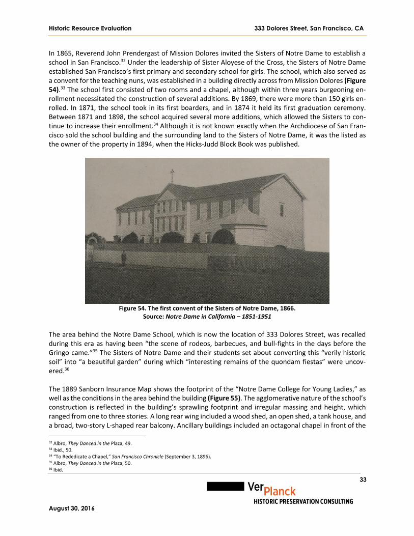
Historic Resource Evaluation 333 Dolores Street, San Francisco, CA
August 30, 2016
33
In 1865, Reverend John Prendergast of Mission Dolores invited the Sisters of Notre Dame to establish a school in San Francisco.32 Under the leadership of Sister Aloyese of the Cross, the Sisters of Notre Dame established San Francisco’s first primary and secondary school for girls. The school, which also served as a convent for the teaching nuns, was established in a building directly across from Mission Dolores (Figure 54).33 The school first consisted of two rooms and a chapel, although within three years burgeoning en-rollment necessitated the construction of several additions. By 1869, there were more than 150 girls en-rolled. In 1871, the school took in its first boarders, and in 1874 it held its first graduation ceremony. Between 1871 and 1898, the school acquired several more additions, which allowed the Sisters to con-tinue to increase their enrollment.34 Although it is not known exactly when the Archdiocese of San Fran-cisco sold the school building and the surrounding land to the Sisters of Notre Dame, it was the listed as the owner of the property in 1894, when the Hicks-Judd Block Book was published.
Figure 54. The first convent of the Sisters of Notre Dame, 1866.
Source: Notre Dame in California – 1851-1951
The area behind the Notre Dame School, which is now the location of 333 Dolores Street, was recalled during this era as having been “the scene of rodeos, barbecues, and bull-fights in the days before the Gringo came.”35 The Sisters of Notre Dame and their students set about converting this “verily historic soil” into “a beautiful garden” during which “interesting remains of the quondam fiestas” were uncov-ered.36 The 1889 Sanborn Insurance Map shows the footprint of the “Notre Dame College for Young Ladies,” as well as the conditions in the area behind the building (Figure 55). The agglomerative nature of the school’s construction is reflected in the building’s sprawling footprint and irregular massing and height, which ranged from one to three stories. A long rear wing included a wood shed, an open shed, a tank house, and a broad, two-story L-shaped rear balcony. Ancillary buildings included an octagonal chapel in front of the
32 Albro, They Danced in the Plaza, 49. 33 Ibid., 50. 34 “To Rededicate a Chapel,” San Francisco Chronicle (September 3, 1896). 35 Albro, They Danced in the Plaza, 50. 36 Ibid.
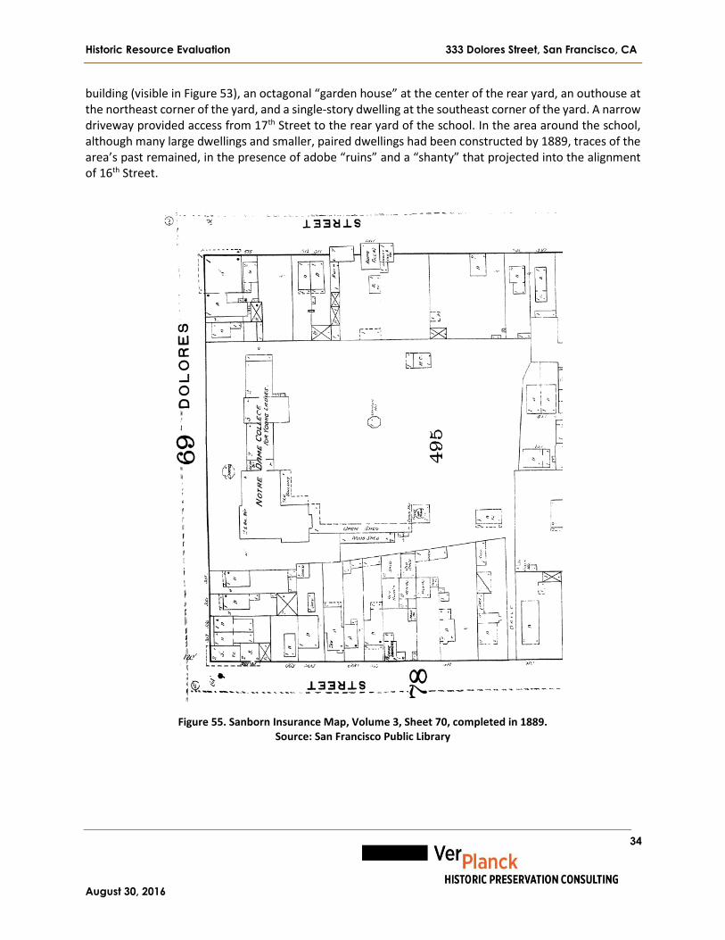
Historic Resource Evaluation 333 Dolores Street, San Francisco, CA
August 30, 2016
34
building (visible in Figure 53), an octagonal “garden house” at the center of the rear yard, an outhouse at the northeast corner of the yard, and a single-story dwelling at the southeast corner of the yard. A narrow driveway provided access from 17th Street to the rear yard of the school. In the area around the school, although many large dwellings and smaller, paired dwellings had been constructed by 1889, traces of the area’s past remained, in the presence of adobe “ruins” and a “shanty” that projected into the alignment of 16th Street.
Figure 55. Sanborn Insurance Map, Volume 3, Sheet 70, completed in 1889.
Source: San Francisco Public Library

Historic Resource Evaluation 333 Dolores Street, San Francisco, CA
August 30, 2016
35
In 1895, plans were announced for a new convent school building for the Sisters of Notre Dame.37 De-scribed as a response to the “pressing demands for more capacious accommodations,” the new building was to be four stories in height. At this time, the school had 250 students, including a large number of boarders. Improvements were planned for the grounds as well. The playground, which was described as already covering half the block, would be extended and beautified. The new landscaping would also ex-tend around the entire perimeter of the new building. Shrines scattered around the yard would be land-scaped and the entire yard would be traversed by gravel paths set off by beds of flowers and shrubbery. When it was completed in 1898, the new Notre Dame School presented a commanding presence on Dolores Street. Like the existing Notre Dame Plaza, it was designed in the Second Empire style (Figure 56).
Figure 56. Notre Dame School, prior to the 1906 Earthquake.
Source: Notre Dame in California – 1851-1951 The 1900 Sanborn Insurance Map shows the footprint of the new Notre Dame School as well as changes to the area behind the building (Figure 57). The new school building had a regular, L-plan footprint and was two-and-a half-stories over a brick basement along Dolores Street and three-and-a half-stories at the south wing. The octagonal chapel that had been in front of the school was moved to the middle of the rear yard, and the garden house was moved to the northeast corner of the yard, where 333 Dolores Street is now located. The outhouse at the northeast corner of the yard had been demolished and a new out-house constructed closer to the school and connected to it by an open breezeway. Ancillary buildings included a laundry, a greenhouse, and the dwelling at the southeast corner of the lot that was shown on the 1889 Sanborn Map. Elsewhere on the block, the remaining vestiges of the adobe buildings of the Mission Dolores settlement had all been removed, and the block was nearly built-out with single-family dwellings, flats, and several commercial buildings – mainly saloons.
37 “A New Convent Building,” San Francisco Call (December 22, 1895).
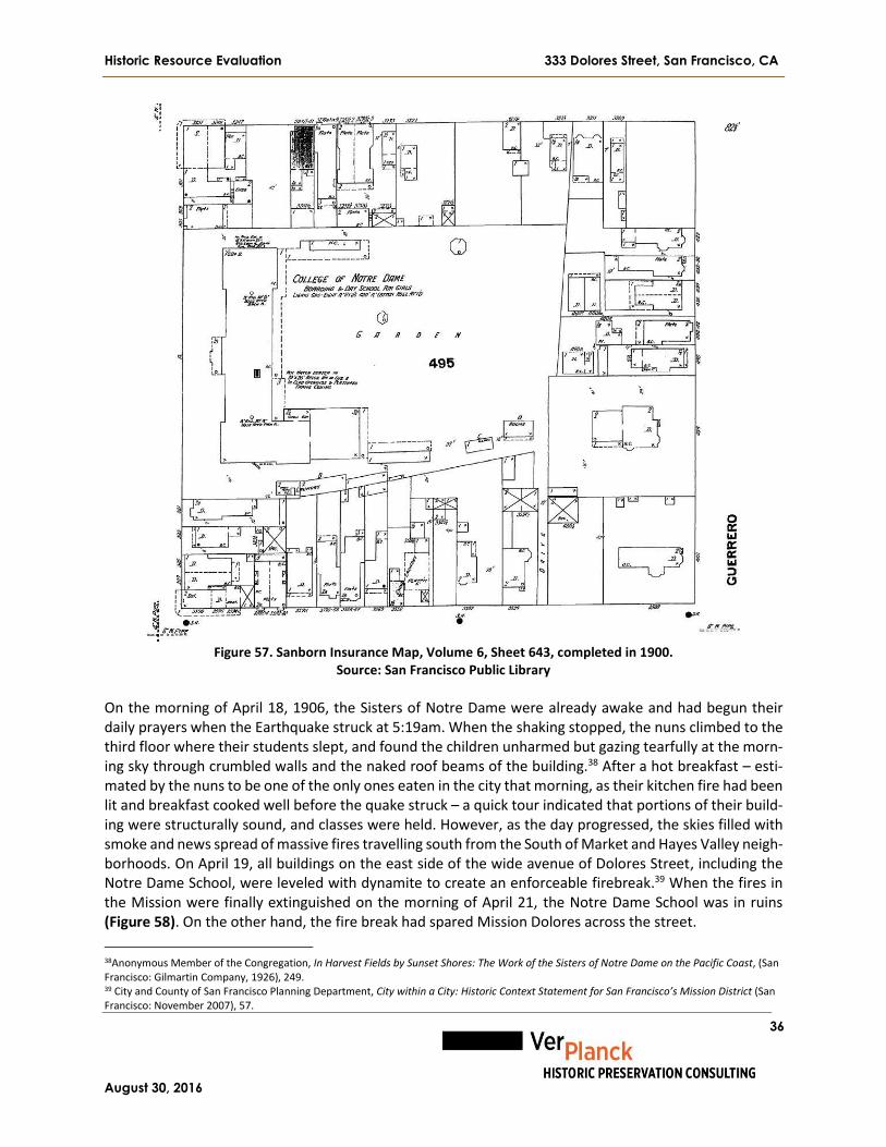
Historic Resource Evaluation 333 Dolores Street, San Francisco, CA
August 30, 2016
36
Figure 57. Sanborn Insurance Map, Volume 6, Sheet 643, completed in 1900.
Source: San Francisco Public Library On the morning of April 18, 1906, the Sisters of Notre Dame were already awake and had begun their daily prayers when the Earthquake struck at 5:19am. When the shaking stopped, the nuns climbed to the third floor where their students slept, and found the children unharmed but gazing tearfully at the morn-ing sky through crumbled walls and the naked roof beams of the building.38 After a hot breakfast – esti-mated by the nuns to be one of the only ones eaten in the city that morning, as their kitchen fire had been lit and breakfast cooked well before the quake struck – a quick tour indicated that portions of their build-ing were structurally sound, and classes were held. However, as the day progressed, the skies filled with smoke and news spread of massive fires travelling south from the South of Market and Hayes Valley neigh-borhoods. On April 19, all buildings on the east side of the wide avenue of Dolores Street, including the Notre Dame School, were leveled with dynamite to create an enforceable firebreak.39 When the fires in the Mission were finally extinguished on the morning of April 21, the Notre Dame School was in ruins (Figure 58). On the other hand, the fire break had spared Mission Dolores across the street.
38Anonymous Member of the Congregation, In Harvest Fields by Sunset Shores: The Work of the Sisters of Notre Dame on the Pacific Coast, (San Francisco: Gilmartin Company, 1926), 249. 39 City and County of San Francisco Planning Department, City within a City: Historic Context Statement for San Francisco’s Mission District (San Francisco: November 2007), 57.

Historic Resource Evaluation 333 Dolores Street, San Francisco, CA
August 30, 2016
37
Figure 58. Mission Dolores and the parish church, as seen from the ruins of the Notre Dame School. Source:
Bancroft Library, University of California, Berkeley
In August, 1906, the Sister Superior of the College of Notre Dame filed an application with the Board of Public Works for a permit to erect a two-story building at 347 Dolores Street.40 The Sisters of Notre Dame hired prominent San Jose architect Theodore Lenzen to design the new building. Lenzen (1863-1912) was a well-known architect whom the San José Mercury once declared had contributed more to the look of dwellings and businesses of San Jose than any other architect in Santa Clara County.41 For the Notre Dame School, Lenzen designed a wood-frame and stucco building that would be “nearly an exact duplicate” of the original. When completed, the French Second Empire-style building was more than twice the size of the old school building, and was ready to welcome over 500 students by the fall of 1907. The building that was constructed in 1907 survives largely unaltered today. The 1914 Sanborn Insurance Map shows the footprint of the rebuilt school building and changes to the area behind the school (Figure 59). Clear similarities can be seen between the footprint of the school building and the footprint of the building that was destroyed in 1906 (visible in Figure 56). The new build-ing was two stories over a brick basement with a mansard roof. The area behind the school was cleared of the attached wings and sheds that were visible on the 1900 Sanborn Map, and there were only three ancillary buildings in the yard, including an octagonal structure in the middle of the yard, which was prob-ably a reconstructed chapel; a one-story shed at the north side of the yard, and two additional sheds along the south side of the lot. The rear yard also included playgrounds and ornamental gardens. Elsewhere on the block, which had been completely destroyed in 1906, rebuilding was nearly complete. The few larger single-family dwellings that were present on the block in 1900 were gone, and replaced by a mixture of flats, small apartment buildings, commercial buildings, food production facilities, social halls, and the St. Matthäus Lutheran church at the southeast corner of 16th and Dolores streets.
40 “File Application for Two-Story Structure on Dolores Street,” San Francisco Call (August 1, 1906). 41 Revised Mission Dolores Neighborhood Survey, 48.

Historic Resource Evaluation 333 Dolores Street, San Francisco, CA
August 30, 2016
38
Figure 59. Sanborn Insurance Map, Volume 7, Sheet 671, completed in 1914.
Source: San Francisco Public Library Construction of 333 Dolores Street On September 23, 1924, Notre Dame College filed a building permit application at the Board of Public Works to erect a new, three-story, reinforced-concrete school building at 333 Dolores Street.42 The build-ing was designed by architect Albert M. Cauldwell of San Francisco and built by J. A. Bryant. According to details on the building permit, the building would be constructed of reinforced Portland cement at the footings, slabs, beams and girders, with a wood roof with wood trusses and steel rods, covered by com-position material at the flat center section and terra cotta tile at the sloped sections. The flat portion of the roof would include three 8’ by 20’ foot steel and glass hipped skylights. Interior partition walls would be of tile and wood, covered by plaster. The permit describes two stairways in the building, both of rein-forced-concrete construction. The cost of construction was estimated at $87,000. An incomplete set of undated drawings by Albert M. Cauldwell is on file with the San Francisco Depart-ment of Building Inspection Records Management Division. These drawings provide some information about Cauldwell’s original design for 333 Dolores Street, but include some elements that do not appear to have been constructed. In Cauldwell’s drawings, the pergola is supported by a wall with nine arched openings. Paired French doors provided the only entrance to the building on the south façade. The draw-ings show no windows at the third floor level of the south facade, and there was a different fenestration
42 San Francisco Building Permit #130906, Filed September 23, 1924.
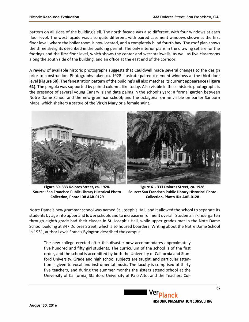
Historic Resource Evaluation 333 Dolores Street, San Francisco, CA
August 30, 2016
39
pattern on all sides of the building’s ell. The north façade was also different, with four windows at each floor level. The west façade was also quite different, with paired casement windows shown at the first floor level, where the boiler room is now located, and a completely blind fourth bay. The roof plan shows the three skylights described in the building permit. The only interior plans in the drawing set are for the footings and the first floor level, which shows the center and west stairwells, as well as five classrooms along the south side of the building, and an office at the east end of the corridor. A review of available historic photographs suggests that Cauldwell made several changes to the design prior to construction. Photographs taken ca. 1928 illustrate paired casement windows at the third floor level (Figure 60). The fenestration pattern of the building’s ell also matches its current appearance (Figure 61). The pergola was supported by paired columns like today. Also visible in these historic photographs is the presence of several young Canary Island date palms in the school’s yard; a formal garden between Notre Dame School and the new grammar school; and the octagonal shrine visible on earlier Sanborn Maps, which shelters a statue of the Virgin Mary or a female saint.
Figure 60. 333 Dolores Street, ca. 1928.
Source: San Francisco Public Library Historical Photo Collection, Photo ID# AAB-0129
Figure 61. 333 Dolores Street, ca. 1928.
Source: San Francisco Public Library Historical Photo Collection, Photo ID# AAB-0128
Notre Dame’s new grammar school was named St. Joseph’s Hall, and it allowed the school to separate its students by age into upper and lower schools and to increase enrollment overall. Students in kindergarten through eighth grade had their classes in St. Joseph’s Hall, while upper grades met in the Note Dame School building at 347 Dolores Street, which also housed boarders. Writing about the Notre Dame School in 1931, author Lewis Francis Byington described the campus:
The new college erected after this disaster now accommodates approximately five hundred and fifty girl students. The curriculum of the school is of the first order, and the school is accredited by both the University of California and Stan-ford University. Grade and high school subjects are taught, and particular atten-tion is given to vocal and instrumental music. The faculty is comprised of thirty five teachers, and during the summer months the sisters attend school at the University of California, Stanford University of Palo Alto, and the Teachers Col-

Historic Resource Evaluation 333 Dolores Street, San Francisco, CA
August 30, 2016
40
lege, for the purpose of keeping abreast of modern developments in various sub-jects. The school has its own chapel and library, and is thoroughly equipped with up to date devices for the proper training of the students. Boarding pupils come to this school from all over the state of California, from Central America, and from the Hawaiian Islands. Athletics are encouraged, and the college always has teams representing the various sports in which girls participate, such as basketball, ten-nis and swimming. Many of the graduates of Notre Dame have gone forth into the world to make real reputations for themselves in music, in art, and in the professions.43
Aerial photographs taken of San Francisco in 1938 by photographer Harrison Ryker provide information about 333 Dolores Street (Figure 62). The roof of 333 Dolores Street does not include the three skylights that were described in both the building’s construction permit and the drawings by Cauldwell, suggesting that they were either never constructed or removed at a very early date. The schoolyard between the two buildings consists primarily of paved sport courts and orthogonal lawn panels punctuated by trees. A small L-plan building is located at the south side of the schoolyard, which is identified on a later map as the school’s heating plant.
Figure 62. San Francisco aerial view, 1938, Sheet 55, by photographer Harrison Ryker.
Source: David Rumsey Map Collection Notre Dame High School and the Notre Dame Grammar School for Girls flourished throughout the middle decades of the twentieth century. During this period, in which the city’s Catholic population was high, there were upwards of 40 Catholic primary and secondary schools in San Francisco (Figures 63, 64). In
43 Lewis Francis Byington, Supervising Editor, The History of San Francisco, California (The S. J. Clark Publishing Company, Chicago-San Francisco 1931).

Historic Resource Evaluation 333 Dolores Street, San Francisco, CA
August 30, 2016
41
addition to the girls’ schools, the Sisters of Notre Dame operated the Mission Dolores Boys’ School, lo-cated behind the Mission Dolores Basilica on 16th Street. The Notre Dame Grammar School for Girls and Mission Dolores Boys’ School choirs often sang together at Catholic events including holiday services and memorial services. The Mothers’ Club of Notre Dame Grammar School met weekly in the school’s third floor auditorium, and hosted events such as the mother-daughter commission and seasonal family carni-vals.
Figure 63. Notre Dame Grammar School
third floor level auditorium, 1954. Source: Notre Dame High School Year-
book, Class of 1954
Figure 64. Students during a ceremony in the yard between Notre
Dame High School and Notre Dame Grammar School, 1954. Source: Notre Dame High School Yearbook, Class of 1954
The 1950 Sanborn Insurance Map is the first to show the footprint of St. Joseph’s Hall, which is labeled St. Joseph’s Hall & Grammar School (Figure 65). Other than the construction of the grammar school, the 1950 map shows no changes to the property since 1938. In fact, the 1950 map duplicates the partially-open shed structure at the north side of the lot that was recorded on the 1914 map. This was likely an error, as the area is clearly shown to be paved and without buildings on the 1938 aerial photograph (see Figure 61).

Historic Resource Evaluation 333 Dolores Street, San Francisco, CA
August 30, 2016
42
Figure 65. 1950 Sanborn Insurance Map, Volume 7, Sheet 671, completed in 1950.
Source: San Francisco Public Library In 1976, Notre Dame Grammar School for Girls merged with the Mission Dolores Boys’ School and became Mission Dolores School.44 From 1976 through 1986, classes for students in kindergarten through fourth grade were held in St. Joseph’s Hall while grades fifth through eighth attended classes at the former boys’ school building behind the Mission Dolores Basilica. This merge reflected a national decrease in Catholic school attendance citywide, which began in the mid-1960s as many long-time Irish and Italian-American families began leaving the city in droves for the suburbs.45 During this time, the demographics of the Notre Dame/Mission Dolores School began to change as well, reaching 44 percent African American, Latino, Asian, and Native American by 1981.46 In 1980, Notre Dame High School eliminated its ninth grade class, and reduced its overall enrollment to 200 students.47 Despite a slight increase in Catholic school enrollment at the beginning of the 1980s, many Catholic schools were forced to close because of the prohibitive cost of improving older school buildings and the dwindling number of teaching nuns. Notre Dame High School closed its doors in June 1981. That same year, the 1907 school building was designated a City Landmark, over the objections of the Sisters of Notre Dame.48
44 “Timeline,” Children’s Day School, https://www.cds-sf.org/we-are-cds/history/timeline. 45 “California’s Big Shift in Private Schools,” San Francisco Chronicle (September 8, 1981). 46 Ibid. 47 “Problems Cloud Opening of School Year,” San Francisco Chronicle (August 31, 1980). 48 “Five Buildings Chosen as Landmarks,” San Francisco Chronicle (August 28, 1981).

Historic Resource Evaluation 333 Dolores Street, San Francisco, CA
August 30, 2016
43
In 1982, the Sisters of Notre Dame still used portions of the building at 347 Dolores Street, while other portions were leased to the Pacific Dance Theater and the Academy of Stenographic Arts.49 Later tenants included early AIDS support groups including CURAS (Comunidad Respueste a la SIDA/Community in Re-sponse to AIDS, 1987) and Project Inform (1988-1990).50 In 1996, 347 Dolores Street was converted into an affordable senior housing project and reopened in 1997 as Notre Dame Plaza. Mission Dolores School continued to hold classes at 333 Dolores Street until 1986, after which time all classes were moved into the Mission Dolores School on 16th Street. In 1987, the Sisters of Notre Dame began leasing 333 Dolores Street to the Children’s Day School (CDS). CDS was founded in 1983 in the Excelsior district by Jim Robinson, and it initially served only preschool-age children. In the late 1980s and into the 1990s, portions of 333 Dolores Street were also used for art studios and performance spaces, as evidenced both by event announcements in local newspapers and by the Sanborn Insurance Map, up-dated to the mid-1990s, in which 333 Dolores Street was labeled as “The Center for the Performing Arts” (Figure 66).51 Elsewhere on the mid-1990s Sanborn Map, 347 Dolores Street is labeled as the location of offices and art studios, while the octagonal structure and the heating plant were still located in the play-ground and ornamental gardens between 347 and 333 Dolores Street.
Figure 66. Sanborn Insurance Map, Volume 7, Sheet 671, updated to the mid-1990s.
Source: San Francisco Assessor’s Office
49 San Francisco City Directory, 1982. 50 Donna J. Graves and Shayne Watson, Citywide Historic Context Statement for LGBTQ History in San Francisco (San Francisco: 2015) 303, 309. 51 “Out-of-Town Select Listings,” Santa Cruz Sentinel (March 25, 1988).

Historic Resource Evaluation 333 Dolores Street, San Francisco, CA
August 30, 2016
44
In 1996, CDS expanded its curriculum to include a kindergarten through eighth grade program. In 2001, Children’s Day School purchased 333 Dolores Street from the Sisters of Notre Dame, including St. Joseph’s Hall and the 1.2 acre lot on which it is located, and it has held classes in the building ever since. In 2015, CDS moved its Upper School to 601 Dolores, a converted church building at 19th and Dolores streets.
C. Summary of Alterations for 333 Dolores Street
333 Dolores Street has undergone very few exterior alterations since it was constructed in 1925, while more significant interior alterations have been made for fire safety and to increase classroom space. The following paragraph summarizes alterations to 333 Dolores Street, excluding fire code-related permits. The exterior boiler room at the west façade was constructed in 1950. One classroom was converted into a toilet room in 1952. That same year, an iron fire escape was added to the south façade. Four wood windows at the second floor level and 13 wood windows at the third floor level auditorium were removed and replaced with steel sash windows in 1958. The kitchen was remodeled and four new aluminum case-ment windows were installed on the third floor level in 1960. Sheet glass was replaced with wire glass in the windows on the first floor level corridor in 1961. Fireproofing of the walls and doors at the first floor level was completed in 1966. The driveways on the north and south sides of 347 Dolores Street were paved in 1968. One aluminum window was installed in 1970. Two stairs were enclosed at the first and second floor levels with one-hour fireproof construction in 1989. An exit corridor was extended in 1996. The pergola at the south façade was repaired in 2000. Two new exit doors, a stair, and a ramp were in-stalled in 2001. A storage shed on the property was demolished in 2003 in advance of the construction of the pre-fabricated classrooms later that year. In 2007, CDS made several exterior and interior alterations, including installing new entrances and replacing doors in existing openings, creating new paths of travel to these doors, removing an existing fire escape, replacing the east stair with a new metal stair, construct-ing a new storage room on the second floor level, building new toilet rooms and a kitchen on the first floor level, and replacing several windows. In 2009, CDS built several new classroom partitions at the third floor level. Finally, in 2013, CDS replaced 38 single-pane wood casement windows in kind with double-pane wood windows. The complete list of permitted work is included in Appendix Item B.

Historic Resource Evaluation 333 Dolores Street, San Francisco, CA
August 30, 2016
45
D. Chain of Title for 333 Dolores Street
333 Dolores Street and 347 Dolores Street were historically located on one parcel, APN#3567/046, which was subdivided into two parcels on January 5, 1996 (see Figure 1).52 347 Dolores Street is now APN#3567/056 and 333 Dolores Street is APN#3567/057.
Document Reference Date Grantor Grantee
Patent for the claim to ownership of the former Mission Dolores lands 03/03/1858
President James Buchanan, signatory Archdiocese of San Francisco
San Francisco Block Book 1894 n/a College of Notre Dame
San Francisco Block Book 1910 n/a College of Notre Dame
Grant Deed 03/01/1993 Unknown (not listed) Larry and Sylvia Chang
Grant Deed 07/09/1993 Larry and Sylvia Chang Sisters of Notre Dame de Namur
Grant Deed 09/28/2001 Sisters of Notre Dame de Namur Children’s Day School
E. Catholic Schools in San Francisco
Technically, the first Catholic school in San Francisco was Mission Dolores, established in 1776 to indoc-trinate the indigenous peoples of the San Francisco Peninsula in the tenets of Catholicism. The first Euro-pean Catholic school in San Francisco was Sacred Heart Cathedral Preparatory, founded in 1852, one year before the establishment of the Archdiocese of San Francisco. Sacred Heart was associated with the Ca-thedral of St. Mary of the Assumption, the mother church of the Archdiocese, which was founded in 1854. The Archdiocese of San Francisco founded a second school in 1856 at Mission Dolores, and invited the Sisters of Notre Dame to establish a school for girls in 1865. From the earliest days of the city’s founding, Catholic education has been an important strain in the city’s intellectual, cultural, political, and commer-cial life, particularly with the ascendancy of the city’s Irish Catholic community to City government and other positions of power during the last quarter of the nineteenth century. Throughout the nineteenth century, Catholic schools in San Francisco were divided into three different types: free schools, schools that collected tuition, and schools where tuition was voluntary. Unlike most eastern cities, many of which had long been dominated by a Protestant elite before the arrival of large numbers of Catholic immigrants, Irish and other Catholic immigrants were part of San Francisco’s elite from its founding. Many Catholic San Franciscans were wealthy and powerful, and they could afford to send their children to elite parochial schools like Sacred Heart.53 On the other hand, most San Francisco
52 San Francisco Property Information Map, “333 Dolores Street.” 53 Catherine Ann Curry, Shaping Young San Franciscans: Public and Catholic Schools in San Francisco, 1851-1906 (Ph.D. diss., Graduate Theologi-cal Union, 1987), iv.

Historic Resource Evaluation 333 Dolores Street, San Francisco, CA
August 30, 2016
46
Catholics were not wealthy, and the city’s free and tuition-optional Catholic schools provided the working and middle classes an alternative to secular public education. Unfortunately, the capacity of these Catholic schools was limited, meaning that space in most schools remained competitive throughout the nineteenth and twentieth centuries. The 1906 San Francisco Earthquake and Fire devastated the city, including the physical plant of the Cath-olic school system. Nearly all schools located downtown; in the South of Market, North Beach, and Ten-derloin neighborhoods; and in parts of the Mission District and the Western Addition were destroyed or heavily damaged. The oldest extant Catholic school building still in use is St. Charles Borromeo, at 3250 18th Street in the Mission District. Built in 1887, it is San Francisco City Landmark #139. The rest of the surviving Catholic school buildings in San Francisco were all built or reconstructed after 1906, including the Notre Dame School building at 347 Dolores Street, which was completed in 1907; and St. Joseph’s Hall at 333 Dolores Street, which was built in 1925. Most of the surviving Catholic school buildings in San Fran-cisco are part of multi-building “campuses” that consist of a church, rectory, convent, and school (Figure 67). Examples include the Sacred Heart campus at Fillmore and Fell streets, St. Joseph’s campus at 10th and Howard streets, or Star of the Sea campus at 8th Avenue and Geary Boulevard. In terms of their archi-tecture, most of these campuses feature multi-story, reinforced concrete schools designed in a modest version of the same style used to design the nearby church. Nearly all post-quake schools are of rein-forced-concrete construction to comply with contemporary fire codes. Ornament is usually kept to a min-imum to save money and to avoid competing with the church component of the “campus.” Most Catholic school buildings in San Francisco are finished in stucco on street-facing façades and unfinished concrete along blind walls and property lines. Styles commonly represented include Renaissance Revival, Mission Revival, Mediterranean Revival, and Gothic Revival.
Figure 67. Sacred Heart Church at Fillmore and Fell streets illustrates the typical “campus” configuration.
Source” Google Maps, annotated by Christopher VerPlanck
Today, there are approximately 40 primary and secondary Catholic schools in San Francisco, including four that have recently closed. Most of the Catholic primary schools are associated with a specific parish, while the secondary schools are run by the Archdiocese. Presently, there is an emerging trend for parishes with

Historic Resource Evaluation 333 Dolores Street, San Francisco, CA
August 30, 2016
47
declining school enrollment to sell their school properties to raise funds to stabilize their churches. Fre-quently, these school buildings, which may also be seismically deficient, are demolished and replaced with luxury housing or other non-scholastic uses. Because altering and demolishing older buildings with historic designations is often more difficult, the Archdiocese has had a policy of discouraging historic designations of its properties.54
F. Architecture: Mediterranean Revival Style
The Mediterranean Revival Style is an eclectic design style that is, at its core, an imprecise adaptation of the sixteenth-century Italian villa. The growing interest in Mediterranean architecture after the of the twentieth century was fueled both by publications about Italian villas, including the works of architect Guy Lowell in 1916 and 1920, as well as longstanding comparisons of the landscape and climate of Cali-fornia with Italy and the Mediterranean at large. The intent was to capture character, not architectural purity, and the Mediterranean Revival style is therefore much more eclectic in comparison with its two Hispanic/Mediterranean counterparts – the Mission Revival and the Spanish Colonial Revival styles. In contrast to these two other styles, the Mediterranean Revival style was non-archaeological, drawing upon any elements that suited the designer or builder, including Spanish, French, Italian, Moorish, and Southwestern adobe influences. Introduced around the turn of the twentieth century, principally in Cali-fornia, Florida, Texas, and other states with a Hispanic legacy, the style entered its heyday during the 1920s and 1930s. The style was applied to a broad range of building types, including civic buildings, reli-gious buildings, hotels, apartment buildings, commercial structures, and residences. The style was adopted by residential real estate developers in California and elsewhere, who converted vast tracts of open land into speculative developments filled with stucco-finished houses capped with tile roofs and embellished with wrought-iron and tile detailing. Both high-end and middle-of-the-road interpretations of the style were popular (Figures 68, 69). In San Francisco, the Outer Sunset provides many examples of the style as applied to middle-class housing, whereas the Seacliff District contains several dozen architec-turally significant examples of the style.
Figure 68. The Harold Lloyd Estate, Beverly
Hills, California, constructed 1928. Source: Los Angeles Times
Figure 69. Mediterranean revival-style tract houses on 30th
Avenue in San Francisco. Source: San Francisco Planning Department
54 Rev. Etienne L. Siffert, Notre Dame des Victoires, San Francisco, 1856-2006 (San Francisco: Notre Dame des Victoires, May 2006), 53.
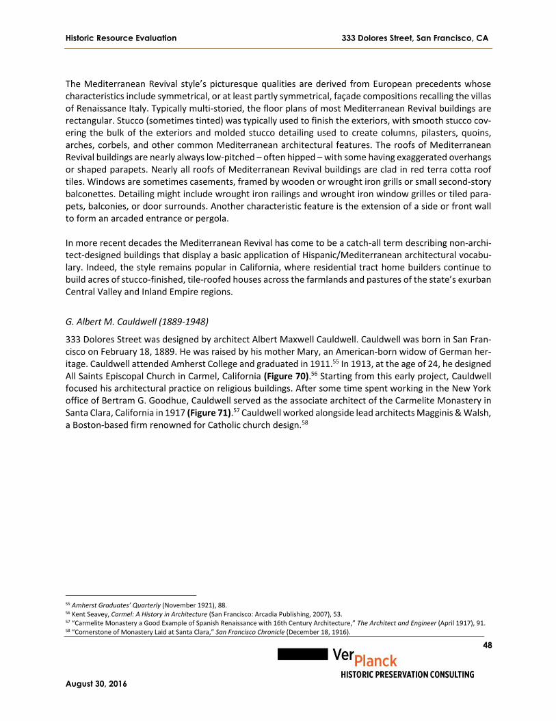
Historic Resource Evaluation 333 Dolores Street, San Francisco, CA
August 30, 2016
48
The Mediterranean Revival style’s picturesque qualities are derived from European precedents whose characteristics include symmetrical, or at least partly symmetrical, façade compositions recalling the villas of Renaissance Italy. Typically multi-storied, the floor plans of most Mediterranean Revival buildings are rectangular. Stucco (sometimes tinted) was typically used to finish the exteriors, with smooth stucco cov-ering the bulk of the exteriors and molded stucco detailing used to create columns, pilasters, quoins, arches, corbels, and other common Mediterranean architectural features. The roofs of Mediterranean Revival buildings are nearly always low-pitched – often hipped – with some having exaggerated overhangs or shaped parapets. Nearly all roofs of Mediterranean Revival buildings are clad in red terra cotta roof tiles. Windows are sometimes casements, framed by wooden or wrought iron grills or small second-story balconettes. Detailing might include wrought iron railings and wrought iron window grilles or tiled para-pets, balconies, or door surrounds. Another characteristic feature is the extension of a side or front wall to form an arcaded entrance or pergola. In more recent decades the Mediterranean Revival has come to be a catch-all term describing non-archi-tect-designed buildings that display a basic application of Hispanic/Mediterranean architectural vocabu-lary. Indeed, the style remains popular in California, where residential tract home builders continue to build acres of stucco-finished, tile-roofed houses across the farmlands and pastures of the state’s exurban Central Valley and Inland Empire regions.
G. Albert M. Cauldwell (1889-1948)
333 Dolores Street was designed by architect Albert Maxwell Cauldwell. Cauldwell was born in San Fran-cisco on February 18, 1889. He was raised by his mother Mary, an American-born widow of German her-itage. Cauldwell attended Amherst College and graduated in 1911.55 In 1913, at the age of 24, he designed All Saints Episcopal Church in Carmel, California (Figure 70).56 Starting from this early project, Cauldwell focused his architectural practice on religious buildings. After some time spent working in the New York office of Bertram G. Goodhue, Cauldwell served as the associate architect of the Carmelite Monastery in Santa Clara, California in 1917 (Figure 71).57 Cauldwell worked alongside lead architects Magginis & Walsh, a Boston-based firm renowned for Catholic church design.58
55 Amherst Graduates’ Quarterly (November 1921), 88. 56 Kent Seavey, Carmel: A History in Architecture (San Francisco: Arcadia Publishing, 2007), 53. 57 “Carmelite Monastery a Good Example of Spanish Renaissance with 16th Century Architecture,” The Architect and Engineer (April 1917), 91. 58 “Cornerstone of Monastery Laid at Santa Clara,” San Francisco Chronicle (December 18, 1916).

Historic Resource Evaluation 333 Dolores Street, San Francisco, CA
August 30, 2016
49
Figure 70. All Saints Episcopal Church, Carmel, California, 1913. Source: Car-
mel: A History in Architecture
Figure 71. Carmelite Monastery, Santa Clara, California, 1917.
Source: Architect and Engineer, April 1917
After this commission, Cauldwell shifted to working exclusively with Catholic clients. By October 1917, Cauldwell was the provincial architect for Dominican Sisters of San Rafael.59 That same month, he enlisted in the U. S. Army, and served with an engineering corps in France during World War I.60 He remained in Europe for a short time after his discharge in April 1919 and worked in Vienna for the American Relief Administration. In July 1920, Cauldwell received his professional certificate to practice architecture from the California State Board of Architecture and he established an office at 251 Kearny Street.61 In 1921, he was appointed the provincial architect for the Sisters of Mercy, and was charged with designing hospitals, schools, and old people’s homes for this order throughout California.62 In 1922, he received a commission to prepare plans for a three-story building at Dominican College (now Dominican University) in San Rafael (likely An-gelico Hall, completed 1922), as well as restoration plans for Mission Dolores.63 He lived during this time in Mill Valley, although by 1924 he had moved to San Francisco and lived at 780 Post Street. In January 1924, Cauldwell was named as the architect of the parish school of St. Thomas the Apostle, at 40th Avenue and Balboa Street, and in 1925 he completed St. Joseph’s Hall at 333 Dolores Street for the Sisters of Notre Dame.64 333 Dolores Street is Caudwell’s last known project; no further mention of any commissions or completed projects by Cauldwell appears in any professional journals or newspapers after 1925. In 1928, Cauldwell moved to a cottage at 309 Filbert Street on Telegraph Hill. In January 1930, he was arrested and charged with contributing to the delinquency of a minor, after a stabbing occurred at a party at his home, described as “one of those gay, mad parties favored by those who follow Fortune’s flickering light along the byways of Bohemia.”65 Cauldwell’s arrest was front-page news for several days, and although the charges against
59 “Brief Mentions of General Interest,” Marin Journal (October 11, 1917). 60 Internment Records for Golden Gate National Cemetery, “Albert M. Cauldwell,” January 9, 1948. 61 “Architects Granted Certificates,” The Architect and Engineer (July 1920), 134. 62 “Will Design Hospitals,” The Architect and Engineer (December 1921), 108. 63 Ibid. 64 “Church Marks New Catholic Parish in S. F.,” San Francisco Chronicle (January 4, 1924). 65 “Telegraph Hill Assault Laid [sic] To Row over Actress,” San Francisco Chronicle (January 20, 1930).
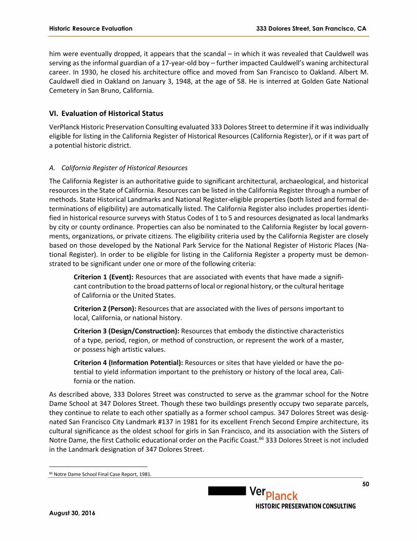
Historic Resource Evaluation 333 Dolores Street, San Francisco, CA
August 30, 2016
50
him were eventually dropped, it appears that the scandal – in which it was revealed that Cauldwell was serving as the informal guardian of a 17-year-old boy – further impacted Cauldwell’s waning architectural career. In 1930, he closed his architecture office and moved from San Francisco to Oakland. Albert M. Cauldwell died in Oakland on January 3, 1948, at the age of 58. He is interred at Golden Gate National Cemetery in San Bruno, California.
VI. Evaluation of Historical Status
VerPlanck Historic Preservation Consulting evaluated 333 Dolores Street to determine if it was individually eligible for listing in the California Register of Historical Resources (California Register), or if it was part of a potential historic district.
A. California Register of Historical Resources
The California Register is an authoritative guide to significant architectural, archaeological, and historical resources in the State of California. Resources can be listed in the California Register through a number of methods. State Historical Landmarks and National Register-eligible properties (both listed and formal de-terminations of eligibility) are automatically listed. The California Register also includes properties identi-fied in historical resource surveys with Status Codes of 1 to 5 and resources designated as local landmarks by city or county ordinance. Properties can also be nominated to the California Register by local govern-ments, organizations, or private citizens. The eligibility criteria used by the California Register are closely based on those developed by the National Park Service for the National Register of Historic Places (Na-tional Register). In order to be eligible for listing in the California Register a property must be demon-strated to be significant under one or more of the following criteria:
Criterion 1 (Event): Resources that are associated with events that have made a signifi-cant contribution to the broad patterns of local or regional history, or the cultural heritage of California or the United States.
Criterion 2 (Person): Resources that are associated with the lives of persons important to local, California, or national history.
Criterion 3 (Design/Construction): Resources that embody the distinctive characteristics of a type, period, region, or method of construction, or represent the work of a master, or possess high artistic values.
Criterion 4 (Information Potential): Resources or sites that have yielded or have the po-tential to yield information important to the prehistory or history of the local area, Cali-fornia or the nation.
As described above, 333 Dolores Street was constructed to serve as the grammar school for the Notre Dame School at 347 Dolores Street. Though these two buildings presently occupy two separate parcels, they continue to relate to each other spatially as a former school campus. 347 Dolores Street was desig-nated San Francisco City Landmark #137 in 1981 for its excellent French Second Empire architecture, its cultural significance as the oldest school for girls in San Francisco, and its association with the Sisters of Notre Dame, the first Catholic educational order on the Pacific Coast.66 333 Dolores Street is not included in the Landmark designation of 347 Dolores Street.
66 Notre Dame School Final Case Report, 1981.

Historic Resource Evaluation 333 Dolores Street, San Francisco, CA
August 30, 2016
51
333 Dolores Street was surveyed by the San Francisco Planning Department in 2004 as part of its Inner Mission North Historic Resource Survey. Although no property-specific research was conducted, the prop-erty was found individually eligible for listing in the California Register under Criterion 1 (Events) for its association with the settlement of San Francisco’s Mission District, and Criterion 3 (Architecture/Design) for its design, features, materials, and/or craftsmanship that embodies the distinctive characteristics and high artistic expression of Mediterranean Revival architecture. For this reason, the Planning Department assigned it the California Historical Resource Status Code of “3CS,” indicating that 333 Dolores Street ap-pears eligible for the California Register as an individual property through survey evaluation. In the fol-lowing analysis we analyze 333 Dolores Street for eligibility for the California Register based on the prop-erty-specific research included in this report. Criterion 1 (Events) 333 Dolores Street appears eligible for listing in the California Register under Criterion 1 (Event) as a build-ing that is associated with the cultural heritage of California. The building appears eligible for listing under this criterion because it was constructed by the Sisters of Notre Dame to serve as an expansion of the Notre Dame School at 347 Dolores Street. The Notre Dame School has already been determined to be historically significant both as the first school for girls in San Francisco, and for its association with the Sisters of Notre Dame, the first Catholic educational order on the Pacific Coast. The construction of 333 Dolores Street enabled the Sisters of Notre Dame to expand their teaching mission, and by 1931 there were five hundred and fifty girls attending school in the two buildings. Along with the ornamental gardens and playground between the two buildings, the Notre Dame Grammar School for Girls and the Notre Dame School formed a campus where several generations of Catholic girls were educated. The period of significance starts in 1925 when the building was constructed and ends in 1976, when a general decrease in Catholic school enrollment caused the Notre Dame Grammar School for Girls to merge with the Mission Dolores Boys’ School and become Mission Dolores School. Criterion 2 (Persons) 333 Dolores Street does not appear eligible for listing in the California Register under Criterion 2 (Persons). The building is not individually associated with any persons important to local, California, or national his-tory. Criterion 3 (Design/Construction) 333 Dolores Street appears eligible for listing in the California Register under Criterion 3 (Design/Construc-tion) as a building that embodies the distinctive characteristics of a type and period of construction. The building appears eligible for listing under this criterion as a well-preserved school building designed in the Mediterranean Revival style. The building includes almost all of the characteristic architectural details of this style, including broad, rectangular massing, L-plan footprint; three-story height; low-pitched hipped and pent roof clad in red terra cotta tiles; smooth stucco exterior walls; molded stucco columns and pilas-ters; overhanging eaves with shaped rafters; wood casement windows; and an open-air pergola with a colonnade and trellis. Despite some alterations made to the exterior and the interior of the building, it retains the characteristic layout of a school building, with large, well-lit classrooms accessed by wide, uni-fying corridors and stairs. There is little exterior ornament, which is characteristic of both the building’s use and its architectural style, though it does have some notable features – in particular the pergola and the Composite-order columns. The only notable interior design elements are the exposed heavy timber beams of the roof trusses, which are characteristic of the building’s Mediterranean Revival style. Although

Historic Resource Evaluation 333 Dolores Street, San Francisco, CA
August 30, 2016
52
some changes have been made to the entrances along the first floor level of the primary façade, and some upper floor level windows have been replaced with metal windows, the façade has undergone no other significant changes since the building was completed in 1925. The period of significance is 1925, the build-ing’s initial date of construction. Criterion 4 (Information Potential) Examination of 333 Dolores Street for eligibility under Criterion 4 is beyond the scope of this report. Cri-terion 4 relates to the potential presence of archeological materials at the site, which have been exten-sively documented in previous reports.
B. Integrity
If a property appears to qualify for listing in the California Register under at least one of the eligibility criteria, it must also be demonstrated to retain sufficient historic integrity. The concept of integrity is essential to identifying the important physical characteristics of historical resources and hence, in evalu-ating adverse changes to them. Integrity is defined as “the authenticity of an historical resource’s physical identity evidenced by the survival of characteristics that existed during the resource’s period of signifi-cance.”67 As outlined above, the period of significance for 333 Dolores Street is 1925-1976. The process of determining integrity is similar for both the California Register and the National Register. The same seven variables or aspects that define integrity—location, design, setting, materials, workmanship, feeling and association—are used to evaluate a resource’s eligibility for listing in the California Register and the National Register. According to the National Register Bulletin: How to Apply the National Register Criteria for Evaluation, these seven characteristics are defined as follows:
Location is the place where the historic property was constructed.
Design is the combination of elements that create the form, plans, space, structure and style of the property.
Setting addresses the physical environment of the historic property inclusive of the land-scape and spatial relationships of the building(s).
Materials refer to the physical elements that were combined or deposited during a par-ticular period of time and in a particular pattern of configuration to form the historic prop-erty.
Workmanship is the physical evidence of the crafts of a particular culture or people during any given period in history.
Feeling is the property’s expression of the aesthetic or historic sense of a particular period of time.
Association is the direct link between an important historic event or person and a historic property.
333 Dolores Street has not been moved from the place where it was constructed and therefore retains integrity of location. Despite some changes to the design of the building, including the insertion of six new doors at the primary (south) façade (four at the first floor level, one at the second floor level, and one at the third floor level); the construction of a new wheelchair ramp and entry platform on the east and west ends of the pergola; and the subdivision of the formerly open-plan third floor level into classrooms, the
67 California Office of Historic Preservation, Technical Assistant Series No. 7, How to Nominate a Resource to the California Register of Historic Resources (Sacramento: California Office of State Publishing, September 2001), 11.

Historic Resource Evaluation 333 Dolores Street, San Francisco, CA
August 30, 2016
53
vast majority of the elements that create the form, plans, space, structure and style of the building remain unaltered, so the building retains integrity of design. 333 Dolores Street retains integrity of setting be-cause the area around the building generally retains the buildings, landscape elements, and spatial rela-tionships that were present when it was constructed. The pre-fabricated classrooms on the south side of the schoolyard do not diminish the integrity of setting because their one-story height and distance from 333 Dolores Street maintain the open spatial relationship of the schoolyard. Integrity of materials is slightly diminished due to the removal of 17 original wood window units at the north façade, which were replaced with metal windows; removal of all or part of 11 original wood window units at the south façade, which were replaced by aluminum windows, fire doors, metal and wood doors, and reconfigured wood windows; and the removal of the original primary entrance door. Workmanship is not notably expressed in this building, due to its restrained architectural style and utilitarian use. How-ever, the modest expressions of workmanship present in the building, namely its molded stucco columns, trellis, roof trusses with shaped beam bracing, shaped exterior rafter tails, and terra cotta tile roof clad-ding, have not been altered and retain integrity. 333 Dolores Street retains integrity of feeling because the building, its surroundings, and its current use largely reflect the historic period in which the building was instructed. And lastly, 333 Dolores Street retains integrity of association because it was constructed as a school building and retains its historic use. Overall, despite slightly diminished integrity of materials, 333 Dolores Street retains good integrity. Character-defining Features
The character-defining features of a building are those features which enable the building to convey its appearance during the era of its historical significance. Thus, the character-defining features of 333 Dolores Street are those elements that were put in place between 1925 and 1976. The character-defining features of 333 Dolores Street include the following:
The building’s three-story height and L-plan footprint;
Compound roof with hipped, flat, and pent areas, including red terra cotta tile cladding;
Stucco cladding;
Ratio of solid to void at all four façades;
Typical window configuration of multi-light wood casement windows;
Location of the building’s two original entrances, at the south and west façades;
Engaged stucco columns at windows;
General arrangement of the open-air pergola, including low wall, columns, and heavy timber trel-lis;
Exposed shaped rafter tails;
Band of rough stucco beneath the eaves;
Stringcourse molding between the second and third floor levels, and slightly recessed façade pro-file above this molding;
Interior arrangement of corridors along the north side of the building and classrooms along the south side of the building;
Exposed wood truss system and shaped beam brackets.

Historic Resource Evaluation 333 Dolores Street, San Francisco, CA
August 30, 2016
54
VII. Evaluation of Project-specific Impacts
A. Project Description
The project sponsor is the Children’s Day School and the project architect is Jensen Architects of San Fran-cisco. This analysis is based on two drawing sets, dated May 21, 2016 and June 13, 2016. The scope of work for the proposed project includes changes to the roof, the exterior, and the interior of 333 Dolores Street. At the roof, the red terra cotta clay tiles would be removed and a 2” layer of rigid board insulation laid atop a new layer of plywood roof sheathing. The purpose of the plywood is to im-prove the building’s seismic performance and the purpose of the insulation is to improve the building’s climate control systems. This new layer of insulation would be shaved down toward the edge of the build-ing to minimize visual changes to the building’s roof profile. The existing tile would not be reused on the building, A) because it is too heavy and would compromise the proposed seismic retrofit scheme, B) be-cause it only has one attachment point making it susceptible to failure and possible injuries from falling tiles, and C) because breakage during the removal process would result in there being too few tiles to replace upon completion of the seismic work. The tiles along the perimeter eave would be installed using traditional “two-piece” method to replicate existing conditions; otherwise the new “S” tiles would be used. All of the proposed project’s exterior changes would occur at the building’s south façade. The non-historic fire-escape that spans the full height of the façade would be removed, and the metal fire doors at the second and third floor levels would also be removed, along with their transoms. The area of the façade below the sills where doors have been removed would be patched, and new wood casement windows that match the building’s original fenestration pattern would be installed. Likewise, the aluminum replace-ment windows at the fifth, eighth, and ninth bays of the third floor level would be removed and replaced with new wood casement windows that match the building’s original fenestration. These changes would restore the historic appearance of the second and third floor levels of the building’s primary façade. At the first floor level of the south façade, the floor of the existing pergola would be removed, including the concrete slab and the non-historic ramp, stair, and platform. A new concrete slab porch would be poured 2’ above the original grade of the pergola floor, creating a level, continuous grade across the front of the building. At the first (far left) bay, six four-light casement windows would be removed, and paired glass entry doors would be installed in their place. At the second and third bays, existing non-historic doors would be removed and replaced with wood multi-light doors. At the fifth bay, the primary entrance door and the sign above it that reads “St. Joseph’s Hall 1925” would be removed. The sill of the door opening would be raised to match the new grade of the pergola floor and widened. New paired glass entry doors would be installed in the opening. At the sixth bay, a portion of the multi-light window would be removed and a multi-light wood door with a sidelight would be installed in the opening. Access to the pergola from the schoolyard would be at three points – at left, center, and right – corre-sponding with the existing gaps in the pergola wall. At the left, a concrete landing would be constructed in front of the pergola, which would be accessed from the driveway/parking area by a ramp and from the schoolyard by a short stair. This landing would include bike parking, and the existing metal gate at the west perimeter of the schoolyard would be relocated to the right side of this landing. At the center, the pergola would be accessed by a straight concrete stair. At the right, the pergola would be accessed by a small landing, a ramp that runs alongside the pergola, and a straight concrete stair. All new stairs would

Historic Resource Evaluation 333 Dolores Street, San Francisco, CA
August 30, 2016
55
have ADA-compliant handrails and children’s handrails. A new metal railing with metal balustrades would be installed on top of the low pergola wall, between the existing columns. Proposed interior changes to 333 Dolores Street would be located on all three levels of the building. At the first floor level, the new entrance doors in the building’s first bay, described above, would open into a new lobby/reception area, which would include an office, a conference room, a new elevator, and a new stair. The elevator shaft foundation would be level with the existing building’s footings. A new door open-ing would connect the lobby/reception area to the kindergarten classroom at the far west end of the building. Other changes at the first floor level would include the construction of a new office at the west end of the corridor, the demolition of a portion of the central stair, and the construction of a new concrete floor at the same grade as the rest of the first floor level. At the second floor level, changes to the second floor would include the continuation of the elevator shaft and the new stairwell, removal of the existing sink in the corridor, and the construction of a door between the center stair and the classroom directly east of it. Proposed interior changes at the third floor level would include the continuation of the elevator shaft to the roof. New gypsum walls around the elevator would not disturb the location or arrangement of the exposed trusses.
B. Status of Existing Property as a Historical Resource
According to Section 15064.5 (a) of the California Environmental Quality Act (CEQA), a “historical re-source” is defined as a property belonging to at least one of the following three categories:
A resource listed in, or determined to be eligible by the State Historical Resources Com-mission, for listing in the California Register of Historical Resources (Pub. Res. Code SS5024.1, Title 14 CCR, Section 4850 et seq.);
A resource included in a local register of historical resources, as defined in Section 5020.1(k) of the Public Resources Code or identified as significant in an historical resource survey meeting the requirements of section 5024.1 (g) of the Public Resources Code, shall be presumed to be historically or culturally significant. Public agencies must treat any such resource as significant unless the preponderance of evidence demonstrates that it is not historically or culturally significant;
Any object, building, structure, site, area, place, record, or manuscript which a lead agency determines to be historically significant or significant in the architectural, engi-neering, scientific, economic, agricultural, educational, social, political, military, or cul-tural annals of California may be considered to be an historical resource, provided the lead agency’s determination is supported by substantial evidence in light of the whole record. Generally, a resource shall be considered by the lead agency to be “historically significant” if the resource meets the criteria for listing on the California Register of His-torical Resources (Pub. Res. Code SS5024.1, Title 14 CCR, Section 4852).
According to the Planning Department, 333 Dolores Street is classified as a Category A: “Known Historic Resource,” on the basis of its evaluation in the Department’s Inner Mission North Survey. The property has also been found individually eligible for listing in the California Register through formal evaluation in
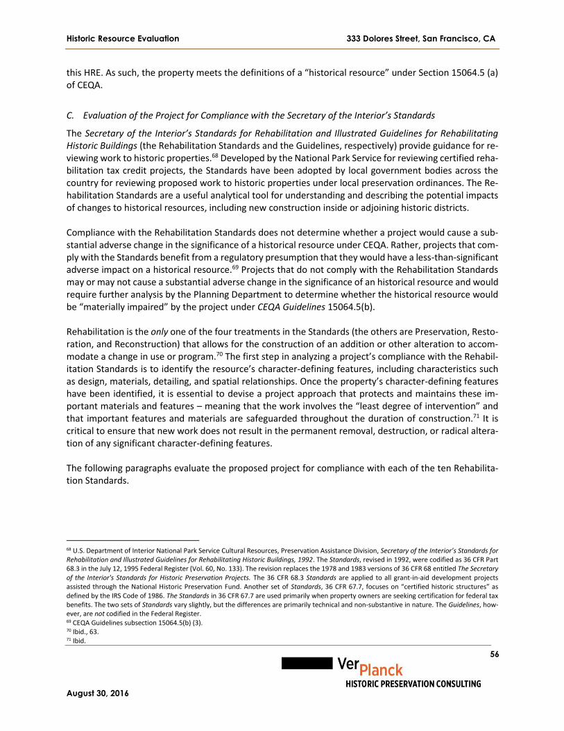
Historic Resource Evaluation 333 Dolores Street, San Francisco, CA
August 30, 2016
56
this HRE. As such, the property meets the definitions of a “historical resource” under Section 15064.5 (a) of CEQA.
C. Evaluation of the Project for Compliance with the Secretary of the Interior’s Standards
The Secretary of the Interior’s Standards for Rehabilitation and Illustrated Guidelines for Rehabilitating Historic Buildings (the Rehabilitation Standards and the Guidelines, respectively) provide guidance for re-viewing work to historic properties.68 Developed by the National Park Service for reviewing certified reha-bilitation tax credit projects, the Standards have been adopted by local government bodies across the country for reviewing proposed work to historic properties under local preservation ordinances. The Re-habilitation Standards are a useful analytical tool for understanding and describing the potential impacts of changes to historical resources, including new construction inside or adjoining historic districts. Compliance with the Rehabilitation Standards does not determine whether a project would cause a sub-stantial adverse change in the significance of a historical resource under CEQA. Rather, projects that com-ply with the Standards benefit from a regulatory presumption that they would have a less-than-significant adverse impact on a historical resource.69 Projects that do not comply with the Rehabilitation Standards may or may not cause a substantial adverse change in the significance of an historical resource and would require further analysis by the Planning Department to determine whether the historical resource would be “materially impaired” by the project under CEQA Guidelines 15064.5(b). Rehabilitation is the only one of the four treatments in the Standards (the others are Preservation, Resto-ration, and Reconstruction) that allows for the construction of an addition or other alteration to accom-modate a change in use or program.70 The first step in analyzing a project’s compliance with the Rehabil-itation Standards is to identify the resource’s character-defining features, including characteristics such as design, materials, detailing, and spatial relationships. Once the property’s character-defining features have been identified, it is essential to devise a project approach that protects and maintains these im-portant materials and features – meaning that the work involves the “least degree of intervention” and that important features and materials are safeguarded throughout the duration of construction.71 It is critical to ensure that new work does not result in the permanent removal, destruction, or radical altera-tion of any significant character-defining features. The following paragraphs evaluate the proposed project for compliance with each of the ten Rehabilita-tion Standards.
68 U.S. Department of Interior National Park Service Cultural Resources, Preservation Assistance Division, Secretary of the Interior’s Standards for Rehabilitation and Illustrated Guidelines for Rehabilitating Historic Buildings, 1992. The Standards, revised in 1992, were codified as 36 CFR Part 68.3 in the July 12, 1995 Federal Register (Vol. 60, No. 133). The revision replaces the 1978 and 1983 versions of 36 CFR 68 entitled The Secretary of the Interior's Standards for Historic Preservation Projects. The 36 CFR 68.3 Standards are applied to all grant-in-aid development projects assisted through the National Historic Preservation Fund. Another set of Standards, 36 CFR 67.7, focuses on “certified historic structures” as defined by the IRS Code of 1986. The Standards in 36 CFR 67.7 are used primarily when property owners are seeking certification for federal tax benefits. The two sets of Standards vary slightly, but the differences are primarily technical and non-substantive in nature. The Guidelines, how-ever, are not codified in the Federal Register. 69 CEQA Guidelines subsection 15064.5(b) (3). 70 Ibid., 63. 71 Ibid.

Historic Resource Evaluation 333 Dolores Street, San Francisco, CA
August 30, 2016
57
Rehabilitation Standard 1: A property will be used as it was historically or be given a new use that requires minimal change to its distinctive materials, features, spaces and spatial relationships. Discussion: The proposed project complies with Rehabilitation Standard 1 because it would not change the historic use of the building. 333 Dolores Street was constructed as a school and will continue to be used as a school after the proposed project is completed. Rehabilitation Standard 2: The historic character of a property will be retained and preserved. The removal of distinctive materials or alteration of features, spaces and spatial relationships that characterize the property will be avoided. Discussion: The proposed project would make changes to a very small proportion of the distinctive mate-rials and features of 333 Dolores Street. At the roof, the addition of a 2” layer of rigid board insulation would slightly alter the profile of the building’s roof, but not to a degree that it would to affect the build-ing’s overall proportions, or that it would alter the spatial relationship between 333 Dolores Street and its surroundings, including the two public vantage points from Dolores Street and 16th and Guerrero streets. At the exterior, small areas of the first floor level of the south façade would be removed to install three new entrances, altering both the ratio of solid-to-void and the fenestration pattern of the primary façade. These alterations would, however, have a minimal effect on the historic character of the building because of the small area affected and because the historic character of the upper stories of the primary façade would be restored and enhanced by the removal of the non-historic fire-escape, fire doors, and aluminum windows; and the restoration of the wood casement windows affected by the removal of the fire escape. At the pergola, the original concrete floor slab, as well as the non-historic ramp, stair and platform, would be removed and replaced by a continuous new slab that is 2’ higher than the original floor of the pergola, altering the spatial relationship between the pergola and the building. Also, the construction of three new stairs, two ramps, and two landings in front of the pergola would alter the spatial relationship between the pergola and the schoolyard. The effect of these changes is minimized by the fact that the grade change to the pergola would be concealed behind the low wall in front of the pergola, placing it out of direct view when looking at the building. Furthermore, the rest of the pergola would remain intact, including the low wall, the columns, the higher walls, and the trellis, all of which are character-defining features of the building. Within the interior, distinctive materials and character-defining spaces and spatial relationships are lim-ited to the exposed wood truss system and the general arrangement of classrooms along the south side and a single-loaded corridor along the north side of the building. The proposed project would not remove or alter any distinctive materials or make any changes to the spaces or spatial relationships that charac-terize the interior of the building. In conclusion, the proposed project complies with Rehabilitation Standard 2. Rehabilitation Standard 3: Each property will be recognized as a physical record of its time, place and use. Changes that create a false sense of historical development, such as adding conjectural features or ele-ments from other historic properties, will not be undertaken.

Historic Resource Evaluation 333 Dolores Street, San Francisco, CA
August 30, 2016
58
Discussion: The proposed project would not add any conjectural features or elements from other historic properties that would create a false sense of historical development. Restoration of the windows at the second and third floor levels on the primary façade will be based on both physical and documentary evi-dence, including the original drawings and historic photographs. Furthermore, the project sponsor will use salvaged window sashes from the first floor level to patch the voids where the metal fire doors will be removed. Newly introduced design elements, namely the two double-leaf entrances at the first floor level, would be made of glass panels to ensure that it is understood that they are contemporary features. In conclusion, the proposed project complies with Rehabilitation Standard 3. Rehabilitation Standard 4: Changes to a property that have acquired historic significance in their own right will be retained and preserved. Discussion: No post-1925 alterations to 333 Dolores Street have acquired significance in their own right. Although the aluminum windows on the south façade were installed during the building’s period of sig-nificance, they are not significant features worthy of retention because of their clear divergence from the building’s historic fenestration – most of which still survives. In conclusion, the proposed project complies with Rehabilitation Standard 4. Rehabilitation Standard 5: Distinctive materials, features, finishes and construction techniques or exam-ples of craftsmanship that characterize a property will be preserved. Discussion: The proposed project would preserve the majority of 333 Dolores Street’s distinctive materi-als, finishes, and construction techniques, including the remaining historic windows, molded stucco col-umns and ornament, the wood beams of the pergola’s trellis, and the distinctive wooden trusses and rafters at the third floor level. The only character-defining materials that would be removed are the red clay roof tiles. The existing tiles, which appear to be original, are beginning to crack and fail, with individual tiles occasionally falling three stories onto the playground. The existing tiles have to be removed in order to install the new roof diaphragm and the rigid board insulation. Removal of the tiles will result in breakage of at least 10 percent, meaning that there would not be enough to reinstall. Instead of reusing the existing tile, the project sponsor plans to install new lighter-weight tiles that match the original in terms of mate-rial, color, and profile. The new tiles are slightly wider to enable two points of attachment, making them much safer than the original. Each curved section is slightly wider than the existing tile and they are slightly thinner as well, reducing their weight, which will improve the building’s seismic performance. Because they are the same material as the existing tile, once they have weathered, it is unlikely that anyone who does not know that they have been replaced would be able to tell the difference. In conclusion, the proposed project complies with Rehabilitation Standard 5. Rehabilitation Standard 6: Deteriorated historic features will be repaired rather than replaced. Where the severity of deterioration requires replacement of a distinctive feature, the new feature will match the old in design, color, texture, and, where possible, materials. Replacement of missing features will be sub-stantiated by documentary and physical evidence.

Historic Resource Evaluation 333 Dolores Street, San Francisco, CA
August 30, 2016
59
Discussion: As discussed above under Rehabilitation Standard 5, for seismic safety reasons, the project sponsor intends to replace the terra cotta roof tile in kind. The existing tile is cracked and deteriorating and it is too heavy for the proposed seismic retrofitting plan. Instead of reusing the existing tile, the pro-ject sponsor has elected to use a thinner tile that otherwise matches the original tile in terms of material, color, and texture. Due to the roof’s height, pitch, and distance from public rights-of-way, it is unlikely that anyone would be able to tell the difference between existing conditions and post-construction con-ditions. Otherwise, the project sponsor plans to retain and repair any deteriorated historic features and materials, in particular the existing wood casement windows on the south, west, and east façades. Re-placement of missing window sashes will make use of salvaged window sashes from the new door open-ings. What cannot not be replaced with salvaged window sash materials will be fabricated to match what currently exists, as well as what appears on original drawings and historic photographs. In conclusion, the proposed project complies with Rehabilitation Standard 6. Rehabilitation Standard 7: Chemical or physical treatments, if appropriate, will be undertaken using the gentlest means possible. Treatments that cause damage to historic materials will not be used. Discussion: The proposed project does not include identify any chemical or physical treatments to 333 Dolores Street. In conclusion, the proposed project complies with Rehabilitation Standard 7. Rehabilitation Standard 8: Archeological resources will be protected and preserved in place. If such re-sources must be disturbed, mitigation measures will be undertaken. Discussion: Though archaeology is beyond the scope of this report, available records suggest that the subject property is likely one of the most potentially rich archeological sites in San Francisco. The proposed project would require very minimal subsurface excavation in the vicinity of the pergola. Though construc-tion of 333 Dolores Street in 1925 likely disturbed any potential archaeological resources within the pro-ject site, the project sponsor should abide by the Planning Department’s Standard Mitigation procedures for archaeological testing, monitoring, data recovery, and reporting. For this reason, the proposed project complies with Rehabilitation Standard 8. In conclusion, as long as the project sponsor follows the Planning Department’s protocols for archeological testing and recovery, the proposed project would comply with Rehabilitation Standard 8. Rehabilitation Standard 9: New additions, exterior alterations, or related new construction will not de-stroy historic materials, features, and spatial relationships that characterize the property. The new work shall be differentiated from the old and will be compatible with the historic materials, features, size, scale and proportion, and massing to protect the integrity of the property and its environment. Discussion: As described in more detail under Rehabilitation Standards 2 and 5, exterior alterations would affect a very small proportion of the building’s area and it would protect the majority of the historic ma-terials and features affected. Indeed, the proposed project would remove several previous alterations that currently detract from the building’s historic appearance, including the 1952 fire-escape and fire doors and the 1970 aluminum windows and restore the upper floor levels of the south façade to their

Historic Resource Evaluation 333 Dolores Street, San Francisco, CA
August 30, 2016
60
historic appearance with wood casement sashes from the new entrances at the first floor level. The spatial relationship between the building and its surrounding context would not be affected by the insertion of rigid board insulation and replacement tiles on the roof, or by the reconfiguration of the pergola floor to match the grade of the first floor level. The two new entrances on the south façade would contain con-temporary glass doors, making it clear what is new and what is old. In conclusion, the proposed project complies with Rehabilitation Standard 9. Rehabilitation Standard 10: New additions and adjacent or related new construction will be undertaken in such a manner that, if removed in the future, the essential form and integrity of the historic property and its environment would be unimpaired. Discussion: If the changes included in the proposed project were to be removed in the future, the affected areas – namely the roof profile, the pergola, and the portions of the first floor level of the south façade where new door openings will be inserted – could be reconstructed and/or patched to match the build-ing’s historic appearance, and the essential form and integrity of the building would be unimpaired. In conclusion, the proposed project complies with Rehabilitation Standard 10. Summary of Standards Compliance: The proposed project complies with all ten Rehabilitation Standards.

Historic Resource Evaluation 333 Dolores Street, San Francisco, CA
August 30, 2016
61
VIII. Conclusion
333 Dolores Street was designed by architect Albert M. Cauldwell and constructed in 1925 for the Sisters of Notre Dame to serve as the grammar school building for the Notre Dame School for Girls. The San Francisco Planning Department found the building to be historically significant in 2004 as part of the Inner Mission North Survey. The Planning Department preliminarily concluded that the building is significant for its association with the settlement and cultural evolution of San Francisco’s Mission District, and for its high artistic expression of Mediterranean Revival architecture. After property-specific research and eval-uation, this report confirms the preliminary findings of the Planning Department in regard to 333 Dolores Street. 333 Dolores Street appears eligible for listing in the California Register under Criterion 1 (Events) for its association with the Sisters of Notre Dame and the Notre Dame School, which was the first girls’ school in San Francisco, and under Criterion 3 (Design/Construction) as a building that embodies the dis-tinctive characteristics of the Mediterranean Revival style. 333 Dolores Street is also a good and reasona-bly well-preserved example of a parochial school constructed by the Archdiocese of San Francisco during the heyday of Catholic education in San Francisco. The period of significance is 1925-1976, beginning with the building’s original construction and ending with the merger of Notre Dame School for Girls with the nearby Mission Dolores Boys School (now Mission Dolores Academy). The proposed project by Children’s Day School (CDS), which is designed by Jensen Architects, includes structural upgrades, a new elevator and interior stairs, new entrances to the building, changes to the interior of the first floor level to improve security, restoration of the historic appearance of the building’s south façade, and changes to the pergola to make it ADA-compliant. The proposed project complies with all ten of the Secretary of the Interior’s Standards for Rehabilitation.

(This page intentionally left blank)


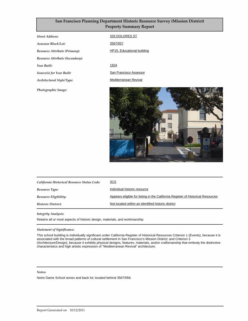
San Francisco Planning Department Historic Resource Survey (Mission District)
Property Summary Report
HP15. Educational building
1924
San Francisco Assessor
Mediterranean Revival
Retains all or most aspects of historic design, materials, and workmanship.
3CS
Individual historic resource
Appears eligible for listing in the California Register of Historical Resources
Not located within an identified historic district
Notre Dame School annex and back lot; located behind 3567/056.
Street Address:
Assessor Block/Lot:
Resource Attribute (Primary):
Resource Attribute (Secondary):
Year Built:
Source(s) for Year Built:
Architectural Style/Type:
Integrity Analysis:
California Historical Resource Status Code:
Resource Type:
Resource Eligibility:
Historic District:
Notes:
333 DOLORES ST
3567/057
Photographic Image:
Statement of Significance:
This school building is individually significant under California Register of Historical Resources Criterion 1 (Events), because it is associated with the broad patterns of cultural settlement in San Francisco’s Mission District; and Criterion 3 (Architecture/Design), because it exhibits physical designs, features, materials, and/or craftsmanship that embody the distinctive characteristics and high artistic expression of "Mediterranean Revival" architecture.
Located in Department files
10/12/2011Report Generated on

(This page intentionally left blank)

PRESERVATION BRIEFS
The Use of Substitute Materials on Historic Building Exteriors
Sharon C. Park, AlA
U.S. Department of the Interior National Park Service Cultural Resources
Heritage Preservation Services
·",; •
The Secretary of the Interior's Standards for Rehabilitation require that "deteriorated architectural features be repaired rather than replaced, wherever possible. In the event that replacement is necessary, the new material should match the material being replaced in composition, design, color, texture, and other visual properties." Substitute materials should be used only on a limited basis and only when they will match the appearance and general properties of the historic material and will not damage the historic resource .
Introduction When deteriorated, damaged, or lost features of a historic building need repair or replacement, it is almost always best to use historic materials. In limited circumstances substitute materials that imitate historic materials may be used if the appearance and properties of the historic materials can be matched closely and no damage to the remaining historic fabric will result.
Great care must be taken if substitute materials are used on the exteriors of historic buildings. Ultra-violet light, moisture penetration behind joints, and stresses caused by changing temperatures can greatly impair the performance of substitute materials over time . Only after consideration of all options, in consultation with qualified professionals, experienced fabricators and contractors, and development of carefully written specifications should this work be undertaken.
The practice of using substitute materials in architecture is not new, yet it continues to pose practical problems and to raise philosophical questions. On the practical level the inappropriate choice or improper installation of substitute materials can cause a radical change in a building's appearance and can cause extensive physical damage over time . On the more philosophical level, the wholesale use of substitute materials can raise questions concerning the integrity of historic buildings largely comprised of new materials. In both cases the integrity of the historic resource can be destroyed.
Some preservationists advocate that substitute materials should be avoided in all but the most limited cases. The fact is, however, that substitute materials are being used more frequently than ever in preservation projects, and in many cases with positive results. They can be cost-effective, can permit
the accurate visual duplication of historic materials, and last a reasonable time. Growing evidence indicates that with proper planning, careful specifications and supervision, substitute materials can be used successfully in the process of restoring the visual appearance of historic resources.
This Brief provides general guidance on the use of substitute materials on the exteriors of historic buildings. While substitute materials are frequently used on interiors, these applications are not subject to weathering and moisture penetration, and will not be discussed in this Brief. Given the general nature of this publication, specifications for substitute materials are not provided. The guidance provided should not be used in place of consultations with qualified professionals . This Brief includes a discussion of when to use substitute materials, cautions regarding their expected performance, and descriptions of several substitute materials, their advantages and disadvantages . This review of materials is by no means comprehensive, and attitudes and findings will change as technology develops.
Historical Use of Substitute Materials The tradition of using cheaper and more common materials in imitation of more expensive and less available materials is a long one. George Washington, for example, used wood painted with sandimpregnated paint at Mount Vernon to imitate cut ashlar stone. This technique along with scoring stucco into block patterns was fairly common in colonial America to imitate stone (see illus. 1, 2).
Molded or cast masonry substitutes, such as drytamp cast stone and poured concrete, became popular in place of quarried stone during the 19th century. These masonry units were fabricated locally, avoiding

Illus. 1. An early 18th-century technique for imitating caroed or quarried stone was the use of sand-impregnated paint applied to wood. The facade stones and quoins are of wood. The Lindens (1754), Washington, D.C. Photo: Sharon C. Park, AlA.
Illus. 3. Casting concrete to represent quarried stone was a popular late 19th-century technique seen in this circa 1910 mailorder house. While most components were delivered by rail, the foundations and exterior masonry were completed by local craftsmen. Photo: Sharon C. Park, AlA.
expensive quarrying and shipping costs, and were versatile in representing either ornately carved blocks, plain wall stones or rough cut textured surfaces . The end result depended on the type of patterned or textured mold used and was particularly popular in conjunction with mail order houses (see illus . 3) . Later, panels of cementitious perma-stone or formstone and less expensive asphalt and sheet metal panels were used to imitate brick or stone.
Metal (cast, stamped, or brake-formed) was used for storefronts, canopies, railings, and other features, such as galvanized metal cornices substituting for wood or stone, stamped metal panels for Spanish clay roofing tiles, and cast-iron column capitals and even entire building fronts in imitation of building stone (see illus. no. 4).
Terra cotta, a molded fired clay product, was itself a substitute material and was very popular in the late 19th and early 20th centuries. It simulated the ap-2
Illus . 2. Stucco has for many centuries represented a number of building materials. Seen here is the ground floor of a Beaux Arts mansion, circa 1900, which represents a finely laid stone foundation wall executed in scored stucco. Photo: Sharon C. Park, AlA.
Illus. 4. The 19th-century also produced a variety of metal products used in imitation of other materials. In this case, the entire exterior of the Long Island Safety Deposit Company is cast-iron representing stone. Photo: Becket Logan, Friends of Cast Iron Architecture.
pearance of intricately carved stonework, which was expensive and time-consuming to produce. Terra cotta could be glazed to imitate a variety of natural stones, from brownstones to limestones, or could be colored for a polychrome effect.
Nineteenth century technology made a variety of materials readily available that not only were able to imitate more expensive materials but were also cheaper to fabricate and easier to use. Throughout the century, imitative materials continued to evolve. For example, ornamental window hoods were originally made of wood or carved stone. In an effort to find a cheaper substitute for carved stone and to speed fabrication time, cast stone, an early form of concrete, or cast-iron hoods often replaced stone. Toward the end of the century, even less expensive sheet metal hoods, imitating stone, also came into widespread use. All of these materials, stone, cast stone, cast-iron, and various pressed metals were in

a b
c
Illus. 5. The four historic examples of various window hoods shown are: (a) stone; (b) cast stone; (c) cast-iron; and (d) sheet metal. The criteria for selecting substitute materials today (availability, quality, delivery dates, cost) are not much different from the past. Photo: Sharon C. Park, AlA.
production at the same time and were selected on the basis of the availability of materials and local craftsmanship, as well as durability and cost (see illus. 5). The criteria for selection today are not much different.
Many of the materials used historically to imitate other materials are still available. These are often referred to as the traditional materials: wood, cast stone, concrete, terra cotta and cast metals. In the last few decades, however, and partly as a result of the historic preservation movement, new families of synthetic materials, such as fiberglass, acrylic polymers, and epoxy resins, have been developed and are being used as substitute materials in construction. In some respects these newer products (often referred to as high tech materials) show great promise; in others, they are less satisfactory, since they are often difficult to integrate physically with the porous historic materials and may be too new to have established solid performance records.
When to Consider Using Substitute Materials in Preservation Projects Because the overzealous use of substitute materials can greatly impair the historic character of a historic structure, all preservation options should be explored thoroughly before substitute materials are used. It is important to remember that the purpose of repairing damaged features and of replacing lost and irreparably damaged ones is both to match visually what was there and to cause no further deterioration. For these reasons it is not appropriate to cover up historic materials with synthetic materials that will alter the appearance, proportions and details of a historic building and that will conceal future deterioration (see illus. 6).
Some materials have been used successfully for the repair of damaged features such as epoxies for wood infilling, cementitious patching for sandstone repairs, or plastic stone for masonry repairs. Repairs are preferable to replacement whether or not the repairs are in kind or with a synthetic substitute material (see illus. 7).
In general, four circumstances warrant the consideration of substitute materials: 1) the unavailability of historic materials; 2) the unavailability of skilled craftsmen; 3) inherent flaws in the original materials; and 4) code-required changes (which in many cases can be extremely destructive of historic resources).
Cost mayor may not be a determining factor in considering the use of substitute materials. Depending on the area of the country, the amount of material needed, and the projected life of less durable substitute materials, it may be cheaper in the long run to use the original material, even though it may be harder to find. Due to many early failures of substitute materials, some preservationist are looking abroad to find materials (especially stone) that match the historic materials in an effort to restore historic
Illus . 6. Substitute materials should never be considered as a cosmetic cover-up for they can cause great physical damage and can alter the appearance of historic buildings. For example, a fiberglass coating was used at Ranchos de Taos, NM, in place of the historic adobe coating which had deteriorated. The waterproof coating sealed moisture in the walls and caused the sfXllIing shown. It was subsequently removed and the walls were properly repaired with adobe. Photo: Lee H. Nelson, FAlA.
3
Illus . 7. Whenever possible, historic materials should be repaired rather than replaced. Epoxy, a synthetic resin, has been used to repair the wood window frame and sill at the Auditors Building (1878) Washington, DC. The cured resin is white in this photo and will be primed and painted. Photo: Lee H. Nelson, FAIA.
Illus. 9. Simple solutions should not be overlooked when materials are no longer available. In the case of the Morse-Libby Mansion (1859) , Portland, ME, the deteriorated brownstone porch beam was replaced with a carved wooden beam painted with sand impregnated paint. Photo: Stephen Sewall.
buildings accurately and to avoid many of the uncertainties that come with the use of substitute materials.
1. The unavailability of the historic material. The most common reason for considering substitute materials is the difficulty in finding a good match for the historic material (particularly a problem for masonry materials where the color and texture are derived from the material itself). This may be due to the actual unavailability of the material or to protracted delivery dates. For example, the local quarry that supplied the sandstone for a building may no longer be in operation. All efforts should be made to locate another quarry that could supply a satisfactory match (see illus. 8) . If this approach fails, substitute materials such as dry-tamp cast stone or textured precast concrete may be a suitable substitute if care is taken to ensure that the detail, color and texture of the original stone are matched. In some cases, it may be possible to use a sand-impregnated paint on wood 4
Illus . 8. Even when materials are not locally available, it may be possible and cost effective to find sources elsewhere. For example, the local sandstone was no longer available for the restoration of the New York Shakespeare Festival Public Theater. The deteriorated sandstone window hoods, were replaced with stone from Germany that closely matched the color and texture of the historic sandstone. Photo: John G. Waite.
Illus . 10. The use of substitute materials is not necessarily cheaper or easier than using the original materials. The complex process of fabricating the polyester bronze reproduction pieces of the gilded wood molding for the clockcase at Independence Hall required talented artisans and substantial mold-making time. From left to right is the final molded polyester bronze detail; the plaster casting mold; the positive and negative interim neoprene rubber molds; and the expertly carved wooden master. Photo: Courtesy of Independence National Historical Park.
as a replacement section, achieved using readily available traditional materials, conventional tools and work skills. (see illus. 9). Simple solutions should not be overlooked.
2. The unavailability of historic craft techniques and lack of skilled artisans. These two reasons complicate any preservation or rehabilitation project. This is particularly true for intricate ornamental work, such as carved wood, carved stone, wrought iron, cast iron, or molded terra cotta. However, a number of stone and wood cutters now employ sophisticated carving machines, some even computerized. It is also possible to cast substitute replacement pieces using

Illus. 11. The unavailability of historic craft techniques is another reason to consider substitute materials. The original first floor cast iron front of the Grand Opera House, Wilmington, DE, was missing; the expeditious reproduction in cast aluminum was possible because artisans working in this medium were available. Photo: John G. Waite.
aluminum, cast stone, fiberglass, polymer concretes, glass fiber reinforced concretes and terra cotta. Mold making and casting takes skill and craftsmen who can undertake this work are available. (see illus. 10, 11). Efforts should always be made, prior to replacement, to seek out artisans who might be able to repair ornamental elements and thereby save the historic features in place.
3. Poor original building materials. Some historic building materials were of inherently poor quality or their modern counterparts are inferior. In addition, some materials were naturally incompatible with other materials on the building, causing staining or galvanic corrosion. Examples of poor quality materials were the very soft sandstones which eroded quickly. An example of poor quality modern replacement material is the tin coated steel roofing which is much less durable than the historic tin or terne iron which is no longer available. In some cases, more durable natural stones or precast concrete might be available as substitutes for the soft stones and modern ternecoated stainless steel or lead-coated copper might produce a more durable yet visually compatible replacement roofing (see illus. 12).
4. Code-related changes. Sometimes referred to as life and safety codes, building codes often require changes to historic buildings. Many cities in earthquake zones, for example, have laws requiring that overhanging masonry parapets and cornices, or freestanding urns or finials be securely reanchored to new structural frames or be removed completely. In some cases, it may be acceptable to replace these heavy historic elements with light replicas (see illus. 13). In other cases, the extent of historic fabric removed may be so great as to diminish the integrity of the resource. This could affect the significance of the structure and jeopardize National Register status. In addition, removal of repairable historic materials could result in loss of Federal tax credits for rehabilitation. Department of the Interior regulations make
Illus . 12. Substitute materials may be considered when the original materials have not performed well. For example, early sheet metals used for roofing, such as tinplate, were reasonably durable, but the modem equivalent, terne-coated steel, is subject to corrosion once the thin tin plating is damaged. Terne-coated stainless steel or lead-coated copper (shown here) are now used as substitutes. Photo: John G. Waite.
Illus . 13. Code-related changes are of concern in historic preservation projects because the integrity of the historic resource may be irretrievably affected. In the case of the Old San Francisco Mint, the fiberglass cornice was used to bring the building into seismic conformance. The original cornice was deteriorated, and the replacement (1982) was limited to the projecting pediment. The historic stone fascia was retained as were the stone columns. The limited replacement of deteriorated material did not jeopardize the integrity of the building. Photo: Walter M. Sontheimer.
clear that the Secretary of the Interior's Standards for Rehabilitation take precedence over other regulations and codes in determining whether a project is consistent with the historic character of the building undergoing rehabilitation.
Two secondary reasons for considering the use of substitute materials are their lighter weight and for some materials, a reduced need of maintenance. These reasons can become important if there is a
5
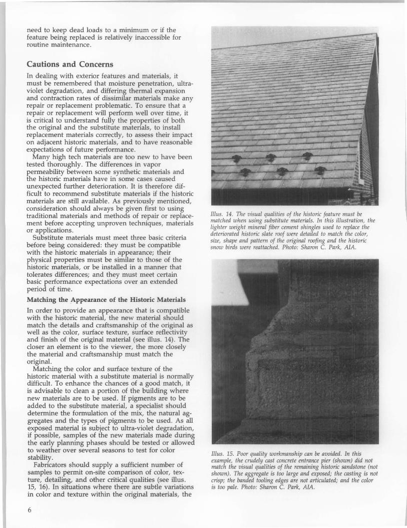
need to keep dead loads to a minimum or if the feature being replaced is relatively inaccessible for routine maintenance.
Cautions and Concerns In dealing with exterior features and materials, it must be remembered that moisture penetration, ultraviolet degradation, and differing thermal expansion and contraction rates of dissimilar materials make any repair or replacement problematic. To ensure that a repair or replacement will perfonn well over time, it is critical to understand fully the properties of both the original and the substitute materials, to install replacement materials correctly, to assess their impact on adjacent historic materials, and to have reasonable expectations of future performance.
Many high tech materials are too new to have been tested thoroughly. The differences in vapor permeability between some synthetic materials and the historic materials have in some cases caused unexpected further deterioration. It is therefore difficult to recommend substitute materials if the historic materials are still available . As previously mentioned, consideration should always be given first to using traditional materials and methods of repair or replacement before accepting unproven techniques, materials or applications.
Substitute materials must meet three basic criteria before being considered: they must be compatible with the historic materials in appearance; their physical properties must be similar to those of the historic materials, or be installed in a manner that tolerates differences; and they must meet certain basic performance expectations over an extended period of time.
Matching the Appearance of the Historic Materials
In order to provide an appearance that is compatible with the historic material, the new material should match the details and craftsmanship of the original as well as the color, surface texture, surface reflectivity and finish of the original material (see illus. 14). The closer an element is to the viewer, the more closely the material and craftsmanship must match the original.
Matching the color and surface texture of the historic material with a substitute material is normally difficult. To enhance the chances of a good match, it is advisable to clean a portion of the building where new materials are to be used. If pigments are to be added to the substitute material, a specialist should determine the formulation of the mix, the natural aggregates and the types of pigments to be used. As all exposed material is subject to ultra-violet degradation, if possible, samples of the new materials made during the early planning phases should be tested or allowed to weather over several seasons to test for color stability.
Fabricators should supply a sufficient number of samples to permit on-site comparison of color, texture, detailing, and other critical qualities (see illus. 15, 16). In situations where there are subtle variations in color and texture within the original materials, the
6
Illus . 14. The visual qualities of the historic feature must be matched when using substitute materials. In this illustration, the lighter weight mineral fiber cement shingles used to replace the deteriorated historic slate roof were detailed to match the color, size, shape and pattern of the original roofing and the historic snow birds were reattached. Photo: Sharon C. Park, AlA.
Illus. 15. Poor quality workmanship can be avoided. In this example, the crudely cast concrete entrance pier (shown) did not match the visual qualities of the remaining historic sandstone (not shown) . The aggregate is too large and exposed; the casting is not crisp; the banded tooling edges are not articulated; and the color is too pale. Photo: Sharon C. Park, AIA.

Illus. 16. The good quality substitute materials shown here do match the historic sandstone in color, texture, tooling and surface details. Dry-tamp cast stone was used to match the red sandstone that was no longer available. The reconstructed first floor incorporated both historic and substitute materials. Sufficient molds were made to avoid the problem of detecting the substitutes by their uniformity. Photo: Sharon C. Park, AlA.
Illus . 17. Care must be taken to ensure that the replacement materials will work within a predesigned system. At the Norris Museum, Yellowstone National Park, the 12-inch diameter log rafters, part of an intricate truss system, had rotted at the inner core from the exposed ends back to a depth of 48 inches. The exterior wooden shells remained intact. Fiberglass rods (left photo) and specially formulated structural epoxy were used to fill the cleaned out cores and a cast epoxy wafer end with all the detail of the original wood graining was laminated onto the log end (right photo). This treatment preserved the original feature with a combination of repair and replacement using substitute materials as part of a well thought out system. Photos: Courtesy of Harrison Goodall.
substitute materials should be similarly varied so that they are not conspicuous by their uniformity.
Substitute materials, notably the masonry ones, may be more water-absorbent than the historic material. If this is visually distracting, it may be appropriate to apply a protective vapor-permeable coating on the substitute material. However, these clear coatings tend to alter the reflectivity of the material, must be reapplied periodically, and may trap salts and moisture, which can in turn produce spalling. For these reasons, they are not recommended for use on historic materials.
Illus . 18. Substitute materials must be properly installed to allow for expansion, contraction, and structural security. The new balustrade (a polymer concrete modified with glass fibers) at Carnegie Hall, New York City, was installed with steel structural supports to allow window-washing equipment to be suspended securely. In addition, the formulation of this predominantly epoxy material allowed for the natural expansion and contradion within the predesigned joints. Photo: Courtesy of MJM Studios.
Matching the Physical Properties
While substitute materials can closely match the appearance of historic ones, their physical properties may differ greatly. The chemical composition of the material (i.e., presence of acids, alkalines, salts, or metals) should be evaluated to ensure that the replacement materials will be compatible with the historic resource . Special care must therefore be taken to integrate and to anchor the new materials properly (see illus. 17). The thermal expansion and contraction coefficients of each adjacent material must be within tolerable limits. The function of joints must be understood and detailed either to eliminate moisture penetration or to allow vapor permeability. Materials that will cause galvanic corrosion or other chemical reactions must be isolated from one another.
To ensure proper attachment, surface preparation is critical. Deteriorated underlying material must be cleaned out. Non-corrosive anchoring devices or fasteners that are designed to carry the new material and to withstand wind, snow and other destructive elements should be used (see illus. 18). Properly chosen fasteners allow attached materials to expand and contract at their own rates. Caulking, flexible sealants or expansion joints between the historic material and the substitute material can absorb slight differences of movement. Since physical failures often result from poor anchorage or improper installation techniques, a structural engineer should be a member of any team undertaking major repairs.
Some of the new high tech materials such as epoxies and polymers are much stronger than historic materials and generally impermeable to moisture. These differences can cause serious problems unless the new materials are modified to match the expansion and contraction properties of adjacent historic materials more closely, or unless the new materials
7

are isolated from the historic ones altogether. When stronger or vapor impermeable new materials are used alongside historic ones, stresses from trapped moisture or differing expansion and contraction rates generally hasten deterioration of the weaker historic material. For this reason, a conservative approach to repair or replacement is recommended, one that uses more pliant materials rather than high-strength ones (see illus. 19). Since it is almost impossible for substitute materials to match the properties of historic materials perfectly, the new system incorporating new and historic materials should be designed so that if material failures occur, they occur within the new material rather than the historic material.
Performance Expectations
While a substitute material may appear to be acceptable at the time of installation, both its appearance and its performance may deteriorate rapidly. Some materials are so new that industry standards are not available, thus making it difficult to specify quality control in fabrication, or to predict maintenance requirements and long term performance. Where possible, projects involving substitute materials in similar circumstances should be examined. Material specifications outlining stability of color and texture; compressive or tensile strengths if appropriate; the acceptable range of thermal coefficients, and the durability of coatings and finishes should be included in the contract documents. Without these written documents, the owner may be left with little recourse if failure occurs (see illus. 20, 21).
The tight controls necessary to ensure long-term performance extend beyond having written performance standards and selecting materials that have a successful track record. It is important to select qualified fabricators and installers who know what they are · doing and who can follow up if repairs are necessary. Installers and contractors unfamiliar with specific substitute materials and how they function in your local environmental conditions should be avoided.
The surfaces of substitute materials may need special care once installed. For example, chemical residues or mold release agents should be removed completely prior to installation, since they attract pollutants and cause the replacement materials to appear dirtier than the adjacent historic materials. Furthermore, substitute materials may require more frequent cleaning, special cleaning products and protection from impact by hanging window-cleaning scaffolding. Finally, it is critical that the substitute materials be identified as part of the historical record of the building so that proper care and maintenance of all the building materials continue to ensure the life of the historic resource.
8
Illus. 19. When the physical properties are not matched, particularly thermal expansion and contraction properties, great damage can occur. In this case, an extremely rigid epoxy replacement unit was installed in a historic masonry wall . Because the epoxy was not modified with fillers, it did not expand or contract systematically with the natural stones in the wall surrounding it. Pressure built up resulting in a vertical crack at the center of the unit, and spalled edges to every historic stone that was adjacent to the rigid unit. Photo: Walter M. Sontheimer.
Illus. 20. Long-term performance can be affected by where the substitute material is located. In this case, fiberglass was used as part of a storefront at street level. Due to the brittle nature of the material and the frequency of impact likely to occur at this location, an unsightly chip has resulted. Photo: Sharon C. Park, AIA.
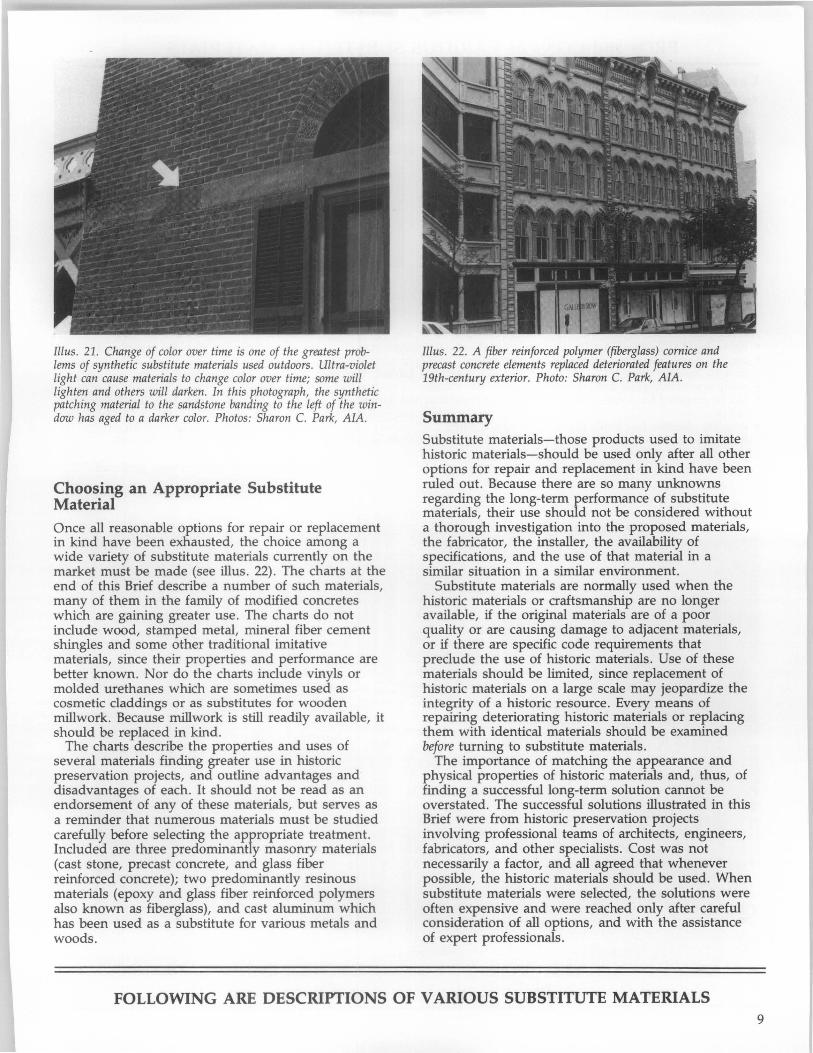
Illus . 21. Change of color over time is one of the greatest problems of synthetic substitute materials used outdoors. Ultra-violet light can cause materials to change color over time; some will lighten and others will darken. In this photograph, the synthetic patching material to the sandstone banding to the left of the window has aged to a darker color. Photos: Sharon C. Park, AlA.
Choosing an Appropriate Substitute Material Once all reasonable options for repair or replacement in kind have been exhausted, the choice among a wide variety of substitute materials currently on the market must be made (see illus. 22). The charts at the end of this Brief describe a number of such materials, many of them in the family of modified concretes which are gaining greater use. The charts do not include wood, stamped metal, mineral fiber cement shingles and some other traditional imitative materials, since their properties and performance are better known. Nor do the charts include vinyls or molded urethanes which are sometimes used as cosmetic claddings or as substitutes for wooden millwork. Because millwork is still readily available, it should be replaced in kind.
The charts describe the properties and uses of several materials finding greater use in historic preservation projects, and outline advantages and disadvantages of each. It should not be read as an endorsement of any of these materials, but serves as a reminder that numerous materials must be studied carefully before selecting the appropriate treatment. Included are three predominantly masonry materials (cast stone, precast concrete, and glass fiber reinforced concrete); two predominantly resinous materials (epoxy and glass fiber reinforced polymers also known as fiberglass), and cast aluminum which has been used as a substitute for various metals and woods.
Illus. 22. A fiber reinforced polymer (fiberglass) cornice and precast concrete elements replaced deteriorated features on the 19th-century exterior. Photo: Sharon C. Park, AlA.
Summary Substitute materials-those products used to imitate historic materials-should be used only after all other options for repair and replacement in kind have been ruled out. Because there are so many unknowns regarding the long-term performance of substitute materials, their use should not be considered without a thorough investigation into the proposed materials, the fabricator, the installer, the availability of specifications, and the use of that material in a similar situation in a similar environment.
Substitute materials are normally used when the historic materials or craftsmanship are no longer available, if the original materials are of a poor quality or are causing damage to adjacent materials, or if there are specific code requirements that preclude the use of historic materials. Use of these materials should be limited, since replacement of historic materials on a large scale may jeopardize the integrity of a historic resource. Every means of repairing deteriorating historic materials or replacing them with identical materials should be examined before turning to substitute materials.
The importance of matching the appearance and physical properties of historic materials and, thus, of finding a successful long-term solution cannot be overstated. The successful solutions illustrated in this Brief were from historic preservation projects involving profeSSional teams of architects, engineers, fabricators, and other specialists. Cost was not necessarily a factor, and all agreed that whenever possible, the historic materials should be used. When substitute materials were selected, the solutions were often expensive and were reached only after careful consideration of all options, and with the assistance of expert professionals.
FOLLOWING ARE DESCRIPTIONS OF VARIOUS SUBSTITUTE MATERIALS 9

PROs and CONs of VARIOUS SUBSTITUTE MATERIALS
Cast Aluminum Material: Cast aluminum is a molten aluminum alloy cast in permanent (metal) molds or one-time sand molds which must be adjusted for shrinkage during the curing process. Color is from paint applied to primed aluminum or from a factory finished coating. Small sections can be bolted together to achieve intricate or sculptural details. Unit castings are also available for items such as column plinth blocks.
Application: Cast aluminum can be a substitute for castiron or other decorative elements. This would include grillwork, roof crestings, cornices, ornamental spandrels, storefront elements, columns, capitals, and column bases and plinth blocks. If not self-supporting, elements are generally screwed or bolted to a structural frame. As a result of galvanic corrosion problems with dissimilar metals, joint details are very important.
Close-up detail showing the crisp casting in aluminum of this 19th-century replica column and capital for a storefront. Photo:
Advantages: • light weight (112 of cast-iron) • corrosion-resistant, non-combustible • intricate castings possible • easily assembled, good delivery time • can be prepared for a variety of
colors • long life, durable, less brittle than
cast iron
Sharon C. Park, AlA.
Disadvantages: • lower structural strength than
cast-iron • difficult to prevent galvanic corrosion
with other metals • greater expansion and contraction
than cast-iron; requires gaskets or caulked joints
• difficult to keep paint on aluminum
Checklist: • Can existing be repaired or replaced
in-kind? • How is cast aluminum to be
attached? • Have full-size details been developed
for each piece to be cast? • How are expansion joints detailed? • Will there be a galvanic corrosion
problem? • Have factory finishes been protected
during installation? • Are fabricators/installers experienced?
The new cast aluminum storefront replaced the lost 19th-century cast-iron original. Photo: Sharon C. Park, AlA.
10

PROs and CONs of VARIOUS SUBSTITUTE MATERIALS
Cast Stone (dry-tamped): Material: Cast stone is an almost-dry cement, lime and aggregate mixture which is dry-tamped into a mold to produce a dense stone-like unit. Confusion arises in the building industry as many refer to high quality precast concrete as cast stone. In fact, while it is a form of precast concrete, the dry-tamp fabrication method produces an outer surface ressembling a stone surface. The inner core can be either dry-tamped or poured full of concrete. Reinforcing bars and anchorage devices can be installed during fabrication .
Application: Cast stone is often the most visually similar material as a replacement for unveined deteriorated stone, such as brownstone or sandstone, or terra cotta in imitation of stone. It is used both for surface wall stones and for ornamental features such as window and door surrounds, voussoirs, brackets and hoods. Rubber-like molds can be taken of good stones on site or made up at the factory from shop drawings.
Dry-tamped cast stone can reproduce the sandy texture of some natural stones. Photo: Sharon C. Park, AlA.
Advantages: • replicates stone texture with good
molds (which can come from extant stone) and fabrication
• expansion/contraction similar to stone • minimal shrinkage of material • anchors and reinforcing bars can be
built in • material is fire-rated • range of color available • vapor permeable
Disadvantages: • heavy units may require additional
anchorage • color can fade in sunlight • may be more absorbent than natural
stone • replacement stones are obvious if too
few models and molds are made
Glass Fiber Reinforced Concretes (GFRC) Material: Glass fiber reinforced concretes are lightweight concrete compounds modified with additives and reinforced with glass fibers. They are generally fabricated as thin shelled panels and applied to a separate structural frame or anchorage system. The GFRC is most commonly sprayed into forms although it can be poured. The glass must be alkaline resistant to avoid deteriorating effects caused by the cement mix. The color is derived from the natural aggregates and if necessary a small percentage of added pigments.
Checklist: • Are the original or similar materials
available? • How are units to be installed and
anchored? • Have performance standards been
developed to ensure color stability? • Have large samples been delivered to
site for color, finish and absorption testing?
• Has mortar been matched to adjacent historic mortar to achieve a good color/tooling match?
• Are fabricators/installers experienced?
Application: Glass fiber reinforced concretes are used in place of features originally made of stone, terra cotta, metal or wood, such as cornices, projecting window and door trims, brackets, finials, or wall murals. As a molded product it can be produced in long sections of repetitive designs or as sculptural elements. Because of its low shrinkage, it can be produced from molds taken directly from the building. It is installed with a separate noncorrosive anchorage system. As a predominantly cementitious material, it is vapor permeable.
This glass fiber reinforced concrete sculptural wall panel will replace the seriously damaged resin and plaster original. A finely textured surface was achieved by spraying the GFRC mix into molds that were created from the historic panel and resculpted based on historic photographs. Photo: Courtesy of MJM Studios.
Advantages: • lightweight, easily installed • good molding ability, crisp detail
possible • weather resistant • can be left uncoated or else painted • little shrinkage during fabrication • molds made directly from historic
features • cements generally breathable • material is fire-rated
Disadvantages: • non-Ioadbearing use only • generally requires separate anchorage
system • large panels must be reinforced • color additives may fade with
sunlight • joints must be properly detailed • may have different absorption rate
than adjacent historic material
Checklist: • Are the original materials and crafts
manship still available? • Have samples been inspected on the
site to ensure detail/texture match? • Has anchorage system been properly
designed? • Have performance standards been
developed? • Are fabricators/installers experienced?
11
PROs and CONs of VARIOUS SUBSTITUTE MATERIALS
Precast Concrete Material: Precast concrete is a wet mix of cement and aggregate poured into molds to create masonry units . Molds can be made from existing good surfaces on the building. Color is generally integral to the mix as a natural coloration of the sand or aggregate, or as a small percentage of pigment. To avoid unsightly air bubbles that result from the natural curing process, great care must be taken in the initial and long-term vibration of the mix. Because of its weight it is generally used to reproduce individual units of masonry and not thin shell panels.
Application: Precast concrete is generally used in place of masonry materials such as stone or terra cotta. It is used both for flat wall surfaces and for textured or ornamental elements. This includes wall stones, window and door surrounds, stair treads, paving pieces, parapets, urns, balusters and other decorative elements. It differs from cast stone in that the surface is more dependent on the textured mold than the hand tamping method of fabrication.
Textured molds can produce a variety of high quality carved, quarried, and tooled surfaces in concrete. Photo: Sharon C. Park, ALA.
Advantages: • easily fabricated, takes shape well • rubber molds can be made from
building stones • minimal shrinkage of material • can be load bearing or anchorage can
be cast in • expansion/contraction similar to stone • material is fire-rated • range of color and aggregate available • vapor permeable
Fiber Reinforced PolymersKnown as Fiberglass
Disadvantages: • may be more moisture absorbent
than stone although coatings may be applied
• color fades in sunlight • heavy units may require additional
anchorage • small air bubbles may disfigure units • replacement stones are conspicuous if
too few models and molds are made
Material: Fiberglass is the most well known of the FRP products generally produced as a thin rigid laminate shell formed by pouring a polyester or epoxy resin gel-coat into a mold. When tack-free, layers of chopped glass or glass fabric are added along with additional resins. ReinforCing rods and struts can be added if necessary; the gel coat can be pigmented or painted.
Checklist: • Is the historic material still available? • What are the structural/anchorage
requirements? • Have samples been matched for
color/texture/absorption? • Have shop drawings been made for
each shape? • Are there performance standards? • Has mortar been matched to adjacent
historic mortar to achieve good color/tooling match?
• Are fabricators/installers experienced?
Application: Fiberglass, a non load-bearing material attached to a separate structural frame, is frequently used as a replacement where a lightweight element is needed or an inaccessible location makes frequent maintenance of historic materials difficult. Its good molding ability and versatility to represent stone, wood, metal and terra cotta make it an alternative to ornate or carved building elements such as column capitals, bases, spandrel panels, beltcourses, balustrades, window hoods or parapets. Its ability to reproduce bright colors is a great advantage.
A fiberglass cornice for the reconstruction of an 18th-century wooden clockcase is being lifted in pre-fabricated sections. The level of detail is intricate and cf high quality. Photo: Courtesy of Independence National Historical Park.
Advantages: Disadvantages: • lightweight, long spans available with • requires separate anchorage system
a separate structural frame • combustible (fire retardants can be • high ratio of strength to weight added); fragile to impact. • good molding ability • high co-efficient of expansion and • integral color with exposed high contraction requires frequently placed
quality pigmented gel-coat or takes expansion joints paint well • ultra-violet sensitive unless surface is
• easily installed, can be cut, patched, coated or pigments are in gel-coat sanded • vapor impermeability may require
• non-corrosive, rot-resistant ventilation detail
Checklist: • Can original materials be saved/used? • Have expansion joints been designed
to avoid unsightly appearance? • Are there standards for color
stability / durability? • Have shop drawings been made for
each piece? • Have samples been matched for color
and texture? • Are fabricators/installers experienced? • Do codes restrict use of FRP?
12

PROs and CONs of VARIOUS SUBSTITUTE MATERIALS
Epoxies (Epoxy Concretes, Polymer Concretes): Material: Epoxy is a resinous two-part thermo-setting material used as a consolidant, an adhesive, a patching compound, and as a molding resin. It can repair damaged material or recreate lost features. The resins which are poured into molds are usually mixed with fillers such as sand, or glass spheres, to lighten the mix and modify their expansion/contraction properties. When mixed with aggregates, such as sand or stone chips, they are often called epoxy concrete or polymer concrete, which is a misnomer as there are no cementitious materials contained within the mix. Epoxies are vapor impermeable, which makes detailing of the new elements extremely important so as to avoid trapping moisture behind the replacement material. It can be used with wood, stone, terra cotta, and various metals.
Application: Epoxy is one of the most versatile of the new materials. It can be used to bind together broken fragments of terra cotta; to build up or infill missing sections of ornamental metal; or to cast missing elements of wooden ornaments. Small cast elements can be attached to existing materials or entire new features can be cast. The resins are poured into molds and due to the rapid setting of the material and the need to avoid cracking, the molded units are generally small or hollow inside. Multiple molds can be combined for larger elements. With special rods, the epoxies can be structurally reinforced. Examples of epoxy replacement pieces include: finials, sculptural details, small column capitals, and medallions.
This replica column capital was made using epoxy resins poured into a mold taken from the building. The historic wooden column shaft was repaired during the restoration. Photo: Courtesy Dell Corporation.
Advantages: • can be used for repair/replacement • lightweight, easily installed • good casting ability; molds can be
taken from building • material can be sanded and carved. • color and ultra-violet screening can
be added; takes paint well • durable, rot and fungus resistant
Disadvantages: • materials are flammable and generate
heat as they cure and may be toxic when burned
• toxic materials require special protection for operator and adequate ventilation while curing
• material may be subject to ultra-violet deterioration unless coated or filters added
• rigidity of material often must be modified with fillers to match expansion coefficients
• vapor impermeable
Checklist: • Are historic materials available for
molds, or for splicing-in as a repair option?
• Has the epoxy resin been formulated within the expansion/contraction coefficients of adjacent materials?
• Have samples been matched for color/finish?
• Are fabricators/installers experienced? • Is there a sound sub-strate of material
to avoid deterioration behind new material?
• Are there performance standards?
Columns were repaired and a capital was replaced in epoxy on this 19th-century 2-story porch. Photo: Dell Corporation
13
Further Reading: Substitute Materials
Berryman, Nancy D.; Susan M. Tindal, Terra Cotta; Preservation of an Historic Material. Chicago: Landmarks Preservation Council of illinois, 1984.
Brookes, A.J., Cladding of Buildings. New York: Longman Inc., 1983.
Fisher, Thomas, "The Sincerest Form of Flattery," Progressive Architecture (Nov. 1985).
Gayle Margot; David W. Look, AlA; John G. Waite, Metals in America's Historic Buildings: Uses and Preservation Treatments. Washington, D.C.: Preservation Assistance Division, National Park Service, U.S. Department of the Interior, 1980.
Historic Building Facades. New York: New York Landmarks Conservancy, 1986.
Hornbostel, Caleb, Construction Materials: Types, Uses and Applications, New York: John Wiley and Sons, Inc., 1978.
Acknowledgements The author gratefully acknowledges the invaluable assistance of co-worker Michael Auer in editing this manuscript. The following individuals are to be thanked for their technical assistance: Mary Oehrlein A.I.A., Washington, D.C.; John G. Waite, Albany, NY: Hyman Myers, R.A., Philadelphia, PA; Thomas Fisher, Stamford, CT; Harrison Goodall, Kinnelon, NJ. In addition, the staff of Preservation Assistance Division, the cultural resources staff of the National Park Service Regional Offices, and Stan Graves, on behalf of the National Conference of State Historic Preservation Officers, provided useful comments that were incorporated into the manuscript.
Cover photograph: Independence Hall, Philadelphia, PA; the 1972 installation of a combination wood and fiberglass clockcase duplicating the lost 18th century original. Photo: Courtesy of Independence National Historical Park.
14
Lynch, Michael F; William J. Higgins, The Maintenance and Repair of Architectural Sandstone, New York Landmarks Conservancy, 1982.
National Park Service, Rocky Mountain Regional Office, Preseroation Briefs 12: The Preservation of Historic Pigmented Structural Glass. Washington, D. c.: Preservation Assistance Division, National Park Service, U.S. Department of the Interior, 1984.
Phillips, Morgan and Judith Selwyn, Epoxies for Wood Repairs in Historic Buildings. Washington, D.C.: Preserva· tion Assistance Division, National Park Service, U.S. Department of the Interior, 1978.
Phillips, Morgan W., The Morse-Libby Mansion: A Report on Restoration Work. Washington, D.C.: Preservation Assistance Division, National Park Service, U.S. Department of the Interior, 1977.
Tiller, deTeel Patterson, Preservation Briefs 7: The Preservation of Historic Glazed Architectural Terra-Cotta. Washington, D.C.: Preservation Assistance Division, National Park Service, U.S. Department of the Interior, 1979.
This publication has been prepared pursuant to Section 101(h) of the National Historic Preservation Act, as amended, which directs the Secretary of the Interior to develop and make available information concerning historic properties. The guidance provided in this Brief will also assist property owners in complying with the requirements of the Internal Revenue Code of 1986.
Preservation Briefs: 16 has been developed under the technical editorship of Lee H. Nelson, FAIA, Chief, Preservation Assistance Division, National Park Service, U.S. Department of the Interior, P.O. Box 37127, Washington, D.C. 20013-7127. Comments on the usefulness of this information are welcome and can be sent to Mr. Nelson at the above address.
For sale by the Superintendent of Documents, U.S. Government Printing Office Washington, D.C. 20402

30 PRESERVATION BRIEFS
The Preservation and Repair of Historic Clay Tile Roofs
Anne E. Grimmer and Paul K. Williams
U.S. Department of the Interior National Park Service Cultural Resources
Heritage Preservation Services
Clay tiles are one of the most distinctive and decorative historic roofing materials because of their great variety of shapes, colors, profiles, patterns, and textures. Traditionally, clay tiles were formed by hand, and later by machine extrusion of natural clay, textured or glazed with color, and fired in high-temperature kilns. The unique visual qualities of a clay tile roof often make it a prominent
SOUTH ELEVATION KM..I: ~. 11-0.
feature in defining the overall character of a historic building (Fig. 1). The significance and inherently fragile nature of historic tile roofs dictate that special care and precaution be taken to preserve and repair them .
Clay tile has one of the longest life expectancies among historic roofing materials-generally about 100 years,
Figure 1. Clay tiles used as roof covering and as vertical cladding on the third story and gable ends are important in defining the historic character of the Alfred W McCune Mansion in Salt Lake City. Designed by the architect S.c. Dallas, and completed in 1901, this brick and brownstone structure is a tiled variation of the Shingle style. Drawing: Clay Fraser, HABS Collection.
1
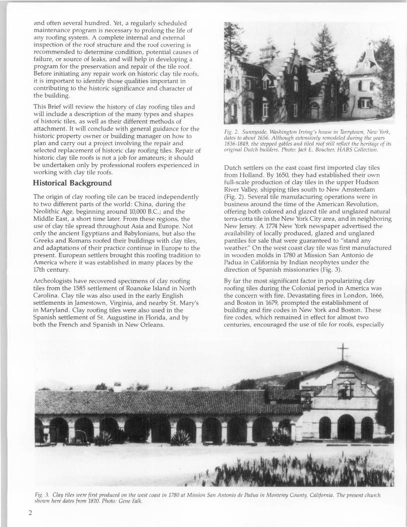
2
and often several hundred. Yet, a regularly scheduled maintenance program is necessary to prolong the life of any roofing system. A complete internal and external inspection of the roof structure and the roof covering is recommended to determine condition, potential causes of failure, or source of leaks, and will help in developing a program for the preservation and repair of the tile roof. Before initiating any repair work on historic clay tile roofs, it is important to identify those qualities important in contributing to the historic Significance and character of the building.
This Brief will review the history of clay roofing tiles and will include a description of the many types and shapes of historic tiles, as well as their different methods of attachment. It will conclude with general guidance for the historic property owner or building manager on how to plan and carry out a project involving the repair and selected replacement of historic clay roofing tiles. Repair of historic clay tile roofs is not a job for amateurs; it should be undertaken only by professional roofers experienced in working with clay tile roofs.
Historical Background
The origin of clay roofing tile can be traced independently to two different parts of the world: China, during the Neolithic Age, beginning around 10,000 B.C.; and the Middle East, a short time later. From these regions, the use of clay tile spread throughout Asia and Europe. Not only the ancient Egyptians and Babylonians, but also the Greeks and Romans roofed their buildings with clay tiles, and adaptations of their practice continue in Europe to the present. European settlers brought this roofing tradition to America where it was established in many places by the 17th century.
Archeologists have recovered specimens of clay roofing tiles from the 1585 settlement of Roanoke Island in North Carolina. Clay tile was also used in the early English settlements in Jamestown, Virginia, and nearby St. Mary's in Maryland . Clay roofing tiles were also used in the Spanish settlement of St. Augustine in Florida, and by both the French and Spanish in New Orleans.
Fig. 2. Sunnyside, Washington Irving 's house in Tarnjtown, New York, dates to about 1656. Although extensively remodeled during the years 1836-1849, the stepped gables and tiled roof still reflect the heritage of its original Dutch builders. Photo: Jack E. Boucher, HABS Collection.
Dutch settlers on the east coast first imported clay tiles from Holland. By 1650, they had established their own full-scale production of clay tiles in the upper Hudson River Valley, shipping tiles south to New Amsterdam (Fig. 2) . Several tile manufacturing operations were in business around the time of the American Revolution, offering both colored and glazed tile and unglazed natural terra-cotta tile in the New York City area, and in neighboring New Jersey. A 1774 New York newspaper advertised the availability of locally produced, glazed and unglazed pantiles for sale that were guaranteed to "stand any weather:' On the west coast clay tile was first manufactured in wooden molds in 1780 at Mission San Antonio de Padua in California by Indian neophytes under the direction of Spanish missionaries (Fig. 3).
By far the most significant factor in popularizing clay roofing tiles during the Colonial period in America was the concern with fire. Devastating fires in London, 1666, and Boston in 1679, prompted the establishment of building and fire codes in New York and Boston . These fire codes, which remained in effect for almost two centuries, encouraged the use of tile for roofs, especially
Fig. 3. Clay tiles were first produced on the west coast in 1780 at Mission San Antonio de Padua in Monterey County, California. The present church shown here dates from 1810. Photo: Gene Falk.

1 2 123456
ttlllill Diamond Gothic Round Round New· York Washing· Square
Corner End Cut ton Cut End
Fig. 4. Many mid- and late-19th century buildings had roofs with uniquely shaped tiles such as fish scale, or another one of the tile shapes that Charles Thomas Davis described as "the six form s of roofing tiles in most common use in this country," and illustrated in his 1884 book A Practical Treatise on the Manufacture of Bricks, Tiles, Terra-Cotta, Etc.
in urban areas, because of its fireproof qualities. Clay roofing tile was also preferred because of its durability, ease of maintenance, and lack of thermal conductivity.
Although more efficient production methods had lowered the cost of clay tile, its use began to decline in much of the northeastern United States during the second quarter of the 19th century. In most areas outside city-designated fire districts, wood shingles were used widely; they were more affordable and much lighter, and required less heavy and less expensive roof framing. In addition, new fireresistant materials were becoming available that could be used for roofing, including slate, and metals such as copper, iron, tinplate, zinc, and galvanized iron. Many of the metal roofing materials could be installed at a fraction of the cost and weight of clay tile. Even the appearance of clay tile was no longer fashionable, and by the 1830s clay roofing tiles had slipped temporarily out of popularity in many parts of the country.
Revival Styles Renew Interest in Clay Roofing Tiles
By the mid-19th century, the introduction of the Italian ate Villa style of architecture in the United States prompted a new interest in clay tiles for roofing. This had the effect of revitalizing the clay tile manufacturing industry, and by the 1870s, new factories were in business, including large operations in Akron, Ohio, and Baltimore, Maryland. Clay tiles were promoted by the Centennial Exhibition in Philadelphia in 1876, which featured several prominent buildings with tile roofs, including a pavilion for the state of New Jersey roofed with clay tiles of local manufacture. Tile-making machines were first patented in the 1870s, and although much roofing tile continued to be made by hand, by the 1880s more and more factories were beginning to use machines (Fig. 4). The development of the Romanesque Revival style of architecture in the 1890s further strengthened the role of clay roofing tiles as an American building material (Fig. 5).
Alternative substitutes for clay tiles were also needed to meet this new demand . By about 1855, sheet metal roofs designed to replicate the patterns of clay tile were being produced. Usually painted a natural terra cotta color to emulate real clay tile, these sheet metal roofs became popular because they were cheaper and lighter, and easier to install than clay tile roofs.
Clay roofing tiles fell out of fashion again for a short time at the end of the 19th century, but once more gained acceptance in the 20th century, due primarily to the popularity of the Romantic Revival architectural styles,
Figure 5. (a) Clay tile was a popular roofing material during the Romanesque Revival period, not only for residential structures including these rowhouses in the Dupont Circle Historic District in Washington, D.C., and designed and built by Thomas F. Schneider between 1889-1892, but also for large-scale public buildings such as (b) the Old Federal Courts Building (1894-1901) in St. Paul, Minnesota, designed by Willoughby J. Edbrooke. Photo: (a) Anne Grimmer, and (b) WinsorlFaricy Architects.
including Mission, Spanish, Mediterranean, Georgian and Renaissance Revival in which clay tile roofs featured prominently. With the availability of machines capable of extruding clay in a variety of forms in large quantities, clay tiles became more readily available across the nation. More regional manufacturing plants were established in areas with large natural deposits of clay, including Alfred, New York; New Lexington, Ohio; Lincoln, California; and Atlanta, Georgia; as well as Indiana, Illinois and Kansas.
The popularity of clay tile roofing, and look-alike substitute roofing materials, continues in the 20th century, especially in areas of the South and West-most notably Florida and California-where Mediterranean and Spanish-influenced styles of architecture still predominate (Fig. 6).
3

4
Fig. 6. Like many other house of this period in Florida, the roof of the Chester C. Boltoll House in Palm Beach features tiles imported fro m Cuba. These tiles, with their richly varied earth colors, were often laid ill thick cement mortar that was intended to give a "rustic" appearance. The residence, which includes the main house (1918-1919) designed by James A. Garfield, and an addition built in 1929 designed by Prentice Sanger, has been described as all Ellglish manor house with Spallish details. Photo: Jack E. Boucher, HABS Collectioll.
Early Tiles
During the 17th and 18th centuries the most common type of clay roofing tiles used in America were flat and rectangular. They measured approximately 10" x 6" x 1/2" (25cm x 15cm x 1.25cm), and had two nail or peg holes at one end through which they were anchored to the roofing laths. Sometimes a strip of mortar was placed between the overlapping rows of tile to prevent the tiles from lifting in high winds. In addition to flat tiles, interlocking S-shaped pantiles were also used in the 18th century. These were formed by molding clay over tapered sections of logs, and were generally quite large. Alternately termed pan, crooked, or Flemish tiles, and measuring approximately 141/2" x 91/2" (37cm x 24cm), these interlocking tiles were hung on roofing lath by means of a ridge or lug located on the upper part of the underside of each tile. Both plain (flat) tile and pantile (S-shaped or curved) roofs were capped at the ridge with semicircular ridge tiles. Clay roofing tiles on buildings in mid-18th century Moravian settlements in Pennsylvania closely resembled those used in Germany at the time. These tiles were about 14"-15" long x 6"-7" wide (36cm-38cm x 15cm-18cm) with a curved butt, and with vertical grooves to help drainage. They were also designed with a lug or nib on the back so that the tiles could hang on lath without nails or pegs.
The accurate dating of early roofing tiles is difficult and often impossible. Fragments of tile found at archeological sites may indicate the existence of clay tile roofs, but the
same type of tile was also sometimes used for other purposes such as paving, and in bake ovens. To further complicate dating, since clay tile frequently outlasted many of the earliest, less permanent structures, it was often reused on later buildings.
Clay Tile Substitutes
In addition to sheet metal "tile" roofs introduced in the middle of the 19th century, concrete roofing tile was developed as another substitute for clay tile in the latter part of the 19th century (Fig. 7). It became quite popular by the beginning of the 20th century. Concrete tile is composed of a dense mixture of portland cement blended with aggregates, including sand, and pigment, and extruded from high-pressure machines. Although it tends to lack the color permanence and the subtle color variations inherent in natural clay tile, concrete tile continues to be a popular roofing material today because it reproduces the general look of clay tile, if not always the exact profile or proportions of historic clay tile, at a somewhat lower cost and weight. Another modern, slightly cheaper and lighter substitute for clay tile more recently developed consists of a mixture of mineral fiber and cement with pigments added to supply color. While these aggregate tiles also replicate the shape and appearance of clay roofing tiles, they have many of the same dissimilarities to clay tiles that are found in concrete tiles. Thus, like concrete tiles, they are seldom appropriate substitutes for clay tiles .

Fig. 7. (a) Metal " tile" roofs of galvanized steel closely resemble the clay tiles they mimic. Often painted to look like terra cotta, their identity can sometimes be revealed In; peeling paint or dented " tiles." (b-c) Concrete roofing tiles are generally thicker than clay tiles, and tend to fade and lose their color. Photos: (a -b) Anne Grimmer, (c) National Park Service Files.
Traditional Tile Shapes and Colors
There are two types of clay roofing tiles: interlocking and overlapping. Interlocking tiles are designed in pairs so that an extrusion or "lip" on one of the tiles "hooks" over the other tile thereby "locking" or securing the two together; they are also usually nailed to the roof structure. Overlapping tiles, w hich can also function in pairs, generally do not have any sort of "lip" and must be nailed in place. There is a wide range of shapes of historic clay roofing tiles, and many, sometimes with slight variations, are still produced today. There are many variations, and the country of origin of some of them may be revealed in their names, but there are essentially only two kinds of shapes: pantiles and flat tiles. Both pantiles and flat tiles may be either interlocking or overlapping (Figs. 8-9) .
Pantiles. The shape most commonly associated with historic clay roofing tiles is probably that of convex or rounded tiles, often grouped together generically as "pan tiles" or "pantiles:' These include Spanish tiles-sometimes called "S" tiles, or the Similarly shaped Mission tiles, also known as Barrel or Barrel Mission tiles, straight or tapered, as well as Roman tiles, and their Greek variation .
Flat Tiles. Flat, shingle tiles are another type of historic clay roofing tiles. Flat tiles can be completely plain and flat , and, like roofing slates, overlap one another, attached with nails to the roof sheathing. Or they may interlock at the top and on one side. Although the "interlock" holds them together, most interlocking shingle tiles also have one or more holes, usually near the top, for nailing to the roof sheathing. Flat tiles are mostly variations of English or Shingle tiles, and include English Shingle, Closed Shingle, Flat, Shingle or Slab Shingle, as well as French tiles which have a slightly higher and more contoured profile.
Any of the standard tile shapes may be known by a different name in another region of the country, or in different parts of the world. For example, what are known as Spanish or "S" tiles in the United States, may be called Single Roman tiles in England. Sometimes Spanish and Mission tiles are equated despite the fact that the former are usually I-piece interlocking tiles and the latter are single V2 cylinders that overlap. Since missions and the Mission style are associated with the Americas, Mission tiles in the United States are more commonly referred to as Spanish tiles in England and Europe. In a similar vein, Spanish or "S" tiles, or Barrel tiles, might seem to be more typical of some tiles used in France than what are marketed as French tiles by American manufacturers .
Today some tile manufacturers have given their own trademark name to historic tile shapes. Other companies market uniquely shaped "S" tiles that are more in the shape of a true, but rather low profile "s" without the customary flat portion of traditional American "S" tiles.
Field and Specialty Tile. The tiles that cover the majority of the flat surface of the roof are called field tile. Some roof shapes, particularly conical towers or turrets, require tiles of graduated sizes, and some shapes or patterns of field tile also require specially shaped finish tiles to complete the roof covering package. Other uniquely-shaped tiles were made to fit odd-shaped spaces and places including dormers and valleys, roof hips, rakes, ridges and corners. There are also finish tiles that fulfill certain needs, such as eave closures or clay plugs called "birdstops:' These are intended to keep out snow and rain, and birds from nesting in the voids under the bottom row of curved tiles . Different patterns and designs can also be created by combining, or mixing and matching flat tiles with dimensional tiles.
Tile Colors. A terra cotta red is the color most commonly associated with historic clay roofing tiles. The reddish color comes from clay with a large percentage of iron oxide, and there are many variations of this natural color to be found in tiles ranging from deep reddish browns to softer and paler oranges and pinks. Lighter buff and beige colors, as well as black, also appear on traditional tile-
5

Traditional Clay Roofing Tile Shapes and Methods of Attachment
Pantiles
Type Average Size Description
-
([] Spanish Spanish or "5" tiles are l-piece interlocking tiles with both a convex .. and a flat , or almost flat, horizontal surface. A raised lip that projects or 13 1/4" long x from the edge of the flat portion is designed to interlock with the
1'5" 93/4" wide edge of the convex, barrel end of the adjacent tile. Spanish tiles are usually laid directly on the wood sheathing, or on roofing felt , and
Interlocking Exposure: 10 1/4" fastened by two nails through holes at the top of the tiles, or sometimes mortared in place. Spanish tiles give a roof surface a fairly low and undulating profile.
Tapered Tapered or Straight Mission, Barrel, Barrel Mission, or ran and
• Cover Tapered or 14"-18" Cover tile roofs are created with both a concave and a convex ,(, cylinder-shaped tile. The concave (pan) tiles are laid first in vertical tJ rJ:lfjaighl Mi"ion, up to rows, and nailed directly to the roof sheathing. The convex (cover) Q Barrel,o,
22"-24" long tiles are laid to overlap and cover the vertical spaces, or joints, that Y Barrel Mission Each half cylinder separate the vertical rows of the concave tiles. The convex tiles may about 3" high x be fastened to the roof sheathing with very long nails, hooks or
about 8" in diameter hangers, or more commonly laid over, and nailed to vertical wood Overlapping
Exposure: 11"-15" battens underneath. Mission tile roofs have a higher profile than • Spanish or Roman
Pantile tile roofs.
Roman, Roman, or ran and Roll , roofs consist of a two-part tile system
Q Pan and Roll, 123/4" long
which includes a convex barrel cover tile with a rather low profile placed over a flat tile laid directly on the roof sheathing. Like
L 7 or Width from center of Mission tiles, the convex tiles may be nailed either to battens laid
Pan and Cover 1 cover tile to center vertically on the roof or directly onto the roof sheathing. Both the
of next including convex cover tile and the flat tile may also have nibs at the top by
Interlocking width of 1 flat tile which they interlock with tiles laid in rows above them. Roman tiles is 12" may also be cemented in place. A Roman tile roof appears as a
and series of fairly wide or broad, flat "va ll eys" alternating with rather Overlapping Exposure: 10" low ridges or hills, much like a Spanish tile roof but with wider
"flat" sections.
rfll Greek Same size
7 and Greek tiles are essentially a variation of Roman tiles, but the convex
Interlocking dimensions tiles that cover the vertical joints between the rows of "pan" tiles are and as shaped like a gable end or inverted "V". Greek tiles are attached to
Overlapping Roman tiles the roof in the same manner as Roman tiles.
Flat Tiles English Shingle:
0 0 13 114" long x
English Shingle 83/4" wide
or Exposure: 101/8"
Closed Shingle long x 73/4" wide
C losed Shingle:
• tL_ ....... .::=-...: _ Interlocking 11" long x 83/4" wide English or Shingle tiles are generally plain and smooth-surfaced,
Exposure: 8" x 8" but some are intended to imitate slate or wood shingles and are
12" x 15" long textured accordingly. The underside of these tiles can be either flat and smooth, or may have a corrugated appearance with 4-5
English Flat x 6" x 7" wide, toothlike projections; all are attached with nails.
DDD or 12" long or x 9"-10" wide
Slab Shingle Exposure varies
Overlapping according to size of the
tile, but is generally s lig htly less than 112
length of the tile
CJJ French tiles feature two deep vertical grooves on the surface that
French 161/4" long x 9" wide facilitate drainage, and create interesting light and shadow contrasts. A vertical lug projects from the top of these tiles that interlocks with
Interlocking the bottom of the tile laid over it. French tiles also have two nail Exposure: 9" holes at the top for nailing, and are often given a dab of cement for
added security.
~ ~
Fig. 8. Traditional Clay Roofillg Tile Shapes and Methods of Attachment. Drawing: Karill Murr Link.
6

Spanish or "S"
Straight Mission, Barrel, Barrel Mission or Pan and Cover
Roman
/f English Shingle or Closed Shingle
Clay Roofing Tile Installation Patterns
Greek
English Flat or Slab Shingle
Fig. 9. Clay Roofing Tile Installation Patterns. Drawing: Karin Murr Link.
7

roofed buildings. Buff-colored tiles were made from nearly pure fire clay, and pouring manganese dissolved in water over the tile before firing resulted in smoke brown or black glazed tiles. Toward the end of the 19th century the popularity of colored glazes for roofing tiles increased, and their use and the range of colors continues to expand today. Most historic glazed roofing tiles are in fairly natural hues that range from reds and browns and buffs, to blacks and purples, blues (often created with smalt, or powdered blue glass), and a wide variety of greens (usually created with copper slag). There could be a considerable range in the colors of tiles that were baked over a wood fire because the temperature within the kiln was so uneven; tiles closest to the fire cooked all the way through and turned a darker red, while tiles farthest from the flames were likely to be smoke-stained, and lighter orange in color.
How Tiles are Attached
The method used to attach clay roofing tiles varies according to the shape, size and style of the particular tile. For the most part, traditional and modern methods of installing clay roofing tiles are very similar, except that modern practice always includes the use of wood sheathing and roofing felt. But most of the earliest clay roofing tiles were laid without benefit of wood sheathing and hung directly on roofing laths and battens that were nailed to the roof rafters; this practice continued up into the mid-19th century in some regions. While this method of attachment allowed for plenty of ventilation, and made it easy to find leaks and make repairs, it also meant that the overall watertightness of the roof depended entirely on the tiles themselves.
8
Gradually, the practice evolved of nailing roofing tiles directly onto continuous wood sheathing, or hanging them from "nibs" on horizontal lath that was attached to roof rafters or sheathing. Some kinds of tile, especially the later Mission or Barrel tiles were laid over vertical strips or battens nailed to the sheathing, or the tiles were fastened to wood purlins with copper wire.
Partly because they do not always fit together very closely, some tile shapes, including Spanish, Barrel or Mission as well as other types of interlocking tiles, are not themselves completely water-repellent when used on very low-pitched roofs. These have always required some form of sub-roofing, or an additional waterproof underlayer, such as felting, a bituminous or a cementitious coating. In some traditional English applications, a treatment called "torching," involved using a simple kind of mortar most commonly consisting of straw, mud, and moss. The tapered Mission tiles of the old Spanish missions in California were also laid in a bed of mud mortar mixed with grass or straw which was their only means of attachment to the very low-pitched reed or twig sheathing ([atia) that supported the tiles (Fig. 10).
More recent and contemporary roofing practices require that the tiles be laid on solid 1" (2.5cm) wood sheathing felted with coated base sheets of at least 30 lbs., or builtup membranes or single-ply roof membranes. This substantially increases the watertightness of the roof by adding a second layer of waterproofing. Horizontal and vertical chalk lines are drawn to serve as a guide in laying
Fig. 10. The underside of this roof on the restored barracks at Santa Cruz Mission reveals the twig sheathing or latia to wh ich ~he clay tiles were traditionally attached with mud mortar. Photo: Gil Sanchez, FAJA.
the tile and to indicate its patterning. Most tiles are designed with one or two holes so they can be attached by copper nails or hangers, and/or with projecting nibs, to interlock or hang on battens or lath attached to the base sheathing.
Before laying the tiles, the copper or lead gutters, flashings and valleys must be installed, preferably using at least #26 gauge (20-24 ounce) corrosion-resistant metal extending a minimum of 12" (30.Scm) under the tile from the edge, or in accordance with the manufacturer's specifications. The long life and expected durability of clay tiles require that, as with the roofing nails, only the best quality metal be selected for the flashing and guttering.
"Field tile" is usually ordered by the number of "squares"that is, a flat section 10' x 10' (2Scm x 2Scm)-needed to cover a roof section. The tile company or roofing contractor should calculate the number of tiles needed according to the type of roof, and based on architect's drawings to ensure accuracy. This should include specialty ridge and eave tiles, decorative trim, partial "squares", approximately 10-20 per cent allowance for breakage, and extra tiles to store for repairing incidental damage later on. Once at the site, the tile is evenly distributed in piles on the roof, within easy reach for the roofers.
The tiles are laid beginning with the first course at the lower edge of the roof at the eaves. The method by which roofing tiles are laid and attached varies, depending on the type and design of the tiles and roof shape, as well as on regional practice and local weather conditions. A raised fascia, a cant strip, a double or triple layer of tiles, or special "birdstop" tiles for under the eaves, may be used to raise the first row of tiles to the requisite height and angle necessary for the best functioning of the roof (Fig. 11). The tile is positioned to overhang the previously installed gutter system by at least 11/2" (4cm) to ensure that rainwater discharges into the central portion of the gutter. Once this first course is carefully fitted and examined from the ground level for straightness and color nuances, and adjusted accordingly, successive courses are lapped over the ones below as the roofer works diagonally up the roof toward the ridge. Positioning and laying tiles in a 10 'x 10 ' (2Scm x 2Scm) square may take on the average of 16112 man hours.

FACE. OF Ol::ICK
~-CA'JT ~TJ<: I P
\',>---+-,,-, I"T~D I~' 6UTT~1': 5~P" • '2.'. c,' C.C.
" '" <"' VEI':I ,"Y ANaLE
lio-!-exJILT · IN =ppe;p'; GUTTeR
NeW VvtX)C N\OLDINGO ALl.. INCCO M~Moe.R~ A.T EA.VE~ , 009=FIT 1 FI>G!i>e 10 eE Fl6.INTe.O.
Fig. 11 . Both a cant strip and a double layer of tiles are used here to raise the first row of tiles to ensure proper roof drainage. This drawing was prepared for the restoration of the 1911-1912 Ja1'1aica Pond Boathouse, Jamaica Plain, Massachusetts, which is part of the original Boston Park system designed by Frederick Law Olmsted in the late-19th century. Drawing: Richard White, Architect/Planner.
Flat Tiles
Most flat clay tiles have one or two holes located at the top, or on a "nib" or "lug" that projects vertically either from the face or the underside of the tiles, for nailing the tile to the sheathing, battens, or furring strips beneath . As successive rows of tile are installed these holes will be covered by the next course of tiles above. Traditionally, clay tiles on the oldest tile roofs were hung on roofing laths with oak wooden pegs. As these wood pegs rotted, they were commonly replaced with nails. Today, copper nails, 13/4" (4.5cm) slaters' nails, are preferred for attaching the tiles because they are the longest lasting, although other corrosion-resistant nails can also be used . Less durable nails reduce the longevity of a clay tile roof which depends on the fastening agents and the other roofing components, as much as on the tiles themselves. Clay roofing tiles, like roofing slates, are intended to hang on the nails, and nailheads should always be left to protrude slightly above the surface of the tile. Nails should not be driven too deeply into the furring strips because too much pressure on the tile can cause it to break during freeze/thaw cycles, or when someone walks on the roof.
Plain flat tiles, like roofing slates, are attached to the roof sheathing only with nails. They are laid in a pattern overlapping one another in order to provide the degree of impermeability necessary for the roof covering. Because plain flat tiles overlap in most cases almost as much of one half of the tile, this type of tile roof covering results in a considerably heavier roof than does an interlocking tile roof which does not require that the tiles overlap to such an extent. Interlocking flat tiles form a single layer, and an unbroken roof covering. Although most interlocking tiles on all but the steepest roofs can technically be expected to remain in place because they hang on protruding nibs from the roofing laths or battens, in contemporary roofing practices they are often likely to be nailed for added security. In most cases it is usually a good idea to nail at least every other tile (Fig. 12) .
Pantiles
With Mission or Barrel tiles, where one half-cylinder overlaps another inverted half-cylinder to form a cover and pan (cap and trough) arrangement, the fastening is more complicated. While the pantiles that rest directly on the sheathing are simply nailed in place, there are two ways of attaching the cover tiles that rest on the pantiles. They can be secured by a copper wire nailed to the sheathing or tied to vertical copper strips running behind the tiles (Fig. 13). Another method requires the installation of vertical battens or nailing strips on the roof to which the cover tiles are nailed, or the use of tile nails or hooks, which are hooked to the pantile below and secured with twisted copper wire.
Sometimes cement mortar, or another underlayer such as grass, moss or straw, or hair-reinforced mortar was added under the tiles. Before the use of felting this was a particularly common practice on some of the plain flat tile or Spanish tile roofs with low rises that were themselves not especially waterproof. Mortar also helped to keep driving rain from getting under the pantiles, and it is still customary in contemporary roofing to add a dab of cement mortar to help secure them (Fig. 14).
Ridge or Hip Tiles
At the roof ridge or hip, clay tile is usually attached to a raised stringer with nails and a small amount of mortar, elastic cement or mastic. The joint is sealed with a flexible flashing such as copper or lead. Ridge tiles are often somewhat larger and more decorative than the field tile utilized on the broad sections of the roof.
Roof Pitch and Weather are Factors in Tile Attachment
The means by which clay tile is attached to the sheathing is also partly determined by the roof pitch. Generally the fastening requirements increase with an increase of roof pitch. For low-pitched rises of 4"-6" (10cm-lScm) in a 12" (30.5cm) run the weight of the tiles is usually sufficient to hold them in place on the lath by the ridge or "lug" on the underside of the tile, with only the perimeter tiles requiring metal clips to secure them to the sheathing. But the tiles on even these low-pitched roofs are usually nailed for added security, and additional fastening measures are necessary on roofs with a higher pitch, or in areas subject to high winds or earthquakes. For steeper pitched roofs, such as towers, 7" -11" (18cm-28cm), or 12" -IS" (30.5cm-38cm) in a 12" (30.Scm) run the tiles are nailed and a band of perimeter tiles three to four tiles thick is secured with clips. For roof rises over 16" (41cm) in a 12" (30.Scm) run, and in areas prone to earthquakes or hurricanes, every tile may be secured with both a nail and a copper or non-corrosive metal clip, and often also with a dab of roofing mastic or mortar.
The installation of clay roofing tiles in areas with significant amounts of snowfall-over 24" (61cm) per year-also varies somewhat from the normal guidelines. Larger battens may be necessary, as well as additional clipping or tying of the tile to securely attach it to the sheathing. The roof structure itself may also need added bracing, as well as the insertion of small snow clips or snow birds that protrude above the surface of the tile to prevent snow and ice from sliding off the roof and damaging the tile .
9

b
10
Figure 12. When constructed in Frankfort, Kentucky, in 1900, the
Colonial Revival-style Berry Hill Mansion, and its 1912 Music Room
addition were both roofed with " Imperial" tiles manufactured by
Ludowici-Celadon (a). In 1992 the entire roof was replaced because of
deterioration and surface spalling of many of the tiles (b). It was not
possible to reproduce the original tiles due to budget limitations, thus
Ludowici-CeIadon's stock " Classic Interlocking" Shingle tiles were
selected as replacements which could provide a close, if not exact, match.
After tearing off and removing the old tiles, 30 lb. roofing felt was laid
over the existing wood sheathing, new lead gutters and valleys were
installed, and 90 lb. roll roofing was laid, on which the new tiles were
laid. Although most of the field tiles were simply attached by 2 nails to
the substrate (c), many of the tiles that had to be cut to fit hips, valleys
and dormers were left with only one hole, and had to be wired and then
nailed in place (d-e). The exact color and glaze of the original tiles also
could not be duplicated because the coloring material is no longer
available; however, the new hipped roof terminus for the Music Room roof
was custom-made and the replacement field tiles are very similar to the
originals (t>. The original ridge tiles were designed to "nest" and fit
perfectly over the field tiles beneath them whereas the new ridge tiles
simply overlap one another, but this is barely perceptible when viewed
from the ground. Photos: Edwin C. Krebs, AlA.

Figure 13 (a-b). These custom-made tapered mission tiles are beins attached to the roof using a special system. This consists at twisted 1D-gauge bras: or copper wires that run up the roof slope through a new treated root ridge, and down the other szde of the roof. These tWIsted wIres are placed about 12 (3D.5cm) apart, and diamond shapes are twisted into them every 6" (15cm). The vertical wires are secured wIth 1D-gaugecopper or brass anchors approximately every 4' (1.22m) on center depending on the roof slope. Although these tIles would have orlgznally been laId In mud mortar, thIS method of attachment is particularly successful in seismic areas. The random placement of the tdes accurately replIcates the pattern tradItIOnally used on the early missions. Photos: Gil Sanchez, FAJA.
Preservation and Repair
Identifying Common Problems and Failures While clay roofing tiles themselves are most likely to deteriorate because of frost damage, a clay tile roof system most commonly fails due to the breakdown of the fastening system. As the wooden pegs that fastened the early tiles to hand-riven battens rotted, they were often replaced with iron nails which are themselves easily corroded by tannic acid from oak battens or sheathing. The deterioration of metal flashing, valleys, and gutters can also lead to the failure of a clay tile roof.
Another area of potential failure of a historic clay tile roof is the support system. Clay tiles are heavy and it is important that the roof structure be sound. If gutters and downspouts are allowed to fill with debris, water can back up and seep under roofing tiles, causing the eventual deterioration of roofing battens, the sheathing and fastening system, or even the roof's structural members (Fig. 15). During freezing weather, ice can build up under tiles and cause breakage during the freeze/thaw cycle. Thus, as with any type of roof, water and improperly maintained rainwater removal and drainage systems are also chief causes for the failure of historic clay tile roofs.
Clay tiles may be either handcrafted or machine-made; in general, roofs installed before the end of the 19th century consist of hand-formed tiles, with machine-made tiles becoming more dominant as technology improved during the 20th century. Clay tile itself, whether made by hand or made by machine, can vary in quality from tile to tile. Efflorescence of soluble salts on the surface may indicate that a tile has excessive porosity which results from underburning during its manufacture. Poor quality porous tiles are particularly susceptible to breaking and exterior surface spalling during freeze-thaw cycles. By letting in moisture, porous tiles can permit the roof battens and roof structure to rot. The problem may be compounded by
waterproof building paper or building felt laid underneath which can, in some instances, prevent adequate ventilation.
Clay roofing tiles can also be damaged by roofers walking carelessly on an unprotected roof while making repairs, or by overhanging tree branches, falling tree limbs, or heavy hail. Broken tiles may no longer provide a continuous waterproof surface, thereby allowing water to penetrate the roofing structure, and may eventually result in its deterioration if the broken tiles are not replaced in a timely manner.
Although modern, machine-made clay tiles are more uniform in appearance than their hand-made counterparts, they also have the potential for failure. Occasionally, entire batches of mass-produced tile can be defective .
Fig. 14. The Spanish or "S" tiles used to re-roof the Mission Revival style Holy Cross Episcopal Church in Sanford, Florida, have corrugated projections or "teeth" on the underside of the flat portion of each tile which adhere to the cemellt mortar holding them to the roof sheathing. Photo: Walter S. Marder, AlA .
11

Figure 15. (a) A regular cleaning schedule would have eliminated the plant growth and leaf build-up in this gutter, which, if not removed, will result In serzous damage to roof sheathing and structure (b) . Photos: (a) Paul K. Williams, and (b) Walter S. Marder. AlA.
Regular Inspection and Maintenance
Broken or missing tiles, or leaks on the interior of the building, are obvious clues that a historic clay tile roof needs repair. Even though it may be clear that the roof is leaking, finding the source of the leak may not be so easy. It may require thorough investigation in the attic, as well as going up on the roof and removing tiles selectively in the approximate area of the roof leak . The source of the leak may not actually be located where it appears to be. Water may come in one place and travel along a roofing member some distance from the actual leak before revealing itself by a water stain, plaster damage, or rotted wooden structural members.
Temporary Protection during Repair
In some instances temporary protection and stabilization may be necessary to prevent further damage or deterioration of a historic clay tile roof. Plywood sheets, plastic, roll roofing, or roofing felt can provide short-term protection until repair or replacement materials can be purchased. Another option may be to erect a temporary scaffold that is epcased or covered with clear or semitransparent polyethylene sheeting over the entire roof . This will not only protect the exposed roofing members during repair or until repairs can be made, but also lets in enough natural light to enable the re-roofing work to take place while sheltering workmen from cold or wet weather.
12
General Repair Guidance
Once the source and cause of a leak has been identified, appropriate repairs must be made to structural roofing members, wood sheathing, felt or roofing paper if it is part of the roofing membrane, or possibly to vertical roof battens to which the tiles may be attached. If the problem appears limited to gutters and flashing in disrepair, repair or replacement will probably require temporary removal of some of the adjacent tiles to gain access to them. If the roofing tiles are extremely fragile and cannot be walked on even with adequate protection (see below), it may also be necessary to remove several rows or a larger area of tiles and store them for later reinstallation in order to create a "path" to reach the area of repair without damaging existing tiles. Even if most of the tiles themselves appear to be intact but no longer securely attached to the roof substrate due to deterioration of the fastening system or roofing members, all the tiles should be labeled and removed for storage. Regardless of whether the repair project involves removal of only a few damaged tiles, or if all the tiles must be removed and relaid, historic clay roofing tiles are inherently fragile and should be pulled up carefully with the use of a slate ripper. The tiles can be reattached one-by-one with new corrosion-resistant copper nails, copper straps or tabs, "tingles", or another means after the necessary repairs have been made to the roof .
Replacing Individual Tiles
The most difficult aspect of replacing a single broken clay roof tile is doing so without breaking neighboring tiles. While flat shingle tiles can generally be walked on by a careful roofer without likelihood of much damage, high profile pantiles are very fragile and easily broken. By using sheets of plywood, planks, or burlap bags filled with sand to distribute weight, the professional roofer can move about the roof to fix broken tiles or flashing without causing additional damage. Another method involves hooking a ladder on the ridge to support and evenly distribute the weight of the roofer.
A broken tile should be carefully removed with a slate ripper or hacksaw blade inserted under the tile to cut the nail or nails holding it in place. If successive layers of tile are already in place covering the nailholes, it will not be possible to attach the replacement tile with nails through the holes, so an alternative method of attachment will be necessary. By nailing a tab of double thickness copper stripping on the sheathing below the tile, the new replacement tile can be slipped into position and secured in place by bending the copper strip up with a double thickness of the copper over the tile. A slate hook or "tingle" can be used in the same way. This fastening system functions in place of nails (Fig. 16).
When replacing hard-to-match historic tile, and if matching clay tile cannot be obtained, it may be possible to relocate some of the original tiles to the more prominent locations on the roof where the tile is damaged, and insert the new replacement tile in secondary or rear locations, or other areas where it will not show, such as behind chimney stacks, parapets, and dormer windows. Even though replacement tile may initially match the original historic tile when first installed, it is likely to weather or age to a somewhat different color or hue which will become more obvious with time. Thus, care should be taken to insert new replacement tile in as inconspicuous a location as
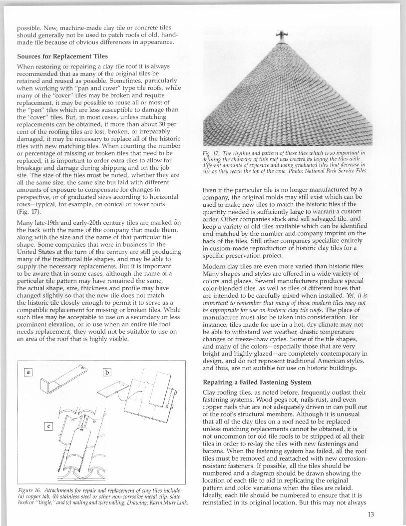
possible. New, machine-made clay tile or concrete tiles should generally not be used to patch roofs of old, handmade tile because of obvious differences in appearance.
Sources for Replacement Tiles
When restoring or repairing a clay tile roof it is always recommended that as many of the original tiles be retained and reused as possible. Sometimes, particularly when working with "pan and cover" type tile roofs, while many of the "cover" tiles may be broken and require replacement, it may be possible to reuse all or most of the "pan" tiles which are less susceptible to damage than the "cover" tiles. But, in most cases, unless matching replacements can be obtained, if more than about 30 per cent of the roofing tiles are lost, broken, or irreparably damaged, it may be necessary to replace all of the historic tiles with new matching tiles. When counting the number or percentage of missing or broken tiles that need to be replaced, it is important to order extra tiles to allow for breakage and damage during shipping and on the job site. The size of the tiles must be noted, whether they are all the same size, the same size but laid with different amounts of exposure to compensate for changes in perspective, or of graduated sizes according to horizontal rows-typical, for example, on conical or tower roofs (Fig. 17).
Many late-19th and early-20th century tiles are marked on the back with the name of the company that made them, along with the size and the name of that particular tile shape. Some companies that were in business in the United States at the turn of the century are still producing many of the traditional tile shapes, and may be able to supply the necessary replacements. But it is important to be aware that in some cases, although the name of a particular tile pattern may have remained the same, the actual shape, size, thickness and profile may have changed slightly so that the new tile does not match the historic tile closely enough to permit it to serve as a compatible replacement for missing or broken tiles. While such tiles may be acceptable to use on a secondary or less prominent elevation, or to use when an entire tile roof needs replacement, they would not be suitable to use on an area of the roof that is highly visible.
Figure 16. Attachments for repair and replacement of clay tiles include: (a) copper tab, (b) stainless steel or other non-corrosive metal clip, slate hook or "tingle," and (c) nailing and wire nailing. Drawing: Karin Murr Link.
Fig. 17. The rhythm and pattern of these tiles which is so important in defining the character of this roof was created by layzng the tIles wIth different amounts of exposure and using graduated tiles that decrease in size as they reach the top of the cone. Photo: NatIOnal Park ServIce FIles.
Even if the particular tile is no longer manufactured by a company, the original molds may still exist which can be used to make new tiles to match the historic tiles if the quantity needed is sufficiently large to warrant a custom order. Other companies stock and sell salvaged tile, and keep a variety of old tiles available which can be identified and matched by the number and company imprint on the back of the tiles. Still other companies specialize entirely in custom-made reproduction of historic clay tiles for a specific preservation project.
Modern clay tiles are even more varied than historic tiles. Many shapes and styles are offered in a wide variety of colors and glazes. Several manufacturers produce special color-blended tiles, as well as tiles of different hues that are intended to be carefully mixed when installed. Yet, it is important to remember that many of these modern tiles may not be appropriate for use on historic clay tile roofs. The place of manufacture must also be taken into consideration. For instance, tiles made for use in a hot, dry climate may not be able to withstand wet weather, drastic temperature changes or freeze-thaw cycles. Some of the tile shapes, and many of the colors-especially those that are very bright and highly glazed-are completely contemporary in design, and do not represent traditional American styles, and thus, are not suitable for use on historic buildings.
Repairing a Failed Fastening System
Clay roofing tiles, as noted before, frequently outlast their fastening systems. Wood pegs rot, nails rust, and even copper nails that are not adequately driven in can pull out of the roof's structural members. Although it is unusual that all of the clay tiles on a roof need to be replaced unless matching replacements cannot be obtained, it is not uncommon for old tile roofs to be stripped of all their tiles in order to re-Iay the tiles with new fastenings and battens. When the fastening system has failed, all the roof tiles must be removed and reattached with new corrosionresistant fasteners. If possible, all the tiles should be numbered and a diagram should be drawn showing the location of each tile to aid in replicating the original pattern and color variations when the tiles are relaid. Ideally, each tile should be numbered to ensure that it is reinstalled in its original location. But this may not always
13

Clay Tile Roofs of Alfred, New York
----!
• • c d
1 • a
F
Takillg advalltage of high quality local shale ideal for makillg terra colla alld clay tiles, the Celadoll Terra Cotta Compally was established ill Alfred, New York, ill 1889. As a result, all ullusually large percelltage of historic buildillgs ill this small tOWIl are roofed with clay tiles. This illcludes commercial alld residential structures as well as other types of structures Ilot commonly roofed with tile, such as bams alld outbuildings. Evell early-19th cen tury houses were re-roofedsometimes illcollgruously-with clay tiles. Today, the tOWIl roofs display all amazillg variety of styles alld patterns of tiles, mallY of which may have been factory seconds orexperilllelltal designs. In operatioll for ollly 20 years when it was destroyed by fire, the compally colltinued lIlanufacturing roofing tiles in New Lexington, Ohio, under the name Ludowici-Celadon. Photos: Terry Palmiter, Courtesy Alfred Historical Society.
14

be feasible or practical, and it may be enough simply to group the tiles as they are removed by type and size or function-such as field tiles, custom tiles for hips, dormers and ridges, and specially cut pieces. This will help facilitate reinstallation of the tiles. If all of the tiles have to be removed, it is probably a good idea to consider installing a layer of modern roofing felt over the wood sheathing. This will add another layer of waterproofing, while providing temporary protection during re-roofing.
Even if the tiles were originally attached with wooden pegs, it is generally recommended that they be rehung with corrosion-resistant, preferably heavy copper, or aluminum alloy nails or hooks. Today there are numerous non-traditional fastening systems for clay tile roofs, and many of them are patented. Roofing contractors and architects may have individual preferences, and some systems may be better suited than others to fit a particular roof shape or to meet a specific climatic or seismic requirement. Original battens or other roof members that may have deteriorated should be replaced to match the original using pressure-treated wood. Additional support may be necessary, particularly if the original roof was inadequate or poorly designed.
Replacing Flashing
Deteriorated flashing, gutters and downspouts should generally be replaced in kind to match the historic material. Copper or lead-coated copper, if appropriate to the building, or terne-coated stainless steel, is often preferred for use on historic clay tile roofs because of their durability and long lasting qualities. However, copper staining from downspouts can sometimes be a problem on light-colored masonry walls which should be taken into consideration when planning replacements to rainwater removal systems. Clay tile roofs usually have an open valley system where the tiles are separated by metal flashing at intersections of roof sections with different angles. This makes the insertion of new flashing quite easy, as only a few surrounding tiles must be removed in the process. New copper flashing that is too "bright" can be made to blend in and "mellowed" by brush-coating it with boiled linseed oil or proprietary solutions.
Inappropriate Repairs
The most important repair to avoid is replacing broken or missing roof tiles on a historic building with materials other than matching natural clay tiles. Concrete, metal or plastic tiles are generally not appropriate substitutes for clay roofing tiles. They lack the natural color variations of clay tile, and they do not have the same texture, shape, thickness or surface irregularities.
Although much concrete tile and composition tile is produced to resemble the general shape, if not the exact profile, of clay roofing tiles, concrete tile is generally too thick and also lacks the range of colors inherent in natural clay tile. Concrete tile is not a compatible substitute material to repair or replace individual historic clay tiles.
Patching a historic clay tile roof with roofing tar, caulk, asphalt, pieces of metal, or non-matching clay tiles is also inappropriate. Such treatments are visually incompatible. They also have the potential for causing physical damage. Water can collect behind these patches, thus accelerating deterioration of roof sheathing and fastening systems, and
during the expansion and contraction of a freeze-thaw cycle ice build-up at patches can break surrounding tiles.
Summary
Clay roofing tile itself, when correctly installed, requires little or no maintenance. Often, it is the fastening system used to secure the tiles to the sheathing that fails and needs to be replaced rather than the tiles themselves. In fact, because clay tiles frequently outlasted the building structure, it was not unusual for them to be reused on another building. When the fastening system has deteriorated, or the roofing support structure has failed, clay tiles can be removed relatively easily, necessary repairs can be made, and the historic tiles can be re-laid with new corrosion-resistant nails or hooks. Broken or damaged tiles should be replaced promptly to prevent further damage to neighboring tiles or to the roof structure itself.
As with any kind of historic roofing material, regular maintenance, such as cleaning gutters and downspouts, can add to the life of a tile roof. Additional preventive measures may include placing wire mesh over downspout openings or over the entire gutter to prevent debris from collecting and water from backing up. Periodic inspection of the underside of the roof from the attic after a heavy rain or ice storm for water stains may reveal leaks in their early stages which can be eliminated before they escalate into larger, more serious repair problems.
If replacement tile is required for the project, it should match the original tile as closely as possible, since a historic clay tile roof is likely to be one of the building's most significant features. Natural clay tiles have the inherent color variations, texture and color that is so important in defining the character of a historic tile roof. Thus, only traditionally shaped, clay tiles are appropriate for repairing a historic clay tile roof.
Selected Reading
Azevedo, J. "Tile Roofing." Fine Homebuilding. No. 60 (April/May 1990), pp. 36-41.
Belle, John, John Ray Hoke, Jr., and Stephen A. Kliment, editors. Traditional Details for Building Restoration, Renovation, and Rehabilitation. From the 1932-1951 Editions of [Ramsey/Sleeper] Architectural GraphiC Standards:' New York: John Wiley & Sons, Inc. 1991.
Davis, Charles Thomas. A Practical Treatise on The Manufacture of Brick, Tiles, Terra Cotta, Etc. Philadelphia: Henry Carey Baird & Co., 1884.
Fidler, John. "Tile, Slate and Stone Roofs." Traditional Homes Technical Information Leaflet. Number 1. 1991.
Labine, Clem. "How to Repair an Old Roof." The Old-House Journal. Vol. XI, No.3 (April 1983), pp. 64-69
Labine, Clem, and Judith Siegel Lief. "The Rise of the Ornamental Roof;' and "Traditional Building's Source List of Traditional Roofing & Specialties." Traditional Building. Vol. 5, No.3 (May/June/1992), pp. 35-46.
Melville, Ian A., and Ian A. Gordon. The Repair and Maintenance of Houses. London: The Estates Gazette Limited, 1973.
Poore, Patricia. "Tile Roofs ." The Old-House Journal. Vol XV, No.5 (September/October 1987), pp. 22-29.
"Special Roof Issue ." The Old-House Journal. Vol XI, No.3 (April 1983).
15

16
Sweetser, Sarah M. Preservation Briefs 4: Roofing for Historic Buildings. Washington, D.C.: National Park Service, U.S. Department of the Interior, 1978.
Vogel, Neal A. Roofing Houses of Worship: Roofing Guidance for Church and Temple Administrators. Information Series No. 59. Chicago: National Trust for Historic Preservation and Inspired Partnerships, 1992.
White, Richard. Olmsted Park System, Jamaica Plain Boathouse, Jamaica Plain, Massachusetts: Planning for Preservation of the Boathouse Roof. Preservation Case Studies. Washington, D.C.: Heritage Conservation and Recreation Service, U.S. Department of the Interior, 1979.
Selected Sources of Clay Roofing Tiles
Boston Valley Terra Cotta 6860 South Abbott Road Orchard Park, NY 14127 Custom-made architectural terra cotta and clay roofing tiles
C.C.N. Oay Roof Tiles (Canteras Cerro Negro S.A.) 8280 College Parkway, Suite 204 Ft. Myers, FL 33919 Distributors of C.C.N. clay roofing tiles from Argentina
Earth/Forms of Alfred 5704 East Valley Road Alfred Station, NY 14803 Made-to-order reproduction clay roofing tiles
Gladding, McBean & Co. P.O. Box 97 Lincoln, CA 95648 Manufacturer since 1875 of terra cotta and clay roofing tiles, and custom reproductions
Hans Sumpf Company, Inc. 40101 Avenue 10 Madera, CA 93638 Made-to-order Mission-style clay roofing tiles
International Roofing Products, Inc. 4929 Wilshire Blvd., Suite 750 Los Angeles, CA 90010 New clay roofing tiles, some suitable for historic buildings
London Tile Co. 65 Walnut Street New London, OH 44851 Made-to-order reproduction clay roofing tiles
Ludowici-Celadon, Inc. 4757 Tile Plant Road New Lexington, OH 43764 Manufacturer since 1880s of clay roofing tiles, and custom reproductions
M.C.A. (Maruhachi Ceramics of America, Inc.) 1985 Sampson Avenue Corona, CA 91719 New clay roofing tiles, some suitable for historic buildings
The Northern Roof Tile Sales Company P.O. Box 275 Millgrove, Ontario LOR IVO, Canada Traditional clay roofing tiles imported from England and South America
Raleigh, Inc. 6506 Business U.S. Route 20 P.O. Box 448 Belvidere, IL 61008-0448 Inventory of new and salvage clay roofing tiles
Supradur Manufacturing Corp. P.O. Box 908 Rye, NY 10580 Imports Spanish ("S") clay roofing tiles from France
TileSearch P.O. Box 580 Roanoke, TX 76262 Computerized network for new and salvage clay roofing tiles
United States Tile Company P.O. Box 1509 909 West Railroad Street Corona, CA 91718 New clay roofing tiles, some suitable for historic buildings
Note: Measurements in this publication are given in both the U.S. Customary System and International (Metric) System for comparative purposes. Metric conversions are, in some cases, approximate and should not be relied upon for preparing technical specifications.
Acknowledgements Anne Grimmer is a senior Architectural Historian with the Preservation Assistance Division of the National Park Service; Paul K. Williams is a Cultural Resource Manager with the Air Force. Both authors wish to thank the following individuals for the technical assistance they provided in the preparation of this publication: Edna Kimbro, Architectural Conservator, Watsonville, CA; Edwin S. Krebs, AlA, K. Norman Berry Associates, Louisville, KY; Melvin Mann, TileSearch, Roanoke, TX; Walter S. Marder, AlA, Division of Historical Resources, Tallahassee, FL; Gil Sanchez, FAIA, Gilbert Arnold Sanchez. Incorporated, Santa Cruz, CA; Terry Palmiter and Sandra Scofield, Alfred, NY; and National Park Service professional staff members. In addition, the authors wish to thank Karin Murr Link, who produced the drawings which illustrate this Brief.
This publication has been prepared pursuant to the National Historic Preservation Act of 1966, as amended, which directs the Secretary of the Interior to develop and make available information concerning historic properties. Comments on the usefulness of this publication may be directed to H. Ward Jandl, Chief, Technical Preservation Services Branch, National Park Service, P.O. Box 37127, Washington, D.C. 20013-7127. This publication is not copyrighted and can be reproduced without penalty. Normal procedures for credit to the authors and the National Park Service are appreciated.
ISSN: 0885-7016 Spring 1993
Cover photograph: Restoration of the I820s Indian barracks at Mission Santa Cruz in California included custom-made tapered barrel clay roof tiles based on archeological data found at the site. Photo: Ron Starr Photography.

Certificate of Appropriateness Application - 1/11/17-Entry Improvements Permit Revision (App. # 201605046539)-Proposed Revision to Permit # 2007-0124-250-R1, issued 7/10/07
1 Historical Photographs2 Existing Photographs3 Existing Photographs4 Enlarged South Elevation (Sans Collonade)5 Enlarged Existing & Proposed Elevation at Entrance6 Entry Rendering7 Entry Rendering8 Photos At Existing Clay Tile Roof9 Roof Visibility Diagrams10 Existing & Proposed Elevations11 Clay Tile Details12 Clay Tile Color Options
SHEET INDEX
333 Dolores Street, San Francisco
Children's Day School: Entry Improvements

CHILDREN’S DAY SCHOOL
Children’s Day School | October 19, 2016
JENSEN ARCHITECTS
page 1
1. HISTORICAL PHOTOGRAPH
3. AERIAL PHOTOGRAPH - 1938
2. HISTORICAL PHOTOGRAPHBETWEEN 1928 - 1941 BETWEEN 1928 - 1941
PHOTOGRAPH KEY / EXISTING SITE PLAN
1
2
HISTORICAL PHOTOGRAPHS

CHILDREN’S DAY SCHOOL
Children’s Day School | October 19, 2016
JENSEN ARCHITECTS
page 2
3. EXISTING ENTRANCE FROM PARKING
2. EXISTING SOUTH ELEVATION FROM PLAYGROUND1. EXISTING ENTRANCE FROM DOLORES STREET
4. EXISTING COLONNADE AND RAISED PORCH PHOTOGRAPH KEY / EXISTING SITE PLAN
EXISTING PHOTOGRAPHS
34
1
2
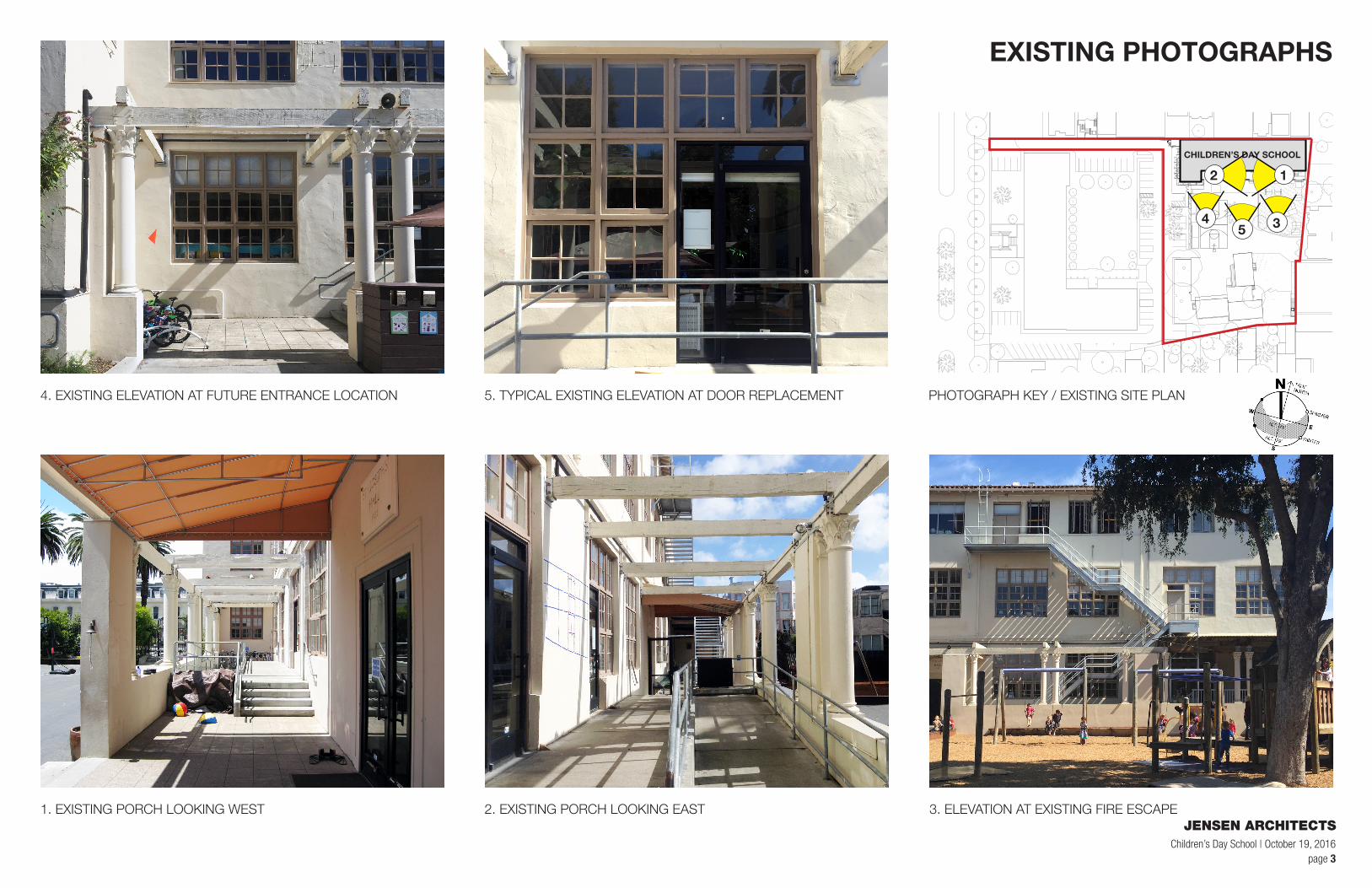
CHILDREN’S DAY SCHOOL
Children’s Day School | October 19, 2016
JENSEN ARCHITECTS
page 3
4. EXISTING ELEVATION AT FUTURE ENTRANCE LOCATION
1. EXISTING PORCH LOOKING WEST 2. EXISTING PORCH LOOKING EAST 3. ELEVATION AT EXISTING FIRE ESCAPE
5. TYPICAL EXISTING ELEVATION AT DOOR REPLACEMENT PHOTOGRAPH KEY / EXISTING SITE PLAN
EXISTING PHOTOGRAPHS
12
345

page 4
JENSEN ARCHITECTSChildren’s Day School | October 19, 2016
PATCH AND REPAIR (E) WALL AS REQ'D., TYP.
CUSTOM WINDOWS TO MATCH (E) BLDG. FENESTRATION WOODWORK
(E) WD. TRELLIS MEMBER SHOWN IN SECTION, TYP.
(E) FENESTRATION, TYP.
2'-4
" V.I.
F.
4'-11" V.I.F.
2'-4
" V.I.
F.
(E) GLAZED WOOD DOORS COMPLETED UNDER PREVIOUS PHASE OF WORK
9'-4
" V.
I.F.
CUSTOM WINDOWS TO MATCH (E) BLDG. FENESTRATION WOODWORK
GLASS DOOR W/ PANIC HARDWARE AT ENLARGED OPENING
CUSTOM WOOD DOOR TO MATCH(E) BLDG. FENESTRATION, TYP.
7'-1
1 1/
4"V.
I.F.
ALIGN EXTERIOR DOOR HEADS & COOR. W/ (E) DIM'S, TYP.
(E) WD. LEDGER
(E) FABRIC AWNING
PUSH PLATE DOOR ACTUATORS
LTG. FIXT., TYP.
WD. FRAME TO MATCH REMOVED (E) FRAME, PTD.
CONCEALED CLOSER
PATCH AND REPAIR (E) WALL AS REQ'D., TYP.
CUSTOM WINDOWS TO MATCH (E) BLDG. FENESTRATION WOODWORK
9'-1
0 1/
2" V
.I.F.
6'-2" V.I.F.
3'-6
" V.
I.F.
90'-6"
F.F. 3RD FLOOR TYP.
CUSTOM WOOD DOOR TO MATCH (E)BLDG. FENESTRATION WOODWORK, TYP.
CUSTOM WOOD WINDOWS TO MATCH (E)BLDG. FENESTRATION WOODWORK, TYP.
PATCH AND REPAIR (E) WALL AS REQ'D., TYP.
GLASS DOOR W/ PANIC HARDWARE AT ENLARGED OPENING
BUILT-IN WD. BENCH
PUSH PLATE DOOR ACTUATORS
INTERCOM
SECURITY FENCE
CONCEALED CLOSER
LINE OF INTERIOR WALL BEYOND INCLUDED FOR REFERENCE
LIGHT FIXTURE, TYP.
76'-0"
F.F. 2ND FLOOR TYP.
61'-6"
F.F. 1ST FLOOR TYP.
0 2' 8'
ENLARGED SOUTH ELEVATION (COLONNADE OMITTED FOR CLARITY)
16'
GRAPHIC SCALE
4'
ENLARGED SOUTH ELEVATION (SANS COLONNADE)

page 5
JENSEN ARCHITECTSChildren’s Day School | October 19, 2016
EXISTING PLASTER
LINE OF FUTURE PROPOSED DOOR
LINE OF FUTUREPROPOSED FINISH FLOOR
EXISTING WD. WINDOW SYSTEM
NEW DIVIDED LIGHTENTRANCE DOORTO MATCH ORIGINALHISTORIC DOORS
EXISTING PLASTER
EXISTING WD. WINDOWSYSTEM
7'-0
"NE
W S
ECUR
ITY
FENC
E
0 2' 4' 8'
EXISTING ELEVATION @ FUTURE KNDRGTN. ENTRANCESCALE: 3/8" = 1'-0"
PROPOSED ELEVATION @ KNDRGTN. ENTRANCESCALE: 3/8" = 1'-0"
EXISTING & PROPOSED: AT ENTRANCE DOORS

page 6
JENSEN ARCHITECTSChildren’s Day School | October 19, 2016
VIEW OF NEW ENTRY GATES FROM PARKING AREA

page 7
JENSEN ARCHITECTSChildren’s Day School | October 19, 2016
VIEW OF NEW RECEPTION AREA FROM NEW ENTRY GATE

page 8
JENSEN ARCHITECTSChildren’s Day School | October 19, 2016
4. ROOF RIDGE
1. DETAIL 2. DETAIL 3. ROOF VISIBILITY FROM PLAY YARD
5. ROOF FACING PLAY YARD 6. ROOF VISIBILITY FROM PARKING LOT
EXISTING CLAY TILE ROOF

CHILDREN’S DAY SCHOOL
Children’s Day School | October 19, 2016
JENSEN ARCHITECTS
page 9
PROPERTY LINE
PL
92'-0"
150'-0"
200'-0"
0 10' 20'
SECTION A-A
40'
GRAPHIC SCALE
PROPERTY LINE
PL
107'-0"
150'-0"
250'-0"
0 10' 20'
SECTION B-B
40'
GRAPHIC SCALE
ROOF VISIBILITY DIAGRAM
SECTION KEY / EXISTING SITE PLAN
* * **** A
A
BB

page 10
JENSEN ARCHITECTSChildren’s Day School | October 19, 2016
0 10' 20'
EXISTING SOUTH ELEVATION
40'
GRAPHIC SCALE
2"
LIGHTWEIGHT CLAYROOFING TILE
UNDERLAYMENT;LAP OVER MTL FLASHING
(E) GUTTER;SALVAGE & REPAIR
-PT., TYP.
1/2" PLYWD.
5/8" PLYWD.SHEATHING; S.S.D.
(E) 3/4" T&G WD. PANELING, TO REMAIN; REPAIR AS NEEDED
(E) WD. RAFTER
2" THK. RIGID INSULATION
(E) CLAY ROOFING TILE
(E) GUTTER; SALVAGE & REPAIR-PT., TYP.
(E) 3/4" T&G WD. PANELING, TO REMAIN; REPAIR AS NEEDED
(E) WD. RAFTER
DETAIL @ PROPOSED EAVESCALE: 3/4" = 1'-0"
DETAIL @ EXISTING EAVESCALE: 3/4" = 1'-0"
0 10' 20'
PROPOSED SOUTH ELEVATION
40'
GRAPHIC SCALE
EXISTING & PROPOSED ELEVATIONS

page 11
JENSEN ARCHITECTSChildren’s Day School | October 19, 2016
MANUFACTURER’S IMAGES OF 1-PIECE & 2-PIECE SYSTEMS
©2012 B
oral Roofing LLC
BR
057-1/12
Boral Roofing
200 Mansell Court East, Suite 310
Roswell, GA 30076
Boral Roofing
7575 Irvine Center Drive, Ste. #100
Irvine, CA 92618
800 669 TILE (8453)
www.boralna.com
The Boral Logo is a trade mark of Boral Limited or its affiliates and may be registered in many jurisdictions worldwide.
Download a QR Code reader app for your smartphone, then take a photo to visit our website.
Faux Mission
The “Faux Mission” installation technique gives architects, builders and homeowners the superior aesthetics of a traditional 2-Piece clay tile roof at an affordable price.
We carefully designed our “S” Tile and our traditional 2-Piece Mission tile profiles to fit together, allowing a custom installation that provides the aesthetics of a traditional 2-Piece tile while capturing the cost saving benefits of an ”S” Tile. 2-Piece Mission tiles are installed at the eave where the details of the roof are most visible. The “S” Tiles are then installed on the rest of the roof for a much quicker and easier installation than a traditional 2-Piece tile roof.
Phoenix, ARIZONA
Corona, CALIFORNIA
Gilroy, CALIFORNIA
Lathrop, CALIFORNIA
Stockton, CALIFORNIA
Rialto, CALIFORNIA
Denver, COLORADO
Pompano Beach, FLORIDA
Lake Wales, FLORIDA
Atlanta, GEORGIA
Kapolei, HAWAII
Kansas City, MISSOURI
Henderson, NEVADA
Tacoma, WASHINGTON
Katy, TEXAS
30595 FM 529
Brookshire, TX 77423
PROPOSED US TILE® by BORAL®2-PIECE MISSION AT PERIMETERONLY. COLOR TO MATCH 1-PIECECLAYLITE TILE ELSEWHERE
US TILE® by BORAL®
2-PIECE AT PERIMETER, TYP.
1-PIECE IN THE FIELD,TYP.
ONE-PIECE INSTALLATIONIN-FIELD FIELD-FOR LESS WEIGHT
TWO-PIECE INSTALLATIONAT PERIMETER-TOO MATCH HISTORIC DETAIL

page 12
JENSEN ARCHITECTSChildren’s Day School | October 19, 2016
COLOR OPTIONS
1. CHAPARRAL BLEND
3. TERRACOTTA BLEND
2. VIEJO BLEND
4. MERLOT BLEND

Cop
yrig
ht ©
2014
Jen
sen
Arc
hite
cts.
All
draw
ings
and
writ
ten
mat
eria
l app
earin
g he
rein
con
stitu
te
orig
inal
wor
k of
the
Arc
hite
ct a
nd m
ay n
ot b
e du
plic
ated
, use
d, o
r di
sclo
sed
with
out t
he w
ritte
n co
nsen
t of t
he A
rchi
tect
.
333
DO
LOR
ES
ST
RE
ET
SA
N F
RA
NC
ISC
O, C
A 9
4110

Copyright
©2014 J
ensen
Arc
hitects
. A
ll dra
win
gs a
nd
written
mate
rial appearing
here
in c
onstitu
te
origin
al w
ork
of th
e A
rchitect
and
may n
ot be
duplic
ate
d, used,
or
dis
clo
sed w
ithout
the w
ritten
consent
of
the A
rchitect.
C O
F A
AP
PLI
CA
TIO
N
333
DO
LO
RE
S S
TR
EE
T
SA
N F
RA
NC
ISC
O, C
A
94110
10/1
9/16
N.T
.S.
CH
ILD
RE
N’S
DA
Y S
CH
OO
LE
NT
RY
& E
GR
ES
S U
PD
AT
EE
XIS
TIN
G S
ITE
PH
OT
OS
G1.06NORTH LOT LINEN.T.S.
1
EXISTING ELEVATIONN.T.S.
3WEST LOT LINEN.T.S.
4
SOUTH LOT LINEN.T.S.
5EAST LOT LINEN.T.S.
6
VIEW FROM PUBLIC R.O.W.N.T.S.
2
333 DOLORES ST. 347 DOLORES ST.315 DOLORES ST.

Cop
yrig
ht ©
2014
Jen
sen
Arc
hite
cts.
All
draw
ings
and
writ
ten
mat
eria
l app
earin
g he
rein
con
stitu
te
orig
inal
wor
k of
the
Arc
hite
ct a
nd m
ay n
ot b
e du
plic
ated
, use
d, o
r di
sclo
sed
with
out t
he w
ritte
n co
nsen
t of t
he A
rchi
tect
.
333
DO
LOR
ES
ST
RE
ET
SA
N F
RA
NC
ISC
O, C
A 9
4110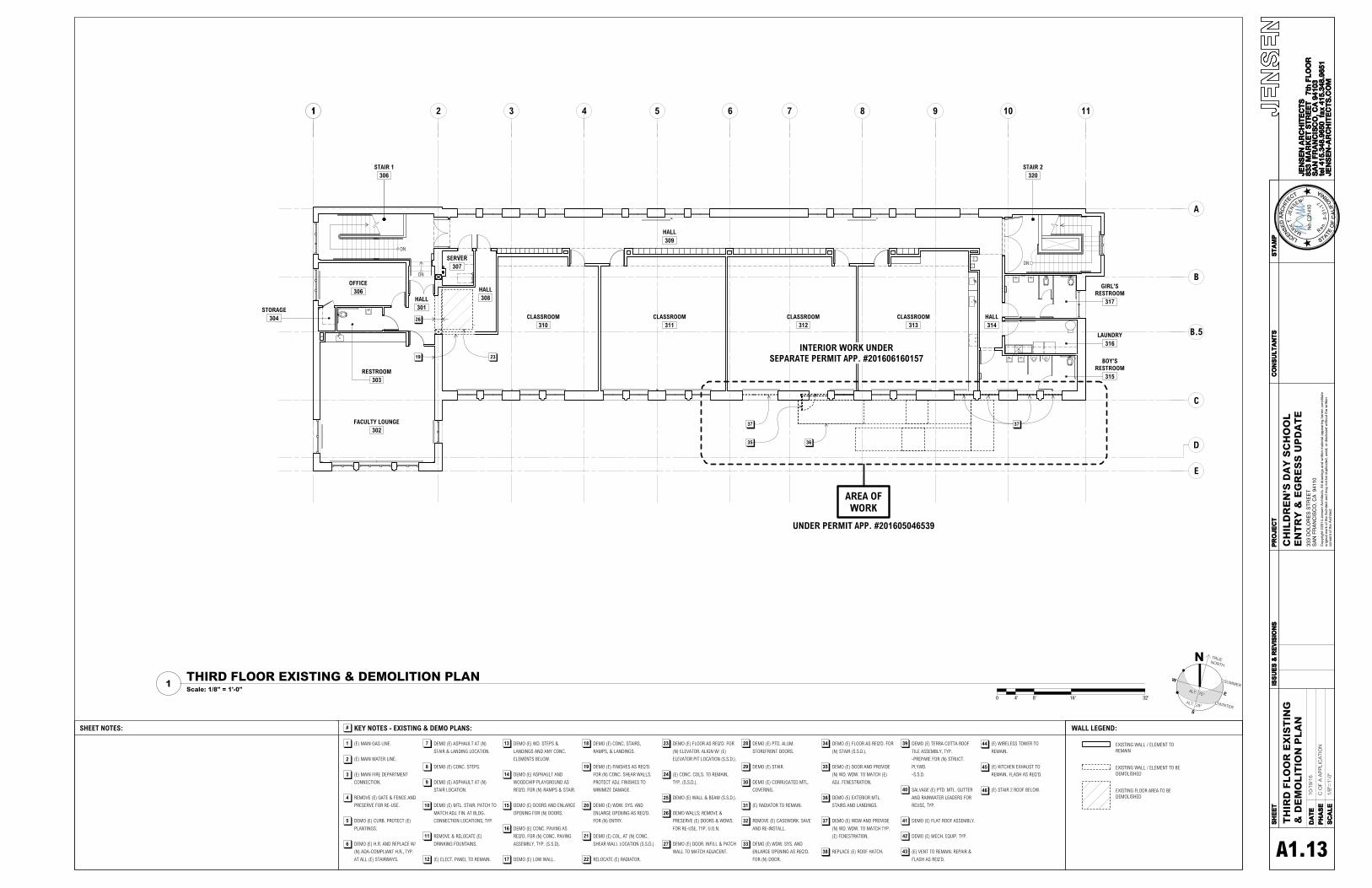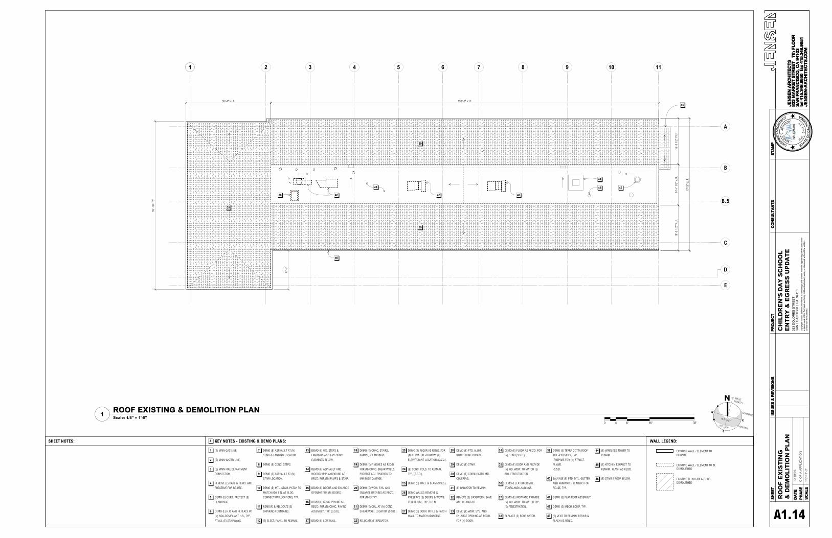
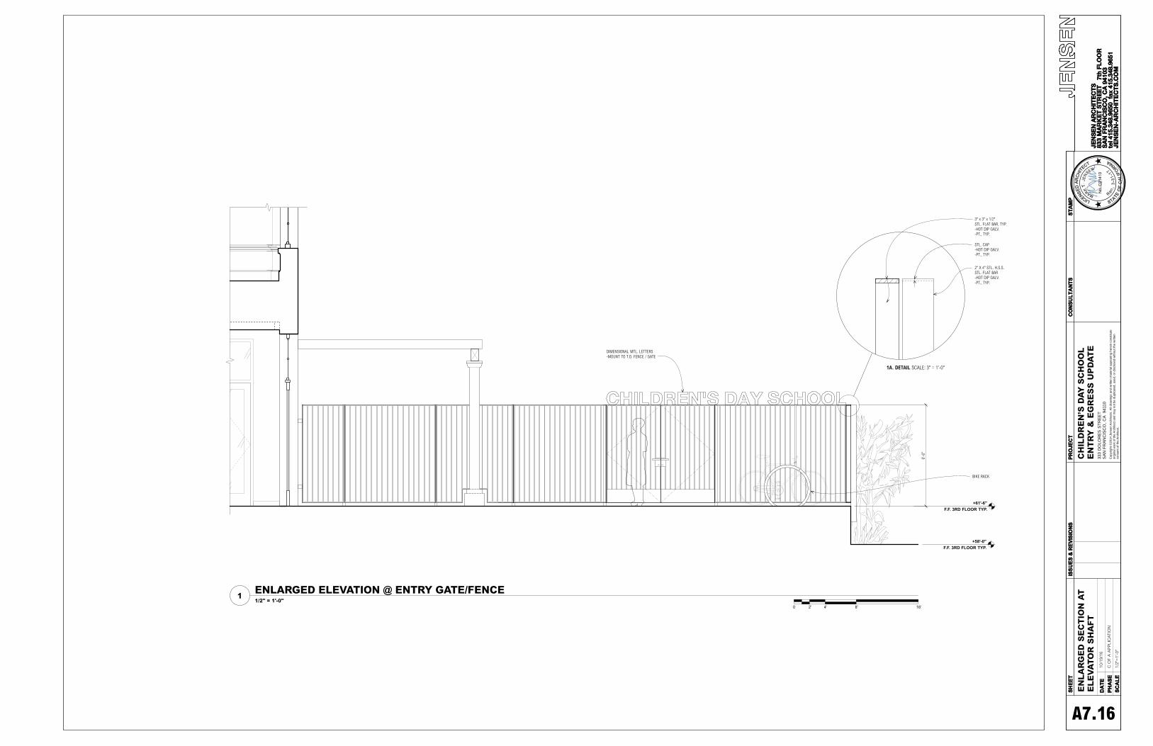
Copyright
©2014 J
ensen
Arc
hitects
. A
ll dra
win
gs a
nd
written
mate
rial appearing
here
in c
onstitu
te
origin
al w
ork
of th
e A
rchitect
and
may n
ot be
duplic
ate
d, used,
or
dis
clo
sed w
ithout
the w
ritten
consent
of
the A
rchitect.
C O
F A
AP
PLI
CA
TIO
N
333
DO
LO
RE
S S
TR
EE
TS
AN
FR
AN
CIS
CO
, C
A
94110
10/1
9/16
1/2"
=1'
-0"
CH
ILD
RE
N’S
DA
Y S
CH
OO
LE
NT
RY
& E
GR
ES
S U
PD
AT
EE
NL
AR
GE
D S
EC
TIO
N A
TE
LE
VA
TO
R S
HA
FT
A7.16
0 2' 4' 8' 16'
ENLARGED ELEVATION @ ENTRY GATE/FENCE1/2" = 1'-0"
1
+58'-0"F.F. 3RD FLOOR TYP.
+61'-6"F.F. 3RD FLOOR TYP.
6'-6
"
DIMENSIONAL MTL. LETTERS-MOUNT TO T.O. FENCE / GATE
3" x 3" x 1/2"STL. FLAT BAR, TYP.-HOT DIP GALV.-PT., TYP.
2" X 4" STL. H.S.S.STL. FLAT BAR-HOT DIP GALV.-PT., TYP.
STL. CAP-HOT DIP GALV.-PT., TYP.
1A. DETAIL SCALE: 3" = 1'-0"
BIKE RACK

3"
42"
TYP.
A.F.
F.,
TYP.
AT
GUAR
DRAI
L
2" X 3/8" STL. FLAT BAR,TYP. AT GUARDRAIL-GALV.-PT., TYP.
1-1/4" O.D. GALV. STL. TUBE-PT., TYP.
1/2" DIA. STL. RODHANDRAIL BRACKET -WELD TO GUARDRAIL-PT., TYP.
4"CO
NC. C
URB
3" TYP.
1-1/4" O.D. GALV. STL. TUBE-PT., TYP.
1/2" DIA. STL. RODHANDRAIL BRACKET -WELD TO GUARDRAIL-PT., TYP.
2" X 3/8" STL. FLAT BAR,TYP. AT GUARDRAIL-GALV.-PT., TYP.
Copyright
©2014 J
ensen
Arc
hitects
. A
ll dra
win
gs a
nd
written
mate
rial appearing
here
in c
onstitu
te
origin
al w
ork
of th
e A
rchitect
and
may n
ot be
duplic
ate
d, used,
or
dis
clo
sed w
ithout
the w
ritten
consent
of
the A
rchitect.
C O
F A
AP
PLI
CA
TIO
N
333
DO
LO
RE
S S
TR
EE
TS
AN
FR
AN
CIS
CO
, C
A
94110
10/1
9/16
AS
NO
TED
CH
ILD
RE
N’S
DA
Y S
CH
OO
LE
NT
RY
& E
GR
ES
S U
PD
AT
EE
NL
AR
GE
D S
EC
TIO
N A
TE
LE
VA
TO
R S
HA
FT
A7.17
(E) COLUMN
42"
(E) WALL BEYOND
61'-6"RAISED CONC. SLAB
+/-58'-0"(E) GRADE
+/-3
'-6"
62'-9 1/2"(E) LOW WALL
1'-3
1/2
"V.
I.F.
EAST STEPS BEYOND
VARI
ES
36" 42
"
24"
4
A7.16
3
A7.16
TYP.
TYP.
4"
TYP.
CURB
, TYP
.
(N) GALV. STL. GUARDRAIL- PT. , TYP.
TYP.
3'-0
"
TREAD + 12"61'-6"RAISED CONC. SLAB
59'-6"(E) CONC. SLAB (FOR REF)
58'-0"(E) ASPHALT
3'-6
"
62'-9 1/2"(E) LOW WALL BEYOND
1'-3
1/2
"V.
I.F.
NOTES: - HANDRAILS ON EACH SIDE OF ALL STAIRS TO COMPLY WITH SFBC 1133B.4.2- PROVIDE 2" CONTRASTING STRIPING ON ALL TREADS PER SFBC 1133B.4.4- S.S.D. FOR MORE SLAB, TREADS, AND RAILING INFO.
2'-0
"TY
P.
TYP.
(N) GALV. STL. HANDRAIL- PT. , TYP.
(N) GALV. STL. GUARDRAIL- PT. , TYP.
(E) CONC. STEPS - FOR REFERENCE
(E) WALLBEYOND
TYP. EXTERIOR STAIR & HANDRAIL1/2"=1'-0"
1
--
TYP. SECTION THROUGH RAMP1/2"=1'-0"
2HANRAIL / GUARDRAIL AT RAMP3"=1'-0"
3GUARDRAIL AT PORCH (103)3"=1'-0"
4

Copyright
©2014 J
ensen
Arc
hitects
. A
ll dra
win
gs a
nd
written
mate
rial appearing
here
in c
onstitu
te
origin
al w
ork
of th
e A
rchitect
and
may n
ot be
duplic
ate
d, used,
or
dis
clo
sed w
ithout
the w
ritten
consent
of
the A
rchitect.
C O
F A
AP
PLI
CA
TIO
N
333
DO
LO
RE
S S
TR
EE
TS
AN
FR
AN
CIS
CO
, C
A
94110
10/1
9/16
AS
NO
TED
CH
ILD
RE
N’S
DA
Y S
CH
OO
LE
NT
RY
& E
GR
ES
S U
PD
AT
ED
OO
R T
YP
ES
TY
PE
S A
ND
SC
HE
DU
LE
S
A7.21
CHILDREN'S DAY SCHOOL: ENTRY & EGRESSJensen ArchitectsDate: September 1, 2016
080610 EXTERIOR DOOR SCHEDULE
NO. TYPESIZE
SET THICK.MATERIAL / FINISH
GLAZING RATING HDWR. GROUP
LOCATIONREMARKS
WIDTH HEIGHT DOOR FRAME ROOM NO.
1 3'-0" 8'-0" SINGLE 1 3/4" WOOD WOOD CLEAR, SAFETY N/R TBD CLASSROOM 113 CUSTOM2 8'-0" 8'-0" DOUBLE 1 3/4" ALUMINUM ALUMINUM CLEAR, SAFETY N/R TBD STAIR 3 130 CUSTOM3 3'-0" 8'-0" SINGLE 1 3/4" WOOD WOOD CLEAR, SAFETY N/R TBD CLASSROOM 112 CUSTOM4 3'-0" 8'-0" SINGLE 1 3/4" WOOD WOOD CLEAR, SAFETY N/R TBD LOBBY 111 CUSTOM5 6'-0" 8'-0" DOUBLE 1 3/4" WOOD WOOD CLEAR, SAFETY N/R TBD LOBBY 111 CUSTOM6 7'-0" 6'-6" DOUBLE 3" STL. STL. N/A N/R TBD ENTRY 101 CUSTOM
DOOR TYPE A2
TYPE: WOOD-FRAMED EXTERIOR DOOR IN (E) FENESTRATION (SEE WINDOW TYPE C3)HEIGHT & WIDTH VARY, SEE SCHEDULEFRAME: WOODGLAZING: MATCH (E) FENESTRATION GLAZING (DIVIDED LIGHT).RATING: N/R
EQ. EQ.
36"
TEMPEREDSAFETY GLAZING,TYP.
12"
STL.
KICK
1
A7.21
DOOR TYPE A1
TYPE: WOOD-FRAMED EXTERIOR DOOR IN (E) FENESTRATION (SEE WINDOW TYPE C2)HEIGHT & WIDTH VARY, SEE SCHEDULEFRAME: WOODGLAZING: MATCH (E) FENESTRATION GLAZING (DIVIDED LIGHT).RATING: N/R
36"
12"
STL.
KICK
TEMPEREDSAFETY GLAZING,TYP.
V.I.F
.1
A7.21
EXTERIOR DOORS1/2"=1'-0"
2
SCHEDULES1/2"=1'-0"
3
(N) CUSTOM WD. DIVIDED LIGHT ENTRANCE DOOR3" = 1'-0"
1
12"
EXTERIOR INTERIOR
DOOR TYPE C1
TYPE: STEEL GATEHEIGHT: 6'-6"FRAME: STEELFINISH: PAINT TO MATCH EXISTING
36"
EQ. EQ.
10"
STL.
KICK
B. TYPICAL DETAIL AT CUSTOM MUNTINFULL SIZE
1 3/4"
3/8"
7/8"
CUSTOM PROFILE TOMATCH EXISTING HISTORICALWINDOWS, TYP.
A. DETAIL AT CUSTOM BOTTOM RAILFULL SIZE
1 3/4"
1/4"
TEMPEREDSAFETYGLASS
CUSTOM PROFILE TOMATCH EXISTING HISTORICALWINDOWS, TYP.
C. DETAIL AT CUSTOM TOP RAILFULL SIZE
TEMPEREDSAFETYGLASS
1/4"
1 3/4"
CUSTOM PROFILE TOMATCH EXISTING HISTORICALWINDOWS, TYP.
NOTE: NEW ENTRANCE DOORS CUSTOM MADE TO MATCH HISTORICALFACADE OPENINGS

Copyright
©2014 J
ensen
Arc
hitects
. A
ll dra
win
gs a
nd
written
mate
rial appearing
here
in c
onstitu
te
origin
al w
ork
of th
e A
rchitect
and
may n
ot be
duplic
ate
d, used,
or
dis
clo
sed w
ithout
the w
ritten
consent
of
the A
rchitect.
C O
F A
AP
PLI
CA
TIO
N
333
DO
LO
RE
S S
TR
EE
TS
AN
FR
AN
CIS
CO
, C
A
94110
10/1
9/16
1/2"
=1'
-0"
CH
ILD
RE
N’S
DA
Y S
CH
OO
LE
NT
RY
& E
GR
ES
S U
PD
AT
EW
IND
OW
TY
PE
SA
ND
SC
HE
DU
LE
S
A7.22
WINDOW TYPE A1
TYPE: TRIPARTITE WOOD-FRAMED WINDOWHEIGHT & WIDTH VARY, SEE SCHEDULEFRAME: WOOD TO MATCH (E) ADJ. FRAMEGLAZING: MATCH (E) ADJ. GLAZINGRATING: N/R
2
A7.22
WINDOW TYPE C2
TYPE: WOOD FRAMED WINDOW LITESHEIGHT & WIDTH VARY, SEE SCHEDULEFRAME: WOOD TO MATCH (E) ADJ. FRAMEGLAZING: MATCH (E) ADJ. GLAZINGRATING: N/R
AREA
OF
(N) W
INDO
W
AREA OF(N) WDW.
DOOR DASHED FORREFERENCE. SEE DOOR TYPE A1 & A2.
2
A7.22
WINDOW TYPE B1
TYPE: BIPARTITE WOOD-FRAMED WINDOWHEIGHT & WIDTH VARY, SEE SCHEDULEFRAME: WOOD TO MATCH (E) ADJ. FRAMEGLAZING: MATCH (E) ADJ. GLAZINGRATING: N/R
2
A7.22
WINDOW TYPE C1
TYPE: PARTIAL MULTI-PARTITE WOOD-FRAMED WINDOWHEIGHT & WIDTH VARY, SEE SCHEDULEFRAME: WOOD TO MATCH (E) ADJ. FRAMEGLAZING: MATCH (E) ADJ. GLAZINGRATING: N/R
AREA
OF
(N) W
INDO
W
AREA OF (N) WINDOW
(E) WDW. SYS.SHOWN DASHED FOR REFERENCE.
2
A7.22
EXTERIOR WINDOWS1/2"=1'-0"
1
SCHEDULES1/2"=1'-0"
3
CHILDREN'S DAY SCOOL: ENTRY & EGRESSJensen ArchitectsDate: September 1, 2016
080650 EXTERIOR WINDOW / STOREFRONT SCHEDULENOMINAL SIZE ASSEMBLY LOCATION
NO. TYPE WIDTH HEIGHT OPERATION THICK. GLAZING FRAME ROOM NO. REMARKS1 A1 24'-0" 13'-10" FIXED 6" 1" I.G.U. SB60 ALUM. ASSEMBLY 1012 A1 24'-0" 13'-10" FIXED 6" 1" I.G.U. SB60 ALUM. ASSEMBLY 1013 A1 24'-0" 13'-10" FIXED 6" 1" I.G.U. SB60 ALUM. ASSEMBLY 1014 A1 24'-0" 13'-10" FIXED 6" 1" I.G.U. SB60 ALUM. ASSEMBLY 1015 A1 24'-0" 13'-10" FIXED 6" 1" I.G.U. SB60 ALUM. ASSEMBLY 1016 A1 24'-0" 13'-10" FIXED 6" 1" I.G.U. SB60 ALUM. ASSEMBLY 1017 A1 24'-0" 13'-10" FIXED 6" 1" I.G.U. SB60 ALUM. ASSEMBLY 1018 A1 24'-0" 13'-10" FIXED 6" 1" I.G.U. SB60 ALUM. ASSEMBLY 101
(N) CUSTOM WD. DIVIDED LIGHT WINDOW SYSTEM3" = 1'-0"
2
EXTERIOR INTERIOR
2 1/
4"2
1/4"
2 1/
8"2
1/4"
V.I.F
.TO
MAT
CHEX
ISTI
NG
V.I.F
.TO
MAT
CHEX
ISTI
NG
V.I.F
.TO
MAT
CHEX
ISTI
NG
B. TYPICAL DETAIL AT CUSTOM MUNTINFULL SIZE
1 3/4"
3/8"
7/8"
A. DETAIL AT CUSTOM BOTTOM RAILFULL SIZE
1 3/4"
1/4"
TEMPEREDSAFETYGLASS
C. DETAIL AT CUSTOM TOP RAILFULL SIZE
TEMPEREDSAFETYGLASS
1/4"
1 3/4"
NOTE: NEW WINDOWS CUSTOM MADE TO MATCH HISTORICALFACADE OPENINGS

Cop
yrig
ht ©
2014
Jen
sen
Arc
hite
cts.
All
draw
ings
and
writ
ten
mat
eria
l app
earin
g he
rein
con
stitu
te
orig
inal
wor
k of
the
Arc
hite
ct a
nd m
ay n
ot b
e du
plic
ated
, use
d, o
r di
sclo
sed
with
out t
he w
ritte
n co
nsen
t of t
he A
rchi
tect
.
333
DO
LOR
ES
ST
RE
ET
SA
N F
RA
NC
ISC
O, C
A 9
4110
Copyright © 2022 FDOKUMEN