Standard operating procedure for eligibility to centralised ...
Upload
khangminh22Category
view
5download
0
CENTRALISED PATIENT HEART RATE
MONITORING SYSTEM USING HEART RATE
SENSOR
NURUL SYAMIMI BINTI MAHMAD SUKRI
BACHELOR OF COMPUTER SCIENCE
(INTERNET COMPUTING)
UNIVERSITI SULTAN ZAINAL ABIDIN
2019

2
DECLARATION
I hereby declare that the report of the project titled Centralised Patient Heart Rate Monitoring
System using heart rate sensor in Web-Based Application is based on my own investigations
based on information from sources that stated. I also declare that my work was never be
produced by any student of Sultan Zainal Abidin.
________________________________
Name: ..................................................
Date: ...................................................

3
CONFIRMATION
I have read this report and in my point of view, this project fulfils the conditions and
requirements to be awarded as Bachelor of Computer Science (Internet Computing) with
honour. I also confirm that the research conducted and the writing of this report was under my
supervisor.
________________________________
Name: ..................................................
Date: ...................................................
4
DEDICATION
First of all, thanks to Allah the most merciful and the most gracious. I would like to
thanks to my parents who give me a bunch of supportive on my studies time. A gracefully
thanks to my supervisor Dr Azrul Amri bin Jamal for his guidance and support in my academic.
I am very thankful of his patience and invaluable advises that inspired me to keep on achieving
my dream and felt honoured with his trust on my capability.
Last but not least, special thanks to my beloved friends for providing moral support
during my studies. Not forgetting those who have directly or indirectly helped me on this thesis.
May Allah rewards your kindness in abundance in this world and next.
5
ABSTRACT
Centralised patient heart rate monitoring system is a system that specifically developed
to make sure the nurse be alert to the notification from the web based system. The heart rate
monitor machine is not centralised because the nurse must be alert to each patient’s heart rate
machine which is located far from nurse side. By using heart rate sensor, we can study how the
system detect the pulse of patient for monitoring their heart rate. In this whole system, the heart
rate are converted into waveform and displays on screen. When the heart rate of patient is not
normalised, it will trigger the notifications to the system so that the nurse aware and take the
right action. The method that I use to build this system is the heart rate sensor to detect the
pulses by means of a sensor secured against the patient’s skin and web based system to display
patient’s information by giving out the notifications. This system will ease the nurse job from
visiting each patients by giving out the notification and identify which patients from database
to take an action.

6
ABSTRAK
Sistem pengawasan kadar denyutan pesakit berpusat adalah sistem yang dibangunkan
khusus untuk memastikan jururawat berwaspada dengan notifikasi daripada sistem berasaskan
web. Mesin pemantau kadar jantung tidak berpusat kerana jururawat mesti berjaga-jaga
terhadap setiap mesin denyutan jantung pesakit yang terletak jauh dari sisi jururawat. Dengan
menggunakan sensor denyutan jantung, kita dapat mengkaji bagaimana sistem mengesan nadi
pesakit untuk mengawasi kadar jantung mereka. Dalam keseluruhan sistem ini, kadar denyutan
jantung akan ditukar kepada bentuk gelombang dan dipaparkan pada skrin. Apabila kadar
jantung pesakit tidak normal, ia akan mencetuskan notifikasi kepada sistem supaya jururawat
peka dan mengambil tindakan yang betul. Kaedah yang saya gunakan untuk membina sistem
ini ialah sensor denyutan jantung untuk mengesan denyutan dengan menggunakan sensor yang
diletakkan terhadap kulit dan sistem berasaskan web pesakit untuk memaparkan maklumat
pesakit dengan memberi notifikasi. Sistem ini akan memudahkan kerja jururawat daripada
melawat setiap pesakit dengan memberi notifikasi dan mengenal pasti pesakit mana dari
pangkalan data untuk mengambil tindakan.

7
Table of Contents
Page
ABSTRACT ........................................................................................................................................... 5
ABSTRAK ............................................................................................................................................. 6
CHAPTER I .......................................................................................................................................... 9
INTRODUCTION ................................................................................................................................. 9
1.1 Project Background ........................................................................................................................ 9
1.2 Problem Statement ........................................................................................................................ 11
1.3 Objectives....................................................................................................................................... 11
1.4 Scope .............................................................................................................................................. 12
1.5 Limitation ...................................................................................................................................... 13
1.6 Expected Result ............................................................................................................................. 13
CHAPTER II ....................................................................................................................................... 14
LITERATURE REVIEW .................................................................................................................. 14
2.1 Introduction ................................................................................................................................ 14
2.2 Research ...................................................................................................................................... 14
2.2.1 ECG Monitoring System ........................................................................................................ 14
2.2.2 Previous ECG Monitoring System Review ........................................................................... 15
2.3 Overview of Article .................................................................................................................... 16
2.3.1 IoT-cloud based Monitoring System ..................................................................................... 16
2.3.2 Automated Remote Cloud-Based Heart Rate Variability ................................................... 17
2.3.3 Real-Time Health Monitoring System .................................................................................. 18
2.3.4 Remote Heart Rate Monitoring System using IoT ............................................................... 19
2.4 Existing Application or System ................................................................................................. 20
2.5 Summary ..................................................................................................................................... 22
CHAPTER III ..................................................................................................................................... 23
PROJECT METHODOLOGY .......................................................................................................... 23
3.1 Introduction ................................................................................................................................... 23
3.2 Waterfall model ............................................................................................................................. 24
3.2.1 Stage 1: Requirement ................................................................................................................ 25
3.2.2 Stage 2: Design ........................................................................................................................... 25
3.2.3 Stage 3: Implementation/ Execution ........................................................................................ 25
3.2.4 Stage 4: Testing .......................................................................................................................... 25
3.2.5 Stage 5: Deployment/Release .................................................................................................... 26
8
3.3 Hardware Requirement ................................................................................................................ 27
3.4 Software Requirement .................................................................................................................. 28
3.3 System Design ................................................................................................................................ 29
3.3.1 Context Diagram ........................................................................................................................ 29
3.4 Data Model .................................................................................................................................... 30
3.4.1 Data Flow Diagram (DFD) ........................................................................................................ 30
3.4.2 Entity Relationship Diagram (ERD) ........................................................................................ 31
3.5 Framework .................................................................................................................................... 32
3.6 Data Dictionary ............................................................................................................................. 33
3.6.1 Admin Database ......................................................................................................................... 33
3.6.2 Doctor Database ......................................................................................................................... 33
3.6.3 Nurse Database ........................................................................................................................... 34
3.6.4 Sensor Database ......................................................................................................................... 34
3.6.5 Patient Database ......................................................................................................................... 35
3.7 Prototype Evaluation .................................................................................................................... 36
3.8 Refined the End Functionality ..................................................................................................... 36
3.9 Proof of Concept ........................................................................................................................... 37
References ............................................................................................................................................ 42
APPENDIX .......................................................................................................................................... 44
9
CHAPTER I
INTRODUCTION
1.1 Project Background
Malaysia is a unique country with its multi-ethnic and cultural diversity
population. With 28.3 million of population in 2009, Malaysia had reached the best
level of health status. Along with the rapid developing world, there are a lot of diseases
related to lifestyles. According to Healthcare Service Industry in Malaysia for both
females and males, they were expected to live for 76 years and 72 years respectively,
while maternal and infant life expectancy rates were 0.3 and 6.4 per 1000 live births,
respectively. Ischemic heart disease (IHD) and cerebrovascular disease (CVD) was the
primary cause of death for both females and males in 2009. Comparing to developed
countries such as Singapore, Malaysia is still dominated the best health status. (Maznah
Dahlui, 2012)
Global phenomena are growing rapidly corresponding with the evolution of
technology. Before the advent of technology, our society is burdened because all chores
consumed a lot of energy and our times. Therefore, we are introduced to technological
advancements to ease all of our works and save our gold times in any field. The
10
advancements technology provided the quality of service that plays a critical role in
customer’s satisfaction. Service quality satisfaction is the most important thing for user
to provide their meets or exceed the user’s expectation in their services. The services
provided within the organization can be divided into two parts namely as technical and
functional quality.
In the healthcare field, quality is based on the technical accuracy of the
diagnosis and procedure. All of the information generally can be access by health care
providers only. While functional quality is referred to the health care service that
provided to the patient and it will be the sign of patient quality perception. In this case,
the hospital provides many services for their patients with medicine and machines that
help their works for monitoring and improving the quality of healthcare. For patients
with heart disease, the doctors monitor them using the electrocardiogram (ECG) to
make sure their patient’s heart rate in normal condition. Nowadays, many patients
suffer from heart disease and the doctor needs more times to spend on monitoring their
patient’s heart rate. Sometimes, the doctors not alert to the sound from a machine’s
patient. However, it is difficult for the doctor to monitor every patient in the ward
because they have a lot of responsibilities.
Therefore, Centralised Patient Heart Rate Monitoring System Using Heart Rate
Sensor aims to ease the doctors to monitor and identify which patient in the database to
take the right action. The notification will pop up on the screen to show which patient’s
bed need help. As an addition, many nurses can use this system to monitor the patients
in the ward. Lastly, it is also can reduce the confusion by detecting which patient has
an urgent case.

11
1.2 Problem Statement
A study found that the electrocardiogram (ECG) machine is an assessment tool
for a heart condition. However, it is a very low evaluation tool to measure the heart rate
patient because the monitor is not centralized. The nurse needs to visit every patient’s
bed to make sure the heartbeat rate is normal. Therefore, when the patient’s bed is far
from the nurse’s sight, the nurse might not be alert to the alarm from the heart rate
machine.
Hence, to solve this problem, this system can be improved by centralizing the
machine into professional monitoring. By doing so, it will alert the nurse when a
notification is popped out on the monitor screen to inform the nurse about the patient’s
condition.
1.3 Objectives
The objective is generally to develop a system that can allow the nurse access for
monitoring their patient’s heart rate and it will replace old method which usually done
by visiting their patient’s bed every time. For the main objective of these projects are
as follows:
i. To analyse how the heart rate sensor is implement into the web-based
system and connect to the database.
ii. To design a system for nurse to monitor their patient’s condition of
heart rate and detect which patient has an urgent case.
iii. To implement and test the functionality of the developed application
that meets the requirement.
12
1.4 Scope
In this project scope involves admin, doctor and nurse only.
1.4.1 Admin
• Able to login
• Able to add, update, delete and view the doctor, nurse and patient.
• Able to manage sensor
1.4.2 Doctor
• Register
• Login
• Able to view schedule
• Able to view list of nurse
• Able to view patient
1.4.3 Nurse
Register
Login
Able to manage patient
Able to view schedule

13
1.5 Limitation
The limitation of this system is power supply. The sensor that will be used in
this system are requires the network connection. When there is no network connection,
this system will not successful functionally. Therefore, this system need the continuous
and strong connection to completely working.
1.6 Expected Result
The expected result for this system is it will function efficiently and successfully
developed using heart rate sensor. The heart rate of the patients can be detect by means of a
sensor secured against the patient’s skin, then the heart rate will transform into waveforms and
display on the screen monitor. The system will set the level of heart rate into two conditions
which is normal and not normal. When the heart rate of patient in not normalised, the system
will trigger notification on screen, then the nurse will take action of that patient.
14
CHAPTER II
LITERATURE REVIEW
2.1 Introduction
This chapter discussed and describe selected research paper and previous
journal that trace similar technique and topic that can be references for the Centralised
Heart Rate Monitoring System using heart rate sensor. By making research from existing
application or system, it can help to give a lot of ideas and useful information for
development of this project.
2.2 Research
2.2.1 ECG Monitoring System
Most of six millions people every year have been reported due to heart disease
and died before reaching the hospital. This disease actually can avoid and prevent by
using electrocardiograph (ECG) which is capable to detect, monitor and provide useful
information of heart condition. It is an important tool that become standard procedure
to diagnose the heart since 1940s which is develop with electrically primitive analog
electronic.

15
ECG monitoring system is the first electronic device developed using
electrically primitive analog. This monitoring system is used in health care environment
especially in hospital. It was developed to measure the patient heart rate for determine
their health continuously. (A.M.Khairuddin, 2018)
2.2.2 Previous ECG Monitoring System Review
Based on the research, there are some limitations of the previous ECG
monitoring system based on their capabilities and performance. Existing ECG
monitoring system not capable to detect the different physical activities of the patients
which is save the time of doctor to check-up every patient’s condition. The previous
review show that, this system not detect the vital sign of the earliest stage of heart
disease such as body temperature, respiration and blood pressure. The intelligent sensor
is known as important technology in improving ECG monitoring system. It has
surprisingly a lot advantages that can provide a uniform monitoring system.
(A.M.Khairuddin, 2019)

16
2.3 Overview of Article
2.3.1 IoT-cloud based Monitoring System
Based on research, there are several articles that similar to the proposed project.
Firstly, the article titled An IoT-cloud based Wearable ECG Monitoring System for
Smart Healthcare by Zhe Yang. This article explained an effective monitoring system
that collect the data from the abnormalities of health using a wearable monitoring node
then transmitted directly to the IoT cloud through Wi-Fi.
The data that have been stored in IoT-cloud based is analysed efficiently. By
using IoT cloud, the processed data and analysis tasks can be compute intensively that
ease the smart devices to process. Generally, IoT cloud for ECG monitoring system has
four functional modules such as data cleaning, data storage, data analysis and disease
warning.
Data Cleaning: detect the potential heart disease and provide ECG signal.
Data Storage: Need to store the history of data for further analysis and make
one copy for disaster recovery.
Data Analysis: to analyze and extract of ECG signal into useful information.
Disease Warning: To give real-time notification for patient’s family and
doctor.

17
The architecture of IoT-based ECG monitoring system shown as below:
Figure 2.1: Architecture of IoT-based ECG monitoring system
2.3.2 Automated Remote Cloud-Based Heart Rate Variability
The second article titled An Automated Remote Cloud-Based Heart Rate
Variability Monitoring System explains that the development of system which is used
to monitor the heart rate in different physical activities. The heart rate of the user is
recorded by using ECG device the directly transmit to cloud-based. This system
conceptualizes two-way communication between patient and healthcare provider.
Besides, this monitoring system works to gather the data in two different
database. First, it is comes from MIT Physionet database which is stored the MIT-BIH
sinus rhythm and MIT-St Petersburg. While the second database, data is collected using
wearable sensor for monitoring people. When critical situation occurs, this system will
generate warning messages directly to the patients and doctors. [Ahmed Fa Hussein,
2018]
18
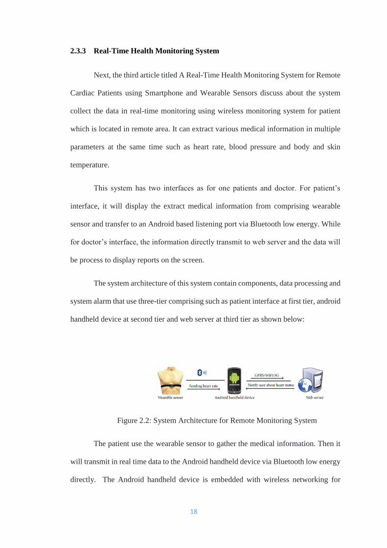
2.3.3 Real-Time Health Monitoring System
Next, the third article titled A Real-Time Health Monitoring System for Remote
Cardiac Patients using Smartphone and Wearable Sensors discuss about the system
collect the data in real-time monitoring using wireless monitoring system for patient
which is located in remote area. It can extract various medical information in multiple
parameters at the same time such as heart rate, blood pressure and body and skin
temperature.
This system has two interfaces as for one patients and doctor. For patient’s
interface, it will display the extract medical information from comprising wearable
sensor and transfer to an Android based listening port via Bluetooth low energy. While
for doctor’s interface, the information directly transmit to web server and the data will
be process to display reports on the screen.
The system architecture of this system contain components, data processing and
system alarm that use three-tier comprising such as patient interface at first tier, android
handheld device at second tier and web server at third tier as shown below:
Figure 2.2: System Architecture for Remote Monitoring System
The patient use the wearable sensor to gather the medical information. Then it
will transmit in real time data to the Android handheld device via Bluetooth low energy
directly. The Android handheld device is embedded with wireless networking for

19
communicate with web server. The GPS application that inbuilt in the device will helps
them to find out the location of the user. Then, the extract data and information of
individual will display on doctor’s interface. [Kakria, Tripathi, Kitipawang, 2015]
2.3.4 Remote Heart Rate Monitoring System using IoT
The fourth article is Remote Heart Rate Monitoring System using IoT discuss
to monitor the condition of heart rate patient in more efficient manner from remote
location. This system works by using pulse rate sensor, Arduino UNO, Raspberry Pi 3
and ThingSpeak cloud.
This monitoring system capable to gather the heart rate using pulse rate sensor
that placed on wrist of the person then the sensor send the extract information to
Arduino UNO. The data will stored in the cloud in a form of graph. If the heart rate of
the person is in abnormal condition, the led will blink into red colour then it will trigger
an alerting message through email or SMS message to doctor while the heart rate in
normal, the led will blink into green colour. [Kazi, Bajantri, Thite, 2018]

20
2.4 Existing Application or System
No. System Description Advantages
1.
An IoT-cloud based
Wearable ECG
Monitoring System for
Smart Healthcare
Using IoT- cloud based
Collect the data using
wearable monitoring
node the transmit directly
to cloud via Wi-Fi
Use HTTP and MQTT
protocol
Need a request from user
to display the medical
information
Display ECG data in
real-time
Give visual and
convenient ECG
information to user
2.
An Automated Remote
Cloud-Based Heart Rate
Variability Monitoring
System
Provide two interface for
patient and doctor
Extract data from sensor
and collect some personal
information of patient
with their location.
Data is stored safely
and securely
Provide best health
monitoring service to
the patient in remote
areas.

21
3.
A Real-Time Health
Monitoring System for
Remote Cardiac
Patients using
Smartphone and
Wearable Sensors
Wearable sensor will
gather the data then
transmit to android
handheld device then
transmit to web
application.
Generate alarm message
when critical situation to
the patient and doctor
To ease the cardiac
patient to get latest
healthcare service
Medical status of
patient will received to
the doctor in real-time
when the
abnormalities of
patient occur.
4.
Arduino Based Heart
Rate Monitoring and
Heart Attack Detection
System
Using Arduino
The data of heart rate and
temperature is measure
by clipping sensors on
one of the fingers and
displays result on android
application interface.
Provide an alert with the
sound peeps by buzzer if
the measurement of heart
rate exceed the maximum
or minimum records.
Continuous records
the patient heart rate
and body temperature.
Provide an alarm to
doctor if the signal has
exceed the maximum
and minimum
predetermined value.

22
2.5 Summary
This chapter provides an overview of the concept of the system. Based on the
research that has been carried out, it shows the literature review is an important chapter
to give us the flows and of technique from current and existing system to develop the
proposed system. The technique is chosen based on the previous articles and journal.

23
CHAPTER III
PROJECT METHODOLOGY
3.1 Introduction
In this chapter will be described on the design of implementing the system. The
concept of methodology that I used to develop this Centralised Patient Heart Rate
Monitoring System using heart rate sensor is Waterfall model. This model consist of
four phases that are applied in order to develop the application. This model is more
organized and structured. It will explain more about every phases that involved in this
project development and also in the system requirements.
Besides, the design of implementing the system will be described in this chapter
which is show the system design and database design. In system design, it contains of
context diagram, Data Flow Diagram (DFD) Level 0, and Data Flow Diagram (DFD)
Level 1. Next, for database design, it consists Entity Relationship Diagram (ERD) and
data dictionary.

24
3.2 Waterfall model
Figure 3.1: Waterfall model
The waterfall model is an activity project that divides each phases in sequence
like a waterfall through the phases of Conception, Initiation, Analysis, Design,
Construction, Testing, Production or Implementation and Maintenance. Each phase
must be completed before the next phase to avoid overlapping in that phase.
Requirements
Testing
Execution
Design
Release
25
3.2.1 Stage 1: Requirement
During the early stage, the possible requirements of the system are analysed
thoroughly and documented so that it can be refer during the future development. The
outcome result about requirements that has been documented shows that what the
system should do but not how it should do it. All the requirements for this system has
been gathered through by brainstorming and analysing existing system.
In this project, brainstorming is the best technique to get as many ideas as
possible and it is the most effective for solving problem to generate a list of ideas.
After all the ideas are generated, then prioritize an idea that suitable and the best for
this solution. The resulting agreement of best idea is used for the early requirement.
3.2.2 Stage 2: Design
For this stage, the idea from brainstorming in the requirement phase and the
result from analysing existing system is studied to design the interface in order to meet
the user needs. The interface is proposed to user in order to satisfy user requirement.
3.2.3 Stage 3: Implementation/ Execution
The implementation phase is begin once the design is approved and accepted by
user. This project is developed using PHP and MySQL.
3.2.4 Stage 4: Testing
At this phase, the system will be tested. If any errors are detected then it must
be solved in this phase. Then, if there is other changes want to make, this system need
to be re-implement back to design phase to make sure it does not effect to the flow of
the system.

26
3.2.5 Stage 5: Deployment/Release
After this system is free from any errors, this system is get ready to be deploy.
The testing that take place in this system will approve the system and decide if the
system is ready to deploy or not.

27
3.3 Hardware Requirement
Hardware Description
Laptop Processor: Intel® Core™ i3-5005U CPU
@ 2.00GHz 2.00GHz
RAM: 8.00 GB
OS: Window 10
USB Universal Serial Bus
Brand: Samsung
Function: Connect Arduino with laptop
Printer Function:
To print the report
Heart rate sensor Function:
To measure heart rate of patient.
Table 3.1: List of Hardware Requirement

28
3.4 Software Requirement
Software Description
Microsoft Office
2016 and Microsoft
Power Point
Function:
For report writing and presentation slide.
MySQL Database Function:
To store data.
Google Chrome Function:
To run localhost and to find research papers and information.
Xampp Server Function:
A local server to run and test the system.
Table 3.2: List of Software Requirement

29
3.3 System Design
3.3.1 Context Diagram
Figure 3.2 Context Diagram for Centralised Patient Heart Rate Monitoring System
Centralised Patient Heart Rate Monitoring System consist of four entities which
are Admin, Doctor, Nurse and sensor. As usual, these entities need to login into the
system before able to access the interface. Admin can see schedule information, the list
of doctor and nurse, information of sensor and profile detail of doctor and nurse. For
doctor, they can manage schedule of the nurse. As for nurse, they able to manage the
information of patients that contains the heart rate of patient and medical information.
The sensor is able to view the details of patient’s heart rate.
30
3.4 Data Model
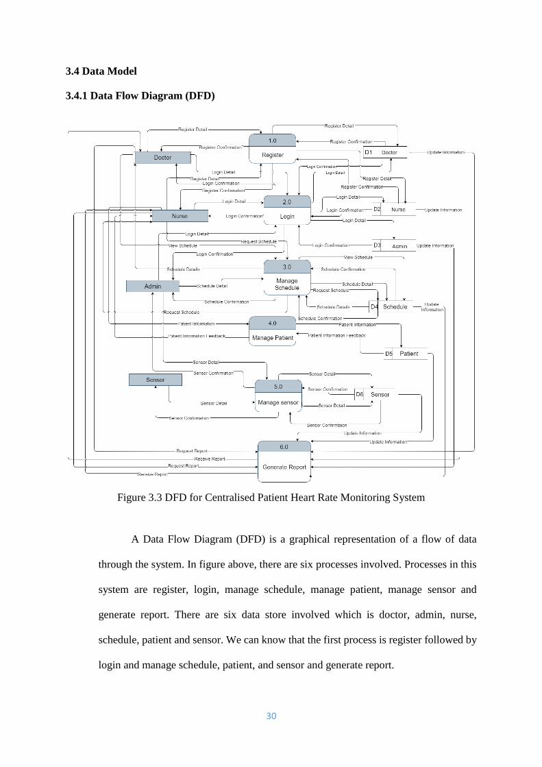
3.4.1 Data Flow Diagram (DFD)
Figure 3.3 DFD for Centralised Patient Heart Rate Monitoring System
A Data Flow Diagram (DFD) is a graphical representation of a flow of data
through the system. In figure above, there are six processes involved. Processes in this
system are register, login, manage schedule, manage patient, manage sensor and
generate report. There are six data store involved which is doctor, admin, nurse,
schedule, patient and sensor. We can know that the first process is register followed by
login and manage schedule, patient, and sensor and generate report.

31
3.4.2 Entity Relationship Diagram (ERD)
Figure 3.4 ERD for Centralized Patient Heart Rate Monitoring System
Figure above shows the entity relational diagram of the system. This diagram
shows the database and their entity that involve in the process for the system. All
updated data in the data store is self-updated by doctor, nurse and sensor. In the
diagram, we can see several lookup tables that is to be inference by the system. For the
login admin, doctor and nurse need email as username and password to proceed the
profile detail page.
32
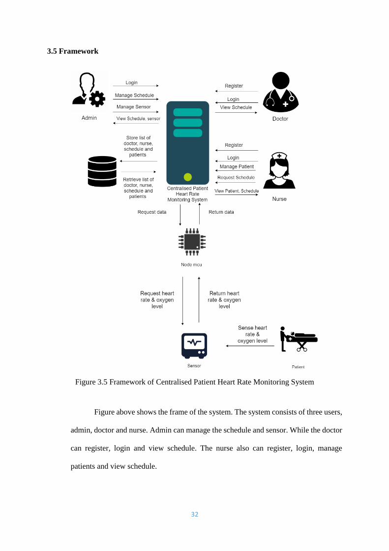
3.5 Framework
Figure 3.5 Framework of Centralised Patient Heart Rate Monitoring System
Figure above shows the frame of the system. The system consists of three users,
admin, doctor and nurse. Admin can manage the schedule and sensor. While the doctor
can register, login and view schedule. The nurse also can register, login, manage
patients and view schedule.

33
3.6 Data Dictionary
3.6.1 Admin Database
Name
Attribute
Type
Description
name None Varchar(50) The name of admin
id_admin Primary key Varchar(20) Admin id
identification
email None Varchar(30) The email of admin
password None Varchar(30) Passcode used by
admin in authenticate
Table 3.3: Database for Admin
3.6.2 Doctor Database
Name
Attribute
Type
Description
name None Varchar(50) The name of doctor
id_doctor Primary key Varchar(20) Doctor id
identification
email None Varchar(20) The email of doctor
password None Varchar(20) Passcode used by
doctor in authenticate
no_phone None Varchar(20) Phone number of
doctor
Table 3.4: Database for Doctor
34
3.6.3 Nurse Database
Name
Attribute
Type
Description
name None Varchar(50) The name of nurse
id_nurse Primary key Varchar(20) Nurse id
identification
email None Varchar(30) The email of doctor
password None Varchar(30) Passcode used by
nurse in authenticate
no_phone None Varchar(20) Phone number of
nurse
no_ward None Varchar(20) Number ward of
patient
comment None Varchar(100) Comment by nurse
about patient’s
condition
Table 3.5: Database for Nurse
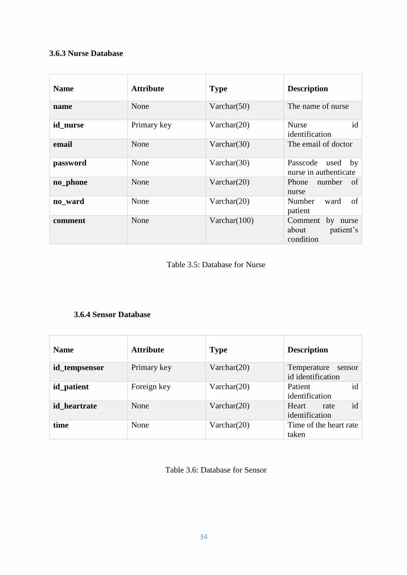
3.6.4 Sensor Database
Name
Attribute
Type
Description
id_tempsensor Primary key Varchar(20) Temperature sensor
id identification
id_patient Foreign key Varchar(20) Patient id
identification
id_heartrate None Varchar(20) Heart rate id
identification
time None Varchar(20) Time of the heart rate
taken
Table 3.6: Database for Sensor
35
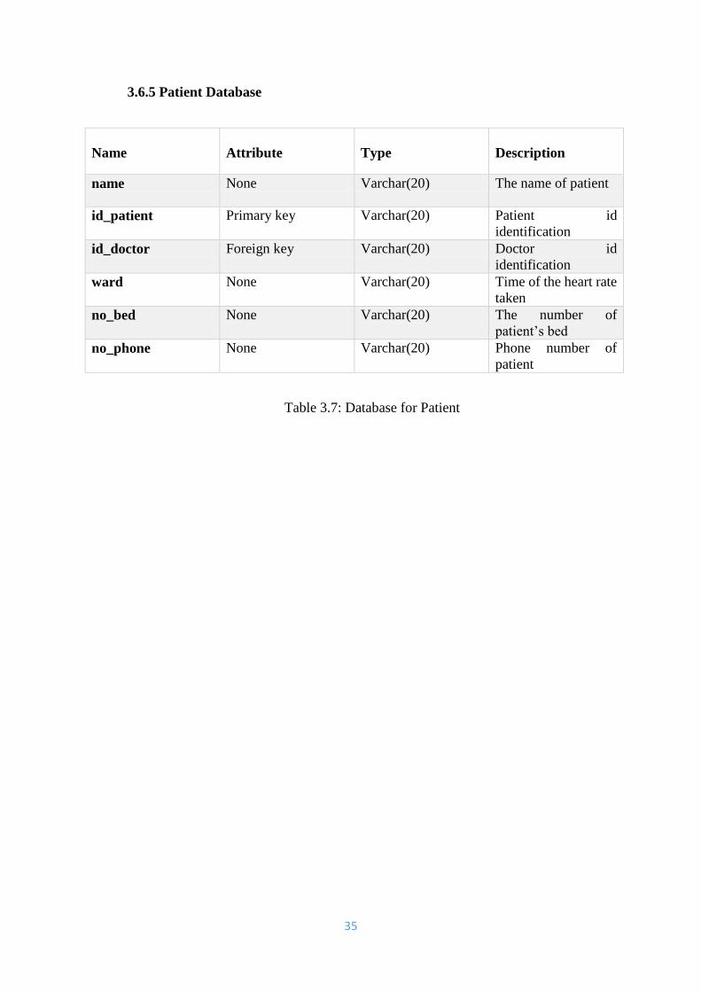
3.6.5 Patient Database
Name
Attribute
Type
Description
name None Varchar(20) The name of patient
id_patient Primary key Varchar(20) Patient id
identification
id_doctor Foreign key Varchar(20) Doctor id
identification
ward None Varchar(20) Time of the heart rate
taken
no_bed None Varchar(20) The number of
patient’s bed
no_phone None Varchar(20) Phone number of
patient
Table 3.7: Database for Patient
36
3.7 Prototype Evaluation
Prototype evaluated phase is where developer show their prototype to the client
and for this proposed project, it is show to the panel. The panel will evaluated is it
satisfy or not. Plus, in this phase also developer able to know what is lack of the system.
Thus, develop will know is it fulfil the requirement of needed or not.
3.8 Refined the End Functionality
This phase is refined the function that cannot be working. First of all, this phase
begin with brainstorming session with the supervisor to come up with the solution of
the problem that occurred and refined the end functionality for the coding project.
37
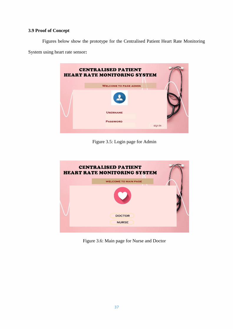
3.9 Proof of Concept
Figures below show the prototype for the Centralised Patient Heart Rate Monitoring
System using heart rate sensor:
Figure 3.5: Login page for Admin
Figure 3.6: Main page for Nurse and Doctor

38
Figure 3.7: Registration and Login Page for Doctor
Figure 3.8: Page Detail for Doctor
Figure 3.9: Home page for Doctor

39
Figure 3.10: Registration and Login Page for Nurse
Figure 3.11: Page Detail for Nurse
Figure 3.12: Home page for Nurse

40
Figure 3.13: Page for Patient record
Figure 3.14: Page for List of Patient
Figure 3.15: Page for Patient Details

41
Figure 3.16: Schedule
Figure 3.17: Notification Alert

42
References
[1] Park, D. Y., Joe, D. J., Kim, D. H., Park, H., Han, J. H., Jeong, C. K., ... & Lee, K.
J. (2017). Self‐powered real‐time arterial pulse monitoring using ultrathin epidermal
piezoelectric sensors. Advanced Materials, 29(37), 1702308.
[2] Yang, Z., Zhou, Q., Lei, L., Zheng, K., & Xiang, W. (2016). An IoT-cloud based
wearable ECG monitoring system for smart healthcare. Journal of medical
systems, 40(12), 286.
[3] Hussein, A. F., Burbano-Fernandez, M., Ramírez-González, G., Abdulhay, E., &
De Albuquerque, V. H. C. (2018). An automated remote cloud-based heart rate
variability monitoring system. IEEE Access, 6, 77055-77064.
[4] Baig, M. M., Gholamhosseini, H., & Connolly, M. J. (2013). A comprehensive
survey of wearable and wireless ECG monitoring systems for older adults. Medical &
biological engineering & computing, 51(5), 485-495
[5] Villanueva-Miranda, I., Nazeran, H., & Martinek, R. (2018, September).
CardiaQloud: A Remote ECG Monitoring System Using Cloud Services for eHealth
and mHealth Applications. In 2018 IEEE 20th International Conference on e-Health
Networking, Applications and Services (Healthcom) (pp. 1-6). IEEE
[6] Baig, M. M., GholamHosseini, H., Moqeem, A. A., Mirza, F., & Lindén, M. (2017).
A systematic review of wearable patient monitoring systems–current challenges and
opportunities for clinical adoption. Journal of medical systems, 41(7), 115
[7] Li, C., Hu, X., & Zhang, L. (2017). The IoT-based heart disease monitoring system
for pervasive healthcare service. Procedia computer science, 112, 2328-2334
[8] Kazi, S., Bajantri, G., & Thite, T. (2018). Remote Heart Rate Monitoring System
Using IoT. IRJET, 5(4)
[9] Alfarhan, Khudhur & Mashor, Mohd & Saad, Abdul. (2016). A REVIEW OF
WIRELESS ECG MONITORING SYSTEMS DESIGN. International Academy of
Engineering and Medical Research (IAEMR). 1.
[10] Dahlui, M. A. Z. N. A. H., & Aziz, N. A. (2012). Developing health service hub
in ASEAN and Asia region country report on healthcare service industry in
Malaysia. DEVELOPINGASEAN ECONOMIC COMMUNITY (AEC) INTO A
GLOBAL SERVICES HUB, 65.
[11] Khairuddin, A. M., KNF, K. A., & Kan, P. E. (2019). A general framework for
improving electrocardiography monitoring system with machine learning. Bulletin of
Electrical Engineering and Informatics, 8(1), 261-268
43
[12] Kakria, P., Tripathi, N. K., & Kitipawang, P. (2015). A real-time health
monitoring system for remote cardiac patients using smartphone and wearable
sensors. International journal of telemedicine and applications, 2015, 8
[13] Shcherbina, A., Mattsson, C. M., Waggott, D., Salisbury, H., Christle, J. W.,
Hastie, T., & Ashley, E. A. (2017). Accuracy in wrist-worn, sensor-based
measurements of heart rate and energy expenditure in a diverse cohort. Journal of
personalized medicine, 7(2), 3.
[14] Parak, J., Tarniceriu, A., Renevey, P., Bertschi, M., Delgado-Gonzalo, R., &
Korhonen, I. (2015, August). Evaluation of the beat-to-beat detection accuracy of
PulseOn wearable optical heart rate monitor. In 2015 37th Annual International
Conference of the IEEE Engineering in Medicine and Biology Society (EMBC) (pp.
8099-8102). IEEE.
44
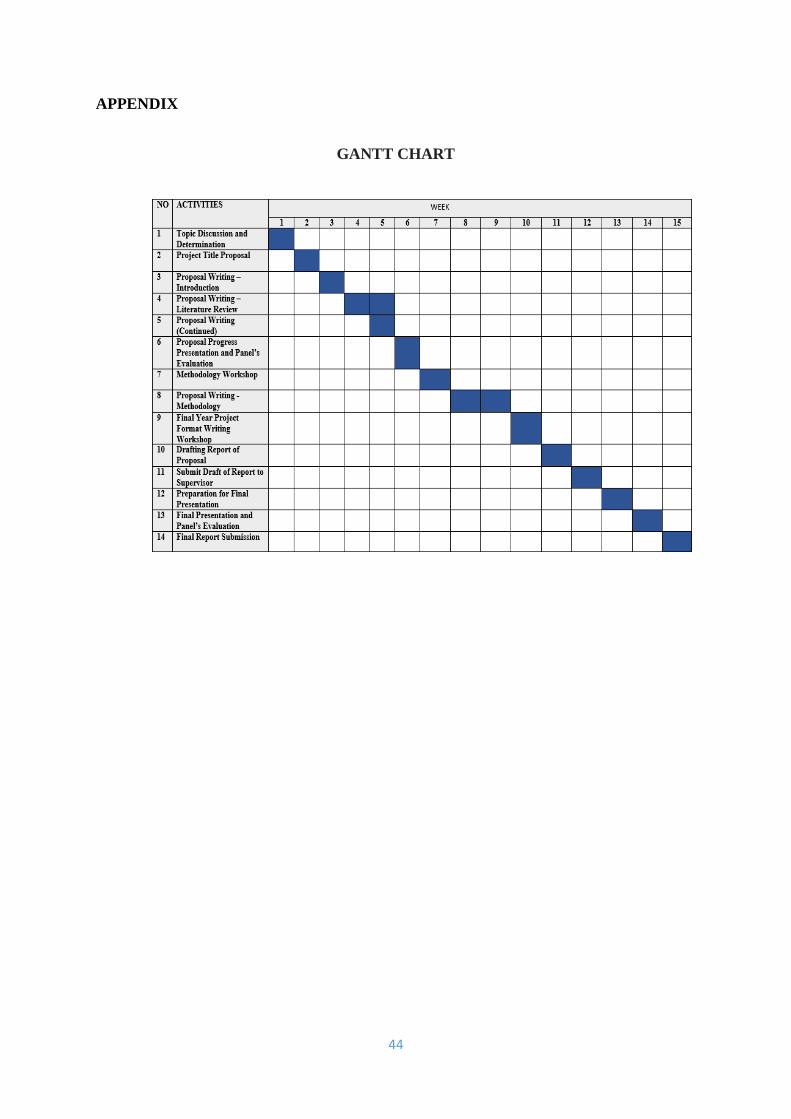
APPENDIX
GANTT CHART
Copyright © 2022 FDOKUMEN