
Central Procurement Organization (Marketing) Bharat ...
442
Central Procurement Organization (Marketing) Bharat Petroleum Corporation Limited ‘A’ Installation, Sewree Fort Road Sewree (E), Mumbai – 400015 OPEN TENDER FOR JOB : “PROCUREMENT OF ANTI STATIC ADDITIVE (ASA) DOSING SKID FOR PIPELINE LOCATIONS AT PANKI & IRUGUR” Tender Ref. No. : CRFQ: 1000387721. DUE DATE : 02.07.2022/1500 Hrs Contact person Mr. Sarath Kumar P Central Procurement Organization (Mktg.), ‘A’ Installation, Sewree Fort Road, Sewree, Mumbai 400015 Email ID: [email protected] Contact: (022) 24176188 /9997442425 Mr. Kamlesh Choudhary Central Procurement Organization (Mktg.), ‘A’ Installation, Sewree Fort Road, S ewree, Mumbai 400015 Email id : [email protected] Contact: (022) 24176418 / 9102011419
-
Upload
khangminh22 -
Category
Documents
-
view
2 -
download
0
Transcript of Central Procurement Organization (Marketing) Bharat ...

Central Procurement Organization (Marketing)
Bharat Petroleum Corporation Limited
‘A’ Installation, Sewree Fort Road Sewree (E), Mumbai – 400015
OPEN TENDER FOR JOB : “PROCUREMENT OF ANTI STATIC ADDITIVE (ASA) DOSING SKID FOR PIPELINE LOCATIONS AT PANKI & IRUGUR” Tender Ref. No. : CRFQ: 1000387721. DUE DATE : 02.07.2022/1500 Hrs
Contact person
Mr. Sarath Kumar P Central Procurement Organization (Mktg.), ‘A’ Installation, Sewree Fort Road, Sewree, Mumbai 400015 Email ID: [email protected] Contact: (022) 24176188 /9997442425
Mr. Kamlesh Choudhary Central Procurement Organization (Mktg.), ‘A’ Installation, Sewree Fort Road, S ewree, Mumbai 400015 Email id : [email protected] Contact: (022) 24176418 / 9102011419

ANNEXURE- I 11.06.2022
Dear Sir/ Madam,
Subject Invitation to bid
Title “PROCUREMENT OF ANTI STATIC ADDITIVE (ASA) DOSING SKID FOR PIPELINE LOCATIONS AT PANKI & IRUGUR”
Tender Details CRFQ: 1000387721.
1. You are invited to submit your offer as E-bids on GEM portal in two-part (techno-commercial and Price Bid) for the above work on the terms and conditions contained in this tender document.
2. A tender is floated on GeM Portal as BPCL intends to place order based on Lot wise L1 Basis. The evaluation of the tenders will be done as per the evaluation methodology mentioned in BQC (Annexure 2). Lot-1 – Panki Location, Lot-2 – Irugur Location
3. The scope of work involves providing Supply of Anti Static Additive Dosing Package: Complete with design, engineering, materials, manufacturing, fabrication, assembly, procurement of bought out items, quality assurance and quality control, inspection, testing, painting, documentation, certification, packing, forwarding and transportation to site, supply of all items, performance guarantee of complete package listed in the tender document, all referenced specifications, documents, drawings, codes and standards including Mandatory spares, Pre-commissioning / commissioning spares, Special Tools & Tackles as per scope of work ( SOW).
4. Completion period of the job is 4 Months.
5. Bidder shall submit the EMD of Rs. 1 lakh
6. This tender document consists of the following Annexure, which are enclosed as part of additional qualification/data require on GEM PORTAL. a) Techno-commercial Bid:
1 Instruction to Bidder (ITB) Annexure- 2
2 Bid qualification criteria(BQC) Annexure- 3
3 Scope of work & Technical specifications Annexure- 4
4 Special Conditions of contracts Annexure- 4
5 General Purchase Conditions Annexure- 5
Declaration by Bidders – MANDATORY The bidders are required to submit the following declaration in addition to BQC document for qualifying
Undertaking with respect to Compliance of Restrictions for Countries which share land border with India – as stipulated by Govt. of India.
Annexure- 6
Declaration for Social Media Policy Annexure- 7
POLICY TO PROVIDE PURCHASE PREFERENCE (LINKED WITH LOCAL CONTENT) (PP-LC):
Annexure- 8(A-F)
INTEGRITY PACT(IP) Annexure-9
Declaration by Bidders for Holiday Listing & Liquidation Annexure- 10&11
FORM- B Annexure- 12

b) Price Bid: Price Bids have to be submitted online on GEM portal.
Bidder have to submit this mandatory form B.
Corrigendum/Addendums if any will be provided against on GEM PORTAL site only.
7. Pre-bid meeting will be conducted through video conferencing system/ Microsoft Teams on 20.06.2022
/ 11:00 hrs. Bidder or their authorized representatives are requested to send their Email ID and Contact No. so that Link / conference ID could be shared with them for attending the pre-bid meeting.
The bidders are requested to send their queries/ clarifications, if any, by e-mail to [email protected] and [email protected] , in following MS-Excel format by 19.06.2022 / 15:00 hrs with E-mail subject “Pre-bid queries – Tender Title & Tender Ref. No. / System ID”. The clarifications shall be provided during the pre-bid meeting.
Sr. No.
Annexure No. / Document Name
Clause No. Clause Description
Query (if any)
Justification
For technical or site-specific queries/location visit, if any, please feel free to contact the below listed.
Site Contact person
To be contacted for
Mr. Santosh Sahu Pipeline Projects, BPCL Marketing Office, 5th Floor, Priyadarshini Building, SION-Trombay Road, Mumbai – 400022 Email ID: [email protected] Contact: (022) 24062634 Mob. 9920219005
Mr. H R Dash Pipeline Projects, BPCL Marketing Office, 5th Floor, Priyadarshini Building, SION-Trombay Road, Mumbai – 400022 Email ID: [email protected] Contact: (022) 24062628 Mob. 9810057603
For any Technical/site specific Queries/ Location Visits
Thanking you, Yours faithfully,
For Bharat Petroleum CorporationLtd. Sd/ Kamlesh Choudhary,
Procurement Leader - CPO (Mktg)


INSTRUCTIONS TO BIDDER
1. Competitive offers are invited in two-part bid- Bid Qualification Cum Techno Commercial Bid and Price Bid
2. Successful bidders will be issued agreement/LOA by CPO (Mktg). The P.O. shall be issued by Pipeline Operation team.
3. Offers should strictly be in accordance with the tender terms & conditions and our specifications. Bidders are requested to carefully study all the documents/ annexures and understand the conditions, specifications, drawings etc. before submitting the tender and quoting the rates. In case of doubt, written clarifications should be obtained, but this shall not be a justification for request for extension of due date for submission of bids.
4. ORDER OF PRECEDENCE FOR PURCHASES :
1. Purchase Order
2. Detailed letter of Acceptance along with its enclosures
3. Letter of Award / Fax of Acceptance
4. Job Specifications (specific to particular job only)
5. Drawings
6. Special Purchase Conditions (SPC)
7. Technical Specifications
8. Instructions to Bidders
9. General Purchase Conditions (in GPC)
10. Other Documents
Additionally, any variation or amendment / change order issued after signing of formal contract shall take precedence over respective clauses of the formal contract and its Annexures.
5. List of abbreviations used :
The terms “BPC”, “BPCL”, The Corporation, the Company and Owner in the appropriate context means Bharat Petroleum Corporation Limited, the Company registered under Companies Act 1956 and includes its successors and assignees. Other abbreviations used and their full form are:
BG : Bank Guarantee BQC : Bid Qualification Criteria CRFQ : Collective Request for Quotation GCC : General Conditions of Contract GPC : General Purchase Conditions INR : Indian Rupee IST : Indian Standard Time IP : Integrity Pact LC : Letter of Credit LD : Liquidated Damages LOA : Letter of Acceptance MSE : Micro and Small Enterprise

NABCB : National Accreditation Board for Certification Bodies

PBG : Performance Bank Guarantee PO : Purchase Order PTR : Proven Track Record SD : Security Deposit SCC : Special Conditions of contract TPIA : Third Party Inspection Agency UDIN : Unique Document Identification Number
6. REFERENCE FOR DOCUMENTATION:
a. The number and date of Tender Reference No. /Collective Request for Quotation (CRFQ) & E- Tender must appear on all correspondence before finalization of Rate Contract / Purchase Order.
b. After finalization of Contract / Purchase Order, the number and date of Contract/Purchase Order must appear on all correspondence, drawings, invoices, dispatch advices, (including shipping documents if applicable) packing list and on any documents or papers connected with this order.
7. LANGUAGE OF BID:
The Bid and all supporting documentation and all correspondence exchanged by bidder and Corporation, shall be written in English language only.
8. All documents attached with the Bid Qualification Cum Techno Commercial Bid, price bid and all corrigenda issued shall form the part of the tender.
9. The bid shall be required to be digitally signed with a Class II B or above digital signature by the authorized signatory.
Online submission of the tender under the digital signature of the authorized signatory shall be considered as token of having read, understood and totally accepted all the terms and conditions and corrigenda if any. Bidder’s digital signature on the documents shall be considered as total acceptance of the terms & conditions.
10. DOCUMENTS TO BE SUBMITTED BY BIDDER:
Bidder shall furnish the necessary documents as per tender conditions along with the bid. In the absence of such documents, BPCL reserve the right to reject the Bid without making any reference to the bidder or assigning any reason what so-ever.
I. Documents to be submitted by Indian MSE (Micro/Small enterprise) Bidder:
1. Bidders quoting as Micro and Small Enterprise shall submit scanned copy of MSE document i.e. valid “Udyam Registration Certificate/ Udyog Aadhaar Memorandum (UAM) Certificate” along with scanned copy of CA certificate to avail the benefits of Public Procurement Policy as per MSMED Act, 2006 and other notifications/circulars/amendments issued from time to time in this regard.
2. CA Certificate and Udyam Registration Certificate/UAM Certificate should be duly attested by a TPIA as specified above.
3. In case CA certificate is not submitted, bidder shall not considered as MSE and such bidder shall not be eligible to avail the benefits of Public Procurement Policy as per the above policy.

i. Bidder shall have to upload scanned copy of CA certificate with stamp of TPIA mentioning as ‘Verified from Original’ (TPIA Certification not required if the CA certificate in original is submitted before tender due date/ before opening of bid).
ii. The CA certificate should be dated after the date of floating of tender and shall be specific to the tender for which bid is being submitted.
iii. Format of the CA certificate is attached as Annexure-A for reference and bidder needs to submit certificate strictly in the said format.
4. To avail purchase preference : Vendor’s declaration/affidavit in their organization/company letter head, stating that in the event of award of contract, all the ordered supplies shall be made from the unit for which the MSE certificate has been submitted.
II. In case any of the supporting documents (either Technical or Financial) are not in English language, then the English translation copy of the same shall also be furnished duly certified, stamped and signed by Local Chamber of Commerce of Bidder’s country or Indian embassy in Bidder’s country or their embassy in India.
III. Bidder shall ensure that any certificate/ reports issued/ attested by a practicing- chartered accountant in India and submitted in the bid shall mandatorily include the UDIN number. Certificate / reports issued/ attested without UDIN number of practicing chartered accountant in India shall not be considered for evaluation.
IV. Charges of TPIA Verification & CA Certificate: All charges of TPIA and CA certificate (if applicable) shall be borne by the Bidder.
V. Submission of authentic documents is the prime responsibility of the bidder. Wherever BPCL has concern or apprehensions regarding the authenticity/correctness of any document or information, BPCL reserve the right to get the documents cross-verified from the document issuing authority.
VI. BPCL reserves the right to inspect the facilities at party’s work to confirm their
capabilities. BPCL also reserves the right to independently assess the capability and capacity of the bidder for execution of the project.
VII. Failure to submit the above documents as per Qualification Criteria will render the Bid liable to be rejected. Therefore, the bidder shall in his own interest furnish complete documentary evidence in the first instance itself, in support of their fulfilling the Qualification Criteria as given in the tender. BPCL reserves the right to complete the evaluation based on the details furnished without seeking any additional information.
11. DECLARATIONS/ UNDERTAKINGS BY BIDDERS:
Bidders have to mandatorily submit the following declarations/undertakings:
(I) DECLARATIONS ON HOLIDAY LISTING & LIQUIDATION: Bidder shall submit the declarations that :
a. Bidder is not under liquidation, court receivership or similar proceeding.

b. Bidders is not serving any Holiday Listing orders issued by BPCL or MoP&NG debarring them from carrying on business dealings with BPCL/ MoP&NG or serving a banning order by another Oil PSE.
(II) COMPLIANCE OF RESTRICTIONS FOR COUNTRIES WHICH SHARE LAND BORDER WITH INDIA:
Bidders have to submit an undertaking in the prescribed format with respect to Compliance of Restrictions for Countries which share land border with India { Restrictions under Rule 144(xi) of the General Financial Rules, 2017–Reference OM no. 6/18/2019 – PPD dtd. 23.07.2020 (read along with any subsequent clarifications/amendments thereof) issued by Ministry of Finance, Public Procurement Division (https://doe.gov.in/procurement-policy-divisions)}.
(III) DECLARATION ON ACCEPTANCE OF TERMS & CONDITIONS OF
SOCIAL MEDIA POLICY OF BPCL:
Terms & Conditions under Social Media Policy of BPCL for business partners are to provide clear guidance on acceptable standards of conduct and practices to be followed by the Business Partners of Bharat Petroleum Corporation Limited, in the usage of social media tools during and post their association with the Corporation. These terms and conditions are intended to protect and safeguard inter alia the interests and reputation of the Corporation, in the access, use of or participation on Social Media platforms by such constituents. Bidders shall return the “Social Media T&Cs” document along with the bid documents, duly Signed & stamped/ Digitally signed by the same signatory who is authorized to sign the bid documents. All the pages of the “Social Media T&Cs” shall be duly signed. Bidder’s failure to return the “Social Media T&Cs” duly signed along with the bid documents shall result in the bid not being considered for further evaluation.
12. SUBMISSION OF BIDS:
i Bidders to note that any deviation if any to the technical/commercial terms and conditions of this tender should be mentioned only in the “DEVIATION” bid form attached. If any bidder fails to do so, it shall be construed that they have no deviations whatsoever to the tender terms and conditions. It is also reiterated that BPCL will not take cognizance of any clarifications/comments mentioned by the bidder in any other document. Similarly if any document is uploaded by the bidder, which inter alia would imply variation or deviation to tender specifications or any terms and conditions of the tender, it shall be taken into consideration for techno commercial evaluation if and only if the reference to the same is mentioned in the deviation bid from.
ii Upload a scanned copy (in pdf format) of the following documents:
All the Bid Qualification Documents as per tender conditions
MSE Certificate and CA Certificate (Where the bidder is quoting as MSE)
In case the no. of pages to be uploaded are more, then the same can also be zipped and uploaded.
Price bid
Price Bids have to be submitted online in the price bid form only. Price if mentioned elsewhere will not be taken into consideration for evaluation.
13. POLICY TO PROVIDE PURCHASE PREFERENCE (LINKED WITH LOCAL
CONTENT) (PP-LC):

Purchase preference under PP-LC policy (linked with local content) issued by MOP & NG, Govt. of India and amendments issued from time to time in this regard will be applicable. Documents required (at bidding stage – Technical): 1. The Bidder (Class-I & II supplier/service provider) shall submit an undertaking from the
authorized signatory of Bidder having the Power of Attorney along with the Bid stating that the Bidder meets the mandatory minimum Local Content (LC) requirement. Power of Attorney to be submitted along with the undertaking.
2. In case the Procurement value exceeds Rs. 10 Crore, the undertaking submitted by the Bidder (Class-I & II supplier/service provider) shall be supported by a Certificate from Statutory or Cost Auditor (in case of companies) or from a practicing Cost Accountant or practicing Chartered Accountant (in respect of other than companies) giving the percentage of local content. The certificate will have to be TPIA verified. TPIA certification is not required if originals of the certificates are submitted. The formats of undertakings are attached as Annexures : (A to F). Bidders shall submit the required undertaking as specified in the tender bidding forms. BPCL reserves the right to seek any other documents (like break up of value and percentage of the local content etc.) from bidder to establish/verify his claim of local content during the Tender Evaluation process
14. VALIDITY OF QUOTE:
The quote shall be valid for as per GeM Bid Document. Bid validity can be extended, if required to complete the tendering process, with consent of the bidders. This condition supersedes the corresponding GCC/GPC condition.

15. ACCEPTANCE/EVALUATION OF BIDS BY THE CORPORATION:
a) BID QUALIFICATION & TECHNO-COMMERCIAL BID: Price bid of only those bidders shall be opened who qualify in the Bid Qualification cum Techno-commercial bid. The schedule for opening the price bid shall be advised separately.
b) PRICE BID: Through this tender, BPCL seeks to surface the lowest price supplier as per the evaluation methodology mentioned in tender document.
Input tax credit (if applicable for the tender) will be considered by BPCL in the evaluation and in such case, the award of work will be on net cash outflow basis considering ITC.
GST rate: In tenders, GST rate will be quoted by the bidder GST, as quoted by the bidder, shall be deemed as final and binding for the purpose of bid evaluation (applicable for tenders where bidder quotes the GST rates). In case a bidder enters “zero” GST or an erroneous GST, the bid evaluation for finalizing the L1 bidder will be done considering the quoted GST rate. No request for change in GST will be entertained after submission of bids.
i. In cases where the bidder quotes a wrong GST rate, for releasing the final order, the following methodology will be followed:
In case the actual GST rate applicable is lower than the quoted GST rate, the actual GST rate will be added to the quoted basic rates. The final cash outflow will reduce to the extent of the revised GST.
In case the actual GST rate applicable is more than the quoted GST rate, the basic rates quoted will be reduced proportionately, keeping the final cash outflow the same as the overall quoted amount.
Based on the Total Cash Outflow calculated as above, BPCL shall place orders.
ii. The Corporation reserves the right to reject any and /or every tender without assigning any reason whatsoever and/or place order on one or more bidders and/ or carry out negotiations with bidder in the manner considered appropriate by the Corporation.
16. LIQUIDATED DAMAGES FOR DELAY:
GST is applicable on LD amount (liquidated damages as per clause 22 of GCC/Clause 20 of GPC), and that the same will be collected in addition to LD amount.
17. PERFORMANCE SECURITY (PERFORMANCE BANK GURANTEE /
SECURITY DEPOSIT/ RETENTION MONEY): The successful contractor/vendor will have to provide Performance Security of 3% of the Basic Value of Contract/Purchase order unless otherwise specified. This bank guarantee shall be valid (shall remain in force) for guarantee period (as mentioned in the guarantee clause), with an invocation period of six months thereafter. In the case of Indigenous vendors, the Performance Bank Guarantee shall be given on a non-judicial stamp paper of appropriate value (currently Rs 100). BG format is enclosed in GCC. Process for submitting Bank Guarantee / PBG under SFMS (Structured Financial Messaging System) mode as follows: Vendors shall insist their Bank on issuance of SFMS Bank

Guarantee for faster payments. Vendors shall provide BPCL's Bank Account No. & IFSC Code (Details given below) to their Bank as beneficiary at the time of application for Bank Guarantee in favor of BPCL. Issuing Bank shall issue the Bank Guarantee & send SFMS message to BPCL's Bank confirming the authenticity of Bank Guarantee who in turn shall send the confirmation to BPCL. SFMS BG will help in faster verification of BGs and prompt release of payments to vendor
18. NEW STATUTORY LEVIES:
The taxes, duties, rates, and Cess quoted shall be final. New tax, if any, introduced later shall be on BPCL account from the date of bid submission (or extended date, if any) up to contract period. During contractual period, any variation in existing taxes, duties, rates and cess shall be borne by BPCL. Any upward statutory variation in taxes, duties rates and cess (including any new tax) beyond contractual completion date shall be borne by the bidder. However, in case of downward variation, the same shall be passed on to BPCL.

19. GST details:
Type of GST namely IGST/CGST-SGST will be determined based upon the billing address provided by the bidder in the tender & the state in which works are being executed.
B idders are requested to enter SAC codes (Service Accounting Codes)/HSN codes as applicable in the relevant column of the price bid.
20. Bidders may have to attend the concerned office of the Corporation for clarifications and/or pre- bid meeting and/or negotiations/clarifications if required at their own cost, in respect of their bids without any commitment from the Corporation.
21. It shall be understood that every endeavour has been made to avoid errors which can
materially affect the basis of the tender and the successful bidder shall take upon himself and provide for risk of any error which may subsequently be discovered and shall make no subsequent claim on account thereof.
22. START-UPS MEDIUM ENTERPRISES:
In case a start-up is interested in supplying the tendered item, but does not meet the Pre- Qualification Criteria (PQC)/ Proven Track Record (PTR) of Prior Turnover norm as indicated in the tender document, i.e., in this case the Bid Qualification Criteria (BQC) mentioned above, the start-up shall be requested to write a detailed proposal separately and not against the present tender requirement, to the tender issuing authority about its product. Such proposals should be accompanied by relevant documents in support of Start-ups as under: i. Certificate of Recognition issued by Department of Industrial Policy and Promotion
(DIPP), Ministry of Commerce and Industry, GOI. ii. Certificate of Incorporation/Registration. iii. Audited P&L statement of all the Financial Years since incorporation. In case where
balance sheet has not been prepared, bidder shall submit a certificate in original from its CEO/CFO stating the turnover of the bidding entity separately for each Financial Year since incorporation along with a declaration stating the reason for not furnishing the audited P&L Statement. The certificate shall be endorsed by a Chartered Accountant/Statutory Auditor
iv. Such proposal will be examined by the tender issuing authority who may consider inviting a detailed offer from the start-up with the intent to place a trial order or test order provided the start-up meets the Quality and Technical specifications.
v. In case the start-up is successful in the trial order, it shall be considered for PQC exemption/relaxation (as the case may be) for the next tender for such item till the time the entity remains a start-up.
*********************************************************************************


BID QUALIFICATION CRITERIA
JOB : PROCUREMENT OF ANTI STATIC ADDITIVE (ASA) DOSING SKID FOR PIPELINE LOCATIONS AT PANKI & IRUGUR.
BPCL is floating tender for the Procurement of Anti Static Additive (ASA) Dosing Skid for pipeline locations at Panki( Kanpur) and Irugur( Coimbatore) as per scope of work( SOW) & technical specifications.
2.BRIEF SCOPE OF SUPPLY : Supply of Anti Static Additive Dosing Package: Complete with design, engineering, materials, manufacturing, fabrication, assembly, procurement of bought out items, quality assurance and quality control, inspection, testing, painting, documentation, certification, packing, forwarding and transportation to site, supply of all items, performance guarantee of complete package listed in the tender document, all referenced specifications, documents, drawings, codes and standards including Mandatory spares, Pre-commissioning / commissioning spares, Special Tools & Tackles as per scope of work ( SOW).
3. BID QUALIFICATION CRITERIA:
Bidder/Vendor should qualify in each of the following Bid Qualification Criteria:
A. TECHNICAL CRITERIA:
The bidder shall have fulfilled the following experience criteria:
I. ESTABLISHED MANUFACTURER:
a) The bidder should be an established Indian Manufacturer of Anti-Static Additive dosing OR chemical injection skid in hydrocarbon/chemical/petrochemical industry in India
Documents required:
The following documents should be submitted in support of the above clause:
1) Factory License OR Pollution Control Board certificate OR NSIC certificate OR any other Statutory document clearly indicating that bidder is Manufacturer of dosing/chemical injection skid.
2) The documents/licenses as per Sr. No.1 above shall specify the manufacturing
range OR shall indicate that the bidder is a manufacturer of the tendered item. In case, the tender item details are not mentioned in the above documents, a certificate from TPIA (after factory inspection) stating that Bidder is a manufacturer of the tendered item be submitted. For this purpose, bidder shall engage a TPIA who is registered under “NABCB accredited bodies as per requirement of ISO/IEC17020 as Type A” in QCI NABCB.
II. SUPPLYING CAPABILITY:
The bidder shall have fulfilled the following experience criteria:

The Bidder shall have successfully supplied minimum one (1) number of Anti-Static Additive dosing OR chemical injection skid sets in hydrocarbon/chemical/petrochemical industry in India and must have successfully run the installed skid during any continuous 12 months period in the preceding 7 (seven) years commencing from the last day of the month previous to the one in which this tender is published. Even if the bidder wishes to quote for Lot-1 or Lot-2 or both the Lots, the above-mentioned criteria should be fulfilled.
Documents required:
The following documents should be submitted in support of the above clause:
1) Signed Agreement/PO copy/Work order/LOI or any other valid document which indicates supply of dosing/Injection skid as mentioned above. The documents shall be in the name of the bidder.
2) Completion/Performance Certificate certified by the client / Tax invoice or any other document which conclusively proves supply of dosing/injection skids. This document shall clearly mention Name of the client, Name of the job, Work Order / Purchase order / LOA No. and date, and Date of delivery/Completion.
B. FINANCIAL CRITERIA:
I. The bidder should have achieved a minimum Average Annual financial turnover as
per below table , Lot- wise
Sr. No Item Description Lot Average Annual Criteria Rs. (Lakhs)
1 Supply of ASA dosing package at Panki as per SOW
Lot-1 18.15
2 Supply of ASA dosing package at Irugur as per SOW
Lot-2 18.10
TOTAL 36.25
Bidder can quote for any one or more than one Lot based on their capability/choice. Example:
If a bidder wants to quote for Lot 1 only, then their Annual Average Turnover should be Rs.18.15 Lakhs.
If a bidder wants to quote for Lot 1 & Lot 2 both, then their Annual Average Turnover should be Rs. 36.25 Lakhs.
as per Audited Balance Sheet and Profit & Loss account, in the last 3 consecutive accounting years ending 31st March of previous financial year.

II. Net worth of the bidder should be positive in the immediate previous financial year.
Documents required:
1. Bidder shall furnish Annual Report/ audited balance sheets including Profit and Loss Accounts for previous three financial years along with the Bid to establish Bidder's conformance to financial criteria and prove existence since three years.
2. In case a bidder (a Parent Company) is having wholly owned subsidiaries but only a single consolidated annual report is prepared and audited which includes the financial details of their wholly owned subsidiaries, consolidated audited annual report shall be considered for establishing the financial criteria subject to statutory auditor of the bidder certifying that separate annual report of bidder (without the financial data of subsidiaries) is not prepared and audited.
3. Further, in case a bidder is a subsidiary company and separate annual report of the bidder is not prepared & audited, but only a consolidated annual report of the Parent Company is available, consolidated audited annual report shall be considered for establishing the financial criteria subject to statutory auditor of the parent company certifying that separate annual report of bidder is not prepared and audited.
4. iv. In case the financial year closing date is within 6 months of original bid due date and audited annual report of immediate preceding financial year is not available, Bidder has the option to submit the financial details of the three previous years immediately prior to the last financial year. In case the financial year closing date is within 6 – 9 months of original bid due date and audited annual report of immediate preceding financial year is not available, Bidder has the option to submit the financial details of the three previous years immediately prior to the last financial year provided Bidder submits a letter from CA stating the reasons of non-preparation/furnishing of the latest year’s Audited Financial Statements.
5. In case the financial year closing date is beyond 9 months of original bid due date, it is compulsory to submit the financial details of the immediate three preceding financial years.
6. Example, in case, audited annual report of immediate preceding financial year (year ending 31st March) is not available and where bid closing date is up to 31st December, the financial details of the three previous years immediately prior to the last financial year may be submitted. However, in case the bid closing date is after 31st December, it is compulsory to submit the financial details of the immediate three preceding financial years only. Note: All the above BQC documents should be in the name of bidder.
C. Declarations by the Bidder:
i. Bidder is not under liquidation, court receivership or similar proceeding.
ii. Bidder is not serving any Holiday Listing orders issued by BPCL or MOPNG debarring them from carrying on business dealings with BPCL/MOPNG or serving a banning order by another Oil PSE,

iii. Compliance of Restrictions for Countries which share land with India { Restrictions under Rule 144(xi) of the General Financial Rules, 2017–Reference OM no. 6/18/2019 – PPD dtd. 23.07.2020 (read along with any subsequent clarifications/amendments thereof) issued by Ministry of Finance, Public Procurement Division (https://doe.gov.in/procurement-policy-divisions)}.
iv. Acceptance to Social Media Guidelines.
v. Integrity pact( IP)
Note: Bidders not furnishing above declarations in tender will not be considered for evaluation and ordering.
4. BIDS MAY BE SUBMITTED BY:
a. An entity (domestic bidder) that has completed 3 financial years of existence as on original due date of tender since date of commencement of business.
b. “JV/Consortium bids will not be accepted (i.e Qualification on the strength of the JV Partners/Consortium Members will not be accepted)”.
5.EARNEST MONEY DEPOSIT (EMD): Bidder shall submit the EMD of Rs. 1 lakh.
6.General:
a. Document Verification: The L1 bidder shall submit all the bidding documents related to Bid Qualification, Technical and Commercial Qualification Criteria duly certified with comments “Verified from Originals w.r.t. all the documents”, by any one of the TPIAs which are registered under “NABCB (National Accreditation Board for Certification Bodies) accredited bodies as per requirement of ISO/IEC 17020 as Type A” in QCI NABCB website (http:/nabcb.qci.org.in/accreditation/reg_bod_inspection_bodies.php) as on date of verification of documents.
Valid accreditation certificate of the TPI under “NABCB accredited bodies as per requirement of ISO/IEC 17020 as Type A” in QCI’s NABCB website, should also be furnished by the bidder.
b. Bidder shall ensure that any certificate/ reports issued/ attested by a practicing-chartered accountant in India and submitted in the bid shall mandatorily include the UDIN number. Certificate / reports issued/ attested without UDIN number of practicing chartered accountant in India shall not be considered for evaluation.
c. Charges of TPIA Verification & CA Certificate: All charges for the third party verification and CA certificate shall be borne by the bidder.
7.PERFORMANCE SECURITY (PERFORMANCE BANK GURANTEE / SECURITY DEPOSIT/ RETENTION MONEY):
A Security cum Performance Bank Guaranty (PBG) of 3% of basic value of contract shall be submitted by the successful bidder, within 15 days of receipt of LOA/Contract.
8.PROPOSAL & EVALUATION METHODOLOGY:

a) It is proposed to float an open domestic tender on GeM for the subject job, as two part bid:
i. Part-1 would cover Bid Qualification Criteria & Technical cum commercial Bid.
ii. Part-2 would be the Price Bid. b) The bid evaluation will be done and awarded on Lot-wise L1 Basis. Procurements
under this tender is non-divisible in each lot and Purchase preference for MSEs will be applicable according to policies of Govt. of India for MSEs.
c) Price bids of only those bidders whose bids qualify the BQ criteria, Technical and Techno-commercial requirements would be opened.
d) Policy to Provide Purchase Preference (linked with local content) (PP-LC) is applicable to this tender.

1 | P a g e
GENERAL PURCHASE CONDITIONS (GPC) (To be accepted online in the mandatory bidding form provided in the E-Tender)
The following conditions shall be applicable for all Non Hydrocarbon procurement unless specifically mentioned in the Special Purchase Conditions.
I N D E X 1. DEFINITIONS
2. REFERENCE FOR DOCUMENTATION 3. RIGHT OF OWNER TO ACCEPT OR REJECT TENDER 4. LANGUAGE OF BID 5. PRICE 6. TAXES AND DUTIES 7. INSPECTION 8. SHIPPING 9. INDIAN AGENT COMMISSION 10. ORDER AWARD / EVALUATION CRITERIA 11. CONFIRMATION OF ORDER 12. PAYMENT TERMS 13. GUARANTEE/WARRANTY 14. PERFORMANCE BANK GUARANTEE 15. PACKING & MARKING 16. DELIVERY 17. UNLOADING AND STACKING 18. TRANSIT INSURANCE 19. VALIDITY OF OFFER 20. DELIVERY DATES AND PRICE REDUCTION SCHEDULE 21. RISK PURCHASE CLAUSE 22. FORCE MAJEURE CLAUSE 23. ARBITRATION CLAUSE 24. INTEGRITY PACT (IP) 25. RECOVERY OF SUMS DUE 26. CONFIDENTIALITY OF TECHNICAL INFORMATION 27. PATENTS & ROYALTIES 28. LIABILITY CLAUSE 29. LIMITATION OF LIABILITY FOR GOODS PROCUREMENT 30. COMPLIANCE OF REGULATIONS 31. REJECTION, REMOVAL OF REJECTED GOODS AND REPLACEMENT 32. NON-WAIVER 33. NEW & UNUSED MATERIAL 34. PURCHASE PREFERENCE CLAUSE 35. CANCELLATION 36. ANTI –COMPETITIVE AGREEMENTS/ABUSE OF DOMINANT POSITION 37. ASSIGNMENT 38. GOVERNING LAW 39. AMENDMENT 40. NOTICES 41. POLICY ON HOLIDAY LISTING 42. ORDER OF PRECEDENCE FOR PURCHASES 43. TERMINATION FOR CONVENIENCE 44. BUILDING AND OTHER CONSTRUCTION WORKERS CESS

2 | P a g e
GENERAL PURCHASE CONDITIONS 1. DEFINITIONS:
The following expressions used in these terms and conditions and in the purchase order shall have the meaning indicated against each of these:
1.1. OWNER: Owner means Bharat Petroleum Corporation Limited (a Government of India
enterprise), a Company incorporated in India having its registered office at Bharat Bhavan, 4 & 6 Currimbhoy Road, Ballard Estate, Mumbai 400038 and shall include its successors and assigns (hereafter called BPCL as a short form).
1.2. VENDOR: Vendor means the person, firm or the Company/ Corporation to whom this
Request for quotation (RFQ)/purchase order is issued and shall include its successors and assigns.
1.3. INSPECTOR: Person/ agency deputed by BPCL for carrying out inspection, checking/testing
of items ordered and for certifying the items conforming to the purchase order specifications..
1.4. GOODS/ MATERIALS: means any of the articles, materials, machinery, equipments, supplies,
drawing, data and other property and all services including but not limited to design, delivery, installation, inspection, testing and commissioning specified or required to complete the order.
1.5. SITE/ LOCATION: means any Site where BHARAT PETROLEUM CORPORATION LIMITED
desires to receive materials anywhere in India as mentioned in RFQ. 1.6. “RATE CONTRACT” means the agreement for supply of goods/ materials between Owner
and Vendor, for a fixed period of time (i.e till validity of Rate Contract, with no commitment of contractual quantity) on mutually agreed terms and conditions. The actual supply of goods/ materials shall take place only on issue of separate purchase orders for required quantity as and when required by Owner.
2. REFERENCE FOR DOCUMENTATION: 2.1. The number and date of Collective Request for Quotation (CRFQ) must appear on all
correspondence before finalization of Rate Contract / Purchase Order. 2.2. After finalization of Contract / Purchase Order: The number and date of Rate Contract/
Purchase Order must appear on all correspondence, drawings, invoices, dispatch advices, (including shipping documents if applicable) packing list and on any documents or papers connected with this order.
2.3. In the case of imports, the relevant particulars of the import Licence shall be duly indicated in
the invoice and shipping documents as well as on the packages or consignments. 3. RIGHT OF OWNER TO ACCEPT OR REJECT TENDER: The right to accept the tender will rest with the Owner. 4. LANGUAGE:

3 | P a g e
The Bid and all supporting documentation and all correspondence whatsoever exchanged by Vendor and Owner, shall be in English language only. In case any of the supporting documents (either technical or financial) are not in English language, then the English translation copy of the same shall also be furnished duly certified, stamped and signed by local Chamber of Commerce of bidder’s country or Indian embassy in bidder’s country or their embassy in India
5. PRICE: Unless otherwise agreed to the terms of the RFQ, price shall be: Firm and no escalation will be entertained on any ground, except on the ground of statutory levies applicable on the tendered items.
6. TAXES AND DUTIES: All vendors shall have GST registration in the concerned State as applicable and vendor shall quote their GSTIN number in the quotation wherever required.
6.1 GST: 6.1.1. GST extra as applicable at the time of delivery within scheduled delivery period will be
payable by BPCL against documentary evidence. Vendor shall mention in their offer, the percentage of GST applicable at present. Any upward variation in GST rates, beyond the contractual delivery period, shall be to vendor’s account.
6.1.2. In case GST is not applicable at present: In case GST gets levied due to change in turnover of
Vendor/Supplier, shall be borne by the vendor/supplier. If GST becomes applicable due to change in the law in future, the same will be borne by vendor subject to 6.1.1. In case of change in stand of vendor/supplier about applicable rate of GST towards higher side, the same will not be payable.
6.1.3. Owner shall take Input Tax Credit of the GST paid on the material supplied for both GST and
cess component as applicable and accordingly GST / Cess should be quoted separately wherever applicable.
Vendor shall ask the transporter of the goods to hand over the copy of GST invoice (transporter’s copy) at the time of delivery of goods at owner’s site. The vendor shall take steps viz. mention relevant GSTIN of BPCL in GST invoices and returns, uploading invoice in GSTR 1, payment of the tax liability on the said invoices and filing of Returns etc. and comply with all the requirements of applicable laws including GST laws for the time being in force to enable the OWNER to avail tax credit/s including input tax credit. Any loss or non-availability of input tax credit by the OWNER due to non-compliance of applicable tax law including but not limited to GST laws in force or otherwise, on the part of VENDOR, an amount equivalent to any tax liability accruing to the OWNER and/or to the extent of any loss accrued to the OWNER due to the non-availability of input tax credit or any liability accrued to the OWNER shall either stand cancelled or deducted from the payment due to the VENDOR or shall be reimbursed by the VENDOR as the case may be till such default is either rectified or made good by the VENDOR and the OWNER is satisfied that it is in a position to claim valid input tax credit within the timelines as per applicable laws. Any cost, liability, dues, penalty, fees, interest as the case may be which accrues to the OWNER at any point of time on account of non-compliance of applicable tax laws or rules or

4 | P a g e
regulations thereof or otherwise due to default on the part of VENDOR shall be borne by the VENDOR. An amount equivalent to such cost, liability, dues, penalty, fees, and interest as the case may be shall be reimbursed by the VENDOR within 30 days. Any GST as may be applicable on such recovery of amount shall also be borne by VENDOR and same shall be collected by the OWNER.”
6.2 FREIGHT: 6.2.1 Freight: Firm freight charges to be quoted as indicated in the Tender documents. Freight shall
be payable after receipt of the Material(s) at the site, unless otherwise specified. 6.3. NEW STATUTORY LEVIES: All new statutory levies leviable on sale of finished goods to owner,
if applicable are payable extra by BPCL against documentary proof, within the contractual delivery period.
6.4 VARIATION IN TAXES/ DUTIES: Any increase/decrease in all the above mentioned statutory
levies on the date of delivery during the scheduled delivery period on finished materials will be on BPCL's account. Any upward variation in statutory levies after contractual delivery date shall be to vendor’s account.
6.5 INCOME TAX (WITHHOLDING TAX): In the case of availment of services from Non Resident
Vendors who are claiming benefits offered under the Double Taxation Avoidance Agreements signed by India with the Government of the other country (i.e. the country of the Vendor), such Non Resident Vendors are required to provide the Tax Residency Certificates at the time of submission of Bid documents. The Tax Residency Certificates shall contain the following details:
a) Name of Vendor (assessee); b) Status (Individual, Company, firm etc.) of assessee; c) Nationality (in case of individual); d) Country or specified territory of incorporation or registration (in case of others); e) Assessee ‘s tax identification number in the country or specified territory of residence
or in case no such number, then, a unique number on the basis of which the person is identified by the Government of the country or the specified territory;
f) Residential status for the purpose of tax; g) Period for which the certificate is applicable; and h) Address of the applicant for the period for which the certificate is applicable.
The Tax Residency Certificate shall be duly verified by the Government of the Country or the specified territory of the assessee of which the assessee claims to be a resident for the purposes of tax.
7. INSPECTION: 7.1. Materials shall be inspected by BPCL approved third party inspection agency if applicable
before dispatch of materials. However, arranging and providing inspection facilities is entirely vendor’s responsibility and in no way shall affect the delivery schedule.
7.2 Scope of Inspection shall be as per RFQ or as specified in the Special Purchase Conditions.

5 | P a g e
Materials shall be inspected as per scope of inspection by TPIAs which are registered under “NABCB accredited bodies as per requirement of ISO/IEC 17020 as Type A” in QCI’s NABCB website as on the date of Inspection of Goods. The link is as below: http://nabcb.qci.org.in/accreditation/reg_bod_inspection_bodies.php
7.3. Unless otherwise specified, the inspection shall be carried out as per the relevant standards/
scope of inspection provided alongwith the Tender Enquiry/Purchase Order. 7.4. BPCL may, at its own expense, have its representative(s) witness any test or inspection. In
order to enable BPCL’s representative(s) to witness the tests/ inspections, BPCL will advise the Vendor in advance whether it intends to have its representative(s) be present at any of the inspections.
7.5. Even if the inspection and tests are fully carried out, the Vendor shall not be absolved from
its responsibilities to ensure that the Material(s), raw materials, components and other inputs are supplied strictly to conform and comply with all the requirements of the Contract at all stages, whether during manufacture and fabrication, or at the time of Delivery as on arrival at site and after its erection or start up or consumption, and during the defect liability period. The inspections and tests are merely intended to prima-facie satisfy BPCL that the Material(s) and the parts and components comply with the requirements of the Contract. The Vendor’s responsibility shall also not be anywise reduced or discharged because BPCL or BPCL’s representative(s) or Inspector(s) shall have examined, commented on the Vendor’s drawings or specifications or shall have witnessed the tests or required any chemical or physical or other tests or shall have stamped or approved or certified any Material(s).
7.6. Although material approved by the Inspector(s), if on testing and inspection after receipt of
the Material(s) at the location, any Material(s) are found not to be in strict conformity with the contractual requirements or specifications, BPCL shall have the right to reject the same and hold the Vendor liable for non-performance of the Contract.
8. SHIPPING: 8.1 SEA SHIPMENT: All shipment of materials shall be made by first class direct vessels as per
procedure detailed hereunder. The Foreign Supplier shall arrange with Vessels Owners or Forwarding Agents for proper storage of the entire Cargo intended for the project in a specific manner so as to facilitate and to avoid any over carriage at the port of discharge. All shipment shall be under deck unless carriage on deck is unavoidable.
The bills of lading should be made out in favour of `Bharat Petroleum Corporation Limited or
order'.
All columns in the body of the Bill of Lading namely marks and nos., material description, weight particulars etc., should be uniform and accurate and such statements should be uniform in all the shipping documents. The freight particulars should mention the basis of freight tonnage, heavy lift charges, if any, surcharge, discount etc. clearly and separately. The net total freight payable shall be shown at the bottom.

6 | P a g e
SHIPPING DOCUMENTS: All documents viz. Bill of Lading, invoices, packing list, freight memos, country of origin certificates, test certificate, drawings and catalogues should be in English language.
In addition of the bill of lading which should be obtained in three stamped original plus as
many copies as required, invoices, packing list, freight memos, (if the freight particulars are not shown in the bills of lading), country of origin certificate, test/ composition certificate, shall be made out against each shipment in as many number of copies as shown below.
The bill of lading, invoice and packing list specifically shall show uniformly the mark and
numbers, contents case wise, country of origin, consignees name, port of destination and all other particulars as indicated under clause 2. The invoice shall show the unit rates and net total F.O.B. prices. Items packed separately should also be invoiced and the value shown accordingly. Packing list must show apart from other particulars actual contents in each case, net and gross weights and dimensions, and the total number of packages. All documents should be duly signed by the Vendor’s authorized representatives.
In the case of FOB orders, shipping arrangements shall be made by the Chartering Wing of
the Ministry of Surface Transport, New Delhi through their respective forwarding agents. The names and addresses of forwarding agents shall be as per Special Purchase Conditions. Supplier shall furnish to the respective agents the full details of consignments such as outside dimension, weights (both gross and net) No of packages, technical description and drawings, name of supplier, ports of loading, etc. 6-weeks notice shall be given by the supplier to enable the concerned agency to arrange shipping space.
The bill of lading shall indicate the following: Shipper: Vendor’s Name Consignee: Bharat Petroleum Corporation Limited In case of supplies from USA, Export Licences, if any required from the American Authorities shall
be obtained by the U.S. Suppliers. If need be assistance for obtaining such export licences would be available from India Supply Mission at Washington.
8.2 AIRSHIPMENT: In case of Airshipment, the materials shall be shipped through freight
consolidator (approved by us). The airway bill shall be made out in favour of BHARAT PETROLEUM CORPORATION LIMITED.
TRANSMISSION OF SHIPPING DOCUMENTS for both modes of shipment viz. Sea and/or Air:
Foreign Supplier shall obtain the shipping documents in seven complete sets including three original stamped copies of the Bill of Lading / Airway bill as quickly as possible after the shipment is made, and airmail/send scanned copies by e-mail as shown below so that they are received at least three weeks before the Vessels arrival or immediately in case of Air shipment. Foreign Supplier shall be fully responsible or any delay and/ or demurrage

7 | P a g e
in clearance of the consignment at the port due to delay in transmittal of the shipping documents.
If in terms of letter or otherwise, the complete original set of documents are required to be
sent to BPCL through Bank the distribution indicated below will confine to copies of documents only minus originals. Documents BPCL Bill of Lading/Airway Bill 4 (including 1 original) Invoice 4 Packing List 4 Freight Memo 4 Country of Origin Certificate 4 Third party inspection certificate 4 Drawing 4 Catalogue 4 Invoice of Third Party 4 for inspection charges whenever applicable.
9. INDIAN AGENT COMMISSION:
Any offer through Indian agents will be considered only after authorization mentioning them as Indian agents, is received from Vendor. Indian agents commission if applicable will be payable only in Indian currency. Indian agents should be registered with Directorate General of Supplies and Disposals, Government of India and agency commission will be payable only after registration with DGS&D, New Delhi.
10. ORDER AWARD/ EVALUATION CRITERIA:
Unless otherwise specified, Order award criteria will be on lowest quote landed price basis. Landed price will be summation of Basic Price, Packing & Forwarding Charges, GST, Freight, Inspection Charges, Supervision of Installation & Commissioning and other taxes & levies, loading etc., if any, reduced by Input tax Credits as applicable.
11. CONFIRMATION OF ORDER:
The vendor shall acknowledge the receipt of the purchase order within 10 days of mailing the same. The vendor shall sign, stamp the acknowledgement copy of the purchase order and return the same to BPCL.
12. PAYMENT TERMS: 12.1. Unless otherwise specified, 100% payment shall be made within 30 days from date of receipt
and acceptance of materials at Site against submission of Performance Bank Guarantee (PBG) for 10% of basic order value if PBG is applicable for the tender.
12.2. In the case of imports, payment will be made on submission of original documents directly to Owner (Telegraphic Transfer-TT) or through Bank (Cash against documents-CAD) or through Irrevocable Letter of Credit.
12.3. Unless otherwise mentioned, the specified documents (All documents listed below (one
original and two copies) should be submitted to originator of P.O. (the name and contact

8 | P a g e
details of whom are given in PO) and payments for despatches will be made by the originator of Purchase Order :
a) Invoice b) GST invoice c) The Lorry Receipt of the consignment d) Packing list for the consignment e) Third Party Inspector’s Certificate covering the invoiced Material(s)/ Release Note,
wherever applicable f) Manufacturers Test/Composition Certificate, wherever applicable g) Drawing(s)/Catalogue(s) covering the Material(s), wherever applicable h) Guarantee/Warranty Certificate(s), wherever applicable. i) Original Receipt for other statutory levies as applicable. j) Performance Bank Guarantee as applicable.
13. GUARANTEE/ WARRANTY: 13.1. Materials shall be guaranteed against manufacturing defects, materials, workmanship and
design for a period of 12 months from the date of commissioning or 18 months from the date of dispatch whichever is earlier. Warranty for replacement of material / accessories should be provided free of charges at our premises. The above guarantee/warranty will be without prejudice to the certificate of inspection or material receipt note issued by us in respect of the materials. In case the defect arises within the abovementioned Defect Liability Period (DLP) and the same is repaired/replaced, the DLP for the repaired/replaced job/item will be extended suitably so as to cover the original DLP. However, in no case, such extension will exceed 24 months from date of start of initial DLP.
13.2. All the materials including components and sub contracted items should be guaranteed by
the vendor within the warranty period mentioned above. In the event of any defect in the material, the vendor will replace / repair the material at BPCL’s concerned location at vendor’s risk and cost on due notice.
13.3. In case, vendor does not replace / repair the material on due notice, rejected material will
be sent to the vendor on “Freight to pay” basis for free replacement. Material after rectification of defects shall be dispatched by the vendor on “Freight Paid” basis. Alternatively, BPCL reserves the right to have the material repaired / replaced at the locations concerned, at the vendor’s risk, cost and responsibility.
13.4. The Vendor shall provide similar warrantee on the parts, components, fittings, accessories
etc. so repaired and / or replaced. 14. PERFORMANCE BANK GUARANTEES: 14.1. Vendor will have to provide Performance Bank Guarantee for 10% of the basic value of
purchase order unless otherwise specified. This bank guarantee shall be valid (shall remain in force) for guarantee period (as mentioned in the guarantee clause), with an invocation period of six months thereafter. In the case of Indigenous vendors, the Performance Bank Guarantee shall be given on a non-judicial stamp paper of appropriate value (currently Rs 100). PBG format is as per Annexure-I.

9 | P a g e
In case, PBG is not provided by the Vendor, 10% of the basic value shall be retained in lieu of PBG, till the expiry of guarantee and claim period.
In the case of imports, the Supplier shall furnish the Performance Bank Guarantee (as per Annexure-I) through the following:
(a) Branches of Indian scheduled banks operating in their Country. (b) Foreign bank operating in their Country which is counter guaranteed by branches of
Indian scheduled banks operating in their Country/ India. (c) Indian branches of foreign banks. (d) Foreign bank operating in their Country counter guaranteed by their Indian branch. However, in respect of (c) and (d) above, the Indian branch of foreign banks should be recognized as scheduled bank by Reserve Bank of India.
14.2. If Vendor wants to submit the PBG at Contract level to avoid multiple number of PBG (i.e.
PBG issued against every purchase/ call off order) then the validity of PBG will be calculated as mentioned below:
Validity of PBG = Rate Contract Issue Date (Start Date of Rate Contract) + Rate Contract Period (validity of Rate Contract) + Contractual Delivery Period of material + Contractual Guarantee period + 6 month (for invocation / Claim).
14.3 Process for submitting Bank Guarantee / PBG under SFMS (Structured Financial Messaging System) mode as follows:
Vendors shall insist their Bank on issuance of SFMS Bank Guarantee for faster payments. Vendors shall provide BPCL's Bank Account No. & IFSC Code (Details given below) to their Bank as beneficiary at the time of application for Bank Guarantee in favor of BPCL. Issuing Bank shall issue the Bank Guarantee & send SFMS message to BPCL's Bank confirming the authenticity of Bank Guarantee who in turn shall send the confirmation to BPCL.
Name of Bank: State Bank of India Branch :CAG Branch, Mumbai Account No: 11083980831 IFSC Code: SBIN0009995
SFMS BG will help in faster verification of BGs and prompt release of payments to vendors.
15. PACKING & MARKING: 15.1 PACKING: 15.1.1 Packing shall withstand the hazards normally encountered with the means of transport for
the goods of this purchase order including loading and unloading operation both by crane and by pushing off.

10 | P a g e
In the case of imports, all equipments/ materials shall be suitably packed in weather proof, seaworthy/airworthy packing for ocean/air transport under tropical conditions and for rail or road or other appropriate transport in India. The packing shall be strong and efficient enough to ensure safe preservance upto the final point of destination.
Raw/Solid wood packaging material of imported items has to be appropriately treated & marked
as per International Standard of Phytosanitary Measures (ISPM-15") for material originating from the contracting countries to the International Plant Protection Convention or the members of Food & Agriculture Organization. Material from non-contracting parties would have to be accompanied by a phytosanitary certificate of the treatment endorsed. The Custom Officer at Indian Port shall not release the material without appropriate compliance of the above provisions w.e.f. 01.11.2004.
15.1.2 The packing specification incorporated herein are supplementary to the internal and
external packing methods and standards as per current general rules of J.R.A. Good Tariff Part-I. All packaging shall be done in such a manner as to reduce volume as much as possible.
15.1.3 Fragile articles should be packed with special packing materials depending on the type of
Materials and the packing shall bear the words "HANDLE WITH CARE GLASS FRAGILE, DON'T ROLL THIS END UP. THIS END DOWN," to be indicated by arrow.
15.1.4 Chemicals in powder form, catalyst, refractories and like materials etc. shall be packed in
drums, cans and tins only. However, Catalyst may be supplied in Jumbo bags. 15.1.5 The hazardous materials shall be packed in accordance with the applicable rules, regulations
and tariff of all cognizant Government Authorities and other Governing bodies. It shall be the responsibility of the seller of hazardous materials to designate the material as hazardous and to identify each material by its proper commodity name and its hazardous material class code.
15.1.6 All packages requiring handling by crane should have sufficient space at appropriate place to
put sling of suitable dia (strength). Iron/Steel angle should be provided at the place where sling marking are made to avoid damage to package/ equipment while lifting.
15.1.7 Item shipped in bundles must be securely tied with steel wire or strapping. Steel reinforcing
rods, bars, pipes, structural members etc. shall be bundled in uniform lengths and the weight shall be within the breaking strength of the securing wire or strapping.
In the case of imports, for bundles the shipping marks shall be embossed on metal or similar tag
and wired securely on each end. 15.1.8 All delicate surfaces on equipment/ materials should be carefully protected and printed with
protective paint/compound and wrapped to prevent rusting and damage. 15.1.9 All mechanical and electrical equipment and other heavy articles shall be securely fastened
to the case bottom and shall be blocked and braced to avoid any displacement/ shifting during transit.

11 | P a g e
15.1.10 Attachments and spare parts of equipment and all small pieces shall be packed separately in wooden cases with adequate protection inside the case and wherever possible should be sent along with the main equipment. Each item shall be suitably tagged with identification of main equipment, item denomination and reference number of respective assembly drawing. Each item of steel structure and furnaces shall be identified with two erection markings with minimum lettering height of 15mm. Such markings will be followed by the collection numbers in indelible ink/paint. A copy of the packing list shall accompany the materials in each package.
15.1.11 All protrusions shall be suitably protected by providing a cover comprising of tightly
bolted wooden disc on the flanges. All nozzles, holes and openings and also all delicate surfaces shall be carefully protected against damage and bad weather. All manufactured surfaces shall be painted with rust proof paint.
In the case of imports, for bulk uniform material when packed in several cases, progressive serial
numbers shall be indicated on each case. 15.1.12 Wherever required, equipment/ materials instruments shall be enveloped in
polythene bags containing silicagel or similar dehydrating compound.
15.1.13 Pipes shall be packed as under: (a) Upto 50mm NB in wooden cases/ crates. (b) Above 50mm NB and upto 100mm NB in bundles and should be strapped at minimum
three places. (c) Above 100mm NB in loose.
15.1.14 Pipes and tubes of stainless steel, copper etc. shall be packed in wooden cases irrespective
of their sizes. 15.1.15 Pipes with threaded or flanged ends shall be protected with suitable caps covers,
before packing. In the case of imports, all pipes and sheets shall be marked with strips bearing progressive no.
15.1.16 Detailed packing list in waterproof envelope shall be inserted in the package together
with equipment/materials. One copy of the detailed packing list shall be fastened outside of the package in waterproof envelope and covered by metal cover.
15.1.17 The supplier shall be held liable for all damages or breakages to the goods due to the
defective or insufficient packing as well as for corrosion due to insufficient protection. 15.1.18 Packaged equipment or materials showing damage defects or shortages resulting
from improper packaging materials or packing procedures or having concealed damages or shortages, at the time of unpacking shall be to the supplier’s account.
All packages which require special handling and transport should have their Centres of Gravity and the points at which they may be slung or gripped clearly indicated and marked “ATTENTION SPECIAL LOAD HANDLE WITH CARE” both in English/ Hindi Languages.

12 | P a g e
In the case of imports, a distinct colour splash in say red black around each package crate/ bundle shall be given for identification.
15.1.19 Along with the packed material, supplier should attach material list, manuals/instructions
and also the Inspection certificate/ release note, wherever applicable. 15.2. MARKING: The following details to be written on the side face of packing:
a) Purchase Order Number b) Consignee Name & Address c) Vendor Name d) Batch no with manufacturing date e) Procedure (in brief) for handling f) Date of dispatch etc. g) Expiry Date, if applicable
15.3 IMPORTED ITEMS: On three sides of the packages, the following marks shall appear, clearly
visible, with indelible paint and on Vendor's care and expenses.
BHARAT PETROLEUM CORPORATION LIMITED (With detailed address as given in Special Purchase Conditions) From : To : Bharat Petroleum Corporation Limited (With detailed address as given in Special Purchase Conditions) Order No.: Rev. No.: Item : Equipment Nomenclature : Net weight : Kgs. Gross weight : Kgs. Case No. : of Total cases: Dimensions : Import License No. : NOTE: Marking shall be bold - minimum letter height 5 cm. For every order and every shipment, packages must be marked with serial progressive numbering. Top heavy containers shall be so marked either Top Heavy or Heavy Ends. When packing material is clean and light coloured, a dark black stencil paint shall be acceptable. However, where packaging material is soiled or dark, a coat of flat zinc white paint shall be applied and allowed to dry before applying the specific markings. In case of large equipments like vessels, heat exchangers, etc. the envelope containing the documents shall be fastened inside a shell connection, with an identifying arrow sign "documents" using indelible paint.

13 | P a g e
16. DELIVERY: 16.1. Unless otherwise mentioned, Vendor is requested to quote their best delivery schedule from
the date of receipt of Purchase order. 16.2. Time being the essence of this contract, the delivery mentioned in the purchase order shall
be strictly adhered to and no variation shall be permitted except with prior authorization in writing from the Owner. Goods should be delivered, securely packed and in good order and condition, at the place of delivery and within the time specified in the purchase order for their delivery.
16.3. The contractual delivery period is inclusive of all the lead time for engineering/ procurement
of raw material, the manufacturing, inspection / testing, packing, transportation or any other activity whatsoever required to be accomplished for affecting the delivery at the required delivery point.
16.4. Unless otherwise specified, Material(s) shall not be despatched without prior inspection
and/or testing and Release Order/Material(s) Acceptance Certificate issued by the Inspector(s).
16.5. BPCL shall have the right to advise any change in despatch point or destination in respect of
any Material(s). Any extra expenditure incurred by the Vendor on this account supported by satisfactory documentary evidence, will be reimbursed to the Vendor by BPCL.
17. UNLOADING AND STACKING:
Unloading and stacking will be arranged by BPCL. The Vendor shall send BPCL information of the proposed consignment well in advance by telegram/fax/e-mail/courier to enable BPCL to take necessary action.
18. TRANSIT INSURANCE:
Unless otherwise mentioned, 18.1. Transit Insurance shall be covered by BPCL against its Mega Package Policy only where
risk/reward has been transferred to BPCL. 18.2 In the case of imports, insurance against all marine and transit risk shall be covered under
the Owner's marine policy. However, the Vendor shall ensure that in effecting shipments clear bill of lading/airway bill are obtained and the carrier's responsibility is fully retained on the Carriers so that the consignee's interests are fully secured and are in no way jeopardized.
18.3. The Vendor shall send BPCL information of the proposed consignment well in advance by
fax/e-mail/courier to enable BPCL to take necessary action for the transit insurance of the consignment. Any failure by the Vendor to do so shall place the consignment at the Vendor’s risk.
18.4. In the case of imports, as soon as any shipment is made, the Foreign Supplier shall send
advance information by way of e-mail to Bharat Petroleum Corporation Limited, (with detailed address as given in Special Purchase Conditions and/or purchase order) giving

14 | P a g e
particulars of the shipments, vessels name, port of shipment, bill of lading number and date, total FOB and freight value.
19 VALIDITY OF OFFER:
The rates quoted against this tender shall be valid for a period of 90 Days from the date of opening of the tender unless otherwise specified in the Special Purchase Conditions.
20. DELIVERY DATES AND PRICE REDUCTION SCHEDULE: 20.1. The time and date of Delivery of Material(s) as stipulated in the Contract shall be adhered to
on the clear understanding that the Price(s) of the Material(s) has/have been fixed with reference to the said Delivery date(s).
20.2. If any delay is anticipated by the Vendor in the delivery of the Material(s) or any of them
beyond the stipulated date(s) of Delivery, the Vendor shall forthwith inform BPCL in writing of such anticipated delay and of the steps being taken by the Vendor to remove or reduce the anticipated delay, and shall promptly keep BPCL informed of all subsequent developments.
20.3. The delivery period quoted must be realistic & specific. The inability of successful Vendors
to execute orders in accordance with the agreed delivery schedule will entitle BPCL, at its options, to:
20.3.1. Accept delayed delivery at prices reduced by a sum equivalent to half percent (0.5%)
of the basic value of any goods not delivered for every week of delay or part thereof, limited to a maximum of 5% of the total basic order value. LR date will be considered as delivery completion date for calculation of price reduction in the case of ex works contract. Date of receipt of materials at owner’s premises shall be considered for calculation of price reduction for F.O.R destination contract.
In the case of imports, the contractual delivery date shall be considered from the date of Letter of Credit (L/C) or the date of L/C amendment because of Buyer’s fault plus one week (to take care of transit time for receipt of L/C) plus the delivery schedule as indicated by the vendors.
In case of the shipment taking place on “Cash against documents”, the contractual delivery shall be taken from the date of purchase order plus one week (to take care of transit time for receipt of order) plus delivery period.
Further the date of B/L or House airway bill shall be considered to find out the delay with respect to contractual delivery date. In case of FOB shipments if the vessel is not available then the intimation by vendors regarding readiness of the goods for the shipment shall be considered for calculating the delay if any. So vendor shall inform the readiness of material for shipment on FOB (Free on Board) basis/ FCA (Free on Carrier) basis.
20.3.2. Cancel the order in part or full and purchase such cancelled quantities from
elsewhere on account at the risk and cost of the vendor, without prejudice to its right under 20.3.1 above in respect of goods delivered.
15 | P a g e
21. RISK PURCHASE CLAUSE: BPCL reserves the right to curtail or cancel the order either in full or part thereof if the vendor fails to comply with the delivery schedule and other terms & conditions of the order. BPCL also reserves the right to procure the same or similar materials/equipment through other sources at vendor's entire risk, cost and consequences. Further, the vendor agrees that in case of procurement by the owner from other sources the differential amount paid by the owner shall be on account of the vendor together with any interest and other costs accrued thereon for such procurement.
22. FORCE MAJEURE
Circumstances leading to force majeure
(a) Act of terrorism;
(b) Riot, war, invasion, act of foreign enemies, hostilities (whether war be declared or not), civil
war, rebellion, revolution, insurrection of military or usurped power;
(c) Ionising radiation or contamination, radio activity from any nuclear fuel or from any nuclear
waste from the combustion of nuclear fuel, radioactive toxic explosive or other hazardous
properties of any explosive assembly or nuclear component;
(d) epidemics, earthquakes, flood, fire, hurricanes, typhoons or other physical natural disaster,
but excluding weather conditions regardless of severity; and
(e) freight embargoes, strikes at national or state-wide level or industrial disputes at a national
or state-wide level in any country where Works are performed, and which affect an essential
portion of the Works but excluding any industrial dispute which is specific to the performance
of the Works or the Contract.
For the avoidance of doubt, inclement weather, third party breach, delay in supply of materials
(other than due to a nationwide transporters’ strike) or commercial hardship shall not constitute
a Force Majeure event.
• Notification of Force Majeure
Contractor shall notify within [10(ten)] days of becoming aware of or the date it ought to have
become aware of the occurrence of an event of Force Majeure giving full particulars of the event
of Force Majeure and the reasons for the event of Force Majeure preventing the Affected Party
from, or delaying the Affected Party in performing its obligations under the Contract.
• Right of either party to terminate
If an event of Force Majeure occurs and its effect continues for a period of 180 (one hundred
eighty days) or more in a continuous period of 365 (three hundred sixty five) days after notice

16 | P a g e
has been given under this clause, either Party may terminate the Contract by issuing a written
notice of 30 (thirty) days to the other Party.
• Payment in case of termination due to Force Majeure
The Contract Price attributable to the Works performed as at the date of the commencement of
the relevant event of Force Majeure.
The Contractor has no entitlement and Owner has no liability for: a) Any costs, losses, expenses, damages or the payment of any part of the Contract Price during
an event of Force Majeure; and
b) Any delay costs in any way incurred by the Contractor due to an event of Force Majeure. Time extension for such cases will be worked out appropriately. 23. ARBITRATION CLAUSE:
Any dispute or difference whatsoever arising out of or in connection with this Agreement including any question regarding its existence, validity, construction, interpretation, application, meaning, scope, operation or effect of this contract or termination thereof shall be referred to and finally resolved through arbitration as per the procedure mentioned herein below : (a) The dispute or difference shall, in any event, be referred only to a Sole Arbitrator (b) The appointment and arbitration proceedings shall be conducted in accordance with SCOPE forum of Arbitration Rules for the time being in force or as amended from time to time (c) The Seat of arbitration shall be at ______(Region/HQ from where the tender has been floated) (d) The proceedings shall be conducted in English language (e) The cost of the proceedings shall be equally borne by the parties, unless otherwise directed by the Sole Arbitrator. In the event of any dispute or difference relating to the interpretation and application of the provisions of commercial contract(s) between the Central Public Sector Enterprises (CPSEs)/Port Trusts inter se and also between CPSEs and Government Departments/Organizations (excluding disputes concerning Railways, Income Tax, Customs & Excise Departments*), such dispute or difference shall be taken up by either party for its resolution through AMRCD as mentioned in DPE OM no.4(1)/2013-DPE(GM)/FTS-1835 dated 22-05-2018. (* The exclusion would also include disputes concerning GST, State level Sales Tax / VAT etc; though not mentioned explicitly)
24. INTEGRITY PACT (IP):
Vendors are requested to sign & return our pre-signed IP document, if applicable. This document is essential & binding. Vendor's failure to return the IP document duly signed along with Bid Document may result in the bid not being considered for further evaluation.
25. RECOVERY OF SUMS DUE:

17 | P a g e
Whenever, any claim against vendor for payment of a sum of money arises out of or under the contract, the owner shall be entitled to recover such sums from any sum then due or when at any time thereafter may become due from the vendor under this or any other contract with the owner and should this sum be not sufficient to cover the recoverable amount of claim(s), the vendor shall pay to BPCL on demand the balance remaining due.
26. CONFIDENTIALITY OF TECHNICAL INFORMATION:
Drawing, specifications and details shall be the property of the BPCL and shall be returned by the Vendor on demand. The Vendor shall not make use of drawing and specifications for any purpose at any time save and except for the purpose of BPCL. The Vendor shall not disclose the technical information furnished to or organized by the Vendor under or by virtue of or as a result of the implementation of the Purchase Order to any person, firm or body or corporate authority and shall make all endeavors to ensure that the technical information is kept CONFIDENTIAL. The technical information imparted and supplied to the vendor by BPCL shall at all time remain the absolute property of BPCL. Imparting of any confidential information by the Vendor will be breach of contract.
27. PATENTS & ROYALTIES:
The vendor shall fully indemnify BPCL and users of materials specified herein/supplied at all times, against any action, claim or demand, costs and expenses, arising from or incurred by reasons of any infringement or alleged infringement of any patent, registered design, trademark or name, copy right or any other protected rights in respect of any materials supplied or any arrangement, system or method of using, fixing or working used by the vendor. In the event of any claim or demand being made or action sought against BPCL in respect of any of the aforesaid matter, the vendor shall be notified thereof immediately and the vendor shall at his/its own expense with (if necessary) the assistance of BPCL (whose all expense shall be reimbursed by the vendor) conduct all negotiations for the settlement of the same and/or litigation which may arise thereof.
28. LIABILITY CLAUSE:
In case where it is necessary for employees or representatives of the Vendor to go upon the premises of owner, vendor agrees to assume the responsibility for the proper conduct of such employees/representatives while on said premises and to comply with all applicable Workmen's Compensation Law and other applicable Government Regulations and Ordinances and all plant rules and regulations particularly in regard to safety precautions and fire hazards. If this order requires vendor to furnish labour at site, such vendor's workmen or employees shall under no circumstances be deemed to be in owner's employment and vendor shall hold himself responsible for any claim or claims which they or their heirs, dependent or personal representatives, may have or make, for damages or compensation for anything done or committed to be done, in the course of carrying out the work covered by the purchase order, whether arising at owner's premises or elsewhere and agrees to indemnify the owner against any such claims, if made against the owner and all costs of proceedings, suit or actions which owner may incur or sustain in respect of the same.
29. LIMITATION OF LIABILITY FOR GOODS PROCUREMENT:

18 | P a g e
The aggregate total liability of the Contractor to Owner under the Contract shall not exceed
the total Contract Price, except that this Clause shall not limit the liability of the Contractor
for following:
(a) In the event of breach of any Applicable Law;
(b) In the event of fraud, willful misconduct or illegal or unlawful acts, or gross negligence of
the Contractor or any person acting on behalf of the Contractor; or
(c) In the event of acts or omissions of the Contractor which are contrary to the most
elementary rules of diligence which a conscientious Contractor would have followed in
similar circumstances; or
(d) In the event of any claim or loss or damage arising out of infringement of Intellectual
Property; or
(e) For any damage to any third party, including death or injury of any third party caused by
the Contractor or any person or firm acting on behalf of the Contractor in executing the
Works.
Neither Party shall be liable to the other Party for any kind of indirect or consequential loss or damage like, loss of use, loss of profit, loss of production or business interruption which is connected with any claim arising under the Contract.
30. COMPLIANCE OF REGULATIONS:
Vendor warrants that all goods/Materials covered by this order have been produced, sold, dispatched, delivered and furnished in strict compliance with all applicable laws, regulations, labour agreement, working condition and technical codes and statutory requirements as applicable from time to time. The vendor shall ensure compliance with the above and shall indemnify owner against any actions, damages, costs and expenses of any failure to comply as aforesaid.
31. REJECTION, REMOVAL OF REJECTED GOODS AND REPLACEMENT:
In case the testing and inspection at any stage by inspectors reveal that the equipment, materials and workmanship do not comply with specification and requirements, the same shall be removed by the vendor at his/its own expense and risk, within the time allowed by the owner. The owner shall be at liberty to dispose off such rejected goods in such manner as he may think appropriate. In the event the vendor fails to remove the rejected goods within the period as aforesaid, all expenses incurred by the owner for such disposal shall be to the account of the vendor. The freight paid by the owner, if any, on the inward journey of the rejected materials shall be reimbursed by the vendor to the owner before the rejected materials are removed by the vendor. The vendor will have to proceed with the replacement of the equipment or part of equipment without claiming any extra payment if so required by the owner. The time taken for replacement in such event will not be added to the contractual delivery period.

19 | P a g e
32. NON-WAIVER:
Failure of the Owner to insist upon any of the terms or conditions incorporated in the Purchase Order or failure or delay to exercise any rights or remedies herein, or by law or failure to properly notify Vendor in the event of breach, or the acceptance of or payment of any goods hereunder or approval of design shall not release the Vendor and shall not be deemed a waiver of any right of the Owner to insist upon the strict performance thereof or of any of its or their rights or remedies as to any such goods regardless of when such goods are shipped, received or accepted nor shall any purported oral modification or revision of the order by BPCL act as waiver of the terms hereof. Any waiver to be effective must be in writing. Any lone incident of waiver of any condition of this agreement by BPCL shall not be considered as a continuous waiver or waiver for other condition by BPCL.
33. NEW & UNUSED MATERIAL: All the material supplied by the vendor shall be branded new, unused and of recent manufacture.
34. PURCHASE PREFERENCE CLAUSE:
Owner reserves its right to allow Public Sector Enterprises (Central/State), purchase preference as admissible/ applicable from time to time under the existing Govt. policy. Purchase preference to a PSE shall be decided based on the price quoted by PSE as compared to L1 Vendor at the time of evaluation of the price bid. Owner reserves its right to allow Micro and Small Enterprises (MSEs), MSEs owned by Women Entrepreneurs and MSEs owned by Scheduled Caste (SC) or the Scheduled tribe (ST) entrepreneurs, purchase preference as admissible/applicable from time to time under the existing Govt. policy. Purchase preference to a MSE, a MSE owned by women entrepreneurs and a MSE owned by SC/ST entrepreneurs shall be decided based on the price quoted by the said MSEs as compared to L-1 Vendor at the time of evaluation of the price bid. Bidders claiming purchase preference as MSE need to submit the following documents:
• Self-attested copy of all the pages of the EM-II certificate/Udyog Adhar Memorandum issued by the appropriate authorities mentioned in the Public procurement policy of MSEs-2012 and
• Vendor’s declaration/affidavit in their organization/Company letter head, stating that, in the event of award of contract, all the ordered supplies shall be made from the unit for which MSE certificate has been submitted.
35. CANCELLATION: 35.1. BPCL reserves the right to cancel the contract/purchase order or any part thereof through a
written notice to the vendor if: 35.1.1. The vendor fails to comply with the terms of this purchase order/contract. 35.1.2. The vendor becomes bankrupt or goes into liquidation.

20 | P a g e
35.1.3. The vendor fails to deliver the goods on time and/or replace the rejected goods promptly.
35.1.4. The vendor makes a general assignment for the benefit of creditors. 35.1.5. A receiver is appointed for any of the property owned by the vendor. 35.2. Upon receipt of the said cancellation notice, the vendor shall discontinue all work on the
purchase order matters connected with it. BPCL in that event will be entitled to procure the requirement in the open market and recover excess payment over the vendor's agreed price if any, from the vendor and also reserving to itself the right to forfeit the security deposit if any, made by the vendor against the contract. The vendor is aware that the said goods are required by BPCL for the ultimate purpose of materials production and that non-delivery may cause loss of production and consequently loss of profit to the BPCL. In this-event of BPCL exercising the option to claim damages for non delivery other than by way of difference between the market price and the contract price, the vendor shall pay to BPCL, fair compensation to be agreed upon between BPCL and the vendor. The provision of this clause shall not prejudice the right of BPCL from invoking the provisions of price reduction clause mentioned in 20.3.1 as aforesaid.
36. ANTI –COMPETITIVE AGREEMENTS/ABUSE OF DOMINANT POSITION:
The Competition Act, 2002 as amended by the Competition (Amendment) Act, 2007 (the Act), prohibits anti- competitive practices and aims at fostering competition and at protecting Indian markets against anti- competitive practices by enterprises. The Act prohibits anti- competitive agreements, abuse of dominant position by enterprises, and regulates combinations (consisting of acquisition, acquiring of control and M&A) wherever such agreements, abuse or combination causes, or is likely to cause, appreciable adverse effect on competition in markets in India. BPCL reserves the right to approach the Competition Commission established under the Act of Parliament and file information relating to anti-competitive agreements and abuse of dominant position. If such a situation arises, then Vendors are bound by the decision of the Competitive Commission and also subject to penalty and other provisions of the Competition Act.
37. ASSIGNMENT:
The Vendor does not have any right to assign his rights and obligations under these general purchase conditions without the prior written approval of BPCL.
38. GOVERNING LAW: These General Purchase Conditions shall be governed by the Laws of India. 39. AMENDMENT: Any amendment to these General Purchase Conditions can be made only in writing and with
the mutual consent of the parties to these conditions. 40. NOTICES:
Any notices to be given hereunder by a Party to the other shall be in English and delivered by hand or sent by courier or facsimile to the other Party at the address or facsimile number

21 | P a g e
stated below or such other address or number as may be notified by the relevant Party from time to time.
41. POLICY ON HOLIDAY LISTING:
The guidelines and procedures for Holiday Listing are available separately in BPCL website and shall be applicable in the context of all tenders floated and consequently all orders/ contracts / purchase orders. It can be accessed using the following link: http://bharatpetroleum.in/pdf/holidaylistingpolicyfinal.pdf .
42. ORDER OF PRECEDENCE FOR PURCHASES :
1. Purchase Order
2. Detailed letter of Acceptance along with its enclosures
3. Letter of Award / Fax of Acceptance
4. Job Specifications (specific to particular job only)
5. Drawings
6. Special Purchase Conditions (SPC)
7. Technical Specifications
8. Instructions to Bidders
9. General Purchase Conditions (GPC)
10. Other Documents
Additionally, any variation or amendment / change order issued after signing of formal contract shall take precedence over respective clauses of the formal contract and its Annexures.
43. TERMINATION FOR CONVENIENCE:
The purchaser may, by written notice of 14 days sent to the seller, cancel the contract, in whole or part, at any time for his convenience. The notice of cancellation shall specify that cancellation is for the purchaser’s convenience, the extent to which performance of work under the contract is cancelled and the date upon which such cancellation becomes effective.
The goods that are complete and ready for shipment within 30 days after the seller’s receipt of notice of cancellation shall be purchased by the purchaser at contract terms and prices. For the remaining goods, the purchaser may opt :-
a. To have any portion completed and delivered at the contract terms and prices
and / or b. To cancel the remainder and pay to the seller an agreed amount for partially completed
goods and materials and parts previously procured by the seller.
44. BUILDING AND OTHER CONSTRUCTION WORKERS CESS:
a. Bidders to note that under Building and other Construction Workers Welfare Act (Re&CS) Act 1996, Cess is applicable to contracts executed outside Factory Area (e.g. construction of

22 | P a g e
new industrial installation, office & residential buildings etc.) as per the provisions applicable under ‘The Building and Other Construction Workers Welfare Cess Act 1996’. b. The contractor must be registered with the concerned authorities under the Building and other Construction Workers‟ (RE&CS) Act, 1996 or in case of non-registration; the contractor should obtain registration within one month of the award of contract. c. The contractor shall be responsible to comply with all provisions of the Building and Other Construction Workers‟ (RE&CS) Act, 1996, the Building and other Construction Workers‟ Welfare Cess Act, 1996, the Building and other Construction Workers‟ (RE&CS) Rules, 1998 and the Building and other Construction Workers Welfare Cess Rules, 1998. d. Cess, as per the prevailing rate (presently 1%), shall be deducted at source from bills of the contactors by the Engineer-in-Charge and remitted to the “Secretary, Building and other Construction Workers Welfare Board” of the concerned State. e. The contactor shall be responsible to submit final assessment return of the Cess amount to the assessing officer after adjusting the Cess deducted at source.
BPCL _______________________ _______________________ VENDOR _______________________ _______________________
xxxxxxxx

23 | P a g e
PERFORMANCE BANK GUARANTEE FOR SECURITY DEPOSIT TOWARDS PERFORMANCE (On Non-judicial paper for appropriate value)
To, Bharat Petroleum Corporation Limited --------------------------------------------------- --------------------------------------------------- --------------------------------------------------- Dear Sir, In consideration of the Bharat Petroleum Corporation Limited, (hereinafter called ‘the Company’ which expression shall include its successors and assigns) having awarded to M/s. (Name) ………. (Constitution)………….. (address) ………. (hereinafter referred to as “The vendor” which expression shall wherever the subject or context so permits include its successors and assigns) a supply contract in terms interalia, of the Company’s Purchase order No…….. dated ………. and the General and Special Purchase Conditions of the Company and upon the condition of vendor’s furnishing security for the performance of the vendor’s obligations and/or discharge of the vendor’s liability under and / or in connection with the said supply contract upto a sum of Rs. (in figures)…………..Rs (in words)…………………………only amounting to 10% (ten percent) of the total contract value. We, (Name)…………..(constitution) ……………(hereinafter called “the Bank” which expression shall include its successors and assigns) hereby jointly and severally undertake and guarantee to pay to the Company in -----(Currency) forthwith on demand in writing and without protest or demur of any and all moneys any wise payable by the Vendor to the Company under in respect of or in connection with the said supply contract inclusive of all the Company’s losses and expenses and other moneys anywise payable in respect to the above as specified in any notice of demand made by the Company to the Bank with reference to this Guarantee upto an aggregate limit of Rs(in figures)…………Rs(in words)……………………….only. AND the Bank hereby agrees with the Company that (i) This Guarantee/undertaking shall be a continuing guarantee and shall remain valid and
irrevocable for all claims of the Company and liabilities of the vendor arising upto and until midnight of …………………………………..
This date shall be 6 months from the last date of guarantee period.
(ii) This Guarantee/ Undertaking shall be in addition to any other guarantee or security of
whatsoever that the Company may now or at any time otherwise have in relation to the vendor’s obligation/liabilities under and /or connection with the said supply contract, and the Company shall have full authority to take recourse to or reinforce this security in preference to the other security(ies) at its sole discretion, and no failure on the part of the Company in enforcing or requiring enforcement of any other security shall have the effect of releasing the Bank from its liability hereunder.
(iii) The Company shall be at liability without reference to the Bank and without effecting the full
liability of the Bank hereunder to take any other security in respect of the vendor’s obligations

24 | P a g e
and /or liabilities under or in connection with the said supply contract and to vary the terms vis a vis the vendor of the said supply contract or to grant time and/ or indulgence to the vendor or to reduce or to increase or otherwise vary the prices of the total contract value or to release or to forbear from enforcement all or any of the obligations of the vendor under the said supply contract and/ or the remedies of the Company under any other security(ies) now or hereafter held by the Company and no such dealing(s), variation(s), reduction(s), increase(s) or the indulgence(s) or arrangement(s) with the vendor or release or forbearance whatsoever shall have the effect of releasing the Bank from its full liability to the Company hereunder or of prejudicing rights of the Company against the Bank.
(iv) This Guarantee /Undertaking shall not be determined by the liquidation or winding up or
dissolution or change of constitution or insolvency of the vendor but shall in all respects and for all purposes be binding and operative until payment of all moneys payable to the Company in terms hereof.
(v) The Bank hereby waives all rights at any time inconsistent with the terms of the Guarantee/
Undertaking and the obligations of the Bank in terms hereof shall not be anywise affected or suspended by reason of any dispute or disputes having been raised by the vendor (whether or not pending before any Arbitrator, officer, Tribunal or Court) or any denial of liability by the vendor or any other order of communication whatsoever by the vendor stopping or preventing or purporting to stop or prevent any payment by the Bank to the Company in terms hereof.
(vi) The amount stated in any notice of demand addressed by the Company to the Guarantor as
liable to be paid to the Company by the vendor or as suffered or incurred by the Company on account of any losses or damages of costs, charges and or expenses shall as between the Bank and the Company be conclusive of the amount so liable to be paid to the Company or suffered or incurred by the Company, as the case may be and payable by the Guarantor to Company in terms hereof.
Yours faithfully, (Signature) NAME & DESIGNATION NAME OF THE BANK NOTES:

ATF PUMPING FACILITIES IN BINA PANKI PIPELINE
& COCHIN COIMBATORE PIPELINE
Technical Specifications for Anti-Static Additive (ASA) Dosing Package

INSPECTION REQUIREMENTS Inspection Required:
Yes Inspection Level: 2
Criticality Rating: C
Special Inspection Requirements: Inspection and testing shall be as agreed at the Pre-Inspection Meeting (PIM), the agreed Quality Control Plan (QCP), requirements mentioned in the Specification for Anti-Static Additive Injection Package and requirements mentioned in this Tender document.
Job Title Anti-Static Additive Dosing Package (Tag Nos. 10-300-AS-PK-001 & 10-300-AS-PK-002)
Customer Name Bharat Petroleum Corporation Limited (BPCL)
Project Title ATF Pumping Facilities in Bina Panki Pipeline Project and Cochin Coimbatore Pipeline

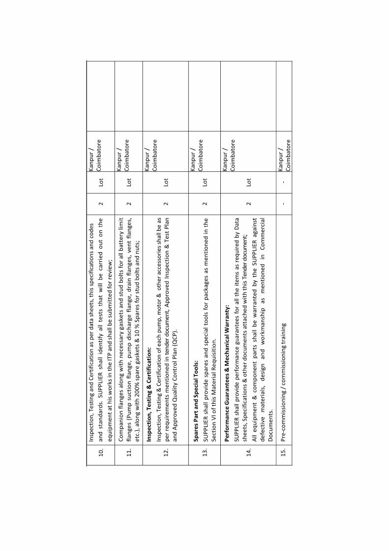


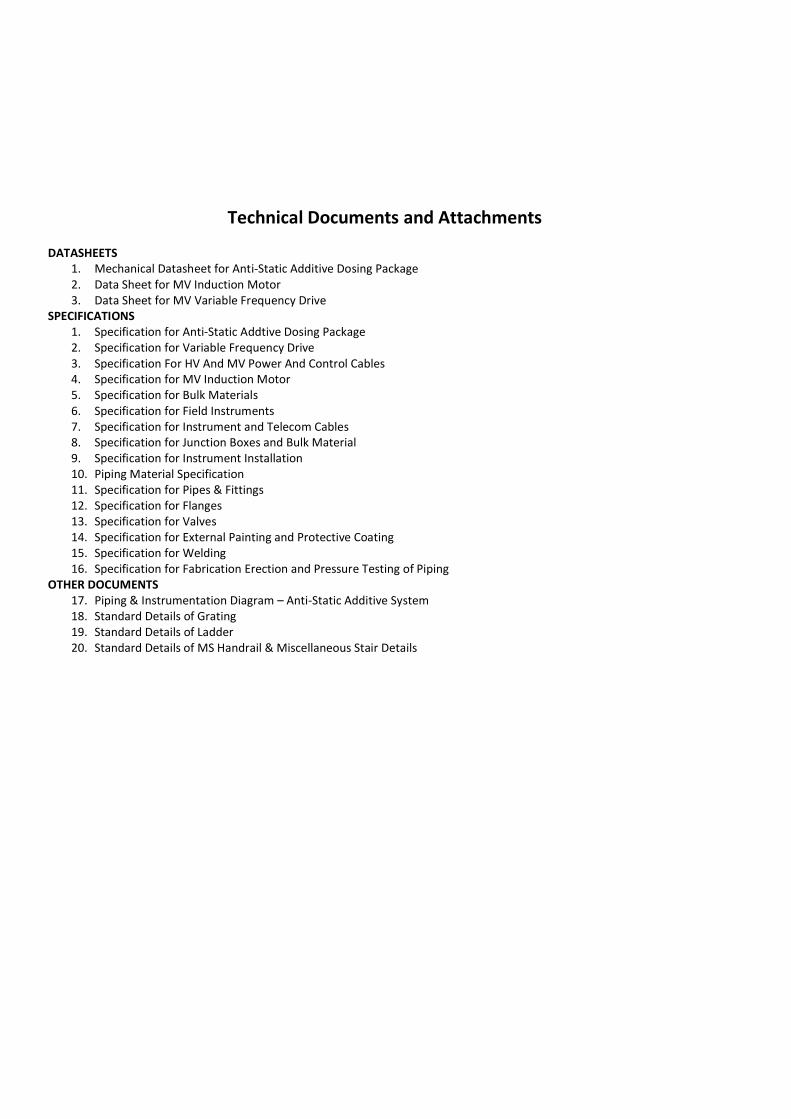
Technical Documents and Attachments
DATASHEETS 1. Mechanical Datasheet for Anti-Static Additive Dosing Package 2. Data Sheet for MV Induction Motor 3. Data Sheet for MV Variable Frequency Drive
SPECIFICATIONS 1. Specification for Anti-Static Addtive Dosing Package 2. Specification for Variable Frequency Drive 3. Specification For HV And MV Power And Control Cables 4. Specification for MV Induction Motor 5. Specification for Bulk Materials 6. Specification for Field Instruments 7. Specification for Instrument and Telecom Cables 8. Specification for Junction Boxes and Bulk Material 9. Specification for Instrument Installation 10. Piping Material Specification 11. Specification for Pipes & Fittings 12. Specification for Flanges 13. Specification for Valves 14. Specification for External Painting and Protective Coating 15. Specification for Welding 16. Specification for Fabrication Erection and Pressure Testing of Piping
OTHER DOCUMENTS 17. Piping & Instrumentation Diagram Anti-Static Additive System 18. Standard Details of Grating 19. Standard Details of Ladder 20. Standard Details of MS Handrail & Miscellaneous Stair Details
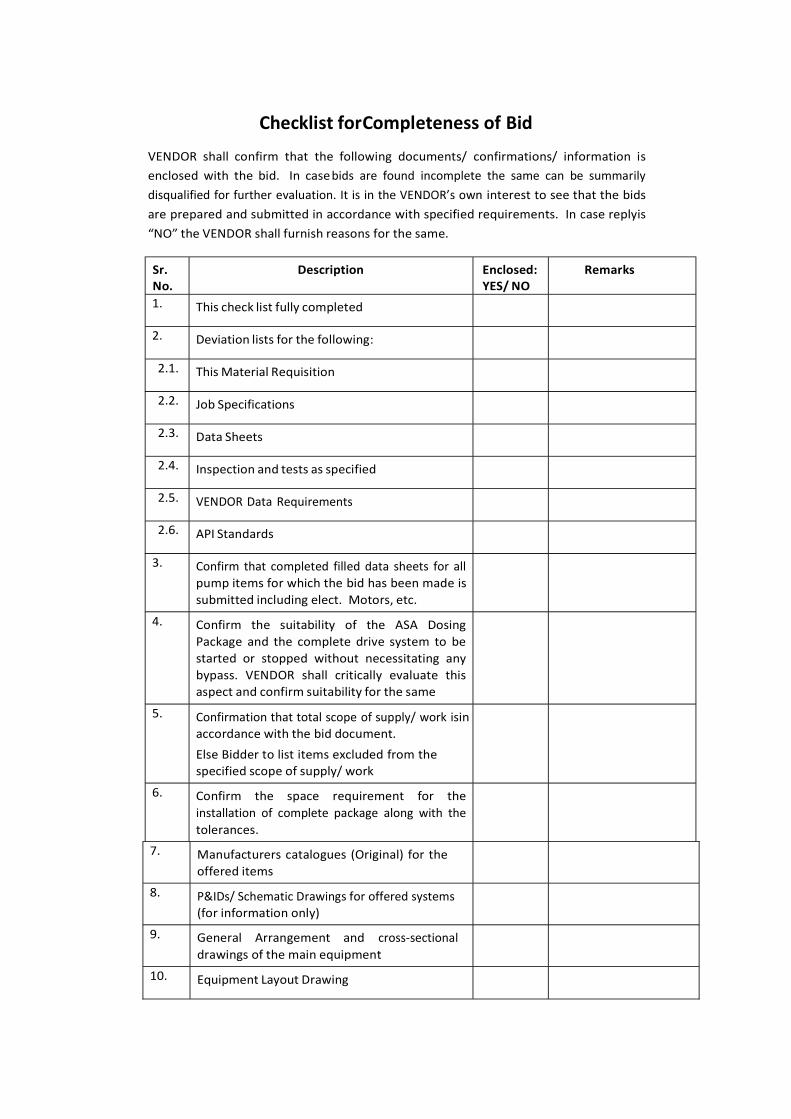
Checklist for Completeness of Bid
VENDOR shall confirm that the following documents/ confirmations/ information is enclosed with the bid. In case bids are found incomplete the same can be summarily disqualified for further evaluation. interest to see that the bids are prepared and submitted in accordance with specified requirements. In case reply is
the VENDOR shall furnish reasons for the same.
Sr. No.
Description Enclosed: YES/ NO
Remarks
1. This check list fully completed
2. Deviation lists for the following:
2.1. This Material Requisition
2.2. Job Specifications
2.3. Data Sheets
2.4. Inspection and tests as specified
2.5. VENDOR Data Requirements
2.6. API Standards
3. Confirm that completed filled data sheets for all pump items for which the bid has been made is submitted including elect. Motors, etc.
4. Confirm the suitability of the ASA Dosing Package and the complete drive system to be started or stopped without necessitating any bypass. VENDOR shall critically evaluate this aspect and confirm suitability for the same
5. Confirmation that total scope of supply/ work is in accordance with the bid document.
Else Bidder to list items excluded from the specified scope of supply/ work
6. Confirm the space requirement for the installation of complete package along with the tolerances.
7. Manufacturers catalogues (Original) for the offered items
8. P&IDs/ Schematic Drawings for offered systems (for information only)
9. General Arrangement and cross-sectional drawings of the main equipment
10. Equipment Layout Drawing

11. Utility Requirements
12. Skid weights
13. Skid size (L X W X H, mm)
14. Maximum Weights
- Erection
- Maintenance
15. Recommended Crane Capacity and the hook height from the floor level
16. Quotation for Spare parts for 2 years of normal operation as recommended by the VENDOR
17. Erection & Commissioning Spares
18. Special Tools & Tackles
19. Quotation for Supervision of Pre- commissioning and commissioning of the packages as listed in the relevant specifications attached with the MR
20. Quotation for Annual maintenance charges.

Vendor Data Requirement List
Schedules
Fabrication/Production Schedule
D(4)
4(4)

Sl.No.
Description Pre-Awardwith Tender
Quantity To Be SubmittedAfter Award
Info FA CF ClassMDR
(X)OMM
(X)
22. Parts List/Bill of Material 2D D X 6
23. Instrument Location Drawings D D X 8
24. Instrument Schedule D D X X 8
25. Wiring Schematic Diagram D D X X 10
26. Termination Details D D X X 10
27. Hook Up Diagram D D X X 10
28. Loop Diagram, Functional Design Basis
29. Cable Block Diagram D D X 10
30. Instrument Outline Drawings D X 10
31. Serial Link
32. Weld Procedures D D X 6
33. NDE Procedures D D X 6
34. Surface Preparation, Painting andCoating Specification D
DX 6
35. Operator Qualifications D D X
36. Functional and Performance TestProcedure D
DX 6
37. Hydrotest Procedures D D X 6
38. Factory Acceptance Test Procedure D D X 6
39. Site Acceptance Test Procedure D D X 6
40. Manufacturing Record Book Index D D X 10
41. Manufacturing Record Book D(6) D(6) X (1)
42. Material Certificates X
43. Hazardous Area Certificates X 6
44. Test Results X (5)
45. Specification Waivers X D D X 4

Sl.No.
Description Pre-Awardwith Tender
Quantity To Be SubmittedAfter Award
Info FA CF ClassMDR
(X)OMM
(X)
46. Inspection Release Notes X
47. Documents Travelling with Goods 10
48. Packing, Shipping, Handling andStorage Procedure D D X
10
49. Preservation Procedure D D X 10
50. Installation Instructions D D X 10
51. Field Fabrication Items D D X 10
52. Spare Parts Interchangeability Record(SPIR) X D(6) D(6) X 10
53. Operating and Maintenance Manual D(6) D(6) X 12
54. VENDORs Catalogue D X
55. Lubrication Schedule X D D X 8
56. Electrical
aDuly filled in Datasheets for all Motorsand VFD X D D X X 2
b Bill of material D D X 4
Power & control schematics, wiringc diagram, cable schedule,
interconnection wiring drawings
X X X 4
d Electrical Performance Curves X D D X X 4
Dimensional/Assembly drawings.
- GA Drawings including clearancerequirements for panels.
- GA Drawings for motors along withe terminal box for motors
- GA Drawings for Local controlstations
- Mounting details- Nameplate details and ratings
X D D X 4

Scope: -1. Separate drawings and document listed in this VDRL shall be submitted for each dosing skid.2. Drawings and documents listed shall be submitted on agreed dates and in accordance with the instructions listed in the
engineering requisition. The documents listed below shall be submitted station wise.
Note1 column indicates proposed schedule
for submission of documents in each relevant
Requirement statusInfo = For informationFA = For approval
input transformers, Motor

NOTES: -
(1) To be submitted prior to shipment
(2) And fortnightly thereafter
(3) Where applicable
(4) Including torque/speed characteristics
(5) Immediately after test
(6) MDR & OMM - one copy to be submitted for review, Final MDR/OMM shall consist of 3 Hard copies & 3Soft Copies.
(7) Sufficient information for buyer to estimate motor
(8) Sufficient information for buyer to purchase motor
Attention


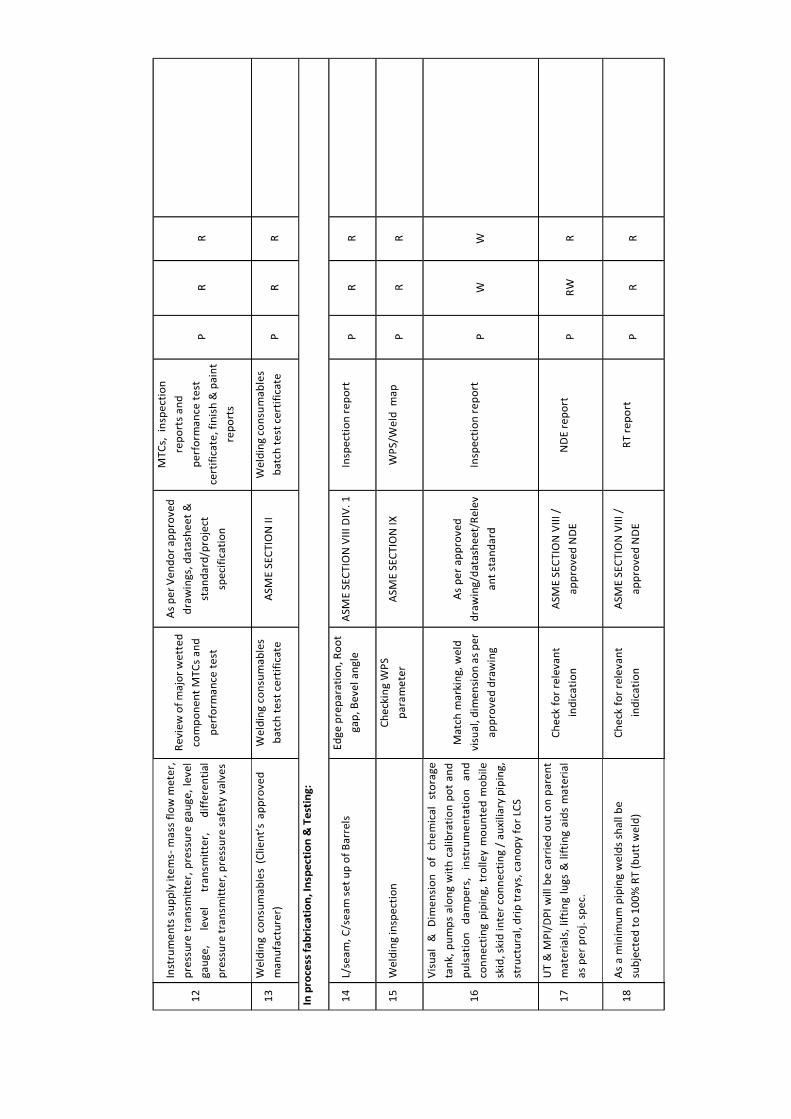


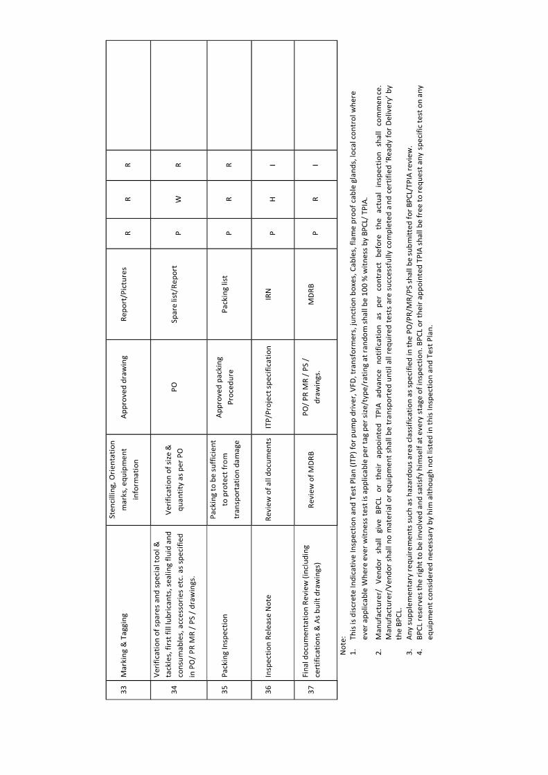

Spare Parts and Special Tools
Location: Kanpur & Coimbatore
Equipment Item Number: 10-100-AS-PK-001 & 002 Total No. of Units Installed: 2
A. Spares
1. Erection, Pre-Commissioning & Commissioning spares
Vendor shall provide the following erection, pre-commissioning & commissioning spare parts for the Anti-Static
Additive Dosing Package:
200% gaskets & 10% bolting of each size 2 set.
Gaskets for all joints to be opened during testing / pressure testing 2 set.
If however, any additional spare is consumed during Erection, Pre-Commissioning & Commissioning over and
above the included Erection, Pre-Commissioning & Commissioning spares, the same shall be provided by the
VENDOR at no extra cost to PURCHASER at the time of erection & commissioning.
2. Spares for two years normal operation
As a minimum Vendor shall provide following 2 years normal operating spares for the Anti-Static Additive Dosing
Package:
Sealing ring for pump NRV 2 set
Oil seal and O-rings for all parts of the pump 2 set.
Gasket set for pump 2 set.
Diaphragm set 2 set.
3. Mandatory Spares
200% gaskets & 10% bolting of each size 2 set.
Sealing ring for pump NRV 2 set.
Oil seal and O-rings for all parts of the pump 8 sets.
Gasket set for pump 2 set.
Diaphragm set 2 set.
Suction and discharge (integrated) valve assembly 2 set.
Pump PRV 2 set.
Power supply module (SMPS) 2 set.
Each rating of MCCB, MCB, contractors and relay 2 set.

All spare parts furnished by VENDOR shall be wrapped and packaged to preserve the package under normal
conditions of storage anticipated at project site.
The same parts shall be tagged by stainless steel tags and coded so that later identification as to their intended
equipment usage will be facilitated. All items supplied shall be packaged separately and clearly marked as "Spare
Parts" and shipped with the equipment in accordance with the instructions from PURCHASER. Packing lists shall be
furnished complete and in detail so that parts can be handled without uncrating.
B. Special Tools
Vendor shall provide the following special tool for the ASA Injection Package:
Pulsation Damper Charging Kit 2 set (1 per skid).
Special Tools & Tackles means all such tools / tackles those are specific to the erection and/or maintenance of
the supplied equipment/package and are normally not expected to be available in a plant workshop, but without
which it would be difficult or time-consuming to do erection and/or maintenance of the supplied
equipment/package.
The VENDOR shall identify the special tools requirement. Special tools shall be itemized and submitted for
review.
Notes:
1. The word means the quantity required for full replacement of that part in one machine.
2. In case, any spare which is listed above but not applicable due to specific construction / design of the
technical explanation.
3. Spare parts shall be identical in all respects to the parts fitted on the main equipment, including dimensions, material of construction & heat treatment.
4. In case no rate is furnished by bidder, it shall be concluded that the quoted package rate includes for all the
spares listed. The Bidder is advised to furnish list of spares along with the techno-commercial offer (i.e. both unpriced & priced copies).
5. The word 'TYPE' means the Make, Model no., Type, Range, Size/ Length, Rating, Material as applicable.
6. Wherever % age is identified, Contractor shall supply next rounded figure.

Data Sheet for
Anti-Static Additive Dosing Package
Rev. Date Issue Description Originated Process
Review
Mech
Review Approved Client
BHARAT PETROLEUM CORPORATION LIMITED (BPCL)
Project No: SHEET
1 of 8 Datasheet No: 10-ME-DAS-0004

DATASHEET FOR ANTI STATIC ADDTIVE DOSING PACKAGE
Rev.
1 Tag No. : 10-300-AS-PK-001 & 10-300-AS-PK-002 Client: BHARAT PETROLEUM CORPORATION LIMITED (BPCL)
2 Service: ANTI STATIC ADDITIVE & ATF Plant Location: Panki (Kanpur) and Irugur (Coimbatore)
3 P&ID No. : Manufacturer:
4 Calculation Ref. : - Purchase Order No. :
5 No. of Units: 1 W for Kanpur and 1 W for Coimbatore
6 Service Description: Anti-Static Additive and Aviation Turbine Fuel Solution Dosing in Multiproduct (HSD, MS, SKO, ATF) pipeline
7 1.0 GENERAL
8 a. This Data Sheet provides the technical requirements for the supply of ASA Injection Package for Panki (Kanpur) Terminal and Irugur (Coimbatore) Terminal Station.
ASA is injected in ATF to increase conductivity of ATF in the pipeline.
9 b. Deleted
10 c. Deleted
11 d. Deleted
12 e. Equipment shall be provided in accordance with this Data Sheet, P&ID, Specification for ASA Dosing Package and this Tender document.
13 f. Refer below information for the details of the ASA Dosing Package.
14
Location Package Tag No. Max. Operating
Press. @ Battery
Limit
Design Press.
@ Injection Discharge
Rating
15 Panki (Kanpur)
10-300-AS-PK-001 9 kg/cm²(g) 18 kg/cm²(g) 150 #
Irugur (Coimbatore)
10-300-AS-PK-002 9 kg/cm²(g) 18 kg/cm²(g) 150 #
16 g. Injection quill pressure drop has been considered as 1 kg/cm2. If it is more than 1 kg/cm2, then VENDOR shall include the same in above max. operating press value.
17 h. All data in blank fields in this data sheet shall be furnished / confirmed by VENDOR. VENDOR shall provide separate datasheets and other documents for each
18 ASA dosing package tag during BID & after order.
19 i. The complete package shall be designed for continuous service.
20 j. Fluid Properties
21
Product
Sp. Gravity @ 15 ºC Viscosity @ 37.8
ºC (cSt)
Viscosity @ 20
ºC (cSt)
True Vapor Pressure
@ 35 ºC (kg/cm2.a)
Flash Point
(ºC)
22
23 ATF (Remark-2) 0.78 @ 45 ºC 1.18 @ 45 ºC 1.53 @ 5 ºC 0.01 @ 37 ºC 38
24
25
26
27
28
29
30
31 2.0 FUNCTIONAL REQUIREMENTS
32
a. The skid shall include 1 X 100% ASA Dosing tank and 2 X 100% ASA injection pumps (for each plant location) with facilities to inject specified ASA chemical at
controlled flow rates through VFD (Variable Frequency Drive) into multiproduct pipeline.
33 b. The ASA solution will effectively increase conductivity of ATF being received through pipeline at respective location under system conditions.
34 c. The ASA selected shall be compatible with all product transferred. It shall also be Oil Soluble/Water Dispersible and having non foaming characteristics.
35
36 3.0 MATERIALS OF CONSTRUCTION
37
a. All materials shall be suitable for process selected, fluid service at specified operating/design conditions and for the site conditions and as per this data sheet & piping
material specification.
38
b. Calibration pot with borosilicate glass and pulsation dampeners material shall be SS 316L. The material of piping and piping fittings/ valves (as applicable for ASA
injection package) shall be as per piping material specification.
39 c. Pump & Tank MOC shall be as mentioned in the respective datasheet (part of this document).
40 4.0 SPARING PHILOSOPHY
41 a. The pump shall be in continuous service with one standby pump.
42 b. All spared equipment shall be provided with suitable isolation valves to allow maintenance of off-line unit while the other unit is on-line.
43
44 5.0 SYSTEM / EQUIPMENT AVAILABILITY
45 a. The skid reliability shall be targeted for 100%. The injection pumps shall have minimum 99% availability.
46
b.
The reliability of the package and equipment shall be minimum 99.5% i.e. there shall be no reduction in the required performance for more than 0.5% of the time. The
VENDOR shall confirm the above required availability and reliability of the skid and equipment / pumps in the offer based on VENDOR's recommended routine
maintenance.
47 c. Please refer Tender document and Specification for ASA Dosing Package.
48
49 6.0 PROJECT SPECIFICATION
50 a. All equipment to be supplied for the ASA dosing package shall be in accordance with the Project Specifications.
51 b. Material requisition for ASA Dosing Package, Specification for ASA Dosing Package along with this datasheets as applicable.
52
c.
Additional project specifications are referenced within the equipment requisition above, and including the documents listed in the various sections of this data sheet.
53 d. ASA dosing Pump, dosing tank, associated instrumentation and injection quill (loose supply) shall be in VENDOR scope.
54 e. Injection to be done by quills.
55
56 7.0 OPERABILITY AND MAINTAINABILITY
57
a. The equipment shall be designed for continuous operation, adequate access for equipment and instrumentation and require a minimum of downtime for maintenance.
This requirement should be considered when determining package layout and selecting items of equipment.
58 b. Flow signal from the product flow meter (supplied by others) is sent to the VFD of the ASA dosing Pump to ensure controlled dosing rate.
59 c. Ladder (internal, ext.) shall be mandatorily provided by VENDOR for approaching tank top instruments. Service platform, if required shall be provided. 1
60
BHARAT PETROLEUM CORPORATION LIMITED (BPCL)
Project No: SHEET
2 of 8 Datasheet No: 10-ME-DAS-0004

DATASHEET FOR A N T I S T A T I C A D D I T I V E DOSING PACKAGE
Rev.
1 Tag No. : 10-300-AS-PK-001 & 002 Client: BHARAT PETROLEUM CORPORATION LIMITED (BPCL)
2 Service: Anti Static Additive Plant Location: Kanpur and Coimbatore
3 P&ID No. : Manufacturer:
4 Calculation Ref. : - Purchase Order No. :
5 No. of Units: 1 W for Kanpur and 1 W for Coimbatore
6 Service Description: Anti-Static Additive and Aviation Turbine Fuel Solution Dosing in Multiproduct (HSD, MS, SKO, ATF) pipeline
7 8.0 DESIGN CONDITIONS
8 a. All equipment shall be suitable for 25 years design life.
9 b. All equipment shall be suitable for an exposed, outdoor, under shed environment.
10 c. Design temperature for all equipment: min. 0°C, max. 65°C. Operating temperature normal is 35°C & max. 65°C.
11 d. Specific design temperatures and pressures for the pumps and tank are specified on the relevant pages of this data sheet.
12 e. All associated piping and instrumentation supplied shall also comply with the relevant design conditions specified for the tank and pump.
13 f. Materials shall be as per the data sheets. Contractor's / VENDOR's recommended material may be proposed, however, is subject to Purchaser's approval.
14
g.
Surface preparation, coating and color coding shall be in accordance with the project specification. Note that the specific paint system shall be selected for all
applicable items including: carbon steel, stainless steel (as applicable per project specification), grating, instrument tubing, piping, structural steel, pumps,
equipment or tank.
15 h. The Combined Noise level of equipment (including driver and auxiliaries) shall not exceed 85 dB(A), when measured at 1 meter from source equipment in all
directions.
16
17 9.0 ANTI STATIC ADDITIVE INJECTION PUMPS
18
a.
Pumps shall be high efficiency double diaphragm type controlled volume pump in accordance with API-675, latest edition, as per Specification for Anti Static
Additive Injection Package and it's material requisition. The pump flow shall be controlled through VFD (Variable Frequency Drive) over entire turndown to
change the flow. Refer to sheets 5 & 6 of this Data Sheet for further technical requirements.
19
b.
Pumps shall be electric motor driven through Variable Frequency Drive (VFD). All electric motors shall be in accordance with "Specification for Medium Voltage
Induction Motors & Specification for Variable Frequency Drives'. Electric motors shall be suitable for the hazardous area as stated on this Datasheet/ motor
datasheet.
20 c. Contractor / VENDOR shall advise rated power and estimate of absorbed power for each motor.
21 d. The injection pumps shall be stopped in case of any internal generated trips e.g. low low liquid level in the ASA Tank, diaphragm rupture etc.
22 e. Pump shall be designed for the continuous duty with accuracy +/- 1% for full operating range. Its flow rate shall be adjustable locally from 0-100% of rated
23 flow while running or stationary.
24 10.0 ASA STORAGE TANK
25 a. The tank shall be cylindrical (with flat flanged end at top and dished end at bottom) in shape as per this datasheet, specification & material requisition for ASA
Injection Package.
26 b. Refer sheets 7 & 8 of this Data Sheet for further technical requirements.
27
c.
The tank vent shall be piped to a safe area to be agreed with the Purchaser during detailed design. As the safe area is outside of the skid boundary, the vent line
shall be extended off-skid by VENDOR. The Package VENDOR shall supply vent piping to the skid edge. The VENDOR shall confirm the size of the vent line to
suit the overall line length. Supplier to identify permanent requirement if any.
28 d. VENDOR to configure the tank elevation and suction piping to provide adequate NPIP to ASA injection pumps for all operating conditions.
29 e. Tank bottom shall be furnished with drain nozzle. This drain nozzle shall be kept at the opposite side of the tank outlet nozzle (Pump suction).
30 f. Level indicator & level transmitter shall be visible from grade.
31 g. The refilling pump shall trip if level of ASA in the storage vessel reaches high-high. The relevant alarms shall be indicated at station PLC.
32 h. Flame arrester shall be provided on vent line of the tank. All components of the flame arrestor shall be of SS316 construction.
33 11.0 STRUCTURAL SKIDS
34 a. All equipment identified and referenced in this datasheet & other documents shall be mounted on a single skid frame.
35 b.
The skid shall be fully welded, painted, provided with integral drip pan underneath the entire skid & drain nozzle with valve and blind flange, lifting lugs, earthing
bosses etc. The skid shall include ladders for the safe operation and maintenance of all equipment on the skid. Access ways & platforms as required shall be
provided too.
1
36 c. Deleted.
37 d. Grating shall be used for all skid floors.
38 12.0 INSTRUMENTATION AND CONTROL
39 a. All necessary instruments and controls (as per Field Instrument Specifications) for the safe start up, operation, shut down and safe guarding of this
40 Package shall be provided. As a minimum it shall include: level gauge, level transmitter on ASA storage tank for monitoring and tripping of the pumps
41 and other monitoring instrumentation including diaphragm failure detection, pump running and AutoStart facility, pressure gauge and pressure transmitter on
42 pump discharge, PSV, etc. (Refer P&ID)
43 b. GRP Canopy / Sun shade shall be provided over the instruments.
44
c.
Mass flow meter (Coriolis type) for very low and pulsating flow rates along with bypass valve shall be provided by VENDOR, for each skid, for close loop control
to correct the dosage rate once in 15 min if ASA solution is not getting dosed as per the set flowrate ppm. Mass flow meter shall be provided as per
specifications attached with this tender document.
45 13.0 OTHER
46 a. ASA Refilling pump of SS316 construction, 20 lpm capacity & 20m differential head with electric motor (suitable for Zone 2 hazardous area),
47 suction strainer, flexible suction piping (SS 316 braided hose of 5 meters), fixed discharge piping, with suitable fixed mounting arrangement/ mounting stool
48 for pump on skid. Pump shall be tested as per applicable standards and test certificates shall be provided for PURCHASER's for approval;
49 b. Name plate for all equipment shall have essential data engraved on SS 316L plate and affixed permanently to the equipment / skid.
50 c. Special tools shall include one set of Hydraulic oil filling kit & diaphragm oil filling device, one set of Pulsation damper charging Kit in addition to Manufacturer's
own recommendation.
51 14.0 QUALITY ASSURANCE, INSPECTION & TESTING
52 a. Refer Specification for Corrosion Inhibitor Dosing Package and Indicative ITP provided in Tender document.
53 b. Hydrotest pressure shall be 1.5 times the maximum allowable working pressure (MAWP) and to be tested for 1 hour duration
54 c. Pressure containing parts shall have material certification in compliance with BS EN 10204 type 3.1 and include original mill certificates or certified copies.
Components shall be fully traceable back to the certificate. Other parts shall be provided with certification to BS EN 10204 type 2.2.
55 d. Positive Material Identification shall be performed on all material that are of alloy construction.
56
BHARAT PETROLEUM CORPORATION LIMITED (BPCL)
Project No: SHEET
3 of 8 Datasheet No: 10-ME-DAS-0004

DATASHEET FOR ANTI STATIC ADDITIVE DOSING PACKAGE Rev.
1 Tag No. : 10-100-AS-PK-001 & 002 Client: BHARAT PETROLEUM CORPORATION LIMITED (BPCL)
2 Service: Anti Static Additive Plant Location: Kanpur & Coimbatore
3 P&ID No. : Manufacturer:
4 Calculation Ref. : - Purchase Order No. :
5 No. of Units: 1 W for Kanpur & 1 W for Coimbatore
6 Service Description: Anti-Static Additive and Aviation Turbine Fuel Solution Dosing in Multiproduct (HSD, MS, SKO, ATF) pipeline
7 SCOPE OF SUPPLY (FOR EACH PACKAGE / LOCATION)
8 A) ASA Injection Pumps along with motor Yes, Refer Sheets 5 and 6 for details
B) Auxiliaries for each ASA Injection Pump
- Suction and discharge isolation valves Yes
- Suction strainer Yes
- Differential Pressure Transmitter with isolation valves Yes
- Discharge check Valve Yes
- Discharge pressure transmitter with isolation valves Yes (common for working & standby pumps)
- Discharge mass flow transmitter (Coriolis type) Yes, with bypass arrangement & valves (common for working & standby pumps)
- Suction dampener VENDOR to verify and to be provided when required.
- Discharge dampener Yes, One per pump, in stainless steel, flanged and with isolation valve
- External pressure relief valve Yes
- Electric motors Yes
- Variable Frequency Drive Yes
- Coupling - Integral Yes
- Stroke adjustment Yes
- Calibration pot Yes, with Isolation valve
- Drain valve on suction line Yes
- Bypass line for the pump with valve Yes (common for working & standby pumps)
C) Refilling Pumps along with motor & Auxiliaries Yes
- Hose of 5 m length for Drum pumps Yes
- Quick connecting coupling and hose fittings Yes
C) ASA Storage Tank Yes, Refer Sheets 7 and 8 for details
D) Tank Auxiliaries As defined below
- Cover of Tank Yes
- Manhole / handhole Yes (Manhole )
- Drain Yes, flanged and valved
- Vent type Yes, To atmosphere with goose neck
- Breather valve No
- Level gauge & level transmitter Yes (LG: Magnetic Float Type / LT: GWR Type)
- Pressure gauge No
- External filling connection Yes, with valve and quick coupling connection
- Nitrogen blanketing inlet Not Applicable
- Overflow protection Yes
- Ladders / platforms Ladder for maintenance access shall be provided. Service platform, if required shall be provided.
- Agitator (included gear and motor) Not Applicable
- Back pressure control valve on vent Not Applicable
- Flame arrestor Yes
E) Base plate Yes
- Type (grating / deckplate) Yes, Single lift Structural Skid for Pumps and Tank
- Material of construction Carbon Steel
- Baseplate drain Yes
- Drip tray with drain connection Yes
- Earthing lugs, Lifting lugs and Name Plates Yes
- Checkered deck plates / grating Yes, Wherever necessary for maintenance or operation access
- Equipment holding down & Anchor bolts Yes
F) Skid Piping
- Piping Material Yes, as per Piping Material Specification (Tubing shall not be used)
- Piping class As per P&I Diagram
- Valve type / material Yes, as per Piping Material Specification
- Drains Yes, Valved and flanged for complete drainage of package
G) Electrical, Instrumentation and Control Yes
- Local control station (LCS) Yes
- Wiring / cabling Control cabling for motors / Cabling of Instruments
- JB at skid edge (including cable glands) Yes
- FRP Cable trays Yes
- All required instruments with local gauge board Yes
- LG,LT, Pl, PT, PSV and NRV Yes (LT Shall be GWR type)
- Operation, Control and safe guarding Centralised through control room by station PLC / RTU (Supplied by Others)
- Flow rate control Yes, Manual & Automatic
- Mass flowmeter (Coriolis type) Yes, with bypass arrangement & valves (common for working & standby pumps)
- Hooters (As per P&IDs) Yes
H) Dimensions and Weights
- Package overall dimensions (L x W x H) VENDOR to Furnish
- Package weights (empty / full / hydrotest) VENDOR to Furnish
I) Others
- Injection Quill Yes
- Spare parts as per Project requirement Yes
- First fill of oil and lubricants No. However, vendor to provide required type, quantity and BPCL equivalent oil grade.
- Special tools (as applicable) Yes
- Painting Yes, As per Project painting specification
- Document as per Project requirements Yes, As per VDRL
9
10
11
12
13
14
15
16
17
18
19
20
21
22
23
24
25
26
27
28
29
30
31
32
33
34
35
36
37
38
39
40
41 1
42
43
44
45
46
47
48
49
50
51
52
53
54
55
56
57
58
59
60
61
62
63
64
65
66
67
68
69
70
71
72
73
74
75
76
77
78
BHARAT PETROLEUM CORPORATION LIMITED (BPCL)
Project No: SHEET
4 of 8 Datasheet No: 10-ME-DAS-0004


DATASHEET FOR ASA INJECTION PUMP
Rev.
1 APPLICABLE TO: PROPOSAL PURCHASE AS BUILT
2 FOR BHARAT PETROLEUM CORPORATION LIMITED (BPCL) UNIT 300-01 (KANPUR) / 300-02 (COIMBATORE)
3
SITE KANPUR / COIMBATORE NO. OF PUMPS REQUIRED 2 (1W+1S)
4
SERVICE: ASA MODEL: SIZE AND TYPE Positive Displacement Metering - Double Diaphragm
5
MANUFACTURER SERIAL NO
6
7 NOTE: INDICATES INFORMATION TO BE COMPLETED BY PURCHASER BY MANUFACTURER
8 GENERAL
9 NO. MOTORS DRIVEN TWO OTHER DRIVER TYPE NOT APPLICABLE
10
PUMP ITEM NO'S 10-300-ASP-001A/B&002A/B PUMP ITEM NO'S NOT APPLICABLE
11
MOTOR ITEM NO'S LATER DRIVER ITEM NO'S NOT APPLICABLE GEAR ITEM NO'S NOT APPLICABLE
12
MOTOR PROVIDED BY PUMP VENDOR DRIVER PROVIDED BY NOT APPLICABLE GEAR PROVIDED BY NOT APPLICABLE
13
MOTOR MOUNTED BY PUMP VENDOR DRIVER MOUNTED BY NOT APPLICABLE GEAR MOUNTED BY NOT APPLICABLE
14
MOTOR DATA SHEET NO. EL-DAS-0012 DRIVER DATA SHEET NO. NOT APPLICABLE GEAR DATA SHEET NO. NOT APPLICABLE
8
15 OPERATING CONDITIONS (VTA) Refer 1b,c,d , e &j (pg 2 of 8) LIQUID (VTA)
16 CAPACITY @ PT (lit/hr): Normal: 10.0 TYPE OR NAME OF LIQUID ASA & ATF SOLUTION
17
MAXIMUM 100.0 MINIMUM 5.0 RATED 90.0
PUMPING TEMPERATURE (°C):
18
DISCHARGE PRESSURE (kg/cm²g): NORMAL 35 MAX 65 MIN
19 MAXIMUM VTA - Refer 1f (pg 2 of 8) MINIMUM
SPECIFIC GRAVITY @ 1.110 MAXIMUM MINIMUM
20
SUCTION PRESSURE (kg/cm²g):
SPECIFIC HEAT Cp (kJ/kg °C)
21 MAXIMUM VTA MINIMUM VTA
VISCOSITY (Cp) MINIMUM MAXIMUM
22
DIFFERENTIAL PRESSURE (kg/cm²):
CORROSIVE/EROSIVE AGENTS
23 MAXIMUM VTA MINIMUM
CHLORIDE CONCENTRATION (PPM)
24
NPIP AVAILABLE (M) VTA
H2S CONCENTRATION (PPM)
25
WITHOUT ACCELERATION HEAD VTA ACTUAL VTA LIQUID TOXIC FLAMMABLE OTHER
26 TURNDOWN RATIO 10:1
VAPOUR PRESSURE : VTA
27
27 PERFORMANCE * SITE AND UTILITY DATA
28 NUMBER OF FEEDS VTA RATED CAPACITY (lit /h) VTA LOCATION INDOOR OUTDOOR
29
NPIP REQUIRED (INCLUDING ACCEL LOSSES) VTA MASP (kg/cm²a) VTA HEATED UNHEATED UNDER ROOF
30
BKW RATED VTA AT RELIEF SETTING (kg/cm²g) VTA ELECTRICAL AREA CLASS Zone 2 Gas Group. IIA / IIB Temp. class T3
31
PLUNGER SPEED (strokes/min) VTA DESIGN MAX VTA
WINTERIZATION REQD TROPICALIZATION REQD
32
DIAMETER (mm) LENGTH OF STROKE (mm) VTA SITE DATA
33
PUMP HEAD: DOUBLE DIAPHRAGM RANGE OF AMBIENT TEMPS:MIN/MAX 2 / 50 °C
34
MAXIMUM PRESSURE (kg/cm²g) Refer 1g (pg 2 of 8)
UNUSUAL CONDITIONS
35
HYDRO TEST PRESSURE (kg/cm²g) VTA
DUST FUMES SALT ATMOSPHERE
36
MAX DISCH PRESS. W/ JOB DRIVER (kg/cm²g) VTA OTHER
37
MAX BKW BASIS GEAR STRENGTH VTA
UTILITY CONDITIONS
38
38 CONSTRUCTION (Refer 1g pg 2 of 8) ELECTRICITY DRIVERS HEATING CONTROL SHUTDOWN
39
SIZE
ANSI RATING
FACING
POSITION
VOLTAGE 415±10% 240 240
40 CONNECTIONS HERTZ 50±5% 50 50
41 SUCTION
PHASE 3 1 1
42 DISCHARGE COOLING WATER - NA INLET RETURN DESIGN MAX D
43 FLUSH
TEMP °C MAX
44
Pump suction / discharge nozzle shall be flanged connection.
PRESS. (BARG) MIN
45 LIQUID END JACKET REQ'D
SOURCE
46 TYPE l DIAPHRAGM (DOUBL PLUNGER INSTRUMENT AIR: Not available MAX MIN
47 DIAPHRAGM DIA (mm) NO REQ. TWO PRESSURE (kPa)(BARG)
26
48 VALVES/FEED SUCTION DISCHARGE APPLICABLE SPECIFICATIONS:
49 TYPE BALL BALL API 675 POSITIVE DISPLACEMENT PUMPS - CONTROLLED VOLUME (3rd Edition)
50
NUMBER TWO TWO GOVERNING SPECIFICATION (IF DIFFERENT)
51
NACE MR-0103 (6.14.2.13) NACE MR-0175 (6.14.2.13)
52
OTHER PROJECT DOC NO. 15984-BP-10-ME-SPC-0001
53 REMARKS: 1. Refer clause 10.0 on pg 3 of 8 of this datasheet.
54 2. Refer clauses 1f (pg 2 of 8), pump flowrate & tank dimensions of this datasheet for NPIP calculation.
55 3. Volumetric efficiency of the pumps shall be ≥ 90% (VTA) and mechanical efficiency shall be ≥ 60% (VTA). Repetitive accuracy shall be in line with API 675 1
56 4. All clause nos. mentioned on this datasheet refers to API 675, 3rd Ed.
57
58
59
60
61
62
BHARAT PETROLEUM CORPORATION LIMITED (BPCL)
Project No: SHEET
5 of 8 Document No: 10-ME-DAS-0004

DATASHEET FOR ASA INJECTION PUMP
Rev.
1
2 LIQUID END
MATERIALS * (Refer 9f pg 3 of 8)
SS 316 L
CONTROLS
TYPE: SIGNAL:
3 CONTOUR PLATE
4 HYDRAULIC DIAPHRAGM
MANUAL REMOTE PNEUMATIC
AUTOMATIC LOCAL ELECTRONIC
5 PROCESS DIAPHRAGM
6 PLUNGER
7 LANTERN RING
8 PACKING GLAND
PTFE / VTA
SS316 / VTA
MS / VTA
STROKE CONTROL: FLOW TO BE CONTROLLED WITH VFD. HOWEVER, PROVISION FOR FLOW
CONTROL BY ADJUSTING STROKE LENGTH SHOULD BE RETAINED ON PUMP
PNEUMATIC (PSIG):
MINIMUM MAXIMUM
9 PACKING
10 LINER
Brass / VTA
ELECTRONIC (mA): MINIMUM 4 MAXIMUM 20
11 VALVE
12 VALVE SEAT
13 VALVE GUIDE
14 VALVE BODY
15 VALVE GASKET
16 FRAME
17 SPECIAL MATERIAL TESTS (2.13.1.3)
18
SS316 / VTA
SS316 / VTA
SS316 / VTA
SS316 / VTA
PTFE / VTA
OTHER PURCHASE REQUIREMENTS
NAMEPLATE UNITS U.S. CUSTOMARY SI
VENDOR FURNISHED PROCESS PIPING ALL ON-SKID MOUNTED PIPING
AND ASSOCIATED VALVES BY PACKAGE VENDOR
VENDOR REVIEW PIPING DRAWINGS
VENDOR FURNISHED PULSATION SUPPRESSION DEVICES
VENDOR FURNISHED RELIEF VALVE
INTERNAL EXTERNAL
19 LOW AMBIENT TEMPERATURE MATERIALS TESTS (2.13.5)
20
21
22 QA INSPECTION AND TEST
23 COMPLIANCE WITH INSPECTORS CHECK LIST (AS PER API 675)
24 CERTIFICATION OF MATERIALS
25 FINAL ASSEMBLY CLEARANCES
26 SURFACE AND SUBSURFACE EXAMINATIONS (REFER REMARK)
RELIEF VALVE SETTING (kg/cm²g)
VENDOR FURNISHED BACK-PRESSURE VALVE
DOUBLE CHECK VALVES REQUIRED
OIL-FILLED PRESSURE GAUGES REQUIRED
VENDOR FURNISHED CONTROL PANEL (LCS)
BASEPLATE PREPARED FOR EPOXY GROUT
PROVIDE TECHNICAL DATA MANUAL
VTA
27 RADIOGRAPHY
28 ULTRASONIC
29
30 MAGNETIC PARTICLE
31 LIQUID PENETRANT
32 CLEANLINESS PRIOR TO FINAL ASSEMBLY
33 HARDNESS OF PARTS, WELDS & HEAT AFFECTED ZONES
34 FURNISH PROCEDURES FOR OPTIONAL TESTS
35
PRESSURE TRANSMITTERS FOR DIAPHRAGM FAILURE DETECTION REQUIRED.
PREPARATION FOR SHIPMENT
DOMESTIC EXPORT EXPORT BOXING
OUTDOOR STORAGE MORE THAN 12 MONTHS
WEIGHTS (KG) *
PUMP BASE GEAR: DRIVER :
36 TESTS REQ'D WIT OBS
37 HYDROSTATIC (8.3.2)
38 STEADY STATE ACCURACY
39 REPEATABILITY
40 LINEARITY
41 PERFORMANCE (8.3.4)
42 MECHANICAL RUN (8.3.5)
MOTOR:
MANUFACTURER
TYPE
FRAME NO.
CONSTANT SPEED
VARIABLE SPEED YES
DRIVERS *
43 NPIP (8.3.7.1) kW RPM
44 COMPLETE UNIT (8.3.7.2)
45 SOUND LEVEL (8.3.7.3)
46 HIGH DISCHARGE PRES (8.3.7.4)
VOLTS
HERTZ
ENCLOSURE
415V AC
50
PHASE 3
SERVICE FACTOR
47 FACTORY ACCEPTANCE (8.3.8)
48
OTHER (SEE SEPARATE DATA SHEETS) REFER DOC NO. 10-EL-DAS-0012
GAS DRIVEN
49 LUBRICATION FLUID *
50 CRANKCASE INTERMEDIATE NR
51 HYDRAULIC FLUID
52 ACCESSORIES *
53 SPEED REDUCER MANUFACTURER
54 INTEGRAL SEPARATE
55 MODEL
56 RATIO
STEAM TURBINE
OTHER
57 BASEPLATE UNDER
58 COUPLING MANUFACTURER
PUMP & MOTOR (MAIN SKID)
59 TYPE
60
DIRECT FLEXIBLE
' * ' - Vendor to fill.
61 REMARKS:
62 1. Acceptance criteria for NDT shall be as mentioned in API 675
63 2. Material shall be in line with API 675 clause 2.13 and Appendix-B
BHARAT PETROLEUM CORPORATION LIMITED (BPCL)
Project No:
Document No: 1 0-ME-DAS-0004
SHEET
6 of 8
l
l
l
l

DATASHEET FOR ASA INJECTION TANK
Rev.
1 Tag No. : 10-300-AST-001 & 002 Client: BHARAT PETROLEUM CORPORATION LIMITED (BPCL)
2 Service: ASA Plant Location: KANPUR & COIMBATORE
3 P & ID No. : Manufacturer:
4 Calculation Ref. : - Purchase Order No. :
5 No. of Units: 1 W for Kanpur & 1W for Coimbatore
6 Service Description: ASA STORAGE TANK
7 DESIGN DATA CONSTRUCTION MATERIAL
8 Basic Shape VERTICAL, CYLINDRICAL with BOTTOM DISH END
& TOP PLATE FLANGED COVER PARTS MATERIAL SPECIFICATION
9 Design Code ASME Sec- VIII, Div. 1, 2019 Dished End / Main body SS 316L
10 Fabrication, inspection / testing AS PER APPLICABLE CODES Shell SS 316L
11 Construction Category - Reinforcing Pads SS 316L
12 Liquid ANTI STATIC ADDITIVE + ATF Nozzle Neck - Pipe SS 316L
13 Corrosion / Erosion APPLICABLE Demister / Vane Pack NOT APPLICABLE
14 Temperature Flanges SS 316L
15 Design - Max./Min. °C 65/0
16 Operating °C 35 Anode Protection NOT APPLICABLE
17 Pressure Leg Supports CARBON STEEL
18 Design kg/cm²g FULL OF WATER Distributor NOT APPLICABLE
19 Operating kg/cm²g ATMOSPHERIC Wrapper Plates/Bearing Plates NOT APPLICABLE
20 Vacuum design pressure kg/cm²g NOT APPLICABLE Stiffener Plates/Angles, if any SS 316 L
21 Shop Hydrotest Pressure AS PER CODE Internal Attachments, if any. SS 316 L
22 Liquid: Density @ 16 0C kg/m3 External Attachments (Lugs) SS 316 L
23 Viscosity @ 38 0C cP External Bolts AS PER PIPING MATERIAL SPEC.
24 Flash point °C Nuts AS PER PIPING MATERIAL SPEC.
25 Vapour pressure kg/cm²a Gaskets AS PER PIPING MATERIAL SPEC.
26 Volume: Required storage m³ VTA Internal Bolts SS 316L
27 Nominal Storage
(HLL to LLL) m³
0.85
(total volume of the tank shall not be more than 1000
litres) Nuts
SS 316L
28 Low Operating Level m VTA
29 High Operating Level m VTA Material Impact Test Required NOT APPLICABLE
30 Nominal Storage days VTA Certified Elevated Temp. Test Req'd NOT APPLICABLE
31 Filling Rate m3/hr VTA CONSTRUCTION
32 Discharge Rate lit/hr 5 to 100 Type Of Heads 2:1 ELLIPSOIDAL
33 Tank Dimensions (Dia. x Ht.) / (WxL) M 1.0 X 1.2 (VTA) Type Of Support LEG SUPPORTS
34 Shell Thickness mm VTA Manway / Handhole YES
35 Dish End Thickness (Min. / Nom.) mm VTA Manway Davit NOT APPLICABLE
36 Mixer required and Heater required NO Pump PSV Return NO
37 Weld Joint Efficiencies: Atmospheric Vent YES
38 Shell AS PER CODE Tank Overflow YES
39 Dish End AS PER CODE Ladder YES 1
40 Non Destructive Testing: Earthing Bosses YES
41 Radiography
AS PER CODE & SPECIFICATION
Lifting Lugs YES
42 Ultrasonic Nameplate YES
43 Magnetic Particle Supports YES
44 Dye Penetrant Platform on the skid, if any AS APPLICABLE
45 Leak testing AS PER CODE & SPECIFICATION
46 Corrosion Allowance mm 0 ESTIMATED WEIGHTS
47 Post Weld Heat Treatment AS PER CODE & SPECIFICATION Empty kg VTA
48 Insulation mm NOT APPLICABLE Shipping kg VTA
49 Fireproofing mm NOT APPLICABLE Operating kg VTA
50 Coating (External) AS PER SPECIFICATION Field Test kg VTA
51 Coating (Internal) NOT APPLICABLE
52
53
54
55
56
57
58
59
60
BHARAT PETROLEUM CORPORATION LIMITED (BPCL)
Project No: SHEET
7 of 8 Datasheet No: 10-ME-DAS-0004

DATASHEET FOR ASA INJECTION TANK
Rev.
1 Tag No. : 10-100-AST-001 & 002 Client: BHARAT PETROLEUM CORPORATION LIMITED (BPCL)
2 Service: ASA Plant Location: Kanpur & Coimbatore
3 P & ID No. : Manufacturer: -
4 Calculation Ref. : - Purchase Order No. : -
5 No. of Units: 1 W for Kanpur & 1 W for Coimbatore
6 Service Description: ASA STORAGE TANK
7 Mark Number Size (in) Rating Facing Service Remarks
8 N1 1 2 150 lb WNRF Filling/ inlet nozzle Shall be provided with removable internal dip pipe.
9 N2 1 2 150 lb WNRF Outlet
10 N3 1 Min. 2 (VTA) 150 lb WNRF Vent Vented to safe location, Goose Neck.
11 N4 1 2 150 lb WNRF Spare
12 N5 1 Min. 2 (VTA) 150 lb WNRF Tank Overflow
13 N6A/B 2 2 300 lb WNRF Level Gauge Connection
14 N7A/B 2 2 300 lb WNRF Level Transmitter Connection
15 M1 1 24 VTA VTA Manway Shall be provided with blind cover, stud, nuts & gaskets.
16
17
18
19
20
21
22
23 SKETCH AND NOTES
24
25
26
27
28
29
30
31
32
33
34
35
36
37
38
39
40
41
42
43
44
45
46
47
48 NOTES
49 1. VTA = Vendor to Advise, VTC = Vendor to Confirm, NA = Not Applicable
50 2. Refer clause 11.0 on page 3 of 8 of this datasheet.
51 3. Level Indicator shall be Magnetic Float Type & Level Transmitter shall be Guided Wave Radar Type.
52
53
54
55
56
57
58
59
60
61
62
BHARAT PETROLEUM CORPORATION LIMITED (BPCL)
Project No: SHEET
8 of 8
Datasheet No: 10-ME-DAS-0004

DATA SHEET FOR MEDIUM VOLTAGE INDUCTION MOTOR
Rev. Date Issue Description Originated Checked Approved Client
BHARAT PETROLEUM CORPORATION LIMITED (BPCL)
Project No: SHEET
Datasheet No: 10-EL-DAS-0012 1 of 6

:
Data Sheet for Medium Voltage Induction Motor
1 Tag No. : As per Annexure-A (VTA) Client: Bharat Petroleum Corporation Limited
2 Service: As per Annexure-A (VTA) Plant Location: As per Annexure-A (VTA)
3 Drg. No. : Later Manufacturer: VTA
4 Specification Ref. : 10-EL-SPC-0010 Purchase Order No. Later
5 No. of Units: As per Annexure-A (VTA)
6 Service Description: As per Annexure-A (VTA)
7 SITE CONDITIONS POWER SYSTEM
8 Location: Indoor Outdoor System Voltage: 415 V ± 15%
9 Ambient air temp: Min: 1.1 °C Max: 45.6 °C Design: 50 °C System Frequency: 50 Hz ± 5%
10 Humidity: Min.16.4% Max: 80% Altitude: < 1000 m Neutral Earthing: Solidly earthed
11 Hazardous area classification: Exd, Zone2, Gas gp IIA/IIB, Temp. Class T3 Or Industrial Safe area as per pump datasheet
12 PARTICULARS OF EQUIPMENT UNITS PURCHASER'S REQUIREMENTS VENDOR'S RESPONSE
13 GENERAL DATA
14 Applicable Standards As per Cl. 2 of Specification
15 Manufacturer VTA
16 Model Number VTA
17 Design site conditions See above
18 Frame Size VTA
19 Rated Voltage V 415
20 Rated Frequency Hz 50
21 Voltage / Frequency Tolerance % ±15 % / ±5 %
22 Rated Power kW As per Annexure-A (VTA)
23 Duty S1 (Continuous)
24 Service Factor 1
25 No of poles As per Annexure-A (VTA)
26 Synchronous Speed rpm As per Annexure-A (VTA)
27 No of Phases 3
28 Stator Connection As per Cl. 5.3.1 (d) of Specification
29 Insulation Class Class F
30 Temperature Rise Limited to Class B (70 0C)
31 Ingress Protection Classification IP66 for all motors
located indoor & outdoor
32 Cooling Type VTA, TEFC
33 Upstream Fault Protection MCCB, Overload relay
34
VFD Application
(Note-5, 8)
Yes / No As per Annexure-A (VTA)
VFD started motors shall also be
suitable for DOL starting
35
36
37 PERFORMANCE CHARACTERISTICS
38 Full Load Current A VTA
39 Full Load Speed rpm VTA
40 Efficiency at FL / ¾ FL / ½ FL pu IE4 as per as per IEC-60034-30-1 / /
41 Power Factor at FL / ¾ FL / ½ FL pu VTA / /
42 Full Load Torque Nm VTA
43 Breakdown Torque pu VTA
44 Pull-up Torque pu VTA
45 Combined Torque-Speed Curve Required Yes / No Yes Required with Bid
46 Thermal Withstand (Hot / Cold) Curve Required Yes / No Yes Required with Bid
47 Load Vs Efficiency, Power Factor Curve Required Yes / No Yes Required with Bid
48 Speed Vs Current Curve Required Yes / No Yes Required with Bid
49 Negative phase sequence current Vs Time Curve Required Yes / No Yes Required post order
50
Speed range for VFD driven motors
VTA (Suitable to match the Pump
operating speed for the flow conditions
as per Pump data sheets)
Rev. Date Issue Description Originated Checked Approved Client
BHARAT PETROLEUM CORPORATION LIMITED (BPCL)
Project No: SHEET
Datasheet No: 10-EL-DAS-0012 2 of 6

Data Sheet for Medium Voltage Induction Motor
51 Tag No. : As per Annexure-A (VTA) Client : Bharat Petroleum Corporation Limited
52 Service : As per Annexure-A (VTA) Plant Location : As per Annexure-A (VTA)
53 Drg. No. : Later Manufacturer : VTA
54 Specification Ref. : 10-EL-SPC-0010 Purchase Order No. : Later
55 No. of Units : As per Annexure-A (VTA)
56 Service Description : As per Annexure-A (VTA)
57 PARTICULARS OF EQUIPMENT UNITS PURCHASER'S REQUIREMENTS VENDOR'S RESPONSE
58 STARTING CHARACTERISTICS
59 Starting Method DOL / VFD if specified in Mechanical
data sheet
60 Starting Performance VTA
61 Maximum Allowable Stall Time (Hot / Cold) s VTA (Post order) /
62 Thermal time constants (Heating / Cooling) s VTA (Post order) /
63 Max. no. of Starts Per Hour 2 Hot and 3 Cold starts
64 Max. no. of Starts Per Year Normal
65 Starting Current at Un / 0.8 x Un pu VTA /
66 Starting Power Factor at Un / 0.8 x Un pu VTA /
67 Locked Rotor Torque at Un / 0.8 x Un pu VTA /
68 Max Run-up Time at Un / 0.8 x Un s VTA /
69 Starting Current Vs Time Curve Required Yes / No Yes (Post order)
70
71
72 CONSTRUCTION
73 Mounting As per Annexure-A (VTA)
74 Stator Frame Material VTA
75 Rotation Facing Drive End CW/CCW Bi Directional
76 Fan Bi-Directional Yes / No Yes
77 Fan Cover Ingress Protection VTA, Min IP21
78 Colour (Note-7) 631 as per IS 5 or equivalent RAL shade
79 Paint Specification VTA Manufacturer's standard
80 Motor Inertia kg m2 As per Annexure-A (VTA)
81 Driven Load Inertia kg m2 As per Annexure-A (VTA)
82 Coupling Type VTA (By Package Supplier)
83 Maximum Sound Pressure Level at Full Load dBA <85 dBA at 1 mtr from all directions
84 Integral Breather / Drain Yes / No VTA
85 DE Bearing Type VTA
86 DE Bearing Make VTA
87 No. of DE Bearings VTA
88 NDE Bearing Type VTA
89 NDE Bearing Make VTA
90 No. of NDE Bearings VTA
91 Bearing Lubrication VTA
92 Bearing Ingress Protection VTA
93 Minimum bearing lifetime, motor only hr VTA
94 Maximum relubrication interval hr VTA
95 Max Shaft Voltage mV rms VTA
96 Insulated Bearings Yes / No Yes for VFD driven motor
97 Bearing Insulation Rating kV VTA (Post order)
98 Rotor Axial Float (pos / neg) mm VTA (Post order)
99 Vibration at No-load, soft mounted, peak-to-peak mm/s VTA
100 Critical speed(s) rpm As per Cl. 5.7 of Specification
Rev. Date Issue Description Originated Checked Approved Client
BHARAT PETROLEUM CORPORATION LIMITED (BPCL)
Project No: SHEET
Datasheet No: 10-EL-DAS-0012 3 of 6

Data Sheet for Medium Voltage Induction Motor
101 Tag No. : As per Annexure-A (VTA) Client : Bharat Petroleum Corporation Limited
102 Service : As per Annexure-A (VTA) Plant Location : As per Annexure-A (VTA)
103 Drg. No. : Later Manufacturer : VTA
104 Specification Ref. : 10-EL-SPC-0010 Purchase Order No. : Later
105 No. of Units : As per Annexure-A (VTA)
106 Service Description : As per Annexure-A (VTA)
107 PARTICULARS OF EQUIPMENT UNITS PURCHASER'S REQUIREMENTS VENDOR'S RESPONSE
108 CONSTRUCTION
109 Maximum Transient Airgap Torque for:
110 Two-phase short circuit at motor terminal kNm VTA
111 Three-phase short circuit at motor terminal kNm VTA
112 Asynchronous Start kNm VTA
113 Re-start with Full Opposite Residual Voltage kNm VTA
114 Overall dimensions : L x W x H mm As per Annexure-A (VTA)
115 Total Weight kg As per Annexure-A (VTA)
116 Name plates Yes / No Yes, As per Cl. 5.9 of Specification
117 HAZARDOUS AREA CERTIFICATION
118
Protection Type and Classification
Ex d for Zone2, Gas gp IIA/IIB, Temp. Class
T3 or Industrial type for safe area as per
mechanical equipment datasheet
119 Ex e Motor te Time s N/A
120 Certifying Authority VTA
121 Certification Standard VTA
122 Certificate Number VTA
123 Certificate Date dd/mm/yyyy VTA
124 Certificate includes VFD service? (Note-5) Yes / No VTA
125 Name plate for VFD driven motors As per Cl. 6.4 of Specification
126 ACCESSORIES
127 Anti-condensation heater Yes / No Yes for motors rated above 22kW
128 Anti-condensation Heater Power W VTA
129 Anti-condensation Heater Voltage V AC 240
130 Winding Temperature Detectors Yes / No Yes for VFD driven motors
131 Bearing Temperature Detectors Yes / No No
132 Frame Earth Yes 2 Nos on opposite side, suitable for
earth fault current
133 Accelerometer Shock-Pulse Measurement Devices Yes / No No
134 Anti-rotational Device Yes / No Yes for fan coolers
135 Auxiliary pump/fan motor Power kW N/A
136 Auxiliary pump/fan motor Voltage VAC N/A
137 Auxiliary heater Power kW VTA
138 Auxiliary heater Voltage V AC 240V±15%, 1Ph+N, 50Hz±5%
139 Control panel Power kW N/A
140 Control panel Voltage V AC N/A
141 Lubrication accessories included Yes / No N/A
142 Cooling accessories included Yes / No N/A
143 Current transformer required Yes / No N/A
144 Current transformer ratio and parameters N/A
145 Differential Current transformer Yes / no N/A
146 Differential Current transformer Vk, Rct, Imag N/A
147 CABLE CONNECTIONS
148 Ingress Protection of Terminal Boxes IP66
149
Main Terminal Box Classification (Ex 'd' / 'e' / 'n') Exd for Zone2, Gas gp IIA/IIB, Temp. Class T3
or Industrial type for safe area as per
mechanical equipment datasheet
150 Power Cable Type Terminals shall be suitably sized for
Aluminium cables (above 16sqmm) Size
and nos. As per Annexure-A
151 Power Cable No. and Size
Rev. Date Issue Description Originated Checked Approved Client
BHARAT PETROLEUM CORPORATION LIMITED (BPCL)
Project No: SHEET
Datasheet No: 10-EL-DAS-0012 4 of 6
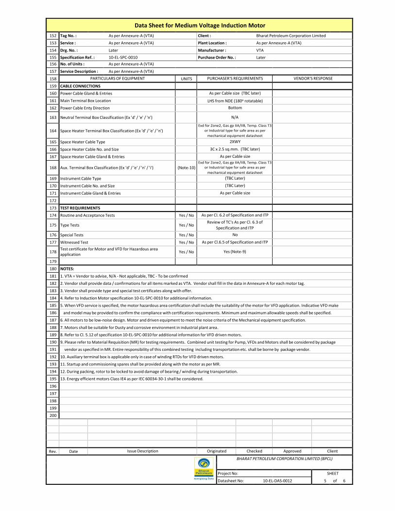
Data Sheet for Medium Voltage Induction Motor
152 Tag No. : As per Annexure-A (VTA) Client : Bharat Petroleum Corporation Limited
153 Service : As per Annexure-A (VTA) Plant Location : As per Annexure-A (VTA)
154 Drg. No. : Later Manufacturer : VTA
155 Specification Ref. : 10-EL-SPC-0010 Purchase Order No. : Later
156 No. of Units : As per Annexure-A (VTA)
157 Service Description : As per Annexure-A (VTA)
158 PARTICULARS OF EQUIPMENT UNITS PURCHASER'S REQUIREMENTS VENDOR'S RESPONSE
159 CABLE CONNECTIONS
160 Power Cable Gland & Entries As per Cable size (TBC later)
161 Main Terminal Box Location LHS from NDE (180o rotatable)
162 Power Cable Enty Direction Bottom
163 Neutral Terminal Box Classification (Ex 'd' / 'e' / 'n')
N/A
164
Space Heater Terminal Box Classification (Ex 'd' / 'e' / 'n') Exd for Zone2, Gas gp IIA/IIB, Temp. Class T3
or Industrial type for safe area as per
mechanical equipment datasheet
165 Space Heater Cable Type 2XWY
166 Space Heater Cable No. and Size 3C x 2.5 sq.mm. (TBC later)
167 Space Heater Cable Gland & Entries As per Cable size
168
Aux. Terminal Box Classification (Ex 'd' / 'e' / 'n' / 'i')
(Note-10) Exd for Zone2, Gas gp IIA/IIB, Temp. Class T3
or Industrial type for safe area as per
mechanical equipment datasheet
169 Instrument Cable Type (TBC Later)
170 Instrument Cable No. and Size (TBC Later)
171 Instrument Cable Gland & Entries As per Cable size
172
173 TEST REQUIREMENTS
174 Routine and Acceptance Tests Yes / No As per Cl. 6.2 of Specification and ITP
175 Type Tests Yes / No Review of TC's As per Cl. 6.3 of
Specification and ITP
176 Special Tests Yes / No No
177 Witnessed Test Yes / No As per Cl.6.5 of Specification and ITP
178 Test certificate for Motor and VFD for Hazardous area application
Yes / No Yes (Note-9)
179
180 NOTES:
181 1. VTA = Vendor to advise, N/A - Not applicable, TBC - To be confirmed
182 2. Vendor shall provide data / confirmations for all items marked as VTA. Vendor shall fill in the data in Annexure-A for each motor tag.
183 3. Vendor shall provide type and special test certificates along with offer.
184 4. Refer to Induction Motor specification 10-EL-SPC-0010 for additional information.
185 5. When VFD service is specified, the motor hazardous area certification shall include the suitability of the motor for VFD application. Indicative VFD make
186 and model may be provided to confirm the compliance with certification requirements. Minimum and maximum allowable speeds shall be specified.
187 6. All motors to be low-noise design. Motor and driven equipment to meet the noise criteria of the Mechanical equipment specification.
188 7. Motors shall be suitable for Dusty and corrosive environment in industrial plant area.
189 8. Refer to Cl. 5.12 of specification 10-EL-SPC-0010 for additional information for VFD driven motors.
190 9. Please refer to Material Requisition (MR) for testing requirements. Combined unit testing for Pump, VFDs and Motors shall be considered by package
191 vendor as specified in MR. Entire responsibility of this combined testing including transportation etc. shall be borne by package vendor.
192 10. Auxiliary terminal box is applicable only in case of winding RTDs for VFD driven motors.
193 11. Startup and commissioning spares shall be provided along with the motor as per MR.
194 12. During packing, rotor to be locked to avoid damage of bearing / winding during transportation.
195 13. Energy efficient motors Class IE4 as per IEC 60034-30-1 shall be considered.
196
197
198
199
200
Rev. Date Issue Description Originated Checked Approved Client
BHARAT PETROLEUM CORPORATION LIMITED (BPCL)
Project No: SHEET
Datasheet No: 10-EL-DAS-0012 5 of 6

Data Sheet for Medium Voltage Induction Motor
201 Annexure-A (See Note 2)
202
Tag no.
Description Location
Indoor/Outdoor
kW
No of
poles
Synchro
nous
speed
Type of
Starting
Mounting
Motor
inertia
Driven load
inertia
Dimesnsio
ns
Weight
Area Classification
(for motor, terminal boxes and Glands)
Power cable
(TBC Later)
203
204
205
206
207
208
209
210
211
212
213
214
215
216
217
218
219
220
221
222
223
224
225
226
227
228
229
230
231
232
233
234
235
236
237
238
239
240
241
242
243
244
245
246
247
248
249
250
251
252
253
254
255
256
257
258
259
260
Rev. Date Issue Description Originated Checked Approved Client
BHARAT PETROLEUM CORPORATION LIMITED (BPCL)
Project No: SHEET
Datasheet No: 10-EL-DAS-0012 6 of 6

DATA SHEET FOR MEDIUM VOLTAGE VARIABLE FREQUENCY DRIVE
Rev. Date Issue Description Originated Checked Approved Client
Project No: SHEET
1 of 7 Datasheet No: 10-EL-DAS-0007

Data Sheet for Medium Voltage Variable Frequency Drive 1 Tag No. : 10300-ASP-001A/B-VFD & 002A/B-VFD Client: Bharat Petroleum Corporation Limited
2 Service: 415V VFD for ASA Dosing Pumps Plant Location: Kanpur & Coimbatore
3 Drg. No. : N/A Manufacturer: VTA
4 Specification Ref. : 10-EL-SPC-0005 Purchase Order No. : After PO
5 No. of Units: As per mechanical data sheet
6 Service Description: 415V VFD for ASA Dosing Pumps
7 ENVIRONMENTAL CONDITIONS POWER SYSTEM
8 Location: Indoor Outdoor System Voltage: 415 V ± 15%
9 Ambient air temp: Min: 1.1 °C Max: 45.6 °C Design: 50 °C System Frequency: 50 Hz ± 5%
10 Humidity: Min.16.4% Max: 80% Altitude: < 1000 m Neutral Earthing: Solidly Earthed
11 Hazardous area classification: Non – hazardous
12 PARTICULARS OF EQUIPMENT UNITS PURCHASER'S REQUIREMENTS VENDOR'S RESPONSE
13 GENERAL REQUIREMENTS
14 Applicable standards As per VFD Specification
15 Manufacturer VTA
16 Model number VTA
17 Design environmental conditions See above
18 Duty Continuous
19 Input Isolator (SFU/MCCB) Yes / No Yes, MCCB (Refer Note 11)
20 Input Contactor
Required (Refer note 12)
21 Output Contactor
22 Input Line harmonic filters Yes / No As Required (VTA)
23 Input power factor correction unit Yes / No Input p.f. > 0.95 (VTA)
24 Input RFI filter Yes / No As Required (VTA)
25 Output filter Yes / No As Required (VTA)
26 VFD Bypass DOL starter Yes / No Yes
27
Continuous power output
kW VTA (Suitable for driven motor at design ambient
temperature with applicable derating)
28 Motor rated power kW VTA
29 Prospective fault level at source kA 50kA for 1 sec for 10100-CIP-001A/B-VFD
30 Upstream feeder size / type TBC (later) / MCCB
31 Motor cable size and length 3Cx2.5sqmm cable, Length Approx. 200m
32 Applicable single line diagram N/A
33
34
35 INPUT / OUTPUT DETAILS
36 Input voltage V AC 415
37 Input number of phases 3
38 Input frequency Hz 50
39 Input voltage tolerance (Nominal) ± % 15
40 Input voltage tolerance (Transient) - % 20
41 Input frequency tolerance ± % 5
42 Output voltage V AC 0 to 415V AC
43 Output number of phases 3
44 Output frequency Hz VTA (Suitable for speed range for driven motor)
45 Output voltage tolerance (Nominal) ± % ± 10%
46 Output frequency tolerance ± % VTA
47 Output system earth VTA
48 Minimum output short circuit capability kA VTA
49
50
Rev. Date Issue Description Originated Checked Approved Client
Project No: SHEET
2 of
7 Datasheet No: 10-EL-DAS-0007

Data Sheet for Medium Voltage Variable Frequency Drive 51 Tag No. : 10300-ASP-001A/B-VFD & 002 A/B-VFD Client: Bharat Petroleum Corporation Limited
52 Service: 415V VFD for ASA Dosing Pumps Plant Location: Kanpur & Coimbatore
53 Drg. No. : N/A Manufacturer: VTA
54 Calculation Ref. : 10-EL-SPC-0005 Purchase Order No. : After PO
55 No. of Units: As per mechanical data sheet
56 Service Description: 415V VFD for ASA Dosing Pumps
57 PARTICULARS OF EQUIPMENT UNITS PURCHASER'S REQUIREMENTS VENDOR'S RESPONSE
58 MOTOR DATA
59 Type
As per MV Motor Datasheet
Doc. No. 10-EL-DAS-0012
(Required data shall be obtained from
Pump package vendor)
60 Rated voltage and phases V AC
61 Rated frequency Hz
62 Full Load Current A
63 Full load speed rpm
64 Speed Range (operational) rpm
65 Starting Torque (Full Voltage) Nm
66 Full Load Torque (rated torque) Nm
67 Location
68 Hazardous Area Classification
69 Enclosure Degree of Protection
70
71 RELIABILITY DATA (Note 5)
72 Overall Mean Time Before Failure (MTBF) hours VTA
73 Overall Mean Time To Repair (MTTR) hours VTA
74
75
76 PERFORMANCE
77 Rating kW VTA
78 Rated input current A VTA
79 Rated output current A VTA
80 Overall efficiency at 100/75/50% rated load > 95% at full load
81 Input power factor at at 100/75/50% rated load > 0.95
82 Input total harmonic voltage distortion % As per IEEE 519
83 Input total harmonic current distortion % As per IEEE 519
84 Maximum Input Current Harmonic Content :
85 2nd % VTA (Post order)
86 3rd % VTA (Post order)
87 4th % VTA (Post order)
88 5th % VTA (Post order)
89 7th % VTA (Post order)
90 11th % VTA (Post order)
91 13th % VTA (Post order)
92 17th % VTA (Post order)
93 19th % VTA (Post order)
94 Speed Range rpm 0-110% with speed set accuracy of ±1% of
rated maximum speed
95 Speed regulation (without tachometer) +% 0.5
96 Maximum overload capability and duration % / min 150% of output current for 1 minute
97 Soft start feature Yes / No Yes
98 Maximum allowable input voltage unbalance % VTA
99
100
Rev. Date Issue Description Originated Checked Approved Client
Project No: 3
SHEET
of
7 Datasheet No: 10-EL-DAS-0007

Data Sheet for Medium Voltage Variable Frequency Drive 101
102
103
104
105
106
107 PARTICULARS OF EQUIPMENT UNITS PURCHASER'S REQUIREMENTS VENDOR'S RESPONSE
108 CONSTRUCTION
109 Enclosure material and thickness 2 mm thick cold rolled sheet steel
110 Base frame material and thickness VTA
111 Type of mounting VTA
112 Degree of protection IP42 (Minimum)
113 Access Front/Rear Front
114 Minimum required clearances (Top/Sides/Rear) mm VTA
115 Anti-condensation heaters: Voltage V 240VAC (Internal)
116 Power consumption W VTA
117 Exterior paint colour RAL 7032
118 Interior paint colour VTA
119 Paint specification As per Specification
120 Cable entry (Top/Bottom) Bottom
121 Cable type CU/XLPE/SWA/PVC
122 Cable size mm2 TBC (later)
123 Gland plate material and thickness VTA
124 Heat Loss at 100/75/50% rated load W VTA
125 Ventilation VTA, (if forced, N+1 redundant fan)
126 Maximum Sound Pressure Level at 1m dBA 85 dBA
127 Overall dimensions : L x W x H mm VTA
128 Largest shipping section dimensions: L x W x H mm VTA
129 Shipping sections (number and weights) No./kg VTA
130 Total weight kg VTA
131 Name plates Yes / No Yes, As per Cl. 5.8 of Specification
132 Busbar Material Electrolytic copper
133 Earthing Bus Bar Minimum 25x6 Copper
134 RECTIFIER
135 Manufacturer VTA
136 Model number VTA
137 Type 6 Pulse rectifier bridge type / VTA
138 Rated input voltage V AC 415
139 Rated input frequency Hz 50
140 Number of phases 3
141 Rated input current A VTA
142 Input inrush current A VTA
143 Maximum input earth leakage current A VTA
144 Maximum input current A VTA
145 Nominal output voltage VDC VTA
146 Output Voltage Regulation ± % VTA
147 Maximum output voltage ripple ± % rms VTA
148 Rated output current A VTA
149 Rectifier power efficiency 100%/75%/50% rated output % VTA
150
Rev. Date Issue Description Originated Checked Approved Client
Project No: SHEET
4 of 7 Datasheet No: 10-EL-DAS-0007

Data Sheet for Medium Voltage Variable Frequency Drive 151
152
153
154
155
156
157 PARTICULARS OF EQUIPMENT UNITS PURCHASER'S REQUIREMENTS VENDOR'S RESPONSE
158 INVERTER
159 Manufacturer VTA
160 Model number VTA
161 Type IGBT based, PWM type / VTA
162 Inverter rating kVA VTA
163 Rated input voltage V DC VTA
164 Input voltage range for rated output ± % VTA
165 Rated input current A VTA
166 Input inrush current A VTA
167 Nominal output voltage VAC 415
168 Output voltage tolerance ± % 10
169 Number of phases 3
170 Inverter output voltage setting range % VTA
171 Nominal output frequency Hz 50
172 Output frequency tolerance ± % 3
173 Output frequency setting range % 0-110%
174 Total Harmonic Distortion of output current (At rated Output) % As per IEC 61800-4
175 Inverter power efficiency 100%/75%/50% rated output % VTA
176
177
178 TRANSFORMER
179 Manufacturer VTA
180 Model number VTA
181 Type Dry
182 Duty Converter
183 Voltage ratio V VTA
184 Tapping range VTA
185 Winding connection VTA
186 Rated power VA VTA
187 Rated impedance vVoltage % VTA
188 Number of output phases VTA
189 Cooling method Air Cooled
190 Full load losses kW VTA
191 Efficiency at 100%/75%/50% rated output % VTA
192 Mouting Inside VFD Panel
193
194 ISOLATION SWITCHES / CONTACTORS (DOL BYPASS)
195 Manufacturer VTA
196 Model number VTA
197
Type
MCCB + Contactors with overload relays for 2
nos of dosing pump motors
198 Rated voltage V 415
199 No of poles A 3
200 Rated continuous current A VTA
Rev. Date Issue Description Originated Checked Approved Client
Project No: SHEET
5 of
7 Datasheet No: 10-EL-DAS-0007

Data Sheet for Medium Voltage Variable Frequency Drive 201
202
203
204
205
206
207 PARTICULARS OF EQUIPMENT UNITS PURCHASER'S REQUIREMENTS VENDOR'S RESPONSE
208 ISOLATION SWITCHES / CONTACTORS
209 Rated short-circuit making capability kA VTA
210 Rated short-circuit breaking capability kA VTA
211 Rated short time withstand current (Icw), duration A, sec
50kA for 1 sec for 10100-CIP-001A/B-VFD
212 Rated power frequency withstand voltage for 1 minute kV (rms) VTA
213 Rated lightning impulse withstand voltage kV (peak) VTA
214 Rated Duty Continuous
215 Operation Manual / Electric
216 Co-ordination between protective devices and starter Type 2
217 Utilisation category VTA
218
219
220 SYSTEM AND CONTROL
221 Auxiliary supply for contactor control, indications : Voltage V 240 VAC (Internal)
222 Power consumption W VTA
223 Auxiliary supply for VFD control and indication : Voltage V 240V AC, 1-ph, 50Hz (UPS, External)
224 Power consumption W VTA
225 Cooling fans : Voltage V 240V AC, 1 Ph, 50 Hz (Internal)
226 Power consumption W VTA
227 Communication with DCS/PLC Yes / No Yes, Modbus RTU RS-485 & hardwired
228 Remote control unit hardwired interface Yes / No Yes
229 Remote control, alarm and monitoring (DCS/PLC) hardwired
interface Yes / No Yes
230 Port for programming Yes / No Yes
231
232
233 MISCELLANEOUS ITEMS
234 Input Line harmonic filters manufacturer and model VTA
235 Input power factor correction unit manufacturer and model VTA
236 Input RFI filter manufacturer and model VTA
237 Output filter manufacturer and model VTA
238 Meters manufacturer and model VTA
239 Protection relay manufacturer and model VTA
240 Indication lamps manufacturer and model VTA
241 Selector switches manufacturer and model VTA
242 Pushbuttons manufacturer and model VTA
243 Timers manufacturer and model VTA
244 Auxiliary relays manufacturer and model VTA
245 Auxiliary contactors manufacturer and model VTA
246 Current transformers manufacturer and model VTA
247 Voltage transformers manufacturer and model VTA
248 Motor winding temperature detector input Yes / no Yes (Note 7)
249
250
Rev. Date Issue Description Originated Checked Approved Client
Project No: 6
SHEET
of
7 Datasheet No: 10-EL-DAS-0007

Data Sheet for Medium Voltage Variable Frequency Drive 251
252
253
254
255
256
257 PARTICULARS OF EQUIPMENT UNITS PURCHASER'S REQUIREMENTS VENDOR'S RESPONSE
258 TEST REQUIREMENTS
259 Routine and Acceptance Tests Yes / No As per Cl. 8.2 of Specification
260 Type Tests Yes / No Review of TC's As per Cl. 8.3 of
Specification
261 Special Tests Yes / No As per Cl. 8.4 of Specification
262 Test certificate for Motor and VFD for Hazardous area application
Yes / No Yes
263 Witnessed Tests Yes / No As per Cl. 8.7 & 8.8 of Specification
264
265
266
267 NOTES:
268 1. VTA = Vendor to advise, N/A - Not applicable, TBA - To be advised.
269 2. Vendor shall provide data / confirmations for all items.
270 3. Vendor shall provide type and special test certificates along with offer.
271 4. Refer to variable frequency drive specification 10-EL-SPC-0019 for additional information.
272 5. The methodology used to derive the reliability data (MTBF and MTTR) shall be provided.
273 6. Refer to MV motor data sheet 10-EL-DAS-0012 for further details
274 7. Motor Thermistor shall be connected to VFD.
275 8. All incoming and outgoing cables to VFD will be copper cables. The sizes will be specified later.
276 09. Please refer to Material Requisition (MR) for testing requirements. Combined testing for VFDs and Motors shall be considered by package vendor
277 if specified in MR. Entire responsibility of this combined testing including transportation etc. shall be borne by package vendor.
278 10. Refer attached Annexure-1 I/O list for VFD interface signals to/from Purchaser's PLC. Serial communication shall be vis MODBUS RTU RS-485 and Hardwired.
279 11. For ASA Dosing package a single vertical panel shall be provided at each location for two nos. Dosing pump VFDs. Two nos. VFDs shall be accommodated in one vertical.
280 Purchaser shall provide individual power supply to each VFD. Input isolation MCCB shall be provided inside the panel. A Local starter panel shall be
281 provided in Field for the refilling pump motor. Motor starter components shall be type 2 co-ordinated and consist of MCCB, Overload relay
282 and power and auxiliary contactors.
283 12. During normal operation VFD A shall drive Pump A and VFD B shall drive Pump B. VFD output shall employ suitable rated power contactors at VFD
284 output which shall enable manual selection of VFD A to drive Pump B (or vice versa VFD B to drive Pump A). Also, each VFD shall have provision for DOL
285 Bypass so that in the event of VFD failures the motor can be started & run in DOL mode. All required components to achieve this logic shall be considered
286 by vendor.
287
288
289
290
291
292
293
294
295
296
297
298
299
Rev. Date Issue Description Originated Checked Approved Client
Project No: 7
SHEET
of
7 Datasheet No: 10-EL-DAS-0007

ANNEXURE-1 Datasheet for MV VFD
10-EL-DAS-0007
415V VFD Panel , Typical signals
SERIAL INPUT TO & OUTPUT FROM PLC HARD WIRED INPUT TO / OUTPUT FROM
PLC
DI DO AI AO DI DO AI AO
415V VFD Panel -VFD Running 1
415V VFD Panel -VFD Stopped 1
415V VFD Panel - VFD Tripped 1
415V VFD Panel - VFD Ready to Run 1
415V VFD Panel - VFD Drive Alarm 1
415V VFD Panel - VFD Drive Fault 1
415V VFD Panel - VFD Local / Remote Mode 1
415V VFD Panel - VFD Auto / Manual Mode
415V VFD Panel - VFD Output Current 1
415V VFD Panel - VFD Speed Indication 1
415V VFD Panel - VFD Start From PLC 1
415V VFD Panel - VFD Stop From PLC 1
415V VFD Panel - VFD Speed Control from PLC 1
Total I/o for 415V VFD Panel 8 0 2 0 0 2 0 1
Page 1 of 1


SUPPLY OF ANTI STATIC ADDITIVE DOSING PACKAGE AT PANKI (KANPUR) TERMINAL AND IRUGUR (COIMBATORE)
TERMINAL FOR
ATF PUMPING IN BINA PANKI AND COCHIN COIMBATORE PIPELINE

1. SCOPE OF WORK / SUPPLY:
The scope of work covered in this Contract shall be as described in Tender document, Technical specifications, Data sheets, Standard Specifications, Schedule of Rates etc.
Supplier’s scope shall include but not limited to;
(a) manufacturing of Items as per Tender including Technical Specifications, data sheets etc;
(b) preparation of Quality Assurance / Quality control program;
(c) obtaining Consultant’s approval;
(d) Inspection as per ITP/QAP approved by Owner/WPIL
(e) Despatch of the shipment after obtaining Inspection Release Note & Despatch clearance from BPCL
(f) Packing, loading and Transportation
(g) Supply of Mandatory Spares
(h) Supervision Services for Installation, Pre-commissioning and Commissioning.
It is however, explicitly understood that scope described above is not limiting, in so far as the responsibilities of the contractor are concerned and shall include, inter alia, carrying out any and all works and providing any and all facilities as are required to complete the works in all respect.
2. TIME OF COMPLETION
The delivery period shall be (4) Four Months on FOT Site basis from the date of Letter of Acceptance. Date of receipt of material at site/designated delivery location shall be considered as the date of delivery.
Failing to meet delivery schedule will be subject to Price Reduction and / or other remedies available to the Purchaser in Bidding Documents.
3. INSPECTION OF SUPPLY ITEMS / MATERIALS:
(a) All inspection and tests on bought out items / materials shall be made as per Approved ITP/ QAP, Specifications forming part of this contract.
(b) Inspection of finished goods / items supplied by Indian bidders shall be in the scope of BPCL / it’s appointed TPIA as per approved QAP. However raw material, consumables, any other stage wise inspection shall be to supplier’s account and this shall be done by TPIA appointed by supplier.
(c) BPCL / it’s appointed TPIA shall perform inspection and expediting of finished goods / items supplied from Indian and Foreign Sources and no additional charges shall be payable by seller on account of the same. All personal / incidental expenses including boarding, lodging, tickets, travel expenses, fees etc. of the inspectors shall be borne by the Purchaser.
(d) The Contractor shall ensure full and free access to the inspection engineer of Owner / at the Contractor’s or their sub-contractor’s premises at any time during contract period to facilitate him to carry out inspection and testing assignments.
(e) The Contractor / sub-contractor shall provide all instruments, tools, necessary for testing and other inspection facilities to inspection engineer of Owner / free of cost for carrying out

inspection.
(f) QAP will be approved by BPCL or nominated Inspection agency incorporating requirements of Inspection and Test Plan, Technical specifications provided with Purchase Order / Contract document.
(g) The Inspection release note issued by the Inspection agency shall clearly stipulate that materials / equipment have been inspected as per Code-1 approved drawings and approved QAP.
(h) Certification of final documents, wherever applicable, for release of final payment, shall be carried out by Inspection Authority issuing the final inspection certificate and accepted by Owner.
4. TERMS OF PAYMENT
Note: No Advance payment is permissible in the contract
A. SUPPLY:
(i) 90% payment within 30 days after receipt of equipment / materials at BPCL’s site.
(ii) 5% payment within 30 days after receipt of final documents as specified in VDRL in Purchase Requisition against BPCL’s certification.
(iii) Balance 5% against commissioning or 6 months from receipt of material at site (against BG of equivalent amount valid for 1 year), whichever is earlier. This BG is to be submitted in addition to the submission of Contract Performance Bank Guarantee.
Bidder to note that in the event of delay in commissioning, the bidder is not relieved of his responsibility of carry out commissioning and in this case the per diem rates quoted by the bidder shall prevail till the completion of the work.
B. Supervision of Installation / Erection, Pre-Commissioning,
Commissioning & Training:
100% of invoice amount shall be paid on completion of services against submission of Invoice after the time sheet duly certified by BPCL Site In Charge. Payment shall be made after deduction of applicable taxes / duties as per prevailing rate at time of payment.
5. Price Reduction for delay in Supervision services:
For supervision of Installation/Pre-Commissioning/commissioning as mentioned in Tender Documents, penalty for non-mobilization/delay in mobilization shall be applicable.
Vendor’s personnel shall be required to reach site within 7 days from the date of written
intimation by BPCL for such supervision services.
The penalty shall be 1.5 times the per diem rate for each day of delay of reporting to site and shall be in addition to price reduction for delayed delivery. Recovery towards delay in mobilization shall be made from any payment due to vendor

6. STATUTORY APPROVAL
Approval from any authority (as applicable & as specified in the Tender Document) required as per statutory rules and regulations of Central / State Government shall be the responsibility of supplier and the quoted prices shall be inclusive of the same.
The application on behalf of the OWNER for submission to relevant authorities along with copies of required certificate complete in all respects shall be prepared and submitted by the supplier well ahead of time so that the actual construction / commissioning of the work is not delayed for want of the approval / inspection by concerned authorities.
The supplier shall carry out any change / addition required to meet the requirements of the statutory authorities, within the quoted rates. The inspection and acceptance of the work by statutory authorities shall be the responsibility of the supplier.
List of all documents, drawings, forms, affidavits etc. required for the approvals shall be submitted by the supplier.
7. MAKE OF MATERIALS:
The bought out materials required to be supplied by the Bidder, under this Contract shall be procured only from Owner’s recommended list of vendors. In case the makes of materials are not indicated under this SPC, Annexure-I, then in such scenario any other make proposed by bidder shall be accepted by Owner only if the proposed make, for equivalent service / rating as per tender requirement, is approved with / by Oil PSUs i.e HPCL, ONGC, IOCL & Other PSUs. Bidder shall furnish the details (Past track record / credentials) of such proposed makes and shall obtain prior approval of Owner before commencement of procurement action of the items. Bidder shall not procure any item from vendors not approved by Owner.
Any other bought out items being supplied by the bidder that are not covered under the Annexure- I, shall be of reputed make, for equivalent service / rating as per tender requirement and approved with/by Oil PSUs i.e HPCL, ONGC, IOCL & other Oil PSUs and EIL, MECON. Bidder shall furnish the details (Past track record / credentials) of such proposed makes and shall obtain prior approval of Owner before commencement of procurement action of the items. Bidder shall not procure any item from vendors not approved by Owner.

Annexure I of SPC
LIST OF OUR RECOMMENDED MAKES
MOTOR
1. ABB LTD. 2. BHARAT BIJLEE LTD. 3. CROMPTON GREAVES LTD. 4. KIRLOSKAR ELECTRIC CO. LTD. 5. MARATHON ELECTRIC (FORMERLY ALSTOM LTD) 6. SIEMENS
VFD
1. HITACHI HIREL 2. SIEMENS LTD. 3. ABB LTD. 4. DANFOSS 5. SCHNEIDER
PRESSURE GAUGES
1. GENERAL INSTRUMENTS CONSORTIUM 2. WIKA INSTRUMENTS INDIA PVT.LTD. 3. GLUCK 4. WAREE INSTRUMENTS LTD. 5. PRECISION (ASHCROFT) 6. ODIN
CHECK VALVES
1. ADVANCE VALVES PVT. LTD. INDIA 2. BDK VALVES 3. LEADER VALVES LTD. 4. FOURESS ENGINEERING (I) LTD. 5. INTERVALVE (I) LTD.
PRESSURE TRANSMITTER
1. EMERSON PROCESS MANAGEMENT (INDIA) PVT. LTD. 2. HONEYWELL AUTOMATION (INDIA) LTD. INDIA 3. YOKOGAWA INDIA LTD. 4. KROHNE MARSHALL PVT. LTD. INDIA 5. ABB LTD 6. GAUGES BOURDON (INDIA) PVT.LTD

PRESSURE RELIEF VALVES
1. INSTRUMENTATION LTD.
2. TYCO SANMAR LTD. 3. SEBIM VALVES INDIA PVT. LTD. 4. FAINGER LASER
LEVEL GAUGES
1. CHEMTROLS ENGINEERING LTD. 2. BLISS ANAND 3. LEVCON INSTRUMENTS PVT. LTD. 4. PRATOLINA INSTRUMENTS PVT. LTD. 5. V. AUTOMAT & INTRUMENTS PVT. LTD. 6. GAUGES BOURDON (INDIA) PVT.LTD
LEVEL TRANSMITTER
1. EMERSON PROCESS MANAGEMENT (INDIA) PVT. LTD. 2. ENDRESS + HAUSER (INDIA) PVT. LTD. INDIA 3. KROHNE MARSHALL PVT. LTD. INDIA 4. MAGNETROL INTERNATION INC.
MASS FLOW METERS
1. EMERSON PROCESS MANAGEMENT (INDIA) PVT. LTD. INDIA 2. ENDRESS + HAUSER (INDIA) PVT. LTD. 3. FLUID COMPONENT 4. KROHNE MARSHALL PVT. LTD. 5. MICRO MOTION INDIA 6. YOKOGAWA (INDIA) LTD. INDIA
JUNCTION BOXES & CABLE GLAND
1. BALIGA LIGHTING EQUIPMENTS PVT.LTD. 2. COMET GLASS PRODUCTS (ONLY CABLE GLANDS) 3. COMET INDUSTRIES (ONLY CABLE GLANDS) 4. FCG FLAMEPRPOOF CONTROLGEARS PVT. LTD. 5. FCG POWER INDUSTRIES LTD 6. SUDHIR SWITCHGEAR PVT. LTD. 7. R. STAHL (P) LTD.
FLAME ARRESTOR
1. PROTEGO 2. NIRMAL INDUSTRIES CONTROL PVT. LTD. 3. FAINGER ENGINEERING 4. AMARAMA ENGINEERS 5. KINSLEY

Annexure-III Terms and conditions for Supervision of
Installation, Pre-Commissioning and Commissioning, training
1) Bidder shall quote per diem charges for Supervision of Installation, Pre-Commissioning &
Commissioning as specified in the material requisition and schedule of quantities for this package, which shall include lodging, boarding, medical, local transport, all insurances, visa charges, taxes & duties (as may be applicable) and all other incidental charges.
2) The successful bidder shall be paid for actual number of days spent for Supervision of
Installation, Pre-Commissioning & Commissioning. No payment will be made for travel days / period.
Working hours prevailing at site, normally 8 hours/day – Monday to Saturday and holidays as applicable to Owner’s site personnel shall apply.
Extra payment for additional man days will be paid, as per quoted rates, only if reasons are not attributable to the bidder and are solely attributable to the owner.
3) Bidder will be responsible for all liabilities towards corporate tax, personal income tax and GST (as may be applicable) for their personnel deputed for the supervision job.
4) All the service engineers/ personnel, as required, deployed by OEM for supervision of Installation, Pre-Commissioning & Commissioning of this Package) shall be competent, qualified and trained personnel and shall have minimum 5 years of relevant previous experience in commissioning / maintenance of similar package.
5) Vendor’s personnel shall be required to reach site within 7 days from the date of intimation by BPCL for the supervision. Failing which, bidder shall liable for penalty. Vendor’s supervisory personnel to observe / abide by the working conditions, safety codes & Indian Laws.

Annexure S
TWO YEARS OPERATION & MAINTENANCE SPARE PART DETAILS
TO BE FILLED BY BIDDER & SUBMITTED WITH TECHNICAL BID
Sr.
No. Line Description Description of Spares Unit Qty
1 SPARE 1
2 SPARE 2
3 SPARE 3
4 SPARE 4
5 SPARE 5
6 SPARE 6
7 SPARE 7
8 SPARE 8
9 SPARE 9
10 SPARE 10
11 SPARE 11
12 SPARE 12
13 SPARE 13
14 SPARE 14
15 SPARE 15
Stamp and Signature of Bidder

Note to Bidder for Two years Operation & Maintenance Spares :
1. Bidder to submit duly filled, signed, stamped Annexure S with Technical Bid.
2. Bidder to indicate description of Spare Part & quantity against each line item for the quoted schedules.

SOQ FOR ASA DOSING PACKAGE
ITEM NO.
SHORT
DECRIPTION
DESCRIPTION
UOM
Qty
1
SUPPLY_ASA DOSING PACKPAGE_PANKI
Supply of Anti Static Additive Dosing
Package: Complete with design,
engineering, materials, manufacturing,
fabrication, assembly, procurement of
bought out items, quality assurance and
quality control, inspection, testing,
painting, documentation, certification,
packing, forwarding and transportation
to site, supply of all items, performance
guarantee of complete package listed in
the tender document, all referenced
specifications, documents, drawings,
codes and standards including
Mandatory spares, Pre-commissioning /
commissioning spares, Special Tools &
Tackles (As per scope of supply and
works mentioned in the tender document
for Tag No: 10-100-AS-PK-001).
Tag No: 10-100-AS-PK-001 at Panki (Kanpur) Terminal
Nos.
1
2
SUPPLY_ASA DOSING PACKPAGE_IRUGUR
Supply of Anti Static Additive Dosing
Package: Complete with design,
engineering, materials, manufacturing,
fabrication, assembly, procurement of
bought out items, quality assurance and
quality control, inspection, testing,
painting, documentation, certification,
packing, forwarding and transportation
to site, supply of all items, performance
guarantee of complete package listed in
the tender document, all referenced
specifications, documents, drawings,
codes and standards including
Mandatory spares, Pre-commissioning /
commissioning spares, Special Tools &
Tackles (As per scope of supply and
works mentioned in the tender document
for Tag No: 10-100-AS-PK-002).
Tag No: 10-100-AS-PK-002 at Irugur (Coimbatore) Terminal
Nos.
1

3
SUPERVISION CHARGES
Supervision Charges for Installation /
Pre-commissioning / Commissioning of
items specified under Sr. No.1 above for
ASA Package for services to be
carried out in Kanpur site.
Mandays
4
4
SUPERVISION CHARGES
Supervision Charges for Installation /
Pre-commissioning / Commissioning of
items specified under Sr. No. 2 above for
ASA Package for services to be
carried out in Coimbatore site.
Mandays
4

SPECIFICATION FOR ASA DOSING PACKAGE
Page 1 of 47
Specification for Anti Static Additive (ASA)
Dosing Package
Document No: 10-ME-SPC-0001

SPECIFICATION FOR ASA DOSING PACKAGE
Page 2 of 47
SYNOPSIS
This document presents Specification for A S A Dosing Package for A T F P u m p i n g i n Bina-Panki
(Kanpur) Pipeline and Cochin Coimbatore Pipeline.
The Specification is used to detail the design requirements for theproject.

SPECIFICATION FOR ASA DOSING PACKAGE
Page 3 of 47
1 INTRODUCTION
1.1 General
This document presents the Specification for ASA Dosing Package for ATF pumping in Bina Panki
and Cochin Coimbatore Karur Pipeline.
1.2 Purpose
This specification describes the minimum technical requirements for ASA injection Package to be
supplied in this tender.
This Specification is to be used in conjunction with the data sheets, drawings, and specifications
enclosed with Tender.
No deviation to this specification is permitted without the written consent of PURCHASER quoting
the clause number of this specification.
VENDOR shall in his offer either make a statement that the offered equipment is exactly as per the
specification or in a separate chapter provide deviations by paragraph without which his offer may
be considered incomplete and further correspondence be halted at the sole discretion of the
PURCHASER.
The VENDOR shall be responsible for the design, materials, manufacturing, fabrication, assembly,
painting, supply, quality assurance and quality control, inspection and testing, certification (as
applicable), preparation for shipment, supply of documentation for the complete package,
performance guarantee of complete package and site supervision during pre-commissioning and
commissioning as described in this specification.
This specification does not dictate the detailed equipment design requirements. It is intended that
this responsibility be retained fully by the VENDOR so that VENDOR's warranty remains fully in
force and is not affected by statements herein.
The ASA Injection package shall be complete including all ancillary equipment/items required to
meet the design and environmental conditions as stated herein. Any additional part, equipment,
material, etc., which are not specifically mentioned in this specification, but are required to make
the supplied equipment/item complete in all respect in accordance with the intent of this
specification, statutory requirements, applicable codes/standards, good engineering practices and

SPECIFICATION FOR ASA DOSING PACKAGE
Page 4 of 47
for safe and trouble-free operation, shall be deemed to be covered under the scope of this
specification.
If national and/or local regulations exist in which some of the requirements may be more stringent
than in this specification, the VENDOR shall determine by careful scrutiny which of the
requirements are the more stringent and which combination of requirements will be acceptable as
regards to safety, environmental, economic and legal aspects, in all cases the VENDOR shall inform
the PURCHASER of any deviation from the requirements of this specification which is considered to
be necessary in order to comply with national and/or local regulations. The PURCHASER may then
decide to negotiate with the Authorities concerned with the object of obtaining agreement to
follow this specification as closely as possible.
1.3 Conflicts, Deviations and Amendments
The VENDOR shall notify the PURCHASER of any conflict between this specification, the related
Data Sheets, the Codes, Standards and any other Specifications referenced herein. Resolution
and/or interpretation precedence shall be obtained from the PURCHASER in writing before
proceeding with the Design or Manufacture.
In case of conflict, the order of Precedence shall be:
Purchase Order
Equipment Data Sheet(s)
This Specification
Project Specifications
Referenced Codes and Standards
1.4 VENDOR Exceptions
VENDOR’S bid shall clearly state and list the exceptions/deviations under a separate section
“exceptions/deviations” to Specifications, referenced codes and standards and all documents
referred in this specification. Exceptions mentioned elsewhere in the bid or implied in the bid shall
be invalid.
1.5 VENDOR Submissions
The VENDOR’s submissions shall provide sufficient data to allow the equipment to be evaluated
against the total life of field costs to be incurred. In this respect, equipment capital cost, cost of
spares and utility requirements shall be considered, as shall the cost of a proposed field life
maintenance programme.
SPECIFICATION FOR ASA DOSING PACKAGE
Page 5 of 47
The VENDOR shall submit full technical details of their standard equipment which best meets the
requirements detailed herein. Aspects of the requirements that cannot be met shall be identified
and the variances explained in a separate section under “exceptions/deviations” to bid document.
1.6 SUB-VENDOR Submissions
VENDOR shall be responsible for materials, engineering from their SUB-VENDORs. VENDOR shall be
considered single point responsibility for the communication with their SUB-VENDORs.
VENDOR shall evaluate all his SUB-VENDORs offers and submit only one consolidated offer along
with bid. The consolidated offer shall consist of one sub-VENDOR offered data per item which is
fully or most technically compliant along with deviations (if any) in deviation list. Direct submission
of multiple Sub-VENDORs offers and deviations shall not be accepted and VENDOR’s bid will be
liable for rejection.
2 ABBREVIATIONS
AC : Alternating Current
API : American Petroleum Institute
ASA : Anti Static Additive
ASME : American Society of Mechanical Engineers
ATF : Aviation Turbine Fuel
AWS : American Welding Society
BHN : Brinell Hardness Number
BS : British Standard
dB : Decibels
DC : Direct Current
DOL : Direct Online
DPT : Differential Pressure Transmitter
ESD : Emergency Shutdown
FLP : Flameproof
HV : High Voltage
IEC : International Electro-Technical Commission
IS : Indian Standards
ISO : International Organization of Standardization
MRT : Mechanical Run Test
MV : Medium Voltage
NPIP : Net Positive Inlet Pressure
NPIPA : Net Positive Inlet Pressure Available
NPIPR : Net Positive Inlet Pressure Required

SPECIFICATION FOR ASA DOSING PACKAGE
Page 6 of 47
NPSH : Net Positive Suction Head
NPSHA : Net Positive Suction Head Available
NPSH3 : Net Positive Suction Head Required
OISD : Oil Industry Safety Directorate
P&ID : Piping & Instrumentation Diagram
PDB : Power Distribution Boards
PLC : Programmable Logic Controller
SI : International System of Units
THD : Total Harmonic Current Distortion
UPS : Uninterruptible power supply
VFD : Variable Frequency Drive
RTU : Remote Telemetry Unit
3 DEFINITIONS
COMPANY /
PURCHASER
/ENGINEER
: Bharat Petroleum Corporation Limited (BPCL)
CONTRACTOR : The party(s) which carry(s) out part of the design, procurement,
installation and testing of the System(s) as specified by the ENGINEER.
VENDOR : The party, which manufactures and/or supplies equipment, technical
documents/drawings and services to perform the duties specified by
PURCHASER/ ENGINEER.
SUB-VENDOR : The party, which manufactures and/or supplies equipment, technical
documents/drawings and services to perform the duties specified by
VENDOR.
WORK : Means all and any of the works and / or services specified in the Contract.
"SHALL" : Denotes mandatory action or requirement.
"SHOULD" : Denotes an action or requirement which is not mandatory, but which is
strongly recommended.

SPECIFICATION FOR ASA DOSING PACKAGE
Page 7 of 47
4 CODES AND STANDARDS
Mechanical Equipment shall meet the requirements of the following codes, regulations and
standards, as applicable, except as superseded herein. In cases where more than one code,
regulation or standard apply to the same condition, the most stringent shall be followed. In the
event of a conflict between the below mentioned codes & standards and project specifications or
correspondence, the PURCHASER shall be consulted and a ruling, in writing, shall be obtained
before any work is started.
4.1 American Petroleum Institute
Standard No. Standard Title
API 520 PT I & PT II l
(latest edition)
Sizing Selection and Installation of Pressure Relieving Devices in Refineries
API 521, 6th edition Pressure-relieving and Depressuring Systems
API 526, 7th edition Flanged Steel Pressure Relief valves
API 675, 3rd Edition Positive Displacement Pumps - Controlled Volume
API RP 686, 2nd Edition Recommended Practices for Machinery Installation and Installation Design
4.2 American Society of Mechanical Engineers
Standard No. Standard Title
ASME B1.1, 2018 Unified Screw Threads
ASME B16.5, 2017 Pipe Flanges and Flanged Fittings (NPS ½” - 24”)
ASME B16.11, 2016 Forged Fittings, Socket-Welding and Threaded
ASME B16.20, 2017 Metallic Gaskets for Pipe Flanges Ring-Joint, Spiral-Wound and Jacketed
ASME B16.21, 2016 Non-Metallic Flat Gaskets for Pipe Flanges
ASME B16.34, 2017 Valves - Flanged, Threaded, and Welding End
ASME B40.100, 2013 Pressure Gauges and Gauge Attachments
ASME B46.1, 2009 Surface Texture (Surface Roughness, Waviness and Lay)
ASME B18.2.2, 2015 Square and Hex Nuts
ASME B31.3, 2016 Process Piping
ASME Section II, 2019 Materials
ASME Section V, 2019 Non-Destructive Examination
ASME Section VIII Div. 1, 2019 Boiler & Pressure Vessel Code - Rules for Construction of

SPECIFICATION FOR ASA DOSING PACKAGE
Page 8 of 47
Standard No. Standard Title
Pressure Vessels
ASME Section VIII Div. 2, 2019 Boiler & Pressure Vessel Code - Alternate Rules for Construction of Pressure Vessels
ASME Section IX, 2019 Qualification Standard for Welding and Brazing Procedures, Welders, Brazers, and Welding and Brazing Operators Welding and Brazing Qualifications.
4.3 International Organization for Standardization
Standard No. Standard Title
ISO 9001, 2015 Quality Management systems — Requirements
4.4 British Standards (BS)
Standard No. Standard Title
BS 1041 (latest editions) Temperature Measurement.
BS 3463, 2018 Observation and gauge glasses for pressure vessels
BS EN 50288-1, 2014 Multi-element metallic cables used in analogue and digital communication and control. Generic specification.
BS EN 50288-7, 2005 Multi-element metallic cables used in analogue and digital communication and control. Sectional specification for instrumentation and control cables.
BS 3693, 2016 Recommendations for design of scales and indexes on analogue indicating instruments
BS EN 10204, 2004 Metallic materials. Types of inspection documents
BS EN 13190, 2002 Dial thermometers
BS EN 60079 – 0 to 11 (latest editions)
Electrical apparatus for potentially explosive atmospheres. General requirements
BS EN 60584 (latest editions) Thermocouples
BS EN 60751, 2009 Industrial platinum resistance thermometer sensors
BS EN 837-1, 1998 Pressure gauges. Bourdon tube pressure gauges. Dimensions, metrology, requirements and testing
PD 5304, 2014 Guidance on safe use of machinery
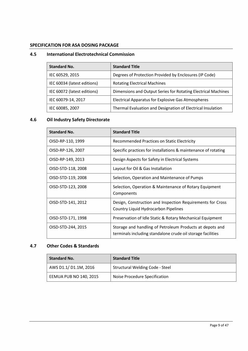
SPECIFICATION FOR ASA DOSING PACKAGE
Page 9 of 47
4.5 International Electrotechnical Commission
Standard No. Standard Title
IEC 60529, 2015 Degrees of Protection Provided by Enclosures (IP Code)
IEC 60034 (latest editions) Rotating Electrical Machines
IEC 60072 (latest editions) Dimensions and Output Series for Rotating Electrical Machines
IEC 60079-14, 2017 Electrical Apparatus for Explosive Gas Atmospheres
IEC 60085, 2007 Thermal Evaluation and Designation of Electrical Insulation
4.6 Oil Industry Safety Directorate
Standard No. Standard Title
OISD-RP-110, 1999 Recommended Practices on Static Electricity
OISD-RP-126, 2007 Specific practices for installations & maintenance of rotating
OISD-RP-149, 2013 Design Aspects for Safety in Electrical Systems
OISD-STD-118, 2008 Layout for Oil & Gas Installation
OISD-STD-119, 2008 Selection, Operation and Maintenance of Pumps
OISD-STD-123, 2008 Selection, Operation & Maintenance of Rotary Equipment
Components
OISD-STD-141, 2012 Design, Construction and Inspection Requirements for Cross
Country Liquid Hydrocarbon Pipelines
OISD-STD-171, 1998 Preservation of Idle Static & Rotary Mechanical Equipment
OISD-STD-244, 2015 Storage and handling of Petroleum Products at depots and
terminals including standalone crude oil storage facilities
4.7 Other Codes & Standards
Standard No. Standard Title
AWS D1.1/ D1.1M, 2016 Structural Welding Code - Steel
EEMUA PUB NO 140, 2015 Noise Procedure Specification

SPECIFICATION FOR ASA DOSING PACKAGE
Page 10 of 47
4.8 Manufacturers Standardisation Society (MSS)
Standard No. Standard Title
MSS SP-55 Quality Standard for Steel Castings for Valves, Flanges & Fittings
and Other Piping Components - Visual Method for Evaluation of
Surface Irregularities
5 TECHNICAL REQUIREMENTS
5.1 General
The ASA Dosing Package and all the auxiliaries within the package shall conform to the minimum
requirements mentioned in this specification along with the datasheets and requirements
furnished in the Material Requisition.
All equipment within the skid shall be suitable for sheltered outdoor environment, suitable for the
hazardous area classification mentioned in the datasheets.
VENDOR shall complete all relevant sections of the data sheet and submit the same with his
bid/offer.
The VENDOR shall comply with applicable state or local Indian codes, regulations, ordinances and
rules.
All the equipment, piping valves, electrical items, instrumentation and controls shall be properly
mounted completely connected in accordance with the applicable project specifications.
Each component shall be located in such a manner as to be easy to operate and maintain. All
instruments and piping valves shall be accessible. The skid layout shall be free from access
obstructions. Layout of piping and cables shall avoid interference and obstructions to any junction
box, instruments or valves.
The design of the individual pieces of equipment forming the packaged unit(s) shall be strictly in
accordance with the mechanical data and process service condition, as noted in this specification
and the data sheets.
The design shall ensure the satisfactory functioning of the complete package, i.e. tanks, ASA
injection pumps, controls and other ancillaries. In cases, where the VENDOR supplies equipment
which he has not manufactured, the VENDOR shall ensure that the design of these are compatible
with each other and with his own equipment in all respects. The satisfactory functioning of the
complete package shall form part of the VENDOR’s guarantee.
The VENDOR shall be fully responsible for the supply, selection, and quality of all materials inclusive
of all consumables, welding, testing, protection devices, machinery, tools, labour and all other
necessary materials and services required to complete the supply of equipment whether or not

SPECIFICATION FOR ASA DOSING PACKAGE
Page 11 of 47
they are specified in this Specification and attachments.
The VENDOR shall be fully responsible for the coordination with all his SUB-VENDOR for materials
and services provided by them. However, VENDOR shall be solely responsible to PURCHASER for
compliance with the specified requirements. VENDOR shall submit to the PURCHASER a list of
experience for all his SUB-VENDORs for the items sub ordered within the package.
Statutory approvals (like PESO etc.) for hazardous area equipment like motors for all tags shall be
considered by VENDOR.
Should the VENDOR come across any discrepancy, deficiency, or lack of clarity in any part of this
specification or attached documents, he shall notify the same to the PURCHASER, along with his
offer, with a proposed alternative or additional item and prices for each category thus included.
Any items so identified after order award will not constitute a change and will not be the cause for
cost or schedule alteration.
5.2 Design Life, Availability and Reliability
The overall availability and reliability of the complete package shall be demonstrated by the
VENDOR. The package design life shall be 25 years with an uninterrupted period of operation of 3
years without any major overhaul.
The VENDOR shall identify any aspects of its standard components or packages that do not meet
this requirement and submit descriptions to the PURCHASER for consideration during the tendering
process.
5.3 Noise Limitation
Noise levels of all equipment (within the package) under normal operation shall not exceed an
eight-hour equivalent continuous A-weighted sound pressure level, LAeq, 8h, of 85 dB(A) at 1
meter at in all directions at full load. Sound level tests shall be performed to verify the same.
In case noise test certificate shows a sound level exceeding 85 dB (A), necessary
rectification/modification shall be done at VENDOR’s own cost and the pump set shall be re-tested
to bring down the sound level to the specified limit.
Predicted noise levels shall be subject to approval by PURCHASER and shall be indicated in the BID.
The specified noise level should be attained without the use of orifices, mufflers, diffusers and/or
credit for thermal or acoustic insulation where practical.
Noise attenuating enclosure is generally not preferred and shall be avoided. However, if used
(subject to approval of PURCHASER) shall be designed to provide full access to the equipment for
maintenance and operation. The details of noise attenuating enclosure, if provided, shall be
indicated in the Bid.

SPECIFICATION FOR ASA DOSING PACKAGE
Page 12 of 47
5.4 Material Certification
Material certificates as per EN 10204 Type 3.1 shall be provided for product contact (wetted parts)
& pressure retaining metal parts and include original mill certificates or certified copies.
Components shall be fully traceable back to the certificate.
For other parts, Material certificates as per EN 10204 Type 2.2 shall be provided.
5.5 Package Design
The package shall be designed to handle ASAs & the same shall be provided with all the items
defined in the datasheet and P&IDs, as a minimum.
VENDOR shall comply with the requirements mentioned in the datasheet & this specification,
however any additional item/ equipment /controls, which are not specifically mentioned in this
specification however deemed necessary by the VENDOR shall be included in the scope of supply.
The package shall be permanently installed at the location assigned for it and the requirement of
the system is:
a. To store the ASAs in the storage tank of adequate capacity considering the delivery period of
the receipt of fresh ASAs.
b. To accommodate changes in dosage rates and ASAs used.
c. To satisfy the availability requirements of the facilities being served.
d. To allow verification of the injection rate and, for critical applications, to generate an alarm if
the injection rate goes outside pre-set limits.
e. To allow most suitable cost-effective automation for the system.
The package shall be provided with adequately sized ASA storage tank as mentioned in the package
datasheet. VENDOR shall furnish the size of the offered tank along with the bid.
The ASA flow shall be metered before being manifolded to the injection points. Calibration pot
(Flow calibration gauge) shall be provided for each dosing pump which shall indicate the dosing
flow rate into the injection point.
ASA injection systems (storage tanks, pumps, piping, mass flow meters, instruments, valves and
injection points) shall be designed, constructed, and commissioned to the level of cleanliness that
the system will not clog.
The health, safety, and environmental properties of ASAs shall be considered to meet all
requirements for intrinsic safety in the design. This selection shall include minimizing fire hazards,
occupational hazards and hazards to the environment.

SPECIFICATION FOR ASA DOSING PACKAGE
Page 13 of 47
VENDOR to note that there is no cooling water available in the plant. In case of any cooling
requirement, VENDOR shall achieve the same using air cooling.
5.6 ASA Injection Pump
The ASA injection pumps and accessories shall be designed as per API 675, 3rd edition. Each pump
shall be capable of 110% of the design capacity.
The pump discharge shall be provided with an external relief valve for protection of the piping
against a closed pump discharge. The external relief device shall be in addition to any internal
pressure relieving device which may be supplied as an integral part of the pump.
A rupture detection system shall be provided for the detection of the diaphragm failure and to trip
the pump, when either of the diaphragms gets detected as ruptured. Diaphragms shall be designed
in such a way that the stresses developed on the diaphragm during the deflection are the
minimum.
VENDOR shall supply suction and discharge pulsation dampeners/ suppressors, as necessary,
including charging kits. VENDOR shall supply fittings/tools for the nitrogen charging of the pulsation
dampeners/ suppressors.
All coupling components liable to rub as a result of failure of the flexible elements shall be of non-
sparking materials. Coupling guard shall also be of non-sparking material. Copper or copper-based
alloys (e.g., brass, bronze) are acceptable but aluminium is not accepted as a non-sparking
material.
The configuration of suction and discharge piping shall allow replacement or maintenance of
suction and discharge valves without dismantling the main piping. All vents and drains shall be
terminated with a valve and blind flange. The outlets on valve vent and drains shall be piped down
to the skid.
5.7 ASA Storage Tank
The storage tank shall be cylindrical shape with dish end for the ASA to be stored in the tank under
the required pressure.
The tank shall meet the following as minimum:
Design, fabrication, welding, inspection & testing shall be in accordance with ASME Sec VIII, Div
1, 2017.
The tank shall be installed in vertical position.
Vents on the tank shall be sized for the sufficient capacity to allow air to escape at the
maximum ASA filling rate.
Full penetration welds shall be used for all nozzles, manholes etc.

SPECIFICATION FOR ASA DOSING PACKAGE
Page 14 of 47
All branch connections shall be of the set-in design.
Heads shall be formed from one piece of plate. Where it is not possible, fabricator shall form
the head from two pieces of plates and weld seams shall be fully radiographed before forming
and again in the knuckle region after forming. 100% surface crack detection shall be made after
forming.
The tank opening should be located to ensure suitable access for cleaning. For proper access &
maintenance, adequate platforms and ladders shall be included.
The material of the tank shall be of Stainless-Steel SS 316L.
All bolt holes in manholes, hand holes and nozzles shall straddle the normal vessel center line
unless otherwise specified on data sheet.
The tank shall be adequately stiffened and supported to prevent buckling and ensure mechanical
stability under the hydrostatic load. Necessary access ladders and maintenance platform shall be
included. Earthing protection of equipment shall be provided.
The tank shall be hydro-tested using water.
Mechanical calculation shall be submitted for the approval of the PURCHASER as listed in the VDRL.
Drum unloading pump and flexible pipe/ hose, to transfer ASA from drum/barrel to the storage
tank shall be provided by Package Vendor.
5.8 Interconnecting Piping:
All necessary on skid interconnecting / auxiliary piping, valves, fittings, pipe supports for each
package as per the piping material specification, P&ID and other specifications shall be provided by
VENDOR.
All piping shall be designed, fabricated, inspected and tested in accordance with ASME B31.3, this
document and other relevant documents attached with the Tender package. Stud length used in
the package shall be as per PNGRB requirement /norms.
Material of construction of all piping, valves shall be as per the Piping Material specifications &
Valve material specifications and material of tubing and tube fitting (as applicable for ASA package)
shall be as per relevant piping class mentioned in the Piping Material Specification (Doc. No. 15984-
BP-10-PE-SPC-0001).
The use of asbestos products is prohibited.
All piping shall be neatly arranged and shall be terminated at the edge of the skid. Minimum
piping/connection size shall be ½” NPT.
Equipment and valves shall be located such that these can be easily accessed, operated, and
maintained. Pipe works shall be routed to allow ease of access to valves and instrumentation.

SPECIFICATION FOR ASA DOSING PACKAGE
Page 15 of 47
Equipment arrangement shall favour compactness but shall allow ample room for convenient
operation, access and maintenance. The layout shall ensure access is available without the use of
scaffolding or portable ladders. Access routes shall be provided into the areas of the package for
equipment needing inspection, checking or servicing, of all pumps, valves, instruments etc.
All valves and local read-out type instruments shall also be positioned in accessible locations.
All piping systems shall be designed so that the loads and moments applied at the flanges of
equipment shall not exceed the permissible reactions for the equipment as specified by the
manufacturers of the equipment.
All piping shall be terminated and anchored at the skid edge with an appropriately rated flange.
Piping connections at the battery limits of package shall be flanged connections. Piping shall be
arranged in such a manner as to avoid tripping or overhead problems.
All piping shall be adequately supported for both service & shipment. Thermoplastic pads shall be
installed between all pipes and their supports. Where U-bolts are used, same shall be of SS 316L.
Suitably located vents & drains shall be provided for any testing, start-up, operations or
maintenance of the skid. These shall be located on equipment or piping as necessary.
As a minimum piping welds shall be subject to 100% DPT and 100% RT, piping shall be hydro tested.
Isolation valves are required between the tank and the level instrument and gauges. Isolation
valves are also required between instruments and piping.
A calibration pot shall be provided on the suction pipe with an isolation valve. A pump Suction
strainer shall also be provided on the suction pipe.
A flame arrestor shall be mounted on the tank, if recommended by ASA supplier. The flame
arrestor shall be complete of SS316L material of construction.
5.9 Package Baseplate:
ASA Dosing Package Skid shall accommodate the storage tank, pump, interconnecting piping,
necessary valve, instrumentation and LCS.
The skid shall be designed and built to ensure that all the equipment along with the accessories &
piping are mounted suitably for convenient operation and maintenance.
The skid shall be rigid construction that cannot distort during lifting / hoisting and shipment.
Anchor bolts shall be provided with the ASA Package.
The VENDOR shall provide a common drip pan (with flanged drain outlet connection) to cover all
sources of spillage and extending underneath the entire skid. The drip pan shall have sufficient

SPECIFICATION FOR ASA DOSING PACKAGE
Page 16 of 47
strength, thickness to prevent sags, rises and out of level areas that may cause liquid trapping. The
drain from the drip pan shall be terminated at skid edge. The drip pan shall be sloped towards the
skid’s flanged drain outlet connection.
All equipment edges shall be within skid structural base plate, no part of equipment or terminal
points shall project beyond the edge of the skid structural base plate.
Equipment shall be mounted on the skid such that equipment supports bear directly on and attach
to primary structural members of the skid.
Spreader beam (if required) to facilitate lifting shall be provided by VENDOR together with slings
and shackles. These lifting devices shall be certified by an approved third-party agency for the
required safe working load (SWL).
Lifting lugs shall be adequately designed and fully welded with 100% NDT and shall be load tested
to minimum 150% of their design load.
100% UT & 100% MPI/DPI will be carried out on parent materials, lifting lugs & lifting aids material.
All welds on lifting lugs & lifting aids shall be subject to a 100% MPI test both before/after the load
test.
5.10 Surge and Transient Protection
Surge / Transient protection to be provided for all electronic instruments to protect these
equipment from lighting surge, indirect current surge, high voltage & current to the acceptable
levels thereby protecting the components and the system itself. In addition, surge/transient
protection devices shall be provided on following power & communication lines as a minimum to
protect equipment within dosing package vendor scope of supply.
• Incoming AC & DC UPS power feeders
5.11 Electrical Requirements
Hazardous area classification for electrical equipment shall be as specified in Electrical
specifications and datasheet.
5.11.1 Electric motor
All motors shall be flameproof and shall comply with Project Specification for MV Induction Motor
and equivalent applicable international standard.
All motors of dosing pumps shall be suitable for operation with variable frequency drive. The
variable frequency drive (VFD) Driven motors design shall match with the variable frequency drive
& VENDOR shall have total responsibility for compatibility between the two.

SPECIFICATION FOR ASA DOSING PACKAGE
Page 17 of 47
Rating of electric motors shall be sized considering margin required as per API 675, 3rd edition. The
motor rating shall also be crosschecked to satisfy the maximum power requirement of pump with
reasonable margin so that the motor is capable enough to cater to any un-intended run-out case.
Type test certificates for flameproof protection class from the recognized testing authority shall be
submitted. As per the statutory requirement in India the approval from the Petroleum and safety
organization (PESO) for flameproof motors, Ex(d) must be submitted by manufacturer. This test
certificate for flameproof motor, Ex(d) must be tested for having tested the motor along with
Variable Frequency Drive for all the offered type of the equipment as per the requirement of IEC.
BIS license must have been possessed by the manufacturer for indigenously manufactured FLP
motors; PESO Certificates for the flameproof motors shall be submitted, latest by, along with the
final MDR/OMM. ATEX certificate with PESO approval is acceptable in case the motors are supplied
from foreign VENDORs.
All motors shall be supplied with flameproof nickel-plated double-compression cable glands and
cable lugs. The terminal box shall be adequately sized to terminate cables of specified size and
cable glands on the terminal box.
Motors shall be energy efficient with minimum IE4 rating.
5.11.2 Variable Frequency Drive (VFD)
ASA Dosing Pump package vendor shall supply the VFD required for the satisfactory operation of
the package as required for the process / mechanical requirements. VFD shall be in compliance
with Specification for MV Variable Frequency Drives 10-EL-SPC-0019 and Datasheet for MV Variable
Frequency Drives 10-EL-DAS-0007.
A single vertical panel shall be provided for two nos. Dosing pump VFDs. Two nos. VFDs shall be
accommodated in one vertical. Purchaser shall provide individual power supply to each VFD. Input
isolation MCCB shall be provided inside the panel. A field mounted Local starter panel shall be
provided for the filling pump motor and Starting /Stopping ASA dosing pumps. Motor starter
components shall be type 2 co-ordinated and consist of MCCB, Overload relay and power and
auxiliary contactors. This local starter panel will be fed from a 240V, 1 phase, AC Socket located
nearby the skid. All internal power and control cabling within skid upto Motor Starter panel shall be
prewired on the skid. Interconnecting cable upto socket maximum 10m length shall be provided by
package supplier. Socket and matching plug shall be supplied and installed by others (Purchaser).
During normal operation VFD A shall drive Pump A and VFD B shall drive Pump B. VFD output shall
employ suitable rated power contactors at VFD output which shall enable manual selection of VFD
A to drive Pump B (or vice versa VFD B to drive Pump A). All required components / contactors to
achieve this logic shall be considered by vendor.
Each VFD system shall have the following features.

SPECIFICATION FOR ASA DOSING PACKAGE
Page 18 of 47
• High input line-side power factor throughout the speed range
• Low load side harmonics with near sinusoidal current in the drive circuit
• Soft ‘start’ and soft ‘stop’ facility with the capability for bi-directional operation of the drive
as may be required
• Reduced shoot through faults
• High starting torque, as may be required, for the drive application
• Low torque pulsations throughout the lowest and highest frequency range
• Stability throughout the lowest and highest load range
• Synchronous bypass feature
VFDs shall have inbuilt dry transformers only.
The VFD shall be capable of maintaining a minimum true power factor (Displacement P.F. x
Distortion P.F.) of 0.95 from 30-100% power. VFD system efficiency shall be a minimum of 95% at
100% speed & 100% load.
System efficiency shall include VFD, input transformer or line reactor, harmonic filter (if applicable)
power factor correction unit (if applicable), and output filter (if applicable). Control power supplies,
control circuits, cooling fans or pumps, shall be included in all loss calculations.
VFDs shall interface with Station PLC over hardwired and Modbus RTU Protocol.
VENDOR shall provide Heat dissipation rate from each VFD along with BID.
5.11.3 Local Control Station
Local control station shall be provided for the skid as per requirements mentioned as follows:
The local control station shall be Flameproof construction in die cast aluminum alloy LM-6 housing
and shall confirm to Indian or international standard. The enclosure class shall be IP65.
Each dosing pump shall be provided with local control station (suitable for hazardous area) with
external mounting stand & canopy including start push button, mushroom head stay-put type
lockable stop push button with protective cover, ESD mushroom push button with protective cover,
ammeter for VFD mode & DOL mode (analog current indicator which accepts 4-20 mA for the local
indication of current of electric motor run either in VFD mode or in DOL mode), LED cluster type
indications for drive ON, lockable type local/ remote selector switch complete with FLP glands.

SPECIFICATION FOR ASA DOSING PACKAGE
Page 19 of 47
With the selector in “ local” position, the start-up of dosing pump from local shall be possible.
Remote operation shall be inhibited. The status of local position of LCS (thru a potential free
contact-PFC) shall interface with Station PLC through Modbus RTU protocol. With selector in “
remote” position, the start-up of dosing pump will be from “remote” either from from station PLC.
Local start-up shall be inhibited. The status of remote position of LCS (thru a potential free contact-
PFC) shall interface with Station PLC through Modbus RTU protocol. The local “stop” push button
shall always be available for operation even when the selector switch is in “remote” position.
Refilling pump shall be provided with, Local Starter panel (suitable for hazardous area) with
external mounting stand and canopy including motor starter components type 2 co-ordinated and
consist of MCCB, Overload relay and power and auxiliary contactors, start push button, mushroom
head stay-put type lockable stop push button with protective cover, ESD mushroom push button
with protective cover, ammeter for DOL mode (Analog current indicator which accepts 4-20 mA for
the local indication of current of electric motor), LED cluster type indications for refilling motor ON
and refilling motor OFF, complete with FLP glands.
Local / remote selector switch is not considered for refilling pump, as “ refilling” will be a local
operation. However, provision for executing “stop” command (in exigency) shall be available from
Station PLC through Modbus RTU protocol.
All local control stations shall be supplied with FLP nickel-plated double-compression cable glands.
5.11.4 Package power supply requirement
Vendor shall clearly indicate in their offer power supply requirement for the package. Vendor shall
provide a list of all consumers within the package which requires power supply with their rated and
absorbed power requirement. Voltage level and type of power supply i.e. single phase or three
phase etc. shall be clearly indicated. Also, the load duty Continuous, Standby or intermittent shall
be indicated.
UPS and Non-UPS supply requirement in the package shall be clearly indicated by Vendor with the
power consumption requirement.
5.11.5 Applicable Voltages
Description Voltage Frequency Phase Motor Rating Remarks
MV Motor / MV VFD 415V ± 15% 50Hz ± 5% 3 Phase ≤ 132kW 3 wire
Refilling pump motor 240V ± 15% 50Hz ± 5% 3 Phase - 3 wire
VFD Auxiliary
(Redundant UPS)
240V ± 15% 50Hz ± 1% 1 Phase - 3 wire
Unit Control Panel
(Non-UPS)
240V ± 15% 50Hz ± 5% 1 Phase - 3 wire

SPECIFICATION FOR ASA DOSING PACKAGE
Page 20 of 47
5.11.6 Cabling
Power and control cables to VFD and from VFD upto Motor/skid shall be by Purchaser. Vendor shall
provide in his documentation interface points clearly marked for external cabling requirement.
Cables upto Single phase socket for refilling pump shall be by Purchaser.
Cables shall be of copper conductor for power cable size upto and including 16 sqmm and
Aluminum conductor for cable size 25 sqmm and above. All control cables shall be of Copper
conductor. All cables shall be armoured type with FRLS PVC outer sheath.
All cables within skid shall run on FRP cable trays.
Earthing continuity for all equipment on the skid and provision for external earthing connection at
two locations shall be provided by pump VENDOR.
5.12 Field Instruments Requirements
Instruments located in hazardous area shall be certified to meet or exceed the electrical hazardous
area classification. In general, all field mounted instruments, electrical components shall be
preferably certified as Ex’i’. If Ex’i’ is not available Ex’d’ can be proposed. It shall be suitable for
Zone-1 Gr. IIA/IIB, T3 area. All field instruments & junction boxes shall be weather proof to IP 65
minimum.
All electrical and instrumentations Items shall be PESO Certified irrespective of their installation in
safe or hazardous area.
The Mass Flow meter shall be bidirectional Coriolis type. The transmitters for Coriolis Mass Flow
meters shall be SMART type using latest digital signal processing technology with integral back-lit
LCD display. The Coriolis Mass Flow meter shall have accuracy + 0.1% for liquid service,
Repeatability: + 0.05% of mass flow rate for liquid service and density accuracy of + 0.1 kg/m3 or
better shall be provided. Coriolis Mass flow sensor shall intrinsically safe. Intrinsically safe signal
electronics and external power supply components shall be housed in separate compartment to
have galvanic separation in intrinsically safe and non-intrinsically safe electrical circuits. All Mass
flow transmitters shall be powered by 240 VAC, ± 10% supply.
Coriolis Mass Flow meter shall provide configurable 4-20 mA Analog outputs of Mass flow meter of
the Flow. All the internal parts and body material of the Coriolis shall be SS 316 as minimum and
the transmitter housing shall be die cast aluminium.
Details of the Field Instrument specifications is mentioned in 10-IC-SPC-0008 as attached with the
Material Requisition. The Datasheet template is attached with the Specs of all instrument Items.
Vendor shall check with BPCL, if any of the sample datasheet is missing or not attached with the
Specification. All the datasheet shall be required to submit in the supplied Template after PO
submission.

SPECIFICATION FOR ASA DOSING PACKAGE
Page 21 of 47
Alarms and Trips
Alarms and trips shall be tested by simulating the alarm or trip conditions at the switching
device and observing that the relevant receiving devices respond appropriately.
Alarms and trips originating in electronic and electric circuitry shall be tested for correct
operation at the same time that the electronic circuitry is tested.
If no other information is available, then alarm and trip settings shall be made at 20% (for low)
and 80% (for high) of the specified range.
5.13 Junction Boxes, Cables and Bulk Material
Specification of Junction box & bulk material and specification for Cables attached with the
Material Requisition shall be referred for the requirement.
5.14 Skid Instrument Installation
The installation and wiring of skid-mounted equipment shall be in accordance with the applicable
Standards, Codes and Statutory Regulations.
Within skid instrument equipment and cabling layout drawings, together with junction box
termination drawings, shall be submitted for approval to the PURCHASER.
The relevant instruments shall be mounted on the local gauge board. All local instruments shall be
located such that instrument dial indicator shall be visible from skid edge. GRP Canopy shall be
provided for the skid mounted junction boxes and local control stations.
5.15 Civil Requirements
VENDOR shall furnish all the relevant information for carrying out foundation designs. As a
minimum, following information shall be provided.
General arrangement drawing which shall include skid dimensions, weights & Centre of Gravity
(individual equipment/ items & complete unit);
Static & dynamic loads and moments acting on each of the foundation bolts;
Anchor bolts or foundation bolt details and foundation pocket details;
Shimming Plate details;
Allowable amplitude of vibration;
Type of grout & extent of grout.

SPECIFICATION FOR ASA DOSING PACKAGE
Page 22 of 47
6 SURFACE PREPARATION AND PAINTING
The pump, motor, all other equipment, exposed steelwork, piping and all items within the package
shall be prepared and painted in accordance with Project Specification for External Painting &
Protective Coating (Doc. No. 15984-BP-10-PE-SPC-0005).
7 SPARE PARTS AND SPECIAL TOOLS
7.1 Spare Parts
7.1.1 Spare Parts Required
I. Spares for two years Normal operation: VENDOR shall furnish an itemized list of
recommended spares with unit prices for two years normal & continuous operation of the
complete Package (including Mechanical, Electrical and Instrumentation spares) required.
Original Equipment manufacturer's recommendations & the list provided in the material
requisition shall be followed by the VENDOR in the preparation of recommended spare parts list.
All spare parts furnished by VENDOR shall be wrapped and packaged to preserve the package
under normal conditions of storage anticipated at project site.
The same parts shall be tagged by stainless steel tags and coded so that later identification as to
their intended equipment usage will be facilitated. All items supplied shall be packaged separately
and clearly marked as "Spare Parts" and shipped with the equipment in accordance with the
instructions from PURCHASER. Packing lists shall be furnished complete and in detail so that parts
can be handled without uncrating.
II. Erection & Commissioning spares :
VENDOR shall provide and include in its scope of supply the recommended spares parts & spare
parts mentioned in the material requisition for the equipment, instruments, valves etc. within his
package to cover the Erection, Pre-Commissioning & Commissioning of the ASA Dosing.
If, however, any additional spare is consumed during erection & commissioning over and above
the included erection & commissioning spares, the same shall be provided by the VENDOR at
no extra cost to PURCHASER at the time of erection & commissioning.
Erection and Commissioning spare shall be inspected and shipped along with skids.
7.1.2 Information Required
The spare parts list shall specify the source of manufacture and model number of each component
part.
7.1.3 Contents
The spare parts list shall also identify the quantity of spare parts held, or the nearest major service
centre, relative to the equipment being offered to the PURCHASER.

SPECIFICATION FOR ASA DOSING PACKAGE
Page 23 of 47
Should the PURCHASER exercise its option to purchase any or all of the spare parts, it shall be the
responsibility of the VENDOR to provide the following at no extra cost to facilitate identification
and classification of spare parts:
Every item shall have a tag or legend bearing the drawing and part number reference;
The shipping advice note shall cross reference to the tag number; and
A list giving the following information for each spare part:
Handbook number;
Handbook drawing number;
Handbook drawing part number;
Spare parts list and item number description;
Manufacturing drawing number;
Manufacturing drawing part number; and
The PURCHASER’s specification number and/or purchase order number under which parts
were supplied.
Where the same part number is used for a component in differing items additional identifiers must
be used.
7.2 Special Tools
The VENDOR shall supply one (1) set of special tools & tackles for each package location (if there
are multiple locations) required for the erection and/or maintenance of the package including all
ancillary equipment.
Special Tools & Tackles means all such tools/tackles those are specific to the erection and/or
maintenance of the supplied equipment/package and are normally not expected to be available in
a plant workshop, but without which it would be difficult or time-consuming to do erection and/or
maintenance of the supplied equipment/package.
Special tools shall be shifted to project site after due demonstration/testing/inspection.
The VENDOR shall identify the special tools required with Bid. Special tools shall be itemised and
submitted for review. Special tools shall be itemised and submitted for review.
If the Material Requisition indicates any special tools & tackles, then same shall also be provided
with the package.

SPECIFICATION FOR ASA DOSING PACKAGE
Page 24 of 47
8 MARKING
All the Equipment, Tanks, instruments, Speciality items shall be supplied with nameplates.
Nameplates shall be manufactured from SS316L. Text and numbering shall be clearly engraved,
paint filled and a minimum of 5mm high with 3 mm spacing between lines.
Nameplates for accessories shall be secured using stainless steel screws, stainless steel wire or
stainless-steel chain.
All pressure regulators shall have a label identifying operating set pressure.
Each valve and actuator assembly shall be fitted with a stainless-steel nameplate providing, as a
minimum, the following information:
Tag Number
Manufacturer's Name or Trademark
Serial Number
Flange Pressure Rating
Packing Type
Maximum Air or Hydraulic supply pressure
The information stamped on the pump nameplate shall be as indicated in Clause 6.15.3 of API 675
3rd edition.
9 TESTING
9.1 General
As a minimum, inspection, testing and QA shall be conducted for each equipment or item within
the ASA Dosing Package according to API-675, its respective project specification, this
specification and the attached data sheets. Additional testing requirements if any shall be specified
in Material Requisition.
The VENDOR shall operate a quality management system to ensure the technical requirements of
this project are met. The QA requirements specified herein shall apply to all materials and
equipment in the VENDOR’s scope of supply. Shop inspection by the PURCHASER’s nominated
inspector will be required and the extent of inspection shall be approved by the PURCHASER.
Test requirements will be as specified here in and as noted on the ASA Dosing Package data sheet.
VENDOR’s standard QA/QC procedures are acceptable except if modified herein.
9.2 Factory Inspection and Testing
VENDOR shall submit for review and approval by the PURCHASER an Inspection and Test Plan (ITP)

SPECIFICATION FOR ASA DOSING PACKAGE
Page 25 of 47
covering all relevant components, completed equipment and systems.
VENDOR shall provide PURCHASER with reasonable access to their and their SUB-VENDOR's plant
facilities in order to verify that equipment is manufactured and tested as specified.
A detailed test procedure of shop tests shall be submitted at least one (1) month in advance of any
testing and shall be approved by the PURCHASER.
All instruments used for conducting tests shall be calibrated before the tests and calibration
certificates shall be furnished at the time of testing.
The various tests carried out as described in this section shall be properly recorded and plotted.
Such documents duly signed by VENDOR’s inspectors and the third-party inspectors, shall be
submitted to PURCHASER
Material certificates and test certificates shall be supplied along with the equipment. Inspection
documents for tank plates and nozzles material shall meet the requirements of this specification.
VENDOR shall provide weekly reports during procurement and fabrication phases indicating
progress status.
The entire unit shall be assembled and tested to functionally check the total system operation and
ensure minimum commissioning and installation time on site. After assembly, VENDOR shall
perform the following tests, as a minimum:
a. Pumps - performance test as per Cl. No. 8.3.4 of API 675 with job motor, material test
certification (BS: EN 10204) & hydrostatic test as per Cl. No. 8.3.2 of API 675 as per approved
data sheets.
b. Motors - Routine Test certificates & as per respective motor specification/ datasheet.
c. VFD - As per respective VFD specification/ datasheet.
d. Tanks - Leak Testing, NDE & tank hydrotest in accordance with design codes & standards & as
per approved test procedure.
e. Instruments - Material certificates as per BS: EN 10204, Instrument & Piping material
certificates as per Piping material specification, Calibration and test reports as per approved
instrument data sheets.
f. Piping, Flanges and Fittings - Hydrostatic testing in accordance with ASME B 31.3, dimensional
test, material identification & correlation of material marking with material test certificates in
accordance with ASME Sec II Part A, ASME B 16.5 & ASME B31.3, and approved drawings and
as per BS: EN 10204.
g. Functional Test of Package Unit - Performance test and functional test as per approved data
sheets.

SPECIFICATION FOR ASA DOSING PACKAGE
Page 26 of 47
h. Noise Test.
i. Visual Inspection.
j. Painting Inspection - Inspection check for Surface blast cleaning, blast grade, paint system,
DFT for primer coat, middle coat and final coat.
k. Dimensional inspection of Skid - As per approved drawings.
l. Packing Inspection - Inspection check for equipment tag no., preservation and safe packing.
The complete unit shall be trial assembled and dimensionally checked prior to shipment. This
activity shall be witnessed by the PURCHASER and/or his representative.
9.3 Site Acceptance Testing
VENDOR shall submit to the PURCHASER a Site acceptance testing procedure after order, SAT shall
be conducted based on the approved procedure by the PURCHASER.
PURCHASER's final acceptance of the equipment will be subject to a performance test once the
equipment has been erected, installed, and Pre-commissioned. Such tests shall be held no later
than one (1) year from initial start-up.
9.4 Material and Welding Inspection:
Butt welds shall be 100% examined by radiography and pressure retaining fillet welds shall be 100%
examined by magnetic particle. Should radiography prove impractical, 100% ultrasonic inspection
shall be permitted with the approval of the PURCHASER.
The final non-destructive examination of welds for acceptance purposes shall be carried out after
completion of PWHT, where applicable. At the manufacturer’s option, radiography may be
performed before PWHT, in which case an ultrasonic examination shall be performed after PWHT
for acceptance purposes.
Skid and vessel pad eyes shall require 100% NDE.
Radiographic, ultrasonic, magnetic particle or liquid penetrant inspection of welds shall be
accordance with the ASME/ASTM specification listed in the table below:
Weld Inspection Acceptance Criteria:
Examination Type Method of Examination Acceptance Criteria
Ultrasonic testing ASME Code Section V
Article 5
ASME Code Section VIII Division 1 Appendix 12
Radiography ASME Code Section V
Article 2
ASME Code Section VIII Division 1 UW 51

SPECIFICATION FOR ASA DOSING PACKAGE
Page 27 of 47
Magnetic Particle
Inspection
ASME Code Section V
Article 7
ASME Code Section VIII Division 1 Appendix 6
Liquid Penetrant ASME Code Section V
Article 6
ASME Code Section VIII Division 1 Appendix 8
Non-destructive testing shall be performed by a PURCHASER approved and accredited, third party
Non-Destructive Examination (NDE) Inspection Company.
Full traceability of all material components (to material certificates) is required.
Full traceability of all welds is required. The VENDOR shall provide a weld map with full traceability
to individual weld numbers. The traceable data shall include NDE reports, welding procedure and
welder number.
Pressure retaining parts shall be hydrostatically tested to at least 1.3 times of the design pressure
for two hours duration, in accordance with Section VIII, Division 1 of the ASME Code or ASME B31.3
/ 31.4.
Welders/welder operators shall be qualified in accordance with Section IX of the ASME code and
approved by the PURCHASER prior to welding on this contract.
Weld procedures shall be qualified in accordance with Section IX of the ASME code and submitted
for approval by the PURCHASER before welding can commence.
9.5 Test Documentation
VENDOR shall supply a full set of deliverable documentation before the start of FAT. As a minimum,
the following shall be supplied:
The Specification and relevant drawings
Set of operator and maintenance manuals
Test Plan and Test Specification for factory acceptance tests
Summaries of all previous testing including VENDOR/SUB-VENDOR tests
The usefulness and purpose of documents shall be major consideration. For example, the operating
manual must include clear and concise instructions for the typical plant operator, while technical
manuals shall be detailed, complete and accurate. Modifications carried out during the test period
shall be detailed appropriately in the documentation.

SPECIFICATION FOR ASA DOSING PACKAGE
Page 28 of 47
10 MATERIAL SOURCING TRACEABILITY AND CERTIFICATION
The VENDOR shall submit a Manufacturers Data Report (MDR) which will allow identification and
certification of all pressure retaining parts and key rotational parts of the pumps and other
equipment within skid; which shall include mechanical properties and ASA composition analysis,
mill certificates, heat numbers and certificates of conformance. Each certificate shall be reviewed
and signed by the manufacturer’s authorised personnel as detailed in the Inspection and Test Plan.
Pressure retaining parts shall be clearly marked to ensure that full traceability is maintained.
Pressure-retaining parts shall include body forgings and castings.
Certificates shall be available at final inspection in the manufacturer’s works.
Certificates of compliance shall be provided for bolting used in pressure retaining parts.
11 PACKING, SHIPPING AND HANDLING
The components of the complete skid shall be shop assembled to the maximum extent practical,
such that field assembly is both minimized and simplified and matching of components is assured.
The parts that cannot be shop assembled prior to shipment shall be shop fitted, identified and
match marked. The equipment items that are shipped in a “knocked down” condition shall be
individually tagged with the assigned tag/part number. VENDOR’s philosophy for the same shall be
reviewed and approved by PURCHASER.
All spare parts shall be packed separately from the main assemblies.
All parts and equipment including spares shall be packed suitable for long term storage in a tropical
climate. All parts shall be packed for an outside open storage period of 12-months in accordance
with API RP 686.
Documents, including unloading, unpacking and lifting instructions, a description of the reassembly
steps required for installation and pre-commissioning and start up instructions shall be included
with the package. The number of copies of documents to be provided shall be as stated in the Bid
Package.
VENDOR shall ensure the equipment is suitably supported and braced for transport.
Prior to shipment, all instrumentation and other equipment vulnerable to damage shall be
disassembled and boxed separately for shipment.

SPECIFICATION FOR ASA DOSING PACKAGE
Page 29 of 47
12 INSPECTION, QUALITY ASSURANCE AND QUALITY CONTROL REQUIREMENTS
The VENDOR shall conform to the requirements of this specification in the performance of the
work under the Contract.
The PURCHASER reserves the right to inspect manufacturing of the ASA Dosing Package and at the
VENDOR or SUB-VENDOR’s premises at any time. The PURCHASER may appoint a third-party
inspector to act on his behalf.
The VENDOR shall submit an Inspection and Test Plan (ITP) for approval prior to commencement of
manufacture. The PURCHASER will advise the VENDOR, by marking up the Inspection and Test Plan,
of the specific inspection review, witness and hold points required. The VENDOR shall give ten
working days prior notice to the PURCHASER of such item or hold point being reached.
VENDOR shall submit quality plans, test procedures for all tests, for approval of PURCHASER and
testing shall be done only after such documents have been duly approved.
The VENDOR shall obtain PURCHASER approval of the following prior to any fabrication taking
place:
Weld procedures; and
All drawings associated with the complete skid.
The VENDOR shall afford the PURCHASER the use of telephone, facsimile and office facilities for
completing reports during inspections.
Where inspection or testing is performed by certified testing laboratories, they shall be registered
by an internationally recognized testing organization.
The appropriate inspection equipment and the VENDOR’s personnel shall be readily available to
complete the inspection at the time agreed.
The appropriate test procedure and acceptance criteria shall be available to the PURCHASER for
immediate analysis of the inspection results.
The final inspection, before issue of a release note for the complete skid, shall include material
certificates, test certificates, surface treatment, dimensional conformity, tagging and packing
conformity. Specimen crating and packaging may also be inspected.

SPECIFICATION FOR ASA DOSING PACKAGE
Page 30 of 47
13 SITE ACCEPTANCE TESTING AND COMMISSIONING
The VENDOR shall provide supervisory assistance in site, erection, testing & commissioning of the
packages. After the completion of the pre-commissioning activities (including mechanical,
electrical, instrumentation) each package shall be subjected to site trial run/operation (Duration for
site trial run shall be finalized after award). During trial run safe and satisfactory operation of
package unit (including pump, driver, VENDOR supplied electrical equipment and all auxiliary
equipment) shall be established. Operating point shall be agreed after award, however will be
within the operating range mentioned on the datasheet. Site trial run shall form the part of
commissioning.
The VENDOR shall be responsible for witnessing and signing off all activities associated with
commissioning and that testing of all the equipment on skid is carried out in accordance with
VENDOR requirements.
On completion of site acceptance testing & commissioning, the VENDOR shall submit a report to
the PURCHASER detailing all activities associated with pre-commissioning, commissioning and
testing of package.
The VENDOR shall specify equipment required to carry out on site testing of package to prove the
operational performance over the total range of duty point specified using the proposed ASA. The
VENDOR shall include details of the testing equipment in the bid.
The information shall include the following as a minimum:
Provision of nozzles; (if required for carrying out SAT)
Provision of instruments (portable or fixed);
Measuring accuracies; and
Calculation sheets for site testing.
Delays which would result in bench sitting shall be paid based on daily rates which VENDOR shall
identify with valid reasons. VENDOR shall provide list of activities and facilities that shall be
provided by the PURCHASER in the bid which if ensured shall not result in eligibility for claiming
bench sitting.
In general PURCHASER considers following shall be adequate to avoid bench sitting. VENDOR shall
review and confirm the adequacy and completeness in the bid.
A. Before arrival of the VENDOR following shall be completed by PURCHASER:
All interconnecting pipe spools will be placed within the skid shed vicinity for installation
immediately after VENDOR acceptance of the alignment and foundation fastening.

SPECIFICATION FOR ASA DOSING PACKAGE
Page 31 of 47
Plant utilities (material handling, power, earthing, vent and drain system) necessary for skid
operation are commissioned.
VENDOR identified support personnel with required qualification and experience as specified by
the VENDOR in the bid are available.
VENDOR supplied special tools and start-up and commissioning spares are available.
B. Before commissioning (which will follow completion of installation to the satisfaction of
VENDOR) following shall be completed or is made available:
Commissioning assistance team is available.
Upstream and downstream systems are installed and ready for commissioning, with completion
of identified pre-commissioning activities agreed with VENDOR.
Duty product supply is available within the specified operating range.
Power is available
A gap will be necessary between A and B activities (days should be specified) and hence at least
2 visits shall be considered by the VENDOR. At least a 15 days’ notice for part A and a week’s
notice for part B would be required.
14 PERFORMANCE GUARANTEE
The VENDOR shall guarantee that all equipment and its internals within his scope of supply shall meet
the performance requirements as stated in the data sheets, specification and other applicable
documents when operating under the specified design and operating conditions.
The VENDOR shall be responsible for Mechanical Guarantee for the Equipment.
The VENDOR shall guarantee that the dosing pumps supplied shall meet the performance
requirements set down in this specification (including referenced documents).
Special emphasis is placed on the following criteria:
The ability to meet duty point at the normal flow range and rated flow rate;
Power draw at normal and rated flow rates;
Drive motor efficiencies at normal and rated flow rates;
Equipment noise level under all operating conditions.
The VENDOR shall warrantee the mechanical design, material, workmanship and performance
requirements as stated in this specification continuously for all conditions stated, for the time period
mentioned in the commercial section of the Tender.

SPECIFICATION FOR ASA DOSING PACKAGE
Page 32 of 47
If during the mechanical warranty period, any part of the equipment proves defectives, VENDOR shall
replace such defective parts at their own cost and expenses.
The VENDOR shall guarantee that all work will be performed in accordance with good and sound
engineering and construction practices and within the requirements of this specification. The
equipment, accessories and all the materials supplied by the VENDOR shall be free from defects, shall
be suitable for the use for which they are intended and shall perform in accordance with the
requirements of this specification.
The VENDOR shall agree to promptly correct, at his own cost at site, all the defects and mal-
performance of the equipment and/or the accessories supplied by VENDOR to comply with obligation
expressed or implied under the Tender and to extend the warranty period for the duration required to
remedy such defects.
The VENDOR shall assume full responsibility for the proprietary equipment and component supplied
by him, and his SUB-VENDOR, incorporated in the package are in accordance with this requisition.
The VENDOR shall guarantee the stability of the material of construction for the duties required, even
if the PURCHASER has specified the type and the grade of material to be used.
15 TRAINING
If specified in the commercial part of the Tender, the ASA Dosing Package VENDOR shall arrange for a
training of PURCHASER’s engineers at site for equipment supplied as per scope of supply specified in
Material Requisition. The training shall cover the design, operation and maintenance aspects of
supplied system including dosing pumps, motor, VFD, etc. by the representative of respective
manufacturer and for a minimum of 2 working days for a group of 20 engineers.
16 VENDOR SUPPLIED DOCUMENTS
The VENDOR shall supply documentation in accordance with the VENDOR Document Requirements
List (VDRL) indicated in the Material Requisition.
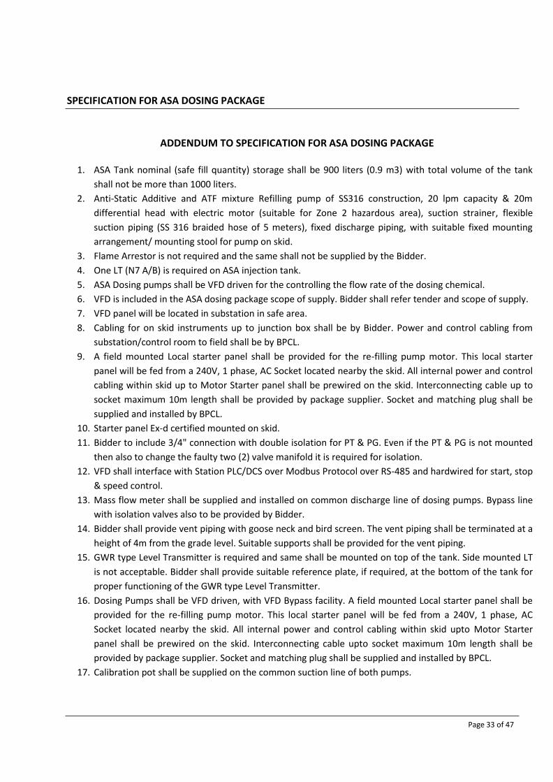
SPECIFICATION FOR ASA DOSING PACKAGE
Page 33 of 47
ADDENDUM TO SPECIFICATION FOR ASA DOSING PACKAGE
1. ASA Tank nominal (safe fill quantity) storage shall be 900 liters (0.9 m3) with total volume of the tank
shall not be more than 1000 liters.
2. Anti-Static Additive and ATF mixture Refilling pump of SS316 construction, 20 lpm capacity & 20m
differential head with electric motor (suitable for Zone 2 hazardous area), suction strainer, flexible
suction piping (SS 316 braided hose of 5 meters), fixed discharge piping, with suitable fixed mounting
arrangement/ mounting stool for pump on skid.
3. Flame Arrestor is not required and the same shall not be supplied by the Bidder.
4. One LT (N7 A/B) is required on ASA injection tank.
5. ASA Dosing pumps shall be VFD driven for the controlling the flow rate of the dosing chemical.
6. VFD is included in the ASA dosing package scope of supply. Bidder shall refer tender and scope of supply.
7. VFD panel will be located in substation in safe area.
8. Cabling for on skid instruments up to junction box shall be by Bidder. Power and control cabling from
substation/control room to field shall be by BPCL.
9. A field mounted Local starter panel shall be provided for the re-filling pump motor. This local starter
panel will be fed from a 240V, 1 phase, AC Socket located nearby the skid. All internal power and control
cabling within skid up to Motor Starter panel shall be prewired on the skid. Interconnecting cable up to
socket maximum 10m length shall be provided by package supplier. Socket and matching plug shall be
supplied and installed by BPCL.
10. Starter panel Ex-d certified mounted on skid.
11. Bidder to include 3/4" connection with double isolation for PT & PG. Even if the PT & PG is not mounted
then also to change the faulty two (2) valve manifold it is required for isolation.
12. VFD shall interface with Station PLC/DCS over Modbus Protocol over RS-485 and hardwired for start, stop
& speed control.
13. Mass flow meter shall be supplied and installed on common discharge line of dosing pumps. Bypass line
with isolation valves also to be provided by Bidder.
14. Bidder shall provide vent piping with goose neck and bird screen. The vent piping shall be terminated at a
height of 4m from the grade level. Suitable supports shall be provided for the vent piping.
15. GWR type Level Transmitter is required and same shall be mounted on top of the tank. Side mounted LT
is not acceptable. Bidder shall provide suitable reference plate, if required, at the bottom of the tank for
proper functioning of the GWR type Level Transmitter.
16. Dosing Pumps shall be VFD driven, with VFD Bypass facility. A field mounted Local starter panel shall be
provided for the re-filling pump motor. This local starter panel will be fed from a 240V, 1 phase, AC
Socket located nearby the skid. All internal power and control cabling within skid upto Motor Starter
panel shall be prewired on the skid. Interconnecting cable upto socket maximum 10m length shall be
provided by package supplier. Socket and matching plug shall be supplied and installed by BPCL.
17. Calibration pot shall be supplied on the common suction line of both pumps.

SPECIFICATION FOR ASA DOSING PACKAGE
Page 34 of 47
18. Winding temperature detectors are required for motors operated with VFD.
19. Suitable protection for dry run/ high discharge pressure of the pump shall be supplied by the Bidder.
20. Total two skids are required in this tender, one for Panki (Kanpur) Terminal and second for Irugur
(Coimbatore) Terminal.

SPECIFICATION FOR ASA DOSING PACKAGE
Page 35 of 47
Appendix 1 DATASHEET FOR INJECTION QUILL

SPECIFICATION FOR ASA DOSING PACKAGE
Page 36 of 47
DATA SHEET - ASA INJECTION QUILL FOR KANPUR / COIMBATORE
TECHNICAL Notes
Description: ASA Injection Quill
Pipe Class: A1X
Tag No: 300-SP-QUI-001 & 002
Quantity: 2
DESIGN
Design Code: ASME B31.4 / Manufacturer's Standard 4, 9, 12
Description: ASA Injection Quill for ASA dosing
Nominal Pipe Size (NPS): 2" Injection Quill on 18" / 14” Pipe
Item 1: Blind Flange NPS 3, ASME B16.5 Class 150, Raised Face (RF) 5, 6, 7
Item 2: Pipe Quill 2", ASME B36.19M, SCH 40, End Chamfered at 45° 3
Item 3: Weldneck Flange 2", ASME B16.5 Class 150, Raised Face (RF), SCH 40 5, 6, 7
Item 4: Support Ribs 3 No's, 10mm x 10mm, Cut to Suit ID of 18" /14” SCH 20 Pipe 8
PROCESS
Service: ASA Dosing
Location: Kanpur & Coimbatore
Design Pressure: barg 17.55 (18 kg/cm2 g)
Design Temperature (Min / Max): oC 0 / 65
Density kg/m³ Note 10, 14 & 15
Viscosity Cst Note 10, 14 & 15
ASA Dosing Flowrate: lph Note 10
MATERIALS
Item 1: Blind Flange ASTM A182 F316
Item 2: Pipe Quill ASTM A312 TP 316
Item 3: Weldneck Flange ASTM A182 F316
Item 4: Support Ribs ASTM A182 F316
Corrosion Allowance: 0 mm
TESTING AND INSPECTION
Inspection: 100% Visual Inspection to MSS SP-55 8
Testing: N/A 11
NDE: 100% Radiographic Inspection Welded Joints according to ASME V Article 2
100% Dye Penetrant Inspection on Welded Joints according to ASME V Article 6
Certification: EN 10204 Type 3.1 - Pressure Containing Parts
EN 10204 Type 2.2 - Non-Pressure Parts
Painting / Coating: Bare
Marking: MSS SP-25 13
NOTES
1 Documentation to be provided according to the requirements specified within the Requisition Documentation.
2 Detailed drawings with dimensions to be provided by Supplier with Bid.
3 The length of the pipe quill shall be confirmed such that the overall quill length from the weldneck flange to the chamfered end is 300mm.
4 Welding shall be in accordance with ASME IX.
5 Flanges shall have a relative roughness of 125 to 250µin AARH on gasket seating surfaces.
6 Flange bolt holes orientated to straddle pipe centre-line.
7 Bolts and gaskets for construction purposes are not required as part of this SP Item.
8 Support ribs (3 No's) shall be cut to just permit installation inside 18" / 14” SCH 20 pipe. Confirmation of this shall be included within the Inspection
process.
9 General technical requirements shall be in accordance with Piping Material Specification Doc. No. 10-PE-SPC-0001
10 ASA injection is through quill to enable injection in the middle of the stream. The Dosing rates shall be from min. 5 to 100 lph
11 Hydrostatic pressure testing is not required on the individual quill. However, testing will be undertaken in accordance with the requirements for the
applicable piping spool, after its fabrication into the completed piping spool.
12 Supplier shall operate a Quality Assurance system in accordance with the Specification for Pipes & Fittings doc. No. 10-PE-SPC-0002
13 Each item to be fitted with a SS316 identification tag clearly stamped with SP Number, Nominal Size, PO No., Rating, Quill Length, Quill ID, Materials of
construction, CE Mark, etc.
14 ASA's properties are on HOLD.
15 Properties of the liquid in which ASA is going to inject is as follows:
Product
Sp. Gravity at 35oC
Viscosity at 35oC Vapor pressure at 35oC
cSt (cP) kg/cm²a
ATF 0.78 @ 45oC 1.18 @ 45°C & 1.53 @ 5°C 0.01 @ 37°C

SPECIFICATION FOR ASA DOSING PACKAGE
Page 37 of 47
Sketch of ASA Injection Quill

SPECIFICATION FOR ASA DOSING PACKAGE
Page 38 of 47
Appendix 2 ELECTRICAL SCOPE DIAGRAM

SPECIFICATION FOR ASA DOSING PACKAGE
Page 39 of 47
MCC (By Others)
STATION – PLC (By Others)
Redundant
VFD with
bypass
VFD with
bypass
ASA
Dosing
Pump
Motor
(Working)
ASA
Dosing
Pump
Motor
(standby)
LCS for each pump/motor with
Start/Stop push buttons, L/R
switch, Ammeter (4-20mA) and
Speed indicator (4-20mA), etc.
ELECTRICAL SCOPE DIAGRAM FOR DOSING PUMPS
MODBUS RTU (Cables
by Others)
Cables (By Others)
SUPPLIER’s scope
Remarks:
1. Motors shall have facility for Local / Remote operation through Local / Remote switch located on
Local Control Station.
2. VFD shall have facility for Auto / Manual operation through Auto / Manual switch on VFD.
3. Speed control for the pump / motor shall be achieved either through VFD or station - PLC.
4. Stop command can be initiated from anywhere irrespective of selector switch status.
When pump VFD is in Auto mode, the station - PLC signal provided to the VFD enables precise speed/ flow
control over a range of flow conditions with pressure limitations.

SPECIFICATION FOR ASA DOSING PACKAGE
Page 40 of 47
Refilling
Pump
Motor
(Working)
ELECTRICAL SCOPE DIAGRAM FOR REFILLING PUMPS
Cables (By Others)
Supplier’s scope cables
Supplier’s scope
m 240V AC, 1 Phase Socket
le length 10m)
Power & Control cables within skid
Remarks:
1. Single point 240V, 1Ph, 50Hz, supply in Ex’d’ type socket receptacles shall be provided by owner
near skid. Tail cable of Maximum 10mtr (As per clause 5.3 , Refer sheet 15) from skid MCC to socket
shall be considered by Supplier.
2. Start/Stop of the pumps shall be done from start/stop buttons on Skid mounted Local starter panel.
PMCC / Distribution Board (By Others)
240V AC, 1 Phase Socket outlet
near skid
(By Others)
Power cable fro
(Maximum cab
Local starter panel on the skid
with DOL starters and
Start/Stop push buttons

SPECIFICATION FOR ASA DOSING PACKAGE
Page 41 of 47
Appendix 3 INSTRUMENT DATASHEET TEMPLATES

INSTRUMENT DATASHEET TEMPLATE FOR CI PACKAGE
Rev. Date Issue Description Originated Checked Approved Client
BHARAT PETROLEUM CORPORATION LIMITED (BPCL)
Project No: SHEET
Datasheet No:

INDEX
Sr. No. Tag No. P&ID No. Page No. Remark Revision
BHARAT PETROLEUM CORPORATION LIMITED (BPCL)
Project No: SHEET
Datasheet No:

DATA SHEET FOR MASS FLOW METER
Rev
GENERAL
1 Tag No:
2 Quantity
3 P & ID Number:
4 Service:
5 Line Number:
6 Line Size / Schedule:
7 Hazardous area classification:
PROCESS
CONDITIONS
8 Fluid Type/State:
9 Flow (Min/Nor/Max): kg/hr
10 Flow (Min/Nor/Max): m³/hr
11 Design Pressure (Min/Max): kg/cm²g
12 Design Temperature (Min/Max): °C
13 Operating Pressure (Min/Nor/Max): kg/cm²g
14 Operating Temperature (Min/Nor/Max): °C
15 Density (Min/Nor/Max): (Kg/m³) @ 15°C
17 Viscosity: (Cst) @ 20 °C
17 Base Pressure kg/cm²a
18 Base Temperature °C
18 Maximum allowable Pressure drop: kg/cm2
19 Amb Temperature (Min/Max): °C
20
ELEMENT/ SENSOR UNIT
21 Type:
22 Meter Size:
23 Process Connection Type:
24 Flange Rating: Flange Finish:
25 Flange Material:
26 Sensor- Tube Material:
27 Body Material:
28 Tube Type:
29 Wetted Part Material Coating Material
30 Orientation in Pipeline:
31
TRANSMITTER
33 Mounting:
34 Housing Material:
35 Instrument Range:
36 Calibration Range (m³/hr) Min Max
37 Accuracy:
Mass Flow Meter
38 Density
39 Stability:
40 Repeatability:
41 Output:
42 Local Indicator:
43 Power Supply:
44 Power Consumption:
45 Cable Entry: (For Control / For Power)
46 Enclosure Protection Class:
47 Hazardous area Certification Code:
48 Hazardous area approval Certification:
49 Sensor Cable:
50 Weight:
51 Material Certification
OTHERS
52 Air Eliminator:
53 Mounting Accessories:
54 Calibration/ Material/ Pressure Test Certificates:
55 NACE Compliance:
56 Hydrostatic Tast:
57 NDT Requirement:
58 Certification/ Stamp:
PURCHASE
59 Manufacturer:
60 Model:
61 PO No.:
62 Requisition No.:
Rev Date Issue Description Originated Checked Approved Client
BHARAT PETROLEUM CORPORATION LIMITED (BPCL)
Project No: SHEET
Datasheet No:

Datasheet for Pressure Transmitter
GENERAL 1 Tag No.
2 P&ID Number
3 Service
4 Line / Equipment No.
5 Hazardous Area Classification:
PROCESS 6 Fluid Type/Sate:
7 Design Pressure kg/cm²g MAX
8 Design Temperature °C MIN/MAX
9 Operating Pressure kg/cm²g MIN/MAX
10 Operating Temperature °C
11 Specific Gravity
TRANSMITTER 12 Mounting
13 Enclosure Material
14 Element Type
15 Bolting Material
16 Element Material
17 Ingress Protection Rating
18 Hazardous Area Approval Certification
19 Electrical Certification
20 Power Supply
21 Output Signal
22 Crippled Mode Detection
23 Burn out direction
24 Calibration Range (kg/cm²)
25 Instrument Range (kg/cm²)
26 Zero Span Adujustment
27 Accuracy Repeatability
28 Local Indicator Indicator Scale
29 Process Connection Electrical Connection
30 SIL Certification Over-range Protection
OPTIONS 31 Valve Manifold Type Material
32 Valve Manifold Manufacturer & Model:
33 Vent/Drain Connections:
34 NACE Requirement Material Certification
35 Mounting Brackets:
PURCHASE 36 Manufacturer:
37 Make/Model:
38 Supplier:
39 Requisition/PO No
Rev Date Issue Description Originated Checked Approved Client
BHARAT PETROLEUM CORPORATION LIMITED (BPCL)
Project No. Sheet
Datasheet No.

Datasheet for Differential Pressure Transmitter
GENERAL 1 Tag No.
2 P&ID Number
3 Service
4 Line / Equipment No.
5 Hazardous Area Classification:
PROCESS 6 Fluid Type/Sate:
7 Design Pressure Design Temperature
8 Specific Gravity
9 Viscosity(cst)
10 Operating Pressure Operating Temperature
11 Operating Differential Pressure Kg/cm²
TRANSMITTER 12 Mounting
13 Body Material
14 Enclosure Material
15 Element Type
16 Bolting Material
17 Element Material
18 O-Ring Material
19 Ingress Protection Rating
20 Hazardous Area Approval Certification
21 Electrical Certification
22 Power Supply
23 Output Signal
24 Crippled Mode Detection
25 Burn out direction
26 Calibration Range(kg/cm²)
27 Instrument Range(kg/cm²)
28 Accuracy (±% Span) Repeatability
29 Local Indicator Indicator Scale
30 Process Connection Electrical Connection
31 Over-range Protection
OPTIONS 32 Valve Manifold Type Material
33 Valve Manifold Manufacturer & Model:
34 Vent/Drain Connections:
35 Manifold Mounting:
36 NACE Requirement Material Certification
37 Mounting Brackets:
PURCHAES 38 Manufacturer:
39 Make/Model:
40 Supplier:
41 Requisition/PO No
Rev Date Issue Description Originated Checked Approved Client
BHARAT PETROLEUM CORPORATION LIMITED (BPCL)
Project No. Sheet
Datasheet No.

Datasheet for Temperature Transmitter (RTD)
GENERAL 1 Tag No.
2 P&ID Number
3 Service
4 Line / Equipment No.
5 Hazardous Area Classification:
PROCESS DATA 6 Fluid Name/Sate: Refer Appendix 7 Design Pressure Design Temperature Refer Appendix
8 Operating Pressure Operating Temperature Refer Appendix
9 Velocity (m/s) Fluid Densiry (kg/m3) Refer Appendix
MEASURING ELEMENT THERMOWELL
10 Element Type 17 Shank Style:
18 Material:
11 Element OD
12 Element standard 19 Connection for element
13 Sheath Diameter 20 Process connection
14 Sheath Material 21 Flange Material
15 Insulation 22 Insertion Length (U-Length)
23 Plug and Chain required / Material
16 Single/Dual Element
TRANSMITTER 24 Transmitter Mounting:
25 Transmitter
26 Enclosure Material:
27 Ingress Protection Rating:
28 Hazardous Area Approval Certification
29 Electrical Certification
30 Power Supply
31 Output
32 Crippled Mode Detection
33 Burn out direction
34 Calibration Range:
35 Instrument Range
36 Zero Adjustment:
37 Calibration Standard
38 Accuracy
39 Stability
40 Local Indicator
41 Indicator Scale / Units:
42 Electrical Connection:
43 Mounting Brackets
44 Material Certification
PURCHASE 45 46 47 48
Manufacturer:
Make/Model:
Supplier:
Requisition/PO No
Note:
Rev Date Issue Description Originated Checked Approved Client
BHARAT PETROLEUM CORPORATION LIMITED (BPCL)
Project No. Sheet
Datasheet No.

Datasheet for Temperature Transmitter (RTD-Skin)
GENERAL 1 Tag No.
2 P&ID Number
3 Service
4 Line / Equipment No.
5 Hazardous Area Classification:
PROCESS DATA 6 Fluid Name/Sate:
7 Design Pressure Design Temperature
8 Operating Pressure Operating Temperature
9 Velocity (m/s) Fluid Densiry (kg/m3)
MEASURING ELEMENT THERMOWELL
10 Element Type 17 Shank Style:
18 Material:
11 Element OD
12 Element standard 19 connection for element
13 Sheath Diameter 20 Process connection
14 Sheath Material 21 Flange Material
15 Insulation 22 Insertion Length (U-Length)
23 Plug and Chain required / Material
16 Single/Dual Element
TRANSMITTER 24 Transmitter Mounting:
25 Transmitter
26 Enclosure Material:
27 Ingress Protection Rating:
28 Hazardous Area Approval Certification
29 Electrical Certification
30 Power Supply
31 Output
32 Crippled Mode Detection
33 Burn out direction
34 Calibration Range:
35 Instrument Range
36 Zero Adjustment:
37 Calibration Standard
38 Accuracy
39 Stability
40 Local Indicator
41 Indicator Scale / Units:
42 Electrical Connection:
43 Mounting Brackets
44 Material Certification
PURCHASE 45 46 47 48
Manufacturer:
Make/Model:
Supplier:
Requisition/PO No
Rev Date Issue Description Originated Checked Approved Client
BHARAT PETROLEUM CORPORATION LIMITED (BPCL)
Project No. Sheet
Datasheet No.

Datasheet for Level Transmitter - GWR (10-100-LT-001)
GENERAL 1 Tag No. P&ID Number
2 Service
3 Tank No. Tank Material
4 Hazardous Area Classification:
PROCESS DATA 5 Fluid Name:
6 Dielectric Constant Fluid Density
7 Design Pressure (Min/Max)
8 Design Temperature (Min/Max)
9 Operating Pressure (Min/Max)
10 Operating Temperature (Min/Max)
VESSEL/TANK GEOMETRY 11 Type
12 Tank Height Nozzle Height
13 Nozzle ID
SENSOR 14 Principle of Operation
15 Process Connection Size, Rating, Face,Finish
16 Flange Material
17 Probe Type Probe Diameter
18 Probe Length Probe Material
19 Probe Deadband from Top (mm)
20 Frequency
21 Stilling Well
22 Dead Zone
TRANSMITTER 23 Function; Interface Total Level
24 Transmitter Mounting
25 Calibration Range Instrument Range
26 Accuracy Repeatability
27 Output Signal Load Resistance
28 Enclosure Material Electrical Certification
29 Power Supply Electrical Connection
30 Local Indicator Burn out direction
31 Sensor Drift Crippled Mode Detection
32 Hazardous Area Approval Certification
33 NACE Requirement
34 SIL Certification Ingress Protection Rating:
EXTERNAL CHAMBER 35 Chamber Material C-C distance (mm)
36 Connection : Size, Rating, Facing & Finish
37 Drain Connection. : Size, Rating, Facing Finish
38 Vent Connection. : Size, Rating, Facing Finish
PURCHASE 39 Manufacturer
40 Model
41 Requisition No / Purchase Order No
Rev Date Issue Description Originated Checked Approved Client
BHARAT PETROLEUM CORPORATION LIMITED (BPCL)
Project No. Sheet
Datasheet No.

Datasheet for Thermal Safety Valve
GENERAL 1 Tag No. P&ID Number
2 Line No. / Vessel No.
3 Service
4 Pipe Class / Vessel Trim
PROCESS DATA 5 Fluid Name/State
6 Required Relieving Capacity / Max. Relieving Capacity (kg/hr)
7 Molecular Weight
8 Density Relief (kg/m3)
9 Viscosity Relief (cP)
10 Design Pressure (Min/Max)
11 Design Temperature (Min/Max)
12 Operating Pressure (Min/Max)
13 Operating Temperature (Min/Max)
14 Set Pressure Relieving Temperature
15 Back Pressure Constant Variable
16 % Allowable Overpressure
17 Allowable Noise level
18 Blowdown % Overpressure Factor
19 Accumulation : (over MAWP)
20 Valve Discharge to
21 Discharge Capacity
RELIEF VALVE ACCESSORIES 22 Valve Design Type 41 Cap : Screwed / Bolted
23 Nozzle Type 42 Lever : Plain / Packed
24 Valve Type 43 Test Gag
25 Bonnet Type 44 Back Flow Preventer
BASIS OF SELECTION 45 Certification/ Stamping
26 Code CONNECTION 27 Fire Case 46 Inlet Connection 28 Basis of Selection
MATERIAL 47 Connection Outlet 29 Body and Bonnet
30 Seat and Disc 48 Body/Bonnet Bolting 31 Nozzle
32 Resilient Seat Seal 49 Gasket 33 Guide
34 Blowdown Ring
35 Spring
36 Bellows
CALCULATION PURCHASE 37 Calculated Area cm² 52 Manufacturer
38 Selected Area cm² 53 Model
39 Orifice Designation 60 Requisition No
40 Rated Relief Capacity 61 Purchase Order No
Rev Date Issue Description Originated Checked Approved Client
BHARAT PETROLEUM CORPORATION LIMITED (BPCL)
Project No. Sheet
Datasheet No.

SPECIFICATION FOR MV VFDS FOR ASA DOSING PACKAGE
Page 1 of 32
SPECIFICATION FOR MV VFDs
FOR ASA DOSING PACKAGE
Document No: 10-EL-SPC-0019

SPECIFICATION FOR MV VFDS FOR ASA DOSING PACKAGE
Page 2 of 32
A. SCOPE OF SUPPLY
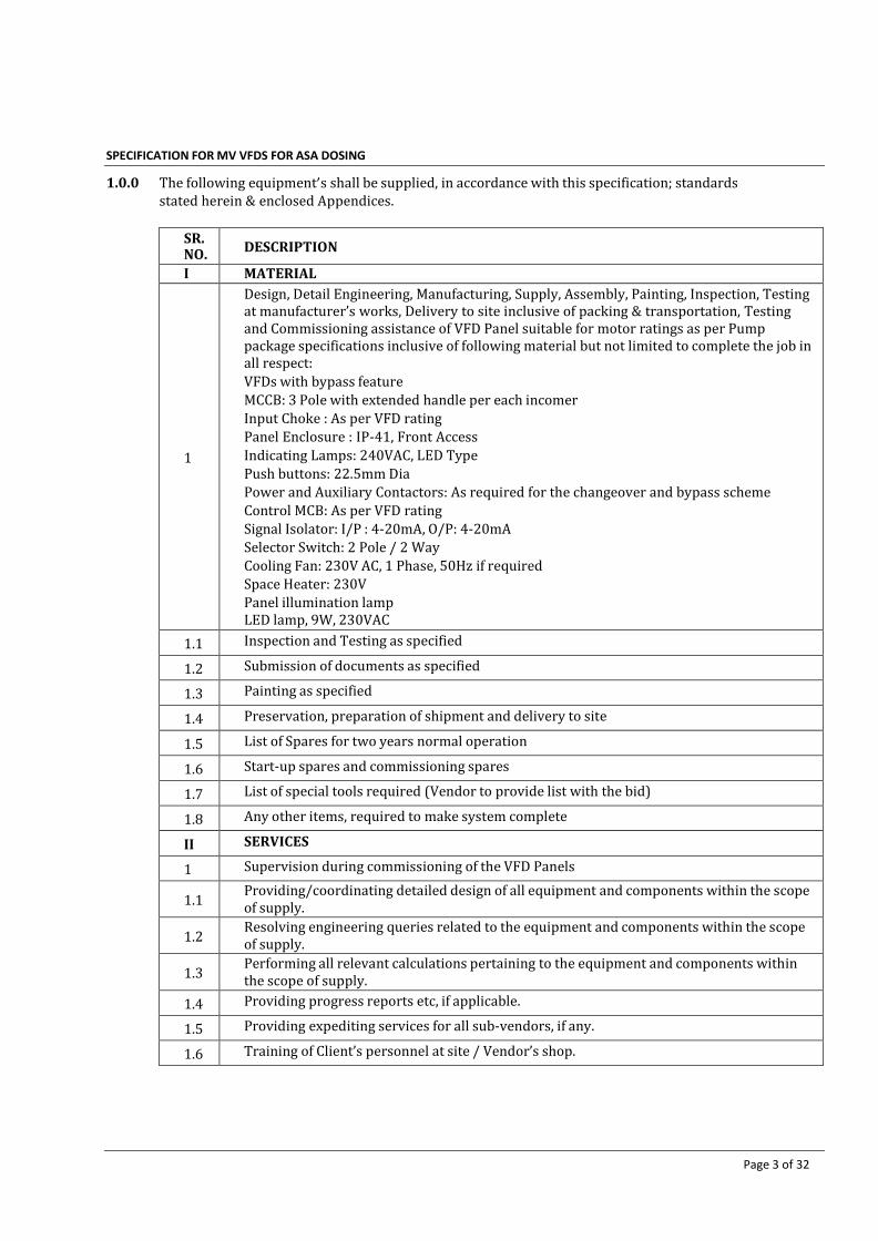
SPECIFICATION FOR MV VFDS FOR ASA DOSING PACKAGE
Page 3 of 32
1.0.0 The following equipment’s shall be supplied, in accordance with this specification; standards stated herein & enclosed Appendices.
SR. NO.
DESCRIPTION
I MATERIAL
1
Design, Detail Engineering, Manufacturing, Supply, Assembly, Painting, Inspection, Testing at manufacturer’s works, Delivery to site inclusive of packing & transportation, Testing and Commissioning assistance of VFD Panel suitable for motor ratings as per Pump package specifications inclusive of following material but not limited to complete the job in all respect:
VFDs with bypass feature
MCCB: 3 Pole with extended handle per each incomer
Input Choke : As per VFD rating
Panel Enclosure : IP-41, Front Access
Indicating Lamps: 240VAC, LED Type
Push buttons: 22.5mm Dia
Power and Auxiliary Contactors: As required for the changeover and bypass scheme
Control MCB: As per VFD rating
Signal Isolator: I/P : 4-20mA, O/P: 4-20mA
Selector Switch: 2 Pole / 2 Way
Cooling Fan: 230V AC, 1 Phase, 50Hz if required
Space Heater: 230V
Panel illumination lamp LED lamp, 9W, 230VAC
1.1 Inspection and Testing as specified
1.2 Submission of documents as specified
1.3 Painting as specified
1.4 Preservation, preparation of shipment and delivery to site
1.5 List of Spares for two years normal operation
1.6 Start-up spares and commissioning spares
1.7 List of special tools required (Vendor to provide list with the bid)
1.8 Any other items, required to make system complete
II SERVICES
1 Supervision during commissioning of the VFD Panels
1.1 Providing/coordinating detailed design of all equipment and components within the scope of supply.
1.2 Resolving engineering queries related to the equipment and components within the scope of supply.
1.3 Performing all relevant calculations pertaining to the equipment and components within the scope of supply.
1.4 Providing progress reports etc, if applicable.
1.5 Providing expediting services for all sub-vendors, if any.
1.6 Training of Client’s personnel at site / Vendor’s shop.

SPECIFICATION FOR MV VFDS FOR ASA DOSING PACKAGE
Page 4 of 32
B. SPECIAL CONDITIONS OF THE PROCUREMENT

SPECIFICATION FOR MV VFDS FOR ASA DOSING PACKAGE
Page 5 of 32
1.0.0 SPECIAL REQUIREMENT
1.0.0 The system offered shall be energy efficient, provide very high reliability, high power factor, low harmonic
distortion, low vibration, wear and noise. It shall be easy to install with minimum time and expense with no special tools required for routine maintenance.
1.0.1 The system shall be suitable for the load characteristics and the operational duty of the driven equipment.
Any damage resulting from such a short circuit or internal fault shall be limited to the component concerned.
1.0.2 The system shall be, speed, torque or power controlled as dictated by the driven equipment.
1.0.3 The drives shall have a bypass arrangement.
1.0.4 The system shall be suitable for continuous speed control of the motor in single drive system as per data
sheet and soft start feature shall be provided to reduce the disturbances in the electrical system.
1.0.5 The drive motor shall be speed regulated to a speed corresponding to purchaser's 4-20 mA reference signal. Upon complete loss of the user's speed reference signal, the drive shall automatically run to constant speed as determined by the last speed reference available prior to the loss of signal.
1.0.6 The drive shall be able to accelerate the load over the full speed range of the speed torque curves and with
incoming voltage regulation of 10%.
1.0.7 The system shall be suitable for single quadrant operation and the range of speed variation shall be with range 1:100 unless otherwise specified with speed set accuracy of 1% of rated maximum frequency and steady state regulation of 0.5% of rated frequency.
1.0.8 Unless otherwise specified, output voltage shall be within 2% under steady state condition and 10% under
transient condition of 50% step load change with recovery time of 100 ms. The total harmonic content of the voltage at inverter output shall not exceed 3% rms of the fundamental.
1.0.9 The system shall be design to supply upto 150% of the rated controller current for upto one minute. If the
motor load exceeds 150% level the drive shall automatically reduce the frequency and voltage to the motor to guard against overload. If load demands exceed 150% current more than 1 minute, the drive shall shut down to prevent motor over heating.
1.0.10 The power controller shall be regulated to always start the motor in the forward direction. Logic shall be
provided to prevent the motor from being started in the reverse direction.
1.0.11 The system shall have provision to control and monitor through the owner's control panel/operator console (PLC). The required provision for the interface with the owner's system including the details of communication module and data transfer facility, I/O details shall be furnished along with the offer. The drive shall support a MODBUS RTU protocol for this communication.
1.0.12 All softwares required for the drive shall be included in the offer and no separate payment shall be made for
the same.
1.0.13 The control cards shall have conformal coating. The Analog input/ output card shall have at least one spare input/output in addition to that required for existing panels.
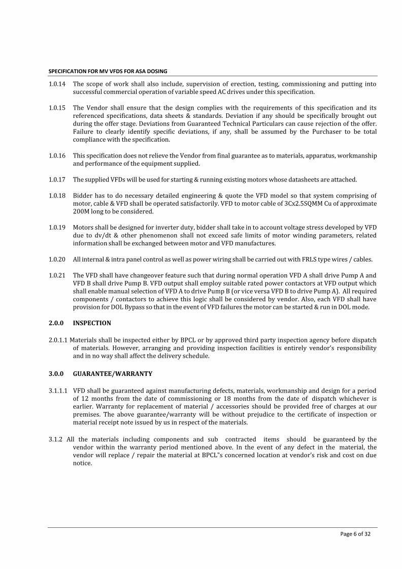
SPECIFICATION FOR MV VFDS FOR ASA DOSING PACKAGE
Page 6 of 32
1.0.14 The scope of work shall also include, supervision of erection, testing, commissioning and putting into successful commercial operation of variable speed AC drives under this specification.
1.0.15 The Vendor shall ensure that the design complies with the requirements of this specification and its
referenced specifications, data sheets & standards. Deviation if any should be specifically brought out during the offer stage. Deviations from Guaranteed Technical Particulars can cause rejection of the offer. Failure to clearly identify specific deviations, if any, shall be assumed by the Purchaser to be total compliance with the specification.
1.0.16 This specification does not relieve the Vendor from final guarantee as to materials, apparatus, workmanship
and performance of the equipment supplied.
1.0.17 The supplied VFDs will be used for starting & running existing motors whose datasheets are attached.
1.0.18 Bidder has to do necessary detailed engineering & quote the VFD model so that system comprising of motor, cable & VFD shall be operated satisfactorily. VFD to motor cable of 3Cx2.5SQMM Cu of approximate 200M long to be considered.
1.0.19 Motors shall be designed for inverter duty, bidder shall take in to account voltage stress developed by VFD
due to dv/dt & other phenomenon shall not exceed safe limits of motor winding parameters, related information shall be exchanged between motor and VFD manufactures.
1.0.20 All internal & intra panel control as well as power wiring shall be carried out with FRLS type wires / cables.
1.0.21 The VFD shall have changeover feature such that during normal operation VFD A shall drive Pump A and
VFD B shall drive Pump B. VFD output shall employ suitable rated power contactors at VFD output which shall enable manual selection of VFD A to drive Pump B (or vice versa VFD B to drive Pump A). All required components / contactors to achieve this logic shall be considered by vendor. Also, each VFD shall have provision for DOL Bypass so that in the event of VFD failures the motor can be started & run in DOL mode.
2.0.0 INSPECTION
2.0.1.1 Materials shall be inspected either by BPCL or by approved third party inspection agency before dispatch
of materials. However, arranging and providing inspection facilities is entirely vendor’s responsibility and in no way shall affect the delivery schedule.
3.0.0 GUARANTEE/WARRANTY
3.1.1.1 VFD shall be guaranteed against manufacturing defects, materials, workmanship and design for a period
of 12 months from the date of commissioning or 18 months from the date of dispatch whichever is earlier. Warranty for replacement of material / accessories should be provided free of charges at our premises. The above guarantee/warranty will be without prejudice to the certificate of inspection or material receipt note issued by us in respect of the materials.
3.1.2 All the materials including components and sub contracted items should be guaranteed by the
vendor within the warranty period mentioned above. In the event of any defect in the material, the vendor will replace / repair the material at BPCL‟s concerned location at vendor’s risk and cost on due notice.

SPECIFICATION FOR MV VFDS FOR ASA DOSING PACKAGE
Page 7 of 32
4.0.0 DELIVERY
4.1.1 All materials are to be delivered within the schedule provide in Tender documents from date of
PO/LOI. Drawing to be submitted within two weeks from date of PO/LOI.
4.1.2 Refer tender documents for delivery location of the ASA Dosing Package.

SPECIFICATION FOR MV VFDS FOR ASA DOSING PACKAGE
Page 8 of 32
C. STANDARD TECHNICAL SPECIFICATIONS OF VFD

SPECIFICATION FOR MV VFDS FOR ASA DOSING PACKAGE
Page 9 of 32
1.0.0 TERMINOLOGY
1.0.0.1 The word “shall” is to be understood as a mandatory requirement
1.0.0.2 The word “should” is to be understood as strongly recommended.
1.0.0.3 The word “may” is to be understood as an action to be undertaken at the BPCL’s discretion
1.1.0 ENVIRONMENTAL CONDITIONS
1.1.0.1 Design ambient temperature for Electrical Equipment (Indoor): 50 degC
1.1.0.2 Design ambient temperature for Electrical Equipment (Outdoor): 55 degC
2.0.0 CODES AND STANDARDS
The VFD shall meet the requirements of this specification and latest edition of all applicable standards
including standards listed below:
IEC: 61800 Adjustable speed electrical power drive systems.
IS: 3715 Letter symbols for semiconductor devices.
IEEE: 519 Recommended Practices and Requirements for Harmonic Control in
Electrical Power System
IS 4411 Code for designation of semi-conductor devices
IS 5469 Code of practice for the use of semi-conductor junction devices
IS: 5921 Specification for metal clad base materials for printed circuits for use in
electronic and telecommunication equipment.
IS: 6297 Specification of Transformers and Inductors (Power, Audio, Pulse and
Switching) for Electronic Equipment.
IS: 6619 Semiconductor rectifier equipment safety code .
IS: 7504 Specification for printed wiring Board.
IEEE: 446 Recommended practice for emergency and standby power systems for
industrial and commercial application.
IS: 3700 / IEC: 60146 Semiconductor devices.
IS: 9000 Basic climate for mechanical durability tests for electronic components &
Environmental tests for electronic equipment.
IS/IEC 60529 Degree of protection provided by enclosures (IP code)
IS: 6553 Environmental requirements of semiconductor devices and integrated
Circuits.
IS: 9676 Ambient temp. of electronic equipment.
IS: 4007 Terminal for electronic equipment.
IS: 3695 / IEC:148 Semiconductor rectifier assemblies and THYRISTOR CONVERTERS.
IEC: 60146 Semiconductor Converters.
IS 8623 Low voltage switchgear and control gear assemblies
IS/IEC 60947 Low voltage switchgear and controlgear

SPECIFICATION FOR MV VFDS FOR ASA DOSING PACKAGE
Page 10 of 32
2.1.1 CONFLICTING REQUIREMENTS
In case of any conflict between documents relating to the enquiry or purchase order, the following
priority of documents shall apply.
2.1.1.1 Statutory regulations
2.1.1.2 Datasheets
2.1.1.3 Job Specifications
2.1.1.4 This specification, requirements attached with the bid.
2.1.1.5 Single Line diagram
2.1.1.6 Applicable codes & Standards
3.0.0 TECHNICAL PARTICULARS
3.1.0. GENERAL
3.1.0.1 VFD panel unit shall be 3-Ph, 6 pulse Rectifier Bridge, D.C. link with reactor/capacitors, Inverter Bridge,
microprocessor based control system. The VFD shall be pulse width modulation (PWM) type with flux
vector control. The VFD unit shall have redundant cooling fans if required and this shall be controlled
based on heat sink temperature. Converter transformer/input reactor and output reactor, if required,
shall be integral part of drive panel.
3.1.0.2 The panel unit shall comprise of incoming switchgear output contactors, output reactors, by-pass
arrangement, etc.
3.2.0 INCOMING & OUTGOING SWITCHGEAR
3.2.0.1 The unit shall be equipped with incoming MCCB with Adjustable Thermal overload and short circuit
protection.
3.2.0.2 The unit shall comprise of an incoming MCB with suitable over current, short circuit releases. The MCB
incomer shall be fully rated having short circuit withstand capacity so as to protect the VFD.
3.2.0.3 Changeover logic and Bypass power contactor with AC-4 duty for the applicable loads. Motor protection
electronic overload protection as required in bypass mode.
3.3.0 CONVERTER AND INVERTER SECTION
3.3.0.1 The rectifier shall be 6 pulses line commuted converters with necessary input transformer or reactor, DC
link reactor, capacitor unit, dynamic braking facility, etc as required.
3.3.0.2 3-Ph inverter with IGBT power circuit devices connected with necessary output filters. The VFD shall be
pulse width modulation (PWM) type with flux vector control for open loop speed control with manual set
points.

SPECIFICATION FOR MV VFDS FOR ASA DOSING PACKAGE
Page 11 of 32
3.3.0.3 The converter shall be able to withstand a three-phase short circuit current until interrupted by normal
break operation.
3.3.0.4 The inverter shall withstand short circuit currents from the motor without fuses until interrupted by a
circuit clearing devices.
3.3.0.5 The thyristors shall have repetitive peak reverse blocking voltage margin at 250% of line voltage.
3.3.0.6 All power converter thyristors design shall include co-ordination by peak voltage protecting snubber
networks, dv/dt & di/dt networks so the converters can operate continuously with one thyristor failed or
shorted in each converter branch.
3.3.0.7 Filters for AC input and output shall be used. All capacitors in filter circuits shall be provided with
discharge circuits to ensure that all residual stored charge is reduced to less than 50V dc within 60
seconds after a loss of AC voltage.
3.3.0.8 The power converter circuit shall be designed so that motor can be powered at its full nameplate rating
continuously without exceeding its rated temperature rise nor reducing its service factor due to
harmonic currents generated by the inverter operation.
3.3.0.9 Fault diagnostic and indication logic shall be built into the system to supervise the operation and failure
of the system.
3.3.0.10 The current rating of the converter semi-conductor components shall not be less than 120% of the
maximum current flowing through the elements at full load of the VFD through the whole speed range.
3.3.0.11 All electrical wound components shall be rated for minimum 125% of the maximum full load rating
through the whole speed range.
3.4.0 DESIGN CRITERIA
3.4.0.1 Input Supply : 415V (+/-15%), TPN, 50KA for 1-sec
3.4.0.2 Input frequency : 50 Hz ± 5%
3.4.0.3 Ambient temperature : 50 deg C
3.4.0.4 Output Voltage : 0- 415 Voltage 3 Phase
3.4.0.5 Output Frequency : 0- 50 Hz or as required
3.4.0.6 Resolution : 0.01 Hz.
3.4.0.7 Inputs and Outputs : Digital & Analogue as required
3.4.0.8 Short time Overload Capacity : 150% for 1 min./ every 10 min.(constant torque)
110% for 1 min. / every 10 min. (squared torque) and meet the
requirement of the driven equipment

SPECIFICATION FOR MV VFDS FOR ASA DOSING PACKAGE
Page 12 of 32
3.4.0.9 Switching Frequency : Adjustable to 15 kHz.
3.4.0.10 Total Harmonic Distortion : As per IEEE-519
3.4.0.11 Length of outgoing cables : 200M (approx)
Note: During momentary voltage dip in the input voltage supply, auxiliary voltage supply, or both, to 80
percent of rated voltage for a duration not exceeding 0.5 second, the VFD shall be able to automatically
continue to supply reduced power to the motor and return to set-point speed (if the speed drifted
slightly), or reaccelerate if load torque demand resulted in reduced speed.
3.5.0 FEATURES
3.5.1 The following minimum features shall be available with selected VFD unit:
3.5.1.0 Auto tuning
3.5.2.0 Parameter lock
3.5.3.0 Adjustable acceleration / deceleration time
3.5.4.0 Adjustable starting torque
3.5.5.0 Suitable for Constant torque / squared torque application as per requirement.
3.5.6.0 Adjustable switching frequency
3.5.0.1 Next-Generation Energy Saving
3.5.0.2 Digital outputs shall be potential free type.
3.5.0.3 Components for the same function and rating shall be of identical design, make and of modular
construction to reduce the inventory.
3.5.0.4 RS485/ Modbus RTU communication
3.5.2 The following Change over and By-pass features shall be included:
3.5.2.0 Manual Change over and bypass shall provide all the circuitry necessary to transfer the motor
1. Changeover such that during normal operation VFD A shall drive Pump A and VFD B shall drive
Pump B. A manual selector switch shall be provided for selection of VFD A to drive Pump B (or vice
versa VFD B to drive Pump A).
2. Bypass from the VFD to the power line, or from the line to the controller while the motor is at zero
speed.
3.5.3.0 The bypass circuitry shall fully isolate both the VFD input and output from the line and load sides,
providing full speed motor operation.
3.5.4.0 The AC Drive shall include mechanically and electrically interlocked isolation and bypass contactors
complete with thermal overload relay, VFD/OFF/BYPASS switch.
3.5.5.0 Motor overload protection shall be provided in both the controller mode and the bypass mode.
3.5.6.0 The operator shall have full control of the bypass starter by operation of the VFD/OFF/BYPASS
selector switch.
3.5.7.0 In the AUTOMATIC mode of operation, the isolation and bypass contactors shall be sequenced by the auto
start contact from remote.
3.5.8.0 Indication shall be provided for motor operating in `Drive’ or `By-pass’ mode.

SPECIFICATION FOR MV VFDS FOR ASA DOSING PACKAGE
Page 13 of 32
3.6.0 CONTROL AND INDICATIONS
3.6.0.1 All local indications offered for the VFD and supporting systems (e.g., cooling
System (s).
3.6.0.2 All analog and digital fields I/O shall be electrically isolated from VFD logic-level
circuits.
3.6.1.0 The following minimum controls shall be provided:
3.6.1.1 START command at the VFD control front panel as well as from remote PLC
3.6.1.2 STOP command at the VFD control front panel as well as from remote PLC
3.6.1.3 Motor speed raise / low at the VFD control front panel as well as from remote PLC
3.6.1.4 Fault reset at the VFD control panel
3.6.1.5 Auto and Manual selection at the VFD control front panel
3.6.1.6 Manual set points at the VFD control front panel as well as from remote PLC
3.6.1.7 VFD/OFF/BYPASS at the VFD control front panel
3.6.2.0 The following minimum indications shall be displayed:
3.6.2.1 Ready to start at the VFD control panel as well as to remote PLC
3.6.2.2 Running at the VFD control panel as well as to remote PLC
3.6.2.3 Motor Running On By-Pass at the VFD control panel as well as to remote PLC
3.6.2.4 Alarms at the VFD control panel as well as to remote PLC
3.6.2.5 Tripped at the VFD control panel as well as to remote PLC
3.6.2.6 Input voltage and frequency at the VFD control panel as well as to remote PLC
3.6.2.7 Input power at the VFD control panel as well as to remote PLC
3.6.2.8 Output voltage and frequency at the VFD control panel as well as to remote PLC
3.6.2.9 Output power at the VFD control panel as well as to remote PLC
3.6.2.10 Output current at the VFD control panel as well as to remote PLC
3.6.2.11 Control supply ON at the VFD control panel
3.6.2.12 Cooling failure at the VFD control panel
3.6.3.0 All indication lamps shall be long-life light emitting diode (LED) type, and shall have a lamp test feature
with input protection.
3.6.4.0 The unit shall have soft / hard wired control system with suitable interfaces for interlocks as well as the
required instruments and signals
3.6.5.0 Suitable operator panel unit for programming /debugging and control shall be provided for remote
parameterisation. Control of set points, display of faults, alarms as well as diagnostic messages shall also
be available in plain text on this operator panel on the cubicle door. It shall be sealed type with
membrane switches & LCD display unit. This shall be user configurable type.

SPECIFICATION FOR MV VFDS FOR ASA DOSING PACKAGE
Page 14 of 32
3.7.0 PROTECTIONS & ANNUNCIATIONS
All required high-speed electronic protections should also be available with unit apart from self-
diagnostic features. A few are listed below.
3.7.1.0 Over current instantaneous trip
3.7.2.0 Short circuit protection for converter/ inverter
3.7.3.0 Adjustable current limit
3.7.4.0 Earth fault protection
3.7.5.0 Over temperature at heat sink
3.7.6.0 DC bus under voltage & over voltage
3.7.7.0 Control & regulated power supply failure
3.7.8.0 Phase reversal protection
3.7.9.0 Motor On By-Pass
3.7.10.0 By-pass doesn’t close
3.7.11.0 By-pass doesn’t open
3.7.12.0 Input surge protection
3.7.13.0 Inverter fault
3.7.14.0 Motor over speed
3.7.15.0 Motor over voltage
3.7.16.0 Possible all Motor protections
Abnormal conditions shall initiate alarm and shut down drive based on the nature of the fault.
3.8.0 METERING
3.8.0.1 Indicating type Voltmeter
3.8.0.2 Indicating type Ammeter
3.8.0.3 Ammeter located in LCS near motor necessary CT in outgoing side of VFD panel
3.8.0.4 Motor speed at the VFD control panel as well as on remote PLC
3.8.0.5 Motor speed demand at the VFD control panel as well as on remote PLC
3.9.0 COOLING SYSTEM
3.9.0.1 Power semiconductor devices shall be mounted on heat sink base which can be individual or common to
a number of devices. Adequate provision for clamping and mounting the power semiconductors shall be
available.
3.9.0.2 Cooling of power semiconductors can either be natural air cooled or forced air cooled. The BIDDER shall
recommend the type of cooling. The power semiconductors shall preferably be double side cooled.
3.9.0.3 Auxiliary power supply for the forced cooling system shall be derived from VFD incoming power.
SPECIFICATION FOR MV VFDS FOR ASA DOSING PACKAGE
Page 15 of 32
3.10.0 EMC, HARMONICS, AND FILTER SYSTEMS
3.10.0.1 The VFD system shall meet local and national standards for radio frequency emissions and susceptibility.
3.10.0.2 The maximum total harmonic distortion shall be approved by the Purchaser.
3.10.0.3 Harmonic current distortion values shall be according to IEEE 519 unless other limits are specified. In
this Specification, the point of common coupling is defined as the first upstream bus that supplies other
loads. Values of total harmonic voltage distortion at the point of common coupling shall be limited as
follows:
3.10.0.4 Individual odd harmonics limited to less than 3 percent.
3.10.0.5 Individual even harmonics limited to less than 1.75 percent.
3.10.0.6 These values shall include any existing background harmonic levels provided by the Purchaser and shall
be based on the minimum short-circuit level (maximum source impedance). Values of harmonic voltage
as a percentage of fundamental shall be verified by Vendor during site testing of the VFD.
3.11.0 NOISE LEVEL
3.11.0.1 The VFD system shall meet local and national standards for Noise level and susceptibility.
3.11.0.2 Noise level shall be limited to 85dBA when measured at one meter from the edge of the VFD panel.
3.12.0 CONSTRUCTION
3.12.0.1 The controller should have modular construction to facilitate maintenance.
3.12.1.0 BUSBARS
3.12.1.1 Power connections shall be of the bolted type and mating surfaces shall be tinned copper. The bus bars
running to various converters shall be suitably designed to ensure equal sharing between the
parallel strings and prevent mechanical stress on the fuse.
3.12.1.2 All bus bars shall be adequately insulated for full circuit voltage by insulating tapes and similar
insulating material. All cubicles shall have copper earth buses of adequate size running the entire
cubicle height along the sides.
3.12.1.3 Busbars shall be of colour coded.
SPECIFICATION FOR MV VFDS FOR ASA DOSING PACKAGE
Page 16 of 32
3.12.2.0 CUBICLE
3.12.2.1 Cubicles housing the power semiconductors and drive level control system shall conform to IP 42
degree of protection to enclosures.
3.12.2.2 Panels shall be free standing, floor mounting type and shall comprise rigid welded structural frames
enclosed completely with cold rolled sheet steel of thickness no less than 2.5 mm for front and rear
portions and 2.0 mm for sides, top and bottom portions. There shall be sufficient reinforcement to
provide level surfaces, resistance to vibrations and rigidity during transportation and
installation.
3.12.2.3 The cable entry shall be from the bottom of the panel and a removable bolted undrilled gland plate shall
be provided for double compression type cable gland. Bolted type terminals shall be used for
connection of 10mm2.
3.12.2.4 All the live parts shall be shrouded to ensure complete safety to personnel intending routine inspection
by opening the panel doors. All the equipment inside the panels and on the doors shall be provided with
suitable nameplate. All wires shall be ferruled and terminals shall be properly numbered. Min. 20%
spare terminal shall be provided.
3.12.2.5 All the control wiring shall preferably be enclosed in plastic channel. Each wire shall be identified at
both ends by self sticking wire marker tapes or PVC ferrules. Ferruling of wires shall be as per relevant
IS.
3.12.2.6 Power and control-wiring inside the panel shall be done with PVC insulated copper conductor. 2.5mm2-
size FRLS wire shall be used for control wiring.
3.12.2.7 All doors, removable covers and panels shall be gasketed all round with neoprene gaskets. Ventilating
louvers shall have screens and filters. The screens shall be made of either brass or GI wire mesh.
3.12.2.8 Design, material selection and workmanship shall be such as to result in a neat appearance inside and
outside with no welds, rivets or belt heads apparent from outside, with all exterior surfaces true and
smooth.
3.12.2.9 All the non-metallic components /parts shall be connected to the main earth bus bar running at the
bottom of the panel and min. 25x6mm Cu having two holes at each end shall be provided for connection
to plant earth grid.
3.12.3.0 TROPICAL PROTECTION
3.12.3.1 All equipment, accessories and wiring shall have fungus protection, involving special treatment of
insulation and metal against fungus, insects & corrosion.

SPECIFICATION FOR MV VFDS FOR ASA DOSING PACKAGE
Page 17 of 32
3.12.3.2 Screens of corrosion resistant material shall be furnished on all ventilating louvers to prevent the
entrance of insects.
3.12.4.0 PAINTING
3.12.4.1 All metal surfaces shall be thoroughly cleaned and degreased, pickled and phosphatised. Thereafter, a
coat of phosphate paint and a coat of zinc chromate primer shall be applied. After removing all
imperfections, all metal surfaces shall be sprayed with two coats of final paint as per colour shade RAL
7032. Final coat shall be of epoxy based. All unpainted parts shall be plated to prevent corrosion.
4.0.0 SPARES AND SPECIAL TOOLS
4.1.0 SPARES
4.1.0.1 The Manufacturer shall furnish list of spares and provide all necessary spares for testing, pre-
commissioning, commissioning. Any of the spares if used during testing/commissioning must be
replenished at no extra cost to the Client.
4.1.0.2 The Manufacturer shall also provide all consumables required during erection up to commissioning.
4.1.0.3 In addition to above, Manufacturer shall quote separately for Spares required for two years of operation.
4.2.0 SPECIAL TOOLS
4.2.0.1 The Manufacturer shall include any special tools, which are required for the installation, commissioning,
operation and maintenance of the equipment being supplied. A list of special tools shall be supplied along
with the offer.
5.0.0 INSTALLATION AND COMMISSIONING
5.0.0.1 Vendor shall provide qualified personnel to supervise the installation and carryout site testing and
commissioning of all equipment supplied under this contract.
5.1.0 PACKING AND TRANSPORTATION
5.1.0.1 Packing, shipping and delivery of equipment at site and unloading requirements shall be as per relevant
Standard. Vendor to submit the procedure & all the relevant necessary datas / informations along with offer.
5.1.0.2 Preparation of the skids for shipment is a crucial step in the completion of this contract. The Vendor must
take in to consideration that all equipment and the skid itself shall be prepared for land transportation.
6.0.0 STATUTORY APPROVAL
6.0.1.1 The Equipment supplied shall be acceptable to local Electrical Inspectorate and changes required, if any,
shall be carried out by the vendor without any extra cost.

SPECIFICATION FOR MV VFDS FOR ASA DOSING PACKAGE
Page 18 of 32
D. DATASHEETS

SPECIFICATION FOR MV VFDS FOR ASA DOSING PACKAGE
Page 19 of 32
For Motor datasheets: Required data shall be obtained from ASA Dosing Package vendor
Guaranteed Technical Particulars for Variable Frequency Drive
(* To be filled in by the Manufacturer for each VFD)
1. Manufacturer : *
2. Model No. : *
3. Reference standard : *
4. Quantity : *
5. Type of Solid state VFD : 6 pulse PWM
6. Rated Input Voltage : 415V
7. Rated Voltage Output : * V
8. VFD Rating : * KVA
9. Frequency Range : * Hz
10. Type of Load : 415V, Three phase AC Induction motor
11. Starting capacity at maximum rated full load current Ir
: * times Ir for * sec.
12. Allowable no. of starts per hour : *
13. Overload capacity & duration : *
14. Selectable Overload Class range : *
15 Selectable Start/stop mode : Voltage / Torque ramp
16. Selectable range of Start Ramp : *
17. Selectable range of Stop Ramp : *
18. Control Type : *
19. Selectable Torque limit range : *
20. Breakaway Torque : *
21. Induced torque pulsation : *
22. Control of VFD with field bus : *
23. Power circuit continuous Rating : * A

SPECIFICATION FOR MV VFDS FOR ASA DOSING PACKAGE
Page 20 of 32
24. Power device peak inverse voltage : * V
25. Power device protection fuse rating : * A
26. Line to line dv/dt at motor terminal : * V/microsec
27. Effective Power Factor of the System : *
28. Complete System Efficiency : *
29. Speed Regulation : *
30. Speed Set Point Resolution : *
31. Control speed range : *
32. Transient voltage protection : *
33. Type of Cooling : *
34. Degree of Protection : *
35. Harmonics Compliance with IEEE 519 Total Harmonic Distortion (THD) Max. total harmonic current distortion at PCC
: : :
* * *
36. Noise Level : *
37. Interface provided as per Specification : YES/NO
38. Metering provided as per Specification : YES/NO
39. Annunciations provided as per Specification : YES/NO
40. Protection provided as per Specification : YES/NO
41. Incomer section CB rating & duty Contactor rating & duty
:
* *
42. Control / power transformer rating : *
43. Overall dimensions of VFD panel : *
44. Overall Weight : *
45. Type of Mounting Floor
46. Heat load : *
47. Requirement of Air-conditioning : YES/NO
48. Life Expectancy : *

SPECIFICATION FOR MV VFDS FOR ASA DOSING PACKAGE
Page 21 of 32
E. QAP & INSPECTION

SPECIFICATION FOR MV VFDS FOR ASA DOSING PACKAGE
Page 22 of 32
1.0.0 QUALITY ASSURANCE
1.0.0.1 The Manufacturer is expected to demonstrate that he has working Quality Assurance System which complies with ISO 9001 or may be appropriate to the type of contract and his product.
1.0.0.2 If the Vendor elects to sub-contract part of the work he shall ensure that only those sub-contractors or
suppliers are used who can demonstrate that they operate Quality Systems based on ISO 9001 or ISO 9002 as applicable. The Vendor shall give his sub-contractors or suppliers assistance in attaining the required standard, if necessary. This shall not relieve the Vendor of his responsibility for the quality of the finished work. The Owner reserves the right to audit the Vendor’s Quality System.
1.0.0.3 The Vendor shall assign sufficient full time personnel to the Project to ensure the Quality Assurance /
Quality Control System, documented in a Quality Assurance / Control Manual, is maintained and kept up- to-date throughout the duration of any purchase order. The Vendor’s Quality Assurance / Control System shall become an integral part of any Purchase Order. Vendor shall organize a prefabrication / inspection meeting with the Owner.
1.0.0.4 Within 3 weeks from the date of Purchase Order the Manufacturer shall submit a “Quality Assurance Plan” for the review of the BPCL.
2.0.0 INSPECTION AND TESTING
2.0.0.1 The responsibility for inspection, certification, etc. of all materials, parts lies with the Vendor.
2.0.0.2 The Vendor shall specify all of the inspection and testing requirements in the quality plan which shall
identify the activities requiring the Owner’s approval, review, witnessing etc.
2.0.0.3 Inspection and testing requirements shall be in accordance with this specification.
2.0.0.4 All Equipment shall be inspected for compliances with:
2.0.0.5 Requirement of Owner’s specification & correspondence therefore.
2.0.0.6 Applicable codes, standards and specifications, which shall also include sub- referenced standards therein.
2.0.0.7 Test and Inspection Plans produced by the vendor.
2.0.0.8 Inspectors have the right to request additional inspections or tests to ensure that the equipment complies
with the specification and all relevant codes & standards.
2.0.0.9 Manufacturer shall furnish valid Type Test Certificates of similar models along with the offer. Fresh type
tests for the equipment are not needed, provided the Manufacturer can submit certificates that the
equipment complies with all type tests as prescribed by IEC/IS Standard specifying the test requirements
for that equipment.
2.1.0.0 The routine tests shall include but not necessarily limited to the following:
2.1.0.1 Visual Inspection:
It involves checking of the various equipments / component fault diagnostic unit,
wiring, terminals, earthing rating etc in line with the approved drawings & visual inspection shall not be

SPECIFICATION FOR MV VFDS FOR ASA DOSING PACKAGE
Page 23 of 32
limited to dimensions & door layout vis-a-vis approved drawing, degree of cubicles, simulation facility of
control signals for testing purpose, memory function of fault diagnostic, voltage / current rating of power
semiconductor elements, cable termination size & number of terminals, accessibility of components,
external signals, indications / alarm signals, earthing of cubicles.
2.1.0.2 Insulation test.
2.1.0.3 Operation under simulated service condition to ensure accuracy of wiring, correctness of control scheme &
proper functioning of the equipment.
2.1.0.4 Load characteristics test
2.1.0.5 Load duty test
2.1.0.6 High voltage test: All wiring and current carrying part shall be given appropriate High Voltage test.
2.1.0.7 Test of the response time and adjustability of ramp times within the operational speed range.
2.1.0.8 Test capability of ride through at voltage less than 15% of rated voltage.
2.1.0.9 Test of reference and remote control conditions.
2.1.0.10 Test of output frequency/voltage reduction initiated by motor current limitation.
2.1.0.11 Test of 5% set point measured point deviation
2.1.0.12 Primary current and voltage shall be applied to all instrument transformers.
2.1.0.13 Component/aux. Failure test
2.1.0.14 Test of all protection, alarm and trip functions.
2.1.0.15Routine test shall be carried out on all equipment such as breakers, instrument transformers, relays,
meters etc.
2.1.0.16 Routine tests on the equipment shall be carried out as per the relevant IS/IEC.
2.1.1.0 Type Test
Following tests shall be performed.
2.1.1.1 Heat Run
One Panel per lot chosen by inspector will be run under the rated load and speed conditions at which the
maximum temperatures will be reached. The unit is to run until the temperature of all components have
stabilized and continue for a minimum of 2 hours. Converter/ Inverter, filter and panel temperature rise,

SPECIFICATION FOR MV VFDS FOR ASA DOSING PACKAGE
Page 24 of 32
shall be measured. Heat run test shall be carried out with negative tolerance voltage i.e. 415 -15% volts.
2.1.1.2 Load Test
Measurements of overall efficiency, power factor, harmonic distortion in the current (live/load side) at full
and half load curve both at minimum operational speed of the total unit and of the transformer, converter
and motor individually.
2.1.1.3 Noise test for all individual equipments - 110% nominal current test for at least 10minutes.
2.1.2.0 Equipment offered for final inspection shall be complete and ready for shipment, with the possible
exception of the final paint finish.
2.1.3.0 Routine Test certificates to be submitted for Equipment and its all auxiliaries. Type test certificate of
similar equipment shall be submitted.
2.1.4.0 Vendor to furnish required copies of test certificates, Ref Documents, Drawings, and Instruction Manuals
before Equipment are dispatched.
2.1.5.0 Factory acceptance test (FAT) is required to be done at no extra cost to the BPCL. The BPCL or his
representative shall be advised of the tentative date for FAT at least weeks in advance prior to the test
date.
2.1.6.0 Any defects found by the TPI or BPCL Inspector shall be rectified in his presence. Where this is not possible
or practical, check lists shall be prepared and signed by the Third Party / BPCL Inspector stating all
“pending items”. Copies of these lists shall be sent to the Owner to enable their subsequent checking. The
equipment shall not leave the Vendor factory before all defects have been rectified and without the written
permission of the Owner.
2.1.7.0 All spare parts shall be subjected to the same inspection standards and full material certification as the
main order.
2.1.8.0 The equipment shall not leave the Vendor / Sub-Vendor’s factory before all discovered defects have been
rectified and without the written permission of BPCL.
2.1.9.0 Any acceptance or release of equipment following an inspection or test activity shall in no way relieve the
Vendor of his contractual responsibility to provide guarantees as to the suitability of the materials,
workmanship and performance of the equipment in accordance with this Specification.
2.1.10.0 BPCL reserves the right to waive the inspection at any stage. Inspection shall be carried out only on receipt
of Vendor's internal test report of the equipment offered and scrutiny of the same. In the event, on receipt
of inspection call BPCL’s representative reaches the Vendor's works and finds the material not ready for
inspection/incomplete/has short supply, the inspector will return to his base station and all expenses
incurred by the inspector including to and from travelling expenses from his base station to place of
inspection, boarding and lodging etc shall be reimbursed by Vendor.

SPECIFICATION FOR MV VFDS FOR ASA DOSING PACKAGE
Page 25 of 32
F. VENDOR DATA REQUIREMENT

SPECIFICATION FOR MV VFDS FOR ASA DOSING PACKAGE
Page 26 of 32
SR. NO
DESCRIPTION FIRST ISSUE FINAL ISSUE
DATE
REQUIRED
PURPOSE QUANTITY
TYPE
1 List of Vendor’s Documents & drawings 2W IFA 1E 1E 2 Painting Procedure 1M IFA 1E 1E
3 Vendor Data Book (VDB) 1M before delivery
4C+1CD
4 Bill of Material 2W IFA 1E 1E 5 Data Sheets 2W IFA 1E 1E 6 Performance Curves 2W IFI 1E 1E 7 Single Line Diagram 2W IFA 1E 1E 8 Block and Logic Diagram 2W IFA 1E 1E 9 Control Schematics 4W IFA 1E 1E
10 GA Drawing including foundation & mounting details
2W IFA 1E 1E
11 Sectional View Drawing 2W IFA 1E 1E 12 Name plate & Label drawing 1M IFA 1E 1E
13 Terminal box detail drawing with termination details
2W IFA 1E 1E
14 Wiring Diagram and Terminal Details 4W IFA 1E 1E 15 Catalogues 2W IFI 1E 1E
16 Calculations for: VFD Sizing, Component Sizing (power & electronic devices), System Cable
2W IFA 1E 1E
17 Installation, Operational and maintenance Manual
2M before Delivery
IFI 1E 1E
18 Quality Assurance Plan 1M IFI 1E 1E 19 Inspection plan & Test Procedure 2M IFA 1E 1E 20 Site acceptance tests procedure 2M IFI 1E 1E 21 Sub-vendor List & Supplier’s List 2W IFA 1E 1E
22 Packing List 1M before delivery
IFI 1E 1E
23 Cubical Arrangement Drawing 2W IFA 1E 1E 24 *Technical Deviations List (if any) 2W IFA 1E 1E 25 *Type test certificate / reports 2W IFI 1E 1E
26 *Reference List of previous PetroASA Projects
2W IFI 1E 1E
1.0.0.1 * Documents required with bid.
1.0.0.2 Issue date: number of D = Days / W = Weeks / M = Months after purchase order effective date (unless
otherwise specified).
1.0.0.3 PURPOSE: IFA = Issue for approval / IFI= Issue for information.
1.0.0.4 QUANTITY: per type / TYPE: E= Electronic file, C = Copy, CD = CDROM.
1.0.0.5 FINAL ISSUE: Document without comments.
1.0.0.6 Electronic files for all drawings and documents shall be submitted together with the Manufacturing

SPECIFICATION FOR MV VFDS FOR ASA DOSING PACKAGE
Page 27 of 32
Record Book. The standard document format shall be Portable Document Format (PDF), but Vendor shall
provide with native source files upon the Purchaser’s request for his convenience.
1.0.0.7 All drawings shall be generated in DWG format of Auto Cad, of which native files (DWG) shall be
submitted to Purchaser.
1.0.0.8 All units and dimensions shall be in metric system.
1.0.0.9 All documentation shall be in English.
1.0.0.10 The Vendor shall complete the “Vendor Proposed Date” column indicating his proposed submission date. At
the same time the Vendor shall advise those documents he will not be submitting because the information
required is provided for within another document. He shall also advise how many documents he will be
supplying within each category.
1.0.0.11 The Vendor will be required to submit all documentation in accordance with the agreed dates.
1.0.0.12 Purchaser will review the documents and return them to the Vendor within 2 weeks of submission.
1.0.0.13 The Vendor shall incorporate the comments and return the document within 2 weeks of receipt from
Purchaser.
1.0.0.14 As built drawings to be provided within 30 days of equipment release.

SPECIFICATION FOR MV VFDS FOR ASA DOSING PACKAGE
Page 28 of 32
Annex-I: Table of Compliance.
The Vendor shall confirm that clauses of the specification have been complied with/accepted or further
clarifications are desired, or Vendor has taken a deviation with reason thereto.
Section
Clause No Conforms
Yes/No Alternative
Yes/No
Clarification
A 1.0.0 & all Sub clauses
B 1.0.0 & all Sub clauses
2.0.0 & all Sub clauses
3.0.0 & all Sub clauses
4.0.0 & all Sub clauses
5.0.0 & all Sub clauses
C 1.1.0 & all Sub clauses
3.1.0 & all Sub clauses
3.2.0 & all Sub clauses
3.3.0 & all Sub clauses
3.4.0 & all Sub clauses
3.5.0 & all Sub clauses
3.6.0 & all Sub clauses
3.7.0 & all Sub clauses
3.8.0 & all Sub clauses
3.9.0 & all Sub clauses
3.10.0 & all Sub clauses
3.11.0 & all Sub clauses
3.12.0 & all Sub clauses
4.0.0 & all Sub clauses
5.0.0 & all Sub clauses
6.0.0 & all Sub clauses
D 1.1.0 & all Sub clauses
F 2.0.0 & all Sub clauses
.. Max. cable length considered
.. VFD is suitable for attached motor datasheet

SPECIFICATION FOR MV VFDS FOR ASA DOSING PACKAGE
Page 29 of 32
G. RECOMMENDED LIST OF VENDORS

SPECIFICATION FOR MV VFDS FOR ASA DOSING PACKAGE
Page 30 of 32
Material : Accepted Makes
VFD : ABB/SIEMENS/ROCKWELL/ALLEN BRADLEY/YASKAWA/L&T/SCHNEIDER/TOSHIBA-MITSUBISHI
MCCB (*) : L&T / Areva / ABB / Siemens / Merlin Gerin
SFU (*) : L&T / Siemens / ABB/ Schnieder MCB : L&T / ABB / Siemens / Merlin Gerin
Protection Relays, Aux. Relays : Areva / ABB / Siemens / SEL/ Schnieder
LT contactor & O/L Relays (*)
: Siemens / Tele-mechanic / L & T/ SEL
Selector switches / Control switches : GECALSTHOM / KAYCEE/ ABB / Siemens / Rishab.
LT, CTS : Automatic electric / ECS / KAPPA electricals / Pragati
PTs : Pragati / KAPPA electricals / ECS
Annunciators : GEC / ALSTOM/ Yashmin / Bharani Electronics / MECO / Minilec / Charger OEM
Indicating Meters : Automatic electric industrial Meters Pvt. Ltd., / IMP / MECO / RISHAB / Enercon / L&T
Microprocessor Based Meters : ENERCON / ABB / Siemens / L&T/UPS OEM
Integrating meters : IMP / BHEL / Universal Instruments / AE / L&T
Indicating lamps (LED type only) & Push buttons
: GECALSTHOM/ Siemens / L & T / Telemecanique / Teknic
Note: Other Vendors if any are subject to approval from BPCL

SPECIFICATION FOR HV AND MV POWER AND CONTROL CABLES
Page 1 of 13
Specification for HV and MV Power and Control
Cables
Document No: 10-EL-SPC-0008

SPECIFICATION FOR HV AND MV POWER AND CONTROL CABLES
Page 2 of 13
2.0 CODES AND STANDARDS
2.1 The equipment shall comply with the requirements of latest revision of following standards issued by
BIS (Bureau of Indian Standards), unless otherwise specified:
IS 209 Zinc ingot
IS 1554 : Part 1 PVC insulated (heavy duty) electric cables: Part 1 For working voltages upto and
including 1100V
IS 3961 : Part 2 Recommended current ratings for cables : Part 2 PVC insulated and PVC
sheathed heavy duty cables
IS 3975 Mild steel wires, formed wires and tapes for armouring of cables
IS 5831 PVC insulation and sheath of electric cables
IS 7098 Cross linked polyethylene insulated PVC sheathed cables
IS 8130 Conductors for insulated electric cables and flexible cords
IS 10418 Drums for electric cables
IS 10462 : Part 1 Fictitious calculation method for determination of dimension of protective
coverings of cables : Part 1 Electrometric and thermoplastic insulated cables
IS 10810 : Part 41 Methods of test for cables : Part 41 Mass of zinc coating on steel armour
IS 10810 : Part 58 Methods of test for cables : Part 58 Oxygen index test
IS 10810 : Part 61 Methods of test for cables : Part 61 Flame retardant test
IS 10810 : Part 62 Methods of test for cables : Part 62 Fire resistance test for bunched cables
IEC 60332-3 Tests on electric and optical fibre cables under fire conditions
IEC 60502 Part 1
and 2
Power cables with extruded insulation and their accessories for rated voltages
from 1kV (Um = 1.2kV) up to 30kV (Um = 36kV)
IEC 60811 Electric and optical fibre cables - Test methods for non-metallic materials
ASTM D2863 Standard Test Method for Measuring the Minimum Oxygen Concentration to
Support Candle-Like Combustion of Plastics (Oxygen Index)
ANSI/NEMA WC
70-2009/ICEA S-
95-658-2009
Power cables rated 2000V or less for the distribution of electrical energy
ANSI/NEMA WC
71-1999/ICEA S-
96-659-1999
Standard for non-shielded cables rated 2001-5000V for use in the distribution of
electric energy
ANSI/NEMA WC
74/ICEA S-93-639- 2012
5-46kV shielded power cable for use in the transmission and distribution of
electric energy

SPECIFICATION FOR HV AND MV POWER AND CONTROL CABLES
Page 3 of 13
2.2 The cables shall also conform to the provisions of CEA Regulation and other statutory regulations, as
applicable.
2.3 In case of any contradiction between various referred standards/specifications/data sheet and
statutory regulations the following order of priority shall govern:
- Statutory regulations
- Data sheets
- This specification
- Project specifications
- Codes and standards
However the vendor shall bring any such contradiction to the notice of Purchaser for prior approval.

SPECIFICATION FOR HV AND MV POWER AND CONTROL CABLES
Page 4 of 13
3.0 CONSTRUCTIONAL REQUIREMENTS
3.1 General
3.1.1 The cables shall be suitable for laying in trays, trenches, ducts, and conduits and for underground-
buried installation with uncontrolled backfill and possibility of flooding by water and ASAs.
3.1.2 Outer sheath of all PVC and XLPE cables shall be black in colour and the minimum value of oxygen index
shall be 29 at 27 + 2 °C. In addition suitable ASAs shall be added into the PVC compound of the outer
sheath to protect the cable against rodent and termite attack.
3.1.3 All cables covered in this specification shall be flame retardant (FR) unless specified otherwise in the
data sheet. The outer sheath of PVC and XLPE cables shall possess flame propagation properties
meeting requirements as per IS 10810 : Part-62 category AF.
3.1.4 Sequential marking of the length of the cable in metres shall be provided on the outer sheath at every
one metre. The embossing / engraving shall be legible and indelible.
3.1.5 The overall diameter of the cables shall be strictly as per the values declared by the manufacturer in the
technical information subject to a maximum tolerance of + 2 mm up to overall diameter of 60 mm and
+ 3 mm for beyond 60 mm.
3.1.6 PVC / Rubber caps shall be supplied free of cost for each drum with a minimum of eight per thousand
metre length. In addition, ends of the cables shall be properly sealed with caps to avoid ingress of water
during transportation and storage.
3.1.7 The cables used in installation under the jurisdiction of Director General of Mines and safety (DGMS)
shall be of copper conductor only, and shall have valid DGMS approvals for the specified locations. The
word “Mining Cable” shall be embossed / engraved on the cable outer sheath as per the applicable
Indian Standards.
3.2 Control cables
3.2.1 All control cables for use on medium voltage systems shall be heavy-duty type, 650/1100V grade with
copper conductor, XLPE insulated, inner-sheathed, armoured and overall PVC sheathed unless specified
otherwise in the data sheet.
3.2.2 The conductors shall be stranded.
3.2.3 The core insulation shall be with cross linked polyethylene insulating compound dry cured, applied by
extrusion. It shall be free from voids and shall withstand all mechanical and thermal stresses under
steady state and transient operating conditions. It shall conform to the properties given in the Table -1
of IS 7098 : Part-2.
3.2.4 The inner sheath shall be applied over the laid-up cores by extrusion and shall be of PVC conforming to
the requirements of Type ST-2 PVC compound as per IS: 5831. The minimum thickness of inner sheath
shall be as per IS 1554 : Part 1. Single core cables shall have no inner sheath.
3.2.5 If armouring is specified for multicore cables in the data sheet, the same shall be by single round
galvanized steel wires where the calculated diameter below armouring does not exceed 13 mm and by
galvanized steel trips where this dimension is greater than 13mm. Requirement and methods of tests
for armour material and uniformity of galvanisation shall be as per IS-3975 and IS 10810 : Part 41. The
dimension of Armour shall be as per method (b) of IS 1554 : Part 1. If armouring is specified for single

SPECIFICATION FOR HV AND MV POWER AND CONTROL CABLES
Page 5 of 13
core cables in the data sheet, the same shall be with H4 grade hard drawn aluminium round wire of 2.5
mm diameter.
For mining cables, the size and type of armour shall be such that the combined conductance of armour
shall be equivalent to 75 percent of the conductance of the largest conductor of the cable.
3.2.6 The outer sheath for the cables shall be applied by extrusion and shall be of PVC compound conforming
to the requirements of type ST-1 compound as per IS 5831. The minimum and average thickness of
outer sheath for unarmoured cables and minimum thickness of outer sheath for armoured cables shall
be as per IS 1554 : Part 1.
3.2.7 If heat resisting PVC cables are specified in the data sheet, the following shall be the requirements:
It shall be possible to continuously operate the cable at a maximum conductor temperature of 85° C.
PVC compounds used for HR PVC cable shall be as follows:
a) Conductor insulation - Type C
b) Inner Sheath - Type ST-2
c) Outer Sheath - Type ST-2
3.3 Power Cables
3.3.1 Power cables from 650/1100V grade up to and including 33 kV systems shall be Aluminium / Copper
conductor, XLPE insulated, sheathed, armoured and overall PVC sheathed.
3.3.2 The conductors shall be solid for conductor of nominal area up to and including 6 mm2 and stranded
beyond 6 mm2. Conductors of nominal area less than 16mm2 shall be circular only. Conductors of
nominal area 16 mm2 and above may be circular or shaped as per IS 8130. Cables with reduced neutral
conductor shall have sizes as per Table 1 of IS 1554 : Part 1.
3.3.2 The conductors of 3.3kV up to and including 33kV systems shall be stranded and completed circular for
all cables.
3.3.3 All cables rated 3.8 / 6.6 kV and above shall be provided with both conductor screening and insulation
screening. The conductors shall be provided with non-metallic extruded semiconducting screen.
3.3.4 The core insulation shall be with cross linked polyethylene insulating compound dry cured, applied by
extrusion. It shall be free from voids and shall withstand all mechanical and thermal stresses under
steady state and transient operating conditions. It shall conform to the properties given in the Table -1
of IS 7098 : Part-2
3.3.5 The insulation screen shall consist of non-metallic extruded semi-conducting compound in combination
with a non-magnetic metallic copper screen. Unless specified otherwise, the copper screen for all the
three cores together for three core cables and individual core for single core cables shall be capable of
carrying the single line to ground fault current value and the duration specified in the data sheet.
3.3.6 The conductor screen, XLPE insulation and insulation screen shall be extruded in one operation by
‘Triple Extrusion’ process to ensure perfect bonding between the layers. The core identification shall be
by coloured strips or by printed numerals.
3.3.7 The inner sheath shall be applied over the laid up cores by extrusion and shall conform to the
requirements of type ST-2 compound of IS 5831. The extruded inner sheath shall be of uniform

SPECIFICATION FOR HV AND MV POWER AND CONTROL CABLES
Page 6 of 13
thickness. In case of single core cables, there shall be extruded inner sheath between insulation metallic
screen and armouring.
3.3.8 For multicore cables, the armouring shall be by galvanized steel strips as per method (b) of IS 7098 :
Part 2. If armouring is specified for single core cables in the data sheet, the same shall be with H4 grade
hard drawn aluminum round wire of 2.5 mm diameter.
3.3.9 The outer sheath of the cables shall be applied by extrusion over the armouring and shall be of PVC
compound conforming to the requirements of Type ST-2 compounds of IS 5831. The minimum and
average thickness of outer sheath for unarmoured cables and minimum thickness of outer sheath for
armoured cables shall be as per IS 7098 : Part 2.
3.3.10 The thickness of the insulation, inner sheath shall be governed by values given in IS 7098 : Part 2.
3.3.11 Where specified, 1100V grade power cables shall also be XLPE insulated and shall meet the
requirements specified in IS 7098 : Part-1.

SPECIFICATION FOR HV AND MV POWER AND CONTROL CABLES
Page 7 of 13
4.0 INSPECTION AND TESTING
4.1 During fabrication, cables shall be subject to inspection by Purchaser or by an agency authorized by the
Purchaser. Vendor shall furnish all necessary information concerning the supply to Purchaser. The
Purchaser shall have free access to the Vendor’s works for the purpose of inspecting the process of
manufacture in all its stages and he will have the power to reject any material, which appears to him to
be of unsuitable description or of unsatisfactory quality.
4.2 Cables shall be tested in accordance with applicable standards. All acceptance, routine, type and special
tests as follows shall be carried out at Vendor's work under his care and expense. Vendor’s internal test
reports shall be provided for Purchaser’s review prior to inspection and testing.
4.2.1 All routine tests, acceptance tests, type tests and additional type tests for improved fire performance
shall be carried out as listed in IS 1554 : Part 1, and IS 7098 : Part 2 on PVC and XLPE insulated cables
respectively.
4.2.2 The test requirement for PVC insulation and sheath of cables shall be as per IS 5831.
4.2.3 Test for Resistance to Ultra Violet Radiation: This test shall be carried out as per DIN 53387 or ASTM G-
53 on outer sheath. The retention value of tensile strength and ultimate elongation after the test shall
be minimum 60% of tensile strength and ultimate elongation before the test. Test certificates with
respect to this test (not older than one year) from recognized testing laboratory to be furnished for
review by Purchaser before dispatch clearance of cables. In case test certificates are not available, test
is to be conducted by vendor at his own cost in any recognized test laboratory or in house testing
laboratory, before dispatch clearance of cables. Sampling for this test is to be done randomly once for
each order, provided outer sheath remains same.
4.2.4 Acceptance tests as per IS 1554 : Part 1 and IS 7098 : Part 2 and the following special tests to be
performed on the cables as per sampling plan.
a) Accelerated water absorption test for insulation as per NEMA WC-5 (For PVC insulated cables) and
as per NEMA WC-7 (for XLPE insulated cables). Test certificates with respect to this test (not older
than one year) from recognized testing laboratory to be furnished for review by Purchaser. In case
test certificates are not available, test is to be conducted by Vendor at his own cost in any
recognized test laboratory or in house testing laboratory, before dispatch clearance of cables.
Sampling for this test is to be done randomly once for each order, provided type of insulation
remains same.
b) Dielectric Retention Test: The dielectric strength of the cable insulation tested in accordance with
NEMA WC-5 at 75 + 1°C shall not be less than 50 % of the original dielectric strength. (For PVC
insulated cables). Test certificates with respect to this test (not older than one year) from recognized
testing laboratory to be furnished for review by Purchaser before dispatch clearance of cables. In
case test certificates are not available, test is to be conducted by vendor at his own cost in any
recognized test laboratory or in house testing laboratory, before dispatch clearance of cables.
Sampling for this test is to be done randomly and once for each order.
c) Oxygen Index Test: The test shall be carried out as per ASTM D 2863 or applicable Indian Standard
specifications. Sampling is to be done for every offered lot / size as per sampling plan.

SPECIFICATION FOR HV AND MV POWER AND CONTROL CABLES
Page 8 of 13
d) Flammability Test: The test shall be carried out on finished cable as per IS 10810 : Part 61 and 62).
Sampling for these tests is to be done randomly once for each order, provided outer sheath remains
same. The acceptance criteria for tests conducted shall be as under:
Part 61- The cable meets the requirements if there is no visible damage on the test specimen within
300mm from its upper end.
Part 62- The maximum extent of the charred portion measured on the test sample should not have
reached a height exceeding 2.5 m above the bottom edge of the burner at the front of the ladder.
e) Test for rodent and termite repulsion property: The vendors shall furnish the test details to analyse
the property by ASA method. Sampling is to be done for every offered lot / size as per sampling plan.
4.3 Acceptance, routine, type and special tests shall be witnessed by Purchaser or an agency authorized by
the Purchaser. Prior notice of minimum 4 weeks shall be given to the Purchaser for witnessing the tests

SPECIFICATION FOR HV AND MV POWER AND CONTROL CABLES
Page 9 of 13
5.0 PACKING AND DESPATCH
5.1 Cables shall be despatched in non-returnable wooden or steel drums of suitable barrel diameter,
securely battened, with the take-off end fully protected against mechanical damage. The wood used for
construction of the drum shall be properly seasoned, sound and free from defects. Wood preservatives
shall be applied to the applied to the entire drum. Ferrous parts used shall be treated with a suitable
rust preventive finish or coating to avoid rusting during transit or storage.
5.2 On the flange of the drum, necessary information such as project title, manufacuter’s name, type size,
voltage grade of cable, length of cable in metres, drum no., cable code, BIS certification mark, gross
weight etc. shall printed. An arrow shall be printed on the drum with suitable instructions to show the
direction of rotation of the drum.
5.3 Unless otherwise specified, cables shall be supplied in drum lengths as follows:
MV Cables
- Multicore Power cables upto 6 mm2 : 1000m
- Multicore Power cables from 10 mm2 up to 300 mm2 : 500m
- Single Core Power cables up to 630 mm2 : 1000m
- Control cables up to 61 cores : 1000m
HV Power cables – up to 11k V (E) Grade
- Three Core cables up to 400 mm2 : 500m
- Single Core cables up to 400 mm2 : 1000m
- Single Core cables above 400 mm2 and up to 630 mm2 : 750m
HV Power Cables – Above 11 kV (E) Grade and up to 33kV (E) Grade
- Three Core cables up to 300 mm2 grade : 350m
- Single Core cables up to 400 mm2 : 1000m
- Single Core cables above 400 mm2 and upto 630 mm2 : 500m
A tolerance of plus 3% (no negative tolerance) shall be permissible for each drum. However, overall
tolerance on each size of cable shall be limited to + 2%. Offers with short / non-standard lengths are
liable for rejection. If non-standard drum lengths are specified in the data sheet, the same shall be
supplied.

SPECIFICATION FOR MV INDUCTION MOTOR
Page 1 of 18
Specification for MV Induction Motor
Document No: 10-EL-SPC-0010 19

SPECIFICATION FOR MV INDUCTION MOTOR
Page 2 of 18
2.0 CODES AND STANDARDS
2.1 The equipment shall comply with the requirements of latest revision of following standards issued by
BIS (Bureau of Indian Standards), unless otherwise specified:
IS 5 Colours for ready mixed paints and enamels
IS 1076 Preferred numbers
IS 1231 Dimensions of three-phase foot-mounted induction motors
IS 1271 Electrical insulation - Thermal evaluation and designation
IS 2223 Dimensions of flange mounted ac induction motors
IS 2253 Designation for types of construction and mounting arrangement of rotating
electrical machines
IS 2254 Dimensions of vertical shaft motors for pumps
IS 2968 Dimensions of slide rails electric motors
IS 4029 Guide for testing three-phase induction motors
IS 4889 Methods of determination of efficiency of rotating electrical machines
IS 6362 Designation of methods of cooling of rotating electrical machines
IS 7816 Guide for testing insulation resistance of rotating machines
IS 8223 Dimensions and output series for rotating electrical machines
IS 8789 Values of performance characteristics for three-phase induction motors
IS 9283 Motors for submersible pump sets
IS 9628 Three-phase induction motors with type of protection 'n'
IS 12065 Permissible limits of noise level for rotating electrical machines
IS 12075 Mechanical Vibration of rotating electrical machines with shaft heights 56
mm and higher - Measurement, evaluation and limits of vibration severity
IS 12615 Energy Efficient Induction Motors - Three Phase Squirrel Cage
IS 13529 Guide on effects of unbalanced voltages on the performance of three-phase
cage induction motors
IS 13555 Guide for selection and application of 3-Phase AC induction motors for
different types of driven equipment
IS 14568 : Part 2 Dimensions and output series for rotating electrical machines : Part 2 -
Frame numbers 355 to 1000 and flange numbers 1180 to 2360
IS/IEC 60034-1 Rotating electrical machines : Part 1 - Rating and performance
IS/IEC 60034-5 Rotating electrical machines : Part 5 - Degrees of protection provided by the
integral design of rotating electrical machines (IP CODE) - Classification

SPECIFICATION FOR MV INDUCTION MOTOR
Page 3 of 18
IS/IEC 60034-8 Rotating electrical machines : Part 8 - Terminal markings and direction of
rotation
IS/IEC 60079-0 Electrical apparatus for explosive gas atmospheres : Part 0 – General
Requirements
IS/IEC 60079-1 Electrical apparatus for explosive gas atmospheres : Part 1 - Flameproof
enclosures "d"
IS/IEC 60079-2 Electrical apparatus for explosive gas atmospheres : Part 2 - Pressurized
enclosure "p"
IS/IEC 60079-7 Electrical apparatus for explosive gas atmospheres : Part 7 - Increased safety
"e"
IS/IEC 60079-15 Electrical apparatus for explosive gas atmospheres : Part 15 - Type of
protection `n'
IS/IEC 60529 Degree of protection provided by enclosures (IP code)
IEC 60034-30-1 Rotating electrical machines – Part 30-1: Efficiency classes of line operated
AC motors (IE code)
IES TS 60034-25 Rotating electrical machines – Part 25: AC electrical machines used in power
drive systems – Application guide
2..2 In case of imported equipment, standards of the country of origin shall be applicable, if these
standards are equivalent or stringent than the applicable Indian standards.
2.3 The equipment shall also conform to the provisions of CEA Regulations and other statutory regulations
currently in force in the country.
2.4 In case Indian standards are not available for any equipment, standards issued by
IEC/BS/VDE/IEEE/NEMA or equivalent agency shall be applicable.
2.5 In case of any contradiction between various referred standards / specifications / data sheet and
statutory regulations the following order of priority shall govern:
- Statutory regulations
- Data sheets
- This specification
- Project specifications
- Codes and standards
However the vendor shall bring any such contradiction to the notice of Purchaser for prior approval.

SPECIFICATION FOR MV INDUCTION MOTOR
Page 4 of 18
3.0 GENERAL REQUIREMENTS
3.1 The offered equipment shall be brand new with state of art technology and proven field track record.
No prototype equipment shall be offered.
3.2 Vendor shall ensure availability of spare parts and maintenance support services for the offered
equipment for at least for 15 years from the date of supply.
3.3 Vendor shall give a notice for at least one year to the Purchaser of equipment before phasing out the
product/spares to enable the Purchaser for placement of order for spares and services.

SPECIFICATION FOR MV INDUCTION MOTOR
Page 5 of 18
4.0 SITE CONDITIONS
4.1 The motor shall be suitable for installation and satisfactory operation in outdoor installation as
specified in the data sheet with humid and corrosive atmosphere.
4.2 The motor shall be designed to operate under site conditions as specified in the data sheet. If not
specifically mentioned therein, a design ambient temperature of 50°C for outdoor and an altitude not
exceeding 1000 metres above mean sea level shall be considered.
4.3 The motor described in this specification is intended for continuous duty at the specified ratings under
the specified site conditions.
SPECIFICATION FOR MV INDUCTION MOTOR
Page 6 of 18
5.0 DESIGN AND FABRICATION REQUIREMENTS
5.1 General design
5.1.1 The motor shall be designed for continuous operation at rated output under following conditions.
a) The terminal voltage variation from its rated voltage as specified in the data sheet
b) The frequency variation from its rated frequency as specified in the data sheet
5.1.2 Unless specified otherwise, motor shall be designed for direct on line starting.
5.1.3 The motor shall be designed for re-acceleration under full load after a momentary loss of voltage with
the residual voltage being 100% and in a phase opposition to the applied voltage.
5.1.4 Minimum locked rotor thermal withstand time at rated voltage shall be 10 seconds under cold
conditions and 8 seconds under hot conditions. The starting time of the motor shall be less than the
hot thermal withstand time (time tE in case of increased safety i.e. Ex’e’ motors) to permit application
of conventional bimetal relays or thermal release against locked rotor and overload conditions.
5.1.5 Unless otherwise specified, all motors shall be suitable for starting under specified load conditions
with 75% of the rated voltage at the motor terminals.
5.1.6 Motor shall be designed to allow the minimum number of consecutive starts indicated in Table-1
below.
TABLE-1
Starts Minimum number of
consecutive starts
Number of consecutive start ups with initial
temperature of the motor at design ambient level (Cold)
3
Number of consecutive start ups with initial
temperature of the motor at full load operating
level (Hot)
2
5.1.7 Motor shall be suitable for either direction of rotation. In case unidirectional fan is provided for the
motor, direction of rotation for which the motor is designed shall be permanently indicated by means
of an arrow. Directional arrow shall be manufactured from corrosion resistant material. When the
motor is provided with bi-directional fans, a double headed arrow shall be provided.
Normally, clockwise rotation is desired as observed from driving (coupling) end. When terminal ABC
are connected to as power supply giving a phase sequence in the order ABC, counter clockwise
rotation of the motor shall be obtained by connecting the power supply to the terminals so that the
phase sequence corresponds to reversed alphabetical sequence of the terminal letters. Ample space
shall be provided at the terminal box for interchanging any two external leads for obtaining the
reverse phase sequence.

SPECIFICATION FOR MV INDUCTION MOTOR
Page 7 of 18
5.2 Performance
5.2.1 Motor shall be rated for continuous duty (S1), unless otherwise specified.
5.2.2 The starting current (as % of rated current) shall not exceed 600% subject to tolerance unless
otherwise specified in data sheet.
5.2.3 In particular cases when starting current is to be limited, care shall be taken such that the design value
of torque meets the load requirement while at the same time complying to clause 5.1 above of this
specification.
5.2.4 In particular cases when the starting with reduced voltage is specified, care shall be taken such that
the design value of torque meets the load requirement while at the same time complying to clause 5.1
above of this specification.
5.2.5 Starting torque and minimum torque of the motor shall be compatible with the speed torque curve of
the driven equipment under specified starting and operating conditions. For heavy duty drives such as
blowers, crushers etc high starting toque motors shall be provided. In case where characteristics of
driven equipment are not available while selecting the motor, minimum starting torque shall be 110%
of rated value for motors upto 75kW and shall be 90% of rated value for motors above 75kW.
5.2.6 The pull out torque at the rated voltage shall not be less than 175% of rated torque with no negative
tolerance. Unless specified otherwise, the pull out torque shall not exceed 300% of the rated torque.
In case of motors driving equipments with pulsating loads (e.g. reciprocating compressors), the
minimum values of pull out torque at 75% of the rated voltage shall be more than the peak value of
pulsating torque and the current pulsation shall be limited to 40%.
5.2.7 Motor Efficiency class shall be IE4. Minimum efficiency values shall be applicable according to IE4 class
as per latest revision of IS 12615 and IEC 60034-30-1.
5.3 Construction
5.3.1 Windings and insulation
a) The windings shall be tropicalized. The windings shall preferably be vacuum impregnated.
Alternatively the windings shall be suitable varnished, baked and treated with epoxy gel for
operating satisfactorily in humid and corrosive atmospheres.
b) Windings shall be adequately braced to prevent any relative movement during operation. In this
respect particular care shall be taken for the stator windings for direct on line starting motors.
Insulation shall be provided between coils of different phases which lie together. Core laminations
must be capable of withstanding burn out for rewind at 400oC without damage or loosening.
c) In case of motors driving equipment with pulsating loads, special care shall be taken for the joints
of rotor bars and end rings to avoid premature failure due to induced fatigue stresses.
d) The windings shall be connected in delta. However for motors rated 2.2kW and below, star
connection may be accepted. In case of motors with star-delta starting, the windings shall be fully
insulated for delta connection.
e) Unless otherwise specified, in the data sheet, motors shall be provided with class “B” insulation as
a minimum. In case of motors with class “F” insulation, the permissible temperature rise above the
specified design ambient temperature shall be limited to those specified in applicable IS for class
“B” insulation.

SPECIFICATION FOR MV INDUCTION MOTOR
Page 8 of 18
5.3.2 Casing and type of enclosure
a) Motors for use in safe areas shall be industrial type meeting the specified site conditions, starting
and operating requirements.
b) Motors for use in hazardous areas (Zone 1 or Zone 2) shall have type of protection Ex’d’, Ex’e’ or
Ex’n’ as specified in the data sheet. The minimum degree of protection of motors and accessories
shall be IP-55.
c) Motors for outdoor use shall be suitable for installation and satisfactory operation without any
protective shelter or canopy. Motor casing shall be provided with suitable drain for removal of
condensed moisture except in case of flameproof (Ex’d’) motors.
d) Vertical motors with downward shaft shall be provided with suitable canopies covering the motor.
Vertical motors with upward shaft e.g. on fin fan coolers shall be adequately protected (such as
cowls/canopies) against ingress of water into the enclosure or the bearing housing even when
standing still for long periods of time.
e) All internal and external metallic parts, which may come into contact with cooling air, shall be of
corrosion resistant material or appropriately treated to resist the corrosive agents which may be
present in the atmosphere. Screws and bolts shall be of rust proof material or protected against
corrosion.
f) Unless otherwise specified, motors shall have standard frame sizes for various output ratings as
stipulated in IS.
5.3.3 Bearing and lubrication
a) Motors shall have grease lubricated ball or roller bearings. In all cases, bearings shall be chosen to
provide a minimum L-10 rating life for 5 years (40,000 hours) at rated operating conditions (The L-
10 rating life is the number of hours at constant speed that 90% of a group of identical bearings will
complete or exceed before first evidence of failure).
b) Unless specified otherwise, the bearings shall be adequate to absorb axial thrust provided by the
motor itself or due to shaft expansion.
c) Vertical motors shall be provided with thrust bearings suitable for the load imposed by the driven
equipment.
d) In cases such as pumps for hot liquids where driven equipment operates at higher temperatures,
bearings shall be cooled by shaft mounted fan. This shall ensure efficient ventilation of the bearing
and disperse the heat transmitted from the driven equipment by conduction or convection.
e) Bearings shall be capable of grease injection from outside without removal of covers with motors in
the running conditions. The bearing boxes shall be provided with necessary features to prevent loss
of grease or entry of dust / moisture e.g. labyrinth seal. Where grease nipples are provided, these
shall be associated where necessary, with appropriately located relief devices which ensure
passage of grease through the bearings.
f) Pre-lubricated sealed bearings may be considered provided a full guarantee is given for 4 to 5 years
of trouble free service without the necessity of re-lubrication.

SPECIFICATION FOR MV INDUCTION MOTOR
Page 9 of 18
5.3.4 Cooling system
All motors shall be self ventilated, fan cooled. Fans shall be corrosion resistant or appropriately
protected. They shall be suitable for motor rotation in either direction without affecting the
performance of the motor. If this is not possible for large outputs, it shall be possible to reverse the
fan without affecting the balancing of the motor. For motors operating in hazardous area, the fans
shall be of an anti-static non sparking material.
5.3.5 Rotor
The rotor shall be of squirrel cage type, dynamically balanced to provide a low vibration level and long
service life for the bearings. The accepted values of peak to peak vibration amplitudes for a motor at
rated voltage and speed on a machine surface bedplate with the motor leveled and with a half-key or
coupling fitted shall not exceed those given in IS. Die cast aluminium rotors for motors in hazardous
areas may be accepted provided the same are type tested and approved by competent authorities.
5.3.6 Shaft extension
Motors shall be provided with a single shaft extension with key-way and full key. Motor shaft shall be
sized to withstand 10 times the rated designed torque.
5.3.7 Lifting hooks
All motors weighing more than 30kg, shall be provided with lifting hooks of adequate capacity.
5.3.8 Anti condensation heaters
a) All motors rated above 22kW shall be provided with 240V anti condensation heaters, sized and
located so as to prevent condensation of moisture during shut down periods. Motors rated 22kW
and below, shall be provided with anti condensation heaters only if specified in the data sheet. The
heaters shall permanently remain ‘ON’ when the motor is not in service and as such shall not cause
damage to the windings.
b) For motors installed in hazardous areas (Zone 1 or Zone 2), such heaters shall conform to the
provisions of applicable IS and the temperature classification specified in the data sheet.
c) The heater leads shall be brought out to a separate terminal box of the same specification and
grade of protection as the main terminal box. The terminals, terminal box and cable entries shall be
suitable for termination of specified cable size.
d) A warning label with indelible red inscription shall be provided on the motor to indicate that the
heater supply shall be isolated before carrying out any work on the motor.
5.4 Main Terminal Box and Terminations
5.4.1 The ends of the windings shall be brought out into a main terminal box. These shall be terminated by
means of terminals mounted on insulation base made of non-hygroscopic and non-flammable
material.
5.4.2 All motors shall be with six terminals and suitable links to connect them in star or in delta except for
motors rated upto and including 2.2kW which may be accepted with three terminals.
5.4.3 All terminals shall be thoroughly insulated from the frame with material resistant to tacking.
5.4.4 Anti-loosening, anti-vibration type of terminals shall be provided in case of increased safety (Ex’e’) and
non-sparking (Ex’n’) motors

SPECIFICATION FOR MV INDUCTION MOTOR
Page 10 of 18
5.4.5 Unless otherwise specified, the main terminal box shall be located on the right hand side as viewed
from the driving (coupling) end. However for motors upto 3.7kW, main terminal box located on top
may be accepted. The main terminal box shall be rotatable in steps of 90°C to allow cable entry from
either direction.
5.4.6 The main terminal box shall be of robust construction and large enough to facilitate easy connection of
the cables. The main terminal box shall be with necessary clearances, creepage distances between live
parts and between live parts to earth considering air insulation and without any compound filling.
Main terminal box cover shall be provided with handles to facilitate easy removal. However for main
terminal box cover weighing less than 5kg, terminal box covers without handles can be accepted.
5.4.7 An adequately sized earth terminal shall be provided in the main terminal box for termination of the
fourth core of specified cable.
5.4.8 The terminals, main terminal box and cable entries shall be suitable for termination of specified cable
sizes.
5.4.9 The main terminal box shall be capable of withstanding internal short circuit conditions without
danger to personnel and plant from emission of hot gases or flame or due to excessive distortion or
damage to the terminal enclosure.
5.4.10 Appropriate phase marking as per IS shall be provided inside the main terminal box. The marking shall
be non removable and indelible.
5.5 Noise level
The permissible noise level shall not exceed the stipulations laid down in IS, unless otherwise specified
in the data sheet.
5.6 Vibrations
Motor vibrations shall be within the limits of IS unless otherwise specified for the driven equipment.
5.7 Critical speeds
The first actual critical speed of stiff rotors shall not be lower than 125% of the synchronous speed. For
flexible rotors, this shall be between 60% and 80% of the synchronous speed. The second actual
critical speed shall be above 125% of the synchronous speed.
5.8 Earthing
5.8.1 Two earth terminals preferably located on diametrically opposite side shall be provided for each
motor. The size of each earth terminal shall be suitable for termination of specified earthing cable size.
Necessary nuts and spring washers shall be provided for earth connection.
5.8.2 An additional earth terminal shall be provided inside the terminal box as stated in clause 5.4.7 of this
specification.
5.9 Name plates
5.9.1 A stainless steel name plate manufactured from series 300 stainless steel and having information as
per IS shall be provided on each motor. Additional information as stipulated in applicable IS shall be
included in the name plate for motors meant for used in hazardous areas.
5.9.2 In addition to the motor name plate, a separate motor tag number plate shall be fixed in readily visible
position. The motor tag number shall be as per data sheet.

SPECIFICATION FOR MV INDUCTION MOTOR
Page 11 of 18
5.10 Painting
Internal and external parts of the casing and all metal parts including the canopy likely to come in
contact with the surrounding air shall be protected with anti acid paint that will resist the specified site
conditions. All external surfaces of the motor and its canopy shall be given a coat of epoxy based paint.
External paint shade shall be as specified in the data sheet.
5.11 Hazardous area motors.
Motor and accessories provided shall conform to the hazardous area classification as specified in the
data sheet.
5.12 Variable Frequency Drive (VFD) driven motors
5.1.2.1 The motor shall be suitable for operation with a solid state power supply consisting of an adjustable
frequency inverter for speed control.
5.12.2 The motor shall be suitable for the current waveforms produced by the power supply including the
harmonics generated by the VFD.
5.12.3 The motor shall be designed to operate continuously at any speed over the range (0-100%) of rated
speed or as specified in the data sheet.
5.12.4 The motors shall be provided with Class 'F' insulation with temperature rise limited to Class B.
5.12.5 The permitted voltage variation should take into account the steady state voltage drop across the AC
drive.
5.12.6 The motor shall be constructed to withstand torque pulsations resulting from harmonics generated by
the solid state power supply.
5.12.7 The motor insulation shall be designed to accept the applied voltage wave form, within the Vpeak and
dv/dt limits as per IEC-61800-2.
5.12.8 The motor shall be fully compatible with the VFD considering given load application and the output
characteristics of the VFD.
5.12.9 Induced voltage at the shaft end of the motor at no load shall not exceed 250 mV rms for roller and
ball bearings and 400 mV for sleeve bearings. The non driving end bearing shall be insulated from the
motor frame to avoid circulating current. The insulated bearing end shield or pedestal shall bear a
prominent warning.

SPECIFICATION FOR MV INDUCTION MOTOR
Page 12 of 18
6.0 INSPECTION AND TESTING
6.1 During fabrication, motors shall be subject to inspection by Purchaser or by an agency authorized by the
Purchaser. Vendor shall furnish all necessary information concerning the supply to Purchaser. The
Purchaser shall have free access to the Vendor’s works for the purpose of inspecting the process of
manufacture in all its stages and he will have the power to reject any material, which appears to him to
be of unsuitable description or of unsatisfactory quality.
6.2 Motors shall be tested in accordance with applicable standards. All acceptance and routine tests as follows
shall be carried out on each motor at Vendor's work under his care and expense. Vendor’s internal test
reports shall be provided for Purchaser’s review prior to inspection and testing
6.2.1 Visual and dimensional check of complete motor and all components
6.2.2 Measurement of clearances in the terminal box.
6.2.3 Verification of type of terminals (For Ex’e’ and Ex’n’ motors).
6.2.4 Verification of direction of rotation.
6.2.5 Measurement of winding resistance
6.2.6 Insulation resistance test (before and after High Voltage test)
6.2.7 High voltage test
6.2.8 No load test and measurement of voltage, speed, current and power input.
6.2.9 Locked rotor test at reduced voltage and measurement of voltage, current and power input
6.2.10 Reduced voltage starting and running
8.2.11 Shaft current / bearing insulation (For VFD driven motors)
6.3 Type tests as follows shall be performed on one motor of each rating at Vendor's work or independent
approved testing laboratory under his care and expense. Type test certificates approved by CPRI or
equivalent approved testing agency may be acceptable in lieu of actual type tests on identical motor
subject to Purchaser approval.
6.3.1 Full load test and measurement of voltage, speed, current and power input
6.3.2 Measurement of starting torque, starting current, full load torque and pull out torque
6.3.3 Measurement of efficiency and power factor at 100%, 75% and 50% rated load.
6.3.4 Temperature rise test
6.3.5 Momentary overload test
6.3.6 Measurement of vibration
6.3.7 Measurement of noise level
6.3.8 Overspeed test
6.3.9 Degree of protection
6.2.10 Test on Ex’d’ enclosures.

SPECIFICATION FOR MV INDUCTION MOTOR
Page 13 of 18
6.4 All motors for use in hazardous areas, shall be tested by CMRI and duly approved by PESO. Nagpur or
DGMS Dhanbad or any other applicable statutory authority. All Ex’d’ type motors shall have valid BIS
license and marking as required by statutory authorities. . For VFD driven motors, motor nameplate
shall clearly indicate that the motor is suitable for operation with variable frequency drive along with
VFD make and model number.
6.5 Acceptance, routine and type tests shall be witnessed by Purchaser or an agency authorized by the
Purchaser. Prior notice of minimum 4 weeks shall be given to the Purchaser for witnessing the tests.
7.0 PACKING AND DISPATCH
All the equipment shall be divided into multiple sections for protection and ease of handling during
transportation. The equipment shall be properly packed for the selected mode of transportation, i.e.
by ship, rail or trailer. The equipment shall be wrapped in polythene sheets before being placed in
crates/ cases to prevent damage to finish. The crates / cases shall have skid bottoms for handling.
Special notations such as ‘Fragile’, ‘This side up’, ‘Centre of gravity’, ‘Weight’, ‘volume’ ‘Purchaser’s
particulars’, ‘P.O. no.’ etc. shall be clearly and indelibly marked on the packages together with other
details as per purchase order.
The equipment may be stored outdoors for long periods before installation. The packing shall be
completely suitable for outdoor storage in areas with heavy rains and high ambient temperature
unless otherwise agreed. In order to prevent movement of equipment/components within the crates,
proper packing supports shall be provided.

SPECIFICATION FOR BULK MATERIALS
Page 14 of 22
SPECIFICATION FOR BULK MATERIALS
Document No: 10-EL-SPC-0012 21

SPECIFICATION FOR BULK MATERIALS
Page 15 of 22
2.0 CODES AND STANDARDS
2.1 The equipment shall comply with the requirements of latest revision of following standards issued by
BIS (Bureau of Indian Standards), unless otherwise specified:
IS 5 Colours for ready mixed paints and enamels
SP 30 (BIS) National Electrical Code 2011
IS 816 Code of practice for use of metal arc welding for general construction in
mild steel
IS 875 - 3 Design Loads (Other Than Earthquake) For Buildings And Structures -
Code Of Practice - Part 3: Wind Loads
IS 1248 Direct acting indicating analogue electrical measuring instruments and
their accessories
IS 1293 Plugs And Socket-outlets Of Rated Voltage Up To And Including 250 Volts
And Rated Current Up To 16 Amperes
IS 1364 Hexagon head bolts, screws and nuts of product grades A and B
IS 1573 Electroplated Coatings of Zinc on Iron and Steel
IS 2157 Handloom shoddy woollen blankets
IS/IEC 62305 Protection against Lightning
IS 2629 Recommended practice for hot dip galvanizing of iron and steel
IS 2633 Methods for testing uniformity of coating of zinc coated articles
IS 3043 Code of practice for earthing
IS 3618 Phosphate treatment of iron and steel for protection against corrosion
IS 3854 Switches For Domestic And Similar Purposes
IS 4759 Hot-dip zinc coatings on structural steel and other allied products
IS 6005 Code of practice for phosphating of iron and steel
IS 6746 Unsaturated Polyester Resin Systems
IS 9794 Boards/blanks for sley bottom, race, cap and box back of cotton looms
IS 9974 : Part 1 High pressure sodium vapour lamps :Part 1 General requirements and
tests
IS 13032 AC Miniature Circuit-breaker Boards For Voltages Not Exceeding 1000 V
IS 16101 General Lighting : LED and LED Modules
IS 16102 Self Ballasted LED lamps for General Lighting Services
IS 16103 LED modules for General Lighting
IS 16104 DC or AC Supply Electronic Control gear for LED Modules

SPECIFICATION FOR BULK MATERIALS
Page 16 of 22
IS 16107 Luminaries Performance
IS/IEC 60079-1 Explosive atmospheres - Part 1: Equipment protection by flameproof
enclosures "d"
IS/IEC 60309 Plugs, Socket-Outlets and Couplers for Industrial Purposes
IS/IEC 60529 Degrees of protection provided by enclosures (IP CODE)
IS/IEC 60947 Low voltage switchgear and controlgear
2..2 In case of imported equipment, standards of the country of origin shall be applicable, if these
standards are equivalent or stringent than the applicable Indian standards.
2.3 The equipment shall also conform to the provisions of CEA Regulation and other statutory regulations
currently in force in the country.
2.4 In case Indian standards are not available for any equipment, standards issued by
IEC/BS/VDE/IEEE/NEMA or equivalent agency shall be applicable.
2.5 In case of any contradiction between various referred standards/specifications/data sheet and
statutory regulations the following order of priority shall govern:
- Statutory regulations
- Data sheets
- This specification
- Project specifications
- Codes and standards
However the vendor shall bring any such contradiction to the notice of Purchaser for prior approval.
3.0 GENERAL REQUIREMENTS
3.1 The offered equipment shall be brand new with state of art technology and proven field track record.
No prototype equipment shall be offered.
3.2 Vendor shall ensure availability of spare parts and maintenance support services for the offered
equipment for at least for 15 years from the date of supply.
3.3 Vendor shall give a notice for at least one year to the Purchaser of equipment before phasing out the
product/spares to enable the Purchaser for placement of order for spares and services.

SPECIFICATION FOR BULK MATERIALS
Page 17 of 22
4.0 SITE CONDITIONS
4.1 The electrical bulk items shall be suitable for installation and satisfactory operation in indoor or
outdoor installation as specified with humid and corrosive atmosphere.
4.2 The electrical bulk items shall be designed to operate under site conditions as specified in the site
conditions. If not specifically mentioned therein, a design ambient temperature of 50oC and an altitude
not exceeding 1000 metres above mean sea level shall be considered.
4.3 The electrical bulk items described in this specification is intended for continuous duty at the specified
ratings under the specified site conditions.
5.0 DESIGN AND CONSTRUCTION REQUIREMENTS
5.1 General
5.1.1 The offered equipment shall be brand new with state of art technology and proven field track record.
No prototype equipment shall be offered.
5.1.2 The electrical bulk items shall be rated for supply voltage and frequency as specified and shall be
suitable for +/-15% supply voltage variations and +/-5% supply frequency variations where applicable.
5.1.3 All electrical bulk items shall be supplied with fixing hardware such as nuts, bolts & washers of stainless
steel necessary for installation.
5.1.4 All electrical bulk items paint shade shall be as per Manufacturers standard unless otherwise specified.
5.1.5 All electrical bulk items specified for installation in hazardous areas, shall be tested by CMRI and duly
approved by PESO Nagpur or DGMS Dhanbad or any other applicable statutory authority. All indigenous
flameproof equipment shall also have valid BIS license as required by statutory authorities.
5.1.6 All Indoor electrical equipments enclosures shall be cleaned free of rust, given a coat of red-oxide
primer and finished with two coats of epoxy based paint of shade RAL 7032. Outdoor equipments
enclosure paint shade shall be 631 as per IS-5
5.2 Local Control Station
5.2.1 Each local control station shall be surface mounted consisting of but not limited to following
Enclosure : Die cast aluminium alloy LM6 for hazardous area
CRCA/Sheet Steel/MS for safe area
Enclosure IP rating : Weatherproof IP 65 for Outdoor Safe Area,
Flameproof IP 67 for hazardousArea.
Type of Protection : Minimum Ex ‘d’ type for hazardous area
Control devices : Shrouded start push button (Green)
Mushroom head, stayput type padlocking, stop push button (Red)
Local/Remote selector switch
Ammeter (for all motors).

SPECIFICATION FOR BULK MATERIALS
Page 18 of 22
Gasket : Neoprene
Terminals : Copper suitable for termination of specified cable size
: numbers as specified
Cable entries : Two nos. 1 no. Control cable and 1 no. ammeter cable
Hardware : Stainless steel
Wiring : Fully wired from circuit elements to pre-numbered terminals
Accessories : Internal and external Grounding Terminal
Canopy : Required for outdoor installation
5.2.2 “Start” pushbutton shall be non-maintaining with “Double Break” type contacts, one pair normally
open and one pair normally closed.
5.2.3 Mushroom head Stayput type “Stop” pushbutton shall be maintaining type contacts, one pair
normally open and one pair normally closed.
5.2.4 Ammeter shall be 62mm dia., taut band, moving iron type with suppressed scale to suit the motor
starting current with Mark of full load current (FLC) & starting current.
5.2.5 Selector switch shall be maintaining type contacts on selected position, one pair normally open and
one pair normally closed.
5.3 Welding Receptacles with Plugs
Each welding receptacle with plug shall consist of but not limited to following items
Type : 4 Wire (3PH+N) with switch
Enclosure : Die cast aluminium alloy LM6 for hazardous area
CRCA/Sheet Steel/MS for safe area
Enclosure IP rating : Weatherproof IP 65 for Outdoor Area,
Flameproof IP 65 for Hazardous Area.
Type of Protection : Minimum Ex ‘d’ type for hazardous area
Gasket : Neoprene
Terminals : Copper suitable for termination of specified cable size
: numbers as specified
Cable entries : 2 Nos. at bottom suitable cable size as specified
Hardware : Stainless steel
Wiring : Fully wired from circuit elements to pre-numbered terminals
Accessories : Internal and external Grounding Terminal
Canopy : If specified for outdoor installation
5.4 Cable Glands
5.4.1 Cable glands shall be of nickel plated brass unless otherwise specified and shall be manufactured in

SPECIFICATION FOR BULK MATERIALS
Page 19 of 22
accordance with IS/IEC 60529 and IS/IEC 60079-1.
5.4.2 Double compression type cable glands shall be used for both indoor and outdoor equipment. The cable
glands for outdoor terminations shall be weather protected and shall have PVC shroud for additional
weather protection.
5.4.3 Cable glands forming a part of relevant flameproof enclosure, shall be flameproof type, tested by CMRI
or any other recognized independent testing laboratory and approved by PESO/DGMS or any other
statutory authority as applicable. Indigenous flameproof glands shall have valid BIS license as per the
requirements of statutory authorities. The size of cable glands supplied shall be appropriate to the size
of cable so that flameproofness of glands is retained.
5.4.4 Cable glands shall meet the requirements of IP-66 (minimum) for suitable weather protection.
5.4.5 Entry thread of cable gland shall be compatible to the entry thread provided in the equipment (BS, ET,
NPT, PG as applicable). If required, suitable reducers/adopters shall be used.
5.4.6 Cable glands shall be manufactured to provide cable sealing of inner and outer sheaths and clamping of
armour by special ring.
5.4.7 Cable glands shall be constructed in such a way that same gland can be used for all types of armouring.
5.4.8 Cable glands shall be provided with earth tag, lock nut and IP sealing washer.
5.4.9 Each cable gland shall be provided with PVC shrouds.
5.5 Cable lugs
5.5.1 The cable lugs shall be tinned copper or aluminium as specified, tubular, seamless compression type
unless specified otherwise.
5.5.2 The type of cable lug shall be as follows.
a) Single hole, ring type for power cable and earthing cable terminations.
b) Pin type insulated or fork type insulated for small power and control cable terminations
5.6 Cable Trays
5.6.1 Cable trays shall be FRP type with Fire & UV protection.
5.6.2 Composite FRP cable trays shall be manufactured in accordance with NEMA FG-1 and ASTM–E84 Class 1
and IS-6746 standards.
5.6.3 All Cable trays shall be made of Glass reinforced Flame retardant vinylester (minimum Glass content
60%) and should be corrosion resistant and Fire retardant (Class 1, Fire rating) in accordance with the
latest ASTM E-84/IS-6746.
5.6.4 It shall have flame spread rating of 25mm or less (class 1 rating) when tested in accordance with ASTM
E-84 / ASTM D635.
5.6.5 All FRP cable trays shall be manufactured using the PULTRUSION technology
SPECIFICATION FOR BULK MATERIALS
Page 20 of 22
5.6.6 Glass content shall be maintained between 55% to 60% by weight in all pultruded components except
in flat sheet where it shall be 30 to 40% and all molded components where it shall be 30 to 40%.
5.6.7 All composite material shall have ultraviolet light inhibiting ASA additive to resist UV degradation. All
pultruded material shall provide maximum ASA and UV protection.
5.6.8 The Pultruded Cable Bearers should have a minimum thickness of 4.0 mm for all sizes of 100 mm &
above. Perforated type cable Bearers 50 mm width is to be provided in 3.0 mm minimum thickness.
5.6.9 The Composite FRP perforted Cable trays shall be supplied with Drilling / Perforation of 8 mm Dia.
Holes/ Perforations staggered @150 mm lengthwise and minimum 25 mm crosswise.
5.6.10 The Cable trays (both ladder and perforated type) shall be supplied in standard lengths of 3000 mm.
5.6.11 The tray construction shall have high degree of finish and shall be such as to facilitate easy handling
as also to ensure easy laying of cables without causing damage to cables. The inside surface shall be
perfectly smooth and free from sharp edges, burrs or projections, etc. Only machine Molding is
acceptable in both the sides.
5.6.12 Cable trays shall have holes on each end for fixing of coupler plates to join individual sections.
5.6.13 Each section of tray shall be complete with necessary FRP coupler plates and associated stainless steel
hardware for joining of trays bends etc.
5.6.14 The hardware shall conform to NEMA FG-1 and shall be able to withstand the loading.
5.6.15 The coupling plate shall also be manufactured of the same material & using the same process
(Pultrusion). The minimum thickness shall be 4 mm, minimum length 200 mm & minimum width should
be as per width of the joining face of the cable tray.
5.6.16 Tolerance on width and length shall be +/- 6mm and height +/- 2mm for cable trays of 150mm and
above. For lower size cable trays, tolerance shall be ± 2mm.
5.6.17 All rung to side member connection shall have both a mechanical and ASA (adhesive) Lock. Trays
shall be assembled by use of locking pin.
5.6.18 Horizontal, vertical bends, tees, crosses, reducers shall be fabricated out of pultruded sections.
5.6.19 The Color of cable trays, beds, tees, crosses, coupler plates, etc. and all other accessories shall
be smoke Grey.
5.6.20 The inside depth of the cable trays shall be as follows
i. 50mm upto 200mm wide tray.
ii. 100mm for above 200mm wide trays
5.6.21 Cable trays shall be covered by removable top covers on upper most tier allowing adequate ventilation
in following cases where:
a) Mechanical damage of cables is likely to occur during maintenance in the plant.
b) Oil or spillage of ASAs can be expected.
c) Protection from exposure to sun is required.
FRP cover sheet shall allow adequate ventilation to the cables and shall be in standard length of 3000
mm, flanged on both sides for fixing on cable tray. Covers shall be complete with required hardware.

SPECIFICATION FOR BULK MATERIALS
Page 21 of 22
5.6.22 For tray system design, in addition to self load and wind forces, following guidelines for design shall be
considered.
Maximum Support span 3000 mm
Cable load for 150 mm wide cable tray 30 kg/linear meter
Cable load for 300 mm wide cable tray 60 kg/linear meter
Cable load for 600 mm wide cable tray 90 kg/linear meter
Cable load for 750 mm wide cable tray 120 kg/linear meter
In addition to this, 70 kg concentrated load at center span shall be considered.
5.7 Lighting and Small Power Distribution Boards
5.7.1 Distribution boards shall be made of 1.6mm thick sheet steel and shall be industrial type, dust and
vermin proof. In case Distribution boards are located in Hazardous area, they shall be made of Die cast
aluminium alloy LM6 and minimum Protection type shall be Ex ‘d’ suitable for Zone 1 & 2, Gas group
IIA/IIB & temperature class T3 unless mentioned elsewhere. All metal surfaces shall be cleaned free of
rust, given a coat of red-oxide primer and finished with two coats of epoxy based paint of shade RAL
7032. Distribution boards shall be indoor/outdoor type as specified. Indoor type distribution boards
shall have IP42 degree of protection and shall be suitable for surface or flush mounting on wall surface
as specified. Distribution boards located outdoor shall be IP55 weather protected and shall also
preferably have integral canopy for additional weather protection. The canopy shall be made of 2mm
thick galvanized sheet steel or FRP where these are separate from the equipment.
5.7.2 Distribution boards shall have TPN incoming feeder and single phase or three phase outgoing feeders as
specified. Distribution boards shall be equipped with phase and neutral busbars of required current
carrying capacity. The outgoing feeders shall be provided with single pole or double pole miniature
circuit breakers (MCBs) as specified for single phase distribution and 4 Pole MCBs for 3 Phase
distribution. The incomer shall be with MCB and ELCB unit for lighting and small power distribution.
Circuit breakers for DC distribution shall be suitably selected for the DC supply application.
5.7.3 Switch fuse units and Miniature circuit breakers shall be mounted in such a way that the operating
levers projects outside the front bakelite cover plates for ease of operation. A hinged door to cover the
operating knobs shall be provided. In addition, a circuit diagram indicating incomer details and outgoing
details viz. circuit number, circuit rating, load connected and details of the load shall be pasted inside
the distribution boards. Also a laminated copy of the diagram shall be provided inside the distribution
boards in a suitably designed pocket.
5.7.4 Two external earthing studs for connection to the plant earthing grid shall be provided on the panel.
Further, the distribution boards shall be provided with an earth bus bar with terminal studs for connection
to the third core of each outgoing circuit. Each circuit phase and neutral shall be given ferrule numbers.
Complete wiring inside the panel, shall be neatly bunched with PVC tape and button. Sufficient terminals
shall be provided in the terminal block so as to ensure that not more than one wire (core) is connected
to a terminal.
5.7.5 The distribution board shall have knock out holes or removable gland plate for the entry of incoming and
outgoing conduits or cables.
5.7.6 All MCBs shall be of M9 category as per IS 8828 and sensitivity of ELCBs shall be 100 mA unless
otherwise specified.

SPECIFICATION FOR BULK MATERIALS
Page 22 of 22
5.7.7 All switches or fuse switches shall be air break type provided with quick make/break manual operating
mechanism.
5.7.8 Fuses shall be non-deteriorating HRC cartridge link type. Power fuses shall be pressure fitted type and
shall preferably have ribs on the contact blades to ensure good line contact.
5.7.9 AC voltmeters and ammeters shall be provided in incoming feeder of distribution boards if specified. All
AC ammeters and voltmeters shall be of digital type with accuracy class of 1.5 as per IS.
5.7.10 Wherever the size of incoming cable to distribution boards is more than 35 sqmm a suitable cable
adapter box shall be provided and attached to the distribution boards. The incoming cable leads shall
be connected to terminal block (bolted type terminals) of required size. This terminal block shall be
connected to TPN incomer unit through separate PVC insulated copper conductor wires/bus bars. Sufficient
space shall be provided (200 to 250mm) between gland plate and the bottom of terminal block for easy
termination.
5.8 Lighting Fixtures
5.8.1 Lighting fixtures shall be manufactured in accordance with IS 2418-1, IS 3323, IS 5081, IS 13021, IS
16101, IS 16102, IS 16103, IS 16104, IS 16107, IS/IEC 60529 and IS/IEC 60079.
5.8.2 Lighting Fixtures shall be suitable for termination of required cable sizes as indicated in lighting and
small power layouts and installation details.
5.8.3 All lighting fixtures shall be suitable for 240V AC supply. Critical lighting fixtures shall be 110V DC.
5.8.4 All lighting fixtures shall be of high power factor type i.e. at least 0.9 or more. Lighting fixtures have
shall be energy efficient type with minimum lumens per watt as specified.
5.8.5 Refer Annexure-1 for detail specification of flameproof light fixture & Annexure-2 for detail
specification of weatherproof Light fixtures.
5.9 Small Power Receptacles
Small Power recpetacles shall be manufactured in accordance with IS 1293, IS/IEC 60309, IS/IEC 60079.
Each recpetacles shall consist of but not limited to following items
Type : 3 Wire (1PH+N+G) with switch
Enclosure : Die cast aluminium alloy LM6 for hazardous area
CRCA/Sheet Steel/MS for safe industrial area
ABS plastic for Safe non-industrial area.
Enclosure IP rating : Weatherproof IP 65 for Outdoor Area,
Flameproof IP 67 for Hazardous Area.
Type of Protection : Ex ‘d’ type for hazardous area
Gasket : Neoprene
Terminals : Copper suitable for termination of specified cable/wire size for loop in loop out,
: numbers as specified
Cable entries : Two nos at bottom for loop in loop out

SPECIFICATION FOR BULK MATERIALS
Page 23 of 22
Hardware : Stainless steel
Wiring : Fully wired from circuit elements to pre-numbered terminals for Hazardous
and Safe Industial area.
Accessories : Mounting accessories as per mounting type and Internal earthing Terminal
Canopy : Required for outdoor installation
5.10 Switches
Switches shall be manufactured in accordance with IS 3854, IS/IEC 60079.
Each switch shall consist of but not limited to following items
Type : 2 pole or 4 pole as specified
Enclosure : Die cast aluminium alloy LM6 for hazardous area
Fibreglass Reinforced Polyster (FRP) for safe area
ABS plastic for Safe non-industrial area.
Enclosure IP rating : IP 55 for Outdoor Area / IP 42 for Indoor Area.
Type of Protection : Minimum Ex ‘d’ type for hazardous area
Gasket : Neoprene
Terminals : Copper suitable for termination of specified cable size,
: numbers as specified
Cable entries : As specified at bottom
Hardware : Stainless steel
Wiring : Fully wired from circuit elements to pre-numbered terminals
Accessories : Mounting accessories as per mounting type and internal earthing Terminal
Canopy : Required for outdoor installation
5.11 Junction boxes
Junction Box shall be manufactured in accordance with IS 8224, IS/IEC 60079.
Each junction box shall consist of but not limited to following items
Type : 2 way to 6 way as specified
Enclosure : Die cast aluminium alloy LM6 for hazardous area
CRCA/Sheet Steel/MS for safe area
Enclosure IP rating : Weatherproof IP 65 for Outdoor Safe Area ,
Flameproof IP 66 for Hazardous Area.
Type of Protection : Ex ‘d’ type for hazardous area
Gasket : Neoprene

SPECIFICATION FOR BULK MATERIALS
Page 24 of 22
Terminals : Copper suitable for termination of specified cable size,
: numbers as specified
Cable entries : As specified at sides / bottom / top depending on number of ways
Hardware : Stainless steel
Wiring : Fully wired from circuit elements to pre-numbered terminals
Accessories : Mounting accessories as per mounting type and internal earthing Terminal
Canopy : If specified for outdoor installation
5.12 Earthing
4.14.1 The main earth grid conductor and earth bars shall be hot dip galvanized MS flat / strip with the sizes as
specified.
4.14.2 The branch conductor shall be either hot dip galvanized MS flat with sizes as specified or Copper cable
size as specified.
4.14.3 Earth electrode shall be heavy duty, hot dip galvanized MS / copper pipe with size and length as
specified.
4.14.4 Amount of galvanizing shall be 610 gm per sq. meter
5.13 Lightning Protection
The horizontal and vertical conductors shall be hot dip galvanized MS flat with the sizes as specified.
Amount of galvanizing shall be 610 gm per sq. meter.
5.14 Conduits
5.14.1 Conduits shall be of hot dip galvanized steel for protection. Stub-up conduits with diameter and length
as specified.
5.14.2 Conduits shall be provided with bushing for protection of cables for stub-up.
5.14.3 Fixation accessories shall be stainless steel or hot dip galvanized after fabrication.
5.14.4 PVC conduits with appropriate accessories shall be provided as specified.
5.15 Miscellaneous and Safety Equipments
Following equipments shall be supplied in substation, as per CEA regulations :
5.15.1 Fire buckets filled with clean dry sand and ready for immediate use for extinguishing fires suitably mounted
on G.I. stand and fire extinguisher (carbon dioxide, dry ASA extinguisher etc.) suitable for dealing with
electric fires shall be conspicuously marked and kept.
5.15.2 First aid boxes containing ointments and medicines for immediate treatment of injuries (As prescribed
by Indian Red Cross Society or equivalent).
5.15.3 Instructions of restoration of persons suffering from electric shock in English, Hindi and local language of
the district shall be affixed in a conspicuous place.
5.15.4 Danger boards (H.V., M.V.) shall be provided on transformer gate, switchboards, entrance to switchgear
room and at other places as required by Purchaser.

SPECIFICATION FOR BULK MATERIALS
Page 25 of 22
5.15.5 Safety insulation mats for operation and maintenance of electrical equipments.
5.15.6 Ladders for maintenance of electrical equipments.
6.0 INSPECTION AND TESTING
6.1 Inspection and testing requirements shall be in accordance with the respective equipment specification,
applicable codes and standards indicated and also Vendor standard inspection and testing
requirements. Purchaser reserves the right to witness all tests with sufficient advance notice from
Vendor. The test reports shall be approved by Purchaser before dispatch.
6.2 Purchaser also reserves the right of inspection of any electrical works equipment / material during
fabrication. Vendor shall furnish all necessary information concerning the supply to Purchaser.
6.3 All routine and acceptance tests shall be carried out at Vendor’s / Manufacturer's work under his care
and expense.
6.4 Type and special tests shall be carried out at Vendor's work or independent approved testing laboratory
under his care and expense. Type and special test certificate of identical rating of equipment may be
acceptable in lieu of actual type and special tests if approved by Purchaser.
6.5 All testing instruments shall be calibrated with proper validity and have traceability to National
Standards.
7.0 PACKING AND DESPATCH
All the equipment shall be divided into several shipping sections for protection and ease of handling
during transportation. The equipment shall be properly packed for selected mode of transportation i.e.
by ship/rail or trailer. The panels shall be wrapped in polyethylene sheets before being placed in
wooden crates /cases to prevent damage to the finish. Crates /cases shall have skid bottoms for
handling. Special precaution notations such as Fragile, This side up, center of gravity, weight,
Purchaser's particulars, Purchase number etc. shall be clearly marked on the package together with
other details as per purchase order.
The equipment may be stored outdoors for long periods before installation. The packing should be
suitable for outdoor storage in areas with heavy rains and high ambient temperature unless otherwise
agreed.

SPECIFICATION FOR FIELD INSTRUMENTS
Page 1 of 44
Specification for Field Instruments
Document No: 10-IC-SPC-0008

SPECIFICATION FOR FIELD INSTRUMENTS
Page 2 of 44
1. APPLICABLE CODES, STANDARDS, ABBREVIATIONS &
DEFINITIONS
1.1 General
As a minimum, all equipment shall be designed, manufactured and delivered in accordance with
the relevant section of the national / international Codes, Standards and Regulations as listed
below.
The latest editions of Codes with amendments if any, Standards including all addenda, supplements
or revisions current at time of order placement, as issued by the following authorities shall apply:
British Standard Institution (BS)
International Electrotechnical Commission (IEC)
The Institute of Petroleum (IP)
Institute of Electrical Engineers (IEE)
IP Codes of Practice
American Petroleum Institute (API)
Instrument Society of America (ISA)
Indian Standard
OISD: Oil Industry Safety Directorate
PMPA: Petroleum & Mineral Pipelines Act, 1962
Railways / Forest / NH / Other Pipelines- Terms and conditions applicable
Petroleum Act 1934 & Rules 2002
MOE&F- Ministry of Environment & Forest guidelines
PNGRB Guidelines
1.2 International Codes and Standards
The design shall comply with the applicable sections of the latest editions of the engineering codes
and standards listed below:
Document Number Document Title
American Petroleum Institute (API)
API RP 500 Recommended Practice for Classification of Locations for Electrical
Installations at Petroleum facilities as class1, DIV 1&2
API STD 520 Sizing, Selection, and Installation of the Pressure – Relieving Devices in
Refineries, Part-I, Part-II – Installation

SPECIFICATION FOR FIELD INSTRUMENTS
Page 3 of 44
API STD 521 Recommended Practices for Pressure Relieving and De-pressured
Systems
API STD 526 Flanged Steel Pressure Relief Valves
API STD 527 Seat tightness of Pressure Relief Valves
API RP 551 Process Measurement
API MPMS Manual of Petroleum Measurement Standards
British Petroleum Standards
BP RP 30-1 Instrumentation & Control – Design & Practice
BP RP 30-2 Selection and Use of Measurement Instrumentation
British Standard
BS EN 60079-11 Electrical Apparatus for Potentially Explosive Atmosphere Intrinsic
Safety ‘i ’.
BS EN 10204 Metallic Products – Types of Inspection Documents Type 3
American National Standards Institute / American Society of Mechanical Engineers
ANSI B 1.20.1 Pipe Threads, General Purpose (inch)
ANSI B 16.11 Forged fittings, Socket welding and Threaded.
ASME B 16.5 Pipe Flanges and Flanged Fittings NPS ½ Through NPS 24
ASME B 16.10 Face to Face and End to End Dimensions of Valve
ASME PTC 19.3 ASME Performance Test Codes - Supplement on Instruments and Apparatus, Part 3 Temperature Measurement
ASME Sec. VIII Rules for Construction of Pressure Vessele
American Society of Testing and Materials
ASTM A269/A269M Standard Specification for Seamless or Welded Austenitic Stainless-
Steel Tubing for General Service
ASTM D2863 Standard Test Methods for Measuring the Minimum Oxygen
Concentration to Support Candle Light Combustion of Plastics (Oxygen
Index)
ASTM D2624 Standard Test Methods for Electrical Conductivity of Aviation and
Distillate Fuels

SPECIFICATION FOR FIELD INSTRUMENTS
Page 4 of 44
International Electro-technical Commission
IEC-60529 Degrees of Protection Provided by Enclosures (IP code).
IEC-60079-15 Explosive Atmospheres- Equipment Protection by Type of Protection
‘n’
IEC-60079-7 Explosive Atmospheres- Equipment Protection by Increased Safety ‘e’.
IEC-60068.2-13 Basic Environmental Testing Procedure – Tests M: Low Air Pressure
Be En 62305-3 Protection Against Lightning
IEC-60079-11 Explosive Atmospheres – Equipment Protection by Intrinsic Safety ‘i’
IEC 61000 Electromagnetic compatibility (EMC)
IEC 60584 Part 1 & 3 Thermocouples. Part 1: EMF Specifications & Tolerances. Part 3:
Extension & Compensation Cables –Tolerance & Identification System
IEC 60751 Industrial Platinum Resistance Thermometers & Platinum
Temperature Sensors
The Instrumentation, Systems and Automation Society
ISA -5.1 Instrumentation Symbols and Identification
ISA -5.2 Binary Logic Diagrams for Process Operations
ISA -5.3 Graphic Symbols for Distributed Control / Shared Display
Instrumentation, Logic and Computer Systems
ISA -5.4 Instrument Loop Diagrams
ISA -5.5 Graphic Symbols for Process Displays
ISA RP-12.06.01 Recommended Practice for Wiring Methods for Hazardous (Classified)
Locations Instrumentation Part1: Intrinsic Safety
ISA-75.01.01 Industrial – Process Control Valves –Part 2-1: Flow capacity – Sizing
Equations for Fluid Flow Under Installed Conditions
International Organisation of Standardisation
ISO 5167 Part 1,2,3,4 & 5 Measurement of Fluid Flow by Means of Pressure Differential Devices
Inserted in Circular Cross Section Conduit Running Full
National Association of Corrosion Engineers
NACE MR-01-75/ ISO 15156 Petroleum, PetroASA and Natural Gas Industries – Material for
Use In H2S Containing Environment in Oil & Gas Production

SPECIFICATION FOR FIELD INSTRUMENTS
Page 5 of 44
Oil Industry Safety Directorate
OISD 117 Fire Protection Facilities for Petroleum Depots, Terminals, Pipeline
Installation & Lube Oil Installation
OISD 141 Design, Construction and Inspection Requirement for Cross Country
liquid Hydrocarbon Pipelines
OISD 149 Design Aspects for Safety in Electrical Systems
OISD 244 Storage and Handling of Petroleum Products at Depots and Terminals.
OISD 118 Layouts for Oil and Gas Installations.
W&M Weight & Measure – Local Govt. Dept.
W & M Regulations Custody Transfer Instruments shall be Verified and Approved by National Weights and Measurement as Applicable. Type Approval for
Central W & M and Stamping by Local W & M.
NMI/PTB/OIML Type approval for Custody transfer instruments International Legal
Metrology.
PESO/CCOE & CIMFR
PESO Certifications Petroleum and Explosives Safety Organisation (PESO)
CIMFR Certifications Central Institute of Mining and Fuel Research
1.3 3 Project Document Reference
Instrument Design Basis
Piping Material Specification
Specification for External Painting and Protective Coating
1.4 4 Abbreviations
API American Petroleum Institute
ANSI American National Standard Institute
ASME American Society of Mechanical Engineers
ASTM American society of Testing & Materials
AI Analogue Input
AO Analogue Output
APPS Application Server

SPECIFICATION FOR FIELD INSTRUMENTS
Page 6 of 44
ATEX Equipment intended for use in Potentially Explosive Atmospheres
BoD Basis of Design
BPCL Bharat Petroleum Corporation Limited
BPPL Bina Panki Pipeline Project
BW Butt Weld
BASEEFA British Approval Service for Electrical Equipment for Flammable Atmosphere
CENELEC European Committee for Electro-technical Standardization
DFR Detailed Feasibility Report
DS Despatch Station
DI Digital Input
DO Digital Output
ESD Emergency Shut Down
EMC Electromagnetic compatibility
Ex’d’ Explosion Proof Protection
Ex’i’ Intrinsic Safe Protection
FAT Factory Acceptance Test
FRP Fiber Reinforced Plastic
FSD Full Scale Deflection
FCV Flow Control Valve
FGS Fire & Gas System
HMI Human Machine Interface
HART Highway Addressable Remote Transducers
HVAC Heating, Ventilation and Air Conditioning
ID Inside Diameter
IEC International Electrotechnical Commission
IEEE Institute of Electrical and Electronic Engineers
IJ Insulating Joint

SPECIFICATION FOR FIELD INSTRUMENTS
Page 7 of 44
ISA International Society of Automation
ISO International Organization of Standardization
I/O Input / Output
IP Ingress Protection
IPS Intermediate Pumping Station
IS Intrinsically Safe
LCD Liquid Crystal Display
MOV Motor Operated Valve
MOC Material of Construction
MMTPA Million Metric Tonnes Per Annum
NDE Non Destructive Examination
NDT Non Destructive Test
OD Pipe Outer Diameter
OID Optical Interface Detector
OISD Oil Industry Safety Directorate
PCV Pressure Control Valve
PSV Pressure Safety Valve
PB Push Button
PFD Process Flow Diagram
RS Receipt Station
RF Raised Face
RTD Resistance Temperature Detector
SV Sectionalizing Valve
SCADA Supervisory Control and Data Acquisition
SAT Site Acceptance Test
SCS Sample Conditioning System
SS Stainless Steel

SPECIFICATION FOR FIELD INSTRUMENTS
Page 8 of 44
SW Socket Weld
TPA Tonne Per Annum
TSV/TRV Thermal Safety/Relief Valve
TB Terminal Block
UPS Uninterrupted Power Supply
UV Ultra Violet
2. GENERAL DESIGN CRITERIA
2.1 Quality Assurance
CONTRACTOR, SUPPLIER / VENDOR of equipment shall operate a Quality Assurance system. This
system shall be based on the principles of ISO 9001 latest edition or equivalent.
The quality system may be subject to auditing and monitoring by the OWNER or his representative.
2.2 Reliability and Maintenance
High reliability of instrumentation is of paramount importance and therefore only existing field
proven instrumentation, which is readily available and used widely in similar applications, shall be
considered.
Selection of Instrumentation systems and equipment shall take account of the projects overall
requirements for high availability. Importance shall be given to reducing the maintenance
frequency and duration.
2.3 Nameplates
All instruments, junction boxes, cabinets, panels and auxiliary equipment should be provided with a
manufacturer’s engraved corrosion resistant nameplate, permanently attached with stainless steel
screws or rivets.
In addition, instruments shall be provided with stainless steel tag number plates and junction boxes
shall be provided with traffolyte service labels.
2.4 Packaged Equipment
3.7.1 General
In order to obtain commonality of instrument types, only instruments manufactured by approved
SUPPLIER / VENDOR shall be adopted for packages.
All instruments shall be supplied, installed and cabled to skid edged junction boxes by the package
SUPPLIER/VENDOR. Separate junction boxes and cables shall be used for:
IS circuits

SPECIFICATION FOR FIELD INSTRUMENTS
Page 9 of 44
Non-IS circuits
FGS circuits
Power circuits
MMS system (Vibration & RTD signals)
Communication signals
2.5 Design Life
The design life of field instrumentation shall be 5 years minimum. The design life of control system
shall be 20 years minimum.
The control system shall also meet the following criteria
Maintenance and support of the system will be readily available for the specified period.
The entire system, including all sub-components, shall facilitate upgrade and are selected
from recognised manufacturers with a proven track record of system maintenance and
essential upgrades.
2.6 9 Surge and Transient Protection
Surge/Transient protection to be provided for all electronic Instruments at field end & at system
end. Surge transient protection shall also be considered for power supply in case of 4-wire
instruments, control valves & MOVs etc.
3. TECHNICAL DESIGN DOCUMENTS
3.1 Piping and Instrumentation Drawing (P& ID)
The instrumentation symbology and presentation on the P&ID’s shall be in accordance with ISA 5.1.
The numbering system shall follow the project standard. A strategy of numbering, however, shall
be developed and approved by the OWNER. Instruments supplied by mechanical package
equipment SUPPLIER / VENDOR shall bear tag numbers provided by the BPCL and will be part of
the Instrument Index prepared by the VENDOR.
3.2 2 Instrument Data Sheets
Instrument Data sheets shall be provided for all instrument types. Data sheets shall be subdivided
for each process parameter i.e. Flow, Level, Pressure, Temperature, Control valves, On-Off valves,
Relief valves, Analysers, OID meter and Miscellaneous, etc. Instrument data sheets shall completely
identify the instrument by type and model number and shall indicate operating data such as range,
capacity, action and set-point as minimum and material of construction.
The package SUPPLIER / VENDOR shall supply data sheets for package equipment.
3.3 3 Calculations
Calculations shall include, but not be limited to, the sizing of Orifice plates, Control valves,
Thermowells, Relief valves etc. All calculations shall be performed in accordance with the latest
international standards and codes.

SPECIFICATION FOR FIELD INSTRUMENTS
Page 10 of 44
Control valve calculations shall be completed to the selected supplier’s formulae, including noise
calculations. Noise level shall not exceed 85 dBA measured from 1 m from the centre of the valve.
Where excessive noise occurs, i.e. greater than 85 dBA, a suitable low noise valve shall be provided
as the primary method of noise reduction. If this fails to meet the noise criteria, then noise
attenuation shall be utilized. Source treatment of the noise is preferred over path treatment.
The noise emitted by a single relief valve at maximum operation shall not exceed 105 dBA. The
VENDOR shall state the predicted noise spectrum on the data sheets submitted for approval to the
BPCL.
In case of sound level exceeding the limit, the schedule of the downstream pipe shall be increased,
or suitable acoustic insulation shall be installed on downstream pipe.
4. DESIGN AND CONSTRUCTION
4.1 1 Hazardous Area Requirements
Instruments located in hazardous area shall be certified to meet or exceed the electrical hazardous
area classification. In general, all field mounted instruments, electrical components shall be
preferably certified as Ex’i’. If Ex’i’ is not available Ex’d’ can be proposed. It shall be suitable for
Zone-1 Gr. IIA/IIB, T3 area.
All electronic /electrical instruments and equipment shall be suitable for area classification as per
IEC codes and shall be tested by any recognized authorities such as BASEEFA, FM, CENELEC, ATEX,
PTB, CMRI, etc.
All electrical and instrumentations Items shall be PESO Certified irrespective of their installation in
safe or hazardous area.
Instrument Explosion
proof
Intrinsically
safe
Increased
Safety
Others
2-wire Transmitters √
4-wire Transmitters √ √
Solenoid Valves √
Proximity Switches √
Fire detectors & devices
√
√
General purpose in
safe area (Inside
Building)
Junction Boxes √
Compression Glands √
√ Dual Certified (both
Ex’d’ & Ex’e’)
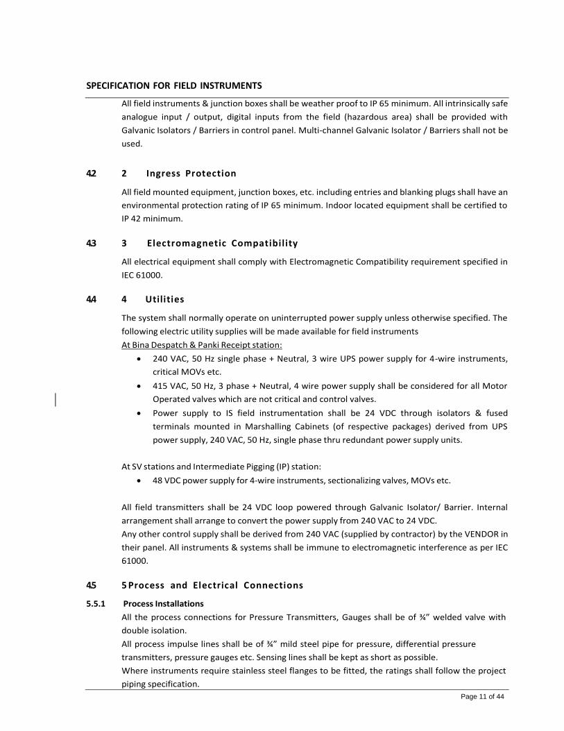
SPECIFICATION FOR FIELD INSTRUMENTS
Page 11 of 44
All field instruments & junction boxes shall be weather proof to IP 65 minimum. All intrinsically safe
analogue input / output, digital inputs from the field (hazardous area) shall be provided with
Galvanic Isolators / Barriers in control panel. Multi-channel Galvanic Isolator / Barriers shall not be
used.
4.2 2 Ingress Protection
All field mounted equipment, junction boxes, etc. including entries and blanking plugs shall have an
environmental protection rating of IP 65 minimum. Indoor located equipment shall be certified to
IP 42 minimum.
4.3 3 Electromagnetic Compatibility
All electrical equipment shall comply with Electromagnetic Compatibility requirement specified in
IEC 61000.
4.4 4 Utilities
The system shall normally operate on uninterrupted power supply unless otherwise specified. The
following electric utility supplies will be made available for field instruments
At Bina Despatch & Panki Receipt station:
240 VAC, 50 Hz single phase + Neutral, 3 wire UPS power supply for 4-wire instruments,
critical MOVs etc.
415 VAC, 50 Hz, 3 phase + Neutral, 4 wire power supply shall be considered for all Motor
Operated valves which are not critical and control valves.
Power supply to IS field instrumentation shall be 24 VDC through isolators & fused
terminals mounted in Marshalling Cabinets (of respective packages) derived from UPS
power supply, 240 VAC, 50 Hz, single phase thru redundant power supply units.
At SV stations and Intermediate Pigging (IP) station:
48 VDC power supply for 4-wire instruments, sectionalizing valves, MOVs etc.
All field transmitters shall be 24 VDC loop powered through Galvanic Isolator/ Barrier. Internal
arrangement shall arrange to convert the power supply from 240 VAC to 24 VDC.
Any other control supply shall be derived from 240 VAC (supplied by contractor) by the VENDOR in
their panel. All instruments & systems shall be immune to electromagnetic interference as per IEC
61000.
4.5 5 Process and Electrical Connections
5.5.1 Process Installations
All the process connections for Pressure Transmitters, Gauges shall be of ¾” welded valve with
double isolation.
All process impulse lines shall be of ¾” mild steel pipe for pressure, differential pressure
transmitters, pressure gauges etc. Sensing lines shall be kept as short as possible.
Where instruments require stainless steel flanges to be fitted, the ratings shall follow the project
piping specification.
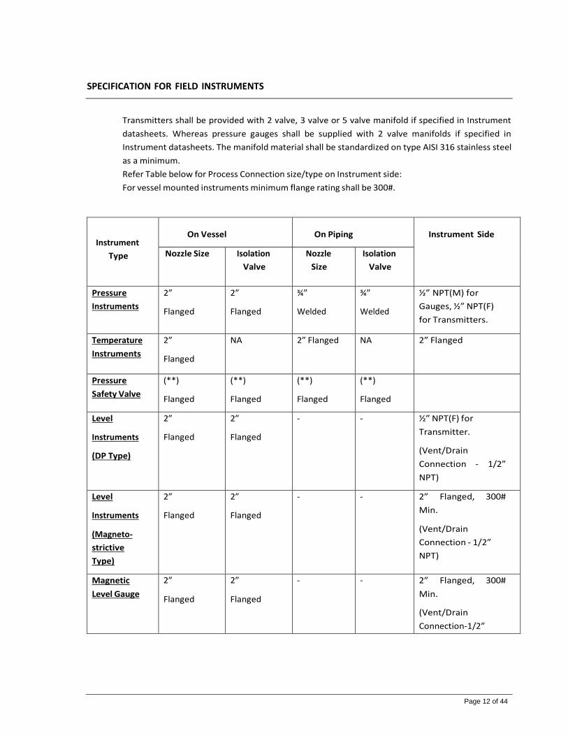
SPECIFICATION FOR FIELD INSTRUMENTS
Page 12 of 44
Transmitters shall be provided with 2 valve, 3 valve or 5 valve manifold if specified in Instrument
datasheets. Whereas pressure gauges shall be supplied with 2 valve manifolds if specified in
Instrument datasheets. The manifold material shall be standardized on type AISI 316 stainless steel
as a minimum.
Refer Table below for Process Connection size/type on Instrument side:
For vessel mounted instruments minimum flange rating shall be 300#.
Instrument
Type
On Vessel
On Piping
Instrument Side
Nozzle Size Isolation
Valve
Nozzle
Size
Isolation
Valve
Pressure
Instruments
2”
Flanged
2”
Flanged
¾”
Welded
¾”
Welded
½” NPT(M) for
Gauges, ½” NPT(F)
for Transmitters.
Temperature
Instruments
2”
Flanged
NA 2” Flanged NA 2” Flanged
Pressure
Safety Valve
(**)
Flanged
(**)
Flanged
(**)
Flanged
(**)
Flanged
Level
Instruments
(DP Type)
2”
Flanged
2”
Flanged
- - ½” NPT(F) for
Transmitter.
(Vent/Drain
Connection - 1/2”
NPT)
Level
Instruments
(Magneto-
strictive
Type)
2”
Flanged
2”
Flanged
- - 2” Flanged, 300#
Min.
(Vent/Drain
Connection - 1/2”
NPT)
Magnetic
Level Gauge
2”
Flanged
2”
Flanged
- - 2” Flanged, 300#
Min.
(Vent/Drain
Connection-1/2”

SPECIFICATION FOR FIELD INSTRUMENTS
Page 13 of 44
NPT)
Level
Instruments
(NCR Type
Radar)
4” (*)
Flanged
4” (*)
Flanged
- - 4” Flanged, 300#
Min.
Level
Instruments
(GWR Type
Radar)
2”
Flanged
2”
Flanged
- - 2” Flanged, 300#
Min.
Miscellaneous
Instruments
(Conductivit
y analyser,
OID etc.)
- - 2”
Flanged
2”
Flanged
2” Flanged
Thermal
Safety Valve
3/4” X 1” Flanged (*)
(*) – Flange size to be confirmed later
(**) – PSV size to be confirmed after valve sizing
5.5.2 Electrical Connections
All instruments shall be supplied along with minimum 2 nos. of ½” NPT(F) cable entries. Spare cable
entries shall be duly plugged with Nickel plated brass dual certified Ex’e’ / Ex’d’ plugs. Refer
instrument datasheet for the actual required number of cable entries & sizes.
4.6 Materials
In general, material of construction for the enclosure for transmitters shall be Die Cast Aluminium.
Stainless steel enclosures shall be provided for local gauges. All wetted part material for the
instruments and impulse tubing / instrument fittings shall be as a minimum SS316.
Material shall be prepared and finished by an approved plating or paint finish as per painting
specifications. In all cases, material and paint shall be proven to be suitable for the environment.
The materials for in-line instruments shall be selected in accordance with the project piping
specification. Due consideration shall be given to dissimilar materials and corrosion by galvanic

SPECIFICATION FOR FIELD INSTRUMENTS
Page 14 of 44
effects. Where dissimilar materials are unavoidable, the contact between the two materials should
be insulated to prevent accelerated corrosion.
In general, the wetted parts of all the instruments shall be provided with material test certificate as
per BS EN 10204 3.1. Piping Material Specifications shall be refered for the material test certificate
and NDE test requirements in case of all inline instruments.
5. GENERAL REQUIREMENTS FOR INSTRUMENTS
Separate transmitters shall be provided for (a) process control / monitoring and (b) shutdown
functions, with each having separate process line tapping points and isolation valves. All electronic
transmitters shall be fitted with an integral local indicator, with a read-out in engineering units. All
local gauge ranges shall be selected such that the normal operating point is between 50% and 75%
of the scale range taking into account the specified minimum & maximum values. For transmitters
ranges shall be selected to cover low & high alarm points.
All instruments shall be designed & constructed suitable for minimum classification in accordance
with international standards and all the instruments shall be certified for use in the applicable
hazardous area by PESO.
All field equipment shall have a minimum Ingress Protection rating of IP 65 and equipment
mounted in control/equipment rooms and buildings which are classified as “safe areas” shall have
as a minimum an Ingress protection rating of IP 42.
All field instrumentation and valves shall be installed in such a way that they are readily accessible
from grade or permanent platforms which shall be 1.2 meters in height without obstructing the
operation. Good access for operation and maintenance shall be provided for all valves and
instruments.
Transmitters shall be provided with body material of epoxy coated die cast aluminium.
All instruments shall feature low power consumption and short stabilization time when they are
powered on. Low maintenance requirements, High Mean Time between Failure (MTBF) and Low
Mean Time To Repair (MTTR) shall be considered in selection of instruments.
All the electronic Instruments shall conform to the Electromagnetic Compatibility (EMC)
requirements of IEC 61000.
5.1 1 Transmitters
All electronic transmitters shall be 2 wire, 24 VDC loop powered, “SMART” type with HART protocol
with 4-20 mA output. This allows efficient preventative maintenance with the use of a HART
communicator. The maintenance shall be able to investigate parameters such as range, calibration,
temperature, pressure, etc.
All transmitters shall have local digital readouts in engineering units.
Materials for all wetted parts shall be min. SS316 and the transmitters shall be able to withstand
differential pressures equal to full line pressure without zero or calibration changes.
Pressure & differential pressure Transmitters shall have an accuracy of ±0.075% and temperature
transmitters shall have an accuracy of ±0.1% of calibrated span or better. All transmitters shall be
complaint as per NAMUR NE 43 requirements.
All the instruments installed on cathodically protected lines shall be installed with DC-Decouplers,

SPECIFICATION FOR FIELD INSTRUMENTS
Page 15 of 44
insulated cable glands etc. to avoid any CP currents to get drained through earthing system.
5.2 2 Electrical Certification
With reference to clause no. 5.1 of this document all field mounted instruments shall be preferably
certified as Ex’i’ or Ex’d’ & shall be suitable for installation in hazardous area Zone-1 Gr. IIA/IIB, T3
area.
5.3 3 Flow Measurement
6.3.1 Orifice Plate
The design, construction, installation and calibration of orifice plates / fittings shall comply to ISO
5167 / AGA report No.3, latest Edition. The units positively seal against both outer faces of the
plate and against both sets of the orifice fitting to prevent leakage.
Wherever possible, prefabricated metering runs shall be used for below 2” (50 mm) line size. The
minimum size orifice flange shall be 50 mm (2") and the minimum flange rating shall be 300# ANSI.
Standard orifice differential pressure ranges shall be adopted with the normal range being 2500
mmWC.
Weep holes shall be provided in steam and gas flow installations where liquid entrainment is
possible. Material shall be ANSI type 316 stainless steel as a minimum.
Concentric, square edged orifice plates with flange taps shall be used. The bore calculations and
the straight upstream / downstream length requirements shall be in accordance with the
applicable code. Beta ratio shall be basically 0.2 and 0.7 for gas, vapour and steam and 0.2 to 0.75
for liquid. The minimum and maximum flow rates shall fall between 20% and 90% of the
transmitter range.
6.3.2 Flow Switch
Flange type thermal dispersion flow switch based on convective heat transfer principle shall be
considered to detect the flow in the line. One sensor shall read the process temperature and the
other is being heated by constant power. The change in flow shall be detected by flow switch as a
change in temperature difference between the sensors.
The switch shall be provided with the fault indication (LED) in the field. It shall have a fast reaponse
and narrow hysteresis.
The switch shall provide volt-free contact to Station PLC upon the flow detection. External 24 VDC
power supply will be provided to flow switch from station PLC. The relay contacts shall be of DPDT
type of rating, 2A, 24 VDC.
The sensors & all wetted surfaces shall be of SS316 minimum and shall be rated for given process
conditions.
5.4 4 Level Measurement
6.4.1 General
For general services, externally mounted level devices are preferred since they permit access for
calibration and maintenance. The use of internally mounted devices is therefore limited to services

SPECIFICATION FOR FIELD INSTRUMENTS
Page 16 of 44
in which external devices cannot be used or in services where a possible shut-down for
maintenance is acceptable.
Each instrument shall be installed with dedicated process isolation, drain and vent valves.
Connections and interconnecting piping should be installed so that no pockets or traps can occur.
Where pockets are unavoidable, drain valves should be provided at low points.
Instruments with external chambers shall be suitable for the equipment design pressure and
temperature. The external chamber material for Radar type shall be, as minimum, carbon steel
unless different material is required by process service. The minimum recommended size for drain
valve is ½”.
Standpipe installation can be used for any application when two or more instruments, including
gauge glasses; the minimum standpipe diameter is 2”.
Level transmitter shall be 2 wire, 24V DC loop powered, “SMART” type with HART protocol with 4-
20 mA output, intrinsically safe, IP-65 Minimum, PESO certified & shall be suitable for installation
in hazardous area. Local LCD of level transmitter shall have a capability of displaying the
measurement values in both the engineering unit & % of level.
Level measurement instruments employed will include magnetic gauges, differential pressure type,
guided wave radar types and non-contact radar type. Level instrument shall be connected on
standpipe or directly on the vessel.
Magnetic gauges are the preferred type of level gauge. Magnetic level gauges are supplied with
stainless steel chamber as standard.
6.4.2 Radar Level Transmitters
Radar type Level transmitter shall have accuracy of ± 3 mm of upper range value. Consideration
shall be taken of fluid properties, operating and external conditions and accuracy requirements
while selecting a measurement type.
Pressure / temperature rating of the Level instruments must be equal or greater than the design
pressure / temperature rating of the vessel to which they are connected.
GWR is the preferred liquid-liquid interface level measurement technology for both process and
shutdown applications.
Radar Level transmitters shall be HART based smart transmitters. The transmitter shall include an
integral LCD indicator.
6.4.3 Level Gauges
Level Gauges shall be of Magnetic-indicator type where magnetized flaps or balls with contrasting
paint colour on each side roll over as the float magnet passes them. Magnetic level gauge shall be
fully assembled at the factory including the float and indicator.
Magnetic level gauge shall be designed in accordance with API STD 551, Process Measurement
Instrumentation. Magnetic level gauge shall be weather proof to IP 65 minimum.
Float Chamber:

SPECIFICATION FOR FIELD INSTRUMENTS
Page 17 of 44
Material of float chamber shall as specified in the data sheet. The chamber shall be suitable for
pressure/ temperature ratings as specified in the data sheets. Float Chambers shall have float stop
springs. Springs lengths shall be adjusted to stop the float’s magnet assembly at zero and span.
Float chamber size shall be 2” minimum on vessel or standpipe as shown in P&ID. Float chamber
Dimension for fluid/fluid interface shall be specified by VENDOR.
Float chambers shall be suitably sized for oil services and design shall be such that float does not
get stuck in the chamber.
Flanged ½“ vent and drain connection shall be provided with isolation valves and dummy plugs.
Float:
Floats shall be hermetically sealed and tested for the design conditions. Vented floats shall not be
used. Floats shall be suitably designed for interface applications, if specified in the data sheet.
Magnet assembly shall be placed in the float such that the indicated level coincides with the actual
level.
Indicator:
Bi-colour indicator shall be a follower (shuttle) housed in a glass tube. The tube shall be held firmly
to the float chamber in a SS316 protective channel. Tube shall be hermetically sealed to prevent
condensation.
Bi-Colour Indicator shall be equipped with a stainless steel calibrated scale marked in millimetre
and 0 to 100 % linear.
5.5 5 Pressure Measurement
Process connections for pressure instruments shall normally be 1/2" NPT. Static pressure sensing
connections on horizontal lines are normally made at the top. Impulse connection between primary
process taps and pressure instruments shall generally be ¾” MS Pipe.
Local pressure and differential pressure indication shall be by means of pressure gauges and
differential pressure gauges respectively.
Pressure transmitter shall be electronic SMART type, two wire, 24 VDC loop powered with 4-20 mA
output and integral digital output meter. Transmitters shall have HART protocol for digital
communication. Material of construction for wetted parts shall be min. SS316. Pressure
transmitters shall have minimum accuracy ± 0.075% of the calibrated span. Pressure transmitters
shall be installed as close as practical to the primary taps. Transmitters shall be installed in
accessible places.
The transmitter shall be able to update output at the rate of 250 milliseconds. The transmitter shall
have selectable damping feature over and above sensor response time. This shall be user selectable
from 0 to 36 seconds, as a minimum.
Pressure transmitter shall be with variable capacitance / piezo resistance type sensor.
The transmitter shall be able to provide diagnostics as real time instrument status. Over range
protection shall be provided for a maximum operating pressure plus 30% over range.

SPECIFICATION FOR FIELD INSTRUMENTS
Page 18 of 44
Capillaries if used shall be in 316 stainless steel, fully armoured and run in supporting channel for
protection. Such diaphragm seal connections shall be provided with bleed rings with vent and drain
connections between the process isolation valve and the diaphragm connection for flushing and
calibrating purpose.
Pressure transmitters to be used in place of pressure switches. All pressure instruments shall be
suitably mounted so as to minimize the length of impulse lines. For pressure transmitters, restrictor
screws or “reduced vibration” type shall be used if installation is head mounted.
Gauges shall be bourdon tube type as per STD EN 837. Pressure gauge accuracy shall be ± 1.0% of
full range. Dial size shall be 150 mm with weather proof IP-65 casing of SS316 material and with a
screwed bezel / bayonet bezel retaining ring. Blow out disc and solid front protection shall be
provided and gauges shall be orientated such that they vent safely.
Where pressure pulsations are present, then snubber / pulsation dampner and glycerine fill shall be
applied to pressure gauges. Gauge windows shall be constructed from safety pattern / toughened
(shatter proof) glass. Wetted part including bourdon tube, pointer material shall be type SS316.
Over-range protection shall be 1.3 times the maximum scale range. Where a gauge is subject to a
greater pressure than the 1.3 times the maximum scale range, a gauge protector / saver shall be
used. Over range protection shall be suitable for 130% of range.
To facilitate pressure gauge removal and alignment, gauges shall be connected to the piping by
means of gauge adapter and not directly into valves. Operating pressure range shall be 50 -75 % of
the dial range.
“Syphons or “Pig Tail” condensate Seals shall be provided in impulse lines for Steam services.
5.6 6 Temperature Measurement
Temperature transmitters shall be electronic "SMART" type with 2-wire, 24 VDC loop powered
output. Transmitter shall have HART protocol.
Thermocouples (T/C’s) or Resistance Thermometer Detectors (RTDs) with local millivolt or
resistance to current converters are the chosen method of temperature measurement and signal
transmission for centralized control, multi-point indication and recording. Resistance Temperature
Devices shall be used for temperatures measurement of up to 1380°F (750°C). RTD if used with
transmitters shall be duplex, three-wire RTD elements with platinum is preferred but a 4-wire type
may also be used to match the receiver manufacturers specification, 100 ohms at 32°F elements as
per IEC 60751 Class A. RTD’s shall have 8 mm sheath OD & sheath shall be of SS316.
All process temperature elements such as at the terminal, stations etc. shall be furnished with
proper flanged thermowells. Thermowell shall as a minimum be machined SS316 drilled from solid
bar stock. Thermowells shall be capable of withstanding the maximum design temperature and
pressure of the system. The thermowell flange material shall be min. SS316 or superior based on
service and shall withstand the associated pressure or temperature rating.

SPECIFICATION FOR FIELD INSTRUMENTS
Page 19 of 44
Any pipe size less than 4” shall be blown to 4” to install thermowell. For 4" pipe and smaller, the
insertion length shall be selected such that the tip of the temperature elements is located in
approximately the centre of the pipe.
For pipe sizes larger than 4" or for the vessels, the insertion length specified shall be such that the
temperature elements are in the main flow of the pipe or vessel. Thermowells shall be checked for
the possibility of wake frequency induced damage, based on ASME PTC 19.3 (latest edition) wake
frequency calculations.
Temperature transmitter shall have ultra- high accuracy, RTD : ± 0.02 % of span + Temperature
transmitter: +/-0.1% of FSD and repeatability +/-0.1% of FSD.
Accuracy of temperature transmitters that form part of leak detection system (LDS) shall be better
than ±0.01 % of span. The transmitters shall be able to output at the rate of 500 m sec per input.
Local temperature indication shall use bi-metallic type, weatherproof hermetically sealed, every
angle adjustable, with 150 mm (6") diameter dial thermometers. The case and stem shall be in
stainless steel. Capillary and armour shall be of SS316 and window material shall be shatter proof
glass. Temperature gauge accuracy shall be + 1% of the span.
Insertion lengths for all thermowells shall be considered as follows.
Thermowell Length (mm)
Line size
230
Line size upto 4”
255
Line size > 4”
405
Equipment’s, Vessels etc.
Temperature transmitter with skin type RTD element suitable for underground installation shall be
considered on piggable lines (e.g. at SV stations). These transmitters shall be supplied with
accessories like RTD extension cable, SS flexible hose to protect the cable, insulation kits, stainless
steel strap, etc.
5.7 Pressure Safety Valves/ Thermal Relief Valves
Pressure Safety Valves shall meet the requirements of API STD 520 (Part-I & II), API STD 526
‘Flanged Safety Relief Valves’. Pressure safety valves shall be full nozzle full lift type.
Safety valve shall be sized for blocked outlet, fire case as indicated in P&ID or process data sheet.
Safety and relief valve orifice sizes shall be calculated on a pure ‘area’ requirement basis. Capacity
adjustments required by codes or other applicable regulations shall be covered while selecting the
safety and relief valve orifice size.
The VENDOR shall provide particular data concerning:
The effect of backpressure on capacity

SPECIFICATION FOR FIELD INSTRUMENTS
Page 20 of 44
The maximum back pressure to which the valve can be subjected, which shall in no case
exceed the pressure rating of the discharge flange.
Selection of the materials for all parts of the valve suitable for the fluid and its conditions
indicated.
Conventional pressure relief valves shall be nozzle entry type and shall comply with API Std. 526.
Pressure safety relief valves shall generally be of conventional direct-acting angle pattern, spring
loaded, full nozzle entry, high capacity type.
All valves shall be UV stamped as per ASME Section VIII.
Safety valves will be set to open at the pressure stated on the P&ID. Where variable back pressure
exceeds 10% of the set pressure, balanced bellows seal type or pilot type safety valves shall be
used. In case of cast steel safety relief valve, castings shall be 100% radiographed.
Thermal relief valves shall be flanged type with inlet / outlet connection (3/4” x 1” flanged with
typically 0.38 cm orifice area).
The body material shall as a minimum, be as per piping material specifications. Nozzle and disc
material shall be SS316 as a minimum with machined stainless steel guide & spindle. The spring
material of pressure relief valves shall be as per API RP 525 Table-2.
Test gag shall be provided for all safety valves. Seat leakage shall be in accordance with the
requirements of API STD 527.
5.8 Hand held Universal Field Configurators / Communicators
HART type Hand held universal field configurators / communicators shall be intrinsically safe
battery-powered with replaceable and rechargeable batteries. Charger power supply shall be 240
VAC, 50 Hz.
Plug-in type connections shall be provided along with necessary interconnection cables and any
other accessories required for connection by SUPPLIER. The universal field Configurators /
communicators shall be dust-proof, certified and suitable for outdoor location. Carrying case shall
be supplied with each communicator.
It shall be possible to connect the communicator at any of the following places for purposes of
digital communication:
System cabinet / panel in the control room.
Junction box in the hazardous area in the field.
Directly at the transmitter, in hazardous area in the field.
Two nos. each universal field configurator / communicator shall be considered at Bina despatch &
Panki receipt station.
5.9 2 Conductivity Analyser
Conductivity analyser shall continuously provide measurement of conductivity in Aviation Turbine
Fuel (ATF).
6.12.1 Design & Construction

SPECIFICATION FOR FIELD INSTRUMENTS
Page 21 of 44
Analyser shall be microprocessor based with state-of-the-art-technology. It shall be capable of
being configured locally using keys from analyser front panel. Conductivity analyser transmitter
shall be electronic "SMART" type with 2-wire, 24 VDC loop powered output. Transmitter shall have
HART protocol & LCD display with digital readout in engineering units.
The analyser shall have,
Accuracy : ± 1% of reading
Repeatability : ± 1% of reading
The analyser shall automatically compensate for changes in temperature over the entire range of
the instrument. Analyser shall be able to run diagnostic subroutines on continuous basis and shall
be able to provide various diagnostic alarm signal to PLC in case of any fault.
The configuration related data of the analyser including calibration range shall be stored in a non-
volatile memory such that this remains unaffected by power fluctuations or power-off conditions.
VENDOR shall clearly state in the technical offer if VENDOR’s standard instrument has a battery
backed RAM. In that case analyser shall have a battery drain alarm facility for maintenance purpose
Conductivity analyser shall comply with the requirement as per ASTM D2624.
The Supplier shall provide a sample handling system for applications where the probe (electrode)
pressure rating is exceeded.
VENDOR shall provide below details as a minimum during technical evaluation.
Specification for analyser & its accessories
Overall dimensions of the SHS, analyser cabinet as applicable
Sampling system details identifying each component with make & model number, process
connection, utility requirement & its connection details, calibration sample & its
connection details, process return connection, cable entry details, external power supply
requirement etc.
Unless otherwise specified in datasheet, all the wetted parts shall be of SS316 as a minimum.
VENDOR must ensure the compatibility of material of each component with the process fluid.
6.12.2 Electrode
The electrode assembly shall be of rugged construction and shall be designed as per process
conditions as specified in the instrument datasheet. The electrode shall meet the below minimum
requirements
Highly resistant to abrasion, coating
Flow through assemblies shall be preferred. In case insertion or submersible assemblies are
offered, the electrode length shall be selected such that the recommended minimum
insertion length falls below the centreline of the pipe / flow cell outlet)
Cable connection to electrodes shall permit easy replacement of electrode
It shall be possible to insert or remove the electrodes on-line without interrupting the
process
In-built temperature sensor (Pt 100) shall be provided for temperature compensation
Conductivity cell shall be of fail-safe construction. The cell constant of the offered
conductivity cell shall be selected based on the range of fluid conductivity.
The conductivity cell shall be of SS316 and electrode of titanium as minimum suitable for

SPECIFICATION FOR FIELD INSTRUMENTS
Page 22 of 44
process conditions
5.10 3 Instrument Manifolds
Pressure and DP transmitters which are mounted remote from the process isolation valve (i.e. not
closed coupled) shall be provided with a 2 and 5 valve manifolds. Pressure gauges which are
mounted directly onto the piping / vessel shall be provided with a 2-valve manifold. The manifolds
shall be suitable for mounting directly on the stanchion (2” pipe). Manifolds shall be supplied along
with mounting accessories. The bolts and nuts shall be as per piping material specifications.
Manifolds shall be complied with the following requirements:
Material of construction for wetted & non-wetted parts shall be SS 316 minimum.
All manifold design shall include :
- ½” NPT (F) connections for process interface / tubing and vent / drain port(s)
- Suitable instrument interface connection
- The packing material and seals shall be either PTFE or Grafoil
- Manifold body rating shall be suitable for given process conditions (pressure-
temperature rating).
The manifolds to be supplied including bolting, gasket / O-ring and with a temporary port protector
plastic plug for all open ports. The body shall be of rugged construction with rolled threads, clean
smooth internal finish and of single piece construction without welds. The block valve and
equalizing valve on the manifold shall be needle valve.
Manifolds are specified on the instrument datasheet and shall be supplied as a complete assembly
by transmitter / pressure gauge VENDOR. The manifold mating dimensions shall be in accordance
with IEC 61518 Type-B for differential pressure (type) measuring instruments.
Instrument manifolds shall be supplied with material test certification as per EN 10204 3.1.
Bolts/nuts & gaskets shall be supplied with material certificates confirming to EN 10204 2.2 and 2.1
respectively.

SPECIFICATION FOR FIELD INSTRUMENTS
Page 23 of 44
6. INSPECTION AND TESTING
6.1 1 General
The VENDOR shall maintain up-to-date documentation at all times reflecting the inspection /
testing status of the equipment. However, the submitted documentation shall not be regarded as
the total requirement. The OWNER may wish to inspect retained documentation such as internal
test results, equipment logs and fault / correction records.
All testing to be carried out in accordance with the approved procedures.
Third Party design verification may be required. Where this is required it shall be performed at the
VENDOR’s cost by an organisation nominated by the BPCL/OWNER and identified in the technical
requisition.
The VENDOR shall ensure that workmanship, materials and quality control are to the highest
standards for all delivered equipment and that only proven techniques and design are utilised.
The VENDOR shall demonstrate that it operates a quality system in accordance with an
internationally recognised standard. The effectiveness of the quality system and the VENDOR’s
compliance with it shall be subject to monitoring by the BPCL and may be audited following an
agreed period of notice.
The VENDOR shall provide facilities for and cooperation with the BPCL and Inspectors during
manufacturing, assembly and testing.
6.2 2 Inspection and Test Plan (ITP)
The VENDOR shall be responsible for the planning and execution of all inspections and tests, but
the BPCL’s representative shall have the right to witness any or all of the manufacturing activities,
inspections or tests.
The VENDOR shall submit an Inspection and Test Plan (ITP) for BPCL review and mark-up following
purchase order placement. The ITP shall list all inspections and tests proposed for the equipment
by the VENDOR, between the date of ordering and the date of delivery.
The OWNER/BPCL and the VENDOR shall sign off the final version of the ITP, which, thereafter,
shall form part of the contract documents.
6.3 3 Inspection
The BPCL or its authorised representatives shall be permitted at all times free access to all parts of
the VENDOR’s workshops that concern the construction, assemblies and testing with prior notice.
Inspection by the BPCL shall not relieve the VENDOR of any guarantees, responsibilities or
obligations to furnish equipment / materials to this specification and the appropriate Instrument
Data Sheets.

SPECIFICATION FOR FIELD INSTRUMENTS
Page 24 of 44
6.4 4 Testing
8.4.1 General
The VENDOR shall devise and execute a test programme during all stages of fabrication. Results of
such testing shall be fully documented.
All stages of testing may be subject to witness and approval by the BPCL and / or a third-party
verifier as identified by the BPCL / Verifier in the inspection and test plan.
The VENDOR shall provide the BPCL with at least 15 calendar days advance notice to witness tests
performed in either the VENDOR’s shop or his sub-VENDOR’s shops.
The BPCL and / or verifier shall review test records and certification prior to releasing the
equipment. All testing shall be carried out at the VENDOR’s test facility. Test equipment shall be
supplied by the VENDOR and shall be calibrated within six months of the test date. All test
equipment used shall have current certification of accuracy from an approved test authority. All
test equipment shall be calibrated and used in accordance with the VENDOR’s QA system.
The VENDOR shall maintain up-to-date documentation at all times reflecting the inspection /
testing. Certificates of Test shall be provided for each item of equipment to prove it has been
satisfactorily tested to meet all requirements of its appropriate manufacturing standards, whether
or not witnessed by the BPCL. Certificates shall be signed by the VENDOR’s and/or BPCL’s quality
representative. Where appropriate, Test certificates shall state values for all test results. Tests for
which the results are indicated as pass or fail shall be qualified by the relevant acceptance criteria.
The submittable documents shall not be regarded as the total requirement. The BPCL may wish to
inspect retained documentation such as internal test results, equipment logs and fault / correction
records.
8.4.2 Test Requirements
Testing and certification for all field instruments shall be in accordance with the Instrument Data
Sheets and BPCLs VENDOR data requirements lists and shall include the following requirements as a
minimum.
Visual checking
Dimensional checking
Flange face finish checking
Hydrostatic testing
NDE
Material Test and traceability reports shall be provided
Functional Testing (for e.g. in case of Pressure safety valves tests like Cold bench set
pressure test, sear leakage test, valve lift test, etc. shall be considered)
OWNER/BPCL shall carry out the testing of the instruments as per approved ITP.
8.4.3 Commissioning and Start-up

SPECIFICATION FOR FIELD INSTRUMENTS
Page 25 of 44
The VENDOR, in their bid, shall identify any special requirements or recommendations for VENDOR
support during commissioning and start-up of the equipment supplied. The BPCL's final
acceptance of the equipment will be subject to a performance test once the equipment has been
installed and commissioned.
The VENDOR shall confirm that, if required, they are able to fully support the installation, testing
and servicing of the supplied instruments and to offer specialist assistance where appropriate.
As an option VENDOR shall quote as lump sum for supervision during hook-up and commissioning.
Any bench sitting qualification shall be defined in the bid.
8.4.4 Site Support
The VENDOR, in their bid, shall provide details of their after-sales support capability. VENDOR shall
advise the location of their nearest service representative and nearest service facility.
7. IDENTIFICATION AND FINISHING
In addition to any international code requirements, the Field Instruments shall be equipped with a
permanently attached primary nameplate manufactured from SS316. Text and numbering shall be
clearly engraved, paint filled and a minimum of 6 mm high.
The primary nameplate shall be mounted in a prominent location secured by stainless steel screws
or rivets. The nameplate shall be engraved with the following information as a minimum:
Client name
Project name
Purchase Order No.
Instrument tag number as per datasheet
Serial Number
Year Manufactured
Pressure / Temperature Safety valves shall have below additional details on nameplate
Nominal flange size & rating for inlet & outlet
Orifice letter designation
Valve set pressure
Cold bench test set pressure
7.1 1 Painting and Coatings
All equipment shall be suitable for operation in the environment referenced in this specification.
Corrosion resistant materials such as SS316L shall not be painted, unless covered by thermal
insulation, in which case the material shall be painted.
All surface preparation, painting and protective coatings shall be in accordance with “Specification
for External Painting and Protective Coating, Doc. No. – 15984-BP-10-PE-SPC-0005”. Alternative
paint procedures may be proposed by the VENDOR but shall be subject to the BPCL’s approval.
Full technical data of the proposed paint manufacturer’s products is to be provided by the VENDOR
with his bid.

SPECIFICATION FOR INSTRUMENT AND TELECOM CABLES
Page 1 of 27
Specification for Instrument and Telecom Cables
Document No: 10-IC-SPC-0009
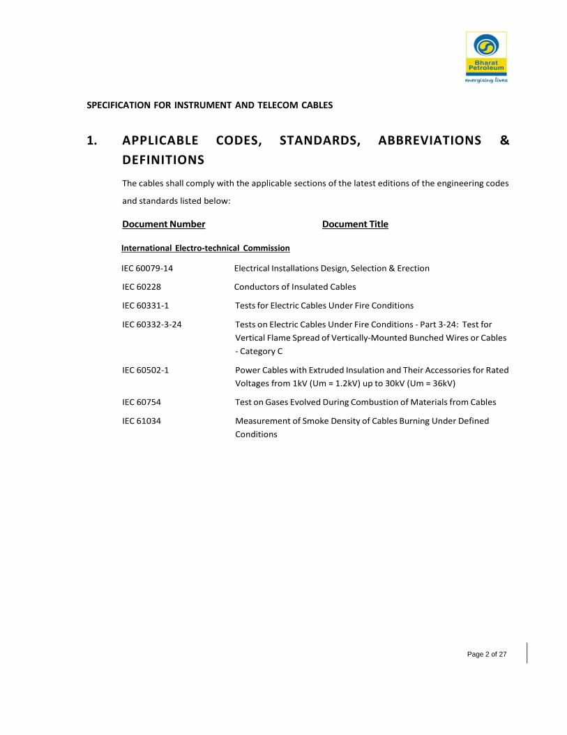
SPECIFICATION FOR INSTRUMENT AND TELECOM CABLES
Page 2 of 27
1. APPLICABLE CODES, STANDARDS, ABBREVIATIONS &
DEFINITIONS
The cables shall comply with the applicable sections of the latest editions of the engineering codes
and standards listed below:
Document Number Document Title
International Electro-technical Commission
IEC 60079-14 Electrical Installations Design, Selection & Erection
IEC 60228 Conductors of Insulated Cables
IEC 60331-1 Tests for Electric Cables Under Fire Conditions
IEC 60332-3-24 Tests on Electric Cables Under Fire Conditions - Part 3-24: Test for
Vertical Flame Spread of Vertically-Mounted Bunched Wires or Cables
- Category C
IEC 60502-1 Power Cables with Extruded Insulation and Their Accessories for Rated
Voltages from 1kV (Um = 1.2kV) up to 30kV (Um = 36kV)
IEC 60754 Test on Gases Evolved During Combustion of Materials from Cables
IEC 61034 Measurement of Smoke Density of Cables Burning Under Defined
Conditions
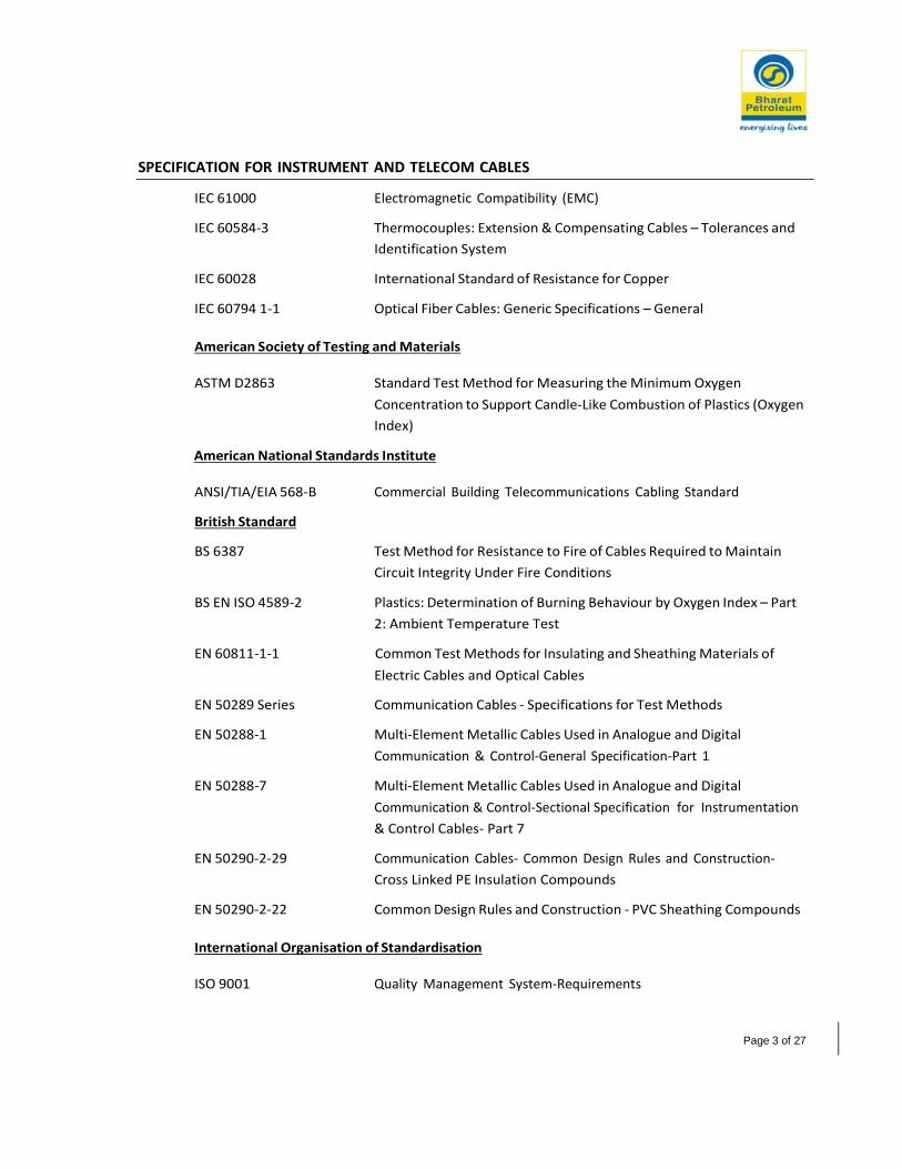
SPECIFICATION FOR INSTRUMENT AND TELECOM CABLES
Page 3 of 27
IEC 61000 Electromagnetic Compatibility (EMC)
IEC 60584-3 Thermocouples: Extension & Compensating Cables – Tolerances and
Identification System
IEC 60028 International Standard of Resistance for Copper
IEC 60794 1-1 Optical Fiber Cables: Generic Specifications – General
American Society of Testing and Materials
ASTM D2863 Standard Test Method for Measuring the Minimum Oxygen
Concentration to Support Candle-Like Combustion of Plastics (Oxygen
Index)
American National Standards Institute
ANSI/TIA/EIA 568-B Commercial Building Telecommunications Cabling Standard
British Standard
BS 6387 Test Method for Resistance to Fire of Cables Required to Maintain
Circuit Integrity Under Fire Conditions
BS EN ISO 4589-2 Plastics: Determination of Burning Behaviour by Oxygen Index – Part
2: Ambient Temperature Test
EN 60811-1-1 Common Test Methods for Insulating and Sheathing Materials of
Electric Cables and Optical Cables
EN 50289 Series Communication Cables - Specifications for Test Methods
EN 50288-1 Multi-Element Metallic Cables Used in Analogue and Digital
Communication & Control-General Specification-Part 1
EN 50288-7 Multi-Element Metallic Cables Used in Analogue and Digital
Communication & Control-Sectional Specification for Instrumentation
& Control Cables- Part 7
EN 50290-2-29 Communication Cables- Common Design Rules and Construction-
Cross Linked PE Insulation Compounds
EN 50290-2-22 Common Design Rules and Construction - PVC Sheathing Compounds
International Organisation of Standardisation
ISO 9001 Quality Management System-Requirements

SPECIFICATION FOR INSTRUMENT AND TELECOM CABLES
Page 4 of 27
Indian Standards (IS)
IS 7098 Specifications for Cross Linked Polyethylene PVC Sheathed Cables
IS 10810 Method of Test for Cables
Part 40 Method for Testing of Uniformity of Coating on Zinc Coated Articles
Part 58 Oxygen Index Test
Part 61 Fame Retardant Test
Part 63 Smoke Density of Electric Cable Under Fire Condition
IS 3975 Low Carbon Galvanized Steel Wires, Formed Wires and Tapes for
Armouring of Cables
IS 1554 Specifications for PVC Insulated (Heavy Duty) Electric Cables
IS 5831 PVC Insulation and Sheath of Electric Cables
IS 6380 Specification for Elastomeric Insulation and Sheath of Electric Cables
Oil Industry Safety Directorate
OISD 117 Fire Protection Facilities for Petroleum Depots, Terminals, Pipeline
Installation & Lube Oil Installation
OISD 141 Design, Construction and Inspection Requirement for Cross Country
liquid Hydrocarbon Pipelines
OISD 149 Design Aspects for Safety in Electrical Systems
OISD 244 Storage and Handling of Petroleum Products at Depots and Terminals.
OISD 118 Layouts for Oil and Gas Installations.
1.1 5 Conflicts, Deviations and Amendments
The VENDOR shall notify the BPCL of any conflict between this specification, the related Data Sheets,
statutory regulations, the Codes, Standards and any other Specifications referenced herein.
Resolution and/or interpretation precedence shall be obtained from the BPCL/OWNER in writing
before proceeding with the Design or Manufacture.
In case of conflict, the order of Precedence shall be:
Statutory Regulations
This Specification / Data Sheet(s)
Project Specifications

SPECIFICATION FOR INSTRUMENT AND TELECOM CABLES
Page 5 of 27
2. GENERAL DESIGN CRITERIA
2.1 Electromagnetic Compatibility
All electrical equipment shall comply with Electromagnetic Compatibility requirement specified in
IEC 61000.
2.2 Quality Assurance
CONTRACTOR, SUPPLIER / VENDOR of equipment shall operate a Quality Assurance system. This
system shall be based on the principles of ISO 9001 latest edition or equivalent.
The quality system may be subject to auditing and monitoring by the OWNER or his representative.
2.3 3 Reliability and Maintenance
High reliability of equipment’s is of paramount importance and therefore only existing field proven
equipment, which is readily available and used widely in similar applications, shall be considered.
Selection of cables shall take account of the projects overall requirements for high availability.

SPECIFICATION FOR INSTRUMENT AND TELECOM CABLES
Page 6 of 27
3. GENERAL REQUIREMENTS OF CABLES
The instrument cables shall be in accordance with EN 50288-1 & EN 50288-7. Cables for intrinsically
safe circuits shall be according to IEC 60079-14. The standard outer sheath colors for IS cables shall
be Blue whereas for Non-IS cables the same shall be Black. Red outer sheath shall be considered for
F&G cables.
All Instrument cables as a minimum shall be of flame retardant type in accordance with IEC-60332-
3-24 (Type-III, Category C) and confirming to category AF as per IS 10810. Cables for F&G system shall
be fire resistant type to IEC-60331-1.
The cables shall have a low smoke property and the minimum value of light transmittance shall be
60%.
Cables for analog signals shall have both individual and overall screen. Cable for digital signals shall
have overall screens. The pairs / triads of the cable shall be uniformly twisted together.
The cables shall be suitable for laying in trays, trenches, ducts, conduits and for direct buried
installations with uncontrolled backfill and possibility of flooding by water and ASAs.
Materials shall be chosen with due regard to this specification and be fit for the duty described.
Cables shall be constructed with suitable sheathing materials which shall withstand exposure to the
environment, with specific attention given to the following:
Exposure to water
Exposure to intense heat and ultra-violet radiation from the sun
Exposure to hydrocarbons
The cables offered shall, preferably, be standard types in regular production by the Manufacturer.
All cables shall be type tested and certified by an independent testing authority.
Instrument cables shall include pair / triad / core cables for intrinsically safe and non-intrinsically safe
circuits. Telecommunication cables shall include telephone cable, CAT-6 A cable, fiber optic cable and
PAGA Cable etc.
3.1 1 Cable Code
A code number has been allocated for each type of cable to be purchased. These codes and their
summarized descriptions (conductor area, number of cores, etc.) of their associated cables are listed
in section 6.3.
The cable type codes shall be typically as per below table.
Cable Type Type Code Cable Code (Refer
Note)
Earthing Cables EC wxyz
Instrument Cables JC wxyz
Fire and Gas Cables FG wxyz

SPECIFICATION FOR INSTRUMENT AND TELECOM CABLES
Page 7 of 27
Telecommunication Cables TC wxyz
Note: ‘wxyz’ = a four digit number, refer section 6.3 for details.
3.2 2 Conductors
Conductors shall be Class 2, high conductivity, concentric stranded manufactured from fully
annealed, circular, tinned copper wires free from Silver, splinters, scales or other imperfections. All
conductors shall comply with IEC 60228.
Cables for analogue signals & discrete signals shall have conductor size 1.5 mm² stranded as a
minimum. Instrument power supply cables (24V DC to solenoid valves etc.) shall have stranded 2.5
mm² conductor size as a minimum.
3.3 3 Conductor Insulation and Color Code
Insulation of the cores shall be 85 deg. C, suitable for the specified voltage designation and duty. The
insulation shall be applied by an “triple extrusion process” to form a compact homogeneous body.
The insulation material for Flame retardant cable shall be “Cross linked Polyethylene (XLPE)” and for
Fire resistance cable shall be “Mica glass tape with XLPE” in accordance with EN 50290-2-29. Fire
resistant cable shall withstand temperature upto 90 deg. C as per IS 6380.
Minimum insulation thickness shall be as per Table 1 of EN 50288-7.
Maximum rated voltage shall be 500 V AC
Insulation details shall be as per below table:
Cable Code Cable Type Insulation Material Conductor Identification / Colour
Type EC Earthing
Cable
PVC Green with yellow stripe
Type JC Core Cable XLPE White (Note 1, 2)
Type JC Pair Cable XLPE White, Black (Note 1)
Type JC Triad Cable XLPE White, Black, Red (Note 1)
Type FG Core Cable Mica glass tape + XLPE White (Note 1, 2)
Type FG Pair Cable Mica glass tape + XLPE White, Black (Note 1)
Type FG Triad Cable Mica glass tape + XLPE White, Black, Red (Note 1)
Notes:-
(1) Each Conductor shall be embossed or printed with the core / pair / triad number.
(2) Green with yellow stripe grounding conductor shall be considered for power cables.

SPECIFICATION FOR INSTRUMENT AND TELECOM CABLES
Page 8 of 27
3.4 4 Laying Up
All cores of cable having two or more conductors shall be laid with a right hand direction of lay.
Alternate directions shall be used for successive layers of multi-pair / triad cables.
For multi-pair cables, each pair shall be uniformly twisted together and the lengths of lay shall be
such that the two wires forming each pair are not disassociated by normal handling. The lay lengths
of adjacent pairs shall not exceed 100 mm.
3.5 5 Bedding
Cables shall be of a circular construction and shall be substantially compact to meet the requirements
for direct entry into Ex certified equipment.
Bedding material shall be compatible with fire performance and toxic emission requirements for the
cable. Bedding shall be of non-hygroscopic material and capable of withstanding the temperatures
encountered when conductors are operating at their maximum rated temperatures.
Bedding shall be suitable for the specified duty and configuration and shall be applied by an extrusion
process.
The process of cable manufacturing shall be controlled to prevent bonding of bedding to the
conductor insulation. In case the bedding materials used in cable construction have a propensity for
such undesirable bonding, the Vendor shall ensure its Quality Procedures for prevention and
detection of such bonding are invoked and strictly applied.
3.6 6 Fillers
Fillers shall be used in the interstices between each core or pair and any central voids, where it is not
possible to achieve a compact and circular cross section with the extruded bedding.
Filler material shall be compatible with fire performance and toxic emission requirements for the
cable. Fillers shall be of non-hygroscopic material and capable of withstanding the temperatures
encountered when conductors are operating at their maximum rated temperatures.
3.7 7 Instrument Cable Screens
The screens shall be formed from a helical wrap of aluminium backed Mylar tape. The shield shall
have 100% coverage of each pair / triad. The aluminium coating shall be on the inside of the tape
and shall be in continuous contact with a 7 / 0.25 mm tinned copper drain wire. Individual screens
shall be electrically isolated from each other. Where individual pair screening is specified, each
screen shall be clearly identified in accordance with the pair numbering system.
3.8 8 Armouring
Galvanized Steel wire armour (GSWA) shall be provided over inner sheath of the cable. The
dimensions of the armour shall be as per IS 1554 (part 1). Requirement and methods of tests for
armour material and uniformity of galvanisation shall be as per IS 3975 and IS 10810 (part 40)
respectively.

SPECIFICATION FOR INSTRUMENT AND TELECOM CABLES
Page 9 of 27
3.9 9 Sheath
All power & control cables shall preferably have extruded inner and outer sheaths. The cable sheath
shall be color coded as specified in Section 6.3.
All cables shall have outer sheaths formed from flame retardant low smoke (FRLS), low halogen PVC
compound in accordance with EN 50290-2-22.
The nominal thickness shall be calculated as per section 4.12 & 4.16 of EN 50288-7 for Inner sheath
and outer sheath respectively.
Sheath materials shall be suitable for direct buried underground installations and for long term
exposure to direct sunlight and shall be resistant to damage by occasional wetting with liquid
hydrocarbon compounds.
Sheath materials shall comply with fire performance and toxic emissions requirements for the cable.
The process of cable manufacture shall be controlled to prevent bonding of the cable sheath to
armour and bedding.
A rip cord shall be provided for inner sheath in all cable types.
Outer sheath shall be suitable for protecting the cable against rodent and termite attack.
3.10 0 Marking and Identification
The cable cores and outer sheaths shall be legibly stamped, embossed or printed using indelible
compounds.
Cores / pairs / triads for control cables shall be numbered commencing at ‘1’ and continuing in
sequence until all circuits are identified. The maximum spacing for identification of cores shall not
exceed 150 mm.
Outer sheaths shall be embossed throughout the cable length on two sides with the following
information:
Manufacturer’s Name
National / International Standard Identification (EN 50288-7)
Cable designation: No. of cores / pairs & core size, Voltage rating
Purchaser’s Type Code
Cable length, starting at zero on the inside of the drum and metre marked at every 1 metre
to the final cable length of each drum.
Cable sheaths for fire resistant cables shall be embossed with the letters “FR” at a spacing not
exceeding 1 metre.

SPECIFICATION FOR INSTRUMENT AND TELECOM CABLES
Page 10 of 27
4. PERFORMANCE REQUIREMENT
4.1 1 Flame Retardant Cables
All cables as a minimum, shall be classified as flame retardant and shall be compliant with the
requirements specified for Category C in IEC 60332.
All cables shall be flame retardant low smoke & shall be tested in accordance with IEC 60754-1.
Cables shall be tested for smoke emission characteristics in accordance with IEC 61034 and shall have
a minimum light transmission value greater than 70%.
4.2 2 Fire Resistant Cables
Fire resistant cables shall be compliant with the requirements of IEC 60331 and shall be listed by UL
/ FM or equivalent in fire service.
Fire resistant cables shall maintain the integrity of the circuit under fire conditions whilst
simultaneously sustaining a degree of mechanical impact for the full time of the test, as described in
IEC 60331. A certificate of test issued by a certified testing authority shall be supplied to verify circuit
integrity.
Fire resistant cables shall be capable of operating when exposed to a water spray during a fire as
detailed in BS 6387. Cable ends are to be sealed to prevent ingress of moisture during the test.
4.3 3 Physical Characteristics
Cable dimensional requirements shall be as per EN 50288-7 & all the dimensional tests of cables
(Thickness of insulation, Concentricity of insulation, thickness of inner & outer sheath, outer
diameter of cable) shall be carried out as per EN 60811-1-1
4.4 4 Oxygen Index
The oxygen index value of 29 or greater is required. All non-metallic material components of the
cable shall be tested for Oxygen Index according to the requirements of BS EN ISO 4589-2 / ASTM
D2863 for determination of oxygen index. The manufacturer shall state the value achieved and if
applicable the equivalent standard used.

SPECIFICATION FOR INSTRUMENT AND TELECOM CABLES
Page 11 of 27
5. CABLE SPECIFICATION
5.1 1 Instrument Cable
Instrument cables shall include single or multi-pairs and triads as appropriate to the application, with
individual and overall screening as specified for the particular cable.
5.2 2 Telecommunication Cables (TC & FO)
Telecommunication cables shall be of flame retardant type, complying with IEC 60332 Category C.
Where fire resistant cables are specified, they shall also comply with IEC 60331.
Communication cables are sub-divided into the following cable types:
Telephone and Data Cables (TC):
Telephone and Data cables shall be designed for use in data communications networks to
meet the requirements of ANSI/TIA/EIA 568-B. Telephone and Data cables shall have black
outer sheaths.
Fiber Optic Cables (FO):
Refer section 6.4.2 for the details of fiber optic cables.
PAGA Cable:
PAGA Cable shall comply with IEC 60331.
5.3 3 Cable Project Codes
Refer below tables for the cable coding format for this project.
EARTHING CABLE CODE - Type ECwxyz
Cable Type Armour 1st
Digit
(w)
Category 2nd
Digit
(x)
No. of
Conduct
ors
3rd
Digit
(y)
Conductor
Cross Section
4th
Digit
(z)
Flame Retardant Unarmo
ured
1 Core Cable 1 1 Core 1 4 mm²
1
6 mm² 2
10 mm² 3
16 mm² 4
25 mm² 5

SPECIFICATION FOR INSTRUMENT AND TELECOM CABLES
Page 12 of 27
INSTRUMENT CABLE CODES – Type Jcwxyz
Cable Type Armour 1st
Digit
(w)
Category 2nd
Digit
(x)
No. of
Conductor
s
3rd
Digit
(y)
Conductor
Cross Section
4th
Digit
(z)
Flame
Retardant, Non-
IS, Black
GSWA 1 Overall
screen
Pair Cable
-
1 1 Pair
Triad
/ 1 0.5 mm² 1
Flame
Retardant, Non-
IS, Black
Unarmo
ured
2 Ind & O/A
screen -
Pair Cable
2 2 Pair
Triad
/ 2 1.0 mm² 2
Flame
Retardant,
Blue
IS,
GSWA 3 Overall
screen -
Triad Cable
3 6 Pair
Triad
/ 3 1.5 mm² 3
Flame
Retardant,
Blue
IS,
Unarmo
ured
4 Ind & O/A
screen -
Triad Cable
4 12 Pair
Triad
/ 4 2.5 mm² 4
Core Cable
+ Ground
5 24 Pair
Triad
/ 5
Type K
Thermoco
uple Ind &
O/A
screen (*)
6 2 Core
GND
+ 6
6 Core
GND
+ 7
12 Core +
GND
8
8 Triad 9
(*) - Type K thermocouple cable shall be as per IEC 60584-3. The outer sheath colour shall be Green as per table 2
of IEC-60584-3.

SPECIFICATION FOR INSTRUMENT AND TELECOM CABLES
Page 13 of 27
FIRE & GAS CABLE CODES – Type FGwxyz
Cable Type Armour 1st
Digit
(w)
Category 2nd
Digit
(x)
No. of
Conductor
s
3rd
Digit
(y)
Conductor
Cross Section
4th
Digit
(z)
Fire Resistant,
Non-IS, Red
GSWA 1 Overall
screen - Pair
Cable
1 1 Pair
Triad
/ 1 0.5 mm² 1
Fire Resistant,
Non-IS, Red
Unarmo
ured
2 Ind & O/A
screen - Pair
Cable
2 2 Pair
Triad
/ 2 1.0 mm² 2
Fire Resistant, IS,
Red
GSWA 3 Overall
screen
Triad Cable
-
3 6 Pair
Triad
/ 3 1.5 mm² 3
Fire Resistant, IS,
Red
Unarmo
ured
4 Ind & O/A
screen - triad
Cable
4 12 Pair /
Triad
4 2.5 mm² 4
Core Cable 5 24 Pair /
Triad
5 4 mm2 5
2 Core 6
6 Core 7
12 Core 8
24 Core 9

SPECIFICATION FOR INSTRUMENT AND TELECOM CABLES
Page 14 of 27
TELECOMMUNICATION CABLE CODES – Type TCwxyz
Cable Type Armour 1st
Digit
(w)
Category 2nd
Digit
(x)
No. of
Conductors
3rd
Digit
(y)
Conductor
Cross
Section
4th
Digit
(z)
Flame
Retardant
Black
Unarmoured 1 Overall
screen pair
1 2 Pair 1 0.20 mm²
(24 AWG)
1
Flame
Retardant
Black
GSWA 2 Ind & O/A
screen pair
2 4 Pair 2 0.25 mm²
(23 AWG)
2
Fire
Resistant
Black
Unarmoured 3 Un-shielded 3 2 Core +
Ground
3 1.5 mm2 3
Fire
Resistant
Black
GSWA 4 Core Cable +
Ground
4 4 2.5 mm2 4
4 mm2 5
Note: Outdoor telecommunication power cable shall be 3 Core (2 Core + Gnd) with conductor cross section of min 4 mm2.
FIBRE OPTIC CABLE CODES – Type FOwxyz
Cable Type Armour 1st
Digit
(w)
Category 2nd
Digit
(x)
No. of
Conductors
3rd
Digit
(y)
Conductor
Cross
Section
4th
Digit
(z)
Flame
Retardant,
Black
GSWA 1 Single Mode 1 6 Core 1 - 1
12 Core 2
4 Core 3

SPECIFICATION FOR INSTRUMENT AND TELECOM CABLES
Page 15 of 27
Cable Type Identification
Each cable type has been assigned a code with following criteria:
Cable Type Code
Cable Type & Armour
Cable Category
No. of Conductors
Conductor Cross Section
Type code-wxyz
E.g. - The identification code for 12 pair x 1.5 mm² armoured, flame retardant cable with individual & overall
screen for intrinsically safe circuits connected to PLC will be JC-3243.
5.4 4 Special Cables
6.4.1 CAT Cable(TC-3322)
Category 6A
Numbers of Pair 4 pair, Twisted, UTP
Size 0.25 mm² (23 AWG)
Conductor material Bare Copper
Insulation Material PVC (Polyvinyl chloride)
Conductor Colour Coding Pair 1 – White / Blue stripe and Blue
Pair 2 – White / Orange stripe and Orange
Pair 3 – White / Green stripe and Green
Pair 4 – White / Brown stripe and Brown
Outer Jacket As per section 4.9
Colour Grey
6.4.2 Fiber Optic Cable (FO-1111, FO-1131 & FO-1121)
(4/6/12 fiber single mode armoured cable specification)
Attenuation (Cabled)
At 1310 nm ≤ 0.36 dB/km
At 1550 nm ≤ 0.25 dB/km
Cladding Diameter 125.0 ± 1.0 μm
Cladding Non-Circularity ≤ 1.0%

SPECIFICATION FOR INSTRUMENT AND TELECOM CABLES
Page 16 of 27
Primary Coating Diameter 243±7
Core/Cladding Concentricity Error ≤ 0.8 μm
Primary coating – cladding concentricity error ≤ 12 μm
Mode Field Diameter 9.3 ± 0.5 μm @ 1310 nm
Fiber Curl Radius > 4 m
Zero-Dispersion Wavelength 1300 to 1324 nm
Zero-Dispersion Slope ≤ 0.092 ps/nm².km
Polarisation Mode Dispersion Coefficient ≤ 0.2 ps/√km @ 1310 nm & 1550 nm
Cut-off Wavelength (Cables) ≤ 1260 nm
Fiber Macrobend :
(100 turns.@1550 nm) ≤ 0.1 dB
Coating Strip Force 1.3 ≤ F ≤ 8.9 N
Proof stress level 0.69 GPa
Technical Data For 6 Core Fiber:
Fiber Count 4/6/12 Core
Armour Galvanized steel wire armour
Moisture Barrier Water Blocking Tape / Water Blocking Jelly
Sheathing As per section 4.9
Strength Member 2 No’s of embedded steel wires, 0.9m
Rip Cords Aramid & Polyester ripcords
Fiber per bundle 4/6
Fiber type / colors G. 652 fibers, Blue, Orange, Green, Brown,
Slate, White, Red, Black, Yellow,
Violet, Rose, Aqua
Type of Installation Direct Buried
Flame Test Method IEC 60332
6.4.3 Telephone Cable (TC-2111)
Number of Pair 2 pair, Twisted
Size 0.20 mm² (24 AWG)
Conductor material Annealed Tinned Copper
Insulation Material XLPE
Armour Type Galvanised steel wire armour
Outer Jacket As per section 4.9
Moisture Barrier Water Blocking Tape / Water Blocking Jelly
Conductor resistance 96 ohms/km

SPECIFICATION FOR INSTRUMENT AND TELECOM CABLES
Page 17 of 27
Insulation resistance (Min) 1500M ohms/km
Capacitance unbalanced (Max) <275pF/500m
Type of Installation Direct Buried
Flame Test Method Flame Retardant (IEC 60332)
6.4.4 .4 PAGA Speaker Cable (TC-2114)
Number of Pair 2 pair, Twisted
Size 2.5 mm²
Conductor material Annealed Tinned Copper
Insulation Material XLPE
Fire Resisting Barrier Glass Mica Tape (GMT)
Overall Screen Aluminium backed Mylar Tape with 100%
coverage
Armour Type Galvanised steel wire armour
Outer Jacket As per section 4.9
Voltage 150/250V
Type of Installation Direct Buried
Flame Test Method Fire Resistant (IEC 60331)
6.4.5 RS-485 Cable (TC-2221)
Number of Pair 4 pair, Twisted, Individual and Overall Shield
Size 24 AWG
Stranding Stranded (7 x 0.2)
Conductor material Annealed Tinned Copper
Insulation Material HDPE
Impedance 120 Ohm
Voltage Rating 300V
Temperature Rating -20 °C to 70 °C
Conductor Colour Coding Pair 1 – White-Blue
Pair 2 – White-Orange
Pair 3 – White-Green
Pair 4 – White-Brown
Individual/Overall Screen Aluminium backed Mylar Tape with 100%
coverage
Outer Jacket As per section 4.9
Colour Black
Armour Galvanised steel wire armour
Type of Installation Direct Buried
Flame Test Method Flame Retardant (IEC 60332)

SPECIFICATION FOR JUNCTION BOXES AND BULK MATERIAL
Page 18 of 29
Specification for Junction Boxes and Bulk Material
Document No: 15984-BP-10-IC-SPC-0010

SPECIFICATION FOR JUNCTION BOXES AND BULK MATERIAL
Page 19 of 29
1.1 2 International Codes and Standards
The design shall comply with the applicable sections of the latest editions of the engineering codes
and standards listed below:
Document Number Document Title
American Society of Mechanical Engineers
ASME B1.20.1 Pipe Threads, General Purpose (inch)
ASME B16.11 Forged Fittings, Socket-Welding and Threaded.
ASME B16.5 Pipe Flanges and Flanged Fittings NPS ½ Through NPS 24 Metric/inch
Standard
International Electro-Technical Commission
IEC 60079 Electrical Apparatus for Explosive Gas Atmospheres
IEC 60529 Degrees of Protection Provided by Enclosures (IP Code)
IEC 61000 Electromagnetic Compatibility
IEC 61537 Cable Management – Cable Tray Systems and Cable Ladder Systems
American Society for Testing and Materials
ASTM A182 Standard Specification for Forged or Rolled Alloy and Stainless Steel
Pipe Flanges, Forged Fittings and Valves and Parts for High
Temperature Service
ASTM A269 Standard Specification for Seamless and Welded Austenitic Stainless
Steel Tubing for General Service
ASTM A312 Standard Specification for Seamless, Welded and Heavily Cold Worked
Austenitic Stainless Steel Pipes
ASTM F1387 Standard Specification for Performance of Piping and Tubing
Mechanically Attached Fittings
ASTM A403 Standard Specification for Wrought Austenitic Stainless Steel Piping
Fittings
ASTM A960 Standard Specification for Common Requirements for Wrought Steel
Piping Fittings
ASTM A276 Standard Specification for Stainless Steel Bars and Shapes

SPECIFICATION FOR JUNCTION BOXES AND BULK MATERIAL
Page 20 of 29
ASTM D635 Standard Test Method for Rate of Burning and/or Extent and Time of
Burning of Plastics in a Horizontal Position
ASTM E84 Standard Test Method for Surface Burning Characteristics of Building
Materials
British Standards
BS 6121-1 Mechanical Cable Glands
European Norms
BS EN 62444 Cable Glands for Electrical Installations
EN 10204 Metallic Products – Types of Inspection Documents
Bureau of Indian Standards (BIS)
IS 6746 Unsaturated Polyester Resin Systems – Specification
Oil Industry Safety Directorate
OISD 117 Fire Protection Facilities for Petroleum Depots, Terminals, Pipeline
Installation & Lube Oil Installation.
OISD 141 Design, Construction and Inspection Requirement for Cross Country
Liquid Hydrocarbon Pipelines
OISD 149 Design Aspects for Safety in Electrical Systems
OISD 244 Storage and Handling of Petroleum Products at Depots and Terminals
Including Standalone Crude Oil Storage Facility
OISD 118 Layouts for Oil and Gas Installations.
PESO/CCOE & CIMFR
PESO Certifications Petroleum and Explosives Safety Organization(PESO)
CIMFR Certifications Central Institute of Mining and Fuel Research
International Organization of Standardization
ISO 9001 Quality Management Systems — Requirements

SPECIFICATION FOR JUNCTION BOXES AND BULK MATERIAL
Page 21 of 29
2. GENERAL DESIGN CRITERIA
2.1 1 Hazardous Area Requirements
Instruments / junction boxes located in hazardous area shall be certified to meet or exceed the
electrical hazardous area classification. In general, all field mounted junction boxes shall be
certified as Ex’d’. Cable glands, blanking plugs shall be Ex’e’/Ex’d’ dual certified. It shall be suitable
for Zone-1 Gr. IIA/IIB, T3 area.
All electronic / electrical instruments and equipment shall be suitable for area classification as per
IEC codes and shall be tested by any recognized authorities such as BASEEFA, FM, CENELEC, ATEX,
PTB, CMRI etc.
All electrical and instrumentations Items shall be PESO Certified irrespective of their installation in
safe or hazardous area.
2.2 2 Ingress Protection
All field mounted equipment, junction boxes, etc. including cable glands and blanking plugs shall
have an environmental protection rating of IP 65 minimum. Indoor located equipment shall be
certified to IP 42 minimum.
2.3 3 Electromagnetic Compatibility
All electrical equipment shall comply with Electromagnetic Compatibility requirement specified in
IEC 61000.
2.4 4 Quality Assurance
CONTRACTOR, SUPPLIER / VENDOR of equipment shall operate a Quality Assurance system. This
system shall be based on the principles of ISO 9001 latest edition or equivalent.
The quality system may be subject to auditing and monitoring by the OWNER or his
representative.
2.5 5 Reliability and Maintenance
High reliability of equipment is of paramount importance and therefore only existing field proven
equipment, which is readily available and used widely in similar applications, shall be considered.
Selection of junction boxes & bulk items shall take account of the projects overall requirements for
high availability.
2.6 7 Design Life
The design life of field instrumentation shall be 5 years minimum.
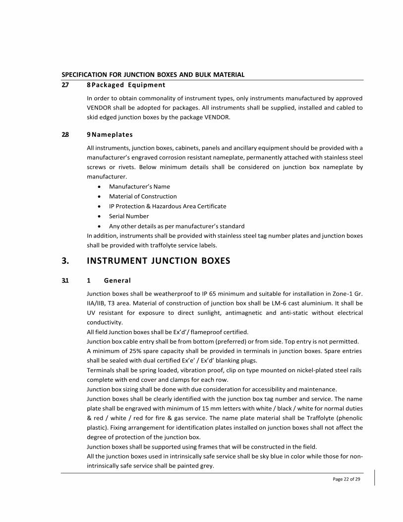
SPECIFICATION FOR JUNCTION BOXES AND BULK MATERIAL
Page 22 of 29
2.7 8 Packaged Equipment
In order to obtain commonality of instrument types, only instruments manufactured by approved
VENDOR shall be adopted for packages. All instruments shall be supplied, installed and cabled to
skid edged junction boxes by the package VENDOR.
2.8 9 Nameplates
All instruments, junction boxes, cabinets, panels and ancillary equipment should be provided with a
manufacturer’s engraved corrosion resistant nameplate, permanently attached with stainless steel
screws or rivets. Below minimum details shall be considered on junction box nameplate by
manufacturer.
Manufacturer’s Name
Material of Construction
IP Protection & Hazardous Area Certificate
Serial Number
Any other details as per manufacturer’s standard
In addition, instruments shall be provided with stainless steel tag number plates and junction boxes
shall be provided with traffolyte service labels.
3. INSTRUMENT JUNCTION BOXES
3.1 1 General
Junction boxes shall be weatherproof to IP 65 minimum and suitable for installation in Zone-1 Gr.
IIA/IIB, T3 area. Material of construction of junction box shall be LM-6 cast aluminium. It shall be
UV resistant for exposure to direct sunlight, antimagnetic and anti-static without electrical
conductivity.
All field Junction boxes shall be Ex’d’/ flameproof certified.
Junction box cable entry shall be from bottom (preferred) or from side. Top entry is not permitted.
A minimum of 25% spare capacity shall be provided in terminals in junction boxes. Spare entries
shall be sealed with dual certified Ex’e’ / Ex’d’ blanking plugs.
Terminals shall be spring loaded, vibration proof, clip on type mounted on nickel-plated steel rails
complete with end cover and clamps for each row.
Junction box sizing shall be done with due consideration for accessibility and maintenance.
Junction boxes shall be clearly identified with the junction box tag number and service. The name
plate shall be engraved with minimum of 15 mm letters with white / black / white for normal duties
& red / white / red for fire & gas service. The name plate material shall be Traffolyte (phenolic
plastic). Fixing arrangement for identification plates installed on junction boxes shall not affect the
degree of protection of the junction box.
Junction boxes shall be supported using frames that will be constructed in the field.
All the junction boxes used in intrinsically safe service shall be sky blue in color while those for non-
intrinsically safe service shall be painted grey.

SPECIFICATION FOR JUNCTION BOXES AND BULK MATERIAL
Page 23 of 29
Cable entry for instrument cables (i.e. single pair / triad / core) shall be ½” NPT(F) minimum. Cable
entries for multi-cables & Breather drain (Ex’e’) to be decided based on cable type, formation &
diameter.
Ex’d’ pull boxes shall be considered for interconnections wherever required.
3.2 2 Junction Box Classification
The following signal segregation rules shall be followed for the Junction boxes.
I.S. Analogue
Non I.S. Analogue
I.S. Digital
Non I.S. Digital
Control signals such as SOV, lamps, etc.
F & G Instruments
Power Supply
The mixing of signal types within a junction box is not allowed. In addition to the above
segregation, separate junction boxes and cables shall be used for signals connected to:
PLC system
F&G system
Package UCP
MMS system
Telecommunication system
The tagging philosophy for the Junction Boxes shall be as:
AA-YJB-ZZZZ
XX: Area Code
10100: Bina Despatch Station
10200: Intermediate Pigging Station
10300: Panki Receipt Station
10400: Sectionalizing Valve Station
Y: I/O Type
A: Analog Input / Output Signal
D: Digital Input Signal

SPECIFICATION FOR JUNCTION BOXES AND BULK MATERIAL
Page 24 of 29
X: Digital Output Signal
F: Fire & Gas Signal
P: Power Signal
T: Telecommunication Signal
JB: Junction Box
ZZZZ: Serial Number - 0001, 0002….
e.g. – Tag number of analogue signal JB located at Bina Despatch Station will be 10100-AJB-0001.
3.3 3 Terminal Block
Terminal strip shall be of modular construction and made of non-hygroscopic compound. All
terminals used in signal, alarm & control junction boxes shall be suitable for terminating minimum
2.5 mm² copper conductor. Higher size of terminals shall be provided when indicated. The
terminals shall be single feed through clamp type to hold the wire ferrule securely in place and shall
be vibration resistant. Multilayer terminals are not allowed. Each terminal shall be fitted with
numerical markers and shall be numbered in compliance with wiring diagrams. Terminals shall be
provided to terminate all cores of the main cable including spare wires. The terminals shall be
equally distributed on either side of the PVC wiring duct in case of multiple rails required. Sizing
shall be done with due consideration for accessibility and maintenance in accordance with the
following guidelines:
50 to 60 mm between terminals and sides of box parallel to terminal strip for up to 50
terminals and additional 25 mm for each additional 25 terminals.
100 to 120 mm between terminal strips for up to 50 terminals and additional 25 mm for
each additional 25 terminals.
Bottom / top of terminal shall not be less than 100 mm from bottom / top of the junction
box.
The terminals shall be blue color for intrinsically safe signals while those for non-intrinsically safe
signals shall be painted grey.
3.4 4 Earthing & Earth Studs
The armour of the field instrument cables going to junction box shall be terminated at cable gland.
Internal / external earth studs shall be provided in junction box suitable for 10 mm² earthing cable.
Earth stud shall be of stainless steel material.
3.5 5 Construction
Junction boxes shall be manufactured from LM-6 cast aluminium. They shall be suitable for surface
mounting and supplied with a mounting plate. Flameproof junction boxes shall have fully

SPECIFICATION FOR JUNCTION BOXES AND BULK MATERIAL
Page 25 of 29
detachable screwed doors. Doors must be fitted with a captive gasket or sealing ring made of
neoprene or synthetic rubber suitable for the given ambient temperature. All mechanical surfaces
shall be free from burrs, dents and integral roughness.
3.6 6 Local Panel (Pushbutton Stations)
The material of construction of Local panels shall be LM-6 Cast Aluminium. It shall be UV resistant
for exposure to direct sunlight, antimagnetic and anti-static without electrical conductivity.
Front cover shall be fully detachable by fixing through SS316 screws.
All enclosures shall be certified Ex’d’ suitable for use in hazardous area classification Zone-1 Gr.
IIA/IIB, T3 area.
Local panel enclosure shall be IP 65 minimum.
Local panels shall have suitable ½” NPT cable entry for field cable connection.
Local panel enclosures shall be suitable for surface mounting and supplied with mounting plate.
The pushbutton(s) for OPEN / CLOSE & START / STOP operation shall be of spring return type with
dual NO / NC contacts with a contact rating of 2A at 24 VDC.
The emergency pushbutton(s) shall be of push to trip and latch & turn and pull to unlatch type with
protective cover. Pushbutton knob shall be mushroom shape, red color, with yellow sleeve ring and
shall be readily accessible. It shall be easily operated by hand for trip and unlatch without the need
of special key or tool.
The terminal assemblies shall be provided mounted on DIN rail and shall be suitable for conductor
sizes of up to 2.5 mm². The pushbuttons shall be connected to terminals inside the enclosure.
The enclosure shall also be provided with stainless steel earth stud / screw with washers & lock
nuts for external earth connection of minimum 10 mm² size. VENDOR shall supply earth continuity
for metallic cable glands (internal gland plate or equivalent).

SPECIFICATION FOR JUNCTION BOXES AND BULK MATERIAL
Page 26 of 29
3.7 7 Typical Junction Box Layout
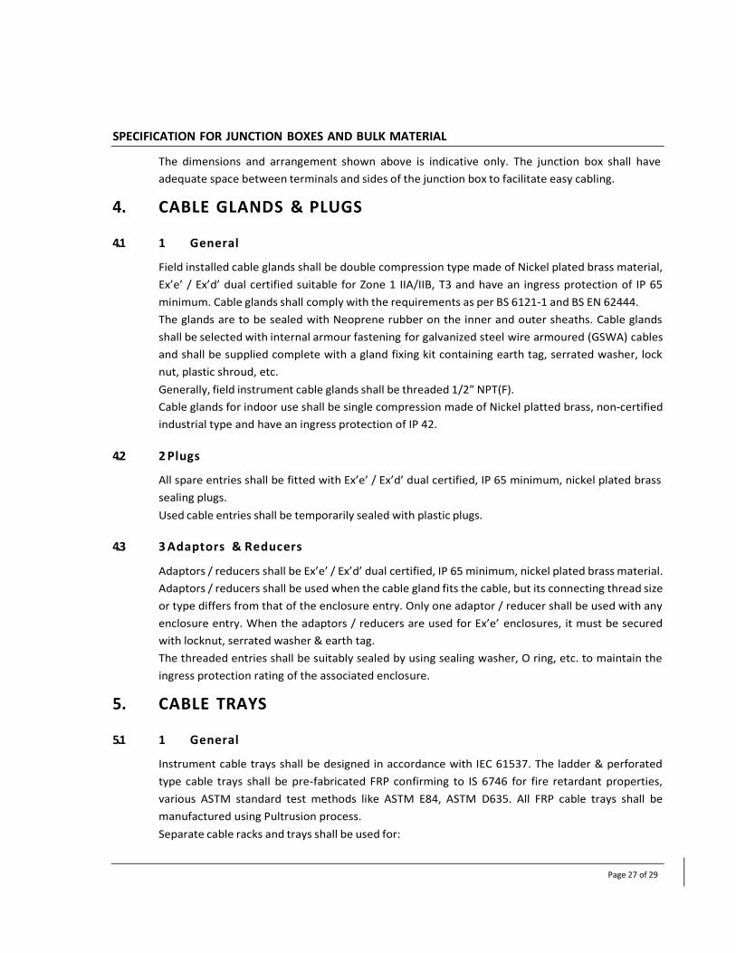
SPECIFICATION FOR JUNCTION BOXES AND BULK MATERIAL
Page 27 of 29
The dimensions and arrangement shown above is indicative only. The junction box shall have
adequate space between terminals and sides of the junction box to facilitate easy cabling.
4. CABLE GLANDS & PLUGS
4.1 1 General
Field installed cable glands shall be double compression type made of Nickel plated brass material,
Ex’e’ / Ex’d’ dual certified suitable for Zone 1 IIA/IIB, T3 and have an ingress protection of IP 65
minimum. Cable glands shall comply with the requirements as per BS 6121-1 and BS EN 62444.
The glands are to be sealed with Neoprene rubber on the inner and outer sheaths. Cable glands
shall be selected with internal armour fastening for galvanized steel wire armoured (GSWA) cables
and shall be supplied complete with a gland fixing kit containing earth tag, serrated washer, lock
nut, plastic shroud, etc.
Generally, field instrument cable glands shall be threaded 1/2” NPT(F).
Cable glands for indoor use shall be single compression made of Nickel platted brass, non-certified
industrial type and have an ingress protection of IP 42.
4.2 2 Plugs
All spare entries shall be fitted with Ex’e’ / Ex’d’ dual certified, IP 65 minimum, nickel plated brass
sealing plugs.
Used cable entries shall be temporarily sealed with plastic plugs.
4.3 3 Adaptors & Reducers
Adaptors / reducers shall be Ex’e’ / Ex’d’ dual certified, IP 65 minimum, nickel plated brass material.
Adaptors / reducers shall be used when the cable gland fits the cable, but its connecting thread size
or type differs from that of the enclosure entry. Only one adaptor / reducer shall be used with any
enclosure entry. When the adaptors / reducers are used for Ex’e’ enclosures, it must be secured
with locknut, serrated washer & earth tag.
The threaded entries shall be suitably sealed by using sealing washer, O ring, etc. to maintain the
ingress protection rating of the associated enclosure.
5. CABLE TRAYS
5.1 1 General
Instrument cable trays shall be designed in accordance with IEC 61537. The ladder & perforated
type cable trays shall be pre-fabricated FRP confirming to IS 6746 for fire retardant properties,
various ASTM standard test methods like ASTM E84, ASTM D635. All FRP cable trays shall be
manufactured using Pultrusion process.
Separate cable racks and trays shall be used for:

SPECIFICATION FOR JUNCTION BOXES AND BULK MATERIAL
Page 28 of 29
Power supply cables
Intrinsically safe Instrument and Communication cables
Non- intrinsically safe Instrument and Communication cables
Instrument cables and Fire alarm cables for addressable systems shall preferably not be laid in
the same trench / tray along with electrical cables. In case these are laid in the same trench /
tray, a clearance of minimum 300 mm from electrical cables shall be provided. The overall cable
layouts shall be designed for minimum interference between signal and power cables.
All cable trays normally shall be supported in every 2 to 2.5 meters. Where it is impractical, extra
heavy duty cable trays shall be used so that supports can be extended at every 3 meters to suit
the application.
In general cable trays shall have 50, 100, 150, 300, 450 & 600 mm width.
The Cable trays shall be supplied in 3 meters length. Tolerance on width and length shall be ±6 mm
and height ±2 mm. Tolerance on width specified is applicable for cable trays of 150 mm and above.
For lower size cable trays VENDOR shall maintain a minimum tolerance.
The construction of cable trays shall be such as to facilitate easy handling and to ensure easy laying
of cables without causing the damage to cables. The inside surface shall be free from sharp edges,
burrs or projection.
The cable trays shall have holes on each end for fixing of coupler plates to join individual cable tray
sections.
Vertical supports for cable trays shall be fabricated out of ISMC 100 channels and horizontal
supports shall be with 65 x 65 x 6 mm angle iron sections.
The inside depth of the cable trays shall be as follows:
50 mm up to 200 mm wide perforated cable trays
100 mm for 300 mm and above wide ladder cable trays
5.2 2 Coupling Plates
The coupling plate (splice plate) shall also be manufactured of the same material as that of cable
tray. The minimum thickness shall be 3 mm, minimum length 200 mm & minimum width should be
as per width of the joining face of the cable tray.
Two coupler plates shall be provided for each length. The couplings between two sections of cable
tray lengths or associated connections shall be done by SS 316 Bolting only. The coupler plates shall
be supplied with fitting accessories like bolts, nuts & washers, etc.
5.3 3 Covers
Cable racks and trays shall be covered by removable FRP covers on upper most tier in following
cases where:
Mechanical damage of cables is likely to occur during maintenance in the plant.
Oil or spillage of ASAs can be expected.
Protection from direct exposure to sun is required.

SPECIFICATION FOR JUNCTION BOXES AND BULK MATERIAL
Page 29 of 29
The cover sheet shall allow adequate ventilation to the cables and shall be in standard length of
3000 mm, flanged on both sides for fixing on cable tray.
5.4 4 Accessories
The tray shall be supplied with standard VENDOR supplied accessories and fittings such as couplers,
elbows, tees, crosses, reducers, risers & hold-down clamps, etc.
The radius of the fittings shall not be less than the minimum bending radius of the largest cable to
be installed.
The hold-down clamps shall be used for fastening a cable tray to cable tray supports.
5.5 5 Design Loading
For the trays system design in addition to the self-load following guidelines shall be
considered.
Length of the trays 3000 mm
Support span 2000 mm
Cable load for perforated trays:
50 mm width 30 Kgs/Linear Meter
100 mm width 40 Kgs/Linear Meter
150 mm width 50 Kgs/Linear Meter
Concentrated and larger Load for the above widths shall not be considered.
Length of the trays 3000 mm
Support span 2500 mm
Cable load for ladder trays:
300 mm width 60 Kgs/Linear Meter
450 mm width 70 Kgs/Linear Meter
600 mm width 90 Kgs/Linear Meter
In addition to this, 75 Kgs concentrated load at centre span shall be considered.

SPECIFICATION FOR JUNCTION BOXES AND BULK MATERIAL
Page 30 of 29
5.6 6 Format to Quote
No. Description Quantity
1 FRP Perforated Cable trays – 50 mm Width x 50 mm Height x 3 mm
Thickness Note-1
2 FRP Perforated Cable trays – 100 mm Width x 50 mm Height x 3 mm
Thickness Note-1
3 FRP Perforated Cable trays – 150 mm Width x 50 mm Height x 3 mm
Thickness Note-1
4 FRP Perforated Cable trays – 200 mm Width x 50 mm Height x 3 mm
Thickness Note-1
5 FRP Ladder Cable trays – 300 mm Width x 100 mm Height Note-1
6 FRP Ladder Cable trays – 450 mm Width x 100 mm Height Note-1
7 FRP Ladder Cable trays – 600 mm Width x 100 mm Height Note-1
8 Coupler plates set suitable for item no. 1 to 7 & consist of,
- 1 No of coupler plate
- 4 Nos of M8 x 25 mm length bolt & nuts
- Double washer etc. for each tray length
Note-1
9 Hold-down Clamps (2 clamps are required per tray) Note-1
10 Accessories: Tee, Elbow, Cross, Inside / Outside Riser, Straight Reducer,
Offset reducer, separators, etc.
As
Required.
NOTE-1: For Detailed Quantity refer Instrument Bulk MTO, Doc No. 15984-BP-10-100-IC-BOM-
0001, 15984-BP-10-200-IC-BOM-0001, 15984-BP-10-300-IC-BOM-0001, 15984-BP-10-400-IC-BOM-
0001
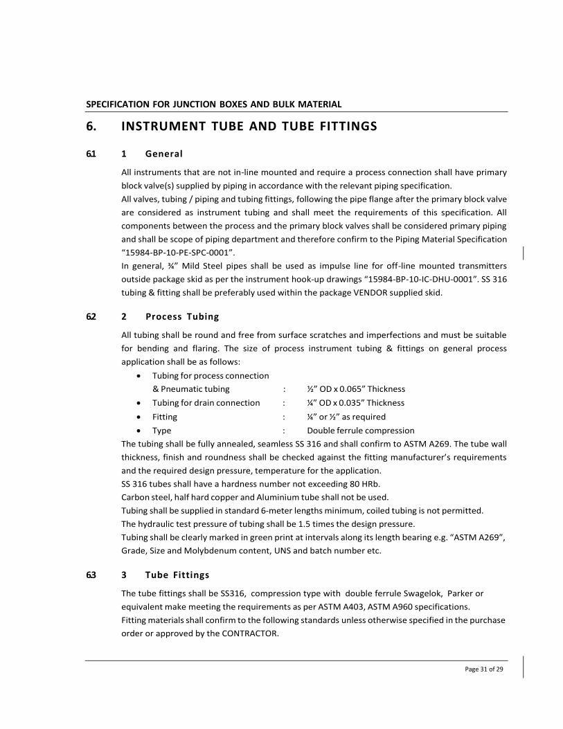
SPECIFICATION FOR JUNCTION BOXES AND BULK MATERIAL
Page 31 of 29
6. INSTRUMENT TUBE AND TUBE FITTINGS
6.1 1 General
All instruments that are not in-line mounted and require a process connection shall have primary
block valve(s) supplied by piping in accordance with the relevant piping specification.
All valves, tubing / piping and tubing fittings, following the pipe flange after the primary block valve
are considered as instrument tubing and shall meet the requirements of this specification. All
components between the process and the primary block valves shall be considered primary piping
and shall be scope of piping department and therefore confirm to the Piping Material Specification
“15984-BP-10-PE-SPC-0001”.
In general, ¾” Mild Steel pipes shall be used as impulse line for off-line mounted transmitters
outside package skid as per the instrument hook-up drawings “15984-BP-10-IC-DHU-0001”. SS 316
tubing & fitting shall be preferably used within the package VENDOR supplied skid.
6.2 2 Process Tubing
All tubing shall be round and free from surface scratches and imperfections and must be suitable
for bending and flaring. The size of process instrument tubing & fittings on general process
application shall be as follows:
Tubing for process connection
& Pneumatic tubing : ½” OD x 0.065” Thickness
Tubing for drain connection : ¼” OD x 0.035” Thickness
Fitting : ¼” or ½” as required
Type : Double ferrule compression
The tubing shall be fully annealed, seamless SS 316 and shall confirm to ASTM A269. The tube wall
thickness, finish and roundness shall be checked against the fitting manufacturer’s requirements
and the required design pressure, temperature for the application.
SS 316 tubes shall have a hardness number not exceeding 80 HRb.
Carbon steel, half hard copper and Aluminium tube shall not be used.
Tubing shall be supplied in standard 6-meter lengths minimum, coiled tubing is not permitted.
The hydraulic test pressure of tubing shall be 1.5 times the design pressure.
Tubing shall be clearly marked in green print at intervals along its length bearing e.g. “ASTM A269”,
Grade, Size and Molybdenum content, UNS and batch number etc.
6.3 3 Tube Fittings
The tube fittings shall be SS316, compression type with double ferrule Swagelok, Parker or
equivalent make meeting the requirements as per ASTM A403, ASTM A960 specifications.
Fitting materials shall confirm to the following standards unless otherwise specified in the purchase
order or approved by the CONTRACTOR.

SPECIFICATION FOR JUNCTION BOXES AND BULK MATERIAL
Page 32 of 29
SS 316: ASTM A276 / ASTM A182 with a minimum Molybdenum content of 2.5%
The difference in hardness between the tubing and fittings shall be such that the fittings hardness
shall be at least 5 hardness numbers more than the tube hardness in Rockwell RB scale.
Ferrule finish and fitting finish shall be such that there is no abrasion / galling when the nut is
tightened.
Compression fittings shall only be used on the range of tube wall thickness specified by the
compression fitting VENDOR. This is important for both thin wall effects where the tube may
collapse or burst and for thick wall effects where the tube may not be sufficiently deformed for the
front ferrule to seal and the rear ferrule to grip. A minimum wall thickness is recommended to
allow the ferrule to overcome surface imperfections, creating a good seal.
Tube fittings shall be sized correctly for the tube on which it is to be used, the use of bushings or
swages is prohibited.
The VENDOR shall provide certification to verify that the material of construction meets the
requirements of the material specification. As a minimum all the tubing and fittings shall be
supplied with material test certification as per BS EN 10204 3.1.
7. SUN SHADES OR CANOPY
7.1 1 General
Protective shades shall be required for all instruments located outdoor for protection against direct
sun radiation. The shade shall be of rigid design, suitable for the ambient conditions and fixed to
the mounting plate in such a way that it can be removed quickly when required.
Sunshades shall be manufactured from Glassfiber Reinforced Plastic (GRP) sunshades material. It
shall be UV resistant for exposure to direct sunlight and anti-static without electrical conductivity.
Sunshade shall be supplied complete with SS 316 mounting kit on 2” pipe.

SPECIFICATION FOR JUNCTION BOXES AND BULK MATERIAL
Page 33 of 29
8. MULTI-CABLE TRANSIT(MCT)
MCT shall be of mild steel with primer coating or of suitable mater. MCT shall be considered where
Instrument & Control cables from the field are entering into the building (e.g. Control room,
substation building etc.). The MCT frames provided should be suitable to withstand blast intensity
for which blast proof building has been designed.
Signal segregation shall be considered at MCT side. Separate MCT shall be considered for electrical
cables.
All the required accessories like sealing block modules, insert blocks, stay plates, wedges etc. shall
be supplied along with MCT frame.
The MCT block entries shall be sized considering at least 50% spare for each cable O.D. no spare
space shall be left uncovered in the frame and shall be filled with solid block of suitable size.
The MCT installation shall be as per recommended practice of the manufacturer. The height of MCT
shall not exceed 600 mm unless otherwise specified.
9. INSPECTION AND TESTING
9.1 General
The VENDOR shall maintain up-to-date documentation at all times reflecting the inspection /
testing status of the junction boxes & bulk items. However, the submitted documentation shall not
be regarded as the total requirement. The Owner may wish to inspect retained documentation
such as internal test results, equipment logs and fault / correction records.
All testing to be carried out in accordance with the approved procedures.
Third Party design verification may be required. Where this is required it shall be performed at the
VENDOR’s cost by an organization nominated by the CONTRACTOR and identified in the technical
requisition.
The VENDOR shall ensure that workmanship, materials and quality control are to the highest
standards for all delivered equipment and that only proven techniques and design are utilized.
The VENDOR shall demonstrate that it operates a quality system in accordance with an
internationally recognized standard. The effectiveness of the quality system and the VENDOR’s
compliance with it shall be subject to monitoring by the CONTRACTOR and may be audited
following an agreed period of notice.
The VENDOR shall provide facilities for and cooperation with the CONTRACTOR during
manufacturing, assembly and testing.
9.2 Inspection and Test Plan (ITP)
The VENDOR shall be responsible for the planning and execution of all inspections and tests, but
the CONTRACTOR’s representative shall have the right to witness any or all the manufacturing
activities, inspections or tests.
The VENDOR shall submit an Inspection and Test Plan (ITP) for CONTRACTOR’s review and mark-up

SPECIFICATION FOR JUNCTION BOXES AND BULK MATERIAL
Page 34 of 29
following purchase order placement. The ITP shall list all inspections and tests proposed for the
equipment by the VENDOR, between the date of ordering and the date of delivery.
The CONTRACTOR and the VENDOR shall sign off the final version of the ITP, which, thereafter,
shall form part of the contract documents.
9.3 Inspection
The CONTRACTOR or its authorized representatives shall be permitted at all times free access to all
parts of the VENDOR’s workshops that concern the construction, assemblies and testing of the
junction boxes and bulk items with prior notice. It is a prior requirement to any final inspection that
the drawings be certified / approved by CONTRACTOR’s representative where appropriate.
VENDOR shall notify to CONTRACTOR’s representative, at least fifteen (15) calendar days in
advance for each scheduled witnessed inspection.
Visual inspection shall be carried out to ensure that good work man ship and practices are
maintained throughout the fabrication and assembly.
Inspection by the CONTRACTOR shall not relieve the VENDOR of any guarantees, responsibilities or
obligations to furnish equipment / materials to this specification.
9.4 Testing
The VENDOR shall devise and execute a test programme during all stages of fabrication. Results of
such testing shall be fully documented.
All stages of testing may be subject to witness and approval by the CONTRACTOR and / or a third-
party verifier as identified by the CONTRACTOR in the inspection and test plan.
The VENDOR shall provide the CONTRACTOR with at least 15 calendar days advance notice to
witness tests performed in either the VENDOR’s shop or his sub-VENDOR’s shops.
The CONTRACTOR and / or verifier shall review test records and certification prior to releasing the
equipment.
All testing shall be carried out at the VENDOR’s test facility.
Test equipment shall be supplied by the VENDOR and shall be calibrated within six months of the
test date. All test equipment used shall have current certification of accuracy from an approved
test authority.
All test equipment shall be calibrated and used in accordance with the VENDOR’s QA system.
The VENDOR shall maintain up-to-date documentation at all times reflecting the inspection /
testing.
Certificates of Test shall be provided for each item to prove it has been satisfactorily tested to meet
all requirements of its appropriate manufacturing standards, whether or not witnessed by the
CONTRACTOR. Certificates shall be signed by the VENDOR’s and / or CONTRACTOR’s quality
representative.
Where appropriate, Test certificates (Eg- Material test, hardness test, pneumatic / hydrostatic test)
shall state values for all test results. Tests for which the results are indicated as pass or fail shall be
qualified by the relevant acceptance criteria.

SPECIFICATION FOR JUNCTION BOXES AND BULK MATERIAL
Page 35 of 29
The submitted documents shall not be regarded as the total requirement. The CONTRACTOR may
wish to inspect retained documentation such as internal test results, equipment logs and fault /
correction records.


SPECIFICATION FOR FLANGES
Page 1 of 17
SPECIFICATION FOR FLANGES
Document No: 10‐PE‐SPC‐0003

SPECIFICATION FOR FLANGES
Page 2 of 17
1 PIPING REQUIREMENTS
1.1 DIMENSION AND TOLERANCES
All standard flanges, weld‐neck, socket‐weld, backing, blind or threaded shall be fully in accordance with
ASME B16.5 for all sizes ≤ NPS 24. Refer ASME B16.47 for 26” & above.
Any flanges not covered by an international standard, shall be specially designed in accordance with Section
VIII, Division 1, of the ASME Boiler and Pressure Vessel Code. The SUPPLIER shall submit calculations and
detailed dimensional drawings for all such flanges with their bid.
All weld neck flanges shall be supplied with the same schedule / wall thickness as specified for the
corresponding piping.
1.2 FLANGES
Flanges shall be fully forged to shape. Flanges machined from bar‐stock or billets or manufactured from
plate materials are not acceptable.
Flanges shall be according to ASTM A105, ASTM A182 and ASTM A694 standard. Material certificates and
mill test reports shall be provided.
All flange drilling shall be fully in accordance with ASME B16.5 for all sizes ≤ NPS 24 and for sizes ≥ NPS 26
flange drilling shall be as per ASME B16.47 Series A.
All butt weld ends shall be beveled in accordance with ASME B16.25 Figures 2A or 3A, as applicable, to
match NPS and WT to ASME B36.10M, ASME B36.19M and / or as stated on the Material Requisition and /
or PO.
Threaded flanges shall be NPT, taper threads in accordance with ASME B1.20.1.
Where specified socket weld flanges shall be in accordance with ASME B16.5.
Flanged facing shall be raised face in CL150, CL 300 & CL600. Flanged facing shall be ring type joint in CL900.
In case of RTJ (Ring Type Joint) flanges, the groove hardness shall be minimum 90 BHN. Ring Joint flanges
shall have octagonal section of Ring joint.
Weld‐neck flanges and socket‐weld flanges shall be provided with bore to match the attached pipe.
All flanges in butt weld (BW) piping shall be weld‐neck (WN) unless specific requirements dictate otherwise.
Repair by welding is not permitted.
Carbon steel forgings shall be supplied with a maximum carbon content of 0.25% and CE of 0.45% by
product analysis.
The finish of contact faces of pipe flanges & connecting end flanges of valves & fittings shall be governed by
ASME B16.5 & following:
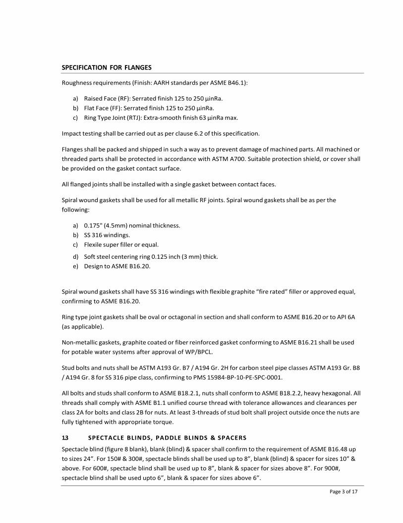
SPECIFICATION FOR FLANGES
Page 3 of 17
Roughness requirements (Finish: AARH standards per ASME B46.1):
a) Raised Face (RF): Serrated finish 125 to 250 μinRa.
b) Flat Face (FF): Serrated finish 125 to 250 μinRa.
c) Ring Type Joint (RTJ): Extra‐smooth finish 63 μinRa max.
Impact testing shall be carried out as per clause 6.2 of this specification.
Flanges shall be packed and shipped in such a way as to prevent damage of machined parts. All machined or
threaded parts shall be protected in accordance with ASTM A700. Suitable protection shield, or cover shall
be provided on the gasket contact surface.
All flanged joints shall be installed with a single gasket between contact faces.
Spiral wound gaskets shall be used for all metallic RF joints. Spiral wound gaskets shall be as per the
following:
a) 0.175" (4.5mm) nominal thickness.
b) SS 316 windings.
c) Flexile super filler or equal.
d) Soft steel centering ring 0.125 inch (3 mm) thick.
e) Design to ASME B16.20.
Spiral wound gaskets shall have SS 316 windings with flexible graphite “fire rated” filler or approved equal,
confirming to ASME B16.20.
Ring type joint gaskets shall be oval or octagonal in section and shall conform to ASME B16.20 or to API 6A
(as applicable).
Non‐metallic gaskets, graphite coated or fiber reinforced gasket conforming to ASME B16.21 shall be used
for potable water systems after approval of WP/BPCL.
Stud bolts and nuts shall be ASTM A193 Gr. B7 / A194 Gr. 2H for carbon steel pipe classes ASTM A193 Gr. B8
/ A194 Gr. 8 for SS 316 pipe class, confirming to PMS 15984‐BP‐10‐PE‐SPC‐0001.
All bolts and studs shall conform to ASME B18.2.1, nuts shall conform to ASME B18.2.2, heavy hexagonal. All
threads shall comply with ASME B1.1 unified course thread with tolerance allowances and clearances per
class 2A for bolts and class 2B for nuts. At least 3‐threads of stud bolt shall project outside once the nuts are
fully tightened with appropriate torque.
1.3 SPECTACLE BLINDS, PADDLE BLINDS & SPACERS
Spectacle blind (figure 8 blank), blank (blind) & spacer shall confirm to the requirement of ASME B16.48 up
to sizes 24”. For 150# & 300#, spectacle blinds shall be used up to 8”, blank (blind) & spacer for sizes 10” &
above. For 600#, spectacle blind shall be used up to 8”, blank & spacer for sizes above 8”. For 900#,
spectacle blind shall be used upto 6”, blank & spacer for sizes above 6”.

SPECIFICATION FOR FLANGES
Page 4 of 17
Thickness of spectacle blind, blank & spacer shall be as per ASME B16.48.
Lifting lugs shall be fitted to all blinds weighing more than 25kg. The materials used for lifting lugs and
handles shall be equal to the blind material and attached by a full penetration weld.
Plate for spectacle blinds shall not be cut using an oxy‐acetylene flame. Thermal cutting shall be done by the
plasma arc method.
Whenever a paddle blind is required it shall be supplied with a corresponding spacer ring.
Impact testing shall be carried out as per clause 6.2 of this specification.
1.4 ORIFICE FLANGES
Orifice flanges shall be ordered in pairs (sets) and shall be in accordance with ASME B16.36.
Each orifice flange shall have one ½″ SW tap, unless otherwise specified.
Each orifice flange set shall be provided with two jackscrews per flange, 180° apart.
Materials for jacking screws and plugs shall be to match the material of the orifice flanges.
Impact testing shall be carried out as per clause 6.2 of this specification.
2 MATERIAL
2.1 GENERAL
All materials shall be new, clean and free from rust, mill scale, pits and other defects or contamination.
All equipment used in the manufacturing process, such as dies, presses, rolls, etc. shall be free from dirt,
scale and surface contaminants, prior to use.
When defining samples for testing purposes, the term ‘Lot’ shall apply to all piping flanges of the same type,
nominal pipe size (NPS) and/or wall thickness, produced from the same heat and subjected to the same
finishing heat treatment.
2.2 IMPACT TESTING
For Piping Class A1X, B1X, D1X and E1X sizes NPS 4” and higher, for all Flanges, Spectacle Blind, Spacer
Blinds, Orifice Flanges and Blind Flanges an Impact test shall be carried out as per clause 423.2.3 of ASME
B31.4. The test temperature shall be lowest expected metal temperature as per respective Piping Class. The
average of the Charpy energy values from each heat shall meet or exceed the following:
a) For all grades with a SMYS (Sy) equal to or greater than 42,000 psi (289 MPa), the required minimum
average (set of three specimens) absorbed energy for each heat based on full‐sized 0.394 in. x 0.394
in. (10mm x 10 mm) specimens shall be 20 lb.‐ft (27 J) for transverse specimens or 30 lb.‐ft (41 J) for
longitudinal samples.
b) For all grades with a SMYS (Sy) less than 42,000 psi (289 MPa), the required minimum average (set of
three specimens) absorbed energy for each heat based on full‐sized 0.394 in. x 0.394 in. (10 mm x 10

SPECIFICATION FOR FLANGES
Page 5 of 17
mm) specimens shall be 13 lb.‐ft (18 J).
2.3 QUALITY ASSURANCE
SUPPLIER shall operate an accredited Quality Management System (QMS) ensuring that the technical
requirements of this Specification and its reference documents are complied with in full.
The QMS shall be based upon the latest issue of ISO 9001 and be accredited by an independent Certifying
Authority.
It is the SUPPLIER’s responsibility to ensure that all SUB‐SUPPLIERS comply with the requirements of this
specification and the Project’s quality requirements.
The SUPPLIER shall provide copies of their and all SUB‐SUPPLIER’s ISO 9001 certification during bid, ensuring
they are valid and up to date copies.
2.4 INSPECTION
Chemical composition and mechanical tests including yield strength, ultimate tensile strength, elongation
and hardness shall be carried out for each heat of steel used as per the applicable standard.
All flanges shall be visually inspected. The internal and external surface of the flanges shall be free from any
strikes, gauges and other detrimental defects.
Dimensional checks shall be carried out on finished products as per ASME B16.5 for flanges, ASME B16.48
for spacers and blinds and ASME B16.36 for orifice flanges & as per this specification.
The requirements for quality control (QC) shall be agreed between the SUPPLIER and the PURCHASER prior
to order placement and will be reflected in the SUPPLIER’s inspection and testing plan (ITP).
All inspection and testing are the responsibility of the Vendor / Contractor. For inspection and testing
activities, an inspection test plan (ITP) shall be prepared for supply item. The ITP shall identify all mandatory
and surveillance inspection requirements for supply item with the stages at which each activity is to be
performed, witnessed and reviewed.
ITP shall be approved by PURCHASER and/ or inspection authority.
The PURCHASER or his nominated representative shall be entitled to access to the SUPPLIER’s work
locations at all times for the inspection of the components being supplied.
All mechanical, chemical, supplementary test such as Charpy V‐notch tightness test, grain sizing and
intergranular corrosion test for austenitic material and metallography test shall be performed by
manufacturer as per requirement.
Raw material heat treatment chart shall be reviewed by TPIA.

SPECIFICATION FOR FLANGES
Page 6 of 17
2.5 CERTIFICATION
Manufacture who intends bidding for flanges must possess the records of a successful test and hardness, in
accordance with the provision of ASME B16.5, as applicable.
Manufacturer shall furnish the following certificates:
Test certificates relevant to the chemical analysis and mechanical properties, including hardness of
the materials used for manufacture of flanges in accordance with the requirement of relevant
standards and this specification.
Test reports on radiography, ultrasonic and magnetic particle examination as applicable.
Certificates for each flange stating that it is capable of withstanding without leakage the test
pressure.
All materials shall be certified in strict accordance with BS EN 10204 3.2 and documentary evidence shall be
provided by the SUPPLIER as part of the PO documentation.
All material certificates shall be originals or certified copies.
All material certificates for forgings and plates shall be from the original steel manufacturers.
2.6 MARKING
The SUPPLIER’s product marking shall include the prescribed information stamped or otherwise suitably
marked on each item in accordance with MSS SP‐25.
In addition to the markings required by the relevant product specifications and the color code markings
required, the following markings shall appear on each item as appropriate;
Manufacturer Name
Material Specification and Grade
Heat Number
Batch Number (as applicable)
Nominal Diameter / Size
Rating / Wall Thickness
PO Number
Type of component / Tag / Part Number
Hydrotest Pressure
The use of markings other than those specified herein may involve rejection of the component.
Marking materials used on Austenitic stainless steel materials shall not contain any harmful metals such as
zinc, aluminum, lead, copper or chloride containing compounds that will cause corrosive attack when
heated.

SPECIFICATION FOR FLANGES
Page 7 of 17
2.7 STAMPING
Pipe flanges with wall thickness less than 5mm and items manufactured from CRA materials shall be marked
by vibro‐etching. All other materials shall be marked by cold stamping using round nosed low stress die‐
stamping or by stenciling, vibro‐etching, dot stamps, or SUPPLIER's rolling stamp method.
Hard stamping shall not be applied to components where the wall thickness is less than 5mm.
All plugs shall be stamped solid.
All stamping shall be such that the depth of markings does not reduce the wall thickness to below the
minimum wall thickness of the component being marked.
2.8 CLEANING
Once all inspection and test have been carried out all external and internal surfaces shall be thoroughly
cleaned to remove grease, dust & rust. Suitable action shall be taken after cleaning to protect Pipe, Fittings
and machined surfaces from rust. Any coating used for rust prevention shall not affect welding.

SPECIFICATION FOR VALVES
Page 1 of 26
SPECIFICATION FOR VALVES
Document No: 10‐PE‐SPC‐0004

SPECIFICATION FOR VALVES
Page 2 of 26
1.1 VALVE IDENTIFICATION
Some requirements in this specification may be modified by specific requirements in the purchase
specification. In case of conflict, the specific requirements supersede this specification.
Any deviation from this specification must be approved, in writing, from CLIENT / BPCL. Such written approval
must be obtained prior to the commencement of any work which would constitute such a deviation.
It is the responsibility of the SUPPLIER to ensure that all valves offered are in accordance with all the
requirements of this specification, component description and valve purchasing description given in the PO
and / or Requisition.
All materials and installation shall be in accordance with code requirements and industry standards for good
workmanship.
4.4.1 Each valve in a facility shall be designated by a descriptive valve identification number consisting of
the following identifiers:
Nominal valve size (inches NPS)
Valve type
Valve body material
Pressure rating
Valve style
End connection
Modifiers
For example, 10"‐BA‐C100‐G, specifies:
10" Nominal valve size (NPS 10).
BA Valve type (Ball valve).
C Valve body material (carbon steel)
1 Pressure rating (ASME class 150).
0 Valve style / pattern (floating, trunnion, etc.).
0 End connection (raised face flanged).
G Modifier (Gear operator, regular port, full port, etc.)
4.4.2 Clause 8 of this specification provides a detailed listing of valve identifiers (valve tag no.), which
shall be used in sequence.
4.4.3 The basic valve designations, without modifiers are standard valves with standard operators. A
modifier symbol or symbols are added to change the specification of the valves to meet the
requirements for special services, temperatures and operators.
Modifiers shall take precedence and swap the normal requirements in regular valve identifier.
4.4.4 Whenever a Hand operated Valve (tag HOV) is specified in Purchase order valve shall be provided
with limit switch as per datasheet attached in Annexure A

SPECIFICATION FOR VALVES
Page 3 of 26
1.2 VALVE TAGGING
Each valve shall be supplied with a stainless steel metal tag attached to the valve with a metal wire, and
stamped with the valve tag number, valve type, size, rating, etc.
1.3 UNITS
In general, the SI system of metric units will be used for the project.
In general, valve diameters shall be stated as Nominal Pipe Size (NPS) in inches.
1.4 LANGUAGE
All documentation shall be in the English Language.
2 DESIGN
2.1 The valve body, bonnet and end plates shall be constructed from a forging or casting as per the
valve purchase description. The minimum thickness of valve bodies and other pressure containing
parts shall be in accordance with ASME B16.34 and ASME VIII Div. 1.
Forgings shall be forged as close as possible to their final shape.
Valve bodies fabricated from plate materials are prohibited.
2.2 Unless otherwise specified gate & globe valves shall have a one piece body with integral end
flanges, bolted bonnet, regular / full port, metal seats, outside screw & yoke (OS&Y), a rising stem
and a non‐rising operator.
Generally, solid wedge gate valves shall be used in sizes NPS ½ to NPS 1½; flexible wedge gate
valves shall be used for sizes ≥ NPS 2.
Globe and Gate valves shall have outside screw and yoke with bolted or welded bonnets.
The disc in a globe valve shall be guided throughout its full range of travel. Guiding may be
provided by stem, body, or other means. For Class 900 and higher, the disc shall be guided by
means other than the stem and shall be guided throughout its full range of travel. Ring Guided Disc
Globe valves are not acceptable.
Bonnets on check valves shall be bolted or welded. Screwed bonnets or union bonnets shall not be
used. Bonnet bolts shall be ASTM A193 Gr. B7 for carbon steel valves.
Unless specified otherwise, straight plug design only is acceptable for globe valve.
On all check and globe valves, the direction of flow shall be cast, stamped or forged on the valve
body.
Dual plate check valves shall be of a retainerless design with spring loaded plates and renewable
seats. Dual plate check valves shall be supplied as lug type OR double flanged type designs as per

SPECIFICATION FOR VALVES
Page 4 of 26
piping material specification.
Swing type check valves shall be top entry, bolted bonnet, flanged ends, renewable seats and long
pattern face to face in accordance with ASME B16.10. The body shall be a one piece design with
the end flanges integral to the valve body. Swing check valves shall have a travel stop to limit disc
swing in the open position. The disc shall be one piece and the disc nut shall be drilled and pinned.
2.3 Trim materials shall conform to relevant pipe classes, valve standards and be suitable for the
proposed service. The minimum requirement for valve trim for carbon steel valve bodies is 13%
chrome. Other trim materials may be used subject to written approval of CLIENT / BPCL. Trim
materials, particularly stainless steels, should be selected to prevent galling. Low melting point
alloys shall not be used.
All gate, globe and check valves ≥ NPS 2 shall be furnished with renewable or replaceable seats
unless specified otherwise. Integral seats are permitted for valves ≤ NPS 1½.
All soft seat and seal materials shall be suitable for the service, minimum/maximum design
temperature and design pressure, as stated in the individual valve purchase description.
All soft seat and seal materials in hydrocarbon services shall be resistant to explosive
decompression.
2.4 Handwheels shall be made of carbon steel, ductile iron, or malleable iron.
2.5 Valves shall be bi‐directional unless valve construction specifically renders this requirement
impractical – e.g. Globe, Ball and Needle valves. For uni‐directional valves, an indicator showing
flow direction shall be engraved or cast/forged into the valve body.
2.6 Where specified, welding end valves shall be supplied with pup pieces having a minimum length of
100mm.
2.7 All valves with non‐metallic seats and seals in hydrocarbon service shall be fire‐safe design. Fire
safe test shall be as per API 607, API 6FA, API 6FD as indicated in datasheet. The vendor shall
submit test certificate for the particular design of the valve offered. Fire safe test witnessed and
certified by an approved third party inspection agencies (LRIS, EIL, CEIL, TUV and DNV) shall be
furnished to the CLIENT / BPCL for approval.
2.8 Ball valves are preferred for block valves.
2.9 Ball valves shall have bolted body with end or top entry. Flanged valves shall be supplied as a
bolted bonnet, 1, 2 or 3 piece split body design and the end flanges shall be integral to the valve
body.
Ball valves shall be provided with anti‐static devices that shall be tested in accordance with API 608
/ API 6D as applicable.
Reduced bore ball valves shall be supplied unless otherwise indicated in the valve purchase

SPECIFICATION FOR VALVES
Page 5 of 26
description.
Ball valve are trunnion mounted for sizes 6” & above ‐ 150# and 300#, 4” & above ‐ 600#, 2” &
above ‐ 900#.
All trunnion mounted ball valves in hydrocarbon service shall be DIB‐2 type as per API 6D.
Upstream seat shall be SPE and downstream shall be DPE.
For ball valves, drain, vent & sealant connection shall have additional valve with blind flange/plug.
Other requirements shall be as per API 6D & MSS SP45.
2.10 For all valves where ENP is specified in the Seat, Ball, Disc, Plug, Wedge the surface shall have 75
micrometers thick Electroless Nickel Plating (ENP) as per ASTM B733 SC4 Type II, Class 2. The
Phosphorus content shall be within 9 and 11% in weight. The hardness of plating shall be in
accordance with ASTM B733 and class mentioned.
2.11 Cast iron, semi‐steel or ductile iron valves shall not be used without CLIENT / BPCL specific
approval.
2.12 Valves which are identified as being lockable in open or closed position shall be fitted with
attachments to permit the valve to be securely locked by a padlock or any suitable device. The
attachments shall be secured to the valve body, hand wheel and lever in such a manner to prevent
un‐authorized removal or release.
2.13 Gear operators shall be provided as follows:
ASME class 150 and 300
Ball valves NPS 6 and larger.
Gate valves NPS 8 and larger.
Globe valves NPS 6 and larger.
Plug valves NPS 6 and larger
Butterfly valves NPS 8 and larger.
ASME class 600
Ball valves NPS 4 and larger.
Gate valves NPS 6 and larger.
Globe valves NPS 4 and larger.
Plug valves NPS 4 and larger.
ASME class 900
Ball valves NPS 3 and larger.
Gate valves NPS 4 and larger.
Globe valves NPS 3 and larger.
Plug valves NPS 3 and larger.
SPECIFICATION FOR VALVES
Page 6 of 26
2.14 Double Block & Bleed Valve: Single valve with two seating surfaces that, in the closed position,
provides a seal against pressure from both ends of the valve with a means of venting/bleeding the
cavity between the seating surfaces.
2.15 Double Block & Bleed and Double Isolation Valve: Single valve with two seating surfaces, each of
which, in the closed position, provides a seal against pressure from a single source, with a means
of venting/bleeding the cavity between the seating surfaces.
Double Block & Bleed and Double Isolation Plug Valve shall have sufficient clearance between
ground/grade level & valve bottom for removal of seals.
The mechanical wedge action of the twin seal plug compresses both the upstream & downstream
seals firmly against the valve body, needing no help from the valve body. Twin seal valve holds
with consistent zero‐leakage. The big advantage of twin seal’s design is that it permits in‐line
servicing by simply removing the valve bonnet or lower plate (after the line is depressurized &
drained).
Valve design shall allow sealing slips to be replaced from the bottom on sizes 3” & above.
2.16 All flanged ends must be integral to the valve body. Screwed‐in or welded‐on flanged end
connections are prohibited.
Flanges ≤ NPS 24 shall conform dimensionally to ASME B16.5.
Flange facings for rating ≤ CL600 shall be raised face (RF) ‐ Serrated finish 125 to 250 μinRa.
Flange facings for rating CL900 shall be ring type joint (RTJ) ‐ Extra‐smooth finish 63 μinRa max.
For flanged valves with ring joint flanges the hardness shall be as follows:
Flange Material Min. Hardness of Groove (BHN)
Carbon Steel 140
SS 304, SS 316 160
Valve dimensions with socket weld ends & screwed ends shall be in accordance with the
SUPPLIER’s standard, with end connections in accordance with ASME B16.11.
Valves with butt weld ends shall conform to ASME B16.25. Valve ends shall match thickness of the
connecting pipe. Sloping of inside contour of valves shall be done in accordance with ASME B31.4
wherever necessary to achieve this.
2.17 All valve assemblies, inclusive of operators; with a weight over 50kg shall be provided with
adequate integral lifting points to facilitate installation and/or maintenance in both the vertical
and horizontal positions.

SPECIFICATION FOR VALVES
Page 7 of 26
Lifting attachments shall be complete with verified documentation and safety instructions. The
safe working load of each lifting joint or attachment shall exceed the weight of the valve and
operator assembly.
The lugs shall preferably be integral to the body but may also be attached by means of a full
penetration weld attached prior to heat treatment.
Strength calculations shall be available from the SUPPLIER and any welding shall be subject to the
necessary heat treatment and NDE as described within this specification.
2.18 Face to face dimensions shall be in accordance with ASME B16.10/API 6D, unless otherwise noted
in the valve purchase description.
All flanged ball valves (150# & 300#) shall be long pattern with the corresponding face to face
dimensions as available in ASME B16.10.
Plug valves shall be supplied as regular pattern unless otherwise specified.
2.19 Unless otherwise specified in the valve purchase description, all valves shall be fully rated to the
ASME pressure class rating as detailed in ASME B16.34.
A pressure / temperature chart for all soft seat / seal materials shall be provided by the SUPPLIER
in their bid.
2.20 During the bid phase, the SUPPLIER shall identify all spare parts required during commissioning,
start‐up and for the first two years operation.
2.21 All materials shall be new, clean and free from rust, mill scale, pits and other defects or
contamination.
All equipment used in the manufacturing process, such as dies, presses, rolls, etc. shall be free
from dirt, scale and surface contaminants prior to use.
2.22 Inspection and testing of valves and acceptance criteria shall be in accordance with the
requirements of the valve design, valve testing standard, valve datasheets, valve purchasing
description and the additional requirements of this specification.
Every valve, its components and auxiliaries must be subjected to all the mandatory tests and
checks called for in the respective codes, data sheets etc. by the manufacturer.
The SUPPLIER shall submit for CLIENT / BPCL approval an Inspection and Testing Procedure
specific for each type of valve to be tested based on the requirements specified herein prior to
commencement of any valve testing.

SPECIFICATION FOR VALVES
Page 8 of 26
All test results shall be recorded.
Any defects found by the INSPECTION AUTHORITY shall be rectified in their presence.
Valves shall not leave the SUPPLIER’s workshop before all discovered defects have been rectified
and the valve has been re‐tested.
Shell Test: All valves shall be subject to a high pressure hydrostatic shell test at 1.5 x Design
Pressure of the ASME B16.34 material group pressure at +38 °C.
Blind flanges shall be supplied by SUPPLIER for hydrotesting.
While carrying out the shell test, the valve shall be inspected for leakage through the stem packing.
If a leak is observed, pressure shall be reduced, and the stem packing shall be tightened.
If this does not stop the leak, this may be cause for rejection. No visible leakage from any external
surface of the shell is permitted throughout the duration of the hydrostatic shell test.
For valves tested according to API 598 maximum allowable leakage rates for closure tests shall be
according to Table 5 of API 598.
For valves tested according to API 6D leakage for soft‐seated valves and lubricated plug valves shall
not exceed ISO 5208, Rate A (no visible detectable leakage for the duration of the test at test
pressure). For metal‐seated valves, other than check valves, the liquid leakage rate shall not
exceed ISO 5208, Rate D. For metal‐seated check valves the liquid leakage rate shall not exceed ISO
5208, Rate G.
Hydrostatic testing shall be completed using potable water containing 1% by volume of
biodegradable wetting agent. Maximum chloride and fluoride content shall be 20ppm and the ph.
value shall be between 6.0 and 8.0. Castings shall not be impregnated with any material to prevent
leakage.
All valves with non‐metallic seats shall have anti‐static features and shall be tested according to
respective design standards.
NDE tests (Radiography, MP & DP) shall be as per clause no. 4.6.10 of Piping Material Specification
Doc. No. 15984‐BP‐10‐PE‐SPC‐0001.
For Piping Class A1X, B1X, D1X, E1X sizes NPS4” and above impact testing shall be carried out as
per API 6D clause 6.6. The impact test shall be carried out as at minimum design temperature
specified in respective valve datasheets.

SPECIFICATION FOR VALVES
Page 9 of 26
Fugitive Emission Testing:
For Valves Size NPS 4” and below:
Valves shall be tested according to ISO 15848 ‐1 “Classification system and qualification
procedures for type testing of valves” where indicated in datasheet and shall be qualified
according to following Performance class:
a) Tightness Class: BH (Test Fluid: Helium)
b) Endurance Class: CO1
c) Temperature Class: tRT to t200 °C
d) SSA (stem or shaft seal adjustment): One
For Valves Size NPS 6” and above, and for Motor Operated Valves (MOV) all Sizes:
Production test according to ISO 15848‐2 shall be carried out for one valve from each lot of
pressure class and nominal size combination. The qualification of the tested valves shall be as per
the following target performance class:
a) Tightness Class: BH (Test Fluid: Helium)
b) Endurance Class: CO1
c) Temperature Class: tRT to t200 °C
d) SSA (stem or shaft seal adjustment): One
If a valve fails in production test, then one additional test on another valve shall be carried out.
Cyclic Test Requirements:
For Valves Size NPS 4” and below:
a) Subsequent to successful testing of all applicable tests to valve one (1) valve from each rating
and size from the total ordered quantity shall be randomly selected for cyclic testing. The valve
shall undergo Cyclic Test for (100 Cycles) with maximum rated pressure corresponding to the valve
rating.
b) Subsequent to the above, the valve shall be subjected to hydrostatic test and
supplementary air seat test.
c) In case this valve does not pass these tests, the valve shall be rejected, and two more
valves shall be selected randomly and subjected to testing as indicated above. If both
valves pass these tests, all valves manufactured for the order (except the valve that failed)
shall be deemed acceptable after refurbishment of the tested valve. If either of the two
valves do not pass these tests, all valves shall be rejected, or each valve shall be tested at
the option of manufacturer.
d) Previously carried out test of similar nature shall be considered acceptable if the same has
been carried out by Manufacturer in last two years. Valves of two sizes below and two

SPECIFICATION FOR VALVES
Page 10 of 26
sizes above the size of valve previously tested and rating similar or one rating lower of
valve tested previously, shall be qualified.
The cyclic tested valve shall be dismantled, thoroughly refurbished by replacing all worn out
internals and shall successfully be subject to routine test including hydrostatic and pneumatic test
before dispatch.
For Valves Size NPS 6” and above, and for Motor Operated valves (MOV) all Sizes:
a) Subsequent to successful testing of all applicable tests to valve one (1) valve from each rating
and size from the total ordered quantity shall be randomly selected for cyclic testing. The valve
shall undergo Cyclic Test for (100 Cycles) with maximum rated pressure corresponding to the valve
rating.
b) Subsequent to the above, the valve shall be subjected to hydrostatic test and supplementary air
seat test.
c) In case this valve does not pass these tests, the valve shall be rejected, and two more valves shall
be selected randomly and subjected to testing as indicated above. If both valves pass these tests,
all valves manufactured for the order (except the valve that failed) shall be deemed acceptable
after refurbishment of the tested valve. If either of the two valves do not pass these tests, all valves
shall be rejected, or each valve shall be tested at the option of manufacturer.
d) Previously carried out test of similar nature shall NOT be considered acceptable.
The cyclic tested valve shall be dismantled, thoroughly refurbished by replacing all worn out
internals and shall successfully be subject to routine test including hydrostatic and pneumatic test
before dispatch.
Following Inspection procedure shall be applicable where 10 % radiography of casting is specified:
a) 10% Radiography is specified to indicate that 10 % of the quantity ordered per size per heat shall
be radiographically tested, fractions shall be rounded off to 1 to decide the number of casting to
be radiographically examined.
b) In case of rejection, double the quantity of the casting to be radiographed as determined by (a)
above shall be offered for radiography. In the event of further rejection of single casting, the whole
lot shall be radiographed.
c) The extent of radiography shall be restricted only to the critical areas as defined in ASME B16.34.
Acceptance of radiography is as defined in ASTM E446.
Strip check is required for 1% of total ordered quantity of Gate & Globe valves (min.1 no.) for each
Valve sheet no., however strip check is not required for CS/Brass/Bronze material valves with 13%
Cr/Brass/Bronze trims. Samples for strip check shall be selected at random and shall generally be in
the highest size in the lot.

SPECIFICATION FOR VALVES
Page 11 of 26
In case of motor operated or actuator operated valves, functional / operational checks as per the
requirements of the specifications shall be made on each valve.
2.23 Painting of valves shall be in accordance with Specification for External Painting and Protective
Coating Doc. No. 15984‐BP‐10‐PE‐SPC‐0005. Marking shall be as per the relevant component
design standard MSS SP‐25.
All materials shall be certified in strict accordance with BS EN 10204 type 3.1 and documentary
evidence shall be provided as part of the PO documentation.
2.24 It is the SUPPLIER’s responsibility to ensure that all SUB‐SUPPLIERs comply with the requirements
of this specification and the Project’s quality requirements.
The SUPPLIER shall provide copies of their and all SUB‐SUPPLIER’s ISO 9001 certification ensuring
they are valid and up to date copies.
The Vendor shall provide full facilities/access for inspection by the CLIENT / BPCL’s representative
during the course of manufacture. The Vendor shall also arrange for the same facilities / access to
be made available at Sub‐SUPPLIERS works, where deemed necessary by the CLIENT / BPCL.
2.25 Valve marking, symbols, abbreviations etc. shall be in accordance with MSS SP 25 or the standard
referred in the specification sheet as applicable. Vendor’s name, valve rating, material designation,
nominal size, direction of flow (if any) etc. shall be integral on the body.
2.26 Valves shall be packed ready for export in a manner which allows easy handling and prevents
damage; SUPPLIER shall submit his standard packing procedure for approval in the bid.
The SUPPLIER shall be responsible for the protection of all items during transit and storage.
3 INSTALLATION
3.1 Wherever possible, valves should be installed near grade level. All valves requiring attention during
operation shall be operable either from grade or platform. Valves 4" and smaller, and instrument
connections, may have ladder or platform access only.
Preferred elevations for valves above grade or platform are:
In low‐level horizontal runs.
In vertical runs, between 0.9 and 1.4 meters (3 and 4‐1/2 feet).
Operating valves with bottom of handwheel over 1.4 meters (4‐1/2 feet) above grade or platform
shall be provided with chain or gear operators from grade or platforms. In pipeways, access or
chain operators shall be provided for operating valves. Little used valves may be located & to be
accessible from the pipeway, using portable ladders.
Chain operation shall not be used for screwed valves or for any valve smaller than 2".

SPECIFICATION FOR VALVES
Page 12 of 26
Valve Installations and Access:
Preferred height of hand wheel from deck or platform:
Horizontally mounted valves (vertical stem) 1000 / 1400mm.
Vertically mounted valves (horizontal stem) 1000 / 1400mm.
Use of chain wheels and extension stems shall be kept to a minimum. Chain shall clear operating
level by 1000mm.
Valves shall be adequately supported to prevent excessive loads being imposed on the piping and
the valve body and flanges.
Valve stems must not obstruct walkways, access ways, ladders, platforms, man ways or the access
area around man ways. Valves for emergency service shall be operable from either platform or
ground level.
3.2 Valves shall not be installed with stems below a horizontal position. Valves shall not be placed
above access ways or in overhead pipe racks.
3.3 Block valves, when required, shall be installed at nozzles of pressure vessels or in lines connected
to nozzles to permit operating valves from grade or a platform.
3.4 All valves shall have sufficient clearance to facilitate removal of the bonnets, plugs and internals.
3.5 Valve instruments and other equipment, which must be observed, adjusted or serviced during
operation, shall be accessible from platform or grade.
4 VALVE SELECTION
Valve type shall be as indicated in the P&IDs and the material of construction of valves shall conform to
relevant pipe class as per Piping Material Specification Doc. No. 15984‐10‐BP‐PE‐SPC‐0001 & respective
Valve Datasheets. Any deviation from the P&IDs shall be discussed with the CLIENT / BPCL and a ruling, in
writing shall be obtained prior to start of any work.

SPECIFICATION FOR VALVES
Page 13 of 26
5 VALVE IDENTIFICATION NUMBER
Nomenclature for Valve Tag Numbers and Datasheets
GA – C 1 0 0 ‐ G
Valve type Modifiers
Valve body material End connection
Pressure rating Valve style / pattern
For example, the short description for the tag number GA‐C100‐G mentioned above will be Gate valve,
carbon steel, 150#, solid wedge, raised face flanged, Gear Operated.
Valve Type:
BA ‐ Ball
BU ‐ Butterfly
CH – Check
GA ‐ Gate
GL ‐ Globe
NE ‐ Needle
PL – Plug
DB – Double Block & Bleed
DI – Double Isolation & Bleed Valve
SP‐ Special Valve
Valve Body Material:
C – Carbon steel
S – Stainless steel (SS 316)
L – Low temperature carbon steel
I – Cast Iron
B – Bronze
T – Stainless Steel (SS 304)
Pressure Rating
1 ‐ ASME Class 150
3 ‐ ASME Class 300
6 ‐ ASME Class 600
8 ‐ ASME Class 800
9 ‐ ASME Class 900
15 ‐ ASME Class 1500

SPECIFICATION FOR VALVES
Page 14 of 26
0 1 2 3 4
Ball Floating Trunnion ‐ ‐ ‐
Check Swing Horizontal Lift Piston Dual Vertical Ball
Gate Solid Wedge Flexible Wedge Slab ‐ ‐
Globe Straight Pattern Angle Pattern Y‐Pattern ‐ ‐
Plug
Pressure
Balanced
Lubricated
Sleeve Lined
‐
‐
‐
Butterfly Lugged Wafer Double Flanged ‐ ‐
Needle Mfg.’s Standard ‐ ‐ ‐ ‐
Other Mfg.’s Standard ‐ ‐ ‐ ‐
End Connections
0 ‐ Raised face flanged
1 ‐ Ring joint flanged
2 ‐ Butt weld
3 ‐ NPT screwed
4 ‐ Socket weld
5 ‐ SW x NPT
6 ‐ Flat faced flanged
7 – Clamped
8 – RF x FNPT
9 – RTJ x FNPT
Modifiers
F ‐ Full port, Piggable; Full Port for Plug Valve
G ‐ Gear Operated
R ‐ Reduced Bore; Regular Port for Plug Valve
C ‐ Internally coated
DB‐ Valve with Integral Double Block & Bleed
E ‐ Extended spindle (length from center line of valve to center line of hand wheel)
IN ‐ Instrument Valve
S ‐ Spring Loaded
1 – Miscellaneous (e.g. Trim, Body material etc.)

SPECIFICATION FOR VALVES
Page 15 of 26
9 CERTIFICATION AND TRACEABILITY
All valves and specialty components shall be certified, and copies of all documentation shall be supplied for
each valve and specialty component. Blanket certification is not acceptable. If more than one component is
on a certificate each component must be identified by the Contractor’s tag number and purchase order
number and Manufacturer's serial number, and certificates for each valve must be listed for that valve.
Certificates shall be provided, and the number of copies called for will be stated in the Contractor’s
documentation specification covering each item supplied. All certificates shall be fully traceable to the item
covered and shall be marked with the Contractor’s order number, item number and tag/part number. They
shall be clearly legible, in the English language only.
Material Certificates for basic material i.e. plate, forgings, or castings used in the manufacture of flanges and
valve bodies, bonnets and pressure retaining parts shall be furnished as test certificates of the EN 10204:3.1
type. Vendor shall confirm which parts are considered pressure retaining and shall include a list in the bid
for Contractor review.
The certificates shall be issued, stamped and signed by the material Manufacturer's inspector, who shall be
independent of the Manufacturer's Production Department. This certificate shall also be stamped and
verified by the valve Manufacturer's QA / QC Department.
Where basic material is further processed by the Vendor to form the valve body or valve components and
such process may change the mechanical properties, etc., the Vendor shall also furnish EN 10204:3.1 type
certificates for the Manufacture of the furnished item.
For valve internals and non‐pressure containing parts works reports of the BS EN 10204 2.2 type shall be
acceptable.


Page 1 of 69
PIPING MATERIAL SPECIFICATION

Page 2 of 69

Page 3 of 69
CONTENTS
1 Introduction .......... . . . . . . . . . . . . . . . . . . . . . . . . . . . . . . . . . . . . . . . . . . . . . . . . . . . . . . . . . . . . . . . . . . . . . . . . . . . . . 5
1.3 Scope ................................................................................................... 5
1.4 Definitions and Abbreviations ............................................................................ 5
1.5 Reference Documents ............................................................................................. 7
1.5.1 Code for Pressure Piping and Pipeline ........................................................... 7
1.5.2 Code and Standards ................................................................................................ 7
1.5.3 American Society of Mechanical Engineers .................................................. 7
1.5.4 American Society for Testing and Materials ................................................. 9
1.5.5 British Standards Institute ................................................................................. 11
1.5.6 American Petroleum Institute ............................................................................ 11
1.5.7 Manufacturer’ s Standardization Society ............................................................... 12
1.5.8 International Organization of standardization ........................................... 12
1.5.9 Project Specif ication ............................................................................................. 13
2 GENERAL REQUIREMENTS .. . . . . . . . . . . . . . . . . . . . . . . . . . . . . . . . . . . . . . . . . . . . . . . . . . . . . . . . . . . . 13
3 TECHNICAL REQUIREMENTS .. . . . . . . . . . . . . . . . . . . . . . . . . . . . . . . . . . . . . . . . . . . . . . . . . . . . . . . . . 13
3.1 General ......... . . . . . . . . . . . . . . . . . . . . . . . . . . . . . . . . . . . . . . . . . . . . . . . . . . . . . . . . . . . . . . . . . . . . . . . . . . . . . . . . . . . 13
4 PIPING .......... . . . . . . . . . . . . . . . . . . . . . . . . . . . . . . . . . . . . . . . . . . . . . . . . . . . . . . . . . . . . . . . . . . . . . . . . . . . . . . . . . . . . . 14
4.1 General ......... . . . . . . . . . . . . . . . . . . . . . . . . . . . . . . . . . . . . . . . . . . . . . . . . . . . . . . . . . . . . . . . . . . . . . . . . . . . . . . . . . . . 14
4.2 Carbon Steel Pipe ................................................................................................... 15
4.3 Austenitic Stainless Steel Pipe ....................................................................... 15
4.4 Pipe Fittings .............................................................................................................. 16
4.5 Flanges and Flanged Joints ............................................................................... 16
4.6 Valves .......... . . . . . . . . . . . . . . . . . . . . . . . . . . . . . . . . . . . . . . . . . . . . . . . . . . . . . . . . . . . . . . . . . . . . . . . . . . . . . . . . . . . . 19
4.6.1 General ......... . . . . . . . . . . . . . . . . . . . . . . . . . . . . . . . . . . . . . . . . . . . . . . . . . . . . . . . . . . . . . . . . . . . . . . . . . . . . . . . . . . . 19
4.6.2 Ball Valves ................................................................................................................. 20

Page 4 of 69
4.6.3 Globe Valv es .............................................................................................................. 21
4.6.4 Check Valves ............................................................................................................ 21
4.6.5 Gate Valves ............................................................................................................... 21
4.6.6 Plug Valves ................................................................................................................ 22
4.6.7 Double Block and Bleed Valves ........................................................................ 22
4.6.8 Double Isolation and Bleed Valves ................................................................. 22
4.6.9 Butterfly Valves ....................................................................................................... 22
4.6.10 Inspection and Testing ......................................................................................... 23
5 CERTIFICATIONS .. . . . . . . . . . . . . . . . . . . . . . . . . . . . . . . . . . . . . . . . . . . . . . . . . . . . . . . . . . . . . . . . . . . . . . . . . . 26
5.1 Type A Certificate ................................................................................................... 27
5.2 Type B Certif icate ................................................................................................... 27
5.3 Type C Certificate ................................................................................................... 27
5.4 Certification Guidelines ....................................................................................... 27
6 PREPAR ATION FOR SHIPMENT .......... . . . . . . . . . . . . . . . . . . . . . . . . . . . . . . . . . . . . . . . . . . . . . . . 28
7 CLASS DESIGNATION CODE ............................................................... 29
8 PIPING CLASS AND SERVICE SUMM ARY .............................................. 30
9 PIPE CLASSES .......... . . . . . . . . . . . . . . . . . . . . . . . . . . . . . . . . . . . . . . . . . . . . . . . . . . . . . . . . . . . . . . . . . . . . . . . . 31
10 DRAIN AND VENT CONNECTIONS FOR PIPING 11 / 2 ” AND BELOW . . . . . 62
11 DRAIN AND VENT CONNECTIONS FOR PIPING 2 ” AND ABOVE .............63
APPENDIX A – BRANCH CONNECTIONS

Page 5 of 69
1 INTRODUCTION
1.1 General
This document presents the Piping Material Specification (PMS) for the ATF facilities in BPPL and CCKPL. The
purpose of this Piping material Specification is to clearly define the materials for piping components to be used
as part of the engineering design and procurement.
1.2 Project Description
The project envisages provision of ATF facilities to pump ATF in Bina Panki and Cochin Coimbatore Karur
Pipeline.
1.3 Scope
This engineering specification specifies the minimum requirements for the design, manufacture and supply of
pipes, fittings, flanges, valves, gaskets, bolts and nuts, etc. for handling non-sour hydrocarbons and utilities. It
describes the specific requirement for the selection of piping materials to be used for the above said Project.
1.4 Definitions and Abbreviations
AARH Average Arithmetic Roughness Height
ASNT The American Society for Non-destructive
Testing
BB Bolted Bonnet
BPCL (COMPANY/OWNER) Bharat Petroleum Corporation Limited
BW Butt Weld
C Carbon
CA Corrosion Allowance
CE Carbon Equivalent
CNAF Compressed Non Asbestos Fibre
Cr Chromium
CS Carbon Steel
Cu Copper
ENP Electroless Nickel Plating
EFW Electric Fusion Welding
FF Flat Face
HAZ Heat Affected Zone

Page 6 of 69
Hv Vickers Hardness
HRC Rockwell Hardness C
HW Handwheel
LO Lever Operated
LR Long Radius
Mo Molybdenum
Mn Manganese
NDE Non-destructive Examination
Ni Nickel
NPS Nominal Pipe Size
OS&Y Outside Screw and Yoke
P&IDs Piping and Instrumentation Diagrams
PEEK Polyether Ether Ketone
PMSS Primary Metal and Secondary Soft Seat
PN Nominal Pressure (in kg/cm2g)
PREN Pitting Resistance Equivalent Number
PTFE Polytetrafluoroethylene (fluoroplastic)
RPTFE Reinforced PTFE
RF Raised Face
RTJ Ring Type Joint
SAW Submerged Arc Welding
Sch Pipe Schedule (wall thickness)
STD Standard Schedule (pipe schedule)
SS Stainless Steel
V Vanadium
WT Wall Thickness
OWNER WorleyParsons
XS Extra Strong (pipe schedule)
XXS Double Extra Strong (pipe schedule)

Page 7 of 69
1.5 Reference Documents
1.5.1 Code for Pressure Piping and Pipeline
Piping shall comply with the latest editions of ASME B31.3, B31.4 and other codes and standards as referred
herein.
1.5.2 Code and Standards
The requirements of the latest editions of the following Codes and Standards shall be complied with unless
specifically noted otherwise within this Specification.
1.5.3 American Society of Mechanical Engineers
ASME B31.3
Process Piping
ASME B31.4
Pipeline Transportation Systems for Liquids and Slurries
ASME SEC II
Materials: Part A- Ferrous Material
Part B- Non Ferrous Material
Part C- Specification for Welding Rods
Part D- Material Properties
ASME SEC V
Non-destructive Examination
ASME SEC VIII ASME Boiler and Pressure Vessel Code, all applicable sections
ASME SEC IX
Welding and brazing qualifications
ASME B1.1
Unified inch screw threads
ASME B1.20.1
Pipe threads, general purpose (inch)
ASME B16.5
Pipe flanges and flanged fittings
ASME B16.9
Factory-made wrought steel butt welding fittings

Page 8 of 69
ASME B16.10
Face-to-face and End-to-end dimensions of valves
ASME B16.11
Forged fittings, socket-welding and threaded
ASME B16.14
Ferrous pipe plugs, bushings, and locknuts with pipe threads
ASME B16.20 Metallic gaskets for pipe flanges – ring joint, spiral wound and jacketed
ASME B16.21
Nonmetallic flat gaskets for pipe flanges
ASME B16.25
Butt welding ends
ASME B16.28
Wrought steel butt welding short radius elbows and returns
ASME B16.34
Valves – flanged, threaded and butt welding end
ASME B16.36
Orifice flanges
ASME B16.48
Steel Line Blanks
ASME B18.2.1
Square and hexagonal bolts and screws
ASME B18.2.2
Square and hexagonal nuts
ASME B36.10
Welded and seamless wrought steel pipe
ASME B36.19
Stainless steel pipe
ASME B46.1
Surface texture

Page 9 of 69
1.5.4 American Society for Testing and Materials
ASTM A53
Pipe, Steel, Black and Hot-Dipped, Zinc-Coated, Welded and Seamless
ASTM A105
Carbon Steel Forgings for Piping Applications
ASTM A106
Seamless Carbon Steel Pipe for High Temperature Service
ASTM A182 Forged or Rolled Alloy Steel Pipe Flanges, Forged Fittings and Valves and Parts for High Temperature Service
ASTM A193 Alloy Steel and Stainless Steel Bolting Materials for High Temperature Service.
ASTM A194 Carbon and Alloy Steel Nuts for Bolts for High Pressure and High Temperature Service
ASTM A216 Steel Castings, Carbon, Suitable for Fusion Welding, for High Temperature Service
ASTM A234
Piping Fittings of Wrought Carbon Steel and Alloy Steel for Moderate and Elevated Temperatures.
ASTM A240 Heat-Resisting Chromium and Chromium-Nickel Stainless Steel Plate, Sheet and Strip for Pressure Vessels
ASTM A262 Detecting Susceptibility to intergranular Attack in Austenitic Stainless Steels
ASTM A269 Seamless and Welded Austenitic Stainless Steel Tubing for General Service
ASTM A312
Seamless and Welded Austenitic Stainless Steel Pipes
ASTM A351
Casting, Austenitic for Pressure-Containing Parts
ASTM A358
Electric Fusion – Welded Austenitic Chromium – Nickel Stainless Steel Pipe for High-Temperature Service
ASTM A370 Test Methods and Definitions for Mechanical Testing of Steel Products
Page 10 of 69
ASTM A403
Wrought Austenitic Stainless Steel Piping Fittings
ASTM A435
Straight-Beam Ultrasonic Examination of Steel Plates
ASTM A450 General Requirements for Carbon, Ferritic Alloy, and Austenitic Alloy Steel Tubes
ASTM A515 Standard Specification for Pressure Vessel Plates, Carbon Steel, for Intermediate and Higher Temperature
ASTM A516 Standard Specification for Pressure Vessel Plates, Carbon Steel, for Moderate- and Lower-Temperature Service
ASTM A519
Seamless Carbon and Alloy Steel Mechanical Tubing
ASTM A672 Electric-Fusion- Welded Steel Pipe for High Pressure Service at Moderate Temperatures
ASTM A694 Carbon and Alloy Steel Forgings for Pipe Flanges, Fittings, Valves and Parts for High Pressure Transmission Service
ASTM A700 Packaging, Marking, and Loading Methods for Steel Products for Domestic Shipment
ASTM A790
Seamless and Welded Ferritic / Austenitic Stainless Steel Pipe
ASTM A815 Wrought Ferritic, Ferritic/Austenitic, and Martensitic Stainless Steel Piping Fittings
ASTM A860
Wrought High-Strength Low Alloy Steel Butt Welding Fittings
ASTM E165
Test Method for Liquid Penetrant Examination
ASTM E709
Standard Guide for Magnetic Particle Testing
ASTM G48
Test Method for Pitting and Crevice Corrosion Resistance of Stainless Steel and Related Alloys by the Use of Ferric Chloride Solution

Page 11 of 69
1.5.5 British Standards Institute
BS EN 10204 Metallic products - Types of inspection documents
ISO 15848-1
Industrial valves — Measurement, test and qualification procedures for fugitive emissions Part 1 Classification system and qualification procedures for type testing of valves
ISO 15848-2
Industrial valves — Measurement, test and qualification procedures for fugitive emissions Part 2 Production acceptance test of valves
1.5.6 American Petroleum Institute
API SPEC 5L
Specification for Line Pipe
API SPEC 6FA
Fire Test for Valves
API SPEC 6FB
Specification for Fire Test for End Connections
API 594
Check valves: wafer and wafer-lug, and double flanged type
API 598
Valve Inspection and Testing
API 599
Metal Plug Valves – Flanged, Threaded and Welding ends
API 600 Steel Gate Valves – Flanged and Butt-welding ends, Bolted and Pressure seal bonnets
API 602 Compact Steel Gate, Globe and Check Valves for Sizes NPS 4 and Smaller for the Petroleum and Natural Gas Industries
API 607
Fire test for Soft-Seated quarter-turn valves

Page 12 of 69
API 608
Metal Ball Valves – Flanged, Threaded and Butt-Welding Ends
API 609
Lug and wafer type butterfly valves
API 623
Steel Globe Valves—Flanged and Buttwelding Ends, Bolted Bonnets
API 6D
Specification for Pipeline and Piping Valves
1.5.7 Manufacturer’ s Standardization Society
MSS SP-6 Standard finishes for contact faces of pipe flanges and connecting end flanges of valves and fittings
MSS SP-25
Standard marking system for valves, fittings, flanges and unions
MSS SP-44 Steel pipeline flanges
MSS SP 45 Bypass and Drain Connections
MSS SP 53 Quality Standard for Steel Castings and Forgings for Valves, Flanges and Fittings and Other Piping Components
MSS SP 55
Quality Standard for Steel Castings for Valves, Flanges, Fittings, and Other Piping Components - Visual Method for Evaluation of Surface Irregularities
MSS SP 75 High Test Wrought Butt Welding Fittings
MSS-SP-95 Swage Nipples and Bull Plugs
MSS SP-97 Integrally reinforced forged branch outlet fittings – socket welding, threaded and butt welding ends
1.5.8 International Organization of standardization
ISO 6506 Metallic Materials - Brinell Hardness Test
ISO 6507 Metallic materials - Vickers hardness test
ISO 6508 Metallic materials - Rockwell hardness test

Page 13 of 69
1.5.9 Project Specification
The following Project Specifications shall be used in conjunction with this specification where
applicable:
* Piping Design Basis
* Specifications for Pipe and Fittings
* Specifications for Flanges
* Specifications for Valves
* Specification for External Painting and Protective Coating
* Specification for Welding
* Specification for Fabrication and Erection and Pressure testing of Piping
2 GENERAL REQUIREMENTS
All piping materials selected under this specification shall be in compliance with the project specification.
Material selections shall comply with the maximum pressure and temperature limitation as specified in the service summary.
Substitution of equivalent materials is subject to approval of the BPCL. All requests for substitution shall be accompanied with sufficient data, drawings and descriptive details to permit evaluation by the BPCL.
Cast iron, ductile or malleable iron, aluminium, plastic or copper-bearing alloys shall not be used in hydrocarbon service.
Piping design pressure is based on flange maximum-allowable working pressure, unless otherwise noted in Job Specification.
When required, impact testing shall comply with applicable standards and material specifications.
All gaskets shall be asbestos free.
Aluminium jumper shall be provided across the flanged joint and length of the bolt shall be taken such that at least two threads remain exposed after the nut for fixing the continuity jumper.
3 TECHNICAL REQUIREMENTS
3.1 General
The piping component wall thickness specified in this document are calculated in accordance with ASME B31.3 for piping classes A1Y, D1Y and for piping classes A1X, B1X, A1U, D1X, E1X for sizes ½” to 3”. For piping class A1X sizes 4” to 30” and for piping classes B1X, A1U, D1X, E1X sizes 4” to 24” piping component wall thicknesses are calculated as per ASME B31.4.
All piping component wall thicknesses specified in this document are based on continuous long-term internal design pressure, design temperature, specified corrosion/erosion allowance, the manufacturing minus/under

Page 14 of 69
tolerance and the threading allowance as applicable. All piping subject to any additional loading such as short term upset conditions, occasional loads, external pressure, thermal loading, live loads, marine motions etc. shall be individually assessed to ensure full compliance with applicable code for that size or Piping class.
Pipe dimensions shall be in accordance with ASME B36.10M for carbon steel and for stainless steel with wall thicknesses in excess of Sch 80S. For stainless steel with wall thicknesses up to and including Sch 80S, dimensions shall be in accordance with ASME B36.19M.
All materials shall be new, clean and free from rust, pits and obvious defects.
Pipe, valves and fittings in sizes 1 1/4", 2 1/2", 3 1/2", 5" and 22” shall not be used. Where equipment is normally provided by a supplier with connections in any of the above sizes, connections will be made with suitable swages or reducers to pipe of approved size.
Materials shall conform to impact test requirements specified in ASME B31.3, for the combination of minimum design metal temperature (MDMT) and reference thicknesses specified if required. For Piping under scope of ASME B31.4 as a minimum the fracture control program shall require Charpy impact energy tested at or below the minimum design temperature as noted in Para. 423.2.3 of ASME B31.4.
Deviations from the Piping Material Specification may occur due to non-availability or design conditions. These deviations are permissible if they are of an equal or higher standard than the individual Piping Standard requirements, and written approval is given by BPCL. Piping components not specified on the individual Piping Spec, shall be treated as specialty piping (SP) items and shall have a specific data sheet for each of the design type, rating and size/dimensions.
All piping materials except for bolts/nuts and gaskets shall be supplied with material certificates conforming to European Standard EN 10204, Type 3.1, or OWNER approved Inspection Certificate. Bolts/nuts and gaskets shall be supplied with material certificates conforming to European Standard EN 10204, Type 2.2 and 2.1 respectively, or OWNER approved Inspection Certificate.
Galvanized piping requiring welding or threading shall be galvanized after fabrication. Electro-less nickel plating may be substituted for galvanizing on certain fittings with OWNER approval. Galvanized piping shall comply with the requirements of ASTM A53.
Screwed full coupling shall be restricted for category ''D'' fluid only (upto DN40 1 ½”).Galvanized pipe shall not be bent or welded. Piping requiring bending, welding or threading shall be galvanized after fabrication.
4 PIPING
4.1 General
All pipe shall be specified with the nominal size and schedule number as per ASME B36.10M unless specified otherwise on the individual Piping Specs. For non-schedule pipe wall thickness when specified is the minimum wall thickness permitted within allowable manufacturing tolerance. The pipe wall thickness may be supplied thicker than specified only after written approval has been given by OWNER. Corrosion allowance is as per the relevant Piping Specs.

Page 15 of 69
Pipes shall be supplied with bevelled end. Bevelling shall be in accordance with ASME B16.25. Where plain end pipes are specified, as for small bore pipes for socket welded piping, the pipes shall be supplied with square cut ends.
Pipe shall preferably be supplied in double random lengths. Each length of pipe shall be subject to a hydrostatic test in accordance with the relevant code. Single random lengths will be accepted where specified in the Job Specification or for small diameter pipes or where double random lengths are unavailable.
Each length of pipe shall be marked legibly by “low stress die-stamping” or by “engraving” or by “stencilling”. Stencil marking shall utilize water insoluble ink; the ink shall not contain any harmful metal or metal salts such as zinc, lead or copper which cause corrosive attack on heating. Stainless steel piping shall be supplied marked permanently over the entire length. The marking details shall be as per material specifications and shall include nominal pipe size (NPS), heat number and the manufacturer’s unique symbol.
Bevelled end pipes shall be supplied with ends protected to avoid transport damages. Pipes shall be shipped with end protectors to protect bevelled ends. Also, pipes shall be supplied, preserved and protected as per the requirements of ASTM A700.
Field weld preps on all pipe shall be left unpainted but shall be protected with a non-petroleum based rust- preventative compound suitable for welding.
4.2 Carbon Steel Pipe
Carbon steel pipe shall have a maximum carbon content of 0.23% by ladle analysis or 0.25% by product analysis. Maximum carbon equivalent (CE) shall be 0.43% by ladle analysis or 0.45% by product analysis according to the formula:
CE C ( Mn
) (Cr Mo V )
(Ni Cu)
6 5 15
Where Cr, Mo, V and Cu are not shown on the material certificates, the carbon equivalent shall be 0.38% by ladle analysis or 0.40% by check analysis, as calculated in accordance with the formula:
CE C ( Mn
) 6
Length will be as specified on the Job Specifications.
4.3 Austenitic Stainless Steel Pipe
Pipe materials shall be in accordance with ASTM A312 TP316 or ASTM A358 TP316, if specified.
All pipes shall be supplied in the de-scaled, pickled, passivated and solution heat treated condition. Repair by welding is not permitted.
Material shall be capable of successfully passing an inter-granular corrosion test. For pipes made by automatic welding process, the entire length of the weld shall be examined 100% by an eddy current test in accordance with

Page 16 of 69
ASTM A450 or by radiography in accordance with the requirements of ASME Section VIII, Div 1 Para UW-51. A weld joint factor of 1.00 shall be guaranteed.
4.4 Pipe Fittings
Carbon steel fittings shall meet the requirements of ASTM A234, A860, A694 and A105N, as applicable. Carbon steel forgings shall be supplied with a maximum carbon content of 0.25% and CE of 0.45% by product analysis. Fittings manufactured from pipe shall comply with requirements specified for pipe.
Where austenitic stainless steel fittings are specified, they shall conform to ASTM A182 or A403 and the same material requirements specified for austenitic stainless steel pipe.
Dimensions of metallic butt weld fittings shall be in accordance with ASME B16.9, with socket weld and threaded fittings to ASME B16.11. All 90° butt weld elbows shall be long radius (1.5D) unless space limitations dictate otherwise and OWNER/BPCL approval is given.
For fittings made of carbon steel, the beveled surface of the welding end shall be subjected to wet magnetic particle examination in accordance with practice E709. Personnel performing the examination shall be qualified in accordance with ASNT-TC-1A.
For fittings made of wrought austenitic stainless steel, preferably, all the surfaces shall be liquid penetrate tested in accordance with Practice E165. Personnel performing the examination shall be qualified in accordance with ASNT-TC-1A.
Repair by welding of wrought fittings shall not be allowed, without OWNER/BPCL approval.
Welding components used for joining unequal wall thickness and/or yield strength materials shall be bevelled in accordance with ASME B16.25 Fig. 2A or 3A, the properties of the welding material shall correspond to the higher strength material.
Threaded and socket-weld fittings: Threaded and socket-welded fittings shall comply with ASME B16.11. Bushings, street elbows and close nipples may be used only with permission of the OWNER/BPCL. Threads shall be per ASME B1.20.1 tapered. Thread sealant shall be Teflon tape. Threaded half couplings are prohibited.
Fittings shall be marked and shipped in crates, grouped according to pressure/class rating where possible.
Pipe fittings, other than non-metallic shall be supplied with wall thickness and nominal sizes that meet the requirements of ASME B36.10M, ASME B36.19M, ASME B16.9, ASME B16.11 and where allowed, ASME B16.28.
Field weld preps on all pipe fittings shall be left unpainted but shall be protected with a non-petroleum based rust-preventative compound suitable for welding.
4.5 Flanges and Flanged Joints
FLANGE
Weld-neck flanges and socket-weld flanges shall be provided with bore to match the attached pipe.

Page 17 of 69
All flanges in butt weld (BW) piping shall be weld-neck (WN) unless specific requirements dictate otherwise.
Flange dimensions shall be in accordance with ASME B16.5 for sizes upto NPS 24” and ASME B16.47 Series A for NPS 26” and higher.
Repair by welding is not permitted.
Flange faces shall be left unpainted but shall be coated with a non-petroleum based rust-preventative compound that is not detrimental to gasket material.
Flanges shall be packed and shipped in such a way as to prevent damage of machined parts. All machined or threaded parts shall be protected in accordance with ASTM A700. Suitable protection shield, or cover shall be provided on the gasket contact surface. Galvanized flanges shall be packed in accordance with ASTM A53.
Carbon steel forgings shall be supplied with a maximum carbon content of 0.25% and CE of 0.45% by product analysis.
The finish of contact faces of pipe flanges, connecting end flanges of valves and fittings shall be governed by ASME B16.5 and following:
Roughness requirements (Finish: AARH standards per ASME B46.1):
a. Raised Face (RF): Serrated finish 125 to 250 µinRa.
b. Flat Face (FF): Serrated finish 125 to 250 µinRa.
c. Ring Type Joint (RTJ): Smooth finish 63 µinRa max.
No radial scratch or imperfections allowed on the flange facings.
All flanges shall be marked in accordance with MSS-SP-25.
For Ring joint flanges the hardness shall be as follows:
Flange Material Min. Hardness of Groove (BHN) Carbon Steel 140 SS 316 160
Orifice flanges shall be as per ASME B16.36. Jack screws, 180° apart, shall be provided, one on each flange, for all orifice assemblies.
BOLTING
Carbon steel flange bolting shall be stud bolting with material conforming to the Piping Specification and threaded full length. Reduced shank stud bolts shall not be used. Nuts shall be as specified on the Piping Specifications.
Stud bolts of 1" diameter and less shall be UNC with those 1-1/8” diameters and larger being of the UN8 series per ASME B1.1. Stud bolts 1-5/8" diameter and larger are to be increased in length by a minimum of one nut thickness to allow the use of hydraulic bolt tensioning equipment. Nuts shall be Hexagon Heavy Series to ASME B18.2.2. Thread sealant shall be teflon paste. All bolts and nuts shall be hot dip galvanised as per ASTM A153.

Page 18 of 69
Flat face flanges, unless specified on the Piping Specifications, shall not be used without specific OWNER/BPCL approval. Full-face gaskets shall be used with flat-face flanges.
GASKET
All flanged joints shall be installed with a single gasket between contact faces.
Spiral wound gaskets shall be used for all metallic RF joints. Spiral wound gaskets shall be as per the following:
a. 0.175" (4.5mm) nominal thickness.
b. SS 316 windings.
c. Flexile super filler or equal.
d. Soft steel Centering ring 0.125" thick, CS for CS piping and SS for SS Piping.
e. Design to ASME B16.20.
Flange gaskets shall be SS 316 windings with flexible graphite “fire rated” filler or approved equal, confirming to ASME B16.20.
Ring type joint gaskets shall be oval or octagonal in section and shall conform to ASME B16.20.
Gaskets shall be resistant to the effects of aviation hydrocarbon fuels and manufactured of fire-resistant materials for ATF service.
Graphite coated, fibre reinforced gasket conforming to ASME B16.21 shall be used for potable water systems after approval of OWNER/BPCL.
Insulating gasket as shown below will generally be used when bolting dissimilar metal flanges. Insulating set is comprised of one phenolic resin central gasket with neoprene coating on faces, one phenolic sleeve per bolt, two phenolic washers per bolt and two steel washers per bolt, packed in an individual box. When bolting copper nickel, stainless steel or duplex stainless steel flanges together, similar sleeves and washers, less phenolic resin gasket, shall be utilized in conjunction with specified stud bolts and gaskets.
Note: - Cut insulating sleeve length 1/4” shorter than dimension A.
Page 19 of 69
4.6 Valves
4.6.1 General
Valve selection shall be in accordance with the relevant Piping Standard and as per P&IDs.
Valves shall be supplied in accordance with OWNER/BPCL’s Approved Manufacturers List. Valve manufacturer’s numbers illustrate an approved type. An equivalent substitute may be made with OWNER/BPCL’s approval.
Valves size 2" and above which are described as Outside Screw and Yoke (OS&Y) with rising stem and non-rising handwheel shall be provided with stem protectors and visual position indicators.
Valves provided with integral by-passes shall confirm to the same Piping Specification as the principal valve. The bypass valve shall be a globe or ball valve. The manufacturer of the principal valve shall furnish and install the bypass complete with valve.
Handwheels shall be made of carbon steel, ductile iron, or malleable iron.
Chain wheel operator when required by Job Specification shall be adequate for the pressure and temperature with chain guides. Chain operated valves, size 10-in and larger, shall be provided with an impact hammer. Hammer-blow operators shall not be provided for cast-iron valves or valves with cast-iron wheels.
Valves shall be bi-directional unless valve construction specifically renders this requirement impractical – e.g. Globe, Ball and Needle valves. For uni-directional valves, an indicator showing flow direction shall be engraved or cast/forged into the valve body.
Vent and drain valves shall comply with the Job Specification and shall be adequate for the pressure and temperature limitation indicated in the relevant Material Specification.
Valve position indicators shall be designed so as to prevent incorrect orientation on valve assembly.
Quarter turn valve handles shall be lever lock type as specified in the purchase requisition or data sheet.
Gearbox operators shall be sized to provide an output torque of at least 150% of the maximum required valve operating torque. Gearbox ratios shall be 60:1 maximum for valves 8" and smaller and 120:1 maximum for valves 10" and larger. Maximum operating force required to operate the valve shall be within 25 kgf. Where indicated in the Job Specification, gear operators are to be supplied and shall be the manufacturer’s standard heavy duty models selected to provide the valve torque requirements. Gear boxes shall be fitted with position indicators, have self-locking mechanisms, and be fully sealed and protected to suit a very corrosive marine environment.
Graphite material shall be chloride free, i.e., leachable chloride shall be less than 50 PPM.
Valve bolting shall comply with the following:
a. Carbon and Alloy Steel Valves:
ASTM A193-B7 and ASTM A194-2H
b. Stainless Steel Valves:

Page 20 of 69
SS316: ASTM A193 B8 and ASTM A194 8
Bolting specified above is for external bolting only. Internal bolting requirements are subject to intended fluid service requirements.
Welding end valves shall be supplied with pup pieces having a minimum length of 100mm.
Studded end valves are not allowed. Where space limitation requires installation of such valves, permission shall be obtained from the OWNER/BPCL.
Valves flange pressure class rating shall be in accordance with ASME B16.5.
Valves shall be tested as per API 6D / API 598 or as specified in the Job Specification or Datasheets. The hydrostatic shell test pressure shall be 1.5 times the rated ASME Class design pressure. Hydrostatic seat test pressure shall be in accordance with the specified testing standard. Hydrostatic seat test for bi-directional valves shall be carried out in both directions. Allowable leakage rates shall be as per Standard/Job Specification.
Valves which are identified as being lockable in open or closed position shall be fitted with attachments to permit the valve to be securely locked by a padlock or any suitable device. The attachments shall be secured to the valve body and handwheel on lever in such a manner so as to prevent un-authorized removal or release.
Hydrostatic testing shall be completed using potable water containing 1% by volume of biodegradable wetting agent. Maximum chloride and fluoride content shall be 20ppm and the pH value shall be between 6.0 and 8.0. Castings shall not be impregnated with any material to prevent leakage.
Material Certificates for basic material i.e. plate, forgings, or castings used in the manufacture of flanges and valve bodies, bonnets and pressure retaining parts shall be furnished as test certificates of the EN 10204 Type 3.1.
Where basic material is further processed by the Vendor to form the valve body or valve components and such process may change the mechanical properties, etc., the Vendor shall also furnish EN 10204 Type 3.1. certificates for the Manufacture of the furnished item.
For valve internals and non-pressure containing parts works reports of the EN 10204 Type 2.2 shall be acceptable.
All valves shall be shipped in the closed position except ball valves, which shall be shipped in the open position.
Valve ends, and stuffing box shall be covered with close fitting protectors (e.g. plastic caps) to protect the machined parts and prevent ingress of dirt and moisture.
All valves shall be marked in accordance with MSS SP-25.
Vendor to provide valid API monogram for API code design valves.
4.6.2 Ball Valves
All ball valves in hydrocarbon service shall be certified “fire-safe design” in accordance with API 607/API 6FA / API 6FD as indicated in datasheet. The vendor shall submit test certificate for the particular design of the valve offered. Fire safe test witnessed and certified by an approved third party inspection agencies (LRIS, EIL, CEIL, TUV and DNV) shall be furnished to the COMPANY / EPCM for approval.

Page 21 of 69
Vents or drains requirement for floating ball valves shall be as per API 6D.
For trunnion mounted ball valves, vent and drain connection shall have an additional valve with plug/blind flange and it shall be as per MSS SP-45.
All trunnion mounted ball valves shall be double block and bleed type.
Ball valves shall be reduced bore unless specifically stated in P&IDs. Valve bodies of either 1 or 2 piece construction shall be used.
All ball valves over 2" shall incorporate anti-static feature ensuring electrical continuity between ball, stem and body. For ball valves 2" and smaller electrical continuity is required between valve stem and body. Use of conductive stem seal is not permitted as the sole means of achieving the anti-static function.Ball valves shall be fitted with blow-out proof stems and have the body split outside the plane of the stem protrusion. Stem seal covers shall be bolted. Valve stems shall be designed so that the stem “weak point” is outside of the valve body.
Sealant injection system shall be provided for trunnion mounted ball valves as per API 6D and shall have additional valve with plug/blind flange.
All Ball valves are required to provide automatic body cavity pressure relief to prevent over pressurisation when valve is closed. Venting shall be in upstream direction unless and until downstream venting is specified in datasheet or specification.
4.6.3 Globe Valves
Pressure/temperature ratings and valve design shall meet minimum ASME B16.34 requirements.
The minimum requirement for valve trim for carbon steel valve bodies is 13% chrome.
Unless specified otherwise, straight plug designs only are acceptable.
4.6.4 Check Valves
Flow direction of the valve shall be clearly marked on the valve body.
For swing check valves, the disk shall be secured in the closed or open position to prevent damage during transport and handling.
Swing check valves shall be provided with limit stops to prevent discs from remaining in open position
4.6.5 Gate Valves
Gate Valves shall be solid wedge types with solid disc or flexible wedge disc. Split wedge gates are not permitted.
For Gate valve sizes 1.1/2" and smaller, where operating torque is not a concern, solid wedge discs shall be used.
For gate valve sizes 2" and larger, higher operating torques and possibilities of sticking of gate due to differential
temperatures shall be considered. Accordingly, flexible wedge ‘H’ type discs shall be used.

Page 22 of 69
Where corrosion or erosion of seat material is possible due to entrapped fluid between the ‘H’ type disc and the seat, simple flexible wedge discs shall be used.
Wedge shall be made from one solid piece of material (mono block construction).
4.6.6 Plug Valves
Plug valves shall be regular type unless specifically stated in P&ID.
Soft-seated plug valves (suitably selected based on temperatures handled) shall be supplied with antistatic devices.
Non-lubricated TFE sleeved plug valves shall be fire-safe design when used in inflammable services, shall be tested as per API 607.
Each valve shall be supplied with a lever / wrench except for gear operated.
4.6.7 Double Block and Bleed Valves
Reduced bore ball valves with needle valve as a bleeder shall be used in DBB valve unless specifically stated in P&ID as per API 6D.
4.6.8 Double Isolation and Bleed Valves
Single valve with two seating surfaces, each of which, in the closed position, provides a seal against pressure from a single source, with a means of venting/bleeding the cavity between the seating surfaces.
Double isolation and bleed plug valve with in position seal replacement shall have sufficient clearance between ground/grade level and valve bottom for removal of seals.
The mechanical wedge action of the twin seal plug compresses both the upstream and downstream seals firmly against the valve body, needing no help from the valve body. Twin seal valve holds with consistent zero-leakage. The big advantage of twin seal’s design is that it permits in-line servicing by simply removing the valve bonnet or lower plate (after the line is depressurized and drained).
Valves shall have weatherproof operators with mechanical position indicators.
Valve design shall allow sealing slips to be replaced from the bottom on sizes 3” and above.
Valve shall be supplied with manually operated bleed valves that can be opened to verify the plug valve is not leaking in the closed position.
4.6.9 Butterfly Valves
Butterfly valve shall be wafer type for utility services only.
Each valve shall be supplied with a lever/wrench except for gear operated valves.

Page 23 of 69
Butterfly valves shall be suitable for throttling application.
Use of soft seated butterfly valves shall be suitably selected based on temperatures handled and shall be supplied with antistatic devices.
Butterfly valves specified as fire-safe design shall be tested in accordance with API 607 and successfully meet all performance requirements.
4.6.10 Inspection and Testing
All inspection and testing is the responsibility of the Vendor / Contractor. For inspection and testing activities, an inspection test plan (ITP) shall be prepared for each supply item. NDE procedures, techniques, and defect evaluation shall conform to the requirements of the applicable code or ASME B31.3 or ASME B31.4.
Prior to award of work, NDE procedures shall be submitted to the COMPANY engineer for review and approval. These NDE procedures shall be approved by a practitioner qualified to ASNT SNT-TC-1A or ISO 9712 Level III.
Qualification of NDE system (NDE company and NDE personnel) shall be in accordance with ASNT SNT-TC-1A or equivalent.
Pressure testing:
Each valve shall be pressure tested in accordance with the requirements of API 6D and API 598.
Page 24 of 69
Non-destructive testing:
Inspection of valve components shall be in accordance with the following:
a) 150# and 300#
INSPECTION APPLICABLE
AREAS
PERCENTAGE OF TESTING
Carbon
Steel
Stainless
Steel
Non-Ferrous
Visual All Materials and
Welds
100 100 100
Radiography Castings –
Critical Areas
100 100 100
Welds 20 20 20
Weld Repairs 100 100 100
Magnetic Particle / Dye
Penetrant (MP/DP)
Forgings 100 100 100
Castings 100 100 100
Welds 100 100 100
Weld Overlays 100 100 100

Page 25 of 69
b) 600# and 900#
INSPECTION APPLICABLE
AREAS
PERCENTAGE OF TESTING
Carbon Steel Stainless Steel Non-Ferrous
Visual All Materials and
Welds
100 100 100
Radiography Castings – Critical
Areas
100 100 100
Welds and Weld
Repairs
100 100 100
Magnetic
Particle / Dye
Penetrant
(MP/DP)
Forgings 100 100 100
Castings 100 100 100
Welds and Weld
Overlays
100 100 100
Non-destructive examination of individual valve material and component consisting of but not limited to castings, forgings, and assembly welds shall be carried out by the Manufacturer.
1) Visual examination shall be performed in accordance with the ASME BPV Code, Section V, Article 9.Visual examination shall be carried out on all prepared joints prior to welding, during welding (welder self- checks) and upon completed welds. Verification checks should include the internal surface of the weld wherever possible. The visual acceptance of each weld shall be recorded by the Contractor.
2) Body castings of all valves shall be radiographically examined in accordance with ASME B16.34/ API 6D /ASME section V Article 3.Procedure and acceptance criteria shall be in accordance with ASME B16.34 Appendix I/API 6D Annexure A.
3) All castings shall be wet magnetic particle inspected 100% of the internal surfaces. Method and acceptance criteria shall comply with ASME B 16.34.
4) All valves, with body made by forgings, shall be ultrasonically examined in accordance with the procedure and acceptance in accordance with Annexure A, Clause 8 of API 6D.
5) Bodies and bonnets made by welded assembly of segments of castings, forgings, or combinations thereof shall be examined, as applicable, by methods specified in point (2) for cast components or point (4) for forged components.
6) Full inspection by radiography shall be carried out on all welds of pressure containing parts. Acceptance criteria shall be in accordance with ASME section VIII Div.1, ASME B 31.3 or ASME B31.4 as applicable and API RP 1104.
7) The liquid penetrant examination shall be applied using the detailed requirements, methods, procedures and qualifications specified in ASME V Article 6. Acceptance criteria shall be as specified for magnetic particle inspection.
Page 26 of 69
8) The requirement for examination of 20% of the welds means that 20% of the production welds shall be randomly and independently selected throughout the fabrication period and fully examined. The random selection shall be equally distributed over all welders and all type of welds, which includes welding procedure, pipe size, thickness, welding position.
9) Welds, which in Purchaser’s opinion cannot be inspected by radiographic methods, shall be checked by ultrasonic or magnetic particle methods and acceptance criteria shall be in accordance with ASME Sec. VIII, Division 1, Appendix 12 and Appendix 6 respectively.
NDE of pipe and fittings shall be in accordance with the nominated specification and any supplementary requirements as specified.
Weld repairs to valves:
Weld repair to valves are not allowed.
Fugitive Emission Testing:
Valves shall be tested according to ISO 15848 -1 “Classification system and qualification procedures for type testing of valves” where indicated in datasheet and shall be qualified according to following Performance class:
a) Tightness Class : BH (Test Fluid : Helium) b) Endurance Class : C01 c) Temperature Class: tRT d) SSA (stem or shaft seal adjustment) : One
Others:
Tests and certification as required by OISD-STD-130
Positive Material Identification (PMI):
Positive Material Identification (PMI) of all sizes, pressure rating and materials (Alloy Steel including Stainless Steel valves) shall be performed for the pressure containing parts of the valves (i.e. valve body and bonnet) and report submitted to Company. PMI is not required for carbon steel body valves.
Contractor shall submit PMI procedure for CLIENT/EPCM approval when PMI examination is required.
5 CERTIFICATIONS
Contractor / Manufacturer shall provide certification to verify that the materials of construction meet the requirements of the material specifications.
Certificates to BS EN 10204 incorporating requirements for documentation and marking are designated as Type A, Type B and Type C. Conformance with EN 10204 is required and clarified as follows:

Page 27 of 69
5.1 Type A Certificate
Reports/Certificates to BS EN 10204 2.1, BS EN 10204 2.2 or equivalent.
Material welded to pressure containing components shall be certified to the same degree as the pressure containing component.
Fasteners All nuts and bolts for FF flanges ,valve extended stem assembly
Gasket All compressed non asbestos gasket for stem housing,
5.2 Type B Certificate
Work Certificate to BS EN 10204 3.1 or equivalent.
Pipes/Fittings/Flanges/Valves All piping and associated fittings, flanges and valves other than for Type C Certificate.
Fasteners (for pressure component) All stud ,nuts and bolts used for pressure boundary components.
Gasket (Metallic gasket) All Ring-joint, Spiral-wound and jacketed type gasket for pressure boundary
5.3 Type C Certificate
Certificate to BS EN 10204 3.2 or equivalent.
All piping within the main transportation system (i.e. pipeline and fittings).
5.4 Certification Guidelines
The Vendor shall ensure that appropriate certification, showing mill heat or batch markings, is received for all furnished materials. Materials furnished without documentation are unacceptable. All certificates shall contain the following information:
a) Name of manufacturer.
b) Purchase order number and date.
c) Manufacturer’s order number.
d) Identification number of certificate and its date of issue.
e) Material specification.
f) Dimensions.
g) Material charge number, batch number or heat-lot number.
h) Mechanical properties recorded from test results.

Page 28 of 69
i) Chemical composition recorded from chemical analyses.
j) NDT methods and results, where applicable.
k) Heat treatment procedures and records, where applicable.
6 PREPARATION FOR SHIPMENT
After inspection and test, valves shall be free of water, dried and prepared for shipment. Adequate protection shall be provided against mechanical damage and atmospheric corrosion in transit, and for at least six months outdoor storage at jobsite prior to installation.
Exposed finished and machined surfaces, including bolting, shall be given a heavy coating of rust inhibition compound.
All openings shall be covered or plugged with substantial wood, metal, or plastic closures, securely fastened and suitable for prolonged exposure prior to final installation.
The gasket contact surfaces shall be protected to ensure the serration is not damaged during shipping and storage period.

Page 29 of 69
7 CLASS DESIGNATION CODE
The class designation shall consist of not more than three components made up of a letter, number and letter; e.g. A1X.
The first letter indicates pressure rating
A 150 CLASS D 600 CLASS G 2500 CLASS
B 300 CLASS E 900 CLASS J 125/150 CLASS
C 400 CLASS F 1500 CLASS
The Middle number indicates difference in specification within the same rating and material as enlisted below.
MIDDLE NUMBER CARBON STEEL SS 304 SS 316
0 CA = 0.5 CA = NIL CA = NIL
1 CA = 1.5 CA = NIL CA = NIL
The third letter indicates type of material.
X CARBON STEEL (A106 GR. B / A672 GR. B60 / API 5L GR. X70 )
Y SS 316
U CARBON STEEL (A53 GR. B)
Z CARBON STEEL (API 5L GR. X70) – PIPELINE SPECIFICATION
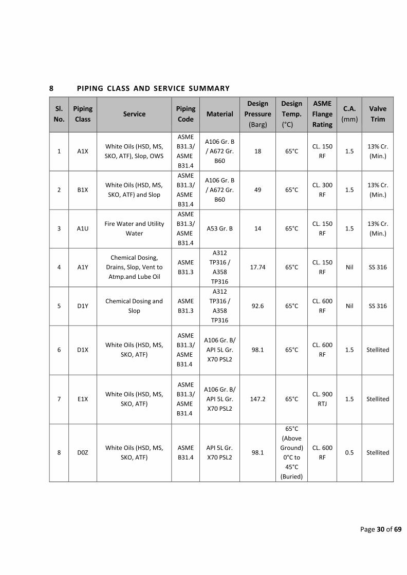
Page 30 of 69
8 PIPING CLASS AND SERVICE SUMMARY
Sl.
No.
Piping
Class
Service
Piping
Code
Material
Design
Pressure
(Barg)
Design
Temp.
(°C)
ASME
Flange
Rating
C.A.
(mm)
Valve
Trim
1
A1X
White Oils (HSD, MS,
SKO, ATF), Slop, OWS
ASME
B31.3/
ASME
B31.4
A106 Gr. B
/ A672 Gr.
B60
18
65°C
CL. 150
RF
1.5
13% Cr.
(Min.)
2
B1X
White Oils (HSD, MS,
SKO, ATF) and Slop
ASME
B31.3/
ASME
B31.4
A106 Gr. B
/ A672 Gr.
B60
49
65°C
CL. 300
RF
1.5
13% Cr.
(Min.)
3
A1U
Fire Water and Utility
Water
ASME
B31.3/
ASME
B31.4
A53 Gr. B
14
65°C
CL. 150
RF
1.5
13% Cr.
(Min.)
4
A1Y
Chemical Dosing,
Drains, Slop, Vent to
Atmp.and Lube Oil
ASME
B31.3
A312
TP316 /
A358
TP316
17.74
65°C
CL. 150
RF
Nil
SS 316
5
D1Y
Chemical Dosing and
Slop
ASME
B31.3
A312
TP316 /
A358
TP316
92.6
65°C
CL. 600
RF
Nil
SS 316
6
D1X
White Oils (HSD, MS,
SKO, ATF)
ASME
B31.3/
ASME
B31.4
A106 Gr. B/
API 5L Gr.
X70 PSL2
98.1
65°C
CL. 600
RF
1.5
Stellited
7
E1X
White Oils (HSD, MS,
SKO, ATF)
ASME
B31.3/
ASME
B31.4
A106 Gr. B/
API 5L Gr.
X70 PSL2
147.2
65°C
CL. 900
RTJ
1.5
Stellited
8
D0Z
White Oils (HSD, MS,
SKO, ATF)
ASME
B31.4
API 5L Gr.
X70 PSL2
98.1
65°C
(Above
Ground)
0°C to
45°C
(Buried)
CL. 600
RF
0.5
Stellited

Page 31 of 69
9 PIPE CLASSES
CLASS A1X PIPING MATERIAL SPECIFICATION
SERVICE White Oils (HSD, MS, SKO, ATF), Slop and OWS CORROSION ALLOWANCE
1.5 mm
RATING ASME 150# PIPING MATERIAL C.S. – GROUP 1.1
SERVICE LIMITS
Pressure (Barg) 19.6 19.2 18.7
5
RADIOGRAPHY 100 %
Temperature
(0C)
0-38
50
65
STRESS RELIEF AS PER ASME B31.3/
ASME B31.4 REQUIREMENTS
ITEMS NPS SIZES
RATING/ SCH
ENDS
MATERIAL COMMODITY
CODE FROM TO
BALL VALVE
1/2”
1½”
800
SW
BODY/BONNET – A105N, TRIM (BALL AND STEM) – 13Cr, SOFT SEAT - PTFE, DIMENSION / DESIGN – MFR. STD. /API 608, FLOATING BALL, REDUCED / FULL BORE, LEVER OPERATED
BA-C804-R / BA-C804- F
2”
4”
150
RF
BODY/BONNET – ASTM A105N, TRIM – 13Cr, SOFT SEAT - PTFE, DIMENSIONS / DESIGN – API 6D / API 6D, FLOATING BALL, REDUCED / FULL BORE, LEVER OPERATED
BA-C100-R / BA-C100-F
6”
24”
150
RF
BODY/BONNET – ASTM A105N, BALL – A105N WITH 75 MICRONS ENP (PMSS), SOFT SEAT - PTFE, DIMENSIONS / DESIGN AS PER API 6D / API 6D, TRUNNION BALL, REDUCED / FULL BORE, GEAR OPERATED
BA-C110-RG / BA-C110- FG
GATE VALVE
1/2”
1½”
800
SW
BODY/BONNET – ASTM A105N, TRIM – 13% Cr, DIMENSIONS / DESIGN AS PER MFR. STD. / API 602, HW OPERATED
GA-C804
GLOBE VALVE
1/2”
1½”
800
SW BODY/BONNET – ASTM A105N, TRIM – 13% Cr, DIMENSIONS / DESIGN AS PER MFR. STD. / API 602, HW OPERATED
GL-C804
2”
4”
150
RF BODY/BONNET – ASTM A216 WCB, TRIM – 13% Cr, DIMENSIONS / DESIGN AS PER ASME B16.10 / API 623, HW OPERATED
GL-C100

Page 32 of 69
6”
12”
150
RF BODY/BONNET – ASTM A216 WCB, TRIM – 13% Cr, DIMENSIONS / DESIGN AS PER ASME B16.10 / API 623, GEAR OPERATED
GL-C100-G
PLUG VALVE (PRESSURE BALANCED LUBRICATED)
1/2”
1½”
150
RF
BODY – ASTM A105N, PLUG - ASTM A216 GR. WCB CASE HARDENED AND 75 MICRONS ENP, METAL SEAT, VITON SEAL, DESIGN API 599, REGULAR PORT, LEVER OPERATED, PRESSURE BALANCED LUBRICATED PLUG
PL-C100-R
2”
4”
150
RF
BODY – ASTM A105N / A216 GR. WCB, PLUG - ASTM A216 GR. WCB CASE HARDENED AND 75 MICRONS ENP, METAL SEAT, VITON SEAL, DESIGN API 599, REGULAR PORT, LEVER OPERATED, PRESSURE BALANCED LUBRICATED PLUG
PL-C100-1-R
6”
24”
150
RF
BODY – ASTM A105N / A216 GR. WCB, PLUG - ASTM A216 GR. WCB CASE HARDENED AND 75 MICRONS ENP, METAL SEAT, VITON SEAL, DESIGN API 599, REGULAR PORT, GEAR OPERATED, PRESSURE BALANCED LUBRICATED PLUG
PL-C100-RG
CHECK VALVE
1/2”
1½”
800
SW LIFT TYPE, BODY – A105N, TRIM 13% Cr, DIMENSIONS / DESIGN AS PER MFR. STD. / API 602
CH-C814
2”
4”
150
RF SWING TYPE, BODY A216 WCB, TRIM 13% Cr, DIMENSIONS / DESIGN AS PER ASME B16.10 / API 594 TYPE B
CH-C100
6” 30” 150 RF DUAL PLATE FLANGED TYPE, BODY A216 WCB, TRIM 13% Cr TO API 594 TYPE A
CH-C130
DOUBLE ISOLATION AND
BLEED VALVE
4”
24”
150
RF
TWIN SEAL PLUG TYPE, BODY/BONNET - A216 GR. WCB, PLUG - ASTM A216 GR. WCB CASE HARDENED AND 75 MICRONS ENP, VITON SEAL, API 6D, GEAR OP.
DI-C100-G
PIPE
1/2” 1½” SCH. 80 PE ASTM A106 Gr. B, SEAMLESS, TO ASME B36.10M
PA01A01A
2” 6” SCH. 40 BE ASTM A106 Gr. B, SEAMLESS, TO ASME B36.10M
PA01A01B
8” 14” SCH. 20 BE ASTM A106 Gr. B, SEAMLESS, TO ASME B36.10M
PA01A01B

Page 33 of 69
16” 24” SCH. 20 BE
ASTM A672 Gr. B60, CL. 12, EFW, TO ASME B36.10M
PA17B01B
26” 30” STD BE ASTM A672 Gr. B60, CL. 12, EFW, TO ASME B36.10M
PA17B01B
NIPPLE
1/2”
1½”
SCH. 80
PBE
ASTM A106 Gr. B, SEAMLESS, TO ASME B36.10M, 100MM LENGTH
PB01A01L
FITTINGS
(NOTE 1)
ELBOW 45
1/2” 1½” 3000 SW ASTM A105N AS PER ASME B16.11 PC05C03C
2” 14” AS PER
PIPE BW
ASTM A234 Gr. OWNERB, SEAMLESS, LR AS PER ASME B16.9
PC06A04D
16” 30” AS PER
PIPE BW
ASTM A234 Gr. OWNERB, WELDED, LR AS PER ASME B16.9
PC06B04D
ELBOW 90
1/2” 1½” 3000 SW ASTM A105N AS PER ASME B16.11 PD05C03C
2” 14” AS PER
PIPE BW
ASTM A234 Gr. OWNERB, SEAMLESS, LR AS PER ASME B16.9
PD06A04D
16” 30” AS PER
PIPE BW
ASTM A234 Gr. OWNERB, WELDED, LR AS PER ASME B16.9
PD06B04D
SOCKOLET 1/2” 1½” 3000 SW ASTM A105N AS PER MSS SP-97 PW05C21C
WELDOLET 2” 24” AS PER PIPE
BW ASTM A105N AS PER MSS SP-97 PK05X21D
TEE
1/2” 1½” 3000 SW ASTM A105N AS PER ASME B16.11 PI05C03C
2” 14” AS PER
PIPE BW
ASTM A234 Gr. OWNERB, SEAMLESS, AS PER ASME B16.9
PI06A04D
16” 30” AS PER
PIPE BW
ASTM A234 Gr. OWNERB, WELDED, AS PER ASME B16.9
PI06B04D
REDUCING
TEE
3/4” 1½” 3000 SW ASTM A105N AS PER ASME B16.11 PJ05C03C
3” 14” AS PER
PIPE BW
ASTM A234 Gr. OWNERB, SEAMLESS, AS PER ASME B16.9
PJ06A04D
16” 30” AS PER
PIPE BW
ASTM A234 Gr. OWNERB, WELDED, AS PER ASME B16.9
PJ06B04D
CAP
1/2” 1½” 3000 SW ASTM A105N AS PER ASME B16.11 PO05C03C
2” 30” AS PER PIPE
BW ASTM A234 Gr. OWNERB, SEAMLESS, AS PER ASME B16.9
PO06A04D

Page 34 of 69
COUPLING FULL
1/2” 1½” 3000 SW ASTM A105N AS PER ASME B16.11 PM05C03C
REDUCER
CONC.
3” 14” AS PER PIPE
BW ASTM A234 Gr. OWNERB, SEAMLESS, AS PER ASME B16.9
PE06A04D
16” 30” AS PER PIPE
BW ASTM A234 Gr. OWNERB, WELDED, AS PER ASME B16.9
PE06B04D
REDUCER ECC.
3” 14” AS PER PIPE
BW ASTM A234 Gr. OWNERB, SEAMLESS, AS PER ASME B16.9
PG06A04D
16” 30” AS PER PIPE
BW ASTM A234 Gr. OWNERB, WELDED, AS PER ASME B16.9
PG06B04D
SWAGE CONC. 3/4” 3” AS PER PIPE
PBE ASTM A105N, SEAMLESS, MSS SP-95 PF05A20N
SWAGE ECC. 3/4” 3” AS PER PIPE
PBE ASTM A105N, SEAMLESS, MSS SP-95 PH05A20N
FLANGES
1/2” 1½” 150 SWRF ASTM A105N AS PER ASME B16.5 PB05A05A
2” 24” 150 WNRF ASTM A105N AS PER ASME B16.5, SCH TO MATCH PIPE
PC05A05A
26” 30” 150 WNRF ASTM A105N AS PER ASME B16.47 SERIES A, SCH TO MATCH PIPE
PC05A27A
1/2” 1½” 300 SWRF ASTM A105N AS PER ASME B16.5 PB05B05A
2” 24” 300 WNRF ASTM A105N AS PER ASME B16.5, SCH TO MATCH PIPE
PC05B28A
2” 24” 600 WNRF ASTM A105N AS PER ASME B16.5, SCH TO MATCH PIPE
PC05C28A
1/2” 20” 900 WN-RTJ ASTM A105N AS PER ASME B16.5, SCH TO MATCH PIPE
PC05D05C
BLIND FLANGES 1/2” 24” 150 RF ASTM A105N AS PER ASME B16.5 PA05A05A
26” 30” 150 RF ASTM A105N AS PER ASME B16.47 SERIES A PA05A27A
SPECTACLE BLIND 1/2” 12” 150 RF ASTM A105N AS PER ASME B16.48 PG05A06A
BLIND AND SPACER 14” 24” 150 RF ASTM ASTM A516 GR. 70 AS PER ASME B16.48
PH09A06A
ORIFICE FLANGE 2” 24” 300 WNRF ASTM A105N AS PER ASME B16.36, SCH TO MATCH PIPE
PJ05B25A

Page 35 of 69
GASKET
1/2”
24”
150
4.5mm THK, SPIRAL WOUND, SS316+GRAPHITE WITH SOFT STEEL CENTERING RING TO ASME B16.20
PR12E07B
26”
30”
150
4.5mm THK, SPIRAL WOUND, SS316+GRAPHITE WITH SOFT STEEL CENTERING RING TO ASME B16.20, DIMENSION TO MATCH FOR ASME B16.47 SERIES A FLANGES
PR12E07B
STUDS / NUTS STUD BOLTS, ASTM A193 Gr. B7 / 194 Gr. 2H FULL LENGTH THREAD WITH TWO HEXAGONAL NUTS AS PER ASME B18.2.1/18.2.2
PS14X09A
NOTE 1: FOR BRANCHING TABLE REFER APPENDIX

Page 36 of 69
CLASS B1X PIPING MATERIAL SPECIFICATION
SERVICE White Oils (HSD, MS, SKO, ATF) Slop CORROSION ALLOWANCE
1.5 mm
RATING ASME 300# PIPING MATERIAL C.S. – GROUP 1.1
SERVICE LIMITS
Pressure (Barg) 51.1 50.1 49 RADIOGRAPHY 100 %
Temperature
(0C)
0-38
50
65
STRESS RELIEF AS PER ASME B31.3/
ASME B31.4 REQUIREMENTS
ITEMS NPS SIZES
RATING/ SCH
ENDS
MATERIAL COMMODITY
CODE FROM TO
BALL VALVE
1/2”
1½”
800
SW
BODY/BONNET – A105N, TRIM (BALL and STEM)– 13Cr, SOFT SEAT - PTFE, DIMENSION / DESIGN – MFR. STD. / API 608, FLOATING BALL, REDUCED / FULL BORE, LEVER OPERATED
BA-C804-R/ BA-C804-F
2”
4”
300
RF
BODY/BONNET – ASTM A105N, TRIM – 13Cr, SOFT SEAT - PTFE, DIMENSIONS / DESIGN – API 6D / API 6D, FLOATING BALL, REDUCED / FULL BORE, LEVER OPERATED
BA-C300-R/ BA-C300-F
6”
24”
300
RF
BODY/BONNET – ASTM A105N, BALL AND SEAT – A105N WITH 75 MICRONS ENP (PMSS), SOFT SEAT - PTFE, DIMENSIONS / DESIGN AS PER API 6D / API 6D, TRUNNION BALL, REDUCED / FULL BORE, GEAR OPERATED
BA-C310-RG / BA-C310- FG
GATE VALVE
1/2”
1½”
800
SW
BODY/BONNET – ASTM A105N, TRIM – 13% Cr, DIMENSIONS / DESIGN AS PER MFR. STD. / API 602, HW OPERATED
GA-C804
GLOBE VALVE
1/2”
1½”
800
SW BODY/BONNET – ASTM A105N, TRIM – 13% Cr, DIMENSIONS / DESIGN AS PER MFR. STD. / API 602, HW OPERATED
GL-C804
2”
4”
300
RF BODY/BONNET – ASTM A216 WCB, TRIM – 13% Cr, DIMENSIONS / DESIGN AS PER ASME B16.10 / API 623, HW OPERATED
GL-C300
6”
12”
300
RF BODY/BONNET – ASTM A216 WCB, TRIM – 13% Cr, DIMENSIONS / DESIGN AS PER ASME B16.10 / API 623, GEAR OPERATED
GL-C300-G

Page 37 of 69
PLUG VALVE (PRESSURE BALANCED LUBRICATED)
1/2”
1½”
300
RF
BODY – ASTM A105N, PLUG - ASTM A216 GR. WCB CASE HARDENED AND 75 MICRONS ENP, METAL SEAT, VITON SEAL, DESIGN API 599, REGULAR PORT, LEVER OPERATED, PRESSURE BALANCED LUBRICATED PLUG
PL-C300-R
2”
4”
300
RF
BODY – ASTM A105N / A216 GR. WCB, PLUG - ASTM A216 GR. WCB CASE HARDENED AND 75 MICRONS ENP, METAL SEAT, VITON SEAL, DESIGN API 599, REGULAR PORT, LEVER OPERATED, PRESSURE BALANCED LUBRICATED PLUG
PL-C300-1-R
6”
24”
300
RF
BODY – ASTM A105N / A216 GR. WCB, PLUG - ASTM A216 GR. WCB CASE HARDENED AND 75 MICRONS ENP, METAL SEAT, VITON SEAL, DESIGN API 599, REGULAR PORT, GEAR OPERATED, PRESSURE BALANCED LUBRICATED PLUG
PL-C300-RG
CHECK VALVE
1/2”
1½”
800
SW LIFT TYPE, BODY – A105N, TRIM 13% Cr, DIMENSIONS / DESIGN AS PER MFR. STD. / API 602
CH-C814
2”
4”
300
RF SWING TYPE, BODY A216 WCB, TRIM 13% Cr, DIMENSIONS / DESIGN AS PER ASME B16.10 / API 594 TYPE B
CH-C300
6” 24” 300 RF DUAL PLATE FLANGED TYPE, BODY A216 WCB, TRIM 13% Cr TO API 594 TYPE A
CH-C330
DOUBLE ISOLATION AND
BLEED VALVE
6”
24”
300
RF
TWIN SEAL PLUG TYPE, BODY/BONNET - A216 GR. WCB, PLUG - ASTM A216 GR. WCB CASE HARDENED and 75 MICRONS ENP, VITON SEAL, API 6D, GEAR OP.
DI-C300-G
PIPE
1/2” 1½” SCH. 80 PE ASTM A106 Gr. B, SEAMLESS, TO ASME B36.10M
PA01A01A
2” 6” SCH. 40 BE ASTM A106 Gr. B, SEAMLESS, TO ASME B36.10M
PA01A01B
8” 10” SCH. 20 BE ASTM A106 Gr. B, SEAMLESS, TO ASME B36.10M
PA01A01B
12” 12” STD BE ASTM A106 Gr. B, SEAMLESS, TO ASME B36.10M
PA01A01B
14” 14” SCH. 20 BE ASTM A106 Gr. B, SEAMLESS, TO ASME B36.10M
PA01A01B

Page 38 of 69
16” 18” STD BE
ASTM A672 Gr. B60, CL. 12, EFW, TO ASME B36.10M
PA17B01B
20” 24” XS BE ASTM A672 Gr. B60, CL. 12, EFW, TO ASME B36.10M
PA17B01B
NIPPLE 1/2” 1½” SCH. 80 PBE ASTM A106 Gr. B, SEAMLESS, TO ASME
B36.10M, 100MM LENGTH PB01A01L
FITTINGS
(NOTE 1)
ELBOW 45
1/2” 1½” 3000 SW ASTM A105N AS PER ASME B16.11 PC05C03C
2” 14” AS PER
PIPE BW
ASTM A234 Gr. OWNERB, SEAMLESS, LR AS PER ASME B16.9
PC06A04D
16” 24” AS PER
PIPE BW
ASTM A234 Gr. OWNERB, WELDED, LR AS PER ASME B16.9
PC06B04D
ELBOW 90
1/2” 1½” 3000 SW ASTM A105N AS PER ASME B16.11 PD05C03C
2” 14” AS PER
PIPE BW
ASTM A234 Gr. OWNERB, SEAMLESS, LR AS PER ASME B16.9
PD06A04D
16” 24” AS PER
PIPE BW
ASTM A234 Gr. OWNERB, WELDED, LR AS PER ASME B16.9
PD06B04D
SOCKOLET 1/2” 1½” 3000 SW ASTM A105N AS PER MSS SP-97 PW05C21C
WELDOLET 2” 24” AS PER PIPE
BW ASTM A105N AS PER MSS SP-97 PK05X21D
TEE
1/2” 1½” 3000 SW ASTM A105N AS PER ASME B16.11 PI05C03C
2” 14” AS PER
PIPE BW
ASTM A234 Gr. OWNERB, SEAMLESS, AS PER ASME B16.9
PI06A04D
16” 24” AS PER
PIPE BW
ASTM A234 Gr. OWNERB, WELDED, AS PER ASME B16.9
PI06B04D
REDUCING
TEE
3/4” 1½” 3000 SW ASTM A105N AS PER ASME B16.11 PJ05C03C
3” 14” AS PER
PIPE BW
ASTM A234 Gr. OWNERB, SEAMLESS, AS PER ASME B16.9
PJ06A04D
16” 24” AS PER
PIPE BW
ASTM A234 Gr. OWNERB, WELDED, AS PER ASME B16.9
PJ06B04D
CAP
1/2” 1½” 3000 SW ASTM A105N AS PER ASME B16.11 PO05C03C
2” 24” AS PER PIPE
BW ASTM A234 Gr. OWNERB, SEAMLESS, AS PER ASME B16.9
PO06A04D

Page 39 of 69
COUPLING FULL
1/2” 1½” 3000 SW ASTM A105N AS PER ASME B16.11 PM05C03C
REDUCER
CONC.
3” 14” AS PER PIPE
BW ASTM A234 Gr. OWNERB, SEAMLESS, AS PER ASME B16.9
PE06A04D
16” 24” AS PER PIPE
BW ASTM A234 Gr. OWNERB, WELDED, AS PER ASME B16.9
PE06B04D
REDUCER ECC.
3” 14” AS PER PIPE
BW ASTM A234 Gr. OWNERB, SEAMLESS, AS PER ASME B16.9
PG06A04D
16” 24” AS PER PIPE
BW ASTM A234 Gr. OWNERB, WELDED, AS PER ASME B16.9
PG06B04D
SWAGE CONC. 3/4” 3”
AS PER PIPE
PBE ASTM A105N, SEAMLESS, MSS SP-95 PF05A20N
SWAGE ECC. 3/4” 3”
AS PER PIPE
PBE ASTM A105N, SEAMLESS, MSS SP-95 PH05A20N
FLANGES
1/2” 1½” 300 SWRF ASTM A105N AS PER ASME B16.5 PB05B05A
2” 24” 300 WNRF ASTM A105N AS PER ASME B16.5, SCH TO MATCH PIPE
PC05B05A
2” 24” 600 WNRF ASTM A105N AS PER ASME B16.5, SCH TO MATCH PIPE
PC05C28A
BLIND FLANGES 1/2” 24” 300 RF ASTM A105N AS PER ASME B16.5 PA05B05A
SPECTACLE BLIND 1/2” 12” 300 RF ASTM A105N AS PER ASME B16.48 PG05B06A
BLIND AND SPACER 14” 24” 300 RF ASTM ASTM A516 GR. 70 AS PER ASME B16.48
PH09B06A
ORIFICE FLANGE 2” 24” 300 WNRF ASTM A105N AS PER ASME B16.36, SCH TO MATCH PIPE
PJ05B25A
GASKETS
1/2”
24”
300
4.5mm THK, SPIRAL WOUND, SS316+GRAPHITE WITH SOFT STEEL CENTERING RING TO ASME B16.20
PR12F07B
STUDS / NUTS STUD BOLTS, ASTM A193 Gr. B7 / 194 Gr. 2H FULL LENGTH THREAD WITH TWO HEXAGONAL NUTS AS PER ASME B18.2.1/18.2.2
PS14X09A
NOTE 1: FOR BRANCHING TABLE REFER APPENDIX A.

Page 40 of 69
CLASS A1U PIPING MATERIAL SPECIFICATION
SERVICE Fire Water and Utility Water CORROSION ALLOWANCE
1.5 mm
RATING ASME 150# PIPING MATERIAL C.S. – GROUP 1.1
SERVICE LIMITS
Pressure (Barg) 14 RADIOGRAPHY NIL
Temperature
(0C)
65
STRESS RELIEF AS PER ASME B31.3/
ASME B31.4 REQUIREMENTS
ITEMS NPS SIZES
RATING/ SCH
ENDS
MATERIAL COMMODITY
CODE FROM TO
BALL VALVE
2”
4”
150
RF
BODY/BONNET – ASTM A105N, TRIM – 13Cr, SOFT SEAT - PTFE, DIMENSIONS / DESIGN – API 6D / API 6D, FLOATING BALL, REDUCED / FULL BORE, LEVER OPERATED
BA-C100-R / BA-C100-F
6”
14”
150
RF
BODY/BONNET – ASTM A105N, BALL – A105N WITH 75 MICRONS ENP (PMSS), SOFT SEAT - PTFE, DIMENSIONS / DESIGN AS PER API 6D / API 6D, TRUNNION BALL, REDUCED / FULL BORE, GEAR OPERATED
BA-C110-RG / BA-C110- FG
GATE VALVE
1/2”
1½”
800
SW
BODY/BONNET – ASTM A105N, TRIM – 13% Cr, DIMENSIONS / DESIGN AS PER MFR. STD. / API 602, HW OPERATED
GA-C804
2”
6”
150
RF
BODY/BONNET – ASTM A216 WCB, TRIM – 13% Cr, DIMENSIONS / DESIGN PER ASME B16.10 / API 600, HW OPERATED
GA-C110
8”
14”
150
RF
BODY/BONNET – ASTM A216 WCB, TRIM – 13% Cr, DIMENSIONS / DESIGN PER ASME B16.10 / API 600, GEAR OPERATED
GA-C110-G
CHECK VALVE
2”
4”
150
RF SWING TYPE, BODY A216 WCB, TRIM 13% Cr, DIMENSIONS / DESIGN AS PER ASME B16.10 / API 594 TYPE B
CH-C100
6” 14” 150 RF DUAL PLATE FLANGED TYPE, BODY A216 WCB, TRIM 13% Cr TO API 594 TYPE A
CH-C130

Page 41 of 69
BUTTERFLY VALVE
3”
6”
150
RF WAFER TYPE; BODY A216 WCB, TRIM 13%Cr, PTFE, AS PER API 609 CATEGORY B, LEVER OPERATED
BU‐C110
8”
14”
150
RF WAFER TYPE; BODY A216 WCB, TRIM 13%Cr, PTFE, AS PER API 609 CATEGORY B, GEAR OPERATED
BU‐C110‐G
PIPE
1/2” 1½” SCH. 80 PE ASTM A106 Gr. B, SEAMLESS, TO ASME B36.10M
PA01A01A
2” 6” SCH. 40 BE ASTM A53 GR. B, WELDED, TO ASME B36.10M
PA19D01B
8” 14” SCH. 20 BE ASTM A53 GR. B, WELDED, TO ASME B36.10M
PA19D01B
NIPPLE
1/2”
1½”
SCH. 80
PBE
ASTM A106 Gr. B, SEAMLESS, TO ASME B36.10M, 100MM LENGTH
PB01A01L
1/2”
1½”
SCH. 80
TOE
ASTM A106 Gr. B, SEAMLESS, TO ASME B36.10M, 100MM LENGTH
PB01A01L
FITTINGS
(NOTE 1)
ELBOW 45
1/2” 1½” 3000 SW ASTM A105N AS PER ASME B16.11 PC05C03C
2” 14” AS PER
PIPE BW
ASTM A234 Gr. OWNERB, SEAMLESS, LR AS PER ASME B16.9
PC06A04D
ELBOW 90
1/2” 1½” 3000 SW ASTM A105N AS PER ASME B16.11 PD05C03C
2” 14” AS PER
PIPE BW
ASTM A234 Gr. OWNERB, SEAMLESS, LR AS PER ASME B16.9
PD06A04D
SOCKOLET 1/2” 1½” 3000 SW ASTM A105N AS PER MSS SP-97 PW05C21C
WELDOLET 2” 14” AS PER PIPE
BW ASTM A105N AS PER MSS SP-97 PK05X21D
TEE
1/2” 1½” 3000 SW ASTM A105N AS PER ASME B16.11 PI05C03C
2” 14” AS PER
PIPE BW
ASTM A234 Gr. OWNERB, SEAMLESS, AS PER ASME B16.9
PI06A04D
REDUCING TEE
3/4” 1½” 3000 SW ASTM A105N AS PER ASME B16.11 PJ05C03C
3” 14” AS PER
PIPE BW
ASTM A234 Gr. OWNERB, SEAMLESS, AS PER ASME B16.9
PJ06A04D

Page 42 of 69
CAP
1/2” 1½” 3000 THD ASTM A105N AS PER ASME B16.11 PO05C03C
2” 14” AS PER PIPE
BW ASTM A234 Gr. OWNERB, SEAMLESS, AS PER ASME B16.9
PO06A04D
COUPLING FULL
1/2” 1½” 3000 SW ASTM A105N AS PER ASME B16.11 PM05C03C
REDUCER CONC.
3” 14” AS PER PIPE
BW ASTM A234 Gr. OWNERB, SEAMLESS, AS PER ASME B16.9
PE06A04D
REDUCER ECC. 3” 14” AS PER PIPE
BW ASTM A234 Gr. OWNERB, SEAMLESS, AS PER ASME B16.9
PG06A04D
SWAGE CONC. 3/4” 3” AS PER PIPE
PBE ASTM A105N, SEAMLESS, MSS SP-95 PF05A20N
SWAGE ECC. 3/4” 3” AS PER PIPE
PBE ASTM A105N, SEAMLESS, MSS SP-95 PH05A20N
FLANGES 1/2” 1½” 150 SWRF ASTM A105N AS PER ASME B16.5 PB05A05A
2” 24” 150 SORF ASTM A105N AS PER ASME B16.5 PD05A05A
BLIND FLANGES 1/2” 24” 150 RF ASTM A105N AS PER ASME B16.5 PA05A05A
SPECTACLE BLIND 1/2” 12” 150 RF ASTM A105N AS PER ASME B16.48 PG05A06A
BLIND AND SPACER 14” 14” 150 RF ASTM ASTM A516 GR. 70 AS PER ASME B16.48
PH09A06A
ORIFICE FLANGE 2” 14” 300 WNRF ASTM A105N AS PER ASME B16.36, SCH TO MATCH PIPE
PJ05B25A
GASKET
1/2”
14”
150
4.5mm THK, SPIRAL WOUND, SS316+GRAPHITE WITH SOFT STEEL CENTERING RING TO ASME B16.20
PR12E07B
STUDS / NUTS STUD BOLTS, ASTM A193 Gr. B7 / 194 Gr. 2H FULL LENGTH THREAD WITH TWO HEXAGONAL NUTS AS PER ASME B18.2.1/18.2.2
PS14X09A
NOTE 1: FOR BRANCHING TABLE REFER APPENDIX A.
NOTE 2: WRAPPING/COATING SHALL BE DONE FOR UNDERGROUND FIRE WATER LINES.
NOTE: 3: MATERIAL FOR FIRE WATER SYSTEM AFTER DELUGE VALVE SHALL BE GALVANISED CARBON STEEL.

Page 43 of 69
CLASS A1Y PIPING MATERIAL SPECIFICATION
SERVICE Chemical Dosing, Drains, Slop, Vent to
Atmp. and Lube Oil CORROSION ALLOWANCE
0 mm
RATING ASME 150# PIPING MATERIAL SS 316 –GROUP – 2.2
SERVICE LIMITS
Pressure (Barg) 19 18.4 17.7 RADIOGRAPHY 20% RANDOM
Temperature (0C)
0- 38 50 65
STRESS RELIEF AS PER ASME B31.3
REQUIREMENTS
ITEMS
NPS SIZES RATING/
SCH
ENDS
MATERIAL
COMMDITY
CODE FROM TO
BALL VALVE
1/2”
1½”
800
SW
BODY/BONNET– ASTM A182 F316, TRIM SS 316, SEAT PTFE, DIMENSIONS/DESIGN AS PER MFR. STD. / API 608. FLOATING BALL, REDUCED/ FULL BORE, LEVER OPERATED
BA-S804-R / BA-S804-F
2”
4”
150
RF
BODY/BONNET– ASTM A351 GR. CF8M, TRIM SS 316, SEAT PTFE. DIMENSIONS/DESIGN AS PER API 6D / API 6D. FLOATING BALL, REDUCED / FULL BORE, LEVER OPERATED
BA-S100-R / BA-S100-F
GATE VALVE
1/2”
1½”
800
SW BODY/BONNET – ASTM A182 F316, TRIM SS 316, DIMENSIONS / DESIGN AS PER MFR. STD. / API 602, HW OPERATED
GA-S804
2”
4”
150
RF BODY/BONNET – ASTM A351 GR. CF8M, TRIM SS 316, DIMENSIONS / DESIGN AS PER ASME B16.10 / API 600, HW OPERATED
GA-S110
GLOBE VALVE
1/2”
1½”
800
SW BODY/BONNET - ASTM A182 F316, TRIM SS 316, DIMENSIONS/DESIGN PER MFR. STD. / API 602, HW OPERATED
GL-S804
2”
4”
150
RF BODY/BONNET, ASTM A351 CF8M, TRIM SS 316, DIMENSIONS/DESIGN – ASME B16.10 / API 623, HW OP.
GL-S100
PLUG VALVE 1/2” 1½” 150 RF BODY A182 F316, TRIM SS 316, SLEEVE AND SEAL PTFE, API 599, REGULAR PATTERN
PL-S110-R
CHECK VALVE 1/2” 1½” 800 SW LIFT TYPE, BODY – A182 F316, TRIM SS 316, DIMENSIONS / DESIGN PER MFR. STD. / API 602
CH-S814

Page 44 of 69
2”
4”
150
RF SWING TYPE, BODY A351 GR. CF8M, TRIM SS 316, DIMENSIONS / DESIGN AS PER ASME B16.10/ BS 1868
CH-S100
PIPE
1/2” 1½” SCH 40S PE ASTM A312 TP316, SEAMLESS, ASME B36.19M PA03A02A
2” 2” SCH 40S BE ASTM A 312 TP316, SEAMLESS, ASME B36.19M PA03A02B
3” 4” SCH 10S BE ASTM A 358 Gr. 316, EFW, TO ASME B36.19M PA04C02B
NIPPLE 1/2” 1½” AS PER
PIPE PBE
ASTM A312 TP316, SEAMLESS, TO ASME B36.19M, 100MM LENGTH
PB03A02N
FITTINGS (NOTE 1)
ELBOW 45
1/2” 1½” 3000 SW ASTM A182 F316 AS PER ASME B16.11 PC07C03C
2” 2” AS PER
PIPE BW
ASTM A403 OWNER316, SEAMLESS, LR AS PER ASME B16.9
PC08A04D
3” 4” AS PER
PIPE BW
ASTM A403 OWNER316, WELDED, LR AS PER ASME B16.9
PC08B04D
ELBOW 90
1/2” 1½” 3000 SW ASTM A182 F316 AS PER ASME B16.11 PD07C03C
2” 2” AS PER
PIPE BW
ASTM A403 OWNER316, SEAMLESS, LR AS PER ASME B16.9
PD08A04D
3” 4” AS PER
PIPE BW
ASTM A403 OWNER316, WELDED, LR AS PER ASME B16.9
PD08B04D
SOCKOLET 1/2” 1½” 3000 PE ASTM A182 F316 AS PER MSS SP-97 PW07C21C
WELDOLET 2” 4”
AS PER PIPE
BW ASTM A182 F316 AS PER MSS SP-97 PK07X21D
TEE
1/2” 1½” 3000 SW ASTM A182 F316 AS PER ASME B16.11 PI07C03C
2” 2” AS PER
PIPE BW
ASTM A403 OWNER316, SEAMLESS, AS PER ASME B16.9
PI08A04D
3” 4” AS PER
PIPE BW ASTM A403 OWNER316, WELDED, AS PER ASME
B16.9
PI08B04D
REDUCING TEE
1/2” 1½” 3000 SW ASTM A182 F316 AS PER ASME B16.11 PJ07C03C
3” 4” AS PER
PIPE BW ASTM A403 OWNER316, WELDED, AS PER ASME
B16.9
PJ08B04D
CAP
1/2” 1½” 3000 SW ASTM A182 F316 AS PER ASME B16.11 PO07C03C
2” 4” AS PER
PIPE BW
ASTM A403 OWNER316, SEAMLESS, AS PER ASME B16.9
PO08A04D

Page 45 of 69
COUPLING FULL
1/2” 1½” 3000 SW ASTM A182 F316, AS PER ASME B16.11 PM07C03C
REDUCER CONC.
3” 4” AS PER PIPE
BW ASTM A403 OWNER316, WELDED, AS PER ASME B16.9
PE08B04D
REDUCER ECC.
3” 4” AS PER PIPE
BW ASTM A403 OWNER316, WELDED, AS PER ASME B16.9
PG08B04D
SWAGE CONC.
3/4” 3” AS PER PIPE
PBE ASTM A182 F316 AS PER MSS SP-95 PF07A20N
SWAGE ECC. 3/4” 3”
AS PER PIPE
PBE ASTM A182 F316 AS PER MSS SP-95 PH07A20N
FLANGES
1/2” 1½” 150 SWRF ASTM A182 F 316 AS PER ASME B16.5 PB07A05A
2” 4” 150 WNRF ASTM A182 F 316, ASME B16.5, SCH TO MATCH PIPE
PC07A05A
BLIND FLANGES 1/2” 4” 150 RF ASTM A182 F 316 AS PER ASME B16.5 PA07A05A
SPECTACLE BLIND 1/2” 4” 150 RF ASTM A240 TYPE 316 AS PER ASME B16.48 PG16A06A
ORIFICE FLANGE 1” 4” 300 WNRF ASTM A182 F 316 AS PER ASME B16.36, SCH TO MATCH PIPE
PJ07A25A
GASKET
1/2” 4” 150 4.5mm THK, SPIRAL WOUND, SS316+GRAPHITE
WITH SOFT STEEL CENTERING RING, B16.20 PR12E07B
1” 4” 300 4.5mm THK, SPIRAL WOUND, SS316+GRAPHITE
WITH SOFT STEEL CENTERING RING, B16.20 PR12F07B
STUDS / NUTS STUD BOLTS, ASTM A193 Gr. B8 /194 Gr.8 FULL LENGTH THREAD WITH TWO HEXAGONAL NUTS AS PER ASME B 18.2.1/18.2.2
PS15X09A
NOTE 1: FOR BRANCHING TABLE REFER APPENDIX A.

Page 46 of 69
CLASS D1Y PIPING MATERIAL SPECIFICATION
SERVICE Chemical Dosing and Slop CORROSION ALLOWANCE
0 mm
RATING ASME 600# PIPING MATERIAL SS 316 –GROUP – 2.2
SERVICE LIMITS
Pressure (Barg) 99.3 96.2 92.6 RADIOGRAPHY 100%
Temperature (0C)
0-38 50 65
STRESS RELIEF AS PER ASME B31.3
REQUIREMENTS
ITEMS
NPS SIZES RATING/
SCH
ENDS
MATERIAL
COMMDITY
CODE FROM TO
BALL VALVE
1/2”
1½”
800
SW
BODY/BONNET– ASTM A182 F316, TRIM SS 316, SEAT RPTFE, DIMENSIONS/DESIGN AS PER MFR. STD. / API 608. FLOATING BALL, REDUCED / FULL BORE, LEVER OPERATED
BA-S804-1- R / BA- S804-1-F
2”
3”
600
RF
BODY/BONNET– ASTM A351 GR. CF8M, TRIM SS 316, SEAT RPTFE. DIMENSIONS/DESIGN AS PER API 6D / API 6D. FLOATING BALL, REDUCED / FULL BORE, LEVER OPERATED
BA-S600-R / BA-S600-F
4”
4”
600
RF
BODY/BONNET– ASTM A351 GR. CF8M, TRIM SS 316, SEAT RPTFE. DIMENSIONS/DESIGN AS PER API 6D / API 6D, API 6D. TRUNNION MOUNTED BALL, REDUCED / FULL BORE, GEAR OPERATED
BA-S610-RG / BA-S610- FG
GLOBE VALVE
1/2”
1½”
800
SW BODY/BONNET - ASTM A182 F316, TRIM STELLITED, STEM-13% CR., DIMENSIONS/DESIGN PER MFR. STD. / API 602, HW OPERATED
GL-S804-1
2”
3”
600
RF BODY/BONNET, ASTM A351 CF8M, TRIM STELLITED, STEM-13% CR., DIMENSIONS/DESIGN – ASME B16.10 / API 623, HW OPERATED.
GL-S600
4”
4”
600
RF BODY/BONNET, ASTM A351 CF8M, TRIM STELLITED, STEM-13% CR., DIMENSIONS/DESIGN – ASME B16.10 / API 623, GEAR OPERATED
GL-S600-G
PLUG VALVE 1/2” 1½” 600 RF BODY A182 F316, TRIM SS 316, SLEEVE AND SEAL RPTFE, API 599, REGULAR PATTERN
PL-S610-R
CHECK VALVE
1/2”
1½”
800
SW LIFT TYPE, BODY – A182 F316, TRIM STELLITED, STEM-13% CR., DIMENSIONS / DESIGN PER MFR. STD. / API 602
CH-S814-1

Page 47 of 69
2”
4”
600
RF SWING TYPE, BODY A351 GR. CF8M, TRIM STELLITED, STEM-13% CR., DIMENSIONS / DESIGN AS PER ASME B16.10/ API 594 TYPE B
CH-S600
PIPE
1/2” 1½” SCH 40S PE ASTM A312 TP316, SEAMLESS, TO ASME B36.19M PA03A02A
2” 2” SCH 40S BE ASTM A 312 TP316, SEAMLESS, TO ASME B36.19M PA03A02B
3” 4” SCH 40S BE ASTM A 358 Gr. 316, EFW, TO ASME B36.19M PA04C02B
NIPPLE 1/2” 1½” AS PER
PIPE PBE
ASTM A312 TP316, SEAMLESS, TO ASME B36.19M, 100MM LENGTH
PB03A02N
FITTINGS (NOTE 1)
ELBOW 45
1/2” 1½” 3000 SW ASTM A182 F316 AS PER ASME B16.11 PC07C03C
2” 2” AS PER
PIPE BW
ASTM A403 OWNER316, SEAMLESS, LR AS PER ASME B16.9
PC08A04D
3” 4” AS PER
PIPE BW
ASTM A403 OWNER316, WELDED, LR AS PER ASME B16.9
PC08B04D
ELBOW 90
1/2” 1½” 3000 SW ASTM A182 F316 AS PER ASME B16.11 PD07C03C
2” 2” AS PER
PIPE BW
ASTM A403 OWNER316, SEAMLESS, LR AS PER ASME B16.9
PD08A04D
3” 4” AS PER
PIPE BW
ASTM A403 OWNER316, WELDED, LR AS PER ASME B16.9
PD08B04D
SOCKOLET 1/2” 1½” 3000 PE ASTM A182 F316 AS PER MSS SP-97 PW07C21C
WELDOLET 2” 4”
AS PER PIPE
BW ASTM A182 F316 AS PER MSS SP-97 PK07X21D
TEE
1/2” 1½” 3000 SW ASTM A182 F316 AS PER ASME B16.11 PI07C03C
2” 2” AS PER
PIPE BW
ASTM A403 OWNER316, SEAMLESS, AS PER ASME B16.9
PI08A04D
3” 4” AS PER
PIPE BW ASTM A403 OWNER316, WELDED, AS PER ASME
B16.9
PI08B04D
REDUCING TEE
1/2” 1½” 3000 SW ASTM A182 F316 AS PER ASME B16.11 PJ07C03C
3” 4” AS PER
PIPE BW ASTM A403 OWNER316, WELDED, AS PER ASME
B16.9
PJ08B04D
CAP
1/2” 1½” 3000 SW ASTM A182 F316 AS PER ASME B16.11 PO07C03C
2” 4” AS PER
PIPE BW
ASTM A403 OWNER316, SEAMLESS, AS PER ASME B16.9
PO08A04D

Page 48 of 69
COUPLING FULL
1/2” 1½” 3000 SW ASTM A182 F316, AS PER ASME B16.11 PM07C03C
REDUCER CONC.
3” 4” AS PER PIPE
BW ASTM A403 OWNER316, WELDED, AS PER ASME B16.9
PE08B04D
REDUCER ECC.
3” 4” AS PER PIPE
BW ASTM A403 OWNER316, WELDED, AS PER ASME B16.9
PG08B04D
SWAGE CONC.
3/4” 3” AS PER PIPE
PBE ASTM A182 F316 AS PER MSS SP-95 PF07A20N
SWAGE ECC. 3/4” 3”
AS PER PIPE
PBE ASTM A182 F316 AS PER MSS SP-95 PH07A20N
FLANGES
1/2” 1½” 600 SWRF ASTM A182 F 316 AS PER ASME B16.5 PB07C05A
2” 4” 600 WNRF ASTM A182 F 316, ASME B16.5 SCH TO MATCH PIPE
PC07C05A
BLIND FLANGES 1/2” 4” 600 RF ASTM A182 F 316 AS PER ASME B16.5 PA07C05A
SPECTACLE BLIND 1/2” 4” 600 RF ASTM A240 TYPE 316 AS PER ASME B16.48 PG16C06A
ORIFICE FLANGE 1” 4” 600 WNRF ASTM A182 F 316 AS PER ASME B16.36, SCH TO MATCH PIPE
PJ07C25A
GASKET 1/2” 4” 600 4.5mm THK, SPIRAL WOUND, SS316+GRAPHITE
WITH SOFT STEEL CENTERING RING, B16.20 PR12G07B
STUDS / NUTS STUD BOLTS, ASTM A193 Gr. B8 /194 Gr.8 FULL LENGTH THREAD WITH TWO HEXAGONAL NUTS AS PER ASME B 18.2.1/18.2.2
PS15X09A
NOTE 1: FOR BRANCHING TABLE REFER APPENDIX A

Page 49 of 69
CLASS D1X PIPING MATERIAL SPECIFICATION
SERVICE White Oils (HSD, MS SKO, ATF) CORROSION ALLOWANCE 1.5mm
RATING ASME 600# PIPING MATERIAL C.S. – GROUP 1.1
SERVICE LIMITS
Pressure (Barg)
102. 1
100. 2
98.1
RADIOGRAPHY 100%
Temperature 0C 0-38 50 65
STRESS RELIEF
AS PER ASME B31.3/ ASME B31.4 REQUIREMENTS
ITEMS NPS SIZES RATING
/ SCH
ENDS
MATERIAL COMMODITY
CODE FROM TO
BALL VALVE
1/2”
1½”
800
SW
BODY/BONNET – A105N, TRIM - SS 316, SOFT SEAT - DEVLON, DIMENSIONS / DESIGN AS PER MFR. STD. / API 608, FLOATING BALL, REDUCED / FULL BORE, LEVER OPERATED
BA-C804-1-R/ BA-C804-1-F
2”
3”
600
RF
BODY/BONNET – ASTM A105N, TRIM - SS 316, SOFT SEAT - DEVLON, DIMENSIONS / DESIGN AS PER API 6D / API 6D, FLOATING BALL, REDUCED / FULL BORE, LEVER OPERATED
BA-C600-R/ BA-C600-F
4”
24”
600
RF
BODY/BONNET – ASTM A105N, BALL AND SEAT – A105N WITH 75 MICRONS ENP (PMSS), SOFT SEAT - DEVLON, DIMENSIONS / DESIGN AS PER API 6D / API 6D, TRUNNION BALL, REDUCED / FULL BORE, GEAR OPERATED
BA-C610-RG / BA-C610-FG
2”
2”
600
BW
BODY/BONNET – ASTM A105N, TRIM - SS 316, SOFT SEAT - DEVLON, DIMENSIONS / DESIGN AS PER API 6D / API 6D, FLOATING BALL, REDUCED / FULL BORE, LEVER OPERATED, WITH PUP PIECE SCH 80
BA-C602-R/ BA-C602-F
4”
4”
600
BW
BODY/BONNET – ASTM A105N, BALL AND SEAT – A105N WITH 75 MICRONS ENP (PMSS), SOFT SEAT - DEVLON, DIMENSIONS / DESIGN AS PER API 6D / API 6D, TRUNNION BALL, REDUCED / FULL BORE, GEAR OPERATED, WITH PUP PIECE SCH 80
NOTE 2
2”
2”
600
BW x
RF
BODY/BONNET – ASTM A105N, TRIM - SS 316, SOFT SEAT - DEVLON, DIMENSIONS / DESIGN AS PER API 6D / API 6D, FLOATING BALL, REDUCED / FULL BORE, LEVER OPERATED, WITH PUP PIECE SCH 80 x FLANGED
NOTE 2 NOTE 6

Page 50 of 69
GATE VALVE
1/2”
1 ½”
800
SW
BODY/BONNET – ASTM A105N, TRIM – STELLITED, STEM-13% CR DIMENSIONS / DESIGN AS PER MFR. STD. / API 602, HW OPERATED
GA-C804-1
2”
2”
600
BW
BODY/BONNET – ASTM A216 GR. WCB, TRIM – 13% CR, STEM-13% CR DIMENSIONS / DESIGN AS PER ASME B16.10 / API 600, BW END SCH 80, HW OPERATED
NOTE 3
GLOBE VALVE
1/2”
1½”
800
SW BODY/BONNET – ASTM A105N, TRIM STELLITED, STEM-13% CR. STEEL, DIMENSIONS / DESIGN PER MFR. STD. / API 602, HW OPERATED
GL-C804-1
2”
3”
600
RF BODY/BONNET – ASTM A216 WCB, TRIM STELLITED, STEM-13% CR. STEEL, DIMENSIONS / DESIGN AS PER ASME B16.10 / API 623, HW OPERATED
GL-C600
4”
12”
600
RF BODY/BONNET – ASTM A216 WCB, TRIM STELLITED, STEM-13% CR. STEEL, DIMENSIONS / DESIGN AS PER ASME B16.10 / API 623, GEAR OPERATED
GL-C600-G
14”
18”
600
RF BODY/BONNET – ASTM A216 WCB, TRIM STELLITED, STEM-13% CR. STEEL, DIMENSIONS / DESIGN AS PER MFR. STD / API 623, GEAR OPERATED
GL-C600-1-G
PLUG VALVE
(PRESSURE BALANCE LUBRICATED)
1/2”
1½”
600
RF
BODY – ASTM A105N, PLUG - ASTM A216 GR. WCB CASE HARDENED AND 75 MICRONS ENP, METAL SEAT, VITON SEAL, DESIGN API 599, REGULAR PORT, LEVER OPERATED, PRESSURE BALANCED LUBRICATED PLUG
PL-C600-R
2”
3”
600
RF
BODY – ASTM A105N / A216 GR. WCB, PLUG - ASTM A216 GR. WCB CASE HARDENED AND 75 MICRONS ENP, METAL SEAT, VITON SEAL, DESIGN API 599, REGULAR PORT, LEVER OPERATED, PRESSURE BALANCED LUBRICATED PLUG
PL-C600-1-R
4”
24”
600
RF
BODY – ASTM A105N / A216 GR. WCB, PLUG - ASTM A216 GR. WCB CASE HARDENED AND 75 MICRONS ENP, METAL SEAT, VITON SEAL, DESIGN API 599, REGULAR PORT, GEAR OPERATED, PRESSURE BALANCED LUBRICATED PLUG
PL-C600-RG
2”
2”
600
RF
BODY – ASTM A105N / A216 GR. WCB, PLUG - ASTM A216 GR. WCB CASE HARDENED AND 75 MICRONS ENP, METAL SEAT, VITON SEAL, DESIGN API 599, REGULAR PORT, LEVER OPERATED, PRESSURE BALANCED LUBRICATED PLUG
NOTE 4
CHECK VALVE 1/2” 1½” 800 SW LIFT TYPE, BODY– A105N, TRIM STELLITED, DIMENSIONS / DESIGN AS PER MFR. STD. / API 602
CH-C814-1

Page 51 of 69
2” 4” 600 RF
SWING TYPE, BODY 216 WCB, TRIM STELLITED, DIMENSIONS / DESIGN AS PER B16.10 / API 594 TYPE B
CH-C600
2”
4”
600
BW SWING TYPE, BODY 216 WCB, TRIM STELLITED, DIMENSIONS / DESIGN AS PER B16.10 / API 594 TYPE B, SCH TO MATCH PIPE
CH-C602
6” 24” 600 RF DUAL PLATE FLANGED TYPE, BODY A216 WCB, TRIM STELLITED, TO API 594 TYPE A
CH-C630
6” 24” 600 BW DUAL PLATE BUTT WELDED TYPE, BODY A216 WCB, TRIM STELLITED, TO API 6D, SCH TO MATCH PIPE
CH-C632
DOUBLE ISOLATION AND BLEED VALVE
4”
24”
600
RF
TWIN SEAL PLUG TYPE, BODY/BONNET - A216 GR. WCB, PLUG - ASTM A216 GR. WCB CASE HARDENED and 75 MICRONS ENP, RPTFE SEAL, API 6D, GEAR OPERATED
DI-C600-G
PIPE
1/2” 1½” SCH 80 PE ASTM A106 GR. B, SEAMLESS, TO ASME B36.10M PA01A01A
2” 3” SCH 80 BE ASTM A106 GR. B, SEAMLESS, TO ASME B36.10M PA01A01B
4” 6” SCH 40 BE API 5L Gr. X70 PSL 2, SEAMLESS, TO ASME B36.10M PA20A01B
8” 10” SCH 20 BE API 5L Gr. X70 PSL 2, SEAMLESS, TO ASME B36.10M PA20A01B
12” 12” STD BE API 5L Gr. X70 PSL 2, SEAMLESS, TO ASME B36.10M PA20A01B
14” 14” SCH 20 BE API 5L Gr. X70 PSL 2, SEAMLESS, TO ASME B36.10M PA20A01B
16” 16” STD BE API 5L Gr. X70 PSL 2, SAW, TO ASME B36.10M PA20B01B
18” 24” XS BE API 5L Gr. X70 PSL 2, SAW, TO ASME B36.10M PA20B01B
4” 4” SCH 80 BE API 5L Gr. X70 PSL 2, SEAMLESS, TO ASME B36.10M NOTE 6
NIPPLE 1/2” 1½” SCH 80 PBE ASTM A106 Gr. B, SEAMLESS, TO ASME B36.10M,
100mm LENGTH PB01A01L
FITTINGS
(NOTE 1)
ELBOW 45
1/2” 1½” 3000 SW ASTM A105N AS PER ASME B16.11 PC05C03C
2” 3” AS PER
PIPE BW
ASTM A234 Gr. OWNERB, SEAMLESS, LR AS PER ASME B16.9
PC06A04D
4” 14” AS PER
PIPE BW
ASTM A860 OWNERHY 70, SEAMLESS, LR AS PER ASME B16.9
PC22A04D
16” 24” AS PER
PIPE BW ASTM A860 OWNERHY 70, WELDED, LR AS PER ASME
B16.9
PC22B04D

Page 52 of 69
4” 4” SCH 80 BW
ASTM A860 OWNERHY 70, SEAMLESS, LR AS PER ASME B16.9
NOTE 6
ELBOW 90
1/2” 1½” 3000 SW ASTM A105N AS PER ASME B16.11 PD05C03C
2” 3” AS PER
PIPE BW
ASTM A234 Gr. OWNERB, SEAMLESS, LR AS PER ASME B16.9
PD06A04D
4” 14” AS PER
PIPE BW
ASTM A860 OWNERHY 70, SEAMLESS, LR AS PER ASME B16.9
PD22A04D
16” 24” AS PER
PIPE BW ASTM A860 OWNERHY 70, WELDED, LR AS PER ASME
B16.9
PD22B04D
4” 4” SCH 80 BW ASTM A860 OWNERHY 70, SEAMLESS, LR AS PER ASME B16.9
NOTE 6
SOCKOLET 1/2” 1 1/2” 3000 SW ASTM A694 F70 AS PER MSS SP-97 PW21C21C
WELDOLET 2” 24” AS PER PIPE
BW ASTM A694 F70 AS PER MSS SP-97 PK21X21D
TEE
1/2” 1½” 3000 SW ASTM A105N AS PER ASME B16.11 PI05C03C
2” 3” AS PER
PIPE BW ASTM A234 Gr. OWNERB, SEAMLESS, AS PER ASME
B16.9
PI06A04D
4” 14” AS PER
PIPE BW ASTM A860 OWNERHY 70, SEAMLESS, AS PER ASME
B16.9
PI22A04D
16” 24” AS PER
PIPE BW ASTM A860 OWNERHY 70, WELDED, AS PER ASME B16.9
PI22B04D
REDUCING TEE
3/4” 1½” 3000 SW ASTM A105N AS PER ASME B16.11 PJ05C03C
3” 3” AS PER
PIPE BW ASTM A234 Gr. OWNERB, SEAMLESS, AS PER ASME
B16.9
PJ06A04D
4” 14” AS PER
PIPE BW ASTM A860 OWNERHY 70, SEAMLESS, AS PER ASME
B16.9
PJ22A04D
16” 24” AS PER
PIPE BW ASTM A860 OWNERHY 70, WELDED, AS PER ASME B16.9
PJ22B04D
4” 4” SCH 80 BW ASTM A860 OWNERHY 70, SEAMLESS, AS PER ASME B16.9
NOTE 6
CAP
1/2” 1½” 3000 SW ASTM A105N AS PER ASME B16.11 PO05C03C
2” 3” AS PER PIPE
BW ASTM A234 Gr. OWNERB, SEAMLESS, AS PER ASME B16.9
PO06A04D

Page 53 of 69
4” 24”
AS PER PIPE
BW ASTM A860 OWNERHY 70, SEAMLESS, AS PER ASME B16.9
PO22A04D
4” 4” SCH 80 BW ASTM A860 OWNERHY 70, SEAMLESS, AS PER ASME B16.9
NOTE 6
COUPLING FULL
1/2” 1½” 3000 SW ASTM A105N AS PER ASME B16.11 PM05C03C
REDUCER
CONC.
3” 3” AS PER PIPE
BW ASTM A234 Gr. OWNERB, SEAMLESS, AS PER ASME B16.9
PE06A04D
4” 14” AS PER PIPE
BW ASTM A860 OWNERHY 70, SEAMLESS, AS PER ASME B16.9
PE22A04D
16” 24” AS PER
PIPE BW ASTM A860 OWNERHY 70, WELDED, AS PER ASME B16.9
PE22B04D
8” x 4” SCH 40 x SCH 80
BW ASTM A860 OWNERHY 70, SEAMLESS, AS PER ASME B16.9
NOTE 6
REDUCER ECC.
3” 3” AS PER PIPE
BW ASTM A234 Gr. OWNERB, SEAMLESS, AS PER ASME B16.9
PG06A04D
4” 14” AS PER PIPE
BW ASTM A860 OWNERHY 70, SEAMLESS, AS PER ASME B16.9
PG22A04D
16” 24” AS PER
PIPE BW ASTM A860 OWNERHY 70, WELDED, AS PER ASME B16.9
PG22B04D
SWAGE CONC.
3/4” 3” AS PER PIPE
PBE ASTM A105N, SEAMLESS, AS PER MSS SP-95 PF05A20N
SWAGE ECC. 3/4” 3” AS PER PIPE
PBE ASTM A105N, SEAMLESS, AS PER MSS SP-95 PH05A20N
FLANGES
1/2” 1½” 600 SWRF ASTM A105N AS PER ASME B16.5 PB05C05A
2” 3” 600 WNRF ASTM A105N AS PER ASME B16.5, SCH TO MATCH PIPE PC05C05A
4” 24” 600 WNRF ASTM A694 F70 AS PER ASME B16.5, SCH TO MATCH PIPE
PC17C05A
1/2” 3” 900 SW- RTJ
ASTM A105N AS PER ASME B16.5 PB05D05C
4” 24” 900 WN- RTJ
ASTM A694 F70 AS PER ASME B16.5, SCH TO MATCH PIPE
PC17D05C
BLIND FLANGES 1/2” 3” 600 RF ASTM A105N AS PER ASME B16.5 PA05C05A
4” 24” 600 WNRF ASTM A694 F70 AS PER ASME B16.5 PA17C05A

Page 54 of 69
SPECTACLE BLIND 1” 3” 600 RF ASTM A105N AS PER ASME B16.48 PG05C06A
4” 8” 600 RF ASTM A694 F70 AS PER ASME B16.48 PG17C06A
BLIND AND SPACER 10” 24” 600 RF ASTM A516 GR. 70 AS PER ASME B16.48 PH09C06A
ORIFICE FLANGE
2” 3” 600 WNRF ASTM A105N AS PER ASME B16.36, SCH TO MATCH PIPE
PJ05C25A
4” 24” 600 WNRF ASTM A694 F70 AS PER ASME B16.36, SCH TO MATCH PIPE
PJ17C25A
GASKET
1/2” 24” 600 RF 4.5 mm THK, SPIRAL WOUND, SS316+GRAPHITE WITH SOFT STEEL CENTERING RING TO ASME B16.20
PR12G07B
1/2” 24” 900 RTJ RTJ TYPE, OCTAGONAL RING JOINT, SOFT IRON TO ASME B16.20 – 90HB MAX.
PV16H07
MONOLITHIC
ISOLATION JOINT
4”
4”
SCH 80
BW
FORGED BODY - ASTM A694 GR. F70 (DOUBLE SEALED), PIPE PUPS - API 5L GR.X70 PSL2 (HOLD) MATCH TO PIPE THICKNESS.
REFER DATA SHEETS FOR MONOLITHIC ISOLATION JOINTS AND SPECIFICATION FOR MONOLITHIC ISOLATION JOINTS.
NOTE 5
STUDS / NUTS STUD BOLTS, ASTM A193 Gr. B7 /194 Gr.2H FULL LENGTH THREAD WITH TWO HEXAGONAL NUTS AS PER ASME B18.2.1/18.2.2
PS14X09A
NOTE 1: FOR BRANCHING TABLE REFER APPENDIX A.
NOTE 2: REFER DATASHEET BP-10-PL-DAS-0007
NOTE 3: REFER DATASHEET BP-10-PL-DAS-0010
NOTE 4: REFER DATASHEET BP-10-PL-DAS-0008
NOTE 5: REFER DATASHEET BP-10-PL-DAS-0002
NOTE 6: TO BE USED FOR PIPELINE CONNECTIONS ONLY
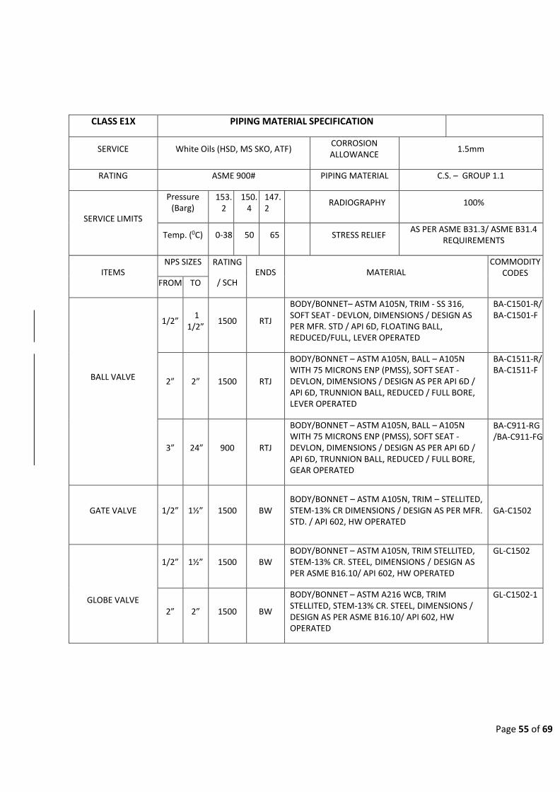
Page 55 of 69
CLASS E1X PIPING MATERIAL SPECIFICATION
SERVICE White Oils (HSD, MS SKO, ATF) CORROSION ALLOWANCE
1.5mm
RATING ASME 900# PIPING MATERIAL C.S. – GROUP 1.1
SERVICE LIMITS
Pressure (Barg)
153. 2
150. 4
147. 2
RADIOGRAPHY 100%
Temp. (0C) 0-38 50 65
STRESS RELIEF AS PER ASME B31.3/ ASME B31.4
REQUIREMENTS
ITEMS NPS SIZES RATING
/ SCH
ENDS
MATERIAL COMMODITY
CODES FROM TO
BALL VALVE
1/2”
1 1/2”
1500
RTJ
BODY/BONNET– ASTM A105N, TRIM - SS 316, SOFT SEAT - DEVLON, DIMENSIONS / DESIGN AS PER MFR. STD / API 6D, FLOATING BALL, REDUCED/FULL, LEVER OPERATED
BA-C1501-R/ BA-C1501-F
2”
2”
1500
RTJ
BODY/BONNET – ASTM A105N, BALL – A105N WITH 75 MICRONS ENP (PMSS), SOFT SEAT - DEVLON, DIMENSIONS / DESIGN AS PER API 6D / API 6D, TRUNNION BALL, REDUCED / FULL BORE, LEVER OPERATED
BA-C1511-R/ BA-C1511-F
3”
24”
900
RTJ
BODY/BONNET – ASTM A105N, BALL – A105N WITH 75 MICRONS ENP (PMSS), SOFT SEAT - DEVLON, DIMENSIONS / DESIGN AS PER API 6D / API 6D, TRUNNION BALL, REDUCED / FULL BORE, GEAR OPERATED
BA-C911-RG /BA-C911-FG
GATE VALVE
1/2”
1½”
1500
BW BODY/BONNET – ASTM A105N, TRIM – STELLITED, STEM-13% CR DIMENSIONS / DESIGN AS PER MFR. STD. / API 602, HW OPERATED
GA-C1502
GLOBE VALVE
1/2”
1½”
1500
BW BODY/BONNET – ASTM A105N, TRIM STELLITED, STEM-13% CR. STEEL, DIMENSIONS / DESIGN AS PER ASME B16.10/ API 602, HW OPERATED
GL-C1502
2”
2”
1500
BW
BODY/BONNET – ASTM A216 WCB, TRIM STELLITED, STEM-13% CR. STEEL, DIMENSIONS / DESIGN AS PER ASME B16.10/ API 602, HW OPERATED
GL-C1502-1

Page 56 of 69
3”
14”
900
RTJ
BODY/BONNET – ASTM A216 WCB, TRIM STELLITED, STEM-13% CR. STEEL, DIMENSIONS / DESIGN AS PER ASME B16.10/ API 623, GEAR OPERATED
GL-C901-G
16”
18”
900
RTJ
BODY/BONNET – ASTM A216 WCB, TRIM STELLITED, STEM-13% CR. STEEL, DIMENSIONS / DESIGN AS PER MFR. STD./ API 623, GEAR OPERATED
GL-C901-1-G
PLUG VALVE (PRESSURE BALANCED
LUBRICATED)
1/2”
1½”
1500
RTJ
BODY – ASTM A105N, PLUG - ASTM A216 GR. WCB CASE HARDENED AND 75 MICRONS ENP, METAL SEAT, VITON SEAL, API 599, REGULAR PORT, LEVER OPERATED, PRESSURE BALANCED LUBRICATED PLUG
PL-C1501-R
2”
2”
1500
RTJ
BODY – ASTM A105N / A216 GR. WCB, PLUG - ASTM A216 GR. WCB CASE HARDENED AND 75 MICRONS ENP, METAL SEAT, VITON SEAL, API 599, REGULAR PORT, LEVER OPERATED, PRESSURE BALANCE LUBRICATED PLUG
PL-C1501-R
3”
24”
900
RTJ
BODY – ASTM A105N / A216 GR. WCB, PLUG - ASTM A216 GR. WCB CASE HARDENED AND 75 MICRONS ENP, METAL SEAT, VITON SEAL, REGULAR PORT, GEAR OPERATED, PRESSURE BALANCED LUBRICATED PLUG
PL-C901-RG
CHECK VALVE
1/2”
1½”
1500
BW LIFT TYPE, BODY / COVER – ASTM A105N, TRIM STELLITED, DIMENSIONS / DESIGN AS PER ASME B16.10 / API 602
CH-C1512
2”
2”
1500
RTJ SWING TYPE, BODY / COVER A216 WCB, TRIM STELLITED, DIMENSIONS / DESIGN AS PER ASME B16.10 / API 594 TYPE B
CH-C1501
3”
4”
900
RTJ SWING TYPE, BODY / COVER A216 WCB, TRIM STELLITED, DIMENSIONS / DESIGN AS PER ASME B16.10 / API 594 TYPE B
CH-C901
6” 24” 900 RTJ DUAL PLATE FLANGED TYPE, BODY / COVER - A216 WCB, TRIM STELLITED, TO API 594 TYPE A
CH-C931
DOUBLE ISOLATION AND BLEED VALVE
6”
24”
900
RTJ
TWIN SEAL PLUG TYPE, BODY/BONNET - A216 GR. WCB, PLUG - ASTM A216 GR. WCB CASE HARDENED AND 75 MICRONS ENP, PEEK SEAL, API 6D, GEAR OPERATED
DI-C901-G
PIPE 1/2” 3” SCH 160 BE ASTM A106 GR. B, SEAMLESS, TO ASME B36.10M PA01A01B

Page 57 of 69
4” 14” SCH 40 BE
API 5L Gr. X70 PSL 2, SEAMLESS, TO ASME B36.10M
PA20A01B
16” 16” SCH 40 BE API 5L Gr. X70 PSL 2, SAW, TO ASME B36.10M PA20B01B
18” 18” XS BE API 5L Gr. X70 PSL 2, SAW, TO ASME B36.10M PA20B01B
20” 24” SCH 40 BE API 5L Gr. X70 PSL 2, SAW, TO ASME B36.10M PA20B01B
NIPPLE 1/2” 1½” SCH. 160 PBE ASTM A106 Gr. B, SEAMLESS, ASME B36.10M,
100mm LENGTH PB01A01L
FITTINGS
(NOTE 1)
ELBOW 45
1/2” 3” AS PER
PIPE BW
ASTM A234 Gr. OWNERB, SEAMLESS, LR AS PER ASME B16.9
PC06A04D
4” 14” AS PER
PIPE BW
ASTM A860 OWNERHY 70, SEAMLESS, LR AS PER ASME B16.9
PC22A04D
16” 20” AS PER
PIPE BW
ASTM A860 OWNERHY 70, WELDED, LR AS PER ASME B16.9
PC22B04D
ELBOW 90
1/2” 3” AS PER
PIPE BW
ASTM A234 Gr. OWNERB, SEAMLESS, LR AS PER ASME B16.9
PD06A04D
4” 14” AS PER
PIPE BW
ASTM A860 OWNERHY 70, SEAMLESS, LR AS PER ASME B16.9
PD22A04D
16” 20” AS PER
PIPE BW ASTM A860 OWNERHY 70, WELDED, ASME B16.9
PD22B04D
WELDOLET 2” 24” AS PER
PIPE BW ASTM A694 F70 AS PER MSS SP-97
PK21X21D
TEE
1/2” 3” AS PER
PIPE BW
ASTM A234 Gr. OWNERB, SEAMLESS, AS PER ASME B16.9
PI06A04D
4” 14” AS PER
PIPE BW
ASTM A860 OWNERHY 70, SEAMLESS, AS PER ASME B16.9
PI22A04D
16” 24” AS PER
PIPE BW
ASTM A860 OWNERHY 70, WELDED, AS PER ASME B16.9
PI22B04D
REDUCING TEE
3/4” 3” AS PER
PIPE BW ASTM A234 Gr. OWNERB, SEAMLESS, ASME B16.9
PJ06A04D
4” 14” AS PER
PIPE BW ASTM A860 OWNERHY 70, SEAMLESS, ASME B16.9
PJ22A04D
16” 24” AS PER
PIPE BW ASTM A860 OWNERHY 70, WELDED, ASME B16.9
PJ22B04D
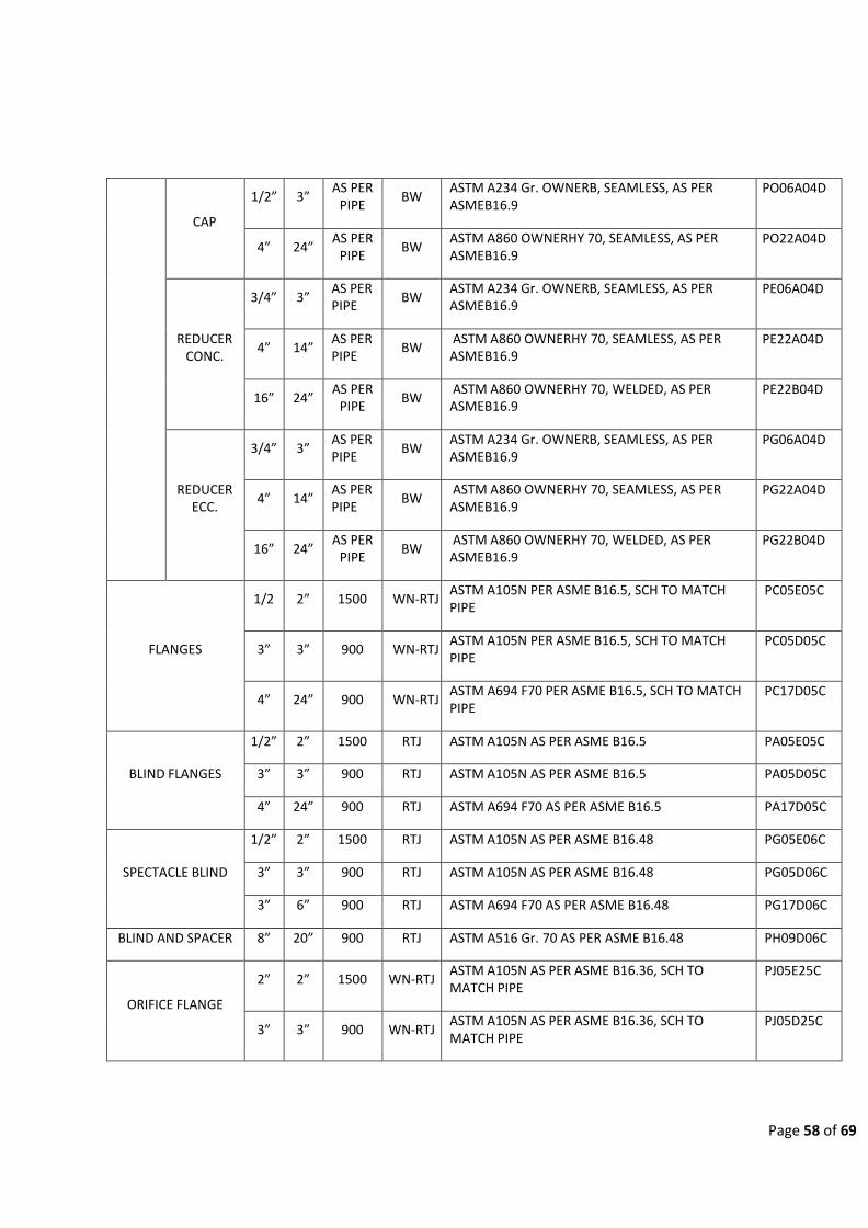
Page 58 of 69
CAP
1/2” 3” AS PER
PIPE BW
ASTM A234 Gr. OWNERB, SEAMLESS, AS PER ASME B16.9
PO06A04D
4” 24” AS PER
PIPE BW
ASTM A860 OWNERHY 70, SEAMLESS, AS PER ASME B16.9
PO22A04D
REDUCER CONC.
3/4” 3” AS PER PIPE
BW ASTM A234 Gr. OWNERB, SEAMLESS, AS PER ASME B16.9
PE06A04D
4” 14” AS PER PIPE
BW ASTM A860 OWNERHY 70, SEAMLESS, AS PER ASME B16.9
PE22A04D
16” 24” AS PER
PIPE BW
ASTM A860 OWNERHY 70, WELDED, AS PER ASME B16.9
PE22B04D
REDUCER ECC.
3/4” 3” AS PER PIPE
BW ASTM A234 Gr. OWNERB, SEAMLESS, AS PER ASME B16.9
PG06A04D
4” 14” AS PER PIPE
BW ASTM A860 OWNERHY 70, SEAMLESS, AS PER ASME B16.9
PG22A04D
16” 24” AS PER
PIPE BW
ASTM A860 OWNERHY 70, WELDED, AS PER ASME B16.9
PG22B04D
FLANGES
1/2 2” 1500 WN-RTJ ASTM A105N PER ASME B16.5, SCH TO MATCH PIPE
PC05E05C
3” 3” 900 WN-RTJ ASTM A105N PER ASME B16.5, SCH TO MATCH PIPE
PC05D05C
4” 24” 900 WN-RTJ ASTM A694 F70 PER ASME B16.5, SCH TO MATCH PIPE
PC17D05C
BLIND FLANGES
1/2” 2” 1500 RTJ ASTM A105N AS PER ASME B16.5 PA05E05C
3” 3” 900 RTJ ASTM A105N AS PER ASME B16.5 PA05D05C
4” 24” 900 RTJ ASTM A694 F70 AS PER ASME B16.5 PA17D05C
SPECTACLE BLIND
1/2” 2” 1500 RTJ ASTM A105N AS PER ASME B16.48 PG05E06C
3” 3” 900 RTJ ASTM A105N AS PER ASME B16.48 PG05D06C
3” 6” 900 RTJ ASTM A694 F70 AS PER ASME B16.48 PG17D06C
BLIND AND SPACER 8” 20” 900 RTJ ASTM A516 Gr. 70 AS PER ASME B16.48 PH09D06C
ORIFICE FLANGE
2” 2” 1500 WN-RTJ ASTM A105N AS PER ASME B16.36, SCH TO MATCH PIPE
PJ05E25C
3” 3” 900 WN-RTJ ASTM A105N AS PER ASME B16.36, SCH TO MATCH PIPE
PJ05D25C

Page 59 of 69
4” 24” 900 WN-RTJ
ASTM A694 F70 AS PER ASME B16.36, SCH TO MATCH PIPE
PJ17D25C
GASKET
1/2” 2” 1500 - RTJ TYPE, OCTAGONAL RING JOINT, SOFT IRON TO ASME B16.20 - 90 HB MAX.
PV16I07
3” 24” 900 - RTJ TYPE, OCTAGONAL RING JOINT, SOFT IRON TO ASME B16.20 - 90 HB MAX.
PV16H07
STUDS / NUTS STUD BOLTS, ASTM A193 Gr. B7 /194 Gr. 2H FULL LENGTH THREAD WITH TWO HEXAGONAL NUTS AS PER ASME B18.2.1/18.2.2
PS14X09A
NOTE 1: FOR BRANCHING TABLE REFER APPENDIX A.
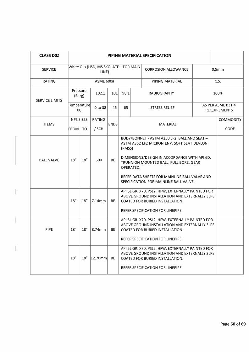
Page 60 of 69
CLASS D0Z PIPING MATERIAL SPECIFICATION
SERVICE White Oils (HSD, MS SKO, ATF – FOR MAIN
LINE) CORROSION ALLOWANCE 0.5mm
RATING ASME 600# PIPING MATERIAL C.S.
SERVICE LIMITS
Pressure (Barg)
102.1 101 98.1 RADIOGRAPHY 100%
Temperature 0C
0 to 38 45 65 STRESS RELIEF AS PER ASME B31.4
REQUIREMENTS
ITEMS NPS SIZES RATING
/ SCH
ENDS
MATERIAL COMMODITY
CODE FROM TO
BALL VALVE
18”
18”
600
BE
BODY/BONNET - ASTM A350 LF2, BALL AND SEAT – ASTM A352 LF2 MICRON ENP, SOFT SEAT DEVLON (PMSS)
DIMENSIONS/DESIGN IN ACCORDANCE WITH API 6D. TRUNNION MOUNTED BALL, FULL BORE, GEAR OPERATED.
REFER DATA SHEETS FOR MAINLINE BALL VALVE AND SPECIFICATION FOR MAINLINE BALL VALVE.
PIPE
18”
18”
7.14mm
BE
API 5L GR. X70, PSL2, HFW, EXTERNALLY PAINTED FOR ABOVE GROUND INSTALLATION AND EXTERNALLY 3LPE COATED FOR BURIED INSTALLATION.
REFER SPECIFICATION FOR LINEPIPE.
18”
18”
8.74mm
BE
API 5L GR. X70, PSL2, HFW, EXTERNALLY PAINTED FOR ABOVE GROUND INSTALLATION AND EXTERNALLY 3LPE COATED FOR BURIED INSTALLATION.
REFER SPECIFICATION FOR LINEPIPE.
18”
18”
12.70mm
BE
API 5L GR. X70, PSL2, HFW, EXTERNALLY PAINTED FOR ABOVE GROUND INSTALLATION AND EXTERNALLY 3LPE COATED FOR BURIED INSTALLATION.
REFER SPECIFICATION FOR LINEPIPE.

Page 61 of 69
NOTE 1: MATERIALS SHALL BE RESISTANT TO THE EFFECTS OF HYDROCARBON FUELS AND MUST BE FIRE RESISTANT.
NOTE 2: BURIED INSTALLATIONS LIKE LINE PIPE, BARRED TEE ETC. SHALL BE EITHER COATED WITH HEAT SHRINK SLEEVES OR
COLD APPLIED TAPES OR TWO PACK HIGH BUILD EPOXY COATING OR 100% SOLIDS POLYURATHANE COATING COMPATIBLE
WITH MAINLINE COATING WITH MINIMUM DFT 450 MICRONS (0.45mm) AS PER OISD-STD-141.
NOTE 3: REFER DATA SHEET OF RESPETIVE PIPELINE COMPONENTS.
NOTE 4: IF PIPE, BENDS AND FITTINGS ARE ABOVEGROUND INSTALLATION THEN IT SHALL BE PAINTED AT SITE IN
ACCORDANCE WITH DOC. “SPECIFICATION FOR EXTERNAL PAINTING AND PROTECTIVE COATING”
NOTE 5: ALL PIPELINE MATERIAL (ASME B31.4 CODE) SHALL BE CHARPY IMPACT TESTED.
FORGED BODY - ASTM A694 GR. F70 (DOUBLE SEALED), PIPE PUPS - API 5L GR.X70 PSL2 (HOLD) MATCH TO PIPE THICKNESS.
2” 4” SCH 80 BW
REFER DATA SHEETS FOR MONOLITHIC ISOLATION JOINTS AND SPECIFICATION FOR MONOLITHIC ISOLATION JOINTS.
MONOLITHIC ISOLATION JOINT
18”
18”
NOTE 3
BW
FORGED BODY - ASTM A694 GR. F70 (DOUBLE SEALED AND PIGGABLE INCLUDING INTELLIGENT PIGGING), PIPE PUPS - API 5L GR.X70 PSL2 MATCH TO PIPE THICKNESS.
REFER DATA SHEETS FOR MONOLITHIC ISOLATION
JOINTS AND SPECIFICATION FOR MONOLITHIC
ISOLATION JOINTS.
FLOW TEE
8”
18”
NOTE 3
BW
ASTM A860 Gr. OWNERHY70, SEAMLESS, MSS SP-75
REFER DATA SHEETS FOR FLOW TEE AND SPECIFICATION FOR FLOW TEE.
INDUCTION BENDS
18”
18”
NOTE 3
BW FROM PIPE, API 5L GR.X 70, PSL2, SAWL/SAWH/HFW, BE, R=6D, MANUFACTURED BY HOT INDUCTION PROCESS (PIGGABLE).
WELDOLET 2” 6” AS PER
PIPE BW ASTM A694 GR. F70, MSS SP-97

Page 62 of 69
10 DRAIN AND VENT CONNECTIONS FOR PIPING 11/2” AND BELOW

Page 63 of 69
11 DRAIN AND VENT CONNECTIONS FOR PIPING 2” AND ABOVE

APPENDIX A
BRANCH CONNECTIONS

BRANCH
3/4 SWT SWT
H 1 SWT SWT SWT
E 1 1/2 SWT SWT SWT SWT
A 2 SW SW SW SW BWT
BWT ‐ Butt Weld Tee Equal and Reducing SWT ‐ Socket Weld Tee Equal and Reducing W ‐ Weldolet
D 3 SW SW SW SW BWT BWT SW ‐ Sockolet
E 4 SW SW SW SW BWT BWT BWT
R 6 SW SW SW SW W BWT BWT BWT
8 SW SW SW SW W W BWT BWT BWT
10 SW SW SW SW W W W BWT BWT BWT
12 SW SW SW SW W W W W BWT BWT BWT
14 SW SW SW SW W W W W W BWT BWT BWT
16 SW SW SW SW W W W W W W BWT BWT BWT
18 SW SW SW SW W W W W W W W BWT BWT BWT
20 SW SW SW SW W W W W W W W W BWT BWT BWT
24 SW SW SW SW W W W W W W W W W BWT BWT BWT
26 SW SW SW SW W W W W W W W W W W BWT BWT BWT
28 SW SW SW SW W W W W W W W W W W W BWT BWT BWT
30 SW SW SW SW W W W W W W W W W W W W BWT BWT BWT
BRANCH CONNECTION TABLE FOR A1X
inches 1/2 3/4 1 1 1/2 2 3 4 6 8 10 12 14 16 18 20 24 26 28 30
1/2 SWT
Notes:
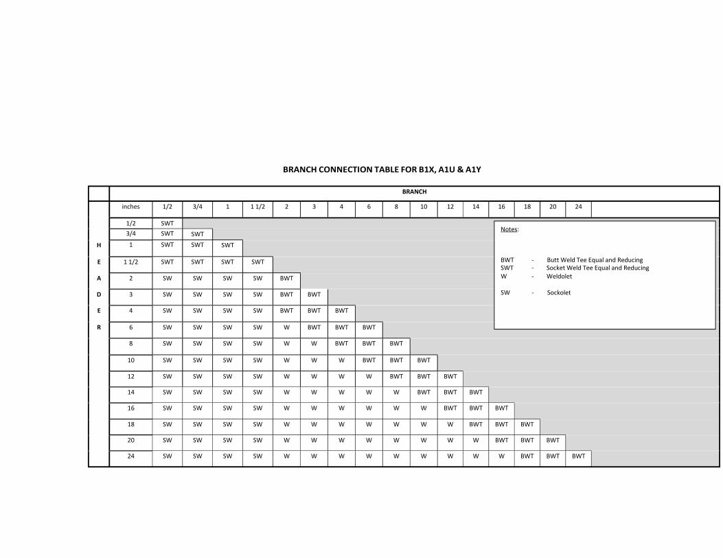
BRANCH CONNECTION TABLE FOR B1X, A1U & A1Y
BRANCH
inches 1/2 3/4 1 1 1/2 2 3 4 6 8 10 12 14 16 18 20 24
H
1/2
3/4
1
SWT
SWT
SWT
SWT
SWT
Notes:
SWT
E 1 1/2 SWT SWT SWT SWT
A 2 SW SW SW SW BWT
BWT ‐ Butt Weld Tee Equal and Reducing SWT ‐ Socket Weld Tee Equal and Reducing W ‐ Weldolet
D 3 SW SW SW SW BWT BWT SW ‐ Sockolet
E 4 SW SW SW SW BWT BWT BWT
R 6 SW SW SW SW W BWT BWT BWT
8 SW SW SW SW W W BWT BWT BWT
10 SW SW SW SW W W W BWT BWT BWT
12 SW SW SW SW W W W W BWT BWT BWT
14 SW SW SW SW W W W W W BWT BWT BWT
16 SW SW SW SW W W W W W W BWT BWT BWT
18 SW SW SW SW W W W W W W W BWT BWT BWT
20 SW SW SW SW W W W W W W W W BWT BWT BWT
24 SW SW SW SW W W W W W W W W W BWT BWT BWT

BRANCH CONNECTION TABLE FOR D1X, D1Y
BRANCH
inches 1/2 3/4 1 1 1/2 2 3 4 6 8 10 12 14 16 18 20 24
½ SWT
H
3/4 SWT
1 SWT
SWT
SWT
Notes:
SWT
E 1 1/2 SWT SWT SWT SWT
A 2 SW SW SW SW BWT
BWT ‐ Butt Weld Tee Equal and Reducing SWT ‐ Socket Weld Tee Equal and Reducing W ‐ Weldolet
D 3 SW SW SW SW BWT BWT SW ‐ Sockolet
E 4 SW SW SW SW BWT BWT BWT
R 6 SW SW SW SW W BWT BWT BWT
8 SW SW SW SW W W BWT BWT BWT
10 SW SW SW SW W W BWT BWT BWT BWT
12 SW SW SW SW W W W BWT BWT BWT BWT
14 SW SW SW SW W W W BWT BWT BWT BWT BWT
16 SW SW SW SW W W W BWT BWT BWT BWT BWT BWT
18 SW SW SW SW W W W W BWT BWT BWT BWT BWT BWT
20 SW SW SW SW W W W W BWT BWT BWT BWT BWT BWT BWT
24 SW SW SW SW W W W W W BWT BWT BWT BWT BWT BWT BWT

BRANCH CONNECTION TABLE FOR E1X
BRANCH
inches 1/2 3/4 1 1 1/2 2 3 4 6 8 10 12 14 16 18 20 24
1/2 BWT
H
3/4 BWT
1 BWT
BWT
BWT
Notes:
BWT
E 1 1/2 BWT BWT BWT BWT BWT ‐ Butt Weld Tee Equal and Reducing W ‐ Weldolet
A 2 W W W W BWT
D 3 W W W W BWT BWT
E 4 W W W W BWT BWT BWT
R 6 W W W W W BWT BWT BWT
8 W W W W W W BWT BWT BWT
10 W W W W W W BWT BWT BWT BWT
12 W W W W W W W BWT BWT BWT BWT
14 W W W W W W W BWT BWT BWT BWT BWT
16 W W W W W W W BWT BWT BWT BWT BWT BWT
18 W W W W W W W W BWT BWT BWT BWT BWT BWT
20 W W W W W W W W BWT BWT BWT BWT BWT BWT BWT
24 W W W W W W W W W BWT BWT BWT BWT BWT BWT BWT


Page 1 of 26
SPECIFICATION FOR EXTERNAL PAINTING AND PROTECTIVE COATING

Page 2 of 26

Page 3 of 26
CONTENTS
1 INTRODUCTION . . . . . . . . . . . . . . . . . . . . . . . . . . . . . . . . . . . . . . . . . . . . . . . . . . . . . . . . . . . . . . . . . . . . . . . . . . . . . . . . . . . . . . . 5
1.1 GENERAL . . . . . . . . . . . . . . . . . . . . . . . . . . . . . . . . . . . . . . . . . . . . . . . . . . . . . . . . . . . . . . . . . . . . . . . . . . . . . . . . . . . . . . . . . . . . . . . . . . . 5
1.2 PROJECT DESCRIPTION ................................................................................................ 5
1.3 SCOPE . . . . . . . . . . . . . . . . . . . . . . . . . . . . . . . . . . . . . . . . . . . . . . . . . . . . . . . . . . . . . . . . . . . . . . . . . . . . . . . . . . . . . . . . . . . . . . . . . . . . . . . . . 5
1.4 EXCEPTIONS . . . . . . . . . . . . . . . . . . . . . . . . . . . . . . . . . . . . . . . . . . . . . . . . . . . . . . . . . . . . . . . . . . . . . . . . . . . . . . . . . . . . . . . . . . 5
2 CODES AND STANDARDS . . . . . . . . . . . . . . . . . . . . . . . . . . . . . . . . . . . . . . . . . . . . . . . . . . . . . . . . . . . . . . . . . . . . . . 5
2.1 ORDER OF PRECEDENCE ............................................................................................. 5
2.2 CODE AND STANDARDS ............................................................................................... 5
3 GENERAL . . . . . . . . . . . . . . . . . . . . . . . . . . . . . . . . . . . . . . . . . . . . . . . . . . . . . . . . . . . . . . . . . . . . . . . . . . . . . . . . . . . . . . . . . . . . . . . . . . . . 6
3.1 WORKMANSHIP . . . . . . . . . . . . . . . . . . . . . . . . . . . . . . . . . . . . . . . . . . . . . . . . . . . . . . . . . . . . . . . . . . . . . . . . . . . . . . . . . . . . . . 6
3.2 MARKING CONDITIONS .................................................................................................. 6
4 MATERIALS . . . . . . . . . . . . . . . . . . . . . . . . . . . . . . . . . . . . . . . . . . . . . . . . . . . . . . . . . . . . . . . . . . . . . . . . . . . . . . . . . . . . . . . . . . . . . 6
4.1 STORAGE OF MATERIALS ............................................................................................ 7
4.2 MANUFACTURER’ S RECOMMENDATION ................................................................ 7
4.3 MATERIAL AND PAINTING FOR INSTRUMENT ITEMS .................................. 7
5 EXTENT OF PAINTING . . . . . . . . . . . . . . . . . . . . . . . . . . . . . . . . . . . . . . . . . . . . . . . . . . . . . . . . . . . . . . . . . . . . . . . . . . . . 7
5.1 SURFACES TO BE PAINTED ........................................................................................ 7
5.2 SURFACES NOT TO BE PAINTED ............................................................................. 7
6 EXPOSURE CONDITIONS . . . . . . . . . . . . . . . . . . . . . . . . . . . . . . . . . . . . . . . . . . . . . . . . . . . . . . . . . . . . . . . . . . . . . . . . 8
7 AMBIENT LIMITATIONS . . . . . . . . . . . . . . . . . . . . . . . . . . . . . . . . . . . . . . . . . . . . . . . . . . . . . . . . . . . . . . . . . . . . . . . . . . 9
7.1 SURFACE PREPARATION AND MATERIAL APPLICATION ......................... 9
7.2 VENTILATION . . . . . . . . . . . . . . . . . . . . . . . . . . . . . . . . . . . . . . . . . . . . . . . . . . . . . . . . . . . . . . . . . . . . . . . . . . . . . . . . . . . . . . . . . 9
8 SURFACE PREPARATION . . . . . . . . . . . . . . . . . . . . . . . . . . . . . . . . . . . . . . . . . . . . . . . . . . . . . . . . . . . . . . . . . . . . . 10
8.1 ABRASIVE BLAST CLEANING .................................................................................. 10

Page 4 of 26
9 PRIMING AND FINISHING . . . . . . . . . . . . . . . . . . . . . . . . . . . . . . . . . . . . . . . . . . . . . . . . . . . . . . . . . . . . . . . . . . . . . 10
9.1 MANUFACTURER' S RECOMMENDATIONS ............................................................ 10
9.2 APPLICATION PROCEDURES ................................................................................... 11
9.3 TYPES OF PRIMER .......................................................................................................... 12
9.4 TYPES OF INTERMEDIATE/ FINISH PAINT ........................................................ 13
9.5 PAINT SYSTEM ................................................................................................................. 13
10 INSPECTION . . . . . . . . . . . . . . . . . . . . . . . . . . . . . . . . . . . . . . . . . . . . . . . . . . . . . . . . . . . . . . . . . . . . . . . . . . . . . . . . . . . . . . . . . . 15
11 GUARANTEE . . . . . . . . . . . . . . . . . . . . . . . . . . . . . . . . . . . . . . . . . . . . . . . . . . . . . . . . . . . . . . . . . . . . . . . . . . . . . . . . . . . . . . . . . 16
12 COATING & WRAPPING . . . . . . . . . . . . . . . . . . . . . . . . . . . . . . . . . . . . . . . . . . . . . . . . . . . . . . . . . . . . . . . . . . . . . . . . . . . 16
12.1 SCOPE . . . . . . . . . . . . . . . . . . . . . . . . . . . . . . . . . . . . . . . . . . . . . . . . . . . . . . . . . . . . . . . . . . . . . . . . . . . . . . . . . . . . . . . . . . . . . . . . . . . . . . 16
12.2 PROCEDURE . . . . . . . . . . . . . . . . . . . . . . . . . . . . . . . . . . . . . . . . . . . . . . . . . . . . . . . . . . . . . . . . . . . . . . . . . . . . . . . . . . . . . . . . 16
1) Surface Preparation . . . . . . . . . . . . . . . . . . . . . . . . . . . . . . . . . . . . . . . . . . . . . . . . . . . . . . . . . . . . . . . . . . . . . . . . . . . . . 16
2) Priming . . . . . . . . . . . . . . . . . . . . . . . . . . . . . . . . . . . . . . . . . . . . . . . . . . . . . . . . . . . . . . . . . . . . . . . . . . . . . . . . . . . . . . . . . . . . . . . . . . . . . 17
3) Preparation of Coating Material . . . . . . . . . . . . . . . . . . . . . . . . . . . . . . . . . . . . . . . . . . . . . . . . . . . . . . . . . . 17
4) Mechanical Application of Coating & Wrapping . . . . . . . . . . . . . . . . . . . . . . . . . . . . . . . . . . 17
12.3 COATING & WRAPPING MATERIALS .................................................................... 18
12.4 INSPECTION . . . . . . . . . . . . . . . . . . . . . . . . . . . . . . . . . . . . . . . . . . . . . . . . . . . . . . . . . . . . . . . . . . . . . . . . . . . . . . . . . . . . . . . . . 18
12.5 REPAIRS . . . . . . . . . . . . . . . . . . . . . . . . . . . . . . . . . . . . . . . . . . . . . . . . . . . . . . . . . . . . . . . . . . . . . . . . . . . . . . . . . . . . . . . . . . . . . . . . . . 18
12.6 HANDLING OF COATED PIPES ................................................................................ 18
12.7 SAFETY PRECAUTIONS ............................................................................................... 18
12.8 GUARANTEE . . . . . . . . . . . . . . . . . . . . . . . . . . . . . . . . . . . . . . . . . . . . . . . . . . . . . . . . . . . . . . . . . . . . . . . . . . . . . . . . . . . . . . . . 18
12.9 REFERENCE . . . . . . . . . . . . . . . . . . . . . . . . . . . . . . . . . . . . . . . . . . . . . . . . . . . . . . . . . . . . . . . . . . . . . . . . . . . . . . . . . . . . . . . . . . . . . 19
Page 5 of 26
1 INTRODUCTION
1.1 GENERAL
This document presents the Specifications for External Painting and Protective Coating for the ATF facilities in Bina
Panki Pipeline (BPPL) and Cochin Coimbatore Karur Pipeline (CCKPL).
1.2 PROJECT DESCRIPTION
The project envisages provision of ATF facilities in BPPL and CCKPL.
1.3 SCOPE
This specification defines the requirements for surface preparation, selection and application of primers and paints on
external surfaces of equipment, vessels, machinery, piping, ducts, steel structures, external & internal protection of
storage tanks for all services, etc. The items listed in the paint systems is indicative only, however, the contractor is fully
responsible for carrying out all the necessary painting, coating and lining on external and internal surfaces as per the
tender requirement.
1.4 EXCEPTIONS
This document does not cover Painting and Coating requirements for materials under Electrical scope except explicitly
stated in this specification. For Painting and Coating requirements for such materials corresponding material specification
shall be referred.
This Specification is not applicable to architectural components and buildings.
2 CODES AND STANDARDS
2.1 ORDER OF PRECEDENCE
The order of precedence of documents is as follows:
1 Purchase order
2 Equipment Data sheets
3 This specification
4 Owner’s Specifications
5 Referenced International Codes and Standards.
2.2 CODE AND STANDARDS
2.2.1 External painting and protective coating shall meet or exceed the requirements of the latest edition of the
following codes, regulations and standards, except as superseded herein. In cases where more than one code,
regulation or standard apply to the same condition, the most stringent shall be followed. In the event of a
conflict between this specification and other specifications or correspondence, the BPCL shall be consulted and
a ruling, in writing, shall be obtained before any work is started.
Codes, Regulations and Statutes of Authorities having jurisdiction in location of installation.
Steel Structures Painting Council Manual SSPC 1 to SSPC 10

Page 6 of 26
IS 5 ‐ Colour coding
IS 101 ‐ Methods of Tests for ready mixed paints and Enamels
IS 2379 – Colour codes for the identification of pipelines
ASA A 13.1 – 1981 ‐ Scheme for Identification of piping system
ASTM‐Vol 6.01 & 6.03 ‐ American standard test methods for Paints and Coatings
Steel Structures Painting Council, U.S.A. (Surface Preparation Specifications (SSPC‐SP).
Swedish Standard – SIS‐05 5900‐1967 / ISO 8501‐1 : ISO standard for Preparation of steel substrates before
application of paints and related products.
White Metal SA 3
Near White Metal SA 2 ½
Commercial Blast SA 2
Brush of blast SA 1
ISO 12944 – A global Corrosion Standard
Industry Quality Control Manual
2.2.2 Some requirements in this specification may be modified by specific requirements in the Purchase Specification.
In case of conflict, the specific requirements supersede this specification.
2.2.3 Any deviation from this specification must be approved, in writing, by BPCL. Such written approval must be
obtained prior to the commencement of any work which would constitute such a deviation.
3 GENERAL
3.1 WORKMANSHIP
Work shall be done by qualified and competent craftsmen in a neat and workman like manner conforming to code
requirements and industry standards. This technical specification shall be applicable for the work covered by the
contract, and without prejudice to the provisions of various codes of practice, standard specifications etc. It is
understood that contractor shall carry out the work in all respects with the best quality of materials and
workmanship and in accordance with the best engineering practice.
3.2 MARKING CONDITIONS
Where elevated structures require marking for safety consideration, they shall be marked in accordance with the
requirements or the Authority having jurisdiction.
4 MATERIALS
Supply of all primers, paints and all other materials required for painting other than Owner's supply.

Page 7 of 26
4.1 STORAGE OF MATERIALS
Materials shall be stored in Manufacturer's containers, clearly marked with Manufacturer's labels, under
Manufacturer's specified storage condition.
4.2 MANUFACTURER’S RECOMMENDATION
Materials shall be used and applied in accordance with this specification.
Manufacturer shall proceed with his proven recommended materials after seeking an approval from BPCL.
4.3 MATERIAL AND PAINTING FOR INSTRUMENT ITEMS
1 Material of construction of junction box shall be LM‐6 cast aluminium.
2 Control room cabinets shall have grey RAL 7035 colour finish. Plinth shall have black with RAL 7022 colour.
3 All cable trays shall be made of FRP or hot dip galvanized iron material of 100 microns galvanization and
instrument sun shades/hoods/canopies shall be of FRP material.
4 Vendor may follow this specification or their standard coating system for Actuators.
5 EXTENT OF PAINTING
5.1 SURFACES TO BE PAINTED
The following surfaces and materials shall require shop, pre‐erection and field painting:
All uninsulated carbon steel & alloy steel equipment like columns, vessels, drums, storage tanks, heat
exchangers, pumps, compressors, motors etc.
All uninsulated carbon and alloy steel piping, fittings, flanges, valves, in‐line Items, MOV, Control Valves
(including painting of identification marks), etc.
All items contained in a package unit as necessary.
All structural steel work, pipe, structural steel supports, walkways, handrails, ladders, platforms etc.
Identification colour bands on all piping as required including insulated aluminium clad, galvanized, SS and
nonferrous piping.
Identification lettering / numbering on all painted surfaces of equipment/piping, insulated aluminium clad,
galvanized, SS and nonferrous piping.
Marking / identification signs on painted surfaces of equipment/piping for Hazardous service.
Over insulation surface of equipments and pipes wherever required.
Painting under insulation for carbon steel.
Painting of pre‐erection/fabrication.
Repair work of damaged/ pre‐erection/ fabrication shop primer and weld joints at field.
5.2 SURFACES NOT TO BE PAINTED
The following are not to be painted and must be protected from painting. However, if there is any specific
requirement by the owner, the same shall be painted as per the relevant specifications:
Porcelain

Page 8 of 26
Gauge Glasses
Meter Faces
Valve Stem and Threads
Working Surfaces of Equipment
Name Plates
Aluminium, Plastic and Stainless Steel
Insulation or Fireproofing
Galvanized Steel
Concrete, Transite, Masonry, Stucco, etc.
Uninsulated austenitic stainless steel.
Plastic and/or plastic‐coated materials
Non‐ferrous materials like aluminium. 5.2.1 All non‐painted surfaces adjacent to panting surface must be masked & protected. Masking or compounds used
to protect non‐painted surface must be removed prior to completion of the job.
6 EXPOSURE CONDITIONS
6.1 Coating requirements are primarily determined by exposure conditions. The types and severity of exposures
are outlined in the Appendixes 2.0. These Appendices are to be used in selecting a coating system for facilities
6.2 Exposure conditions may overlap in a single location or a change in operation may bring a change of exposure
conditions, either more or less severe.
6.3 Exposure Areas selected for this specific project – Definitions
6.3.1 Area Classification C3 as per ISO 12944 (See Appendix 2.0).
This exposure area shall be defined as any area where Urban and industrial atmospheres, moderate sulphur
dioxide levels production areas with chemical fumes, mist or dust can combine with high humidity and
condensed moisture to corrode carbon steel at rates greater than 150 micrometers per year and corrode zinc
at rates greater than 25 micrometers per year. Local rates of pitting corrosion may be higher.
Other areas that are having equipment and surfaces operating above 66 deg. C and are subject to spills of
corrosive materials.
Examples of areas where severe exposure conditions exist are sulphur plant areas, sulphur loading areas,
chlorination units, areas within 15m radius of cooling towers and areas with high concentrations of solvent
and alkaline fumes.
6.3.2 Areas Classification C1/C2 as per ISO 12944.
This exposure area shall be defined as rural area, Low pollution, heated buildings/Natural atmosphere, normal
outdoor weathering and/or light concentrations of chemical fumes that combine with humidity and

Page 9 of 26
condensed moisture to corrode carbon steel at rates of 80 micrometers or less per year and zinc is almost free
of corrosion.
Examples of areas are mostly tank farms, areas where moderate exposure conditions may be found and
equipment operating at a temperature such that condensation forms on equipment externals.
6.4 Decide on the design life (durability) of the coating system
ISO 12944 Durability ranges (Time to first major maintenance)
High Durability > 15 years design life
Medium Durability 5 to 15 years design life
Low Durability < 5 years design life
For this Project specific Durability of 7 years selected.
7 AMBIENT LIMITATIONS
7.1 SURFACE PREPARATION AND MATERIAL APPLICATION
Surface preparation and material application is advisable when ambient temperature of the atmosphere is at
maximum level. Surface preparation and primer application shall be done only in painting booth. Selected surface
preparation standard for this project specific is SA 2 ½ unless specified exclusively otherwise.
No surface preparation or application of material may take place under the following conditions:
Wet or damp atmosphere
Noticeable wind
Atmosphere contaminated by dirt, dust, oil, product or any other pollutant
No primer shall be applied without witnessing of surface preparation & paint mixing by Project
Consultant/Designated Site Engineer.
All tools, brushes, rollers, spray guns, blast material, hand power tools for cleaning and all equipments, scaffolding
materials, shot & grit blasting equipments & air compressors etc. required to be used shall be suitable for the work
and all in good order and shall be arranged by the contractor at site and in sufficient quantity. The manufacturer’s
test certificates / data sheets for all the above items shall be reviewed by site engineer at site before start of work.
Mechanical mixer shall be used for paint mixing operations in case of two pack systems except that the site engineer
may allow the hand mixing of small quantities at his discretion in case of specific requirement for touch up work
only.
7.2 VENTILATION
During all stages of surface preparation and application of material, adequate ventilation must be assured.

Page 10 of 26
8 SURFACE PREPARATION
In order to achieve the maximum durability following method of surface preparation shall be followed, depending
on condition of surface to be painted. Adhesion of the paint film to surface depends largely on the degree of
cleanliness of the metal surface. Proper surface preparation contributes more to the success of the paint protective
system.
8.1 ABRASIVE BLAST CLEANING
8.1.1 The steel surface shall be cleaned by either abrasive blast cleaning or shot‐blasting.
8.1.2 Remove all other contaminants, oil, grease etc. by use of an aromatic solvent prior to surface cleaning.
8.1.3 All rough welds, burrs and sharp surface projections shall be ground smooth and all weld splatter shall be
removed prior to blasting operations.
8.1.4 Blast cleaning operations shall not be conducted on wet surfaces and before coating. Blast cleaning shall not be
performed where dust can contaminate surfaces undergoing such cleaning or during humid weather conditions
having humidity exceed 85%.
8.1.5 The blast cleaned surface shall be coated with one application of specified primer during the same day as
blasted, prior to sundown of that day and before any visible rusting occurs. Blast cleaned surfaces allowed to set
overnight shall be reblasted prior to priming.
8.1.6 Sandblast sand shall be fresh water washed, controlled particle size, high silica content sand, with sharp angular
surfaces and no soft particles to ensure fast, positive cleaning action with a minimum of dusting when used to
blast clean metal surfaces. Under no circumstances shall it contain clay particles or any other extraneous matter.
8.1.7 Profile depth of the abrasive blast cleaned surface shall not be less than 25 nor greater than 40 micrometers
8.1.8 The compressed air for blasting shall be free of water and oil.
8.1.9 No coating shall be permitted to be applied over scale, rust, oil, grit or other foreign material. All sand, shot and
grit will be removed by brush, air blast or vacuum type cleaner prior to applying primer. Care shall be exercised
to assure that the cleaned surface is not contaminated with any foreign material or fingerprints prior to applying
primer.
8.1.10 Surface preparation of fabricated items to be painted in the shop shall be done in an area free of dust and
contaminants from other shop work.
8.1.11 Irrespective of the method of surface preparation, the first coat of primer must be applied by airless spray/ air
assisted conventional spray if recommended by the paint manufacturer on dry surface. This should be done
immediately and in any case within 4 hours of cleaning of surface. However, at times of unfavourable weather
conditions, the site engineer shall have the liberty to control the time period, at his sole discretion and/or to
insist on recleaning, as may be required, before primer application is taken up. In general, during unfavourable
weather conditions, blasting and painting shall be avoided as far as practicable.
9 PRIMING AND FINISHING
9.1 MANUFACTURER' S RECOMMENDATIONS
The finish and primer paint Manufacturer's recommendations on application and surface preparation are to take
precedence over these general specifications.

Page 11 of 26
9.2 APPLICATION PROCEDURES
9.2.1 Mixing of Paint shall be done only in the presence of Consultant/Site Engineer. The normal method of application
shall be airless spraying method.
9.2.2 The gun shall be at right angles to the surface and 20 cm to 25 cm from the surface.
9.2.3 Each pass of the gun shall overlap by 50%.
9.2.4 When a pause in spraying occurs, the material shall be blown back into the pot.
9.2.5 The material in the pot shall be kept thoroughly mixed at all times.
9.2.6 Any material not used in its pot life shall be destroyed and the containers used thoroughly cleaned.
9.2.7 No spraying shall be done within 15 cm of unprepared surfaces.
9.2.8 Primer coat shall be applied soon after preparation ‐ before flash rusting occurs.
9.2.9 Finish coating shall be applied as soon as possible after the underlying coat is in condition to receive it, according
to Manufacturer's specifications.
9.2.10 Care must be taken to ensure that "hard to get at" places are properly primed and painted, that there is no
bridging, etc.
9.2.11 Thickness gauge shall be used to determine that a complete even coat has been applied for each primer and
finish coat.
9.2.12 No coat shall be applied until the preceding coat has dried. The material shall be considered dry for re‐coating
when another coat can be applied without the development of any film irregularities such as lifting or loss of
adhesion of undercoats. Drying time of the applied coat should not exceed maximum specified for it as a first
coat; if it exceeds the paint material has possibly deteriorated or mixing is faulty.
9.2.13 No paint shall be force dried under conditions which will cause checking, wrinkling, blistering formation of pores,
or detrimentally affect the conditions of the paint.
9.2.14 No drier shall be added to paint on the job unless specifically called for in the manufacturer’s specification for the
paint.
9.2.15 Paint shall be protected from rain, condensation, contamination, snow and freezing until dry to the fullest extent
practicable.
9.2.16 Ingredients shall be kept properly mixed in the spray pots or containers during application by continuous
mechanical agitation.
9.2.17 Blast cleaned surface shall be coated with one complete application of primer as soon as practicable but in no
case later than 4 hrs the same day.
9.2.18 Spray equipment shall be kept sufficiently clean so that dirt, dried paint, and other foreign materials are not
deposited in the paint film.
9.2.19 Any solvents left in the equipment shall be completely removed before applying paint to the surface being
painted.
9.2.20 Paint shall be applied in a uniform layer, with overlapping at the edge of the spray pattern. The spray patterns
shall be adjusted so that the paint is deposited uniformly. During application, the gun shall be held perpendicular
to the surface and at a distance which will ensure that a wet layer of paint is deposited on the surface. The
trigger of the gun should be released at the end of each stroke.
9.2.21 All runs and sags shall be brushed out immediately or the paint shall be removed and the surface repainted.
9.2.22 All nameplates, manufacturer’s identification tags, machined surfaces, instrument glass, finished flange faces,
control valve items and similar items shall be masked to prohibit coating deposition. If these surfaces are coated,
the component shall be cleaned and resorted to its original condition.
9.2.23 If spray gun shows choking, immediately de‐choking procedure shall be followed.
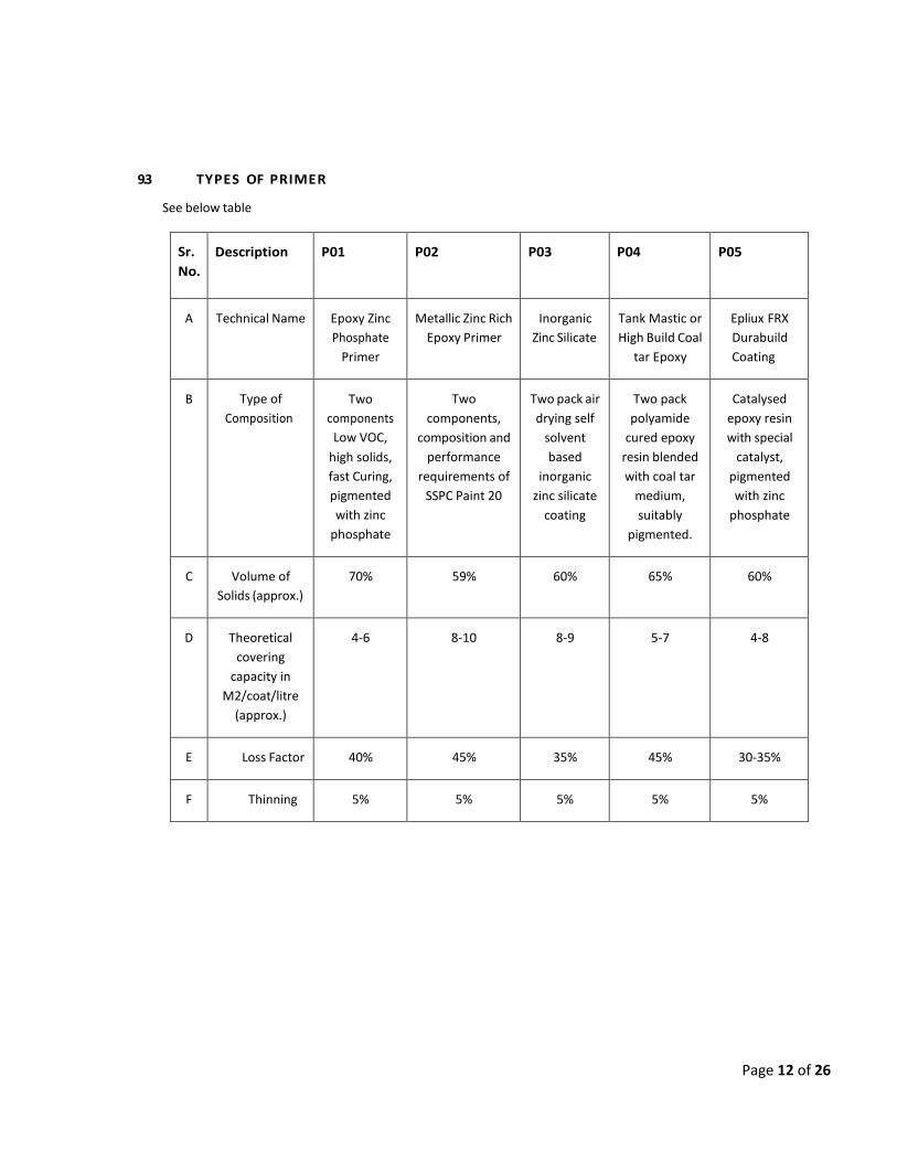
Page 12 of 26
9.3 TYPES OF PRIMER
See below table
Sr.
No.
Description P01 P02 P03 P04 P05
A Technical Name Epoxy Zinc
Phosphate
Primer
Metallic Zinc Rich
Epoxy Primer
Inorganic
Zinc Silicate
Tank Mastic or
High Build Coal
tar Epoxy
Epliux FRX
Durabuild
Coating
B Type of
Composition
Two
components
Low VOC,
high solids,
fast Curing,
pigmented
with zinc
phosphate
Two
components,
composition and
performance
requirements of
SSPC Paint 20
Two pack air
drying self
solvent
based
inorganic
zinc silicate
coating
Two pack
polyamide
cured epoxy
resin blended
with coal tar
medium,
suitably
pigmented.
Catalysed
epoxy resin
with special
catalyst,
pigmented
with zinc
phosphate
C Volume of
Solids (approx.)
70% 59% 60% 65% 60%
D Theoretical
covering
capacity in
M2/coat/litre
(approx.)
4‐6 8‐10 8‐9 5‐7 4‐8
E Loss Factor 40% 45% 35% 45% 30‐35%
F Thinning 5% 5% 5% 5% 5%

Page 13 of 26
9.4 TYPES OF INTERMEDIATE/ FINISH PAINT
See below table for types of finish paint. Where required coats of finish as per Appendix 2.0 are to be applied, the
first coat is to be discoloured (1 paint of contrasting shade to every gallon of main colour), so as to aid visual
inspection for holidays, coverage and wear, etc.).
Sr.
No.
Description F01 F02 F03 F04
A Technical Name Acrylic
polyurethane
finish paint
Epoxy high build
finish paint
(Polyamide)
Self priming type
surface tolerant high
build epoxy coating.
(complete rust control
Coating)
Epliux super
high build
coat
B Type of
Composition
Two pack
aliphatic
isocyanate
cured acrylic
finish paint
Two pack
polyamide/
polyamine cured
epoxy resin medium
suitably pigmented
Two pack epoxy resin
based suitable
pigmented and capable
of adhering to manually
prepared surface
Catalysed
epoxy resin,
suitably
pigmented
C Volume of Solids
(approx.)
57% 62% 80% ‐
D Theoretical
covering capacity
in M2/coat/litre
(approx.)
10‐13 5‐6 5‐7 4‐5
E Weight per litre in
Kgs/litre (approx.)
1.3 1.4 1.4 ‐
F Loss Factor 30% 30% 30% 30‐35%
G Thinning 5% 5% 5% 5‐8%
9.5 PAINT SYSTEM
For this project specific system selected C3 as per Cl. 6.3.1, the selected paint system is also suitable upto 90 deg. C
temperature for specific requirements.
Following paint systems are applicable, for Tank outside, Piping and Structural, for Tank bottom plate soil side, for
Inside Tank bottom plate and inside shell, for Floating Roof Tanks roof.

Page 14 of 26
Tank outside, Piping and Structural
Paint Type DFT(µ)
Primer P03 70x1
Intermediate Coat F02 100
Final Coat F01 2x40
TOTAL DFT 250
Tank Bottom Plate soil side
Paint Type DFT(µ)
Primer P04 2x100
TOTAL DFT 200
Tank Bottom Plate and Inside shell
Paint Type DFT(µ)
Primer P03 70
Final Coat F04 125
TOTAL DFT 195

Page 15 of 26
Inner side of cone / roof of Fixed & Floating Roof Tanks
Paint Type DFT(µ)
Primer P05 2x100
Final Coat F04 2x50
TOTAL DFT 300
10 INSPECTION
10.1 The BPCL’s representative shall have access to all work while being performed and shall be given sufficient
notification to complete all required inspections.
10.2 All prepared surfaces shall be subject to inspection by BPCL’s representative and approval before primer is
applied.
10.3 Paint dry film thickness shall be as per this specification. Failure to meet specified thickness requirement shall
cause work to be rejected.
10.4 Paint shall not be thinned beyond Manufacturer's recommendation and if BPCL requires it, a viscosity
check shall be made.
10.5 Work will be rejected because of poor workmanship. Poor workmanship is defined as inadequate drying or
curing, dirt and dust inclusions, overspray, pin‐holes, runs and sags, or inadequate film build.
10.6 Acceptable finish work must be free of abrasions and must be uniform in colour and appearance.
10.7 All painting materials including primers and thinners brought to site by contractor for application shall be
procured directly from manufactures as per specifications and shall be accompanied by manufacturer's test
certificates. Paint formulations without certificates are not acceptable.
10.8 The contractor shall produce test reports from manufacturer regarding the quality of the particular batch of
paint supplied. The site engineer shall have the right to test wet samples of paint at random for quality of
same. Batch test reports of the manufacturer for each batch of paints supplied shall be made available by the
contractor.
10.9 The painting work shall be subject to inspection by site engineer at all times. In particular, following stage wise
inspection will be performed and contractor shall offer the work for inspection and approval of every stage
before proceeding with the next stage. The record of inspection shall be maintained in the registers. Stages of
inspection are as follows:
a) Surface preparation
b) Primer application
c) Each coat of paint

Page 16 of 26
10.10 Any defect noticed during the various stages of inspection shall be rectified by the contractor to the entire
satisfaction of site engineer before proceeding further. Irrespective of the inspection, repair and approval at
intermediate stages of work, contractor shall be responsible for rectifying any defects found during final
inspection/guarantee period/defect liability period as defined in general condition of contract. Dry film
thickness (DFT)) shall be checked and recorded after application of each coat and extra coat of paint should
be applied to make‐up the DFT specified without any extra cost to owner, the extra coat shall have prior
approval of site engineer.
10.11 After surface preparation, the primer should be applied to cover the crevices, corners, sharp edges etc.
10.12 The shades of successive coats should be slightly different in colour in order to ensure application of individual
coats, the thickness of each coat and complete coverage should be checked as per provision of this
specification.
10.13 The contractor shall provide standard thickness measurement instrument with appropriate range(s) for
measuring.
10.14 Dry film thickness of each coat & surface profile gauge for checking of surface profile in case of sand blasting
shall be measured. Holiday detectors and pinhole detector & protector shall be used whenever required for
checking in case of immersion conditions.
10.15 Final inspection shall include measurement of paint dry film thickness, adhesion, holiday detection check of
finish and workmanship. The thickness should be measured at as many points/ locations as decided by site
engineer and shall be within + 10% of the dry film thickness, specified in the specifications.
11 GUARANTEE
Contractor shall guarantee painting against any defect including poor workmanship and improper application. This
guarantee shall remain in effect for seven (7) years from the date painting is completed or after final inspection
release note from OWNER. Contractor shall repair at his own expense any defects noted during the guarantee
period.
The contractor shall guarantee that the chemical and physical properties of paint materials used are in accordance
with the specifications contained herein/to be provided during execution of work.
12 COATING & WRAPPING
12.1 SCOPE
This specification covers the requirement of material, surface preparation, application, inspection, repairs and
handling of wrapping and coating at site for underground steel pipeline with service temperature up to 60°c, using
coating & wrapping materials confirming to AWWA C‐203 (Latest edition).
12.2 PROCEDURE
1) Surface Preparation
All oil, grease on the pipe metal surface shall be thoroughly removed by flushing with a suitable solvent. (Such as
xylene or 1:1:1 trichloroethylene) and wiping with clean tags. The degreased pipe metal surface shall be grit blasted

Page 17 of 26
to get surface to confirm Swedish Standard SA‐2 ½ of SSPC‐SP10, Surface profile shall be uniform to provide good
key to paint (50‐75 micron depth).
2) Priming
Immediately after grit blasting the surface shall be applied with fast drying unmodified pure chlorinated rubber
based coal tar synthetic primer.
Second coat of primer to be applied before application of coal tar enamel. The entire surface of pipe should be
primed. No specific time gap between two coats of primer needs to be maintained but after the second coat of
primer, the enamel coating should start before the primer is completely hardened.
3) Preparation of Coating Material
The coal tar enamel shall be supplied in metal drums that shall be cropped or cut out on a suitable platform to
prevent the enamel coming in contact with wooden cinders, grass and other forms of contamination. The enamel
shall be as per AWWA C‐203.The cropped out pieces of enamel may not weigh more than 10 Kgs. The broken pieces
shall be placed in a clean melting kettle which is made of heavy duty, MS sheet in form of closed vessel. The vessel
should have manual operating stirring arrangement. It is also having special type of heating arrangement with fuel
as kerosene oil/diesel. To maintain uniform coverage of material required quantity of enamel is heated in the kettle
with temperature range of 230°c to 240°c (application temperature). Temperature of enamel can be checked by
dipping thermometer in the enamel. Thermometer shall be used in heating kettle in such a way so as to read the
temperature clearly. The thermometer shall have temperature range up to 300°c.
4) Mechanical Application of Coating & Wrapping
i. The pipe shall be kept rotating on a machine having circumferential and linear motions, while the pipes are in
rotating condition, pour the hot coal tar enamel manually and spread uniformly with the help of rubber brushes.
ii. Simultaneously, one wrap of glass fibre tissue shall be applied over the molten coal tar enamel. Initially, the wrap
is held with hand and pressed over the molten enamel. There after the revolving pipe puffs the fibre wrap from the
reel, which ensures continuous wrapping over the molten enamel with the required overlap (i.e.: 13 mm)
iii. Second coat of coal tar enamel as well as glass fibre tissue paper shall be applied as per above procedure (i.e. sr.
no. i & ii).
iv. Third coat of molten coal tar enamel shall be applied next.
Final, outer wrap of impregnated fibre shall be applied immediately over the third coat of coal tar enamel, similar to
inner wrap application procedure as given in sr. no. i & ii above.
The overlap at edges of all wrappings should be minimum 13 mm. The coating shall be continuous for the full length
of the pipe except 200mm at both ends of the pipes.
Finally, carry out white wash with Acrylic water emulsion Latex Paint Material.

Page 18 of 26
This application will be carried out manually by paint brushes. There after the pipes is lifted by suitable methods and
allowed to dry on wooden sleepers.
Alternative to above is directly use coating material of 4mm thick (PIPEKOTE or equivalent) available in market, it
will be easy and less time consuming.
12.3 COATING & WRAPPING MATERIALS
All coating and wrapping materials for underground piping shall be procured from the manufacturers approved by
BPCL and all material shall be used with in shelf life period. The primer and coal tar enamel shall be compatible and
shall be of the same manufacturer.
12.4 INSPECTION
1) Thickness – Thickness of the coal tar enamel coating shall be measured with digital thickness gauge.
2) Electrical Inspection ‐ All coated and wrapped pipes shall be tested with the positive signalling device to indicate
any fault, holes, breaks or conductive particles in the coating. The test voltage shall be 13 KV.
3) Peel Off Test ‐ Peel test shall be conducted at temperature from 10°c to 25°c as per AWWA‐203 methods.
Acceptable criteria shall be as per AWWA‐203.
4) Adhesive Test – Adhesive test shall be conducted as per AWWA‐203.
12.5 REPAIRS
Wherever any holiday is observed or any defective work is found, remove the wrapping and coating to the required
extend from those areas by using a sharp knife. Then heated enamel shall be applied manually over the area
following the procedure described above and inner and outer wrap applied. Holidays test shall be repeated for the
portion.
12.6 HANDLING OF COATED PIPES
The coated pipes shall be handled at all times with equipments such as wide belt slings and wide padded skids
designed to prevent damage to the coating. Bare cables, chains, hooks etc. shall not be permitted to come in contact
with coatings. A suitable crane may be used. Coated pipes shall be supported at two bare ends clear from ground
either on skids or sand bags.
12.7 SAFETY PRECAUTIONS
Adequate and proper PPE shall be provided to persons involved in short of grit blasting work. Adequate and proper
PPE shall be provided to all persons involved in hot application of coal tar enamel along with the wraps. Proper
firefighting system shall be provided during application of primer and enamel coats and all safety requirements shall
be ensured for the underground trenching, lowering and back filling. All precaution shall be observed as per the
instruction of OWNER.
12.8 GUARANTEE
The guarantee of the coal tar enamel coating and wrappings performance shall be at least 5 yrs. After the system is
put under the operation.

Page 19 of 26
12.9 REFERENCE
AWWA C‐203 – Coal tar protective coating linings to carbon steel pipeline. SSPC‐
SP10 – Steel Structure Painting Council, Surface Preparation Specification.
ASTM G8 – Test method for cathodic Disbonding of pipeline coating.

Page 20 of 26
Appendix 1 PAINT COLOUR CODE FOR PIPING AND EQUIPMENT:
SCOPE
This specification covers the requirement of colour scheme for the identification of the contents of the pipelines carrying
fluids, storage tanks and equipments in refineries, terminals and petrochemical installations. The following colour coding
system has been made based on international standards like ASME, BS and Indian Standard.
IDENTIFICATION
The system of colour coding consists of a ground colour and secondary colour bands superimposed over the ground colour. The ground colour identifies the basic nature of the service and secondary colour band over the ground colour distinguishes the particular service. The ground colour shall be applied over the entire length of the uninsulated pipes. For insulated lines ground colour shall be provided as per specified length to identify the particular service.
The following ground colour designation for identification of basic classification of various important services shall be followed:
Post Office Red (ISC 538) Fire protection materials
Orange (ISC 592) Volatile petroleum products (motor spirit and Lighter)
Oxide Red (ISC 446)
Non‐ Volatile Petroleum Products (SKO and heavier, Including
HSD)
Black Slop Oils
Sky Blue (ISC 101) Water (All purities and temperature)
Sea Green (ISC 217) Air and its components
Secondary colours: the narrow bands presenting the secondary colour which identifies the specific service may be applied by painting or preferably by use of adhesive plastic tapes of the specific colour.
COLOUR BANDS AND IDENTIFICATION LETTERING
Colour band and lettering shall be done in with the same paint as for finished coat. The details given in Industry Quality Control Manual shall only be followed, unless specified exclusively.
The following specifications of colour bands shall be followed.
For identifying the piping contents, size of letters in legends will depend to some extent upon the pipe diameter. Either white or black letters are selected to provide max. contrast to the band colour. Bands usually are 50mm wide and regardless of band width, are spaced 25 mm apart when two bands are employed.

Page 21 of 26
Colour Bands and sizing of lettering for piping as per IS 2379:
Size of Pipe or Covering in inch Width of Colour Bands in
mm
Size of Legend Letters in
mm
¾” to 1” 200 10
11/2” to 2” 200 20
3” to 6” 300 30
8” to 10” 600 63
Over 10” 800 90
Size of the letters stencilled / written for equipments shall be as given below:
Vessel ‐ 150mm (Height)
Pump, and other machinery ‐ 50 mm (Height)
Colour Bands: The location and size of the bands, as recommended, when used, shall be applied to the pipe.
On both side of the valves, tees and other fittings of importance. Where the pipe enters and emerges from wall and where it emerges from road and walkway overpasses, unit battery limits. At uniform intervals along long section of pipe. Adjacent to Tanks, Vessels and Pumps.
For piping, writing of name of service and direction of flow for all the lines shall be done at following location.
The letters will be black on pipes painted with light shade colours and white on pipes painted with dark shade colour to give good contrast.
On stainless steel line precaution should be taken while painting by using low chloride content. Colour Band Specification:
a) Unit area; bands at intervals of 6.0 Mtrs. b) Offsite area: Bands at intervals of 10.0 Mtrs. c) Each pipe segment will have min. one band indication, irrespective of length. d) The band shall be displayed near walkway, both side of culverts, tank dykes, tanks, Vessels, suction and
discharge of Pumps, unit battery limit, near valves of line, etc. e) In case of camouflaging requirements of civil defence or any other location requirement, the same shall be
followed accordingly.

Page 22 of 26
The specification for application of the complete piping identification colour code, including base and bands colours, are presented in the enclosed table.
Sr.
No. Service Recommended colour Code
Hydrocarbon Lines (Uninsulated)
1
M.S., HSD, SKO (Common pipeline for these
services)
WHITE WITH 1 DARK ADMIRALTY GREY (ISC 632)
BAND
2 SLOP & WASTE OIL BLACK WITH ONE ORANGE (ISC 592) BAND
3
CORROSION INHIBITOR
CANARY YELLOW (ISC 309) WITH 1 ALUMINIUM
BAND
WATER LINES (UNINSULATED)
4 RAW WATER SKY BLUE (ISC 101) WITH 1 BLACK BAND
5
POTABLE WATER
SKY BLUE (ISC 101) WITH SEA GREEN (ISC 217)
BAND
6
SERVICE WATER
SKY BLUE (ISC 101) WITH 1 SIGNAL RED (ISC 537)
BAND
FIRE PROTECTION ABOVE GROUND LINES (UNINSULATED)
7 FIRE WATER, FOAM AND EXTINGUISHERS POST OFFICE RED (ISC 538)
8 FIRE WATER PUMP POST OFFICE RED (ISC 538)
9
DIESEL ENGINE (FOR FIREWATER
APPLICATION)
POST OFFICE RED (ISC 538)
10 MOTOR (FOR FIREWATER APPLICATION) POST OFFICE RED (ISC 538)
UNINSULATED EQUIPMENT, TANKS & STRUCTURES
11 VESSELS ALUMINIUM

Page 23 of 26
12 ALL OTHER TANKS ALUMINIUM
13 PUMPS NAVY BLUE (ISC 106)
14 HAND RAILINGS SIGNAL RED (ISC 537)
15 STAIRCASE, LADDER & WALKWAYS BLACK
16 LOAD LIFTING EQUIPMENTS & MONO RAILS GOLDEN YELLOW (ISC 356)
17 GENERAL STRUCTURES BLACK
Note:
Contractor shall follow Camouflaging requirements at locations falling under Defence requirement.

Page 24 of 26
Appendix 2
DESCRIPTION
AREA COVER
TEMP DEG.
C
SURFACE PREPARATION
PRIMER
FINISH PAINT
Total DFT(µ)
REMARKS
Field Paint system for C3 Environment for CS
For Uninsulated Structures, Piping,
Equipments, Rotary Eqpts. etc.
‐14 to 80
SA‐2 ½
1 coat of
P03 of 70µ DFT
1 coat of F02 of
100 DFT + 2 coats of F01 of
40µ DFT/ Coat
250
Field Paint System for CS Storage tanks (External) for C3 Environment
External shell, wind girders as well as and associated structural
works, for all environment for HSD, SKO, MS, fire water, raw water, potable
water etc.
‐14 to 80
SA‐2 ½
1 coat of
P03 of 70µ DFT
1 coat of F02 of
100 DFT + 2 coats of F01 of
40µ DFT/ Coat
305
Contractor shall follow Camouflaging requirements at locations falling under Defence requirement
Field Paint System for CS Storage tanks roof (External) for C3 Environment
Roof top of all above ground tank including
top side of floating roof of open tank as well as
and associated structural works,
rolling and stationary ladders, spiral
stairway, hand rail for all environment for
HSD, SKO, MS,
‐14 to
80
SA‐2 ½
2 Coats of P05 of 100 DFT/ Coat
2 Coats
of F04 of 50 DFT/
Coat
300
Contractor shall follow
Camouflaging requirements at locations falling under
Defence requirement
Field Paint System for CS Storage tanks (External) for C3 environments
External Surface of
bottom plate (soil side) for all Storage tank
‐14 to 80
SA‐2 ½
2 Coats of P04 of 100 DFT/Coat
‐
200
Field Paint System for CS Storage tanks (Internal) for C3 environments
Internal surface of tanks bottom plate and tank shell up to 1 mtr.
height from bottom plate
‐14 to 80
SA‐2 ½
1 coat of
P03 of 70µ DFT
1 coat of F04 of 125µ DFT
195

Page 25 of 26
Coating system for External Side of Underground CS Plant Piping & Tanks
Yard and over the ditch
coating
25 to
60
SA‐2 ½
2 Coats of P02 of 75
DFT
4.5 mm Thk. coal
tar coating wrappin g as per AWWA‐ C‐203 & Cl. 12 of
this spec.
4.5 mm

Page 1 of 26

PIPING AND INSTRUMENTATION DIAGRAM
NOTE:
1. Pressure Transmitter to be considered in common suction line of Dosing Pumps
2. By arrangement with isolation valves to be considered for Mass flow meter shown in P & ID.


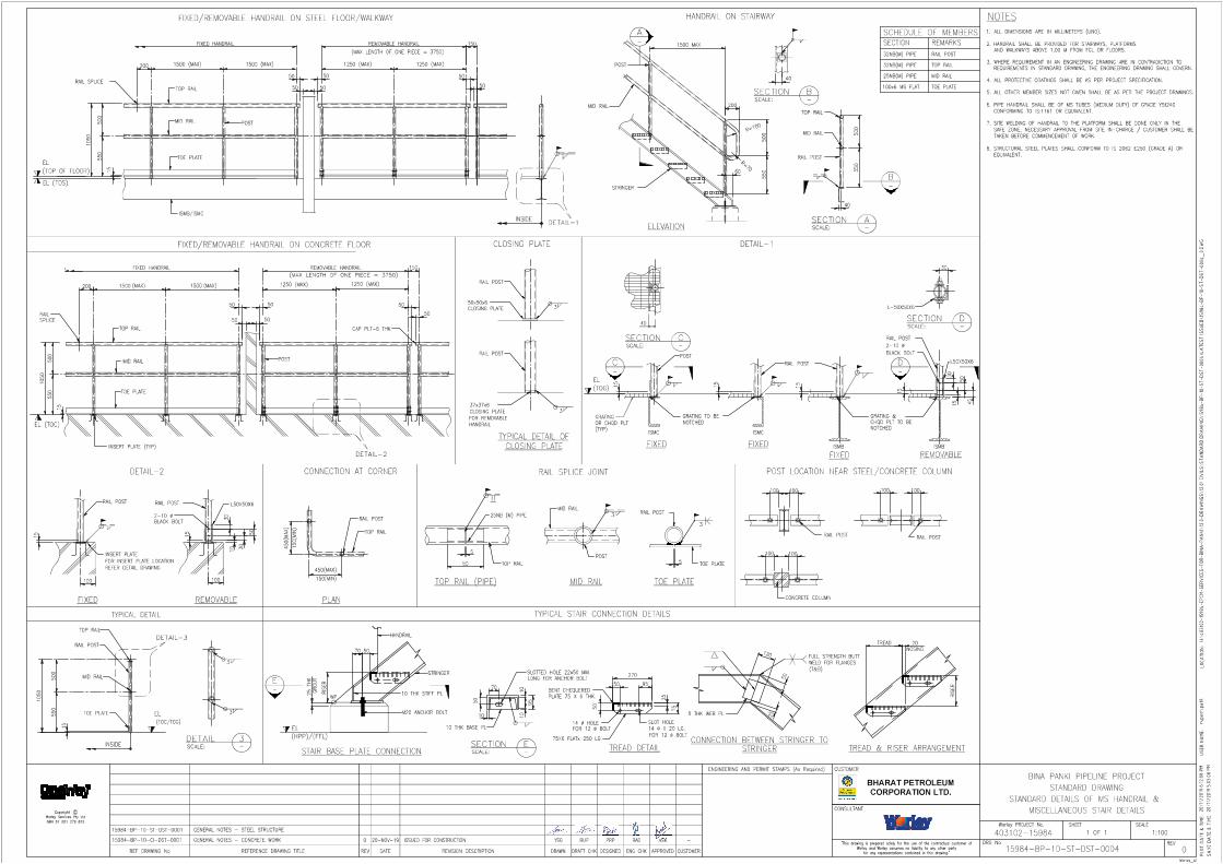

SUPPLY OF ANTI STATIC ADDITIVE DOSING PACKAGE AT PANKI (KANPUR) TERMINAL AND IRUGUR (COIMBATORE)
TERMINAL FOR
ATF PUMPING IN BINA PANKI AND COCHIN COIMBATORE PIPELINE

1. SCOPE OF WORK / SUPPLY:
The scope of work covered in this Contract shall be as described in Tender document, Technical specifications, Data sheets, Standard Specifications, Schedule of Rates etc.
Supplier’s scope shall include but not limited to;
(a) manufacturing of Items as per Tender including Technical Specifications, data sheets etc;
(b) preparation of Quality Assurance / Quality control program;
(c) obtaining Consultant’s approval;
(d) Inspection as per ITP/QAP approved by Owner/WPIL
(e) Despatch of the shipment after obtaining Inspection Release Note & Despatch clearance from BPCL
(f) Packing, loading and Transportation
(g) Supply of Mandatory Spares
(h) Supervision Services for Installation, Pre-commissioning and Commissioning.
It is however, explicitly understood that scope described above is not limiting, in so far as the responsibilities of the contractor are concerned and shall include, inter alia, carrying out any and all works and providing any and all facilities as are required to complete the works in all respect.
2. TIME OF COMPLETION
The delivery period shall be (4) Four Months on FOT Site basis from the date of Letter of Acceptance. Date of receipt of material at site/designated delivery location shall be considered as the date of delivery.
Failing to meet delivery schedule will be subject to Price Reduction and / or other remedies available to the Purchaser in Bidding Documents.
3. INSPECTION OF SUPPLY ITEMS / MATERIALS:
(a) All inspection and tests on bought out items / materials shall be made as per Approved ITP/ QAP, Specifications forming part of this contract.
(b) Inspection of finished goods / items supplied by Indian bidders shall be in the scope of BPCL / it’s appointed TPIA as per approved QAP. However raw material, consumables, any other stage wise inspection shall be to supplier’s account and this shall be done by TPIA appointed by supplier.
(c) BPCL / it’s appointed TPIA shall perform inspection and expediting of finished goods / items supplied from Indian and Foreign Sources and no additional charges shall be payable by seller on account of the same. All personal / incidental expenses including boarding, lodging, tickets, travel expenses, fees etc. of the inspectors shall be borne by the Purchaser.
(d) The Contractor shall ensure full and free access to the inspection engineer of Owner / at the Contractor’s or their sub-contractor’s premises at any time during contract period to facilitate him to carry out inspection and testing assignments.
(e) The Contractor / sub-contractor shall provide all instruments, tools, necessary for testing and other inspection facilities to inspection engineer of Owner / free of cost for carrying out

inspection.
(f) QAP will be approved by BPCL or nominated Inspection agency incorporating requirements of Inspection and Test Plan, Technical specifications provided with Purchase Order / Contract document.
(g) The Inspection release note issued by the Inspection agency shall clearly stipulate that materials / equipment have been inspected as per Code-1 approved drawings and approved QAP.
(h) Certification of final documents, wherever applicable, for release of final payment, shall be carried out by Inspection Authority issuing the final inspection certificate and accepted by Owner.
4. TERMS OF PAYMENT
Note: No Advance payment is permissible in the contract
A. SUPPLY:
(i) 90% payment within 30 days after receipt of equipment / materials at BPCL’s site.
(ii) 5% payment within 30 days after receipt of final documents as specified in VDRL in Purchase Requisition against BPCL’s certification.
(iii) Balance 5% against commissioning or 6 months from receipt of material at site (against BG of equivalent amount valid for 1 year), whichever is earlier. This BG is to be submitted in addition to the submission of Contract Performance Bank Guarantee.
Bidder to note that in the event of delay in commissioning, the bidder is not relieved of his responsibility of carry out commissioning and in this case the per diem rates quoted by the bidder shall prevail till the completion of the work.
B. Supervision of Installation / Erection, Pre-Commissioning,
Commissioning & Training:
100% of invoice amount shall be paid on completion of services against submission of Invoice after the time sheet duly certified by BPCL Site In Charge. Payment shall be made after deduction of applicable taxes / duties as per prevailing rate at time of payment.
5. Price Reduction for delay in Supervision services:
For supervision of Installation/Pre-Commissioning/commissioning as mentioned in Tender Documents, penalty for non-mobilization/delay in mobilization shall be applicable.
Vendor’s personnel shall be required to reach site within 7 days from the date of written
intimation by BPCL for such supervision services.
The penalty shall be 1.5 times the per diem rate for each day of delay of reporting to site and shall be in addition to price reduction for delayed delivery. Recovery towards delay in mobilization shall be made from any payment due to vendor

6. STATUTORY APPROVAL
Approval from any authority (as applicable & as specified in the Tender Document) required as per statutory rules and regulations of Central / State Government shall be the responsibility of supplier and the quoted prices shall be inclusive of the same.
The application on behalf of the OWNER for submission to relevant authorities along with copies of required certificate complete in all respects shall be prepared and submitted by the supplier well ahead of time so that the actual construction / commissioning of the work is not delayed for want of the approval / inspection by concerned authorities.
The supplier shall carry out any change / addition required to meet the requirements of the statutory authorities, within the quoted rates. The inspection and acceptance of the work by statutory authorities shall be the responsibility of the supplier.
List of all documents, drawings, forms, affidavits etc. required for the approvals shall be submitted by the supplier.
7. MAKE OF MATERIALS:
The bought out materials required to be supplied by the Bidder, under this Contract shall be procured only from Owner’s recommended list of vendors. In case the makes of materials are not indicated under this SPC, Annexure-I, then in such scenario any other make proposed by bidder shall be accepted by Owner only if the proposed make, for equivalent service / rating as per tender requirement, is approved with / by Oil PSUs i.e HPCL, ONGC, IOCL & Other PSUs. Bidder shall furnish the details (Past track record / credentials) of such proposed makes and shall obtain prior approval of Owner before commencement of procurement action of the items. Bidder shall not procure any item from vendors not approved by Owner.
Any other bought out items being supplied by the bidder that are not covered under the Annexure- I, shall be of reputed make, for equivalent service / rating as per tender requirement and approved with/by Oil PSUs i.e HPCL, ONGC, IOCL & other Oil PSUs and EIL, MECON. Bidder shall furnish the details (Past track record / credentials) of such proposed makes and shall obtain prior approval of Owner before commencement of procurement action of the items. Bidder shall not procure any item from vendors not approved by Owner.

Annexure I of SPC
LIST OF OUR RECOMMENDED MAKES
MOTOR
1. ABB LTD. 2. BHARAT BIJLEE LTD. 3. CROMPTON GREAVES LTD. 4. KIRLOSKAR ELECTRIC CO. LTD. 5. MARATHON ELECTRIC (FORMERLY ALSTOM LTD) 6. SIEMENS
VFD
1. HITACHI HIREL 2. SIEMENS LTD. 3. ABB LTD. 4. DANFOSS 5. SCHNEIDER
PRESSURE GAUGES
1. GENERAL INSTRUMENTS CONSORTIUM 2. WIKA INSTRUMENTS INDIA PVT.LTD. 3. GLUCK 4. WAREE INSTRUMENTS LTD. 5. PRECISION (ASHCROFT) 6. ODIN
CHECK VALVES
1. ADVANCE VALVES PVT. LTD. INDIA 2. BDK VALVES 3. LEADER VALVES LTD. 4. FOURESS ENGINEERING (I) LTD. 5. INTERVALVE (I) LTD.
PRESSURE TRANSMITTER
1. EMERSON PROCESS MANAGEMENT (INDIA) PVT. LTD. 2. HONEYWELL AUTOMATION (INDIA) LTD. INDIA 3. YOKOGAWA INDIA LTD. 4. KROHNE MARSHALL PVT. LTD. INDIA 5. ABB LTD 6. GAUGES BOURDON (INDIA) PVT.LTD

PRESSURE RELIEF VALVES
1. INSTRUMENTATION LTD.
2. TYCO SANMAR LTD. 3. SEBIM VALVES INDIA PVT. LTD. 4. FAINGER LASER
LEVEL GAUGES
1. CHEMTROLS ENGINEERING LTD. 2. BLISS ANAND 3. LEVCON INSTRUMENTS PVT. LTD. 4. PRATOLINA INSTRUMENTS PVT. LTD. 5. V. AUTOMAT & INTRUMENTS PVT. LTD. 6. GAUGES BOURDON (INDIA) PVT.LTD
LEVEL TRANSMITTER
1. EMERSON PROCESS MANAGEMENT (INDIA) PVT. LTD. 2. ENDRESS + HAUSER (INDIA) PVT. LTD. INDIA 3. KROHNE MARSHALL PVT. LTD. INDIA 4. MAGNETROL INTERNATION INC.
MASS FLOW METERS
1. EMERSON PROCESS MANAGEMENT (INDIA) PVT. LTD. INDIA 2. ENDRESS + HAUSER (INDIA) PVT. LTD. 3. FLUID COMPONENT 4. KROHNE MARSHALL PVT. LTD. 5. MICRO MOTION INDIA 6. YOKOGAWA (INDIA) LTD. INDIA
JUNCTION BOXES & CABLE GLAND
1. BALIGA LIGHTING EQUIPMENTS PVT.LTD. 2. COMET GLASS PRODUCTS (ONLY CABLE GLANDS) 3. COMET INDUSTRIES (ONLY CABLE GLANDS) 4. FCG FLAMEPRPOOF CONTROLGEARS PVT. LTD. 5. FCG POWER INDUSTRIES LTD 6. SUDHIR SWITCHGEAR PVT. LTD. 7. R. STAHL (P) LTD.
FLAME ARRESTOR
1. PROTEGO 2. NIRMAL INDUSTRIES CONTROL PVT. LTD. 3. FAINGER ENGINEERING 4. AMARAMA ENGINEERS 5. KINSLEY

Annexure-III Terms and conditions for Supervision of
Installation, Pre-Commissioning and Commissioning, training
1) Bidder shall quote per diem charges for Supervision of Installation, Pre-Commissioning &
Commissioning as specified in the material requisition and schedule of quantities for this package, which shall include lodging, boarding, medical, local transport, all insurances, visa charges, taxes & duties (as may be applicable) and all other incidental charges.
2) The successful bidder shall be paid for actual number of days spent for Supervision of
Installation, Pre-Commissioning & Commissioning. No payment will be made for travel days / period.
Working hours prevailing at site, normally 8 hours/day – Monday to Saturday and holidays as applicable to Owner’s site personnel shall apply.
Extra payment for additional man days will be paid, as per quoted rates, only if reasons are not attributable to the bidder and are solely attributable to the owner.
3) Bidder will be responsible for all liabilities towards corporate tax, personal income tax and GST (as may be applicable) for their personnel deputed for the supervision job.
4) All the service engineers/ personnel, as required, deployed by OEM for supervision of Installation, Pre-Commissioning & Commissioning of this Package) shall be competent, qualified and trained personnel and shall have minimum 5 years of relevant previous experience in commissioning / maintenance of similar package.
5) Vendor’s personnel shall be required to reach site within 7 days from the date of intimation by BPCL for the supervision. Failing which, bidder shall liable for penalty. Vendor’s supervisory personnel to observe / abide by the working conditions, safety codes & Indian Laws.

Annexure S
TWO YEARS OPERATION & MAINTENANCE SPARE PART DETAILS
TO BE FILLED BY BIDDER & SUBMITTED WITH TECHNICAL BID
Sr.
No. Line Description Description of Spares Unit Qty
1 SPARE 1
2 SPARE 2
3 SPARE 3
4 SPARE 4
5 SPARE 5
6 SPARE 6
7 SPARE 7
8 SPARE 8
9 SPARE 9
10 SPARE 10
11 SPARE 11
12 SPARE 12
13 SPARE 13
14 SPARE 14
15 SPARE 15
Stamp and Signature of Bidder

Note to Bidder for Two years Operation & Maintenance Spares :
1. Bidder to submit duly filled, signed, stamped Annexure S with Technical Bid.
2. Bidder to indicate description of Spare Part & quantity against each line item for the quoted schedules.

SOQ FOR ASA DOSING PACKAGE
ITEM NO.
SHORT
DECRIPTION
DESCRIPTION
UOM
Qty
1
SUPPLY_ASA DOSING PACKPAGE_PANKI
Supply of Anti Static Additive Dosing
Package: Complete with design,
engineering, materials, manufacturing,
fabrication, assembly, procurement of
bought out items, quality assurance and
quality control, inspection, testing,
painting, documentation, certification,
packing, forwarding and transportation
to site, supply of all items, performance
guarantee of complete package listed in
the tender document, all referenced
specifications, documents, drawings,
codes and standards including
Mandatory spares, Pre-commissioning /
commissioning spares, Special Tools &
Tackles (As per scope of supply and
works mentioned in the tender document
for Tag No: 10-100-AS-PK-001).
Tag No: 10-100-AS-PK-001 at Panki (Kanpur) Terminal
Nos.
1
2
SUPPLY_ASA DOSING PACKPAGE_IRUGUR
Supply of Anti Static Additive Dosing
Package: Complete with design,
engineering, materials, manufacturing,
fabrication, assembly, procurement of
bought out items, quality assurance and
quality control, inspection, testing,
painting, documentation, certification,
packing, forwarding and transportation
to site, supply of all items, performance
guarantee of complete package listed in
the tender document, all referenced
specifications, documents, drawings,
codes and standards including
Mandatory spares, Pre-commissioning /
commissioning spares, Special Tools &
Tackles (As per scope of supply and
works mentioned in the tender document
for Tag No: 10-100-AS-PK-002).
Tag No: 10-100-AS-PK-002 at Irugur (Coimbatore) Terminal
Nos.
1

3
SUPERVISION CHARGES
Supervision Charges for Installation /
Pre-commissioning / Commissioning of
items specified under Sr. No.1 above for
ASA Package for services to be
carried out in Kanpur site.
Mandays
4
4
SUPERVISION CHARGES
Supervision Charges for Installation /
Pre-commissioning / Commissioning of
items specified under Sr. No. 2 above for
ASA Package for services to be
carried out in Coimbatore site.
Mandays
4

Annexure: A
Date:
CERTIFICATE CONFIRMING ELIGIBILTY FOR BENEFITS OF PUBLIC PROCUREMENT POLICY (To submitted at bidding stage by Bidder seeking benefits under MSE policy)
Ref: Tender No………….. for……………………………………………………………
This is to confirm that we have verified the investment limits and other details of Unit _ pertaining to M/s and certify that they satisfy the eligibility criteria as per MSMED Act, 2006 and other notifications/circulars/amendments issued from time to time in this regard. Accordingly, M/s is a Micro/Small enterprise (strike out which is not applicable) under the said Act and are eligible to claim the benefits of public procurement policy for the tender mentioned above.
In case applicable:
Based on our verification of share holding pattern and other details, it is certified that M/s meets the eligibility criteria under SC/ST provision of Public Procurement Policy Order 2012 and other notifications/circulars issued from time to time in this regard and are hence eligible to claim benefits pertaining to SC/ST under the act.
In case applicable:
Based on our verification of share holding pattern and other details, it is certified that M/s __________meets the eligibility criteria under Women Entrepreneur provision of Public Procurement Policy Order 2012 and other notifications/circulars issued from time to time in this regard and are hence eligible to claim benefits pertaining to Women Entrepreneur under the Act.
Name of CA Firm: [Signature of Authorized Signatory]
Name:
Date: Designation:
Seal:
Membership no.
UDIN No.

Annexure-B
UNDERTAKING FOR APPLICABILITY OF PURCHASE PREFERENCE POLICY
[To be submitted at bidding stage (applicable for tender of quoted value more than 1 Crore)]
To,
M/s BHARAT PETROLEUM CORPORATION LIMITED CPO (MARKETING), SEWREE, MUMBAI-400015
TENDER TITLE:
TENDER REF. NO. :
Dear Sir
We, M/s_ _ (Name of Bidder) hereby confirm that following purchase preference to be considered (please write YES/ NO) :-
Description Preference Purchase Preference (linked with local content)
OR
Purchase Preference under Public Procurement Policy for MSE
Note: (i) Please indicate your preference against only one policy. (ii) The above preference shall be extended only after submission of requisite documents (as
mentioned in the tender documents). (iii) In case a bidder is eligible to seek benefit under PP-LC policy as well as under MSE 2012, then
the bidder should categorically seek benefits against only one of the two policies i.e. either PP- LC or MSE policy.
(iv) In case an MSEs bidder opts for purchase preference based on PP-LC, he shall not be entitled to claim purchase preference benefit available to MSE Bidders under PPP for MSE 2012. However, the exemptions from furnishing Bidding Document fee and Bid security/EMD shall continue to be available to such MSE Bidders.
(v) The option once exercised cannot be modified subsequently.
Place: [Signature of Authorized Signatory of Bidder having power of Attorney] Date:
Name:
Designation:
Seal:

Annexure-C
UNDERTAKING BY BIDDER TOWARDS MINIMUM LC (Self – Declaration as per PP-LC Policy)
[To be submitted at bidding stage (applicable for tender of quoted value more than Rs. 1 Crore)]
To,
M/s BHARAT PETROLEUM CORPORATION LIMITED CPO (MARKETING), SEWREE, MUMBAI-400015
TENDER TITLE:
TENDER REF. NO. :
Dear Sir,
We, M/s.......................................(Name of Bidder) have submitted bid against aforesaid tender.
We have read and understood the PPLC policy attached with the tender document. Accordingly, we hereby confirm that our local content percentage for the tendered item is .................... %.
We further confirm that in case we fail to meet the above mentioned local content, BPCL will take action as per provisions of tender document/ PPLC Policy.
Place: [Signature of Authorized Signatory of Bidder having Power of Attorney] Date:
Name:
Designation:
Seal:
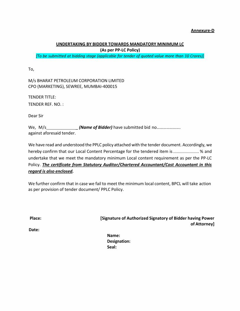
Annexure-D
UNDERTAKING BY BIDDER TOWARDS MANDATORY MINIMUM LC (As per PP-LC Policy)
[To be submitted at bidding stage (applicable for tender of quoted value more than 10 Crores)]
To,
M/s BHARAT PETROLEUM CORPORATION LIMITED CPO (MARKETING), SEWREE, MUMBAI-400015
TENDER TITLE:
TENDER REF. NO. :
Dear Sir
We, M/s _ (Name of Bidder) have submitted bid no…………………. against aforesaid tender.
We have read and understood the PPLC policy attached with the tender document. Accordingly, we hereby confirm that our Local Content Percentage for the tendered item is ...................... % and undertake that we meet the mandatory minimum Local content requirement as per the PP-LC Policy. The certificate from Statutory Auditor/Chartered Accountant/Cost Accountant in this regard is also enclosed.
We further confirm that in case we fail to meet the minimum local content, BPCL will take action as per provision of tender document/ PPLC Policy.
Place: [Signature of Authorized Signatory of Bidder having Power of Attorney]
Date: Name: Designation: Seal:

Annexure-E
CERTIFICATE BY CHARTERED ACCOUNTANT OF BIDDER TOWARDS MANDATORY MINIMUM LC (As per PP-LC Policy)
[Format for CA Certificate in respect of other than company (applicable for tender of quoted value more than 10 Crores )]
To,
M/s BHARAT PETROLEUM CORPORATION LIMITED CPO (MARKETING), SEWREE, MUMBAI-400015
TENDER TITLE:
TENDER REF. NO. :
Dear Sir
We,………………………………………. (Name of the issuing CA Firm) have verified relevant records of M/s ..................................................................................... (Name of the bidder) and we certify that their Local Content Percentage for the tendered item is ...................... %. We hereby also certify that they meet the mandatory minimum Local content requirement as per the PP-LC Policy.
Name of CA Firm: [Signature of Authorized Signatory]
Name:
Date: Designation:
Seal: Membership no.
UDIN No.

Annexure-F
CERTIFICATE BY STATUTORY AUDITORS OF BIDDER TOWARDS MANDATORY MINIMUM LC (As per PP-LC Policy)
[Format for Certificate from Statutory Auditor/Cost Auditor in case of company (applicable for tender of quoted value more than 10 Crores)]
To,
M/s BHARAT PETROLEUM CORPORATION LIMITED CPO (MARKETING), SEWREE, MUMBAI-400015
TENDER TITLE:
TENDER REF. NO. :
Dear Sir
We,………………………………………. (Name of the Statutory Auditor/Cost Auditor) have verified relevant records of M/s .......................................... (Name of the bidder) and wecertify that their Local Content Percentage for the tendered item is ...................... % . We hereby also certify that they meet the mandatory minimum Local content requirement as per the PP-LC Policy.
Name of Audit Firm: [Signature of Authorized
Signatory] Name:
Date: Designation:
Seal: Membership
no. UDIN No.

COMPLIANCE OF RESTRICTIONS FOR COUNTRIES WHICH SHARE LAND BORDER WITH INDIA
Restrictions under Rule 144(xi) of the General Financial Rules, 2017–Reference OM no. 6/18/2019 – PPD dtd. 23.07.2020 (read along with any subsequent clarifications/ amendments thereof) issued by Ministry of Finance, Public Procurement Division (https://doe.gov.in/procurement-policy-divisions)
(I) Any bidder* from a country which shares a land border with India will be eligible to bid in this tender only if bidder is registered with Competent Authority. The Competent authority for the purpose of registration shall be the Registration Committee constituted by the Department of Promotion of Internal Trade (DPIIT) of Govt. of India. (* In case of domestic tenders, the term “bidder” shall mean domestic bidders as defined under clause III below)
(II) “Bidder” (Including the term ‘Tenderer’, ‘Consultant’ or ‘Service Provider’ in certain contexts) means any person or firm or company, including any member of a consortium or joint venture (that is an association of several persons, or firms or companies), every artificial juridical person not falling in any of the descriptions of bidders stated herein before, including any agency branch or office controlled by such person, participating in a procurement process.
(III) “Bidder from a country which shares a land border with India” means:
a) An entity incorporated, established or registered in such country; or b) A subsidiary of an entity incorporated, established or registered in such country; or c) An entity substantially controlled through entities incorporated, established or registered in such country; or d) An entity whose beneficial owner is situated in such a country; or e) An Indian (or other) agent of such an entity; or f) A natural person who is a citizen of such a country; or g) A consortium or joint venture where any member of the consortium or joint venture falls under any of the above.
(IV) “Beneficial owner” for the purpose of para (III) above will be as under:
1. In case of a company or Limited Liability Partnership, the beneficial owner is the natural person(s), who, whether acting alone or together, or through one or more juridical person(s), has a controlling ownership interest or who exercises control through other means. Explanation:
a. “Controlling ownership interest “means ownership of an entitlement to more than
twenty-five percent of shares or capital or profits of the company;
b. “Control shall include the right to appoint majority of the directors or to control the management or policy decisions including by virtue of their shareholding or management rights or shareholders agreements or voting agreements;

2. In case of a partnership firm, the beneficial owner is the natural person(s) who, whether acting alone or together, or through one or more juridical person, has ownership of entitlement to more than fifteen percent of capital or profits of the partnership;
3. In case of an unincorporated association or body of individuals, the beneficial owner is the natural person(s), who, whether acting alone or together, or through one or through one or more juridical person(s), has ownership of or entitlement to more than fifteen percent of the property or capital or profits of such association or body of individuals;
4. Where no natural person is identified under (1) or (2) or (3) above, the beneficial owner is the relevant natural person who holds the position of senior managing official;
5. In case of a trust, the identification of beneficial owner(s) shall include identification of the author of the trust, the trustee, the beneficiaries with fifteen percent or more interest in the trust and any other natural person exercising ultimate effective control over the trust through a chain of control or ownership.
(V) An “Agent” is a person employed to do any act for another, or to represent another in dealings with third person.
(VI) The successful bidder shall not be allowed to sub-contract works to any contractor from a country which shares a land border with India unless such contractor is registered with the Competent Authority.
# # # # #
The format for Undertaking by the Bidder, is provided on next page.

FORMAT For
Undertaking with respect to Compliance of Restrictions for Countries which share land border with India – as stipulated by Govt. of India.
(On Company Letter Head, to be signed by the duly authorized person)
Date:
TENDER NO. : ………………
TITLE OF TENDER : ………………………………………………………………………………
To, Bharat Petroleum Corporation Ltd CPO-M, A-Installation Sewri Fort Road, Sewri East Mumbai-400015
Dear Sir/Madam,
In line with the guidelines issued for compliance of Restrictions for Countries which share land border with India – as issued by Govt. of India in July’2020,
I/We have read the clause regarding restrictions on procurements from a bidder of a country which shares a land border with India and on sub-contracting to contractors from such countries.
a. I/We certify that this bidder is not from such a country or if from such a country has been registered with the competent authority. I hereby certify that this bidder fulfills all requirements in this regard and is eligible to be considered*.
b. I/We certify that this bidder is not from such a country or if from such a country has been registered with the competent authority and will not sub-contract any work to a contractor from such countries unless such contractor is registered with the competent authority. I hereby certify that this bidder fulfills all requirements in this regard and is eligible to be considered*.(Applicable for works involving possibility of sub-contracting)
I/We hereby certify that I/We fulfill all requirements in this regard and am/are eligible to be considered.
[ * Where applicable, evidence of a valid registration by the Competent Authority shall be attached]
Name and Signature of the Authorised Signatory

CONFIDENTIAL 1
BHARAT PETROLEUM CORPORATION LIMITED
SOCIAL MEDIA POLICY FOR BUSINESS PARTNERS

CONFIDENTIAL 2
Contents
1. OBJECTIVE ........................................................................................................ 3
1.1. Social Media ................................................................................................ 3
1.2. Scope and Applicability .............................................................................. 4
1.3. Relevant Documents ................................................................................... 4
2. CONTENT GUIDELINES .................................................................................... 4
3. ACCEPTABLE USAGE OF SOCIAL MEDIA...................................................... 7
4. ENFORCEABILITY AND COMPLIANCE ......................................................... 10
ANNEXURE I ........................................................................................................... 11
ANNEXURE II .......................................................................................................... 12
ANNEXURE III ......................................................................................................... 13

CONFIDENTIAL 3
TERMS AND CONDITIONS FOR ACCEPTABLE USE OF SOCIAL MEDIA BY
BUSINESS PARTNERS
1. OBJECTIVE Social media has become part of everyday life and a means of communication and sharing information with others. Every organization recognises the benefits that social media tools can provide, and also reckons the challenges it brings. These terms and conditions (“Social Media T&Cs”) seek to provide clear guidance on acceptable standards of conduct and practices to be followed by the Business Partners (as defined below) of Bharat Petroleum Corporation Limited (“Corporation”), in the usage of social media tools during and post their association with the Corporation. These terms and conditions are intended to protect and safeguard inter alia the interests and reputation of the Corporation, in the access, use of or participation on Social Media (as defined below) platforms by such constituents. It is important to maintain the highest degree of professional standard that is associated with the Corporation’s name, brand and reputation. Constituents must constantly be aware of the risk of damaging the Corporation’s name or reputation in public forums. These terms and conditions should be adhered to by each constituent at all times and should be read harmoniously and in conjunction with the terms of their engagement with the Corporation, as well as other applicable policies and directions issued by Corporation, from time to time, including the Relevant Documents (as defined below).
1.1. Social Media Social Media includes any web or mobile based platform that enables an individual or agency to communicate interactively and enables exchange of user generated content. The term “Social Media” describes internet-based technologies and practices that people use to share opinions, insights, experiences and perspectives. It may be internal (housed within the Constituent’s technology infrastructure and open for use only by the Constituents) or public (widely available to the population of internet users). These terms and conditions are applicable equally to a wide range of websites and mobile phone / tablet applications, including the following: (a) Social Networking sites, for example - Facebook, Twitter, and LinkedIn. (b) Media Sharing sites, for example - Instagram, Snapchat, YouTube (c) Discussion forums, for example - Reddit, Quora, Digg, Glassdoor (d) Content Curation network, for example - Pinterest, Flipboard

CONFIDENTIAL 4
(e) Blogging and Publishing sites, for example - WordPress, Tumblr, Medium including blogs
(f) Interest-based network, for example - Goodreads, Houzz (g) Information sharing sites, such as Wikipedia (h) Opinion sites (e.g. Yahoo! Answers) (i) Any other social media platform/s
1.2. Scope and Applicability
These Social Media T&Cs are applicable to all Business Partners (as defined below), including any prospective partners of the Corporation (the “Constituents”).
The Social Media T&Cs provides a framework for the usage of Social Media by the Constituents and non-conformance with these Social Media T&Cs or any other applicable policy or directions issued by the Corporation as may be relevant to the Constituents, may result in penalties ranging from financial to legal liabilities, as set out under the respective contractual understanding between each Business Partner and the Corporation.
1.3. Relevant Documents These Social Media T&Cs have been formulated in line with the Framework & Guidelines for Use of Social Media for Government Organizations, issued by the Department of Electronics and Information Technology, Ministry of Communications & Information Technology, Government of India. In addition, these Social Media T&Cs must be read in conjunction with the underlying contract documents including the following documents (collectively, the “Relevant Documents”), as may be applicable to each Constituent:
(a) General Conditions of Contract for vendors (relevant clauses are placed at
Annexure I);
(b) Transportation Contract Agreement Bulk LPG Transportation Contract By Road (relevant clauses are placed at Annexure II);
(c) PCVO, Retail and Lubes Transport guidelines.
2. CONTENT GUIDELINES This section seeks to set out the guidelines for content management as well as administration rights of all official Business Partner Social Media accounts and ensure accountability of the authorised representatives of such Business Partner. The following guidelines on content sharing (“Content Guidelines”) must be followed, in relation to all content created, posted or shared on Social Media:

CONFIDENTIAL 5
(a) All post and other content shared via Social Media shall abide by applicable laws, including the Information Technology Act, 2000 and rules made thereunder, as amended.
(b) The content posted or shared though official Social Media accounts, shall be relevant, engaging and in line with the Corporation’s brand and communication strategy, whether in the form of text, images, gifs, videos, etc.
(c) The Constituents shall be mindful of content and the tone associated with
it. A negative tonality, sarcasm, dry humour, pun, memes, etc. should be avoided to steer clear from any controversy.
(d) The Constituents shall be careful and ensure that any content posted or shared through the official Social Media accounts does not bring disrepute to the Corporation. Opinion or comments on political observations, religious beliefs, gender biases, etc. must be avoided while operating official Social Media accounts. In the use of official Social Media accounts, the Constituents shall refrain from forwarding or sharing any videos or images or messages, which are considered inappropriate or any content that is considered offensive, obscene or derogatory in nature.
(e) The Constituents shall be cognizant of concerns regarding confidentiality
and disclosure requirements, and must at all times, adhere to the Relevant Documents as well as these terms and conditions, to understand what shall be disclosed on a public platform. For instance any communication marked as “privileged” or “restricted” or “confidential” or “not for circulation” should not be shared on Social Media. The Constituents are absolutely prohibited from disclosing commercially sensitive, anticompetitive, private or confidential information. If unsure whether the information that is proposed to be shared falls within one of these categories, authorised representatives of the Constituent may discuss with the concerned official as designated by the Corporation.
(f) The Constituents shall ensure that any references to the Corporation or its employees, or other customers, partners and vendors do not contravene any non-disclosure agreements. The Constituents shall avoid disclosure of any information pertaining to any employee / vendor / customer or individual associated with the Corporation, without their prior consent.
(g) The Constituents shall be vigilant about tagging, mentions and conversations around the Corporation. If it notices any customer complaint, dealer/ distributor/ vendor grievances, media story etc., the same may be flagged to the official channels of the Corporation and will be responded to by authorized personnel within the Corporation.
(h) In the operation of official Social Media accounts, the Constituents shall be cognizant of maintaining professional etiquette for all interactions and shall not initiate or engage in discussions which may be characterised as showcasing a personal opinion such as political or religious beliefs. In
CONFIDENTIAL 6
addition, official Social Media accounts should not share any content or comment that may be viewed as colouring the relations between the Corporation and the Government of India or any Ministry / Department of the Central or State Governments.
(i) The Constituents, particularly in the use of official Social Media accounts, shall only post original content, which is free of any copyright infringement or plagiarism. To ensure the reputation and principles of the Corporation are safeguarded, all Constituents must avoid posting content that violates the law, infringes the intellectual property rights of the Corporation and its group companies or of any individual or organization. Any inadvertent posts, which violates these principles, must be removed / deleted immediately upon becoming aware of the implications as set out in these guidelines.
As responsible business partners of the Corporation, the following points must be strictly observed and followed by the Constituents: (i) Text, photos, images, musical work in any form, video clips, movie
clips, or any other content for which the Constituent does not own copyright, must not be used in any form, and in particular for official purposes to promote any activities related to the Corporation, without obtaining consent from the copyright owner. If the copyright owner for such work cannot be identified or if the consent for use of such work is not provided by the copyright owner, the work must not be used by the Constituent.
(ii) Capturing photographs and/or videos of the Corporation’s offices,
facilities, and other establishments (within or outside) or customer sites is strictly prohibited. Any such illegal images and/or videos of the Corporation’s establishments, offices, facilities and factories or other sites and whether directly emailing or otherwise circulating such content via Social Media posts on the Internet, shall attract legal consequences. Official visual materials may be availed from the Corporation and can be requested through email, to the relevant State / Territory team.
(iii) Creation, sharing and/or distribution of videos which make use of
unlicensed music is strictly prohibited.
(iv) Unauthorized videos of any events hosted by the Corporation, whether within or outside the Corporation’s premises that may be captured by Constituents shall not be shared/distributed on Social Media.
(v) All Constituents must take due care to protect the Corporation’s
copyright and intellectual property within and outside the organization.

CONFIDENTIAL 7
(j) The authorised personnel operating official Social Media accounts of respective Business Partner shall not post unverified news, or news from dubious ‘sources’, that may project the Corporation in a negative light.
(k) The admins operating official Social Media accounts shall clearly state the source and give due disclaimers while quoting any third-party content through such Social Media accounts.
(l) Additionally, content on official Business Partner Social Media Accounts shall be limited to the coverage of activities related to the business only. However, these accounts can re-share / retweet the posts of Corporation’s official Social Media accounts, subject to the veracity of such accounts.
3. ACCEPTABLE USAGE OF SOCIAL MEDIA BY BUSINESS PARTNERS
The following guidelines are applicable to vendors, suppliers and other contractors of the Corporation (“Business Partners”), and these are intended to supplement, and do not to replace the terms and conditions or any other agreement or guidelines (including the applicable provisions set out under Annexure I or II of these Social Media T&Cs), which are currently in place to regulate the conduct of such Business Partners:
(a) Business Partners have the discretion to decide whether their Social Media
accounts will be used for personal or professional purposes. However, in any event, whether such Social Media accounts are used for official purposes or personal purposes, to the extent that they declare their affiliation with the Corporation in any way, it is deemed that they will abide by these terms and conditions read with the applicable contractual provisions and the Framework & Guidelines for Use of Social Media for Government Organizations, issued by the Department of Electronics and Information Technology, Ministry of Communications & Information Technology, Government of India.
(b) Only official Business Partners accounts are eligible to declare their
association with the Corporation or using any content owned by or belonging to the Corporation, including logo, product specifications, product pictures, product catalogues, etc. Such accounts may only post content that are official in nature and reasonably expected to promote the activities specific to its business. Such official Business Partner Social Media account shall be akin to a professional page to promote business interactions and shall not post any content which may showcase the account as expressing opinion on ancillary matters which are not in furtherance of the objective set out under the Relevant Documents, such as posts related to entertainment industry, or political views etc. However, such affiliation or use of Corporation’s content, such as logo, product pictures etc. is only limited to use by official Social Media accounts of such Business Partner, and will not, at any time, be used by any authorised or other personnel of such Business Partner, in the operation of a personal Social Media account.

CONFIDENTIAL 8
(c) Every Business Partner’s official or personal (individual) Social Media account is prohibited from posting / circulating any official communication / document or disclosing any business-related or other confidential information, pertaining to the Corporation, in accordance with the Relevant Documents.
(d) Each Business Partner Social Media account, particularly those accounts which have been permitted to acknowledge their association with the Corporation, has an obligation to exercise caution in the posting or sharing of content on Social Media, and shall undertake adequate diligence prior to posting any content. In particular, such accounts shall be fully cognizant of posting or providing traction to any ‘fake news’ and shall refrain from posting or sharing unlawful, controversial or unverified news, or news from dubious ‘sources’, particularly in relation to the Corporation and the Central / State Governments.
(e) The Business Partner Social Media account which are maintained for official
purposes, shall refrain from engaging in unlawful or inappropriate posts or sharing any content that may be defamatory or may have the effect of downplaying the Corporation’s business or competitors. In addition, such account should also not post or share content using derogatory language or is likely to demean sentiments of anyone with whom they engage in any public communication using Social Media.
(f) Business Partners using Social Media for official purposes and especially
those accounts that have been approved by the Corporation, shall maintain professional and proper etiquette in online interaction via Social Media and shall not engage in inappropriate behaviour. Such inappropriate behaviour includes but may not be limited to posting, sharing or endorsing in any form, any content which may be considered as:
(i) Divisive, unethical or unlawful at the workplace;
(ii) False, or derogatory, or amounting to bullying, trolling, intimidating, or harassing including using offensive, defamatory, threatening, discriminating, obscene or insulting language;
(iii) A misrepresentation of the Corporation, such as creating any unofficial groups or networks (whether intentional or unintentional) using the Corporation’s name, logo, or email address;
(iv) Compromising the confidentiality (of the Constituents and/or the Corporation’s information), or creating a conflict of interest;
(v) Disclosing commercially sensitive, anticompetitive, or information which is marked as restricted for internal circulation within the Corporation;
(vi) Misleading and misrepresentative, such as creating or endorsing any video channel / account representing the Corporation or any specific Business Unit, or otherwise posting or sharing any content owned by the

CONFIDENTIAL 9
Corporation, unless such content has been posted on verifiable official Social Media accounts of the Corporation;
(vii) Amounting to pornographic material (that is, writing, pictures, films and video clips of a sexually explicit nature) or content that could be considered as offensive, obscene or criminal; or
(viii) Creating or likely to create any liability (whether criminal or civil, for the
Corporation). Where evidence of misuse or inappropriate behaviour is brought to the notice of the Corporation, the Corporation may undertake a more detailed investigation in accordance with its procedures, which may involve the examination and disclosure of records by those nominated to undertake the investigation and any witnesses involved in the investigation. If necessary, action may be taken against such Business Partner under the respective contractual agreement and in case required, such information may be handed to authorities in connection with the investigation.
(g) Any violation of these Social Media T&Cs shall be treated as violation of
General Conditions of Contract of the Corporation and may invite action by the Corporation as deemed fit, based on the sole discretion of the Corporation.
(h) The Corporation has a zero-tolerance policy for any complaints that may be
brought to its notice via Business Partner Social Media accounts. In the event the Business Partner or its associates etc. are dissatisfied with the Corporation, or have any unresolved query or grievance against the Corporation or any individual who is in the employment or association of the Corporation, the Business Partner or such person associated with it must reach out to the designated official and follow the hierarchy established within the Corporation. All such communication must follow the formal processes that are available as per contractual agreement with the Corporation. In the event the Business Partner, whether by itself or its employee or associate publishes any such information on Social Media or discloses details of any complaint or dispute with the Corporation on a public forum through Social Media, it will be in breach of the terms of these T&Cs and its agreement with the Corporation, and the Corporation will have the right to pursue such legal remedies as may be appropriate and available under law.
(i) Upon termination or expiry of the Relevant Document / underlying
contractual agreement between the Corporation and the Business Partner, the Business Partner shall ensure that all references and posts which disclose any affiliation with the Corporation has been scrubbed from the Business Partner’s Social Media account and a formal written declaration to this effect must be provided to the Corporation, within 7 days of such termination or expiry.

CONFIDENTIAL 10
4. ENFORCEABILITY AND COMPLIANCE
4.1. These Social Media T&Cs are construed to be a part of the Relevant Documents and form an integral part of the contractual understanding between the Corporation and the Business Partner.
4.2. Any violation of the Social Media T&Cs shall be treated as violation of respective contractual understanding between the Corporation and the Business Partner, and may invite appropriate action by the Corporation as deemed fit.
4.3. The Business Partner agrees and understands that all activities of the Business Partner’s official Social Media Account is subject to monitoring and periodic audits by the Corporation, if required.
4.4. The Business Partner will provide its written acknowledgement to these Social Media T&Cs, in the form set out in Annexure III, failing which the Corporation may take such action as may be necessary to ensure compliance with these terms and conditions.
4.5. The concerned official of the Corporation shall be responsible for reviewing the compliance of these Social Media T&Cs as may be required to ensure that it meets legal requirements and reflects best practice.
---------

CONFIDENTIAL 11
ANNEXURE I
GENERAL CONDITIONS OF CONTRACT FOR VENDORS
Clause 34: Contractor’s Subordinate Staff and Their Conducts: 34.2 If and whenever any of the Contractor’s or sub-contractor’s agents, sub-agents, assistants supervisor or other employees shall in the opinion of Engineer-in-Charge be guilty of any misconduct or be incompetent or insufficiently qualified or negligent in the performance of their duties or that in the opinion of the owner or Engineer-in-Charge, it is undesirable for administrative or any other reason for such person or persons to be employed in the works, the contractor, if so directed by the Engineer-in- Charge, shall at once remove such person or persons from employment thereon. Any person or persons so removed from the works shall not again be employed in connection with the works without the written permission of the Engineer-in-Charge. Any person so removed from the works shall be immediately replaced at the expense of the contractor by a qualified and competent substitute. Should the contractor be requested to repatriate any person removed from the works he shall do so and shall bear all costs in connection herewith. 34.3 The contractor shall be responsible for the proper behaviour of all the staff, supervisor, workmen and others and shall exercise a proper degree of control over them and in particular, and without prejudice to the said generality, the contractor shall be bound to prohibit and prevent any employees from trespassing or acting in any way detrimental or prejudicial to the interest of the community or of the properties or occupiers of land and properties in the neighbourhood and in the event of such employee so trespassing, the contractor shall be responsible therefore and relieve the Owner of all consequent claims or actions for damages or injury or any other grounds whatsoever. The decision of the Engineer-in-Charge upon any matter arising under this clause shall be final. Contractor shall ensure that none of their employees are ever engaged in any anti-national activities. Clause 44: Liens 44.2 Contractor will not disclose details of the work to any person or persons except those engaged in its performance, and only to the extent required for the particular portion of the work being done. Contractor will not give any items concerning details of the work to the press or a news disseminating agency without prior written approval from Engineer-in-Charge. Contractor shall not take any pictures on site without written approval of Engineer-in-Charge.
-----

CONFIDENTIAL 12
ANNEXURE II
TRANSPORTATION CONTRACT AGREEMENT FOR BULK LPG TRANSPORTATION CONTRACT BY ROAD
Clause 28: (a) The Transporter shall remain at all times liable to the Corporation for any loss or damage caused to any building, plant machinery or the property of the Corporation due to careless, negligent, inexperienced act or default of the Transporter, their agents, representative or employees. The Corporation shall be entitled to deduct from the amounts payable to the Transporter under this Agreement or otherwise the loss or damages so suffered. (b) The Transporter will be liable for any loss and/or injury to Corporation’s employee due to careless, negligent, wrongful act or default of the Transporter, his/their representatives or employees in carrying out the job under this contract.
Clause 38: All terms & conditions stipulated in the Guidelines for Bidders, Tender Terms & Conditions, Declarations, Agreement, Industry Bulk LPG Transport Discipline Guidelines and other documents furnished with the Tender and related correspondence shall form part of the contract. The Corporations are entitled to frame and implement the Policy(ies) applicable to Transporters, and to modify and amend the same from time to time, and that the Policy(ies) as framed, amended and modified would be binding on the Transporters, immediately upon being communicated to them.
Clauses from Transportation Agreement of Retail and MAK Lubricants -----

CONFIDENTIAL 13
ANNEUXRE III
FORMAT OF ACKNOWLEDGEMENT To, [insert details to whom such acknowledgement may be addressed] [in the case of an individual or sole proprietorship] I am _______________________ , an inhabitant of ______________ and carrying on business of _____
OR
We are [insert names of all partners of firm] carrying on business at ___________________________________________________ in partnership under the firm name and style of M/s. __________________________________________
OR
[insert name of Limited Company or a Co-operative Society / Trust Co-operative] incorporated under the laws of India and having its Registered Office at ______________________________________________ ______________________________________________________ I / We have entered into a [insert name of agreement] dated [insert date] (“Agreement”) for the [insert purpose], with Bharat Petroleum Corporation Limited (“BPCL”). In furtherance thereof, we have been provided with a copy of the Terms and Conditions for Acceptable Use of Social Media by Business Partners, issued by the Corporation. I / We have read and understood BPCL’s Terms and Conditions for Acceptable Use of Social Media by Business Partners and agree to abide by it. I / We understand that any violation of the above conditions may result in disciplinary action, or termination or revocation of the Agreement. In acknowledgement thereof, please see below our acceptance of the Terms and Conditions for Acceptable Use of Social Media by Business Partners, issued by the Corporation, duly signed and acknowledged by [insert name], in the capacity of our authorised representative. A copy of such authorisation is also attached for your record. _________________________ (Signature & seal) Name: Designation: Date:

System ID: / CRFQ No…………………
Page 1 of 5
BHARAT PETROLEUM CORPORATION LIMITED
_
INTEGRITY PACT
Between
Bharat Petroleum Corporation Limited (BPCL) hereinafter referred to as "The Principal"
And
………………………………………………………………. hereinafter referred to as "The Bidder/ Contractor/ Supplier"
Preamble
The Principal intends to award, under laid down organization procedures, contract/s “ ………………………………………………………………………………………………………………………………………………………………………………… ………………………………………………………………………………………………………………………………………………………………………………… ………………………………………………………………………………………………………………………………………………………………………………… ………………………………………………………………………………………………………………………………………………………………………………… ………………………………………………………………………………………………………………………………………………………………………………… The Principal values full compliance with all relevant laws and regulations, and the principles of economic use of resources, and of fairness and transparency in its relations with its Bidder(s), Contractor(s) and Supplier(s).
In order to achieve these goals, the Principal cooperates with the renowned international Non-Governmental Organization "Transparency International" (TI). Following TI's national and international experience, the Principal will appoint an Independent External Monitor who will monitor the tender process and the execution of the contract for compliance with the principles mentioned above.
Section 1 - Commitments of the Principal:
(1) The Principal commits itself to take all measures necessary to prevent corruption and to observe the following principles:
a) No employee of the Principal, personally or through family members, will in connection with the tender, or the execution of the contract, demand, take a promise for or accept, for himself/ herself or third person, any material or immaterial benefit which he/ she is not legally entitled to.
b) The Principal will, during the tender process, treat all Bidders with equity and reason. The Principal will, in particular, before and during the tender process, provide to all Bidders the same information and will not provide to any Bidder confidential/ additional information through which the Bidder could obtain an advantage in relation to the tender process or the contract execution.
c) The Principal will exclude from the process all known prejudiced persons.
(2) If the Principal obtains information on the conduct of any of its employees which is a criminal offence under the relevant Anti-Corruption Laws of India, or if there be a substantive suspicion in this regard, the Principal will inform its Vigilance Office and in addition can initiate disciplinary actions.
Section 2 - Commitments of the Bidder/ Contractor/ Supplier:
(1) The Bidder/ Contractor/ Supplier commit itself to take all measures necessary to prevent corruption. He
commits himself to observe the following principles during his participation in the tender process and during the contract execution.
(a) The Bidder/ Contractor/ Supplier will not, directly or through any other person or firm, offer, promise
or give to any of the Principal's employees involved in the tender process or the execution of the contract or to any third person, any material or immaterial benefit which he/ she is not legally entitled to, in order to obtain in exchange, any advantage of any kind whatsoever during the tender process or during the execution of the contract.

System ID: / CRFQ No…………………
Page 2 of 5
(b) The Bidder/ Contractor/Supplier will not enter with other Bidders into any undisclosed agreement or
(c) Understanding, whether formal or informal. This applies in particular to prices, specifications, certifications, subsidiary contracts, submission or non-submission of bids or any other actions to restrict competitiveness or to introduce cartelization in the bidding process.
(d) The Bidder/ Contractor/ Supplier will not commit any offence under the relevant Anti-Corruption Laws of
India; further the Bidder/ Contractor/ Supplier will not use improperly, for purposes of competition or personal gain, or pass on to others, any information or document provided by the Principal as part of the business relationship, regarding plans, technical proposals and business details, including information contained or transmitted electronically.
(e) The Bidder/ Contractor/ Supplier shall make sure that the terms of this Integrity Pact are also adopted by
its sub-contractors, sub-sub-contractors etc., if any and submit such adoption confirmation proof to the Principal.
(2) The Bidder/ Contractor/ Supplier will not instigate third persons to commit offences outlined above or be an
accessory to such offences.
Section 3 - Disqualification from tender process and exclusion from future contracts:
If the Bidder, before contract award, has committed a transgression through a violation of Section 2 or in any other form such as to put his reliability or credibility as Bidder into question, the Principal is entitled to disqualify the Bidder from the tender process or to terminate the contract, if already signed, for such reason.
(1) If the Bidder/ Contractor/ Supplier have committed a transgression through a violation of Section 2 such as to
put his reliability or credibility into question, the Principal is also entitled to exclude the Bidder/ Contractor/ Supplier from future contract award processes. The imposition and duration of the exclusion will be determined by the severity of the transgression. The severity will be determined by the circumstances of the case, in particular the number of transgressions, the position of the transgressors within the company hierarchy of the Bidder and the amount of the damage. The exclusion will be imposed for a minimum of 6 months and maximum of 3 years.
(1) A transgression is considered to have occurred if the Principal after due consideration of the available evidences,
concludes that no reasonable doubt is possible.
(2) The Bidder accepts and undertakes to respect and uphold the Principal's absolute right to resort to and impose such exclusion and further accepts and undertakes not to challenge or question such exclusion on any ground, including the lack of any hearing before the decision to resort to such exclusion is taken. This undertaking is given freely and after obtaining independent legal advice.
(3) If the Bidder/ Contractor/ Supplier can prove that he has restored/ recouped the damage caused by him and has
installed a suitable corruption prevention system, the Principal may revoke the exclusion prematurely.
Section 4 - Compensation for Damages:
(1) If the Principal has disqualified the Bidder from the tender process prior to the award according to Section 3, the Principal is entitled to demand and recover from the Bidder liquidated damages equivalent to Earnest Money Deposit/ Bid Security.
(2) If the Principal has terminated the contract according to Section 3, or if the Principal is entitled to terminate the
contract according to Section 3, the Principal shall be entitled to demand and recover from the Contractor/ Supplier liquidated damages equivalent to Security Deposit/ Performance Bank Guarantee.
(3) The Bidder agrees and undertakes to pay the said amounts without protest or demur subject only to condition
that if the Bidder/ Contractor/Supplier can prove and establish that the exclusion of the Bidder from the tender
System ID: / CRFQ No…………………
Page 3 of 5
process or the termination of the contract after the contract award has caused no damage or less damage than the amount of the liquidated damages, the Bidder/ Contractor/ Supplier shall compensate the Principal only to the extent of the damage in the amount proved.
Section 5 - Previous Transgression:
(1) The Bidder declares that no previous transgression occurred in the last 3 years with any other Company in any
country conforming to the TI approach or with any other Public Sector Enterprise in India that could justify his exclusion from the tender process.
(2) If the Bidder makes incorrect statement on this subject, he can be disqualified from the tender process or the
contract, if already awarded, can be terminated for such reason.
Section 6 - Equal treatment of all Bidders/ Contractors/ Suppliers/ Subcontractors:
(1) The Bidder/ Contractor/ Supplier undertake to demand from all subcontractors a commitment in conformity with this Integrity Pact, and to submit it to the Principal before contract signing.
(2) The Principal will enter into agreements with identical conditions as this one with all Bidders, Contractors/
Suppliers and Subcontractors.
(3) The Principal will disqualify from the tender process all Bidders who do not sign this Pact or violate its provisions.
Section-7 Punitive Action against violating Bidders/ Contractors/ Suppliers/ Subcontractors:
If the Principal obtains knowledge of conduct of a Bidder, Contractor, Supplier or Subcontractor, or of an employee or a representative or an associate of a Bidder, Contractor, Supplier or Subcontractor which constitutes corruption, or if the Principal has substantive suspicion in this regard, the Principal will inform the Vigilance Office.
Section-8 Independent External Monitors:
(1) The CVC has appointed competent and credible Independent External Monitors for this Pact.
The task of the Monitor is to review independently and objectively, whether and to what extent the parties comply with the obligations under this agreement.
(2) The Monitor is not subject to instructions by the representatives of the parties and performs his functions
neutrally and independently. He reports to the Chairperson of the Board of the Principal.
(3) The Bidder/Contractor/Supplier accepts that the Monitor has the right to access without restriction to all Project documentation of the Principal including that provided by the Bidder/Contractor/Supplier. The Bidder/Contractor/Supplier will also grant the Monitor, upon his request and demonstration of a valid interest, unrestricted and unconditional access to this project documentation. The same is applicable to Subcontractors. The Monitor is under contractual obligation to treat the information and documents of the Bidder/Contractor/Supplier/ Subcontractor with confidentially.
(4) The Principal will provide to the Monitor sufficient information about all meetings among the parties related to
the Project provided such meetings could have an impact on the contractual relations between the Principal and the Bidder/Contractor/Supplier. The parties offer to the Monitor the option to participate in such meetings.
(5) As soon as the Monitor notices, or believes to notice, a violation of this agreement, he will so inform the
Management of the Principal and request the Management to discontinue or heal the violation, or to take other relevant action. The Monitor can in this regard submit non-binding recommendation. Beyond this, the Monitor has no right to demand from the parties that they act in a specific manner, refrain from action or tolerate action. However, the Independent External Monitor shall give an opportunity to the Bidder/Contractor/Supplier to present its case before making its recommendations to the Principal.

System ID: / CRFQ No…………………
Page 4 of 5
(6) The Monitor will submit a written report to the Chairperson of the Board of the Principal within 8 to 10 weeks from the date of reference or intimation to him by the 'Principal' and, should the occasion arise, submit proposals for correcting problematic situations.
(7) If the Monitor has reported to the Chairperson of the Board a substantiated suspicion of an offence under
relevant Anti-Corruption Laws of India, and the Chairperson has not, within reasonable time, taken visible action to proceed against such offence or reported it to the Vigilance Office, the Monitor may also transmit this information directly to the Central Vigilance Commissioner, Government of India.
(8) The word 'Monitor' would include both singular and plural.
Section-9 Pact Duration: This Pact begins when both parties have legally signed it. It expires for the Contractor/ Supplier 12-months after the last payment under the respective contract, and for all other Bidders 6 months after the contract has been awarded.
If any claim is made/ lodged during this time, the same shall be binding and continue to be valid despite the lapse of this pact as specified above, unless it is discharged/ determined by Chairperson of the Principal.
Section-10 Other Provisions:
(1) This agreement is subject to Indian Law. Place of performance and jurisdiction is the Registered Office of the Principal, i.e. Mumbai. The Arbitration clause provided in the main tender document/ contract shall not be applicable for any issue / dispute arising under Integrity Pact.
(2) Changes and supplements as well as termination notices need to be made in writing. Side agreements have not been made.
(3) If the Bidder/Contractor/Supplier is a partnership or a consortium, this agreement must be signed by all partners or consortium members.
(4) Should one or several provisions of this agreement turn out to be invalid, the remainder of this agreement remains valid. In this case, the parties will strive to come to an agreement to their original intentions.
(5) The Bidder / Supplier / Contractor entering into Integrity Pact, aggrieved by any decision / action of the Principal, shall approach the IEM(s) and await their decision before pursuing any other remedy available to him in law.
Digitally signed by choudhary kamlesh Date: 2022.05.13 16:14:14 +05'30'
….………………..…… Kamlesh Choudhary ……………………….…………..…......... For the Principal for the Bidder/ Contractor/ Supplier
Place : Mumbai Witness-1: Signature:
Name:
Address:
Date ………………. Witness-2: Signature:
Name:
Address:
choudhar y kamlesh

System ID: / CRFQ No…………………
Page 5 of 5
INDEPENDENT EXTERNAL MONITORS (IEM) DETAILS:
NAME, ADDRESS AND CONTACT NUMBER OF INDEPENDENT EXTERNAL MONITOR (IEM)
Name of IEM Shri. Jagadip Narayan Singh (IAS- Retd), Shri. Anupam Kulshreshtha
Shri. Ramabhadran Ramanujam
IEM Address
C- 54, Bharatendu Harischandra Marg, Anand Vihar, New Delhi- 110092
B-3/3, Yarrows Apartments, Plot C-58/5, Sector-62, Noida, UP - 201 309
Address : 44/24, 3rd trust Cross Street, Mandavelipakkam, Chennai 600028.
IEM E-Mail ID [email protected] [email protected] [email protected]
IEM Mobile 9978405930 +91 99682 81160 +91 9495511954

FORMAT for Declaration of Holiday Listing orders issued by BPCL or MOPNG debarring us from carrying on business dealings with BPCL/ MOPNG or serving a banning order by another Oil PSE.
(On Company Letter Head, to be signed by the duly authorized person)
Date: SUBJECT:
TENDER NO : To,
Bharat Petroleum Corporation Ltd ., CPO-M, A-Installation, Sewri Fort Road, Sewri East Mumbai-400015
Dear Sir/Madam,
I /We declare and confirm that we are currently not serving any Holiday Listing orders issued by BPCL or MOPNG debarring us from carrying on business dealings with BPCL/ MOPNG or serving a banning order by another Oil PSE.
(Signature and Stamp of the Bidder)
Bidder Name: Date :
Address

FORMAT FOR DECLARATION OF LIQUIDATION, COURT RECEIVERSHIP OR SIMILAR PROCEEDING. (On Company Letter Head, to be signed by the duly authorized person)
Date:
SUBJECT: -
TENDER NO :_______________________________ To, Bharat Petroleum Corporation Ltd CPO-M, A-Installation, Sewri Fort Road, Sewri East Mumbai-400015
Dear Sir/Madam,
I /We declare and confirm that we are not under liquidation, court receivership or similar proceeding.
(Signature and Stamp of the Bidder)
Bidder Name:
Date :

FORM B -- AFFIDAVIT CONFIRMING SUBMISSION OF TPIA CERTIFIED BQC DOCUMENTS -
MANDATORY DOCUMENT
TENDER NO.
NAME OF
WORK
We, M/s ................................................................... hereby declare that all documents submitted by us towards Technical and Financial Bid Qualification are true and genuine.
In case we become the L1 bidder in the tender, we hereby confirm that we will get the technical and financial documents submitted verified with originals by TPIA agency as specified in the tender and submit the hard copy to BPCL.
NAME :
DESIGNATI
ON: PLACE:
DATE:

(Format for PBG/EMD) ANNEXURE- J PROFORMA OF BANK GUARANTEE (On non-judicial paper of appropriate value) FOR EARNEST MONEY / SECURITY DEPOSIT TOWARDS PERFORMANCE To Bharat Petroleum Corporation Ltd. Dear Sirs, M/s. ________________________________________________have taken tender for the work______________________CRFQNo/PONo________________________________________ for Bharat Petroleum Corporation Ltd. The tender Conditions of Contract provide that the Contractor shall pay a sum of Rs._____________________________________________________ (Rupees___________________________________________) as earnest money/security deposit in the form therein mentioned. The form of payment of earnest money/security deposit includes guarantee executed by Scheduled Bank, undertaking full responsibility to indemnify Bharat Petroleum Corporation Ltd. in case of default. The said_________________________________________ have approached us and at their request and in consideration of the premises we_______________________________________________having our office at ___________________have agreed to give such guarantee as hereinafter mentioned.
1. We_______________________________________________________________ hereby undertake and agree with you that if default shall be made by M/s. _____________________________________ in performing any of the terms and conditions of the tender or in payment of any money payable to Bharat Petroleum Corporation Ltd., we shall on demand pay to you in such matter as to you may direct the said amount of Rupees _______________________________only or such portion thereof not exceeding the said sum as you may from time to time require.
2. You will have the full liberty without reference to us and without effecting this guarantee postpones for
any time or from time to time the exercise of any of the powers and rights conferred on you under the contract with the said ______________and to enforce or to for bear from endorsing any power of rights or by reason of time being given to the said which under law relating to the sureties would but for provision have the effect of releasing us.
3. Your right to recover the said sum of Rs.__________________(Rupees__________________
____________________) from us in manner aforesaid will not be affected or suspended by reason of the fact that any dispute or disputes have been raised by the said M/s.__________________ _________________and/or that any dispute or disputes are pending before any officer, tribunal or court.
4. The guarantee herein contained shall not be determined or affected by the liquidation or winding up,
dissolution or change of constitution or insolvency of the said______________ ____________________but shall in all respects and for all purposes be binding operative units payment of all money due to you in respect of such liabilities is paid.
5. Our liability under this guarantee is restricted to Rupees__________________________________. Our
guarantees shall remain in force until_____________________________________________ unless a suit or action to enforce a claim under_________________________________________ Guarantee is filed against us within six months from _____________________________(which is date of expiry of guarantee) all our rights under the said guarantee shall be forfeited and shall be relieved and discharged from all liabilities thereunder.
6. We have power to issue this guarantee in your favour under Memorandum and Articles of Association and
the undersigned has full power to do under the Power of Attorney dated __________________granted to him by the Bank.
Yours faithfully ______________________________ Bank by its Constituted Attorney Signature of a person duly authorized to sign on behalf of the bank.