CENTRAL ELECTRONICS LIMITED TENDER DOCUMENT For
147
FORMAT NO. : CEL/FR/MMD/03(01) CENTRAL ELECTRONICS LIMITED (A Public Sect or Enterprise) TENDER DOCUMENT For “Design, engineering, supply, procurement, installation, commissioning, operation and maintenance of 10 MW Solar Photovoltaic grid connected power plant in the state of Gujarat” Tender No. C-2(b)/RC/0800/0020/2022 dated 24.01.2022 Asstt. General Manager Materials Management Division Central Electronics Limited, 4, Industrial Area, Saur Urja Marg, Sahibabad 201010 (UP) INDIA Fax No. 0091-120-2895148 Email: [email protected] Website: www.celindia.co.in Tender Document No.: C-2(b)/RC/0800/0020/2022 Page 1 of 147
-
Upload
khangminh22 -
Category
Documents
-
view
1 -
download
0
Transcript of CENTRAL ELECTRONICS LIMITED TENDER DOCUMENT For

FORMAT NO. : CEL/FR/MMD/03(01)
CENTRAL ELECTRONICS LIMITED
(A Public Sector Enterprise)
TENDER DOCUMENT
For
“Design, engineering, supply, procurement, installation, commissioning, operation and maintenance of 10 MW Solar
Photovoltaic grid connected power plant in the state of Gujarat”
Tender No. C-2(b)/RC/0800/0020/2022 dated 24.01.2022
Asstt. General Manager Materials Management Division Central Electronics Limited, 4, Industrial Area, Saur Urja Marg, Sahibabad 201010 (UP) INDIA Fax No. 0091-120-2895148 Email: [email protected] Website: www.celindia.co.in
Tender Document No.: C-2(b)/RC/0800/0020/2022
Page 1 of 147

FORMAT NO. : CEL/FR/MMD/TN/03(01)
CENTRAL ELECTRONICS LIMITED (A Public Sector Enterprise)
4, Industrial Area, Saur Urja Marg, Sahibabad – 201 010 (UP) INDIA Fax No. 0091-120-2895148
Email: [email protected] Website: www.celindia.co.in
TENDER NOTICE
Tender No. C-2(b)/RC/0800/0020/2022 Date: 24.01.2021
Central Electronics Limited invites ONLINE bids (Technical & Price) from eligible bidders which are valid for a minimum period of 90 days from the date of opening for “Design, engineering, supply, procurement, installation, commissioning, operation and maintenance of 10 MW Solar Photovoltaic grid connected power plant in the state of Gujarat”.
Scope of Tender Design, engineering, supply, procurement, installation, commissioning, operation and maintenance of 10 MW Solar Photovoltaic grid connected power plant in the state of Gujarat
Earnest Money Deposit
Rs. 5,00,000/- (Rupees Five Lakh Only)
Interested eligible bidders may view and download the tender document containing the detailed terms & conditions, free of cost from the website www.etenders.gov.in or www.celindia.co.in.
Bids are to be submitted ONLINE Only.
Please see document control Sheet at Annexure - I. FOR CENTRAL ELECTRONICS LIMITED
Sd-
Assistant General Manager
Materials Management Division
Tender Document No.: C-2(b)/RC/0800/0020/2022
Page 2 of 147

FORMAT NO. : CEL/FR/MMD/03(01)
TENDER DOCUMENT for Tender notice no. C-2(b)/RC/0800/0020/2022 Important Instructions: - 1. The following documents/Annexures are part of tender document:
a. Tender notice b. Document Control Sheet - Annexure - I c. General Scope of Work Annexure - A d. Price bid format Annexure - A e. Commercial terms & conditions Annexure - B f. Format for Vendor Data Form Annexure - C g. Format for Tender acceptance letter Annexure - D
2. Quotations shall be liable to be rejected if there is/are any deviation(s) from the specifications. 3. Escalation in price (except where price variation clause is applicable), deviation from delivery
schedule, terms and conditions will not be permitted in your quotation. Statutory Taxes & Duties should be shown separately from the price.
4. Catalogue, literature, specification details should accompany the quotation. Incomplete quotations are liable to be rejected.
5. Any deviations whether technical or commercial stated anywhere in the bid shall not be taken into account and may render the bid ineligible and liable to be rejected.
6. Quotation should be submitted in TWO Bid System 7. Bids should be submitted in ONLINE only. Following are to be submitted in your bid:
a) Technical Bid
i. Documents required as per eligibility criteria given in the tender. ii. Filled up Format for Submission of Vendor Data as per format at Annexure - C.
iii. Tender acceptance letter as per format at Annexure - D.
b) Price Bid: Prices to be filled ONLINE in the separate BOQ file only.
Tender Document No.: C-2(b)/RC/0800/0020/2022
Page 3 of 147

Annexure - I
Document Control Sheet & Important dates
Tender Reference No. C-2(b)/RC/0800/0020/2022 Name of Organization Central Electronics Limited Tender Type (Open/Limited/EOI/Auction/Single) Open
No. of Packets Two
Tender Category (Services/Goods/Works) Goods
Type/Form of Contract (Work/Supply/ Auction/Service/Buy/Empanelment/Sell)
Supply
Payment Mode (Online/Offline) Online Date of Issue/Publishing 24.01.2022 (17:00 Hrs) Document Download/Sale Start Date 24.01.2022 (17:00 Hrs) Document Download/Sale End Date 31.01.2022 (11:00 Hrs)
Bid submission Start Date 24.01.2022 (17:00 Hrs)
Last Date and Time for Submission of Bids 31.01.2022 (11:00 Hrs) Date and Time of Opening of Technical Bids 31.01.2022 (11:00 Hrs) Date and Time of Opening of Price Bids* 02.02.2022 (11:00 Hrs)
*Price bids of only those bidders will be opened who are found qualified in technically bids.
THIS IS AN OPEN TENDER.
BIDS ARE TO BE SUBMITTED ONLINE ONLY AT www.etenders.gov.in.
NO OFFLINE DOCUMENT WILL BE ACCEPTED.
EMD if submitted through BG may be sent to:
Asstt. General Manager
Materials Management Division Central Electronics Limited,
4, Industrial Area, Saur Urja Marg, Sahibabad 201010 (UP)
Please superscribe the envelope invariably with
“EMD against Tender No.C-2(b)/RC/0800/0020/2022” and ensure to submit scanned copy of the BG with technical bid.
Tender Document No.: C-2(b)/RC/0800/0020/2022
Page 4 of 147

Note:
1. Prices to be filled in separate BOQ file (specimen is given above). 2. Quoted per year rate for O&M (S No. 8 to 12) shall be multiplied on the basis of
NPV value given against each year (as given on page No. 135) for evaluation of the price bid. Total EPC value (S. No. 1 to 7) + Total NPV of O&M charges of 5 years shall be considered for evaluation of price bid.
3. The Bidder with the lowest “Total EPC value + Total NPV of O&M charges of 5 years “ shall be the Successful Bidder.
Tender Document No.: C-2(b)/RC/0800/0020/2022
Page 5 of 147

Annexure -A
DESIGN, ENGINEERING, SUPPLY, PROCUREMENT, INSTALLATION, COMMISSIONING, OPERATION AND MAINTENANCE OF 10 MW SOLAR PHOTOVOLTAIC GRID CONNECTED POWER PLANT IN THE STATE OF GUJARAT”.
ELIGIBILITY CRITERIA
In order to be eligible to participate in the tender, the bidder must fulfill the following eligibility criteria. Any discrepancy or departure from the same shall make the bidder ineligible for participating in the tender:
Sr. No.
Eligibility Criteria Documents to be submitted. Comply (Yes/No)
1 The bidder should be a firm registered/incorporated under Companies Act, 1956 or Companies Act, 2013/ and further amendment (s), OR A registered partnership firm (registered under section 59 of the Partnership Act, 1932) OR A limited liability partnership (under the Limited Liability Partnership Act, 2002).
(i) Copy of certificate of incorporation from Registrar of Companies. OR
(ii) A Registered partnership deed OR (iii) A LLP registration certificate issued by
registrar of companies (iv) In addition, PAN Card and GST
Registration Certificate shall also be submitted.
2 “Bidder’s company/firm must have designed, supplied, tested, installed and commissioned cumulative 3 MW Grid connected Solar Power Plants for any government department/ PSU/NGO/NSE-BSE Listed company/ Regd. Cooperative Society/Private Companies in last 5 years (FY. 16- 17, FY. 17-18, FY. 18-19, FY. 19-20 and FY. 20-21 & till the due date of bid submission). Out of which atleast one single project of 1 MW or above capacity of Grid Connected Solar Power Plant at single location for any government department/ PSU/NGO/ NSE-BSE Listed company/ Regd. Cooperative Society/private parties in last 5 years (FY. 16-17, FY 17-18, FY 18-19, FY 19-20 and FY 20-21 & till the due date of bid submission). RESCO mode Plant shall also be considered as per the above criteria. However, PPA signed with state govt./Central Govt. electricity board and certificate issued by the concerned agency with stating that the plant is operational as on date must be submitted with the application/duly certified latest invoice. (i) In case of PO/Work Order from
Government Bodies/ PSUs - Copies of Contract Document/PO along with either completion certificates or duly Certified copy of bills/Invoices. OR
(ii) In case of Work Orders from
1. Purchase Order/ PPA issued by the Customer 2. Completion Certificate issued by the concerned agency 3. Other documents (if any) as mentioned in the eligibility criteria. Note: SPV based canal top/floating solar power projects which are grid connected, shall also be considered. SPV projects with solar PV modules supplied by developer/owner/ customer as free issue item to EPC contractor shall also be considered eligible.
Tender Document No.: C-2(b)/RC/0800/0020/2022
Page 6 of 147
NGO/NSE-BSE Listed company/ Regd. Cooperative Society/ private parties- Certificate from CA certifying value of work done.
3 Bidder must have Average Annual Turnover of 15 Crores in any three consecutive financial years out of last four years i.e. FY 17-18, FY 18-19, FY 19-20 and FY 20-21.
Copies of the audited balance sheet and profit & loss account of any three consecutive financial years out of last four years i.e. FY 17-18, FY 18-19, FY 19-20 and FY 20-21. In case audited balance sheet of FY20-21 is not available, then the provisional balance sheet of FY 20-21duly signed by Chartered Accountant may be submitted.
4 The bidder must be company registered under GST in the state of Gujarat. All compliance of GST is to made by bidder.
(i) GST registration certificate of Gujarat
(ii) In case, bidder doesn’t have the GST registration in the state of Gujarat, bidder shall submit the undertaking that GST registration certificate of Gujarat state will be provided within 10 days from the date of purchase order.
5 The firm must not have been debarred / blacklisted / defaulted by any Govt. Dept., agency, PSUs /institution / agencies / autonomous organizations. "Bidder shall submit a duly notarized undertaking self-certificate by an authorized person of the bidder's company/firm as per the format given in the tender".
Undertaking as per given format as Attachment-2 to be submitted.
6 It is a zero-deviation tender. Undertaking to be submitted regarding the compliance/ acceptance of all the technical specifications and terms & conditions of the tender documents and its corrigendum(s), if any.
Undertaking is to be submitted
7 Bidder has to submit a declaration that all the documents are authentic and true as per format attached
Undertaking as per given format as Attachment-3 to be submitted
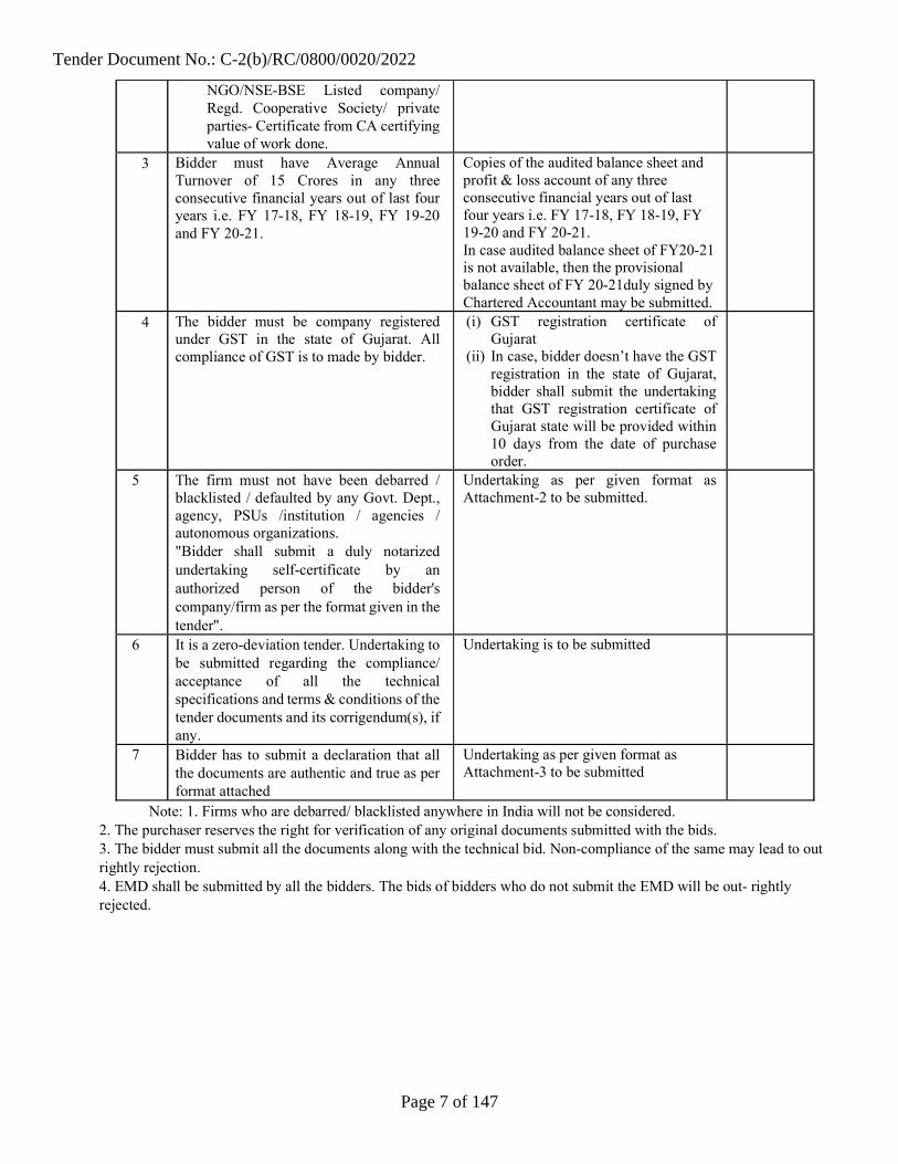
Note: 1. Firms who are debarred/ blacklisted anywhere in India will not be considered. 2. The purchaser reserves the right for verification of any original documents submitted with the bids. 3. The bidder must submit all the documents along with the technical bid. Non-compliance of the same may lead to out rightly rejection. 4. EMD shall be submitted by all the bidders. The bids of bidders who do not submit the EMD will be out- rightly rejected.
Tender Document No.: C-2(b)/RC/0800/0020/2022
Page 7 of 147

Design, Engineering, Supply, Procurement, Installation, Commissioning, Operation and Maintenance (5 years) of 10 MW Solar Photovoltaic Grid Connected Power Plant in the State of Gujarat”.
GENERAL SCOPE OF WORK
Scope of work includes setting up of grid connected solar PV power plants (including Solar PV Modules) around in the Gujarat. The cumulative maximum DC installation capacity under Standard Test Conditions (STC) as per IEC:61215 and IEC:61730. The Contractor shall comply that the maximum AC capacity shall not exceed 5% higher than the capacity mentioned for respective substation. The general scope of work involves Design, Engineering, Procurement & Supply and Construction (EPC) of the grid-connected solar photovoltaic power plant commissioning and evacuation of power into the substation through construction, erection, testing and commissioning of complete 66 KV bay along with bus bar extension in respective substations, as per GETCO guidelines, is in bidder's scope. guaranteed plant performance in the form of guaranteed energy output. Generation from solar PV plant shall be terminated 66 KV S/s., through 66 KV U/g cable or single circuit overhead line, which must be GETCO approved Cable or Al conductor of suitable rating as per current carrying capacity, fault level and voltage drop selection criteria.
The project site location is as under:
District Locations Land area in (Ha)
Co-Ordinate of locations
Capacity of location in(MW)
Respective GETCO S/s
Capacity of Group in (MW)
Dist:
Jamnagar Nikava 25.05
Latitude: 22.20° N
Longitude: 70.55° E
10 66 KV
Nikava
10
Note: 1. Distance of transmission line from Nikava to 66 kV Nikava Sub-station is 1 to 2 KM Indicative Approximate distance. Note: The Land allotment Orders to CEL’s customer and Mapni Sheet from respective collector is attached with tender. Bidder has to adhere all the conditions of land order and Mapni Sheet for establishment of solar projects.
Evacuation of Power & Metering Point: For the purpose of this project, the evacuation voltage shall be at 66 KV AC (three phase) wherein evacuating point cum metering point shall be installed at 66 KV Substation for ABT metering. Scope of work shall also include 66 KV Under Ground cable work from solar plant to 66 KV substation as well as construction, erection, testing and commissioning of complete
Tender Document No.: C-2(b)/RC/0800/0020/2022
Page 8 of 147

66 KV bay along with bus bar extension in respective substations as per GETCO guidelines. ABT Meter to measure net power evacuation shall be installed at 66 KV GETCO and SPV Plant end as per GETCO guidelines. For each solar PV plant, 4 cables (three-phase plus one spare) are required. ROW and all relevant approvals from statutory authority are in bidder’s scope.
(a) “Bidder is required to submit the Test reports supported by self-undertaking as well as compliance certificate from manufacturer for all applicable provisions under the CEA (Technical standards for connectivity to the Grid) Regulations, 2007 (as amended) ((including the provisions of LVRT/HVRT, active power injection control, dynamically varying reactive power support, limits for harmonic & DC injection, Flicker limits, etc.) from labs accredited by Govt./NABL/other recognized agencies. In case any discrepancies / incompleteness are found in the documents / test reports submitted, the connectivity agreement shall not be processed further. Also, SLDC requirements needs to be fulfilled before actual connectivity established with the grid.”
(b) 66 KV voltage profile at all these substations are being maintained in a way that adequate voltage profile is available at subsequent 66KV substations as well as 11 KV feeders at respective substations. Therefore, all the solar projects are required to be tuned according to operating voltage profile at respective substations.
Operation and Maintenance (O&M): Comprehensive operation & Maintenance of the Solar PV plant including supply of spare parts, consumables, repairs/replacement of any defective equipment etc. shall be performed by the contractor for a period of 05 years. Five years O & M is compulsory and other five years may be extendable for further period on mutually agreeable basis.
The scope of work includes Operation and Maintenance (O&M) of the plant for Five (5) years, where in the plant shall generate at least equivalent to the guaranteed Performance of the plant. The Bidder shall submit in the Bid a comprehensive project execution schedule as well as Operation and Maintenance (O&M) schedule with resource planning in the form of Gantt chart, Bar chart, PERT chart and shall be liable for abiding by the schedule. It is the responsibility of the Contractor to perform the necessary maintenance/ timely replacement of all Civil /Mechanical or Electrical components of the project during this O&M period such that the guaranteed performance of the plant is not compromised. Any damage to CIVIL/ ELECTRICAL/ MECHANICAL components of the plant is to be reworked/ replaced/ supplied without any extra cost and time by the Contractor during complete O&M period. The Operation and Maintenance shall be comprehensive. The maintenance service provided shall ensure project functioning of the Solar PV system as a whole and Power Evacuation System to the extent covered in the Contract. All preventive/ routine maintenance and breakdown/ corrective maintenance required for ensuring maximum uptime shall have to be provided. Accordingly, the Comprehensive Operation and Maintenance shall have two distinct components as described below:
Tender Document No.: C-2(b)/RC/0800/0020/2022
Page 9 of 147

a. Preventive / Routine Maintenance: This shall be done by the Contractor regularly and shall include activities such as cleaning and checking the health of the Plant, cleaning of module surface, tightening of all electrical connections, and any other activity that may be required for proper functioning of the Plant as a whole. Necessary maintenance activities, preventive and routine for Transformers and associated switchgears also shall be included.
b. Breakdown/ Corrective Maintenance: Whenever a fault has occurred, the Contractor has to rectify the fault, the fault must be rectified within 48 hrs time from the time of occurrence of fault, failing which the Contractor will be penalized as per terms and conditions of this Tender.
The date of Comprehensive Operation and Maintenance Contract period of the Plant shall begin on the date as defined in the Tender. However, operation of the Power Plant means operation of system as per bidding schedule and workmanship in order to keep the project trouble free covering the guarantee period.
c. Scheduling and forecasting activity/appointment of Qualified coordinating agency for scheduling and forecasting activity shall be in bidder’s scope. All required SCADA/System for each site shall be in bidder’s scope.
Tracking Structures: The Company encourages Bidders to employ proven and reliable seasonal tracking system, however the Bidder should note that total land available is approximately as mentioned above in for the Project. The Bidder shall submit in the Bid, the details / specifications / designs / guarantees and warrantees / and any other claims on performance / output of the solar tracking solutions in the Bid document. Bidder may consider fixed or tilt or tracking system. Engineering is in the scope of Bidder.
Electrical Work: Consisting of supply and installation of solar PV modules, junction boxes, grid-tied inverters, isolation transformers, meters, relay & control panel, 11 or 33 KV switchgear, 66 KV switchyard for evacuation at solar plant peripheri, 66 KV UG cable/transmission line , 66 KV bay and bus bar extension in GETCO substation ,interconnection through wires, cables, bus bars, system fault level study etc.; plant lighting system, automatic weather station, SCADA and remote web-based communication & monitoring hardware, software etc.; plant and human safety and protection equipment including danger signs etc. Anything not mentioned in the list but still required to finish the EPC contract of Solar Plant capacity to be considered for the BID and same is in the scope of bidder.
Civil and Other Non-Electrical Work: Module Mounting Structures (MMS): The Contractor shall design, fabricate, supply and install module mounting structures with all required accessories like clamps, nuts, bolts, cable ties etc.,
Tender Document No.: C-2(b)/RC/0800/0020/2022
Page 10 of 147

The structures can be of fixed/ seasonal tracker are accepted.
Modules shall be mounted on a non-corrosive support structures (EPDM rubber gasket /Stainless Steel Star Washer). The frames and leg assemblies of the array structures shall be made of hot dip Galvanized steel per ASTM A123. Material grade shall be as per IS:2062. HDG Steel only. All nuts and bolts (fasteners) shall be made very good quality stainless steel of grade SS 304 required for module fixing and for other components of MMS, superstructure or switchyard, inverter room, control room, etc. in the plant premises nuts and bolts (fasteners) shall be of MS material with minimum Grade HDG: 5.6.
Foundations: The Contractor shall design and construct appropriate civil foundations for MMS, prefabricated structures/RCC, transformers, switchyard equipment, feeder bay etc.
Prefabricated Structures: The following prefabricated /RCC structures are to be planned and constructed by the Contractor for the Solar PV project:
Prefabricated Inverter rooms for indoor inverters. All outdoor items shall be IP 65 or IP-54/IP55 with roof structure shall be required.
Prefabricated Watchman’s cabin (At Main Gate) - 01 Nos. Security: Security cabin shall be provided at the entry of each pocket (i.e. if
utilized for installing Solar PV Project) of project site.
Storm Water Drainage System: The Contractor shall provide storm water drainage system for entire plant. Natural slope of ground shall be followed and drainage shall be designed accordingly. There shall not be any water accumulation in the project area.
Solar PV Module Cleaning System: Cleaning frequency shall be decided by the Bidder to meet the guaranteed generation. For this, the Contractor shall construct and operate 10,000 litre /MW capacity RCC/Sintex or underground water storage tank. The Contractor also has to drill a bore and construct pipeline for carrying water to storage tank, provide electric panel and pump for bore and total water cleaning system. For module cleaning, the contractor can provide new tanker with pump; water jet and hose pipe or establish a pipeline network with valves. Bidder may also consider Robotic/dry/ tractor mounted jet cleaning.
RCC Precast Boundary Wall: The Contractor shall provide RCC precast boundary wall for the entire plant boundary of solar plant site.(as per drawing attached herewith).
Approach / Internal Roads and Pathways: The Contractor shall provide internal roads and approach roads / pathways of WBM type. If plant is being installed in more than one pockets. Each pocket shall have internal connectivity by WBM road. Peripheral roads & road connected to inverter transformer shall be of WBM. Carriage way Width of WBM/ Asphalt shall be 4 mtr. and Shoulders width of 0.50 mtr. on both sides of road.
Cable Trenches: Construction of RCC cable trenches with cable trays and covers for inverter and control rooms, earthen excavated cable trench with alternate layers of sand and brick as per relevant IS from PV arrays to inverter room to control room to switchyard shall be provided by the Contractor. However, during detail engineering cable laying philosophy
Tender Document No.: C-2(b)/RC/0800/0020/2022
Page 11 of 147
will be decided and bidder shall have to follow respective philosophy as per standard.
Main Gate: The Contractor shall provide main gate of structural steel material of appropriate design. Also, necessary arrangement has to be made by Contractor to erect the main gate on pylon stone.
Site levelling: The Contractor shall level the site, as required, so as to compact the plant in minimum possible area and also minimize shading losses because of solar PV module structures. Removal of debris and bush-cutting is mandatory. To obtain necessary approval from Govt. / semi Govt. body etc. as a statutory requirement bidder has to approach the government organization, CEL/Customer will provide required supporting documents for the purpose. Levelling of the site is to be done if required. Bidder shall design Array of Solar PV as per the natural contour of site. However, water accumulation (rain +plant) shall not be occurred in Solar PV plant area.
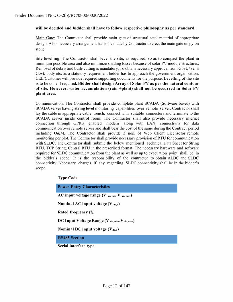
Communication: The Contractor shall provide complete plant SCADA (Software based) with SCADA server having string level monitoring capabilities over remote server. Contractor shall lay the cable in appropriate cable trench, connect with suitable connectors and terminate to the SCADA server inside control room. The Contractor shall also provide necessary internet connection through GPRS enabled modem along with LAN connectivity for data communication over remote server and shall bear the cost of the same during the Contract period including O&M. The Contractor shall provide 3 nos. of Web Client License for remote monitoring per plot. The Contractor shall provide necessary provision of RTU for communication with SLDC. The Contractor shall submit the below mentioned Technical Data Sheet for String RTU, TCP String, Central RTU in the prescribed format. The necessary hardware and software required for SLDC communication from the plant as well as up to evacuation point shall be in the bidder’s scope. It is the responsibility of the contractor to obtain ALDC and SLDC connectivity. Necessary charges if any regarding SLDC connectivity shall be in the bidder’s scope.
Type Code
AC input voltage range (V ac, min V ac, max)
Nominal AC input voltage (V ac,n)
Rated frequency (fr)
DC Input Voltage Range (V dc,min..V dc,max)
Nominal DC input voltage (Vdc,n)
Serial interface type
RS485 Section
Power Entry Characteristics
Tender Document No.: C-2(b)/RC/0800/0020/2022
Page 12 of 147

Baud rate
Protocol
Number of devices
Line biasing resistor (wherever
necessary) Termination resistor
Serial interface type
Baud rate
Protocol
Number of devices
Line biasing resistor (wherever
necessary) Termination resistor
Environmental protection rating
Ambien temperature range
Relative humidity
Compliance Isolation
Marking
Safety and EMC standard
Essential list of I/O and equipment is given herewith, but scope is not limited to the Essential List, contractor is fully responsible to provide complete SCADA System which can be extensible / communicable with additional / future solar plant. 20 % spare I/O modules and equipments shall be provided.
Sr. Equipment to be Data to Be Monitor (Real Type of IO monitored Time)
1 String Monitoring String/Inverter level monitoring Through / Array Required Communication with Monitoring SJB PLC/Card
2 String Junction SJB internal temperature and Through
RS485 MODBUS section
Physical and Environmental
Tender Document No.: C-2(b)/RC/0800/0020/2022
Page 13 of 147

Box / Array SJB Bus Voltage and Current Communication with Junction Box
(SJB = AJB) SJB PLC/Card
3 Inverter All Electrical Parameters of Inverter along with Scanning, Records & Error communication
Through Communication with SJB PLC/Card
4 Inverter Transformer
Oil and Monitoring
Winding Temp Analog Input
5 11/33 KV / VCB ON/OFF and Trip position of VCB and Energy Meter RS-485 communication
DI Communication
and
6 66KV Switchyard All Equipment details including Power Transformer, Breakers, C&R Panels, Isolators, Earth Break Switches, Metering & Protection Devices etc.
DI Communication
and
7 Weather Monitoring Station
Two no. of Class I Pyranometer (one for GHI, one at PV plane collector angle), Two numbers of contact type temperature sensors at backside of the module. Ambient temperature sensor, Wind velocity and speed sensor.
Through Communication
8 Aux. Equipment’s
Aux. Transformers, UPS, Fire Alarm Panel, Water & Utility Pumps & Panels,
AI / DI / Communication for Information / Records / Logging
9 Main and Check Meter
All electrical parameters recorded by energy meter
Through RS- 485/MODDBUS communication
Plant Safety Equipments: The Contractor shall provide appropriate numbers of foam type fire extinguishers / CO2 extinguishers, sand buckets and transformer discharge rod at Invertor Rooms, Control Room, Security Cabin and Switchyard/Substation. Further, all high voltage places to be provided with danger sign boards with appropriate size and material to last for 25 years. Transformers shall be provided with appropriate Fire protection/ NIFPS fire prevention system.
Statutory Requirements: All construction, operation and maintenance procedures shall be carried out as stipulated to
Tender Document No.: C-2(b)/RC/0800/0020/2022
Page 14 of 147

appropriate relevant standards, regulations laid by CEA/CEL/CEL’s Customer/State Nodal agencies/ DISCOM / GoI / MNRE and / or any other agency as and when applicable. Further, this shall comply with the applicable labor laws. The Bidder shall make himself aware of such requirements and shall not solely depend on the Company to make available full information. Bidders should follow CEL/CEL’s Customer/State Nodal agency’s norms, regulations, T & C, specifications and guidelines prevailing at present & amended time to time in all 66 KV and GETCO connected/related works. The GETCO norms, regulations, T & C, specifications and guidelines etc is available at site or as per requirement during the execution of the projects which is to be implemented in supply erection & commissioning and testing of GETCO items/ related works. Following drawing/documents are attached for ready reference only.
1) Standard primary drawings for 66 KV GETCO substation (i.e. SLD, layout plan and section)
2) Typical arrangement for CEL’s Customer solar feeder in 66KV s/s.
3) CEA regulation related to solar developers.
4) SCADA data/system requirement of GETCO with typical system architecture
5) Solar SCADA shall be monitoring the equipment till 66KV Switchyard at Solar end of SPV project scope.
Planning and Designing: i. The Contractor shall plan and design for the electrical / mechanical / civil requirements
including but not limited to plant configuration, space optimization, distance between rows of modules, sufficient passage for vehicle and man-power movement in the plant, mounting structures, location of inverter room, cable routing, selection of equipment and items, procurement plan etc. to enhance plant output.
ii. The Contractor has to carry out the complete soil investigation of the site, through Government approved laboratory before designing various civil structures. The design of all civil foundations, R.C.C structures, buildings etc. shall be carried out considering appropriate seismic zone of the area. All appropriate loads, wind velocity, seismic factors etc. shall be considered as per the relevant IS Specifications while designing any civil structure. Also, the environmental conditions, soil characteristics, atmospheric effect, ground water table level, rain water data, land profile, etc. must be considered as per site actual condition and accordingly appropriate precautions and preventive measures shall be taken while designing the structures. RCC structures shall be adopted considering surrounding weather and soil conditions of site and as per the relevant IS codes. The concrete mix design test shall be carried out in Govt. certified laboratory or NABL Accredited laboratory for minimum M20 grade with 400 kilograms of cement.
iii. The Contractor shall take into consideration all parameters like wind speed, seismic zone, safety factor and safe Soil Bearing Capacity (SBC) etc. for the purpose of design and construction of civil foundations for all civil work as per relevant IS codes.
iv. The Contractor shall carryout Shadow Analysis at the site and accordingly design strings and arrays layout considering optimal usage of space, material and labor.
v. All designs & drawings have to be developed based on the governing standards and
Tender Document No.: C-2(b)/RC/0800/0020/2022
Page 15 of 147

requirements of the project and also keeping in mind basic design specifications.
Company may approve minor deviations or suggest required modifications in the same which are meant for increasing plant performance without sacrificing quality / workmanship norms.
vi. All designs, specifications, reports, etc. submitted or used by the Contractor at any point in time shall first be approved by the Company /Consultant and revised by Company /Consultant, if required, prior to execution.
vii. The technology offered shall be commercially established technology and at least one Project based on this technology shall be satisfactorily operational for at least one year in India. Details of the Project with location and the successful operational period of the Project utilizing this technology shall also be mentioned before the submission of first set of drawings for approvals.
viii The Contractor shall have to arrange the facility for testing bulk material at site such as elcometer for testing the galvanization, cube-testing machine for testing the strength of cube samples etc.
ix The Contractor shall have to send samples for testing of the material to Govt. accredited /NABL Accredited laboratory as when required by the Company.
Approval of Design/Drawings The following procedure has to be followed for assessment and approval of designs, specifications and drawings during the course of the project: The Contractor shall submit to the Company/Consultant the documents in hard copy and soft copy both with proper reference and drawing numbers. The respective documents for selection, supply, installation, erection, commissioning of equipment/ structures have to be submitted at least 15 days in advance to the planned start of the activity as per the Contractor’s project schedule. The Contractor shall submit documents as required for this project according to his design and specifications. The Company / Consultant (on behalf of the Company) will assess, review and approve the documents within 15 days of submission of documents; and only after the approval the Contractor shall release the documents on site for execution. The documents shall be revised by the Contractor as per instructions /comments given by the Company / Consultant (on behalf of the Company) if required, prior to execution. Subsequent revisions and the final version of the documents shall also be submitted in hard and soft copy to the Company and the Consultant. The Contractor has to take into account the above mentioned process of revisions (if required) and adjust the preparation and delivery of the documents such that the overall planned project schedule is not affected.
ii. The Contractor has to submit all drawings, which are related to plant for approval and the Contractor, shall not claim any drawing as their intellectual property. Drawing which is developed for project will be the intellectual property of the Company.
iii. The Contractor shall submit a comprehensive project management schedule in the form of a Gantt chart CPM/PERT chart and shall be liable for abiding by the schedule. The submitted copy shall be compatible to open in either MS project or Primavera & MS Excel.
iv. The Contractor shall submit a comprehensive maintenance schedule for operation and
Tender Document No.: C-2(b)/RC/0800/0020/2022
Page 16 of 147
maintenance of the photovoltaic power plant along with checklists before commencement of work on site and shall be liable for abiding by the schedule. All construction, operation and maintenance procedures shall be carried out through appropriate relevant standards, regulations and labor laws.
Final Commissioning The commissioning procedure shall be as per CEL/CEL’s Customer/GEDA/ GETCO / DISCOM / Chief Electrical Inspector to Government (CEIG) requirements. The Contractor shall also ensure the following:
i. Obtaining written certificate of commissioning of the facility and permission to connect to the grid from the office of the Chief Electrical Inspector of the state and any other authorized representative from Government of India (GoI)/ GoG /GETCO / CEL’S CUSTOMER / DISCOM/GEDA.
ii. Inspection and successful electrical commissioning certificate from the Company.
iii. Obtaining all certificates required by DisCom from agency appointed by them.
iv. Satisfactory completion certificate towards completion of all other contractual obligations by the Contractor as stipulated from the Company.
Comprehensive Operation and Maintenance Contract The Bidder shall separately quote for Operation and Maintenance of the power plant for Five (05) Years where in the plant should perform at a minimum annual NEEGG derated every year by not more than 1% referring to the installed DC capacity of the plant indicated by the Bidder. Any damage to CIVIL/ELECTRICAL/MECHANICAL components of the plant is to be reworked/replaced/supplied without any extra cost and time by the Contractor during maintenance period. This means after completion of O & M period every component of the plant should be in good and working condition. Disclaimer: Any civil / electrical / other work, which is not mentioned or included in this Tender document but necessary for the construction and O&M of Solar PV plant around substations shall be borne by the Contractor. The Contractor shall, unless specifically excluded in the Contract, perform all such works and /or supply all such items and materials not specifically mentioned in the Contract/ Tender Document but can be reasonably inferred from the Contract as being required for attaining completion, commissioning and performance of the facilities, delivering NEEGG and maintaining the plant & achieving NEEGG during O&M period of Solar PV Power Plant around substations as if such work and / or items and materials were expressly mention in the Contract without any extra cost implication and liability to CEL/CEL’s customer. All specifications mentioned in this Tender indicates minimum technical requirement. The Contractor may propose alternate specifications or design though the final acceptance of the same is subject to the CEL/CEL’s Customer’s discretion.
GENERAL SCOPE OF WORK
The proposed location of solar project may be flat/uneven/hilly/submerged during monsoon. Bidder has to visit the site before pre bid meeting and accordingly discuss
Tender Document No.: C-2(b)/RC/0800/0020/2022
Page 17 of 147
with the CEL for any query. The roads passing through the allotted land area shall be kept as it is for villagers
movement & boundary wall shall be constructed on both sides of road for security point of view. Bidder shall have to execute the work of proposed solar project i.e. 10 MW in one / two / three / four pockets or more for proposed location as per the acquired government clear land, accordingly precast boundary wall of each pocket shall be provided for security point of view.
Bidder shall have to construct Storm water drain for each pocket of proposed location. The storm water drain shall be designed by the bidder in such a way that rainy water shall not be accumulated in pocket area and discharge of the same smoothly to nearest village nalla /palika drain etc.
If huge quantity of rainy water entered into the proposed solar project site area than bidder has to construct bund/protection wall and necessary storm water drain shall be provided for each pocket of proposed solar project site and divert the same smoothly into nearest village nalla /palika drain to avoid the damage the solar project site etc. during monsoon.
Bidder shall have to construct road as per site requirement of proposed solar project capacity i.e. 10 MW shall be executed in one/two/three/four pocket of each location, then as per site availability for internal connectivity with each pocket necessary WBM road, culvert with site slope rubble pitching, laying NP-3 pipe of sufficient diameter wherever required etc. shall be executed as per site requirement.
Bidder shall have to make its own arrangement for construction water as well as water required during O & M period.
The fresh OPC53/PPC cement and TMT steel reinforcement bars Fe 500 CRS shall be used confirming to relevant I.S. Specifications of the approved manufacturers of CEL’S CUSTOMER.
The all material, installations, fixtures, accessories etc. to be provided shall be as per the relevant I.S. specifications and of best quality and of standard manufacturer as approved by the EIC.
Bidder shall have to keep the full proof records of purchase and consumption along with original purchase bills of Cement and Steel as per the CEL’s Customer procedures and rules.
Bidder shall have to provide best workmanship with skilled manpower for all the civil items as per the standard specifications/ best practice as approved by the EIC. If there is dispute in the items of civil works/no standard specifications of civil work items, in that case CPWD/ PWD/ booklet of Standard specification shall be applicable. CEL will not supply any material for this work.
To obtain necessary approval from Govt. / semi Govt. body etc. as a statutory requirement bidder has to approach the government organization, CEL will provide required supporting documents required from customer for the purpose.
All such items and materials not specifically mentioned in the Contract/ Tender
Tender Document No.: C-2(b)/RC/0800/0020/2022
Page 18 of 147

Document but required as per site condition during execution for completion of proposed solar project / during O & M period of Solar PV Power Plant, bidder has to execute the same without any extra cost.
For all the civil work of proposed solar project bidder has to submit the drawing for approval of CEL/CEL’s Customer.
Civil foundation design for Module Mounting Structures (MMS) as well as control room, invertor room, switch yard transformer / equipment shall be made in accordance with the Indian Standard Codes and soil conditions, with the help of Chartered Structural Designer having substantial experience in similar work. The Successful Bidder shall submit the detailed structural design analysis along with calculations and bases / standards.
Module Mounting Structures Design is to be certified by Chartered Structure Engineer and certificate to be produced along with the design details for approval by CEL/CEL’s Customer. Switchyard structures / transmission line structure designs shall be strictly as per GETCO design.
The scope of work includes Operation and Maintenance (O & M) of the plant for five (5) years, where in the plant shall generate the guaranteed Performance. The Bidder shall submit in the Bid a comprehensive project execution schedule as well as Operation and Maintenance (O & M) schedule with resource planning in the form of Gantt chart, Bar chart, CPM, PERT and shall be liable for abiding by the schedule. It is the responsibility of the Contractor to perform the necessary maintenance/ timely replacement of all Civil /Mechanical or Electrical components of the project during this O&M period such that the guaranteed performance of the plant is not compromised. Any damage to CIVIL/ ELECTRICAL/ MECHANICAL components of the plant is to be reworked/ replaced/ supplied without any extra cost and time by the Contractor during complete O&M period. The Operation and Maintenance shall be comprehensive. The maintenance service provided shall ensure project functioning of the Solar PV system as a whole and Power Evacuation System to the extent covered in the Contract. All preventive/ routine maintenance and breakdown/ corrective maintenance required for ensuring maximum uptime shall have to be provided. Accordingly, the Comprehensive Operation and Maintenance shall have two distinct components as described below:
a. Preventive / Routine Maintenance: This shall be done by the Contractor regularly and shall include activities such as cleaning and checking the health of the Plant, cleaning of module surface, tightening of all electrical connections, and any other activity that may be required for proper functioning of the Plant as a whole. Necessary maintenance activities, preventive and routine for Transformers and associated switchgears also shall be included.
b. Breakdown/ Corrective Maintenance: Whenever a fault has occurred, the Contractor has to attend or to rectify the fault, the fault must be rectified within 48 hrs time from the time of occurrence of fault failing which the Contractor will be penalized as per terms and conditions of this Tender.
Civil work:
Tender Document No.: C-2(b)/RC/0800/0020/2022
Page 19 of 147

The proposed location of solar project may be flat/uneven/hilly/submerged during monsoon. Bidder has to visit the site before quoting and accordingly discussed with the CEL representative for any query.
Bidder shall have to execute the work of proposed solar project i.e. @ 10 MW in one/two/three/four pocket for proposed location as per the acquired government clear land, accordingly precast boundary wall of each pocket shall be provided for security point of view.
Bidder shall have to make its own arrangement for construction water as well as water required during O & M period.
The fresh OPC/PPC 53 grade cement and TMT steel reinforcement bars Fe 500 CRS shall be used confirming to relevant I.S. Specifications of the approved manufacturers of GSECL.
The concrete mix design test shall be carried out in Govt. certified laboratory or NABL accredited laboratory for minimum M20 grade with 400 kilograms of cement.
The all material, installations, fixtures, accessories etc. to be provided shall be as per the relevant I.S. specifications and of best quality and of standard manufacturer as approved by the EIC.
Bidder shall have to keep the full proof records of purchase and consumption along with original purchase bills of Cement and Steel as per the CEL’s customer procedures and rules.
Bidder shall have to provide best workmanship with skilled manpower for all the civil items as per the standard specifications/ best practice as approved by the EIC. If there is dispute in the items of civil works/no standard specifications of civil work items, in that case CPWD/ PWD/ booklet of Standard specification shall be applicable. CEL/CEL customer will not supply any material for this work.
To obtain necessary approval from Govt. / semi Govt. body etc. as a statutory requirement bidder has to approach the government organization, CEL will arrange to provide any other supporting documents if required from customer for the purpose.
Bidder has to obtain BOCW certificate & labour license for the proposed solar site from concern government department.
All such items and materials not specifically mentioned in the Contract/ Tender Document
but required as per site condition during execution for completion of proposed solar project / during O & M period of Solar PV Power Plant, bidder has to execute the same without any extra cost.
For all the civil work of proposed solar project bidder has to submit the drawing to CEL for approval of CEL & CEL’s Customer.
Topographical Survey:
Tender Document No.: C-2(b)/RC/0800/0020/2022
Page 20 of 147

CEL team will show the proposed project site physically to bidder , necessary required survey work for co-ordinate of site will be carried out by bidder and accordingly final plot layout ( As per JMS sheet ) drawing shall be submitted to CEL/CEL’s customer for further approval. Topographical survey shall have to be done by the Bidder for the proposed site at 5 mt. interval with the help of Total Station or any other suitable standard method of survey. All necessary Reduced Levels (RL) as entered in the Field Book/Soft Copy have to be submitted along with pre contour layout of the total site. The formation levels of the proposed solar power plant have to be fixed with reference to High Flood Level of the proposed site. The ground level and plinth level of structures shall be fixed taking into consideration on the highest flood level and surrounding ground profiles.
Soil Test:
The soil testing of proposed project site shall be carried out by the agency. Contractor is solely responsible to carry out detailed Geotechnical investigation to ascertain soil parameters of the proposed site for the use of planning / designing / construction / providing guarantee / warranty of all civil works including but not limited to foundations / piling for module mounting structures, HT lines, 66 kV switchyard equipment etc. The Contractor shall carryout soil investigation through NABL accredited labs. These reports shall be furnished to the Company prior to commencing work. All RCC works shall be provided of required grade of concrete as per relevant IS specifications as well as soil data considering appropriate earthquake seismic zone, wind velocity, whether effect, soil characteristics etc. The minimum Bore hole for soil investigation report should be done as per IS Code. Soil testing is in the scope of bidder.
The scope of soil investigation covers execution of complete soil exploration including boring, drilling, collection of disturbed & undisturbed soil sample conducting laboratory test of samples to find out the various parameters mainly related to load bearing capacity, ground water level, settlement, and soil condition and submission of detail reports along with recommendation regarding suitable type of foundations for each bore hole along with recommendation for soil improvement where necessary. The design will done based on considering the worst result among the bore holes. Contractor has to carry out also Electrical Resistivity Test.
The bidder shall have to carry out Shadow Analysis at the site and accordingly design strings and arrays layout considering optimal use of space, material and manpower and submit all the details / design to Company for its review / suggestions /approval.
The foundations should be designed considering the weight and distribution of the structure and assembly, and wind speed as per IS 875 for calculations of Vz. Bidder shall take basic wind speed value for respective sites as per following.
Site wise wind speed to be mentioned here as per IS875
Success full Bidder shall also plan for transport and storage of materials at site and shall arrange for its own construction power and water. However, the Contractor can avail construction power connection from Discom by applying for temporary connection and necessary charges will be borne by the bidder. Client will help for supporting documents.
Land Development and Cleaning:
Tender Document No.: C-2(b)/RC/0800/0020/2022
Page 21 of 147

Site leveling:
The bidder shall have to level the site, as required, so as to compact the plant in minimum possible area and also to minimize shading losses because of solar PV module structures. Removal of debris and bush-cutting is mandatory. Leveling & area grading of the site is to be done if required for easy drain of surface water naturally to avoid the accumulation of rainy water in plant area. During execution of work if any hidden masonry / concrete foundation / pipe line etc. found then agency has to execute / remove / reroute the same without any financial implication. The bidder shall visit the site to ensure the land development work if any and shall carry out the topographical survey to ensure land development work such that land is perfectly flat. The Contractor has to clean the site from small trees and shrubs, removal of debris, if any; filled the depression area and excavates and level the high level areas wherever required even though contractor follows the natural ground level for entire plant execution. Land to be developed in a way to achieve maximum utilisation. Disposal of excavated earth will be decided by site engineer of CEL. The Contractor can also use the natural contour of the land, if shadow is not affecting the generation. However, the Contractor shall take reasonable care to ensure that the plant is aesthetically designed. Bidder shall have to Level the uneven area of each pocket of the proposed location as per site requirement. If any hidden structure beneath land is found, bidder may leave that portion of leave such portion of land.
Storm Water Drainage System:
The Contractor shall provide storm water drainage system for entire plant.
The drain is to be designed as per actual site requirement and to avoid accumulation of water in solar Plant area. The peripheral drain and all other internal drains to inverter room, control room, switchyard of solar project shall be of brick lining which is backed up by PCC (75 mm thick C.C. 1:4:8 ) on side slope and at bottom of drain with brick lining and all joints of Brick lining are to be filled up with cement mortar in C.M. 1:4. Also, the bidder shall provide RCC Hume pipe (NP3 grade) at the crossing of road and drains and at required locations. And also necessary arrangement for disposing / lifting of accumulated surface water is to be made by providing pump and RCC sump of required capacity shall be provided by bidder as per site requirement or naturally as per site conditions.
Storm water drain for each pocket of proposed location shall be designed by the bidder in such a way that rainy water will not be accumulated in pocket area and discharge the same smoothly to nearest village nalla /palika drain etc.
If huge quantity of rainy water entered into the proposed solar project site area than bidder shall have to construct bund/protection wall with necessary storm water drain shall be provided for each pocket of proposed solar project site and divert the same smoothly into nearest village nalla /palika drain to avoid the damage the solar project site etc. during monsoon.
Foundations:
The Contractor shall design and construct appropriate civil foundations for MMS RCC Pile Foundation, prefabricated structures / RCC frame structure of control room, transformers, switchyard equipment, feeder bay etc. During execution of work if any hidden masonry /
Tender Document No.: C-2(b)/RC/0800/0020/2022
Page 22 of 147

concrete foundation / any structure /pipe line etc. found then agency has to execute / remove / reroute the same without any financial implication. Site is found to be more or less flat.
Civil foundation design for Module Mounting Structures (MMS) as well as control room, inverter room, switch yard transformer / equipment shall be made in accordance with the Indian Standard Codes and soil conditions, with the help of Chartered Structural Designer having substantial experience in similar work. The Successful Bidder shall submit the detailed structural design analysis along with calculations and bases / standards.
Module Mounting Structures Design is to be certified by Chartered Structure Engineer and certificate to be produced along with the design details for approval by CEL/CEL’s Customer. Switchyard structures / transmission line structure designs shall be strictly as per CEL’s customer/State Nodal agency’s design. The Contractor shall design, fabricate, supply and install module mounting structures with all required accessories like clamps, nuts, bolts, cable ties etc., The structures can be of fixed/ seasonal tracker are accepted.
Pile integrity test of minimum 5% at random of total piles to be casted for MMS Structure.
Solar PV Module Cleaning System (RCC/ PVC water Tank):
Cleaning frequency shall be decided by the Bidder to meet the guaranteed generation. For this the Contractor has to design as per relevant IS codes, submit and take approval from CEL/CEL’s Customer, construct and operate 10,000 litter /MW capacity RCC / PVC water storage tank, the PVC water storage shall be of first quality and shall be approved EIC. The Contractor also has to drill a bore and construct pipeline for carrying water to storage tank, provide electric panel and pump for bore and total water. Silting chamber for filtration of the water before the inlet and which shall match with invert level of Storm Water drain. Design of RCC water tank shall be such that it shall resist Earth pressure and Water pressure and satisfy all IS codes. Design of water tank shall be done strictly based on Soil Investigation Report with complying all latest IS codes.
Cleaning system. For module cleaning, the contractor can provide new tanker with pump, water jet and hose pipe or establish a pipeline network with valves.
Approach / Internal Roads and Pathway & Peripheral Road:
Main road connecting to Government palika/village road to proposed site for each location for construction purpose as per site requirement shall be WBM 4.00 mtr.wide plus side shoulders both side.
The road connecting from the main gate to control room and switch yard shall be accessed by Asphalt road having 4.00 mtr.wide plus side shoulders both side.
Peripheral roads & road connected to inverter transformer shall be of WBM. Width of WBM/ Asphalt road shall be 4.00mtr. wide plus side shoulders both side.
The Contractor shall provide internal roads and approach roads / pathways of WBM type. If plant is being installed in more than one pockets, each pocket shall have internal connectivity by WBM road. Peripheral roads & road connected to inverter transformer shall be of WBM.
Tender Document No.: C-2(b)/RC/0800/0020/2022
Page 23 of 147

Width of WBM/ Asphalt road shall be 4mtr.
Bidder shall have to construct road as per site requirement of proposed solar project capacity i.e. @ 10 MW to 55 MW shall be executed in one/two/three/four pocket of each location, as per site availability for internal connectivity with each pocket necessary WBM road, culvert with side slope rubble pitching, laying NP-3 pipe of sufficient diameter wherever required etc. shall be executed as per site requirement for road crossing.
Cable Trenches:
Construction of RCC cable trenches with cable trays and covers for inverter and control rooms, earthen excavated cable trench with alternate layers of sand and brick as per relevant IS from PV arrays to inverter room to control room to switchyard shall be provided by the Contractor.
Watchman’s Cabin and Main Entrance Gate
The Contractor shall provide main gate of structural steel material of appropriate design. Also, necessary arrangement shall have to be made by Contractor to erect the main gate on pylon stone.
An all-weather main gate with width of at least 6 meter shall be erected at the entrance of the plant siteand another gate (4 mt. width) for each pocket shall be provided for internal connectivity with of proposed location.
The Prefabricated Security Cabin of size 3.5 meter x 3.5 meter at the main entrance gate shall be designed & constructed by the Successful Bidder keeping in view the safety and security of the power plant. The Bidder shall provide detailed civil, electrical, plumbing, etc. drawings and equipment specifications for the security cabin for approval.
Security Cabin:
Security Cabin – Security cabin shall be provided at the entry of each pocket (i.e. if utilized for installing Solar PV Project) of project site.
The Contractor shall provide 4 (four) numbers of prefabricated Watchman’ portable cabin at minimum 4 (four) corners of the boundary of each pocket of proposed Plant such that safety of the plant is ensured along with one Watchman’s cabin at the boundary of each pocket of proposed location. The minimum size of watchmen’s (Security Cabin) cabin shall be 1.2 meter x 1.8 meter size and height of 2.10 mt. with appropriate roof at the top, considering minimum height of 6 mt above ground level. Location of the watch Cabin (Security Cabin) shall be as directed by CEL/CEL’s Customer. Bidder shall have to submit the design of supporting structure with ladder & railing for safety point of view. Security cabin of galvanized steel with roof will be submitted for the approval of EIC from CEL/CEL’s Customer. Fencing:
The bidder shall provide RCC precast boundary wall with barbed wire for entire plant area. Internal fencing for PCU, X’mer, HT SWGR -Aux. Chain link fencing of 2.0 mtr. Height with
Tender Document No.: C-2(b)/RC/0800/0020/2022
Page 24 of 147

provision of gate shall be considered. A. Precast compound wall column Supply and installation of smooth finish and uniform shape & size precast compound wall column of concrete grade M30 with use of OPC 53 Grade of GSECL approved brand cement, including shuttering, reinforced with 3mm wiron (phosphorous carbon steel) of TATA make using pre stressed technology, 1.8m high from finished ground level, vertical post size 150mmx150mmx2700mm, reinforced of 7 nos-3mm dia PC steel of TATA make with a provision of 300 mm long (12”)having 12mm dia MS bolt (9" length) grouted at the time of casting with 3" outside for fixing of angle on top of each column for barbed wire fence as per drg. Precast compound wall columns shall be provided with groove for wall panel slab fixing and grouted below ground level by Augur piling or excavation of 300mm dia, 900mm depth and grouted with PCC of M20 (1:1.5:3 proportion of cement concrete). B. Precast compound wall panel slab Supply and installation of smooth finish and uniform shape & size precast compound wall panel slab of concrete grade M30 with use of OPC 53 Grade of GSECL approved brand cement, including shuttering, reinforced with 3mm wiron (phosphorous carbon steel) of TATA make using pre stressed technology, wall panel slab size 1800mmx300mmX50mm thick, reinforced of 3 nos-3mm dia PC steel of TATA make, fixed in groove of vertical posts as per drg. Wall panel slab shall be fixed in groove of vertical column/posts with engraved precast logo in each section with text of GSECL on each one panel of each span and with provision of excess water flow weep holes having reinforced of 4 nos-3mm dia (phosphorous carbon steel of TATA make, fixed in groove of vertical posts as per drg. The two coat of 1st quality exterior premium emulsion paint with one coat of primer shall be applied on both side of pre-cast compound wall. The exterior paint shall be of 1) Asian Paint : Apex Ultima , 2) Nerolac Paint : Excel Total, 3) ICI Dulux (Akzo Nobel) : Weather sheild Max, 4) Berger Paint : Weather Coat All guard.
C. Angle Post Angle size of 40x40x5, 90cm. Long with Galvanize coating of minimum 80 micron & 8mm Plate to be provided for angle fixing100x100mm size. D. Barbed GI wires Providing and fixing barbed GI wires four nos 12x14 SWG GI barbed wire (IS 278- 2009) heavy coated 230/240 GSM zinc on wire of TATA make shall be provided on top of precast compound wall and fixed over 450mm high MS HDG 'L' angle (40mmx40mmx5mm). The barbed wire has to be fitted in direction longitudinally between two posts fitted & fixed with GI staples, turn buckles, with all hardware etc, complete as per direction of Engineer-in –charge. Water supply: All necessary arrangement for wet cleaning of the solar panels shall be in the scope of the
bidders and accordingly bidder shall have to provide all the necessary equipment, accessories, tool & tackles, pumps, tankers, tractors and piping arrangement which is required for the same. Bidder shall have to make its own arrangement for construction water as well as water required during O & M period.
Tender Document No.: C-2(b)/RC/0800/0020/2022
Page 25 of 147

Pre-fabricated Invertor Room (for indoor inverters only)& R.C.C./PEB Control Room
Bidder has to submit the design drawing for approval of Pre-fabricated Inverter Room & R.C.C./PEB Control Room. Civil work for Pre-fab Inverter Room & R.C.C. Control cum Conference room shall be of adequate size and of be of standard manufacturer with sufficient lighting points and RCC cable trenches with oil painted edge angle of 65mm x 65mm x 6mm and checker plate covers of 8 mm thickness and shall have exhaust chimney and also sufficient ventilation. All prefab inverter room and Control Room shall be laid on RCC plinth with sufficient foundation and reinforced grade slab with finished Kotah of 25mm thickness /Vitrified of 8-10 mm thickness tile flooring and 100 mms skirting of same tiles. The plinth shall be minimum 500 mm high from formation levelof the plant. Plinth protection shall be given throughout perimeter of width 0.75 m with rough kotah of 25mm thickness on its top for Inverter rooms and Control Rooms. Sufficient steps at the entry of the room with rough Kotah on its top and RCC ramp of sufficient angle shall be provided for shifting the equipment in the rooms for all Inverter rooms and Control Room. Rain water pipe at various locations with gutter at the top shall be provided to discharge rain water. The bidder shall provide to CEL/CEL’s Customer the detailed civil, electrical, plumbing, etc. drawings and equipment specifications for the inverter room & control room and shall obtain approval of the same. The drawings of Panels with the make of components should be approved from CEL/CEL’s Customer.
For invertor transformer Chain link fencing of 2.0 mtr. height With provision of gate shall be provided
i. RCC frame structure below plinth
Inverter Rooms/Control cum Conference Room shall have adequate size of footing, pedestal columns, plinth beam, grade slab with reinforcement as per relevant IS specifications considering seismic zone, wind & soil detail etc. Back filling material shall be of Laboratory tested Murrum or Sand. Grade slab shall be laid on 100 mm thick PCC. Also, Termite proofing is required before preparation of grade slab and plinth protection. The Control cum Conference Room shall have a rolling shutter at the front side.
ii. Control room
It shall be of adequate size (minimum height 3.6 mtr) for fixing the panels, battery banks etc. With; a) SCADA Room with Work station, Desktop and Chairs; b) Store Room with almirah; c) Pantry unit of sufficient size with sandwich type of platform with plumbing fixture and exhaust fan; d) Toilet unit for Gents with urinals and Ladies having wash basins in each; e) RCC cable trenches with covers and cable trays and all openings of cable entry shall have vermin proofing using spray foam or mortar; f) Furniture like conference table, chair and sofa etc.; g) Lighting points and fixtures; and h) Plumbing fixtures.
iii. Facilities required for Control cum Conference Room:
It shall also have adequate size SCADA cabin with necessary 2 numbers of work station with drawers of Godrej/ Durian/ Zuari make, 2 numbers Computer and 1 number of LED TV of 48 inch of Sony/ Phillips / Samsung make, 4 numbers of chairs for workstation, 2 Nos. of almirah
Tender Document No.: C-2(b)/RC/0800/0020/2022
Page 26 of 147

and split A.C of 1.5 Ton of Voltas/ Hitachi/ Samsung/LG make for operating staff for work station. Conference Room shall also be equipped with conference table of 10 persons with Power Sockets with 10 chairs of Godrej/ Durian/ Zuari/ Usha/ Lexus and sofas. In Control cum Conference room, except control room (where panels are fixed) all other rooms like SCADA cabin, conference room, store, pantry and passage shall have False ceiling that shall consist of 600 x 600 x 20 mm gypsum board with one coat of primer and two or more coat of Acrylic emulsion paint. The suspension system shall consist of 6 mm diameter galvanised steel rods suspended from ceiling supporting by aluminium grid of 38 x 25 x 1.5 mm and cross tie of 25 x 25 x 1.5 mm and aluminium angle of 25 x 25 x 1.5 mm. Conference room shall be equipped with an all-in-one printer cum scanner, landline phone, refrigerator (150 litre) of Voltas/Godrej/Whirlpool make, projector and screen of 2m x 2m. All material, installations, accessories to be provided shall be of best quality and of standard manufacturer as approved by the EIC-CEL/ CEL’s customer. All units of the Control cum Conference Room shall have marked signage of SS sheet of 1mm along with engraving words and filled with black color at all facilities within Control cum Conference room and on all equipment. The lighting points and fixtures shall be of Anchor/Philips make. The fans shall be of Khaitan/Usha/Bajaj make and lights (only LED shall be used) shall be of Philips/Syska/Havells make.
iv. Structural Steel, Insulated Walls and Roof for Super structure (prefabricated invertor room:
Design of Super-Structure i.e. Steel Structure like purlin, rafter, columns, truss etc. for fixing the Pre-Fabricated Panels conforming to relevant IS codes and of Jindal/Tata/ RINL make. It shall include all necessary fitting like nuts, bolts, washers etc. of good quality. All structural steel shall be treated with two coats of red oxide and three coats of Oil paint (Asian Paints, Berger, Durex). The gap between base plate of structural members and concrete top of foundation shall be filled with GP-2 grouting material of reputed make. The material of all J- bolts shall be of 8.8 Class. The Insulated panels should be of required size for roof and walls. The insulated wall and roof panels shall be sandwich type. The panels shall be made out with 0.35 mm thick pre coated steel sheet on both side of Poly Urethane Foam (PUF) for both wall and roof. The density of PUF shall be 40±2 kg/m3 and thermal conductivity shall be within range of 0.019-0.021 W/m˚K at 10°C. The total thickness of the panels for walls shall be 60mm and for roof is 40mm. The panels shall be joined together by tongue and groove method. The joints of the panels shall be filled with silicon or equivalent filling material. Panels shall be cuts such that the exposure of PUF and patch work is avoided. The fixing of the panels shall be such that there should not be any gaps at joints like wall and roof, wall to wall, etc. from which air and water particle can pass (Air and Water tight). Roof panel shall be extended 300 mm from the eaves wall and 150 mm from Gable walls. Rain water gutter shall be provided throughout the periphery with rain water pipes (CPVC pipes) with proper clamping at regular interval. Provision of future installation of Solar panels on the top of the roof shall be done by I or C section with Small base plate assembly.
v. Landscaping: Landscaping in surrounding area of 2 meter of Main Control Room is to be done using
aesthetically pleasing and suitable varieties of flora. vi. Flooring:
Tender Document No.: C-2(b)/RC/0800/0020/2022
Page 27 of 147

Best quality Vitrified tile flooring having min size of 600 mm x 600 mm x 8-10 mm thickness of standard manufacturers as approved by EIC. vii. Toilet: Toilet shall be designed for 10 persons; and constructed with following finish □ Floor: Vitrified tiles □ Door and window: made out of aluminum brown anodized sections, 6mm float glass □ Ventilators: Mechanical exhaust facility □ Plumbing fixtures: Jaquar and Kohler make □ Sanitary ware: Hindware, Cera or equivalent make □ EWC: 390 mm high with health facet, toilet paper roll holder and allfittings □ Urinal (430 x 260 x 350 mm size) with all fittings. □ Wash basin (550 x 400 mm) with all fittings. □ Bathroom mirror (600 x 450 x 6 mm thick) hard board backing □ CP brass towel rail (600 x 20 mm) with C.P. brass brackets □ Soap holder and liquid soap dispenser.
vii. Doors and Windows:
Doors and windows shall be made of aluminum sections. All sections shall be 20 microns anodized. Sections of door frame and window frame shall be adopted as per industrial standards. Door shutters shall be made of aluminum sections and combination of compact sheet and clear float/wired glass. All windows of Control cum conference room shall be protected by Sun film protection sheet. The control room shall require a number of windows/louvers to be provided for ventilation/ fresh air circulations. All fixtures for doors and windows shall be of Dorma, Godrej and Kich make.
viii. Water Supply for Toilets:
GI pipes (B class) Tata or equivalent make. Separate Overhead water tank Sintex or equivalent of 2,000 litres capacity.
ix. Drainage for Toilets:
Drainage pipes shall be of CPVC (6 kg/cm2) Supreme, Prince or equivalent make. Gully trap, inspection chambers, septic tank for 10person and soak well to be constructed for abovementioned requirement.
x. Air Conditioner for Control Room:
The control room shall be equipped with appropriate numbers of fans for effective heat dissipation. The SCADA cabin and Conference room shall have split type air conditioning units.
xi. Fire Extinguishers:
Liquefied CO2 fire extinguisher shall be up right type of capacity 10 kg having IS: 2171. 7 IS: 10658 marked. The fire extinguisher shall be suitable for fighting fire of Oils, Solvents, Gases, Paints, Varnishes, Electrical Wiring, Live Machinery Fires, and All Flammable Liquid
Tender Document No.: C-2(b)/RC/0800/0020/2022
Page 28 of 147

& Gas. Bidder shall provide Min. 10 no of fire extinguisher is envisaged for main control room.
xii. Sand Bucket:
Sand buckets should be wall mounted, made from at least 24 SWG sheet with bracket fixing on wall conforming to IS 2546. Bucket stands with four buckets on each stand shall be provided in the Transformer Yard – 4 Nos.
xiii. Sign Boards:
The sign board containing brief description of various components of the power plant as well as the complete power plant in general shall be installed at appropriate locations of the power plant.
- For Switchyard and Transformer Yard:
The Sign boards shall be made of steel plate of not less than 3 mm. Letters on the board shall be with appropriate illumination arrangements.
- All Inverter Rooms and Control and Conference Room:
The name boards shall be made of acrylic sheet of 300mm height and fixed at the entry of the all facilities.
□ The Contractor shall provide to CEL, detailed specifications of the sign boards.
Module Mounting Structures (MMS): The Contractor shall design and construct appropriate civil foundations for MMS. The array structure shall be so designed that it will occupy minimum space without sacrificing the output from Solar PV panels at the same time it will withstand severe cyclonic storm with wind speed as per IS 875 for calculations of Vz. Bidder shall take basic wind speed value for respective sites as per following. Site wise wind speed to be mentioned here as per IS 875 Pile casting for testing shall be as per IS before approval of drawing & design. Testing of pile by NABL accredited laboratory.
It shall support Solar PV modules at a given orientation, absorb and transfer the mechanical loads to the ground properly. There shall be no requirement of welding or complex machinery at site and is strictly not allowed.
Seismic factors for the site to be considered while making the design of the foundation/ramming etc. or any technology. The design of array structure shall be based on soil test report of the site and shall be approved from CEL/CEL’s Customer/Consultant.
The Contractor has to plan for pilot test like pull out; lateral and compression of minimum 10,10,3 are required to be conducted for each floor at strategic location, immediately. Based on the results of above-mentioned tests, final approval for design of pile shall be provided.
Tender Document No.: C-2(b)/RC/0800/0020/2022
Page 29 of 147

The material of construction, structural design and workmanship shall be appropriate with a factor of safety of not less than 1.5.
For multiple module mounting structures located in a single row, the alignment of all modules shall be within an error limit of 5 mm in vertical / horizontal line.
The Contractor shall provide to CEL the detailed design, specifications and calculations of the MMS and take approval from CEL/CEL’s Customer (in coordination with CEL).
The Contractor shall specify installation details of the Solar PV modules and the support structures with appropriate diagrams and drawings.
The Module Mounting Structure design shall be certified by a chartered structural engineer and it is mandatory.
The Contractor should design the structure height considering highest flood level at the site. The minimum clearance between the lower edge of the module and the ground shall be the higher of (i) above highest flood level at the site and (ii) minimum 500 mm.
The Contractor shall provide to the Company the detailed design, specifications and calculations of the MMS during detailed engineering.
Curing of all piles shall be done thrice a day and be maintained for a period of seven days from the date of casting.
The Contractor has to ensure sufficient lighting arrangement for all concreting activities during night time. Sufficient illumination should be ensured in and around areas wherever civil and construction activities take place during night time.
The Contractor shall specify installation details of the Solar PV modules and the support structures with appropriate diagrams and drawings.
The Bidder shall be permitted ramming of the module mounting structure provided that they obtain consent of EIC. EIC shall provide such consent once it is convinced that such ramming shall not in any way deteriorate the strength of the structure and shall not reduce the structure’s strength to enjoy a working life of more than 25 years.
Civil foundation design for Module Mounting Structures (MMS) as well as control room, inverters room shall be made in accordance with the Indian Standard Codes and soil conditions, with the help of Chartered Structural Designer having substantial experience in similar work. The Successful Bidder shall submit the detailed structural design analysis along with calculations and bases/ standards in the Bid.
Module Mounting Structures Design is to be certified by Chartered Structure Engineer and certificate to be produced along with the design details for approval by CEL. Switchyard structures / transmission line structure designs shall be strictly as per CEL’s Customer/State Nodal agency’s design.
All the civil defects, rectification, repairing, replacement related to civil works shall be in the scope of contractor during the O&M period, the Contactor shall be responsible for rectification
Tender Document No.: C-2(b)/RC/0800/0020/2022
Page 30 of 147

of any defect in the civil work and maintain the structure/buildings in good condition with proper maintenance. The Contractor shall be responsible for the maintenance of each civil works carried out as mentioned below.
1. Buildings Control room premises, Underground water tank includes:
I. Water tightness/ leak proof of roof and walls.
II. Painting to the structure either PEB/ RCC Framed structure at regular interval (not more than five years).
III. Plumbing & Sanitation related defects/replacement.
IV. Chalking / overflow of septic tank and soak pit.
V. Replacement / repairing of water tank if major/minor leakage observed.
VI. Leakage of water to be attended by suitable crack filler.
VII. Repairing/replacement of doors, windows, ventilators & rolling shutter.
2. Road WBM or Bitumen:
I. Crack repairing of the road surface.
II. Pot-holes over the top road surface to be rectify.
III. Maintenance of shoulders for the rain cuts or damage due to some external reasons.
IV. Re-carpeting of the road surface at every five years interval.
3. Storm water Drainage:
I. Before and after the monsoon season the storm water drainage shall be maintained & cleaned for smoother flow of storm water.
4. Main Entry gate & Fencing:
I. Maintain the elegance of entry gate with painting as & when required.
II. Repairing & painting of precast boundary wall as & when required.
The above list is not exhaustive but indicative only. Although most of the structures are covered here in, any other system (Civil, Structural and Architectural) required for successful operation and maintenance of the works shall form a part of this contract and shall be deemed to be included in the scope of works. The scope of Bidder/EPC Contractor shall include supply of all required materials, mobilization of labour, and arrangement of required tools tackles and equipment to carry out all above civil maintenance works.
5.2 DETAILED ELECTRICAL WORK
Tender Document No.: C-2(b)/RC/0800/0020/2022
Page 31 of 147
Photovoltaic modules
In line with OM no 283/54/2018 GRID SOLAR-Part-I dtd 10.03.2021(Requirement for compulsory registration), Order 2019, PV modules are to be sourced from ALMM Annexure - 1 of above OM and amended from time to time.
The Contractor shall employ solar PV module of Crystalline-Si (Poly / Multi or Mono / Single) solar technology only. The Contractor shall provide detail Technical Data Sheets, Certifications of Standard Testing Conditions (STC: defined as Standard Testing Condition with air mass AM1.5, irradiance 1000W/m2, and cell temperature 25°C) as per the latest edition of IEC 61215 and IEC 61730 and as tested by IEC / MNRE recognized test laboratory. The Bidder shall also specify the minimum guaranteed energy output of solar PV module as per the site condition in the RFP.PV module must be registered with BIS.
i. The PV modules to be employed shall be of minimum 72 cell configuration with rated power of module ≥300 Wp as certified for solar PV module power performance test as prescribed by latest edition of IEC 61215 and IEC 61730 and as tested by IEC / MNRE recognized test laboratory. The maximum tolerance in the rated power of solar PV module shall have maximum tolerance up to +3%. No negative tolerance in the rated capacity of solar PV module is allowed.
ii. PV module must be registered with BIS.
iii. All modules shall be certified IEC 61215 2nd Edition (Design qualification and type approval for Crystalline Si modules), IEC 61730 (PV module safety qualification testing @ 1000 V DC or higher). IEC 62804 Certified PV modules should be PID free, documents for the same should be submitted with conditions of the PID test should be for a humidity of 85 % and a cell temperature of 850 C at 1000Volts , IEC 62716 , IEC 61701.
iv. The certified Bill of Material (BOM) to be used in the PV Modules should be the same as used during the IEC certification of reference PV Module certified by renowned agency like TUV, UL, etc.
v. Minimum certified module efficiency shall be 15% for crystalline with minimum fill factor of 0.75.The permissible maximum temperature coefficient of power (Pmpp) shall be -0.43%/ 0C or better.
vi. All photovoltaic modules should carry a performance warranty of >90% during the first 10 years, and >80% during the next 15 years.
vii. Further, module shall have performance warranty during the first year of installation as under.
Mono > 97% Poly > 97.5%
viii. The module mismatch losses for modules connected to an inverter should be less than 1%. (Maximum)
Tender Document No.: C-2(b)/RC/0800/0020/2022
Page 32 of 147
ix. SPV module shall have module safety class-II and should be highly reliable, light weight and must have a service life of more than 25 years.
x. The PV modules shall be equipped with IP67 or higher protection level junction box with min. 3 by pass diodes of appropriate rating and appropriately sized output power cable of symmetric length with twist locking connectors.
xi. The SPV module shall be made up of high transmitivity glass (Not less than 3.2 mm) & front surface shall give high encapsulation gain and the module shall consists of impact resistance, low iron and high transmission toughened glass. The module frame shall be made of corrosion resistant material, which shall be electrically compatible with the structural material used for mounting the modules.
xii. The SPV modules shall have suitable encapsulation and sealing arrangements to protect the silicon cells from environment. The encapsulation arrangement shall ensure complete moisture proofing for the entire life of solar modules.
xiii. The module frame should have been made of Aluminium or corrosion resistant material, which shall be electrolytically compatible with the structural material used for mounting the modules with sufficient no. of grounding/installation.
xiv. All materials used for manufacturing solar PV module shall have a proven history of reliability and stable operation in external applications. It shall perform in relevance as per IEC standards.
xv. Modules only with the same rating and manufacturer shall be connected to any single inverter. Modules shall compulsorily bear following information in the form of ID encapsulated with solar cell in the manner so as not to cast shadow on the active area and to be clearly visible from the top.
xvi. The Bidder shall provide to CEL in the Bid, power performance test data sheets of all modules. The exact power of the module shall be indicated if the data sheet consists of a range of modules with varying output power.
xvii. Only those crystalline modules (above 300Wp) of the same module manufacturer which has supplied for a capacity more than 0.75MW x *awarded project capacity, in other projects in India with minimum 1 project size of 0.075MW x*awarded project capacity. On this account, the Contractor shall provide full information, to the satisfaction of CEL’s customer, before placing final order for the modules. The Contractor shall also submit the proof of original purchase.
* This is to be noted that, cumulative capacity of awarded project shall be considered in case of single bidder are awarded project for more than one Site.
xviii. CEL/CEL’s Customer or its authorized representative reserves the right to inspect the modules at the manufacturer’s site prior to dispatch.
xix. The Bidder is advised to check and ensure the availability of modules prior to submitting the Tender Document.
Tender Document No.: C-2(b)/RC/0800/0020/2022
Page 33 of 147

xx. The Contractor would be required to maintain accessibility to the list of module IDs along with the above parametric data for each module.
Table 1 Information to be displayed on solar PV module
Sr.
1
Particulars
Name of the manufacturer of the PV module and RFID code
2 Name of the manufacturer of solar cells
3 Month & year of the manufacture (separate for solar cells and modules)
4 Country of origin (separately for solar cells and module)
5 I-V curve for the module at standard test condition (1000 w/m2 , AM 1.5, 25oC
6 Wattage, Imp, Vmp, Isc, Voc, temperature co-efficient of power and FF for the module
7 Unique Serial No. and Model No. of the module
8 Date and year of obtaining IEC PV module qualification certificate
9 Name of the test lab issuing IEC certificate
10 Other relevant information on traceability of solar cells and module as per ISO 9001 and ISO 14001
Junction Box/ Combiner Box i. The Contractor shall provide sufficient no. of Array Junction Boxes / PV combiner
boxes / DCDBs. ii. All switch boards shall be provided with adequately rated copper bus-bar, incoming
control, outgoing control etc. as a separate compartment inside the panel to meet the requirements of the Chief Electrical Inspector of Government (CEIG). All live terminals and bus bars shall be shrouded. The outgoing terminals shall be suitable for connection to suitable runs and size of cables required for the Inverter/Transformer rating.
iii. The degree of protection for following equipment shall be: Indoor Junction box : IP 21 Outdoor Junction Box: IP 65
iv. All junction/ combiner boxes including the module junction box, string junction box, array junction box and main junction box should be equipped with appropriate functionality, safety (including fuses, grounding, etc.), string monitoring capabilities,
Tender Document No.: C-2(b)/RC/0800/0020/2022
Page 34 of 147
and protection.
v. The terminals will be connected to copper bus-bar arrangement of proper sizes to be provided. The junction boxes will have suitable cable entry points fitted with cable glands of appropriate sizes for both incoming and outgoing cables. Suitable markings shall be provided on the bus-bars for easy identification and cable ferrules will be fitted at the cable termination points for identification.
Each Array Junction Box shall have suitable Reverse Blocking Diodes / Fuses of maximum DC blocking voltage of 1000 V with suitable arrangement for its connecting. The Array Junction Box shall also have suitable surge protection device. In addition, over voltage protection shall be provided between positive and negative conductor and earth ground such as Surge Protection Device (SPD) or on-load DC dis-connectors with shoes. All incoming & outgoing cables must be terminated with Brass Gland for Cu Cables & Steel Gland for Al Cables. Bidder can also provide polyamide glands and MC4 connector. All Glands must be of Double Compression type for Outdoor duty & Single Compression type for Indoor duty. The rating of the Junction Boxes shall be suitable with adequate safety factor to inter connect the Solar PV array.
vi. The Junction Boxes shall have suitable arrangement for the followings
vii. Combine groups of modules into independent charging sub-arrays that will be wired into the controller.
viii. Provide arrangement for disconnection for each of the groups.
ix. Provide a test point for each sub-group for quick fault location.
x. To provide group array isolation
xi. The rating of the Junction Boxes shall be suitable with adequate safety factor to inter connect the Solar PV array.
xii. The junction boxes shall be dust, vermin, and water proof and made of thermoplastic/ metallic in compliance with IEC 62208, which should be sunlight/ UV resistive as well as fire retardant & must have minimum protection to IP 65(Outdoor)/ IP 21(indoor) and Protection Class II or higher.
xiii. The terminals shall be connected to copper bus-bar arrangement of proper sizes. The junction boxes shall have suitable cable entry points fitted with cable glands of appropriate sizes for both incoming and outgoing cables.
xiv. The current carrying rating of the Junction Boxes shall be rated with standard safety factor to interconnect the Solar PV array.
xv. Suitable markings shall be provided on the bus-bars for easy identification and cable ferrules will be fitted at the cable termination points for identification.
xvi. Adequate capacity solar DC fuses & isolating miniature circuit breakers / MCCB should be provided if required. Fuses for string and outgoing DC dis-connector for
Tender Document No.: C-2(b)/RC/0800/0020/2022
Page 35 of 147
SMB are allowed. The Junction Box must have space for the maintenance and 10% Spare Install Capacity for future integration.
xvii. Detailed junction box specifications and data sheet shall be provided in the Technical Bid document.
xviii. Other Sub systems and components used in the SPV power plants (Cables, connectors, Junction Boxes, Surge Protection devices, etc.) must also confirm to the relevant international /national standards for electrical safety besides that for quality required for ensuring expected service life and weather resistance. It is recommended that the cables of 600-1800 Volts Dc for outdoor installations should comply with the draft EN 50618 for service life expectancy of 25 years.
Inverter and Power Conditioning Unit (PCU)
Bidder shall consider Central or String Inverters as per specifications mentioned in NIT
(A) Central Inverters
i. Only those PCUs/ Inverters which are commissioned for more than **0.75 MW1x awarded project capacity, capacity in other solar PV projects till date shall be considered for this project. The Contractor has to provide sufficient information to the satisfaction of CEL/CEL’s Customer before placing the final order for PCUs/Inverters. Power Conditioning Unit (PCU) shall consist of an electronic inverter with latest technology available in the market along with associated control, protection and data logging devices and must be fully communicable to SCADA with OPEN Communication Protocol. If any software required for the communication & SCADA, the same to be made available within the EPC package by the Contractor.
ii. All PCUs should consist of associated control, protection and data logging devices and remote monitoring hardware, software for string level monitoring.
iii. Dimension and weight of the PCU shall be indicated by the Bidder in the Bid.
iv. Capacity of single unit of inverter shall be min. 1,000 kW. This plant shall be divided into 40-50 identical Solar PV arrays “sections”, wherein the capacity of each section varies depending upon supplier’s product capacity.
v. No. of inverters to be supplied shall be worked out by the Contractor based on DC rating of inverter, Pnom ratio, limit on overloading capacity.
vi. The Bidder shall guarantee average annual power loss due to non-threshold condition to be less than 0.1% and shall support the claim with necessary document / data / graphs in the Bid.
____________________________________________________________________________________________________
**This is to be noted that 0.75 MW x awarded project capacities for the Inverter
manufacturer to test their strength and capability for supplying for this Project. Also,
cumulative capacity of awarded project shall be considered in case of single bidder
Tender Document No.: C-2(b)/RC/0800/0020/2022
Page 36 of 147

awarded project for more than one site.
vii. DC Injection into the grid: This shall be avoided by using a step-up transformer at the output of the inverter. DC injection shall be limited to 1% of the rated current of the inverter as per IEC 61727.
viii. Inverters shall be capable of operating at varying power factor preferably between 0.85 lag to 0.85 lead and shall be able to inject or absorb reactive power.
ix. Inverters shall operate at ambient temperature of 50°C without deration.
x. The up-time of Inverters should be of 99% in a year, in case of failing to achieve this due to failure of any component of inverter the Contractor shall either replace the inverter or the component at his own cost.
xi. All inverters shall be tested for IEEE 519 &IEC 62116 standard.
xii. DC input terminals must be in enough numbers so as each terminal is connected to dedicated single input. Two DC inputs cannot be connected on the single input DC terminal of the inverter. If adequate number of input are not available in the selected inverter by the Contractor then a DC junction box with protection devices such as fuse, DC disconnects may be incorporated in to design. The Bidder has to indicate the selected parameters in the Bid.
xiii. The minimum European efficiency of the inverter shall not be less than 98% measured at 100% load as per IEC 61683 standards for measuring efficiency. The Bidder shall specify the conversion efficiency at different loads i.e. 25%, 50%, 75% and 100% in the Bid. The Bidder should specify the overload inverter capacity in the Bid.
xiv. The PCU shall be tropicalized and design shall be compatible with conditions prevailing at site. Provision of exhaust fan with proper ducting for cooling of PCU’s should be incorporated in the PCU’s, keeping in mind the extreme climatic condition of the site.
xv. The inverters shall have Protection Class II or higher and minimum protection of IP as under: Outdoor : IP 65(Electronics )/ IP 54 (Magnetic) Indoor : IP 21
xvi. Nuts & bolts and the PCU enclosure shall have to be adequately protected taking into consideration the atmosphere and weather prevailing in the area.
xvii. (Grid Connectivity) Relevant CERC/GERC regulations and grid code as amended and revised from time to time shall be complied. The system shall incorporate a uni- directional inverter and should be designed to supply the AC power to the grid at load end. The power-conditioning unit shall adjust the voltage & frequency levels to suit the Grid.
Tender Document No.: C-2(b)/RC/0800/0020/2022
Page 37 of 147
xviii. All three phases shall be supervised with respect to rise/fall in programmable threshold values of frequency.
xix. The inverter output shall always follow the grid in terms of voltage and frequency. This shall be achieved by sensing the grid voltage and phase and feeding this information to the feedback loop of the inverter. Thus control variable then controls the output voltage and frequency of the inverter, so that inverter is always synchronized with the grid. The inverter shall be self-commutated with Pulse width modulation technology.
xx. This should be capable to synchronize maximum within 1 Minutes.
xxi. The PCU shall be capable of controlling power factor dynamically.
xxii. Maximum power point tracker (MPPT) shall be integrated in the power conditioner unit to maximize energy drawn from the Solar PV array. The MPPT should be microprocessor based to minimize power losses. The details of working mechanism and make of MPPT shall be mentioned by the Bidder in the Bid. The MPPT must have provision for constant voltage operation. The MPPT unit shall confirm to IEC 62093 or EN50330 for design qualification.
xxiii. The system shall automatically “wake up” in the morning and begin to export power provided there is sufficient solar energy and the grid voltage and frequency is in range.
xxiv. Sleep Mode: Automatic sleep mode shall be provided so that unnecessary losses are minimized at night. The power conditioner must also automatically re-enter standby mode when threshold of standby mode reached.
xxv. Stand – By Mode: The control system shall continuously monitor the output of the solar power plant until pre-set value is exceeded & that value to be indicated.
xxvi. Basic System Operation (Full Auto Mode): The control system shall continuously monitor the output of the solar power plant until pre-set value is exceeded & that value to be indicated.
xxvii. The PCU shall include appropriate self-protective and self-diagnostic feature to protect itself and the PV array from damage in the event of PCU component failure or from parameters beyond the PCU’s safe operating range due to internal or external causes. The self-protective features shall not allow signals from the PCU front panel to cause the PCU to be operated in a manner which may be unsafe or damaging. Faults due to malfunctioning within the PCU, including commutation failure, shall be cleared by the PCU protective devices. In addition, it shall have following minimum protection against various possible faults.
a. Earth Leakage Faults: The PCU shall have the required protection arrangements against earth leakage faults and –ve DC directional protection.
b. Over Voltage & Current: In addition, over voltage protection shall be provided between positive and negative conductor and earth ground such as Surge Protection Devices (SPD).
Tender Document No.: C-2(b)/RC/0800/0020/2022
Page 38 of 147
c. PCU shall have arrangement for adjusting DC input current and should trip against sustainable fault downstream and shall not start till the fault is rectified.
d. Galvanic Isolation: The PCU inverter shall have provision for galvanic isolation. Each solid state electronic device shall have to be protected to ensure long life of the inverter as well as smooth functioning of the inverter.
e. Anti-islanding (Protection against Islanding of grid): The PCU shall have anti islanding protection. (IEEE 1547/UL 1741/ equivalent BIS standard).
f. Unequal Phases: The system shall tend to balance unequal phase voltage.
g. Heat Transfer / Cooling / Built in Ventilation Systems must be provided with 20% Spare capacity. Bidders to Submit Heat Rejection / Transfer calculation for Air Conditioning of Inverter Room.
h. Inverter must be provided with –ve earthing for protection of PV modules against possible “Potential Induced Degradation”.
xxviii. Reactive Power: The output power factor of the PCU should be of suitable range to supply or sink reactive power. The PCU shall have internal protection arrangement against any sustained fault in the feeder line and against lightning in the feeder line.
xxix. Isolation: The PCU shall have provision for input & output isolation. Each solid-state electronic device shall have to be protected to ensure long life as well as smooth functioning of the PCU.
xxx. All inverters/ PCUs shall be three phase using static solid state components. DC lines shall have suitably rated isolators to allow safe start up and shut down of the system. Circuit breakers used in the DC lines must be rated suitably.
a. Sinusoidal current modulation with excellent dynamic response.
b. Compact and weather proof housing.
c. Direct use in the outdoors with outdoor housing.
d. Comprehensive network management functions (including the LVRT and capability to inject reactive power to the grid).
e. No load loss < 1% of rated power and maximum loss in sleep mode shall be less than 0.05%.
f. Unit wise & integrated Data logging
a. Bidder shall consider as per standard design of vendor for Ethernet networking.
b. PCU shall have protection against over current, sync loss, over temperature, DC bus over voltage, cooling fan failure (if provided), short circuit, lightening, earth fault, surge voltage induced at output due to external source, power regulation in the event of
Tender Document No.: C-2(b)/RC/0800/0020/2022
Page 39 of 147

thermal overloading,
xxxi. It shall have bus communication via interface for integration, remote control via telephone model or mini web server, integrated protection in the DC and three phase system, insulation monitoring of PV array with sequential fault location. Alternatively, the same can be provided through SCADA.
xxxii. Ground fault detector which is essential for large PV generators in view of appreciable discharge current with respect to ground.
xxxiii. The power conditioner must be entirely self-managing and stable in operation. A self- diagnostic system check should occur on start up. Functions should include a test of key parameters on start up.
xxxiv. Over voltage protection against atmospheric lightning discharge to the PV array is required.
xxxv. The power conditioner must be entirely self-managing and stable in operation. A self- diagnostic system check should occur on start up. Functions should include a test of key parameters on start up.
xxxvi. Standards and Compliances:
The Bidder also has to confirm the PCU specifications in the Bid.
Table 2. Detailed Specifications of PCU
Sr.
1
Particulars
PCU Mounting
Details
As per the design
2 Nominal AC Output Power ≥ 1000 kW
3 Nominal AC Output Voltage 415 Volts +15%/-10% AC / 270 V / As per design
4 Maximum Input Voltage 1500 V DC
5 Wave Form Pure Sine wave
6 DC voltage range, MPPT 450 to 1000 volts DC / As per design
7 Minimum Efficiency at 100% load
The rated European efficiency (Euro Eta Efficiency) and peak efficiency
> 98%, measured as per IEC 61683 standard for measuring efficiency.
* Inverter No Load / Full Load Loss Calculation must be submitted by the Bidder.
Tender Document No.: C-2(b)/RC/0800/0020/2022
Page 40 of 147

8 Output frequency 50 Hz +3% to - 5% Hz
9 Power Factor 0.85 lag- 0.85 lead
10 Max. THD at rated power Less than 3 %
11 Ambient dry bulb temperature range 0 to 50˚ deg C
12 Humidity 15% to 95 % non- condensing
13 Enclosure IP 20/ IP 65 (Indoor/ Outdoor rated) IEC-60068-2 (environmental)
14 Grid Specifications IEC 61727, VDE 0126
15 Nominal Voltage & Frequency 415 Volts & 50 Hz
16 Voltage Tolerance + 10% and -10% or better than that
a. PCU shall confirm to IEC 60068-2 standards for Environmental Testing.
b. All inverters shall be IEC 61000 compliant for electromagnetic compatibility, harmonics, etc.
c. All inverters shall be safety rated as per IEC 62109 (1 &2), EN 50178 or equivalent DIN or UL standard.
d. Each PCU shall be compliant with IEEE standard 929 – 200 or equivalent. The Bidder should select the inverter (Central / String) as per its own system design so as to optimize the power output.
xxxvii Display
a. The PCU shall have local LCD (Liquid crystal display) and keypad for system control, monitoring instantaneous system data, event logs, data logs and changing set points. Control and read-out should be provided on an indicating panel integral to the Inverter. Display should be simple and self-explanatory. Display to show all the relevant parameter relating to PCU operational data and fault condition in form of front panel meters/ LEDs or two line LCD Display.
b. PCU front panel shall be provided with display (LCD or equivalent) to monitor the following
Instantaneous DC power input DC input voltage DC Current Instantaneous active AC power output Instantaneous reactive AC power output
Tender Document No.: C-2(b)/RC/0800/0020/2022
Page 41 of 147

AC voltage ( all the 3 phases and line) AC current ( all the 3 phases and line) Power Factor kWh Produced during entire day Total kWh produced during its life time Thermal loading (percentage)
PCU must be provided with display and also the same has to be made available at the SCADA monitoring & controlling desk installed in Main Control Room through Universal Open Protocol of Communication.
xxxviii Documentary Requirements & Inspection.
a. The bill of materials associated with PCUs should be clearly indicated while delivering the equipment.
b. The Contractor shall provide to CEL data sheet containing detailed technical specifications of all the inverters and PCUs. Operation & Maintenance manual should be furnished by the Bidder before dispatch of PCUs.
Note:The Company or its authorized representative reserves the right to inspect the PCUs/ Inverters at the manufacturer’s site prior to dispatch.
(B) String Inverters
Technical specifications for string Inverter
(1) CODES AND STANDARDS The PCU shall conform to all applicable IEC standards. Where an applicable IEC standard is not available, IS/ any applicable international standard shall be referred to as best practice.
Tender Document No.: C-2(b)/RC/0800/0020/2022
Page 42 of 147

IEC-61683 Energy efficiency requirements IEC 61000 Emission/ Immunity requirement IEEE 519 Recommended Practices and Requirements for Harmonic
Control in Electrical Power Systems. IEC 60068-2-1, 2, 6, 14, 27 & 30
Environmental Testing
IEC 62116 Testing procedure—Islanding prevention measures for power conditioners used in grid-connected photovoltaic (PV) power generation systems
IEC 62109-1 & 2 Safety of power converters for use in photovoltaic power systems
EN 50530 Overall efficiency of grid connected photovoltaic inverters BDEW 2008 Technical Guidelines for Generating plant connected to
Medium voltage network IEEE 1547 Standard for interconnecting distributed resources with
electrical power systems. IEC 60529 Ingress protection test Grid Connectivity Relevant CEA Regulations (including LVRT/HVRT
compliance) and Grid Code as amended and revised from time to time.
(2) GENERAL REQUIREMENTS OF PCU The minimum euro efficiency of the PCU as per IEC 61683 shall be 97%. The bidder
shall specify the conversion efficiency at following load conditions i.e. 25%, 50%, 75% and 100% during detail engineering, which shall be confirmed by type test reports.
The PCU shall remain connected to the grid as per Central Electricity Authority Technical (standards for connectivity to the grid) regulation 2007 with all latest amendments and its components shall be designed accordingly.
In case auxiliary supply of PCU is met internally, then it should have sufficient power backup to meet the LVRT requirement. Bidder needs to submit the detail auxiliary supply arrangement for PCU during detail engineering stage.
The PCU shall be capable of operating in the frequency range of 47.5 Hz to 52 Hz and shall be able to deliver rated output in the frequency range of 49.5 Hz to 50.5 Hz.
The monitoring/measurement of DC inputs and AC output shall be done using transducers/instruments having sensor accuracy of 0.5 class or better.
Internal Surge Protection Device (SPD) shall be provided in the PCU on DC and AC side. It shall consist of Metal Oxide Variaster (MOV) type arrestors. The discharge capability of the SPD shall be at least 12.5kA at 8/20 micro second wave as per IEC 61643-12.
The PCU shall be capable of supplying reactive power as per grid requirement (manual intervention through SCADA) during solar generation hours. However, reactive power support, below 0.95 power factor, might be as the behest of active power.
The PCU shall have protection against any sustained fault in the feeder line and against
Tender Document No.: C-2(b)/RC/0800/0020/2022
Page 43 of 147

lightning discharge in the feeder line. The Contractor shall ensure by carrying out all necessary studies that the PCU will not
excite any resonant conditions in the system that may result in the islanded operation of PV plant and loss of generation. In case there is excitation of any resonant condition in the system during PV plant operation that may result in the islanding/tripping of the PV plant and affect the power transfer, it shall be the responsibility of contractor to rectify the design and carryout required modification in the equipment of his supply.
The PCU must be self-managing and stable in operation. In case of grid failure, the PCU shall be re-synchronized with grid after revival of power
supply. Bidder to furnish the time taken by PCU to be re-synchronized after restoration of grid supply during detailed engineering.
The PCU shall include appropriate self-protective and self-diagnostic feature to protect itself and the PV array from damage in the event of PCU component failure or from parameters beyond the PCU’s safe operating range due to internal or external causes. The self-protective features shall not allow signals from the PCU front panel to cause the PCU to be operated in a manner which may be unsafe or damaging. Faults due to malfunctioning within the PCU, including commutation failure, shall be cleared by the PCU protective devices.
PCU shall have active power limit control, reactive power and power factor control feature. Plant operator shall be able to provide (manual intervention) Active power, reactive power and power factor control/limit set point through SCADA HMI and local control display unit (or Laptop computer). PCU shall be provided with remote start and stop facility from SCADA HMI. All required hardware and software required for this purpose shall be provided by Bidder.
PCU shall have necessary limiters in build in the controller so as to ensure safe operation of the PCU within the designed operational parameters.
PCU shall have thermal overloading protection to prevent failure of switching devices (i.e. IGBT) and other components of Inverter. PCU controller shall automatically regulate/limit the power output in order to reduce the PCU cabinet and switching devices temperature. Bidder to submit the PCU power vs ambient temperature curve during details engineering stage. PCU shall be able to provide inverter inside cabinet and IGBT's (switching device) temperature (in soft analog value) to SCADA system for remote monitoring, storing and report generation purpose.
PCU shall have the following feature, a) AC & DC overcurrent protection. b) Synchronization loss protection. c) Over temperature protection. d) DC & AC under and over voltage protection.
Tender Document No.: C-2(b)/RC/0800/0020/2022
Page 44 of 147

e) Under & over frequency protection. f) Cooling system failure protection g) PV array ground fault monitoring & detection h) PV array insulation monitoring i) LVRT j) Anti-islanding protection k) Grid monitoring
One number of laptop PC shall be supplied for PCU configuration and troubleshooting purpose. Laptop shall be supplied with complete set of hardware & software accessories. Laptop detailed configuration must ensure suitability for the required applications. Supplied Laptop shall be protected with the latest anti-virus software and shall be provided 3 Years onsite warranty including its battery. At least two sets of communication cable for Laptop to PCU communication shall be provided.
PCU shall be provided with Mobile user interface facility for monitoring of inverter by plant O&M personal for better O&M and highest yield from PV plant. In case PCU does not have this facility, then bidder can provide the same facility through plant SCADA system.
PCU shall have AC and DC side monitoring capability and reporting to SCADA system (measured analog and digital value measured within PCU). Any special software if required for this purposes shall be provided for local and remote monitoring and report generation.
DC Overloading: Maximum PCU DC overloading shall be limited to its design PV Array power to PCU nominal AC power ratio. Bidder needs to submit all the relevant technical documents/test report from PCU manufacturer (OEM) during detailed engineering stage in support of declared PCU design DC overloading capacity.
(3) EARTHING OF INVERTERS:-
The PCU shall be earthed as per manufacturer recommendation. During detail engineering the Bidder needs to submit the details earthing arrangement of PCU and system earth pit requirement during detail engineering stage. The detail specification for panel earthing for safety has been mentioned elsewhere in this specification.
(4) OPERATING MODES OF PCU a) Low Power Mode: - The PCU shall be able to wake-up automatically when PV
array open circuit voltage value is equal/more than preset value in the PCU program. Once it starts generation the PCU shall automatically enter maximum power mode.
b) Maximum Power Point Tracking (MPPT):- In order to maximized the energy collection from solar PV array, the PCU shall have inbuilt maximum power point tracker (MPPT) controller and MPPT shall be able operate the PV array at its maximum power point by adjusting output voltage of PV array system according to atmospheric condition. PCU MPPT controller shall ensure that it operates the PV array system at its global maximum power point and it shall not trap into PV array local maximum power point during cloudy atmospheric condition. The PCU shall operate within its MPPT operating input DC voltage range (window). The PCU
Tender Document No.: C-2(b)/RC/0800/0020/2022
Page 45 of 147

MPPT operating DC voltage range shall be large enough so that it shall be able to satisfactorily operate the PV modules exposed to the maximum ambient temperature of 500C or any other condition. In case the solar PV array operating maximum power point voltage fall below (or above) the PCU MPPT operating voltage range, then the PCU controller shall automatically adjust the PCU input voltage so that PCU shall not enter into sleep mode. If the PV array output power fall below the PCU minimum preset power value then PCU shall automatically switched to sleep mode. In case, PV modules connected to Inverter are in Flickering shading zone of Wind turbines, Suitable MPPT algorithm shall be adopted for those Inverters to optimize Energy Yield.
c) Sleep Mode: -PCU shall automatically go into sleep mode when the output voltage of PV array and/or output power of the inverter falls below a specified limit. During sleep mode the inverter shall disconnect from grid. Inverter shall continuously monitor the output of the PV array and automatically start when the DC voltage rises above a pre-defined level. During evening and night (non solar generation hours) the PCU shall be in sleep mode in order to minimize the internal power loss. Maximum loss in sleep mode shall be less than 0.05% of PCU rated power.
d) Standby Mode: - In standby mode the PCU DC & AC contactor are open, inverter is powered on condition and waiting for start command.
(5) PCU shall meet the following technical parameter
Nominal output voltage frequency 50Hz Continuous operating frequency range 47.5 Hz to 52 Hz Continuous operating AC voltage range ± 10% rated AC voltage Operating power factor range Operating power factor (adjustable) shall be
0.9 Lead to 0.9 Lag. Maximum input DC voltage 1000V or 1500V as per application Current THD value < 4% at nominal load Operating ambient temperature 0 to 50 ° C Humidity 95 % non-condensing Maximum Noise level (at 1 meter distance) 75 dBA for indoor type PCU DC Injection <0.5 % at rated current Flicker As per IEC61000
(6) Inverter Details
The string inverter enclosure protection class shall be IP 65 or better protection.
The string inverter should be placed inside a canopy shed with atleast 15 cm in all direction, if installed in open. Alternatively, the Bidder can also install the inverter on the column post of the module mounting structure, below the modules. In such case, the canopy is not required and the column and foundation shall be designed accordingly.
String inverter shall have suitable communication port (RS485/TCP-IP/PLC) for SCADA
integration. All necessary hardware, software and accessories used for communication
Tender Document No.: C-2(b)/RC/0800/0020/2022
Page 46 of 147
with SCADA (including Data logger if supplied) at both the ends shall be provided by the bidder.
String inverter shall have string monitoring capability and reporting to SCADA system. Any special software if required for this purposes shall be provided for remote monitoring and report generation.
Anti-PID device along with all hardware and communication cable/device shall be provided in case negative grounding of PV string provision is not available in string inverter. Data logger used in Anti-PID device shall be integrated with SCADA system.
DC fuse requirement for PV string at string inverter end shall be as per string manufacturer/system requirement and same shall be finalized during detail engineering stage.
Provision for AC electrical isolation device (such as MCB/MCCB/Isolator) inside string shall be as per string inverter manufacturer practice.
Local Display unit for viewing important parameters, configuration and troubleshooting purpose shall be provided as per string inverter manufacture practice.
(7) TYPE TESTING During detailed engineering, the contractor shall submit all the type test reports including temperature rise test and surge withstand test carried out within last ten years from the date of techno-commercial bid opening for Owner's approval. These reports should be for the test conducted on the equipment similar to those proposed to be supplied under this contract and the test(s) should have been either conducted at an independent laboratory or should have been witnessed by a client.
However if the contractor is not able to submit report of the type test(s) conducted within last ten years from the date of techno-commercial bid opening, or in the case of type test report(s) are not found to be meeting the specification requirements, the contractor shall conduct all such tests under this contract at no additional cost to the owner either at third party lab or in presence of client/owners representative and submit the reports for approval.
Cables and Wires
i. All cables and connectors for use for installation of solar field must be of solar grade which can withstand harsh environment conditions for 25 years and voltages as per latest IEC standards.(Note: IEC standards for DC cables for PV systems is under development, the cables of 600- 1800 volts DC for outdoor installations should comply with the draft EN 50618 for service life expectancy of 25 years). Copper cable as per EN50618 shall be used to connect module to module & module to SCB. DC Cable from SCB to Inverter shall be as per IS 7098.
ii. Wires with sufficient ampacity and parameters shall be designed and used so that average voltage-drop at full power from the PV modules to inverter should be 2% (including diode voltage drop). PV Modules should be connected with USE-2/RHW-2
Tender Document No.: C-2(b)/RC/0800/0020/2022
Page 47 of 147

cables array to junction box conductors and junction box to photovoltaic disconnector with the THHN/THWN-2 sunlight resistant with 90ºC wet rated insulation cable. Due consideration shall be made for the de-rating of the cables with respect to the laying pattern in buried trenches / on cable trays, while sizing the cables. The Contractor shall provide voltage drop calculations in excel sheet during detail engineering. Cable used from PV Module to SCB as per EN 50618 & for SCB to Inverter shall be IS 7098 ( part -2). Bidder shall also allow following EN 50618, IEC 60228 and IS7098 (Part-2).
iii. All cables shall be supplied in the single largest length to restrict the straight-through joints to the minimum number. Only terminal cable joints shall be accepted. No cable joint to join two cable ends shall be accepted. All wires used on the LT side shall conform to IS and should be of appropriate voltage grade. Copper conductor wires of reputed make shall be used. Armoured Aluminium cable connecting SMB and Inverter and also for LT applications are allowed.
iv. All wires used for connecting the modules and array should conform to the NEC standards. Modules should be connected with USE-2/RHW-2 cables array to junction box conductors and junction box to photovoltaic dis-connector with the THHN/THWN-2 sunlight resistant with 90ºC wet rated insulation cable.
v. All high voltage cables connecting the main junction box/string inverters to the transformers should be PVC insulated grade conforming to IS 1554 and cables shall also conform to IEC 60189 for test and measuring the methods.
vi. Irrespective of utilization voltage and current rating all type of power cables shall be minimum of 1100 V grade PVC insulated conforming to IS 1554 / IS 694 for working voltage less than 150 V control cable shall be of minimum 500 V grade, the control and power cable shall have to be laid separately. All LT XLPE cables shall confirm to IS: 7098 Part I & II. All HT XLPE Cables (up to 33kV) Shall confirm IS: 7098 PART-2 & IEC -60287, IEC-60332 and the Contractor to submit technical data sheet, Voltage drop calculation, Power Loss Calculation and type test report for the approval of client / consultants. LV cables with voltage grade less than or equal to 1.1KV shall be as per IS 7098 part - 1, MV cables with voltage grade ranging from 1.1KV to 33KV shall be as per IS 7098 part - 2, HV cables with voltage grade greater than 33KV shall be as per IS 7098 part – 3.
vii. The cables shall be adequately insulated for the voltage required and shall be suitably color coded for the required service. Bending radious for cables shall be as per manufacturer's recommendations and IS: 1255.
viii. Bidder shall also allowed for cable testing and measurement as per IS 7098 (Pt-2) 2011, IS 8130 (2013) and IS 3975 (1999).
Tender Document No.: C-2(b)/RC/0800/0020/2022
Page 48 of 147

Table 3 Relevant Codes & Standards for Cable
Sr. Item Relevant IS Relevant IEC
1 Conductors of Insulated Cables IS: 8130 - 1984 IEC: 228
2 Impulse tests accessories
on cables and their IEC: 230
3 Extruded solid dielectric-insulated power cables for rated voltage from 1 KV upto 30 KV.
IEC: 502
4 Test methods for insulations and sheaths of electric cables and chords.
IEC: 540
5 Test on cable over a sheath which has special protective functions and are applied by extrusion.
IEC: 229
6 Calculations of continuous current rating of cables (100% load factor).
IEC: 287
7 Cross-linked polyethylene insulated PVC sheathed cable for voltage from 3.3 KV up to 33 KV.
IS: 7098 (Part II)
8 PVC insulation & sheath of electrical cables.
IS: 5831 - 1984
9 Mild steel wires, formed wires and tapes for armouring of cables.
IS: 3975
10 Electrical test methods for electric cables partial discharge test.
IEC: 885(2) - 1987 (Part II)
11 Methods of test for cables. IS: 10810
12 Common test methods for insulating and sheathing materials of electric cables.
13 Impulse test on cables & other accessories
14 Cable termination for gas insulated switchgear.
Tender Document No.: C-2(b)/RC/0800/0020/2022
Page 49 of 147

Technical Specification for LT XLPE Cable
General Constructional Features
The medium voltage cables shall be supplied, laid, connected, tested and commissioned in accordance with the drawings, specifications, relevant Indian Standards specifications, manufacturer’s instructions. The cables shall be delivered at site in original drums with manufacturer’s name, size, and type, clearly written on the drums.
A. Material:
Medium voltage cable shall be XLPE insulated. PVC sheathed, aluminium or copper conductor, armoured conforming to IS: 7098 Part I.
B. Type:
The cables shall be circular, multi core, annealed copper or aluminium conductor, XLPE insulated and PVC sheathed, armoured.
C. Conductor:
Uncoated, annealed copper, of high conductivity upto 4 mm² size, the conductor shall be solid and above 4 mm², conductors shall be concentrically stranded as per IEC:228.
D. Insulation:
XLPE rated 70° c. extruded insulation.
E. Core Identification:
Two core : Red and Black
Three core : Red, Yellow and Blue
Four core : Red, Yellow, Blue and Black
Single core : Green cable with Yellow strips for earthing
Black shall always be used for neutral.
F. Assembly:
Two, three or four insulated conductors shall be laid up, filled with non-hygroscopic material and covered with an additional layer of thermoplastic material.
G. Armour:
Galvanised steel flat strip / round wires applied helically in single layers complete with covering the assembly of cores.
For cable size upto 25 Sq. mm. : Armour of 1.4 mm dia G.I. round wire
Tender Document No.: C-2(b)/RC/0800/0020/2022
Page 50 of 147

For cable size above 25 Sq. mm. Armour of 4 mm wide 0.8 mm thick G.I strip
H. Sheath:
The cable shall be rated extruded for XLPE 90 deg.C. Inner sheath shall be extruded type and shall be compatible with the insulation provided for the cables.
Outer sheath shall be of an extruded type layer of suitable PVC material compatible with the specified ambient temp 50 deg. C and operating temperature of cables. The sheath shall be resistant to water, ultraviolet radiation, fungus, termite and rodent attacks. The colour of outer sheath shall be black. Sequential length marking required at every 1.0 meter interval on outer sheath shall be available. The contractor has to furnish resistance / reactance / capacitances of the cable in the technical datasheet.
I. Rating:
Rating shall be as per IS 7098 (part-II).
Technical Specification for HT XLPE Cable
General Constructional Features
A. Conductors:
The conductor shall be of circular stranded Aluminium confirming to IS: 8130 & IEC: 228. It shall be clean, reasonably uniform in size & shape smooth & free from harmful defects. Any other form of conductor may also be accepted if in line with modern trends.
B. Semi-Conductor Barrier Tape/Tapes:
The semi-conducting barrier tape/tapes shall be provided over the conductors.
C. Conductor Screen:
The conductor screen shall consist of an extruded layer of thermosetting semi-conducting compound which shall be extruded simultaneously with the core insulation.
D. Insulation:
The insulation shall be super clean XLPE compound applied by extrusion and vulcanized to form a compact homogenous body.
E. Insulation Screen:
a. Each insulation have an insulation screen in two parts consisting of:
b. A water barrier tape/Non-metallic semi-conducting swellable tape part and a metallic screen part.
c. The non-metallic part shall be directly applied upon the insulation of each core
Tender Document No.: C-2(b)/RC/0800/0020/2022
Page 51 of 147

and may consist of an impregnated but nylon/PVC tape or a similar approved material or, an extruded semi-conducting material extruded simultaneously with the conductor screen and insulation (triple extrusion).
d. The semi-conductor shall be readily strippable and must not be bonded in such a manner that it has to be shaved or scraped to remove.
e. The metallic part shall consist of a copper tape helical applied with a 30% overlap over the water barrier tape/blocking tape. A binder tape of copper shall be applied over the copper wire metallic screen.
F. Laying Up:
a. The cores shall be identified on the non-metallic part of the insulation screen by legible printing on the length of each conductor or, by the inclusion of a marker tape.
b. The cores shall be laid up with a right hand direction of lay.
c. Binder tape/Moisture barrier:
During layup, a suitable open spiral binder may be applied, at the manufacturer's discretion, before the application of an extruded inner covering.
G. Fillers:
Fillers shall be polypropylene.
H. Inner Covering/Sheath:
he inner covering shall be extruded over the laid up cores to form compact and circular bedding for the metallic layer.
I. Metallic Layer:
The metallic layer shall be galvanised steel wire.
J. Outer Sheath:
The tough outer sheath, black coloured best resisting PVC polyethylene compound type ST-2 as per IS: 5831 for the operating temperature of the cable shall be provided over the armour as specified in relevant standards by extrusion process.
K. Cable Marking:
a. Embossing on outer sheath:
The following particulars shall be properly legible embossed on the cable sheath at the intervals of not exceeding one meter throughout the length of the cable. The cables with poor and illegible embossing shall be liable for rejection.
CEL’s Customer SPVPP (or as instructed by customer) – Bidder must ask these details
Tender Document No.: C-2(b)/RC/0800/0020/2022
Page 52 of 147
from CEL before procuring Voltage grade Year of manufacture Manufactures name Successive Length Size of cable ISI mark
i. Packing and marking shall be as per clause No. 18 of IS 7098 (part I)/1988 amended up to date.
ii. Cables inside the control room and in the switchyard shall be laid in Galvanized Cable Trays mounted on mild steel supports duly painted, in constructed trenches with RCC raft and brick sidewalls and provided with removable RCC covers.
iii. Cable terminations shall be made with suitable cable lugs & sockets etc, crimped properly and passed through brass compression type cable glands at the entry & exit point of the cubicles.
iv. All cable/wires shall be provided with Punched Aluminium tags only. The marking on tags shall be done with good quality letter and number ferrules of proper sizes so that the cables can be identified easily.
v. The wiring for modules interconnection shall be in the GI pipe /HD Pipe of approved make.
vi. Data sheets of individual cable sizes (HT & LT) shall be submitted for approval by the Company. Drum numbers and drum length details shall be submitted with each consignment.
vii. Cable end terminations and joint kits shall comply with the latest version of the relevant IS standard.
viii. The cable ends shall be terminated with adequate size copper lugs and sockets etc, single/double compression cable glands. Cable glands shall be of robust construction capable of clamping cable and cable armor (for armored cables) firmly without injury to insulation. The metallic glands shall be earthed at two locations. Suitable lock type crimping lugs shall be used for cable end terminations. Where cables are raising from ground, suitable PVC pipe guarding shall be provided for cable raising with sealing of the guarding PVC pipe including a suitable clamp.
ix. HT cable termination kits and straight through joints shall be selected as per the cable specifications. Installation shall be as per the instructions given in the manufacturer’s manual. Heat shrinkable type kits only shall be used for HT and LT cables.
x. Data sheets of the joints and kits shall be submitted for approval by CEL/CEL’s Customer.
Clamps and Connectors
Tender Document No.: C-2(b)/RC/0800/0020/2022
Page 53 of 147

i. The bus-support clamps, spacers, T-connectors and various equipment connectors shall be supplied as per the enclosed drawings. The material to be used for these items shall be generally as per the below mentioned table against point (iii).
ii. The materials shall be of the best workmanship, and all the sharp edges and corners shall be rounded off. The thickness of tinning, wherever applicable, shall be not less than 10 microns. The minimum thickness of pads made of copper shall be 10 mm and those made out of Aluminium/Aluminium Alloy, shall be 12 mm, unless otherwise indicated in the specifications.
iii. All the clamps and connectors shall be designed to carry a continuous current not less than 125% of the rated current of the conductor (twin/single as the case may be)/equipment terminal to which these are to be connected. Temperature rise of the connector under the above condition shall not be more than 50% of the temperature of the main conductor/equipment terminal.
Table 4 - Clamps & Connectors
iv. All the fasteners (i.e. nut-bolts, washers, check-nuts, etc.) used in the clamps and
connectors shall be of non-magnetic stainless steel. The straight bolts shall be fully threaded, and the U-bolts shall be threaded up to 30 mm from the ends. For connectors made out of Aluminium/Aluminium Alloy, the bolts shall be of 12 mm diameter, and for copper connectors the bolts shall be of 10 mm diameter.
v. The clamps and connectors meant for ACSR and AAAC shall have the same crimping dimensions. It shall be possible to use the same clamp/connector for ACSR or AAAC, as would be required, without any modification/change at site.
vi. The length of bolt shall be chosen such that after fully tightening the nut and check- nut, minimum 5 (five) threads of the bolt shall project outside the nut/check-nut.
vii. As an alternative to the various types of clamps and connectors detailed under 2.0 above, the Contractors may offer connectors of Power Fired Wedge Pressure Technology
3.
4.
Aluminum terminal
For connection to copper terminals, with crimping facility to connect ACSR/AAAC jumper
Crimping type connection
designate A6 as per IS 617
Electrolytic grade copper, forged and tinned
5. For connection to ACSR/AAAC jumper
Electrolytic grade aluminum
1.
2.
Bolted type connection
For connection to ACSR/AAAC/ Aluminum Alloy conforming to
Sr. Application Material
Tender Document No.: C-2(b)/RC/0800/0020/2022
Page 54 of 147
(PFWPT). However, the same needs to be specified in the Bid.
viii. Connectors of PFWPT type shall meet the general requirements for various connections/joints as indicated in the relevant drawings.
ix. PFWPT type connectors shall comprise of:
a. Tapered `C' - shaped spring member b. Wedge for connecting solid/stranded conductor along with handle, suitable
for connection between: Aluminium & Aluminium Copper & Copper Aluminium & Copper Aluminium & Al. Alloy Copper & Al. Alloy Al. Alloy & Al. Alloy
i. Components of the PFWPT type connectors shall be made of Aluminium Alloy suitably heat-treated to ensure that the required Mechanical & Electrical parameters are in line with ANS 1 specification no. C 119.4-1991. The connectors shall have`self-cleaning' capability during application. The connector shall ensure stable and low contact resistance under varying load conditions and the thermal cycling effects.
ii. The special tools and tackles required for installation of the PFWPT type connectors shall be identified in the offer. One set of these bolts and tackles shall be included in the scope of supply.
iii. The Contractor shall furnish the following information in their bill of material:
a. Availability of the PGWT connectors indigenously.
b. Unit rate of each item
c. Not-withstanding anything stated above, the final decision regarding acceptance of the type of clamps and connectors (conventional/PFWPT type) shall rest with CEL/CEL’s Customer
Structural Steel Work
i. The structural steelwork required for termination incoming 66 KV line/ Cable, equipment supports, lighting masts and for shielding towers together with all foundation bolts shall be included by the Bidder in its scope of work. The steel work shall be fabricated from galvanized structural sections. The height of structures for incoming line shall be as per the design developed by the Bidder and drawings submitted.
ii. The incoming line gantry shall be designed on the basis of ACSR conductor/Cable considered in the design and also considering that GETCO terminal tower will be located at a distance of not more than 100 meters from the incoming gantry at SPV power station switchyard. The Bidder shall take into account wind load, temperature variation etc. while
Tender Document No.: C-2(b)/RC/0800/0020/2022
Page 55 of 147

designing the gantry structure. The column shall be provided with step bolts and anti-climbing devices.
iii. The entire structural steel work shall conform to IS: 802. The Bidder shall furnish design calculations for approval by CEL/CEL’s Customer before procuring the material.
iv. The design of the switchyard towers, gantries and equipment structures shall also be designed in conformity with the standards followed by the Company. Approval from the Company also shall be obtained by the Bidder if required.
Hardware
i. Metal fittings of specified material for string hardware meant for power conductor and earth wire shall have excellent mechanical properties such as strength, toughness and high corrosion resistance. The suspension and tension clamps shall be made from aluminum alloy having high mechanical strength. Suspension and tension clamps offered shall be suitable for ACSR / AAAC conductor as per design.
ii. All hooks, eyes, pins, bolts, suspension clamps and other fittings for attaching insulators to the tower or to the power conductor shall be so designed as to reduce (to a minimum) the damage to the conductor, insulator or the fitting arising from conductor vibration.
iii. All drop-forged parts shall be free-from flaws, cracks, or other defects and shall be smooth, close-grained and of true forms and dimensions. all machined surfaces shall be true, smooth and well-finished. The thickness of all structural steel of Switchyard shall be minimum 80 microns measured at all points of the structure member when measured. No averaging is allowed. The gap between base plate of structural members and concrete top of foundation shall be filled with GP-2 grouting material of reputed make. The material of all J-bolts shall be of 8.8 Class.
iv. All ferrous parts of hardware shall be galvanized in accordance with IS 2629. The galvanization shall withstand four dips of 1-minute duration each in copper-sulphate solution as per the test procedure laid down in the relevant ISS.
v. The threads in nuts and tapped holes shall be cut after galvanizing, and shall be well- lubricated/greased. All other threads shall be cut before galvanizing.
vi. Both the suspension and the tension hardware shall be of ball and socket type, and shall be with `R' and `W' type security clip of stainless steel or phosphor Bronze conforming to IS 2486. The tension clamps of both compression type and bolted type as shown in the relevant drawings shall be offered. Arcing horns shall be provided on the line side for both the suspension type and compression type hardware.
a. Danger Plates
vii. Size of each Danger Notice plates shall be 200 mm x 150 mm made of mild steel sheet and at least 2 mm thick, and vitreous enameled white on both sides and with inscription in signal red colors on front side as required. The inscriptions shall be in Gujarati and English.
Tender Document No.: C-2(b)/RC/0800/0020/2022
Page 56 of 147

viii. Fire Extinguishing System
ix. The installation shall meet all applicable statutory requirements, safety regulations in terms of fire protection
x. Liquefied CO2 fire extinguisher shall be upright type of capacity 10 kg having IS: 2171. 7 IS: 10658 marked. The fire extinguisher shall be suitable for fighting fire of Oils, Solvents, Gases, Paints, Varnishes, Electrical Wiring, Live Machinery Fires, and All Flammable Liquid & Gas. Bidder shall provide portable fire extinguisher as given below:
xi. The minimum 1 no. of fire extinguishers shall be required for every installations /
building.
xii. Sand bucket should be wall mounted made from at least 24 SWG sheet with bracket fixing on wall conforming to IS 2546.
Lightening Protection for PV Array
i. The source of over voltage can be lightning or other atmospheric disturbance. Main aim of over voltage protection is to reduce the over voltage to a tolerable level before it reaches the PV or other sub-system components as per IS: 2309 – 1989 (Reaffirmed – 2005), Edition 3.1 (2006-01).
ii. Necessary foundation / anchoring for holding the lightning conductor in position to be made after giving due consideration to shadow on PV array, maximum wind speed and maintenance requirement at site in future.
iii. The lightning conductor shall be earthed through flats and connected to the earth mats as per applicable Indian Standards with earth pits. Two earth pits shall be provided for each lightening arrestor. Each lightning conductor shall be fitted with individual earth pit as per required Standards including accessories, and providing masonry enclosure with cast iron cover plate having locking arrangement, watering pipe using charcoal or coke and salt as required as per provisions of IS & Earth Resistance of Lightening System must be less than one (1) Ohm. Bidder may use maintenance free earth electrodes with compound as per standard.
a.If necessary more numbers of lightning conductors may be provided. The Contractor is also free to provide franklin rod / Early Streamer type of lightning arrestors on the MMS structure designed in such a way not to cast shadow on the next raw of solar PV modules. The Contractor to submit necessary calculations based upon rolling sphere method for the Lightening protection system.
Hand 9 kg
DCP Foam Type type) (10 kg Cap)
Tender Document No.: C-2(b)/RC/0800/0020/2022
Page 57 of 147
i. The Contractor shall submit the drawings and detailed specifications of the PV array lightning protection equipment to CEL/CEL’s Customer for approval before installation of system.
AC Network
AC converted by the inverter is transmitted through the appropriate cables from the Inverter to appropriately sized Inverter transformer and from transformer to adequate rating of 11/33KV VCB breakers.VCB breakers should be equipped with adequate protection relays, fuses, annunciations and remote operating and controlling facility from the Main Control Room. Relevant national & international codes to be follows:-
Table 5 Relevant National & International Code
Sr. Item Relevant IS Relevant IEC
1 Power transformer IS 2026 IEC 76
2 Fittings & Accessories IS 3639
3 Climate Proofing IS 3202 IEC 354
4 Loading of Transformer IS 6600 IEC 296
5 Oil IS 335 IEC 137
6 Bushings IS 20650 IEC 144
7 Degree of Protection IS 2147 IEC 76
8 Testing, Tolerances on guaranteed Particulars
IS 2026 IEC 76
9 Buchholz Relay IS 3637
10 Electrical Insulation IS 1271 IEC 85
i. Radial scheme through VCB panel is acceptable. It shall have circuit breaker of suitable rating for connection and disconnection of PCU from grid. The bus bar shall connect the AC distribution board to the transformer. It shall have provision to measure bus voltage, current and power of the transformer. Outdoor inverter & RMU panel with IP65 or above are acceptable. In case of outdoor inverters, the inverter station should be properly provided with canopy structure and working platform.
ii. Bus-bars shall be of high conductivity Aluminium alloy or Copper of adequate size. The bus-bars shall be adequately supported by non-hygroscopic, non-combustible track resistant and high strength type polyester fibre glass moulded insulators. Separate supports shall be provided for each phase and neutral bus bar. The bus-bars joints shall
Tender Document No.: C-2(b)/RC/0800/0020/2022
Page 58 of 147
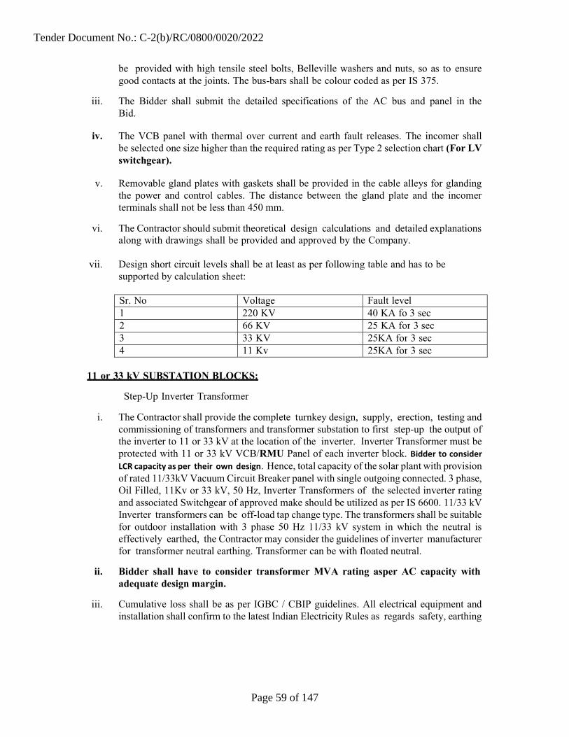
be provided with high tensile steel bolts, Belleville washers and nuts, so as to ensure good contacts at the joints. The bus-bars shall be colour coded as per IS 375.
iii. The Bidder shall submit the detailed specifications of the AC bus and panel in the Bid.
iv. The VCB panel with thermal over current and earth fault releases. The incomer shall
be selected one size higher than the required rating as per Type 2 selection chart (For LV switchgear).
v. Removable gland plates with gaskets shall be provided in the cable alleys for glanding the power and control cables. The distance between the gland plate and the incomer terminals shall not be less than 450 mm.
vi. The Contractor should submit theoretical design calculations and detailed explanations along with drawings shall be provided and approved by the Company.
vii. Design short circuit levels shall be at least as per following table and has to be
supported by calculation sheet:
Sr. No Voltage Fault level 1 220 KV 40 KA fo 3 sec 2 66 KV 25 KA for 3 sec 3 33 KV 25KA for 3 sec 4 11 Kv 25KA for 3 sec
11 or 33 kV SUBSTATION BLOCKS:
Step-Up Inverter Transformer
i. The Contractor shall provide the complete turnkey design, supply, erection, testing and commissioning of transformers and transformer substation to first step-up the output of the inverter to 11 or 33 kV at the location of the inverter. Inverter Transformer must be protected with 11 or 33 kV VCB/RMU Panel of each inverter block. Bidder to consider LCR capacity as per their own design. Hence, total capacity of the solar plant with provision of rated 11/33kV Vacuum Circuit Breaker panel with single outgoing connected. 3 phase, Oil Filled, 11Kv or 33 kV, 50 Hz, Inverter Transformers of the selected inverter rating and associated Switchgear of approved make should be utilized as per IS 6600. 11/33 kV Inverter transformers can be off- load tap change type. The transformers shall be suitable for outdoor installation with 3 phase 50 Hz 11/33 kV system in which the neutral is effectively earthed, the Contractor may consider the guidelines of inverter manufacturer for transformer neutral earthing. Transformer can be with floated neutral.
ii. Bidder shall have to consider transformer MVA rating asper AC capacity with adequate design margin.
iii. Cumulative loss shall be as per IGBC / CBIP guidelines. All electrical equipment and installation shall confirm to the latest Indian Electricity Rules as regards safety, earthing
Tender Document No.: C-2(b)/RC/0800/0020/2022
Page 59 of 147

IS: 2026 (Part Specifications for Power Transformer 1 to 4)
and other essential provisions specified for installation and operation of electrical plants. The Contractor may consider the timeline of guideline of inverter manufacturer for Transformer neutral earthing. The transformer can be floated neutral.
iv. Relevant national and international standards in this connection are mentioned in Table 6 General Standards for Transformers.
v. All working parts, in so far as possible, are to be arranged for convenience of operation, inspection, lubrication and ease of replacement with minimum downtime. All parts of equipment or of duplicate equipment offered shall be interchangeable.
vi. The quality of materials of construction and the workmanship of the finished products/ components shall be in accordance with the highest standard and practices adopted for the equipment covered by the specification.
vii. All items of equipment and materials shall be thoroughly cleaned and painted in accordance with relevant Indian Standards. The finish paint shall be done with two coats of epoxy based final paint of colour Shade RAL 7032 of IS:5 for indoor equipment
viii. Any fitting or accessories which may not have been specifically mentioned in the specification but which are usual or necessary in the equipment of similar plant or for efficient working of the plant shall be deemed to be included in the contract and shall be provided by the Contractor without extra charges. All plant and apparatus shall be complete in all details whether such details are mentioned in the specifications or not.
ix. All equipment shall be designed for operation in tropical humid climate at the required capacity in an ambient air temperature of 50°C. Equipment shall be suitable for an ambient temperature of 50°C. Maximum relative humidity of 100% shall also be taken into consideration for design of equipment.
x. The reference ambient temperatures for which the transformers are to be designed are as mentioned in Table 7.
xi. The rating and electrical characteristics of the MV / 11 kV Outdoor type transformer (typical) shall be as mentioned in Table 8
Table 6General Standards for Transformers
Tender Document No.: C-2(b)/RC/0800/0020/2022
Page 60 of 147

IS: 2099 Bushings for alternating voltage above 1000 V
IS: 3639 Fittings and accessories for power transformer
IEC: 60076 (Part 1 to 5)
IS: 9921 Part 1 to 5
Specifications for Power Transformer
Alternating currents dis-connectors (isolators) and earthing switches rating, design, construction, tests etc.
IS: 2705 Part Current transformer 1 to 4 & IEC:
IS: 3156 Part 1 to 4
IS: 3070 part 1 to 3
IS: 2544
IS: 5350
IS: 5621
IS: 5556
IEC: 186
Voltage Transformer
Lightning arrestors
Porcelain insulators for system above 1000 V
Part III – post insulator units for systems greater than1000 V
Hollow Insulators for use in electrical equipment
Serrated lock washers – specification
Voltage transformer
Tender Document No.: C-2(b)/RC/0800/0020/2022
Page 61 of 147

Table 7 Reference Weather Conditions for Transformer Design
Particulars Specifications Sr.
1.
2.
3.
4.
5.1
5.2
Maximum ambient temperature
Maximum daily average ambient temp
Maximum yearly weighted average
ambient temp
Minimum ambient air temperature: (Coolingmedium shall be Air)
Climatic Conditions :
Maximum relative humidity
Yearly average number of thunder storms
Average no. of rainy days per annum
50 degree C
45 degree C
40 degree C
Minus 5 degreeC
5.
100%
Varies from 30 to 50
5.3 60 days
Tender Document No.: C-2(b)/RC/0800/0020/2022
Page 62 of 147

CODES&STANDARDS
IS:13118/IEC56 Specification for High voltage Alternating Current Circuit Breakers.
IS9921 AC dis-connectors(isolators) and Earth switches for voltages above1000volts
IS-2705 Current transformers
IS-3156 Voltage transformers
IEC-60358 Coupling capacitors and capacitor dividers
IEC-60044 Instrument transformers
IEC-60481 Coupling devices for power line carrier systems
IS-3070 Lightning arresters 'for" alternating current systems: Metal oxide lightning arrestors without gaps.
IEC-60099 Metal oxide surge arrestors without gaps
IS-8792 Line traps forAC power system
IS-8997 Coupling devices for PLC systems
IEC-60353 Line traps for AC power systems
IEC-6 0 Communication Network and Systems in Substations
Technical Data Sheet of 11/66 KV or 33/66 KV Step Up Power Transformer
5.4 Fog
5.5
The atmosphere is subject to fog for two month in winter
Number of months during which 3 months tropical monsoon conditions prevail
Dust storms occur at frequent intervals
Average annual rainfall 60 cms
Maximum wind speed 180 kmph
Tender Document No.: C-2(b)/RC/0800/0020/2022
Page 63 of 147

Type of transformer: ONAN cooled, Three phase, 66/11KV or 66/33 KV Step Up Power Transformer, Double Limb wound, Core type for OUT DOOR application. Mounted on Rails with wheels. THREE Phase. Location of 33/66kV trafo and 66kV Circuit Breaker shall be at Solar Plant End.
Type of windings : HV: Interleaved type / Disc type with static end rings at both ends with uniformly insulated, LV: Continuous disc type / layer type with uniformly insulated. Winding connection for 3 phase HV winding – Delta, LV winding – Star or as per Design.
Vector Grouping : D-Y n 11 (as per IS: 2026 part-IV) or as per Design. Type of insulation : Uniformly insulated as per IS: 2026 Part III Winding Material : Electrolytic grade copper Winding Insulation : Class-A System frequency : 50Hz ± 3% Rated Capacity : As per IS 6600 for Power Transformer Rated Primary Voltage : 11 kV or 33 KV Rated Secondary Voltage : 66 kV
i. Non-cumulative over load capacity after the transformer has reached steady temperature on continuous operation at rated load i.e. At rated power) 110% for continuous, 125% for 15 minute, 140% for 5 min Tapings (On load Tap Changer) OLTC shall be of minimum 72 KV Voltage class and shall have maximum rated through current not less than 300 Amps at normal tap, short circuit withstand current not less than 10 KA for 3 Seconds and shall be of High Speed Resistor type, housed in a separate tank outside the main tank.: Min. 17 Taps in step of 1.25%. Bidder shall have to consider transformer MVA rating as per AC capacity with adequate design margin. Further, losses shall be as per IS and ONAN is only acceptable.
Transformer Losses : As per IS
Insulating medium Transformer oil as per IS: 12463
i. Instrument Transformer (66 kV Switchyard)
i. The instrument transformers i.e. current and voltage transformers shall be single phase transformer units and shall be supplied with a common marshaling box for a set of three single phase units. The tank as well as top metallics shall be hot dip galvanized or painted Grey color as per RAL 7032.
ii. The instrument transformers shall be oil filled hermetically sealed units. The instrument transformers shall be provided with filling and drain plugs.
iii. Polarity marks shall indelibly be marked on each instrument transformer and at the lead terminals at the associated terminal block. The insulators shall have cantilever strength of more than 500 kg.
Tender Document No.: C-2(b)/RC/0800/0020/2022
Page 64 of 147

iv. Current Transformer, Voltage Transformer, Circuit Breaker and Relays should match –Local distribution CEL’s Customer requirements.
ii. Current Transformer (66 kV Switchyard)
Contractor shall provide CT for protection/Energy/metering purpose. CT & PT for ABT meter shall be as per GETCO guidelines and as approved by GETCO.
i. Current transformers may be either of the bushing type or wound type. The bushing types are normally accommodated within the transformer bushings and the wound types are invariably separately mounted. The location of the current transformer with respect to associated circuit breaker has an important bearing upon the protection scheme as well as layout of, substation. Current transformer class and ratio is determined by electrical protection, metering consideration.
ii. Technical specifications – Current ratings, design, Temperature rise and testing etc. should be in accordance with IS: 2705 (part I to IV).
Type and Rating
a. The current transformer should be of outdoor/ indoor type, single phase, oil immersed, self-cooled and suitable for operation in 3 phase solidly grounded system.
b. Each current transformer should have the following particulars under the site conditions for the system under design (typical values for 66 kV systems are given).
c. General Parameters: 66 kV CT.
d. Each current transformer should have the following particulars under the site conditions for the system under design (typical values for 66 kV system are given).
Table 8 General parameters for 66 kV CT
Highest system Voltage 72 kV rms (Um)
Rated frequency
System Neutral Earthing
50 Hz
Effective earthed
Sr. Particulars Details
Tender Document No.: C-2(b)/RC/0800/0020/2022
Page 65 of 147

Installation
Rated short time thermal current
Rated dynamic current
Outdoor/indoor(IP 65)
31.5kA for 3 sec or appropriate thermal current as per design calculations
63 kA (Peak) appropriate dynamic current as per design calculations
Rated min power 140 kV & 150 Hz frequency withstand voltage (rms value)
8 Rated lightning impulse 350 kV withstand voltage value)
Minimum Creepage distance
Temperature rise
Type of insulation
Number of cores
(peak
10 31 mm/kV
11
12
13
As per -IS 2705/1992
Class A
For Transformer : Three (3) with One protection core and One (1)
metering core (1) Diff. Protection of Transformer
For ABT Meter Line Side : Three (3) with One (1) protection core and One
ABT metering core Main & Check
14 CT secondary current
15 Number of terminals in marshaling box
16 CT ratio & Rated VA Burden, short time thermal rating ,class of
Protection cores – 1 Amp.
Metering Core – 1 Amp
(With Highest Accuracy Class)
All terminals of control circuits wired up to marshaling box plus 20 terminals spare
Minimum burden required :
1. Metering core – 15 VA min.
Tender Document No.: C-2(b)/RC/0800/0020/2022
Page 66 of 147
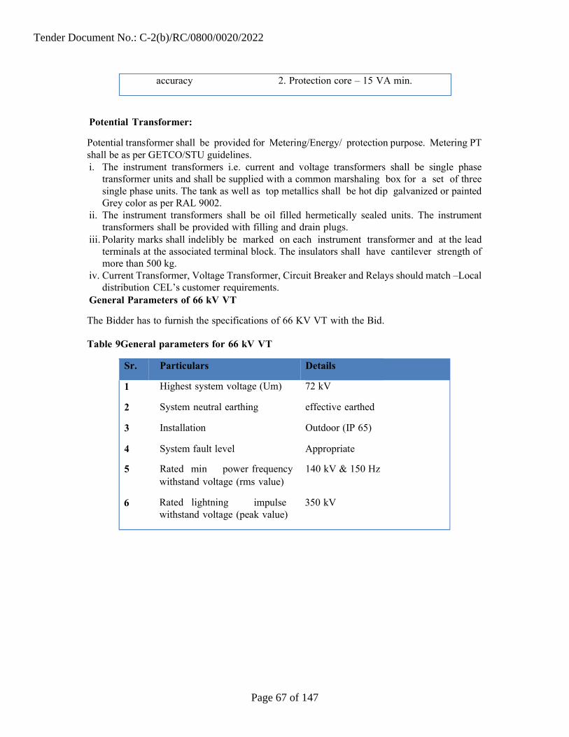
withstand voltage (rms value)
Rated lightning impulse 350 kV withstand voltage (peak value)
Potential Transformer:
Potential transformer shall be provided for Metering/Energy/ protection purpose. Metering PT shall be as per GETCO/STU guidelines. i. The instrument transformers i.e. current and voltage transformers shall be single phase
transformer units and shall be supplied with a common marshaling box for a set of three single phase units. The tank as well as top metallics shall be hot dip galvanized or painted Grey color as per RAL 9002.
ii. The instrument transformers shall be oil filled hermetically sealed units. The instrument transformers shall be provided with filling and drain plugs.
iii. Polarity marks shall indelibly be marked on each instrument transformer and at the lead terminals at the associated terminal block. The insulators shall have cantilever strength of more than 500 kg.
iv. Current Transformer, Voltage Transformer, Circuit Breaker and Relays should match –Local distribution CEL’s customer requirements.
General Parameters of 66 kV VT
The Bidder has to furnish the specifications of 66 KV VT with the Bid. Table 9General parameters for 66 kV VT
Sr. Particulars Details
1 Highest system voltage (Um) 72 kV
2 System neutral earthing effective earthed
3 Installation Outdoor (IP 65)
4 System fault level Appropriate
5 Rated min power frequency 140 kV & 150 Hz
accuracy 2. Protection core – 15 VA min.
Tender Document No.: C-2(b)/RC/0800/0020/2022
Page 67 of 147

7 Standard reference range of frequencies for which the accuracy are valid
96% to 102% for protection and 99% to 101% for measurement
8 Rated voltage factor 1.2 continuous & 1.5 for 30 sec
9 Class of Accuracy 0.5 / 3P, IS3156/1992
10 Minimum Creepage distance at 31 mm/kV
11 Stray capacitance and stray conductance of LV terminal over entire carrier frequency range
12 One Minute Power frequency Withstand voltage for secondary winding
13 Temp. Rise over an ambient temp. of 50 deg. C
14 Number of terminals in control spare.
As per IEC:358
3 kV rms
As per IS 3156/1992
All terminals of control circuits wired Cabinet up to marshaling box plus 10 terminals
15 Rated total thermal burden 50 VA min.
16 Number of cores 2 (two) – 1 for protection and one for metering with 0.5 class accuracy.
17 Rated Output, insulation level, transformation ratio, rated voltage factor
Should be provided by the Contractor.
Circuit Breaker (66 KV)
i. The circuit breakers shall be capable of rapid and smooth interruption of currents under all conditions completely suppressing all undesirable phenomena even under the most severe and persistent short circuit conditions or when interrupting small currents or leading or lagging reactive currents. The circuit breakers shall be ‘Restrike-Free’ under all operating conditions. The details of any device incorporated to limit or control the rate of rise of restriking voltage across, the circuit breaker contacts shall be stated. The over voltage across, the circuit breaker contacts shall be
Tender Document No.: C-2(b)/RC/0800/0020/2022
Page 68 of 147

stated. The over voltage caused by circuit breaker while switching inductive or capacitive loads shall not exceed 2.5 times the highest phase to neutral voltage. The actual make and break times for the circuit breakers throughout the ranges of their operating duties shall be stated in the offer and guaranteed.
ii. The arc quenching chambers shall have devices to ensure almost uniform distribution of voltage across the interrupters.
iii. Appropriate & adequate Capacity AC& DC power supply shall be provided as per the IEC 60898 / IEC 62271 – 100 or equivalent Indian Standards for control circuit and protection relay circuit, fuses, annunciations and remote operating and controlling facility from the Main Control Room.
iv. Circuit breaker shall be C2/Ml class under all duty conditions and shall be capable of performing their duties without opening resistor. The circuit breaker shall meet the duty requirement of any type of fault or fault location and shall be suitable for line charging and dropping when used on 6 kV effectively grounded or ungrounded systems and perform make and break operations as per the stipulated duty cycles satisfactorily.
v. The circuit breaker shall be capable for breaking the steady & transient magnetizing current corresponding to 66 kV transformers. It shall also be capable of breaking line charging currents as per IEC- 62271-100 with a voltage factor of 1.4.
vi. The rated transient recovery voltage for terminal fault and short line faults shall be as per IEC: 62271-100.
vii. The Bidder shall indicate in the Bid, the noise level of breaker at distance of 50 to 150 m from base of the breaker.
viii. The Bidder may note that total break time of the breaker shall not be exceeded under any duty conditions specified such as with the combined variation of the trip coil voltage, pneumatic pressure etc. While furnishing the proof of the total break time of complete circuit breaker, the Bidder may specifically bring out the effect of non- simultaneity between same pole and poles and show how it is covered in the guaranteed total break time.
ix. While furnishing particulars regarding the D.C. component of the circuit breaker, the Bidder shall note that IEC-62271-100 requires that this value should correspond to the guaranteed minimum opening time under any condition of operation.
x. The critical current which gives the longest arc duration at lock out pressure of extinguishing medium and the duration shall be indicated.
xi. All the duty requirements specified above shall be provided with the support of adequate test reports.
Tender Document No.: C-2(b)/RC/0800/0020/2022
Page 69 of 147
xii. Circuit breaker shall be SF6 with electrically spring charged mechanism. The operating mechanism shall be anti-pumping and trip free (as per IEC definition) electrically under every method of closing. The mechanism of the breaker shall be such that the position of the breaker is maintained even after the leakage of operating media and / or gas. The circuit breaker shall be able to perform the duty cycle without any interruption.
xiii. Electrical tripping shall be performed by shunt trip coil. Provision shall also be made for local electrical control. 'Local / remote' selector switch and close & trip push buttons shall be provided in the breaker central control cabinet. Remote located push buttons and indicating lamps shall also be provided. The SF6 coil DC supply through appropriately rated battery bank and charger to be supplied by the Contractor.
xiv. Operating mechanism and all accessories shall be in local control cabinet. A central control cabinet for the three poles of the breaker shall be provided along with supply of necessary tubing, cables, etc.
xv. Mounting and supporting structure for Circuit Breaker. The circuit breakers should be self-supporting type. However, if necessary for the purpose of minimum ground clearance the circuit breakers should be mounted on raised steel structures which should be included in the scope of supply of circuit breaker.
xvi. Following information and data for design of foundations from the supplier of the circuit breaker be obtained.
a. Dead weight per pole for complete circuit breaker
b. Static bending moments above the feet of each pole and for complete circuit breaker.
c. Static shear force at the foot of each pole and for complete circuit breaker
d. Maximum height of the steel supporting structure
e. Maximum diameter of the pole
f. Maximum horizontal force acting at upper terminal of each pole due to impact of closing/opening of the circuit breaker
g. Max. Impact loading in terms of equivalent static load both compression and upward due to opening/closing of the breakers. It shall be clearly stated whether these forces shall act simultaneously or at different timing.
h. No. of steel supporting columns provided for mounting the equipment.
i. The above data should represent static reactions for the worst windage or operation conditions. Circuit breakers whether of self-supporting type or on
Tender Document No.: C-2(b)/RC/0800/0020/2022
Page 70 of 147

Indian Standard Title International & Internationally recognized standard
raised steel structure should ensure minimum sectional clearance (say 3500 mm for 66 kV)
j. Necessary connecting materials such as clamps, bolts, nuts, washers etc. and fixing bolts for mounting the equipment on the supporting structures wherever required should be obtained from the circuit breaker supplier.
xvii. Applicable Standards:The materials shall conform in all respects to the relevant Indian Standard Specifications/ IEC Standards, with latest amendments indicated below in Table 10.
Table 10 Applicable Standards for Circuit Breakers
ISS-13118/1991 General requirements for Circuit breakers for voltage above 1000 V
ISS-2705/1992 Current Transformers
ISS-2099/1986 Bushings for alternating voltages above 1000 V
ISS-2633/1964 Methods of testing uniformity of coating of zinc coated articles
ISS-3231/1986 Electrical relays for power system protection
ISS-1248/1983 Specification for Ammeters & Voltmeters
IEC 62271-100- 1/2001
ISS-335/1983 New insulating oils Electrical Clearances IEC 71 (For oils in
Tender Document No.: C-2(b)/RC/0800/0020/2022
Page 71 of 147

xx. General Parameters of Circuit Breaker: General parameters: Outdoor/ Indoor
Vacuum type Circuit Breaker.
Table 11 General Parameters for 66 kV Circuit Breakers
1 Type of circuit breaker SF6 type
2 Highest System Voltage 72 kV
3 Rated operating voltage 66 kV
4 Rated frequency 50 Hz (+3% to -5%)
5 Number of poles Three (3)
6 Rated/minimum power frequency Withstand voltage
140 kV
7 Rated lightning impulse Withstand voltage 350 kV
8 Minimum Creepage distance 31mm/kV
9 Rated operating duty cycle 0 - 0.3 sec. - CO – 3 min. – CO
10 Rated line charging breaking As per IEC
11 Reclosing Single and three phase high speed auto reclosing
12 Maximum fault level 31.5 kA (rms) for 3 sec. However, it should be supported with calculations and not limited to above value.
13 Auxiliary contacts As required plus 6NO and 6NC contacts per pole as spare.
CTs)
ISS-2147/1962 Degree of protection provided by enclosures for low voltage switchgear & control gear
Sr. Particulars Details
Tender Document No.: C-2(b)/RC/0800/0020/2022
Page 72 of 147
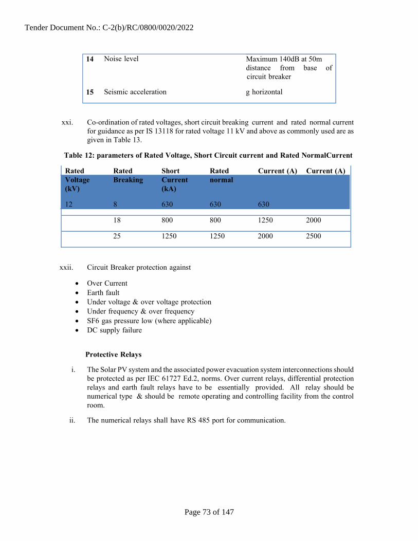
xxi. Co-ordination of rated voltages, short circuit breaking current and rated normal current for guidance as per IS 13118 for rated voltage 11 kV and above as commonly used are as given in Table 13.
Table 12: parameters of Rated Voltage, Short Circuit current and Rated Normal Current
Rated Voltage (kV)
12
Rated Breaking
8
Short Current (kA)
630
Rated normal
630
Current (A)
630
Current (A)
18 800 800 1250 2000
25 1250 1250 2000 2500
xxii. Circuit Breaker protection against
Over Current Earth fault Under voltage & over voltage protection Under frequency & over frequency SF6 gas pressure low (where applicable) DC supply failure
Protective Relays
i. The Solar PV system and the associated power evacuation system interconnections should be protected as per IEC 61727 Ed.2, norms. Over current relays, differential protection relays and earth fault relays have to be essentially provided. All relay should be numerical type & should be remote operating and controlling facility from the control room.
ii. The numerical relays shall have RS 485 port for communication.
14 Noise level Maximum 140dB at 50m distance from base of circuit breaker
15 Seismic acceleration g horizontal
Tender Document No.: C-2(b)/RC/0800/0020/2022
Page 73 of 147

iii. The operating voltage of the relays shall be 110 V DC/220 V DC as per battery bank rating.
iv. Detailed Design calculations shall be provided on fault power computations and the philosophy of protective relaying with respect to short circuit kA calculations. Design, drawing and model of protection relay shall be approved by the Company/Electricity Authority (GETCO).
Earthing for PV Array
i. The photovoltaic modules, BOS and other components of power plant requires adequate earthing for protecting against any serious faults as guided by IEC 60364.
ii. The earthing system shall be designed with consideration of the earth resistivity of the project area. The earth resistivity values shall be measured prior to designing the earthing system. Unless otherwise specified, earthing system shall be in accordance with IS: 3043 and IEEE 80, Indian Electricity Rules, Codes of practice and regulations existing in the location where the system is being installed.
iii. The permissible system fault power level at all the voltage shall be kept in consideration while designing the earthing system. Each array structure of the PV yard, LT power system, earthing grid for switchyard ,all electrical equipment ,control room ,PCU, All junction boxes, ACDB& DCDB ,all motors and pumps etc .shall be grounded properly as per IS 3043 - 1987. All metal casing / shielding of the plant shall be thoroughly grounded in accordance with Indian electricity act / IE Rules.
iv. The earthing for array and LT power system shall be made of 3.0 m long 40 mm diameter perforated Cu/GI/ chemical compound filled, double walled earthing electrodes including accessories, and providing masonry enclosure with cast iron cover plate having pad-locking arrangement, chemical compound mix as required as per provisions of IS: 3043. Bidder is also allowed to use chemical earthing system with 17.2 MM Dia 3 Mts long Cu bonded rod. Detail calculation to satisfy tender specification shall be submitted during detail engineering.
v. Necessary provision shall be made for bolted isolating joints of each earthing pit for periodic checking of earth resistance.
vi. Each string/ array and MMS of the plant shall be grounded properly. The array structures are to be connected to earth pits as per IS standards. Necessary provision shall be made for bolted isolating joints of each earthing pit for periodic checking of earth resistance.
vii. The complete earthing system shall be mechanically & electrically connected to provide independent return to earth.
viii. For each earth pit, a necessary test point shall be provided.
Tender Document No.: C-2(b)/RC/0800/0020/2022
Page 74 of 147

ix. In compliance to Rule 11 and 61 of Indian Electricity Rules, 1956 (as amended up to date), all non-current carrying metal parts shall be earthed with two separate and distinct earth continuity conductors to an efficient earth electrode.
x. The Contractor should submit the earthing system design calculations along with the system layout for the Company’s approval prior to the installation of the system
xi. Unless otherwise specified, the earthing system primary and secondary grid conductors, equipment connections shall be constructed with galvanized iron flat. However the earthing of transformer neutrals, plc and inverter terminals and electronic earthing shall be provided using copper earthing conductor only.
xii. Earthing Mesh is to prepared and installed in entire power plant. Earthing shall be as per IS-3043. However, Earthing mesh in the area of 11/33/66 KV equipments of Solar plant end and 66 KV GETCO yard shall be provided as per tender specifications.
Lightening Protection for PV Plant and Earthing
i. The source of over voltage can be lightning or other atmospheric disturbance. Main aim of over voltage protection is to reduce the over voltage to a tolerable level before it reaches the PV or other sub-system components as per IEC 60099 / IS: 2309 – 1989 (Reaffirmed – 2005), Edition 3.1 (2006-01). Lightening Protection System required for Solar PV Plant, Inverter Room, and Substation Structure & Control Room within the EPC scope of work. The intent of specification can be conventional as per IS : 2309 or can be Early Streamer Emission Type depending upon Area, Protected Equipment & Technical feasibility.Necessary concrete foundation for holding the lightning conductor in position to be made after giving due consideration to shadow on PV array, maximum wind speed and maintenance requirement at site in future. We recommended going with Early Stream Emission Air Terminal Technology as per NFC 17-102 / IEC 62305-2. Level of Protection must be defining as per Rolling Sphere Method LPL-I, LPL-II, LPL-III & LPL-IV where the radius shall be of 20mtr, 30mtr, 45mtr & 60mtr respectively.
ii. Rp(h) : Protection radius at a given height (h) Rp(h) = √ 2rh - h2 + Δ(2r + Δ) (for h ≥ 5 m) For h < 5 m, refer to the table below h : Height of the OPR tip above the surface(s) to be protected r(m) : Standardized striking distance ∆(m) = 106 .ΔT (OPR efficiency)
Tender Document No.: C-2(b)/RC/0800/0020/2022
Page 75 of 147
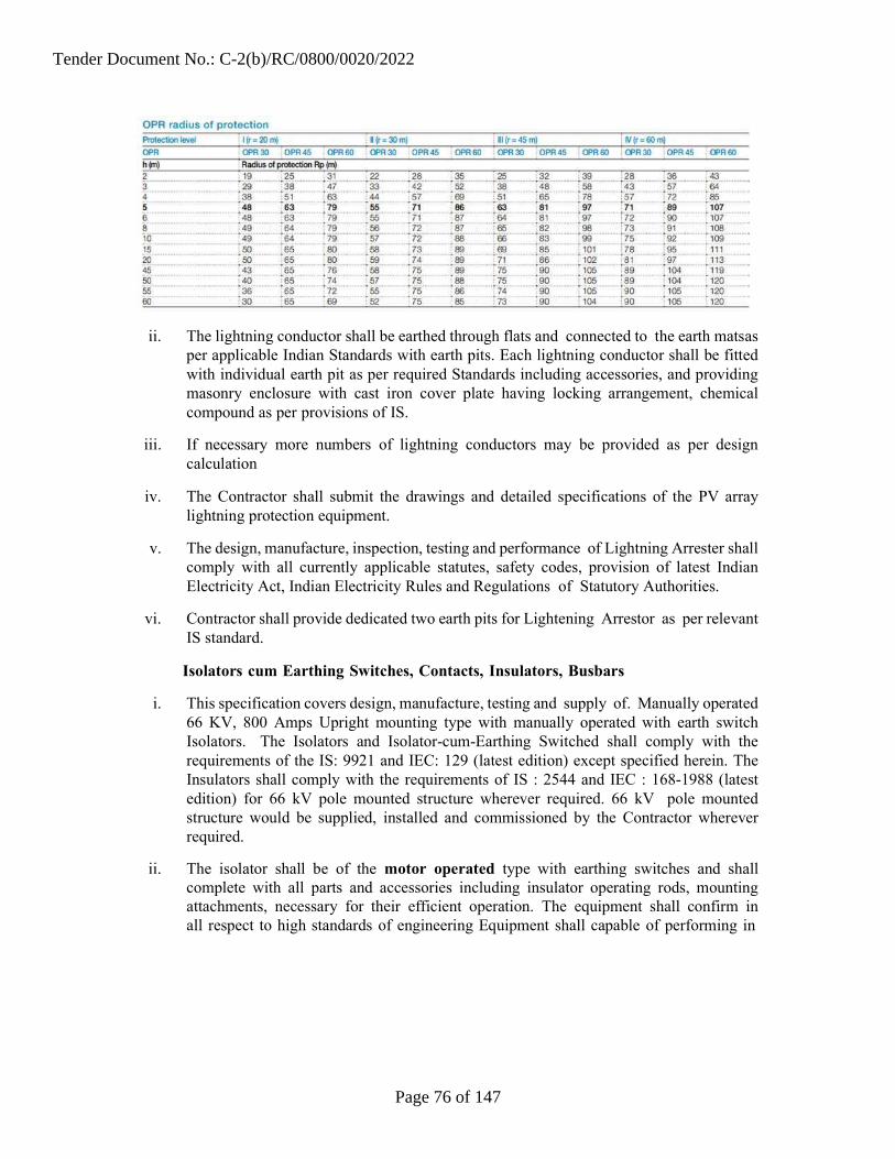
ii. The lightning conductor shall be earthed through flats and connected to the earth mats as per applicable Indian Standards with earth pits. Each lightning conductor shall be fitted with individual earth pit as per required Standards including accessories, and providing masonry enclosure with cast iron cover plate having locking arrangement, chemical compound as per provisions of IS.
iii. If necessary more numbers of lightning conductors may be provided as per design calculation
iv. The Contractor shall submit the drawings and detailed specifications of the PV array lightning protection equipment.
v. The design, manufacture, inspection, testing and performance of Lightning Arrester shall comply with all currently applicable statutes, safety codes, provision of latest Indian Electricity Act, Indian Electricity Rules and Regulations of Statutory Authorities.
vi. Contractor shall provide dedicated two earth pits for Lightening Arrestor as per relevant IS standard.
Isolators cum Earthing Switches, Contacts, Insulators, Busbars
i. This specification covers design, manufacture, testing and supply of. Manually operated 66 KV, 800 Amps Upright mounting type with manually operated with earth switch Isolators. The Isolators and Isolator-cum-Earthing Switched shall comply with the requirements of the IS: 9921 and IEC: 129 (latest edition) except specified herein. The Insulators shall comply with the requirements of IS : 2544 and IEC : 168-1988 (latest edition) for 66 kV pole mounted structure wherever required. 66 kV pole mounted structure would be supplied, installed and commissioned by the Contractor wherever required.
ii. The isolator shall be of the motor operated type with earthing switches and shall complete with all parts and accessories including insulator operating rods, mounting attachments, necessary for their efficient operation. The equipment shall confirm in all respect to high standards of engineering Equipment shall capable of performing in
Tender Document No.: C-2(b)/RC/0800/0020/2022
Page 76 of 147

continuous commercial operation up to the suppliers guarantee in a manner acceptable to the client, The equipment offered shall be complete with all components necessary for its effective and trouble free operation along with associated equipments, interlock, protection schemes, etc. Such components shall be deemed to be within the scope of the Contractor's supply irrespective of whether those are specifically brought out in this specification or not. All similar parts particularly removable ones shall be interchangeable.
iii. Each pole shall have three Pedestal type of Insulator’s stacks. Necessary arrangements shall be provided for proper alignment of the contacts. Ganged operated links shall be so designed that all phases shall make and break simultaneously. The design of Isolators and Isolator-cum-Earthing Switches shall be provided for positive control of blades in all positions with minimum mechanical stress on the Insulators. Fixed guides shall be so provided that proper setting of contacts shall be obtained, when a blade is out of alignment even by 25mm in either direction. All movable parts which may be in current path shall be shunted by flexible copper conductor of adequate cross-section and capacity, which shall be furnished under bill of material.
Service Condition:
The 66 kV triple pole air break isolators are intended to be used primarily for sectionalizing 66 kV UG cable portion of the line with 66 kV overhead portion of the line.
Isolator shall confirm IS: 9921(Part 1 to 4) & IEC 600 - 129 "alternating current disconnects (Isolators) and earthing switches", and IS 9921 (Part-I to IV) "Specification for alternating current disconnects (isolators) and earthing switches for voltages above 1000V”
a. The moving & fixed contacts shall be made of hard drawn electrolytic grade copper strips and shall be heavy duty self- aligning & high pressure type preferably which applies pressure to the contact surfaces after the blades are fully closed and release the pressure before they start to open. High pressure type contacts shall wipe the contact surfaces, while opening and closing. The contacts shall be so designed that wiping, action shall not cause securing or abrasion on the contact surfaces. The wiping action shall be sufficient to remove oxide film, formed during the operation of the switches. The pressure shall be developed by rotation of the entire blade.
b. The temperature rise of contacts due to the flow of rated short circuit current for a period of 3 seconds shall not cause any annealing or welding of contacts.
c. The moving contacts, if provided, shall close first and open last so that no damage is caused due to arcing whatever to the main contacts. The Successful Bidder shall give full details of such contacts with necessary drawings.
d. The arcing contacts, if provided shall close first and open last so that no damage is caused due to arcing whatever to the main contacts. The Contractor shall give full details of such contacts with necessary drawings.
Tender Document No.: C-2(b)/RC/0800/0020/2022
Page 77 of 147
e. The female contact and its tensioning by spring shall be such that there will, always, be a positive contact with adequate pressure to give enough contact surface for the passing of current. The springs provided should not go out of alignment or get entangled with the male contact during operation. The details of springs shall be furnished on the G.A. drawing.
INSULATORS: The isolator shall be provided with solid core insulators.
i. These shall be of stacking type to be used. The dimensions and other parameters unless otherwise specified shall generally conform to IS - 5350-Part-11 & IEC 273.
ii. The cylindrical type post insulators shall be of solid core type. Insulators of similar type shall be interchangeable. The mechanical strength class for outdoor cylindrical post insulators shall be of strength class 6, corresponding mechanical strength in tension, compression and torsional shall be as per IS : 53550 Part - II. When operated at maximum system voltage, there shall be no electrical discharge. Shielding rings, if necessary shall be provided.
iii. The parameters of the insulators required shall conform to IS : 0350 - Part - II - 1973 or IEC 273.
iv. The cylindrical post insulators shall consist of single unit only.
v. The insulator shall be provided with a completely galvanized steel base designed for mounting on the support. The base and mounting arrangement shall be such that the insulator shall be rigid and self-supporting and no guying or cross bracing between phase shall be necessary.
vi. Porcelain of the insulator:
a. The porcelain used for the manufacture of the insulators shall be homogenous, free from laminations and other flaws or imperfections that might effect the mechanical or dielectric quality and shall be thorough vitrified, tough and impervious to moisture. The glazing of the porcelain shall be uniform brown colour, with a smooth surface arranged to shade away rain water and free from blisters, burns and other similar defects. Insulators shall be inter-changeable.
b. The porcelain and metal parts shall be assembled in such a manner and with such materials that any differential thermal expansion between the metal and porcelain parts throughout the operating temperature range will not loosen the parts or electrical strength or rigidity. The assembly shall not have excessive concentration of electrical stress in any section or across leakage surfaces. The cement used shall not give rise to chemical reaction with metal fittings. The insulator shall be suitable for water washing by rains or artificial means in service conditions. Further the insulators to be
Tender Document No.: C-2(b)/RC/0800/0020/2022
Page 78 of 147

supplied shall be of high- quality and should not result in mismatch and misalignment of stacks during erection and operation.
c. Each cap shall be of a high grade cast iron or malleable steel casting or steel forging. Cap and base insulators shall be interchangeable with each other. The insulator shall conform to the requirement of the latest edition of IS: 2544,or any other equivalent standard. The Bidder should furnish the characteristics of insulators in the Bid.
Busbars
i. The outdoor bus-bars and equipment connections shall be with ACSR conductor (Panther /suitable size as per design).
ii. The bus-bars and the connection jumpers shall be supported on post insulators wherever required.
iii. The ACSR bus bars are an underground system of wires strung between two supporting structures and supported by strain type insulators. The stringing tension may be limited to 500-900 kg. depending upon the size of the conductor used. These types of bus bars are suitable for earthquake prone areas.
iv. Bus bar Material – The materials in common use for bus bars and connections of the strain type are ACSR conductor.
v. Since aluminum oxides rapidly great care is necessary in making connections. In the case of long spans expansion joints should be provided to avoid strain on the supporting insulators due to thermal expansion or contraction of pipe.
vi. The bus bar sizes should meet the electrical and mechanical requirements of the specific application for which they are chosen.
vii. The isolator shall be provided with padlocking device to permit locking of the isolator in both fully open and fully closed positions.
Control & Relay Panel Specification
i. The control & relay panel shall be free standing, simplex type, floor mounting type, fabricated from 2 mm thick MS sheet for main enclosure and 1.6 mm thick MS sheet for internals and partitions. The main enclosure shall be mounted on a base frame fabricated out of 100x50 ISMC mild steel section.
ii. The enclosure external finish color shade shall be decided by the CEL’s Customer, The internal surface shall have a glossy white finish all over.
iii. The control & relay panel shall contain the following metering and protection devices:
Metering, Indications & Controls Ammeter – 0 ............... A
Tender Document No.: C-2(b)/RC/0800/0020/2022
Page 79 of 147

Ammeter selector switch Voltmeter – 0 – 12/36 kV Voltmeter selector switch Load manager to display the following parameters : MW, MVA, MVARh, MVAR
Cos Ø, Hz, Indication lamps for R, Y, B phases, Breaker ‘ON’ (R), Breaker ‘OFF’ (G), Breaker
‘TRIP’ (A), Spring charged (W), Trip Circuit Healthy (B) TNC switch, spring return to neutral position shall be provided for circuit breaker
operation. Local / Remote selection switch for circuit breaker operation Semaphore indicators (LED type) for CB and Isolator ‘Open’ & ‘Close’ positions Mimic diagram for the 66 KV systems with aluminum strips and ‘ON’ ‘OFF’
indications for isolators.
Low Voltage Switchgear
i. This specification is for the 415V TP&N Power Control Centre (PCC).
ii. The PCC shall be rated for the maximum output of the supply transformer feeding the system.
iii. The short circuit withstand rating (1 sec) at rated voltage of the switchgear shall be minimum of 20 kA (rms) and corresponding dynamic rating shall be 50 kA (peak). However, this shall be supported by design calculations. Rating shown as above is indicative only.
iv. The configuration of the PCCs shall be as per the Single Line Diagram of the system.
Execution
i. Single front / compartmentalized, modular design, degree of protection IP52 with provision of extension on both sides.
ii. Incomer feeders: mains incomer - Electrically operated draw out type Air Circuit Breakers (ACBs).
iii. Outgoing feeders : Electrically operated draw out type Air Circuit Breakers (ACBs) / Molded Case Circuit Breakers (MCCBs)
iv. The color finish shade of switchgear enclosure for interior shall be glossy white & for exterior it shall be light grey, semi glossy shade 631 of IS: 5. If a different exterior shade is desired by the PURCHASER, the same shall be intimated to the supplier.
Tender Document No.: C-2(b)/RC/0800/0020/2022
Page 80 of 147

v. The PCC shall be fabricated out of CRCA sheet steel; 2 mm thick for the outer shall all-round. The internal walls and separators shall be of 1.6 mm thick CRCA sheet steel.
vi. The gland plates shall be 3 mm thick.
Control & Relay Specification for 415V TP & N Power Control Centre(PCC)
i. This specification is for the 415V TP&N Power Control Centre (PCC).
v. The PCC shall be rated for the maximum output of the supply transformer feeding the system. The short circuit withstand rating (1 sec) at rated voltage of the switchgear shall be minimum of 20 kA (rms) and corresponding dynamic rating shall be 50 kA (peak). However, Bidder shall have to carry out the short circuit current analysis and shall submit to CEL/CEL’s Customer for approval before selection of short circuit rating of equipments. Rating shown as above is indicative only.
ii. The configuration of the PCCs shall be as per the Single Line Diagram of the system.
Execution
Power Control Centres (Construction)
a. Single front / compartmentalized, modular design, degree of protection IP52 with provision of extension on both sides.
b. Incomer feeders: mains incomer - Electrically operated draw out type Air Circuit Breakers (ACBs).
c. Outgoing feeders : Electrically operated draw out type Air Circuit Breakers (ACBs) / Moulded Case Circuit Breakers (MCCBs)
d. The colour finish shade of switchgear enclosure for interior shall be glossy white & for exterior it shall be light grey, RAL 7032 of IS: 5. If a different exterior shade is desired by the PURCHASER, the same shall be intimated to the supplier.
e. The PCC shall be fabricated out of CRGO sheet steel; 2 mm thick for the outer shall all-round. The internal walls and separators shall be of 1.6 mm thick CRGO sheet steel
f. The gland plates shall be 3 mm thick
.Control Circuit
a. Control supply for breaker closing / tripping - 110V DC
b. Air Circuit Breaker spring charge motor – 240 /220 V AC/DC
Tender Document No.: C-2(b)/RC/0800/0020/2022
Page 81 of 147

c. Molded Case Circuit Breakers – 240 V AC, 1 phase
d. Indications, annunciation – 110V DC
e. Space heater, sockets, etc. – 240 V AC, 1 phase
Bus bar and Cable Cavity
a. The material for main bus bars and tap off bus bars shall be electrolytic grade aluminum with HR PVC sleeved insulation
b. Bus bars shall be suitable for short circuit rating and current suitable for all connected load.
c. Bottom cable entry for incoming and outgoing cables
d. A suitable gland plate shall be supplied for termination of power, control and instrumentation cables.
e. Whenever feeders are housed in multi-tier configuration, these tiers shall be segregated by sheet metal barriers.
Control Room Electrical Wiring
i. Electrification of building shall be carried out as per IS 732-1989, IS 46481968 and other relevant standards. Suitable AC Distribution Board should be designed to Supply AC power in Control room.
ii. Control room AC distribution Board theoretical design, calculations and detailed explanations along with drawing shall be provided and approved by CEL/CEL’s customer.
Auxiliary Power Supply
i. The Contractor shall install a separate 11 kV / 415 V or 33KV/415 Vstep down transformer to supply power for internal equipment such as power for control equipment, area lighting, water pumps, and conference room fixtures, control room lighting and air-condition, etc.
ii. This auxiliary power should be utilized directly from the grid through a separate meter and should not interfere with accounting of solar electricity fed into the grid.
DC Battery & Charger
i. Adequate capacity DC battery Bank should be provided for emergency control supply of inverters, control / protection system & emergency lighting. A appropriate capacity
battery charger with relevant IS/IEC standards & protection and automatic change over system should be provided to charge the battery bank along with relay circuit, fuses, annunciations and remote operating and controlling facility from the Main Control
Tender Document No.: C-2(b)/RC/0800/0020/2022
Page 82 of 147

Room.
ii. A DC power supply Distribution panel/board should be supplied along with the Charger as per relevant IS standards. Inverter room / Control room DC Battery Bank & DC supply system theoretical design, calculations and detailed explanations along with drawing shall be provided and approved by CEL/CEL’s Customer/State Nodal Agency. Integral DCDB in a separate compartment shall be provided.
iii. DC Batteries the batteries shall have the following specifications
a. Type : Nickel Cadmium Stationary/ VRLA, sealed type, storage battery
b. Rating : 110 V D.C., Minimum 80 Ah at 8 Hour rate of discharge
c. Standard : IS 1651 – 1979 ; performance as per IS 8702
d. Container : Plastic Resin, ABS or PP
e. Terminal Post : Designed suitably to accommodate external bolted connections
iv. The battery room shall be provided with epoxy paint coated exhaust fan for removal of gasses released from the battery cells.
v. The data sheet for the battery shall be submitted along with the Bid for evaluation.
Earthing
i. Earthing bus bar shall be terminated at both ends of the switchgear to suit the connections to outside earthing conductor. All components inside the module are required to be earthed individually and are to be looped and connected to the horizontal earth bus.
Terminals
a. CT circuit - Isolating link type terminals with shorting facility
b. PT circuit – clip on type terminals
c. Spare contacts shall be wired up to terminal block. 10% spare terminals shall be provided for each module
Specific Requirements
Tender Document No.: C-2(b)/RC/0800/0020/2022
Page 83 of 147

1. All ACBs shall be 4 pole, electrically operated, draw-out type, with closing coil, spring charge motor, trip coil, TNC switch for close and trip, manual closing and tripping push buttons, door I/L, test and service position micro switches, emergency P.B., safety shutters, etc. The circuit breaker shall be provided with anti-pumping feature.
2. ACBs shall be complete with microprocessor release and shall be provided with over current, short circuit and earth fault protections.
3. Minimum10% spare feeders of each rating shall be provided in the switchgear. No spare feeder is required for 11kV VCB panel and SMB.
4. All current transformers shall have 5/1A secondary and all meters shall be suitable for 5/1A operation.
5. All indicating lamps shall be of LED cluster type. ACB feeders shall be provided with ON, OFF, AUTOTRIP, SPRING CHARGED, TEST, SERVICE, TRIP CIRCUIT HEALTHY indications
6. All indicating instruments shall be flush mounting, Digital, 96 sq.mm size.
7. Window annunciator with hooter and accept, test, reset button shall be provided. Necessary auxiliary relays for contact multiplication shall be provided in the panel.
8. The maximum temperature of the bus bars, droppers and contacts at continuous current rating under site reference ambient temperature of 50º C shall not exceed 105º C.
Instrumentation: Switchgear instrumentation shall be provided as follows:
a. Mains Incomer – Voltmeter with selector switch b. Ammeter with selector switch c. Power Factor meter d. Frequency meter e. TVM + MD meter f. Potential indicating lamps g. Outgoing Feeders h. Ammeter with selector switch on all feeders.
General Technical Specifications of Control Panel
i. The panel shall be self-supporting, free standing, floor mounted, modular type with construction having degree of protection of IP 54 as per IS 2147.
ii. The panel shall be fabricated from 2 mm CRCA sheet steel for frame & load bearing surfaces. Partitions may be fabricated from 1.6 mm CRCA if no components are mounted on them.
Tender Document No.: C-2(b)/RC/0800/0020/2022
Page 84 of 147

iii. The panel shall be painted with 2 coats of primer after pre-treatment and 2 coats of Polyurethane / epoxy paint with shade as decided by the Company.
iv. Stiffeners shall be provided at corners & between modules to make panel rugged. The stiffeners will necessarily be required for relay compartments or doors where heavy components are mounted.
v. The openable covers shall be provided with lift off type hinges, quarter turn door locks and flexible copper wire for earth connection.
vi. The panel shall be dust and vermin proof. Synthetic or neoprene gaskets shall be provided at all openings.
vii. The panel shall be of dead front construction suitable for front operated and back maintained functioning.
viii. Panel shall be provided with fl. lamp of 20 w capacity operated by door operated limit switch. Panel shall also have space heaters and thermostat arrangement.
ix. Panel shall be provided with 3 pin switch socket combined unit of 5 Amp capacity.
x. Lifting hooks shall be provided at the top of the panel.
xi. The hardware components used in the panel shall be hot dipped galvanized.
xii. The control components shall be fixed on mounting plate by drilling & tapping.
xiii. Aluminum anodized legend plates shall be provided for all the components. For components mounted on front face, legend plate from inside shall also be provided.
xiv. Pretreatment by 7 tank process shall be done before painting / powder coating the panel.
xv. Panel shall have provision of drawing pocket.
xvi. The panel shall be designed to ensure maximum safety during operation inspection, connection of cables and maintenance. Inside panel, checking and removal of components shall be possible without disturbing other units.
xvii. Cable entries will be from bottom. The opening of cable entry shall be covered by 3 mm thick gland plates.
xviii. The panel shall be provided with all necessary components / devices and instruments as per the enclosed schematic diagram and functional requirements.
xix. The components such as protective relays, auxiliary relays, push buttons, switches, instruments shall be flush mounted on the front side of a panel.
Tender Document No.: C-2(b)/RC/0800/0020/2022
Page 85 of 147
xx. The control wiring shall be done with PVC insulated flexible copper wire. For CT secondary circuits 2.5 sq.mm. wire shall be used. For control wiring 1.5 sq.mm. wire shall be used.
xxi. Earthing busbar of suitable cross section shall be provided throughout the length of panel.
xxii. The panel shall be fully wired all the terminals shall be brought out for cable connections. 10% spare terminals shall be provided on each terminal block. Separate terminal block shall be provided for different voltages. All wire shall have P.V.C. ferrules as per wiring diagram.
xxiii. Proper shrouding to incoming and outgoing terminals shall be provided to ensure safety during operation, inspection and maintenance.
xxiv. Indicating lamps shall be with multiple LEDs & shall be suitable for the voltage specified.
xxv. All the components in the panel shall be properly labeled. The labels shall be made of non-rusting metal or engraved PVC material properly fixed by screws.
xxvi. The panel layout shall be made in such a way that it will always facilitate easy removal and reconnection of control cables without disturbing other wiring.
xxvii. Centre lines of control switches, push buttons and indicating lamps shall be matched so as to give neat appearance. Similarly top lines of indicating instruments and relays shall also be matched.
xxviii. The panel shall be provided with electrolytic grade aluminum busbar of suitable cross section so as to maintain max current density of 0.8 AMP/ Sq.mm.
xxix. Bus bars shall be provided with color coded heat shrinkable sleeves.
xxx. Bus bars shall be supported by high quality epoxy insulators provided at specified distances so as to withstand to the given fault level.
xxxi. The busbar chambers shall be provided with suitable ventilation arrangements so as to limit the maximum temperature of 85°C while carrying rated current.
xxxii. Proper clearance of minimum 25 mm shall be maintained between phase bus bars and between bus bars.
xxxiii. The panel shall be inspected at manufactures works before dispatch to site at the discretion of CEL/CEL’s customer.
xxxiv. All routine tests shall be carried out on the panel in presence of the Company / its representative. These tests shall include following:
Tender Document No.: C-2(b)/RC/0800/0020/2022
Page 86 of 147

a. Verification of components ratings and operation.
b. High voltage measurement test.
c. Insulation Resistance measurement.
xxxv. Control testing.
xxxvi. Approval on following drawings shall be obtained before manufacturing the panels
a. General arrangement drawing.
b. Wiring Diagram.
xxxvii. Detail bill of material.
66kV Under Ground Cable
The Contractor shall provide 66kV Under Ground Cable along with bay and metering on Turnkey basis as per client’s requirement at substation. The Bidder shall confirm the same in the Bid. The Underground cable shall also be approved registered supplier in GETCO.
Bidder can opt underground cable or Transmission line. However it shall be as per GETCO guidelines.
Metering System
i. ABT energy meter shall be provided as approved by GETCO to measure the delivered quantum of energy to the grid for sale. The responsibility of arranging for the meter, its inspection/calibration/testing charges etc. rests with the Contractor. All charges incurred on Meter testing, shall be borne by the Contractor. ABT energy metering system is to be approved by GETCO. Metering shall be at CEL’s Customer’s S/s end.
ii. Meter must be provided with the necessary data cables.
iii. Separate metering system has to be provided for L.T. (incoming) and H.T. (outgoing) supply is only for monitoring at Solar plant end. Main & Check ABT meters shall be installed at GETCO SS end. One number ABT is required as per latest GETCO guidelines at Solar PV plant end
iv. The Bidder shall provide ABT compliant meters at the interface points. Interface metering shall conform to the Central Electricity Authority (Installation and Operation Meters) Regulation 2006 and amendment thereof Commercial settlement of solar Photovoltaic Grid Interactive based power project shall be in accordance with the GERC relevant order. Meter shall be suitable for interfacing for synchronizing the built-in clock of the meter by GPS time synchronization equipment existing at the station either through a synchronization pulse received from the time synchronization equipment or through a remote PC synchronized to GPS clock shall also be in the scope of Bidder.
Tender Document No.: C-2(b)/RC/0800/0020/2022
Page 87 of 147

v. All charges for testing and passing of the meter with relevant government agency shall be borne by Bidder; CEL will assist Bidder for necessary document as and when required.
vi. ABT compliant Energy Meters shall have technical specification as given below (not limited to specified requirement, Bidder can provide Meter with latest facilities):
vii. Shall be microprocessor-based conforming to IEC 60687 / IEC 6205211/ IEC 62053- 22 / IS 14697
viii. Shall carry out measurement of active energy (both import and export) and reactive energy (import) by 3-phase, 4 wire principle suitable for balanced/ unbalanced 3 phase load.
ix. Shall have an accuracy of energy measurement of at least Class 0.2 for active energy and at least Class 0.5 for reactive energy according to IEC 60687, and shall be connected to Class 0.2 CT cores and Class 0.2 VT windings.
x. The active and reactive energy shall be directly computed in CT & VT primary ratings.
xi. Shall compute the net MWh and MVARh during each successive 15-minute block metering interval along with a plus/minus sign, instantaneous net MWh, instantaneous net MVARh, average frequency of each 15 minutes, net active energy at midnight, net reactive energy for voltage low and high conditions at each midnight.
xii. Each energy meter shall have a display unit with a seven digit display unit. It shall display the net MWh and MVARh with a plus/minus sign and average frequency during the previous metering interval; peak MW demand since the last demand reset; accumulated total (instantaneous) MWh and MVARh with a plus/minus sign, date and time; and instantaneous current and voltage on each phases.
xiii. All the registers shall be stored in a non-volatile memory. Meter registers for each metering interval, as well as accumulated totals, shall be downloadable. All the net active/reactive energy values displayed or stored shall be with a plus /minus sign for export/import.
xiv. At least the following data shall be stored before being over-written for the following parameters:
Table 13 Co-ordination Parameters
Sr. Parameters Details Min No of Days.
1 Net MWh 15 min Block 90 days in meter
Tender Document No.: C-2(b)/RC/0800/0020/2022
Page 88 of 147

xxxviii. Shall have a built in clock and calendar with an accuracy of less than 15 seconds per
month drift without assistance of external time synchronizing pulse.
xxxix. Date/time shall be displayed on demand. The clock shall be synchronized by GPS time synchronization equipment existing at the station provided by Bidder.
xl. The meter shall be suitable to operate with power drawn from the VT supplies. The burden of the meters shall be less than maximum 2 VA.
xli. The power supply to the meter shall be healthy even with a single-phase VT supply. An automatic backup, in the event of non-availability of voltage in all the phases, shall be provided by a built in long life battery and shall not need replacement for at least 10 years with a continuous VT interruption of at least 2 years. Date and time of VT interruption and restoration shall be automatically stored in a non-volatile memory.
xlii. Even under the absence of VT input, energy meter display shall be available and it shall be possible to download data from the energy meters.
xliii. Shall have an optical port on the front of the meter for data collection from either a hand held meter reading instrument (MRI) having a display for energy readings or from a notebook computer with suitable software.
xliv. The meter shall have means to test MWh and MVARh accuracy and calibration at site in-situ and test terminal blocks shall be provided for the same.
xlv. The meter shall have a unique identification code provided by the Company and shall be permanently marked on the front of the meter and stored in the non-volatile memory of the meter.
xlvi. The Company shall have the right to carry out surprise inspections of the Metering Systems from time to time to check their accuracy.
SCADA and Remote Monitoring System
Average Frequency
Net MVARh for > 103 %
Cumulative Net MWh
15 min Block
15 min Block
At every Mid-night
Cumulative Net MVARh for At every Mid-night v > 103 %
90 days in meter
90 days in meter
30 days in meter / 90 days in PC
30 days in meter / 90 days in PC
Date and time blocks of VT failure on any phase
Tender Document No.: C-2(b)/RC/0800/0020/2022
Page 89 of 147

i. The plant shall be automatically operated and shall be controlled by microprocessor based control system SCADA. There shall be simultaneous data logging, recording and display system for continuous monitoring of data for different parameters of different sub systems, power supply of the power plant at DC side and AC side.
ii. An integrated SCADA shall be supplied which should be capable of communicating with all inverters and provide information of the entire Solar PV Grid interactive power plant.
iii. Computer-aided data acquisition unit shall be a separate & individual system comprising of different transducers to read the different variable parameters, A/D converter, multiplexer, de multiplexer, interfacing hardware & software, which will be robust & rugged suitable to operate in the control room Environment.
iv. Reliable sensors for solar insolation, temperature, and other weather and electrical parameters are to be supplied with the data logger unit.
v. The data acquisition system shall measure and continuously record electrical parameters at inverter output,11KV terminal, 66 KV terminal, 66 kV ABT meter at evacuation point, ambient temperature near array field, control room temperature, AC and DC side electrical parameters of each inverter, power characteristics of the HT side.
vi. All data shall be recorded chronologically date wise. The data file should be MS Excel compatible. The data logger shall have internal reliable battery backup and data storage capacity to record all sorts of data simultaneously round the clock. All data shall be stored in a common work sheet chronologically and representation of monitored data shall be in graphics mode or in tabulation form. All instantaneous data can be shown in the Computer Screen. Provision should be available for Remote Monitoring.
vii. The Bill of Materials associated with the equipment must clearly indicate especially the details about the PC and Printers, etc.
viii. The Data Acquisition System should be housed in a desk made of steel sheet.
ix. SCADA shall provide following data at a 5-15 minute interval.
a. Power at 66 kV ABT meter at switchyard b. Ambient temperature near array field. c. Wind Speed d. AC and DC side Power of each inverter e. Solar irradiation/isolation f. Voltage of the HT Side g. Any other parameter considered necessary by supplier based on current prudent practice.
Tender Document No.: C-2(b)/RC/0800/0020/2022
Page 90 of 147

x. Minimum I/O Consideration as per below table. Any other parameter not mentioned in the list but required as per current prudent practice to be considered & provided.
Minimum Requirements of SCADA System for I/O Consideration
Sr. No.
Equipment Details
Location
SCADA Requirements
Monitoring / Status
Control / Operation
Data Logging
Specific Remarks
1 ABT Meter 66kv Switchyard
Yes
Yes
2 Isolators 66kv Switchyard
Yes
3 C & R 66kv Switchyard
Yes Yes Yes Relay Log
4 Power Transformer
66kv Switchyard
Yes
Yes Marshalling Box
5 Breakers 66kv Switchyard
Yes Yes
6 11kV or 33 KV VCB Panel
MCR Yes Yes Yes MFM Meters with RS485
7 DC Battery Charger
MCR Yes Battery Back
Up Status
8 UPS MCR / LCR Yes UPS Data Log
9 Aux. Transformer
66kv Switchyard
Yes Marshaling
Box
10
Fire Alarm Panel
MCR / LCR
Yes
Yes
Fire alarming system shall be in confirmation with relavant IS/statutory requirement.
Tender Document No.: C-2(b)/RC/0800/0020/2022
Page 91 of 147

11 Inverter LCR Yes Yes Yes Inverter Data Log
12 11kV RMU LCR Yes Yes Yes MFM Meters with RS485
13
Weather Monitoring Status
MCR
Yes
Yes
14
Plant & Switchyard Lighting
Plant & 66kV Switchyard
Yes
Yes
Feedback through ACDB & Light ON/OFF Programming
15 String Junction Box
Plant Yes
Yes Each String Monitoring
xi. SCADA shall provide 15 minute daily, monthly and annual average of following parameters:
Exported Energy to grid at 66 kV Energy of each inverter Solar Radiation Temperature
xii. The SCADA server PC shall be of Industrial type, rugged & robust in nature to operate in a hostile environment. The PC shall have minimum Intel Core i5 processor having 2 X 500 GB HDD with 8 GB RAM + 2GB RAM with Graphics Card. The PC shall also have 42” LED Color monitor, DVD Drive with Writer, USB drive, Scroll Mouse and UPS for 4 hours Power back up.
xiii. The printer shall be of industrial type, rugged & robust in nature and of reputed make. The printer shall be equipped for printing, scanning, copying and fax.
xiv. String Monitoring System: String Monitoring System designed exclusively for parallel connection of the photovoltaic field strings, allowing for protection in the case of breakdown & monitoring the entire photovoltaic field, by means of the following checks.
Reading the string currents (10 channels available)
Reading the total voltage of the field
Checking the fuses positioned in the system, to protect the photovoltaic panels.
Tender Document No.: C-2(b)/RC/0800/0020/2022
Page 92 of 147
Checking the state of the internal protection against over-voltages.
Should be very low power consumption.
a. Monitoring of various parameters at string level should be made possible in the main control room at site by installing the suitable string monitoring system any fault at string level could be recognizable by that system.
b. A provision should be present for remote monitoring of the power plant at string detail over the web.
c. The Contractor shall provide to CEL/Customer the detailed specifications, and all administrative rights/ privileges/ passwords to the string monitoring system.
xv. Weather Station and Data logger
a. Contractor shall provide the data over remote web-server with rights to control or modify the same through appropriate arrangements.
b. Contractor shall provide necessary licensed software and hardware solution to offer monitoring of electrical parameters of grid and solar generator monitored at individual string level over remote web server. The Contractor shall provide all necessary accessories like power supply, connection cords, sensors, active SIM card with appropriate data plan etc. so as to make the system complete in all respect.
c. The cost of data plan during the project and O&M shall be borne by the Contractor. At the end of the O&M, the same shall be transferred to Customer at no extra cost.
d. It shall also have local data logging and communication through Bluetooth / Wi Fi and Ethernet port.
e. The Remote Monitoring System shall be capable of sustaining maximum – minimum temperature, rainfall, wind gusts and UV radiation. The enclosure shall be IP65 for outdoor installation / IP21 for indoor installation.
f. The Remote Monitoring System shall have capability to log and send data from weather sensors.
g. The data shall be available for every minimum 15 minutes interval.
h. The system shall have sufficient internal memory storage to retain data for one complete year and shall have provision of expanding memory through external memory card / USB drive.
i. The system shall be able to communicate wirelessly in a close proximity
j. The Contractor shall provide to the Company the detailed specifications, and all administrative rights/ privileges / passwords to the string monitoring system.
k. The Contractor shall provide following measuring instruments with all necessary
Tender Document No.: C-2(b)/RC/0800/0020/2022
Page 93 of 147

software & hardware compatible with the Data logging and web based monitoring system.
i. Pyranometer: The Contractor shall provide two no. of pyranometers for measuring incident global solar radiation, one each on the horizontal surface and in the same orientation (inclination and azimuth) as the photovoltaic modules. The pyranometers shall have following specifications mentioned in Table 14.
Table 14 Specification of Pyranometers
Sr. Particulars Specification
1 Class II
2 Spectral Response 0.31 to 2.8 micron
3 Sensitivity Approx. 9 micro - volt/w/m2
4 Time response (95%) Max 15 sec.
5 Non linearity ±0.5%
6 Temperature Response ±2%
7 Temperature Response Max ±2%
8 Tilt error ±0.5%.
9 Zero offset thermal radiation ±7 w/m2
10 Zero offset temperature change ±2 w/m2
11 Operating temperature range - 40 deg. to +80 deg.
12
Uncertainty(95% confidence Level)
Hourly- Max-3%
13 Daily- Max -2%
Tender Document No.: C-2(b)/RC/0800/0020/2022
Page 94 of 147

ii. Temperature Sensor: The Contractor shall provide suitable nos. of RTD type temperature sensors with required weather shield as per Indian Standards, so as to individually and simultaneously measure both, ambient temperature, and module temperature. To measure module temperature, the temperature sensors shall be located on the back of representative modules and on front glass surface. Care must be taken to ensure that the temperature of the cell in front of the sensor is not substantially altered due to the presence of the sensor. Instrument shall have a range of -5°C to 60°C.
iii. Anemometer and Wind Vane: The Contractor shall provide double cup anemometer on tubular type made up of hot dipped Galvanized Iron. Velocity range upto 65 m/s, accuracy limit of 0.1 m/s. the anemometer shall have valid calibration certificates which should be produced during one month of the installation.
iv. Each instrument shall be supplied with necessary cables. Calibration certificate with calibration traceability to World Radiation Reference (WRR) or World Radiation Centre (WRC) shall be furnished along with the equipment. The signal cable length shall not exceed 20m. Bidder shall provide Instrument manual in hard and soft form.
v. The data acquisition system shall measure, continuously record power at PV module ambient temperature near array field, cell temperature, wind velocity, AC and DC (string level) side power of each inverter, power characteristics of the HT side, fault messages, alarms etc. in Indian Standard Time.
vi. Reliable sensors for solar insolation, temperature & other weather & electrical parameters are to be supplied with data logger unit.
vii. All data shall be recorded chronologically date wise. The data file should be MS Excel compatible. The data logger shall have internal reliable battery backup and data storage capacity to record all sorts of data simultaneously round the clock. All data shall be stored in a common work sheet chronologically. Representation of monitored data in
14 Non stability Max ±0.8%
15 Resolution Min + / - 1 W/m2
16
17
Input Power Peripherals
Output Signal
for Instrument & 230 VAC (If required)
Analogue form which is compatible with the data
Tender Document No.: C-2(b)/RC/0800/0020/2022
Page 95 of 147

graphics mode or in tabulation form. All instantaneous data can be shown in the Computer Screen.
viii. Provision should be available for Remote Monitoring and Data Retrieval over web server. Moreover, Successful Bidder shall also provide one no. of PC with required hardware and licensed copies of software to make it fully functional for normal operation and data logging through Bluetooth / Wi Fi / RS port from the site.
ix. The Bill of Materials associated with the equipment must clearly indicate especially the details about the PC and other accessories.
x. The Data Acquisition System should be housed in appropriate enclosure to sustain outdoor environment as per generation design guidelines laid for enclosures. The same shall have provision of locking the same to prevent unauthorized operation. Remote Monitoring System (RMS) shall provide following data at a 15 minute interval.
Power, Current and Voltage at individual solar PV strings (Instantaneous) Ambient temperature near array field, cell temperature measured at module
front and back surface Wind Speed Cumulative AC and DC side Power of each inverter Cumulative AC and DC energy of each inverter
a. Solar irradiation/isolation over horizontal and in-plane of the module
b. Voltage, frequency and other important electrical parameters etc. in the local grid.
c. Any other parameter considered necessary by supplier based on current prudent practice
d. RMS shall have feature to be integrated with the local system as well remotely via the web using either a standard modem or a GSM/WIFI modem. The Bidder shall provide compatible software and hardware so that data can be transmitted via Standard modem.
e. RMS shall be provided with independent solar PV based power supply along with maintenance free battery having 3 days autonomy.
f. The RMS shall be compatible to the requirements for measuring and reporting the performance-ratio of the power plant.
g. The contractor shall provide all administrative rights/ privileges/ passwords of the RMS system to CEL’s Customer.
h. The Bidder shall submit the data sheet with technical specifications of the RMS system in the Bid.
Tender Document No.: C-2(b)/RC/0800/0020/2022
Page 96 of 147

Testing Instruments For Electrical and Electronics
The Contractor shall also provide required set of onsite testing instruments/equipment Whenever need arises for testing, instruments i.e. Rheostats, CRO, Function generator, inverter testing kit for commissioning, testing and O & M of plant bidder shall have to be arranged at their cost. The instruments /equipment’s viz earth resistance tester, insulation tester, millimetres, clamp meters, transformer oil BDV kit, Relay testing kit, infra-red thermal imaging hand held temperature meter etc.. Shall have to be supplied
5.4 66 KV bay at GETCO S/s and Bus bar extension.
66 KV construction, erection, testing and commissioning of 66 KV bay at S/s and Bus bar extention shall be carried out under supervision of GETCO and as per GETCO guidelines. Also Contractor has to select GETCO registered vendor for EPC work of 66 KV bay and Bus as well as 66 KV line(if U/G cable not selected) from solar plant to GETCO S/s. Any statutory approval for transmission line shall be in bidder’s scope or otherwise GETCO bay supervision charges and transmission line approval & supervision charges shall be in bidder’s scope. 11Kv line may be shifted in consultation with local DISCOM , it is in bidder 's scope & to be completed within the project completion time.
Area Lighting The system provides lighting and electric power supply for lighting to solar plant areas, boundary fencing, roads, Peripheral roads inside boundary wall etc. In addition, it also provides lighting to selected areas during plant emergency conditions. The design shall be such as to provide minimum lighting levels as specified for different areas.
General Outdoor Area : 05 Lux average Main Roads : 10 Lux Secondary Roads: 05 Lux Near Equipment : 50 Lux Main Control Room : 400 Lux Conference Room/ Staff Room : 300 Lux Other Room : 200 Lux
The lighting system shall comprise Normal A.C. Lighting, Emergency A.C. Lighting and Emergency D.C. Lighting only at MCR & ICR with UPS system with 1 hr. back up shall be provided.
CCTV NVR based recording & data transmission 360 degree rotatable, night vision and state of the art Technology of reputed bidder shall be considered. A. Recording shall be minimum 15 days. Complete plant periphery and Important plant areas like main gate, MCR, LCR, WMS etc shall be monitored in CCTV.
Tender Document No.: C-2(b)/RC/0800/0020/2022
Page 97 of 147
Annexure A5: Operation and Maintenance
Operation and Maintenance (O & M)
Operation & Maintenance period shall be as mentioned in the tender document. The start of O&M and first year operation shall be considered after completion of all works and certification by CEL.
Guideline for Operation and Maintenance (O&M):
O&M Contract shall cover complete Solar PV Power plant and power evacuation system up to inter connection point (66 kV GETCO end S/S) as specified elsewhere in the Contract. Contractor to achieve guaranteed Generation in respective O&M year.
Further, it is the responsibility of the Contractor to liaison with the following authorities:
(a) Liaison with State/Central Government. (b) Liaison with State Power Utilities. (c) Liaison with State Renewable Agency. (d) Any other department / agency as may be required. (e) CEL shall provide required documents.
O&M OF PLANT Comprehensive operation & maintenance of the Solar PV plant including supply of spare parts, consumables, repairs/replacement of any defective equipment etc. shall be performed by the Contractor for a period of 05 years (warranty period). CEL/CEL’s Customer shall review the performance of Solar PV plant at the end of 5th year of O & M.
During O&M period, employer personnel shall have unrestricted entry to the solar plant and Control Room any time. CEL/CEL’s Customer may depute its personals to associate with O&M activities. The Contractor shall assist them in developing expertise through their day to day O&M activities and all records of maintenance must be maintained by the contractor which can be accessed by employer on demand. These recordings are to be handed over to employer after the O&M period of contract.
During the O&M period, the Contactor shall be responsible for any defect in the work due to faulty workmanship or due to use of sub-standard material in the work. Any defects in the work during the warrantee period shall there be rectified/replaced by the contractor without any extra cost to the employer within a reasonable time as may be considered from the date of receipt of such intimation from employer failing which employer shall take up rectification work at the risk and cost of contractor.
The Contractor shall be responsible for supply of all spare parts, repairs / replacement of any defective equipment(s) including civil works at his own cost as required from time to time during the O&M period.
During O & M period the Contractor shall be responsible for all the activities required for the successful running, optimum energy generation etc. This shall include but not necessarily be limited to following:
Tender Document No.: C-2(b)/RC/0800/0020/2022
Page 98 of 147
1. Deputation of adequate number of O&M, engineering and supporting personal, security etc. 2. O&M Contractor shall have to fill at least 65% of post in supervisory and managerial cadres and
80% of posts in other cadres by the local persons. The expression “Local person “ shall mean a person domiciled in Gujarat state for minimum 15 years shall be considered as local person.
3. Operation part consists of deputing necessary manpower necessary to operate the Solar Photovoltaic Power Plant at the optimum capacity. Operation procedures such as preparation to start, routine operations with safety precautions, monitoring of Solar Power Plant etc. shall be carried out as per the manufacturer’s instructions to have trouble free operation of the complete system.
4. Daily work of the operators in the Solar Photovoltaic Power Plant involves cleaning of Modules, logging the voltage, current, power factor, power and energy output of the solar Power Plant. The operator shall also note down failures, interruption in supply and tripping of different relays, reason for such tripping, duration of such interruption etc.
5. The Contractor shall demonstrate guaranteed generation in respective O&M year. In case the contractor fails to achieve the guaranteed generation, then penalties shall be recovered as defined in the tender document.
6. Water cleaning of SPV modules. The Contractor shall wash the modules minimum twice in a month and maintain this schedule in its records for the cleaning cycle.
7. Housekeeping of complete power plant. 8. Reporting the energy generation data to CEL. 9. Monitoring, controlling, troubleshooting, maintaining of records, registers etc. 10. Recording/logging of all the operational parameters (e.g. voltage, current, power factor, energy
output, temperature etc.) and preparation of daily/weekly/monthly reports etc. including submission of periodical consolidate plant performance reports to the Owner / CEL.
11. Conducting periodical checking, testing, over hauling and preventive action of all equipment in systematic method including regular cleaning of PV modules of the solar PV plant as per OEM guidelines.
12. The contractor shall carry out the periodical/plant maintenance as given in the manufacturer’s service manual and requirement.
13. Cleaning including cutting/removing of bushes/vegetation etc. of the complete plant on regular basis and as and when required.
14. Particular care shall be taken for outdoor equipment to prevent corrosion. Cleaning of the junction boxes, cable joints, insulators etc. shall also be carried out at every month interval.
15. Resistance of the earthing system as well as individual earthing is to be measured and recorded every month. If the earth resistance is more than 3 ohm, suitable action is to be taken to bring down the same.
16. According to the recommendations stock of special tools and tackles shall be maintained for Modules, PCU’s and other major electrical equipment.
17. Breakdown / Corrective Maintenance: Whenever a fault has occurred, the contractor has to attend to rectify the fault & the fault must be rectified at the earliest time from the time of occurrence of fault.
18. A maintenance record is to be maintained by the contractor to record the regular maintenance work carried out as well as any breakdown maintenance along with the date of
Tender Document No.: C-2(b)/RC/0800/0020/2022
Page 99 of 147
maintenance reasons for the breakdowns steps have taken to attend the breakdown duration of the breakdown etc.
19. The Schedules will be drawn such that some of the jobs other than breakdown, which may require comparatively long stoppage of the Power Plant, shall be carried out preferably during the non-sun period.
20. The Contractor shall ensure that all safety measures are taken at the site to avoid accidents to his employees or his co-contractor’s employees as per prevailing safety rules.
21. In order to ensure longevity, safety of the core equipment and optimum performance of the system the contractor should use only genuine spares of high quality standards.
22. Supply of all spares, consumables and fixing / installation of the same including proper storage of tool, tackles & spares.
23. The Contractor shall at his own expense provide all amenities to his workmen as per applicable laws and rules.
24. The Contractor shall immediately report the accidents, if any, to the Engineer In charge & to all the concerned authorities as per prevailing laws of the state.
25. The Contractor shall comply with the provision of all relevant Acts of Central or State Governments including payment of Wages Act 1936, Minimum Wages Act 1948, Employer's Liability Act 1938, Workmen's Compensation Act 1923, Industrial Dispute Act 1947, Maturity Benefit Act 1961, Employees State Insurance Act 1948, Contract Labour (Regulations & Abolishment) Act 1970 or any modification thereof or any other law relating whereto and rules made there under from time to time.
26. Coordinating, on behalf of CEL, and obtaining renewal of statutory licenses, clearances and approvals from state departments such as State Electricity Supply & Transmission Boards/CEIG/GEDA/CEL’s customer etc.
27. Contractor shall keep updating the spares inventory at the site every time there is consumption of spare items towards replacement.
28. Coordinating with sub-station upon grid failures, line problems etc. and implementing the needful steps to restore the plant to normal operation
29. Theft incidents: immediate reporting to CEL’s customer (in coordination with CEL project incharge), filing FIRs with police stations on behalf of CEL/CEL’s customer, coordination for site inspection by insurance companies and clearance of insurance claims, logging of events (date, time) and maintaining records
30. Proper housekeeping shall be maintained during O&M period by the Contractor. 31. Required security personnel shall be deployed for Plant security, round the clock.
HANDING OVER THE FACILITIES
After expiry of O&M period, the Contractor shall hand over the Facilities to Employer in good operating condition along with requisite tools & tackles and spares etc. The Contractor shall demonstrate functional operations of all the major & critical Plant & Equipment. The spare if consumed during O&M period then same shall be replenished at the time of handing over of facilities.
Tender Document No.: C-2(b)/RC/0800/0020/2022
Page 100 of 147

Special Terms and Conditions
1. Objective of the Project
The main objective of this project is “Design, Engineering, Supply, Procurement, Installation, Commissioning, Operation and Maintenance of 10 MW solar Photovoltaic grid connected power plant at various substations in the State of Gujarat”. Compliance with GUVNL/GETCO/GEDA Guidelines The Bidders and Contractor shall make themselves fully aware of and comply with the norms and guidelines provided by GUVNL/GETCO/GEDA if any, towards the Project. The Contractor shall ensure that the Project shall comply with all the norms and guidelines of GUVNL/GETCO/GEDA if any, and subsequent clarifications or amendments issued from time to time. The Contractor is required to refer the compliance documents of GUVNL/GETCO/GEDA if any, for necessary compliances of GUVNL/GETCO/GEDA requirements. In case of any conflict between the compliance of GUVNL/GETCO/GEDA and this Tender or any aspect of the Project, the Contractor shall immediately notify CEL for clarity. 2. Scope of Service
The item of work to be performed on all equipment and accessories shall include but not limited to the following: a. Transportation, unloading, receiving and storage at site.
b. Arranging to repair and/or re-order all damaged or short-supply items.
c. Final check-up of equipment and commissioning and putting the system into successful operation, feeding power to the local internal grid. 3. Training of Personnel
The Bidder shall provide training on Plant operations and maintenance to three (3) teams of 5-10 personnel each (Engineers and Technician/ Operators) of CEL/CEL’s Customer as and when requested by CEL/CEL’s Customer. 4. Mode of Execution
The entire work shall be executed on turnkey basis. Any minor item(s) not included in the schedule but required for completion of the work shall have to be carried out/ supplied without any extra cost. Such works, not listed in the schedule of works but elaborately described to perform or to facilitate particular operation(s) required for completion of the project shall be deemed to have been included in the scope of this work and the Contractor shall supply, install the same without any extra cost.
5. Programme of Work
The Contractor shall submit the programme of work within 7 days from the date of receipt of Purchase order. The programme shall include a Bar Chart indicating there in the starting position and completion date of each of the major items of work.
6. Starting of Work
The Contractor shall be required to start the work within 7 (seven) days from the date of issue of Purchase Order and shall thereof, report to CEL accordingly.
7. Completion Schedule
The time of completion and commissioning of the Plant is from the date of Notice to Proceed as per relevant clauses. The O&M contract period is for Five (5) years. O&M contract after fifth year
Tender Document No.: C-2(b)/RC/0800/0020/2022
Page 101 of 147

shall be mutually decided by the contractor and CEL. The Contractor shall inform CEL at least sixty five (65) days advanced preliminary written notice and at least thirty five (35) days advanced final written notice, of the date on which it intends to synchronize the Power Project to the Grid System.
The Contractor shall prepare the completion schedule accordingly and inconformity with provisions of technical specifications and carry out the work as per this schedule subject to “Force Majeure” conditions. The Contractor shall mobilize resources keeping in view, the above scheduled completion period. The Contractor shall provide the power evacuation schedule as and when required or asked by any Central or State Government agency(s). 8. Site Inspection & Basis of Bid
The volume and quantity of work indicated in schedule of works may vary. The Contractor should visit the Site before quoting rate for civil works. After taking in to consideration all aspects of the site, condition of soil etc., the Contractor should quote for civil works. No extra claim will be entertained at post bidding stage. The foundation design of module structure and the building shall have to be approved by CEL’s Customer. In case of any defects arising in the building during guarantee period, the Contractor shall have to rectify the same at its own cost. 9. Price Escalation The rate(s) quoted against the work shall remain firm during the entire Contract period.
10. Taxes and Duties
The price quoted shall be exclusive of GST as applicable, which shall be paid on production of documentary evidences for the same. Statutory variations in the tax shall be permitted as under:
(A) Statutory variations during original contractual completion period:
(i) If any increase takes place in taxes and duties due to statutory variation, then CEL shall admit the same on production of documentary evidences.
(ii) If any decrease takes place in taxes and duties due to statutory variation, the same shall
be passed on to CEL or CEL shall admit the decreased rate of taxes and duties while making the payment.
(B) Statutory variations beyond original contractual completion period:
(i) If reasons for extension of contractual completion period is attributable solely to CEL, the provisions of (A) (i) above shall apply. (ii) If any decrease takes place in taxes and duties due to statutory variation, the same shall be passed on to CEL or CEL shall admit the decreased rate of taxes and duties while making the payment.
Variation on account of exchange rate will not be payable. No statutory variation shall be payable by CEL on the input items. i.e. raw materials etc. 11. Procurement of Materials
The Contractor shall procure all necessary material required for the project work and arrange to store them properly. Test certificate in accordance with the specifications are to be furnished by the Contractor to CEL/CEL’s Customer for approval in respect of the materials procured by the Contractor.
12. Samples
Tender Document No.: C-2(b)/RC/0800/0020/2022
Page 102 of 147
Apart from adhering to special provision made in the specification regarding submission of samples, the Contractor shall within fifteen (15) days of its receipt of Letter of Intent, provide to CEL/CEL’s Customer samples along with detailed literature of all materials it proposes to use irrespective of the fact that specific make/ material might have been stipulated. If certain items proposed to be used are of such nature that samples cannot be presented or prepared at Site, detailed literature / test certificate of the same shall be provided instead. CEL/CEL’s Customer shall check the samples and give his comments and/or approval to the same. Samples of all materials to be utilised viz. tiles, doors/windows frame etc. all for SPV projects are covered. However, it shall be produced before procurement for approval of CEL/CEL’s Customer.
13. Notice of Operation
The Contractor shall not carry out important operation without the consent in writing of CEL or his representative. For carrying out such important activity, the Contractor shall intimate to CEL at least seventy two (72) hours before starting of the job. 14. Rejection of Materials
CEL/CEL’s Customer’s decision in regard to the quality of the material and workmanship will be final. The Contractors at its own cost and risk without any compensation shall immediately remove any material rejected by the Project Manager or Engineer-in- Charge from the Site of work. 15. Power and Water Supply during Construction
i. The Contractor shall arrange for the temporary Power Supply at the site for construction purpose at its own cost.
ii. Cost of water shall be as per prevailing rate and to be borne by the Contractor. iii. Cost of electricity required during construction shall be payable by the Contractor. For
construction, temporary connection from Distribution Company shall be arranged by the Contractor as per applicable tariff.
iv. CEL/CEL’s Customer shall not provide facility for storage of material, and accommodation for labours at site. The Contractor shall make his own arrangement for the same.
16. Labour Engagement
i. The Contractor shall be responsible to provide all wages and allied benefits to its labours engaged for execution of the project work and also to carry out Operation and Maintenance service. The Contractor shall remain liable to the authorities concerned for compliance of the respective existing rules and regulations of the government for this purpose and shall remain liable for any contravention thereof.
ii.Strict adherence of various applicable labour laws like the Factories Act, Minimum Wages Act, ESI Act, Payment of Wages Act, the Workman’s Compensation Act, EPF Act, Contractor labour (Regulation & Abolition) Act, 1970 and all other statutory requirements as amended from time to time to the entire satisfaction of Central/State Govt. Authorities, shall be the responsibility of the Contractor and he shall have to make good loss, if any, suffered by CEL/CEL’s Customer on account of default in this regard by the Contractor.
iii. The contractor is encouraged to use local manpower as per the local statutory (labour) requirement, if any.
iv.The successful Bidder shall obtain license under Contract Labour (Regulation &Abolition) Act 1970, read with rules framed there under and furnish the same to the Company within 15 days of the issue of PO failing which the PO shall be cancelled/terminated without any further notice and its EMD and/ or performance guarantee shall be forfeited.
v.The agency should have valid license under contract labour regulation and abolition of Gujarat state or should given an undertaking that he will get himself registered within one
Tender Document No.: C-2(b)/RC/0800/0020/2022
Page 103 of 147

month if work is allotted to him. 17. Handing Over –Taking Over i. Project shall be taken over by CEL upon successful completion of all tasks to be performed
at Site(s) on equipment supplied, installed, erected and Commissioned by the Contractor in accordance with provision of this Tender. During handing over complete Project work, the Contractor shall submit the following for considering final payment: 1. All as- Built Drawings; 2. Detailed Engineering Document with detailed specification, schematic drawing, circuit drawing and test results, manuals for all deliverable items, Operation, Maintenance & Safety Instruction Manual and other information about the project; 3. Bill of material; and 4. Inventory of spares at projects Site. 5. Copies of all warranties/guarantees.
ii. Immediately after taking over of complete Plant, the same will be handed over to the Contractor for Operation & Maintenance for a period as mentioned in the Tender.
iii. Handing over will be done only after Completion of Facilities and successful Operational Acceptance Test
Prior to the handing over, CEL along with CEL’s Customer shall conduct a plant audit by self or the third party as per CEL/CEL’s Customer’s discretion, and any defects identified during such audits or inspection shall be rectified by the Contractor at its own cost prior to the completion of the O&M period. 18. Limitation of Liability (LLP)
The total liability of the Contractor under or in connection with this Tender and the consequent Contract shall not exceed the EPC Contract Price. This sub-Clause shall not limit the liability in case of fraud, deliberate default/ negligence, reckless misconduct or illegal or unlawful acts by the Contractor.
19. GST on Penalties GST will be applicable on penalties at prevailing applicable rate. 20. Termination on the death of Contractor
Without prejudice to any of the rights or remedies under this contract, if the Contractor dies, the Engineer-in-Charge on behalf of CEL shall have the option of terminating the Contract without compensation to the contractor. 21. Bank Guarantees
The Successful Bidder shall furnish the following Bank Guarantees: i) Security Deposit cum Performance Bank Guarantee (SDPBG) Bank Guarantee for Security Deposit cum Performance Bank Guarantee, shall be furnished in favour of Central Electronics Limited, Sahibabad. The Successful Bidder shall submit Security Deposit cum Performance Bank Guarantee of 10% of the EPC Contract Price as per PO, to be submitted within seven (7) working days, along with the acceptance of PO, initially valid for a period of 25 months from the date of PO; if required, the PBG shall have to be extended for further 3 months beyond the due date of successful completion of PG test. Security Deposit Cum Performance Bank Guarantee (CPG) shall be payable online through Net
Tender Document No.: C-2(b)/RC/0800/0020/2022
Page 104 of 147

Banking / NEFT / RTGS. Security Deposit Cum Performance Bank Guarantee may be furnished through Bank Guarantee (BG) from any nationalized / scheduled Bank in the prescribed format provided by CEL, provided the amount of Security Deposit is not less than Rs.1,00,000/- (Rs. One Lakh only). BG format may be requested from MMD, CEL through mail on [email protected]. If the successful bidders so desire, the Earnest Money Deposit of successful bidders may be adjusted against Security Deposit amount and would be returned (after deduction of bank charges, if any) to the bidders after one month of successful completion of the work. Validity of PBG: Validity of the BG for Security Deposit cum performance Guarantee shall be 25 Months from the date of PO. However, in case of delay in demonstration of the PG test, the same will have to be extended upto 3 months beyond the due date for successful completion of PG test. The period for Performance Guarantee Test shall begin from the date mentioned in Tender document and shall continue till the validity period. SD/PBG shall be returned only after successful Performance Guarantee Test/ Final Acceptance Test.
ii) O&M Bank Guarantee: The Contractor shall undertake comprehensive Operation and Maintenance (O&M) activities for a period of Five (5) years from the date mentioned in the tender/date of start of O&M period which is later. The Contractor shall submit the O&M Bank Guarantee as mentioned in the tender, to CEL within 30 days from the date of start of O&M period as specified in the Tender in favour of Central Electronics Limited, Sahibabad. 5% of EPC Contract Price, to be submitted upon completion and acceptance of Performance Guarantee Test from 2nd year of O&M to the end of 5th year of O&M i.e for a period of four year after acceptance of PG test Period. This O&M BG shall cover the risk against extended warrantee for equipment up to O&M Period and recovery towards shortfall in NEEGG during O&M Period. iii) Bank Guarantee against PV Module Warranty: The Successful Bidder who is not able to provide insurance of PV modules as specified in the Tender Clause No. 66 shall submit a Bank Guarantee of Rs. 10 Lakh per each megawatt of PV modules (i.e. DC capacity), which shall be valid for a period of Twenty Five (25) years of from the start date O & M period or extendible O&M period whichever is higher form the start date of O&M period. The minimum validity of the Bank guarantee shall be five (5) years and shall be renewed subsequently every five (5) years prior to thirty (30) days of its expiry. In case the PV module fails to provide power output as per its performance warranty, and if the Contractor fails to rectify, replace or repair the PV module, then the Company shall carry out the necessary rectification, repair or replacement at its own discretion at the risk and cost of the Contractor. The cost of such rectification, repair or replacement shall be encashed from the Bank Guarantee against PV Module Warranty. The same shall be replenished by the Contractor within thirty (30) day, failing which the entire Bank Guarantee amount shall be encashed and all pending payment shall be withheld by the Company till such amount is replenished by the Contractor. In another instance, if the Contractor becomes bankrupt or insolvent, then the Company shall immediately encash the entire amount of the Bank Guarantee against PV Module Warranty. iv) Bank Guarantee for shortfall at the time of PG Test: In case the Contractor fails to achieve the NEEGG at the PG test then the Contractor shall, within a period of thirty (30) days, contractor has to provide a Bank Guarantee of the amount equal to “Rs 25.80x No. of shortfall units” valid for a period of 4(Four)years. In case the Contractor achieves the NEEGG in the 5th year then Bank Guarantee shall be returned to the Contractor at the end of 5th year of O&M
Tender Document No.: C-2(b)/RC/0800/0020/2022
Page 105 of 147

Period. However, if the Contractor fails to achieve the NEEGG during the 5th year then Rs. 25.80/ KWh shall be charged for the shortfall that has occured in the 5th year with a maximum amount limited to the Bank Guarantee value. For example, during the PG Test, if the Contractor has a shortfall of 100 kWh, then the Contractor shall submit a Bank Guarantee of Rs. 2580/- valid for 4(Four) years. Further at the end of 5thyear, if the short fall is of 100 kWh then maximum penalty of Rs 2580 shall be encashed from the Bank Guarantee. However, if the shortfall is of 80 kWh then Rs. 2064 (i.e. Rs.25.80 x 80kWh) shall be encashed from the Bank Guarantee and the remaining amount of the Bank Guarantee shall be released to the Contractor. It is further clarified that the year-on-year shortfalls in achieving the NEEGG during the 1st to 5th year of O&M Period shall be charged as per Clause No 38 of this Tender Document, which shall be over and above the provision of this current Clause. Due to an extended nature of the O&M Bank Guarantee, the Contractor is allowed to provide O&M Bank Guarantees of not less than two (2) year and renew the same each year. However, the Contractor shall renew the O&M Bank Guarantee at least one month before the expiry of the validity failing which CEL will be at liberty to encash the same. In case the O&M Bank Guarantee is encashed due to any penalty then the Contractor has to replenish within 20 days the O&M Bank Guarantee for the remaining period. Any lapse in the timely renewal of the O&M Bank Guarantee shall entitle CEL to encash it without assigning any further reason thereof. The O&M Bank Guarantee should be valid up to 90 days beyond the due date of completion of O&M year. For subsequent O&M years, the Bank Guarantee should be extended/renewed in such a manner that the same remains valid up to 45 days beyond the date of completion of each subsequent O&M year. All the bank guarantees as mentioned in the tender, must be applied such that, to enable issuing bank to provide SFMS confirmation.
22. Project Management Consultant and Third Party Inspection Agency
A Project Management Consultancy (PMC) or Third-Party Inspection agency (TPI) may be appointed by CEL/CEL’s Customer, at its sole discretion, to conduct any kind of inspection regarding procurement, fabrication, installation, hook-up, quality, execution, commissioning, operation and maintenance during the span of the Project. The Contractor shall provide necessary access and coordination to conduct such inspections. The Contractor shall provide all necessary access and cooperation for inspection by National or State agency. Charges of CEL/CEL’s Customer officials/TPI shall not be in scope of Bidder. 23. Right to Accept or Reject any or all Bids
Notwithstanding anything contained in this Tender, CEL reserves the right to accept or reject any Bid and to annul the bidding process and reject all Bids at any time without any liability or any obligation for such acceptance, rejection or annulment, and without assigning any reasons thereof. CEL reserves the right to reject any Bid and appropriate the EMD if: a. after reviewing the Bid there is doubt that the offered works, materials or equipment are not state of the art and/ or not suitable for the site operating conditions;
b. at any time, a material misrepresentation is made or uncovered, or c. the Bidder does not provide, within the time specified by the CEL, the supplemental information sought by CEL for evaluation of the Bid.
Such misrepresentation/ improper response shall lead to the disqualification of the Bidder. If such disqualification / rejection occur after the Bids have been opened and the Successful Bidder gets disqualified / rejected, then CEL reserves the right to:
Tender Document No.: C-2(b)/RC/0800/0020/2022
Page 106 of 147

a. select the next Bidder with the Lowest Evaluated Bid Value as the Successful Bidder; <or>
b. take any such measure as may be deemed fit in the sole discretion of CEL, including annulment of the bidding process.
In case it is found during the evaluation or at any time before signing of the Contract or after its execution and during the period of subsistence thereof, that one or more of the pre-qualification conditions have not been met by the Bidder or the Bidder has made material misrepresentation or has given any materially incorrect or false information, the Bidder shall be disqualified forthwith, if not yet appointed as the Contractor either by issue of the PO, and if the Successful Bidder has already been issued the PO, as the case may be, the same shall, notwithstanding anything to the contrary contained therein or in this Tender, be liable to be terminated, by a communication in writing by CEL to the Contractor, without CEL being liable in any manner whatsoever to the Bidder or Contractor, as the case may be. In such an event, CEL shall forfeit and appropriate the bank guarantees without prejudice to any other right or remedy that may be available to CEL. CEL reserves the right to verify all statements, information and documents submitted by the Bidder in response to the Tender Documents. Failure of CEL to undertake such verification shall not relieve the Bidder of its obligations or liabilities hereunder nor will it affect any rights of CEL there under. CEL reserves the right to divert the order if the bidder does not perform as per the requirement of tender within the schedule time frame at the sole discretion of CEL. In such event, the relevant clause mentioned in General Terms & Conditions shall apply.
CEL reserves the right to increase the total order quantity of any successful bidder by 50% and award the same to any successful Bidders at same rate & Terms and Conditions. In case of any ambiguity in interpretation of any of the provisions of the tender, the decision of “CEL” shall be final and binding on the bidders.
Central Electronics Limited, (CEL) reserves the right to alter and/ or modify the terms, reject any or all tenders without assigning any reason thereof. The decision of CMD, CEL will be final and binding on the Bidders.
CEL reserves the right to divert the awarded quantity of successful bidder to third party if the bidder does not perform within one month as per the schedule on the risk and cost of the bidder.
Further, in case any successful bidder is not able to supply quantity allocated to them as per scheduled timelines, CEL reserves the right to shift the part/full quantity to other successful bidder who has matched the price or retender the same. 24. Net Electrical Energy Generation Guarantee (NEEGG)
Net Electrical Energy Generation Guarantee (NEEGG) for five (5) years period shall be checked at the metering point. NEEGG per annum after considering proposed configuration and all local conditions, solar insolation, wind speed and direction, air temperature & relative humidity, barometric pressure, rainfall, sunshine duration, grid availability and grid related all other factors and losses due to near shading, incidence angle modifier, irradiance level, temperature loss, array loss, module quality loss, module array mismatch loss, soiling loss and various inverter losses etc. has been mentioned in the tender documents. To assess/ verify feasibility of NEEGG, Bidders are required to provide computation documents along with considered factors based on which NEEGG has been computed. Necessary spares to be maintain by bidder to meet NEEGG.
Tender Document No.: C-2(b)/RC/0800/0020/2022
Page 107 of 147
Bidders are expected to undertake their own study of solar profile and other related parameters of the area and make sound commercial judgment about power output i.e. Net Electrical Energy Guaranteed Generation. The Site information and solar data provided in this Tender except the reference radiation for the twelve months is only for preliminary information purpose. No claim or compensation shall be entertained on account of this information. It shall be the responsibility of the Bidder to access the corresponding solar insolation values and related factors of solar plant along with expected grid availability. The Bidder should access all related factors about the selected Site for the Project and then quote the prices for the proposed Project. The Contractor shall be responsible for achieving NEEGG. For any shortfall in NEEGG corresponding to the offer, the compensation shall be recovered from the Contractor as per Clause no. 38. The Contractor shall maintain the Plant equipment including its repair, replacement, overhauling, etc., so as to ensure guaranteed NEEGG per year, for which CEL shall pay the agreed O&M Contract Price and the applicable taxes. NEEGG guaranteed shall not be construed as limiting value of generation. The Contractor shall maintain such that maximum generation is achieved. The Bids with NEEGG of less than or equal to 25 % of CUF(AC) (Considering 365 days a year) for the first year shall be summarily rejected. The Minimum CUF will be 25% (considering 365 days a year) in NEEGG calculation.
The Lower limit for CUF of all individual locations is also 25%. The deration in NEEGG for any year shall not be more than 1% of the NEEGG for the previous year. If the Bidder anticipates any degradation of the modules during the first year, it shall be taken care of to provide additional capacity of solar PV modules to meet guaranteed generation at the end of first year to avoid liquidated damages/ compensation on account of Performance Guaranteed Generation. Bids not following these conditions shall be summarily rejected.
25. Retired Government servants taking to Contract
i. No engineer of gazette rank or other gazette officer employed in engineering or administrative duties in the Engineering Department of the Company is allowed to work as contractor for a period of two years of his retirement from Company's service without the previous permission of the Company. This contract is liable to be cancelled if either the contractor or any of his employees is found at any time to be a person who had not obtained the permission of the Company as aforesaid before submission of the tender or engagement in the contractor's service as the case may be.
26. EPF
i. The contractor will deduct and deposit EPF of his labour staff/worker as applicable from time to time in his own EPF A/c code and then produce a photocopy of documentary evidence of EPF Challan with each R.A. Bill for the concerned period.
27. Miscellaneous
i. The project manager appointed by EPC contractor shall not be replaced without the prior written approval of CEL.
ii. Any project manager or member of the Contractor at Site shall be replaced within a period of forty eight (48) hours of intimation by CEL without assigning any reason thereof.
iii. The Contractor shall take care of all statutory, local clearance, approvals etc . CEL will provide all documentary support if needed. Any approval in regard with Land of SPV site is
Tender Document No.: C-2(b)/RC/0800/0020/2022
Page 108 of 147

in the scope of CEL’s Customer. iv. All warranties on the equipment shall be in the name of CEL’s Customer with reference to
the Clause No. 66. v. The Contractor shall be responsible for claiming and retaining any subsidy and shall quote
only final price. Responsibility of Project registration/ applications, factory registration etc. shall lie with the Bidder only. In no case, CEL’s Customer is responsible to provide any additional amount other than the EPC Contract Price & O&M Contract Price.
vi. The Contractor shall provide arrangement for water drainage, which shall be appropriately arranged for dispersion/ evacuation as per the local statutory norms without causing any local inconvenience or hindrance.
vii. The design philosophy and related specifications mentioned in this Tender are to be treated as baseline specifications. The Contractor may further improve the design of the Plant through minor modifications and execute the same contingent on CEL/CEL’s Customer’s approval of the new design or specification.
viii. Based on reviewing the Project, if the progress is below expectation as judged based on CEL discretion, then CEL shall reduce the Scope of the Contractor in part or full and assign the same to other contractor(s) at the risk and cost of the existing Contractor.
ix. The Contractor shall continue to provide all the monitoring services, licenses, software, access to all information (real-time or stored) that were been used during the O&M Contract period by the Contractor to CEL/CEL’s Customer at the time of hand over at no extra cost to CEL’s Customer for the rest of the life of the Plant.
x. The Contractor shall construct a dedicated site office including tables, chairs, functional power outlets, light, fan air conditioner, etc. for at least eight (8) people to host CEL’s Customer’s employees or authorized representatives at the time of construction of the Plant.
xi. Provision for installing any additional monitoring equipment to facilitate on-line transfer of data shall be provided by the Contractor.
xii. CEL/CEL’s Customer shall provide necessary support to the Contractor for the high-sea sales of the PV modules.
28.Materials and Workmanship
All materials shall be of the best quality and workmanship capable of satisfactory operation under the operating and climatic conditions as may be specified. Unless otherwise specified, they shall conform in all respect to the latest edition of the relevant Bureau of Indian Standard (BIS) specification wherever Indian specifications apply or British Standard (BS) or International Electro-technical Commission (IEC) or internationally accepted standard. The Contractor shall supply and deliver all equipment and materials for installation at site. The Contractor shall arrange for transportation, loading and unloading and safe storage of materials at project site at his own cost and risk. If the Contractor offers equipment manufactured in accordance with other international well recognized standards, he shall, in that case, supply a copy in English of the Standard Specification adopted and shall clearly mention in what respect such standard specification differs from Indian Standard Specifications. The plant, equipment, and materials offered by the Contractor should comply with one consistent set of Standards only as far as possible. No deviation in foreign exchange rate shall be admissible at any point of time after submission of the Bid.
29. Inter-changeability
All the parts shall be made accurately to standard gauges and specifications so as to facilitate replacement and repairs. All corresponding parts of similar apparatus shall be inter-changeable.
30. Packing and Marking
Tender Document No.: C-2(b)/RC/0800/0020/2022
Page 109 of 147

The Contractor shall be responsible for securely protecting and packing the plant and equipment as per prescribed standards in force to withstand the journey and ensuring safety of materials and also arrival of materials at destination in original condition and good for contemplated use. Packing case size and weight shall take into consideration the remoteness of the goods’ final destination and absence of heavy material handling facilities at all points in transit. Packing lists of materials shall be provided in each package to facilitate checking up of the contents at the destination. In order to import any items, associated with the Project, from abroad or from any other state in India, the Contractor shall have to arrange any clearance, permission, if required at his own risk, from any Government (Government of State and Government of India) or any Government (Government of State and Government of India) controlled organization for transportation of materials from manufacturing shop to delivery at any site. All packing material is the property of CEL and shall be immediately deposited by the Contractor to CEL Customer’s Store at Project Site.
31. Negligence
If the Contractor neglects to manufacture or supply the plant and equipment with due diligence and with expeditiousness or refuses or neglects to comply with any reasonable order given to it in writing by CEL/CEL’s Customer or contravenes any provisions of the Contract, CEL may give seven (7) seven days’ notice in writing to the Contractor, to make good the failure, neglect or contravention complained of. If the Contractor fails to comply with the notice within reasonable time from the date of serving thereof, in the event of failure, neglect or contravention capable of being made good within that time, then in such case, if CEL thinks fit, it shall be lawful for it to take the manufacture or supply of plant wholly or in part, out of the Contractor’s hand and give it to another person on Contract at a reasonable price and CEL shall be entitled to retain any balance which may be otherwise due on the Contract by it to the Contractor or such part thereof as may be necessary, to the payment of the cost of manufacture or supply of such plant as aforesaid. If the cost of executing the work as aforesaid shall exceed the balance due to the Contractor and the Contractor fails to make good such deficiency, CEL shall take action in the manner it may consider deem fit in terms of the Contract. 32. Statutory Responsibility
The Contractor shall comply with all applicable laws, by laws, rules, and regulations and shall procure and maintain their validity all necessary Municipal, Panchayat and Government permits & licenses etc. at its own cost. 33. Insolvency and Breach of Contract
CEL may at any time by notice in writing summarily terminate the Contract without compensation to the Contractor in any of the following events: a. If the Contractor at any time, is adjudged insolvent or have a receiving order or order from administration of its state made against it or shall take any proceeding for compensation under any Insolvency Act for the time being in force or make any conveyance or assignment with its creditors or suspend payment. If the Contractor being a company is wound up voluntarily or by the order of a court or a Receiver, Liquidator or manager on behalf of the Debenture holder is appointed or circumstances have arisen which entitle the Court or debenture holder to appoint a Receiver, Liquidator or Manager. 34. Timeline
The Contractor shall provide full program of the supply in detail and delivery schedule along
Tender Document No.: C-2(b)/RC/0800/0020/2022
Page 110 of 147
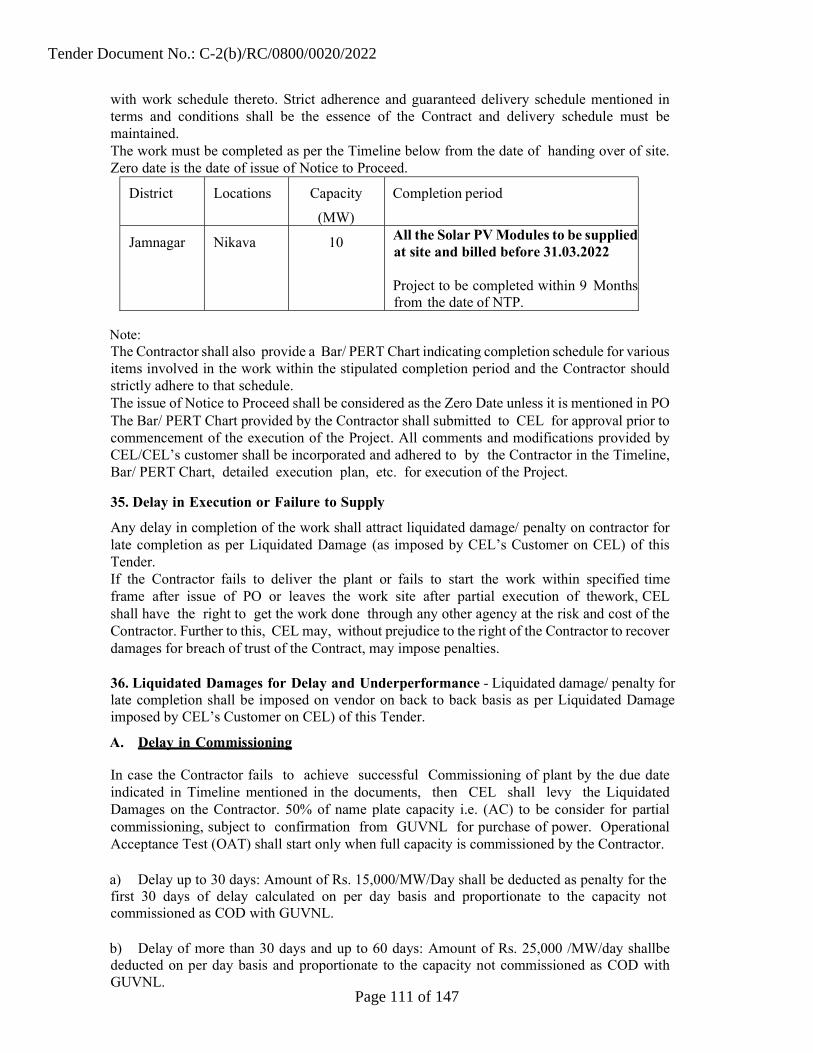
with work schedule thereto. Strict adherence and guaranteed delivery schedule mentioned in terms and conditions shall be the essence of the Contract and delivery schedule must be maintained. The work must be completed as per the Timeline below from the date of handing over of site. Zero date is the date of issue of Notice to Proceed.
District Locations Capacity
(MW)
Completion period
Jamnagar Nikava 10 All the Solar PV Modules to be suppliedat site and billed before 31.03.2022 Project to be completed within 9 Monthsfrom the date of NTP.
Note: The Contractor shall also provide a Bar/ PERT Chart indicating completion schedule for various items involved in the work within the stipulated completion period and the Contractor should strictly adhere to that schedule. The issue of Notice to Proceed shall be considered as the Zero Date unless it is mentioned in PO The Bar/ PERT Chart provided by the Contractor shall submitted to CEL for approval prior to commencement of the execution of the Project. All comments and modifications provided by CEL/CEL’s customer shall be incorporated and adhered to by the Contractor in the Timeline, Bar/ PERT Chart, detailed execution plan, etc. for execution of the Project.
35. Delay in Execution or Failure to Supply
Any delay in completion of the work shall attract liquidated damage/ penalty on contractor for late completion as per Liquidated Damage (as imposed by CEL’s Customer on CEL) of this Tender. If the Contractor fails to deliver the plant or fails to start the work within specified time frame after issue of PO or leaves the work site after partial execution of the work, CEL shall have the right to get the work done through any other agency at the risk and cost of the Contractor. Further to this, CEL may, without prejudice to the right of the Contractor to recover damages for breach of trust of the Contract, may impose penalties. 36. Liquidated Damages for Delay and Underperformance - Liquidated damage/ penalty for late completion shall be imposed on vendor on back to back basis as per Liquidated Damage imposed by CEL’s Customer on CEL) of this Tender.
A. Delay in Commissioning
In case the Contractor fails to achieve successful Commissioning of plant by the due date indicated in Timeline mentioned in the documents, then CEL shall levy the Liquidated Damages on the Contractor. 50% of name plate capacity i.e. (AC) to be consider for partial commissioning, subject to confirmation from GUVNL for purchase of power. Operational Acceptance Test (OAT) shall start only when full capacity is commissioned by the Contractor. a) Delay up to 30 days: Amount of Rs. 15,000/MW/Day shall be deducted as penalty for the first 30 days of delay calculated on per day basis and proportionate to the capacity not commissioned as COD with GUVNL. b) Delay of more than 30 days and up to 60 days: Amount of Rs. 25,000 /MW/day shall be deducted on per day basis and proportionate to the capacity not commissioned as COD with GUVNL.
Tender Document No.: C-2(b)/RC/0800/0020/2022
Page 111 of 147

c) Delay of more than 60 days: Amount of Rs. 35,000 /MW/day shall be deducted on per day basis and proportionate to the capacity not commissioned as COD with GUVNL. Maximum applicable Liquidated Damages: The upper ceiling for total liquidated damages for delay shall be maximum 10% of the EPC Contract Price (between CEL and CEL’s Customer). For calculation of penalty, date of Notice to Proceed shall be the reference date. B. Underperformance
The OAT shall be conducted. At the time of the Operational Acceptance Test, any shortfall in the Performance Ratio (PR) as determined through the Test Procedure Testing will attract imposition of Liquidated Damages after one (1) unsuccessful chance. For any shortfall in PR below 0.75 for any location by the Bidder for the second (2) time, a penalty of Rs. 4 lakhs x AC capacity of individual location, shall be levied. In case the first the Test is unsuccessful then penalty shall not be charged but the Contractor has to make the necessary corrections to conduct the test again within the stipulated maximum 30 days, so as to demonstrate the PR equal to or more than 0.75. In the second (2nd) time, a penalty at the rate specified above shall be levied on the Contractor. The penalty shall be deducted from the pending payment and Performance Bank Guarantee. However, if Contractor feels that NEEGG may not be achieved and want to carry out further correction, the same will be allowed for the one more time i.e. 3rd time but PG Test and O&M period shall start from such later date. In case the Contractor is successful in 3rd attempt then penalty deducted after unsuccessful 2nd attempt shall be returned. However, if the Contractor fails in the 3rd attempt as well then the penalty deducted at the time of 2nd unsuccessful attempt shall not be returned. 37. Performance Guarantee Test / Final Acceptance Test If the “Actual Delivered Energy” at metering point is less than the Base NEEGG (corresponding to NEEGG quoted for 1st year of O&M) based on the procedure mentioned in the Attachment -2, then the penalty (as imposed by CEL’s Customer on CEL) at rate of Rs. INR 3.00 per kWh (Maximum 25% of contract value, excluding O&M charges) shall be charged for the shortfall. 38. Penalty for Loss of Generation during O&M - Liquidated damage/ penalty for late completion shall be imposed on vendor on back to back basis as per Liquidated Damage imposed by CEL’s Customer on CEL) of this Tender For each Contract Year, the Contractor shall demonstrate “Actual Delivered Energy” at the Metering Point as compared to the ‘Base NEEGG’ for the particular year (calculated as per the methodology given in Attachment-2). If for any Contract Year, it is found that the ‘Actual Delivered Energy’ is less than ‘Base NEEGG for the particular year, the Contractor shall pay the compensation to CEL equivalent to Rs INR 3.00 per kWh and maximum of 50% of contract value, excluding O&M charges of respective year. The same shall be recovered from payments yet to be made by CEL to the Contractor and/or from the Bank Guarantees available with CEL. In case of any defect in the system after commissioning, the contractor shall repair the fault which does not involve major/critical equipment replacement within 48 hrs time. However, for major/critical equipment fault the contractor shall rectify/repair/replacement of equipment within 72 hrs. After elapsed of time period as specified above for rectification/repair of such faults, penalty at the rate of Rs INR 3.00 per kWh shall be charged and the same shall be deducted/recovered from payments yet to make by CEL to the Contractor and/or from the Bank Guarantee submitted to CEL. However, in case the Contractor fulfils the NEEGG at the end of the year then the amount deducted as a penalty for loss of generation as per this Clause shall be adjusted in the
Tender Document No.: C-2(b)/RC/0800/0020/2022
Page 112 of 147
Contractor’s bill or reimbursed. In case the Contractor fails to meet the NEEGG at the end of the year then above-mentioned penalty shall be adjusted from the penalty calculated at the end of the year for the shortfall in the generation so that there is no duplication of penalty for the same loss of generation. The first 48 hours shall not be considered for the penalty in case of any defect.
In case the Project fails to generate any power continuously for 6 months any time during the O&M period, it shall be considered as an “Event of Default”. Upon occurrence of any Event of Default mentioned in Special terms and conditions of the tender documents herein above, CEL shall have the right to encash the entire amount of O&M Bank Guarantee submitted by the Contractor and withheld any other pending payment. The Company reserves the right to perform random audits of weather monitoring system of the plant anytime during the entire O&M period. If any discrepancy is found between the measured parameters, the difference between the measured parameters by CEL’s Customer from secondary sources and the weather monitoring system installed by the Contractor at the site will be factored in calculating the adjusted NEEGG during the entire year. However, CEL will have the final authority to decide on this matter. GST will be applicable on penalties at prevailing applicable rate. 40. DSM charges
EPC/O&M contractor shall be responsible for carrying out scheduling & forecasting work. All cost associated towards scheduling & forecasting activity like charges for Qualified Co-ordinating Agency (QCA), additional SCADA requirements if any for accurate scheduling & forecasting work, related to DSM regulation by GERC in existence and amended from time to time, shall be in the scope of EPC/O&M contractor. CEL’s Customer shall bear 50% of DSM charges and EPC/O&M contractor shall have to bear remaining 50% DSM charges.
41. Defect Liability
The Contractor must warrant that the facilities or any part thereof shall be free from defects in the design, engineering, materials and workmanship of the Plant and Equipment supplied and of the work executed. If it shall appear to the authorized representative of the Company that any supplies have been executed with unsound, imperfect or unskilled workmanship, or with materials of any inferior description, or that any materials or articles provided by the Contractor for the execution of Contract are unsound or otherwise not in accordance with the Contract, the Contractor shall on demand in writing inform the authorized representative of the Company specifying the item, materials or articles complained of, notwithstanding that the same may have been inadvertently or otherwise passed, certified and paid for. The Contractor shall forthwith rectify or remove and replace that item so specified and provide other proper and suitable materials or articles at its own charge and cost, and in the event of failure to do so within a period to be specified by the authorized representative of the Company in its demand aforesaid, the Project Manager may on expiry of notice period rectify or remove and re-execute the time or remove and replace with others, the materials or articles complained of as the case may be at the risk and cost in all respects of the Contractor. The decisions of the authorized representative of the Company as to any question arising under this Clause shall be final and conclusive. The Contractor shall be liable for the operation and maintenance of the Facility and Consequently shall be required to rectify any defects that emerge during the operation of the Facilities for the entire term of this Contract. Defect Liability Period shall be eighteen (18) months from the date of Commissioning or twelve (12) months from the completion of last Operational Acceptance Test, whichever is later.”
Tender Document No.: C-2(b)/RC/0800/0020/2022
Page 113 of 147

If during the Defect Liability Period any defect found in the design, engineering, materials and workmanship of the Plant and Equipment supplied or of the work executed by the Contractor, the Contractor shall promptly, in consultation and agreement with CEL/CEL’s Customer regarding appropriate remedying of the defects, and at its cost, repair, replace or otherwise make good (as the Contractor shall, at its discretion, determine) such defect as well as any damage to the Facilities caused by such defect. Furthermore, without prejudice to the generality of the foregoing, it is clarified that the Contractor shall also be responsible for the repair, replacement or making good of any defect or of any damage to the Facilities arising out of or resulting from any of the following causes: a. Improper operation or maintenance of the Facilities by the Contractor during operation and maintenance of the Facility; or b. Operation of the Facilities violating specifications of the Facilities.
CEL shall give the Contractor a notice stating the nature of any such defect together with all available evidence thereof, promptly following the discovery thereof. CEL/CEL’s Customer shall afford all reasonable opportunity for the Contractor to inspect any such defect. CEL/CEL’s customer shall provide the Contractor all necessary access to the Facilities and the Site to enable the Contractor to perform its obligations. The Contractor may, with the consent of the Company, remove from the Site any Plant and Equipment or any part of the Facilities that are defective, if the nature of the defect and/ or any damage to the Facilities caused by the defect is such that repairs cannot be expeditiously carried out at the Site. If the repair, replacement or making good is of such a nature that it may affect the efficiency of the Facilities or any part thereof, the Company may give to the Contractor a notice requiring that tests of the defective part of the Facilities shall be made by the Contractor immediately upon completion of such remedial work, whereupon the Contractor shall carry out such tests. If such part fails the tests, the Contractor shall carry out further repair, replacement or making good (as the case may be) until that part of the Facilities passes such tests. The tests, in character, shall in any case be not inferior to what has already been agreed upon by CEL and the Contractor for the original equipment/part of the Facilities. If the Contractor fails to commence the work necessary to remedy such defect or any damage to the Facilities caused by such defect within a reasonable time (which shall in no event be considered to be less than seven (7) days), the Company may, following notice to the Contractor, proceed to do such work, and the reasonable costs incurred by CEL in connection therewith shall be paid to CEL by the Contractor or may be deducted by the Company from any monies due to the Contractor or claimed under the Performance Guarantee, without prejudice to other rights, which CEL may have against the Contractor in respect of such defects.
If the Facilities or any part thereof cannot be used by reason of such defect and/ or making good of such defect, the Defect Liability Period of the Facilities or such part, as the case may be, shall be extended by a period equal to the period during which the Facilities or such part cannot be used by the Company because of any of the aforesaid reasons. Upon correction of the defects in the Facilities or any part thereof by repair/ replacement, such repair/ replacement shall have the defect liability period of eighteen (18) months from such replacement. In addition, the Contractor shall also provide an extended warranty for any such component of the Facilities and for the period of time. Such obligation shall be in addition to the Defect Liability Period specified under tender documents. 42. Termination for Default The Company may, without prejudice to any other remedy for breach of Contract, by written notice of default sent to the Contractor, terminate the Contract in whole or in part if the Contractor fails to deliver or execute any or all of the goods within the time period(s) under the
Tender Document No.: C-2(b)/RC/0800/0020/2022
Page 114 of 147

Contract or any extension thereof granted by CEL’s Contractor pursuant to the clause for Delay in Execution or Failure to Supply or, If the Contractor fails to perform any other obligations(s) under the Contract. In the event the Company terminates the Contract in whole or in part, pursuant to above, the Company may procure, upon such terms and in such manner as it deems appropriate, goods similar to those undelivered, the Contractor shall be liable to the Company for any excess costs for such similar goods. However, the Contractor shall continue the performance of the Contract to the extent not terminated. In case the Contractor is not able to demonstrate the “Actual Delivered Energy” as per the “Base NEEGG” based on the procedure mentioned in Attachment-2 during the Performance Guarantee Test and after the penalties levied as mentioned in the tender documents.; CEL reserves the right to terminate the Contract at its discretion if there are no efforts are made from the Contractor to correct the issues regarding plant performance. In case termination of the Contract due to default, the Contractor may be blacklisted by CEL and its associate companies, etc. for future work. 43. Breach and Cancellation of the Contract
In case of non-performance in any form or change of the covenant and conditions of the Contract by the Contractor, the Company shall have the power to annul, rescind, cancel or terminate the order and upon its notifying in writing to the Contractor that it has so done, this Contract shall absolutely determine. The decision of the Company in this regard shall be final and binding. The Company may cancel the order or a portion thereof, and if so purchase or authorize purchase of the plant/equipment not so delivered or order Plant/ Equipment of similar description (opinion of the Company shall be final) at the risk and cost of the Contractor. 44. Force Majeure
In the event of either party being rendered unable by Force Majeure to perform any obligation required to be performed by them under this Contract, relative obligation of the party affected by such Force Majeure shall be treated as suspended during which the Force Majeure Clause lasts. The term “Force Majeure” shall have herein mean riots (other than among the Contractor’s employee), Civil commotion, War (whether declared or not), invasion, act of foreign enemies hostilities, civil war, rebellion, revolution, insurrection, military coup, damage from aircraft, nuclear fission, embargoes, quarantines, acts of god such as earthquake (above 7.0 magnitude on Richter scales), lightning, unprecedented floods, fires not caused by the Contractors negligence and other causes which the Contractor has no control and accepted as such by CEL/CEL’s Customer whose decision shall be final and binding. Normal rainy season and monsoons are not Force Majeure. Upon occurrence of such causes and upon its termination, the party alleging that it has been rendered unable as aforesaid, thereby, shall notify the other party in writing by registered notice within 24 (twenty four) hours of the alleged beginning and ending thereof giving full particulars and satisfactory evidence in support of its claim. Time for performance of the relative obligation suspended by the Force Majeure shall stand extended by the period for which such clause lasts. If works are suspended by Force Majeure conditions lasting for more than two (2) months, CEL shall have the option of cancelling this Contract in whole or part thereof, at its discretion. The Contractor shall not claim any compensation for Force Majeure conditions and shall take appropriate steps to insure men and materials utilized by it under the Contract well in advance. 45. Progress Report of Work The Contractor shall submit a weekly progress report on execution of works conforming to bar/
Tender Document No.: C-2(b)/RC/0800/0020/2022
Page 115 of 147

PERT Chart and format provided by CEL. In case of any slippage(s) or delay in execution of work reasons for such delay along with details of hindrances will be submitted by the Contractor along with modified Bar/ PERT Chart mentioning the action plan being taken to keep the due date of completion of project unchanged. If required, the Contractor shall use additional manpower to keep the due date of completion of Project unchanged. The authorized representative of the Contractor shall review the progress of the Project work every fortnight on a prefixed day at project site with CEL or its representative as per the network and record the minutes. 46. Insurance During the construction period, i.e. before the Commissioning of the Project, all insurance related expenses shall be borne by the Contractor. The goods supplied under the Contract shall be fully insured against the loss or damage incidental to manufacture or acquisition, transportation, storage, delivery, theft, natural or other disaster, etc. in such a manner that the Company shall not incur any financial loss, as long as the construction of the Project continues to remain under the custody of the Contractor.
In case of any loss or damage or pilferage or theft or fire accident or combination of the said incidents etc. under the coverage of insurance, the Contractor shall lodge the claim as per rules of insurance. Any FIR required to be lodged to local Police Station shall be the responsibility of the Contractor. The Contractor shall arrange to supply/ rectify/ recover the materials even if the claim is unsettled for timely completion of the Project. The final financial settlement with the insurance company shall be rested upon the Contractor. In case of any delay of the Project attributable to the Contractor, the Contractor himself in consultation with the Company should take the extension of insurance. Any financial implications shall, however, be borne by the Contractor. The Contractor shall arrange for providing insurance coverage to its workmen under Workmen’s Compensation Act or similar Rules and Acts as applicable during execution of work for covering risk against any mishap to its workmen. The Contractor shall also undertake a Third Party Insurance. The Company shall not be responsible for any such loss or mishap. Comprehensive insurance is to be arranged by the Contractor during the O&M period of the Contract on behalf of CEL and at the prices informed by CEL after award of the contract. At the end of the term of insurance undertaken by the Contractor, the Contractor shall provide all the necessary documents to the satisfaction of the Company in order to enable the Company to take up the insurance of the Plant. 47. Statutory Acts, Rules and Standards The work shall be executed in conformity with the relevant standard of Bureau of Indian Specification (or equivalent International Standard), Electricity Rules, 2010 (as amended up to date), Indian Electricity Act, BARC/DAE rules, Explosive Act 1948, Petroleum Act 1934, National Building Code and relevant Rules in vogue at the time of execution including operation and maintenance period. 48. Tools and Tackles The Contractor shall provide technically suitable tools and tackles for installation & erection of Plant and Machineries conforming to relevant BIS safety and technical standards for proper execution of work. The Company, in no way, shall be responsible for supply of any tools and tackles for implementation of the work and also to carry out operation and maintenance activities. 49. Safety Measures The Contractor shall have to provide necessary and adequate safety measures including personal protective equipment and precautions to avoid any accident, which may cause damage
Tender Document No.: C-2(b)/RC/0800/0020/2022
Page 116 of 147

to any equipment/ material or injury to workmen. The Company shall not be responsible for any such accidents. 50. Hazardous Material Any hazardous material used during construction or used as part of the plant has to be taken back by the supplier for recycling or dumping purpose after its operating/working life, so that it may not affect the environment or any living being. The Contractor shall comply with the State Pollution Board regulation. 51. Stoppage of Work The Company shall not be responsible and not liable to pay any compensation due to stoppage of work as a reaction from local public due to any undue action on the part of the Contractor causing annoyance to local people. 52. Hindrance Register The Contractor may also maintain a Hindrance Register where reasons for delay may be recorded from time to time and at the time of occurrence of the hindrance and get it duly certified by the Project Manager or his authorized representative. 53. Responsibility of the Contractor The Contractor shall provide guarantee and be entirely responsible for the execution of the Contract in accordance with this Tender including but not limited to its specification, schedules, and annexure. The Contractor shall further provide guarantee and be responsible for the quality and workmanship of all materials and completed works, correct designs and drawings, correct delivery of material, erection, testing and commissioning including operation and maintenance. 54. Right of the Company to Make Change(s) in Design All designs shall be approved by CEL’s Customer prior to the execution of such designs. The Company shall have the right to make any change in the design, which may be necessary in the opinion of CEL/CEL’s customer to make the plant and materials conform to the provisions and contents of the specification without extra cost to CEL. 55. Manuals The Contractor shall supply all necessary erection and commissioning manuals, O&M manuals etc. as and when required. 1 Set Original + 5 sets of copy of test results, manuals etc. shall be submitted by the Contractor on completion of the work in hard and soft copies. 56. Governing Language The Contract shall be written in English Language. All correspondence and documents pertaining to the Contract, which are exchanged by the Company and Contractor, shall be written in English. 57. Order Amendments No variation in or modification of the terms of the contract shall be made except by written amendments issued by the Company. 58. Assignments or Subletting of Contract The Contractor shall not, without the prior consent in writing of the Company, assign or sublet or transfer its Contract in whole or in part, its obligations to perform under the Contract or a substantial part thereof, other than raw materials, or for any part of the work of which makers are named in the Contract, provided that any such consent shall not relieve the Contractor from any obligation, duty or responsibility under the Contract. 59. Subcontracts The Contractor shall notify the Company in writing of all subcontracts awarded under the Contract if not already specified in his Bid. Such notification in its original Bid or later shall not
Tender Document No.: C-2(b)/RC/0800/0020/2022
Page 117 of 147

relieve the Contractor from any liability or obligation under the Contract. Subcontracting a work shall not, under any circumstances, relieve the Contractor from its obligations towards the Project and the Company. In case, the Contractor engages any Subcontractor to carry out a part of the work, the Subcontractor should have requisite Government License for carrying out such part of the work. 60. Inspection and Testing The Company or its authorized representative including appointed Consultant for the project shall have, at all times, access to the Contractor’s premises and also shall have the power to inspect and examine the materials and workmanship of project work during its manufacture, shop assembly and testing. If part of the plant is required to be manufactured in the premises other than the Contractor’s, the necessary permission for inspection shall be obtained by the Contractor on behalf of CEL/CEL’s Customer or its duly authorized representative. CEL/CEL’s Customer shall have the right to serve notice in writing to the Contractor on any grounds of objections, which he may have in respect of the work. The Contractor has to satisfy the objection, otherwise, the Company at his liberty may reject all or any component of plant or workmanship connected with such work. The Contractor shall issue request letter to CEL or his authorized representative for testing of any component of the plant, which is ready for testing at least seven (07) working days in advance from the date of actual date of testing at the premises of the Contractor or elsewhere. When the inspection and the tests have been satisfactorily completed at the Contractor’s works, CEL shall issue a certificate to that effect. However, the Company at its own discretion may waive the inspection and testing in writing under very special circumstances. In such case, the Contractor may proceed with the tests which shall be deemed to have been made in CEL/CEL’s Customer’s presence, and it shall forthwith forward six (6) sets of duly certified copies of test results and certificates to the Company for approval of the Company. The Contractor, on receipt of written acceptance from CEL, may dispatch the equipment for erection and installation. For all tests to be carried out, whether in the premises of the Contractor or any Subcontractor or the supplier, the Contractor, shall provide labour, materials, electricity, fuel, water, stores, apparatus and instruments etc. free of charge as may reasonably be demanded to carry out such tests of the plant in accordance with the Contract. The Contractor shall provide all facilities to CEL/CEL’s Customer or its authorized representative to accomplish such testing.
The Company or his authorized representative shall have the right to carry out inward inspection of the items on delivery at the Site and if the items have been found to be not in line with the approved specifications, shall have the liberty to reject the same. If the Company desires, testing of any component(s) of the plant be carried out by an independent agency, the inspection fee, if any, shall be paid by the Company. However, the Contractor shall render all necessary help to CEL whenever required free of charge. The Contractor has to provide the necessary testing reports to CEL as and when required. Neither the waiving of inspection nor acceptance after inspection by CEL/CEL’s Customer shall, in anyway, absolve the Contractor of the responsibility of supplying the plant and equipment strictly in accordance with specification and drawings etc. 61. Authorized Test Centres The PV modules, inverters, transformers, panels, wires, etc. deployed in the power plants shall have valid test certificates for their qualification as per above specified IEC/ BIS Standards by one of the reputed labs of the respective equipment (preferably NABL Accredited Test Centres) in India. In case of module or other equipment for which such Test facilities may not exist in India, test certificates from reputed ILAC Member Labs abroad will be acceptable. 62. Delivery of Equipment
Tender Document No.: C-2(b)/RC/0800/0020/2022
Page 118 of 147

The Contractor shall deliver the equipment of the plant and machineries in accordance with the terms of the Contract at the time(s) to the place(s) and in the manner specified in the Contract. The Contractor shall comply with instructions that may be given by the Company from time to time regarding the transit of the plant and material. Notification of delivery or dispatch in regard to each and every consignment shall be made to the Company immediately after dispatch or delivery from the manufacturing works. The Contractor shall supply to the consignee Invoice in triplicate and packing account of all stores delivered or dispatched by him. In case of any occurrence of loss or damage in transit, it shall be the liability of the Contractor to initiate or pursue the claim with the Insurance company. It should take immediate steps to repair the damaged apparatus or replacement there to. 63. Liabilities during Transit The Contractor shall be responsible for loss, damages, or depreciation to goods or of plant, equipment, and machineries up to delivery at the Site. 64. Deduction from Contract Price All costs, claims, damages or expenses, which the Company may have paid for which the Contractor is liable, will be deducted by the Company from deposited bank guarantees or from any money due or which become due to him under this Contract or any contract are being executed elsewhere with the Company. Any sum of money due and payable to the Contractor, as per the PO, may be appropriated by the Company and set off against any claim of the Company, for the payment of a sum of money arising out of or under any other contract made by the Contractor with the Company. It is an agreed term of the Contract that the sum of money, withheld or obtained under this clause by the Company, will be kept withhold or retained as such by the Company or till this claim arising out of in the same Contract is either mutually settled or determined by the arbitrator, or by competent court, as the case may be, and that the Contractor shall have no claim for interest or damages whatsoever on this account or any other account in respect of any sum of money withheld or retained under this clause and duly notified as such to the Contractor. 65. Terms of Payment CEL generally follows project costing methodology and the payment shall be made on pro-rata basis as per availability of funds under this project subject to verification of material and activities by CEL/Customer site representative. The contractor has to submit all the documents required for claiming the payments from customer and overall completion of the project including O&M for 5 years. Bidder shall follow-up with customer for realization of payments. (a) Supply and 5years O&M: The Company shall pay the Contractor in the following manner for supply of material and at the following time for achieving the respective milestone for the Supply. The Tender is for a comprehensive EPC Contract of Supply, Works and O&M. There shall be 3 (three) different Contracts signed for Supply, Works and O&M. However, a single PO shall be issued to the Successful Bidder. The payment terms for Supply, Works and O&M is given below. Payment milestones for supply
Sr. No. Milestones
1 Advance Payment against Bank Guarantee of Equivalent Value.
5% of Supply contract Price (Excluding Taxes and Duties)
2 Supply and receipt of Materials to site on MRC
50% of item wise BBU value received material only
Tender Document No.: C-2(b)/RC/0800/0020/2022
Page 119 of 147

3 Completion of Erection equipment/system 15% of item wise BBU value received material only
4 Upon successful testing equipment/system 5% of item wise BBU value received material only
5 Upon successful commissioning of one complete block for equipment/system on prorate basis.*
5% of item wise BBU value received material only
6 Upon successful commissioning of full capacity of the plant.
5% of item wise BBU value received material only
7 Upon Completion of Successful Operational Acceptance Test
10% of item wise BBU value received material only
8 Upon Completion of all the Facilities of the project
5% of item wise BBU value for received material only
* Block shall be as per approved design (b)Payment Terms for the Works & years O&M:
Sr. No.
Milestones
1 Mobilization Advance Payment (Interest Free) against Bank Guarantee of Equivalent Value.
5% of works contract price. (Including Taxes and Duties)
2 Against monthly RA bills for the Works executed at site
70% of executed Activity/item as per BBU.
3 Upon successful commissioning of full capacity of the plant
10% of executed activity/item as per BBU.
4 Upon Completion Of Successful Operational Acceptance Test
10% of executed activity/ item as per BBU.
5 Upon Completion of all the Facilities of the project 5% of executed activity/item as per BBU.
6 On Successful Operation and Maintenance of the Solar PV Power Plant on quarterly basis for each year till 5 years
Year 1: OM-1 Year 2: OM-2 Year 3: OM-3 Year 4: OM-4 Year 5: OM-5
Note:
1. Bank Guarantee against mobilization & supply Advance shall be submitted for initial validity of 12 (Twelve) months and shall be extended till adjustment of the entire amount.
2. Billing Break up (BBU) and dispatch schedule shall get approved by CEL/CEL’s Customer. Separate BBU is to be furnished. The price allocation in each BBU is to be provided on Pro rata of AC capacity.
3. Advance Payment shall be made only after Acceptance of PO and submission of Security Deposit cum Performance Guarantee.
4. All works shall be considered for payment on pro-rata basis of payment milestones per approved billing break up to be approved after PO.
Tender Document No.: C-2(b)/RC/0800/0020/2022
Page 120 of 147
5. The Contractor shall submit all the invoices related Project and invoices of the O&M to notified officer (will be informed to successful bidder). All material shall be consigned to notified officer (will be informed to successful bidder).
6. The payment for works shall be released on monthly basis. 7. Mobilization Advance Payment shall be adjusted in monthly RA bills on pro-rata basis. Supply
advance shall be adjusted from subsequent bills on pro rata basis. 8. For payment against milestone 2& 3 of works, the joint recording of work done at site shall be
attached with the invoice.” 9. EPC Contract Price of Supply means the total Supply part of the Total EPC Price. 10. Contract Value of Works means the Contract value of the Works part of the Total EPC Price 11. Commercial Operation Date” (COD): with respect to the Project/Unit shall mean the date on
which the project /unit is commissioned (certified by GEDA) and available for commercial operation and such date as specified in a written notice given at least 10 days in advance by the EPC Contractor to Owner /GUVNL.
Payments
Subject to any deduction which the Company may be authorized to make under this Contract, and or to any additions or deductions provided for in this Contract, the Contractor shall be entitled to payment as follows: a. All payments shall be made in Indian Rupees, unless otherwise specified in the Purchase order. All payment shall be made on the basis of actual measurement for the quantified items as per schedule of works.
b. The Contractor shall submit the bill / invoice for the work executed showing separately GST and any other statutory levies in the bill / invoice.
All deductions shall be applicable as per prevailing income tax and other statutory rules and provisions in force.
c. While making payment for each invoice, amount of GST and applicable cess will be kept under retention till submission of documentary proof of payment of GST or till reflection of payment of GST pertains to respective bill amount in GST Return for concern Invoice after due verification.
TCS is applicable will be applicable as per the Govt. Notification. on the total order value of supply including GST.
66. Warranty/ Guarantee
The Plant shall perform as per the Guaranteed Performance indicated by the Bidder in its Financial Proposal. PV modules used in grid connected solar power plants must be warranted for peak output power at Standard Testing Condition (STC), which shall not be less than 90% at the end of ten (10) years and not less than 80% at the end of twenty five (25) years. The first year degradation shall not be more 2.5% for poly and 3% for mono of the PV Module capacity and in subsequent years it shall be 1% maximum. The mechanical structures, electrical works, all plant equipment and components and overall workmanship of the grid solar power plants shall be warranted for a minimum of 5 years.
The Contractor shall ensure that the goods supplied under the Contract are new, unused and of most recent or current models and incorporate all recent improvements in design and materials unless provided otherwise in the Contract. The warranty / guarantee period shall be as follows: a. Solar PV Modules: Modules shall be warranted for a minimum period of 25 years in the
Tender Document No.: C-2(b)/RC/0800/0020/2022
Page 121 of 147

Bidder’s detailed Warranty/ Guarantee certificate. Same shall be furnished with its Bid.
b. Inverters: Inverters shall be warranted for the guarantee period provided by the original equipment manufacturer. Same shall be furnished with its Bid.
c. Transformers, associated switchgear and others: Bidder shall furnish in detail its warranties/ guarantees for these items.
During the period of Warranty/ Guarantee the Contractor shall remain liable to replace/ repair any defective parts, that becomes defective in the Plant, of its own manufacture or that of its Subcontractors, under the conditions provided for by the Contract under and arising solely from faulty design, materials or workmanship, provided such defective parts are not repairable at Site. After replacement the defective parts shall be returned to the Contractors works at the expense of the Contractor unless otherwise arranged. At the end of Guarantee period, the Contractor’s liability shall cease. In respect of goods not covered above, CEL shall be entitled to the benefit of such Guarantee given to the Contractor by the original Contractor or manufacturer of such goods. During the Operation and Maintenance and Guarantee period, the Contractor shall be responsible for any defects in the work due to faulty workmanship or due to use of sub-standard materials in the work. Any defects in the work during the guarantee period shall therefore, be rectified by the Contractor without any extra cost to CEL within a reasonable time as may be considered from the date of receipt of such intimation from CEL failing which CEL shall take up rectification work at the risk and cost of the Contractor. 66.1 Material Warranty: Material Warranty is defined as: The manufacturer should warrant the Solar Module(s) to be free from the defects and/or failures specified below for a period not less than ten (10) years from the date of sale to the CEL’s customer: Defects and/or failures due to manufacturing defects and/or failures due to materials, including PID defect Non-conformity to specifications due to faulty manufacturing and/or inspection processes. If the solar Module(s) fails to conform to this warranty, the manufacturer will repair or replace the solar module(s), at CEL’s sole option. All the manufacturer warranty certificates and other documents related to the product warranty should be directly in the name of CEL (or as directed by CEL) in line with tender documents (a) Performance Warranty:
The manufacturer should warrant the output of Solar Module(s) If, Module(s) fail(s) to exhibit such power output in prescribed time span, the Contractor will either deliver additional PV Module(s) to replace the missing power output with no change in area of land used or repair or replace the PV Module(s) with no change in area of land used at CEL’s sole option. Total land available from CEL’s Customer is fixed and the bidder shall design the plant so that in this case he has enough space within this land to accommodate additional capacity.
66.2 Insurance or Bank Guarantee: (A) Bank Guarantee against PV Modules Warranty: The Successful Bidder shall provide security in form of Bank Guarantee of Rs 10 lac per MW (DC capacity) valid for 25 (Twenty Five) Yrs from the start date of O & M period or extendible O&M period whichever is higher from start date of O&M period.
Bidder shall provide a single bank guarantee (BG) to cover generation guarantee during O&M period, warranty of PV Module and AMC of Critical equipment i.e. Inverter, Solar SCADA, dry
Tender Document No.: C-2(b)/RC/0800/0020/2022
Page 122 of 147

cleaning (as applicable).
The requirement of Warranty and Comprehensive AMC of Critical Equipment is as follows.
Equipment/ System Comprehensive AMC Warranty
PV Module - 25 Years
Inverter 5 -
SCADA 5
Dry Cleaning System 5
<Or>
(B) Insurance: Successful Bidder shall provide the insurance for PV module power output warranty for 25 years, as per the technical specification backed up through an insurance policy by a reputed insurance company. This shall cover the PV module power output warranty in case of insolvency or bankruptcy of the PV module manufacturer. The Bidder shall submit a suitable insurance from Third Party in the name of CEL as per rates informed by CEL after issuance of PO. However, Bidder shall provide undertaking for followings. (i) Bidder will be fully liable and responsible for the performance of supplied Solar PV Module for entire project life till O & M period under bidder’s scope.
Bidder liability is till 05 years or extended O & M period whichever is higher. For remaining project life, EPC contractor shall support CEL/CEL’s Customer for claim to insurance company for any defect of performance. (ii) Failing to which Bidder will make all arrangement at their risk and cost to replace or make it good in order to keep Solar PV plant under smooth operation and meeting the obligation of Guarantee/warrantee. (iii) in case of any failure of Solar PV Module or any spare part of it under guarantee Bidder will be liable to replace it and all relevant expenses shall be borne by them (iv) Bidder will indemnify to CEL/CEL’s Customer for any loss and/or damage from time to time and will undertake all the relevant procedure of insurance claim for guarantee/warrantee at their own with the PV module supplier/ insurer at no cost to CEL/CEL’s Customer. (v) In case of failure to meet performance warrantee of Solar PV modules, Bidder will make all arrangement at their risk and cost to replace or make it good in order to keep Solar PV plant under smooth operation and meeting the obligation of warrantee. Final Bill The Final EPC Bill relating to the Contract shall be prepared only after the Performance Guaranteed Test of the plant has been observed as under Attachment -2: Procedure for Performance Testing and it will include the adjustments of all claims against the Contractor by the Company and awarded in its favour by the arbitrator up to the date of preparation of the final bill. 68. Degradation of Solar Modules
Tender Document No.: C-2(b)/RC/0800/0020/2022
Page 123 of 147
The Contractor should warrant for the output of each Solar Module(s) for at least 90% of its actual rated capacity at Standard Testing Condition after initial 10 years and 80% of its rated capacity after 25 years upon commissioning of the Plant. The derating of module should not be more than 1% in any year except for the first year of operation, which should be limited to 2.5% for poly and 3% for mono. If, Module(s) fail(s) to exhibit such power output, the Contractor will either: a. Deliver additional PV Module(s) to replace the loss of power output with no change in area of land used;
<or> b. Repair or replace the existing PV Module(s) with no change in area of land used; <or> c. Compensate CEL with an amount equivalent to the loss of revenue from the date of audit to 25th years which shall be calculated based on Net Present Value of amount of loss of revenues from the date of audit to 25th years discounted at the rate of CEL’s Customer’s cost of capital. d. The Company will specifically do the audit of solar PV module by third-party at any point of the operation period and in case the Contractor fails to demonstrate the value as per the maximum deration allowed then, the Contractor shall compensate as per this clause.
69. Risk Purchase
If the Contractor fails, on receipt of the PO, to take up the work within a reasonable period or leave the work Site after partial execution of the work, CEL shall have the liberty to get the work done through other agency at the Contractor’s own risk and additional cost if any. If the situation, so warrants, to compel CEL to cancel the PO placed on the Contractor, it shall be liable to compensate the loss or damage, which CEL/CEL’s Customer may sustain due to reasons of failure on Contractor’s part to execute the work in time.
70. Confidential Information
CEL/CEL’s Customer and the Contractor shall keep confidential and shall not, without the written consent of the other Party hereto, divulge to any third party any documents, data or other information furnished directly or indirectly by the other Party hereto in connection with the Contract, whether such information has been furnished prior to, during or following termination of the Contract. Notwithstanding the above, the Contractor may furnish to its Subcontractor(s) such documents, data and other information it receives from CEL/CEL’s customer to the extent required for the Subcontractor(s) to perform its work under the Contract, in which event the Contractor shall obtain from such Subcontractor(s) an undertaking of confidentiality similar to that imposed on the Contractor. Notwithstanding the generality of the foregoing Clause No. 70 all maps, plans, drawings, specifications, schemes and the subject matter contained therein and all other information given to the Contractor, by the Company in connection with the performance of the Contract shall be held confidential by the Contractor and shall remain the property of the Company and shall not be used or disclosed to third parties by the Contractor for any purpose other than for which they have been supplied or prepared. The Contractor may disclose to third parties, upon execution of secrecy agreements satisfactory to the Company, such part of the drawings, specifications or information if such disclosure is necessary for the performance of the Contract under this Clause No. 70. Maps, layouts and photographs of the unit/integrated plant including its surrounding region's showing vital installation for national security shall not be published or disclosed to the third parties or taken out of the country without prior written approval of the Company and upon
Tender Document No.: C-2(b)/RC/0800/0020/2022
Page 124 of 147

execution of secrecy agreements satisfactory to the Company with such third parties prior to disclosure.
Title to secret processes, if any, developed by the Contractor on an exclusive basis and employed in the design of the unit shall remain with the Contractor. The Company shall hold in confidence such process and shall not disclose such processes to the third parties without prior approval of the Contractor and execution by such third parties of secrecy agreements satisfactory to the Contractor prior to disclosure. Technical specifications, drawings, flow sheets, norms, calculations, diagrams, interpretations of the test results, schematics, layouts and such other information which the Contractor has supplied to the Company under the Contract shall be passed on to the Company. The Company shall have the right to use these for construction erection, start-up, commissioning, operation, maintenance, modifications and/ or expansion of the unit including for the manufacture of spare parts. The obligation of a party under this Clause 70, however, shall not apply to that information which: a. now or hereafter enters the public domain through no fault of that Party, b. can be proven to have been possessed by that Party at the time of disclosure and which was not previously obtained, directly or indirectly, from the other Party hereto, or otherwise lawfully becomes available to that Party from a third party that has no obligation of Confidentiality. The above provisions of this Clause 70 shall not in any way modify any undertaking of Confidentiality given by either of the Parties hereto prior to the date of the Contract in respect of the Facilities or any part thereof. The provisions of this Clause No. 69 of SCC shall survive Termination, for whatever reason, of the Contract.
71. BCD on Solar Cells and PV modules/Panels Imposition of BCD as per MNRE Office Memorandum No. 283/3/2018-GRID SOLAR, Dtd 09.03.2021will not be construed as Change in law.
72. Earnest Money Deposit (EMD): EMD amounting Rs. 5,00,000/- must be submitted through NEFT/RTGS/BG by all the bidders at the time of bidding (copy of the proof to be submitted with the bid). Bid without Earnest Money Deposit will be out-rightly rejected. The EMD of unsuccessful bidders will be returned within one month of award of work to lowest evaluated technically acceptable bidder. EMD will be returned to the successful bidder after receipt of Performance Bank Guarantee and its confirmation from issuing bank. PBG to be submitted as per “Security Deposit Cum Performance Bank Guarantee” clause in the tender. The EMD may be forfeited if: a. If the bidder withdraws its bid during the period of bid validity as specified in the bid. b. If the bidder does not accept computational/arithmetical error correction made by CEL and as explained in "Price Bid" section of the Bid document. c. If the Bidder refuses or withdraw, without any cost to the CEL, any deviation not listed in the bid but found elsewhere in the bid; or d. In the case of successful bidder, if the bidder fails within the specified time limit: • To send PO acceptance with 07 days from the date of PO • To furnish the required PBG in accordance with the tender document. No exemption is allowed for submission of EMD and Public Procurement Policy for Micro and Small Enterprises (MSEs) Order, 2012 is not applicable for this tender.
Tender Document No.: C-2(b)/RC/0800/0020/2022
Page 125 of 147

Attachment-1
UNDERTAKING
(To be submitted duly notarized self-certificate on company’s letter head by an
authorized person of the bidder’s company/firm not below the rank of Director)
We, M/s_ hereby give undertaking that our firm have not been
debarred/blacklisted/defaulted by any State Govt. Dept./Govt. of India, agency, PSUs/
Corporate(s)/institution/agencies/any funding/partner agency/autonomous organizations/
private companies.
Date: Signature of Authorized Person
Place: Name:
Seal: Designation:
Tender Document No.: C-2(b)/RC/0800/0020/2022
Page 126 of 147

Attachment -2: Procedure for Performance Testing
Part A: Solar PV power plant Net power generation
1. ‘Net Electrical Energy Generation Guarantee” NEEGG for annual basis considering the Reference Global Average Radiation indicated in this Tender.
Sr. No. Year Min. NEEGG in KWH
1 For first year 22100000 2 For second year 21881200 3 For third year 21664586 4 For fourth year 21450107 5 For fifth year 21237751
The Contractor shall demonstrate “Actual Delivered Energy” at metering point as compared to the ‘Base NEEGG’ for every year from the date of starting of O&M Period.
1. The NEEGG shall be permitted with maximum 1 % degradation factor in previous year generation.
2. The NEEGG mentioned in the above table will be used for calculating CUF for that particular year.
3. The Bidder shall clearly mention the technology used i.e. fixed/tilt or seasonal tracker (please specify)
Operational Acceptance Test Procedure
Performance Ratio (PR) - Test Procedure
1. Performance Ratio as determined through the PR Test Procedure specified here should not
be less than 0.75 for Operational Acceptance Test.
2. The Performance Ratio Test to prove the guaranteed performance parameters of the power plant shall be conducted at site by the Contractor in presence of the Company. The Contractor's Engineer shall make the plant ready to conduct such tests. The Operational Acceptance Test shall be commenced, within a period of one (1) month after successful Commissioning and, there will be continuous monitoring of the performance for 30 days. Any extension of time beyond the above one (1) month shall be mutually agreed upon. These tests shall be binding on both the parties to the Contract to determine compliance of the equipment with the guaranteed performance parameters. This monitoring will be performed on the site under the supervision of the Company/ Company's engineer.
3. The test will consist of guaranteeing the correct operation of the plant over 30 days, by the
way of the efficiency rate (performance ratio) based on the reading of the energy produced and delivered to the grid and the average incident solar radiation. During this period of 30
Tender Document No.: C-2(b)/RC/0800/0020/2022
Page 127 of 147

days, any 5 (five) instances of 15 (fifteen) minutes shall be taken to calculate the instantaneous Performance Ratio of 15 minutes block as per the formula given below in Point No. 5. If the PR of these fives instances is above 75%, then Operational Acceptance Test (OAT) shall be considered successful.
4. PR shall be demonstrated against the installed DC Capacity.
5. The Efficiency or performance ratio (PR) of the PV Plant is calculated as follows (according
to IEC 61724)
Performance Ratio (PR) = YA / YR
YA = Eac / PNom
YR = IR Site/ IR STC
Where; YA = Final PV system yield (representing the number of hours that the system would need to operate at its rated output power PNom to contribute the same energy to the grid as was monitored. YR = Reference yield (representing the number of hours during which the solar radiation would need to be at STC irradiance levels in order to contribute the same incident energy as was monitored).
Eac = AC energy injected into the grid during a clearly specified amount of time (kWh).
PNom = Installed nominal peak power of modules (Name plate rating at STC) (kWp);
IRSite = Irradiation on the module plane of array during a clearly specified amount of time (measured with a pyranometer installed on the plane of array, POA) (kWh/sq. m).
IRSTC = Irradiance at STC (kW/ sq. m); 1000W/m2
Monitoring System for PR Verification
The following instrumentation will be used to determine the Solar Plant Performance: Power Meter at the delivery point. Power Meter for each inverter for reference only. One nos. calibrated pyranometer to determine irradiance on the plane of array (with a
target measurement uncertainty of ± 2). One nos. calibrated pyranometer to determine irradiance on horizontal plane (with a
target measurement uncertainty of ± 2) Two nos. thermocouples to measure module temperature with a measurement
uncertainty of ±1 °C. Shielded ventilated thermocouple with a measurement accuracy of ±1°C. An anemometer mounted on a 10m mast to measure wind speed (without additional
shadowing on modules). Data measurement shall be witnessed in the format mutually agreed before the start of
PR test by the employer and the contractor jointly for the said period. The Contractor shall show the specified PR for Operational Acceptance.
Part C: The procedure for Performance Guarantee Test (PGT) - cum- Final Acceptance
Test- shall be as follows:
1. A weather station with a calibrated pyranometer shall be installed by the Contractor at the
Tender Document No.: C-2(b)/RC/0800/0020/2022
Page 128 of 147
location mutually agreed by the Contractor and CEL/CEL’s customer. The test report for the
calibration shall be submitted by the Contractor for approval by CEL/CEL’s Customer. The
calibration should be traceable to a national/international laboratory. The output of this
pyranometer for shall be logged in the SCADA system.
2. In case the pyranometer is found to be working erratically then immediately the Contractor
shall take necessary steps to rectify and/or recalibrate the instrument to the satisfaction of
CEL/CEL’s Customer. However, for the dispute period for which such error has occurred and
until the instrument is recalibrated to the satisfaction of CEL/CEL’s Customer, data from
any one of the following list of sources as decided by CEL/CEL’s customer will be used:
i. A separate pyranometer installed by the Company near the site, if available
ii. Average of two closest solar power projects, as identified by CEL/CEL’s Customer
iii. Nearest MNRE weather station
3. “Actual Delivered Energy” from the plant supplied by the Contractor shall be noted for every
month and summed up for entire year. For this purpose, the net delivered energy at the
metering point shall be taken into account.
4. To judge the performance on monthly basis and accordingly to initiate measures to
meet guaranteed NEEEG for respective years, the measured value of energy at step (3)
shall be compared with ‘Base NEEGG’ and hence with ‘Base CUF’ value. “Base
NEEGG/ CUF” for a month is calculated by using the NEEGG mentioned in the table
at Part-A adjusted with a correction factor to take into account the actual average
global solar radiation measured by the calibrated pyranometer for that month. This shall
be for intermittent performance monitoring only. However, correction in annual
NEEGG offered will be only on annual GHI measured.
5. Further, if the plant is not able to achieve the calculated Base NEEGG/CUF during PGT
and O&M period and there is a shortfall in energy generation, then the Contractor shall be
penalized as per relevant Clause of the Tender.
6. The Contractor shall share with CEL/CEL’s Customer all the radiation, generation, etc.
parameters details and all other factors necessary for CEL/CEL’s Customer to corroborate the
estimate. CEL/CEL’s customer has the right to cross verify data submitted by the Contractor
by all possible means/sources.
Following factors shall be considered for computing the Base NEEGG/ CUF and PR Test:
7. Effect due to variation in annual insolation shall only be considered for computing the Base
NEEGG/ CUF.
8. Effect due to variation of meteorological parameters e.g. ambient temperature, wind speed,
humidity etc. shall not be considered.
9. Generation loss due to grid outage (or power evacuation system which is not in the
Tender Document No.: C-2(b)/RC/0800/0020/2022
Page 129 of 147

scope of the Contractor): The measured global solar radiation of the period of the outage of
the power evacuation system shall be excluded to calculate average global solar radiation for
the period of PGT and O&M.
Solar Radiation:
Ideally, actual measurement of solar radiation at the site is desirable for estimating the projected power
output since solar energy is the raw material for power generation. It may be noted that the annual
average solar radiation measurement even for 1-2 years is not sufficient. World over, an average
radiation value for at least 8-10 years is used for solar power project designing since climatic variations
are quite wide year-to-year. Under such a situation, the prevailing practice world over is to develop
software which uses satellite measured solar radiation and matches it with the actual ground measured
data for the particular site where actual data has been obtained for many years. The derived values for
GETCO S/s are tabulated below:
Month GHI(kWh/m2/month)
Nikava January 143.8
February 149.5
March 191.3
April 201.0
May 206.8
June 174.0
July 147.9
August 142.0
September 156.0
October 161.8
November 139.8
December 133.6
Annual 1947.5
The above radiation data shall be used by the Bidder to calculate annual NEEGG. This radiation data is for evaluation purpose. However, for every year actual radiation shall be considered.
Tender Document No.: C-2(b)/RC/0800/0020/2022
Page 130 of 147

Illustration:
If the GHI of a year is more or less than the reference GHI then NEEGG will be calculated as follows:
NEEGG = (Actual GHI x NEEGG on reference GHI)/ (Reference GHI)
NEEGG = 71,832,000 KWh
Reference GHI= 1947.5 KWh/m2 per annum
For Example:
Case A) for higher irradiation:
If Actual GHI = 1900 kWh/m2 per annum then NEEGG will be: NEEGG
= (1900 x 71,832,000)/ 1886
NEEGG = 72,365,217 KWh/ Annum
Case B) for lower irradiation:
If Actual GHI = 1850 kWh/m2 per annum then NEEGG will be: NEEGG
= (1850 x 71,832,000)/ 1886
NEEGG = 70,460,870 KWh/ Annum
Tender Document No.: C-2(b)/RC/0800/0020/2022
Page 131 of 147

Attachment-3
DECLARATION (To be submitted on company’s letter head by an authorized person of the bidder’s
company/firm not below the rank of Director)
We, M/s ____________________ hereby declare that all the documents submitted by us with our bid
against tender No. _____________________________________ are authentic and true to the best of our
knowledge and belief. In case, any document is found false, CEL may reject our bid/cancel our order(s) /
ban the business dealings with us/ suspend us from quoting in future tenders/ take any other action as per
the terms of the tender.
Date: Signature of Authorized Person
Place: Name:
Designation:
Seal:
Tender Document No.: C-2(b)/RC/0800/0020/2022
Page 132 of 147

Price Bid (Part -1)
Sr. No.
Item Unit Rate INR
Qty
Basic Price (without GST)
A1 A2 (A)= A1*A2
(INR) 1 Supply of PV Modules including freight,
transportation, insurance and all other terms required as per tender for 10 MW AC Solar Power Generating System
1 set
2 Supply of Inverters including freight, transportation, insurance and all other terms required as per tender for 10 MW AC Solar Power Generating System
1 set
3 Supply of MMS including freight, transportation, insurance and all other terms required as per tender for 10 MW AC Solar Power Generating System
1 set
4 Supply of Inverter Transformer including freight, transportation, insurance and all other terms required as per tender for 10 MW AC Solar Power Generating System
1 set
5 Supply of Power Transformer including freight, transportation, insurance and all other terms required as per tender for 10 MW AC Solar Power Generating System
1 set
6 Supply of Balance of System excluding Sr.no 1 to 5 includes all equipment, materials, accessories etc. of SPV Plant, Transmission line and GETCO bay and freight, transportation, insurance and all other terms required as per tender for 10 MW AC Solar Power Generating System
1 set
7 Total Supply
8 General works including construction, erection, testing, commissioning, of entire plant including transmission line and bay equipment, COD with GEDA / GUVNL etc. of entire plant as per details specified in the Tender documents, on EPC Basis required for 10 MW AC Solar Power Generating System.
1 set
9 Total Works
Total EPC value (INR)=7+8
Tender Document No.: C-2(b)/RC/0800/0020/2022
Page 133 of 147

Note: 1) Total EPC value + Total NPV of O&M charges of 5 years shall be considered for evaluation of bid.
Quoted per year rate for O&M shall be multiplied on the basis of NPV value given against each year for evaluation of the price bid. The Bidder with the lowest “Total EPC value + Total NPV of O&M charges of 5 years “ shall be the Successful Bidder
2) No variation due to change in forex rate shall be admissible. 3) Payment shall be made in Indian National Rupees (INR) only. Bidder(s) has to quote their rate in INR only. 4) Arithmetical errors will be rectified on the following basis: If there is a discrepancy between words and figures, the
amount written in words will prevail. 5) Bidder has to mandatorily quote for all the items of Price Bid. 6) GST on supply & Works shall be considered in confirmation with Govt. of India Notification No. 24/2018-Central Tax
(Rate) dtd 31.08.2018. 7) While making payment for each invoice, amount GST and applicable CESS will be kept under retention till submission of
documentary proof of payment of GST or till reflection of payment of GST pertains to respective bill amount in GST return for concern invoice after due verification.
8) Imposition of BCD as per MNRE office Memorandum No. 283/3/2018-GRID SOLAR, Dtd 09.03.2021 will not be construed as change in law.
Tender Document No.: C-2(b)/RC/0800/0020/2022
Page 134 of 147

Price Bid -2
Sr. No.
Description Annual rate for comprehen sive
O&M (A)
Discounting factor for NPV @10.69
(B) (In Rs.)
1. Operation and Maintenance of the Project for First Year.
1.000
2. Operation and Maintenance of the Project for Second Year.
0.9034
3. Operation and Maintenance of the Project for Third Year.
0.8162
4. Operation and Maintenance of the Project for Fourth Year.
0.7374
5. Operation and Maintenance of the Project for Fifth Year.
0.6661
TOTAL (In Figures) TOTAL Rate for Comprehensive O&M
“ Total O&M Contract Price” (In Words)
# GST – Shall be extra at actual.
Quoted per year rate for O&M shall be multiplied on the basis of NPV value given against each year for evaluation of the price bid.
Note:
1. The Rate for Comprehensive O&M for subsequent year shall not be more than 5% of the previous
year. E.g. The Rate for Comprehensive O&M of 3rd Year shall not be more than 5% of the 2nd
Year.
2. O&M Contract after 5th year shall be mutually decided by the Contractor and CEL.
Tender Document No.: C-2(b)/RC/0800/0020/2022
Page 135 of 147

Tender Document No.: C-2(b)/RC/0800/0020/2022
Page 136 of 147

Annexure-B
Commercial Terms and Conditions:
1. This is an open tender. Eligible bidders qualifying the eligibility criteria may submit their ONLINE
BID as described in the tender. Bids having deviation from our specifications, terms & conditions would be rejected.
2. Basis of price: Prices should be submitted as per the scope of work described in Annexure-A. 3. In a tender either the Indian agent on behalf of the Principal/OEM or Principal/OEM itself can bid
but both cannot bid simultaneously in the same tender. If an agent submit bid on behalf of the Principal/OEM, the same agent shall not submit a bid on behalf of another Principal/OEM in the same tender. Agent quoting on behalf of OEM /Principal shall submit valid authorization certificate along with their offer. The Principal OEM should not be from any country restricted by Public Procurement Division, Department of Expenditure, Ministry of Finance, Government of India vide OM No.6/18/2019-PPD dated 23 July 2020 inserting Rule 144 (xi) in GFR 2017. Further, OM No.6/18/2019-PPD dated 23 July 2020 and Annexures thereto shall be fully applicable to this tender.
4. GST: GST shall be paid extra on actual as applicable. 5. Delivery Schedule: As given in Annexure-A. 6. Payment terms: As given in Annexure-A. 7. Guarantee/Warranty: As given in Annexure-A. 8. Performance bank guarantee: As given in Annexure-A
(To be submitted in CEL’s prescribed format given in the tender) 9. Price reduction for delayed delivery: As given in Annexure-A. 10. Inspection: As given in Annexure-A 11. Price variation Clause: Price variation would not be permitted and quotations having Price
variation clause would be rejected. 12. Validity of offer: The quotation/tender/bid submitted by the bidder/supplier shall be valid for a
minimum period of 90 days from date of opening. 13. Penalty/LD Clause: As given in Annexure-A 14. Any corrections/alterations in the tender/quotation/bid are to be duly signed by the bidder. CEL
does not take any responsibility for delay in receipt or non-receipt or loss of tender(s) in transit. 15. Earnest Money Deposit: An amount of ₹ 5,00,000/- to be submitted as Earnest Money Deposit
through RTGS/NEFT/BG (format attached). No interest shall be payable on the earnest money deposit. The earnest money may be deposited into CEL’s account with Canara Bank. The details of account are as below: Beneficiary Name: Central Electronics Limited Beneficiary Account Number/IBAN: 87761250000014 Beneficiary Bank MICR Code: 113502010 Beneficiary Bank Name: Canara Bank (IFSC: CNRB0018776) Bank Address: Sahibabad Branch, CEL Complex, Plot No. 1, Site 4, Sahibabad 201010 For further details on EMD, relevant clause in Annexure-A may be referred. No exemption is allowed for submission of EMD and Public Procurement Policy for Micro and Small Enterprises (MSEs) Order, 2012 is not applicable for this tender.
16. CEL reserves the right to reject any or all tenders/quotations/bids received or accept any or all tenders/quotation/bids wholly or in part. Further, CEL reserves the right to order a lesser quantity without assigning any reason(s) thereof. CEL also reserves the right to cancel any order placed on the basis of this tender in case of strike, accident or any other unforeseen contingencies causing stoppage of production at CEL or to modify the order without liability for
Tender Document No.: C-2(b)/RC/0800/0020/2022
Page 137 of 147

any compensation and or claim of any description.
17. 1. Submission of Tender: Bids should be submitted in ONLINE only before 11:00hrs on 31.01.2022. Following are to be submitted in your bid: a) Technical Bid
i. Documents required as per eligibility criteria given in the tender. ii. Filled up Format for Submission of Vendor Data as per format at Annexure - C.
iii. Tender acceptance letter as per format at Annexure - D.
b) Price Bid: Prices to be filled ONLINE in the separate BOQ file only.
18. Opening of Tenders: Bids will be opened on 31.01.2022 at 11:00 hrs (IST). Price bids of technically qualified bidders shall be opened after technical evaluation as per procedure given in Annexure - 01.
19. Technical Clarifications: Bidders desiring any technical clarification may contact Senior Technical Manager (Special Projects), Central Electronics Limited, 4, Industrial Area, Sahibabad – 201010 Phone No. 0120-2895165 Fax: 0120-2895148 email: [email protected]. However, the tender submission and opening dates would remain unchanged.
20. In case an order placed by the CEL based on the quotation/bid/tender submitted by the bidder/supplier is not executed by the supplier/bidder, CEL may buy the ordered goods/services from elsewhere and recover the additional amount that CEL may have to spend in procuring the stores plus 10% to cover the overhead & incidental expenses.
21. Termination for Default: CEL may, without prejudice to any other remedy for breach of contract, by written notice of default sent to the Supplier, terminate the Contract in whole or in part:
a) If the Supplier fails to deliver any or all of the Goods within the period(s) specified in the Contract, or within any extension thereof granted by the Purchaser; or
b) If the Supplier fails to perform any other obligation(s) under the Contract. c) If the supplier, in the judgment of the purchaser, has engaged in corrupt or fraudulent
practices in competing for or in executing the contract. For the purpose of this clause: “Corrupt practice” means the offering, giving, receiving, or soliciting of anything of value to influence the action of a public official in the procurement process or in contract execution. “fraudulent practice” means a misrepresentation of facts in order to influence a procurement process or the execution or a contract to the detriment of the borrower, and includes collusive practice among bidders (prior to or after bid submission) designed to establish bid prices at artificial non-competitive levels and to deprive the borrower of the benefits of free and open competition. In the event the Purchaser terminates the Contract in whole or in part, the Purchaser may procure, upon such terms and in such manner as it deems appropriate, Goods or services similar to those undelivered, and the Supplier shall be liable to the Purchaser for any excess costs for such similar Goods or services. However, the Supplier shall continue the performance of the Contract to the extent not terminated. The contractor/bidder shall not display the photographs & content of the work and also will not take advantage through publicity of the work without written permission of CEL. Noncompliance to this may result in the blacklisting of the supplier.
22. Banning of Business Dealings: CEL reserves the right to ban the business dealings of the supplier/bidder as per CEL’s “Policy on banning of business dealings” available on CEL website (www.celindia.co.in).
23. Dispute Resolution: Inter se Ministries and its Departments/ Subordinate Offices/ Attached Offices and Autonomous and Statutory Bodies: In case the bidder is a Ministry or its
Tender Document No.: C-2(b)/RC/0800/0020/2022
Page 138 of 147

Departments/ Subordinate Offices/ Attached Offices and Autonomous and Statutory Body, then any dispute arising out of this tender, between such bidder and CEL, shall be resolved as per Administrative Mechanism for Resolution of Disputes (AMRD) in accordance with OM No. 334774/DoLA/AMRD/2019 dated 30-03-2020 issued by Ministry of Law & Justice.
24. Replacement of Rejected Material: Any material supplied against order placed on the basis of this tender and found to be defective on inspection or differing from approved samples or make or specifications will be replaced by the supplier free of cost or full refund made for the amount paid by Central Electronics Limited including freight and insurance and other incidental charges at CEL’s discretion.
25. Arbitration: All the disputes, difference controversies/ difference of opinions, breach and violation arising from or related to this tender between the parties, then the same shall be resolved by mutual discussion /reconciliations in good faith. If disputes, difference controversies /difference of opinions, breach and violation arising from or related to this tender cannot be resolved within 30 days of commencement of reconciliations / discussions then the matter shall be referred to the sole arbitrator. The party invoking arbitration shall suggest five names out of list of panel arbitrators of DIAC/SCOPE, Delhi and the other party will chose one name out of the same to act as an arbitrator Decision of the arbitrator shall be final binding on both the parties. The cost of arbitration, if any shall be shared equally between the parties. The arbitration proceedings shall be conducted by the Arbitral Tribunal in accordance with the provisions of the Arbitration & Conciliation Act, 1996 as amended from time to time. The place of arbitration shall be Delhi and language of such arbitration proceedings shall be in English. All disputes relating to this agreement shall be subject to jurisdiction of the courts at Delhi only. Interse Ministries and its Departments/ Subordinate Offices/ Attached Offices and Autonomous and Statutory Bodies: In case the bidder is a Ministry or its Departments/ Subordinate Offices/ Attached Offices and Autonomous and Statutory Body, then any dispute arising out of this tender, between such bidder and CEL, shall be resolved as per Administrative Mechanism for Resolution of Disputes (AMRD) in accordance with OM No. 334774/DoLA/AMRD/2019 dated 30-03-2021 issued by Ministry of Law & Justice
26. Force Majeure: In no event shall either Party have any liability for failure to comply with this Agreement, if such failure results directly from the occurrence of any contingency beyond the reasonable control of the Party, including, without limitation, strike or other labor disturbance, riot, major power failure, war, natural calamities including but not limited to floods, earthquakes, fire, volcanic eruptions, epidemics, National Emergency, interference by any government or governmental agency, embargo, seizure, or enactment or abolition of any law, statute, ordinance, rule, or regulation (each a " Force Majeure Event"). In the event that either Party is unable to perform any of its obligations under this Agreement because of a Force Majeure Event, the Party who has been so affected shall as soon as may be, after coming to know of the Force Majeure Event, inform the other Party and shall take reasonable steps to resume performance as soon as may be after the cessation of the Force Majeure Event. If the period of nonperformance due to a Force Majeure Event exceeds thirty (30) days, the Party whose ability to perform has been so affected may, by giving written notice, terminate this Agreement.
27. All the terms & conditions mentioned in Annexure-A shall also apply. In case of any ambiguity in the terms & conditions mentioned here-above and Annexure-A of the tender, clause defined in Annexure-A shall supersede.
Tender Document No.: C-2(b)/RC/0800/0020/2022
Page 139 of 147

Annexure – C
Format for submission of Vendor Data
1. Name of vendor
2. Registered Address
Postal Code Company’s Year of Establishment
Company’s nature of business
Company’s Legal Status
Registration No. Phone:
Fax No. Website:
Name of Proprietor/ CEO/Chairman
Phone/Mobile No.
Email id
3. Factory Address
Phone No.
Fax No.
Email id
4. Delhi/NCR Address (if any)
Phone No.
Fax No.
Email id
5. Correspondence Address
6.
Name of Contact Person for this tender
Designation
Date of Birth
Phone/Mobile no.
Fax No.
Email id
Tender Document No.: C-2(b)/RC/0800/0020/2022
Page 140 of 147

*Must be answered invariably
Correspondence with respect to this tender may be addressed to Mr/Ms …………………………… at email id ……………………………………………………………………… and mobile no……………………………………… I/We accept that CEL may send SMS and/or email regarding this tender/any other tender, award of contract, purchase order(s) and/or any other information on any/all mobile nos. mentioned in this vendor data sheet. I/We certify that the information given herein is correct to the best of my knowledge and belief. Signature of Proprietor/CEO/Chairman Seal of the company/concern
7.0 GST related information
7.1 GST No.
8.0 Income Tax related information
8.1 PAN No.
8.2 PAN reference no. (in case PAN applied for)
8.3 PAN Status (in case PAN applied for)
9. Registration No. with Directorate of Industries
10. SSI/MSE Reg. No. (if Small Scale Industrial Unit)
(Please enclose certificate from DIC/NSIC along with Certificate from registered CA with value of plant and machinery)
10.1 *Is MSE/SSI is owned by ST/SC?
Yes / No ( If Yes please enclose relevant certificate as proof)
10.2 *Is MSE/SSI is owned by woman?
Yes / No ( If Yes please enclose relevant certificate as proof)
11.0 Bank related information
11.1 Bank name
11.2 Branch name
11.3 Bank address
11.4 Bank phone no.
11.5 Bank fax no.
11.6 Bank MICR Code
11.7 RTGS-IFSC Code
11.8 Account type
11.9 Account no.
11.10 Swift Code
Tender Document No.: C-2(b)/RC/0800/0020/2022
Page 141 of 147

Annexure - D
TENDER ACCEPTANCE LETTER (To be given on Company’s Original Letter Head)
Date:
To, Sub: Acceptance of Terms & Conditions of Tender
Tender Reference No: C-2(b)/RC/0800/0020/2022
Name of Tender / Work: - Design, engineering, supply, procurement, installation, commissioning, operation and maintenance of 10 MW Solar Photovoltaic grid connected power plant in the state of Gujarat
Dear Sir,
1. We have downloaded / obtained the tender document(s) for the above mentioned ‘Tender/Work’ from the web site(s) namely:
as per your advertisement, given in the above mentioned website(s).
2. We hereby certify that we have read the entire tender document along with technical specifications and terms & conditions of the tender documents from Page No. 01 to 147 (including all documents like annexure(s), schedule(s), etc.,), which form part of the contract agreement and we shall abide hereby by all the terms / conditions / clauses contained therein.
3. The corrigendum(s) issued from time to time by your department/ organization too have also been taken into consideration, while submitting this acceptance letter.
4. We hereby unconditionally accept all the technical specifications and terms and conditions of the above mentioned tender document(s) /corrigendum(s) in its totality / entirety.
5. In case any provisions of this tender are found violated, then your department/ organization shall without prejudice to any other right or remedy be at liberty to reject this tender/bid including the forfeiture of the full said security deposit absolutely.
Yours Faithfully,
(Signature of the Bidder, with Official Seal)
Tender Document No.: C-2(b)/RC/0800/0020/2022
Page 142 of 147

BANK GUARANTEE FORMAT FOR EARNEST MONEY DEPOSIT (BG to be issued from a bank in the list of Scheduled Commercial Banks of RBI)
(Issuing Bank to send SFMS message to: Canara Bank, CEL Campus, Sahibabad, Ghaziabad, U.P. IFSC: CNRB0018776) To , Central Electronics Limited, A Public Sector Enterprise, 4, Industrial Area, Sahibabad – 201 010 (U.P.)
1. By a Tender No. ______ dated ______ (the “Tender”) floated by Central Electronics Limited, 4, Industrial Area, Sahibabad-201010, U.P. (the “Buyer”) for _________________________ and unreservedly accepted by M/s……………………………………. a company incorporated under the companies act, 1956 and having its Regd. Office ……………………….. Works at ………….. and office at …………………………….. (the “Bidder”), the bidder has agreed to participate in the above Tender and for such consideration and subject to such covenants, condition and stipulation as provided in the Tender including but not limited to a stipulation that the Bidder shall furnish to the Buyer an irrevocable and unconditional Bank Guarantee towards Earnest Money Deposit for the value of (Currency) ……………. (Amount) ……in favour and to the satisfaction of the Buyer to ensure the due performance of all its obligations and liabilities by the Bidder under and in terms of the tender..
2. Accordingly, in consideration of the premises, and other good and valuable consideration ……………. (the “Bank”) having its head office at ………………………….. undertakes assures and agrees with the Buyer as follows:- a) The Bank, as primary obligor and not merely as surety, hereby irrevocably, unconditionally and
absolutely guarantees, as a continuing guarantees, during its currency to the Buyer (its successors and assigns) full complete and prompt performance of the obligations and liabilities by the Bidder, w.r.t ……………………………….. including but not limited to the financial liabilities of the Bidder to the Buyer for any payment, repayment, refund or otherwise of any money, or any other dues claim or demand of the Buyer against the Bidder (Collectively called the “Guaranteed Obligation”).
b) The bank hereby further irrevocably and unconditionally guarantees and undertakes to the Buyer that if the Bidder, in any manner, defaults in the performance in the Tender or any Guaranteed Obligations, then the Bank shall without demur upon the first demand by the Buyer, pay to the Buyer forthwith in full the amount due to or claimed or demanded by the Buyer from the Bank without any deduction and withholding and free from any claim by the Bank or any other person. The obligations of the bank hereunder shall be absolute in all respects and the demand so made by the Buyer shall be conclusive and binding on the Bank, regardless of any dispute, difference of proceeding pending or threatened between the Buyer and Bidder or any other person in Court of Law, arbitration or otherwise.
c) It is a strict condition of this Guarantee that the Bank shall not be discharged or released from the Guaranteed Obligations undertaken by it, nor shall the Bank’s liabilities and obligation hereunder diminish, by virtue of any new arrangements between the Buyer and the Bidder or any variations in the contract mutually made, or any indulgence or forbearance by the Buyer to the Bidder at any time as regards any of the Guaranteed Obligations with or without knowledge or consent of the Bank, provided that in no case the financial liabilities of the Bank shall be increased without its prior concurrence.
d) This Guarantee shall not be released by the Bidder furnishing to the Buyer any other security under and in terms of the contact nor shall the Buyer be obliged to purse such security as a condition precedent to exercising any of its rights hereunder.
e) This Guarantee shall come into force from the date of issuance i.e. __/__/ . The Guarantee shall remain valid and effective up to ----/ ---/ --- i.e 90 days from issuance of this Bank Guarantee
Tender Document No.: C-2(b)/RC/0800/0020/2022
Page 143 of 147

until the Bidder duly and fully performs and completes all its financial and other obligations under and in terms of the Tender, or the Guaranteed Obligations are discharged by the Bank hereunder, whichever is earlier.
f) This Guarantee shall not be discharged or be rendered ineffective by change in the constitution of the Bank or Buyer or the Bidder and shall nevertheless continue to be binding on its respective successor-in-interest or assign. Nor shall this Guarantee be discharged by the Buyer recovering its dues, claims or demands partially from the Bank in respect of any of the remaining Guaranteed Obligations hereunder. This Guarantee is and shall always be deemed to be a continuing Guarantee during its currency.
g) This Guarantee shall be governed by and construed and interpreted in accordance with the laws and courts in New Delhi shall have exclusive jurisdiction in this regard.
h) Notwithstanding anything to the contrary we agree that decision of the Buyer as to whether the Bidder has committed a breach of any terms and conditions of the contract shall be final and binding on us and we shall not be entitled to ask Buyer to establish claim or claims under this Guarantee but shall pay the same forthwith without any objection or excuse.
i) The guarantor hereby declares and represents that this Guarantee has been given without any undue influence or coercion, and that the Guarantor has fully understood the implications of the same. The Guarantor represents and confirms that the signatory of the Guarantee has the legal capacity, power and authority under the delegations of powers and notification made under general regulation and resolutions in this regard to issue this Guarantee and that giving of this Guarantee.
3. Notwithstanding anything herein contained the maximum financial liability of the Bank shall not in any circumstances exceed Rs………………. Not-withstanding anything contained herein above:
i. Our Liability under this Guarantee shall not exceed Rs……………….. (Rupees ……………….. only).
ii. This Bank Guarantee shall be valid up to and including --/--/--. iii. We shall be liable to pay any amount under this bank guarantee or part thereof only if we receive
a written claim or demand under this guarantee on or before --/--/--.
Place: Date: Signature of the Bank with seal Full address of Bank: ………………………. ………………………. ………………………. Witness:
1) Name: ___________________ Signature_________________
2) Name: ___________________ Signature_________________
Tender Document No.: C-2(b)/RC/0800/0020/2022
Page 144 of 147

Instructions for Online Bid Submission
(Department User may attach this Document as an Annexure in their Tender Document which
provides complete Instructions for on line Bid submission for Bidders)
The bidders are required to submit soft copies of their bids electronically on the CPP Portal, using
valid Digital Signature Certificates. The instructions given below are meant to assist the bidders in
registering on the CPP Portal, prepare their bids in accordance with the requirements and submitting
their bids online on the CPP Portal.
More information useful for submitting online bids on the CPP Portal may be obtained at:
https://etenders.gov.in/eprocure/app .
REGISTRATION
1) Bidders are required to enroll on the e-Procurement module of the Central Public
Procurement Portal (URL: https://etenders.gov.in/eprocure/app ) by clicking on the link
“Online bidder Enrollment” on the CPP Portal which is free of charge.
2) As part of the enrolment process, the bidders will be required to choose a unique username
and assign a password for their accounts.
3) Bidders are advised to register their valid email address and mobile numbers as part of the
registration process. These would be used for any communication from the CPP Portal.
4) Upon enrolment, the bidders will be required to register their valid Digital Signature
Certificate (Class III Certificates with signing key usage) issued by any Certifying Authority
recognized by CCA India (e.g. Sify / nCode / eMudhra etc.), with their profile.
5) Only one valid DSC should be registered by a bidder. Please note that the bidders are
responsible to ensure that they do not lend their DSC’s to others which may lead to misuse.
6) Bidder then logs in to the site through the secured log-in by entering their user ID /
password and the password of the DSC / e-Token.
SEARCHING FOR TENDER DOCUMENTS
1) There are various search options built in the CPP Portal, to facilitate bidders to search
active tenders by several parameters. These parameters could include Tender ID,
Organization Name, Location, Date, Value, etc. There is also an option of advanced search
for tenders, wherein the bidders may combine a number of search parameters such as
Organization Name, Form of Contract, Location, Date, Other keywords etc. to search for a
tender published on the CPP Portal.
2) Once the bidders have selected the tenders they are interested in, they may download the
required documents / tender schedules. These tenders can be moved to the respective ‘My
Tenders’ folder. This would enable the CPP Portal to intimate the bidders through SMS / e-
mail in case there is any corrigendum issued to the tender document.
3) The bidder should make a note of the unique Tender ID assigned to each tender, in case
they want to obtain any clarification / help from the Helpdesk.
(THESE ARE NIC'S INSTRUCTIONS AND NOT A PART OF THE TENDER)
Tender Document No.: C-2(b)/RC/0800/0020/2022
Page 145 of 147

PREPARATION OF BIDS
1) Bidder should take into account any corrigendum published on the tender document
before submitting their bids.
2) Please go through the tender advertisement and the tender document carefully to
understand the documents required to be submitted as part of the bid. Please note the
number of covers in which the bid documents have to be submitted, the number of
documents - including the names and content of each of the document that need to be
submitted. Any deviations from these may lead to rejection of the bid.
3) Bidder, in advance, should get ready the bid documents to be submitted as indicated in the
tender document / schedule and generally, they can be in PDF / XLS / RAR / DWF/JPG
formats. Bid documents may be scanned with 100 dpi with black and white option which
helps in reducing size of the scanned document.
4) To avoid the time and effort required in uploading the same set of standard documents
which are required to be submitted as a part of every bid, a provision of uploading such
standard documents (e.g. PAN card copy, annual reports, auditor certificates etc.) has been
provided to the bidders. Bidders can use “My Space” or ‘’Other Important Documents’’ area
available to them to upload such documents. These documents may be directly submitted
from the “My Space” area while submitting a bid, and need not be uploaded again and
again. This will lead to a reduction in the time required for bid submission process.
Note: My Documents space is only a repository given to the Bidders to ease the uploading process.
If Bidder has uploaded his Documents in My Documents space, this does not automatically
ensure these Documents being part of Technical Bid.
SUBMISSION OF BIDS
1) Bidder should log into the site well in advance for bid submission so that they can upload
the bid in time i.e. on or before the bid submission time. Bidder will be responsible for any
delay due to other issues.
2) The bidder has to digitally sign and upload the required bid documents one by one as
indicated in the tender document.
3) Bidder has to select the payment option as “offline” to pay the tender fee / EMD as
applicable and enter details of the instrument.
4) Bidder should prepare the EMD as per the instructions specified in the tender document.
The original should be posted/couriered/given in person to the concerned official, latest by
the last date of bid submission or as specified in the tender documents. The details of the
DD/any other accepted instrument, physically sent, should tally with the details available in
the scanned copy and the data entered during bid submission time. Otherwise the
uploaded bid will be rejected.
5) Bidders are requested to note that they should necessarily submit their financial bids in the
format provided and no other format is acceptable. If the price bid has been given as a
standard BoQ format with the tender document, then the same is to be downloaded and to
be filled by all the bidders. Bidders are required to download the BoQ file, open it and
complete the white coloured (unprotected) cells with their respective financial quotes and
other details (such as name of the bidder). No other cells should be changed. Once the
details have been completed, the bidder should save it and submit it online, without
changing the filename. If the BoQ file is found to be modified by the bidder, the bid will be
rejected.
(THESE ARE NIC'S INSTRUCTIONS AND NOT A PART OF THE TENDER)
Tender Document No.: C-2(b)/RC/0800/0020/2022
Page 146 of 147
6) The server time (which is displayed on the bidders’ dashboard) will be considered as the
standard time for referencing the deadlines for submission of the bids by the bidders,
opening of bids etc. The bidders should follow this time during bid submission.
7) All the documents being submitted by the bidders would be encrypted using PKI encryption techniques to ensure the secrecy of the data. The data entered cannot be viewed by unauthorized persons until the time of bid opening. The confidentiality of the bids is maintained using the secured Socket Layer 128 bit encryption technology. Data storage encryption of sensitive fields is done. Any bid document that is uploaded to the server is subjected to symmetric encryption using a system generated symmetric key. Further this key is subjected to asymmetric encryption using buyers/bid opener’s public keys. Overall, the uploaded tender documents become readable only after the tender opening by the authorized bid openers.
7) The uploaded tender documents become readable only after the tender opening by the
authorized bid openers.
8) Upon the successful and timely submission of bids (i.e. after Clicking “Freeze Bid
Submission” in the portal), the portal will give a successful bid submission message & a bid
summary will be displayed with the bid no. and the date & time of submission of the bid
with all other relevant details.
9) The bid summary has to be printed and kept as an acknowledgement of the submission of
the bid. This acknowledgement may be used as an entry pass for any bid opening meetings.
ASSISTANCE TO BIDDERS
1) Any queries relating to the tender document and the terms and conditions contained
therein should be addressed to the Tender Inviting Authority for a tender or the relevant
contact person indicated in the tender.
2) Any queries relating to the process of online bid submission or queries relating to CPP
Portal in general may be directed to the 24x7 CPP Portal Helpdesk.
****
(THESE ARE NIC'S INSTRUCTIONS AND NOT A PART OF THE TENDER)
Tender Document No.: C-2(b)/RC/0800/0020/2022
Page 147 of 147