XVII Simposio de Ingeniería de Control y el V Seminario ... - CEA
Upload
khangminh22Category
view
0download
0
1 IAEA-CN245-279
R&D status on in-sodium ultrasonic transducers for ASTRID inspection
F. Baqué1 (CEA), C. Lhuillier1 (CEA), F. Le Bourdais2 (CEA), F. Navacchia1 (CEA), JF. Saillant3 (AREVA NP/INTERCONTROLE), R. Marlier4 (AREVA NP), JM. Augem5 (EDF).
1French Atomic Commission (CEA), St Paul lez Durance Cedex, France 2French Atomic Commission (CEA), Gif sur Yvette Cedex, France 3AREVA NP/INTERCONTROLE, Chalon sur Saone, France 4AREVA NP, Lyon, France 5EDF SEPTEN, Villeurbanne, France
E-mail contact of main author: [email protected]
Abstract. The in-service inspection of the sodium-cooled fast reactor prototype ASTRID requires substantial R&D efforts for selecting, developing and qualifying ultrasonic techniques and tools. Several ultrasonic transducers have been developed and tested: the TUSHT model by the CEA, the TUCSS model by AREVA NP/INTERCONTROLE (both using piezoelectric materials), and electromagnetic acoustic transducers (EMAT) by the CEA. Each type of transducer has several advantages and disadvantages regarding the ultrasonic applications considered for ASTRID: transducer location, ultrasonic techniques (“contact” or “immersion”, bulk or guide waves, etc.), temperature, and the type of measurement (telemetry/vision or defect detection). This article describes the development and qualification programmes that are currently underway. This programme aims at ultimately selecting the most appropriate transducer for each ASTRID ultrasonic application. This involves tests on both simple and elaborate targets (with defects to be detected or specific shapes to be measured/seen), together with tests in water at room temperature and in sodium at 200°C. Simulation tools have also been improved by developing the CIVA software platform. Key Words: In-service inspection and repair, instrumentation, ultrasonic transducers, sodium
1. Introduction: Context, issues and objectives
The in-service inspection of the future sodium-cooled fast reactor prototype ASTRID requires substantial R&D efforts for selecting, developing and qualifying ultrasonic techniques and tools [1] [2]. In-Service Inspection and Repair (ISI&R) is considered to be a challenge for Generation IV sodium-cooled fast reactors due to the sodium coolant which is opaque, hot and highly chemically reactive. Thus ISI&R aims at enhancing plant safety, consolidating availability and protecting the associated investment [3].
Several ultrasonic transducers are currently being developed and tested: the TUSHT probes (patented by CEA), the TUCSS probes (designed by AREVA NP/INTERCONTROLE) - both based on piezoelectric materials - and electromagnetic acoustic transducers (EMAT, designed by CEA) to ensure transducer diversity. Each type of transducer has its advantages and disadvantages regarding the various ultrasonic applications considered for ASTRID: transducer location during inspection, ultrasonic techniques (“contact” or “immersion”, bulk

2 IAEA-CN245-279
or guide waves, etc.), temperature, and the applications (telemetry, imaging, non-destructive examination for defect detection during periodic examinations, performed under shutdown conditions: in isothermal 200°C sodium, with low sodium velocity and low irradiation).
This paper describes the development and qualification programmes that are currently performed at the CEA and AREVA NP/INTERCONTROLE. This programme aims at ultimately selecting the most appropriate transducer for each ASTRID ultrasonic application. This involves tests on both simple and elaborate targets (with defects to be detected or specific shapes to be measured/seen), along with tests both in water at room temperature and in sodium at about 200°C. Associated simulation tools are also being developed through the CIVA software platform.
Ongoing activities are covering issues such as transducer optimisation and qualification, first in water (or in air for EMAT sensors) and then in liquid sodium. A collaboration agreement has also been signed by the CEA with TOSHIBA Corporation to develop and manufacture multi-element piezoelectric transducers.
2. Development of piezoelectric ultrasonic transducers
The work to improve piezoelectric transducers like high-temperature ultrasonic transducers (TUSHT) and ultrasonic transducers for NDT in sodium (TUCSS) benefits from the results of tests first conducted in water and then in sodium.
2.1 Improving the reliability and efficiency of the procedure for building TUSHTs
The concept of this single-element transducer developed by the CEA dates back to the 1990s and was qualified in the Phenix reactor over several years of operation. It shows a slightly damped multi-frequency behaviour with 0.7, 1.4, 2.1, 2.8 and 4.2 MHz as the five main frequencies in its spectrum (40 mm diameter model).
The 21 procedures on the list of manufacturing and inspection operations are now up to date and ready to integrate the latest standards and to consolidate the sequencing tasks (input and output data of each phase). Nevertheless, R&D works goes on for some improvements [4]. TUSHT sensors are enclosed in a 304L stainless steel box that can be immersed in liquid sodium at high temperatures (up to 600°C).
FIG. 1. Parts and assembly of a TUSHT transducer (left) and sample view (right).
3 IAEA-CN245-279
To limit the air flow which has led us, up to now, to equip the transducers with two mini vent tubes to permanently supply air, in-depth research was instigated to better understand oxygen transfers in the TUSHT box (tests in an ultra-high vacuum).
It was understood that the oxygen is transferred from the piezoelectric material to the stainless steel box. Oxygen depletion sharply affects the efficiency of piezoelectric transduction. This is why a study was launched with the objective to protect the steel inside the transducers against oxidation at 600°C, by looking for parameters leading to the formation of a protective layer of oxide that adheres on the internal box faces:
• by testing the efficiency of high heat treatments (> 600°C) on 304L steels with deposits or formation of different oxide materials to improve the protective layer (thickness and material structure),
• by also testing materials that are more resistant to oxidation: Inconel 600 (Ni base) and Thyrinox (Fe-14Cr-0.8Mo-0.42C).
The analysis techniques used are: thermogravimetric analysis (TGA) if the temperature is high enough so the weight gain can be detected, X-ray diffraction (XRD) to identify the oxides formed, and scanning electron microscopy (SEM) for surfaces and cross-sections to check the adhesion and composition of the oxide layers formed.
In order to better control the sensitive operation of brazing the piezoelectric crystal of the TUSHT, a review of the state-of-the-art has made it possible to highlight certain technological breakthroughs that need to be considered by:
• Choosing an intermediary layer to reduce residual stress due to differences in thermal expansion coefficients between a ceramic and a metal.
• Controlling the roughness of the side to be assembled and the plating pressure on the assemblies to obtain junctions with high mechanical resistance.
The assembly processes used for the ceramic-metal bond have also been identified. Among the processes, active brazing and diffusion welding are two options that will be investigated.
The final quality control of the brazing is also taken into consideration: simulation calculations with the CIVA software platform point towards a precise ultrasonic inspection using high-frequency transducers (20 to 30 MHz).
2.2 Design of multi-element piezoelectric transducers
As part of collaboration on the ASTRID project between the CEA and TOSHIBA Corporation, a linear ultrasonic sensor with 64 elements has been designed based on acoustic simulations carried out with the CIVA software platform (with benchmarking on the results obtained with a TOSHIBA acoustic simulation software) to produce ultrasonic images in sodium (application for close viewing to detect open cracks, with an image lateral resolution higher than 800 µm) using the total focusing method (TFM).
The technical specifications were then drafted by TOSHIBA Corporation, taking into account what is currently considered industrially feasible, e.g. available materials, assembly processes, component cabling, etc. Then, the first three 64-element prototypes were built.
Pulse-echo tests were performed in water and in silicon oil at 200°C with the first 64-element linear sensor prototype and with simple elements. These tests helped improve the acoustic performance of the elements while assessing (via simulation using CIVA) the impact of faulty elements (up to 10% of the 64 elements) on the quality of the resulting images. First
4 IAEA-CN245-279
simplified sodium tests have been successfully carried out at TOSHIBA in 2016. Extended tests will be performed at CEA in 2017 to confirm the results.
2.3 Development of ultrasonic transducers for under sodium NDT (TUCSS) at AREVA NP/INTERCONTROLE
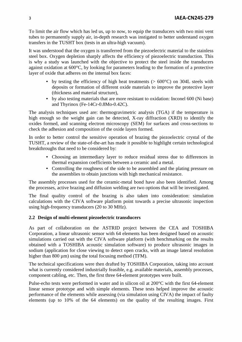
AREVA NP/INTERCONTROLE has put much effort on the development of ultrasonic transducers for performing Non-Destructive testing under liquid sodium during the reactor outages, when sodium is at a temperature of approximately 200°C. Prior work has been reported on experiments related to “contact” NDT technique using TUCSS transducers [5]. The work reported here shows “immersion” NDT testing, where the transducer is not in contact with the entry face of the inspected part. This allows to search for potential flaws with different incident angles while keeping the same transducer.
The test block considered here is represented in FIG.2 left. It includes two reflectors R1 and R2 oriented in the x-direction and y-direction respectively. R1 should be detected using an L0° beam when scanning from x0 to x2, and R2 should be detected when scanning from x1 to x4 using an angled beam (tilted transducer). The test block was made of 316L stainless steel and the notches R1 and R2 were made by spark machining. The notches were 20 mm deep for a 0.2 mm opening width on the whole height of the block (100 mm), which is representative or conservative of the potential flaws that would be sought in ASTRID reactor structures.
FIG. 2. Sketch of the test block and scanning range (left) and view of the DEFO testing device (right).
Under-sodium tests were conducted in a glove box of CEA-DEN (Cadarache, France) sodium facilities [6].
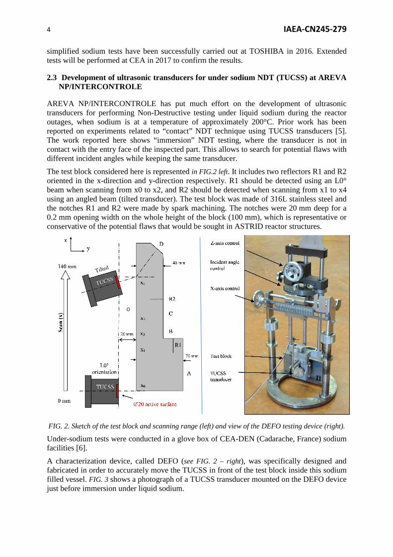
A characterization device, called DEFO (see FIG. 2 – right), was specifically designed and fabricated in order to accurately move the TUCSS in front of the test block inside this sodium filled vessel. FIG. 3 shows a photograph of a TUCSS transducer mounted on the DEFO device just before immersion under liquid sodium.
O

5 IAEA-CN245-279
FIG. 3. Photograph of a TUCSS transducer (left) and photograph of a TUCSS mounted on the DEFO device just before immersion under liquid sodium (right).
FIG. 4 (left) shows a B-scan done under sodium at 200°C in normal incidence (i.e. with the orientation of the TUCSS transducer perpendicular to the surface of the test block). Interpretation is as follows:
• The red band from 0 to 10 µs is the saturated dead zone of the transducer. • The red bands O and O’ (at 18 µs and 36 µs) are respectively the block’s entrance
echo and its repetition (between the transducer and the block). • The echo from surface A is visible at 45 µs. • The echo from reflector R1 is visible at 40 µs. • The echo from surface C is visible at 33 µs. The echo from surface C is disrupted
when TUCSS passes the position of reflector R2.
FIG. 4. Detection of R1 using longitudinal waves 0° (left) and detection of R2 using shear waves 38° (right) – under sodium at 200°C.

6 IAEA-CN245-279
FIG. 4 (right) shows a B-scan done in oblique incidence. The axis of the transducer was tilted to an incidence angle of 30°, producing pure shear waves with a 38° refraction angle (critical angle at 26.3°, therefore no longitudinal waves). Interpretation of this scan is as follows:
• The red band from 0 to 10 µs is the saturated dead zone of the transducer. • The echo at 70 mm / 60 µs is the echo coming from R2. • The echo at 15 mm / 73 µs is the echo from the corner between R1 and surface B. • The echo at 120 mm / 60 µs is coming from the chamfered surface D.
These two scans clearly demonstrate that the TUCSS acoustical properties are sufficient to perform basic NDT using normal and oblique immersion techniques, under sodium at 200°C.
The B-scan made in oblique incidence looks much cleaner than that made in normal incidence. This is principally due to the fact that there is no echo from the block’s entrance and no repetition echo. It is also due to the fact that shear waves are slower than longitudinal waves (VL=5 608m/s and VS=3 038m/s in 316L material at 200°C), delaying arrival time of echoes and pushing them further out from the dead zone. Inspection using normal incidence technique should therefore be done using a greater distance.
This transducer spent 27 days in total under sodium without physical degradation. It was noticed that amplitude of echoes gradually decreased with time. Nonetheless, its acoustical properties were finally still good enough to detect R2 with good signal to noise ratio.
These results demonstrate that basic immersion ultrasonic NDT technics can be used in the chemically aggressive sodium environment during outages. Further work will consist of under-sodium tests with mockups including representative welds.
3. Development of ultrasonic electromagnetic acoustic transducers (EMAT)
3.1 Introduction to electromagnetic acoustic transducers (EMAT) developed at CEA
In 2009, CEA chose to start the development of Electro Magnetic Acoustic Transducer (EMAT) probes for liquid sodium applications.
EMAT probes produce ultrasonic waves by generating an alternating volumic Lorentz force field in conducting media. The working principle of EMAT probes (see FIG. 5) can be explained in the following way [7]: first, eddy currents are induced in the conducting medium below the probe with the help of a coil. A static magnetic field is generated at the same time in the medium (using a permanent magnet). The Lorentz force is created by the interaction of the eddy currents and the permanent magnetic field. The Lorentz force field has dynamic properties which are due to the oscillation of the current injected in the coils and hence of the induced eddy currents. This generates an ultrasonic wave that can be used in applications as any other ultrasonic wave.

7 IAEA-CN245-279
FIG. 5. Principle of EMAT wave generation.
Thanks to the electromagnetic coupling between the probe and the medium, EMAT probes offer an advantage over classic piezoelectric probes (see previous sections), due to the absence of wetting effects. This comes at a cost, however. The electromagnetic coupling efficiency is low, and EMAT probes usually require higher currents and voltages.
To develop the expertise needed for building and using liquid sodium EMAT probes, two mains areas of research have been explored since 2009. Firstly, numerical models of the ultrasonic propagation have been developed to understand the EMAT transduction process better. Secondly, numerous EMAT probes for under-sodium applications, have been built and tested. Both of these topics are detailed in the next sections.
3.2 EMAT modelling
CEA has been developing the CIVA platform as a general tool for nondestructive evaluation [8], [9]. The CIVA platform features models from different branches of the nondestructive evaluation field under a single user interface: ultrasonic bulk waves, ultrasonic guided waves, eddy currents and X-rays. As explained in the previous section, EMAT transducers work using physical principles at the intersection of ultrasonic bulk waves and eddy currents. Hence, existing expertise in these modelling topics was leveraged to develop a simulation model capable of solving the equations arising from the EMAT physics equations. The models assume that the EMAT transduction is a two-step process that can be decoupled [10]. The time-domain Lorentz force is computed first and then used as an input for the semi-analytical elastodynamic models. This allows the computation of ultrasonic beams as well as flaw responses in pulse-echo or pitch-catch configurations.
The developed models have been fully integrated within the CIVA software platform, allowing easy computation of typical EMAT coil and magnet configurations (next FIG. 6).
FIG. 6. Some coils that can be addressed with the EMAT models developed in the CIVA platform.
N
S
N
S
�� ���
������ � ��� ���

8 IAEA-CN245-279
An example of a simulation carried out on one of the phased array EMAT probes designed by CEA is shown in the next FIG. 7.: defect response data for a side drilled hole in an aluminum block as inspected by electronic focusing using an 8 element phased array EMAT probe.
FIG. 7. Visualization of the defect response simulated in the case of electronic focusing with an 8 element phased array EMAT probe.
3.3 Development of probes and experimental results
Another important aspect of the work carried out at CEA has been the evaluation of existing and newly designed EMAT probes. The next figure gives an overview of some of the probe types that haven been developed by CEA. First, single element probes have been developed and tested in liquid sodium [11]. To extend the capabilities of the probes and allow for more flexible ultrasonic inspection types, 8 element phased array probes have been investigated and tested in liquid sodium during recent years [12]–[14] (see next FIG. 8.).
FIG. 8. Gallery of EMAT probes developed in the past years at CEA.
The experimental results obtained with these probes have shown that EMAT sensors can indeed prove very useful for under-sodium tasks. In particular, the tests have shown that telemetric measurements over short distances can easily be carried out with these probes (see FIG. 9). What’s more, EMAT probes designed by CEA have shown stable ultrasonic signals immediately upon immersion and robustness to thermal shock, as well as long 200°C immersion. The phased array probes have been used to investigate beam deflection and focusing. While laboratory experiments have shown that electronic delay laws can indeed be used to steer the acoustic beam, the liquid sodium tests have not been able to confirm the full potential of the probes. Still, we consider that the probe developed in 2015 has shown the ability of EMAT phased arrays to perform advanced electronic focusing in liquid sodium.

9 IAEA-CN245-279
FIG. 9. Sodium immersion of the 2015 8 element phased array probe using the PENELOPE experimental facility (left) and reconstructed B-scan showing target and backwall echoes (right).
Further work is still needed to design probes suited to the nondestructive evaluation tasks needed in the liquid sodium environment. In particular, larger EMAT probes need to be developed, which requires the use of a new type of coil design. Also, the center frequency of the probes needs to be increased to achieve smaller acoustical focal spots.
Other possible areas of improvement have been identified in the domain of electrical circuit optimization. The coils designed by CEA have been used to carry out impedance measurements. These impedance measurements have allowed us to perform electrical simulations of the injected current. Furthermore, this elementary measurement can be used as a mean to precisely characterize the transfer functions of the elements in the measurement chain. This work will lead to further prototypes that will be used for liquid sodium tests and imaging of new specimens in liquid sodium in 2017.
4. Conclusion: future prospects
Development and qualification programs are currently underway at the CEA and AREVA NP/INTERCONTROLE on ultrasonic transducers that allow non-destructive examination in sodium at about 200°C. These programmes will lead to the development of appropriate and diversified transducers for each ASTRID ultrasonic application (telemetry, imaging, NDE).
• The TUSHT concept by the CEA is being optimised by way of controlling the oxygen content in the transducer during operation at high temperature. Its manufacturing process has been standardised and the brazing of piezoelectric material with stainless steel front surfaces should be simplified.
• Innovative phased-array transducers are being developed and should lead to the development of transducers that will be available for in-sodium inspection.
• The TUCSS transducer by AREVA NP/INTERCONTROLE has demonstrated, through 200°C sodium tests, that it has sufficiently good acoustic properties to perform basic NDT (flaw detection) on structures immersed in liquid sodium at 200°C using conventional immersion ultrasonic techniques. Next step is to detect flaws in welded mock-ups.
• The CEA EMAT: this concept has demonstrated its suitability for telemetric inspection in liquid sodium at 200°C. Nevertheless, characterising the different components of the EMAT system showed that better understanding of the

10 IAEA-CN245-279
phenomena occurring in the coils and the pre-amplifiers would help optimise the performance of this sensor.
5. References
[1] BAQUE, F., et al., “In Service Inspection and Repair of the Sodium Cooled ASTRID reactor prototype”, Int. Conf. ICAPP 2015, Nice, France, May 2015, Paper 15041.
[2] BAQUE, F., et al., “In Service Inspection and Repair of Sodium cooled ASTRID Prototype”, Int. Conf. ANIMMA 2015, Lisbon, Portugal, April 2015, invited lecture #44.
[3] BAQUE, F., et al., “ASTRID In Service Inspection and Repair: review of R&D program and associated results”, Int. Conf. FR13, Paris, France, March 2013, ref. T1-CN-199/337.
[4] LHUILLIER, C., et al., “Generation IV Nuclear Reactors: Under Sodium Ultrasonic Transducers for Inspection and Surveillance”, Int. Conf. ANIMMA 2013, Marseille, France, June 2013.
[5] SAILLANT, J.F., et al., “Ultrasonic transducers for Sodium cooled reactors”, 10th International Conference on NDE in Relation to Structural Integrity for Nuclear and Pressurized Components, Cannes, France, October 2013.
[6] SAILLANT, J.F., et al., “First results of non-destructive testing under liquid sodium at 200°C”, Tours, France, September 2016.
[7] HIRAO, M. and OGI, H., “EMATs for science and industry: noncontacting ultrasonic measurements”, Springer Science & Business Media, 2013.
[8] CALMON, P., et al., “CIVA: an expertise platform for simulation and processing NDT data,” Ultrasonics, vol. 44, pp. e975–e979, 2006.
[9] MAHAUT, S., et al., “Recent advances and current trends of ultrasonic modelling in CIVA,” Insight-Non-Destr. Test. Cond. Monit., vol. 51, no. 2, pp. 78–81, 2009.
[10] PREMEL, D., et al., “Numerical simulation of electromagnetic acoustic transducers in time domain,” Stud. Appl. Electromagn. Mech., vol. 36, pp. 19–28, 2012.
[11] LHUILLIER, C., et al., “In sodium tests of ultrasonic transducers,” Int. Conf. ANIMMA 2011, Ghent, Belgium, 2011.
[12] LE BOURDAIS, F. and MARCHAND, B., “Design of EMAT Phased Arrays for SFR Inspection,” in Proceedings of the 40th Review of Progress in Quantitative NDE, Baltimore, USA, 2013.
[13] LE BOURDAIS, F. and MARCHAND, B., “Experimental Validation of an 8 Element EMAT Phased Array Probe for Longitudinal Wave Generation,” presented at the Proceedings of the 41th Review of Progress in Quantitative NDE, Boise, USA, 2014.
[14] LE BOURDAIS, F., et al., “Liquid sodium testing of in-house phased array EMAT transducer for L-wave applications”, Int. Conf. ANIMMA 2015, Lisbon, Portugal, April 2015.
6. Acknowledgements
The authors of this paper would like to thank their colleagues, and also TOSHIBA Corporation, for their collaboration on these studies.
Copyright © 2022 FDOKUMEN