
Annual Report of the Association EURATOM/CEA
367
3 9 TT [NI Annual Report of the Association EURATOM/CEA 1998 Compiled by: P. MAGAUD and F. LE VAGUERES FR9906315
-
Upload
khangminh22 -
Category
Documents
-
view
0 -
download
0
Transcript of Annual Report of the Association EURATOM/CEA

3 9
TT [NI
Annual Report of theAssociation EURATOM/CEA
1998Compiled by: P. MAGAUD and F. LE VAGUERES
FR9906315

FUSION TECHNOLOGY
Annual Report of theAssociation CEA/EURATOM
1998
Compiled by : P. MAGAUD and F. LE VAGUERES
ASSOCIATION CEA/EURATOMDSM/DRFC
CEA CADARACHE13108 Saint-Paul-Lez-Durance (France)
Tél. : 33-4 42 25 46 59Fax : 33-4 42 25 64 21
Cover : DIADEMO experimental device for double-wall tube validation

Please be aware that all of the Missing Pages in this document wereoriginally blank pages

- I -
CONTENTSPage
ill
PLASMA FACING COMPONENTS
CNET 96-412
CNET 97-463
CNET 98-477
DV4
T222.4ter
ITER outboard baffle : Design, analysis, technical specifications & follow-upof fabrication & testing of mock-ups and prototypes
High heat flux testing of primary first wall small scale mock-ups -200 kW electron beam gun test
Thermal fatigue of divertor medium scale components -200 kW electron beam gun test
Full scale manufacturing of high heat flux components designsfor Divertor modules
Manufacture and testing of permanent components optimisation of coolingsystem - Critical heat flux and thermo-hydr. of representative elements(continuation T222.4) ; Non destructive testing, calibrated defects;heat load influence (T222.15)
11
13
15
19
VACUUM VESSEL and SHIELD
CNET 98-473
CNET 98-474
NWC2-2
T204-1
T204-4
T216
T216-1
T216-2
ITER reference breeding blanket design (stage 2) : Safety analysis
ITER reference breeding blanket design : Thermo-mechanical and pebble-bedanalvses and breeder material assessment
Aqueous corrosion - Out-of-pile and in-pile experiments on the stresscorrosion cracking of reference 316L stainless steel and welds
ITER backplate mockup project - Laser cutting for repair.
Ultrasonic inspection for backplate inter-sector weld
Development of a reliable 316LN/DS-Cu/Be joint
Attachment of blanket modules to the back-plate -Laser process for cutting and welding of the hydraulic connections.
Numerical analysis and metallurgical expertise of first wall mock-ups
25
29
33
35
39
41
45
49

- I I -
T217 Improved materials and joint corrosion testing - Fabrication of aCuCrZr IG/316LN IG joint for corrosion testing 53
T224 Development of a thermal bond layer for first wall repair -Study of Rheocast Al-Ge thixotropic compliant layer for in-situ rebrazing 55
T301-2 YAG laser welding for sector field joint - Laser multipass welding
of a prototype containment vessel sector 59
T330 Water radiolysis irradiation tests 61
V63 Improved materials and joints irradiation testing -Cu alloys and joints improvement. Standardization of joint testing procedures 63
MAGNETS
CNET 94-345 Design study on ITER joints 67
CNET 96-409 ITER cryoplant design evaluation 71
CNET 96-432 Modelling, testing and analysis of full size ITER joints 73
M29 Conductor fabrication - ITER conductor R&D and monitoring 77
M3 0 Conductor fabrication - ITER conductor R&D coordination 79
M40 Design work on magnet R&D 81
M48 Winding & insulation development - Joint development 85
REMOTE HANDLING
T252 Radiation tolerance assessment of standard components
for remote handling and process instrumentation 87
T329-1 Bore tooling for divertor cooling pipe 93
T329-2 Magnet feeder lines and cryogenic connectors maintenance 95
T329-4 Carrier and bore tools for 4" bend pipes 99
T329-5 In-vessel RH dexterous operations 103
SAFETY
SEA 1-11 Safety approach and documentation support for ITER -SEA 1-2 Assessment of ITER non site specific safety report 107
SEA 1-14 Contribution to the European assessment of the documentationemitted by JCT I l l

- Ill -
SEA 3-1 Coherent system of codes for the ITER safety analysis -
SEA 5-2 Validation of computer codes and models 115
SEA 3-5 In vessel safety analysis 117
SEA 5-1 Validation of computer codes and models - Pactiter validation 121
SEA 5-3 Validation of computer codes and models -Thermalhydraulic codes validation experiments EVITA 125
SEP 1 -1 Adaptation of the PACTOLE code for the evaluation of ITER activatedcorrosion product source term 127
SEP 3-1 Waste characterisation and strategy 131
EUROPEAN BLANKET PROJECT
Water Cooled Lithium Lead (WCLL) Blanket
WP-A1-1.1 DEMO blanket feasibility and design, segment design and analysis -Segment design adaptation to new specifications 137
WP-A2-1.1 Test Blanket Module feasibility and design, design and analysis -TBM design, analysis and manufacturing sequence 139
WP-A2-2.1 Test Blanket Module feasibility and design, TBM subsystems -TBM ancillary equipment design 141
WP-A2-3.1 Test Blanket Module feasibility and design, interface with ITERand test program - ITER interface and TBM test program 145
WP-A2-4.1 Test Blanket Module feasibility and design, maintenance, support,remote handling, waste disposal - TBM support systemand maintenance procedure 149
WP-A3-1.1 ITER Test Module fabrication : Double wall tube development and fabrication
Double Wall Tube HIP Fabrication 153
WP-A3-2.1 Double-wall tube out-of-pile testing - DIADEMO experimental programme 157
WP-A3-4.1 ITER test module fabrication -ITM box fabrication using powder HIP technique 161
WP-A3-9.1 TBM fabrication : Development of minor components and instrumentation -PABLITO : a new lithium-lead test facility for instrumentation test 165
WP-A4-1.1 Permeation barriers fabrication and characterisation -Permeation barriers fabrication and characterisation by CVD and HIP 167

-IV-
WP-A4-2.1 Permeation barriers out-of-pile testing (PB performance) -
PRF in Pbl7Li & in water (and corrosion) 169
WP-A5-1 Tritium extraction from Pbl7Li 173
WP-A6-1.1 Safety analysis for DEMO power plant 177
WP-A6-2.1 Safety analysis of ITER WCLL test module - Definition of safety approach 181
WP-A7-1.1 Demo-blanket : Segment design & analysisWP-A7-2.2 Data base and ITM Reliability Assessment 185WP-A8-3.1 Pb 17Li Physico-Chemistry -
On-Line monitoring and stabilisation of the Li-Content 187
WP-A9-2.2 Pbl7Li water interaction : Water large leaks 191
WP-A9-3.1 Pb 17Li water interactions, definition of countermeasures -Required countermeasures 195
WP-A 10-2.2 Experimental demonstration of MHD phenomena -Turbulence in MHD flow shear layers 197
Helium Cooled Pebble Bed (HCPB) Blanket
WP-B1-1.2 DEMO-HCPB blanket : segment design & analysis -Design optimisation for alternative ceramics Li2ZrO3/Li2TiO3 201
WP-B2-1 ITER Test Module blanket feasibility & design -
Adaptation to HIP fabrication technology 205
WP-B6-1.3 Contribution to the safety approach of the DEMO HCPB blanket concept 209
WP-B7-1.1 Demo-blanket : Segment design & analysisWP-B7-2.3 Data base and ITM Reliability Assessment 185WP-B8-2 Development of Li2Zr03 and Li2Ti03 pebbles -
Development of Li2Zr03 and Li2Ti03 pebbles made by sintering 213
Structural Materials
SM 1-2.4 Irradiation experiments - PIE of samples irradiated in HFR - Phase 1A 217
SM 2-1.1 Characterisation and qualification of potential low activation martensitic steelsEffects of thermal ageing on the microstructure and mechanical propertiesof 7.5/9 Cr (W/Ta/V) Reduced Activation Martensitic steels 221
SM 2-3.1 Mechanical properties of weldments (F82 mod.) 225
SM 3-5.1 Corrosion in water with additives -Corrosion studies on specimens from task A 4.2.1 229
SM 4-1.1 Assessment of EB and GTAW weldability of LAM steel 231

- V -
SM 4-4.1 Transition weldment with a LAM steel using EB process 235
SM 4-5.1 Investigation on commercial filler metal for GTAW of LAM steels 237
SM 5-1.2 Evaluation for application of mechanical design codes for fusion materials 239
SM 6-4.2 Microstructural characterisation by SANS techniques -Microstructural characterisation after thermal ageing of LAM andconventional martensitic steels by Small Angle Neutron Scattering 243
WP5 Coordination - Materials R&D strategy for future fusion reactors 247
MATERIALS for FUSION POWER PLANT
Advanced Materials
WP3-3.3 Characterisation of material, specific tests and performance considerationsof low activation ceramic compounds (LACC) such as SiCf/SiC 251
Neutron Source
CNET 97-451 Evaluation and refinement of the conceptual design of the accelerator partof the D-Li neutron source 257
LONG TERM SAFETY
SEAFP 2-2 Improved coverage of events - Event sequence analysis 261
SEAFP 3-1 Improved containment concepts 265
SEAL 4.3 Multiple failure sequences - Risk and consequence assessment 269
SEAL 10.3 Waste detritiation -Integration of experimental support 273
SOCIO-ECONOMIC RESEARCH ON FUSION (SERF)
SERF 0-3 Socio-economic research on fusion : Long term scenari,the effects of uncertainty on the evaluation of research programmes 275
PLASMA FACING COMPONENTS
UT-PFC&C-HFW Transparent polycrystalline ceramic windows 281
UT-PFC&C-PS B4C and composite coatings '. 283
-V I -
UT-PFC&C-SiC Composite materials for PFC 285
UT-SM&C-A4 Assessment of laser weldability of internal components materials -Laser weldability of martensitic and low activation steels 289
VACUUM VESSEL & SHIELD
UT-N-DPA Displacement per atom modelling 293
UT-N-NDA Nuclear data assessment 295
UT-SM&C-CM3 Interaction between the deformation dislocation network and irradiation -Mechanical properties and micro-mechanisms in irradiated stainless steels 299
UT-SM&C-COR Metal and oxides thermodynamic stability and solubility in water
cooling system - Aluminium oxides stability and solubility in water 303
UT-SM&C-FCC FLICA-CASTEM coupling 305
UT-SM&C-GAL Compatibility of some alloys and refractory metals with liquid metals 3 07
UT-SM&C-FflP Solid and powder HIP technologies development 311
UT-SM&C-LAM2 Irradiated behaviour of reduced activation (RA) martensitic steels afterneutron irradiation at 325°C 315
UT-SM&C-LAM3 Microstructural investigation of reduced activation martensitic steelsby SANS - Study of secondary hardening phenomena in F82H steel bySmall Angle Neutron Scattering 319
UT-SM&C-REL Reliability modelling 323
UT-SM&C-WI Design and analysis of vacuum vessel and internals 327
BLANKETS
UT-SM&C-BLK Helium cooled pebble bed blanket 333
UT-SM&C-LiPb Purification of liquid metals 337
UT-SM&C-LME Liquid metal embrittlement 341
UT-SM&C-PB Fabrication of permeation barriers using CVD processes 345
UT-SM&C-PBM Pebble bed thermo-mechanical modelling 347
UT-SM&C-RC CVD/PVD coatings resistant to liquid metals 349
-VI I -
REMOTE HANDLING
UT-RHl
UT-RH2
Technology and control for hydraulic manipulator.
Graphical programming for remote handling
351
355
FUEL CYCLE
UT-Tl Separation of the D/T mixture from helium in fusion reactors usingsuperpermeable membranes - Study of plasma driven superpermeation :Effects of methane and helium additive, membrane superpermeation indeuterium plasma, plasma driven superpermeation of palladium membrane. 359
SAFETY
UTS2
UTS3
Mitigation of hydrogen hazard in a fusion reactor by reductionof metallic oxides
Blanket safety - Modeling of heat exchanges for high flux componentsin a fusion reactor during accidental conditions
363
367
(X\j:~Â.:lAi£%'JL#^l%&$Jf.*\$:^
ICF-01
ICF-02
ICF-03
Intense laser and ions beams dynamics in thermonuclear ICF plasmas
Civil applications of inertial confinement fusion -Cryogenic targets production using magnetic lévitation
Fast igniter concept studies.
373
377
381

- 1 -
INTRODUCTIONThe French EURATOM-CEA Association made in 1998 significant contributions to the European Fusion Technology
Programme. This report presents all EURATOM-CEA activities which are carried out in the frame of the European fusiontechnology programme as follows :
• The ITER CEA activities and related developments are described in the first part• The second part is dedicated to the Long Term activities as Blankets and structural materials developments, long
term safety, socio-economic problem.• The Underlying Technology activities are compiled in the third part of this report.• And the fourth part describes the inertial confinement studies.
hi each section, the tasks are sorted out to respect the European presentation. For an easy reading, appendix 4 gives the list oftasks in alphabetical order with a page reference list.
The CEA is in charge of the French Technology programme. Three specific organisational directions of the CEA, locatedon four sites (see appendix 5), are involved this year in this programme:
• Advanced Technologies Direction (DTA), for Material and Remote Handling tasks• Nuclear Reactors Direction (DRN), for Blanket design, Neutronic problems, Safety tasks• The Physical Sciences Direction (DSM) uses the competence of the Tore Supra team in the Magnet design, Plasma
Facing Component field and Cryogenic technologies.
The CEA programme is completed by collaborations with industry (Technicatome, COMEX-Nucléaire) and externallaboratories (Ecole Polytechnique, University of Paris XI, University of Toulouse).
The breakdown of the programme by Directions is presented in figure 1.
The allocation of tasks is given in appendix 2 and in appendix 3, the related publications.
DTADRN
DSM1PSN
__ Inertial Confinement
Underlying Technology
Long Term
Next Step
IndustryExternal
Lab.
Figure I : Breakdown of the work carried out by Directions and Topics

- 3 -
NEXT STEPPROGRAMME
Long TermUnderlyingTechnology
' •1 ' \
InertialConfinement
s
- 5 -
CNET 96-412
Task Title : ITER OUTBOARD BAFFLE : DESIGN, ANALYSIS, TECHNICALSPECIFICATIONS & FOLLOW-UP OF FABRICATION &TESTING OF MOCK-UPS AND PROTOTYPES
INTRODUCTION
The ITER BAfile (BA) modules, which are the inboardand outboard bottom row of shielding blanket modules,have the main function of avoiding particle back-flow fromthe divertor chamber. For this reason they are consideredto belong to the divertor system. As a consequence, the BAFirst Wall (FW) is submitted to an high thermal flux andits design needs the use of high-heat-flux componenttechnology. The activities have been focused on theoutboard B A-FW because of the more severe heat flux loadconditions and the more complex overall geometrycompared to the inboard one.
This contract, originally running from March 1996 to June1998, covers the second phase of the ITER T232.10subtask. It includes design and analysis of the BA-FWmock-ups (small-scale, medium-scale and prototypes), theprediction of the results on the mock-ups tests, theinterpretation of the obtained experimental results, and thefollow-up of the mock-ups manufacturing. In order tocover all the required expertise, these activities aresupported by an established collaboration betweenmembers of different CEA Departments, in particularDMT, DRFC, DER and DEM/SGM. Moreover, the workis performed in close collaboration with industry(EFET/Framatome).
Because of the new attachment system developed for theprimary shielding modules by the ITER JCT at the end of1996, significant design modifications for most in-vesselcomponents have been required. In particular, themodularity of the shielding blanket has been modified. Foran almost unchanged total number of modules, the newpoloidal segmentation has been increased to 26 modules.Both inner and outer baffles are now formed by twomodules, the lower and the upper baffles. Moreover,because the new ITER shielding blanket envisages frontalpenetrations of 30 mm of diameter, the existing concept ofbelt-limiter using three rows of outboard shielding modulesis no more acceptable. The main reason is the very highheat loads at which the armour material around the frontalholes will be submitted (15-20 MW/m2, mainly located onthe hole side walls). For this reason, a new concept oflimiter, a port-limiter, which will be located in thehorizontal ports and which can then be easily replacedduring ITER BPP operations, has been preliminarydesigned by the ITER JCT. Reasonable heat loads (peakvalues of 10-15 MW/m2) can be obtained with twoidentical limiters located in two toroidally-oppositehorizontal ports.
This situation has lead to a significant modification of thetime-scale and contents of the BA-related activities. It wasdecided by the NET Team that the medium-scale mock-upswill be manufactures, if necessary, as a demonstration ofspecific details (e.g., corners) of the BA-prototype, by theindustry charged of the prototype manufacturing.Moreover, it was decided that the BA-prototype should alsocover FW-designs relevant for the port limiters.
Therefore, the 1998 situation is the following: thefabrication of two different prototypes was launched inspring 98, one with CFC/W FW-protection and one withBe-protection. The manufacturing of both prototypes isexpected by the end of 99 and their tests should beperformed in spring 2000.
The CEA activity in 1998 has been focused on thepredictions of the prototype behavior under thermo-mechanical testing (which can have an impact on the usedprototype fabrication techniques), while the prototypes andtesting follow-up have been extended to the years 1999 and2000.
1998 ACTIVITIES
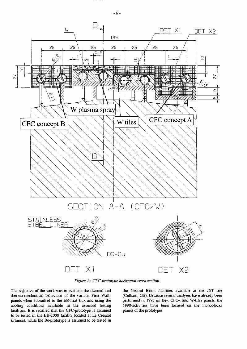
With reference to the 1997 Progress Report [1], theactivities in 1998 have been focused on the two baffleprototypes (Be and CFC/W) as defined after a call fortender to which the CEA has participated in the frameworkof the present task. The first prototype (indicated hereafteras the "CFC-prototype") will have four FW-panels usingrespectively CFC-tiles, W-plasma spray, and two CFC-monoblock designs (see Fig. 1). It is under fabrication atFramatome (France). The second prototype (indicatedhereafter as the "Be-prototype") will have four FW-panelsusing respectively Be-tiles 4 mm and 8 mm-thick , two Be-monoblock with the same design. It is under fabrication atNNC (England). The specificity of the baffle module and,therefore, of the proposed prototypes is the presence, in thepoloidal direction, of two corners at the bottom and at thetop of the FW-panel, which requires a challenging FW-panel arrangements and extrapolation of the selectedfabrication techniques.
- 6 -
C\l
o
PET XI DET X2
CFC concept B
in
W plasma spray
CFC concept A
SECTION A-A (CFC/WSTAINLESS
L
DET XI DET X2Figure 1 : CFC-prototype horizontal cross section
The objective of the work was to evaluate the thermal andthermo-mechanical behaviour of the various First Wall-panels when submitted to the EB-heat flux and using thecooling conditions available in the assumed testingfacilities. It is recalled that the CFC-prototype is assumedto be tested in the EB-2000 facility located at Le Creusot(France), while the Be-prototype is assumed to be tested in
the Neutral Beam facilities available at the JET site(Culham, GB). Because several analyses have already beenperformed in 1997 on Be-, CFC-, and W-tiles panels, the1998-activities have been focused on the monoblockspanels of the prototypes.

- 7 -
CFC-MONOBLOCKS PANELS
The steady state thermal analysis has been performed firstwith the incident heat flux as parameter (variation from 1to 10 MW/m2). For example, maximum temperature in theCFC-monoblock under 10 MW/m2 is 1074°C. The firstpart of the Table 1 resumes the main results. Thermaltransient has been performed for an incident heat flux of10 MW/m2. Values of the characteristic times, x6g% and x90%, are respectively 1.8 s and 3.8 s.
Mechanical calculations have been divided in two distinctparts : the first one concerned the straight part of themock-up and the second one the bottom corner which isexpected to be the most critical corner. Fig. 2 gives forexample the stresses in each material direction in the CFC-monoblock for an incident heat flux of 10 MW/m2.
Maximum displacements, useful in particular as boundarycondition for the bottom corner calculations, are howevercalculated for an incident flux of 5 MW/m2 (average). Forthe bottom corner, it has been necessary to distinguish thecases of the "slotted-monoblock" and of the "sliding-tiemonoblock" (different boundary conditions). In each of thefour cases performed for the "sliding-tie monoblock", eventhe most favourable free-tube case, a stress concentrationappeared on the tube in the first element between twomonoblocks. In any cases, the maximum level of stress waslocated in such a zone. In the case of the slotted-monoblock, for the bottom corner no difference inboundary conditions appears with and without incidentflux on the straight part of the mock-up. Indeed, the FWbeing strongly attached to the shield through the steel pad,there is no FW elongation to be accommodated by thecorners. Found maximum stresses are lower than thoseobtained for the "sliding-tie" monoblock concept.
Table 1: Main results of the parametric steady state thermal analyses
Temperatures (°C) obtained in the CFC-prototype parametric steady state thermal analysis
incident flux (max)
min
CFC monoblock aver.
max
min
OFHC layer aver
max
min
CuCrZr tube aver.
max
Water (mid)
1 MW/m2
145 °C
164
208
145
151
161
144
149
158
142
2.5 MW/m2
152 °C
202
320
151
168
192
150
164
185
146
5 MW/m2
163 °C
269
534
162
195
242
160
187
228
152
7.5 MW/m2
174 °C
341
788
173
221
292
169
209
272
158
10 MW/m2
185 °C
420
1074
183
247
341
179
231
312
164
Temperatures (°C) obtained in the Be-prototype parametric steady state thermal analysis
incident flux (max)
min
Be monoblock aver.
max
min
Glidcop tube aver.
max
Water (mid)
1 MW/in2
35
45
87
34
42
56
32
2.5 MW/m2
41
68
177
40
59
91
35
5 MW/m2
50
106
347
48
85
148
39
7.5 MW/m2
58
145
546
56
109
202
44
10 MW/m2
66
186
776
64
132
255
48

Stress
>-4.60E
< 2.22E
-44.
-31.
-19.
-6.2
6.4
19.
32.
44.
57.
69.
82.
94.
1.07E
1.20E
1.32E
1.45E
: 1.57E
1 70E
MPa
01
02
+02
+ 02
+02
+02
+ 02
+02
(material)7
Stress (MPa)
>-1.37E+01
< 4.06E+01
-13.
-11.
-8.2
-5.6
-3 .1
-0.54
2.0
4.6
7.1
9.6
12.
15.
17.
20.
22.
25.
27.
30
33.
35
38.
40.
Figure 2 : CFC concept A, straight part: stress distribution in each material direction in the CFC-monoblock
- 9 -
BERYLLIUM-MONOBLOCK PANELS
Calculations performed for the Be-prototype are about thesame than those performed for the CFC one. The parametricsteady state thermal analysis has been performed first. Thesecond part of the Table 1 gives the main results.
Characteristic times, X68% and X 90%, obtained in the thermaltransient analysis under 10 MW/m2 are lower (respectively1.4 s and 2.7 s).
Elastic mechanical calculations performed for the straightpart of the Be-prototype have been repeated for the cases of10 and 20 mm-long monoblocks. Von Mises thermal stressdistributions have been obtained. It was observed that themaximum values of stress obtained in the case of the20 mm-long monoblocks were about 40% higher than in thecase of 10 mm-long monoblocks. But for both cases, it wasnot possible to conclude with this analysis neither on thestructure lifetime nor on it's failure probability (problem ofstress concentrations). However, taking into account thelarge difference between the maximum levels of stress, it isstrongly recommended to manufacture the mock-up with 10mm-long Be-monoblocks.
Because of the difficulty on the results interpretation, it hasbeen decided to make a comparison with the stress levelsobtained for a similar component already tested under fluxduring the small-scale mock-ups testing campaign. Thermo-mechanical calculations of Be-monoblocks which havebeen successfully tested in JET (able to withstand 10.1MW/m2 for 5s for a few hundred of cycles without damage)has been performed using the same type of modelling thanthe one used for prototype in order to compare the stresslevels. The obtained stress levels are comparable. One cantherefore expect similar lifetime.
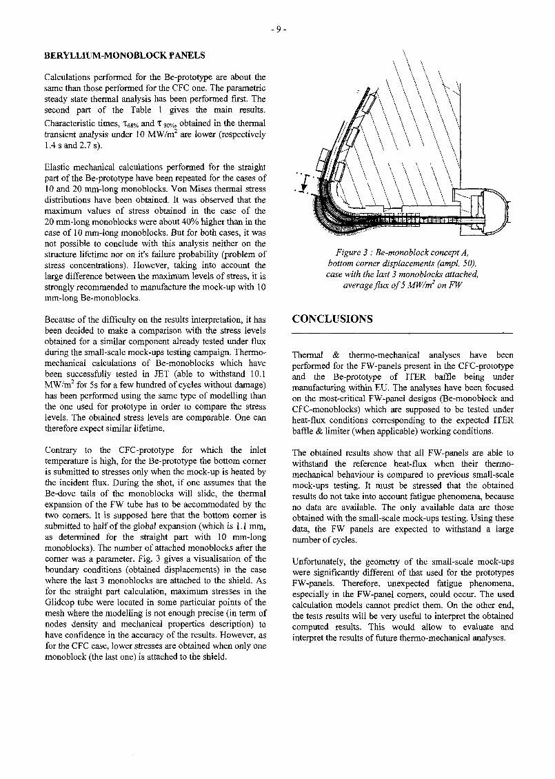
Contrary to the CFC-prototype for which the inlettemperature is high, for the Be-prototype the bottom corneris submitted to stresses only when the mock-up is heated bythe incident flux. During the shot, if one assumes that theBe-dove tails of the monoblocks will slide, the thermalexpansion of the FW tube has to be accommodated by thetwo corners. It is supposed here that the bottom corner issubmitted to half of the global expansion (which is 1.1 mm,as determined for the straight part with 10 mm-longmonoblocks). The number of attached monoblocks after thecorner was a parameter. Fig. 3 gives a visualisation of theboundary conditions (obtained displacements) in the casewhere the last 3 monoblocks are attached to the shield. Asfor the straight part calculation, maximum stresses in theGlidcop tube were located in some particular points of themesh where the modelling is not enough precise (in term ofnodes density and mechanical properties description) tohave confidence in the accuracy of the results. However, asfor the CFC case, lower stresses are obtained when only onemonoblock (the last one) is attached to the shield.
Figure 3 : Be-monoblock concept A,bottom corner displacements (ampl. 50),case with the last 3 monoblocks attached,
average flux of 5 MW/m2 on FW
CONCLUSIONS
Thermal & thermo-mechanical analyses have beenperformed for the FW-panels present in the CFC-prototypeand the Be-prototype of ITER baffle being undermanufacturing within EU. The analyses have been focusedon the most-critical FW-panel designs (Be-monoblock andCFC-monoblocks) which are supposed to be tested underheat-flux conditions corresponding to the expected ITERbaffle & limiter (when applicable) working conditions.
The obtained results show that all FW-panels are able towithstand the reference heat-flux when their thermo-mechanical behaviour is compared to previous small-scalemock-ups testing. It must be stressed that the obtainedresults do not take into account fatigue phenomena, becauseno data are available. The only available data are thoseobtained with the small-scale mock-ups testing. Using thesedata, the FW panels are expected to withstand a largenumber of cycles.
Unfortunately, the geometry of the small-scale mock-upswere significantly different of that used for the prototypesFW-panels. Therefore, unexpected fatigue phenomena,especially in the FW-panel corners, could occur. The usedcalculation models cannot predict them. On the other end,the tests results will be very useful to interpret the obtainedcomputed results. This would allow to evaluate andinterpret the results of future thermo-mechanical analyses.

-10-
PUBLICATIONS TASK LEADER
[1] P. Magaud, F. Le Vaguères (eds.), Fusion L. GIANCARLITechnology, 1997 Annual Report of the AssociationCEA/EURATOM, Task CNET 96-412, CEA DRN/DMT/SERMADSM/DRFC, May 1998. CEA Saclay
91191 Gif-sur-Yvette Cedex[2] J.F. Salavy, L, Giancarli, Thermo-mechanical
analyses of the two baffle-FW prototypes being Tél. : 33 169 08 21 37manufactured EB-tested by the ITER EU-HT, Fax : 33 1 69 08 99 35CEA/DMT Report, SERMA/LCA/RT/98-2425/A,October 1998. E-mail : [email protected]

-11 -
CNET 97-463
Task Title : HIGH HEAT FLUX TESTING OF PRIMARY FIRST WALLSMALL SCALE MOCK-UPS200 kW electron beam gun test
INTRODUCTION
The scope of this contract is to test under high heat fluxactively cooled mock-ops representative of the ITER firstwall. Evaluation of the joining, mock-up preparation andpost mortem examination are also included in this contractThe FE 200 high heat flux test facility is operated jointly byCEA and FRAMATOME since 1991. Various testing havebeen performed under NET contracts on this installationsince 1991.
The ÏTER first wall technology is an integrated conceptwith a water cooled copper heat sink joined to the stainlesssteel blanket modules and covered by a beryllium plasmafacing material. The average incident heat flux is in theorder of 0.5 MW/nf.
The aim of this study was to compare the different qualitiesof the copper to stainless steel joints and characterize thebehavior of representative small scale mock-ups under highheat flux fatigoe loading.
Nine Hipped (powder or plate) elements where delivered toDRFC: "
- 4 produced by Studvick- 4 produced by NNC- 1 by CEA
All elements where prepared and examined by CEA. Onlyfour where fatigue tested in FE200 under heat load higherthan designed (X 10).
Four large element manufactured by solid Hipping whereassembled two by two (FW2 & FW3) for fatigue testing inthe FE200 test facility.
The comparison was always between a precipitationhardened (PH) and a dispersionned hardened (DH) copper.
FIRST TEST CAMPAIGN (FW2)
After a screening test up to 7 MW/nr", the fatigue testingstarted at 5 MW/nr.
The surface temperature measured during the testing wherecomt>arable for each elements.
* 800
I 600 :
| 200 ~
2 4 6
heat flux jHWIm1)
Figure 2 : Comparison of the thermal behavioro/PH and DH Hipped element
The DS element started first to failed (hot spot) after 315cycles. The testing continued until 960 cycles and the visualexamination showed a large disbonding of a copper tocopper joint and a deep surface crack (fig. 3. bottomelement).
Figure 1 : MKI and MK2 elements [CuCrZr (powder)Hipped to Stainless steel (powder and plate)] prepared
for IR testing on SA TIR
Figure 3 : FW2 mock-up after fatigue testinga! 5 &7 MW/mr. Disbonding failure on DS element
and surface cracking on PH element

The PH element survived 1000 cycles at 5 MW/nr withouttemperature excursion. A hot spot appeared after 300 cyclesat 7 MW/nr but fatigue testing was pursued until 800cvcles.
CONCLUSIONS
Visual examination of thesurface crackings (figure 4).
surface show's many small
Figure 4 : Surface cracking on PH copper elementofFW3 mock-up after fatigue testing (cell size = 2 mm)
SECOND TEST CAMPAIGN (FW3)
An improved DS copper element for the second pair ofsolid HIP components was produced after the first testingcampaign (FW2).
Surface temperature remained constant during the 1000cycles fatigue test at 5 MW/nr on both elements. Afteropening a large crack was visible between the copper heatsink and the stainless steel back part on the DS copperelement. No crack was detected at the copper/copperinterface.
After 150 cycles at 7 MW/nr on the PH copper element ahot soot was detected at the center of the heated area.
The Hipping technology deveioped for these elements is notsatisfactory for assembling DS copper and stainless steelwhen the component is subjected to high heat loads in therange of 5 MW/m2. The PH copper assembled by the sametechnology has a better behavior but cannot survived at 7MW/nr. Nevertheless this technology couid be sufficientfor the low design heat loads (0.5 MW/m1) of the first wail.
TASK LEADER
Ph. CHAPPUIS
DSM/DRFC/SIPPCEA Cadaracfae13108 St Paul Lez Durance Cedex
Tél. : 33 4 42 25 46 62'Fax : 33 4 42 25 49 90
E-mail : [email protected]
POST MORTEM EXAMINATION
The DS copper element with a large crack at the copper tostainless steel interface had the largest deflection (0.5 mm /200 mm).
The PH copper element showed the same orange skin as forthe first test (FW2). The electrical conductivity(proportional to the heat conductivity) and themicrohardness were reduced on the exposed area(50%). TheDS element remained roughly with the same values.
- 1 3 -
CNET 98-477
Task Title : THERMAL FATIGUE OF DIVERTOR MEDIUM SCALECOMPONENTS200 kW electron beam gun test
INTRODUCTION
The scope of this contract is to test under high heat fluxactively cooled mock-ups representative of the ITERdivertor.
The FE 200 high heat flux test facility is operated jointly byCEA and FRAMATOME since 1991. Various testing havebeen performed under NET contracts on this installationsince 1991.
The ITER Divertor requires to test different high heat fluxtechnologies which could used in the full region of thedivertor (dome, gas box, dump, vertical target). During theyear 98, only one test campaign has been devoted to suchqualification:
Prodivl : prototypical mock-up of the vertical target.
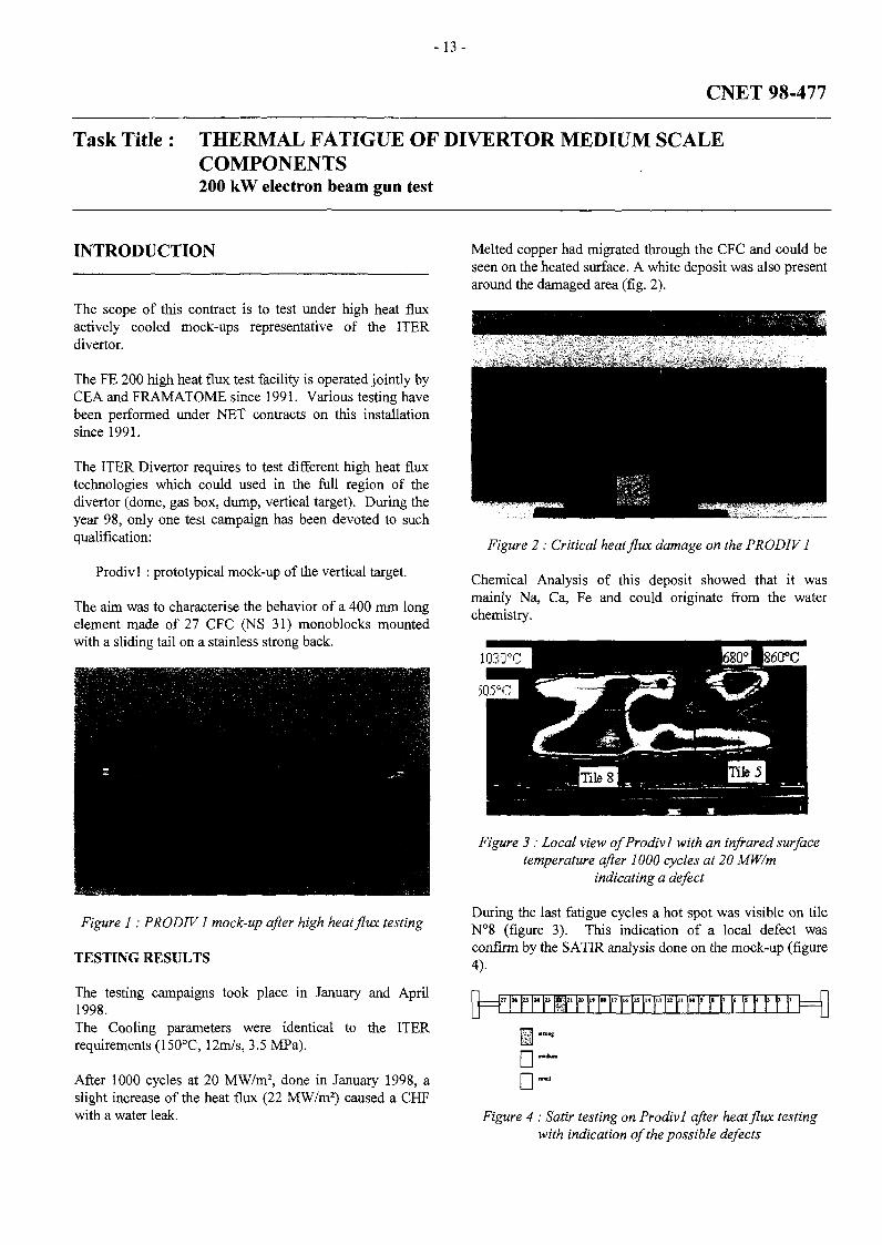
The aim was to characterise the behavior of a 400 mm longelement made of 27 CFC (NS 31) monoblocks mountedwith a sliding tail on a stainless strong back.
Melted copper had migrated through the CFC and could beseen on the heated surface. A white deposit was also presentaround the damaged area (fig. 2).
Figure 1 : PRODIV1 mock-up after high heat flux testing
TESTING RESULTS
The testing campaigns took place in January and April1998.The Cooling parameters were identical to the ITERrequirements (150°C, 12m/s, 3.5 MPa).
After 1000 cycles at 20 MW/m2, done in January 1998, aslight increase of the heat flux (22 MW/m2) caused a CHFwith a water leak.
Figure 2 : Critical heat flux damage on the PRODIV 1
Chemical Analysis of this deposit showed that it wasmainly Na, Ca, Fe and could originate from the waterchemistry.
Figure 3 : Local view of Prodivl with an infrared surfacetemperature after 1000 cycles at 20 MW/m
indicating a defect
During the last fatigue cycles a hot spot was visible on tileNC8 (figure 3). This indication of a local defect wasconfirm by the SATIR analysis done on the mock-up (figure4).
|}=r i" r iM r m r r r r r r r r r r r r r r r r- r r r r t={j
• •• •
Figure 4 : Satir testing on Prodivl after heat flux testingwith indication of the possible defects

- 1 4 -
CONCLUSIONS TASK LEADER
This mock-up demonstrated the ability of the monoblock Ph. CHAPPUISconcept to sustain very high heat flux (up to 20 MW/m2).The critical heat flux negative margin could be explained DSM/DRFC/SIPPby an increased peaking factor du to some local defects. A CEA Cadarachenew test campaign was done to correctly evaluate this 13108 St Paul Lez Durance Cedexmargin.
Tél. : 33 4 42 25 46 62Fax : 33 4 42 25 49 90
E-mail : [email protected]
-15-
DV4
Task Title : FULL SCALE MANUFACTURING OF HIGH HEAT FLUXCOMPONENTS DESIGNS FOR DIVERTOR MODULES
INTRODUCTION
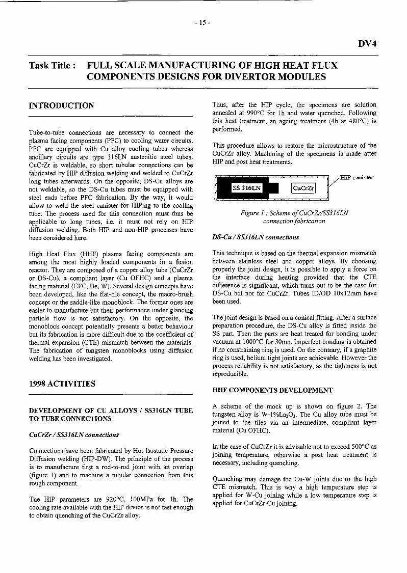
Tube-to-tube connections are necessary to connect theplasma facing components (PFC) to cooling water circuits.PFC are equipped with Cu alloy cooling tubes whereasancillary circuits are type 316LN austenitic steel tubes.CuCrZr is weldable, so short tubular connections can befabricated by HIP diffusion welding and welded to CuCrZrlong tubes afterwards. On the opposite, DS-Cu alloys arenot weldable, so the DS-Cu tubes must be equipped withsteel ends before PFC fabrication. By the way, it wouldallow to weld the steel canister for HIPing to the coolingtube. The process used for this connection must thus beapplicable to long tubes, i.e. it must not rely on HIPdiffusion welding. Both HIP and non-HIP processes havebeen considered here.
High Heat Flux (HHF) plasma facing components areamong the most highly loaded components in a fusionreactor. They are composed of a copper alloy tube (CuCrZror DS-Cu), a compliant layer (Cu OFHC) and a plasmafacing material (CFC, Be, W). Several design concepts havebeen developed, like the flat-tile concept, the macro-brushconcept or the saddle-like monoblock. The former ones areeasier to manufacture but their performance under glancingparticle flow is not satisfactory. On the opposite, themonoblock concept potentially presents a better behaviourbut its fabrication is more difficult due to the coefficient ofthermal expansion (CTE) mismatch between the materials.The fabrication of tungsten monoblocks using diffusionwelding has been investigated.
1998 ACTIVITIES
DEVELOPMENT OF CU ALLOYS / SS316LN TUBETO TUBE CONNECTIONS
CuCrZr /SS316LN connections
Connections have been fabricated by Hot Isostatic PressureDiffusion welding (HIP-DW). The principle of the processis to manufacture first a rod-to-rod joint with an overlap(figure 1) and to machine a tubular connection from thisrough component.
The HIP parameters are 920°C, lOOMPa for lh. Thecooling rate available with the HIP device is not fast enoughto obtain quenching of the CuCrZr alloy.
Thus, after the HIP cycle, the specimens are solutionannealed at 990°C for lh and water quenched. Followingthis heat treatment, an ageing treatment (4h at 480°C) isperformed.
This procedure allows to restore the microstructure of theCuCrZr alloy. Machining of the specimens is made afterHIP and post heat treatments.
, HIP canister
^^HSS316LNHB CuCrZi-
Figure 1 : Scheme ofCuCrZr/SS316LNconnection fabrication
DS-Cu /SS316LN connections
This technique is based on the thermal expansion mismatchbetween stainless steel and copper alloys. By choosingproperly the joint design, it is possible to apply a force onthe interface during heating provided that the CTEdifference is significant, which turns out to be the case forDS-Cu but not for CuCrZr. Tubes ID/OD 10x12mm havebeen used.
The joint design is based on a conical fitting. After a surfacepreparation procedure, the DS-Cu alloy is fitted inside theS S part. Then the parts are heat treated for bonding undervacuum at 1000°C for 30mn. Imperfect bonding is obtainedif no constraining ring is used. On the contrary, if a graphitering is used, helium tight joints are achievable. However theprocess reliability is not satisfactory, as the tightness is notreproducible.
HHF COMPONENTS DEVELOPMENT
A scheme of the mock up is shown on figure 2. Thetungsten alloy is W-l%La2O3. The Cu alloy tube must bejoined to the tiles via an intermediate, compliant layermaterial (Cu OFHC).
In the case of CuCrZr it is advisable not to exceed 500°C asjoining temperature, otherwise a post heat treatment isnecessary, including quenching.
Quenching may damage the Cu-W joints due to the highCTE mismatch. This is why a high temperature step isapplied for W-Cu joining while a low temperature step isapplied for CuCrZr-Cu joining.

- 1 6 -
Figure 2 : HHF mock up
Development of W-l%La2O/Cu OFHC joints and CuOFHC/Cu alloy joints
W and Cu form an immiscible system and, even thoughdirect joining is possible, an intermediate layer providing a"metallurgical transition" is desirable to obtain resistantjoints. The interlayer choice was made on the basis of phasediagrams, diffusion coefficients and literature data. Bestresults were obtained with a 10um thick nickel foil. TheHIP cycle is based on a 2h step at 950°C. In the case of DS-Cu, the same HIP cycle is used for DS-Cu / Cu OFHCjoining.
In the case of CuCrZr, several techniques have beeninvestigated. Direct HIP DW at 500°C is achievable. Thetensile properties of flat specimens are comparable to thoseof pure, annealed Cu OFHC, the rupture being located awayfrom the interface. However, this result was not repeatedwith a tubular geometry due to CTE mismatch. Joining at500°C using the so-called diffusion brazing process allowedbetter results. In this process, isothermal solidification of abrazing material occurs during the temperature step due tothe dissolution of the braze by the base metal. The brazemetal is pure tin.
The fabrication process is based on the use of a coppercanister (figure 3). After surface preparation, the tungstenalloy tiles as well as Cu OFHC tube and Ni foil are insertedin the canister. The canister is sealed by electron beamwelding. A first high temperature HIP cycle is applied.Then, CuCrZr tube and a Sn foil are inserted in the canisterwhich is sealed again by EB welding. A second HIP cycle(low temperature) is applied. Only one HIP cycle isnecessary in the case of a DS-Cu alloy.
Figure 3 : Canister for HHF componentsmock up fabrication
Joint design
Finite Element Modelling has been used to evaluate theeffect of the interface geometry on the stress and strain,using FE code Castem 2000.
The model chosen is an axi-symmetric representation oftwo tiles in which a OFHC copper tube ID/OD 12/14mm isinserted. The calculation takes into account the coolingfrom 950°C (HIP joining temperature) to 50°C.
Different joint geometries have been considered : 90° joint(reference), 0.5mm 45° chamfer, rounded edge 0.5mm. Inthe latter case, copper filling of the angle has been takeninto account.
The results are shown on figures 4-6. In all cases high stressconcentration develops on cooling in the tungsten tiles.Conversely, plastic deformation of the copper OFHCoccurs. Though the value of the maximum Von Mises stressshall not be considered as an exact result because ofcalculation divergence, a qualitative comparison can easilybe made between the different configurations considered.
The peak stress is greatly reduced when a 45° chamfer ismachined on the tiles or when the tile edge is rounded. Itdecreases from 1.8GPa to 680MPa and finally 210MPa. Inthe second and third case it is worth noting also that thelocation of the stress concentration in tungsten does notcoincide with a free edge of the joint, whereas it does in thecase of 90° tiles.

- 1 7 -
-l.ODE+08
- 1 . 5 2E+07
7.51E+07
1.S5E+08
2.3 6E+08
3.*6E+08
4.3 6E+08
3.2 7E+08
6.17E+08
7.0 7E+08
7.9 7E+08
8.8 8E+08
* 9.7 8E+08
1.0 7E+09
1.16E+09
,- 1.2 5E+09
| | 1.3 4E+09
1.13E+09
1.5 2E+09
l.SUE+09
1.7 0E+09
1.7 9E+09
Figure 4 : FEM calculation of Von Mises equivalent stress (unchamfered tile)From left to right : mesh, enlarged view of Von Mises stress, scale (Pa)
-9 .2 3E+01
- 3 . 3 4E+07
- 1 . 8 3E+07
1.8 4E+07
3.3 3E+07
9.21E+07
1.2 9E+08
1.6 6E+08
2.0 3E+08
2.40E+08
2.T7E+08
3.13E+08
3.3 0E+08
3.8 7E+08
4.2 4E+08
4.9 8E+08
3.3 3E+08
3 . î 2E+08
S.0 8E+08
6.4 3E+08
6 .8 2EH-08
Figure 5 : FEM calculation of Von Mises equivalent stress (45° chamfered tile)From left to right : mesh, enlarged view of Von Mises stress, scale (Pa)

-18-
-1 .6 5E+07
-3.7 2E+06
1.38E+07
2.S6E+07
3.74E+07
1.8 2E+07
5.S9E+07
«.97E+07
8.O3E+07
9.13E+07
1.0 2E+08
I 1.13E+08
1.2 4E+08
1.3 4E+08
• 1.4 3E+08
I 1.1SE+08
1.6 7E+08
1.7 7E+08
1.8 8E+08
1.99E+08
2.10E+08
Figure 6 : FEM calculation of Von Mises equivalent stress (rounded tile with copper filling)From left to right : mesh, enlarged view of Von Mises stress, scale (Pa)
CONCLUSIONS
A HIP diffusion welding technique has been used tofabricate CuCrZr / SS316LN bimetallic tubularconnections. Single and double overlap tubular connections(CuCrZr/SS316LN and SS316LN/CuCrZr/SS316LN) havebeen fabricated and delivered to Forschungzentrum Julichfor tensile, pressure and low cycle fatigue testingrespectively. The application of a diffusion bondingtechnique to DS-Cu tubes was not successful.
Using HIP diffusion welding with a copper canister, it ispossible to manufacture monoblock HHF mock ups. Thisprocess allows to use smaller tubes than dia. 14mm becausethe expansion of the tubes can easily be obtained. It is thusadapted to the fabrication of curved shaped HHFcomponents. However in that case the canister design has tobe improved to reduce the machining costs.
For CuCrZr alloy a two step HIP process is proposed. Afirst HIP cycle is used to diffusion weld Cu OFHC and W-l%La2O3 at 950°C using a Ni foil, and a second HIP cycleis used to diffusion braze Cu OFHC with CuCrZr at 500°C,using a Sn foil. For DS-Cu alloy a only one HIP cycle isnecessary thanks to the thermal stability of DS-Cu.
Finite Element Modelling has shown that a 90° joint angleleads to very high stress concentration on cooling. Muchbetter designs are obtained by chamfering the tiles.
Four mock ups, three of which with chamfered tiles, havebeen fabricated and delivered to Forschungzentrum Julichfor irradiation at 0.2dpa and l.Odpa.
PUBLICATIONS
[1] E. Rigal, Ph Bucci "Full scale manufacturing of highheat flux components designs for divertor modules",ITER task DV4, final report, Note Technique DEM n°69/98
TASK LEADER
Emmanuel RIGAL
DTA/DEM/SGMCEA Grenoble17, rue des Martyrs38054 Grenoble Cedex 9
Tél. : 33 4 76 88 97 22Fax : 33 4 76 88 95 38
E-mail : [email protected]
- 1 9 -
T222.4ter
Task Title : MANUFACTURE AND TESTING OF PERMANENTCOMPONENTS OPTIMISATION OF COOLING SYSTEMCritical heat flux and thermo-hydr. of representative elements (continuation T222.4);Non destructive testing, calibrated defects, heat load influence (T222.15)
INTRODUCTION
The work on task T222.4 has been actively pursued in1998:
- after round robin tests performed in 1997 in Sandia Nat.Lab. (US) new tests were performed in JAERI (Japan),
- various tentative of the manufacture of brazed swirl tapeinsert were launched,
- two tube-in-tile concept mock-ups were tested on theFE200 facility.
1998 ACTIVITIES
ROUND ROBIN TESTS [1 to 9]
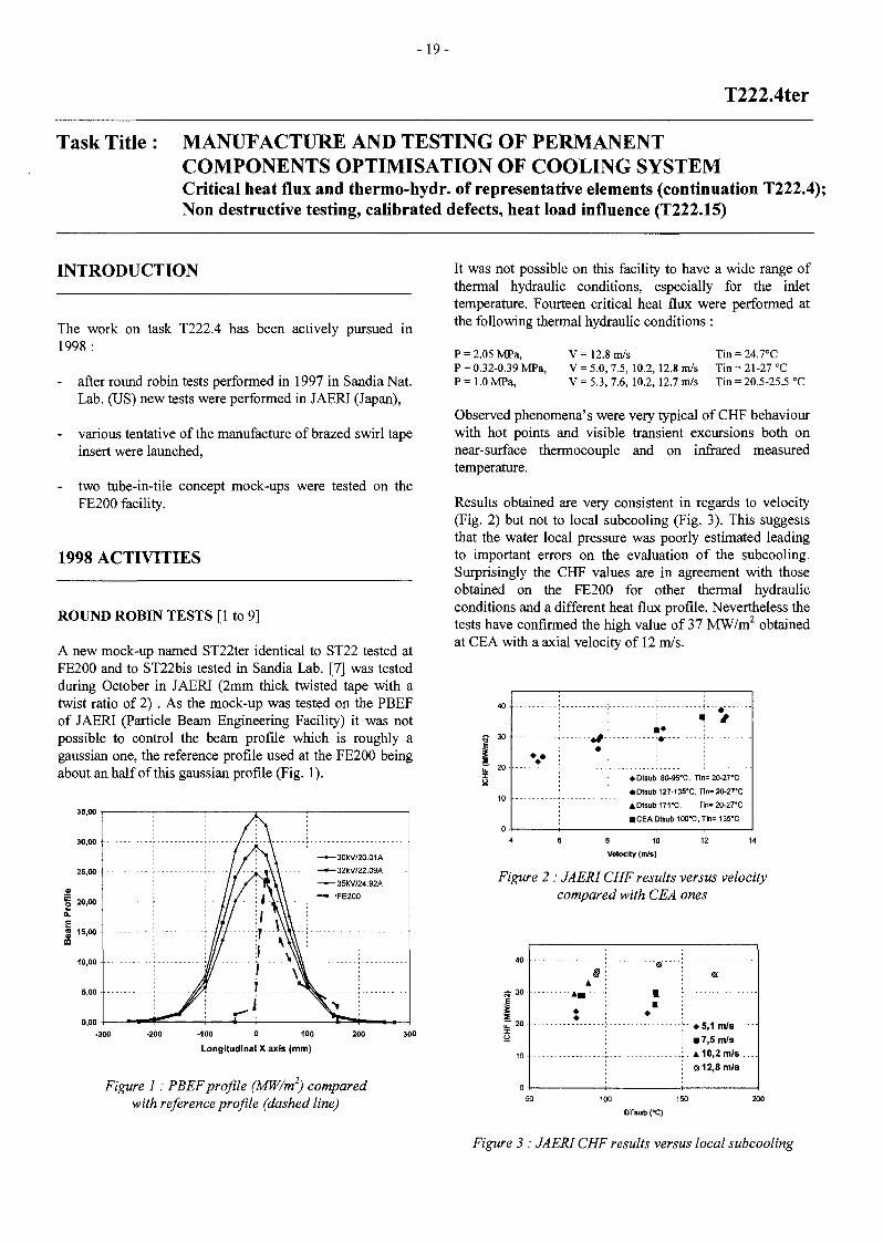
A new mock-up named ST22ter identical to ST22 tested atFE200 and to ST22bis tested in Sandia Lab. [7] was testedduring October in JAERI (2mm thick twisted tape with atwist ratio of 2) . As the mock-up was tested on the PBEFof JAERI (Particle Beam Engineering Facility) it was notpossible to control the beam profile which is roughly agaussian one, the reference profile used at the FE200 beingabout an half of this gaussian profile (Fig. 1).
35,00
-100 0 100
Longitudinal X axis (mm)
Figure 1 : PBEF profile (MW/m2) comparedwith reference profile (dashed line)
It was not possible on this facility to have a wide range ofthermal hydraulic conditions, especially for the inlettemperature. Fourteen critical heat flux were performed atthe following thermal hydraulic conditions :
P = 2.05 MPa,
P = 0.32-0.39 MPa,
P= 1.0 MPa,
V= 12.8 m/s
V = 5.0, 7.5, 10.2, 12.8 m/s
V = 5.3, 7.6, 10.2, 12.7 m/s
Tin = 24.7°C
Tin = 21-27 °C
Tin = 20.5-25.5 °C
Observed phenomena's were very typical of CHF behaviourwith hot points and visible transient excursions both onnear-surface thermocouple and on infrared measuredtemperature.
Results obtained are very consistent in regards to velocity(Fig. 2) but not to local subcooling (Fig. 3). This suggeststhat the water local pressure was poorly estimated leadingto important errors on the evaluation of the subcooling.Surprisingly the CHF values are in agreement with thoseobtained on the FE200 for other thermal hydraulicconditions and a different heat flux profile. Nevertheless thetests have confirmed the high value of 37 MW/m2 obtainedat CEA with a axial velocity of 12 m/s.
5Î 30• •
• Dtsub 80-95X, Tin=20-27"C
• Otsub 127-135'C, Tln= 20-27'C
ADtsub17VC. Tln-aWTC
• CEA Dtsub 100-0, Tln= 135'C
8 10 12
Velocity (m/s)
Figure 2 : JAERI CHF results versus velocitycompared with CEA ones
jr 20 'y ^5,1 m/s
• 7,5 m/s
A 10,2 m/s .
•:< 12,8 m/s
100 150
DTsub CC)
Figure 3 : JAERI CHF results versus local subcooling

- 2 0 -
BRAZING OF A THICK SWIRL TAPE [10]
After the difficulties encountered with the first selectedmanufacturer who resigned after some tries, a new call fortender was launched grouping together the swirl tapespecific manufacturing and the brazing.
The problem was found too critical by the industry and theasked prices were not compatible with CEA budget. Thestudy will be pursued in 1999 in Tore Supra laboratory.
4 8 12 16 20EHFCMW/m2)
Figure 4 : Screening test on the Prodivl Prototypicalmock-up; comparison between tests (points)
and FE calculations (lines) on a without-defect zone
PROTOTYPICAL MOCK-UP : THERMAL FATIGUETESTING [11 to 15]
A prototypical mock-up made of 22 monoblock tiles wasreceived in December 1997 and prepared for tests on theFE200 in January 1998. The component was screened (Fig.4 and 6) and thermal fatigue tested in the FE200 electronbeam facility. A thousand cycles at about 20 MW/m2 wereperformed over an heated length of 110 mm (Fig. 5).Although defects were visible at the beginning (Fig. 6 left)and propagated slowly during the 1000 cycles (Fig. 6 right)the mock-up sustained well the fatigue cycling.
Figure 5 : Surface temperature during the last cycle,after 1000 cycles at 20 MW/m2, 12m/s, 3.4 MPa,
140°C, shot 2047
Figure 6 : Screening test performed before (left, shot 2041) and after (right, shot 2048)the thermal fatigue testing, IHF = 11 MW/m2, 12m/s, 3.4 MPa, 140°C
Figure 7 : View ofPRODIV2 mock-up (tiles 16 to 27)before its installation on FE200 test bed
PROTOTYPICAL MOCK-UPS:FLUX TESTS [12 to 17]
CRITICAL HEAT
Two mock-ups were CHF tested during two campaigns:PRODIV1 and PRODIV2 (Fig. 7). This latter was builtfrom the non tested part of PRODIVl, after the water leakduring the first campaign, and was extensively tested on theinfrared test bed SATIR of CEA Cadarache; some defectswere visible and well correlated with the screening duringFE200 testing (Fig. 8).

- 2 1 -
Tàble 1 : Interpolated CHF results (3.5 MPa, ATsub,out=100°C, V=12m/s, ID = 10 mm)
TwistRatio
ICHF(MW/m2)
flat | peaked
Pressuredrop
(MPa/m)
-22-30
0.61
Pumpingpower
(W/m)
428
27 26 25 24 23 22 21 20 19 18 17
Figure 8 : Comparison between SATIR testingand 11 MW/m2 FE200 screening for PRODIV2
For these mock-ups it was not possible to detect the CHF bylooking at the infrared (IR) camera screen so that each timethe mock-up was damaged up to the water leak. The IRimages of the surfaces just before water leak are givenFig. 9 and 10.
1030
Figure 9 : IR image of a flat profile at 21 MW/m2
onPRODWl mock-up, Shot 2049, 100 mm, 47 kW
Tile 20
Figure 10 : IR image with a peaked reference profileat 29 MW/m2 on PRODIV2 mock-up, Shot 2094, 45 kW
The low CHF values (Table 1) are attributed to defects atthe bond between CFC and Cu layer or between this layerand the Glidcop tube. A limit at 22MW/m2 was found undera flat profile whereas 27 MW/m2 was expected after testson Glidcop mock-ups; under peaked profile the limit was30MW/m2, the lowest value of the range 30-37 MW/m2
expected. However the problem of CHF is a stability oneand the low thickness of copper in the tube-in-tile concept(0.5 mm of copper and 1 mm of Glidcop) could also explaina trend to decrease the CHF. FE calculations show a goodcorrespondence, in terms of wall heat flux distribution,between Glidcop blocks and tube-in-tile concept, so that theCHF decrease cannot be attributed to that. The temperatureprofile under peaked heat flux given by the IR image isinfluenced by the IR camera resolution (about 5 mmcompared with the 23 mm mock-up width). After CHFtests, an examination of PRODIVl was undertaken. A crosssection of tile 12 showed that the CHF occur on the middleof the tile at the place where swirl tape is perpendicular tothe heated surface (Fig. 11 and 12). It is clear that at CHFthe copper was molten and drew up by the porous CFC(Fig. 13).
Figure 11 : Destructive examination of tile 12 after CHF,cross section AA near the middle of the tile
Figure 12 : Destructive examination of tile 12 after CHF,cross section BB on the side of tile 12
- 2 2 -
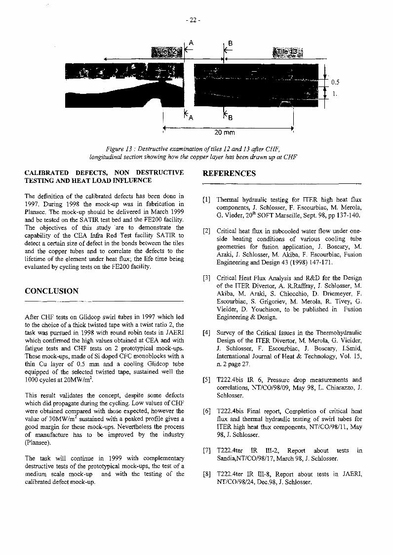
20 mm
Figure 13 : Destructive examination of tiles 12 and 13 after CHF,longitudinal section showing how the copper layer has been drawn up at CHF
CALIBRATED DEFECTS, NON DESTRUCTIVETESTING AND HEAT LOAD INFLUENCE
The definition of the calibrated defects has been done in1997. During 1998 the mock-up was in fabrication inPlansee. The mock-up should be delivered in March 1999and be tested on the SATIR test bed and the FE200 facility.The objectives of this study are to demonstrate thecapability of the CEA Infra Red Test facility SATIR todetect a certain size of defect in the bonds between the tilesand the copper tubes and to correlate the defects to thelifetime of the element under heat flux; the life time beingevaluated by cycling tests on the FE200 facility.
CONCLUSION
After CHF tests on Glidcop swirl tubes in 1997 which ledto the choice of a thick twisted tape with a twist ratio 2, thetask was pursued in 1998 with round robin tests in JAERIwhich confirmed the high values obtained at CEA and withfatigue tests and CHF tests on 2 prototypical mock-ups.These mock-ups, made of Si doped CFC monoblocks with athin Cu layer of 0.5 mm and a cooling Glidcop tubeequipped of the selected twisted tape, sustained well the1000 cycles at 20MW/m2.
This result validates the concept, despite some defectswhich did propagate during the cycling. Low values of CHFwere obtained compared with those expected, however thevalue of 30MW/m2 sustained with a peaked profile gives agood margin for these mock-ups. Nevertheless the processof manufacture has to be improved by the industry(Plansee).
The task will continue in 1999 with complementarydestructive tests of the prototypical mock-ups, the test of amedium scale mock-up and with the testing of thecalibrated defect mock-up.
REFERENCES
[1] Thermal hydraulic testing for ITER high heat fluxcomponents, J. Schlosser, F. Escourbiac, M. Merola,G. Vieder, 20th SOFT Marseille, Sept. 98, pp 137-140.
[2] Critical heat flux in subcooled water flow under one-side heating conditions of various cooling tubegeometries for fusion application, J. Boscary, M.Araki, J. Schlosser, M. Akiba, F. Escourbiac, FusionEngineering and Design 43 (1998) 147-171.
[3] Critical Heat Flux Analysis and R&D for the Designof the ITER Divertor, A. R.Raffray, J. Schlosser, M.Akiba, M. Araki, S. Chiocchio, D. Driemeyer, F.Escourbiac, S. Grigoriev, M. Merola, R. Tivey, G.Vieider, D. Youchison, to be published in FusionEngineering & Design.
[4] Survey of the Critical Issues in the ThermohydraulicDesign of the ITER Divertor, M. Merola, G. Vieider,J. Schlosser, F. Escourbiac, J. Boscary, I.Smid,International Journal of Heat & Technology, Vol. 15,n. 2 page 27.
[5] T222.4bis IR 6, Pressure drop measurements andcorrelations, NT/CO/98/09, May 98, L. Chiarazzo, J.Schlosser.
[6] T222.4bis Final report, Completion of critical heatflux and thermal hydraulic testing of swirl tubes forITER high heat flux components, NT/CO/98/11, May98, J. Schlosser.
[7] T222.4ter IR III-2, Report about testsSandia,NT/CO/98/17, March 98, J. Schlosser.
in
[8] T222.4ter IR III-8, Report about tests in JAERI,NT/CO/98/24, Dec.98, J. Schlosser.

- 2 3 -
[9] T222.4ter IR III-9, A study of the heat transfercorrelation for subcooled water under one-side highheat flux, NT/CO/98/25, Dec. 98, E. Rabaglino, J.Schlosser.
TASK LEADER
[10] T222.4ter IR III-6, Brazed tubesNT/CO/98/21, Dec. 98, J. Schlosser.
Milestones,
[11] High heat flux testing of a prototypical divertorcomponent, MMerola F.Escourbiac, L.PLochl,R.Raffray, J.Schlosser, I.Smid, R.Vesprini, G.Vieder,20th SOFT Marseille, Sept. 98, pp 189-192.
[12] T222.4ter PR III-3, Review of fatigue and critical heatflux testing on prototypical divertor mock-upPRODIVl, NT/CO/98/03, March 98, J. Schlosser.
[13] Report FRAMATOME, T222.4 : fatigue and criticalheat flux testing on prototypical divertor mock-upPRODIV1-DIV5 (CEA 60), MC/TS 97.832 A,March 98, M. Diotalevi.
[14] T222.4ter IR III-4, Review of critical heat flux testingon prototypical divertor mock-up PRODIV2,NT/CO/98/15, June 98, J. Schlosser.
[15] Report FRAMATOME, T222.4 : critical heat fluxtests on prototypical divertor mock-up PRODIV2(CEA 64), MC/TS R98.839 A, April 98, M.Diotalevi
J. SCHLOSSER
DSM/DRFC/SIPPCEA Cadarache13108 St Paul Lez Durance Cedex
Tél. : 33 4 42 25 25 44Fax. : 33 4 42 25 49 90
E-mail : [email protected]
[16] T222.4ter IR III-5, Metallographic examination of theprototypical divertor component PRODIV1,NT/CO/98/22, Dec. 98, J. Schlosser.
[17] T222.4ter IR III-7, CHF tests on CFC prototypicalmock-ups for ITER divertor vertical target,NT/CO/98/23, Dec. 98, J. Schlosser.
[18] T222.4ter IR IV-1, Definition and location ofcalibrated defects for monoblock type mock-ups,NT/CO/98/16, Oct. 98, J. Schlosser.

- 2 5 -
CNET 98-473
Task Title : ITER REFERENCE BREEDING BLANKET DESIGN (STAGE 2) :SAFETY ANALYSIS
INTRODUCTION
As a contribution to Non-site Specific Safety Report ofITER (NSSR2), Loss Of Coolant Accidents inside abreeding blanket module (so called in box LOCA) have tobe analysed. The main acceptance criteria for this safetyanalysis is to limit the hydrogen production (caused byoxydation of Be with steam) to lower than 10 kg .
1998 ACTIVITIES
A schematic drawing of half a module of the ITERreference breeding blanket design is presented in fig. 1.The cells of the module contain the breeder rods which aresurrounded by a binary beryllium pebble bed. The pebbleswith diameters of 2 mm and 0.1 to 0.2 mm are needed asneutron multiplier. The free volume of the module is filledwith helium which flows in the breeder rods and throughthe Be (multiplier) to the He purge gas lines.
The postulated accidents are a leakage of one pipe (fromthe FW cooling channels or from the lateral cooling plates)discharging water coolant into the module.
The in-box LOCA consequences are a pressurisation of themodule and possibly a leakage of the module into thevacuum vessel (In vessel LOCA).
[nkt manifold 'BackplareCooling manifold
Figure 1
A strongly exothermic chemical reaction (Be + H2O -->BeO + H2 -370 kJ/mol) occurs between the hot Be andthe water and steam of the cooling loop.
The reaction rate is a function of the steam pressure(maximum pressure dependency factor for a steam pressureof 6 bar) and of the temperature of the beryllium (seefig-2).
Figure 2
METHODOLOGY AND CODES USED FOR THEANALYSIS
Three codes were used to perform this analysis :
- ATHENA [1] : Athena is a ID thermal hydraulic codewhich was used to calculate the characteristics of thefluid in the cooling loops and the characteristics of thefluid at the break (flow rate, void fraction,temperature).
The modélisation includes the breeding blanketmodules of the cooling loop up to the primary heattransfert system.
The characteristics of the fluid at the break (flow rate,temperature of the fluid and ratio between vapor flowrate and total flow rate) were given as boundaryconditions to Intra code.
The following results from Athena were used as inputdata for Ansys code :
* heat transfert coefficient between the fluid and theheat slabs,
* temperature of the fluid in the cooling channels.
- ANSYS [2] : Ansys is a general purpose 2D/3D FEMcode which was used to perform a 2-D thermal analysisto have the temperature distribution in the blanketinternals in normal condition and after a transient from

- 2 6 -
normal operation to fully developped Loss Of FlowAccident (LOFA) conditions. The output temperatureprofile was given to Intra code as an initial boundarycondition for LOCA analyses. The Ansys modélisationconsisted of a breeding blanket basic cell.
- INTRA [3] : Intra is a ID thermal hydraulic codewhich was used to calculate the pressure andtemperature in the module and the hydrogenproduction during an in box LOCA. Since Intra is aID code, we didn't put (as a conservative assumption)the lateral cooling plates in the modélisation of thebreeding blanket module.
RESULTS OF THE ANALYSIS
Three different scenarios have been studied :
- in box LOCA during normal operating conditions,
- in box LOCA following a Loss Of Flow Accident(LOFA) without active plasma shutdown,
- in box LOCA following an ex vessel LOCA withoutactive plasma shutdown.
For these scenarios, a single breeding blanket module ofthe cooling loop is affected by the in-box LOCA. The Hepurge gaz lines are isolated by a passive system when themodule pressure increases.
In-box LOCA
In case of in-box LOCA during normal operatingconditions, the module is assumed to sustain the pressureof the cooling loop (40 bar) since the temperature profile israther low. No plasma shutdown is assumed during thefirst minutes of the transient.
The Intra results showed a very low hydrogen generation(less than 1 g) because of the low temperature of theberyllium pebbles which doesn't allow a révélant Be/steamreaction.
LOFA + in box LOCA
To investigate the ultimate safety margins of the design aloss of flow in the coolant loop (LOFA) followed by an inbox LOCA has been analysed. The LOFA consequencesare an elevation of the coolant temperature up to thesaturation at 40 bar and a strong decrease of the heattransfert coefficient between the steel of the pipes and theemulsion (from 25000 W/m2/°C down to 1000w/m2/°C).
No active plasma shutdown is assumed after the pump trip(aggravating event). The passive disruption due to impurityinflux is assumed to occur once the Be temperature of thefirst wall (of the affected loop) reached 1150°C.
The subsequent disruption is assumed to cause a failure ofone cooling pipe of the breeding blanket module (in-boxLOCA).
The pressure in the box reached 10 bar within one second,then the failure of the box was assumed, and the pressureinside the module was kept constant (conservativeassumption to maximise H2 production). After an increaseof the Be pebble bed temperature (up to 740 °C) due to theheat coming from the hot steel of the first wall, the Be iscooled down by convection with the steam.
The hydrogen production reached 15 g for this referencecase, which is far below the safety limits of 10 kg.
Ex vessel LOCA + in box LOCA
In this case, an ex vessel LOCA was assumed as initiatingevent. The most important difference between the ex vesselLOCA and the LOFA is the decrease of the heat transfertcoefficient down to a lower value in the ex-vessel LOCAcase (from 25000 W/m2/°C down to 400W/m2/°C).
Therefore, the temperature profile in the breeding blanketat the moment of the in box LOCA is higher (maximum Bepebble bed temperature : 840°C between the first wall andthe first breeder rod).
The INTRA results showed that the temperature of thehottest Be pebble bed heat slab was high enough to cause arévélant chemical reaction, so the increase of the Betemperature is linear with the flow rate crossing themodule.
A diverging reaction occurs, and the hydrogen productionis only limited by the steam flow rate crossing the module.In this case, the safety criteria of 10 kg of H2 is exceeded.
CONCLUSIONS
Theses analysis showed that the most severe accidents of inbox LOCA in cat V can lead to an hydrogen inventory overthe safety limit of 10 kg.
A flow blocage in one breeding blanket module would alsobe a very severe initiating event because the disruptionwould occurs when the temperature of the first wall tile hasreached a higher level (1300°C instead of 1150°C becauseof the smaller area affected by the accident).
Further analysis are needed to show that a propagation ofan in box LOCA to adjacent blanket modules can beexcluded.

-27-
REFERENCES
[1] ATHENA: RELAP5/MOD3 Code Manual (User'sGuide and and Input Requirements)
[2] ANSYS : ANSYS 5.2 Code Manual
[3] INTRA : INTRA documentation ES-97 (may 97)
TASK LEADERS
Xavier MASSON
TECHNICATOMEBP 3400013791 Aix-en-Provence Cedex 3
Tél. : 33 4 42 60 28 61Fax : 33 4 42 60 25 11
E-mail : [email protected]
Gabriel MARBACH
DRN/DER/SERSICEA Cadarache13108 St Paul Lez Durance Cedex
Tél. : 33 4 42 25 34 14Fax : 33 4 42 25 65 08
E-mail : [email protected]
- 2 9 -
CNET 98-474
Task Title: ITER REFERENCE BREEDING BLANKET DESIGN :THERMO-MECHANICAL AND PEBBLE-BED ANALYSES ANDBREEDER MATERIAL ASSESSMENT
INTRODUCTION The first two activities have been performed atDMT/SERMA, the third one at CEREM7CE2M.
The Breeding Blanket for ITER is designed to breed thenecessary tritium for ITER operation during the EnhancedPerformance Phase (EPP). It replaces the ShieldingBlanket (SB) and the upper baffle modules of the BasicPerformance Phase (BPP).
The BB design was submitted to various technical andprogrammatic constraints. The main ones are thefollowing: i) the module geometry, coolant parameters,structural material and attachment system have to beidentical to those of the SB ; in particular, the design hasto accommodate the presence of 8 holes in the FW, whichwould be unacceptable for DEMO breeding blankets;ii) the design has to maximise the benefit from R&Defforts required to develop DEMO blankets, in order tominimise the need of additional ITER-specific R&D;iii) maximise the benefit derived from the ITER blanketoperation to DEMO blanket activity, which, in particular,means the use of ceramic breeder and Be pebbles.Moreover, the ceramic breeder has to be one the ceramicbreeder candidates for DEMO blankets (e.g., Li-zirconate,Li-titanate, and Li-silicate).
The reference ITER BB concept was selected at the end of1997 and corresponds to the one proposed the EU HT [A].It is recalled that the main design parameters are the sameas for SB; the concept is based on the use of Li-zirconateand Be pebble-beds and of flat radial-poloidal coolingplates. Enriched Li (90% in 6Li) is used to enhance theTBR. Contrary to the SB, the 5 mm-thick Be-tiles aredirectly attached to the 316L(N)-IG steel FW. Thebreeding zone has a poloidal coolant flow in radial-poloidal coolant panels. These panels are also used toreinforce the blanket module structure in addition to thecooling function. A poloidal bundle of breeder rods islocated between each pair of adjacent coolant panels. Eachbreeder rod consists of a steel tube with the breeder rodsand the panels and the module structure. The breeder andthe Be are purged with Helium flowing through the pebblebeds. The breeder rods bundle has two supporting tubeplates at the poloidal ends which supply and collect theHelium and a central spacing grid.
This contract includes the 1998 CEA contribution to theBB studies which includes the following activities:i) thermal and thermo-mechanical analyses of a samplemodule ; ii) evaluation of numerical tools for pebble-bedmechanical modeling ; and, iii) ceramic breeder materialsdata collection and assessment to be included in the ITERMaterial Property Handbook (MPH).
1998 ACTIVITIES
Hereafter are summarized the main results obtained duringthe year 1998 in the framework of this contract.
THERMAL ANALYSES [B]
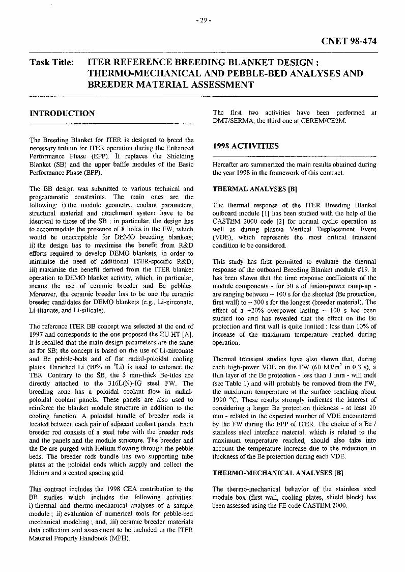
The thermal response of the ITER Breeding Blanketoutboard module [1] has been studied with the help of theCASTEM 2000 code [2] for normal cyclic operation aswell as during plasma Vertical Displacement Event(VDE), which represents the most critical transientcondition to be considered.
This study has first permitted to evaluate the thermalresponse of the outboard Breeding Blanket module #19. Ithas been shown that the time response coefficients of themodule components - for 50 s of fusion-power ramp-up -are ranging between ~ 100 s for the shortest (Be protection,first wall) to ~ 300 s for the longest (breeder material). Theeffect of a +20% overpower lasting ~ 100 s has beenstudied too and has revealed that the effect on the Beprotection and first wall is quite limited : less than 10% ofincrease of the maximum temperature reached duringoperation.
Thermal transient studies have also shown that, duringeach high-power VDE on the FW (60 MJ/m2 in 0.3 s), athin layer of the Be protection - less than 1 mm - will melt(see Table 1) and will probably be removed from the FW,the maximum temperature at the surface reaching about1990 °C. These results strongly indicates the interest ofconsidering a larger Be protection thickness - at least 10mm - related to the expected number of VDE encounteredby the FW during the EPP of ITER. The choice of a Be /stainless steel interface material, which is related to themaximum temperature reached, should also take intoaccount the temperature increase due to the reduction inthickness of the Be protection during each VDE.
THERMO-MECHANICAL ANALYSES [B]
The thermo-mechanical behavior of the stainless steelmodule box (first wall, cooling plates, shield block) hasbeen assessed using the FE code CASTEM 2000.

- 3 0 -
Table 1 : Thermal results for a slow high-power VDE in the first wall (60 MJ/m2 in 0.3 s)with different Be protection thickness
T max Be tile (°C)
Be tile thickness > T melting (mm)
T max Be/SS interface (°C)
T max FW channel wall (°C)
FWwith 10 mmBe protection
1991
0.6
493
219
F W with 13 mmBe armour
1991
0.6
438
208
FWwith 18 mmBe armour
1991
0.6
380
196
: . is
•i'..
2 . OOC-tOÎ
O.ITE-tOS
4.SUEIUÏ
Figure 1 : Von Mises thermal stress (MPa) distribution at steady state under 100% nuclear heating(Finc = 0.5 MW/m2, NWL = 1.25 MW/m2). Zoom on the side part of the module
Transient calculations during normal cyclic operation havebeen performed on a cross section of an outboard module inorder to evaluate the stress level in regions which have notbeen explored yet (side walls, shield block) and to assessthe effect of the global deformation of the module on localstress level. The calculated stress levels in the current partof the first wall and cooling plates (far away from sidewalls) are in good agreement with previous localcalculations. But, this study has shown clearly the need todefine detailed design of the cooling circuit in shield block,side walls and at the front corner of the stainless steelmodule box. The thermal stress level in those regions areindeed often very high (see Figure 1, max. -495 MPa) andcould be minimized with appropriate design of the coolingcircuits.
Some preliminary local thermo-mechanical calculations onthe Be tile / First Wall bonding have been also performed inorder to evaluate the size effect of a poloidal castellation. Apreliminary 2D local calculation on the first wall shows thata smaller size of Be tiles obtained by poloidal castellationgoes in the sense of a reduction of the stress level in the firstwall. This effect should be higher with both poloidal andtoroidal castellations which could be analyzed in furthercalculation with a local 3D model. An optimization of thesize of the tiles should be done too on the basis of aparametric study, taking also into account a possiblecompliant interlayer material.

- 3 1 -
EVALUATION OF NUMERICAL TOOLS FORPEBBLE-BED MECHANICAL MODELING [B]
Under operation the ITER Breeding Blanket Be pebble bedwill tend to expand more than the stainless steelsurrounding structures and will then be compressedleading to a possible internal rearrangement.Heterogeneous temperature internal distribution in the bedmay also contribute to this rearrangement. The designrequirements are to understand and evaluate the behaviourof the bed and surrounding structures with regard tomechanical criteria. Two numerical approaches have beenevaluated for their capability to modelise typical fusionblanket problems.
The first one is based on the use of a Discrete ElementMethod (DEM) which, starting from the mechanicalinteraction of each pebble with the surrounding pebbles orstructures, permits to determine a macroscopic behaviourof the pebble bed. The DEM approach appears interestingas it gives at each time step, the local void fraction andcontact forces between particles. The deformation ofparticles should also be taken into account, but aDEM/FEM coupling appears to be too costly for a largenumber of particles. To preliminary simulate the plasticityof the particles, a numerical artefact such as the use of athreshold in the reaction force between particles could beanyway envisaged in a simple DEM approach. The DEMapproach has also appeared practically limited to themodélisation of large pebbles, the small pebblesoverreaching the million even in thin test cross sections.The thermal loading and irradiation-induced swellingcould be easily simulated in the DEM approach by anincrement of reaction force between particles. It should benoted also that the dynamic aspect of the DEM approachmay also constitute an advantage for blanket pebble bedsimulation.
The second approach consists in describing the pebble bedas a continuous homogenised medium through a FiniteElement Model (FEM). Based on soil mechanics, a FEmodel derived from the Cam-Clay model has beenimplemented in CASTEM 2000 and qualified.Experimental campaigns have demonstrated that thismodel gives good results for predicting round shape pebblebeds behaviour. They have also permitted to obtain rangesfor the setting parameters. This approach could beespecially interesting to modelise the overall stress level ofthe surrounding structures and evaluate the risk of localmechanical failure. Attention should be paid to the factthat the model has been developed and qualified on non-rigid compression test (large deformation of the overall testvolume), as the configuration of the blanket pebble bedsappears to be quite rigid (high packing factor and rigidwalls). Further work may consist in evaluating therelevance of the Hujeux model for a specific blanketconfiguration.
For both approaches, the modélisation of the initial state ofthe pebble bed appeared to be essential as it determines thebed capability for further internal rearrangement.
The need for a high initial Be bed packing factor achievedduring through vibro-compaction and a rigid containmentstructure may however limit the possibility of bedaccommodation under operation.
CERAMIC BREEDER MATERIALS DATACOLLECTION AND ASSESSMENT [C]
The properties data available within EU for optimisedLi4Si04, Li2Zr03 and Li2Ti03 ceramic breeder materialshave been compiled and assessed.
Compositions of the EU optimised ceramics are :
- 0.935 Li4Si04 + 0.065 SiO2 denoted Li/Si = 3.74- 0.95 Li2Zr03 + 0.05 ZrO2 denoted Li/Zr =1.9- 0.95 Li2Ti03 + 0.05 TiO2 denoted Li/Ti = 1.9
Following recommendations, the aim of this work was tocollect consistent sets of data. Therefore, single datumand/or single or discontinued materials were generally notincluded in the collection or the case was clearly indicated.
First priority was given to collecting pebble beds propertiesdata, and second priority to collecting properties data forbasic materials.
Data reported in the final report [4] related to :
1. Li4Si04 single bed of 0.25 mm - 0.63 mm pebbles(Melt/Spray) ;
2. Li2Zr03 single beds of -1.2 mm pebbles (Extrusion)and of 0.1-0.3 mm pebbles (Atomisation) ;
3. Li2Ti03 single beds of ~ 1.2 mm pebbles (Extrusion)and of ~1 mm pebbles (Agglomeration) ;
4. Li2Zr03 basic material ;5. Li2Ti03 basic material
Typical included data, besides the basic physical propertiesof pebbles and basic material, are for instance (whenavailable) information on fabrication, microstructure,compatibility with steel, interaction with Hydrogen andwater, tritium residence time, and partial pressure ofLithium species.
Including also the LiO2 among possible candidatematerials, it has been noticed that available data bases ofpebble beds of the four ceramics are uneven, mainlybecause some of them (e.g., ) were considered onlyrecently. Focus has therefore to be placed on R&Dprograms for data base completion before being capable ofa sound evaluation of the four candidates, and, thereby, asound selection. In particular, key issues, such asirradiation behaviour of pebble beds up to end-of-lifelithium burn-ups, and the thermo-mechanical behaviourunder representative blanket conditions are presently beingaddressed. The performed assessment has been included inthe ITER Material Assessment Report as chapter 5.2corresponding to Breeder Materials.

- 3 2 -
CONCLUSIONS TASK LEADER
The calculated stress levels in the current part of the BB-module FW and cooling plates (far away from the sidewall) are in good agreement with previous localcalculations and are acceptable. On the contrary, this studyhas clearly shown the need to improve the design of thecooling circuit in shield block, side walls and at the frontcorner of the SS-module box. The thermal stresses in theseregions are indeed often very high and could be reducedwith more appropriate cooling circuit design. The interestof having small Be-tiles (castellation) has also been clearlydemonstrated.
Concerning the modélisation of the pebble beds formechanical evaluations, the major conclusion is that forboth approaches, DEM and FEM, the modélisation of theinitial state of the pebble beds (which is at present a majorunknown) is essential as it determines the bed capabilityfor further internal rearrangements. Both methods aretherefore promising but, at present, unsatisfactory.
Data base for making a sound selection of the ceramicbreeder material for the ITER BB pebble beds are stilluncompleted although at different degrees for the differentcandidates. However, an extensive effort is under way totest and compare the behavior of pebble beds of the fourcandidate ceramics, both out-of-pile and in-pile, underblanket representative conditions. In parallel, large-scalefabrication issues of the as-optimized pebbles are beingaddressed.
L. GIANCARLI
DRN/DMT/SERMACEA Saclay91191 Gif-sur-Yvette Cedex
Tél. : 33 169 08 21 37Fax : 33 1 69 08 99 35
E-mail : [email protected]
REFERENCES
[1] ITER Design Description Document, WBS1.6BTritium Breeding Blanket System, 1998.
[2] CASTEM 2000 code manual, CEA/Saclay DMT(1998).
PUBLICATIONS
[A] P. Magaud, F. Le Vaguères (eds.), FusionTechnology, 1997 Annual Report of the AssociationCEA/EURATOM, Task CNET 97-454, CEADSM/DRFC, May 1998.
[B] Y. Poitevin, L. Giancarli, Contribution to theReference Design of the ITER Breeding Blanket,CEA Internal Report, SERMA/LCA/RT/98-2463(1998).
[C] N. Roux, EU Contribution to the ITER MPH -Ceramic Breeder Materials, CEA Report,CEREM/CE2M/LECMA (1998).
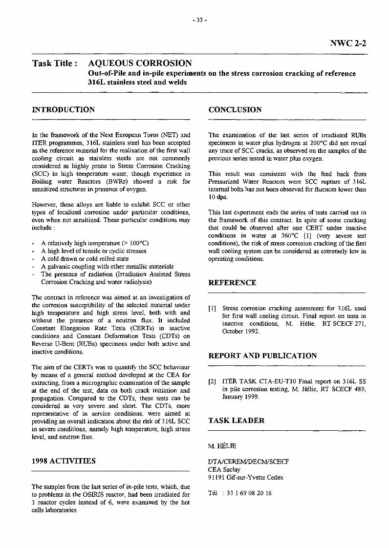
- 3 3 -
NWC2-2
Task Title : AQUEOUS CORROSIONOut-of-Pile and in-pile experiments on the stress corrosion cracking of reference316L stainless steel and welds
INTRODUCTION CONCLUSION
In the framework of the Next European Torus (NET) andITER programmes, 316L stainless steel has been acceptedas the reference material for the realisation of the first wallcooling circuit as stainless steels are not commonlyconsidered as highly prone to Stress Corrosion Cracking(SCC) in high temperature water, though experience inBoiling water Reactors (BWRs) showed a risk forsensitized structures in presence of oxygen.
However, these alloys are liable to exhibit SCC or othertypes of localized corrosion under particular conditions,even when not sensitized. These particular conditions mayinclude :
- A relatively high temperature (> 100°C)- A high level of tensile or cyclic stresses- A cold drawn or cold rolled state- A galvanic coupling with other metallic materials- The presence of radiation (Irradiation Assisted Stress
Corrosion Cracking and water radiolysis)
The contract in reference was aimed at an investigation ofthe corrosion susceptibility of the selected material underhigh temperature and high stress level, both with andwithout the presence of a neutron flux. It includedConstant Elongation Rate Tests (CERTs) in inactiveconditions and Constant Deformation Tests (CDTs) onReverse U-Bent (RUBs) specimens under both active andinactive conditions.
The aim of the CERTs was to quantify the SCC behaviourby means of a general method developed at the CEA forextracting, from a micrographie examination of the sampleat the end of the test, data on both crack initiation andpropagation. Compared to the CDTs, these tests can beconsidered as very severe and short. The CDTs, morerepresentative of in service conditions, were aimed atproviding an overall indication about the risk of 316L SCCin severe conditions, namely high temperature, high stresslevel, and neutron flux.
1998 ACTIVITIES
The samples from the last series of in-pile tests, which, dueto problems in the OSIRIS reactor, had been irradiated for3 reactor cycles instead of 6, were examined by the hotcells laboratories
The examination of the last series of irradiated RUBsspecimens in water plus hydrogen at 200°C did not revealany trace of SCC cracks, as observed on the samples of theprevious series tested in water plus oxygen.
This result was consistent with the feed back fromPressurized Water Reactors were SCC rupture of 316Linternal bolts has not been observed for fluences lower than10 dpa.
This last experiment ends the series of tests carried out inthe framework of this contract. In spite of some crackingthat could be observed after one CERT under inactiveconditions in water at 360°C [1] (very severe testconditions), the risk of stress corrosion cracking of the firstwall cooling system can be considered as extremely low inoperating conditions.
REFERENCE
[1] Stress corrosion cracking assessment for 316L usedfor first wall cooling circuit. Final report on tests ininactive conditions, M. Hélie, RTSCECF271,October 1992.
REPORT AND PUBLICATION
[2] ITER TASK CTA-EU-T10 Final report on 316L SSin pile corrosion testing, M. Hélie, RT SCECF 489,January 1999.
TASK LEADER
M HELIE
DTA/CEREM/DECM/SCECFCEA Saclay91191 Gif-sur-Yvette Cedex
Tél. : 33 1 69 08 20 16

- 3 5 -
T204-1
Task Title : ITER BACKPLATE MOCKUP PROJECTLASER CUTTING FOR REPAIR
INTRODUCTION The laser gas cutting using nitrogen assist couldn't achievea performance higher than 25 mm thick (figure 1).
This survey, as part of a research and development programis involved in the maintenance operation of fusion reactors.It consists in cutting defect part of reactor plasma chamberwith YAG laser. The chamber is composed of double platesof 60 mm thick each separated by 200 mm. The quality ofthe cuts have to be compatible with an ulterior weldingoperation, in order to replace the defect parts.
Thus, the objectives are to validate experimentally YAGlaser thick cutting with both pulsed and continuous waveYAG lasers, it includes the design and the manufacture ofthe high pressure cutting head , the improvement linked tothe gas flow outcoming of the nozzle and the cuttingparameters.
1998 ACTIVITIES
First of all, thick cutting trials have been implemented usingthe IQL pulsed YAG laser with the average output of 1.2kW.
200
-. 180c
I 160
Ê 140
1 120Q.
Dl 100
\\
\\
\
Parameters set N"1
>--
10 15 20
Plate thickness (mm)
25
Figure 1 : Correlation between the maximum cuttingspeed and the sheet steel thickness (Nitrogen assist
and set of pulsed parameters N°l, 1.2 kW mean power)
Meanwhile the cut quality was good with a kerf of 1 mmwidth (figure 2).
Thickness (mm) Cutting aspect Cross section shape
10
15
20
Figure 2 : Cut appearance of plate cutting with pulsed YAG laser and Nitrogen assist

- 3 6 -
The laser gas cutting using oxygen assist could perform abetter performance with a cut quality better than the onedone with nitrogen (kerf of about 1 mm width), but thethickness reached was not higher than 50 mm with 1.2 kWmean power (table 1 and figure 3).
Table 1 : Pulsed parameter sets usedfor pulsed YAG laser cutting
Parameterset
N°l
N°2
pulseduration
(ms)
5
2
repetitionrate(Hz)
10
60
Energyper pulse
(J)
120
20
Maximumcut thickness
(mm)
50
25
» Parameters set N°2 —
• Pararn(
i
tore set N*1 —
20 30 40Plate thickness (mm/min)
So, whereas pulsed YAG laser couldn't provide an averagepower high enough to reach the 60 mm thick steel, acontinuous wave YAG laser source was required.
The feasibility of 60 mm thick cut by continuous waveYAG laser with the output of 4 kW has been carried out.These tests also allowed to define the future high pressurecutting head characteristics (30 bar). This high pressurecutting head used to remove the molten debris out of thekerf is shown below, (figures 4 and 5).
As aerodynamic conditions depend mainly on the shape ofthe nozzle, workpiece proximity and the kerf shape, aresearch is being done to improve the shape of the gas flowby modifying the nozzle internal shape and the kerf width.First trials have been implemented with different kind ofnozzle. The jet flow is visualised by strioscopy.Efforts are being made to decrease the diameter of the jetflow while increasing its length. But flow impinging onplates as well as flow propagation between two plates arealso being studied.
The figure 6 shows the jet outcoming of two differentnozzles, the left one is conical, the right one has beenimproved, it is a kind of convergent/divergent one.
The jet outcoming of the last one appears to be thinner andlonger. In results the first cutting trials have beenimplemented with this nozzle.
Figure 3 : Correlation between the maximum cutting speedand the sheet thickness with oxygen assist
for both sets of parameters (mean power 1.2 kW)
Collimation lensNozzle
Focusing lensight port
Workpiece
Figure 4 : Diagram of the high pressure cutting head
Figure 5 : Picture of the high pressure cutting head

- 3 7 -
Picture 1 Picture 2
Convergent/divergent nozzle exit
Figure 6 : Picture of the jet flow outcoming,. difference between a conical nozzle and a convergent/divergent one
The first cutting trials concern 20, 40 and 60 mm thickplates, they allow to estimate the maximum cutting speedcompared to this tisree different thicknesses (figure 7).
At a power of 4 kW on the plate, the thickness of 40 mmcan be easily cut with a cutting speed of about 80 mm/min.The cut appearance is shown on the figure 8.
On the other hand, the thickness of 60 mm can't beperformed with a cutting speed higher than 5 mm/min(figure 9).
20 40 60PLATE THICKNESS (mm)
Figure 7 : Correlation between the cutting speedand the plate thickness with nitrogen assistance
2001901801701S0150140130120110100908070605040302010
Thickness(mm)
Kerf shape Cut appearance
20
40
Figure 8 : Cut appearance of plates cut by CW YAG laser at a power of 4 kWwith nitrogen assistance

- 3 8 -
REPORT AND PULICATION
tmn/mm
8 mm/rnin
'•* I2mm/min
Dross
Figure 9 : Picture of the beginning of kerfs on the edgeof a 60 mm thick plate with 30 bar of nitrogen assistance
[1] C. Dupuy, J.P. Aifillé.. "ÏTER project : Thick cuttingevaluation using a 1.2 kW pulsed YAG laser inlaboratory conditions" . DPSACLFAW-NTOOS/JPAT204-1, March 99.
TASK LEADER
JP. ALFILLE
DTA/DPSA/CLFACEA Fontenay aux RosesBoîte Postale 692265 Fontenay aux Roses Cedex
Tél. : 33 142 3192 83Fax : 33142319747
CONCLUSION
These preliminary tests have provided some accurateinformation about thick cutting parameters.
Oar objectives are now to implement new trials to cut 60mm thick plates. The first step will be to optimise thecutting at a power of 4 kW, that means to enlarge the kerf totwo mm in order to make the removal molten easier, toimprove the internal shape of the nozzle to a kindsupersonic one and to change the inert gas to a mixture ofNitrogen and Oxygen.
The second step is to make trials with two lasers, one of 4kW the other of 2 kW, combine together in a new cuttinghead, to enhance the power to 6 kW on the workpiece.

- 3 9 -
T204-4
Task Title : ULTRASONIC INSPECTION FOR BACKPLATE INTER-SECTORWELD
INTRODUCTION
The vacuum vessel of ITER is a toroidal structure made upof several 316L stainless steel sectors of about 60 mmthickness. A project aiming to demonstrate the feasibilityof one sector is in progress. The next stage of the programis to develop both a suitable inter sector welding processand the related non destructive testing method.
As far as non destructive examination is concerned, theobjective of the study is to work out an ultrasonic testingmethod which can be applied industrially on the intersector welds during the vacuum vessel assembly. Thismethod is required to ensure both detection and sizing ofweld defects.
The main stages of the program are described below :
- Stage 1 : Development of US method on availablemock-ups.
- Stage 2 : Validation of the US method on realisticwelds.
- Stage 3 : Qualification of the US process onrealistic specimen.
The first stage has been addressed in 1998, the next twowill be addressed respectively in 1999 and 2000.
1998 ACTIVITIES
A recent detection and sizing US method based on aphased array probe and a multi-channels unit (FAUSTsystem) developed at the CEA/STA, has been used.Advantages of this new method are to considerablyincrease the capacity of the US process, both to detect andto fully characterise the flaws. This technique allows tosteer and focus the ultrasonic beam radiated by atransducer split into an array of individually addressedelements, according to specific delay and amplitude laws,supplied by a multi-channels acquisition system. Theresulting US parameters can then be fully optimised toensure the best performances of the control.
A field computational model developed at the CEA/STA isused to design tailored phased arrays dedicated to specificNDE configurations. Theoretical delay laws and relatedultrasonic fields can be computed through this model.
In addition, these computed delay laws can be fed as dataautomatically to the FAUST system. Several fields hasbeen computed. The calculation has been carried out inwide band mode, the focusing depths varying step by stepfrom 0 to over 120 mm (in order to take a reflection on thebackwall into account). In every case the main features ofthe acoustic beam (length, width, focusing depth, waveform duration ...) has been calculated in order to assess theexpectable defect size accuracy.
The tests has been carried out in two phases : the detectionphase and the characterisation phase.
- The detection phase was performed using the delay lawproducing the most suitable field for detection sake.This phase has been carried out through a beamreflection on the back wall so that to ensure a longerfield length, hence a better through wall detectionlikelihood. Detection tests were carried out using 45°shear waves at fixed focusing depth.
- For every detected flaw, the characterisation phase wasperformed by radiating a field whose focusing depthmatches that of the flaw. The focusing depth isoptimised so that to allow accurate sizing and locationof every detected flaw. At first, these experiments areperformed in immersion through an elliptical sectoredphased array transducer (80 mm diameter, 12 rings, 2Mhz). Then, further capabilities along with thedevelopment of a phased array contact probe will beexperimented within the following stages.
The specimen involved in the 1998 work is a 316Lstainless steel mock-up representative for the vacuumvessels both in terms of material and thickness (60 mm).
Even though the welding process is not yet known(electron beam welding, laser beam welding,...), it willprovide a narrow weld to ensure minimum welddistortions. Consequently, in first approximation the weldsides can be considered perpendicular to the componentwalls. Two sets of notches have been machined on bothsides of the mock up in order to simulate defectsperpendicular to the weld sides.
The field computation have shown that a delay law thatmakes the phased array probe focuse at 100 mm in depth issuitable to detect both sets of defects. The detection phasewas carried out successfully that way. For instance figure 1shows the detection results regarding the first set ofbreaking surface defects. In this case the detection methodrelies on the high amplitude of corner echoes seen afterbeam reflection on the back wall.
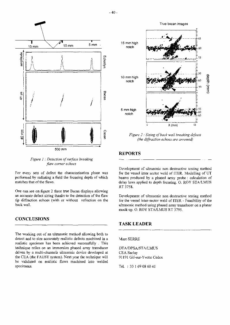
- 4 0 -
15 mm 10 mm 5 mm •
ia.
mo
I<
o(0
500 mm
Figure 1 : Detection of surface breakingflaw corner echoes
For every sets of defect the characterisation phase wasperformed by radiating a field the focusing depth of whichmatches that of the flaws.
One can see on figure 2 three true Bscan displays allowingan accurate defect sizing thanks to the detection of the flawtip diffraction echoes (with or without reflection on theback wall.
CONCLUSIONS
True bscan images
15 mm highnotch
10 mm highnotch
5 mm highnotch
X(mm) 93
Figure 2 : Sizing of back wall breaking defects(the diffraction echoes are arrowed)
REPORTS
Development of ultrasonic non destructive testing methodfor the vessel inter sector weld of ITER. Modelling of UTbeams produced by a phased array probe : calculation ofdelay laws applied to depth focusing. O. ROY STA/LMUSRT 3758.
Development of ultrasonic non destructive testing methodfor the vessel inter-sector weld of ITER - Feasibility of theultrasonic method using phased array transducer on a planarmock-up. O. ROY STA/LMUS RT 3795.
TASK LEADER
The working out of an ultrasonic method allowing both todetect and to size accurately realistic defects machined in arealistic specimen has been achieved successfully . Thistechnique relies on an immersion phased array transducerdriven by a multi-channels ultrasonic device developed atthe CEA (the FAUST system). Next year the technique willbe validated on realistic flaws machined into weldedspecimens.
Marc SERRE
DTA/DPSA/STA/LMUSCEA Saclay91191 Gif-sur-Yvette Cedex
Tél. : 33 1 69 08 60 41

-41 -
T216
Task Title : DEVELOPMENT OF A RELIABLE 316LN/DS-Cu/Be JOINT
INTRODUCTION
In the frame of the ITER project, beryllium is a candidatefor Plasma Facing Components. In the present design,beryllium is joined onto Dispersion Strengthening Cu alloy(DS-Cu) which is joined onto Stainless Steel 316LN.Beryllium-copper alloy junctions must withstand high in-service temperature of, at least, 300cC depending on thedesign of components. This working temperature may reachhigher temperature values during transient events. Thesedifferent materials are joined by Hot Isostatic PressingDiffusion Bonding (HIPB) which has been selected as thereference joining technique for ITER Primary First Wall[1-3].
The work performed during 1998 was focused on thedevelopment of 1) high temperature SS/DS-Cu joint and 2)Beryllium/DS-Cu joint with aluminium base alloyinterlayers and titanium base alloy interlayers. Mock-upswith these two different technologies have been fabricatedand delivered for irradiation purpose. Different diffusionbarriers have been proposed in order to avoid reaction withthe materials to be joined and then make easier the removalof the canister after the HIPB process.
1998 ACTIVITIES
DEVELOPMENT OF HIGH TEMPERATURESS/DS-CU JOINT
This development was focused on the fabrication andcharacterisation of two Glidcop® grade IGO and IG1 joinedonto 316LN by HIPB at 1050°C. For both grades theinterface is clean without segregations and defects. Someprecipitates are observed along the joint in the copper. Thethickness of the Zone Affected by the Diffusion (ZAD) isabout 80um, mainly located in the Glidcop®. The thicknessof this interdiffusion zone is twice the one observed forjoint performed at 920°C. No significant differences areobserved between the 2 joints. Figure 1 reports tensile testat 300°C for these two grades joined onto 316LN.
The rupture occurs always in the Glidcop® after striction at20 and 300°C. The yield and ultimate stresses of theIG1/316LN joint are lower than IG0/316LN joint.
Grain growth and modification of the extruded Glidcop®structure are changed by heat-treatments above 1060°C.Figure 2 shows that there is a hardness decrease associatedto these changes.
It has been concluded that a maximum temperature of1050°C is recommended. Taken into account an incertitudeof 10°C on temperature measurements, a nominal value of1040°C should be chosen.
IGO-junctlon 1050"C
IGl-junction 1050°C
True strain (%)
0% 1% 2% 3% 4% 5% 6% 7% 9% 10%
Figure 1 : Tensile curve at 300°C
140
130
! 1 2 0
block 19 * I
900 920 940 960 980 [000 1020 1040 1060 1080
temperature
Figure 2 : Hardness as a function ofT°.
DEVELOPMENT OF Be/DS-Cu JOINT
Interlayer for low temperature application
Aluminium base alloys with various thickness were used asinterlayer. Diffusion barrier was used in order to avoid largedissolution of aluminium into copper. It has been shownthat the diffusion barrier must be sputtered onto copperinstead onto the aluminium foil for a good joining.Aluminium diffuses through cracks that are present withinthe diffusion barrier but this is not deleterious to theadhesion at the interface the maximum size is severalmicrons. The addition of magnesium to aluminium or theuse of aluminium alloy such as 6061 don't improve thestrength of the joint.

- 4 2 -
Interlayer for high temperature application
A complete description of the Be S65C/DS-Cu jointstructure is given in [4] for 3 different titanium baseinterlayers. The interdiffusion at the Be/Ti and Cu/Ti isreduced by the addition of vanadium-aluminium or onlyaluminium : The thickness of the intermetallics at theinterface has been divided by two, thus, the mechanicalresistance should have been improved.
Moreover, different potential candidates for diffusionbarrier to be placed between the canister and the parts to bejoined have been proposed. The idea is to avoid reactionbetween the canister and the parts so the joined parts maybe extracted easily. Even 2 or 3 materials can be used asdiffusion barrier, it is not sure that the parts can be removedeasily because the canister is pressed against the internalmaterials during the HIPB process [4] and adhesion mayhave occurred. Thus, machining of the canister may benecessary.
Up to now the HIPB temperature was chosen between 820and 850°C, this study was dedicated to the study ofdifferent HIPB temperature and pressure using threedifferent titanium base alloys and pure titanium asreference. The titanium base alloys were designed in orderto decrease the process temperature and to create a lessabrupt interdiffusion profile on the beryllium side.
MOCK-UPS FABRICATION
Mock-ups have been fabricated for irradiation purposes : 3with aluminium interlayer and 3 with titanium one [1-3].Figure 3 shows some of the mock-ups. The different stepsof the fabrication may be described as in the following as :
- electromachining of the beryllium substrate, the surfaceto be joined are perpendicular to the pressing directionfor beryllium powder compaction (longitudinaldirection),
electromachining of the DS-Cu substrate,
- degassing of the DS-Cu under vacuum at hightemperature,
- placement of the interlayer between the beryllium andthe DS-Cu,
- surface preparation of DS-Cu, Al, and Be,
- stacking in the canister previously equipped withoutgassing tubes,
EB welding of the canister,
- cleaning of the atmosphere and degassing of the canisterusing argon flow,
- sealing of the outgassing tubes.
Figure 3 : 3 mock-ups (length of the tube : 76 mm)
CONCLUSIONS
The main conclusions are the following :
1) Fabrication, the microstructural and mechanicalcharacterisation of stainless-steel/DS-Cu joints. Jointswith IGO and IG1 were HIPped at 1050°C and 140MPafor 2 hours : the yield and ultimate stresses forIG1/316LN joint are lower than IGO/316 LN SS,probably due to an actual HIP temperature higher than1050°C. The evolution of the IG1 hardness is presentedas a function of temperature.
2) Fabrication of 6 mock-ups : 3 mock-ups with titaniuminterlayer and 3 with aluminium one have beenfabricated. The different steps of the fabrication havebeen defined.
3) Development of joining technology : low and hightemperature solutions based respectively on aluminiumand titanium interlayer have been tested. The differenttitanium base alloys were chosen in order to decreasethe process temperature. Three different Ti base alloyshave been fabricated and the container with the differentjunction Be/DS-Cu have been HIPped.
Moreover, we have performed different experiences inorder to have an idea of the vacuum level in thecontainer during the degassing within the Electron Beammachine and after the welding of the containers. Wehave also designed an experiment for the cleaning anddegassing of the containers with various atmospheresbefore the welding: a better vacuum quality is reachedwhen a cleaning of the atmosphere is performed withinert gas. The vacuum level in dynamic condition(measurement during pumping) is about 10'5 mbar andin static condition (measurement with no pumping) iswithin the range 10"'-10"2 mbar.

- 4 3 -
PUBLICATIONS TASK LEADER
[1] F. Saint-Antonin, G. Bourgeois, Ph. Bucci, H. Burlet,"ITER task T216a. Development and characterisationof Be/Cu alloy HIP joint", Note Technique DEMN°80/97, 29 december 1997, CE A/Grenoble.
[2] F. Saint-Antonin, P. Bucci, D. Barberi, H. Burlet, A.Laillé, G. Le Marois, "Development of Be/Glidcop®joints obtained by Hot Isostatic Pressing diffusionBonding for high in-service temperature", 3rd
International Beryllium Workshop, 22-24 October1997, Mito (Japan).
[3] F. Saint-Antonin, D. Barberi, G. Le Marois, A.Laillé, "Development and characterisation ofBe/Glidcop® joints obtained by Hot Isostatic Pressingfor high temperature working conditions", ICFRM-8th, 27-31 October 1997, Sendaï (Japan).
[4] F. Saint-Antonin, P. Sire,"Completion of ITER TaskT216a : Development and characterisation of Be/Cualloy HIP joint", Milestone GB6 T216, Milestone 14CEA, Note Technique DEM N°02/99, 11 janvier1999.
François SAINT-ANTONIN
DTA/DEM/SGMCEA Grenoble17, rue des Martyrs38054 Grenoble Cedex 9
Tél. : 33 4 76 88 54 77Fax : 33 4 76 88 95 38
E-mail : saint-antonin(2>cea.fr

- 4 5 -
T216-1
Task Title : ATTACHMENT OF BLANKET MODULES TO THE BACK-PLATELaser process for cutting and welding of the hydraulic connections
INTRODUCTION 1998 ACTIVITIES
The aim of this study is to validate experimentally one ofthe basic aspects of the blanket modules assembly anddisassembly from the back-plate within the scope of theITER project.
The contribution of the CLFA team is to implement diecutting and welding of hydraulic connections between theblanket module and the back-plate by YAG laser.
The laser tools will access each pipe stub through a frontaccess hole of diameter 30 mm. Only the feasibility ofcutting and welding will be demonstrated during thiscontract.
The work program concerns, the design and manufactureof the cutting /welding laser tool. In a first stage,parametric cutting and welding tests will be carry out inthe CLFA laboratory.
Then during a second stage the YAG laser, thecutting/welding tool will be set on the Brasimone moke-upin order to validate the laser process.
\
For the cutting tool and the welding tool, the decision wasto combine in the same tool both the cutting and thewelding operations. The figure 1 shows a diagram of thecomplete tool.
The laser head optical part is composed of the fibre output,an optical system with two lenses (a collimating lens and afocusing lens) and a folding mirror to deflect the laserbeam by 90° towards the tube. For the tool centring (the tippart), an adjustable system takes place into the hole insidethe plug.
The only difference between the cutting and welding tool islocated near the interaction area (not represented on thedrawing). The picture 2 shows a complete view of the tooland the detail of the head tip.
A special nozzle is use to perform the cutting operation bymultiple strokes as it was achieved during the previouscontract(1). For the welding operation a cross-jet is set inorder to protect the folding mirror inside the laser tool.
c-c
Tool stand
Tube tocut/weld
Figure 1 : General diagram of the cutting/welding head

- 4 6 -
Figure 2 : Complete view of the cutting/welding head and detail of the tool tip
Surface bead profile
Reverse bead profile
Laser parameters :
- Welding speed : 150 mm/min- Cover gas (top) : Argon (301/min)• Cover gas (back) : Argon (201/min)
- Power on sample : 900 W- Pulse duration : 4 ms
- Repetition rate : 40 Hz
Cross section of weld bead
Figure 3 : Aspects of the weld bead of a 3 mm thick plane plate welded by pulsed YAG laser

- 4 7 -
The assembling of the orbital tool as well as the first trialsof beam introduction in the cutting/welding head havebeen achieved at the end of the year 98. The remote controlof the rotating head is driven by a computer using theLABVIEW software. It enables to achieve cutting cycle bymultiple strokes as well as welding cycle.
First welding tests were carried out on plane plates(thicknesses of 3 and 4 mm) in order to determine thepulsed parameters before beginning the welding tests withthe orbital tool.
These tests were performed with a local cover gas of argonon both sides of the plates. At a mean power of 900 W theresults of the welding trials are:
- For 3 mm thick plates, the welding speed is 150 mm/min,- For 4 mm thick plates, the welding speed is 75 mm/min.
But some tests were also carried out with two differentplates thicknesses (3 and 4 mm) in order to simulate thewelding capability of different tubes.
The figure 3 shows the welding results of the 3 mm thickplates.
CONCLUSION
The work carried out in 98 consisted in the study andmanufacture of the laser cutting/welding head. Also,welding tests were carried out on plane plates in order todetermine the process parameters.
EXTERNAL REFERENCE
[1] J.P. Alfillé, T.Dubois, B. Stockmann, "ITER project :Orbital cutting inside a 50 mm diameter tube bymeans of a pulsed YAG laser", DPSA/DIR/97-NT004/JPA, T329-1 (C.E.A. V, 2052,112), december97
REPORT AND PULICATION
P. Aubert, "Hot cracking sensitivity to 316 LN and 316LNITER grade austenitic stainless steels welded by YAGlaser", DPSA/CLFA/97-NT008/PhA/NA, december 97
TASK LEADER
JP. ALFLLLE
DTA/DPSA/CLFACEA Fontenay aux RosesBoîte Postale 692265 Fontenay aux Roses Cedex
Tél. : 33 142319283Fax : 33 142 31 97 47

- 4 9 -
T216-2
Task Title : NUMERICAL ANALYSIS AND METALLURGICAL EXPERTISEOF FIRST WALL MOCK-UPS
INTRODUCTION
The purpose of this work is to provide an expertise of twomock-ups (Figure 1) representative of the ITER first wall,after testing under high heat flux in the Le Creusot FE200facility. The first mock-up, named DS IF is made of 316LNstainless steel and of DS copper Al-25, manufactured usinga solid HIP technique. The second one, named PH/S IF ismade also of 316LN stainless steel and of Cu Cr Zr alloy.
Figure 1 : View of both mock-ups in Le Creusot facility
The loading is a cyclic high flux performed by an electronbeam, going alternatively on one mock-up and then on theother. As the DS IF mock overheated rapidly, the testingwent ahead by shooting alternatively the right side then theleft side of the PH/S IF mock-up.
In this study, metallurgical examination and modelling havebeen performed to understand their behaviour under highheat flux testing and to point out the differences observedbetween the 2 mock-ups.
1998 ACTIVITIES
POST-MORTEM ANALYSIS
Post-mortem analysis include mock-ups cut up, visualobservations, optical microscopic and scanning electronmicroscopic examinations.
The DS-1Fmock-up
A cut-up has been performed by electrodischargemachining. The result is shown on Figure 2.
Figure 2 : View of the DS IF mock-up after cutting
Macroscopic examinations :
A crack is observed, it makes an angle about 45° from thesurface of the copper to the extremity of the hole of thethermocouple, then is perfectly aligned with it, and stopsjust at the joint between the two copper plates. (Figure 3)
Figure 3 : View of the crack
The delaminated plane continues into the mock-up underthe first tube, then over and partly under the second tubeand under the third tube. Therefore, after electro-dischargemachining, this part crumbs in pieces. Figure 4 gives anoverview of the different parts indicating that the crack wasnot only between the two plates of copper, but also allaround the stainless steel tubes.
Figure 4 : View of the parts
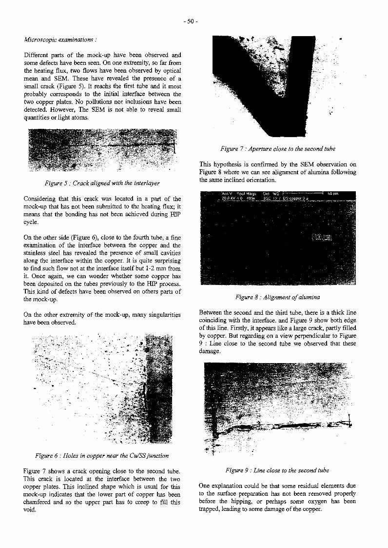
- 5 0 -
Microscopic examinations :
Different parts of the mock-up have been observed andsome defects have been seen. On one extremity, so far fromthe heating flux, two flows have been observed by opticalmean and SEM. These have revealed the presence of asmall crack (Figure 5). It reachs the first tube and it mostprobably corresponds to the initial interface between thetwo copper plates. No pollutions nor inclusions have beendetected. However, The SEM is not able to reveal smallquantities or light atoms.
Figure 5 : Crack aligned with the interlayer
Considering that this crack was located in a part of themock-up that has not been submitted to the heating flux; itmeans that the bonding has not been achieved during HIPcycle.
On the other side (Figure 6), close to the fourth tube, a fineexamination of the interface between the copper and thestainless steel has revealed the presence of small cavitiesalong the interface within the copper. It is quite surprisingto find such flow not at the interface itself but 1-2 mm fromit. Once again, we can wonder whether some copper hasbeen deposited on the tubes previously to the HIP process.This kind of defects have been observed on others parts ofthe mock-up.
On the other extremity of the mock-up, many singularitieshave been observed.
Figure 6 : Holes in copper near the Cu/SS junction
Figure 7 shows a crack opening close to the second tube.This crack is located at the interface between the twocopper plates. This inclined shape which is usual for thismock-up indicates that the lower part of copper has beenchamfered and so the upper part has to creep to fill thisvoid.
Figure 7 : Aperture close to the second tube
This hypothesis is confirmed by the SEM observation onFigure 8 where we can see alignment of alumina followingthe same inclined orientation.
Figure 8 : Alignment of alumina
Between the second and the third tube, there is a thick linecoinciding with the interface, and Figure 9 show both edgeof this line. Firstly, it appears like a large crack, partly filledby copper. But regarding on a view perpendicular to Figure9 : Line close to the second tube we observed that thesedamage.
Figure 9 : Line close to the second tube
One explanation could be that some residual elements dueto the surface preparation has not been removed properlybefore the hipping, or perhaps some oxygen has beentrapped, leading to some damage of the copper.

-51 -
Along the tubes, an other damage zone has been detected. Xanalysis performed on the SEM has indicated only thepresence of iron, copper, chromium and nickel.
Never the less, we guess that there was some residualelements on the surface of the copper plate, which hasreacted with the materials during the HIP cycle. It is worthnoting that such kind of damage has not been detectedeverywhere on the mock-up but just in this area.
PH/S-1Fmock-up
Macroscopic examinations :
The first observations are illustrated on Figure 10. Thecopper plate has been deformed during the tests. The upperface (viewing the heat flux) presents an network of smallcracks. This kind of damage is frequently observed onsurfaces submitted to thermal fatigue.
There are some waves on the top of the mock-up, the crestscorresponding to the location of the tubes. It can be alsoseen, that the tubes have been deformed.
No crack has been detected between the two copper plates.But some damage can be seen between the stainless tubesand the copper on the hottest side of the tube.
Figure 10 : View of the middle of the mock-up (part 4)
Optical and SEM analysis :
Detail of the damage close to the stainless steel is shown onFigure 11. We can see that the crack does not lie within theinterface between the tube and the plate but in the copper at20 - 50 (am from the tube.
t
THERMO-MECHANICAL ANALYSIS
Introduction
The second part of the study is devoted to numericalcalculations. Previous thermal-elastic analysis has proved'that both copper and steel reached their yield stress. Thusinelastic calculations have been performed.
Thermal analysis
For both mock-up the loading is the same. We simulated aheat flux 7 MW/m2 on the upper face, and a cooling in thetubes with water at 140°C.
Figure 12 present the temperature distribution for a heatflux of 7 MW/m2 on the DS IF mock-up. The temperaturedistribution is nearly the same for the PH/S IF mock-up.
> 1.8 9E+02
•= 6.J3E+02
Figure 11 : Crack in the copper, close to a tube (x 200)
Figure 12 : Typical map of temperaturefor 7 MW/m2 heat flux
Mecanical analysis
Figure 13 shows the evolution of the maximum of VonMises Stress for both mock-up over few cycles. We can seethat the level of stresses grows at each cycle and does notpresent accommodation. Such behaviour is not good to geta long life time.
Figure 14 shows the evolution of the cumulated plasticstrain and we still have a constant increasing of plasticityfor each step.
Even that there are some differences between the amount ofstresses for both mock-up, the plasticity seems equivalentfor the outer tube, but the plasticity is more important in theDS copper than in the Cu Cr Zr alloy.

- 5 2 -
E VOLUTION of MAXIMUM ofMPa VON MISES versus TIME
3,20E+02 T
EVOLUTION of MAXIMUM ofCUMULATED PLASTIC STRAIN
versus TIME
2,20E+02 J 1 1 !
O.OOE+00 1.00E+02 2,00E+02 3.00E+02
0,OOE+00 l,00E+02 2.00E+02 3.00E+02
Figure 14 : Evolution of cumulated plasticstrain versus timeFigure 13 : Evolution of Von Mises versus time
The next figures represent Von Mises and Cumulated plastic strain at the end of the third cycle (171 s)
311-0 3
3 3E-0 2
16S-02
OE-O:
4E-o:
si-o;
3E-01
BE-O.
Figure 15 : View of Von Mises and cumulated plastic strain for DS IF mock-up
CONCLUSIONS PUBLICATION
The different behaviour under high heat flux should resultof some defects during the fabrication. The junction DScopper - DS copper was not enough good and rapidly aaperture propagates.
The modelization shows that both mock-ups should react inthe same way. The level of stress are more important withthe DS copper than Cu CR Zr alloy, but the plasticity isnearly the same.
An other information get by computation is that theplasticity is more important in the outer tube, and increasesat each cycle. Such behaviour will limit the number ofcycles before the damage of the mock-up even under lowflux (1 MW/m2).
[1] Le Gallo P., Burlet H., «NUMERICAL ANALYSISAND METALURGICAL EXPERTISE OF FIRSTWALL MOCK-UPS ». NT DEM 99/11
TASK LEADER
H. BURLET
DTA/DEM/SGMCEA Grenoble17, rue des Martyrs38054 Grenoble Cedex 9
Tél. : 33 4 76 88 94 96Fax : 33 4 76 88 94 63
E-mail : [email protected]

- 5 3 -
T217
Task Title : IMPROVED MATERIALS AND JOINT CORROSION TESTINGFabrication of a CuCrZr IG/316LN IG joint for corrosion testing
INTRODUCTION
Several types of Stainless Steel/Cu joints are specified inthe design of the plasma facing components. The jointsmust withstand the thermal, mechanical and neutron loadsand the cyclic mode of operation. In terms of structural andgalvanic corrosion requirements, the pressure boundaryjoints are the most critical ones, and their reliability has tobe guaranteed throughout the components' lifetime.Manufacturing the joints by Solid HEPing has advantagesin comparaison with commonly used methods(Combination of forging, pressing, machining, etc) butrelatively limited experience exists on HEPing of CuCrZr/Stainless steel joints.
The objective of this task is to demonstrate the feasibility ofa CuCrZr IG / 316 LN IG joint by HIPing and to supply afinal junction - whose dimensions are 200x80x (2x35)mm3 - in order to perform the corrosion testing.
1998 ACTIVITIES
PRODUCTION OF HEP DIFFUSION WELDEDSPECIMENS
The CuCrZr alloy used in this study has been supplied byLe Bronze Industriel. Its grade is Electral CRM 16N TR.The Cr and Zr contents of the sheet fall within the ITERspecifications. The as-received material is solutionannealed, quenched and tempered.
A billet of 316L stainless steel in as-forged conditions hasbeen supplied by Tecphy. The billet was produced undervacuum conditions.
Preliminary joints have been produced, using the followingparameters :
HIP parameters :Solution treatment
Ageing :
820°C for lh under 100 MPa.990°C for 2h, followed by waterquenching.480°C for 4h, followed by furnacecooling.
The geometry of the specimens was :
Diameter of the specimen :Copper part :Stainless steel part :
29 mm36 nun thick64 mm thick
The plane of the joint was perpendicular to the plane of theaxial direction of the forged billet of stainless steel andparallel to the CuCrZr plate.
uCiCuCrZr
Figure 1 : Joint Specimen Configuration
The main role of interlayers is to limit the diffusionthrough the interface of elements that can potentiallyfragilize the joint. In CuCrZr/steel joints the main problemis to avoid the precipitation of zirconium carbide particlesat the joint.
CHOICE OF AN INTERLAYER
The following foils have been selected as interlayers :
Material
Titanium
Molybdenum
FN 42 (Fe-42wt%Ni)
Copper OFHC
Nickel
Thickness (mm)
0.025
0.0125
0.1
0.025
0.01
The choice of the final interlayer or direct bonding wasbased on the mechanical and microstructural properties.Bending tests, metallographical characterisation andmicroprobe analysis of the joints (fig. 2 for direct bonding)have ben performed.
Results :
Refractory metals (Ti, Mo) do not allow to achieve soundjoints. Bonding with a Ni foil provides satisfactory jointsbut the bending test results are slightly better with FN 42or from direct joining without interlayer. Bonding with aCu foil leads to premature failure during the bending test.

- 5 4 -
In regards to the mechanical tests and he metallographicexaminations there is no significant evidence for selectingthe FN 42 interlayer or the direct bonding.
The dimensions of the plate after machining are 200x80x(2x35) mm3. The part is shown after HIPing andmachining :
Stainless steel on the left / CuCrZr on the right
Figure 2 :a) Metallographic examinationb) Micropobe analysis of Nickel
The microstructure of the joint is characterised by a nickeldepletion on the stainless steel side, leading to a ferrite band4 urn wide. Conversely the CuCrZr alloy is enriched innickel, leading to the disappearing of Cr precipitates closeto the interface.
PLATE FABRICATION
It has been decided to fabricate the bimetallic plate withoutany interlayer, thereby minimising the number ofinterfaces. The extrapolation to the fabrication of a partwith an interface of complex shape is easier.
The fabrication of the plate was done by using the processparameters defined in Section I.
Figure 3 : Diffusion bondingSS 316 LN- COPPER ALLOY CuCrZr
MOCK UP after machining
CONCLUSIONS
The bimetallic plate has been joined without an interlayerusing HIP conditions : 920°C, lOOmpa for lh. After HIPinga heat treatment was applied, consisting of a 2h step at990°C followed by water quenching and finally ageing for4h at 480°C. It was chosen not to use an interlayer on thebasis of previous microstuctural examination and bendingtests.
PUBLICATIONS
[1] S. Revol, C. Labonne, T. Portra, E. Rigal « ImprovedMaterials and Joints Corrosion Testing » NT DEM n°74/98.
TASK LEADER
Stéphane REVOL
DTA/DEM/SGMCEA Grenoble17, rue des Martyrs38054 Grenoble Cedex 9
Tél. : 33 4 76 88 98 42Fax : 33 4 76 88 54 79
E-mail : [email protected]

- 5 5 -
T224
Task Title : DEVELOPMENT OF A THERMAL BOND LAYER FOR FIRSTWALL REPAIR - STUDY OF RHEOCAST Aï-Ge THIXOTROPICCOMPLIANT LAYER FOR IN-SITU REBRAZING
INTRODUCTION
The purpose of this study concerns the development ofmetal forming processes of the AI-17%wtGe alloy, chosenas brazing alloy because of its sufficient intrinsic strengthand enough amount of eutectic for brazing the First Wall,(FW) of thermonuclear fusion reactors to a permanentlycooled high conductivity copper substrate. It has beenalready shown [1-4] that this alloy family is able to be usedas « Thermal Bond Layer » which functions are to provide agood thermal contact between armour and heat sink and tobe compliant for reducing the interface thermal stresses.Extrusion is a candidate technique for the fabrication ofcomplex shapes that are required for the fabrication of FirstWall components.
The billet and container heating is performed in aconventional furnace of resistances. Reduction by extrusionis measured by using the expression (A;-Af)/A;. being A; thearea of the initial cylindrical material, and A{ the final areaof the section obtained. This reduction is -95%. Theextrusion parameters (temperature, force, extrusion speed)were chosen in order to get a recovexy/recristallisationprocess and thus a good homogeneity of the different phasewithin the material.
MICROSTRUCTURE CHARACTERISATION
The structure of the material after extrusion is given infigure 2. The germanium phases are aligned along theextrusion direction. During extrusion, germanium particlesare broken in small parts and are much more rounded thanbefore extrusion. Some heterogeneity were observed.
1998 ACTIVITIES
EXTRUSION
The extrusion is an operation for the production of varioussolid and hollows sections by forcing suitable materialthrough a die by means of a ram under high level pressure(see figure !).
BcrausoN
Figure 1 : Extrusion process
of the high forces required in extrusion, mostmetals are hot extruded under conditions where thedeformation resistance of the metal is low. Ingots from pureAl and Ge were obtained by casting the molten alloy into awater-cooled cylindrical copper mould. Diameter ofcylinder was of 40 mm and height of 50 mm. The extrusionof the Ai-17%wtGe is made with an hydraulic verticaloress.
Figure 2 : Microstructure of the extruded ÀÏ-17%Ge alloy
This material was heat-treated with various conditions inorder to obtained the globular structure. Figure 3 gives thetransversal and longitudinal microstructure. Globules arealigned along the extrusion direction (see longitudinalsection figure 3b }. Entrapped liquid are present and alignedalso along the extrusion direction. The amount of entrappedliquid decreases with the increase of the temperature andduration of the heat treatments.
The globule size is about the same whatever the heat-treatment duration and temperature in the semi-solid state.The globule size is twice smaller when the material isextruded and cold-rolled.

- 5 6 -
a) TRANSVERSAL
Figure 3 : Extruded Al-l7%Ge and heat treated a) Transversal section.b) Longitudinal section. Details of globules without entrapped liquid (1) and
globules -with high quantity of entrapped liquid aligned in the direction of extrusion (2)
MECHANICAL CHARACTERISATION
The different metal process routes have bees, compared.Figures 4 aod 5 gives the tensile behaviour at 25 and 300°Cfor Ai-Ge after extrusion, extrusion + cold rolling and, hotrolling. The yield strength of the extraded-f-cold rolling ishigher than only extrusion or hot rolling. The behaviour ofthe extruded material or the hot rolling one is the same.
T=25°C
oEXTRUDED 2• EXTRUDED 2+COLD-ROLLED* HOT-ROLLED
0% 10% 20% 30% 40% 50%
Figure 4 : Tensile tests of Al-17%-wtGe alloy fabricatedby various routes
50 —4 5 -40 ~
AJ-17%Ge T=300"C
• HOT-#0U_=DA EXTRUDED 2+COLD-ROLLED.
| ..«GLOSJLAR .r\0% 20% 40% 60% 80% 100%
Figure 5 : Tensile tests of Al-17%wtGe alloy fabricatedby various routes
BRAZING
A new brazing process have been defined : even with lowGe content, the brazing température is about 450°C Figure6 gives the typical microstructure of a brazed sample. Cu-Albase intermetailics are present at the interface between thebrazing alloy AI-Ge and copper. The mechanical resistance(shear strength) of such assembly is about ISOMPa.Recommendations for the improvement of the quality andhomogeneity of the joint structure along the interface arepresented : a possible way is to control the germaniumrepartition at the interface.
INTERMETALUCS AI-17%wtGe
QJJGUDCOP
Figure 6 : Typical Al-17%wtGe/copper interface structure
CONCLUSIONS
It has been demonstrated that the extrusion is possible atintermediate temperature. The globular microstructure afterextrusion is equivalent to the one observed after hot rolling.The strength of such alloy after extrusion is at leastequivalent to the one obtained after hot rolling only and isimproved if cold rolling is performed after extrusion. A newbrazing process with a temperature of about 450°C has beenpatented.
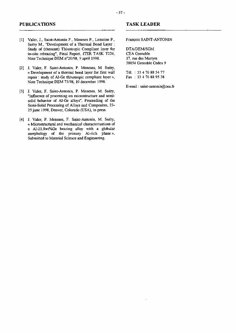
- 5 7 -
PUBLICATTONS TASK LEADER
[1] Valer, J., Saint-Antonin F., Meneses P., Lemoine P.,Suéry M., "Development of a Thermal Bond Layer :Study of (rheocast) Thixotropic Compliant layer forin-situ rebrazing", Final Report, ITER TASK T224,Note Technique DEM n°20/98, 9 april 1998.
[2] J. Valer, F. Saint-Antonin, P. Meneses, M. Suéry,« Development of a thermal bond layer for first wallrepair : study of Al-Ge thixotropic compliant layer »,Note Technique DEM 73/98, 10 december 1998.
[3] J. Valer, F. Saint-Antonin, P. Meneses, M. Suéry,"Influence of processing on microstructure and semi-solid behavior of Al-Ge alloys", Proceeding of theSemi-Solid Processing of Alloys and Composites, 23-25 June 1998, Denver, Colorado (USA), in press.
[4] J. Valer, P. Meneses, F. Saint-Antonin, M. Suéry,« Microstructural and mechanical characterisations ofa Al-21.8wt%Ge brazing alloy with a globularmorphology of the primary Al-rich phase»,Submitted to Material Science and Engineering.
François SAINT-ANTONIN
DTA/DEM/SGMCEA Grenoble17, rue des Martyrs38054 Grenoble Cedex 9
Tél. : 33 4 76 88 54 77Fax : 33 4 76 88 95 38
E-mail : saint-antonin(®cea.fr
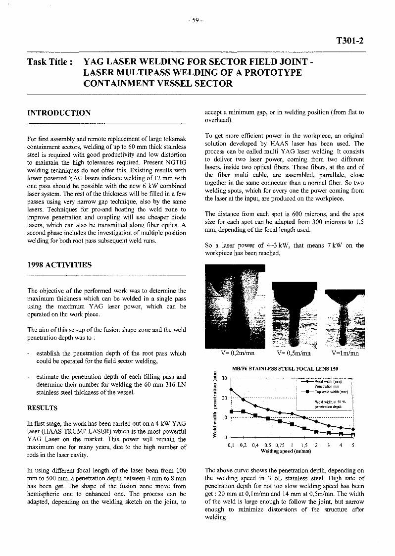
- 5 9 -
T301-2
Task Title : YAG LASER WELDING FOR SECTOR FIELD JOINTLASER MULTIPASS WELDING OF A PROTOTYPECONTAINMENT VESSEL SECTOR
INTRODUCTION
For first assembly and remote replacement of large tokamakcontainment sectors, welding of up to 60 mm thick stainlesssteel is required with good productivity and low distortionto maintain the high tolerances required. Present NGTIGwelding techniques do not offer this. Existing results withlower powered YAG lasers indicate welding of 12 mm withone pass should be possible with the new 6 kW combinedlaser system. The rest of the thickness will be filled in a fewpasses using very narrow gap technique, also by the samelasers. Techniques for pre-and heating the weld zone toimprove penetration and coupling will use cheaper diodelasers, which can also be transmitted along fiber optics. Asecond phase includes the investigation of multiple positionwelding for both root pass subsequent weld runs.
1998 ACTIVITIES
The objective of the performed work was to determine themaximum thickness which can be welded in a single passusing the maximum YAG laser power, which can beoperated on the work piece.
The aim of this set-up of the fusion shape zone and the weldpenetration depth was to :
establish the penetration depth of the root pass whichcould be operated for the field sector welding,
- estimate the penetration depth of each filling pass anddetermine their number for welding the 60 mm 316 LNstainless steel thickness of the vessel.
RESULTS
In first stage, the work has been carried out on a 4 kW YAGlaser (HAAS-TRUMP LASER) which is the most powerfulYAG Laser on the market. This power will remain themaximum one for many years, due to the high number ofrods in the laser cavity.
In using different focal length of the laser bean from 100mm to 500 mm, a penetration depth between 4 mm to 8 mmhas been get. The shape of the fusion zone move fromhemispheric one to enhanced one. The process can beadapted, depending on the welding sketch on the joint, to
accept a minimum gap, or in welding position (from flat tooverhead).
To get more efficient power in the workpiece, an originalsolution developed by HAAS laser has been used. Theprocess can be called multi YAG laser welding. It consiststo deliver two laser power, coming from two differentlasers, inside two optical fibers. These fibers, at the end ofthe fiber multi cable, are assembled, parrallale, closetogether in the same connector than a normal fiber. So twowelding spots, which for every one the power coming fromthe laser at the input, are produced on the workpiece.
The distance from each spot is 600 microns, and the spotsize for each spot can be adapted from 300 microns to 1,5mm, depending of the focal length used.
So a laser power of 4+3 kW, that means 7 kW on theworkpiece has been reached.
V= 0,2m/mn V= 0,5m/mn V=lm/mn
MB/F6 STAINLESS STEEL FOCAL LENS 150
-Weld width (mm)Penetration mm
- Top weld width (mm)
0,2 0,4 0,5 0,75 1 1,5 2Welding speed (ni/mm)
The above curve shows the penetration depth, depending onthe welding speed in 316L stainless steel. High rate ofpenetration depth for not too slow welding speed has beenget : 20 mm at 0,lm/mn and 14 mm at 0,5m/mn. The widthof the weld is large enough to follow the joint, but narrowenough to minimize distorsions of the structure afterwelding.

- 6 0 -
Hot cracking has been observed in the middle of the joint.But the stainless steed tested was standard one. This pointmust be followed in the following results. In working theprocess, by changing the shape of the fusion zone, thisphenomena must be controlled, evenmore in using the preand post heating laser diode, which will be tested in April1999.
Filler wire technology is get acquired. The process will bestudied in the second semester of 1999.
CONCLUSIONS
For Fieldwels, a power of the continuous Yag Laser up to 4kW is necessary. A root pass with a penetration depthbetween 10 to 12 mm seems to be achieved. The shape ofthe fusion zone can be adapted by working the process :welding speed, length of the focusing lens. A gap seems tobe adapted by working the process (work to be carried out).Penetration deptli of 20 mm has been get on stainless steelin one pass welding. The filler wire system has beenselected and successfully tested and qualified. The Arcueilfacility is equiped from the march 2nd with 4 kW and 2 kWcontinuous Yag Lasers, and the twinlas fiber.
TASK LEADER
Philippe AUBERT
DTA/DPSA/DIR/CLFACEA Fontenay aux RosesBoîte Postale 692265 Fontenay aux Roses Cedex
Tél. : 33 142 3187 09Fax : 33 142 3197 47
E-mail : [email protected]

- 6 1 -
T330
Task Title : WATER RADIOLYSIS IRRADIATION TESTS
INTRODUCTION
The radiolysis of water gives free radicals which are shortlived and molecular products, H2, H2O2 and O2. In presenceof a small concentration of hydrogen (1.5 ppm) dissolved inwater, most of the radiolytic products are recombined andin some cases the concentrations of the molecular speciesH2, H2O2 and G? reach a steady state where thereconcentrations remain constant as a function of theirradiation time. The level of the concentrations in thesteady state depends on the experimental conditions. Abovea threshold, which depends of the intensity and LET of theradiation together with the temperature, the hydrogenconcentration and the presence of impurities in the water, asharp transition is observed with a net water decompositionand no steady state. Above this threshold the concentrationof O2, H2O2 and H2 increase with the irradiation time andare many orders of magnitude higher than in the steadystate regime [1] [2]. It was also shown that in the steadystate conditions the main oxidising species is H2O2 and thatthe concentration of O2 is three orders of magnitude lowerthan the concentration H2O2 [1] [2].
The purpose of the task is to determine experimentally andby computer simulations the concentration of the molecularproducts as a function of the LET and irradiation intensityand to check the influence of some impurities in the water.The results will be then extrapolated to the condition ofirradiation in ITER for the water of the in-vesselcomponents.
1998 ACTIVITIES
The beam Energy of Carbon Ions C^ is 1110 MeVcorresponding to a LET (-dE/dx) of 26 keV per micron inwater.
The solutions are prepared with ultrapure water with aresistivity of 18 MQ cm. They are thoroughly deaerated bybubbling high purity Argon and then saturated underatmospheric pressure with hydrogen. The concentration ofH2 in the water is 7.5 x 10"" M (1.5 ppm). In someexperiments to test the influence of corrosion products asolution of copper sulfate was added in the water saturatedwith H2. It was shown previously that the sulfate anion doesnot interfere with the radiolysis of water.
The irradiations are performed in quartz cell at roomtemperature. The solution are flow through the cell duringthe irradiation. After irradiation, the concentration of H2O2
is determined by a spectrophotometric method. The limit ofdetection is 0.2 yM (7 ppb).
RESULTS
The experimental results are given in tables 1 and 2 and infigure 1. The concentrations of H2O2 in micromole per literand in ppm are given as a function of the dose rate. Inabsence of copper sulfate, the concentration of H2O2
increases as a function of (I)1/3 where I is the dose rate. Theinfluence of Cu** is clearly shown on figure 1. For the samedose rate there is an increase in the concentration of H2O2
which is much more pronounced for Cu = 378 ppb than forCu = 63 ppb but an increase of a factor 6 in the copperconcentration gives only an increase of a factor 2 in theconcentration of H2O2.
The influence of LET, irradiation intensity and the presenceof copper cations on the formation of H2O2 which is themain oxidising species was studied with high energy ionsbeam of carbon. The irradiations were performed in theGrand Accélérateur d'Ions Lourds GANIL at Caen.
Table 1Irradiation with C6^ E = 1110 MeVLET = 26 keV/|im Solution H2O +1.5 ppm H2
In the whole range of dose rate and copper cationsconcentrations there is no evidence that the threshold wasattained, where the concentration of radiolytic productsincrease with the dose. This is confirmed by computersimulation [2] where the calculations show that thehydrogen peroxide concentration remains in a steady state.
N°
1
2
3
4
5
6
Dose ratekrads'1
44
44
118
118
458
458
Dosekrad
234
234
630
630
2400
2400
H2O2
ppm
0.36
0.37
0.61
0.60
0.84
0.73
[H2O2]
pM
10.5
10.9
18
17.7
24.6
21.5

- 6 2 -
Table 2
Influence of copper cationsIrradiation with C6*
= 26keV/nmE=1110MeVSolution H2O +1.5 ppm H2
N°
7
g
9
10
11
12
13
14
15
Cuppb
63
63
63
378
378
378
378
378
378
Dose rateloads'1
10
80
350
11.5
43
108
149
317
500
Dosekrad
54
432
1890
61
230
570
790
1680
2650
H 2O 2
ppm
0.14
0.61
1.06
0.25
0.74
1.42
1.69
1.91
2.04
[H2O2]HM
4.1
18
31.7
7.3
21.8
41.9
49.8
56.1
59.9
100
90
80
70
60
5 0
30
20
10
0
• [Cu ] = 0D [Cu**] = 63ppbA [Cu**] « 378 ppb
0 100 200 300 400 500 600
Dose rate / krad s
Figure 1 : Influence of dose rate and copper cationsCarbon ions, LET = 26keV//jm
CONCLUSION
REPORTS AND PUBLICATIONS
[1] B. Hickel, G. Baldacchino and E. BjergbakkeIntermediate report on the Task T 330CEA/Saclay April 1998
[2] B. Hickel, G. Baldacchino and E. BjergbakkeFinal Report on the Task T 330CE A Saclay July 1998
TASK LEADER
B. HICKEL
DSM/DRECAM/SCM URA 331 CNRSCEA Saclay91191 Gif-sur-Yvette Cedex
Tél. : 33 169 08 5126Fax : 33 1 69 08 34 66
E-mail : [email protected]
In the presence of 1.5 ppm of H2 dissolved in water theformation of H2O2 from the radiolysis reached a steadystate. The level of the concentration increases with theintensity of the irradiation.
The presence of copper cation Cu"" has a detrimental effectand increase the level of the H2O2 concentration at thesteady state but there are no indications that the threshold,where there is no steady state, is attained in the range ofLET and copper concentrations studied.

- 6 3 -
V63
Task Title : IMPROVED MATERIALS AND JOINTS IRRADIATION TESTINGCu alloys and joints improvement. Standardization of joint testing procedures
INTRODUCTION
The main objective of this task is to develop experimentsand analyses to characterise the toughness of dissimilarbimetallic joints. The studied joint is manufactured usingthe solid diffusion bonding technique under Hot IsostaticPressing (HIP). The two materials to be bonded are aforged stainless steel 316LN, and a reinforced copper.Different kinds of specimens are machined within bondedblocks. CEA conducts tests on CT specimens whereas VTTconducts tests on SENB specimens.
In addition to this mechanical work, fine examinations ofthe microstructure of the glidcop are carried out. The plateused in this study has been manufactured according tospecification IG1. It is delivered rough from cross-rollingand with the cladding of pure copper acting as a protector.The study of the relationship between the microstructureand the mechanical properties of this material shouldprovide useful indications for improving this material. Adescription of the nature, size and distribution of theinclusions, the texture, the grain is given below, theexaminations of the deformed state being delayed to 99.
1998 ACTIVITIES
MECHANICAL CHARACTERISATION OFDS-COPPERIG1 PLATE
In order to analyse the tests performed on the bimaterialspecimens, it is necessary to measure first the toughness ofpure glidcop, having seen exactly the same heat treatmentthan the base materials of the assembly.
The studied state all along this report is thus thefollowing :
1000°C - lh30 under vacuum + 920°C - 3h under vacuum
Specimen and testing procedure
Two kinds of CTJ20 specimens have been prepared :standard CT-TL, and sandwich CT-SL. For this lastspecimen, the thickness of the decladed plate being 18mm,the CT were machined in an assembly SS/Cu/SS such thatthe crack is located in the middle of the copper.
All the tests have been conducted under standardASTM1737-96. Electro-discharged machining was madeup to a depth of a=15mm. Then fatigue precracking wascarried out at room temperature. The specimens were thenside-grooved.
Test results
The results are summarised in Table 1. Note that the testsat 200°C were performed under inert argon. The unloadingslopes were linear proving that no relaxation occurred.
Discussion :
The values obtained on the CT-TL are quite usual, even ifthe scatter is quite high. The values of the CT-TS areunusual especially at room temperature for whichexperiments conducted on SENB on a DS-copper IGO leadto 40kJ/m2. Numerical calculations are currently done toanalyse this difference.
Table 1 : Fracture toughness of glidcop IG1
specimen number
10
l ib
3h
4h
12
13b
5h
6h
orientation
TL
TL
SL
SL
TL
TL
SL
SL
temperature
20
20
20
20
200
200
200
200
Jq (kJ/m2)
50
71.9
63.1
80.8
27.5
27.5
19.8
21.5
comments
standard CTJ20
standard CTJ20
sandwich 3 materials specimen
sandwich 3 materials specimen
standard CTJ20
standard CTJ20
sandwich 3 materials specimen
sandwich 3 materials specimen

- 6 4 -
M1CROSTRUCTURE EXAMINATIONS OFDS-COPPERIG1 PLATE
Optical examinations
Optical micrographs of the heat treated plate IG1 made inthe planes S-T and S-L, have revealed a fine elongated grainstructure oriented in the extrusion direction. They arelooking like platelets with typical size: length in the range 5- 20 urn. width m the range 5-10 urn, and thickness in the
aspect ratio is thusrange 0.5-2 urn. The grainapproximately between 5 to 10,
TEM examinations
TEM examinations have revealed a subgrain structurebounded by dislocation walls (figure 1). The subgrain sizeis in the micron range.
Figure 1 : TEM micrographs showinga subgrain structure
Fine AliOj particles can be imaged using largemagnification. Analysis of their distribution requirescaution because some of these can be deposited over thethin foil during the electropolishing. This is the case formost of the large particles observed on figure 2.Nevertheless we can note that the particle distribution is nothomogeneous within all the grains. Some grains contain alarge number of particles (figure 2) whereas others containonly a few aligned long the rolling distribution (figure 3).Most of the particles are sphere-like with a diameter in therange 5 to 2Gnm, except some particles which are elongatedalong a <01 i> copper direction.
Figure 3 : Grain containing a few alumina particles
MECHANICAL CHARACTERISATIONOF SS/DS-COPPER JOINT
The process route used within this study is the following :
- heat treatment for the giidcop parts : 1000CC - L5hunder vacuum,
- HIP cycle : 920°C - 3h/3h/3h - 12QMPa.
Tensile tests
Some tensile tests have been performed on bimaterialspecimens to check the soundness of the joint. The fracturealways occurred in the giidcop side, far from the interface atroom temperature but close to it at both 200 and 300°C.
Nevertheless, the debonding zone was limited to a narrow-band underneath the external surface, proving mat the jointwas not weak.
Fracture toughness tests
Eleven bimaterial CTJ20 specimens have been machined inblocks manufactured by CEA. They have all the sameorientation : CT-SL. For nine specimens, a crack ismachined up by electro-discharged to a given depth as closeas possible to the interface. These specimens are then side-grooved to force the crack to remain in the vicinity of thebond, before being fatigue precracked at room temperature.
As we fear that the crack will not remain within theinterface during the fatigue loading, two special CTspecimens have been manufactured for which the precrackhas been introduced during the elaboration. An aluminafilm of thickness Sum has been deposited on the stainlesssteel part using magnetron reactive Physical VaporDeposition technique. Side grooves have also beenmachined on these specimens.
The tests have been conducted according to standard ASTM1737-96. The results are summarised in table 2.
Figure 2 : Grain containing a large numberof alumina part ides

- 6 5 -
Table 2 : Fracture toughness ofSS/glidcop IG1 joints
specimennumber
2b •
7
8
lh
2h
5b
6b
initial crack
fatigue
oxide flaw
oxide flaw
fatigue
fatigue
fatigue
fatigue
temperature
20
20
20
200
200
200
200
Jq (kJ/m2)
9
11.5
6.9
9
2.2
6.5
7.2
comments
the fatigue crack was located in the glidcop.
the crack deviates from the interface to grow inthe glidcop parallel to the Interface
the crack deviates from the interface to grow inthe glidcop parallel to the interface
precrack and crack in the glidcop side
precrack and crack in the glidcop side
precrack and crack in the glidcop side
precrack and crack in the glidcop side
Discussion :
It can be noticed that the toughness measured on fatigueprecracked specimens are similar to those obtained on CTwith an initial flaw located exactly at the interface.Moreover, both the fatigue and final cracks grew within thecopper side parallel to the interface (see figure 4). These 2results indicate that the rupture of the assembly is governedby the glidcop. Numerical calculations are currentlyperformed to determine a criteria in terms of plastic strain(see figure 5) and main stress in the glidcop to predict therupture of these joints. The same analysis will be applied toSENB specimens tested at VTT on the same joint.
Figure 5 : Plastic zone in a bimaterial CTspecimen at rupture
CONCLUSIONS
All these results detailed in [1] indicate that the rupture of astainless steel - glidcop joint manufactured by soliddiffusion under High Isostatic Pressure is governed by theglidcop.
Applying a rupture criteria of the laminated plate to theassembly should predict correctly its failure. To confirmthis assumption, the analysis of fracture toughness testsperformed on different kinds of specimens (SENB, CT...) isstill necessary, and will be performed in 99.
mFigure 4 : Fracture surface of a bimaterial CT

- 6 6 -
PUBLICATION
[1] Burlet H., Guetaz L., Bucci PH., Gentzbittel JM., ChuI., Scheer N.: «Iter DPI task bll2.2-01. Detailedinvestigation of CuA125 (IGl) , its joints with 316LNstainless steel and joints testing procedure». NTDEM 98/75
TASK LEADER
H. BURLET
DTA/DEM/SGMCEA Grenoble17, rue des Martyrs38054 Grenoble Cedex 9
Tél. : 33 4 76 88 94 96Fax : 33 4 76 88 94 63
E-mail : [email protected]
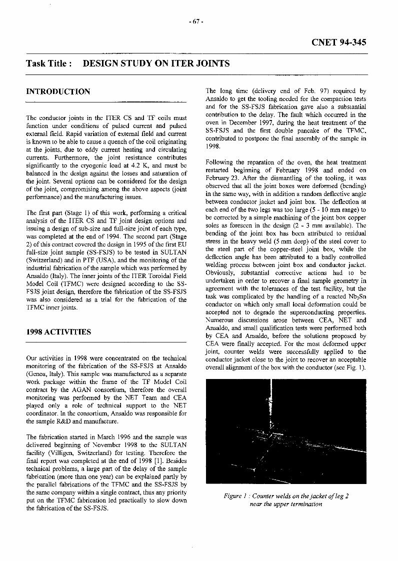
- 6 7 -
CNET 94-345
Task Title : DESIGN STUDY ON ITER JOINTS
INTRODUCTION
The conductor joints in the ITER CS and TF coils mustfunction under conditions of pulsed current and pulsedexternal field. Rapid variation of external field and currentis known to be able to cause a quench of the coil originatingat the joints, due to eddy current heating and circulatingcurrents. Furthermore, the joint resistance contributessignificantly to the cryogenic load at 4.2 K, and must bebalanced in the design against the losses and saturation ofthe joint. Several options can be considered for the designof the joint, compromising among the above aspects (jointperformance) and the manufacturing issues.
The first part (Stage 1 ) of this work, performing a criticalanalysis of the ITER CS and TF joint design options andissuing a design of sub-size and full-size joint of each type,was completed at the end of 1994. The second part (Stage2) of this contract covered the design in 1995 of the first EUfull-size joint sample (SS-FSJS) to be tested in SULTAN(Switzerland) and in PTF (USA), and the monitoring of theindustrial fabrication of the sample which was performed byAnsaldo (Italy). The inner joints of the ITER Toroidal FieldModel Coil (TFMC) were designed according to the SS-FSJS joint design, therefore the fabrication of the SS-FSJSwas also considered as a trial for the fabrication of theTFMC inner joints.
1998 ACTIVITIES
Our activities in 1998 were concentrated on the technicalmonitoring of the fabrication of the SS-FSJS at Ansaldo(Genoa, Italy). This sample was manufactured as a separatework package within the frame of the TF Model Coilcontract by the AGAN consortium, therefore the overallmonitoring was performed by the NET Team and CEAplayed only a role of technical support to the NETcoordinator. In the consortium, Ansaldo was responsible forthe sample R&D and manufacture.
The fabrication started in March 1996 and the sample wasdelivered beginning of November 1998 to the SULTANfacility (Villigen, Switzerland) for testing. Therefore thefinal report was completed at the end of 1998 [1]. Besidestechnical problems, a large part of the delay of the samplefabrication (more than one year) can be explained partly bythe parallel fabrications of the TFMC and the SS-FSJS bythe same company within a single contract, thus any priorityput on the TFMC fabrication led practically to slow downthe fabrication of the SS-FSJS.
The long time (delivery end of Feb. 97) required byAnsaldo to get the tooling needed for the compaction testsand for the SS-FSJS fabrication gave also a substantialcontribution to the delay. The fault which occurred in theoven in December 1997, during the heat treatment of theSS-FSJS and the first double pancake of the TFMC,contributed to postpone the final assembly of the sample in1998.
Following the reparation of the oven, the heat treatmentrestarted beginning of February 1998 and ended onFebruary 23. After the dismantling of the tooling, it wasobserved that all the joint boxes were deformed (bending)in the same way, with in addition a random deflective anglebetween conductor jacket and joint box. The deflection ateach end of the two legs was too large (5-10 mm range) tobe corrected by a simple machining of the joint box coppersoles as foreseen in the design ( 2 - 3 mm available). Thebending of the joint box has been attributed to residualstress in the heavy weld (5 mm deep) of the steel cover tothe steel part of the copper-steel joint box, while thedeflection angle has been attributed to a badly controlledwelding process between joint box and conductor jacket.Obviously, substantial corrective actions had to beundertaken in order to recover a final sample geometry inagreement with the tolerances of the test facility, but thetask was complicated by the handling of a reacted Nb3Snconductor on which only small local deformation could beaccepted not to degrade the superconducting properties.Numerous discussions arose between CEA, NET andAnsaldo, and small qualification tests were performed bothby CEA and Ansaldo, before the solutions proposed byCEA were finally accepted. For the most deformed upperjoint, counter welds were successfully applied to theconductor jacket close to the joint to recover an acceptableoverall alignment of the box with the conductor (see Fig. 1).
Figure 1 : Counter welds on the jacket of leg 2near the upper termination

- 6 8 -
For the lower joint (to be tested in high magnetic field), thissolution could not be retained and a copper wedge had to beinserted and tin soldered between the two copper faces ofthe jointed boxes (see Fig. 2).
CONCLUSIONS
Figure 2 : Lower joint with inserted copper wedgeafter tin soldering
In addition, the copper soles of all the joint boxes had to bemachined up to the maximum acceptable value to recoveras much as possible a correct overall sample geometry.Obviously, at the end a final machining of the joint boxeswas also needed to enter the facility dimensional tolerances.The mechanical assembly of the sample was thus completedat the end of September 1998. The rather substantialinstrumentation of the sample was then installed in October,and the sample was delivered to the SULTAN facility onNovember 4, 1998 (see Fig. 3) for testing.
Figure 3 : SS-SS-FSJS ready for testingin SULTAN facility
The main achievement of this manufacture is a successfultransfer of the technology developed for the subsizesamples in a laboratory (at CEA/Cadarache) to a full sizesample manufactured in industry. Although unexpecteddeformations of joint boxes occurred after heat treatment, arecovery procedure could be set up which allowed toproceed with the sample assembly leading to a finalgeometry compatible with the test facility requirements.
The actual fabrication of the SS-FSJS started in June 1996with the first R&D work on the terminations and ended inOctober 1998. Although no major technical problem wasencountered before the heat treatment, a significant timedelay finally arose (about one year) which must be mainlyattributed to the wish to carry out the R&D work on the SS-FSJS in parallel to the R&D on the ITER TF Model Coil toavoid any problem of technology transfer. The inclusion ofthe sample manufacture into the contract for fabrication ofthe first ITER TF Model Coil double pancake led,particularly at the beginning, to delay some operations onthe SS-FSJS due to the lack of available manpower inAnsaldo. Finally the sample was delivered at the beginningof November 1998 to the CRPP for testing in the SULTANfacility .
From the technical point of view, only few critical issuesconcerning the joint fabrication were identified, they aremainly related to the characteristics of the full-size cablewhich could not be simulated during subsize jointfabrications. Thus the inner spiral tube of the cable had tobe replaced by a thick plain tube in order to avoid bucklingduring the compaction process, on the other hand thischange has been cleverly used to improve the cooling of theannulus area of the cable inside the joint (compared to theoriginal design). Sometimes a slight modificationintroduced to improve the design led to further muchheavier modifications, this was the case of the preliminaryheat treatment of the joint box which led to machine deeperthe compaction tooling to provide a better holding of thebox side walls during the cable compaction, and then tomodify accordingly the heat treatment beams. Also to benoted is the rather high force (about 200 tons) finallyrequired to achieve the compaction, compared to the value(about 100 tons) estimated from subsize sample tests. Lastbut not least, the large deformations of all the joint boxesobserved after heat treatment could not be expected at suchlevels from the subsize joint fabrications. Thesedeformations have been attributed to residual stressesremaining after heat treatment, from initial stresses createdduring the deep welding of the steel cover. Such aphenomenon was also observed on the TFMC joint boxes, itcan be reduced by applying a proper welding process andcan be associated with a preliminary counter deflectionangle between the conductor jacket and the joint box inorder to recover an acceptable overall alignment after heattreatment.

- 6 9 -
The SS-FSJS was successfully tested in November and TASK LEADERDecember 1998, the joint resistance was the lowestmeasured so far on this kind of joint (about 1.3 nO at 4 T),and both conductor leg critical currents were at the Q Q A Z Y N S K Iexpected levels (see report on contract CNET 96-432).
DSM/DRFC/STEPCEA Cadarache
REFERENCE AND PUBLICATION 131Og St Paul Lez Durance Cedex
Tél. : 33 4 42 25 42 18[1] P. DECOOL et al. : NET Contract 94-345 : Final Fax : 33 4 42 25 49 90
Report : Manufacture of the SS-Full Size Joint sample- Note NT/EM/98/61 - December 17, 1998.

- 7 1 -
CNET 96-409
Task Title : ITER CRYOPLANT DESIGN EVALUATION
INTRODUCTION
The ITER cryoplant can be considered as a quite largeextrapolation with respect to the worldwide previously builtand tested helium refrigeration plants.
The total cooling capacity of about 120 KW is around 6time larger than the largest existing helium refrigerators.
The typical working conditions of a tokamak machinecaracterized by a pulsed cryogenic load are quiteincompatible with a safe and efficient operation of thecryogenic refrigerators.
A large scattering between the various operating duties(cooling down, standby or full power operation) asks for alarge operational flexibility.
Due to the relevant experience available within theEUROPEAN COMMUNITY, first, for the design andoperation of the TORE SUPRA tokamak, then, for thebuilding at CERN of large cryogenic plants for the LEP andLHC particule accelerators with the support of industrialfirms (Air Liquide and Linde), the ITER joint central teamhas requested support from the EUROPEAN home team toget technical assistance for the ITER cryoplant design.
1998 ACTIVITES
Only the first half of the year was devoted to providetechnical assistance to The ITER JCT about the same topicsthan described in the 1997 activity report.
The results will be summarized hereafter and only specificpoints for which further studies were performed will beoutlined.
PULSED OPERATION AND COOLING CAPACITYADJUSTMENT
No more study was performed by 1998.
The solution investigated and reported in 1997 was kept asa reference with the following specificities :
- No additional helium storage dewar working as athermal buffer is needed.
- The pulsed energy is kept stored where it is deposited(coils, cases, structures) then removed by controlingseveral indépendant cooling circuits with the relevantalgorithm and the adéquat hierarchy to avoid coilquenching while keeping constant load to the
refrigerator (cooling power shifted in time from onecircuit to the other).
- Cooling capacity adjustment performed by using threedifferent ways with graduated time constant :
. For short period of time or for periodic capacitycheck, electrical heater.
. For few hours transient regimes, LHe storage dewarwith varying liquid level.
. For daily adjustment versus expected scenario,cooling cycle operating pressure adjusted from l i bfor standby to 15 b for normal operation.
(See for reference : ITER cryoplant and magnet systemcontrol for pulsed operation. Note SBT/CT/97-32, July1997 by G. CLA UDET, P. ROUSSEL and V. KALININ).
80 K REFRIGERATION PLANTFOR ITER THERMAL SHIELDS
In the proposal studied and reported in 1997,indépendant 80 K cooling systems were considered :
two
- For 80 K shielding with heat loads of 500 kW in normaloperation and 300 kW additional load for plasma vesselbaking, a liquid nitrogen cycle was proposed andassociated with a helium closed loop, activated by aroom temperature circulator.
- For 80 K precooling inside the seven 4.5 K, 18 kW coldboxes, helium turbo-expanders are included in thehelium Claude cycle to produce about 50 kW for each(350 kW total power).
A more centralised concept has been considered for twomain reasons :
- A central 850 to 900 kW liquid nitrogen cycle would bebetter optimised than two indépendant sources.
- A full redundancy level should be obtained to providethe capability to keep cold the machine near 80 K in thecase of any trouble coming from the cryoplant andcryodistribution system.
This new concept will have to be more deeply investigatedin a further study.
FAST COOLING OF THE TORUS CRYOPUMP
Due to tritium inventory any of the 16 cryopanels has to beregenerated by degassing near 80 K then cooled again at 4K in a time cycle of about 5 minutes.

- 7 2 -
In the proposed solution using 300 K helium gas for fastheating and liquid helium filling for fast cooling theequivalent power consumption at 4 K was 37 kW.
A more advanced proposal was suggested by the CEAGrenoble team to save energy by considering serialcoupling between one pump to be heated and an other oneto be cooled in order to directly transfer enthalpy from oneto the other.
Technical assistance given to the Garching European hometeam ended by July 1998 with the withdrawal of the USmembers (Kurt SCHAUBEL from vacuum pumping andfuelling group).
DETAILED DESIGN AND LAY OUT
No specific problem was associated with the lay out of thecryoplant itself for which relevant references were availablefrom the EUROPEAN STATE OF THE ART (CEA-DESY-CERN-AIR LIQUIDE-LINDE).
The most questionnable part was about the cryodistributionsystem at which CEA technical assistance was mainlyconcentrated :
- From a preliminary failure analysis, it was shown thatthe needed 80 K redundancy was not satisfactorily givenby using only one cryoline from the refrigeratorbuilding to the machine building.
- By using two different cryolines and by separatelyfeeding, on one side, the auxiliary cryostats associatedwith the coils and, on the other side, those connected tothe structures, it was shown that full redundancy can beobtained at 80 K and, in more, a limited redundancylevel could be obtained at 4.5 K at least for standbyoperation.
(See for reference : ITER cryoplant and cryolines generallay out. Note SBT/CT/98-39, Draft 0 - April 1998 by G.CLAUDET).
- A further study was discussed and recommended,starting from a more detailed failure analysis in order toperform a conceptual design taking into account all theITER specifications and lay out constraints.
DETAILED DESIGN DESCRITPION REPORT ANDCOST ESTIMATE
DDD 3.4 (cryoplant and cryodisribution system) wasamended and completed up to mid 1998 in close contactwith the JCT Naka group.
Cost estimate was also revisited and adjusted to help JCT inpreparing several variants for reduced cost ITER options.
REFERENCE
[ 1 ] ITER CRYOPLANT DESIGN EVALUATIONITER task agreement N34 TD 01Net reference 96-409Final report : SBT/CT/98-28, G. CLAUDET,July 1998.
TASK LEADER
Gérard CLAUDET
DRFMC/SBTCEA Grenoble17, rue des Martyrs38054 Grenoble Cedex 9
Tél. : 33 4 76 88 43 60Fax : 33 4 76 88 5171
E-mail : [email protected]

- 7 3 -
CNET 96-432
Task Title : MODELLING, TESTING AND ANALYSIS OF FULL SIZE ITERJOINTS
INTRODUCTION
hi the frame of the NET contract #94-345, CEA was incharge of designing the EU proposal of joints for ITER.Within this contract a full size prototype sample (FSJS) wasdesigned. Two joint samples are now being manufactured inindustry, the so-called SS-FSJS and TFMC-FSJS, in theframe of the TF Model Coil manufacture, under technicalmonitoring by CEA. During this phase an importantexperience has been gained on joint designing.Considerations on manufacturing process and assembly inrelation with heat treatment, analyses of pulsed field lossesand DC electrical resistance, have led to the present twinbox concept which has been retained by ITER. Taking intoaccount this concept, further work is needed to model thebehavior of such a joint, as well in DC as in AC conditions.This work has to be done in a strong coordination with thetest of the manufactured joints in order to assess the modelwith the experiments.
Contract 96-432 is dedicated to the modeling of the DCbehavior of the joint and to interpretation and analysis oftest results of the two above full size joints. In addition, thiscontract covers the participation of CEA in the tests and inthe data analyses of these two EU full-size joint samples :the SS-FSJS in PTF (MIT, Boston) and in SULTAN(Villigen, Switzerland), and the TFMC-FSJS in SULTAN.
1998 ACTIVITIES
Our activities in 1998 were concentrated on the tests of theSS-FSJS in SULTAN during November and December.These tests were divided into three parts : firstly the tests ofthe joint with the sample lifted up in the facility in order toplace the joint in the SULTAN magnetic field, secondly thetests of the two conductor legs with the sample in theregular position, and last new tests of the joint (samplelifted up) with reverse helium flow to simulate the TFMCinner joint operating conditions.
JOINT TESTS
The DC resistance of the joint was measured usingelectrical measurements and was cross checked withcalorimetric measurements. In order to adopt a more generalpoint of view, the joint resistance Rj01M has been plotted inFig. 1 as a function of the maximum magnetic field on thejoint (i.e. SULTAN field + sample self field).
o j
— r\1• Bsultan > 2 T
o Bsultan = 0 T
It can be seen in this figure that as soon as Bmax > 0.5 T, themagneto-resistance effect is constant and the resistance canbe written as follows (R in nfi, B in T) :
RJ0mt = 0.68 + 0.129 Bmax
Joint Resistance at 4.7 K
1.81.61 4
1.2
0.6
0.4
0 1 2 3 4 5 6 7 8 9
Bmax (T)
Figure 1 : SS-FSJS joint resistance as a function ofmaximum magnetic field on joint
This result is more remarkable that it looks first because, fora given transport current, the exploding electromagneticforce on the joint increases as BSultan increases, therefore thisresult shows that no de-cohesion has been observedbetween superconducting strands and copper sole in eachjoint box in spite of the high e.m. force.
It should be also noted that this resistance is the lowestvalue ever measured so far on ITER FSJS joint fabricatedby other ITER parties (USHT and JAHT).
The joint resistance was measured under ITER TFMC jointoperating conditions with increasing operating temperature.Thus, with 5.5 T in SULTAN and 80 kA in the sample(max. field on joint 6.8 T), a DC resistance of about 1.5 nQwas measured, this value remaining constant up to anhelium inlet temperature of 8.0 K. At an helium inlettemperature of 8.9 K, stable operation (without quench) waspossible with a slight increase in joint resistance of 9%,which shows stable current transfer in the joint. Note thatthis operating point (at 4.5 K.) corresponds to the workingconditions of the inner joints of the ITER TFMC with 80kA in this coil and no current in LCT.
Also with 6.7 T in SULTAN and 70 kA in the sample (max.field on joint 7.8 T), a DC resistance of about 1.7 nQ hasbeen measured, this value remaining constant up to anhelium inlet temperature of 7.5 K. At an helium inlettemperature of 8.4 K, stable operation (without quench) hasbeen possible with a slight increase in joint resistance
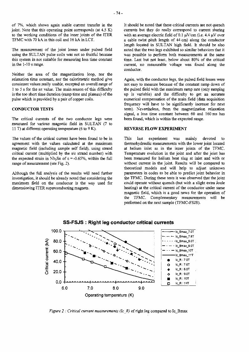
- 7 4 -
of 7%, which shows again stable current transfer in thejoint. Note that this operating point corresponds (at 4.5 K)to the working conditions of the inner joints of the ITERTFMC with 70 kA in this coil and 16 kA in LCT.
The measurement of the joint losses under pulsed fieldusing the SULTAN pulse coils was not so fruitful becausethis system in not suitable for measuring loss time constantin the 1-10 s range.
Neither the area of the magnetization loop, nor therelaxation time constant, nor the calorimetric method giveconsistent values really usable, excepted an overall range ofI to 5 s for the m value. The main reason of this difficultyis the too short time duration (ramp time and plateau) of thepulse which is provided by a pair of copper coils.
CONDUCTOR TESTS
The critical currents of the two conductor legs weremeasured for various magnetic field in SULTAN (7 toI1 T) at different operating temperature (6 to 9 K).
The values of the critical current have been found to be inagreement with the values calculated at the maximummagnetic field (including sample self field), using strandcritical current (multiplied by the s/c strand number) withthe expected strain in Nb3Sn of s = -0.65%, within the fullrange of measurement (see Fig. 2).
Although the full analysis of the results will need furtherinvestigation, it should be already noted that considering themaximum field on the conductor is the way used fordimensioning ITER superconducting magnets.
It should be noted that these critical currents are not quenchcurrents but they do really correspond to current sharingwith an average electric field of 0.1 uV/cm 0-e- 4.4 uV overa cable twist pitch length of 44 cm) along the conductorlength located in SULTAN high field. It should be alsonoted that the two legs exhibited so similar behaviors that itwas possible to perform both measurements at the sametime. Last but not least, below about 80% of the criticalcurrent, no measurable voltage was found along theconductor.
Again, with the conductor legs, the pulsed field losses werenot easy to measure because of the constant ramp down ofthe pulsed field with the maximum ramp rate (only rampingup is variable) and the difficulty to get an accuratenumerical compensation of the main field (data acquisitionfrequency will have to be significantly increase for nexttests). Nevertheless, from the magnetization relaxationsignal, a loss time constant between 60 and 160 ms hasbeen found, which is within the expected range.
REVERSE FLOW EXPERIMENT
This last experiment was mainly devoted tothermohydraulic measurements with the lower joint locatedat helium inlet as in the inner joints of the TFMC.Temperature evolution in the joint and after the joint hasbeen measured for helium heat slug at inlet and with orwithout current in the joint. Results will be compared totheoretical models and will help to adjust unknownparameters in codes to be able to predict joint behavior inthe TFMC. During these tests it was observed that the jointcould operate without quench (but with a slight extra Jouleheating) at the critical current of the conductor under samemagnetic field, which is a good news for the operation ofthe TFMC. Complementary measurements will beperformed on the next sample (TFMC-FSJS).
SS-FSJS : Right leg conductor critical currents
(kA
)re
ntic
al c
urC
ril
IUU.U •
80.0-
60.0 -
40.0-
20.0-
0.0-
* O "••- ""'**- •** ^ * ^ ^
1 ' " " • • ' ' 1 ' • ' ' • • ' • • 1 • ' • 1 • • . • i
6.0 7.0 8.0 9.0
Operating temperature (K)
_ . _ .
•
o•
•D
lc_Bmax_7.0T
lc_Bmax_7.6T
lc_Bmax_8.0T
lc_Bmax_9.0T
lc_Bmax_10T
lc_Bmax_11T
ic_R : 7.0T
lc_R : 7.6T
lc_R : 8.0T
lc_R : 9.0T
lc_R: 10T
lc_R:11T
Figure 2 : Critical current measurements (IcR) of right leg compared to Ic_Bmax
- 7 5 -
CONCLUSIONS TASK LEADER
The first European full-size joint sample, so-called SS-FSJS, was successfully tested in November and December1998 in the SULTAN test facility. The joint exhibited thelowest value ever measured on this type of sample (1.3 nD.at 4 T) and was able to be operated up to the criticalcurrent of the conductor without quench. The twoconductor legs showed very similar behaviors with stablecritical currents in agreement with expected values fromstrand properties at maximum magnetic field. A significantanalysis work remains to be done and comparisons withmore sophisticated theoretical models will be very fruitful[2]. On the other hand, pulsed field operation have shownto be disappointing in SULTAN and losses measurementswill need a serious improvement (if possible) in the futuretests. As a general conclusion, the results gained with thetests of the SS-FSJS in SULTAN give confidence in thegood behavior of the inner (high field) joints of the TFMC.
B.TURCK
DSM/DRFCCEA Cadarache13108 St Paul Lez Durance Cedex
Tél. : 33 4 42 25 47 45Fax : 33 4 42 25 49 90
REFERENCE AND PUBLICATION
[1] D. CIAZYNSKI - NET Contract 96/432 : SS-FSJSTesting Program in SULTAN - Note NT/EM/98/51 -October 10, 1998.

- 7 7 -
M29
Task Title : CONDUCTOR FABRICATIONITER Conductor R&D and monitoring
INTRODUCTION
The ITER PF coils are made of NbTi superconductor. Asolution is investigated for NbTi CICC to control losses atan acceptable level [1], It is to design the strand with aresistive layer inside the copper crown surroundingfilamentary area.
This would have the advantage to be a cheap solution. Totest this method, three NbTi strands have beenmanufactured with a lOum copper nickel layer. Thelocation of the resistive layer is different for each strand inorder to evaluate the effect of the location on the efficiencyof the layer. Three 36 strands CICC have been realised toperform interstrand resistance and AC losses measurements.
1998 ACTIVITIES
SAMPLES DESCRIPTION
Three NbTi strands have been produced by GEC Alsthom,with three different locations of a CuNi30% resistive barrierof 10|im thickness. Each strand has a 0.81 mm diameter.
The CuNi barrier location is characterised by the thicknessof copper remaining around the barrier (see Table 1). Thebarrier location associated to sample #1 is adjusted duringthe billet assembly (see Fig.l strand #1 cross section).
The barrier location of samples #2 and #3 is adjusted afterthe extrusion process by shaving the external copper shell.This produces only a very small variation of the inter-filaments distance and filament diameter. ResidualResistance Ratio and Non Copper Ratio have been providedby the manufacturer.
The cable manufacturing and jacketing has been done byShapemetal Innovation. The cable is a 3x3x4 multistageCICC with A316LN stainless steel jacket (see Fig.2). Thespecified void fraction is 33 %(see Table. 1). The final outerdiameter of the cable is 8.52±0.02 mm.
A scattering can be noticed in the last twist pitch length(from 120 mm to 160 mm) compared to the specified value120 mm. It has to be noticed that a scattering has also beenobserved along a cable length. This remark is veryimportant because coupling losses are proportional to thesquare of the twist pitch length.
Figure 1 : Cable cross-section
Figure 2 : Strands #1 cross section
Table 1 : Samples description
(Cu+CuNi)/NbTi
RRR
Copper sheetthickness
Twist pitch pattern
Void fraction
Units
Urn
mm
mm
#1
1.52
130
22
30x86x140
33.2%
#2
1.38
137
14
30x80x160
32.8%
#3
1.23
132
0
29x76x120
34.8%
MEASUREMENTS
Losses
For each strand, hysteresis and coupling losses have beenmeasured by a magnetisation method. Magnetisation ismeasured using two compensated pick-up coils and apulsed solenoid providing a ±3 T trapezoidal field for ratesbetween 0.3 T/s and 6 T/s. The hysteresis reference volumeis the non copper volume (copper nickel is included incopper volume).
- 7 8 -
The coupling losses reference volume is the strand.Coupling losses per volume unit, Qc, are usuallycharacterised by a time constant m :
Table 3 : Inter-strand resistance
nxB'(1)
For each cable, hysteresis and coupling losses have alsobeen measured using the same method as for strands. Asuperconducting dipole provides a +2 T trapezoidal fieldfor rates between 0.02 T/s and 2 T/s. Two cable lengths areused for these measurements, 240 mm and 400 mm. Inorder to be installed on the sample holder an epoxy framehas been impregnated on the conductor jacket. It meansthat every conductor has been heat-treated before lossesmeasurements, typically at 120°C during 3 hours. All thesemeasurements are summarised in Table 2 (nxM is themeasured time constant). It has to be noticed that there is afactor ~2.5 between the hysteresis losses on strands andcables because the applied pulsed fields were different. Adiscrepancy can be observed between measurements onsame samples (30% for #1, 40% for #2, 5% for #3). Itcould be explained by the difficulty to measure lowhysteresis losses on samples with high time constant. It isimportant to notice that the strand time constant is notnegligible compared to the cable time constant.
Inter-strand resistance
On each 240 mm long cable, inter-strand resistances havebeen measured in every triplets. These measurements havebeen performed under DC field from 0 T to 4 T and for aDC current from 50 A to 300 A by step of 50 A.
Table 2 : Losses results
nxM
nxo
nxR
strand
240mm cable
400mm cable
strand
240mm cable
400mm cable
Units
mJ/cm3
mJ/cm3
mJ/cm3
ms
ms
ms
ms
ms
#1
107
55
60
4.8
38
32
72
10
#2
127
36
59
5.8
46
34
88
17
#3
128
/
53
7.0
/
12
11
7
No influence of the transport current on the resistance hasbeen measured. A 20% increase of the resistance has beennoticed between 0 T and 4 T from samples #1 and #2. The#3 inter-strand resistance appears to be independent offield. Measurements are summarised in Table 3.
Discussion
The time constant design value of ITER conductors is100 ms. It means roughly a value of 50 ms for our sub-sizecables.
nCi.m
BDC=0 T
B D C =4 T
Max
Mean
Min
Max
Mean
Min
#1
35
45
65
41
53
78
#2
21
22 .
26
23
26
30
#3
295
330
394
295
329
394
As 35 ms and 40 ms were measured for samples #1 and #2,it appears that an inner copper nickel barrier could ensurea sufficient inter-strand resistance to reduce couplinglosses to the required level. The strand with an externalcopper nickel barrier has a very low time constant, 12 ms,that is of the same order of magnitude as the strand timeconstant, 7 ms. It is important to note that the timeconstant should not be reduced too much in order to ensurethe current redistribution capability in case of currentimbalance among strands.
CONCLUSION
It has been demonstrated in this study that a CuNi resistivebarrier can ensure sufficiently low coupling losses in largetwisted NbTi cables. To be efficient this barrier should benearly external. For ITER application, on the one handexternal CuNi barrier can be achieved in practical NbTicomposites, on the other hand plating solutions usingchromium or Nickel are also possible. Both kinds ofindustrial solutions will be explored and economicallycompared in a next Euratom contract led jointly byENEA/Frascati and CEA/Cadarache.
REFERENCE
[1] T. Schild, J.L Duchateau. AC losses dependence ona CuNi layer location in NbTi CICC. Physica C 310(1998) p.247-252
TASK LEADER
JL. DUCHATEAU
DRFC/STEPCEA Cadarache13108 St Paul Lez Durance Cedex
Tél. : 33 4 42 25 49 67Fax : 33 4 42 25 26 61
- 7 9 -
M30
Task Title : CONDUCTOR FABRICATIONITER Conductor R&D coordination
INTRODUCTION
The frame of this task is the coordination of the Europeanactivity in the field of ITER magnet R&D.
This coordination consists in monitoring the tasks ofseveral European laboratories and industry and inpreparing new tasks in relation with ITER tasks. For 1998the laboratories and industries included in this activitywere : University of Twente, University of Padova,University of Create, University of Torino, CEACadarache, CEA Saclay, FZK, ENEA ,CRPP andOutokumpu. About 16 different contracts have beencovered.
Meetings were organised in the different laboratories andindustries to monitor the fabrications, to prepare theexperiments or to discuss the results. A central meetingwas organised in March 1998 at Cadarache with the fourparties of ITER. About 10 nationalities were present todiscuss ITER design criteria, taking into account the recentresults of R&D and try to reduce the cost of the machine.Main results of this activity are presented there.
1998 ACTIVITIES
CONDUCTOR PERFORMANCES
- For the PF coils of ITER, due to the low field in theregion, NbTi can be used for the conductor. To controlthe losses at an acceptable value an internal CuNilayer can be used situated in the outer copper shell ofthe composite. Three 36 strands samples have beenproduced, with three different locations of the CuNilayer. The conclusions of the losses and contactresistance measurements at CEA Cadarache, is that theinternal layer solution is at the upper limit of the ITERspecifications for the PF coils. Other solutions likecoatings have to be studied.
- Mechanical cycling has been performed at TwenteUniversity on two full size ITER samples. It turned outthat this cycling is greatly affecting the conductor timeconstant. There is roughly a decrease by a factor ofthree, starting from a virgin sample. The explanation isprobably that the oxygen diffuses through the coppermatrix during the heat treatment of the sample at theclosed contacts between strands. Starting from a lowvalue of the contact resistance, some reoxydation couldthen take place during the cycling and the associatedstrand movement.
The losses are quite within the ITER specification inthis condition, but the current redistribution betweenstrands could be affected if the resistance is too high.Friction losses have been also evaluated during thecycling using hysteretic cycles. These results have beenused as an input in the theoretical homogenous modeldeveloped by University of Padova.
- Concerning losses measurement on full size samples, across checking has been performed at CEA Saclay onthe full size Japanese conductor, to confirm the lowvalue of the coupling time constant of full sizeconductors already obtained at Twente University. Afactor of three between the calorimetric measurementsat Saclay (55 ms) and at Twente (108 ms corrected to162 ms to have the correct superconducting strandreference section ) can be pointed out. It can beperhaps put in relation with the evolution along thetime of this time constant due to the reoxydation of thecontact surfaces of the strands after heat treatment.
JACKET MATERIAL MECHANICAL PROPERTIES
The quality of the incoloy-copper bonding has been studiedat CEA Cadarache on mechanical samples. Themechanical behaviour of this joint at cold temperature isquite comparable to the stainless steel-copper bondingbehaviour. The limitation is always associated to thecopper and not to the joint.
This study has demonstrated the ability to manufacture anincoloy version of the European connection box. Dummyjoint boxes were manufactured, then heat treated undervacuum. The joint design will have to take into account thedeformations due to the differential thermal contractionand stresses relaxation occuring after heat treatment andthermal cycling of incoloy-copper explosion bondingmaterial.
TEST COIL PERFORMANCES
New tests have been performed on the 12 T CICC magnet.It is believed that critical current reduction in multistrandcable superconducting cables in non steady state condirionis caused by non uniform current distribution amongstrands. This current imbalance has been pointed out onthis experiment, for different ramp rates, by means ofnumerous local miniature field sensors located in a fewpositions along the conductor. It has been shown thatsevere current nonuniformity exists in the cable and thatinduced current loops are generated which decay with verylong time constants, (up to 104-105 s). The next step is nowfor this coil to be tested at nominal field in the Sultan testfacility.

- 8 0 -
CONNECTIONS
Model
An electrical model has been developed at CEA Cadaracheto predict the behaviour of a conductor associated to itsconnections at the two ends, in steady state. This modeltakes into account the unequal distribution of currentamong the strands in the connection due to the contactwith the copper sole and the current redistribution processoccurring all along the length of the conductor.
This current redistribution is a function of the conductancebetween the strands and of the critical properties of thestrand. These characteristics cannot always be obtainedfrom experience.
This model is a theoretical basis to work out data comingfrom Sultan experiments, but also to predict the behaviourofthelTERTFcoil.
Tests
A Japanese conductor has been tested at Sultan with a so-called lap joint. A very high unacceptable resistance ofmore than 100 nD has been pointed out on the lower joint.
The European SS-FSJS has been tested. This sample wasaimed to validate, for ITER, the twin box conceptdeveloped by CEA Cadarache. CEA has made theconnection concept by using a full size Nb3Sn ITERconductor, then has monitored the fabrication at Ansaldo(Genova, Italy) in the frame of the TF model coilfabrication. The CEA has been in charge of organising thetests at the Sultan CRPP test facility (Villigen,Switzerland). The results were very good. One of the mostsignificant results is the following :
The connection resistance does not exceed 1.5 nQ for80 kA current in a field of 6.8 T with a temperature up to8.2 K.
CURRENT LEADS
Studies are carried out jointly by CRPP and FZK topromote HTSC current leads for ITER and reduce theassociated losses. During the first stage of the contract on1-2 kA leads, Bi-2223 tapes electrically stabilised by AgAumaterial were selected for the further developmentprogram because of their larger safety margin than bulkmaterial. In a next step one 10 kA current lead has beenreceived from the industry and another one is beingmanufactured at FZK. The first one will be tested in 1999at FZK.
OTHER STUDIES
Starting from their general contribution on eddy currentsin ITER during normal scenario and disruptions last year ,University of Create has provided this year more refinedcalculations on points specified by ITER.
These points were mainly field maps in the TF magnetduring disruptions, additional results on pre-loadingflanges and lower OIS (Outer Intercoil Structure) duringthe normal scenarios and disruptions and poloidal eddycurrents induced by a plasma disruption. The conclusionfor this last point was that the thermal effects of thepoloidal eddy currents are negligible compared to those ofthe toroidal eddy currents.
CONCLUSION
The very good results obtained on the SS-FSJS has pointedout that a solution was quite available for the ITERconnections. The research community is now quiteconscious that current distribution among strands is reallya problem for large Cable in Conduits and can bringinstabilities. As a matter of fact, Niobium Titaniumconductor could be specially affected by this problem dueto the very low critical temperature. R&D is now urgentlyneeded for the NbTi conductor of the PF ITER coils and inparticular to control the inter strand conductance at theright level.
TASK LEADER
JL. DUCHATEAU
DRFC/STEPCEA Cadarache13108 St Paul Lez Durance Cedex
Tél. : 33 4 42 25 49 67Fax : 33 4 42 25 26 61
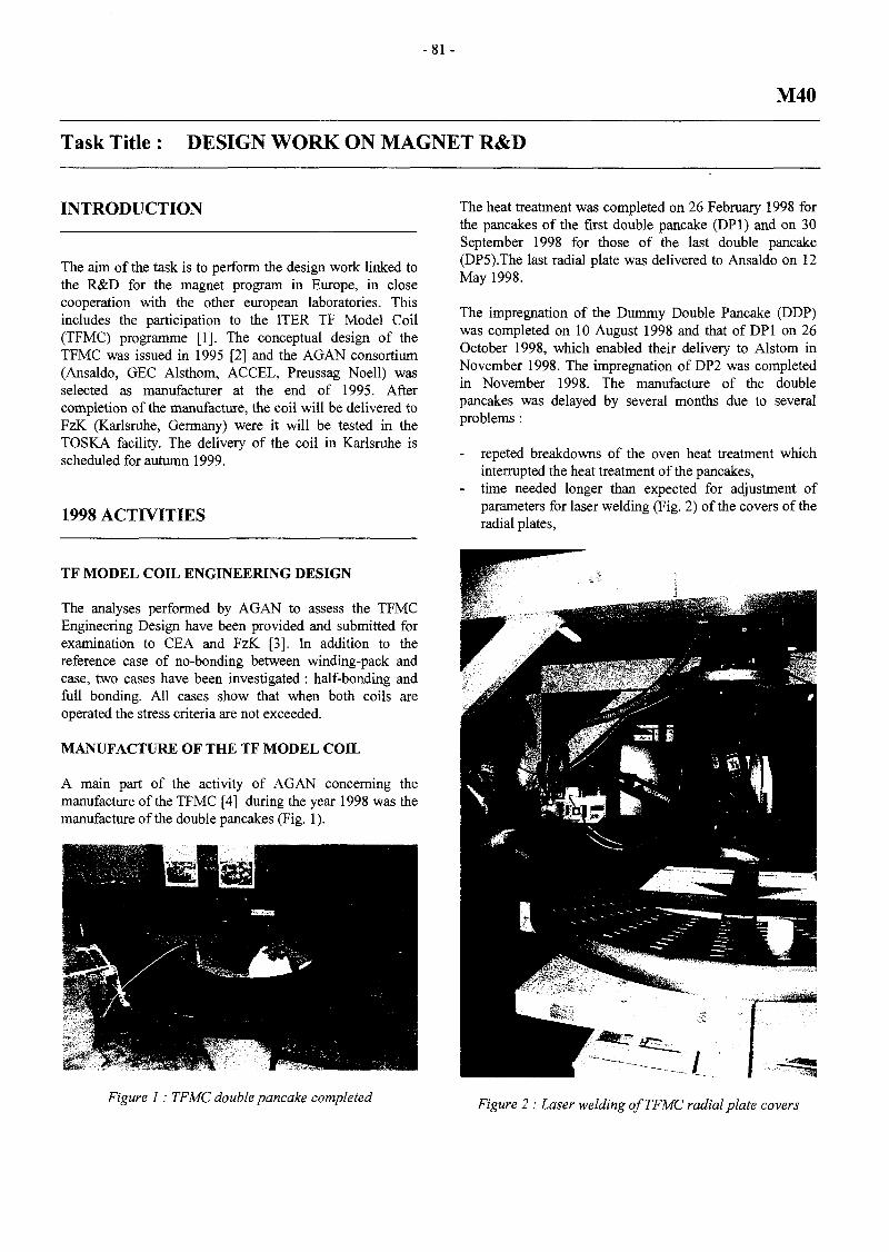
- 8 1 -
M40
Task Title : DESIGN WORK ON MAGNET R&D
INTRODUCTION
The aim of the task is to perform the design work linked tothe R&D for the magnet program in Europe, in closecooperation with the other european laboratories. Thisincludes the participation to the ITER TF Model Coil(TFMC) programme [1]. The conceptual design of theTFMC was issued in 1995 [2] and the AGAN consortium(Ansaldo, GEC Alsthom, ACCEL, Preussag Noell) wasselected as manufacturer at the end of 1995. Aftercompletion of the manufacture, the coil will be delivered toFzK (Karlsruhe, Germany) were it will be tested in theTOSKA facility. The delivery of the coil in Karlsruhe isscheduled for autumn 1999.
1998 ACTIVITIES
TF MODEL COIL ENGINEERING DESIGN
The analyses performed by AGAN to assess the TFMCEngineering Design have been provided and submitted forexamination to CEA and FzK [3], In addition to thereference case of no-bonding between winding-pack andcase, two cases have been investigated : half-bonding andfull bonding. All cases show that when both coils areoperated the stress criteria are not exceeded.
MANUFACTURE OF THE TF MODEL COIL
A main part of the activity of AGAN concerning themanufacture of the TFMC [4] during the year 1998 was themanufacture of the double pancakes (Fig. 1).
The heat treatment was completed on 26 February 1998 forthe pancakes of the first double pancake (DPI) and on 30September 1998 for those of the last double pancake(DP5).The last radial plate was delivered to Ansaldo on 12May 1998.
The impregnation of the Dummy Double Pancake (DDP)was completed on 10 August 1998 and that of DPI on 26October 1998, which enabled their delivery to Alstom inNovember 1998. The impregnation of DP2 was completedin November 1998. The manufacture of the doublepancakes was delayed by several months due to severalproblems :
- repeted breakdowns of the oven heat treatment whichinterrupted the heat treatment of the pancakes,
- time needed longer than expected for adjustment ofparameters for laser welding (Fig. 2) of the covers of theradial plates,
Figure 1 : TFMC double pancake completed Figure 2 : Laser welding of TFMC radial plate covers

- 8 2 -
modifications required for the impregnation tool (Fig.3), in order to meet the specifications on the doublepancake thickness and flatness.
Figure 3 : TFMC double pancake impregnation tool
TFMC-FULL-SIZE-JOINT-SAMPLE
A prototype joint sample of the outer joints of the TFMC isplanned to be tested at CRPP (Villigen, Switzerland) in theSULTAN facility [5]. The legs of this TFMC-Full-Size-Joint-Sample (TFMC-FSJS) have been manufactured andheat treated by Ansaldo and delivered to Alstom on 20November 1998 for assembly and installation of theinstrumentation. This sample will incorporate thetechnology of copper pins welded by electron beam to thetermination box copper sole.
TF MODEL COIL MAGNETIC FIELDCALCULATIONS
A detailed model of the TFMC was built with the TRAPScode to perform a precise calculation of the magnetic fieldon the conductor. The maximum field values are shown in
Table 1 and the variation of field along the DP 1.1 pancakeinner turn when the TFMC is operated with the LCT Coil isshown in Fig. 4. As it can be seen, a strong magnetic fieldgradient arises through the conductor cross-section.
Table 1 ': Maximum field on TFMC conductor
Operatingconditions
Maximum field
Single mode
I TFMC = 80 kA,I LCT = 0 kA
7.80 T
Operation with LCT
I TFMC = 70 kA,IL C T=16kA
9.02 T
TFMC OPERATING DIAGRAM
The TFMC operating diagram has been revised (Fig. 5),taking into account the precise field calculations presentedabove and the results of the experiments performed at FzKon samples made with the TFMC conductor subcables.
TFMC CONDUCTOR HYDRAULICCHARACTERISTICS
The thermohydraulic analyses of the TFMC require amodeling of the conductor taking into account twohydraulic circuits in parallel : the cable area and the centralchannel .This needs to determine the hydrauliccharacteristics, in particular the friction factor, of each ofthese circuit. Pressure drop measurements have beenperformed at Cadarache in the OTHELLO facility withsamples of the actual TFMC conductor in order todetermine these friction factors [6]. The friction factor ofthe cable area is determined by closing the central channelin inserting a plastic tube in it and the friction factor of thecentral channel is derived by substracting the pressure dropof the cable area from that of the full conductor (Fig. 6).
9
8,5
7
fi c:
V /Vy
DP2.2 inner
o :
Conductor edgey
K
V— Conductor .
Inner joint
2 4
s(m)
DP2.1 innerl
6 i
Figure 4 : Magnetic field along DP 2 inner turns (I TFMC 70 kA, I ICT 16 kA)

- 8 3 -
stability limit with coppe
5,00 6,00 7,00 8,00
B(T)
9,00 10,00 I
Figure 5 : TFMC operating diagram
reQ.
a2•a230)W©
0,40
0,35
0,30
0,25
0,20
0,15
0,10
0,05
0,00
Normalizedconditions
Pm = 3.0 MPaTm = 273 K
DP = 0.0011*m1 4367
I
i
0 20 80 100 120
Gas flow (g/s)
Figure 6 : Pressure drop measurements on TFMC conductor
QUENCH TRIGGERING CALCULATIONS
Resistive heaters will be installed on DPI pancakes heliuminlet in order to heat locally the helium circulating insidethe conductor. The heat slug will propagate inside theconductor and a quench will be triggered inside thepancake. In order to check that the quench will occur in theconductor and not in the joint area, a dedicatedthermohydraulic model was built to investigate the heat slugpropagation. The temperature along the conductor iscomputed at each time step and compared to the conductorcurrent sharing temperature. As shown in Fig. 7, when bothcoils are operated, the quench will arise first in theconductor, but the margin between minimum Tcs value in
conductor and joint is very small (Table 2). The model willbe assessed by comparison with the SS-FSJS test resultsand parameters adjusted.
Table 2 : Current sharing temperature in DP 1.2during heat slug propagation
W = 8 0 kA ; ILCT= 16 kA
Bmax(int)
Bmin(int)
Tcsmax(int)
Tcsmin(int)
Joint
8.23 T
7.95 T
6.91 K
6.65 K
Conductor
9.68 T
8.23 T
7.48 K
6.16 K

- 8 4 -
7,50 -
7,00
6,50 -
— 6 00 -
^ 5,50 -
5,00 -
4,50
4,00
0,
—->-•^————
central channel
[Joint inner
00 1,00
Tes
cable area V~
turn of DP 1,2
2,00 3,00
s(m)
/ ^
4,
«•
L.
DO
Figure 7 : Heat slug propagation inside DPI. 2 (ITFMC SO kA, I LCT 16 kA)
CONCLUSION TASK LEADER
The assessment of the TFMC Engineering Design has beencompleted and the manufacture of the double pancakes haswell progressed, despite some delay. The preparation of thetesting included in 1998 magnetic field calculations,measurement of hydraulic characteristics of the conductorand analysis of the heat slug propagation.
REFERENCES
[1] The ITER Toroidal Field Model Coil (TFMC), E.Salpietro et al., 20th SOFT,Marseille, 7-11 September1998
[2] Conceptual design of the ITER TF Model Coil, P.Libeyre et al., IEEE Trans, on Mag., vol. 32, pp 2260-2263,1996
[3] From Conceptual to Engineering Design of the ITERTFMC, P. Libeyre et al., 20th SOFT, Marseille, 7-11September 1998
[4] Manufacture of the ITER TF Model Coil, R. Maix etal., 20th SOFT, Marseille, 7-11 September 1998
[5] Development of Joints in Europe for the ITER TFMC,P. Libeyre et al , MT15 Proa, pp 421-424
[6] Hydraulics of the ITER TFMC cable-in-conduitconductor, S. Nicollet et al., 20* SOFT, Marseille, 7-11 September 1998
P. LIBEYRE
DSM/DRFC/STEPCEA Cadarache13108 St Paul Lez Durance Cedex
Tél. : 33 4 42 25 46 03Fax : 33 4 42 25 26 61
E-mail : [email protected]

- 8 5 -
M48
Task Title: WINDING AND INSULATION DEVELOPMENTJoint Development
INTRODUCTION
The task was divided into threedifferent parts, the first partdeal with measurements of ITER strand critical currentsunder field having angles with regard to the wire axis, thesecond part was concerned with the modification of theCadarache test facility for testing subsize joints underparallel field and with the test of an already existingsubsize joint sample (from task MWIN-2) under parallelfield, this part also covered an extra test on a modifiedsubsize joint sample for the TF Model Coil. The third partwas devoted to fabrication and characterization tests of anincoloy-copper plate bonded with the explosive method,foreseen for the fabrication of the ITER joints.
1998 ACTIVITIES
PART 1: TESTS OF NB3SN STRANDS UNDERVARIOUS FIELD ANGLES
This part was completed in 1997.
PART 2
Completion of tests of one modified MWIN-2 subsizejoint sample for the TFMC
This activity was completed in 1997.
Modification of the Cadarache joint test facility to allowparallel field testing
The Cadarache joint test facility previously developedwithin task MWIN-2 for testing subsize joints undertransverse field was upgraded by the addition of an extraassembly where the dipole has been replaced by a solenoid.This NbTi helium bath cooled solenoid can provide amaximum field of 7.5T with a maximum ramp rate of0.5T/s over about a 500mm length and with an availablebore diameter of 80mm. It allows to test under parallelfield the electrical resistance and AC losses of subsizejoints like the ones developed within the task MWIN-2.The test facility JOSEFA available in Cadarache has beenfully operational since March 1998 to perform tests onsubsize samples like joints both in transverse and parallelfield.
Completion of test of one MWIN-2 (Phase II) sampleunder parallel field
One subsize joint sample previously tested within taskMWIN-2 in transverse magnetic field was again tested inparallel magnetic field in the CEA test facility JOSEPHAwhich has been upgraded to allow testing in parallel fieldup to 6T of subsize joint samples cooled by supercriticalhelium. DC resistance measurements with high transportcurrent up to 10 kA and with high ratio to the criticalcurrent were performed. Joint losses under pulsed field aswell as stability tests under varying magnetic field werealso carried out.
The tests results have been compared to the previousresults gained under transverse magnetic field.
No sensible modification of the joint resistance has beenfound.
The quench temperatures have been found to be inagreement with the theoretical values of the currentsharing temperatures Tes, calculated using the averageangle (a = 20°) between strand axes and cable axis, andare therefore higher than under transverse field (a = 90°).
The pulsed field loss measurements have shown a nr valueof about 0 .1s inside the joint which is consistent withprevious experimental values determined within taskMWIN-2 and which shows that the main contribution tothe losses comes from pure eddy currents in the jointcopper soles.
The stability tests were perturbed by problems of quenchoccurring at the connection between the sample and thecurrent leads of the facility (due to local overheating).Nevertheless a minimum critical energy boundary of286 mJ/cm3 for a temperature To = 9.5K was measuredwhich is in agreement with theoretical models and withpreceding results under transverse field. This result alsoshows that no substantial limit of the joint stability marginhas been observed due to unexpected phenomenon, such asinduced circulating currents.
PART 3
Fabrication of an incoloy-copper plate by the explosivebonding
This activity was completed in 1997

- 8 6 -
Characterization of the incoloy-copper assembly
Samples for tensile and shear tests as well as foil size jointbox mock-ups using the EU design for joints have beenmanufactured using the explosion bonded incoloy-copperplate.The shear and tensile tests were performed before andafter heat treatment simulating the Nb3Sn reaction heattreatment at 300K and 4K. The results were compared tothose gained during the previous qualification program ofsteel-copper assembly bonded by the explosive method.The mechanical behaviour of the incoloy-copper bondingwas found to be as good as it was for the steel-copperbonding which means the breakage never occurred at theinterface, the mechanical limits were always given by thecopper itself. Two full size dummy joint boxes were heattreated under vacuum simulating the Nb3Sn reaction.Dimensionnal measurements and leak tests before andafter LN2 thermal cycling were performed. As it was foundwith steel-copper material, no cracks on the joint boxesusing incoloy-copper bonded material was found. Thedeformation after heat treatment shows a bending of theboxes due to differential thermal contraction betweencopper and incoloy added to a first pre-bending of theboxes due to stress relaxation of incoloy. This bendingappears towards the copper sole in the straight part in arange of a 20m radius and towards the opposite directionin the pre-bended part of the joint boxes within the samerange. These deformations were not observed on the steel-copper joint box mock-up. So, particular attention willhave to be paid in the fabrication of joints using incoloy-copper explosion bonded material in order to take intoaccount the deformations due to differential thermalcontraction and stresses relaxation occurring after heattreatment of incoloy-copper explosive bonded assembly.
CONCLUSIONS
Part 2 of the task was completed by the availability of theupgraded Cadarache joint test facility for testing subsizejoint sample in transverse and now in parallel magneticfield. The test of a previously manufactured subsize jointsample in parallel field has not shown any degradation ofthe joint performances by comparison with the previoustests in transverse field (higher Tes and low losses).
Due to the important delivery delay of the incoloy plates,part 3 of the task could be completed at the end of 1998.Now the Incoloy-copper bonding has been follycharacterized and leads to confirm the validity of the EUconcept for ITER joints. These results have allowed to startthe fabrication for tests of a TF Full Size Joint Sampleusing the ITER TF incoloy jacketed conductor and theIncoloy-copper bonding technology for the joint.
REPORTS AND PUBLICATIONS
[1] T.SCHILD, H.CLOEZ - Final report M48 part I:Tests of two Nb3Sn ITER strands under various fieldangles - Note NT/EM/97.40, September 22, 1997
[2] P.DECOOL - Task M48: Test of one modifiedMWIN-2 subsize joint sample for the TFMC - NoteNT/EM/97.08, February 17, 1997
[3] P.DECOOL - Task M48 part II: Modification of anexisting joint test facility to allow parallel field testing- Note NT/EM/98.56, december 21, 1998
[4] P-DECOOL - Task M48 part II: Test of one MWIN-2subsize joint sample under parallel field - NoteNT/EM/99.06, March, 1999
[5] P-DECOOL - Task M48 part III: Manufacture of anincoloy-copper plate bonded by the explosive method- Note NT/EM/98.36, September 09, 1998
[6] P-DECOOL - Task M48 part III: Characterisation ofan incoloy-copper plate bonded by the explosivemethod - Note NT/EM/98.57, december 21, 1998
TASK LEADER
P. DECOOL
DSM/DRFC/STEPCEA Cadarache13108 St Paul Lez Durance Cedex
Tél. : 33 4 42 25 43 50Fax : 33 4 42 25 26 61
E-mail : [email protected]

- 8 7 -
T252
Task Title : RADIATION TOLERANCE ASSESSMENT OF STANDARDCOMPONENTS FOR REMOTE HANDLING AND PROCESSINSTRUMENTATION
INTRODUCTION
This present report is corresponding to the intermediatereport on CEA/DEIN/SLA and CEA/DEIN/SPEcontribution to ITER T252 task "Radiation toleranceAssessment of standard components for remote handlingand process instrumentation".
From now, the known missions for remote handlingmodules are organised around three main topics :
- very short visual in-vessel inspection (few hours) justafter shut-down of experimental reactor where total doselevel expected for vision modules is around lMGy,
- extensive in-vessel inspection (few days) where totaldose expected during such missions is up to 1 OMGy,
- maintenance (2 or 3 months) where total dose couldreach up to lOOMGy. The main actions to be takenduring this time are the replacement of divertor cassetteand the control of the blanket. It should be possible tochange critical modules every week in order to notexceed lOMGy for them.
One topic should normally be added, the six-months storageof inspection modules. But, if the environmental conditionsof the third ones are agreed by ITER teams (between 50°C
and 200°C for a dose rate averaged to 30kGy/h), it seemsnot to be the same for storage period. Total dose and doserate are unknown. Neutrons are at least 1012n/m2/s andspectrum is not defined. For all duration of post-EDA T252,we do not take into account this topic.
The purpose of CEA/DEIN is to assess the radiationtolerance of commercial electronic or optical componentsable to be integrated in remote handling modules. Forelectronic components, studies are mostly focused on MOStechnologies but nothing stands to look at emerging oroldest technologies to design a digital elementary module ofITER remote control.
State of the art of methods to reduce constraints onumbilical (size, weight, maintenance) has started withdelay due to the priority given to organise experiments.
1998 ACTIVITIES
ELECTRONIC COMPONENTS
The purpose of the work performed here is to assess theradiation tolerance of electronic commercial componentsand technologies, mainly MOS.
Dm itt*0
M ray*MmodMi
\
\\\
/gi»4V owing l>n
•MhHVdM-1.»)
•«•He
1
-m
—
r -
•ss.Kama»
—
Yv-.HMOr
l ia r
J ,
T
— ^ Ji
.
» .
3.
,Œ.,,
1JB-11
\ \ \
A\! \\\
— I —
«MM
\
-XHttarV«t
\1
ISO
1•-4 .,,.i
Figure 1 : Evaluation ofVgs threshold up to lOMGy ofBS250 PMOS andBSl 70 NMOS low power transistor under differentbias conditions. Tests have been made off-line.

- 8 8 -
Our strategy would also include assessments of modules(based on these components) prototyped in our lab andalready industrialised able to be included in ITER engines.A first campaign of irradiation has been engaged at thebeginning of the year to reach lOMGy (6kGy/h and 50°Cfor environmental conditions) on sets of componentsusually found in electronic embedded systems for lowerdose tolerance.
Due to the proximity of irradiation facilities and the greatnumber of components (for each one, at least two samplesof the same lot, and when possible, multiple lots andmanufacturers, multiple bias conditions to cover mainfuture uses), intermediate tests in our lab have beenscheduled at regular total dose levels. Components are pullout irradiation cells, measured and put back to be irradiatedagain. Figure 2 shows on the cards used for theseexperiments.
Figure 2 : Card used to irradiate set of componentsup to lOMGy (steps by steps tests)
Data exploitation is not yet finished but some results areshown above.
A large set of components have been irradiated withdifferent bias conditions and evaluation has been made bysteps. All the results are not yet analysed. However, thefollowing curves (Figure 1) on PMOS and NMOStransistors give enough information to continue to test themunder hardest conditions like for ITER. Permanent state hasbeen arriving around 1 OOkGy with no significant evolutionafter. Recovery at room temperature after more than 6months is not so significant.
Curves not shown in this report give the behaviour oftransistors from other technologies. Like for MOScomponents, a permanent state is reached for bipolarcomponents. It does not changed when total dose increases.
The other, SiC, is an emerging technology. Today, thecomponents come from laboratories, not enough debuggedto be commercial. One of its main characteristic is theability to support very high temperature. So, componentscould be use for ITER inspection missions.
A transistor (biased at -12V during irradiation) has badlyrecovered (an other sample has been destroyed during thisperiod) to reach lOMGy.
The second campaign, using SCK/CEN facilities to beneared ITER goals, could not be a remake of the previousone. Even if for few components, data could be takenthrough previous results, too much parameters areuncertain.
Firstly, we have never met such high dose rate (up to30kGy/h). The early hours of irradiation get sometimesinformation on the establishing of permanent state.
Secondly, the short period (3 weeks) and the distant area ofirradiation do not simplify management of experiments.Risk is important to test components unable to givesignificant data.
Thirdly, no such level of temperature has been requested inour background. If for an electronic component, thermalannealing is well known to recover characteristics off line,the combined effect of dose and temperature is an opensubject.
Due to these reasons, we have been opting for in-linemeasurements with a specific measuring method.
To make it into action, we chose MOS transistors. Wejustify this choice because these components are useful forlow and high power applications and already used on realconditions under irradiation. We have many results onprevious irradiation tests and good feedback aboutapplications using it.
We have been designing a new testbed based on existingone to take into account ITER constraints et developpingspecific test cards and wires to connect them to BRIGITTEplugs.
Figure 3 shows one of the MOS testbeds use in our lab.ITER testbed is similar to it.
Figure 3 : Instruments used to evaluate componentsafter steps of irradiation (see an other card used
for lOMGy campaign)
During irradiation, component is biased. Many types areused (+/-10V, OV, +5V, alternate +/-10V and unsupply).
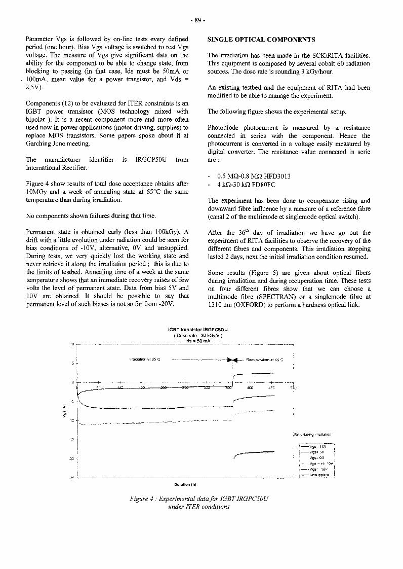
- 8 9 -
Parameter Vgs is followed by on-line tests every definedperiod (one hour). Bias Vgs voltage is switched to test Vgsvoltage. The measure of Vgs give significant data on theability for the component to be able to change state, fromblocking to passing (in that case, Ids must be 50mA or100mA, mean value for a power transistor, and Vds =2,5V).
Components (12) to be evaluated for ITER constraints is anIGBT power transistor (MOS technology mixed withbipolar ). It is a recent component more and more oftenused now in power applications (motor driving, supplies) toreplace MOS transistors. Some papers spoke about it atGarching June meeting.
The manufacturer identifier is IRGCP50U fromInternational Rectifier.
Figure 4 show results of total dose acceptance obtains afterlOMGy and a week of annealing state at 65°C the sametemperature than during irradiation.
No components shown failures during that time.
Permanent state is obtained early (less than lOOkGy). Adrift with a little evolution under radiation could be seen forbias conditions of -10V, alternative, 0V and unsupplied.During tests, we very quickly lost the working state andnever retrieve it along the irradiation period ; this is due tothe limits of testbed. Annealing time of a week at the sametemperature shows that an immediate recovery raises of fewvolts the level of permanent state. Data from bias 5V and10V are obtained. It should be possible to say thatpermanent level of such biases is not so far from -20 V.
SINGLE OPTICAL COMPONENTS
The irradiation has been made in the SCK\RITA facilities.This equipment is composed by several cobalt 60 radiationsources. The dose rate is rounding 3 kGy/hour.
An existing testbed and the equipment of RITA had beenmodified to be able to manage the experiment.
The following figure shows the experimental setup.
Photodiode photocurrent is measured by a resistanceconnected in series with the component. Hence thephotocurrent is converted in a voltage easily measured bydigital converter. The resistance value connected in sérieare :
- 0.5MQ-0.8MQHFD3013- 4 kQ-30 kQ FD80FC
The experiment has been done to compensate rising anddownward fibre influence by a measure of a reference fibre(canal 2 of the multimode et singlemode optical switch).
After the 36th day of irradiation we have go out theexperiment of RITA facilities to observe the recovery of thedifferent fibres and components. This irradiation stoppinglasted 2 days, next the initial irradiation condition resumed.
Some results (Figure 5) are given about optical fibersduring irradiation and during recuperation time. These testson four different fibres show that we can choose amultimode fibre (SPECTRAN) or a singlemode fibre at1310 nm (OXFORD) to perform a hardness optical link.
IGBT transistor IRGPC5OU( Dose rate : 30 kGy/h )
Ids = 50 mA
Irradiation at 65 C Recuperation at 65 C
460 5ij)0
Bias during .radiation :
j vgs= 10V
| Vgs=5V' Vgs- 0V! Vgs - « - 10V
Vgs=-10Vi Unsupptied
Duration (h)
Figure 4 : Experimental data for IGBT IRGPC50Uunder ITER conditions

- 9 0 -
m
g
Ito
3
m
cgCO
1T3CDO3
•001
«ois
-ace
QD25
\
V•i
\
V
f1
IX 1« 180 1BS
•aoi
«015
/1
«s,
/
- -
\
\
^ _
X
J20 « 80
« 50 95
— — —
10
15
•XI
•S
10
15
25
00
36
- -
N
\
0 ÎO
( J
\
— _
D eo a:
"X
too
-
3) 1« IS)
-
Figure 5 : Evaluation of attenuation for single and multimode fibres during irradiation and recuperation
1=76 mA
1=56 mA
1=36 mA
1=16 mA
T,r.-n*~&-*Vrz^'
ÏÏÏ!£S!=S33E K
Dose (kGy)
CD
g"Scô
a>IQ.
30 mA24 mA20 mA18 mA16 mA
14 mA
0 500 1000
: -
Dose
-,'
(kGy)
—:
- r
1000 tSDO 2000 2500 3000
Figure 6 : Evaluation of power variation of DEL, laserdiodes and VCSELs during irradiation and recuperation
GQ
c.o
CD
CD
I0.
Figure 7 : Evaluation of power variation of photodiodes during irradiation and recuperation

- 9 1 -
The recovery on the CORNING fibre haven't been studiedbecause of rupture in link between instrumentation andirradiation container.
These tests show that the fibre tend to get back to normalattenuation after a irradiation stop. But when irradiationresumed, attenuation evolution continue like beforeirradiation stop.
The next tests are about single optical components used totransmit and receive light. DEL, laser diodes, photodiodesand VCSEL (emerging technology for optical components)had been evaluated during irradiation and recuperation.
These test (Figure 6 and Figure 7) show that DEL have avery stable comportment under irradiation. The efficiency israpidly decreased of 2dB, and after the comportment is verystable. The component find is initial efficiency afterirradiation stop.
Like DEL, efficiency of laser diode loss 2 dB, and thismodification can be recovery by a irradiation stop.Irradiation tend to change threshold current and electro-luminescent effect before laser effect, but most of time thispart of characteristic is unused.
The VCSEL irradiation show a good comportment of thiscomponent. The only influence is a small fall of the ficiency( rounding 1 dB) and for one component an instabilitypower at 4 mA (an unused current).
On this experiment, it seems that the optical link betweeninstrumentation and component has been damage. So theoptical power on this photodiode wasn't enough to make angood measure. Nevertheless we can remark a modificationof the comportment for a dose rounding 2 MGy.

- 9 2 -
CONCLUSION TASK LEADER
Due to the very short time from the end of first campaignirradiation under ITER constraints, we have not hadenough time to analyse all the measured data. But thepreliminary results on some important electroniccomponents (if we included results of previous campaign)are cheerful. They tend to show that designing specificmodules using these components and taking into accountthe shown degradation (permanent state) of mainparameters could be reach for ITER maintenance missionsand could contribute to reduce number of wires on theumbilical.
Emerging technology have shown mainly good response tolOMGy. It should be important for task T252 to followthese technologies which could be an answer at the designtime of ITER future machine.
This preliminary results tend to demonstrated that theweakest element for an fibre link is the photodiode.Multimode and monomode fibre can be used without agreat variation of their attenuation, as well as emitterelement like DEL, VCSEL, and DL.
An efficient optical link for remotely controlled handlingunit will require to test more photodiode type.
The necessary work to perform during beginning of 1999will take into account the influence of temperature andirradiation on the behaviour of same components than in1998. The results of theses experiments could give ananswer to the use of electronic for short time inspectionmissions. Temperature levels expected are 140°C and200°C. Nothing is really known about the ability of eachelement to support such environment. We must be carefuland increase the control of testing supports (cards, wires,connections, weldings,..).
In the same time, testing supports will be made for logicalcomponents in order to test them during second or thirdtrimester.
For optical components, irradiations will be scheduled tocontinue the evaluation of total dose acceptance on laserdiodes, VCSEL and optic fibers (single mode and multiplemode) in order to reach ITER level constraints ( in 1998,steps were around 3MGy).
With SCK-CEN teams, a large number of photodiodes willbe irradiated in order to be able to select the hardest ones.The evaluation of temperature in the behaviour of opticcomponents will be engaged.
Alain GIRAUD
DTA/LETI/DEIN/SLA/CSDCEA Saclay91191 Gif-sur-Yvette Cedex
Tél. : 33 1 69 08 64 30Fax : 33 1 69 08 20 82
E-mail : [email protected]
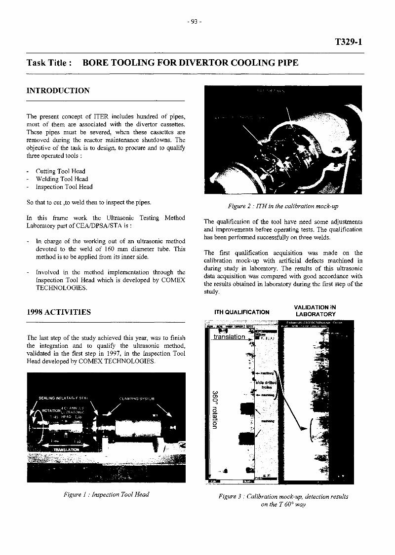
-93-
T329-1
Task Title : BORE TOOLING FOR DIVERTOR COOLING PIPE
INTRODUCTION
The present concept of ITER includes hundred of pipes,most of them are associated with the divertor cassettes.These pipes must be severed, when these cassettes areremoved during the reactor maintenance shutdowns. Theobjective of the task is to design, to procure and to qualifythree operated tools :
- Cutting Tool Head- Welding Tool Head- Inspection Tool Head
So that to cut ,to weld then to inspect the pipes.
In this frame work the Ultrasonic Testing MethodLaboratory part of CEA/DPSA/STA is :
In charge of the working out of an ultrasonic methoddevoted to the weld of 160 mm diameter tube. Thismethod is to be applied from its inner side.
- Involved in the method implementation through theInspection Tool Head which is developed by COMEXTECHNOLOGIES.
Figure 2 : ITH in the calibration mock-up
The qualification of the tool have need some adjustmentsand improvements before operating tests. The qualificationhas been performed successfully on three welds.
The first qualification acquisition was made on thecalibration mock-up with artificial defects machined induring study in laboratory. The results of this ultrasonicdata acquisition was compared with good accordance withthe results obtained in laboratory during the first step of thestudy.
1998 ACTIVITIES
The last step of the study achieved this year, was to finishthe integration and to qualify the ultrasonic method,validated in the first step in 1997, in the Inspection ToolHead developed by COMEX TECHNOLOGIES.
ITH QUALIFICATIONVALIDATION INLABORATORY
Figure 1 : Inspection Tool Head Figure 3 : Calibration mock-up, detection resultson the T 60° way

- 9 4 -
The following acquisitions were made on two weldsrealized in operational conditions by the Welding ToolHead. We obtained in both cases some complete inspectionresults. One of the specimen have a lowest thickness. Inthis case the acquisition parameters must be adapted.
The qualification have been realized with a laboratoryacquisition software specifically modified for that purpose.This software is running on a personal computer dedicatedto the ultrasonic data acquisition. The ultrasonic data canbe controlled by an imaging software just after theinspection with the same computer. The expert softwareCIVA was used to produce the detection results.
TASK LEADER
D. DE PRUNELE
DTA/DPSA/STACEA Saclay91191 Gif-sur-Yvette Cedex
Tél. : 33 1 69 08 20 14Fax : 33 1 69 08 75 97
CONCLUSIONS
The ITH associated to an ultrasonic data acquisition systemis able to inspect the whole cooling pipe weld.
All parameters described in the operating instructions arevalidate by the qualification.
In specific conditions, the method can be applied to adifferent pipe thickness but with other acquisitionparameters.
The ITH qualification confinns the system's capability toobtain complete exploitable data file during a cooling pipeweld inspection. The system uses 4 ultrasonic channelswith 45° and 60° shear waves contact focalizedtransducers.
REPORTS
[1] RT3602 : ITER - Contrôle par ultrasons destuyauteries de 160 mm - Description et spécificationde fonctionnement de l'acquisition - octobre 1997
[2] RT3662 : ITER - Contrôle par ultrasons destuyauteries de 160 mm - Evaluation de la méthode enlaboratoire - mars 1998
[3] RT3732 : ITER - Inspection par ultrasons dessoudures de tuyauteries de 160 mm - Mode opératoire- septembre 1998
[4] RT3733 : ITER - Contrôle par ultrasons destuyauteries de 160 mm - Rapport final - septembre1998

- 9 5 -
T329-2
Task Title : MAGNET FEEDER LINES AND CRYOGENIC CONNECTORSMAINTENANCE
INTRODUCTION
The R&D program carried out by the teleoperation androbotic section of CEA/STR was to demonstrate thefeasibility of a representative in-cryostat remote repairoperation on ITER magnet system components. While allthe components inside the ITER cryostat are designed tolast the lifetime of ITER without requiring inspection ormaintenance, provisions are made for unscheduledinspection and/or repair interventions. Although hands-onemergency repair operations are intended to be the referencescenario, in-cryostat remote handling access and operationwill be required when the environment inside the cryostatwill exceed the radiation level which prevents humanintervention. A typical repair operation on ITER superconducting magnet system component has been selected asa reference.
1998 ACTIVITIES
The R&D programme was set up to demonstrate that :a) the electrical insulator of one magnet cryogenic coolingsystem line can be replaced remotely,andb) a magnet current feeder connector can be disconnectedand re-connected remotely.
A full model of ITER machine, set up on a CAD system.The system is equipped with a robotics package which isused to determine the manipulator/transporter system to beused for the reference repair operation (Fig. 1).
Following the above computer analysis, a more specificassessment of the RH equipment requirements (hardwareand control system) for the repair, with two manipulators,of a cryogenic line electrical insulator and the connectionand disconnection of a current feeder of ITER magnetsystem was carried out. This basis was used to set up the1:1 scale mock up tests described below (Fig. 2).
Isupervisory staion 7"C 3D graphic station
Controllers
Figure 1 : Remote repair, CAD analysis
Figure 2 : Test campaign equipment description
The programme was carried out using a mock-up facilitywhich included a fully remotely controlled robotics systemwith two master-slave servo-manipulators and a dedicatedset of remote handling tools and jigs. The remote controlstation included remote cameras and was fitted with a forcefeed-back control system to ease the operator task.
A CAT (Computer Assisted Teleoperation) system(TAO2000) was also used to assist the operator, to increasethe remote operation efficiency and to prevent collision bymeans of virtual boundaries.The tests campaign addressed the following issues:
a- performance of all .the elementary process tasks(cutting, alignment, welding, inspection, ...) in aremote assisted mode;
b - pre-programming of the remote operation sequenceand execution with a "man in the loop" mode;
c - ability to cope with unexpected situation (design of theCAT should also fit this requirement);
d - effectiveness of the graphical assistance to improvethe operation speed and quality.
The above master-slave force reflecting manipulators (50kg load capacity each) were used in conjunction withremote controlled tools based on modified hands-onwelding, cutting and bolting/unbolting tools.

- 9 6 -
The mock-up included a model of a typical ITER breakbox, reflecting all the spatial constraints (walls, adjacentpipes, etc.)- The break box mock-up was mounted such thatits position relative to the servo-manipulators could bechanged to reflect different positions as it would be the caseon ITER. Remote cutting of a section of a cryogenic pipe,positioning of a new pipe and re-welding it wassuccessfully tested (Fig 3.).
Figure 3 : Remote repair ofcryoline
A further mock-up was built to simulate a current feederdisconnection/re-reconnection. The test did not address theissue of cable and feeder terminals alignment, focusing onlyon bolting/unbolting of the feeder clamps and on thehandling/positioning of the feeder cover required for heliumcooling containment. Further tests were successfullyconducted to demonstrate the possibility of groundelectrical insulation application to the feeder cover.
CONCLUSIONS
A test campaign on key components of the ITER magnetsystem indicated that basic repair operations can besuccessfully performed remotely with the aid of suitablydesigned CAT system to drive two manipulators. The testsprovided useful indications for improving the design of theabove components. Recommendations for ITER designhave been produced therefore.
Figure 4 : Remote repair of current feeder line
REFERENCES
[1] European Fusion Technology programme - TaskAction sheet T329-2 " Magnets feeder lines andcryogenic connectors Maintenance".
[2] EFET/TR/N083 Issue P02, "Remote disconnectionand connection of super-conducting magnet cryogenicpipe and current feeder line components".
[3] NET TASK : 93/851BP1995 "MAGNETSMAINTENANCE" Maintenance procedures and RHequipment"
[4] NET TASK : 93/85 IBP 1995 "MAGNETSMAINTENANCE" Maintenance procedures and RHequipment - Central solenoid maintenance"
[6] Tesini, A. et al, "Repair of components located insidethe ITER cryostat: engineering and safety aspects",presented at 20th SOFT 1998 Conference, Marseille,France, Sept. 7-11, 1998
[7] Tesini, A, et al, "Remote Operation for the Repair andReplacement of a Lower Poloidal Field Coil in ITER",in proceedings of the 19th SOFT Conference, Lisbon,Portugal, Sept. 1996, pp. 1661-1664

- 9 7 -
[8] Iida, F. Et al, "ITER Magnet Interface System",presented at the 15th Conference on MagnetTechnology, Bejing, China, Oct. 20-24 1997
[9] Haange, R. et al, "Overview of remote-maintenancescenarios for the ITER machineÔ, FusionEngineering and Design, 1995
[10] Milard, J., "NET/TTER Remote Handling systemsIntegration and Computer Aided Engineering, IEEEFusion conference, San Diego, Sept. 1991.
PUBLICATIONS
TASK LEADER
E. VILLEDIEU
DTA/DPSA/STRCEA Fontenay aux RosesBoîte Postale 692265 Fontenay aux Roses Cedex
Tél. : 33 1 46 54 75 58Fax : 33 1 46 54 75 80
E-mail : [email protected]
CEA/DPSA/STR - ref. str/lam/96.116 rel. 0 "Magnetfeeder lines and cryogenic connectors Maintenance- T329-2" - Task Report-Detailed technical specifications JPFRICONNEAU, Nov 96.
CEA/DPSA/STR - ref. str/lam/97.089 rel. 0 "Magnetfeeder lines and cryogenic connectors Maintenance - T329-2" -Intermediate Task Report - J. JOUAN, JPFRICONNEAU, July 97.
CEA/DPSA/STR - ref. str/lam/97.138 rel. 0 "Magnetfeeder lines and cryogenic connectors Maintenance - T329-2" -Cryogenic line maintenance with one manipulator - J.JOUAN, JP FRICONNEAU, Dec. 97.
CEA/DPSA/STR - ref. str/lam/98.045 rel. 0 "Magnetfeeder lines and cryogenic connectors Maintenance - T329-2" -Intermediate Task Report - Maintenance with two arms- J. JOUAN, JP FRICONNEAU, Jul.98.
CEA/DPSA/STR - ref. str/lam/98.114 rel. 0 "Magnetfeeder lines and cryogenic connectors Maintenance- T329-2" - Final Report - J. JOUAN, JP FRICONNEAU, Oct 98.
Friconneau, JP, et al, "ITER Magnet System RemoteRepair: R&D aspects", presented at 20th SOFT 1998Conference, Marseille, France, Sept. 7-11, 1998

- 9 9 -
T329-4
Task Title : CARRIER AND BORE TOOLS FOR 4" BEND PIPES
INTRODUCTION
This project is an R&D program in remote handlingactivities for Fusion reactor In Vessel maintenance.
The removal/installation of Vacuum Vessel componentsoften requires cutting, welding and inspection of coolingpipes. To allow the replacement of these components whileminimising the space requirements, bore tools arepreferred to orbital tools for these operations.
Following the latest ITER developments, an effort tostandardise the pipes inside the cryostat is underway. Oneof these standards could be 4" pipes (100 mm ID). Thesepipes will be bent with a bending radius greater than 400mm and cutting / welding will be required up to 10 metersaway from the tool insertion point.
The objective of this task is to demonstrate the feasibility tooperate with bore tools in 100 mm bend pipes and to studythe associated mechanism required.
This task includes design activities, manufacture andtesting of a demonstrator of the basic steps of 100 mmbend pipes maintenance.
1998 ACTIVITIES
This year the study is focused on the analysis of theintervention in these pipes, the design of the carrier withassociated bore tools and the manufacture and testing of ademonstrator of the carrier.
ANALYSIS
The status of piping inside Fusion reactor machine inducesdifferent isometric constrains on bore tools and carrierdesign.
The analysis of the intervention inside bend pipes inducesthe use of a modular carrier concept with 4 mainfunctions :
- set up tools from pipe entry point to working zone,- position tools at the correct location,- generate stress in pipe :
clamping on pipe,compensate internal pipe stress after cutting,
. align two faces of pipe before welding;- and rescue of the system.
The carrier should also onboard tools required to proceedto the maintenance operations. The required toolsfunctions are :
- Milling, to cut 80% of the pipe- Final cutting with a cutting disk- Tack welding- Butt welding with filler metal- Non destructive testing to check the quality of the
operation.
One of the major difficulties for the design of such carrieris the lack of space to onboard all the required devices, toproduce enough forces, to deal with bend pipes duringprogression.
We therefore proposed an optimised concept that consist ina flexible modular structure, able to be rigidify, thatonboard process devices in the modules.
The basic case selected to drive the design activitiesconcerns the Divertor cooling pipe with various possibleinterfaces. Possible cases are semi-embedded or embeddedpipe which directly influence the flexibility of the pipe thatthe carrier should connect/disconnect.
These cases have been analysed. It shows the need of 100daN level of stress generated by the carrier to align thepipe before the welding operation within 20 mm maximumfree space along pipe axis and 10 mm radialy.
The main issue to demonstrate the feasibility of theintervention is focused on the operations which requiresthe use of a process while maintaining the pipe on place(compensation of internal pipe stress) : the final cutting ofthe pipe requires to compensate internal pipe stress, tackwelding induces alignment of the two faces of pipe. Thoseare the two selected operations to demonstrate.
CARRIER DESIGN
The carrier should be flexible in order to progress intobend pipe, and must rigidify along the intervention areawhen process requires to compensate heavy loads.
The carrier is made of cylindrical modules dedicated forvarious functions with flexible links to progress along bentpipes.
When in the intervention area (straight part of pipe), acable mechanism assembles the modules. Carrier is now arigid structure with good capability to generate stress inpipe.

-100-
Carrier modules are also equipped with clamps to lockinside the pipe.
Carrier motion is controlled from outside the pipe with aglass fibre flexible rod which could be assisted, ifnecessary, by a specific propulsion module when motionrequired forces become too high.
After end of cutting or before welding operation, the carriershould compensate the stress of the pipe in order to separate/ reassemble the both side of pipe along the interface.
Therefore, a front process module is required to producestress inside the pipe. Previously, the two faces of the pipehave been aligned by the carrier itself.
Other modules are dedicated to support and carry outprocess operations.
TOOLS DESIGN
The study concentrates on final cutting and tack weldingbecause it allows to demonstrate all the major difficulties.
The final cutting tool ends the cutting of the pipe after themilling process. The milling process only produces 80% ofthe cut, avoiding schwarff off the pipe. When the cut isachieved, the carrier should compensate the constraintsbetween the two parts of pipe in order to avoid jamming ofthe tool.
The tack welding tool is located in the Front ProcessModule (FPM) of the carrier and should perform 3 tackwelding points at 120° in the welding groove of the pipeafter the carrier had been aligned and approach the twofaces of pipe.
Figure 1: 3D view of the CARRIER
Final Cutting Tool Tack Welding Tool
Figure 2 : 3D view of the tools

- 1 0 1 -
DEMONSTRATOR MANUFACTURE AND TESTING
A demonstrator of the basic functions of the carrier hasbeen manufactured and tested to qualify its principles :
- Displacement, in a bent pipe, of the carrier by means ofa flexible rod,
- Assembling, along the straight part of pipe, of the carrierby means of traction on cables,
- Correct positioning,- Clamping inside the pipe,- Alignment of pipe prior to tack welding, axial and axial
drive of the pipe with the carrier.
REFERENCES
Figure 3 : Demonstrator of the carrier's basic functions
CONCLUSIONS
The analysis of the maintenance operation has beenperformed and an innovative modular system of carrier andtools has been proposed that fit all the requirements.
The carrier and the associated bore tools has been designed.
A demonstrator of the basic functions of the carrier hasbeen manufactured and tested. The first test campaignshows that it reaches the required values of performance.
The future work program consists in the following steps :
Manufacture and testing of a complete carrier (withoutprocess tools).
- Manufacture and testing of two tools identified ashighest issue, the final cutting tool and the tack weldingtool.
- Test and upgrade of the complete equipment (carrierwith embedded tools).
[1] European Fusion Technology Programme - TaskAction Sheet T329-4 "Bore tools for 100 mm bendpipes" October 16th, 1997
[2] European Fusion Technology Programme - TaskAction Sheet T329-4 EXTENSION "Bore tools andcarrier for 100 mm bend pipes" May 15th, 1998.
[3] European Fusion Technology Programme - TaskAction Sheet T329-4 EXTENSION2 "Bore tools andcarrier for 100 mm bend pipes" July 31th, 1998.
PUBLICATIONS
[1] CEA/DPSA/STR - réf. STR/LAM 98/22 rel.O "Analyse de la faisabilité de l'intervention demaintenance d'ITER par l'intérieur dans des tubescoudés de 4" T329-4". Y. PERROT, August 1998.
[2] CEA/DPSA/STR - réf. STR/LAM 98/067 rel.O " Boretools and carrier for 100 mm bend pipes T329-4Intermediate Task Report". Y. PERROT, August1998.
[3] CEA/DPSA/STR - réf. STR/LAM 99/024 rel.O"Carrier and Bore tools for 4" bend pipes, Etude,réalisation et essais d'une maquette de porteur". Y.PERROT, March 1999.
[4] CEA/DPSA/STR - réf. STR/LAM 99/025 rel.O "Carrier and Bore tools for 4" bend pipes, T329-4,Report on tools manufacturing and commissioning".Y. PERROT, March 1999.
TASK LEADER
Jean Pierre FRICONNEAU
DTA/DPSA/STRCEA Fontenay aux RosesBoîte Postale 692265 Fontenay aux Roses Cedex
Tél. : 33 1 46 54 89 66Fax : 33 1 46 54 75 80
E-mail : [email protected]

-103-
T329-5
Task Title : IN-VESSEL RH DEXTEROUS OPERATIONS
INTRODUCTION
Scope of this work is to carry out an R&D program todemonstrate the feasibility of an effective remote handlingdexterous operation that takes place within the Divertor RHmaintenance.
The maintenance operation will be performed under socalled « blind » conditions (without video feedbackassistance) based on 3D graphical model assistance. ADivertor Test Platform has been set-up in Italy (ENEA site)to demonstrate the feasibility of such maintenance fornominal conditions. An open issue of such operationconcerns the demonstration of unexpected situationspecially when rescue mode is required.
The main concern of this R&D project consist in thedemonstration under real remote handling conditions suchforce feedback device can afford with unexpected situationin rescue mode. Therefore, a demonstration is foreseen onthe Divertor Test Platform at ENEA site.
1998 ACTIVITIES
Project T329-5 started in July 1998.
Specification of the RH operation has been defined with aspecial issue concerning the definition of the rescuescenario to be taken into account. The situation takes place
within the divertor region located in-vessel at thebotomside.
The rescue scenario finally defined is the following :
1. CTM to release the cassette,2. CTM backward by monitoring driving motor currents
(few tens of cm to allow enough free space for MAMoperation),
3. MAM , with tactile sensors, to position the CTM /rails, to send to the supervisor the real position of theCTM,
4. CTM toroidal re-positioning (Operator in overridemode),
5. CTM backward to RCC (for example) for positionsensors re initialisation,
6. CTM forward the cassette at low speed (5 mm/s) up tothe detection of the cassette by means of one CTM USsensors,
7. CTM backward a few cm to provide enough space tothe MAM operation,
8. MAM with tactile sensors, to send to the supervisorthe real position of the cassette,
9. MAM to check and totally unlock if needed both CLS,10. Use of the real cassette position at the supervisor level
to prepare the cassette mission rescue :
- correct toroidal alignment of the cassette (over-ridemode)removal of the cassette (nominal mode)
CassetteCTM : Cassette Toroïdal Mover
MAM : manipulator arm MAESTRO
Figure 1 : RH operation

- 104-
Once the mission defined and specification completed, thework has been focused on the graphical model to be usedfor RH assistance. The mission can be prepared off lineusing a geometric model of the DTP. Since, the system usedat BRASIMONE for DTP modeling by ENEA is DENEB 'sCAD system TELEGRIP, and system used at C.E.A / STRis derived from ALEPH 's ACT CAD system, a graphicalmodel adaptation is required. Both these systems are CADrobotics systems. They provide different kind offunctionality but are completely disconnected : one can't beincluded into the other one.
The work has then consisted on adaptation of the graphicalmodel of the mission environment based on IGRIP softwareto have a graphical model compatible with TA2000Teleoperation system developed by CEA. To respect theperformances, it must be considered the obstacle avoidanceand visualisation of 3D models. We have demonstrate thepossibilities to work with a model comming from ENEAsite.
Selected operation for this demonstration is the boltingoperation of the two clamps on the connector core. Themock up features are illustrated below.
Figure 2 : MAESTRO and DTP tractor
We then experiment some of our obstacle avoidance andtrajectory generation algorithm successfully with thismodel. We, finaly, procured a specification document tofocus ENEA work to built the 3D environment of the DTP.
After graphical model adaptation task, we analysed andvalidated the feasibility of remote manipulation in blindconditions based on graphical model assistance.
Trials and evaluation of remote manipulation and boltingoperations in blind conditions have been performed usingthe experimental site set up for the Fusion project,« Magnets feeder lines and cryogenic connectorsMaintenance », which is composed of RD500 slavemanipulators controlled with TAO2000 remote controlsystem and the mock up of magnet system electric feederline connectors. This experimental site represents realisticconditions to carry out such analysis and validation withtime and resources saving since it is already set up.
Clamps to bolt
Electric connector
Figure 3 : Electric connector
Three steps have been executed to validate the feasibility ofremote manipulation in blind condition :
REMOTE MANIPULATION BASED ONGRAPHICAL ASSISTANCE WITHOUTPOSITIONING ERRORS
In that case, remote operation is done with only graphicalassistance, video camera feedback is switched off.
The graphical model fits « perfectly » the real mock upenvironment so the operator has not to overcomepositioning error. In this ideal case (positioning errors lessthan 5 mm), we have analysed the effect of the graphicalbased remote operation.
Figure 4 : Right and front view of the graphicalmodel of the connector

-105 -
The same view in line graphical configuration :
Screw axis
Screw drivermachine fitting
Figure 5 : Right and front view « in line » of the graphical model of the connector
In these conditions, we have demonstrated that RHoperation could be done in safe and efficient way.
REMOTE MANIPULATION BASED ONGRAPHICAL ASSISTANCE WITH POSITIONINGERRORS
Connector mock up is shifted by +/- 25 mm from originalposition used for graphical modelling. Trials in thatcondition have shown that RH operations are difficult andnot reliable.
CALIBRATION OF GRAPHICAL MODEL
To be able to work in conditions close to case 1, calibrationof the graphical model is required. This operation isessential since RH operation based on graphical assistanceis achievable only if positioning errors are limited.Calibration is performed by the manipulator equipped withrange finder sensor and remote controlled in Master/Slavemode by the operator. This calibration procedure done in« blind » condition requires the operator to sensecharacteristics features of the environment to calibrate (asplane surfaces) thanks to force feedback capabilities of thesystem. Results of these experiments have demonstratedthat the size of surfaces to measure for calibration is criticaland that a minimum size seems to be close to 100 mm x100 mm.
CONCLUSIONS
The work carried during this first phase of the projectpointed out the feasibility of two critical point :
Adaptation of the graphical model to get IGRIP modelsfrom ENEA into TAO2000 system is possible through DXFformat exchange. RH operation in « blind » condition isachievable with some constraints : calibration is a criticalstep to overcome, to get the graphical model to fit the realenvironment, thus measurement features like surfaces withminimum size of about 100 mm x 100 mm are required.
The project is now running the following steps :
mission analysis- RH tool and light mock up design and manufactory,- preparation of mission at Brasimone,- mission final demonstration.
In addition, three sub-tasks have been considered in order tofollow fusion requirements :
- Absolute positioning of the manipulator within its realenvironment, considering advanced technics to optimizeuse of contact sensors.
- R&D activities for the use of pure water hydraulicactuator for force feedback manipulators in order torespect environmental requirements.
- The study of a long distance remote handling intends toimprove advanced maintenance for ITER : remotemaintenance with support of several expert located atlong distance various sites, advanced remote diagnostics.... are fields of interests for large project like ITER.
These sub-tasks will start beginning of 1999.

-106
REFERENCES TASK LEADER
[1] CEA/DPSA/STR - réf. STR/98.114, rel. 0"Magnet feeder lines and cryogenic connectorsMaintenance- T329-2"- Final Report
PUBLICATIONS
[1] CEA/DPSA/STR - ref. STR/98.074 rel. 1 « In-vessel RH dexterous operations - T329-5 « -Specification of the RH operations-, Y.SOULABAILLE, Nov 98.
[2] CEA/DPSA/STR - ref. STR/99.013 rel. 0 « In-vessel RH dexterous operations - T329-5 « -Setup graphical DTP model-.C. LEROUX, Feb 99.
Eric Villedieu
DTA/DPSA/STRCEA Fontenay aux RosesBoîte Postale 692265 Fontenay aux Roses Cedex
Tél. : 33 1 46 54 75 58Fax : 33 1 46 54 75 80
E-mail : [email protected]
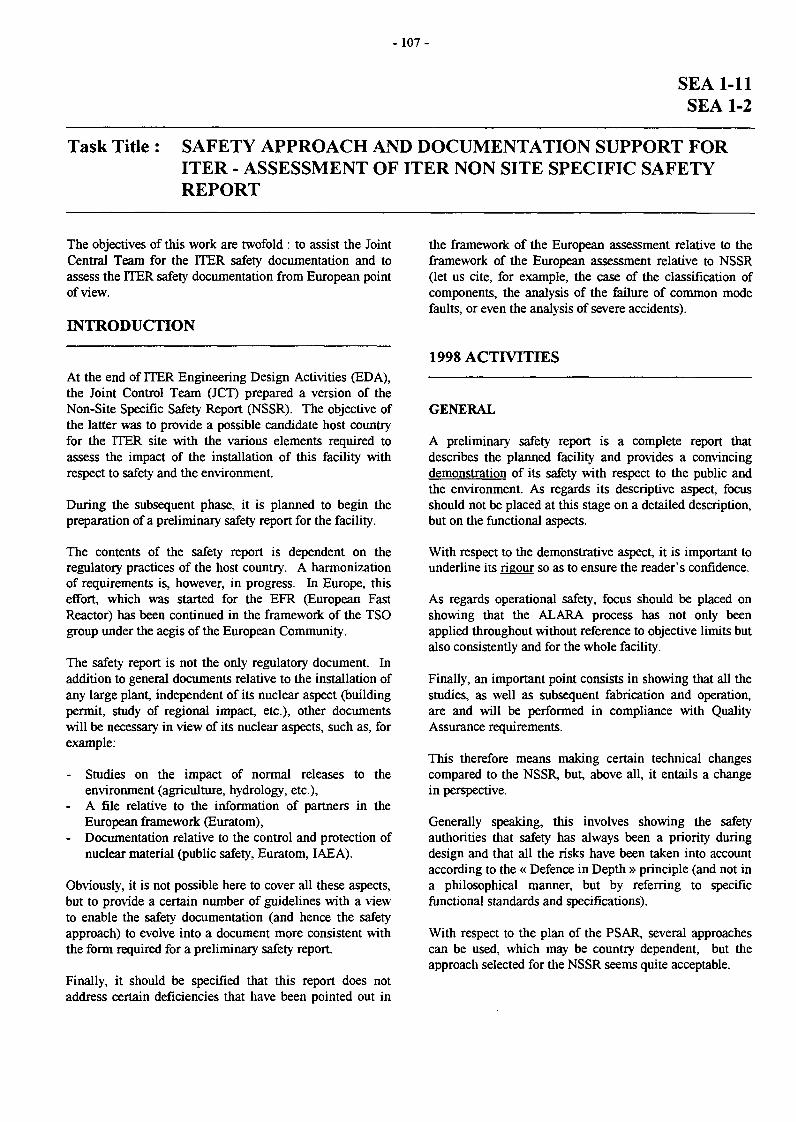
- 107-
SEA 1-11SEA 1-2
Task Title : SAFETY APPROACH AND DOCUMENTATION SUPPORT FORITER - ASSESSMENT OF ITER NON SITE SPECIFIC SAFETYREPORT
The objectives of this work are twofold : to assist the JointCentral Team for the ITER safety documentation and toassess the ITER safety documentation from European pointof view.
INTRODUCTION
At the end of ITER Engineering Design Activities (EDA),the Joint Control Team (JCT) prepared a version of theNon-Site Specific Safety Report (NSSR). The objective ofthe latter was to provide a possible candidate host countryfor the ITER site with the various elements required toassess the impact of the installation of this facility withrespect to safety and the environment.
During the subsequent phase, it is planned to begin thepreparation of a preliminary safety report for the facility.
The contents of the safety report is dependent on theregulatory practices of the host country. A harmonizationof requirements is, however, in progress. In Europe, thiseffort, which was started for the EFR (European FastReactor) has been continued in the framework of the TSOgroup under the aegis of the European Community.
The safety report is not the only regulatory document. Inaddition to general documents relative to the installation ofany large plant, independent of its nuclear aspect (buildingpermit, study of regional impact, etc.), other documentswill be necessary in view of its nuclear aspects, such as, forexample:
- Studies on the impact of normal releases to theenvironment (agriculture, hydrology, etc.),
- A file relative to the information of partners in theEuropean framework (Euratom),
- Documentation relative to the control and protection ofnuclear material (public safety, Euratom, IAEA).
Obviously, it is not possible here to cover all these aspects,but to provide a certain number of guidelines with a viewto enable the safety documentation (and hence the safetyapproach) to evolve into a document more consistent withthe form required for a preliminary safety report.
Finally, it should be specified that this report does notaddress certain deficiencies that have been pointed out in
the framework of the European assessment relative to theframework of the European assessment relative to NSSR(let us cite, for example, the case of the classification ofcomponents, the analysis of the failure of common modefaults, or even the analysis of severe accidents).
1998 ACTIVITIES
GENERAL
A preliminary safety report is a complete report thatdescribes the planned facility and provides a convincingdemonstration of its safety with respect to the public andthe environment. As regards its descriptive aspect, focusshould not be placed at this stage on a detailed description,but on the functional aspects.
With respect to the demonstrative aspect, it is important tounderline its rigour so as to ensure the reader's confidence.
As regards operational safety, focus should be placed onshowing that the ALARA process has not only beenapplied throughout without reference to objective limits butalso consistently and for the whole facility.
Finally, an important point consists in showing that all thestudies, as well as subsequent fabrication and operation,are and will be performed in compliance with QualityAssurance requirements.
This therefore means making certain technical changescompared to the NSSR, but, above all, it entails a changein perspective.
Generally speaking, this involves showing the safetyauthorities that safety has always been a priority duringdesign and that all the risks have been taken into accountaccording to the « Defence in Depth » principle (and not ina philosophical manner, but by referring to specificfunctional standards and specifications).
With respect to the plan of the PSAR, several approachescan be used, which may be country dependent, but theapproach selected for the NSSR seems quite acceptable.

- 1 0 8 -
It will anyway contain the following data:
- General information on the safety approach, includingthe logical approach, the main principles, theobjectives, and main safety functions,
- A descriptive aspect: the manner in which the safetyfunctions are installed,
- A quantification of the risks,- Operational safety (dose to workers),- Effluents and releases under normal operation,- Wastes and dismantling,- Accident analyses (classes 2 to 4),- Severe accident analyses,- Accidents of external origin.
SAFETY FUNCTIONS AND THEIR INSTALLATION
The presentation of the safety systems should not belimited to an individual description of each system orcomponent, but should provide, in addition, overallfunctional aspects, together with the interfaces between thesystems.
The starting point should consist in a global description ofthe facility, its environment and its operating conditions.The desired operating range should also be described withsufficient precision to enable assessing its safety and of therelevance of the analyses presented.
Furthermore, once overall safety objectives have beendefined (in terms of releases to the environment, forexample), it could be interesting to express them as a set ofobjectives at sub-assembly level.
The analysis of these sub-assemblies would thus providethe demonstration that, under normal or accident operatingconditions (in the entire specified domain), these objectiveswould be met.
Let us take an example: Let us consider the ventilationsystem in the exchanger rooms:
It is understood that the ventilation of these rooms isassured under normal operation and that the closure of thevent is ensured within a specified time in the event of arisk of a significant water circuit leak.
It is therefore necessary to:
- Define the instrumentation and the way to determinethe values which will actuate this system,
- Describe the process itself,- Analyze the entire chain, identifying the risks of
failure. Common mode hazards (loss of power, fire,etc.), as well as possible interfaces should also beidentified.
This analysis will permit having all available data foraccident studies and enable making the demonstration:
- Envelope of slight leaks that do not lead to the closureof the venting system,
- Precise conditions of the action with its uncertainties(response time, etc.),
- Data for the analysis of possible common modefailures.
At the preliminary report stage, the design of these systemswill probably not be sufficiently developed to permitmaking this analysis: their functional specifications willtherefore be given and will serve as guidelines for design.
All the systems relative to safety (which will subsequentlybe cited in the accident analysis, for example) should betreated in this way.
ACCIDENT ANALYSES
The presentation of accident studies should not requiremany changes insofar as the assumptions relative to theevolution of consequences are consistent with the analysisof the various systems cited.
The consistency of the various approaches for the selectionof accidents should also be verified (it should be checked,for example, that the failures considered are consistentwith the analysis of the systems).
In addition, the validation of the computer codes, models,and basic data, together with the uncertainties involved,should be discussed. The validation of all the data, codesand models used for the safety analysis is an importantissue in the licensing process.
Both the transient analysis and the Ultimate SafetyMargins analysis depend heavily on computer codes. Thishas required the development of new specific codes and theuse of codes developed for other purposes, but which are attimes required to operate outside the existing qualificationenvelope.
A systematic approach for exhaustive verification andvalidation of the Thermal-Hydraulic codes for fissionapplications in LWR (Light Water Reactor) has beencarried out over the last decade by the CSNI (Committeefor the Safety of Nuclear Installations) of the OECDNuclear Energy Agency. It is suggested that a similarmethodology for fusion would be appropriate. This wouldhowever only need to concentrate on validation of thosephenomena which are specific to fusion.
This work would involve the identification andcharacterisation of the fusion specific phenomena andestablish a facility cross reference matrix, using allrelevant data. It is suggested that a dedicated group ofexperts should evaluate the validation program and verifythe results.

- 109 -
OCCUPATIONAL SAFETY
If the ongoing process relative to the investigation of allmaintenance operations is pursued so as to consistentlyaim for a minimization of doses to workers, the currentpresentation is correct, associated with its resulting zoning.
However, care should be taken to avoid presenting in theALARA process any objective that could be considered asfinal: the objectives cited are only intermediate, permittingthe consistency of the approach to be assured.
In addition, non-scheduled maintenance operations shouldalso be investigated, including those intended, for example,to put the facility back into operation following an incidentor accident likely to occur during the service life of thefacility (a small coolant leak, for example).
TASK LEADER
Gabriel MARBACH
DRN/DER/SERSICEA Cadarache13108 St Paul Lez Durance Cedex
Tél. : 33 4 42 25 34 14Fax : 33 4 42 25 48 68
E-mail : [email protected]
CONCLUSION
In the frame of the cost reduction objective of ITER, aprocess of redesign this installation will be done during theextension phase of the EDA.
This could be an opportunity to ensure a better definitionof the safety implementation including the objective ofminimising the doses for the workers (by a systematicALARA process).
In parallel an effort should be done for the validation ofcodes and data on the basis of comparison withexperiments and benchmark exercises.

- I l l -
SEA 1-14
Task Title : CONTRIBUTION TO THE EUROPEAN ASSESSMENT OF THEDOCUMENTATION EMITTED BY JCT
INTRODUCTION
A veiy comprehensive effort has been made, during thelast years, by the ITER Joint Central Team to integrate aset of safety recommendations within the ITER design andto organise a preliminary safety assessment of the plant.Detailed documentation is now available : the Non-SiteSpecific Safety Report (NSSR-2).
Following a proposal described in ref. [1] and recalled inthe document, the task starts a systematic analysis of theITER safety approach, both concerning the methodsimplemented for the design as well as those used for thesafety assessment. The objective is to lead the final designsto correctly answer the safety authorities requirementsthrough the detailed and systematic analysis of thisdocumentation.
The « regulatory » requirements are not yet explicit forlarge fusion plants. This is why the basis for the suggestionis the coherency with the evolution that characterises thesafety approach for future fission plants. This objectivedoes not mean that the « standardisation » of the details ofthe safety approach among fission and fusion plants will bethe solution. Nevertheless, it seems obvious that all thedifferences must be identified and understood verifyingthat the basis of the « safety philosophy », used for thedefinition of the recommendations for the future nuclearinstallations, is respected.
Practically, all the recognised discrepancies have to beidentified and understood in detail, by performing adetailed comparison between on one side the ITER conceptcharacteristic and, on the other side, the safety and designrequirements applicable to large fission plants.
1998 ACTIVITIES
OBJECTIVE AND APPROACH
The radiological risk that characterises large fusion plantslead to consider them - from regulatory point of view - as
Nuclear Installations1. This administrative classificationask for ad-hoc licensing procedures.
* ITER must be considered as Nuclear Installation, due toquality and quantity of its confined radiotoxic materials.
The fundamental safety objectives (i.e. the radiologicalimpacts) as well as the fundamental principles for thesafety implementation and the assessment (i.e. the defencein depth) must be analogous for all the future NuclearInstallations. On the other hand, it is recognised that thedemonstration that these objectives are correctly fulfilledshall be achieved integrating the specificity of the ITERplant.
Thus, the goal of the engaged analysis is the assessment ofthe ITER safety approach from both design (i.e.architecture) and safety analysis (i.e. rules and methods forthe analysis) point of view.
The whole ITER safety approach is presented through theNon-Site Specific Safety Report (NSSR-2) [3] and a seriesof complementary documents (see next Section).
The assessment can be performed taking as referencesdifferent documents currently available for future fissionnuclear plants.
Within this context, the present work has the mainobjective to investigate the real capability to « assess » theITER safety related design options, by analysing itsavailable safety-related documentation, through a detailedcomparison versus the current actual safety requirementsfor future advanced European LWRs, when applicable.As a matter of exercise, this analysis has been focused onthe EUR document's parts that have more importantrelevance from safety point of view i.e. the SafetyApproach [2].
ITER - EUR DOCUMENTATION COMPARISON
EUR documentation analysed
The main goal of the EUR [4] consortium is « to produce acommon set of utility requirements, endorsed by majorEuropean utilities for the next generation ofLWR nuclearpower plants ». Moreover « One of the main objectives isthat a standard LWR project designed to comply with theEUR should be licensable in the different countries ofEurope without need for significant changes to meetdifferences in national licensing requirements ».
In connection with our goal, the interest of the documentwas double :
- First, it shows a comprehensive set of requirements andthe risk to forget something is reduced.
- Second, these safety related requirements are currentlyanalysed by the European safety authority.

- 112 -
This « on line » assessment will identify the discrepancieswith the safety authority's recommendations and, ifnecessary, will have feedback on the EUR content.
The EUR « Safety Requirements » (Volume 2, Chapter 1)have been analysed and compared with the claimed ITERsafety approach.
ITER documentation analysed
The NSSR-2 [3] is structured into the different followingvolumes :
Vol. I Safety Approach and functionsVol. II Safety DesignVol. Ill Radiological and Energy Source TermVol. IV Effluents and EmissionsVol. V Waste Management and DecommissioningVol. VI Occupational SafetyVol. VII Analysis of Reference eventsVol. V m Ultimate Safety MarginsVol. IX External Hazards AssessmentVol. X Sequence AnalysisVol. XI Safety Models and Codes
Coherently with the objectives discussed above, all thesevolumes must be completely reviewed. But, for thispreliminary comparison only the NSSR-2 Volumes I, II,and VIII have been taken into account.
Three other official ITER documents have been alsoanalysed : the ITER General Safety and EnvironmentalDesign Criteria (GSEDC) [5], the Safety AnalysisGuidelines (SAG) [6], and the Safety ImportanceClassification (SIC) [7] related to the General DesignRequirements Document (GDRD) [8]. These documentsdetail the basis for the ITER safety approach.
ITER - EUR comparison
To operate such a review, as a preliminary step, Appendix1 of ref. [2] presents a detailed analysis of each section of
the EUR Chapter « Safety Requirements »^, reportingcomments on the evaluation of the possible applicabilityand on any discrepancies.
Items that require more thorough analysis are alsoidentified. In the commented text of Appendix 1 someindications are given on the 'applicability / applicationrealised' of the different statements.
Still using the EUR document, an exhaustive assessment ofboth the ITER technical principle and design options couldbe organised to achieve a preliminary exercise, performedby following the main functions, whose role is analogousin ITER and in the future nuclear fission plants (e.g. Decay
2 Only the Sections 2.1.7 (Site Conditions) and 2.1.8(Tables), and the Appendices A and B are not specificallycommented. In any case the relative text in the annexedAppendix 1 is presented to complete the comparison.
Heat Removal (DHR), Containment System, Primary HeatTransfer System, etc.).
MAIN HIGHLIGHTS FROM THE PERFORMEDANALYSIS
By the performed analysis, as far as initial andpreliminary, some technical highlights may be deduced inorder to discuss the ITER safety approach.
- During the next design developments a satisfactoryoperator-related analysis (Human Factor) will besuitable. Making this it some operator action targetsshall be taken into account, like for example : « Therelease targets of Design Basis Categories 2, 3, and 4Conditions and DEC (each event sequence category),can be met without operator action from the maincontrol room in less than 30 minutes, and no actionoutside the main control room in less than 1 hour »(EUR [4]).
- A more detailed examination is necessary to operate ameaningful comparison and understand ITER SafetyImportance Classification (SIC) for both componentsand functions categorisation. For the moment, no safetycategory I equipment are present in ITER. This wouldbe thoroughly assessed after the discussed SICapproach.
- The Controlled Plant State notion is not retained inITER and furthermore the general approach assessingthe plant performances after accident conditions is verydifferent. The optimisation of the SIC phase is possiblethrough the adoption of Controlled Plant State and SafeShutdown State notions.
- Neither licensing practices nor real operationalexperience are available for fusion. There is noexperience feedback for fusion machine like ITER andtherefore reference is made, where possible, to fissionreactor experience and elsewhere a certain field ofuncertainty remains to be investigated.
- ITER Containment barrier target is not to containaccident conditions, but instead a reliability target isadopted. This is made because the reference option isthe notion of « dynamic confinement ».
- Among the issues linked to the rules for the analysis,the Single Failure Criterion is an important tool. Itsapplication should be detailed.
- The Severe Accident concept for ITER is notexplicitly expressed and thus no reference SevereAccident has been selected. The following definition ofSEVERE ACCIDENT is proposed: «Sequences oraccidental situations, characterised by an occurrencefrequency beyond design limits. In these conditions, theinstallation is severely damaged and it exists apotential for the release of a significant radiotoxic

-113-
inventory, considered unacceptable for theenvironment ». In analysing the Design ExtensionConditions, complex sequences constitute animplementation of additional failures (like for ITERCat-V events) and the specific Severe Accident analysisensures the design against a possible lack ofexhaustivity. If the Hypothetical Sequences areevaluated (equivalent to EUR complex sequences),nothing is present in the ITER safety approach inrelation to Severe Accident.
The ITER no-evacuation objective constitutes asignificant difference in terms of safety approach withrespect to the EUR considerations for Design ExtensionConditions.
The uncertainties assessment for the Cat-V eventsshall be thoroughly analysed to verify the coherencywith the need for appropriate attention to residualscientific uncertainties. This is mainly necessaryparticularly by performing best estimate analyses.
The loads resulting from the adequate combination of :normal or extreme environmental conditions, initiatingevents, or hazards together with Design BasicConditions, shall be used for the design of systems,structures, and components.
It seem interesting to investigate the occurring of ITERAnticipated Transient Without Scram (ATWS)events. In feet, the ATWS event can be considered as :«failure of the emergency shut-down system whenoperational conditions of I and II category needintervention of that system ». For this eventcombination the Safety Authority requests « todemonstrate that the implemented dispositions permitto drive the event consequences, from a safety point ofview, to the level of IV category » ([CAB], in Appendixlof réf. [2]).
For the H2 hazard no distinction is made betweendeflagration and detonation by hydrogen.
Likely further developments in the Cat-V events(NSSR-2/Vol. VIII) should be operated to investigate
the « cliff edge effect »•*.
The cumulative probability value for all sequences of10"6 per year for unacceptable consequences, remains amilestone. The ITER approach seems coherent with therequirement. The only ambiguity arises from thestatement : «(...) the no-evacuation goal implies theneed to limit doses to the local population to
3 This risk corresponds to the mobilisation of a potentiallyunacceptable source term - severe accident - with thesimultaneous loss of the containment (releases muchhigher than those which are acceptable).
approximately 50 mSv /event early dose, even for someCategory V events. » (note d, of Table 2.7.1-1, in [5])
Choice of HTO and Divertor-First Wall as referencedata for release limits shall be thoroughly discussed.
It will be necessary better investigate the fire hazard.
A more specific fault tolerance application should beperformed.
A major effort in explaining design features forreliability of safety functions is necessary.
Concerning plant performance after accidentconditions, the specific favourable inherent andpassive characteristics of fusion should be furtherinvestigated and understood.
The ITER enunciation for the Defence-in-depthprinciple is in accordance with the EUR enunciation,but careful attention shall be paid to its correctapplication.
The well balanced deterministic-probabilisticmixture for the safety approach is in good agreementwith the EUR's requirements.
Use of the same type of reference dose definition willbe necessary.
CONCLUSIONS
The current available ITER safety documents describe thesafety approach elaborated with the support of the partnershome teams. Obviously differences still exist with thehome teams positions. For example, following a roughcomparison, it appears that the current ITER design andthe corresponding safety documentation do not answerintegrally the needs of a hypothetical licensing procedurein an European context.
By means of the present study, a preliminary evaluation ofthe possible applicability and of any discovered fission-fusion discrepancies between EUR's recommendations andITER safety approach has been performed.
Nevertheless, a more complete detailed comparison issuggested between on one side the ITER conceptcharacteristic and, on the other side, the requirements fromboth regulatory bodies and utilities to identify andunderstand in detail all the still existing discrepancies.
In any case, the performed comparison results in ameaningful tool to verify the ITER safety approach.Because it enables to determine, through a point-by-pointanalysis, some shortages and some suitable developmentsfor the next design progresses.

- 114 -
Thus, this activity would be the first step of a morecomprehensive analysis that should improve the coherencyand the acceptability of the plant design, as well as thesafety documentation content.
REFERENCES
[1] G.L. FioriniProposal for the Analysis of the ITER SafetyApproachMemorandum CEA/DRN/DER SIS/LSS 98/32-2003(Cadarache, 10.04.1998)
[2] M. Costa, G.L. FioriniITER - EUR comparison from a safety point of viewTechnical Report CEA/DRN/DER NT/SIS/LSS98/32-1017 Ind. 1 (Cadarache, 18.12.1998)
[3] ITER Non-Site Specific Safety Report (NSSR-2)(Volumes from I to XI)
[4] European Utilities Requirements for LWR NuclearPower PlantsEUR Organisation, Revision B, November 1995
[5] ITER General Safety and Environmental DesignCriteriaAppendix to GDRD, ver. 25.09.1997, Integration ofRPP
[6] Safety Analysis Guidelines for NSSR-1, ITER-EDASEHD 8.1.C-1, Version 1.1, March 1996 (S 81 RI 195-12-13 W2)
[7] Safety Importance Classification, ITER-EDASEHD 8.1-B, Version 1.2, April 1997 (S 81 RI 6 95-12-13 Fl)
[8] ITER General Design Requirements Documentpart of Final Design Report of ITER-EDA, to bepublished by IAEA
ACRONYMS
ITER
NSSR-2
LWR
EUR
PSA
ATWS
DEC
SIC
HTO
TASK
International Thermonuclear ExperimentalReactor
Non-Site Specific Safety Report
Light Water Reactor
European Utilities Requirements
Probabilistic Safety Assessment
Anticipated Transient Without Scram
Design Extension Condition
Safety Importance Classification
Tritiated Water (chemical formula)
LEADER
Gian Luigi FIORINI
DRN/DER/SERSI/ECPCEA Cadarache13108 St Paul Lez Durance Cedex
Tél. : 33 4 42 25 76 29Fax : 33 4 42 25 40 46
E-mail : [email protected]

- 115 -
SEA 3-1SEA 5-2
Task Title : COHERENT SYSTEM OF CODES FOR THE ITER SAFETYANALYSIS - VALIDATION OF COMPUTER CODES ANDMODELS
INTRODUCTION 1998 ACTIVITIES
The main purpose of these tasks has been to optimise thecoupling methodology for a set of representatives cases forITER studies, and to provide users with a better tool for thecontrol of coupled runs.
To achieve this last objective, a new command language hasbeen introduced to solve some problems that could not besolved by the previous Gibiane command language. Thisnew version does not require any modification of the slavecodes ATHENA, INTRA and NAUA, already integratedinto ISAS. Only small modifications of the supervisor inputdecks are needed.
The general activity of task SEA5-2 concerns also usersassistance and bug fixes.
INTRODUCTION OF PARALLELIZATION FORCOUPLED RUNS
hi order to reduce the CPU time needed for some referencecalculations, often larger for coupled runs than for standalone runs because of the drastic reduction of the internaltime step into each slave code, parallelization has beensuccessfully introduced.
For example, an application for the LOFA5 calculationshows 40% saving of CPU time :
Sequential run
Total cpu : 15309
Total CPU
Athena Intra ISAS
Parallel run
Total cpu : 9145
40% savingof CPU time
Total CPU time isapproximativelyAthena CPU time
Athena Intra ISAS
with the same physical results :
2.3JBCB
0.G0BO0
I Sequential
1
Btfaty
run
I
11 • I V I 1O-1 , i
10D 102 10» 105 106 110 15) 189 229
8.00BO5
7.00BO5
6.00BO5
5.00BO5
4.CDBO5
3.00BO5
2,00805
1.C0BO5
acceoo
1.50EKB
1.2SEKB
1.G0EKB
7.SCEKE
29DBO2
Q006CO
PV
Parallel run
/~—~—
V\asrfb»
\JiUi.»
8,00605
7.00BO5
800BO5
500BO5
400BO5
300BO5
2.00BO5
1.C0BO5
QCCEKD
100 102 104 106 108 110 150 190 230
- 1 1 6 -
Mixed methods based on the variations of some physicalvariables, using a parallel run when the gradients of thesevariables are not stiff, and a sequential run otherwise, havebeen also successfully tested.
RELEASES OF THE ISAS SYSTEM
Several releases of the ISAS system have been done due tothe introduction of new versions of tlie slave codes INTRAand SAFALY that take account of new physical abilities.
During this period, SAFALY code was integrated into theISAS system. Several interface routines were written toenable coupled runs with ATHENA.
NEW VERSION OF THE ISAS SUPERVISOR
During this period, a new version of ISAS has beendeveloped. So as to provide users with a better tool for thecontrol of coupled runs the main improvement has beenthe replacement of the Gibiane command language by anobject oriented one, OCAML developed by INRIA
The purpose was to get some improvements without anyeffect on the work already achieved, and we can resumethis updating as follows :
- no modification or recompilation of any slave code wasneeded : tlie supervisor input deck only is different andit has to be written again.
- a better way to control potential problems such ascrashes of slave codes, using exception mechanisms ofOCAML.
- the OCAML Command language is more powerful andfast as compared with Gibiane.
- a direct exchange of data is made between slave codeswithout any transit by ISAS.
The firsts tests for tlie control of Athena and Intra with theOCAML version of ISAS are conclusive.
PRE-PROCESSING CAPABILITIES OF ISAS
The objective was to give the user of Intra the samegraphic abilities as those implemented by the Xmgrpackage as for Athena, it consisted in exploring the resultsof a calculation after a run from files generated by the slavecode.
REPORTS DURING THE PERIOD
[1] ISAS : Description of Athena, Intra, Naua and Safalycoupling for safety analysisDMT 97-574 update 11/98
[2] ISAS : on line documentation based on HTML3.2languageDMT 97-575 update 11/98
TASK LEADER
I. TOUMI
DMT/SYSCOCEA Saclay91191 Gif-sur-Yvette Cedex
Tél. : 33 1 69 08 49 47Fax : 33 169 08 23 81
E-mail : imad.toumi(5)cea.fr

-117-
SEA 3-5
Task Title : IN VESSEL SAFETY ANALYSIS
INTRODUCTION 1998 ACTIVITIES
In the frame of validation and verification of the codesused for ITER safety demonstration, a benchmark is underprogress between the different parties of the project. Theaim is to compare experimental tests achieved on the'Ingress of Coolant Event' (ICE) Japanese facility andcalculations by different pressurisation codes (INTRA,PAX, MELCOR, TRAC). The objectives are to investigatethe pressurisation rate and heat transfer characteristics ofwater injection into the vacuum vessel of ITER. Thepresent work is based on the PAX calculations of thefourth set of tests on the ICE facility.
DESCRIPTION OF THE ICE FACILITY
The facility consists of a boiler pressurised at 35 bar usedto inject water through a nozzle on a target plate inside thevessel (0.38 m3 initially at 10 pa) connected through arupture disk to a blow down tank (0.55 m3). A shematicflow diagram of the facility is shown on figure 1.
The parameters of the tests are : the temperature of thefluid in the boiler, the temperature of the vacuum vesseland blow down tank structures, the size of the nozzle, theinjection duration and the rupture disk design pressure.They are summarised in table 1 :
'boiler
targetBlow down tank
Rupture disk
Figure 1 : Schematic flow diagram of the ICE facility
Table 1 : Tests parameters
Parameters
case 1
case 2
case 3
case 4
case5case 6
case 7
vacuum vessel wallsTemp (°C)
250
250
100
230
230
230
230
fluid Temp(°Q
200
200
200
160
160
160
160
AP of the rupturedisk (bar)
2
10
2
10
10
2
10
Nozzle diam(mm)
2
2
2
0.5
0.5
2
2
flow duration(s)
10
10
10
10
160
10
10

-118-
PAX CODE CALCULATIONS
Pax code capabilities
The PAX code is a safety studies code used mainly toevaluate both :
- the depressurisation of a containment (cooling loop forexample) and,
- the resulting pressurisation of a vessel receiving thefluid from the depressurisation.
Safety Authorities acknowledge this code as a tool forpressurisation calculation and safety reports support.
The main parameters that can be taken into account are :
- for the containment (here the boiler) :
. thermodynamic conditions,
. thermal inertia of the containment structures,
. pressure losses in the piping to the break.
The flow at the break can be evaluated through a correlationdeveloped under a specific experimental programme.
- for the vessel :
initial thermodynamic conditions,. temperature profile in the structures (made of
different material slices),. rupture disks (or scrubbers) and expansion
containment.
The main results that can be provided are :
- for the containment (here the boiler) :
. thermodynamic conditions,
. temperature of the containment structures,
. flow at the break,
- for the vessel :
. thermodynamic conditions,
. water/steam inventories,
. temperature profile in the structures,
Main hypothesis
The followings hypothesis and correlations, based onengineering judgement and using the experience gained byparticipation in the previous pre and post test calculations,were used for the PAX calculations :
- the wet surface at the bottom of the vacuum vessel wascalculated at each time step in order to take into accountthe pool boiling effect (important for the pressurisationof the vacuum vessel)
- the pool boiling correlation is deducted from the boilingcurve at 1 bar (ref [1]),
- the impingement target was chosen as a disk of 0.2 m indiameter which corresponds to a focalised spray (feedback of the previous sets of tests),
- a constant heat transfer coefficient (if the temperature ofthe walls is higher than the fluid) of 5000 W/m2/°C hasbeen applied on the target (corresponding to dry wallmode condition),
- the condensation correlation used was a Nusselt lawwithout uncondensable gas,
- the axial and cross conduction has been neglected in thecalculation.
RESULTS OF THE CALCULATIONS
The PAX results were in good agreement with themesurements and were presented during the last ICE/LOVAmeeting held in San Diego in February 98 (ref [2]). Themain pressure transient are plotted in the following figures :
figure 2 : Case 1 pressure in the vacuum vessel and in theblow down tank,figure 3 : Case 3 pressure in the vacuum vessel,figure 4 : Case 7 pressure in the vacuum vessel,
I'-*• 1.COW0
S.0O6O1
y[-J/f--
2
te?
-s
VKUum V»
t : : : : : : :
| : . : : : : :
• | '
0 6
• a l * BOT pnmutm
^ r - : : : - ::r.:-; — B
- - 3 - - ^ | | ^ N — - - - -
10 13 14 16 IS
Figure 2 : Test 1 ; pressure transient
The rupture disk opens after 5 s of injection, at about 15 sthere is no more liquid water in the vacuum vessel(superheated conditions in the vacuum vessel).
1.40*00 T
120E*00
1.O0BO0
Z 600B-01
4.00E-01
2.006O1
0.00&00
0
vacuum v e « e l pressure
/
1 | :
i • : i i
i ! , !
| FVV
!
20 40 60 80 100 120 140 ISO 180 200
tlm* (S)
Figure 3 : Test 3 ; pressure transient
adiabatic external condition for the vacuum vessel hasbeen assumed,

-119-
The pressure rises in the vacuum vessel during the 10 s ofinjection, and it is stopped by the condensation when itexceeds the saturation pressure at the walls temperature.
REFERENCES
Vacuum vessel pranure
^ . ! !/ ! : :/ ! i
i !i
100
l l m . (s>
Figure 4 : Test 7 ; pressure transient
During this test, the initial pressure rise is due to theinjection flow rate and then, the pressure continue to risebecause of the pool boiling effect and the naturalconvection.
CONCLUSIONS
This analysis has pointed the importance of heat transferunder impinging jet and pool boiling conditions as far asvacuum vessel pressurisation is concerned. Since these twophenomena might be met during accidental transients onITER (any scenario that could lead to an in-vessel LOCA),it is very important to specify and analyse clearly thesesituations. However, as these types of global tests haveshown not to be sufficient to built a precise correlation forthe heat transfer coefficients under jet impingementconditions, experiments to provide the necessaryinformation will be outlined.
[1] J.G. COLLIER: « Convective boiling andcondensation »
[2] Technicatome : « ICE FACILITY : 4th set of pre andpost calculations of in vessel LOCA's » 1998
T A S K L E A D E R
Xavier MASSON
SEPSTECHNICATOMEBP 3400013791 Aix-en-Provence Cedex 3
Tél. : 33 4 42 60 28 61Fax : 33 4 42 60 25 11
E-mail : [email protected]
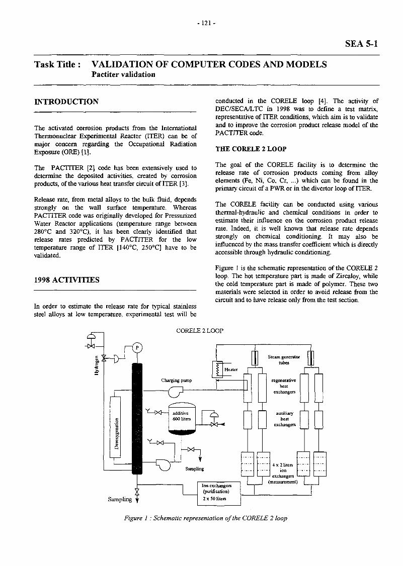
-121 -
SEA 5-1
Task Title : VALIDATION OF COMPUTER CODES AND MODELSPactiter validation
INTRODUCTION
The activated corrosion products from the InternationalThermonuclear Experimental Reactor (ITER) can be ofmajor concern regarding the Occupational RadiationExposure (ORE) [1].
The PACTITER [2] code has been extensively used todetermine the deposited activities, created by corrosionproducts, of the various heat transfer circuit of ITER [3].
Release rate, from metal alloys to the bulk fluid, dependsstrongly on the wall surface temperature. WhereasPACTITER code was originally developed for PressurizedWater Reactor applications (temperature range between280°C and 320°C), it has been clearly identified thatrelease rates predicted by PACTITER for the lowtemperature range of ITER [140°C, 250°C] have to bevalidated.
1998 ACTIVITIES
In order to estimate the release rate for typical stainlesssteel alloys at low temperature, experimental test will be
conducted in the CORELE loop [4]. The activity ofDEC/SECA/LTC in 1998 was to define a test matrix,representative of ITER conditions, which aim is to validateand to improve the corrosion product release model of thePACTITER code.
THE CORELE 2 LOOP
The goal of the CORELE facility is to determine therelease rate of corrosion products coming from alloyelements (Fe, Ni, Co, Cr, ...) which can be found in theprimary circuit of a PWR or in the divertor loop of ITER.
The CORELE facility can be conducted using variousthermal-hydraulic and chemical conditions in order toestimate their influence on the corrosion product releaserate. Indeed, it is well known that release rate dependsstrongly on chemical conditioning. It may also beinfluenced by the mass transfer coefficient which is directlyaccessible through hydraulic conditioning.
Figure 1 is the schematic representation of the CORELE 2loop. The hot temperature part is made of Zircaloy, whilethe cold temperature part is made of polymer. These twomaterials were selected in order to avoid release from thecircuit and to have release only from the test section.
CORELE 2 LOOP
Sampling
Ion exchangers(purification)2 x 50 liters
4 x 2 litersion
exchangers(measurement)
Figure 1 : Schematic representation of the CORELE 2 loop
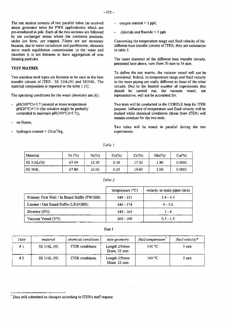
-122 -
The test section consists of two parallel tubes (as receivedsteam generator tubes for PWR applications) which arepre-irradiated in pile. Each of the two sections are followedby ion exchanger resins where the corrosion products,under ion form, are trapped. Filters are not necessarybecause, due to water circulation and purification, elementsnever reach equilibrium concentration in the water andtherefore it is not foreseen to have aggregation of ionsforming particles.
TEST MATRIX
Two stainless steel types are foreseen to be used in the heattransfer circuits of ITER : SS 316L(N) and SS304L. Thematerial composition is reported in the table 1 [5]:
The operating conditions for the water chemistry are [6] :
- pH(300°C)=5.7 (neutral at room temperaturepH(20°C)=7.0 (the solution might be probablycontrolled to maintain pH(300°C)=5.7)),
- no Boron,
- hydrogen content = 25cm3/kg,
- oxygen content < 1 ppb,
chloride and fluoride < 1 ppb.
Concerning the temperature range and fluid velocity of thedifferent heat transfer circuits of ITER, they are summarizein table 2.
The inner diameter of the different heat transfer circuits,presented here above, vary from 20 mm to 54 mm.
To define the test matrix, the vacuum vessel will not beconsidered. Indeed, its temperature range and fluid velocityin the main piping are really different to those of the othercircuits. Due to the limited number of experiments thatshould be carried out, the vacuum vessel, notrepresentative, will not be accounted for.
Two tests will be conducted in the CORELE loop for ITERpurpose. Influence of temperature and fluid velocity will bestudied while chemical conditions (those from ITER) willremain constant for the two tests.
Two tubes will be tested in parallel during the twoexperiments.
Table 1
Material
SS316L(N)
SS 304L
Fe (%)
65.00
67.80
Ni(%)
12.30
10.00
Co(%)
0.10
0.25
Cr(%)
17.50
19.00
Mn(%)
1.80
2.00
Cu(%)
0.0001
0.0001
Table 2
Primary First Wall / In Board Baffle (FW/TBB)
Limiter / Out Board Baffle (LIM/OBB)
Divertor (DV)
Vaccum Vessel ( W )
temperature (°C)
140- 191
140 - 174
140 - 165
100 - 109
velocity in main pipes (m/s)
3.4-4.5
4-5 .6
3 - 4
0.5-1.5
Testl
Tube
# 1
#2
material
SS316L(N)
SS316L(N)
chemical conditions
ITER conditions
ITER conditions
tube geometry
Length 250mmDiam. 22 mm
Length 250mmDiam. 22 mm
fluid temperature"
140 °C
140 °C
fluid velocity*
3 m/s
5 m/s
Data still submitted to changes according to ITER's staff request

- 123 -
Test 2
Tube
# 1
# 2
material
SS316L(N)
SS316L(N)
chemical conditions
ITER conditions
ITER conditions
tube geometry
Length 250mmDiam. 22 mm
Length 250mmDiam. 22 mm
fluid temperature *
190 °C
190 °C
fluid velocity*
3m/s
5m/s
CONCLUSIONS TASK LEADER
In agreement with ITER design and up-to-date chemicalspecifications, a test matrix, for the CORELE facility, hasbeen settled. The aim of this test matrix is to study releasefrom stainless steel alloys at low temperature (ITER range)in order to validate and to improve the PACTITER code.
REPORTS
[1] D. TARABELLI, P. SCHTNDLERDefinition of the CORELE test matrix for ITERpurposeTechnical Note DEC/SECA/LTC/98-176
Didier TARABELLI
DRN/DEC/SH2C/LTCCEA Cadarache13108 St Paul Lez Durance Cedex
Tél. : 33 4 42 25 39 95Fax : 33 4 42 25 47 77
E-mail : [email protected]

- 125 -
SEA 5-3
Task Title : VALIDATION OF COMPUTER CODES AND MODELSThermalhydraulic codes validation experiments EVITA
INTRODUCTION
The safety implementation of fusion facilities has beenwidely developed during two main programs which areITER and SEAFP in Europe. Lots of specific phenomenahave been discovered and needs to validate and qualifynew or adapted modeling have arisen. From a globalperspective, the safety goals for a fusion reactor will befulfilled. However it is necessary to anticipate questionsthat doubtless will come from the regulatory boards and tofollow the trends concerning safety that are going toinduce more and more constraints on the nuclear reactors.
In this respect, computer code validation is one of themajor task of safety implementation, especially for newprototypes like ITER where very few feedback experienceexists.
The experimental program EVITA has been set up in theframe of the SEA5 task which aim is to validate computercodes and models used in the fusion safety.
1998 ACTIVITIES
DEFINITION OF THE TEST OBJECTIVES ANDPROGRAM
According to the identified issues and the test facilitiesavailable in CEA Cadarache, the following objectives havebeen proposed :
- Simulate physical phenomena occurring during a waterleak into a vacuum compartment.
- Provide a data base for code correlations in order tobetter predict compartment pressurization following awater leak.
- Avoid using too big margins in pressure design offusion vacuum vessel.The test program must account for the followingrequirements :
- Must be settled on a complementarity basis with ICEexperiments.
- The experimental conditions will be set as close toITER conditions in order to provide scaled experimentsallowing to rank the different effects.
- Two different effects must be perfectly controlled in thefacility :
1 - cryogenic condensation : steam condensation onsurfaces at very low temperature. In category 4accidents (ITER NSSR vol. VII - 4 .12), the ingressof water in the cryostat is one of the inducedphenomena following damages caused by a possibleelectrical arcs from the magnets . The penetratingguardpipes and cooling pipes are supposed to befailed (ruptured) allowing a steam leak to take placeinto the cryostat. The condensation effects on thecold surfaces of the cryostat (magnets at 4°K,thermal shields at 80°K) are the leading phenomenain this sequence. The accident description includesa maintained cooling capability of the cryogeniccircuits as a conservative assumption. The codesmodels for low (cryogenic) temperaturecondensation are not qualified.
2 - jet impingement effect : the heat exchange betweenthe impinged walls and the steam jet has to beassessed in a complementarily way to ICE. Due tothe relatively small space in a torus, some smallwater leaks can impinge the walls opposite to thebreak and lead to increased condensation orvaporization phenomena which has an effect on thepressurization transient of the vessel. The objectiveof this test is to assess the influence and possiblyquantify the jet impingement phenomena.
CONCLUSION
The main objectives of the EVITA experimental programhave been defined in 1998. Two main phenomena havebeen selected to be developed in the experimental program,they are : « cryogenic condensation » and « jetimpingement effects ».
The feasibility study, in order to define more precisely thefacility features, will now be conducted and will define thetest requirements. These objectives are only defined for thefirst part of this experimental program, others objectivesshould be defined more precisely during the continuationof the program.
LIST OF REPORTS
[1] « EVITA experimental program - definition of theobjectives» C. Girard - NT DER/STML/LCFI98/039

-126-
E V I T AEuropean Vacuum Ingress Test Apparatus
Pressure probe
Stainless steel mock-up100 - 600°c
Thermocouples
Electrical heating
Existing testvessel
Waterinjection 40 b.temperature150 to 250°c
Free volume
Design pressure
Vacuum level
Electrical power
: 0.220 m3
: 50 bar
: 10"3 mb
: 200 kW
Vacuumpump
Cold surfaceat cryogenictemperature
Cad 19.12.961
TASK LEADERS
Christian GIRARD
DRN/DER/SERSI/LEFSCEA Cadarache13108 St Paul Lez Durance Cedex
Tél. : 33 4 42 25 49 56Fax : 33 4 45 25 66 38
M. ARNOULD
SEPSTECHNICATOMEBP 3400013791 Aix-en-Provence Cedex 3
Fax : 33 4 42 60 25 11
E-mail : [email protected]

- 127-
SEP 1-1
Task Title : ADAPTATION OF THE PACTOLE CODE FOR THEEVALUATION OF ITER ACTIVATED CORROSION PRODUCTSOURCE TERM
INTRODUCTION
The PACTOLE code, initially developed for PWR iscurrently being used extensively for predicting theactivities in the various heat transfer circuits (HTS) of theInternational Thermonuclear Experimental Reactor(ITER).
Since the operating conditions, material compositions andwater chemistry of ITER (no soluble Boron, lowtemperature range, Cu-water systems) are quite differentfrom those of PWR, some modifications were required toadapt the PACTOLE code for consistent application in theevaluation of ITER source terms. Code verification of themodified PACTOLE, called PACTITER, was performedwith available solubility law for stainless steel/watersystem in the temperature range of ITER.
1998 ACTIVITIES
The ITER heat transfer circuit design calls the utilizationof copper/water and stainless steel/water systems bothoperated in a temperature range of 100°C to 200 °C. Theactivity of DRN/DEC/SECA/LTC in 1998 was devoted tothe improvement of the PACTITER code modeling forcopper/water system and for code verification of the releaseprocess from stainless steel alloys at low temperature.
PACTITER COPPER/WATER SYSTEM MODELING
- Steady state concentrations for copper, as a function oftemperature, can be fitted by the following law [3] :
[Cu] = 1.15 10"11 T2-6.61 10-9T+1.32 10"6
(T in K, [Cu] in mole/kg)
This last equation, representing the evolution of the so-called observed copper solubility has been determinedusing experimental investigations. Experience wasconducted in water containing 670 ppm of boric acid and0.7 ppm of lithium in order to simulate ITERrepresentative chemical conditions of the divertor loop.Copper concentration was measured for different fluidtemperatures varying between 20°C and 250°C.
The experimental results and the fitted curve are presentedin the figure below.
Total concentration of copper in aqueous solution measured at theexit of device as function of temperature
100
6 0 -
20--
• experimental result;
— fitted curve
100 150
Temperature (°Q
200 250
Introducing a new element in PACTOLE requireschemical and radiochemical data. First PACTITERversion, previously reported in [1], was developed in orderto account for copper element and its relevant isotopes.Modifications can be summarized as follows :
- The following nuclear reactions were introduced withappropriate reaction rates [2]:
. 63Cu (n,y) M C u
. 65Cu (n,2n) "Cu
. 63Cu (n,a) 60Co
- Metallic copper is the stable form for copper alloys inreducing conditions
The characterization of the curve, describing coppersolubility function of temperature, has been determinedwith the rational that only lower measured values, ofcopper concentrations, may represent equilibriumconcentration. Indeed, it was not possible to separatesoluble and insoluble species which were measured.
The involved equilibrium reaction that was enlightenedduring the experimental investigation is the following :
From thermodynamic considerations, the solubility can bewritten as follows :
AGr
RT

- 128-
The pH number and hydrogen dependence of the coppersolubility is clearly shown in the above equation. Theactual solubility law that was implemented in PACTITERtakes into account those dependencies. Although thosedependencies are accounted for, the real validity for thecopper solubility is the one described in the report (i.e.partial hydrogen pressure = 1 bar, [B] = 670 ppm, [Li]=0.7ppm). pH number dependence on copper solubilitycalculated by PACTITER is shown on the figure below :
PACTITER cspper solubility function of pH number
i.ooE-o r
1.00E-05
1.00E-06
U l.OOE-07
1.00E-08
1.0OE-09Temperature (°C)
PACTITER STAINLESS STEEL/WATER SYSTEMVERIFICATION
Although the global behavior of corrosion/release processis not dramatically different in a high (280-320 °C forPWR) and in a low (140-250°C for ITER) temperaturerange, PACTITER verifications in the ITER temperatureconditions were needed. Because PACTOLE was originallydeveloped and applied for PWR, the solubility curves, forelements appearing in stainless steel composition (mainlyIron), have been verified in a high temperature range. Thiswas possible regarding the large amount of available data.For low temperature conditions, less data are available.
Within all experiments conducted in the last 20 years, twoseries of test were selected [4] for PACTITER verification.These tests were performed to measure the solubility ofFe3O4 in boric acid and lithium hydroxide hydrogenatedsolutions by static method. These two tests were selectedbecause they were realized over a wide range oftemperature and because the pH number specified duringthese experiments are close to the one specified for theITER conditions.
The two figures provided here below, represent thecomparison of PACTITER magnetite solubility curvesversus the experimental measurements. The goodagreement between computation solubility andmeasurements can be seen on these two figures, eventhough for low temperature the predicted equilibriumconcentration is a little bit over-estimated by PACTITER.
100000
10000
•sr loofa,
C
SobbHRy of magnMRt «a a ftjnclton of t«mp*r*tur«
10 ' molWkBBOjH,
V ^ ^ 10-* mol«ft0UOH
• Exp*nmarlal dale
_ » _ PACTITER
100 200Température f C )
1000
100
10
1
• S«UllKyornugn«tll«uaftmctler<ort«mp«r«un
• ' N . . 1.410-* m«t«A« UOM
* ExtM"m*r*ai data
-•-PACTITER
Temperature (°C)
CONCLUSIONS
The first version of PACTITER, adapted version of thePACTOLE code, has been released in 1997. The mainmodifications were related to the introduction of coppersolubility derived from experimental investigations and tothe introduction of copper isotopes linked to the definitionof nuclear reactions for ^Cu.
Last improvement of the PACTITER code was related tothe pH dependence of copper solubility curve according tothermodynamic considerations.
Although basic verifications of the PACTITER predictionsat low temperature (ITER HTS range) for magnetitesolubility was carried, further investigations, based onmore global experiments should be performed. It shouldbe, for instance, important to focus on stainless steelrelease in ITER conditions (mainly temperature and flowvelocity).

-129 -
REFERENCES TASL LEADER
[1] D. TARABELLI, J.C. ROBINPACTITER : A PACTOLE adaptation for copperTechnical Note DEC/SECA/LTC 97-123
[2] D.G. CEPRAGAReview workshop meeting for the task SEP 1-1 -Corrosion product modelingFrascati, June 28th - 30th, 1995
[3] D. YOU, S. LEFEVRE, P. GERLINGER, A.CHENIEREThermodynamic stability and solubility of copper andcopper oxidesTechnical Report DTA/CEREM/SCECF 420, May1997
[4] I. LAMBERT, J. MONTEL, P. COURVOISIERInfluence of hydrogen pressure on the solubility ofmagnetite in aqueous solutionsWater Chemistry II, BNES, 1980, Paper 4
Didier TARABELLI
DRN/DEC/SH2C/LTCCEA Cadarache13108 St Paul Lez Durance Cedex
Tél. : 33 4 42 25 39 95Fax : 33 4 42 25 47 77
E-mail : [email protected]
REPORTS
[1] E. KAJLERT, L. DI PACE, S. SANDRI, D.TARABELLIOccupational dose assessment for the ITER primaryheat transfer system20th Symposium On Fusion Technology (S.O.F.T.),Marseille, 1998
[2] L. DI PACE, D. TARABELLI, D. YOUDevelopment of the PACTITER code and itsapplication to the assessment of the ITER divertorcooling loop corrosion products13th Topical meeting on the technology of fusionenergy - Nashville, 1998
[3] D. TARABELLIPACTITER (PACTOLE version for ITER) - FinalreportTechnical Note DEC/SECA/LTC 98-150

-131 -
SEP 3-1
Task Title : WASTE CHARACTERISATION AND STRATEGY
INTRODUCTION
The Nuclear Materials Processing Department at theNuclear Research Centre of VALDUC is performingdetritiation of metallic wastes resulting from the operationor dismantling of giove boxes used in tritium, by means of amelting process (initiai activity of about Î00Ô Ci/t). Thisexperience is important for steel detritiation studies in theframework of waste management for ÏTER.
These metallic wastes are characterized by:
• The decontamination factor after melting.• Measurement of the degassing rate,• The distribution of tritium activity in the ingots.
1998 ACTIVITY
In 1998, measurements of tritium degassing of metallicingots have been done.
At the same time, a cooperation agreement has beeninitiated with the Structural Metallurgy Laboratory at Orsay(URA CNRS n° 1Î 07. Bât 413. Université Paris-Sad,91405 Orsay) to study methods of measuring local ratherthan overall degassing rates as well as tritium activitydistribution in. ingots. A preliminary feasibility study wasperformed on a sample supplied by the CEA VALDUC(CEA/VA/DTMN/SADX taken from an ingot produced bythe melting of tritiated austenitic stainless steels.
MEASUREMENTS OF TRITIUM DEGASSING OFMETALLIC INGOTS
Six ingots produced between 1988 and 1991 were selectedfor the representativeness of their daily tritium degassingrate after melting (low. medium, and high values).
Daily degassing measurements were resumed in My andAugust 1998, according to the procedure presented above.The 2nc column shows the activity of the ingot aftermelting. The 3rc column gives the value of the first dailydegassing rate measurementindicated in the 4* column.
performed on the date
The last degassing measurements which were performed, aswell as their associated uncertainties are indicated incolumns 5 and 6. The presence of an abnormal point foringot 062 (*) should be noted. The last column gives thevariation of the degassing rate, which is given by thefollowing formula :
ADegassing; Initial measurement - Final measurement
Initial measurement
The degassing values are also reported versus time inFigure 1. The activity measured in 1998 is always lowerthan that corresponding to the radioactive decay of tritium.However, it is impossible to deduce any law with respect tothe degassing process. For instance, it is not possible todistinguish between a process that favours degassing from acontaminated surface layer and one related to tritiumdiffusion in the structure of the steel.
120
1000 2000 3000Time {days)
500C
Figure 1: Degassing values versus time
iagoi.
; 052
! 062
065
072
081
\ 083
Ingot:activity(Ci/T):
6.48
8.2
1.0.43
144
4.65
4.11
Initialmeasurement
(KBq)
70.6
731
16.3
92.5
109
19.9
'.Dàtev
measurement
27/08/91
08/02/89
21/02/89
22/03/89
01/08/91
27/08/91
Secondmeasurement
(KBq)
2.54
0.189 (*)
9.1
8.5
13.94
8.4
.-' Uncertainty
Î.27
0.95
4.5
6.97
4.2
/ Dateof second
measurement
05/07/98
06/08/98
18/08/98
20/08/98
25/08/98
27/08/98
Adegassiag%
•
96=2
99.8(*) •
44=27
91=5
87=7
58=21

-132-
CHARACTERIZATION BY AUTORADIOGRAPHYAND p COUNTING OF TRITIUM DISTRIBUTIONAND DESORPTION IN A STAINLESS STEELINGOT
The macroscopic distribution of the tritium was studied byauîoradiography by means of a specific film placed incontact with the previously polished surface (paper 4000).The autoradiogram was exposed aï -20°C under dry primaryvacuum. The macrostructure of the sample (Figure 2A)revealed the presence of numerous bubbles of millimetricsize.
Figure 2A fx3)
The corresponding autoradiographic image (Figure 2B) wasobtained on the sample with a coating of collodion filmafter exposure times ranging from seven to IS days.
The images showed :
• That this technique permitted visualizing the presenceand macroscopic distribution of tritium in the material;obtaining usable images, however, required exposuretimes of 10 to 20 days ;
• A near-homogeneous distribution of the tritium (at theobservation scale) ;
• The absence of tritium marking perpendicularly to thebubbles and the absence of tritium enrichment of thesurface of these internal porosities.
Tritium desorption kinetics was measured at 20°C using (5counting by liquid scintillation, the sample being directlyimmersed in the scintillation liquid. This original countingmethod permitted continuous counting of the quantity oftritium that desorbs from the solid sample with very highsensitivity. The measured values were corrected withrespect to the quenching effect reiated to the presence of asolid in the scintillation liquid and are expressed in dpm.
Evolution versus time of the quantity of accumulatedtritium that desorbs from the sample is shown in Figure 3.
The near-linear aspect of the desorption curve is a result ofthe very slow desorption kinetics which is such that thefraction of tritium desorbed from the sample after1000 min. at a steady 20°C is about 5 10"*. The averagedesorption flux measured over this period is of the order of1.5 m*Be.em2.s''.
The processing of the data permitted estimating the tritiumdiffusion coefficient under these conditions aï about 10"°crn2.s"!; this estimation is consistent with reported values ofthe hydrogen diffusion coefficient in austenitic stainlesssteels
Figure 2B (x3)
i
1.0S£*OS
78750
S2&00
26250
0
Activité <<f£wn)
\ ',
5
1 !i
*̂
\
\1 1 1
10 ' 00 200 300 4C0 50C SCC 700 300 SCO 1000 ^

- 1 3 3 -
CONCLUSION TASK LEADER
The technique of tritium autoradiography permitsvisualizing the presence of the tritium in an ingot producedby the melting of tritiated stainless steels under vacuum.This original P counting technique using liquidscintillation developed at the Orsay Structural MetallurgyLaboratory permits measuring tritium desorption kineticson solid samples taken from this type of ingot with verygreat accuracy.
The two techniques allow local characterization of theingot and an evaluation of tritium distribution curveswithin the ingot. They complete the informations done bythe measurement of tritium degassing of metallic ingot.
Sandrine ROSANVALLON
DRN/DER/STPI/LPCPCEA Cadarache13108 St Paul Lez Durance Cedex
Tél. : 33 4 42 25 64 19Fax : 33 4 42 25 72 87
E-mail : [email protected]
REPORTS
[1] "Measurement of tritium degassing of metallicingots", J.P. DACLIN, S. ROSANVALLON, NoteTechnique STML/LEPE 98/095
[2] "Characterization by autoradiography and p countingof tritium distribution and desorption in a stainlesssteel ingot" ; preliminary study", A.M. BRASS, J.CHENE, S. ROSANVALLON, Note TechniqueSTML/LEPE 98/096

- 135 -
LONG TERMPROGRAMME
UnderlyingTechnology
InertialConfinement
Next Step
Lori a Term

-137-
WP-A1-1.1
Task Title : DEMO BLANKET FEASIBILITY AND DESIGN,SEGMENT DESIGN AND ANALYSISSegment design adaptation to new specifications
INTRODUCTION
The water-cooled Pb-17Li blanket line for a DEMO reactoris being developed under the project leadership of CEAwith the participation of FZK, ENEA, SCK-CEN, NRG(formerly ECN) and JRC [1]. The concept is based on theuse of the liquid alloy Pb-17Li as breeder and neutronmultiplier material, of pressurized water at PWRtemperature and pressure as coolant, and of martensitic steelas the structural material.
The low tritium solubility in Pb-17Li in combination withthe high permeability of the structural steel is suspected tocause a relatively elevated tritium permeation into theprimary coolant. To limit this permeation and the effortrelated to coolant detritiation, special coatings calledpermeation barriers should be applied on the structuralmaterial. These coatings in turn are currently not qualifiedyet so that there is an incentive to minimize therequirements on them.
Therefore, the tritium fluxes in the water-cooled Pb-17Liblanket for DEMO were recalculated in detail so as toimprove the requirement estimates for this blanket conceptin terms of permeation reduction factor PRF of a barrier,tritium extraction efficiency from Pb-17Li r|, the capacityfor tritium extraction from the cooling water, and the dailyPb-17Li recycle rate n.
1998 ACTIVITIES
To evaluate the impact on tritium management, calculationswith a further improved and specially developed computertool were performed and the following blanket parametersand their combinations were modified:
- permeation reduction factor (PRF) on first wall coolingtubes PRFFW to simulate the presence of a permeationbarrier between Pb-17Li and first wall coolant,
- PRF on double-walled cooling tubes PRFDWT tosimulate the presence of a permeation barrier betweenPb-17Li and breeder zone coolant,
- efficiency r| of tritium extraction from Pb-17Li,
- Pb-17Li recycle rate n.
The results for the previously assumed boundary conditionswere confirmed and claim that a tritium permeation limit of1 g/d can be respected with PRFFW = PRFDWT
= 75, t| =83% and n = 10 (cf. Fig.l).
H ==1.0 0.90.8 0.7 0.6 0.5 0.4
20 30 40 50 60 70 80 90 100T partial pressure in Pb-17Li at outlet [Pa1'2]
Figure 1 : Tritium permeation into the cooling wateras a function of PRF and rj
Additionally, it was shown that when assuming apermeation barrier on one cooling circuit, an equallyefficient one is required on the other to obtain an efficientreduction of tritium losses into the coolant. Otherwise therequirements on the permeation barrier would significantlyincrease instead of decreasing . As expected, this "bypass"effect is the more pronounced the better the permeationbarrier (high PRF). This detrimental effect is less significantwhen only coating the double-walled tubes.
The influence of Pb-17Li recycle rate onto permeation wasalso investigated. For the most probable conditions (0.6 < r|< 1), doubling of the Pb-17Li velocity would decrease thepermeation by about a factor 2 (cf. Fig. 2).
0,7 0,8 0,9r| (T extraction efficiency from Pb-17Li)
Figure 2 : Tpermeation into the coolant vs. 77for different Pb-17Li recycle rates

- 138 -
The consequences of these new findings are discussed inthe light of recent publications which suggest that:
1. the previously assumed limits for tritium permeationinto the coolant (1 g/d to maintain a maximum tritiumactivity in the coolant of 1 Ci/kg) were much too severeeven from a safety point of view and
2. the uncertainty concerning tritium permeation from ionimpingement on the first wall calculated with theaccepted Pick's model is much lower than previouslyassumed.
As a consequence, the required end-of-life performance ofpermeation barriers and tritium extraction from Pb-17Licould be further reduced. The conditions under which thisblanket could even operate without permeation barriers areoutlined and appear feasible.
CONCLUSIONS
The results for the reference boundary conditions wereconfirmed and claim that a tritium permeation of 1 g/dlimited by the extraction capacity from the water, can berespected. Several combinations of parameters are possible,e.g. PRF = 75, T| = 83% and n = 10.
Additionally, it was shown that when assuming apermeation barrier on one cooling circuit, an equallyefficient one is required on the other to obtain a reductionof tritium losses into the coolant. As expected, this"bypass" effect is the more pronounced the better thepermeation barrier (high PRF). This detrimental effect isless significant when only coating the double-walled tubes.
The influence of Pb-17Li recycle rate onto permeation wasdemonstrated to be significant.
This study provided a strong incentive to modify thetritium management for this blanket. A detailed feasibilityand cost analysis for tritium extraction from water waslaunched for 1999 and will decide if permeation barrierswill be required.
PUBLICATIONS
[1] P. Magaud, F. Le Vaguères (eds.), FusionTechnology, Annual Report of the AssociationCEA/Euratom 1997, Task WP-A-1.2, CEADSM/DRFC, May 1998.
[2] M A. Futterer, 0. Ogorodnikova, S. Thareau, L.Marié, Tritium migration in the European water-cooled Pb-17Li blanket for DEMO, CEA reportDRN/DMT SERMA/LCA/RT/98-2371/A, September1998.
[3] M. A. Futterer, O. Ogorodnikova, L. Marie, S.Thareau, L. Giancarli, Management of tritiatedcoolant in the European water-cooled Pb-17Li blanketfor DEMO, Proc. SOFT-20, Marseille, France,September 7-11, 1998.
TASK LEADER
Michael A. FUTTERER
DRN/DMT/SERMA/LCACEA Saclay91191 Gif-sur-Yvette Cedex
Tél. : 33 1 69 08 36 36Fax : 33 1 69 08 99 35
E-mail : [email protected]

- 139-
WP-A2-1.1
Task Title : TEST BLANKET MODULE FEASIBILITY AND DESIGN,DESIGN AND ANALYSISTBM design, analysis and manufacturing sequence
INTRODUCTION
Since 1996 a water-cooled Pb-17Li test blanket module(WCLL-TBM) for ITER was developed in the EU [1]. Withthis module, representative for the corresponding blanketdesigned for DEMO, tests were envisaged in ITER to takebenefit from the unique possibility to operate and qualify ablanket system in a combination of strong magnetic field,high surface heat flux and neutron wall loading, the valuesof which are close to what is expected for a DEMO blanket
1998 ACTIVITIES
In 1998, the TBM design was finalized for the boundary'conditions given in the ITER Final Design Report. TheWCLL-TBM is basically a modified and shrunk straightDEMO inboard blanket nioduie dimensioned to fit the testport geometry [1]. It is characterized by four functionalelements: a water-cooled steel box including the first wallreinforced with stiffeners. a tube plate with the lithium-lead(Pb~ Î 7Li) and coolant headers, a poioidally oriented coolingtube bundle and a bottom cap. Work in 1998 focused on animproved design of the bottom cap of the TBM. Thiscomponent is of particular interest because it has to resistthe full coolant pressure in accidental situation and has toconform with temperature and stress limits. A 3D-thermornechanical analysis of an improved design of thisbottom cap was performed. The objective was to obtain abottom cap thin enough to minimize heat deposition andthermal stress, but thick enough to resist a pressurization ofthe box in case one of the cooling tubes fails. The routing ofthe cooling tubes in the bottom was optimized to avoidseparate cooling in this area.
The bottom cap was modeled like a plane plate welded atall sides to the SB. The thickness of the bottom plate wasestimated, preliminarily, by means of a static mechanicalcalculation. Subsequently, the plate thickness and theconnection radius were modified to minimize the platethickness while keeping the thermal and mechanicalstresses below the acceptable limits. The principal resultsare a thickness of the bottom cap of 4 cm with a comerradius of 2 cm.
The maximum temperature value was. obviously, obtainedon the FW (Fig. 1). As regards the bottom cap, themaximum temperature was obtained on the lower surfacenear the FW.
Figure 1 : Temperature distribution in the WCLL-TBMduring normal operation
This value (495 °C) Is lower than the accepted limit for thesteel. Tne temperature at the interface between the Pb-17Liand the steel is 474 *C. thus beina uncritical for corrosion.Tais result is eat also to the optimized routingcooling tubes in the bottom region of the BZ.
of the
Concerning the mechanical results. Fig. 2 show-s theelastically calculated Von Mises stress distribution relatedto the nominal load condition (i.e. nominal temperaturefield and pressure in the tube of the FW), These resultsshow that the adopted configuration of the bottom cap issatisfactory, because the thermal Von Mises stresses areeverywhere lower than the acceptable limit given by theRCC-MRcode.
Figure 2 : Equivalent thermal von Mises stress [Pa]distribution in the bottom cap during normal operation
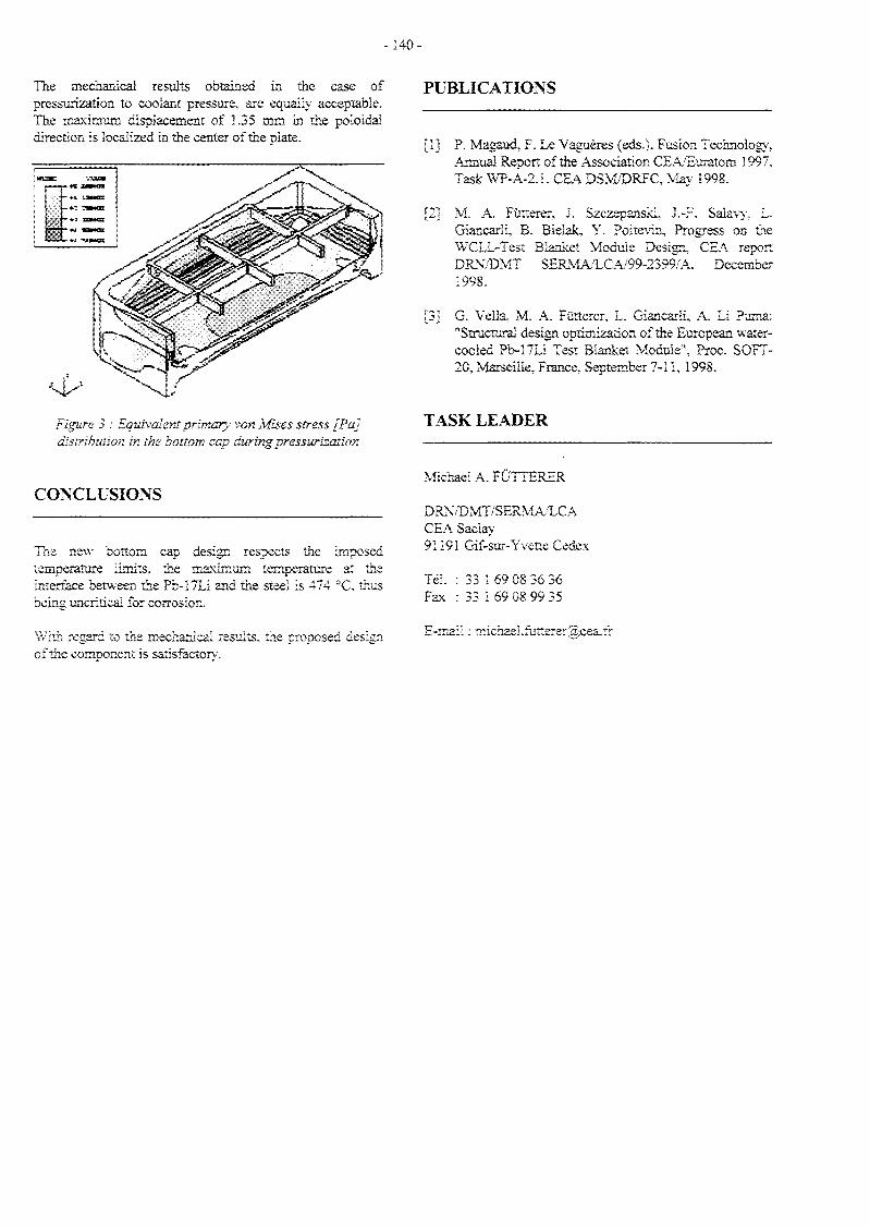
-140-
The mechamcai results obtained in the case ofpressurization to coolant pressure, are equally acceptable.The maximum displacement of Î.35 mm in the poloidaldirection is localized in the ceater of the plate.
PUBLICATIONS
Figure 3 : Equivalent primary von Mises stress [Pa]distribution in the bottom cap during pressurization
CONCLUSIONS
The new bottom cap design respects the imposedtemperature limits, the maximum temperature at theinterface between the Ph-!7Li and the steel is 474 °C. thusbeing uncritical for corrosion.
With regard to me mechanical results, the proposed designof the component is satisfactory.
[1] P. Magaud. F. Le Vaguères (eds.). Fusion Technology,Annual Report of the Association CEA/Euratom 1997.Task WP-A-2.L CEA DSM/DRFC, May
m M. A. Pûtterer, J. Szczepanski, J.-F. Saiavy, L.Gîancarii, B. Bieiak, Y. Poitevin, Progress on theWCLL-Test Blanket Module Design, CEA reportDRN/DMT SERMA/LCA/99-2399/A. December1998.
[3] G. Vella, M. A. Fûtterer, L. Giancarii, A. Li Puma:"Structurai design optimization of the European water-cooled Pb-17ti Test Bianket Module", Proc. SOFT-20, Marseille, France, September 7-1 i, 1998.
TASK LEADER
Michael A. FÛTTERER
DRN/DMT/SERMA/LCACEA Saclay91191 Gif-sur-Yvette Cedex
Tél. : 33 1 69 08 36 36Fax : 33 1 69 08 99 35
E-mail : michael.futterer®cea.£r

- 141 -
WP-A2-2.1
Task Title : TEST BLANKET MODULE FEASIBILITY AND DESIGN,TBM SUBSYSTEMSTBM ancillary equipment design
INTRODUCTION
The water-cooled Pb-17Li test blanket module (WCLL-TBM) in ITER [1] required the lay-out, dimensioning andintegration of ancillary equipment into the allocated space.This ancillary equipment comprises two primary coolingcircuits using pressurized water and one Pb-17Li circuit forthe ex-situ extraction and measurement of the generatedtritium. Additionally, the circuits required for theoccasional demonstration of electricity production from theTBM power were to be considered.
1998 ACTIVITIES
The design of the ancillary circuits for the water-cooledPb-17Li test blanket module for ITER was further refinedto reach full consistency with the requirements in theITER-FDR. The operating conditions, lay-out and size ofthe coolant loops were specified in detail. With optimizedequipment, the thermal efficiency at PWR conditionswould attain > 34.5%.
This additional requirement aggravated the alreadystringent space problem in the pit. For space reasons it wasimpossible to install all equipment for a steam cycle (e.g.steam generator, turbine, alternator, condenser) in the pitarea. Moreover, it would be problematic to operate rotatingmetallic machines (turbine, alternator) in a relativelystrong magnetic field as long as no space for sufficientmagnetic shielding is available. The power conversionequipment had therefore to be installed in the TokamakServices Building (East). With the ITER duty cycle of 45%and a realistic thermal conversion efficiency of 20% fornon-optimized equipment, the produced electric power(averaged over a back-to-back cycle) would become 57kWe from the BZ cooling circuit and 79 kWe from the SBcooling circuit (if assuming a surface heat flux of 0.5MW/m2).
Several circuit arrangements are feasible and differ interms of complexity (lay-out and operation), power output,required heater power and space. Due to the uncertaintiesrelated to the surface heat flux, and consequently the SBpower, the SB power is only to be used if maximizing theelectricity production would be the main objective. Adefinite choice between the various options was not madeyet because ITER did not clarify the question whether ornot an intermediate cooling circuit would be required.
Table 1: Various configurations for power production
Configuration
intermediate cooling circuit
origin of power
number of steam generators
primary cooling circuit slip-stream
A
yes (2)
BZ+SB
1
no
B
no
BZ + SB
2
no
C
no
BZ + SB
1
no
D
no
BZ
1
no
E
no
BZ
1
yes
F
yes
BZ
1
no
G
yes
BZ
1
yes
Criteria and Evaluation
complexity (lay-out and operation)
electricity output
ancillary heater requirements
space requirements
safety
2
4
1
1
4
2
5
1
1
2
3
5
1
2
2
3
4
2
2
2
3
3
3
4
2
3
3
2
3
4
3
2
4
4
4
marks from 1 (poor) to 5 (good)
Configuration A has used the objective to produce amaximum of power while keeping the safety andoperational advantages of the intermediate cooling circuits.The space requirements for the secondary system wereminimized by using one single steam generator. Theancillary heater requirements are high.
Configuration B would maximize the achievableelectricity production by avoiding an intermediate coolingcircuit and by using both the SB and BZ power. The use oftwo steam generators would simplify the SG design but, inreturn, require more space. The complexity of the circuit isconsiderable and so is the heater power required to avoidthermal cycling of the circuits between pulses.

-142-
Confîguration C is the same as A, however without theintermediate cooling circuits. This would enhance thepower output, and reduce space requirements andcomplexity.
Configuration D would reduce the complexity and spacerequirements, but produce less power. The required heaterpower to compensate thermal cycling is still considerable.
Configuration E would respond to the objective to reducethe space requirements for power production and therequired heater power by using only a fraction of the flow-rate of the BZ cooling circuit.
Configuration F would use an intermediate cooling circuit.This can be considered advantageous or even required byavoiding the routing of activated primary cooling across theseismic gap into the Tokamak Services Building. The riskof contaminating ancillary equipment would thus beminimized. Even though the intermediate cooling circuit issomewhat detrimental for the complexity and thermalefficiency, the produced power is still relatively elevated,but the required heater power as well.
Configuration G is the same as F but uses only a fractionof the BZ power which would minimize the space andheater requirements for the equipment. However, theachievable electricity production is only small. Thisconfiguration is shown in Fig. 1.
Alternative power conversion methods (e.g. thermoelectricconversion) were not investigated yet in detail.Thermoelectric generators for a heat source at PWRconditions and a heat sink at 300 K could attain conversionefficiencies of approx 14% which would be equivalent toaverages of 40 kWe from the BZ circuit and 55 kWe fromthe SB circuit when taking into account the 45% duty cycle.The advantages would be to reduce the auxiliary heatingrequirements between pulses, considerably lesscomponents, no moving parts, lower space requirements,probably reduced costs, relative ease to produce power fromboth cooling circuits and no additional safety orcontamination risks.
Finally, a test rig containing all components for a WCLL-TBM mock-up was designed [2] to enable the out-of-pilequalification of the system.
3xeecer Zone Water Coolant Circuit Box
C.76HK
Secretta
i. 05»;
'£ Pn*ss\riMT15.5 SMV«l. t.îi «l
• H-S
HER Secoûdarytfeter Cirojic
Hurt W««ar It»
i-r.;:: v I^
Ctx»n :%çn I A
p. I*» : w a/io I N
To Turfcma
and :cnd<m»fr
??r »l«trieity
Segsent box rater coclan: ciroait é
•loi. e .25 mS.-1 1
ITER SecondaryHater Circuit
> C I ilfit j
?ti»aiy Kater circuit
Figure 1 : Ancillary circuit lay-out for WCLL-TBM including IHX and power conversion

- 1 4 3 -
CONCLUSIONS TASK LEADER
A refined lay-out of the primary and secondary coolingcircuits for the WCLL-TBM was performed. Thepossibility for electricity generation was considered and ledto a selection of several configurations. A test system for aWCLL-TBM mock-up and its cooling circuits was alsoconceived. Such an experiment will be required to qualifythe TBM system as a whole or any other water-cooledcomponent in representative operating conditions beforeinstallation in a test reactor.
PUBLICATIONS
Michael A. FUTTERER
DRN/DMT/SERMA/LCACEA Saclay91191 Gif-sur-Yvette Cedex
Tél. : 33 1 69 08 36 36Fax : 33 1 69 08 99 35
E-mail : [email protected]
[1] P. Magaud, F. Le Vaguères (eds.), FusionTechnology, Annual Report of the AssociationCEA/Euratom 1997, Task WP-A-2.2.1, CEADSM/DRFC, May 1998.
[2] Y. Seven, ITER Test Blanket Module - Out-of-pileblanket system mock-up proposal, CEA reportDRN/DER STML/LCFI-98-043, October 1998.

- 145 -
WP-A2-3.1
Task Title : TEST BLANKET MODULE FEASIBILITY AND DESIGN,INTERFACE WITH ITER AND TEST PROGRAMITER interface and TBM test program
INTRODUCTION
The WCLL-TBM shall be tested in ITER. The mainobjectives of these tests are:
1. to verify and demonstrate the general functionality andthe performances of the system, including Tritiumproduction, extraction, and recovery;
2. to verify and demonstrate the general functionality andthe performances of specific fabrication technologies,such as those concerning Tritium permeation barriers,double-wall tubes, and HIPped structures;
3. to validate and calibrate calculation codes and modelsused for the different design analyses;
4. to verify and demonstrate the performance of high-grade heat production and removal system byestablishing a complete power balance.
1998 ACTIVITIES
A feasibility assessment for achieving these objectives wasperformed and a preliminary test plan was outlined. Itforesees the installation of the TBM already in the BPPwhich can be used to test the functionality of certainsystems. All performance tests will then be performedduring the D-T stage.
The WCLL-TBM test strategy is based on the followingpoints:
1. all technologies required for the corresponding DEMOblanket are to be used (i.e. same structural material,double-wall tubes, permeation barriers);
2. functional tests should start before the TBM will beactivated, preferably with the first H-H plasma;
3. the TBM should remain in place as long as possible toobtain reliability estimates for components; no TBMexchange is foreseen unless dictated by failures and/orby the decision of using new technologies;
4. the WCLL-TBM tests should be independent from thetests of other TBMs, i.e., no sharing of components.
The TBM geometry is similar to the corresponding DEMOblanket. Despite the lower heat flux and neutron wallloading, temperature and stress levels relevant to those ofDEMO can be obtained by properly choosing wallthickness and coolant parameters. Electromagnetic loadsand thermal cycling will be even much more severe thanthose expected in DEMO. The neutron fluence isinsufficient to evaluate high-dose irradiation effects onmaterials and components.
MINIMUM OPERATING REQUIREMENTS
The most important operating parameters for the TBM arethe heat flux on the FW, the neutron wall loading, thepulse length and corresponding duty cycle, and the numberof back-to-back pulses. It is essential to evaluate reasonableminimum requirements for such parameters in order toachieve the fixed testing objectives. Such requirements arerelated to the time needed for the TBM to reach relevanttemperatures and Tritium concentration conditions.
THERMO-MECHANICAL TIME CONSTANT
The thermal transient calculations, performed withCASTEM 2000, have shown that the front part of the TBMachieves temperature steady state after about 60 secondswhile the rear part never does. However, the thermo-mechanical analyses have shown that thermal stresses inTBM structures after 60 seconds are comparable to those ofDEMO. From a thermo-mechanical point of view the testobjectives are already satisfied after this short time.
TRITIUM TIME CONSTANT
The time-dependence of tritium concentration in water andin Pb-17Li can be measured on-line to evaluate the tritiumpermeation rate into the coolant and to provide data forestablishing the Permeation Reduction Factor (PRF) of thepermeation barrier by the comparison of the experimentaland the calculated results during a given transient.
In general, the higher the PRF, the faster a certain tritiumconcentration in the Pb-17Li will be achieved. As anexample, for reference pulse conditions with 1000 s burntime and 1200 s dwell, the time required to reach anaverage tritium partial pressure of 100 Pa in the Pb-17Li incontact with the cooling tubes would be approx. 4 pulseswithout permeation barriers and only 3 pulses for PRF=100(see Fig. 1), supposed the Pb-17Li is kept stagnant (nopumping). With PRF=100, 1000 Pa (maximum in DEMO)would be reached after 10 pulses (no pumping).

- 1 4 6 -
Time (hours)
Figure 1 : Average tritium partial pressure transientin Pb-17Li during the reference pulses with/without
permeation barriers (no Pb-17Li Pumping)
Yet, it is expected that if Pb-17Li circulation anddetritiation are taken into account, a much larger numberof pulses will be required.
Best results and most reliable data interpretation can infact be obtained from irradiating the TBM without Pb-17Licirculation for a number of pulses and only then start Pb-17Li pumping with or without tritium extraction. Thetritium related kinetics of the Pb-17Li circuit can bemeasured in an out-of-pile experiment and confirmedduring the D-D phase. They are expected to be comparableto the TBM kinetics.
DISCUSSION
As it is shown in Table I, the reference ITER operatingparameters, such as heat flux on FW and neutron wallloading, permit to reach a TBM design point representativeof DEMO. The performed transient analyses have shownthat representative thermal and thermo-mechanicalconditions can be reached after less than 100 seconds. It isexpected that representative conditions can be achievedalso with significantly reduced wall loading (i.e. 50%),provided that the TBM design is performed for theseconditions.
On the other hand, a single pulse is not sufficient forreaching relevant Tritium parameters. In view of therequirements presented above in terms of tritium balance,experimental repetitivity, number of data points to generateand time needed for one measurement, it can be estimatedthat the required number of uninterrupted back-to-backcycles is of the order of 100.
PROPOSED TEST PROGRAM
A test program for the WCLL TBM has been defined forboth the BPP and the EPP of ITER taking into account thetesting strategy, the TBM responses and the ITERoperating scenario. The test program in ITER is based onthe assumption that the whole TBM system was previouslytested in an out-of-pile experiment before the installationin ITER.
ENVISAGED ITER OPERATING SCENARIO
The ITER BPP is expected to last about 10 calendar years.In the first 2 Vi years, the machine will not be activated (H-H plasma), then after a 6-month period of D-D operation,tritium will be used for D-T operation. The reference pulseis expected to last 1000 s, with 1200 s of downtime leadingto a 45% duty cycle. In case of back-to-back pulses thiswould mean about 40 pulses per day. Maximum expectedvalues for heat flux and neutron wall loading on ITER FW(and assumed for the TBM analyses described above) arerespectively 0.5 MW/m2 and 1.2 MW/m2.
During the last four calendar years of the BPP, 2 - 4periods with an extended burn time could be expected, e.g.,two 6-week periods or four 3-week periods of back-to-backpulses. Long pulses of up to 10,000 s length might beavailable also. The expected total neutron fluence duringthe BPP is about 0.3 MWa/m2.
The ITER EPP is also expected to last about 10 calendaryears with an expected total neutron fluence of about 1.0MWa/m2 and a large number of back-to-back referencepulses.
TESTS TO BE PERFORMED DURING THE H-HAND D-D PLASMA PULSES
Significant information can be obtained during the H-Hphase, especially concerning the system functionality. Theadvantages of testing the TBM during this phase is thepossibility of hands-on intervention in case of problems.
Major tests to be performed are:
1. overall functionality of the TBM system (e.g., thermo-couples, sensors, pumps, heat exchanger, flow-meters);
2. verification of safety-relevant functions (e.g., Pb-17Lidraining) implemented in the TBM system;
3. MHD pressure drop as a function of Pb- 17Li flow-rate;
4. H/D permeation from Pb-17Li to coolant and vice-versaby introducing H/D in the Pb-17Li circuit for differentDEMO-relevant H/D-partial pressures such as 100 Pa,500 Pa, and 1000 Pa.
- 1 4 7 -
The D-D phase is assumed to last a short period (approx. 6months), three years after the first plasma. Significantinformation can be obtained from the comparison withresults obtained in the H-H phase, especially concerningthe system functionality, in particular temperaturetransient monitoring. An important measurement, whichcan only be performed during this short D-D phase is thepermeation to the FW-cooling water of D coming from theplasma. Impinging ion-permeation is expected but itsestimation is very uncertain.
TESTS TO BE PERFORMED DURING THE BPP D-TPLASMA PULSES
This part of the tests is characterized by the deposition ofnuclear volumetric heat in the TBM. Significantinformation can be obtained from the comparison withresults obtained in the H-H and D-D phase, especiallyconcerning the system functionality.
Major items to be measured for comparison with thetheoretical estimates are:
1. TBM temperature distribution;
2. neutron and gamma fluxes distribution;
3. maximum stress level in the structure;
4. tritium production rate and integral tritium production;
5. Tritium permeation rate into the cooling water andestablishment of the Permeation Reduction Factor(PRF) of the used permeation barriers.
Tritium inventory and permeation will be evaluated inthree different scenarios leading to different T-partialpressures in the Pb-17Li:
1. the Pb-17Li is maintained static (short time constant);
2. the Pb-17Li flows but no T-extraction is performed;
3. the Pb-17Li flows and the T-extractor located in the pitis operating (corresponding to the larger time constant).
TESTS TO BE PERFORMED DURING THE ITEREPP
The same tests performed in the previous phase will berepeated for confirmation. The remaining operating time isdevoted to reliability growth and to the verification ofhigher-fluence induced irradiation effects (such as apossible shift of the ductile-to-brittle temperature transitionin the structural material and performance of joints).Demonstration of electricity production could beenvisaged.
FEASIBILITY ASSESSMENT
In order to achieve the test objectives, sensitive and reliablemeasurement techniques and powerful theoreticalinterpretation tools have to be used. In particular, theeffective TBM operating conditions have to measured withappropriate detectors installed in the TBM.
MEASUREMENT INTERPRETATION
The most complex measurements are those concerning theTritium parameters during the D-T pulses, in particularbecause of the pulsed operation and of the fact that Tritiumcan be measured only outside the vacuum vessel.
One main uncertainty is the Tritium production itself. Theidea is to perform on-line thermal measurement forcalibrating the Tritium sources. Thermal and thermal-hydraulics calculations and associated codes are assumedto be already validated. Thus, thermal measurements willbe used to estimate the actual heat flux received from thefirst wall and the nuclear heat deposition, and then derivethe actual neutron wall loading. This information will beused to calculate the tritium production so as to validatethe Monte Carlo code and neutron cross-sections fromneutron detector signals.
The T-permeation rate to the water and the correspondingbarrier PRF can be estimated as follows. In the lastexperiment the Pb-17Li is flowing (the flow-rate isadjusted so as to obtain a DEMO-relevant T-partialpressure) and the tritium is extracted by the T-extractorlocated in the pit. The time constant is relatively large(approx. 100 back-to-back pulses are required).Information on T-inventory in the external circuit andcomponents will become available. The T-concentration inthe Pb-17Li as a function of time and flow rate will bemeasured in the pit, both before and after the T-extractor.The T-concentration in the water-coolant, due to thepermeated tritium to the water-coolant within the TBM,will be measured in the pit as a function of time. A full T-balance evaluation can then be performed. The tritiumproduction will therefore be evaluated and compared to theresults of the neutronic calculations. With the help of theprevious experiments (Pb-17Li stagnant and/or no T-extraction, which are less affected by the pulse length) thePRF of the T-permeation barriers can be evaluated.
Uncertainties of measurements andpredictions have to be investigated.
of theoretical

- 148-
CONCLUSIONS TASK LEADER
The present EU R&D program for the water-cooled Pb-17Li DEMO blanket foresees to test a representative testblanket module in ITER from its initial phase. Theperformed work shows that a WCLL-TBM can bemanufactured and safely operated in the ITERenvironment. Its DEMO relevancy depends on the outcomeof ongoing R&D, in particular concerning the developmentof a suitable structural material, permeation barriers anddouble-walled tubes. It has also been shown that theproposed test program is able to give essential informationfor the development of relevant technology to be used in aDEMO reactor.
The possibility of achieving the WCLL-TBM testingobjectives have been discussed from the point of view ofthe presently defined ITER operation conditions and of theavailability and installation of appropriate instrumentation.No major difficulties are expected although further R&D isrequired for ensuring a complete interpretation of theexpected experimental data, especially on bothinstrumentation technology and numerical on-lineanalysis.
Michael A. FUTTERER
DRN/DMT/SERMA/LCACEA Saclay91191 Gif-sur-Yvette Cedex
Tél. : 33 1 69 08 36 36Fax : 33 1 69 08 99 35
E-mail : [email protected]
PUBLICATIONS
[1] L. Giancarli, M. A. Fùtterer, B. Bielak, Y. Poitevin,J.-F. Salavy, J. Szczepanski, WCLL-TBM teststrategy during ITER-BPP, CEA report DRN/DMTSERMA/LCA/98-2400/A, December 1998.
[2] L. Giancarli, B. Bielak, M. A. Futterer, O.Ogorodnikova, Y. Poitevin, J.-F. Salavy, J.Szczepanski, Y. Seven, G. Marbach, G. Benamati, C.Nardi, J. Reimann, Objectives feasibility assessmentof the WCLL mock-up testing in ITER, Proc. SOFT-20, Marseille, France, September 7-11, 1998.

-149 -
WP-A2-4.1
Task Title: TEST BLANKET MODULE FEASIBILITY AND DESIGN,MAINTENANCE, SUPPORT, REMOTE HANDLING, WASTEDISPOSALTBM support system and maintenance procedure
INTRODUCTION
The drain system to purge the Pbl7Li from the TBM andthe instrumentation both require penetrations through thebackplate of the TBM. In both cases it had to be ensuredthat these penetrations will not challenge the structuralintegrity of the TBM during accidental pressurization. Forhydraulic reasons, the Pbl7Li draining would beincomplete and slow if no additional gas injection into theTBM is performed.
Additionally, the instrumentation needs identified in WPA2.3.1 were integrated in the TBM design. This concernsin particular the measurement of temperature anddeformation. The locations of thermocouples and straingauges were selected and design solutions were found toinstall this instrumentation in the TBM.
1998 ACTIVITIES
The objective of this work was to integrate auxiliaryfunctions in the design of the water-cooled Pbl7Li TestBlanket Module (WCLL-TBM). Such auxiliary functionsare :
- a Pbl7Li drain system to remove the liquid Pbl7Lifrom the TBM during extended shut-down periods andbefore removal; this system is required to avoid thefreezing and consecutive re-melting of Pbl7Li insidethe TBM which is a complex operation and maychallenge the integrity of the TBM;
- the acquisition of different kinds of measurement datafor determining the operating conditions and for safetysurveillance, e. g. temperatures and deformations;
Pbl7Li DRAIN SYSTEM
Because melting of solidified Pbl7Li in the TBM itselfmay provoke structural damage of the TBM box, thePbl7Li shall be removed from the TBM during extendedshut-down phases. Most of the Pbl7Li can be removedwhen inserting a drain pipe from low on the back plate.For remote handling reasons the pipe dimensions areidentical to the other pipes, i. e. 050 x 3 mm. This drainpipe leads to the Pbl7Li storage tank located on a lowerlevel than the TBM to facilitate gravity draining.
The drain pipe is equipped with a valve and is constantlytrace heated to speed up draining. Temperature gradientsbetween TBM and valve should be minimized to avoidsegregation of the alloy. Inert gas injection is foreseen inboth the Pbl7Li inlet and outlet pipes to further acceleratethe process and to compensate the drained Pbl7Li volume.
INSTRUMENTATION
In the Design Description Document for the WCLL-TBM,several types of instrumentation for installation within theTBM were proposed to meet the test objectives. Theseincluded thermocouples for mapping the temperatures invarious areas, electrical potential probes to determinecurrents, stress transducers or strain gauges to monitordeformation during operation, neutron detectors andgamma scan wires to measure flux and fluence and tocalibrate neutronic calculations.
More recently, additional electrodes for the determinationof a local Pbl7Li velocity were proposed to investigateMHD phenomena, which can be done even without plasmaoperation. With thermocouples and strain gauges asexamples for performing the thermomechanicalmeasurements, it was demonstrated that theinstrumentation is feasible and that it is adapted to theTBM environment.
INSTALLATION OF INSTRUMENTATION
All instrumentation was installed respecting the followingrequirements:
- no connectors between sensor and pit area asconnectors are a source of malfunction and almostinaccessible without TBM removal;
- electrical insulation between sensor wires andTBM/interface frame to protect the measurement signalfrom leak currents;
- attachment of wires to the TBM by spot welded clampsso as to maintain their position;
TEMPERATURE
The following provides examples for the installation ofthermocouples in various places of the TBM. If desired, theTBM could be more amply equipped to improvetemperature mapping.

-150-
Pbl7Li TEMPERATURE
2 x 7 thermocouples are foreseen for this purpose. Theirtentative position is shown in Figs. 1 and 2.
Located in the lower section of the TBM, two sets of 7thermocouples each read the Pbl7Li temperatures in twoparallel radial directions, one in the central channels, one inthe lateral channels. These thermocouples will be installedon two fingers that will be inserted in the TBM frombehind.
These fingers consist essentially of an open tube connectedto a flange that ensures the sealing with the backplate. Thisflange can be either bolted or welded to the backplate. Thepassage of the thermocouple wires is sealed with Swagelocktype connectors. The tube is open to freely allow the Pbl7Lito penetrate and thus to minimize tritium trapping. Behindthe First Wall, the tube is positioned by a support. Thepassage of the tube across the stiffener plates is ensured bydrilling holes from the backplate. Play between tube andholes should be minimized to avoid Pbl7Li shortcircuits.
- TEST BLANKET MODULE - INSTRUMENTATIONS -
INSTRUMENTATION LIST
THERMOCOUPLES
1 ) 2 X 7 THERMOCOUPLES - T 1 TO T14
2] 2 X 2 THEBMOCOUPLES - T15 TO T18
3 ) 2 X 1 THERMOCOUPLE - T19 TO T20
4) 1 THERMOCOUPLE - T21
STRAIN GAGES
5) 2 X i STRAIN GAGES - SGI TO SG8
6) 2 X 3 STRAIN GAGES - SG9 TO SG14
- 1811.32.001.B - NOVEMBRE 1998 - SZCZEPANSKI J. -
Figure I : Location of thermocouples and strain gauges
FIRST WALL TEMPERATURE
2 x 2 thermocouples are foreseen for this purpose. Theirposition is shown in Fig. 2.
These thermocouples will be installed in the middle of thefirst wall thickness, one pair on the lower part, the other inthe middle of the TBM height.
This requires holes to be drilled in the middle of the firstwall thickness and between two first wall cooling tubes. Asmall groove will accommodate the thermocouple aroundthe corner before the installation of the Be armor. On theTBM side walls the thermocouples will be attached withsmall spot welded clamps.
- TEST BLANKET MODULE - INSTRUMENTATIONS -
in
T ] SEE 1811.32.002.B -ÎL '_ — PLAMCBE 3 -' •
THERMOCOUPLE T7OR T14
THERMOCOUPLE T6OR T13
_ , THERMOCOUPLE T5 !| | t » 0 R _ T 1 2 _ | _
THERMOCOUPLE T4OR T i l
'- SECTION A A -
£SECTION B B -
THERMOCOUPLE T3OR 'HO
THERMOCOUPLE T2OR T9
THERMOCOUPLE TlOB T8
SEE 1811.32.002.BPLANCHE 2
- 1811.32.002.B - PLANCHE 1 - NOVEMBRE 1998 - SZCZEPANSKI J. -
Figure 2 : Thermocouple holders (general view)
FIRST WALL COOLANT TEMPERATURE
2 x 1 thermocouple are foreseen for this purpose. Each FirstWall coolant manifold is equipped with one thermocoupleon the inlet and another on the outlet. Swagelock typeconnectors are foreseen to seal the thermocouple againstcoolant pressure and vacuum. Alternatively, simple weldedpenetrations could be used to improve leak tightness ifrequired.
BREEDER ZONE COOLANT TEMPERATURE
1 thermocouple (T21) is foreseen for this purpose. Itsposition is shown in Fig. 2.
This thermocouple will be located inside the coolant outletcollector chamber to read the average Breeder Zone coolantoutlet temperature. It is attached to the inside of the coolantoutlet chamber by spot welded clamps.

- 1 5 1 -
Swagelock type connectors are foreseen to seal thethermocouple against coolant pressure and vacuum.Alternatively, simple welded penetrations could be used toimprove leak tightness if required.
DEFORMATION
Tie rod elongation and deflection
2 x 4 strain gauges are foreseen for this purpose. Theirposition is shown in Fig. 1.
Two of the four tie rods for the mechanical TBMattachment to the interface frame will be instrumented with4 strain gauges each. This double instrumentation has beenchosen for different reasons:
- confirmation of the tie rod deformation calculated forthe attachment analysis
- confirmation of symmetric deformation of TBM
- functional redundancy (relatively short lifetime ofstrain gauges is expected)
TBM deformation
3 x 2 strain are foreseen for this purpose. Their position isshown in Fig. 1.
Three pairs of strain gauges will be installed on the TBMside walls, on pair on the top, the second in the middle andthe third on the bottom. One strain gauge out of each pairis close to the plasma facing front corner, the other close tothe back plate.
This distribution was chosen to measure the global TBMdeformation and to confirm the information from the tierod deformation.
PUBLICATIONS
[1] M. A. Futterer, B. Bielak, J. Szczepanski, L.Giancarli, Drain system and instrumentation of awater-cooled Pbl7Li test blanket module, CE A reportDRN/DMT SERMA/LCA/98-2460/A, December1998.
TASK LEADER
Michael A. FUTTERER
DRN/DMT/SERMA/LCACEA Saclay91191 Gif-sur-Yvette Cedex
Tél. : 33 1 69 08 36 36Fax : 33 1 69 08 99 35
E-mail : [email protected]
CONCLUSIONS
The auxiliary functions Pbl7Li draining and thethermomechanical instrumentation of the WCLL-TBMwere successfully integrated in the overall design. A degreeof detail was reached that allows to confirm the feasibilityon the one hand, but that leaves enough flexibility forfuture modifications on the other.

- 153 -
WP-A3-1.1
Task Title : ITER TEST MODULE FABRICATION :DEVELOPMENT AND FABRICATIONDouble Wall Tube HIP Fabrication
DOUBLE WALL TUBE
INTRODUCTION
In the DEMO Water Cooled Lithium Lead blanket, coolingof the LiPb breeder alloy is made thanks to bentmartensitic steel (MS) tubes. Each module is equippedwith a bundle of 24 tubes.
For safety reasons, it is necessary to use two concentrictubes (each of them designed to withstand the full load byitself) separated by a compliant layer. The role of thecompliant layer is to stop or to deviate cracks that couldpotentially develop through one of the tubes. Furthermore,this layer shall provide a good thermal contact between thetubes.
A fabrication sequence based on Hot Isostatic PressureDiffusion Bonding has been developed. HIP-DB allows toeliminate the gap between the two tubes while at the sametime insuring a full contact between the compliant layerand the steel.
1998 ACTIVITIES
MECHANICAL PROPERTIES OF THE JOINTS
The mechanical properties of the MS/interlayer/MS jointshave been assessed using several testing methods. Tensilespecimens, Charpy impact specimens and CompactTension specimens have been fabricated using F82Hmartensitic steel and 0.1mm foils. Decohesion tests usingdouble wall rings made of T91 steel have been also used.
Three cases have been studied : a pure Fe or a pure Cuinterlayer HIPed at 1050°C and a titanium interlayerHIPed at 750°C. In the case of high temperature diffusionbonding, the samples were quenched and tempered at750°C. In the case of low temperature diffusion bonding,no further heat treatment was necessary.
The results are as follows : rupture occurs within the Feand the Cu compliant layer, while interface decohesion isobserved in the case of Ti. The force to rupture is higherwith Fe than with Cu due to the higher strength to ruptureof Fe itself. Detailed results for double-ring decohesiontesting are given in table 1.
Table 1 : Results of double ringdecohesion test (T91 steel)
interlayer
force to rupture
comments
Copper
650±40 daN/mm
ductile ruptureinCu
Iron
1430±60 daN/mm
ductile ruptureinFe
Titanium
710±320 daN/mm
interfacedecohesion
Despite the better behaviour of iron, it has been decided tochoose copper as a compliant material because coppercoating is easily achievable by electroplating, whereas ironcoatings are not available on an industrial scale.
Tensile and impact results for Cu are given in table 2 :
Table 2 : tensile and impact resultsfor F82/Cu/F82Hjoints
F82H/Cu/F82H joint
F82H
0.2% yieldstrength
520 MPa
550 MPa
strength torupture
605 MPa
650 MPa
totalelongation
2.5%
20%
impactresistance
(KCU)
48±21 J/cm2
-190 J/cm2
The yield strength of the F82H/Cu/F82H joint is 30MPalower than that of as received F82H due to a slightsoftening of F82H steel during the PHP cycle. The ruptureof the joint occurs after a limited elongation of the sampledue to the "weakness" of copper, but the strength to rupturefar exceeds the strength to rupture of pure copper due toconstraining effects. The impact resistance of the joint isabout 25% of those of the base F82H, which is notsurprising considering the much lower strength of copper.Examination of the rupture surface of impact specimensrevealed that the rupture path oscillates between the twoCu/F82H interfaces but keeping within Cu. Dimples ofabout lum diameter are observed.
MOCK UPS FABRICATION
During 1997, small length mock ups were fabricated usingT91 tubes and 0.1mm foils. For longer DWT it wasnecessary to coat the inner MS tube in order to insure thecontinuity of the compliant layer all around the tubes.During 1998, three mock ups about 450mm long werefabricated. A description of the fabrication sequencefollows.

-154-
Coating
The Cu coating technique is eledxodeposition. First,chemical cleaning of the Ilxî3.5mm T91 tube using anitric acid based solution is made. Then, it is necessary todeposit a nickel underiayer to get a fair adherence of thecopper coating. The thickness of this underlayer is about0.1 urn. Copper deposition is made using an electrolytic bathtypically used for eiectroforming. The choice of this bath isjustified by the relatively high thickness of the coatingcompared to the thickness of decorative coatings.
For the three tubes, the coating thickness lied between 0.15and 0.2mm. The excess of copper was carefully machineduntil the coateé tube could fit in the outer 14x17mm tube.
The microstructure of the as deposited coating ischaracterised by the presence of rather numerous inclusionsat the steel / copper interface. This is typical of theelectrodeposition process (figure 1).
^L>,^\*-ï - -*• > - i - •
Figure 1 : As-deposited copper coating (right)on T91 tube (left), xldOO
12C
time |
Figure 2 : HIP cycle used for DUT fabrication.
Microstructure and properties
The microstracture of the joint after HIP and posttreatments is characterised by :
- a diffusion affected zone in steel on the inner tube side(figure 2). Martensite platelets morphology differs fromthat of base T91 steel due to nickel enrichment. Themicrohardness of this zone is about 3OOHvO.O15 against240Hv0.1 for the base T9i steel.
- a very fine precipitation of chromium and iron in thecopper layer. This is due to the rapid decrease of thesolubility of these elements in copper, on cooling.
HIPDW
The electroplated tubes were degreased and heat treated at750°C for lh30 under vacuum for outgassing. Electroplatedcoatings usually contain great amounts of absorbed gases.
Then, inner and outer tubes couples were prepared bymeans of degreasing and acid pickling. The tubes werefitted one in each other, both ends TIG welded and theinterface was outgassed.
The HIP cycle is as shown on figure 2. To avoid damage ofthe tubes, heating is made under low pressure. Then a Ihstep at 850°C and a Ih increase to IO40°C are appliedduring which the pressure is increased to 140MPa.Normalising conditions are applied for the joining (1040°C,40min for T91). The maximum cooling rate of the HIPequipment used for this fabrication was only about4.5°C/mm. so further normalising at 1040°C for 40min. gasquench and tempering for Ih at 750°C were applied afterHIP.
Figure 3 : T91 (top) / copper(botiomj interfaceafter DWTfabrication, xlOOO
Samples were cut for double-ring decohesion test. The forceto rupture was about $00daN/mm for 1.5mm thick ringscompared to 640daN/mm for samples fabricated with a foil.The difference is probably due to the longer exposure of theDWT mock ups at high temperature : no furthernormalisation heat treatment was necessary in the first casebecause the HIP cooling rate was high enough to insure themartensitic transformation.
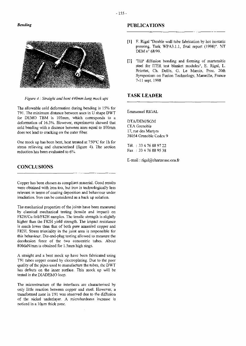
-155-
Bending PUBLICATIONS
[1] E. Rigal "Double wall tube fabrication by hot isostaticpressing. Task WPA3.1.1, final report (1998)". NTDEM n° 68/99.
[2] "HIP diffusion bonding and forming of martensiticsteel for ITER test blanket modules", E. Rigal, L.Briottet, Ch. Dellis, G. Le Marois, Proc. 20thSymposium on Fusion Technology, Marseille, France7-11 sept. 1998
Figure 4 : Straight and bent 440mm long mock tips
The allowable cold deformation during bending is 15% forT91. The minimum distance between axes in U shape DWTfor DEMO TBM is 103mm, which corresponds to adeformation of 16.3%. However, experiments showed thatcold bending with a distance between axes equal to 100mmdoes not lead to cracking on the outer fiber.
One mock up has been bent, heat treated at 750°C for lh forstress relieving and characterised (figure 4). The sectionreduction has been evaluated to 6%.
CONCLUSIONS
TASK LEADER
Emmanuel RIGAL
DTA/DEM/SGMCEA Grenoble17, rue des Martyrs38054 Grenoble Cedex 9
Tél. : 33 4 76 88 97 22Fax : 33 4 76 88 95 38
E-mail : [email protected]
Copper has been chosen as compliant material. Good resultswere obtained with iron too, but iron is technologically lessrelevant in terms of coating deposition and behaviour underirradiation. Iron can be considered as a back up solution.
The mechanical properties of the joints have been measuredby classical mechanical testing (tensile and impact) onF82H/Cu foil/F82H samples. The tensile strength is slightlyhigher than the F82H yield strength. The impact resistanceis much lower than that of both pure annealed copper andF82H. Stress triaxiality in the joint area is responsible forthis behaviour. Die-and-plug testing allowed to measure thedecohesion force of the two concentric tubes. About800daN/mm is obtained for 1.5mm high rings.
A straight and a bent mock up have been fabricated usingT91 tubes copper coated by electroplating. Due to the poorquality of the pipes used to manufacture the tubes, the DWThas defects on the inner surface. This mock up will betested in the DIADEMO loop.
The microstructure of the interfaces are characterised byonly little reaction between copper and steel. However, atransformed zone in T91 was observed due to the diffusionof the nickel underlayer. A microhardness increase isnoticed in a lOum thick zone.

- 157 -
WP-A3-2.1
Task Title : DOUBLE-WALL TUBE OUT-OF-PILE TESTINGDIADEMO EXPERIMENTAL PROGRAMME
INTRODUCTION
Within the framework of the study on Water-CooledLithium-Lead tritigenous Blankets for a fusion reactor,technological choices on cooling tubes must be validated.Within this context, tests on Double-Wall Tubes (DWT's)through which reactor power will be transferred must becarried out.
The state of the art technology of these tubes is of utmostimportance as it conditions the concept and must bevalidated from both mechanical and thermal point of view.Before considering industrial manufacturing, samples haveto be tested under fusion reactor nominal.
The main objective of DIADEMO experimental device isto validate, in close collaboration with the task WP-A3-1(Double-Wall tube fabrication), the choice of the double-walled tube for the future Fusion reactor.
1998 ACTIVITIES
This task (WP A3-2.1) has been launched in 1996.Following that :
- A preliminary feasibility study, concerning anexperimental device in order to test DWTs, has beenperformed by mid of 1996.
- A pre-design study has been, then, performed duringthe second half of 1996 in order to launch, beginning of1997.
- A call for tender for the fabrication study.
- Following this fabrication study, a call for tender hasbeen launched for the manufacturing of the mechanicalpart of the experimental device.
- In the mean time (summer 1997), a call for tender hasbeen launched in order to perform the study and themanufacturing concerning the 'Instrumentation andControl1 of the experimental device.
- The end of the year 97 and the year 98 have beendevoted to the fabrication of the experimental device(mechanical part, instrumentation and control, thermalisolation).
This task is performed in close collaboration with task WP-A3-1, driven by CEA/ CEREM, responsible of thefabrication of the DWTs (choice of the DWT fabricationprocedure, DWT manufacturing). It is forecasted as a firststep, the fabrication of small size test samples (straight andbent), and in a second step the fabrication of large size bentDWTs (~2. meters developed length).
The first straight sample (length 500 mm, heated on 200mm) has been manufactured by CEA/ CEREM duringthe first half of the year 98. It has been delivered toCadarache during the SOFT period (11th, September).It has been hydraulically tested (up to 25 Mpa).
The straight DWT sample has been fitted and preparedduring the rest of September. It is now installed on theDIADEMO test loop.
Concerning DIADEMO experimental device, the year1998 has been devoted as follows :
- January - end of July 98,Mechanical Part.
Manufacturing of the
- January - end of November 98, study, fabrication andacceptance tests of the Instrumentation and Controlpart,
THE EXPERIMENTAL DEVICE.
The experimental device "DIADEMO" has to satisfy tofusion reactor operating conditions. So the circuit has beendesigned for pulsed conditions (in order to perform thermalfatigue tests on the DWTs. 3000 thermal cycles areforeseen for the first mock-up) and for long time thermalsteady-state operating conditions (in order to performendurance tests).
The final experimental device is as follow :
Two test stations :
i) the first one called "Air Test Station", using only thepressurized water cooling circuit. The test samplesare electrically heated (not use of Pb-17Li loop),
ii) the second one called "Pb-17Li Test Station", usingthe entire circuit; the Pb-17Li being also electricallyheated.
The "Air Test Station" will be used for the small size testssamples. The "Pb-17Li Test Station" will be available forthe final qualification of the DWT in presence of theeutectic.
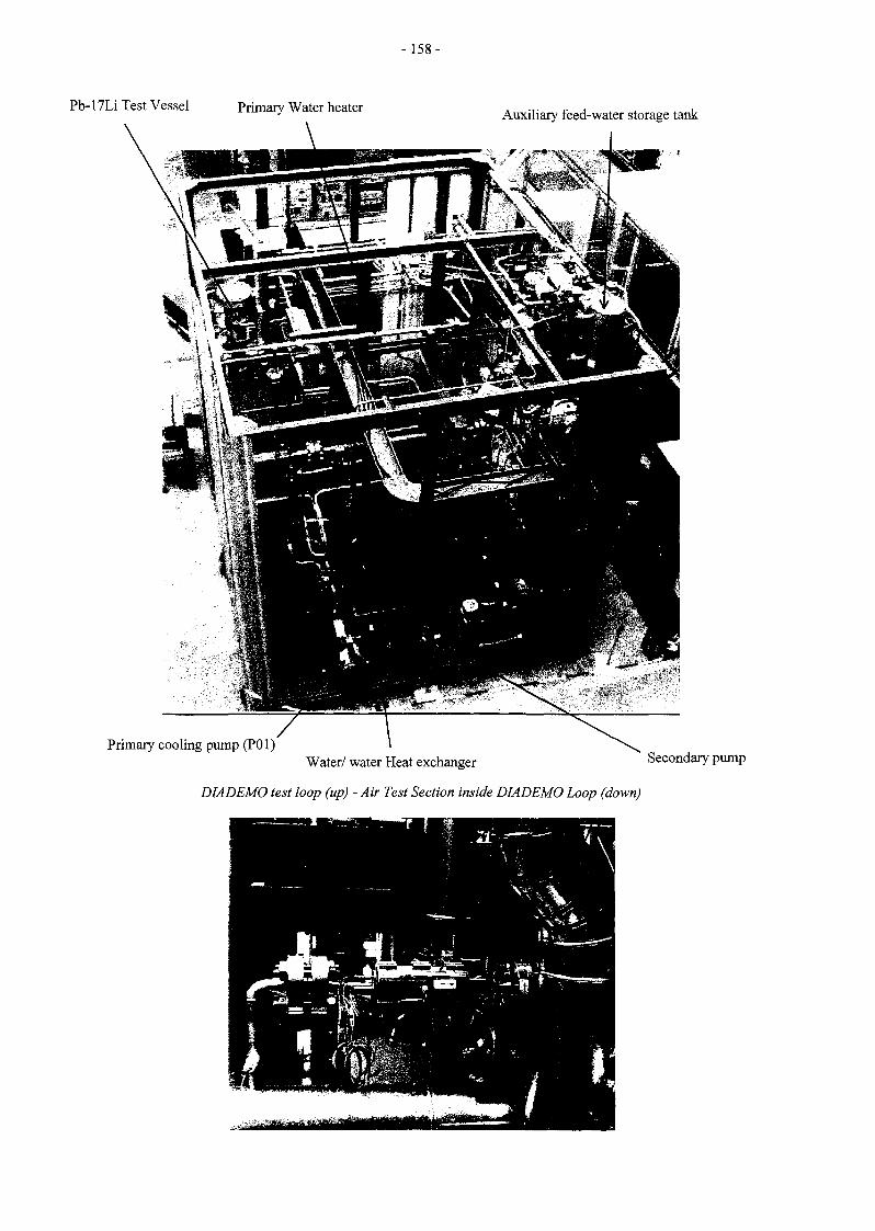
-158-
Pb-17Li Test Vessel Primary Water heater Auxiliary feed-water storage tank
Primary cooling pump (P01)Water/ water Heat exchanger Secondary pump
DIADEMO test loop (up) - Air Test Section inside DIADEMO Loop (down)

-159-
AIR TEST SECTION
Tube Thermocouple
Inside electrical heaters
Double-Wall Tube
Lateral flangeOutside electrical heater
Graphite envelop
View of the Straight Double-Wall Tube Sample (200 mm)
Lithium-Lead Loop
The maximum operating temperature in the Pb-17Li is550°C (Reactor operating condition in the blanket).Nevertheless it will be possible to perform thermaltransients in the liquid metal for Reactor pulsed operatingconditions. The operating temperatures in this case will bebetween 300 and 390°C.
Primary Water Cooling Loop
The operating conditions of the primary water coolingcircuit will simulate reactor conditions :
- Maximum water temperature : 325°C,- Minimum water temperature : 265°C,
Water pressure :15.5MPa,- Water tube flow rate : 0.37 kg/s.

- 160 -
The "Air Test Station" is in fact a derivation on the mainwater loop. The test samples will be connected to the watercooling loop with flanges and externally electricallyheated. It is forecasted to test on this station small sizesamples (straight and bent).
Secondary Water Cooling Loop
The operating conditions of the secondary water coolingcircuit are the following :
REFERENCES
Mean water temperatureWater pressureWater tube flow rate
55°C,1.5 MPa,1.5 kg/s.
The secondary water loop is connected to an external aircooler, in order to remove the final thermal power.
THE INSTRUMENTATION AND CONTROL -DATA- ACQUISITION
During the year 1998 (up to the end of November), thedetailed study, the fabrication and the acceptance tests of"the Instrumentation and Control -Data Acquisition" hasbeen performed.
In the mean time, in order to get the authorization to startthe loop, a safety study has been performed [1].
[1] NT. DER/ STML/ LCFI - 98-017. (20/ 05/ 1998)."Installation d'essais DIADEMO - Dossier seSécurité "
[2] 20th SOFT - September 7-11, 1998. MARSEILLE -FRANCE."Water-Cooled Pb-17Li Blanket - DiademoExperimental Programme for Double-Wall TubeQualification"
[3] NT. DER/ STML/ LCFI - 98-046. J.P. DIEPPOIS -Y. SEVERI« WATER-COOLED LITHIUM-LEAD BLANKET -Task Sheet TS A 3.2 - Progress Report (1998) -DIADEMO EXPERIMENTAL PROGRAMME »
TASK LEADER
Yves SEVERI
DRN/ DER/ STPI/ LCFICEA Cadarache13108 St Paul Lez Durance Cedex
TIME SCHEDULE
As it has been explained previously, the Instrumentationand Control-Data Acquisition with acceptance tests have tobe completed by the end of November.
The first acceptance tests of the complete loop (intemperature) have started by mid of December 98.
Tél. : 33 4 42 25 64 01Fax : 33 4 42 25 66 38
E-mail : [email protected]

-161 -
WP-A3-4.1
Task Title : ITER TEST MODULE FABRICATIONITM BOX FABRICATION USING POWDER HIP TECHNIQUE
INTRODUCTION
Hot Isostatic Pressing (HIP) is foreseen to producecomponents of fusion reactors blanket. This technology canbe used to manufacture net shape components from powder.Due to large deformations (up to 30% in volume), anhelpfull tool is finite element calculation. Modelling thedensification of the powder in a container allows to predictthe kinetic of consolidation of the component and so toimprove the HIP cycle. The final shape, the residual stressesand strains state are also predicted.
Numerical simulation required a finite element code withthe adapted constitutive equations implemented, and thematerial data base.
The finite element code which is used for this study iscalled PRECAD. Developed by CEA/CEREM, it is devotedto thermomechanical calculations of multimaterials.Classical plastic and viscoplastic models are available. Theparameters of the laws may depend on temperature. Thespecific viscoplastic law for porous materials has beenimplemented for 2D-axisymmetric configuration and for 3Dgeometries.
In 1997 a small-scale mock-up had been manufactured inview to validate the material data base for a simple shapepart.
In 1998, a more relevant size mock-up for the primary wallof the WCLL ITER Test Module (ITM) has been designed,simulated and manufactured, in order to validate:
- the material data and the finite element calculation,- the capabilities of the powder metallurgy route to
manufacture complex parts such as a test blancketmodule.
The manufacturing route for the fabrication of the testblancket module (TBM) according to the Water CooledLithium Lead (WCLL) concept has been described.
1998 ACTIVITIES
DESCRIPTION OF THE MANUFACTURINGROUTE FOR THE FABRICATION OF THE TESTBLANCKET MODULE
An advanced manufacturing route ihas been proposed forthe fabrication of the test blanket module (TBM) according
to the Water Cooled Lithium Lead (WCLL) conceptdevelopped by CEA/Saclay. Both reference fabricationMethod and alternative fabrication method (using powdermetallurgy) have been detailed. This manufacture route isthe conclusion of a work performed by the CEREM and theDMT. The route using the powder metallurgy displays somesimplifications if compared with the reference route. Thosesimplications ensure a highest quality of the final part.
RELEVANT SIZE MOCK-UP MANUFACTURING
This component is 390 mm in height and 175mm indiameter at initial. It is made of a coiled stainless steel tube(fig 1) (8-10 mm inner and outer diameters) representingthe first wall cooling channels. A 200 (im thick coppercompliant layer is deposited on the coiled tube.
Figure 1 : Coiled tube made of304L before coating
4 tubes of T91 (fig 2) (representative of the LiPb tubes) areinserted within the inner diameter with the T91LiPb tankplate (fig 3). Preliminarly, tubes of T91 are closed at the topby welding small plates (fig 4).
Figure 2 : Drilled tubes and plate tube before hipping

-162-
Figure 3 : Drilled tubes and plate tube before hipping
Figure 5 : Welded components before hipping
Figure 4 : Drilled tubes and plate tube andwelded before hipping
Initial geometry is measured before HIP'ing to validatesimulation.
For consolidation, the powder is encapsulated in thecylindrical canister made of 304LN steel. This canister isfilled with the powder, degassed for several hours atmedium temperature (200°C), and closed. Filling is doneunder vibration to obtain a uniform distribution of theparticles. The tap density obtained is 64 %. The canister isput into the HIP vessel. Gas pressure and temperature areraised simultaneously, then maintained for some hours atthe specified values, and finally decreased. In the case ofF82H martensitic steel, temperature and pressure areincreased in one hour to 800°C and 100 MPa, thenincreased in 30 minutes to 1050°C and 140 Mpa.
During the single HIP step, both powder compacts and partsmadeofT91 diffusion-bonded.
Figures 5 displays details of the mock-up and moreparticularly the Cu-coating on the coiled tube. Figure 6display the insertion of the mock-up within the canisterbefore the powder filling.
Figure 6 : Welded components before hippingwith the canister before hipping
SIMULATION THE MOCK-UP
A data base has been identified on F82H material. This database is used in PRECAD® software developped byCEA/CEREM to simulate the consolidation of the powderduring hipping. This modelling is shown on figure 7.
CONCLUSIONS
A relevant size mock-up has been manufactured. Itconfirms the possibility to manufacture a complex part bypowder metallurgy.
The modelling of HIP forming of F82H powder has beendevelopped and used on this relevant size mock-up relevantoflTM first wall.

-163 -
t-\ O
t r
before consolidation
PUBLICATION
t, 1.0
after consolidation (density distribution)
Figure 7 : Modelling with PRECAD
TASK LEADER
[1] Ch. Dellis, L. Federzoni, R. Baccino, G. Le Marois.Powder HIP manufacturing fusion reactor blancket.Proceeding of SOFT-1998, vol 2, p.1231-1234.
L. FEDERZONI
DTA/DEM/SGMCEA Grenoble17, rue des Martyrs38054 Grenoble Cedex 9
Tél. : 33 4 76Fax : 33 4 76
;57 26;54 79
E-mail : [email protected]

- 1 6 5 -
WP-A3-9.1
Task Title : TBM FABRICATION : DEVELOPMENT OF MINORCOMPONENTS AND INSTRUMENTATIONPABLITO : A NEW LITHIUM-LEAD TEST FACILITY FORINSTRUMENTATION TEST
HISTORY
The PABLITO test facility was initially built (in 1996) inorder to permit physico-chemical studies on the eutecticLil7 Pb83. It has been adapted for a study anddevelopment program on the instrumentation of lithium-lead circuits associated to the development program ofrepresentative test modules in ITER. The goal of thisprogram of study is, on one side to determine the capacityof adaptation of instruments used on the fast breeders'sodium circuits to the lithium-lead circuits of fusionreactors, on the other side to study the modifications whichwould be necessary for a more specific adaptation, andfinally to develop, if necessary, new instruments.
1998 ACTIVITIES
PROGRAM OF STUDY ON THEINSTRUMENTATION OF LITHIUM-LEADCIRCUITS
Instrumentation of lithium-lead circuits can be classified intwo categories :
- measure instrumentation (flowmeters, pressurecollectors, level probes, temperature measures...),
- functionning instrumentation (pumps, valves,heaters...).
Among the first problems which were identified at thelevel of instrumentation, those can be mentionned :
- pumping of lithium-lead and up-raising,- flow measure and flowmeters gauging,- the study of quick valves permiting the closure of
lithium-lead circuits in case of incident,- consequences of the closure of quick valves on the
pressure inside circuits.
Lithium-lead pumping
The case of electromagnetic pumps
Many sodium test facilities are equiped withelectromagnetic pumps. In that sort of pump, the liquidmetal is moved thanks to the Laplace powers. The liquidmetal located in a magnetic field is traversed by an electriccurrent (inducted or not). Then Laplace powers appearinside the liquid, which provoque its movement.
The powers are proportional to the intensity of the currentscirculating inside the liquid metal. If electrical resistivityof the lead-lithium (56.3 . 108. D.. m) is compared to thatof the sodium (24.58 . 108. Q.. m) at 450°C it can be seenthat lithium-lead is much less conductor than sodium.Electromagnetic pumps which efficiency with sodium wasalready low see their capacity strongly reduced with lead-lithium (minimum factor 4 on pressure and flows). Thusthey cannot be envisaged for lead lithium circuits. Theycan be used in the case of small test facilities to obtain, atbest, low flows of some hundreds of liters per hour.
The case of mechanical pumps
Even with sodium, when high flows and efficiencies arerequired, mechanical pumps are used. Actual technologypermits to pump lead and raise it back at any height if thepower of the engine (mainly electrical) is correctlyadapted. The LEET (Laboratoire d'Exploitation et d'EssaisTechnologiques) has ordered a wheel pump in order to setit on the PABLITO test facility. This pump will permit toraise the lithium lead back from the emptying tank (low),on which it will be set, up to the loading tank (high),which makes a height of some three meters (height of thefacility).
Calculated characteristics of the lithium-lead pump are thefollowing :
FlowPump speedAbsorbed powerEngine powerWheel diameterMaximum pressing back height
0,144 to 0,72 m3/h1 050 à 1 100 t/mn1,5 à 2 kW4kW180 mm5,2 à 5,5 m
This pump will be usable by mid-august, 1998. An other"circulation" pump, totally water-tight and that may be seton a pipe in order to ensure a circulation, is under studyand may be achieved in 1999. Some details on the thermicreaction of reels are still to be resolved.
Flowmeter for lithium-lead on a magneticallyperturbated context
The main measure instrument used on sodium circuits isthe electromagnetic flowmeter. That sort of instrumentuses a permanent magnet. The presence of stronginterfering magnetic fields can alter the measures. Another system based on an alternative, relatively highfrequency magnetic field, is thus envisaged: the "flowdistorsion flowmeter", or FDF.

-166-
It uses Foucault currents. It is made of three coaxial reels:one central emiting reel traversed by an alternative current,and two receiving (passive) side reels connected inopposition.
When there is no circulation of lithium-lead in the pipe themagnetic field is symétrie on both sides of the emiting reeland the sum of tensions of the two secondary reels is zero.When there is a flow, the Foucault currents inducted in theliquid are draged by it. The fields perceived by thesecondary reels are different, and the difference of tensionbetween the secondary reels is no more zero. This tensionis proportionnai to the speed of the liquid, and thus to theflow.
Our tests aim to :
- verify the possibilities of applying the FDF to lead-lithium,
- study its utilisation limits according to the nature of theflow,
- verify the influence of an external magnetic field on thereaction of the instrument.
Two test pipes have been realised. Both are equipped withremovable FDF which aim is to explore the different sortsof reaction along the piping after a singularity (knee,broadening, narrowing...).
Utilisation of valves on lithium-lead circuits
The high volumic mass of lithium lead, may in case of thequick closure of a valve generate phenomenons of the"battering ram effect" category, which consequences can bebad for the installations. A test pipe that may be set onPablito has thus been designed. Its aim is to study from aqualitative point of view the apparition of "battering rameffects" according to the speeds of closure of a valve. Itmay be tested in 1999-2000.
Furthermore, test programs to study quick closure valves,that may answer safety problems, may be built(electropneumatic, membrane, electromagnetic... valves).
PABLITO TEST FACILITY
Work realised in 1996/1997 permitted to adapt this pipefor instrumentation tests (pumps, flowmeters, levelgauges...). We thus chose a simple and quick installationpermitting to change the models to be tested. We thusrealised two removable parts which can each be replacedby a piping element carrying instrumentation.
The lower pipe can receive different sorts of "circulationpumps", whereas the higher pipe is more adapted to lightinstrumentation (flowmeters, valves...).
A weighing installation permitting flowmeters gauging hasalso been installed at the upper loading tank level.
Finally, the setting of a mechanical pump for raising backthe liquid on a quick and simple way was necessary tomake the installation totally operational.
The facility now has two pumps:
- a mechanical pump ensuring the raising back oflithium lead from the lower tank to the upper tank.This tank is equipped with a weighing system forflowmeters gauging.
- an electromagnetic pump located on the lower test pipe,ensuring circulation in the whole circuit. This CA 81-type pump has a relatively low flow (500 litters/hour).
CONCLUSION
The Pablito test facility thus allows an important flexibilityfor instrumentation tests.
Its 1997-1998 program includes :
- adaptation of the test facility and requalification,
- study, fabrication and test of a mechanical pump forlead-lithium,
- flow measure tests with a FDF under different outflowconfigurations and according to magneticperturbations.
REFERENCE
[1] D. Piat «PABLITO: a new Lithium-Lead Testfacility for Instrumentation Test » Proc. of the 20th
Symposium on Fusion Technology, MARSEILLE, 7-11 September, 1998
TASK LEADER
Didier PIAT
DRN/DER/STPICEA Cadarache13108 St Paul Lez Durance Cedex
Tél. : 33 4 42 25 35 16Fax : 33 4 42 25 79 49
E-mail : [email protected]

-167-
WP-A4-1.1
Task Title : PERMEATION BARRIERS FABRICATION ANDCHARACTERISATIONPermeation Barriers Fabrication and Characterisation by CVD and HIP
INTRODUCTION
The objectives of this task are the fabrication and thecharacterization of tritium permeation barriers (TPB) foroutside martensitic steel tubes. Two of the differentmethods studied for the fabrication of alumina as TPBmaterial were :
- Chemical Vapour Deposition (CVD)- Hot Isostatic Pressing (HIP).
In the second case, major technical problems have beenmet for the obtention of good quality of barriers made bythe diffusion welding technique because of the highoxidability of the FeCrAl material chosen for the purpose.In addition, its availability as thin wall tubes seems to be amajor issue.
So, during 1998, the effort has been focused on the CVDtechnique to develop TPB with the following items as mainobjectives :
- Coating qualification- Technical evaluation of the CVD fabrication procedure.
1998 ACTIVITIES
COATING QUALIFICATION
The aim of this part has been :
- to describe precisely the operating procedures used forthe different processes involved in the TPB fabrication,
- to perform a basic characterization of the CVDcoatings,
- to provide specific specimens for standard qualificationtests.
The CVD coating proposed for the TPB is consisted of twolayers :
- a Fe-Al sub-layer performed by pack-cementation,
- an alumina top layer performed by MOCVD using aPyrosol® method.
An optimization of the different processes used for thisdeposition has been carried out in order to perform acoating with good metallurgical properties with regards tothe barrier function. In particular, the development hasbeen focused on deposition techniques involvingtemperatures which do not exceed 750°C (steel temperingconditions) in order to avoid any further heat treatmentnecessary to restore the material properties. In addition,specific conditions have been optimized in order to avoidthe formation of brittle intermetallic phases during pack-cementation.
In those conditions, the CVD procedure used to deposit theTPB is the following one :
1 - Fe-Al deposition by pack-cementation : the piece to betreated is put in a box in contact with a cement, whichpowder is composed of Al and Fe as donors, NH4CI asactivator which allows the transport of the metallicspecies and A12O3 as inert filler which role is to avoidthe sintering of the cement. This cement is specificallyprepared using a sray-drying process which provides afine grained (50-100um) and homogeneous powder.The treatment is performed during 1 or 2 hours at atemperature of 750°C : in fact, we take advantage of theFe-Al deposition to performed simultaneously thetempering necessary to restore the steel properties afterthe HIP of the double-wall tubes. The formation of Al-rich intermetallic phases such as Fe2Al5 is avoidedthanks to a work under reduced pressure (a few mbar)and thanks to the use of a (Fe,Al) donor which enablesa codeposition of Fe and Al.
2 - Al2Qj deposition by Pyroso!® method : the principle ofthis method is based on the pyrolysis of an aerosolgenerated from a solution containing a metalorganicprecursor (Al-i-propoxide) and a solvent. Air is used ascarrier gas and alumina can be deposited in the range450-500°C. The process is performed underatmospheric pressure which is a real advantage forindustrial applications since long tubes can be coated inan air-air conveyor belt system.
The coating which is formed is consisted of a FeAl/Fe^Alsub-layer and a covering alumina top layer. It has a totalthickness of about 7 urn (Fig. 1). It is very uniform, denseand adhesive, without cracks or porosities.
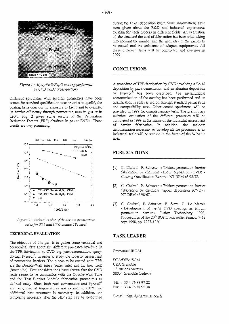
-168-
FeA!
Fe3AI
during the Fe-Al deposition itself Some informations havebeen given about the R&D and industrial experiencesexisting for each process in different fields. An evaluationof the time and the cost of fabrication has been tried takinginto account the number and the geometry of the pieces tobe coated and the existence of adapted equipments. Allthese different items will be completed and precised in1999.
substrate CONCLUSIONSscaie = 1C JIT
Figure 1 : AhO/FeA^FesAI coaling performedby CVD (SEM cross-section)
Different specimens with specific geometries have beencoated for standard qualification tests in order to qualify' thecoating behaviour during exposure to Li-Pb and to evaluateits barrier efficiency through permeation tests in gas or inLi-Pb. Fig. 2 gives some results of the PermeationReduction Factors (PRF) obtained in gas at ENEA. Theseresults are very promising.
823 773 723 «73 623 573 523 (K)
10*
10-5
10*
1 10-'
1 to*"5
» .
• T9ï-K>B{Fe-AJ+AJ,O,):CFM \
• m T91+CVD (Fe-Ah-AUOj); PRM [
1.2 1.4 1.6 1.!
1000/T(K)
=7.5 îWa !
FS2H '
1
•
3 2
Figure 2 : Arrhenius plot of deuterium permeationrates for T91 and CVD coated T91 steel
TECHNICAL EVALUATION
The objective of this part is to gather some technical andeconomical data about the different processes involved inthe TPB fabrication by CVD, e.g. pack-cementation, spray-drying. PyrosoP. in order to study the industry assessmentof permeation barriers. The pieces to be coated with TPBare the Double-Wai! tubes (outer side) and the box itself(inner side). First considerations have shown that the CVDroute seems to be compatible with the Double-Wali Tubeand the Test Blanket Module fabrication procedures asdefined today. Since both pack-cementation and Pyrosol®are performed at temperatures not exceeding 750°C. noadditional heat treatment is necessary. In addition, thetempering necessary' after the HIP step can be performed
A procedure of TPB fabrication by CVD involving a Fe-Aldeposition by pack-cementation and an alumina depositionby Pyrosol* has been described. The metallurgicalcharacterization of the coating has been performed and itsqualification is still carried on through standard permeationand compatibility tests. Other coated specimens will beprovided in 1999 for complementary tests. The preliminarytechnical evaluation of the different processes will becompleted in 1999 in the frame of the industrial assessmentof barrier fabrication, in addition, the scale-updemonstration necessary to develop all the processes at anindustrial scale will be studied in the .frame of the WPA3.Îtask.
PUBLICATIONS
[1] C. Chabrol, F. Schuster «Tritium permeation barrierfabrication by chemical vapour deposition (CVD) -Coating Qualification Report » NT DEM n° 98/32.
[2] C. Chabrol, F. Schuster « Tritium permeation barrierfabrication by chemical vapour deposition (CVD) »NT DEM n° 98/67.
[3] C. Chabrol, F. Schuster, £. Serra, G. Le Marois« Development of Fe-AI CVD coatings as tritiumpermeation barrier» Fusion Technology 199S,Proceedings of the 20a SOFT. Marseille, France, 7-11sept 1998, pp. 1227-1230
TASK LEADER
Emmanuel RJGAL
DTA/DEM/SGMCEA Grenoble17, rue des Martyrs38054 Grenoble Cedex 9
Tél. : 33 4 76 88 97 22Fax : 33 4 76 88 95 38
E-mail : [email protected]

- 1 6 9 -
WP-A4-2.1
Task Title : PERMEATION BARRIERS OUT-OF-PILE TESTING(PB PERFORMANCE)PRF in Pbl7Li & in water (and corrosion)
INTRODUCTION
The cooling of the water-cooled Pbl7Li blanket developedin Europe, is insured by pressurized water flowing in tubeswhich are immersed in Pbl7Li. For economical and safetyreasons, the permeation through the tubes of the producedtritium in Pbl7Li has to be minimized. To decrease thispermeation, the use of coatings as tritium permeationbarrier is considered. To validate such a solution, thepermeation barrier efficiency has to be evaluated inexperimental conditions taking into account the mainfeatures of the blanket operating conditions.
But, in a first step, the coatings have to be tested insimplified conditions to make a first selection between thepotential candidates. After, the performances of theselected ones have to be evaluated in conditions asrepresentative as possible of the running conditions of theblanket.
A device to test the performance of coatings as tritiumpermeation barrier in presence of gas and Pbl7Li has beenbuilt. It has been used this year to test an aluminizedcoating supplied by CEA/CEREM Grenoble. Moreover, totake into account the presence of the water in the coolingtubes, a permeation device with water and Pbl7Li has beendesigned.
1998 ACTIVITIES
PERMEATION TESTS WITH GAS AND Pbl7Li
The device
The device [1] consists in a cylindrical external envelopemade of aluminized 316L stainless steel in which arelocated the permeation chamber (length 150 mm, internaldiameter 23 mm, thickness 1 mm), a finger for athermocouple and a bubbling device as it is shown onFigure 1. The envelope is continuously swept by an argonor helium hydrogen mixture and the inside of thepermeation chamber is swept by a continuous helium flow.The space between the envelope and the permeationchamber can also be filled with some Pbl7Li. An ironmembrane enables to measure the hydrogen concentrationin the gas or in the Pbl7Li. The gas is analyzed with achromatograph.
The permeation chamber
Tests have been performed using two permeationmembranes: one made of a 1.4914 martensitic steel andwhich was used for the tests carried out in this device in1996 and 1997. In July 1998, it has been received fromCEA/CEREM/DEM a 1.4914 steel membrane externallycovered (except on the weld between the cylindrical partand the top cover of the membrane) with an aluminisedcoating obtained by CVD process.
Conditions of the tests
Two kinds of tests have been performed: one for which themedium inside the envelope was a gas flow and the other,for which the inside of the envelope was filled with Pbl7Liin which a gas was bubbling.
All the tests have been performed in the followingconditions:
- gas pressure in the permeation chamber or in theenvelope: 1.13 ± 0.01 105Pa;
- gas flow rate in the permeation chamber or in theenvelope: 100 cm3 min'1;
- hydrogen content in the envelope sweeping gas (argonor helium): 2 vol%;
- sweeping gas in the permeation chamber: helium.
During the envelope filling with Pbl7Li, some liquid metalwent up in the envelope tubes dedicated to the gasadmission and exit. Therefore, some Pbl7Li has been lostand the precise Pbl7Li level in the envelope, initiallycalculated to be 30 mm under the top of the ironmembrane, was not precisely known. It is possible that thetop part of the iron membrane was not immersed inPbl7Li. Moreover, as the Pbl7Li liquid surface is veryoften covered by an oxide layer, the top part of the ironmembrane might have been covered by these oxides.
Results
The hydrogen content and the hydrogen permeation fluxtowards the permeation membrane are measured at steadystate and represent the mean values obtained during 2 to 4tests.

-170-
During the tests with gas in the envelope, the hydrogenpressure in the iron membrane was 2260 ±10 Pa,corresponding to the hydrogen content in the gas. On theother hand, when some Pbl7Li was in the envelope,although the hydrogen content in the bubbling gas was also2 vol%H2, the hydrogen pressure in the iron membraneafter a 80 hour bubbling was only equal to 940 Pa. Thisdifference between the hydrogen partial pressure in thebubbling gas and the pressure in the iron membrane can beexplained in two ways. First, it could result from amalfunction of the iron membrane (especially if it has beencovered by oxides as Pbl7Li was introduced) and thehydrogen partial pressure in Pbl7Li corresponds to that inequilibrium with the bubbling gas, that is to say 2260 Pa.Second, the hydrogen diffusion in Pbl7Li is too slow toenable to the hydrogen partial pressure in Pbl7Li to reachthe value corresponding to the equilibrium with thebubbling gas and consequently the hydrogen partialpressure in Pbl7Li is 940 Pa. Therefore, we haveconsidered for the permeability calculations the two values,940 and 2260 Pa for the partial pressure of the dissolvedhydrogen in Pbl7Li.
The permeability values, given in the Table 1 have beendeduced from the permeation flux using the Richardsonequation assuming that the permeation is controlled by thediffusion and using the Fick equation for an infinite hollowcylinder :
J = O ( VPH - VPHO ) / ro ln(r/ro) (1)
with:
- J: hydrogen permeation flux per unit of surface area (mol m'2 s1)- PH : hydrogen partial pressure in the envelope (Pa)- PHo : hydrogen partial pressure in the permeation chamber (Pa)- r: external radius of the permeation chamber (m)- r0: internal radius of the permeation chamber (m)- <I>: permeability of the permeation chamber material (mol m'1 s ' Pa""2)
Discussion
The permeability values obtained with the 1.4914 steelpermeation chamber are shown on the Figure 1 togetherwith the values obtained in 1996 [2] and 1997 [3]. We cannotice that the values obtained in 1997 [3] and 1998 arelower than those obtained in 1996 [2].
This difference could be due to an oxidation of themembrane. These values are also lower than those given byother authors by a factor between 10 and 20. From 1998data, we have deduced an activation energy of 50 kJ mol"1
which is higher than the values from the literature(between 35 and 46 kJ mol1).
The permeability values obtained with the coatedpermeation membrane are shown on Figure 1. Thedifference between the values obtained when the envelopeis swept by a gas and those when the envelope containsPbl7Li is of the same order of the uncertainties on thevalues obtained when the envelope contains some Pbl7Li.
Therefore, it cannot be put in evidence a difference in thepermeability of the membrane when it is swept by gas orwhen it is immersed in Pbl7Li.
From Figure 1, we can also see that, in the testedconditions, this coating enables to achieve a maximumpermeation reduction factor of 10 if we compare thepermeation fluxes of the coated membrane with thoseobtained with the bare material in [2] but only a factor 2 ifthe comparison is made with the results obtained in 1997[3] and in 1998. But this latter comparison is probablymade with a 1.4914 oxidized membrane. In any case, it isless than what is reported in [4] with T91 material (up to5000). However, these results would require to be validatedand completed. Microscopic observations of the coatingwould be necessary to assess the quality and homogeneityof the coating. Moreover, the results shown in [4] wereobtained with a different technique and only in the gasphase (disk technique).
1E-10 T-
I
r'isO-
"« 1E-11
j » 1.4814 nt.3 and 1SSS («suit*
• 1.4914 nl.2
ialummized 1.4914 gas/Pb-17LII PH*Z26OP«• aluminizad 1.4914 g«/Pb-17Li
PH-940P»
1E-13
0,00135 0,0014 0,00145 0,0015 0,00155 0.0016 0,00165
Figure 1 : Hydrogen permeability of 1.4914 steelwith and without coating
PERMEATION DEVICE WITH WATER AND Pbl7Li
In this device, the produced tritium in PB17LI will besimulated by deuterium which will be dissolved in PB17LIby bubbling. The water will have a chemistryrepresentative of the blanket circuit water. This chemistrywill be chosen to avoid large corrosion damage. Moreover,dissolved hydrogen will be added in the pressurized wateras it will be done in the blanket water circuit to counteractradiolysis effects. This device will enable to determine thehydrogen and deuterium fluxes through a martensiticcylindrical membrane by measuring the partial pressures ofhydrogen and deuterium in the water and PB17LI. Thesame measurements will be performed with a membranecovered by a coating in order to evaluate the efficiency ofthis latter to decrease the deuterium permeation.
Moreover corrosion studies of the martensitic steel withand without a coating by the pressurized water will also beperformed.

- 1 7 1 -
The detailed design of the device has been done. Theequipment has been chosen and is being supplied exceptfor the gas compressor of the gas circuit. In fact, thecompressors which have been proposed up to now eitherenable to fight again the gas pressure drop due to PB17LIheight but the flow rates are too large or have a convenientgas flow rate range but a too low compression ratio. Othersuppliers are being consulted.
The end of the construction of the device is planed in thesecond 1999 quarter.
CONCLUSION
Hydrogen permeation tests have been performed with a1.4914 steel permeation membrane with an aluminizedCVD coating on its external side. The coating was incontact either with a gas flow or with stagnant Pbl7Li inwhich an helium/hydrogen gas mixture was bubbling. Thehydrogen permeation fluxes in the two cases are similarand taking into account of the experimental uncertainties,it is not possible to put in evidence some difference in thepermeabilities. If we compare these results with thoseobtained in the same device with the uncoated material, amaximum permeation reduction factor of ten can bededuced. These results would require to be confirmed andmicroscopic observations of the coated membrane would benecessary.
REPORT
[1] T. Dufrenoy, A. Terlain, Hydrogen permeationmeasurements with an aluminized martensitic steel,CEA Report, RT SCECF 487 (December 1998)
TASK LEADER
A. TERLAIN
CEREM/SCECFCEA Saclay91191 Gif-sur-Yvette Cedex
Tél. : 33 1 69 08 16 18Fax : 33 1 69 08 15 86
E-mail : [email protected]
The detailed design of the permeation device withpressurized water and Pbl7Li has been done and theequipment is being supplied. The complete construction isplaned for the second 1999 quarter.
REFERENCES
[1] S. Berger, A. TerlainHydrogen permeation: experimental device andanalysis techniqueCEA Report, RT SCECF 371 (September 1995)
[2] T. Dufrenoy, M. Perrot, A. TerlainHydrogen permeation, First results with 1.4914martensitic steel -Task WP-A-5-3-CEA Report, RT SCECF 408 (December 1996)
[3] A. Terlain, T. DufrenoyTrittium permeation barrier testing devicesCEA Report, RT SCECF 448 (December 1997)
[4] C. Chabrol, F. SchusterTritium permeation barrier fabrication by chemicalvapor deposition (CVD). Coating qualification reportCEA Report, NT DEM 98/32 (July 1998)
- 173 -
WP-A5-1
Task Title : TRITIUM EXTRACTION FROM Pbl7Li
INTRODUCTION
The Mélodie loop is an experimental facility dedicated totest gas-liquid contactors to extract the tritium produced inthe water cooled liquid blanket of fusion reactors. Thistritium extraction will allow not only to supply the plasmawith tritium but also to decrease the tritium permeation inthe coolant by lowering the inventory in the blanket.
In 1995, a 600 mm high packed column was settled in theloop where hydrogen is used to simulate tritium. Thechoice of this type of extractor was due to the expectedbeneficial impact of the liquid film flow involved in thistype of contactor on the kinetic of the mass transfer.During 1996 and 1997 tests, a 22% maximum efficiencywas reached at 673 K [1] but incoherence about thehydrogen mass balance was observed, for which nosatisfactory explanation was found [2], in spite of theexperimental work performed in that aim.
This year, a new contactor was settled and tested. It differsfrom the previous one by its height (800 mm), the absenceof dead volume between the packing and the envelope andseveral internal devices allowing to study the contactoreither in a bubble or in a film configuration. Moreover, anew acquisition data system has been installed.
1998 ACTIVITIES
NEW DEVICES SETTLED AND ELECTRO-MAGNETIC PUMP PERFORMANCES
A new liquid distributor, constituted by a plate perforatedwith 30 holes of 3 mm diameter and crossed by four pipesof 4 mm diameter allowing the gas to go out of thepacking, was settled. As expected from the preliminaryexperiments in a glove box which has led to its design [2],a liquid retention occurs on the liquid distributor necessaryto insure a good radial spreading on the first packingcylinder. Indeed, with the lowest liquid flow rateinvestigated during the extraction tests, the retentionheight estimated via level electrodes, was between 1 and 4centimetres. Moreover, due to the new configuration of thegas evacuation from the packing (four pipes attached to theliquid distributor), a constant gas flow rate of 1000 N.T.P.cm3 mn'1 of argon was maintained during the extractiontests in a bubble column configuration withoutelectromagnetic pumps breakdowns.
The previous gas flow sparger, a perforated pipe, waschanged to a sintered disk with an average porosity of3 um.
This device is well suited to the bubble column since inthat case, the interfacial area is the area of the wholegenerated bubbles and is all larger since the bubbles aresmall. In the liquid column, the sparger gas flow has onlyto insure a radial distribution of the gas stream. The porediameter has been chosen in order to maintain the headlosses compatible with the extractor design. However, thehigh inlet pressure obtained experimentally (5 105 Pa)results from both the flow through the sintered disk and thelikely partial plugging of the flow inlet way, may be bysome oxide or by solid Pbl7Li in cold zones.
The packed cold trap settled at the exit of the gas streamhas not solved problems of the gas exit control valveplugging. Observations with an optical microscope showedthat the particles trapped in this valve had an averagedimension lower than 1 urn. Regarding to this size, thebest way to trap them seem to be a process based on filters.
Regarding the previous high intensities delivered to theelectromagnetic pump coils in 1996 and 1997 and pastproblems of coil overheating, an optimisation of thecolumn gas pressures was done to share at best betweeneach pump the supplementary rise of power required toincrease the Pbl7Li lifting height of 200 mm when thecolumn is in film configuration. The resulting intensities,about 10 A each, led to a liquid flow rate between 35 and100 10~3 m3 h1 . In this configuration, many break downs ofthe pumps occurred due to a high sensibility to anyvariation of the gas pressure in the extractor (likely relatedto a sudden modification of the retention height).Moreover, a significant instability of the liquid flow ratewas observed, the larger variations being due to drops oftension in the supply network. However, most of the time,the liquid flow rate evolved by steps whose durations weresufficient to determine its incidence on the efficiency butnot sufficient to quantify the extraction efficiencies at anestablished steady state.
CHECKING OF THE MEMBRANE RELIABILITY
An experiment was performed to check the reliability ofthe hydrogen pressure sensors of the membranes immersedin the Pbl7Li at the extractor entrance and exit, which areused to calculate the extraction efficiency. In that aim, thewhole loop was saturated with a 2% hydrogen gas whichallowed to check that the resulting pressures were similarand around 2370 Pa.
EXTRACTION TESTS IN A BUBBLE COLUMNCONFIGURATION
The bubble column configuration corresponds to the wholeimmersion of the packing, the gas phase being a flow ofbubbles.

- 174 -
From extracting tests in that hydraulic configuration,experiments were performed in order to :
- validate that, for an identical small gas flow rate, theextraction efficiency is lower than in a liquid filmcolumn,
- investigate the potential of a bubble packed columnwhen increasing the gas flow rate to generateinterfacial area. In a bubble packed column, it isexpected that the packing would organise the flow ofbubbles thus preventing or limiting their coalescence.
Therefore, two series of tests were performed respectivelyat 500 and 1000 N.T.P cm3 mn"1. These tests which werecarried out with inlet hydrogen pressures ranging from1100 to 1300 Pa in Pbl7Li entering the reactor, showed:
- a beneficial impact of a higher retention time of theliquid alloy on the extraction efficiency since a rise ofits flow rate provoked reproducibly, a decrease of theefficiency. Quantitatively, as no steady state could bereached at high retention time, it can only be assertedthat the efficiency increases from 10 to at least 13.5%when decreasing the liquid flow rate from 90 to60 10-3m3h-'.
- a negligible impact of an increase of the purge gas flowrate on the extraction efficiency since for an equivalentrange of liquid flow rate tested (80 to 110 10"3 m3 h1) ,the efficiencies were quite the same, in a 10 to 12%range.
If we rely on the capability of the packing to preventefficiently the bubble coalescence, these results wouldindicate that the efficiency which could be expected from abubble column will be mostly function of the retention timeof the liquid.
EXTRACTION TESTS IN A LIQUID FILMCOLUMN CONFIGURATION
The decrease of the liquid flow rate injected on the packingalways involved an increase of the extraction efficiency.The best result obtained is 33 % for the lower liquid load,about 31 10"3 m3 h"1, which represents a superficial velocityof 2.8 10"3 m3m2 s'1 for the 62.7 mm diameter packing.This value is in the range advised by the packingmanufacturer for its petrochemical reference liquids (3 10"4
to 4 103 m V 2 s"1).
The 1996 and 1997 investigations on the liquid flow ratehad led to conclude to the non incidence of this latter inthe 70 to 100 10'3 m3 h'1 range. At this time, thecalculations were based on average values because of thelack of real time data. It is clear that with the inaccuracyresulting from these averages, we were not able to detect apossible weaker impact of the liquid load in this range.
The beneficial influence of the liquid flow rate decrease,observed this year, could be due to a separated or acombined effect of :
- the increase of the retention time,
- a thinner liquid film on the packing favourable to thekinetics of transfer, if it is assumed that this film takesplace.
There is no significant impact of the gas flow rate on theextraction efficiency, in the 100 to 500 N.T.P. cm3 mn"1
range investigated. If an effect was further observed at aflow rate larger than 500 N.T.P. cm3 mn'1, it should becompared on an economical point of view to the increase ofthe column height leading to similar performances.
COMPARISON BETWEEN THE PREVIOUS 600 mmEXTRACTOR AND THE PRESENT 800 mm ONE INA LIQUID FILM FLOW CONFIGURATION
For an equivalent liquid flow rate, 80 10'3 m3 h'1, theefficiency obtained is quite the same, about 21%, with the800mm high packing and with the 600 mm one ([1] and[2]).
If the mass transfer model of NUT and HUT,comprehensibly described in [2] is used, the 800 mm highcolumn efficiency should have been about 27%.
Regarding this result, the problem is to know if the absenceof improvement of the efficiency signifies that no betterperformance has to be expected from an increase of thepacking height or if it is just due to a not justifiedextrapolation and comparison between two systems whichwere not exactly the same in their design and which werenot studied with the same tools (recording of the data inreal time in 1998, dead volume).
In order to evaluate the impact of a packing height increaseof the present extractor, a test was performed with the firsthalf of the column in a film flow configuration and thesecond one in a bubble flow configuration.
The liquid flow rate was maintained at a 40 10'3 m3 h1
average value. The resulting efficiency varied in a 20 to22% range for an inlet hydrogen pressure in Pbl7Libetween 1050 and 1100 Pa.
The real efficiency of the 400 mm packing used in a filmflow configuration is in fact inferior to the 21% observedfor the whole column because of the supplementaryextraction occurring in the last 400 mm bubble flow.Therefore, the 400 mm packing efficiency is at least 10%inferior to the one reached with 800 mm of packing for thesame liquid load, 33%, as reported before. It isconsequently highly probable that further improvements ofthe efficiency have to be expected from an increase of thepacking height settled.

- 1 7 5 -
COMPARISON BETWEEN THE BUBBLE FLOWAND THE LIQUID FILM FLOW CONFIGURA-TIONS IN A PACKED COLUMN
From the presented results, it can be concluded that for asimilar liquid flow rate of 80 10~3 m3 h"1, the liquid filmflow leads to higher efficiency than the bubble flow (21against 10.5%). Since the retention time should be higherin the bubble flow than in the film flow, this difference canbe attributed to:
- the suitability of the liquid film flow for the kinetics ofmass transfer (diffusion of atomic hydrogen in theliquid as the limiting step),
- the difficulty to generate interfacial area via bubbles.
PROSPECTS
A device insuring a stabilisation of the liquid flow ratewould be highly convenient. It should allow to reachestablished steady state and should be absolutely necessaryfor the resolution of the mass balance incoherence.
A new trap based on filters should be settled on the loopwhatever the column flow configuration. These filterscould avoid plugs to occur during long time running evenat low gas flow rate.
An improvement of the average 30 % efficiency can beexpected from:
- a decrease of the superficial velocity below the lowestvalue investigated, 2.8 10'3 mVm"2.
- an increase of the packing height.
CONCLUSIONS
An improvement of the extraction efficiency was obtainedin 1998, up to about 30%, for 1000 Pa inlet hydrogenpressure in Pbl7Li entering the extractor. The previousefficiency reached at the same temperature of 673 K was22%. It was achieved thanks to a reduction of the liquidload injected, the lowest investigated (2.8 10'3 mV'm'2)being still not the optimal one.
An experiment, performed with the 1998 extractor, showedthat an increase of 400 mm of the packing height leads toat least 10% of supplementary efficiency (for an hydrogenpressure in the 400 to 1000 Pa range). However, byextrapolation of the results obtained with the previouscolumn [1] and for the same conditions of liquid load, theprediction of the efficiency consecutive to the 200 mmincrease of the packing height, was not reliable. It may beattributed to the lack of control of the previous extractingprocess (data record, dead volume).
The behaviour of the bubble packed column wasinvestigated. It led to efficiencies lower than the onesobtained in a liquid film flow configuration. According tothese experiments, the only way to improve the bubblepacked efficiency column would be an augmentation of theretention time.
REFERENCES
[1] N.ALPY, T. DUFRENOY, A. TERLAINHydrogen extraction tests in Mélodie: 1996 resultswith a packed columnCE A report, RT-SCECF 407 (December 1996)
[2] N. ALPY, A. TERLAIN, M. PERROT, T.DUFRENOYHydrogen extraction from Pbl7Li: 1997 results on thepacked column running and 1998 viewsCE A report, RT-SCECF 446 (December 1997)
1998 PUBLICATION
[ 1 ] N. ALPY, A. TERLAIN, V. LORENTZHydrogen extraction from Pbl7Li: 1998 results with a800 mm high packed columnCEA report, RT-SCECF 485 (December 1998)
TASK LEADER
Anne TERLAIN
DTA/CEREM/DECM/SCECFCEA Saclay91191 Gif-sur-Yvette Cedex
Tél. : 33 1 69 08 16 18Fax : 33 1 69 08 15 86
E-mail : TERLAIN(S)oitolan.cea.fr

-177 -
WP-A6-1.1
Task Title : SAFETY ANALYSIS FOR DEMO POWER PLANT
INTRODUCTION
Technological analyses relative to the blankets of aDEMOnstration reactor based on the principle of aTokamak associated with the DT reaction have beenperformed in Europe for several years now.
The European strategy foresees that the DEMO reactor willhave its place between the next experimental machine,ITER, intended to demonstrate the feasibility of fusionpower, and a series of fusion reactors.
In a fusion reactor, the blankets have several functions:
- they serve to produce the tritium needed for the D-Treaction (by neutronic reaction with lithium);
- they serve to remove heat in order to convert it intomechanical energy;
- and lastly, they help protect the components behindthem, particularly the superconducting magnets atcryogenic temperature, from radiation.
Of the two concepts retained after selection in 1995, oneoption uses the eutectic alloy lithium-lead as breedermaterial and water as the coolant (WCLL: water-cooled,lithium-lead) [1].
The purpose of this task is to make a preliminaryassessment of the safety of such a concept. Withoutdetailed drawings of the other components of the reactor,preparing an actual safety analysis, however, is out of thequestion.
1998 ACTIVITIES
OVERVIEW OF THE SAFETY APPROACH
Introduction
The safety studies made in the framework of SEAFP andSEAFP2, and particularly the development of a safetyassessment in the framework of ITER, permitted thedevelopment of a safety approach suited to fusion facilities.
As in any nuclear facility, the objective is to protect thegeneral public, workers, and the environment fromradioactive hazards. It is natural, therefore, that the samegeneric principles developed for other nuclear applicationsshould similarly be applied, and, among these, particularlythat of "Defence in Depth".
Generally speaking, this is an exhaustive and progressiveapproach that consists in setting up various levels ofprevention, protection, and mitigation with the aim oflimiting the risk and the environmental consequences of anaccident.
Identification of Safety Functions
The main objective of safety is to protect the general publicagainst any dispersal of radioactive material into theenvironment, and the way to prevent such an eventuality isto ensure the containment of this radioactive material byproviding for robust and reliable containment barriers.
These containment barriers must be protected againstpossible aggression related to the presence of energysources in the facility, which can be of three types:chemical, thermal, and magnetic.
Figure 1 gives a summary of these energy sources, the risksthey induce, and the safety functions to be put in place toprotect the containment barriers against these risks.
We shall rapidly review the identified safety functions andhighlight the aspects linked to blanket design:
Plasma Energy Control
An undeniable advantage of fusion energy is that anyfailure (a coolant leak, for example) that occurs within thevacuum chamber inevitably leads to plasma shutdown.With respect to blanket design, this means taking intoaccount the thermal and mechanical effects of such adisruption.
The automatic shutdown of the plasma within a reasonablelapse of time is particularly useful when the initial failureis located outside the vacuum chamber: it permits avertingan internal LOCA in the event of an external break or aLOFA.
The presence of two cooling circuits on the blankets,however, permits avoiding a rapid temperature rise andshould enable easily managing this type of incident withoutgenerating an internal break in the short term
Residual Power Removal
The studies conducted in the framework of SEAFP andSEAFP2 showed that, in the event of even completecooling failure, the increase in temperature due only toresidual power does not reach a temperature high enoughto result in rapid structural collapse.

-178-
safety objective:public protection
major hazard:radioactive releases
limit the mobilisableinventory
prevent releases
normalsituations
abnormalsituations
limit the quantities of:- tritium- activation products- corrosion products
CONFINEMENTBARRIERS
designprotection
robustdesign
D. in D. lev.1
detection andcontrol of malfunction:
D. in D. niv.2
energy sourcescontrol
D. in D. niv.3
Ï
accidentmanagementD. in D. ntv.4
explosion
limiter la température
PLASMASHUTDOWN
HEATREMOVAL
PLASMASHUTDOWN
HEATREMOVAL
CONTROL OFCOOLANT ENERGY
CONTROL OFMAGNETICENERGY
majorsafetyfunction
energysources
hazards
safetyfunctions
Figure 1 : Fusion Power Plant Safety Functions
However, the presence of a residual power removal systemcan greatly facilitate the management of such an accidentand prevent further degradation.can greauy lauinuue me manajand prevent further degradation.
Chemical Energy Control
A risk of chemical reaction exists as a result of the designof the WCLL blankets itself: this is the reaction between thelithium contained in the LiPb alloy and the water that servesas a coolant.
The control of this reaction is the subject of an extensiveR&D programme, not only to estimate its consequences(the LIFUS experiment and modelling) but also to definedetection methods [4].
The chemical reaction between water and the material ofthe first wall should also be considered, depending on thenature of the latter.
Coolant Energy Control
The consequences of failures should be taken into accountin the design of the various containment barriers, as well asin the definition of systems permitting these barriers to beprotected.
As regards the design of the blankets, a mechanical analysisof the structures should take into account the pressurelinked to the coolant, considering, if need be, overpressurelinked to thermal and/or chemical interaction due to water-LiPb interaction.
Magnetic Energy Control
The SEAFP studies showed that correct design of themagnets permitted averting the risk of missiles.
The possibility of an electric arc should, however, beconsidered, as it can lead to containment degradation.
IDENTIFICATION OF DESIGN BASIS ACCIDENTSEQUENCES
In the framework of the SEAFP programme, as in theframework of ITER/FDR, it was demonstrated that all thesequences resulting from a single failure, such as, forexample, a LOCA or LOFA, result only in minimal releasesprovided the containment barriers have been correctlydesigned (with the possible presence of safety systemsenabling these barriers to be protected even under the mostsevere conditions: pressure suppression systems, expansionvolumes, etc.) [2].

- 179 -
The conclusion in this case is the same as for the morecomplex sequences considered in the framework ofSEAFP2 [3].
This systematic study has permitted identifying the mostsevere design basis accident for the containment strategy:the loss of heat sink. The management of this accidentsequence is not linked to the design of the blanket itself; itdetermines, however, containment strategy for thecomponents within the torus building.
Analysis also shows that particular attention should begiven to the management of other sequences, such as:
- those involving an electric arc around the magnets(with no direct relation with blanket design);
- those involving hydrogen release due to chemicalreaction (once again, risk of a water-LiPb reaction andpossible water-first wall material reaction).
Outside releases can be kept to a very low level thatdepends essentially on two factors, for a given containmentstrategy:
- the mobilisable radioactive inventory inside the vacuumchamber (mainly the tritium contained in first wallmaterial and dusts),
- the radioactive inventory in the fluid circuits,particularly in the coolant.
The tritium content in the coolant can also have a directeffect on the level of releases and therefore should becarefully controlled.
CONCLUSION
Analysis has thus shown that the DEMO reactor safetyassessment is covered by that made in the framework of theSEAFP and SEAFP2. In particular, the conclusionsrelative to the containment strategy defined in the SEAFP2context are also applicable.
The review we have made has nevertheless permittednoting certain points that deserve clarification orexamination.
The studies on the DEMO blankets do not take intoaccount any first wall armour. The presence of the latterproves to have an effect on the analysis of accidentsequences (possible reaction with water in the event of aLOCA).
An appropriate containment strategy permits keepingreleases to a very limited level in the event of an accidentof internal origin; this depends, however, on theradioactive material inventory inside the vessel (tritiumand dusts), as well as on tritium and corrosion productactivity in the coolant.
The studies performed on long-term safety programs andthe ITER program have permitted identifying design basisaccidents. Among these, the accident that concerns theblanket design of interest is related to the case of a waterleak in the lithium lead: its analysis confirms that prioritymust be given to studies relative to this accident sequence(with respect to both the estimation of its consequences andits detection).
REFERENCES
[1] L. GIANCARLI, M. DALLE DONNE, W. DIETZ -« Status of the European Breeding BlanketTechnology » Fusion Engineering and Design 36(1997) 57-74
[2] J. RAEDER and all « Safety and EnvironmentAssessment of the fusion Power (SEAFP) »EUFURBRUXII 217/95
[3] G. MARBACH, I. COOK « Safety and environmentaspects of a Fusion Power Reactor »Invited SOFT Communication to be published inFUSION TECHNOLOGY
[4] P. SARDAIN, G. BENAMATI, I. RICAPITO, G.MARBACH «Consequences of Pb-17Li/waterInteraction within a Blanket Module » Proc. of the20th Symposium on Fusion Technology,MARSEILLE, 7-11 September, 1998
TASK LEADER
Gabriel MARBACH
DRN/DER/SERSICEA Cadarache13108 St Paul Lez Durance Cedex
Tél. : 33 4 42 25 34 14Fax : 33 4 42 25 48 68
E-mail : marbach(3)babaorum.cad.cea.fr

-181 -
WP-A6-2.1
Task Title : SAFETY ANALYSIS OF ITER WCLL TEST MODULEDEFINITION OF SAFETY APPROACH
INTRODUCTION
ITER is an experimental D-T fusion reactor.
One of the objectives of this facility is to include andirradiate experimental test blanket modules.
These ITER test-blanket modules (TBM) will help qualifya tritium breeding blankets for a future fusion powerreactor [1].
The main objectives of this experimental programme areto:
- Verify and demonstrate the functionality of theintegrated system, subsystems and individualcomponents in the fusion environment,
- Verify and demonstrate the performance of tritiumproduction, extraction and recovery by establishing acomplete tritium balance of the system which has tocorrectly simulate future reactor conditions,
- Verify and demonstrate high-grade heat production andremoval by establishing a complete power balance ofthe system with a concept representative of reactorconditions,
- Calibrate and validate the analysis, including thecalculations and modelling used.
The WCLL concept has the following main characteristics[2]:
The coolant is water at a pressure of 15.5 MPa and theoutlet temperature is 325°C.
The breeder is the liquid eutectic alloy Pb-17Li. (This alloywhose melting point is 235°C has the followingcomposition : 17 at % Li with up to 90 % *Li enrichmentfor breeding and 83 at % Pb for neutron multiplication).
The structural material is a martensitic steel (EUROFER -97 which is being developed for reduced activation andgood irradiation characteristics.
The WCLL blanket concept is based on a type of boxwhich is cooled separately and can withstand disruptionand pressure loading. This box confines a pool of the liquidalloy Pb-17 Li which is slowly pumped through the blanketfor tritium extraction and Pb-17 Li replenishment indedicated equipment.
The heat generated in the pool is extracted by bundles ofdouble-walled U-tubes and through conduction to thecooled walls of the segment box.
The test module will be surrounded by a frame made ofstainless steel and cooled by water. The first wall iscovered with a 5 mm beryllium layer and is cooled, like theside walls, by toroidal-radial cooling tubes.
1998 ACTIVITIES
THE WCLL-TBM - GENERAL SAFETYAPPROACH
TheTBM safety approach has to follow the guidelines andrecommendations issued for ITER's global installation.
The implementation of these safety principles has to takeinto account the experimental aspects of the TBM. Themain issues are as follows:
The safety analysis has to take in account TBM failuresand induced potential hazards from the defence in depthpoint of view (prevention, detection, protection andmitigation of consequences),
TBMs are designed in such a way that an operation oraccidental sequence does not lead to unacceptableconsequences with respect to the safety of the ITERfacility, workers and the public in the vicinity of thefacility,
The analysis of TBM roles, as far as the main safetyfunctions of ITER are concerned, has to demonstrate that :
- Either that the safety functions planned for the reactoritself are not degraded by any potential risks generatedby the implementation of TBMs,
- Or that the safety functions planned for TBM designcover these risks,
RADIOLOGICAL AND ENERGY SOURCE TERMS
Tritium Production
Tritium production is a function of ^ i enrichment.
Even with naturally abundant ^ i , daily tritium productionis still almost half as high as with the 90 % enrichmentforeseen for the DEMO blanket.

- 182 -
Most of the test objectives could be attained with naturalabundance so that high enrichment is not a priorityrequirement for a WCLL-TBM.
Nevertheless, assuming a 45 % duty the cycle, the highestvalue of tritium production is rather low : 67 mg/d (with90 at % ^ i enrichment)
Energy Sources
The inventory of energy sources is summarised in the tablebelow :
The figures for the coolant and Pb-17Li are quite similar,and together represent % of the total inventory. Thecontribution of the steel is quite small, however, the smallamount of Be armour already has a relatively highpotential.
Table 1 : Estimate for the energy inventory in the WCLL-TBM (excluding afterheat).
Steel
Pb-17Liliquidlatent heatsolidreaction with water
Pb-17Li
Bethermalreaction
with-waterwith-air
Max. (Be)
Coolant
Max. TBM
Mass[kg]
950
3955
8.75
1000
T[°C]
500
500
235
527
500
350
P[MPa]
-
15.5
Cp (average)[kJ kg'K1]
0.7
0.19
0.17
2.8
AH[kJ kg"1]
214.88
4000067400
1400
AHf
[kJkg1]
33.9
Energy[MJ]
319
199134145850
1328
12
(350)590602
1400
3649
[%]
8.74
5.453.673.97
23.29
36.39
0.33
16.1716.50
38.37
100.00
EFFLUENTS AND EMISSIONS UNDER NORMALOPERATING CONDITIONS
Effluents and emissions result from diffusion and leaksfrom the piping.
Considering the amount of tritium and other activationproducts generated in the TBM, this part is negligible incomparison with the ITER facility as a whole.
WASTE MANAGEMENT ANDDECOMMISSIONING
After irradiation, the inventory in the TBM and theancillary circuits is composed of Be (« 8.75 kg), steel («950 kg + TBD kg in the circuits), water with additives(FW 11.1 kg, BZ 8.7 kg, headers « 40 kg + 1000 kg in thecircuits + TBD g corrosion products, max. tritiumconcentration 1 Ci/kg), Pb-17Li (« 3955 kg + ~ 4000 kg inthe circuit). Some of the materials (in particular the steel)are activated and contain a total of up to 1 g of tritium. Apermeation barrier (aluminization oxidised to A12O3 on thesurface) and joining or filler materials are equally present.
The activity of the reduced activation martensitic steel ison the same level as, or lower than, the structural materialof ITER.
Therefore management of the structural material wastecould follow the same operations as for ITER waste.
Pb-17Li management has yet to be defined, taking intoaccount a low activation value after temporary storage.
ANALYSIS OF REFERENCE EVENTS
Identification of Events and Postulated Initiating Events
A Failure Mode and Effects Analysis has been performedon the WCLL-TBM.
A set of possible failures has been taken into account foreach component. Each failure has been classified whereapplicable as a Postulated Initiating Event (PIE) for whichthe expected frequency has been determined.

- 183 -
A first analysis and grouping of these events has shownthat the consequences are covered by a set of a limitednumber of sequences :
- In-vessel LOCA,
- In-TBM LOCA,
- Ex-vessel LOCA,
- Loss of on-site power (decay heat removal).
In addition, accidental sequences affecting the in-vesselpart are covered by the ITER standard case (like in vesselLOCA).
Consequences of Accidental Events
Calculations of the consequences of the main sequenceswere performed.
The results of two representative cases are reported below :
Case A : In-vessel LOCA
An in-vessel LOCA is a Class IV event. The consequencesare identical to an in-vessel LOCA from the ITERshielding blanket. The ingress of water into the vacuumvessel extinguishes the plasma immediately, but no leakdue disruption is assumed. Surface and nuclear heatingdisappear instantaneously, only decay heat remains. Bothcooling circuits are assumed to be non-operational.
Postulating a blow-down of the complete water inventoryof both cooling circuits (1 m3 at 300°C, 15.5 MPa) into thevacuum vessel (3800 m3), this would first lead to therelease of a two-phase mixture with approx. x = 0.45(evaporation at constant enthalpy). The remaining waterwould then gradually evaporate on the hot first wall(evaporation at constant density) and would reachsaturated steam conditions (0.03 MPa at 69°C). In the longterm, and if no countermeasures are taken, this steamwould superheat to the shielding blanket coolant inlettemperature of 140°C (superheating at constant density),corresponding to 0.036 MPa. This is much lower than thedesign guideline, 0.5 MPa, for the ITER vacuum vesselwith respect to an in-vessel LOCA event of ITER in-vesselcomponents.
Case B : In-TBM LOCA
This event is classified as Class IV. A LOCA inside theTBM causes the interaction of the cooling water with thePb-17Li. The determination of the subsequent generationof heat and hydrogen is being investigated within theongoing EU R&D program [3]. Previous experiments seemto indicate a self-limiting reaction. Nevertheless, due to theremaining uncertainties, the maximum values for reactionenthalpy and hydrogen production are calculated. Thehydrogen is assumed to remain confined in the TBM (norelease into the vacuum vessel).
Pb-17Li inventory in the TBM : 3955 kg (excludingancillary circuits),
thereof Li (0.68 wt %) : 26.89 kg = 3898 mol Li.
Assuming the worst possible reaction for enthalpy andhydrogen production in Pb-17Li.
2 Li + H2O -> Li2O + H2 - 31.6 kJ/g Li, T = 800 K
the required water mass would amount to 1949 mol (35.1kg) to react the entire Li inventory in the TBM (excludingancillary circuits). This is of course a very theoreticalassumption as the injected water would displace much ofthe Pb-17Li. Also, the pressurization of the TBM boxwould limit the amount of injected water, so that thereaction would remain incomplete.
A hypothetical complete reaction would release anenthalpy of 850 MJ and 3.9 kg of H2 which is well belowthe tolerable release limit (10 kg). Assuming anapproximate average specific heat for the TBM of 0.33 J g"1 K"1 (950 kg of steel and 3955 kg of Pb-17Li) the reactionenthalpy would theoretically be sufficient to increase, theTBM temperature by approximately 500 K.
In case of a simultaneous rupture in vessel and in TBM theconsequences the pressurisation of the vacuum vessel andthe hydrogen produced by the reaction remain at the sameorder.
In addition a quantity of liquid Pb-17Li, depending of thelocation of the leak, will fall in the divertor region.
CONCLUSION
The safety analysis performed for the WCLL TBM hasshown that the main potential hazards fulfil the ITERrequirements.
Nevertheless this analysis has point out the fact that furtherR&D is required to have a better knowledge of theconsequences of the steam- Pb-17Li reaction.
REFERENCES
[1] L. GIANCARLI, M. DALLE DONNE, W. DIETZ -« Status of the European Breeding BlanketTechnology »Fusion Engineering and Design 36(1997) 57-74
[2] L. GIANCARLI and all «Objectives FeasibilityAssessment of the WCLL Mock-up testing in ITER. »Proc. of the 20th Symposium on Fusion Technology,MARSEILLE, 7-11 September, 1998
- 184 -
[3] P. SARDAIN, G. BENAMATI, I. RICAPITO, G.MARBACH « Consequences of Pb-17Li/waterInteraction within a Blanket Module » Proc. of the20th Symposium on Fusion Technology,MARSEILLE, 7-11 September, 1998
TASK LEADER
Gabriel MARBACH
DRN/DER/SERSICEA Cadarache13108 St Paul Lez Durance Cedex
Tél. : 33 4 42 25 34 14Fax : 33 4 42 25 48 68
E-mail : [email protected]

- 1 8 5 -
WP-A7-1.1WP-A7-2.2WP-B7-1.1WP-B7-2.3
Task Title : DEMO-BLANKET : SEGMENT DESIGN & ANALYSISData Base and ITM Reliability Assessment
INTRODUCTION
The aim of these sub tasks is to : 1/ collect, validated andprocess relevant failure data for fusion reactor designactivities and 2/ assess the reliability/availability of theconceptual designs and test-items.
An European reliability file is set up and periodicallyrevised in association with ENEA (Italy) and Fzk(Gemany). Data are issued from nuclear industry andanalogue systems.
Reliability/Availability assessments either for the heliumcooled pebble bed (HCPB) or the water cooled liquidlithium (WCLL) blanket and related test items are carriedon in common with the European partners.
1998 ACTIVITIES
Two blanket concepts are under development in theEuropean Blanket Project. The first concept uses liquidPbl7Li as breeder and neutron multiplier and water ascoolant (WCLL). The second concept uses lithium ceramicas breeder, beryllium as neutron multiplier and helium ascoolant (HCPB). The two concepts represent designalternatives for the DEMO blanket and will be testedindependently in ITER.
An extended experimental program will be carried out infusion environment in order to validate the conceptualdesign options and related technology. As the only stepforeseen between the present tokamaks and DEMO isITER, this experimental program must be carried out inITER or ITER-like machines. Thus two mock-ups,[R1,R2], representative of the DEMO blankets will beplaced in ITER ports and tests will be carried during theBPP (Basic Performance Phase).
The unavailability of the Test Blanket Modules (TBMs)including the Test Blanket Auxiliary Systems (TBAS) havebeen assessed and the influence on the availability of ITERis analysed, [PI]. Reference systems in ITER are thecooling systems for the first wall, the divertor, the limiterand the vacuum vessel.
These TBM's are new technology components and nooperating experience feedback is available for them.Subsequently, evaluations must be estimated based on theavailable nuclear experience feedback. This extrapolationis, to large extend, dependent on the expert judgement. Adata base has been set up, [R4] and contains the mostcommon items present in the blanket concepts. As forauxiliary components a direct use of the existingconventional components databases is satisfactory, [R5].
For the immediate use of this assessment, the auxiliarycomponents are limited to the cooling circuits for the FW,limiters, divertors and vacuum vessel. A reasonable FailureModes and Effects Analyses (FMEA) has already beenperformed in the past.
The assessment integrates also the previous assessments onthe WCLL and the HCPB TM's.
As it has been already recalled in different occasion on thereliability of the blanket, one of the key figures is the meandown time (MDT). Past assessments, [R3,R6,R7], haveproved that the resultant blanket availability is verysensitive to the value of the MDT. While, the value of theMDT is dependent on the blanket accessibility and theremote handling systems (RHS) and procedures. However,at this stage of the analysis no additional effort will bedevoted to the treatment of this key issue. A reasonableassumption of 8 weeks of MDT has been used for thisassessment.
The details of the assessment are given in [PI].
CONCLUSIONS
The contribution of the TM's (HCPB+WCLL) in ITERoverall failure rate (without the modules cooling systems)is about 6.7 10"7 /h. If TM's cooling systems should beconsidered, the total contribution to ITER overall failurerate is about 1.4 10"4 /h, for details see [PI].

- 186 -
REFERENCES REPORTS AND PUBLICATIONS
[RI] M. Futterer et al. « Design Description Document(DDD) for the European Water-Cooled Pb-17Li Test(WCLL) Blanket Module» CEA technical note,SERMA/LCA/2125, DMT 97/549, Nov. 1997
[R2] L. Boccaccini et al. « Design Description Document(DDD) for the European Helium-Cooled Pebble Bed(HCPB) Test Blanket Module, 7/1998.
[R3] H. Schnauder, C. Nardi, M. Eid « Comparativeavailability analysis of the four European DEMOblanket concepts in view of the selection exercise »Fus. Eng. & Des. 36 (1997) 343-365.
[R4] T. Pinna « Structure of a component failure rate database for fusion applications » ENEA technical report,ENEA/FUS/TECN/S&F 32/96, Nov. 1996.
[R5] L. C. Cadwallader et al. « Failure rate screening datafor fusion reliability and risk analysis »INEL-EGG-FSP-7922, Jan. 1988.
[R6] B. Bielak, M. Eid « Reliability/AvailabilityAssessment of the water cooled lithium-lead ITERtest module» CEA technical note, DMT 97/262,SERMA/LCA/2026, July 1997.
[R7] C. Nardi et al. « Evaluation on the influence of theTest Blanket Modules on the ITER cooling circuitsavailability» ENEA report, ENEA RTI-DEMO/WCLL/001/98, Feb. 1998.
[PI] M. Eid « European Blanket : CEA contribution to theReliability/Availability analysis and relatedactivities» CEA report, SERMA/LCA/RT/2474/A,Dec. 1998.
TASKLEADER
Mohamed EID
DRN/DMT/SERMACEA Saclay91191 Gif-sur-Yvette Cedex
Tél. : 33 169 08 3175Fax : 33 1 69 08 99 35
E-mail : [email protected]

- 187-
WP-A8-3.1
Task Title : Pbl7Li PHYSICO-CHEMISTRYOn-Line monitoring and stabilisation of the Li-Content
INTRODUCTION
The aims of this task are to solve some physico-chemicalproblems due to the extended use of the Pbl7Li alloy in theliquid metal blanket. During operation, tritium generationand potential accidental ingress of air or water will resultin Li depletion from the alloy, leading to modification ofits physical and chemical properties. To ensure safe andefficient operation of the blanket, it is thus necessary tohave a reliable and accurate method for the determinationof the lithium content and for its adjustment.
The methods proposed for monitoring the composition ofPbl7Li can be divided into two categories, batch methodsand continuous methods. The former, which are attractiveowing to their simplicity, rely on the removal of a sampleof alloy for analysis. The latter, which are more complex,are favored due to their on-line application. Twocandidates have been proposed for the continuousdetermination of the lithium content: (i) anelectrochemical lithium sensor which compares thelithium activity in the liquid alloy and in a biphasicLi3Bi/Li-Bi mixture using a sodium (3-alumina electrolyte,(ii) an electrical resistivity meter which is based on thefact that the electrical resistivity of the Pb-Li alloy isdependent on composition and temperature. Besides, aplugging indicator based on plugging temperaturemeasurements has also been proposed. Such a device couldbe considered as an intermediate candidate as it partlyworks in continuous mode. Its principle is derived from theNa technology and it needs to be tested with the Pbl7Lialloy. With regard to the electrochemical lithium sensorand the electrical resistivity meter, those apparatus for thedetection of composition changes in Pb-Li alloys weremainly tested on a laboratory scale. The present objectivewas to test them on a larger scale such as a liquid metalloop system. The Anapurna loop was used to carry out thiswork.
1998 ACTIVITIES
The three methods (electrochemical lithium sensor,electrical resistivity meter and plugging indicator) havebeen successively studied in the Anapurna loop (Fig. 1). In1998, they have been compared.
[ANAPURNA LOOP\ ) GLOVE BOX ji O O (3) O O ! Plugging
indicator
Pot 2-
— Cold trap
Magnetic _flowmeter
DERIVED CIRCUIT(2)
Heated leg
MAIN CIRCUIT(1)
Magneticflowmeter
Alloytank
E.M.Pump
Figure 1 : Schematic diagram of the Anapurna loop
THE ELECTROCHEMICAL LITHIUM SENSOR
The sensor compares the Li activity in the liquid alloy andin a biphasic Li-Bi mixture (the reference system) using asodium (3-alumina electrolyte. At equilibrium, themeasured electromotive force (emf) of such a cell followsthe Nernst law. Its design comprises a solid p electrolytethimble sealed in a cylindrical stainless steel housing bymeans of a ceramic cement. The central electrode, made ofstainless steel, dips into the reference system and exits thethimble through a vacuum tight sealant situated at the topof the probe. The other electrical connection is made to theexternal surface of the steel housing which makes contactwith the Pb-Li alloy to be monitored.
In a first step, it was decided to test them in a containerwith static Pb-Li alloy rather in a loop system. Tests wereperformed in a glove box under an Argon atmosphere. Afixed mass of Pbl7Li was melted in a container at 400°C.The sensor preheated above the liquid alloy during 30minutes was then immersed. Composition change of thealloy was obtained by small lead additions. It wasobserved that the sensor signal is relatively in goodagreement with the expected composition change. Thisindicates that the concept is satisfying for Li measurementsin Pb-Li alloys. A stable signal was observed 10 minutesafter immersion of the sensor into Pbl7Li, and areproducibility of ± 1 mV was achieved. It was deduced bylinear regression method that a variation of 1 mVcorresponds to a composition change of 0.15 ± 0.05 at %Li.

- 1 8 8 -
We must say that for most of sensors which were tested atthat time, the mean life time was very short because ofcracks in the P-alumina electrolyte due to thermal shocks.Some of them were broken after their first immersion.After this period, no more tests were performed in Pb-Lialloys with these electrochemical sensors. However, recentimprovement in the mechanical properties of the aluminaceramic has been obtained. For example, goodperformance of an electrochemical sodium sensor wasachieved for determination of the sodium concentration inaluminium melts. The immersion conditions in suchenvironment are more severe because the temperature ishigher (close to 725°C). This new ceramic being lesssensitive to thermal shock, it is expected that similarresults would be also obtained in Pb-Li alloys wheretemperature is lower (less than 500 °C).
THE ELECTRICAL RESISTIVITY METER
The body of the cell in 316L stainless steel was connectedto the main circuit of the loop (Fig. 1) and attached to acapillary section (o.d. 4.8 mm, i.d. 3.0 mm, length 450mm) also made of 316L stainless steel. The liquid alloywas pumped around the capillary by means of a miniatureelectromagnetic pump.
Two plates were attached to the capillary section 150 mmapart and two silver leads were placed on each plate tosupply a constant current and monitor the resistance of thecell. The capillary was inserted in a furnace and thetemperature was controlled by four thermocouples.
Resistance data were determined by a version of the fourterminal method. A constant current of 3 A generated by astabilized power supply was passed through the capillarysection and a standard 0.01 Q resistance. The resistance ofthe capillary (RJ was calculated from the potentialdifference across the standard (Vs) and the cell (Vt): R, =0.01 Vt/Vs. The resistance of the Pb-Li alloy (RJ was thenobtained from the resistance of the monitor filled withalloy (Rt) and the resistance of the empty monitor (Re)using the expression for parallel conductors. The resistivityof the alloy (pm) can be obtained by the relationship pm =Rn, A/I where A is the cross-sectional area and I the lengthof the capillary between the two plates. The geometricalconstant A/I is specific to each monitor. Prior to use, theresistance of the empty capillary and the constant A/I weredetermined (A/1 = 5.74 in the present case). Thecalibration of the resistivity meter was performed manuallybefore connection to the loop. Data concerning resistances,temperatures and resistivities were collected for variousalloy compositions.
For use on loop, the meter must be able to operatecontinuously. Therefore, a computer controlled system wasdeveloped to collect data and record fluctuations incomposition. A multiplex device with six input channelswas used: four of these were connected to thethermocouples on the capillary section, one carried thevoltage across the plates, the final input was the voltageacross the standard resistance.
Then, the output of the multiplex was carried out to adigital voltmeter. A microprocessor controlled the channelselection of the multiplex and read the voltage displayed onthe digital voltmeter. A program was written for dataacquisition and calculation so that, at regular time interval,data were collected and the lithium composition wasdetermined. Information was transferred to a screen, a lineprinter and stored on disk.
The study of the resistivity meter was carried out with Pb-Li alloys of various compositions. At first, addition ofoxygen and lead to Pb-Li alloys were made to decrease theLi content to a fixed value (close to 13.5 at.%). Then, theLi composition was increased by addition of a Li-Pbcompound to the liquid alloy. Sufficient quantities of LiPb(equimolar composition) were prepared and dissolved inthe liquid alloy to obtain a composition close to Pbl7Li atthe end of the experiment.
The reaction of oxygen with Pb-Li alloys was detected bythe apparatus and the decrease in lithium content was inagreement with Li2O formation. Then, the adjustment ofthe lithium concentration was performed by adding LiPbcompounds. These compounds were easily prepared bymixing lead and lithium in equimolar proportions in theliquid state.
The ingots produced after solidification of the mixture andimmersed into the alloy of the loop were entirely dissolvedin a short time without any difficulty. The resistivity meterresponded very well after each LiPb addition and a steadyincrease in lithium content was observed. The monitor wasthus sensitive to composition change, the minimumunambiguously detectable limit being + 0.15 at% Li whichcorresponds to an accuracy of + 0.2 10"8 Qm on theresistivity. Its response time was only limited by the ratesampling/mixing in the loop.
The potential of the electrical resistivity meter to monitorcontinuously the lithium concentration of Pb-Li alloys in aloop system has been demonstrated throughout this work.The apparatus is able to detect lithium depletion in case ofoxygen ingress. Then, adjustment of the lithium contentcan be easily controlled by adding LiPb compounds to Pb-Li alloys. This compound is the easiest to handle to obtainthe requested Li-concentration.
THE PLUGGING INDICATOR
The plugging indicator was initially developed for thedetermination of the oxygen concentration in liquidsodium. The principle consists in determining thetemperature at which the crystallization of sodium oxidetakes place. This is based on the measurement of theplugging temperature obtained by decreasing thetemperature of the liquid metal until a drop in the flow rate(corresponding to the deposition of crystals) is observed.The oxygen content is thus approximately deduced fromthis plugging temperature. It was proposed to transfer thistechnology to Pb-Li alloys as the device could be sensitiveto lithium concentration changes.

- 189 -
It had to be tested if the plugging temperature could beidentified with the liquidus temperature of the Pb-Li alloy.
The plugging indicator was connected to the Anapumaloop as shown in Fig. 1. It was set up vertically in aderived part of the main circuit (part 1). It is made of a316 L stainless steel cylinder (« 0.9 litre). The alloy flowsinto a narrowed section equipped with a pellet where thealloy temperature is lowered by an air cooling system. Inthe present experiments, the circulation of air and Pb-Lialloy is in opposite direction so that the air turbine isplaced at the top of the plugging indicator. Thetemperature is measured very close to the pellet by athermocouple introduced in a thimble.
The plugging indicator tests were performed with Pb-Lialloys initially at 400°C. Experiments were carried outwith various flow rates. For each test, the air coolingsystem was set in operation so that the temperature of thePb-Li alloy entering in the plugging indicator started todecrease. Simultaneously, the pellet temperature and theflow rate in the apparatus were both recorded as a functionof time (t). When the flow rate was stabilized to zero, thecooling system was stopped and the reheating phase tookplace.
Besides plugging measurements, a thermal analysis studywas also carried out to measure the liquidus temperature ofthe alloy. A small amount (100 g) of the Pb-Li alloy usedfor the plugging indicator tests was taken from the loop forthe analysis. In this simple experiment performed out ofthe loop, a thermocouple was dipped into the liquid alloycontained in a crucible and the temperature was recordedas a function of time during cooling of the alloy. Theliquidus temperature of the Pb-Li alloy was thusdetermined from the thermal curve.
With regard to the flow rate effect, the plugging time isincreased with faster alloy circulation. Moreover, the flowdrop is not so abrupt for high rates. It results that theplugging temperature determination is not so accurate.Nevertheless, the tests show that the plugging temperatureis not affected by the flow rate of the alloy. The smallvariations which could be detected are not significantbecause of the experimental errors on the temperaturemeasurements (± 2°C).
The results indicate that the plugging temperature can beeasily measured. However, the plugging indicator candetect Li composition change, assuming the Li variation issufficiently large and higher than 1 at %. It seems that theplugging temperature and the liquidus temperature of thealloy can be identified.
The liquidus temperature being determined from theplugging measurements, the Li concentration can bededuced using the Li-Pb phase diagram. It is obvious thatthe liquidus line of the phase diagram must be knownunambiguously to determine accurate Li concentrationsfrom the plugging measurements. This could be adisadvantage of the method.
CONCLUSION
Various methods of monitoring the Li composition ofPbl7Li alloy have been examined in a loop system. Thework has been mainly focused on continuous methodswhich are more attractive even if more complex.Nevertheless, batch methods based on chemical analyseshave also been tested in the frame of this work. They arevery simple and a deviation of 0.3 at % Li can be detectedbut their disadvantage is the fact that samples have to betaken from the loop.
Three concepts have been tested for the on-linedetermination of the Li content of the liquid alloy. Theconcepts based on the Li electrochemical sensor and on theelectrical resistivity meter require calibration prior toinsertion in the loop. Although the tested electrochemicalsensors were susceptible to thermal shock and to fracture,our results show that the concept is very attractive. Thesensor is specific to lithium, simple to use and it can detecta composition change of ± 0.15 at% Li. The improvementof the mechanical properties of the solid electrolyte (p-alumina) which is the key element of the sensor should notmake difficulties since new sensors have been producedwith success in 1995 for more severe immersionconditions. The good performance obtained in suchenvironments is also expected in presence of Pbl7Li alloy.
The resistivity meter is robust and very sensitive tocomposition change, the minimum unambiguouslydetectable limit being + 0.15 at% Li. Although nominallysensitive to any solute, this will not influence its operationbecause potential impurities have small solubilities inPbl7Li. The resistivity meter is easy to handle but itsreplacement in the loop could be slightly more complicatedthan the electrochemical sensor. The plugging indicatordoes not need calibration and it is very robust. However,changes in the composition of the liquid alloy must behigher than 1 at % Li to be detected. The pluggingtemperature is well related to the liquidus temperature butit is necessary to have a good knowledge of the Li-Pb phasediagram to deduce the Li concentration of the alloy.Therefore, it is thought that the monitors with greatestpotential for the continuous monitoring of the Li content inPb-Li alloys are the electrochemical sensor and theresistivity meter.
Throughout this work, methods to replace the lost lithiumand to adjust the Li content of Pb-Li alloys have also beenexamined. It is shown that for additions to liquid alloy, theLiPb compound (equimolar composition) was the easiest tohandle to obtain the requested Li-concentration because itsdissolution process is well controlled and rapid.
-190 -
PUBLICATIONS
[1] F. BARBIER, F. HERBERT, "Monitoring of the Licontent with a plugging indicator", RT SCECF 467(June 1998)
[2] F. BARBIER, F. HERBERT, "Continuous monitoringof the Li content in liquid Pbl7Li alloy", RT SCECF475 (November 1998)
TASK LEADER
F. BARBIER
DTA/CEREM/DECM/SCECF/LECNACEA Saclay91191 Gif-sur-Yvette Cedex
Tél. : 33 1 69 08 16 13Fax : 33 1 69 08 15 86
E-mail: [email protected]

- 191 -
WP-A9-2.2
Task Title : Pbl7Li WATER INTERACTION : WATER LARGE LEAKS
INTRODUCTION
In the frame of the liquid breeder blanket programme,several activities are devoted to the interaction between thecoolant (water) and the lithium lead alloy. They concernexperiments and modelling with software as well. Thisprogramme is subject to a collaboration between ENEAand CEA.
1998 ACTIVITIES
Two main phenomena are considered for Pbl7Li/waterinteraction, the effects of which on safety must besignificantly different: small leakage (microcracks,...) andlarge leakage (cooling tube rupture). The main concernsare as follows :
- for the small leakage, hydrogen production, thermalspots coming from solid reaction products aggregation,corrosion coming from lithium hydroxide,...
- for the large leakage, pressure peak due to watervaporisation and hydrogen production, hydrogenevolution, history of solid reaction products,...
Several experiments are devoted to the study of thesephenomena:
- RELAII for the small leakage
- BLAST,(the results of which are known) and LIFUS 5(planned for 1999) for the large leakage (see figuresbelow).
ATMOSPHERE
V1
GS2 VUFIG. 1
LIFUS 5 facility

-192-
1 injector2 reaction vessel3 expansion tutje4 expansion vessel
5 rupture disk6 safety vessel7 melting vessel8 storage vessel
BLASTfacility
The study which is presented here is related to theassessment of the consequences of the large leakage.
The main phenomena which are involved in macro-leaks(tube rupture within a blanket module) are as follows:
- possible water-hammer effect due to high pressure waterimpact,
- thermal reaction due to water vaporisation=o first pressure peak (see figure below)
- chemical reaction leading to hydrogen production=o second pressure peak (see figure below)
60bar50
40
20
10
0
reactionvessel
AV// !
^ injection vessel ,1 :
i
I
^ expansion vessel !i j !
I iBLAST 5inj"fme
ection pressure:iter temperature:5ft temperature:
60225350
bar°C°C
5 S
BLAST experimental results
The assessment strategy includes the following steps:
- the evaluation of interaction models is made throughavailable experimental results (BLAST),
- the current models are to be improved for a bettersimulation of the reaction course (kinetics, reactionproducts),
- the improved models will be validated on availableexperimental results,
- the influence of sensitive parameters (stoichiometricratio, water injection,...) will be studied,
- post calculations of LIFUS 5 will be done.
The main difficulties are related to the simulation of thechemical reaction. The great influence of the initialconditions on the reaction course and thus on pressurepeaks, can affect the accuracy of the results in so far theyare not precisely known. Moreover, the simulation ofspecific phenomena (limitation of the mixing between thereactants due to a shield made by solid reaction products) isdifficult.
The chemical effect is calculated with the PLEXUS code,using a sodium/water reaction model, hi this model, onlythe following chemical reaction is considered:
2Na + 2H2O •» H2 + 2NaOH
The results are shown on the following figures
60bar50
402
£°- 20
10
0
rejection vessel
reactionvessel I_
)f expansion vessel •
J\l
BLAST 5injection pressure: 60 barwater temperature: 225 °Cmelt temperature: 350 °C
3
timet5 s
pre calculations of LIFUS 5 are done, BLAST: PLEXUS calculation

-193 -
Since the model assumes an instantaneous and totalreaction, it does not represent the reaction kinetics. Theinjected mass of water has to be adjusted in order to fit themodel on the BLAST results.
The thermal effect is calculated with the SIMMER codewhich has been developed in the frame of the assessment ofsevere accidents within fast breeder reactors. This code cannotably be used to simulate interaction phenomena.
The results are shown on the following figures. A goodagreement with the experimental results is found withoutany parameter adjustment.
60bar50
40S?
1 3°°- 20
10
0
— • — —
reactionvessel
—•
\/jl \
i
" injection vessel -,
1
expansion vessel !
1BLAST 5injW T
m
ection pressure:Jter temperature-sit temperature:
60225350
bar
°C
3timet
P ( P a )
O . O 0 . 1 O . Z 0 . 3 0 . 4 O . 3
They will notably bring further informations on the pressureevolution and the hydrogen production. The experimentalresults allow us to validate the models for the assessmentof the consequences of large leakage. Pre calculations offuture experiments can be done. The models are to beimproved in order to get a better simulation of the reactioncourse
REFERENCES
[1] P. Sardain, Assessment of the pressure peak in theLIFUS experiment, International workshop on LiquidMetal Blanket Activities, Paris, 1997
[2] Kottowski et al., Studies with respect to the estimationof liquid metal blanket safety, Fusion Engineering anddesign, 445-448, 1991
[3] Benamati et al.,LIFUS 5 experimental facility onPbl7Li/water interaction to be built up at ENEABrasimone center. Technical specifications,Brasimone 01/03/1997
[4] Kondo et al., Status and achievment of assessmentprogramme for SIMMER in, a multiphase,multicomponent code for LMFBR safety analysis,NURETH 8 Kyoto 1997
[5] P. Sardain, G.L. Benamati, I Ricapito, G. MarbachConsequences of Pbl7Li/water Interaction within aBlanket ModuleSymposium On Fusion Technology, Marseille FranceSeptember 1998
REPORTS
[1] P. SARDAINConsequences of Pbl7Li/water Interaction within aBlanket ModuleReport DER/SERA/LETh 98/5030
TASK LEADER
CONCLUSION
Concerning Pbl7Li/water interaction due to water macro-leaks some experiments have already been done (BLAST).They have shown two main processes: a "thermal" effect(short time) and a "chemical" effect (long time). Othersexperiments will be carried out in the next future (LIFUS),which will be representative of the ITER Test Modules.
Pierre SARDAIN
DRN/DER/SERSI/LECCCEA Cadarache13108 St Paul Lez Durance Cedex
Tél. : 33 4 42 25 37 59Fax : 33 4 42 25 71 87
E-mail: [email protected]

- 195 -
WP-A9-3.1
Task Title: Pbl7Li/WATER INTERACTIONS, DEFINITIONOF COUNTERMEASURESRequired countermeasures
INTRODUCTION
In the frame of the safety studies for the water-cooled testblanket module (WCLL-TBM), three types of events wereidentified which would lead to an interaction betweenPblTLi and water. These are:
1. a small leak, the most probable places are the bends ofthe double-walled tubes and the welds with the tubeplate,
2. an In-TBM LOCA with rupture of a cooling pipe orsudden failure of a weld between tube and tube plate,subsequent pressurization of the TBM with and withoutfailure of the TBM as a confinement,
3. an ex-vessel LOCA in the ancillary systems where e.g.a failure of a cooling system component would damagethe Pbl7Li circuit.
1998 ACTIVITIES
Because case 1 is quite easily detectable (gas production inthe Pbl7Li circuit, quick Li depletion, pressure dropincrease in the Pbl7Li circuit) and because only littlehydrogen and heat is released, no safety problems areexpected to arise from such an event. The analysistherefore focused on cases 2 and 3. The hydrogenproduction entailed by Pbl7Li-water interaction wasidentified as the major safety criterion. The expectedpressurization of the pit vaults was equally investigated.Other LOCA related safety issues (e.g. hydrogenproduction due to interaction between overheated berylliumand steam) were treated in WP A6.
IN-TBM LOCA
This event is classified as Class IV. A LOCA inside theTBM causes the interaction of the cooling water with thePbl7Li. The determination of the subsequent generation ofheat and hydrogen is being investigated within the ongoingEU R&D program. Previous experiments seem to indicatea self-limiting reaction. Nevertheless, due to the remaininguncertainties, the maximum values for reaction enthalpyand hydrogen production are calculated. The hydrogen isassumed to remain confined in the TBM (no release intothe vacuum vessel).
With the reduced size WCLL-TBM the theoreticallypossible hydrogen production is just above 5 kg and thusjust over the tolerance limit given by ITER. A smallreduction of the TBM size would eliminate the problem.
IN-VESSEL AND IN-TBM LOCA WITH RUPTUREOF FIRST WALL
This event is classified as Class V. The water ingress intothe vaccum vessel extinguishes the plasma immediately,but no disruption is assumed. Additionally, Pbl7Li isspilled and flows down in the divertor region. The amountof spilled Pbl7Li depends on the location of the leak. Thehydrogen produced during the Pbl7Li/water interactionenters the W . The surface and nuclear heating disappearinstantaneously, only decay heat remains.
EX-VESSEL LOCA
This event is classified as Class IV for the failure of oneout of two cooling circuits. No safety credit is given for thefact that two indépendant cooling systems are available.Here, two large ex-vessel breaks in the cooling circuits areassumed so that no active cooling is available at all.
The pit volume is assumed to be pressurized with thereleased steam, and, conservatively, no condensation oncold surfaces is considered. The blow-down is assumed todamage the Pbl7Li circuit thus enabling a reactionbetween Pbl7Li and the released steam/water.
Postulating a blow-down of the complete water inventoryof both cooling circuits (1 m3 at 300°C, 15.5 MPa) into thepit vault (2156 m3), would lead to the release of a two-phase mixture with x = 0.43 at 84°C and 0.056 MPa.
At the same time the air (initially at 0.1 MPa, 40°C) heatsup thus causing an additional pressure increase of 0.014MPa so that the final pressure will reach 0.17 MPa. Thesevalues disregard space occupation by ancillary equipmentand do not include the additional heat take-up from hotstructural material. This pressure rise in the pit seems toraise only little concern for the structural integrity of thepit vaults. If required, actively cooled condensationsurfaces or other countermeasures could be envisaged.
The behavior of the TBM during these accidents wereinvestigated in the safety related taks of WP A6:

- 1 9 6 -
CONCLUSIONS TASK LEADER
From the different events involving Pbl7LiAvaterinteraction, only large leaks either in the TBM itself or inthe pit where the ancillary circuits are deployed are safetyrelevant, in particular because the production and releaseof several kilograms of hydrogen cannot be fully excluded.Only when counting the Pbl7Li inventory in the TBMitself and in the ancillary circuits, the potential hydrogenproduction would exceed the allowable maximum of 5 kg.To reach an inherently safe condition, a small reduction ofthe total Pbl7Li volume in the system would be required.
Means of prevention consist in the use of doubleconfinement between Pbl7Li and water (except in theheader area), leak detection and the spatial separation ofthe ancillary circuits for water and Pbl7Li. Should afailure occur nevertheless, an active accident managementas proposed in 1997 could be applied.
Michael A. FUTTERER
DRN/DMT/SERMA/LCACEA Saclay91191 Gif-sur-Yvette Cedex
Tél. : 33 1 69 08 36 36Fax : 33 1 69 08 99 35
E-mail : [email protected]
PUBLICATIONS
[1] M. A. Fùtterer, Pbl7Li-water interaction in theWCLL-TBM: Consequences and countermeasures,CEA report DRN/DMT SERMA/LCA/98-2370/A,December 1998.
- 1 9 7 -
WP-A10-2.2
Task Title : EXPERIMENTAL DEMONSTRATION OF MHD PHENOMENATURBULENCE IN MHD FLOW SHEAR LAYERS
INTRODUCTION
The objective is to give a contibution to the understandingof the Pbl7Li flow behaviour in the WCLL blanket and inparticular to assess the presence of two-dimensionnalturbulences in MHD flow shear layers and to characterizethem under representative magnetic field. Relevantparameters and scaling laws have to be obtained in order toevaluate the impact of MHD effects on Pbl7Li velocity andtemperature distribution and consequently on the T-permation towards the water coolant in WCLL blankets.
1998 ACTIVITIES
Theoretical, numerical and experimental results wereobtained in 1998 within the framework of the studies onthe turbulence of MHD flows in the water-cooled lithiumlead blankets of fusion reactors.
The activity this year has been marked :
- on the experimental level, by the construction of a newMATUR-5 cell and by a first series of experimentalresults obtained under intense magnetic fields whichcan reach 6 Tesla,
- on the theoretical level, by a thorough re-examinationof the Hartmann layer present in the vicinity of theperpendicular walls of the magnetic field,
- on the numerical level, by a simulation of the MATUR-5 flow modeled by the quasi-2D equation of Somméria-Moreau [1] using the FLUENT code.
EXPERIMENTAL STUDIES
MATUR-5 experimental device
The configuration of the experimental device MATUR-5 isidentical to that of the preceding versions. The circular cellwith a radius of 11 cm contains a mercury layer with athickness set at 1 cm, in which the electric current isinjected by electrodes located in a circle of 9.3 mm inradius and closes by the external cylindrical wallmaintained at constant temperature, thus starting arotational movement of the external fluid cylinder. Acentral heating plot allows the injection of several watts inpower in order to observe the turbulent transport of a scalarorder of magnitude as for the heat through the shear layer.
Compared to the former versions, the modified parametersare essentially the magnetic field and the value of thesource current.
Whereas the magnetic field was up to now limited to 0.2Tesla, the MATUR-5 cell has been placed in a LCMI coil(Laboratoire des Champs Magnétiques Intenses) inGrenoble thus making the magnetic field continuously varybetween 0 and 6 Teslas, and consequently allowingconditions representative of fusion reactor blankets to bereached.
The electrical current, characterizing the maximum speedof the fluid cylinder was up to then limited to 50A. Thetechnology used in MATUR-5 allows an intensity of 150Ato be reached, in other terms rates of roughly 1.5 m/s.
Experimental results
As under a moderate magnetic field, the thickness of theshear layer is much greater (by a factor of 10) than thatpredicted in laminar regime. It appears that the latter isindependent from the electrical current but it significantlydepends on the magnetic field.
The maximum speed measured under moderate magneticfield was reduced by half compared to the theoreticalpredictions because of the centrifugal re-circulationmovement. The results obtained under intense magneticfield show the progressive disappearance of this re-circulation and of the transport of the associated kineticmomentum, thus leading to values measured in perfectagreement with the predictions as soon as the magneticfiled exceeds 2 Tesla.
The efficient values of the fluctuations of the two speedcomponents remain roughly 12 % of the maximum speed,which is clearly greater than in classic turbulence.
The spectra measured all have the same shape, whateverthe acquisition location and the parameters of the magneticfield and of the current, which can be considered as asignature of this MHD turbulence. This original shape,which is clearly different from the classic turbulencespectra, is characterized by :
- a shift towards the low frequencies, typically of roughlya hertz, or 100 to 1000 times less than in a classicturbulence, that is to say towards greater vortex sizes,

- 198-
- the presence of 3 to 4 peaks easy to identify, associatedto larger vortex structures, rather coherent and fed byan inverse cascade of energy specific to the two-dimensional turbulence,
- an inertial zone which is less spread out and marked bya law in power of type k"n, with a value of n very closeto 4 as soon as the magnetic field is rather high.
Whereas the mechanical inertia of the system is low (a fewseconds), its thermal inertia is rather great (of about onehour). This is due to the fact that the turbulence poorlypenetrates the central region where the transport of heat iscontrolled by conduction. The temperature measurementsmade in stabilized regime show that the heat fluxtransported constantly increases with the current, that is tosay with the speed and the number of Reynolds. This isobvious on the average temperature profiles which follow aradius where the difference in the measured temperaturebetween the central plot and the external wall decreasesmonotonously with the speed for a set flux.
We can also note that, in transient regime, the temperaturegradient is much lower in the shear layer (where theturbulence is intense) than in the poorly mixed centralregion.
These temperature measurements must however beconsidered with care as the heating conditions arecomplex. Apart from the heat flux from the central plot, athermal power is supplied by Joule effect in the Hartmannlayers in which the currents circulate. This source of powerincreases with the square of the product of the magneticfield and of the current and can exceed the power deliveredby the central spot with the high values of these twoparameters. The results obtained will be re-examined byattempting to separate the effects of the two heat sources.
THEORETICAL RESULTS
The theoretical studies concerned a more accurate analysisof the Hartmann layer aiming at introducing the inertialeffects and evaluating the three-dimensional effects in thecore region located between the Hartmann layers.
These studies came from the comparison of numericalresults and the experimental results obtained undermoderate magnetic field which showed a good agreementas long as the electrical current, of which the inertialeffects, was moderate and degraded at high intensities. Theintegration of the inertia forces in the Hartmann layer thusappear as a fundamental necessity of which theconsequences could be of a very general interest for all thehigh speed flows.
This problem was addressed using a specific perturbationmethod based on two parameters : the inverse of theHartmann number which measures the thickness of theHartmann layer, and the inverse of the number of Reynoldswhich characterizes the ratio of inertia forces to the viscousfriction.
The different orders of magnitude are developed accordingto these two parameters, on the one hand in the Hartmannlayer and on the other hand, in the core. In the first order,we find the Somméria-Moreau equation [1], and at thehigher orders, the expected effects appear and the strictly 2D flow progressively becomes 3D under the effect ofinertia.
A new equation model integrating the terms of inertiaintroduced in the Hartmann layer into the braking forcewas thus developed.
NUMERICAL STUDIES
The numerical studies concern the direct simulation of theturbulent MHD flow using the FLUENT code including thesimulation of the transport of a scalar such as temperatureby coupling the Navier-Stokes equation with a source termmodeling the friction forces in the Hartmann layer and anenthalpy equation.
The first numerical results have been compared in asatisfactory way to the experimental results obtained on theformer version of MATUR under moderate field [2] [3][4].
These have particularly shown in a satisfactory way, theevolution of the speed field towards an established regimeof large vortex structures originating from the instability ofthe shear layer towards the large scales via an inverseenergy cascade.
The numerical results corresponding to the new version ofMATUR-5 under intense magnetic field present a level ofaccuracy close to that obtained under moderate field [5].
The present balance on the numerical simulation is asfollows :
- the accuracy on the average speed distribution is verysatisfactory, but that on the temperature presents adifference with the experiment which would suggestsome improvements such as a better integration of theeffective diffusivity in the parietal layer,
- the model deserves to be improved by introducing, inthe equation, the corrections allowing therepresentation of the low 3 D of the flow and itscontribution to the total dissipation of energy,
- the present level of development of the numerical toolis validated enough to already be able to apply it to themore representative flows of the fusion reactorblankets.

-199-
CONCLUSION AND PERSPECTIVES REFERENCES and REPORTS
The experimental results on the turbulent speed fieldwhich are now of great accuracy thanks to the high valuesof the magnetic field make up a data base likely to serve asa reference to any attempt at modeling. They show both thedistributions of the most important average values (averagespeed, average temperature, tension of Reynolds) and thespecific characteristics of this turbulence marked by a hightwo dimensionality (spatial distributions with lowfrequency peaks corresponding to large coherent vortexstructures and with an inertial zone in power law of whichthe characteristic power goes from -5/3 at a low energylevel to-3, then -4 when the kinetic energy increases.
The study of the Hartmann layer leads to a modeling of thethree-dimensionality which persists in this flow. The newmodel takes form in the Somméria-Moreau equation [1]which allows the integration of an additional inertial termin the braking force of the flow.
The numerical results acquired which are based on thenon-modified Somméria-Moreau equation show that thismodel is very satisfactory (accuracy level close to 5 %) todescribe a turbulent shear flow under intense magneticfield. The comparison with the experimental resultsconfirm, as for under moderate magnetic field, a slightlyinferior accuracy on the temperature field.
The convergence of the theoreticalexperimental studies is now clear :
numerical and
- the theory allows the improvement in accuracy of themodel-equation with a view to extending its validity tohigh speed regimes,
- the numerical model is already satisfactory at moderatespeeds and will be applied to more representative flowsof fusion reactor blankets,
- the experiment has provided a first set of importantdata which will be used as references for the scientificcommunity concerned.
The experiments under intense magnetic field will becontinued by modifying some parameters and by takinggreater care with the heat transport. The theoretical studywill be continued by an analysis of the internal structure ofthe large vortexes then completed by a study of theboundary layer located near the wall to characterize adetachment effect of the boundary layer. Finally, thenumerical study will be continued by the modification ofthe model-equation to integrate the three-dimensionaleffects.
[1] "Why, when and how MHD turbulence becomes two-dimensional"Somméria, R. Moreau, I Fluid Mech.(1982), vol. 118pp 507-518.
[2] "1997 Progress report: Turbulence in MHD FlowShear Layers"NT DER/STML/LCFI 97/049. G. Laffont, R. Moreau.
[3] "Two dimensionnal numerical simulation of a MHDturbulent shear flow"Y. Delannoy - R. Moreau . 3rd Pamir Conf, Aussois,France, Sept.22-26, 1997.
[4] "Quasi 2D turbulence MHD in MHD shear flows :The MATUR experiment and simulations"Y. Delannoy and al. Transfer Phenomena in MHDand Electroconducting Flows, 1998, Kluwer Acad.Pub., Dordrecht, The Netherlands.
[5] "MHD turbulent shear layers : experiment andmodélisation at hight Hartmann number"Y. Delannoy and al.To be presented et the TMSAnnual Meeting on Fluid Flow Phenomena in metalprocessing, San Diego, Feb28-March4, 1999.
TASK LEADER
Guy LAFFONT & R. MOREAU
DRN/DER/STML/LCFICEA Cadarache13108 St Paul Lez Durance Cedex
Tél. : 33 4 42 25 73 14Fax : 33 4 42 25 77 88
E-mail : [email protected]
- 2 0 1 -
WP-B1-1.2
Task Title : DEMO-HCPB BLANKET : SEGMENT DESIGN & ANALYSISDesign optimisation for alternative ceramics Li2ZrO3/Li2TiO3
INTRODUCTION
In order to reduce the risks associated to the R&Dactivities in the design of a Helium Cooled Pebble (HCPB)blanket for DEMO fusion power reactor, CEA hasproposed to the EU to examine the use of the meta-zirconate/meta-titanate as breeding cermaics, [R1,R2]. TheEU-HCPB blanket reference conceptual design makes useof the ortho-silicate as reference ceramic breeder. Thereplacement of the reference ceramic by any of these twocandidates would certainly necessitate to re-optimise thedesign.
During the FY97, CEA has proposed an optimumconceptual design for the HCPB blanket using indifferentlythe meta-zirconate or the meta-titanate. The main featuresof the CEA proposed HCPB was the use of a breeder bed of16-18 mm thickness for a Li6 enrichment of 25-28%. Theresultant maximum operating temperatures mounted tosome 1215 °C. Some uncertainties about the thermalstability of the pebbles [R3,R4] have advocated in thefavour of a significant reduction of the maximum operatingtemperature in the breeder bed.
Meanwhile, the EU-fusion program has decided to switchfrom the use of the MANET to the use of the EUROFER97as structural material.
Subsequently, CEA has devoted the FY98 activities to therevision of its previous proposal.
1998 ACTIVITIES
As already mentioned above, CEA has revised the HCPBblanket proposal, it presented in the FY97. With the twomain objectives : 1/ to reduce the breeder bed thickness toreduce the observed maximum operating temperature and2/ to take into account the use of the EUROFER97 asstructural materials.
The whole neutronic optimisation calculations have to bere-carried out [R5]. A full detailed count is given in thetask UT-N-Blk, of the same report. These calculations haveresulted a set of optimum options in terms of TBR values.After some iterations between neutronic and thermalevaluations, the option Zr50%_08.09.80 has been selectedbased on the requirement of lowering the maximumoperating temperature in the breeder bed.
The Zr50%_08.09.80 refers to a HCPB blanket based onthe meta-zirconate ceramic breeder at 50% enrichment,with a cooling plate thickness of 8mm, a breeder bedthickness of 9mm and a Be-bed thickness of 80mm. Pastexperience ,[R1], has proved the that use of the titanaterather than the zirconate would not significantly alter theneutronic behaviour of the blanket.
Based on the resultant heating radial distributions, thethermal calculation had followed in order to evaluate themaximum operating temperature in the breeder bed. Oneof the critical issues, is the choice of the relevant pebblethermal conductivity model.
PEBBLE BED EFFECTIVE THERMALCONDUCTIVITY
The pebble bed thermal conductivity relations for thezirconate and the titanate are those developed by P.Gierszewski et al. in reference [8] ;
= 0.66+1.17x10 T Tin °C andKbedin W/m/°K
zirconate pebbles of 1.2 mm (~ 82% DT, 63% pf), and
= 0.62 + 5.5 x 10*" T , T in *C and Kbed in W/m/'K
titanate pebbles of 1.2 mm (~ 82% DT, 63% pf)Both relations are valid up to 1.3 Mpa.
P. Gierszewski estimates in reference [7], that for pebbleswith 90% TD and 65% pf, the preceding relations wouldbe corrected by 12%.
MAXIMUM OPERATING TEMPERATURE
In the precise case of the breeder bed option of Zr50%-08.09.80 the maximum heating rate issued from theneutronic calculation was estimated to be about 67 W/cm3(BoL). Using the above relations describing the effectivebed conductivity would produce a maximum operatingtemperature in the OB-breeder bed equal to 1085 °C (forCP and FW at 450 °C), [PI].
Although, this temperature is still higher than the 900 °Cthat has been recommended by the EU-HCPB projectleader as indicative limiting figure, many of the materialexperts show no particular concerns about this value basedon the present available experience. However, efforts arebeing employed to propose solutions that may lead toapproaching the indicative limit of 900 °C.

- 2 0 2 -
Certainly one way to decrease the maximum operatingtemperature in the breeder bed is to improve the globalthermal conductivity of the zirconate bed. Thermalconductivity improvement may result from using a specifictype of coatings.
Another way to relief thermal limitations is to improve thepebble thermal stability. As it will be stated in thefollowing section thermal stability is one of the strongestreasons to limit the maximum operating temperatures.
HCBP BLANKET SPECIFICATIONS
The revised proposal of the CEA for a HCPB using themeta-zirconate/meta-titanate would have the followingspecifications :
- the use of the EUROFER97 as structural material,
- the ceramic breeder (zirconate/titanate) bed is of 9mmthickness at 50% enrichment in Li6. The breeder bedpacking factor is 56%. The pebbles are of 1-1.5mm sizewith a 15% porosity. The total number of the breederbed is a 206/segment,
- the Be-bed is with a thickness of 80mm with a packingfactor of 75%. The Be-bed is a binary bed with 63%packing factor for the large pebbles (1.5-2.3mm) and18% for the finer pebbles (0.1-0.2mm). The totalnumber of Be-beds is 206/segment,
- the cooling plates are made of EUROFER97 with athickness of 8mm and a voide fraction of 40%. Thenumber of cooling plates is 412 /segment,
- the global TBR is 1.14 if the ports are not consideredand 1.08 at BoL (considering the ports),
- the maximum heating rate is about 67 W/cm3 (BoL) inthe breeder bed resulting in a maximum operatingtemperature in the OB-breeder bed equal to 1085 °C(for CP and FW at 450 °C),
- the blanket contains 32 IB-segments and 48 OB-segments. The energy production is 22 MW/IB-segment and 44 MW/OB-segment with a total energyproduction rate of 2785 MW from the blanket,
- 40% of the blanket energy is produced in the breedermaterials, 30-35% in the Be-bed (IB/OB) and 11% inthe FW's.
CONCLUSIONS
CEA is proposing to examine the use of the meta-zirconateand the meta-titanate as breeder materials for the EU-HCPB blanket which uses the ortho-silicate as a referenceceramic breeder amterial, [PI].
CEA has assessed the impact of the use of any of theseceramic candidates and addressed the specification of theHCPB blanket optimised for this use.
REFERENCES
[RI] M Eid, J. F. Salavy, 'Contribution to the HCPBblanket design optimisation in the case of the use ofthe zirconate/titanate as breeder material' technicalreport, DMT 97/551, SERMA/LCA 2154, CEA,01/1998.
[R2] J. F. Salavy, M. Eid 'Neutronic & thermalcharacteristics of the HCPB blanket in the case of theuse of the zirconate/titanate as breeder material'technical report, DMT 97/552, SERMA/LCA 2155,CEA, 01/1998.
[R3] D. Lulewicz - N. Roux, « Development of Li2ZrO3and Li2TiO3 pebbles. Report Jannuary-Decemberl997» technical report - DT97/064JDL/NR/FL, CEA.
[R4] J D. Lulewicz - N. Roux, « Examination at CEA ofLi4SiO4, Li22rO3 and LI2TiO3 pebbles specimensbefore and after the long time annealing test at FzK »technical report - DT98/081 JDL/NR/FL, CEA.
[R5] M. Eid et al. « Neutronic Optimisation of the HCPBBlanket using the zirconate/titanate as breedermaterials » CEA technical note,SERMA/LCA/RT/98-2384/A, Sept. 1998.
[R6] M. Eid et al. « Status report on the HCPB Blanketusing the zirconate/titanate as breeder materials »CEA technical note, SERMA/LCA/RT/98-2462/A,Dec. 1998.
[R7] P. Gierszewski « Canadian ceramic breedertechnology : recent results » Fusion Engineering &Design, 27 (1995) 297-306.
[R8] Private Communication, from P. Gierszewski to N.Roux « Comments on N. Roux paper in the SOFT19,Lisbon », Fax on 4 November 97.

- 2 0 3 -
REPORT AND PUBLICATION
[PI] M. Eid et al. « European Blanket ; CEA contributionto the HCPB Design, impact of the use of thezirconate/titanate as breeder materials» CEAtechnical note, SERMA/LCA/RT/98-2475/A,Dec. 1998.
TASK LEADER
Mohamed EID
DRN/DMT/SERMACEA Saclay91191 Gif-sur-Yvette Cedex
Tél. : 33 169 08 3175Fax : 33 1 69 08 9935
E-mail : [email protected]

- 2 0 5 -
WP-B2-1
Task Title : ITER TEST MODULE BLANKET FEASIBILITY & DESIGNAdaptation to HEP fabrication technology
INTRODUCTION 1998 ACTIVITIES
This subtask is performed in the framework of the Helium-cooled (HCPB) Test Blanket Module (TBM) Feasibility &Design studies which have the aim of defining the TBMreference design and identifying the possiblemanufacturing sequence and techniques. This subtask isfocused on the evaluation of the advantages of using theHIP technique for the FW manufacture compared to theinitially proposed diffusion bonding technique.
In this initially proposed technique, cooling channels areobtained by assembly by diffusion bonding of structuralplates with milled grooves, while the HIP techniqueproposes to HIP a tube inside such structural plates.Therefore, the main difference between the two techniquesis that, in case of diffusion bonding, initial defects at thejoining zone may occur due to partial failure of thebonding process. In order to evaluate the interest of theHIP technique compared to diffusion bonding, the impactof such a possible initial defect between two coolantchannels has been assessed.
In 1997, a mechanical analysis of the first wall submittedonly to internal channel pressure loading has beenperformed [1]. This year studies have consisted in thesecond part of these analyses which included thermalloading.
A two-dimensional FE model of the outboard first wall hasbeen produced {Figure 1) to evaluate the thermal stressesin the stainless steel with the help of the FE codeCASTEM 2000 [2]. An evaluation with regard to theRCC-MR mechanical criteria has then been performed.
Transient calculations have been performed assuming anuclear heating cycle simulating a normal operating cyclein ITER [3]. Transient thermal results on two operatingcycles are reported in Figure 2, showing the evolution ofthe maximum stainless steel temperature (point PI) andthe temperature evolution of a point (P2) in the corner ofthe cooling channel. At steady-state, the temperature rangeof the Be/stainless steel interface is about [494 - 512] °C.
Sx =
Figure 1 : Thermo-mechanical model of the TBM-I First Wall

-206-
T (°C) (x 100)«.00
903.730. 00
0.90 l.OO 1 . » 2.00 2.SO 3.00 4.00 4. SO
Time (s)(x 1000)
Figure 2 : Temperature (°C) evolutionin the stainless steel First Wall
The corresponding maximal thermal stress level isreported in Figure 3 and indicates a transient maximumthermal stress of 311 MPa occurring 200 s after the end ofthe power ramp-up. At steady-state, the maximum vonMises stress is a little bit lower at about 308 MPa. Thiseffect is explained by the fact that the back of the first wallhas a slightly higher thermal response coefficient than thefront part. The maximum stress state is obtained when thefront region has almost reached its maximum temperatureas the back part is still much colder. The range of the vonMises thermal stress level in the stainless steel at steady-state under full power heating is [37-308] MPa.
Stress (MPa) (x 102)
Time (s) (x 1000)
Figure 3 : Max. von Mises stress (MPa)in the stainless steel First Wall
The thermo-mechanical results have been analysed withthe help of the RCC-MR criteria [4] against the risk ofprogressive deformation. Table 1 summarises themaximum primary and secondary stress levels obtained inthe stainless steel during the cycle transient.
Table 1 : Maximum primary and secondary stress levels inthe stainless steel first wall at steady-state under full
power heating. Comparison with the RCC-MR criteria [4]against the risk of progressive deformation of the structure
Max vonMises
primarystress1
(MPa)
35
Max vonMises
secondarystress(MPa)
311
Max vonMises primary+secondary
stress(MPa)
346
Allowable limitfor primary +
secondary stress(3Smrule)
(MPa)
438
Margin
1.27
From Table 1, it can be seen that the maximum stress stateis dominated by thermal stresses and that there is no risk ofprogressive deformation of the structure under normaloperating cycle with a good safety margin of 1.27.
Similar evaluation has been done in the case of adebonding of a diffusion weld between coolant channelsusing primary stress results from [1]: 140 MPa instead of35 MPa. As shown in Table 2, the limit imposed by theRCC-MR are overreached.
Table 2 : Maximum primary and secondary stress levels inthe stainless steel first wall at steady-state under fullpower heating with a debonding of a diffusion weld
between coolant channels flj. Comparison with the RCC-MR criteria against the risk of progressive deformation of
the structure
Max vonMises
primarystress '(MPa)
140
Max vonMises
secondarystress(MPa)
311
Max vonMises primary+ secondary
stress(MPa)
451
Allowable limitfor primary +
secondary stress(3Sm rule)
(MPa)
438
Margin
0.97
It should be however noted that the maximum primarystress of 140 MPa obtained in the case of a diffusion welddebonding has been evaluated with a 2D model, whichassumes that the debonding occurs on the all length of theweld. In reality, the defect may occur on a limited portionof the weld. The present evaluation is therefore veryconservative.
CONCLUSION
Thermo-mechanical results have permitted to complete thestress analysis performed in the case of a potentialdebonding of a diffusion weld between two adjacentcoolant channels in the First Wall.
1 evaluated in [1] for 8 MPa internal pressure loading inthe coolant channel

- 2 0 7 -
They have shown that the safety margin evaluated in theDDD [5] may be significantly reduced in the case of adebonding of one diffusion weld. A conservative 2Dapproach has lead to the conclusion that in case of severedebonding (large initial defect of a weld), the limit criteriamay even be overreached. Local 3D calculation mayconstitute a good way to assess the impact of a morelimited and realistic defect in a weld.
PUBLICATION
[1] Y. Poitevin, L. GiancarliContribution to the HCPB ITER Test BlanketFeasibility & Design Studies, Part 2, CEA report,SERMA/LCA/RT/98-2469/A, Dec. 1998.
REFERENCES TASK LEADER
[1] Y. Poitevin, L. Giancarli, « Contribution of the CEAto the HCPB ITER Test Blanket Feasibility &Design Studies, Part 1 », CEA reportSERMA/LCA/2141 (November 1997).
[2] CASTEM 2000 Manual, CEA/DMT/Saclay (1998).
[3] ITER Design Description Document, WBS1.6ABlanket System (1997).
[4] RCC-MR, AFCEN, June 1985 Edition.
[5] Design Description Document of the HCPB TestBlanket (Status of the 26.9.1997).
Yves POITEVIN
DRN/DMT/SERMACEA Saclay91191 Gif-sur-Yvette Cedex
Tél. : 33 169 08 3186Fax : 33 1 69 08 99 35
E-mail : [email protected]

- 2 0 9 -
WP-B6-1.3
Task Title : CONTRIBUTION TO THE SAFETY APPROACH OF THE DEMOHCPB BLANKET CONCEPT
INTRODUCTION
Technological analyses relative to the blankets of aDEMOnstration reactor based on the principle of aTokamak associated with the DT reaction have beenperformed in Europe for several years now.
Of the two concepts retained after selection in 1995, oneoption uses a lithium-ceramic as breeder material andhelium as the coolant ; beryllium in form of pebbles bed isused as neutron multiplier (HCPB : Helium Cooled PebbleBed) [1].
An assessment of the safety of such a concept was analysedlast year in the frame of the ITER Test Module studies. Forthis year the purpose of our work is to propose a qualitativeanalysis of the hydrogen hazard in the case of the DEMO-HCPB Power Plant concept.
The hydrogen hazard is apparently very limited in areactor of DEMO-HCPB type: contact between steam andberyllium could only occur if there are two simultaneousfailures:
- A failure at steam generator level,
- A failure in the blanket permitting a leak in the heliumcooling circuit (previously polluted with water) towardsthe bed of beryllium pebbles.
In the case of HCPB ITM (ITER Test Module), contactbetween water and beryllium could be caused by a LOCAin the vacuum chamber of a standard module associatedsimultaneously with a failure of the ITM. This situationcould occur for example in the event of an undetectedLOFA in the ITM (without automatic plasma shutdown).The plasma shuts down on a disruption during the failureof the module and this disruption leads to a water leak inthe vacuum chamber from a standard module.
This type of sequence will not be examined below : theanalysis will be only focused on the cases of accidentalsequences presenting a generic interest for the HCPBconcept.
The analysis of the hydrogen hazard can be divided undertwo sub-headings:
- Identification of one or several sequence(s) permittingcontact between water and beryllium,
- Analysis of hydrogen generation in the module (whichsupposes, among other things, not only a goodunderstanding of the beryllium-water reaction, but alsoan accurate estimation of the associated thermalconditions).
1998 ACTIVITIES
IDENTIFICATION OF THE SEQUENCESPERMITTING CONTACT BETWEEN STEAM ANDBERYLLIUM
As the confinement strategy and the definition of the safetyand protection systems are not yet defined for the futureDEMO facility, a realistic analysis of the accidentalsequences liable to result in this situation cannot be made.
We shall therefore restrict ourselves to the discussion of afew generic sequences.
One of them could be a steam generator break withoutplasma shutdown with the following steps :
- Large break in the steam generator (or heat exchangerin the case of the ITM).
The consequence of such a break is the ingress of steaminto the circuit concerned, pressurization of this circuit(with pressure valve opening), and disrupted cooling ofthe associated blankets.
- Absence of plasma shutdown (or late plasmashutdown).
- A rise in the temperature of the blanket leads to itsfailure.
It should be noted that even if a cooling circuit nolonger assures its cooling function, the increase in thetemperature of the blanket would be progressive, as theblankets are cooled by two independent parallel circuitsand the second circuit would remain operational (theheat calculations show that when a single coolingcircuit is in service, the temperature of the first wallrises from 500° C to 730° C in three minutes and thenstabilises :If the shutdown of the plasma occurs withina reasonable lapse of time no failure will occur).

- 2 1 0 -
It is obviously impossible to quantify such a sequence froma probabilistic standpoint; it can only be assessedqualitatively.
The initiating event is a low-probability event: it can becompared to a strong line of defence (occurrence about 10'3
to 10^ a year). The absence of plasma shutdown within areasonable lapse of time can also be considered as a strongline of defence.
A double failure is therefore likely to lie beyond the scopeof usual design, although with a margin that cannot beconsidered as particularly large.
An other sequence may be a break in the Steam Generatorassociated with a loss of power with the following steps :
- Break in the steam generator identical as in the firstcase.
- Loss of power.This situation is usually considered deterministically inall the sequences studied in the safety analysis. In thiscase it can be considered that plasma shutdown wouldalso be the result.
- Inner failure of the blanket module, resulting eitherfrom a strong disruption following plasma shutdown, ora temperature rise due to residual heat (which supposesa simultaneous failure of the residual heat removalsystem).
The probability of this second sequence is even moredifficult to estimate due to lack of data; it is liable to liebeyond the usual design scope.
In conclusion, we can say that we have identified certainplausible situations in which a double failure could occur.Their probability is likely very low although it cannot bediscarded as a residual risk.
HYDROGEN GENERATION IN THE EVENT OFMODULE FAILURE
Let us now consider the assumption of an inner or modulefailure with contact between steam and the berylliumpebbles.
This event is very similar to the cases of accidents thathave been analysed in the framework of studies onbreeding blankets in the second phase of ITER [2]. Thesestudies showed the particular importance of twoparameters:
- The temperature of the beryllium bed at the time of theaccident,
- The possibilities of power removal after the beginningof the reaction.
In all cases, it can be considered that there exist twodistinct domains of behaviour that depend on the initialtemperature of the bed of beryllium.
In the cases in which the temperature is lower than thistransition value when contact between the steam and theberyllium occurs, the reaction is slight enough at thebeginning to enable the generated heat to be removed: thereaction rapidly dies out and the quantity of hydrogenproduced is small.
In the case in which the temperature is higher than thistransition value, there is, on the contrary, runaway of thereaction, and the generation of hydrogen only stops when areaction is no longer possible through lack of one of theconstituents.
In the configuration studied for accidents in ITER, thistransition temperature was about 750° C [2]. This valuecan be considered as indicative only, as it dependsconsiderably on various parameters:
- The possibility of removing heat by conduction tostructures at lower temperatures,
- The possibility of heat removal linked to the circulationof gas and steam fluxes passing through the bed ofberyllium.
Finally, a last parameter concerns the kinetics of thereaction itself. Numerous experiments have beenperformed with several types of beryllium includingpebbles. The effect of kinetic is significant (and it is surethat further experiments are needed in representativeconditions to decrease the uncertainties), but likely not asdetermining as knowledge of the temperature itself in viewof the complexity of the assumptions concerning theconservative heat calculation during the circulation of gasand steam in the bed of pebbles.
In conclusion, the determination of the maximal quantityof hydrogen generated supposes that heat conditions in thebed of pebbles is calculated conservatively taking intoaccount the possibilities of conduction and heat removal bycirculation of gas and steam.
CONCLUSION
In the case of the DEMO-HCPB concept, in which thesecondary system intended to produce electric energy is awater circuit, the possibility of contact between water andthe beryllium present in the blankets cannot be totallyexcluded.
Management of the hydrogen hazard requires first of alldefining safety systems able to maintain the bed ofberyllium at temperatures that permit preventing reactionrunaway.

- 211 -
In view of the presence of two cooling systems per blanket,correct control of heat conditions should be possibleprovided suitable plasma shutdown and residual heatremoval systems are provided for.
REFERENCES
[1] L. GIANCARLI, M. DALLE DONNE, W. DIET,"Status of the European Breeding BlanketTechnology" - Fusion Engineering and Design 36(1997) 57-74
[2] W. GULDEN , X. MASSON, H. JAHN, M.FERRARI, G. MAZZONE, A. BIANCHI, G.MARBACH, "ITER Breeding Blanket SafetyAnalysis" Proc. Of the 20th Symposium on FusionTechnology, MARSEILLE, 7-11 September, 1998
[3] R.A. ANDERL, R.J. PAWELKO, M.A. OATES,G.R. SMOLK and K.A. McCARTHY - "Steam-chemical Reactivity Studies for Irradiated Beryllium"J. FUS. Energy 16 (1997)101-108.
[4] F. DRUYTS, "Determination of Be/ Air and Be/SteamReactivities with TG/DTA", Proc. Of the 20th
Symposium on Fusion Technology, MARSEILLE, 7-11 September, 1998.
TASK LEADER
Gabriel MARBACH
DRN/DER/SERSICEA Cadarache13108 St Paul Lez Durance Cedex
Tél. : 33 4 42 25 34 14Fax : 33 4 42 25 48 68
E-mail : [email protected]

-214-
Initial goals being met, the subsequent objective was tocheck the performance of these pebbles as regards theHCPB blanket requirements, and, if needed, to adjustfabrication parameters in order to tailor pebbles properties.
Optimization of the pebbles
Following the testing campaign (see next section), thecharacteristics of the Li2Zr03 pebbles were found quitesatisfactory to meet the present HCPB requirements. Thecharacteristics of the Li2Ti03 pebbles were found adequatetoo. However, in view of the better tritium releasebehaviour observed in the EXOTIC-8 experiment, underidentical conditions, of specimens of pebbles and pelletswith a slightly lower density, an attempt is being made toslightly lower the Li2Ti03 pebbles density so as to improvethe tritium release behaviour, provided such densitychange does not result in an unacceptable degradation ofany key property. A new testing campaign will be requiredto check the performance of the new pebbles so as to eitheradopt the revised characteristics or make the bestcompromise on properties.
PERFORMANCE TESTING OF Li2ZrO3 ANDLi2Ti03 PEBBLES
The most promising specimens of pebbles obtained in theoptimization work were subjected to several relevant testsbeing available at CEA, and in the European andworldwide organizations. In this respect, it has to bestressed that it is very important that candidate ceramicpebbles and pebble beds be tested using the same facilitiesand experimental conditions so as to obtain a reliablecomparison of ceramics candidates performance.
Tests performed at CEA
a) Crush tests of single pebbles.
b) Long-term (up to 4 months) annealing tests, in air, inthe range 900°C to 1200°C.
c) Thermal cycling tests at 17°C/s heating and coolingrate, between 170°C and 600°C, and between 350°Cand 800°C.
d) Out-of-pile tritium release annealing tests (bothisochronal and isothermal) of pebbles specimenssubjected to a short time irradiation in the OSIRIS
reactor.
Tests performed at FZK
a) Annealing tests at 970°Cduring 96 days, in flowing He+ 0.1%H2.
b) Uniaxial compressive tests of the pebble beds up to 6MPa, and up to 700°C.
Tests performed at JAERI-Naka
Measurement of thermal conductivity of pebble bed ofLi2Ti03, using the hot-wire method.
Tests performed at RNG
In-situ tritium release tests of Li2Ti03 and Li2Zr03 pebblesare conducted in the EXOTIC-8 experiment, as well as atest of irradiation behaviour of Li2TiO3 pebbles up toDEMO end-of-life conditions.
Results of the above mentioned tests were reported in [2-6]and can be summarized as follows :
- As could be expected, changes on thermal annealingare the larger, the higher the annealing temperature.However, no significant changes, except a little graingrowth, and a little lithium vaporization were observedfor Li2Zr03 pebbles on annealing at ~ 1000°C in airand in He + 0.1% H2. A larger grain growth wasobserved for Li2Ti03 pebbles, with no apparent effecton crush load, on annealing at ~ 1000°C in air, and He+ 0.1% H2. Blackening of the Li2Ti03 pebbles wasobserved which disappears on heating in air, and canbe attributed to a substoichiometry in O2.
- A good behaviour was observed in the uniaxialcompression test of pebble beds with no fracture ofLi2Zr03 pebbles and very little fracture of Li2Ti03
pebbles (0.3% fracture at 4 MPa and at 400°C). Noplastic deformation was observed for any of theceramics at 400°C. Some agglomeration of pebbles wasobserved at 700°C, small for Li2Ti03, even smaller forLi2Zr03, which in both cases disappears underapplication of modest mechanical forces.
- The first measurement ever obtained of thermalconductivity of Li2Ti03 pebble bed was made at JAERI-Naka. Comparison with the other candidate ceramicswill be made with the same facility, and under identicalconditions.
- No change in microstructure, and no fragmentation wasobserved for both Li2ZrO3 and Li2Ti03 pebbles onthermal cycling at CEA at ~ 15°C/s during 300 cyclesin the ranges 170°C-600°C, and 350°C-800°C, and nochange in crush load was observed for Li2Ti03 pebblesafter the test.
- Results of in-pile tritium release in EXOTIC-8confirmed once again the excellent behaviour ofLi2Zr03 pebbles. Results showed once more the effectof the ceramic material density on its tritium releaseperformance. The behaviour of 90% T.D. Li2Ti03
pebbles was found to be intermediate between that ofthe current Li2Zr03 pebbles and of the Li4Si04 pebbles.
c) Thermal shock and thermal cycling tests.

-215 -
CONCLUSION TASK LEADER
The extrusion-spheronization-sintering process was chosenat CEA for the lab-scale fabrication of Li2Zr03 andLi2Ti03 pebbles. The as-optimized pebbles characteristicsallow a satisfactory pebbles performance as shown in therelevant tests performed so far.
Additional tests are necessary to complete the data bases ofproperties of Li2ZrO3 and Li2Ti03 pebbles and pebble beds,as only with equivalent data bases of properties will asound selection of one ceramic for the HCPB blanket beable to be made.
Most of the future tests require quantities of pebbles largerthan those available with the current laboratory fabricationmeans. Therefore, one of the next objectives is the scaling-up of the production of the Li2Ti03 (Li2ZrO3) pebbles,which will involve the use of pre-industrial means at allfabrication steps.
Nicole ROUX
DTA/CEREM/CE2M/LECMACEA Saclay91191 Gif-sur-Yvette Cedex
Tél. : 33 1 69 08 25 86Fax : 33 1 69 08 91 75
E-mail : françoise.lefê[email protected]
REFERENCES
[1] J.D.Lulewicz, N.Roux, Characteristics of Li2Zr03 andLi2Ti03 pebbles fabricated by the extrusion-spheronization-sintering process. Internationalworkshop on ceramic breeder blanket interactionsPetten (1998)
[2] J.D.Lulewicz, N.Roux, Examination at CEA ofLi4SiO4, Li2ZrO3 and Li2Ti03 pebbles specimensbefore and after the long annealing test at FZK.CEA/DTA/CE2M/LECMA DT 98/81 (1998)
[3] G.Piazza, M.Dalle Donne, KWerle, E.Giinther,R.Knitter, N.Roux, J.D.Lulewicz, Long-termannealing of ceramic breeder pebbles for the HCPBDEMO blanket. International workshop on ceramicbreeder blanket interactions Petten (1998)
[4] J.Reimann, E.Arbogast, S.Muller, K.Thomauske,Thermomechanical behaviour of ceramic breederpebble beds. International workshop on ceramicbreeder blanket interactions Petten (1998)
[5] J.G.van der Laan, R.Conrad, K.Bakker, N.Roux,M.P.Stijkel, In-pile behaviour of some lithiumtitanates to medium lithium burn-ups. 20th
Symposium on Fusion Technology, Marseille (1998)
[6] N.Roux, Summary of the results of 1998 performancetesting of Li2Zr03 and Li2Ti03 pebbles, internaldocument. CEA/DTA/CEREM/CE2M/LECMA DT99/103 (1999)

- 2 1 7 -
SM 1-2.4
Task Title : IRRADIATION EXPERIMENTS - PIE OF SAMPLESIRRADIATED IN HFR - PHASE 1A
INTRODUCTION
The irradiation experiment Phase-1A performed in HFRreactor consisted on a screening irradiation test of reducedactivation martensitic steels, including 7 Europeancandidates and F82H materials. Irradiation temperaturesranged from 250°C to 450°C and the dose was 2.4 dpa.
The objective of this subtask is to perform the post-irradiation tests on materials supplied by CEA, that isLA12LC and LA12TaLC experimental steels. Materialshave been irradiated as tensile and Charpy V specimens.Post-irradiation tests have been performed at ECN hot-cells (Petten).
1998 ACTIVITIES
The irradiation experiment started on early 96 and finishedon May 97. The dismantling of the capsule started onSeptember 97 and the irradiated specimens weretransferred to ECN hot-cells on December 97. Post-irradiation tests were performed in the period March-October 1998.
MATERIALS AND SPECIMENS
LA12LC and LA12TaLC are experimental reducedactivation steels, where the chemical composition is givenin Table 1 (weight %). The main difference is the tantalumcontent, which is 0.01% in the case of LA12LC and 0.10%for LA12TaLC. These materials have been obtained in thefollowing metallurgical condition : normalisation for 30minutes at 1030°C, tempering for lh at 750°C and a finalcold-working of 10%. They have been included in HFRPhase-1A experiment as tensile and Charpy specimens.The first ones are cylindrical samples of 3 mm in diameterand 18 mm of gauge length. Impact specimens are« subsize » Charpy V samples, KLST specimens, wherethe dimensions are 27 mm long, 4 mm wide and 3 mmthick. All specimens have been obtained parallel to therolling direction of plates. For each material, 7 Charpy Vand 2 tensile specimens have been included in the capsulefor each irradiation temperature.
Table 1 : Chemical composition ofRA martensitic steels(in wt%)
Alloy
LA12LC
LA12TaLC
C
0.089
0.090
Si
0.03
0.03
Mn
1.13
1.13
Cr
8.92
8.80
V
0.30
0.30
W
0.73
0.73
N
0.035
0.019
Ta
0.01
0.10
POST-IRRADIATION TESTS
To qualify the irradiation behaviour of mentionedmaterials, tensile and impact tests have been performed.Samples for microstructural studies, that is thin foils fortransmission electron microscopy observations and platesfor small angle neutron scattering experiments have beenalso obtained from the Charpy specimens after testing.
Tensile properties
For each irradiation temperature (Ti) and each material,two tensile tests have been conducted, one at 20°C and theother at the irradiation temperature, using a strain rate of
-4
about 1.8 10 Is. For each broken specimen, measurementsof area reduction to rupture have been performed by imageanalysis techniques.
Figure 1 shows the tensile properties determined for eachmaterial as a function of the irradiation temperature (Ti)and the comparison with the values obtained beforeirradiation. Both materials present nearly the samebehaviour after irradiation. As shown, an importantincrease of the tensile strength is observed at the lowerirradiation temperatures, that is, in the range 250-300°C.Beyond these temperatures the strength reaches the samelevel than unirradiated specimens. Total elongation is notvery much modified by the irradiation. In contrast, lowvalues (<0,5%) of uniform elongation are obtained at 250-300°C simultaneously to the hardening occurrence. Somedecrease of reduction in area values from about 80% to70% after irradiation occur, but no clear effects of theirradiation temperature are observed.
Impact properties
Impact energy transition curves in the range -100°C to+ I50°C have been obtained for each irradiationtemperature and each material. The Ductile-BrittleTransition Temperature (DBTT) has been defined as thetemperature corresponding to the mid-value between theupper and lower shelves. The accuracy of DBTTdetermination is ± 10°C.
Before irradiation both materials presented similar impactproperties, that is, a DBTT value of -70°C and a level ofUpper Shelf Energy (USE) of about 9 J.
But, after irradiation and in contrast to tensile properties,both materials display a different evolution of impactproperties. In all the cases, an increase of the DBTT isobserved with sometimes a small decrease of the USElevel.

- 2 1 8 -
LA12LC-Control- - a - LA12TaLC-Control— s — LA12LC-lrrad.
-a— U\12TaLC-lrrad.
200 250 300 350 400 450 500
Irradiation Temperature ("C)
800 -•
^
i > i i
= Tlest
, , , ,
mid
, , , ,
"T11
LA12LC-C• - » - LA12TaL(—a—LA12LC-I
-9— LA12TaL
Control
^-ControlTadMrrad
»
200 250 300 350 400 450 500
Irradiation Temperature (*C)
25 - — -- - -
T
', , , ,
LA12LC-Conlrol• - LA12TaLC-Control
•»—LA12LC-lrrade — LA12TaLC-lrrad
= T
, , , .
rrad
, , . ,
fi**
i :
200 250 300 350 400 450 500
Irradiation Temperature (°C)
— - B
i i i . j , , . , i , , ,
--LA12LC-Contral• - LA12TaLC-Control'—LA12LC-lrrad>— LA12TaLC-lrrad
J
— 'if'-
/ /
. . _
1 1 1 1
T =toat
•
Ï
250 300 350 400
Irradiation Temperature (°C)
95
.....• -
. - a
^
---U\12LC-Cont• - LA12TaLC-Cca— LA12LC-lrrad•— LA12TaLC-lrr
1
= Ttut
, , , ,
• -
rrad
, , ,
Ol
ntrol
ad
> • "
' ^
1 1
;
80 -ju~.--~-zx-
200 250 300 350 400 450 500
Irradiation Temperature (°C)
Figure 1 : Tensile properties of LA12LC andLA12TaLC steels determined at the irradiationtemperature for a dose of 2.4 dpa. Irradiation
performed in the HFR reactor - Phase IA
In the case of the LA12TaLC (0.10% Ta) steel, the highershift of DBTT is obtained at 250°C. At this irradiationtemperature, the DBTT reaches a value of +50°C after adose of 2.4 dpa and is associated to the maximumhardening detected. Beyond 250°C, the DBTT decreasewith Ti up to 350-400°C to slightly increase at 450°C asshown in figure 2.
LA12LC steel present a different behaviour. The higherDBTT shift is obtained at Ti = 450°C, where DBTT isabout +20°C. At lower Ti, DBTT is always lower than 0°C.In this case, the embrittlement at 450°C is not accompaniedby irradiation-induced hardening as observed forLA12TaLC alloy. This fact seems to indicate that twodifferent embrittlement mechanisms operate in these alloysat 250 and 450°C.

-219-
Figure 2 compares the DBTT evolution of LA12LC andLA12TaLC alloys with other reduced activation martensiticsteels irradiated at the same conditions (HFR, sametemperatures and dose), that is F82H (0.018%Ta) and 9Cr-ORNL (0.06%Ta) [M. Rieth et al., J. of Nuclear Mater.
258-263 (1998) p. 1147]. As shown, it is very difficult tocorrelate the differences of irradiation-induced impactbehaviour with Ta content. Microstructural studies areneeded in order to put forward the main factors governingthe embrittlement and hardening in this type of steels.
80
40
o~ 0m
-40
-80
2.4 dpa
* LA12TaLC(9Cr-0.8W-0.tTa) :ffl\ r ;• ;•: \ v : : :
\ v . y F82H<7.5Cr-2VV-0.018Ta)(1):
i
ORNL (9Cr-2W-0.06Ta) (1)
I Unirradiated :
: (1):M. Rieth et al.JNM, 258-263(1998) 1i147
200 250 300 350 400
Irradiation Temperature (°C)
450 500
15 r
2.4 dpa
<uLU
"55
W
10
Unirradiated
250 300 350 400
Irradiation Temperature (°C)
450 500
Figure 2 : Evolution of the impact properties ofLA12LC andLA12TaLC steels for a dose of 2.4 dpaShift of the DBTT and USE level as a function of the irradiation temperature
Comparison -with other RA martensitic steels (F82H and ORNL) irradiated in the same conditions

- 2 2 0 -
CONCLUSIONS TASK LEADER
Two reduced activation martensitic steels have beenirradiated in HFR reactor at five temperatures rangingfrom 250°C to 450°C with a dose of 2.4 dpa. Thesematerials, LA12LC and LA12TaLC, are experimentalalloys of 9Cr-0.8W-V type with different Ta content (0.10and 0.01%Ta). They have been irradiated as tensile andCharpy V specimens.
The following conclusions could be drawn from post-irradiation tests :
• Both reduced activation martensitic steels exhibited anincrease of tensile strength after irradiation at 250 and300°C accompanied by a limited decrease of ductility.No modification of tensile properties is observed at Ti> 300°C.
• In the case of LA12TaLC with 0.10%Ta, the higherDBTT shift is observed at 250°C, temperaturecorresponding to the maximum hardening. In contrast,the LA12LC (0.01%Ta) alloy exhibited the mostimportant DBTT shift at 450°C, where no irradiation-induced hardening is detected.
• Two different embrittlement mechanisms seem tooperate in these alloys at 250 and 450°C. Furthermicrostructural studies are needed in order to precisethem and the role of Ta in the irradiation behaviour ofFeCrWVTa steels.
A. ALAMO
DTA/DECM/SRMACEA Saclay91191 Gif-sur-Yvette Cedex
Tél. : 33 1 69 08 67 26Fax : 33 169 08 7130
E-mail : [email protected]
REPORTS
[1] M.G. HORSTEN, R. den BOEF, J. BOSKELJON,F.A. van den BERG, « Tensile and Charpy impactproperties of irradiated LA12LC and LA12TaLC »,ECN-C—98-087, Dec. 1998.
-221 -
SM 2-1.1
Task Title : CHARACTERISATION AND QUALIFICATION OF POTENTIALLOW ACTIVATION MARTENSITIC STEELSEffects of thermal ageing on the microstructure and mechanical properties of7.5/9 Cr (W/Ta/V) Reduced Activation Martensitic steels
INTRODUCTION
The objective of the SM 2-1.1 programme is to assess lowactivation materials for in-vessel components (first walland blanket structures) of the fusion reactors. The maingoal is to optimise and qualify the metallurgical andmechanical behaviour of 7/9 Cr Reduced ActivationMartensitic (RAM) steels, including: i) materials producedfor the first time as large-scale industrial heats as F82Hand JLF-1 Monbusho steel, both produced in Japan andstudied in the frame of IE A programme; ii) LA12LC andLA12TaLC, European steel candidates.
SM 2-1.1 actions involve the study of physical metallurgyof these materials, the optimisation of heat-treatmentsapplied during the fabrication route, their thermal stabilityin the range 250-550°C.
The physical metallurgy of F82H, JLF-1 and also Europeansteels including transformation characteristics andmechanical have been investigated yet [1-4].
1998 ACTIVITIES
The microstructural and mechanical evolution of theseRAM steels was characterised after thermal ageing in thetemperature range 250°C to 550°C [5]. For this purpose,mechanical characterisation on aged samples (2000 h,5000 h and 13500 h) was carried out by tensile and CharpyV tests. The microstructure was also characterised by TEPand examined by Transmission Electron Microscopy(TEM) to analyse the relationships between the chemicalcomposition, the mechanical properties and themicrostructure.
MATERIALS
The martensitic steels studied in the present work proceedfrom experimental heats (LA12TaLC and LA12LCsupplied by AEA-Culhman) and large scale heats (F82Hproduced by JAERI-NKK and JLF-1 produced by NipponSteel Corporation). The experimental steels (LA12TaLCand LA12LC) were normalised (40 minutes at 1030°C) +tempered (1 hour at 750/780°C) + cold-worked (10% coldrolling) but the industrial steels were normalised at1040/1050 °C and tempered 1 h at 750/780°C. Followingtable summarises the chemical compositions of the steels.
Alloy
LA12LC
LA12TaLC
F82H
JLF-1
C
0.089
0.090
0.087
0.106
Si
0.03
0.03
0.10
0.05
Mn
1.13
1.13
0.21
0.52
Cr
8.92
8.80
7.46
8.70
V
0.30
0.30
0.15
0.18
W
0.73
0.73
1.96
1.91
N
0.035
0.019
0.0066
0.028
Ta
0.01
0.10
0.023
0.08
MECHANICAL PROPERTIES
Tensile properties
JLF- 1 andF82H
Figure 1 presents the evolution of the proof stress and thereduction in area of F82H before and after ageing infunction of the test temperature. The obtained values arethose expected for that type of martensitic steels. JLF-1 andF82H steels exhibit almost the same behaviour. The proofstress at 20°C for F82H is 520 MPa (500 MPa for JLF-1)and this value decreases with the test temperature to reach230 MPa (220 MPa for JLF-1) at 650°C. The U.T.S.follows the same behaviour : 630 MPa at 20°C for theF82H (640 MPa for JLF-1) and 240 MPa for both steels at650°C. They exhibit adequate performances regardingductility with, for example, a reduction in area whichranges between 80 to 95% for F82H in the AR conditions.For both steels, the tensile properties of aged specimens arequite similar as the as-received materials excepted for theageing at 550°C where a slight embrittlement is detected inthe measures of the reduction in area. Indeed, after theageing at 550°C, a decrease of the reduction in area isobserved specially for the test temperatures 20°C and 400-500 °C.
LA12TaLCandLA12LC
These steels are in the N&T-CW conditions. The values ofthe tensile properties before and after ageing of LA12TaLCsteel are reported in figure 2. Owing to the recovery of theinitial cold work structure, the proof stress decreases withthe increase of the ageing temperature. For example, at20°C the proof stress of LA12LC is 660 Mpa in the as-received conditions and 530 MPa after thermal ageing at550°C during 5000 hours. In return, the U.T.S. of agedspecimens remains close to the AR one whatever the testtemperature is. For example, the U.T.S. of the controlspecimens of LA12LC and LA12TaLC at 20°C is 680 MPaagainst 650 MPa after ageing at 550°C. Measurements ofthe Reduction in Area of control and aged specimens areroughly the same (close to 80% at 20°C) and no sign ofembrittlement is detected.

- 222 -
6 o o - '• ; • ; i
Aapina for 1
\ —•— As-r
3 400h
eceived
9— 250Xa 350Xx 400X+ 450X4 550X
i i i i
. . . .
1 1 1 1 i i i i
2H
i
, , , . , , , ,0 100 200 300 400 500 600 700
Temperature (X)
£ 90SC
c 85ovî
l 1 1 1 1 1 1 1 1 1 1 1 1 1 1 I . I 1
Aaeinafori^oOh i
—•— As-received-e— 250Xn 350X
1 x 400X ,! + 450X
- A--550X
, - ' : ' : ! " j
Jr.'. i. ; ....j ...' • ' : ' • £
F82H
S•y?
+ A
i \ i i
s ^
W
/;.....̂//.
200 300 400 500 600 700
Temperature (X)
Figure : 1 Effects of thermal ageing on the tensile properties ofF82H steelcompared to the as-received condition (N&T)
8 0 0 i i < i i | i • i i |
700
"Aqeina-for-5060rt---
—•—12TaLC-Rp
-B— V350-Rp
x V400-Rp
+ V450-Rp
--4--V550-Rp
0 100 200 300 400 500 600 700
Temperature (X)
95
g qnS
c 85
3"g<* 80
75
70
Adeina for SOOOh
- B - 350X
• x 400X
+ 450X
• --A--550X
. , , ,
1 1 1 1
LA12
. . . .
TaLG
//*
, , , ,
/j- • * / -
^ -
I ! , ! '
100 200 300 400 500
Temperature (X)
600 700
Figure : 2 Effects of thermal ageing on the tensile properties ofLA12TaLC steelcompared to the as-received condition (N&T-10%CW)
Impact properties
JLF-landF82H
Figure 3 presents the full transition curves obtained for F82Hsteel. Regarding impact tests, both industrial steels follow thesame behaviour. The Upper Self Energy (USE) is stable forageing until 400°C - 450°C (about 200 J/cm2 for F82Hagainst 190 J/cm2 for JLF-1) and for ageing at 550°C, adecrease of the USE of about 10% is observed. The DuctileBrittle Transition Temperature behaves in the same way : it isstable for ageing until 400°C - 450°C ( -60°C for F82H and -65°C for JLF-1) and increases clearly for ageing at 550°C (-30°C for the F82H and -45°C for JLF-1).
LA12LCandLA12TaLC
Contrary to the industrial steels, the increase of the ageingtemperature induces a slight but continuous improvement ofthe impact properties. Indeed, the USE are close to 100 J/cm2
and reaches 110 J/cm2 after ageing at 550°C (the maindifference between the USE of the industrial steels and theexperimental steels is due to the geometry difference of thespecimens used for the tests). The improvement of the DBTTwith the ageing temperature is also noticeable : it shifts from- 75°C to - 90°C for LA12LC and from - 70°C to -85°C forLA12TaLC.

-223 -
F82H steel thermal aged for 13400h
0-200
- As-received8--260-Cs 350-C
400-C450'C
- 550°C
100
Temperature ("C)
200
Figure 3 : Effects of thermal ageing on the impact propertiesofF82H steel compared to the as-received condition (N&T).
Charpy V transition curves determined with specimens of55mm x 10 mm x 3.5 mm thick
MICROSTRUCTURAL CHARACTERISATION
Only F82H and J1F-1 specimens have been characterised byTEM.
F82H alloy
The typical microstructure of the control and aged specimensconsists in intergranular laths of martensite within prioraustenite grains. Compared to conventional martensitic steels,these laths are more or less well defined and at the TEMscale, the microstructure of this steel is not completelyuniform. Two types of zones are observed :
- the first one consists in laths structure as already seen inN&T martensitic steels (see figure 4).
Figure 4 : TEM of the laths structure in F82Hsteel As-Received (thin foil)
the second one is sensitively different. It seems that thelath structure has almost disappeared, may be due to apartial recristallisation. In those zones the alignment ofprecipitates that decorated the lath interfaces is stillobservable but the lath structure has disappeared (seefigure 5). From our observations, the precipitation is onlydue to fine or coarse M23C6 precipitates along grain andlath/subgrain boundaries. M is approximately in at %60Cr-34Fe-5W-lV.
Figure 5 : TEM of a recristallised zone in F82Hsteel As-Received (thin foil)
We did not detect any microstructural change between controland aged specimens. No noticeable recovery of the matrixstructure was observed, zones with a lath structure welldefined and also zones with a « partial recristallisation » arestill clearly observed and no significant variation of thechemical composition of M23C6 precipitates is observed. It isimportant to note that no amount of Laves phase (W rich) isobserved even after ageing at 550°C.
JLF-1 alloy
The control and aged specimens microstructure consists inlath-shaped martensite within prior austenite grains.
The main precipitation is due to coarse M23C6 along grain andlath/subgrain boundaries. The different kinds of precipitateswhich have been identified are :
- M23C6 where M is approximately in at % 55Cr-34Fe-2V-8W. As for F82H, M23C6 are principally located atgrain/lath boundaries and their size can reach 300 to400 nm.
- M4X3, rich in V where X is C and/or N. M4X3 aregenerally located between M23C6 precipitates. Their sizeis about 100 nm.
- MX, where M is approximately in at % 90Ta-6V-2Fe-3.5Cr-0.5W, and X is C and/or N. They are globular witha size inferior to 100 nm and they are distributed all overthe matrix.

- 2 2 4 -
After thermal ageing at 250°C, 400°C and 550°C during 13500 hours, the microstructure remains similar to the oneobserved before ageing. It has not been possible tocharacterise in detail the aged specimens. Nevertheless, forthe specimen aged at 400°C, the chemical composition ofM23C6 and MX particles did not change significantly afterthermal ageing. For this material, the M4X3 particlesobserved in the as-received material are probably stillpresent after thermal ageing whatever the ageingtemperature is.
CONCLUSION
Industrial and experimental RAM steels were characterisedby mechanical tests, by, TEP and by TEM before and afterthermal ageing. The ageing treatments were performed atthe relevant temperatures for fusion applications (250°C -550°C) and, depending of the alloy, during 5000 or 13500hours. Before ageing, the materials exhibit near the samemetallurgical and mechanical behaviour as conventional 9CrIMo martensitic steels.
After ageing, the tensile properties depend on themetallurgical conditions of the alloy. The industrial steels(F82H and JLF-1), which are in the N&T conditions beforeageing, display very stable strength values and only adecrease of the reduction in area is observed after thermalageing at 550°C. For the N&T + CW experimental steels(LA12LC and LA12TALC), because of the recovery of thestructure during the ageing treatment, a decrease of the proofstress is observed. In contrast, no significant change in theUTS is detected. Concerning the impact properties of theindustrial steels, a slight decrease of the USE associated withan increase of the DBTT is observed. In contrary, forexperimental steels, the ageing treatments improve theimpact properties and we noted an increase of the USE and adecrease of the DBTT with the ageing temperature.
The TEM examinations realised on industrial steels haveshown important differences between F82H and JLF-1martensite morphology. The microstructure of the JLF-1steel is similar to the one observed on conventionalmartensitic steels. In contrast, for F82H steel, we observedzones with martensite laths but also zones recrystallisedduring the tempering treatment. In those zones, the lathstructure has disappeared but the alignments of theprecipitates (mainly M23C6 precipitates) are still present. Forboth steels, no modification between control and agedmicrostructures has been observed. The chemicalcomposition of the major precipitation, M23C6, remainsstable whatever the ageing temperature is. The formation ofLaves phase, that could be expected because of the highcontent of W in these materials, has not been observed. Thisfact seems to indicate that the weak decrease viewed on theimpact properties of these steels, specially at 550°C, is due toan other phenomenon maybe in relation with the evolutionof the network of dislocations.
REFERENCES
[1] "Tensile and impact properties of LA martensiticsteels", A. Alamo, A. Castaing, WP1 - IntermediateReport, N.T. SRMA 96-2186, March 1996.
[2] "Etude de la métallurgie physique de deux nuancesindustrielles d'aciers martensitiques à faible activation(F82H et JLF-1)", C. Lepoittevin, C.R. Stage SRMA96-1555, July 1996.
[3] "Status of work on low activation martensitic steels"CEA Contribution to 2nd Milestone Meeting of LongTerm Materials Programme, FZK, 9-10 Sept. 1996, A.Alamo.
[4] "Effects of heat-treatments and phase transformationsof F82H and JLF-1 low activation martensitic steels",WP1 Intermediate Report, A. Alamo et al., N.T. SRMA96-2211, Dec. 1996.
REPORTS AND PUBLICATIONS
[5] "Effects of thermal ageing on the microstructure andmechanical properties of 7.5/9 Cr (W/Ta/V) ReducedActivation Martensitic steels" Final Report -ContractSM2-1.1 - Y. de CARL AN, A. ALAMO - N.T. SRMA99-2317
TASK LEADER
A. ALAMO
SRMACEA Saclay91191 Gif-sur-Yvette Cedex
Tél. : 33 1 69 08 67 26Fax : 33 169 08 7130
E-mail : [email protected]

- 2 2 5 -
SM 2-3.1
Task Title: MECHANICAL PROPERTIES OF WELDMENTS (F82 MOD.)
INTRODUCTION
Low martensitic activation (LAM) steel F82H has beendeveloped by JAERI as a structural material for the firstwall of fusion reactors. Two five-tons heat of F82H steelhave been processed by NKK Corporation into plates of7.5, 15 and 25 mm thick. Welded joints of 15 and 25 mmthick were produced by using both the Electron Beam (EB)and the TIG processes. Welded plates have been sent to theEU and to the USA for qualification. The main objective ofthis task is to characterise the mechanical behaviour ofwelds in the as-received condition and after thermal ageingperformed in the relevant in-service temperatures.
1998 ACTIVITIES
The activities developed in this period mainly deal with themechanical characterisation on each type of weld beforeand after ageing. For this purpose, tensile, impact andcreep properties of welds have been performed in the as-received condition.
The evolution of tensile and impact properties of both typeof welds (TIG and EB) have been also determined afterthermal ageing performed for 10000 hours at 400°C and55O°C.
Actions included in this task are conducted atCEA/STA/LMS and CEA/SRMA laboratories.
WELDMENTS
The EB welded joints have been processed in flat positionusing high power input so that the welds display a largetransversal width. No post welding heat treatment has beenapplied.
The TIG welded joints of 15 and 25 mm of width havebeen processed using an oscillating electrode on narrowgap grooves and following 5 or 6 and 10 or 12 passesrespectively. The TIG welded joints have followed a postwelding heat treatment for 1 h at 720°C.
EXPERIMENTAL
The program settled for the mechanical characterisation ofthe welds in the delivery state has consisted in series oftensile and impact tests to have a reference for themechanical behaviour of aged or irradiated samples. Inorder to check that sampling is correctly done, themachining blanks have been etched using Vilella reagent
to reveal the different zones of the weld before machining.Concerning TIG welds, the test specimens were sampledavoiding as possible the bottom of the seam in order toprevent an eventual effect of composition.
The cylindrical tensile specimen of 2 mm in diameter and12mm of gauge length have been used. They wereessentially sampled in transverse direction of both TIG andEB welds. Supplementary specimens have been sampled inthe melted zone following the longitudinal direction of 25mm thick EB welds (table 1). 6 specimens sampled in EBwelds have followed a post welding heat treatment.
For the impact tests, two types of Charpy V specimenswere considered :
- KCV standard : 55mm x 10mm x 10mm, fracturesection of 8 x 10 mm2,
- KCV-CEA : 55mm x 10mm x 2.5mm, fracturesection of 8 x 2.5 mm2.
Concerning TIG welds, the heat affected zone is sufficientwide to place the notch inside it, so that both melted andheat affected zones were tested. Concerning EB welds,only the melted zone were tested. Table 1 summarises thedifferent tests performed.
Cylindrical specimens for creep tests were obtained in thetransverse direction. Their dimensions were 4 mm indiameter and 20 mm of gauge length for EB and basemetal specimens, 25 mm in the case of TIG joints.
In the case of the thermal aged samples, the same type oftensile and Charpy V (KCV-CEA) impact specimens havebeen used.
MECHANICAL CHARACTERISATION OF AS-RECEIVED WELDS
Tensile tests
Tensile tests have been carried out from room temperatureup to 600°C. The 4 types of weldments were tested (2thickness and 2 processes) and the base metal forcomparison (Table 1).
The results on the base metal confirm that the second heatof F82H (n° 9753) shows a higher tensile strength than thefirst one (n° 9741).
The tensile tests on the TIG welds have shown that all thetransverse specimens were broken in the heat affected zoneor in the interface with the melted zone.

-226-
Table 1 : Matrix of mechanical tests on welded joints of F82H processed by JAERI
reference
2W-531W-37
31W-14
4-5
4-6
42W-9
42W-6
heat
97539753
9753
9741
9741
9753
9753
process
TIGTIG
TIG
EB
EB
EB
base metal
thick
(mm)
1525
25
15
15
25
25
impact tests
subside CEA
MZ
3Fat1 to3Fat12
T1 to T5,X1 to X5,R1 to R5
HAZ
3Aat13 to3Aat24
KCV standard
MZ
3FC1 to3FC12
5FC1 to5FC12
HAZ
3AC13to3AC24
tensile tests
transversesampling
1.1tto1.6t2.1tto2.2t
3.3tto3.6t
4.1tto4.6t
5.1tto5.6t
longitudinalsampling
5.7Lto5.12L
base metal
6.1tto6.6t
number of samplestotal
27 12 24 1275
24 636
If compared with the behaviour of respective base metals,the TIG welded joints show a slightly higher strength(figure 1). Fractographic examinations have revealed aductile rupture mode.
700-
600-
500-
400-
300-
(
TK3 welded F82H, 15 et 25 mm thick, transversal sampling
i_
Rpbase mieat42W
—_.
etal
i—
r
, ^ 2
i
B
) 100 200 300 400 500 600
Temperature (°C)
rjRm TIG 15 mm
A RpTIG 15 mm
• Rm TIG 25 mm
A RpTIG 25 mm
Figure 1 : Tensile strength of TIG welded jointsof 15 and 25 mm of thickness
Concerning the EB welds, all transverse sampledspecimens have been broken in the base metal whateverthey have been heat-treated or not. The longitudinalsampled specimens have markedly displayed a highertensile strength than the base metal and lower ductility.The heat treatment induced a considerably decrease of thetensile strength to values close to those of the base metal(figure 2). The fractographic examinations have revealed aductile rupture mode in all cases.
Impact tests
The impact tests carried out on TIG welds have shownsimilar behaviours in heat affected zone and melted zone tothat of the base metal. Considering the KCV standardgeometry, the DBTT and the upper shelf energy of themelted zone are respectively -20 ±5 °C and 350 ±5 J.cm"2.Considering KCV-CEA geometry, they are respectively -60±5 °C and 170 ±30 J.cm"2.
1200-
1100-
1000-
900-
800-
700-
600-
500-
400-
300-200-
EB welded F82H, 25 mm thick longitudinal sampling
•*•;• >
^
r
;
;... Rp base metal.:— heat 42W-6—
" Rni base metal-eat 42W-6 '
3 100 200 300 400 500
Temperature (°C)
• " i
....4
600
nRm as-welded
A Rp as-welded
ARpPWHT
.Figure 2 : Tensile strength ofEB welded joints of 25 mmof thickness with or without post
welding heat treatment.
However in the heat affected zone, the DBTT is slightlylower (-60 ±5 °C and -70 ±5 °C for both specimens typesrespectively).
The EB weldments in the as-received condition (withoutany post welding heat treatment) displayed a markedlyworse impact test behaviour characterised by high scatteredenergy values. The DBTT is about 70 °C and between -100and 50 °C for KCV and KCV-CEA respectively. Theseresults suggest that the EB weldments should be heattreated before to be used, as in the case of the TIGweldments.
Creep tests
Creep tests have been performed at 550 and 600°C on TIGand EB weld joints in the as-received condition as well ason the base metal. In the last case, specimens wereobtained in the transverse direction, that is perpendicularlyto the rolling direction of the plate.

- 2 2 7 -
Figure 3 shows the dependence of the rupture time and thesecondary creep rate with the applied stress. Weldmentspresented in general lower creep strength compared to thebase metal, especially for EB joints. But in all the cases,rupture times and minimal secondary creep rates are nearlyof the same order of magnitude.
sso-c
10' 1O2 103 .
Rupture Tim« (h)
a
10" 10s
550"C . . .
101 102 103 104 105
Secondary Creep Rate (10 *lh)
b
Figure 3 : Creep properties of TIG andEB welds comparedto the F82H base metal, a) Rupture time and
b) Secondary creep rate determined at 550 and 600°C
In the case of TIG welds, both parameters tend to becomparable to those of the base metal for the lower stresslevels used here (180 MPa at 550°C, 140-160 MPa at600°C), as shown in figure 3. In contrast, EB welds exhibitsystematically shorter rupture times and higher strain rates,in particular at 600°C. Nevertheless, the rupture is generallylocated in the base metal.
MECHANICAL CHARACTERISATION OFTHERMAL AGED WELDS
Tensile tests
Thermal ageing have been performed at 400 and 550°Cduring 10 OOOh. Compared to the unaged condition, yieldstress and UTS values of aged TIG joints are slightly lowershowing that some further recovery have occurred duringageing.
No significant modifications in the total and uniformelongations are detected, but the reduction in area valuestend to decrease after ageing at 550°C.
In the case of aged EB welds, no changes in the tensilestrength is observed, but ductility values are in generallower compared to the aged and unaged base metal [2].
Impact tests
Figures 4 and 5 show the behaviour of TIG and EB weldsafter ageing. The transition curves corresponding to agedweld specimens are compared with those of the welds andbase metal in the as-received condition.
F82H weldments - 15mm thick
TIG joints thermal aged for 10000h
80
-200 -100 0 100 200
Temperature (°C)
300 400
Figure 4 : Impact properties of TIG welds thermal aged forlOOOOh at 400 and 550°C compared to the unaged
condition and the unaged F82H base metal
F82H weldments - 15mm thick
EB joints thermal aged for 10000h
Unaged Base MetalUnaged EB
•Aged400*CAged550X
uj 40
0 100 200
Temperature fC)
300 400
Figure 5 : Impact properties ofEB welds thermal aged forWOOOh at 400 and 550°C compared to the unaged
condition and the unaged F82H base metal

- 2 2 8 -
Aged TIG welds showed a similar evolution that the basemetal, that is, no significant modification is observed afterageing at 400°C, but at 55O°C a shift of DBTT and adecrease of the USE level are detected. In the last case, anextended transition region is obtained (from -200°C to20°C) and the USE level drops from 37J to 30J. Comparedto the as-received F82H, the main difference of TIG jointsis their lower USE level which reaches only about 60% ofthe USE base metal values.
• The mechanical behaviour of EB welds is related to thelack of recovery of the as-welded structure. Comparedto TIG joints and the base metal, lower ductility andvery scattered impact properties were obtained.Consequently, a post-welding annealing seems to benecessary to improve EB joint properties. Tensile testson specimens with a post-welding heat treatment haveshown a similar behaviour compared to the base metal.
EB welds presented a quite different behaviour afterageing. At 400°C, scattered energy values are obtained asin the imaged condition, but in the range of lowtemperatures, the lower shelf is better defined and isextended up to 20°C. As in the case of as-received EBjoints, it is very difficult to determine the DBTT, but thisone seems to be located in the range 20/70°C.
In contrast, after ageing at 550°C for lOOOOh a regulartransition curve is obtained characterised by a DBTT of -50°C and the USE level of 38J as shown in figure 5. Theseconditions of ageing certainly induces a recovery of the EBweld structure producing a higher USE level with the sameDBTT compared to TIG welds.
REPORTS
[1] A. FONTES, F. CASTILAN, "Coupons d'acier detype Z 9 CWV 0802 (F82H) soudés par faisceaud'électrons ou par procédé TIG (provenance JAERI) :caractérisation mécanique 2ème partie",STA/LMS/99-RT3794, février 1999.
[2] A. Alamo et al. , « Mechanical properties of TIG andEB welds before and after thermal ageing», Finalreport contract SM2.3.1, CEA report, NT SRMA 98-2304, December 1998.
CONCLUSIONS TASK LEADER
The mechanical behaviour of F82H weldments in the as-received and thermal aged conditions have beencharacterised by creep, tensile and impact tests. Specimensexamined in this work have been produced by TIG andelectron beam (EB) processes. The main results could besummarised as follows :
• TIG welds have been delivered in the post-weld heattreated condition. In contrast, no post-weldingannealing have been performed for EB joints.
• Compared to the base metal, TIG welds arecharacterised by :
• Similar creep strength, rupture times andsecondary strain rates, in particular for the lowerstress range examined.
• Similar tensile strength and ductility values beforeand after ageing, but a faster decrease of thereduction in area values is observed after ageing at550°C.
A. ALAMO
SRMACEA Saclay91191 Gif-sur-Yvette Cedex
Tél. : 33 1 69 08 67 26Fax : 33 169 08 7130
E-mail : [email protected]
Lower DBTT values but also lower USE levels inboth as-received and aged conditions. A smallshift of the DBTT and a decrease of USE isdetected after ageing at 550°C. The USE level ofTIG welds reach in all the cases only 60-65% ofthe USE base metal.

-229-
SM 3-5.1
Task Title : CORROSION IN WATER WITH ADDITIVESCorrosion studies on specimens from task A 4.2.1
INTRODUCTION
The first objective this subtask is to perform screening testson various Low Activation Ferritic (LAFs) materials inorder to access their susceptibility to various forms of watercorrosion in fusion representative water conditions. Thissubtask could then be followed by a more thoroughassessment of specific forms of corrosion on the selectedmaterials, in particular those that could be induced byfaulted conditions. Concerning the first objective, theproposed programme can be summarised as follows :
SPECIMENS PREPARATION
A maximum of twenty specimens will be tested in thecorrosion loop of task A 4.2.1. Depending on materialavailability, four grades of LAFs could be tested in thisprogramme. The specimens will be prepared from coupons50 x 20 x 2 mm. If tubes available, they will be used for theStress Corrosion Cracking (SCC) specimens.
GENERAL CORROSION IN WATER AT 320°C
The test will be carried out four samples of each grade inthe autoclave fitted on the loop of the Task A 4.2.1 for amaximum duration of 5 000 hours. The exact waterchemistry will be defined in the Task a 4.2.1. The kineticof general corrosion will be evaluated by mass variationmeasurements after removal of adherent corrosionproducts, and on micrograpghic cuts at the end of the test.The autoclave will be periodically opened and twospecimens of each nature removed for mass variationmeasurements after 2 000, 3 000 and 5 000 hours of testduration. These test duration could vary according to therequirements of Task A 4.2.1.
PITTING CORROSION IN WATER AT 320°C
The test conditions will be similar to the ones describedbefore. The general corrosion specimens will be used forthis task. Pitting susceptibility will be evaluated by surfaceexamination for non destructive examination and at theend of the test on the micrographie cuts of the specimens.
STRESS CORROSION CRACKING IN WATER AT320°C
Depending on the materials availability, the SCCspecimens will consist either in :
U-bend orcoupons,
four point load specimens prepared from
or :
- Reverse U-bend (RUB) specimens prepared from tubes.
The SCC susceptibility will be assessed by non destructivemicroscopic examination of the specimens at the periodicopenings of the autoclave. At the end of the tests, thespecimens will be cut, resin mounted and polished fordestructive examination.
A maximum number of 8 samples will be used in thistask , for instance 4 grades x 1 condition x 2 specimens.
1998 ACTIVITIES
All the tests performed in the framework of this task willbe carried out in the corrosion loop of task A 4.2.1. Themanufacture of this loop started in March 1998 and will befinished in April 1999. Thus, mid-1999 the corrosion testswill start.
CONCLUSION
The susceptibility of four grades of LAFs to various formsof water corrosion in fusion representative water conditionswill be investigated in this Task. On of theses materialswould be used to perform the water cooled lithium leadblanket.
TASK LEADER
O. RAQUET
DTA/DECM/SCECF/LECACEA Saclay91191 Gif-sur-Yvette Cedex
Tél. : 33 1 69 08 15 92Fax : 33 1 69 08 15 86
E-mail : [email protected]
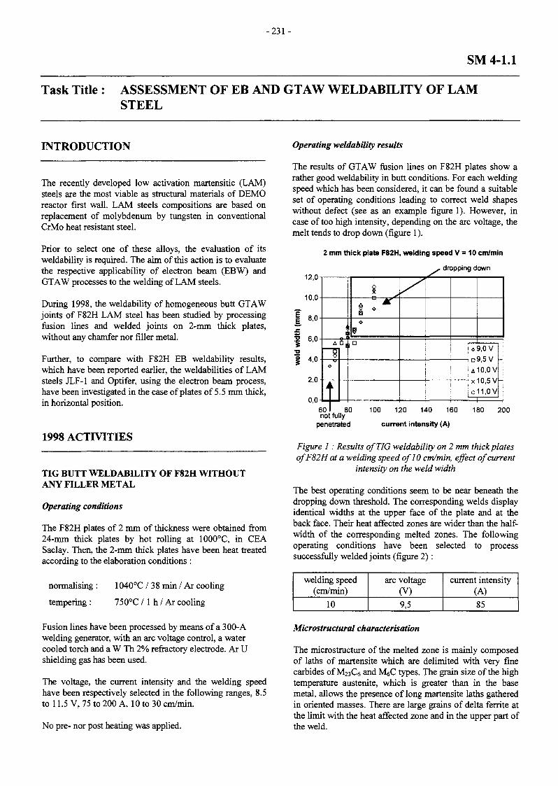
- 2 3 1 -
SM 4-1.1
Task Title : ASSESSMENT OF EB AND GTAW WELDABILITY OF LAMSTEEL
INTRODUCTION
The recently developed low activation martensitic (LAM)steels are the most viable as structural materials of DEMOreactor first wall. LAM steels compositions are based onreplacement of molybdenum by tungsten in conventionalCrMo heat resistant steel.
Prior to select one of these alloys, the evaluation of itsweldability is required. The aim of this action is to evaluatethe respective applicability of electron beam (EBW) andGTAW processes to the welding of LAM steels.
During 1998, the weldability of homogeneous butt GTAWjoints of F82H LAM steel has been studied by processingfusion lines and welded joints on 2-mm thick plates,without any chamfer nor filler metal.
Further, to compare with F82H EB weldability results,which have been reported earlier, the weldabilities of LAMsteels JLF-1 and Optifer, using the electron beam process,have been investigated in the case of plates of 5.5 mm thick,in horizontal position.
1998 ACTIVITIES
TIG BUTT WELDABILITY OF F82H WITHOUTANY FILLER METAL
Operating conditions
The F82H plates of 2 mm of thickness were obtained from24-mm thick plates by hot rolling at 1000°C, in CEASaclay. Then, the 2-mm thick plates have been heat treatedaccording to the elaboration conditions :
normalising : 1040°C / 3 8 min / Ar cooling
tempering : 750°C / 1 h / Ar cooling
Fusion lines have been processed by means of a 300-Awelding generator, with an arc voltage control, a watercooled torch and a W T h 2% refractory electrode. Ar Ushielding gas has been used.
The voltage, the current intensity and the welding speedhave been respectively selected in the following ranges, 8.5to 11.5 V, 75 to 200 A, 10 to 30 cm/min.
No pre- nor post heating was applied.
Operating weldability results
The results of GTAW fusion lines on F82H plates show arather good weldability in butt conditions. For each weldingspeed which has been considered, it can be found a suitableset of operating conditions leading to correct weld shapeswithout defect (see as an example figure 1). However, incase of too high intensity, depending on the arc voltage, themelt tends to drop down (figure 1).
2 mm thick plate F82H, welding speed V = 10 cm/min
^ dropping down12,0
10,0
8,0
6,0
4,0
2,0
0,0
i1
~i|0
Î
Si
(i
I <o
9n
y
0
D
A
X
O
9,0 V9,5 V10,0 V10,5 V11,0V
601 80not fully
penetrated
100 120 140 160
current intensity (A)
180 200
Figure 1 : Results of TIG weldability on 2 mm thick platesofF82Hat a welding speed of 10 cm/min, effect of current
intensity on the weld width
The best operating conditions seem to be near beneath thedropping down threshold. The corresponding welds displayidentical widths at the upper face of the plate and at theback face. Their heat affected zones are wider than the half-width of the corresponding melted zones. The followingoperating conditions have been selected to processsuccessfully welded joints (figure 2) :
welding speed(cm/min)
10
arc voltage(V)9,5
current intensity(A)85
Microstructural characterisation
The microstructure of the melted zone is mainly composedof laths of martensite which are delimited with very finecarbides of M23C6 and M^C types. The grain size of the hightemperature austenite, which is greater than in the basemetal, allows the presence of long martensite laths gatheredin oriented masses. There are large grains of delta ferrite atthe limit with the heat affected zone and in the upper part ofthe weld.
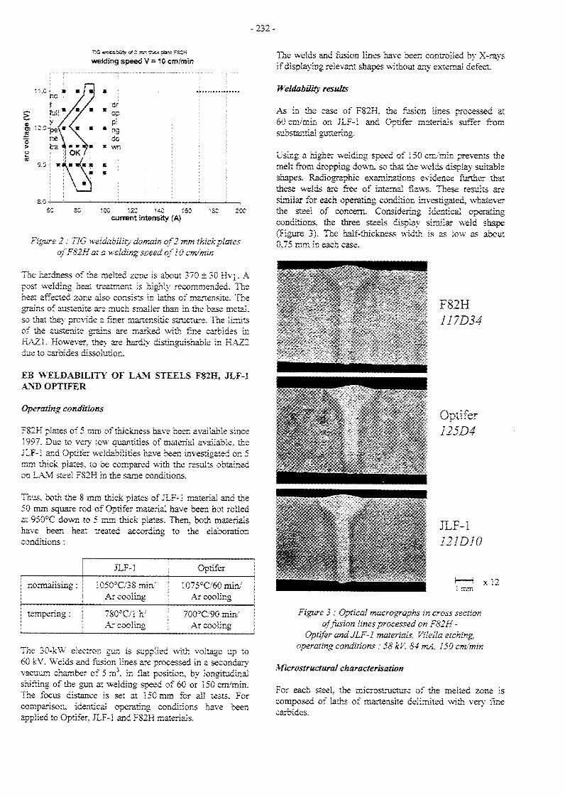
- 232 -
11,0 -!
ÏSG welsSsSiSîy a? 2 jrro t t w * pùtîe F82H
welding speed V -10 cm/mïn
OpPi
" ngdo
« wn
«
8.0-
80 3 120 140 tSOcurrent intensity (A)
ISO 200
Figure 2 : TIG weldabiiity domain of 2 mm thick platesofF82H at a welding speed of 10 cm/'min
The hardness of the melted zone is about 370 ± 30 Bx\. Apost welding heat treatment is highly recommended. Theheat affected zone also consists in laths of rnartensite. Tnegrains of austenite are much smaller than in the base metal,so that they provide a finer martensitic structure. The limitsof the austenite grains are marked with fine carbides inHAZi. However, they are hardly distinguishable in HAZ2due to carbides dissolution.
EB WELBABILITY OF LAM STEELS FS2H, JLF-1AND OPTIFER
Operating conditions
F82H plates of 5 mm of thickness have been available since1997. Due to very low quantities of material available, theJLF-1 and Optifer weldabilities have been investigated on 5mm thick plates, to be compared with the results obtainedon LAM steel FS2H in the same conditions.
Thus, both the 8 mm thick plates of JLF-1 material and the50 mm square rod of Optifer material have been hot rolledat 950°C down to 5 mm thick plates. Then, both materialshave been heat treated according to the elaborationconditions :
inormalising : |
tempering : |
JLF-1 j
1050°C/38min/ jAr cooling )
78CFC/1 h/ fAr cooling 1
Optifer
10?56C/60min/Ar cooling
700°G'90 min/Ar cooling
The 30-kW electron gun is supplied with voltage up to60 kV. Welds and fusion lines are processed in a secondaryvacuum chamber of 5 m\ in Sat position, by longitudinalshifting of the gun at welding speed of 60 or 150 cnv'min.The focus distance is set at 150 mm for all tests. Forcomparison, identical operating conditions have beenapplied to Optifer. JLF-Î and F82H materials.
The welds and fusion lines have been controlled by X-raysif displaying relevant shapes without any external defect.
Weldability results
As in the case of F82H. the fusion lines processed at60 cm/min on JLF-Î and Optiter materials suffer fromsubstantial guttering.
Using a higher welding speed of 150 cm/min prevents themelt from dropping down, so that the welds display suitableshapes. Radiographie examinations evidence farther thatthese welds are free of internal flaws. These results aresimilar for each operating condition investigated, whateverthe steel of concern. Considering identical operatingconditions, the three steels display similar weld shape(Figure 3). The half-thickness width is as low as about0.75 mm in each case.
F82H117DU
Optifer125D4
JLF-1121D10
1 mmx 12
Figure 3 : Optical macrographs in cross sectionaffusion lines processed on F82H -
Optifer and JLF-1 materials, Vilella etching,operating conditions : 58 kV, 84 mA, 150 cm/min
Microstructural characterisation
For each steel, the microstructure of the melted zone iscomposed of laths of martensite delimited with very finecarbides.

- 2 3 3 -
The grain size of the high temperature austenite is coarserwithin the Optifer base metal if compared to the two othersteels.
The hardness of the melted zone is about 420 ± 20 Hvi forF82H and JLF-1 materials. The hardness of the Optifermelted zone is slightly higher : 475 ± 20 Hvi (figure 4).
HV1
Distance from the weld axis (mm)
Figure 4 : Transversal hardness profilesin cross section of the welds, operating conditions :
58 kV, 84 mA, 150 cm/min
CONCLUSION
PUBLICATIONS
[1] A. FONTES, M. BARRAS, F. CASTELAN,"Soudabilité par procédé TIG sans métal d'apport del'acier martensitique à faible activation F82H", CE Areport, STA/LMS/98-RT3765, December 98
TASK LEADER
Diane DE PRUNELE
DTA/DPSA/STACEA Saclay91191 Gif-sur-Yvette Cedex
Tél. : 33 1 69 08 20 14Fax : 33 1 69 08 75 97
The operating weldabilty of LAM steel F82H without anychamfer nor filler metal, has been widely investigated byprocessing fusion lines and welded joints on 2 mm thickplates. Several sets of suitable operating conditions havebeen selected. Welded joints have been successfullyprocessed. The microstructure of the welds are similar tothose of TIG welded joints processed by JAERI on 15 and25 mm thick plates.
The EB weldabilities of F82H, JLF-1 and Optifer steelshave been investigated using plates of 5 mm of thickness.The results show so far that the weldabilities are highlysimilar. Defects-free suitable welds have been obtainedwith the three steels at a welding speed of 150 cm/min.However, the Optifer weld has displayed higher hardness.
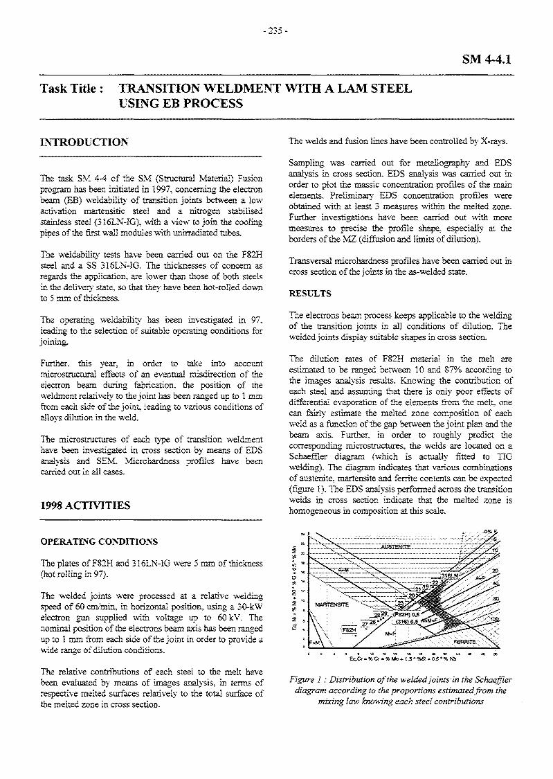
- 2 3 5 -
SM 4-4.1
Task Title : TRANSITION WELDMENT WITH A LAM STEELUSING EB PROCESS
INTRODUCTION
The task SM 4-4 of the SM (Structura! Material) Fusionprogram has been initiated, in 1997, concerning the electronbeam (EB) weidability of transition joints between a lowactivation martensitic steel and a nitrogen stabilisedstainless steel (3Î6LN-IG), with a view to join the coolingpipes of the first wall modules with unirradiated tubes.
The weldability tests have been carried out on the F82Hsteel and a SS 3I6LN-IG. The thicknesses of concern asregards the application, are lower than those of both steelsin the delivery state, so that they have been hot-roiled downto 5 mm of thickness.
The operating weldability has been investigated in 97,leading to the selection of suitable operating conditions forjoining.
Further, this year, in order to take into accountmicrostructurai effects of an eventual misdirection of theelectron beam during fabrication, the position of theweldment relatively to the joint has been ranged up to 1 mmfrom each side of the joint leading to various conditions ofalloys dilution hi the weld.
The microstructures of each type of transition weldmenthave been investigated in cross section by means of EDSanalysis and SEM. Microhardness profiles have beencarried out in all cases.
1998 ACTIVITIES
The welds and fusion lines have been controlled by X-rays.
Sampling was carried out for metallography and EDSanalysis in cross section. EDS analysis was carried out inorder to plot the massic concentration profiles of the mainelements. Preliminary EDS concentration profiles wereobtained with at least 3 measures within the melted zone.Further investigations have been carried out with moremeasures to precise the profile shape, especially at theborders of the MZ (diffusion and limits of dilution).
Transversal microhardness profiles have been carried out incross section of the joints in the as-welded state.
RESULTS
The electrons beam process keeps applicable to the weldingof the transition joints in all conditions of dilution. Thewelded joints display suitable shapes in cross section.
The dilution rates of F82H material in the melt areestimated to be ranged between 10 and 87% according tothe images analysis results. Knowing the contribution ofeach steel and assuming that there is only poor effects ofdifferential evaporation of the elements from the melt, onecan fairly estimate the melted zone composition of eachweld as a function of the gap between the joint plan and thebeam axis. Further, in order to rough!}? predict thecorresponding microstructures, the welds are located on aSchaeffler diagram (which is actually fitted to TIGwelding). The diagram indicates that various combinationsof austenite, martensite and ferrite contents can be expected(figure 1). The EDS analysis performed across the transitionwelds in cross section indicate that the melted zone ishomogeneous in composition at this scale.
0%S
OPERATING CONDITIONS
The plates of F82H and 316LN-IG were 5 mm of thickness(hot rolling in 97).
The welded joints were processed at a relative weldingspeed of 60 cm/min, in horizontal position, using a 30-kWelectron gun supplied with voltage up to 60 kV. Thenommai position of the electrons beam axis has been rangedup to 1 mm from each side of the joint in order to provide awide range of dilution conditions.
The relative contributions of each steel to the melt havebeen evaluated by means of images analysis, in terms ofrespective melted surfaces relatively to the total surface ofthe melted zone in cross section.
8 '*<~ 10 .
S 8 1* « T* 1« IS 20 52 S*
Eq.Cr • % Or * % Mo* 1,5 * %Si •«• 0.5 •% NS
Figure 1 : Distribution of the welded joints in the Schaefflerdiagram according to the proportions estimated from the
mixing law knowing each steel contributions

- 2 3 6 -
For each element, the analysis confirms the concentrationcalculated according to the relative contributions to themelt. Further, the metallographic examinations roughlyconfirm the predictions coming from the Schaefflerdiagram. From 87 to 50% of F82H contribution, the meltedzone is essentially martensitic. Then, from 50 to 20%, themartensite content in the welded zone decreases as afunction of F82H contribution and the microstructuresdisplays small quantities of delta ferrite. Beneath 20% ofF82H steel in the weld, the melt is essentially austeniticwith small quantities of delta ferrite. The various phasescontents lead to specific hardness profiles across the joints.In case of high F82H contributions (from 87 to 50%), thehardness in the melted zone fits unannealed martensitehardness (figure 2).
0,68 (F82H)+0,32(316)
Base Metal F82
———^—
f
JXX
E
I f]\l
y
s,
It
/\ 1
1z [1 Base
1 >^y
Metal 316 .NJG
Distance from the melted zone axis (mm)
Figure 2 : Transversal hardness profile (Hvl)across the transition weld at half plate thickness,
F82H contribution to the melt : 68%
At lower F82H contributions (from 50 to 20%), thehardness decreases from the unannealed martensite valueat the F82H side to the austenite value at the 316LN-IGside (figure 3).
0.35 (F82H) •0.65(316)
> IBX
BM 82H
AXX
E
IAZ1
1
1 \ 'LIZ BM: 16 LN
-
0.23 (F82H)* 0.77 (316)
BMF82H
I/I1
/ 9/ X
r s\J
x
N Z BM3 6LN
Distance from the melted zone axis (mm)
Figure 4 : Transversal hardness profile (Hvl)across the transition weld at half plate thickness,
F82H contribution to the melt : 23%
CONCLUSION
The processing conditions leading to various dilutions ofeach alloy in the melt led to suggest that an eventualmisdirection of the electron beam would not be risky forthe status of the welded joint. The various conditions ofdilution that were obtained led to various correspondingcompositions of the melted zone. In case of low F82H alloyfraction the melted zone displayed on the whole amicrohardness close to that of the austenitic stainless steel.The corresponding microstructure was indeed essentiallyaustenitic. This result indicated that in such a case, themelted zone would be able to partially accommodate therestraint and the stresses due to the gap between theexpansion coefficients of both alloys.
PUBLICATIONS
[1] A. FONTES, M. BARRAS, F. CASTELAN, "Joint detransition par procédé faisceau d'électrons entre unacier martensitique à faible activation (de typeAFNOR Z9CWV 08 02) et un acier inoxydableausténitique à azote contrôlé (Z2CND 17 12), 2èmepartie : différentes conditions de dilution", CE Areport, STA/LMS/98-RT3774, December 98
TASK LEADERDistance from the melted zone axis (mm)
Figure 3 : Transversal hardness profile (Hvl)across the transition weld at half plate thickness,
F82H contribution to the melt : 35%
In case of austenitic melted zone, the hardness profile inthe melted zone is nearly at the level the austenitic basemetal (figure 4).
Diane DE PRUNELE
DTA/DPSA/STACEA Saclay91191 Gif-sur-Yvette Cedex
Tél. : 33 1 69 08 20 14Fax : 33 1 69 08 75 97
- 237 -
SM 4-5.1
Task Title : INVESTIGATION ON COMMERCIAL FILLER METAL FORGTAW OF LAM STEELS
INTRODUCTION
The task SM 4-5 of the SM (Structural Material) Fusionprogram has been initiated in 1998. The aim of this taskwas to provide filler metal as an input for TIG weldabilitytasks planned for the next Structural Material program(1999-2002). Informations concerning filler metal for theTIG welding of low activation martensitic steel has beengathered focusing on F82H steel proposed by JAERI.Further, commercial product suppliers have been contactedwith a view to select suitable filler wire or electrode.
1998 ACTIVITIES
LITERATURE RESULTS
A literature review has been carried out concerning generalaspects of LAM steels weldability, focusing on F82H.
On a wide range of composition, the LAM steels are easilyweldable following the TIG process. The weldments areshown to be usually free of cracks. It appears that a widerange of filler metal composition could be suitable (inparticular, filler metal for chromium steels) except for thelow activation criterion.
Preferential vaporisation of chromium and manganese (alower manganese content could low down the Acltemperature) could occur during TIG welding so that fillermetal may compensate this phenomenon by slightly highercontents of these two elements. Low tantalum content(0.02%) and low carbon content tend to improve theultimate tensile strength of the weld. However, a highertantalum content tends to provide a finer martensite, sothat a compromise solution has to be reached. The effect ofcarbone alone is not clear yet. The addition of borumseems not to be necessary. This is a favourable pointknowing that the ductile brittle temperature transition ofLAM steels after irradiation can easily be lowed down ofabout 100°C if lowing down the borum content from 300 to5 ppm (considering a possible shift of DBTT afterirradiation, a high value of absorbed energy is desirable).
FILLER METAL SUPPLIERS INVESTIGATION
Thirty six filler metal suppliers have been investigateduntil December 98 (Alliages Industrie, AMSR, AvestaSheffield, Boehler Aciers Spéciaux, Boehler, Bonnefon,Chpolansky (Ets), Commercy-Soudure, ComptoireLyonnais de Soudage, Cupex SA, DOGA, ESAB,
Eutectic+Castolin, Forges de Saint-Hyppolyte (Sté des), FPSoudage, Frésa, FRO Saldatura Spa / Air Liquide, KobelcoWelding of Europe BV, Lincoln Electric France SA,Lincoln Smitweld BV, Mannesmann, Messer GriesheinFrance, Metrode France SARL, Oerlikon Soudure France /Air Liquide, Perma France, R&D Metals and ChemicalsInc., Reboud Roche (Ets), SAF / Air Liquide, Sandvik,Sandvik, Sprint Metal / Imphy SA, Thyssen France SA,Thyssen Schweisstechnik GmbH Hamm, Unifrance, UnitedStates Welding Corporation, UTP Boehler Thyssen).
Up to now, not any of them can propose a commerciallyavailable product.
In order to have some filler metal available for the nextstep, two filler wires of ten kilograms each have beensupplied from the JAERI with attached composition. Thesewires come from the same heat as those used by JAERI toprocess TIG welded joints.
CONCLUSION
A literature review has been carried out showing that thefiller products for the TIG welding of LAM steels shouldhave compositions close to those of the base materials.However, the investigation has shown that no filler productis commercially available yet. As a substitutive solution,two F82H filler wires have been supplied from JAERI.
PUBLICATIONS
[1] A. FONTES, « Produit d'apport pour le soudage TIGde l'acier martensitique à faible activation AFNORZ9CWV 08 02 : Etude bibliographique et enquêteauprès des fournisseurs », CEA report, STA/LMS/98-RT3782
TASK LEADER
Diane DE PRUNELE
DTA/DPSA/STACEA Saclay91191 Gif-sur-Yvette Cedex
Tél. : 33 1 69 08 20 14Fax : 33 1 69 08 75 97

-239 -
SM 5-1.2
Task title: EVALUATION FOR APPLICATION OF MECHANICAL DESIGNCODES FOR FUSION MATERIALS
INTRODUCTION 1998 ACTIVITIES
Within the ITER program, Structural Design Criteria(ISDC) have been developed. Irradiation-inducedembrittlement and swelling have been treated in ISDC.High temperatures envisioned in the long term fusionprogram, involve more significant consequences ofirradiation damages than in ITER.
Moreover, it is known that martensitic materials have amechanical behaviour that may be different, in particularfor cyclic loads, from austenitic steels.
So, the aim of this task is to assess the applicability ofISDC in the loading and material conditions forecast forlong term programme.
In this framework, it is of great interest to evaluate theinfluence of the evolution of material properties underirradiation on design rules.
SIMULATION OF IRRADIATION MECHANICALEFFECT BY MATERIAL HARDENING
Irradiation gives rise in material to hardening andreduction of elongation and necking performance. Thisphenomenon was simulated by strain hardening of thematerial. Even if the mechanisms at the microscopic levelare not the same, the macroscopic mechanical behaviourcan be very similar.
So, we are using rotating hammering in order to simulatethe mechanical effect of irradiation. This way is very usefulin order to test the impact of material behaviourmodification on plastic instability and secondary stresslimitation rules.
1000 j 250"C 6,8dpa
900
, 45%
20 30 40
elongation ((L- Lo)/LoX% )
50 60 70
Figure 1 : Comparison of tensile curves of irradiated and strain hardened material
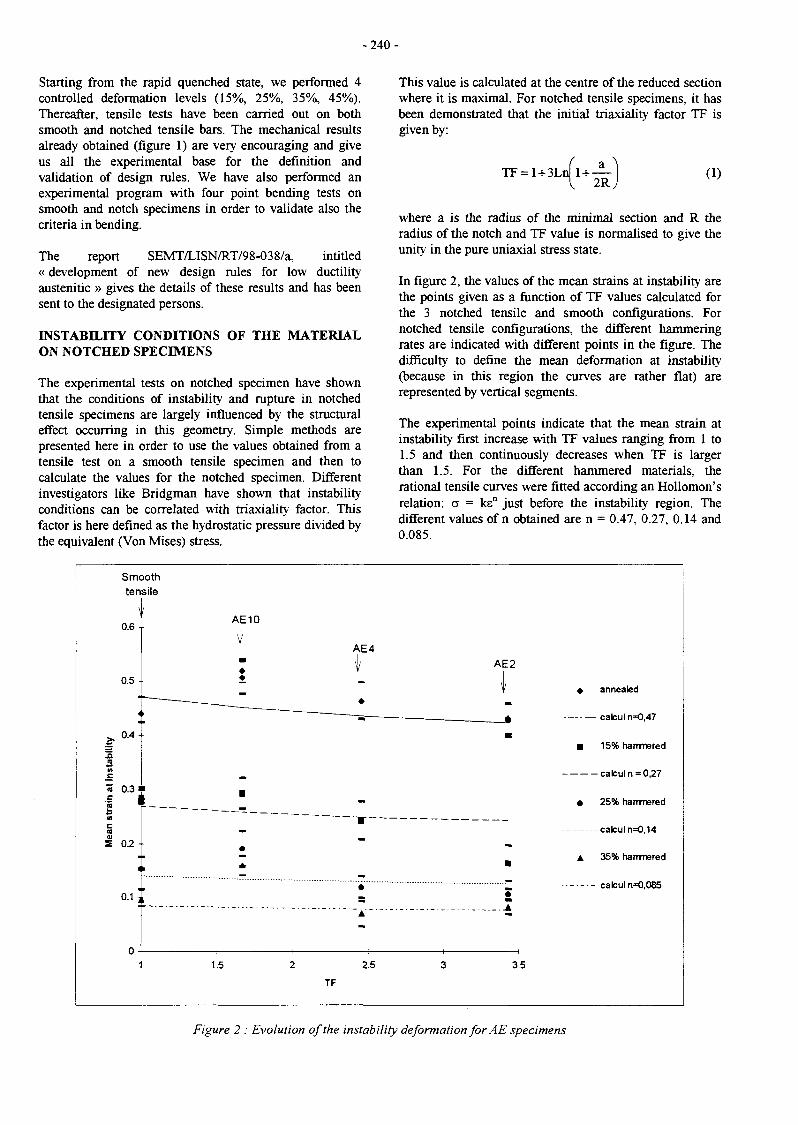
- 2 4 0 -
Starting from the rapid quenched state, we performed 4controlled deformation levels (15%, 25%, 35%, 45%).Thereafter, tensile tests have been carried out on bothsmooth and notched tensile bars. The mechanical resultsalready obtained (figure 1) are very encouraging and giveus all the experimental base for the definition andvalidation of design rules. We have also performed anexperimental program with four point bending tests onsmooth and notch specimens in order to validate also thecriteria in bending.
The report SEMT/LISN/RT/98-038/a, intitled« development of new design rules for low ductilityaustenitic » gives the details of these results and has beensent to the designated persons.
INSTABILITY CONDITIONS OF THE MATERIALON NOTCHED SPECIMENS
The experimental tests on notched specimen have shownthat the conditions of instability and rupture in notchedtensile specimens are largely influenced by the structuraleffect occurring in this geometry. Simple methods arepresented here in order to use the values obtained from atensile test on a smooth tensile specimen and then tocalculate the values for the notched specimen. Differentinvestigators like Bridgman have shown that instabilityconditions can be correlated with triaxiality factor. Thisfactor is here defined as the hydrostatic pressure divided bythe equivalent (Von Mises) stress.
This value is calculated at the centre of the reduced sectionwhere it is maximal. For notched tensile specimens, it hasbeen demonstrated that the initial triaxiality factor TF isgiven by:
l + 3LnU + —\ 2R
(1)
where a is the radius of the minimal section and R theradius of the notch and TF value is normalised to give theunity in the pure uniaxial stress state.
In figure 2, the values of the mean strains at instability arethe points given as a function of TF values calculated forthe 3 notched tensile and smooth configurations. Fornotched tensile configurations, the different hammeringrates are indicated with different points in the figure. Thedifficulty to define the mean deformation at instability(because in this region the curves are rather flat) arerepresented by vertical segments.
The experimental points indicate that the mean strain atinstability first increase with TF values ranging from 1 to1.5 and then continuously decreases when TF is largerthan 1.5. For the different hammered materials, therational tensile curves were fitted according an Hollomon'srelation: a = ksn just before the instability region. Thedifferent values of n obtained are n = 0.47, 0.27, 0.14 and0.085.
stra
in a
t in
stab
ility
Mea
n
Smoothtensile
I\
0.6 -
0.5 -
im
0.4-
0.3"1
0.2 -
i
0.1 '
n
1
:•
•
\
•
AE10
•
" ~ •
•
1 It
!•
1
1.5
1 •
2
A
\
.—.
kE4
*
*
2.5
TF
3
AE2
É•
•
5
3.5
« annealed
• 15% hammered
calcul n = 0,27
• 25% hammered
calcul n=0,14
A 35% hammered
calcul n=0,085
Figure 2 : Evolution of the instability deformation for AE specimens
- 2 4 2 -
Mac Clintock has shown that A parameter is proportionalto strain hardening coefficient n. This has been found alsoin our experimental results. The A values are calculatedfrom Srup and TF experimental values with the upperequation. This gives a linear correlation with the n valuesthat were obtained by fitting of n parameter of anHollomon's equation of the tensile curves on smoothspecimen.
This model gives a fairly good approximation of theexperimental results obtained. For comparison, Figuregives also the reduction calculated by Mac Clintock for aplastic perfect material (n=0) for which A=0.86 isproposed.
TASK LEADER
Claude SAINTE CATHERINE
DRN/DMT/SEMT/LISNCEA Saclay91191 Gif-sur-Yvette Cedex
Tél. : 33 1 69 08 88 56Fax : 33 1 69 08 87 84
E-mail : stecath(8),semt2.smts.cea.fr
CONCLUSIONS
The four tasks which were scheduled in this program arenow achieved. The first task was entitled "Needs formaterials characteristics - Compilation of availablematerials characteristics". The second one was entitled"Local approach use assessment". The third one iscorresponding to "Experimental validation tests". Finally,the last item was "Evolution of ISDC to a general fusionreactors design guidance"
This set of work can now be use for the definition of aneventual evolution of ISDC rules. Further work will berequired for the low cycle fatigue regime or the elastic-plastic fracture mechanics area.
REPORTS AND PUBLICATIONS
[1] GOUIN H., SAINTE-CATHERINE C. and MOULIND., "Development of new design rules for LowDuctility Steels", CEA Saclay, France, ReportSEMT/LISN/RT/98-038, (1998).
[2] BRACHET J-C, "Properties and Data of EM 10Steel - Comparison with some Commercial andExperimental Alloys, including Low Activation9Cr(N,V,Ta) Steels", CEA Saclay, France, ReportCEREM-SRMA-96/200, (1996).
[3] SAINTE CATHERINE C. and MARINI B., "Localapproach assessment", CEA Saclay, France, ReportDMT-95/667, (1995).
[4] TOUBOUL F., "Programme Long Term Fusion:evaluation of the needs for materials characteristics'',CEA Saclay, France, Report DMT-95/440, (1995).

- 2 4 3 -
SM 6-4.2
Task Title : MICROSTRUCTURAL CHARACTERISATION BY SANSTECHNIQUESMicrostructural characterisation after thermal ageing of LAM and conventionalmartensitic steels by Small Angle Neutron Scattering
INTRODUCTION
Low Activation Martensitic (LAM) steels are candidatesfor internal structures of fusion reactors. The concept ofLow Activation steels or Reduced Activation steels wasintroduced for new materials that offer benefits onmaintenance operations and waste management. Formartensitic/ferritic steels, the main alloying elements suchas molybdenum, niobium and nickel present in commercialsteels are substituted by elements such as tungsten,vanadium, manganese and tantalum. These elements havea similar influence on the constitution and structure butexhibit a lower radiological impact.
In order to assess low activation materials and tounderstand the effect of the substitution of W to Mo and Tato Nb on the evolution of the microstructure during long-term ageing, LAM alloys and also conventional steels arecharacterised by Small Angle Neutron Scattering (SANS).
1998 ACTIVITIES
LAM alloys F82H, JLF1, LA12LC and LA12TaLC werecharacterised by Small Angle Neutron Scattering (SANS)before and after ageing [1] and the results were comparedto those acquired previously on conventional steels (EM 10andHT9)[2].
MATERIALS
The chemical compositions of the steels used in this studyare listed in table 1. The Japanese steels F82H and JLF-1alloys contain respectively (%wt) 7.5Cr -2W and 9Cr-2Wand are large industrial heats. Compared to F82H and JLF-1, the LA12LC and LA12TaLC alloys (9Cr-0.8W), containlow concentrations of W. These two last materials allow tostudy the effect of a low W and Ta content on themicrostructure evolution under thermal ageing.
The alloys were austenitized at high temperature, then theywere tempered at 750/780°C during 1 hour. Some of thestudied materials have been 10% cold rolled. The details ofthese treatments for each material are given in table 2.After these thermal treatments, a fully martensitic structureis obtained for all the alloys except for HT9 which presentsa small amount of delta-ferrite (<3%) in the martensiticstructure.
After normalisation and tempering treatments, thepredominant precipitated phase is a chromium rich M23C6
carbide. These particles are located preferentially alongprior austenite grain boundaries and along lath boundaries.The chemical composition of the M23C6 was measured byTEM on carbon extraction replica and does not reallydiffer from LAM and conventional alloys. It is about35%Fe-60%Cr-5%W/Mo (in atomic %) [3,4] and for theF82H steel no other precipitation has been detected [5].Other second phases M2X and/or MC are also detectedrespectively in EM10 and HT9. Some particles of Ta(N,C)and of MX (M=ll%Cr, 77%V, 10%Fe) have beenobserved in the JLF-1 alloy [5]. For the LA12LC andLA12TaLC, the TEM observations have not yet beenperformed, but we could expect that V-rich MX andTa(N,C) (only in the Ta rich alloy) precipitates are present.
The normalised and tempered specimens, HT9 and EM10,were aged at 400°C, 450°C and 500cC up to respectively22000 h and 15000 h. The LAM alloys were aged at250°C, 35O°C, 400°C, 450°C and 550°C up to 13500 h forF82H and JLF-1, and up to 5000 h for LA12TaLC andLA12LC.
Table 1 : Chemical analysis of experimental steels (wt %)
Steel
F82H
JLF-1
LA12TaLC
LA12LC
EM10
HT9
Cr
7.46
8.7
8.9
9.0
8.8
12
W
1.96
1.91
0.76
0.76
0.5
Mo
1.0
1.0
Ni
0.2
0.6
Mn
0.21
0.47
1.01
1.01
Ta
0.023
0.08
0.1
V
0.15
0.18
0.39
0.38
0.02
0.3
Si
0.10
0.05
0.03
0.03
C
0.087
0.10
0.09
0.09
0.1
0.1
N
0.006
0.028
0.019
0.033
0.024
NA*
* Not Analysed
RESULTS
Measurements have been made at room temperature, undersaturating magnetic field H=2T perpendicular to theincident neutron beam direction in order to separatemagnetic and nuclear scattering.
LAM alloys
F82H alloy
The intensities obtained on F82H samples present ananisotropy, before and after ageing, even in absence ofmagnetic field. This anisotropy is probably the result of amorphologic texture of the microstructure i.e. apreferential orientation of the precipitates in the matrix.

-244 -
The scattered intensities obtained as a function of thescattered vector q and measured on the samples aged 13500h are presented in figure 1. There is no evolution of themicrostructure in comparison with the reference sample(without thermal ageing). All the SANS intensities areidentical taking into account the error bars. The scatteredintensities are high at low q and correspond to large sizeprecipitates, i.e. the M23C6 carbides initially present in thematerial.
îocr-
1
o.i
0.011
° F82H reference• F82H aged 13500h at 350°C• F82H aged 1350Oh at 400°Cx F82H aged 135OOh at 550°C
, ,0.05 0.1 0.15 0.2
Figure 1 : Scattered intensities measured, without appliedmagnetic field, on F82H samples before (reference)
and after thermal ageing for during 13500 h at differenttemperatures
At low q, the A ratio(ratio on the scattered intensitiesmeasured perpendicularly and parallel to H) of M23Qcarbides is about 4-4.5. The A ratio calculated using thechemical composition measured by TEM, i.e. 35%Fe65%Cr 5%W, is 3.5. This value depends on manyparameters which are unknown precisely, such as theatomic volumes in the matrix and in the precipitate, and themagnetic moments. So, to estimate the A ratiocorresponding to the carbides, we used theoretical values(the atomic volume has been deduced from tabulated Cr23C6
cell parameters, the magnetic moment is taken equal to thatof pure iron). Taking into account of this uncertainty, themeasured A ratio at low q is in agreement with chemicalcomposition of the carbides determined by TEM.
JLF-1 alloy
The JLF-1 alloy has been characterised by SANS after :2000 h at 550°C and 13500 h at 250°C, 400°C and 500°C.The variation of scattered intensity in comparison with thereference sample is too weak to be considered asrepresentative of a microstructure evolution. At 550°C, theSANS intensity seems to increase at low q with ageing.Some SANS measurements have been made with andwithout magnetic field and have confirmed this behaviourbut this evolution of SANS intensity with the ageing at550°C is too weak to be interpreted.
Furthermore, the A ratio measured at low q, does notchange with ageing and is about 3-3.5. This value is slightlylower than for F82H alloy, although the chemicalcomposition of the M23Q carbides is not significantlydifferent in these two materials. The difference of the Aratio between the steels is significant and probablyrepresentative of the presence of additional or differentphases. Quantitatively, it is very complicated to calculate amean A ratio resulting of several kinds of particles becauseeach contribution has to be weighted by its correspondingform factor and by the number density of each phase. The Aratio in a pure iron matrix is for TaC equal to 10, for VN itis equal to 3.9 and for VC it is equal to 2.23. Qualitatively,only the VC or VN or V[N+C] particles can induce adecrease of the mean A ratio. Indeed, the presence of TaCcarbides should sharply increase the A factor. So, to explainthe results obtained on JLF-1, we have to assume that thecontribution of the V(N,C) particles in the matrix have animportant effect on the mean observed A ratio.
LAHTaLC and LA12LC alloys
As for JLF-1 and F82H materials, we did not observe bySANS any significant variation of the scattered intensityafter ageing ( figure 2). The A ratio measured at low q isabout 2.5 for the LA12LC alloy and 3 for the LA12TaLCalloy.These values are lower compared to the other alloys.The A ratio is higher for the Ta rich alloy which iscompatible with the presence of Ta(N,C) in the matrix ofLA12TaLC and not in the matrix of LA12LC.
X
I 1
0.1
0.01
° LA 12LC reference
• LA12LCaged5000hat250°C
» LA12LC aged SOOOh at 400 °C J
x LAI 2LC aged 5000h at 450 °C
•<- LA 12LC aged 5000h at 550 °C
0.02 0.04 0.06 0.08 0.1 0.12 0.14 0.16
Figure 2 : Intensities scattered perpendicularly to magneticfield measured on LA12LC samples before (reference) and
after thermal ageing for during 5000 h at differenttemperatures
Conventional alloys
For these alloys (in contrast with the LAM materials), aftereach ageing treatment, we observed an increase of thescattered intensity in comparison with the reference sample.

-245 -
So, the intensities presented are obtained after subtractionof the reference sample (without thermal ageing). Thescattered intensities obtained on HT9 alloy thermally aged22000 h at 400, 450 and 500°C are plotted in figure 3.
100
10 r
1 r
0.1
0.01 F
r
A _,_A
- i: t
i
o 400°C* 450°C+ 500°C
:
~T—i
prm
i
1
« .« ; ; . . .
0.001
0.5 1.5
q ( nm"1)
Figure 3 : Intensities scattered perpendicularly to magneticfield, obtained after subtraction of the reference sample,
measured on HT9 samples thermally aged 22000 h atdifferent temperatures
EM10 alloy
The scattered intensities after treatment at 400 and 450°Care similar and markedly lower compared to those observedafter ageing at 500°C.
For thermal ageing at 400°C and 450°C, mechanicalproperties show a clear hardening with the same intensityfor the two ageing temperatures [6]. The scatteredintensities could correspond to the microstructural evolutionresponsible of this hardening. The data treatment shows thatthe SANS profiles can be interpreted with a distribution ofparticles with a mean radius close to 3 nm. The A ratios areconstant on the whole measured q domain and equal to 3.5± 0.6. This value could correspond to several kinds ofparticles : M2C carbides with the following chemicalcontent M(at%)= 83Cr, 12Fe, 5Mo, or VC carbides. Theprecipitation of M2C is not expected because during thermalageing at those temperatures they seem to disappear [7].Moreover, preliminary thermodynamic calculations showedthat, at the equilibrium, these carbides are present onlybetween 600 and 850°C.
At 500°C, the intensity is higher and follows a POROD law(I « A/q4) characteristic of large size particles. This kind ofprofile can be due to Laves phases at grain boundaries. TheA ratio is equal to 6 ± 1, which is consistent with Fe andMo rich particles such as the Laves phase Fe2Mo observedby TEM.
HT9 alloy
The behaviours at 400 and 450°C are different, the intensityat 400°C is lower than at 450°C and 500°C.
On the other hand, we note only a small evolution between450°C and 500°C as it is shown on figure 12. At hightemperature, the scattered intensities follow a POROD law(I °c A/q4) as for the EM 10 alloy. Furthermore, the A ratiois equal to 3.45 ± 0.5 and 4 ± 1 respectively for 450°C and500°C, which is consistent with Fe2(Mo,W) Laves phase.Indeed, the substitution of Mo by W in the Laves phaseinduces an important decrease of the calculated A ratio(compared to the case of EM10, aged at 500°C, containingnoW).
At 400°C, the study of the form factor shows that the radiusof the particles is around lnm. The associated A ratio isequal to 2 ± 0.4, in agreement with the value expected foralpha-prime clusters. With the assumption of alpha prime-clusters containing 90%Cr and 10%Fe, the precipitatedvolume fraction is around 0.25%. For this thermaltreatment, no new phase has been observed by TEM.
CONCLUSIONS
SANS experiments were performed on Low ActivatedMaterials JLF-1, F82H, LA12TaLC and LA12LC and onconventional alloys EM10 and HT9. These measurementshave been made several times in order to confirm the resultsand to define the experimental error bars.
This study confirms the different behaviours under thermalageing between the conventional and LAM alloys.
In the conventional alloys HT9 (12Cr IMo-W) and EM 10(9Cr IMo), the SANS results have shown, in agreementwith TEM observations, the formation of Laves phase underthermal ageing beyond respectively 450°C and 500°C witha chemical composition depending on the W and Mo initialcontent. A higher precipitated fraction probably occurs inHT9 due to the higher Mo+W concentration. The fact thatno Laves phase occurs at 450°C in the EM 10 can beexplained by the low precipitation kinetics at thistemperature. At lower temperature (400°C), in theconventional alloys, we observed the formation of alpha-prime clusters in HT9 and of a new precipitation in EM 10which are probably at the origin of the hardening observedon mechanical properties.
In LAM steels, the structure developed after temperingseems to be stable under thermal ageing up to 13500h attemperature between 250°C and 550°C. The measuredscattered intensities correspond essentially to the M23C6
carbides present after tempering treatment. The A ratioshows some variations with chemical composition of thealloys which can be due to the presence before ageing ofother kinds of precipitates (VX or TaX). Under thermalageing, no significant evolution has been detected in F82H,JLF-1, LA12TaLC and LA12LC alloys whatever the ageingtemperature, hi particular, no Laves phase was detected at550°C even in the high W content steels (F82H, JLF-1).

-246-
Due to the very low solubility of W and Mo in iron, wecould expect the formation of the intermetallic Fe2(W,Mo)in all the alloys. It seems that the precipitation kinetic ofthe Laves phase in W rich steels is liindered by the weakdiffusion of the W in iron.
Furthermore, at low temperature, no new phase wasdetected in studied LAM alloys although that the Crcontent is quite similar in EM 10 and JLF-1, LA12LC andLA12TaLC.
Finally, the LA12TaLC and LA12LC exhibit similarmicrostructure stability under ageing, so no significanteffect of tantalum on precipitation evolution has beenobserved excepted a slight increase of the A Ratio.
In order to clarify the role of each main element, studies ofmodel LAM alloys (LA4Ta, LA12Ta and LA13Ta)thermally aged between 250 and 550°C are in progress.
REPORT
[1] M.H. MATHON, G. GEOFFROY, C.H. de NOVION,Y. DE CARLAN, A. ALAMOMicrostructural caracterisation after thermal ageingof LAM and conventional martensitic Steels by SmallAngle Neutron Scattering - Final Report contract SM6.4.2 - Note Technique : LLB/98/108 - LSI/98/03
[5] Y. de CARLAN , A. ALAMO, Effect of thermalageing on microstructure and mechanical propertiesof 7.5/9 Cr (W/Ta/V) Reduced Activation martensiticsteels - final Report - Contract UT-SM&C 2.1.1 - NTSRMA to be published
[6] J.L. SERAN, A. ALAMO, A. MAILLARD, H.TOURON, J.C. BRACHET, P. DUBUISSON, O.RABOUILLE - J. Nucl. Mater. Vol. 212-215 (1994),p588
[7] J.C. Brachet, CEA report, CEA R-5581, France, 1991
TASK LEADER
A. ALAMO
CEA Saclay91191 Gif-sur-Yvette Cedex
Tél. : 33 1 69 08 67 26Fax : 33 169 08 71 30
E-mail : ana.alamo(Scea.fr
REFERENCES
[2] M.H MATHON, G GEOFFROY, C.H. de NOVION,Y. DE CARLAN, A ALAMO,Microstructural characterisation of EM10, HT9,F82H and JLF1 steels by small angle neutronscattering, Note technique LLB/97/170-LSI/98/01.
[3] A. ALAMO, C. LEPOITTEVIN, F. NEE, C.BOUSSIDAN, Effects of heat treatments and phasetransformations of F82H and JLF-1 low activationmartensitic steels, Progress Report NT SRMA 96-2211, dec. 1996
[4] C. BOUSSIDANDétermination des fractions de phases à l'équilibrethermodynamique de différents aciers inoxydablesd'intérêt nucléaire. - C.R. SRMA 95-1519, août 1995

- 2 4 7 -
WP5
Task Title : COORDINATIONMaterials R&D Strategy for Future Fusion Reactors
INTRODUCTION
Until recently, the fusion technology programme had anear term goal and a long term goal. The near term goalaimed at construction of an International ThermonuclearExperimental Reactor (ITER) in about 10 years time andwas carried out jointly by four Home Teams (EU, JA, RF,US). The long term goal focussed on post ITER machinesand was carried out primarily at the national level, thoughthe R&D programmes were usually harmonised underdifferent IEA implementing agreements. The transitionbetween the two goals was insured through testing ofBreeding Blanket Module concepts in ITER.
With the recent changes in the fusion technologyprogrammes, at the national and international levels, thenear term objectives are scaled down and the long termobjectives delayed. This paper addresses the consequencesof such changes on the EU materials long termprogrammes and attempts to develop a materials strategyfor the future work. It is based on a presentation made atan IEA Sponsored Workshop on "Strategic Planning andCo-ordination of Research on Fusion Structural Materials",5-7/9/98 RISÔ National Laboratory, Denmark.
1998 ACTIVITIES
MATERIALS R&D STRATEGY
The most likely scenario for the next step machine is areduced cost machine and/or an extension of existingfusion machines. ITER Test Blanket Module programmehas to be adapted to the new machine. The delay in thelong term program could be used for evaluation ofalternative reactor concepts. Though the present liquidand solid breeding blanket concepts should remainamongst the primary solutions, the possibility of a differentapproach can not be ruled out. As a result, the materialsprogramme must incorporate a certain degree of flexibilityand design independence.
To develop such a long term materials strategy, one couldmake a number of assumptions that would apply to anyfuture fusion reactor concept and based on thoseassumptions derive the target materials requirements.
Assumption 1 : The future reactor would operatein a continuous mode
In a continuous operation mode, the reactor is onlyperiodically shut down for maintenance. For instance, in apool type fission reactor, each operation cycle time is aboutone month, in a research type reactor such as Phénix it isabout three months, and in a commercial reactor it is overone year. As a result, we can reasonably deduce that thenumber of thermal fatigue cycles resulting from normalstart-ups and shut-downs would be small, about 20 to 200times. In another word, the number of thermal fatiguecycles (excluding plasma disruptions) will be small, but theexposure time and the neutron doses much higher.
Conclusion: Target materials may not need to exhibit ahigh resistance to thermal fatigue resistance, but have towithstand exposures to high neutron irradiation doses (100to 200 dpa).
Assumption 2 : The future reactor has to be economical
A number of factors determine the economy of a reactor.From the thermal efficiency point of view, the reactor mustoperate at higher temperatures. A higher servicetemperature would:
1) accentuate the creep damage,2) modify the choice of coolant,3) change the irradiation damage mechanism.
At low irradiation temperatures, the main damagemechanism is hardening associated with a reduction inductility and toughness. At high irradiation temperatures,radiation hardening is less pronounced but swelling andgrain boundary embrittlement are enhanced. The lattertwo mechanisms are intensified with the increasingirradiation dose.
Since some components or part of the same componentmay operate at lower temperatures, the target materialsmust also resist low temperature irradiation embrittlement.
Conclusion: The target materials must have good elevatedtemperature mechanical properties, be compatible with thecooling medium and resist low and high temperatureirradiation damage.
Assumption 3 : Low activation materials
This assumption applies to materials that yield lower shortterm (for intervention) and lower long term (for storage)activation characteristics.

- 2 4 8 -
Two solutions can be envisaged. One is to develop lowactivation grade materials from the existing conventionalalloys (more affordable solution), the other is to developtotally new alloys from advanced or alternative materials(requires more extensive R&D work).
A reduction of high activation trace elements or impuritiesin commercial materials is a generic problem and is tied totechnological advances and cost. It is, therefore, thepresence of major alloying elements that determine theirthe aptitude of a materials towards low activation gradedevelopment.
In a typical stainless steel alloy composition, nickel,molybdenum, and niobium are the principal causes ofactivation. Molybdenum and niobium can be easilyreplaced with their equivalent low activation elements. Incontrast, replacing nickel with another element meansdeveloping a totally new alloy.
The situation of ferritic / martensitic steels is different.Here, nickel is not a principal alloying element and Moand Nb are present in small amounts and can be replacedwith other elements (e.g. W, V, Ta).
In the category of advanced / alternative materials,vanadium alloys and silicon carbide ceramics offer anexcellent combination of low activation and hightemperature resistances.
Conclusion: Ferritic / martensitic steels offer the easiestand most reliable transition from the current qualifiedfamily of materials to the low activation materials. Thefuture R&D work needed for these alloys is mainly refiningof specifications developed under current nationalprogrammes and generation of design data for differentproduct sizes and forms. Development of high temperaturegrades (e.g. ODS) should also be part of this work.Alternative materials, such as vanadium alloys andceramic carbides offer higher service temperaturepotentials. The scope of the R&D work for these materialsshould remain open and responsive in the next few years tothe results of the ongoing work and technologicaladvances.
Assumption 4 : A variety of materials will be needed
The operating conditions of various components in a fusionreactor vary significantly. Often one has to use differentmaterials or a combination of materials to satisfy theseconditions. For instance, in ITER, Be was envisaged as anarmour material in the primary modules, but W and CFCwere chosen for the lower modules and divertor region.Copper and copper alloys were placed on the stainless steelto act as a heat sink. Nickel and titanium alloys wereenvisaged for attachment of primary modules to the back-plate.
Conclusion: A large number of materials have to beinvestigated. However, most of these can only be identifiedat a later stage of design or after qualification in the nearterm machines.
Assumption 5 : Advanced Fabrication Methods
The complex geometries of first wall, blanket and vacuumvessel require advanced fabrication methods. These includesolid and powder HIPing, casting, diffusion bonding,brazing, etc.
Conclusion: Target materials must be compatible with theadvanced fabrication techniques.
Assumption 6 : Joining, inspection and repair techniques
It is imperative to develop appropriate joining, inspectionand repair techniques for materials used in fusion reactors.In fact, the choice of a material can be governed by theavailability of such techniques for that material.
Conclusion: Identify and develop appropriate joining,inspection and repair techniques for target materials.
GENERAL SUMMARY AND CONCLUSIONS
A number of assumptions are made in this paper regardingthe needs of future fusion reactors. From theseassumptions, principal requirements of structural materialsand related R&D programmes are derived. These can beclassified under three themes.
1) Principal axis of R&D
Ferritic/martensitic steels are confirmed as thereference target materials for future fusion reactors.Work to be done on these materials in the next fewyears includes fine tuning of compositions andproduction of design data. Higher temperature gradesof F/M steels, e.g. ODS, should be developed forspecific applications.
2) Alternative materials
Alternative materials such as vanadium alloys andceramic carbides offer a greater potential for futurereactors. The scope of the R&D programme for thesematerials should, nevertheless, remain open andresponsive to the ongoing work and the technologicaladvances.
3) Mechanistic studies
Since the damage mechanisms resulting under truefusion environments (e.g. 14 MeV neutrons) are notfully understood, the R&D programme should integratebasic studies and experimental facilities for validatingand guiding future programmes.

-249-
ACKNOWLEDGEMENTS TASK LEADER
The strategy developed in this paper is based on the resultsobtained in various EU laboratories and contributions fromassociations at national and international levels, inparticular the EEA Implementing Agreement for aProgramme of Research and Development on FusionMaterials.
REPORTS AND PUBLICATIONS
Farhad TAVASSOLI
DTA/CEREM/DECMCEA Saclay91191 Gif-sur-Yvette Cedex
Tél. : 33 169 08 60 21Fax : 33 169 08 71 31
E-mail : [email protected] or [email protected]
[1] F. Tavassoli , Target Materials PerformanceCharacteristics And Critical Issues As EstablishedFor Fusion Power System, IEA Sponsored Workshopon "Strategic Planning and Co-ordination of Researchon Fusion Structural Materials", 5-7/9/98 RISONational Laboratory, Denmark
- 2 5 1 -
WP3-3.3
Task Title : CHARACTERISATION OF MATERIAL, SPECIFIC TESTS ANDPERFORMANCE CONSIDERATIONS OF LOW ACTIVATIONCERAMIC COMPOUNDS (LACC) SUCH AS SiCf/SiC
INTRODUCTION
The use of SiCf/SiC composites as structural materialappears essential to demonstrate the potential of D-TFusion Power Reactors (FPR) in terms of safety. The lowactivation- and afterheat-level associated with SiCf/SiCafter long-term neutron irradiation permits to design FPRnuclear components showing high safety standards andsimplified maintenance schemes.
In particular two strategies [1] can be conceived : i)minimize the inventory of activation in the plasmachamber such as inherent safety can be achieved, whichleads to the ARIES-type proposals for breeding blanketusing Helium as coolant and Lithium-based ceramics astritium breeder, and ii) minimize the energy inventory inthe plasma chamber leading to passive safety, as obtainedin the TAURO-type proposal using Pbl7Li as coolant andbreeder. In the first case accidental releases haveminimized radiological consequences for the public, in thesecond case accidental releases have minimized occurrenceprobability.
Within this framework, in the last couple of years theactivities of CE A, which started in 1992, have beenconcentrated on the development of the TAURO conceptand on the definition of the main issues related with theuse of SiCf/SiC composite as FPR breeding blanketstructural material when comparing the required materialproperties with present-day characteristics of industrialSiCf/SiC.
Experimental activities for developing joining techniquesfor SiCf/SiC (e.g., brazing) are also being performed atCEA. In fact, these activities have continued in 1998without support from the EU technology program and,therefore, will not be reported here.
1998 ACTIVITIES
With reference to the 1997 Progress Report [2], theactivities in 1998 have further been focused on theassessment of the use of SiCf/SiC as structural material forfusion in-vessel components application and on thedevelopment of the TAURO blanket design.
ASSESSMENT OF THE USE OF SiCf/SiC AS IN-VESSEL COMPONENTS STRUCTURALMATERIALS [1]
The comparison of the characteristics of present-dayindustrial materials with those required when ceramiccomposites are used as structures of in-vessel componentsin FPR can give an idea of the R&D efforts and lead timefor obtaining a satisfactory fusion-relevant SiCf/SiC. Thisassessment, which was the most important objective of the1995-98 activities, is shortly summarized hereafter.
Main characteristics of present-day industrial SiCf/SiC
Recently developed by SEP, a 3-dimensional SiCf/SiC
composite, the Cerasep® N3-1, has been industriallymanufactured in 1996. Its main characteristic are given inTable 1 in comparison with those used in the design
analyses. Cerasep® N3-1 is based on an advanced texture,
called GUIPEX®, a multilayer 3D texture in which a thirdtexture direction, created by linking the layers duringweaving, avoids delamination risks when shaping anddensifying the parts.
Furthermore, GUIPEX® texture permits the manufacture
of parts with very complex shape. Cerasep® N3-1 has thesame raw components as the previous 2D version, that isNL207 Nicalon fibers and SiC matrix (CVI process).Therefore, most results of tests obtained for 2D-materials,such as compatibility tests, can be extended to this new3D-material.
In order to improve the composite irradiation resistance,
the Cerasep® N4-1 is under development ; this new
material has the same structure of the Cerasep® N3-1 butit uses Hi-Nicalon fibers which leads to a reduced Oxygen-content in SiCf/SiC of 0.2 wt% instead of 4.6 wt%. It isexpected that the maximum operating temperature of thisnew composites can be significantly increased up to1400°C.
At present, the maximum thickness that can bemanufactured is 6 mm, lower than the 10 mm FW-thickness assumed for TAURO. Techniques for achievingthe fabrication of higher wall thickness need therefore tobe developed.

-252-
Table 1 : Main characteristics (and uncertainties) of present-day industrial SiCf/SiCcomposite compared with those used in the calculations
SiCf/SiC Characteristics
Density
Porosity
Fiber content
Tensile strength (in plane)
Tensile strain (in plane)
Young Modulus (in plane)
Trans-laminar shear stress (x-y)
Inter-laminar shear stress (x-z)
Thermal Conductivity (in plane)
Thermal conductivity (along the thickness, z)
Thermal expansion coeff. (in plane)
Fracture toughness
Poisson ratio, n
Temperature(°C)
20
20
-
20
20
20
20
20
1000
208001000
20
20
20
Assumed in TAUROanalyses
2.5 g/cm3
10%
4 0 %
285 MPa
0.65 %
230 GPa
-
40
15 W/m/K
15 W/m/K15 W/m/K15 W/m/K
S.OxlO^K"1
30 MPa m-1/2
0.18
Measured for Cerasep®N3-1
> 2.4 g/cm3
(10 ± 2) %
4 0 %
(300 ± 20) MPa
(0.80 ± 0.25) %
(200 + 20) GPa
(200 ± 20) GPa
44 MPa
15 W/m/K
(13 ± 2) W/m/K7.6 W/m/K7.5 W/m/K
4.0 x lO^6 K1
-
-
Assumed joining techniques (i.e., assembling duringmanufacturing at a textile or intermediate densificationstage and/or brazing between finished components)require, in order to be efficient in a fusion environment, tobe further developed and tested [3].
It is known that the presence of some kind of impuritiescan considerably jeopardize the advantages of using low-activation materials. In the case of SiCf/SiC, informationfrom industry are available on SiC, but very little is knowfor the composite. However, because of the fabricationmethod using CVI used for the SiCf/SiC, the onlysignificant impurities are those present in the SiC-fiber.Table 2 summarizes the maximum levels of impurities thathave been measured for Nicalon-NL207 fibers and,therefore, that can be expected in present-day industrialSiCf/SiC.
Effects of neutron irradiation
Neutron irradiation have several deleterious effects on thecomposites characteristics. The major ones, mainly due toatoms displacements (dpa) and He-production, are thereduction of thermal conductivity, the expected increase ofelectrical conductivity, the reduced stability of the fibers tobulk SiC-interface, the swelling, the fiber densification,and the irradiation creep. Performed neutron irradiationexperiments on SiCf/SiC are in the dpa-level range of 20to 50, to be compared at the more than 100 dpa expected inFW of in-vessel components. Promising behavior onradiation stability has been shown from Hi-Nicalon fiberswith a reduced Oxygen content.
Table 2 : Chemical composition of industrialSiCf/SiC using Nicalon NL207 fibers
Element
Si
N
Ti
Mn
Ni
As
Mo
Sb
Tb
W
Na
Br
Au
wt%
-66.8
0.114
1.9E-4
2.9E-5
4.2E-4
1.0E-5
4.0E-4
5.3E-6
2.0E-7
4.9E-5
3.2E-4
4.7E-6
6.0E-6
Element
C
Al
V
Fe
Cu
Zr
Ag
Nd
Hf
Os
K
La
Hg
wt%
-30.1
6.3E-5
3.0E-5
7.7E-3
3.0E-4
1.0E-4
1.0E-5
1.0E-4
1.2E-6
3.0E-3
8.0E-4
2.2E-6
6.0E-7
Element
O
Cl
Cr
Co
Zn
Nb
Sn
Eu
Ta
Pb
Se
Ce
Ga
wt%
-4 .1
0.03
8.0E-4
4.4E-5
8.3E-5
5.0E-4
3.0E-4
6.6E-8
1.1E-5
1.0E-4
7.6E-4
1.1E-6
4.8E-6
Thermal conductivity
Out-of-pile values of thermal conductivity for industrially-available SiCf/SiC are already too low for their use inplasma-facing components (e.g., blanket FW, divertor,etc.); neutron irradiation will reduce even further suchvalues; a significant improvement of the thermalconductivity of present-day SiCf/SiC (a factor 3 or more)has to be obtained; this could probably be done by addingsome doping materials and/or by using advanced SiCfibers; the choice is more limited for He-cooledcomponents.
-253 -
T-inventory and chemical stability
Very few information is available on the T-retention ofSiCf/SiC. Kinetics of possible chemical and physicalinteractions between the composite and H-isotopes inblanket-relevant conditions have to be experimentallyevaluated. Experimental data on Tritium diffusivity andsolubility over the temperature range of 1000 to 1500°Care only available for vapor-deposited b-SiC. Bothdiffusivity and solubility are found higher than for metals.There are indications that both diffusivity and solubilityare controlled by tritium trapping at lattice defects.However, the extrapolation to relatively highly-porousSiCf/SiC is not straightforward.
Design-related issues
The following main developments are needed :i) appropriate design codes and design criteria;ii) appropriate models for evaluating ceramic compositesbehavior taking into account the multi-layers structure andthe spread of the experimental data on basic materialcharacteristics ; iii) methods for evaluating jointsbehavior ; iv) basic calculation models concerning bothfatigue analysis and the evaluation of the impact ofirradiation effects (e.g., dpa, He-production, etc,) onlifetime and properties modification.
Hermeticity
This issue is more important for He-cooling than forPbl7Li cooling and it is related to porosity. Densificationup to almost zero-porosity of SiCf/SiC is in principlefeasible (very long process); however, the final materialwill be highly brittle because porosity favors the compositeelastic behavior. Therefore, a difficult compromise isneeded : reaching very high tightness to the coolantwithout loosing the good mechanical and thermo-mechanical properties of the composite (even moredifficult in case of SiCf/SiC tubes). In case of He, the onlyavailable solution appears the use of dense SiC-coating onporous SiCf/SiC. Lifetime and efficiency of coatings arestill very critical issues.
Electrical conductivity
The proposal of self-cooled liquid-metal blanket is stronglybased on the assumption that SiCf/SiC is an electricalinsulator and, of course, that will remain as such afterneutron irradiation. The requirement is that the wallelectrical conductivity should be not much larger than500 W'm"1, which corresponds to a relatively "bad"insulator. The measured out-of-pile value of the electricalconductivity for SiCf/SiC at 1000°C is just about to 500 W"'m"\ However, insulators electrical conductivity tends to beincreased under irradiation and therefore an in-pile test hasto be performed. It must be recalled that a low electricalconductivity would simplify the issue of disruption-inducedloads for all type of blankets.
Chemical compatibility
Chemical compatibility with high T, high-velocity Pbl7Lihas to be measured for a relevant time length. In this case,the issue is related to the SiCf/SiC tightness towardsPbl7Li; in fact, although the hermiticity issue is expectedto be marginal in respect to Pbl7Li spills in the W , aPbl7Li slow penetration through the SiCf/SiC thicknesscould have a significant impact on the SiCf/SiCmechanical properties. Compatibility of Pbl7Li with thejoining material (brazing) has also to be checked.
PROGRESS ON TAURO BLANKET DESIGN STUDY
It is recalled that the basic module of the TAUROblanket [2] is essentially formed by a SiCf/SiC box withindirectly-cooled FW which acts as container for thePbl7Li which has the simultaneous functions of coolant,tritium breeder, neutron multiplier and, finally, tritiumcarrier. The design is based on the FPR specificationsdefined for SE AFP study [1]. The module is divided in thetoroidal direction in five sub-modules, each of themsupported by the back plate and cooled in parallel througha common top horizontal collector formed by two levels,one for the inlet and one for the outlet flow. The feedingpipes are located behind the module. The maximumPbl7Li velocity is about 1 m/s occurring in a thin channel(thk = 1.25 mm) located just behind the First Wall (FW).The design activity in 1999 has been focused on improvingthe calculation model used for the mechanical analysis, thedesign criteria and the neutronic analysis.
Adopted modeling and design criteria
All the calculations have been performed with the CEAfinite element code CASTEM2000 using an orthotropicmonolayer model for the SiCf/SiC composite. A new fully3D massive elements modeling (Fig. 1) has finally beenadopted in order to obtain the detailed 3D stressdistribution in the structure.
The mechanical behavior of the composite has beenassumed as linear and elastic, i.e. no modeling of thedamage mechanism has been made. This hypothesis isvalid as long as the stress levels do not exceed the matrixmicro-crack threshold. For the 2D composite Cerasep®N2-1 the measured threshold value was approx. HOMPain the case of tensile loading in the plane of the composite.The mechanical behavior remains elastic, although nomore linear, up to approx. 145 MPa. No data are currentlyavailable for the Cerasep® N3-1. Also, no data on thestress-strain relation through the thickness are availableneither for the 2D nor for the 3D composites.
On the basis of the above considerations, the followingresistance criteria have been adopted: starting from the 3Dstress tensor, components in plane and through thethickness have been separately investigated.

-254-
Figure 1 : FEM models used for the mechanical analyses of the TAURO blanket
Components in plane have been combined to express theVon Mises stress. Stress levels up to 145 MPa have beenconsidered acceptable, taking into account that they shoulddecrease when the non linear behavior of the composite willbe taken into account. For the shear stress through thethickness the limit of 44 MPa, corresponding to the inter-laminar shear stress (rupture limit - SEP data), has beenassumed. For tensile stress through the thickness a limit of110 MPa has been assumed.
Further improvements in the design criteria are still needed.A behavioral model capable to simulate the non linear stressstrain relation and to predict the damage status of thecomposite is required. Also it must be noticed that thecurrent resistance criterion does not distinguish betweencompressive and tensile stresses.
Mechanical analysis [4, 5]
The mechanical calculations performed on 3D massivefinite element model of an outboard sub-module showedthat, for an wall thickness of 10 mm, the basic module ableto withstand the load due to the Pbl7Li hydrostatic pressure(1.5 MPa).
Although the maximum values of the Von Mises stress arehigher than those obtained in previous analyses, they arestill below the assumed limits. The analyses also showedthat, with the current design, the box bottom is capable towithstand the pressure load even without reinforcingstiffeners. Concerning the stresses along the orthotropyaxes, they are quite far from the measured materialstrengths; so, depending on the adopted criteria, there couldbe still a wide margin to fully exploit the materialproperties.
The maximum composite thickness that can be achievedwith present state-of-the-art manufacturing techniques isinstead 6 mm. Performed analyses showed that, byincreasing the number of stiffeners, stress levels couldbecome acceptable even if such a low wall thickness.
Neutronics analysis [6]
This reports presents the results of a 2D neutronic analysisof the TAURO blanket. All the calculations have beenperformed with the Monte-Carlo code TRIPOLI 4 using theENDBF-VI transport cross section library. The adoptedmodel reproduces half sector (i.e. 11.25 degree) of theblanket geometry at the equatorial plane (see Fig. 2).
Figure 2 : Horizontal cross-section of the model used for the TRIPOLI neutronic analyses of the TAURO blanket
- 2 5 5 -
Obtained results showed that with 90% ^ i enrichment aTBR value of 1.37 is obtained. A rough 3D-estimate,taking into account the presence of lOports, would give aTBR of about 1.17 which leave some margin fordecreasing the 'TLi -enrichment (up to 30%).
Power deposition in the blanket has been evaluated to beabout 2600 MW (taking into account the FW surface heatflux). Knowing the mass flow in one module (approx. 250Kg/sec), the specific heat of the Pbl7Li (189 JKg'K1) andthe temperature at entrance of the module (275°C), thenthe temperature of the Pbl7Li at the module's exit is about615°C.
Also a detailed distribution of the power density depositionhas been obtained. The maximum values of the powerdensity in the SiCf/SiC and in the Pbl7Li are about 18W/cm3 and 20 W/cm3 respectively.
CONCLUSIONS
The use of SiCf/SiC composite as structural material forthe blanket components could permit to achieve high safetystandards in future fusion power reactors. The results ofthe performed design activities and analyses confirm thatthe TAURO design has the potential of fulfilling all the FPRblanket requirements.
At the same time, the necessity of further R&D on theSiCf/SiC composites to be used for fusion applications hasbeen pointed out. Appropriate design criteria need to befurther developed in order to fully exploit the resistancelimits of the material. Other main examples of R&Drequirements are the improvement of the thermalconductivity through the thickness (at least by a factor of2), the improvement of the composite's resistance toneutron irradiation, the assessment of the compatibilityissues between flowing Pbl7Li and SiCf/SiC (including thebrazing material) and a better characterization of thematerial's properties under irradiated and unirradiatedconditions.
PUBLICATIONS
[1] L. Giancarli, et al., R&D Issues for SiC/SiCcomposites structural material for fusion powerreactor blankets, presented to the IAEA-TC Meetingon FPPD, Culham, March 24-27, 1998, to bepublished in Fus. Eng. & Des (1999).
[2] Fusion Technology, 1997 Annual Report of theAssociation CEA/Euratom, Task WP 3-3.3. Compiledby P. Magaud (May 1998).
[3] A. Gasse, et al., Progress on SiC/SiC structuresjoining techniques and TAURO blanket designanalyses, submitted to SOFT-20, September 7 - 1 1 ,1998, Marseille, France.
[4] G. Aiello, et al., A new approach for evaluating stresslevels in the TAURO SiC/SiC Breeding Blanket,CEA Report, SERMA/LCA/98-2351/RT (1998).
[5] G. Aiello, et al., SiC/SiC ceramic composite asstructural material for fusion power reactor in-vesselcomponents, presented at 11 ernes JNC, November 18-20, 1998, Arcachon, France.
[6] G. Aiello, et al., 2D-Neutronic Analysis of theTAURO Breeding Blanket, CEA Report,SERMA/LCA/98-2464/RT (1998).
TASK LEADER
L. GIANCARLI
DRN/DMT/SERMACEA Saclay91191 Gif-sur-Yvette Cedex
Tél. : 33 169082137Fax : 33 1 69 08 99 35
E-mail : [email protected]
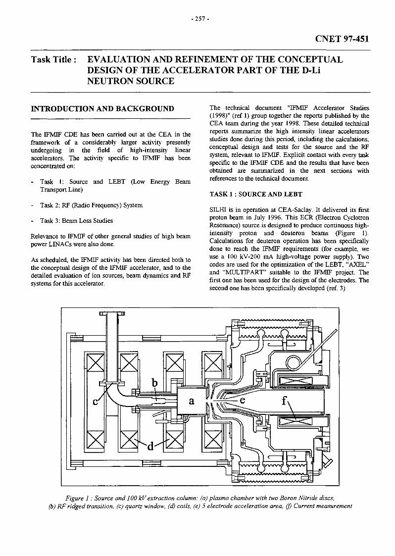
- 2 5 7 -
CNET 97-451
Task Title : EVALUATION AND REFINEMENT OF THE CONCEPTUALDESIGN OF THE ACCELERATOR PART OF THE D-LiNEUTRON SOURCE
INTRODUCTION AND BACKGROUND
The IFMIF CDE has been carried out at the CEA in theframework of a considerably larger activity presentlyundergoing in the field of high-intensity linearaccelerators. The activity specific to EFMTJF has beenconcentrated on:
- Task 1: Source and LEBT (Low Energy BeamTransport Line)
- Task 2: RF (Radio Frequency) System
- Task 3: Beam Loss Studies
Relevance to IFMIF of other general studies of high beampower LINACs were also done.
As scheduled, the IFMIF activity has been directed both tothe conceptual design of the IFMIF accelerator, and to thedetailed evaluation of ion sources, beam dynamics and RFsystems for this accelerator.
The technical document "IFMIF Accelerator Studies(1998)" (ref 1) group together the reports published by theCEA team during the year 1998. These detailed technicalreports summarize the high intensity linear acceleratorsstudies done during this period, including the calculations,conceptual design and tests for the source and the RFsystem, relevant to IFMIF. Explicit contact with every taskspecific to the IFMIF CDE and the results that have beenobtained are summarized in the next sections withreferences to the technical document.
TASK 1 : SOURCE AND LEBT
SILHI is in operation at CEA-Saclay. It delivered its firstproton beam in July 1996. This ECR (Electron CyclotronResonance) source is designed to produce continuous high-intensity proton and deuteron beams (Figure 1).Calculations for deuteron operation has been specificallydone to reach the DFMIF requirements (for example, weuse a 100 kV-200 mA high-voltage power supply). Twocodes are used for the optimization of the LEBT, "AXEL"and "MULTIPART" suitable to the IFMIF project. Thefirst one has been used for the design of the electrodes. Thesecond one has been specifically developed (ref. 3)
Figure 1 : Source and 100 kV extraction column: (a) plasma chamber with two Boron Nitride discs,(b) RF ridged transition, (c) quartz window, (d) coils, (e) 5 electrode acceleration area, (f) Current measurement
- 2 5 8 -
SILHI is operated with proton beams because it is presentlyinstalled in an unshielded area that precludes deuteronacceleration. Nevertheless, all the results obtained usingprotons can be directly applied to the deuteron beamrequired by the IFMIF accelerator, for example:
- control of high currents,- stability of the operation in continuous mode,- microwave-plasma coupling,- design/technologies used for the 100 kV extraction
system,- materials used for the plasma chamber.
The LEBT is also constructed and a full set of diagnosticsis now in operation to allow a complete analysis of thebeam characteristics. Again, all these diagnostics havebeen designed to reach the IFMIF goals. Themeasurements done using high-intensity continuous protonbeams show that they are perfectly suitable for IFMIF.
These equipment, designed and tested at CEA-Saclay forthe SILHI source and directly applicable for the IFMIFdesign are:
- Focusing system and mechanical set up,- Pumping system,- CCD camera and associated software for beam profile
measurements- Emittance measurement units, classical and using the
CCD camera technique- Beam intensity monitors.
After several studies of the microwave-plasma couplingand several tests of materials (plasma chamber andextraction system), the following results (which set athighest results worldwide) have been obtained:
- Intensity = 122 mA in the continuous mode- Plasma density = 213 mA/cm2 (<{> = 8 mm)- Proton fraction = 88%- Intensity stability = ± 2%- Normalized rms emittance = 0.20 7t.mm.mrad
All these parameters are close to those required for theIFMIF source. Calculations show that a deuteron beamintensity of 160 mA can be reached using a 10 mmdiameter extraction hole without emittance deterioration.This EFMIF goal could be verified using SILHI, in apossible continuation of this activity, in the IFMIFframework.
As a first attempt to measure the long term reliability ofthe ion source, 96% availability was recorded during 103hours of continuous operation with a total beam of 100 mAat 78 keV. The operation has been interrupted basically byHV sparkdowns between electrodes. Most of these eventsoccurred during the first 24 hours, and the rate ofsparkdowns was pretty much lower on the rest of theperiod.
The beam availability is 98.8% for the last 80 hours. Themean time between failures (MTBF) during that periodturns out to be 5.5 hours, and the mean duration of 85% ofthese failures is lower than 6 minutes.
TASK 2 : RF SYSTEM
It could be recalled that the RF system is one of the biggestchallenges for the IFMIF accelerator.
The IFMIF RF system frequency is 175 MHz, tetrode ordiacrode tubes must be used instead of the classicalklystrons used for the other projects which require higherfrequencies. The CEA-Saclay team activity concerning the1.3 MW - 175 MHz RF systems is then only devoted to theIFMIF project.
CEA-Saclay activity has been mainly to interact withThomson Tubes Electronics (TTE) on the IFMIF aims andto collect, evaluate, and transmit all the availableinformation to the IFMIF team.
Following our request, TTE has produced a verysubstantial effort to demonstrate the feasibility of such RFsystems. The study of an IFMIF type RF system, theTH628 Diacrode has been done since a few month. Thequalitative tests gave goods results. They carried out a 24hours test with a length/repetition frequency combinationof 2.27 ms/88 Hz. The RF operation frequency was200 MHz. The power was increased up to 600 kW (3 MWpeak). Only the test stand needs to be upgraded to proceedto the 100 hours test at 1 MW cw. Two tubes should bebuilt before the end of the year.
These preliminary results obtained by TTE are verypromising, and suggest convincingly that a RF system, upto full IFMIF performance, could be built and operatedsatisfactorily.
TASK 3 : BEAM LOSS STUDIES
Beam loss limitation is a critical issue for every high-power accelerator (structure activation), especially forIFMIF due to the acceleration of deuterons.
An important point concerning the beam loss problem isthe ability designers have to predict them up to extremelylow levels. For IFMIF, beam loss must be below 10'10 of thetotal beam. An effort of several years done by thecollaboration between CERN, CEA-Saclay and LosAlamos National Laboratory has allowed to make greatprogress in this field. A new powerful simulation code(DYNAC) has been written. Accuracy gain is especiallyimportant for RF field modélisation and for space-chargecalculation.
As already pointed out, DYNAC is now considered as themore accurate code for beam dynamics calculations and isoperational to make precise simulations of the IFMIF DTL.

-259 -
CEA-Saclay works on beam dynamics calculations hasbeen also done during this CDE. An important work hasbeen undertaken on space charge calculation. It is nowoperational to make precise beam dynamics calculations inthe IFMIF DTL (see next section).
A first experimental approach to check theoreticalpredictions for the beam r.m.s. parameters and latterinvestigate the halo formation has been done in Saclay.The beam transverse phase space distribution has beenmeasured as a function of the beam current at the output ofa long FODO channel.
Equipartitioning phenomena are also analyzed. Space-charge interactions in high-intensity linear accelerator canlead to equipartitioning of energy between the longitudinaland the radial degrees of freedom. This can be a source ofemittance growth and halo formation.
GENERAL STUDIES OF HIGH BEAM POWERLINACS
As already noted, some of the work carried out at the CEAin the general field of high power accelerators has directrelevance to all high-intensity accelerators, includingIFMIF. In this field of "general studies", the workundertaken for the IFMIF design has been directed at theselection, systematization, collection and formatting ofinformation. These results have been integrated, by theCEA team, in the refined conceptual design of the IFMIFaccelerator, via interaction with the rest of the IFMIF team.
In particular, the following investigations undertaken forthe construction of the EPHI prototype are directly relevantfor the IFMIF accelerators:
- Choices made to optimize the design ( RF lossminimization, focusing scheme)
- Technological choices for the cavities (cavitymanufacturing process, cooling system, vacuumsystem)
- Definition of the strategy used to rise the beam currentup to its nominal value
- Definition of the diagnostics able to handle high-power,high intensity beams.
REFERENCES
[1] "IFMIF Accelerator Studies (1998)",CEA/DSM/DAPNIA/SEA 98/68, November 25, 1998
[2] "Last results of the CW High-Intensity Light IonSource SILHI at CEA-Saclay", R. Gobin, A. France,P-Y. Beauvais, O. Delferrière, D. De Menezes, R.Ferdinand, proceeding of ICIS 1997, Taormina, Italie
[3] "Principes des codes LIGNES-COURBES etMULTIPART. Simulation du transport d'un faisceaude particules chargées", DSM/LNS/GECA 97-47.
[4] "New performances of the CW High-Intensity LightIon Source (SILHI)", R. Gobin, P-Y. Beauvais,D. Bogard, G. Charruau, A. France, R. Ferdinand, F.Harrault, J-L. Jannin, J-M. Lagniel, P-A. Leroy,proceeding of EPAC 1998, Stockholm Sweden
[5] "Non-Interceptive Emittance Measurement of a HighIntensity Beam at Low Energy", R. Ferdinand,P-Y. Beauvais, D. Bogard, R. Gobin, B. Pottin,proceeding of LINAC 1998, Chicago USA
[6] "Measurement of space charge-dynamics effects in aFODO channel", N. Pichoff, P.Y. Beauvais,R. Ferdinand, G. Haouat, S. Nath, proceeding ofAPAC 1998, KEK, Tsukuba, Japan
[7] "On Energy Equipartition Induced By Space ChargeIn Bunched Beams", J-M. Lagniel and S. Nath,proceeding of EPAC 1998, Stockholm Sweden
[8] "Simulation Results with an Alternate 3D SpaceCharge Routine, PICNIC", N. Pichoff, J.M. Lagniel,S. Nath, proceeding of LINAC 1998, Chicago USA
[9] "The SCHERM Space Charge Routine - limitationsand solutions", P. Lapostolle, J.M. Lagniel, S. Nath,N. Pichoff, E. Tanke, S. Valero, proceeding ofLINAC 1998, Chicago USA
[10] "A review of linacs and beam transport systems fortransmutation", J-M Lagniel, proceeding of EPAC1998, Stockholm SWeeden
[11] "High-intensity linac studies in France", J-M Lagniel,proceeding of LINAC 1998, Chicago USA
TASK LEADER
Jean-Michel LAGNIEL
DSM/DAPNI A/SEACEA Saclay91191 Gif-sur-Yvette Cedex
Tél. : 33 1 69 08 53 65Fax : 33 1 69 08 85 62
E-mail : [email protected]

- 2 6 1 -
SEAFP 2-2
Task Title : IMPROVED COVERAGE OF EVENTSEvent sequence analysis
INTRODUCTION
One objective of the SEAFP2 program is to giverecommendations for fusion reactor containment conceptsin order to fulfil a no evacuation goal of the populationsfollowing any type of accidental sequences occurring withinthe reactor building. In this respect a methodology has beenfollowed which was first to identify the most challengingsequences in terms of containment integrity and then toperform the safety analysis for a selected and limitednumber of generic containment concepts.
The process used to define the most important sequences isbased on a top-down approach which is a general approachsui for projects at a pre-design stage. The top event wasdefined as « excessive external radioactive releases » andthe top-down reasoning process (deductive) was followed,leading to the identification of events which could initiatesequences leading to external releases (see figure 1).
Two references for containment were defined following asurvey study of different containment concepts performedunder another SEAFP2 task. They are named « LargeContainment Building » and « Inner Containment » (seefigures 2 and 3) . Of course, the previous SEAFPcontainment defined in the program was kept as a reference.
EXCESSIVERADIOACTIVE
RELEASE
1stCONFINEMENT
BARRIERFAILURE
1CONTROL OF
PLASMAENERGY
- powerexcursion
- plasmadisruption
1RESIDUAL
POWERREMOVAL
- LOFAs-LOCAs- Loss of heat
sink
1CHEMICAL
ENERGYCONTROL
- LOFAs- LOCAs
1COOLANTENERGY
CONTROL
- in VVLOCAs
MAGNETENERGY
CONTROL
- arcs- quenches
2ndCONFINEMENT
BARRIERFAILURE
ENSUREBARRIER
INTEGRITY
COOLANTENERGY
CONTROL
pre-existingopeningisolationfailureexplosion (H2)
- ex_VVLOCAs
- overpressurisation- pipe whip
MAGNETENERGY
CONTROL
'•- missiles
Figure 1 : Global Master Logic Diagram

-262-
STACK
HTS54440m3
FIRST WALL/BLANKET
CIRCUIT (8 LOOPS)
DIVERTOR cmcurr (2 LOOPS)
PSS Rupture disk
Inner Containment with PSS (type B)
Figure 2 : Type B concept for accident analysis
2nd CONFINEMENT
101370 Irf iSBECONDARYCIRCUIT
FIRST WALL/BLANKETCIRCUIT (8 LOOPS)
Rupture disk'7" A»4l# SECONDARY- - p
DIVERTOR CIRCUrr (2 LOOPS)
Large Containment Building (type C)
Figure 3 : Type C concept for accident analysis
Following the top-down analysis, a certain number ofaccident sequences were identified and the most importantin terms of confinement concept influence were analysed.The influence of human actions as accident initiator oraccident mitigation was also considered in this analysis.
1998 ACTIVITIES
SELECTION OF SEQUENCES
Following the top-down approach analysis a certain numberof accidental sequences were identified to be assessed indetail.
The sequences involving by-pass and the sequences withimportant LOCA appeared to be the most interesting onesthat could deserve a particular attention. It was also foundthat an assessment of magnet energy hazards inducedsequences should be performed on a complementary basisof previous SEAFP works.
By-pass through the HTS (for model 2 only) :
The sequence to study is initiated by a SLR (Steam LineRupture) which induces a 10 tubes SGTR (Steam GeneratorTube Rupture) and leading to an in-vessel break.
The aim is to quantitatively evaluate if the initiator couldreally induce the by-pass of containment, and determineboth the pressure loads on containment and the radioactiverelease through the individuated paths.
Important LOCAs - loss of heat sinks :
This case is related to highly hypothetical sequences butwhere a suitable confinement strategy could allow tocontrol the releases and stay below the evacuation limits.
This sequence involves the loss of heat sink event whichleads to a complete loss of the coolant inventories of all theloops. The energy released and the Decay Heat Removalstrategy has thus to be controlled by other means (active orpassive).
This study will propose different mitigating alternativesrelated to the type of coolant (helium or water) and to thecontainment concepts defined in the task.
Magnet accident sequences :
The cryostat is the second barrier for radioactive releases ofa fusion plant. Therefore damage of this barrier due tomagnet accidents must be investigated.
Ten different electrical faults of the TF circuit have beeninvestigated and evaluated in terms of maximumconsequences of the cryostat. It was found that a doubleshort to ground at the bus bar of one coil probably has themost severe consequences on the cryostat wall. Duringdump of the coil system such shorts can ignite at the bus bardue to a multiple insulation failure.
CONCLUSIONS FROM SEQUENCES ANALYSISPERFORMED IN 1998
The bypass scenarios identified in the top down approachwould call to minimize those events probability. In thiscase, it is preferable to have a Large Containment Buildingas in our type C option. This would decrease the number ofpenetrations and consequently the number of by-passpossibilities.

-263 -
When dealing with the Heat Transfer System (HTS) by-passscenarios, as presented in this report, one can conclude thatthe selection criteria are less obvious. The concern with theHTS is that it contains a certain quantity of energy and thatit links the vacuum vessel to the turbine building in allcases of confinement strategy.
If the consequences are smaller in terms of releases for thetype B containment concept, the pressures reached are muchhigher than in the type C concept and special attention hasto be put on containment strength. Finally, for these by-passscenarios no definite trends can be outlined and norecommendations for confinement selection can be made.
The analysis of important LOCAs such as « loss of thecondenser » which are at the limits of the Beyond DesignBasis Accidents allows to conclude that in any type ofconfinement option, a mitigating action has to be triggeredin order to contain the overpressurisation of thecontainment (see figure 4).
A building spray system combined with an auxiliary feedwater system would be the most efficient strategy to preventexternal releases. But this analysis raise the issue of post-accidental recovery. In fact, using sprays with tritiumparticles has to be assessed and the consequences on plantfinal state have to be accounted for.
PRESSURE IN THE CONTAINMENT
with vented scrubber
Bar
1,50
1,45
1,40
1,35
1,30
1,25
1,20
1,15
1,10
1,05
1,00
i|VI \irfI
>—V---y s
•<—< i l
* \
\
\
Design limit
0 1000 2000 3000 4000 5000 6000
seconds
SEAFP_Reference Concept B - - - - Concept C
Figure 4 : Pressure trends with a vented scrubber
Magnets accidents are certainly those which have beenanalysed with the most important number of assumptions.Therefore the estimation of induced damage on thecontainment has to be considered as preliminary results.Nevertheless, the cryostat is the equipment most exposedwhich can suffer magnets accidents and its role in theconfinement strategy has to be considered when accountingfor magnets accidents. In the two different options we haveselected (type B and C concepts), the cryostat has roughlyno confinement mission.
Human operators safety actions have been analysedaccording to the previous SEAFP studies and definitions.The role of operator in initiating or mitigating accidents hasbeen identified. The conclusions of this study cannot beextended to confinement strategy as far as accidentalsequences are concerned.
Indeed a more detailed description of man/machineinterface is required in order to give accurate numbers interms of probability of man initiated sequences or recoveryprocedures failures. However, it seems that for confinementstrategy selection the role of operator initiated faults duringor after maintenance operations should give more results.
REFERENCES
[1] « Report on first set of analyses » R. Meyder - April 98- SEAFP2/2.2/FZK/2
[2] « Report on updated analyses on the basis of task 1.5»R. Meyder - Sept. 98 - SEAFP2/2.2/KZK/2
[3] « Steam Line Break Leading to In-Vessel LOCA andBy-Pass of First Containment » L-L Johansson - July98 - SEAFP2 - 6713 ES-98/22
[4] « Steam generator tube rupture - qualitative analysis »R. Caporali, L. Di Pace, T. PinnaSEAFP2/2.2/ENEA/1 October 97
[5] « Definition and selection of accident sequences :Master Logic Diagrams for SEAFP2 - Interim report»G. Cambi, T. Pinna, L. Burgazzi, R. CaporaliFebruary 98 - SEAFP2/2.1/ENEA/1
[6] « Human factors - General approach » J. Werasko, J.B.Munoz, A. Barquin Duenas - July 97EFET/TR/N115 Issue P01
[7] « Initial Human Factors Assessment » J. Werasko, A.Barquin Duenas - Aug. 98 - EFET/TR/N135 IssueV02
[8] « Interim report on definition and selection of accidentsequences » I. Cook, N.P. Taylor - June 97 -SEAFP2/2.1/UKAEA/1
[9] « Response of model 1 concept (helium concept) to In-Vessel LOCA» X. Masson- Nov. 97 - TA-31137DR

-264-
LIST OF REPORTS TASK LEADERS
[10] « Containment Response During a LOCA Transient »J.P. Gaillard - Sept. 98 - DER/SERA/LETH 98/5016
[11] «Analysis of Mitigation Systems for SEAFP2Containment» J.P. Gaillard - Oct. 98DER/SERA/LETH 98/5025
[12] « SEAFP2 - Macrotask 2 - Final report » C. Girard -Nov. 98 - DER/STML/LCFI 98/048
[13] « Ex-vessel accidents on SE AFP divertor cooling loop- a sensitivity study » C. Girard, M. Porporat - SOFT98 - September 7-11, Marseille
[14] « Consequences of a loss of a condenser in theSEAFP reactor» P. Sardain, J.P. Gaillard, M.Porporat - SOFT 98 - September 7-11, Marseille
[15] « Containment response of the SEAFP reactor duringa LOCA transient » J.P. Gaillard, P. Sardain - SOFT98 - September 7-11, Marseille
Christian GIRARD
DRN/DER/SERSI/LEFSCEA Cadarache13108 St Paul Lez Durance Cedex
Tél. : 33 4 42 25 49 56Fax : 33 4 45 25 66 38
E-mail : [email protected]
M. ARNOULD
SEPSTECHNICATOMEBP 3400013791 Aix-en-Provence Cedex 3
Fax : 33 4 42 60 25 11

- 2 6 5 -
SEAFP 3-1
Task Title : IMPROVED CONTAINMENT CONCEPTS
INTRODUCTION
The energy produced by means of controlled fusion powerhas obvious advantages for the future in view of thepractically unlimited availability of its fuel and its littleimpact on the environment, as well as, in particular, theabsence of "greenhouse" effect gas emissions.
Because of the tritium inventory, an electricity-producingfacility such as this would be a basic nuclear installationand therefore submitted to the constraints associated withsuch facilities with respect to design and safety.
A primary requirement is to show that, by its design orbecause of the safety systems installed, any radiologicalreleases would not affect the public in the vicinity of afacility, and that this would hold true whatever the eventsor succession of events of internal origin. There wouldtherefore be absolutely no technical reason to envisage theevacuation of the population.
These requirements are no different from those self-imposed by the designers for future fission facilities.However, their implementation seems to be clearly to theadvantage of fusion by demonstrating, in particular, that asuitable design permits very low level releases, whatevercredible severe accidents are considered.
The intrinsic advantages of a fusion facility of this typehave often been presented:
- A moderate mobilizable radioactive inventory,
- Absence of critical power excursion and the fact thatany external disruption results in the shutdown of thereaction,
- Low residual energy, due in large part to the activationof the materials and dependent on the choice of thesematerials.
It should be added that the quantity of fuel available withinthe plasma is very small.
In addition, the long-term impact of the wastes on theenvironment can be limited without any require ofpermanent storage by a judicious choice of structuralmaterials.
With these objectives, reflection has been initiated in theframework of the European programme, SEAFP2 in 1997and 1998 with a view to proposing a confinement strategyand safety options that permit taking into account thesesafety requirements and the reduced impact on theenvironment
The SEAFP2 programme (Safety and EnvironmentAssessment of Fusion Power) is the follow-up of theSEAFP programme, in which a first assessment of fusionenergy was performed with respect to safety and theenvironment.
The methodology used in the framework of thisprogramme to define the safety options is essentially of"top down" type. It starts with the objectives that havebeen set, that is to say the minimisation of accidentalreleases and seeks to identify systems permitting theseobjective to be reached.
It is assumed in this study that the field of investigation islimited: only facilities of Tokamak type are consideredwith three types of blanket concepts:
Model 1 : Vanadium is used as the structural material,helium as the coolant, and lithiated ceramic as the breedermaterial;
Model 2 : Martensitic steel as the structural material,pressurized water as the coolant, eutectic lithium-lead asthe breeder material (concept identical to the DEMOWCLL blanket);
Model 3 : Martensitic steel as the structural material,helium as the coolant, lithiated ceramic as the breedermaterial (concept identical to the DEMO HPCB blanket).
The objective is to determine which confinement strategyand safety systems permit significantly reducing theradioactive releases.
1998 ACTIVITIES
SAFETY FUNCTIONS AND ASSOCIATED SAFETYSYSTEMS
The analysis performed using a master logic diagram hasconfined the studies conducted previously to the variousfusion installations, and has thus led to the identification ofthe following safety functions intended to protect thebarriers:
Plasma Energy Control
One undeniable advantage of fusion energy is that most ofthe disruptions within the vacuum chamber leadsineluctably to the shutdown of the reaction. The corollarydifficulty is that this shutdown could lead to a significantdisruption liable to generate considerable energy depositionon the walls, and therefore a leak may result.

-266-
Control of the plasma, and therefore the automaticshutdown of the latter, is particularly useful if the initiatoris outside the vacuum chamber (external LOFA or LOCA,for example). It then permits avoiding an internal LOCAand preventing or minimizing any potential chemicalreactions.
Residual Power Removal
The envelope studies conducted in the SEAFP andSEAFP2 programmes showed that the removal of residualpower by conduction or radiation did not permit reachingtemperatures resulting in ultimate structural degradation(temperature of the internals lower than the meltingtemperature of the structures).
A study of accidental sequences showed, however, that theexistence of a residual power removal system, even thoughnot indispensable to maintaining structural integrity,contributes considerably to the management of an accidentby preventing additional degradation.
Chemical Energy Control
The best way of avoiding any possibility of chemicalreaction is obviously to avoid this possibility in the designor, if it already exists, to avoid, by design, the occurrenceof high temperatures permitting their development.
The first case is possible since, in Model 1, if the use ofwater as a coolant, or the use of reagent materials (such asberyllium) on or in internals is avoided, no chemicalreaction is possible. In the case of Model 3 (similar toHCPB), situations may arise in which the water of thesecondary system comes into contact with the berylliumused as a neutron generator material (case of the SGTRassociated with another failure or loss of heat sinkaccident). In the case of coolant water (Model 2), a LiPb -water reaction, or a reaction of the water with material ofthe first wall can be involved. Guaranteeing by design thata temperature remains below the level at which this occursseems unrealistic for most of the reactions envisaged.
Coolant Energy Control
One method of guaranteeing the absence of aggressionagainst the barriers consists in designing the designpressure - containment volume pair so that loading, evenin ultimate situations (leakage of all the coolants andpossibly a leak in the cryogenic system), does not everexceed the design pressure.
This possibility seems unrealistic in the event of aninternal leak (loading appears excessive for the vacuumchamber whatever the coolant).
There are two methods of protecting the first barrier :either removal towards an expansion tank or removaltowards an adjacent containment.
In the case of a leak outside the vacuum vessel, the controlof overpressure seems to lead to very high containmentvolumes
Various methods exist with respect to the next barrier thatserves as a containment around the heat exchangers:
Either a system permitting the pressure inside thecontainment to be reduced.
In the case of water, the classic system calls for thespraying of the containment, which leads to thecondensation of the water. However, this system, even if itis less efficient, can also be used in the case of helium as itfavours heat exchange in an environment whosetemperature has previously been decreased (pre-refrigerated stones);
Or a system permitting removal to the atmosphere byreducing if possible the content in radioactive elements andfavouring their dispersion (release to high altitude via astack).
In case of use of this kind of open system, use of filters orScrubber systems permit reducing the radioactive elementcontent:
Magnetic Energy Control
If correct design of the magnetic system enables avertingthe missile hazard, avoiding the risk of an external arc ismore delicate: an arc could lead to the degradation of thecontainment in the event of failure of the electricalprotection system.
Without wishing to determine an order of absolute priority,it seems that the primary objective should be to define asystem permitting the control of coolant energies.
Correct design of a system using at least two barriers andsystems for their protection against overpressure, wouldalready be a considerable step towards guaranteeing verylow releases under all the conditions that have beenenvisaged: the early definition of these options is all themore important as they have a considerable effect on thegeneral architecture.
CONFINEMENT STRATEGY
One of the major results of the accidental consequencesevaluation is that, providing design precautions are takenand perhaps barrier protection systems added, all releasescan be kept at very low levels.
The study of the accidents considered, permits to identifythat the design load from the coolant energies is linked tothe loss of heat sink accident.
-267 -
In order to define the confinement strategy for the futurefusion power plant, we believe, that it would be of interestto discuss the advantages and drawbacks of two mainconfinement options.
A large containment building
Advantages:
An obvious advantage of this type of containment is that itposes no boundary problem: all active components areinstalled within its walls. (It is assumed that externalconnections, such as, for example, towards the tritiumplant, are ensured by a double-valve system possiblyassociated with a buffer system).
It is even possible to provide for a volume - pressure designcombination to permit management of all possiblechanges, but, in this case, the volume required seemsunrealistic even in the case of water as the coolant (morethan 200 000 m3 with a design pressure of 1.6 bar tomanage a LOCA on all the circuits), and it seems morejudicious to provide for a protection system for theenvelope cases: either a spray installation, or a system forremoval to the stack via a scrubber and/or filters.
Drawbacks:
The greatest drawback with respect to accidentmanagement is that this concept does not allow any leakrecovery.
This point may be improved either by reducing the leaks (ametallic liner would permit considerably decreasingtritiated water or gas leaks), or by providing for a doubletotal or partial containment system with ventilation andreleases through the stack (natural or induced condensationwould reduce the content of released tritiated water).
Inner Containment
Advantages:
The presence of a ventilated building, possibly providedwith atmosphere detritiation systems, would permitefficient leak recovery and result in a lesser impact on theenvironment than in the previous case.
Drawbacks:
The greatest difficulty in this option consists in definingboundaries.
The choice of this option requires a detailed examinationof all the rooms adjacent to the cryostat to define themaximal accident possible. In addition, this option impliesthat an appropriate protection system be installed: thesimplest and most obvious seems to be a rupture disksystem to the stack via a scrubber or filters.
To sum up the discussion of the two options in a fewwords, the "Large Containment Building" option has theessential advantage of extreme simplicity in its design andsafety analysis. The "Inner Containment" option has theadvantage of using in part natural barriers such as thecryostat, but the definition of boundaries is more delicateand requires a specific analysis of each room adjacent tothe cryostat containing a penetration.
In conclusion, there is no determining argument resultingfrom the consideration of severe accidents for a specificconfinement strategy, provided the design pressure, thevolume, and the barrier protection systems are correctlyselected with respect to the highest loading.
As a consequence, the choice of strategy has to take intoaccount other aspects, among which, in particular,economy and easy maintenance with the objective tominimise the doses for the workers.
CONCLUSION
With respect to all the concepts envisaged, this analysisreveals the following highly positive findings: theconfinement strategies envisaged, associating both barriersand systems that permit protecting these barriers, canguarantee low releases even under the most severeaccidental conditions that can be envisaged. The impacton the closest population could be kept down to valueslower than one mSv through correct design of the barriersand associated safety systems, whatever the type ofaccident of internal origin.
An analysis of severe accidents does not permit definingarguments that are determining for any one confinementstrategy, provided suitable safety systems are provided for.
Additional in-depth studies on cost, maintenance, andconsequences in terms of doses to workers, or even onaspects of a sociological nature, will permit providingother elements for the assessment of a confinementstrategy.
REFERENCES
[1] G. MARBACH, I. COOK « Safety and environmentaspects of a Fusion Power Reactor »Invited SOFT Communication to be published inFUSION TECHNOLOGY

- 2 6 8 -
TASK LEADERS
Gabriel MARBACH
DRN/DER/SERSICEA Cadarache13108 St Paul Lez Durance Cedex
Tél. : 33 4 42 25 34 14Fax : 33 4 42 25 48 68
E-mail : [email protected]
M. ARNOULD
SEPSTECHNICATOMEBP 3400013791 Aix-en-Provence Cedex 3
Fax : 33 4 42 60 25 11

-269-
SEAL 4.3
Task Title : MULTIPLE FAILURE SEQUENCES - RISK AND CONSEQUENCEASSESSMENT
INTRODUCTION
The consequences of multiple failure sequences within thecooling systems of the SEAFP tokamak concept areassessed. The aim of this study is to evaluate theconsequences of such accidents on the containment system.
1998 ACTIVITIES
Two types of accidental sequences are studied:
- Loss Of Coolant Accident (LOCA): The breach islocated on the pump discharge pipe of the firstwall/shield blanket cooling loop
- Main Steam Line Rupture (MSLR)
In each case, an induced Steam Generator Tube Rupture(SGTR) is supposed to occur.
The transient study follows three steps:
- A preliminary calculation is made with the ex-vesselbreak or the main steam line rupture only. This stepsallows us to determine the time of the peak of speed inthe steam generator, primary side. The transient progressis :. LOCA of a determined diameter at t = Os.
Pump stop if cavitation. The plasma emergency shutdown starts with the
LOCA
- The second step consists in including the occurrence ofthe SGTR at the time (tSGTR) determined in the formertransient; the criterion is the occurrence of a velocitypeak within the steam generator tubes which can lead tovibrations. The transient progress is the same definedbefore, added with :. STGR 10 tubes at t=tSGTR
- A third step consists in calculating with CONTAINVI. 11 code, the containment response; the calculatedpressure peak is compared to the design limit. The massand enthalpic flow rates are used as boundaryconditions. The cooling loop response is calculatedusing the CATHARE code. The modelling is shownbelow:
Inlet feeder
BU (160)
BP (16)
Steam generator
Side Walls & Ribs pipes (68)
Back Plate pipes (24)
Inboard segments ( x 2) Outboard segments ( x 2)

-270-
The containment response is calculated using the CONTAIN code. The modelling is shown below:
EXPANSION VOLUME68 000 m3
STEAM GENERATORVAULT
770 m3
FIRST WALL/BLANKETCIRCUIT (4 LOOPS)
I» D I V E R T O R SECONDARY
VAULT QRCUJT10 000 m3
OU7
nrm
DIVERTOR CIRCUIT (I LOOP)
The compartment which is the most challenged is the steamgenerator vault.
The transient course for a LOCA (break size 150 mm) isindicated in the following table:
Time
0s
8s
10s
90s
100 s
250 s
Events
• LOCA occurrence
• Feedwater is shut off
• Turbine is tripped
• The mass flow rate is maximum at the breachwith about 1500kg/s
• The disk rupture of the SG vault breaks
• SGTR occurrence
• The peak of velocities is reached in SG tubes
• Stagnation of the primary pressure
• Stagnation of the secondary pressure
• The safety SG relief valve opens
• The containment vault pressure exceeds the 1.4bar limit
• The primary water inventory increases: Thesecondary mass feeds the breach flow throughthe SGTR break
• The break flow is not equal to zeroCalculation stops
The SG containment vault receives the discharge of thebreach and the steam generator security valve. Itspressurization is quick due to the important flow of thebreach.
Rupture disk
DP = 4 bar
Rupture diskA = 2 m1
DP • 0.4 bar
EXPANSION VOLUME25 000 m3
The enthalpic break flow rate remains high because theincreasing quality. The break flow can not be stoppedbefore the pressure reaches the limit of 1.4 bar in thecontainment vault.
As far as the main steam line rupture is concerned thetransient course is indicated in the following table:
Time
0s
1 s
12 s
50 s
200 s
400 s
500 s.
600 s.
Events
• RTV occurrence
• Feedwater is shut off
• Turbine is tripped
• The mass flow rate is maximum at the breach withabout3100kg/s
• The disk rupture of the SG vault breaks
• The containment vaults pressures exceeds the designlimit
• Peak of velocity in the dowcomer
• 4/5 of the initial secondary coolant inventory is lossthrough the breach
• Primary pressure starts to increase due to the loss ofits sink of energy
• The containment vault pressure reaches itsmaximum (2 bar.)
• The containment pressure starts to decrease
• End of calculation
• The break flow is nearly equal to zero
• 100 % of the initial secondary permanent coolantinventory discharged through the breach

- 2 7 1 -
The SG containment vault receives directly the largedischarge of the steam line breach. Due to the SGTR, thepressure increases more rapidly. This is the worst situationof all, the pressure reaches 2 bar before starting to decreaseat about t=5OOs.
The consequences of cumulated MSLR and SGTR areassessed for two other containment options of the SEAFPreactor:
Concept B: "inner containment"Concept C: "large containment building""A" refers to the reference case
The results of CONTAIN analysis are summarized in thefollowing table :
CONCLUSION
Concept
A
B
C
Mitigationsystem
NO
Scrubber
Scrubber
Total containmentvolume
m3
68000 + 2*18770
54440+2*5500
101370+5500
Peak ofpressure
(bar)
2.16
1.77
1.72
Release inatmosphere
(tons)
0
45.3
45.3
Consequences of multiple failure sequences in SEAFPthermalhydraulic analyses of accidental transients havebeen studied. In most cases, the failure of the containmentcan not be avoided (see the table below) without mitigationdevices.
RTV is the worst sequences basically because the transientcombines a high mass flow rate with a high quality.Consequently, the steam has no time to condense and thepressure exceeds quickly the design limit.
SGTR is always a aggravating factor because it increasesthe energy release in the containment. In this case, bothcooling circuits feed the breach.
Present containment options can not overcome largeLOCA accident. Future confinement improvements shouldprobably combine the effect of expansion volume andmitigation systems (pressure suppression systems & spray)to find a reliable solution.
Case
1
2
3
4
5
6
Type ofaccident
LOCA
LOCA
LOCA
LOCA
MSLR
MSLR
STGR
no
no
yes
yes
no
yes
Break sizein mm
75
150
75
150
750
750
Calculation Timein s.
500
250
500
250
600
600
Containment overpressure
yes at t=326s
no
yes at t=438s
yes at t=88s
yes at t= 14s
yes at t= 14s
Peak (bar)
>1.47
1.4
>1.43
>1.6
1.72
2.0
REFERENCES
[1] READER &al."SEAFP final report" NET Team, November 1994
[2] MICAELLL BARRE, BESTION"CATHARE code : développement and assessmentmethodologies"ANS Winter Meeting, SAN FRANCISCO 1995.
[3] WASHINGTON & al."Reference manual for CONTAIN 1.1 code forcontainment severe accident analysis"NUREG/CF-5715 - SAND 91-0835
[4] SARD AIN PORPORATConsequences of multiple failure sequences in SEAFP- Thermalhydraulic analyses of accidental transientReport DER/SERA/LETh 96/5038
[5] E.M.J. KOMEN H. KOMTNGFour Loss of Flow accidents in the SEAFP firstwall/blanket cooling system"Report ECN-R-94-008, 1994
[6] R. BLOMQUIST, J. COLLEN, C. FONG, S.K.SOODRadioactivity confinement second confinementbarrier optimisationParti Water-cooled option
[7] R. CAPORALI, T. PINNAMultiple failure accident sequences for SEAL reactorReport ENEA FUS TECN S&E 11/96
[8] L. DI PACE G. MADDALUNOSynthesis of energy inventories and hasards -Summary Report 1Report SEAFP2/1.2/ENEA/1

-272 -
REPORTS TASK LEADER
[1] P. Sardain, S. Boulonne Pierre SARDAINMultiple failure sequences in SE AFP : SGTR inducedby LOCA DRN/DER/SERSI/LECCReport DER/SERA/LETh 98/5017 CEA Cadarache
13108 St Paul Lez Durance Cedex[2] P. Sardain, S. Boulonne
Containment response in case of steam line rupture Tél. : 33 4 42 25 37 59with SEAFP : sensitivity analysis Fax : 33 4 42 25 71 87Report DER/SERA/LETh 98/5020
E-mail : [email protected]

- 2 7 3 -
SEAL 10.3
Task Title : WASTE DETRITIATION -INTEGRATION OF EXPERIMENTAL SUPPORT
INTRODUCTION
The steels detritiation remains a crucial element in wastemanagement for future fusion installations.
Starting with a melting process implemented at theCEA/DAM at Valduc, which seems insufficient forconventional storage, a previous study set out to listpossible improvements to the simple melting process andto propose others.
A first type of process consists in exchanging the tritiumbetween a bath of liquid steel and a gas phase: meltingunder vacuum (Valduc), melting under reduced pressurewith argon bubbling or hydrogen and argon bubbling (thehydrogen could play a tritium-pumping role by favouringthe formation of HT).
The second type of process consists in enriching a liquidphase in tritium using the difference in solubility betweenliquid and solid phases: the assumption is that solubility inthe liquid phase is greater than in the solid phase. Themethods that can be used are therefore continuous or semi-continuous melting, a cold crucible, a melting area andisotopic exchange. Other processes are conceivable:electrochemical generation of hydrogen at the surface ofthe steel, dissolution in an aggressive medium, diffusion inan electric field, melting under vacuum with aprecipitation additive.
1998 ACTIVITIES
The scientific data provided by French specialists on thebehaviour of hydrogen, tritium, and deuterium havepermitted making an inventory of these various processesin terms of feasibility.
DETRITIATION AT LOW TEMPERATURE :
This is the process proposed by the CEA/DAM at Bruyèresle Châtel : complete detritiation of metals using the « twoisotopes » method.
The method is based on successive tests on thepermeability to hydrogen and subsequently deuterium, of acopper sheet ; it was shown that the absorbed hydrogen isdriven out by the deuterium. The « two-isotope degassing »method would permit complete detritiation by hydrogensweeping at moderate temperature (about 80 to 100°C).
This process permits averting the risk of favouring thetransformation at high temperature of clusters of 3He intohigh pressure bubbles, the most often at the grainboundaries, and thus averting the risk of embrittling themetal. However, this poses a problem in the case of tritiumextraction from a system in operation.
The process would permit increasing the service life ofparts before their being removed as wastes.
DETRITIATION AT HIGH TEMPERATURE :
In the framework of reprocessing with destruction, meltinggives good results, except on the crust. The way in whichmelting can be achieved and the elements that should beadded constitute a metallurgical problem.
Placing the steel in an oven at about 500°C should alsopermit extracting the greater part of the tritium. However,duration and temperature conditions, the effect of thepresence of bubbles of helium, the presence of defects dueto irradiation, e t c . , remain to be determined.
With respect to the optimization of the detritiation processby melting, melting under reduced pressure with bubblingappears to be an interesting avenue of investigation. In thefields of secondary metallurgy operations and reactions, theexperience of the IRSID (Metallurgical Research Institute)is essential. These treatments particularly concerndecarburization, dehydrogenation, and denitridation. In thecase of dehydrogenation, industrial facilities comprise avessel connected to a pump unit (containing ejectors, acondenser and pumps).
The ladle of metal is agitated by argon injected through aporous plug.
The modelling of the phenomena thus encountered willdepend on :
- The thermodynamics of the metal/gas reactions,- Elementary kinetics,- Reactor hydrodynamics (not detailed here).
In terms of thermodynamics of the metal/gas reactions,modelling is governed by Sievert's law.
The methods for removing the hydrogen from the metaltherefore consists in:
- Decreasing the total pressure by using vacuum,- Reducing the molar fraction of the hydrogen by
agitation and cleaning using gas.

- 2 7 4 -
It seems that the efficiency of the process is essentially dueto agitation and dilution. The effect of the vacuum level isless significant in this case.
In terms of elementary kinetics, the transport of hydrogenin the metal will depend, among other things, on the areaof the bubbles, the relative velocity of the gas in relation tothe metal, the diffusion coefficient in the metal, etc... Thediffusion coefficient of the tritium in the metal can becompared to that of the hydrogen.
In the industrial case, the dehydrogenation limit in a ladleunder vacuum is 0.5 ppm in the liquid metal. In order toverify if this process permits attaining tritiumconcentrations of about5.10'3 ppm, it is essential to use the modelling perfected bythe ER.SID, introducing isotopic exchange and theformation of HT into the initial model.
When the limits of the melting process have been reached,it would perhaps be of interest to stabilize the tritiumwithin the ingot and limit the degassing rate.
The stabilization of the tritium could be favoured byforming inclusions (addition of Mn, S, Ca, e tc . ) . Theproblems posed by the metallurgists with respect todehydrogenation are thus addressed the other way round:the inclusions fix the hydrogen.
This method could be of interest as an end process. Theradiation reached in the first process (melting, isotopicexchange in a liquid or solid phase), could be stabilized fora storage period. This would permit limiting degassingrates.
The possibility of favouring the stabilization of theresidual tritium through the formation of inclusions,which could constitute a process to be studied in termsof efficiency and feasibility.
REPORTS
[1] "Steel detritiation : processes studies", S.ROSANVALLON, Note Technique STML/LEPE98/090
TASK LEADER
Sandrine ROSANVALLON
DRN/DER/STPI/LPCPCEA Cadarache13108 St Paul Lez Durance Cedex
Tél. : 33 4 42 25 64 19Fax : 33 4 42 25 72 87
E-mail : [email protected]
CONCLUSION
Of all the processes mentioned above, area melting andcontinuous melting do not seem realistic. Electrochemicalgeneration and diffusion under an electrical field shouldonly be submitted to investigation in a second phase.
We therefore propose to develop the following elements :
- Isotopic exchange in liquid and solid phases. In thisframework, tests performed on solid steel, charging indeuterium on the one hand and in hydrogen anddeuterium on the other, followed by desorptionmeasurements could permit verifying whether isotopicexchange provides interesting results;
- Modelling of the phenomena observed during meltingwith argon or argon and hydrogen bubbling, whichcould permit quantifying the effect of bubbling on themelting process under simple vacuum;

- 2 7 5 -
SERF 0-3
Task Title : SOCIO-ECONOMIC RESEARCH ON FUSION : LONG TERMSCENARI, THE EFFECTS OF UNCERTAINTY ON THEEVALUATION OF RESEARCH PROGRAMMES
INTRODUCTION 1998 ACTIVITIES
The aim of this task consists in showing that thedifficulties in technological assessment, of which fusion isa mere example, do not resist totally analytical approaches.I try to suggest that even if a complete and definitivemodelling proves relatively unfeasible or disappointing,one can develop a better intuition of the weights of thevarious uncertainties attached to the success of fusion. Thisis the modest contribution of economic decision theory :disentangling the various types of effects andunderstanding each of them a bit more allows for a bettersupport of the art of making choice.
My report proposes a series of reflections on theimportance of uncertainty in research policy, and inprospective studies in general. It is argued that uncertaintycan be modelled within a rigorous and rational framework.Different types of uncertainty are distinguished ; theirdiffer not so much by their intensities, but rather on thenature of their consequences on the best actions ("what arethe projects to finance in priority?", and even "what isthe optimal design of a certain project ?) that must beundertaken.
As far as research policy is concerned, I discuss typicaladaptations to risky contexts : (a) Diversification, (b)Flexibility and (c) Experimentation. The idea is that underuncertainty, the economic value of a certain plan dependson its ability (a) at exploring alternative technologies at thesame time, (b) at keeping margins for accommodatingshocks (arrival of new information and evidence), and (c)at accelerating the improvement of scientific knowledge byradical procedures. Of course, neither of these threeresponses is desirable per se. I discuss the limiting factorsunderlying the trade-off that must be reached.
I propose a short analysis of ITER, and analogousscientific programmes, in which I insist on the pointswhere the impact of uncertainty is the highest. The secondapplication concern the cost of the kWh, and its use inprospective studies serving for the optimisation ofinvestment. It serves as a specific illustration of the moregeneral arguments that were developed before.
Some remarks are given on the possibility (from the pointof view of the decision-makers) of selecting the bestexperts and obtaining the best expertise from them. This iscompleted by a reflection on the possibility of buildingprospective studies based on scientific foundations.
The report proposes a reflection on the methodologicalprinciples that should drive a prospective study. Theapplication of the principles can undoubtedly vary,depending notably on the degree of formality that isrequired, and of course of the data available. Thearguments will rely on recent (and not so recent) advancesin the theory of decision in risky contexts, and theeconomics of information, where information willessentially be the measure of scientific knowledge (anduncertainty). The readership that is targeted are thescientists and the engineers involved in technological andeconomic assessment. Almost systematically, these studiesare weak on the so-called "economic ingredients".
Just to take an example : take any power plant. You candescribe how much capital and personnel are needed tooperate it, then you calculate the cost per unit of product.Now assume that the cost of capital relative to the cost ofpersonnel changes. A new calculation of the cost can bedone. But in reality, the change in relative prices will notkeep the initial design optimal (if only it were optimal inthe first place). Some reorganisation, due to thesubstitutability between factors, will take place. Is thiseconomics or technology ? Of course both. To go further,assume that a given plant is "flexible" : changes in therelative prices of the production factors can easily beaccommodated. Assume that the relative prices do varyover time. The correct valuation of the cost has to take intoaccount in advance the technical flexibility of the plant(what are the possible substitutions between factors ? forexample, can the production plan be changed overnight ?)and the economic flexibility (can we find the desiredpersonnel in the market ? can we fire ? is the costlytechnical flexibility incorporated in the plant reasonablewith respect to the variations of prices ?)... In any case,reasoning as if economic aspects and technical aspectswere separable (solve one problem first, then the second) isjust impossible.
Everybody knows examples of old prospective studies thathave proved in total contradiction with reality, andconversely, from times to times, "visionary" studies thatseem to have predicted with astonishing accuracy whathappened afterwards are exhumed. This sort of judgementrelies on a form of "prospective in retrospect" : a givenstudy is evaluated ex post by being confronted with realityvia a "well-chosen" sample of its predictions, either fordiscredit or for appraisal.

-276-
It amounts basically to quoting, after cuts andrearrangements, an author and to make him apparentlysupport opinions he would not necessarily subscribe to.Evaluating prospective studies in this way is unfair and notreally scientific since by an adequate selection of thearguments, contrived opinions can be attributed. Moreover,it is a little bit too late : a prospective study plays a role atthe moment its is published ; except in the rare case wherethe ex post evaluation can be done in a short time after, theconclusions on the quality of the expert that can be drawnare of little value.
The only argument in favour of this "critical" method,shocking as it may seem, is that it often matches the rigorof the criticised study. In other terms, a prediction (and themethod behind) will be criticised because it was claiming(or believed) to offer some firm conclusion. The tension isexactly the following : either the advice are strong andaffirmative, they lead to spectacular decisions, but theirconsequences may be dramatic, or the statements arevague, the decisions cautious, or even very conservative,and some opportunities may be missed. My view is that itis possible to search for a reasonable intermediate betweenthese poles, if we accept that uncertainty can be modelled.
Common sense imposes that judgements on prospectivestudies should be moderate, and should take into accountthe conditions under which they were performed. Now, aprospective study must be perfectly clear on themethodology adopted. The criticisms, either when it ispublished, or ex post, must rely only (a) on the announcedmethodology AND (b) on the verification that themethodology was really implemented. The firstrequirement is more theoretical by nature, and a certainvision of the world has to be given. The secondrequirement may seem trivial. However, even the besttheoretical constructions meet difficulties when the timecomes to give numbers to the key notions defined in themodels. For example, if data on the proven reserves of acertain fuel have to be used as an input for a certainpurpose, it is important for the expert to understand howthese data are constructed, and whether the theory behindthis construction is consistent with his own. In the case ofoil reserves, the discussion over the different qualities andlocalisation of the oil fields is extremely important : anysynthetic index may be too rough for certain applicationsinterested in the exploitation and valorisation of particularqualities.
The part on the art of building and using scenariosexplains the exact theoretical status of scenarios, thisclarification allowing for a better understanding of theconclusions that can be drawn in practice from a series ofscenarios giving a broad view of the future. Theimplications of this analysis for the presentation thatscenario analysis should adopt will be given.
I do not raise original epistemological issues, but of course,I discuss whether some testability of prospective studiescan be imagined.
After all, nobody is forced to be an expert : accepting therole involves accepting to see one's work scrutinised,criticised, and evaluated. Clearly, the common caveatsaccording to which a certain study is "simplified, raw,preliminary, and so on", is by no way a barrier againstcritics, and the expert cannot dismiss his responsibility. Itis essential that assessments of precision and confidence,which are statistical notions, be associated to the study.The advantage of stochastic modelling is that it offers itsown appreciation.
The methodology suggested by stochastic modelling raisesthe question of testability of the predictions, i.e. thequestion of making prospective a discipline with scientificstandards.
CONCLUSIONS
One of the driving ideas of this work is that economicreasoning should be incorporated in technical studies rightfrom the beginning. Otherwise, the sort of compromise inthe allocation of effort that every model contains could beseverely unbalanced : what is the sense of piling up a hugeamount of high quality technical details, when it appearsthat for a given gain in precision, the marginal cost (intime) of more technique is by far larger than the marginalcost of more economics. This difference is in my opinionthe proof that technical studies are crying for moreeconomics. Contrary to what many engineers and scientiststhink, for given technical conditions, the economic value ofa project is not a simple function a synthetic interest rateand the speed of learning-by-doing driving costs down : infact, the degree of uncertainty, and its interaction with theflexibility can cause reassessments of the economic valueof a project that are of the same (if not larger) order as thedependency on traditional key parameters. Again, thoughflexibility can be defined in purely technical terms(feasibility), there will be all over the life of the equipment(or research project, etc.) optimising actions that will beundertaken. The total effect of the dynamic managementneed not be negligible. Above all, the anticipation that adynamic management is possible and desirable enters intothe search for the best project : flexibility is a property thatcan be desired, designed, cultivated.
REFERENCES
[1] CIEMAT (ed.) (1998): Proceedings of the"Workshop on Public Acceptability of Fusion Power(Madrid, February 9-10, 1998)".
[2] Dixit, A.K., and R.S. Pindyck (1994) : "Investmentunder Uncertainty", Princeton University Press,Princeton.

- 2 7 7 -
[3] Eeckhoudt, L., and C. Gollier (1995) : "Risk.Evaluation, Management and Sharing", HarvesterWheatsheaf, New York.
REPORT
[4] Fischer, I. (1930) :acmillan, New York.
"The Theory of Interest'
[5] Fusion Programme EvaluationCommission, DG XII.
1996, European
[6] Gilli, P.V. and R. Kurz (1998) : "Fusion Power as anAdditional Vector in the IIASA-WEC WorldScenarios", Arbeitsgemeinschaft Wàrmetechnik,Graz.
[7] Gollier, C. (1998) : "Discounting an UncertainFuture", unpublished manuscript.
[8] Gollier, C, B. Jullien, and N. Treich (1997) :"Learning and Irreversibility : An EconomicInterpretation of the 'Precautionary Principle'",GREMAQ Working Paper, University of Toulouse.
[9] Henry, C. (1974) : "Investment Decision underUncertainty: The Irreversibility Effect", AmericanEconomic Review, 64, 1006-1012.
[10] IPCC (Intergovernmental Panel on Climate Change(1996) : "Climate Change 1995", CambridgeUniversity Press.
[11] Stirling, A. (see CIEMAT) : "Plural Public Valuesand Long Term Energy Decisions".
[1] The Effect of Uncertainty on the Evaluation ofResearch Programmes (November 1998). Report tothe SERF (Socio-Economic Research on Fusion)Group, DGXII, Brussels.
TASK LEADER
Dr Bertrand VILLENEUVE
Affiliation :DSE/SEE/LEMMECEA Saclay91191 Gif-sur-Yvette Cedex
Institut d'Economie IndustrielleUniversité de Toulouse 121, allée deBrienne31000 TOULOUSE
Tél. : 33 5 61 12 85 95Fax : 33 5 61 12 86 37
E-mail : [email protected]

-279-
UNDERLYINGTECHNOLOGY
Next Step Long Term
InertialConfinement
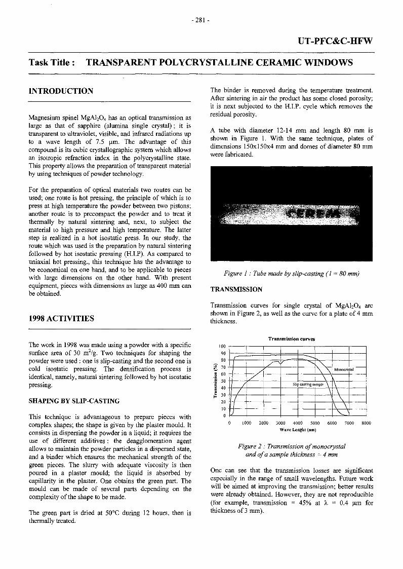
- 2 8 1 -
UT-PFC&C-HFW
Task Title : TRANSPARENT POLYCRYSTALLINE CERAMIC WINDOWS
INTRODUCTION
Magnesium spinel MgAl2O4 has an optical transmission aslarge as that of sapphire (alumina single crystal) ; it istransparent to ultraviolet, visible, and infrared radiations upto a wave length of 7.5 um. The advantage of thiscompound is its cubic crystallographic system which allowsan isotropic refraction index in the polycrystalline state.This property allows the preparation of transparent materialby using techniques of powder technology.
For the preparation of optical materials two routes can beused; one route is hot pressing, the principle of which is topress at high temperature the powder between two pistons;another route is to precompact the powder and to treat itthermally by natural sintering and, next, to subject thematerial to high pressure and high temperature. The latterstep is realized in a hot isostatic press. In our study, theroute which was used is the preparation by natural sinteringfollowed by hot isostatic pressing (H.I.P). As compared touniaxial hot pressing., this technique has the advantage tobe economical on one hand, and to be applicable to pieceswith large dimensions on the other hand. With presentequipment, pieces with dimensions as large as 400 mm canbe obtained.
1998 ACTIVITIES
The binder is removed during the temperature treatment.After sintering in air the product has some closed porosity;it is next subjected to the H.I.P. cycle which removes theresidual porosity.
A tube with diameter 12-14 mm and length 80 mm isshown in Figure 1. With the same technique, plates ofdimensions 150x150x4 mm and domes of diameter 80 mmwere fabricated.
Figure 1 : Tube made by slip-casting (1-80 mm)
TRANSMISSION
Transmission curves for single crystal of MgAl2O4 areshown in Figure 2, as well as the curve for a plate of 4 mmthickness.
The work in 1998 was made using a powder with a specificsurface area of 30 m2/g. Two techniques for shaping thepowder were used : one is slip-casting and the second one iscold isostatic pressing. The densification process isidentical, namely, natural sintering followed by hot isostaticpressing.
SHAPING BY SLIP-CASTING
This technique is advantageous to prepare pieces withcomplex shapes; the shape is given by the plaster mould. Itconsists in dispersing the powder in a liquid; it requires theuse of different additives : the deagglomeration agentallows to maintain the powder particles in a dispersed state,and a binder which ensures the mechanical strength of thegreen pieces. The slurry with adequate viscosity is thenpoured in a plaster mould; the liquid is absorbed bycapillarity in the plaster. One obtains the green part. Themould can be made of several parts depending on thecomplexity of the shape to be made.
The green part is dried at 50°C during 12 hours, then isthermally treated.
eso
Is
H
9080 -70 -60 -
40
20 -
10 -
n -
1
/
/
J
y/
Transmission curves
r\ \
\ ^Slip casting sample \
\
Monocristal
\
\
. \
\ \
0 1000 2000 3000 4000 5000 6000 7000 8000Wave Lenght (am)
Figure 2 : Transmission of monocrystaland of a sample thickness - 4 mm
One can see that the transmission losses are significantespecially in the range of small wavelengths. Future workwill be aimed at improving the transmission; better resultswere already obtained. However, they are not reproducible(for example, transmission = 45% at X = 0.4 um forthickness of 3 mm).

- 2 8 2 -
SHAPING BY COLD ISOSTATIC PRESSING
The powder is introduced in a latex membrane which issubsequently closed; the device is placed in a liquid bathwhich is pressurized. After the cold isostatic pressing, theprecompact can be handled easily. Pieces with given shapescan be made using rigid compacts and a latex membranes;this technique is called semi isostatic pressing. A domeprepared by this type of precompacting is presented inFigure 3.
Figure 3 : Dome prepared by semi isostatic pressing
The investigation of the optimal transmission was madewith precompacts of powder densified by CLP. In theparametric study, the following parameters wereinvestigated : pressure of C.I.P., heating rate, temperature ofdwell time, duration of dwell time for natural sintering. TheH.I.P. cycle has been maintained constant in all the trials.
Presently, a good reproducibility of the results wasobtained, and the transmissions of the parts are satisfactory.Transmissions curves for 3 thicknesses of material, rangingfrom 3 to 12 mm, are presented in Figure 4.
Transmission curves100 T
80
60
I 40
S 20
1I
- ^ • -
Thickness -
^ ^ ^ Single
\ \
\
crystal
Thickness = 2.3 mm
v\
As can be noted, theoretical transmission is reached in theinfrared range. In the ultraviolet and visible ranges, furtherimprovement is necessary. Transmission expressed as afunction of thickness is in good agreement with the law T =To e"°" with a absorption coefficient and t the thickness ofthe sample.
CONCLUSION
In order to improve transmission, investigation in 1999 willfocus on the influence of the atmosphere during the naturalsintering cycle on one hand, and on the influence of the hotisostatic cycle on the other hand. These investigations willbe made with C.I.Ped specimens. As far as slip-casting isconcerned, the study will deal with the optimization of thepreparation (milling) and of the composition (additives) ofthe solution.
REPORTS
[1] CEA/DTA/CEREM/CE2M/LECMA D.T. 98/074,20/04/1998 - F.Valin - Fabrication and characteristicsof MgAl2O4 disks supplied to DRFC.
[2] CEA/DTA/CEREM/CE2M/LECMA D.T. 98/095,21/11/1998 - F.Valin - Transparent polycrystallineceramic windows. M.4.
TASK LEADER
Frédéric VALIN
DTA/CEREM/CE2M/LECMACEA Saclay91191 Gif-sur-Yvette Cedex
Tél. : 33 1 69 08 25 14Fax : 33 169 08 91 75
E-mail : françoise.lefè[email protected]
0 2000 4000 6000 8000Wave length (nm)
Figure 4 : Transmission of specimens with differentthicknesses, and of single crystal
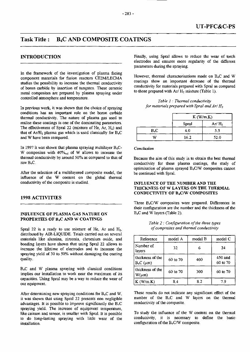
- 2 8 3 -
UT-PFC&C-PS
Task Title : B4C AND COMPOSITE COATINGS
INTRODUCTION
In the framework of the investigation of plasma facingcomponent materials for fusion reactors CE2M/LECMAstudies the possibility to increase the thermal conductivityof boron carbide by insertion of tungsten. These ceramicmetal composites are prepared by plasma spraying undercontrolled atmosphere and temperature.
In previous work, it was shown that the choice of sprayingconditions has an important role on the boron carbidethermal conductivity. The nature of plasma gas used torealise these coatings is one of the dominating parameters.The effectiveness of Spral 22 (mixture of He, Ar, H2) andthat of Ar/H2 plasma gas which is used classically for B4Cand W have been compared.
In 1997 it was shown that plasma spraying multilayer B4C-W composites with 40%^ of W allows to increase thethermal conductivity by around 50% as compared to that ofraw B4C
After the selection of a multilayered composite model, theinfluence of the W content on the global thermalconductivity of the composite is studied.
1998 ACTIVITIES
INFLUENCE OF PLASMA GAS NATURE ONPROPERTIES OF B4C AND W COATINGS
Spral 22 is a ready to use mixture of He, Ar and H2,distributed by AIR-LIQUIDE. Trials carried out on severalmaterials like alumina, zirconia, chromium oxide, andbonding layers have shown that using Spral 22 allows toincrease the lifetime of electrodes and to increase thespraying yield of 30 to 50% without damaging the coatingquality.
B4C and W plasma spraying with classical conditionsimplies our installation to work near the maximum of itscapacities. Using Spral may be a way to reduce the wear ofour equipment.
After determining new spraying conditions for B4C and W,it was shown that using Spral 22 presents non negligibleadvantages. It is possible to improve significantly the B4Cspraying yield. The increase of equipment temperature,like caisson and sensor, is smaller with Spral. It is possibleto do long-lasting spraying with little wear of theinstallation.
Finally, using Spral allows to reduce the wear of torchelectrodes and ensures more regularity of the differentparameters during the spraying.
However, thermal characterisations made on B4C and Wcoatings show an important decrease of the thermalconductivity for materials prepared with Spral as comparedto those prepared with Ar/ H2 mixture (Table 1).
Table 1 : Thermal conductivityfor materials prepared with Spral andAr/B.2
B4C
W
K (W/m.K)
Spral
4.0
16.2
Ar/H2
5.5
52.0
Conclusion
Because the aim of this study is to obtain the best thermalconductivity for these plasma coatings, the study ofoptimisation of plasma sprayed B4CAV composites cannotbe continued with Spral.
INFLUENCE OF THE NUMBER AND THETHICKNESS OF W LAYERS ON THE THERMALCONDUCTIVITY OF B4C/W COMPOSITES
Three B4C/W composites were prepared. Differences intheir configuration are the number and the thickness of theB4C and W layers (Table 2).
Table 2 : Configuration of the three typesof composites and thermal conductivity
Reference
Number oflayers
thickness of theB4C (nm)
thickness of theW(um)
K (W/m.K)
model A
32
60 to 70
60 to 70
8.4
model B
6
400
300
8.2
model C
24
450 and60 to 70
60 to 70
7.9
These results do not indicate any significant effect of thenumber of the B4C and W layers on the thermalconductivity of the composite.
To study the influence of the W content on the thermalconductivity, it is necessary to define the basicconfiguration of the B4C/W composite.

-284 -
Once fixed the number of W layers, the W content in thecomposite varies as the thickness of the W layers. Theplasma spraying technique allows to make layers withvarious thicknesses. Taking into account the powder and theparameters used. W layers with thickness less than 30 to 40tum cannot be expected to be obtained with good conditionsin our facility. Based on different criteria it was chosen tocontinue the work on B4CAV composites of mode! B,namely 3 + 3 layers.
Several composites have been made with different contentsof W. The spraying conditions and materials used hi thesetriais are the same. The W contest was varied from 10 to 50%VOÎ- Theoretical characteristics of composites are listed inTable 3.
Table 3 : Theoretical characteristics of B/Z/W composites
Comrxjsite
B4C/W 10
B4C/W 20
B4C/W 30
40
B4C/W 50
Thickness ofW individual
<%voi) 1 W layer(am)
20
30
50
Thickness of Totalindividual [ thicknessB4C layer [ (mm)
(um) |
67 600
133 333
267
467
400
i -v..
Photo n° 1 : B/Z/W'10 Photo n° 2 : B4OW20 Photo n" 3 : B/yW 30
Photo n°4: B/Z/W40
CONCLUSION
Photo nz 5 : 3.C/W50
TASK LEADER
Results of all characterisation tests will allow to check theeffect of W on the thermal conductivity of the composite.Analysis of the tests will be reported in Î999.
REPORT
[1] DTA/CEREM/CE2M/LECMA D.T. 98/88 - 16/09/98- N.Lochet Study of influence of plasma gas nature onspraying conditions and properties of B4C coatings,
[2] DTA/CEREM/CE2M/LECMA D.T. 98/96 - 03/12/98- N.Lochet. Study of the influence of the number andthickness of W layers on the thermal conductivity ofS4C,;"W multilayers composites.
Nicolas LOCHET
DTA/CEREM/CE2M/LECMACEA Saclay91191 Gif-sur-Yvette Cedex
Tél. : 33 1 69 08 32 16Fax : 33 1 69 08 91 75
E-maiî : nicolas.locheftScea.fr

- 2 8 5 -
UT-PFC&C-SiC
Task Title : COMPOSITE MATERIALS FOR PFC
INTRODUCTION
A technique was worked out for the fabrication of pure anddense SiC parts. Fabrication essentially includes foursteps :
precompacting ofisostatic pressing,
commercial powder using cold
- removal of the binder,
- natural sintering,
- post hipping.
This technique makes use only of conventional steps ofpowder technology.
The final hipping operation which is a high temperature,high pressure treatment of naturally sintered parts remainsan economical treatment as it does not require anycladding of the parts.
Main results obtained in 1998 and reported in [1-2] arerecalled hereafter and future work is overviewed.
1998 ACTIVITIES
The results are obtained with a SiC powder purchasedfrom H.C.STARCK (UF 15 Premix) ; this powder contains10 w% binder, which permits easily the shaping of thepiece, and 0.5 w% boron and 3 w% carbon, which are aidsfor sintering step.
- Precompacting of the powder is realized in a latexmembrane under isostatic pressure of 250 MPa; thendewaxing is made at 800°C during 2 hours undervacuum.
- Natural sintering is carried out in a resistor furnaceunder helium atmosphere with heating rate of 600°C/h.The dwell time is 1 or 2 hours, and the cooling rate is600°C/h.
In Table 1 are given the characteristics of the dwell timeand of the densities of SiC after this step. Aftermeasurement of densities, the samples are introduced inthe hot isostatic press. The goal of this treatment is toreduce the closed porosity. The hot isostatic pressing wascarried out in an argon atmosphere of 200 MPa at 2000°Cduring 2 hours.
The heating and cooling rate are 600°C/h. The densities ofthe samples are given in Table 1.
Table 1 : Density of SiC after sinteringand after hot isostatic pressing steps
Ref
A
B
C
D
Sintering
2100°C-2h
2130°C-2h
2150°C -1 h
2200°C - 1 h
Densitygem"3
2.93
2.94
2.975
3.075
Hipping
2000°C - 2 h
2000°C - 2 h
2000°C - 2 h
2000°C - 2 h
Density
2.96
2.94
3.04
3.15
From the results in Table 1, it is observed that it ispreferable to use a high temperature and shorter timesrather than a lower temperature and longer times in orderto increase the density after the natural sintering. Inaddition, the efficiency of the hot isostatic pressing is thelarger, the larger the density of the product. This isexplained by the fact that for specimens A and B theporosity is likely to be essentially open, whereas for C andD the fraction of closed porosity is larger and the 200 MPagas pressure at 2000°C can decrease the number and thesize of the pores.
Characteristics which are studied are microstructure,mechanical strength and thermal conductivity.
MICROSTRUCTURE
S.E.M. examinations were made on etched samples and, asa consequence, the size of defects are overestimated. Theseobservations are summarized in Table 2. The porosity isdetermined by image analysis
Table 2 : Characteristics of the microstructureof samples after H.I. P.
Ref
A
B
C
D
Pore size(urn)
8
10
< 1 0
1
Porosity(%)
5.5
6.8
1.8
= 0
Maximumgrain size ( p i )
< 1 0
< 1 0
20
25
The microstructure of these different materials ishomogeneous, except for type B for which defects as largeas 60 um can be observed.

- 2 8 6 -
MECHANICAL PROPERTIES
The measurements have been realized at room temperatureon bars of 25x4x4 mm with the 3 point bending test. Thelength between the supports is 20 mm and the loadapplication rate is 0 .2 mm/minute. The faces of the barsare not polished. The results are given in Table 3.
Table 3 : Flexural strength ofSiC after hipping
Table 5 : Thermal conductivity ofSiC (d = 3.10 g cm'3)
Ref
A
B
C
D
a (MPa)
366
269
369
390
^maximum
383
333
414
495
^minimum
343
200
318
342
It can be noted that the mean value of the modulus ofrupture is > 365 MPa for all types except for type B. Its lowbending strength can be explained by large defects, 60 um,observed in the material.
If we compare the flexural strength of SiC before and afterH.I.P, it can be seen that this treatment can be in certaincases very beneficial. For the fabrication types C and D,bending tests have been realized before and after H.I.P. ;results are given in Table 4.
Table 4 : flexural strength before and after H.I.P.
cD
CT(MPa)
Before H.I.P.
335
269
After H.I.P.
369
390
The improvement in mechanical resistance is obviousparticularly for the D samples. The H.I.P. treatment hasthe main effect of removing, or decreasing the size of, thedefects and consequently of ensuring a better homogeneityof the material.
The comparison of the results obtained for types A and Bshows a flexural strength almost the same for the twoproducts although their densities are very different(A=2.96 g cm'3 and B=3.15 g cm"3). This shows theinfluence of the material grain size on its mechanicalresistance. Thus, material A with grains less than 10 umand 6% porosity has roughly the same flexural strengththan an almost dense material with grains as large as25 urn.
THERMAL CONDUCTIVITY
The thermal conductivity has been calculated from thermaldiffusivity measurements by the laser flash technique.Measurements have been made on a sample after naturalsintering at 2200°C - 1 hour ; the density is 3.10 g cm"3.
Temperature (°C)
20
100
200
300
400
500
600
700
800
^(Wm-'K-1)
113
103.3
90.2
78.5
71.4
65.0
58.3
55.2
51.8
The results are in agreement with current values of thermalconductivity obtained for silicon carbide.
CONCLUSION
This study of densification and characterization of SiCparts was realized with large pieces with finaldimensions of 0 = 42 mm and h = 35 mm. Thespecimens for flexural strength have been cut out fromthese parts, and one can except that these values areminimum ones. If the densification is made on sampleswith smaller dimensions in one direction, the densitywill be higher.
A second means to improve the quality of the productswill be to optimize the pressureless sintering cycle. Thetimes of the plateau used in our experiments are toolong. Trials of 30 minutes for the temperature plateauwould be probably sufficient. The next experiments willbe made at temperatures of 2125°C to 2200°C duringsuch a time. A short time for the plateau will limit thegrain size increase, and consequently, will improve themechanical resistance of the material. The H.I.P. cycleconditions will remain the same because, in the case ofindustrial extrapolation, no present facility can operateabove 2000°C.
REPORT
[1] CEA/DTA/CEREM/CE2M/LECMA D.T. 98/076,15/05/98 - F.Valin. Fabrication and characterizationof SiC parts.
[2] CEA/DTA/CEREM/CE2M/LECMA D.T 98/97,7/12/98 - F.Valin. Densification of SiC using naturalsintering followed by hipping.

- 2 8 7 -
TASK LEADER
Frédéric VALIN
DTA/CEREM/CE2M/LECMACEA Saclay91191 Gif-sur-Yvette Cedex
Tél. : 33 1 69 08 25 14Fax : 33 169 08 9175
E-mail : [email protected]

-289-
UT-SM&C-A4
Task Title : ASSESSMENT OF LASER WELDABILITY OF INTERNALCOMPONENTS MATERIALS - LASER WELDABILITY OFMARTENSITIC AND LOW ACTIVATION STEELS
INTRODUCTION
The objective of this task is to complete and finalize theknowledge of the base metal weldability and the feasibilityof laser welding processes of martensitic and lowactivation steels (F82H nuancies).
The characteristics, advantages and limits of the lasersprocesses have been established. An opening of the laserprocess feasibility will be explored in order to increase theprocess strength, to assume larger assembly tolerances, andconclude on the supply specifications variations. Theacquired knowledge will permit to conclude on the laserwelding of these types of steels.
1998 ACTIVITIES
1997 activities has been devoted to the study of martensiticand low activation steels, such comparison of the behaviorof JLF1 and F82H steels in CO2 flat welding, and YAGposition welding on F82H butt joints.
RESULTS :
Following the YAG and CO2 weldabilty work on JLF1 andF82H steels, performed during 1997 on butt joints andbead on plate have been realized. The small quantity ofthese materials has limited the welding trials on F82Hsamples. Three welding sketches has been tested :
- 1,2 kW pulsed YAG laser :overhead position, sample : 6 mm thickness
- 20 kWCO2 laser:on wall position, sample : 15 mm thickness
- 4 kW continuous laser :Bead on plate, flat welding position, sample : 7,5 mmthickness
Overhead position welding has been tested for pulsed YAGlaser welding on the F82H steel. Due to the small quantityof these materials, the welding parameters have beenshortly optimized. In fact, good welds have been getquickly.
This shows that the process seems to be tolerant with thewelding position. Welds on butt joints have been realized.Smooth welds in full penetration have been get (at top andbottom). The weld width is nearly simular to thoseobserved in the case of vertical rising welding.
The quantity of bubbles in the molten pool is high(dimensions around 0.6 mm). No hot cracking has beenobserved. The weld structure is comparable to thoseobserved in flat position : martensitic in the fusion zoneand the two HAZ observed before (y transformed and not).
The heat affected zone is similar whatever the weldingposition (6 mm width). The joints hardness behavior isbetween 380 to 420 Hv in the fusion zone and HeatAffected Zone( 220 to 240 Hv in the base metal).
On wall position welding has been realized for CO2 laserprocess on the F82H. The welding trials have been carriedout, bead on plate, on 15 mm thickness samples, with laserwelding power from 14 to 16 kW and welding speedbetween 12 to 23 mm/s.
The optimized welding parameters (15 kW/ 15 mm/s)have provided acceptable welds (figure 1). For higherwelding speed, hot cracking occurs in the center of thefusion zone.
In any case, porosities are found in the fusion zone.However, an improving of the joint compacity must becarried out for decreasing the porosity rate (shielding gas)and hot cracking defects (possibility of using pre and pot-heating).
In continuous YAG laser welding, bead on plate jointshave been realized on 7,5 mm samples, with 4 kW laserpower and travel speed between 4 to 6 mm/s. Thegeometrical and metallurgical appearance has a pooraspect. Pores and undercut has been observed (figure 1).
This process does not allow to weld such a thickness. Thelaser power seems to be not suffisant (too low weldingspeed).
The welding behavior seems to be different with standardstainless steel for this process. In using 4 and 2 kW laserscombined in the same focusing head, the process will allowto improve the welds quality.

-290-
i J W C0 2 /aœr welding of 15 mm thick F82Hplates(12 mm /sec, 15 mm/sec ami 18 mm/sec) :
weld bead configurations
4 kW YAG cw welding at 4.5 mm/secon 7.5 mm F82H plates
Nail-head aspect of the bead - Presence of 2 HAZ(with and without phase transformation)
4 kW YAG cw welding at 4 mm/secon 7.5 mm F82H plates
Nail-head aspect of the bead, presence ofmicroporosities and crack initiation at the bottom of thebead
Figure I
CONCLUSIONS
Overhead position welding has been successfully tested forpulsed YAG laser welding on F82H butt joints. Theobtained welds are very comparable to those get in the otherwelding position : wall, up and down vertical rising. Thejoints aspect is comparable. No filling out of the moltenpool has been observed, smooth welds in full penetrationhave been get (at top and bottom).
The quantity of bubbles in the molten pool is high, andsimilar for both up and down vertical rising weldingpositions (around 0.5 mm). The weld structure iscomparable to those observed in flat position.
The possibility- of welding in wall position has beeninvestigated in using a 20 kW CO2 laser on F82H samples.Welding conditions optimization has permitted to getacceptable welds shape, as seen in figure I. However, animproving of the joint compacity must be carried out fordecreasing the porosity rate (shielding gas) and hot crackingdefects (possibility of using pre and pot-heating).

-291 -
The mastering of the molten pool seems to be manageablein wall welding position, and 15 mm thickness weldingseems to be manageable, in working the process.
The results obtained in continuous YAG welding do notprovide yet acceptable welds on 7,5 mm thicknesssamples. It has been observed pores, undercut (figure 2).This thickness is too large for this process. In theseconditions, the liquid movement of the molten pool are toostrong, and shielding gas are driven in the seam. Thedecreasing of the porosity rate must be implemented. For alower thickness, a comparison with normal stainless steelwill help the welding parameters optimization. Moredevelopment welding trials must be conducted to assessthese first set-up. The previous work an the 2 kW pulsedand continuous laser will help for understanding andmastering the welding conditions.
TASK LEADER
Philippe AUBERT
CEA Fontenay aux RosesBoîte Postale 692265 Fontenay aux Roses Cedex
Tél. : 33 142 3187 09Fax : 33 142 3197 47
E-mail : [email protected]
REPORTS AND PUBLICATIONS
[1] "Soudage en position plafond de l'acier F82H enépaisseur 6 mm par laser YAG impulsionnel", P.PEYRE, DPSA/CLFA/99-NTOOl/PP/PhA, Janvier1999
[2] "Soudabilité de l'acier F82H par laser CO2 et YAGcontinus", P. PEYRE, DPSA/CLFA/99-NT002/PP/PhA, Février 1999

- 2 9 3 -
UT-N-DPA
Task Title : DISPLACEMENT PER ATOM MODELLING
INTRODUCTION PUBLICATIONS
The objective of this task is to contribute to thedevelopment of tools for calculating dpa induced byneutrons irradiation in structure materials.
1998 ACTIVITIES
The work on the dpa calculation code DIANE, developedat CEA, has been continued. The DIANE code has beenimproved and a documentation has been produced topresent :
- physical laws used into the DIANE code,
- application examples : Aluminium, Copper, and B4Cmaterials.
It is important to recall that the DIANE code can calculatedpa induced by electron, ion and neutron. A formalism totreat polyatomic materials has been also implemented.
CONCLUSIONS
[1] D. Simeone, Lois physiques utilisées dans DIANE etexemples d'application. Rapport SEMI/LEMA/RT/98-008, septembre 1998.
[2] P. Cuendet, Développement et validation d'unschéma de calcul pour l'étude des systèmesspallateurs, Thèse de Doctorat en Sciences Physiques,Université de Paris 6, Paris, Juillet 1998.
TASK LEADER
C. M. DIOP
DRN/DMT/SERMACEA Saclay91191 Gif-sur-Yvette Cedex
Tél. : 33 1 69 08 56 76Fax : 33 1 69 08 45 72
E-mail : [email protected]
The results obtained by the DIANE code give usefulinformations concerning :
- the energy transfer processes from the projectile (ion,electron and neutron) to the PKA (Primary KnockedAtoms),
- the creation of defaults into the matter.
The models could be improved to take into account thedisorder state generated in the cristal.
Two work directions are being investigated actually :
- the physical mean of the dpa concept to characterizematerial damages. A AEN/OCDE working group isthinking about this subject.
- the coupling of DIANE dpa model calculation toneutron cross-section evaluation (as JEF-2, ENDF/BVI)or directly to neutron transport codes as 3 D MonteCarlo codes.
- 2 9 5 -
UT-N-NDA
Task Title : NUCLEAR DATA ASSESSMENT
INTRODUCTION
The UT-N-NDA, activities continue to cover both materialassessment needs and models development and validation.The structural materials activation & characterisation inthe FY97 has been completed by the Breeder CeramicCharacterisation during the FY98. While, a newdevelopment effort has been devoted to simulate pulsedactivation of different types.
Brief description of the progress in these two directions isgiven in the following.
1998 ACTIVITIES
Activities during the FY98 were mainly focused on theceramic breeder activation characteristics assessment andthe efforts to develop and validate models to simulateexactly the pulsed activation in fusion reactors.
The activation characterisation of the ceramic breederscontributed into the Ceramic Breeder Characterisationactivities required by the Solid Breeder Sub-task Groupissued from the IEA-Implementation Agreement onNuclear Technology of Fusion Reactors.
As for the simulation of the pulsed activation regimes, themain effort of development was given to the ITER-likepulse model. A module based on FISPACT, [Rl],activation code has been developed and is under validation.Efforts will be continued in order to cover extremesituations with irradiation pulses in the order of fractionsof seconds.
CERAMIC MATERIALS CHARACTERISATION
In the frame of the EEA-Implementation Agreement onNuclear Technology of Fusion Reactors, the Solid BreederSub-task Group has decided, during their meeting at Mito-Japan, on October 24th, 1997, to address a list of the R&Dsub-areas to be considered for international co-operation.One of these sub-areas is the Ceramic BreederCharacterisation.
Subsequently, breeder ceramic neutron-induced activationhas been required and carried out using the neutronspectrum in the vicinity of the First Wall (FW) of an ITER-like fusion machine uses beryllium in form of pebble-bedas multiplier and MANET as structure materials. Thebreeder ceramic pebbles are cooled by helium, while theFW is cooled by water.
A FW neutron loading of 1 MW/ra2 was assumed. Theactivation evaluations were carried out for an irradiationtime of a continuous 1 year full power. The cooling timevaries from 0 to 5 104 years after reactor shutdown.
Only the three EU breeder ceramic candidates wereconsidered, namely, the Ortho-silicate [Li4Si04], the meta-zirconate [Li2Zr03], and the meta-titanate [Li2Ti03]. Forthe purpose of the neutron induced activation assessmentno-impurities were considered. Only, the ceramic basematerial composition is considered, [R2].
The neutron transport calculations were carried out usingthe Monte-Carlo simulation code TRIPOLI4, [R3], and aENDF/B6 cross sections library, for an ITER breedingblanket, [R4], type of geometry.
No-impurities have been taken into account in thisassessment, as demanded by the materials group's experts.For this step of the breeder ceramic activationcharacterisation, attention has been paid to the ceramicspecific activity [Bq/kg] and decay heat [kW/kg]. Dose rate[Sv/hr], ingestion dose [Sv] and inhalation dose [Sv] willbe evaluated later when impurities will be better defined.The later quantities are very sensitive to impuritiescomposition.
Neutron induced activation evaluations were carried outusing the FISPACT4 code package and its EAF library,[Rl].
As Li (Li6 and Li7) element has by so far the mostsignificant contribution in the Tritium productioncompared to the contribution of the other existingelements, calculations were repeated twice with andwithout Li element in order to simulate the two extremesituations. As it could be shown in [PI], considering thesituation with Li will not allow to distinguish between thespecific activation characteristics of each ceramic breeder.
They show almost the same evolution until some hundredof years, [PI], before the complete decay of tritium isotope.However, the three ceramic breeders show quite differentevolution profile if tritium production is fully omitted.Meta-titanate and meta-zirconate evolve in comparativeway for few decades, with higher specific activity (twice) inthe case of the meta-zirconate during the 1st year. Afterthese few decades, the meta-titanate specific activity isalmost the same as the ortho-silicate up to 5 10+4 years,after shutdown. During the first 5 years after shutdown, theortho-silicate shows the smallest specific activity comparedto the meta-zirconate and the meta-titanate, when tritiumcontribution is not counted for, [PI].

-296-
In addition to the specific activity [Bq/kg] evaluation, thespecific decay heat [kW/kg] of each ceramic breeder underthe same irradiation and cooling conditions has beenevaluated. The results of the evaluation are given in [PI]. Itcan be concluded that all three ceramic breeders show verycomparable specific decay heat [~ 2.5 10-2 kW/kg] justafter shutdown. Few minutes after shutdown, the decay heatof the ortho-silicate deviates significantly from the othertwo ceramics. In 5 day interval, the ortho-silicate heat decayhas decreased by 5 folds while the meta-zirconate and themeta-titanates have decreased only by factor 2, [PI].
It should be underlined that these trends may be changed ifthe exact impurities were taken into account in eachceramic.
The Activation of the ceramic breeders is given in details in[PI].
PULSED ACTIVATION MODELLING
Although future fusion reactors will be designed to operatein continuous mode, some intermediate fusion machineslike ITER are designed to operate in pulsed mode. The totalnumber of pulses are expected to be in the order of 105
pulses of 2200 seconds minimum, for the two operationalphases of ITER. At such high rate of short irradiationpulses, the existing activation codes are not adequate tosimulate the exact operating conditions and moredevelopment is still required.
HZRNcmmzi303
:œ
ixc
soc
acts
70S
œs
3CQ
402
300
200
sa
\ i• i
; ;
; î
; ii
; s
11 ! ! î
1 i i Î
' 1 '1 î !
1 1 11 ! !
i l ! \î 1 1 ! \
| |i 1 ! !
f
I l l ;co scoo «œa «e&o 12032 UCOÙ IdODS SSCO» SOCS
Figure !
FISPACT code is extensively used for neutron-inducedactivation evaluations within the European Fusion Program[EFP]. In its present state of development, FISPACT codeis fully satisfactory, up to some hundred irradiation cycles.However, It is not the case for irradiation cycles number ashigh as hundred of thousands.
An experimental supervisor called PULSE has thus beendeveloped to allow a fast cycling of FISPACT code. Itcontains two different types of routines :
1. Master routine: is written in C-Shell command andsupervising FISPACT execution, the I/O files and theexecutive routine
2. Executive routine : is written in FORTRAN77 andenabling the extraction of isotopic compositions directlyfrom FISPACT Output file after the (n-l)* cycle andrewriting the FISPACT INPUT file for the n* cyclecalculations.
In case of a high number of irradiation cycles evaluation,PULSE tool reports, in principal, the last cycle of theirradiation campaign. However, user will be able to printintermediate results of specific interest with the help of theMaster Routine.
One of the main features of the PULSE tool is thus itscapacity to reduce drastically the FISPACT output file inthe case of high number of irradiation cycles. Although,intermediate results could at each given cycle be recalledand kept on a separate output file. This possibility and manyothers are avaible through the implementation of therequired functions in the Master Routine.
Another interesting feature is that PULSE tool allowcontinuing the same calculations for additional number ofcycles. While, FISPACT needs to restart the wholecalculations if an additional number of cycles have to beadded.
A test case has been run in order to ensure the reliability ofthe PULSE iterative scheme. As the data transfer betweenFISPACT and the Executive Routine is done through theOUTPUT file of FISPACT. it was necessary to assess theeventual losses in numerical precision of the calculatedvalues (isotopic concentrations, activities, equivalent dose,inhalation dose, ingestion dose, decay heat,...}.
Several comparisons between FISPACT under PULSE tooland FISPACT have been undertaken to validate the PULSEtool. A case is run for the evaluation of the neutron inducedactivation in the were performed for many irradiationcampaigns, 1 cycle, 10 cycles, 100 cycles.
After 100 cycles, FISPACT normal output was already ofsome 9 MB size. Computation time was about 27min on theUltra-1 SUN work station. In the case of using PULSE toolto carry out the same evaluations, the output file was of 157kB reporting only the calculated values within the 100*cycle.
Computation time was about 25min on the same Ultra-1SUN work station. After 100 cycles, the integral values ofthe activation (Bq/kg), heating rates (kW) and different typeof dose (Sv) were compared. The results are almostidentical with numerical differences less than 1%. Theresultant dominant isotopes are similar for FISPACT andFISPACT under PULSE tool as it is shown in, [P2].
-297-
The inventory of the isotopes by FISPACT evaluates 212isotopes, while PULSE tool evaluates only 211 isotopes.The missing isotope is the Zr87 with the concentration of1.86 10* at/kg by the end of the 100th cycle. Its half-life isabout 6.24 10+3 s and contributes by 207 Bq/kg out of 2.110+14 Bq/kg of the total activity. Details are given in [P2].
Unfortunately, it was not possible to validate FISPACTunder PULSE Tool for cycles number as high as 1000 andhigher. This is beyond the operational limit of FISPACT atthe present.
Although, validation was not possible, several trials withFISPACT under PULSE were undertaken to assesseventual operational problems at large number ofirradiation cycles. No specific problems has been detectedup to 10+5 cycles. A run with 10+5 cycles took some 410hours on the Ultra 1 SUN work station.
REPORTS AND PUBLICATIONS
[PI] M. Eid, « Neutron induced activation in differentceramic breeder materials » CEA technical note,SERMA/LCA/RT/98-2224/A, May 1998.
[P2] M. Eid, « PULSE - a tool to allow the simulation ofcyclic neutro-induced activation, using FISPACTcode» CEA technical note, SERMA/LCA/RT/98-2395/A, Sept. 1998.
[P3] M. Eid « Status Report on the Nuclear Dataassessment for Fusion Energy Applications » CEAreport, SERMA/LCA/RT/98-2461/A, Dec.98.
TASK LEADER
REFERENCES
[R1]R.A Forrest, J.Ch. Sublet, « FISPACT3-UserManual» AEA-In Tec-1293, AEA/Fus/227, April1993
[R2] N. Roux, « Caractéristiques actuelles des billes deLi2ZrC>3 et Li2TiÛ3 fabriquées au CEA », fax du 2Mars 1998.
[R3] J. P. Both et al., « Notice d'utilisation de TRIPOLI-IV : code de transport de particules par la méthode deMonte-Carlo » DMT 96/650, SERMA/LEPP 96/2009,12/1996.
[R4] M. Eid, J. M. Gay, L. Giancarli, G. Marbach, X.Masson, Y. Poitvin, « Contribution to the preliminarydesign of ITER Breeding Blanket»SERMA/LCA/RT/98-217/A, CEA report, January1998.
[Rl] « ITER, Interim Design Report-Chapter II : ITERGeneral Design requirements » Draft, June 12, 1995.
Mohamed EID
DRN/DMT/SERMACEA Saclay91191 Gif-sur-Yvette Cedex
Tél. : 33 169 08 3175Fax : 33 1 69 08 99 35
E-mail : [email protected]

-299-
UT-SM&C-CM3
Task Title : INTERACTION BETWEEN THE DEFORMATION DISLOCATIONNETWORK AND IRRADIATIONMechanical properties and micro-mechanisms in irradiated stainless steels
INTRODUCTION
The purpose of this work is to investigate the interaction ofthe irradiation defects with the dislocation networkproduced by the plastic deformation. The objective is tocorrelate the measured hardening with the observation ofthe microstructures by transmission electron microscopy.Since the samples are ion irradiated, part of the work dealswith developing mechanical tests on small irradiatedsamples. In the following, we present an application of thesubmicronic indentation technique to the samples irradiatedby helium ions in order to test mechanical properties andobserve by transmission electron microscopy the interactionbetween the gliding dislocations and the irradiationdamages.
A large number (> 50) of indents are made on each sampleusing a Berkovitch tip.From the depth versus load curves atconstant maximum depth the conventional hardness iscalculated as the applied load per surface of the projectedpermanent area [1,2]. The dispersion of the curve is rathersmall (fig. la, b and c).
1998 ACTIVITIESFigure la
In a first stage we irradiated with helium ions in order tocharacterise the hardness by nanoindentation in twomechanical states of 316L steel : solution annealed (SA),cold-worked (CW). Two helium implantations levels havebeen chosen : 2 and 10 at.% He corresponding roughly to 2and 10 dpa. The irradiation temperature is 350°C.
MICROSTRUCTURES
The microstructure of the solution annealed material beforeirradiation consists in a low dislocation density (<1012 m-2).The cold work materials has been furnished by EDF from a12-20% cold worked rod. Its microstructure consist in cells(1 jim wide) and mechanical twins (10 nm thick).
The irradiated solution annealed alloys presents :
- large FRANK dislocation loops located in the (111)planes (diameter : 500 nm).
- bubbles (diameter 1-2 nm) without strain field around.The distance between bubbles : is 10 nm, correspondingto a density of 1024 m'3.
HARDNESS MEASUREMENTS
Experimental method
The samples are 3 mm diameter disk, 0.1 mm thick. Theyare electropolished before irradiation.
Figure lb
Figure lc
Figure 1 : Depth versus load :a) SA, b) SA + 2% He, c) CW
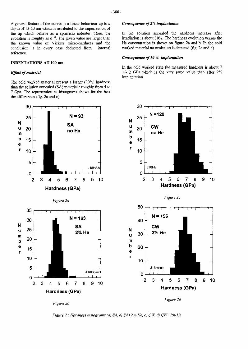
-300 -
A general feature of the curves is a linear behaviour up to adepth of 15-20 nm which is attributed to the imperfection ofthe tip which behave as a spherical indenter. Then, theevolution is roughly as dm. The given value are larger thanthe known value of Vickers micro-hardness and theconclusion is in every case deducted from internalreference.
INDENTATIONS AT 100 nm
Effect of material
The cold worked material present a larger (70%) hardnessthan the solution annealed (SA) material : roughly from 4 to7 Gpa. The represention as histograms shows for the bestthe differences (fig. 2a and c)
Nu 20km
Number
1 1 1 1 1 1
2 3 4 5 6 7 8 9 10
Hardness (GPa)
Figure 2a
Consequence of 2% implantation
In the solution annealed the hardness increase afterirradiation is about 30%. The hardness evolution versus theHe concentration is shown on figure 2a and b. In the coldworked material no evolution is detected (fig. 2c and d)
Consequence of10 % implantation
In the cold worked state the measured hardness is about 7+/- 2 GPa which is the very same value than after 2%implantation.
Hardness (GPa)
Figure 2b
Number
o u
25
20
15
10
5
0
i I . I i ! .
N=120
CWno He
1
J18HE II , I ttJ
I ' I ' I ' I '
I • ~~^̂H__ -
_^^^^^_ -
2 3 4 5 6 7 8 9 10Hardness (GPa)
Figure 2c
35
30
25
20
15
10
5
0
i | , | i | , | r | , | I | ,
- N = 163
HI SA^L 2% He
r 1- •^ ^ ^ ^ H J18HSAIR
> 3 4 5 6 7 8 9 10
N
mber
40
30
20
10
1 I ' i ' I ' !
N = 156
CW_ 2% He |
1
J18HEIR ^ ^ Hi , i , ^^H
2 3 4 5 6
Hardness
i ' i ' i '
1•
7 8 9 10
(GPa)
Figure 2d
Figure 2 : Hardness histograms :a) SA, b) SA+2% He, c) CW, d) CW+2% He
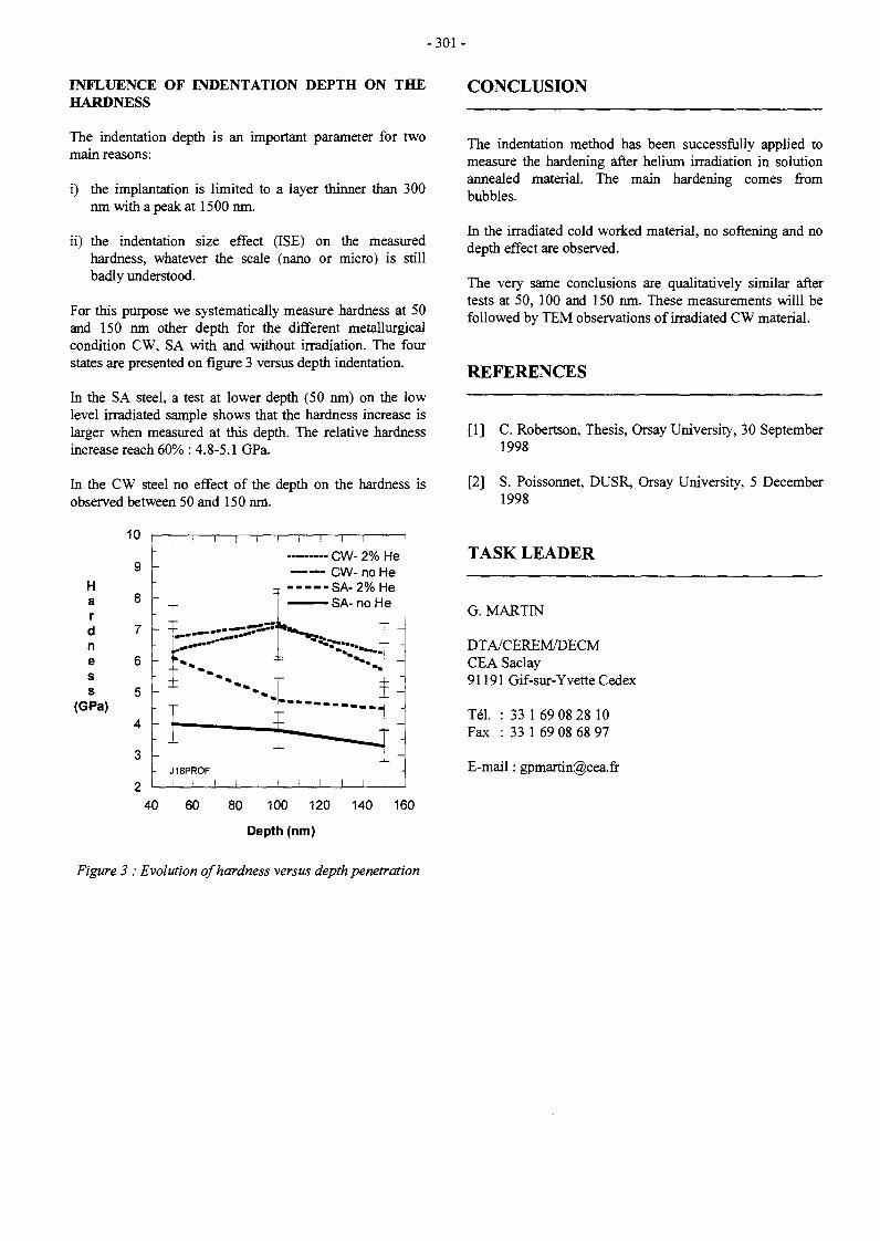
- 3 0 1 -
INFLUENCE OF INDENTATION DEPTH ON THEHARDNESS
The indentation depth is an important parameter for twomain reasons:
i) the implantation is limited to a layer thinner than 300nm with a peak at 1500 nm.
ii) the indentation size effect (ISE) on the measuredhardness, whatever the scale (nano or micro) is stillbadly understood.
For this purpose we systematically measure hardness at 50and 150 nm other depth for the different metallurgicalcondition CW, SA with and without irradiation. The fourstates are presented on figure 3 versus depth indentation.
hi the SA steel, a test at lower depth (50 nm) on the lowlevel irradiated sample shows that the hardness increase islarger when measured at this depth. The relative hardnessincrease reach 60% : 4.8-5.1 GPa.
hi the CW steel no effect of the depth on the hardness isobserved between 50 and 150 nm.
10
Hardness
(GPa)
CONCLUSION
u
9
8
7
6
5
4
3
0
I I I
" T
- :
-
-
- —
_
- J18PROFI I !
I I I
CW- 2% HeCW- no He
- - - - -SA-2% He— — SA- no He
'— ".. —
-
; -
-
The indentation method has been successfully applied tomeasure the hardening after helium irradiation in solutionannealed material. The main hardening comes frombubbles.
hi the irradiated cold worked material, no softening and nodepth effect are observed.
The very same conclusions are qualitatively similar aftertests at 50, 100 and 150 nm. These measurements willl befollowed by TEM observations of irradiated CW material.
REFERENCES
[1] C. Robertson, Thesis, Orsay University, 30 September1998
[2] S. Poissonnet, DUSR, Orsay University, 5 December1998
TASK LEADER
G.MARTIN
DTA/CEREM/DECMCEA Saclay91191 Gif-sur-Yvette Cedex
Tél. : 33 1 69 08 28 10Fax : 33 1 69 08 68 97
E-mail : [email protected]
40 60 80 100 120 140 160
Depth (nm)
Figure 3 : Evolution of hardness versus depth penetration

- 3 0 3 -
UT-SM&C-COR
Task Title : METAL AND OXIDES THERMODYNAMIC STABILITY ANDSOLUBILITY IN WATER COOLING SYSTEMAluminium oxides stability and solubility in water
INTRODUCTION
The objectives are to study the stability of the oxides whichmay be formed in the water cooling circuits (divertorcooling loops or breeder cooling loops) and theirsolubilities.
1998 ACTIVITIES
In neutral aqueous solution, the oxide formed in thesurface of the metallic aluminium depends only on thetemperature : bayerite phase, ot-Al(OH)3 (or a-A12O3,3H2O), is observed up to 70 °C - 80 °C, and after,boehmite, y-AlO(OH) (or Y-A12O3 ,H2O), up to 300 °C. Theaqueous species identified by different authors areessentially Al3+, A1(OH)2+, A1(OH)2
+, A1(OH)3° andA1(OH)4\ In the nature, the gibbsite phase, Y-A1(OH)3 (ory-Al2O3,3H2O), is usually observed in bauxite, the naturalmine stone aluminium. Literature data are used to describethe thermodynamic behaviour of the two phases: y-AIO(OH), a-Al(OH)3 in contact with water. The modelallows to determine the total concentration in aluminiumin the aqueous solution and the distribution of thehydrolysis species according to pH and temperature.
This work shows that the dissolution of the aluminiumoxides is expected to have a minimum according to pH.This solubility minimum varies according to thetemperature. For example, the boehmite solubility isrelated as follows. The known species of aluminium inaqueous solution are Al3+, A1(OH)2+, A1(OH)2
+, A1(OH)3°and A1(OH)4". The considered equilibria are as follows:
The mixing of last equations gives the total concentrationin aqueous aluminium according to pH and temperature :
Al3 t + H2O <*• A1(OH)2+ + H*
A1(OH)2+ + H2O *• A1(OH)2+ + H+
A1(OH)2+ + H2O <*- A1(OH)3° + H*
A1(OH)3° + H2O »• A1(OH)4' + H+
K,,, = [AJ(OH)2+].[H+]/[Al3+] ;
K,,2 = [AlCOlVj.IH^/tAlCOH)2*] ;
K,.j = [AJ(OH)3°].[H+]/[Al(OH)2+] ;
K M = [Al(OHVJ.[H+]/[Al(OH)30].
The solubility of boehmite in pure water is described by theequilibrium reaction :
Y-A1O(OH)(!) + 2 H2O •»• A)(OH)4 ' + H+
In tliese conditions, the total concentration in aqueousaluminium is obtained by the summation of individualconcentration of each aluminium species :
[H+]4/(Ku.K,,2.Ki,3.K1.4) + [Ht]1/(K,,tKu.K,.4)[Al] =
At a given temperature, the different equilibrium constantsare determined by the known of Gibbs energy AG°(T):
AG°(T) = RT.ln K
and AG°(T) is calculated by the known of thethermodynamic data [1-3] of each species involved in Al-H2O system : standard enthalpy of formation atTref= 298.15 K, AH°f{Tref), standard entropy atTref= 298.15 K, S°(Tref) and the specific heat capacity atconstant pressure Cp°(T).
This method is applied to model the solubility of boehmite,bayerite and gibbsite in water according to pH andtemperature. The figure 1 shows the results obtained forboehmite with the pH range 2-10 at 25 °C and 100 °C.
The figure 2 shows the results obtained for the threephases, gibbsite, bayerite and boehmite at 25 °C if weconsider the selected data in this work or those used byPourbaix [4]. Significant change is observed in the relativeposition of the solubility curves but the shape is similar.
[Al] [A1(OH)2+] + [A1(OH)2+] + [Al(OH),0] + [AJ(OHy].
1 V.A. POKROVSKII et H.C. HELGESON.Thermodynamic properties of aqueous species andsolubilities of minerals at high pressures andtemperatures : The system Al2O3-H2O-NaCl.American Journal of Science Vol. 295 December1995 p.1255.
2 J.A. APPS, J.M. NEIL et C.H. JUN.Thermodynamical properties of gibbsite, bayerite,boehmite, diaspore and aluminate ion between 0 and350°C. Division of waste management. Office ofNuclear Material Safety and Safeguard. U.S NuclearRegulatory Commission. Washington D.C. 20555.NUREG/CR--5271. LBL 21482, 1989.
3 I. DIAKONOV, G. POKROVSKI, I SCHOTT, S.CASTET et R. GOUT. An experimental andcomputational study of sodium-aluminiumcomplexing in crustal fluids. Geochim. Cosmochim.Acta60(1996)p.l97.
4 M. POURBAIX. Atlas d'Equilibres Electrochimiquesà 25°C. Gauthier-Villars & de Editeur. Paris 1963.

- 304 -
— 3
-5
-6
- 9
-10
1,1
1,2
\
\ \
V\\\\\ \
1,0
25'
-4{
4
//
1,̂
/
10
pH PH
Figure 1 : Boehmite solubility and contribution of each aluminium species according to pH at 25 °C and at 100 °Cneutral pH (— •—) ; total concentration in aqueous aluminium (—).
1,0= Al3+ ; 1,1= Al(OH)2+ ; 1,2 = Al(OH)2+ ; 1,3 = Al(OH)3 and 1,4 = Al(OH)4~
-2
-3 1-
-5
- 6
- 7 ••
-9
-10
>
\
N
\
\\
//
/
'//
1
//
//
•
' A/
/
// y
-2
- 3
-5
-7
- 9 -
-10
\
\ I
VVV
1 a
r
//
10 10
pH PH
Figure 2 : Solubility diagrams ofgibbsite ( — ) , bayerite ( — ) and boehmite ( ' ) at 25°C1) data used by Pourbaix [4] and 2) result of our work
CONCLUSION TASK LEADER
This work show the interest to using up to date data tocalculate the thermodynamic behaviour of oxide-watersystem, especially for AI-H2O system.
Dominique YOU
CEA/DTA/CEREM/DECM/SCECFCEA Saclay91191 Gif-sur-Yvette Cedex
Tél. : 33 1 69 08 16 22Fax : 33 1 69 08 15 86
E-mail : [email protected]

- 3 0 5 -
UT-SM&C-FCC
Task Title : FLICA-CASTEM COUPLING
INTRODUCTION
The European Fusion Underlying Technology programaims at constructing and maintaining basic genericknowledge and tools necessary for the future fusion reactordesign and manufacturing activities.
Among these tools, a specific tool for coupling (ISAS)thermo-mechanics (CASTEM-2000) and thermo-hydraulics (FLICA-4) was designed by CEA in 1996,within the UT-SM&C-FCC task.
A new version of the ISAS code supervisor has beenspecified in 1997 according to the ELAN-Project WorkingGroup, in order to improve its efficiency, to overcomesome limitations, and to add new facilities.
1998 ACTIVITIES
The specifications of ISAS2 [3] follow the ELANrecommendations :
- a distributed objects architecture (CORBA) to integratethe codes,
- a powerful supervision language (Java) to write easilythe coupling procedures.
The new version of ISAS, so called ISAS/CORBA, hasbeen developed and validated in 1998. Two test cases havebeen reported to explain the use and the advantages ofISAS/CORBA : the fist test is just a matrix-vector product[1], and the second test is a 3D thermal-hydraulicscoupling between CATHARE and FLICA-4 [2]. Theresults have been successfully compared to the first versionof ISAS.
The main benefits of the new version of ISAS are related tothe distributed objects architecture : each code can bemodeled through the Module Managers, without explicitknowledge of the code implementation and its plate-form.Only the code interface is needed to request a task to aModule Manager. The data needed to carry on thecalculation are read and written from the Data Managers.As a result, large 3D coupling data structures do not needto be exchanged trough the ISAS supervisor, but they canbe directly accessed by the codes.
Among the new facilities of ISAS/CORBA, one canmention the in line debugging help : a tracing channel isdevoted to carrying information about codes execution.Then the supervisor can easily manage exceptionsoccurrence, and advise the user.
Improvements of ISAS enable code easy integration withinthe CORBA protocol, from the first step of design to thefinal one. Since ISAS/CORBA has been validated by the3D coupling of the CATHARE and FLICA-4 codes,ISAS/CORBA is fully operable and suitable for complexcoupling applications such as fusion calculations involvingCASTEM-2000 and FLICA-4.
PUBLICATIONS
[ 1 ] E. ROYER, O. FLEBUSISAS validation report - Test case 1Report SERMA/LETR/RT/98-2392/A
[2] E. ROYER, O. FLEBUSISAS validation report - Test case 2Report SERMA/LETR/RT/98-2416/A
REPORTS
[3] P. TRUELLE, I. TOUMISpécifications du système de couplage de codesISAS2Report DMT/97-581
TASK LEADER
D. CARUGE
DRN/DMT/SERMACEA Saclay91191 Gif-sur-Yvette Cedex
Tél. : 33 1 69 08 21 61Fax : 33 1 69 08 85 68

- 3 0 7 -
UT-SM&C-GAL
Task Title : COMPATIBILITY OF SOME ALLOYS AND REFRACTORYMETALS WITH LIQUID METALS
INTRODUCTION
The corrosion of martensitic steels, such as the DIN 1.4914steel, in the presence of Pbl7Li liquid is characterized byan uniform dissolution, without formation of a corrosionlayer. The kinetics of this dissolution is linear and dependson the temperature, thermal gradient and velocity of theliquid alloy. These characteristics indicate that theconvective diffusion of the dissolved metallic species in theliquid boundary layer is the limiting step of the dissolutionprocess of this type of steel. An experiment for determiningthe iron and chromium diffusion coefficients in the Pbl7Liliquid alloy was thus developed and a first determination ofthese diffusion coefficients at 500°C was obtained. Thesevalues were confirmed latter by complementary tests and itwas shown the the corrosion of martensitic steels is limitedby the iron diffusion in the Pbl7Li liquid [1].
In order to establish a corrosion model of this type of steel,new tests were performed to determine the variation withthe temperature of the iron diffusion coefficient in Pbl7Li.
1998 ACTIVITIES
EXPERIMENTAL METHOD
Among the different existing experimental methods, whichenable to determine the diffusion coefficients in a liquidmetal, a method with well defined convection has beenchosen. This technique can be used in that case because themass transfer is governed by the convective diffusion of thedissolved species in the liquid boundary layer.
This technique consists in rotating a specimen in the liquidalloy for a determined period. The dissolution flux is givenby the weight loss of the specimen during the test. In thatcase and assuming that the concentration of the diffusingspecies at the solid/liquid interface corresponds to thesolubility of this species in the liquid, the diffusion flux J(g m s ) is given by the first Fick's law :
J = D (Cs - C) / e (1)
with:
D: diffusion coefficient (m2 s"1)Cs : solubility of the specie in the liquid metal at thesolid/liquid interface (g m'3)
C: concentration of the species in the liquid metal bulk
e: the thickness of the boundary layer
As the test periods are sufficiently short for theconcentration C to remain negligible compared to Cs, andusing an expression for the boundary layer thicknessdetermined empirically for a cylindrical specimen in aturbulent flow, the equation (1) becomes [1] :
J = 0.176 d 0 4 v"0-344 D 0 6 4 4 f07 Cs (2)
with
d : specimen diameter (m)v : kinematics viscosity (m2 s"!)D : diffusion coefficient (m2 s'1)f : specimen rotational speed (rev min"1)
If the curve representing the dissolution flux values as afunction of the rotational speed at 0.7 power is a straightline, the slope allows the diffusion coefficient to bedetermined.
EXPERIMENTAL TECHNIQUE
The principle of the apparatus is represented in Figure 1. Acrucible containing Pbl7Li is placed in an airtightcontainer equipped with a magnetic device allowing theiron cylindrical specimen to rotate. A hot and a coldisothermal zones are respectively at the top and the bottomof the crucible. The specimen is immersed in the Pbl7Lihot zone. The test consists of four main steps:
- the preparation of the crucible and the container (outgassing under vacuum);
- the wetting of the specimen by Pbl7Li (immersion ofthe specimen at 550°C in a separated highertemperature crucible containing stagnant Pbl7Li for 16hours);
- the rotation of specimen in Pbl7Li;
- the elimination of Pbl7Li after test by immersion in aliquid lithium bath at 300°C during 1 hour and then inethanol to eliminate the lithium layer.
The temperatures of the hot and cold isothermal zoneswere respectively 475°C and 415CC. The rotational speedsof the specimen were between 200 and 1000 rev min"1 inPbl7Li and produced a turbulent liquid flow.

- 3 0 8 -
Magnetic stirring
Thermocouple
1.4914 steel rod
Crucible (TZM)
Cylindrical specimen
Pb17Li
Heating resistance
Figure 1 : Experimental apparatus
THE RESULTS
Six tests have been performed. Their operating conditionsand the specimen weight losses after test are reported inthe Table 1. Unfortunately, due to experimental problems(probably an incomplete Pbl7Li or Li elimination), theresults of only four tests can be used for interpretation.
The iron dissolution fluxes which have been deduced fromthe weight losses are gathered in the Table 2.
DISCUSSION
From the Table 2, it can be seen that the test 1 diffusionflux value (obtained with a 16.5 rev s1 rotational speed) isvery low compared to the other value obtained with thesame rotational speed but also with the values obtainedwith lower rotational speeds. Taking into account thedifficulties which have been encountered to eliminate allthe Pbl7Li or Li in some cases, we think that this lowvalue results from an incomplete elimination of the Pbl7Lior Li in the thread screw of the specimen and therefore, ithas been considered as unreliable and has not been takeninto account for the interpretation of the results.
The 475°C dissolution flux values together with thosepreviously determined at 500°C are plotted as a function ofthe rotational speed at the 0.7 power on the Figure 2.Considering the origin and the results of tests 4 and 6 onone hand and 5 and 6 on the other hand, it can be deducedrespectively the following maximum and minimum 475 °CD values :
D(Fe/Pbl7Li)475«c max = 5 10"15
D(Fe/Pbl7Li)475°c min = 2 lO"15nV
mV
A linear regression with these points and the origin leadsto a mean value for the 475 °C iron diffusion coefficientequal to :
D(Fe/Pbl7Li)475°c = 3 10"15 m2 s"1
The value of the iron diffusion coefficient obtained at475°C is lower than the one previously measured at 500°C(D(Fe/Pbl7Li)5Oo«c= 1-3 to 1.4.10'1'-14 m 2 s"1).
Table 1 : Results of tests with a rotating specimen
N° test
1
2
3
4
5
6
Rotationalspeed
(revs"1)
16.5
16.5
16.5
16.5
8.5
3.5
Duration(h)
140
234
160
233
211
192
Initialweight
(g)
15.1174
15.09870
15.08248
15.10229
14.8749
15.1006
Finalweight0}
(g)
15.1159
15.09573
15.08279
15.09611
14.8682
15.0985
Weightloss(2)
(mg)
1.0
2.5
-0.3
5.7
6.2
1.6
Remarks
the crucible was brokenduring the test
negative weight loss
(1) : after Pbl7Li and Li elimination(2) : weight loss including the 0,5 mg lost during the wetting treatment

- 3 0 9 -
Table 2 : Dissolution flux of iron in Pbl7Li at 475°C
N°test
1
4
5
6
Dissolution fluxuncorrected(1)
(HgnfV)3.2
7.8
8.7
3.2
Dissolution fluxcorrected(2)
(ugrnV)2.1
7.2
8.0
2.5
(1) : without taking into account the 0.5 mg lost during thewetting treatment
(2) : taking into account the 0.5 mg lost during the wettingtreatment
SA
S
3
cUO
I
lut
e
25 -
20 -
15 -
10 -
5 -
> 475°CI500°C
Rotational speed ((rev. s"1)0-7)
Figure 2 : Dissolution flux of iron in Pbl7Liat 475°C and 500°C
It is also lower than the value which can be deduced fromthe corrosion data [2] and which is equal to2.3 10"14m2s-1. It has to be noticed that at 500°C, thedifference between the diffusion coefficient value deducedfrom the corrosion data and the one deduced from therotating specimen was lower (factor 4 at 500°C comparedto 7.5 ± 4 at 475°C).
Although the D value at 475 °C has to be confirmed, fromthe D values at 475°C (mean value) and 500°C[l], we haveestimated the activation energy from an Arrhenius plotequal to 280 ± 90kJ mol"1. This value is much highercompared to that obtained for iron in Pb by Roberston [3],44 kJ mol1 but using the grain boundary grooving method.Therefore, according to our results, we can estimateD(Fe/Pbl7Li)475°c = 2 to 5 10"15 m2 s"1 This value has to beconsidered as a tentative estimation of the iron diffusioncoefficient in Pbl7Li and has to be validated.
CONCLUSION
A first estimation of this value, D(Fe/Pbl7Li)475<.c = 2 to 510"15 m2 s"1, has been obtained but due to someexperimental problems to completely remove the Pbl7Liafter test, this value has to be validated by complementarytests. Using the previous data obtained at 500°C, anestimation of the activation energy of the diffusioncoefficient has been deduced. This value, higher than thatobtained by an other technique for iron in lead demands tobe validated by completing these data by iron diffusioncoefficient measurement at other temperatures.
REFERENCES
[1] T. Dufrenoy, A. Terlain, Determination of thediffusion coefficient of iron in Pbl7Li at 500°C,Proceedings of the First International Workshop onLiquid Metal Blanket Experimental Activities,September 16-18, 1997, CEA Headquarters, ParisFrance
[2] T. Flament, P. Tortorelli, V. Coen, H. U. Borgstedt,Compatibility of materials in fusion first wall andblanket structures cooled by liquid metals, Journal ofNuclear materials, 191-194 (1992) 132-138
[3] W.M. RobertsonDiffusion of cobalt and iron in liquid lead measuredby grain boundary grooving, Trans. Met. Soc. AIME,242 (10), (1968), 2139-2142
REPORT
[1] T. Dufrenoy, A. Terlain, Determination of thediffusion coefficient of iron in Pbl7Li liquid alloy at475°C, CEA Report RT-SCECF 486 (December1998)
TASK LEADER
Thierry DUFRENOY
CEREM/DECM/SCECFCEA Saclay91191 Gif-sur-Yvette Cedex
Tél. : 33 1 69 08 16 16Fax : 33 1 69 08 15 86
E-mail : [email protected]
In order to determine the variations with temperature ofthe iron diffusion coefficient in Pbl7Li, tests have beenperformed using a rotating specimen at 475 °C.

-311-
UT-SM&C-HIP
Task Title : SOLID AND POWDER HIP TECHNOLOGIES DEVELOPMENT
INTRODUCTION
Hot Isostatic Pressing (HIP) is considered as a productionprocess In manufacturing Fusion Reactors components, asthis technology allows to fabricate and join complex shapeones without welding. This technology can be used invarious ways : consolidation of powder to manufacture netshapes components, diffusion bonding to join two solidparts of the same or of different materials, in the aboveprocesses, an helpful tool is given by Finite Elementcalculations. It allows to predict the kinetic of densificationor the final shape when modelling powder consolidation.When diffusion bonding is considered, it can also predictthe residual stresses and strains.
SolMSI6LN/316LN
The bond cleanness is shown in figure 1, where a S-ferriteline can be observed.
. l
1998 ACTIVITIES
During this year, attention has been focused on three kindof junctions : 3Î6LA73Î6LX, 3!6LN/Giidcop® andF82H/F82H, and on a better knowledge of the Glidcop®.The first two junctions are foreseen in the ITER concept toproduce the baffle components. In the previous years, thesejunctions have been performed following the Europeanprocess [I]. This year the junction 316LN/3I6LN/Glidcophas been done during a single HIP cycle (with a step at1050°C) following the Japanese concept. A comparison ofthe results obtained with the two processes is given in thefirst part. Although only the 3I6LN/GIidcop junction at1050°C was foreseen in this task, it has been decided toperform the whole junction , including the 316LN/3I6LNone. since the low activation martensitic steel "eurofer"(foreseen to be used in the future DEMO reactor) could notbe delivered on time.
As a consequence, it has also been decided to work onanother LAMS . F82H (supposed to be representative of thefuture maxtensitic steel "Eurofer"), in order to improve thesolid/solid joining HIP process of martensitic materials.Thus, two homogeneous junctions of this martensitic steel(F82H) have been carried out and analyzed bymetallography and mechanical testings.
SOLID 316LN7316LN/GLÎDCOP JUNCTIONAT 1050°C
Following the Japanese concept, the 316LN/3I6LN/GIidcopinjunction has been performed with the following HIPcycle : 1050°C /140 Mpa / 2 hours step.
Figure 1: 316LN/316LNjunction at J050°C
Tensile and impact tests at room temperature and at 300°Chave been done. The results are good and similar to thoseobtained previously on a single 316LN/316LN bondperformed by Tecphy at 1050°C [4,61
On impact test samples tested at room temperature, one cansee that the crack does not follow the bond (figure 2).
Figure 2 : Impact lest at 20°C -316LN/316LNat 1050°C
As already observed on the previous 3I6LN/316LNjunctions performed, a band, 40 urn large, containingmicrovoids initiated on small particles and surrounding thejoint is observed in the high plastic zones.
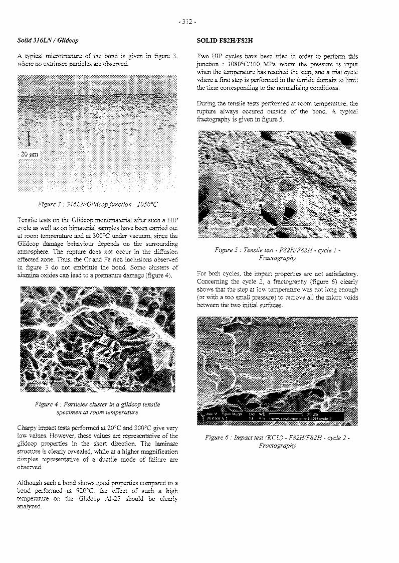
- 3 1 2 -
Solid 316LN/GIMcop
A typical microtructure of the bond is given inwhere no extrinsec particles are observed.
'<V-20 urn
>' ...*.-/•"
Figure 3 : 516LN/Glidcop junction - 1050°C
Tensile tests on the Giidcop rnonomateria! after such a HIPcycle as well as on bimateriai samples have been carried outat room temperature and at 300°C under vacuum, since theGiidcop damage behaviour depends on the surroundingatmosphere. The rupture does not occur in the diffusionaffected zone. Thus, the Cr and Fe rich inclusions observedin figure 3 do not embrittle the bond. Some clusters ofalumina oxides can lead to a premature damage (figure 4).
Figure 4 : Particles cluster in a giidcop tensilespecimen at room température
Charpy impact tests performed at 20°C and 300°C give verylow values. However, these values are representative of thegiidcop properties in the short direction. The iaminatestructure is clearly revealed, while at a higher magnificationdimples representative of a ductile mode of failure areobserved.
SOLID F82H/F82H
Two HIP cycles have been tried in order to perform thisjunction : 1080°C/100 MPa where the pressure is inputwhen the temperature has reached the step, and a trial cyclewhere a first step is performed in the ferritic domain to limitthe time corresponding to the normalising conditions.
During the tensiie tests performed at room temperature, therupture always occured outside of the bond. A typicalfractography is given in figure 5.
Figure S : Tensile test - F82H/F82H - cycle 1 -Fractography
For both cycles, the impact properties are not satisfactory.Concerning the cycle 2, a fractography (figure 6) clearlyshows that the step at low temperature was not long enough(or with a too small pressure) to remove all the micro voidsbetween the two initial surfaces.
f~
. *"-' *""Ace V Spot Maqn Dot WO•/0 0 kV b 1 Sf 9 9
Figure 6 : Impact test (KCU) - F82H/F82H - cycle 2 -Fractography
Although such a bond shows good properties compared to abond performed at 920°C, the effect of such a hightemperature on the Giidcop Al-25 should be clearlyanalvzed.

- 3 1 3 -
CONCLUSION
1) Following the Japanese concept, a316LN/316LN/Glidcop junction has been performed inour laboratory at 1050°C.
Since the SS/SS junction has good tensile as well asimpact properties, a 1050°C cycle is recommendedrather than a 1100°C cycle to keep the smallestaustenitic grains as possible.
The SS/Glidcop junction mechanical properties arefound at least as good as the Glidcop ones. However,the influence of such a high temperature on themechanical properties of the ITER foreseen copperalloy should be carefully addressed in the future.
2) Two different cycles have been perfomed in order tobond two solid parts of F82H martensitic steel.
The first one had previously been established toassemble a mock-up.
The second trial cycle has been performed in order tolimit the step temperature and time close to thenormalising conditions.
Although the tensile results are good, the impactproperties are poor for both cycles. The surfacepreparation and the HIP cycle still must be improved.
[5] LeMarois G., Burlet H., Solomon R., Marini B.,Gentzbittel J.M., Briottet L., Structural materialsjoints for ITER in-vessel components, ISFNT-4, April6-11 1997, Tokyo, Japan.
[6] Briottet L., Bucci P., Rigal E., Chu I , Lemoine P.,Solid and powder Hip technologies development, UT-SM&C-HIP, Milestones M6-M7, Note techniqueDEM n° 98/72.
TASK LEADER
L. BRIOTTET
DTA/DEM/SGMCEA Grenoble17, rue des Martyrs38054 Grenoble Cedex 9
Tél. : 33 4 76 88 33 15Fax : 33 4 76 88 58 91
E-mail : [email protected]
PUBLICATIONS
[1] Burlet H., Bouaziz O., Le Gallo P., Mourniac Ph.,Hip and brazing technologies development, UT-M-A13, Note technique DEM N° 08/96.
[2] Gentzbittel J.M., Nombalais G., Conte J., Fracturetoughness and creep properties of unirradiated DScopper, Note Technique DEM n° 58/94.
[3] Briottet L., Bouaziz 0., Burlet H., Hip and brazingtechnologies development, UT-M-A13, Notetechnique DEM N° 62/96.
[4] Briottet L., Burlet H., Couturier R., Riccetti B., ChuI., Solid and powder Hip technologies development,UT-SM&C-HIP, Milestones Rl, Note technique DEMn° 97/67.
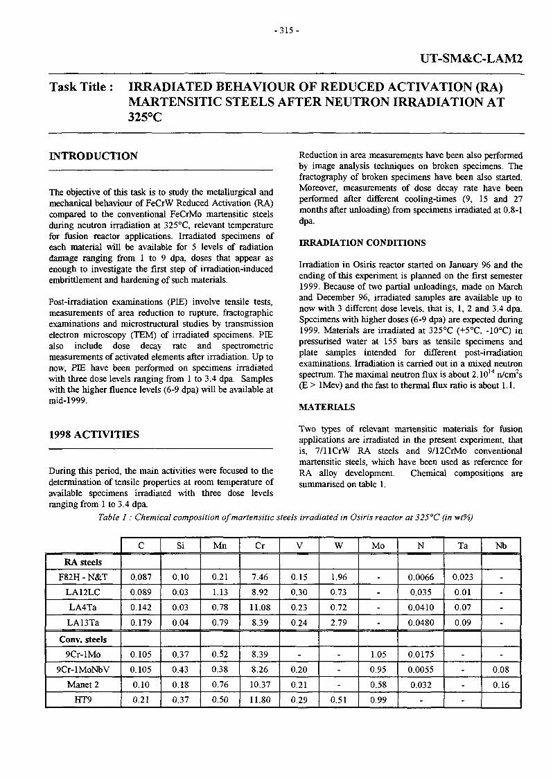
- 315 -
UT-SM&C-LAM2
Task Title : IRRADIATED BEHAVIOUR OF REDUCED ACTIVATION (RA)MARTENSITIC STEELS AFTER NEUTRON IRRADIATION AT325°C
INTRODUCTION
The objective of this task is to study the metallurgical andmechanical behaviour of FeCrW Reduced Activation (RA)compared to the conventional FeCrMo martensitic steelsduring neutron irradiation at 325°C, relevant temperaturefor fusion reactor applications. Irradiated specimens ofeach material will be available for 5 levels of radiationdamage ranging from 1 to 9 dpa, doses that appear asenough to investigate the first step of irradiation-inducedembrittlement and hardening of such materials.
Post-irradiation examinations (PIE) involve tensile tests,measurements of area reduction to rupture, fractographicexaminations and microstructural studies by transmissionelectron microscopy (TEM) of irradiated specimens. PIEalso include dose decay rate and spectrometricmeasurements of activated elements after irradiation. Up tonow, PIE have been performed on specimens irradiatedwith three dose levels ranging from 1 to 3.4 dpa. Sampleswith the higher fluence levels (6-9 dpa) will be available atmid-1999.
1998 ACTIVITIES
During this period, the main activities were focused to thedetermination of tensile properties at room temperature ofavailable specimens irradiated with three dose levelsranging from 1 to 3.4 dpa.
Reduction in area measurements have been also performedby image analysis techniques on broken specimens. Thefractography of broken specimens have been also started.Moreover, measurements of dose decay rate have beenperformed after different cooling-times (9, 15 and 27months after unloading) from specimens irradiated at 0.8-1dpa.
IRRADIATION CONDITIONS
Irradiation in Osiris reactor started on January 96 and theending of this experiment is planned on the first semester1999. Because of two partial unloadings, made on Marchand December 96, irradiated samples are available up tonow with 3 different dose levels, that is, 1, 2 and 3.4 dpa.Specimens with higher doses (6-9 dpa) are expected during1999. Materials are irradiated at 325°C (+5°C, -10°C) inpressurised water at 155 bars as tensile specimens andplate samples intended for different post-irradiationexaminations. Irradiation is carried out in a mixed neutronspectrum. The maximal neutron flux is about 2.1014 n/cm2s(E > lMev) and the fast to thermal flux ratio is about 1.1.
MATERIALS
Two types of relevant martensitic materials for fusionapplications are irradiated in the present experiment, thatis, 7/llCrW RA steels and 9/12CrMo conventionalmartensitic steels, which have been used as reference forRA alloy development. Chemical compositions aresummarised on table 1.
Table 1 : Chemical composition ofmartensitic steels irradiated in Osiris reactor at 325°C (in wt%)
RA steels
F82H - N&T
LA12LC
LA4Ta
LA13Ta
Conv. steels
9Cr-lMo
9Cr-lMoNbV
Manet 2
HT9
C
0.087
0.089
0.142
0.179
0.105
0.105
0.10
0.21
Si
0.10
0.03
0.03
0.04
0.37
0.43
0.18
0.37
Mn
0.21
1.13
0.78
0.79
0.52
0.38
0.76
0.50
Cr
7.46
8.92
11.08
8.39
8.39
8.26
10.37
11.80
V
0.15
0.30
0.23
0.24
-
0.20
0.21
0.29
W
1.96
0.73
0.72
2.79
-
-
-
0.51
Mo
-
-
-
-
1.05
0.95
0.58
0.99
N
0.0066
0.035
0.0410
0.0480
0.0175
0.0055
0.032
-
Ta
0.023
0.01
0.07
0.09
-
-
-
-
Nb
-
-
-
-
-
0.08
0.16

- 316-
The following nuances of RA martensitic steels are beingirradiated :
- F82H is a 7.5CrWTaV RA-steel developed by JAERI(Japan) and produced for the first time as a large-scaleheat (5 tons).
- LA12LC, LA4Ta and LA13Ta are RA experimentalalloys of 9/llCrWTaV type with different contents ofCr, W, Ta.
Conventional martensitic steels are commercial alloyswhich present different contents of Cr (9 to 12%), Mo andstabilising elements (V, Nb). These materials wereproduced as plates in the normalised and temperedcondition (N&T) like F82H RA-steel.
RA experimental alloys have been supplied by AEA-Culham as cast ingots. They were subsequentlytransformed in our laboratory as plates, where the last stepsof the fabrication route consisted on the normalisation andtempering followed by 10% cold-working (N&T-CW).
TENSILE PROPERTIES
Tensile specimens irradiated in this experiment are platesamples of 2 mm wide, 1 mm thick and 8 mm of gaugelength. Previous tests conducted at the irradiationtemperature, that is 325°C, have been reported previously(see Annual Report CEA/Euratom, 1997).
Several available specimens have been tested at roomtemperature for doses ranging from 1 to 3.4 dpa. Values of0.2% proof stress, Ultimate Tensile Strength (UTS), totaland uniform elongation have been measured. Reduction inarea measurements have been performed using an imageanalysis procedure to evaluate the cross-section area ofbroken specimens.
Before irradiation tensile strength depends on themetallurgical condition. RA and conventional steels in theN&T condition presented 0.2% proof stress values ofabout 540-580MPa and about 680-740 MPa for N&T-CWRA steels. Figure 1 shows the evolution of the 0.2% proofstress and reduction in area measurements as a function ofthe dose.
hi all the cases, an important increase of tensile strengthwith the fluence is observed, which ranges from 190 to520 MPa depending on the chemical composition and themetallurgical condition of steels. The most importantirradiation-induced hardening is obtained for HT9 (N&T)steel (520 MPa) followed by 9Cr-lMo (350MPa), F82H(310MPa), LA4Ta (270MPa) and LA12LC (190MPa). So,the lower hardening levels are obtained for the RAmartensitic steels.
Ductility values decrease simultaneously with theincreasing strength. In particular, a strong decrease ofreduction in area value is obtained for materials displayingthe higher increase of strength.
The best compromise between the strength value andreduction in area level is obtained for F82H, LA12LC and9Cr-lMo steels.
DOSE RATE DECAY MEASUREMENTS
To check the concept of « reduced activation », the doserate measurements are being performed on several types ofsteels, including stainless steels, conventional and reducedactivation martensitic alloys, all of them irradiated in thesame conditions.
Measurements have been conducted on specimens comingfrom the first unloading (0.8-1 dpa), which was obtainedon March 1996.
1200
1100;.HT9.(1ÎÇ.r-1MçH3,5W)..
•sr 1000 I-
I tS 900s55g 800 V-;y':
LA4Ta(11Cr-0.8W) ;
ar^-'-' tAT2UC-i(9Cr-a.8W)- • • - -
":'-'~']F82iï(7Ï5Cr-2WJ; 1
9Cr-1Mo i i ]
T =25°C :
0.0 0.5 1.0 1.5 2.0 2.5 3.0 3.5
Dose(dpa)
4.0 0.0 0.5 1.0 1.5 2.0 2.5 3.0 3.5 4.0
Dose (dpa)
Figure 1 : Evolution of the 0.2% proof stress and reduction in area values of reduced activationand conventional martensitic steels as a function of the dose

60 •
- 3 1 7 -
X
Dmoa
Measurements after 9 months
n n3 S
o £ g es es O
111 = iô à
s aCO «
< < 5
Austenitic ConventionalMartensitïc
ReducedActivation Mart
5 0 •
50-
£]g 3D"S
"s 2C»o2
LJ LJ .LJ
O5
Measurements after 27 months
0LDLU.n5 o g
f I «Ô "7 2
5 5ô 1 T» o o
D D_ O_£L.n
< ^ -J ™ "-
Figure 2 : Evolution of the dose rate with the cooling-time for different classes of steels irradiated at 0.8-ldpain the Osiris reactor. Measurements performed 9 and 27 months after unloading
The dose rate is measured with a Geiger-Mûller counter fordifferent distances between the samples and the counter,that is. 50, 100 and 185 mm. The first measurement hasbeen performed 9 months after unloading, the followingones at 15 and 27 months and it is planned to go on themeach 12 months.
Figure 2 compares the dose rate values measured after 9and 27 months for a distance sample-counter of 100 mm.
After 9 months of cooling, the group of stainless steels(type 304 and 316) present the higher residual activity (30-58mGy/h) and both types of martensitic steels arecharacterised by dose rates in the range 8-20mGy/h).Measurements performed after 27 months show a decreaseof the residual activity for all materials.
At this time, the activity of stainless steels is always thehigher one and ranges from 16 to 36 mGy/h, theconventional martensitic steels CrMo from 3 to 12 mGy/hand only 2.5-3.0 mGy/h are found in the case of the reducedactivation CrW martensitic steels.
It is worthwhile to point out that the rate of the decreasingactivity is different for each class of steeis. Compared to thefirst measurements (9 months). 304 and 316 steeis exhibit zreduction of the dose rate of 20-32%, 30-55% in the case ofconventional martensitic alloys, and 65-80% for thereduced activation steels.

- 3 1 8 -
These first experimental data assess the good performanceof « reduced activation steels » from the point of view ofradiological effects and environmental considerations.Consequently, reduced activation materials are veryencouraging for applications as structural materials forfusion reactors and other projects where components aresubmitted to in-service high doses.
CONCLUSIONS
Several Cr-W low activation and Cr-Mo conventionalmartensitic steels have been irradiated in the Osiris reactorat 325°C for three dose levels : 1, 2 and 3.4 dpa.
Tensile tests were performed at 25°C. All materialsexhibited an increase of tensile strength accompanied by adecrease of ductility.
• For the fluence levels examined here, 7.5-9%Crcontaining steels present a lower sensitivity to theirradiation-induced hardening and ductilitydegradation. The best compromise strength/ductility isobtained for F82H and LA12LC reduced activationmartensitic steels and the conventional 9Cr-lMo.
REPORT
[1] A. Alamo, X. Averty, "Status of post-irradiationexaminations performed on RA and conventionalmartensitic steels irradiated at 325°C in Osirisreactor", Progress Report UT-SM&C-LAM2December 1998, CEA report, NT SRMA 99-2316.
TASK LEADER
A. ALAMO
DTA/DECM/SRMACEA Saclay91191 Gif-sur-Yvette Cedex
Tél. : 33 1 69 08 67 26Fax : 33 169 08 7130
E-mail : [email protected]
• In contrast, a strong hardening accompanied by asevere ductility degradation is obtained in the case ofHT9 (12%Cr) conventional steel.
Measurements of the dose rate have been performed afterseveral cooling-time to validate the concept of « reducedactivation materials ». For this purpose, specimens ofdifferent types of steels have been examined : austeniticsteels, conventional martensitic and reduced activationmartensitic alloys, after irradiation for a dose of 0.8-1 dpa.Experimental data, obtained up to 27 months of cooling-time, show that :
• The reduced activation martensitic steels exhibit thelower residual activity (< 3 mGy/h). Conventionalmartensitic steels are characterised by an activity levelof 4-12 mGy/h.
• The higher activity values were found for the austeniticsteels, 304 and 316 type (15-35 mGy/h), which areabout 4 to 15 times higher compared to martensiticalloys.
• On the other hand, reduced activation martensitic steelsdisplay the higher rate of desactivation.
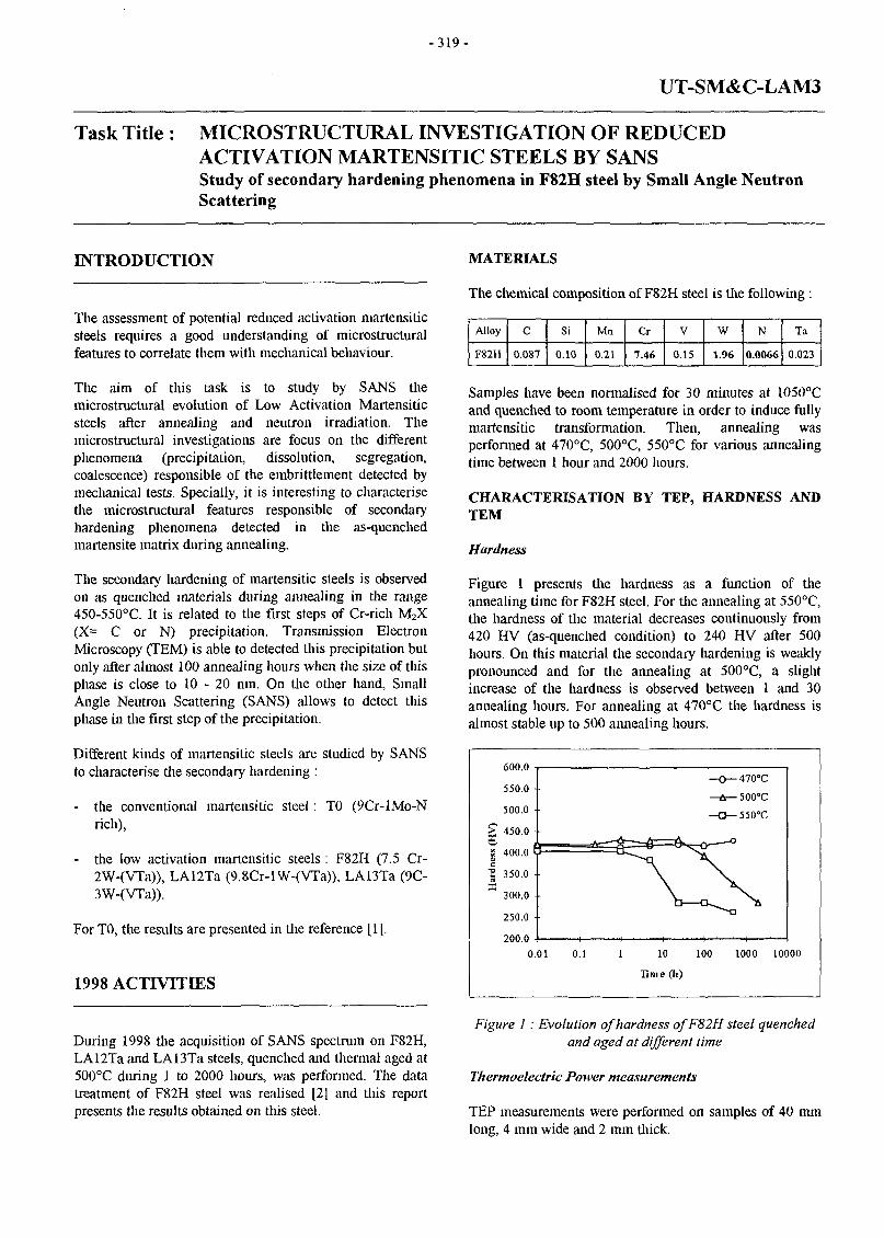
- 319 -
UT-SM&C-LAM3
Task Title : MICROSTRUCTURAL INVESTIGATION OF REDUCEDACTIVATION MARTENSITIC STEELS BY SANSStudy of secondary hardening phenomena in F82H steel by Small Angle NeutronScattering
INTRODUCTION
The assessment of potential reduced activation martensiticsteels requires a good understanding of microstructuralfeatures to correlate them with mechanical behaviour.
The aim of this task is to study by SANS themicrostructural evolution of Low Activation Martensiticsteels after annealing and neutron irradiation. Themicrostructural investigations are focus on the differentphenomena (precipitation, dissolution, segregation,coalescence) responsible of the embrittlement detected bymechanical tests. Specially, it is interesting to characterisethe microstructural features responsible of secondaryhardening phenomena detected in the as-quenchedmartensite matrix during annealing.
The secondary hardening of martensitic steels is observedon as quenched materials during annealing in the range450-550°C. It is related to the first steps of Cr-rich M2X(X= C or N) precipitation. Transmission ElectronMicroscopy (TEM) is able to detected this precipitation butonly after almost 100 annealing hours when the size of thisphase is close to 10 - 20 nm. On the other hand, SmallAngle Neutron Scattering (SANS) allows to detect thisphase in the first step of the precipitation.
Different kinds of martensitic steels are studied by SANSto characterise the secondary hardening :
- the conventional martensitic steel : TO (9Cr-lMo-Nrich),
- the low activation martensitic steels : F82H (7.5 Cr-2W-(VTa)), LA12Ta (9.8Cr-lW-(VTa)), LA13Ta (9C-3W-(VTa)).
For TO, the results are presented in the reference [1],
1998 ACTIVITIES
During 1998 the acquisition of SANS spectrum on F82H,LA12Ta and LA13Ta steels, quenched and thermal aged at500°C during 1 to 2000 hours, was performed. The datatreatment of F82H steel was realised [2] and this reportpresents the results obtained on this steel.
MATERIALS
The chemical composition of F82H steel is the following :
Alloy
F82H
C
0.087
Si
0.10
Mn
0.21
Cr
7.46
V
0.15
W
1.96
N
0.0066
Ta
0.023
Samples have been normalised for 30 minutes at 1050°Cand quenched to room temperature in order to induce fullymartensitic transformation. Then, annealing wasperformed at 470°C, 500°C, 55O°C for various annealingtime between 1 hour and 2000 hours.
CHARACTERISATION BY TEP, HARDNESS ANDTEM
Hardness
Figure 1 presents the hardness as a function of theannealing time for F82H steel. For the annealing at 550°C,the hardness of the material decreases continuously from420 HV (as-quenched condition) to 240 HV after 500hours. On this material the secondary hardening is weaklypronounced and for the annealing at 500°C, a slightincrease of the hardness is observed between 1 and 30annealing hours. For annealing at 470°C the hardness isalmost stable up to 500 annealing hours.
600.0
550.0 -•
500.0 -
450.0 •
S 400.0
| 350.0
300.0 •
250.0
200.0
-470°C
-500°C
-55O-C
0.01 0.1 10 100
Time (h)
1000 10000
Figure 1 : Evolution of hardness ofF82H steel quenchedand aged at different time
Thermoelectric Power measurements
TEP measurements were performed on samples of 40 mmlong, 4 mm wide and 2 mm thick.

-320 -
The samples were aged in air and under vacuum. ReportedTEP values in figure 2 are the average of 4 measurementsfor each sample. Pure copper has been chosen as referencemetal, due to its high electric conductivity (So = 1.83uV/K). The accuracy of the TEP values is about 0.005uV/K. It appears that for the three annealing temperatures,the TEP values (known to be very sensitive to theinterstitial content in the matrix) decrease continuously withthe annealing time. This evolution is the sign of acontinuous precipitation of carbo-nitrides (M3C, M7C3,M23C6 and M2X) in the matrix.
0.01 1 10 100
Time (h)
1000 10000
Figure 2 : Evolution of thermoelectric power measurementsof F82H steel quenched and aged
at different time
We performed diffraction patterns on groups of precipitatesand we measured the distance between the different planes.The obtained results are the following :
dhu measured(nm) 0.29 0.24 0.21 0.19 0.16 0.12
and they could correspond to M2N or M2C precipitates.Indeed, the interplanar distances (in nm) of theses phasesare :
dhU(Cr,C)
(hid)
dhw(Cr,N)
(hkl)
0.305
(101)
0.24
(100)
0.241
(110)
0.22
(002)
0.224
(002)
0.211
(101)
0.212
(HI)
.0163
(102)
0.208
(200)
0.139
(110)
0.189
(201)
0.127
(103)
0.164
(112)
0.149
(211)
0.139
(300)
0.127
(113)
The size of the M2X precipitates was determined by imageanalysis. We reproduced on a tracing-paper the M2Xprecipitates and we determined by image analysis the sizeof the particles. We analysed 250 precipitates and theaverage radius obtained was : 13 nm with a ratio betweenthe big and the small axis of about 1.6.
CHARACTERISATION BY SANS
The experimental set-up and the data treatment werealready described in [1]. SANS experiments wereperformed on F82H samples aged 0, 1,5, 24, 100, 500 and2000h at 500°C. The scattered intensities measured in thedirection parallel to the applied magnetic field are plotted infigure 4.
Characterisation by TEM
F82H steel, quenched and aged during 2000 hours at 500°C,was characterised by TEM. Figure 3 shows carbonextraction replica micrograph of this material. Fineintergranular precipitates, that seem responsible of thesecondary hardening observed, were characterised.
Figure 3 : TEM of M2Xprecipitates in F82H steel quenchedand aged 2000 hours at 500°C (carbon replica)
10 r
0.1 r
0.01 r
• * ?
è 'O « A g
0
•
0
A
referencelh
5h
24h
lOOh
500h
8
• ; * .
0 ° o o o o • 5 ; o s .
0 0.2 0.4 0.6 0.8
q ( nm-1)
1.2 1.4 1.6
Figure 4 : Intensities scattered parallel to the appliedmagnetic field obtained on F82Hsamples annealed at
500°C during times between 0 and 500h
These are intensities without subtraction of the referencesample. We notice a clear evolution of the scatteredintensity with annealing time even after 1 hour at 500°C.This evolution affects all the q range. At small q (q <0.5nm"1), the scattered intensity is dominated by the relativelylarge (carbide) precipitates, already present in the as-quenched samples. The A ratio (ratio on the scatteredintensities measured perpendicularly and parallel to H)

- 3 2 1 -
obtained on the q<0.5 nm"1 domain, decreases with theannealing time (see table 1). For lh, it is equal to 11 as forthe reference sample which can correspond to M3C carbideswith M=20%Cr+ 80% Fe. Then for 24h, the A ratiodecreases hardly in agreement with the expectedstoechiometry variation M23C6. For long annealing times, itis compatible with M23C6 carbides containing for example75%Cr, 25%Fe and 5%W. At high q (q>0.5 nm"1), theincrease of the scattered intensities is related to theformation of the fine precipitation of M2X particles. Inorder to analyse it, we have considered the intensitiesobtained after subtraction of the reference sample in thelarge q range. The profiles have been fitted taking intoaccount a size distribution of spherical or afterwards rod-shaped ellipsoidal precipitates. The best fits were obtainedconsidering that M2X particles were nearly spherical for theshorter times of annealing (t<100h) and became afterwardsrod-shaped ellipsoidal with a ratio between the big and thesmall axis of about 1.5 (figure 5) in agreement with theTEM observations after 2000h at 500°C.
F82h aged 100h at 500°C
0.4 0.6 0.8 1 1.2
q (nm'1 )
1.6
Figure 5 : Intensity scattered perpendicularly to themagnetic field obtained on the lOOh annealed sample fitted
with a rod-shaped ellipsoidal ( the ratio between the bigand small axis is equal to 1.5 ) form factor and a gaussian
size distribution
The mean radius, given in table 1, increases continuouslywith annealing time and for 2000h the mean diameter (18nm) is consistent with the TEM results. We observe also avariation of A ratio with annealing time. For lh annealing,the A ratio is around 4 which can correspond with theassumption of carbides M2C, to a metal site composition of60% Cr, 30% Fe and 10%V (at. %).
Then, the A ratio decreases with annealing time showing anenrichment of chromium. After lOOh, it is equal to 2.5, itcan correspond to a metal site composition of 80% Cr and20%V (at. %). For such chemical content, the precipitatedfraction is around 0.7 % but the chemical composition hasto be confirmed by TEM measurement. As for the TOalloys, the interstitial element X seems to be essentiallycarbon because in the case of nitrogen, the A ratio would behigher.
CONCLUSION
SANS experiments, performed on F82H steel, quenchedand annealed and aged at 500°C, have shown that thistechnique is very sensitive to microstructural evolution inmartensitic steels. For large M2X precipitates, observedafter long time annealing by TEM, the SANS results are inagreement with TEM observatiion. For the fineprecipitation not detected by TEM, SANS experiments putforward specific information. In fact, M2X precipitation wascharacterised even after short annealing time (lh à 500°C)when the precipitate size is around 1 nm.
About the determination of the chemical composition ofM2X, if we assume that they are M2C carbides, SANSresults are consistent with a content of about 20% invanadium and 80% in chromium after annealing 2000 hoursat 500°C. This result has to be confirmed by TEMmeasurements that are in progress.
Table 1 : SANS results obtained on thermally aged F82H samples at 500°C** Mean equivalent sphere radius calculated with the following relation:Re= Rmin (b)'/3 and b=Rmw/ Rmin Rmin is the minor radius of the ellipsoid.
Annealing time (h) at500°C
1.0000
5.0000
24.000
100.00
500.00
2000.0
A ratio (q<0.5 nm"1) M3Cor M23C6
11 ±0.4
9 ±0.5
4.7 ± 0.6
3 ±0.1
3 ±0.1
3.2 ±0.2
A Ratio
M2X
3.9 ±0.6
3.2 ±0.5
2.8 ± 0.3
2.5 ±0.3
Mean radius (nm)M2X
1.03
1.22
1.4
2.9**
7.2**
8.9**
AR(nm)
0.1
0.26
0.4
0.2
1.5
1
•K-min
(nm)
1.03
1.22
1.4
2.5
6.3
7.6
Aspect ratio
1
1.
1.
1.5
1.5
1.5

- 3 2 2 -
REFERENCES TASK LEADER
[1] M.H. Mathon, G. Geoffroy, A. Alamo, C.H. deNovion - Small angle neutron scattering study ofsecondary hardening phenomena in martensitic steels- Progress Report Fusion Technology contract UT-M6CM4 -Note technique LLB/96/119 décembre 1996
REPORTS AND PUBLICATIONS
A. ALAMO
CEA Saclay91191 Gif-sur-Yvette Cedex
Tél. : 33 1 69 08 61 26Fax : 33 1 69 08 71 30
E-mail : [email protected]
[2] M.H. Mathon, Y. de CARLAN - Study of secondaryhardening phenomena in F82H steel by Small AngleNeutron Scattering - Progress Report -Contract UT-SM&C - LAM3- NT SRMA 99 - 2318

- 3 2 3 -
UT-SM&C-REL
Task Title : RELIABILITY MODELLING
INTRODUCTION
Two EU test modules are expected to undergo extensivetesting in ITER machine during the EPP-phase. Theyrepresent the two European conceptual designs of thebreeding blanket of DEMO, namely ; the helium cooledpebble bed (HCPB) and the water cooled liquid lithium(WCLL) blankets. Some other modules from Japan, USAand RF are planned to be tested as well. ITER pulsed modeof functioning will induce cyclic loading modes ondifferent structures and may hereby affect the evaluationsof some failure modes occurrence rates and/or occurrenceprobabilities.
The available failure data do not permit performing acomprehensive time-dependant reliability assessment.Subsequently, it was necessary to lay out some workinghypotheses in modelling the impact that ITER pulsedfunctioning mode might have on the components failureoccurrence rate. The same would be valuable regarding thedetection rate and the detection probability of an existingfailure.
Specific attention will be given to the interdependencebetween failure events and detection ones, the timedependency of both failure occurrence and detection, andthe interpretation of the corresponding measurements.Models describing the interdependence between failureevents and detection ones, the time dependency of bothfailure occurrence and detection probabilities, are thusneeded.
The development of such models contributes into the testmodules reliability assessment and into guiding the R&Dactivity on the testing management through reliability.This approach would allow us to make the best use ofdifferent Reliability Oriented Testing (ROT) tools to helpin testing decision making.
1998 ACTIVITIES
The main object of the FY1998 activities was thus tomodel the interdependence between failure events anddetection ones, the time dependency of both failureoccurrence and detection probabilities, given the ITER-pulsed mode of operation.
A model has been developed. The implementation of themodel has already been started and should be completed bythe beginning of the FY1999. The validation of the modelwill constitute an important part of the FY1999 activities.
FAILURE MODES
Two examples may be mentioned to illustrate the type offailure modes we are interested in :
1. small cracks in the double-walled tubes of the EU-WCLL test module, and
2. small leaks through inlet/outlet bents providinghelium coolant to the cooling plats in the EU-HCPBtest module.
In the 1st failure mode, a small crack on only one side ofthe double-walled tube will not lead to the undesired« Water-Liquid metal Contact » event which is aninitiating event of ITER shutdown. In the 2nd failure mode« small leaks of helium coolant », mentioned above, wouldbe tolerated if it does not lead to « Loss of test modulecooling capability » neither to « Plasma contamination »events. Both are initiating events for ITER shutdown. Thisis an illustrative but not exhaustive list of failure modesthat may be tolerated during the test-machine operation. Itis dependent on the test-object and on the testing machinespecifications and requirements, as well. Subsequently, itinfluences the choice and the design of the Detection &Control Apparatus (DCA) and related systems. Itinfluences the inspection protocol during down-time.Inspection of failure may thus have a significant impact onthe Mean-Down Time (MDT) of ITER machine.
PULSED OPERATING MODE
A simple pulsed mode has been used for this step ofmodelling. The full operating cycle was considered with aninterval equal to 2x seconds. From 0 to x the reactor is onand between x and 2x the reactor is off.
FAILURE RATE TIME BEHAVIOUR
The failure occurrence rate time dependence (A. h"1) willfollow the operational time profile of ITER. The failureoccurrence rate is in some way correlated to the loads[neutron, thermal, ...] time behaviour. The exact wayfailure occurrence rate should follow the operational timeprofile of the reactor is not yet well determined. The moststraight forward time profile model we might expect is theone which is qualitatively described in the following.
In this model, the simplest we could suppose, there areonly two values defining the failure occurrence rate, onelower value corresponds to the observed occurrence ratewhen neutron and thermal loads are off and a higherobserved value when the loads are on, such as :

- 3 2 4 -
Ht) = i< t <x
< t <2T
where ; Xc, > Xos.
DETECTION RATE TIME BEHAVIOUR
In a similar way, detection rate will show a time behaviourdependent on the loads time evolution. This reflects thefact that a detection system generally includes signalreceptors, signal transmitters, signal processors and sometimes signal verifier devices (AND/OR gates). A part ofthis chain of devices are in-vessel and subject to the loadsevolution with response functions which degradesignificantly under neutron and thermal varying loads.Subsequently, the detection rate (co h"1) will be describedby:
r<0(t) = "I
Cùo
©off
0 t <x
t <2T
w h e r e ; coon < ©O£f.
OCCURRENCE PROBABILITIES DEFINITION
In order to establish a model describing the occurrenceprobability of an event like « Detection during the j * cycleof a given failure mode », the expressions of the occurrenceprobability of some elementary events should beestablished beforehand.
The exhaustive set of possible elementary events would be :« failure occurs during the j * cycle, failure occurs duringthe j * cycle and be detected within the same cycle, failureoccurs during the j * cycle and be detected in one of thelater cycles, failure occurs some where else than in the j *cycle and be detected in the j " 1 cycle, failure occurs and bedetected in the j * cycle, failure occurs and be detected,failure occurs during the j1*1 cycle and never be detected,failure occurs and never be detected, and failure neveroccurs. » Out of this exhaustive list of possible events, onlythe following ones are directly observable (measurable) ; 1/failure occurs and be detected in the j * cycle, (in-linedetection during operation), 2/ failure occurs and bedetected, (in-line detection during operation), 3/ failureoccurs and never be detected, (inspection duringshutdown), and 4/ failure never occurs, (inspection duringshutdown).
Matching mutually these four measurable events wouldprovide us with the necessary input failure/detection datato validate the models.
Out of the preceding list of measurable events, we mayobserve that event # 2 « failure occurs and be detected » issimply the sum of all measured events in #1 « failureoccurs and detected in the j * cycle ». Besides, events #2,#3 and #4 are complementary. Subsequently, only event #1could be considered elementary with respect to the otherthree measurable events.
The determination of the occurrence probability of theevent #1 will determine the occurrence probability of theothers. In [PI], an expression of this elementary probabilityhas been developed as following ;
jjexp(-cùix)
where P, is the probability of the event « failure occurs andbe detected in the j * cycle ». Starting from this probability,the other measurable quantities are immediatelydetermined, [PI]. A limited set of numerical applicationshas been carried on and detailed in [PI].
CONCLUSIONS
Preliminary calculations have demonstrated that belowsome failure rate values no-significant output informationshould be expected considering the limited number ofcumulated cycles (-10000) expected in ITER-like testing
[l-exp(-cojT)]
machines. This would be the case of events with failurerate values less or equal to 10"5 h1.
Some other almost-certain failure events (X > 10"2 h'1),which is a potential source of reliable data, will necessitatethe shutdown of the testing machine after the occurrence ofa limited number of failures (to be determined for eachfailure mode) to avoid serious hazards. This could affectsignificantly the machine testing availability. To limit theimpact of such set of failure events, some technologicalmeasures would be necessary to prevent the eventsoccurrence or to detect it immediately (improving detectionrates and using active redundancies of detection systems).
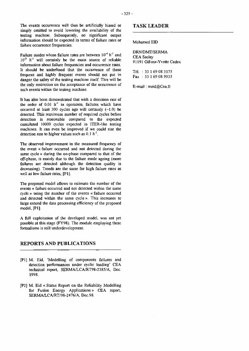
- 3 2 5 -
The events occurrence will thus be artificially biased orsimply omitted to avoid lowering the availability of thetesting machine. Subsequently, no significant outputinformation should be expected in terms of failure rates orfailure occurrence frequencies.
Failure modes whose failure rates are between 10^ h"1 and10'3 h"1 will certainly be the main source of reliableinformation about failure frequencies and occurrence rates.It should be underlined that the occurrence of thesefrequent and highly frequent events should not put indanger the safety of the testing machine itself. This will bethe only restriction on the acceptance of the occurrence ofsuch events within the testing machine.
It has also been demonstrated that with a detection rate ofthe order of 0.01 h'1 in operation, failures which haveoccurred at least 300 cycles ago will certainly (~1.0) bedetected. This maximum number of required cycles beforedetection is reasonable compared to the expectedcumulated 10000 cycles expected in ITER-like testingmachines. It can even be improved if we could rise thedetection rate to higher values such as 0.1 h"1.
The observed improvement in the measured frequency ofthe event « failure occurred and not detected during thesame cycle » during the on-phase compared to that of theoff-phase, is mainly due to the failure mode ageing (morefailures are detected although the detection quality isdecreasing). Trends are the same for high failure rates aswell as low failure rates, [PI].
The proposed model allows to estimate the number of theevents « failure occurred and not detected within the samecycle » using the number of the events « failure occurredand detected within the same cycle ». This increases tolarge extend the data processing efficiency of the proposedmodel, [PI].
A full exploitation of the developed model, was not yetpossible at this stage (FY98). The module employing theseformalisms is still underdevelopment.
TASK LEADER
Mohamed EID
DRN/DMT/SERMACEA Saclay91191 Gif-sur-Yvette Cedex
Tél. : 33 169 08 3175Fax : 33 1 69 08 9935
E-mail : [email protected]
REPORTS AND PUBLICATIONS
[PI] M. Eid, 'Modelling of components failures anddetection performances under cyclic loading' CEAtechnical report, SERMA/LCA/RT98-2385/A, Dec.1998.
[P2] M. Eid « Status Report on the Reliability Modellingfor Fusion Energy Applications » CEA report,SERMA/LCA/RT/98-2476/A, Dec.98.

-327 -
UT-SM&C-WI
Task Title: DESIGN AND ANALYSIS OF VACUUM VESSELAND INTERNALS
INTRODUCTION
The task UT-SM&C-VVI is a contribution to the EuropeanFusion Underlying Technology Programme. This task isintended to maintain/develop the DMT competence andanalysis tools in the field of the design of the tokamaksvacuum-vessel and internals (divertor, limiters, baffle, firstwall, shielding blanket, breeding blanket).
1998 ACTIVITIES
The main performed activities in 1998, some of them to beseen as a continuation of those described in [A], havemainly addressed two components : the ITER BreedingBlanket (BB) in support to the Task CNET 98-474 activity,and the ITER baffle in support to the ITER JCT activity. Inparticular, for the ITER BB the work included : 1) thermalanalysis of slow high-power plasma Vertical DisplacementEvent (VDE), and 2) thermo-mechanical analysis of the BBmodule box. For the ITER baffle the work concerned the« reference » transient thermo-mechanical analyses of theITER baffle module Nb. 26.
THERMAL ANALYSIS OF SLOW HIGH-POWERVDE
The most critical design condition to be considered for thefirst wall consists in slow high-power VDE. During suchevent, between 20 and 60 MJ/m2 are dumped on the FirstWall (FW) in ~ 0.3 s, leading to the melting of a thin layerof the Be protection. The FEM computer code
CASTEM2000 has been used to evaluate the thermaltransient in the FW during a high-power VDE [B]. A localtwo-dimensional model (Figure 1) including the Beprotection and the stainless steel FW appeared to besufficient to analyse this temperature transient. As meltingof beryllium will occur during each VDE, thick Beprotection - at least 10 mm - have been considered here.
In the present CASTEM 2000 model, the Be melting istaken into account by adding the melting latent heat(1300kJ/kg) to the heat capacity of the Be over a pre-defined temperature interval of 40°C. Moreover, energy-absorbing phenomena such as evaporation, impurity [1] orblackbody radiation (surrounding structures taken at 500°C)have also been taken into account by the use of appropriatelaws. An energy dumping of 60 MJ/m2 in 0.3 s has beenhere considered in the analysis, corresponding to anincident surface heat flux of 200 MW/m2 during 0.3 s.
Figure 1 : Local 2D thermal mesh of the First Wallfor VDE analysis
Table 1 : Thermal results for a slow high-power VDE in the first wall (60 MJ/m2 in 0.3 s)with a 10 mm thick Be protection. Thermo-hydraulic parameters set to nominal value
Max. surface temperature
Surface temperature
Max. T at different depths
Be melted thickness
Minimum water sub-cooling
t = O.ls
t = 0.3s
t = 3s
at 1 mm from surface
at 2 mm from surface
at 3 mm from surface
at 10 mm from surface (Be/SS interface)
t = 0.3s
t = 3s
1991 °C
1974 °C
1991°C
557 °C
1128°C
886 °C
761 °C
493 °C
0.6 mm
31 °C

-328-
Thermohydraulic parameters are those defined for thenominal case (Twater = 150°C, 40 bars) and thecorresponding convective heat transfer coefficient iscalculated as a function of the wall temperature.
The main thermal results for the most critical energydumping - 60 MJ/m2 in 0.3 s on a 10 mm thick Be tile - canbe summarised as follow (see Table 1 and Figure 2) : i) themaximum temperature reached at the Be surface is about1991°C, which is higher than the melting temperature of Be(1283°C); ii)the melted Be thickness is evaluated to0.6 mm ; iii) the risk of exceeding the CHF is null, as asignificant minimum sub-cooling of 31°C is maintained inthe coolant flow ; iv) the maximum temperature reached atthe Be/stainless steel interface is evaluated at 493°C,reached 2.5 s after the beginning of the transient.
Figure 2 : Thermal transient of the First Wall during high-power VDE (60 MJ/m2 in 0.3 s).
A0 affront surface, All (resp. A22) at 1 (resp. 2) mmfrom front surface.
These results strongly indicates the interest of considering alarge Be protection thickness - at least 10 mm - related tothe expected number of VDE encountered by the FWduring the EPP of ITER. The choice of a Be/stainless steelinterface material, which is strongly related to themaximum temperature reached, should also take intoaccount the temperature increase due to the reduction inthickness of the Be protection during each VDE.
THERMO-MECHANICAL ANALYSIS OF THE BBMODULE BOX
The finite element code CASTEM 2000 has been used toevaluate the transient thermo-mechanical behaviour of theoutboard module box during normal cyclic operation [C]. Atwo-dimensional model of a cross section of an halfoutboard module #19 box including first wall, coolingplates and shield block has been used and detailed geometryand cooling conditions are given in [C]. Mechanicalcalculations have been performed using the generalisedplane strain option. The transient calculations have beenperformed assuming the nuclear heating cycle simulatingthe fusion power ramp-up of a normal operating cycle inITER [2]. The main results on temperatures and thermalstress level at steady-state are summarised in Table 2.
The maximum temperature of the module box is located atthe corner of the first wall and at the back of the side wall.This indicates that cooling circuit design should be nowoptimised for detailed areas like corners, side walls andshield block. The corresponding thermal stress level showsa stress concentration at the corner of the module box and inthe side wall (Figure 3) which is due to stress level inducedby the global deformation of the structure. The stress levelreaches its maximum of 495 MPa at the corner.
Figure 3 : Von Mises thermal stress (MPa) distributionat steady state under 100% nuclear heating(Fim = 0.5 MW/m2, NWL = 1.25 MW/m2).
Zoom on the side part of the module
Table 2 : Temperature and von Mises stress level of the outboard module at steady-stateunder 100% nuclear heating (Finc = 0.5 MW/m2, NWL = 1.25 MW/m2)
First Wall (FW)
Cooling Plates (CP)
Shield Block (SB)
Total Module Box (FW + CP + SB)
T min. (°C)
150
171
150
150
T average (°C)
208
202
218
211
T max. (°C)
373
285
278
373
Von Mises max. (MPa)
495
220
293
495

-329 -
This study has shown clearly the need to define detaileddesign of the cooling circuit in shield block, side walls andat the front corner of the stainless steel module box. Thethermal stress level in those regions are indeed often veryhigh (~495 MPa) and could be minimised with appropriatedesign of the cooling circuits.
TRANSIENT THERMO-MECHANICAL ANALYSESOF THE ITER BAFFLE MODULE N°26 p ]
Transient thermo-mechanical analyses have beenperformed for the ITER baffle, module 26 (lower outboardmodule) with tungsten-tiles. Calculations concerned theequatorial section of the module (straight part) and didn'ttake into account the fixing holes. They have been used asthe "baffle reference" analyses included in the ITERComprehensive Design Report edited in July 1998 andwhich has concluded he ITER EDA period.
Taking into account the typical ITER transient loads (seeTable 3), thermal calculations have been performed for twocycles ; the main results are indicated in Table 3, whileFig. 4 shows the temperature distribution in the FW at theend of the first cycle. Elastic and elasto-plastic transientmechanical calculations', with various modeling of thehardening law assumed for the OFHC-layer have beenperformed after taking into account the thermal evolution.
The main results were that thermal gradients andtemperature level have been found acceptable in any part ofthe structure, and from the thermal-hydraulic point ofview, the FW concept presented a large margin againstcritical heat flux event. The level of stress at the top of theW-tiles being reasonable (less than 600 MPa) even with a2D generalised plane strain mechanical analysis, the 3Dcalculation taking into account the 5 mm-thick poloidalcastellations has not been judged necessary.
Table 3 : Temperatures reached in baffle materials at various times of the transient calculation
Load Histogram for Baffle analysis (first cycle)
time (s)
Heat Flux (MW/m2)
Nuclear Heating (%)
0
0.12
0
150
0.12
0
200
3
100
1200
3
100
1210
0
0
2200
0
0
Thermal transient calculation results (Temperature in °C)
min.
Wl%La2O3-tilcs ave.
max.
min.
OFHC-layer ave.
max.
min.
DSC-heat sink ave.
max.
min.
SS-liner ave.
max.
min.
SS-shield ave.
max.
min.
Total ave.
max.
t=1200 s
355.9
504.2
652.1
343.5
352.7
364.7
227.1
271.8
348.9
191.1
239.6
312.9
181.7
216.0
265.7
181.7
224.1
652.1
t=3400 s
355.9
504.2
652.1
343.5
352.7
364.7
227.1
271.8
348.9
191.1
239.6
312.9
181.7
216.1
265.7
181.7
224.2
652.1
t=2200 s
140.0
140.0
140.0
140.0
140.0
140.0
140.0
140.0
140.0
140.0
140.0
140.0
140.0
141.1
149.9
140.0
141.0
149.9
t=4400 s
140.0
140.0
140.0
140.0
140.0
140.0
140.0
140.0
140.0
140.0
140.0
140.0
140.0
141.1
150.0
140.0
141.1
150.0

-330-
Temperature (C)
> 1.91E+02
< 6.52E+02
1.95E+02
2.16E+02
2.38E+02
2.59E+02
2.81E+02
3.03E+02
3.24E+02
3.46E+02
3.67E+02
3.89E+02
4.11E+02
4.32E+02
4.54E+02
4.76E+02
4.97E+02
5.19E+02
5.40E+02
5.62E+02
5.84E+02
6.05E+02
6.27E+02
6.48E+02
Baffle Module 26 - TIME = 1200.00 S
Figure 4 : Baffle transient thermal analysis: temperature distribution in the FW
Von Mises thermal stresses obtained with an elasticcalculation are within allowable values (below 3Sm) for theshield, the liner and the major part of the DSC-heat sink.Elasto-plastic analysis has also been performed, inparticular because of the high level of stress found in theOFHC compliant layer. SS-liner and DSC-heat sink werealso treated with an elasto-plastic model. Relevant fatiguecurves necessary to correctly predict lifetime for thesematerials are not available at present. However, levels ofplastic strain found in these calculations are far below thosecomputed for the various high heat flux component mock-ups which have been tested under thermal cycling withsuccess. Even if these conclusions have to be verified withrelevant tests and checked when data will be available,plastic strains are considered acceptable. Therefore, suitablefatigue lifetime for this component can be ensured.
CONCLUSIONS
The activities performed within this task have been ofsignificant importance, both for the contribution to the in-vessel components designs and for the understanding ofcritical issues related, in particular, to the severe conditionsto which are submitted the FW of plasma-facingcomponents. Main achievements in 1998 have been theidentification of some improvements required for the ITERBB, such as the use of thicker Be-tiles and the need ofmodifying the BB module box cooling circuit, and theestablishment of the reference thermo-mechanical analysesfor the ITER baffles. These and past activities in the field ofITER in-vessel components designs have permitted to givesignificant contribution to papers presented at various 1998international conferences [E, F, G, H].

- 3 3 1 -
REFERENCES TASK LEADER
[1] Yu. Igitkhanov et al., Effect of Slow High-PowerTransients on ITER Divertor Plates and LimiterComponents, 22nd Conference on Controlled Fusionin Plasma Physics, July 95, Bournemouth, UK.
[2] ITER Design DescriptionBlanket System, 1997.
PUBLICATIONS
Document, WBS1.6A
[A] P. Magaud, F. Le Vaguères (eds.), FusionTechnology, 1997 Annual Report of the AssociationCEA/EURATOM, Task UT-SM&C-W&I, CEADSM/DRFC, May 1998.
[B] Y. Poitevin, L. Giancarli, Transient thermal analysisof the ITER Breeding Blanket outboard module, CEAReport SERMA/LCA/RT/98-2428, October 1998.
[C] Y. Poitevin, L. Giancarli, Thermo-MechanicalAnalysis of the ITER Breeding Blanket Module Box,CEA Report SERMA/LCA/RT/98-2435, December1998.
[D] J.F. Salavy, L. Giancarli : Transient thermo-mechanical analyses of the ITER Baffle Module n°26,CEA Report, SERMA/LCA/RT/98-2347/A, May1998.
L. GIANCARLI
DRN/DMT/SERMACEA Saclay91191 Gif-sur-Yvette Cedex
Tél. : 33 1 69 08 21 37Fax : 33 1 69 08 99 35
E-mail : [email protected]
[E] M. Merola, L. Giancarli, et al., European high heat-flux component development for ITER, presented atthe 8th Workshop on Carbon Materials, 3-4 Sept.1998, Julich, Germany, to be publ. in Physica Scripta.
[F] L. Giancarli, et al., Alternative design proposal forCFC-monoblocks to be used in ITER high heat-fluxcomponents, presented at SOFT-20, September 7-11,1998, Marseille, France.
[G] M. Ferrari, Y. Poitevin, et al., ITER ReferenceBreeding Blanket Design, presented at SOFT-20,September 7 - 1 1 , 1998, Marseille, France.
[H] A. Cardella, L. Giancarli, et al., Design of the ITEREDA Plasma Facing Components, Fus. Eng. & Des.39-40 (1998) 377-384.

- 3 3 3 -
UT-SM&C-BLK
Task Title : HELIUM COOLED PEBBLE BED BLANKET
INTRODUCTION
The CEA has proposed, within the EU-Fusion Program, toexamine the use of the lithium meta-zirconate/meta-titanate as breeder materials for DEMO-HCPB blanket andto assess the impact of the use of these candidates on thegeneral design features. The reference breeder material forthe EU-HCPB blanket of DEMO is the lithium ortho-silicate, proposed and studied by FzK.
Accordingly, the CEA has presented a 1st proposal in 1997[R1,R1] and assessed the impact of using these potentialcandidates on the DEMO-Blanket general features. Themain characteristics of that proposal was the use of abreeder beds as thick as 16-18 mm with ceramic breedermaterials as rich as 25-28% in Li6. The resultantmaximum operating temperatures was evaluated to be ashigh as 1215 °C. Some recent experimental work onpebble thermal stability have increased the uncertainty inthe thermal stability of the Li-zirconat/-titanante at suchhigh temperatures. Although the full interpretation of theseresults has not yet been completed, the HCPB-blanketproject leader joined by materials experts haverecommended to revise the CEA proposed design to resultin lower operating temperatures. Due to the absence of allexperimental figures, the project leader advised to keep themaximum operating temperature around the indicativevalue of 900 °C for both meta-zirconate and the meta-titanate ceramics.
In additions, the EU-Fusion Program has decided to usethe EUROFER97 rather than the Martensitic (MANET) asstructure material. A change that would alter significantlythe TBR and the neutron induced activation characteristicsof the HCPB blanket.
Subsequently, it appeared necessary to revise the CEAproposal in order to integrate the materials experts'recommendations and the DEMO new specifications.
1998 ACTIVITIES
In 1998, a wide set of optimum configurations, in the TBRsense, has been determined for DEMO-HCPB. A givenconfiguration will be fully defined by the cooling platethickness (tl), the breeder bed thickness (t2) and the Be-bed thickness (t3) for a given breeder ceramic at a givenLi-6 enrichment. Thus the option Zr50%-08.09.80 willassign a 8mm for the cooling plate thickness, a 9mm ofbreeder bed thickness and a 80mm of Beryllium bedthickness in the case of the lithium meta-zirconate ceramicwith 50% enrichment in Li-6.
The BoL Li6 enrichment will be fixed at 50% for allstudied configurations. This resulted from theinvestigations done in 1997, [Rl], where thermalcalculations showed that approaching values near to 900-1000°C of maximum operating temperatures shouldnecessitate decreasing the breeder thickness to values lessthan 12mm. At such small thickness of the breeder bed,only Li6 enrichment equal or higher than 45% willguarantee the TBR value of 1.07 at BoL (considering theports).
GEOMETRICAL MODEL
The HCPB blanket geometry has been described by a 3Dlocal model in the equatorial plan region. It allows tocalculate the maximum neutron heating rates in the bedsand optimise the TBR as well. The 3D-local model used inthe neutronic optimisation is fully described in [Rl, PI].Three ceramic bed thickness have been considered 9, 10and 12 mm. At each ceramic bed thickness, the Be-bedthickness has been varied from 30 to 80 mm and theoptimum Be-bed thickness is determined.
TBR OPTIMISATION
TBR optimisation calculations were carried on usingTRIPOLI4, the CEA Monte Carlo neutron transport code.The details of this parametric evaluations are given in[PI]. The local TBR values are calculated with statisticaluncertainty less than 0.1% in the worst case. The choicebetween different possible breeder bed thickness will bedecided in function of the maximum nominal temperatureobserved in the equatorial breeder bed. Among differentexamined options, the series of Zr50%_08.12.80,Zr50%_08.10.80 and Zr50%_08.09.80 have resulted in alocal TBR of 1.43, 1.42 and 1.41, respectively. At Be-bedthickness of 80mm, the optimum TBR change slightly withthe breeder bed thickness between 12 and 8mm. The finalchoice will be done in function of the maximum operatingtemperature.
BREEDER DEPLETION
The 2nd needed quantity is the Li-depletion in the time.Starting from the depletion rate of Li6 and Ii7 per neutronemitted in the plasma at 14.1 Mev calculated byTRBPOLI4, the Ii6-enrichment as function of the operatingtime at full power could be determined, [P1,P2]. Thevariation of the Li6-enrichment against the operating timein the case of the Zr-08.09.80 option shows that the Li6-enrichment lower limit of 47% would be attainable around28 000 hours of full power operation. An enrichment of47% is corresponding to a local TBR of 1.39(corresponding to a 1.05 global 3D TBR with the ports, atthe EoL).
- 3 3 4 -
NEUTRON FW LOAD
The resultant FWOB maximum neutron loading wasevaluated to be equal to 2.87 MW/m2 while the meanneutron loading is equal to 2.50 MW/m2 with an offsetfactor of 1.15 due to the neutron source poloidaldistribution.
HEAT RATE RADIAL DISTRIBUTION
The heating rate radial distribution in the OB-breeder bedin the vicinity of the equatorial plan, for the Zr50%-08.09.80 option, is evaluated to 67 W/cm3 within the20mm behind the FW and decreases to 8 W/cm3, 50 cmfurther.
MAXIMUM OPERATING TEMPERATURE
All examined options have been evaluated and themaximum operating temperature in each option wasdetermined. In the precise case of the breeder bed option ofZr50%-08.09.80 the maximum heating rate issued fromthe neutronic calculation was estimated to be about 67W/cm3 (BoL). Using the relations describing the effectivebed conductivity as mentioned in [PI] would produce amaximum operating temperature in the OB-breeder bedequal to 1085 °C (for CP and FW at 450 °C).
The option Zr50%-08.09.80 results in the lowest maximumoperating temperature.
PEBBLE THERMAL STABILITY
The main restriction on the maximal allowable operatingtemperature is due to the existing uncertainty on thethermal stability of the lithium meta-zirconate and thelithium meta-titanate at temperatures as high as 1000 °Cand slightly beyond.
Long annealing behaviour in air for temperatures between800 and 900 has been tested for the meta-zirconate andmeta-titanate in pebbles form and results are reported in[R4]. It concludes that, for lithium zirconate, produced byextrusion and sintered at 1050°C for 2 hours, grain sizeshows almost no-significant change between 800 °C - 900°C, up to 75. Results were confirmed in the testseffectuated at Fzk in He+0.1%H2 at 970 C during 96 days.In this campaign, X-ray diffraction pattern tests indicatedno additional phase within the detection limits (~ 1%).However, a slight densification was observed from porositymeasurements from 89% TD at the beginning-of-test to90.5% at the end-of-test. It has also been observed that theannealing effect decreases significantly for the pebbleshaving been sintered at higher temperatures (~1200 °C) forzirconate and titanate. Thus, It seems that potentialimprovements in the pebble thermal long term behaviourwould be possible by developing fabrication proceduresusing higher sintered temperatures. However, the tritiumrelease behaviour of the pebbles sintered at highertemperatures should be re-examined.
As for crash load time evolution, only zirconate andtitanate pebbles were tested in the CEA testingprogrogram. For titanate pebbles sintered at 1050 °C,crush load seems tend to a limit of 1.7 daN after 90 days ofcontinuous annealing at 900 C. For the zirconate pebblessintered and annealed in the same conditions, the crushload limit tends towards a constant value of 1.9 daN. In allthree ceramics one may conclude that crush load decreasesby almost 50%. However, the crush load limit of thesilicate pebbles presents specific concerns for HCPBregarding the fact that it has the lesser crash load limit.While, the crush load limits for the zirconate/titanateshould not en principal rise any specific concerns.
The effect of thermal cycling has also been examined intwo configurations ; 1/ cycling at temperatures between 80and 600 °C for some 600 cycles, and. 2/ cycling at a rangebetween 1100 °C and 1200 °C for some 30 cycles. It seemsas if the crush load after cycling tends to the crush loadcorresponding to the upper temperature of the cycle.
THERMAL POWER BALANCE
The total plasma energy is transferred to the blanket andthe in-vessel surrounding structure through neutrons at14.1 MeV (1800 MW*) and alpha-particles (400 MWth).Neutronic calculations estimated the global quantity ofuseful thermal energy deposed and amplified by theneutron transportation in different blanket structure by2875 MWth, [R5].
It showed also that the major part of the thermal energycomes from the breeder bed zone with the same share of41% of the total energy production, in the IB- and the OB-breeders, in the IB- and OB-segments, respectively.
The 2nd important contribution is that of the multiplierwith almost 35.5% in the case of the OB-segments and30% in the IB-segments.
The rest of the contributions comes from the metallicstructures principally made of the Eurofer (FW, coolingplates, side-walls, and back-walls). The contribution of themetallic parts rises to about 25% of the total production ofthe thermal energy in the blanket.
ACTIVATION CALCULATION
The activation of the structure components such as the FWand the CP in the HCPB blanket has been assessed. For allstructure components, neutron irradiation time was takenequal to 20000 h of full power irradiation regime.
The specific activity of the Eurofer structures attain some10+12 Bq/kg and 2 10+u Bq/kg, just after 20000h of fullirradiation time, for the FW and the other blanketstructures, respectively. Calculations shows that the maincontribution comes from radioactive elements such as F55(-25%) and W187 (20%), just after shutdown. After 200years, the specific activity becomes lower than 104* Bq/kg.

-335 -
Roughly estimations show that an OB-segment will emitsome 3.5 10+15 Bq just after shutdown. This maximumactivity is shared between the FW (2.3 10+15 Bq) and theother components (1.2 10+15 Bq).
The dose rate is relatively higher for the FW componentscompared to the CP ones. For all structures, dose rate is ofthe order of 10+5 Sv/h just after shutdown. It decreases byfactor of 2 after one cooling year and by 3 decades after 10years. Just after shut down, the main contributions in thedose rate come from the W187 and the V52. The situationchanges after one year and lasts for few tens of years withmajor contributions coming from F55 and Co60.
As for the specific decay heating rate, we observe the sametendency of having the FW relatively hotter than the otherstructures, [P2]. The heating rates of 10"4 kW/kg and 4 10"5
kW/kg are observed just after shut down for the FW andthe CP, respectively. Then, they decrease by some 2decades in one year. After 10 years, the heating rates arealready lower than 10"7 kW/kg, whatever the structure is.
[R2] J. F. Salavy, M. Eid 'Neutronic & thermalcharacteristics of the HCPB blanket in the case of theuse of the zirconate/titanate as breeder material'technical report, DMT 97/552, SERMA/LCA 2155,CEA, 01/1998.
[R3] D. Lulewicz - N. Roux, « Development of Li2ZrO3and Li2TiO3 pebbles. Report Jannuary-Decemberl997 » technical report - DT97/064JDL/NR/FL, CEA.
[R4] J D. Lulewicz - N. Roux, « Examination at CEA ofLi4SiO4, Li2ZrO3 and LI2TiO3 pebbles specimensbefore and after the long time annealing test at FzK »technical report - DT98/081 JDL/NR/FL, CEA.
[R5] M Eid et al. « European Blanket ; CEA contributionto the HCPB Design, impact of the use of thezirconate/titanate as breeder materials » CEAtechnical note, SERMA/LCA/RT/98-2475/A,Dec. 1998.
CONCLUSIONS REPORTS AND PUBLICATIONS
CEA has to revised its concept proposed in 1997, [RI, R2].The revised concept make use of a breeder bed of 9mmthickness, a Be-bed of 80mm thickness and a coolingplates with 8mm thickness, [P1,P2]. The zirconateenrichment in Li6 is increased up to 50%. The maximumheating rate in the breeder bed of this concept (Zr50%-08.09.80) is about 67 W/cm3 resulting in a maximumoperating temperature equal to 1085°C.
The corresponding overall 3D TBR (considering the ports)is equal to 1.09 at BoL. Breeder depletion calculationsshowed that this blanket (Zr50%-08.09.80) may operatecontinuously at full power for some 28 000-29 000 hoursbefore attending the EoL TBR limit of 1.05 (3D withports).
Limitations on the maximum operating temperature in theceramic breeder comes from uncertainty in the thermalstability of the pebbles and Li transport at hightemperatures. However, experimentally confirmed figuresare lacking.
REFERENCES
[PI] M. Eid et al. « Neutronic Optimisation of the HCPBBlanket using the zirconate/titanate as breedermaterials » CEA technical note,SERMA/LCA/RT/98-2384/A, Sept. 1998.
[P2] M. Eid et al. « Status report on the HCPB Blanketusing the zirconate/titanate as breeder materials »CEA technical note, SERMA/LCA/RT/98-2462/A,Dec. 1998.
TASKLEADER
Mohamed EID
DRN/DMT/SERMACEA Saclay91191 Gif-sur-Yvette Cedex
Tél. : 33 169 08 3175Fax : 33 1 69 08 9935
E-mail : [email protected]
[Rl] M. Eid, J. F. Salavy, 'Contribution to the HCPBblanket design optimisation in the case of the useof the zirconate/titanate as breeder material'technical report, DMT 97/551, SERMA/LCA2154, CEA, 01/1998.

- 3 3 7 -
UT-SM&C-LiPb
Task Title : PURIFICATION OF LIQUID METALS
INTRODUCTION
During operation of the water-cooled liquid metal blanket,the steel box which acts as the liquid metal container canbe corroded by the Pbl7Li alloy flowing at low velocity.The corrosion products dissolved in the alloy are thentransported with the flow. In some regions, characterizedfor example by low temperatures, these corrosion productscan crystallize and form aggregates which can be depositedon the walls. The processes of corrosion, formation ofaggregates and deposition depend on several factors suchas temperature, hydrodynamics, solubility, kinetics ofexchange at the solid/liquid interface, roughness of thewall... Another significant factor is the high externalmagnetic field used to confine the plasma.
The deposition in uncontrolled zones can lead to pluggingand the accumulation of activated products is a problem forthe maintenance. Therefore, it is necessary to remove themetallic impurities present in the liquid alloy andpurification methods have to be developped. One way is topromote the preferential deposition of the products incontrolled areas either by cold trapping or by magnetictrapping. It results that the deposition process has to beunderstood from a basic point of view.
1998 ACTIVITIES
In 1998, the effect of a magnetic field on the formation ofdeposits in Pbl7Li liquid alloy has been examined. Morespecifically, the deposition of metallic elements resultingfrom the corrosion of steels by the liquid alloy underthermal gradient and magnetic field has been studied. Thecase of martensitic steel exposed to Pbl7Li has beenconsidered and the deposits formed in such conditions havebeen identified.
EXPERIMENTAL PROCEDURE
Martensitic steel (type 56T5: 86.7Fe-10.5Cr-0.66Ni-0.65Mo-0.61Mn-0.48Nb-0.18V-0.22Si) has been used asmaterial. It was prepared in tubes which were closed at oneend by welding and filled with liquid Pbl7Li under anargon atmosphere. The open ends of the tubes were thensealed under vacuum. Two steel tubes were exposed toPbl7Li: one was placed under thermal gradient withoutmagnetic field (test 1), the second one was placed underthermal gradient with magnetic field (test 2). The tubeswere vertically located in a furnace where a temperaturegradient was established for the test duration.
In test 1 without magnetic field, the temperature gradientwas 510-250 °C. In test 2 with magnetic field, atemperature gradient 510-250 °C was arranged and apermanent magnet (0.25 T) was placed around a region ofthe tube where deposition was thought likely to occur inthe hope of trapping out any ferromagnetic materials. Inthe present experiment, the magnet was placed in atemperature region ranging from 390 to 320 °C.
On completion of tests (3300 h), the crystals formed on thewalls of tubes or in the bulk of the lithium-lead alloy werecharacterized and the composition of the solidified Pbl7Liwas analyzed.
CHARACTERIZATION OF DEPOSITSWITHOUT MAGNETIC FIELD
FORMED
In test 1, no corrosion layer was observed on the surface of56T5 steel. The only evidence for corrosion was the directobservation of crystals on the walls of tubes after theremoval of Pbl7Li, indicating that mass transfer occurred.Therefore, the main constituents of this steel seem tocorrode at a similar rate when it is in contact with moltenPbl7Li. Dissolved metallic elements were found in Pbl7Li(in wppm): 13 for Fe, 3.5 for Mn, < 1.5 for Cr and < 0.7for Ni.
The characterization of crystals deposited on the steelsurface was complex because they were distributed all overthe tube and exhibited varying compositions. Nevertheless,some results may be drawn.
The hottest part of the tube (480-510 °C) was mainlycomposed of iron-rich crystals having the composition97.5Fe-2.5Cr. In the temperature range 400-480 °C, othertypes of crystals were observed in small quantities: Fe-Crcrystals (38Fe-59Cr-3Mo), Ni-Fe-Mn-Sn crystals (29.2Ni-27.2Fe-14Mn-28.3Sn-l.lCr-0.3Mo) and Fe-Nb crystals(28.2Fe-65.7Nb-2.5Cr-3Mo). For lower temperature(T<400 °C), the Ni-Fe-Mn-Sn crystals were foundassociated with higher chromium content (32Ni-10.5Fe-16Mn-33.5Sn-8Cr).
It was deduced that the Fe/Cr ratio of these crystalsdecreases with temperature. However, at temperature lessthan 350°C, the Fe and Cr concentrations were bothlowered and the crystals reach the composition 33.5Ni-7Fe-18Mn-39Sn-2.5Cr which corresponds to the ternarycompound (Ni,Fe,Cr)2MnSn.
Although the concentrations of Ni and Mn in steel, and Snin Pbl7Li are very low, these three elements are easilyassociated to form crystals.

- 3 3 8 -
•"'s
.*'
t. '*.fa; General view (b) Orientated 92Fe-8Cr crystals
Figure I : Deposits in Pbl 7Li under magnetic field
CHARACTERIZATION OF DEPOSITS FORMED INTHE PRESENCE OF A MAGNETIC FIELD
In test 2. the corrosion behavior of 56T5 steel seems similarto that observed in test 1. Corrosion is detected becausecrystals are found but the experimental procédure does notpermit to say if there is a quantitative effect of the magneticfield on the corrosion process. Furthermore, the magneticfield is placed in a low temperature region so its effect oncorrosion is probably limited. The concentration of metallicelements present in PblTLi alloy at the end of this test hasbeen determined. It was found (in wppm): 6.5 for Fe and1.9 for Cr. The Fe concentration is thus divided by a factorof 2 compared to test Î.
A completely different situation was observed with regardto the distribution of crystals in test 2. In fact, the regionwhich had been at a temperature ranging from 510 to 390°C during the test was nearly free from deposition. Most ofthe crystals were found in the region which was directly inthe magnetic field (temperature range 390-320 CC). Figure 1shows abundant crystals which were detected in this areaafter removal of Pbl7Li. Another evidence for the effect ofthe magnetic field is the fact that the crystals are notrandomly distributed but orientated along directions (Fig.1b). The EDS analysis indicates they are composed of ironand chromium: 92Fe-8Cr. A large quantity of these crystalswas suspended in the frozen alloy (about 75 mg) but someof this material were also found adhering to the surface ofthe tube. For temperatures less than 300 °C (correspondingto the part of the tube below the magnetic field), somecrystals were sparsely detected. The analysis showed theircomposition to be a mixture of Ni, Mn and Sncorresponding to the ternary compound (Ni,Fe,Cr)iMnSn.The deposition of this material seems unaffected by thepresence of the magnetic field because it was also found inthis range of temperature in test 1.
Therefore, the presence of the magnetic field alters thedistribution of corrosion products formed under thermalgradient.
Preferential deposition of ferromagnetic Fe-Cr crystals inthe region affected by the field has been observed. Thedecrease of the Fe content remaining in the Pbl7Li alloy atthe end of the test is consistent with magnetic trappingeffect.
CONCLUSION
A series of simple deposition tests has been carried out inPh!7Li contained in martensitic tubes under a thermalgradient. Different types of crystals have been identified,composed of Fe and Cr or a mixture of Fe, Cr, Ni. Mn andSn. They were found in various quantities and distributedail over the steel surface.
Tne deposits with Ni, Mn and Sn were detected in verysmall quantities at low temperature below 300 CC. Inpresence of a magnetic field there was a marked differencein behavior.
There was nearly an absence of crystals in the hightemperature region out of the magnet. The majority ofdeposits was observed in the region placed in the magneticfield, some adhering to the steel walls and some in the bulkof the Pbl7Li. Only one type of this ferromagnetic depositcomposed of Fe and Cr was found. The magnetic field hasno effect on the small amount of deposits composed of Ni,Mn and Sn.
There is evidence for the magnetic field effect on thetrapping of ferromagnetic material. Deposition is observedin the region directly affected by the field and theconcentration of iron in solution in Pbl7Li is lowered.Therefore, magnetic trapping would be an effective methodto remove Fe and Cr from the liquid alloy.

- 3 3 9 -
PUBLICATIONS
[1] F. BARBIER, "Deposition of corrosion products inliquid Pbl7Li under a magnetic field: case of amartensitic steel", RT SCECF 476 (December 1998).
TASK LEADER
F. BARBIER
DTA/CEREM/DECM/SCECF/LECNACEA Saclay91191 Gif-sur-Yvette Cedex
Tél. : 33 1 69 08 16 13Fax : 33 1 69 08 15 86
E-mail: [email protected]

- 3 4 1 -
UT-SM&C-LME
Task Title : LIQUID METAL EMBRITTLEMENT
INTRODUCTION
In the frame of the future fusion reactors, liquid metalsmight be used as coolants in parts submitted to high heatpeaks (for example, divertor), or as tritium breedingmaterials (for example, lithium-lead alloy). This impliesthat the properties of the structural materials must not beaffected by the presence of the liquid metal. Thus, for asafe operation of the reactor, one must be aware of theproblems which can arise during the solid-liquid contact.
It has long been known that ductile solid metals exposed tospecific liquid metal environments may exhibit asignificant reduction in elongation to failure and fracturestrength when they are tested in tension. Under certainexperimental conditions, the liquid metal embrittlement(LME) can be quite dramatic and one of the peculiarities ofthis phenomenon is the crack propagation rate which isreported to be very high (up to 50-500 cm.s1). The factthat a liquid metal can drastically affect the materialresistance to fracture has serious technologicalsignificance.
Embrittlement in liquid metal environments has been thesubject of many reviews describing the phenomenologicalfeatures of the LME, the prerequisites for its occurrence,the effects of variables including grain size, strain rate,temperature, metallurgical state... However, despitedecades of research, a qualitative explanation of LME hasnot yet emerged and its prediction is still missing. It istherefore appropriate that LME should be reviewed in thelight of more recent work to provide a current assessmentof this phenomenon.
1998 ACTIVITIES
In 1998, the literature survey has been pursued. Thevarious mechanisms and models which have beenadvanced so far to describe the LME have been examinedin details.
There are different models of LME mechanism:
- the dissolution - diffusion models of Robertson andGlickman,
- the brittle fracture theory based model, denominatedSJWK, proposed by Stoloff, Johnson, Westwood andKamdar,
- the ductile failure based models of Lynch andPopovich,
- the liquid metal atoms penetration based model ofGordon.
This list is not complete, but the main purpose is to presentthe most outstanding models. A diagram whichsummarizes the elementary mechanisms involved in eachmodel has been proposed (Fig. 1). This diagram describes,for each model, the sequence of the elementarymechanisms leading to the propagation of cracks inpresence of stress and liquid metal.
They are represented by arrows, which are numbered inorder to link the following description of the models to thediagram. It allows to make a quick comparison between thedifferent models and to see whether they use commonelementary mechanisms or not. Furthermore, if we makethis hypothesis that several mechanisms can occur at thesame time to produce LME, as it has yet been proposed,this diagram gives a general overview of all themechanisms that could be involved.
The concept of the adsorption-induced surface energylowering is the central point of all these models, exceptedfor Robertson who does not mention the occurrence ofadsorption. The adsorption-induced surface energylowering has first been introduced by Rebinder, as theorigin of the Rebinder effect (RE) which is one of theeffects exerted by a liquid or a gaseous medium on themechanical properties of solids. RE appears as a plasticflow increase and a strength reduction. The main problemin using the Rebinder effect to describe LME is that it hasa pure thermodynamic character. That is the reason whymany authors have improved his work by adding molecularmechanisms and/or by adding kinetic modelization of thephenomenon.
Robertson has presented his dissolution-diffusion basedmodel in 1966. The main purpose of his theory is to givean expression for the crack propagation rate. There is noreference to a crack initiation stage, consequently the finalexpression concerns only the propagation rate. This modeluses only macroscopic, thermodynamic and elasticconcepts.
According to Glickman, LME is a clear manifestation ofthe Rebinder Effect (RE). He adds to this approach amechanism based on dissolution and diffusion of solidmetal atoms. Glickman worked mainly with solid copperand lead-bismuth melt. His model of the phenomenon ismainly kinetic, but also thermodynamic because it is basedon Rebinder's effect.

- 3 4 2 -
Robertson GHckman
Glickman
DISSOLUTIONUIBOJSION
Click, man
i— 5 —
PRESENCE OFI LIQUID METAL
Glickman
Popovich4
Lynch
SJVVKGordon
O.oe.
ATOM1CROUGHNESS
NUfXRATTON OFDISLOCATIONS
Popovich
10
-H-,
DISLOCATION [PILE-UPS I
Popovich 15
WORKHARDENING
PopovichADSORPTION OFLIQUID METAL I PROPAGATION l£I
17
«
If £13-J !
CRACKNUCLEATION NL'Cl .RATION
i
WEAKENING OF !•! INTERATOMIC i
BONDS I
CooC
19
Gordon
DIFFUSION-PENETRATION
OFEMRWTTI.F.RATOMS
Gordon
Figure 1 : Diagram illustrating all the elementary steps involved in the different LME models
The SJWK model is based on the « weakening ofinteratomic bond » mechanism, which is a particular case ofthe brittle fracture theory. It manages to rationalize theeffects of many experimental variables: temperature, strainrate, grain size, slip character, but it was not capable ofpredicting susceptibility of a new substrate-environmentsystem.
The Lynch model, which is also based on « the decrease ofthe strength of the interatomic bonds », differs from SJWKmodel, because it assumes that crack propagation does notoccur by atom-by-atom rupture of the bonds. This modelgives an explanation for the presence of ductility at amicrolevel. It is mainly based on metallographicinvestigations on many different systems.
Popovich presents a mechanism for LME, based on theRebinder effect and on enhanced plastic flow. At thethermodynamic aspect developed by Rebinder, he adds anatomistic approach. His model is only qualitative and giveno quantitative expression for the time to rupture or for thecrack propagation rate.
The Gordon model is based on the penetration of liquidmetal atoms along the grain boundaries. This concept is thatthe actual crack nucleation event is not the rate-controllingstep in the crack initiation, but rather than during anincubation period there is a preparation process which israte-controlling.
For Gordon, the present approach must allow to explain thedelayed fracture, often observed in experimental studies.
CONCLUSION
The survey has been concerned with the most outstandingmodels that have been proposed so far in the literature todescribe liquid metal embrittlement. Unfortunately, thereview does not allow an easy comparison between them. Infact, we cannot conclude that one model is moreappropriate than another one for a specific solid metal -liquid metal couple. Attempts to apply these models in asystem have often been carried out taking into accountexperimental results obtained in specific conditions.Therefore, we think it is difficult to draw generalconclusions via such limited data.
Some models have been developed to be in agreement withthe behavior of large number of systems. In spite of someadvances, the difficulty still remains to understand and topredict why a particular embrittling species attacks aparticular metal and how the embrittled metal will crack. Asa consequence, the approach which consists in comparingthe results obtained in two different systems is not relevant,since the elementary mechanisms which simultaneouslywork in one system may not be the same as those involvedin the other.

- 3 4 3 -
For example, diffusion-penetration mechanism should notbe eliminated because it is not involved in some systems.In fact, it takes place in the embrittlement of copper-bismuth system, like other elementary mechanisms such asadsorption. For this reason, studying the elementaryprocesses that occur in the embrittlement of a specificsolid-liquid couple may lead to improved understanding.
The chemisorption process, which is assumed in most ofthe models, should be studied. Liquid penetration at sitesof high stress concentrations (e.g., grain boundaries) andits effect on embrittlement should be also moreinvestigated in the future. For example, in a recent paper, amechanism of grain boundary penetration via thedevelopment of a macroscopic amorphous layer has beenproposed to explain the loss of ductility in the aluminum-gallium system. Such a mechanism could be expanded toother systems. It is necessary therefore to investigate newexperimental work in that field including microstructuraland mechanical studies.
TASK LEADER
F. BARBIER
DTA/CEREM/DECM/SCECF/LECNACEA Saclay91191 Gif-sur-Yvette Cedex
Tél. : 33 1 69 08 16 13Fax : 33 1 69 08 15 86
E-mail : [email protected]
PUBLICATIONS
[1] B. JOSEPH, M. PICAT and F. BARBIER, "Liquidmetal embrittlement: a state-of-the-art appraisal", RTSCECF 474 (October 1998)
[2] B. JOSEPH, M. PICAT and F. BARBIER, "Liquidmetal embrittlement: a state-of-the-art appraisal", TheEuropean Physical Journal - Applied Physics 5, 19-31(1999).

- 3 4 D -
UT-SM&C-PB
Task Title : FABRICATION OF PERMEATION BARRIERSUSING CVD PROCESSES
INTRODUCTION
The R&D programme devoted to the fabrication of thetritium permeation barrier (TPB) in the Water CooledLithium-Lead (WCLL) blanket concept is focused on thedevelopment of Fe-Ai coatings by different techniques (hotdipping , CVD. plasma spraying).
The purpose of the study is to show the interest of the CVDtechniques to propose alternative materials for the TPB.
TiAIN deposition by Plasma Assisted CVD (PACVD) andvapour aiuminization have been checked in a first part. Thechromizing and siiiconizing feasabiiity has been studied in1998 on, T91 martensitic steel substrates.
1998 ACTIVITIES
CHROMIZING FEASABILITY
Chromizing has been performed using a pack cementationmethod. The piece to be treated is put in a box in contactwith a cement which powder is composed of Cr as donor.KH4CI as activator and Al;Oj as inert filler which role is toavoid the sintering of the cement. The activator decomposesunder temperature and reacts with the donor to producegaseous compounds of the element to deposit.
The cement has been specifically prepared using a spray-drying process which produces an homogeneous powderwith an average particle size of 50 urn for a composition of25 % of Cr, 4 % of MiUCl and 71 % of AI2O3.
The chromizing has been optimized in a furnace equipedwith a pumping system in order to work under low pressureif necessary. Treatments have been performed at 750°C notto exceed the tempering temperature of the steel. Times of16 hours have been tested.
Coatings of about 1.5 urn thick have been obtained asillustrated on Fig. 1. The layer is rather dense and uniform.There is no defect such as inclusions, cracks, porosities....The adhesion is ensured by diffusion between the film andthe substrate. A control by Energy Dispersive Spectroscopy(EDS) analysis performed on the surface gives acomposition of about 92 % of Cr and 8 % of Fe. The X RayDiffraction analysis (XRD) reveals the formation of Cr^Qcompounds. The formation of chromium carbides duringchromization has been already observed and it strondy
depends on the steel carbon content which participates tothe coating formation by diffusion. Surface analysis byGlow Optical Discharge Spectroscopy (GDOS) confirmsthis carbon enrichment.
Figure 1 : SEM metallography of the chromïzed layer(cross-section)
SILICONIZING FEASABILITY
CVD methods such as processes using SiCu or packcementation are currently used for siiiconizing of steelsaccording to the literature. So the effort has been focused onthe realization of a oxide top layer to check a similarcoating structure as in the case of the Fe-Al/AkOs bi-layerperformed in the frame of the WPA4 programme devoted tothe barrier fabrication.
In effect, in other fields, amorphous silica coatings haveshown remarkable long-term corrosion protection inoxidizing and suipfaidizing environments up to 1000°C andthis seems to be due to its amorphous structure whichprovides a more effective diffusion barrier than thepolycristalline oxide scales formed on iron- or chromium-based alloys exposed to these environments. Silica coatingsare also considered for diffusion barriers in hightemperature hydrocarbon conversion reactors.
Silica deposition has been optimized in order to perform thecoating on the siliconized steei. A Plasma Assisted CVD(PACVD) method starting from an organosilicon precursor(hexamethyldisiloxane : HMDS-G) has been tested becauseit presents the advantage to be easily transferable to anindustrial scale. The coatings have been performed in apiiote-scale reactor. The decomposition of the gaseousphase is activated by the electrical discharge and noadditional heating is necessary. So, the depositiontemperature does not exceed 300°C which does not modifyneither the substrate properties nor the siliconized layer.

-346-
An ion cleaning is carried out before the deposition step (inthe same device) in order to ensure a good adhesion of thecoating.
Uniform and covering coatings are obtained withthicknesses of a few micrometers. The layers are very denseand present a glassy morphology (Fig. 2) which illustratesthe formation of an amorphous structure according to the XRay Diffraction analysis. There is no crack or pinholes andthe film presents a good adhesion during test of rupture inliquid nitrogen. Rutherford Backscatîering Spectroscopy(RBS) and Nuclear Reaction Analysis (NRA) reveal theobtention of different Si/O stoechiometiies according to theratio between the oxygen and the HMDS-Q flow rates :films of plasma-poiymers are formed for low oxygenconcentration in the vapour phase whereas silica coatingsare deposited for high Oj/HMDS-O ratio.
Figure 2 : SEM metallography of a silica coating(cross-section/
CONCLUSIONS
PUBLICATIONS
[1] C. CHABROL, F. SCHUSTER "Fabrication ofpermeation barriers using CVD processes" NT DEMn° 98/81.
TASK LEADER
Claude CHABROL
DTA/DEM/SGMCEA Grenoble17, rue des Martyrs38054 Grenoble Cedex 9
Tél. : 33 4 76 88 99 77Fax : 33 4 76 8S 99 85
E-mail : chabroi:®chartreuse.cea.fr
This study shows the interest of the CVD methods to formvarious coatings with metallurgical characteristicsinteresting with regards to the barrier function (highuniformity, compacity. adhesion....). A iarge panel oftechniques can be used with a choice relevant with thespecifications required by the application. In particular,specific developments can be performed to producecoatings at temperatures compatible with the substrateproperties.
The feasability of TiAIN and silica deposition has beentested and the possibility of aluminizing and chromizing hasbeen shown with different operating condition ranges. Itmust be noticed that SiC coatings which seem promisingbarriers and resistant to corrosion by liquid metais could beeasily performed by the PACVD method used for the silicadeposition.

- 3 4 7 -
UT-SM&C-PBM
Task Title : PEBBLE BED THERMO-MECHANICAL MODELLING
INTRODUCTION
There is evidently an increasing interest in the use of thepebble-beds as a blanket component in the future fusionreactors. In ITER Breeding Blanket (ITER-BB) and inDEMO-Helium Cooled Pebble Bed (DEMO-HCPB)concept both beryllium and breeding ceramics are proposedin the form of pebble beds for the blanket.
However, the behaviour of different pebble bed types underfusion-like load conditions is far from being modelled withsatisfaction. CE A has thus initiated, since 1995, a R&Dprogramme aiming at the modelling and experimentalvalidation of the pebble-bed mechanical behaviour. Withina fusion like environment, the pebbles are subjected toirradiation-induced swelling, thermal (gradient, cyclic)stress and bed wall-induced stress.
After the FY96-FY97 experimental campaigns to validatea model based on the soil mechanics approach, [R1-R6],precisely on the Hujeux model derived from Cam-Claymodel. After validation, the model has been implementedin CASTEM2000, the CEA qualified code in mechanics(CEA/DRN/DMT), [R1-R5].
The pebbles are confined in an elementary basic cell of316L-N stainless steel with typical dimensions of800x60x250 (mm), [PI].
THERMAL LOADING
Be-pebbles (at 310 °C) are subjected to a cyclic loadingand will tend to expand more than the structure itself (at200 °C). Relative thermal strain of each material are givenin details in [PI].
IRRADIATION-INDUCED SWELLING
Be-pebbles swelling is mainly due to He-particlesproduction as a result of the neutron-Be interaction. Theeffective volumetric irradiation swelling of the Be-bed isevaluated to be less than 1% at the EoL (3 Mwy/m3). Thisvalue is extrapolated from the experimental measurementsobtained from the mixed bed Be+Li2Si03 irradiationexperiments, [PI].
GRAVITY LOADING
An order of magnitude equal to 0.8 m of a Be-columnstatic head has been considered to represent the gravityeffect. This equivalent to some 15 kg.
1998 ACTIVITIESCONCLUSIONS
During the FY98, R&D effort has been oriented towardsthe better understanding of the pebble bed behaviour undergiven thermal loading and swelling conditions, andcomparing between different models. Two possibleapproaches have been compared ; 1/ the finite elementsmodel (FEM) and 2/ the discrete elements method (DEM).
The FEM approach is that of the CEA developed modelnew implemented in CASTEM, as described above. While,the DEM approach is that developed at MIT (Boston) andimplemented in the 2D DEM code, MIMES.
Both approaches have thus been applied in one specificcase and compared. The studied case is described in thefollowing sections.
GEOMETRY & MATERIALS
ITER-BB configuration has served as base of the study-case. Interest has been drawn principally towards the Be-pebble bed of ITER blanket. Be-pebble bed is a binary bedof relatively high packing factor 63%/18% (largepebbles/small pebbles) and pebbles are with 1.5-2.3/0.1-0.2mm diameters.
The most significant conclusions out of the methodscomparative analyses are described in the following.
The DEM approach seems interesting in the sense that itallows a step-by-step (in the time) to follow up the localvoid fraction and the pebbles-contact forces evolution. Thethermal loading and the irradiation-induced swelling caneasily be modelled using the DEM. Besides, it should beunderlined that the dynamic aspect of the approachconstitutes its main attractiveness. One the other hand, thepebble-deformation should also be taken into account, but aDEM/FEM coupled approach seems to be too costly at highnumber of pebbles. The DEM has thus appeared limited tothe modelling of large pebbles.
The FEM approach based Cam-Clay type of modellinggives good evaluations when dealing with round-shapepebbles at very high number. It allows the determination ofranges for the setting parameters. It predicts withsatisfaction the overall stress level in the surroundingstructures and determine the criteria for the evaluation ofthe structure failure.

- 3 4 8 -
However, attention should be paid to the fact that themodel has been validated upon non-rigid compressiontests. The blanket pebble bed appears to be relatively toorigid to be directly applied in the blanket configurationwith no-additional corrections.
Additional efforts are still needed to improve pebble-bedmechanical response understanding. A model which isadequate to the fusion blanket operational conditions maycome out of the coupling of the two approaches : the FEMand the DEM. The adequate model should be able to takeinto account the cyclic nature of the mechanical andthermal loads in the future fusion machines, as well.
REFERENCES
[Rl] A. Duchesne, X. Raepsaet « Compte-rendu de lacampagne d'essais triaxiaux sur matériauxgranulaires à grains arrondis » Rapport DMT 96/353,SERMA LCA/1929.
[R2] Fusion Technology, 1996 Annual Report of theAssociation CEA/Euratom, Task UT-PBM, compiledby Ph. Magaud, CEA/DRFC, (5/1997).
[R3] A. Duchesne et X. Raepsaet, « Un modèle élasto-plastique de CASTEM-2000 utilisable pour lamodélisation du comportement mécanique d'un lit departicules » DMT 97/237, SERMA/LCA 2054.
[R4] M. Eid, « Status of Thermal and Thermo-mechanicalBehaviour of Pebble Beds» DMT 97/558,SERMA/LCA 2158
[R5] Fusion Technology, 1997 Annual Report of theAssociation CEA/Euratom, Task UT-PBM, compiledby Ph. Magaud, CEA/DRFC, (5/1998).
REPORTS AND PUBLICATIONS
[PI] Y. Poitevin et al. « Evaluation of the numericalapproaches to modelise the mechanical behaviour offusion blanket pebble beds » CEA technical report,SERMA/LCA/RT/98-2431/A, Oct. 1998.
[P2] Y. poitevin et al., « Modélisation of the mechanicalbehaviour of breeding blanket pebble bed» 20th
SOFT, Marseille September 1998.
TASKLEADER
Mohamed EE>
DRN/DMT/SERMACEA Saclay91191 Gif-sur-Yvette Cedex
Tél. : 33 169 08 3175Fax : 33 1 69 08 9935
E-mail : [email protected]

-349 -
UT-SM&C-RC
Task Title : CVD/PVD COATINGS RESISTANT TO LIQUID METALS
INTRODUCTION
The choice of liquid metals as breeder and coolant forfusion reactor blankets, requires to use specific materialswhich present a good chemical stability in liquid metals.Another solution lies in the protection of more classicalstructural materials against liquid metals corrosion byusing coatings. Chemical and Physical Vapour Deposition(CVD, PVD) are proposed to produce corrosion barriers inmedia such as liquid Li or LiPb.
1998 ACTIVITIES
MATERIALS RESISTANT TO LIQUID METALS:LITERATURE ANALYSIS
Barrier coatings may be interesting solutions to test forcorrosion applications with regards to bulk materials fromeconomical and technical point of view. CVD and PVDtechniques are candidates in other fields such as Alcasting, galvanizing... where corrosion protection againstliquid metals is currently met with operating conditionsmore drastic than in the case of the Li or LiPb breeders(temperature level, thermal shocks...).
Corrosion by liquid metals is governed by differentmechanisms which depend on the physico-chemistry of theliquid-solid system, the material structure, the thermal andmechanical conditions.... and can be illustrated by differentattack features. Some data about the behaviour of differentmaterials in lithium, in lead and even in the liquid Pbl7Lialloy are partially available in handbooks and literature butthey strongly depend on the tested conditions.
In liquid lithium, depending on the conditions, Ni and Coare not stable whereas Nb and Ta base alloys exhibit verygood corrosion resistance as well as W and W alloys, pureTi, V and Zr. Different carbides such as SiC, TiC, ZrC andNbC show promising results.
In lead, refractory metals such as Nb, Mo, Ta and W havea good behaviour at different temperatures whereas Ti andZr are attacked at 815°C. A wide range of ceramics resistsafter 100 hour exposure at 815°C : B4C, SiC, TiC, ZrC,Cr3C2, BN, TiN, Si3N4, MgO, A12O3, ZrO2, MgAl2O4.
More recent works carried out in conditions closer to thebreeder blanket specifications complete these data.
A12O3 must be avoided in lithium whereas its corrosionresistance is very good in LiPb. Nitrides such as TiN, A1Nand BN seem to be resistant in both media. Oxides such asMgO and Al2O3-MgO could be used in LiPb as well asY2O3 if its density is correct.
CVD AND PVD DEPOSITION: EXPERIMENTALRESULTS
The use of coatings as corrosion barriers introduces otherfactors to guaranty their efficiency such as : coveringcapability of the deposition technique, adhesion of thecoating to the substrate, compacity and absence of defectssuch as cracks or pinholes.
CVD and PVD respect these specifications. In addition,they allow «moderate » deposition temperatures which canbe compatible with the structural material properties.Finally, they offer a large variety of materials (metals,ceramics...) with various compositions.
The CVD and PVD feasibility of different coatings amongnitrides, carbides, oxides and refractory metals has beentested in this work. The tested materials have been selectedon the basis of the literature analysis, e.g. (Ti,Al)N, SiC,Y2O3 and A12O3 by CVD and W by PVD, for their interestthey should present for protection against LiPb. In thisstudy, the deposition of the different materials has beenperformed on specimens in pilote-scale deposition reactors.A physico-chemical and metallurgical characterization hasbeen mainly carried out to check the homogeneity and thecompacity of the layers deposited on martensitic steels (8-10 % Cr).
CVD deposition
CVD deposition includes different static and dynamicprocesses which can be selected for the final applicationsaccording to their own specificities. So, different CVDmethods have been used to deposit the selected materials.
(Ti,Al)N films either Al-rich or Ti-rich have beendeposited at 550°C by Plasma-Assisted CVD (PACVD)starting from a method of in situ chlorination of a TiAlmetallic charge.
SiC coatings have been performed at 500°C, also byPACVD, but starting from a metalorganic precursor of Sisuch as tetramethysilane (Fig . 1).

-350-
Figure 1 : SiC CVD coating(SEM metallography on cross-section)
For both oxides, yttria and alumina, the deposition has beencarried out using a Pyrosol® method starting frommetaiorganic precursors (MOCVD) such as yttrium (HI)acetylacetonate trihydrate and aluminum-i-propoxiderespectively in the ranges of 520-530°C and 450-500°C. Forthe alumina, the coating has been deposited on themartensitic steel previously treated by a pack cementationCVD process in order to form a Fe-Ai sub-layer.
PVD deposition
The W deposition has been carried out by a magnetronsputtering process. A parametric study of the depositionconditions has been carried out to achieve good layercharacteristics (Fig. 2). The temperature does not exeed350°C during deposition.
Films of a few micrometers thick can be tvpically depositedwithout redhibitory defects for the corrosion barrierfunction such as cracks, porosities....
CONCLUSIONS
A literature analysis on materials resistant to molten metalshas enabled to select some candidates which should resist toexposure in Li or LiPb among ceramics (nitrides, carbides,oxides) and refractory metals.
The deposition of titanium-aluminum nitride, siliconcarbide, yttria. alumina and tungsten has been studiedbecause of the interest they should present as corrosionbarrier for the protection of the structural materials such asmartensitic steels in liquid LiPb.
This study shows the interest of CVD and PVD for thedeposition of various materials thanks to a large panel ofexisting techniques. They provide thin coatings with goodquality and without redhibitory defects with regards to thecorrosion barrier function. The deposition of multi-layeredcoatings could also be considered.
The behaviour of the different coatings could be checkedthanks to exposure in LiPb in specific equipments such asthe Mélodie loop of CEACEREM.
PUBLICATIONS
[1] C. CHABROL. P. JULIET, F. SCHUSTER "CVD /PVD coatings resistant to liquid metals" NT DEM n°98/77.
TASK LEADER
Figure 2 : W PVD coating (SEMfractography)
Film characterization
With some optimizations, both CVD and PVD techniquesprovide dense coatings with fine morphologies, gooduniformity and adhesion.
Claude CHABROL
DTA/DEM/SGMCEA Grenoble17. rue des Martyrs38054 Grenoble Cedex 9
Tél. : 33 4 76 8S 99 77Fax : 33 4 76 88 99 85
E-mail : chabrol®chartreuse.cea.fr

- 3 5 1 -
UT-RH1
Task title : TECHNOLOGY AND CONTROL FOR HYDRAULICMANIPULATOR
INTRODUCTION
To adapt and improve hydraulic technology and control forfusion remote handling hydraulic manipulators :
- development of force and hybrid control,
- integration of specific hardware to simplify electronicsand wiring for nuclear hardening, and to improveperformances.
To integrate and demonstrate these improvement on anoperational manipulator.
1998 ACTIVITIES
Hydraulic manipulators are candidate for fusion reactormaintenance. Their main advantages are their largepayload with respect to volume and mass, their reliabilityand their robustness. However due to their force controllimitations, they are not relevant for precise manipulation.For safety reasons, it is required to improve force controlefficiency, specially when contact appears between themanipulator and its environment for both expected andunexpected situation.
The aim of the action « Remote handling technique -Technology and control for hydraulic manipulator » duringthe first year was to develop force and hybrid control inorder to avoid these problems. The control scheme hadbeen developed and tested on a one axis mock-up.
In 1998, this scheme has been implemented in TAO2000,the robotic controller of CEA/STR. The MAESTROhydraulic manipulator was coupled with a master system.The Man Machine Interface between TAO2000 and theoperator is the software OTARIE. In the same time,hydraulic technology improvements have been tested. Thefeasibility to manufacture pressure sensor working underfusion requirements has been studied. Pressure servovalvesare tested in order to control the joint without any pressuresensors.
A master / slave system MA23 / MAESTRO has beeninstalled and tested during tasks which was performedusing manual mode and automatic mode.
CONTROL SOFTWARE
TAO-2000 is a control hardware and software dedicated toComputer Aided Teleoperation (CAT). A CAT systemprovides the human operator with manual, automatic andmixed control modes. With such a system, the humanintervenes at an execution level (in manual and mixedmodes) and at a supervisory level in order to select,monitor and sequence the implemented control modes. Inthis supervision activity, two problems are generallyencountered : (i) the operation of a basic CAT systemimplies specialised robotics knowledge which cannot bemastered on-line by an operator whose training is often amatter of the application domain rather than robotics and(ii) it heavily relies on geometrical data which areconsidered differently by the human and by the computer.
The latter difficulty may be avoided by providing thecontrol system with a 3D model of the workspace thatallows the operator to visualise and designate geometricalobjects on the screen of a graphic workstation. A solutionto the former problem is to assist the human with acomputer possessing some description of the task : thissupervisory computer is thus able to support a high-levelman-machine dialogue hiding the execution details.However, a tedious and rigid "programming" phase isinappropriate as it would jeopardise the flexibility of theteleoperation system.
1. Control modes
Hybrid force-position control modes are particularly usefulto perform telerobotic tasks. They aim to control positionand force in separate directions and rely upon the virtualmechanism concept (figure 1). Its principle consists insimulating with the computer a mechanical linkagebetween the arm end-effector (actually the center of thetool frame) and the environment. The manipulator mobilityis thus restricted to the motions (manually or force-controlled) which verify the kinematics of the chosen"virtual" mechanism. In this way, a wrench may be easilyguided perpendicular to a surface or moved along its axis.
The system also provides full manual master-slave modes(with force feedback), in Cartesian and joint spaces. Allthese modes are generally combined with several otherfunctions : master arm indexing, adjustment of master-slave ratios, dynamic balancing of a carried load andposition learning.

-352-
Slave Arm
Spring and Damperin Cartesian Coordinates
VirtualMechanism
Joint Coordinates ofthe Virtual Mechanism
Joint Coordinates ofthe Slave Ann
1,
Joint Coordinates ofthe Master Arm
Figure 1 : The virtual mechanism concept :
2. Graphic and supervision functions
Based on a 3D model of the remote environment, theimplemented 3D graphic functions provide computer-generated visual feedback, they detect and signal collisionthreats, they calculate geometrical parameters and computecollision-free trajectories to reach specified positions. Theyalso permit the human operator to designate and selectenvironment objects (like a tool or a screw). The systemman-machine interface is then enhanced with a graphicworkstation that displays an animated synthetic view of theworkspace used as a support for the other 3D graphicfunctions. At the higher level, the remote work is eithersupervised by a program or interactively controlled throughthe dedicated human-computer supervisory interface.
Since telerobotic missions are generally unpredictable, theeffects of a running program may be on-line adjusted,modified or countermanded using this interface. The partsplayed by the supervision interface are thus :
Display the system current configuration, the activatedcontrol modes and 3D graphic functions, the detectedevents and alarms. Provide a direct access to the systemgeneral procedures (start...), the control modes and to basicgraphic functions (synthetic viewing, collision detectionand trajectory generation).
The graphic functions and the supervision functions aregrouped in OTARIE software. This new concept of Man /Machine Interface is represented on figure 2 :
Figure 2 : Man Machine Interface OTARIE

- 3 5 3 -
EXPERIMENTS
The master / slave system MA23 / MAESTRO is now installed.
Figure 3 : MAESTRO and the ma23 master arm
This master /slave system has been tested on the following tasks :
- peg in hole (laboratory task) - screw and unscrew
Figure 4 : Peg in hole with a MAESTRO
automatic tools exchange
Figure 6 : Unscrewing
cutting
Figure 5 : Tool exchangeFigure 7 : Tube cutting

-354-
FONCTION DE TRANSFERT : FICHIER S8r\o.mat
s.s
10°Frequence [Hz]
102
1 —— •**
s
\ ss
10"' 10° 10 !
1
0.5
•0.5
1
-
«30 -800 -400 -300 -200 -100Real Axis
iao
180
140
120
100
30
40
20
0
Court» ds calibration da f« swvo pression n" 003
y*
S/
1 2 3 4 5 6 7 3 9 10Tension da consigne {VI
Répanse A un échelon sur la seno pression n* 003
V V
Figure 8 : Pressure servovalve characteristics
HARDWARE
On the hardware, the pressure servovalves has been testedin order to be integrated in a hybrid control scheme.
To know if the selected pressure servovalve can run in thecontrol scheme, the performances of the servovalve hasbeen characterized. Static and dynamic characteristic havebeen identified. These characteristics indicate that thisservovalve allows to control the joint torque with enoughprecision and rapidity. So, they can be integrated in aMAESTRO.
CONCLUSIONS
At the end of this year, a master / slave system (MA23 /MAESTRO) is able to be tested on the fusion task.Development of the control software has been achieved andtested. The system is ready to be qualified under newrealistic tasks.
The studies on the hardware must be forwarded. Thecharacteristics of the pressure servovalve indicate that itcould be interesting to replace the classical servovalve andthe pressure sensor. This modification will simplify thehardware in terms of sensors, of wiring. The software willbe also simplified without reduction of performances.
REPORT AND PUBLICATIONS
[1] STR/98.059 : EUROPEAN FUSION TECHNOLOGYPROGRAMMERemote handling techniquesTechnology and control for hydraulic manipulator18 month reportF. LOUVEAU - P. GICQUEL - Ph MORGANTI
[2] STR/99.021 : EUROPEAN FUSION TECHNOLOGYPROGRAMMERemote handling techniquesTechnology and control for hydraulic manipulatorFinal reportF. LOUVEAU
TASK LEADER
R. FOURNIER
DTA/DPSA/STR/LTOCEA Fontenay aux RosesBoîte Postale 692265 Fontenay aux Roses Cedex
Tél. : 33 1 46 54 72 12Fax : 33 1 46 54 75 80
E-mail : [email protected]

- 3 5 5 -
UT-RH2
Task Title : GRAPHICAL PROGRAMMING FOR REMOTE HANDLING
INTRODUCTION
The UT-RH2 « Graphical programming for remotehandling» action deals with the programming andsupervision of the remote-controlled telerobotics systemsused for the maintenance of the ITER fusion reactor.
Telerobots relying upon Computer Aided Teleoperation (orCAT) techniques [1] are known to significantly enhancethe performances of remote interventions. CAT allows thehuman operator to dynamically set the configuration of histeleoperation system in order to benefit from the mostappropriate perception-action loop according to theconsidered sub-task. As the system generally offersdifferent ways of achieving a remote task, the operatormust select the telerobot control modes (from full manualto full automatic) in order to get the best efficiency at anymoment [2].
The supervision of a CAT mission seems therefore torequire a strong robotics expertise. The maintenanceoperators in the nuclear field are generally efficient formanually controlling telerobots, but they are not specialistsin computer programming, nor in robotics. The presentaction addresses this problem. Its goal is the developmentof a man-computer supervision and programming interfacerelying on virtual reality techniques. Using suchtechniques, the supervision activities may be translatedinto a graphic metaphor based on a 3D realistic orsymbolic representation of the work environment. Thisvirtual universe contains a number of graphical tools thathave specific behaviours and interact both with the humanoperator and with the modelled environment objects.Preparing and supervising a remote mission is thusexpressed in terms of directly operating virtual tools like awelding device or a measuring tape without having tobother about robotics intricacies.
The UT-RH2 action has been organised into 2 steps :
- In 1997, a graphical programming mock-upimplementing the virtual tools concept has beenspecified, developed and validated for a well knowndrilling task. At the same time, in the frame of actionT329-2 « Magnets feeder lines and cryogenicconnectors maintenance », several processes suited tothe maintenance of the ITER reactor were studied andspecified.
- In 1998, the previous graphical programming mock-uphas been modified to deal with the programming andsupervision of one of the maintenance missionsanalysed in action T329-2.
This system has then been used to define a number ofrecommendations and guidelines for the specificationof a complete man-computer interface for programmingand supervising ITER remote maintenance missions.
1998 ACTIVITIES
Following its successful validation in 1997, the graphicalprogramming concept has been developed in 1998 andapplied to the supervision of a remote missionrepresentative of ITER maintenance tasks. The 1998demonstrator is dedicated to a pipe cutting missionperformed for maintaining cryogenic connectors. Itfeatures a graphical command and programming languagebased on a set of virtual tools that duplicate real drawing,metrology and maintenance tools.
The demonstrator interface basically displays a computer-generated 3D representation of the workspace and theremote robotics arm called in this context the virtual arm(figure 1). The human operator may first select and adjusthis visual feedback through a virtual camera module easilycontrolled with mouse operations. Using a 6 degrees offreedom (6 DOF) input device (either a SpaceBall or aSpaceMouse), he may then displace the virtual manipulatorand simulate motions performed under manual control.Collisions with the environment are detected and signalledto the operator. The system also prevents the manipulatorfrom « entering » inside the modelled obstacles.
The mission tested with the graphical programmingdemonstrator consists in replacing a part of an ITERcryogenic connector by a new pipe section. This isachieved using a special cutting device made in 2 elementsthat can be closed around the pipe in the area where itmust be cut. The successive steps of the procedure are thus(figure 2) :
- grasp the tool,- go to one end of the cryogenic connector and close the
pipe cutter around it,- cut,- open the cutting tool and release the pipe,- change the orientation of the tool,- go to the other extremity of the connector and repeat
the cutting operation,- move the tool while it is still closed and thus holds the
free part of the pipe,- go and ungrasp the tool and the pipe.
All this mission is performed inside a tight volume withnumerous potential obstacles.

-356-
Etat• Preparation
Simulation
Execution
IWUw ' -
Messages
Fenêtres_ Système ; Repères ^ Modélisation _ Points de vue _ Robot j Affichage
snapshot
Figure 1 : General view of the ITER Graphical Programming demonstrator interface
Saisir coupeTube
Approche configuration gauche
_ Ouverture Coupa tube
_ Approche position gauche
; Découpe gauche
_ Dégagement
Retournement
_; Approche position droite
_ Découpe droite
• Dégagement
_; Approche position depose tube
_ Depose tube
Etat - - -
Preparation
• Simulation
Execution
Modélisation Points de vue Robot
Figure 2 : Simulation of the pipe cutting process showing the operation list displayed to the operator

-357-
In this context, the main task of the operator is to specifythe work that has to be remotely performed. This isachieved by interacting inside the 3D graphic environmentwith various virtual tools :
- some of them represent the real tools used for themaintenance operation ; a model of the pipe cutter thusmaterialises the main process of our mission ; its mainpurpose is to allow the operator to control tasks likegrasping the tool or cutting a pipe ;
- some others stand for the robotics functions that areinvolved in the pipe cutting mission ;
- the last are used to define the geometrical parameters ofthe previous functions or tool operations.
All these graphical tools have their own graphical shape andbehaviour that simplify their utilisation by the human
operator. To start the mission, the operator designates withthe mouse the cutter tool and the pipe to replace.
A window showing the various steps of the mission isdisplayed on the 3D virtual environment. In this case, themain difficulty is to specify the trajectories that themanipulator will follow, especially when it is carrying thetool and a part of the pipe. To do that, the operator justdefines a path consisting in a number of intermediarymanipulator configuration.
These configurations are constructed by moving the arm inthe desired area and pressing a switch. The representation ofa co-ordinate frame is displayed at the selected location. Itfeatures sensitive components (figure 3) that allow theoperator to easily modify them both in translation andorientation only with the mouse. When a path has beendefined, a trajectory is automatically generated using anautomatic collision free trajectory generation algorithm.
Figure 3 : Creation of a path that can be easily modified

- 3 5 8 -
RESULTS REPORTS AND PUBLICATIONS
The main benefit of the graphical programmingdemonstrator is to allow the operator to easily prepare amission using a representation of the 3D workspace whereall the geometrical parameters required by the robot aredisplayed. Additionally, it provides an efficient means togenerate collision free trajectories that can be very complexwhen the environment is encumbered by obstacles.
The assessment of the system have shown the followingadvantages :
- robot programming is simplified by relying only onsimple input devices (classical 2D mouse and 6 DOFSpaceBall or SpaceMouse) ;
- help messages are displayed for each mouse motion andinform the operator of the commands that are availableat any given moment ;
- starting complex robot programs is easily made bydesignating objects with the mouse inside the 3Denvironment ; often, geometrical parameters are notrequested by the system since they are implicitelydefined through the designated environment objects ;
- the configuration of the manipulator is well understoodby the operator as it is displayed on the syntheticimages and colours are used to indicate mechanicalstops or collision threats ;
- the operator may virtually move the arm using theSpaceBall or SpaceMouse and be aware of collisions ;
- all the parameters of the robotics procedures aredisplayed on the screen.
[1] Spécification du démonstrateur de programmationgraphique ITER (Specification of the ITER graphicalprogramming demonstrator), C. Leroux, rapportSTR/98.017, 17 mars 1998.
[2] Contribution à la spécification de l'interface deprogrammation graplûque d'un système opérationnel(Contribution to the specification of an operationalgraphical programming interface), C. Leroux, mars1999 (to be released in the near future).
TASK LEADER
Raymond FOURNIER
DPSA/STRCEA Fontenay aux RosesBoîte Postale 692265 Fontenay aux Roses Cedex
Tél. : 33 1 46 54 72 12Fax : 33 1 46 54 75 80
E-mail : [email protected]
REFERENCES
[1] G. André, R. Fournier, "Generalized End-EffectorControl in a Computer Aided Teleoperation System",in Proceedings oflCAR '85, Tokyo, 1985.
[2] P. Gravez, H. Le Bars, R. Fournier, "Supervision inComputer Aided Teleoperation : An Approach Basedon the Description of Remote Tasks", SPIEProceedings, Vol. 1833, pp. 266-277, Boston, 1992.

- 3 5 9 -
UT-T1
Task Title : SEPARATION OF THE D/T MIXTURE FROM HELIUM INFUSION REACTORS USING SUPERPERMEABLE MEMBRANESStudy of plasma driven superpermeation : Effects of methane and helium additive,membrane superpermeation in deuterium plasma, plasma driven superpermeationof palladium membrane
INTRODUCTION
The study undertaken during the present project (1994 -1998) on hydrogen interaction with superpermeable
membranes confirmed that such membranes can letthrough the energetic hydrogen particles almost like anopening of the same area, and, thus, can be used forhydrogen pumping, purification and separation fromimpurities in fusion and plasma devices.
As for membrane practical application under actual plasmaconditions, there are several important subjects that requirefurther study. The first one is the effect of such impuritiesas CH|, O2, He, etc. on the membrane operation. Thesecond subject is the size of the flux to pass through themembrane. This is related with the development ofasymmetric membranes with the preferential hydrogendesorption at membrane output surface.
Plasma driven permeation of the hydrogen isotope,deuterium, that is widely employed in fusion devices is thenext subject of our investigation.
Thus, the main goals of the work carried out in 1998 were:
- investigation of the effect of methane and of the heliumadditive on the plasma driven permeation through theniobium membrane;
- study of plasma driven permeation through thepalladium membrane;
investigation of interaction of deuterium plasma withniobium membrane.
1998 ACTIVITIES
EFFECT OF METHANE ADDITIVE ONMEMBRANE SUPERPERMEABILITY
The superpermeability is controlled by delicate catalyticprocesses at the membrane surfaces and is conditioned bythe state of membrane input surface. Usually monoatomicfilms of non-metallic elements (O, C, S, etc.) protect themembrane from chemical interactions with stablemolecules.
In the case of plasma, impurity molecules can bedissociated, ionized, etc. That can promote the chemicalprocesses at the surface, including the growth of thickfilms. The effect of methane on niobium membranepermeability to thermal hydrogen atoms and to energetichydrogen generated by plasma was investigated over awide range of membrane temperatures, hydrogen pressuresand methane influxes. It was found that methane has noeffect on the thermal atom driven permeation. In contrastto that methane had a substantial influence on plasmadriven permeation resulting in the membrane permeabilitydecrease at membrane temperature below 1000°C. Thereason of the effect observed was methane decompositionin plasma and formation of an amorphous carbon filmpreventing permeation of energetic hydrogen particles. Tomaintain the membrane superpermeation in the presence ofmethane, the method of carbon removal out from themembrane surface was elaborated. It is based on thepreliminary oxygen dissolution into the membrane. As aresult, the stable long-term plasma driven superpermeationof niobium membrane was demonstrated under conditionof methane additive.
EFFECT OF HELIUM ADDITIVE
The detailed study of helium effect on niobium membranesuperpermeability showed that helium had no effect on themembrane pumping both of hydrogen atoms and of otherenergetic hydrogen particles generated by plasma. Thetypical data observed during these experiments are shownin fig. 1.
Nb membrane,
P,n =2x10'3 Torr H,, T = 725Xplasma (25 - 40) A, 68 V
500 1000 1500 2000 2500
Time, s
Figure 1 : Plasma driven permeationof hydrogen through the niobium membrane
with various quantities admitted heliumHydrogen plasma: 25 A, 65 V. Helium plasma 0-15 A,
depending on He pressure, U=65 V

-360-
As it is seen in fig. 1, the output pressure remainedunchanged even when the ratio of helium / hydrogenpressures was increased up to the value of 2.
As for pure helium plasma, switching on of the atomizer orof the plasma had no effect on the partial pressure ofhelium in the input and output volumes of the plasma set-up. Thus, a niobium membrane superpermeable tohydrogen energetic particles demonstrated its totalimpermeability to helium particles.
PLASMA DRIVEN SUPERPERMEATIONPALLADIUM MEMBRANE
OF
Palladium and its alloys are the most widespread materialsfor pumping of molecular hydrogen and its isotopes as wellas for their purification and separation from impurities.This is due to its outstanding physical-chemical propertiessuch as, for example, very favorable for hydrogenpermeation combination of the heat of hydrogen solution inpalladium and of the diffusion coefficient of dissolvedhydrogen. Note, also, that palladium is a "noble" metal ofPlatinum Group and possesses high resistance toaggressive media.
The interaction of a palladium membrane with energetichydrogen particles was investigated. The superpermeableregime of membrane operation both in the case of thermalatoms and plasma driven permeation was obtained for thefirst time. In particular, the typical for the superpermeableregime temperature independence of plasma drivenpermeation was observed (fig. 2).
i o 1 6 -
1 0 1 5 :
-
: - ; - -
.--j-.-T,,.
! 700 K r
-: - ; -
600 K ; -
Pd membrane
P n = 1,0 x 10"2TorrH2
plasma 68 V, 20 A
• • " ' • • - . •
•
- 500K- I - !- - - ; 400 K
1.4x10 1.6x10 1.6x10 2.0x10 2.2x10 2.4x10 2.6x10
T'.K"1
Figure 2 : Temperature dependence of plasma drivenpermeation through palladium membrane
PLASMA DRIVEN PERMEATION OF DEUTERIUM
Although such thermodynamic characteristics ofdeuterium - niobium system as the diffusion coefficient ofdeuterium in niobium and deuterium solubility in niobium
do not differ from that of hydrogen more than by 4Ï, thesputtering coefficient by deuterium exceeds that ofhydrogen. As a result, fast neutral particle bombardment ofthe input membrane surface may lead to the destruction ofsuperpermeable regime of membrane operation.
Deuterium plasma driven permeation through the niobiummembrane was studied over the same range ofexperimental parameters as that for hydrogen. Thesuperpermeable regime of membrane operation wasobserved. Detailed study of such membrane characteristicsas membrane asymmetry, absorption pumping speed anddegree of deuterium compression showed that all theseparameters were very close to that of hydrogen. The moredistinct difference in hydrogen and deuterium permeabilitywas observed in the value of characteristic transient time of
permeation, -t, that was longer by a factor of V? in thecase of deuterium (fig. 3). It was found that membranecharacteristics remained unchanged after a long term,hundreds of hours operation with deuterium plasma.
100-
0.8 0.9 1.0 1.1 1.2 1.3
lO3 T ' . K ' '
Figure 3 : Temperature dependence of characteristic timesof permeation flux establishment,
to.5 and of its decay Tdecfor hydrogen and deuterium.1,2 - TQ.S for deuterium and hydrogen, respectively,3, 4 - Tdecfor deuterium and hydrogen, respectively.
CONCLUSION
Effect of methane on niobium membrane permeability tothermal hydrogen atoms and to energetic hydrogengenerated by plasma was investigated at methane influxesup to 10"4 Torr. The long-term plasma drivensuperpermeation of niobium membrane under the methaneadditive was successfully observed.
The study of helium effect on niobium membranesuperpermeability showed that helium had no effect on themembrane pumping both of atomic helium and heliumplasma. It was also demonstrated that niobium membranesuperpermeable to hydrogen energetic particles is totallyimpermeable to any helium particles.
Plasma driven permeation through a palladium membranewas investigated for the first time, and the superpermeableregime of its operation was demonstrated. It was found alsothat investigated palladium membrane has a strongfavorable asymmetry of input and output surfaces.

- 361 -
The interaction of deuterium plasma with a niobiummembrane was detailed investigated, and deuteriumplasma driven superpermeation through the membrane wasobserved for the first time. Direct comparison of deuteriumand hydrogen permeability did not show a significantisotope effect.
REPORTS AND PUBLICATIONS
[1] A. I. Livshits, F. Sube, M. N. Solovyev, M. E. Notkinand M. Bacal, Plasma Driven Superpermeation ofHydrogen through Group Va Metals, J.Appl.Phys.84, 2558 (1998). Report PMI 3586.
[2] M. Bacal, F. El Balghiti-Sube, A. I. Livshits,M. E. Notkin, D. Riz, M. N. Solovyev, T. Kuroda andM. Y. Tanaka, Plasma Driven Superpermeation andits Possible Applications to Ion Sources and NeutralBeam Injectors, Rev.Sci.Instr. 69, 935 (1998). ReportPMI 3488.
[3] M. Y. Tanaka, M. Bacal, M. Sasao and T. Kuroda,High-density plasma production for neutralizingnegative ion beam, Rev. Sci. Instrum., 69, 980(1998). Report PMI 3507.
[4] A. Livshits, N. Ohyabu, M. Bacal, Y. Nakamura,A. Busnyuk M. Notkin, V. Alimov, A. SamartsevH. Suzuki and F. Sube, Fuel recycling and edgeplasma control with membrane techniques: plasma-membrane simulation experiments, J.Nucl.Mater. inpress. Report PMI 3637.
[5] A. Livshits, N. Ohyabu, M. Bacal, M. Yamawaki,M. Notkin, F. Sube, A. Samartsev, A. Doroshin,V. Alimov, A. Busnyuk, Y. Nakamura, H. Suzuki andK. Yamaguchi, Superpermeability: LatestAchievements and Possible Applications, Paperpresented at the 5th International Conference onInorganic Membranes ICIM5 98, Nagoya, Japan,June 22-26, 1998, to be printed in the ConferenceProceedings. Report PMI 3584.
[6] M.E. Notkin, S. Le Pape, A.M. Bruneteau,A.I. Livshits, M. Bacal, Rapport N° 1 du ContratCEA/Cadarache, V.3094.002, Juillet 1998. ReportPMI 3612.
TASK LEADER
Marthe BACAL
Laboratoire de Physique des Milieux IonisésEcole Polytechnique91128 Palaiseau
Tél. : 33 1 69 33 32 52Fax : 33 1 69 33 30 23
E-mail : [email protected]
[7] M.E. Notkin, A.M. Bruneteau, M. Bacal, RapportN°2 du Contrat CEA/Cadarache, V.3094.002,Décembre 1998. Report PMI 3692.
[8] S. Le Pape, Rapport de stage DEA "Physiqueexpérimentale des atomes, molécules et applications",Juin 1998. Report PMI 3613.

- 3 6 3 -
UTS2
Task Title : MITIGATION OF HYDROGEN HAZARD IN A FUSION REACTORBY REDUCTION OF METALLIC OXIDES
INTRODUCTION
The main environmental and safety issue for fusion plants isthe control of the radioactive substances that will be used orgenerated during operation, under all operational oraccidental conditions. Thus, the production of hydrogen andits subsequent explosion hazard represents a threat toconfinement safety. Significant quantities of hydrogencould be generated in a very short time inside a fusionreactor during a loss of coolant accident (LOCA) bychemical reaction between steam released into the torus andplasma-facing components at high temperature. On thebasis of functional specifications stemming from accidentsequence analyses, it appears that the implementation of ananaerobic hydrogen elimination system inside the torus orits expansion volume is the most advisable mitigationmeans because it allows removal of the hydrogen at itssource of production before it comes into contact withoxygen. After a review of literature data and anexperimental evaluation of various types of metallic oxidesat laboratory scale, manganese oxide catalyzed by
silver compounds was found to be the most efficienthydrogen material. In order to test this hydrogen mitigationtechnique in representative fusion plant accident conditions,Technicatome and the CEA designed and built a pilotinstallation named MIRHABEL (Mitigation of the Risklinked to Hydrogen by ABsorption and ELimination). Aftera short description of MIRHABEL, this report presents anddiscusses the test results with respect to ITER accidentconditions.
1998 ACTIVITIES
DESCRIPTION OF MIRHABEL
MIRHABEL is located at the Cadarache research centre in ablockhouse. A static reactor was selected for MIRHABELbecause it represents accident conditions in a fusion plantbetter than a dynamic reactor. The MIRHABEL loop iscomposed of a 2.6 litre stainless-steel autoclave (see Fig. 1).
ftM•
o
pneumatic valve
valve
preuureregulator
check valve
L.VPN2
zzzzzzzzzzz
BUNKER
-M-
VPH.
¥
fc?"
V
V
EVAIR
¥oMuump
"5
• Opening Indicator light, , UghfouvertureS Open-do» twitch
D»play
| ] Temperature regulator
Figure 1 : The MIRHABEL Reactor

-364-
Its design temperature and pressure are respectively 200° Cand 20 bar. The reactor is heated by heating rings arrangedaround it. The reactor can be provided with variablematerial charges (50 to 500 g housed in an appropriatelyporous container and placed on a platform) and operates attemperatures of up to 200° C.
The material and gas temperatures are measured by fivethermocouples. The processing loop includes four feed gaslines (hydrogen, nitrogen, helium and steam), together witha gas injecting device and a vacuum line. When the reactoris placed under vacuum, the hydrogen-nitrogen mixture isintroduced at a pressure of between 1 to 10 bar and the totalpressure increase is monitored as a function of time until nopressure variation is observed
DEFINITION OF TESTS
The parameters to be taken into account in the tests must berepresentative of the physical phenomena present underITER accident conditions. The following parameters wereinvestigated : pressure (from 2 to 10 bar), hydrogen partialpressure (from 0.2 to 5 bar), %H2(from 10 to 100%),temperature (from 25 to 100°C), oxide mass (from 10 to 50g), presence of steam.
TEST RESULTS
During a test, two types of data are monitored : pressurevariation and temperature evolution at four levels. Thechemical reaction between the hydrogen and the oxideinduces a drop in pressure. Continuous pressuremeasurement in the reactor permits evaluating reactionkinetics and, after integration, the quantity of hydrogenremoved during the test (hydrogen oxide capacity).
To allow the comparison and interpretation of the variousresults, the pressure drop in the MIRHABEL reactor isillustrated by both the hydrogen conversion ratio andhydrogen oxide capacity. The main results show that thechemical reaction consists of the chemical reduction ofdioxide manganese to monoxide manganese. This meansthat theoretical dioxide manganese hydrogen capacity is231.5 cm3 H2 NTP/y. The maximal capacity obtained for ahydrogen pressure of 5 bar and a temperature of 25° C was215 cm3 H2 NTP/y. In this case the chemical reductionratio was 94 %. The main results are summarized in thenext table :
When the chemical oxide formula is changed to 50 % CuO- 45 % MnO2 - 5 % Ag2O, its hydrogen capacity increases,reaching 263 m3 H2/g. The chemical reaction between thehydrogen and the manganese dioxide is exothermal(Figure 2). Powder temperature increases over 500° C.
"1
400
S 100
aoo
100
0
f —! —5 10
•SU
C MMKn
14 20
ESSAI n* MRSTA-PD02
InlKUann* 1 2 3
P*qu«x»<bâr)
H2MK»{moMio)
29
2.05
0
23.1
4.4
0 1.9
40.3 22,7
0 0
4.0 4.1
-
x n
Figure 2
TX(%)
T(°C)
25
60
100
PH2
Dilution(%H2)
Implementation
1 containerof 50 g
64 containerof 0.78 g
1 containerof 10 g
1 containerof 50 g
1 container of50 g
64 containerof 0.78 g
lbar
10% 50%dry
50%humid
100%
2 bar
10% 50% 100%
5 bar
50%
Manganese oxide reduction efficiency (MnO2 to MnO)Tx (100 %) = 231.5 cm2 H2 TPN/g
26 58
23
94
65
94
23
30
78
12
72
87
95
80 94
80
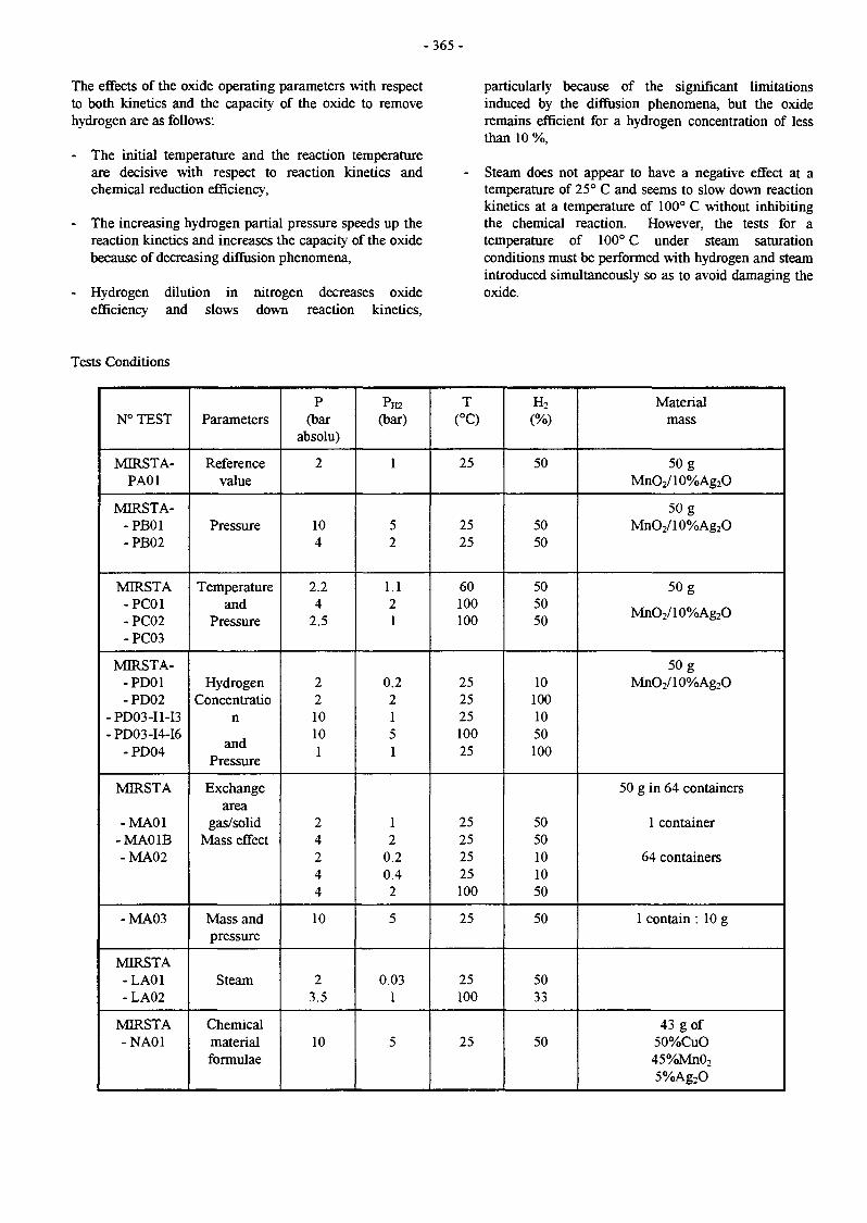
- 3 6 5 -
The effects of the oxide operating parameters with respectto both kinetics and the capacity of the oxide to removehydrogen are as follows:
- The initial temperature and the reaction temperatureare decisive with respect to reaction kinetics andchemical reduction efficiency,
- The increasing hydrogen partial pressure speeds up thereaction kinetics and increases the capacity of the oxidebecause of decreasing diffusion phenomena,
- Hydrogen dilution in nitrogen decreases oxideefficiency and slows down reaction kinetics,
particularly because of the significant limitationsinduced by the diffusion phenomena, but the oxideremains efficient for a hydrogen concentration of lessthan 10 %,
Steam does not appear to have a negative effect at atemperature of 25° C and seems to slow down reactionkinetics at a temperature of 100° C without inhibitingthe chemical reaction. However, the tests for atemperature of 100° C under steam saturationconditions must be performed with hydrogen and steamintroduced simultaneously so as to avoid damaging theoxide.
Tests Conditions
N°TEST
MIRSTA-PA01
MIRSTA--PB01-PB02
MIRSTA-PC01-PC02-PC03
MIRSTA--PD01-PD02
-PDO3-I1-I3- PD03-I4-I6
-PD04
MIRSTA
-MA01-MAO IB-MA02
-MA03
MIRSTA-LA01-LA02
MIRSTA-NA01
Parameters
Referencevalue
Pressure
Temperatureand
Pressure
HydrogenConcentratio
n
andPressure
Exchangearea
gas/solidMass effect
Mass andpressure
Steam
Chemicalmaterialformulae
P(bar
absolu)
2
104
2.24
2.5
2210101
24244
10
23.5
10
PH2
(bar)
1
52
1.121
0.22151
12
0.20.42
5
0.031
5
T(°C)
25
2525
60100100
25252510025
25252525100
25
25100
25
H2
(%)
50
5050
505050
101001050100
5050101050
50
5033
50
Materialmass
50 gMnO2/10%Ag2O
50 gMnO2/10%Ag2O
50 g
MnO2/10%Ag2O
50 gMnO2/10%Ag2O
50 g in 64 containers
1 container
64 containers
1 contain : 10 g
43 g of50%CuO45%MnO2
5%Ag2O

- 3 6 6 -
CONCLUSION -FUTURE DEVELOPMENTS
REFERENCES
These first tests show that the manganese dioxide catalyzedby 10 % silver dioxide is a suitable hydrogen getter.Accident conditions in a fusion plant are covered by thismaterial with respect to pressure and temperature.
Several uncertainties will have to be clarified before usingthis hydrogen mitigation strategy in a fusion plant. Theyare the following:
• Steam effect on material characteristics,• Validation of material efficiency with respect to low
hydrogen concentrations,• Behaviour of the material with respect to beryllium dust
and activation radionuclides (poisoning effects),• Tritium removal.
In order to qualify this material for a fusion plant, thefollowing developments are necessary:
* Evaluation of reaction kinetics using an experimentalloop adapted to a static reactor,
* Phenomena modelling that integrates environmentalcharacteristics, transfer phenomena, and reactionkinetics,
* Solution of the issues arising from the uncertainties,
* Design of an industrial process for the ITER project.
[1] 20th SOFT- September 7-11, 1998. MARSEILLE-FranceMitigation of hydrogen hazard in a fusion reactor byreduction of metallic oxides.V. CHAUDRON, F. ARNOULD, C. LATGE, A.LAURENT
TASK LEADER
Christian LATGE
DRN/DER/STPI/DIRCEA Cadarache13108 St Paul Lez Durance Cedex
Tél. : 33 4 42 25 44 71Fax : 33 4 42 25 48 68
E-mail : [email protected]

-367-
UTS3
Task Title : BLANKET SAFETYModeling of heat exchanges for high flux components in a fusion reactor duringaccidental conditions
INTRODUCTION
One sided high heat flux is the major feature of heatgenerated from the plasma of a fusion reactor. This heat isremoved by sub-cooled water flow. For one sided heatloads, different heat transfer regimes can be present. Thecoupling of thermal and hydraulic computation is necessaryto produce a detailed description of the flow and thethermal pattern in the cooling pipes. This coupling gives adetailed knowledge of the flow in the channel and thethermal response of the wall. The final application of such awork is a better description of fusion heat exchangers underaccidental conditions where heat transfer is degraded.
1998 ACTIVITIES
THERMALHYDRAULIC AND THERMALCOMPUTATION
The three-dimensional thermalhydraulic and thermalequations are solved using a finite element method. Thefluid domain is modeled as a half horizontal cylinder andthe solid domain as a half horizontal rectangle. The axialmesh is structured and the mesh of the fluid and solid basesis unstructured (see figure 1).
For the thermalhydraulic computation, the heating of thefluid is modeled by the volumetric source term of theenergy balance equation. This term is computed from theflux calculated on the F I2 boundary (diffusive heat flux :--ks9T/cfi = qw(<p) ) and used as an input on the F2
boundary.
For the thermal computation, the major difficulties of themodeling are related to the boundary conditions at thecooled surface of the solid. At this boundary, the flow wasdivided into different heat transfer regimes determined bythe local wall temperature. The mathematical formulationcan be expressed as a three dimensional conduction
problem with the boundary conditions : - ks —^ = qinc ondn
the heated surface Fn and - k , — - = h(T - T )on theôii
internal wall FI2. Tm is the average water temperature oneach section of the fluid mesh, calculated by the thermalhydraulic computation.
The heat transfer coefficient is computed using thefollowing correlations :
- the single phase forced convection regime is describedby the Sieder-Tate equation,
- the fully developed sub-cooled boiling regime isdescribed as a function of the local heat flux and thebulk pressure by the Thom/CEA equation,
- the onset of nucleate boiling is approximated using anequation proposed by Bergles-Rohsenow,
The link between convection and subcooled boiling is madeusing the Bergles and Rohsenow method.
NUMERICAL RESULTS
Several calculationsincident heat fluxesconditions (Tin = 99.1
were performed using differentand steady state thermalhydraulic
'C - Vin = 5.1 m/s - Pin = 3.39 MPa).
Figure 1 : Thermal and thermalhydraulic coupling(Thermal map of the solid and void fraction in the fluid)
Figure 1 shows the thermal map of the solid and the voidfraction in the fluid. This figure shows that different heattransfers are present in a same section : the void fraction isdifferent from zero in the top of the tube (subcoolednucleate boiling regime) and equal to zero in the rest of thetube (single phase forced convection regime).

-368-
Figure 2a shows a comparison of numerical andexperimental wall temperature vs incident heat flux. Owingto the high thermal gradients in the solid, the error on thethermocouple position is important in comparison ofnumerical and experimental results. The experimenter givesan error of 1 mm on the thermocouple position. This error isreported on Figure 2.
This allows to note that the numerical results (TC2num) areabove the margin of error. The main reason for thisoverprediction is that the value of the heat transfercoefficient calculated by the Sieder Tate correlation is toosmall.
The thermocouples TC3 and TC4 show that the differencebetween the numerical and experimental results depends onthe circumferential location. Consequently, we suggest touse a non uniform corrective factor depending on thedifference between the temperature of the wall and thetemperature of the fluid. As the Prandtl number is adimensionless number depending on the temperature, thecorrective term is calculated as the ratio between the Prandtlnumber at fluid temperature and the Prandtl number at walltemperature. Its value is near to one for areas where thedifference between wall and fluid temperatures is small andincreases when this difference increases. We have thus :
Nu = CxNu with C =Pr,,
« I T
160
•TC2wp—Tcaium*-TC2nod
Incident heat flux (MW/m*)
5 10 15Incident Heat Flux (MW/m2)
20
Figure 2 shows that the computations with the modifiedcorrelation match the experimental data (TC2mod) in abetter way.
Figure 2b shows a comparison of numerical andexperimental outlet fluid temperature vs incident flux.
The good agreement between numerical and experimentalvalues shows that the coupling between solid and fluiddomain is correct : the heat generation term of the energybalance equation agrees with the incident heat flux.
CONCLUSION
The temperature profiles for a three dimensional cross-section of the cooling channel and the hydraulic features ofthe two phase flow have been calculated in a steady-statenormal condition of a fusion reactor (single phaseconvective regime and developed subcooled boiling) andthe finite element calculations have been compared toexperimental results in order to qualify the coupling methodand the heat transfer correlations.
The main output of these tests is that the couplingmethodology is correct. The type of boundary conditionsused allows to model different heat transfer regime on eachsections.
A modification of the Sieder Tate heat transfer correlationhas been proposed and results appeared then to be in betteragreement.
Another important task of this work is the modélisation ofswirl tubes which has been reported in the final reportconstituted by the thesis memorandum.
REFERENCES
[1] M. Grandotto and P. Obry, Computation of two phasesflow in heat exchanges by a finite element method,European Journal of Finite Element, volume 5, n°l,1996
[2] E.N. Sieder and G.E. Tate, Heat transfer and pressuredrop of liquids in tubes, Ind Eng Chem, 28, 1936
[3] A.E. Bergles and W.M. Rohsenow, The determinationof forced convection surface boiling heat transfer, J.Heat Transfer, 1964
[4] J. Boscary, Transfert thermique et flux critique dansun écoulement hélicoïdal en tube chaufféasymétriquement, Thesis, Institut de Mécanique desFluides de Toulouse, 1995
Figures 2a - 2b : Comparison of numerical andexperimental solid temperatures

-369-
LIST OF REPORTS TASK LEADER
[5] « 3D thermal and thermalhydraulic coupling for high Gilles LANGLAISheat flux components safety assessments » G.Langlais NT DER/STML/LCFI 98/052 DRN/DER/STML/LCFI
CEA Cadarache[6] «Modélisation de la thermique et de la 13108 St Paul Lez Durance Cedex
thermohydraulique dans un échangeur d'un réacteurde fusion thermonucléaire à l'aide du code Génépi » Tél. : 33 4 42 25 49 56G. Langlais - Mémoire de thèse soutenue à l'Ecole Fax : 33 4 45 25 66 38Supérieure de Mécanique de Marseille le 1er février1999.

- 3 7 1 -
INERTIALCONFINEMENT
Long Term
Next Step UnderlyingTechnology
Inertial Confinement

- 3 7 3 -
ICF-01
Task Title : INTENSE LASER AND IONS BEAMS DYNAMICS INTHERMONUCLEAR I.C.F. PLASMAS
INTRODUCTION
The part of our work that is described here is devoted to themodeling of intense electrons and ions beams interactingwith thermonuclear pellet within the framework of theInertial Confinement Fusion. We pay special attention toelectron propagation in the ultra dense part of the ICF targetand to the energy deposition of swift heavy ion beams inthe radiator elements of the thermonuclear pellet. Wefocussed our theoretical and modeling attention on twospecific points:
- Correlated Stopping of Relativistic Electron Beamsin Supercompressed DT fuel
The fast ignitor concept [1] can be applied to laser aswell as to heavy ions ICF. The shape and temperature ofthe initial hot spot created by the high intensity laserpulse has to be determined from the deposition profileof the electron beam generated in the laser-plasmainteraction region. Here we study the collective part ofthe energy deposited by the electrons due to theirdynamical intrabeam correlations.
- Effective charges and density effect of swift heavyions in dense matter
In Heavy Ion Inertial Fusion (HIIF) the beams deposittheir energy inside radiator element generally made oflight material. We have already shown [4,5] that in suchcase, the energy loss and the charge exchange processesare strongly correlated. A crucial question is then todetermine the effective stopping charge of a partiallyionized heavy ion beam. Our results detailed here giveus a new insight in the so-called density effect for soliddensity target, thus having a broad range of applicationsthat are underlined.
1998 ACTIVITIES
CORRELATED STOPPING OF RELATIVISTICELECTRON BEAMS IN SUPERCOMPRESSED DTFUEL
Recently, an intense interest for the stopping of relativisticelectron beams in dense and hot plasma of thermonuclearconcern has emerged from the so-called fast ignitorscenario initially advanced at Livermore [1]. This proposalis about decoupling the fuel compression through standarddrivers (laser, particle or cluster beams) from the hot spotignition in a fraction only of the DT mixture.
The latter process is expected to arise through afemtosecond laser boring a hole in the corona of the pre-compressed material.
Here, we address the issues concerning the interaction ofthe laser produced relativistic electrons with the fullyionized and mostly classical electron plasma featuring thevery dense compressed core. The corresponding beam-plasma collective modes are seen to be collisionalydamped.
The relativistic stopping of MeV electrons (p « 0.94) insupercompressed DT fuel (300g/cc, n,. = 1026 cm'3,T=5keV) has been recently demonstrated [2]. We haveaddressed the issue of correlated effects in a dense electronbeam with nb=1022 cm'3, arising from ad hoc femtosecondlaser. These correlated effects are due to the interferencebetween the induced electromagnetic field created by eachparticle beam. To determine these interference terms weimplemented numerically a classical impact parameterformalism due to Rule and Cha [3], and we have consideredvarious orientations of two-electron cluster w.r.t. beamvelocity.
A first unexpected result is that for cluster extensions evenmuch larger than target Debye length, one gets significantcorrelated stopping for perpendicular [Fig. 1) and parallel(Fig. 2) 2-cluster interdistance. As can be seen from Fig. 1,this effect persists over tens of target screening length in thecase of transverse orientation. The longitudinal correlatedstopping (Fig. 2) is seen modulated and undamped overseveral mean electron beam distances, as well. Inferences tothe coupling efficiency of relativistic electron beams withsupercompressed DT fuel are currently under investigation.
3.5-
Figure 1 : Correlated stopping/charge for a 2-clusteroriented perpendicular to the beam velocity (5=0.94 in termof interdistance given in number of the target Debye length.
Rx-1 pertains to the relativistic stoppingof an isolated charge

- 3 7 4 -
£ -2o
Figure 2: Correlated stopping/charge for a 2-clusteroriented parallel to beam velocity in term of interdistance
given in numbers n of mean interelectronbeam distance 2.88 10s cm
EFFECTIVE CEEARGES AND DENSITY EFFECT OFSWIFT HEAVY IONS IN DENSE MATTER
In the previous report [4] we have shown how the chargeexchange processes affect the straggling of the energydeposition profile of swift heavy ions in light material. Thecrucial parameter here is the average energy 8E lost by aprojectile between two successive charge exchangeprocesses. It is easily recognized that in cold target 5E ismaximum in light material and it is further increased withtarget ionization. Fully ionized light material asencountered in the radiator element thus exhibits the largest5E yielding specific effects, as already discussed in [4], likea large charge exchange dependent energy loss straggling.The large value of SE has also a profitable consequence onthe experimental side: it gives the best possible accuracy ofthe charge dependent stopping power measurement from agiven experimental setup. This gave us the opportunity tocheck with a high precision our new charge dependentstopping theory [5-7] called Convergent Kinetic LindhardTheory (CKLT). The CKLT has then be used to re-analyzethe so called density effect, our results are summarized inthe following.
There is, up to now, no precise experimental result on thestopping power of swift heavy ion beam in hot plasmas atsolid density. However, in many respects, a solid target canbe viewed as a strongly correlated dense plasma. Thereforethe accumulated experimental results on swift heavy ionsinteracting with thin solid foils are good benchmarks tovalidate theoretical models that will be used to describe theinteraction between swift heavy ion beams and ICFplasmas. The interaction of swift heavy ions beams with afoil can be characterized by two parameters ofprimaryimportance: the effective stopping charge Zef andthe outside average equilibrium charge Zout of the beam. Zef
is given by the squared root of the ratio of the heavy ionstopping divided by the proton stopping at the samevelocity Zef = (S(Z,V)/S(Z=1,V))1/2 while ZM is determinedfrom the measure of the beam average ionization state afterinteraction with a foil. A crucial point is that Zef comesfrom collisions with target electrons while Zout depends onion-ion or ion-atom collisions. Thus these two parametersenables to check the main features of all the collisionalprocesses.
One interesting point in the beam-target interaction processis the influence of the target density. This can be analyzedby comparing Zef and Zout for solid and gas targets (asindicated in the following by the superscript s and g).
Comparison of Z*f and Z ^ is very puzzling and, until
recently, has not received a satisfactory theoreticalexplanation. The experimental results can be summarizedas follow:
1. If the ion is fully ionized, then there is no densityeffect, the difference between Zef and Z ^ thereforeonly comes from non-linear terms in the stoppingpower
2. If the ion is partially ionized then ZsolA » Z*ut while
Zrf is only slightly larger than Z*f
The commonly assumed explanation, following the work ofBetz in 1972, is that it is due to multiple excited electronsinside the solid that yield Auger electrons at the exitsurface. However experiments failed to detect the requiredlarge number of emitted electrons. Thus the full answer hasto come from another side.
We have proposed [8] that non-linear contributions couldhave a larger influence than usually assumed and be largeenough to reduce in a large part the density effect on thestopping effective charge. This can be understood by thesimple following arguments: let us take the example of a 4MeV/u Uranium ion in carbon, we have approximately [8]Zout = 58 and Zef = 42. If we do not take into account anywhile our code produce a maximum of two. The nonlinearity however reduce the stopping power thus yielding alower effective charge. This means that it reduces thedifference between the effective charges corresponding totwo different average charges and it is precisely what weneed to explain the density effect on the stopping power.
On a more quantitative level, the density effect is a functionof the slope of the curve of the stopping power S(Q,V) non-linear correction we then need 16 Auger electrons versusthe ionization state Q at a given velocity V. The larger thisslope is, the larger the density effect will be on the stoppingpower. Experimental results require that this slope is muchlower than the linear Q2 scaling. In [8] we already showed,using a point like stopping model, that the non-linearcontribution reduces to a large part the discrepancy betweentheoretical and experimental results on the density effect.
This density effect has been re-examined within theframework of our new charge dependent stopping theory[5-7]. We showed that the influence of the electronic chargedensity bounded to the projectile yields another reductionof the slope of S(Q,V) thus allowing now a full satisfactorydescription of the density dependent stopping process. Asan example we give in Fig 2-3 our results for a 1.5MeV/amu Chlorine ions in cold and ionized hydrogentargets.

- 3 7 5 -
REFERENCES
10 12 14 16
Projectile ionization state
Figure 3 : S(Q,V)for a 1.5MeV/amu Cfi+ in hydrogen.Full curve : linear Q2 scaling; dot curve : non linear point-
like model; dash curve : our new result
We see that even when the ion is more than half ionized,our results depart significantly from the linear model. Thedifference between the full and point like model is twicelarger in the cold target than in the plasma one. This arisesmainly from the low value of our plasma target (2 1017 cm'3). For solid density target it is expected that the cold andplasma target will be closer. This point is currently underinvestigation.
[1] M. Tabak, I. Hammer, M.E. Glinsky, W.L. Kruer,S.C. Wilks, J. Woodworth, E.M. Campbell, M.D.Perry andRJ. Mason, Phys. Plasma, 1, 1626, 1994
[2] C. Deutsch, K. Nishihara, Phys. Rev. Lett., 77, 2483,1996
[3] D.W. Rule and M.H. Cha, Phys. Rev., 24, 55, 1981
[4] Annual Report of the Association CEA/EURATOM,1997
[5] M. Chabot, M. Nectoux, D. Gardes, G.Maynard andC. Deutsch, Nucl. Instr. Meth. A 415, 571, 1998
[6] G. Maynard, K. Katsonis, G. Zwicknagel, S. Mabong,M. Chabot, and D. Gardes, Y.K. Kurilenkov, Nucl.Instr. Meth. A415, 687, 1998
[7] G. Maynard, D. Gardés, M. Chabot, M. Nectoux andC. Deutsch, Nucl. Instr. Meth. B146, 88, 1998
[8] G. Maynard, W. André, M. Chabot, C. Deutsch, C.Fleurier, D. Gardés, D. Hong, J. Kiener, M. Pouey,and K. Wohrer, II Nuovo Cimento, 106A, 1825, 1993
350-
300-
Cb
£250-
3-200-
> 150-
o" 1 0 0 -
50-
Plasma I / _
10 12 14Projectile ionization state
16
Figure 4 : Same as Figure 3 for a plasma target
CONCLUSION
We report recent progress made in the understanding ofhigh-energy electrons and ions beams interaction withdense plasma. In both cases emphasis is put on taking intoaccount all of the physical parameters influences in acoherent way. The relativistic, multiple scattering andcollective effects in the electron case and the non-linearityand the extended charge contribution for the swift heavyions. Our results provide significant improvements uponprevious approximated theoretical models thus allowing abetter understanding of high intensity particles beamsinteracting with ICF plasma, specifically concerning theinfluence of the target high density.
REPORTS AND PUBLICATIONS
References [2] and [5-7]
TASK LEADER
Dr. Claude DEUTSCH
Laboratoire de Physique des Gaz et des PlasmasUniversité Paris XIBâtiment 21091405 Orsay Cedex
Tél. : 33 1 69 15 76 05Fax : 33 1 69 15 78 44
E-mail : [email protected]

-377 -
ICF-02
Task Title : CIVIL APPLICATIONS OF INERTIAL CONFINEMENT FUSIONCryogenic targets production using magnetic lévitation
INTRODUCTION
Inertial confinement fusion experiments will be performedwith laser beams focusing on a target. These targets arehollow spheres of about two 2 mm in diameter the internalwall of which are covered with a solid D2 or DT layer. Thesuccess of the experiments will depend of the homogeneityof the layer thickness. In a previous report [1], we haveshown that theorically, magnetic lévitation couldcompensate gravity effect and allow to obtain anhomogeneous thickness of liquid in the target beforesolidification. A 10 Teslas supra conducting coil has beencaracterised and a cryostat has been designed. This year, thecryostat has been built and experiments have beenperformed. We report in this paper some view of the facilityand the first experimental results we have obtained withHydrogen.
1998 ACTIVITIES
THE TEST FACILITY
As we have previously shown [1], the product of the fieldby the field gradient necessary to levitate hydrogen is -491T2/m. This can be obtained with a 10 Teslassupraconducting coil.
A vacuum vessel containing the condensation cell (fig. 1)is placed in the bore of the coil. Magnetic lévitation isobserved thank to an endoscope associated with a CCDcamera (fig. 2).
Endoscope for thcamera
Figure 2 : A view of the cryostat
Capillary for H2
sapphire window
valve (ice plug) ~~leads of the heater(to melt the ice plug)
copper thermal bridge
Thermometer
Heater (temperaturecell regulation)
brass stick
Figure 1 : A view of the experimental cell

- 3 7 8 -
EXPEREMENTAL RESULTS
Two preliminary experiments have been performed withtwo different cells [2]: the first one has a 10 mm diameterand the second one has a 3 mm diameter.
The 10 mm diameter cell :
The results are shown on the FIG 3.
Fig 3 a) the cell is empty.
Fig 3 b) the cell is half filled with liquid H2. We can seeclearly the meniscus. The thickness of the liquidlayer should be 1.5 mm for a well distributedconfiguration all around the cell.
Fig 3 c) the magnetic field is increased to compensate77% the gravity. We can see the meniscusbecoming more circular.
Fig 3 d) the magnetic field is increased to compensate99.5% the gravity.
Fig 3 e) the magnetic field compensates the gravity. Themeniscus is a perfect circle but the vapor phasedoesn't come to the center of the cell. Theposition of the vapor phase is instable, sometimeit comes to the right of the cell and sometime itgoes to the left of the cell. This is probably dueto gradient field inhomogeneties at the cellscale.
Fig 3 f) the magnetic field is increased to be strongerthan the gravity. We can see the vapor phasegoing to the bottom of the cell and the liquidgoing to the top of the cell.
This experiments shows that for such a large cell and alarge thickness layer (1.5mm), the magnetic lévitationcannot be a mean to obtain an homogenous layer thicknesswith the present magnetic field profile, due to theinstabilities of the vapor phase.
The 3 mm diameter cell :
The results are shown on the FIG 4.
Fig 4 a) the cell is empty.
Fig 4 b) the cell is about half filled with liquid H2.
Fig 4 c) the magnetic field is increased to compensatethe gravity. We can see that the liquid is welldistributed around the cell (the thickness of thelayer is about 300um). This time, the vaporphase is stable at the center of the cell.
Fig 4 d) die temperature of the cell is decreased belowthe triple point, (some H2 freezes on thewindows),
Fig 4 e) if we wait for some hours, the ice on thewindows disappears (due to parasitic heatcoming from the light).
Fig 4 f) if we decrease the magnetic field and increasethe temperature, the liquid falls down again.
CONCLUSION
A test facility showing that magnetic lévitation can be away to obtain a uniform thickness solid layer in the inertialconfinement fusion targets has been designed and built.
Experiments have been performed in two different cells.The results are the following :
- In a 10mm diameter cell in which the liquid thicknesslayer would be about 1.5 mm, we have not got auniform thickness layer because of the instability of theposition of the vapor phase due to a non uniformity ofthe magnetic field.
- In a 3 mm diameter cell in which the liquid thicknesslayer is about 300um (two sizes which are probablynear by the required sizes for the inertial confinementfusion targets), we have obtained a good and stableuniformity of the liquid (and solid) layer thickness.
After these encouraging preliminary results, furtherinvestigations should be performed to characterize thesolid layer thickness and roughness. But to prepare theseinvestigations, more details should be given on thespecifications (geometry, roughness,...) of the future targetsrequired for inertial confinement fusion.
Another aspect to be looked at rapidly is also the overallprocess of production and distribution of these targets(frequency and number of plasma shots). Somedevelopments and studies will be necessary to define andqualify a nominal process.
REFERENCES
[1] "Cryogenic targets production using magneticlévitation"Interim report. Task ICF 02.
[2] "Cryogenic targets production using magneticlévitation"Final report. Task ICF 02.

CO
ÎZ
i l

- 3 8 0 -
TASK LEADER
Mr CHATAIN Denis
DSM/DRFMC/SBTCEA Grenoble17, rue des Martyrs38054 Grenoble Cedex 9
Tél. : 04 76 88 50 28Fax : 04 76 88 5171
E-mail : [email protected]

- 3 8 1 -
ICF-03
Task Title : FAST IGNITER CONCEPT STUDIES
INTRODUCTION 1998 ACTIVITIES
In the usual scheme of inertial laser fusion, a sphericalpellet filled with deuterium-tritium fuel is irradiated eitherdirectly by several laser beams or indirectly by X-raysgenerated by the laser beams interacting with a high-Zmaterial.
The outer part of the target expands in vacuum, while theinner part is accelerated inward. During this implosion, thefuel is progressively compressed. At the end of thecompression stage, it is expected that the density and thetemperature of the fuel will be high enough to initiate aburn process of the fuel. With present day lasers, the non-uniformity of illumination resulting from laser-intensityimbalance and hydrodynamic instabilities is a stronglimiting factor. As a result, the compressed core is notignited so that only a small fraction of the fuel is effectivelyused.
A new scheme has been proposed recently. Near the end ofthe compression stage to very high densities (~300 g/cc) —this is done with "conventional" nanosecond pulse durationlasers — a laser beam creates a channel in the plasma bypushing the critical density surface towards the core, afterwhich the final heater or igniter beam is turned on.
The igniter beam interacts with the density gradientgenerated by the channeling beam and generates hotelectrons at MeV energies, which penetrate into thecompressed core and cause an instantaneous rise in its localtemperature. In the very high intensity regime, the quivervelocity of the electrons in the laser field is relativistic.
The LULI Laboratory is involved in this research effort intwo different ways:
- Through a long term collaboration with the RutherfordAppleton Laboratory (RAL), CEA-Limeil (laser P102)and the University of California (UCLA). The LULIand RAL have intensified recently their collaborationthrough a "Laboratoire Européen Associé" named HighPower Laser Science,
- The new 100 TW, 0.3 ps Chirped-Pulse-AmplificationTitane:Sapphire laser has allowed to perform particleacceleration experiments (involving other laboratories atthe Ecole, the University of Orsay and the RAL) and tostudy the different phases of the fast igniter concept andmany other subjects related to high intensity laser-matter interaction.
Our experimental and numerical work have concentrated upto know on the following topics:
- Propagation of intense laser pulses in underdenseplasmas, formation of density channels, self-focusing,absorption mechanisms, generation of fast particles,
- Interaction with overdense plasmas, relativisticpropagation at over-critical densities, generation of fastelectrons,
- Simulations of the experimental results obtained instudies of the relativistic propagation at over-criticaldensities. This is the numerical part of the tasks 4 and 5of the contract,
- Theory of parametric instabilities in the high intensitylaser interaction regime. This is the theoretical part oftask M4,
- Interaction with overdense plasmas at ultra-highintensities (which cannot be reached in present-day laserinstallations), demonstration of the role of magneticfields in collisionless shock generation, channeling,electron transport. This corresponds to the task 5 of thecontract.
In 1998, we have gone in the subject of parametricinstabilities in greater depth. It is well known that laserpropagation in plasmas is subject to various instabilities,which could play an important role in advanced fusionconcepts and advanced accelerators.
At moderate intensities, these instabilities are clearlyidentified as the stimulated Raman scattering (SRS), therelativistic modulational instability (RMT), the relativisticfilamentation instability (RFI), and the two-plasmons decay(TPD). In the weakly relativistic regime, forward SRS andRMI have been shown to merge in a rarefied plasma.
In the fully relativistic regime, the one-dimensional (1-D)dispersion relation has been established recently. In ourtheoretical work, we have derived the general 2-Ddispersion relation for circularly polarized waves in a coldplasma, valid for any laser intensity and plasma density,which includes the SRS, RMI, RFI, and TPD instabilities aslimiting cases at low intensities, and the previousrelativistic 1-D results.

-382-
Figure 1: Contour plots of the growth rate of theinstabilities as a function of the wave number (kz,\a±).
The parameters are (a) a0 =1.46 and n o / n c =5xlO"3 ,
(b) ao=V37I and no/nc=O.5, (c) ao=V37ï andn o / n c = 1 . 5 . (d) shows the growth rate for the same
parameters as (b) but calculated from a naïve 2-Dextension of previous works. There are 10 contours on eachplot, the minimum and maximum being, respectively, (a)0.01, 0.1; (b) and(d) 0.04, 0.4; (c) 0.035, 0.35.
The dispersion relation is obtained as an infinite Hilldeterminant that we solve numerically. We first verifiedthat we recover the known results in the case of underdense( n o « n c ) plasmas and of not too high ( a o < O . l )intensities of the laser with slight modifications due to thecircular polarization. At low density and higher intensities,we found new zones of instability in the ( k z , k x ) plane.Their shape is semi-circular and well described by theequation (k2 - N k 0 ) 2 + k x
2 = N2(<o0 / c ) 2 , N > 2 as canbe seen in Fig. l(a), for which ao=1.46 and
n o / n c = 5 x l ( T 3 . Each lobe corresponds to a resonancewith a different harmonic of the vector potential through athree-wave process. A typical result of the calculations is
shown in Fig. l(b), which corresponds to a0 = v3 /2 andn o / n c = O . 5 . We emphasize here that the naïve 2-Dextension of the 1-D fully relativistic dispersion relationdoes not predict any of the successive TPD lobes, as can beclearly seen in Fig. l(d) which shows the growth rate aspredicted by this naïve extension for the same parameters asFig. l(b). Correlatively, the electrostatic (ES) character, ascompared to electromagnetic (EM), of the instabilityevolves towards a mixed EM/ES character. In the inducedtransparency regime n c < n 0 < y n c , t h e different zones ofinstability already described tend to merge and new lobesappear that extend in the kz <0 region (see Fig. lc) for
which a0 =1.46 and n o / n c =1.5 . The successive lobesin the wave-vector plane are no more associated with asingle harmonic as in the very underdense case, but a widerange of harmonics are simultaneously excited.
A more detailed description of these results can be found inRefs. [21-23].
Following the work of Pukhov and Meyer ter Venn [9] whoshowed clear evidence of channeling in overdense plasmasat intensities up to 1020 W/cm2, we have investigated theultrahigh intensity regime, at intensities of
IX2 = 1020 W/cm2. These intensities are marginally reachedin present-day laser installations but continuous progress inreducing laser-induced damage to compression gratings andin improving the quality of beam focusing (deformablemirrors or active adapative optics to reduce the beamwavefront inhomogeneities) will soon make this possible.One of the drawback of Pukhov's simulations is the ratherlow (10 n<;) electron density of the target. Another limitationresides in the limited number of particles used and the smallsize of the system. In the present work, we have studied theinteraction of a 1 um wavelength laser field with a massivetarget at 80 times critical density. The laser pulse rises in 72
©o"1 (about 35 fs) and is then kept constant. The laserimpinges on the target at normal incidence in a focal spot of5 um FWHM. Figure 2 shows the magnetic field (left) andthe electron density (right, in units of nc ) as a function of
space (in ko units corresponding to a box of 1OOX.O ). The
time for this snapshot is 1400 a0'1 (approximately 700 fs).
The laser intensity is IX2 = 1021 W/cm2.
On the electron density plot, the "crater" drilled by the laserponderomotive pressure is clearly visible. On both sides ofthis crater, a shock extending several tens of wavelengthsradially around the focal spot has been created by thepressure associated to the huge magnetic field (exceeding109 G, see the left picture) extending in the vacuum.Electron densities around 200 x nc are reached at the edge
of this shock. Several filamentary structures can be seen inthe density plot, corresponding to individual channelsdriven by the currents of fast electrons. Similar structuresare seen in the magnetic field plot. No evidence of mergingof these filaments (a feature which could be seen inPukhov's simulations) is observed. Figure 3 shows theelectron thermal flux for laser intensities of
IX2 = 1020 W/cm2 (left) and IX.2 = 1021 W/cm2 (right), againas a function of space. One can see clearly, in the vacuumregion, the curvature of the electron trajectories around thetoroidal magnetic field lines shown in Fig. 2. At the lowerintensity (left in Fig. 3), clear channels of electron thermalfluxes can be seen in the direction of the incident laserbeam. A limited amount of energy is transferred radially.The picture changes abruptly for the higher intensity (rightin Fig. 3) which shows a quasi-isotropic heat transfer in thebulk of the target. While electron trajectories have a regularbehavior at low intensity, some turbulence can be seen atthe higher intensity, in front of the target. Iso-contours ofthe relativistic electron density nc /y with values 1 (bluecurve) and 5 (red curve) have been superimposed in thefigures. At the lower intensity the relativistic iso-densitiesare well separated outside the focal spot, and the crater hasa nice round shape. At the higher intensity, the two iso-densities are undistinguishable, and the crater has a morechaotic shape.

-383 -
Figure 2 : Magnetic field in Megagauss (bottom) and
electron density (top)) at 1400 ©0~!
(approximately 700 fs). Massive target at 80 x nc
Laser intensity is IÂ2 =102ï W/cnc.
A huge, shallow, crater caused by the magnetic pressurecan be seen around the focal spot These results clearlyindicate the lack of channeling for these ultra-relativisticintensities.
We do not recover the feature found by Pukhov that whenpenetrating the overdense region, the electron currentbreaks up into several filaments at early times, but ischanneled into a single magnetized jet later on.
More simulations are necessary to fully investigate theseeffects, which could result from differences in the codes,important improvements would be to introduce binarycollisions in the code and to simulate more realistic laserpulse shapes.
Figure 3 : Electron thermal flux in zmits of n / nc (v / c)2
as a function of position for a laser intensity
of I/,2 = 1020 W/cnc (left) and I/? = 1021 W/anr (right)
at 1400 ®0~ (approximately 700fs).
Massive target at 80 x n c .
CONCLUSIONS
Salient results of our recent experimental effort in faigb-kttensity short-pulse laser interaction studies of the fastigniter concept can be summarized as follows:
Channeling in underdense plasmas
- Using the 24TW Vulcan laser focused on the edge of ahelium gas jet, we have been able to detect 100 MeVelectrons accelerated by the Raman self-modulatedwakefield. This corresponds to electric fields of about100 GV/m. Channeling by the relativistically-mtenselaser pulse has been demonstrated.

- 3 8 4 -
- Using the LULI laser in the long (600 ps) pulse regime,we have demonstrated channeling over distances ofseveral mm. The channel parameters can be optimizedby changing independently the laser intensity or the gaspressure. These results are very encouraging forexperimental situations (particle acceleration, fastigniter) where high-intensity optical guiding is needed.
Propagation of intense laser pulses in overdense targets
- Transmission of laser pulses in the relativistic regime(IX2 > 1018 W/cm2um2) has been observed at a level ofa few percent for target thickness around 100 nra. Thecondition of near-solid density at the time of laserinteraction has been verified by time-resolved X-rayspectroscopy.
- Spectra of the back-scattered light show a strong red-shift which is the signature of the effect of the laserponderomotive force pushing on the plasma. At thesame time, transmitted light spectra show strongmodulations.
- These observations show that neither self-inducedtransparency nor hole-boring can explain theobservations. A new mechanism has to be found toexplain the overdense propagation.
- Recent simulations performed at CPTH show that fastelectrons may play a role in the starting process ofoverdense propagation.
Laser wakefield acceleration and parametricinstabilities
In the optimum conditions (laser pulse length of the orderof half a plasma period) electrons injected at 3 MeV havebeen accelerated to 4 - 5 MeV. The accelerating electricfield is then of the order of E ~ 1 GV/m. The next step forthis kind of experiment will be to increase the laser energyand the electron injection energy to both reduce the radialeffects and improve the maximum energy gain.
We have presented the first calculation of the growth rate ofelectron parametric instabilities of circularly polarizedelectromagnetic waves valid for any laser intensity andplasma density.
Ultrahigh intensity laser plasma simulations
We have demonstrated the role of high magnetic fields,located near the surface of the target, in the dynamics of theinteraction outside the focal region of the intense laser. As aresult of these fields, a collisionless shock is launchedinside the target.
When the laser intensity is raised from IX.2 > 1020
W/cm2|im2 to IA,2 > 1021 W/cm2um2, the electron thermalflux inside the bulk of the target is more isotropic. Thiscounter-intuitive result is an indication that the formation ofa single channel at ultrahigh intensities is far from being aneasy goal to reach, contrary to the results obtainedelsewhere [9].
REFERENCES
[I] A. Modena, Z. Najmudin, and A. E. Dangor, C. E.Clayton, K. A. Marsh, C. Joshi, V. Malka, C. B.Darrow, C. N. Danson, D. Neely, F. N. Walsh, Nature,377, 606, (1995).
[2] A. Modena, Z. Najmudin, and A. E. Dangor, C. E.Clayton, K. A. Marsh, C. Joshi, V. Malka, C. B.Darrow, C. Danson, IEEE Transactions on PlasmaScience 24, 2, 289, (1996).
[3] V. Malka, E. De Wispelaere, F. Amiranoff, A.Modena, R. Haroutunian, R. Bonadio, C. Coulaud, D.Puissant, C. Stenz, S. Huiler, and M. Casanova, Phys.Rev. Lett. 79,16 (1997).
[4] V. Malka, A. Modena, Z. Najmudin, A. E. Dangor, C.E. Clayton, K. A. Marsh, C. Joshi, C. Danson, D.Neely, and F. N. Walsh, Physics of Plasma 4, 1127,(1997).
[5] D. Gordon, K. C. Tzeng, C. E. Clayton, A. E. Dangor,V. Malka, K. A. Marsh, A. Modena, W. B. Mori, P.Muggli, Z. Najmudin, and C. Joshi, Phys. Rev. Lett.80,10 (1998).
[6] C. E. Clayton, K.-C. Tzeng, D. Gordon, P. Muggli, W.B. Mori, C. Joshi, V. Malka, Z. Najmudin, A.Modena, D. Neely, and A. E. Dangor, Phys. Rev.Letters 81, 100 (1998).
[7] M. Tabak et al., Phys. Plasmas 1, 1626 (1994).
[8] A. Akhiezer and R. Polovin, Sov. Phys. JETP 3, 696(1956).
[9] S.C. Wilks et al., Phys. Rev. Lett. 69, 1383 (1992) ; S.Omel'chenko et al., Quantum Electronics 26, 565(1996) ; S. Guérin et al., Phys. Plasmas 3, 2693 (1996); A. Pukhov and J. Meyer-ter-Vehn, Phys. Rev. Lett.79, 2686 (1997).
[10] N. Blanchot et al., Opt. Lett 20, 395 (1995).
[II] J. Fuchs, J.C. Adam, F. Amiranoff, S.D. Baton, P.Gallant, L. Grémillet, A. Héron, J.C. Kieffer, G.Laval, G. Malka, J.L. Miquel, P. Mora, H. Pépin, andC. Rousseaux, Phys. Rev. Lett. 80, 1658 (1998).
[12] J. Fuchs, G. Malka, J.C. Adam, F. Amiranoff, S.D.Baton, N. Blanchot, A. Héron, G. Laval, J.L. Miquel,P. Mora, H. Pépin, and C. Rousseaux, Phys. Rev. Lett80, 2326 (1998).
[13] S. Jacquemot and A. Decoster, Laser and Part. Beams9,517(1991).
[14] P. Mora and J.F. Luciani, Laser and Part. Beams 12,387 (1994).

- 3 8 5 -
[15] J.C. Kieffer et al., J. Opt. Soc. Am. B 13, 132 (1996).
[16] O. Peyrusse et al., J. Phys. B 26, L511 (1993) ; D.Gilles in Spectral Line Shapes, L. Frommhold andJ.W. Keto Eds, (American Institute of Physics, New-York 1990), vol. 6, p. 48.
[17] G. Malka and J.L. Miquel, Phys. Rev. Lett. 77, 75(1996).
[18] A. Pukhov and J. Meyer-ter-Vehn, Phys. Rev. Lett.76, 3975 (1996).
[19] E. Lefebvre, Ph.D dissertation, Paris XI University,1997 ; see §B.V and CHI.
[20] F. Amiranoff, S. Baton, D. Bernard, B. Cros, D.Descamps, F. Dorchies, F. Jacquet, V. Malka, J. R.Marques, G. Matthieussent, P. Miné, A. Modena, P.Mora, J. Morillo, and Z. Najmudin, Phys.Rev. Letters81, 995 (1998).
[21] B. Quesnel, P. Mora, J.C. Adam, A. Héron, S. Guérin,and G. Laval, Phys. Rev. Letters 78, 2132 (1997).
[22] B. Quesnel, P. Mora, J.C. Adam, A. Héron, and G.Laval, Phys. Plasmas 4, 3358 (1997).
[23] B. Quesnel, Thèse de l'Ecole polytechnique (1998).
TASK LEADER
Dr Arnold MIGUS
Laboratoire LULIEcole polytechnique91128 Palaiseau
Tél. : 33 1 69 33 38 50Fax : 33 1 69 33 30 09
E-mail: [email protected]

- 3 8 7 -
APPENDIX 1 : DIRECTIONS CONTRIBUTIONTO THE FUSION PROGRAMME
Direction des Sciences dela Matière
DRECAM IDépartement de Recherche sur l'Etat
Condensé, les Atomes et les Molécules
DRFCDépartement de Recherche sur la
Fusion Contrôlée
DRFMCDépartement de Recherche
Fondamentale sur la MatièreCondensée
Direction des RéacteursNucléaires
DMTDépartement de Mécanique et de
Technologie
PERDépartement d'Etude des
Réacteurs
T330
CNET94-345CNET96-432CNET97-463CNET98-477M29M30M40M48T222.4ter
CNET96-409ICF-02
CNET96-412CNET98-474SEA3-1SEA5-2SM5-1.2UT-N-DPAUT-N-NDAUT-SM&C-BLKUT-SM&C-FCCUT-SM&C-PBMUT-SM&C-RELUT-SM&C-WIWP3-3.3WP-A1-1.1WP-A2-1.1WP-A2-2.1WP-A2-3.1WP-A2-4.1WP-A7-1.1WP-A7-2.2WP-A9-3.1WP-B1-1.2WP-B2-1WP-B7-1.1WP-B7-2.3
CNET98-473SEA1-11SEA1-14SEA1-2SEA5-1SEA5-3SEAFP2-2SEAFP3-1SEAL10.3SEAL4.3SEP1-1SEP3-1UTS2UTS3WP-A10-2.2WP-A3-2.1WP-A3-9.1WP-A6-1.1WP-A6-2.1WP-A9-2.2WP-B6-1.3
Saclay
CadaracheCadaracheCadaracheCadaracheCadaracheCadaracheCadaracheCadaracheCadarache
GrenobleGrenoble
SaclaySaclaySaclaySaclaySaclaySaclaySaclaySaclaySaclaySaclaySaclaySaclaySaclaySaclaySaclaySaclaySaclaySaclaySaclaySaclaySaclaySaclaySaclaySaclaySaclay
CadaracheCadaracheCadaracheCadaracheCadaracheCadaracheCadaracheCadaracheCadaracheCadaracheCadaracheCadaracheCadaracheCadaracheCadaracheCadaracheCadaracheCadaracheCadaracheCadaracheCadarache

- 3 8 8 -
DTADirection des
Technologies Avancées
CEREMCentre d'Etude et deREcherches sur les
Matériaux
CE2MCentre d'Elaboration et de Mise
en forme des Matériaux
DECM IDépartement d'Etudes du
Comportement des Matériaux
DEMDépartement d'Etudes des
Matériaux
DPSADépartement des Procédés et
Systèmes Avancés
LETI DEINLaboratoire d'Electronique de
Technologie etd'instrulentation
Département d'Electronique etd'Instrumentation Nucléaires
UT-PFC&C-HFWUT-PFC&C-PSUT-PFC&C-SiCWP-B8-2
NWC2-2SM 1-2.4SM2-1.1SM2-3.1SM3-5.1SM6-4.2UT-SM&C-CM3UT-SM&C-CORUT-SM&C-GALUT-SM&C-LAM2UT-SM&C-LAM3UT-SM&C-LiPbUT-SM&C-LMEWP5WP-A4-2.1WP-A5-1WP-A8-3.1
DV4T216T216-2T217T224UT-SM&C-HIPUT-SM&C-PBUT-SM&C-RCV63WP-A3-1.1WP-A3-4.1WP-A4-1.1
SaclaySaclaySaclaySaclay
FontenaySaclaySaclaySaclayFontenaySaclaySaclayFontenayFontenaySaclaySaclayFontenayFontenaySaclayFontenayFontenayFontenay
GrenobleGrenobleGrenobleFontenayGrenobleGrenobleGrenobleGrenobleSaclayGrenobleGrenobleGrenoble
SM4-1.1SM4-4.1SM4-5.1T204-1T204-4T216-1T301-2T329-1T329-2T329-4T329-5UT-RH1UT-RH2UT-SM&C-A4
SaclaySaclaySaclaySaclaySaclayFontenaySaclaySaclaySaclaySaclaySaclayFontenaySaclaySaclay
T252 Saclay
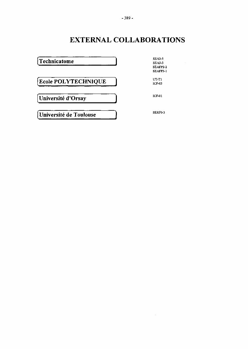
-389 -
EXTERNAL COLLABORATIONS
rr u • A. I SEA3-5
Technicatome I SEAS-3
Ecole POLYTECHNIQUE )
Université d'Orsay '
SEAFP2-2SEAFP3-1
UT-T1ICF-03
Université de Toulouse ) SERFO-3

-391 -
APPENDIX 2 : ALLOCATIONS OF TASKS
NEXT STEP PROGRAMME
-^ PLASMA FACING COMPONENTS |
CNET96-412 ITER outboard baffle : Design, analysis, technical specifications & folow-up offabrication & testing of mock-ups and prototypes
CNET97-463 High heat flux testing of primary first wall small scale mock-ups - 200 kW electronbeam gun test
CNET98-477 Thermal fatigue of divertor medium scale components - 200 kW electron beam gun
DV4 Full scale manufacturing of high heat flux components designsfor Divertor modules
T222.4ter Manufacture and testing of permanent components ; optimisation of cooling system -Critical heat flux and thermo-hydr. of representative elements (continuation) ; Nondestructive testing, calibrated defects; heat load influence
-[VACUUM VESSEL and SHIELD
CNET98-473 ITER reference breeding blanket design (stage 2) : Safety analysis
CNET98-474 ITER reference breeding blanket design : Thermo-mechanical and pebble-bedanalyses, material assessment
NWC2-2 Aqueous corrosion - Out of pile and in-pile experiments on the stress corrosion
cracking of reference 316L stainless steel and welds
T204-1 ITER backplate mockup project - Laser cutting for repair
T204-4 Ultrasonic inspection for backplate inter-sector weld
T216 Development of a reliable 316LN/DS-Cu/Be joint
T216-1 Attachment of blanket modules to the back-plate - Laser process for cutting and
welding of the hydraulic connections
T216-2 Numerical analysis and metallurgical expertise of first wall mock-ups
T217 Improved materials and joint corrosion testing - Fabrication of a CuCrZr IG/316 LNIG joint for corrosion testing
T224 Development of a thermal bond layer for first wall repair. Study of Rheocast Al-Gethixotropic compliant layer for in-situ rebrazing
T301-2 YAG laser welding for sector field joint - Laser multipass welding of a prototype
containment vessel sector
T330 Water radiolysis irradiation tests
V63 Improved materials and joints irradiation testing - Cu alloys and joints improvement.Standardization of joint testing procedures
H MAGNETS
CNET94-345 Design study on ITER joints
CNET96-409 ITER cryoplant design evaluation
CNET96-432 Modelling, testing and analysis of full size ITER Joints
M29 Conductor fabrication - ITER conductor R&D and monitoring
M30 Conductor fabrication - ITER conductor R&D coordination
M40 Design work on magnet R&D
M48 Winding & insulation development - Joint development
-1 REMOTE HANDLING \
T2S2 Radiation tolerance assessment of standard components for remote handling processinstrumentation
T329-1 Bore tooling for divertor cooling pipe
T329-2 Magnet feeder lines and cryogenic connectors maintenance
T329-4 Bore tools for 4" bend pipes
T329-5 In-vessel RH dexterous operations
Unit
DMT
DRFC
DRFC
DEM
Site
Saclay
Cadarache
Cadarache
Grenoble
investigator
Giancarli
Chappuis
Chappuis
Rigal
DRFC Cadarache Schlosser
DER
DMT
Cadarache
Saclay
DRFC Cadarache
DRFMC Grenoble
DRFC Cadarache
DRFC Cadarache
DRFC Cadarache
DRFC Cadarache
DRFC Cadarache
DIN Saclay
Marbach
Giancarli
DECM Fontenay Hélie
DPSA
DPSA
DEM
DPSA
DEM
DEM
DEM
DPSA
DRECAM
DEM
Saclay
Saclay
Grenoble
Fontenay
Grenoble
Fontenay
Grenoble
Saclay
Saclay
Grenoble
Affilie
Serre
Saint Antonin
Affilie
Burlet
Revol
Saint-Antonin
Aubert
Hickel
Burlet
Ciazynski
Claudet
Turck
Duchateau
Duchateau
Libeyre
Decool
Giraud
DPSA
DPSA
DPSA
DPSA
Saclay
Fontenay
Saclay
Saclay
De Prunelé
Villedieu
Friconneau
Villedieu

L-l SAFETY |
SEAl-ll
SEA1-14
SEA1-2
SEA3-1
SEA3-5
SEA5-1
SEA5-2
SEA5-3
SEP1-1
SEP3-1
-392-
Safety approach and documentation support. Assessment of ITER Non Site Specific DERSafety Report
Contribution to the european assessment of the documentation emitted DER
byJCT
Safety approach and documentation support
Coherent system of codes for the ITER safety analysis
In vessel safety analysis
Validation of computer codes and models - Pactiter validation
Validation of computer codes and models
Validation of computer codes and models - Thermohydraulical codes validationexperiments EVITA
Adaptation of the PACTOLE code for the evaluation of ITER activated corrosion
product source term
Waste characterisation and strategy DER
Cadarache Marbach
Cadarache Fiorini
DER
DMT
TA
DER
DMT
DERTA
DER
Cadarache
Saclay
Aix-les-Milles
Cadarache
Saciay
CadaracheAix-les-Milles
Cadarache
Marbach
Toumi
Masson
Tarabelli
Toumi
GirardArnould
Tarabelli
Cadarache Rosanvallon
LONG TERM PROGRAMME
-A EUROPEAN BLANKETPROJECT |
-Water Cooled Lithium Lead (WCLL) Blanket
WP-A1-1.1
WP-A2-1.1
WP-A2-2.1
WP-A2-3.1
WP-A2-4.1
DEMO blanket feasibility and design, segment design and analysis - Segment designadaptation to new specifications
Test Blanket Module feasibility and design, design and analysis - TBM design,analysis, and manufacturing sequence
Test Blanket Module feasibility and design, TBM subsystems - TBM ancillaryequipment design
Test Blanket Module feasibility and design, Interface with ITER and test program -ITER Interface & TBM test program
Test Blanket Module feasibility and design : Maintenance, support, remote handling,waste disposal - ITER support system and maintenance procedure
WP-A3-1.1 ITER Test Module fabrication : Double wall tube development and fabrication -
Double Wall Tube HIP fabrication
WP-A3-2.1 Double-wall tube out-of-pile testing. DIADEMO experimental programme
WP-A3-4.1 Iter Test Module fabrication - ITM box fabrication using powder HIP technique
WP-A3-9.1 TBM fabrication : Development of minor components and instrumentation - Pablito :a new lithium-lead test facility for instrumentation test
WP-A4-1.1 Permeation Barriers Fabrication and Characterization - Permeation BarriersFabrication and Characterization by CVD and HIP
WP-A4-2.1 Permeation barriers out of pile testing (PB performance) - PRF in Pbl7Li & in water(and corrosion)
WP-A5-1 Tritium extraction from Pbl7Li
WP-A6-1.1 Safety analysis for DEMO power plant
WP-A6-2.1 Safety analysis of ITER WCLL test module -Definition of safety approach
WP-A7-1.1 Data base for blanket systems - Contribution to the common blanket systems Database
WP-A7-2.2 ITER Test module system reliability - Contribution to the ITER Test Module
reliability assessment
WP-A8-3.1 Pbl7Li Physico-Chemistry - On-Line monitoring and stabilisation of the Li-Content
WP-A9-2.2 Pbl7Li water interaction : Water large leaks
WP-A9-3.1 Pb 17Li/Water interactions, definition of counter-measures - Required counter-measures
WP-A10-2.2 Experimental demonstration of MHD phenomena - Turbulence in MHD flow shearlayers
DMT
DMT
DMT
DMT
DMT
DEM
DER
DEM
DER
DEM
DECM
DECM
DER
DER
DMT
DMT
DECM
DER
DMT
Saclay
Saclay
Saclay
Saclay
Saclay
Grenoble
Cadarache
Grenoble
Cadarache
Grenoble
Fontenay
Fontenay
Cadarache
Cadarache
Saclay
Saclay
Fontenay
Cadarache
Saclay
Fûtterer
Fûtterer
Fûtterer
Fûtterer
Fûtterer
Rigal
Séveri
Federzoni
Piat
Rigal
Terlain
Terlain
Marbach
Marbach
Eid
Eid
Barbier
Sardain
Fûtterer
DER Cadarache Laffont

-393-
• Helium Cooled Pebble Bed (HCPB) Blanket
WP-B1-1.2 DEMO-HCPB Blanket : Segment design & analysis - Design optimisation foralternative ceramics Li2ZrO3 or Li2TiO3
WP-B2-1 ITER Test Module blanket feasibility & design - Adaptation to HIP fabrication
technology
WP-B6-1.3 Contribution to the safety approach of the DEMO HCPB blanket concept
WP-B7-1.1 Data base for blanket systems - Contribution to the Common blanket systems data
base
WP-B7-2.3 Contribution to ITER Test Module reliability assessment
WP-B8-2 Development of Li2ZrO3 and Li2TiO3 pebbles - Development of Li2ZrO3 and Li2TiO3
pebbles made by sintering
-Structural Materials
SM1-2.4 Irradiation experiments. PEE of samples irradiated in HFR - Phase 1A
SM2-1.1 Characterisation and qualification of potential low activation martensitic steels -Effects of thermal ageing on the microstructure and mechanical properties of 7.5/9 Cr(W/Ta/V) reduced activation martensitic steels
SM2-3.1 Mechanical properties of weldments (F82 mod.)
SM3-5.1 Corrosion in water with additives - corrosion studies on specimen from task A4-2.1
SM4-1.1 Assessment of EB and GTAW weldability of LAM steel
SM4-4.1 Transition weldment with a LAM steel using EB process
SM4-5.1 Investigations on commercial filler metal for GTAW of LAM steels
SM5-1.2 Evaluations for application of mechanical design codes for fusion materials
SM6-4.2 Micostructural characterisation by SANS techniques - Microstructuralcharacterisation after thermal ageing of LAM and conventional martensitic steels bySmall Angle Neutron Scattering
WP5 Coordination - Materials R&D strategy for future fusion reactors
-\ MATERIALS for FUSION POWER PLANT 1
.Advanced Materials
WP3-3.3 Characterisation of material, specific tests and performance considerations of lowactivation ceramic compounds (LACC) such as SiC/SiC
. Neutron Source
CNET97-451 Evaluation and refinement of the conceptual design of the accelerator part of the D-Lineutron source
H LONG TERM SAFETY!
SEAFP2-2 Improved coverage of events - Event sequence analysis
SEAFP3-1 Improved containment concepts
SEAL4.3 Multiple failure sequences. Risk and consequence assessment
SEAL 10.3 Waste detritiation. Integration of experimental support
L-f SOCIO-ECONOMIC RESEARCH ON FUSION (SERF) |
SERFO-3 Socio-economic research on fusion : Long term scenari, The effects of uncertainty onthe evaluation of research programmes
DMT
DMT
DER
DMT
DMT
CE2M
Saclay
Saclay
Cadarache
Saclay
Saclay
Saclay
Eid
Poitevin
Marbach
Eid
Eid
Roux
DECM
DECM
DECM
DECM
DPSA
DPSA
DPSA
DMT
DECM
DECM
Saclay
Saclay
Saclay
Fontenay
Saclay
Saclay
Saclay
Saclay
Saclay
Saclay
Alamo
Alamo
Alamo
Raquet
De Prunelé
De Prunelé
De Prunelé
Sainte Catherin
Alamo
Tavassoli
DMT
DSM
Saclay
Saclay
Giancarli
Lagniel
DERTA
DERTA
DER
DER
CadaracheAix-les-Milles
CadaracheAix-les-Milles
Cadarache
Cadarache
GirardAmould
MarbachAmould
S arda in
Rosanvallon
UToulousc Toulouse Villeneuve

-394-
UNDERLYING TECHNOLOGY PROGRAMME
-(PLASMA FACING COMPONENTS
-I VACUUM VESSEL & SHIELD |
UT-PFC&C-HFW Transparent polycrystalline ceramic windows
UT-PFC&C-PS B4C and composite coatings
UT-PFC&C-SiC Composite materials for PFC
UT-SM&C-A4 Assessment of laser weldability of internal components materials - Laser weldabilityof martensitic and low activations steels
UT-N-DPA Displacement Per Atom modelling
UT-N-NDA Nuclear data assessment
UT-SM&C-CM3 Interaction between the deformation dislocation network and irradiation - Mechanicalproperties and micro-mechanisms in irradiated stainless steels
UT-SM&C-COR Metal & oxides thermodynamic stability and solubility in water cooling system -Aluminium oxides stability and solubility in water
UT-SM&C-FCC FLICA-CASTEM coupling
UT-SM&C-GAL Compatibility of some alloys and refractory metals with liquid metals
UT-SM&C-HIP Solid and powder HIP technologies development
UT-SM&C-LAM2 Irradiated behaviour of reduced activation (RA) martensitic steels after neutronirradiation at 325°C
UT-SM&C-LAM3 Microstructural investigation of reduced activation martensitic steels by SANS -Study of secondary hardening phenomena in F82H steel by Small Angle NeutronScattering
UT-SM&C-REL Reliability modelling
UT-SM&C-WI Design & analysis of vacuum vessel & internals
H BLANKETS!
UT-SM&C-BLK Helium cooled pebble bed Blanket
UT-SM&C-LiPb Purification of liquid metals
UT-SM&C-LME Liquid metal embrittlement
UT-SM&C-PB Fabrication of permeation barriers using CVD processes
UT-SM&C-PBM Pebble bed thermo-mechanical modelling
UT-SM&C-RC CVD/PVD coatings resistant to liquid metals
H REMOTE HANDLING!
UT-RHl
UT-RH2
-IFUEL CYCLE!
UT-Tl
HSAFETY!
UTS2
UTS3
Technology and control for hydraulic manipulator
Graphical programming for remote handling
Separation of the D/T mixture from helium in fusion reactors using superpermeablemembranes - Study of plasma driven superpermeation : effects of methane and heliumadditive, membrane superpermeation in deuterium plasma, plasma drivensuperpermeation of palladium membranes
Mitigation of hydrogen hazards in a fusion reactor by reduction of metallic oxydes
Blanket safety - Modeling of heat exchanges for high flux components in a fusionreactor during accidental conditions
CE2M
CE2M
CE2M
DPSA
Saclay
Saclay
Saclay
Saclay
Valin
Lochet
Valin
Aubert
DMT
DMT
DECM
Saclay
Saclay
Saclay
Diop
Eid
Martin
DECM Fontenay You
DMT
DECM
DEM
DECM
Saclay
Fontenay
Grenoble
Saclay
Caruge
Dufrenoy
Briottet
Alamo
DECM
DMT
DMT
DPSA
DPSA
EP
Saclay
Saclay
Saclay
Fontenay
Fontenay
Palaiseau
Alamo
Eid
Giancarli
DMT
DECM
DECM
DEM
DMT
DEM
Saclay
Fontenay
Fontenay
Grenoble
Saclay
Grenoble
Eid
Barbier
Barbier
Chabrol
Eid
Chabrol
Foumier
Fournier
Bacal
DER Cadarache Latgé
DER Cadarache Langlais

-395-
INERTIAL CONFINEMENT FUSION PROGRAMME ~"|
ICF-01 Intense laser and ions beams dynamics in thermonuclear ICF plasmas Université Orsay Oeutsch
ICF-02 Civil applications of Inertial confinement fusion-Cryogenic targets production using DRFMC Grenoble Châtainmagnetic lévitation
ICF-03 Fast igniter concept studies EP Palaiseau Migus

- 3 9 7 -
APPENDIX 3 : REPORTS and PUBLICATIONS (1998)
PLASMA FACING COMPONENTS
P. Magaud, F. Le Vaguerès (eds.), Fusion Technology, 1997 Annual Report of theAssociation CEA/EURATOM, Task CNET 96-412, CEA DSM/DRFC, May 1998.
Thermo-mechanical analyses of the two baffle-FW prototypes being manufactured EB-tested by the ITER EU-HT,CEA/DMT Report, SERMA/LCA/RT/98-2425/A, October 1998.
J.F. Salavy, L. Giancarli
Full scale manufacturing of high heat flux components designs for divertor modules, E. Rigal, Ph BucciITER task DV4, final report, Note Technique DEM n° 69/98.
Survey of the Critical Issues in the Thermohydraulic Design of the ITER Divertor,International Journal of Heat & Technology, Vol. 15, n. 2 page 27.
M.Merola, G.Vieider, J.Schlosser,F.Escourbiac, J.Boscary, I.Smid
T222.4bis IR 6, Pressure drop measurements and correlations,NT/CO/98/09, May 98.
LChiarazzo, J.Schlosser
T222.4bis Final report, Completion of critical heat flux and thermal hydraulic testing ofswirl tubes for ITER high heat flux components,NT/CO/98/11, May 98.
J.Schlosser
T222.4ter IR III-2, Report about tests in Sandia,NT/CO/98/17, March 98.
J.Schlosser
T222.4ter IR III-8, Report about tests in JAERI,NT/CO/98/24, Dec.98.
J.Schlosser
T222.4ter IR III-3, Review of fatigue and critical heat flux testing on prototypical divertormock-up PRODIV1,NT/CO/98/03, March 98.
J.Schlosser
T222.4ter IR HI—4, Review of critical heat flux testing on prototypical divertor mock-upPRODIV2,NT/CO/98/15, June 98.
J.Schlosser
Report FRAMATOME, T222.4 : Critical heat flux tests on prototypical divertor mock-upPRODIV2 (CEA 64),MC/TS R98.839 A, April 98.
M.Diotalevi
T222.4ter IR III—5, Metallographic examination of the prototypical divertor componentPRODIV1,NT/CO/98/22, Dec. 98.
J.Schlosser
T222.4ter IR III-7, CHF tests on CFC prototypical mock-ups for ITER divertor verticaltarget,NT/CO/98/23, Dec. 98.
J.Schlosser
Thermal hydraulic testing for ITER high heat flux components,20th SOFT Marseille, Sept. 98, pp 137-140.
J.Schlosser, F.Escourbiac, M.Merola,G.Vieder
Critical heat flux in subcooled water flow under one-side heating conditions of variouscooling tube geometries for fusion application,Fusion Engineering and Design 43 (1998) 147-171.
J.Boscary, M.Araki, J.Schlosser,M.Akiba, F.Escourbiac

-398 -
T222.4ter IR 111-9, A study of the heat transfer correlation for subcooled water underone-side high heat flux,NT/CO/98/25, Dec. 98.
E.Rabaglino, J.Schlosser
T222.4ter IR 111-6, Brazed tubes : Milestones,NT/CO/98/21, Dec. 98.
J.Schlosser
High heat flux testing of a prototypical divertor component,20th SOFT Marseille, Sept. 98, pp 189-192.
M.Merola F.Escourbiac, LPLochl,R.Raffray, J.Schlosser, I.Smid,R.Vesprini, G.Vieder
T222.4ter IR IV-1, Definition and location of calibrated defects for monoblock typemock-ups,NT/CO/98/16, Oct. 98.
J.Schlosser
Report FRAMATOME, T222.4 : fatigue and critical heat flux testing on prototypicaldivertor mock-up PRODIV1-DIV5 (CEA 60),MC/TS 97.832 A, March 98.
M.Diotalevi
VACUUM VESSEL and SHIELD
Contribution to the Reference Design of the HER Breeding Blanket,CEA Internal Report, SERMA/LCA/RT/98-2463 (1998).
Y. Poitevin, L. Giancarli
P. Magaud, F. Le Vaguerès (eds.), Fusion Technology, 1997 Annual Report of theAssociation CEA/EURATOM, Task CNET 97-454, CEA DSM/DRFC, May 1998.
EU Contribution to the ITER MPH - Ceramic Breeder Materials,CEA Report, CEREM/CE2M/LECMA (1998).
N. Roux
Final report on 316L SS in pile corrosion testing,ITER TASK CTA-EU-T10, RT SCECF 489, January 1999.
M. Hélie
ITER project : Thick cutting evaluation using a 1.2 kW pulsed YAG laser in laboratoryconditions,DPSA/CLFA/99-NT003/JPA, T204-1, March 99.
C. Dupuy, J.P. Alfillé
Development of ultrasonic non destructive testing method for the vessel inter-sectorweld of ITER - Feasibility of the ultrasonic method using phased array transducer on aplanar mock-up,STA/LMUS RT 3795.
O.ROY
Development of ultrasonic non destructive testing method for the vessel inter sectorweld of ITER. Modelling of UT beams produced by a phased array probe : calculationof delay laws applied to depth focusing,STA/LMUS RT 3758.
O.ROY
Development and characterisation of Be/Cu alloy HIP joint,Completion of ITER Task T216a : Milestone GB6 T216, Milestone 14 CEA, NoteTechnique DEM N°02/99,11 janvier 1999.
F. Saint-Antonin, P. Sire
Improved Materials and Joints Corrosion Testing,NT DEM n" 74/98.
S. Revol, C. Labonne, T. Portra, E. Rigal
Development of a Thermal Bond Layer : Study of (rheocast) Thixotropic CompliantLayer for in-situ Rebrazing,Final Report, ITER TASK T224, Note Technique DEM n°20/98, 9 april 1998.
Valer, J., Saint-Antonin F., Meneses P.,Lemoine P., Suéry M.
- 3 9 9 -
Development of a thermal bond layer for first wall repair : study of Al-Ge thixotropiccompliant layer,Note Technique DEM 73/98,10 december 1998.
J. Valer, F. Saint-Antonin, P. Meneses,M. Suéry
Intermediate report on the Task T 330,CEA/Saclay April 1998.
B. Hickel, G. Baldacchino and E.Bjergbakke
Final Report on the Task T 330,CEASaclay July 1998.
B. Hickel, G. Baldacchino and E.Bjergbakke
ITER DPI task bl12.2-01. Detailed investigation of CuAI25 (IG1 ), its joints with 316LNstainless steel and joints testing procedure,NT DEM 98/75
Burlet H., Guetaz L, Bucci PH.,Gentzbittel JM., Chu I., Scheer N.
MAGNETS
NET Contract 94-345 : Final Report : Manufacture of the SS-Full Size Joint sample,Note NT/EM/98/61 - December 17, 1998.
P. DECOOL et al.
ITER cryoplant and cryolines general lay out,Note SBT/CT/98-39, Draft 0 - April 1998.
G. CLAUDET
Final report CNET96-409,SBT/CT/98-28, July 1998.
G. CLAUDET
SS-FSJS Testing Program in SULTAN,NET Contract 96/432, Note NT/EM/98/51 -October 10,1998.
D. CIAZYNSKI
AC losses dependence on a CuNi layer location in NbTi CICC,Physica C 310 (1998) p.247-252.
T. Schild, J.L Duchateau
The ITER Toroidal Field Model Coil (TFMC),20th SOFT, Marseille, 7-11 September 1998.
E. Salpietro et al.
From Conceptual to Engineering Design of the ITER TFMC,20th SOFT, Marseille, 7-11 September 1998.
P. Libeyre et al.
Manufacture of the ITER TF Model Coil,20th SOFT, Marseille, 7-11 September 1998.
R. Maix et al.
Hydraulics of the ITER TFMC cable-in-conduit conductor,20th SOFT, Marseille, 7-11 September 1998
S. Nicollet et al.
Development of Joints in Europe for the ITER TFMC,MT15Proc.,pp 421-424.
P. Libeyre et al.
Task M48 part III: Manufacture of an incoloy-copper plate bonded by the explosivemethod,Note NT/EM/98.36, September 09, 1998.
P. DECOOL
Task M48 part II: Modification of an existing joint test facility to allow parallel fieldtesting,Note NT/EM/98.56, december 21, 1998.
P. DECOOL
Task M48 part II: Test of one MWIN-2 subsize joint sample under parallel field,Note NT/EM/99.06, March, 1999.
P. DECOOL
Task M48 part III: Characterisation of an incoloy-copper plate bonded by the explosivemethod,Note NT/EM/98.57, december 21, 1998.
P. DECOOL

- 4 0 0 -
REMOTE HANDLING
ITER - Contrôle par ultrasons des tuyauteries de 160 mm - Evaluation de la méthodeen laboratoire,RT3662, mars 1998.
ITER - Inspection par ultrasons des soudures de tuyauteries de 160 mm - Modeopératoire,RT3732, septembre 1998.
ITER - Contrôle par ultrasons des tuyauteries de 160 mm - Rapport final,RT3733, septembre 1998.
Magnet feeder lines and cryogenic connectors Maintenance, T329-2, IntermediateTask Report, Maintenance with two arms,CEA/DPSA/STR- ref. str/lam/98.045 rel. 0, Jul.98.
J. JOUAN, JP FRICONNEAU
Magnet feeder lines and cryogenic connectors Maintenance, T329-2, Final Report,CEA/DPSA/STR- ref. str/lam/98.114 rel. 0, Oct 98.
J. JOUAN, JP FRICONNEAU
ITER Magnet System Remote Repair : R&D aspects,presented at 20th SOFT 1998 Conference, Marseille, France, Sept. 7-11,1998.
JP FRICONNEAU et al.
Analyse de la faisabilité de l'intervention de maintenance d'ITER par l'intérieur dans destubes coudés de 4" T329-4,CEA/DPSA/STR - ref. STR/LAM 98/22 rel.O, August 1998.
Y. PERROT
Bore tools and carrier for 100 mm bend pipes T329-4 Intermediate Task Report,CEA/DPSA/STR - ref. STR/LAM 98/067 rel.O, August 1998.
Y. PERROT
Carrier and Bore tools for 4" bend pipes, Etude, réalisation et essais d'une maquette deporteur,CEA/DPSA/STR - ref. STR/LAM 99/024 rel.O, March 1999.
Y. PERROT
Carrier and Bore tools for 4" bend pipes, T329-4, Report on tools manufacturing andcommissioning,CEA/DPSA/STR - ref. STR/LAM 99/025 rel.O, March 1999.
Y. PERROT
In-vessel RH dexterous operations, T329-5, Specification of the RH operations,CEA/DPSA/STR - réf. STR/98.074 rel. 1, Nov 98.
Y. SOULABAILLE
In-vessel RH dexterous operations, T329-5, Set up graphical DTP model,CEA/DPSA/STR - réf. STR/99.013 rel. 0, Feb 99.
C. LEROUX
SAFETY
ITER - EUR comparison from a safety point of view,Technical Report CEA/DRN/DER NT/SIS/LSS 98/32-1017 Ind. 1 (Cadarache,18.12.1998).
M. Costa, G.L. Fiorini
Proposal for the Analysis of the ITER Safety Approach,Memorandum CEA/DRN/DER SIS/LSS 98/32-2003 (Cadarache, 10.04.1998).
G.L. Fiorini
ISAS : Description of Athena, Intra, Naua and Safaly coupling for safety analysis,DMT 97-574, update 11/98.
ISAS : on line documentation based on HTML3.2 language,DMT 97-575, update 11/98.
ICE FACILITY : 4th set of pre and post calculations of in vessel LOCA's,Internal report Technicatome 1998.

- 4 0 1 -
Definition of the CORELE test matrix for ITER purpose,Technical Note DEC/SECA/LTC/98-176.
D. TARABELLI, P. SCHINDLER
EVITA experimental program - definition of the objectives,NT DER/STML/LCFI 98/039.
C. Girard
Development of the PACTITER code and its application to the assessment of the ITERdivertor cooling loop corrosion products,13th Topical meeting on the technology of fusion energy - Nashville, 1998.
L Dl PACE, D. TARABELLI, D. YOU
Occupational dose assessment for the ITER primary heat transfer system,20th Symposium On Fusion Technology (S.O.F.T.), Marseille, 1998.
E. KAJLERT, L. Dl PACE, S. SANDRI,D. TARABELLI
PACTITER (PACTOLE version for ITER) - Final report,Technical Note DEC/SECA/LTC 98-150.
D. TARABELLI
Measurement of tritium degassing of metallic ingots,Note Technique STML/LEPE 98/095.
J.P. DACLIN, S. ROSANVALLON
Characterization by autoradiography and p counting of tritium distribution anddesorption in a stainless steel ingot ; preliminary study,Note Technique STML/LEPE 98/096.
A.M. BRASS, J. CHENE, S.ROSANVALLON
EUROPEAN BLANKET PROJECT
* Water Cooled Lithium Lead (WCLL) Blanket
Quasi 2D turbulence MHD in MHD shear flows : The MATUR experiment andsimulations,Proceedings of Transfer Phenomena in MHD and Electroconducting Flows, 1998,Kluwer Acad. Pub., Dordrecht, The Netherlands.
Y. Delannoy and al.
Fusion Technology, Annual Report of the Association CEA/Euratom 1997, Task WP-A1.2, CEA DSM/DRFC, May 1998,P. Magaud, F. Le Vaguerès (eds.).
Tritium migration in the European water-cooled Pb17Li blanket for DEMO,CEA report DRN/DMT SERMA/LCA/RT/98-2371/A, September 1998.
M. A. Fiitterer, O. Ogorodnikova, S.Thareau, L. Marié
Management of tritiated coolant in the European water-cooled Pb17Li blanket forDEMO,Proc. SOFT-20, Marseille, France, September 7-11,1998.
M. A. Futterer, O. Ogorodnikova, L.Marie, S. Thareau, L. Giancarli
Progress on the WCLL-Test Blanket Module Design,CEA report DRN/DMT SERMA/LCA/99-2399/A, December 1998.
M. A. Fùtterer, J. Szczepanski, J.-F.Salavy, L. Giancarli, B. Bielak, Y. Poitevin
Fusion Technology, Annual Report of the Association CEA/Euratom 1997, Task WP-A2-1.1, CEA DSM/DRFC, May 1998,P. Magaud, F. Le Vaguerès (eds.).
Structural design optimization of the European water-cooled Pb17Li Test BlanketModule,Proc. SOFT-20, Marseille, France, September 7-11,1998.
G. Vella, M. A. Fùtterer, L. Giancarli, A. LiPuma
ITER Test Blanket Module - Out-of-pile blanket system mock-up proposal,CEA report DRN/DER STML/LCFI-98-043, October 1998.
Y. Severi

- 4 0 2 -
Fusion Technology, Annual Report of the Association CEA/Euratom 1997, Task WP-A2-2.1, CEA DSM/DRFC, May 1998,P. Magaud, F. Le Vaguerès (eds.).
WCLL-TBM test strategy during ITER-BPP,CEA report DRN/DMT SERMA/LCA/98-2400/A, December 1998.
L. Giancarli, M. A. Fütterer, B. Bielak, Y.Poitevin, J.-F. Salavy, J. Szczepanski
Objectives feasibility assessment of the WCLL mock-up testing in ITER,Proc. SOFT-20, Marseille, France, September 7-11, 1998.
L. Giancarli, B. Bielak, M. A. Fütterer, O.Ogorodnikova, Y. Poitevin, J.-F. Salavy,J. Szczepanski, Y. Seven, G. Marbach,G. Benamati, C. Nardi, J. Reimann
Drain system and instrumentation of a water-cooled Pb17Li test blanket module,CEA report DRN/DMT SERMA/LCA/98-2460/A, December 1998.
M. A. Fütterer, B. Bielak, J. Szczepanski,L. Giancarli
Double wall tube fabrication by hot isostatic pressing,Task WPA3.1.1, final report (1998)". NT DEM n° 68/99.
E. Rigal
HIP diffusion bonding and forming of martensitic steel for ITER test blanket modules,Proc. 20th Symposium on Fusion Technology, Marseille, France 7-11 sept. 1998.
E. Rigal, L. Briottet, Ch. Dellis, G. LeMarais
Installation d'essais DIADEMO - Dossier de Sécurité,NT. DER/ STML/ LCFI - 98-017. (20/ 05/1998).
Water-Cooled Pb17Li Blanket - Diademo Experimental Programme for Double-WallTube Qualification,20th SOFT - September 7-11, 1998. MARSEILLE - FRANCE.
WATER-COOLED LITHIUM-LEAD BLANKET - Task Sheet TS A 3.2 - ProgressReport (1998) - DIADEMO EXPERIMENTAL PROGRAMME,NT. DER/ STML/ LCFI - 98-046.
J.P. DIEPPOIS - Y. SEVERI
Powder HIP manufacturing fusion reactor blancket,Proceeding of SOFT-1996, vol 2, p.1231-1234.
Ch. Dellis, L. Federzoni, R. Baccino, G.Le Marois
PABLITO : a new Lithium-Lead Test facility for Instrumentation Test,Proc. of the 20th Symposium on Fusion Technology, MARSEILLE, 7-11 September,1998
D. Piat
Development of Fe-Al CVD coatings as tritium permeation barrier,Fusion Technology 1998, Proceedings of the 20th SOFT, Marseille, France, 7-11sept.1998, pp. 1227-1230
C. Chabrol, F. Schuster, E. Serra, G. LeMarois
Tritium permeation barrier fabrication by chemical vapour deposition (CVD) - CoatingQualification Report,NT DEM n" 98/32.
C. Chabrol, F. Schuster
Tritium permeation barrier fabrication by chemical vapour deposition (CVD),NT DEM n° 98/67.
C. Chabrol, F. Schuster
Hydrogen permeation measurements with an aluminized martensitic steel,CEA Report, RT SCECF 487 (December 1998).
T. Dufrenoy, A. Terlain
Hydrogen extraction from Pb17Li: 1998 results with a 800 mm high packed column,CEA report, RT-SCECF 485 (December 1998).
N. ALPY, A. TERLAIN, V. LORENTZ
Safety and environment aspects of a Fusion Power Reactor,Invited communication SOFT 98 - September 7-11, Marseille.
G. MARBACH, I. COOK
Consequences of Pb17Li/water Interaction within a Blanket Module,Proc. of the 20th Symposium on Fusion Technology, MARSEILLE, 7-11 September,1998.
P. SARDAIN, G. BENAMATI, I.RICAPITO, G. MARBACH
- 4 0 3 -
Objectives Feasibility Assessment of the WCLL Mock-up testing in HER,Proc. of the 20th Symposium on Fusion Technology, MARSEILLE, 7-11 September,1998.
L. GIANCARLI et al.
European Blanket : CEA contribution to the Reliability/Availability analysis and relatedactivities,CEA report, SERMA/LCA/RT/2474/A, Dec. 1998.
M. Eid
Monitoring of the Li content with a plugging indicator,RT SCECF 467 (June 1998) .
F. BARBIER, F. HERBERT
Continuous monitoring of the Li content in liquid Pb17li alloy,RT SCECF 475 (November 1998).
F. BARBIER, F. HERBERT
Consequences of Pb17Li/water Interaction within a Blanket Module,Report DER/SERA/LETh 98/5030
P. Sardain
Pb17Li-water interaction in the WCLL-TBM: Consequences and countermeasures,CEA report DRN/DMT SERMA/LCA/98-2370/A, December 1998.
M. A. Fùtterer
Helium Cooled Pebble Bed (HCPB) Blanket
European Blanket ; CEA contribution to the HCPB Design, impact of the use of thezirconate/titanate as breeder materials,CEA technical note, SERMA/LCA/RT/98-2475/A, Dec.1998.
M. Eid et al.
Contribution to the HCPB ITER Test Blanket Feasibility & Design Studies, Part 2,CEA report, SERMA/LCA/RT/98-2469/A, Dec. 1998.
Y. Poitevin, L. Giancarli
Long-term annealing of ceramic breeder pebbles for the HCPB DEMO blanket,International workshop on ceramic breeder blanket interactions Petten (1998).
G.Piazza, M.Dalle Donne, H.Werle,E.Gunther, R.Knitter, N.Roux,J.D.Lulewicz
Thermomechanical behaviour of ceramic breeder pebble beds,International workshop on ceramic breeder blanket interactions Petten (1998).
J.Reimann, E.Arbogast, S.Muller,KThomauske
Characteristics of LJ2ZrO3 and Li2Ti03 pebbles fabricated by the extrusion-spheronization-sintering process,International workshop on ceramic breeder blanket interactions Petten (1998).
J.D.Lulewicz, N.Roux
Examination at CEA of Li4Si04, Li2ZrO3 and Li2TiO3 pebbles specimens before andafter the long annealing test at FZK,CEA/DTA/CE2M/LECMA DT 98/81 (1998).
J.D.Lulewicz, N.Roux
In-pile behaviour of some lithium titanates to medium lithium burn-ups,20th Symposium on Fusion Technology, Marseille (1998).
J.G.van der Laan, R.Conrad, K-Bakker,N.Roux, M.P.Stijkel
Summary of the results of 1998 performance testing of Li2ZrO3 and Li2Ti03 pebbles,internal document. CEA/DTA/CEREM/CE2M/LECMA DT 99/103 (1999).
N.Roux
* Structural Materials
Effects of thermal ageing on the microstructure and mechanical properties of 7.5/9 Cr(W/Ta/V) Reduced Activation Martensitic steels, Final Report -Contract SM2-1.1, NT.SRMA 99-2317.
Y. de CARLAN, A. ALAMO
Coupons d'acier de type Z 9 CWV 0802 (F82H) soudés par faisceau d'électrons oupar procédé TIG (provenance JAERI) : caractérisation mécanique 2ème partie,STA/LMS/99-RT3794, février 1999.
A. FONTES, F. CASTILAN
Mechanical properties of TIG and EB welds before and after thermal ageing,Final report contract SM2.3.1, CEA report, NT SRMA 98-2304, December 1998.
A. Alamo et al.

- 4 0 4 -
Soudabilité par procédé TIG sans métal d'apport de l'acier martensitique à faibleactivation F82H,CEA report, STA/LMS/98-RT3765, December 98
A. FONTES, M. BARRAS, F. CASTILAN
Joint de transition par procédé faisceau d'électrons entre un acier martensitique àfaible activation (de type AFNOR Z9CWV 08 02) et un acier inoxydable austénitique àazote contrôlé (Z2CND 17 12), 2ème partie : différentes conditions de dilution,CEA report, STA/LMS/98-RT3774, December 98
A. FONTES, M. BARRAS, F. CASTILAN
Produit d'apport pour le soudage TIG de l'acier martensitique à faible activationAFNOR Z9CWV 08 02 : Etude bibliographique et enquête auprès des fournisseurs,CEA report, STA/LMS/98-RT3782
A. FONTES
Development of new design rules for Low Ductility Steels,CEA Saclay, France, Report SEMT/LISN/RT/98-038, (1998).
GOUIN H., SAINTE-CATHERINE C.and MOULIN D.
Microstructural characterisation after thermal ageing of LAM and conventionalmartensitic Steels by Small Angle Neutron Scattering,Final Report contract SM 6.4.2 - Note Technique : LLB/98/108 - LSI/98/03.
M.H. MATHON, G. GEOFFROY, C.H.de NOVION, Y. DE CARLAN, A. ALAMO
SiC/SiC ceramic composite as structural material for fusion power reactor in-vesselcomponents,presented at 11 ernes JNC, November 18-20,1998, Arcachon, France.
G. Aiello, et al.
Fusion Technology, 1997 Annual Report of the Association CEA/Euratom, Task WP 3-3.3. Compiled by P. Magaud (May 1998).
Progress on SiC/SiC structures joining techniques and TAURO blanket designanalyses,submitted to SOFT-20, September 7-11,1998, Marseille, France.
A. Gasse, et al.
A new approach for evaluating stress levels in the TAURO SiC/SiC Breeding Blanket,CEA Report, SERMA/LCA/98-2351/RT (1998).
G. Aiello, et al.
2D-Neutronic Analysis of the TAURO Breeding Blanket,CEA Report, SERMA/LCA/98-2464/RT (1998).
G. Aiello, et al.
Target Materials Performance Characteristics And Critical Issues As Established ForFusion Power System,IEA Sponsored Workshop on "Strategic Planning and Co-ordination of Research onFusion Structural Materials", 5-7/9/98 RISO National Laboratory, Denmark.
F. Tavassoli
MATERIALS for FUSION POWER PLANT
* Advanced Materials
SiC/SiC ceramic composite as structural material for fusion power reactor in-vesselcomponents,presented at 11 ernes JNC, November 18-20,1998, Arcachon, France.
G. Aiello, et al.
Fusion Technology, 1997 Annual Report of the Association CEA/Euratom, Task WP 3-3.3. Compiled by P. Magaud (May 1998).
Progress on SiC/SiC structures joining techniques and TAURO blanket designanalyses,submitted to SOFT-20, September 7-11,1998, Marseille, France.
A. Gasse, et al.
A new approach for evaluating stress levels in the TAURO SiC/SiC Breeding Blanket,CEA Report, SERMA/LCA/98-2351/RT (1998).
G. Aiello, et al.
2D-Neutronic Analysis of the TAURO Breeding Blanket,CEA Report, SERMA/LCA/98-2464/RT (1998).
G. Aiello, et al.

- 4 0 5 -
LONG TERM SAFETY
Containment Response During a LOCA Transient,Sept. 98 - DER/SERA/LETH 98/5016.
J.P. Gaillard
SEAFP2 - Macrotask 2 - Final report,Nov. 98 - DER/STML/LCFI 98/048.
C. Girard
Ex-vessel accidents on SEAFP divertor cooling loop - a sensitivity study,SOFT 98 - September 7-11, Marseille.
C. Girard, M. Porporat
Consequences of a loss of a condenser in the SEAFP reactor,SOFT 98 - September 7-11, Marseille.
P. Sardain, J.P. Gaillard, M. Porporat
Containment response of the SEAFP reactor during a LOCA transient,SOFT 98 - September 7-11, Marseille.
J.P. Gaillard, P. Sardain
Analysis of Mitigation Systems for SEAFP2 Containment,Oct. 98 DER/SERA/LETH 98/5025.
J.P. Gaillard
Safety and environment aspects of a Fusion Power Reactor,Invited communication SOFT 98 - September 7-11, Marseille.
G. MARBACH, I. COOK
Steel detritiation : processes studies,Note Technique STML/LEPE 98/090.
S. ROSANVALLON
Multiple failure sequences in SEAFP : SGTR induced by LOCA,Report DER/SERA/LETh 98/5017.
P. Sardain, S. Boulonne
SOCIO-ECONOMIC RESEARCH ON FUSION (SERF)
The Effect of Uncertainty on the Evaluation of Research Programmes,(November 1998), Report to the SERF (Socio-Economic Research on Fusion) Group,DGXII, Brussels.
PLASMA FACING COMPONENTS
Fabrication and characteristics of MgAI2O4 disks supplied to DRFC,CEA/DTA/CEREM/CE2M/LECMA D.T. 98/074, 20/04/1998.
F.Valin
Transparent polycrystalline ceramic windows. M.4,CEA/DTA/CEREM/CE2M/LECMA D.T. 98/095, 21/11/1998.
F.Valin
Study of influence of plasma gas nature on spraying conditions and properties of B4Ccoatings,DTA/CEREM/CE2M/LECMA D.T. 98/88 -16/09/98.
N.Lochet
Study of the influence of the number and thickness of W layers on the thermalconductivity of B4C/W multilayers composites,DTA/CEREM/CE2M/LECMA D.T. 98/96 - 03/12/98.
N.Lochet
Fabrication and characterization of SiC parts,CEA/DTA/CEREM/CE2M/LECMA D.T. 98/076, 15/05/98.
F.Valin
Densification of SiC using natural sintering followed by hipping,CEA/DTA/CEREM/CE2M/LECMA D.T 98/97, 7/12/98
F.Valin

-406-
Soudabilité de l'acier F82H par laser CO2 et YAG continus,DPSA/CLFA/99-NT0O2/PP/PhA, Février 1999.
P. PEYRE
Soudage en position plafond de l'acier F82H en épaisseur 6 mm par laser YAGimpulsionnel,DPSA/CLFA/99-NT001/PP/PhA, Janvier 1999.
P. PEYRE
VACUUM VESSEL and SHIELD
Développement et validation d'un schéma de calcul pour l'étude des systèmesspallateurs,Thèse de Doctorat en Sciences Physiques, Université de Paris 6, Paris, Juillet 1998.
P. Cuendet
Lois physiques utilisées dans DIANE et exemples d'application,Rapport SEMI/LEMA/RT/98-008, septembre 1998.
D. Simeone
Status Report on the Nuclear Data assessment for Fusion Energy Applications,CEA report, SERMA/LCA/RT/98-2461/A, Dec 98.
M. Eid
Neutron induced activation in different ceramic breeder materials,CEA technical note, SERMA/LCA/RT/98-2224/A, May 1998.
M. Eid
PULSE - a tool to allow the simulation of cyclic neutro-induced activation, usingFISPACT code,CEA technical note, SERMA/LCA/RT/98-2395/A, Sept. 1998.
M. Eid
ISAS validation report - Test case 1,Report SERMA/LETR/RT/98-2392/A.
E. ROYER, O. FLEBUS
ISAS validation report - Test case 2,Report SERMA/LETR/RT/98-2416/A.
E. ROYER, O. FLEBUS
Spécifications du système de couplage de codes ISAS2,Report DMT/97-581.
P. TRUELLE, I. TOUMI
Determination of the diffusion coefficient of iron in Pb17Li liquid alloy at 475°C,CEA Report RT-SCECF 486 (December 1998).
T. Dufrenoy, A. Terlain
Structural materials joints for ITER in-vessel components,ISFNT-4, April 6-11 1997, Tokyo, Japan.
Le Marais G., Burlet H., Solomon R.,Marini B., Gentzbittel J.M., Briottet L.
Solid and powder HIP technologies development,UT-SM&C-HIP, Milestones M6-M7, Note technique DEM n° 98/72.
Briottet L., Bucci P., Rigal E., Chu I.,Lemoine P.
Status of post-irradiation examinations performed on RA and conventional martensiticsteels irradiated at 325°C in Osiris reactor,Progress Report UT-SM&C-LAM2 December 1998, CEA report, NT SRMA 99-2316.
A. Alamo, X. Averty
Study of secondary hardening phenomena in F82H steel by Small Angle NeutronScattering,Progress Report -Contract UT-SM&C - LAM3- NT SRMA 99 - 2318.
M.H. Mathon, Y. de CARLAN
Status Report on the Reliability Modelling for Fusion Energy Applications,CEA report, SERMA/LCA/RT/98-2476/A, Dec.98.
M. Eid
Modelling of components failures and detection performances under cyclic loading,CEA technical report, SERMA/LCA/RT98-2385/A, Dec. 1998.
M. Eid
European high heat-flux component development for ITER,presented at the 8th Workshop on Carbon Materials, 3-4 Sept. 1998, Julich, Germany,to be publ. in Physica Scripta.
M. Merola, L. Giancarli, et al.
- 4 0 7 -
Alternative design proposal for CFC-monoblocks to be used in ITER high heat-fluxcomponents,presented at SOFT-20, September 7-11,1998, Marseille, France.
L. Giancarli, et al.
ITER Reference Breeding Blanket Design,presented at SOFT-20, September 7-11,1998, Marseille, France.
M. Ferrari, Y. Poitevin, et al.
Design of the ITER EDA Plasma Facing Components,ISFNT4, Fus. Eng. & Des. 39-40 (1998) 377-384.
A. Cardella, L. Giancarli, et al.
P. Magaud, F. Le Vaguères (eds.), Fusion Technology, 1997 Annual Report of theAssociation CEA/EURATOM, Task UT-SM&C-W&I, CEA DSM/DRFC, May 1998.
Transient thermal analysis of the ITER Breeding Blanket outboard module,CEA Report SERMA/LCA/RT/98-2428, October 1998.
Y. Poitevin, L. Giancarli
Thermo-Mechanical Analysis of the ITER Breeding Blanket Module Box,CEA Report SERMA/LCA/RT/98-2435, December 1998.
Y. Poitevin, L. Giancarli
Transient thermo-mechanical analyses of the ITER Baffle Module N°26,CEA Report, SERMA/LCA/RT/98-2347/A, May 1998.
J.F. Salavy, L. Giancarli
BLANKETS
Neutronic Optimisation of the HCPB Blanket using the zirconate/titanate as breedermaterials,CEA technical note, SERMA/LCA/RT/98-2384/A, Sept.1998.
M. Eid et al.
Status report on the HCPB Blanket using the zirconate/titanate as breeder materials,CEA technical note, SERMA/LCA/RT/98-2462/A, Dec.1998.
M. Eid et al.
Deposition of corrosion products in liquid Pb17Li under a magnetic field: case of amartensitic steel,RT SCECF 476 (December 1998).
F. BARBIER
Liquid metal embrittlement: a state-of-the-art appraisal,RT SCECF 474 (October 1998).
B. JOSEPH, M. PICAT and F. BARBIER
Fabrication of permeation barriers using CVD processes,NT DEM n° 98/81.
C. CHABROL, F. SCHUSTER
Modélisation of the mechanical behaviour of breeding blanket pebble bed,20th SOFT, Marseille September 1998.
Y. Poitevin et al.
Evaluation of the numerical approaches to modelise the mechanical behaviour of fusionblanket pebble beds,CEA technical report, SERMA/LCA/RT/98-2431/A, Oct.1998.
Y. Poitevin et al.
CVD / PVD coatings resistant to liquid metals,NT DEM n° 98/77.
C. CHABROL, P. JULIET, F.SCHUSTER
REMOTE HANDLING
Remote handling techniques, Technology and control for hydraulic manipulator, 18month report,STR/98.059.
F. LOUVEAU, P. GICQUEL, PhMORGANTI
Remote handling techniques, Technology and control for hydraulic manipulator, Finalreport,STR/99.021.
F. LOUVEAU

- 4 0 8 -
Spécification du démonstrateur de programmation graphique ITER (Specification ofthe ITER graphical programming demonstrator),rapport STR798.017,17 mars 1998.
C. Leroux
Contribution à la spécification de l'interface de programmation graphique d'un systèmeopérationnel (Contribution to the specification of an operational graphical programminginterface),mars 1999 (to be released in the near future).
C. Leroux
FUEL CYCLE
Rapport de stage DEA "Physique expérimentale des atomes, molécules etapplications",Juin 1998. Report PMI 3613.
S. Le Pape
Plasma Driven Superpermeation of Hydrogen through Group Va MetalsJ.Appl.Phys. 84, 2558 (1998). Report PMI 3586.
A. I. Livshits, F. Sube, M. N. Solovyev, M.E. Notkin and M. Bacal
Plasma Driven Superpermeation and its Possible Applications to Ion Sources andNeutral Beam Injectors,Rev.Sci.lnstr. 69, 935 (1998). Report PMI 3488.
M. Bacal, F. El Balghiti-Sube, A. I.Livshits, M. E. Notkin, D. Riz, M. N.Solovyev, T. Kuroda and M. Y. Tanaka
High-density plasma production for neutralizing negative ion beam,Rev. Sci. Instrum., 69, 980 (1998). Report PMI 3507.
M. Y. Tanaka, M. Bacal, M. Sasao and T.Kuroda
Fuel recycling and edge plasma control with membrane techniques:plasma-membrane simulation experiments,J.Nucl.Mater. in press. Report PMI 3637.
A. Livshits, N. Ohyabu, M. Bacal, Y.Nakamura, A. Busnyuk M. Notkin, V.Alimov, A. Samartsev H. Suzuki and F.Sube
Superpermeability: Latest Achievements and Possible Applications,Paper presented at the 5th International Conference on Inorganic Membranes ICIM598, Nagoya, Japan, June 22-26, 1998, to be printed in the Conference Proceedings.Report PMI 3584.
A. Livshits, N. Ohyabu, M. Bacal, M.Yamawaki, M. Notkin, F. Sube, A.Samartsev, A. Doroshin, V. Alimov, A.Busnyuk, Y. Nakamura, H. Suzuki and K.Yamaguchi
Rapport N° 1 du Contrat CEA/Cadarache,V.3094.002, Juillet 1998. Report PMI 3612.
M.E. Notkin, S. Le Pape, A.M. Bruneteau,A.I. Livshits, M. Bacal
Rapport N° 2 du Contrat CEA/Cadarache,V.3094.002, Décembre 1998. Report PMI 3692.
M.E. Notkin, A.M. Bmneteau, M. Bacal
SAFETY
Mitigation of hydrogen hazard in a fusion reactor by reduction of metallic oxides,20th SOFT- September 7-11,1998. MARSEILLE- France.
V. CHAUDRON, F. ARNOULD, C.LATGE, A. LAURENT
Modélisation de la thermique et de la thermohydraulique dans un échangeur d'unréacteur de fusion thermonucléaire à l'aide du code Génépi,Mémoire de thèse soutenue à l'Ecole Supérieure de Mécanique de Marseille le 1erfévrier 1999.
G. Langlais
3D thermal and thermalhydraulic coupling for high heat flux components safetyassessments,NT DER/STML/LCFI 98/052.
G. Langlais

-409 -
Nucl. Instr. Meth. A 415, 571,1998. M. Chabot, M. Nectoux, D. Gardes,G.Maynard and C. Deutsch
Nucl. Instr. Meth. B146, 88,1998. G. Maynard, D. Gardés, M. Chabot, M.Nectoux and C. Deutsch
Cryogenic targets production using magnetic lévitation,Interim report. Task ICF 02.
Cryogenic targets production using magnetic lévitation,Final report. Task ICF 02.

- 4 1 1 -
APPENDIX 4 : CEA TASKS IN ALPHABETICAL ORDER
page
CNET 94-345 Design study on ITER joints 67
CNET 96-409 ITER cryoplant design evaluation 71
CNET 96-412 ITER outboard baffle : Design, analysis, technical specifications & follow-up
of fabrication & testing of mock-ups and prototypes 5
CNET 96-432 Modelling, testing and analysis of full size ITER joints 73
CNET 97-451 Evaluation and refinement of the conceptual design of the accelerator partof the D-Li neutron source 257
CNET 97-463 High heat flux testing of primary first wall small scale mock-ups -
200 kW electron beam gun test 11
CNET 98-473 ITER reference breeding blanket design (stage 2) : Safety analysis 25
CNET 98-474 ITER reference breeding blanket design : Thermo-mechanical and pebble-bedanalyses and breeder material assessment 29
CNET 98-477 Thermal fatigue of divertor medium scale components -200 kW electron beam gun test 13
DV4 Full scale manufacturing of high heat flux components designs
for Divertor modules 15
ICF-01 Intense laser and ions beams dynamics in thermonuclear ICF plasmas 373
ICF-02 Civil applications of inertial confinement fusion -
Cryogenic targets production using magnetic lévitation 377
ICF-03 Fast igniter concept studies 381
M29 Conductor fabrication - ITER conductor R&D and monitoring 77
M3 0 Conductor fabrication - ITER conductor R&D coordination 79
M40 Design work on magnet R&D 81
M48 Winding & insulation development - Joint development 85
NWC 2-2 Aqueous corrosion - Out-of-pile and in-pile experiments on the stresscorrosion cracking of reference 316L stainless steel and welds 33
SEA 1-11 Safety approach and documentation support for ITER -Assessment of ITER non site specific safety report 107
SEA 1-14 Contribution to the European assessment of the documentationemitted by JCT I l l

-412-
SEA 1-2 Safety approach and documentation support for ITER -Assessment of ITER non site specific safety report 107
SEA 3-1 Coherent system of codes for the ITER safety analysis -
Validation of computer codes and models 115
SEA 3-5 In vessel safety analysis 117
SEA 5-1 Validation of computer codes and models - Pactiter validation 121
SEA 5-2 Coherent system of codes for the ITER safety analysis -Validation of computer codes and models 115
SEA 5-3 Validation of computer codes and models -
Thermalhydraulic codes validation experiments EVITA 125
SEAFP 2-2 Improved coverage of events - Event sequence analysis 261
SEAFP 3-1 Improved containment concepts 265
SEAL 4.3 Multiple failure sequences - Risk and consequence assessment 269
SEAL 10.3 Waste detritiation -Integration of experimental support 273
SEP 1-1 Adaptation of the PACTOLE code for the evaluation of ITER activated
corrosion product source term 127
SEP 3-1 Waste characterisation and strategy 131
SERF 0-3 Socio-economic research on fusion : Long term scenari,the effects of uncertainty on the evaluation of research programmes 275
SM 1-2.4 Irradiation experiments - PIE of samples irradiated in HFR - Phase 1A 217
SM 2-1.1 Characterisation and qualification of potential low activation martensitic steelsEffects of thermal ageing on the microstructure and mechanical propertiesof7.5/9Cr(W/Ta/V) Reduced Activation Martensitic steels 221
SM 2-3.1 Mechanical properties of weldments (F82 mod.) 225
SM 3-5.1 Corrosion in water with additives -
Corrosion studies on specimens from task A 4.2.1 229
SM 4-1.1 Assessment of EB and GTAW weldability of LAM steel 231
SM 4-4.1 Transition weldment with a LAM steel using EB process 235
SM 4-5.1 Investigation on commercial filler metal for GTAW of LAM steels 23 7
SM 5-1.2 Evaluation for application of mechanical design codes for fusion materials 239
SM 6-4.2 Microstructural characterisation by SANS techniques -Microstructural characterisation after thermal ageing of LAM andconventional martensitic steels by Small Angle Neutron Scattering 243

T204-1
T204-4
T216
T216-1
T216-2
T217
T222.4ter
T224
T252
T301-2
T329-1
T329-2
T329-4
T329-5
T330
UT-N-DPA
UT-N-NDA
UT-PFC&C-HFW
UT-PFC&C-PS
UT-PFC&C-SiC
UT-RH1
UT-RH2
UTS2
-413 -
ITER backplate mockup project - Laser cutting for repair 35
Ultrasonic inspection for backplate inter-sector weld 39
Development of a reliable 316LN/DS-Cu/Be joint 41
Attachment of blanket modules to the back-plate -
Laser process for cutting and welding of the hydraulic connections 45
Numerical analysis and metallurgical expertise of first wall mock-ups 49
Improved materials and joint corrosion testing - Fabrication of aCuCrZr IG/316LN IG joint for corrosion testing 53Manufacture and testing of permanent components optimisation of coolingsystem - Critical heat flux and thermo-hydr. of representative elements(continuation T222.4) ; Non destructive testing, calibrated defects;heat load influence (T222.15) 19
Development of a thermal bond layer for first wall repair -Study of Rheocast Al-Ge thixotropic compliant layer for in-situ rebrazing 55
Radiation tolerance assessment of standard componentsfor remote handling and process instrumentation 87
YAG laser welding for sector field joint - Laser multipass welding
of a prototype containment vessel sector 59
Bore tooling for divertor cooling pipe 93
Magnet feeder lines and cryogenic connectors maintenance 95
Carrier and bore tools for 4" bend pipes 99
In-vessel RH dexterous operations 103
Water radiolysis irradiation tests 61
Displacement per atom modelling 293
Nuclear data assessment 295
Transparent polycrystalline ceramic windows 281
B4C and composite coatings 283
Composite materials for PFC 285
Technology and control for hydraulic manipulator 351
Graphical programming for remote handling 355
Mitigation of hydrogen hazard in a fusion reactor by reductionof metallic oxides 363

-414-
UTS3 Blanket safety - Modeling of heat exchanges for high flux componentsin a fusion reactor during accidental conditions 367
UT-SM&C-A4 Assessment of laser weldability of internal components materials -
Laser weldability of martensitic and low activation steels 289
UT-SM&C-BLK Helium cooled pebble bed blanket 333
UT-SM&C-CM3 Interaction between the deformation dislocation network and irradiation -Mechanical properties and micro-mechanisms in irradiated stainless steels 299
UT-SM&C-COR Metal and oxides thermodynamic stability and solubility in water
cooling system - Aluminium oxides stability and solubility in water 3 03
UT-SM&C-FCC FLICA-CASTEM coupling 305
UT-SM&C-GAL Compatibility of some alloys and refractory metals with liquid metals 307
UT-SM&C-HIP Solid and powder HIP technologies development 311
UT-SM&C-LAM2 Irradiated behaviour of reduced activation (RA) martensitic steels afterneutron irradiation at 325°C 315
UT-SM&C-LAM3 Microstructural investigation of reduced activation martensitic steelsby SANS - Study of secondary hardening phenomena in F82H steel bySmall Angle Neutron Scattering 319
UT-SM&C-LiPb Purification of liquid metals 337
UT-SM&C-LME Liquid metal embrittlement 341
UT-SM&C-PB Fabrication of permeation barriers using C VD processes 345
UT-SM&C-PBM Pebble bed thermo-mechanical modelling 347
UT-SM&C-RC CVD/PVD coatings resistant to liquid metals 349
UT-SM&C-REL Reliability modelling 323
UT-SM&C-WI Design and analysis of vacuum vessel and internals 327
UT-T1 Separation of the D/T mixture from helium in fusion reactors using
superpermeable membranes - Study of plasma driven superpermeation :Effects of methane and helium additive, membrane superpermeation indeuterium plasma, plasma driven superpermeation of palladium membrane 359
V63 Improved materials and joints irradiation testing -Cu alloys and joints improvement. Standardization of joint testing procedures 63
WP3-3.3 Characterisation of material, specific tests and performance considerationsof low activation ceramic compounds (LACC) such as SiCf/SiC 251
WP5 Coordination - Materials R&D strategy for future fusion reactors 247

- 4 1 5 -
WP-A1-1.1 DEMO blanket feasibility and design, segment design and analysis -Segment design adaptation to new specifications 137
WP-A2-1.1 Test Blanket Module feasibility and design, design and analysis -TBM design, analysis and manufacturing sequence 139
WP-A2-2.1 Test Blanket Module feasibility and design, TBM subsystems -TBM ancillary equipment design 141
WP-A2-3.1 Test Blanket Module feasibility and design, interface with ITERand test program - ITER interface and TBM test program 145
WP-A2-4.1 Test Blanket Module feasibility and design, maintenance, support,remote handling, waste disposal - TBM support systemand maintenance procedure 149
WP-A3-1.1 ITER Test Module fabrication : Double wall tube development and fabrication
Double Wall Tube HIP Fabrication 153
WP-A3-2.1 Double-wall tube out-of-pile testing - DIADEMO experimental programme 157
WP-A3-4.1 ITER test module fabrication -ITM box fabrication using powder HIP technique 161
WP-A3-9.1 TBM fabrication : Development of minor components and instrumentation -P ABLITO : a new lithium-lead test facility for instrumentation test 165
WP-A4-1.1 Permeation barriers fabrication and characterisation -Permeation barriers fabrication and characterisation by CVD and HIP 167
WP-A4-2.1 Permeation barriers out-of-pile testing (PB performance) -
PRF in Pbl7Li & in water (and corrosion) 169
WP-A5-1 Tritium extraction from Pbl7Li 173
WP-A6-1.1 Safety analysis for DEMO power plant 177
WP-A6-2.1 Safety analysis of ITER WCLL test module - Definition of safety approach 181
WP-A7-1.1 Demo-blanket : Segment design & analysisData base and ITM Reliability Assessment 185
WP-A7-2.2 Demo-blanket : Segment design & analysisData base and ITM Reliability Assessment 185
WP-A8-3.1 Pb 17Li Physico-Chemistry -
On-Line monitoring and stabilisation of the Li-Content 187
WP-A9-2.2 Pbl7Li water interaction : Water large leaks 191
WP-A9-3.1 Pb 17Li water interactions, definition of countermeasures -Required countermeasures 195
WP-A 10-2.2 Experimental demonstration of MHD phenomena -Turbulence in MHD flow shear layers 197
-416-
WP-B 1-1.2 DEMO-HCPB blanket : segment design & analysis -Design optimisation for alternative ceramics L^ZrOs/L^TiOs 201
WP-B2-1 HER Test Module blanket feasibility & design -
Adaptation to HIP fabrication technology 205
WP-B6-1.3 Contribution to the safety approach of the DEMO HCPB blanket concept 209
WP-B7-1.1 Demo-blanket : Segment design & analysisData base and ITM Reliability Assessment 185
WP-B7-2.3 Demo-blanket : Segment design & analysisData base and ITM Reliability Assessment 185
WP-B8-2 Development of Li2Zr03 and Li2Ti03 pebbles -Development of Li2ZrO3 and Li2Ti03 pebbles made by sintering 213
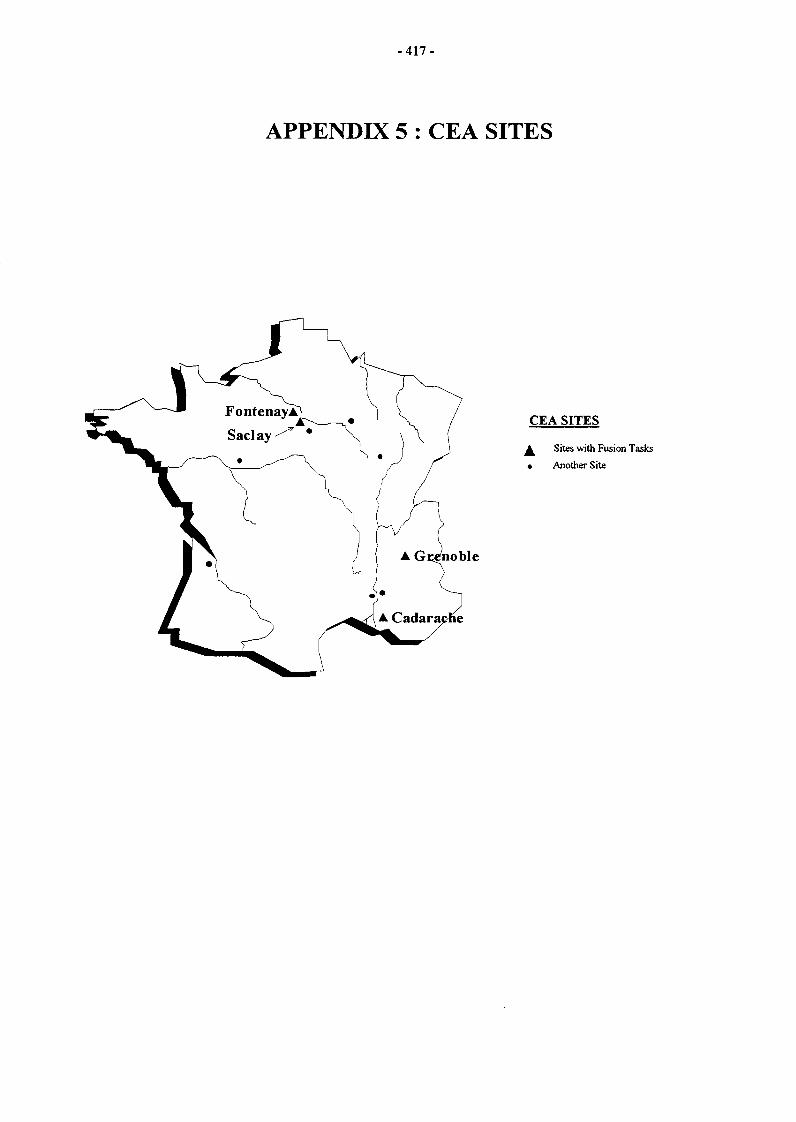
- 4 1 7 -
APPENDIX 5 : CEA SITES
CEA SITES
^ Sites with Fusion Tasks
• Another Site
• Gcenoble