CCSL - FINAL REPORT 9-28-2017 - New Smyrna Beach ...
219
4643 S. Clyde Morris Blvd., Unit 302 • Port Orange, FL 32129 • Phone: 386-304-6505 • Fax: 386-304-6506 [email protected] • www.dmces.com September 28, 2017 Ms. Amye King Planning Director City of New Smyrna Beach 2650 N. Dixie Frwy 32168-5774 RE: City of New Smyrna Beach Coastal Construction Setback Line Review in conformance to FDEP Coastal Construction Control Line (CCCL) Ms. King: Dredging & Marine Consultants, LLC (DMC) is pleased to provide this summary letter report to the City of New Smyrna Beach with regards to the comparison of the City’s Coastal Construction Setback Line (CCSL) to that of the Florida Department of Environmental Protection’s Costal Construction Control Line (CCCL) focusing on the section along N. Atlantic Avenue between the Crawford Road intersection north to Sapphire Road intersection. The report summarizes the City’s ordinances and our suggested revisions based on our review and comparison. Additionally, the differences between the City’s CCSL and DEP’s CCCL are presented in a table format for the City’s consideration. DMC has provided information so that the City can make an appropriate decision regarding the determination of the City’s CCSL and its regulations. The following documents were reviewed: Aerial of Crawford Rd. to Sapphire Rd. with DEP CCSL (1991), DNR CCCL (1973), and NSB CCSL (Appendix A) The City of New Smyrna Beach’s ordinances on Development in the coastal area- Article 703.00 (Appendix B) FDEP 2012 Rules and Procedures for Coastal Construction and Excavation- 62B-33 (Appendix C) The City of New Smyrna Beach’s general definitions – Article 201.00 (Appendix D) Methodology on Coastal Construction Control Line Establishment (Appendix E) Florida Statutes 161.053 (Appendix F) Analyzing the placement of the DEP CCCL (1991), DNR CCCL (1973) and the NSB CCSL, we recommend that the city use the CCCL determined by the DEP in 1991 instead of the NSB CCSL that is offset 50-feet west of the DNR CCCL (1973), to enforce the City’s coastal regulations, specifically in this location. The DNR CCCL (1973) was replaced and updated by the DEP CCCL (1991) in order to create uniformity in the placement and regulations throughout the state of Florida. The CCCL line was restudied in 1984 for its reestablishment in 1991, through mathematical models generated by qualified professionals at the University of Florida. These models created predictability of shoreline erosional trends, shoreline
-
Upload
khangminh22 -
Category
Documents
-
view
1 -
download
0
Transcript of CCSL - FINAL REPORT 9-28-2017 - New Smyrna Beach ...

4643 S. Clyde Morris Blvd., Unit 302 • Port Orange, FL 32129 • Phone: 386-304-6505 • Fax: 386-304-6506 [email protected] • www.dmces.com
September 28, 2017 Ms. Amye King Planning Director City of New Smyrna Beach 2650 N. Dixie Frwy 32168-5774 RE: City of New Smyrna Beach Coastal Construction Setback Line Review in conformance to FDEP Coastal Construction Control Line (CCCL) Ms. King:
Dredging & Marine Consultants, LLC (DMC) is pleased to provide this summary letter report to the City of New Smyrna Beach with regards to the comparison of the City’s Coastal Construction Setback Line (CCSL) to that of the Florida Department of Environmental Protection’s Costal Construction Control Line (CCCL) focusing on the section along N. Atlantic Avenue between the Crawford Road intersection north to Sapphire Road intersection. The report summarizes the City’s ordinances and our suggested revisions based on our review and comparison. Additionally, the differences between the City’s CCSL and DEP’s CCCL are presented in a table format for the City’s consideration. DMC has provided information so that the City can make an appropriate decision regarding the determination of the City’s CCSL and its regulations. The following documents were reviewed:
Aerial of Crawford Rd. to Sapphire Rd. with DEP CCSL (1991), DNR CCCL (1973), and NSB CCSL (Appendix A)
The City of New Smyrna Beach’s ordinances on Development in the coastal area- Article 703.00 (Appendix B)
FDEP 2012 Rules and Procedures for Coastal Construction and Excavation- 62B-33 (Appendix C)
The City of New Smyrna Beach’s general definitions – Article 201.00 (Appendix D)
Methodology on Coastal Construction Control Line Establishment (Appendix E)
Florida Statutes 161.053 (Appendix F)
Analyzing the placement of the DEP CCCL (1991), DNR CCCL (1973) and the NSB CCSL, we recommend that the city use the CCCL determined by the DEP in 1991 instead of the NSB CCSL that is offset 50-feet west of the DNR CCCL (1973), to enforce the City’s coastal regulations, specifically in this location. The DNR CCCL (1973) was replaced and updated by the DEP CCCL (1991) in order to create uniformity in the placement and regulations throughout the state of Florida. The CCCL line was restudied in 1984 for its reestablishment in 1991, through mathematical models generated by qualified professionals at the University of Florida. These models created predictability of shoreline erosional trends, shoreline
City of New Smyrna Beach Coastal Construction Setback Line Review DMC Project No. 17-128-02 August 11, 2017
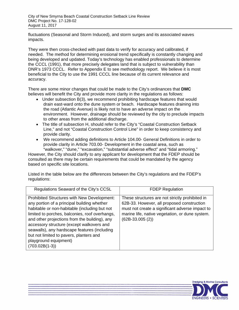
fluctuations (Seasonal and Storm Induced), and storm surges and its associated waves impacts. They were then cross-checked with past data to verify for accuracy and calibrated, if needed. The method for determining erosional trend specifically is constantly changing and being developed and updated. Today’s technology has enabled professionals to determine the CCCL (1991), that more precisely delegates land that is subject to vulnerability than DNR’s 1973 CCCL. Refer to Appendix E to see methodology report. We believe it is most beneficial to the City to use the 1991 CCCL line because of its current relevance and accuracy. There are some minor changes that could be made to the City’s ordinances that DMC believes will benefit the City and provide more clarity in the regulations as follows:
Under subsection B(3), we recommend prohibiting hardscape features that would drain east-ward onto the dune system or beach. Hardscape features draining into the road (Atlantic Avenue) is likely not to have an adverse impact on the environment. However, drainage should be reviewed by the city to preclude impacts to other areas from the additional discharge.
The title of subsection H, should refer to the City’s “Coastal Construction Setback Line,” and not “Coastal Construction Control Line” in order to keep consistency and provide clarity.
We recommend adding definitions to Article 104.00- General Definitions in order to provide clarity in Article 703.00- Development in the coastal area, such as “walkover,” “dune,” “excavation,” “substantial adverse effect” and “tidal armoring.”
However, the City should clarify to any applicant for development that the FDEP should be consulted as there may be certain requirements that could be mandated by the agency based on specific site locations. Listed in the table below are the differences between the City’s regulations and the FDEP’s regulations:
Regulations Seaward of the City’s CCSL FDEP Regulation
Prohibited Structures with New Development: any portion of a principal building whether habitable or non-habitable (including but not limited to porches, balconies, roof overhangs, and other projections from the building), any accessory structure (except walkovers and seawalls), any hardscape features (including but not limited to pavers, planters and playground equipment) (703.02B(1-3))
These structures are not strictly prohibited in 62B-33. However, all proposed construction must not create a significant adverse impact to marine life, native vegetation, or dune system. (62B-33.005 (2))

City of New Smyrna Beach Coastal Construction Setback Line Review DMC Project No. 17-128-02 August 11, 2017
In no case shall fence height be allowed to exceed four feet in height. (max. height is three feet if more than 25% of the fence is opaque)
(703.02D)
There are no guidelines in 62B-33 on fence heights.
Proposed construction must be located behind any existing seawall or tidal armoring (this excludes proposed construction of dune walkovers, new sea walls, other tidal armoring and similar structures by function must be constructed in front of existing seawalls and tidal armoring)
(703.02D(1.d))
There are no guidelines in 62B-33 on proposed construction having to be behind a seawall.
Regulations of walkovers: The walkover shall be posted with signs containing information including the laws concerning the prohibition of disturbing sea turtle nests, dates indicating sea turtle nesting season and prohibition against disturbing state protected vegetation and dunes. If constructed across vegetated dunes or vegetated beach berms, then walkover shall be pile-supported and elevated above vegetation and dune system Walkovers shall be designed to protect the Volusia County conservation zone, natural areas, and beach habitat from construction impacts and long-term pedestrian impacts Walkovers must be approved by FDEP
(703.02D(1.e)(1.g-1.i))
There are no guidelines in 62B-33 on walkovers. However, all proposed construction must not create a significant adverse impact to marine life, native vegetation, or dune system (62B-33.005 (2))
Replacement of any removed vegetation within 60 days of completed construction is required. It must be vegetation from a list of acceptable plants approved by Volusia County (refer to Table 1 in Appendix A) and must be water continuously for a minimum of 45 days. (703.02D(1.f))
The removal or destruction of vegetation cannot either destabilize a frontal, primary, or significant dune or cause a significant adverse impact to the beach and dune system due to increased erosion by the wind or water. (62B-33.005 (4a)) In considering project impact to native salt-tolerant vegetation, the Department shall evaluate the type and extent of native salt-tolerant vegetation, the degree and extent of disturbance by invasive nuisance species and mechanical and other activities, the protective value to adjacent structures and

City of New Smyrna Beach Coastal Construction Setback Line Review DMC Project No. 17-128-02 August 11, 2017
natural plant communities, the protective bale to the beach and dune system, and the impacts to marine turtle nesting and hatchlings. The Department shall restrict activities that lower the protective value of natural and intact beach and dune, coastal strand, and maritime hammock plant communities. Activities that result in the removal of protective root systems or reduce the vegetation’s sand trapping and stabilization properties of salt tolerant vegetation are considered to lower its protective value. Construction shall be located, where practical, in previously disturbed areas or areas with non-native vegetation in lieu of area is native plant communities. (62B-33.005 (11))
Construction of Seawalls: The proposed seawall shall fill in an existing gap of less than 200 feet between existing seawalls. The proposed seawall shall not exceed,
a. The highest point of the existing grade within 25 feet of the proposed seawall location.
b. The average height of the two nearest seawalls.
(703.02E)
Construction of armoring shall be authorized if a gap exists that does not exceed 250 feet. (62B-33.0051 (1)(a)3.) The installment shall not exceed the highest level of protection provided by the adjoining walls. (62B-33.0051 (1)(a)3.d.) There is no guideline regarding a limitation on the height of the wall equaling the highest point of grade within a certain distance.
Prior to commencing any construction activity near a dune system, a dune restoration plan, prepared by a qualified professional, must be approved by the City and must be executed after construction should any damage to the natural dune environment occur.
(703.02G(3-4))
A dune restoration plan is not outlined in 62B-33. However, all proposed construction must not create a significant adverse impact to marine life, native vegetation, or dune system. (62B-33.005 (2))
No excavation of the dunes, removal of dune vegetation or any disruption of the natural environment shall be allowed except as indicated herein. (703.02G(1))
Sandy material excavated seaward of the CCCL or setback line shall be maintained on site seaward of the CCCL or setback line and placed in the immediate area of construction. (62B-33.005 (6)) The construction will not result in the net excavation of the in situ sandy soils seaward of CCCL or setback. (62B-33.005 (4)(d)) The construction will not result in removal or disturbance of in situ sandy soils

City of New Smyrna Beach Coastal Construction Setback Line Review DMC Project No. 17-128-02 August 11, 2017
of the beach and dune system to such a degree that a significant adverse impact to the beach and dune system would result from either reducing the existing ability of the system to resist erosion during a storm or lowering existing levels of storm protection to upland properties and structures. (62B-33.005 (4)(b)) The removal or destruction of native vegetation is not allowed if it will either destabilize a frontal, primary, or significant dune or cause a significant adverse impact to the beach and dune system. (62B-33.005 (4)(a))
Rebuilding after a Hurricane: If structure sustains total damages less
than 50 percent of the primary or accessory structure’s replacement cost at the time of damage, it may be rebuilt to its original condition
If structure sustains total damage more than 50 percent of primary structures replacement cost, it may be rebuilt to the same square footage and density it had immediately prior to the event (but must comply with all regulations)
(703.02I(1-2))
There are no guidelines in 62B-33 on rebuild following a hurricane. Any construction must follow all regulations in 62B-33. The repairs may be completed under the Emergency Final Order.
DMC is pleased to meet with you to discuss any of the information presented or give any additional guidance prior to final changes to the City’s ordinance for this particular location. We thank you for this opportunity. Respectfully, Dredging & Marine Consultants, LLC Shailesh K. Patel, M.Sc., CPSSc Project Manager
SKuhn
Stamp

APPENDIX A

806
801
805
807
809
811
813
815
903
905
907
911
919
921
951
941
403401
700314
310
317315
313311
400318
316
314312310306
243241
239237
235233
231
804
902
900
238234
230904
906237235233
231229227
228
232228
224222
309305
301221
1000
1006
1002
ATLA
NTIC
AV N
CRAWFORD RD
KIRKLAND RD
ROBINSON RD
SAPPHIRE RD
ATLA
NTIC
AV N
LOCAL ROADADDRESSPARCELDEP COASTALCONSTRUCTIONSETBACK LINE(1991)DNR COASTALCONSTRUCTIONCONTROL LINE(1973)NSB COASTALCONSTRUCTIONSETBACK LINE
OMarch 2, 2017
0 50 100 150 200 Feet
911

APPENDIX B

Page 1
703.00. - Development in the coastal area.
703.01. Construction standards. All development or redevelopment proposed on land within the coastal area shall be in accordance with article X, Coastal Construction, Code sections 10-320 through 10-324 as amended, City Code of Ordinances.
703.02. Development east of the city construction setback line.
A. Location of city's Coastal Construction Setback Line.
(1) Between the north corporate limit and the centerline of Crawford Road, the city's Coastal Construction Setback Line (CCSL) shall be 50 feet west of the Department of Environmental Protection (DEP) Coastal Construction Control Line (CCCL) as it existed prior to January 24, 1991, except as follows:
i. The city's Coastal Construction Setback Line (CCSL) shall move eastward of Department of Environmental Protection Coastal Construction Control Line (CCCL) from the Point of Beginning and Point of Termination in the following manner: from a Point of Beginning, commence at the intersection of the southwesterly prolongation of the northwesterly line of Lot 4, Block 5, Boardwalk Subdivision, Coronado Beach, according to the map or plat thereof as recorded in Plat Book 8, Page 114, Public Records of Volusia County, Florida and the Department of Natural Resources Coastal Construction Setback Line as recorded in Map Book 30, Page 19, Public Records of Volusia County, Florida; thence northeasterly along said prolongation of said northwesterly line, a distance of 61.61 feet; thence southerly, a distance of 50.26 feet to a point on the southeasterly line of said Lot 4, said point being 46.74 feet from the monumented southwesterly corner of said Lot 4 as measured along the southeasterly line of said Lot 4; thence southwesterly, a distance of 57.20 feet and along said southeasterly line of Lot 4 to said Department of Natural Resources Coastal Construction Setback Line for the Point of Termination.
ii. The city's Coastal Construction Setback Line (CCSL) shall move eastward of the Department of Environmental Protection Coastal Construction Control Line (CCCL) from the Point of Beginning and Point of Termination in the following manner: From the Point of Beginning, commence at the intersection of the westerly prolongation of the northerly line of Lot 10, Block 5, Map of "The Boardwalk" Subdivision, according to the map or plat thereof, as recorded in Map Book 8, Page 114, of the Public Records of Volusia County, Florida and the City of New Smyrna Beach Coastal Construction Setback Line per City of New Smyrna Beach Ordinance No. 12-01, dated 04/02/01, said City of New Smyrna Beach Coastal Construction Setback Line lies 50 feet westerly of the Department of Natural Resources Coastal Construction Setback Line as recorded in Map Book 30, Page 19, Public Records of Volusia county, Florida; thence North 63° 27' 59" East, along said westerly prolongation of the northerly line of Lot 10 and along said northerly line of Lot 10, a distance of 148.07 feet; thence South 26° 18' 57" East, a distance of 50.00 feet to the southerly line of said Lot 10; thence South 63° 27' 59" West, along said southerly line of Lot 10 and its westerly prolongation, a distance of 147.04 feet to said New Smyrna Beach Coastal Construction Setback Line for the Point of Termination.
iii. For a Point of Beginning, commence at the intersection of the City of New Smyrna Beach Coastal Construction Setback Line per Ordinance No. 12-01 and the westerly prolongation of the southerly line of Lot 3, Block 5, Map of Resubdivision of "The Boardwalk" Subdivision, according to the plat thereof as recorded in Map Book 8, Page 114 of the Public Records of Volusia County, Florida; thence North 63° 27' 59" East, along said westerly prolongation and along said southerly line of Lot 3, a distance of 101.37 feet; thence North 22° 29' 04" West, a distance of 50.04 feet to the northerly line of said Lot 3; thence South 63° 27' 59" West, along said northerly line of Lot 3 and along the westerly prolongation of said northerly line of Lot 3, a distance of 105.75 feet to said
Page 2
City of New Smyrna Beach Coastal Construction Setback Line and for the Point of Termination.
iv. Commence at the Northwest corner of Lot 5, Block 2, Colin Park, according to the plat thereof, as recorded in Map Book 1, Page 83, of the Public Records of Volusia County, Florida; thence N 68°21′16″ E along the Northerly line of said Lot 5, a distance of 148.68 feet to the intersection of the City of New Smyrna Beach Coastal Construction Setback Line per Ordinance No. 12-01 and for the Point of Beginning; thence continue N 68°21′16″ E along the Northerly line of said Lot 5, a distance of 51.84 feet to the Easterly line of said Lot 5; thence S 21°48′41″ E along the easterly line of said Lot 5, a distance of 49.95 feet to the Southerly line of said Lot 5; thence S 68°21′16″ W along the Southerly line of said Lot 5, a distance of 51.06 feet to the intersection of the City of New Smyrna Beach Coastal Construction Setback Line per Ordinance No. 12-01 and for the Point of Termination.
v. Commence at the intersection of the westerly prolongation of the northerly line of Lot 2, Block 5, Map of "The Boardwalk" Subdivision, according to the map or plat thereof, as recorded in Map Book 8, Page 114 of the Public Records of Volusia County, Florida and the City of New Smyrna Beach Coastal Construction Setback Line per City of New Smyrna Beach Ordinance No. 12-01, dated 04/02/01, said City of New Smyrna Beach Coastal Construction Setback Line lies 50 feet westerly of the Department of Natural Resources Coastal Construction Setback Line as recorded in Map Book 30, Page 19, Public Records of Volusia County, Florida; thence North 63°27'59" East, along said westerly prolongation of the northerly line of Lot 2 and along said northerly line of Lot 2, a distance of 101.37 feet to a point on the City of New Smyrna Beach Coastal Construction Setback Line per City of New Smyrna Beach Ordinance No. 20-11, dated 03/29/2011, and for the Point of Beginning; thence continue North 63°27'59" East, along said northerly line of Lot 2, a distance of 16.83 feet; thence South 26°07'22" East, a distance of 100.74 feet to the southerly line of Lot 1, Block 5, said Map of "The Boardwalk" subdivision; thence South 88°59'59" West, along said southerly line of Lot 1, a distance of 75.74 feet to the southwesterly corner of said Lot 1, thence South 62°29'59" West, to said New Smyrna Beach Coastal Construction Setback Line per City of New Smyrna Beach Ordinance No. 12-01 for the Point of Termination.
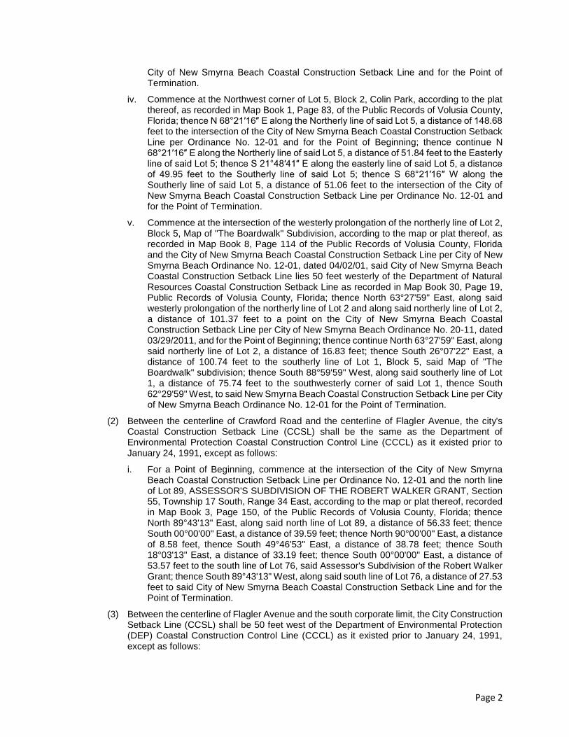
(2) Between the centerline of Crawford Road and the centerline of Flagler Avenue, the city's Coastal Construction Setback Line (CCSL) shall be the same as the Department of Environmental Protection Coastal Construction Control Line (CCCL) as it existed prior to January 24, 1991, except as follows:
i. For a Point of Beginning, commence at the intersection of the City of New Smyrna Beach Coastal Construction Setback Line per Ordinance No. 12-01 and the north line of Lot 89, ASSESSOR'S SUBDIVISION OF THE ROBERT WALKER GRANT, Section 55, Township 17 South, Range 34 East, according to the map or plat thereof, recorded in Map Book 3, Page 150, of the Public Records of Volusia County, Florida; thence North 89°43'13" East, along said north line of Lot 89, a distance of 56.33 feet; thence South 00°00'00" East, a distance of 39.59 feet; thence North 90°00'00" East, a distance of 8.58 feet, thence South 49°46'53" East, a distance of 38.78 feet; thence South 18°03'13" East, a distance of 33.19 feet; thence South 00°00'00" East, a distance of 53.57 feet to the south line of Lot 76, said Assessor's Subdivision of the Robert Walker Grant; thence South 89°43'13" West, along said south line of Lot 76, a distance of 27.53 feet to said City of New Smyrna Beach Coastal Construction Setback Line and for the Point of Termination.
(3) Between the centerline of Flagler Avenue and the south corporate limit, the City Construction Setback Line (CCSL) shall be 50 feet west of the Department of Environmental Protection (DEP) Coastal Construction Control Line (CCCL) as it existed prior to January 24, 1991, except as follows:
Page 3
i. For a Point of Beginning, Commence at the northwesterly corner of Lot 1, Block 1, Armstrong & Johnson Subdivision, according to the map or plat thereof, recorded in Map Book 8, Page 92 of the Public Records of Volusia County, Florida; thence North 63°23′37″ East, along the northerly line of said Lot 1, a distance of 72.13 feet to the intersection of the City of New Smyrna Beach Coastal Construction Setback Line per Ordinance No. 12-01 and for the Point of Beginning; thence continue North 63°23′37″ East, along said northerly line of Lot 1 and the easterly prolongation thereof, a distance of 92.32 feet; thence South 27°19′47″ East, a distance of 49.94 feet to the easterly prolongation of the southerly line of said Lot 1; thence South 63°21′32″ West, along said easterly prolongation of the southerly line of Lot 1 and along the southerly line of said Lot 1, a distance of 92.18 feet to the intersection of said City of New Smyrna Beach Coastal Construction Setback Line and for the Point of Termination.
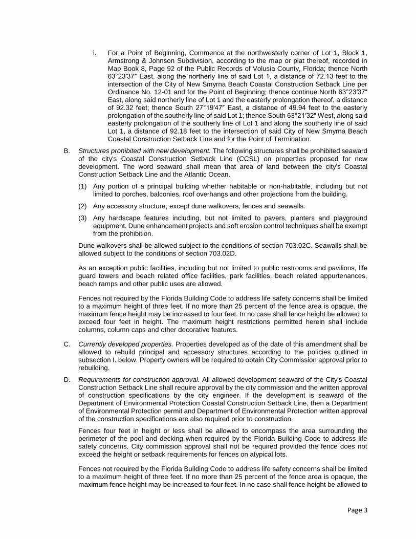
B. Structures prohibited with new development. The following structures shall be prohibited seaward of the city's Coastal Construction Setback Line (CCSL) on properties proposed for new development. The word seaward shall mean that area of land between the city's Coastal Construction Setback Line and the Atlantic Ocean.
(1) Any portion of a principal building whether habitable or non-habitable, including but not limited to porches, balconies, roof overhangs and other projections from the building.
(2) Any accessory structure, except dune walkovers, fences and seawalls.
(3) Any hardscape features including, but not limited to pavers, planters and playground equipment. Dune enhancement projects and soft erosion control techniques shall be exempt from the prohibition.
Dune walkovers shall be allowed subject to the conditions of section 703.02C. Seawalls shall be allowed subject to the conditions of section 703.02D.
As an exception public facilities, including but not limited to public restrooms and pavilions, life guard towers and beach related office facilities, park facilities, beach related appurtenances, beach ramps and other public uses are allowed.
Fences not required by the Florida Building Code to address life safety concerns shall be limited to a maximum height of three feet. If no more than 25 percent of the fence area is opaque, the maximum fence height may be increased to four feet. In no case shall fence height be allowed to exceed four feet in height. The maximum height restrictions permitted herein shall include columns, column caps and other decorative features.
C. Currently developed properties. Properties developed as of the date of this amendment shall be allowed to rebuild principal and accessory structures according to the policies outlined in subsection I. below. Property owners will be required to obtain City Commission approval prior to rebuilding.
D. Requirements for construction approval. All allowed development seaward of the City's Coastal Construction Setback Line shall require approval by the city commission and the written approval of construction specifications by the city engineer. If the development is seaward of the Department of Environmental Protection Coastal Construction Setback Line, then a Department of Environmental Protection permit and Department of Environmental Protection written approval of the construction specifications are also required prior to construction.
Fences four feet in height or less shall be allowed to encompass the area surrounding the perimeter of the pool and decking when required by the Florida Building Code to address life safety concerns. City commission approval shall not be required provided the fence does not exceed the height or setback requirements for fences on atypical lots.
Fences not required by the Florida Building Code to address life safety concerns shall be limited to a maximum height of three feet. If no more than 25 percent of the fence area is opaque, the maximum fence height may be increased to four feet. In no case shall fence height be allowed to

Page 4
exceed four feet in height. The maximum height restrictions permitted herein shall include columns, column caps and other decorative features.
(1) Criteria for city commission approval. The city commission may approve a request for construction, erection, installation, or placement of allowed construction upon determining the request meets all of the following criteria:
(a) The request is both the minimum required distance seaward of the city's Coastal Construction Setback Line and the minimum required height that is reasonably and customarily necessary to accommodate the proposed construction.
(b) Adequate land does not exist landward of the city's Coastal Construction Setback Line to allow the reasonable, normal and customary use and accessory uses of the property (as compared to other properties in the neighborhood) without building seaward of the line.
(c) The proposed construction does not cause a substantial adverse effect on functionality of the existing dune system either as a habitat for native species of animals and plants; or, as a tidal barrier.
(d) The proposed construction is located behind any existing seawall or tidal armoring (excluding dune walkovers, new sea walls, either tidal armoring and similar structures that by function must be constructed in front of existing seawalls and tidal armoring.
(e) Walkovers shall be constructed in a manner that minimizes short-term disturbances to the dune system and existing vegetation. The walkover shall be posted with signs containing information including the laws concerning the prohibition of disturbing sea turtle nests, dates indicating sea turtle nesting season and prohibitions against disturbing state protected vegetation and dunes.
(f) Replacement of any vegetation destroyed during construction of the walkover with similar plants suitable for beach/dune stabilization is required. Replanting must be accomplished with native coastal vegetation suitable for beach and dune stabilization in accordance with the list of acceptable plants approved by the County of Volusia, and included as Table 1, below and must be watered continuously for a minimum of 45 days. A dune restoration plan must be included with the request for city commission approval to construct the walkover. A copy of the dune restoration plan approved by the city commission must also be included with the building permit application. All dune plantings must be completed within 60 days after construction of the dune walkover is completed.
(g) Walkovers constructed across vegetated dunes or over vegetated beach berms shall be pile-supported and elevated above the vegetation and dune system.
(h) All walkovers shall be designed to protect the Volusia County conservation zone, natural areas, and beach habitat from construction impacts and long-term pedestrian impacts.
(i) All new or replaced walkovers shall be constructed in accordance with the FDEP regulations, which mandate the preservation and restoration of the associated dune system.
TABLE 1: NATIVE COASTAL VEGETATION FOR DUNE REPLANTINGS
Shrubs
Chrysobalanus icaco Green cocoplum Myrcianthes frangrans Simpson stopper

Page 5
Croton punctatus Beach croton Serenoa repens Saw palmetto
Dodonaea viscosa Varnish leaf Sophora tomentosa Necklace pod
Erythrina herbacea Coral bean Suriana maritima Bay cedar
Forestiera seqregata Florida privet Yucca aloifolia Spanish bayonet
Groundcovers
Alternanthera flayescens Yellow joyweed Licania michauxli Gopher apple
Alternanthers maritima Beach chaff-flower Muhlenberqia capillaris Muhly grass
Ambrosia hispida Coastal ragweed Opuntie humifusa Prickly-pear cactus
Blutaparon vermiculare Samphfire Opuntia stricta Prickly-pear cactus
Chamaesyce spp. Dune spurge Panicum amarum Bitter panic grass
Distichlis spicata Saltgrass Paspalum vaqinatum Seashore paspalum
Ernodia littoralis Golden creeper Calicornia spp. Glasswort
Hymenocallis latifolia Spider lily Sesuvium portulacastrum Sea purslane
Ipomoea imperati Beach morning glory Spartina patens Saltmeadow cordgrass
Ipomoea pascaprae Railroad vine Sporobolus virginicus Seashore dropsees
Iva imbricata Beach elder Uniola paniculata Sea oats
Vines
Canavalia rosea Beach bean Passiflora incarnata Purple passionflower
Ecbites umbellata Devil's potato Passiflora suberosa Corkystem
Ipomoea spp. Morning glory Pentalinon luteum Wild allamanda

Page 6
Wildflowers
Borrichia spp. Sea oxeye daisy Heliauthus debilis Dune sunflower
Chamaecrista spp. Partridge pea Ipomopsis rubra Standing cypress
Eustoma exaltatum Seaside gentian Monarda punctate Dotted horsemint
Gaillaxdia pulchella Blanket flower Oenothera humifusa
Seaside evening
primrose
Glandularia maritima Beach verbena Salvia coccinea Tropical sage
The city commission shall deny the request if one or more of the aforementioned criteria is not met.
_____
E. Construction of seawalls. The construction of seawalls seaward of the city's Coastal Construction Setback Line may be permitted by the city commission provided the following conditions are met:
(1) The proposed seawall will fill in an existing gap of less than 200 feet between existing seawalls or is an emergency event required to protect public health and safety.
(2) The height of the proposed seawall shall not exceed the greater of the following:
(a) The highest point of the existing grade within 25 feet of the proposed seawall location; or
(b) The average height of the two nearest seawalls to the proposed seawall location.
F. Soft erosion control techniques (dune enhancement). Soft erosion control techniques (dune enhancement) such as erection of sand fences, planting of sea oats, and the placement of compatible sand fill may be allowed seaward of the city's Coastal Construction Setback Line (CCSL) without city commission approval, provided the following regulations are met:
(1) The erosion control is not greater than 20 feet from the toe of an existing dune, except a sand fence can be no greater than one foot from the toe of the dune;
(2) The erosion control will not disrupt traffic flow on the beach;
(3) No persons are allowed within the erosion control area (except a person preparing or maintaining the erosion control area);
(4) A certificate of zoning and a city permit are issued prior to proceeding with erosion control; and
(5) A Department of Environmental Protection permit is provided if the activity is seaward of the Coastal Construction Control Line.
G. Excavation of the dunes, removal of dune vegetation or any disruption of the natural environment.

Page 7
(1) No excavation of the dunes, removal of dune vegetation or any disruption of the natural environment is be allowed seaward of the city's Coastal Construction Setback Line (CCSL) except as indicated herein.
(2) Any person engaging in construction or development activity landward of the city's Coastal Construction Setback Line that is likely to impact, or has impacted upon, the natural dune environment seaward of the city's Coastal Construction Setback Line shall be required to mitigate, fix, repair and restore, as the need may be, to prevent and correct any damage to the functionality of natural dune system either as a habitat for native species of animals and plants; or, as a tidal barrier.
(3) Prior to commencing any construction activity near a dune system, a dune restoration plan, which must be prepared by a qualified professional, must be submitted and approved by the city.
(4) Following construction, any damage to the natural dune environment must be repaired according to the approved restoration plan.
H. Public hearing requirement to approve construction seaward of the city's Coastal Construction Setback Line. The city commission shall conduct a quasi-judicial hearing on any request to build seaward of the city's Coastal Construction Setback Line (CCSL) in accordance with Bd. of Cty. Com'rs of Brevard v. Snyder, 627 So.2d 469 (Fla. 1993). Said quasi-judicial public hearing shall be conducted in a manner to insure that all parties are provided notice of the proceedings, an opportunity to be heard, an opportunity to present evidence, an opportunity to cross-examine witnesses, and to be informed of all the facts upon which the commission's decision is based. Ex parte communications between the parties and members of the city commission must be disclosed in accordance with the city's ex parte communication Ordinance No. 75-95. The city clerk shall notify the neighboring property owners by mailing a copy of the notice of the time and place of the public hearing on the request to build seaward of the city's Coastal Construction Setback Line (CCSL) at his or her last-known address. The names and addresses of such property owners shall be obtained by the applicant from the records of the property appraiser. The 150-foot radius shall be measured from the corners where the property fronts on a public street. Notice shall only be given to entities or public agencies having a title interest in property. Proof of such mailing shall be made by affidavit of the city clerk.
I. Coastal construction rebuild policy after a hurricane, tornado, flood or fire.
(1) Notwithstanding contrary provisions contained in the Land Development Regulations and other building ordinances, a primary or accessory structure damaged by a hurricane, northeastern storm, tornado, flood, fire or other disaster that as the result of such an event sustains total damage less than fifty percent (50%) of the primary or accessory structure's replacement cost at the time of damage may be rebuilt to its original condition, subject only to current building regulations and life-safety codes.
(2) Notwithstanding any contrary provisions contained in the Land Development Regulations and other building ordinances, a primary structure damaged by a hurricane, tornado, flood or fire that as the result of such an event sustains total damage more than fifty percent (50%) of the primary structure's replacement cost at the time of damage may be rebuilt to the same square footage and density it had immediately prior to the event, provided that said rebuild otherwise complies with all applicable:
• Federal requirements for elevation above the 100-year flood level;
• Building code requirements for flood-proofing;
• Current building and life-safety codes;
• State Coastal Construction Control Lines;

Page 8
• All required city zoning or other development regulations (other than density or intensity); and
• Any and all other county, state and federal laws and regulations to which the structure is subject.
(3) Actual uses, densities, intensities and compliance with regulations in effect at the time of construction may be documented through such means as photographs, diagrams, plans, affidavits, permits, appraisals and tax records. The property owner shall have the burden of proof as required in civil actions in Florida courts to establish that he or she is entitled to rebuild in accordance with (1) and (2) above.
(4) In the event that deterioration through time or a disaster destroys any accessory structure east of the Coastal Construction Setback Line (CCSL) which received a certificate of occupancy prior to (the effective date of this ordinance) by more than fifty percent (50%) of the structure's replacement cost, the property owner may reconstruct a similar structure if the following conditions are met:
a. The structure must be no larger in area or volume or further east of the CCSL than the structure it replaces.
b. The structure is placed as westerly as practicable and provide for protecting the beach and dunes from storm water runoff and restoring the remaining natural dune system with sand and dune vegetation.
c. The structure is located on property clearly owned by the upland entity seeking approval for the structure, as evidenced by an attorney's opinion of title, or a license agreement to use the land is approved by the city.
d. All local and non-local permits are obtained to reconstruct the structure.
e. All non-CCSL setbacks existing at the time the structure is replaced must be met.
f. Any other regulations within the respective zoning district and LDR must be met.
703.03. Outdoor lighting. All developments along the beach shall conform to [sub]section 604.15B. of this LDR.
(Ord. No. 12-01, § 1, 3-29-2001; Ord. No. 19-03, § 1, 10-14-2003; Ord. No. 25-04, § 1, 9-14-
2004; Ord. No. 41-08, § 1, 6-10-2008; Ord. No. 18-10, § 1, 4-27-2010; Ord. No. 55-10, § 1, 11-
9-2010; Ord. No. 20-11, § 1, 4-12-2011; Ord. No. 31-13, § 1, 4-23-2013; Ord. No. 40-13, § 1, 6-
25-2013; Ord. No. 48-14, § 1, 8-12-2014; Ord. No. 02-15, § 1, 8-25-2015; Ord. No. 67-15, § 1,
8-25-2015)
APPENDIX C

CHAPTER 62B-33
RULES AND PROCEDURES FOR COASTAL CONSTRUCTION AND EXCAVATION (PERMITS FOR
CONSTRUCTION SEAWARD OF THE COASTAL CONSTRUCTION CONTROL LINE AND FIFTY-FOOT SETBACK)
62B-33.002 Definitions
62B-33.004 Exemptions from Permit Requirements
62B-33.005 General Criteria
62B-33.0051 Coastal Armoring and Related Structures
62B-33.007 Structural and Other Requirements Necessary for Permit Approval (Repealed)
62B-33.008 Permit Application Requirements and Procedures
62B-33.0081 Survey Requirements
62B-33.0085 Permit Fees
62B-33.013 Permit Modifications, Time Extensions, and Renewals
62B-33.014 Emergency Procedures
62B-33.0155 General Permit Conditions
62B-33.024 Thirty-Year Erosion Projection Procedures
62B-33.002 Definitions.
(1) “Agency” is an administrative division of local, municipal, county, state, or federal government.
(2) “Agent” is any person with the written power or authority to act on behalf of the applicant for purposes of an application
submitted under Chapter 161, F.S.
(3) “Alongshore” is a directional reference meaning along or approximately parallel to the shoreline; alternatively, shore-
parallel, or longshore.
(4) “Applicant” is any person, firm, corporation, county, municipality, township, special district, or any public agency or their
authorized agent having authority pursuant to Section 161.052 or 161.053, F.S., to request a permit to conduct construction seaward
of the control line or fifty-foot setback. An applicant may include the owner of record, agent, leaseholder, or holder of any legal
instrument which gives the holder legal authority to undertake the construction for which a permit is sought.
(5) “Armoring” is a manmade structure designed to either prevent erosion of the upland property or protect eligible structures
from the effects of coastal wave and current action. Armoring includes certain rigid coastal structures such as geotextile bags or
tubes, seawalls, revetments, bulkheads, retaining walls, or similar structures but does not include jetties, groins, or other construction
whose purpose is to add sand to the beach and dune system, alter the natural coastal currents, or stabilize the mouths of inlets.
(6) “Beach” is the zone of unconsolidated material that extends landward from the mean low water line to the place where there
is marked change in material or physiographic form, or to the line of permanent vegetation.
(7) “Beach and Dune System” is that portion of the coastal system where there has been or there is expected to be, over time and
as a matter of natural occurrence, cyclical and dynamic emergence, destruction, and reemergence of beaches and dunes.
(8) “Beach quality sand” is sand which is similar to the native beach sand in both coloration and grain size and is free of
construction debris, rocks, clay, or other foreign matter.
(9) “Breakaway Wall” or “Frangible Wall” is a partition independent of supporting structural members that is intended to
withstand design wind forces but to collapse from a water load less than that which would occur during a 100-year storm event
without causing collapse, displacement, or other structural damage to the elevated portion of the building or supporting foundation
system.
(10) “Building Support Structure” is any shore-parallel structure which supports floor, wall, or column loads and transmits them
to the foundation.
(11) “Coastal Construction Control Line” (CCCL) or “Control Line” is the line established pursuant to the provisions of Section
161.053, F.S., and recorded in the official records of the county, which defines that portion of the beach-dune system subject to
severe fluctuations based on a 100-year storm surge, storm waves, or other predictable weather conditions.
(12) “Coastal System” is the beach and adjacent upland dune system and vegetation seaward of the coastal construction control
line; swash zone; surf zone; breaker zone; offshore and longshore shoals; reefs and bars; tidal, wind, and wave driven currents;
longshore and onshore/offshore drift of sediment materials; inlets and their ebb and flood tide shoals and zones of primary tidal
influence; and all other associated natural and manmade topographic features and coastal construction.

(13) “Construction” is any work or activity, including those activities specified in Section 161.053(2), F.S., which may have an
impact as defined in this rule, except as applicable in Rule 62B-33.004, F.A.C.
(14) “Construction Debris” is the material resulting from the demolition of a structure. For the purpose of this rule chapter,
construction debris shall not include such material which has been sorted, cleaned, and otherwise processed such that it meets the
suitability criteria for armoring materials set forth in this rule chapter.
(15) “Department” is the Florida Department of Environmental Protection. The head of the Department is the Secretary.
(16) “Dune” is a mound, bluff or ridge of loose sediment, usually sand-sized sediment, lying upland of the beach and deposited
by any natural or artificial mechanism, which may be bare or covered with vegetation and is subject to fluctuations in configuration
and location.
(a) “Significant dune” is a dune which has sufficient height and configuration or vegetation to offer protective value.
(b) “Primary dune” is a significant dune which has sufficient alongshore continuity to offer protective value to upland property.
The primary dune may be separated from the frontal dune by an interdunal trough; however, the primary dune may be considered the
frontal dune if located immediately landward of the beach.
(17) “Eligible Structures” are public infrastructure and private structures qualified for armoring as follows:
(a) Public infrastructure includes those roads designated as public evacuation routes, public emergency facilities, bridges, power
facilities, water or wastewater facilities, other utilities, hospitals, or structures of local governmental, state, or national significance.
(b) Private structures include:
1. Non-conforming habitable structures,
2. Major non-habitable structures which are not expendable,
3. Expendable major structures which are amenities necessary for occupation of the major structure, and
4. Expendable major structures whose failure would cause an adjacent upland non-conforming habitable structure or major non-
habitable structure, which is not expendable, to become vulnerable.
(c) Eligible structures do not include minor structures.
(18) “Emergency Protection” is the use of armoring or other measures such as sand fill or expedient foundation reinforcement to
temporarily protect eligible structures which are threatened by erosion as a result of recent storm events.
(19) “Erosion” is the wearing away of land or the removal of consolidated or unconsolidated material from the beach and dune
system by wind, water, or wave action. Erosion includes:
(a) Landward horizontal movement of the line of mean high water or beach and dune system profile.
(b) Vertical lowering or volumetric loss of sediment from the beach and dune system or the offshore profile.
(20) “Excavation” is any mechanical or manual removal or alteration of consolidated or unconsolidated soil or rock material
from or within the beach and dune system.
(21) “Expendable Structure” means a structure that is subject to use or consumption, suitable for sacrifice, or is not essential to
preserve.
(22) “Fifty (50)-foot Setback” or “Setback Line” is the line of jurisdiction established pursuant to the provisions of Section
161.052, F.S., in which construction is prohibited within 50 feet of the line of mean high water at any riparian coastal location
fronting the Gulf of Mexico or the Atlantic coast shoreline.
(23) “Fixed Coastal Cell” is a geomorphological component of the coastal system which is closely linked internally by active
physical processes and is bounded by physical features which exercise a major control on refraction patterns or which
compartmentalize or severely limit longshore sediment transport such as headlands or inlets.
(24) “Florida Building Code” (FBC) refers to Part VII of Chapter 553, F.S., the Florida Building Codes Act, effective March 1,
2002.
(25) “Foundation” is the portion of a structure which transmits the associated dead and live loads of the structure to the ground
and includes, but is not limited to, spread footings, foundation walls, posts, piers, piles, beams, girders, structural slabs, cross
bracing, and all related connectors. For habitable major structures, the foundation includes all load bearing components below the
first habitable floor. For pavements, the foundation includes the subbase and base course layers supporting the pavement layer.
(26) “Geotextile container” is a bag or tube, made of blanket-like synthetic fibers manufactured in a woven or loose nonwoven
manner, used as an agent to hold together a large mass of sand forming a rigid tubular structure.
(27) “Global Positioning Systems (GPS)” is a passive, satellite-based, navigation system operated and maintained by the United
States Department of Defense. Its primary mission is to provide passive global positioning/navigation for land, air, and sea-based

activities.
(28) “Governmental Entity,” as used in Rule 62B-33.0051, F.A.C., Coastal Armoring and Related Structures, is defined as an
agency, political subdivision, or municipality having jurisdiction over the proposed activities.
(29) “Hydrodynamic Loads” are those horizontal and vertical forces resulting from a mass of water in motion, such as the forces
associated with the flow accompanying a storm surge. Hydrodynamic loads include the effects of turbulence resulting from the
interaction of the flowing water mass with a rigid structure.
(30) “Hydrostatic Loads” are those horizontal and vertical forces resulting from a standing mass of water.
(31) “Immediately Adjacent Properties” are properties lying contiguous to a property proposed for construction including
properties separated by a road, right-of-way, or accessway and those seaward and landward of the property.
(32) “Impacts” are those effects, whether direct or indirect, short or long term, which are expected to occur as a result of
construction and are defined as follows:
(a) “Adverse Impacts” are impacts to the coastal system that may cause a measurable interference with the natural functioning
of the coastal system.
(b) “Significant Adverse Impacts” are adverse impacts of such magnitude that they may:
1. Alter the coastal system by:
a. Measurably affecting the existing shoreline change rate;
b. Significantly interfering with its ability to recover from a coastal storm;
c. Disturbing topography or vegetation such that the dune system becomes unstable or suffers catastrophic failure or the
protective value of the dune system is significantly lowered; or
2. Cause a take, as defined in Section 379.2413(1), F.S., unless the take is incidental pursuant to Section 379.2413(1)(f), F.S.
(c) “Minor Impacts” are impacts associated with construction which are not adverse impacts due to their magnitude or
temporary nature.
(d) “Other Impacts” are impacts associated with construction which may result in damage to existing structures or property or
interference with lateral beach access.
(33) “Major Reconstruction” is the complete or partial replacement or rebuilding, to its original level of protection, of a
significant portion of an existing armoring structure which has failed or deteriorated.
(34) “Marine Turtle” is any turtle, including all life stages from egg to adult, of the species Caretta caretta (loggerhead),
Chelonia mydas (green), Dermochelys coriacea (leatherback), Eretmochelys imbricata (hawksbill), and Lepidochelys kempi
(Kemp’s ridley).
(35) “Mean Tidal Range” is the difference in height between mean high water and mean low water.
(36) “Minor Reconstruction” is the routine repair of an existing, functional, and intact armoring which is necessary to maintain
the structural and functional integrity of the structure as originally designed and includes: repair or replacement of caps, return walls,
tiebacks, individual sheet piles, and armor stone.
(37) “Mitigation” is an action or series of actions taken by the applicant that will offset impacts caused by a proposed or existing
construction project.
(38) “NAD 83/90” – is the North American Datum 1983 adjustment of 1990.
(39) “NAVD 88” is the North American Vertical Datum of 1988.
(40) “NGVD” is National Geodetic Vertical Datum, as established by the National Ocean Survey (formerly called “mean sea
level datum, 1929”).
(41) “Nesting Activity” is any activity by marine turtles associated with nesting including: beach selection, emergence from
marine waters onto the beach, nest site selection, transit to and from the nest site, nest excavation, egg deposition, nest covering,
incubation of eggs, hatching, hatchling emergence, orientation, and the transit of hatchlings into marine waters.
(42) “Nesting Season” is the nesting period for marine turtles from May 1 through October 31 of each year for all counties
except Brevard, Indian River, St. Lucie, Martin, Palm Beach, and Broward. Nesting season for these counties is the period from
March 1 through October 31 of each year.
(43) “Nonconforming Structure” is any major habitable structure which was not constructed pursuant to a permit issued by the
Department pursuant to Section 161.052 or 161.053, F.S., on or after March 17, 1985.
(44) “Notice to Proceed” is the formal notification from the Department authorizing all or portions of the permitted construction
to commence.

(45) “One-hundred-year Storm” or “100-year Storm” is a shore-incident hurricane or any other storm with accompanying wind,
wave, and storm surge intensity having a one percent chance of being equaled or exceeded in any given year.
(46) “Permit” is the authorization issued by the Department to conduct certain specified construction in a specified location
seaward of a control line, upon issuance of a Notice to Proceed. Permit shall also include variances of the 50-foot setback
requirements.
(47) “Permit Condition” is a statement or stipulation issued with, and appearing in or referenced in, a permit.
(48) “Pile Foundation” is a system of piles providing the support of a structure, including those piles terminating below grade at
pile caps and those piles extending above grade to superelevate a structure.
(49) “Protective Value” is the measurable protection level afforded by the dune system to upland property and structures from
the predictable erosion and storm surge levels associated with coastal storm events.
(50) “Rebuilding” is a substantial improvement of the existing structure as defined in Section 161.54, F.S.
(51) “Repair” is the restoration of a portion of an existing structure, including the foundation of the structure, to its original
design or an equivalent structural standard. Repair of a structure assumes that a significant portion of the structure, including its
foundation, remains intact.
(52) “Revetment” is a sloped, facing structure made of an armoring material designed to protect an escarpment or embankment
or an upland structure from erosion by wave or current action.
(53) “Scour” is erosion caused by the interaction of waves and currents with man-made structures or natural features.
(54) “Seawall” is a structure separating land from water areas, primarily designed to prevent erosion and other damage due to
wave or current action.
(55) “Shoreline” is the intersection of a specified plane of water with the beach. For example, the mean high water shoreline is
the intersection of the plane of mean high water with the beach.
(56) “Shoreline Change Rate” is the average annual horizontal shift of the intersection of the foreshore slope of the beach with
the referenced water plane, based on recorded historical measurements.
(57) “Shore-normal” is a directional reference meaning approximately perpendicular to the shoreline.
(58) “Storm Surge” is the rise of water above normal water level on the open coast due to a number of factors, including the
action of wind stress on the water surface and the rise in water level due to atmospheric pressure reduction.
(59) “Structure” is the composite result of putting together or building related components in an ordered scheme. Enumeration
of types of structures in this rule subsection shall not be construed as excluding from the application of this rule chapter any other
structure which by usage, design, dimensions, or structural configuration meets the general definition herein provided and requires
engineering considerations similar to the following:
(a) “Rigid Coastal Structures” are characterized by their solid or highly impermeable design or construction. Typically included
within this category are groins, breakwaters, mound structures, jetties, weirs, seawalls, bulkheads, and revetments.
(b) “Minor Structures” are designed to be expendable, and to minimize resistance to forces associated with high frequency
storms and to break away when subjected to such forces, and which are of such size or design as to have a minor impact on the
beach and dune system.
(c) “Major Structures” which, as a result of design, location, or size could cause an adverse impact to the beach and dune
system. Major structures include:
1. “Nonhabitable Major Structures” which are designed primarily for uses other than human occupancy. Typically included
within this category are roads, bridges, storm water outfalls, bathhouses, cabanas, swimming pools, and garages.
2. “Habitable Major Structures” which are designed primarily for human occupancy and are potential locations for shelter from
storms. Typically included within this category are residences, hotels, and restaurants.
(60) “Thirty-year Erosion Projection” or “30-year Erosion Projection” is the projection of long-term shoreline recession
occurring over a period of 30 years based on shoreline change information obtained from historical measurements.
(61) “Toe scour protection” is a supplemental structure or structural component of armoring designed to prevent waves from
scouring and undermining the base of the armoring.
(62) “Understructure” is any wall, partition, or other solid fabrication not comprising a part of the structural support system and
located below the first floor support structure.
(63) “Vulnerable” is when an eligible structure is subject to either direct wave attack or to erosion from a 15-year return interval
storm which exposes any portion of the foundation.

Rulemaking Authority 161.052(11), 161.053(20), 161.085(5) FS. Law Implemented 161.052(1), (2), (3), (4), (5), (6), (7), 161.053(2), (4), (5), (6),
(8), (9), (11), (12), (14), (17), (19), (21), 161.0535, 161.054(1), (2), (5), 161.061(1), (2), 161.085(1), (2), (3), (4), (6), (7), (8), (9) FS. History–New
11-18-80, Amended 3-17-85, 11-10-85, Formerly 16B-33.02, Amended 5-12-92, Formerly 16B-33.002, Amended 9-12-96, 1-26-98, 8-27-00, 7-1-
01, 12-31-01, 6-13-04, 5-31-07, 7-17-08.
62B-33.004 Exemptions from Permit Requirements.
(1) Any structures under construction prior to the establishment of a coastal construction control line (CCCL) in a particular
county are exempt from the provisions of Section 161.053, F.S., and this rule chapter, except as noted in Sections 161.053(8) and
(11), F.S.
(a) “Under construction” is the ongoing physical activity at the time of consideration of the exemption referenced in Section
161.053(9), F.S., of placing the foundation of, or continuation of construction above the foundation of, any structure seaward of the
established CCCL or the setback line.
(b) A pile-supported structure shall be deemed “under construction” when placement of the permanent pile members for the
foundation has begun. Driving of test piles and temporary placement of piles in preparation for driving shall not qualify a structure
as “under construction.” For concrete footer, base, slab, or grade beam supported structures, a structure will be deemed “under
construction” when the placement of concrete for the foundation has begun. For roads, parking lots, driveways, walkways, or similar
paved structures, the structure will be considered “under construction” when placement of the base course, if used, or surface has
been started.
(c) Whenever it is unclear under either paragraph 62B-33.004(1)(a) or (b), F.A.C., that a structure is “under construction”, the
applicant shall provide to the Department the following documents demonstrating that the structure is under construction:
1. A copy of all required local government permits authorizing the structure,
2. A full set of construction plans for the structure approved by the local government in conjunction with the building permit,
and
3. Other documentation, including local building inspectors’ construction reports, construction contracts, or other information,
substantiating that a bona fide construction process, which appears will be continuous in nature, has started.
(d) Exemptions granted under this rule subsection shall only apply to those individual structures or parts of such structures
which are determined to be under construction and are also described in both the local permit and the building plans. Only those
structures which are under construction as defined in this rule section may be exempted. Other proposed structures shown on site
plans, building permits, planned unit developments, or similar documents are not exempt. Any subsequent construction activity in
addition to that so described and exempted shall require a permit, unless exempted under other provisions of this rule.
(e) Property owners may request a determination of exemption status within the period starting with the date of the first Public
Hearing on reestablishing the CCCL held within the respective county and ending with the date of the establishment of the CCCL.
The effective date of an exemption granted under this rule section shall be the date the CCCL is established.
(2) In addition to the exemptions provided in Section 161.053(11), F.S., the following are exempt from the provisions of Section
161.053, F.S., and this rule chapter:
(a) Construction of offshore structures, such as drilling platforms, gas and oil rigs, towers, or navigation aides, located beyond
the effective limits of littoral sediment transport.
(b) Construction, excavation, and damage or destruction of vegetation conducted by the United States Government on lands
owned and maintained by the United States Government.
(c) Minor activities which do not cause an adverse impact on the coastal system and do not cause a disturbance to any
significant or primary dune are exempt from the permitting requirements of this rule chapter. Such activities shall be conducted so as
not to disturb marked marine turtle nests or known nest locations or damage existing native salt-tolerant vegetation. The activities
which are exempt pursuant to this rule paragraph include, but are not limited to, the following:
1. Beach or deck furniture and awnings.
2. Tie-downs, or anchors to existing minor structures or trees.
3. Portable public lifeguard stands.
4. Mono-post structures including umbrellas, antennas, or light posts provided there is minimal disturbance to the beach and
dune system, no damage to vegetation, and the grade is restored.
5. Minor recreational diggings and other forms of art on the unvegetated beach provided there is no removal or filling of sand at

the site.
6. The removal of windblown sand from paved roads and parking areas, beach access ramps, pools, patios, walkways, or decks
not involving a change in the general grade and provided that any beach quality sand is returned to the beach and dune system
seaward of the CCCL.
7. The minor maintenance of bulkheads and seawalls specifically involving scraping, chipping, sandblasting, guniting, and
painting.
8. Minor structures, including but not limited to driveways, water wells, and irrigation wells which are either located within the
landward shadow of existing habitable major structures, landward of the second line of development of major structures, or
landward of public evacuation routes.
9. Maintenance or repair of the structures listed below. The structure(s) must be located a minimum of 30 feet landward of the
frontal dune, escarpment, or coastal armoring structure, and the maintenance or repair must not expand or enlarge the existing
structure(s).
a. Streets and roads, parking areas, and other paved areas not draining or discharging onto the beach; and
b. Swimming pools, provided the activity does not involve excavation.
10. Landscaping located a minimum of 30 feet landward of the frontal dune, escarpment, or coastal armoring structure which
does not involve excavation of existing grade or destruction or removal of native salt-resistant vegetation.
11. Repairs to pile supported foundations which include replacing bolts, hurricane straps, secondary members, and shore-normal
cross bracing.
(3) The Department shall issue a letter of exemption pursuant to the provisions of Section 161.053(11)(b), F.S., provided that
the applicant fulfills the information requirements of subsection 62B-33.008(11), F.A.C., and provided that the Department
determines that the proposed project will not cause a measurable interference with the natural functioning of the coastal system.
Prior to commencement of work under the exemption, the applicant shall comply with the public notice requirements for the agency
action of Chapter 120, F.S.
(4) If the Department determines the proposed minor construction is exempt from the provisions of Section 161.053(11)(c)9.,
F.S., the Department shall issue a notice of exemption using the DEP exemption form. The exemption form, which is entitled
“Exemption Determination Pursuant to Section 161.053 or 161.052, F.S.,” DEP form number 73-120 (Updated 3-05), is hereby
incorporated by reference. A copy of the form can be obtained by writing to the Department of Environmental Protection, 2600 Blair
Stone Road, MS 3522, Tallahassee, Florida 32399-2400, or by telephoning (850)245-8336. The exemption notice shall be posted on
site for the duration of the activity. If the proposed activity is determined not to be exempt, a permit pursuant to Section 161.053,
F.S., and this rule chapter is required.
(5) Major structures and additions to major structures proposed above existing patio slabs, decks, or similar unenclosed areas
are considered as new structures separate and independent of the existing slab, deck, or other unenclosed area and shall comply with
regulatory requirements set forth in this rule chapter.
Rulemaking Authority 161.052(11), 161.053(20) FS. Law Implemented 161.052(3), (4), (6), 161.053(1), (2), (4), (9), (11) FS. History–New 11-18-
80, Amended 3-17-85, 11-10-85, Formerly 16B-33.04, Amended 5-12-92, 11-11-92, Formerly 16B-33.004, Amended 1-26-98, 8-27-00, 5-31-07.
62B-33.005 General Criteria.
(1) The beach and dune system is an integral part of the coastal system and represents one of the most valuable natural resources
in Florida, providing protection to adjacent upland properties, recreational areas, and habitat for wildlife. A coastal construction
control line (CCCL) is intended to define that portion of the beach and dune system which is subject to severe fluctuations caused by
a 100-year storm surge, storm waves, or other forces such as wind, wave, or water level changes. These fluctuations are a necessary
part of the natural functioning of the coastal system and are essential to post-storm recovery, long term stability, and the preservation
of the beach and dune system. However, imprudent human activities can adversely interfere with these natural processes and alter
the integrity and functioning of the beach and dune system. The control line and 50-foot setback call attention to the special hazards
and impacts associated with the use of such property, but do not preclude all development or alteration of coastal property seaward
of such lines.
(2) In order to demonstrate that construction is eligible for a permit, the applicant shall provide the Department with sufficient
information pertaining to the proposed project to show that adverse and other impacts associated with the construction have been
minimized and that the construction will not result in a significant adverse impact.

(3) After reviewing all information required pursuant to this rule chapter, the Department shall:
(a) Deny any application for an activity which either individually or cumulatively would result in a significant adverse impact
including potential cumulative effects. In assessing the cumulative effects of a proposed activity, the Department shall consider the
short-term and long-term impacts and the direct and indirect impacts the activity would cause in combination with existing
structures in the area and any other similar activities already permitted or for which a permit application is pending within the same
fixed coastal cell. The impact assessment shall include the anticipated effects of the construction on the coastal system and marine
turtles. Each application shall be evaluated on its own merits in making a permit decision; therefore, a decision by the Department to
grant a permit shall not constitute a commitment to permit additional similar construction within the same fixed coastal cell.
(b) Deny any application for an activity where the project has not met the Department’s siting and design criteria; has not
minimized adverse and other impacts, including stormwater runoff; or has not provided mitigation of adverse impacts.
(4) The Department shall issue a permit for construction which an applicant has shown to be clearly justified by demonstrating
that all standards, guidelines, and other requirements set forth in the applicable provisions of Part I, Chapter 161, F.S., and this rule
chapter are met, including the following:
(a) The construction will not result in removal or destruction of native vegetation which will either destabilize a frontal,
primary, or significant dune or cause a significant adverse impact to the beach and dune system due to increased erosion by wind or
water;
(b) The construction will not result in removal or disturbance of in situ sandy soils of the beach and dune system to such a
degree that a significant adverse impact to the beach and dune system would result from either reducing the existing ability of the
system to resist erosion during a storm or lowering existing levels of storm protection to upland properties and structures;
(c) The construction will not direct discharges of water or other fluids in a seaward direction and in a manner that would result
in significant adverse impacts. For the purposes of this rule section, construction shall be designed so as to minimize erosion induced
surface water runoff within the beach and dune system and to prevent additional seaward or off-site discharges associated with a
coastal storm event.
(d) The construction will not result in the net excavation of the in situ sandy soils seaward of the control line or 50-foot setback;
(e) The construction will not cause an increase in structure-induced scour of such magnitude during a storm that the structure-
induced scour would result in a significant adverse impact;
(f) The construction will minimize the potential for wind and waterborne missiles during a storm;
(g) The activity will not interfere with public access, as defined in Section 161.021, F.S.; and
(h) The construction will not cause a significant adverse impact to marine turtles, or the coastal system.
(5) In order for a manmade frontal dune to be considered as a frontal dune defined under Section 161.053(5)(a)1., F.S., the
manmade frontal dune shall be constructed to meet or exceed the protective value afforded by the natural frontal dune system in the
immediate area of the subject shoreline. Prior to the issuance of a permit for a single-family dwelling meeting the criteria of Section
161.053(5)(c), F.S., the manmade frontal dune must be maintained for a minimum of 12 months and be demonstrated to be as stable
and sustainable as the natural frontal dune system.
(6) Sandy material excavated seaward of the control line or 50-foot setback shall be maintained on site seaward of the control
line or 50-foot setback and be placed in the immediate area of construction unless otherwise specifically authorized by the
Department.
(7) Swimming pools, wading pools, waterfalls, spas, or similar type water structures are expendable structures and shall be sited
so that their failure does not have adverse impact on the beach and dune system, any adjoining major structures, or any coastal
protection structure. Pools sited within close proximity to a significant dune shall be elevated either partially or totally above the
original grade to minimize excavation and shall not cause a net loss of material from the immediate area of the pool. All pools shall
be designed to minimize any permanent excavation seaward of the CCCL.
(8) Major structures shall be located a sufficient distance landward of the beach and frontal dune to permit natural shoreline
fluctuations, to preserve and protect beach and dune system stability, and to allow natural recovery to occur following storm-induced
erosion. Where a rigid coastal structure exists, proposed major structures shall be located a sufficient distance landward of the rigid
coastal structure to allow for future maintenance or repair of the rigid coastal structure. Although fishing piers shall be exempt from
this provision, their foundation piles shall be located so as to allow for the maintenance and repair of any rigid coastal structure that
is located in close proximity to the pier.
(9) If in the immediate area a number of existing major structures have established a reasonably continuous and uniform

construction line and if the existing structures have not been unduly affected by erosion, except where not allowed by the
requirements of Section 161.053(5), F.S., and this rule chapter, the Department shall issue a permit for the construction of a similar
structure up to that line.
(10) In considering applications for single-family dwellings proposed to be located seaward of the 30-year erosion projection
pursuant to Section 161.053(5), F.S., the Department shall require structures to meet criteria in Section 161.053(5)(c), F.S., and all
other siting and design criteria established in this rule chapter.
(11) In considering project impacts to native salt-tolerant vegetation, the Department shall evaluate the type and extent of native
salt-tolerant vegetation, the degree and extent of disturbance by invasive nuisance species and mechanical and other activities, the
protective value to adjacent structures and natural plant communities, the protective value to the beach and dune system, and the
impacts to marine turtle nesting and hatchlings. The Department shall restrict activities that lower the protective value of natural and
intact beach and dune, coastal strand, and maritime hammock plant communities. Activities that result in the removal of protective
root systems or reduce the vegetation’s sand trapping and stabilizing properties of salt tolerant vegetation are considered to lower its
protective value. Construction shall be located, where practicable, in previously disturbed areas or areas with non-native vegetation
in lieu of areas of native plant communities when the placement does not increase adverse impact to the beach and dune system.
Planting of invasive nuisance plants, such as those listed in the Florida Exotic Pest Plant Council’s 2005 List of Invasive Species –
Categories I and II, will not be authorized if the planting will result in removal or destruction of existing dune-stabilizing native
vegetation or if the planting is to occur on or seaward of the dune system. A copy of this list is available on the Internet at
www.fleppc.org; or can be obtained by writing to the Department of Environmental Protection, 2600 Blair Stone Road, MS 3522,
Tallahassee, Florida 32399-2400; or by telephoning (850)245-8336. Special conditions relative to the nature, timing, and sequence
of construction and the remediation of construction impacts shall be placed on permitted activities when necessary to protect native
salt-tolerant vegetation and native plant communities. A construction fence, a designated location for construction access or storage
of equipment and materials, and a restoration plan shall be required if necessary for protection of existing native salt-tolerant
vegetation during construction.
(12) Special conditions relative to the nature, timing, and sequence of construction shall be placed on permitted activities when
necessary to protect marine turtles and their nests and nesting habitat. In marine turtle nesting areas, all forms of lighting shall be
shielded or otherwise designed so as not to disturb marine turtles. Tinted glass or similar light control measures shall be used for
windows and doors which are visible from the nesting areas of the beach. The Department shall suspend any permitted construction
when the permittee has not provided the required protection for marine turtles and their nests and nesting habitat.
Rulemaking Authority 161.052(11), 161.053(20), 161.085(5) FS. Law Implemented 161.052(2), 161.053(2), (4), (5), (6), (12), (17), (18),
161.085(1), (2) FS. History–New 11-18-80, Amended 3-17-85, 11-10-85, Formerly 16B-33.05, 16B-33.005, Amended 9-12-96, 1-26-98, 8-27-00, 6-
13-04, 5-31-07.
62B-33.0051 Coastal Armoring and Related Structures.
(1) General Armoring Criteria. In determining the appropriate means to protect existing private structures and public
infrastructure from damage from frequent coastal storms, applicants should be aware that armoring may not be the only option for
providing protection. Applicants are encouraged to evaluate other protection methods such as foundation modification, structure
relocation, and dune restoration. If armoring (other than through the use of geotextile containers as the core of a reconstructed dune,
which are governed exclusively by Chapter 62B-56, F.A.C.), is the selected option, the following siting, design, and construction
criteria shall apply in order to minimize potential adverse impacts to the beach and dune system:
(a) Construction of armoring shall be authorized under the following conditions:
1. The proposed armoring is for the protection of an eligible structure; and,
2. The structure to be protected is vulnerable. The determination of vulnerability will be made utilizing the dune erosion model
contained in the report entitled “Erosion due to High Frequency Storm Events,” by the University of Florida, dated November 22,
1995, which is incorporated herein by reference. Where direct application of the model shows that the structure to be protected is not
vulnerable, but the construction otherwise meets the requirements of this rule chapter, an applicant may further demonstrate
vulnerability by taking into account the effects of shoreline change rates, natural physical features, and existing manmade structures
in accordance with the following circumstances:
a. If it is projected that the eligible structure will become vulnerable at some future date which falls within the authorized time
limit of a permit, then the permit shall authorize the construction of armoring once the anticipated site condition changes occur and
the structure becomes vulnerable. The permit shall allow additional time to allow for construction operations and appropriate timing
to avoid construction during the marine turtle nesting season.
b. Where there are multiple eligible structures in close proximity to one another, but not all of the structures are vulnerable and
shoreline trends indicate continued erosion stress on the shoreline, and the Department determines through the use of numerical
modeling and engineering analysis that the construction of armoring for only the vulnerable structures would cause the adjacent
structures to become vulnerable following installation of the armoring, then all the eligible structures are considered vulnerable.
c. Where an eligible structure is located on a dune or escarpment and the dune erosion model predicts that the erosion from a
15-year return interval storm would fall landward of the existing dune crest or escarpment and seaward of the eligible structure, and
where the applicant has provided the Department appropriate geotechnical analysis by a qualified professional engineer specialized
in geotechnical or foundation engineering which demonstrates that the structure would be in danger of imminent collapse following
the occurrence of erosion from a 15-year return interval storm. Imminent collapse means the structure’s foundation will fail due to
its own weight under normal conditions, resulting in structural damage to the supported structure.
d. Where an applicant demonstrates to the Department that another site specific circumstance exists other than listed in sub-
subparagraphs 62B-33.0051(1)(a)2.a. through c., F.A.C., such that the eligible structure is vulnerable; or
3. A gap exists, that does not exceed 250 feet, between a line of rigid coastal armoring that is continuous on both sides of the
unarmored property. Such adjacent armoring shall not be deteriorated, dilapidated, or damaged to such a degree that it no longer
provides adequate protection to the upland property. The top of the adjacent armoring must be at or above the still water level,
including setup, for the design storm of a 15-year return interval storm plus the breaking wave calculated at its highest achievable
level based on the maximum eroded beach profile and highest surge level combination. The adjacent armoring must be stable under
the design storm of 15-year return interval storm, including maximum localized scour with adequate penetration, and must have
sufficient continuity or return walls to prevent upland erosion and flooding under the design storm of 15-year return interval storm.
Such installation shall:
a. Be sited no farther seaward than the adjacent armoring;
b. Close the gap between the adjacent armoring;
c. Avoid significant adverse impacts to marine turtles;
d. Not exceed the highest level of protection provided by the adjoining walls; and,
e. Comply with the requirements of Section 161.053, F.S.
4. The armoring shall not result in a loss of public access along the beach without providing alternative public access;
5. The construction will not result in a significant adverse impact.
(b) Where all permit criteria of this rule have been met, but a beach nourishment, beach restoration, sand transfer, or other
project which would provide protection for the vulnerable structure is scheduled for construction within nine months and all permits
and funding for the project are available, then no permit for armoring shall be issued.
(c) Minor reconstruction of existing armoring is exempt from the conditions of paragraph 62B-33.0051(1)(a), F.A.C., provided
that the proposed construction would not result in a significant adverse impact.
(d) Major reconstruction of existing armoring is exempt from the requirements of subparagraph 62B-33.0051(1)(a)2., F.A.C.,
unless the habitable structure protected by the armoring has been destroyed to the extent that it requires rebuilding.
(2) Siting and Design. Armoring shall be sited and designed to minimize adverse impacts to the beach and dune system, marine
turtles, native salt-tolerant vegetation, and existing upland and adjacent structures and to minimize interference with public beach
access, in accordance with the following criteria:
(a) Siting. Armoring shall be sited as far landward as practicable to minimize adverse impacts while still providing protection to
the vulnerable structure. In determining the most landward practicable location, the following criteria apply:
1. Excavation shall be the minimum required to properly install the armoring and shall not result in the destabilization of the
beach and dune system seaward of the armoring or have an adverse impact on upland structures.
2. If armoring must be located close to the dune escarpment in order to meet the criteria listed above and such siting would
result in destabilization of the dune causing damage to the upland structure, the armoring shall be sited seaward of, and as close as
practicable to, the dune escarpment.
3. Armoring shall be sited a sufficient distance inside the property boundaries to prevent destabilizing the beach and dune
system on adjacent properties or increasing erosion of such properties during a storm event. Return walls shall be sited as close to
the building as practicable while ensuring the building is not damaged and space is allowed for maintenance.

4. Existing armoring in need of major reconstruction, whose alignment either interferes with movement of sediment material
along the beach or causes significant adverse impacts, shall be relocated consistent with the siting requirements of subsection 62B-
33.0051(2), F.A.C.
5. When construction of armoring interferes with public access along the beach, the permittee shall provide alternative access.
(b) Design. Armoring shall be designed to provide protection to vulnerable structures while minimizing adverse impacts and
shall be designed consistent with generally accepted engineering practice. The following criteria apply:
1. Coastal armoring structures shall be designed for the anticipated runup, overtopping, erosion, scour, and water loads of the
design storm event. Design procedures are available in the latest edition of the Department of the Army Corps of Engineers’ Coastal
Engineering Manual (EM 1110-2-1100), or other similar professionally recognized publications.
2. To minimize adverse impacts to the beach and dune system, adjacent properties, and marine turtles, the shore-normal extent
of armoring which protrudes seaward of the dune escarpment, vegetation line, or onto the active beach shall be limited to minimize
encroachment on the beach. In areas with viable marine turtle habitat, the highest part of any toe scour protection shall be located to
minimize encroachment into marine turtle nesting habitat.
3. All armoring shall be designed to remain stable under the hydrodynamic and hydrostatic conditions for which they are
proposed. Armoring shall provide a level of protection compatible with existing topography, not to exceed a 50-year design storm.
4. Armoring shall be designed to minimize interference with public access along the beach.
5. Armor stone, including that used for toe scour protection, shall have a minimum dry unit weight of 135 pounds per cubic
foot. In locations where there is potential for adverse impacts on marine turtles and their habitat, armor stone, except that used for
toe scour protection, shall have a minimum dry unit weight of 150 pounds per cubic foot to reduce the armoring footprint. Armor
stone shall be durable, hard, and free from laminations and weak cleavages, and sound enough to avoid fracturing under the design
storm forces.
6. Armoring which utilizes any construction material other than stone in the construction shall be designed to meet both the
requirements outlined in subparagraph 62B-33.0051(2)(b)5., F.A.C., and the unit weight, strength, and durability requirements
generally accepted by the engineering community for use in the marine environment.
7. Armoring, which utilizes sand-filled geotextile containers as the core of a reconstructed dune for dune stabilization or
restoration activities is not authorized under this rule. These structures are governed under Chapter 62B-56, F.A.C.
(c) The applicant shall provide the Department with certification by a professional engineer licensed in the State of Florida that
the design plans and specifications submitted as part of the permit application are in compliance with this rule chapter.
(3) Marine Turtle Protection. Construction of armoring shall not be conducted during the marine turtle nesting season if the
Department determines that the proposed construction will result in a significant adverse impact, except as allowed under subsection
62B-33.0051(6), F.A.C., or unless under the provisions of Rule 62B-33.014, F.A.C., emergency permitting procedures are enacted.
No additional armoring shall be permitted on public lands in the Archie Carr National Wildlife Refuge. For the purposes of this
provision, public lands means lands owned by local, state, or federal governments, or any lands acquired for the specific purpose of
allowing them to be managed as part of the refuge. This ban does not apply where armoring is necessary, and there is no reasonable
alternative, to protect public infrastructure as that term is defined in Section 161.085, F.S.
(4) In addition to the requirements provided in this rule section, armoring shall meet all other applicable provisions of this rule
chapter.
(5) Emergency Protection. Upon the occurrence of a coastal storm which causes erosion of the beach and dune system such that
existing structures have either become damaged or vulnerable to damage from a subsequent frequent coastal storm, pursuant to
Section 161.085, F.S., the governmental entity may take emergency protection measures to protect public infrastructure and private
structures within its jurisdiction. Alternatively, upon declaring a shoreline emergency and providing notification to affected property
owners and to the Department, the governmental entity may issue permits authorizing private property owners within their
jurisdiction to protect their private structures. Local governments shall not authorize the use of geotextile containers. Emergency
protection measures shall be subject to the following:
(a) If the Department has declared a shoreline emergency pursuant to this rule chapter and affected governmental entities do not
provide for emergency protection permits, pursuant to Section 161.085, F.S., and this rule section, then private property owners must
obtain such permits from the Department prior to construction.
(b) Emergency protection timelines shall be as follows:
1. If a governmental entity declares a localized emergency event and the Department does not issue an emergency final order,

emergency protection measures shall be taken within 30 days after the initial erosion event. Delay in providing protection measures
in excess of 30 days from the declaration of emergency shall result in a finding of no emergency, and emergency protection pursuant
to this rule section shall no longer be authorized. Governmental entities may extend this period up to 30 additional days upon their
revalidation of the emergency conditions.
2. If the state of Florida declares a shoreline emergency, emergency protection measure timelines for activities considered under
Section 161.085, F.S., shall be concurrent with the Department’s emergency final order timelines.
(c) Measures used for temporary protection shall be the minimum required as determined by the governmental entity pursuant to
Section 161.085, F.S., to protect the structure from imminent collapse. Armoring or other measures shall be sited and designed to
minimize excavation of the beach and frontal dune; impacts to existing native coastal vegetation, marine turtles, and adjacent
properties; and encroachment onto the beach. Temporary protection shall be sited and designed to facilitate removal.
(d) Other measures used for temporary protection include the following:
1. Temporary reinforcement of foundations, placement of sandbags, and construction of protective sand berms. Sand used to fill
sandbags or construct protective berms shall be beach compatible material and be obtained from an upland source. Excavation of the
beach face or near shore area shall require a permit from the Department, pursuant to this rule chapter. Any excavation that occurs
below the mean high water line on sovereignty lands is subject to the provision of Section 161.041 and Chapter 253, F.S. Sandfilled
geotextile containers used as the core of a reconstructed dune for dune stabilization or restoration activities are not authorized under
this rule. These structures are governed under Chapter 62B-56, F.A.C.
2. Construction of temporary wooden retaining walls, cantilever sheetpile walls (without concrete caps, tiebacks, or other
reinforcement), or similar structures.
(e) Construction debris resulting from the coastal storm shall not be buried.
(f) Construction debris shall not be used for emergency protection. Any materials used for emergency protection shall either
comply with the materials criteria in paragraph 62B-33.0051(2)(b), F.A.C., or shall be clean and easily removed or designed to
assimilate into the natural environment without damage to the beach and dune system or marine turtles nesting habitat.
(g) Temporary structures shall be removed within 60 days of installation unless a complete application for a permit seeking
authorization to retain the temporary structure or to provide alternative protection has been provided to the Department pursuant to
Sections 161.053 and 161.085, F.S. In order for a temporary structure to remain in place, it must be permitted and meet all
eligibility, siting, and design criteria for permanent armoring provided in this rule chapter.
(h) No activities shall result in a significant adverse impact.
(i) Under Section 161.085, F.S., if installation of a temporary emergency protection structure has caused, is causing, or has the
reasonable potential to cause a significant adverse impact, the governmental entity that authorized the structure shall conduct or
require appropriate action to eliminate any significant adverse impact.
(j) The Department shall require mitigation of any adverse impacts caused by emergency protection structures. In addition, the
Department shall require removal of a temporary emergency protection structure if a significant adverse impact, as defined in Rule
62B-33.002, F.A.C., occurs.
(k) If installation of emergency protection structures occurs during the marine turtle nesting season, the following measures for
the protection of marine turtles shall be implemented prior to siting and during installation of the emergency protection structure:
1. The Department shall be contacted for information on appropriate siting of the emergency structure to minimize impacts to
marine turtles and provided with the location of any known marine turtle nests within the area of the proposed project.
2. Temporary emergency protection structures shall be sited and constructed in a manner that protects marine turtles.
3. Construction and storage of equipment or materials shall be conducted from or located at upland locations landward of the
nesting beach.
4. In order to be prepared for coastal emergencies, local governmental entities who anticipate installing or authorizing
emergency coastal protection structures should obtain a federal Endangered Species Act, Section 10, Incidental Take authorization
from the United States Fish and Wildlife Service through the development of a marine turtle habitat conservation plan.
(l) Governmental entities shall notify the Department’s Division of Water Resource Management, within three (3) working days
of installing or authorizing the installation of any armoring pursuant to this rule section (overnight delivery to Florida Department of
Environmental Protection, Division of Water Resource Management, 2600 Blair Stone Road, MS #3522, Tallahassee, Florida
32399, or facsimile copy to (850)245-8356) or to the following address: [email protected]. Notification shall include:
1. A description of the structure, including a sketch and location;

2. The name and address of the property owner; and,
3. The date of installation.
(m) Other authorizations under Chapters 253, 258, 373 and 379, F.S., are necessary to conduct activities below mean high
water.
(6) The provisions of this rule section shall apply until the following measures to reduce the threat of erosion damage to upland
property and structures within the specific fixed coastal cells of a coastal region have been taken:
(a) The shoreline has been restored such that private structures and public infrastructure are no longer vulnerable to frequent
coastal storms; and,
(b) The shoreline restoration project provides authority for future nourishment to maintain the level of protection; or
(c) Where applicable, an inlet management plan has been adopted by the Department and implemented by the governmental
entity having jurisdiction over the inlet.
Rulemaking Authority 161.053(20), 161.085(5) FS. Law Implemented 161.053(2), (4), 161.085(1), (2), (3), (4), (6), (8) FS. History–New 9-12-96,
Amended 1-26-98, 8-27-00, 7-1-01, 6-13-04, 7-3-05, 5-31-07, 7-17-08.
62B-33.007 Structural and Other Requirements Necessary for Permit Approval.
Rulemaking Authority 161.052(11), 161.053(20) FS. Law Implemented 161.052(2), 161.053(2), (4) FS. History–New 11-18-80, Amended 3-17-85,
11-10-85, Formerly 16B-33.07, Amended 5-12-92, Formerly 16B-33.007, Amended 9-12-96, 1-26-98, 8-27-00, 12-31-01, 6-13-04, 5-31-07,
Repealed 2-16-12.
62B-33.008 Permit Application Requirements and Procedures.
(1) All applications submitted to the Department or to the appropriate local building department prior to March 1, 2002, the
effective date of the Florida Building Code Act (Part VII, Chapter 553, F.S.), shall contain all the information required in subsection
62B-33.008(3), F.A.C.
(2) Applications received by the Department after the March 1, 2002 effective date of the Florida Building Code Act shall not
be required to comply with the provisions of paragraphs 62B-33.008(3)(j), and subsection 62B-33.008(4), F.A.C., except as noted in
subsection 62B-33.008(1), F.A.C.
(3) Any person desiring to obtain a permit for construction seaward of the coastal construction control line (CCCL) or 50-foot
setback from the Department, except those persons applying pursuant to the emergency procedures in Rule 62B-33.014, F.A.C.,
shall submit two (2) copies of a completed application form to the Department at the address below. The permit application form,
which is entitled “Application for a Permit for Construction Seaward of the Coastal Construction Control Line or Fifty-Foot
Setback” – DEP Form 73-100 (Revised 12/06), is hereby adopted and incorporated by reference. Copies of the form can be obtained
by writing the Department of Environmental Protection, 2600 Blair Stone Road, MS 3522, Tallahassee, Florida 32399-2400; or by
telephoning (850)245-8336. The application shall contain the following specific information:
(a) Name, mailing address, and telephone number of the property owner and of any duly authorized agent making the
application on behalf of the owner, and the signature of the applicant.
(b) The name and mailing address of the owners of the immediately adjacent properties, exclusive of street-ends or easements.
(c) Sufficient evidence of ownership including the legal description of the property for which the permit is requested. Examples
of evidence of ownership may include a copy of an executed warranty deed bearing evidence of appropriate recordation; a copy of a
long term lease-purchase agreement, or contract for deed; a copy of a property tax receipt bearing the name and address of the
current owner; articles of condominium bearing evidence of appropriate recordation (for condominiums); or the cooperative
documents defined in Section 719.103(13)(a), F.S. (for residential cooperatives). Other documents submitted as evidence of
ownership will be reviewed by the staff and shall be rejected if found not to be sufficient. A copy of a quit claim deed, a purchase
contract, an affidavit from the owner, or a tax record obtained from an Internet website (unless obtained from an authenticated
official county record) is not sufficient evidence of ownership. If the applicant is not the property owner, the applicant shall submit
certification on the form provided by the Department as part of the permit application form, which is referenced in subsection 62B-
33.008(3), F.A.C., authorizing the applicant to act as the owner’s agent for the purpose of applying for a permit and to act on behalf
of the owner in other matters pertaining to the permit.
(d) Written evidence, provided by the appropriate local governmental entity having jurisdiction over the activity, that the
proposed activity, as submitted to the Department, does not contravene local setback requirements or zoning codes.

(e) A statement describing the proposed work, activity, or construction.
(f) Two original copies of a signed and sealed survey of the subject property. The information depicted on the drawing shall be
from a field survey conducted not more than six months prior to the date of the application. The survey shall comply with the
requirements given in Rule 62B-33.0081, F.A.C.
(g) For major and rigid coastal structures, two copies of a dimensioned site plan drawn to an appropriate scale, on eight and one-
half (8 1/2)-inch by eleven (11)-inch size paper showing property boundaries, the location of the proposed structure(s), the proposed
construction limits, the location and volume of any proposed excavation or fill, and the locations of roads, adjacent dwellings, the
vegetation line, and the approximate mean high water line.
(h) For major and rigid coastal structures, two copies of dimensioned cross-sections drawn to an appropriate scale, on eight and
one-half (8 1/2)-inch by eleven (11)-inch paper, showing:
1. All subgrade construction or excavation with elevations referenced to NAVD 88 (U.S. survey foot).
2. Typical cross-sections of major structures and crest elevations for any proposed coastal or shore protection structure.
3. Location of the control line or, if not established, the MHWL and the 50-foot setback.
4. Typical profile of existing and proposed grade at the site.
5. The location of the contour line corresponding to elevation 0.0 NAVD 88 (U.S. survey foot).
(i) For structures with proposed permanent exterior lighting, two copies of a dimensioned lighting plan drawn to an appropriate
scale showing:
1. The location of all proposed permanent exterior lighting fixtures clearly marked by distinctive symbols for each model used,
2. A table with the column headings shown below providing the specified information for each fixture model used, and
SYMBOL FIXTURE
(e.g., name or stock number)
TOTAL
NUMBER
OF EACH
FIXTURE
BULB LUMENS OUTPUT AND
TYPE (e.g., 420 lumens output
standard incandescent yellow
“bug” bulb)
TYPE OF
MOUNT (e.g.,
wall, pole,
bollard)
MOUNTING HEIGHT
3. A detailed description or manufacturer’s catalog sheet (cut sheet) for each fixture model used.
4. Multi-family and commercial project applications shall include three copies of the items listed in rule subparagraphs 62B-
33.008(3)(i)1., through 3., F.A.C.
(j) Two copies of detailed final construction plans and specifications for all proposed structures or excavation including all
planned appurtenant structures, permanent exterior lighting, and utilities. For major structures, these documents shall be signed and
sealed by an engineer or architect (as appropriate) licensed in the State of Florida, and the site plan shall include all information
required in subsection 62B-33.0081(1), F.A.C.
(k) For major habitable multifamily dwelling structures, two copies of detailed foundation plans and specifications. These
documents shall be signed and sealed by an engineer or architect (as appropriate) licensed in the State of Florida.
(l) Two copies of a dimensioned site plan. The drawings shall be signed and sealed by an architect, engineer, landscape
architect, or professional surveyor and mapper (as appropriate) licensed in the state of Florida. The site plan shall include:
1. The locations and exterior dimensions of all proposed structures, including foundations and other activities, and the bearings
and distances from the CCCL or 50-foot setback to the seaward corners of the foundations of any major structures or the seaward
limit of any coastal or shore-protection structure.
2. Dimensions and locations of the foundation outlines of any existing structures on adjacent properties and distances from the
CCCL or 50-foot setback to the seaward corners of the foundations of any existing structures or the seaward limit of any coastal or
shore-protection structure. These measurements shall include all structures that the applicant contends have established a reasonably
continuous and uniform construction line for permits requested under the provisions of Sections 161.052(2)(b) or 161.053(4)(b), F.S.
3. Dimensions and locations of the foundation outlines of any existing structures on the subject property and distances from the
CCCL or 50-foot setback to the seaward corners of the foundations of any major structures or the seaward limit of any coastal or
shore-protection structure.
4. The horizontal location of the erosion control line (if one exists), any contour lines corresponding to elevation 0.00, the
approximate contour of mean high water and the seasonal high water, and the horizontal location of the seaward line of vegetation
and outlines of existing natural vegetation.
5. The horizontal location of the CCCL or the 50-foot setback (if no CCCL is established for the county in which the property is

located) for the full width of the subject property, including the location and full stamping of the two nearest Department or
published second order or higher horizontal control points.
6. The location and dimensions of the property boundary, rights of way, and easements, if any.
7. The property owner and project name, street address, scale, north arrow, sheet number, and date of drawings.
8. The location of work limits, construction fences, and dune features and vegetation to be protected during construction.
(m) Two copies of a dimensioned grading plan. The drawings shall be signed and sealed by an architect, engineer, landscape
architect, or professional surveyor and mapper (as appropriate) licensed in the State of Florida. The grading plan shall include:
1. Existing and proposed elevations, contours and spot elevations.
2. For any proposed excavation or fill:
a. A table of all permanent, temporary, and net excavation and fill volumes seaward of the CCCL;
b. The storage locations and description of handling methods for all temporary excavation and fill material; and,
c. Soil and geotechnical data for beach compatible imported or excavated material proposed for placement on the beach seaward
of a frontal dune or on the sandy beach.
(n) Two copies of dimensioned cross-sections. The drawings shall be signed and sealed by an architect, engineer, landscape
architect, or professional surveyor and mapper (as appropriate) licensed in the State of Florida. The cross-sections shall include a
typical view from the mean high water line to the CCCL depicting all structures and building elevations, proposed and existing
grades, subgrade construction, excavation, fill, and elevations for any proposed or existing rigid coastal structures.
(o) For rigid coastal structures, two copies of a dimensioned site plan and detailed final construction plans and specifications for
all proposed structures or excavation. These documents shall be signed and sealed by an engineer licensed in the State of Florida and
shall bear the certification specified in paragraph 62B-33.0051(2)(c), F.A.C., and the site plan shall include all information required
in subsection 62B-33.0081(1), F.A.C.
(p) Details, including engineering design computations, for any proposed waste or storm water discharge onto, over, under, or
across the beach and dune system, such as storm water runoff, swimming pool drainage, well discharge, domestic waste systems, or
outfalls. For multi-family dwellings, commercial developments, paved roadways, parking lots, and any de-watering projects, the
applicant shall provide two copies of a dimensioned storm water management plan or other drainage plan(s). These plans shall show
all conveyance systems (pipes, swales, culverts, wells, catchbasins, outlets), retention areas, invert elevations, and surface runoff
drainage arrows.
(q) An anticipated construction schedule.
(r) Two copies of detailed planting plans, including the location of proposed plants, existing native vegetation, and plants to be
removed. Plans shall include a plant list with both scientific and common names.
(4) If the application proposes to repair or rebuild, improve, or add an addition to an existing structure, the applicant shall
submit a statement from the local governmental agency having jurisdiction over the activity which clearly states whether or not the
proposed construction is a substantial improvement as defined in Section 161.54(12), F.S. If a statement is not available, the
applicant shall submit to the Department all documentation necessary for the Department to make such a determination. The
documentation shall include the cost of the improvement or repair and a figure representing the cumulative total of 50 percent of the
market value of the structure, either before the improvement or repair is started or, if the structure has been damaged and is being
restored, before the damage occurred.
(5) The staff shall require the applicant to provide other site specific information or calculations as is necessary for proper
evaluation of the application. The dimensions for the plans referenced in this section shall be submitted in U.S. Customary System
units. Structures shall be located with distances measured perpendicular to the control line, 50-foot setback line, or the mean high
water line, as appropriate. All elevations in this rule shall be referenced to NAVD 88 (U.S. survey foot). Site, grading, drainage, and
landscape plans as well as cross-sections shall be drawn to a scale no smaller than 1'' = 40' in the horizontal dimension.
(6) The Department recognizes that the requirements specified in paragraphs 62B-33.008(3)(f) through (r), and Rule 62B-
33.0081, F.A.C., may not, due to the project specific circumstances, be applicable or necessary to ensure protection to the beach and
dune system. In such cases, the applicant shall, as part of the application, identify those requirements and state the reason why they
are inapplicable. The Department shall waive requirements that do not apply.
(7) The applicant shall have 180 days from the date the Department mails a timely request for additional information to submit
that information to the Department. If an applicant requires more than 180 days in which to respond to a request for additional
information, the applicant may notify the Department in writing of the circumstances, at which time the application shall be held in

active status for a period of up to 90 days. Additional extensions shall be granted for good cause shown by the applicant. A showing
that the applicant is making a diligent effort to obtain the requested additional information shall constitute good cause. Failure of an
applicant to provide the timely requested information by the applicable deadline shall result in denial of the application.
(8) Permits for major structures shall expire three (3) years from the date of issuance unless the Department receives a written
request for extension from the applicant demonstrating that the construction phase of the project cannot be completed within three
years. In such case, permits for major structures shall expire five (5) years from the date of issuance. Permits for minor structures
shall expire one year from the date of issuance. Once a permit has expired, all activity authorized must cease unless a new permit, a
time extension, or a permit renewal is approved by the Department.
(9) Any substantial modification to a complete application shall require an additional processing fee determined pursuant to
subsection 62B-33.0085(4), F.A.C., and shall restart the time requirements of Section 120.60, F.S. For purposes of this rule section,
the term “substantial modification” shall mean a modification that is reasonably expected to lead to new or increased adverse
impacts that require a detailed review. (10) As an alternative to the above procedure, the Department issues field permits for certain minor structures and activities if
the Department determines the activity has minor impacts. The field permit form that, is entitled “Field Permit Pursuant to Section
161.053 or 161.052, F.S.,” DEP Form 73-122 (Revised 3/05), is hereby adopted and incorporated by reference. A copy of the form
can be obtained by writing to the Department of Environmental Protection, 2600 Blair Stone Road, MS 3522, Tallahassee, Florida
32399-2400, or by telephoning (850)245-8336.
(11) Requests for the Department to determine that the proposed activity is exempt from permitting pursuant to the provisions
of Section 161.053(11)(b), F.S., shall include, at a minimum, a survey meeting the requirements of Rule 62B-33.0081, F.A.C., and
the information requirements of paragraphs 62B-33.008(3)(l), (m), (n), (p), (r), and subsection 62B-33.008(5), F.A.C. The
Department recognizes that the requirements specified above may not be necessary to make an exemption determination. In such
cases, the applicant shall, as part of the request for exemption, identify those requirements and state the reason why they are
inapplicable. The Department shall waive requirements that do not apply.
Rulemaking Authority 161.052(11), 161.053(20), 161.085(5) FS. Law Implemented 161.052(2), 161.053(2), (4), 161.085(1), (2), (12) FS. History–
New 11-18-80, Amended 7-7-81, 3-17-85, 11-10-85, Formerly 16B-33.08, Amended 8-7-86, Formerly 16B-33.008, Amended 1-26-98, 8-27-00, 12-
31-01, 6-13-04, 5-31-07.
62B-33.0081 Survey Requirements.
(1) The certified survey of the subject property, which is required by paragraph 62B-33.008(3)(f), F.A.C., shall include the
following information:
(a) The property owner’s name.
(b) All vertical data specified on the survey shall be referenced to NAVD 88 (U.S. survey foot).
(c) The location of the property in relation to bordering roads and streets.
(d) Property boundaries and right-of-ways.
(e) Legal description of the property.
(f) All horizontal coordinates, bearings, and distances referenced to the control provided upon the most recently recorded Map
of Record for the CCCL in the county where the subject property is located.
(g) The recording date, book, and page of the Map of Record of the CCCL as recorded in the county public records where the
subject property resides.
(h) The horizontal location of the CCCL or the fifty (50)-foot setback (if no CCCL is established for the county in which the
property is located) for the full width of the subject property, including the location and full stamping of the two (2) nearest
Department or published second order or higher horizontal control points.
(i) The horizontal location of the erosion control line, if one exists,
(j) The horizontal locations of the contour lines corresponding to elevation 0.00, the approximate contour of the mean high
water, and the contour of the seasonal high water.
(k) The horizontal location of the seaward line of vegetation and outlines of existing natural vegetation. Each contiguous stand
shall be circumscribed at the outermost edge of the vegetation or the drip line of a tree canopy and shall be identified as being one of
the following categories:
1. Beach dune (grasses and groundcovers);

2. Coastal strand (saw palmetto and salt pruned shrubs);
3. Hammock (overhead forest canopy);
4. Wetland (mangrove, marsh, or swamp); or
5. Exotics (greater than 50 percent Australian pine, Brazilian pepper, Australian scaevola, or other invasive nuisance species).
(l) When the topographic contours of the subject property are uniform in nature in the shore-normal direction throughout the
project area, show (1) a minimum of three transects, (2) one transect per lot line, and (3) one transect per 100 feet of shore-normal
direction, with data points at 25-foot intervals and at one-foot or greater changes in elevation on each transect. In project areas that
are irregular or not uniform in nature or where abnormal topographic entities exist in a dune system, provide sufficient transect data
points and elevations to establish a two-foot contour interval throughout the dune system.
(m) Dimensions and locations of the foundation outlines of any existing structures on the subject property and the bearings and
distances perpendicular from the CCCL or 50-foot setback to the seaward corners of the foundations of any major structures or the
seaward limit of the crest or cap at the extremities of any coastal or shore protection structure.
(n) If the permit is requested under the provisions of Section 161.053(4)(b) or 161.052(2)(b), F.S., the survey shall show the
dimensions and locations of the foundation outlines of any existing structures in the immediate contiguous or adjacent areas that the
applicant contends have established a reasonably continuous and uniform construction line. The survey shall show bearings and
distances perpendicular from the CCCL or fifty (50)-foot setback to the seaward corners of the foundations of any major structures
or the seaward limit of the crest or cap at the extremities of any coastal or shore protection structure, including the down line
bearings and distances from the nearest point of intersection of the CCCL and the established perpendicular intersection.
(2) When conventional route surveying is used to locate the CCCL, the following information must be shown, reported, and
become a part of the drawing:
(a) The location traverse showing all adjusted angles, distances, and directions shall be shown, reported, and become a part of
the drawing.
(b) At least two (2) CCCL Map of Record control points or any two (2) published second order or higher horizontal control
points shall be used in the location traverse. The bearing and distance from the nearest control monuments to the points of
intersection on the CCCL shall be shown upon the survey.
(c) The survey shall provide the Florida State Plane Coordinates referenced to NAD 83/90 (U.S. survey foot) for two
consecutive property corners on the subject property and the perpendicular bearings and distances to the most recently recorded
CCCL or 50-foot setback, including the down-line bearing and distance from the nearest point of intersection of the CCCL and the
established perpendicular intersection.
(3) When Global Positioning Systems are used, the following must be shown, reported, and become a part of the drawing:
(a) A tabular listing of all Geodetic Control Stations occupied and checked into, along with their latitude, longitude, State Plane
Coordinate, zone, and specifications of units (U.S. survey foot).
(b) The software brand and version number used for the baseline or real-time processing and or adjustment.
(c) Identification of the Geodetic Control that was held fixed or used as Base Station installation. The Geodetic Control that was
checked or allowed to take adjustment. When using real-time kinematic carrier phase processing, at least one additional control
monument shall be occupied and a statistical comparison to the published values shall be provided.
(d) A general statement of accuracy for each newly established coordinate.
(e) A graphic representation of the final fixed position data depicting the three-dimensional vector baseline established between
the control station and the newly established stations, including three-dimensional loop closure statistics on the checked
monumentation.
(f) A tabular listing of all newly established positions obtained from the final fixed vectors which includes their latitude,
longitude, State Plane Coordinate, zone, grid Azimuth (convergence angle), scale factor, and specification of units (U.S. survey
foot). Newly established stations shall be identified as such. The number of decimal places displayed shall reflect the level of
precision of the work performed.
(g) The survey drawings shall include the following notes or equivalent:
1. The procedures and or network design meet the Geodetic Accuracy Standards and Specifications for Using GPS Related
Positioning as set forth by the Federal Geodetic Control Sub-Committee in their most current publication for 3rd order class 1
horizontal control survey or provide the horizontal accuracy for all new positions established as a positional tolerance.
2. Provide the vertical accuracy for all new positions established as a positional tolerance.

3. The survey shall provide the Florida State Plane Coordinates referenced to NAD 83/90 (U.S. survey foot) for two (2)
consecutive property corners on the subject property and the perpendicular bearings and distances to the most recently recorded
CCCL or fifty (50)-foot setback, including the down line bearing and distance from the nearest point of intersection of the CCCL
and the established perpendicular intersection.
4. For general location purposes the survey shall provide a bearing and distance from the state plane coordinated property
corners to the nearest Department range baseline monitoring location.
Rulemaking Authority 161.052(11), 161.053(20), 161.085(5) FS. Law Implemented 161.052(2), 161.053(2), (4), 161.085(1), (2) FS. History–New
6-13-04, Amended 5-31-07.
62B-33.0085 Permit Fees.
(1) Each application for a new permit or for a change in permit status to be considered by the Department pursuant to Section
161.053, F.S., or Rule 62B-33.013, F.A.C., except the applications listed in paragraphs 62B-33.0085(1)(a) through (e), F.A.C., shall
be accompanied by a fee. Monies from fees assessed pursuant to this rule section shall be deposited into the Florida Permit Fee Trust
Fund. No fee shall be assessed for:
(a) Applications pursuant to Rule 62B-33.014, F.A.C., Emergency Procedures;
(b) Applications filed by agencies of government of the executive branch of the State of Florida;
(c) Applications for permits pursuant to Section 161.052, F.S., for work to be conducted in counties where no CCCL has been
established pursuant to Section 161.053, F.S.;
(d) Field permits; or
(e) Transfer of permits.
(2) The appropriate fee is to be submitted to the Department at the time of application. No permit application will be considered
complete until the required fee has been received by the Department.
(3) If an applicant has submitted a fee for an activity which is exempt from the fee provisions of this rule section, such fee shall
be refunded to the applicant pursuant to the provisions of Section 120.60(2), F.S. Any fee payment in excess of the amount required
by this rule section shall be refunded to the applicant. Fees submitted to the Department pursuant to this rule section shall not be
refunded if the application is withdrawn, denied, or if separate application(s) to other governmental agencies are denied.
(4) The total permit fee shall be the sum of the fees assessed for each individual major structure plus any additional fee for
minor structure. The fees for each activity, experimental project, rigid coastal structure, permit modification, time extension, permit
renewal, area wide permit, or structure or addition, when any portion of the foundation or any habitable portion of such structure or
addition is proposed by the applicant to extend seaward of the CCCL, shall be assessed in accordance with the following schedule:
(a) Nonhabitable major structures: $1,000.
(b) Habitable major structures with a roof footprint less than 2,400 square feet for a single family dwelling: $2,000.
(c) Habitable major structures with a roof footprint equal to or greater than 2,400 square feet for a single family dwelling:
$4,000.
(d) Habitable major structures with more than one dwelling unit (e.g., hotels, motels, apartment buildings, and condominiums):
$5,000 plus $100 per dwelling unit for each dwelling unit in the structure.
(e) Other major habitable structures (e.g., commercial or public buildings, restaurants, and towers): $3,000.
(f) Additions to existing habitable structures for a single family dwelling: $1,000.
(g) Additions to existing habitable structures with more than one dwelling unit: $2,500 for the first unit and $100 for every
additional dwelling unit in the structure.
(h) Minor structures and activities: $300 for a single minor structure, $500 for multiple minor structures, and $300 for one or
more minor activities. Minor activities include but are not limited to dune construction and enhancement, placement of fill, and
removal of debris. Minor structures and activities exclude minor structures and activities authorized by a field permit. There shall be
no additional fee for minor activities in conjunction with a permit for a major structure.
(i) Experimental Projects: $3,000 for experimental projects permitted in accordance with Section 161.053, F.S., and Section 27,
Chapter 89-175, Laws of Florida.
(j) Area Wide Permits pursuant to Section 161.053(17), F.S.: $500.
(k) Rigid Coastal Structures: $3,000 for structures up to 100 feet in length, plus $500 for each additional 50 feet of length or
portion thereof. For fee payment purposes, the length of the structure shall include return walls.

(l) Other Activities: $500. Other activities include, but are not limited to minor reconstruction of coastal protection structures,
repairs to major structures, excavation, and large landscaping projects.
(m) Time Extension: $200 for projects that are certified by a professional engineer or architect licensed in the State of Florida to
be at least 75 percent complete, $500 for projects that are certified by a professional engineer or architect licensed in the State of
Florida to be less than 75 percent complete and above the foundation, and $750 for projects in which the foundation is incomplete.
In order to be eligible for a time extension, a request, pursuant to subsection 62B-33.013(3), F.A.C., must be filed in writing with the
Department prior to the permit expiration date.
(n) Permit Renewal: $1,000 or 10 percent of the original permit fee whichever is greater for permits which expire without a
request for time extension or in cases in which a request for a time extension is not received prior to the permit expiration date.
(o) Revisions or Modifications of Approved Permits.
1. For a modification to a permit for a minor structure or activity which adds a new minor structure or activity, the fee will be
the amount assessed for the additional structure or activity under subsection 62B-33.0085(4), F.A.C. For a modification which
includes revisions to a permitted minor structure or activity and does not include a new minor structure or activity, the fee will be
$150.
2. For a modification to a permit for a major structure which adds a new major structure or dwelling unit, the fee will be $500 or
the amount assessed for the structure or dwelling unit under subsection 62B-33.0085(4), F.A.C., whichever is greater. For a
modification which includes revisions to a permitted major structure or dwelling unit and does not include a new major structure or
dwelling unit, the fee will be $500.
(p) Fee Waiver: For projects which are cost shared under Section 161.101, F.S., with the state government, the local government
may request a waiver of that portion of the fee above the local government pro rata share. (Example: local share 50%, computed
total fee $5,000, waived fee is $2,500, local pro rata fee $2,500). In no case will the local pro rata share be less than $2,000.
(q) Development Agreements pursuant to Section 161.0531, F.S.: $2000.
Rulemaking Authority 161.052(11), 161.053(20), 161.0535 FS. Law Implemented 161.0535 FS. History–New 8-7-86, Formerly 16B-33.0085,
Amended 6-16-97, 4-30-98, 8-27-00, 6-13-04.
62B-33.013 Permit Modifications, Time Extensions, and Renewals.
(1) Requests for major changes or modifications including additions, revisions, or structural modifications of permitted projects
or activities shall be reviewed in the same manner as the initial application. Changes considered major are those changes that will
affect compliance with structural standards of this rule or which increase the potential for adverse impacts.
(2) A determination that minor changes or modifications, including minor additions, revisions, or structural modifications of
permitted projects or activities that are within the scope of the permit, shall be made upon request of the applicant. Minor additions,
revisions, or structural modifications are those changes which will not increase the risk of adverse impacts.
(3) The permittee or authorized agent may request an extension of the permit expiration date by filing a written request with the
Department prior to the permit expiration date. If a request for a time extension is completed pursuant to paragraph 62B-
33.013(3)(a), F.A.C., and received prior to the permit expiration date, the permit will be valid until the Department acts upon the
extension request. If a timely but incomplete request for a time extension is received, construction must cease upon the expiration
date of the permit and shall not restart until the request is complete or until the Department acts upon the request. Time extensions
for major structures can be issued for periods of up to three years. The total time extensions shall not extend beyond three years from
the permit’s original expiration date. The request shall be made using the time extension form entitled “Application for a Permit
Time Extension Pursuant to Rule 62B-33.013, F.A.C.,” DEP Form 73-113 (Revised 7/04), which is hereby adopted and incorporated
by reference. A copy of the form can be obtained by writing to the Department of Environmental Protection, 2600 Blair Stone Road,
MS 3522, Tallahassee, Florida 32399-2400, or by telephoning (850)245-8336.
(a) A written request for a permit time extension shall include the following items:
1. The permit number;
2. The length of time requested;
3. A copy of a valid building permit or evidence provided by the applicable county or municipality that the authorization
previously provided under paragraph 62B-33.008(3)(d), F.A.C., shall remain in effect throughout the duration of the requested time
extension;
4. Reasonable assurance that the activity can be completed within the time extension requested based on a schedule for

completion included with the request, that no significant change in shoreline conditions has occurred since the original permit was
issued, and that the nature of the work has not changed; and
5. A fee pursuant to Rule 62B-33.0085, F.A.C.
(b) The Department shall deny a request for a time extension if:
1. Shoreline or other conditions have changed so that the project is no longer permittable under this rule chapter;
2. Application for a time extension is made after the expiration date of the permit;
3. Construction has not started within the five (5)-year period following the date of permit issuance for a major structure;
4. The permit has previously been extended to the limit allowed under this subsection or renewed pursuant to subsection 62B-
33.013(4), F.A.C.; or
5. The time extension request would extend the expiration date beyond three years from the permit’s original expiration date.
(4) If a permit has expired before the work is complete, the applicant may apply in writing for a permit renewal provided the
request is made within six months of the original permit expiration date. A permit renewal can be issued for periods of up to two
years. Permit renewals are not available if a time extension, pursuant to subsection 62B-33.013(3), F.A.C., was previously issued. In
order to obtain a renewal, the applicant must provide information required in subparagraphs 62B-33.013(3)(a)1. through 5., F.A.C.
Time extensions are not authorized while a permit renewal is in effect.
(5) If construction is not complete after having been granted additional time by means of either a time extension or a permit
renewal, the permittee must submit a new application pursuant to Rule 62B-33.008, F.A.C.
Rulemaking Authority 161.052(11), 161.053(20), 161.085(5) FS. Law Implemented 161.052(2), 161.053(2), (4), 161.085(1), (2) FS. History–New
11-18-80, Amended 3-17-85, Formerly 16B-33.13, 16B-33.013, Amended 1-26-98, 8-27-00, 6-13-04, 5-31-07.
62B-33.014 Emergency Procedures.
(1) A “shoreline emergency” declared by the Governor or the Department is any unusual incident resulting from a hurricane,
storm, or other violent coastal disturbance that has resulted in erosion, beach or coastal damage, sudden and unpredictable hazards to
navigation, damage to upland structures, or any other unusual incident from natural or unnatural causes that endangers the coastal
system or health, safety, welfare, or resources of the citizens of the state. Permits approved under the emergency procedures
described in this rule section are intended to alleviate conditions resulting from a shoreline emergency and for purposes of this rule
section shall be referred to as “emergency permits”.
(2) Once a state of emergency is declared by either Executive Order of the Governor, pursuant to Section 252.36, F.S., or by the
Secretary, pursuant to Section 120.569(2)(l), F.S., the following emergency procedures shall be followed:
(a) Designated representatives of the Department shall process emergency permits upon the request for an emergency field
permit or the submittal of an emergency permit application. All construction shall be reasonably expected to be completed within
ninety (90) days of permit issuance;
(b) Emergency field permits that are processed pursuant to subsection 62B-33.008(11), F.A.C., may be issued for construction,
including but not limited to: temporary or remedial activities to protect structures; repair or replace minor structures, including dune
walkovers, retaining walls, decks, and gazebos; dune restoration with beach compatible sand; repair or replacement of minor
damages to coastal armoring structures, including bulkhead or seawall caps, return walls, tiebacks, individual sheet piles, and armor
stone; and other similar activities;
(c) Emergency permit applications may be submitted for the following activities: permanent foundation repair to major
structures, repair or reconstruction of major structures, or repair or reconstruction of major damages to coastal armoring structures.
The request shall be submitted using the form entitled “Emergency Permit Application Pursuant to Section 161.052 or 161.053,
F.S.” – DEP Form 73-303 (New 12/06), which is hereby adopted and incorporated by reference;
(d) Processing fees for emergency permits shall be waived;
(e) Information requirements of this rule chapter shall be deferred if the delay necessary to gather and submit the information
will compound the emergency; and
(f) Public notice procedures shall be waived.
(3) Emergency permit processing procedures shall be designated for no longer than the period stated in the executive order. The
Department shall authorize emergency permit processing extensions, of thirty (30) days each, not to exceed three extensions,
concurrent with an emergency final order.
(4) Emergency permits shall expire 90 days after the date of issuance unless an earlier date is specified in the permit. If the
permittee demonstrates that the emergency conditions still exist and that failure to complete the project was beyond the permittee’s
control, the Department shall grant an extension of no more than 90 days after the initial expiration date.
(5) When the proposed activity is not for the purpose of alleviating conditions resulting from the shoreline emergency,
permitting and authorization procedures set forth in the other sections of this rule chapter shall be followed.
(6) Emergency permits shall not be issued for the creation of new lands or permanent structures that did not exist before the
emergency.
Rulemaking Authority 161.052(11), 161.053(20), 161.085(5) FS. Law Implemented 161.052(2), 161.053(2), (4), 161.085(1), (2), (3), (4), (6), (8)
FS. History–New 11-18-80, Amended 3-17-85, 11-10-85, Formerly 16B-33.14, 16B-33.014, Amended 1-26-98, 5-31-07.
62B-33.0155 General Permit Conditions.
(1) The following general permit conditions shall apply, unless waived by the Department or modified by the permit:
(a) The permittee shall carry out the construction or activity for which the permit was granted in accordance with the plans and
specifications that were approved by the Department as part of the permit. Deviations therefrom, without written approval from the
Department, shall be grounds for suspension of the work and revocation of the permit pursuant to Section 120.60(7), F.S., and shall
result in assessment of civil fines or issuance of an order to alter or remove the unauthorized work, or both. No other construction or
activities shall be conducted. No modifications to project size, location, or structural design are authorized without prior written
approval from the Department. A copy of the notice to proceed shall be conspicuously displayed at the project site. Approved plans
shall be made available for inspection by a Department representative.
(b) The permittee shall conduct the construction or activity authorized under the permit using extreme care to prevent any
adverse impacts to the beach and dune system, marine turtles, their nests and habitat, or adjacent property and structures.
(c) The permittee shall allow any duly identified and authorized member of the Department to enter upon the premises
associated with the project authorized by the permit for the purpose of ascertaining compliance with the terms of the permit and with
the rules of the Department until all construction or activities authorized or required in the permit have been completed and all
project performance reports, certifications, or other documents are received by the Department and determined to be consistent with
the permit and approved plans.
(d) The permittee shall hold and save the State of Florida, the Department, and its officers and employees harmless from any
damage, no matter how occasioned and no matter what the amount, to persons or property that might result from the construction or
activity authorized under the permit and from any and all claims and judgments resulting from such damage.
(e) The permittee shall allow the Department to use all records, notes, monitoring data, and other information relating to
construction or any activity under the permit, which are submitted, for any purpose necessary except where such use is otherwise
specifically forbidden by law.
(f) Construction traffic shall not occur and building materials shall not be stored on vegetated areas seaward of the control line
unless specifically authorized by the permit. If the Department determines that this requirement is not being met, positive control
measures, such as temporary fencing, designated access roads, adjustment of construction sequence, or other requirements, shall be
provided by the permittee at the direction of the Department. Temporary construction fencing shall not be sited within marine turtle
nesting habitats.
(g) The permittee shall not disturb existing beach and dune topography and vegetation except as expressly authorized in the
permit. Before the project is considered complete, any disturbed topography or vegetation shall be restored as prescribed in the
permit with suitable fill material or revegetated with appropriate beach and dune vegetation.
(h) All fill material placed seaward of the control line shall be sand which is similar to that already existing on the site in both
coloration and grain size. All such fill material shall be free of construction debris, rocks, clay, or other foreign matter; shall be
obtained from a source landward of the coastal construction control line; and shall be free of coarse gravel or cobbles.
(i) If surplus sand fill results from any approved excavation seaward of the control line, such material shall be distributed
seaward of the control line on the site, as directed by the Department, unless otherwise specifically authorized by the permit.
(j) Any native salt-tolerant vegetation destroyed during construction shall be replaced with plants of the same species or, by
authorization of the Department, with other native salt-tolerant vegetation suitable for beach and dune stabilization. Unless
otherwise specifically authorized by the Department, all plants installed in beach and coastal areas – whether to replace vegetation
displaced, damaged, or destroyed during construction or otherwise – shall be of species indigenous to Florida beaches and dunes,
such as sea oats, sea grape, saw palmetto, panic grass, saltmeadow hay cordgrass, seashore saltgrass, and railroad vine, and grown

from stock indigenous to the region in which the project is located.
(k) All topographic restoration and revegetation work is subject to approval by the Department, and the status of restoration
shall be reported as part of the final certification of the actual work performed.
(l) If not specifically authorized elsewhere in the permit, no operation, transportation, or storage of equipment or materials is
authorized seaward of the dune crest or rigid coastal structure during the marine turtle nesting season. The marine turtle nesting
season is May 1 through October 31 in all counties except Brevard, Indian River, St. Lucie, Martin, Palm Beach, and Broward
counties where leatherback turtle nesting occurs during the period of March 1 through October 31.
(m) If not specifically authorized elsewhere in the permit, no temporary lighting of the construction area is authorized at any
time during the marine turtle nesting season and no additional permanent exterior lighting is authorized.
(n) All windows and glass doors visible from any point on the beach must be tinted to a transmittance value (light transmission
from inside to outside) of 45% or less through the use of tinted glass or window film.
(o) The permit has been issued to a specified property owner and is not valid for any other person unless formally transferred.
An applicant requesting transfer of the permit shall sign two copies of the permit transfer agreement form, agreeing to comply with
all terms and conditions of the permit, and return both copies to the Department. The transfer request shall be provided on the form
entitled “Permit Transfer Agreement” – DEP Form 73-103 (Revised 1/04), which is hereby adopted and incorporated by reference.
No work shall proceed under the permit until the new owner has received a copy of the transfer agreement approved by the
Department. A copy of the transfer agreement shall be displayed on the construction site along with the permit. An expired permit
shall not be transferred.
(p) The permittee shall immediately inform the Department of any change of mailing address of the permittee and any
authorized agent until all requirements of the permit are met.
(q) For permits involving major structures or activities, the permittee shall submit to the Department periodic progress reports
on a monthly basis beginning at the start of construction and continuing until all work has been completed. If a permit involves
either new armoring or major reconstruction of existing armoring, the reports shall be certified by an engineer licensed in the State
of Florida. The permittee or engineer, as appropriate, shall certify that as of the date of each report all construction has been
performed in compliance with the plans and project description approved as a part of the permit and with all conditions of the
permit, or shall specify any deviation from the plans, project description, or conditions of the permit. The report shall also state the
percent of completion of the project and each major individual component. The reports shall be provided to the Department using
the form entitled “Periodic Progress Report” – DEP Form 73-111 (Revised 6/04), which is hereby adopted and incorporated by
reference. Permits for minor structures or activities do not require submittal of periodic reports unless required by special permit
condition.
(r) For permits involving habitable major structures, all construction on the permitted structure shall stop when the foundation
pilings have been installed. At that time the foundation location form shall be submitted to and accepted by the Department prior to
proceeding with further vertical construction above the foundation. The form shall be signed by a professional surveyor, licensed
pursuant to Chapter 472, F.S., and shall be based upon such surveys performed in accordance with Chapter 472, F.S., as are
necessary to determine the actual configuration and dimensioned relationship of the installed pilings to the control line. The
information shall be provided to the Department using the form entitled “Foundation Location Certification” – DEP Form 73-114B
(Revised 9/05), which is hereby adopted and incorporated by reference. Phasing of foundation certifications is acceptable. The
Department shall notify the permittee of approval or rejection of the form within seven (7) working days after staff receipt of the
form. All survey information upon which the form is based shall be made available to the Department upon request. Permits for
repairs or additions to existing structures with nonconforming foundations are exempt from this condition.
(s) For permits involving major structures, the permittee shall provide the Department with a report by an engineer or architect
licensed in the State of Florida within thirty (30) days following completion of the work. The report shall state that all locations
specified by the permit have been verified and that other construction and activities authorized by the permit have been performed in
compliance with the plans and project description approved as a part of the permit and all conditions of the permit; or shall describe
any deviations from the approved plans, project description, or permit conditions, and any work not performed. Such report shall not
relieve the permittee of the provisions of paragraph 62B-33.0155(1)(a), F.A.C. If none of the permitted work is performed, the
permittee shall inform the Department in writing no later than 30 days following expiration of the permit. The report shall be
provided on the form entitled “Final Certification” DEP Form 73-115B (Revised 9/05), which is hereby adopted and incorporated by
reference.

(t) Authorization for construction of armoring or other rigid coastal structures is based on an engineering review and assessment
of the design and anticipated performance and impact of the structure as a complete unit. Construction of any less than the complete
structure as approved by the Department is not authorized and shall result in the assessment of an administrative fine and the
issuance of an order to remove the partially constructed structure. Modifications to the project size, location, or structural design
shall be authorized by the Department in accordance with Rule 62B-33.013, F.A.C.
(2) The permittee shall not commence any excavation, construction, or other physical activity on or encroaching on the
sovereignty land of Florida seaward of the mean high water line or, if established, the erosion control line until the permittee has
received from the Board of Trustees of the Internal Improvement Trust Fund the required lease, license, easement, or other form of
consent authorizing the proposed use.
(3) The permittee shall obtain any applicable licenses or permits required by Federal, state, county, or municipal law.
(4) This permit does not authorize trespass onto other property.
(5) In the event of a conflict between a general permit condition and a special permit condition, the special permit condition
shall prevail.
(6) Copies of any forms referenced above can be obtained by writing to the Department of Environmental Protection, 2600 Blair
Stone Road, MS 3522, Tallahassee, Florida 32399-2400, or by telephoning (850)245-8336.
Rulemaking Authority 161.052(11), 161.053(20), 161.085(5) FS. Law Implemented 161.052(2), 161.053(2), (4), (12), 161.085(1), (2) FS. History–
New 6-13-04, Amended 5-31-07.
62B-33.024 Thirty-Year Erosion Projection Procedures.
(1) A 30-year erosion projection is the projection of long-term shoreline recession occurring over a period of 30 years based on
shoreline change information obtained from historical measurements. A 30-year erosion projection of the seasonal high water line
(SHWL) shall be made by the Department on a site specific basis upon receipt of an application with the required topographic
survey, pursuant to Rules 62B-33.008 and 62B-33.0081, F.A.C., for any activity affected by the requirements of Section 161.053(5),
F.S. An applicant may submit a proposed 30-year erosion projection for a property, certified by a professional engineer licensed in
the state of Florida, to the Department for consideration.
(2) A 30-year erosion projection shall be determined using one or more of the following procedures:
(a) An average annual shoreline change rate in the location of the mean high water line (MHWL) at a Department reference
survey monument shall be determined and multiplied by 30 years. The resulting distance shall be added landward of the SHWL
located on the application survey. The rate shall be determined as follows:
1. The shoreline change rate shall be derived from historical shoreline data obtained from coastal topographic surveys and maps,
controlled aerial photography, and similar sources approved by the Department. Data from periods of time that clearly do not
represent current prevailing coastal processes acting on or likely to act on the site shall not be used.
2. The shoreline change rate shall include the zone spanned by three adjacent Department reference monuments on each side of
the site. A lesser or greater number of reference monuments can be used as necessary to obtain a rate representative of the site, and a
rationale for such use shall be provided.
3. In areas that the Department determines to be either stable or accreting, a minus one-foot per year shoreline change rate shall
be applied as a conservative estimate.
(b) If coastal armoring is present at the site, the Department shall determine whether or not the 30-year erosion projection shall
stop at the armoring. The applicant shall provide scientific and engineering evidence, including a report with data and supporting
analysis certified by a professional engineer licensed in the state of Florida, which verifies that the armoring has been designed,
constructed, and maintained to survive the effects of a 30-year storm and has the ability to stop erosion of the MHWL for 30 years.
The Department shall waive the requirement for the applicant to provide scientific and engineering evidence if the Department
determines the information is not necessary in order to make the erosion projection determination.
(c) Some shoreline areas, such as those adjacent to or in the vicinity of inlets without jetty structures, can experience large-scale
beach-width fluctuations with or without net erosional losses. Other beach areas can fluctuate greatly due to the observed longshore
movement of large masses of sand, sometimes referred to as sand waves. In these areas, a 30-year erosion projection shall be
estimated from the available data at the SHWL landward limit of the large beach-width fluctuations within the last 100 years.
(d) Beach nourishment or restoration projects shall be considered as follows:
1. Future beach nourishment or restoration projects shall be considered as existing if all funding arrangements have been made
and all permits have been issued at the time the application is submitted.
2. Existing beach nourishment or restoration projects shall be considered to be either a one-time beach construction event or a
long-term series of related sand placement events along a given length of shoreline. The Department shall make a determination of
remaining project life based on the project history, the likelihood of continuing nourishments, the funding arrangements, and
consistency with the Strategic Beach Management Plan adopted by the Department for managing the state’s critically eroded
shoreline and the related coastal system.
3. The MHWL to SHWL distance landward of the erosion control line (ECL) shall be determined. If the ECL is not based on a
pre-project survey MHWL, then a pre-project survey MHWL shall be used instead of the ECL. The pre-project SHWL shall be
located by adding the MHWL to the SHWL distance landward of the pre-project MHWL (usually the ECL). The remaining project
life, which is the number of years the restored beach MHWL is expected to be seaward of the ECL, shall be subtracted from the 30
years as a credit for the nourishment project. The non-credited remaining years times the pre-project shoreline change rate for the
site yields the 30-year projection distance landward of the pre-project SHWL.
4. If the Department is unable to scientifically determine a pre-project erosion rate due to a lack of pre-project data, the
Department shall set the 30-year erosion projection along an existing, reasonably continuous, and uniform line of construction that
has been shown to be not unduly affected by erosion.
(e) The 30-year erosion projection shall extend no farther landward than the coastal construction control line (CCCL). In the
event that the plane of the seasonal high water elevation does not intercept the upland terrain on the site, the 30-year erosion
projection shall stop at the CCCL, unless it is determined to be stopped by armoring as described in paragraph 62B-33.024(2)(b),
F.A.C.
(f) When the Department approves a permit for new, repaired, or significantly modified coastal structures or activities that affect
the lateral movement of sand along the shore, the change in site conditions can significantly affect the future shoreline location. In
these areas, if the Department is unable to use historic data to determine a 30-year erosion projection, the Department shall make a
30-year erosion projection assessment based on the best available information and shall provide the rationale to all interested parties.
(g) If a specific shoreline change rate for a 30-year erosion projection has not yet been determined for a given area, but the
Department can determine that a proposed structure is sufficiently landward such that it will not likely be affected by a worst case
erosion projection estimate, then the proposed structure shall be considered as being landward of the 30-year erosion projection.
Such an estimate shall be based on the topography, geomorphology, the erosion experienced at the site thus far, the sand supply
situation, and any other applicable coastal engineering factors.
(h) In the event the Department is unable to make a site specific 30-year erosion projection following the procedures in this rule
section, the Department shall make an assessment based on the best available information and shall provide the rationale to all
interested parties.
(3) The Department shall continue to develop, maintain, and update a database of shoreline data for assistance in making 30-
year erosion projections.
Rulemaking Authority 161.053(20) FS. Law Implemented 161.053(5) FS. History–New 11-10-85, Formerly 16B-33.24, 16B-33.024, Amended 1-
26-98, 6-13-04, 5-31-07.

APPENDIX D

Page 1
201.00. ‐ General definitions.
The following definitions shall apply to these regulations in general unless superseded by a definition pertaining to a specific article as indicated in sections 202.00 through 207.00 of these regulations:
Accessory building or structures. A subordinate building or structure which is located on the same lot as the principal building, the use of which building is clearly incidental to the use of the principal building.
Accessory use. A use customarily subordinate to the principal use or building and located on the same lot with such principal use or building. Accessory uses shall include patios, or porches enclosed by screening, and swimming pools.
Accommodations. Any hotel, motel, tourist court, roominghouse or rental unit intended to be used for transient persons or tourists for overnight lodging, or longer.
Administrative official . The municipal official appointed by the city manager to administer the Land Development Regulations.
Administrative variance. A modification of, or a deviation from, the side, rear, and front yard setback regulations, up to ten percent of the required setback, for residential and commercial properties.
Adult bookstore. A place which sells, or offers for sale, for any form of consideration, any one or more of the following:
(1) Books, magazines, periodicals, or other printed matter, or photographs, films, motion pictures, videocassettes, slides or other visual representations or recordings, novelties and devices, which has as their primary or dominant theme matter depicting, illustrating, describing or relating to specified sexual activities or sexually related anatomical areas; or
(2) Instruments, devices, or paraphernalia, which are designed for use in connection with specified sexual activities; and an adult bookstore includes a place with only a portion or section of its area set aside for the display or sale to adults of materials listed in subsection[s] (1) and (2) above except that any place, otherwise included within this definition, that derives not more than ten percent of its gross income from the sale of materials listed in subsection[s] (1) and (2) above, shall be exempt from the provisions of this definition so long as such material is kept in a location where it is not visible to the customers of such place. The burden shall be on the owner/operator of such premises to establish the "not more than ten percent gross income" threshold.
Adult congregate living/assisted living facility. Any institution, building, or buildings, residence, private home, boarding home, home for the aged, or other place, whether operated for profit or not, licensed with the state as an adult congregate living facility, which undertakes through its ownership or management, to provide for a period exceeding 24 hours, one or more personal services for four or more ambulatory persons, not related to the owner or administrator by blood, or marriage, who require such services. Personal services means services in addition to housing and food services, which include, but are not limited to, personal assistance with bathing, dressing, ambulation, housekeeping, supervision, eating, supervision of self administered medication, and assistance with securing health care from appropriate sources.
Adult day care center. Any building or buildings, or other place, whether operated for profit or not, licensed with the state as an adult day care center, which undertakes, through its ownership or management, to provide for a part of the 24-hour day, basic services to three or more adults, not related by blood or marriage, who require such services. These basic services are (1) a protective setting; (2) social activities; (3) leisure time activities; (4) self-care training; (5) rest or periods of relaxation; (6) nutritional services; and (7) physical and speech therapy; when possible and needed.
Adult entertainment establishment means that as defined in article IX of the LDR. The application of this term as a permitted use for purposes of this Code, shall include the definitions provided within article IX of the LDR.

Page 2
Adult motion picture booth. An area within an adult motion picture theater designed for, or used for, the viewing by one or two persons of motion pictures which have, as their dominant or primary theme, matters depicting, describing or relating to specified sexual activities.
Adult motion picture theater. An establishment or premises which shows or displays to the general public or specific public (such as a club), movies or films which have as their primary or dominant theme, matter depicting and illustrating specified sexual activities or sexually related anatomical areas.
Affordable housing. Housing in which monthly rents or payments do not exceed 30 percent of the gross household income for people in the very low income category. "Very low income" category shall mean a household having a medium income of less than 50 percent median income within the Daytona Beach Metropolitan Statistical Area (MSA).
Alcoholic beverage. All beverages containing more than one percent of alcohol by weight. The percentage of alcohol by weight shall be determined in accordance with F.S. § 561.01(4)(b).
Alley. Any public right-of-way set aside for public travel at least ten but no more than 30 feet in width, intended to be used only as a secondary means of access for service to abutting properties and not intended for general traffic circulation.
Altered. Any change or rearrangement in the supporting members of an existing building, such as bearing walls, columns, beams, girders or interior partitions, as well as any change in doors or windows, or any enlargement to or diminution of a building or structure, whether horizontally or vertically, or the moving of a building or structure from one location to another.
Apartment. An apartment shall mean a customarily renter-occupied dwelling unit constructed as part of a group of three or more units which are attached by a common wall and located on land which is owned by others or the apartment management.
Apartment-garage. A detached, accessory building, with ground floor storage for automobiles and with single-family living quarters on the second floor which shall not exceed two stories in height.
Apartment-garden. A garden apartment shall mean a customarily renter-occupied dwelling unit as part of a group of three, but not more than eight dwelling units, all of which are attached to the adjacent dwelling unit by common wall.
Applicant. Any person who submits to any city department plans, letters, or forms, for the purpose of obtaining approval of proposed development or action. The owner may designate an authorized applicant, if not same, to make application on behalf of the owner.
Arcade. An amusement center having more than six coin- or token-operated games which may have up to four pool or billiard tables and may have refreshments available but does not sell alcoholic beverages.
Area, building. The total area taken on a horizontal plane at the main grade level of the principal building and all accessory buildings exclusive of uncovered porches and steps.
Artificial light. Any source of light emanating from a manmade device, including, but not limited to, incandescent mercury vapor, metal halide, or sodium lamps, spotlights, street lights, construction or security lights.
Assembly, place of. An area with or without designated seating in which groups of people come together for a purpose.
Auditorium. A place of assembly whether entrance money is collected or not collected.
Automobile sales area. An area other than a public right-of-way used for display, sale or the rental of new or used motor vehicles in operable condition, and where no repair work is done.
Automobile wrecking. The dismantling or disassembling of used motor vehicles or travel trailers or the storage, sale, or dumping of dismantled, partially dismantled, obsolete or wrecked vehicles or travel trailers.

Page 3
Ballpark. A field with or without spectator seats or player seats in which baseball, softball, football, soccer, rugby, lacrosse, polo, field hockey, or any other field sport is played.
Bank or lending institution . A business establishment in which money is kept for savings or commercial purposes, or is invested, supplied for loans, or exchanged. This term shall include credit unions and similar establishments which typically include automatic teller machines (ATMs) and drive-through facilities.
Bar. Any place devoted primarily to the retailing and drinking of malt, vinous or other alcoholic beverages, or any place where any sign is exhibited or displayed indicating that alcoholic beverages are obtainable for consumption on the premises. The word "bar" shall include the words "saloon," "tavern," "pub," and "bar room."
Beach. That area of unconsolidated material along the Atlantic Ocean that extends landward from the mean low water line to the place where there is a marked change in material or physiographic form, or to the line of permanent vegetation (usually the effective limit of storm waves).
Beachside. All areas east of the intracoastal waterway including Bouchelle Island.
Bed and breakfast homes. A building, or majority of a building, at least 50 years old; not including a hotel, motel, lodge, or inn; wherein sleeping accommodations and meals are provided for lodgers for a daily charge and which also serves as the residence of the owner or operator. All establishments using the title "bed and breakfast" in the name of business, on the business's sign or other advertisements, must be operated out of a building that has been preserved, restored, and maintained, in a manner to promote the building's historic ambiance (for the building's original period architecture).
Beginning of construction. The incorporation of labor and material within the foundation of the building or buildings.
Billiard hall. An establishment with the primary purpose of playing pool or billiards and having more than three pool or billiard tables. Said establishment may also have electronic or other types of amusement games and/or a lounge.
Block. A tract of land bounded by streets or by a combination of streets and public parks, cemeteries, railroad right-of-way, shore lines of waterways, or boundary lines of a municipality.
Boarding kennel. An establishment for the breeding or shelter of domesticated animals for not more than six months.
Boat livery. A boat livery is a premises or site used as a commercial establishment for the provision of charter fishing boats, rental of covered or uncovered boat slips or dock space, or enclosed dry storage space, rental and/or sale of boats and boat motors, repair and maintenance of boats and boat motors, marine fuel and lubricants, bait and fishing equipment, on-shore restaurants, and small boat hauling or launching facilities. (Such premises or site shall not include boat and/or motor manufacturing as an incidental use.)
Boathouse, private. An accessory building on the same lot with a residence designed for the protection or storage of boats which shall not be used for temporary or permanent dwelling purposes.
Bowling center. An establishment which contains any of several games in which balls are rolled on a green or down an alley at an object or group of objects. The establishment may have any number of alleys and may also contain game rooms, restaurants and lounges, and meeting rooms.
Buildable area. That area within, and bounded by, the building lines established by the required yards and setbacks.
Building. Any structure having a roof supported by columns, or walls, and intended for use for a residence, business, industry, or other public or private purpose. For the purpose of this ordinance, mobile homes shall not be considered as a building.
Building coverage. That percentage of the lot area covered or occupied by principal and accessory buildings.
Building, front of. The side of a building, or structure, where the main entrance is located.
Page 4
Building height. The vertical distance measured from the average elevation of the proposed finished grade along the front of the building to the highest point of the building or roof excluding accessory operation equipment enclosed within the roof line. Stairways and elevator penthouses are excluded. Also, a screen to conceal facilities on the roof is excluded, provided the screen is not under roof, and is less than ten feet in height.
Building line. The line established by yard or setback requirements outside of which no principal building may be erected.
Building, manufactured. A closed structure, building assembly, or system of subassemblies, which may include structural, electrical, plumbing, heating, ventilating, or other service systems manufactured in manufacturing facilities for installation or erection, with or without other specified components, as a finished building or as part of a finished building, which shall include, but not be limited to, residential, commercial, institutional, storage, and industrial structures. This part does not apply to mobile homes. Manufactured building may also mean, at the option of the manufacturer, any building of open construction made or assembled in manufacturing facilities away from the building site for installation, or assembly and installation, on the building site.
Building, principal. The building in which the principal use conducted on a lot is situated.
Building setback line. The area within which a structure other than an incidental structure is allowed to be located.
Bulkhead line. An imaginary line established in, or along, the Atlantic Ocean, a river, watercourse, or other body of water, in order to fix and establish the maximum distance from the shoreline within which filling may be permitted.
Cafeteria. A place where food is obtained by self-service and eaten on the premises.
Carport. A covered structure used to protect automobiles or other vehicles and open on at least two sides, one of which, shall be used for vehicle entry. Any structure not falling under this definition shall be considered to be a garage and shall be equipped with a garage door.
Carwash. A building or portion thereof containing apparatus and facilities other than a faucet and hose for washing automobiles.
Change of occupancy . The term "change of occupancy" shall mean a discontinuance of an existing use and the substitution of a use of a different kind or class. Change in occupancy is not intended to include a change in tenants, or proprietors, unless accompanied by a change of use.
Change in use . The term "change of use" shall mean a change of use as described by the building code, the Standard Industrial Classification Manual, or when determined to be a change of use by the administrative official.
Charter boat. A watercraft which is hired by a party for a specific purpose such as fishing and which is operated by an employee of the company which owns or leases the watercraft.
Chief building official. The city official designated as the chief building official for the City of New Smyrna Beach. The chief building official shall have the responsibility and authority to enforce this LDR.
Church. A body of persons associated together for the purpose of maintaining religious worship, and/or the building in which persons habitually assemble for religious purposes and public worship and including customary accessory uses.
City planner. The city planner shall have the responsibility and authority to administer this LDR.
Club, bottle. A place where alcoholic beverages are not for sale, but are served and consumed on the premises, to members and guests.
Club, country. A semipublic club which has a golf course.
Club/courts, tennis/racquetball. An establishment having tennis or racquetball courts. The establishment may also contain sports or health club facilities.
Page 5
Club, night. A commercial establishment retailing alcoholic beverages for consumption on the premises, and in which, customer dancing is permitted, and where floor shows or entertainment, is provided for the customers.
Club, semipublic. An association of persons for some recreational, literary, political, or social purpose, or the like, catering exclusively to members and their guests, but not including groups organized to render a service customarily carried on as a business or groups organized for religious purposes. The term "semipublic club" shall include the terms "lodge," "service and fraternal orders," and "societies."
Club, sports or health. Facilities offering numerous types of fitness activities, including weight training, aerobics, jazzercise, saunas, running, and body building.
College level and adult educational facility. A state-supported institution of higher education which offers work above the public school level, authorized and established by law together with all activities and services authorized by law to be administered by or through said institution.
Commercial establishment. An operation having financial profit as the primary aim by the exchange or buying and selling of commodities or services with the general public.
Commercial vehicle. Any vehicle designed, intended, or used for transportation of people, goods, or things, other than private transportation of goods, and boats.
Commission, city. The city commission shall mean the city commission of New Smyrna Beach, Florida.
Comprehensive plan. A document including text, maps, tables, and goals, objectives and policies intended to guide the city's future growth and development. This document shall meet the requirements of F.S. ch. 163.
Conditional use. A use permitted in a particular zoning district when it is shown that such use in a specified location will comply with all the conditions and standards for the location or operation of the use as specified in the zoning ordinance and authorized by the approving authority.
Condominium. A condominium is a form of ownership from the inside wall inward and is customarily constructed as part of a group of three or more units which are attached by a common wall and located on land that is owned by the condominium management.
Condominium garage. A condominium structure consisting of one or more units, the principal purpose of said structure being for the storage of automobiles and not associated with a residential building on the same site.
Conforming. Term used in conjunction with lots, uses, and structures that are in accordance with, or meet, the minimum requirements of the regulations contained herein.
Convenience store. A one-story, retail store containing less than 2,000 square feet of gross floor area that is designed and stocked to sell primarily food, beverages and other household supplies to customers purchasing only a relatively few items (in contrast to "supermarkets"). It is designed to attract and depends upon large volume stop and go traffic. Illustrative examples of convenience stores are those operated by "7-11," "Circle K," and "Jiffy." This definition includes convenience market.
Crosswalk. A right-of-way within a block dedicated to public use and intended for pedestrians.
Day care center. A premises where more than five children, other than members of the immediate family occupying the premises are kept under supervision. The term "day care center" includes child day care centers, day nurseries, kindergartens, day care services, day care agency, nursery school, play school, preschool, or any other terms indicating that children are under day care control. This term does not include family day care homes as defined in F.S. § 402.302.
Developer. Any person engaged in developing or improving a lot or group of lots for use or occupancy.
Development. The division of a parcel of land into two or more parcels; the construction, reconstruction, conversion, structural alteration, relocation or enlargement of any structure; any mining, excavation, landfill disturbance, and any use or extension of the use of land. A lot prepared for open

Page 6
space shall also constitute development. However, erecting a fence and cutting the grass, planting flora or trimming vegetation to keep a good appearance of a lot, shall not constitute development.
Development order. Permission from a governing agency with or without conditions, to begin development of property.
District. A portion of the territory of the City of New Smyrna Beach in which certain uniform regulations and requirements, or various combinations thereof, apply under the provisions of this LDR.
Driveway. A private roadway providing access for vehicles to a parking space, garage, dwelling, or other structure.
Dwelling. A house, apartment, or building, primarily designed for human habitation and containing housekeeping and cooking facilities. The word "dwelling" shall not include units in a "hotel," "motel," "tourist court," "roominghouse," "cabin," "tent," or "bed and breakfast home."
Dwelling, attached. One or more dwelling units attached to a nonresidential use.
Dwelling, detached. A dwelling unit which is entirely surrounded by open space on the same lot.
Dwelling, manufactured. A dwelling fabricated in a manufacturing facility and bearing a seal certifying it is constructed to standards as adopted under the authority of F.S. part IV, ch. 553 and rules adopted by the Florida Department of Community Affairs under F.A.C. ch. 9B-1 et seq.
Dwelling, multi-family. A building containing three or more dwelling units. The word "multi-family dwelling" includes, but is not limited to, apartments, single-family attached, and townhouses. The word "multi-family dwelling" does not include the word "transient lodging."
Dwelling, single-family. A detached dwelling unit designed for, or occupied by, one family, and having one housekeeping and cooking facility for one family.
Dwelling, single-family attached. A dwelling unit designed for, or occupied by, one family with housekeeping and cooking facilities for one family, which is separately wired and metered, and is attached or joined structurally to another dwelling, and may be sold separately from other dwellings in the same structure, including townhouses, and patio homes.
Dwelling, two-family. A dwelling designed for, or occupied by two families, and having one housekeeping and cooking facility for each family. The word "two-family dwelling" includes the word "duplex."
Dwelling unit. A building, or portion of a building, designed for, or occupied by, one family and having one housekeeping and cooking facility for the exclusive use of the family.
Easement. A grant by a property owner for the use of land for a specific purpose.
Eaves. That part of a roof which projects over the side wall; a margin or lower part of a roof hanging over the wall.
Enclosed. A portion of a building having walls whether the walls extend partially or wholly from the floor to the ceiling or roof. Screening of any type, whether moveable or collapsible, shutter and shades shall be considered walls.
Erect. Erect shall mean to build, construct, reconstruct, move upon or make any physical operations required for building on the premises. Excavations, fill, drainage, and the like, shall be considered a part of erection.
Essential services. The erection, construction, alteration or maintenance, by public utilities or municipal or other governmental agencies of underground or overhead gas, electrical, steam, or water transmission or distribution systems, collection communications, supply or disposal systems, including poles, wires, mains, drains, sewers, pipes, conduits, cables, fire alarm boxes, police call boxes, traffic signals, hydrants and other similar equipment and accessories in connection therewith, reasonably necessary for the furnishing or adequate service by such public utilities or municipal or other governmental agencies or for the public health, safety or general welfare.

Page 7
Family. One or more persons related by blood, marriage, adoption, or guardianship, or not more than four persons not so related, living in one household.
Financial services . An establishment engaged in the management of money and credit, and may include but not be limited to accounting, bookkeeping, investment securities, money transfer, mortgage loans, pension plans, stock and bond brokerage, and tax planning. This term would not include the term "bank."
Flag. Any material, usually made of fabric, which usually contains a symbol (such as a business or jurisdiction).
Floodlight. Reflector-type light fixture which is attached directly to a building and which is unshielded.
Floor area, residential. The sum of the gross horizontal areas of the several floors of a building excluding cellar and basement floor area not devoted to residential use, porches, patios, breezeways, carports, sun porches, or other similar structural additions that are unenclosed or enclosed with mesh screen. Floor area shall be measured from the exterior faces of exterior walls and shall exclude attic areas having less vertical distance than seven feet, unenclosed stairs, fire escapes, elevator structures or other accessory apparatus.
Food, prepared. Items intended to be eaten on or off the premises in which they are served and which are altered in some way on the premises in which they are served. Altered shall mean cooked, warmed, wrapped, assembled, seasoned, mixed with other edible items, baked, fried, barbecued, broiled, or a combination of the above. Prepared food shall not include popping popcorn; previously wrapped candy, potato chips, pretzels, or similar food; or any food sold in a convenience type market or gas station.
Fortune telling. A business providing prediction, psychic, paranormal, augury, or divination services through any means.
Frontage, building. The width of a building along a roadway whether the portion of the building is the front facade, side, or rear of the building.
Frontage, street. The length of the front property line of the lot, lots, or tract of land abutting a public or private street, road, highway, or other right-of-way.
Future land use map. A map contained within the comprehensive plan which indicates the generalized future land use designation of land within the city.
Garden wedding venue. An outdoor landscaped and/or natural area which may include patios or decks, gazebos, and other covered spaces, which is used to accommodate weddings, parties and other social events.
Golf course. An area of land laid out for the game of golf with a series of nine or 18 holes each including tee, fairway, and putting green, and often one or more natural or artificial hazards such as a sand trap or pond.
Grade. The slope of a road, street, or other public way, specified in percent.
Grade, finished. The completed surface of lawns, walks, and driveways brought to grade as shown on the plans or designs relating thereto.
Gross leasable area. The total area within a building including all floors, restrooms, offices, showrooms, storage areas, meeting rooms, restaurant areas, and hallways. Uncovered or partially covered ancillary areas shall be included as gross leasable area.
Home occupation. An accessory use permitted in residential districts as provided in the supplementary regulations.
Hospital. An institution where the sick or injured are given medical or surgical care. Patients may stay at the institution for extended periods of time such as weeks or months.

Page 8
Hotel. A building designed to provide sleeping room accommodations for transient guests and licensed by the Florida Department of Business Regulation, Division of Hotels and Restaurants, Bureau of Hotels and Restaurants, as a hotel. This definition shall not include bed and breakfast establishments.
Housekeeping and cooking facility. A kitchen containing an oven, stove, refrigerator, and sink.
Impervious materials. Materials which do not allow free flow of water. Impervious materials include asphalt, cement, and roofed structures. For the purposes of calculating the amount of impervious area, porous cement, porous paver blocks, and other porous materials approved by the city engineer shall be assumed to be 80 percent impervious.
Improvement. See Development.
Improvement, public. Any sanitary sewer, storm sewer, drainage ditch, water main, roadway, parkway, sidewalk, pedestrian way, planting strip, off-street parking area, or other facility for which the city may ultimately assume the responsibility for maintenance and operation.
Improvements, required. Any utility system, water management structure, trafficway, whether pedestrian or vehicular, site construction, or any other nonbuilding improvements associated with a subdivision or site plan.
Incidental uses, nonresidential. Accessory structures located on a nonresidential lot which may or may not be permanently fixed in the ground but can be removed. Incidental uses include outdoor light poles, trellises, mail boxes, flag poles, minor steps, planters, park type benches, tables and chairs for refreshments or dining, fences or walls, statues, landscaping or lawn sprinklers, signs, newspaper boxes, telephone stands, and similar objects. Storage sheds, garages, porches, gazebos, patios, and other large structures shall not be construed as incidental uses.
Incidental uses, residential. Accessory structures located on a residentially used lot which may or may not be permanently fixed in the ground but can be removed. Incidental uses include park type benches, bird baths, clothes line poles, outdoor light poles, trellises, mail boxes, planters, flag poles, minor steps, fences or walls, statues, lawn or landscaping sprinklers, signs identifying occupant and address, and similar objects. Incidental uses may be located within required yard areas unless deemed inappropriate to locate in a required yard by the city planner. Gazebos, doghouses, porches, swimming pools, storage sheds, patios, garages, fixed outdoor grills, major steps, and other large structures shall not be construed as incidental uses.
Industry. Any activity involving the manufacturing or treatment of any commodity including the assembly, packaging, canning, bottling, or processing of any item. To change any commodity in composition for size, shape, texture, or appearance, is deemed to be an industrial process.
Industry, light. Light manufacturing, assembly, processing raw materials, repairing, research, storage, wholesaling and distributions, retailing of permitted uses, and closely related light industrial uses, in which all operations, other than transportation are performed entirely within enclosed buildings, and are not obnoxious because of dirt, smoke, odor, noise, vibration, radioactivity, or explosive capability.
Industry, heavy. Heavy manufacturing, assembly, processing raw materials, repairing, research, storage, wholesaling and distribution, retailing of permitted uses, and closely related having industrial uses, in which all operations, other than transportation, may be performed within enclosed buildings or in open storage areas subject to performance standards imposed by all applicable governmental agencies.
Industry, industrial park. Planned manufacturing developments, assembly, processing, raw materials, repairing, research, airports, wholesaling, and distribution, retailing of permitted uses and closely related supportive industries, in which all operations may be performed within the enclosed buildings or in open storage areas, subject to restrictive covenants and performance standards applying specifically to industrial park operations and performance standards imposed by all other applicable governmental agencies. Open storage areas are screened to minimize adverse visual impact to other industrial park operations and/or community. Hazardous, noxious, or offensive conditions are not permitted. This definition includes industrial subdivisions.
Intermediate care facility. A facility designed to care for persons often nonambulatory and/or mentally or physically handicapped. Said facility must be licensed by the department of health.
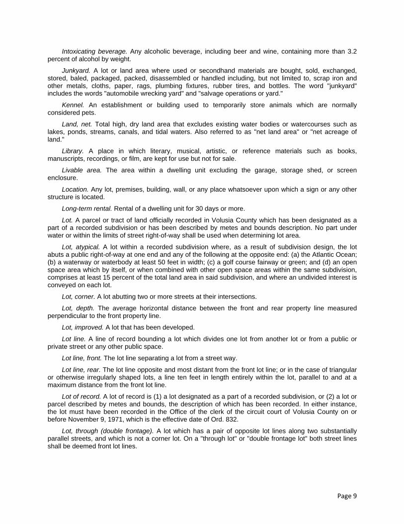
Page 9
Intoxicating beverage. Any alcoholic beverage, including beer and wine, containing more than 3.2 percent of alcohol by weight.
Junkyard. A lot or land area where used or secondhand materials are bought, sold, exchanged, stored, baled, packaged, packed, disassembled or handled including, but not limited to, scrap iron and other metals, cloths, paper, rags, plumbing fixtures, rubber tires, and bottles. The word "junkyard" includes the words "automobile wrecking yard" and "salvage operations or yard."
Kennel. An establishment or building used to temporarily store animals which are normally considered pets.
Land, net. Total high, dry land area that excludes existing water bodies or watercourses such as lakes, ponds, streams, canals, and tidal waters. Also referred to as "net land area" or "net acreage of land."
Library. A place in which literary, musical, artistic, or reference materials such as books, manuscripts, recordings, or film, are kept for use but not for sale.
Livable area. The area within a dwelling unit excluding the garage, storage shed, or screen enclosure.
Location. Any lot, premises, building, wall, or any place whatsoever upon which a sign or any other structure is located.
Long-term rental. Rental of a dwelling unit for 30 days or more.
Lot. A parcel or tract of land officially recorded in Volusia County which has been designated as a part of a recorded subdivision or has been described by metes and bounds description. No part under water or within the limits of street right-of-way shall be used when determining lot area.
Lot, atypical. A lot within a recorded subdivision where, as a result of subdivision design, the lot abuts a public right-of-way at one end and any of the following at the opposite end: (a) the Atlantic Ocean; (b) a waterway or waterbody at least 50 feet in width; (c) a golf course fairway or green; and (d) an open space area which by itself, or when combined with other open space areas within the same subdivision, comprises at least 15 percent of the total land area in said subdivision, and where an undivided interest is conveyed on each lot.
Lot, corner. A lot abutting two or more streets at their intersections.
Lot, depth. The average horizontal distance between the front and rear property line measured perpendicular to the front property line.
Lot, improved. A lot that has been developed.
Lot line. A line of record bounding a lot which divides one lot from another lot or from a public or private street or any other public space.
Lot line, front. The lot line separating a lot from a street way.
Lot line, rear. The lot line opposite and most distant from the front lot line; or in the case of triangular or otherwise irregularly shaped lots, a line ten feet in length entirely within the lot, parallel to and at a maximum distance from the front lot line.
Lot of record. A lot of record is (1) a lot designated as a part of a recorded subdivision, or (2) a lot or parcel described by metes and bounds, the description of which has been recorded. In either instance, the lot must have been recorded in the Office of the clerk of the circuit court of Volusia County on or before November 9, 1971, which is the effective date of Ord. 832.
Lot, through (double frontage). A lot which has a pair of opposite lot lines along two substantially parallel streets, and which is not a corner lot. On a "through lot" or "double frontage lot" both street lines shall be deemed front lot lines.

Page 10
Lot width. The perpendicular distance between the side property lines of a lot measured along the front and rear setback lines or the chord distance of the arc measured on a cul-de-sac or road curve at the front yard setback line.
Low profile luminaire. Light fixture set on a base which raises the source of the light no higher than 48 inches off the ground, and designed in such a way that light is directed downward from a hooded light source.
Mainland. All areas west of the intracoastal waterway including the north causeway.
Major tenant. A tenant that serves as a major store (anchor) in a shopping center and occupies more gross leasable area than supplementary tenants. Major tenants are generally placed at each end of a strip or mall so that to reach them shoppers must walk past the store fronts to supplementary tenants.
Manufacturing. See Industry.
Marina. A marina is a commercial establishment with a waterfront location for docking pleasure boats or providing services to pleasure boats and the occupants thereof; including servicing and repair to boats; sale of fuel and supplies and providing for food and beverages as accessory uses. A hotel, motel, or similar use, with docking boats and provision of services thereto, shall not be considered a marina, nor shall boat docks accessory to a residential project where no boat related sales or services are rendered be considered a marina. (Such premises or site shall not include boat and/or motor manufacturing as an incidental use.)
Master planned unit development (PUD) development agreement (MDA). An agreement between the city and owners of a land which will be developed under the planned unit development (PUD) zoning regulations.
Miniature golf course. A golf course which has no fairway, is intended for putting only, and has no less than nine holes. A private golf course in which no charge whether credit or cash is required to enter does not constitute a miniature golf course.
Mobile home. A structure, transportable in one or more sections, which is eight or more feet in width and 35 or more feet in length, is built on an integral chassis, and designed to be used as a dwelling when connected to the required utilities including plumbing, heating, air-conditioning, and electrical systems contained therein. This definition shall not include a manufactured dwelling.
Mobile home park. A land area of at least five acres in size which is divided into mobile home spaces that are rented or leased to owners or possessors of mobile homes.
Mobile home space. An area within a mobile home park which is leased or rented to a mobile home occupant.
Mobile home subdivision. A land area which has been subdivided according to the MH-2 district requirements and is intended for mobile home or manufactured building placement on individually owned lots.
Motel. One or more buildings containing sleeping units for transients, with automobile parking spaces provided in connection therewith, and with individual access to the outside parking area. The word "motel" includes the following: motor court, motor hotel, motel lodge, and tourist court.
Motorcycle safety instruction. An instructional program that teaches adults to ride street-legal motorcycles through hands-on practice and field instruction.
New development. Shall include new construction and remodeling of existing structures when such remodeling includes alteration to the exterior of the building.
Nonconforming lot. A lot which does not meet the minimum size requirements of this LDR except as provided in section 504.01J. of this LDR.
Nonconforming structures. A structure or portion thereof, existing at the effective date of this ordinance or any amendment thereto, which was occupied, designed, erected, intended, or structurally altered, for a use not permitted at its location by the provisions of this ordinance, and/or for a new use which does not conform to all of the regulations applicable to the district in which it is located.

Page 11
Nonconforming use. The use of a structure or premises existing at the effective date of this ordinance, or any amendment thereto, for any purpose not permitted for a new use in the district in which it is located.
Nursing homes. A home for aged, chronically ill, or indigent people, licensed with the state as a nursing home, in which persons not of the immediate family of the occupant are received, kept, or provided with food and shelter or care for compensation and where registered or practical nurses are on duty 24 hours each day to provide nursing care and administer medicines, but not including hospitals, clinics, or similar institutions devoted primarily to the diagnosis and treatment of the acutely ill.
Office building, general. A structure which contains individual working areas for professional, technical, or clerical employees, but not medical or dental employees.
Office building, government. An office building for persons whose employer is a federal, state, county, or municipal entity.
Office building, medical/dental/psychology/psychiatry. An office building for persons in the medical, dental, psychological, and psychiatric fields.
Official zoning map. A map which graphically illustrates the boundaries of each zoning district and is officially adopted as the official zoning map by the city commission.
Off-street loading space. A space for loading or unloading located on the same lot with a building, or contiguous to a group of buildings, for the temporary parking of a commercial vehicle while loading or unloading merchandise or materials which abuts upon a street, alley, or other appropriate means of access.
Off-street parking space. A permanently surfaced area for the parking of a motor vehicle. Such space shall have a minimum width of ten feet and a minimum length of 20 feet. No parking space which requires backing into a public or private right-of-way shall be considered an off-street parking space.
Open space. That portion of net land area not used for street right-of-way; off-street automobile parking and driveways; off-street loading; and maximum building lot coverage. Bicycle, walking and jogging paths, and other recreational facilities, plazas, undevelopable lot areas and stormwater management areas outside of rights-of-way shall be considered open space.
Open space, common. A commonly owned area of land reserved primarily for the leisure or recreational use of the owners of a residential development. Community pools, golf courses, parks and other outdoor spaces intended for use by the residents of a PUD shall be considered common open space.
Owner. Any person, group of persons, firm or firms, corporation or corporations, or any other legal entity having legal title to the land sought to be developed or redeveloped under this ordinance.
Package store. A place of business where at least 51 percent of the gross revenue is derived from the sale of alcoholic beverages sold only in sealed containers for consumption off the premises. For the purposes of this definition, a place of business that sells only beer and/or wine shall not be considered a package store.
Pain management clinic. Any publicly or privately owned facility:
(1) That advertises in any medium for any type of pain-management services; or
(2) Where in any month a majority of patients are prescribed opioids, benzodiazepines, barbiturates, or carisoprodol for the treatment of chronic nonmalignant pain.
Expressly exempted from this definition are hospitals, nursing homes, ambulatory surgical care centers, hospice or intermediate care facilities for the disabled, and clinics which are affiliated with an accredited medical school at which training is provided for medical students, residents and/or fellows.
Parking lot. A lot where motor vehicles are parked or stored temporarily but not including the wrecking of automobiles or storage of new or used cars for sale, services, rental, or any other purpose other than specified.

Page 12
Penthouse. An enclosed area upon a roof of a building occupying not more than an aggregate area of 30 percent of the roof and not used for purposes other than sheltering mechanical equipment, elevators, stairways, or other accessory equipment.
Person. Any individual, firm, association, joint venture, partnership, estate, trust, syndicate, fiduciary, corporation, group, or unit of federal, state, county, or municipal government.
Personal enrichment establishments. Businesses which are neither retail sales nor retail services but are engaged in bettering one's ability in a specialized field such as health clubs, martial arts studios, aerobics or jazzercise studios, dance studios or businesses which teach a specialized trade or art such as computer operation, musical instrument lessons, typing lessons or similar businesses.
Personal services . An establishment which provides for the care of a person or a person's apparel, and may include, but not be limited to, beauty/barbershop, nail salon, tanning salon, laundry, dry cleaning (retail store), garment service, and shoe repair.
Planned unit development. A tract of land which is developed as an integrated unit under single ownership or control, which may include a mixing of residential building types ranging from single-family to multifamily dwellings and supporting related land uses comprised of institutional, business, office, industrial, or recreational facilities. Or, a planned unit development may consist of a combination of any of these land uses or only one land use.
Planning and zoning board. Planning and zoning board shall mean the New Smyrna Beach Planning and Zoning Board.
Plat. A map or drawing depicting the division of land into lots, blocks, parcels, tracts, sites, or other divisions.
Pole lighting. Light fixture set on a base or pole which raises the source of the light higher than 48 inches off the ground.
Premises. A parcel or lot of property, or any combination of parcels or lots; except that in the case of a business having in excess of 250 feet of continuous road frontage, in which such case, each 250 feet of road frontage shall constitute one premises for the purpose of this ordinance. For example. A new car dealership with 500 feet of road frontage would constitute two premises for the purpose of this ordinance.
Public body. Any government or governmental agency of the City of New Smyrna Beach, Volusia County, the State of Florida, or the United States.
Public use. The use of any land, water, or buildings by a municipality, public body, or board, commission or authority, county, state, or federal government, or any agency thereof for a public service or purpose.
Recreation, active. A leisure activity in which a considerable amount of physical energy is exerted and which capital facilities are required. Active recreation includes, but is not limited to, playing field sports such as baseball, soccer and football, playing court sports such as tennis, basketball, racquetball, or shuffleboard, swimming in a public or semipublic pool, jogging or exercising on an improved jogging trail, and exercising stations.
Recreation center. A building for which sporting events, social events, fund raising events, educational classes, and exercise classes are held.
Recreation complex. An area within a subdivision which usually contains a pool, clubhouse, shuffleboard courts, limited parking, sun deck, and may contain other recreational facilities. The complex is usually intended for residents and guests of a particular residential development. The complex is nonprofit and paid for by association fees.
Recreation, passive. A leisure activity in which little physical energy is exerted and few capital facilities are provided. Passive recreation includes, but is not limited to, walking on an improved trail, sitting on park benches, picnicking on picnic tables, enjoying various flora and fauna, and fishing from a boat or from shore.

Page 13
Recreational equipment, major. Boats and boat trailers, travel trailers, pickup campers or coaches (designed to be mounted or towed on automotive vehicles), motorized dwellings, tent trailers, and similar equipment.
Recreation[al] equipment, minor. Swing sets and other playground equipment, court related equipment such as tennis, racquetball, volleyball and basketball courts, horseshoe pit equipment, canoes and other small boats less than 15 feet in length and not requiring a trailer for transport, bicycles, motorcycles, surfboards, and other smaller lightweight equipment, generally used for enjoyment in the out-of-doors.
Research center. Buildings or groups of buildings devoted nearly exclusively to research and development of various subjects and products. Said buildings contain some offices and some light fabrication but the primary function is research and development.
Residential development. Any multifamily or single-family housing project that is approved by the planning and zoning board. Phasing of a project shall not constitute a separate residential development for the purpose of sign standards, unless the phase shall bear a separate name.
Restaurant. A building or room, not operated as a dining room in connection with a hotel, where meals, or prepared food, including beverages and confections, are served to customers. Restaurants are hereby classified as follows:
Type A. Restaurants with dining tables and counter stools having all service indoors and providing no service to persons in vehicles or at walkup windows.
Type B. Restaurants dispensing food from service windows for consumption on or off of the premises which specializes in short order foods and beverages.
Type C. Restaurants serving food and/or beverages to persons in their vehicles for consumption in their vehicles on the premises.
Type D. Restaurants serving food and beverages to persons sitting at tables or bars which are located outside of the principal structure. Type D restaurants may also serve to persons inside the principal or accessory structure.
Restaurant, family. A restaurant which may serve beer and wine but which does not serve liquor and has no bar or lounge. These restaurants are intended for the entire family, and have service directly at the table.
Restaurant, fast food. A type A, B, C, or D restaurant which usually does not serve customers at the table but serves at a counter which customers walk to pay for packaged food items, and either seat themselves or take the food out. This is a high volume restaurant which requires more seating then family or quality restaurants.
Restaurant, quality. A restaurant which serves beer, wine, and liquor, and has a lounge or bar. Quality restaurants require more parking than family restaurants but less parking than fast food restaurants.
Retail, big box. A retail sales establishment (including retail department stores, retail discount stores, retail hardware/paint/home improvement stores, and retail shopping center, as defined herein) consisting of a single tenant building of 80,000 square feet or more of total gross floor area.
Retail, department store. A retail establishment which devotes certain areas to a particular type of retail item such as automotive, mens clothes, shoes, lingerie, etc. department stores are typically chains such as K-Mart, Wal-Mart, J.C. Penneys, etc.
Retail, discount store. A freestanding retail establishment having a theme of low priced merchandise, either food items or appliances. Said stores include but are not limited to Service Merchandise, Discount City, etc. Parking requirements for discount stores are greater than regular retail establishments.
Retail, hardware/paint/home improvement store. A retail establishment selling items intended to improve the home such as plumbing.

Page 14
Retail, planned shopping center. A shopping center containing at least one anchor store such as a department store, discount store, or a supermarket and containing greater than 20,000 square feet of gross leasable area.
Retail sales and services. The duly licensed selling of general or specialized merchandise directly to the consumer from the store, shop, or similar building. The maintenance, repair, installation, servicing, and minor manufacturing of that merchandise is allowed as an accessory use to the permitted sales. Said minor manufacturing shall be conducted without the use of significant industrial equipment and in a manner that will not produce significant amounts of noise, vibration, odor, smoke, or fumes. Retail items sold may also be rented or leased. Services are useful forms of labor that do not produce a tangible commodity such as maintenance and repair, a cleaning establishment, a laundromat, or a facility that provides some public demand as parcel packaging, shipping and delivery, notary public, mail forwarding and holding, and similar functions. This definition does not include a flea market or curb market.
Right-of-way. A strip of land occupied or intended to be occupied by a street, crosswalk, railroad, electric transmission line, oil or gas pipeline, watermain, sanitary or storm sewer main, or for another special use. The usage of the term "right-of-way" for land platting purposes shall mean that every right-of-way hereafter established and shown on a plat is to be separate and distinct from the lots or parcels adjoining such right-of-way, and not included within the dimensions or areas of such lots or parcels. Rights-of-way intended for streets, crosswalks, watermains, sanitary sewers, storm drains, or any other use involving maintenance by a public agency shall be dedicated to public use by the maker of the plat on which such right-of-way is established.
Right-of-way line. A line designated as the boundary of a right-of-way.
Roller/ice skating rink. An establishment containing an area which is intended for ice or roller skating. Said establishment may also dispense refreshments and contain amusement games and a lounge.
Roof line. The juncture of the roof and the perimeter wall of the structure.
Roominghouse. A residential building used, or intended to be used as a place where sleeping or housekeeping accommodations are furnished or provided for pay to transient or permanent guests or tenants in which less than ten and more than three rooms are used for the accommodations of such guests or tenants which may maintain a dining room in the same building servicing only residents and regular boarders. The word "roominghouse" includes the words "boardinghouse" and "lodginghome."
Screen pool enclosure. A structure constructed over a swimming pool and surrounding pool deck which has walls and a roof composed of screen. Enclosure with a solid roof shall be considered a screen room.
Seawall. A retainer wall or structure designed to prevent the erosion of land by water action or acts of nature.
Self-service laundry. A business rendering a retail service by making available to retail customers, for a charge at a fixed location and structure, equipment for washing and drying laundry.
Semipublic body. Any organization operating as a nonprofit activity and serving a public purpose or service including such organizations as noncommercial clubs, lodges, theater groups, recreational and neighborhood associations, cultural organizations, schools, and churches.
Service station, type A . A business primarily engaged in servicing motor vehicles, but limited to:
(1) Sales of automotive fuels, lubricants, and accessories.
(2) Sales, service and maintenance of spark plugs and batteries.
(3) Maintenance of lubrication systems including replacement of lubricants and filters.
(4) Replacement of minor part items such as light bulbs, fuses, floor mats, seat covers, windshield wipers and wiper blades.
(5) Washing, polishing, and detailing services, sales of automotive washing and polishing materials, but not car washes.

Page 15
Service station, type B . A business primarily engaged in servicing motor vehicles, but limited to:
(1) All activities allowed by a type A service station.
(2) Tire servicing, installation and repair, but not recapping or regrooving.
(3) Windshield repair and replacement.
(4) Mechanical repair that does not require the removal of the transmission, engine, heads, or crankcase. This includes, but is not limited to, engine tune ups and repairs to: exhaust, HVAC, brakes, cooking system, alignment, electrical system, and fueling systems.
Service station, type C . A business primarily engaged in servicing motor vehicles, but limited to:
(1) All activities allowed by a type B service station.
(2) Tire servicing including recapping and regrooving.
(3) Transmission repair involving the removal, disassembly or reassembly of the transmission.
(4) Engine rebuilding, reconditioning, or repair involving the removal of the engine, heads, crankcase.
(5) Collision service including body, frame or fender straightening or repair.
(6) Painting or paint shop.
(7) Repairs requiring welding.
(8) Work involving undue noise, vibration, glare, fumes and smoke.
Setback. The minimum distance between the property lines and the front, rear, or side line of the building, or any projections thereof, excluding projections specifically permitted.
Setback, waterfront. Setbacks on waterfront property shall be as follows:
(1) Bulkheaded and seawalled lots not on the oceanfront. Setbacks or property lines shall be measured from the bulkhead or seawall regardless if the fee simple property line extends into the water or is upland from the bulkhead or seawall.
(2) Bulkheaded and seawalled lots on the oceanfront. Setbacks shall be at the City Coastal Construction Setback Line (see [sub]section 703.02 in this LDR) if the fee simple ownership extends to the east of the City Coastal Construction Setback Line. If ownership does not extend east of the City Coastal Construction Setback Line, the setback shall be as required in the upland zoning district from the property line.
(3) Non-bulkheaded and non-seawalled lots on the oceanfront. Setbacks shall be at the City Coastal Construction Setback Line (see [sub]section 703.02 in this LDR) if the fee simple ownership extends east of the City Coastal Construction Setback Line or to the City Coastal Construction Setback Line. If ownership does not extend east of the City Coastal Construction Setback Line, the setback shall be at the east property line.
(4) Non-bulkheaded and non-seawalled lots not on the ocean and not adjacent to jurisdictional wetlands. The setback or property line shall be measured from the mean high water line.
(5) Property adjacent to jurisdictional wetlands. Setbacks shall be measured from the jurisdictional wetland line. Structures may be placed at the setback line or wetland buffer line, whichever is greater.
Shopping center. A group of commercial establishments planned, developed, owned, and managed as a unit.
Short-term rental. Rental of a dwelling unit for less than 30 days.
Sidewalk. That portion of a street or cross-walkway, paved or otherwise surfaced, intended for pedestrian use.

Page 16
Special exception. A special exception is a use that would not be appropriate generally or without restriction throughout the zoning district, but which, if controlled as a number, area, location, or relation to the neighborhood, would promote the public health, safety, welfare, morals, order, comfort, convenience, appearance, prosperity, or general welfare. Such uses may be permitted in a zoning district as a special exception in accordance with this LDR.
Specified sexual activities. Any one or more of the following: (1) depiction of human genitals in a state of sexual stimulation, arousal, or turgidity; (2) acts of human anilingus, bestiality, buggery, cunnilingus, coprophilia, fellatio, flagellation, masochism, masturbation, necrophilia, pederasty, pedophilia, sadism, sadomasochism, sapphism, sexual intercourse and sodomy; (3) fondling or other erotic touching of human genitals, pubic region, buttock or female breasts; (4) excretory functions as part of, or in connection with, any of the activities set forth in (1) through (3) above.
Sports bar. A bar which contains numerous televisions, whether large screen or regular screen, used primarily for entertaining the patrons with professional or college sports.
Sports facility . A public or private facility used for sporting activities such as archery ranges, golf driving ranges, boxing, batting cages, skating rinks, and other similar activities. This term does not include ballparks, bowling centers, golf courses or stadiums.
Stadium . A ballpark having tiered seats or bleachers on which spectators sit.
Statutory development agreement. An agreement entered into pursuant the Florida Local Government Development Agreement Act. See, F.S. §§ 163.3220—32432.
Steps, major. Four or more steps extending more than four feet horizontally from a principal or accessory structure and extending 28 or more inches in height.
Steps, minor. Less than four steps extending four or less feet horizontally from a principal or accessory structure and extending less than 28 inches in height.
Story. The portion of a building included between the upper surface of a floor and the upper surface of the floor or roof next above. An elevator or stairway penthouse on the roof of a building shall not constitute a story.
Story, half. A story under a gabled, hipped or gambrel roof, the wall plates of which, on at least two opposite exterior walls are not more than two feet above the finished floor of such story.
Street. A public right-of-way which affords a primary means of vehicular access to abutting properties, whether designated as a street, avenue, highway, road, boulevard lane, throughway, or however otherwise designated, but excepting driveways to buildings.
Street, arterial. A high capacity roadway designed to carry large volumes of intracity and intercity traffic as well as interstate and intrastate traffic.
Street, collector. A medium capacity roadway designed to carry traffic from numerous local streets to arterial streets.
Street, cul-de-sac. A low capacity roadway having a turnaround or bulb at the end of a dead-end street designed to carry traffic from individual lots to a collector or local street.
Street line. A line between a street and the abutting lot which defines the edge of the legal width of a street right-of-way.
Street, local. A low capacity roadway designed to carry traffic from individual lots to collector streets or other local roadways.
Street, marginal access. A street which parallels a collector street or arterial street and which provides access to abutting properties and protection from through traffic.
Street, private. Any roadway or street constructed to city specifications and owned and maintained by a private entity.

Page 17
Structure. A combination of materials to form a construction for use, occupancy, for ornamentation whether installed on, above, or below the surface of land or water.
Subdivider. Any person, group of persons, corporation, or duly authorized agent, who undertakes the subdivision of land as defined herein.
Subdivision. The platting of real property into three or more lots, parcels, tracts, tiers, blocks, sites, units, or any other division of land; and includes establishment of new streets and alleys, additions, and resubdivisions; and when appropriate to the context, relates to the process of subdividing or to the lands or area subdivided.
Subdivision final plat . The detailed drawing of the property to be divided. This drawing shall be submitted to the Volusia County Clerk of the Circuit Court for recording upon approval by the city commission.
Subdivision, minor. The division of real property into two lots, parcels, or tracts which front on an existing street and has available utilities.
Subdivision plat construction drawings. The detailed drawings of the improvements proposed to be constructed within and in the vicinity of the respective property to be divided.
Subdivision preliminary plat. A preliminary drawing indicating the proposed layout of a subdivision and containing all the information as required herein.
Supermarket. A retail establishment selling food and containing greater than 20,000 square feet of gross leasable area.
Surveyor . A land surveyor registered with the Florida Department of Agriculture and Consumer Services as a professional surveyor and mapper.
Swimming pool, private . Any pool or open tank, not located within a completely enclosed building, and containing or capable of containing, water to a depth at any point of greater than one and one-half feet. The sundeck area if above grade, diving boards, slides, and other related types of swimming pool equipment, and all appurtenances thereto, are included as a part of a private swimming pool.
Tattoo parlor . A business engaged in any method of placing designs, letters, scrolls, figures, symbols or any other marks under the skin of a person with pigment, ink or color by the aid of needles or other instruments. An establishment providing for the application of only permanent makeup either as an accessory use or as a primary use shall not be considered a tattoo parlor.
Theater. A structure that is used for dramatic, motion pictures, or other performances for admission to which entrance money is collected.
Timeshare unit. An accommodation of a timeshare plan which is divided into timeshare periods. A room or rooms in any timeshare unit in which a door or doors connecting two or more separate rooms are capable of being locked to create two or more private dwellings shall each constitute a timeshare unit for purposes of this Code.
Tour boats. A watercraft used for the specific purpose of entertaining people with leisurely cruises and sight-seeing. This definition shall include water taxis and water ferries.
Townhouse. A dwelling unit constructed as part of a group of at least three, but not more than eight dwelling units in one building, all of which are (a) attached to the adjacent dwelling unit by common walls; (b) customarily owner occupied; and (c) situated on individually owned parcels of land.
Traditional city area. The area located approximately east of the Turnbull Bay/Turnbull Creek waterway north of State Road 44 and approximately east of Mission Road south of State Road 44.
Transient lodging. A facility providing sleeping quarters to the general public for a fee, such that the facility must be licensed by the State of Florida for a rooming house, boarding house, hotel, motel, timeshare resort, executive suite or similar use. This does not include the terms "bed and breakfast" or "multi-family dwelling," nor shall this term be construed to mean any form of residential dwelling as defined by this Code.

Page 18
Transient lodging rooms, deluxe. Larger units within a transient lodging facility that may contain housekeeping and cooking facilities.
Transient lodging rooms, standard. Units within a transient lodging facility that may not contain housekeeping and cooking facilities.
Travel trailers. A vehicular, portable structure, built on a chassis designed to be used as a temporary dwelling for travel, recreational and vacation purposes, and permanently identified as a travel trailer by the manufacturer of the trailer. The word "travel trailer" shall not include the word "mobile home."
Use. The purpose for which land or a structure thereon is designed, arranged, or intended to be occupied or utilized, or for which it is occupied or maintained.
Use, permitted. A use which is permitted in a particular zoning district.
Use, principal. The primary use of the lot as distinguished from accessory uses.
Utilities. Includes, but is not limited to, potable and nonpotable water systems, electrical power systems, gas systems, wastewater systems, stormwater management systems, telephone systems, and television cable systems. Household appliances such as water heaters, air conditioning/heating units, pool maintenance equipment, and yard irrigation pumps, shall not be construed as utilities.
Valet parking. The service of parking vehicles for patrons of a business.
Variance. A modification of, or a deviation from, the regulations of this ordinance which is authorized and approved by the planning and zoning board after it finds that the literal applications of the provisions of this LDR would cause unnecessary hardship in the use or development of a specific lot or building.
Wall, retaining. A structure used to prevent the collapse of soil which has irregular topography.
Warehouse, mini. An enclosed storage area containing individual rented or owned compartments or stalls and intended to store items other than vehicles.
Waterfront dining and entertainment establishment. An establishment serving food or refreshments located on a lot adjacent to the Indian River Lagoon system, its tributaries, or another body of water at least 50 feet wide, and intending to use the water as an amenity for the dining or refreshment activity.
Wrecker. Any motor vehicle that is used to tow, carry, or otherwise transport motor vehicles, and that is equipped for that purpose with a boom, winch, car carrier, or other similar equipment.
Yard. A required open space unoccupied and unobstructed by any principal or accessory structure or portion of a principal or accessory structure except those structures specified in [sub]section 804.03.
Yard, front. A space extending the full width of the lot between any building and the front lot line, and measured perpendicular to the building at the closest point to the front lot line. Such front yard is unoccupied and unobstructed from the ground upward except as may be permitted elsewhere in the ordinance. See [following] drawing, [Typical Yard Arrangements].
Yard, rear. A yard which does not front on, or is not adjacent to, a street, which is typically in the center of a block and to the rear of a structure or building and is not a side yard: Depth of required rear yards shall be measured along a line drawn perpendicular to the rear lot line. See [following] drawing, [Typical Yard Arrangements].
Yard, side. A yard which extends perpendicular, or generally perpendicular, to a front yard: See [following] drawing, [Typical Yard Arrangements].
Zoning, certificate of. A document issued by the administrative official authorizing buildings, structures, or use consistent with the terms of this LDR and to be used by the enforcement official when enforcing its provisions.

Page 19
Typical Yard Arrangements
(Ord. No. 40-02, § 1, 8-21-2002; Ord. No. 07-05, § 6, 3-17-2005; Ord. No. 02-06, § 1, 3-27-2006; Ord. No. 121-06, § 1, 12-12-2006; Ord. No. 80-07, § 1, 11-13-2007; Ord. No. 38-08, § 1, 6-10-2008; Ord. No. 53-08, § 1, 9-9-2008; Ord. No. 62-08, § 1, 11-11-2008; Ord. No. 69-08, § 1, 11-25-2008; Ord. No. 72-08, § 1, 12-9-2008; Ord. No. 05-09, § 1, 3-23-2009; Ord. No. 21-10, § 1, 5-11-2010; Ord. No. 22-10, § 1, 5-11-2010; Ord. No. 54-10, § 1, 10-12-2010; Ord. No. 59-10, § 1, 12-14-2010; Ord. No. 08-11, § 1, 2-8-2011; Ord. No. 35-11, § 2, 6-28-2011; Ord. No. 38-11, § 1, 6-28-2011; Ord. No. 60-11, § 1, 8-9-2011; Ord. No. 68-11, § 1, 10-11-2011; Ord. No. 01-12, § 1, 1-24-2012; Ord. No. 62-12, § 1, 8-28-2012; Ord. No. 68-12, § 1, 8-28-2012; Ord. No. 218-13, § 1, 10-10-2013)

APPENDIX E
METHODOLOGY ON COASTAL CONSTRUCTION CONTROL LINE ESTABLISHMENT
by
T. Y. Chiu
Beaches and Shores Resource Center Institute of Science and Public Affairs
Florida State University Tallahassee, FL 32306
and
R. G. Dean
Department of Coastal and Oceanographic Engineering University of Florida
Gainesville, FL 32606 through
Beaches and Shores Resource Center Florida State University
June 2002

PREFACE
This report presents an update of the methodology and procedures to the original 1984 report which was published after a public work shop with consulting coastal engineers. In the eighteen years since 1984, the basic theory and methodology of establishing the Florida Coastal Construction Control Line (CCCL) have been applied to the 24 coastal counties along the Florida Atlantic and Gulf coasts with good results. Minor refinements and modifications have been made from time to time to the numerical models in the long study period of the program to enhance the quality of the analysis of the parameters essential to the studies, but the basic theory and methodology have not been changed.
An illustration of the CCCL in Pinellas County and related numerical analysis presents all the
refinements and modifications to the numerical models calculating the combined storm tide elevations and corresponding erosions. Some frequently asked questions related to the technical aspect of the methodology in public hearings are addressed in Addendums A and B with a number of cases of concern to the inquisitors. Discussions and notes in the peer review program carried out in the 1992 to 1994 period are presented in Addendum C.

TABLE OF CONTENTS Section Page
I. INTRODUCTION.............................................................................................
II. METHODOLOGY OF STORM SURGE CALCULATION ..................................................... 1
2.1 Introduction ..................................................................................................................... 1 2.2 Parameterized Hurricane ................................................................................................. 1 2.3 Classification by Path Relative to Shoreline ................................................................... 2 2.4 General Overview of Storm Surge Numerical Models and Procedures .......................... 6 2.5 Features and Solution of the Two-Dimensional Numerical Model ................................. 6
Governing Differential Equations for Two-Dimensional Numerical Model. .................. 9 Finite Difference Forms of Governing Differential Equations ...................................... 10 Inlet and Barrier Island Representation as Hydraulic Elements .................................... 11 Methodology.................................................................................................................. 12 Boundary Conditions ..................................................................................................... 15 Implicit Solution of the Finite Difference Equations ..................................................... 15 Dynamic Wave Set-up ................................................................................................... 18
2.6 Features of the One-Dimensional Numerical Model ..................................................... 19
Governing Differential Equations for One-Dimensional Numerical Model .................. 22 Finite Difference Forms of Governing Differential Equation........................................ 22 Initial Boundary Conditions for One-Dimensional Model ............................................ 22 Explicit Solution of the Finite Difference Equations ..................................................... 22
2.7 Long-Term Simulation .................................................................................................. 23
III. APPLICATIONS OF STORM SURGE METHODOLOGY WITH SPECIFIC ILLUSTRATION BY EXAMPLE TO PINELLAS COUNTY. ............................................... 24
3.1 Two-Dimensional Model (Appendix A) ........................................................................ 24
Verification with Storms of Record ............................................................................... 24 Generation of Data Base for Calibration of the One-Dimensional Model ..................... 31
3.2 One-Dimensional Model (Appendix B) ........................................................................ 38
Calibration with Two-Dimensional Model Results ....................................................... 38
3.3 Long-Term Simulations ................................................................................................. 38
VI. EROSION CALCULATION METHODOLOGY .................................................................... 4
4.1 Introduction ................................................................................................................... 47

Section Page
4.2 Equilibrium Beach Profile ............................................................................................. 47 4.3 Cross-Shore Transport Models ...................................................................................... 53 4.4 Prediction of Beach and Dune Erosion Due to Severe Storms by Kriebel’s Model ...... 55
Profile Schematization ................................................................................................... 55 Governing Equations ..................................................................................................... 55 Method of Solution of Finite Difference Equations ....................................................... 56 Application of Method to Computation of Idealized Beach Response .......................... 56 Application of Method to Long-Term Beach and Dune Response Simulations ............ 60
4.5 Prediction of Beach and Dune Erosion Due to Severe Storms by Simple Model .......... 64 4.6 Augmentation of the Erosion Predicted by the Model for Recommending
Position of CCCL .......................................................................................................... 65
V. WAVE HEIGHT DECAY CALCULATIONS ........................................................................ 68
5.1 Introduction ................................................................................................................... 68 5.2 Methodology ................................................................................................................. 68
Wave Height Decay Due to Shoaling Water ................................................................. 68 Wave Height Decay Due to Vegetation ........................................................................ 68 Wave Height Decay Due to Buildings .......................................................................... 68 Combined Effects of Topography, Vegetation and Buildings. ...................................... 69
VI. LONG-TERM EROSIONAL CONSIDERATIONS ................................................................ 70
6.1 Introduction ................................................................................................................... 70 6.2 Methodology ................................................................................................................. 70
VII. OVERALL VERIFICATIONS OF CCCL METHODOLOGY ............................................... 72
7.1 Hurricane Agnes, St. George Island, Franklin County .................................................. 72 7.2 Hurricane Eloise Damage in Walton and Bay Counties ................................................ 74 7.3 Hurricane Opal Damage along the Florida Panhandle .................................................. 76
REFERENCES ......................................................................................................................... 78
APPENDIX A ........................................................................................................................... 80
APPENDIX B ......................................................................................................................... 105
APPENDIX C ......................................................................................................................... 113
ADDENDUM A ...................................................................................................................... A1
ADDENDUM B .......................................................................................................................B1
ADDENDUM C .......................................................................................................................C1

LIST OF FIGURES
Figure Page
VII-1 General Location of Study Area ............................................................................................... 2
VII-2 Directional Distribution of Historical Hurricanes in a 300 n.mi. Segment of Coast Comprising the Pinellas Coastline ........................................................................................... 2
VII-3 A Definition Sketch of Three Types of Hurricanes .................................................................. 3
VII-4 Designation of Alongshore, Landfalling and Exiting Hurricanes Depending on Track Directions Relative to Shoreline Orientation ............................................................................ 3
VII-5 Cumulative Probability Distribution of Hurricane Track Direction .......................................... 4
VII-6 Cumulative Probability Distribution of Radius to Maximum Winds, R, for Landfalling and Exiting Hurricanes............................................................................................................. 4
VII-7 Cumulative Probability Distribution of Radius to Maximum Winds, R, for Alongshore Hurricanes ....................................................................................................................................... 4
VII-8 Cumulative Probability Distribution of Central Pressure Deficity, )p, for Landfalling and Alongshore Hurricanes ...................................................................................................... 4
VII-9 Cumulative Probability Distribution of Central Pressure Deficity, )p, for Exiting Hurricanes ................................................................................................................................................. 4
VII-10 Historical Trend of Central Pressure Deficity, )p, and Radius to Maximum Winds, R .......... 4
VII-11 Cumulative Probability Distribution of Storm Translation Speed VF, for Landfalling, Alongshore and Exiting Hurricanes ......................................................................................... 5
VII-12 Cumulative Probability Distribution of Landfalling Distance, YF, for Landfalling and Exiting Hurricanes ....................................................................................................................................... 5
VII-13 Cumulative Probability Distribution of Offshore Distance, XL, for Alongshore Hurricanes ... 5
VII-14 Flow Chart of Methodology ..................................................................................................... 6
VII-15 Grid System Layout for Pinellas County .................................................................................. 8
VII-16 Bottom Friction Coefficients for Various Bottom Conditions ............................................... 10
VII-17 Schematic of Implicit Method of Solving Momentum and Continuity Equations .................. 11
VII-18 Region of Interest in Description of Sub-Grid Features ......................................................... 12

Figure Page
VII-19 Profile One of the Transect Line One and Its One-Dimensional Grid Representation. ........... 20
VII-20 Profile Two of the Transect Line Two and Its One-Dimensional Grid Representation ........... 20
VII-21 Profile Three of the Transect Line Three and Its One-Dimensional Grid Representation ....... 21
VII-22 Profile Four of the Transect Line Four and Its One-Dimensional Grid Representation ........... 21
VII-23 Flow Chart for Storm Tide Simulations (After Calibration to Determine (AMP)LF, (AMP)ALONG and (AMP)Exit) ..................................................................................................... 23
III-1 Comparison Between Measured and Computed Storm Tide at Venice Inlet, Florida for the September 1947 Hurricane .............................................................................. 26
III-2 Comparison Between Measured and Computed Storm Tide at Ft. Myers, Florida for the September 1947 Hurricane................................................................................................. 26
III-3 Comparison Between Measured and Computed Storm Tide at Cedar Key, Florida for the September 1947 Hurricane................................................................................................. 27
III-4 Comparison Between Measured and Computed Storm Tide at Venice Inlet, Florida for Hurricane Alma of June 1966 .................................................................................................. 27
III-5 Comparison Between Measured and Computed Storm Tide at Ft. Myers, Florida for Hurricane Alma of June 1966 ................................................................................................................... 28
III-6 Comparison Between Measured and Computed Storm Tide at Cedar Key, Florida for Hurricane Alma of June 1966 .................................................................................................. 28
III-7 Comparison Between Measured and Computed Storm Tide at St. Marks, Florida for Hurricane Agnes of 1972 ......................................................................................................... 30
III-8 Comparison Between Measured and Computed Storm Tide at St. Marks, Florida for Hurricane Eloise of 1975 .......................................................................................................................... 30
III-9 Comparison Between Measured and Computed Storm Tide at Fernandina Beach, Florida for Hurricane Dora of 1964 ........................................................................................ 33
III-10 Comparison Between Measured and Computed Storm Tide at Mayport, Florida for Hurricane Dora of 1964 ........................................................................................................... 33
III-11 Comparison Between Measured and Computed Storm Tide at Fernandina Beach, Florida for Hurricane David of 1979 ...................................................................................... 34
III-12 Comparison Between Measured and Computed High Water Mayport, Florida for Hurricane David of 1979 ......................................................................................................... 34

Figure Page
III-13a Calibration Relationship Between the One-Dimensional and the Two-Dimensional Calculations for Peak Surges at the Profile One and Profile Two Transect Lines of Pinellas County for Landfalling Hurricanes ............................................................................. 39
III-13b Calibration Relationship Between the One-Dimensional and the Two-Dimensional Calculations for Peak Surges at the Profile Three and Profile Four Transect Lines of Pinellas County for Landfalling Hurricanes ............................................................................. 40
III-14a Calibration Relationship Between the One-Dimensional and the Two-Dimensional Calculations for Peak Surges at the Profile One and Profile Two Transect Lines of Pinellas County for Alongshore Hurricanes ............................................................................. 41
III-14b Calibration Relationship Between the One-Dimensional and the Two-Dimensional Calculations for Peak Surges at the Profile Three and Profile Four Transect Lines of Pinellas County for Alongshore Hurricanes ........................................................................... 42
III-15a Calibration Relationship Between the One-Dimensional and the Two-Dimensional Calculations for Peak Surges at the Profile One and Profile Two Transect Lines of Pinellas County for Exiting Hurricanes .................................................................................. 43
III-15b Calibration Relationship Between the One-Dimensional and the Two-Dimensional Calculations for Peak Surges at the Profile One and Profile Two Transect Lines of Pinellas County for Exiting Hurricanes .................................................................................. 44
III-16 Combined Total Storm Tide Elevation Versus Return Period for Four Transect Lines in Pinellas County .................................................................................................................. 46
IV-1 Location Map of the 502 Profiles Used in the Analysis (from Hayden, et al., (10)) .............. 48
IV-2 Characteristics of Dimension Less Beach Profile h = (
x )m
for Various m hb w
Values (from Dean, (11)) ....................................................................................................... 49
IV-3 Equilibrium Beach Profiles for Sand Sizes of 0.2 mm and 0.6 mm A(D = 0.2mm) = 0.1 mm1/3, A(D = 0.6 mm) = 0.2 mm1/3 .................................................................................. 50
IV-4 Histogram of Exponent m in Equation h-Ax2 for 502 United States East Coast and Gulf of Mexico Profiles (from Dean, (11)). ........................................................................... 50
IV-5 Beach Profile Factor, A, vs Sediment Diameter, D, in Relationship h - Ax2/3
(modified from Moore, (12)) .................................................................................................. 51
IV-6 Profile P4 from Zenkovich (1967). A Boulder Coast in Eastern Kamchatka. Sand Diameter: 150 mm - 300 mm. Least Squares Value of A - 0.82 m1/3 (from Moore, (12)) ....................................................................................................................................... 52

Figure Page
IV-7 Profile P10 from Zenkovich (1967). Near the End of a Spit in Western Black Sea Whole and Broken Shells. A - 0.24 m1/3 (from Moore, (12)) ................................................ 52
IV-8 Profile from Zenkovich (1967). Eastern Kamchatka. Mean Sand Diameter: 0.25 mm. Least Squares Value of A - 0.07 m1/3 (from Moore, (12)) ...................................................... 53
IV-9 Model Simulation of 0.5 Meter Sea Level Rise and Beach Profile Response with a Relatively Mild Sloping Beach (from Moore, (12)) ................................................................................ 54
IV-10 Effects of Varying the Sediment Transport Rate Coefficient on Cumulative Erosion During the Simulation of Saville’s (1957) Laboratory Investigation of Beach Profile Evolution for a 0.2 mm Sand Size (from Moore, (12)) .......................................................... 54
IV-11 Model Representation of Beach Profile, Showing Depth and Transport Relation to Grid Definitions (from Kriebel, (14)) ..................................................................................... 55
IV-12 Characteristics Form of Berm Recession Versus Time for Increased Static Water Level (from Kriebel, (14)) ...................................................................................................... 57
IV-13 Comparison of Asymptotic Berm Recession from Model (—) and as Calculated by Equation (60) (**) .............................................................................................................. 58
IV-14 Effect of Breaking Wave Height on Berm Recession (from Kriebel, (14)) ............................ 58
IV-15 Effect of Static Storm Surge Level on Berm Recession (from Kriebel, (14)) ......................... 59
IV-16 Effect of Sediment Size Berm Recession (from Kriebel, (14)) ............................................... 60
IV-17 Comparison of the effects of 12, 24, and 36 hrs. Storm Surge on Volumetric Erosion (From Kriebel, (14)) .................................................................................................. 61
IV-18 Flow Diagram of N-Year Simulation of Hurricane Storm Surge and Resulting Beach Erosion (from Kriebel, (14)) ........................................................................................ 62
IV-19 Average Frequency Curve for Dune Recession, Developed by Monte Carlo Simulation, Bay-Walton Counties, Florida (from Kriebel (14)) .............................................. 63
IV-20 Probability of Risk of Dune Recession of Given Magnitude Occurring at Least Once in N-Years, Bay-Walton Counties, Florida (from Kriebel (14)) .................................... 64
IV-21 Features of Simplified Beach Erosion Model .......................................................................... 65
IV-22 Results of Applying Erosion Model to Range R-1, Martin County (Hutchinson Island), 100 Year Storm Tide, Average Erosion ..................................................................... 66
IV-23 Results of Applying Erosion Model to Range R-89, Martin County (Jupiter Island), 100 Year Storm Tide, Average Erosion ..................................................................... 66

Figure Page
IV-24 Calibration of Simplified Erosion Model by Comparison with Erosion Occurring at Various Elevation Due to Hurricane Eloise ........................................................................ 67
VI-1 General Erosion Conditions in Florida (Bruun, Chiu, Gerritsen and Morgan, (20)) ............... 71
VII-1a Beach Profile at Range R-105 on St. George Island. A Location of Severe Overwash and Damaged Roadway Due to Hurricane Agnes, 1972 (see Figure VI-1b for Extension of this Profile) ................................................................................................... 73
VII-1b Continuation of Profile Across St. George Island, Range R-105, Showing Location of Damaged Road, Due to Hurricane Agnes, 1972 .................................................. 73
VII-2 Landfall Location of Hurricane Eloise, September 23, 1975 and some Resulting Tide and Uprush Characteristics (from Chiu (16)) .................................................................. 74
VII-3 Relation of Erosional Characteristics and Pre-Eloise Vegetation Line to Set-back Line, Bay County, Florida (from Chiu (16)) ........................................................................... 75
VII-4 Relation of Erosional Characteristics and Pre-Eloise Vegetation Line to Set-back Line, Walton County, Florida (from Chiu (16) ....................................................................... 75
VII-5 Damage to Structures in Relation to Location of Set-back Control Line (based on Study of 540 Structures in Bay County After Hurricane Eloise, by Shows (21)) .................... 76

Table
III-1
LIST OF TABLES
Input Parameters for Calibration Hurricanes (Hurricane of September 1947 and
Page
Hurricane Alma of June 1972) 25
III-2 Input Parameters for Calibration Hurricane (Hurricane Agnes of June 1972) 29
III-3 Input Parameters for Calibration Hurricane (Hurricane Eloise of September 1975) 29
III-4 Input Parameters for Calibration Hurricane (Hurricane Dora of September 1964) 32
III-5 Input Parameters for Calibration Hurricane (Hurricane David of September 1979) 32
III-6a Parameters Defining 11 Landfalling Storms Used in Calibrating the One-Dimensional Model with the Two-Dimensional Model
35
III-6b Calibration of Landfalling Model Hurricanes 35
III-7a Parameters Defining 11 Alongshore Storms Used in Calibrating the One-Dimensional Model with the Two-Dimensional Model
36
III-7b Calibration of Alongshore Model Hurricanes 36
III-8a Parameters Defining 11 Exiting Storms Used in Calibrating the One-Dimensional Model with the Two-Dimensional Model
37
III-8b Calibration of Exiting Model Hurricanes 37
III-9 Values of 1-D/2-D Peak Storm Surge Correlation Coefficients for Counties Completed to Date
45
III-10 Combined Total Storm Values for Various Return Periods 46
VII-1 Structural Damage of Major Habitable Structures (MHS) Seaward of CCCL Along Panhandle
76

1
METHODOLOGY
ON
"COASTAL CONSTRUCTION CONTROL LINE ESTABLISHMENT"
I. INTRODUCTION The coastal engineering phenomena leading to the rationale for the Coastal Construction Control
Line (CCCL) are: Shoreline Erosional Trends Shoreline Fluctuations (Both Seasonal and Storm Induced) and, Storm Surges and Associated Waves.
The general objective of the CCCL program is, as required by Florida statute, to define the zone of impact of a one hundred year storm event along the sandy outer coastline segments of the State of Florida. This program is implemented on a county-by-county basis. The Florida Department of Environmental Protection (DEP) permitting program applies seaward of the CCCL with the two-fold purpose of ensuring: (1) the protection of the adjacent shoreline, and (2) the integrity of structures.
Due to the sparsity of specific data which would identify directly the appropriate location for the CCCL, a series of numerical models and calculation procedures is employed and combined with historical hurricane and erosion data to establish the recommended CCCL position.
II. METHODOLOGY
The establishment of the recommended location of the CCCL requires calculation of the 100 year storm surge and accompanying waves and shoreline erosion. These models and their implementation are based on the best data generally available and on data collected specifically for the purpose of this program. In particular, an extensive set of nearshore and beach profiles is taken at intervals of approximately 1,000 ft with all profiles extending out to approximately the thirty foot depth contour. The field data are valuable input to the computer models; however, the field program will be described elsewhere.
2.1 Introduction
As noted previously, because storm surge data are quite sparse (especially long-term storm surge data) and because most tide gages and high water marks collected are in locations which are not representative of open coast conditions, it is necessary to use numerical models with long-term historical hurricane characteristics which are relatively insensitive geographically, although there are, for example, trends in the hurricane parameters.
2.2 Parameterized Hurricanes
Each hurricane is unique in its structure, shape, size, translational characteristics, etc. However, it is generally agreed that when considering many hurricanes, it is valid to employ the concept of an idealized or parameterized hurricane. In this approach, a hurricane is represented by five parameters:
)p = the central (lowest) barometric pressure relative to the ambient pressure usually reported in inches of mercury (in. Hg) or millibars of mercury. )p is a measure of the intensity of the hurricane,
R = radius to the band of maximum winds, usually reported in nautical miles. R is a measure of the size of the hurricane,
VF = forward translational speed of the hurricane, usually reported in knots, 2 = forward translational direction, defined as the direction from which a hurricane
originates, L = landfall location or some other parameter positioning the hurricane at some time
during the hurricane's close proximity to the area of primary concern.

2
Pinellas County
2.3 Classification by Path Relative to Shoreline Hurricanes causing appreciable storm tides
in the vicinity of a county shoreline are classified as either landfalling", "alongshore" or "exiting" storms, depending on their paths relative to the shoreline orientation. Reasonably good data are available describing the characteristics of such storms, from approximately 1900 to 1987. For purposes of establishing the statistical characteristics, the frequency and direction data contained in References (1) and (2) are merged for a segment of the coast usually extending from 100 n.mi. to 150 n.mi up and down coast, i.e., a total length of 200-300 n.mi.
The hurricane direction is defined here as the azimuth of hurricane translation direction at the time of landfall, or, if an alongshore storm, when in close proximity to the site.
The designation of a storm as "landfalling", "exiting", or "alongshore" is somewhat arbitrary as storms travel over a continuous range of
Figure II-1 General Location of the Study Area
0E
Number of hurricanes directions and there is not a particular direction relative to the shoreline for which the storm tide- generating characteristics change markedly.
320E
340E 20E
6
5
in each 20E sector
40E
Moreover, one directional distribution is applied for all three types of storms. Figure II-1 shows the location of Pinellas County, FL and Figure II-2 presents an example of the directional distribution for Pinellas County. It is important to note that the manner in which the track of a hurricane is characterized for the purposes of this study is different for landfalling, exiting and alongshore hurricanes. For landfalling and exiting hurricanes, the track is specified by a location of landfall (or exit) and direction, whereas for the alongshore storms, the track is specified by an offshore
300E
280E
260E
240E
220E
4
3
2
1
140E
60E
80E
100E 120E
distance and a track direction. Figure II-3 presents a definition sketch of the three types of
200E
180E 160E
Approximate shoreline orientation
hurricanes. Note: Direction is that from which hurricane originates
Figure II-2 Direction Distribution of Historical Hurricanes in a 300 n. mi. Segment of Coast Comprising the Pinellas Coastline
For purposes of this study, landfalling and exiting hurricanes are considered to be of possible significance if they made landfall within a 250 nautical mile segment of the coast comprising the study area. Generally, this segment is centered approximately near the mid-point of the county of interest. Usually an offshore limit of alongshore storms is on the order of 50 to 100 nautical miles. Figure II-4 shows the sectors of propagation paths for the three types of hurricanes for Pinellas County.

3
Figure II-3 A Definition Sketch of Three Types of Hurricanes
For purposes of computer representation, the cumulative probability distribution is developed from Figure II-2 and is presented in Figure II-5.
In the following discussion of the remaining parameters defining the idealized hurricane, Pinellas County will be used as an illustrative example. Figure II- 6 presents the cumulative probability distribution of radius to maximum winds for landfalling and exiting hurricanes, and Figure II-7 presents the same for alongshore hurricanes.
In the following discussion of the remaining parameters defining the idealized hurricane, Pinellas County will be used as an illustrative example. Figure II- 6 presents the cumulative probability distribution of radius to maximum winds for landfalling and exiting hurricanes, and Figure II-7 presents the same for alongshore hurricanes.
The cumulative probability distribution of central pressure deficit for landfalling and alongshore hurricanes is presented in Figure II-8 and Figure II-9 presents the same information for exiting hurricanes.
Figure II-4 Designation of Alongshore, Landfalling and
Exiting Hurricanes Depending on Track Directions Relative to Shoreline Orientation
Examination of historical hurricane data has demonstrated that for landfalling storms the distributions for radius to maximum winds and central pressure deficit are not independent. The correlation is such that the hurricanes with the more extreme central pressures tend to be smaller. Figure II-10 presents the ranges of R and )p for the 300 n.mi. coast comprising the area of interest. The relationship of R and )p is incorporated into the simulations to generate hurricanes in accordance with historical trends. For purposes of computer application, the joint cumulative probability distribution of R is modified to conform to the limited range shown on Figure II-10 for any specific )p selected within the range of -0.9 to -2.5 in. Hg, the first limit corresponding approximately to hurricane winds.
Y N Approximate shoreline orientation
24E
alongshore 356E hurricanes
316E exiting
hurricanes 156E
landfalling hurricanes
X 136E
176E alongshore hurricanes
N N Y
24E
2N 2N
YF N
YE L
exiting 2N hurricane
X
landfalling hurricanes alongshore
hurricanes shoreline

4
(-2.10, 0.82)
(-1.90, 0.77)
(-1.80, 0.71) (-1.65, 0.65)
(-1.20, 0.41)
(-1.00, 0.18)
(-0.90, 0.00)
Exiting Alongshore Landfalling
1.00
(40, 1.00
< < < 1.00
0.75
0.50
0.25
(255, 1.00)
0.75
0.50
0.25
(14.2, 0.08)
(21, 0.61)
(32.7, 0.93)
0.00
50 (65, 0.00)
100 150 200 250 300
2 N (Direction from which Storm Originates)
0.00
5 (5, 0.00)10 15 20 25 30 35 40 Radius to Maximum Winds, R (n. mi.)
Figure II-5 Cumulative Probability Distribution of Hurricane Track Direction
Figure II-6 Cumulative Probability Distribution of Radius to Maximum Winds, R, for Landfalling and Exiting Hurricanes
1.00
0.75
0.50
0.25
(25, 1.00)
1.00
0.75
0.50
0.25
(-2.50, 1.00)
0.00 (5, 0.00) 5 10 15 20 25
Radius to Maximum Winds, R (n. mi.)
0.00 -0.5
-1.0
-1.5
Central Pressure Deficit, )p, (in. Hg)
-2.0
-2.5
Figure II-7 Cumulative Probability Distribution of Radius to Maximum Winds, R, for Alongshore Hurricane
Figure II-8 Cumulative Probability Distribution of Central Pressure Deficit, ªp, for Landfalling and Alongshore Hurricanes
1.00
(-2.50, 1.00)
50.0
(-2.2, 0.89)
0.75
0.50
0.25
0.00
(-1.00, 0.00)
(-1.60, 0.44)
(-1.50, 0.33)
40.0
30.0
20.0
10.0
-1.0 -1.5 -2.0
Central Pressure Deficit, )p, (in. Hg)
Figure II-9 Cumulative Probability Distribution of Central Pressure Deficit, ªp, for Exiting
-2.5 0.0
-0.5 -1.0 -1.5 -2.0
Central Pressure Deficit, )p, (in. Hg)
-2.5
-3.0
Hurricanes Figure II-10 Historical Trend of Central Pressure Deficit, ªp, and Radius to Maximum Winds, R
P (R
), P
roba
bilit
y th
at R
adiu
s to
Max
imum
Win
ds is
less
than
(2 40, 0.92)
(230,
(190, 0.54)
0.70)
( (160, 0.4
136, 0.35) 5) (176 , 0.46)
(115, 0.15)
P (R
), Pr
obab
ility
that
Rad
ius
to M
axim
um W
inds
is le
ss th
an R
P ()
p), P
roba
bilit
y th
at C
entra
l Pre
ssur
e D
efic
it is
Gre
ater
than
)p
P ()
p), P
roba
bilit
y th
at C
entra
l Pre
ssur
e D
efic
it is
Gre
ater
than
)p
(-0.9, 40.0)
(-2.5, 31.0)
(-0.9, 5.0)
(-2.5, 5.0)
Rad
ius
to M
axim
um W
inds
, R (n
. mi.)

5
The cumulative probability distribution of the forward speed of translation for landfalling, exiting and alongshore hurricanes is presented in Figure II-11.
1.00
0.75
0.50
0.25
0.00
(2.0, 0.00)
(20, 1.00)
10 15 20 Hurricane Translation Speed, VF (knots)
Figure II-11 Cumulative Probability Distribution of
Hurricane Translation Speed, VF, for Landfalling, Alongshore and Exiting Hurricanes
For the landfalling and exiting hurricanes, the track position is determined by the y coordinate, YF and YE, representing the landfalling or exiting point, respectively, as defined in Figure II-3. Figure II-12 presents the cumulative probability distribution for the actual landfalling position, YF, for landfalling and exiting hurricanes. Figure II-13 presents the cumulative probability distribution for the actual offshore distance, XL, for alongshore hurricanes.
1.00
0.75
0.50
0.25
(75, 1.00)
1.00
0.75
0.50
0.25
(50, 1.00)
0.00 -200 -150 -100 -50 0 50 100
Landfalling Distance YF , (n. mi.)
0.00 20 30 40 50
Landfalling Distance XL , (n. mi.)
Figure II-12 Cumulative Probability Distribution of Landfalling Distance, YF, for Landfalling and Exiting Hurricanes
Figure II-13 Cumulative Probability Distribution of Offshore Distance, XL, for Alongshore Hurricanes
To generate a parameter (say R) in accordance with the statistical distribution, a random number is generated between 0 and 1 and the associated R value interpolated from the cumulative probability distribution. Since the cumulative probability distribution (cdf) is the integral of the probability density distribution (pdf), the slope of the cdf is proportional to the probability of occurrence and thus the method above yields the correct population of the parameter (in this case, R).
(14
, 0.85)
(8.6
(7.0, 0.07)
, 0.15)
(0, 0.83)
(30,
0.85)
(-105, 0.62)
(-50, 0.65)
(-140, 0.4 5)
(-200, 0.00)
(20, 0.00)

6
2.4 General Overview of Storm Surge Numerical Mode1s and Procedures In the establishment of the return period vs storm surge relationship, two numerical models were
employed to obtain the best combination of accuracy, detail and economy. The first model employed is a two-dimensional (2-D) variable grid numerical model and may extend over a shoreline length of 100-200 n.mi. The purpose of the 2-D model is two-fold: (1) to verify and develop confidence in the 2-D model by comparing predicted storm surges with those caused by storms of record, and (2) to provide a data base of storm tides for calibration of the faster and more economical one-dimensional (1-D) model. As inferred, the 2-D model is much more expensive to run than the 1-D model. The ratio of run times is approximately 200:1 to 400:1.
The flow chart presented in Figure II-14 describes the general methodology and relationship of the two numerical models to the overall computational process.
The following sections describe each of the two numerical models, with illustrative examples from
Pinellas County.
Figure II-14 Flow Chart of Methodology
2.5 Features and Solution of the Two-Dimensional Numerical Model As noted previously, this is a variable grid two-dimensional model for the offshore and coastal areas
which carries out the generation of storm tides for Pinellas County. The grids of the model are arranged in such a way that
1) The finest grids cover the coastal areas of Pinellas county to yield detailed information for the study. Fine grids are also used in locations where calibration of the model results against measured storm tides is going to take place.
2) The coarsest grids cover the areas where detailed information is not needed. 3) A number of grids varying gradually in size are used for the transition from the coarsest to
the finest grids. This arrangement of the varying grid system of the two-dimensional model gives good efficiency of
computing time utilization. The size of the finest grid is 1,000 ft. x 5,000 ft. and the coarsest 28,423 ft. x 29,802 ft. The two-dimensional model covers an area of 185.40 n.mi. x 322.49 n.mi. (122 grids x 155grids) with the northwest-southeast grid lines oriented approximately parallel with the southern half of the Pinellas County shoreline. Figure II-15 shows the grid system layout.
The two-dimensional storm surge model is an implicit finite difference system in which the three governing differential equations are the two vertically averaged equations of momentum and the equation of continuity. The solution to the equations is carried out by a fractional time step procedure. The

7
advantage of this fractional time step procedure is that it is time and space centered to first order. The finite difference equations appropriate for implicit solution are solved by the “double sweep” method, and will be described later in this section. The surface (wind) and bottom (friction) shear stresses, the barometric pressure, the Coriolis effect, the components of slope of the water surface and the boundary conditions are all incorporated into the solution process.
Inlets and barrier islands which are too small to be resolved by the normal grid sizes are represented in the model by a special treatment. The boundary conditions specified on the two- dimensional model are that the water surface displacements on the boundaries where water is present are equal to the barometric head, due to atmospheric pressure variations. The normal discharge at these boundaries is that necessary to satisfy the volume requirement by the rising and falling water surface occurring at the boundaries. Although this is an approximation, if the boundaries are sufficiently distant from the site of interest, any extraneous effects of this approximation should be small. The second type of boundary condition is the no-flow requirement which ensures that the flows are zero normal to grid lines where land elevations exist that are higher than the adjacent water elevations. At times when the elevation of a rising water surface exceeds the land elevation of an adjacent grid block, that block is flooded by a simple algorithm and vice versa for the “deflooding” from grid blocks at times that the falling water surface leaves a block exposed. The effects of vegetation on bottom and surface friction factors are accounted for in an approximate manner.

8
11
185.40 n. mi. (122 grids)
1) 8 varying grids = 20.4 n. mi. 1
2) 3 constant grids = 2.5 n. mi. 2
3) 11 varying grids = 24.9 n. mi. 3
4) 2 constant grids = 10.0 n. mi.
4
5) 11 varying grids = 24.9 n. mi. 5
6) 35 constant grids = 28.8 n. mi.
7) 10 varying grids = 13.5 n. mi. 6
8) 2 constant grids = 4.2 n. mi.
9) 10 varying grids = 13.5 n. mi. 7
10) 3 constant grids = 2.5 n. mi. 8
9
11) 3 varying grids = 3.5 n. mi. 10 12 13
12) 2 constant grids = 3.2 n. mi. 14 15
16
13) 3 varying grids = 3.5 n. mi. 17 18
14) 3 constant grids = 2.5 n. mi. 19
15) 6 varying grids = 9.4 n. mi.
16) 2 constant grids = 5.4 n. mi.
17) 6 varying grids = 9.4 n. mi.
18) 3 constant grids = 2.5 n. mi. 20
19) 7 varying grids = 15.5 n. mi.
20) 25 constant grids = 122.6 n. mi.
Profile 1
Profile 3
N
Profile 2
Profile 4 Pinellas County
8 7 6 5 4 3 2 1
1) 17 varying grids = 22.9 n. mi. 2) 14 varying grids = 4.1 n. mi. 3) 21 varying grids = 9.0 n. mi. 4) 19 varying grids = 6.9 n. mi.
5) 9 varying grids = 1.9 n. mi. 6) 8 varying grids = 2.6 n. mi. 7) 8 varying grids = 16.4 n. mi. 8) 26 constant grids = 121.6 n. mi.
Figure II-15 Grid System Layout for Pinellas County
322.4
9 n
. mi. (1
55
grid
s )

9
y y
w
w y
b
x y
Governing Differential Equations For Two-Dimensional Numerical Model The governing differential equations for the two-dimensional model are the two vertically
averaged equations of momentum and the equation of continuity, given by: Momentum Equations
∂ qx q ∂ q
+ x x +
qy ∂ qx = − ∂ n D ∂ p τ w
− + x
τb
− x −
(1)
∂ t D ∂ x D ∂ y gD ∂ x ρ ∂ x ρ ρ βqy
∂ qy q ∂ q
+ x y
qy ∂ qy
+ = − ∂ n D ∂ p τ w τb
− + − + (2)
∂ t D ∂ x D ∂ y gD ∂ y ρ ∂ y ρ ρ βqx
Continuity Equation in which
∂ n ∂ t +
∂ qx
∂ x
∂ q y
+ ∂ y = 0
(3)
qx = volumetric transport component per unit width in the x direction qy = volumetric transport component per unit width in the y direction t = time D = total water depth (h+0) including the still water depth, h and the storm
surge, 0 0 = storm surge above mean water level x = horizontal coordinate, directed offshore y = horizontal coordinate direction according to the left-hand coordinate system g = gravitational constant D = mass density of water p = barometric pressure
τ = wind shear stress component in the x direction x
τ = wind shear stress component in the y direction
τb = bottom shear stress component in the x direction x
τ y = bottom shear stress component in the y direction
f = Darcy-Weisbach friction coefficient $ = Coriolis parameter = 2S sinR S = angular speed of earth rotation = 7.27 x 10⁻⁵ rad/sec R = latitude of site of interest
The surface and bottom shear stress components are related to the wind speed W and discharge components by
τ w = ρKWWx
and τ w = ρKWWy (4)
x y
τb = ρ f |q|qx 8D2
, τb ρ f |q|qy =
8D2
where |q| =
q 2 + q 2
(5)
x x
in which K is an air-sea friction coefficient developed by Van Dorn (3); and depends on the wind speed,

10
cr
A η + i x C η = D
i x
A η + j x C η = D
C
A WATER AREA B MANGROVE A C GRASS AREA D FORESTED AR
D
B
A
LEGEND REA
EA
W, as follows:
♣♠1.1x 10− 6 for W < Wcr
K = ♦ ♥♠ 1.1 x10− 6
+ 2.5 x10 − 6 (1 − W / W)2 for W ≥ Wcr
(6)
where Wcr = 23.6 ft/sec. The quantity, f, is the Darcy-Weisbach bottom friction coefficient and varies with depth, bottom
roughness and vegetation, if present. For purposes of this study, f was developed by Christensen and Walton (4) of the University of Florida and is presented in Figure II-16.
Finite Difference Forms of Governing Differential Equations
The finite difference representations of Equations (1), (2) and (3) are expressed as follows with the convective terms (i.e.,
qx
D
∂ qx , etc) ∂ x
omitted in preparation for an implicit type of solution. The solution to
the equations will be carried out in a fractional time step procedure. This procedure is schematized in Figure II-17. The advantage of this fractional time step procedure is that it is time and space centered to first order.
The finite difference equations for the first portion of the fractional time step that are appropriate for the implicit method of solution are:
n+1/2
i i , j B qn+1 + i , j
n+1/2
i i , j i (7)
* n+1 + * n+1/2 + * n+1 = * (8) A q
i +1, j Bi ni , j Ci qi , j Di
where Equation (7) represents the momentum equation in the x-direction and Equation (8) represents the continuity equation; these two equations are to be solved simultaneously. The second set of simultaneous equations representing flow in the y-direction which is solved subsequent to the solution of the first set is:
n+1/2
j i , j B qn+1 + i , j
n+1
j i , j −1 j (9)
A*q n+1 + B*nn+1 + C*qn+1 = D* (10) j yi , j +1 j i , j j i , j j
1.2
1.0
0.8
f 0.6
0.4
0.2
0.0
0 5 10 15
DEPTH (feet)
Figure II-16 Bottom Friction Coefficients for Various Bottom Conditions

11
q n+½ qn
x y
0 n+½
qx
Eq. (7)
q n+½ x
0 q n+1
y
Eq. (8)
qy
Eq. (10)
0 n+½
Eq. (9)
Time Level Time Level Time Level
n n + ½ n + 1
Notes: (1) Vertical links denote equations that are solved simulataneously. (2) Values adjacent to the horiontal bars indicate the time level of the different variables entering
into the computation.
Figure II-17 Schematic of Implicit Method of Solving Momentum and Continuity Equations
Inlet and Barrier Island Representation as Hydraulic Elements Inlets and barrier islands represent features which are too small to be resolved by the normal grid
sizes (• miles) of the numerical model. Thus, these features are termed "sub-grid" features and must be represented by a special treatment.
The domain of interest here is the two adjacent half grid blocks with a sub-grid feature imbedded in the grid line common to the grid blocks, see Figure II-18. The grid line can be oriented in either the x or y- direction and here is indicated generically as in the R-direction with the direction of flow occurring in the s- direction. The sub-grid feature can consist of the following combinations:
a) a barrier of a prescribed height, and frictional characteristics, extending over the full length, DL of the grid line,
b) a barrier of prescribed height, width, WB and frictional characteristics. The remaining width, (DL - WB), of the grid line is considered too high for flow to occur over the top,
c) a barrier of prescribed height, width and frictional characteristics with an inlet of designated width, WI, depth and frictional characteristics occupying a portion of the grid line length.
The computer program allows flow to occur over the barrier if the average water elevation as determined from the two adjacent grid blocks exceeds the barrier elevation. In addition the appropriate flow occurs through the inlet, if present.

12
= s
− i
F
Figure II-18 Region of Interest in Description of Sub-Grid Features
The section below describes the methodology for representing the barrier/inlet features and of incorporating this representation into the numerical formulation.
Methodology Consider the following simplified form of the monentum
(direction of flow).
equation expanded in the s
direction
∂ qs = − ( + ∂ η ) −
f |qs |qs (11)
∂ t g h n ∂ s 8(h + η)2
in which qs is the average discharge per unit width in the s-direction and h+0 represents the total water depth. The application of Equation (11) is relatively straight forward to a normal grid block in which there are no sub-grid features. This results in the following finite difference form.
ϒ qn 1 n
( )[ n
n ]⁄
∞
in which + 1 i F2
′qsi
′≤
− F1 g h + η η ηi −1
DS İ
(12)
F1 = 1
F2 = 1 +
f|qs | DT
g(h + η)2
(13)
In order to utilize the existing framework for solution of the finite difference equations, Equations (12) and (13) are modified slightly to
qn+1 =
1 qn − F ' g ⋅ (h + η)( i i −1 )
(14) si ' si 1
2 ηn − ηn

13
' '
DS
The paragraphs below describe the rationale for determining the factors F 1 and F 2 .

14
I I
I I I ( K + K ) Q
I I B B
B B B
α I α B
( K + K ) Q
B B
I
The only invariant in the flow in the s-direction is the total discharge. Thus we first integrate Equation (11) over the R-direction to obtain Q, then integrate over the s-direction between the centers of the i-1 and i grid cells. The results of the first integration is
∂ Qs = − ∂ η
( + ) − f Wq |q| (15)
∂ t gW h η ∂ s ∑ 8(h + η)2
in which W represents the local width at some locations, i.e. W=W(s). The last term which represents the flow resistance involves a sum since the flow properties at various locations along the grid line differ. In order to express this flow term as a function of Q|Q|, we consider that the flow over the grid line will be friction-dominated, i.e., will be represented by equations for the head loss across the grid line and by introducing entrance and exit loss terms.
∆ ηGL =
or
f Q2 DS 8g(h + η)3 W 2
2
+ en ex I I
2g(h + η)2 W 2
QB
QI
f Q2 DS =
8g(h + η)3 W 2
=
2
+ en ex B B
2g(h + η)2 W 2
(16) (17)
in which αI =
fI DSI
8g(h + η)3 W 2
(K + K ) + en ex I W 2 (h + η)2
(18)
I I I I and a similar expression applies to "B. Equation (15) can now be expressed as
∂ Qs
∂ t ∂η
= − gW(h + η) ∂ s − G |Qs |Qs
(19)
where G = f Ds
8(h +η )2W
, Normal Section
Sub-Grid Contribution
G I =αI W I ( h +η) I
G B =αB WB ( h +η) B
, Inlet Only Present and Active
, Barrier Only Present and Active
(20)
ϒ ⁄ ′ ∞ ′ G G ∞
G = ′ I + I
∞ , Both Barrier and Inlet Present and Active IB 2 2
′ � ′ � 1 + ≤ �
α � �
αB
� � � 1 +
�

15
B � ƒ
α � ∞
αI � ∞
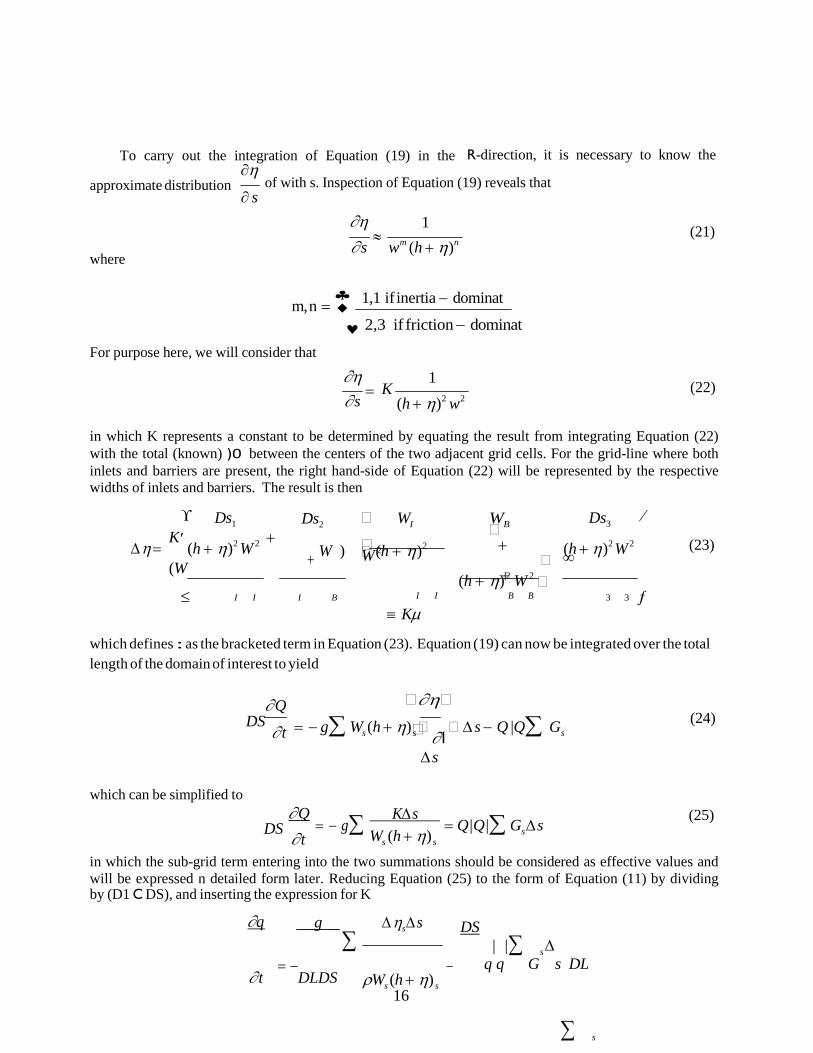
16
�
∑ s
∑ s
To carry out the integration of Equation (19) in the ∂η
R-direction, it is necessary to know the
approximate distribution where
of with s. Inspection of Equation (19) reveals that ∂ s
∂η 1 ∂ s
≈ wm (h + η)n
(21)
♣
m, n = ♦ 1,1 if inertia − dominat For purpose here, we will consider that
♥ 2,3 if friction − dominat
∂η ∂ s
=
1 K
(h + η)2 w2
(22)
in which K represents a constant to be determined by equating the result from integrating Equation (22) with the total (known) )0 between the centers of the two adjacent grid cells. For the grid-line where both inlets and barriers are present, the right hand-side of Equation (22) will be represented by the respective widths of inlets and barriers. The result is then
ϒ Ds1 Ds2 � WI WB �
Ds3 ⁄
∆ η = K ′ (h + η)2 W 2 +
(W + W ) � � (h + η)2 W 2
+ �
+ (h + η)2 W 2 �
(h + η)2 W 2
∞
(23)
≤ I I I B I I B B
≡ Kµ 3 3 ƒ
which defines : as the bracketed term in Equation (23). Equation (19) can now be integrated over the total length of the domain of interest to yield
∂ Q DS
∂ t
� ∂η�
= − g∑ Ws (h + η) s � ∂ l
� ∆ s − Q |Q∑ Gs
∆ s
(24)
which can be simplified to ∂ Q
DS ∂ t
= − g∑
K∆ s Ws (h + η) s
= Q|Q|∑ Gs ∆ s
(25)
in which the sub-grid term entering into the two summations should be considered as effective values and will be expressed n detailed form later. Reducing Equation (25) to the form of Equation (11) by dividing by (D1 C DS), and inserting the expression for K
∂q g ∆ ηs ∆ s DS
| | ∆ = −
∂ t DLDS −
ρWs (h + η) s
q q G s DL ∑
17
s s
(26)
∂ q ∆ η 1 ∆ s DL = − g(h + η)
∂ t ∆ s µDL(h + η) ∑ W (h + η) =
q|q| G ∆ s
DS (27)

18
'
F 2
ηB =
Thus, by comparison with Equation (14), we see that the expressions for F1 and F2 are 1 ϒ
Ds1 Ds2 � WI WB � Ds3 ⁄
F1 = η ′ η + � +
� + η η
∞ (28) η
DL(h + ) ≤ WI (h + ) I (WB + WI ) � WI (h + ) I WB (h + ) B � (h +
)3 ƒ
' = 1.0 + [GI + G2 + (GI , GB or GIB )]|q| DT
(29) Boundary Conditions
To complete formulation of the problem, boundary conditions must be specified at the boundaries of the grid presented in Figure 14. On the "open" (water) boundaries, the water surface is specified to be that associated with the barometric pressure, i.e.,
� p∞ − pi , j �
(30)
� i , j
� ρg �
in which p4 denotes the far field barometric pressure. In addition, on the open boundary grid cells, it is specified that only discharge components perpendicular to the boundaries occur and that these discharges on the exterior boundaries of the grid system are those required to satisfy the continuity equation (Equation 8).
On the "closed" boundaries, i.e., at the shoreline where land elevations are higher than the adjacent water elevations, a no-flow boundary condition is specified perpendicular to that boundary. However, "flooding" and "deflooding" of grid blocks adjacent to the boundaries can occur. Flooding occurs when the water level is greater by a specified small amount than the ground elevation of an adjacent grid block. When this condition exists, the grid block is activated by a simple allocation of this excess elevation on the newly activated block and in subsequent time steps the grid block is incorporated into the normal calculation scheme. Deflooding occurs when the water level on a grid block drops below a specified level leaving a very small depth on that block. The block is "deactivated" and the excess water placed on the adjacent grid.
The solution is started from an initial condition of zero water surface displacement and zero discharge components. The hurricane system is translated along a specified path at a designated speed. At each time step, the hurricane effects (represented by the pressure and wind stress components) on each cell are calculated and the finite-difference equations (Equations 7, 8, 9, and 10) employed. The results are updated values of 0, qx and qy for each cell.
Implicit Solution of the Finite Difference Equations
The solution for each time step progresses by first solving Equations (7) and (8) simultaneously n+1 for each j grid line sweeping over all values of i. This establishes the values of 0n+1 and qy for the entire (i, j) field. The procedure is then repeated for Equations (9) and (10) in which this pair of equations is n+1 solved simultaneously for 0n+1 and qy for the entire (i, j) field. This latter pair of equations is expressed sequentially for each value of i, then solved for all values of j, for that particular i grid line. The expressions for the various coefficients are presented as follows.
DL DS

19
Ai = ∆ t
g(h + η) ∆ x

20
i , j
x i xi , j
i
B i
y
y y y ]
( ) 2
q n x + q
i , j ( ) 2 n x i , j |qy
i , j
( n yi , j
B = 1 + f |qn |∆t
i 8(h + η)2
C i = −Ai
D = qn
+ ∆ t (h + η) ∂ p τ w + − β(qy )
i , j ρ ∂ x ρ
A* = ∆ t
4∆ x
* = 1.0
C * =− ∆t
i 4 ∆x
D * n ∆t
(q n
q n )
∆t (q n
q n ) i =ηi , j −
4 ∆x x i +1
− x i − 2 ∆x
y i , j +1 − y i , j
q =
i , j
4 [qyi −1, j + q + q + q
i , j i −1, j +1 i , j +1
n 1 n n n n
n |= ,
i j
Aj = g(h + η) ∆ t
2 ∆ x
B =1 + f | q n |∆t
J 8( h +η) 2
Cj = − Aj
D = q n
ϒ g(h + η) + ∆ t − ′ ∆ t + η
− ηn
) −
h + η ∂ p +
τ w
+ β(q
⁄ )n ∞
j yi , j
′≤ 2∆ x i , j i , j −1
n

21
ρ ∂ y ρ x ƒ∞
n 1 n n n n qx =
4 qx + qx + qx + qx
i , j i , j i , j −1 i −1, j i +1, j −1

22
(q xi j , ) 2
+ (q yi j, ) 2 n n |qx
j
j
j j
η = i x i
E η + F
i i
i i i i i i
n |=
i , j
A* = ∆ t
2∆ y
* = 1.0
C * = −A *
* n +1/ 2 ∆t (q n q n ) ∆t (q n +1 q n +1 ) D j =ηi , j −
4 ∆x x i +1,j
− x i , j −
4 ∆x x i +1,j
− xi i , j
With the coefficients now specified, the method of solving the sets of simultaneous equations will be described. The method is termed the "doubled sweep" method in which the first sweep involves "conditioning" two sets of auxiliary coefficients (Ei, Fi, E*
i, F*i). The second sweep determines the values
of 0 and q and, in the process, incorporates the required boundary conditions. The procedure will be illustrated for Equations (7) and (8) and it is noted that the same procedure is applicable to solving Equations (9) and (10). The procedure commences by establishing two auxiliary equations with four variables (Ei, Fi, E* , F* ) which are initially unknown,
i i
n+1/2 i , j
E qn+1 + F
i , j
(31a)
n+1 xi +1, j
* n+1/2 * i i , j i (31b)
Equations (31a) and (31b) are substituted in Equations (7) and (8) and the results simplified to yield
C D − A F qn+1 = − i ηn+1/2 + i i i (32a)
xi , j Ai Ei + Bi i −1, j Ai Ei + Bi
* * * *
ηn+1/2 = − Ci
D qn+1 + i − Ai Fi (32b)
i , j * * * x * * *
Ai Ei + Bi i , j Ai Ei + Bi
Comparison of Equations (31) and (32) establishes the values of the unknown coefficients in terms of the known coefficients (Ei, Fi, E* , F* ), (A, B, ..., A*, B*,...). The expressions are
C* D* − A* F *
Ei = i , A* E * + B*
Fi
=
i i i
A* E * + B*
(33)
C E * = − i
, F * = Di − Ai Fi
(34)
i −1 Ai Ei + Bi i −1 Ai Ei + Bi
To illustrate the manner in which boundary condition information is incorporated into the
B
q =

23
procedure, suppose that the water surface level, 0, is specified at i = IMAX and that qx is specified as zero

24
IMAX −1 IMAX −1
F
qx
at i = 2§. The first sweep commences by noting (from Equation 31a) EIMAX = 0.0
ηn+1/2
(35)
FIMAX = IMAX , j
With the values of EIMAX and FIMAX known, E * and F * can be calculated from Equation (34), then values of E * and F * computed from Equation (33) and so on. E * and F * are set equal to
IMAX −1 IMAX −1 Ei = Fi i i = 0.0 (36)
* *
in accordance with the boundary condition and Equation (31b). This completes the first sweep and establishes all the coefficients over the grid line.
The second sweep simply consists of applying Equations (32) from small i to large i (IMAX). In summary, the "double sweep" procedure as presented here progresses from large i to small i for the first sweep (conditioning the E, F, E*, F* coefficients), and then progresses back from small i to large i for the second sweep (determining the 0, qx and qy at the (n+1)th time step.
Dynamic Wave Set-Up
When waves break, a shoreward directed force in addition to the wind stress, is exerted on the water in the surf zone. This causes an additional rise in water level termed "wave set-up". This effect has been studied extensively in the laboratory [Saville (5), Bowen et al. (6)], and tide gage measurements during severe storms have confirmed its importance in nature. Most of the information relative to wave set-up has been developed for "regular" waves, that is for a wave train in which each wave is the same as the preceding wave. Waves in nature, however, are not regular and tend to occur in groups. An analytic study by Lo (7) has shown that for natural wave trains there is a dynamic wave set-up that is approximately 50% larger than would be predicted by a static treatment. In order to evaluate this result, model studies were conducted in the large University of Florida wave tank. It was found that the experimental and analytical results by Lo were in approximate agreement.
The maximum dynamic wave set-up, approximately
' max , across the surf zone can be shown to be
1/2 ϒ � H � ⁄ ' = 0.285 ′1 − 2.82�
b � ∞ H (37) ηmax
′≤ � gT 2 � ƒ∞ b
which includes the dynamic factor of 50% and in which T is the wave period and Hb is the breaking wave height based on the deep water significant wave height, H0, taken approximately as
Hb = 0.94 Ho (38)
The deep water significant wave height is determined from an extension of a method recommended for hurricane generated waves as summarized in the Shore Protection Manual (8),
� R( ∆p/100) � 0.208V � � (Ho ) max = 16.5e
1 + � UR �
(39)
§It is noted that other combinations of boundary conditions at the two ends for the grid line could
be accommodated. Also, internal boundary conditions of the type
n+1 i , j
are satisfied by the choice of
η

25
* * coefficients: E i −1 = Fi −1 = 0 .

26
max
max
where R = radius to maximum winds in nautical miles, )p = central pressure deficit in inches of mercury, VF = translation speed of hurricane in knots, and UR = maximum sustained wind speed in knots. For purposes here, the local effective deep water significant wave height is based on the local winds, U, at the surf zone area of interest and the maximum winds in the hurricane, Umax, as
2
H = (H � U � ) max � �
(40)
o o � U max � Equations 37, 38, 39 and 40 provide the basis for determining the maximum dynamic wave set-up within the surf zone. The computed value of η ' was added to the nearshore storm surge. It is stressed that
' max represents the maximum dynamic wave set-up across the surf zone and that this value varies with
time (because the wind speed varies with time). The value of η ' was computed at each time step for the shoreward grid, and added to the corresponding surge value resulting from wind stress, barometric pressure and the effect of astronomical tide to yield the combined total storm tide history.
With the combined total storm tide history thus determined, it is a simple matter to search in the computer to obtain the maximum of the combined total storm tide at the site of interest.
2.6 Features of the One-Dimensional Numerical Model
As noted earlier, a simple one-dimensional numerical model was developed and calibrated to allow the statistics to be generated based on simulation (calculations) of many hurricanes and associated storm tides.
The one-dimensional numerical model is described as follows. A transect line is established which is approximately perpendicular to the bottom contours. The characteristics ()p, R, 2N, VF and track) of the hurricane are defined and the hurricane is advanced along the track line. The water surface displacement (boundary condition) at the seaward end of the transect line is taken as the static response of the water surface to the barometric pressure deviation at that point. The locations of the four transect lines for Pinellas County are shown in Figure II-15. Figures II-19, II-20, II-21 and II-22 present the profiles of the four transect lines and their one-dimensional grid representations.
η

27
Figure II-19 Profile One of the Transect Line One and Its One-Dimensional Grid Representation
Figure II-20 Profile Two of the Transect Line Two and Its One-Dimensional Grid Representation
0 PROFILE TWO
-100 -200 -300 -400 -500 -600 -700
0 10 20 30 40 50 60 70 80 90 100 110 120 130 140 150
Distance (n. mi.)
PROFILE ONE 0
-100 -200 -300 -400 -500 -600 -700
0 10 20 30 40 50 60 70 80 90 100 110 120 130 140 150
Distance (n. mi.)

28
Figure II-21 Profile Three of the Transect Line Three and Its One-Dimensional Grid Representation
Figure II-22 Profile Four of the Transect Line Four and Its One-Dimensional Grid Representation
PROFILE FOUR 0
-100 -200 -300
-400 -500 -600 -700
0 10 20 30 40 50 60 70 80 90 100 110 120 130 140 150
Distance (n. mi.)
0 PROFILE THREE
-100 -200 -300 -400 -500 -600 -700
0 10 20 30 40 50 60 70 80 90 100 110 120 130 140 150
Distance (n. mi.)

29
w b
G
yi
Governing Differential Equations For One-Dimensional Numerical Model The one-dimensional numerical model is significantly less expensive and simpler to run and is
used in the long-term simulation phase, in order to generate the required data within budgetary constraints. The justification for using the one-dimensional model is that it can be adequately calibrated with the rather complete two-dimensional model.
The one-dimensional numerical model is the Bathystropic Storm Tide Model by Freeman, Baer and Jung (9) (1957) and is static in the x-direction model. The governing differential equations in the x and y directions are:
δη 1 � τ w � 1 δ p (41)
δ x gD � ρ
βqy �
ρg δ x = � x − � −
dq y 1 ( ) (42)
dt =
ρD τ − τ y y
in which all variables are evaluated along the transect line perpendicular to shore and passing through the site.
Finite Difference Forms of Governing Differential Equations
The finite difference forms of the governing one-dimensional differential equations (Equations (1) and (2) are:
� 1 ∆ t � � qn+1 = q n + τ
� (43)
� yi BB yi ρ wyi �
∆ x � τ w � pn+1 − pn+1
n+1 n+1 �� xi
n+1 ��
i i +1 (44) ηi +1 = ηi
+ gDi � ρ
− βq + i � ρg
where
BB = 1.0 + f ⋅ ∆ t |q n |
Di
(45)
where the variables are as defined previously for the two-dimensional model. Initial and Boundary Conditions for the One-Dimensional Model
The one-dimensional model is initiated from a condition of rest (qy = 0) and zero water surface displacement (0 = 0). The only boundary condition required is that at the seaward end (i = 1) of each transect where the “barometric tide” is imposed as
η = p∞ − pi
ρ g (46)
Explicit Solution of the Finite Difference Equations
Equations (41) and (42) are solved sequentially for each time step with the hurricane advanced along its specified track with the initial position of the hurricane at a sufficient distance to allow the

30
longshore transport qy to be free of any artificial transients. The solutions of these equations are straight forward and free of any potential instabilities. At the landward grid the wave set-up is superposed as described previously for the two-dimensional model.

31
2.7 Long-Term Simulation With the statistical characteristics of historical hurricanes available and the simple one-
dimensional model calibrated as described previously, the long-term simulation (2,000 years, generally) is carried out. The first phase of the simulation comprises the selection of the hurricane characteristics in accordance with the historical data. In each storm, this involves the following (also, see Figures II-14 and II-23).
Figure II-23 Flow Chart for Storm Tide Simulations for Pinellas County (After Calibration to Determine (AMP)LF, (AMP)ALONG and (AMP)EXIT)
1) Quantifying )p, R, VF, 2N and hurricane track in accordance with the historical probabilities (Section 2.2).
2) For these characteristics, a random astronomical tide from the hurricane season is generated as a boundary condition to the one-dimensional numerical model and the model is run to determine the storm surge at the site of interest. This storm surge is then adjusted in accordance with the factors obtained from the two-dimensional model calibration runs.
3) For the landward grid and each time step, the contribution due to dynamic wave set-up is included to yield the combined total storm tide.
4) Determine whether enough storms have been simulated for the n-year simulation. 5) After the required number of storms and associated storm tides have been simulated, the peak
water levels for each storm are ranked and the return period, TR, is calculated, according to
TR = 2000
M
(47)
where M is the rank of the combined total tide level. (For example, if the simulation was carried out for a 2,000 year period, the highest combined total tide level would have a return period of 2,000 years, etc.) Finally, by presenting these results on semilog paper, it is possible to interpolate for the return periods of interest, i.e., TR = 10, 50, 100 and 500 years.
Landfalling )p, R, V F, YF, ÷ AMP
176E < 2N < 316E
Generate astronomical Tide 0A (t) randomly as boundary condition to simple 1-Dim model
Random 2N (Random No. Gen.)
136E # 2N #176E
316E # 2N # 356E
Alongshore )p, R, V F, L, ÷ AMP
2 = 2N - 66E Run simple 1-D Model 0(1) (t)
s
Exiting )p, R, VF,
YE, ÷ AMP 356E < 2N < 136E
Rank 658 combined total storm tide and calculate recurrence intervals
Have simulated 658 cases
(2) (1) 0s (t) = AMP0s
(t) Yes
No
Store 0max

32
III. APPLICATIONS OF STORM SURGE METHODOLOGY WITH SPECIFIC ILLUSTRATION BY EXAMPLE TO PINELLAS COUNTY
3.1 Two-Dimensional Model (Appendix A) As noted previously, the two-dimensional model is first verified using storms of record and then
employed to generate a data base for calibration of the one-dimensional model. Verification With Storms of Record
Several examples will be presented comparing measured and calculated storm tides for storms of record. In these comparisons, an attempt was made to extract the astronomical tide and only tide measurements were generally used for comparison since the more abundant high water marks can be shown to contain significant extraneous effects. The calculated storm tides were based on a parameterized hurricane which is undoubtedly responsible for some of the differences between the measured and computed tides. The parameters were allowed to change along the hurricane path in accordance with measurements of these parameters.
The storm tides located for calibration for Pinellas County were those produced by hurricanes of September, 1947 and June 1966 (Alma). The parameters for the hurricanes used for input into the two- dimensional model are presented in Table III-1. Water level measurements for the hurricanes were available at Venice Inlet, Ft. Myers and Cedar Key and the comparisons are presented in Figures III-1, III- 2 and III-3 for the 1947 hurricane and III-4, III-5 and III-6 for the 1966 hurricane (Alma), respectively. It is seen that although the peak surges due to this hurricanes were not large (2.0 to 3.0 ft), there is generally reasonable agreement between the peak measured and computed storm surges at Venice Inlet and Ft. Myers, with the maximum deviation being less than 0.5 ft. At Cedar Key, the measured is 1.1ft. and 0.5 ft. higher than the computed for the 1947 and the 1966 hurricanes, respectively. Similar discrepancies occur at Cedar Key in other county’s analysis. The cause might be an error in datums.
Comparisons conducted for Franklin County included Hurricanes Agnes (1972) and Eloise (1975) with measurements available from the St. Marks tide gage. These input data for these hurricanes are presented in Tables III-2 and III-3 and the comparisons are presented in Figures III-7 and III-8 for Hurricane Agnes and Hurricane Eloise, respectively. For Hurricane Agnes, the peak measured tide exceeds the computed by approximately 0.8 ft, whereas for Hurricane Eloise, the peak computed tide exceeds the measured by approximately 0.5 ft; on average this is considered reasonable agreement.

33
TABLE III-1
Input Parameters for Calibration Hurricanes
Hurricane of September 1947
date time (EST)
)p (in Hg)
YF
(knots) R
(n. mi.) 2N
(degrees)
9/17 1300 -1.95 7.35 34.0 74.22
1900 -1.95 5.31 34.0 90.00
9/18 0100 -1.95 6.51 34.0 107.90
0700 -1.39 12.97 34.0 117.56
1300 -1.39 17.82 34.0 116.68
1900 -1.39 22.11 34.0 122.87
9/19 0100 -1.39 20.83 34.0 121.88
0700 -1.39 12.17 34.0 109.18
Starting coordinates: Landfalling coordinates: Xs = -80.45 n.mi. XF = -8.40 n.mi. Ys = -136.31 n.mi. YF = -117.25 n.mi.
Hurricane Alma of 1966
date time (EST)
)p (in Hg)
YF
(knots) R
(n. mi.) 2N
(degrees)
6/8 0100 -0.98 15.64 23.0 196.42 0700 -1.22 15.03 23.0 183.37 1300 -1.27 15.10 23.0 173.27 1900 -1.15 17.16 23.0 158.85
6/9 0100 -1.22 17.88 23.0 147.04 0700 -1.27 9.17 23.0 168.88 1300 -0.95 7.45 23.0 216.39 1900 -1.07 11.98 23.0 234.26
6/10 0100 -0.46 11.98 23.0 234.26
Starting coordinates: Landfalling coordinates: Xs = -80.45 n.mi. XF = -8.40 n.mi. Ys = -136.31 n.mi. YF = -117.25 n.mi.

34
measured
computed
HURRICANE 1947 - VENICE INLET, FL 4
0 15 16 17 18 19 20 21
Time (Hours)
September 1947
Figure III-1 Comparison between Measured and Computed Storm Tide at Venice Inlet, Florida for the September 1947 Hurricane
HURRICANE 1947 - FT. MYERS, FL 4
3
2
1
0 10 11 12 13 14 15 16 17 18
Time (Hours)
September 1947
Figure III-2 Comparison between Measured and Computed Storm Tide at Ft. Myers, Florida for the September 1947 Hurricane
3
2
1
m
easured
computed

35
measured
computed
computed
measured
HURRICANE 1947 - CEDAR KEY, FL 4
3
2
1
0 22 23 0 1 2
Time (Hours)
September 18, 1947 September 19, 1947
Figure III-3 Comparison between Measured and Computed Storm Tide at Cedar Key, Florida for the September 1947 Hurricane
HURRICANE ALMA - VENICE INLET, FL 4
3
2
1
0 9 10 11 12 13
Time (Hours)
June 1966 Figure III-4 Comparison between Measured and Computed Storm Tide at Venice Inlet, Florida for
Hurricane Alma of June 1966

36
computed
measured
measured
compute d
HURRICANE ALMA - VENICE INLET, FL 4
3
2
1
0 9 10 11 12 13
Time (Hours)
June 1966
Figure III-5 Comparison between Measured and Computed Storm Tide at Ft. Myers, Florida for Hurricane Alma of June 1966
HURRICANE ALMA - CEDAR KEY, FL 6
5
4
3
2
1
0 9 10 11 12 13 14 15 16 17
Time (Hours)
June 1966
Figure III-6 Comparison between Measured and Computed Storm Tide at Cedar Key, Florida for Hurricane Alma of June 1966

37
TABLE III-2
Input Parameters for Calibration Hurricane
Hurricane Agnes (June, 1972)
date time
(EST)
)p
(in Hg)
YF
(knots)
R
(n. mi.)
2N
(degrees) 6/18 1900 -0.92 12.0 20 180.0
6/19 0100 -1.04 13.0 20 180.0
0700 -1.04 11.0 20 134.5
1300 -0.89 9.7 20 201.1
1900 -0.79 10.0 20 205.8
6/20 0100 -0.68 11.2 20 224.!l
Starting coordinates: Landfalling coordinates: Xs = 220.0 n.mi. XF = 4.2 n.mi. Ys = 45.4 n.mi. YF = 40.2 n.mi.
TABLE III-3
Hurricane Eloise (September, 1975)
date
time
(EST)
)p
(in Hg)
YF
(knots)
R
(n. mi.)
2N
(degrees) 9/22 0100 -0.59 10.0 18 175.0
0700 -0.80 7.1 18 187.1
1300 -0.98 11.2 18 224.3
1900 -1.33 15.2 18 223.5
9/23 0100 -1.63 20.0 18 205.8
0700 -1.72 28.5 18 190.5
1300 -0.91 27.8 18 205.9
Starting coordinates: Landfalling coordinates: Xs = 292.2 n.mi. XF = -31.8 n.mi. Ys = 238.3 n.mi. YF = 76.6 n.mi.
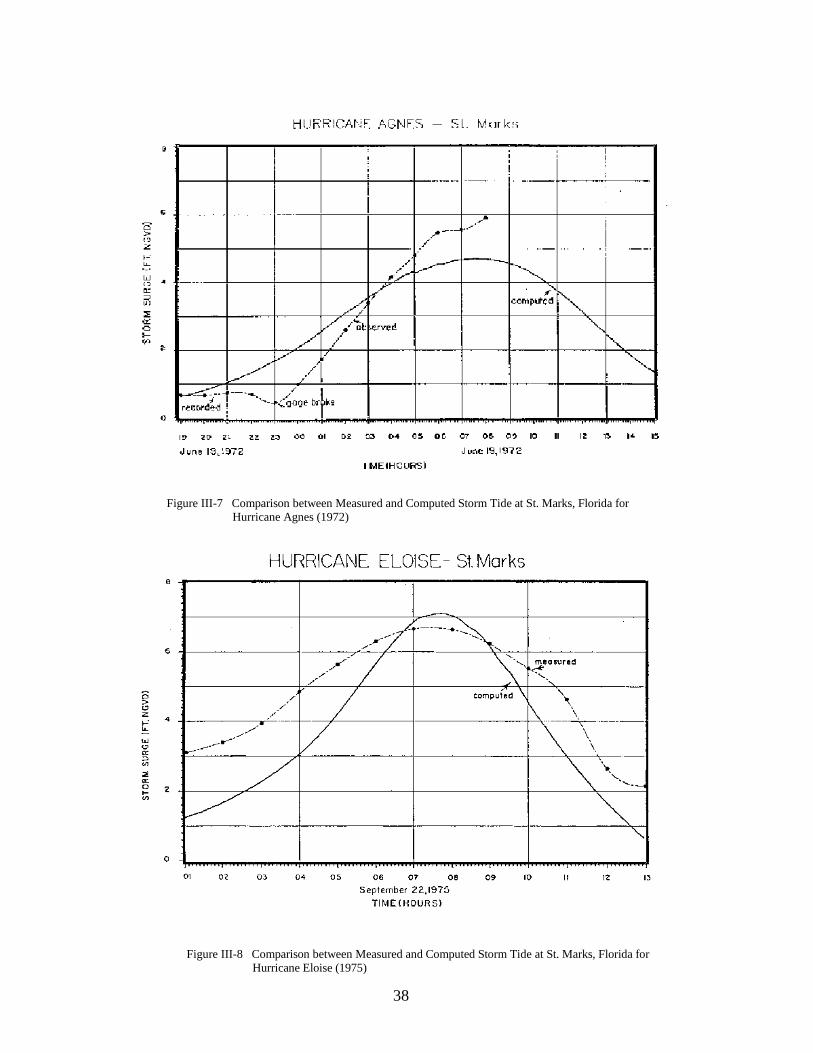
38
Figure III-7 Comparison between Measured and Computed Storm Tide at St. Marks, Florida for Hurricane Agnes (1972)
Figure III-8 Comparison between Measured and Computed Storm Tide at St. Marks, Florida for Hurricane Eloise (1975)

39
In the CCCL study for Nassau County, comparisons were carried out for Hurricane Dora (1964) and Hurricane David (1979), using the input parameters presented in Tables III-4 and III-5, respectively. Measurements were available at Fernandina Beach and Mayport. The comparisons are presented in Figures III-9, III-10, III-11 and III-12. In general the average agreement is considered good.
In summary of the comparisons shown (and others available but not shown for Dade, Broward and Walton Counties), the agreement between measured and computed storm surges is considered good. We regard this comparison/validation phase as useful in demonstrating the validity of the model and ensuring that the nearshore bathymetry/topography is represented adequately. Differences that exist in the peak surges are believed to be due to the wind field structure of the specific hurricanes, i.e., a measure of the deviation from the idealized hurricane used as input and other factors such as the difference in air-sea temperature which influences the wind surface stress coefficient.
Generation of Data Base For Calibration of One-Dimensional Model
With the two-dimensional model validated, a data base is generated spanning the hurricane parameters of interest. This data base is subsequently employed for calibration of the one-dimensional model which includes more severe approximations to the physics of the hurricane problem.
To illustrate the range of hurricane parameters included in the data base, Tables III-6a, III-6b, III-7a, III-7b, III-8a and III-8b present the cases selected for Landfalling, Alongshore and Exiting Storms in the Pinellas County vicinity. Note that eleven storms are selected for each hurricane path category. The last columns in these tables contain the maximum storm surges for the coastal terminus of the four transects shown in Figures II-19, II-20, II-21 and II-22 and will be discussed in the next section.

40
TABLE III-4
Input Parameters for Calibration Hurricane
Hurricane Dora (September, 1964)
date time
(GMT)
)p
(in Hg)
YF
(knots)
R
(n. mi.)
2N
(degrees)
9/8 9/9
9/10
1 20 98.80 8.0 20 104.60
10.3 20 112.88
6.0 20 120.13
6.0 20 99.41
6.1 20 99.41
8.7 20 96.62
6.1 20 96.62
3.5 20 90.00 Starting coordinates: Landfalling coordinates:
Xs = 165.43 n.mi. XF = 5.17 n.mi. Ys = 90.00 n.mi. YF = 36.00 n.mi.
TABLE III-5
Input Parameters for Calibration Hurricane Hurricane David (September, 1979)
date
9/3
9/4
9/5
Xs = 51.70 n.mi. XL = 15.51 n.mi. Ys =150.00 n.mi. YL = -60.00 n.mi.
1800 -1.48 0000 -1.35 0600 -1.21 1200 -1.27 1800 -1.51 0000 -1.45 0600 -1.39 1200 -1.30 1800 -1.25
time (GMT)
)p (in Hg)
YF
(knots) R
(n. mi.) 2N
(degrees)
1200 -1.14 10.4 10 150.14 1800 -1.17 8.4 10 162.07 0000 -1.20 11.3 10 166.07 0600 -1.23 11.0 10 175.52 1200 -1.23 13.3 10 168.75 1800 -1.23 10.0 10 184.92 0000 -1.17 10.2 10 189.78 0600 -1.05 14.2 10 190.46 1200 -0.98 14.2 10 190.46
Starting coordinates: Offshore coordinates:

41
Figure III-9 Comparison between Measured and Computed Storm Tide at Fernandina Beach, Florida for Hurricane Dora (1964)
Figure III-10 Comparison between Measured and Computed Storm Tide at Mayport, Florida for Hurricane Dora (1964)

42
Figure III-11 Comparison between Measured and Computed Storm Tide at Fernandina Beach, Florida for Hurricane David (1979)
Figure III-12 Comparison between Measured and Computed High Water Mayport, Florida for Hurricane David (1979)
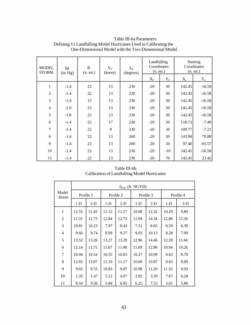
43
Table III-6a Parameters Defining 11 Landfalling Model Hurricanes Used in Calibrating the
One-Dimensional Model with the Two-Dimensional Model
MODEL STORM
)p (in. Hg)
R (n. mi.)
VF
(knots)
2N
(degrees)
Landfalling Coordinates
(n. mi.)
Starting Coordinates
(n. mi.) XF YF Xs Ys
1 -1.4 22 13 230 -20 30 142.45 -16.58 2 -1.4 32 13 230 -20 30 142.45 -16.58 3 -1.4 12 13 230 -20 30 142.45 -16.58 4 -1.0 22 13 230 -20 30 142.45 -16.58 5 -1.8 22 13 230 -20 30 142.45 -16.58 6 -1.4 22 17 230 -20 30 110.73 -7.49 7 -1.4 22 9 230 -20 30 109.77 -7.21 8 -1.4 22 13 260 -20 30 143.98 70.88 9 -1.4 22 13 200 -20 30 97.40 -91.57
10 -1.4 22 13 230 -20 -10 142.45 -56.58 11 -1.4 22 13 230 -20 70 142.45 23.42
Table III-6b Calibration of Landfalling Model Hurricanes
Model Storm
0max (ft. NGVD)
Profile 1 Profile 2 Profile 3 Profile 4
1-D 2-D 1-D 2-D 1-D 2-D 1-D 2-D 1 11.55 11.45 11.12 11.27 10.98 12.32 10.29 9.80 2 11.31 11.73 12.84 12.73 12.94 14.34 12.86 12.26 3 10.81 10.23 7.97 8.43 7.51 8.65 6.59 6.39 4 9.60 9.74 8.99 9.27 9.03 10.13 8.28 7.99 5 13.52 13.26 13.27 13.29 12.96 14.46 12.28 11.66 6 12.14 11.75 11.67 11.90 11.69 12.90 10.94 10.26 7 10.94 10.54 10.55 10.03 10.27 10.99 9.63 8.79 8 12.65 13.07 11.10 11.17 10.00 10.87 9.63 8.89 9 9.65 9.53 10.83 9.87 10.98 11.20 11.55 9.03 10 1.35 1.47 5.12 4.07 2.92 3.29 7.67 6.28 11 8.54 9.36 5.84 6.95 6.25 7.53 5.61 5.86

44
Table III-7a Parameters Defining 11 Alongshore Model Hurricanes Used in Calibrating the
One-Dimensional Model with the Two-Dimensional Model
MODEL STORM
)p (in. Hg)
R (n. mi.)
VF
(knots)
2N
(degrees)
Landfalling Coordinates
(n. mi.)
Starting Coordinates
(n. mi.) XL YL Xs Ys
1 -1.4 18 13 155 20 -5 17.05 -173.97 2 -1.4 24 13 155 20 -5 17.05 -173.97 3 -1.4 12 13 155 20 -5 17.05 -173.97 4 -1.0 18 13 155 20 -5 17.05 -173.97 5 -1.8 18 13 155 20 -5 17.05 -173.97 6 -1.4 18 17 155 20 -5 17.63 -140.98 7 -1.4 18 9 155 20 -5 17.64 -139.98 8 -1.4 18 13 170 20 -5 60.88 -168.98 9 -1.4 18 13 140 20 -5 -26.58 -167.45 10 -1.4 18 13 155 -5 -5 -7.95 -173.97 11 -1.4 18 13 155 45 -5 42.05 -173.97
Table III-7b Calibration of Alongshore Model Hurricanes
Model Storm
0max (ft. NGVD)
Profile 1 Profile 2 Profile 3 Profile 4
1-D 2-D 1-D 2-D 1-D 2-D 1-D 2-D
1 6.08 4.43 3.16 3.14 6.36 6.20 5.67 3.82 2 7.27 5.52 3.92 3.81 7.49 7.29 6.70 4.71 3 4.60 3.17 2.36 2.30 4.89 4.72 4.34 2.71 4 4.70 3.53 2.25 2.25 4.95 4.89 4.29 2.96 5 7.47 5.38 4.11 4.06 7.77 7.45 7.06 4.73 6 6.28 5.13 3.18 4.07 6.56 6.58 5.80 4.23 7 5.89 4.28 3.14 2.98 6.15 5.38 5.54 3.31 8 8.30 6.80 5.23 5.18 7.77 7.63 7.02 4.99 9 4.12 2.40 1.99 1.47 5.02 4.74 4.43 2.69
10 9.92 8.77 8.94 7.57 9.19 9.57 10.09 7.47 11 3.24 2.67 1.29 1.79 3.25 3.37 2.47 1.99

45
Table III-8a Parameters Defining 11 Exiting Model Hurricanes Used in Calibrating the
One-Dimensional Model with the Two-Dimensional Model
MODEL STORM
)p (in. Hg)
R (n. mi.)
VF
(knots)
2N
(degrees)
Landfalling Coordinates
(n. mi.)
Starting Coordinates
(n. mi.) XE YE Xs Ys
1 -1.4 22 13 100 5 0 -135.11 -94.50 2 -1.4 32 13 100 5 0 -135.11 -94.50 3 -1.4 12 13 100 5 0 -135.11 -94.50 4 -1.0 22 13 100 5 0 -135.11 -94.50 5 -1.8 22 13 100 5 0 -135.11 -94.50 6 -1.4 22 17 100 5 0 -107.75 -76.05 7 -1.4 22 9 100 5 0 -106.92 -75.49 8 -1.4 22 13 80 5 0 -158.98 -40.88 9 -1.4 22 13 120 5 0 -94.34 -136.72 10 -1.4 22 13 100 5 -25 -135.11 -119.50 11 -1.4 22 13 100 5 25 -135.11 -69.50
Table III-8b Calibration of Exiting Model Hurricanes
Model Storm
0max (ft. NGVD)
Profile 1 Profile 2 Profile 3 Profile 4
1-D 2-D 1-D 2-D 1-D 2-D 1-D 2-D
1 1.51 1.32 2.89 1.26 5.18 4.59 7.80 4.89 2 1.64 1.69 3.14 1.57 5.22 4.71 6.81 4.37 3 1.38 0.89 1.99 0.85 5.04 4.26 8.64 5.63 4 1.09 1.03 2.01 0.95 3.88 3.52 5.85 3.95 5 1.95 1.60 3.80 1.57 6.50 5.66 9.74 5.85 6 1.49 1.43 2.81 1.31 5.13 4.41 7.53 4.67 7 1.53 1.31 2.97 1.33 5.23 4.58 8.02 5.15 8 0.49 0.84 5.59 3.01 4.05 3.35 9.23 6.21 9 4.31 2.47 2.90 1.89 7.03 6.44 8.11 4.93
10 0.76 1.44 0.71 1.43 0.93 1.55 0.65 1.18 11 6.85 4.85 9.23 6.56 8.64 7.92 8.80 6.54

46
3.2 One-Dimensional Model In the following, the results will be presented of calibrating the one-dimensional model with the
data base generated by the two-dimensional model. In addition, the results of the long-term simulation will be illustrated.
Calibration With Two-Dimensional Model Results
The one-dimensional numerical model represents the physics of storm surges in a much more simplified manner than does the two-dimensional model. Simplifications in the 1-D model include, but are not limited to:
a) The onshore dynamics of the storm surge are not represented, b) Only the hurricane pressure and wind stresses along the transect selected are taken into
account, and c) Convergences and divergences of flow are not represented. Because of the omission of these and other realistic features from the one-dimensional model and
the comprehensive nature of the validated two-dimensional model, the latter is considered as a reliable basis for calibrating the one-dimensional model.
Comparisons of the one-dimensional and two-dimensional peak surges along the four transect lines for Pinellas County are shown in Figures II-19, II-20, II-21 and II-22 and for each of the hurricane categories are presented in Tables III-6a, III-6b, III-7a, III-7b, III-8a and III-8b and in Figures III-13a through III-15b. In each of these twelve graphs, best fit least squares curves are shown of the form
(ηmax )2− D = K(ηmax )1− D + C (48)
where for perfect agreement, a value of unity would be obtained for K and a value of 0 for C. For landfalling storms, the range of K is 0.86 to 1.06 and the range of C is 0.17 to 0.56. For alongshore storms, the range for K is 0.75 to 1.02 and -1.04 to 0.58 for C. For exiting Storms, the range of K is 0.56 to 0.84 and -0.36 to 0.68 for C. These values are employed in the subsequent long-term simulation which uses the one-dimensional model.
Table III-9 presents the ranges of K and C values for the three categories of storms for all the counties studied in the CCCL program.
3.3 Long-Term Simulations
As noted previously, long-term simulations are carried out using the one-dimensional numerical model, usually for a duration of at least 500 years. The study of historical occurrence ensures along with the directional distribution (presented for Pinellas County in Figure II-5) that the correct number and category of hurricanes are selected.
The long-term simulation is carried out for each transect selected, the peak total storm surges ranked and their return periods calculated in accordance with Equation. (47).
For Pinellas County, five 2,000 year simulations were carried out and averaged for each of the four transect lines. The return period vs peak total storm tide relationships for these transects are presented in Figure III-16 and are summarized for selected specific return periods in Table III-10. It is seen that the 100 year peak storm tide ranges from 9.9 ft (above MSL) for the southern profile to 11.5 ft for the northern profile.

47
Figure III-13a Calibration Relationship between the One-Dimensional and the Two-Dimensional Calculations of Peak Surges at Profile One and Profile Two Transect Lines of Pinellas County for Landfalling Hurricanes

48
Figure III-13b Calibration Relationship between the One-Dimensional and the Two-Dimensional Calculation of Peak Surges at Profile Three and Profile Four Transect Lines of Pinellas County for Landfalling Hurricanes

49
Figure III-14a Calibration Relationship between the One-Dimensional and the Two-Dimensional Calculations of Peak Surges at Profile One and Profile Two Transect Lines of Pinellas County for Alongshore Hurricanes

50
Figure III-14b Calibration Relationship between the One-Dimensional and the Two-Dimensional Calculations of Peak Surges at Profile Three and Profile Four Transect Lines of Pinellas County for Alongshore Hurricanes

51
Figure III-15a Calibration Relationship between the One-Dimensional and the Two-Dimensional Calculations of Peak
Surges at Profile One and Profile Two Transect Lines of Pinellas County for Exiting Hurricanes

52
Figure III-15b Calibration Relationship between the One-Dimensional and the Two-Dimensional Calculations of Peak Surges at Profile Three and Profile Four Transect Lines of Pinellas County for Exiting Hurricanes

53
TABLE III-9
Values of 1-D/2-D Peak Storm Surge Correlation for Counties Completed to Data
County
Date of Study Range of K and C
Landfalling Hurricanes Alongshore Hurricanes Exiting Hurricanes K C K C K C
Broward 1981 1.07* 1.07* *** Charlotte 1984 1.09-1.14 0.93-1.00 0.93-0.94 Dade 1981 1.03 1.34 1.13 Franklin 1983 0.95-1.18 *** *** Walton 1982 0.99-1.05 *** *** Nassau 1982 0.93-0.99 0.84-0.90** 0.84-0.90** Franklin September 1983 0.95-1.18 n/a n/a n/a n/a n/a Charlotte April 1984 1.09-1.14 N/a 0.93-1.00 N/a 0.92-0.94 N/a Martin July 1984 1.05-1.07 N/a n/a n/a 0.98-0.99 N/a Gulf August 1985 0.32-1.57 0.78-1.07 n/a n/a n/a n/a Indian River October 1986 1.03-1.12 (-0.44)-0.43 0.90-0.95 0.33-0.63 0.94-0.96 0.03-0.17 Escambia November 1986 1.07-1.12 N/a n/a v/a n/a n/a Manatee March 1987 1.05-1.10 0.14-0.22 0.91-0.99 0.40-0.43 0.90-0.92 0.09-0.12 St. Johns June 1987 0.99-1.18 (-0.53)-0.67 0.92-0.99 0.24-1.05 0.92-0.97 0.02-0.19 Flagler September 1987 0.99-1.19 (-0.04)-0.23 0.85-1.00 0.03-0.25 0.90-0.99 0.00-0.11 St. Lucie March 1988 1.05-1.10 (-0.20)-0.14 0.80-0.89 0.70-0.90 0.99-1.00 0.03-0.13 Sarasota August 1988 1.05-1.17 (-0.36)-0.56 1.00-1.05 0.30-0.39 0.91-0.93 0.04-0.19 Volusia July 1989 0.96-1.15 (-0.25)-1.54 0.92-0.93 0.77-1.03 0.90-0.97 (-0.16)-0.36 Collier November 1989 0.96-1.12 (-0.00)-0.26 0.84-0.98 0.82-1.26 0.55-0.83 0.13-2.14 Lee July 1990 0.93-1.13 (-0.21)-2.45 0.91-1.03 (-1.44)-0.76 0.78-1.12 (-0.46)-1.06 Okaloosa January 1991 1.09-1.12 (-0.05)-0.42 N/a n/a n/a n/a Palm Beach April 1992 1.05-1.07 (-0.04)-0.03 N/a n/a 1.02-1.03 (-0.01)-(-
0.06) Bay September 1994 0.90-1.17 (-0.31)-1.33 0.75-0.97 0.73-1.15 N/a n/a Pinellas 1995 0.86-1.06 0.17-0.56 0.75-1.02 (-1.04)-0.58 0.56-0.84 (-0.36)-0.68
* The calibration of the landfalling and alongshore hurricanes was combined. ** The calibration of the alongshore and exiting hurricanes was combined. *** Due to their very small relative frequency of occurrence, alongshore and exiting hurricanes
were not included.

54
Pinellas County
Profile One Profile Two Profile Three
Profile Four
Pinellas County 16
15
14
13
12
11
10
9
8
7
6
5
4
3
2
1
0 1 4 10 20 50 100 200 500 1000
Return Period, TR (years)
Figure III-16 Combined Total Storm Tide Elevation Versus Return Period for Four Transect Lines in Pinellas County
Table III-10
Combined Total Storm Tide Values for Various Return Periods
Return Period, Combined Total Storm Tide Level* above NGVD (ft.) (ft.)
TR (years) Profile One Profile Two Profile Three Profile Four
500 15.3 13.4 14.7 13.1 200 13.1 12.0 12.7 11.3 100 11.5 10.0 11.5 9.9 50 9.5 8.5 9.9 8.5 20 6.2 5.7 7.3 6.1 10 3.2 3.4 4.3 3.6 5 2.0 2.0 2.4 2.2
*Includes contributions of: wind stress, barometric pressure, dynamic wave set-up and astronomical tide.
Com
bine
d To
tal S
torm
Tid
e (ft
. - N
GV
D)

55
IV. EROSION CALCULATION METHODOLOGY
4.1 Introduction The erosion calculation methodology is based on measurements of beach profiles, both in an
equilibrium and post-storm state and reasonable approximations to the physics, where necessary. These methods have been under development for approximately seven years and the numerical models are continually being upgraded, both as new and improved information becomes available and in our continuing attempt to include as much realism (for example, overwash) in the numerical model as possible.
4.2 Equilibrium Beach Profiles
A number of theories have been advanced attempting to describe the properties of and mechanisms associated with equilibrium beach profiles.
Based on a data set comprising more than 500 beach profiles ranging from the eastern tip of Long Island to the Texas-Mexico border, see Figure IV-1, the following form for an equilibrium beach profile was identified
h(x) = Axm (49)
in which A and m are scale and shape parameters, respectively. Figure IV-2 presents normalized beach profiles for various m values. It is seen that for m < 1, the profile is concave upward as commonly found in nature. Figure IV-3 demonstrates the effect of the scale parameter, A.
The data from the 502 beach profiles were evaluated employing a least squares procedure to determine the A and m values for each of the profiles. The results of this analysis strongly supported a value of m = 0.667, (see Figure IV-4). It can be shown that a value of m = 2/3 corresponds to uniform wave energy dissipation per unit water volume in the surf zone. The physical explanation associated with this mechanism is as follows. As the wave propagates through the surf zone, coherent wave energy is converted to turbulent energy by the breaking process. This turbulent energy is manifested as eddy motions of the water particles, thus affecting the stability of the bed material. Any model must acknowledge that a particular sand particle is acted on by constructive and destructive forces. The model here addresses directly only the destructive (destabilizing) forces. It was reasoned that the parameter A depends primarily on sediment properties, and secondarily on wave characteristics, i.e.
A = F(Sediment Properties, Wave Characteristics) (50)
where “F()” denotes “function of” and it would be desirable to combine wave and sediment characteristics to form a single dimension less parameter.

56
Figure IV-1 Location Map of the 502 Profiles Used in the Analysis (from Hayden, et al. 1975)

57
Figure IV-2 Characteristics of Dimensionless Beach Profile for Various m Values (from Dean, 1977)

58
Figure IV-3 Equilibrium Beach Profiles for Sand Sizes of 0.2 mm and 0.6 mm A(D = 0.2 mm) = 0.1 mm1/3,
A(D = 0.6 mm) = 0.20m1/3
Figure IV-4 Histogram of Exponent m in Equation h=Axm for 502 United States East Coast and Gulf of Mexico Profiles (from Dean (11), 1977)

59
A portion of Mr. Brett Moore’s M.S. Thesis (12) was directed toward an improved definition of the scale parameter, A. Moore combined available laboratory and field data to obtain the results presented in Figure IV-5, thereby extending considerably the previous definition of A. Some of the individual beach profiles used in the development of Figure IV-5 are interesting. For example, Figure IV- 6 presents the actual and best least squares fit to a beach consisting of “sand particles” 15-30 cm in diameter (approximately the size of a bowling ball). Figure IV-7 presents the same information for a beach reported to be composed almost entirely of whole and broken shells. Figure IV-8 shows a profile with a bar present resulting in one of the poorer fits to the data. It is emphasized that the analytical form (Equation (50)) describes a monotonic profile.
Figure IV-5 Beach Profile Factor, A, vs. Sediment Diameter, D, in Relationship h = Ax2/3(Modified from Moore (12), 1982)

60
Figure IV-6 Profile P4 from Zenkovich (1967). A Boulder Coast in Eastern Kamchatka. Sand Diameter: 150
mm - 300 mm. Least Squares Value of A = 0.82 m1/3 (from Moore (12), 1982)
Figure IV-7 Profile P10 from Zenkovich (1967). Near the End of a Spit in Western Black Sea. Whole and
Broken Shells. A = 0.25 m1/3 (from Moore (12), 1982)

61
κ h
Figure IV-8 Profile from Zenkovich (1967). Eastern Kamchatka. Mean Sand Diameter: 0.25 mm. Least Squares Value of
A = 0.07 m1/3 (from Moore (12), 1982)
4.3 Cross-Shore Transport Models It has been noted that most equilibrium profiles correspond to uniform energy dissipation per unit volume
with the scale of the profile represented by the parameter A which depends primarily on sediment characteristics and secondarily on wave characteristics, i.e.
h( x) = Ax 2/3 (51)
The parameter, A, and the uniform energy dissipation per unit volume, <*, are related for linear spilling waves by
� 24 A = � ν * �
� 2/3
(52) � 5 ρg 3/2κ 2 �
It can be shown that for the spilling breaker assumption and linear waves, the energy dissipation per unit volume, <, is proportional to the product of the square root of the water depth and the gradient in depth,
5 ν = ρ g
16 3/2 2 1/2 ∂ h
∂ x
(53)
Thus it is clear that an increase in water level such as due to a storm surge will cause wave energy dissipation to increase beyond the equilibrium value. It is also known that the beach responds by erosion of sediment in shallow water and deposition of this sediment in deeper water (Figure IV-9). It therefore appears reasonable to propose as a hypothesis that the offshore sediment transport, Qs, per unit width is given by
Qs = K(υ − υ*) (54) where K is a rate constant that hopefully does not vary too greatly with scale. Moore (12) evaluated this relationship using large scale wave tank data of Saville (13) and found
K = 2.2x10− 6 m4 / n (55)

62
Figure IV-10 presents comparisons of predicted cumulative erosion for various values of K with the measured values obtained from Saville’s wave tank tests.
Figure IV-9 Model Simulation of a 0.5 Meter Sea Level Rise and Beach Profile Response with a Relatively Mild Sloping Beach (from Moore (12), 1982)
Figure IV-10 Effect of Varying the Sediment Transport Rate Coefficient on Cumulative Erosion During the Simulation of Saville’s (1957) Laboratory Investigation of Beach Profile Evolution for a 0.2 mm sand size (from Moore (12), 1982)

63
(h h − h
n n+1 n
g
Figure IV-11 Model Representation of Beach Profile, Showing Depth and Transport Relation to Grid Definitions (from Kriebel (14), 1982)
4.4 Prediction of Beach and Dune Erosion Due to Severe Storms by Kriebel’s Model
Mr. David Kriebel carried out a Master’s thesis on this subject. He incorporated previous work and developed considerable original contributions to this problem, including the capability to model single storm events and long-term scenarios in which many storms occur. Profile Schematization
The profile was schematized as a series of depth contours, hn, the locations of which are specified by coordinates, xn, measured from an arbitrary baseline, see Figure IV-11. The profile is thus inherently monotonic and at each time step, the xn values of each of the active contours is updated. Governing Equations
As in most transport problems, there are two governing equations. One is an equation describing the transport in terms of a gradient or some other feature. The second is a continuity or conservation equation which accounts for the net fluxes into a cell.
As discussed previously, the offshore transport is defined by Equation (54) in terms of the excess energy dissipation per unit volume. Specifically, in finite difference form
where νn+1 =
KD '
n+1
γ
5/2 5/2 n+1 n
+ h' )(x − x )
2
(56)
The sand conservation equation is
KD = κ 4
K∆ t
(57)
∆ xn = ∆ h
(υn − υn+1 ) (58)

64
Method of Solution of Finite Difference Equations
A number of methods could be employed for solving Equations. (54) and (58). For example, explicit methods would be fairly direct and simple to program; however, the maximum allowable time increment would be relatively small resulting in a program which is quite expensive to run. Implicit methods are somewhat more difficult to program, but have the desirable feature of remaining stable with a much greater time step. Because of the planned application to long-term simulation in which for a 500 year time period and on the order of three hundred storms would be modeled, each with an erosional phase of six to twelve hours, an implicit method was adopted. This method will not be described in detail here except to note that a double sweep approach is used in which the Qsn
values and the xn values are updated simultaneously at each time step. For )h values of 1 ft, and
a time step of thirty minutes, the system of equations was stable. The boundary conditions used were somewhat intuitive. At the shoreward end of the system, erosion
proceeded with a specified slope above a particular depth, h*. The depth, h*, is the depth that the equilibrium slope and the slope corresponding to the beach face are the same. Thus a unit of recession of the uppermost active contour causes an erosion of the profile above the active contour that is "swept" by this specified slope. This material is then placed as a source into the uppermost active contour. The offshore boundary condition is that the active contours are those within which wave breaking occurs. If an active contour extends seaward, thereby encroaching over the contour below to an extent that the angle of repose is reached, the lower contour (and additional lower contours if necessary) are displaced seaward to limit the slope to that of the angle of repose.
Application of Method to Computation of Idealized Beach Response
Kriebel (14) carried out computations for a number of idealized cases, some of which are reviewed below.
Response to Static Increased Water Level - Figure IV-12 presents the beach recession due to a static increase in water. The beach responds as expected. In the early stages, the rate of adjustment is fairly rapid with the latter adjustments approaching the equilibrium recession in an asymptotic manner. Of special relevance is that the response time to equilibrium is long compared to the duration of most severe storm systems, such as hurricanes. The form of the response presented in Figure IV-12 is reminiscent of that for a first order process in which the time rate of change of beach recession, R, is represented as

65
Figure IV-12 Characteristic Form of Berm Recession Versus Time for Increased Static Water Level (from
Kriebel (14), 1982)
for which the solution is
dR = − KR
dt (59)
R(t)
= (1 − e− Kt )
(60) R∞
Figure IV-13 presents a comparison of the response from the numerical model and Equation. (60). This similarity forms the basis for a very simple and approximate numerical model of beach and dune profile response. Such a model has been developed, is used currently in the CCCL program and will be described in the next section.
Effects of Various Wave Heights - Considering a common increased water level, but storms with different wave heights, the larger wave heights will break farther offshore causing profile adjustments over a greater distance and thus a greater shoreline recession. Simulations were carried out to examine evolution of the beach under different wave heights with the results presented in Figure IV-14. As expected, the greater shoreline recessions are associated with the larger wave heights. Surprisingly, however during the early phases of the evolution, the larger wave heights do not cause proportionally larger erosions. Thus, for storms of short duration, the sensitivity of the maximum erosion to breaking wave height may not be large.

66
Figure IV-13 Comparison of Asymptotic Berm Recession from Model (—) and as Calculated by Equation (60) (••)
Figure IV-14 Effect of Breaking Wave Height on Berm Recession (from Kriebel, 1982)

67
Effects of Various Storm Tide Levels - The counterpart to the previous case is that of a fixed wave height
and various storm water levels. The results of these simulations are presented in Figure IV-15. In contrast to the previous case, the various storm tide levels cause recession rates in the early stages of the process which are nearly proportional to the storm water level.
Figure IV-15 Effect of Static Storm Surge Level on Berm Recession (from Kriebel, 1982)
Effect of Sediment Size on Berm Recession - The effect of two different sediment sizes on amount and rate of berm recession is shown in Figure IV-16. The equilibrium recession of a coarser material is much less; however, the equilibrium is achieved in a much shorter time than that for the finer sediment. The explanation for the lesser equilibrium erosion for the coarser material is that since the beach is steeper, the waves break closer to shore and thus less material is required to be transferred offshore to establish an equilibrium profile out to the breaking depth (considered to be the limit of motion). Presumably the explanation for the slower approach to equilibrium for the finer material is that, as will be shown by consideration of the initial and equilibrium profile geometries, a much greater volume of sediment must be moved a greater distance to establish equilibrium.
Effect of Storm Duration - The effect of storm duration on shoreline recession was investigated by considering a fixed wave height and an idealized storm tide variation, expressed as

68
Figure IV-16 Effect of Sediment Size on Berm Recession (from Kriebel, 1982)
� σ (t − 18)� T . cos2 � � , |t | η = 12 �
= 0
− 18 < 2 � 2
T , |t − 18|>
2
(61)
in which T (/ 2B/F) is the total storm duration in hours. The results are presented for three storm durations in Figure IV-17. For the shortest storm duration (T = 12 hours), the potential volume eroded is approximately 70 m3/m whereas the computed actual maximum volume eroded is 10 m3/m. With increasing storm tide duration, the computed actual maximum volume eroded increases. Tripling the storm tide duration to 36 hours doubles the maximum volume eroded to 20 m3/m. It is noted that this is only approximately 28% of the potential volume eroded, again underscoring the likelihood that most storms will only reach a fraction of their potential erosion limit. This feature also highlights the significance of cumulative effects of sequential storms and of the need to better understand the recovery process (especially the rates), a portion of the cycle not addressed in this project.
Application of Method to Long-Term Beach and Dune Response Simulations
The previous section has described the application of the model to idealized examples of beach and dune response. The model can also be applied to more realistic situations in which the initial beach and dune conditions are specified along with time-varying waves and tides.
Evaluation of Method by Hurricane Eloise Erosion Data - Kriebel carried out an evaluation of the method by comparing erosion computations for Hurricane Eloise (1975) with measurements reported by Chiu (16). Although the wave and tide conditions were not measured along the beaches of Bay and Walton Counties (Florida) of interest, some tide data were available and wave heights were estimated. Erosion was computed for twenty combinations of dune slope, wave height and peak surge. It was found that the volumetric erosion ranged from 21 to 38 m3/m compared to average measured values of 18 to 20 m3/m for Bay and Walton ranged

69
Figure IV-17 Comparison of the Effects of 12, 24, and 36 hrs. Storm Surge on Volumetric Erosion (from Kriebel, 1982)
from 21 to Counties, respectively and an average of 25 m3/m near the area of peak surge. Although the predicted values are somewhat larger than the observed, Chiu (16) states that the beaches had started to recover at the time of the post-storm surveys, with approximately 5 m3/m of sand having returned to the beach. Thus the maximum eroded volume would be 30 m3/m compared to a maximum calculated value of 38 m3/m, a difference of approximately 27%. This reasonably close agreement was considered adequate recognizing the uncertainty in the storm tide employed in the computations; therefore no further calibration of the model was considered warranted. It is of interest that the erosion potential associated with the peak tide is approximately nine times that predicted for the time-varying conditions included in the computations. This again reinforces the fact that most storms in nature cause only a fraction of the potential erosion associated with the maximum conditions in the storm.
Long-Term Simulation - With the model reasonably verified for the Bay and Walton Counties area of Florida, a long-term simulation of beach and dune erosion was carried out. The hurricane wind and pressure fields were idealized in accordance with a representation published by Wilson (17). The five idealized hurricane parameters
)p = Maximum Pressured Deficit Rmax = Radius to Maximum Winds VF = Hurricane System Translational Speed
$ = Hurricane Translational Direction YF = Landfall Point
were selected by a Monte Carlo method in accordance with the historical characteristics of hurricanes in the general area. For each hurricane, the storm tide was calculated using the Bathystrophic Storm Tide Model of Freeman, Baer and Jung (9). With the time-varying storm tide and wave height calculated, the beach and dune

70
model was applied until maximum erosion was achieved. As the recovery mechanism is not yet understood to a degree for realistic modeling and because hurricanes occur approximately on a biennial basis, the erosion for successive hurricanes was assumed to commence from a fully recovered condition. This is clearly an approximation as the recovery process occurs at several orders of magnitude slower than the erosion process. Study of some recovery stages from severe storms has shown that up to seven years may be required to achieve approximately 90% recovery. The duration required for recovery from milder storms would, of course, be less.
Figure IV-18 presents a "flow chart" describing the elements of the long-term simulation. In the Bay- Walton Counties area, hurricanes making landfall within " 150 n.mi. of these counties were considered requiring a total of 393 hurricanes to simulate a 500 year record. return periods associated with various dune recessions as determined from the simulations are presented in Figure IV-19. As examples, the dune recessions for return periods of 10, 100 and 500 years are 4 m, 12 m and 18 m, respectively. Based on these results, Hurricane Eloise is judged to represent a 20 to 50 year erosional event; however based on results from a storm surge analysis, Hurricane Eloise was a 75 to 100 year coastal flooding event.
Figure IV-18 Flow Diagram of N-year Simulation of Hurricane Storm Surge and Resulting Beach Erosion (from Kriebel, 1982)
RANDOMLY GENERATE
HURRICANE CHARACTERISTICS IN ACCORDANCE WITH
HISTORICAL METEOROLGY. SELECT INTENSITY, SIZE, SPEED, DIRECITON, AND
LOCATION, AS WELL AS THE ASTORICAL TIDE LEVEL.
BEGIN N-YEAR EROSION
SIMULATION
CALCULATE STORM SURGE AT SITE OF INTEREST USING BATHYSTROPHIC
STORM SURGE MODEL
CALCULATE WAVE HEIGHT AT SITE OF
INTEREST USING LOCAL WIND SPEED
MODEL
CALCULATE BEACH-DUNE EROSION
FOR PROFILE AT SITE OF INTEREST USING BEACH EROSION
MODEL BASED ON EQUILIBRIUM BEACH PROFILE THEORY
ANALYZE RESULTS: (1) STORM SURGE FREQUENCY CURVE (2) EROSION FREQUENCY CURVES FOR:
DUNE RECESSION VOLUMETRIC EROSION
NO NO
IS N-YEAR
SIMULATION COMPLETE?
YES IS
SINGLE STORM SIMULATION COMPLETE?
YES

71
Figure IV-19 Average Frequency Curve for Dune Recession, Developed by Monte Carlo Simulation, Bay-Walton Counties,
Florida (from Kriebel, 1982)
It is also possible to present the results of the erosion simulations in a manner that is of maximum relevance to individuals or agencies responsible for shoreline management. This type of presentation is demonstrated for the Bay-Walton County area in Figure IV-20. This plot includes the contributions from storms and sea level rise. As examples, without any erosion mitigation measures within the next 50 years, the erosion

72
due to sea level rise (regarded as a certainty or probability of 100%) is expected to be approximately 15 ft. Within 50 years, the probability of dune erosion occurring to a distance of 40 ft is 85% and for distances of 60 and 80 ft, the corresponding probabilities are 32% and 9%, respectively. Through the use of figures such as these it would be possible to weigh the costs of certain erosion control measures against the potential of damage if those measures are not carried out.
These procedures provided, for the first time, a basis for conducting the necessary technical studies to implement the erosion component calculations of the Flood Insurance Act of 1973 which provides for the application of methodology to provide the basis for insurance rates for flooding and erosion coastal hazards. Although the flooding component of this act has been implemented, the erosion component has not.
4.5 Prediction of Beach and Dune Erosion Due to Severe Storms by Simple Model
For computational ease and economy, a much simpler erosion model was developed and is applied in the CCCL process. This model is not physically-based, yet retains the overall characteristic response described previously in the Kriebel model.
Figure IV-20 Probability or Risk of Dune Recession of Given Magnitude Occurring at Least Once in N-years, Bay-
Walton Counties, Florida (from Kriebel, 1982)

73
Figure IV-21 Features of Simplified Beach Erosion Model
The model is based on the characteristic response exhibited in Figure IV-13 and Equation. (60) rewritten for reference purposes as
R(t) = (1 − e− Kt )
(62)
R∞
At each time step, for the instantaneous value of the time-varying water level S(t) and the selected breaking wave height, Hb, the equilibrium profile and the associated equilibrium recession, R4, from the existing profile is established, see Figure IV-21. The characteristics of the equilibrium profile are: (1) the eroded volume above the "hinge point" equals the deposited volume below the hinge point, (2) The equilibrium profile is in accordance with Equation (49) with the scale parameter either specified by
the user, or determined as a best-least squares fit to the measured profile during the field program, and (3) the equilibrium profile above the instantaneous water level is characterized by a uniform slope, XMD, on
the order of 2 or 3 as determined by post-storm profile measurements following Hurricane Eloise 1975) and other storms. With the equilibrium profile established, the erosion occurring from time t to time t+)t, )x is given by
∆ x = x(t + ∆ t) − x(t) − R∞ (1 − e− K∆t ) (63)
where, through calibration with Kriebel's model, a K value of 0.075 sec-1 has been found. Figures IV-22 and IV-23 present examples of application of the erosion model to two ranges in Martin
County.
4.6 Augmentation of the Erosion Predicted by the Model for Recommending Position of CCCL As noted previously, the erosion model accounts only for cross shore sediment transport and has been
verified against the average erosion occurring in Hurricane Eloise, see Figure IV-24. As documented by Chiu, there are a number of factors which result in considerable variability about the mean value. Probably the greatest causes of this variability are the gradients in longshore sediment transport as a result of the relatively small scale of the hurricane system, and natural variability due to inhomogeneities in the system (sand size, consolidation, offshore bay system, etc.). Regardless, the variability of erosion is recognized and as documented by Chiu (16) in Hurricane Eloise, the maximum erosion was approximately 2.5 times the average erosion factor is incorporated in the erosion considerations employed in the recommended CCCL position by

74
Figure IV-22 Results of Applying Erosion Model to Range R-1, Martin County (Hutchinson Island), 100 Year Storm Tide, Average Erosion
Figure IV-23 Results of Applying Erosion Model to Range R-89, Martin County (Jupiter Island), 100 Year Storm
Tide, Average Erosion

75
modifying Equation (63) as follows
∆ x = − (2.5) R∞ (1 − e− k∆t ) (64)
which, due to the long beach response time compared to the time scale of storms, results in a profile which is in approximate accord with the 2.5 factor.
Figure IV-24 Calibration of Simplified Erosion Model by Comparison with Erosion Occurring at Various Elevations Due to Hurricane Eloise

76
V. WAVE HEIGHT DECAY CALCULATIONS
5.1 Introduction If calculated erosion is not governing, the final recommended Coastal Construction Control Line position
is based on the location where the significant wave height has attenuated to three feet. This three feet criterion is consistent with the Federal Emergency Management Administration (FEMA) criterion for delimiting the so- called "High Velocity Zone" and is considered to be the wave height (significant) at which structural damage is considered to be substantial. This is presumably in recognition of the rather large piling forces and uplift forces that waves of this magnitude can induce. (The wave force is proportional to Hn where 2 < n < 3.) A potential storm related factor not presently included in the methodology that could cause significant damage is storm-tide induced current across barrier islands (the potential velocity due to a 2 ft tide difference across a submerged barrier island is on the order of 10 ft/sec.).
The following section describes the methodology for calculating wave height decay.
5.2 Methodology As waves propagate, energy can be added to or removed from the wave system. The most common
mechanism for energy addition is by wind blowing over the water surface. Principal mechanisms for energy loss (or dissipation or reflection) include wave breaking due to shoaling water, turbulent losses due to damping by vegetation and wave reflection by buildings. In the present application, energy input by winds is neglected due to the short distances considered, for example the wave height decay usually occurs over a maximum distance of 600-800 ft. The National Academy of Sciences (NAS) (18) has developed recommended methodology for calculating wave decay due to the various mechanisms noted above. The method employed in the CCCL establishment is basically that recommended by the NAS report. Each of the decay mechanisms is described briefly below; the interested reader is referred to the 1977 NAS report for greater detail.
Wave Height Decay Due to Shoaling Water
The maximum wave height, H, which can be supported in a water depth, h, is H = 0.78 h (65)
a result developed by McCowan for shallow water waves.
Wave Height Decay Due to Vegetation Consider waves propagating through a stand of vertical cylindrical elements of diameter, D,
(representing for example tree trunks) at a uniform spacing, S. For a water depth, h, an initial wave height, HI, and a propagation distance, )x. the wave height, HT, after propagation through the stand of elements is
in which
HT = 1 +
HI
AHI ∆ x
(66)
CD D
A = 3π S 2 h
(67)
where CD is the hydrodynamic drag coefficient (taken as 1.0 in this study) associated with flow about the elements. Equation (67) would be modified, for vegetative elements extending only partially over the depth. Wave Height Decay Due to Buildings
Buildings serve to reduce the transmitted wave energy by blocking the waves and causing energy reflection. For an incident wave encountering buildings with a proportionate blockage density, B (perpendicular to the direction of wave propagation), the incident and transmitted wave heights are related by
HT = (1 − B) HI (68)

77
If n rows of buildings, each with the same blockage density, are present, the corresponding result is
HT = (1 − B) n/2 I
Combined Effects of Topography, Vegetation and Buildings For an incident wave height, HI, and both vegetation and buildings effects present, the transmitted wave
height is
HT = 1 +
1
AHI ∆ x (1 − B)
n/2
I
If the transmitted wave height as calculated by Equation (69) is greater than the depth-limited value given by Equation (65), the wave height is set equal to the depth-limited value.
H
H
78
VI. LONG-TERM EROSIONAL CONSIDERATIONS
6.1 Introduction Prior sections have described methodology for calculating the erosion associated with a single severe
storm event. In addition to erosion due to relatively short-term events, the recommended location of the CCCL includes consideration of any long-term erosion trends.
6.2 Methodology
The methodology employed presently consists of accessing those studies which have focused on and identified long-term erosional trends. These studies usually incorporate comparison of early surveys (in chart form) and perhaps comparison of early and more recent aerial photography. Additionally, as counties are resurveyed as part of this study, these data are examined to determine long-term trends.
Studies of value may be directed toward a particular county or may be broad in scope, such as the National Shoreline Study (19) of the U.S. Army Corps of Engineers. Some of the early studies by the University of Florida, Coastal Engineering Laboratory quantified longterm erosion around the State (20), Figure VI-1.
With the long-term erosion rate established, the recommended location of the CCCL includes accounting for a 5 year duration of this erosion. That is, if the long-term erosion rate is 5 ft/year and the methodology described heretofore indicates that the CCCL should be located x feet from shore, then the recommended position is specified at x + 25 ft. from shore.

79
Figure VI-1 General Erosion Conditions in Florida (Bruun, Purpura and Morgan, 1962)

80
VII. OVERALL VERIFICATIONS OF CCCL METHODOLOGY
As might be expected, due to the relative rarity of storms of the 100 year severity level and of the difficulty in conducting meaningful measurement/observations before and after such a storm, there is only limited direct data available to evaluate the CCCL methodology. Two examples which provide varying degrees of evaluation/confirmation are presented below.
7.1 Hurricane Agnes, St. George Island, Franklin County
This example is of interest, in part, because the extent of storm impact was discovered after the recommended position of the CCCL had been established.
Slightly to the west of the center of St. George Island (Range 105-106), the recommended position of the CCCL was some 500 ft landward of the mean sea level contour. The position of the line was challenged by a developer who, by counsel, requested a delay from the Governor and Cabinet to develop proof that the recommended line was too far landward; the delay was granted. After the delay was granted, DNR located aerial photographs flown on June 21, 1972, the day after the passage of Hurricane Agnes, which documented the almost completed destruction of the only road along this portion of St. George Island and landward of Monuments 104 and 105. The roadway is located some 100 ft landward of the recommended position of the CCCL, see Figures VII-1(a) and (b) and photographs on display as a part of the workshop in 1984. It is noted that the storm tide accompanying Hurricane Agnes in Franklin County is believed to be on the order of a 40 year event with the erosion event on the same order.

81
Figure VII-1(a) Beach Profile at Range R-105 on St. George Island. A Location of Severe Overwash and Damaged Roadway
Due to Hurricane Agnes, 1972 (see Figure VII-1(b) for Extension of this Profile)
Figure VII-1(b) Continuation of Profile Across St. George Island, Range R-105, Showing Location of Damaged Road Due to
Hurricane Agnes, 1972

82
It is stressed again that the evidence of storm impact cited in this example was located after the CCCL position had been recommended, we interpret the line location in this area to be somewhat too far Gulfward in the vicinity of Monuments 104 and 105.
7.2 Hurricane Eloise Damage in Walton and Bay Counties
The set-back line was established in Walton and Bay Counties in April, 1975, and August, 1974, respectively. Hurricane Eloise made landfall in Walton County on September 23, 1975, as shown in Figure VII- 2. The hurricane storm tide is ranked as a 75-100 year occurrence and, due to the relatively high translational speed of the hurricane, the erosion is ranked only as a 20-50 year event.
Two types of information will be presented by way of comparison of the measured zone of impact versus location of the (then) set-back line. Figures VII-3 and VII-4 compare the eroded zone with the location of the set-back lines in Bay and Walton Counties, respectively. The location of the pre-hurricane vegetation line is also shown. It is clear that the limits of erosion correlate reasonably well with the location of the set-back line.
The second type of information available from Hurricane Eloise relates to the per structure damage costs relative to the location of that structure with respect to the set-back line. Of course the quality of construction is very important in terms of the damage that an individual structure will experience.
Based on a survey of 540 structures (20), Figure VII-5 presents the per structure damage costs as a function of the structure position relative to the set-back line. Of general relevance is the quite steeply rising damage costs as a function of proximity to the shoreline. Of specific interest is that average damage costs for a structure situated on the set-back line were approximately $8,000, whereas the average damage costs for a structure located 150 ft seaward of the set-back line was in excess of $200,000.
Figure VII-2 Landfall Location of Hurricane Eloise, September 23, 1975 and Some Resulting Tide
and Uprush Characteristics (from Chiu, 1976)

83
BAY COUNTY CCSL
350 Plan View
300 250 EROSION LIMIT
200 150 100
VEGETATION LINE
50
LAGUNA BEACH PANAMA CITY BEACH MEXICO BEACH 0
16 18 20 22 24 26 28 30 32 34 36 38 56 58 60
Distance from Eloise Landfalling Point (miles) Vegetation Line
Erosion due to Hurricane Eloise CCSL
Stable or accreting beach
Note: Vegetation line shown is prior to Hurricane Eloise
WALTON COUNTY
Plan View 300 250 CCSL
200 EROSION LIMIT
150 100 ELOISES TRACK
VEGETATION LINE
50
MIRAMAR BEACH 0
GRAYTON BEACH 10 8 6 4 2 0 2 4 6 8 10 12 14
Distance from Eloise Landfalling Point (miles) Vegetation Line Erosion due to Hurricane Eloise
CCSL Stable or accreting beach
Note: Vegetation line shown is prior to Hurricane Eloise
Figure VII.3 Relation of Erosional Characteristics and pre-Eloise Vegetation Line to Set-Back Line, Bay County, Florida (from Chiu (16))
Figure VII.4 Relation of Erosional Characteristics and pr-Eloise Vegetation Line to Set-Back Line, Walton County, Florida (from Chiu (16))
Dist
ance
from
Orig
inal
MSL
(feet
) D
ista
nce
from
Orig
inal
MSL
(fee
t)
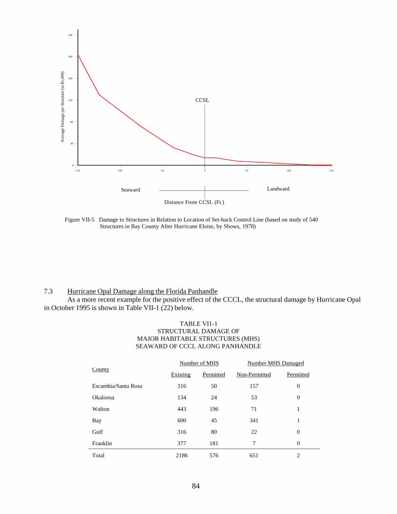
84
CCSL
240
200
160
120
80
40
0
-150 -100 -50 0 50 100 150
Seaward Landward
Distance From CCSL (Ft.)
Figure VII-5 Damage to Structures in Relation to Location of Set-back Control Line (based on study of 540
Structures in Bay County After Hurricane Eloise, by Shows, 1978)
7.3 Hurricane Opal Damage along the Florida Panhandle As a more recent example for the positive effect of the CCCL, the structural damage by Hurricane Opal
in October 1995 is shown in Table VII-1 (22) below.
TABLE VI1-1 STRUCTURAL DAMAGE OF
MAJOR HABITABLE STRUCTURES (MHS) SEAWARD OF CCCL ALONG PANHANDLE
Number of MHS Number MHS Damaged
County Existing Permitted Non-Permitted Permitted
Escambia/Santa Rosa 316 50 157 0 Okaloosa 134 24 53 0 Walton 443 196 71 1 Bay 600 45 341 1 Gulf 316 80 22 0 Franklin 377 181 7 0 Total 2186 576 651 2
Ave
rage
Dam
age
per S
truct
ure
(in $
1,00
0)

85
Severe damage occurred across the entire Panhandle from Escambia County through Franklin County.
The above table indicates that the existing and non-permitted structures suffered a damage rate of 40%, and that the permitted structures under CCCL program with improved construction design and siting suffered only a 0.35% damage rate.

86
REFERENCES
1. U. S. Department of Commerce, National Oceanic and Atmospheric Administration, "Meteorological
Criteria for Standard Project Hurricane and Probable Maximum Hurricane Windfields, Gulf and East Coasts of the United States," NOAA Technical Report NWS 23, September 1979.
2. U. S. Department of Commerce, National Oceanic and Atmospheric Administration, "A Tropical
Cyclone Data Tape for the North Atlantic Basin, 1886-1977: Contents, Limitations and Uses," NOAA Technical Memorandum HWS HC 6, June 1978.
3. Van Dorn, W., "Wind Stress on an Artificial Pond," Journal of Marine Research, Volume 12, No. 3,
1953.
4. Christensen, B. A. and Walton, R., "Friction Factors in Flooding Due to Hurricanes," Proceedings, National Symposium on Urban Stormwater Management in Coastal Area, Blacksburg, Virginia, June 19- 20, 1980.
5. Saville, T., "Experimental Determination of Wave Set-Up," Proceedings, Second Technical Conference
on Hurricanes, pp. 242-252, 1961.
6. Bowen, A. J., Inman, D. L. and Simmons, V. P., "Wave 'Set-Down and Set-Up'," Journal of Geophysical Research, Volume 73, No. 8, pp. 2569-2577, 1968.
7. Lo, J. M., "Dynamic Wave Setup," Paper No. 111, 21st International Conference on Coastal Engineering,
Malaga, Spain, June 1988.
8. U. S. Army Corps of Engineers, "Shore Protection Manual, Volumes I, II and III," U. S. Government Printing Office, 1984.
9. Freeman, J. C., Jr., Baer, L. and Jung, C. H., "The Bathystrophic Storm Tide," Journal of Marine
Research, Volume 16, No. 1, 1957.
10. Hayden, B., et al., “Sysmetic Variation in Inshore Bathmetry” Tech. Report No. 10, Department of Environmental Science, University of Virginia, 1975.
11. Dean, R.G., “Equilibrium Beach Profiles: U.S. Atlantic and Gulf Coasts,” Ocean Engineering Report No.
12, Department of Civil Engineering, University of Delaware, January, 1977.
12. Moore, B., “Beach Profile Evolution in Response to Changes in Water Level and Wave Height,” M.S. Thesis, University of Delaware, 1982.
13. Saville, T., “Scale Effects in Two-Dimensional Beach Studies,” Trans. 7th Meeting of Intl. Assoc. of
Hydraulic Research, Lisbon, 1957.
14. Kriebel, D.L., “Beach and Dune Response to Hurricanes,” M.S. Thesis, University of Delaware, 1982.
15. Kriebel, D.L., “Beach Erosion Model (EBEACH) Users Manual,” Volumes I and II, Division of Beaches and Shores, Florida Department of Natural Resources, 1984.
16. Chiu, T.Y., “Beach and Dune Response to Hurricane Eloise of September 1975,” Coastal Sediments ‘77,

87
ASCE, 1977.
17. Wilson, B. L., "Hurricane Wave Statistics for the Gulf of Mexico," U. S. Army Corps of Engineers,
Beach Erosion Board, Technical Memorandum 98, 1956.
18. National Academy Sciences, “Methodology for Calculating Wave Action Effects Associated with Storm Surges, “ Washington, D.C., 1977.
19. U. S. Army Corps of Engineers, "National Shoreline Study - Regional Inventory Report," South Atlantic
Division, Atlanta, Georgia, August 1971.
20. Brunn, P., Morgan, W.H. and Purpura, J.A. “Review of Beach Erosion and Storm Tide Conditions in Florida,” Technical Progress Report No. 13, Florida Engineering and industrial Experiment Station, University of Florida, 1962.
21. Shows, E.W., “Florida’s Coastal Setback Line - An Effect to Regulate Beach Front Development,”
Coastal Zone Management Journal, Vol. 4, Numbers ½, pp. 151-164, Crane, Russak and Company, Inc., 1978.
22. Leadon, M. E., Nguyen, N. T. and Clark, R. R., “Hurricane Opal - Beach and Dune Erosion and
Structural Damage along the Panhandle Coast of Florida,” Report No. BSC-98-01, Bureau of Beaches and Coastal Systems, Department of Environmental Protection, State of Florida, January 1998.
23. Bodge, K. R. and Kriebel, D. L., “Storm Surge and Wave Damage along Florida’s Gulf Coast
from Hurricane Elena,” Coastal and Oceanographic Engineering Department, University of Florida, Gainesville, Florida, 1985.
24. Clark, R., “The Impact of Hurricane Elena and Tropical Storm Juan on Coastal Construction in
Florida,” Bureau of Coastal Engineering and Regulation, Division of Beaches and Shores, Florida Department of Natural Resources, Beaches and Shores Post-Storm Report No. 85-3, March 1986.

88
APPENDIX A
2-D STORM TIDE MODEL*
*This program represents a numerical modeling procedure that is subject to change due to: 1. newly encountered topo-bathymetric and hydraulic boundary conditions, and 2. incorporation of new advancements quantifying coastal processes. This program is applied on a county-by-county basis and is subject to acceptable calibration constraints recommend by the Beaches and Shores Resource Center and approved by Florida Department of Environmental Protection.

89
C ******************************************************************** C C PROGRAM : 2-D STORM TIDE C C -------Note------ C C C DEFINITION OF PARAMETERS: C
C CASE 20 CHARACTER TITLE TO IDENTIFY A SPECIFIC OUTPUT C DX HORIZONTAL GRID DISTANCE, IN NAUTICAL MILES C DY VERTICAL GRID DISTANCE, IN NAUTICAL MILES C DT TIME INCREMENT FOR EACH TIME STEP, IN HOURS C PINF REFERENCE PRESSURE (ATMOSPHERIC) USED TO C CALCULATE C BAROMETRIC TIDES C BF BOTTOM FRICTION COEFFICIENT (0.02 - 0.002) C RMAX RADIUS FROM CENTER OF HURRICANE TO THE POSITION C OF MAX. WINDS C YS INITIAL Y-COORD. OF THE HURRICANE CENTER, IN C NAUTICAL MILES C DP HURRICANE CENTRAL PRESSURE INDEX, IN INCHES OF C MERCURY C VF FORWARD VELOCITY OF THE HURRICANE SYSTEM IN C KNOTS C NIT 0 C WSC WIND SHEAR STRESS COEFFICIENT C INTERV TIME STEP INTERVALS AT WHICH TO PRINT OUT C AN OUTPUT FOR THE GRID SYSTEM C THETA LANDFALL HURRICANE TRACK W.R.T. NORTH AND C CLOCKWISE IN DEGREES C XHB INITIAL DIST OF THE HURRICANE, IN NAUTICAL MILES C (MAY BE OUTSIDE THE GRID SYSTEM, W.R.T. ORIGIN) C XHE FINAL DIST OF THE HURRICANE, IN NAUTICAL MILES C (MAY BE OUTSIDE THE GRID SYSTEM, W.R.T. ORIGIN) C TIDE ASTRONOMICAL TIDAL ADJUSTMENT IN FEET, POSITIVE C ABOVE MSL C XCB THE X-COORD DIST OF THE LEFT-EDGE OF THE GRID C SYSTEM, IN NAUTICAL MILES C XCF THE X-COORD DIST OF THE RIGHT-EDGE OF THE GRID C SYSTEM, IN NAUTICAL MILES C YCB THE Y-COORD DIST OF THE TOP-EDGE OF THE GRID C SYSTEM, IN NAUTICAL MILES C YCF THE Y-COORD DIST OF THE BOTTOM-EDGE OF THE GRID C SYSTEM, IN NAUTICAL MILES C TMAX THE MAX DURATION OF THE PROTOTYPE HURRICANE C MODEL SYSTEM, IN HOURS C TMIN THE TIME AFTER WHICH OUTPUTS ARE GENERATED C NDELT 0 C B6 CORIOLIS PARAMETER (0 OR 0.0000727) C NOCVT SET TO 1, THEN DT, DX, DY IS READ IN SECONDS &

90
C FEET NO CONVERSION TAKES PLACE C C C ********************************************************************
COMMON /A/ UUX(ISIZE,JSIZE),UUY(ISIZE,JSIZE),P(ISIZE,JSIZE),
- H(ISIZE,JSIZE),DPDX(ISIZE,JSIZE),DPDY(ISIZE,JSIZE),DX COMMON /B/ ETA(ISIZE,JSIZE),QX(ISIZE,JSIZE),QY(ISIZE,JSIZE),
- TIDE,NQBX(JSIZE),DY,NNX,IEND COMMON /C/ IS,J COMMON /E/ PINF,DT,NNY COMMON /F/ JJ COMMON /H/ IFFACT(ISIZE,JSIZE), IFF1(ISIZE,JSIZE) COMMON /BAR/ NORBAR(120),IBAR(120),JBAR(120),XLBAR(120),HBAR(120),
- WBAR(120),FBAR(120),XKEX(120),NORINL(130),IINL(130),JINL(130), - WINL(130),DPINL(130),XKENEX(130),FINL(130),XLINL(130) COMMON /XANDY/ X(ISIZE),Y(JSIZE)
DIMENSION YNM(JSIZE),XNM(ISIZE),
- ETMX(ISIZE,JSIZE),DXA(ISIZE),DYA(JSIZE), - D(ISIZE,JSIZE),NET(ISIZE,JSIZE), - CVAR(600,3,39),CTIME(600),IPLOT(78), - ETAMAX(39,3),QS(ISIZE,JSIZE),ETAS(ISIZE,JSIZE), - QC(250),ETAC(250),AC(250),BC(250),CC(250),DC(250), - ACS(250),BCS(250),CCS(250),DCS(250), - ETAS0(250),ETAS1(250),ETAS2(250), - VTIME(80),VDP(80),VVF(80),VRMAX(80),VTHETA(80), - THETAL(50), IJV(ISIZE,JSIZE,2),BF2(ISIZE,JSIZE), - FACTX2(ISIZE), WX2(ISIZE)
CHARACTER*20 SYSTEM,DUMMY,CASE
OPEN (4,FILE='n1947.cal') OPEN (5,FILE='pin2d.sys') OPEN (7,FILE='n1947.pun') OPEN (8,FILE='n1947.prt')
12000 FORMAT(/)
C ******************************************************************** C THE FOLLOWING CODE ADDED FOR PAGING PURPOSES ON THE SUPER COMPUTER * C ********************************************************************
DO 1, J=1,JSIZE DO 1, I=1,ISIZE
DPDX(I,J) = 0.0 1 CONTINUE
DO 2, J=1,JSIZE
DO 2, I=1,ISIZE DPDY(I,J) = 0.0
2 CONTINUE
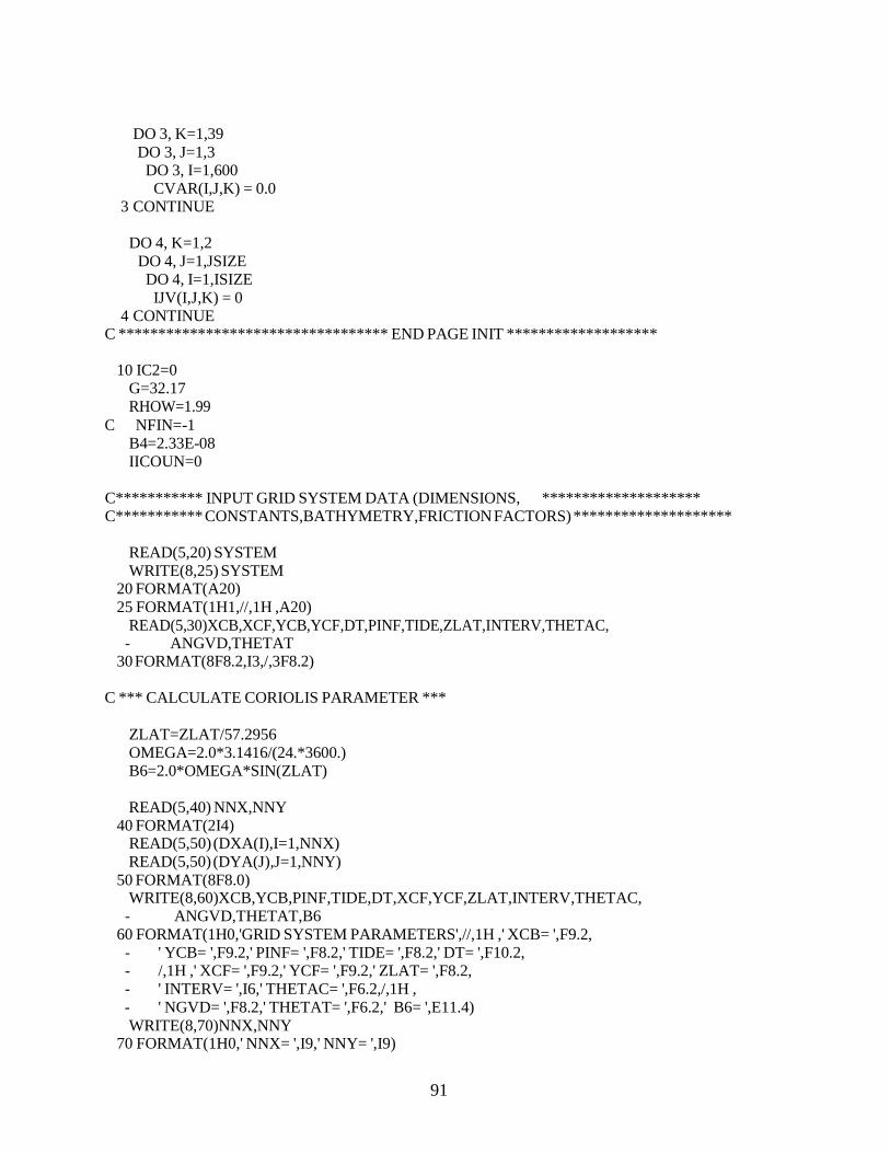
91
DO 3, K=1,39 DO 3, J=1,3
DO 3, I=1,600 CVAR(I,J,K) = 0.0
3 CONTINUE
DO 4, K=1,2 DO 4, J=1,JSIZE DO 4, I=1,ISIZE IJV(I,J,K) = 0
4 CONTINUE C ********************************** END PAGE INIT *******************
10 IC2=0
G=32.17 RHOW=1.99
C NFIN=-1 B4=2.33E-08 IICOUN=0
C*********** INPUT GRID SYSTEM DATA (DIMENSIONS, ******************** C*********** CONSTANTS,BATHYMETRY,FRICTION FACTORS) ********************
READ(5,20) SYSTEM WRITE(8,25) SYSTEM
20 FORMAT(A20) 25 FORMAT(1H1,//,1H ,A20)
READ(5,30)XCB,XCF,YCB,YCF,DT,PINF,TIDE,ZLAT,INTERV,THETAC, - ANGVD,THETAT
30 FORMAT(8F8.2,I3,/,3F8.2) C *** CALCULATE CORIOLIS PARAMETER ***
ZLAT=ZLAT/57.2956 OMEGA=2.0*3.1416/(24.*3600.) B6=2.0*OMEGA*SIN(ZLAT)
READ(5,40) NNX,NNY
40 FORMAT(2I4) READ(5,50) (DXA(I),I=1,NNX) READ(5,50) (DYA(J),J=1,NNY)
50 FORMAT(8F8.0) WRITE(8,60)XCB,YCB,PINF,TIDE,DT,XCF,YCF,ZLAT,INTERV,THETAC,
- ANGVD,THETAT,B6 60 FORMAT(1H0,'GRID SYSTEM PARAMETERS',//,1H ,' XCB= ',F9.2,
- ' YCB= ',F9.2,' PINF= ',F8.2,' TIDE= ',F8.2,' DT= ',F10.2, - /,1H ,' XCF= ',F9.2,' YCF= ',F9.2,' ZLAT= ',F8.2, - ' INTERV= ',I6,' THETAC= ',F6.2,/,1H , - ' NGVD= ',F8.2,' THETAT= ',F6.2,' B6= ',E11.4) WRITE(8,70)NNX,NNY
70 FORMAT(1H0,' NNX= ',I9,' NNY= ',I9)

92
C WRITE(8,80) (DXA(I),I=1,NNX) C WRITE(8,80) (DYA(J),J=1,NNY) C 80 FORMAT(1H0,10F10.0)
READ(5,90) NBAR,NINL C
WRITE(8,95) NBAR,NINL 90 FORMAT(2I3)
C 95 FORMAT(1H0,2I3) IF (NBAR.EQ.0) GO TO 130
DO 110 N=1,NBAR READ(5,100) NORBAR(N),IBAR(N),JBAR(N),XLBAR(N),HBAR(N),
- WBAR(N),FBAR(N),XKEX(N) C **** ADJUST HEIGHT OF BARRIER TO MEAN SEA LEVEL ****
HBAR(N)=HBAR(N)+ANGVD C WRITE(8,105) NORBAR(N),IBAR(N),JBAR(N),XLBAR(N),HBAR(N), C - WBAR(N),FBAR(N),XKEX(N) C ** NOTE : IJV(I,J,NORBAR) IS EQUAL TO N IF A BARRIER EXISTS FOR C ** GRID (I,J).
IJV(IBAR(N),JBAR(N),NORBAR(N)) = N 110 CONTINUE
100 FORMAT(I1,1X,2I3,5F10.3)
C 105 FORMAT(1H0,3I3,5F10.3) WRITE(8,*)'*********' IF (NINL.EQ.0) GO TO 130 DO 120 N=1,NINL READ(5,100) NORINL(N),IINL(N),JINL(N),XLINL(N),DPINL(N),
- WINL(N),FINL(N),XKENEX(N) DPINL(N)=DPINL(N)+ANGVD
C **** ADJUST DEPTH OF INLET TO MEAN SEA LEVEL **** C WRITE(8,115) NORINL(N),IINL(N),JINL(N),XLINL(N),DPINL(N), C - WINL(N),FINL(N),XKENEX(N) C 115 FORMAT(1H0,3I3,5F10.3)
120 CONTINUE 130 CONTINUE
C **** READ IN BATHYMETRY. ELEVATIONS=-H, DEPTHS(WATER)=+H.****
DO 170 J=1,NNY READ(5,185)DUMMY C
WRITE(8,185)DUMMY READ(5,145)(H(I,J),I=1,NNX)
C WRITE(8,150) (H(I,J),I=1,NNX) 145 FORMAT(10F7.2)
C 150 FORMAT(1H ,10F7.2) C 152 FORMAT(/)
H(1,J)=-99. C ***** ADJUST BATHYMETRY TO MEAN SEA LEVEL *****
DO 160 I=2,NNX 160 H(I,J)=H(I,J)+ANGVD 170 CONTINUE
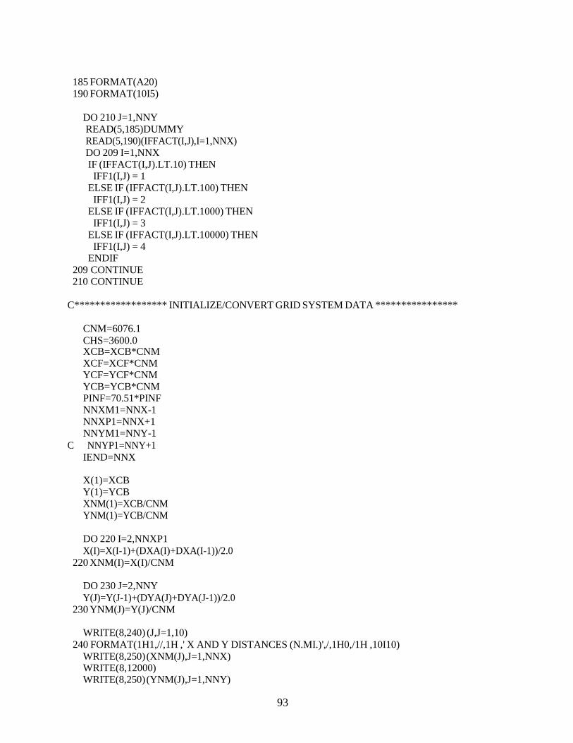
93
185 FORMAT(A20) 190 FORMAT(10I5)
DO 210 J=1,NNY READ(5,185)DUMMY READ(5,190)(IFFACT(I,J),I=1,NNX) DO 209 I=1,NNX IF (IFFACT(I,J).LT.10) THEN
IFF1(I,J) = 1 ELSE IF (IFFACT(I,J).LT.100) THEN
IFF1(I,J) = 2 ELSE IF (IFFACT(I,J).LT.1000) THEN
IFF1(I,J) = 3 ELSE IF (IFFACT(I,J).LT.10000) THEN
IFF1(I,J) = 4 ENDIF
209 CONTINUE 210 CONTINUE
C****************** INITIALIZE/CONVERT GRID SYSTEM DATA ****************
CNM=6076.1 CHS=3600.0 XCB=XCB*CNM XCF=XCF*CNM YCF=YCF*CNM YCB=YCB*CNM PINF=70.51*PINF NNXM1=NNX-1 NNXP1=NNX+1 NNYM1=NNY-1
C NNYP1=NNY+1 IEND=NNX
X(1)=XCB Y(1)=YCB XNM(1)=XCB/CNM YNM(1)=YCB/CNM
DO 220 I=2,NNXP1 X(I)=X(I-1)+(DXA(I)+DXA(I-1))/2.0
220 XNM(I)=X(I)/CNM
DO 230 J=2,NNY Y(J)=Y(J-1)+(DYA(J)+DYA(J-1))/2.0
230 YNM(J)=Y(J)/CNM
WRITE(8,240) (J,J=1,10) 240 FORMAT(1H1,//,1H ,' X AND Y DISTANCES (N.MI.)',/,1H0,/1H ,10I10)
WRITE(8,250) (XNM(J),J=1,NNX) WRITE(8,12000) WRITE(8,250) (YNM(J),J=1,NNY)

94
250 FORMAT(1H ,10F10.2) WRITE(8,260)
260 FORMAT(1H ) C ********* ARRAY INITIALIZATIONS ************************************
DO 310 J=1,NNY DO 310 I=1,NNX
ETA(I,J)=0.0001 310 CONTINUE
DO 311 J=1,NNY DO 311 I=1,NNX QX(I,J)=0.0001
311 CONTINUE DO 312 J=1,NNY
DO 312 I=1,NNX QY(I,J)=0.0001
312 CONTINUE DO 313 J=1,NNY DO 313 I=1,NNX NET(I,J)=0
313 CONTINUE DO 314 J=1,NNY DO 314 I=1,NNX
UUX(I,J)=0.001 314 CONTINUE
DO 315 J=1,NNY DO 315 I=1,NNX
UUY(I,J)=0.001 315 CONTINUE
DO 316 J=1,NNY DO 316 I=1,NNX
P(I,J)=0.0001 316 CONTINUE
C ************** INPUT HURRICANE PARAMETERS **************************
325 READ(4,330,END=11130)CASE 330 FORMAT(A20)
READ(4,340)XHB,YHB,TMIN,TMAX,NPARM C&&&&&&&&&&&&&& C TMAX=0.001 C&&&&&&&&&&&&&&
340 FORMAT(4F8.1,I3) WRITE(8,345)CASE
345 FORMAT(1H1,//,1H ,A20) WRITE(8,350)XHB,YHB,TMIN,TMAX,NPARM
350 FORMAT(1H0,' HURRICANE PARAMETERS ',/,1H0,' XHB= ',F8.1,' YHB= ', - F8.1,' TMIN= ',F8.1,' TMAX= ',F8.1,' NPARM= ',I3) WRITE(8,360)
360 FORMAT(1H-,20X,'VARIABLE PARAMETERS:',//1H ,21X,'TIME',8X,'DP',7X, - 'VF',6X,'RMAX',6X,'THETA',/) DO 390 I=1,NPARM READ(4,370) VTIME(I),VVF(I),VRMAX(I),VDP(I),VTHETA(I)

95
370 FORMAT(5F7.2) WRITE(8,380) I,VTIME(I),VDP(I),VVF(I),VRMAX(I),VTHETA(I)
380 FORMAT(1H ,13X,I2,5X,F5.2,5X,F5.2,5X,F4.1,6X,F4.1,6X,F5.1) VTIME(I)=VTIME(I)*CHS VDP(I)=VDP(I)*70.51 VVF(I)=VVF(I)*1.69 VRMAX(I)=VRMAX(I)*CNM VTHETA(I)=(VTHETA(I)+THETAT-THETAC)/57.2956
390 CONTINUE RMAX=VRMAX(1) DP=VDP(1) VF=VVF(1) THETA=VTHETA(1) THETAT=THETAT/57.2956 XHB=XHB*CNM YHB=YHB*CNM TMAX=TMAX*CHS TMIN=TMIN*CHS IC2=0 IICOUN=0
C ---------------------- CHANGED --------------------------- DO 3900 J=1,48,2 JJ=J+1 READ(4,391) (IPLOT(K),K=J,JJ),THETAL(J) WRITE(8,391) (IPLOT(K),K=J,JJ),THETAL(J)
391 FORMAT(I3,1X,I3,F7.2) THETAL(J)=THETAL(J)/57.2956 IF (IPLOT(J).EQ.0) GO TO 3905
3900 CONTINUE 3905 CONTINUE
C----------------------------------------------------------- NPLOT=0 DO 392 JPLOT=1,48,2 IF(IPLOT(JPLOT).EQ.0.OR.IPLOT(JPLOT+1).EQ.0) GO TO 394 IJ=(JPLOT+1)/2 NPLOT=NPLOT+1 DO 392 JJJJ=1,3 ETAMAX(IJ,JJJJ)=0.0
392 CONTINUE 394 CONTINUE
NPLOT2=NPLOT*2 WRITE(8,396) (IPLOT(J),J=1,NPLOT2)
396 FORMAT(1H0,'GRIDS FOR PLOTTING: ',/,(1H0, - 10(' (',I3,',',I3,')')))
C***********************************************************************
NTIMES=IFIX((TMAX-TMIN)/DT + 0.5) + 1 WRITE(8,398)NTIMES
398 FORMAT(1H0,'NTIMES (MAIN LOOP VALUE) = ',I4) CC STARTING SECTION TO DETERMINE ACTIVE ETA ELEMENTS

96
CC NET(I,J)=0 IF DRY AND =1 IF FLOODED.
DO 420 J=1,NNY DO 420 I=1,NNX IF(ETA(I,J)+H(I,J)) 400,400,410
400 NET(I,J)=0 ETA(I,J)=-H(I,J)-0.0001 GO TO 420
410 NET(I,J)=1 420 CONTINUE
C ESTABLISH REFERENCE HURRICANE VALUES FOR WAVE SETUP C CALCULATIONS
IPARM=2
C WRITE(8,430) C 430 FORMAT(1H0,' I THR ETA NET QX QY D(53,60)',//) C C **************************** MAIN LOOP *******************************
DO 10500 JJ=1,NTIMES XJ=JJ-1 T=XJ*DT+TMIN THR=T/3600. TS=T IF (NPARM.EQ.0.OR.IPARM.GT.NPARM) GO TO 2020 IF (T.LE.VTIME(IPARM)) GO TO 2010 IF (IPARM.EQ.1) GO TO 2000 XHB=XHB+(VTIME(IPARM)-VTIME(IPARM-1))*VVF(IPARM-1)
- *COS(VTHETA(IPARM-1)) YHB=YHB+(VTIME(IPARM)-VTIME(IPARM-1))*VVF(IPARM-1)
- *SIN(VTHETA(IPARM-1)) 2000 IPARM=IPARM+1 2010 IF (IPARM.GT.NPARM) GO TO 2020
DPCT=(T-VTIME(IPARM-1))/(VTIME(IPARM)-VTIME(IPARM-1)) DP=VDP(IPARM-1)+DPCT*(VDP(IPARM)-VDP(IPARM-1)) RMAX=VRMAX(IPARM-1)+DPCT*(VRMAX(IPARM)-VRMAX(IPARM-1)) VF=VVF(IPARM-1) THETA=VTHETA(IPARM-1) TS=T-VTIME(IPARM-1)
2020 CONTINUE C*************************************************************** C MOVED 4/12/88
IS=0 CALL HURCH0(USQ,IS,J,VF,PINF,DP,RMAX,THETA,RHOW) USQM=USQ UMAX=SQRT(USQ)/1.69
C WRITE(8,*) 'DP=', DP AA=-RMAX*DP*B4 AA2=0.160*VF/SQRT(UMAX)

97
HMAX=16.5*EXP(AA)*(1.0+AA2) C TMAX1=8.6*EXP(AA/2.0)*(1.0+AA2/2.0) C***************************************************************
XH=XHB+TS*VF*COS(THETA) YH=YHB+TS*VF*SIN(THETA) XHN=XH/CNM YHN=YH/CNM IF (T.GT.TMAX) GO TO 11000
DO 2025 J=1,NNY
DO 2025 I=1,NNX 2025 QS(I,J)=QX(I,J)
DO 2026 J=1,NNY DO 2026 I=1,NNX
2026 ETAS(I,J)=ETA(I,J) C ---------------------------------------------------------------------- C ESTABLISH ACTIVE (DISCHARGE) JUNCTIONS C USE BOUNDARY CONDITION OF NO FLOW ACROSS A BOUNDARY C NQBX(J) IS THE POSITION OF THE NO FLOW COASTLINE ON THE J'TH COLUM C ----------------------------------------------------------------------
DO 2100 J=1,NNYM1 DY=DYA(J) DO 2090 I=1,NNXM1 DX=DXA(I) IF (JJ.NE.1.OR.NET(I,J).NE.1) GO TO 2030 CALL HURCH(USQ,I,J,VF,PINF,DP,RMAX,THETA,RHOW,XH,YH) ETA(I,J)=0.015625*(PINF-P(I,J))
2030 IF (NET(I,J)*NET(I+1,J)) 2040,2040,2050 2040 QX(I+1,J)=0.001
NQBX(J)=I+1 2050 CONTINUE 2060 IF(NET(I,J)*NET(I,J+1)) 2070,2070,2080 2070 QY(I,J+1)=0.001 2080 CONTINUE 2090 CONTINUE 2100 CONTINUE
CALL ETABCS (XH,YH,T,VF,DP,RMAX,THETA,RHOW) DO 2110 J=1,NNY DO 2110 I=1,NNX
2110 D(I,J)=ETA(I,J)+H(I,J) C -------------------------------------------------------------- C THIS PORTION OF PROGRAM FOR SWEEPS IN THE X-DIRECTION C --------------------------------------------------------------
IMPDIR=1
DO 3090 J=2,NNYM1 DY=DYA(J)
DO 3001 I=2,NNX

98
CALL HURCH(USQ,I,J,VF,PINF,DP,RMAX,THETA,RHOW,XH,YH) 3001 CONTINUE
DO 3002 I=2,NNX CALL CALLFR(I,J,BF2(I,J))
3002 CONTINUE
DO 3003 I=2,NNX DX=0.5*(DXA(I-1)+DXA(I)) FACTX2(I) = 1.0 WX2(I) = 0.5 IF (IJV(I,J,IMPDIR).NE.0)
- CALL BARR(IJV(I,J,IMPDIR),I,J,BF2(I,J),DT,FACTX2(I), - FACTY,WX2(I),WY,IICOUN,NINL)
3003 CONTINUE
DO 3030 I=2,NNX
DX=0.5*(DXA(I-1)+DXA(I)) DX2=DXA(I) IF (NET(I-1,J)*NET(I,J).NE.0.0.AND.WX2(I).LT.400.0) GO TO 3000 AC(I)=0.0 BC(I)=0.0 CC(I)=0.0 DC(I)=0.0 GO TO 3010
3000 DBAR=0.5*(D(I-1,J)+D(I,J)) IF (ABS(DBAR).LT.0.001) DBAR=0.001 AC(I)=G*DBAR*DT/DX*FACTX2(I) QYBAR=0.25*(QY(I-1,J)+QY(I,J)+QY(I-1,J+1)+QY(I,J+1)) QQ=SQRT(QX(I,J)**2+QYBAR**2) IF (WX2(I).GT.0.5) THEN
BC(I) = WX2(I) ELSE
BC(I)=1.0+BF2(I,J)*QQ*DT/(8.0*DBAR**2) ENDIF
CC(I)=-AC(I) DC(I)=QX(I,J)+(-DBAR*DPDX(I,J)/RHOW+UUX(I,J)/RHOW-B6*QYBAR)*DT
3010 IF (NET(I,J).NE.0) GO TO 3020 ACS(I)=0.0 BCS(I)=0.0 CCS(I)=0.0 DCS(I)=0.0 GO TO 3030
3020 ACS(I)=DT/(4.0*DX2) BCS(I)=1.0 CCS(I)=-ACS(I) DCS(I)=ETA(I,J)-ACS(I)*(QX(I+1,J)-QX(I,J))-DT/(2.0*DY)*
- (QY(I,J+1)-QY(I,J)) 3030 CONTINUE
IDIR=1

99
CALL DSWEEP(IDIR,NNX,AC,BC,CC,DC,ACS,BCS,CCS,DCS,ETAC,QC,J,NET)
3050 DO 3060 I=1,NNX QX(I,J)=QC(I)
3060 ETA(I,J)=ETAC(I)
3090 CONTINUE C --------------------------------------------------------------- C THIS PORTION OF PROGRAM FOR SWEEPS IN THE Y-DIRECTION C ---------------------------------------------------------------
IMPDIR=2 DO 4090 I=2,NNXM1 DX=DXA(I) DO 4030 J=2,NNY DY=0.5*(DYA(J-1)+DYA(J)) DY2=DYA(J) FACTY=1.0 CALL HURCH(USQ,I,J,VF,PINF,DP,RMAX,THETA,RHOW,XH,YH) CALL CALLFR(I,J,BF) WY=0.5 IF (IJV(I,J,IMPDIR).NE.0)
-CALL BARR(IJV(I,J,IMPDIR),I,J,BF,DT,FACTX,FACTY,WX,WY,IICOUN,NINL) C----------------------------------------------------------------------
IF (NET(I,J-1)*NET(I,J).NE.0.0.AND.WY.LT.400.0) GO TO 4000 AC(J)=0.0 BC(J)=0.0 CC(J)=0.0 DC(J)=0.0 GO TO 4010
4000 DBAR=0.5*(D(I,J-1)+D(I,J)) IF (ABS(DBAR).LT.0.001) DBAR=0.001 AC(J)=G*DBAR*DT/(2.0*DY)*FACTY QXBAR=0.25*(QX(I,J-1)+QX(I+1,J-1)+QX(I,J)+QX(I+1,J)) QQ=SQRT(QXBAR**2+QY(I,J)**2)
IF (WY.GT.0.5) THEN
BC(J) = WY ELSE
BC(J)=1.0+BF*QQ*DT/(8.0*DBAR**2) ENDIF
CC(J)=-AC(J) DC(J)=QY(I,J)-AC(J)*(ETAS(I,J)-ETAS(I,J-1))+(-DBAR*DPDY(I,J)/RHOW+
- UUY(I,J)/RHOW+B6*QXBAR)*DT 4010 IF (NET(I,J).NE.0) GO TO 4020
ACS(J)=0.0 BCS(J)=0.0 CCS(J)=0.0 DCS(J)=0.0 GO TO 4030
4020 ACS(J)=DT/(2.0*DY2)

10
BCS(J)=1.0 CCS(J)=-ACS(J) DCS(J)=ETA(I,J)-DT/(4.0*DX)*((QX(I+1,J)-QX(I,J))+
- (QS(I+1,J)-QS(I,J))) 4030 CONTINUE
IDIR=2 CALL DSWEEP(IDIR,NNY,AC,BC,CC,DC,ACS,BCS,CCS,DCS,ETAC,QC,I,NET)
4050 DO 4060 J=1,NNY QY(I,J)=QC(J)
4060 ETA(I,J)=ETAC(J)
4090 CONTINUE C REESTABLISH WET AND DRY GRIDS; DRY=0, FLOODED=1 C START AT IEND-1 C DRYS UP IF ETA+H<=0.0
DO 5030 J=2,NNYM1 DO 5030 I=2,NNX IS=NNXM1+2-I
IF (NET(IS,J) .EQ. 0) GO TO 5030 ETA(IS,J)=0.67*ETA(IS,J)+0.33*ETAS(IS,J) IF(ETA(IS,J) + H(IS,J)) 5000,5000,5010
5000 ETA(IS,J)=-H(IS,J)-0.0001
D(IS,J)=ETA(IS,J)+H(IS,J) NET(IS,J)=0 GO TO 5020
5010 NET(IS,J)=1
D(IS,J)=H(IS,J)+ETA(IS,J)
5020 CONTINUE 5030 CONTINUE
C REESTABLISH ACTIVE (DISCHARGE) JUNCTIONS C USE BOUNDARY CONDITION OF NO FLOW ACROSS A BOUNDARY C NQBX(J) IS THE POSITION OF THE NO FLOW COASTLINE ON THE J'TH COLUMN
DO 5065 J=1,NNYM1 DO 5060 I=1,NNXM1 IF (NET(I,J)*NET(I+1,J)) 5035,5035,5040
5035 QX(I+1,J)=0.001 NQBX(J)=I+1
5040 CONTINUE 5045 IF(NET(I,J)*NET(I,J+1)) 5050,5050,5055 5050 CONTINUE
QY(I,J+1)=0.001 5055 CONTINUE 5060 CONTINUE 5065 CONTINUE

10
C--------------- CHANGED ---------------------------
DO 6020 NPLT=1,NPLOT NPLT1=(NPLT-1)*2 + 1 ICUR=IPLOT(NPLT1) J=IPLOT(NPLT1+1) DEL=THETAL(NPLT1)-THETAC/57.2956 CDEL=COS(DEL) SDEL=SIN(DEL) CALL HURCH(USQ,ICUR,J,VF,PINF,DP,RMAX,THETA,RHOW,XH,YH) TAUN=UUX(ICUR,J)*CDEL + UUY(ICUR,J)*SDEL
C TAUP=-UUX(ICUR,J)*SDEL + UUY(ICUR,J)*CDEL H0=HMAX*USQ/USQM AAA=SQRT(UUX(ICUR,J)**2+UUY(ICUR,J)**2) IF (AAA.EQ.0.0) WRITE(8,6015)ICUR,J,UUX(ICUR,J),UUY(ICUR,J)
6015 FORMAT(' ICUR= ',I4,' J= ',I4,' UUX= ',F8.3,' UUY= ',F8.3,/) IF (AAA.EQ.0.0) AAA=0.0001 H0=H0*ABS(TAUN)/AAA T0=2.13*SQRT(H0) HB=0.936*H0 IF (TAUN.GT.0.0) HB=0.1 IF (T0.EQ.0.0) THEN
WSU = 0.0 ELSE
WSU=0.19*(1.0-2.82*SQRT(HB/(G*T0*T0)))*HB ENDIF
6021 WSU1=WSU*1.0
WSU2=WSU*1.5 C ETAS0(NPLT)=ETA(ICUR,J)
ETAS1(NPLT)=ETA(ICUR,J)+WSU1 ETAS2(NPLT)=ETA(ICUR,J)+WSU2
6020 CONTINUE
C ESTABLISH MOST SHOREWARD FLOODED STATION. C NOTE-NEW SHORE ELEMENTS ARE ACTIVATED ONLY BY FLOODING IN X-DIRECTION
DO 6150 J=2,NNYM1 IC=NQBX(J) DX=DXA(IC-1)
6060 IF(ETA(IC,J)+H(IC-1,J)) 6080,6080,6070
6070 ETA(IC-1,J)=-H(IC-1,J)+0.25*(ETA(IC,J)+H(IC-1,J)) D(IC-1,J)=ETA(IC-1,J)+H(IC-1,J) NET(IC-1,J)=1 QX(IC,J)=-DX*(ETA(IC-1,J)+H(IC-1,J))/DT ETA(IC,J)=-H(IC-1,J)+0.75*(ETA(IC,J)+H(IC-1,J))
6080 IF(NET(IC,J+1)) 6090,6090,6110 6090 IF(ETA(IC,J)+H(IC,J+1)) 6110,6110,6100

10
6100 ETA(IC,J+1)=-H(IC,J+1)+0.25*(ETA(IC,J)+ H(IC,J+1)) D(IC,J+1)=ETA(IC,J+1)+H(IC,J+1) NET(IC,J+1)=1 DY=DYA(J+1) QY(IC,J+1)=DY*(ETA(IC,J+1)+H(IC,J+1))/DT ETA(IC,J)=-H(IC,J+1)+0.75*(ETA(IC,J)+H(IC,J+1))
6110 IF(NET(IC,J-1)) 6120,6120,6140 6120 IF( ETA(IC,J)+H(IC,J-1)) 6140,6140,6130 6130 ETA(IC,J-1)=-H(IC,J-1)+0.25*(ETA(IC,J)+H(IC,J-1))
D(IC,J-1)=ETA(IC,J-1)+H(IC,J-1) DY=DYA(J-1) NET(IC,J-1)=1 QY(IC,J-1)=-DY*(ETA(IC,J-1)+H(IC,J-1))/DT ETA(IC,J)=-H(IC,J-1)+0.75*(ETA(IC,J)+H(IC,J-1)) D(IC,J)=ETA(IC,J)+H(IC,J)
6140 CONTINUE 6150 CONTINUE
C****** STORE ETA VALUES FOR TIME SERIES' OF GRIDS FOR PLOTTING ********
IC2=IC2+1 DO 8000 NPLT=1,NPLOT JPLOT=(NPLT-1)*2+1 KPLOT=IPLOT(JPLOT) LPLOT=IPLOT(JPLOT+1) CVAR(IC2,1,NPLT)=ETA(KPLOT,LPLOT) CVAR(IC2,2,NPLT)=ETAS1(NPLT) CVAR(IC2,3,NPLT)=ETAS2(NPLT)
C****** FIND MAXIMUM ETA'S OF GRIDS FOR PLOTTING *********************** 7910 DO 8000 JJJJ=1,3
IF(ETAMAX(NPLT,JJJJ).LT.CVAR(IC2,JJJJ,NPLT)) ETAMAX(NPLT,JJJJ)= - CVAR(IC2,JJJJ,NPLT)
8000 CONTINUE C****** FIND MAXIMUM ETA VALUES (NO SETUP) FOR ALL GRIDS ***************
DO 9000 JJJJ=1,NNY DO 9000 IIII=1,NNX IF (ETA(IIII,JJJJ).GT.ETMX(IIII,JJJJ)) ETMX(IIII,JJJJ)=ETA(IIII,
- JJJJ) 9000 CONTINUE
CTIME(IC2)=T/CHS IF (MOD(JJ-1,6).NE.0) GO TO 10020 WRITE(8,10010) THR,XHN,YHN WRITE(6,10010) THR,XHN,YHN
C WRITE(9,10010) THR,XHN,YHN 10010 FORMAT(1H0,'*****','THR=',F10.2,' XHN=',F10.2,' YHN=',F10.2) 10020 CONTINUE C IF (NFIN.EQ.14) NFIN=1
10500 CONTINUE
C ********************************************************************** C *********************** END OF MAIN LOOP *****************************

10
C ********************************************************************** 11000 CONTINUE
WRITE(8,11005) 11005 FORMAT(1H1,//,1H ,'TIME SERIES FOR PLOTTING GRIDS',//)
I5=-1 DO 11040 J=1,NPLOT I5=I5+2 WRITE(8,11010) IPLOT(I5),IPLOT(I5+1)
11010 FORMAT(1H ,'GRID (',I3,',',I3,')'/) WRITE(8,11020) (CTIME(K6),(CVAR(K6,I,J),I=1,3),K6=1,IC2)
11020 FORMAT(1H ,F6.2,3F10.3,5X,F6.2,3F10.3,5X,F6.2,3F10.3) WRITE(8,11030)
11030 FORMAT(1H1,//) 11040 CONTINUE
WRITE(7,11050) CASE 11050 FORMAT(A20)
WRITE(8,11055) 11055 FORMAT(28X,' SURGE +ST.WSU +DYN.WSU',/)
DO 11090 I=1,NPLOT J=(I-1)*2+1 K=IPLOT(J) L=IPLOT(J+1) WRITE(7,11060) IPLOT(J),IPLOT(J+1),IC2
11060 FORMAT(2I3,I5) WRITE(7,11070) (CTIME(LL),(CVAR(LL,MM,I),MM=1,3),LL=1,IC2)
11070 FORMAT(4F7.2,3X,4F7.2) WRITE(8,11080) K,L,(ETAMAX(I,M),M=1,3)
11080 FORMAT(1H ,'ETAMAX FOR GRID (',I3,',',I3,') = ',3F11.2) 11090 CONTINUE
WRITE(8,11100)
11100 FORMAT(1H1,//,' MAXIMUM ETA VALUES FOR ALL GRIDS (NO SETUP)',//) DO 11120 JJJJ=1,NNY WRITE(8,11110) JJJJ,(ETMX(IIII,JJJJ),IIII=1,NNX)
11110 FORMAT(1H0,I3,3X,10F7.2,/,10(1H ,6X,10F7.2,/)) 11120 CONTINUE 11130 STOP
END C----------------------------------------------------------------------- C HURCH0 IS SAME AS HURCH WHEN I=0 C-----------------------------------------------------------------------
SUBROUTINE HURCH0 (USQ,I,J,UH,PINF,DP,RMAX,THETA,RHO) PARAMETER(ISIZE=200,JSIZE=200) COMMON /A/ UUX(ISIZE,JSIZE),UUY(ISIZE,JSIZE),P(ISIZE,JSIZE),
- H(ISIZE,JSIZE),DPDX(ISIZE,JSIZE),DPDY(ISIZE,JSIZE),DX COMMON /XANDY/ X(ISIZE),Y(JSIZE)
PARAMETER(RHOA=0.0024,UCR=23.6,COR=0.7221E-04)
C BEWARE-SOME SIGNS HAVE BEEN MODIFIED TO ACCOUNT FOR LEFT-HANDED COORD
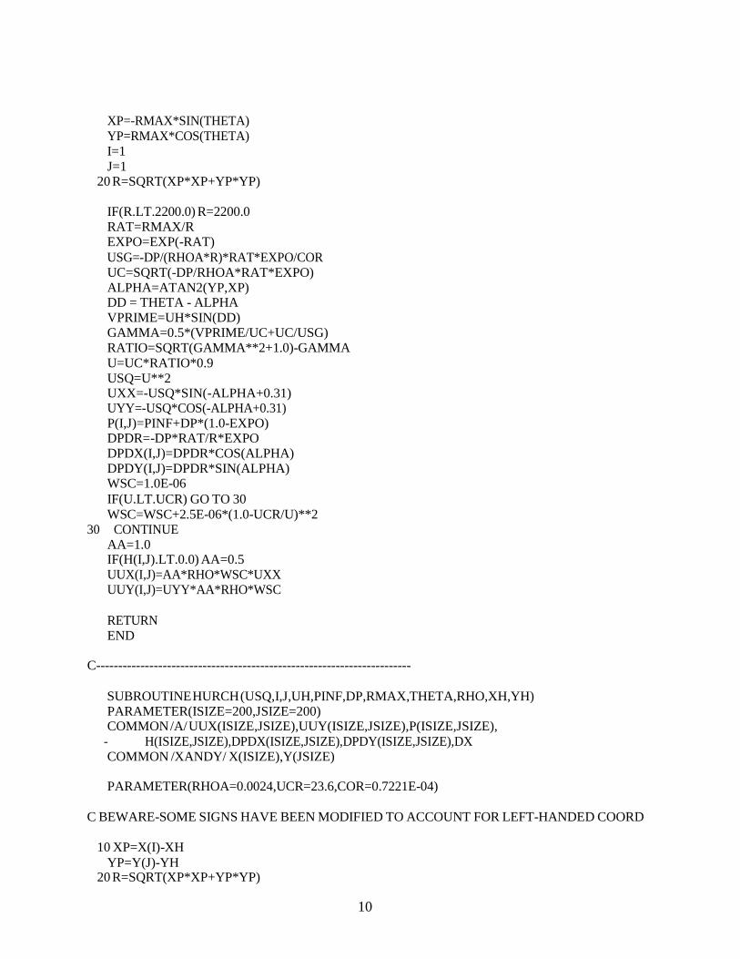
10
XP=-RMAX*SIN(THETA) YP=RMAX*COS(THETA) I=1 J=1
20 R=SQRT(XP*XP+YP*YP)
IF(R.LT.2200.0) R=2200.0 RAT=RMAX/R EXPO=EXP(-RAT) USG=-DP/(RHOA*R)*RAT*EXPO/COR UC=SQRT(-DP/RHOA*RAT*EXPO) ALPHA=ATAN2(YP,XP) DD = THETA - ALPHA VPRIME=UH*SIN(DD) GAMMA=0.5*(VPRIME/UC+UC/USG) RATIO=SQRT(GAMMA**2+1.0)-GAMMA U=UC*RATIO*0.9 USQ=U**2 UXX=-USQ*SIN(-ALPHA+0.31) UYY=-USQ*COS(-ALPHA+0.31) P(I,J)=PINF+DP*(1.0-EXPO) DPDR=-DP*RAT/R*EXPO DPDX(I,J)=DPDR*COS(ALPHA) DPDY(I,J)=DPDR*SIN(ALPHA) WSC=1.0E-06 IF(U.LT.UCR) GO TO 30 WSC=WSC+2.5E-06*(1.0-UCR/U)**2
30 CONTINUE AA=1.0 IF(H(I,J).LT.0.0) AA=0.5 UUX(I,J)=AA*RHO*WSC*UXX UUY(I,J)=UYY*AA*RHO*WSC
RETURN END
C-----------------------------------------------------------------------
SUBROUTINE HURCH (USQ,I,J,UH,PINF,DP,RMAX,THETA,RHO,XH,YH) PARAMETER(ISIZE=200,JSIZE=200) COMMON /A/ UUX(ISIZE,JSIZE),UUY(ISIZE,JSIZE),P(ISIZE,JSIZE),
- H(ISIZE,JSIZE),DPDX(ISIZE,JSIZE),DPDY(ISIZE,JSIZE),DX COMMON /XANDY/ X(ISIZE),Y(JSIZE)
PARAMETER(RHOA=0.0024,UCR=23.6,COR=0.7221E-04)
C BEWARE-SOME SIGNS HAVE BEEN MODIFIED TO ACCOUNT FOR LEFT-HANDED COORD
10 XP=X(I)-XH YP=Y(J)-YH
20 R=SQRT(XP*XP+YP*YP)
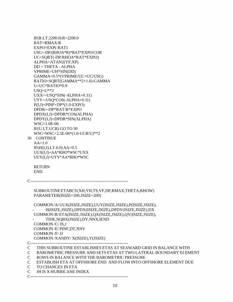
10
IF(R.LT.2200.0) R=2200.0 RAT=RMAX/R EXPO=EXP(-RAT) USG=-DP/(RHOA*R)*RAT*EXPO/COR UC=SQRT(-DP/RHOA*RAT*EXPO) ALPHA=ATAN2(YP,XP) DD = THETA - ALPHA VPRIME=UH*SIN(DD) GAMMA=0.5*(VPRIME/UC+UC/USG) RATIO=SQRT(GAMMA**2+1.0)-GAMMA U=UC*RATIO*0.9 USQ=U**2 UXX=-USQ*SIN(-ALPHA+0.31) UYY=-USQ*COS(-ALPHA+0.31) P(I,J)=PINF+DP*(1.0-EXPO) DPDR=-DP*RAT/R*EXPO DPDX(I,J)=DPDR*COS(ALPHA) DPDY(I,J)=DPDR*SIN(ALPHA) WSC=1.0E-06 IF(U.LT.UCR) GO TO 30 WSC=WSC+2.5E-06*(1.0-UCR/U)**2
30 CONTINUE AA=1.0 IF(H(I,J).LT.0.0) AA=0.5 UUX(I,J)=AA*RHO*WSC*UXX UUY(I,J)=UYY*AA*RHO*WSC
RETURN END
C----------------------------------------------------------------------
SUBROUTINE ETABCS (XH,YH,TS,VF,DP,RMAX,THETA,RHOW) PARAMETER(ISIZE=200,JSIZE=200)
COMMON /A/ UUX(ISIZE,JSIZE),UUY(ISIZE,JSIZE),P(ISIZE,JSIZE),
- H(ISIZE,JSIZE),DPDX(ISIZE,JSIZE),DPDY(ISIZE,JSIZE),DX COMMON /B/ ETA(ISIZE,JSIZE),QX(ISIZE,JSIZE),QY(ISIZE,JSIZE),
- TIDE,NQBX(JSIZE),DY,NNX,IEND COMMON /C/ IS,J COMMON /E/ PINF,DT,NNY COMMON /F/ JJ COMMON /XANDY/ X(ISIZE),Y(JSIZE)
C---------------------------------------------------------------------- C THIS SUBROUTINE ESTABLISHES ETAS AT SEAWARD GRID IN BALANCE WITH C BAROMETRIC PRESSURE AND SETS ETAS AT TWO LATERAL BOUNDARY ELEMENT C ROWS IN BALANCE WITH THE BAROMETRIC PRESSURE C ESTABLISH ETA AT OFFSHORE END AND FLOW INTO OFFSHORE ELEMENT DUE C TO CHANGES IN ETA C JH IS X HURRICANE INDEX C----------------------------------------------------------------------

10
C THIS NEEDS TO BE CHANGED....... USQ=0.0 NNYP1=NNY+1 NNYM1=NNY-1 RHOW=1.99 G=32.2 AA=1.0/(RHOW*G) AST=0.0 DO 45 J=1,NNY IF(H(IEND,J)+ETA(IEND,J).LT.0.0) GO TO 45 CALL HURCH(USQ,IEND,J,VF,PINF,DP,RMAX,THETA,RHOW,XH,YH) TETA=ETA(IEND,J) ETA(IEND,J)=TIDE-AA*(P(IEND,J)-PINF)+AST QX(IEND+1,J)=QX(IEND,J)-(ETA(IEND,J)-TETA)*DX/DT
45 CONTINUE C***** ESTABLISH ETA AT TWO LATERAL BOUNDARY ELEMENT ROWS AND BOUNDARY C***** FLOW, QY(I,1) AND QY(I,NNY) INTO AND FROM THESE ROWS
NQBX(NNY)=NQBX(NNYM1) DO 50 J=1,NNY NLIMIT=NQBX(J)
50 QX(NLIMIT,J)=0.001 J=1 IBP2=NQBX(2)+2 DO 70 I=IBP2,IEND IS=IEND+IBP2-I ISP=IS-1 IF(H(ISP,J)+ETA(ISP,J).LT.0.0) GO TO 70 CALL HURCH(USQ,ISP,J,VF,PINF,DP,RMAX,THETA,RHOW,XH,YH) TETA= ETA(ISP,1) AST=0.0 ETA(ISP,J)=TIDE-AA*(P(ISP,J)-PINF)+AST QY(ISP,J)=QY(ISP,2)+(ETA(ISP,J)-TETA)*DY/DT
70 CONTINUE J=NNY IBP2=NQBX(NNYM1)+2 DO 80 I=IBP2,IEND IS=IEND+IBP2-I ISP=IS-1 IF(H(ISP,J)+ETA(ISP,J).LT.0.0) GO TO 80 CALL HURCH(USQ,ISP,J,VF,PINF,DP,RMAX,THETA,RHOW,XH,YH) TETA=ETA(ISP,J) ETA(ISP,J)=TIDE-AA*(P(ISP,J)-PINF) QY(ISP,NNYP1)=QY(ISP,NNY)-(ETA(ISP,J)-TETA)*DY/DT
80 CONTINUE 90 RETURN
END C-----------------------------------------------------------------------
SUBROUTINE CALLFR(I,J,BF)

10
PARAMETER(ISIZE=200,JSIZE=200)
COMMON /A/ UUX(ISIZE,JSIZE),UUY(ISIZE,JSIZE),P(ISIZE,JSIZE), - H(ISIZE,JSIZE),DPDX(ISIZE,JSIZE),DPDY(ISIZE,JSIZE),DX COMMON /B/ ETA(ISIZE,JSIZE),QX(ISIZE,JSIZE),QY(ISIZE,JSIZE),
- TIDE,NQBX(JSIZE),DY,NNX,IEND COMMON /H/ IFFACT(ISIZE,JSIZE), IFF1(ISIZE,JSIZE)
DVA = ETA(I,J)+H(I,J) D2 = DVA IFA = IFFACT(I,J) I2 = IFF1(I,J) IF (I2.EQ.0) I2=1 BF=0.0 TF=0.0 IDIV=10**I2
DO 90 K=1,I2
IDIV=IDIV/10 ITEST=IFA/IDIV GO TO (50,60,70,80,85),ITEST
50 PHI=1.0 IF (DVA .LE. 10.0) DVA=10.0 D2 = DVA CALL COMP(PHI,0.0,0.0,5.47,1.0,0.0,DVA,BF,TF,D2) GO TO 90
60 PHI=0.0 CALL COMP(PHI,0.999,0.34,10.94,0.3,0.0,DVA,BF,TF,D2) GO TO 90
70 PHI=1.0 CALL COMP(PHI,0.0,0.0,0.91,1.0,0.0,DVA,BF,TF,D2) GO TO 90
80 PHI=0.0 CALL COMP(PHI,0.969,0.5445,10.94,0.3,0.7,DVA,BF,TF,D2) GO TO 90
85 PHI=0.0 CALL COMP(PHI,0.64,0.204,10.94,1.0,0.0,DVA,BF,TF,D2)
90 IFA=IFA-ITEST*IDIV
A2=FLOAT(I2) TF=TF/A2 BF=BF/A2
C **************************************************************
BFSUM = BF TFSUM = TF
C ***********************************************************
IPM = I+1 DVA = ETA(IPM,J)+H(IPM,J)
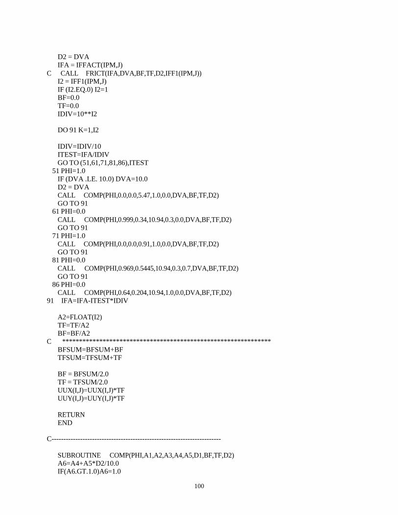
100
D2 = DVA IFA = IFFACT(IPM,J)
C CALL FRICT(IFA,DVA,BF,TF,D2,IFF1(IPM,J)) I2 = IFF1(IPM,J) IF (I2.EQ.0) I2=1 BF=0.0 TF=0.0 IDIV=10**I2
DO 91 K=1,I2
IDIV=IDIV/10 ITEST=IFA/IDIV GO TO (51,61,71,81,86),ITEST
51 PHI=1.0 IF (DVA .LE. 10.0) DVA=10.0 D2 = DVA CALL COMP(PHI,0.0,0.0,5.47,1.0,0.0,DVA,BF,TF,D2) GO TO 91
61 PHI=0.0 CALL COMP(PHI,0.999,0.34,10.94,0.3,0.0,DVA,BF,TF,D2) GO TO 91
71 PHI=1.0 CALL COMP(PHI,0.0,0.0,0.91,1.0,0.0,DVA,BF,TF,D2) GO TO 91
81 PHI=0.0 CALL COMP(PHI,0.969,0.5445,10.94,0.3,0.7,DVA,BF,TF,D2) GO TO 91
86 PHI=0.0 CALL COMP(PHI,0.64,0.204,10.94,1.0,0.0,DVA,BF,TF,D2)
91 IFA=IFA-ITEST*IDIV
A2=FLOAT(I2) TF=TF/A2 BF=BF/A2
C ************************************************************** BFSUM=BFSUM+BF TFSUM=TFSUM+TF
BF = BFSUM/2.0 TF = TFSUM/2.0 UUX(I,J)=UUX(I,J)*TF UUY(I,J)=UUY(I,J)*TF
RETURN END
C-----------------------------------------------------------------------
SUBROUTINE COMP(PHI,A1,A2,A3,A4,A5,D1,BF,TF,D2) A6=A4+A5*D2/10.0 IF(A6.GT.1.0)A6=1.0

101
TF=TF+A6 D3 = D2 IF(A3.EQ.5.47) D3=D1 TEMP1 = A3*D3 IF (TEMP1.EQ.0.0) TEMP1 = 0.000001 TEMP2 = A2*ABS(D3)**1.333 IF ((A1+TEMP2).EQ.0.0) TEMP2 = 0.000001 IF(PHI.EQ.1.0) GO TO 10 PHI = 1.0/(ABS(A1+TEMP2))**0.5
10 BF = 1.28/((PHI**2)*(ALOG(ABS(TEMP1+1.0)))**2)+BF RETURN END
C-----------------------------------------------------------------------
SUBROUTINE BARR(N,I,J,F,DT,FACTX,FACTY,WX,WY,IICOUN,NINL) PARAMETER(ISIZE=200,JSIZE=200)
COMMON /BAR/ NORBAR(120),IBAR(120),JBAR(120),XLBAR(120),HBAR(120),
- WBAR(120),FBAR(120),XKEX(120),NORINL(130),IINL(130),JINL(130), - WINL(130),DPINL(130),XKENEX(130),FINL(130),XLINL(130)
COMMON /A/ UUX(ISIZE,JSIZE),UUY(ISIZE,JSIZE),P(ISIZE,JSIZE),
- H(ISIZE,JSIZE),DPDX(ISIZE,JSIZE),DPDY(ISIZE,JSIZE),DX COMMON /B/ ETA(ISIZE,JSIZE),QX(ISIZE,JSIZE),QY(ISIZE,JSIZE),
- TIDE,NQBX(JSIZE),DY,NNX,IEND
C THE PRESENT TREATMENT IS FOR SUBMERGED BARRIERS ONLY
NORB=NORBAR(N) IM1=I-1 IC=I JM1=J JC=J DL=DY DS=DX QC=QX(IC,JC) IF (NORB.EQ.1) GO TO 10 IM1=I JM1=J-1 DS=DY DL=DX QC=QY(IC,JC)
10 CONTINUE D1=H(IM1,JM1)+ETA(IM1,JM1) D3=H(IC,JC)+ETA(IC,JC)
C----AVERAGE WATER SURFACE ELEVATION
ETABAR=0.5*(ETA(IM1,JM1)+ETA(IC,JC)) W1=DL W3=DL
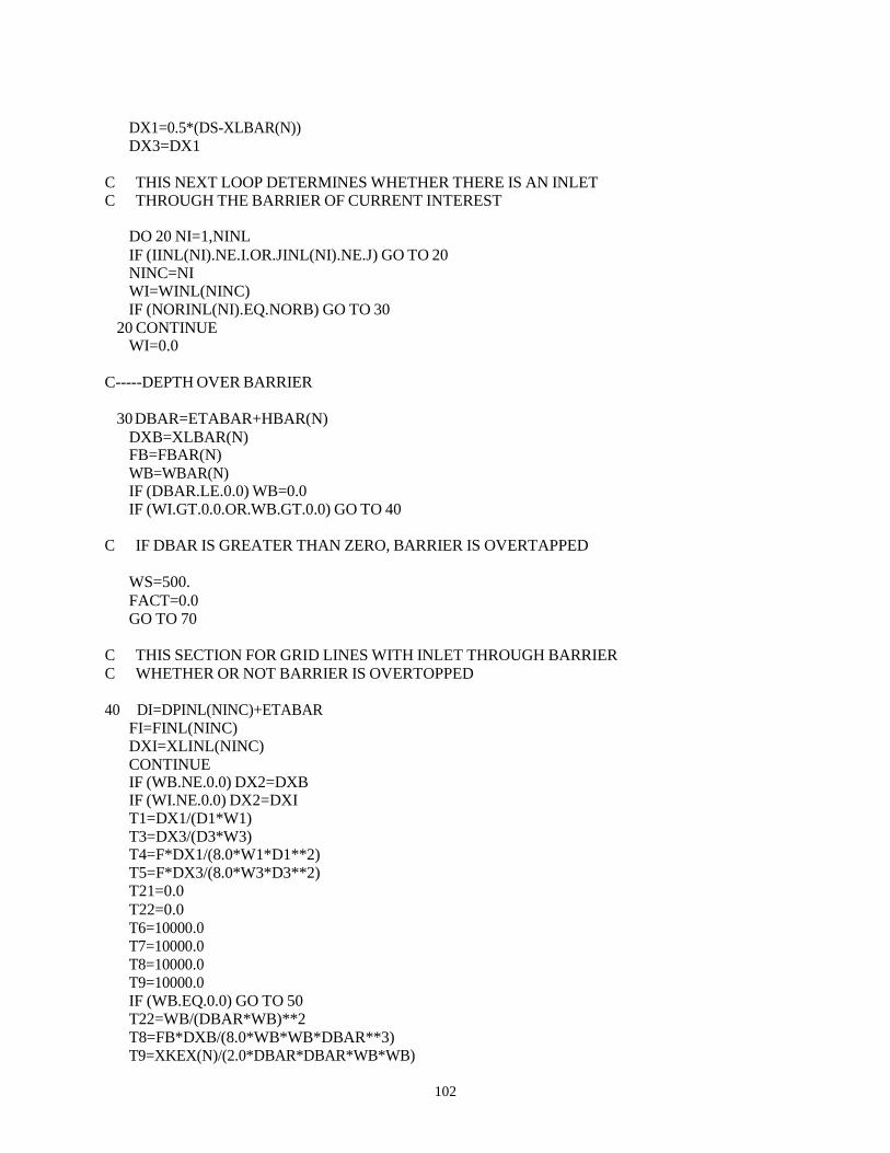
102
DX1=0.5*(DS-XLBAR(N)) DX3=DX1
C THIS NEXT LOOP DETERMINES WHETHER THERE IS AN INLET C THROUGH THE BARRIER OF CURRENT INTEREST
DO 20 NI=1,NINL IF (IINL(NI).NE.I.OR.JINL(NI).NE.J) GO TO 20 NINC=NI WI=WINL(NINC) IF (NORINL(NI).EQ.NORB) GO TO 30
20 CONTINUE WI=0.0
C-----DEPTH OVER BARRIER
30 DBAR=ETABAR+HBAR(N) DXB=XLBAR(N) FB=FBAR(N) WB=WBAR(N) IF (DBAR.LE.0.0) WB=0.0 IF (WI.GT.0.0.OR.WB.GT.0.0) GO TO 40
C IF DBAR IS GREATER THAN ZERO, BARRIER IS OVERTAPPED
WS=500. FACT=0.0 GO TO 70
C THIS SECTION FOR GRID LINES WITH INLET THROUGH BARRIER C WHETHER OR NOT BARRIER IS OVERTOPPED
40 DI=DPINL(NINC)+ETABAR
FI=FINL(NINC) DXI=XLINL(NINC) CONTINUE IF (WB.NE.0.0) DX2=DXB IF (WI.NE.0.0) DX2=DXI T1=DX1/(D1*W1) T3=DX3/(D3*W3) T4=F*DX1/(8.0*W1*D1**2) T5=F*DX3/(8.0*W3*D3**2) T21=0.0 T22=0.0 T6=10000.0 T7=10000.0 T8=10000.0 T9=10000.0 IF (WB.EQ.0.0) GO TO 50 T22=WB/(DBAR*WB)**2 T8=FB*DXB/(8.0*WB*WB*DBAR**3) T9=XKEX(N)/(2.0*DBAR*DBAR*WB*WB)

103
50 IF (WI.EQ.0.0) GO TO 60 IF (DI.GT.0.0) GO TO 55 GO TO 60
55 T21=WI/(DI*WI)**2 T6=FI*DXI/(8.0*DI**3*WI**2) T7=XKENEX(NINC)/(2.0*DI*DI*WI*WI)
60 ALPHAI=T6+T7 ALPHAB=T8+T9 IF (ALPHAI.LT.0.0) WRITE(8,65) ALPHAI,T6,T7 IF (ALPHAB.LT.0.0) WRITE(8,66) ALPHAB,T8,T9
65 FORMAT(' ALPHAI= ',F8.3,' T6= ',F8.3,' T7= ',F8.3,/) 66 FORMAT(' ALPHAB= ',F8.3,' T8= ',F8.3,' T9= ',F8.3,/)
SAI=SQRT(ALPHAI) SAB=SQRT(ALPHAB) T2=(T21*WI*DI+T22*WB*DBAR)*DX2/(WB+WI) XMU=T1/(D1*W1)+DX2/(WB+WI)*(T21+T22)+T3/(D3*W3)
C ----------- ADDED 3/15/1988 ---------------------------- IF (XMU.EQ.0.0) XMU = 0.0000001
C -------------------------------------------------------- FACT=2.0/(XMU*DL)*(T1+T2+T3)/(D1+D3) TEMP=ALPHAI*WI*DI/(1.0+SAI/SAB)**2+ALPHAB*WB*DBAR/(1.0+SAB/SAI)**2 WS=(DL/DS)*(T4+T5+TEMP)*ABS(QC) WS=WS*DT+1.0
70 CONTINUE IF(NORBAR(N).EQ.1) GO TO 80 FACTY=FACT WY=WS GO TO 90
80 FACTX=FACT WX=WS
90 CONTINUE 250 RETURN
END C-----------------------------------------------------------------------
SUBROUTINE DSWEEP(IDIR,NNI,A,B,C,D,AS,BS,CS,DS,ETAC,QC,JC,NET) PARAMETER(ISIZE=200,JSIZE=200)
COMMON /B/ ETA(ISIZE,JSIZE),QX(ISIZE,JSIZE),QY(ISIZE,JSIZE),
- TIDE,NQBX(JSIZE),DY,NNX,IEND COMMON /F/ JJ DIMENSION A(250), B(250), C(250), D(250), E(250), F(250) DIMENSION AS(250),BS(250),CS(250),DS(250),ES(250),FS(250) DIMENSION QC(250),ETAC(250) DIMENSION NET(ISIZE,JSIZE)
C IF IDIR=1, SWEEP IN X-DIRECTION C IF IDIR=2, SWEEP IN Y-DIRECTION
NNM1=NNI-1

104
IF (IDIR.EQ.2) GO TO 10
C CARRY OUT FIRST SWEEP TO CONDITION COEFFICIENTS
E(NNI)=0.0 F(NNI)=ETA(NNI,JC) ETAC(1)=ETA(1,JC) GO TO 20
10 CONTINUE E(NNI)=0.0 F(NNI)=ETA(JC,NNI) IF (NET(JC,NNI).EQ.0) F(NNI)=0.0 ETAC(1)=ETA(JC,NNI)
20 DO 30 I=2,NNM1 IC=NNM1+2-I ICP=IC+1 DEN=A(ICP)*E(ICP)+B(ICP) IF (DEN.EQ.0.0) DEN=1.0 ES(IC)=-C(ICP)/DEN FS(IC)=(D(ICP)-A(ICP)*F(ICP))/DEN DEN=AS(IC)*ES(IC)+BS(IC) IF (DEN.EQ.0.0) DEN=1.0 E(IC)=-CS(IC)/DEN F(IC)=(DS(IC)-AS(IC)*FS(IC))/DEN
30 CONTINUE
C CARRY OUT SECOND SWEEP TO ESTABLISH ETA AND Q
DO 40 I=2,NNI IM=I-1 QC(I)=ES(IM)*ETAC(IM)+FS(IM) ETAC(I)=E(I)*QC(I)+F(I)
40 CONTINUE
E(1)=ETAC(1) E(NNI)=ETAC(NNI)
110 RETURN END

105
APPENDIX B
1-D STORM TIDE MODEL*
*This program represents a numerical modeling procedure that is subject to change due to:1. newly encountered topo-bathymetric and hydraulic boundary conditions, and 2. incorporation of new advancements quantifying coastal processes. This program is applied on a county-by-county basis and is subject to acceptable calibration constraints recommend by the Beaches and Shores Resource Center and approved by Florida Department of Environmental Protection.

106
CCCCCCCCCCCCCCCCCCCCCCCCCCCCCCCCCCCCCCCCCCCCCCCCCCCCCCCCCCCC C C C ONE-DIMENSIONAL NUMERICAL STORM SURGE MODEL C C CCCCCCCCCCCCCCCCCCCCCCCCCCCCCCCCCCCCCCCCCCCCCCCCCCCCCCCCCCC
DIMENSION CTS(3,5,1200) DIMENSION H(250),X(250),ETA(250),QY(250),EMXMN(5,2),DXA(250)
CHARACTER*10 PROFIL CHARACTER*20 COUNTY,CASE
10 FORMAT(A20) 20 FORMAT(A10,I3,4F10.2) 30 FORMAT(8F9.2) 32 FORMAT(10F7.1) 40 FORMAT(11F7.2,3I3) 100 FORMAT(1H ) 110 FORMAT(1H1,'ONE-DIMENSIONAL NUMERICAL STORM SURGE MODEL') 120 FORMAT(1H ,A20,4X,A10,/1H ,40('-'),///) 130 FORMAT(1H ,'PROFILE DATA -- (DIST,DEPTH):',/) 135 FORMAT(5(1H ,5(F7.0,F7.2,2X),/)) 140 FORMAT(1H-,'INPUT PARAMETERS:',//1H ,
1 'PINF=',F8.2,T26,'P0=',F8.2,T51,'DP=',F8.2,/1H , 2 'ZLAT=',F8.2,T26,'RMAX=',F8.2,/1H , 3 'COR=',E12.4,T26,'VF=',F8.2,/1H , 4 'THETAC=',F8.2,T26,'THETAN=',F8.2,T51,'THETA=',F8.2,/1H , 5 'XSITE=',F8.2,T26,'XHC=',F8.2,T51,'XHB=',F8.2,/1H , 6 'YSITE=',F8.2,T26,'YHC=',F8.2,T51,'YHB=',F8.2,/1H , 7 'XOFF=',F8.0,T26,/1H , 8 'DT=',F8.2,T26,'TMAX=',F8.2,T51,'NTIMES=',I5,/1H , 9 'THETAL=',F8.2)
145 FORMAT(1H ,A20,4X,A10,20X,A20,/1H ,80('-'),///) 150 FORMAT(1H-,'TIME STEP ',I5,5X,'TIME=',F8.3,' HRS.',5X,'XH=',
1 F9.2,' N.MI.',5X,'YH=',F9.2,' N.MI.',//,1H , 2 'STORM SURGE, ETA(I) IN FEET ABOVE MSL -- (I,ETA):',//, 3 (1H ,6(I5,F9.3)))
160 FORMAT(1H ,20X,'CONDENSED TIME SERIES OF STORM SURGE ETAS',//1H ,
1 A20,4X,A10,20X,A20,///1H , 2 2(' TIME SURGE SETUP W/SETUP W/DYNMC '),/)
170 FORMAT(1H ,F5.2,4F8.3,6X,F5.2,4F8.3) 175 FORMAT(F5.2,4F8.3,6X,F5.2,4F8.3) 180 FORMAT(1H-,'MAXIMUM SURGES FOR ',A20,2X,A10,2X,A20,//1H
,5X,4F8.3)
OPEN (UNIT=5, FILE='b1dtest.lan', STATUS='old')
OPEN (UNIT=6, FILE='b1dtest.prt', STATUS='unknown') OPEN (UNIT=9, FILE='b1dtest.pun', STATUS='unknown')

107
OPEN (UNIT=10, FILE='b1dtest.out', STATUS='unknown')
RHOA=0.0024 RHOW=1.99 G=32.17 PI=3.1416 FRICT=0.0025 CNM=6076.1 CHR=3600. CHG=70.51 CDEG=180.0/PI OMEGA=2.0*PI/(24.0*CHR) BETA2=1.5
C READ(5,10) COUNTY READ(5,20) PROFIL,IMAX,XSITE,YSITE,THETAL,ANGVD READ(5,30) (DXA(I),I=1,IMAX READ(5,32) (H(I),I=1,IMAX) THETAL=THETAL/CDEG
C
C
C C C C C
WRITE(6,110) WRITE(7,110) WRITE(6,120) COUNTY,PROFIL WRITE(7,120) COUNTY,PROFIL WRITE(6,130) WRITE(7,130) WRITE(6,30) (DXA(I),I=1,IMAX) WRITE(7,30) (DXA(I),I=1,IMAX) WRITE(6,32) (H(I),I=1,IMAX) WRITE(7,32) (H(I),I=1,IMAX)
290
IMP1=IMAX+1 XOFF=XSITE*CNM X(1)=XOFF H(1)=H(1) + ANGVD DO 290 I=2,IMAX X(I)=X(I-1) + (DXA(I)+DXA(I-1))/2.0 H(I)=H(I) + ANGVD CONTINUE
C
WRITE(6,135) (X(I),H(I),I=1,IMAX) WRITE(7,135) (X(I),H(I),I=1,IMAX)
300
XSIT=XSITE*CNM YSIT=YSITE*CNM READ(5,10,END=999) CASE
READ(5,40) DT,THETAC,ZLAT READ(5,40) PINF,DP,RMAX,VF,THETAN,XHB,YHB,TMAX,TMIN
P0=PINF+DP C change the following angle to 90 for west, 270 for east
THETA=THETAN-THETAC+270. IF (THETA.GT.360.0) THETA=THETA-360.0

108
IF (THETA.LT.0.0) THETA=THETA+360.0 COR=2.0*OMEGA*SIN(ZLAT/CDEG) NTIMES=IFIX(TMAX*CHR/DT)+1 INTERV=IFIX(CHR/DT/2.0) INTER4=4*INTERV NSTORE=IFIX(180.0/DT) IF (NSTORE.EQ.0) NSTORE=1
WRITE(6,110)
C WRITE(7,110) WRITE(6,145) COUNTY,PROFIL,CASE
C WRITE(7,145) COUNTY,PROFIL,CASE WRITE(6,140) PINF,P0,DP,ZLAT,RMAX,COR,VF,THETAC,THETAN,THETA,
- XSITE,XHC,XHB,YSITE,YHC,YHB,XOFF,DT,TMAX,NTIMES,THETAL C WRITE(7,140) PINF,P0,DP,ZLAT,RMAX,COR,VF,THETAC,THETAN,THETA, C - XSITE,XHC,XHB,YSITE,YHC,YHB,XOFF,DT,TMAX,NTIMES,THETAL
PINF=PINF*CHG P0=P0*CHG DP=DP*CHG RMAX=RMAX*CNM VF=VF*CNM/CHR THETAC=THETAC/CDEG THETAN=THETAN/CDEG THETA=THETA/CDEG DEL=THETAL-THETAC CDEL=COS(DEL) SDEL=SIN(DEL) XHB=XHB*CNM YHB=YHB*CNM
DO 310 I=1,IMP1 QY(I)=0.0
310 CONTINUE
DO 320 I=1,5 EMXMN(I,1)=0.0 EMXMN(I,2)=0.0
320 CONTINUE
TIMSC=-DT IS=0
CALL HURCH(IS,X,XSIT,YSIT,XH,YH,PINF,DP,RMAX,VF,THETA,
- RHOW,RHOA,COR,USQ,P,TAUX,TAUY,CDEL,SDEL) USQM=USQ UMAX=SQRT(USQ)*CHR/CNM AA=-RMAX*DP/(CNM*CHG*100.0) AA2=0.160*VF/SQRT(UMAX) HMAX=16.5*EXP(AA)*(1.0+AA2) TMAX1=8.6*EXP(AA/2.0)*(1.0+AA2/2.0)

109
C---- **** MAIN TIME LOOP ****
DO 600 NTIME=1,NTIMES
WSU=0.0 TIMSC=TIMSC+DT XH=XHB+VF*TIMSC*COS(THETA) YH=YHB+VF*TIMSC*SIN(THETA) TIMHR=TIMSC/CHR XHN=XH/CNM YHN=YH/CNM ETASUM=0.0 SUMSTR=0.0 CSUM=0.0
DO 500 I=1,IMAX IS=IMAX-I+1 CALL HURCH(IS,X,XSIT,YSIT,XH,YH,PINF,DP,RMAX,VF,THETA,
- RHOW,RHOA,COR,USQ,P,TAUX,TAUY,CDEL,SDEL) ETAPR=1.0/(RHOW*G)*(PINF-P) DX=X(IS+1)-X(IS) TDPTH=H(IS)+ETASUM IF (I.EQ.1) TDPTH=H(IS) IF (TDPTH.GT.0.0) GO TO 400 GO TO 450
C---- TAUN = TAU-NORMAL, TAUP = TAU-PARALLEL 400 TAUN=TAUX*CDEL + TAUY*SDEL
TAUP=-TAUX*SDEL + TAUY*CDEL SUMSTR=SUMSTR+TAUN*DX/(RHOW*G*TDPTH) ETA(IS)=ETAPR-SUMSTR ETASUM=ETA(IS) TDPTH=H(IS)+ETASUM BB=1.0+DT*FRICT*ABS(QY(IS))/(TDPTH*TDPTH) QY(IS)=(QY(IS)+DT/RHOW*TAUP)/BB CCTIDE=DX*COR*QY(IS)/(G*TDPTH) CSUM=CSUM+CCTIDE ETA(IS)=ETA(IS)+CCTIDE ETASUM=ETA(IS) IF (IS.NE.1) GO TO 500
450 H0=HMAX*ABS(USQ)/USQM IF (USQ.GT.0.0) H0=1.0 T0=2.13*SQRT(H0) HB=0.936*H0
WSU=0.19*(1.0-2.82*SQRT(HB/(G*T0*T0)))*HB
C WRITE(6,6019)TIMHR,IS,H0,USQM,TO,HB,USQ,HMAX,G,WSU,ETASUM,ETA(IS) 6019 FORMAT(' TIME=',F9.3,' IS=',I9, ' H0=',F9.3,/,
- ' USQM=',F9.3,' T0=',F9.3,' HB=',F9.3,/, - ' USQ=',F9.3,' HMAX=',F9.3,' G=',F9.3,/, - ' WSU=',F9.3,' ETASUM=',F9.3,' ETA(IS)=',F9.3,/)

110
ETASUM=ETASUM+BETA2*WSU IF ((ETA(IS)+H(IS)).GT.0.0) GO TO 500 ETA(1)=0.0 GO TO 510
500 CONTINUE
510 CONTINUE
NTM=(NTIME-1)/NSTORE+1 CTS(1,1,NTM)=TIMHR CTS(1,2,NTM)=ETA(1) CTS(1,3,NTM)=WSU CTS(1,4,NTM)=ETA(1)+WSU CTS(1,5,NTM)=ETA(1)+1.5*WSU
DO 520 I=2,5 IF (CTS(1,I,NTM).GT.EMXMN(I,1)) EMXMN(I,1)=CTS(1,I,NTM) IF (CTS(1,I,NTM).LT.EMXMN(I,2)) EMXMN(I,2)=CTS(1,I,NTM)
520 CONTINUE
IF (MOD(NTIME,INTERV).NE.1) GO TO 600 IF (MOD(NTIME,INTER4).EQ.1) WRITE(6,110)
C
IF (MOD(NTIME,INTER4).EQ.1) WRITE(6,145) COUNTY,PROFIL,CASE WRITE(6,150) NTIME,TIMHR,XHN,YHN,(I,ETA(I),I=1,IMAX)
C 151
WRITE(6,151) (CTS(1,K,NTM),K=2,5) FORMAT(1H0,'ETA:',F8.3,4X,'WSU:',F8.3,4X,'ETA+WSU:',F8.3,4X,
- 'ETA+1.5*WSU:',F8.3)
600 CONTINUE
C --- **** END OF MAIN TIME LOOP ****
605
DO 605 I=1,5 CTS(1,I,NTM+1)=0.0
152
WRITE(9,152)NTM FORMAT(I5)
DO 610 I=1,NTM,2 IF (MOD(I,100).EQ.1) WRITE(6,110) IF (MOD(I,100).EQ.1) WRITE(6,160) COUNTY,PROFIL,CASE IF (MOD(I,10).EQ.1) WRITE(6,100) IP1=I+1
C WRITE(6,170) ((CTS(1,J,K),J=1,5),K=I,IP1) WRITE(9,175) ((CTS(1,J,K),J=1,5),K=I,IP1)
610 CONTINUE C WRITE(11,11) ((CTS(1,J,K),J=1,5,4),K=1,NTM,3) C 11 FORMAT(2F10.1)
WRITE(6,180) COUNTY,PROFIL,CASE,(EMXMN(I,1),I=2,5)

111
C WRITE(7,180) COUNTY,PROFIL,CASE,(EMXMN(I,1),I=2,5) WRITE(10,180) COUNTY,PROFIL,CASE,(EMXMN(I,1),I=2,5)
999
GO TO 300 CONTINUE
STOP END
SUBROUTINE HURCH(IS,X,XSITE,YSITE,XH,YH,PINF,DP,RMAX,VF,THETA, - RHOW,RHOA,COR,USQ,P,TAUX,TAUY,CDEL,SDEL) DIMENSION
X(1)
C---- BEWARE-SOME SIGNS HAVE BEEN MODIFIED TO ACCOUNT FOR LEFT-HANDED C---- COORDINATES
UCR=23.6 IF (IS.NE.0) GO TO 4 XP=-RMAX*SIN(THETA) YP=RMAX*COS(THETA) GO TO 6
4 XIS=0.5*(X(IS+1)+X(IS)) XP=XIS-XH YP=YSITE-YH
6 R=SQRT(XP**2+YP**2) IF(R.LT.2200.0) R=2200.0 RAT=RMAX/R EXPO=EXP(-RAT) USG=-DP/(RHOA*R)*RAT*EXPO/COR UC=SQRT(-DP/RHOA*RAT*EXPO) ALPHA=ATAN2(YP,XP) BETA=THETA-ALPHA VPRIME=VF*SIN(BETA) GAMMA=0.5*(VPRIME/UC+UC/USG) RATIO=SQRT(GAMMA**2+1.0)-GAMMA IF(RATIO.LT.1.0E-05) RATIO=1.0E-05 U=UC*RATIO*0.9 USQ=U**2 UXX=-USQ*SIN(-ALPHA+0.31) UYY=-USQ*COS(-ALPHA+0.31) P=PINF+DP*(1.0-EXPO) WSC=1.0E-06 IF(U.LT.UCR) GO TO 20 WSC=WSC+2.5E-06*(1.0-UCR/U)**2
20 CONTINUE AA=1.0 TAUX=AA*RHOW*WSC*UXX TAUY=AA*RHOW*WSC*UYY IF (IS.NE.0) USQ=UXX*CDEL + UYY*SDEL IJK=0 IF (IJK.EQ.0) GO TO 79

112
C WRITE(6,40)I,J,XH,YH,XP,YP,R,RMAX,RAT,P,DPDX,DPDY C WRITE(6,50) I,J,EXPO,COR,RHOA,USG,DP,PINF,ALPHA,BETA,VPRIME C WRITE(6,60) I,J,UH,GAMMA,RATIO,USQ,U,UXX,UYY C WRITE(6,70) I,J,WSC,TAUX,TAUY,THETA
40 FORMAT(1H0,'I=',I3,' J=',I3,' XH=',E12.4,' YH=',E12.4,' XP=',E12.4
1 ,' YP=',E12.4,' R=',E12.4,' RMAX=',E12.4, 2 /1H , ' RAT=',E12.4,'
P(I,J)=',E12.4, 3 ' DPDX(I,J)=',E12.4, ' DPDY(I,J)=',E12.4)
50 FORMAT(1H0,'I=',I3,' J=',I3,' EXPO=',E12.4,' COR=',E12.4, 1 ' RHOA=',E12.4,' USG=',E12.4,' DP=',E12.4,' PINF=',E12.4, 2 /1H , 3 E12.4,' BETA=',E12.4,' VPRIME=',E12.4)
60 FORMAT(1H0,'I=',I3,' J=',I3,' UH=',E12.4,' GAMMA=',E12.4, 1 ' RATIO=',E12.4,'USQ=',E12.4,' U=',E12.4,' UXX=',E12.4, 2 ' UYY=',E12.4)
70 FORMAT(1H0,'I=',I3,' J=',I3, 1 ' WSC=',E12.4, ' TAUX= ',E12.4,' TAUY=
',E12.4, 2 ' THETA=',E12.4)
79 RETURN END

113
APPENDIX C
BEACH-DUNE EROSION MODEL*
*This program represents a numerical modeling procedure that is subject to change due to: 1. newly encountered topo-bathymetric and hydraulic boundary conditions, and 2. incorporation of new advancements quantifying coastal processes. This program is applied on a county-by-county basis and is subject to acceptable calibration constraints recommend by the Beaches and Shores Resource Center and approved by Florida Department of Environmental Protection.
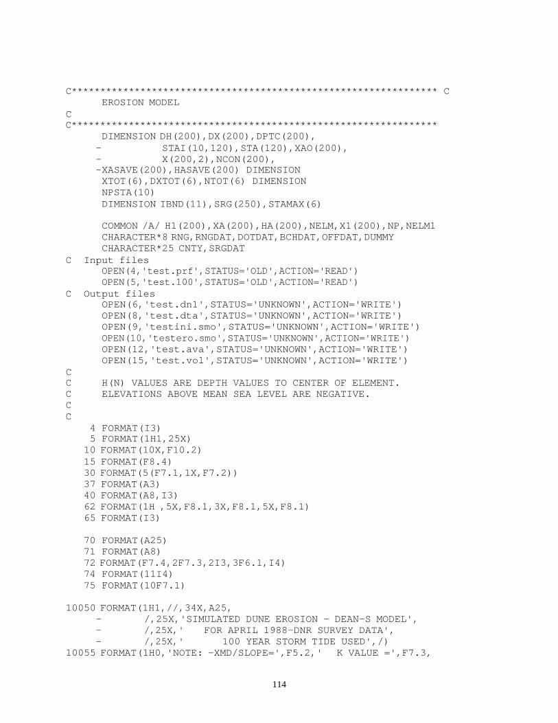
114
C**************************************************************** C EROSION MODEL C C****************************************************************
DIMENSION DH(200),DX(200),DPTC(200), - STAI(10,120),STA(120),XAO(200), - X(200,2),NCON(200), - XASAVE(200),HASAVE(200) DIMENSION XTOT(6),DXTOT(6),NTOT(6) DIMENSION NPSTA(10) DIMENSION IBND(11),SRG(250),STAMAX(6)
COMMON /A/ H1(200),XA(200),HA(200),NELM,X1(200),NP,NELM1 CHARACTER*8 RNG,RNGDAT,DOTDAT,BCHDAT,OFFDAT,DUMMY CHARACTER*25 CNTY,SRGDAT
C Input files OPEN(4,'test.prf',STATUS='OLD',ACTION='READ') OPEN(5,'test.100',STATUS='OLD',ACTION='READ')
C Output files OPEN(6,'test.dn1',STATUS='UNKNOWN',ACTION='WRITE') OPEN(8,'test.dta',STATUS='UNKNOWN',ACTION='WRITE') OPEN(9,'testini.smo',STATUS='UNKNOWN',ACTION='WRITE') OPEN(10,'testero.smo',STATUS='UNKNOWN',ACTION='WRITE') OPEN(12,'test.ava',STATUS='UNKNOWN',ACTION='WRITE') OPEN(15,'test.vol',STATUS='UNKNOWN',ACTION='WRITE')
C C H(N) VALUES ARE DEPTH VALUES TO CENTER OF ELEMENT. C ELEVATIONS ABOVE MEAN SEA LEVEL ARE NEGATIVE. C C
4 FORMAT(I3) 5 FORMAT(1H1,25X) 10 FORMAT(10X,F10.2) 15 FORMAT(F8.4) 30 FORMAT(5(F7.1,1X,F7.2)) 37 FORMAT(A3) 40 FORMAT(A8,I3) 62 FORMAT(1H ,5X,F8.1,3X,F8.1,5X,F8.1) 65 FORMAT(I3)
70 FORMAT(A25) 71 FORMAT(A8) 72 FORMAT(F7.4,2F7.3,2I3,3F6.1,I4) 74 FORMAT(11I4) 75 FORMAT(10F7.1)
10050 FORMAT(1H1,//,34X,A25,
- /,25X,'SIMULATED DUNE EROSION - DEAN-S MODEL', - /,25X,' FOR APRIL 1988-DNR SURVEY DATA', - /,25X,' 100 YEAR STORM TIDE USED',/)
10055 FORMAT(1H0,'NOTE: -XMD/SLOPE=',F5.2,' K VALUE =',F7.3,

115
- ' A VALUE = VARIABLE',/, - 1H ,' -ALL PROFILES CONTAIN OFFSHORE DATA.',/, - 1H ,' -ALL VOLUME CHANGES ARE CALCULATED FROM
THE',/, - 1H ,' HIGHEST CONTOUR DOWN TO THE MSL CONTOUR.')
10056 FORMAT(1H0,'NOTE: -XMD/SLOPE=',F5.2,' K VALUE =',F7.3, - ' A VALUE = ',F6.4,/, - 1H ,' -ALL PROFILES CONTAIN OFFSHORE DATA.',/, - 1H ,' -ALL VOLUME CHANGES ARE CALCULATED FROM
THE',/, - 1H ,' HIGHEST CONTOUR DOWN TO THE MSL CONTOUR.')
10060 FORMAT(1H ,' -EROSION INCREASED BY FACTOR OF 2.5',/) 10065 FORMAT(1H ,' -THIS IS THE ORIGINAL EROSION - NO ADDITIONS',/,
- 1H ,' (IE, 2.5 FACTORS) HAVE BEEN MADE.',/) C
VOLTOT=0.0 PROF=0.0 DO 98 I=1,6 NTOT(I)=0 XTOT(I)=0.0
98 DXTOT(I)=0.0 C C-----READ COEFFICIENTS AND STORM SURGE HYDROGRAPHS C
READ(5,70) CNTY READ(5,70) SRGDAT READ(5,72) A,XK,XMD,IFCT25,ICALA,HB,PERIOD,DY,NPROFS
READ(5,65) NHYDRO C WRITE(6,82)A,XK,XMD,HB,PERIOD,DY,NPROFS,NHYDRO,IFCT25,ICALA
82 FORMAT(1H ,' A= ',F7.3,' XK= ',F7.3,' XMD= ',F7.2,/ - ,' HB= ',F7.2,' PERIOD= ',F7.2,' DY= ',F7.2,/ - ,' NPROFS= ',I7,' NHYDRO= ',I7,' IFCT25= ',I7,/ - ,' ICALA= ',I7,/)
C-----IBND VALUES INDICATE PROFILES WHICH USE EACH HYDROGRAPH.
NBND=NHYDRO+1 READ(5,74) (IBND(I),I=1,NBND)
C WRITE(6,74) (IBND(I),I=1,NBND) C-----SRG IS THE SURGE LEVEL LOCATED AT EACH RANGE. C-----SRGFCT(1) = ETAMAX(PROFILE 1) / STAMAX(HYDRO 1)
READ(5,75) (SRG(I),I=1,NPROFS) C WRITE(6,75) (SRG(I),I=1,NPROFS)
DO 100 J = 1,NHYDRO READ(5,4)NPSTA(J)
C WRITE(6,4)NPSTA(J) NP=NPSTA(J) STAMAX(J)=0.0

116
DO 100 K = 1,NP READ(5,10) STAI(J,K) IF (STAI(J,K).GT.STAMAX(J)) STAMAX(J)=STAI(J,K)
C WRITE(6,10)STAI(J,K) 100 CONTINUE
C C READ H,X VALUES
WRITE(8,201) 201 FORMAT('INITIAL SURVEY DATA')
WRITE(9,202) 202 FORMAT('INITIAL SMOOTHED DATA')
WRITE(10,203) 203 FORMAT('ERODED-SMOOTHED DATA')
WRITE(6,10050)CNTY IF (ICALA.EQ.1) WRITE(6,10055)XMD,XK IF (ICALA.EQ.0) WRITE(6,10056)XMD,XK,A IF (IFCT25.EQ.1) WRITE(6,10060) IF (IFCT25.EQ.0) WRITE(6,10065)
C C
READ(4,37)DUMMY 175 READ(4,20,END=9999)RNG,RNGDAT,ICODE,YNORTH,XEAST,AZMUTH
READ(4,25)DOTDAT,BCHDAT,OFFDAT,NP,NPDOT,NPBCH,NPOFF 20 FORMAT(A8,A8,I2,2F12.3,F7.2) 25 FORMAT(A8,A8,A8,4I3,/)
C C-----INPUT CONTOUR INFO. OBTAINED BY LOOKING OVER EACH PROFILE. C C READ(1,22000)CRNG,CVAL 22000 FORMAT(A8,F10.0) C--------------------------------------------------------------------- -
IF (AMOD(PROF,5.0).NE.4.OR.PROF.EQ.0.0) GO TO 1750 WRITE(6,5)
1750 PROF=PROF+1.0 DO 176 I=1,200 X(I,1)=0.0 X(I,2)=0.0 X1(I)=0.0 H1(I)=0.0 NCON(I)=0 XA(I)=0.0
176 HA(I)=0.0
READ(4,30)(X1(I),H1(I),I=1,NP) NPOFF=0 NPDOT=0 NPBCH=NP
DO 1760 I=1,NP IF (H1(I).LT.-20.0) GO TO 1762

117
1760 CONTINUE 1762 NSTOP=I-1
C FILE 8 CONTAINS INITIAL SURVEY DATA.
WRITE(8,20)RNG,RNGDAT,ICODE,YNORTH,XEAST,AZMUTH WRITE(8,25)DOTDAT,BCHDAT,OFFDAT,NSTOP,NPDOT,NSTOP,NPOFF WRITE(8,30)(X1(I),H1(I),I=1,NSTOP)
IDUNEM = 1 DO 177 I = 1,NP IF (H1(I) .GT. H1(IDUNEM)) IDUNEM = I
177 CONTINUE MIN1=1 DO 178 I = 1,IDUNEM IF (H1(I) .LT. H1(MIN1)) MIN1 = I
178 CONTINUE MIN2=1 DO 1781 I = IDUNEM,NP IF (H1(I) .LT. H1(MIN2)) MIN2 = I
1781 CONTINUE IMAX=IFIX(H1(IDUNEM)+0.2) IMIN1=IFIX(H1(MIN1)) IMIN2=IFIX(H1(MIN2)) NELM1=IMAX-IMIN1+1 NELM2=IMAX-IMIN2+1 NELM=NELM1+NELM2 NL=NELM II=1 DO 179 I=IMIN1,IMAX HA(II)=I II = II + 1
179 CONTINUE DO 1791 I=IMAX,IMIN2,-1 HA(II)=I II = II + 1
1791 CONTINUE DO 2 I=1,NELM NCON(I)=1
2 XA(I)=0.0 CALL SMOOTH(IDUNEM,1,2) CALL SMOOTH(IDUNEM,NP,1)
NELM1M = NELM1 - 1 N2=NELM1+1
DO 17800 M=1,NELM1M XASAVE(M) = -XA(M) + X1(IDUNEM) HASAVE(M)=-HA(M)
17800 CONTINUE XASAVE(NELM1) = X1(IDUNEM) HASAVE(NELM1) = -HA(NELM1) DO 17820 M=N2,NELM

118
XASAVE(M) = XA(M) + X1(IDUNEM) HASAVE(M)=-HA(M)
17820 CONTINUE C-----FILE 9 CONTAINS INITIAL SMOOTHED CURVE.
NPDOT = 0 NPBCH = NL NPOFF = 0
DO 17810 I=1,NL IF (HASAVE(I).GT.20.0) GO TO 17812
17810 CONTINUE 17812 NSTOP=I-1
WRITE(9,20)RNG,RNGDAT,ICODE,YNORTH,XEAST,AZMUTH WRITE(9,25)DOTDAT,BCHDAT,OFFDAT,NSTOP,NPDOT,NSTOP,NPOFF WRITE(9,30)(XASAVE(I),HASAVE(I),I=1,NSTOP)
DO 1780 M=1,NELM1 I=NELM1-M+1 NCON(I)=2 XA(I) = -XA(I) + X1(IDUNEM) X(M,1)=XA(I)
1780 CONTINUE DO 1782 M=N2,NELM I=M-NELM1 XA(M) = XA(M) + X1(IDUNEM) X(I,2)=XA(M) HA(I)=-HA(M) NLS=I
1782 CONTINUE C-----INITIALIZE 'ACTIVE' PROFILE
NL=NLS X(NELM1,1)=-1000.0 DO 1783 I=1,NL
1783 XA(I)=X(I,2) IF (ICALA.EQ.1) CALL CALCA(A,NL) NPDOT = 0 NPBCH = NL NPOFF = 0
C C-----CONVERT CHARACTER RANGE TO INTEGER RANGE C
IRNG=0 DO 505 I=1,3 J=I+2 K=ICHAR(RNG(J:J)) IF (K.LT.48) GO TO 507 IRNG=IRNG*10+(K-48)
505 CONTINUE C-----CHOOSE STORM SURGE HYDROGRAPH ACCORDING TO PROFILE

119
C
507 508
DO 508 I=1,NHYDRO IF (IRNG.GE.IBND(I).AND.IRNG.LT.IBND(I+1)) GO TO 509 CONTINUE
509 IHYDRO=I
184
NTIMES=NPSTA(IHYDRO) SMULT=SRG(IRNG)/STAMAX(IHYDRO) WRITE(6,184)RNG,IRNG,SMULT,STAMAX(IHYDRO),IHYDRO,SRG(IRNG) FORMAT(' RNG,IRNG,SMULT,STAM,IHYDRO,SRG= ',A8,I5,2F7.3,I4,F7.3)
185
SSURGE=0.0 DO 185 I = 1,NTIMES STA(I) = STAI(IHYDRO,I) * SMULT IF (STA(I).GT.SSURGE) SSURGE=STA(I) CONTINUE
C 1885
WRITE(6,1885)(I,STA(I),I=1,NTIMES) FORMAT(5(I5,F8.4))
C-----CALCULATE HSTAR TO NEAREST FOOT
DO 200 I = 1,NL XAO(I) = XA(I)
200 CONTINUE HS = (0.667 * A**1.5 / XMD)**2 DXS = (HS / A)**1.5 HSTAR = HS
C C K LOOP - FOR CALIBRATING APPROPRIATE EROSION RATE CONSTANT C
DO 300 I = 1,NL XA(I) = XAO(I)
300 CONTINUE XR = 0.0 DH(1) = 1.0
C C ESTABLISH INSTANTANEOUS WATER LEVEL, ST C
DT = PERIOD DO 400 I = 2,NL DH(I) = (HA(I) - HA(I-1) - DH(I-1)/2.0)*2.0
400 CONTINUE C C NTIMES LOOP - LOOP FOR EACH SURGE VALUE C
ZZ=1.0-EXP(-XK*DT) NPA=1 DO 1600 NTIME = 1,NTIMES ST = STA(NTIME) DO 499 I = 1,NL DPTC(I) = HA(I) + ST
499 CONTINUE

120
DPTB = HB/0.8 XB = (DPTB / A) ** 1.5
C C ESTABLISH THE INDICES OF STILL WATER LEVEL AND HSTAR C
IE = 1 AA = 100.0 DO 600 I = 1,NL BB = ABS(DPTC(I) - DPTB) IF (BB .GT. AA) GO TO 550 AA = BB IE = I
550 IF (ABS(DPTC(I)) .LE. DH(I)/2) IWL = I IF (ABS(HSTAR - DPTC(I)) .LE. DH(I)/2) ISTAR = I
600 CONTINUE IB=NPA DO 1200 IIT = 1,10 SUM1 = 0.0 SUM2 = 0.0 SUM3 = 0.0 SUM4 = 0.0 DO 700 I = IB,ISTAR SUM1 = SUM1 + (HA(I) + ST - HSTAR) * DH(I) / XMD + DXS * DH(I) SUM4 = SUM4 + DH(I) SUM3 = SUM3 + XA(I) * DH(I)
700 CONTINUE ISP = ISTAR + 1 DO 800 I = ISP, IE SUM4 = SUM4 + DH(I) SUM2 = SUM2 + (DPTC(I)/A)**1.5 * DH(I) SUM3 = SUM3 + XA(I) * DH(I)
800 CONTINUE IEP = IE + 1 DO 850 I = IEP,NL IFILL = I-1 IF (XR + XB .LT. XA(I)) GO TO 1000 SUM3 = SUM3 + XA(I) * DH(I) SUM4 = SUM4 + DH(I) SUM2 = SUM2 + XB * DH(I) IFILL = I
850 CONTINUE 1000 CONTINUE
XRO = XR XR = 1.0/SUM4 * (SUM3 - SUM2 - SUM1)
C BB = (XR - XA(IB)) * XMD - ST - HA(IB) + HSTAR C WRITE(6,940) NTIME,IIT,BB,XR,IB,IFILL 940 FORMAT(' NTIME,IIT,BB,XR,IB,IFILL',2I5,2F8.3,2I5) C+++++++++++++++++++++++++++++++++++++++++++++++++++++++++++++++++++++ ++ C C ESTABLISH NEW VALUE OF IB C

121
IBO = IB BSTAR=XR+DXS-XA(ISTAR)+(DPTC(ISTAR)-HSTAR)/XMD BSTAR=BSTAR*ZZ XSTAR=XA(ISTAR)+BSTAR IB=NPA
C WRITE(6,1106) 1106 FORMAT(' NTIME,IIT,I,IB,BB,XSTAR,BSTAR,XA(ISTAR),DPTC(I),
-HSTAR,XA(I),ZZ ') IB=NPA DO 1100 I = NPA,IE BB=XSTAR+(DPTC(I)-HSTAR)/XMD-XA(I) IF (BB.LT.0.0) GO TO 1110 IB=I+1
C WRITE(6,1105)NTIME,IIT,I,IB,BB,XSTAR,BSTAR, C - XA(ISTAR),DPTC(I),HSTAR,XA(I),ZZ 1105 FORMAT(4I4,8F7.2) 1100 CONTINUE 1110 CONTINUE
IF (IB.LT.1)IB=1 IF ((IB .EQ. IBO) .AND. (ABS(XRO - XR) .LE. .01)) GO TO 1300
C+++++++++++++++++++++++++++++++++++++++++++++++++++++++++++++++++++++ ++ 1200 CONTINUE 1300 CONTINUE
C WRITE(6,1302) 1302 FORMAT(//) C C CALCULATE DX VALUES C
DO 1400 I = IB,IFILL IF (I .GT. ISTAR .AND. I .LE. IE) GO TO 1304 IF (I .GT. IE) GO TO 1350 DX(I) = XA(I) - (XR + DXS + (HA(I) + ST-HSTAR) / XMD) GO TO 1400
1304 DX(I) = XA(I) - (XR + ((HA(I) + ST)/A)**1.5) GO TO 1400
1350 DX(I) = XA(I) - (XR + XB) 1400 CONTINUE
VOLCHG = 0.0 BA = (1.0 - EXP(-XK*DT)) DO 1500 I = IB,IFILL BB = -DX(I) * BA VOLCHG = VOLCHG + BB * DH(I) XA(I) = XA(I) + BB IF (NCON(NPA).EQ.2.AND.XA(NPA).LT.X(NPA,1)) NPA=NPA+1
1500 CONTINUE C IF (MOD(NTIME,5).NE.0.AND.NTIME.NE.1) GO TO 1510 C WRITE(6,1505)NTIME,NPA,IB,IWL,ISTAR,IE,ST, C - (I,HA(I),XA(I),NCON(I), C - X(I,1),X(I,2),I=1,NP) 1505 FORMAT(1H0,'NTIME NPA IB IWL ISTAR IE ST',/,1H ,
- 2I5,I5,I5,I7,I4,F5.2,/,1H ,

122
-' HA(I) XA(I) NCON(I) X(I,1) X1(I,2)',/, - (I5,F5.1,F8.1,I8,F10.2,F10.2))
1600 CONTINUE C C *** END OF TIME LOOP *** C C
DO 1700 I = 1,NL DX(I) = XA(I) - XAO(I)
1700 CONTINUE
IF (IFCT25.EQ.0) GO TO 1328
NPA2=NPA IE=0 DO 1322 I=NPA,NL IE=I IF (DX(I).GT.0.0) GO TO 1323 XA(I)=XA(I)+1.5*DX(I) DXT=DX(I)*2.5 NB=I IF (I.GT.NELM1) GO TO 1322 IF (XA(I).GT.X(I,1)) GO TO 1322 XA(I)=X(I,1)
C DXT=X(I,2)-X(I,1) DXT=X(I,1)-X(I,2) NPA2=I
1322 DX(I)=DXT 1323 CONTINUE
C WRITE(6,13222)(I,DX(I),XA(I),HA(I),I=NPA,NL) 13222 FORMAT(I4,3F10.2,/) C WRITE(6,13231)(I,XA(I),HA(I),DX(I),I=1,IE) 13231 FORMAT(3(I5,3F7.2))
NPA=NPA2 C WRITE(6,13230)NPA,IE,NB,XA(NPA),XA(IE),XA(I),HA(I) 13230 FORMAT(' NPA= ',I3,' IE= ',I3,' NB= ',I3,4F7.2)
IO=0 XMIN=10000.0 DO 1324 I=NPA,NB IF (XA(I).GT.XMIN) GO TO 1324 IF (DX(I).EQ.0.0) GO TO 1324 XMIN=XA(I) IO=I
1324 CONTINUE C WRITE(6,13240)IO,XA(IO) 13240 FORMAT(' IO= ',I5,F7.2)
SUM=0.0 IF (IO.EQ.0) GO TO 1327 IBEG=0 DO 1325 I=1,IO XT=XA(IO) - (HA(IO)-HA(I))/XMD IF (XT.GT.XA(I)) GO TO 1325
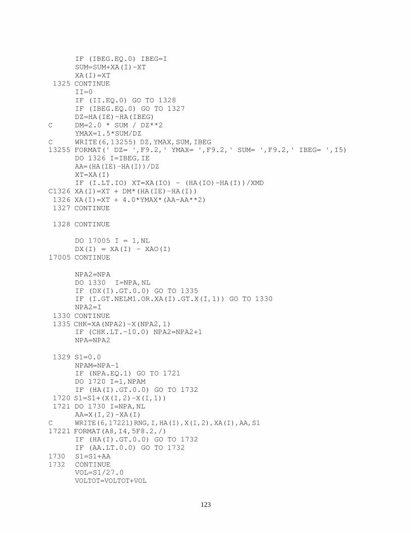
123
IF (IBEG.EQ.0) IBEG=I SUM=SUM+XA(I)-XT XA(I)=XT
1325 CONTINUE II=0 IF (II.EQ.0) GO TO 1328 IF (IBEG.EQ.0) GO TO 1327 DZ=HA(IE)-HA(IBEG)
C DM=2.0 * SUM / DZ**2 YMAX=1.5*SUM/DZ
C WRITE(6,13255) DZ,YMAX,SUM,IBEG 13255 FORMAT(' DZ= ',F9.2,' YMAX= ',F9.2,' SUM= ',F9.2,' IBEG= ',I5)
DO 1326 I=IBEG,IE AA=(HA(IE)-HA(I))/DZ XT=XA(I) IF (I.LT.IO) XT=XA(IO) - (HA(IO)-HA(I))/XMD
C1326 XA(I)=XT + DM*(HA(IE)-HA(I)) 1326 XA(I)=XT + 4.0*YMAX*(AA-AA**2) 1327 CONTINUE
1328 CONTINUE
DO 17005 I = 1,NL DX(I) = XA(I) - XAO(I)
17005 CONTINUE
NPA2=NPA DO 1330 I=NPA,NL IF (DX(I).GT.0.0) GO TO 1335 IF (I.GT.NELM1.OR.XA(I).GT.X(I,1)) GO TO 1330 NPA2=I
1330 CONTINUE 1335 CHK=XA(NPA2)-X(NPA2,1)
IF (CHK.LT.-10.0) NPA2=NPA2+1 NPA=NPA2
1329 S1=0.0
NPAM=NPA-1 IF (NPA.EQ.1) GO TO 1721 DO 1720 I=1,NPAM IF (HA(I).GT.0.0) GO TO 1732
1720 S1=S1+(X(I,2)-X(I,1)) 1721 DO 1730 I=NPA,NL
AA=X(I,2)-XA(I) C WRITE(6,17221)RNG,I,HA(I),X(I,2),XA(I),AA,S1 17221 FORMAT(A8,I4,5F8.2,/)
IF (HA(I).GT.0.0) GO TO 1732 IF (AA.LT.0.0) GO TO 1732
1730 S1=S1+AA 1732 CONTINUE
VOL=S1/27.0 VOLTOT=VOLTOT+VOL

124
C-----WRITE INFO FOR REDUCE/INCREASE EROSION.
C CVAL=HA(NPA) 1699 DO 1701 I=1,NL IF (HA(I).EQ.CVAL) GO TO 1702 C IF (DX(I).NE.0.0) GO TO 1702 C CVAL=CVAL+2.0 C GO TO 1699 1701 CONTINUE 1702 NRNG=I C WRITE(6,1784)RNG,IRNG,NRNG,CVAL,HA(NRNG),DX(NRNG) 1784 FORMAT(' RNG,IRNG,NRNG,CVAL,HA,DX= ',A8,2I5,F7.2,2F7.2)
WRITE(15,11010)RNG,HA(NRNG),DX(NRNG),XA(NRNG),VOL
11010 FORMAT(A8,4F10.2)
C-----***************************************************************
WRITE(12,1717) RNG,A 1717 FORMAT(5X,A8,F10.4)
C-----***************************************************************
WRITE(6,11001)RNG,SSURGE,IMAX 11001 FORMAT(//,1X,A8,'WTL= ',F4.1,
- ', DUNE ELEV.= ',I2,', LOC. RELATIVE TO MONU.(FT.) DISTANCE
-ERODED (FT.)',/)
IPRT=0
DO 1550 IJK = NPA,NL C-----WRITE INFO FOR FIRST POINT IN ERODED PROFILE.
IPRT=IPRT+1 IF (IPRT.GT.2) GO TO 1531 H=AMOD(HA(IJK),5.0) IF (H.EQ.0) GO TO 1531 WRITE(6,11000)HA(IJK),XA(IJK),DX(IJK)
1531 IF (HA(IJK) .NE. -25.0) GO TO 1532 XTOT(6)=XTOT(6)+XA(IJK) DXTOT(6)=DXTOT(6)+DX(IJK) NTOT(6)=NTOT(6)+1 WRITE(6,11000) HA(IJK),XA(IJK),DX(IJK)
11000 FORMAT(1H ,15X,F5.1,' FT. CONTOUR: ',10X,F9.1,17X,F9.1) 1532 IF (HA(IJK) .NE. -20.0) GO TO 1534
XTOT(5)=XTOT(5)+XA(IJK) DXTOT(5)=DXTOT(5)+DX(IJK) NTOT(5)=NTOT(5)+1 WRITE(6,11000) HA(IJK),XA(IJK),DX(IJK)

125
1534 IF (HA(IJK) .NE. -15.0) GO TO 1536 XTOT(4)=XTOT(4)+XA(IJK) DXTOT(4)=DXTOT(4)+DX(IJK) NTOT(4)=NTOT(4)+1 WRITE(6,11000) HA(IJK),XA(IJK),DX(IJK)
1536 IF (HA(IJK) .NE. -10.0) GO TO 1538 XTOT(3)=XTOT(3)+XA(IJK) DXTOT(3)=DXTOT(3)+DX(IJK) NTOT(3)=NTOT(3)+1 WRITE(6,11000) HA(IJK),XA(IJK),DX(IJK)
1538 IF (HA(IJK) .NE. -5.0) GO TO 1540 XTOT(2)=XTOT(2)+XA(IJK) DXTOT(2)=DXTOT(2)+DX(IJK) NTOT(2)=NTOT(2)+1 WRITE(6,11000) HA(IJK),XA(IJK),DX(IJK)
1540 IF (HA(IJK) .NE. 0.0) GO TO 1550 XTOT(1)=XTOT(1)+XA(IJK) DXTOT(1)=DXTOT(1)+DX(IJK) NTOT(1)=NTOT(1)+1 WRITE(6,11000) HA(IJK),XA(IJK),DX(IJK)
1550 CONTINUE
WRITE(6,1734)VOL 1734 FORMAT(1H0,13X,'VOLUME ERODED: ',F10.2,' CUBIC YARDS PER FOOT
-')
NP=NL-NPA+1 DO 1551 KK=NPA,NL IF (HA(KK).GT.20.0) GO TO 1552
1551 CONTINUE NSTOP=NL GO TO 1554
1552 NSTOP=KK-1 1554 NP=NSTOP-NPA+1
C FILE 10 CONTAINS ERODED SMOOTHED CURVE. WRITE(10,20)RNG,RNGDAT,ICODE,YNORTH,XEAST,AZMUTH WRITE(10,25)DOTDAT,BCHDAT,OFFDAT,NP,NPDOT,NP,NPOFF WRITE(10,30)(XA(KK),HA(KK),KK=NPA,NSTOP)
C FILE 13 CONTAINS A VALUES. C WRITE(13,77)RNG,A
77 FORMAT(A8,F10.4) GO TO 175
9999 IF (PROF.LE.1.0) GO TO 99999 WRITE(6,10050)CNTY
C WRITE(6,10055)XMD,XK,A IF (IFCT25.EQ.1) WRITE(6,10060) IF (IFCT25.EQ.0) WRITE(6,10065) WRITE(6,1560)
1560 FORMAT(///,6X,'TOTALS FOR ALL PROFILES LOC. RELATIVE TO M
-ONU.(FT.) DISTANCE ERODED (FT.)',/)

126
DO 1570 I = 1,6 IF (NTOT(I).NE.0) GO TO 1575 XTOT(I)=0.0 DXTOT(I)=0.0 GO TO 1577
1575 XTOT(I)=XTOT(I)/NTOT(I) DXTOT(I)=DXTOT(I)/NTOT(I)
1577 CONT=FLOAT(I-1)*5.0 WRITE(6,1580) CONT,XTOT(I),DXTOT(I)
1580 FORMAT(1H ,15X,F5.1,' FT. CONTOUR: ',10X,F9.1,17X,F9.1) 1570 CONTINUE
VOLT=VOLTOT/PROF WRITE(6,1590)VOLTOT,VOLT
1590 FORMAT(1H0,5X,'TOTAL VOLUME ERODED FOR ALL PROFILES: ',F10.2,/ - 1H ,5X,'AVERAGE VOLUME ERODED FOR ALL PROFILES:
',F10.2,//) C 99999 CONTINUE
CLOSE(4) CLOSE(5) CLOSE(6) CLOSE(8) CLOSE(9) CLOSE(10) CLOSE(12)
STOP END
SUBROUTINE SMOOTH(NBEG,NMAX,ICODE) C C SUBROUTINE TO SMOOTH SURVEY DATA. C IF ICODE EQUALS 2, SUBROUTINE HAS BEEN CALLED TO SMOOTH REAR C OF DUNE; IF ICODE EQUALS 1, SUBROUTINE HAS BEEN CALLED TO C SMOOTH FRONT OF DUNE. SMOOTHING OCCURS FROM HIGHEST ELEVATION C TO EITHER FIRST OR LAST SURVEY POINT. C SUBROUTINE USES SURVEY H AND X VALUES TO SET VALUES FOR XA, C GIVEN PREVIOUSLY SET HA VALUES (FROM MAIN). C
COMMON /A/ H1(200),XA(200),HA(200),NELM,X1(200),NP,NELM1 NSTART=NBEG NFINI=NMAX-1 IF (ICODE .EQ. 2) NFINI = NMAX IF (ICODE .EQ. 2) NSTART = NBEG - 1
C WRITE(6,10)NSTART,NFINI 10 FORMAT(' NSTART,NFINI ',2I5)
INC = 1 IF (ICODE .EQ. 2) INC = -1
DO 800 I = NSTART,NFINI,INC H11=H1(I) H22=H1(I+1)

127
DH=ABS(H11-H22) DX=X1(I+1)-X1(I) HU=H11 HL=H22
C WRITE(6,20)H11,H22,DH,DX,HU,HL 20 FORMAT(' H1,H2,DH,DX,HU,HL ',6F7.2)
IF (H22.LT.H11) GO TO 100
HU=H22 HL=H11
100 NEL1 = NELM1 NEL2 = NELM IF (ICODE .NE. 2) GO TO 200 NEL1 = NELM1 NEL2 = 1
200 DO 300 NEL=NEL1,NEL2,INC
IF (HA(NEL).LT.HU) GO TO 400 300 CONTINUE
C400 WRITE(6,30)NEL,NEL1,NEL2,HA(NEL),HU 30 FORMAT(' NEL,NEL1,NEL2,HA(NEL),HU',3I5,2F7.2)
400 NB=NEL NEL2 = NELM IF (ICODE .EQ. 2) NEL2=1
DO 700 N = NB,NEL2,INC IF (HA(N).GT.HL) GO TO 600 XA(N)=XA(N)+DX GO TO 700
600 DEL1 = (HU - HA(N))/DH
XA(N) = XA(N) + DX * DEL1 C WRITE(6,40)N,HA(N),HL,X(N),XA(N),DEL1 40 FORMAT(' N,HA(N),HL,X(N),XA(N),DEL1 ',I5,5F7.2) 700 CONTINUE
800 CONTINUE
RETURN END
C********************************************************************* **
SUBROUTINE CALCA(A,NL) COMMON /A/ H1(200),XA(200),HA(200),NELM,X1(200),NP,NELM1 XM=2.0/3.0 SUM1=0.0 SUM2=0.0 N=0 XS=0.0 DO 10 I=1,NL IF (HA(I).LT.0.0) GO TO 10 IF (XS.NE.0.0) GO TO 5

128
C IX=I XS=XA(I) GO TO 10
5 SUM1=SUM1 + ALOG(XA(I)-XS) SUM2=SUM2 + ALOG(HA(I)) N = N + 1
10 CONTINUE XN = FLOAT(N) A = EXP((SUM2 - XM*SUM1)/XN)
C WRITE(6,12) 12 FORMAT(' I XA(I) HA(I)',/)
C WRITE(6,13)(I,XA(I),HA(I),I=1,NL) 13 FORMAT(I5,F10.2,F10.2)
C WRITE(6,15)SUM1,SUM2,XN,A,XS,IX 15 FORMAT(' SUM1= ',F8.2,' SUM2= ',F8.2,' XN= ',F8.2,' A= ',F8.2,
- ' XS= ',F8.2,' IX= ',I5,/) RETURN END

Page 1
201.00. ‐ General definitions.
The following definitions shall apply to these regulations in general unless superseded by a definition pertaining to a specific article as indicated in sections 202.00 through 207.00 of these regulations:
Accessory building or structures. A subordinate building or structure which is located on the same lot as the principal building, the use of which building is clearly incidental to the use of the principal building.
Accessory use. A use customarily subordinate to the principal use or building and located on the same lot with such principal use or building. Accessory uses shall include patios, or porches enclosed by screening, and swimming pools.
Accommodations. Any hotel, motel, tourist court, roominghouse or rental unit intended to be used for transient persons or tourists for overnight lodging, or longer.
Administrative official . The municipal official appointed by the city manager to administer the Land Development Regulations.
Administrative variance. A modification of, or a deviation from, the side, rear, and front yard setback regulations, up to ten percent of the required setback, for residential and commercial properties.
Adult bookstore. A place which sells, or offers for sale, for any form of consideration, any one or more of the following:
(1) Books, magazines, periodicals, or other printed matter, or photographs, films, motion pictures, videocassettes, slides or other visual representations or recordings, novelties and devices, which has as their primary or dominant theme matter depicting, illustrating, describing or relating to specified sexual activities or sexually related anatomical areas; or
(2) Instruments, devices, or paraphernalia, which are designed for use in connection with specified sexual activities; and an adult bookstore includes a place with only a portion or section of its area set aside for the display or sale to adults of materials listed in subsection[s] (1) and (2) above except that any place, otherwise included within this definition, that derives not more than ten percent of its gross income from the sale of materials listed in subsection[s] (1) and (2) above, shall be exempt from the provisions of this definition so long as such material is kept in a location where it is not visible to the customers of such place. The burden shall be on the owner/operator of such premises to establish the "not more than ten percent gross income" threshold.
Adult congregate living/assisted living facility. Any institution, building, or buildings, residence, private home, boarding home, home for the aged, or other place, whether operated for profit or not, licensed with the state as an adult congregate living facility, which undertakes through its ownership or management, to provide for a period exceeding 24 hours, one or more personal services for four or more ambulatory persons, not related to the owner or administrator by blood, or marriage, who require such services. Personal services means services in addition to housing and food services, which include, but are not limited to, personal assistance with bathing, dressing, ambulation, housekeeping, supervision, eating, supervision of self administered medication, and assistance with securing health care from appropriate sources.
Adult day care center. Any building or buildings, or other place, whether operated for profit or not, licensed with the state as an adult day care center, which undertakes, through its ownership or management, to provide for a part of the 24-hour day, basic services to three or more adults, not related by blood or marriage, who require such services. These basic services are (1) a protective setting; (2) social activities; (3) leisure time activities; (4) self-care training; (5) rest or periods of relaxation; (6) nutritional services; and (7) physical and speech therapy; when possible and needed.
Adult entertainment establishment means that as defined in article IX of the LDR. The application of this term as a permitted use for purposes of this Code, shall include the definitions provided within article IX of the LDR.

APPENDIX F

161.053 Coastal construction and excavation; regulation on county basis.—
(1)(a) The Legislature finds and declares that the beaches in this state and the coastal barrier
dunes adjacent to such beaches, by their nature, are subject to frequent and severe fluctuations and
represent one of the most valuable natural resources of Florida and that it is in the public interest to
preserve and protect them from imprudent construction which can jeopardize the stability of the
beach-dune system, accelerate erosion, provide inadequate protection to upland structures, endanger
adjacent properties, or interfere with public beach access. In furtherance of these findings, it is the
intent of the Legislature to provide that the department establish coastal construction control lines on
a county basis along the sand beaches of the state fronting on the Atlantic Ocean, the Gulf of Mexico,
or the Straits of Florida. Such lines shall be established so as to define that portion of the beach-dune
system which is subject to severe fluctuations based on a 100-year storm surge, storm waves, or other
predictable weather conditions. However, the department may establish a segment or segments of a
coastal construction control line further landward than the impact zone of a 100-year storm surge,
provided such segment or segments do not extend beyond the landward toe of the coastal barrier dune
structure that intercepts the 100-year storm surge. Such segment or segments shall not be established
if adequate dune protection is provided by a state-approved dune management plan. Special siting and
design considerations shall be necessary seaward of established coastal construction control lines to
ensure the protection of the beach-dune system, proposed or existing structures, and adjacent
properties and the preservation of public beach access.
(b) As used in this subsection:
1. When establishing coastal construction control lines as provided in this section, the definition of
“sand beach” shall be expanded to include coastal barrier island ends contiguous to the sand beaches
of the state fronting on the Atlantic Ocean, the Gulf of Mexico, or the Straits of Florida.
2. “Coastal barrier island ends” means those areas on the ends of barrier islands fronting the
Atlantic Ocean, the Gulf of Mexico, or the Straits of Florida, which are subject to severe fluctuations
based on a 100-year storm surge, storm waves, or other predictable weather conditions.
3. “Coastal barrier islands” means geological features which are completely surrounded by marine
waters that front upon the open waters of the Atlantic Ocean, the Gulf of Mexico, or the Straits of
Florida and are composed of quartz sands, clays, limestone, oolites, rock, coral, coquina, sediment, or
other material, including spoil disposal, which features lie above the line of mean high water. Mainland
areas which were separated from the mainland by artificial channelization for the purpose of assisting
marine commerce shall not be considered coastal barrier islands.
(c) Coastal construction control lines shall be set on coastal barrier island ends only in conjunction
with the resetting of the coastal construction control line throughout the entire county within which
the barrier island end is located, and shall not be established on reaches of coastal barrier island ends
where the shore is vegetated with mangroves.

(2)(a) Coastal construction control lines shall be established by the department only after it has
been determined from a comprehensive engineering study and topographic survey that the
establishment of such control lines is necessary for the protection of upland properties and the control
of beach erosion. No such line shall be set until a public hearing has been held in each affected county.
After the department has given consideration to the results of such public hearing, it shall, after
considering ground elevations in relation to historical storm and hurricane tides, predicted maximum
wave uprush, beach and offshore ground contours, the vegetation line, erosion trends, the dune or
bluff line, if any exist, and existing upland development, set and establish a coastal construction
control line and cause such line to be duly filed in the public records of any county affected and shall
furnish the clerk of the circuit court in each county affected a survey of such line with references
made to permanently installed monuments at such intervals and locations as may be considered
necessary. However, no coastal construction control line shall be set until a public hearing has been
held by the department and the affected persons have an opportunity to appear. The hearing shall
constitute a public hearing and shall satisfy all requirements for a public hearing pursuant to
s. 120.54(3). The hearing shall be noticed in the Florida Administrative Register in the same manner as
a rule. Any coastal construction control line adopted pursuant to this section shall not be subject to a
s. 120.56(2) rule challenge or a s.120.54(3)(c)2. drawout proceeding, but, once adopted, shall be
subject to a s. 120.56(3) invalidity challenge. The rule shall be adopted by the department and shall
become effective upon filing with the Department of State, notwithstanding the provisions of
s. 120.54(3)(e)6. Upon such filing with the Department of State, no person, firm, corporation, or
governmental agency shall construct any structure whatsoever seaward thereof; make any excavation,
remove any beach material, or otherwise alter existing ground elevations; drive any vehicle on, over,
or across any sand dune; or damage or cause to be damaged such sand dune or the vegetation growing
thereon seaward thereof, except as hereinafter provided. Control lines established under the provisions
of this section shall be subject to review at the discretion of the department after consideration of
hydrographic and topographic data that indicate shoreline changes that render established coastal
construction control lines to be ineffective for the purposes of this act or at the written request of
officials of affected counties or municipalities. Any riparian upland owner who feels that such line as
established is unduly restrictive or prevents a legitimate use of the owner’s property shall be granted a
review of the line upon written request. After such review, the department shall decide if a change in
the control line as established is justified and shall so notify the person or persons making the request.
The decision of the department shall be subject to judicial review as provided in chapter 120.
(b)1. The department shall exempt construction proposed for a location seaward of a coastal
construction control line and landward of existing armoring from certain siting and design criteria of
this chapter, provided the armoring is capable of protecting the proposed construction from the effects

of erosion from a 100-year storm surge. The exemption shall apply to proposed structures involving the
foundation, siting, and excavation criteria of this section, except such structures shall be:
a. Sited a sufficient distance landward of the armoring to allow for maintenance of the armoring.
b. Located up to or landward of the established line of construction.
c. Designed to comply with the windload requirements of this section.
d. Sited and designed to protect marine turtles.
2. The applicant shall provide scientific and engineering evidence that the armoring has been
designed, constructed, and maintained to survive the effects of the design storm and provide
protection to existing and proposed structures from the erosion associated with that event. Evidence
shall include a report with data and supporting analysis, and shall be certified by a professional
engineer registered in this state, that the armoring was designed and constructed and is in adequate
condition to meet the following criteria:
a. The top must be at or above the still water level, including setup, for the design storm plus the
breaking wave calculated at its highest achievable level based on the maximum eroded beach profile
and highest surge level combination, and must be high enough to preclude runup overtopping.
b. The armoring must be stable under the design storm including maximum localized scour, with
adequate penetration and toe protection to avoid settlement, toe failure, or loss of material from
beneath or behind the armoring.
c. The armoring must have sufficient continuity or return walls to prevent flanking under the design
storm from impacting the proposed construction.
d. The armoring must withstand the static and hydrodynamic forces of the design storm.
(3) A coastal county or coastal municipality may establish coastal construction zoning and building
codes in lieu of the provisions of this section if such zones and codes are approved by the department
as being adequate to preserve and protect the beaches and coastal barrier dunes adjacent to such
beaches, which are under the jurisdiction of the department, from imprudent construction that will
jeopardize the stability of the beach-dune system, accelerate erosion, provide inadequate protection
to upland structures, endanger adjacent properties, or interfere with public beach access. Exceptions
to locally established coastal construction zoning and building codes may not be granted unless
previously approved by the department. The intent of this subsection is to provide for the local
administration of established coastal construction control lines through approved zoning and building
codes if desired by local interests and where such local interests have, in the judgment of the
department, sufficient funds and personnel to adequately administer the program. Should the
department determine at any time that the program is inadequately administered, the department
may revoke the authority granted to the county or municipality.
(4) Except in those areas where local zoning and building codes have been established pursuant to
subsection (3), a permit to alter, excavate, or construct on property seaward of established coastal
construction control lines may be granted by the department as follows:
(a) The department may authorize an excavation or erection of a structure at any coastal location
as described in subsection (1) upon receipt of an application from a property or riparian owner and
upon the consideration of facts and circumstances, including:
1. Adequate engineering data concerning shoreline stability and storm tides related to shoreline
topography;
2. Design features of the proposed structures or activities; and
3. Potential effects of the location of the structures or activities, including potential cumulative
effects of proposed structures or activities upon the beach-dune system, which, in the opinion of the
department, clearly justify a permit.
(b) If in the immediate contiguous or adjacent area a number of existing structures have
established a reasonably continuous and uniform construction line closer to the line of mean high water
than the foregoing, and if the existing structures have not been unduly affected by erosion, a proposed
structure may be permitted along such line on written authorization from the department if the
structure is also approved by the department. However, the department may not contravene setback
requirements or zoning or building codes established by a county or municipality which are equal to, or
more strict than, the requirements provided in this subsection. This paragraph does not prohibit the
department from requiring structures to meet design and siting criteria established in paragraph (a) or
in subsection (1) or subsection (2).
(c) The department may condition the nature, timing, and sequence of construction of permitted
activities to provide protection to nesting sea turtles and hatchlings and their habitat, pursuant to
s. 379.2431, and to native salt-resistant vegetation and endangered plant communities.
(d) The department may require engineer certifications as necessary to ensure the adequacy of the
design and construction of permitted projects.
(e) The department shall limit the construction of structures that interfere with public access along
the beach. However, the department may require, as a condition of granting permits, the provision of
alternative access if interference with public access along the beach is unavoidable. The width of the
alternate access may not be required to exceed the width of the access that will be obstructed.
(f) The department may, as a condition of granting a permit, require mitigation, financial, or other
assurances acceptable to the department to ensure performance of conditions of a permit or enter into
contractual agreements to best assure compliance with any permit conditions. The department may
also require notice of the permit conditions required and the contractual agreements entered into to
be filed in the public records of the county in which the permitted activity is located.
(5)(a) As used in this subsection, the term:

1. “Frontal dune” means the first natural or manmade mound or bluff of sand which is located
landward of the beach and which has sufficient vegetation, height, continuity, and configuration to
offer protective value.
2. “Seasonal high-water line” means the line formed by the intersection of the rising shore and the
elevation of 150 percent of the local mean tidal range above local mean high water.
(b) After October 1, 1985, and notwithstanding any other provision of this part, the department, or
a local government to which the department has delegated permitting authority pursuant to
subsections (3) and (15), may not issue a permit for any structure, other than a coastal or shore
protection structure, minor structure, or pier, meeting the requirements of this part, or other than
intake and discharge structures for a facility sited pursuant to part II of chapter 403, which is proposed
for a location that, based on the department’s projections of erosion in the area, will be seaward of
the seasonal high-water line within 30 years after the date of application for the permit. The
procedures for determining such erosion shall be established by rule. In determining the area that will
be seaward of the seasonal high-water line in 30 years, the department may not include any areas
landward of a coastal construction control line.
(c) If the application of paragraph (b) would preclude the construction of a structure, the
department may issue a permit for a single-family dwelling for the parcel if:
1. The parcel was platted or subdivided by metes and bounds before the effective date of this
section;
2. The owner of the parcel does not own another parcel immediately adjacent to and landward of
the parcel for which the dwelling is proposed;
3. The proposed single-family dwelling is located landward of the frontal dune structure; and
4. The proposed single-family dwelling will be as far landward on its parcel as is practicable
without being located seaward of or on the frontal dune.
(d) In determining the land areas that will be below the seasonal high-water line within 30 years
after the permit application date, the department shall consider the effect on erosion rates of an
existing beach nourishment or restoration project or of a beach nourishment or restoration project for
which all funding arrangements have been made and all permits have been issued at the time the
application is submitted. The department shall consider each year there is sand seaward of the erosion
control line whether erosion took place that year. However, the seaward extent of the beach
nourishment or restoration project beyond the erosion control line may not be considered in
determining the applicable erosion rates. This subsection does not prohibit the department from
requiring structures to meet the criteria established in subsection (1), subsection (2), or subsection (4)
or to be further landward than required by this subsection based on the criteria established in
subsection (1), subsection (2), or subsection (4).

(e) The department shall annually report to the Legislature the status of this program, including
any changes to the previously adopted procedures for determining erosion projections.
(6) Any coastal structure erected, or excavation created, in violation of this section is declared to
be a public nuisance and such structure shall be removed or such excavation shall be refilled after
written notice by the department directing such removal or filling. If the structure is not removed or
the excavation refilled within a reasonable time as directed, the department may remove such
structure or fill such excavation at its own expense and the costs thereof shall become a lien on the
property of the upland owner upon which the unauthorized structure or excavation is located.
(7) Any person, firm, corporation, or agent thereof who violates this section commits a
misdemeanor of the first degree, punishable as provided in s. 775.082 or s. 775.083, except that a
person driving a vehicle on, over, or across a sand dune and damaging or causing to be damaged such
sand dune or the vegetation growing thereon in violation of this section commits a misdemeanor of the
second degree, punishable as provided in s. 775.082 or s. 775.083. A person, firm, corporation, or
agent thereof commits a separate offense for each day during any portion of which a violation of this
section is committed or continued.
(8) This section does not apply to structures intended for shore protection purposes which are
regulated by s. 161.041 or to structures existing or under construction before the establishment of the
coastal construction control line if the structures are not materially altered except as provided in
subsection (4). Except for structures that have been materially altered, structures under construction
at the time of the establishment or reestablishment of the coastal construction control line are exempt
from the provisions of this section. However, unless such an exemption has been judicially confirmed
to exist before April 10, 1992, the exemption shall last only for a period of 3 years from the date of the
determination of the exemption or April 10, 1992, whichever occurs later. The department may extend
the exemption period for structures that require longer periods for completion if construction during
the initial exemption period is continuous. For purposes of this subsection, the term “continuous”
means following a reasonable sequence of construction without significant or unreasonable periods of
work stoppage.
(9) The department may exempt specifically described portions of the coastline from the provisions
of this section if, in its judgment, such portions of coastline because of their nature are not subject to
erosion of a substantially damaging effect to the public.
(10) Pending the establishment of coastal construction control lines as provided herein, the
provisions of s. 161.052 shall remain in force. However, upon the establishment of coastal construction
control lines, or the establishment of coastal construction zoning and building codes as provided in
subsection (3), s. 161.052 shall be superseded by the provisions of this section.
(11)(a) The coastal construction control requirements defined in subsection (1) and the
requirements of the erosion projections in subsection (5) do not apply to any modification,

maintenance, or repair of any existing structure within the limits of the existing foundation which does
not require, involve, or include any additions to, or repair or modification of, the existing foundation
of that structure. Specifically excluded from this exemption are seawalls or other rigid coastal or shore
protection structures and any additions or enclosures added, constructed, or installed below the first
dwelling floor or lowest deck of the existing structure. The Florida Building Commission may not adopt
any rule having the effect of limiting any exceptions or exemptions contained within this paragraph.
(b) Activities seaward of the coastal construction control line which are determined by the
department not to cause a measurable interference with the natural functioning of the coastal system
are exempt from the requirements of subsection (4).
(c) The department may establish exemptions from the requirements of this section for minor
activities determined by the department not to have an adverse effect on the coastal system.
Examples of such activities include, but are not limited to:
1. Boat moorings;
2. Maintenance of existing beach-dune vegetation;
3. The burial of seaweed, dead fish, whales, or other marine animals on the unvegetated beach;
4. The removal of piers or other derelict structures from the unvegetated beach or seaward of
mean high water;
5. Temporary emergency vehicular access, if the affected area is immediately restored;
6. The removal of any existing structures or debris from the upland, if there is no excavation or
disturbance to the existing topography or to beach-dune vegetation;
7. Construction of a new roof overhang extending no more than 4 feet beyond the confines of the
existing foundation during modification, renovation, or reconstruction of a habitable structure within
the confines of the existing foundation of that structure which does not include any additions to or
modification of the existing foundation of that structure;
8. Minor and temporary excavation for the purpose of repairs to existing subgrade residential
service utilities (e.g., water and sewer lines, septic tanks and drainfields, electrical and telephone
cables, and gas lines), if there is minimal disturbance and the grade is restored with fill compatible in
both coloration and grain size to the onsite material and any damaged or destroyed vegetation is
restored using similar vegetation; and
9. Any other minor construction that has an effect similar to the above activities.
(12)(a) Notwithstanding the coastal construction control requirements defined in subsection (1) or
the erosion projection determined pursuant to subsection (5), the department may issue a permit for
the repair or rebuilding within the confines of the original foundation of a major structure pursuant to
subsection (4). Alternatively, the department may also issue a permit for a more landward relocation
or rebuilding of a damaged or existing structure if such relocation or rebuilding would not cause further

harm to the beach-dune system, and if, in the case of rebuilding, the rebuilding complies with
subsection (4) and otherwise complies with this subsection.
(b) The department may not permit repairs or rebuilding that expands the capacity of the original
structure seaward of the 30-year erosion projection established pursuant to subsection (5).
(c) In reviewing applications for relocation or rebuilding, the department shall specifically consider
changes in shoreline conditions, the availability of other relocation or rebuilding options, and the
design adequacy of the project sought to be rebuilt.
(d) Permits issued under this subsection are not considered precedential as to the issuance of
subsequent permits.
(13) Concurrent with the establishment of a coastal construction control line and the ongoing
administration of this chapter, the secretary of the department shall make recommendations to the
Board of Trustees of the Internal Improvement Trust Fund concerning the purchase of the fee or any
lesser interest in any lands seaward of the control line pursuant to the state’s Save Our Coast,
Conservation and Recreation Lands, or Outdoor Recreation Land acquisition programs; and, with
respect to those control lines established pursuant to this section before June 14, 1978, the secretary
may make such recommendations.
(14) A coastal county or municipality fronting on the Gulf of Mexico, the Atlantic Ocean, or the
Straits of Florida shall advise the department within 5 days after receipt of any permit application for
construction or other activities proposed to be located seaward of the line established by the
department pursuant to this section. Within 5 days after receipt of such application, the county or
municipality shall notify the applicant of the requirements for state permits.
(15) In keeping with the intent of subsection (3), authority for permitting certain types of activities
that have been defined by the department may be delegated by the department to a coastal county or
coastal municipality. Such partial delegation shall be narrowly construed to those particular activities
specifically named in the delegation and agreed to by the affected county or municipality. The
delegation may be revoked by the department at any time if it is determined that the delegation is
improperly or inadequately administered.
(16) The department may, at the request of a property owner, contract with the property owner for
an agreement, or modify an existing contractual agreement regulating development activities landward
of a coastal construction control line, if the contractual agreement is consistent with the design and
siting provisions of this section. The contractual agreement may not bind either party for a period
longer than 5 years following its date of execution. Before beginning a construction activity covered by
the agreement, the property owner must obtain the necessary authorization required by the
agreement. The agreement may not authorize construction for:
(a) Major habitable structures that require construction beyond the expiration of the agreement,
unless such construction is above the completed foundation; or

(b) Nonhabitable major structures or minor structures, unless such construction is authorized at the
same time as the habitable major structure.
(17) The department may grant areawide permits to local governments, other governmental
agencies, and utility companies for special classes of activities in areas under their general jurisdiction
or responsibility or for the construction of minor structures, if these activities or structures, due to the
type, size, or temporary nature of the activity or structure, will not cause measurable interference
with the natural functioning of the beach-dune system or with marine turtles or their nesting sites.
Such activities or structures must comply with this section and may include, but are not limited to:
road repairs, not including new construction; utility repairs and replacements, or other minor activities
necessary to provide utility services; beach cleaning; dune restoration; on-grade walkovers for
enhancing accessibility or use in compliance with the Americans with Disabilities Act; and emergency
response. The department shall adopt rules to establish criteria and guidelines for permit applicants.
The department shall consult with the Fish and Wildlife Conservation Commission on each proposed
areawide permit and must require notice provisions appropriate to the type and nature of the activities
for which the areawide permits are sought.
(18)(a) The department may grant general permits for projects, including dune restoration, dune
walkovers, decks, fences, landscaping, sidewalks, driveways, pool resurfacing, minor pool repairs, and
other nonhabitable structures, if the projects, due to type, size, or temporary nature, will not cause a
measurable interference with the natural functioning of the beach-dune system or with marine turtles
or their nesting sites. Multifamily habitable structures do not qualify for general permits. However,
single-family habitable structures and swimming pools associated with such single-family habitable
structures that do not advance the line of existing construction and satisfy all siting and design
requirements of this section, and minor reconstruction for existing coastal armoring structures, may be
eligible for a general permit.
(b) The department shall adopt rules to establish criteria and guidelines for permit applicants.
(c) Persons wishing to use the general permits must, at least 30 days before beginning any work,
notify the department in writing on forms adopted by the department. The notice must include a
description of the proposed project and supporting documents depicting the proposed project, its
location, and other pertinent information as required by rule, to demonstrate that the proposed
project qualifies for the requested general permit. Persons who undertake projects without proof of
notice to the department, but whose projects would otherwise qualify for general permits, shall be
considered to have undertaken a project without a permit and are subject to enforcement pursuant to
s. 161.121.
(d) Persons wishing to use a general permit must provide notice as required by the applicable local
building code where the project will be located. If a building code does not require notice, a person
wishing to use a general permit must, at a minimum, post a sign describing the project on the property

at least 5 days before commencing construction. The sign must be at least 88 square inches, with
letters no smaller than one-quarter inch.
(19)(a) The department may suspend or revoke the use of a general or areawide permit for good
cause, including: submission of false or inaccurate information in the notification for use of a general
or areawide permit; violation of law, department orders, or rules relating to permit conditions;
deviation from the specified activity or project indicated or the conditions for undertaking the activity
or project; refusal of lawful inspection; or any other act by the permittee which results or may result
in harm or injury to human health or welfare, or which causes harm or injury to animal, plant, or
aquatic life or to property.
(b) The department shall have access to the permitted activity or project at reasonable times to
inspect and determine compliance with the permit and department rules.
(20) The department may adopt rules related to the establishment of coastal construction control
lines; activities seaward of the coastal construction control line; exemptions; property owner
agreements; delegation of the program; permitting programs; and violations and penalties.
(21) In accordance with ss. 553.73 and 553.79, and upon the effective date of the Florida Building
Code, the provisions of this section which pertain to and govern the design, construction, erection,
alteration, modification, repair, and demolition of public and private buildings, structures, and
facilities shall be incorporated into the Florida Building Code. The Florida Building Commission may
adopt rules pursuant to ss. 120.536 and 120.54 to administer those provisions. This subsection does not
limit or abrogate the right and authority of the department to require permits or to adopt and enforce
environmental standards, including, but not limited to, standards for ensuring the protection of the
beach-dune system, proposed or existing structures, adjacent properties, marine turtles, native salt-
resistant vegetation, endangered plant communities, and the preservation of public beach access.
History.—s. 1, ch. 71-280; s. 2, ch. 75-87; s. 1, ch. 77-12; s. 5, ch. 78-257; s. 29, ch. 79-164; s. 3, ch. 80-183; s. 67,
ch. 81-259; s. 2, ch. 83-247; s. 33, ch. 85-55; s. 1, ch. 86-191; s. 13, ch. 87-97; s. 1, ch. 88-106; s. 1, ch. 88-349; s. 11,
ch. 89-175; s. 9, ch. 91-224; s. 1, ch. 92-191; s. 22, ch. 94-356; s. 1437, ch. 95-147; s. 1, ch. 96-371; s. 21, ch. 96-410; s.
2, ch. 98-131; s. 6, ch. 2000-141; s. 5, ch. 2000-346; s. 34, ch. 2001-186; s. 3, ch. 2001-372; s. 186, ch. 2008-247; s. 39,
ch. 2010-102; s. 2, ch. 2011-222; s. 16, ch. 2013-14; s. 12, ch. 2014-151.