CCNP Security VPN 642-648: Official Cert Guide
863
-
Upload
khangminh22 -
Category
Documents
-
view
2 -
download
0
Transcript of CCNP Security VPN 642-648: Official Cert Guide

ptg8126969

ptg8126969
Cisco Press
800 East 96th Street
Indianapolis, IN 46240
CCNP Security VPN 642-648 Official Cert Guide
Howard Hooper, CCIE No. 23470

ptg8126969
ii CCNP Security VPN 642-648 Official Cert Guide
CCNP Security VPN 642-648 Official Cert Guide
Howard Hooper CCIE No. 23470
Copyright © 2012 Pearson Education, Inc.
Published by:
Cisco Press800 East 96th StreetIndianapolis, IN 46240 USA
All rights reserved. No part of this book may be reproduced or transmitted in any form or by any means, electronic or mechanical, including photocopying, recording, or by any information storage and retrieval system, without written permission from the publisher, except for the inclusion of brief quotations in a review.
Printed in the United States of America
First Printing June 2012
Library of Congress Cataloging-in-Publication data is on file.
ISBN-13: 978-1-58720-447-0
ISBN-10: 1-58720-447-9
Warning and Disclaimer
This book is designed to provide information for the Cisco CCNP Security VPN 642-648 exam. Every effort has been made to make this book as complete and as accurate as possible, but no warranty or fit-ness is implied.
The information is provided on an “as is” basis. The authors, Cisco Press, and Cisco Systems, Inc., shall have neither liability nor responsibility to any person or entity with respect to any loss or damages arising from the information contained in this book or from the use of the discs or programs that may accompany it.
The opinions expressed in this book belong to the author and are not necessarily those of Cisco Systems, Inc.
Feedback Information
At Cisco Press, our goal is to create in-depth technical books of the highest quality and value. Each book is crafted with care and precision, undergoing rigorous development that involves the unique expertise of members from the professional technical community.
Readers’ feedback is a natural continuation of this process. If you have any comments about how we could improve the quality of this book, or otherwise alter it to better suit your needs, you can contact us through email at [email protected] . Please make sure to include the book title and ISBN in your message.
We greatly appreciate your assistance.

ptg8126969
iii
Corporate and Government Sales
The publisher offers excellent discounts on this book when ordered in quantity for bulk purchases or special sales, which may include electronic versions and/or custom covers and content particular to your business, training goals, marketing focus, and branding interests. For more information, please contact:
U.S. Corporate and Government Sales 1-800-382-3419 [email protected]
For sales outside the United States, please contact:
International Sales [email protected]
Trademark Acknowledgments
All terms mentioned in this book that are known to be trademarks or service marks have been appropriately capitalized. Cisco Press or Cisco Systems, Inc., cannot attest to the accuracy of this information. Use of a term in this book should not be regarded as affecting the validity of any trademark or service mark.
Publisher: Paul Boger Manager, Global Certification: Erik Ullanderson
Associate Publisher: Dave Dusthimer Business Operation Manager, Cisco Press: Anand Sundaram
Executive Editor: Brett Bartow Technical Editors: Chris Turpin, Cristian Matei
Managing Editor: Sandra Schroeder Development Editor: Eleanor C. Bru
Senior Project Editor: Tonya Simpson Copy Editor: Keith Cline
Editorial Assistant: Vanessa Evans Book Designer: Gary Adair
Compositor: Mark Shirar Indexer: Tim Wright
Proofreader: Sarah Kearns

ptg8126969
iv CCNP Security VPN 642-648 Official Cert Guide
About the Author
Howard Hooper , CCIE No. 23470, CCNP, CCNA, CCDA, JNCIA, works as a network consultant and trainer for Transcend Networks Ltd., specializing in network design, installation, and automation for enterprise and government clients. He has worked in the network industry for 10 years, starting his career in the service provider field as a support engineer, before moving on to installations engineer and network architect roles, working on small, medium, enterprise, and service provider networks. In his spare time, Howard is a professional skydiver and Cisco Academy instructor. When he is not free falling from more than 13,500 feet at his local drop zone, he is teaching the CCNA syllabus at his local Cisco Academy.
About the Technical Reviewers
Chris Turpin , CCIE No. 17170, is a senior network consultant for Tomorrows Networks Limited. Chris has more than 15 years of experience in networking across a varied range of disciplines, including IP telephony, security, wireless, LAN switching, data center net-working, and WANs. More recently, he has been responsible for the design and planning of secure, large-scale IP and MPLS networks worldwide, including in Australia, Europe, and the United States, with a particular focus on financial and service provider networks. He earned his Master’s degree in astronomy and astrophysics from Newcastle University.
Cristian Matei , CCIE No. 23684, is a senior security consultant for Datanet Systems, Cisco Gold Partner in Romania. He has designed, implemented, and maintained multiple large enterprise networks covering the Cisco security, routing, switching, and wireless portfolio of products. Cristian started this journey back in 2005 with Microsoft technol-ogy and finished MCSE Security and MCSE Messaging tracks. He then joined Datanet Systems, where he quickly obtained his Security CCIE, among other certifications and specializations such as CCNP, CCSP, and CCDP. Since 2007, Cristian has been a Cisco Certified Systems Instructor (CCSI) teaching CCNA, CCNP, and CCSP curriculum courses. In 2009, he was awarded by Cisco with Cisco Trusted Technical Advisor (TTA) and got certified as Cisco IronPort Certified Security Professional on Email and Web (CICSP). That same year, he started his collaboration with Internetwork Expert as tech-nical editor on the CCIE Routing & Switching and Security Workbook series. In 2010, Cristian earned his ISACA Certified Information Security Manager (CISM) certification. He is currently preparing for Routing & Switching, Service Provider CCIE tracks and can be found as a regular active member on Internetwork Expert and Cisco forums.

ptg8126969
v
Dedications
I dedicate this book to my family and friends, without whom I would not be in the posi-tion that I am and have the opportunities I currently enjoy.
In particular, I want to say special thanks to the following:
My grandmother, Mary, for always taking the time to be there for others, making sure we always had what we needed and were happy, many times at her own personal sacri-fice. I still miss you and miss being able to talk to you. I hope you would be proud of who I have become; one day we will meet again.
My stepfather, Nigel, one of the hardest working and knowledgeable people I know, for taking us in, providing for us, and becoming a father figure. Without you, I would not have been lucky enough to have the opportunities I have today or know the things I know. For this, I will always be thankful.
My sister, Angela, and brother in-law, Stuart, you have always been there day and night and have helped in a way that no one could even begin to imagine. For this, I will be eternally grateful and one day I hope I can repay the many favors.
My son, Ridley, I hope one day you can understand why I’m not around as much as I’d like to be. I want you to understand, though, that the times we have together are the ones I look forward to the most. Your happiness will always be the most important thing in my world. Daddy misses you and loves you very much.
Acknowledgments
When writing a book, a small army of people backs you up and undertakes a huge amount of work behind the scenes. I want to thank everyone involved who helped with the writing, reviewing, editing, and production of this book. In particular, I want to acknowledge Brett Bartow for giving me this fantastic opportunity and for his help with the many deadline extensions and obstacles that presented themselves along the way. I also want to acknowledge and thank Eleanor Bru, who worked tirelessly with myself and the technical reviewers to transform this manuscript into a book. I haven’t made it easy and have kept you waiting; for this I apologize, but I thank you and will be forever grate-ful to both of you.
Thanks must also go out to the two technical reviewers, Chris Turpin and Cristian Matei. Your comments and suggestions have been a great help throughout the entire book. Your input has definitely made this version of the book better.
Last, but by no means least, I want to thank my family and co-workers for their support during the writing of this book. Without that support, this would not have been possible.

ptg8126969
vi CCNP Security VPN 642-648 Official Cert Guide
Contents at a Glance
Introduction xxiii
Part I ASA Architecture and Technologies Overview
Chapter 1 Examining the Role of VPNs and the Technologies Supported by the ASA 3
Chapter 2 Configuring Policies, Inheritance, and Attributes 47
Part II Cisco Clientless Remote-Access VPN Solutions
Chapter 3 Deploying a Clientless SSL VPN Solution 71
Chapter 4 Advanced Clientless SSL VPN Settings 127
Chapter 5 Customizing the Clientless Portal 167
Chapter 6 Clientless SSL VPN Advanced Authentication and Authorization 213
Chapter 7 Clientless SSL High Availability and Performance 239
Part III Cisco AnyConnect Remote-Access VPN Solutions
Chapter 8 Deploying an AnyConnect Remote-Access VPN Solution 255
Chapter 9 Advanced Authentication and Authorization of AnyConnect VPNs 313
Chapter 10 Advanced Deployment and Management of the AnyConnect Client 371
Chapter 11 AnyConnect Advanced Authorization Using AAA and DAPs 409
Chapter 12 AnyConnect High Availability and Performance 441
Part IV Cisco Secure Desktop
Chapter 13 Cisco Secure Desktop 479

ptg8126969
vii
Part V Cisco IPsec Remote-Access Client Solutions
Chapter 14 Deploying and Managing the Cisco VPN Client 513
Part VI Cisco Easy VPN Solutions
Chapter 15 Deploying Easy VPN Solutions 545
Chapter 16 Advanced Authentication and Authorization Using Easy VPN 595
Chapter 17 Advanced Easy VPN Authorization 623
Chapter 18 High Availability and Performance for Easy VPN 649
Chapter 19 Easy VPN Operation Using the ASA 5505 as a Hardware Client 673
Part VII Cisco IPsec Site-to-Site VPN Solutions
Chapter 20 Deploying IPsec Site-to-Site VPNs 693
Chapter 21 High Availability and Performance Strategies for IPsec Site-to-Site VPNs 731
Part VIII Exam Preparation
Chapter 22 Final Exam Preparation 761
Part IX Appendixes
Appendix A Answers to the “Do I Know This Already?” Quizzes 769
Appendix B 642-648 CCNP Security VPN Exam Updates, Version 1.0 775
Glossary 779
Index 785
On the CD
Appendix C Memory Tables (CD only)
Appendix D Memory Table Answer Key (CD only)

ptg8126969
viii CCNP Security VPN 642-648 Official Cert Guide
Contents
Introduction xxiii
Part I ASA Architecture and Technologies Overview
Chapter 1 Examining the Role of VPNs and the Technologies Supported
by the ASA 3
“Do I Know This Already?” Quiz 3
Foundation Topics 6
Introducing the Virtual Private Network 6
VPN Termination Device (ASA) Placement 10
Meet the Protocols 12
Symmetric and Asymmetric Key Algorithms 12
IPsec 14
IKEv1 15
Authentication Header and Encapsulating Security Payload 17
IKEv2 20
SSL/TLS 21
SSL Tunnel Negotiation 24
Handshake 24
DTLS 29
ASA Packet Processing 31
The Good, the Bad, and the Licensing 33
Time-Based Licenses 42
When Time-Based and Permanent Licenses Combine 42
Shared SSL VPN Licenses 43
Failover Licensing 43
Exam Preparation Tasks 44
Review All Key Topics 44
Complete Tables and Lists from Memory 44
Define Key Terms 44
Chapter 2 Configuring Policies, Inheritance, and Attributes 47
“Do I Know This Already?” Quiz 47
Foundation Topics 49
Policies and Their Relationships 49
Understanding Connection Profiles 52
Group URL 53
Group Alias 54

ptg8126969
Contents ix
Certificate-to-Connection Profile Mapping 56
Per-User Connection Profile Lock 56
Default Connection Profiles 57
Understanding Group Policies 61
Configure User Attributes 63
Using External Servers for AAA and Policies 65
Exam Preparation Tasks 68
Review All Key Topics 68
Complete Tables and Lists from Memory 68
Define Key Terms 68
Part II Cisco Clientless Remote-Access VPN Solutions
Chapter 3 Deploying a Clientless SSL VPN Solution 71
“Do I Know This Already?” Quiz 71
Foundation Topics 74
Clientless SSL VPN Overview 74
Deployment Procedures and Strategies 75
Deploying Your First Clientless SSL VPN Solution 77
IP Addressing 78
Hostname, Domain Name, and DNS 78
Become a Member of a Public Key Infrastructure 79
Adding a CA Root Certificate 80
Certificate Revocation List 81
Revocation Check 82
CRL Retrieval Policy 82
CRL Retrieval Method 82
OCSP Rules 83
Advanced 86
Enable the Relevant Interfaces for SSL 95
Create Local User Accounts for Authentication 97
Create a Connection Profile (Optional) 99
Basic Access Control 105
Bookmarks 106
HTTP and HTTPS 106
CIFS 107
FTP 107
Group Policies 111

ptg8126969
x CCNP Security VPN 642-648 Official Cert Guide
Content Transformation 116
Gateway Content Rewriting 116
Application Helper Profiles 118
Java Code Signing 120
Troubleshooting a Basic Clientless SSL VPN 120
Troubleshooting Session Establishment 120
Troubleshooting Certificate Errors 123
Exam Preparation Tasks 124
Review All Key Topics 124
Complete Tables and Lists from Memory 124
Define Key Terms 124
Chapter 4 Advanced Clientless SSL VPN Settings 127
“Do I Know This Already?” Quiz 127
Foundation Topics 131
Overview of Advanced Clientless SSL VPN Settings 131
Application Access Through Port Forwarding 134
Configuring Port Forwarding 136
Application Access Using Client-Server Plug-Ins 142
Configuring Client-Server Plug-In Access 143
Application Access Through Smart Tunnels 150
Configuring Smart Tunnel Access 152
Configuring SSL/TLS Proxies 158
Email Proxy 158
Internal HTTP and HTTPS Proxy 159
Troubleshooting Advanced Application Access 160
Troubleshooting Application Access 161
Client 161
ASA/VPN Termination Appliance 162
Application/Web Server 164
Exam Preparation Tasks 165
Review All Key Topics 165
Complete Tables and Lists from Memory 165
Define Key Terms 165
Chapter 5 Customizing the Clientless Portal 167
“Do I Know This Already?” Quiz 167
Foundation Topics 170

ptg8126969
Contents xi
Basic Portal Layout Configuration 170
Logon Page Customization 172
Portal Page Customization 174
Logout Page Customization 175
Outside-the-Box Portal Configuration 176
Portal Language Localization 177
Getting Portal Help 182
AnyConnect Portal Integration 183
Clientless SSL VPN Advanced Authentication 185
Using an External and Internal CA for Clientless Access 187
Clientless SSL VPN Double Authentication 197
Deploying Clientless SSL VPN Single Signon 202
Troubleshooting PKI and SSO Integration 206
Exam Preparation Tasks 210
Review All Key Topics 210
Complete Tables and Lists from Memory 210
Define Key Terms 210
Chapter 6 Clientless SSL VPN Advanced Authentication
and Authorization 213
“Do I Know This Already?” Quiz 213
Foundation Topics 216
Configuration Procedures, Deployment Strategies, and Information Gathering 216
Create a DAP 219
Specify User AAA Attributes 220
Specify Endpoint Attributes 221
Configure Authorization Parameters 224
Configure Authorization Parameters for the Default DAP 226
DAP Record Aggregation 227
Troubleshooting DAP Deployment 233
ASDM Test Feature 233
ASA Logging 235
DAP Debugging 235
Exam Preparation Tasks 237
Review All Key Topics 237
Complete Tables and Lists from Memory 237
Define Key Terms 237

ptg8126969
xii CCNP Security VPN 642-648 Official Cert Guide
Chapter 7 Clientless SSL High Availability and Performance 239
“Do I Know This Already?” Quiz 239
Foundation Topics 241
High-Availability Deployment Information and Common Strategies 241
Failover 241
Active/Active 241
Active/Standby 241
VPN Load Balancing (Clustering) 242
External Load Balancing 242
Redundant VPN Peering 243
Content Caching for Optimization 244
Clientless SSL VPN Load Sharing Using an External Load Balancer 246
Clustering Configuration for Clientless SSL VPN 247
Troubleshooting Load Balancing and Clustering 250
Exam Preparation Tasks 253
Review All Key Topics 253
Complete Tables and Lists from Memory 253
Define Key Terms 253
Part III Cisco AnyConnect Remote-Access VPN Solutions
Chapter 8 Deploying an AnyConnect Remote-Access VPN Solution 255
“Do I Know This Already?” Quiz 255
Foundation Topics 258
AnyConnect Full-Tunnel SSL VPN Overview 258
Configuration Procedures, Deployment Strategies, and Information Gathering 260
AnyConnect Secure Mobility Client Installation 261
Deploying Your First Full-Tunnel AnyConnect SSL VPN Solution 261
IP Addressing 262
Enable IPv6 Access 263
Hostname, Domain Name, and DNS 264
Enroll with a CA and Become a Member of a PKI 265
Add an Identity Certificate 265
Add the Signing Root CA Certificate 269
Enable the Interfaces for SSL/DTLS and AnyConnect Client Connections 272
Create a Connection Profile 273

ptg8126969
Contents xiii
Deploying Your First AnyConnect IKEv2 VPN Solution 278
Enable the Relevant Interfaces for IKEv2 and AnyConnect Client Access 279
Create Your IKEv2 Policies 280
Create a Connection Profile 282
Client IP Address Allocation 285
Connection Profile Address Assignment 287
Group Policy Address Assignment 290
Direct User Address Assignment 295
Advanced Controls for Your Environment 296
ACLs and Downloadable ACLs 296
Split Tunneling 299
Access Hours/Time Range 303
Troubleshooting the AnyConnect Secure Mobility Client 305
Exam Preparation Tasks 311
Review All Key Topics 311
Complete Tables and Lists from Memory 311
Define Key Terms 311
Chapter 9 Advanced Authentication and Authorization
of AnyConnect VPNs 313
“Do I Know This Already?” Quiz 313
Foundation Topics 315
Authentication Options and Strategies 315
Provisioning Certificates as a Local CA 321
Configuring Certificate Mappings 333
Certificate-to-Connection Profile Maps 334
Mapping Criteria 337
Provisioning Certificates from a Third-Party CA 339
Configure an XML Profile for Use by the AnyConnect Client 342
Configure a Dedicated Connection Profile for Enrollment 345
Enroll the AnyConnect Client into a PKI 347
Optionally, Configure Client Certificate Selection 348
Import the Issuing CA’s Certificate into the ASA 351
Create a Connection Profile Using Certificate-Based Authentication 353
Advanced PKI Deployment Strategies 355
Doubling Up on Client Authentication 359
Troubleshooting Your Advanced Configuration 366

ptg8126969
xiv CCNP Security VPN 642-648 Official Cert Guide
Exam Preparation Tasks 368
Review All Key Topics 368
Complete Tables and Lists from Memory 368
Define Key Terms 368
Chapter 10 Advanced Deployment and Management of
the AnyConnect Client 371
“Do I Know This Already?” Quiz 371
Foundation Topics 373
Configuration Procedures, Deployment Strategies, and Information Gathering 373
AnyConnect Installation Options 374
Manual Predeployment 375
Automatic Web Deployment 378
Managing AnyConnect Client Profiles 387
Advanced Profile Features 392
Start Before Login 392
Trusted Network Detection 394
Advanced AnyConnect Customization and Management 398
Exam Preparation Tasks 406
Review All Key Topics 406
Complete Tables and Lists from Memory 406
Define Key Terms 406
Chapter 11 AnyConnect Advanced Authorization Using AAA and DAPs 409
“Do I Know This Already?” Quiz 409
Foundation Topics 411
Configuration Procedures, Deployment Strategies, and Information Gathering 411
Configuring Local and Remote Group Policies 411
Full SSL VPN Accountability 424
Authorization Through Dynamic Access Policies 432
Troubleshooting Advanced Authorization Settings 435
Exam Preparation Tasks 438
Review All Key Topics 438
Complete Tables and Lists from Memory 438
Define Key Terms 438
Chapter 12 AnyConnect High Availability and Performance 441
“Do I Know This Already?” Quiz 441
Foundation Topics 444

ptg8126969
Contents xv
Overview of High Availability and Redundancy Methods 444
Hardware-Based Failover 444
VPN Clustering (VPN Load Balancing) 446
Redundant VPN Peering 446
External Load Balancing 446
Deploying DTLS 448
Performance Assurance with QOS 450
Basic ASDM QoS Configuration 452
Basic CLI QoS Configuration 459
AnyConnect Redundant Peering and Failover 462
Hardware-Based Failover with VPNs 466
Configure LAN Failover Interfaces 467
Configure Standby Addresses on Interfaces Used for Traffic Forwarding 469
Define Failover Criteria 470
Configure Nondefault MAC Addresses 471
Redundancy in the VPN Core 472
VPN Clustering 472
Load Balancing Using an External Load Balancer 475
Exam Preparation Tasks 477
Review All Key Topics 477
Complete Tables and Lists from Memory 477
Define Key Terms 477
Part IV Cisco Secure Desktop
Chapter 13 Cisco Secure Desktop 479
“Do I Know This Already?” Quiz 479
Foundation Topics 481
Cisco Secure Desktop Overview and Configuration 481
Prelogin Assessment 482
Host Scan 484
Secure Desktop (Vault) 484
Cache Cleaner 485
Keystroke Logger 486
Integration with DAP 486
Host Emulation Detection 486
Windows Mobile Device Management 487
Standalone Installation Packages 487
CSD Manual Launch 487

ptg8126969
xvi CCNP Security VPN 642-648 Official Cert Guide
CSD Order of Operations 487
Prelogin Phase 487
Post-Login Phase 488
Session-Termination Phase 488
CSD Supported Browsers, Operating Systems, and Credentials 490
Enabling Cisco Secure Desktop on the ASA 493
Configure Prelogin Criteria 495
Keystroke Logger and Safety Checks 500
Cache Cleaner 501
Secure Desktop (Vault) General 502
Secure Desktop (Vault) Settings 503
Secure Desktop (Vault) Browser 504
Host Endpoint Assessment 504
Authorization Using DAPs 506
Troubleshooting Cisco Secure Desktop 507
Exam Preparation Tasks 510
Review All Key Topics 510
Complete Tables and Lists from Memory 510
Define Key Terms 510
Part V Cisco IPsec Remote-Access Client Solutions
Chapter 14 Deploying and Managing the Cisco VPN Client 513
“Do I Know This Already?” Quiz 513
Foundation Topics 515
Cisco IPsec VPN Client Features 515
Cisco ASA Basic Remote IPsec Client Configuration 517
IPsec Client Software Installation and Basic Configuration 520
Create New VPN Connection Entry, Main Window 525
Authentication Tab 525
Transport Tab 526
Backup Servers Tab 526
Dial-Up Tab 527
Advanced Profile Settings 528
VPN Client Software GUI Customization 536
Troubleshooting VPN Client Connectivity 537
Exam Preparation Tasks 542
Review All Key Topics 542

ptg8126969
Contents xvii
Complete Tables and Lists from Memory 542
Define Key Terms 542
Part VI Cisco Easy VPN Solutions
Chapter 15 Deploying Easy VPN Solutions 545
“Do I Know This Already?” Quiz 545
Foundation Topics 547
Configuration Procedures, Deployment Procedures, and Information Gathering 547
Easy VPN Basic Configuration 549
ASA IP Addresses 549
Configure Required Routing 550
Enable IPsec Connectivity 551
Configure Preferred IKEv1 and IPsec Policies 558
Client IP Address Assignment 567
VPN Client Authentication Using Pre-Shared Keys 569
Using XAUTH for VPN Client Access 573
IP Address Allocation Using the VPN Client 575
DHCP Configuration 580
Controlling Your Environment with Advanced Features 582
ACL Bypass Configuration 583
Basic Interface ACL Configuration 583
Per-Group ACL Configuration 586
Per-User ACL Configuration 587
Split-Tunneling Configuration 588
Troubleshooting a Basic Easy VPN 590
Exam Preparation Tasks 592
Review All Key Topics 592
Complete Tables and Lists from Memory 592
Define Key Terms 592
Chapter 16 Advanced Authentication and Authorization Using Easy VPN 595
“Do I Know This Already?” Quiz 595
Foundation Topics 597
Authentication Options and Strategies 597
Configuring PKI for Use with Easy VPN 599
Configuring Mutual/Hybrid Authentication 604
Configuring Digital Certificate Mappings 606
Provisioning Certificates from a Third-Party CA 610

ptg8126969
xviii CCNP Security VPN 642-648 Official Cert Guide
Advanced PKI Deployment Strategies 616
CRLs 616
OCSP 617
AAA 618
Troubleshooting Advanced Authentication for Easy VPN 618
Exam Preparation Tasks 621
Review All Key Topics 621
Complete Tables and Lists from Memory 621
Define Key Terms 621
Chapter 17 Advanced Easy VPN Authorization 623
“Do I Know This Already?” Quiz 623
Foundation Topics 626
Configuration Procedures, Deployment Strategies, and Information Gathering 626
Configuring Local and Remote Group Policies 627
Assigning a Group Policy to a Local User Account 633
Assigning a Group Policy to a Connection Profile 634
Accounting Methods for Operational Information 636
NetFlow 9 640
RADIUS VPN Accounting 643
SNMP 644
Exam Preparation Tasks 647
Review All Key Topics 647
Complete Tables and Lists from Memory 647
Define Key Terms 647
Chapter 18 High Availability and Performance for Easy VPN 649
“Do I Know This Already?” Quiz 649
Foundation Topics 652
Configuration Procedures, Deployment Strategies, and Information Gathering 652
Easy VPN Client HA and Failover 654
Hardware-Based Failover with VPNs 656
Configure Optional Active/Standby Failover Settings 660
Clustering Configuration for Easy VPN 663
Troubleshooting Device Failover and Clustering 666
Exam Preparation Tasks 670
Review All Key Topics 670

ptg8126969
Contents xix
Complete Tables and Lists from Memory 670
Define Key Terms 670
Chapter 19 Easy VPN Operation Using the ASA 5505
as a Hardware Client 673
“Do I Know This Already?” Quiz 673
Foundation Topics 675
Easy VPN Remote Hardware Client Overview 675
Client Mode 675
Network Extension Mode 676
Configuring a Basic Easy VPN Remote Client Using the ASA 5505 678
Configuring Advanced Easy VPN Remote Client Settings for the ASA 5505 679
X-Auth and Device Authentication 679
Remote Management 683
Tunneled Management 683
Clear Tunneled Management 684
NAT Traversal 684
Device Pass-Through 685
Troubleshooting the ASA 5505 Easy VPN Remote Hardware Client 687
Exam Preparation Tasks 690
Review All Key Topics 690
Complete Tables and Lists from Memory 690
Define Key Terms 690
Part VII Cisco IPsec Site-to-Site VPN Solutions
Chapter 20 Deploying IPsec Site-to-Site VPNs 693
“Do I Know This Already?” Quiz 693
Foundation Topics 696
Configuration Procedures, Deployment Strategies, and Information Gathering 696
IKEv1 698
Phase 1 698
Phase 2 (Quick Mode) 700
IKEv2 701
Phase 1 701
Phase 2 701

ptg8126969
xx CCNP Security VPN 642-648 Official Cert Guide
Configuring a Basic IKEv1 IPsec Site-to-Site VPN 702
Configure Basic Peer Authentication 703
Enable IKEv1 on the Interface 703
Configure IKEv1 Policies 705
Configure Pre-Shared Keys 706
Configure Transmission Protection 707
Select Transform Set and VPN Peer 707
Define Interesting Traffic 709
Configuring a Basic IKEv2 IPsec Site-to-Site VPN 714
Configure Advanced Authentication for IKEv1 IPsec Site-to-Site VPNs 718
Troubleshooting an IPsec Site-to-Site VPN Connection 725
Tunnel Not Establishing: Phase 1 725
Tunnel Not Establishing: Phase 2 726
Traffic Not Passing Through Your Tunnel 727
Exam Preparation Tasks 729
Review All Key Topics 729
Complete Tables and Lists from Memory 729
Define Key Terms 729
Chapter 21 High Availability and Performance Strategies
for IPsec Site-to-Site VPNs 731
“Do I Know This Already?” Quiz 731
Foundation Topics 733
Configuration Procedures, Deployment Strategies, and Information Gathering 733
High Assurance with QoS 734
Basic QoS Configuration 736
Deploying Redundant Peering for Site-to-Site VPNs 743
Site-to-Site VPN Redundancy Using Routing 746
Hardware-Based Failover with VPNs 750
Configure LAN Failover Interfaces 751
Configure Standby Addresses on Interfaces Used for Traffic Forwarding 753
Define Failover Criteria 754
Configure Nondefault Mac Addresses 754
Troubleshooting HA Deployment 755

ptg8126969
Contents xxi
Exam Preparation Tasks 758
Review All Key Topics 758
Complete Tables and Lists from Memory 758
Define Key Terms 758
Part VIII Exam Preparation
Chapter 22 Final Exam Preparation 761
Tools for Final Preparation 761
Pearson Cert Practice Test Engine and Questions on the CD 761
Install the Software from the CD 762
Activate and Download the Practice Exam 762
Activating Other Exams 763
Premium Edition 763
The Cisco Learning Network 763
Memory Tables 764
Suggested Plan for Final Review/Study 764
Using the Exam Engine 765
Summary 766
Part IX Appendixes
A Answers to the “Do I Know This Already?” Quizzes 769
B 642-648 CCNP Security VPN Exam Updates, Version 1.0 775
Glossary 779
Index 785
On the CD
C Memory Tables (CD-only)
D Memory Tables Answer Key (CD-only)

ptg8126969
xxii CCNP Security VPN 642-648 Official Cert Guide
Icons Used in This Book
WirelessRouter
Router ATM/FastGbEitherswitch
AccessPoint
Switch
SecureSwitch
Cisco IOSFirewall
CS-MARS IPS SSL VPNGateway
IP Phone AAA Server Web Server SecureEndpoint
Database
PC File/Application
Server
Laptop WirelessConnection
NetworkCloud
EthernetConnection
Cisco ASA5500

ptg8126969
Introduction xxiii
Introduction
This book is designed to help you prepare for the CCNP Security VPN exam. This exam is one in a series of exams required for the Cisco Certified Network Professional - Security (CCNP - Security) certification. This exam focuses on the application of security principles with regard to Cisco IOS routers, switches, and virtual private network (VPN) devices.
Who Should Read This Book
Network security is a complex business. It is important that you have extensive experi-ence in and an in-depth understanding of computer networking before you can begin to apply security principles. The Cisco VPN program was developed to introduce the remote-access and site-to-site VPN products associated with or integrated into the Cisco Adaptive Security Appliance (ASA) and available client software, explain how each product is applied, and explain how it can increase the security of your network. The VPN program is for network administrators, network security administrators, network architects, and experienced networking professionals who are interested in applying security principles to their networks.
How to Use This Book
The book consists of 22 chapters. Each chapter builds on the chapter that precedes it. The chapters that cover specific commands and configurations include case studies or practice configurations.
The chapters of the book cover the following topics:
■ Chapter 1 , “Examining the Role of VPNs and the Technologies Supported by
the ASA”: This chapter reviews the VPN operation and ASA architecture. It is this core of understanding that provides a good base for the other chapters.
■ Chapter 2 , “Configuring Policies, Inheritance, and Attributes”: This chapter reviews the different methods used to apply policies and their contained attributes for controlling and ultimately securing our remote users. The policy inheritance model is also introduced to help network security personnel understand the results of having multiple policy types configured.
■ Chapter 3 , “Deploying a Clientless SSL VPN Solution”: This chapter introduces you to the Cisco clientless Secure Sockets Layer (SSL) VPN implementation. In addi-tion, we look at the configuration required for a basic deployment of an SSL VPN.
■ Chapter 4 , “Advanced Clientless SSL VPN Settings”: This chapter reviews the advanced settings that are available for our clientless SSL VPN deployment and the available application access methods and their configuration.

ptg8126969
xxiv CCNP Security VPN 642-648 Official Cert Guide
■ Chapter 5 , “Customizing the Clientless Portal”: This chapter reviews the avail-able customization options we have when approaching the task of customizing our clientless SSL VPN environment for our remote users. We also discuss the implementation of public key infrastructure (PKI) and of double-authentication mechanisms.
■ Chapter 6 , “Clientless SSL VPN Advanced Authentication and
Authorization”: This chapter reviews the implementation and configuration of group policies and the available attributes contained within. We also discuss the available logging and accounting methods on the ASA.
■ Chapter 7 , “Clientless SSL High Availability and Performance”: This chapter reviews the available HA and performance enhancements that can be deployed when working with clientless SSL VPN solutions.
■ Chapter 8 , “Deploying an AnyConnect Remote-Access VPN Solution”: This chapter introduces you to the Cisco AnyConnect remote-access VPN configuration and client software. You learn how to configure a basic AnyConnect remote-access connection, along with the configuration required basic remote user authentication.
■ Chapter 9 , “Advanced Authentication and Authorization of AnyConnect
VPNs”: This chapter reviews the available mechanisms that can be configured to successfully authenticate your remote users. We take a closer look at PKI technol-ogy and its implementation as a standalone authentication mechanism, along with the steps required for successful deployment of PKI and username/password-based authentication (doubling up on authentication).
■ Chapter 10 , “Advanced Deployment and Management of the AnyConnect
Client”: This chapter reviews the various methods of the AnyConnect client deployment and installation available. In addition, we explore the various modules that are available and their benefits.
■ Chapter 11 , “AnyConnect Advanced Authorization Using AAA and DAPs”:
This chapter describes the role and implementation of advanced authorization, which enables us to maintain complete control over the resources our remote users can or cannot access before and during their connection to our VPN deployment. In addition, we review the role of dynamic access policies (DAP) and how their con-figuration can be used to enhance the authorization process.
■ Chapter 12 , “AnyConnect High Availability and Performance”: This chapter reviews the different types of redundancy and high availability that you can deploy on the ASA device through configuration of the AnyConnect client or with external hardware.
■ Chapter 13 , “Cisco Secure Desktop”: This chapter reviews the Cisco Secure
Desktop (CSD) environment and associated modules for use with both the AnyConnect client and the clientless SSL VPN.
■ Chapter 14 , “Deploying and Managing the Cisco VPN Client”: This chapter introduces you to the Cisco IPsec VPN client and its available methods of installa-tion, configuration, and advanced customization.

ptg8126969
Introduction xxv
■ Chapter 15 , “Deploying Easy VPN Solutions”: This chapter introduces you to the Cisco Easy VPN client and server architecture. In addition, we review the con-figuration steps required for a basic Easy VPN deployment, XAUTH configuration, IP address assignment, and so on.
■ Chapter 16 , “Advanced Authentication and Authorization Using Easy VPN”:
This chapter covers the configuration of PKI and its subsequent implementation with Easy VPN deployments. It also covers certificate mappings and their role when used for advanced authentication purposes.
■ Chapter 17 , “Advanced Easy VPN Authorization”: This chapter describes the implementation of group policies and the attributes that can be included to provide advanced authorization of our remote users. In addition, this chapter describes logging and accounting methods and their use with Easy VPN deployments.
■ Chapter 18 , “High Availability and Performance for Easy VPN”: This chapter describes the mechanisms that can be put in place to provide a high-availability
(HA) solution that will protect an organization from outages alongside an Easy VPN deployment.
■ Chapter 19 , “Easy VPN Operation Using the ASA 5505 as a Hardware
Client”: This chapter introduces you to the Easy VPN hardware client capabilities of the ASA 5505 device and the configuration required for successful deployment.
■ Chapter 20 , “Deploying IPsec Site-to-Site VPNs”: This chapter introduces you to the IPsec site-to-site VPN solution available on the ASA devices and the configu-ration procedures required for a successful deployment.
■ Chapter 21 , “High Availability and Performance Strategies for IPsec Site-
to-Site VPNs”: This chapter examines the available HA mechanisms for use when providing hardware- and software-level redundancy with an IPsec site-to-site VPN deployment. We also review the available quality of service (QoS) mechanisms on the ASA and their associated configuration.
■ Chapter 22 , “Final Exam Preparation”: This short chapter lists the exam prepara-tion tools useful at this point in the study process and provides a suggested study plan now that you have completed all the earlier chapters in this book.
■ Appendix A , “Answers to the “Do I Know This Already?” Quizzes”: This appen-dix provides the answers to the “Do I Know This Already?” quizzes that you will find at the beginning of each chapter.
■ Appendix B , “642-648 CCNP Security VPN Exam Updates, Version 1.0”:
This appendix provides you with updated information when Cisco makes minor modifications to the exam upon which this book is based. When Cisco releases an entirely new exam, the changes are usually too extensive to provide in a simple update appendix. In those cases, you need to consult the new edition of the book for the updated content. This additional content about the exam will be posted as a PDF document on this book’s companion website, at www.ciscopress.com/title/9781587204470 .

ptg8126969
xxvi CCNP Security VPN 642-648 Official Cert Guide
■ Appendix C , “Memory Tables” (CD only): This appendix, which you will find in PDF form on the CD accompanying this book, provides a series of tables that highlight some of the key topics in each chapter. Each table provides some cues and clues that will enable you to complete the table and test your knowledge about the table topics.
■ Appendix D , “Memory Tables Answer Key” (CD only): This appendix, which you will find in PDF form on the CD accompanying this book, provides the com-pleted memory tables from Appendix C so that you can check your answers. In addition, you can use this appendix as a standalone study tool to help you prepare for the exam.
■ Glossary : This glossary defines the key terms that appear at the end of each chap-ter, for which you should be able to provide definitions on your own in preparation for the exam.
Each chapter follows the same format and incorporates the following tools to assist you by assessing your current knowledge and emphasizing specific areas of interest within the chapter:
■ “Do I Know This Already?” Quiz: Each chapter begins with a quiz to help you assess your current knowledge about the subject. The quiz is divided into specific areas of emphasis that enable you to best determine where to focus your efforts when working through the chapter.
■ Foundation Topics: The foundation topics are the core sections of each chapter. They focus on the specific protocols, concepts, or skills that you must master to successfully prepare for the examination.
■ Exam Preparation: Near the end of each chapter, the “Exam Preparation” section highlights the key topics from the chapter and the pages where you can find them for quick review. This section also refers you to the memory tables appendixes, and provides a list of key terms that you should be able to define in preparation for the exam. It is unlikely that you will be able to successfully complete the certification exam by just studying the key topics, memory tables, and key terms, although they are good tools for last-minute preparation just before taking the exam.
■ Practice exam on the CD-ROM: This book includes a CD-ROM containing an interactive practice exam. It is recommended that you continue to test your knowl-edge and test-taking skills by using this exam. You will find that your test-taking skills will improve by continued exposure to the test format. Remember that the potential range of exam questions is limitless. Therefore, your goal should not be to “know” every possible answer, but to have a sufficient understanding of the subject matter so that you can figure out the correct answer with the information provided. If you want to practice with additional questions, check out the Premium Edition eBook and Practice Test version of this book, which contains both eBook files and two additional practice exams. See the offer in the CD sleeve for more details.

ptg8126969
Introduction xxvii
Certification Exam and This Preparation Guide
The questions for each certification exam are a closely guarded secret. The truth is that if you had the questions and could only pass the exam, you would be in for quite an embarrassment as soon as you arrived at your first job that required these skills. The point is to know the material, not just to successfully pass the exam. We do know which topics you must know to successfully complete this exam, because they are published by Cisco. Coincidentally, these are the same topics required for you to be proficient when configuring Cisco security devices. It is also important to understand that this book is a “static” reference, whereas the exam topics are dynamic. Cisco can and does change the topics covered on certification exams often. This exam guide should not be your only reference when preparing for the certification exam. You can find a wealth of informa-tion available at Cisco.com that covers each topic in painful detail. The goal of this book is to prepare you as well as possible for the CCNP Security VPN exam. Some of this is completed by breaking a 600-page (average) implementation guide into a 30-page chap-ter that is easier to digest. If you think that you need more detailed information about a specific topic, feel free to surf. Table I-1 lists each exam topic along with a reference to the chapter that covers the topic.
Table I-1 VPN Exam Topics and Chapter References
Exam Topic Chapter Where
Topic Is Covered
Preproduction Design
Choose ASA VPN technologies to implement high-level design (HLD) based on given requirements
1 , 3 , 8 , 14 , 15 , 20
Choose the correct ASA model and license to implement HLD based on given performance requirements
1 , 3 , 8 , 14 , 15 , 20
Choose the correct ASA VPN features to implement HLD based on given corporate security policy and network requirements
1 – 5 , 8 – 10 , 14 – 16 , 19 , 20
Integrate ASA VPN solutions with other security technology domains (CSD, ACS, device managers, cert servers, and so on)
1 – 5 , 8 – 10 , 14 – 20
Complex Operations Support
Optimize ASA VPN performance, functions, and configurations 3 – 5 , 7 – 10 , 14 – 21
Configure and verify complex ASA VPN networks using features such as DAP, CSD, smart tunnels, AnyConnect SSL VPN, clientless SSL VPN, site-to-site VPN, remote-access VPNs, certificates, QoS, and so on to meet security policy requirements
3 – 10 , 14 – 21

ptg8126969
xxviii CCNP Security VPN 642-648 Official Cert Guide
Exam Topic Chapter Where
Topic Is Covered
Create complex ASA network security rules using such features as access control lists (ACL), DAP, VPN profiles, certificates, Modular Policy Framework (MPF), and so on to meet the corporate security policy
4 – 6 , 10 – 12 , 14 , 16 , 17 , 19
Advanced Troubleshooting
Perform advanced ASA VPN configuration and troubleshooting 4 – 6 , 8 , 10 – 12 , 14 – 21
You will notice that not all the chapters map to a specific exam topic. This is because of the selection of evaluation topics for each version of the certification exam. Our goal is to provide the most comprehensive coverage to ensure that you are well prepared for the exam. To do this, we cover all the topics that have been addressed in different ver-sions of this exam (past and present). Network security can (and should) be extremely complex and usually results in a series of interdependencies between systems operating in concert. This book shows you how one system (or function) relies on another, and each chapter of the book provides insight into topics in other chapters. Many of the chapters that do not specifically address exam topics provide a foundation that is nec-essary for a clear understanding of network security. Your short-term goal might be to pass this exam, but your overall goal is to become a qualified network security profes-sional.
Note that because security vulnerabilities and preventive measures continue apace, Cisco Systems reserves the right to change the exam topics without notice. Although you can refer to the list of exam topics listed in Table I-1 , always check the Cisco Systems web-site to verify the actual list of topics to ensure that you are prepared before taking an exam. Note also that, if needed, Cisco Press might post additional preparatory content on the web page associated with this book at www.ciscopress.com/title/9781587204470 . It is a good idea to check the website a couple of weeks before taking your exam to be sure that you have up-to-date content.
Overview of the Cisco Certification Process
The network security market is currently in a position where the demand for qualified engineers vastly surpasses the supply. For this reason, many engineers consider migrating from routing/networking over to network security. Remember that “network security” is just “security” applied to “networks.” This sounds like an obvious concept, but it is actu-ally an important one if you are pursuing your security certification. You must be famil-iar with networking before you can begin to apply the security concepts. For example, the skills required to complete the CCNP Security exam will give you a solid foundation that you can expand upon and use when working in the network security field.
The requirements for and explanation of the CCNP Security certification are outlined at the Cisco Systems website. Go to Cisco.com , hover over Training & Events, and select CCNP Security from the Certifications list.

ptg8126969
Introduction xxix
Taking the VPN Certification Exam
As with any Cisco certification exam, it is best to be thoroughly prepared before tak-ing the exam. There is no way to determine exactly which questions will appear on the exam, so the best way to prepare is to have a good working knowledge of all subjects covered on the exam. Schedule yourself for the exam and be sure to be rested and ready to focus when taking the exam.
The best place to find out the latest information available about Cisco training and certi-fications is under the Training & Events section at Cisco.com .
Tracking CCNP Security Status
You can track your certification progress by checking www.cisco.com/go/certifications/login . You must create an account the first time you log in to the site.
How to Prepare for an Exam
The best way to prepare for any certification exam is to use a combination of the preparation re-sources, labs, and practice tests. This guide has integrated some practice questions and labs to help you better prepare. It is encouraged that you have hands-on experience with the Cisco ASA devices. There is no substitute for experience, and it is much easier to understand the commands and concepts when you can actually work with Cisco ASA devices. If you do not have access to a Cisco ASA device, you can choose from among a variety of simulation packages available for a reasonable price. Last, but certainly not least, Cisco.com provides a wealth of information about the Cisco ASA device, all the products that operate using Cisco ASA software, and the products that interact with Cisco ASA devices. No single source can adequately prepare you for the VPN exam unless you already have extensive experience with Cisco products and a background in networking or network security. At a minimum, use this book combined with the Technical Support and Documentation site resources ( www.cisco.com/cisco/web/support/index.html ) to prepare for this exam.
Assessing Exam Readiness
After completing a number of certification exams, we have found that you do not actu-ally know whether you are adequately prepared for the exam until you have completed about 30 percent of the questions. At this point, if you are not prepared, it is too late. The best way to determine your readiness is to work through the “Do I Know This Already?” quizzes at the beginning of each chapter. It is best to work your way through the entire book unless you can complete each subject without having to do any research or look up any answers.

ptg8126969
xxx CCNP Security VPN 642-648 Official Cert Guide
Cisco Security Specialist in the Real World
Cisco has one of the most recognized names on the Internet. You cannot go into a data center or server room without seeing some Cisco equipment. Cisco-certified security specialists can bring quite a bit of knowledge to the table because of their deep under-standing of the relationship between networking and network security. This is why the Cisco certification carries such clout. Cisco certifications demonstrate to potential employers and contract holders a certain professionalism and the dedication required to complete a goal. Face it, if these certifications were easy to acquire, everyone would have them.
Cisco ASA Software Commands
A firewall is not normally something to play with. That is, after you have it properly configured, you will tend to leave it alone until there is a problem or until you need to make some other configuration change. This is why the question mark ( ? ) is probably the most widely used Cisco IOS and Cisco ASA software command. Unless you have con-stant exposure to this equipment, you might find it difficult to remember the numerous commands required to configure devices and troubleshoot problems. Most engineers remember enough to go in the right direction, but still use ? to help them use the correct syntax. This is life in the real world. Unfortunately, the question mark is not always avail-able in the testing environment.
Rules of the Road
We have always found it confusing when different addresses are used in the examples throughout a technical publication. For this reason, we use the address space defined in RFC 1918. We understand that these addresses are not routable across the Internet and are not normally used on outside interfaces. (Even with the millions of IP addresses avail-able on the Internet, there is a slight chance that we might have used an address that the owner did not want published in this book.)
It is our hope that this will assist you in understanding the examples and the syntax of the many commands required to configure and administer Cisco ASA devices.
Exam Registration
The VPN exam is a computer-based exam, with multiple-choice, fill-in-the-blank, list-in-order, and simulation-based questions. You can take the exam at any Pearson VUE ( www.pearsonvue.com ) testing center. Your testing center can tell you the exact length of the exam. Be aware that when you register for the exam, you might be told to allow a certain amount of time to take the exam that is longer than the testing time indicated by the testing software when you begin. This discrepancy is because the testing center wants you to allow for some time to get settled and take the tutorial about the test engine.

ptg8126969
Introduction xxxi
Book Content Updates
Because Cisco Systems occasionally updates exam topics without notice, Cisco Press might post additional preparatory content on the web page associated with this book at www.ciscopress.com/title/9781587204470 . It is a good idea to check the website a couple of weeks before taking your exam, to review any updated content that might be posted online. We also recommend that you periodically check back to this page on the Cisco Press website to view any errata or supporting book files that may be available.
Premium Edition eBook and Practice Test
This Cert Guide contains a special offer for a 70% discount off the companion CCNP
Security VPN 642-648 Official Cert Guide Premium Edition eBook and practice test. The Premium Edition combines an eBook version of the text with an enhanced Pearson IT Certification practice test. By purchasing the Premium Edition, you get access to two eBook versions of the text: a PDF version and an ePUB version for reading on your tablet, eReader, or mobile device. You also get an enhanced practice test that contains an additional two full practice tests of unique questions. In addition, all the practice test questions are linked to the PDF eBook, allowing you to get more detailed feedback on each question instantly. To take advantage of this offer, you will need the coupon code included on the paper in the CD sleeve. Just follow the purchasing instructions that accompany the code to download and start using your Premium Edition today!

ptg8126969
This chapter covers the following subjects:
■ Introducing the Virtual Private Network: In this section, you learn what a VPN is and the role it can play within and outside of an organization. In addition, VPN methods available on the ASA are discussed and compared.
■ Meet the Protocols: This section introduces you to the all-important protocols that operate either independently or together to enable a VPN connec-tion to successfully establish. As you move through the rest of this book, you might want to refer to this section to remind yourself of protocol-specific details.
■ ASA Packet Processing: This section discusses the process that is followed by the ASA device for a packet traveling through it both inbound toward your internal environment and outbound away from it.
■ The Good, the Bad, and the Licensing: This sec-tion discusses the overall licensing model used by the ASA, the implementation of optional features, and licensing requirements that might apply.

ptg8126969
So, you just received your first brand-new Adaptive Security Appliance (ASA) device and have unpacked the box. Your heart and mind fill with excitement as you stare at the shining rectangular, rack-mountable beacon of near-endless security possibilities. You let out a faint giggle as the flick of the rear power switch causes a rush of cool air to escape from the built-in fan mechanisms, and the intense flash of the front and rear LEDs sug-gests that your new friend shares your enthusiasm to start building a new secure future. You decide the first thing you want to do is to give the ASA an IP address so that you and the ASA can start to communicate with each other properly, but how? You then realize that you have purchased the CCNP Security VPN Certification Guide and not the ASA all-in-one how-to book you really need.
Yes, the preceding paragraph might provide some of you with the warm feeling of nostalgia and others with a cringe-like sensation. However, you have learned an impor-tant piece of information: This book is not a how-to-do-everything-on-an-ASA manual. Instead, as we work through the various information, facts, and examples together, I am assuming you already have a good understanding of the various virtual private network
(VPN) and ASA architectures.
This chapter serves as a review for much of the ASA and its overall operation. However, as we move through the chapter, we start to explore more VPN-specific information in the form of their security, the protocols used, and their operation. We then finish the discussion with a look at the various licenses available on the ASA device and which ones you might need for the successful deployment and operation of the technologies we explore throughout this book.
“Do I Know This Already?” Quiz
The “Do I Know This Already?” quiz helps you determine your level of knowledge on this chapter’s topics before you begin. Table 1-1 details the major topics discussed in this chapter and their corresponding quiz sections.
CHAPTER 1
Examining the Role of VPNs and the Technologies Supported by the ASA

ptg8126969
4 CCNP Security VPN 642-648 Official Cert Guide
Table 1-1 “Do I Know This Already?” Section-to-Question Mapping
Foundation Topics Section Questions
Examining ASA Control Fundamentals 4 , 5 , 6
Routing the Environment 3
Address Translations and Your ASA 2
ASA VPN Technology Comparison 1
Managing Your ASA Device 7
ASA Packet Processing 8 , 9
1. Which of the following are available VPN connection methods on the ASA? (Choose all that apply.)
a. Clientless SSL
b. AnyConnect IKEv2
c. Easy VPN IKEv2
d. AnyConnect SSL
2. Which of the following are processes achieved by secure VPNs? (Choose all that apply.)
a. Authentication
b. Antireplay
c. Hashing
d. Integrity
3. Which of the following are valid encryption protocols? (Choose all that apply.)
a. 3DES
b. DES
c. MD5
d. Diffie-Hellman
4. Which of the following are valid characterizations of key encryption protocols? (Choose all that apply.)
a. Asymmetric
b. Bidirectional
c. Symmetric
d. One-Way

ptg8126969
Chapter 1: Examining the Role of VPNs and the Technologies Supported by the ASA 5
5. Which of the following would be considered a valid type of VPN? (Choose all that apply.)
a. VLAN
b. X.25
c. Ethernet
d. IPsec site-to-site
6. What is the key size used by the DES encryption protocol?
a. 168
b. 256
c. 56
d. 64
7. What are the two IKE methods used by the IPsec protocol for secure tunnel nego-tiation? (Choose all that apply.)
a. IKEv1
b. IKE-New
c. IKEv2
d. IKEng
8. Which of the following is not a valid packet-processing action taken by the ASA for flows traveling from the inside interface to the outside interface?
a. NAT host check
b. Route lookup
c. IP options lookup (MPF)
d. NAT (RPF)
9. Which of the following is the recommended tool for viewing the path a packet takes through the ASA device?
a. Traceroute
b. Ping
c. Packet Tracer
d. SNMP

ptg8126969
6 CCNP Security VPN 642-648 Official Cert Guide
Foundation Topics
Introducing the Virtual Private Network
Although you might not have noticed, virtual private networks (VPN) have been used within and between many organizations for some time now. When the term VPN is used, many people immediately think of an IPsec site-to-site or remote-access VPN providing private connectivity between or into organizations. Although both of these methods are valid types of VPN connectivity, there are also many other technologies that because of their use and function can be characterized as a VPN type or method, including the following:
■ Virtual local area networks (VLAN) are a common VPN type that achieve the privacy and segmentation of networks by means of a tag or encapsulation method applied to network data.
■ Multiprotocol Label Switching (MPLS) VPNs operate by appending multiple labels to a data packet to provide private connectivity throughout or between networks across a WAN.
■ Generic routing encryption (GRE) or IP-in-IP tunneling methods create a private connection between devices by appending header information to an assembled packet for the formation of a point-to-point tunnel.
■ Legacy VPN types that were commonly used to provide WAN connectivity between organizations (for example, X.25, Frame Relay, and ATM).
This list of VPN types above is not exhaustive, but it does give you a good idea about the various roles VPNs play. Put simply, VPNs provide private connectivity between devices operating over a shared infrastructure and can generally be categorized in two types: those that offer privacy through various isolation methods (VLANs, MPLS VPNs), and those that offer both privacy and security (IPsec/ Secure Sockets Layer [SSL] VPNs). The security provided for VPNs is achieved by the implementation of cryptographic protocols (for example, IPsec, SSL, and Transport Layer Security [TLS], to name a few). This book focuses on the VPN methods that provide both privacy and security between both remote sites and remote users and a central site. VPNs of this sort provide three basic benefits:
■ Authentication: This can be achieved through the use of usernames and passwords, pre-shared keys (PSK) , one-time passwords (OTP) or tokens, public key infra-
structure (PKI) and digital certificates, or a combination of these. The primary pur-pose of authentication is to make sure you are who you say you are.
■ Confidentiality: Provided by encrypting user data before transmission through the established VPN tunnel with the aim of preventing any data that may be captured by an attacker.

ptg8126969
Chapter 1: Examining the Role of VPNs and the Technologies Supported by the ASA 7
■ Integrity: Provides a means to ensure data has not been tampered with along the path between the source and destination (for example, by an attacker attempting to perform a man-in-the-middle attack).
■ Antireplay: The sending device can add sequence numbers to each packet sent through the VPN tunnel and thus allow the receiving end (ASA) to determine whether, in an effort to overcome the security measures provided by the VPN, a packet has been duplicated.
Although the process of encrypting (and therefore, hiding) data is often assumed with VPN operation, all functions just listed are optional and are carried out by a specific protocol.
The secure VPN methods covered within this book are those capable of providing con-nectivity either between organizations (site to site) or between remote users and an organization (remote access). The CCNP Security VPN exam covers the following VPN methods and their associated protocols supported by the ASA:
■ IPsec remote access (IKEv1)
■ Easy VPN Remote client and server (IKEv1)
■ Easy VPN Remote hardware client (ASA 5505 only)
■ Clientless SSL remote access
■ AnyConnect SSL remote access (SSL/TLS)
■ AnyConnect IKEv2 remote-access (SSL/TLS and Datagram Transport Layer
Security [DTLS] )
■ IPsec site to site (IKEv1 and IKEv2) (ASA 8.4 allows for LAN-to-LAN [L2L] tunnels using both IKEv1 and IKEv2.)
Table 1-2 lists the methods and their typical deployment scenarios, IP addressing, fea-ture support, and so on.
Table 1-2 Advantages and Limitations of Available ASA VPN Methods
IPsec Remote Access Easy VPN Clientless SSL
Protocol IPsec/IKEv1 IPsec/IKEv1 SSL/TLS
Client based/remote access/site to site
Cisco IPsec VPN client ASA 5505 hardware client
Site to site/remote access on supported client device
Clientless browser based
Client IP addressing
Supported Supported Not supported
All traffic tunneled
Key Topic
Key Topic

ptg8126969
8 CCNP Security VPN 642-648 Official Cert Guide
IPsec Remote Access Easy VPN Clientless SSL
High availability (HA) support
Stateful Stateful Stateless
Management/deployment overhead
Configuration on the ASA required
Manual installation and distribution of Cisco IPsec VPN client software
Configuration on the local and remote ASA device
Basic configuration required on ASA 5505
Policy deployed during connection
Configuration on the ASA required
Policy update/configuration change method
Manual configuration for client authentication changes and so on in the Cisco IPsec VPN client
Automatic policy download and update during connection establishment
Requires client to log out and back in to the web interface for updates to portal to take effect
Client authentication methods
XAUTH (AAA or ASA local user authentication). Certificates. Hybrid SDI can be used with PSK only.
XAUTH (AAA or ASA local user authentication). Additionally for hardware client SUA and IUA.
AAA or ASA local user authenticaton cDigital Certificates. SDI.
LAN extension Yes Yes No (unless smart tunnels are configured)
Standards-based access method/protocols
Yes Proprietary Yes
Table 1-2 Continued Advantages and Limitations of Available ASA VPN Methods
AnyConnect SSL AnyConnect IKEv2 IPsec Site to Site
Protocol SSL/TLS/DTLS IKEv2 IPsecIKEv1/IKEv2
Client based/remote access/site to site
AnyConnect Secure Mobility Client
AnyConnect Secure Mobility Client
Remote router, firewall, or concentrator device
Remote client IP addressing
Supported Supported N/A
HA support Stateful Stateful Stateful
Key Topic

ptg8126969
Chapter 1: Examining the Role of VPNs and the Technologies Supported by the ASA 9
AnyConnect SSL AnyConnect IKEv2 IPsec Site to Site
Management/deployment overhead
Configuration on the ASA required
Automatic download and installation/upgrade of AnyConnect client software
Configuration on the ASA required
Automatic download and installation/upgrade of AnyConnect client software
Configuration on the ASA required and matching configuration on remote devices
Policy update/configuration change method
Automatic download and installation of policy updates during connection establishment
Automatic download and installation of policy updates during connection establishment
Remote devices must manually update their policies/settings to match
Client authentication methods
User AAA or local ASA user based, certificates, SDI
AAA or ASA local user authentication. Certificates.
Standards-based Extensible Access Protocol (EAP) methods.
Cisco proprietary EAP
N/A
LAN extension (full tunnel)
Yes Yes Yes
Standards-based access method/protocols
Yes Yes Yes
Based on the information shown in the preceding table, it is safe to assume that if you require a site-to-site VPN providing LAN extension services between two Cisco devices, an Easy VPN client/server deployment should meet your requirements. However, if you have the same requirements but the remote endpoint is a checkpoint or other third-party device, you need to use a standard IKEv1/IKEv2 IPsec site-to-site VPN connection.
If you concentrate on the remote-access VPN methods, a clientless SSL VPN-based deployment may meet the needs of your remote users based on ease of deployment and policy update procedures. However, if your remote users also require full LAN exten-sion (that is, to be able to seamlessly access internal resources and servers as though working from in the office), an AnyConnect SSL or IKEv2 VPN should be implemented because of the minimal support for this access method offered with the browser-based clientless SSL VPN.
You may choose to deploy a clientless SSL VPN if your remote users operate a number of web-based applications that do not require their remote devices to have an IP address or use complicated dynamic protocols for access to internal resources. However, as

ptg8126969
10 CCNP Security VPN 642-648 Official Cert Guide
discussed in later chapters, a degree of application and server access can be provided to remote users through the implementation of smart tunnels, port forwarding, and plug-ins.
One benefit provided by the ASA is the device’s ability to provide multiple VPN con-nectivity methods simultaneously. For example, you may have one or more site-to-site IKEv1/IKEv2 IPsec VPN tunnels established between your ASA and remote ASAs and at the same time allow clientless SSL, full-tunnel (client-based) SSL, and IPsec remote-access VPN connections, as shown in Figure 1-1 . In addition, the ASA can provide multiple sessions per connectivity method (the limit depending on the ASA platform chosen). For example, if your organization has a requirement to establish a secure site-to-site VPN connection between one or more remote sites, depending on the number of tunnels that are required between your organization and others the ASA may be able to terminate all the sessions simultaneously instead of just one at a time.
CiscoASA
Full Tunnel SSL VPN
Clientless SSL VPNFull Tunnel IPsec VPN
IPsec Site-to-Site VPNCiscoASA
Figure 1-1 Available VPN Methods on the ASA
Later in this chapter, the “Meet the Protocols” section introduces you to the various underlying protocols that are used along with the VPN methods discussed earlier.
VPN Termination Device (ASA) Placement
When implementing a new device for the purposes of VPN termination within your organization, you need to decide whether to place the device within your existing topol-ogy. This is usually somewhere near or at the perimeter of your network. The following three common design methodologies are recommended and used when deploying a VPN termination device into an existing network:
■ In parallel with a firewall device, as shown in Figure 1-2
■ Inline with a firewall device, as shown in Figure 1-3

ptg8126969
Chapter 1: Examining the Role of VPNs and the Technologies Supported by the ASA 11
Internet EdgeRouter
Internet
Internal
FirewallSSL VPNApplianceASA 5500
Figure 1-2 VPN Appliance Parallel Topology
Internet EdgeRouter
Internet
Internal
FirewallSSL VPNApplianceASA 5500
Figure 1-3 VPN Appliance Inline Topology
■ Inside a demilitarized zone (DMZ) for greater segregation from your network, as shown in Figure 1-4

ptg8126969
12 CCNP Security VPN 642-648 Official Cert Guide
Internet EdgeRouter
Internet
Internal
FirewallSSL VPNApplianceASA 5500
Figure 1-4 VPN Appliance DMZ Topology
The most popular design is to place the VPN appliance into its own DMZ, allowing for greater scale and ease of management. Unlike the parallel design, this removes the threat of attackers from the Internet being able to have direct public access to your device without first having to pass through a firewall. It also removes the possibility of inbound traffic being checked by the firewall twice, which can happen when using the inline design.
It is also important to remember that ASA 5500 devices are also firewall devices. If you are designing the topology for a small to medium business (SMB) network, you also have the possibility of “collapsing” the two roles (SSL VPN termination and firewall) into the same physical device to minimize the overall cost of deployment.
Meet the Protocols
As the title of this section suggests, the information that follows introduces the various protocols that work either independently or in collaboration to provide a secure tun-nel and means of data transmission for the purposes of providing remote users and sites access to your internal resources. However, this access is provided in a manner without compromising your internal security policies. As you move through the remaining chap-ters and configuration examples in this book, notice the role of each protocol and how they operate to provide the overall method of VPN connectivity.
Symmetric and Asymmetric Key Algorithms
The sections that follow cover the operation of IPsec, SSL/TLS, and DTLS. Before these protocols can establish a secure communications tunnel (VPN) between two endpoints,

ptg8126969
Chapter 1: Examining the Role of VPNs and the Technologies Supported by the ASA 13
they generate, exchange, and use keys as a means to authenticate/encrypt the informa-tion used to create a secure tunnel that is sent between both parties. As you read on through the later sections in this chapter, note that each protocol goes through specific stages when establishing a secure tunnel. Depending on the stage they are at in their negotiations, either a symmetric or asymmetric encryption protocol is used.
So, what are symmetric and asymmetric key algorithms? Well, without noticing, you’ve probably come across them, heard of them, and no doubt have used them without even knowing (when shopping online, for example).
During their operation, symmetric key algorithms generate and use a single key for the purposes of encrypting and decrypting data. Examples of symmetric key algorithms include Digital Encryption Standard (DES) , Triple DES (3DES) , and Advanced
Encryption Standard (AES) . The downside with using a single key for both encryption and decryption is just that: If attackers gain access to the key used for encrypting sensi-tive data, they are automatically able to decrypt and read it. Some argue that symmetric key algorithms are subject to brute-force attacks (given enough computing power), whereby attackers attempt to “guess” the key by literally trying number after number against an encrypted piece of data. However, efforts have been made to overcome this problem, mainly by the introduction of a larger key size. Examples of symmetric algo-rithms and their key sizes include the following:
■ DES uses a key size of 56 bits.
■ 3DES uses a key size of 168 bits.
■ AES offers 128, 192, 256 key sizes.
Symmetric encryption algorithms are prone to a specific problem: the process of key exchange. As mentioned earlier, for two parties to be able to encrypt and decrypt data they must both be in possession of the same key. However, this means the encryption/decryption key must be exchanged somehow, which leaves it open to potential attack-ers if, for example, the key is exchanged in an email. Therefore, asymmetric encryption protocols are commonly used to set up a secure communications path for the purpose of exchanging the symmetric key.
Instead of using one single key to perform the encryption/decryption operation, asym-metric key algorithms use a key pair, one key for encryption and one key for decryp-tion. Because of a mathematical relationship of the two keys generated, a piece of infor-mation or data that has been encrypted can be decrypted only by the key that belongs to the corresponding key pair of the encryption key used. You might have heard of the terms public and private key before. These terms refer to the keys used by asymmetric key algorithms. Usually, a public key is distributed to people who expect to receive the encrypted data (commonly using digital certificates), and a private key is kept and known only to the person encrypting the data. Public/private key pairs are also easier to distribute than keys used with symmetric algorithms. For example, if you were to send the key used by a symmetric key algorithm to decrypt some information to a host across the Internet, an attacker could likely intercept this key and the messages sent between the source and destination and could then freely decrypt and read them.

ptg8126969
14 CCNP Security VPN 642-648 Official Cert Guide
Public/private key pairs commonly use digital certificates as a method of key distribu-tion. Internet shopping and other sites often use SSL/TLS as a way to secure transactions on their websites. In this case, you usually receive a copy of the server’s digital certifi-cate. Within the certificate is a copy of the server’s public key. By using this public key, the host and server can set up a secure communications path (because the server has a corresponding private key). Examples of asymmetric key algorithms include the following:
■ Rivest, Shamir, and Adleman (RSA)
■ Diffie-Hellman (DH)
When working with VPNs, you will often see asymmetric key algorithms used (for example, DH used to encrypt and securely exchange symmetric keys). The sending and receiving hosts at either end of the VPN exchange symmetric keys to encrypt and decrypt any data sent. Their use is popular because of the simplicity of symmetric encryption protocols in terms of mathematics and the ability to run them within hard-ware at a very fast rate. However, asymmetric encryption algorithms often use larger key sizes and more-sophisticated and processor-intensive mathematical functions such as dis-crete logarithms or factoring large prime numbers, so their use is limited mainly to key exchange or for authentication purposes (RSA tokens).
Note Recall that symmetric and asymmetric protocols and the methods used by each to encrypt data (for example, block ciphers, stream ciphers, Electronic Code Book [ECB] and Cipher Block Chaining [CBC] used by DES) are explained in great detail within the CCNA Security Official Exam Certification Guide (Cisco Press).
IPsec
IPsec is composed of a collection of underlying protocols that together provide the overall operation of parameter negotiation, connection establishment, tunnel mainte-nance, data transmission, and connection teardown.
Three protocols are used in the IPsec architecture to provide key exchange in addition to the integrity, encryption, authentication, and antireplay features discussed earlier:
■ IKEv1 or IKEv2 is used by IPsec for the exchange of parameters used for key nego-tiation, the exchange of the derived authentication/encryption keys, and overall establishment of security associations (SA) .
■ Encapsulating Security Payload (ESP) provides a framework for the data integrity, encryption, authentication, and antireplay functions of an IPsec VPN.
■ Authentication Header (AH) provides a framework for the data integrity, authenti-cation, and antireplay functions. (No encryption is provided when using AH.)

ptg8126969
Chapter 1: Examining the Role of VPNs and the Technologies Supported by the ASA 15
IKEv1
IKEv1 provides a framework for the parameter negotiation and key exchange between VPN peers for the correct establishment of an SA.
However, the actual processes of key exchange and parameter negotiation are carried out by two protocols used by IKEv1:
■ Internet Security Association and Key Management Protocol (ISAKMP)
■ Oakley
ISAKMP takes care of parameter negotiation between peers (for example, DH groups, lifetimes, encryption [if required], and authentication). The process of negotiating these parameters between peers is required for the successful establishment of SAs. After an SA has been established, ISAKMP defines the procedures followed for correct mainte-nance and removal of the SA during connection termination.
Oakley provides the key-exchange function between peers using the DH protocol. DH is an asynchronous protocol, meaning each peer uses its own set of keys for com-munications establishment and operation between peers. However, the keys are never exchanged, providing a much higher level of security than synchronous protocols (DES, 3DES, and so on) that require both peers to use the same keys for operation. After both peers have established their shared communication path, they can proceed to exchange the keys used by the various synchronous protocols for authentication and encryption purposes.
Note You will often find the terms ISAKMP and IKE used interchangeably in ear-lier versions of ASA (pre 8.4) and IOS to reference IKEv1 functions and parameters. However, as discussed when working with ASA 8.4 and later, any references to IKE now include the respective version number (for example, IKEv1 or IKEv2).
Two mandatory IKEv1 phases (aptly named IKEv1 Phase 1 and IKEv1 Phase 2) must be followed by each peer before a communications tunnel can be established between them and they are ready for successful data transmission:
■ IKEv1 Phase 1: During this phase, both peers negotiate parameters (integrity and encryption algorithms, authentication methods) to set up a secure and authenticated tunnel. This is also called a management channel because no user data is flowing through it (and it is actually a bidirectional IKE SA). Its sole scope is to handle secure Phase 2 negotiations. It is called bidirectional because both peers use only one session key to secure both incoming and outgoing traffic. Peer authentication can be carried out by one of the following methods:
■ Pre-shared keys
■ Digital certificates
ptg8126969
16 CCNP Security VPN 642-648 Official Cert Guide
■ IKEv1 Phase 2: This second mandatory phase uses the negotiated parameters in Phase 1 for secure IPsec SA creation. However, unlike the single bidirectional SA created within Phase 1, the IPsec SAs are unidirectional, meaning a different session key is used for each direction (one for inbound, or decrypted, traffic, and one for outbound, or encrypted, traffic). This is applicable for any administrator-configured source-destination network pair. Therefore, you might end up with four unidirec-tional IPsec SAs if you have two source-destination network pairs defined in a VPN policy. (IPsec VPN policy configuration is discussed in later chapters.)
IKEv1 uses either IKEv1 Main mode or IKEv1 Aggressive mode in Phase 1 to carry out the actions required to build a bidirectional tunnel. It then uses IKEv1 Quick mode for Phase 2 operations.
IKEv1 Main mode (Phase 1) uses three pairs of messages (making six in total) between peers:
■ Pair 1 consists of the IKEv1 security policies configured on the device: One peer (initiator) begins by sending one or more IKEv1 policies, and the receiving peer responds (responder) with its choice from the policies.
■ Pair 2 includes DH public key exchange: DH creates shared secret keys using the agreed upon DH group/algorithm exchanged in pair 1 and encrypts nonces (a randomly generated number) that begin life by first being exchanged between peers. They are then encrypted by the receiving peer and sent back to the sender and decrypted using the generated keys.
■ Pair 3 is used for ISAKMP authentication: Each peer is authenticated and their identity validated by the other using pre-shared keys or digital certificates. These packets and all others exchanged from now on during the negotiations are encrypt-ed and authenticated using the policies exchanged and agreed upon in pair 2.
IKEv1 Aggressive mode (Phase 1) uses just three messages rather than the six used with Main mode. The same information is exchanged between peers. However, the process is abbreviated by carrying out the following actions:
■ The initiator sends DH groups signed nonces (randomly generated numbers), iden-tity information, IKEv1 policies, and so on.
■ The responder authenticates the packet and sends back accepted IKEv1 policies, nonces, key material, and an identification hash that are required to complete the exchange.
■ The initiator authenticates the responder’s packet and sends the authentication hash.
Note Of the two available modes, Main mode is the preferred due to the lack of encryption used between hosts in Aggressive mode. Therefore, Aggressive mode makes it possible for an attacker to sniff the packets and discover peer identity information. Aggressive mode is used by default on ASAs when configuring an IPsec VPN because of the slower operation of Main mode.

ptg8126969
Chapter 1: Examining the Role of VPNs and the Technologies Supported by the ASA 17
During IKEv1 Quick mode (Phase 2), IKEv1 transform sets (a list of encryption and hashing protocols) used for IPsec policy negotiation and unidirectional SA creation are exchanged between peers. Regardless of the parameters/attributes selected within a transform set, the same five pieces of information are always sent:
■ IPsec encryption algorithm (DES, 3DES, AES)
■ IPsec authentication algorithm (MD5, SHA-1)
■ IPsec protocol (AH or ESP)
■ IPsec SA lifetime (seconds or kilobytes)
■ IPsec mode (Tunnel, Transport)
An optional Extended Authentication (XAUTH) phase can also take place after success-ful Phase 1 SA creation. XAUTH carries out the process of end host/device authentica-tion before a user can use the VPN connection. Be careful not to confuse this optional step with the peer authentication carried out within IKEv1 Phase 1. The difference is IKEv1 Phase 1 carries out the authentication of the VPN peers used to terminate each end of the SA, whereas XAUTH is used for the authentication of users or devices that will be transmitting and receiving data across the established VPN tunnel. This phase can occur in remote-access or Easy VPN scenarios, but not in site-to-site VPNs. XAUTH authentication can be achieved by using either of the following:
■ Static username and passwords
■ One-time passwords (OTP)
Authentication Header and Encapsulating Security Payload
Both AH and ESP operate at the network layer of the OSI model and, as a result, have their own protocol numbers for protocol identification carried out by devices in the VPN path. (The protocol numbers assigned are 51 and 50, respectively.) As mentioned earlier, ESP can provide the optional encryption function for data traversing the VPN connection. Therefore, ESP is the preferred choice for use with IPsec. The data encryp-tion function provided by ESP is carried out by one of the following symmetric key algorithms:
■ Digital Encryption Standard (DES)
■ Triple DES (3DES)
■ Advanced Encryption Standard (AES) (preferred)
The origin authentication, provided by both AH and ESP, can be carried out by one of the following hash algorithms:
■ Message digest 5 algorithm (MD5)
■ Secure Hash (SHA) (and only for IKEv2: SHA256, SHA384, SHA512)

ptg8126969
18 CCNP Security VPN 642-648 Official Cert Guide
AH is unavailable for use on the ASA because of the lack of an encryption option. Therefore, when configuring a VPN, only ESP is available to us.
Because ESP and AH operate at the network layer, as illustrated in Figure 1-5 , the origi-nal host and destination IP addresses remain in the packet throughout the network, exposing them to potential attackers of the VPN connection. However, which IPsec mode (either Transport or Tunnel) is chosen determines the amount of the original pack-et to be hidden.
ESP TransportFrame
TCP/UDPHeader
ESPHeader
Authenticated
Encrypted
IPHeader
EthernetHeader
ESP TunnelMode
IPHeader
ESPHeader
Authenticated
Encrypted
New IPHeader
EthernetHeader
ESPAuthentication
ESPTrailerData
TCP/UDPHeader
AH TransportMode
TCP/UDPHeader
AHHeader
Authenticated
IPHeader
EthernetHeader
AH TunnelMode
IPHeader
AHHeader
Authenticated
New IPHeader
EthernetHeader Data
TCP/UDPHeader
GenericFrame
TCP/UDPHeader
IPHeader
EthernetHeader Data
Data
ESPTrailer
ESPAuthenticationData
Figure 1-5 ESP and AH Transport and Tunnel Frame Formats
As shown in Figure 1-5 , in both AH and ESP Transport mode, the original IP addresses remain untouched and are visible to potential attackers. However, when operating within Tunnel mode, the AH and ESP headers are placed after the original IP header, and a new IP header is added. This header contains the IP addresses of the VPN endpoints (ASA, PIX, concentrator, or router), which are generally public IP addresses and contain no information, thus not allowing an attacker to determine any valuable information about the internal network. ASA, as a VPN tunnel endpoint, supports only Tunnel mode. Even if Transport mode is configured on the ASA, the resulting VPN tunnel negotiates and uses Tunnel mode. This is also the case for Cisco routers running IOS. However, this restriction applies only to native IPsec functionality, Transport mode is supported on IOS routers (for example, when generic routing encapsulation [GRE] tunneling is used along with IPsec, but not on the ASA, which does not support GRE termination).
A feature often used with remote-access IPsec VPNs, which you will see more of later, is NAT Traversal (NAT-T) . As you might have noticed already, Network Address
Translation (NAT) and Port Address Translation (PAT) play a large and important role

ptg8126969
Chapter 1: Examining the Role of VPNs and the Technologies Supported by the ASA 19
in many organizations and general Internet connectivity. The original idea behind NAT was to provide a temporary solution to the growing decline in available IPv4 addresses. However, many organizations have also seen the benefit of using NAT/PAT to mask/hide the IP address information of the internal network from external attackers. Also, home users and small to medium business (SMB) remote users typically use NAT and PAT to translate many internal hosts or devices to only one or two public IP addresses. However, ESP and AH are not PAT aware, cannot be PAT’ed because these protocols do not have the notion of port numbers, and run on top of IP with their own protocol num-bers. To resolve this problem, a similar approach to adding a new IP header can be taken by adding a new transport header.
AH cannot operate with NAT-T because changing the authenticated IP address in the outer header will break the integrity check when the packet reaches the remote VPN endpoint, unlike ESP, which does not perform authentication of the outer header, thus allowing for the IP address to be changed without breaking communications.
For ESP to pass across PAT devices on Cisco ASA, the following options are available:
■ Standard-based NAT-T, which encapsulates ESP into User Datagram Protocol
(UDP) port 4500 only if NAT/PAT device is detected along the path between the two VPN endpoints. This method is supported for all IKEv1 IPsec VPN types, but only in Tunnel mode.
■ Cisco proprietary UDP or TCP encapsulation, which always encapsulates ESP into UDP or TCP, even though no NAT/PAT device exists along the path. If UDP encap-sulation is being used, IKEv1 negotiation still uses UDP port 500, but ESP is encap-sulated into UDP. (By default, port 10000 is used.) With TCP encapsulation, both IKEv1 and ESP are encapsulated into TCP, and by default, port 10000 is used. This method is available only for remote-access IKEv1 IPsec VPNs in Tunnel mode.
Figure 1-6 shows the resulting packet format with the addition of the new TCP or UDP transport layer headers that can be added for NAT-T operation.
ESPTrailer
ESPAuthenticationData
AuthenticationESPESP
TrailerData
ESP TunnelMode
IPHeader
ESPHeader
Authenticated
Encrypted
New IPHeader
EthernetHeader
ESP TunnelMode with
NAT-T
ESPHeader
NewTCP/UDPHeader
Authenticated
Encrypted
New IPHeader
EthernetHeader
IPHeader
TCP/UDPHeader
TCP/UDPHeader
Figure 1-6 ESP and ESP with NAT-T Frame Format

ptg8126969
20 CCNP Security VPN 642-648 Official Cert Guide
IKEv2
The original IKEv1 protocol has been around for many years and enjoys widespread deployment in site-to-site VPN tunnels and remote-access VPNs. The Cisco IPsec VPN client supports the IKEv1 protocol for the purposes of establishing an IPsec remote-access connection. However, difficulties were encountered with the complexity of IKEv1 and its implementation. In addition, the protocol lacked initial support for the extended capabilities required by remote clients (for example, NAT-T), which ultimately led to many vendors implementing their own versions of required features, even though additional standards had later been created to provide for a standardized application of NAT-T, legacy authentication, and remote-address acquisition.
Both IKEv1 and IKEv2 use UDP for the encapsulation and transmission of information between peers. Although the header format used by both protocol implementations is similar enough to allow them to simultaneously use the same UDP port (500), the two protocols cannot interoperate with each other.
IKEv2 (RFC 5996) was created to simplify and streamline the processes and architecture of IKEv1. So, IKEv2 (RFC 5996) combines the contents of the ISAKMP (RFC 2408), IKE (RFC 2409), Internet Domain of Interpretation (RFC 2407), NAT-T, legacy authentica-tion, and remote-address acquisition, which had previously been documented separately.
IKEv2 has streamlined the original IKEv1 packet exchanges during Phase 1 and Phase 2 operation (Main mode, Aggressive mode, and Quick mode) used to create IKE and IPsec SAs for a secure communications tunnel. IKEv1 uses either nine messages (Main mode = 6 + Quick mode = 3) or six messages (Aggressive mode = 3 + Quick mode = 3) for successful operation. However, IKEv2 introduces a new packet-exchange process using just four messages most of the time. A successful message exchange involves a pair of messages. IKEv2 uses the following new exchange types (which are used either for Phase 1 or Phase 2 operation) to replace the IKEv1 Main mode, Aggressive mode, and Quick modes:
■ IKE_SA_INIT (Phase 1)
■ IKE_AUTH (Phase 1 and 2)
The first exchange, IKE_SA_INIT, is used to negotiate the security parameters by send-ing IKEv2 proposals, including the configured encryption and integrity protocols, DH values, and nonces (random) numbers. At this point, the two peers generate SKEYSEED (a seed security key value) from which all future IKE keys are generated. The messages that follow in later exchanges are encrypted and authenticated using keys also generated from the SKEYSEED value.
The second exchange, IKE_AUTH, operates over the IKE_SA created by the IKE_SA_INIT exchanges and is used to validate the identity of the peers and negotiate the vari-ous encryption, authentication, and integrity protocols to establish the first CHILD_SA for use by ESP or AH in which IPsec communication occurs. Peers are validated using pre-shared keys, certificates, or Extensible Authentication Protocol (EAP) (allowing for legacy authentication methods between peers). Figure 1-7 shows these two exchanges.

ptg8126969
Chapter 1: Examining the Role of VPNs and the Technologies Supported by the ASA 21
IKE_SA_INIT
IKEv2 Peer IKEv2 Peer
IKE_AUTH
IKE_SA_INIT
IKEv2 Phase 1
IKEv2 Phase 2
IKE_AUTH
Figure 1-7 IKEv2 Message Exchange and Tunnel Creation Between Peers
The first CHILD_SA created in the second exchange is commonly the only SA cre-ated for IPsec communication. However, if an application or peer requires the use of additional SAs to secure traffic through an encrypted tunnel, IKEv2 uses the CREATE_CHILD_SA exchange. During the CREATE_CHILD_SA exchange, new DH values may be generated and cryptographic protocols used. (That is, there is no requirement for later SAs to use the same key material created during the initial IKE_SA_INIT exchange.) This behavior is similar in function to the use of Perfect Forwarding Secrecy (PFS) , whereby during an IKEv1 Quick mode exchange new DH values may be used to prevent the reuse of key material created in the previous Phase 1 exchanges. You’ll usually have multiple CREATE_CHILD_SA exchanges to create multiple SAs for securing data traffic, if you do not want to multiplex multiple source/destination traffic pairs over the same SA.
IKEv2 also implements a fourth exchange type: INFORMATIONAL. This message type is used to exchange error and management information between peers.
As mentioned earlier, IKEv2 was created to combine many of the existing standards used by IKEv1. For example, NAT-T is now a part of the IKEv2 standard and is a “built-in” function of the protocol, as is a keepalive function between peers allowing for an IKEv2 peer to recognize when a tunnel is down and facilitate the regeneration of the tunnel.
IKEv2 can also reduce the overhead experienced by VPN peers. For example, multiple subnets and networks may be included into an exchange and an SA created for all of them, whereas IKEv1 requires a separate SA for each subnet/network source and destina-tion pair.
SSL/TLS
Originally developed by Netscape in 1994, the SSL protocol quickly became domi-nant for use in applications and servers when transferring secured data across the Internet. Back then, during the consumer infancy of the Internet, the World Wide Web Consortium decided that a secure way to transfer web traffic across the Internet was needed to encourage e-commerce providers onto the Internet. Initially, the consortium

ptg8126969
22 CCNP Security VPN 642-648 Official Cert Guide
voted in favor of using Secure Hypertext Transfer Protocol (S-HTTP) , a protocol that had also been developed for secure Internet communication during the mid-1990s. However, because Netscape was already using its own secure implementation (SSL) in their browser and Microsoft had adopted the use of the SSL protocol within its operating systems, the decision was made to use Hypertext Transfer Protocol Secure
(HTTPS) , a combination of the SSL and HTTP protocols. The standard was later created for HTTPS and is defined in RFC 2818.
TLS is a standards-based implementation of SSL 3.0 (known as SSL 3.1). Because SSL is a proprietary protocol, the Internet Engineering Task Force (IETF) published the stan-dard in 1999, details of which you can find in RFC 2246. (The most recent version of the standard is RFC 6176 TLS 1.2.) Although SSL and TLS are similar, significant differences exist so that the protocols do not interoperate. Three versions of the SSL protocol are available, as are two versions of the TLS protocol:
■ SSL 1.0 (deprecated)
■ SSL 2.0 (not recommended for use in production environments)
■ SSL 3.0
■ TLS 1.1 (SSL 3.1)
■ TLS 1.2
SSL provides message authentication, confidentiality, and integrity through the combina-tion of the underlying cryptographic protocols (reviewed earlier in this chapter). SSL sits between the application and transport layers of the OSI model, as shown in Figure 1-8 , and includes no mechanism for reliable packet delivery. Therefore, the protocol relies on other higher-layer protocols within the OSI model and the VPN termination device for ordered and guaranteed delivery of packets. For these reasons, TCP is the transport layer of choice for this situation, with its sequencing, reordering, and reliable delivery functionality.
SSL/TLS
Physical
Data-Link
Network
Transport
Session
Presentation
Application
Figure 1-8 SSL’s OSI Layer Position

ptg8126969
Chapter 1: Examining the Role of VPNs and the Technologies Supported by the ASA 23
Within an SSL packet is the Record protocol responsible for packaging the lower-level messages to be transmitted. For example, the Record protocol fragments, assembles, applies, and removes MAC hashing and compression schemes and encrypts or decrypts the messages encapsulated within it. The overall hash, encryption algorithms, and com-pression schemes are negotiated by the lower-level protocols it encapsulates, as you will see in a moment.
Figure 1-9 shows the format of a Record protocol message.
1 Byte
Content Type
Major Minor
Version Length
4 Bytes
Encapsulated Protocol Message
MAC
Padding (Var)
Figure 1-9 SSL Record Protocol Format
■ Content Type: Indicates the message encapsulated in this record. The message can be one of four values:
■ Handshake: 22
■ ChangeCipherSpec: 20
■ Application: 23
■ Alert: 21
■ Version: Indicates the version of the protocol. For example:
■ SSL 2.0: Major 2, Minor 0
■ SSL 3.0: Major 3, Minor 0
■ TLS 1.0: Major 3, Minor 1 (known as SSL 3.1)
■ Length: The length of this record.
■ Encapsulated Protocol Message: Carries the messages or application data sent between client and server during a conversation. After the authentication, encryp-tion, and hash parameters have been negotiated, this field may be encrypted.
■ MAC: The MAC calculated for the application data held in the encapsulated pro-tocol message. The protocol used for the MAC is negotiated between client and server using the ClientHello and ServerHello messages.

ptg8126969
24 CCNP Security VPN 642-648 Official Cert Guide
■ Padding: Used alongside MAC protocols that operate as block ciphers to pad the message length to an even block size. This field is not required with stream ciphers.
SSL Tunnel Negotiation
SSL establishes a connection between both the client (typically the user’s web browser or the Cisco AnyConnect client) and server by sending a number of messages encapsulated within the Record protocol described in the preceding section. This section walks you through the SSL tunnel negotiation process, the messages involved, and their parameters and use, which all occur during a phase called the handshake. The handshake is one of two phases involved in the building blocks of an SSL tunnel, the second being the appli-cation phase, during which the transmission of data between the client and server takes place.
As shown in Figure 1-10 and the following list, a number of messages are sent between the client and server within the handshake phase:
■ ClientHello: Sent from the client to the server, the first message to be sent
■ ServerHello: Sent from the server to the client as the server’s response to the ClientHello
■ Certificate: Sent from the server to the client, and used by the client to authenti-cate the server and obtain a copy of the server’s public key
■ ServerHelloDone: Sent from the server to the client to indicate that all information the server has or expects to send has been
■ ClientKeyExchange: Sent from the client to the server containing information used to create a master key
■ ChangeCipherSpec: Sent by the client after successful negotiation of all parameters have completed to indicate all messages from this point onward will be encrypted
■ Finish: Sent by the client to indicate the completion of its part in the tunnel-establishment phase
■ ChangeCipherSpec: Sent by the server after successful negotiation of all parameters have completed to indicate all messages from this point onward will be encrypted
■ Finish: Sent by the server to indicate the completion of its part in the tunnel-establishment phase
Handshake
During the handshake stage, various parameters are negotiated between the client and server. The client starts the conversation by sending a ClientHello packet to the server, as shown in Figure 1-10 .
Key Topic

ptg8126969
Chapter 1: Examining the Role of VPNs and the Technologies Supported by the ASA 25
ServerClient
ClientHello
ClientKeyExchange
ServerHello
Certificate
ChangeCipherSpec
Finished
ServerHelloDone
ChangeCipherSpec
Finished
Figure 1-10 SSL/TLS Handshake Process
The ClientHello packet contains the fields shown in Figure 1-11 .
1 Byte
Content Type = 22
Major Minor
Version Length
4 Bytes
Handshake Message Data Length
Handshake Message Data
Handshake Message Data Length
Handshake Message Data
Message Type
Message Type
Figure 1-11 SSL/TLS ClientHello/ServerHello Packet Format
The following list describes the data included within the Handshake Message Data field of the ClientHello packet:
■ The cipher suite lists the available protocols for encryption and their key lengths. Protocols used for message hashing and integrity checks (for example, an available cipher) are listed in the form of TLS_RSA_WITH_DES_CBC_SHA.

ptg8126969
26 CCNP Security VPN 642-648 Official Cert Guide
■ A random number is used to construct the master key. The random number is a 4-byte field created with a combination of the client’s configured date and time and a 28-byte pseudorandom number.
■ The protocol version: The higher value is preferred. For example, if TLS is avail-able, it is the preferred protocol, then SSL 3.0, then SSL 2.0. (A few vendors have already removed SSL 2.0 support from their browsers.) Common version numbers include the following:
■ 3.1: TLS
■ 3: SSL 3.0
■ 2: SSL 2.0
■ Any compression schemes supported by the client are included.
■ A session ID: If this is a new conversation, the session ID is null. If the client is try-ing to reconnect to an existing session, the ID is placed into the session ID during this stage.
After the server has received the ClientHello message, it responds with its own ServerHello message. This packet is similar in construction to the original ClientHello message. However, the server generates and includes its own random number for cre-ation of the master key and chooses a compression scheme from the list of supported schemes it receives from the client.
Instead of the server sending the client a list of the cipher suites it supports, the server chooses from the highest supported version of protocols it has, based on the list it received from the client. For example, if the client had sent a cipher suite including Advanced Encryption Standard 256 (AES-256) and Secure Hash 1 (SHA-1) , and the server could not find an entry for any protocol version higher (more secure) but had these protocols installed, it would choose to use these and send the name of the cipher back to the client to confirm its choice. As mentioned earlier, the client also sends the server a session ID in its ClientHello message. If the session ID is null, the server gener-ates a new session ID and includes this in its ServerHello to the client. If the session ID received from the client is not null and that of an existing session, however, the server restarts the existing session where possible.
At this stage, after the ClientHello and ServerHello messages have been sent and received, and the protocol, encryption, hash, and authentication algorithms have been negotiated, the server sends its certificate to the client, which contains a copy of the server’s public key, as shown in Figure 1-12 .

ptg8126969
Chapter 1: Examining the Role of VPNs and the Technologies Supported by the ASA 27
Figure 1-12 A Server Certificate Displaying the Server’s Attached Public Key
The client, upon receiving the server’s certificate, checks to see whether the name of the root certificate authority (CA) exists in its own trusted root CA store, retrieves the root CA’s public key, and validates the digital signature using it. The client then moves on to validating the server by inspecting the name of the server it is connecting to against the name held in the certificate file, the current date and time against the certificates valid from-to values, and the certificate revocation list (CRL) .
At this point in the tunnel negotiation, the server sends the client the ServerHelloDone message, indicating to the client that the server has finished sending the information it has.
The client now sends a ClientKeyExchange message to the server, which includes the protocol version number originally sent in the ClientHello message and a pre_master secret used by both the server and client, to generate the master secret for encryption. Depending on the cipher suite negotiated in earlier messages, the pre_master secret can vary in length and the information carried within it. The pre_master secret is typically composed of the client’s SSL/TLS version number and a string of random bytes, and before being transmitted it is encrypted using the server’s public key. The client sends the protocol version again to prevent a rollback attack (attacks that attempt to fool the server and client into using a lower version of the protocol).
The server then decrypts the pre_master secret using its private key matching the public key from its certificate. Both client and server now use the pre_master secret along with both random numbers to generate the master key, which is then used to create the sym-metric keys used for message encryption, key seed identification and integrity-checking purposes.
The client now sends a ChangeCipherSpec (CCS) message to the server as a sign that everything sent from now on will be encrypted using the keys and protocols as estab-lished in the earlier messages, followed by a Finish message. The server also sends the client a CCS message to indicate the same state, followed by a Finish message. The diagram

ptg8126969
28 CCNP Security VPN 642-648 Official Cert Guide
in Figure 1-13 illustrates the packet format of the CCS message. The CCS protocol type is currently set to 1 because it is the only available protocol type in a CCS message.
1 Byte
Content Type = 20
Major
CCS Protocol Type = 1
Minor
Version Length
4 Bytes
Figure 1-13 ChangeCipherSpec Packet Format
As you will see in later configuration examples of this book, in addition to the server using a digital certificate for authentication purposes, the client (remote site or user) can also use their own digital certificate during the SSL/TLS handshake process for them to be authenticated by the ASA.
If you recall, after the ServerHello and ClientHello packets are sent and received, the server sends its certificate and optionally can prompt for a user certificate by sending the CertificateRequest message followed by the ServerHelloDone message. The client responds to the CertificateRequest with its own Certificate message containing its digital certificate, and optionally the certificate chain that includes the list of CAs responsible for issuing the certificate.
After sending the server a copy of its certificate, the client then sends another new mes-sage, this time of the type CertificateVerify. This message (which is encrypted using its private key) contains the signature/hash, which is then computed over all the messages sent up to this point. The server receives the CertificateVerify message, and with the corresponding public key (which was sent with the client’s certificate file) decrypts the information. Successful decryption verifies that the certificate belongs to the client.
The handshake process then continues. The client and server each use the parameters received in earlier messages to generate the master secret. Figure 1-14 shows the SSL handshake process, including the messages that are used when client authentication is in operation.

ptg8126969
Chapter 1: Examining the Role of VPNs and the Technologies Supported by the ASA 29
Client Hello
Certificate
Client Key Exchange
Certificate Verify
Change Cipher Spec
Finished
Client Server
Server Hello
Certificate
Change Cipher Spec
Finished
Certificate Request
ServerHelloDone
Figure 1-14 SSL Handshake Process with Client Authentication
DTLS
Recall that TCP is used by SSL/TLS because of the need for support for message re-ordering, retransmission, and reliable delivery purposes. However, for many delay-sensitiveprotocols (for example, voice and video), the benefits of TCP are often sacrificed to make way for faster transmission of data using UDP, so a problem surfaced when net-work designers and engineers needed to send delay-sensitive applications through an SSL/TLS tunnel. For this reason, DTLS (RFC 6347) was born. DTLS is based on the origi-nal implementation of TLS, but instead operates using the UDP transport protocol for faster packet delivery. Additional parameters, fields, and functions allow it to provide reliable message delivery, message reordering, fragmentation, and antireplay natively.
To provide the functions of message reordering and reliable delivery, the DTLS protocol has added two new fields to the TLS record layer format: the Sequence Number and the Epoch. The sequence number increments for each packet sent between the client and server. DTLS also uses a windowing system for antireplay purposes, providing the proto-col to be able to distinguish between packets that are yet to be received and should be

ptg8126969
30 CCNP Security VPN 642-648 Official Cert Guide
processed further and packets that have already been received. (Any packets containing sequence numbers in this range should be dropped.)
Unlike the implicit sequence number used by TCP, the sequence number in DTLS is defined explicitly. Therefore, there is a potential for a client or server taking part in many DTLS conversations and encountering DTLS packets from different conversa-tions using the same sequence number. For this reason, the Epoch field is used to distinguish the different conversations that may be occurring at the same time. The Epoch field begins at zero during the handshake process and increments each time a ChangeCipherSpec packet is sent. Although the Epoch is reset to zero each time the handshake occurs between client and server, it is suggested that because of the minimal number of conversations that will require a “re-handshake,” this should not pose much of an overlapping-conversations problem.
In addition to the changes DTLS makes to the TLS protocol, as described previously, the protocol can also prevent potential denial-of-service (DoS) attacks by using an optional authentication cookie mechanism that is inserted into the handshake phase. Using an authentication cookie allows the server to validate the identity of the client by reply-ing to the client with a HelloVerifyRequest message after receiving a ClientHello mes-sage. The HelloVerifyRequest message contains the authentication cookie generated by the server. Upon receipt of the HelloVerifyRequest packet, the client sends the server another ClientHello that this time contains the received authentication cookie using a new “cookie” field created explicitly by DTLS in the ClientHello packet for carrying the authentication cookie. The server can now confirm the identity of the client on receiving and validating the authentication cookie, as shown in Figure 1-15 .
ServerClient
ClientHello
ClientHelloContaining Authentication
Cookie
HelloVerifyRequestContaining Authentication
Cookie
Figure 1-15 DTLS Authentication Cookie Client Identity Verification Process (DoS Mitigation)
Although this process describes the use of the HelloVerifyRequest packet sent by the server for sending the authentication cookie, this packet has also been added to the existing TLS handshake phase for providing state information. For example, DTLS pre-vents against packet loss using timers on the client and server. After the client has started a new handshake by sending the ClientHello packet to a server, it starts a timer (based loosely on the TCP RTT). Upon receipt of the ClientHello, the server replies to the cli-ent with a HelloVerifyRequest packet, and the client resets the timer. If the original

ptg8126969
Chapter 1: Examining the Role of VPNs and the Technologies Supported by the ASA 31
ClientHello message had been dropped because of congestion in the path between the client and server, the server does not receive a packet and therefore does not respond to the client. The client’s timer will expire, resulting in the client sending a new ClientHello message to the server.
So, you can see that in addition to using UDP to overcome the speed limitations that can be imposed on delay-sensitive applications with TCP, DTLS has extended TLS to pro-vide for similar functions carried out by TCP but still allows delay-sensitive applications to enjoy the faster transmission offered by using UDP without additional overhead.
The Cisco AnyConnect client supports the use of DTLS with the addition of a native TLS tunnel. If at any point during communications the DTLS tunnel is torn down between the client and server, the AnyConnect client can fall back to the established TLS tunnel for data transmission.
ASA Packet Processing
When processing incoming and outgoing packets from internal and external networks, the ASA device goes through a flow of operations in which it performs routing look-ups, enforces host limits, inspects the packet against any configured access control lists
(ACL) , and so on.
When configuring available features and settings of a VPN, it is important to understand the flow of operations that ASA devices engage in on both an incoming and outgoing path. Understanding this information can also save you a great deal of time when trou-bleshooting a configuration error or even a suspected error on the ASA.
However, depending on the incoming interface (direction of traffic), the ASA processes the operations in a different order. The following list shows the order of operations the ASA goes through upon receiving a packet from an inside interface destined to a host on the outside interface:
■ Received packet from interface: Inside.
■ Flow lookup: Does this packet belong to an existing flow entry?
■ Route lookup: Perform a longest prefix match route lookup for the destination IP address in the packet against the information held within the ASA’s routing table.
■ Access list: Check the packet against any access lists configured on the incoming path.
■ IP options (Modular Policy Framework [MPF]): Check the packet against MPF configured policies ( quality of service (QoS) , embryonic limits, and so on).
■ VPN crypto match?: Is this packet destined for a host through a VPN tunnel?
■ NAT: Perform NAT translation against the fields in the packet based on any config-ured NAT rules.
■ NAT host limit: Is this packet subject to any limits imposed that might cause it to be discarded (for example, half-open connections)?
Key Topic

ptg8126969
32 CCNP Security VPN 642-648 Official Cert Guide
■ IP options (MPF): Check the packet against MPF configured policies (QoS, embry-onic limits, and so on).
■ Flow creation: If this packet is a new flow, create a new flow entry for it here.
■ Send packet out of interface: Outside.
The following is the order of operations taken by the ASA upon receiving a packet on the outside interface destined for a host connected to a network on the inside interface:
■ Received packet from interface: Outside.
■ Flow lookup
■ Route lookup
■ Access list
■ IP options (MPF)
■ VPN crypto match?
■ NAT (Reverse Path Forwarding [RPF]): Is the best path in the routing table toward the source IP address in the packet through the interface in which it came into the ASA?
■ NAT host limit
■ NAT lookup
■ Send packet out of interface: Inside.
We can also use the available Packet Tracer tool as a visual guide to how a packet will be treated by our ASA device, by specifying the source and destination IP address, ports, protocol, and the incoming interface the packet may be received on.
Figure 1-16 shows the Packet Tracer utility available from the Tools menu along the top of the ASDM window. This tool can prove invaluable when troubleshooting a problem if, for example, you are experiencing packet loss or drops and suspect the problem might be caused by something configured on your ASA device.

ptg8126969
Chapter 1: Examining the Role of VPNs and the Technologies Supported by the ASA 33
Figure 1-16 ASA Packet Tracer Utility
The Packet Tracer tool assesses the IP, port, protocol, and interface information you enter against any configured access lists, MPF, NAT rules, and so on and provides you with the results of its step-by-step check.
The Good, the Bad, and the Licensing
Now that you have reviewed the available VPN connectivity methods provided by the ASA, their comparison and the path taken by a packet through the ASA device, it is time to take a look at the licensing models available. When it comes to licensing on the ASA, a lot of information is involved. I suggest using the following information as a handy ref-erence instead of trying to memorize all of it. You might be required to know the result of combining two matching licenses (for example, on two devices during a failover con-figuration). However, the majority of the information provided here is for your informa-tion only and will not be included on the exam.

ptg8126969
34 CCNP Security VPN 642-648 Official Cert Guide
You can view your currently installed and active licenses on the ASA by navigating to Configuration > Device Management > Licensing > Activation Key within the ASDM, or by issuing the show version command when working from the command-line inter-
face (CLI) .
The license information available includes the combination of all permanent and time-based licenses. (Time-based licenses are explained in greater detail in the next section.)
Tables 1-3 to 1-8 include the model-specific licensing information available for the ASA 5505 to ASA 5580.
Table 1-3 ASA 5505 License Features
ASA 5505 Base License Security Plus
Firewall Licenses
Botnet Traffic Filter Disabled
(Optional time - based license available)
Disabled
(Optional time - based license available)
Firewall Conns, Concurrent
10 K 25 K
GTP/GPRS No support No support
Intercompany Media Engine
Disabled
(Optional license available)
Disabled
(Optional license available)
UC Phone Proxy Sessions
2
(Optional license upgrade : 24)
2
(Optional license upgrade : 24)
VPN Licenses
Adv. Endpoint Assessment
Disabled
(Optional license available)
Disabled
(Optional license available)
AnyConnect Essentials
Disabled
(Optional license available)
Disabled
(Optional license available)
AnyConnect Mobile
Disabled
(Optional license available)
Disabled
(Optional license available)
AnyConnect Premium SSL VPN Edition (sessions)*
2
(Optional permanent or time - based licenses: 10 or 25 sessions)
2
(Optional permanent or time -based licenses: 10 or 25 sessions)
IPsec VPN (sessions)
10 (max. 25 combined IPsec and SSL VPN)
25 (max. 25 combined IPsec and SSL VPN)
VPN load balancing No support No support

ptg8126969
Chapter 1: Examining the Role of VPNs and the Technologies Supported by the ASA 35
ASA 5505 Base License Security Plus
General Licenses
Encryption Base (DES)
(Optional license : Strong [3DES/AES])
Base (DES)
(Optional license : Strong [3DES/AES])
Failover No support Active/standby (no stateful failover)
Security contexts No support No support
Users, concurrent 10
(Optional licenses: 50 or unlimited)
10
(Optional licenses: 50 or unlimited)
VLANs/zones, maximum
3 (2 regular zones and 1 restricted zone)
20
VLAN trunk, maximum
No support 8 trunks
Table 1-4 ASA 5510 License Features
ASA 5510 Base License Security Plus
Firewall Licenses
Botnet Traffic Filter Disabled
(Optional time - based license available)
Disabled
(Optional time - based license available)
Firewall Conns, Concurrent
50 K 130 K
GTP/GPRS No support No support
Intercompany Media Engine
Disabled
(Optional license available)
Disabled
(Optional license available)
Unified Comm. Sessions
2
(Optional licenses available: 24, 50, or 100 sessions)
2
(Optional licenses available: 24, 50, or 100 sessions)
VPN Licenses
Adv. Endpoint Assessment
Disabled
(Optional license available)
Disabled
(Optional license available)

ptg8126969
36 CCNP Security VPN 642-648 Official Cert Guide
ASA 5510 Base License Security Plus
AnyConnect Essentials
Disabled
(Optional license available)
Disabled
(Optional license available)
AnyConnect Mobile Disabled
(Optional license available)
Disabled
(Optional license available)
AnyConnect Premium SSL VPN Edition (sessions)
2
(Optional permanent or time -based licenses available: 10, 20, 50, 100, or 250 sessions)
Optional shared licenses : Participant or Server. For the Server, these licenses are available:
500–50,000 in increments of 500
50,000–545,000 in increments of 1000
2
(Optional permanent or time -based licenses available: 10, 20, 50, 100, or 250 sessions)
Optional shared licenses : Participant or Server. For the Server, these licenses are available:
500–50,000 in increments of 500
50,000–545,000 in increments of 1000
IPsec VPN (sessions) 250 (max. 250 combined IPsec and SSL VPN)
250 (max. 250 combined IPsec and SSL VPN)
VPN Load Balancing No support Supported
General Licenses
Encryption Base (DES)
Optional license available : Strong (3DES/AES)
Base (DES)
Optional license available : Strong (3DES/AES)
Failover No support Active/Standby or Active/Active
Interface Speed All: Fast Ethernet Ethernet 0/0 and 0/1: Gigabit Ethernet
Ethernet 0/2, 0/3, and 0/4 (and any others): Fast Ethernet
Security Contexts No support 2
Optional licenses: 5
VLANs, Maximum 50 100

ptg8126969
Chapter 1: Examining the Role of VPNs and the Technologies Supported by the ASA 37
Table 1-5 ASA 5520 License Features
ASA 5520 Base License
Firewall Licenses
Botnet Traffic Filter Disabled
(Optional time - based license available)
Firewall Conns, Concurrent 280 K
GTP/GPRS Disabled
(Optional license available)
Intercompany Media Engine Disabled
(Optional license available)
Unified Communications Proxy Sessions
2
(Optional licenses available: 24, 50, 100, 250, 500, 750, or 1000 sessions)
VPN Licenses
Adv. Endpoint Assessment Disabled
(Optional license available)
AnyConnect Essentials Disabled
(Optional license available)
AnyConnect Mobile Disabled
(Optional license available)
AnyConnect Premium SSL VPN Edition (sessions)
2
(Optional permanent or time - based licenses available: 10, 25, 50, 100, 250, 500, or 750 sessions)
Optional shared licenses : Participant or Server. For the Server, these licenses are available:
500–50,000 in increments of 500
50,000–545,000 in increments of 1000
IPsec VPN (sessions) 750 (max. 750 combined IPsec and SSL VPN)
VPN Load Balancing Supported
General Licenses
Encryption Base (DES)
Optional license available : Strong (3DES/AES)
Failover Active/standby or active/active

ptg8126969
38 CCNP Security VPN 642-648 Official Cert Guide
ASA 5520 Base License
Security Contexts 2
(Optional licenses available: 5, 10, or 20)
VLANs, Maximum 150
Table 1-6 ASA 5540 License Features
ASA 5540 Base License
Firewall Licenses
Botnet Traffic Filter Disabled
(Optional time - based license available)
Firewall Conns, Concurrent 400 K
GTP/GPRS Disabled
(Optional license available)
Intercompany Media Engine Disabled
(Optional license available)
Unified Communications Proxy Sessions
2
(Optional licenses available: 24, 50, 100, 250, 500, 750, 1000, or 2000 sessions)
VPN Licenses
Adv. Endpoint Assessment Disabled
(Optional license available)
AnyConnect Essentials Disabled
(Optional license available)
AnyConnect Mobile Disabled
(Optional license available)
AnyConnect Premium SSL VPN Edition (sessions)
2
Optional permanent or time - based licenses available: 10, 25, 50, 100, 250, 500, 750, 1000, or 2500 sessions
Optional shared licenses : Participant or Server. For the Server, these licenses are available:
500–50,000 in increments of 500
50,000–545,000 in increments of 1000

ptg8126969
Chapter 1: Examining the Role of VPNs and the Technologies Supported by the ASA 39
ASA 5540 Base License
IPsec VPN (sessions) 5000 (max. 5000 combined IPsec and SSL VPN)
VPN Load Balancing Supported
General Licenses
Encryption Base (DES)
(Optional license available : Strong [3DES/AES])
Failover Active/standby or active/active
Security Contexts 2
(Optional licenses available: 5, 10, 20, 50)
VLANs, Maximum 200
Table 1-7 ASA 5550 License Features
ASA 5550 Base License
Firewall Licenses
Botnet Traffic Filter Disabled
(Optional time - based license available)
Firewall Conns, Concurrent 650 K
GTP/GPRS Disabled
(Optional license available)
Intercompany Media Engine Disabled
(Optional license available)
Unified Communications Proxy Sessions
2
(Optional licenses available: 24, 50, 100, 250, 500, 750, 1000, 2000, or 3000 sessions)
VPN Licenses
Adv. Endpoint Assessment Disabled
(Optional license available)
AnyConnect Essentials Disabled
(Optional license available)
AnyConnect Mobile Disabled
(Optional license available)

ptg8126969
40 CCNP Security VPN 642-648 Official Cert Guide
ASA 5550 Base License
AnyConnect Premium SSL VPN Edition (sessions)
2
Optional permanent or time - based licenses available: 10, 25, 50, 100, 250, 500, 750, 1000, 2500, 5000
Optional shared licenses : Participant or Server. For the Server, these licenses are available:
500–50,000 in increments of 500
50,000–545,000 in increments of 1000
IPsec VPN (sessions) 5000 (max. 5000 combined IPsec and SSL VPN)
VPN Load Balancing Supported
General Licenses
Encryption Base (DES)
(Optional license available : Strong [3DES/AES])
Failover Active/standby or active/active
Security Contexts 2
(Optional licenses available: 5, 10, 20, 50)
VLANs, Maximum 400
Table 1-8 ASA 5580 License Features
ASA 5580 Base License
Firewall Licenses
Botnet Traffic Filter Disabled
(Optional time - based license available)
Firewall Conns, Concurrent 5580-20: 1000 K
5580-40: 2000 K
GTP/GPRS Disabled
(Optional license available)
Intercompany Media Engine Disabled
(Optional license available)

ptg8126969
Chapter 1: Examining the Role of VPNs and the Technologies Supported by the ASA 41
ASA 5580 Base License
Unified Communications Proxy Sessions
2
Optional licenses available: 24, 50, 100, 250, 500, 750, 1000, 2000, 3000, 5000, or 10,000 sessions
VPN Licenses
Adv. Endpoint Assessment Disabled
(Optional license available)
AnyConnect Essentials Disabled
(Optional license available)
AnyConnect Mobile Disabled
(Optional license available)
AnyConnect Premium SSL VPN Edition (sessions)
2
Optional permanent or time - based licenses available: 10, 25, 50, 100, 250, 500, 750, 1000, 2500, 5000
Optional shared licenses : Participant or Server. For the Server, these licenses are available:
500–50,000 in increments of 500
50,000–545,000 in increments of 1000
IPsec VPN (sessions) 5000 (max. 5000 combined IPsec and SSL VPN)
VPN Load Balancing Supported
General Licenses
Encryption Base (DES)
(Optional license available : Strong [3DES/AES])
Failover Active/standby or active/active
Security Contexts 2
Optional licenses available: 5, 10, 20, 50
VLANs, Maximum 1024
Table 1-9 includes the VPN-specific licensing information. By default, the ASA includes two AnyConnect Premium licenses. You cannot mix an AnyConnect Premium and AnyConnect Essentials license on the same device. You can have only one or the other.

ptg8126969
42 CCNP Security VPN 642-648 Official Cert Guide
Table 1-9 VPN Licensing and Compatibility
Supported With Enable One of the Following Licenses
AnyConnect
Essentials
AnyConnect Premium
SSL VPN Edition
AnyConnect Mobile Yes Yes
Advanced Endpoint Assessment No Yes
AnyConnect Premium SSL VPN Edition Shared
No Yes
Client-based SSL VPN Yes Yes
Browser-based (clientless) SSL VPN No Yes
IPsec VPN Yes Yes
VPN load balancing Yes Yes
Cisco Secure Desktop No Yes
Note IKEv1 IPsec sessions are not licensed, and the maximum number of sessions avail-able equal the maximum number available for the ASA platform used. IKEv2 site-to-site VPNs are not licensed either.
IKEv2 IPsec remote-access VPN sessions are available for use only with the AnyConnect client and as such are licensed using the same AnyConnect Essentials or AnyConnect Premium licenses used with SSL VPNs.
Time-Based Licenses
You might have noticed in these tables the inclusion of an optional time-based license avail-able from Cisco for the particular feature you are enabling. Time-based licenses are usually purchased from Cisco to allow your device to handle temporary surges of use for a particu-lar feature. For example, if you are performing a failover of your production traffic to a sec-ondary device during a weekend, but your secondary device does not have enough installed licenses to support the number of SSL VPN sessions required, a time-based license could be installed to cover your requirements for the weekend but only last, say, 90 days.
The timer for a time-based license starts to count down as soon as the license has been activated on your ASA and continues to count down even if your device is shut down for a period of time and then turned on again. It is possible to install multiple time-based licenses. However, only one license can be active on your device at any one time. For example, if you were to install a 250 Clientless SSL VPN time-based license and then a 500 Clientless SSL VPN time-based license, only one of these licenses would be active.
When Time-Based and Permanent Licenses Combine
Depending on the feature you are purchasing or have installed, a time-based license for the resulting combination of your permanent and time-based licenses will differ. For example:
Key Topic

ptg8126969
Chapter 1: Examining the Role of VPNs and the Technologies Supported by the ASA 43
■ SSL VPN Sessions (Client and Clientless): The license with the higher value is used. For example, if you have a time-based license with a 1000-session limit and a permanent license with a 500-session limit, the time-based license is used, and you have 1000 sessions available.
■ Unified Communications Proxy Sessions: The time-based and permanent licens-es are combined up to the platform limit. For example, if you have a time-based license with a 1000-session limit and a permanent license with a 2000-session limit, you have 3000 sessions available.
■ Security Contexts: The time-based and permanent licenses are combined up to the platform limit. For example, if you have a time-based license with a 20-context limit and a permanent license with a 5-context limit, you have 25 contexts available.
■ Botnet Traffic Filter: There is no permanent license for this feature. The time-based license is always used.
■ All remaining licensed features: The license with the higher limit is used.
Note It is not advisable to install a time-based license with a lower license limit than your current permanent licenses because features that use the license with the higher limit will continue to use your permanent license.
Shared SSL VPN Licenses
Instead of purchasing device-specific license bundles, it is also possible to set up a shared SSL VPN server if you are running two or more ASA devices (Version 8.2+). Licenses are purchased from Cisco in large numbers and entered onto the ASA and will be configured with the role of the shared SSL VPN License server. The other ASA devices contact the SSL VPN License server running on the ASA and request licenses in blocks of 50 to allow for them to cope with the current connections they have.
The ASA devices can contact the SSL VPN License server and keep requesting licenses. However, they can only install and use up to the platform limit locally.
Failover Licensing
Beginning with ASA Version 8.3(1), the two devices in a failover pair no longer require matching licenses to operate. Instead, the primary failover device typically has a license installed and the secondary device inherits this license.
If both devices have licenses installed, however, they merge to become one large failover interface, allowing for the combination of licensed VPN session numbers up to the platform-specific maximum.
Both ASA 5505 and ASA 5510 devices require the Security Plus license before they can operate in Failover mode.

ptg8126969
44 CCNP Security VPN 642-648 Official Cert Guide
Exam Preparation Tasks
As mentioned in the section “How to Use This Book” in the Introduction, you have a few choices for exam preparation: Chapter 22 , “Final Exam Preparation,” Appendix C , “Memory Tables” (CD only), and the exam simulation questions on the CD.
Review All Key Topics
Review the most important topics in the chapter, noted with the Key Topic icon in the outer margin of the page. Table 1-10 lists a reference of these key topics and the page numbers on which each is found.
Table 1-10 Key Topics
Key Topic Element Description Page
Bulleted list Available VPN methods on the ASA 7
Table 1-2 Advantages and limitations of various VPN methods 7-8
Subtopic SSL tunnel negotiation 24
Topic ASA packet processing 31
Topic Time-based licenses 42
Complete Tables and Lists from Memory
Print a copy of Appendix C , “Memory Tables” (found on the CD), or at least the section for this chapter, and complete the tables and lists from memory. Appendix D , “Memory Tables Answer Key,” also on the CD, includes completed tables and lists to check your work.
Define Key Terms
Define the following key terms from this chapter, and check your answers in the glossary:
DES, 3DES, AES, Diffie-Hellman, IPsec, SSL, TLS, DTLS
Key Topic

ptg8126969
This page intentionally left blank

ptg8126969
This chapter covers the following subjects:
■ Policies and Their Relationships: This section reviews the available policies you can apply during a VPN connection and how they work together to form the overall policy applied to a remote user.
■ Understanding Connection Profiles: This sec-tion discusses the role of connection profiles, their configuration elements, and how they are applied to remote users.
■ Understanding Group Policies: This section dis-cusses the role of group policies for attribute assign-ment and control of your remote users.
■ Configure User Attributes: This section reviews the creation of a user account and looks at the avail-able parameters and attributes that you can assign to an individual remote user.
■ Using External Servers for AAA and Policy
Assignment: This section discusses the role of AAA servers and briefly covers their configuration and how to deploy policies through them.

ptg8126969
Not only is allowing remote access to resources through a virtual private network
(VPN) important, you must also be able to control the access granted to those resources. In this chapter, you learn how the Adaptive Security Appliance (ASA) achieves the role of access control through policy assignment, whether this be through the use of dynam-
ic access policies (DAP) , connection profiles (also known as tunnel groups), group poli-cies, or direct user assignment.
In addition to the available policy assignment methods, you are introduced to the inheri-tance model that takes place between these methods and learn how they interact with each other when attributes set within them contain different values.
“Do I Know This Already?” Quiz
The “Do I Know This Already?” quiz helps you determine your level of knowledge on this chapter’s topics before you begin. Table 2-1 details the major topics discussed in this chapter and their corresponding quiz sections.
Table 2-1 “Do I Know This Already?” Section-to-Question Mapping
Foundation Topics Section Questions
Policies and Their Relationships 2
Understanding Connection Profiles 1 , 3
Understanding Group Policies 4 , 5
Using External Servers for AAA and Policy Assignment 6
1. Which of the following are available methods of assigning a connection profile? (Choose all that apply.)
a. User connection profile lock
b. Certificate to connection profile maps
c. User choice using a menu in either clientless or full-tunnel VPN
d. All of the above
CHAPTER 2
Configuring Policies, Inheritance, and Attributes

ptg8126969
48 CCNP Security VPN 642-648 Official Cert Guide
2. Which of the following policy types take precedence over all others configured based on the ASA policy hierarchy?
a. DAPs
b. Group policy
c. Connection profile
d. User attributes
3. Which two of the following are the default connection profiles that exist on the ASA device?
a. DefaultRAGroup
b. DefaultWebVPNGroup
c. DefaultL2LGroup
d. DefaultAnyConnectGroup
4. Which of the following objects can be used for post-login policy assignment? (Choose all that apply.)
a. Connection profiles
b. User attributes
c. Group policies
d. DAPs
5. Which of the following are valid group policy types?
a. External
b. Internal
c. Local
d. Remote
6. When configuring external group policies, which AAA protocols or servers can you use for authorization?
a. RADIUS
b. SDI
c. TACACS+
d. LDAP

ptg8126969
Chapter 2: Configuring Policies, Inheritance, and Attributes 49
Foundation Topics
Policies and Their Relationships
For a successful VPN deployment, you must be able to enforce user policy and con-nection parameters. Without them, you cannot provide login parameters, authorization methods, or resource access for users, and thus control what they can or cannot access and how they can access them and when.
Note that before remote users can build a successful connection into an organization through a VPN, they must first go through the following two phases:
■ The prelogin phase is achieved through the use of connection profiles (also known as tunnel groups). In connection profiles, you can carry out the assignment of con-nection attributes and parameters (for example, authentication, authorization, and
accounting [AAA] and IP address assignment) and define the available connection methods (for example, IKEv1, IKEv2, and Secure Sockets Layer [SSL] ), allowing users to move on to the login process.
■ The post-login phase is achieved through the use of group policy objects, DAPs, and user-specific attributes. These may include such items as IPv4 or IPv6 access lists, Domain Name System (DNS) servers, access hours, split tunneling, and so on. Group policies offer a great deal of flexibility when assigning attributes to users, either individually in a user account or groupwide by assignment to a connection profile. DAPs provide an advanced policy assignment method based on user AAA attributes or client device posture assessment. We discuss DAPs, their configuration, and deployment in later chapters.
In this chapter, with the exception of DAPs, we discuss the various policy types and attributes that may be applied within either the prelogin phase or the post-login phase. Of the available VPN methods on the Adaptive Security Appliance (ASA) , the client-less SSL, full-tunnel SSL (AnyConnect), and full-tunnel IPsec (Cisco Easy VPN IKEv1, AnyConnect IKEv2) remote-access methods all follow the same process to classify and log in a remote user, as illustrated in Figure 2-1 .

ptg8126969
50 CCNP Security VPN 642-648 Official Cert Guide
Sales Group Policy
Post-Login Phase(DAP, Group Policy,
User Attributes)
IT Group Policy
Prelogin Phase(Connection Profile)
Clientless SSL User
Remote AccessVPN Methods
Full Tunnel IPsec User
Full Tunnel SSL User
Figure 2-1 Remote VPN User Prelogin and Post-Login Phases
As the number of VPN connections you roll out increases, the following two key points are an important part of the policy assignment methodology:
■ Flexibility: Flexibility is achieved through being able to assign the same security or network settings to any user or group regardless of their method of VPN connectiv-ity (clientless SSL, AnyConnect, and so on).
■ Scalability: Scalability is achieved through modularity and policy inheritance. Inheritance can limit the amount of duplicate configuration items that may be required (for example, by assigning policies containing “global” attributes to mul-tiple connections or groups and policies containing specific role-oriented attributes directly to individual groups or users). You see later in this chapter how to use inheritance to your advantage when assigning policies to users, groups, or connec-tion profiles.
To give a bit of perspective on how both flexibility and scalability are achieved through policy and attribute assignment on the ASA, suppose you have two departments in your organization called sales and engineering. Each department contains users who need to access resources in the office when working remotely. Two connection profiles have been created, aptly named Sales and Engineering, allowing users from the sales depart-ment to connect using a clientless SSL VPN and users from the engineering department to connect using a full-tunnel SSL VPN (AnyConnect). Later you create a new time range called Office_Hours allowing users to log in during office hours only and assign it to the sales department by creating a new group policy called sales_gp and attaching it to the sales connection profile. However, you have now been asked to also assign the Office_Hours time range to the engineering department. You decide to add the time range to the default group policy object instead so that it applies to both of your connection pro-files (and thus the respective departments) and remove it from the sales_gp.
Key Topic

ptg8126969
Chapter 2: Configuring Policies, Inheritance, and Attributes 51
Note Configuring the default group policy (DfltGrpPolicy) to contain connection-spe-cific properties is generally frowned upon because its intended use is a systemwide policy used to provide global settings to remote users of what may be multiple connectivity types. The systemwide default group policy (DfltGrpPolicy) is discussed in more detail in the “Understanding Group Policies” section, later in this chapter.
You can be as specific as you like or as needs require for any environment, either sharing multiple policies between multiple groups, reusing multiple attributes in multiple poli-cies, using multiple groups connecting to one connection profile, or configuring each group to have its own specific connection profiles, policies, and attributes. The choice is yours.
In the earlier scenario, you had a number of choices, depending on the level of granu-larity, control, and specificity you aim to have on the policies configured and their specific assignments. For example, instead of assigning the Office_Hours time range using the default group policy object, you could have just assigned the sales_gp group policy object to the Engineering connection profile. Despite the fact that you would have confused any remaining and future technical staff in your organization by placing a sales object onto an engineering object (the two seldom work well together anyway), you would lose the ability to add specific attributes and settings to the engineering department’s connectivity without potentially affecting the sales department. Sure, you could assign specific attributes to the engineering users’ accounts individually without modifying the group policy object applied to both connection profiles, but that’s just no fun, even if you do have only 20 engineering users. In time, as your employee numbers increase, the environment could quickly turn into a support nightmare.
As you can probably guess, your overall and ongoing policy configuration should be an item on your list that is given a good deal of thought and preparation. You will see in a moment how the different policy objects behave and the results that occur when they are configured together. As a rule of thumb, it is a whole lot easier to assign global attri-butes and settings further away from the object you are assigning them to and more spe-cific attributes and settings closer or even directly to the object you are assigning them to. For example, use default group policies for companywide login or welcome banners that need to apply to all users and their respective connection profiles, while assigning group policies that contain specific user attributes or settings to groups of users (depart-ments/organizational units) or users directly.
As you start to create many connection profile policies and begin assigning attributes, you may end up with a user who has been assigned the same attributes multiple times by separate policies. These might have been applied because of the user’s group or depart-ment membership, connection type, or location. Regardless of the reason for these assignments, the result is the user’s policies are merged and assigned in a hierarchical fashion.
The hierarchal policy model shown in Figure 2-2 works from top to bottom, with any attributes set within policy assignment methods toward the top of the list (DAPs) taking precedence over any conflicting attributes assigned within methods toward the end of
Key Topic

ptg8126969
52 CCNP Security VPN 642-648 Official Cert Guide
the list (default group policy object). In contrast, any unassigned attributes inherit their settings from the lower-level policy methods.
User Connects
Dynamic Access Policy
User Attribute Assignment
User AccountGroup Policy
Connection ProfileGroup Policy
Default GroupPolicy
Figure 2-2 ASA VPN Policy Enforcement Hierarchy
If users attempt to create a new VPN connection into your organization and pass the prelogin phase, the post-login phase begins, and their session assigns attributes using one of the available policy methods. The list begins with DAPs. Any particular attributes or settings configured within a DAP are applied to the user’s session and the process con-tinues by moving on to check for any attributes configured within the users account. After this phase, the process checks for attributes to be applied within the group policy object assigned to the user account. Then the group policy object assigned to the con-nection profile used during the prelogin phase, and finally any remaining attributes that have not been set or used, are assigned using the default group policy configuration.
If at any time during this process conflicting attributes are found between policy meth-ods in the hierarchy, attributes contained within the preceding policy method are used based on the hierarchical model shown in Figure 2-2 .
Understanding Connection Profiles
Connection profiles, or tunnel groups as they are more commonly known, provide the necessary prelogin policy criteria required to enable remote users to successfully estab-lish a VPN connection to the ASA device. Connection profiles are typically used to separate remote users into the relevant groups (commonly departments) that may require separate methods of access or login (for example, clientless SSL VPN, AnyConnect VPN sessions, username and password, or certificate-based authentication) and provide

ptg8126969
Chapter 2: Configuring Policies, Inheritance, and Attributes 53
these groups with general connectivity settings such as AAA, DNS, DHCP servers, and IP address pools. In addition to access methods and general settings, you can assign each connection profile a group policy object specific to the connecting remote users, con-taining filters, access times, proxy settings, and so on (as discussed in the “Understanding Group Policies” section, later in this chapter).
Consider the following scenario. You have two groups of users connecting into your environment: guests and corporate employees. Guests connecting into your organi-zation do not require the same level of access as your employees. In fact, they only require access to an internal intranet portal. However, your corporate employees require access to internal file servers and email. Based on the level of access required by each group, you could create two connection profiles, aptly named Guests and Corporate for this discussion. The Guests connection profile would only allow access for incom-ing clientless SSL VPNs and authenticate connecting users with a shared guest internal username and password. A group policy (covered in more detail in the “Understanding Group Policies” section) would be applied to the connection profile containing the relevant bookmarks needed for browsing your company’s intranet using the SSL VPN portal. However, your Corporate connection profile would allow access for incoming AnyConnect SSL, IKEv2, and IKEv1 (IPsec VPN clients), and an IP address would be assigned per remote user from an existing IP address pool. Authentication and autho-rization would be carried out using a combination of a one-time password (OTP) and internal Windows Active Directory server. A group policy would be applied to the con-nection profile to provide users with split-tunnel lists and access lists, restricting commu-nication to only those internal subnets and devices that are required.
A few methods are available for allowing users to select and connect to the appropriate connection profile. Depending on the authentication scheme configured for users and the chosen login method (clientless SSL VPN, AnyConnect, IPsec client), they can either select a connection profile manually from a list of those available or have it selected for them automatically, based on one of the following methods:
■ Group URL
■ Group alias
■ Certificate to connection profile mapping
■ Per-user connection profile lock
Group URL
Group URLs allow remote users connecting through a clientless SSL VPN session to select a connection profile by entering the direct URL in their browser that has been configured for the profile they require. An example of a configured group URL would be either of the following:
https:// ASA IP address / connection profile name
https:// ASA FQDN / connection profile name
Key Topic

ptg8126969
54 CCNP Security VPN 642-648 Official Cert Guide
Group Alias
Group aliases allow clientless SSL VPN users to select the appropriate connection profile from a list at the portal login page and AnyConnect users to select a connection profile in the client software. Both scenarios occur before a user has logged in and are covered in greater detail in Chapter 3 , “Deploying a Clientless SSL VPN Solution,” and Chapter 8 , “Deploying an AnyConnect Remote-Access VPN.” As shown in Figure 2-3 , the configura-tion of both a group alias and group URL can be achieved on the Group Alias/Group URL pane of a connection profiles properties window available at Configuration > Remote Access VPN > Network (Client) Access | Clientless SSL VPN Access > AnyConnect Connection Profiles | Connection Profiles . Select the connection profile, click Edit , and then use the menu on the left side to select Advanced > Group Alias/Group URL .
Figure 2-3 Connection Profile Group URL and Alias Configuration
You can complete the same configuration via the command-line interface, as shown in Example 2-1 .
Example 2-1 Cisco ASA Group Alias and Group URL Commands
CCNPSec(config)# tunnel-group SSLVPN webvpn-attributes
CCNPSec(config-tunnel-webvpn)# group-alias SSL enable
CCNPSec(config-tunnel-webvpn)# group-url https://ccnp.vpn.com/SSL enable

ptg8126969
Chapter 2: Configuring Policies, Inheritance, and Attributes 55
Note The group-url can accept a URL entry with either an http:// or https:// prefix.
As you will also see in later chapters, before remote users can select a connection pro-file by group alias, you must first enable this feature on the ASA either using the CLI or in the respective connection profiles pane of the Adaptive Security Device Manager
(ASDM) , as shown in Figure 2-4 .
Figure 2-4 Connection Profile Pane: Allow Group Alias Selection
For example, you can enable AnyConnect and clientless SSL VPN users to select a con-nection profile in their client software or from the portal login page using the following steps within the ASDM:
■ AnyConnect users: Navigate to Configuration > Remote Access VPN > Network (Client) Access > AnyConnect Connection Profiles . In the Login Page Setting sec-tion of the window, select Allow User to Select Connection Profile , Identified by Its Alias .
■ Clientless SSL VPN users: Navigate to Configuration > Remote Access VPN > Clientless SSL VPN Access > Connection Profiles . In the Login Page Setting sec-tion of the window, select Allow User to Select Connection Profile , Identified by Its Alias .
Alternatively, just enter the tunnel-group-list enable command when in global webvpn configuration mode, as shown in Example 2-2 .

ptg8126969
56 CCNP Security VPN 642-648 Official Cert Guide
Example 2-2 Enabling the Use of Group URLs or Aliases via the CLI
CCNPSec(config)# webvpn
CCNPSec(config-webvpn)# tunnel-group-list enable
Certificate-to-Connection Profile Mapping
If you have chosen to use digital certificate authentication for your connection pro-files, the distinguished name (DN) values in a remote user’s certificate can be used to select the appropriate connection profile. For example, if the remote user initiating a connection is a member of the Accounts team, his certificate DN value may equal OU=Accounts. Using certificate-to-connection profile maps, you can configure the ASA to match any connecting users with the value of OU=Accounts to a custom connection profile created for Accounts department personnel. You can apply the same actions to any DN values held in your user certificates (as discussed in Chapter 6 , “Clientless SSL VPN Advanced Authentication and Authorization,” and Chapter 9 , “Advanced Authentication and Authorization of AnyConnect VPNs”).
Per-User Connection Profile Lock
You can also assign a connection profile directly to remote users on an individual basis. For example, you might have a specific connection profile for sales users and want to make the process of connecting as seamless as possible for them without their having to first enter or select a connection profile.
You can assign a connection profile directly to a user using the ASDM (in the properties menu of the user’s account), as shown in Figure 2-5 .
Figure 2-5 Configuring Per-User Connection Profile Lock

ptg8126969
Chapter 2: Configuring Policies, Inheritance, and Attributes 57
Begin by selecting the user account to edit from Configuration > Device Management > Users/AAA > User Accounts , and then click Edit . In the Edit User Account window, select VPN Policy from the menu on the left, and in the pane on the right side, uncheck the Connection Profile (Tunnel Group) Lock Inherit check box. Using the drop-down list, select the appropriate connection profile to be assigned to this user.
You can achieve the same configuration by using the group-lock command at the CLI. The command has two options: none and value . Enter value followed by the name of a connection profile if your aim is to configure per-user connection profile lock, as shown in Example 2-3 . Note, however, by carrying out the direct user assignment of a connec-tion profile, you “lock” the user to the connection profile you have specified, and the user can only authenticate to this.
Example 2-3 Cisco ASA Per-User Connection Profile Lock Configuration
CCNPSec(config-username)# username CCNP attributes
CCNPSec(config-username)# group-lock value SSL
You see a great deal more of connection profiles and their use in the chapters that fol-low. It is important to note at this stage that you can only allow clientless SSL VPN and client-based (AnyConnect) VPN remote users the option to select a connection profile. As discussed in Chapter 15 , “Deploying Easy VPN Solutions,” when working with IPsec remote-access VPNs, you configure the connection profile name in the client software because the group name and username must match before a successful connection can occur.
Default Connection Profiles
Besides your own custom connection profiles, default connection profiles are applied to a user’s session if the various connection parameters in manually configured connection pro-files are not satisfied or the user is not allowed to select the connection profile before login.
Three default connection profiles are configured on the ASA, as listed here. These can-not be removed, but they can be modified, allowing you to change the settings to match your environment:
■ DefaultRAGroup: Used for client-based (AnyConnect) SSL VPNs and IPsec remote-access VPNs
■ DefaultWEBVPNGroup: Used for clientless SSL VPNs
■ DefaultL2LGroup: Used for IPsec LAN-to-LAN connections
By default, all settings and attributes are inherited from the default connection profiles. Therefore, as mentioned earlier, they are used mainly for global property assignment or as a catchall mechanism for users who may only require a basic VPN portal (webmail and so on) and do not require specific settings to be applied. They can also be used for users who are not able to or allowed to select a connection profile. It is recommended that you cre-ate your own custom connection profiles for your specific VPN deployments, instead of relying on the default connection profiles for remote user connection establishment.
Key Topic

ptg8126969
58 CCNP Security VPN 642-648 Official Cert Guide
By default, when using plain old username and password-based authentication for remote user authentication, users are automatically connected to the appropriate default connection profile based on their connection method (that is, clientless SSL, IPsec, and so on). You can overcome this problem by providing remote users with the means to select a connection profile before authenticating (either from a drop-down list in the cli-entless SSL portal or the AnyConnect client). If you have deployed username and pass-word-based authentication (no certificates) for clientless SSL and AnyConnect VPNs, however, and have configured the ASA to provide remote users with the ability to select a connection profile, users must select an available connection profile from the list to continue. If they do not select a connection profile, they are mapped to their default connection profile.
When using certificate-based authentication, the game changes, and the default connec-tion profile is used only if predefined fields within a user’s certificate do not match the values configured in certificate-to-connection profile mapping rules for automatic con-nection profile assignment.
The process that occurs when using the Cisco IPsec VPN client is different from that just described for both clientless and full-tunnel connections, again depending on the type of authentication method in use. As you will see later in Chapter 14 , “Deploying and Managing the Cisco VPN Client,” when deploying IPsec remote-access connections using pre-shared key authentication, the connection profile name must be entered exact-ly into the client software (in the Group Name field). If the connection process fails, the client is not assigned to the default connection profile for the specific method of con-nection (DefaultRAGroup). Instead, the connection fails.
When using certificate-based authentication with the Cisco IPsec VPN client, remote users are not given the option of selecting or entering a connection profile/group name. Instead, you must configure certificate-to-connection profile mappings on the ASA; otherwise, by default, the ASA attempts to match the OU field value of the cer-tificate to an available connection profile with the same name. If one or both of these methods fail, unlike with the pre-shared key method, the remote user is mapped to the DefaultRAGroup connection profile. Note, however, if none of the settings within the DefaultRAGroup connection profile have been changed, the user will still be unable to establish a session at this time. For further information about the configuration that can be applied to allow a successful IPsec client connection, see Chapter 14 .
The DefaultL2LGroup acts as a catchall for any LAN-to-LAN IPsec VPN sessions that do not match on a manually administrator-configured connection profile, regardless of its authentication type, pre-shared-key, or if it is certificate based. As with the earlier DefaultRAGroup connection profile scenario, however, the VPN connection will still fail and be unable to establish when mapped to the DefaultL2LGroup.
Note that, by default, neither DefaultWEBVPNGroup nor DefaultRAGroup allows for AnyConnect SSL VPN sessions, because these connection profiles have the DfltGrpPolicy group policy attached, which permits only clientless SSL VPN, IPsec IKEv1 VPN, IPsec IKEv2, and L2TP/IPsec sessions. You can, of course, modify these settings.

ptg8126969
Chapter 2: Configuring Policies, Inheritance, and Attributes 59
As you move through the rest of the book, you will learn many more uses of connection profiles with all available types of connectivity offered by the ASA device, in addition to many advanced features that are available within a connection profile.
Connection profiles are created using the ASDM by first navigating to Configuration > Remote Access VPN or Site-to-Site VPN . Depending on the chosen method of connec-tivity (whether this be clientless SSL, IKEv1, IKEv2, or so forth), select one of the fol-lowing options in the Remote Access VPN or Site-to-Site VPN areas to continue:
■ Remote Access VPN
■ Network (Client) Access: Use for AnyConnect (full-tunnel) SSL and IKEv2, Cisco IPsec VPN client, and IKEv1 connections.
■ Clientless SSL VPN: Use for browser-based clientless SSL VPN connections.
■ Site-to-Site VPN
■ Connection Profiles: Use for all site-to-site connection profiles.
After navigating to the appropriate area, create a connection profile by clicking Add on the right side of the window. The Add Connection Profile window appears, as shown in Figure 2-6 .
Figure 2-6 Connection Profile Creation

ptg8126969
60 CCNP Security VPN 642-648 Official Cert Guide
In this window, the connection profile is given a name, the authentication method selected, and custom attributes assigned (such as IP address pools, Dynamic Host
Configuration Protocol [DHCP] servers, group policies, and so on). These settings are described in detail in later chapters.
You can also create connection profiles by using the tunnel-group command at the CLI. With this command, you begin by entering a name for the connection profile ( tunnel-group ) and then select the type of connection, SSL, IKEv1, Site to Site, and so on. Example 2-4 shows the configuration of a new connection profile named SSL and of type remote-access at the CLI.
Example 2-4 Cisco ASA Connection Profile CLI Configuration
CCNPSec(config)# tunnel-group SSL type remote-access
Table 2-2 lists the available options when configuring a connection profile with the tunnel-group command.
Table 2-2 ASA tunnel-group CLI Command Configuration Options
Command Information
tunnel-group name type remote-access | ipsec-l2l
Use this command for initial connection profile creation. Use remote-access if the connection profile will be used for SSL, IKEv1, or IKEv2 VPNs using either web-based, AnyConnect, or IPsec VPN client connectivity. Alternatively, use ipsec-l2l if the connection profile will be used for IPsec site-to-site VPN purposes.
tunnel-group name general-attributes
Use this command to enter the connection profile general configuration mode, in which you can associate address pools, DHCP servers, authentication servers, and so on to the connection profile.
tunnel-group name ipsec-attributes
Use this command to enter the connection profile ipsec configuration mode, in which you can enter IKE- and ISAKMP-specific values (for example, nat-traversal ).
tunnel-group name ppp-attributes
Use this command to enter the connection profile PPP configuration mode, in which you can enter PPP-specific authentication methods.
tunnel-group name webvpn-attributes
Use this command to enter the connection profile webvpn configuration mode, in which you can enter clientless SSL VPN-specific values and attributes such as portal customization, group URLs CSD (Cisco Secure Desktop), and so on.

ptg8126969
Chapter 2: Configuring Policies, Inheritance, and Attributes 61
Understanding Group Policies
As you saw earlier, a group policy object is a container for the various attributes and post-login parameters that can be assigned to VPN users and to endpoints such as IPv4 and IPv6 ACLs, DHCP servers, address pools, and so on.
Group policies can simplify configurations because they can be assigned to multiple users or connection profiles. This provides a greater level of scale, flexibility, and man-agement when working with multiple connection methods and remote users.
Group policies may be internal (local) or external (remote). Both internal and external group policies are configured on the ASA. However, unlike internal policies, which hold their configured attributes and parameters locally on the ASA, external group policy attributes and parameters are configured and stored on external AAA servers. During a login attempt, the configured AAA authorization servers are contacted and send back the relevant policy attributes and parameters, based on the connecting user’s policy assignment.
For more information about external group policy objects, see Chapter 9 . For the remainder of this section, this discussion focuses only on the deployment and configura-tion of local group policies.
Group policies, as previously mentioned, are applied to either a connection profile or a user account directly. They do not provide any function while they are unassigned.
Although you can select the connection method that a group policy can apply to (for example, IKEv1d, IKEv2, or AnyConnect SSL), unlike connection profiles, group policy objects are not locally specific to a connection profile type. If you create a group policy in the Network (Client) Access area of the ASDM for AnyConnect or IPsec remote-access clients, the same group policy is globally available among the other connection types within the ASA, and we can select, edit, or delete it within the Group Policies sec-tion of the Site-to-Site or Clientless SSL VPN areas of the ASDM. This enables you to reuse group policy objects, not just by multiple connection profiles of the same type, but by all connection profile types and remote users regardless of their connection method (depending on the configured protocols in the group policy itself). However, not all configuration areas or items may be available, depending on the configuration area you are using to add or edit your group policy object. For example, when configur-ing a site-to-site group policy object, there is no need for you to be able to see all the remote user-specific attributes and parameters that might be assigned, because they are unavailable for use in the connection type being configured.
Group policy objects are configured using the ASDM in any one of these three areas:
■ Configuration > Remote Access VPN > Network (Client) Access > Group Policies
■ Configuration > Remote Access VPN > Clientless SSL VPN > Group Policies
■ Configuration > Site-to-Site VPN > Group Policies
Key Topic

ptg8126969
62 CCNP Security VPN 642-648 Official Cert Guide
Select Add > Internal Group Policy , and the window shown in Figure 2-7 appears.
Figure 2-7 Internal Group Policy Creation
Begin by giving the group policy object a name, a banner, and address pools. (Note the group policy name is only used internally and has no impact on user connections.) If you expand the More Options section of the window, you are presented with a greater list of parameters that you can configure to further tailor the remote user experience during VPN connectivity sessions. All these options are covered in later chapters. For now, it is just important to at least know they exist and how to get to them.
You can also create group policies by using the group-policy CLI command, as shown in Example 2-5 .
Example 2-5 Cisco ASA Group Policy CLI Configuration
CCNPSec(config)# group-policy name internal
The group-policy command accepts a value for the name. You must also specify the type of policy: internal or external . You will see an example of external group policy configuration later in this chapter.
In addition to the previous values, you can specify the name of an existing group policy object for the new group policy object to use as a template, as shown in Example 2-6 .

ptg8126969
Chapter 2: Configuring Policies, Inheritance, and Attributes 63
Example 2-6 Cisco ASA Group Policy CLI Configuration, Copy Settings from Existing Group Policy Object
CCNPSec(config)# group-policy name internal from existing policy
You might have noticed also in Figure 2-7 that all the fields in the Add Internal Group Policy window have the Inherit option in front of them. Similar to connection profiles, the ASA also has a default group policy object DfltGrpPolicy that cannot be deleted. However, its properties can be modified and indirectly applied to your configured group policies, because they all by default inherit the settings configured in DfltGrpPolicy unless they have been explicitly configured. Note when issuing a show run or show run group-policy from the CLI, at first you are unable to view the DfltGrpPolicy until any settings or attributes contained within it have first been modified.
Configure User Attributes
You have several choices as to which user accounts to use (for example, local users or remote users who have been created specifically for the deployment on a RADIUS, TACACS+, or other remote AAA servers). You can also use an existing database of users. For example, a company might want to use their existing Microsoft Windows Active Directory deployment for the management of new users and allow their internal users to connect into their environment remotely.
Many of the examples in this book use the internal user database (local users) available on the ASA. The policies and parameters assigned to either local or remote users are the same and are assigned using either connection profiles or group policy objects discussed earlier.
However, in a locally configured user, you can also assign attributes and policy objects directly to the user account using the various options available. (For example, in the preceding sections the assignment of group policies and connection profiles to a user account directly had been discussed.)
Local user accounts are configured on the ASA device in the Device Management > Users/AAA > User Accounts area of the ASDM. Begin by creating a new user account, shown in Figure 2-8 , by clicking Add .

ptg8126969
64 CCNP Security VPN 642-648 Official Cert Guide
Figure 2-8 ASDM Local User Account Creation
Enter a username, password (select the MSCHAP option if the user’s password is to be encrypted and a hash sent during authentication attempts), and the type of management access the user will have to the ASA device (for example, Telnet, Secure Shell [SSH] , ASDM). Depending on the type of user account being created (VPN User, Management Only, VPN User with Management Functions), select the appropriate level of manage-ment access to the ASA to grant the user. By default, any new user accounts created are given the option of Full Access to the ASA. However, if your users are created only for the purposes of connecting to your configured VPNs, there is no requirement for them to have management access to the ASA. In this case, change the option to No ASDM , SSH , Telnet, or Console Access instead.
You can configure the same from the CLI by using the username command, as shown in Example 2-7 . The name of the account (username) and password are the only mandatory parameters. Table 2-3 shows the optional parameters that you can append to the user-name command.
Example 2-7 Cisco ASA Local User Account CLI Configuration
CCNPSec(config)# username SSL-TEST password SSL

ptg8126969
Chapter 2: Configuring Policies, Inheritance, and Attributes 65
Table 2-3 Optional Parameters for the username Command
Command Parameters Information
encrypted Enter this command after entering the user’s password if the password has been previously encrypted on another device and you are copying and pasting in the value.
mschap | nt-encrypted Enter this option if the user’s password should be encrypted using MSCHAP.
privilege Enter this command if you want to assign the user a privilege command, either restricting or allowing the user to carry out configuration actions on the device. Select a value from 0 to 15, 15 (default) granting the highest level of access to the ASA, and 0 indicating this user cannot make any configuration changes. Enter 0 if this user will be used for VPN purposes only.
You can further customize the user experience during their VPN connection either through a clientless SSL VPN session or AnyConnect full-tunnel session (for example, bookmark lists, smart tunnel applications and access, manual or automatic download of the AnyConnect client) by assigning from the various session options available within the user account menu of the ASDM or by using the username user attributes CLI com-mand, However, it is recommended if you have multiple users in your VPN deployment that all have similar parameters and settings attached to their account. For ease of man-agement, you should assign these attributes using group policy objects or connection profiles.
As you continue through this book, you will see the creation of local user accounts in detail, along with the advanced attributes that are available to them and the results that occur after their assignment.
Using External Servers for AAA and Policies
As briefly discussed earlier, not only can we use remote AAA servers for the purposes of user creation and management, we can also use them for the purposes of policy assign-ment using external group policies.
The use of an external AAA server for the purposes of policy assignment is recommend-ed. This provides centralized policy storage and management where a VPN deployment might have more than one ASA device available (for example, when using two or more ASA devices in a VPN cluster).
The ASA device supports the following external AAA server types and protocols for authentication purposes:
■ RADIUS
■ TACACS+
Key Topic
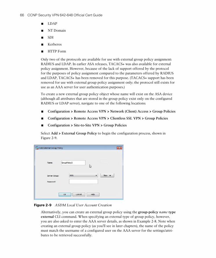
ptg8126969
66 CCNP Security VPN 642-648 Official Cert Guide
■ LDAP
■ NT Domain
■ SDI
■ Kerberos
■ HTTP Form
Only two of the protocols are available for use with external group policy assignment: RADIUS and LDAP. In earlier ASA releases, TACACS+ was also available for external policy assignment. However, because of the lack of support offered by the protocol for the purposes of policy assignment compared to the parameters offered by RADIUS and LDAP, TACACS+ has been removed for this purpose. (TACACS+ support has been removed for use with external group policy assignment only; the protocol still exists for use as an AAA server for user authentication purposes.)
To create a new external group policy object whose name will exist on the ASA device (although all attributes that are stored in the group policy exist only on the configured RADIUS or LDAP server), navigate to one of the following locations:
■ Configuration > Remote Access VPN > Network (Client) Access > Group Policies
■ Configuration > Remote Access VPN > Clientless SSL VPN > Group Policies
■ Configuration > Site-to-Site VPN > Group Policies
Select Add > External Group Policy to begin the configuration process, shown in Figure 2-9 .
Figure 2-9 ASDM Local User Account Creation
Alternatively, you can create an external group policy using the group-policy name type external CLI command. When specifying an external type of group policy, however, you are also asked to enter the AAA server details, as shown in Example 2-8 . Note when creating an external group policy (as you’ll see in later chapters), the name of the policy must match the username of a configured user on the AAA server for the settings/attri-butes to be retrieved successfully.

ptg8126969
Chapter 2: Configuring Policies, Inheritance, and Attributes 67
Example 2-8 Cisco ASA External Group Policy CLI Configuration
CCNPSec(config)# group-policy name external server-group name password<PASS>
By default, the command accepts an unencrypted (plain-text) password for the server-group . However, you can enter an encrypted password by entering the character 8 in between password and your entered password (for example, password 8 encrypted
password ).
The ASA asks for very few parameters in comparison to when creating an internal group policy because we are only creating the container or name for the group policy on the ASA and specifying the AAA server that will store the policy attributes along with the password the ASA uses to authenticate against it.
Table 2-4 lists only a few of the available RADIUS attributes, attribute number, type, and values that you may configure on an external RADIUS or LDAP server for the pur-poses of user policy assignment. For a more complete list, visit http://www.cisco.com .
Table 2-4 Supported RADIUS Attributes and Values
Attribute Name Attribute Number Type Value
Access-Hours 1 String Name of the time range (for example, Work Time)
Simultaneous-Logins 2 Integer A number between 0 and 2,147,483,647
Primary-DNS 5 String IP address
Secondary-DNS 6 String IP address
Primary-WINS 7 String IP address
Secondary-WINS 8 String IP address
SEP-Card-Assignment 9 Integer Not used
Tunneling-Protocols 11 Integer 1 = PPTP
2 = L2TP
4 = IPsec
8 = LT2P/IPsec
16 = WebVPN
4 and 8, mutually exclusive
0–11 and 16–27, legal values

ptg8126969
68 CCNP Security VPN 642-648 Official Cert Guide
Exam Preparation Tasks
As mentioned in the section “How to Use This Book” in the Introduction, you have a few choices for exam preparation: Chapter 22 , “Final Exam Preparation,” Appendix C , “Memory Tables” (CD only), and the exam simulation questions on the CD.
Review All Key Topics
Review the most important topics in the chapter, noted with the Key Topic icon in the outer margin of the page. Table 2-5 lists a reference of these key topics and the page numbers on which each is found.
Table 2-5 Key Topics
Key Topic Element Description Page
Bulleted list The benefits of the modular policy assignment of the ASA 50
List ASA policy inheritance 51
Bulleted list Available connection profile selection and assignment methods
53
Bulleted list Default connection profiles 57
Section Understanding group policies 61
Bulleted list Available AAA server types and protocols 65
Complete Tables and Lists from Memory
Print a copy of Appendix C , “Memory Tables” (found on the CD), or at least the section for this chapter, and complete the tables and lists from memory. Appendix D , “Memory Tables Answer Key,” also on the CD, includes completed tables and lists to check your work.
Define Key Terms
Define the following key terms from this chapter and check your answers in the glossary:
connection profile, internal group policy, external group policy
Key Topic

ptg8126969
This page intentionally left blank

ptg8126969
This chapter covers the following subjects:
■ Clientless SSL VPN Overview: This section intro-duces you to the clientless SSL VPN available on all Cisco ASA devices. We discuss scenarios that may lead to the implementation and use of a clientless SSL VPN and the common building blocks used to create one.
■ Deployment Procedures and Strategies: This section briefly discusses design recommendations and steps to help you prepare for an SSL VPN deployment.
■ Deploying Your First Clientless SSL VPN
Solution: This section presents a configuration example of a basic clientless SSL VPN solution that allows users to log in using accounts created for them in the local user database.
■ Basic Access Control: This section discusses the use of basic access control to allow user access to resources such as URLs, bookmarks, and file shares within the clientless SSL VPN portal. This section also briefly examines group policies that you can use to achieve a greater level of granularity when controlling user access to resources.
■ Content Transformation: This section discusses the ASA’s role during content rewriting and how to include or exempt specific resources from being rewritten. The section also covers the use of Java applet signing and the Application Helper feature.
■ Troubleshooting a Basic Clientless SSL VPN: This section explains how to troubleshoot a client-less SSL VPN.

ptg8126969
This chapter starts by building on your existing understanding of the technology behind a Security Sockets Layer virtual private network (SSL VPN) and the building blocks associated with creating one. Armed with this information, we then explore the steps required to create a basic clientless SSL VPN and test your ability to log in using local user accounts configured on the Adaptive Security Appliance (ASA) .
After being able to log in and view the portal page, you also need to make sure that remote users have access only to the resources they should have and cannot browse to anything you have not defined for them. As one way to achieve this, we review the group policy configuration tasks using both the Adaptive Security Device Manager (ASDM)
and command-line interface (CLI) . And finally, we take a look at a few of the added extras you can configure for users of your SSL VPN, such as content rewriting and Java signing, and the important steps to troubleshoot common failures you may encounter.
“Do I Know This Already?” Quiz
The “Do I Know This Already?” quiz helps you determine your level of knowledge on this chapter’s topics before you begin. Table 3-1 details the major topics discussed in this chapter and their corresponding quiz sections.
Table 3-1 “Do I Know This Already?” Section-to-Question Mapping
Foundation Topics Section Questions
Deploying Your First Clientless SSL VPN Solution 1 , 3 , 4 , 6 – 10
Troubleshooting a Basic Clientless SSL VPN Solution 5
Content Transformation 2
1. Which two of the following are required when creating a CSR for an identity certificate?
a. DNS
b. Hostname
c. NTP server
d. Domain name
CHAPTER 3
Deploying a Clientless SSL VPN Solution

ptg8126969
72 CCNP Security VPN 642-648 Official Cert Guide
2. What file is required for the operation of the ASA Application Helper?
a. XML
b. HTML
c. APCF
d. OCSP
3. Which ASDM location is used to import an identity certificate?
a. Configure > Remote Access VPN > Clientless SSL VPN Access > Portal
b. Monitoring > Interfaces
c. Home > Certificates
d. Configuration > Device Management > Certificates > CA Certificates
e. Configuration > Device Management > Certificates > Identity Certificates
4. When creating a new DNS group, what is the maximum number of DNS servers that you can add?
a. 2
b. 3
c. 4
d. 6
e. 100
5. When troubleshooting an SSL tunnel establishment attempt, which two ASDM loca-tions can you use to view syslog debugging information?
a. Home
b. Monitoring > Interfaces > ARP Table
c. Monitoring > Logging >Real-Time Log Viewer
d. Monitoring > VPN > Sessions
e. show logging
6. Which configuration command is used in the CLI to create a new RSA key pair?
a. crypto ca trustpoint TrustPoint0
b. crypto key zeroize rsa noconfirm
c. do show run
d. crypto key generate rsa modulus 2048
e. crypto key generate rsa modulus 4096

ptg8126969
Chapter 3: Deploying a Clientless SSL VPN Solution 73
7. When configuring RSA key pairs, which modulus values are available on the ASA device? (Choose all that apply.)
a. 1024
b. 16384
c. 768
d. 512
e. 2048
8. Which is the default authentication scheme used by the DefaultWEBVPNGroup connection profile?
a. AAA(RADIUS)
b. AAA(TACACS+)
c. AAA(LOCAL)
d. AAA(LDAP)
e. None
9. When configuring the CA CRL revocation-retrieval policy, which methods are avail-able? (Choose all that apply.)
a. FTP
b. HTTPS
c. HTTP
d. TFTP
e. LDAP
f. SCEP
10. A user is complaining of being unable to open external or internal URLs directly or from the bookmark list. What could be the problem?
a. The user is not really connected to the SSL VPN.
b. The user is connected to somebody else’s SSL VPN.
c. The user has not been given an IP address by the ASA.
d. The administrator has not configured a DNS server group.
e. The ASA device has experienced a blue screen error.
f. The administrator has not configured a hostname.

ptg8126969
74 CCNP Security VPN 642-648 Official Cert Guide
Foundation Topics
Clientless SSL VPN Overview
Your manager is out of the office for the week attending a technical conference for the release of the latest and greatest gadget, so you are taking things easy this morning and sipping your coffee while clicking through your latest emails, although you are unaware that at this very moment he is trying to connect from his hotel room to your corporate headquarters to upload his notes from the previous day. After a few failed attempts to get the VPN client installed on his laptop to connect, he asks the hotel staff whether there are any restrictions on their wireless network. Your manager—now equipped with the information and frustration that everything out to the Internet is blocked except for HTTP and HTTPS—calls you, the company’s resident security guru, to ask how he can continue to work.
Sound familiar? With the number of remote and home workers ever increasing, and the daily emergence of new security threats businesses face from the Internet, this scenario is becoming more common. The need for a new technology that would allow authorized users to quickly and easily connect to their workplace from anywhere using almost any device had arisen. The answer: the clientless SSL VPN.
One key element behind the popularity and growth of the SSL VPN is in the name Secure Socket Layer . SSL, or Hypertext Transfer Protocol Secure (HTTPS) , as it is more commonly referred to, has been around since the early 1990s, and it is rare to see HTTP access allowed in an environment without its partner HTTPS. The initial support work involved with a new VPN client deployment has been substantially reduced, due to no longer needing additional ports or protocols to be enabled or allowed and new soft-ware having to be installed.
The SSL VPN has allowed companies large and small to deploy ubiquitous access to visi-tor and staff resources quickly and easily while maintaining their corporate security poli-cies and effectively removing the support burden that once might have occurred with third-party VPN client software and incompatible operating systems or hardware.
SSL VPNs are often deployed to allow access to a company intranet, Microsoft SharePoint, or web mail. The SSL VPN enables users to connect from a handheld device (smartphone or PDA), a public Internet cafe, or a corporate laptop. Users within these environments usually are just opening a calendar, editing a document, or reading email within a web page. So, the need for an installed VPN client can almost be construed as overkill in this situation.
Consider, for example, the following situation: John, a salesman from your company, has collected his new laptop this morning on the way to a customer site but needs access to an important quotation saved on the corporate file server. After reassuring the cus-tomer with “Don’t worry, we have a VPN,” he inserts the CD the support desk gave him containing the VPN client software into his laptop and follows the prompts to install it. Installation complete, he now restarts his machine as instructed and checks with the

ptg8126969
Chapter 3: Deploying a Clientless SSL VPN Solution 75
customer’s support team to make sure the necessary protocols and ports are allowed through their firewall. With the laptop now running, he opens the software, chooses to create a new connection, and diligently enters the group name, shared secret, and host-name from the piece of paper he pulls from his pocket. He clicks Connect, enters his username and password when prompted, and then double-clicks a familiar shared drive on his computer. Prompted again, he enters a username and password and searches for the file. Sounds like a lot of work, doesn’t it?
If the company John works for had invested in the deployment of a clientless SSL VPN solution, he could have easily accessed the portal URL using his default installed brows-er, because SSL and Transport Layer Security (TLS) are already enabled in all popular browser applications today. In that case, he would not have had to turn on anything or install anything new (with maybe the exception of having to click Allow on an installed pop-up blocker). He would be presented with an aesthetically pleasing customized portal, where he would enter his corporate username and password and click the Login button to gain access to the resources he needs, in the form of hyperlinks and menu bars listed neatly on the page.
Single signon (SSO) is another feature of the SSL VPN that is explored in greater detail later. However, in reference to this example, it is worth a brief mention here. You might have noticed earlier that John was prompted twice for a username and password: once during the initial VPN connection phase and again when opening the corporate shared drive. SSO can be implemented within a clientless SSL VPN to prevent users from being prompted for their credentials multiple times when trying to access certain resources. ASA achieves this by caching the credentials or storing them within predefined variables during the initial user login and effectively becomes an authentication proxy between the user and resource. If configured, this could have removed another step from this sce-nario and made John’s life even easier.
Deployment Procedures and Strategies
An important consideration when designing your SSL VPN is the resource access required by your users and the type of SSL VPN deployment you require. What sets an SSL VPN apart from an IPsec VPN is being able to offer users a completely different experience based on their location, connection method, or access privileges.
You can configure five options to provide that experience:
■ Reverse proxy: Also known as the clientless SSL VPN, the reverse-proxy method of connection provides the benefits of ubiquitous connectivity (anywhere, anytime, from anything connectivity—within reason, of course). This particular connection method is commonly deployed for user access to internal web-enabled resources (Microsoft SharePoint or web mail, for example). This method of connectivity allows for a greater level of granularity when configuring user access to resources. However, resource access is typically limited to only those who are “web enabled.”
■ Port forwarding: This connection method does not require the use of a full-featured software client for applications’ access to the internal network, but instead
Key Topic

ptg8126969
76 CCNP Security VPN 642-648 Official Cert Guide
allows users to use familiar installed applications by the use of port forwarding using a downloadable Java applet. Typically, the use of this connection method is for users accessing a Telnet application. The program’s connection/server settings must be changed from the default server addresses to the local loopback address where port 23 is listening and forwarded to the VPN appliance.
Port forwarding has a few downsides from the user’s point of view. Users require local administrator access for installation and changes to installed application set-tings, because the application used for port-forwarding purposes must be installed on the local PC. Only TCP applications using static port assignments can be used, and client certificates cannot be used because the Java Runtime Environment (JRE) cannot access the local certificate store. Because of these reasons and others, port forwarding is now considered a legacy application, and Cisco recommends the use of plug-ins or smart tunnels.
■ Client/server plug-ins: Plug-ins enable users to access their familiar applications from within the browser window. This feature continues the ubiquitous ideal of SSL VPNs, where unlike port forwarding, the client can connect to the VPN and use the application from a public computer without any need for the application to be locally installed. Available plug-ins include Remote Desktop (RDP) , Ubuntu’s remote desktop (VNC), Secure Shell (SSH) , Telnet, and Citrix.
■ Smart tunnels: Smart tunnels are recommended for use by Cisco because of the performance increase they offer over plug-ins due to enabling users to be able to access familiar applications from outside the browser window (email, SSH, Telnet, and RDP, for example). The smart tunnel client requires the exact executable name of the local PC’s application process, including the extension (such as .exe), to be configured on the ASA, and it redirects any requests from the process to the ASA device through the SSL tunnel. Unlike with the plug-ins feature, the applications used by the client need to be installed locally on the PC in use. However, this fea-ture can allow clients to use their existing application without the need to change any settings, and therefore the need for local administrator rights is removed as a requirement. Access using smart tunnels is usually granted for users accessing resources from a company-owned computer/laptop, due to the need for installed and configured applications.
■ Full tunnel with AnyConnect: Similar to the IPsec client implementation, this method of access enables users to tunnel into the internal network and access net-work resources from their machines without having to choose a URL or change their local application settings. The experience offered to users is similar to that of being at their desk in the office. For further information about the AnyConnect VPN, see Chapters 8 through 12 .
As mentioned earlier, when using a clientless SSL VPN, resource access is presented to users in the form of URLs or hyperlinks listed within the portal that loads after a suc-cessful login attempt.
One of the most effective ways to control user access is through the use of login URLs. Each VPN connection profile (also known as a tunnel group) defined on the ASA can
ptg8126969
Chapter 3: Deploying a Clientless SSL VPN Solution 77
be configured to use a separate login page or choose from a list of defined groups at a central login page. This would, for example, allow a user from the Sales depart-ment to browse to https://your.device.com/sales and guests to browse to https://your.device.com/visitor . Each URL or login page has its own unique set of security policies and authentication parameters, allowing for greater flexibility when managing separate groups of users, login and connection type, and the resources users can access.
Depending on the attributes and parameters your security policies take into account when evaluating a user’s access requirements, you can choose to allow or deny the user access to certain resources through the use of group policies and dynamic access poli-
cies (DAP) and to check for attributes such as operating system, Windows group mem-bership, RADIUS attributes, Registry keys, antivirus, and so on.
Deploying Your First Clientless SSL VPN Solution
Now that you have a good understanding of the tunnel-negotiation process that occurs during the creation of an SSL/TLS connection and have reviewed the various options to keep in mind when deploying an SSL VPN, we are ready to move on and configure a basic clientless SSL VPN.
When preparing to deploy a basic clientless SSL VPN for the first time, a few key items must be completed before you can test access and move on to providing for advanced access and features, as follows (in order):
Step 1. IP addressing: It is important to know the IP addressing plan for the site on which you are installing the ASA because you need an IP address for the external interface (the one closest to VPN clients and terminating SSL VPN sessions).
Step 2. Configure a hostname, domain name, and Domain Name System (DNS): Before publishing the relevant SSL VPN URLs to users, you configure your ASA with a hostname and a domain name,. You also enter the addresses of any internal and external DNS servers to allow user access to any bookmarks or external URLs they browse to using your SSL VPN.
Step 3. Enroll with a CA and become a member of a PKI: Because users will be accessing the device externally over an SSL connection, a device certificate is required for successful authentication of the ASA. Another option is to use a locally generated self-signed certificate.
Step 4. Enable the relevant interfaces for SSL VPN access: Before SSL VPN access can occur, you need to specify which interface the service will be available on.
Step 5. Create LOCAL user accounts: Because this is a basic SSL VPN, you use LOCAL authentication for user access. Doing so requires that you to create the user accounts on the ASA device.
Key Topic

ptg8126969
78 CCNP Security VPN 642-648 Official Cert Guide
Step 6. Create a Connection Profile (optional but recommended so that the DefaultWEBVPNGroup is not used): In this step, create a new connection profile and map it to users through group policies or user attributes. A con-nection profile is used for prelogin settings such as authentication method, DNS servers and domain name, and portal customization.
IP Addressing
Before you can allow users access to your SSL VPN, you need to make sure the ASA device can be contacted from external locations. This requires the configuration of an IP address on your external interface. In an installation, you usually already have this or have the necessary knowledge of your IP addressing plan to be able to allocate an address to the device.
Hostname, Domain Name, and DNS
Before you generate a certificate request to send to a CA for creation of a digital cer-tificate, you need to give the ASA device a hostname and configure your local domain name. It can also be of benefit while troubleshooting a networking environment for devices to have a meaningful hostname. (That is, some providers use a networkwide nam-ing convention of roomnumber_racknumber_racklocation_device, whereas others might prefer a more Star Wars- or Muppets-centric theme.) In any case, you can enter this information within the Device Name/Password pane located at Configuration > Device Setup > Device Name/Password . The hostname, domain name, and DNS server group can also be configured using the CLI commands shown in Example 3-1 .
Example 3-1 Cisco ASA Hostname, Domain Name, and DNS Group CLI Configuration
CCNPSec(config)# hostname DEVICENAME
CCNPSec(config)# domain-name mydomainname.com
CCNPSec(config)# dns server-group name
After you enter the dns server-group name command, there are a number of attributes available for configuring the name servers you require, the domain name, retries, and so on within the server group area, as shown in Table 3-2 .

ptg8126969
Chapter 3: Deploying a Clientless SSL VPN Solution 79
Table 3-2 DNS Server Group Configuration Options
Command Value
domain-name Enter the domain name that will be appended to DNS queries for this server group.
name-server Enter up to six DNS servers, each separated by a space.
retries Enter the number of times from 0 to 10 that a name server configured in this group will be retried.
timeout Enter the time from 0-30 seconds the ASA should wait for a response to a query from a name server.
As mentioned earlier, if you want your users connecting to the SSL VPN to be able to browse to websites, servers, or bookmarks using the hostname or fully qualified domain
name (FQDN) , you must enter your internal and external DNS servers. If you do not carry out this step, when users enter a domain name ( www.cisco.com , for example) into the URL field and click Browse, they will be presented with an error indicating that the domain Cisco.com could not be found.
To enter the external or internal DNS servers, browse to Configuration > Device Management > DNS > DNS Client , where you can either choose to configure a global DNS server group that applies to all queries regardless of domain or choose to configure multiple DNS server groups with up to six DNS servers in each group, which will allow you to specify the timeout and retry values and the domain name per group.
Become a Member of a Public Key Infrastructure
By default, the ASA device creates a self-signed certificate for SSL authentication. This is fine for a test or lab environment. However, when you come to allowing access to remote users outside of your organization, you will usually purchase a valid certificate from a recognized certificate authority (CA) to instill trust into the hearts and minds of your remote users (and to prevent them from receiving any browser warnings about your certificate being invalid).
At the time of this writing, Cisco ASA customers can purchase a digital certificate at a discounted price from Entrust, or they can apply for a 3-month trial certificate from them. You can access more information about this offer in the Adaptive Security
Device Manager (ASDM) by navigating to Configuration > Device Management > Certificate Management > Identity Certificates > Enroll with Entrust . Alternatively, you can visit the page directly at http://www.entrust.net/cisco .
In the section that follows, we walk through the steps for generating a certificate request and installing the received certificate. These instructions can be followed for any CA and are not specific to Entrust.

ptg8126969
80 CCNP Security VPN 642-648 Official Cert Guide
Adding a CA Root Certificate
The process of adding a CA root certificate is straightforward and easy enough. In its out-of-the-box state, the ASA has no default CA root certificates installed. So, before you add an identity certificate for the ASA, you first need to add the certificate of the issuing CA from which you purchased your certificate. When the CA issues an identity certificate, it usually sends the certificates of their root CA to add, as well. If you do not have a copy, however, these are normally easy to locate and download from the CA’s website. A few locations to download common root CA certificates are listed here:
■ https://www.entrust.net/downloads/root_index.cfm
■ http://www.globalsign.com/support/intermediate-root-install.html
■ http://www.verisign.com/support/roots.html
Otherwise, if you have an in-house deployed CA, specific URLs exist and are publicly available, depending on the operating system vendor this is hosted on.
Now that you have your CA’s root certificate, in the ASDM navigate to Configuration > Device Management > Certificate Management > CA Certificates and click the Add but-ton on the right side. The Install Certificate window will open, as shown in Figure 3-1 .
Figure 3-1 Installing the CA Root Certificate
Within the Install Certificate window, you have the option to enter a trustpoint name for the CA certificate you are importing. A trustpoint is used by the ASA as a container for CA and certificate information, as you will see throughout the remaining chapters of this

ptg8126969
Chapter 3: Deploying a Clientless SSL VPN Solution 81
book that reference CA certificates. It is generally advisable to enter the name of the root CA, which will make life a bit easier for you when you come to install new certificates or troubleshoot existing ones. You have three options for how to install the certificate, depending on how you retrieved the root certificate (downloaded it from the CA’s site in a zip file, copied a base64 output to your Clipboard, or used Simple Certificate Enrollment
Protocol [SCEP] to retrieve the file). Your method dictates which option you choose. For this example, we copied the base64 output of the VeriSign root certificate from their web-site and chose the option to Paste the Certificate in PEM Format to add it.
Certificate Revocation List
You now set the parameters your ASA will use to check and retrieve the certificate revo-
cation list (CRL) . To do so, click the More Options button within the Install Certificate window. The Configuration Options for CA Certificate window will appear, as shown in Figure 3-2 .
Figure 3-2 CA Certificate CRL Options
Within the Configuration Options for CA Certificate window, you can enter the method you use to check for the CRL, the protocol you use to retrieve the CRL, and the loca-tions you retrieve it from. If you are using Online Certificate Status Protocol (OCSP) , you can enter the certificate to rule mappings you want to use with this certificate. Finally, you can set advanced options, such as the type of VPN this certificate can be used for and the OCSP server URL. The Configuration Options for CA Certificate win-dow, as shown in Figure 3-10 , presents five tabs where you enter your settings:
■ Revocation Check
■ CRL Retrieval Policy

ptg8126969
82 CCNP Security VPN 642-648 Official Cert Guide
■ CRL Retrieval Method
■ OCSP Rules
■ Advanced
Revocation Check
On the Revocation Check tab, you have the option to turn off certificate revocation checking or leave it at the default of on. However, by default, no revocation-checking methods are chosen, and the check box to consider a certificate valid if the CRL cannot be retrieved is selected, meaning that all certificates, by default, are considered valid by the CA.
Depending on your own implementation, you choose CRL, OCSP, or both.
If you choose OCSP, you can optionally create OCSP rules that use preconfigured certificate mappings to control the OCSP actions applied to specific certificates on the OCSP Rules tab, and on the Advanced tab, you can enter information such as the server URL and disabling the use of nonces. If you decide to choose both CRL and OCSP methods, note that the second option in the list is used only if the first returns an error. Therefore, if it is important to use OCSP as a primary means of checking the list and have CRL used only if there is an error with the OCSP server, make sure the OCSP meth-od is at the top of the list. You can change the order of methods using the Move Up and Move Down buttons to the right of the window.
For this example, we chose to use CRL for our revocation check by choosing CRL from the available revocation methods and clicking Add . Then we unchecked the box to make sure the CRL is always checked. Therefore, if it is unavailable, the certificates will be marked as invalid.
CRL Retrieval Policy
From here, you can choose whether you want to use the CRL location stored in the cer-tificate or a specific URL to a known revocation list (this information may be published on your CA’s website) or both. If you choose the option to enter the specific URLs, you are given the option of entering either an HTTP:// or LDAP:// URL, and the URLs you enter will be listed in an order of preference from top to bottom. After you have finished entering all the URLs, use the Move Up and Move Down buttons to the right of the window to set your order of preference.
CRL Retrieval Method
Next, choose the retrieval methods that can be used to download the CRL: Lightweight
Directory Access Protocol (LDAP) , HTTP, SCEP, or all three. If you choose LDAP, you must enter a username and password and optionally specify the default server name or IP address. After you have entered the server name or IP, you have the option to change the LDAP port. However, if your CA has not listed a specific port, it is recommended to keep the default of 389.

ptg8126969
Chapter 3: Deploying a Clientless SSL VPN Solution 83
Although by default all three options (LDAP, HTTP, and SCEP) are enabled, I have unchecked everything except for HTTP.
OCSP Rules
On the OCSP Rules tab, you can allocate your predefined certificate mappings and rules to the certificates imported into your ASA. Although we had earlier selected only CRL as the revocation list method for this example (rather than OCSP), for the purposes of the exam, it is worth a mention here.
Certificate mappings can be used to map a certificate to a connection profile based on the criteria that was selected or configured explicitly in a certificate-matching rule. Certificate mappings and rules first need to be configured in Configure > Remote Access VPN > Network (Client) Access > Advanced > IPsec > Certificate to Connection Profile Maps . There are two sections to configure:
■ Policy
■ Rules
In the Policy window, you are presented with common criteria that can be selected to enable the certificate-to-connection profile mapping, based on a match. The ASA starts from the top of the list of options you select and works toward the bottom of the list until it finds a match (the top of the list having the higher priority).
Figure 3-3 shows the Policy window and the common criteria that you can choose. By default, all criteria are chosen, except for Use the Configured Rules to Match a Certificate to a Connection Profile.
Figure 3-3 Certificate-to-Connection Profile Maps: Policy Configuration

ptg8126969
84 CCNP Security VPN 642-648 Official Cert Guide
Note If you do configure your own mapping rules within the Rules window, you need to check the Use Configured Rules to Match a Certificate box for your rules to be con-sidered in the certificate-to-connection profile mapping process.
Within the Rules window, you can take a more granular approach to certificate mapping, whereby you can select your own criteria or fields to match within the certificate. Start by configuring a certificate-to-connection profile map. You can either use an existing map or create a new one. Give your profile map a priority and associate it with a con-nection profile/tunnel group. The priority values must be between 1 and 65535, with the highest priority being the lowest value (that is, 1). By default, the DefaultCertificateMap is given a priority of 10. Although you cannot change the default priority, you can delete the map and re-create it or create your own custom default map and give it a pri-ority value of 65535 so that it is always evaluated last. This is shown in Figure 3-4 .
Figure 3-4 Certificate-to-Connection Profile Maps: Rule Configuration
For example, you may choose to present all U.S. employees a different certificate from that presented to U.K. employees who access your SSL VPN. As shown in Figure 3-4 , we matched the country code GB in the certificate and mapped it to the UKEmployees con-nection profile.
Depending on the criteria you selected to match within the certificate, you can use one of the following operands per rule:
■ Equals
■ Contains

ptg8126969
Chapter 3: Deploying a Clientless SSL VPN Solution 85
■ Does Not Equal
■ Does Not Contain
The criteria that can be matched against in a rule are as follows:
■ Subject
■ Country (C)
■ Common Name (CN)
■ DN Qualifier (DNQ)
■ Email Address (EA)
■ Generational Qualifier (GENQ)
■ Given Name (GN)
■ Initials (I)
■ Locality (L)
■ Name (N)
■ Organization (O)
■ Organization Unit (OU)
■ Serial Number (SER)
■ Surname (SN)
■ State/Province (SP)
■ Title (T)
■ User ID (UID)
■ Unstructured Name (UNAME)
■ IP Address (IP)
■ Domain Component (DC)
■ Alternative Subject
■ Issuer
■ Country (C)
■ Common Name (CN)
■ DN Qualifier (DNQ)
■ Email Address (EA)
■ Generational Qualifier (GENQ)
■ Given Name (GN)
■ Initials (I)
■ Locality (L)
■ Name (N)
■ Organization (O)
■ Organization Unit (OU)
■ Serial Number (SER)
■ Surname (SN)

ptg8126969
86 CCNP Security VPN 642-648 Official Cert Guide
■ State/Province (SP)
■ Title (T)
■ User ID (UID)
■ Unstructured Name (UNAME)
■ IP Address (IP)
■ Domain Component (DC)
■ Extended Key Usage
Now back to the original configuration of the CA certificate. We have covered the OCSP Rules tab. The last tab available in the Edit Options for CA Certificate window is the Advanced tab.
Advanced
On this tab, you can configure the CRL cache refresh time, which is set to a default of 60 minutes. You also can enter the OCSP server URL, choose to accept the certificates issued by the CA (or subordinate CA of the CA you are importing the certificate from), and more important, control whether this certificate will be used for SSL, IPsec, or both types of cli-ent connections. Unless you have chosen to use certificate-based authentication with both your IPsec and SSL connections and are using a separate CA certificate for each connec-tion type, you can choose to leave this at the default value of SSL and IPsec.
As shown in Figure 3-5 , after we entered the information and clicked OK , the import operation was successful, and the CA is now listed in the window along with its certifi-cate expiry date, issued by, issued to and usage values, and the trustpoint name entered.
Figure 3-5 CA Certificate Import Complete

ptg8126969
Chapter 3: Deploying a Clientless SSL VPN Solution 87
The majority of tasks you can carry out using the ASDM can also be performed via the command-line interface (CLI) . The commands to configure the same trustpoint, CRL revocation, and retrieval methods are shown here. In the following section, we take a look at the CLI process to manually import a CA certificate.
To create a trustpoint and configure it for manual enrollment, enter the following:
ciscoasa(config)# crypto ca trustpoint TrustPoint0
ciscoasa(config-ca-trustpoint)# enrollment terminal
Table 3-3 lists the commands available for the enrollment keyword.
Table 3-3 Certificate Enrollment/Import Type
Command Command Options/Explanation
retry ( count | period ) Command used to configure the number of times (count) 0–100 (0 = unlimited) and frequency (period) in minutes between those attempts (1–60). Used with SCEP retrieval.
self Generate a self-signed certificate.
terminal Use this command when cutting and pasting a certificate file into the configuration.
url Use this command to enter the server and full path to the file when using SCEP.
After creating a trustpoint and setting the certificate-retrieval method, you can continue to configure the revocation methods. Start by entering the revocation-check command, followed by the crl keyword, because for this example we have chosen to use CRL for the revocation method. As shown in the earlier example using the ASDM, you can also enter ocsp or choose none :
ciscoasa(config-ca-trustpoint)# revocation-check crl
To enter multiple check methods, enter them in the order you would like them to be used following the revocation-check command, as follows:
ciscoasa(config-ca-trustpoint)# revocation-check crl ocsp
A number of commands are available within the config-ca-trustpoint mode. Many of them allow you to enter the information required for automatic certificate enrollment using SCEP. Because we are using the manual method for this example, they are not required at this time; however, for the purposes of the exam, it will benefit you to review the commands and their use. For this example, we continue to enter the com-mands required for CRL revocation checks. Table 3-2 lists the rest of the available commands.
Now we enter CRL configuration mode to set the retrieval options. The change of mode can be noted by the new prompt that appears after the command, as shown in line 2 of

ptg8126969
88 CCNP Security VPN 642-648 Official Cert Guide
the following output. We then proceed to configure the cache timeout to 1440 minutes (remember, the default of 60 minutes) and tell the ASA to also consider the NextUpdate field in the received CRL from the CA with the use of the enforcenextupdate com-mand.
The NextUpdate is sometimes added to the CRL and can be used by clients to dynami-cally set their cache timeouts. The existence of the NextUpdate field depends on the CA because it is an optional field. However, if the ASA receives this field from the CA and also has a cache timeout set locally, it uses the lower of the two. For example, if the ASA had a default cache timeout of 60 minutes and the NextUpdate field in the received CRL has been set to 30 minutes, the received value of 30 is chosen as the time-out, and all entries within the CRL file for this certificate are then aged out after this time.
We then use the protocol http command to configure the protocol used for CRL retrieval as HTTP. This is similar to the ASDM configuration, and we are also presented with the option of using HTTP, LDAP, SCEP, or a combination of all three. Also similar to the ASDM configuration, we have the option of entering a URL for the CRL location using the url command, and we can enter up to five URLs, each with a separate priority of 1 to 5, where they are tried in order of priority (highest to lowest, with 1 being the highest priority):
ciscoasa(config-ca-trustpoint)# crl configure
ciscoasa(config-ca-crl)# cache-time 1440
ciscoasa(config-ca-crl)# enforcenextupdate
ciscoasa(config-ca-crl)# protocol http
ciscoasa(config-ca-crl)# url 1 http://5.5.5.5/CertEnroll/CA.crl
To manually enter the root CA certificate, enter the command crypto ca authenticate TrustPoint0 ( TrustPoint0 should be replaced with the name of the trustpoint you’ve previously created) and you are given the option of entering the following subcommands with the crypto ca authenticate command:
■ FingerPrint: We can enter an optional fingerprint ( message digest algorithm 5
[MD5] or Secure Hash algorithm [SH] signature, depending on how the CA was configured) that may have been sent with the certificate file to authenticate the cer-tificate contents, if the CA requires it.
■ Noninteractive: This command is used only with the ASDM when entering a cer-tificate using the manual method and should not be entered using the CLI.
After the command has been entered, we follow the prompt to paste the certificate output into the CLI and end with quit on a separate line. We are then asked to verify the fingerprint of the certificate against that sent to us by the CA. (You may or may not receive this depending on how you retrieved the original certificate.) Example 3-2 shows this output.

ptg8126969
Chapter 3: Deploying a Clientless SSL VPN Solution 89
Example 3-2 CA Certificate Import Process
ciscoasa(config)# crypto ca authenticate TrustPoint0
Enter the base 64 encoded CA certificate.
End with the word "quit" on a line by itself
-----BEGIN CERTIFICATE-----
MIIEVzCCAz+gAwIBAgIQFoFkpCjKEt+rEvGfsbk1VDANBgkqhkiG9w0BAQUFADCB
jDELMAkGA1UEBhMCVVMxFzAVBgNVBAoTDlZlcmlTaWduLCBJbmMuMTAwLgYDVQQL
EydGb3IgVGVzdCBQdXJwb3NlcyBPbmx5LiAgTm8gYXNzdXJhbmNlcy4xMjAwBgNV
BAMTKVZlcmlTaWduIFRyaWFsIFNlY3VyZSBTZXJ2ZXIgUm9vdCBDQSAtIEcyMB4X
DTA5MDQwMTAwMDAwMFoXDTI5MDMzMTIzNTk1OVowgYwxCzAJBgNVBAYTAlVTMRcw
FQYDVQQKEw5WZXJpU2lnbiwgSW5jLjEwMC4GA1UECxMnRm9yIFRlc3QgUHVycG9z
ZXMgT25seS4gIE5vIGFzc3VyYW5jZXMuMTIwMAYDVQQDEylWZXJpU2lnbiBUcmlh
bCBTZWN1cmUgU2VydmVyIFJvb3QgQ0EgLSBHMjCCASIwDQYJKoZIhvcNAQEBBQAD
ggEPADCCAQoCggEBAMCJggWnSVAcIomnvCFhXlCdgafCKCDxVSNQY2jhYGZXcZsq
ToJmDQ7b9JO39VCPnXELOENP2+4FNCUQnzarLfghsJ8kQ9pxjRTfcMp0bsH+Gk/1
qLDgvf9WuiBa5SM/jXNvroEQZwPuMZg4r2E2k0412VTq9ColODYNDZw3ziiYdSjV
fY3VfbsLSXJIh2jaJC5kVRsUsx72s4/wgGXbb+P/XKr15nMIB0yH9A5tiCCXQ5nO
EV7/ddZqmL3zdeAtyGmijOxjwiy+GS6xr7KACfbPEJYZYaS/P0wctIOyQy6CkNKL
o5vDDkOZks0zjf6RAzNXZndvsXEJpQe5WO1avm8CAwEAAaOBsjCBrzAPBgNVHRMB
Af8EBTADAQH/MA4GA1UdDwEB/wQEAwIBBjBtBggrBgEFBQcBDARhMF+hXaBbMFkw
VzBVFglpbWFnZS9naWYwITAfMAcGBSsOAwIaBBSP5dMahqyNjmvDz4Bq1EgYLHsZ
LjAlFiNodHRwOi8vbG9nby52ZXJpc2lnbi5jb20vdnNsb2dvLmdpZjAdBgNVHQ4E
FgQUSBnnkm+SnTRjmcDwmcjWpYyMf2UwDQYJKoZIhvcNAQEFBQADggEBADuswa8C
0hunHp17KJQ0WwNRQCp8f/u4L8Hz/TiGfybnaMXgn0sKI8Xe79iGE91M7vrzh0Gt
ap0GLShkiqHGsHkIxBcVMFbEQ1VS63XhTeg36cWQ1EjOHmu+8tQe0oZuwFsYYdfs
n4EZcpspiep9LFc/hu4FE8SsY6MiasHR2Ay97UsC9A3S7ZaoHfdwyhtcINXCu2lX
W0Gpi3vzWRvwqgua6dm2WVKJfvPfmS1mAP0YmTcIwjdiNXiU6sSsJEoNlTR9zCoo
4oKQ8wVoWZpbuPZb5geszhS7YsABUPIAAfF1YQCiMULtpa6HFzzm7sdf72N3HfwE
aQNg95KnKGrrDUI=
-----END CERTIFICATE-----
quit
INFO: Certificate has the following attributes:
Fingerprint: e019f5fc c09a130e 38b7bf0d 0240d3c2
Do you accept this certificate? [yes/no]: yes
Trustpoint CA certificate accepted.
% Certificate successfully imported
ciscoasa(config)#
Table 3-4 describes the automatic certificate enrollment commands. Note that this table also includes those commands not previously mentioned but available within the config-ca-trustpoint mode for automatic certificate enrollment or the creation of identity cer-tificates.

ptg8126969
90 CCNP Security VPN 642-648 Official Cert Guide
Table 3-4 Automatic Certificate Enrollment Commands
Command Command Options/Explanation
email email address Enter the email address of the technical/administrative contact for your organization. This is included in the Subject Alternative Name field of the certificate.
fqdn cisco.com Enter the fully qualified domain name to be used within the certificate. This will be sent to the CA and included in the Subject Alternative Name field.
ip-address ASA IP address
Use this command to tell the CA to include the IP address of the ASA within the certificate.
ocsp url url Used to tell the ASA to check all certificates with the server entered instead of that found within the AIA extension of the certificate.
ocsp disable-nonce Disables nonce extensions that are used to avoid replay attacks by cryptographically binding requests with responses.
password password Enter a password for revocation requests to be authenticated by the server with.
subject-name name Enter the name you want entered into the certificate DN field in X.509 format. To prevent errors within the command, enclose your name within quotes (that is, “ciscocomcert” ).
serial-number Tells the issuing CA to include this ASA’s serial number in the certificate.
After successfully importing a root certificate, it is time to generate a CSR (certificate request) for the ASA identity certificate. Within the ASDM, navigate to Configuration > Device Management > Certificate Management > Identity Certificates and click the Add button. The Add Identity Certificate window will open, as shown in Figure 3-6 .
Figure 3-6 Add Identity Certificate: Generate CSR

ptg8126969
Chapter 3: Deploying a Clientless SSL VPN Solution 91
Within this window, you must enter a name for the trustpoint and can choose the default action of importing an existing certificate from a file, add a new identity certifi-cate, or generate a self-signed certificate. To begin the process of creating a new CSR, start by clicking the Add a New Identity Certificate radio button, and then click the now-available New button to create a new key pair.
In the Add Key Pair window that opens, you are asked to enter a name for the key pair. Choose one that you can use to easily distinguish it from others that you may create later or have already created. Select the key modulus size (either 1024 or 2048) and the usage. The vast majority of CAs still accept a key size of 1024.
After clicking Generate Now and waiting a short time while the key pair is created, you are returned to the Add Identity Certificate window. From the drop-down list, choose the key pair you just created, and then click the Select button to the right of the Certificate Subject DN box.
As shown in Figure 3-7 , the Certificate Subject DN will now open, and you use this win-dow to enter Distinguished Name (DN) identity certificate attributes, such as Common Name (CN), Department (OU), and so on. At least one attribute needs to be configured for successful enrollment in most cases.
Figure 3-7 Add Identity Certificate: Enter CSR Details
As you can see in this figure, the values for CN, OU, O, and C have been entered by choosing them from the list of available attributes in the Attributes drop-down menu, entering the necessary information into the Value field, and clicking Add . Because for this example we are generating a CSR for a lab environment, we are okay with the details shown. However, when generating a CSR for a valid public certificate, the CA would require you to enter the information from all the attributes available in the drop-down menu for them to be able to check your authenticity. The attributes available are as follows:
■ Common Name (CN)
■ Department (OU) (also known as organization unit, hence the OU)
■ Company Name (CN)
■ Country (C)

ptg8126969
92 CCNP Security VPN 642-648 Official Cert Guide
■ State (ST)
■ Location (L)
■ Email Address (EA)
When you have finished entering all the information required, click OK , and you are once again returned to the previous Add Identity Certificate window. You are now able to see that the details previously entered have been formatted as Attribute=Value in a continuous string ready to be processed in the CSR generation.
Next, click the Add Certificate button, and after the familiar “loading” window has flashed up and closed, you are presented with a new window asking you to enter a location for the CSR to be saved locally on your PC. As you can see in Figure 3-8 , we entered the location C:\asa-csr.txt . Then, shortly after clicking the OK button, we received a message indicating that the file had been saved successfully.
Figure 3-8 Add Identity Certificate: Save the CSR Locally to Your PC
After generating a CSR and saving a copy on your PC, you can proceed to submit the file containing your CSR to your chosen CA, along with any other information they require in the way of personal or company identification (and, of course, their fee).
Depending on how fast your individual CA’s turnaround time is, you might be sent your certificate within a matter of hour or days, or they may contact you if they require fur-ther information about your request. When you do receive the certificate, all that is left to do is finish the request process and import it into your ASA’s configuration.
You can finish the import process by choosing Install from the right side of the Identity Certificates window. At this stage, the Install Identity Certificate window opens, and you will have the option to import the certificate from a file or to copy and paste the base64-encoded certificate into the window (see Figure 3-9 ). Depending on how your certificate was sent to you by the issuing CA, the certificate contents can be in a zip or text file attachment or included in the body of an email. Choose the appropriate option for your certificate installment and click Install Certificate .

ptg8126969
Chapter 3: Deploying a Clientless SSL VPN Solution 93
Figure 3-9 Installing an Identity Certificate
After a few moments, you should receive a pop-up alerting you that the certificate has installed successfully. If you receive an error instead, especially if you are copying and pasting the certificate contents, make sure you have not added any unnecessary spaces or text to the encoding. The file or contents of the message may have also been cor-rupted due to spam or antivirus settings within your email. In this situation, your CA will have normally included a link in the email for you to be able to download the certificate instead. After you have downloaded/retrieved the certificate from your CA, simply repeat the process to install your certificate.
When the install process completes, you are returned to the Identity Certificates win-dow, and your new certificate should now be listed, displaying the issued to, issued by, validity date, the trustpoint name you entered earlier, and the certificate usage.
The process used to generate an identity certificate from the CLI is similar to that shown earlier and in Table 3-3 .
In this next example, we have already created the trustpoint CLI-New and entered our email address, FQDN, password, and entered the enrollment terminal command to let the ASA know we be manually cutting and pasting our certificate into the CLI after receiving it from our issuing CA.
To complete the process, issue the crypto ca enroll trustpoint command to create and generate our CSR, as shown in Example 3-3 .
Note It is not shown in Example 3-3 , but as discussed earlier about these configura-tion steps, we entered the domain name and hostname of our ASA using the commands domain-name fqdn and hostname hostname . Without these commands, the ASA uses the default hostname and domain name to set the DN within your certificate request.

ptg8126969
94 CCNP Security VPN 642-648 Official Cert Guide
Example 3-3 Generate Identity Certificate CSR
CCNP(config)# crypto ca trustpoint CLI-New
CCNP(config-ca-trustpoint)# enrollment terminal
CCNP(config-ca-trustpoint)# crypto ca enroll CLI-New
% Start certificate enrollment ..
% The fully-qualified domain name in the certificate will be: CCNP.LAB.COM
% Include the device serial number in the subject name? [yes/no]: no
Display Certificate Request to terminal? [yes/no]: yes
Certificate Request follows:
-----BEGIN CERTIFICATE REQUEST-----
MIIBlzCCAQACAQAwHTEbMBkGCSqGSIb3DQEJAhYMQ0NOUC5MQUIuQ09NMIGfMA0G
CSqGSIb3DQEBAQUAA4GNADCBiQKBgQCzCAtKzbBAz0uLdH4uVcS0RQ+Vg5pHNFqe
yVVrxQHIH7B4ZBn/xOPlHQ5yt48syCq28/WhZ4zOR5TN9c+rhSiApAgG1FLDM9Vm
sml9iCr8JgayMfzUuDnEB3TSx4cm/q1A/coea6UG2E8gvze+piq4yvdgwPpkbymU
JFcfLfb2bwIDAQABoDowOAYJKoZIhvcNAQkOMSswKTAOBgNVHQ8BAf8EBAMCBaAw
FwYDVR0RBBAwDoIMQ0NOUC5MQUIuQ09NMA0GCSqGSIb3DQEBBQUAA4GBADz2Q6A0
+PcIzbcWtyiHB0RwYd6l7Gq2OTVg3B5wuYEg5Raqer1H8BUZ1n6GSxjmOYafQgvZ
JdkD9YvInOB5zh3fBzPNxp3ldPhkDYCo+QVLvp8aI3nw7KJEICh526RnGy+VWvS9
328kC3QxK04NHuNg3J0W24fKrDKyhAeAPYrR
-----END CERTIFICATE REQUEST-----
Redisplay enrollment request? [yes/no]: no
CCNP(config)#
As shown in Example 3-3 , the CSR is generated with the domain name and hostname combination of CCNP.LAB.COM and displayed to the terminal. You can now copy and paste this into a form or email it to a CA for certificate generation.
When you receive the certificate back from the issuing CA, you can use the command crypto ca import trustpoint pkcs12 | certificate passphrase to complete the import process and paste the received certificate file into the terminal, as shown in Example 3-4 .
Example 3-4 Import Identity Certificate
CCNP(config)# crypto ca import CRL-New pkcs12 passphrase
Enter the base 64 encoded pkcs12.
End with the word "quit" on a line by itself:
-----BEGIN CERTIFICATE-----
MIIFvDCCBKSgAwIBAgIQPw6Lnube3lvIG0upxkE1oTANBgkqhkiG9w0BAQUFADCB
yzELMAkGA1UEBhMCVVMxFzAVBgNVBAoTDlZlcmlTaWduLCBJbmMuMTAwLgYDVQQL
EydGb3IgVGVzdCBQdXJwb3NlcyBPbmx5LiAgTm8gYXNzdXJhbmNlcy4xQjBABgNV

ptg8126969
Chapter 3: Deploying a Clientless SSL VPN Solution 95
BAsTOVRlcm1zIG9mIHVzZSBhdCBodHRwczovL3d3dy52ZXJpc2lnbi5jb20vY3Bz
L3Rlc3RjYSAoYykwOTEtMCsGA1UEAxMkVmVyaVNpZ24gVHJpYWwgU2VjdXJlIFNl
cnZlciBDQSAtIEcyMB4XDTEwMTEwNDAwMDAwMFoXDTEwMTExODIzNTk1OVowgZAx
CzAJBgNVBAYTAkdCMRIwEAYDVQQIEwlCRVJLU0hJUkUxDDAKBgNVBAoUA0xBQjEM
MAoGA1UECxQDTEFCMTowOAYDVQQLFDFUZXJtcyBvZiB1c2UgYXQgd3d3LnZlcmlz
27ucHyy4Mds/helgCHeWKLQOQCQYgoiNzB41S0NwPw2s+K/oMsobVYJSBfOtzMti
cT/IGBWEECtVguh34q1hUQCmItEqtCneX+zoemmg/pM=
-----END CERTIFICATE-----
quit
INFO: Certificate successfully imported
CCNP(config)#
Enable the Relevant Interfaces for SSL
After generating and importing the certificates, you can enable SSL VPN on the outside or any SSL VPN terminating interface of your ASA. By default, none of the interfaces on the ASA are set up to allow for SSL VPN access, so you need to configure access on the interface from which users will be accessing the SSL VPN. In the majority of cus-tomer deployments, the outside interface is used for access. However, this might differ depending on the specific details of the implementation. For the purposes of this exam-ple and the exam, SSL access is configured on the external outside interface in the loca-tion Configuration > Remote Access VPN > Clientless SSL VPN Access > Connection Profiles , as shown in Figure 3-10 .
Figure 3-10 Enable SSL VPN Access on the External Interface

ptg8126969
96 CCNP Security VPN 642-648 Official Cert Guide
Note that this enables both TLS and DTLS, although for clientless SSL VPN sessions, DTLS is not applicable. To enable only SSL/TLS tunneling from the CLI, enable it using command enable outside tls-only under WebVPN configuration mode.
You also need to assign the identity certificate imported earlier to the outside interface so that remote users will be presented with it. To assign the identify certificate, either click the Device Certificate link or navigate to Configuration > Remote Access VPN > Advanced > SSL Settings to open the relevant pane.
By default, no certificates are assigned to the interfaces of the ASA, and it presents the user with a fallback or self-generated certificate during an SSL certificate establishment. However, because you might have paid for a certificate and imported it into the ASA configuration, you might as well use it. It is also poor practice to present a user with a self-generated certificate; doing so will cause the user’s browsers to display a number of error messages warning them about an invalid certificate. As network engineers, we have a responsibility not only to provide as safe an environment for our users as possible but to also provide them with the reassurance that everything they are doing within their working environment is protected.
Figure 3-11 shows the SSL Settings window, where you can assign your identity certificate to the outside interface. Carry out this action by choosing the interface from the list shown within the Certificates window and clicking Edit , as shown in Figure 3-11 . Within the new window, Select SSL Certificate, choose the installed identity certificate from the drop-down menu next to Primary Enrolled Certificate and click OK to complete the operation.
Figure 3-11 Map Identity Certificate to Outside Interface

ptg8126969
Chapter 3: Deploying a Clientless SSL VPN Solution 97
From the CLI, this is a relatively simple process, as demonstrated in Example 3-5 . First, enter the command webvpn to enter into the SSL VPN mode, and then specify the interfaces on which you want to enable the service, using the command enable outside | inside . After configuring the outside interface for SSL VPN termination, you then map the trustpoint (defined earlier in the chapter) to the outside interface, which automati-cally maps the identity certificate associated with the trustpoint to the interface outside.
Example 3-5 Enable WebVPN and Map the Identity Certificate to the Outside Interface
CCNP(config)# webvpn
CCNP(config-webvpn)# enable outside
INFO: WebVPN and DTLS are enabled on 'outside'.
CCNP(config-webvpn)# exit
CCNP(config)# ssl trust-point CLI-New outside
CCNP(config)#
Create Local User Accounts for Authentication
You are now in a position to create a couple of user accounts to test access to your basic SSL VPN.
By default, the DefaultWEBVPNGroup connection profile is configured to use LOCAL authentication, so there is no need to make any changes to this just yet. You are only aiming for your users to be able to log in to the VPN and view the portal page at this point. Remember that any newly created connection profile will inherit its WebVPN settings from the DefaultWEBVPNGroup connection profile, which exists by default on the ASA.
For this example, we create two users, employee1 and contractor1, that will be used for our test. In the ASDM, navigate to Configure > Remote Access VPN > AAA/Local Users > Local Users and click Add . The Add User Account window will appear. We enter the name of our user, employee1 , and enter and confirm the password thisismy-password for this account, as shown in Figure 3-12 . We then repeat the procedure to create the contractor1 user.

ptg8126969
98 CCNP Security VPN 642-648 Official Cert Guide
Figure 3-12 ASDM: Add Local User Account
Because the employee1 and contractor1 user accounts will be used only to test access to the SSL VPN for now, we also chose the option under Access Restriction for the account to have no ASDM, SSH, Telnet, or Console access. This effectively makes the user accounts VPN-only accounts. You may create a user account that will require access to the ASDM or CLI for troubleshooting purposes. This might be required, for example, for a member of the support team when working remotely, and there are two remaining options, as shown in Figure 3-12 , from which you can choose.
The first is Full Access, which will allow the user access to the ASDM and CLI through the use of SSH, Telnet, and Console (where available) while keeping the VPN access functionality. If you are using authentication, authorization, and accounting (AAA) for command authorization purposes, you also have the option to set the user’s privilege level, with 1 being the lowest and 15 the highest. This is explored later in Chapter 11 , “AnyConnect Advanced Authorization Using AAA and DAPs.”
The second option allows you to grant a user access to the CLI through either SSH, Telnet, or Console access (where available) but not the ASDM. You can also restrict VPN access.

ptg8126969
Chapter 3: Deploying a Clientless SSL VPN Solution 99
Note It is important to note that when restricting user access rights to the ASDM, SSH, Telnet, and Console, this does not stop the user’s ability to log in to the portal and gain network access. We cover user access with group policies, web access control lists
(ACL) , and DAPs later in the chapter.
When you have finished entering the username and password and configuring access restrictions, click OK to complete the user account creation. Now repeat the steps previ-ously outlined to create any remaining user accounts you require. Remember that the users are assigned to the DefaultWebVPNGroup, so there is no need at this time to con-figure user-specific attributes for these test accounts. Example 3-6 shows the command lines for creating the two local user accounts for this example configuration.
Example 3-6 Create Local User Accounts
CCNP(config)# username employee1 password thisismypassword
CCNP(config)# username contractor1 password thisismypassword
Create a Connection Profile (Optional)
Creating a new connection profile is as an optional step. At this stage, you have config-ured enough information to allow a remote user to log in using the default connection profile (DefaultWEBVPNGroup). For the exam, however, it is important to know how to create a basic connection profile. All other necessary prelogin parameters have been configured, so this is the right stage to create a basic connection profile. We discuss advanced connection profile options and configurations in later chapters, as we progress further into customization.
To create a new connection profile, begin by navigating to Configuration > Remote Access VPN > Clientless SSL VPN Access > Connection Profiles within the ASDM. You should notice immediately at the bottom of the Connection Profiles win-dow that two profiles have been created by default: the DefaultRAGroup and the DefaultWEBVPNGroup. Both of these connection profiles are configured to allow cli-entless SSL VPN access. However, in a moment, you will see how this can be restricted to deny clientless SSL VPN access through the connection profile options.
You encountered the Connection Profiles window earlier when you originally enabled the outside interface for clientless SSL VPN access, so this option should already be checked, and the access port should be set to 443. Figure 3-10 shows the window.
Beneath the Interfaces section, in the Login Page section, you can choose the option of allowing users to select their connection profile when at the login page for the SSL VPN. This is a typical choice if you have many departments or differing groups of users connecting to the same VPN appliance. In this case, the administrator (you) can con-figure a connection profile per user group with the profile alias set to the group name. (For example, the connection profile alias engineering would be configured for the

ptg8126969
100 CCNP Security VPN 642-648 Official Cert Guide
user group engineering.) Remote users can then be given the option of choosing from a drop-down list the group they are a member of and logging in and are presented with the appropriate bookmarks, applications, and so on. However, for ease of access from the user’s side, you will give each group of users a specific URL to connect to (by use of aliases) and that URL will automatically map the SSL VPN session to the required con-nection profile. The option to allow users to enter their internal password is discussed in greater detail later. However, this is typically used in an environment where the ASA and internal network have different authentication policies set up between them, and the user might use a different password to log in to the SSL VPN than the password used to access internal resources.
To create your new connection profile, click Add from the bottom of the window under the Connection Profiles heading. The Add Clientless SSL VPN Connection Profile win-dow appears, and you are presented with two options on the left of the window:
■ Basic
■ Advanced
We start by first examining the Basic option area of the window because this is the main area where you enter the information when creating a new profile. In the fields described in Table 3-5 , you can enter the basic information required to get your users connected.
Table 3-5 Connection Profile Creation, ASDM Basic Settings
Field Description
Name Enter a unique name for the connection profile used internally on the ASA.
Aliases Enter a name for this connection profile to be accessed by a remote user through the selection from a drop-down box. This field is typically the user’s department or group name.
Method Choose AAA , Certificate , or Both as authentication schemes.
AAA Server Group
Choose from a list of defined server groups or create a new one. The default group is set to LOCAL . We leave this as default for our profile.
DNS Server Group
Select from a predefined DNS server group or create a new one (as discussed earlier).
Servers Upon selecting a server group, this field is prepopulated with the servers included in the group. Otherwise, you can enter specific DNS servers here.
Domain Name
Upon selecting a server group, this field is prepopulated with the domain name included in the group. Otherwise, you can enter a specific domain name here.
Group Policy
Select from a list of predefined group policy objects or create a new one. For this example of a basic SSL VPN, we use the default value of DfltGrpPolicy .
Enable Clientless SSL VPN Protocol
By default, this option box is checked to enable all connection profiles for clientless SSL VPN. However, if you are creating an AnyConnect- or IPsec-only connection profile, uncheck this box.
Key Topic

ptg8126969
Chapter 3: Deploying a Clientless SSL VPN Solution 101
From this table, you can see you have the basic information required for your users to log in. At a bare minimum, the SSL VPN connection will require only these fields to be populated. You can then take a more granular approach and enter specific authentica-tion, accounting, NetBIOS, and other settings. As you move on through the chapters of this book discussing advanced application access, portal customization, and AAA, you explore the advanced settings that are required for each topic and how you can use the connection profile to match your profiles/customizations.
The Advanced option from the menu on the left lists multiple configurable subsections, as follows:
■ General
■ Authentication
■ Secondary Authentication
■ Authorization
■ Accounting
■ NetBIOS Servers
■ Clientless SSL VPN
The same tasks required to create a connection profile can also be carried out using the CLI. Example 3-7 displays the creation of a new connection profile. Also shown are the tunnel-group name general-attributes and tunnel-group name webvpn-attributes commands. This allows you to enter the group policy configuration mode and enter the attributes as shown earlier in Table 3-5 . Table 3-6 following the example displays the available commands within this mode using the CLI and their meanings/available values.
Example 3-7 Cisco ASA Connection Profile-Creation CLI Configuration
CCNPSec(config)# tunnel-group SSL-VPN type remote-access
CCNPSec(config)# tunnel-group SSL-VPN general-attributes
CCNPSec(config)# tunnel-group SSL-VPN webvpn-attributes
Table 3-6 Cisco ASA Connection Profile General Attributes CLI Configuration
Command Description
accounting-server-group Enter the name of an AAA server group that can be used for accounting purposes.
address-pool Enter the name of a predefined IPv4 IP address pool (used in client-based SSL or IPsec VPNs).
annotation Used by ASDM only.
authenticated-session-username
Enter a username that will be used for AAA authorization and accounting purposes to represent users of this connection profile.

ptg8126969
102 CCNP Security VPN 642-648 Official Cert Guide
Command Description
authentication-attr-from-server
Enter the AAA server that supplies authorization attributes for sessions established using this connection profile.
authentication-server-group Enter the name of an AAA server group used for authentication purposes with this connection profile.
authorization-required Require successful user authorization by an external AAA server before the remote users connection is successfully established.
authorization-server-group Enter the name of an AAA server group used for authorization purposes with this connection profile.
default-group-policy Enter the name of a group policy that will be applied to this connection profile.
dhcp-server Enter the IP address or name of a Dynamic Host Configuration Protocol (DHCP) server that will be used to issue IP address to VPN client-based remote users.
ipv6-address-pool Enter the name of a pre-defined IPv6 IP address pool (used in client-based SSL or IPsec VPNs).
override-account-disable Enter this option if you want to override the AAA server’s attribute signaling the user account has been disabled.
password-management Enter this command along with the subcommand password-expire-in-days 0-180 to enable password management.
scep-enrollment enable Use this command to enable Simple Certificate Enrollment Protocol (SCEP) for use with this connection profile and the assigned CA certificate.
secondary-authentication-server-group
Enter the name of a secondary AAA server group for authentication purposes.
secondary-username-from-certificate
Enter this command along with the certificate attribute (for example, C, CN, EA, or O), to use the contained value as the secondary username for authentication purposes.
strip-group Enter this command to strip the group name for AAA authentication purposes.
strip-realm Enter this command to strip the realm name for AAA authentication purposes.
username-from-certificate Enter this command along with the certificate attribute (for example, C, CN, EA, or O), to use the contained value as the username for authentication purposes.
group-alias (webvpn configuration mode)
Enter a name for this connection profile to be accessed by a remote user through the selection from a drop-down box.

ptg8126969
Chapter 3: Deploying a Clientless SSL VPN Solution 103
You have now completed enough of the information required for you to be able to log in and see your VPN portal for the first time.
Open a web browser, type in the full hostname of your ASA device (or the IP address if the FQDN is not DNS resolvable, but bear in mind you might receive a certificate error), and click Go .
If everything so far has gone to plan, you should be presented with a login page similar to that shown in Figure 3-13 .
Figure 3-13 Basic SSL VPN Login Page
Enter the username and password for a user created in the earlier step, and click Login to be taken through to the default portal page shown in Figure 3-14 .

ptg8126969
104 CCNP Security VPN 642-648 Official Cert Guide
Figure 3-14 Basic SSL VPN Portal
Success! You can log in and access the portal. You cannot do a lot from here because you do not have any bookmarks to click or network resources to access, but you can test the SSL rewrite function by entering an address in the address bar toward the top of the home page and clicking Browse . For example, I chose to browse to http://www.cisco.com . My request was sent to the ASA through the established SSL tunnel and proxied by the ASA device. Upon receiving the reply from server with the index page for Cisco.com, the ASA’s rewrite function rewrote any links embedded within the page and delivered them back to my browser, as shown in Figure 3-15 . If I were to click one of the links shown on the page in the figure, the request from my browser would be sent directly to the ASA (SSL server), and the ASA would forward the request details to Cisco.com on my behalf, forcing the traffic sent between me and the ASA through the encrypted SSL tunnel. Note, however, that if a user were to open another tab within the same browser window and access a site, this traffic would not travel through the created SSL tunnel and be encrypted.

ptg8126969
Chapter 3: Deploying a Clientless SSL VPN Solution 105
Figure 3-15 Basic SSL Portal URL Request
Note that for traffic to come in and go out on the same interface, same-security-traffic permit intra-interface does not need to be enabled. This is required only for traffic where both source and destination are identifiable by IP addresses, as is the case for IPsec VPN or AnyConnect SSL VPN. For clientless SSL VPN, the ASA acts like a proxy and the rule does not apply.
Also notice that in the upper-right corner of the web page the floating toolbar has appeared, which loaded after my request for the web page. Depending on your browser and version, this might open as a pop-up in a separate window. With this toolbar, I can enter a new URL to navigate through the SSL VPN, return to the portal home page, or log out from the clientless SSL VPN session.
Basic Access Control
As discussed in the previous section, the tasks to allow a user access to a basic SSL VPN portal are straightforward enough to be completed in a few easy steps. However, the example we have worked through is only a basic SSL VPN. As a result, all users are lim-ited to what they can achieve when logged in.

ptg8126969
106 CCNP Security VPN 642-648 Official Cert Guide
Cisco provides many tools that enable you to customize, design, secure, and deploy vari-ous sections of our clientless SSL VPN, from access control through the use of separate login pages, bookmark assignment based on the users’ windows Active Directory (AD) group membership, home folder and drive mapping with the use of session cookies, and resource and tunnel assignment based on LDAP or RADIUS attributes using DAP. The list, although not endless, at first glance can appear to be.
In later sections, we discuss providing your configured user with a separate URL for login purposes, which links us nicely to the first of many discussions we have that cover group policies on the ASA. During this discussion, we cover the use of group policies to publish or revoke bookmark, URL entry, and file access, depending on the logged-in user’s group membership.
Bookmarks
The resources you make available to a user are listed in the form of Bookmarks/Links on the page within the Portal area. Depending on the overall user access level being config-ured, four types of bookmarks can be created:
■ HTTP
■ HTTPS
■ CIFS (Common Internet File System)
■ FTP
HTTP and HTTPS
HTTP or HTTPS bookmarks are generally used to grant a user access to an internal intranet portal (for example, SharePoint or web mail access) to a front-end exchange server. These bookmarks are entered in the same format as a URL you enter directly into your browser (for example, http://www.cisco.com ), and the ASA then rewrites or man-gles the individual bookmarks and sends them to the client browser. As a result of the rewrite, any requests for the bookmark travel to the ASA. For example, we create a new bookmark, Cisco, with the destination URL of http://www.cisco.com . Upon entering the URL, the ASA runs it through the internal rewrite engine, and the URL is presented to the client as the following JavaScript link:
parent.doURL('756767633A2F2F6A6A6A2E70766670622E70627A',null,'get',false,'no', false)
Key Topic

ptg8126969
Chapter 3: Deploying a Clientless SSL VPN Solution 107
This might look like a bunch of gibberish because of the rewriting. However, when we click the Cisco bookmark, the request is interpreted by the client browser’s JavaScript engine and passed back to the ASA. The ASA then rewrites the outgoing URL as http://www.cisco.com . The rewrite operation can also be carried out by the client using the browser’s JavaScript engine and is the default behavior for user-entered URLs from the portal or a Java applet downloaded by the client. The main purpose of offloading the rewrite to the client is to help maximize the available resources of the ASA for other functions that might need to be completed, or for dynamic web content that might not be easily rewritten.
Whenever a user clicks an HTTPS bookmark, the ASA establishes a direct SSL session between itself and the web or mail server being accessed, and it performs the process of certificate validation on behalf of the client. The client never directly receives a copy of the server’s certificate, and therefore the client cannot carry out its own verification/authentication of the server. Note, however, that the current implementation of SSL VPN on the ASA does not permit any communication with sites that present an invalid or expired certificate. It will also not carry out any CA certificate validation for SSL-enabled sites being accessed through the SSL VPN. It is up to you to decide whether to give users access to any web-enabled internal resources using SSL, or if there is no ben-efit to providing SSL VPN users with links to internal SSL resources and you will provide them with an HTTP link to the resource instead.
CIFS
Common Internet File System bookmarks enable users to access common internal file shares. When clicking a CIFS link, the user may or may not be asked to log in (based on the permissions assigned to the file share and whether SSO has been implemented for the tunnel group), and then files and folders are presented to the user in the familiar Explorer format within the portal page. Because of the URL rewrite, users can access them by choosing the requested file or folder within the window. CIFS URLs are entered in the same format as that for HTTP, HTTPS, and FTP: cifs://file-server-name/share-name.
FTP
When users access an FTP site through the portal, files and folders are displayed in the familiar Explorer format. An organization might choose to grant a user access to an FTP resource if, for example, they do not use any Windows file shares internally, or if the user is a contractor who needs access to a company web server.
Figure 3-16 shows the Add Bookmark List window that appears when you navigate to Configuration > Remote Access VPN > Clientless SSL VPN Access > Portal > Bookmarks , and click Add .

ptg8126969
108 CCNP Security VPN 642-648 Official Cert Guide
Figure 3-16 Create Bookmark List
As shown in Figure 3-16 , you are asked to enter a name for the bookmark list. This name is used internally when you come to add/map the list to a group policy or later in a DAP, so it is normally best practice to enter a meaningful name (for example, Contractor_URLs).
After you have entered the URLs you are granting access to, the buttons Edit, Delete, Move Up, and Move Down become available. These buttons allow you to change set-tings for the selected bookmark, remove it, or move it to the desired location in the list. The order of the bookmarks in this window is the order in which they are presented to the user in the portal page.
Note After you have entered the name for your bookmark list and saved it, you are then unable to change the name. Any future name changes require the deletion and re-creation of the list. It is important to keep in mind now any naming convention you want to use to present resources to your users. You might kick yourself later if you have to re-create a list containing more than 50 bookmarks.
To add URLs to your bookmark list, click Add on the right of the window. The Add Bookmark window will open, with a number of fields into which you can enter the infor-mation required by your users. The only two required fields for creation of the book-mark are the bookmark title (the name presented to the user) and the URL, for which you will choose the type (HTTP, HTTPS, CIFS, or FTP) from the drop-down list.
Table 3-7 describes the other fields in the Add Bookmark window.

ptg8126969
Chapter 3: Deploying a Clientless SSL VPN Solution 109
Table 3-7 Add Bookmark Optional and Advanced Fields
Field Description
Subtitle (Optional) Enter a subtitle or informative description for this bookmark to present users with when viewing the bookmark list.
Thumbnail (Optional) Enter a thumbnail image for the bookmark for users to easily distinguish with a visual aid and text.
Enable Smart Tunnel (Optional)
Enable the bookmark access over a smart tunnel. The use of smart tunnels is discussed later in this book. Enabling Smart Tunnel for URL may result in all browser traffic be tunneled through the SSL tunnel.
Allow the Users to Bookmark the Link (Optional)
By default, this option is selected to allow users to save a bookmark of the page offline. Exercise caution, however, when assigning this permission to users. If you can, try to allow only client-based users to carry out this action, because potential security threats exist if a user creates a bookmark on a public machine.
URL Method (Advanced) Get | Post
By default, this option is set to GET, because we are not sending any information to the web server either through forms or session macros. We discuss the GET and POST options later in this book.
Post Parameters (Advanced)
This option is used only when the URL method has been changed to POST from the default of GET. We discuss the use of forms and macros in later chapters.
When you finish entering all the information your users may require, you can repeat the process for each bookmark you want to publish.
When the bookmark list is complete, apply and save your changes to flash. Your book-mark list will then display within the Bookmarks pane using the name you assigned to it earlier. To assign your bookmark list to a user or group, choose it within User Attributes or a group policy object. However, because you have no defined group policy objects yet and by default the DefaultGrpPolicy does not contain any bookmark lists, you need to assign a list.
Creating bookmarks using the CLI is a different process entirely to when configuring using the ASDM as the ASDM creates the necessary files in the background without any user/administrator intervention. Bookmarks are held in files on the ASA, although the recommended approach to configuring bookmarks is by using the ASDM, it is also possible to modify the files offline and import them into the ASA’s flash using the import webvpn url-list filename source command in global configuration mode at the CLI. Example 3-8 displays the contents of a simple bookmark file aptly named book-marks.

ptg8126969
110 CCNP Security VPN 642-648 Official Cert Guide
Example 3-8 Cisco ASA Bookmark File
<url-list>
<bookmark>
<title><![CDATA[Cisco]]></title>
<method><![CDATA[get]]></method>
<favorite><![CDATA[yes]]></favorite>
<url><![CDATA[http://www.cisco.com]]></url>
<subtitle><![CDATA[]]></subtitle>
<thumbnail><![CDATA[]]></thumbnail>
<smart-tunnel><![CDATA[no]]></smart-tunnel>
</bookmark>
The contents of the bookmark file are fairly intuitive. Even so, Table 3-8 lists the avail-able options and the values that may be configured for them.
Table 3-8 Bookmark File Fields and Values
Field Value
<title> Enter the title of the bookmark that will be shown within the portal page.
<method> Enter the HTTP method that will be used for this URL. For example, if the user will be sending information or getting information, options are GET or PUT.
<favorite> Enable this URL as a favorite within the Portal window. Options are YES or NO.
<url> Enter the full URL including prefix (for example, HTTP, HTTPS, ICA, VNC) and any port information required to connect.
<subtitle> Enter a subtitle or other informative text that can help the user identify the bookmark and its purpose.
<thumbnail> Enter the full URL to a thumbnail image stored in the ASA’s flash that can be used for this bookmark.
<smart-tunnel> Values YES or NO are available for use. If this URL requires the use of a smart tunnel, enter YES . Smart tunnels are discussed further in Chapter 4 , “Advanced Clientless SSL VPN Settings.”
So after editing the file shown in Example 3-8 offline on an FTP server, you can import it into the ASA by using the import command, as follows:
CCNPSec(config)# import webvpn url-list bookmarks ftp://myserver.com/bookmarks

ptg8126969
Chapter 3: Deploying a Clientless SSL VPN Solution 111
The next section explains how to create a group policy to which you can apply a book-mark list you’ve created using the ASDM or imported using the import command.
Group Policies
Group policies are used as a post-login access policy object to restrict user and con-nection profile access to only the resources you want them to be able to access. Group policies act as a container for other objects that can be defined and applied to a user or connection profile for a granular and scalable extension of your existing security policy (for example, bookmark lists or web ACLs).
It is within group policies that you can also define the portal customization available for the particular user or connection group and control file access, port forwarding, and smart tunnel behavior, login timeout settings, and SSO.
At this point, we do not cover every option available when configuring a group policy object because this chapter serves as just an introduction to the SSL VPN and basic cli-entless SSL VPN configuration. We start by creating a new group policy object, which we apply to a user account created using the earlier steps. We then review the assign-ment of a bookmark list and explain the removal of the URL entry field from the portal to prevent users from accessing anything other than your defined bookmarks.
To begin the creation of a group policy object, navigate within the ASDM to Configuration > Remote Access VPN > Clientless SSL VPN Access > Group Policies . At the moment, note that only the one default group policy for DfltGrpPolicy exists (depending on your ASA’s configuration; I am assuming a device from Factory Reset State in these examples). Because you are creating a new group policy, click Add at the top of the pane. You are immediately presented with the Add Internal Group Policy window.
The Add Internal Group Policy window contains the following links to enter further configuration information on the left side:
■ General
■ Portal
■ More Options
Because we are aiming to keep things simple at this time, we stick to the General and Portal panes for entering configuration information and explore the More Options area in later chapters, when we configure advanced settings.
Table 3-9 describes the fields in the General pane.

ptg8126969
112 CCNP Security VPN 642-648 Official Cert Guide
Table 3-9 Group Policy General Configuration
Field Description
Name Enter a name for this group policy object to be used later when assigning it to a user or connection profile.
Banner Enter a welcome banner that users first see when logging in to the SSL VPN. If the Inherit option is checked, this policy inherits this option from the default group policy.
Tunneling Protocols
Choose the protocols this group policy will apply to (for example, clientless SSL VPN, IPsec). By default, this option inherits from the default policy.
Web ACL Assign a web ACL to the group policy for purposes of preventing access to certain URLs or TCP services. Only one web ACL can be applied per group policy. (Web ACLs are discussed in greater detail in chapters that follow.) By default, this option inherits from the default policy.
Access Hours Assign the time profile for this group policy (for example, if you want the VPN to be available only during office hours). By default, this option inherits from the default policy.
Simultaneous Logins
Enter the number of simultaneous user logins allowed per user (default 3). By default, this option inherits from the default policy.
Restrict Access to VLAN
Restrict user access over this SSL VPN to the following VLAN (affects only tunnel or client VPNs). By default, this option inherits from the default policy.
Connection Profile (Tunnel Group) Lock
Assign the users within this group policy to the following connection profile. This disallows the connection profile to change based on user location, attributes, and so on. By default, this option inherits from the default policy and is disabled.
Maximum Connect Time
Enter the maximum connection timeout per SSL VPN session for this group policy (default Unlimited). By default, this option inherits from the default policy.
Idle Timeout Enter the idle timeout per SSL VPN session for this group policy (default 30 minutes). By default, this option inherits from the default policy.
Begin by entering the group policy name, choose clientless SSL VPN, and leave all other protocols unchecked for the tunnel protocols using this VPN. All other options should be left at their default of Inherit, which will serve the purpose for this test.
Now you can move on to the Portal pane, where you can assign a bookmark list to this policy. You can also remove the users’ ability to browse directly using the URL Entry field, which will restrict users’ navigation to only your bookmark list, as you will see in a moment.
As with the General pane, the Portal pane contains additional options that are not required for this particular example. However, these configuration options are important

ptg8126969
Chapter 3: Deploying a Clientless SSL VPN Solution 113
to know because they provide granularity you may require for controlling user access within the SSL VPN portal. Table 3-10 describes these options.
Table 3-10 Policy Configuration for Group Policies
Field Description
Bookmark List Use this field to select a predefined bookmark list. By default, this option inherits from the default policy. However, no default bookmark list is defined.
URL Entry The options available are Enable and Disable. When this option is disabled, users cannot enter direct HTTP or HTTPS URLs within the SSL portal. The opposite occurs when we choose Enable (default is Enable). By default, this option inherits from the default policy.
File Server Entry The options available are Enable and Disable. When this option is disabled, users cannot enter direct CIFS URLs within the SSL portal. The opposite occurs when we choose Enable (default is Enable). By default, this option inherits from the default policy.
File Server Browsing
When enabled, this setting allows users to browse for available file servers on the network (default is Enable). By default, this option inherits from the default policy.
Hidden Share Access
Enables/disables access to hidden shares for CIFS files, which are identified by the dollar sign ($) at the end of the share name (default is Disable).
Port Forwarding List
Assign a defined port forwarding list (or create a new list) to allow users access to TCP-based applications through the use of a Java applet. By default, this option inherits from the default policy. However, no default port-forwarding lists are defined.
Auto Applet Download
Enable/disable automatic download of the Java applet for port forwarding when a user logs in. By default, this option is unselected.
Applet Name Enter a custom title you want to add to the Java applet. By default, this is set to Application Access (Inherit).
Smart Tunnel Policy
It gives you the option to apply smart tunnels based on the accessed network subnet/host, not on the application process name, and you have three options: Use Smart Tunnel for the Specified Network, Do Not Use Smart Tunnel for the Specified Network, and Use Tunnel for All Network Traffic. For the first two, you also need to configure smart tunnel network lists using the Manage button.
Smart Tunnel Application
Choose from a list of predefined Winsock2 applications installed on the client for TCP application access (or create a new one). Check the Auto Start box to start smart tunnel access after the client has logged in. Check Smart Tunnel All Applications so that all applications are smart tunneled, regardless of the previously specified smart tunnel policy.

ptg8126969
114 CCNP Security VPN 642-648 Official Cert Guide
Field Description
Auto Sign-On Server*
Choose from a predefined list of servers (or enter a new one) for SSO purposes when using smart tunnel connectivity. Optionally, enter the Windows domain name to pass with the user credentials to the server. IT works with Internet Explorer on Windows only, or with Firefox on any platform.
ActiveX Relay Allow users to take advantage of the Microsoft Office ability to launch in a browser using an ActiveX object. Documents are uploaded and downloaded across the SSL tunnel (default is Enable). By default, this option inherits from the default policy.
HTTP Proxy We are given three options with this field: Enabled, Disabled (default), and Auto-Start. When enabled, the ASA forwards a Java applet to the client for rewrite/proxy purposes. When Auto-Start is checked, the actions described are available from user login. It only works with Internet Explorer.
HTTP Compression
Enables HTTP compression over the SSL tunnel between client and server. Choose to either enable or disable this option (default is Enable). By default, this option inherits from the default policy.
To apply a bookmark, URL, or file server list, uncheck the Inherit box for the Bookmark List, URL Entry, and File Server Entry fields, respectively, and select your list depending on the type of list you have created. You can also select the option to disable URL entry and file server entry. For example, if you have disabled only the URL entry, remote users would still be able to enter addresses into the field. However, they would have been able to select only the CIFS:// or FTP:// prefix for their URL. Depending on your own preferences, you might want to remove the field entirely from the page. To accom-plish this, make sure to follow the example and disable the URL Entry and File Server Entry options.
Example 3-9 shows the use of the url-list command within group policy webvpn attri-butes mode to add a bookmark list to a group policy using the CLI.
Example 3-9 Cisco ASA Group Policy Bookmark List Assignment CLI Configuration
CCNPSec(config)# group-policy webvpn-attributes
CCNPSec(group-policy-webvpn)# url-list value bookmark list name num

ptg8126969
Chapter 3: Deploying a Clientless SSL VPN Solution 115
You can also specify the order in which bookmark lists are displayed within the SSL VPN portal by entering a value for num at the end of the command. For example, if you had entered a list without entering a number at the end of it, the list would automatically be assigned position 1 in the list. However, if you were to add a second list and specify 1 at the end of the command, the preceding list would be moved to position 2 (that is, lower or beneath the new list in the order shown in the portal).
Now that you have created a group policy object and entered the security parameters and bookmark list, you need to assign the policy to a user.
There are two ways to map a policy to a user account: through the use of a connection profile, or within the user account settings directly. Because you are only aiming to test user access and view a bookmark list at this time, you can assign the policy directly to a user account. (We discuss the creation of connection profiles in greater depth in later chapters.)
To assign the policy, navigate to Configuration > Remote Access VPN > AAA/Local Users > Local Users .
Select the user account and click Edit on the right side.
Under the VPN Policy tab, notice the VPN group policy is currently set to the default of Inherit Group Policy, which would end up with the user in your current configuration receiving the DfltGrpPolicy. However, if you had assigned a group policy to the connec-tion profile for the user, this would have been applied to the user instead based on the policy inheritance model.
In the Edit User Account window, choose VPN Policy from the pane on the left. Under the Group Policy check box on the right, now uncheck the default option to inherit the group policy object. From the drop-down box that appears, choose your new group policy, and then click OK .
Example 3-10 displays the commands required to assign your group policy object to a user account using the CLI.
Example 3-10 Cisco ASA User Account Group Policy Assignment CLI Configuration
CCNPSec(config-username)# username name attributes
CCNPSec(config-username)# vpn-group-policy group-policy-name
Now you can open a browser to your SSL VPN login page, enter the credentials for your configured user when prompted, and click Login . You are redirected to the portal, where you can see your bookmark list, as shown in Figure 3-17 .

ptg8126969
116 CCNP Security VPN 642-648 Official Cert Guide
Figure 3-17 User Portal with Bookmarks List and Basic Access Control
Content Transformation
This section explains the additional functions the ASA provides for gateway content rewriting, bypassing its rewrite engine if your users are experiencing problems with con-tent access or if specific web resources are unable to function correctly through the SSL tunnel. We also take a look at the Application Helper configuration and sample APCF files for additional support of your web applications that might experience errors or are unsupported by the native ASA functions. Then, we take a look at Java code signing: the ability to add code signatures to downloaded Java applets for application code integrity checks.
Gateway Content Rewriting
The ASA performs rewriting through the use of a rewriting engine or can offload the rewriting and mangling tasks to a client browser with the use of Java proxy applet. By default, all content traveling through (requested by and returning to the client) is rewrit-ten. However, the ASA also allows the use of custom rewrite rules for us to be able to bypass the rewrite engine for specific URLs or a range of URLs that we define.
For example, you might want to bypass the rewrite rules for any Internet (HTTP or HTTPS) sites or websites on the user’s local LAN. Bypassing the content-rewrite engine produces a similar behavior to that of split tunneling (used within a full-tunnel or IPsec

ptg8126969
Chapter 3: Deploying a Clientless SSL VPN Solution 117
client VPN), whereby we can prevent access to specific resources from traveling through the SSL tunnel and effectively save the available resources on our ASA for other, more important tasks we might require it to be doing at the time. Another good example for bypassing the content-rewrite engine is for user access to secure Internet banking web-sites. When a client accesses a website using HTTPS through the SSL tunnel, the ASA negotiates the SSL tunnel to the bank’s website on behalf of the client and processes any certificates it receives for authentication purposes. However, the client is not presented with the bank’s digital certificate when accessing the user’s account details, and subse-quently, many banks allow their customers to download software to install on their PCs that may warn them they are not accessing the bank’s website as they should be. This can cause the most advanced of users to close their session in a fit of panic. Therefore, we can enter the necessary rules on the ASA device to tell it any specific banking websites need to be bypassed from the content-rewrite rules.
You can define your content-rewrite rules in the ASDM by navigating to Configure > Remote Access VPN > Clientless SSL VPN Access > Advanced > Content Rewrite . From here, you are presented with the Configure Content Rewriting window, with the default rewrite rule listed in the window. Each rule entered is configured with a priority/Rule number from 1 to 65535 and is assessed by the ASA using the order of highest pri-ority/lowest rule number to lowest priority/highest rule number. The default rewrite rule is automatically given the priority 65535, and it cannot be edited or removed. Therefore, any rules that we add are configured with a lower priority and are preferred or take pre-cedence over the default.
To add a rule to bypass the content-rewrite engine, click the Add button to create a new one. In the Add Content Rewrite Rule window, specify the information described in Table 3-11 .
Table 3-11 Content-Rewrite Configuration
Field Description
Enable Content Rewrite
Checked by default. If left checked, this causes the ASA to enable to the rewrite engine function for the URL mask we enter.
Rule Number
Enter a value from 1 to 65534 (default 65535). The lower the number, the higher the priority.
Rule Name Enter a name you want to use for this rule.
Resource Mask
The resource mask can take a string of up to 300 characters and has limited support of regular expression matching, as shown here. However, use of the expressions must be accompanied by one alphanumeric character:
* Wildcard matches anything
? Matches any single character
[!seq] Matches any character not in sequence
[seq] Matches any character in sequence
Key Topic

ptg8126969
118 CCNP Security VPN 642-648 Official Cert Guide
The same options are available when configuring at the CLI, as shown in Example 3-11 .
Example 3-11 Cisco ASA CLI Configuration
CCNPSec(config)# webvpn
CCNPSec(config-webvpn)# rewrite order num enable resource-mask mask name
Based on these fields and rules, if you were to enter a new content-rewrite rule with a resource mask of https://* and uncheck Enable Content Rewrite , all HTTPS sites would bypass the rewrite engine and not travel through our SSL tunnel. This would at least fix the problem with the previous user’s attempt to access his Internet banking website. Likewise, if you were to enter the resource mask of http://[!www] , any websites your users browse to without entering the www prefix would bypass the rewrite engine.
Application Helper Profiles
The ASA’s Application Helper allows for natively unsupported/nonstandard applications used through the SSL VPN to be displayed correctly based on the information held within the application code.
The Application Helper achieves this task through the use of an Extensible Markup
Language (XML) APCF script that has been defined offline and loaded into the ASA’s flash. It can also be linked to an external HTTP, HTTPS, or FTP server. The APCF file itself is formatted with stream editor (sed) syntax for string transformation.
When first examining the underlying code of an APCF file, you can determine the actions to be carried out and the particular section of the applications code (header, body, request, response) during the current operation of the application (pre, post) from the familiar XML output that you have seen many times with other applications. For example, if any of you have ever dabbled in the odd web development or worked with a Cisco VoIP installation, XML files should be familiar to you.
Example 3-12 lists the XML output of a sample APCF file.
Example 3-12 APCF File Output
<APCF>
<version>1.0</version>
<application>
<id>Do not compress content from cisco.com</id>
<apcf-entities>
<process-request-header>
<conditions>
<server-fnmatch>*.cisco.com</server-fnmatch>
</conditions>
<action>
<do><no-gzip/></do>
</action>

ptg8126969
Chapter 3: Deploying a Clientless SSL VPN Solution 119
</process-request-header>
</apcf-entities>
</application>
</APCF>
You can follow the syntax of the file shown in Example 3-12 for the familiar hierarchal XML syntax. The syntax of the file to pay particular attention to is enclosed in the opening <apcf-entities> and closing </apcf-entities> tags. The tag <process-request-header> indicates the APCF processing should occur at the header stage of the received file. Within the <conditions></conditions> tags, the ASA has been set to use regular expression matching any address from the domain Cisco.com. Beneath this, the actions specify that, based on a match of the condition field (for example, www.cisco.com or ftp.cisco.com), gzip compression should not be applied to the received information.
To load an Application Helper APCF file into the ASA’s flash, enter the following com-mand at the ASA’s CLI after entering webvpn configuration mode: apcf url . The URL can use one of the following prefixes based on the file location: http:// , https:// , tftp:// , ftp:// , flash:// , disk#:/ . Alternatively, navigate within the ASDM to Configuration > Remote Access VPN > Clientless SSL VPN Access > Advanced > Application Helper and click Add . The Add APCF Profile window will open, in which you can do one of the following actions:
■ Select an existing file from flash
■ Upload an APCF file to flash
■ Specify an HTTP, HTTPS, TFTP, or FTP path
After you have chosen the option that meets your requirements (that is, your location to the APCF file), click the OK button. APCF files are listed in the order of entry into the ASA from top to bottom. When you upload a new APCF file, it is placed at the bottom of the list. Therefore, the oldest files are used first. If you require your most recent file to be used first, you can choose it from the list and use the Move Up and Move Down buttons to the right of the window to change processing order.
Note Application Helper profiles (APCF files) are created by Cisco engineers to solve a specific application problem at the time. You can easily create adverse effects and actu-ally slow down the performance of your ASA if you enter the wrong information into an APCF file. Therefore, it is recommended that you check with Cisco Technical Assistance
Center (TAC) the syntax of any APCF files you create manually.

ptg8126969
120 CCNP Security VPN 642-648 Official Cert Guide
Java Code Signing
Upon creation of a Java applet or program at the end of the build process, a digital sig-nature can be added to the application to provide the client with a way to verify that the application’s underlying code has not been tampered with between the server sending it and the client receiving it. The ASA can be configured to add a digital signature to Java objects for code-verification processes on the receiving client, because the ASA’s rewrite operation has the potential to modify any stored links within the file and render the cur-rent signature useless.
To add a digital signature for code-verification processes, navigate to Configuration > Remote Access VPN > Clientless SSL VPN Access > Advanced > Java Code Signer .
By default, no signature files are available for code signing on the ASA. To add them, go to Configure > Remote Access VPN > Certificate Management > Code Signer and follow the enroll and import process, similar to the certificate-import process described earlier in this chapter.
The same process can be followed when configuring using the CLI. Similar to the earlier CA certificate configuration example, you must first create a trustpoint using the cry pto ca trustpoint name command, configure the enrollment parameters, and import the necessary certificate. After configuring the trustpoint, you can use the following com-mand within webvpn configuration mode to assign the certificate to the Java code signer process:
(config-webvpn)# java-trustpoint trustpoint name
You can purchase a digital signature for code signing from many public CAs or applica-tion vendors. For example, if you create Java applications that run on BlackBerry devic-es, you must apply for and purchase digital signature keys from RIM directly.
Troubleshooting a Basic Clientless SSL VPN
When troubleshooting a basic clientless SSL VPN session, the most common causes of problems for users are as follows:
■ Session establishment
■ Certificate errors
Troubleshooting Session Establishment
So, you are receiving calls from a remote user, John, saying he cannot access the SSL VPN from his location. Your first check should be whether this is happening for every-one, or is it only John who is affected? At times, the answer to this question can be simple: When you have worked in a network support environment for long enough, you get used to the fact that people contact you only when they are having problems, and depending on your environment, you might receive a large number or very few calls per day. However, one thing you can usually be sure of is if there is a problem occurring that

ptg8126969
Chapter 3: Deploying a Clientless SSL VPN Solution 121
is affecting all of your users’ abilities to carry out their work, your phones will ring like they have never rung before. If you are in an environment where user location is widely dispersed geographically, and you may have the odd user login in the morning from the United Kingdom and several logins in the late afternoon from the United States, the chances of everybody calling you at the same time is minimal. So, instead of waiting for the majority of your users to try to connect and see whether they have a problem (by the way, I do not recommend this strategy), you have a few options:
■ Test the connection yourself: This can be carried out from a remote location or public connection (for example, a backup ADSL or 3G Mobile).
■ Use the ASDM monitoring tool to obtain user session information: By view-ing the number of user sessions currently underway, you should be able to loosely determine whether a problem is occurring. For example, if your one user (John) can-not connect, but you see that another user (Patrick) has been connected and access-ing resources for the majority of the day, it is likely that John’s problem is local only to his account/access.
■ Use syslog: You can view the connection attempts through syslog, either viewing from the CLI by issuing the show logging command or by using the ASDM logging facility by navigating to Monitoring > Logging . (Leave the settings at their defaults of logging level debugging and buffer limit 1000 and click View .) The Real-Time Log Viewer window will appear, in which you can view and filter debugging mes-sages being reported by the device.
You can access the ASDM user session monitoring tool from Monitoring > VPN > VPN Statistics > Sessions . You can use it to determine the number of VPN sessions currently established, the protocol used (clientless, IPsec, and so on), username, group policy and connection profile, IP addresses, protocol/encryption, and session duration. You can also filter the results currently displayed within the window to view only a particular VPN protocol type, username, IP address, and so forth.
When troubleshooting a client connection to the ASA, two of the most invaluable com-mands are ping and traceroute . These are installed by default on all client operating systems, so there should be no need to have to talk a user through their installation. You can use the ping command to check for basic Layer 3 connectivity to the ASA device IP address (if Internet Control Message Protocol [ICMP] echo is allowed on the SSL client-facing interface). If the command fails, it is worth checking the client’s connection to the Internet to determine whether the user can contact any other public websites. You can use the traceroute command to check the Layer 3 path between the client and the ASA device. If something is configured incorrectly or broken in between the client and ASA, this tool can be a valuable resource for locating the problem and identifying potential steps or locations for further troubleshooting.
If the client has confirmed Layer 3 connectivity to the ASA device IP address, you can use the NSLookup (Windows) and dig (Linux/UNIX) tools to confirm that the client’s lookup of the ASA’s FQDN is working correctly. These tools can be used to determine potential DNS faults and areas for further troubleshooting.

ptg8126969
122 CCNP Security VPN 642-648 Official Cert Guide
The following steps aid in the troubleshooting of SSL VPN establishment. Follow the steps to narrow down the problem you are experiencing:
Step 1. Observe the SSL establishment phase for any incompatible protocol versions or cipher suites. If protocol errors have occurred, you can see these in the syslog real-time viewer within the ASDM or within the client browser. Some browsers, such as Mozilla, return messages that are easier to read and under-stand. Others, such as Internet Explorer, provide more generic error mes-sages.
Step 2. After confirming SSL establishment has completed successfully, check for user authentication errors within the ASDM real-time viewer. Authentication errors (for example, an incorrect password or username) also display to the client upon submission.
Step 3. Check the user’s associated connection profile/tunnel group and group poli-cy objects for clientless SSL VPN being allowed under the Protocols section. With this you make sure the user is allowed to connect using a clientless SSL VPN session and is also allowed to connect by using a certain or any connec-tion profile.
After the user session has established successfully and you have confirmed the user is logged in but cannot access resources from within the SSL portal or through the SSL tun-nel, follow the troubleshooting steps here to locate the problem:
Step 1. Verify whether the ASA device is allowing traffic through the SSL tunnel without denying it. If any errors exist, examine the ASDM syslog output to display them.
Step 2. Check any content-rewrite rules configured to determine whether inside resources are incorrectly being sent by the user to the Internet directly (and thus bypassing the rewrite engine by mistake).
Step 3. Verify the HTML content being passed back to the client by the ASA.
You can use packet-sniffing tools locally on the PC to check for the content being returned by the ASA when a user clicks a link and so forth.
Step 4. Verify the DNS server configuration on the ASA. If the ASA does not have any DNS servers or DNS server groups assigned, the client cannot browse resources internal or external by name through the SSL VPN portal.
Step 5. Ensure that the ASA is included in the browser Trusted Zone and that cook-ies are enabled in the used browser.
Key Topic

ptg8126969
Chapter 3: Deploying a Clientless SSL VPN Solution 123
Troubleshooting Certificate Errors
This section describes the common causes of certificate errors. However, note that dur-ing the certificate-creation phase, clients should be given no reason to doubt the secure nature of their connectivity into your organization. Certificate errors should not happen.
■ Certificate expires: One of the main and most common of all reasons for certifi-cate errors is that certificate validity has expired, causing the client to receive an “Invalid Certificate” error. Some browsers go to great lengths to prevent or warn users about accepting “Invalid Certificate” errors, as they should. However, the responsibility still rests with the person whose job it is to manage the renewals each year.
■ Invalid hostname or hostname mismatch: This can occur if a user browses to an older version of a URL (for example, a saved bookmark that has not been updated) or a DNS A-record that has been set up for access by a different user group with-out a matching certificate. A user also may have navigated to the server’s hostname directly instead of the matching FQDN within the certificate file. This sometimes happens when the Canonical Name (CN) from the identity certificate is not identical to the address/hostname you’ve typed in the browser.
■ Invalid CA root certificate: This can be generated for a number of reasons. The most common is when the root certificate is not included with the client’s browser. This can be due to the issue of a new CA, where the browser’s manufacturer might not have released the required update or the client might not have updated the browser in a while and so the certificate has not had a chance to install. This is also common with self-signed certificates or if the CA is an internal CA. If you are using an internal CA for your users, the necessary CA root certificates must be deployed to the clients. However, when allowing access to the public or guests, it is generally common practice to offer a self-signed certificate.
■ Revoked certificate: You must make sure the certificate you’ve received and installed onto your devices is from a trusted CA and has not been compromised in any way during transmission.
■ Connection partially encrypted: This error occurs when components that are used to construct the page being viewed are linked to or retrieving information from remote sources over an unsecured channel. This error should not occur when accessing the SSL VPN portal. If it does, check the content of the received page or contact Cisco TAC for further troubleshooting.

ptg8126969
124 CCNP Security VPN 642-648 Official Cert Guide
Exam Preparation Tasks
As mentioned in the section “How to Use This Book” in the Introduction, you have a few choices for exam preparation: Chapter 22 , “Final Exam Preparation,” Appendix C , “Memory Tables” (CD only), and the exam simulation questions on the CD.
Review All Key Topics
Review the most important topics in the chapter, noted with the Key Topic icon in the outer margin of the page. Table 3-12 lists a reference of these key topics and the page numbers on which each is found.
Table 3-12 Key Topics
Key Topic Element Description Page
Bulleted List Deployment procedures and strategies 75
Topic Deploying your first clientless SSL VPN solution 77
Table 3-5 Connection profile basic requirements 100
Topic Bookmark lists 106
Table 3-11 Content rewrite configuration 117
Step list Troubleshooting steps 122
Complete Tables and Lists from Memory
Print a copy of Appendix C , “Memory Tables” (found on the CD), or at least the section for this chapter, and complete the tables and lists from memory. Appendix D , “Memory Tables Answer Key,” also on the CD, includes completed tables and lists to check your work.
Define Key Terms
Define the following key terms from this chapter, and check your answers in the glossary
APCF, bookmark list, CIFS (Common Internet File System), code signing, content-rewrite engine, CSR (certificate signing request), digital signature, DNS (Domain Name System), group policy, LDAP (Lightweight Directory Access Protocol), resource mask, XML (Extensible Markup Language)
Key Topic

ptg8126969
This page intentionally left blank

ptg8126969
This chapter covers the following subjects:
■ Overview of Advanced Clientless SSL VPN
Settings: This section discusses the various options you have for deploying application access through your SSL VPN tunnel to remote users and their relative advantages/disadvantages.
■ Application Access Through Port Forwarding: This section covers the components involved and behavior of application access using the port forwarding applet, the applications supported using the port forwarding applet, and TCP support. You also learn the reasons why this type of access is now regarded as legacy in comparison to other application access options.
■ Application Access Using Client-Server Plug-Ins: This section reviews the implementation of client-server plug-ins for your remote users through the SSL VPN portal. You also learn which plug-ins are available, how to download and install them on your ASA device, how to add them to a bookmark list, and their operation and customization.
■ Application Access Through Smart Tunnels: In this section, you discover the powerful application smart tunnels within your environment and learn how to enable their implementation for remote users through your SSL VPN portal. This section also covers the applications currently supported through them and their support on varying operating systems.
■ Configuring SSL/TLS Proxies: This section reviews the operation and implementation of email, HTTP, and HTTPS proxies and their use cases.
■ Troubleshooting Advanced Application Access: This section covers troubleshooting techniques and common questions that arise when troubleshooting application access through SSL VPNs.

ptg8126969
In previous chapters, you learned the various protocols involved when creating and maintaining a Secure Sockets Layer virtual private network (SSL VPN) tunnel and the steps involved in creating and deploying a basic SSL VPN. Now we can move on to another important topic you need to understand, not only for the exam, but for the suc-cessful deployment of any SSL VPN you might come to install during your professional career: allowing application access to remote users.
With a basic clientless SSL VPN, you have given enough access to your users for them to access resources (for example, web mail, file servers, and intranet sites/portals) through bookmarks or direct URL input. However, to enhance the productivity of your remote users, you can deploy access to the familiar applications they use when in the office (for example, Remote Desktop [RDP] , Citrix, Virtual Network Computing [VNC] , and SSL/Telnet), allowing them to fulfill the vast majority of their normal work duties while main-taining the ubiquitous access provided by an SSL VPN.
“Do I Know This Already?” Quiz
The “Do I Know This Already?” quiz helps you determine your level of knowledge on this chapter’s topics before you begin. Table 4-1 details the major topics discussed in this chapter and their corresponding quiz sections.
Table 4-1 “Do I Know This Already?” Section-to-Question Mapping
Foundation Topics Section Questions
Application Access Through Smart Tunnels 1 , 4 , 8 , 9
Application Access Through Client-Server Plug-Ins 2
Application Access Through Port Forwarding 6 , 10
Configuring SSL/TLS Proxies 3 , 7
Troubleshooting Advanced Application Access 5
CHAPTER 4
Advanced Clientless SSL VPN Settings

ptg8126969
128 CCNP Security VPN 642-648 Official Cert Guide
1. When creating a new smart tunnel entry with the ASDM, which operating systems are available for you to select? (Choose all that apply.)
a. Windows
b. Google
c. Linux
d. Mac
2. Which of the following are available client-server plug-ins from Cisco.com? (Choose all that apply.)
a. RDP2
b. RDP
c. Limewire
d. ICA
e. VNC
f. Internet Explorer 8
g. SSH/Telnet
3. Which three of the following are available protocols when configuring the ASA email proxy?
a. HTTPS
b. POP3
c. SMTPS
d. SMTP
e. POP3S
f. IMAP4S
4. When assigning a new smart tunnel list, how many can you apply per group?
a. 1
b. 2
c. 3
d. 4
e. 256

ptg8126969
Chapter 4: Advanced Clientless SSL VPN Settings 129
5. When troubleshooting application access through your SSL VPN, which three areas should be considered?
a. Client
b. Router
c. Application server
d. ASA
e. CA
6. Which configuration command enables you to create a new port forwarding entry in List1?
a. smart-tunnel list List1 mstsc.exe platform windows
b. port forward List1 3001 192.168.1.2 telnet Telnet Server
c. port forward List1 telnet Telnet Server
d. port-forward List1 3001 192.168.1.2 telnet Telnet Server
7. Where in the ASDM do you go to configure the email proxy settings?
a. Configuration > Remote Access VPN > Clientless SSL VPN Access > Advanced > Proxies
b. Configuration > Remote Access VPN > Clientless SSL VPN Access > Portal > Bookmarks
c. Configuration > Remote Access VPN > Advanced > SSL Settings
d. Configuration > Remote Access VPN > Advanced > E-Mail Proxy
8. Which two locations can you use to enable the use of smart tunnels?
a. Smart tunnel lists
b. Port forwarding
c. Bookmarks
d. Secure Desktop Manager
9. You have recently deployed a new application using smart tunnels, but now users complain that their web browsing outside of the SSL VPN is slow. What could be the cause?
a. You enabled port forwarding instead.
b. There is a problem with the Java applet.
c. You selected the Smart Tunnel option for a web bookmark.
d. Your smart tunnel list has not been applied correctly.

ptg8126969
130 CCNP Security VPN 642-648 Official Cert Guide
10. Which two are required for port forwarding to work on a client device?
a. The user must have local administrator rights.
b. The user must be a power user.
c. The user must have Internet Explorer installed.
d. The application must be installed locally.

ptg8126969
Chapter 4: Advanced Clientless SSL VPN Settings 131
Foundation Topics
Overview of Advanced Clientless SSL VPN Settings
This chapter assumes you already have a working basic clientless SSL VPN set up on your Adaptive Security Appliance (ASA) device, and we build on that existing configu-ration. If you need to review the requirements for setting up a basic clientless SSL VPN, see Chapter 3 , “Deploying a Clientless SSL VPN Solution,” for an in-depth discussion.
The ability of a remote user to access the information and programs he needs when connected to your SSL VPN is a basic requirement for anyone working away from his or her native environment. You have a few options available when allowing application access through your SSL VPN. Which one you decide to use ultimately depends on the environment from which the user is connecting. For example, is the user on a company-owned device or connecting from an Internet cafe?
Before you begin the process of granting a user application access through the SSL VPN, review the potential solutions:
■ Port forwarding: One of the first types of application access Cisco offered on the SSL VPN way back when version numbers used to begin with 7.x, the port forwarding solution is implemented by way of a Java applet that can be opened by clicking the appropriate link within the user’s portal. The applet then listens on the local machine loopback address using specific and well-known application ports, as defined by the administrator (you) from within the Adaptive Security Device
Manager (ASDM) or command-line interface (CLI) . There are drawbacks with this solution, as discussed later in the chapter. For example, the client application must be installed on the remote user’s machine, and the remote user also requires admin-istrative access to the local machine.
■ Client-server plug-ins: By far one of the most robust and convenient ways to allow application access to users is through the use of client-server plug-ins. These are available for download from Cisco.com and can be added to an existing or new bookmark list for remote users to be able to click the link and have the applica-tion open in front of them. Because access is through a plug-in, the user does not need the full client (fat) version of the application. There is also no requirement for the remote user to have administrative functions on the local PC, meaning that the ubiquitous nature of an SSL VPN solution is maintained (that is, users can connect via almost any available location and method). The main drawback with the plug-in solution is the lack of supported plug-ins available. At the time of this writing, Cisco offers the following plug-ins for download:
■ RDP (Remote Desktop)
■ RDP2 (for use with newer Windows 2003, 2008, Vista, and 7 machines)
■ Citrix ICA Client
■ SSH/Telnet

ptg8126969
132 CCNP Security VPN 642-648 Official Cert Guide
■ VNC
■ VPN AUTH and POST plug-ins to be used for Single Sign-On (SSO)
However, as more SSL VPN solutions are deployed and more applications are required, this will be one of the motivating factors for further plug-in development. We have also noticed a much greater number of thin client versions of popular and new programs being developed and released, so the requirement for plug-ins may even decrease as we move further into the future.
■ Smart tunnels: Smart tunnel access is the next evolution of application access with regard to port forwarding and plug-ins. Through the implementation of smart tun-nels, remote users can use their existing, locally installed applications. When the remote user requests application access or selects the appropriate bookmark, the smart tunnel causes a small Java applet to be downloaded to the client machine and run silently in the background. If at any time it encounters a request or other activ-ity from one of the particular processes it has been set up to watch, or toward some networks that were specified in a smart tunnel policy, any traffic originating from or traveling to the responsible application traverses the SSL VPN tunnel.
As you can guess, however, there are advantages and disadvantages to the opera-tion of smart tunnels. Unlike using client-server plug-ins, the local application must be installed on the client PC. However, there is no requirement for the user to have local administrative rights on the client machine, because the application settings can remain as they are for operation.
Table 4-2 summarizes the various options for application access and shows the advan-tages and disadvantages for each.
Table 4-2 Application Access Methods
Method Advantages/Disadvantages
Port forwarding
Allows limited application access for remote users through the SSL VPN tunnel.
Requires local administrator rights on client machine.
Requires client applications to be locally installed and their settings modified.
Limited to TCP applications using well-known static ports.
Windows, Mac OS X, and limited Linux OS support.
Client-server plug-in
Allows application access for remote users through the SSL VPN tunnel.
Does not require client application to be locally installed.
Does not require local administrator access.
Limited to plug-in range available from Cisco.com (RDP, RDP2, VNC, ICA, and SSH/Telnet).
Windows, Mac OS X, and limited Linux OS support.
Key Topic

ptg8126969
Chapter 4: Advanced Clientless SSL VPN Settings 133
Method Advantages/Disadvantages
Smart tunnel Allows application access for remote users through the SSL VPN tunnel.
Requires client applications to be locally installed.
Does not require local administrator access.
Local application settings do not need to be modified.
Higher number of TCP applications natively supported than port forwarding. Applications requiring dynamic port support may require a VPN client or AnyConnect session if smart tunnel split tunneling based on destination networks is not configured.
Supports Windows and Mac OS X, but only for TCP applications.
Before you can deploy application access to your SSL VPN users, you need to deter-mine the appropriate method for deployment based on the following details about their computing environment:
■ What OS are they using (for example, 32-bit Windows XP, Fedora Core 9, or Mac OS X)?
■ Which applications will they need to access?
■ What location are they using to connect from (home on a PC, on a company-owned laptop, or at an Internet cafe)?
■ Do they have the applications locally installed on their PC?
■ Do they have local administrative access to the machine?
After assessing the client’s environment against these details, compare the information gathered to the available solutions (as listed in Table 4-2 ) to decide which application-access solution to use.
For example, you have been asked by the marketing manager to allow his staff to use Outlook when logged in to the SSL VPN. Between what you already know about the existing environment and the information he has given us, you have the following details:
■ Group name: Marketing.
■ Application: Outlook.
■ What they use to access the SSL VPN: Company-provided laptops. Users typi-cally connect from their home ADSL or cable connections but might occasionally connect from a public Wi-Fi point.
■ OS: Windows.
■ Users have local admin access: No.
■ Is Outlook currently installed on each machine: Yes.

ptg8126969
134 CCNP Security VPN 642-648 Official Cert Guide
You can now determine which application suits the Marketing team’s needs. Figured it out yet? The answer is smart tunnels.
You can use Figure 4-1 as a guide through the process of determining the solution to provide. This process starts by asking which operating system the user uses.
Windows
Which OS is the userusing to connect from?
Are the applicationslocally installed?
DeployClient Plug-ins
DeploySmart Tunnels
DeployPort Forwarding
Mac
No Yes
Linux
Figure 4-1 Choose Your Application Deployment Solution
Application Access Through Port Forwarding
We have explored the various options to deploy application access to your users through the SSL VPN. Now we examine how each method operates, is configured, and is verified.
This section begins by looking at application access using port forwarding. Port forward-ing was the first method of application access deployed by Cisco for SSL VPNs. Like any technology, it can be a great solution to all of your problems when it is launched, but there is always room for improvement, as you learn later when we discuss client-server plug-ins and smart tunnels.
Port forwarding operates this way: The ASA admin (you) first creates a new port forward-ing list and entry consisting of a name, the local forwarded port on the client machine, the remote/application server name, the application server’s port, and a description. The port

ptg8126969
Chapter 4: Advanced Clientless SSL VPN Settings 135
forwarding list is then made available through a Java applet that automatically opens when the user logs in to the SSL VPN portal or clicks the Application Access pane from within the portal and chooses Start Application Access .
Upon starting application access, a Java applet is downloaded to the client, and an entry is created in the local hosts file of the user’s PC, which contains the application server’s name and the local machine’s loopback address. The application in use (for example, Telnet) must be configured to send its traffic via the local port as configured in the port forwarding entry on the ASA. With the Java applet open, all traffic originating from Telnet is sent via the SSL tunnel to the ASA. The ASA then establishes a TCP session with the destination server and relays any application data between the client and server, as shown in Figure 4-2 .
SSL/TLS Tunnel
Remote User ASA
Public Network
TCP SessionTCP Session
Private Network
TCP Destination Port = 3001
Application Server
AppletTCP Destination Port = 23
TCP Proxy Application
Figure 4-2 Port Forwarding Process
The port forwarding applet can operate with simple applications that run on static TCP ports. However, this allows clients to use familiar applications that are already installed on their laptop/PC. The port settings of the application must also be changed to use those configured on the ASA. For example, if the administrator creates a new port forwarding entry with the remote port 23 and local port 3001, users must modify their application to use port 3001 for Telnet purposes.
One of the main disadvantages to using the port forwarding solution is that remote cli-ents require local administrator access on the machine from which they are connecting. This is because to the local hosts file has to be modified when entering an entry for the remote server. Unfortunately, because of the strict security requirements users often face when using a corporate laptop or PC, it is unlikely that a user will be granted these rights, and this requirement also prevents the user from connecting via a public or shared machine.
When the port forwarding solution is used, remote users face several drawbacks, which have ultimately led to it now being regarded as legacy:
■ As mentioned earlier, local administrative access is required for modification of the hosts file.

ptg8126969
136 CCNP Security VPN 642-648 Official Cert Guide
■ The application must be installed on the local machine.
■ The application’s port settings must be changed by the user for the application to be able to send data via the SSL tunnel.
■ Only simple TCP applications are supported.
Although port forwarding is now a legacy method of remote application access, for the exam it is still important to understand both its purpose and configuration. It is also good to understand any past technologies that have led to the ones in current use.
Configuring Port Forwarding
Configuring and deploying port forwarding for application use involves several tasks. For example, you can deploy access to a Telnet server for remote users, allowing them to access it by selecting a link within the portal area. Automatic deployment of the port forwarding applet occurs after the link has been selected.
To configure using the ASDM, begin by navigating to Configuration > Remote Access VPN > Clientless SSL VPN Access > Portal > Port Forwarding . Depending on your device, there should be no port forwarding entries listed in the Port Forwarding window. Create one by clicking Add . As shown in Figure 4-3 , the Edit Port Forwarding List dia-log opens.
Figure 4-3 Edit Port Forwarding List Window
Begin creating application entries that remote users can access by giving the port for-warding list a name. For this example, we name the list List1 . However, because it is used later to add the list to a group policy, you might want to give yours a more memo-rable or meaningful name during deployment. (Remember, list names cannot contain spaces.) After naming the list, click Add , which takes you to the Add Port Forwarding Entry dialog shown in Figure 4-4 .

ptg8126969
Chapter 4: Advanced Clientless SSL VPN Settings 137
Figure 4-4 Add Port Forwarding Entry Dialog
Enter the following information using the four fields in the window:
■ Local TCP Port: The listening TCP port on the remote user’s machine
■ Remote Server: The application server’s name/IP address on the trusted network
■ Remote TCP Port: The listening TCP port on the application server
■ Description: An optional field where you can enter an informative note for the remote user
For the example, we entered the following information:
■ Local TCP Port: 3001 (A high port is generally chosen to avoid conflicts with regis-tered applications.)
■ Remote Server: 192.168.1.2
■ Remote TCP Port: 23
■ Description: Telnet Server
With the information entered, click OK and you are returned to the Add Forwarding List window with your new port forwarding entry in the list. If you have no other port forwarding entries to add, click OK and you are returned to the original Port Forwarding window (displayed in Figure 4-5 ), where you can see that the list now appears.

ptg8126969
138 CCNP Security VPN 642-648 Official Cert Guide
Figure 4-5 Add Port Forwarding List Entries
To configure a port forwarding list using the CLI, use the port-forward command, as shown in Example 4-1 .
Example 4-1 Cisco ASA Port Forwarding CLI Configuration
hostname(config)# webvpn
hostname(config-webvpn)# port-forward Engineering 2025 Mail 25 Send Mail
hostname(config-webvpn)# port-forward Engineering 2023 Telnet 23 Telnet App
hostname(config-webvpn)# port-forward Sales 2023 Telnet 23 Telnet App
The port-forward command accepts the following parameters:
port-forward <list name> <user listening port> <corporate server ip/name> <server desti-nation port> <description>
As with the earlier ASDM example, if you configure multiple port forwarding entries they can be held together in the same list, which makes it easier for you to assign them all to the same resource (for example, to a group policy or dynamic access policy
[DAP] ). You can do this by using the same list name value shown in Example 4-1 . Two lists have been created. The Engineering list contains two port forwarding entries, and the Sales list only one. Using these lists, you can assign only the required port forward-ing entries to the appropriate users.
After successfully creating a port forwarding list, you can assign it to your remote users. Port forwarding lists can be assigned to users either through group policy objects, DAPs,

ptg8126969
Chapter 4: Advanced Clientless SSL VPN Settings 139
or directly within their user configuration. This example makes the port forwarding list available to all users through the use of the default group policy object (DfltGrpPolicy). We do this by navigating to Configuration > Remote Access VPN > Clientless SSL VPN Access > Group Policies and choosing the group policy and clicking Edit . When the Edit Internal Group Policy: policy name window appears, we choose Portal from the menu on the left, as shown in Figure 4-6 .
Figure 4-6 Edit Group Policy Window
You are given the option of selecting and assigning various URL, smart tunnel, port for-warding entries, and other settings for users. For this example, choose the port forward-ing list created earlier from the Port Forwarding List drop-down. If you want the port forwarding applet to automatically start upon the user logging in to the portal, choose the Auto Applet Download option. However, for this example, we navigate through the portal to enable it. You are also given the option of assigning a name to the applet, which can help your users to identify the application when it is running (for example, Telnet Access). For this example, use the default name Application Access , and then click OK.
Example 4-2 shows how to assign a port forward list to a group policy using the commands required at the CLI. You can assign just one port forward list to a group policy using either

ptg8126969
140 CCNP Security VPN 642-648 Official Cert Guide
the ASDM or CLI commands. If you enter more than one list name using the CLI, the last name you configure is the only list applied to your group policy. To allow access to a group of users to multiple port forwarding-based applications, you just configure multiple entries within the same port forwarding list, which you apply at group or user level.
Example 4-2 Assigning a Port Forwarding List to Group Policy
hostname(config)# group-policy <name> webvpn-attributes
hostname(config-group-webvpn)# port-forward enable <list name>
After assigning a port forward list to a group policy, DAP, or user account, if you want to temporarily disable the list while you make additions/removals from it, you can do so by using the port-forward disable command within the group policy, DAP, or user account settings.
In addition, you can also configure the Auto Start feature to enable the port forwarding applet to start automatically after a remote user has successfully connected and opened the portal page. To do so, use the port-forward auto-start list name command within the WebVPN attributes settings area of your group policy, DAP, or user account. You can enable same option by checking the Auto Applet Download check box after open-ing the Portal window of the ASDM’s group policy settings, as shown in Figure 4-6 .
You can now test the application-access applet from the SSL VPN portal page. Log in to the SSL VPN using the employee1 account created earlier. From the menu on the left, click the Application Access button and you are presented with the Application Access window, including the button to start access and a brief help guide, as shown in Figure 4-7 .
Figure 4-7 SSL VPN Portal Application Access Pane
After you select Start Applications , the Java applet loads, as shown in Figure 4-8 . The Java applet presents a list of the applications that have been set up for port forwarding, with the details entered earlier.

ptg8126969
Chapter 4: Advanced Clientless SSL VPN Settings 141
Figure 4-8 Portal Application Access Window
We are now ready to connect to the Telnet server. If the Java applet does not load suc-cessfully, check that the client machine has the Java plug-in installed and enabled for the user’s browser. If the applet does load but no applications are listed, there might be a port or permissions error. At this point, make sure the remote client has local administra-tive access on the PC and that the client port within your configuration is not already in use on the remote user’s machine.
As shown in Figure 4-9 , we open a Telnet connection to our local loopback address and the port configured for port forwarding. We are now connected and ready to work. (Note that for a production environment, you usually connect to the server name because the ASA would have entered this into the hosts file.)
Figure 4-9 Connect to the Local Port for Application Access

ptg8126969
142 CCNP Security VPN 642-648 Official Cert Guide
Application Access Using Client-Server Plug-Ins
Client-server plug-ins are one of the preferred methods of application access when using SSL VPNs, mainly because of their support of the ubiquitous model that SSL VPNs are supposed to provide to users: connect from anywhere using anything. One of the great-est benefits of using client-server plug-ins over the smart tunnel or port forwarding solu-tions is that clients can have application access without having the full (fat) client applica-tion installed on the PC they are connecting from. This is a great benefit to users who are always out and about connecting via different machines and methods where access to the installed applications might not always be available (for example, from an Internet cafe).
One limitation to using client-server plug-ins relates to the nature of plug-ins themselves. They are a thin client application designed to give the users easy access. But this might come at a compromise because of the lack of functionality when compared to a full installation.
You can download plug-ins directly from Cisco.com and import them into your ASA’s flash. Currently, the following plug-ins are available for download:
■ SSH/Telnet Client
■ Citrix ICA Client
■ RDP Client (used for Windows 2000 Pro, Server, and XP)
■ RDP2 Client (used for Windows Vista, 7, and Server 2003 and 2008)
■ VNC Client
Plug-ins operate directly within the remote user’s browser, and their application traffic is sent and received through the SSL VPN tunnel to the ASA. The ASA carries out the same actions as it does for port forwarding (creates a TCP connection between itself and the application server), and then sends and receives application traffic from the server to the remote user and vice versa, as shown in Figure 4-10 .
Plug-in
SSL/TLS Tunnel
RemoteUser
ASA
Public Network
TCP SessionTCP Session
Private Network
Application Server
TCP Proxy Application
Figure 4-10 Application Plug-In Process
Key Topic

ptg8126969
Chapter 4: Advanced Clientless SSL VPN Settings 143
One of the drawbacks of client-server plug-ins is the lack of them. At the moment, how-ever, the applications required for a user to be able to make a connection to a remote server do exist (for example, using RDP, RDP2, or Citrix ICA), and the user can run the additional or custom applications within the terminal. As time passes and demand grows, more plug-ins may become available for remote users, although the lack of functionality in comparison to the full client installation might be their downfall.
Configuring Client-Server Plug-In Access
Installing and deploying client-server plug-ins for remote users to access from within the SSL VPN portal is a five-step process:
Step 1. Download the plug-in JAR files from Cisco.com.
Step 2. Import the plug-in JAR files into the ASA’s flash memory using the ASDM or CLI.
Step 3. Configure a bookmark list or use an existing one and create a new bookmark using the plug-in prefix. (For example, the VNC plug-in uses a prefix of vnc://.)
Step 4. (Optional) Define plug-in parameters to customize the user experience or connection type. (This step is usually carried out during bookmark creation. However, it is important and therefore requires its own step.)
Step 5. Connect to a remote server using the application plug-in bookmark for access and experience verification.
Note In the case of the Citrix ICA (and possibly future plug-ins), the file type is a ZIP file instead of the common JAR file. However, the import process shown here is the same for each file type, whether using the ASDM or CLI.
As you can see, the configuration and verification process is pretty straightforward. In fact, the most time-consuming process is probably waiting for the plug-in files to down-load from Cisco.com and importing them into the ASA’s flash. Because you have already seen the required configuration for bookmarks in earlier discussions, Step 3 will be familiar. It is similar to the process used earlier, except for selecting the application-specific prefix rather than the HTTP, HTTPS, CIFS, and FTP prefixes available by default.
A CCO account on Cisco.com is required to be able to log in and download the plug-ins. Navigate to http://www.cisco.com/cisco/software/navigator.html . This page provides a list of available images, plug-ins, and other software for the ASA.
As mentioned previously, the plug-ins require only guest access to download. If you want to download any other files (for example, ASA BIN images), you must have or reg-ister for privileged access. As shown in Figure 4-11 , you can scroll down the page and locate the available plug-in files.
Key Topic

ptg8126969
144 CCNP Security VPN 642-648 Official Cert Guide
Figure 4-11 Download Available Plug-Ins from Cisco.com
Depending on your environment, you might want to download only one or all of them. For this example, we imported all of them for portal-illustration reasons. However, we only cover the installation of one here. (I am not cruel enough to make you sit through the individual screens for the import of each file.)
To begin the example, we have downloaded a plug-in file (in this case, the vnc-plugin.jar file). To import this into the ASA’s flash for use in our SSL VPN, navigate in the ASDM to Configuration > Remote Access VPN > Clientless SSL VPN Access > Portal > Client-Server Plug-Ins and click Import .
The Import Client-Server Plug-In window appears, as shown in Figure 4-12 , and from there you can choose the plug-in you are importing and the location you are importing it from:
■ Local Computer
■ Flash File System
■ Remote Server (FTP, TFTP, HTTP)

ptg8126969
Chapter 4: Advanced Clientless SSL VPN Settings 145
Figure 4-12 Plug-In Import Process
For this example, we select VNC for the plug-in name and enter the path to the destina-tion file on the local computer. We then click Import Now and receive a pop-up dialog confirming the plug-in has been installed. We continue this process for all the plug-in files we have downloaded. The Client-Server Plug-In pane lists all the plug-ins we have installed, as shown in Figure 4-13 .
Figure 4-13 Client-Server Plug-In Pane

ptg8126969
146 CCNP Security VPN 642-648 Official Cert Guide
You can also import or remove plug-in files via the CLI with the commands shown here. Example 4-3 displays the use of the import process:
import webvpn plug-in protocol plugin type file location URL
reverr webvpn plug-in protocol protocol
Example 4-3 Transfer and Import the Plug-In File
CCNP#
CCNP# import webvpn plug-in protocol vnc tftp://192.168.50.5/vnc-plugin.jar
!!!!!!!!!!!!!!!!!!!!!!!!!!!!!!!!!!!!!!!!!!!!!!!!!!!!!!!!!!!!!!!!!!!!!!!!!!!!!
!!!!!!!!!!!!!!!!!!!!!!!!!!!!!!!!!!!!!!!!!!!!!!!!!!!!!!!!!!!!!!!!!!!!!!!!!!!!!
!!!!!!!!!!!!!!!!!!!!!!!!!!!!!!!!!!!!!!!!!!!!!!!!!!!!!!!!!!!!!!!!!!!!!!!!!!!!!
!!!!!!!!!!!!!!!!!!!!!!!!!!!!!!!!!!!!!!!!!!!!!!!!!!!!!!!!!!!!!!!!!!!!!!!!!!!!!
!!!!!!!!!!!!!!!!!!!!!!!!!!!!!!!!!!!!!!!!!!!!!!!!!!!!!!!!!!!!!!!!!!!!!!!!!!!!!
!!!!!!!!!!!!!!!!!!!!!!!!!!!!!!!!!!!!!!!!!!!!!!!!!!!!!!!!!!!!!!!!!!!!!!!!!!!!!
!!!!!!!!!!!!!!!!!!!!!!!!!!!!!!!
CCNP#
After successful import of the plug-in files, you can now create the bookmark that users can use to access an application server and assign it to a bookmark list.
To create a new bookmark, navigate to Configuration > Remote Access VPN > Clientless SSL VPN Access > Portal > Bookmarks . For this example, w e use the exist-ing Employee_URLs bookmark list (created in Chapter 3 ) for this exercise. Choose the bookmark list and click Edit . In the Edit Bookmark List dialog, click Add to create a new one.
As displayed in Figure 4-14 , in the Add Bookmark dialog we enter the information required to create our new virtual network computing (VNC) bookmark. From the URL drop-down, we choose VNC (the prefix), and then click OK .
Figure 4-14 Create New Bookmark Entry for Plug-In Operation

ptg8126969
Chapter 4: Advanced Clientless SSL VPN Settings 147
The process of adding a new bookmark using plug-ins with the CLI is the same as shown earlier in Chapter 3 . When editing the bookmark file offline and entering the URL to the resource that your remote users will use the plug-in for, be sure to enter the relevant prefix required for operation of the plug-in you are using. For example, with the line url ![CDATA[vnc://192.168.1.2]]/ url for your bookmark, you can achieve the same result as shown in Figure 4-14 when configuring the bookmark using the ASDM.
You can now log in to the profile and inspect any changes that may have occurred because of the addition of the plug-ins. Because you have created a bookmark within a predefined bookmark list that is already applied to the default group policy, you can test access using the bookmark without having to carry out any further configuration. However, depending on your deployment at the time, you might require the addition of a new or custom bookmark list for a specific group or user.
As shown in Figure 4-15 , upon logging in to the SSL VPN portal using the employee1 user, you can immediately see new buttons in the menu on the left and a new VNC Bookmarks section on the portal home page, with the bookmark created earlier listed underneath.
Figure 4-15 The Addition of Plug-In Menus to Our Default SSL VPN Portal
Each plug-in is given its own menu icon and link to ease access and navigation for remote users. As you take your time to navigate around the new menus available, also notice that the address bar prefix along the top of the window also changes, indicating that remote users also have the opportunity to enter a server name directly (unless you remove the option for them to do so).

ptg8126969
148 CCNP Security VPN 642-648 Official Cert Guide
As mentioned earlier, you can customize the majority of a plug-ins actions and environ-ment by the addition of parameters to the end of the bookmark file you create. I have left this part for discussion until now because configuring the options at this stage can save you a lot of time digging through and searching for the various documentation files that may be available for each plug-in.
As you navigate through the portal after the addition of any plug-ins, you will also notice that each file shows its own help information on the right side of the respective pane. Most of the available plug-ins have a brief guide on what the application is and its basic use, and you will see the various parameters that are listed for it.
For example, the help available for the RDP plug-in lists the parameters you can use to customize the user connection experience, as shown in Example 4-4 .
Example 4-4 SSL VPN RDP Plug-In Parameters
server:port/?Parameter1=value&Parameter2=value&Parameter3=value
You may enter the parameters in any order, however, do not enter all of them. We recommend entering the geometry parameter.
bpp=integer - Color depth in the popup window to be opened. The value is the number of bits per pixel to reserve for specifying color. Enter 8, 16, 24, or 32.
command=string - Working directory.
console=yes - Connect to console.
debug_hex=yes - Show bytes sent and received.
debug_key=yes - Show scan code sent for each key pressed.
debug_level=string - Severity of debug output to log. Enter DEBUG, INFO, WARN, ERROR, or FATAL.
domain=string - Logon domain.
geometry=widthxheight - Specifies the width and height in pixels of the popup window to be opened.
hostname=string - Client host name.
keymap=string - Keyboard mapping file name for terminal server.
password=string - Password to log on to the server. The password displays in the text box as you type it; use only with care and make sure no one is observing. Otherwise, wait for the password prompt instead of entering this parameter.
port=integer - RDP port number. The default RDP port number is 3389.
rdp4=yes - Enables use of RDP Version 4.
shell=string - Shell.
username=string - Username to log on to the server.
The following example specifies the size of the popup window and the bits per pixel:
myserver/?geometry=1024x786&bpp=16

ptg8126969
Chapter 4: Advanced Clientless SSL VPN Settings 149
Now that you know where to easily find the parameter information, you can use this to further customize your application bookmarks if you want to enhance your remote user’s SSL VPN experience.
It is strongly recommended, however, that unless you are interested in allowing your users to be able to define their own connections to internal servers using the parameters they choose, remove the help file contents and address bar. You can find further infor-mation about how to do so in Chapter 5 , “Customizing the Clientless Portal.”
To test the VNC plug-in and the bookmark we created earlier, we choose the bookmark on the home page, shown in Figure 4-15 . Shortly after, we are prompted to enter the local VNC password for the server we are connecting to. (This is configured and stored locally on the server. For more information about the installation and configuration of the VNC program on a server, visit http://www.realvnc.com .) If you have used VNC to connect to a server or client desktop before, you will notice the familiar options that are available on the local installation are also available by accessing the Options menu in the window (for example, desktop sharing and compression). As shown in Figure 4-16 , we are also given the option to record our session for later review to the local PC we are connecting from.
Figure 4-16 VNC Plug-In Connection Authentication
We enter our password and click OK , and then shortly afterward, a window to the serv-er appears, as shown in Figure 4-17 , where we can continue to work on existing docu-ments or use locally installed applications for troubleshooting or complete a number of other tasks.

ptg8126969
150 CCNP Security VPN 642-648 Official Cert Guide
Figure 4-17 RemoteVNC Connection to Server Desktop Through Your SSL VPN
Application Access Through Smart Tunnels
Smart tunnels are the next in the evolution of application access. With smart tunnels, the requirement for a local user to have administrative rights on the client machine has now gone. The user no longer has to reconfigure his local application settings to forward ses-sions to local loopback and preconfigured port, and the list of applications supported is more extensive. (Note that this is limited to Winsock2 clients only; Microsoft Outlook MAPI in conjunction with Exchange Server 2010 is supported starting with ASA 8.4, although if you read the ASA 8.4 Configuration Guide, you find contradictory notes.)
Essentially, the operation of forwarding application traffic through the SSL VPN tunnel remains the same as with port forwarding and client-server plug-ins: Upon receiving the client application traffic, the ASA performs a proxy condition, and after creating a local TCP connection between itself and the application server, forwards the information to it.
The noticeable advantage smart tunnels have over client-server plug-ins is the speed in which the application operates over the tunnel (it is primarily a Java thing, as you may have noticed), and the client can make use of the full feature list available for the appli-cation. However, as with port forwarding, the drawback is that the application has to be locally installed on the remote user’s PC. Therefore (and also for security reasons), smart tunnels are generally deployed to users on company- or employee-owned PCs/laptops and not those connecting from a public machine.

ptg8126969
Chapter 4: Advanced Clientless SSL VPN Settings 151
Smart tunnels can be implemented into an existing or new SSL VPN connection using the following three methods:
■ Smart tunnel application lists: Similar to bookmark lists created in the earlier example, you must first create a list and then associate smart tunnel applications.
■ Smart tunnel network lists: Similar to application lists, you must first create a network list and then associate networks to be tunneled by the Smart Tunnel feature.
■ Bookmarks: As mentioned in Chapter 3 , when creating a bookmark list, you have an Enable Smart Tunnel option. You can check this option for web-enabled applica-tions, allowing users to automatically start the smart tunnel process upon bookmark selection.
We discuss all options for smart tunnel configuration because you might be presented with any of them during the exam.
Smart tunnels traditionally operate by listening for and interacting with an application process on the remote user’s machine. Starting with ASA 8.3, however, you have the option to smart tunnel applications based on the destination networks users are access-ing. For example, in Figure 4-18 , the application process used by the Microsoft remote desktop viewer (mstsc.exe) is listened for, and any application data originating from it is sent by the smart tunnel applet to the ASA and forwarded to the trusted application server. The smart tunnel itself is a small Java applet that silently runs upon user execution of a bookmark or upon selection of the option to start smart tunnel application access.
A different approach to accomplish the same thing by using the second method speci-fied earlier is to create a smart tunnel network policy in which you specify that all user traffic toward the application server identified by the IP address of 10.10.10.10 will smart be tunneled, so that you are no longer tied by the application name/process from the remote user’s machine. This is the concept of split tunneling applied to clientless SSL VPN sessions through the use of smart tunnels. You can create one or more smart tunnel network lists. In each list, you can specify one or multiple networks. Afterward, at the user or group policy level, you can configure a smart tunnel policy. If you do so, you have three options:
■ Use the smart tunnel for the specified network: Only traffic toward networks identified in the smart tunnel network lists are tunneled.
■ Do not use smart tunnel for the specified network: Traffic toward all networks except those identified in the smart tunnel network lists are tunneled.
■ Use tunnel for all network traffic: All traffic toward all networks is tunneled.
Key Topic

ptg8126969
152 CCNP Security VPN 642-648 Official Cert Guide
SSL/TLS Session
SmartTunnelApplet
ASA
TCP SessionTCP Session
Application Server
TCP Proxy Application
WAN/InternetPrivate/
Internal Network
Figure 4-18 Smart Tunnel Operation
It is important to note that when enabling the smart tunnel option within a bookmark (the third option mentioned earlier), if the bookmark is a web URL (for example, www.cisco.com ), this causes the smart tunnel to listen for and send any traffic from the web browser’s process (for example, iexplore.exe) through the SSL tunnel. This also means that if you have multiple instances of the browser open, multiple processes with the same name will be running, causing all browser traffic (for the watched browser application anyway) to traverse the SSL tunnel. Despite unnecessarily using the available resources on the ASA for all of your web traffic, this also means the browser sessions that are not holding the window to the SSL VPN portal will also be affected by any web
access control lists (WACLs) or other restrictions you might have in place. If you want to use this configuration of enabling smart tunnel for a bookmark entry, you can over-come the described undesired behavior by using smart tunnel network lists and choosing to send through the smart tunnel only traffic toward specific ASA-protected networks.
Configuring Smart Tunnel Access
It’s now possible to start configuring the smart tunnel. In this example, we run through the process of implementing a basic smart tunnel list that contains a VNC application entry. When it is configured, we log in using our test employee1 account and verify con-nectivity to a remote server.
Not unlike other configuration tasks carried out so far, the implementation of smart tun-nels is pretty straightforward for both scenarios. This is largely because the intuitive lay-out of the ASDM, with all configuration options more or less in the same place. The GUI can at times put other vendor approaches to shame. However, the configuration tasks through the CLI are also straightforward enough to complete in a few commands.
Key Topic

ptg8126969
Chapter 4: Advanced Clientless SSL VPN Settings 153
As is the case with bookmark lists, the configuration scenario starts by creating a new smart tunnel list. As with bookmark lists, you can also configure many smart tunnels within a list, and it is important to bear in mind that only one smart tunnel list can be applied to a group or user policy. If you have multiple applications that require smart tunnel access, you should place them within the same list.
In the ASDM, navigate to Configuration > Remote Access VPN > Clientless SSL VPN Access > Portal > Smart Tunnels > Smart Tunnel Application List and click Add . In the Add Smart Tunnel List window, for this example we name the list Smart List 1 , and then create the smart tunnel by clicking Add on the right side. In the Add Smart Tunnel Entry window, we are given the options described in Table 4-3 to configure.
Table 4-3 Add Smart Tunnel Entry Configuration Options
Field Options
Application ID
Enter the name you want to give to this smart tunnel entry for user information.
OS Choose your OS from the drop-down box (Windows or Mac).
Process Name
Enter the Windows executable process name; or if Mac is selected, enter the full path to the application file on the remote computer.
Hash An optional field that can be used to enter the SHA-1 hash of the application process file to check for application integrity. Currently, this is supported only when working with Windows machines.
As shown in Figure 4-19 , we enter the following details for our smart tunnel to work with the remote client’s VNC viewer process, and then click OK and OK again to save the tunnel entry and the smart tunnel list:
■ Application ID: VNC
■ OS: Windows
■ Process Name: vncviewer.exe
■ Hash: Left blank

ptg8126969
154 CCNP Security VPN 642-648 Official Cert Guide
Figure 4-19 Smart Tunnel Configuration
When using the CLI for configuration purposes, smart tunnel lists can be created using one or more instances of the smart-tunnel list list name app name local app path or smart-tunnel network name ip network/subnet mask commands within global or global WebVPN configuration mode, respectively.
Example 4-5 displays the use of the smart-tunnel list command and the values required to achieve the same results as shown in Figure 4-19 earlier. To add additional lines to the list, you can use the same command with the correct values required multiple times. In addition to this, the example includes a line displaying the use of the smart-tunnel net-work list command.
Example 4-5 ASDM CLI: Create a New Smart Tunnel List/Entry
CCNPsec# conf t
CCNP(config)# webvpn
CCNP(config-webvpn)# smart-tunnel list SmartList1 VNC "vncviewer.exe"
CCNP(config-webvpn)# smart-tunnel network SmartListNet ip 192.168.0.0 255.255.255.0
Now you can assign them to your users. As mentioned earlier, you can assign a list to either a group or user policy. However, for this example, assign the list to your default group policy (DfltGrpPolicy), as shown with past settings.
Navigate in the ASDM to Configuration > Remote Access VPN > Clientless SSL VPN > Group Policies , select the default group policy from the list, and click Edit to open the configuration window.

ptg8126969
Chapter 4: Advanced Clientless SSL VPN Settings 155
Choose the Portal option from the menu on the left, and the pane appears on the right, as shown in Figure 4-20 . You should recognize this pane; it was used to select your bookmark port forwarding lists earlier.
Figure 4-20 Smart Tunnel Addition to Group Policy
Choose the new smart tunnel list from the Smart Tunnel Application drop-down under the Smart Tunnel section of the pane. For now, leave the Auto Start check box unchecked. The Auto Sign-On feature is explored in later chapters when covering SSO and authentication. Now click OK, and that is all.
You can also apply a smart tunnel list via the CLI within the webvpn-attributes mode of a group policy or user account configuration. Example 4-6 shows the commands required to enable your smart tunnel list within a group policy and how to later on dis-able it should you be required to do so.
Example 4-6 Assign a Smart Tunnel List to a Group Policy
CCNPSec#
CCNPSec(config)# group-policy webvpn-attributes
CCNPSec(group-policy-webvpn)# smart-tunnel list "Smart List 1" enable
CCNPSec# !! And now to disable !!
CCNPSec(group-policy-webvpn)# smart-tunnel list "Smart List 1" disable

ptg8126969
156 CCNP Security VPN 642-648 Official Cert Guide
Now that you have configured and applied your first smart tunnel entry, it is time to test the smart tunnel and make sure you can use your locally installed VNC application to access the remote server.
Begin by logging in to the portal again using test user employee1 and clicking the Application Access button in the menu on the left. You should notice a new button has appeared: Smart Tunnels. Figure 4-21 shows the applications that can be used through your tunnel. (In this case, it is the VNC smart tunnel entry created earlier.)
Figure 4-21 Smart Tunnel Button and Details Addition to the Portal
When you click the Start Smart Tunnel button, the Java application is loaded and the window is hidden to allow for a “silent operation.” Click the VNC icon on your local Programs menu. As shown in Figure 4-22 , enter the remote address (server’s local address) of the server. You can also check the Details option that appears within the SSL VPN portal pane after clicking the Start button to display the amount of data using the connection.

ptg8126969
Chapter 4: Advanced Clientless SSL VPN Settings 157
Figure 4-22 Start Smart Tunnel Access and Load Local Application
Figure 4-23 displays what happens after OK has been clicked and the password entered when prompted by VNC. The VNC window has opened, displaying a view of the remote server. You can verify the smart tunnel is being used for communication as the Kbytes Sent and Received counters increase within the portal.
Figure 4-23 Connect to Remote Server Using Smart Tunnel

ptg8126969
158 CCNP Security VPN 642-648 Official Cert Guide
Configuring SSL/TLS Proxies
The ASA allows for the configuration of various proxy parameters for secure email and use of an internal proxy server for additional security or web/content filtering.
Email Proxy
You can configure an email proxy on the ASA device to enable the secure communi-cations of Post Office Protocol Version 3 Secure (POP3S) , Internet Message Access
Protocol Version 4 Secure (IMAP4S) , and Simple Mail Transfer Protocol Secure
(SMTPS) protocols, much like HTTP and HTTPS, by sending their application/control data across a Secure Sockets Layer/Transport Layer Security (SSL/TLS) -authenticated tunnel.
The three mail protocols listed here (POP3S, IMAP4S, and SMTPS) have their own RFC documents that describe the implementation of secure connectivity:
■ POP3S, IMAP4S: RFC 2595
■ SMTPS: RFC 3207
To configure the ASA as an email proxy, navigate in the ADSM to Configuration > Remote Access VPN > Advanced > E-Mail Proxy . You are given the following menu options. Each of them is used to configure the relevant information required:
■ Access E-Mail Proxy
■ Default Servers
■ AAA
■ Authentication
■ Delimiters
By default, the email proxy is not enabled on the ASA. However, you can enable it on a per-protocol and per-interface basis. (For example, the Access E-Mail Proxy window lists the interfaces that are available.) If you choose the inside interface and click Edit button on the right side of the window, you are presented with the interface name you are currently configuring the protocols for, followed by the protocols POP3S, IMAP4S, and SMTPS, which you can enable. You are also given the option to allow the protocol configuration in this window to be applied to all interfaces on the ASA device (internal, external, and so on).
In the Default Servers pane, you can specify the IP addresses used for each service, fol-lowed by the individual protocol ports the ASA will be listening on for sessions. You can also limit nonauthenticated sessions for denial-of-service (DoS) attack-mitigation purposes.

ptg8126969
Chapter 4: Advanced Clientless SSL VPN Settings 159
By default, the session limit for nonauthenticated clients is 20 per protocol. The port numbers used for each service are as listed:
■ POP3S: 995
■ IMAP4S: 993
■ SMTP: 988
Depending on your own environment, you might want to leave the configured ports at their default values shown here or modify them to use custom values for additional security purposes.
The next three tabs are used to define the authentication, authorization, and account-
ing (AAA) and the location of the connecting user’s username/password within each protocol’s control data. You can select the AAA group you want to use for per-protocol authentication reasons; the type of authentication in place per protocol (for example, AAA, piggyback HTTPS, or certificates); and the delimiter to aid the ASA in locating the username, password, and server within each protocol’s control data. For example, your mail client or server implementation might use the following format for a username, password, and server string: user:pass@server. Using delimiters, you can tell the ASA the separating character (: @ /) between each authentication field.
Although not as familiar, piggyback HTTPS authentication is fairly simple to understand. With piggyback HTTPS authentication, the user needs to have the SSL VPN session established before connecting to the email server. If SSL VPN and email username/pass-words are different, it needs to provide both, separated by the VPN delimiter config-ured, VPN credentials being used only to verify that the SSL VPN session is established for the respective user. If the session is not established, user access to the email server is not allowed.
Because of an SMTP flaw, if piggyback authentication is used with SMTP, an attacker can potentially send spam email messages using any name and using a legitimate user account. It happens when the attacker spoofs the IP address and the VPN name of the legitimate user. For this reason, consider using IMAP4 or POP3 for piggyback authenti-cation or, alternatively, certificate authentication for SMTP.
Internal HTTP and HTTPS Proxy
Internal HTTP and HTTPS proxy servers can be configured for clientless SSL VPN users to send their requests and receive responses through. If I am client1, and my proxy serv-er and ASA are ASA1 and proxy1, respectively, the following happens with request and response data traveling from and to my browser through the SSL tunnel:
client1 > ASA1 > proxy1 > Application Server > proxy1 > ASA1 > client1
Security administrators and corporations usually configure and set all their internal cli-ents’ browser sessions to use an internal proxy server for authentication, accounting, and filtering services. By configuring the proxy server settings on the ASA device, you can maintain the corporate internal security policy on the user’s company laptop/device when it is taken out of the office and connected to the SSL VPN.
Key Topic

ptg8126969
160 CCNP Security VPN 642-648 Official Cert Guide
You can configure the internal proxy servers on the ASA by navigating to Configuration > Remote Access VPN > Clientless SSL VPN Access > Advanced > Proxies .
In the Proxies pane, you have the option to select HTTP or HTTPS. When one is select-ed, the fields for the relevant configuration details appear automatically in the pane. For example, the fields described in Table 4-4 are available when you check the HTTP/HTTPS option.
Table 4-4 HTTP/HTTPS Proxy Configuration Parameters
Field Value
Proxy Server Enter the internal proxy server name or IP address.
Port Enter the port used by the proxy server to send requests to. (The default is 80, or 443 for HTTPS.)
Exception Address List
An optional field allowing you to enter server names, IP addresses of fully qualified domain names (FQDN) that should be excluded from traffic sent to this proxy server (similar to a proxy bypass list).
User Name Optional field if your proxy server requires authentication.
Password Optional field if your proxy server requires authentication.
Use Proxy Auto-Config (PAC) File to Automatically Choose the Appropriate Proxy Server
Specify the URL to a predefined PAC file used for client browser autoconfiguration.
Troubleshooting Advanced Application Access
When troubleshooting application access through a clientless SSL VPN session, first make sure the user has established a connection between his device and the ASA. When you have confirmed that a connection exists or the problem the user is experiencing is not due to session establishment, you can troubleshoot application-specific settings, a process that can be divided into two categories:
■ Troubleshooting session establishment
■ Troubleshooting application access
For the purposes of this chapter, we focus only on troubleshooting application access. If you require further information when troubleshooting common VPN session-establish-ment errors, see the “Troubleshooting a Basic Clientless SSL VPN” section in Chapter 3 .

ptg8126969
Chapter 4: Advanced Clientless SSL VPN Settings 161
Troubleshooting Application Access
When troubleshooting application access through an SSL VPN solution, the key is to locate where the error might be occurring. Your aim should be to narrow down the par-ticular errors being experienced to one of the following areas (where possible):
■ Client
■ SSL VPN appliance
■ Server
Client
When troubleshooting application access, most problems you will encounter result from misconfiguration or a missing component on the client device. For example, when troubleshooting application access through port forwarding, you must do the following before a successful client application session can function:
Step 1. Confirm the application required is installed locally.
Step 2. Confirm the local application settings are set to the correct values required for the port forwarding configuration.
Step 3. Ensure the local port configured within the port forwarding applet is unique and not in use on the client. (You can use the Netstat tool available for Windows, Linux, and Mac to complete this step.)
Step 4. Confirm the user has local administrative rights.
When troubleshooting problems that may exist on the client device, the following points are also important to consider:
■ Client Java Runtime Environment (JRE): Java errors are also a common problem encountered on a client device. More often than not, clients will have an outdated copy of the JRE installed for their particular browser. If they cannot see the Java icon on their taskbar, there is every possibility that Java has not been installed. In this case, try downloading and installing the latest copy of Java specific to the oper-ating system from http://www.java.com .
■ Client antivirus or firewall: The client might have a local antivirus or firewall run-ning that may need an exception or rule addition to allow for the Java and applica-tion components to run correctly.
■ Client browser settings: Windows Vista (or, in general, Microsoft IE) users, for example, might need to add the URL used for the SSL VPN to their trusted sites, if not automatically prompted, to allow for application/local machine access through the browser interface. Also check for pop-up blockers that might be running, which may prevent additional windows needed by the SSL VPN from opening correctly.
Key Topic

ptg8126969
162 CCNP Security VPN 642-648 Official Cert Guide
ASA/VPN Termination Appliance
When troubleshooting a problem with the ASA, you must first determine
■ Is the problem affecting all users trying to use the service?
■ Is the error occurring only with a particular service?
■ Is another administrator currently modifying the device’s configuration or are you in the middle of a scheduled change window?
If you can narrow down the problem to a particular service, it is significantly easier to delve deeper into the problem and troubleshoot specific issues that might be the cause. For example:
■ If you are using a client-server plug-in list, have the plug-in destination server and details been configured correctly?
■ Check any attributes configured for the particular plug-in. Are they valid attributes? Do they have the wrong values? Are there known client-side errors with particular attributes?
You can find most of the plug-in attribute information in the help file specific to the particular plug-in.
If you have deployed smart tunnels to allow your users a connection to an internal server, check the settings between the remote client device and the smart tunnel configu-ration. However, most of the timer problems with smart tunnels originate from the client device. The following are some items or areas you can check on the client device:
■ Does the client have the application locally installed?
■ Can you verify (using Windows Task Manager) that the process name matches that configured within the smart tunnel entry?
■ Can you verify whether the local path to the destination program is the same as that configured within the ASA?
■ Ensure that ActiveX, Java, or JavaScript operate without problems.
■ Inspect the application and system logs using the Event Viewer (Windows only) for any errors.
■ Clear the device’s browser/Java cache, and log out and log in again to the SSL VPN session.
The following are some actions that are recommended to check on the ASA using the ASDM:
■ What is your smart tunnel network policy configuration on the ASA? Have you configured the option to tunnel all , tunnelspecified , or tunnelallexcept through the use of smart tunnels?

ptg8126969
Chapter 4: Advanced Clientless SSL VPN Settings 163
■ Disable the SSL VPN caching function on the ASA.
In addition to the various file parameters, paths, and ASDM configuration elements of the troubleshooting process you can check, you can view the current VPN and SSL VPN specific tunnel/session information from the CLI using the following commands:
■ show vpn-sessiondb detail
■ show vpn-sessiondb detail webvpn
Example 4-7 shows the output presented after running show vpn-sessiondb detail on the ASA.
Example 4-7 show vpn-sessiondb detail Output
CCNP# show vpn-sessiondb detail
---------------------------------------------------------------------------
VPN Session Summary
---------------------------------------------------------------------------
Active : Cumulative : Peak Concur : Inactive
----------------------------------------------
AnyConnect Client : 0 : 40 : 2 : 0
SSL/TLS/DTLS : 0 : 40 : 2 : 0
Clientless VPN : 0 : 19 : 1
Browser : 0 : 19 : 1
IKEv1 IPsec/L2TP IPsec : 0 : 9 : 1
---------------------------------------------------------------------------
Total Active and Inactive : 0 Total Cumulative : 68
Device Total VPN Capacity : 25
Device Load : 0%
---------------------------------------------------------------------------
---------------------------------------------------------------------------
Tunnels Summary
---------------------------------------------------------------------------
Active : Cumulative : Peak Concurrent
----------------------------------------------
IKEv1 : 0 : 9 : 1
IPsecOverUDP : 0 : 9 : 1
Clientless : 0 : 23 : 2
AnyConnect-Parent : 0 : 36 : 2
SSL-Tunnel : 0 : 38 : 2
DTLS-Tunnel : 0 : 10 : 1
---------------------------------------------------------------------------
Totals : 0 : 125
---------------------------------------------------------------------------

ptg8126969
164 CCNP Security VPN 642-648 Official Cert Guide
Application/Web Server
Unless the application you are allowing access to through the SSL VPN is a new imple-mentation, application access errors caused by the server hosting them might not be the cause. For example, unless created specifically for the SSL VPN environment, applica-tions running on internal servers are usually also made available to internal users on the LAN, and any errors with a server are commonly reported to the appropriate team.
However, if you are the administrator of the server or have the appropriate access to troubleshoot, it is worth going through the basics. For example, does the server have power? Is the application available on the server? Can you make a connection internally? Check using tools such as ping, Netstat, and so on for the correct availability or open ports.
If the application is hosted on a remote server or the ASA device is in a remote facil-ity, you move into the area of troubleshooting connectivity between the ASA’s site and application server’s site. For example, is there a site-to-site VPN between them? Is it cur-rently established, and can you pass traffic through it?
The troubleshooting discussion here is far from exhaustive. However, this information should give you a reasonable starting point to locate the cause of the problem and move on to more specific troubleshooting techniques for the particular area/configuration.
From a command-line point of view, the following debugs can help identify application access problems:
■ debug webvpn cifs: For CIFS shares accessing-related issues
■ debug webvpn nfs: For NFS shares accessing-related issues
■ debug webvpn citrix: For Citrix connection-related issues
■ debug webvpn javascript trace user: For JavaScript mangling problems
You could also use the ASA capture tools to sniff on user traffic seen on the ASA and troubleshoot websites that are not correctly displayed over a clientless SSL VPN session:
Capture capture_name type webvpn user username

ptg8126969
Chapter 4: Advanced Clientless SSL VPN Settings 165
Exam Preparation Tasks
As mentioned in the section “How to Use This Book” in the Introduction, you have a few choices for exam preparation: Chapter 22 , “Final Exam Preparation,” Appendix C , “Memory Tables” (CD only), and the exam simulation questions on the CD.
Review All Key Topics
Review the most important topics in the chapter, noted with the Key Topic icon in the outer margin of the page. Table 4-5 lists a reference of these key topics and the page numbers on which each is found.
Table 4-5 Key Topics
Key Topic Element Description Page
Table 4-2 Access methods 132
Bulleted list Client-server plug-ins 142
Topic Configuring client-server plug-in access 143
Bulleted list Smart tunnel implementation methods 151
Topic Configuring smart tunnel access 152
Bulleted list Email proxy common service ports 159
Topic Troubleshooting application access 161
Complete Tables and Lists from Memory
Print a copy of Appendix C , “Memory Tables” (found on the CD), or at least the section for this chapter, and complete the tables and lists from memory. Appendix D , “Memory Tables Answer Key,” also on the CD, includes completed tables and lists to check your work.
Define Key Terms
Define the following key terms from this chapter, and check your answers in the glossary:
email proxy, plug-in, port forwarding applet, proxy auto-configuration file (PAC), proxy server, smart tunnel list
Key Topic

ptg8126969
This chapter covers the following subjects:
■ Basic Portal Layout Configuration: This section discusses how to successfully customize the look and feel of your SSL VPN portal area to match that of your corporate or custom scheme. We also discuss the procedures required to successfully implement a different user experience/environ-ment based on the group policies assigned to them.
■ Outside the Box Portal Customization: This section reviews advanced customization options.
■ Portal Language Localization: This section covers the localization features you have when deploying an SSL VPN to a global or geographically dispersed user base.
■ Getting Portal Help: This section reviews the tasks required to obtain and install the portal help files for our remote users.
■ AnyConnect Portal Integration: This section reviews the integration of the SSL VPN portal with AnyConnect SSL VPN client.
■ Clientless SSL VPN Advanced Authentication: This sec-tion provides a brief review of the various authentication options that are available for your SSL VPN, along with digital certificates, AAA, and so on.
■ Using an External and Internal CA for Clientless
Access: This section provides a brief overview of CA options, local and remote CA configuration options, and certificate mappings.
■ Clientless VPN Double Authentication: This section reviews the implementation of the double authentication process using token or certificate authentication, along with AD or local user accounts.
■ Deploying Clientless SSL VPN Single Signon: This sec-tion discusses the SSO process and provides an overview of the SiteMinder and SAML configuration requirements.
■ Troubleshooting SSO and PKI Integration: This section discusses the various steps available for the troubleshooting of SSO and PKI common problems you might encounter.

ptg8126969
An important part of deploying a Secure Sockets Layer virtual private network (SSL
VPN) solution is customization. After all, businesses often have a logo or color scheme used throughout the company on various pieces of documentation, assets, or even their buildings. It is not only pleasing to the eye and important for the company image to be able to extend this scheme to your VPN portal, but it can also help your remote users to identify who they are connected to and the portal resources they require quickly. An international business may choose to deploy the same VPN solution to staff worldwide. To simplify the deployment, we have the option of selecting localization features and custom help files.
The available authentication schemes are also important to understand and deploy. Unlike the traditional IPsec VPN deployment, SSL VPNs are designed with ubiquitous access in mind. So, you need to be especially wary when designing and implementing a suitable authentication scheme. Many corporations choose to implement a two-factor authentication scheme using one-time passwords or certificates and a user’s familiar cor-porate logon details.
“Do I Know This Already?” Quiz
The “Do I Know This Already?” quiz helps you determine your level of knowledge on this chapter’s topics before you begin. Table 5-1 details the major topics discussed in this chapter and their corresponding quiz sections.
Table 5-1 “Do I Know This Already?” Section-to-Question Mapping
Foundation Topics Section Questions
Clientless SSL VPN Advanced Authentication 1
Using and External and Internal CA for Clientless Access 2
Basic Portal Layout Configuration 3 – 6
CHAPTER 5
Customizing the Clientless Portal

ptg8126969
168 CCNP Security VPN 642-648 Official Cert Guide
1. When configuring an authentication scheme, which three options are available?
a. Static passwords
b. Digital certificates
c. LDAP
d. Double authentication
2. When preparing to deploy a PKI authentication scheme, which two methods are available for CA use?
a. Internal
b. Inside
c. External
d. Microsoft ISA
e. Outside
3. What are the available methods for portal customization? (Choose two.)
a. CLI
b. ASDM
c. Full manual configuration
d. SNMP
4. By default, which four languages are available for localization?
a. EN - English
b. DE - German
c. FR - French
d. RU - Russian
e. JA - Japanese

ptg8126969
Chapter 5: Customizing the Clientless Portal 169
5. In which ASDM location can you enable the onscreen keyboard?
a. Configuration > Remote Access VPN > Clientless SSL VPN Access > Portal > Customization
b. Configuration > Remote Access VPN > Clientless SSL VPN Access > Advanced
c. Configuration > Remote Access VPN > Clientless SSL VPN Access > Portal > Web Contents
d. Monitoring > VPN > Sessions
6. Which of the following sections are not available panels for portal customization?
a. Title panel
b. Toolbar
c. Applications
d. Bookmarks

ptg8126969
170 CCNP Security VPN 642-648 Official Cert Guide
Foundation Topics
Basic Portal Layout Configuration
When given the task of customizing our SSL VPN portal, you have two options available to carry out the task:
■ ASDM basic customization
■ Full manual customization
We review the process of carrying out a basic customization task using the Adaptive
Security Device Manager (ASDM) . Later, in the “Outside-the-Box Portal Configuration” section, we review the available methods of manual customization.
The customization option you choose will depend on the level of granularity and cus-tomization you require. Customization through the ASDM is based on predefined areas and sections of the profile pages that you can easily modify by changing the color and text and uploading and inserting logos. If you choose to fully customize the portal with-out the use of the ASDM, you can upload your own XML files and code; however, you are restricted to use only those items supported by the Adaptive Security Appliance
(ASA) . Cisco ASA uses customization objects to define pages presented to clientless SSL VPN users, where a customization object is compiled from an Extensible Markup
Language (XML) file that contains XML tags for all customizable items.
Regardless of the customization method chosen, you can modify the look and feel of the following pages for your users:
■ Logon page
■ Portal page
■ Logout page
When complete, you can apply your customization settings directly to a user, group, or connection profile. This enables you to modify the user environment based on the cur-rent location or access method. These multiple customization option allows the ASA to transform the user experience, in that each user or group of users can be presented with a completely different look and feel of the login/portal/logout pages.
You perform customization tasks within the ASDM in the Customization pane at Configure > Remote Access VPN > Clientless SSL VPN Access > Portal > Customization . Within this window, you can view a list of the currently configured customization objects and immediately start the customization process by enabling the onscreen keyboard.
The onscreen keyboard is a Java-based keyboard that you can use to prevent potential keylogger software access to any credentials the user might be required to enter. This is an especially useful feature if your remote users are known to operate from publicly available computers or devices that you have no control over. The onscreen keyboard
Key Topic

ptg8126969
Chapter 5: Customizing the Clientless Portal 171
can be configured to pop up either during the logon page or each time a user is required to provide authentication parameters (in Username and Password fields) when work-ing within the SSL VPN portal. You have the following options within the ASDM Customization pane to control the behavior of the keyboard:
■ Do Not Show the OnScreen Keyboard (Default)
■ Show Only for the Logon Page
■ Show for All Portal Pages Requiring Authentication
If you find a large number of remote users are accessing your SSL VPN from publicly available devices or home computers that your organization cannot effectively control, it is recommended to enable the onscreen keyboard for at least the logon page.
When approaching the portal configuration, you can either create a new customization object or modify the default DfltCustomization object that is currently applied to all pages. Regardless of which option you choose, you can preview any changes you make before you apply them to the device.
For this task, you carry out the configuration of a new customization object. Start by clicking Add . In the Add Customization Object window, you must first give the object a name. For this configuration example, we entered the name CorpCustom1 , as shown in Figure 5-1 .
Figure 5-1 ASDM Add Customization Object Window

ptg8126969
172 CCNP Security VPN 642-648 Official Cert Guide
In addition to entering a name, you can use the General pane to select either the connec-tion profiles or the group policies to which you want to apply the customization object. Note that although not available from this pane, you can also apply portal customiza-tion at the user level. Within your own environment, you might have many connection profiles or group policies available. However, for this particular example, we apply our object to the DfltGrpPolicy group policy object.
After entering a name for your customization object and selecting the group policy object to which you want it applied, you can review the customization options available within the remaining areas of the Add Customization Object window.
Three main categories are available for customization within the Add Customization Object window:
■ Logon page
■ Portal page
■ Logout page
Logon Page Customization
When fully expanded, the following sections are available for logon page customiza-tion (although this might vary depending on the ASA running image and ASDM running image you are using):
■ Title Panel
■ Language
■ Logon Form
■ Logon Form Fields Order
■ Informational Panel
■ Copyright Panel
On the main logon page pane, you can select the option to either customize the logon page using the parameters you enter into the ASDM and indirectly modify predefined components or select a custom logon page that you might have created offline. The advanced configuration of the portal is discussed later in the “Outside-the-Box Portal Configuration” section. Within this pane, you can also enter a new title you want dis-played in the browser title bar instead of the default title SSL VPN Service. Corporations often enter the company name here for easy identification by the user.
When selecting the Title Panel section, the first option you are presented with is to remove the title panel from the logon page or leave the default of it being visible to users. This is the panel shown in Figure 5-2 . You can also change the default Cisco logo to your own logo or image, change the default SSL VPN Service text to your own title or welcome message, and modify the font weight, size, and color, and background color.

ptg8126969
Chapter 5: Customizing the Clientless Portal 173
Title Panel Language SelectorInformational Panel
Login FormCopyright Information
Title
Figure 5-2 SSL VPN Logon Page Customization Areas
The Language pane enables you to enable the optional language selector so that users can choose their preference from a drop-down list. By default, this option is disabled. To enable it, just check the box. The ASA typically has four languages preinstalled:
■ EN: English (current default fallback language if errors occur)
■ JA: Japanese
■ FR: French
■ RU: Russian
In the Logon Form pane, you can customize the color, title, informational message, and most important, the form fields and their descriptions. This can prove useful if you use a nonstandard authentication scheme or secondary/double authentication scheme, allow-ing you to rename the fields (that is, password can become pin number). You can order the fields in the next pane, Logon Form Fields Order, by moving the location of the available form fields displayed up or down in relation to each other.
The Informational Panel pane, disabled by default, allows you to add a new panel either to the left or right of our logon form. It is used to enter your own information message or logon instructions to our users. You are also given the option to add an image to the panel and change its position to be above or below our message text.

ptg8126969
174 CCNP Security VPN 642-648 Official Cert Guide
Finally, the Copyright Panel, disabled by default, allows you to enter any copyright information you want displayed on the page. This is positioned toward the bottom left of the page, as shown in Figure 5-2 .
Portal Page Customization
When fully expanded, the following sections are available for portal page customization:
■ Title Panel
■ Toolbar
■ Applications
■ Custom Panes
■ Home Page
On the main portal pane, you can enter a new title that we want displayed in the browser title bar, rather than the default title SSL VPN Service.
On the Title Panel, you have the same options as the logon Title Panel. For example, you can remove the title panel from the logon page or leave it visible to users (the default), change the default Cisco logo to that of your own logo or image, change the default SSL VPN Service text to your own title or message, and choose the font weight, size, and color, and background color.
In the Toolbar pane, you can change the default labels/text for the address bar, Browse button, or Logout prompt. You can even choose to remove the toolbar altogether.
The Applications pane lists the applications available through the SSL VPN (that is, VNC, RDP, and so on) and allows you to remove them, change their names, or hide/dis-able the navigation panel entirely.
The Custom Panes option allows you to add your own columns and rows to the default portal layout. You can then choose to add your custom content to the new columns and rows. As shown in Figure 5-3 , for example, we have added an RSS feed.

ptg8126969
Chapter 5: Customizing the Clientless Portal 175
Title Bar ToolbarAdd Custom Panels HereNavigation Pane
Figure 5-3 Portal Pane Customization Panels
Finally, in the Home Page pane, you can add your own intranet or other page link to the portal for user access.
Logout Page Customization
For the logout page, shown in Figure 5-4 , you can customize all text color, size, and weight. You can also modify the title bar to match the design of your logon and portal pages. You can also remove the Logon button and add or change the text displayed to users on successfully logging out of the SSL VPN.

ptg8126969
176 CCNP Security VPN 642-648 Official Cert Guide
Figure 5-4 SSL VPN Logout Page
Outside-the-Box Portal Configuration
As mentioned earlier, you are given two options for customization of the SSL VPN logon, portal, and logout pages: either using ASDM predefined pages or uploading your own pages that you have created offline.
Companies often upload their own versions of SSL VPN portal pages for one of these reasons:
■ To publish a detailed design to match those of an existing intranet, website, or theme.
■ They require changes to pages where predefined elements might not been imple-mented or available.
■ A large number of changes have been made, and it is easier to edit the pages offline instead of using the ASDM.
Regardless of why you upload your own versions of the portal pages, it is important to at least know how to do so for the purposes of the exam.
Using the command-line interface (CLI) , you can download any current template or content files that reside on the ASA device by using the export webvpn customization name ftp|tftp|http://location/filename command when in global configuration mode.

ptg8126969
Chapter 5: Customizing the Clientless Portal 177
For example, the following command exports the default customization template to an FTP server and renames the file to custom_page1:
export webvpn customization DfltCustomization ftp://myftpserver/custom_page1
The templates and pages used for offline customization of the portal pages are in the familiar XML format. Although their contents and editing are beyond the scope of this exam, if you want additional information, take a look at www.cisco.com/en/US/docs/security/asa/asa84/configuration/guide/vpn_clientless_ssl.html#wp1166489 .
After editing the customization templates/files offline, you can then import them to the ASA using the import webvpn customization name ftp|tftp|http://location/filename command. The following line displays the command used to import the file custom_page1 created in the earlier example:
import webvpn customization custom_page1 ftp://myftpserver/custom_page1
Using the ASDM, you can upload custom content (images, pages, and so on) for later use by navigating to Configuration > Remote Access VPN > Clientless SSL VPN Access > Portal > Web Contents . You can then view and edit your content and upload by clicking the Import button. When choosing to import new content, you are given the option of uploading from the local machine or from a remote FTP, HTTP, or TFTP serv-er, or using a file on the ASA’s flash that you might have uploaded earlier. You can also specify whether the content you upload can be viewed with or without having to first be authenticated by logging in to the SSL VPN.
Portal Language Localization
As mentioned earlier, it is possible to allow users to determine the portal localization based on their selection of a language from the language drop-down menu.
The ASA manages the task of localization with the use of translation tables. These tables hold the localization information or language editable fields required for each pane or section of the portal pages, client/server plug-ins, Secure Desktop, and AnyConnect cli-ent page. Translation tables are then grouped by application or location into functional domains. There are currently 11 translation domains configured that can be edited. Each by default has the following preconfigured languages:
■ EN: English
■ JA: Japanese
■ FR: French
■ RU: Russian
Table 5-2 lists the available translation domains and their functional areas or translation tables that are affected when translation is applied to the domain.

ptg8126969
178 CCNP Security VPN 642-648 Official Cert Guide
Table 5-2 ASA Translation Domains and Functional Areas
Translation Domain Functional Areas
AnyConnect Messages/text displayed on the AnyConnect user interface
CSD Messages/text displayed for the Cisco Secure Desktop (CSD)
Customization All customizable and default messages on the portal, logon, and logout pages
Keepout “Access denied” messages
PortForwarder Port forwarding user/informational messages
url-list URL bookmarks configured within bookmark lists and displayed on the portal page
Webvpn All noncustomizable Layer 7, AAA (authentication, authorization, and accounting) , and portal messages
Plugin-ica Citrix ICA plug-in messages
Plugin-rdp Remote Desktop Protocol (RDP) messages
Plugin-telnet/plugin-ssh Secure Shell (SSH) or Telnet plug-in messages
Plugin-vnc Virtual Network Computing (VNC) plug-in messages
As you might have noticed, each plug-in, when installed, includes its own translation file and therefore has its own translation domain. The translation domains that apply to ASA portal content have their own translation files that are included with the ASA software.
To configure localization for a connection, group, or user, you must complete three steps:
Step 1. Create a new translation table or edit an existing one.
Step 2. Enable the language selection drop-down menu.
Step 3. Add to or edit the available languages displayed within the language selection menu.
Before you can enter additional languages into the drop-down list for user selection, you must first create the translation table for the language you want to import.
You can create a new translation table by one of these methods:
■ Use one of the available template files from the bottom of the Language Localization pane.
■ Edit one of the existing translation table files by first exporting it, editing the file offline, and importing it again.
■ Add a new table within the ASDM using the buttons from the top of the pane, as shown in Figure 5-5 .
Key Topic

ptg8126969
Chapter 5: Customizing the Clientless Portal 179
Figure 5-5 ASDM Language Localization Pane
The translation tables are saved in the form of an XML file and include the following fields:
■ Msgid: English translation of the message
■ Msgstr: The translated version of the message
Figure 5-6 displays the Edit Language Localization Entry window; to give you an idea of the translation table file format, note that there are no explicit language files available for the native English (EN) language because this language is by default always present on the ASA device.
Figure 5-6 ASDM Edit Translation Table Entry

ptg8126969
180 CCNP Security VPN 642-648 Official Cert Guide
To edit the translation table, click the Save to File button and choose where you want to save the file on your computer. When it has finished downloading, open the file within a text editor and proceed to change the translation file for the language you require. When you finish editing the file, click the Import button within the Language Localization pane, and then select the language you are importing (from the available list), the translation domain into which you’re importing the translation table, and the path to the file.
As shown in Figure 5-7 , we are importing a custom translation table entry for the German language. We started by selecting DE (the language or country code) from the drop-down list, and we then selected the domain we are importing the translation table into. For this example, we selected the customization domain and entered the local path to our file. With this information entered, we then click the Import Now button. After a few seconds, the import process completes, and a message indicating that a successful import has taken place appears.
Figure 5-7 Import New Translation Table Entry
After importing a new translation table entry, you can continue the localization process and allow your users to select this language by enabling the Language Selection pane.
As discussed earlier, you can enable the Language Selection pane by navigating to Configuration > Remote Access VPN > Clientless SSL VPN Access > Portal > Customization . Here you select your customization object from the list (for this exam-ple, we are editing the default object) and click Edit .
Within the Edit Customization Object window that opens, open the Logon Page > Language area, where you are first presented with an option box that enables you to turn the Language Selection pane on or off (which is deselected by default).
With your Language Selection pane on, you can add to the available languages list by clicking Add . When the Add Language window appears, choose your new language from the drop-down list, and then enter a name for the language that will display to the remote user. When complete, click OK .

ptg8126969
Chapter 5: Customizing the Clientless Portal 181
Figure 5-8 displays the configuration required to add the German language entry for the translation table created earlier.
Figure 5-8 Add New Language to Language Selection Pane
Now that you have added the required languages to the list of those available to the remote user, you can verify the changes have been made successfully by navigating to your SSL VPN logon page. As shown in the right corner of Figure 5-9 , when you now select a language you see the imported language on the list.

ptg8126969
182 CCNP Security VPN 642-648 Official Cert Guide
Figure 5-9 Logon Page Language Selection
Getting Portal Help
As well as being able to customize the SSL VPN portal design, content, and localization, you can import help files in other languages for your users. The help file language that is available to your users for each application or for the portal areas can be customized, based on the connecting users language settings in their browser.
Cisco supplies help files for each of the plug-ins and portal panels that require user input. They are categorized as shown in Table 5-3 .
Table 5-3 ASA Help File Types, Panels, and Filenames
Application Type Panel Filename
Standard Application Access App-access-hlp.inc
Standard Browse Networks File-access-hlp.inc
Standard AnyConnect Client Net-access-hlp.inc
Standard Web Access Web-access-hlp.inc
Plug-in Citrix Metaframe Access Ica-hlp.inc
Plug-in Terminal Services Rdp-hlp.inc
Plug-in Telnet/SSH Services Ssh/telnet-hlp.inc
Plug-in VNC Connections Vnc-hlp.inc
Key Topic

ptg8126969
Chapter 5: Customizing the Clientless Portal 183
You can upload new or custom help files to your ASA for use on each of the panels or application types shown in Table 5-3 within the ASDM Configuration > Remote Access VPN > Clientless SSL VPN Access > Portal > Help Customization location. It is also possible to download the currently installed help files for modification offline and then re-import them when you have finished your customization.
Existing help files can be downloaded by entering the direct path to them within your browser after first logging in to the SSL VPN. When prompted, click the Save As button to save them to a location on your computer. For example, to download the app-access-hlp.inc file, you enter the following URL into a web browser (after first logging on):
https://ASA_IP_Address/+CSCOE+/help/en/app-access-hlp.inc
or
https://ASA_FQDN/+CSCOE+/help/en/app-access-hlp.inc
You must change the /en/ directory used within the URL depending on the language files you want to edit or import. For example, to edit the French language version of a file, you must change the /en/ to /fr/.
AnyConnect Portal Integration
You can integrate the Cisco AnyConnect client into your existing SSL VPN portal, and a new application button will become available to remote users within the portal naviga-tion pane.
When a remote user clicks the AnyConnect link, one of two actions can occur (depend-ing on whether the remote user already has the client software installed):
■ If installed, the AnyConnect software launches and proceeds to connect.
■ If not installed, the user is presented with the Cisco AnyConnect VPN Client WebLaunch page, and the software attempts to verify the platform/OS the remote user is connecting from, any ActiveX support, and whether Java has been installed and is active. When the verification procedures have completed, the AnyConnect client attempts to install on the remote user’s machine. If the installation is unsuc-cessful, the remote user is presented with a link to the installation file (if previously uploaded to the ASA) for his OS for manual installation. However, if the installation is successful, the software proceeds to connect.
After the AnyConnect client has been enabled on the interface and within the relevant group policy, the Application button appears in the user’s portal window. You can cus-tomize the logon behavior of the SSL VPN either per user or per group within the group policy settings for automatic download and installation of the AnyConnect client, or to be directed to the portal home page (default) if, for example, the AnyConnect client is not required by the user.
In the Edit Internal Group Policy window located within Configuration > Remote Access VPN > Clientless SSL VPN Access > Group Policies and shown in Figure 5-10 , you can set a post logon setting, giving users a choice over the action that occurs after

ptg8126969
184 CCNP Security VPN 642-648 Official Cert Guide
they have successfully logged on and a timeout if they cannot make up their mind within a certain number of seconds, or leaving the option at the default of not allowing users to choose. What happens, whether the user can choose or not, depends on the post logon selection you choose. By default, the option is selected to redirect remote users to the SSL VPN portal home page. However, you can change this to enable the automatic download and install the AnyConnect client.
Figure 5-10 SSL VPN Portal Post-Login Parameters
The action you decide to take ultimately depends on your remote user’s environment. Because you can change the previously discussed options based on the user’s own account settings or assigned group policy object, you have a great deal of scope when it comes to customizing the environment and type of connection the user is presented upon logon.
With the AnyConnect WebLaunch enabled, as shown in Figure 5-11 , when remote users click the AnyConnect link from the navigation panel and click the Start AnyConnect button on the following portal page, they are presented with the WebLaunch portal, where they are guided through the client installation and connection processes.

ptg8126969
Chapter 5: Customizing the Clientless Portal 185
Figure 5-11 Cisco AnyConnect VPN Client WebLaunch
Clientless SSL VPN Advanced Authentication
So far in this book, we have discussed the various integration and deployment options you can make available to remote users. In most cases, the basic authentication schemes that can be deployed (for example, local authentication) may be a choice for a small business or satellite deployment. However, when you start to consider larger deploy-ment scenarios, or being able to extend or build on your existing internal security policies, you require more advanced authentication options. With options such as Lightweight Directory Access Protocol (LDAP) , RADIUS, and TACACS+ authentica-tion, you can integrate the authentication process with Public Key Infrastructure (PKI) and introduce the use of certificates for client authentication and server (ASA) authenti-cation. You can also deploy a double authentication scenario if, for example, you have opted for use of RSA tokens or any other token solution that integrates via RADIUS, such as CryptoCard.
Furthermore, if you have extended your internal authentication scheme to your SSL VPN deployment, you can allow your users to log on using their existing internal cre-dentials. With the use of single signon (SSO) , users might never need to be prompted again for their credentials when accessing internal resources through the SSL VPN.
When you approach the subject of securing your SSL VPN deployment, it is important to note that authentication occurs as a two-stage process:
■ Server authentication: The ASA is authenticated by the remote user/client.
■ Client authentication: The remote user is authenticated by the ASA.
Server authentication during SSL VPN tunnel negotiation typically occurs with the use of digital certificates, and depending on the deployment scenario, you have three choices when it comes to configuring them:

ptg8126969
186 CCNP Security VPN 642-648 Official Cert Guide
■ Self-signed certificate
■ Public certificate authority (CA) -issued certificate
■ Internal CA-issued certificate
Self-signed certificates are recommended only for small or test deployments. One of the main disadvantages of using them is that remote users receive a certificate warning from a browser whenever they navigate to the SSL VPN pages. This, unfortunately, does not inspire confidence when trying to assure users of your identity.
Certificates issued by a public CA are typically installed with all public-facing SSL deployment scenarios whether they are placed on a web server for secure entry of user details or an SSL VPN deployment for securing user access to company resources. Remote users can verify the authenticity of the server they are connecting to, because the majority of commercial CA root server certificates are usually installed on and trust-ed by client browsers.
The third option you have is to use an internal, company-owned CA and require employ-ees to have the CA certificate imported into their local device’s trusted root certificate authorities. This solves the warning problem for them, but not for outside users (for example, contractors or consultants who do not have the CA certificate installed).
The following are typical authentication options for client authentication:
■ Static passwords: Static passwords can be used either with local user authenti-cation on the ASA or via an external AAA server. Generally, static passwords are used for temporary authentication procedures. However, an SSL VPN deployment scenario could offer different access based on the user authentication. For example, static passwords would be used for guest or low-level access, and a more robust authentication scheme could be in place for higher-level or application access.
■ Digital certificates: As you have learned from the discussion of the SSL/TLS tun-nel negotiation between server and host, the client can also send its own certificate file to the server for purposes of client authentication. You have two options for the deployment of client certificate authentication: using the local CA server on the ASA or the certificates issued by a remote (public/commercial) CA server.
■ Double authentication: Through the use of double authentication, you can ensure that remote users are given a more robust way of being authenticated. Typical uses of double authentication are client certificates and static passwords or one-time
passwords (OTPs) (for example, RSA tokens and static passwords).
When planning to deploy an advanced authentication scheme, consider these three things:
■ Security: What level of security do you require for your SSL VPN deployment? Are you considering multiple security levels or different groups? How secure is the authentication scheme you are planning to deploy, and what security benefits do you derive by deploying such a scheme?
Key Topic

ptg8126969
Chapter 5: Customizing the Clientless Portal 187
■ Scalability: What special factors must you consider when deploying your security scheme? Will every client require a certificate file or OTP token? How will the cer-tificates or tokens be distributed? Will users be able to choose or change their static passwords? Will the introduction of multiple authentication methods cause deploy-ment problems with a geographically dispersed user base?
■ Integration: Can the authentication scheme be integrated with existing authentica-tion methods or database types?
These points are not, of course, an exhaustive list. However, they indicate the type of information you might require when planning for a new authentication scheme.
Using an External and Internal CA for Clientless
Access
As you have already seen, during the SSL tunnel negotiation phases, the server sends the client a copy of its own digital certificate for authentication purposes. During the same process, the server can also request a copy of the client certificate file, and the client would then, if it has one available, send a copy of its own certificate so that the server can verify the client.
You are given two options when deploying certificates for the purposes of client authen-tication: You can either use the internal CA that can be enabled and configured on the ASA to generate your own certificate files and distribute them to clients or you can use an external/commercial CA for certificate generation.
The main advantage of using an external CA over an internal CA is the widespread public root CA support from browser manufacturers, which can mean a certificate pur-chased from them will be trusted by a client browser and not display any warning errors to remote users trying to connect.
When you enable the ASA as a local CA server, you lose the failover functionality. You cannot deploy both local CA and failover at the same time, although, for example, in IOS boxes, PKI HA is supported.
Table 5-4 lists some of the common advantages and disadvantages of using an internal CA or an external CA.
Table 5-4 Advantages and Disadvantages of Internal or External CAs
Application/
Task
External CA Internal CA
Certificate generation and deployment
The responsibility of certificate generation and deployment is down to the external CA.
The responsibility of certificate generation and deployment is down to the internal CA.
Certificate trust External certificates are automatically trusted by common Internet browsers and generally trusted by partners/guests.
Internal certificates are generally not accepted by partners or guests to a company. Browser trust depends on internal root CA certificates being imported.

ptg8126969
188 CCNP Security VPN 642-648 Official Cert Guide
Application/
Task
External CA Internal CA
Cost A cost is usually involved per certificate file generated unless bulk deployment packages are available.
There is no cost involved with certificate generation when using an internal CA.
Scalability/future growth
External CAs are usually worldwide trusted authorities with all necessary resources in place to manage multiple or a larger number of certificate requests.
Cost might be an issue when expanding an internal CA deployment because any future servers might have to be purchased. New root CA certificates must be imported in all client browsers.
Available resources
External CAs are experts in their field and employ key staff for the purpose of certificate generation/management.
In-house staff might need to undergo training, or new staff might need to be employed because of a rise in workload (depending on the size of your deployment).
Manageability/flexibility
We are limited to what we can or cannot achieve or the speed of deployment with external CAs because they are a separate company in their own right.
We have the flexibility with internal CA deployment to be able to scale up or down to meet our needs at our own pace in our own timeframe.
Integration External CAs are usually only used for certificate generation and authentication and cannot be integrated into other internal applications or deployments
Internal CAs, depending on your deployment, may be used for other purposes or integration with third-party databases or products (for example, Microsoft Active Directory).
Whether you choose to deploy an internal or external CA depends on your own deploy-ment situation and environment, because each method has its advantages. When deploy-ing certificates for client authentication in a small business, cost might be the overriding factor, and an external CA solution is not as feasible to implement as an internal CA. However, for enterprise deployments, you generally use an external CA because of the overall scale and deployment overhead involved with issuing certificates to each of your users.
External CAs, certificate signing request (CSR) generation, and certificate import using the ASDM and CLI were all discussed in Chapter 3 , “Deploying a Clientless SSL VPN Solution,” in the “Troubleshooting a Basic Clientless SSL VPN” section. Review that section for information about external CAs if necessary.
The ASA enables you to configure its own internal CA for the use of certificate deploy-ment and authentication. To start using the internal CA, you must first enter the informa-tion specific to your deployment (for example, the key sizes you want used, the issuer

ptg8126969
Chapter 5: Customizing the Clientless Portal 189
name, and certificate lifetime). You can find all these options and more by navigating in the ASDM to Configure > Remote Access VPN > Certificate Management > Local Certificate Authority > CA Server , as shown in Figure 5-12 . Alternatively, you can enter the local CA configuration mode by using the crypto ca server command in global configuration mode at the CLI and then issue ? to view a list of available commands.
Figure 5-12 ASDM CA Server Configuration Pane
To start configuring the server, you must first create it. You do this by checking the Create Certificate Authority Server check box toward the top of the CA Server pane.
You can edit all the parameters below this option box. Check the Enable radio button and click Apply to push configuration to the ASA and bring the CA server to life. After the CA server has been activated, configuration parameters related strictly to the CA ( Simple Mail Transfer Protocol [SMTP] server address is an exception, for example) are no longer configurable/editable and are dimmed to minimize any production environ-ment impact during server operation. To modify CA parameters, you must first remove the CA from the system by clicking the newly created Delete Certificate Authority Server button.

ptg8126969
190 CCNP Security VPN 642-648 Official Cert Guide
Note Before the CA server can be enabled, you must enter a passphrase in the CA Server pane. The passphrase can be any password of your choice, but must be a minimum of eight characters in length. Also note that enabled here means activated and is not related to the Enable radio button but to the Apply button. To configure the passphrase, you must click Enable .
Table 5-5 lists the available fields you can modify using the ASA to customize the local CA server for your own deployment. Their CLI counterparts, when in (config-ca-server) configuration mode after first entering the crypto ca server command, are also included.
Table 5-5 CA Server Configuration Fields and Values
Field CLI Commands Value
Enable/Disable
no shutdown/shutdown Disabled by default. Must be in this state if you need to make changes to any of the configuration values.
Passphrase This value is required after entering the no shutdown command to initially create and enable the server. There is no corresponding command, however, because you are prompted for the value.
Mandatory field used to enter the password for the local CA keystore. The password must be 8 characters in length.
Issuer Name issuer-name dn string Enter the hostname or IP address you want to be used for the issuer value in any certificates generated. By default, this is the ASA IP address or hostname (where configured).
CA Server Key Size
keysize server num Enter the minimum key size the server will use (512, 768, 1024, or 2048 bits, default 1024).
Client Key Size
keysize num Enter the minimum key size used by clients (512, 768, 1024, or 2048 bits, default 1024).
CA Certificate Lifetime
lifetime ca-certificate time Enter the lifetime of the local CA root certificate file (default 3650 days).
Client Certificate Lifetime
lifetime certificate time Enter the lifetime of issued client certificate files (default 365 days).
SMTP Server Name/IP Address
N/A Enter the name or IP address of the SMTP server used to send Enrollment invitations through.

ptg8126969
Chapter 5: Customizing the Clientless Portal 191
Field CLI Commands Value
From Address
smtp from-address address Enter the email address you want to use to send enrollment invitations from (default admin@asa-domain-name).
Subject smtp subject value Enter the subject for enrollment certificate emails (default Certificate Enrollment Invitation).
CRL Distribution Point URL
cdp-url url Default http://ASA Hostname/ +CSCOCA+/asa_ca.crl.
Publish-CRL Interface and Port
publish-crl interface interface port portnumber
Enter the interface and port to use for the CRL publishing.
CRL Lifetime lifetime crl time Enter the lifetime for the CRL (default 6 hours).
Database Storage Location
database path mount name (that is, disk0:/directory-path)
Enter the path and filename of the database stored on the ASA flash.
Default Subject Name
issuer-name Enter the default subject name to be used in issued certificates and appended to the user name.
Enrollment Period
enrollment-retrieval timeout Enter the time period for enrollment purposes (default 24 hours).
One-Time Password Expiration
otp expiration time Default 72 hours.
Certificate Expiration Reminder
renewal-reminder time Enter the value in days used to mark the reminder value for emails sent to certificate owners about expiration deadlines (default 14 days).
After you have created the CA server, the option to create it is removed, and instead a button to delete the CA server is placed at the bottom of the pane. If you select the option to delete the server, all configurations, key pairs, and certificate files generated by the server are removed, and you cannot re-create or import them.
After enabling the CA server, you can add users to the database for certificate cre-ation. In the ASDM, navigate to Configuration > Remote Access VPN > Certificate Management > Local Certificate Authority > Manage User Database . If you navigate to this pane without first enabling the CA server, the pane disappears and you cannot view/edit/add/delete users from the database.

ptg8126969
192 CCNP Security VPN 642-648 Official Cert Guide
By default, the local CA database contains no users, so you need to add some. You do this by clicking the Add button. In the new Add User window, enter the following details:
■ Username: The user’s name.
■ Email ID: The user’s email address where the enrollment invitation will be sent.
■ Subject (DN String): The string of user information that will be entered into the Subject field of the certificate. The available attributes we can add are as follows:
■ Common Name (CN)
■ Department (OU)
■ Company name (O)
■ Country (C)
■ State (St)
■ Location (L)
■ Email address (EA)
■ Allow Enrollment: Allows users to fulfill their certificate enrollment online without administrator manual intervention (selected by default).
When you have entered all the information you have available, click the Add User button. To allow the user to complete the process, click the Email OTP button within the Manage User Database pane, and an enrollment invitation will be sent to the email address you entered into the user’s Email ID field, along with an OTP for authentication.
You can also use the CLI to add a new user to the ASA’s local CA database by using the crypto ca server user-db add username dn dn email emailaddress within privileged EXEC mode. After adding the user with the user-db add command, you must then allow the user to enroll by using the crypto ca server user-db allow username command. Then, to send a user his OTP notification email, you use the crypto ca server user-db email-otp username command. Example 5-1 shows the commands required for user cre-ation, enabling user enrollment, and sending the user an OTP email.
Example 5-1 ASA Local CA Server User Creation via the CLI
CCNPSec# crypto ca server user-db add employee1 dn [email protected], Engineering, CCNP VPN, UK, email [email protected]
CCNPSec# crypto ca server user-db allow employee1
CCNPSec# crypto ca server user-db email-otp employee1

ptg8126969
Chapter 5: Customizing the Clientless Portal 193
After sending the OTP to your user, you can view it from the CLI by using the crypto ca server user-db show-otp username command. In addition, you can view all outstand-ing OTP requests by appending the all-unenrolled keyword at the end of the command instead of a specific username.
If you check your user’s mailbox (or he or she might prefer to check it instead), the user should have received an email with the subject Reminder: Certificate Enrollment Invitation and the following text in the body of the email (see Example 5-2 ).
Example 5-2 Enrollment Invitation - Instructions Received
You have been granted access to enroll for a certificate.
The credentials below can be used to obtain your certificate.
Username: employee1
One-time Password: B3DC9569C6572F1A
Enrollment is allowed until: 07:50:36 UTC Mon Nov 22 2010
NOTE: The one-time password is also used as the passphrase to unlock the
certificate file.
Please visit the following site to obtain your certificate:
https://asa hostname/+CSCOCA+/enroll.html
You may be asked to verify the fingerprint/thumbprint of the CA certificate
during installation of the certificates. The fingerprint/thumbprint
should be:
MD5: F39470FE 493EC3C1 210416D2 42F4B0CB
SHA1: A8BC57F3 CBE92751 961DEFF6 2A09AA5F 58E72A80
Now your users can click the link included in the email and visit it to download their password. To confirm their identity, they must first enter their username and the OTP received in the email, as shown in Figure 5-13 .

ptg8126969
194 CCNP Security VPN 642-648 Official Cert Guide
Figure 5-13 Local CA Web Certificate Download Portal
After entering their credentials, users click the Submit button and are automatically asked whether they want to save or open the certificate file. If users choose the option to Save the Certificate File and are on a device running a Microsoft Windows OS, they need to double-click the certificate file to start the Certificate Import Wizard and follow the wizard through each step until the certificate has been imported successfully. If your users are running MAC OS X, they can add a new certificate file to an existing or new keychain by using the KeyChain Access program located in Applications > Utilities . To import your new certificate using Ubuntu, copy the saved certificate file to the /etc/ssl/certs directory. If your users are running another version of Linux, consult the relevant documentation for that OS.
After issuing certificates to your users, you can manage them within the Manage User Certificates pane of the ASDM, found by navigating to Configuration > Remote Access VPN > Certificate Management > Local Certificate Authority > Manage User Certificates . As you can see in Figure 5-14 , our user is now listed in the pane along with his certificate’s serial number and the current status (Revoked or Not Revoked).

ptg8126969
Chapter 5: Customizing the Clientless Portal 195
Figure 5-14 Manage User Certificates Pane
You are given two options: You can revoke the user certificate if, for example, the user has left the company or if the certificate data becomes invalid (for example, a depart-ment or name changes and the user needs a new certificate to be generated). You can also unrevoke the certificate, allowing the user to use it for authentication procedures once again. The option of being able to revoke and unrevoke a certificate gives you a great deal of flexibility. For example, if you rehire the same contractors or temporary staff, each time they arrive you can unrevoke the certificate, and when they leave at the end of the contract, you can revoke the certificate until needed again.
To revoke or unrevoke a previously added user certificate using the CLI, enter the fol-lowing privileged EXEC commands, respectively;
■ Revoke: crypto ca server revoke certificate serial number
■ Unrevoke: crypto ca server unrevoke certificate serial number
Alternatively, to remove a user from the user database, you can use the crypto ca server user-db remove username command, also in privileged EXEC mode.
You can use the show crypto ca server user-db command to view a list of the currently configured users and their certificate/enrollment statuses, as shown in Example 5-3 .

ptg8126969
196 CCNP Security VPN 642-648 Official Cert Guide
Example 5-3 View the Contents of the Local CA Server User Database
CCNPSec# show crypto ca server user-db
username: employee1
email: [email protected]
dn: <None>
allowed: 00:06:22 GMT/BDT Thu Apr 21 2011
notified: 1 times
enrollment status: Enrolled, Certificate valid until 00:09:01 GMT/BDT Tue Apr 17 2012,
Renewal: Not Allowed
As you saw during the user account creation stage, you can enter certificate-specific attributes (for example, the department and company name). When you use client certif-icates for authentication, the ASA can use this information to determine the connection profile assigned to the user on connecting.
This behavior is achieved via certificate to connection profile maps. You can configure the available certificate maps by navigating to Configure > Remote Access VPN > Advanced > Certificate to SSL VPN Connection Profile Maps . This pane has two sec-tions where we define the settings of our certificate maps:
■ Certificate to Connection Profile Maps
■ Mapping Criteria
To configure mapping criteria, you must first create a certificate matching rule under the Certificate to Connection Profile Maps section. You can either select the default match rule if no other exists or create a new one. When creating a new match rule, enter a name for it and give the rule a priority between 1 and 65535, with higher-priority (lower-value) rules chosen first in the list. After entering the priority, select the connection pro-file you want this rule, when matched, to apply to. The potential connection profiles are presented as a drop-down list.
You can now add the rules used to specify the matching certificate criteria that will be used in the matching rule we created. In the Matching Rule Criterion window, you can select fields within the certificate, including the following:
■ CN: Common name
■ O: Company
■ OU: Department
■ EA: Email address
■ SN: Surname

ptg8126969
Chapter 5: Customizing the Clientless Portal 197
After selecting the certificate field you want to match, select an operand. These include the following:
■ Equals
■ Contains
■ Does Not Contain
■ Does Not Equal
Now enter a value you want your rule to look for in the specified field and click OK . Your finished rule will have a form similar to the following:
OU - Equals - Sales
You can define as many rules as you need within your matching rule. However, all rules must match (or not, in the case of Does Not operands) before the selected connection profile will be applied.
You can also use the CLI to complete this task. Just enter the following command in global configuration mode to enter certificate map configuration mode. (If you are add-ing to an existing map, you can use the sequence number to specify the priority or order of configured maps, with the lower number taking precedence.) If you want to edit the system default certificate map, you can leave the name field blank when entering this command:
CCNPSec(config)# crypto ca certificate map name sequence number
After entering into certificate map configuration mode, you can specify the map criteria by entering the commands issuer-name value and subject-name attr certificate field eq | ne | co | nc value . For example, the following command matches against certificates car-rying the value engineering within the OU (Organizational Unit) field:
subject-name attr ou eq engineering
Clientless SSL VPN Double Authentication
As mentioned earlier, many options are available when considering the deployment of a new authentication scheme for your users. One of the most common deployment scenarios for an SSL VPN solution is the use of a double authentication scheme. Double authentication was introduced in ASA code 8.2. If password management is enabled along with double authentication, both primary and secondary authentication requests include MS-CHAPv2 request attributes. This can be a problem if one of the authentica-tion schemes includes a RADIUS server that does not support MS-CHAPv2. For this, you need to configure the ASA with the no mschapv2-capable command.
The ASA can support up to three simultaneous authentication methods that must all succeed before a user is successfully authenticated. It is, however, more common for corporations to use only two authentication methods when accessing internal resources remotely. Note that RSA/SDI is not supported as the secondary authentication server, so it needs to be configured as the primary authentication method.
Key Topic

ptg8126969
198 CCNP Security VPN 642-648 Official Cert Guide
The three authentication methods available are as follows:
■ AAA authentication server (primary authentication stage)
■ AAA authentication server (secondary authentication stage)
■ Client certificate authentication (can be used alongside either the primary or sec-ondary authentication stages or on its own)
As you saw earlier in the “Using an External and Internal CA for Clientless Access” section, during the user account creation phase in the local CA user database, you entered the information into the account form that would be used for certificate genera-tion. The username is automatically entered into the CN field of the client certificate and can be retrieved by the ASA to automatically populate the Username field on the logon page.
You can also specify whether the username entered for the first authentication stage will be used for the second. In this case, the ASA enables you to indicate this and automati-cally copies the username and removes the second Username field from the logon page.
To configure the use of double authentication, you must first decide whether you are using AAA server groups, client certificates, or both. You then need to enable the authen-tication methods required per connection profile, as shown toward the top of Figure 5-15 .
Figure 5-15 Enable Your Chosen Authentication Methods

ptg8126969
Chapter 5: Customizing the Clientless Portal 199
For the purposes of this example, we configure both double AAA and certificate authentication by first navigating to Configure > Remote Access VPN > Clientless SSL VPN Access > Connection Profiles > Connection Profile . In the Basic pane of the Edit Clientless SSL VPN Connection Profile window, click the Both option. Note that if you are using, for example, Microsoft Active Directory credentials and an RSA SecurID token for authentication purposes, you would select only AAA after creating the rele-vant AAA groups. We have also selected our AAA server group below the method selec-tion buttons to indicate we will be using the LOCAL authentication database.
Now you can select the stage in the authentication process at which the defined meth-ods will be used. You also review manipulating the received data to minimize the amount of information the user might have to enter into the logon form. Typically, you use a different AAA server group per authentication stage. However, for the purposes of this example, and shown in Figure 5-16 , we have selected the LOCAL group for each stage (primary and secondary). See Figure 5-17 for the reference to the LOCAL group as the secondary authentication stage.
Figure 5-16 Primary Authentication Parameters and Options
As shown in Figure 5-16 , we have now moved to the Authentication pane of the Advanced menu for the connection profile settings. In this pane, you can select inter-face-specific AAA server groups. (This is not required for the configuration to work

ptg8126969
200 CCNP Security VPN 642-648 Official Cert Guide
because we have selected the LOCAL AAA server group in the last stage regardless of the interface. However, we have selected an internal/inside and external/outside server group for illustration purposes.)
Within this pane, you can also select the option to prefill the logon Username field with the username stored in the client certificate. You can choose a primary and secondary field of the certificate that will be checked (in order of priority) for the existence, its value being used by the ASA as the username. You can then select the option of using the entire DN certificate field contents as the username or upload and assign a custom script you might have created for username extraction. You can also choose to hide the Username field from the user.
For this example, we have chosen the option to prefill the username from the Certificate field and have told the ASA to first look at the CN field of the certificate for the user-name. If it does not exist, the ASA looks at the OU field instead.
You can now configure the secondary authentication method. Begin by selecting the Secondary Authentication option from the Advanced menu on the left of the window, as shown in Figure 5-17 .
Figure 5-17 Secondary Authentication Parameters and Options

ptg8126969
Chapter 5: Customizing the Clientless Portal 201
Select the secondary authentication server from the drop-down list. Optionally, you can click the Manage button if you need to create a new server group. If you select a group other than LOCAL, the Use LOCAL If Server Group Fails check box becomes available as a fallback option.
For this example, we selected Use Primary Username because we are using LOCAL authentication twice. By us selecting this option, the ASA also hides the secondary Username field from the SSL VPN logon page because there is no longer any need for it. Choosing to use the username dims the certificate options at the bottom of the pane. The options in this case are the same as those given in the earlier Authentication pane.
Below the Secondary Authentication Server Group configuration, you can select inter-face-specific AAA server groups. If you choose to use a RADIUS server or the LOCAL authentication database for external-facing users and an Active Directory server for internal users, for example, you can do so using this section.
As a result of this configuration, users are now required to have a client certificate installed and must enter a primary and secondary password. The Username field, as shown in Figure 5-18 , has already been prefilled with the one found within the certificate files CN field. If the client does not have the necessary client certificate installed, they are presented with a link that takes them to the ASA’s local CA portal page to download one.
Figure 5-18 SSL VPN Logon Page with Double Authentication and Prefilled Username
You can also use the CLI to configure secondary authentication. To do so, first enter general-attributes configuration mode for your selected tunnel group (connection profile) by issuing the tunnel-group name general-attributes command. Then specify the secondary authentication AAA group as follows:
CCNPSec(config-tunnel-general)secondary-authentication-server-group ASAinterface none | LOCAL | groupname [ use-primary-name]

ptg8126969
202 CCNP Security VPN 642-648 Official Cert Guide
The use-primary-name part of the command here is an optional parameter that enables you to achieve the same behavior discussed earlier when you use the same username pre-sented for the primary (first) authentication method.
Deploying Clientless SSL VPN Single Signon
Single signon (SSO) can remove the need for users to have to reenter their authentica-tion credentials when accessing internal resources after first logging on successfully to the SSL VPN. SSO is achieved by the ASA taking the role of an authentication proxy between the remote user and the server. After users submit their credentials at the SSL VPN logon page, the ASA sends the details onto the authentication/application server, and if authenticated successfully, the server returns a cookie. The ASA then uses this cookie for all future authentication parameters that the client may be prompted for when accessing resources within the domain protected by the SSO server.
The ASA device supports two SSO server types: CA SiteMinder and SAML Post. However, it can also support the use of HTTP Forms POST, HTTP Basic, NTLMv1, or FTP protocols defined for simplified auto-signon purposes if no internal SSO scheme currently exists A difference between these options is when the SSO mechanism starts: It can start as part of the AAA process (HTTP Forms) at the login stage or after user authentication to a SiteMinder/SAML Post server.
Via the CLI, you can define SSO by entering the sso-server name type [ siteminder | SAML-V1.1-post ] command within webvpn configuration mode. Alternatively, you can use the ASDM by navigating to Configure > Remote Access VPN > Clientless SSL VPN Access > Advanced > Single Signon Servers . To enter the details of a new SSO server using the ASDM, click Add , and within the Add SSO Server window, enter a name for the server and select the authentication type (either SiteMinder or SAML Post).
If you select SiteMinder, you can enter the details shown within Table 5-6 within the fields that become available. The table lists the commands to enter the same information via the CLI.
Table 5-6 Available Fields for SSO SiteMinder Server Configuration
Field CLI Commands Purpose
URL web-agent-url url Select HTTP or HTTPS and enter the full URL to the authentication server.
Secret Key policy-server-secret password Enter the password used to authenticate your requests from the ASA to the server entered in the earlier web agent URL field.
Maximum Retries
max-retry-attempts num Enter the number of times the ASA should attempt to send its authentication requests to the server (default 3).
Request Timeout
request-timeout num Enter the amount of time in seconds the ASA should wait between communication retries with your SSO server (default 5).
Key Topic

ptg8126969
Chapter 5: Customizing the Clientless Portal 203
Note When using SiteMinder, you also need to configure the SiteMinder Policy Server with the Cisco authentication scheme, for which you must download cisco_vpn_auth.jar and copy it to the default library directory of the server.
If you choose SAML Post as your authentication type, you are presented with the fields listed in Table 5-7 . The table also lists the CLI commands that are the counterparts to these fields.
Table 5-7 Available Fields for SSO SAML Post Server Configuration
Field Commands Purpose
Assertion URL
assertion-consumer-url value Select HTTP or HTTPS and enter the full URL to the authentication server.
Issuer issuer name Enter the full name of the authentication issuer.
Certificate trust-point trustpoint name Choose from a drop-down list a certificate to use for authentication of the ASA device on issuing requests to the server.
Maximum Retries
max-retry-attempts num Enter the number of times the ASA should attempt to send its authentication requests to the server (default 3).
Request Timeout
request-timeout num Enter the amount of time in seconds the ASA should wait between communication retries with your SSO server (default 5).
To view the SSO servers and verify their configuration on your ASA device from the CLI, use the show webvpn sso-server command.
After defining an SSO server, you can then choose to enforce configured parameters for either a single user or a group of users within a group policy.
For this example, you can review the group policy settings by navigating to Configuration > Remote Access VPN > Clientless SSL VPN Access > Group Policies and editing the default group policy object.
In the Edit Internal Group Policy window on the menu on the left, expand More Options > Single Signon . By default, the group policy settings inherit the SSO settings of the DfltGrpPolicy policy. (Remember, you are editing the default policy.) However, if you need to specify an SSO server for an administrator-added group policy, uncheck the Inherit option and choose an earlier defined SSO server from the list of those available within the drop-down menu.
Alternatively, you can add an SSO server entry to the webvpn-attributes configuration of a local user or group policy on the ASA using the sso-server value name command. When

ptg8126969
204 CCNP Security VPN 642-648 Official Cert Guide
working at the CLI, you can also test your SSO deployment by using the test sso-serverserver name username name command in privileged EXEC mode. The results of the test will be shown shortly after you enter the command with an INFO: Success or Failure output, indicating further configuration or troubleshooting may or may not be required.
If you do not already have a defined SSO policy in your organization, you can configure auto-signon servers that allow you to specify the use of HTTP, NTLMv1, or FTP server credentials.
Start by unchecking the Inherit box (this option is available only on manually administra-tor added group policies) and clicking Add . The Add Auto Signon Entry window, dis-played in Figure 5-19 , appears.
Figure 5-19 Group Policy Add Auto Signon Entry
You can specify a range of server IP addresses or a single server IP address or enter the URI to a server for which you want auto signon to occur. You can also specify the type of authentication the server will be using: Basic (HTTP), NTLM, FTP, or all three.
At the bottom of the window, you can choose whether the ASA should use the authenti-cation credentials entered by the user at the logon page for auto-signon. If you uncheck the box, you can specify a different username or password by either manually entering the credentials or by using POST variables either taken from other areas of the ASA

ptg8126969
Chapter 5: Customizing the Clientless Portal 205
configuration or other fields available to the user on the logon page. The available mac-ros for username substitution are listed in Table 5-8 .
Table 5-8 Available Macros for Username Entry
Macro Purpose
CSCO_WEBVPN_USERNAME Username from the SSL VPN logon page.
CSCO_WEBVPN_CONNECTION_PROFILE
Connection profile alias.
CSCO_WEBVPN_MACRO1 RADIUS/LDAP vendor-specific attribute (VSA).
CSCO_WEBVPN_MACRO2 RADIUS LDAP VSA attribute.
CSCO_WEBVPN_PRIMARY_USERNAME
Only available if double authentication has been configured. This is the primary username from the logon page.
CSCO_WEBVPN_SECONDARY_USERNAME
Only available if double authentication has been configured. This is the secondary username from the logon page.
If authentication is taking place on a domain, you can specify the username macros here within the form domain\macro name .
You can also specify user passwords by macro substitution using one of the available macros listed in Table 5-9 .
Table 5-9 Available Macros for Password Entry
Macro Purpose
CSCO_WEBVPN_PASSWORD Password from the SSL VPN logon page.
CSCO_WEBVPN_INTERNAL_PASSWORD
Internal password from the SSL VPN logon page.
CSCO_WEBVPN_PRIMARY_PASSWORD
Available only if double authentication has been configured. This is the primary password from the logon page.
CSCO_WEBVPN_SECONDARY_PASSWORD
Available only if double authentication has been configured. This is the secondary password from the logon page.
When you have finished entering in the available information for auto-signon or SSO server definition within the user’s group policy, click OK to complete the operation.
Via the CLI, you can assign auto-signon servers to either a user, group, or IP address range by using the auto-signon command. Here is an example of the command’s use

ptg8126969
206 CCNP Security VPN 642-648 Official Cert Guide
within the web-attributes configuration of a group policy object:
CCNPSec(config-group,-webvpn)# auto-signon allow url https://ccnp.vpn.lab auth-type all
For further information about the auto-signon command and its available options/attri-butes, take a look at the SSO information at www.cisco.com/en/US/docs/security/asa/asa84/configuration/guide/vpn_clientless_ssl.html#wp1153085 .
Note It is important that auto-signon be enabled only for those servers that require authentication and use the authentication parameters saved by the ASA for the user con-nection. For example, if the ASA is sending NTLM authentication parameters to the internal server SERVER1 that has been configured to use HTTP POST for authentication purposes, authentication will fail, and the user will not be prompted for other credentials.
Troubleshooting PKI and SSO Integration
As with any authentication scheme, problems can occur. Although the majority of them result from user or server error or configuration, some problems may derive from ASA configuration. And although troubleshooting client certificate authentication might involve external certificate and PKI component issues, we focus here on problems caused by the configuration of the ASA’s internal CA.
As you configure and manage the CA, you are responsible for the issuing, revocation, validity, and overall deployment of client certificates used for authentication purposes. One upside to owning or managing the internal CA is that you can troubleshoot any cer-tificate problems directly on the device without the hassles of working through a third party.
Five common points to client certificate authentication can be used for troubleshooting purposes. These points, outlined in Figure 5-20 , help determine the root cause of any particular problem.

ptg8126969
Chapter 5: Customizing the Clientless Portal 207
CheckCertificates
on Client andASA
Clientless SSLVPN
AuthenticationFails
Check WhetherEnrollment
Is Successful
1 4
2 5
3
CheckCertificate to
ProfileMapping
Verify theFQDN
CheckCurrent Time
andCertificate
Validity
SynchronizeTime
VerifyAAA
Fix Local AAAAuthentication
CheckRevoked
Certificates
UnrevokeCertificate
Figure 5-20 Troubleshooting Client Certificate Authentication Errors
Step 1. First check that the certificates have been installed correctly on the client. After all, the client, if a certificate is not present, will receive a “certificate not found” error on the web page and a link to the appropriate page for them to be able to download one.
Step 2. After you have confirmed that the certificate has been successfully installed on the client machine, check the validity of the installed certificate. If the certificate is being reported as invalid, check the validity time stored within the certificate, and also check to make sure the client and ASA clocks are synchronized.
Step 3. Confirm that the certificate has not been revoked. If it has been (and depend-ing on the reason), you might need to unrevoke it from within the ASDM certificate management pane, found at Configuration > Remote Access VPN > Certificate Management > Local Certificate Authority > Manage User Certificates . (Alternatively, enter the command crypto ca server unrevoke serial number from the CLI in privileged EXEC mode.)
Step 4. If the user is receiving an incorrect connection profile, this might be due to an incorrectly configured certificate to connection profile map. Check for configured certificate mapping rules within Configure > Remote Access VPN > Advanced > Certificate to SSL VPN Connection Profile Maps.
Key Topic

ptg8126969
208 CCNP Security VPN 642-648 Official Cert Guide
Step 5. Check AAA configuration on the server to determine whether certificate-based authentication parameters are configured to provide details or work alongside AAA authentication.
The vast majority of certificate errors can be explained by either a client-side error mes-sage or by information shown on the available log entries or by viewing the real-time monitor available at Monitor > Logging > Real-Time Log Viewer or by enabling debug-ging at the CLI using the debug crypto ca server level command. The optional level you enter with the debug command can be anything from 1 to 255 depending on the amount of information you want to receive. For example, for low-level debugging enter 255 ; for a smaller amount of detail, enter 1 .
When troubleshooting, it is common to choose the default debugging level because this gives us the largest amount of information available about a device. However, it is impor-tant to bear in mind that enabling debugging in a production environment can impact performance for all users connected to and through the device.
Figure 5-21 displays the debugging results we collected when testing a user connection that was reported to be working incorrectly when accessing the SSL VPN device. From the debugging output shown, we can determine that the certificate has been reported as invalid because of the certificate’s validity time lapsing. If, after checking the certificate file, you determine that the date shown is still valid, check the date and time settings on the ASA.
Figure 5-21 Real-Time Log Viewer Debugging Output

ptg8126969
Chapter 5: Customizing the Clientless Portal 209
In a similar way to certificates, SSO errors can result from user error or server configura-tion or the ASA. Because we are now moving the process of authentication between the ASA and server and removing the user from the equation, we can rule out the majority of user errors (if successful logon authentication has first taken place for the SSL VPN) and troubleshoot the cause on the ASA device or server.
One of the most common reasons for SSO errors is the organization using different authentication schemes internally. As discussed earlier, after authentication has been completed successfully by the ASA and server on behalf of the user, the server returns an authentication cookie, which is stored by the ASA for future server authentication requests. If the server that requires authentication has a different username or password for the user or uses a different authentication protocol than that is configured for the SSO profile on the ASA, however, authentication fails. The user is not prompted for additional logon details.
The same can also occur if a server has not been set up to authenticate users accessing its resources. The ASA continues to wait for an authentication request to occur, resulting in the client being unable to access the requested resources.
To troubleshoot user authentication problems from the CLI, you have the following options:
■ debug webvpn / debug aaa common (for general authentication)
■ debug radius (for RADIUS authentication)
■ debug ntdomain (for domain authentication)
■ debug ldap (for LDAP authentication)
■ debug sdi (for RSA authentication)
■ debug kerberos (for Kerberos authentication)
Within the Monitor > Logging > Real-Time Log Viewer window of the ASDM or by issuing a show logging command at the command line, you can find most of the infor-mation you need to solve the problem. In addition, the server failing the authentication attempts usually holds valuable logging information that can aid your troubleshooting process.

ptg8126969
210 CCNP Security VPN 642-648 Official Cert Guide
Exam Preparation Tasks
As mentioned in the section “How to Use This Book” in the Introduction, you have a few choices for exam preparation: Chapter 22 , “Final Exam Preparation,” Appendix C , “Memory Tables” (CD only), and the exam simulation questions on the CD.
Review All Key Topics
Review the most important topics in the chapter, noted with the Key Topic icon in the outer margin of the page. Table 5-10 lists a reference of these key topics and the page numbers on which each is found.
Table 5-10 Key Topics
Key Topic Element Description Page
List Customization areas 170
Table 5-2 Translation domains and functional areas 178
Table 5-3 Help customization 182
Bulleted list Client authentication types 186
Section SSL VPN double authentication 197
Topic SSO server types 202
Step list Internal CA troubleshooting 207
Complete Tables and Lists from Memory
Print a copy of Appendix C , “Memory Tables” (found on the CD), or at least the section for this chapter, and complete the tables and lists from memory. Appendix D , “Memory Tables Answer Key,” also on the CD, includes completed tables and lists to check your work.
Define Key Terms
Define the following key terms from this chapter and check your answers in the glossary:
single signon (SSO), certificate authority (CA), Public Key Infrastructure (PKI), macro substitution
Key Topic

ptg8126969
This page intentionally left blank

ptg8126969
This chapter covers the following subjects:
■ Configuration Procedures, Deployment
Strategies, and Information Gathering: This sec-tion discusses the information required for a basic DAP deployment and the additional user local AAA and endpoint attributes available.
■ DAP Record Aggregation: This section reviews the configuration procedures outlined in earlier sec-tions and discusses the differences between policy configuration and deployment for local and remote users.
■ Troubleshooting DAP Deployment: This sec-tion covers how to troubleshoot errors you might encounter following DAP deployment.

ptg8126969
In previous chapters, we reviewed the customization and deployment of a clientless Secure Sockets Layer virtual private network (SSL VPN ) to users via group policy objects as a container to store the available resource, application, and customization attributes. We then discussed the assignment of group policy objects directly to users or connection objects.
Dynamic access policies (DAP) provide a higher level of granularity when assign-ing object access to users or groups through the matching of specific authentication,
authorization, and accounting (AAA) attributes and endpoint attributes (for example, the existence of particular local files or Registry settings). DAP is not restricted to just clientless SSL VPN. It can be applied to all remote-access VPN connection types. Most important, DAP policy evaluation is enabled by default starting with Adaptive Security
Appliance (ASA) Version 8.0.
This chapter also covers the available Adaptive Security Device Manager (ASDM) and command-line interface (CLI) methods used for troubleshooting and verification pur-poses.
“Do I Know This Already?” Quiz
The “Do I Know This Already?” quiz helps you determine your level of knowledge on this chapter’s topics before you begin. Table 6-1 details the major topics discussed in this chapter and their corresponding quiz sections.
Table 6-1 “Do I Know This Already?” Section-to-Question Mapping
Foundation Topics Section Questions
Configuration Procedures, Deployment Strategies, and Information Gathering
1 , 2 , 4 , 6 , 7
DAP Record Aggregation 3
Troubleshooting DAP Deployment 5
CHAPTER 6
Clientless SSL VPN Advanced Authentication and Authorization

ptg8126969
214 CCNP Security VPN 642-648 Official Cert Guide
1. Where within the ASDM would you create a new clientless SSL VPN DAP?
a. Configuration > Remote Access VPN > Clientless SSL VPN Access > Dynamic Access Policies
b. Configuration > Remote Access VPN > Network (Client) Access > Dynamic Access Policies
c. Configuration > Remote Access VPN > Clientless SSL VPN Access > Group Policie s
d. Configuration > Remote Access VPN > Clientless SSL VPN Access > Advanced
2. Which of the following DAP endpoint attributes do not require installation of the CSD? (Choose all that apply.)
a. Application
b. Antivirus
c. Antispyware
d. NAC
e. Policy
3. When aggregating the DAP records SalesPolicy Priority = 20 and EmployeePolicy = 30, which policy takes precedence?
a. SalesPolicy
b. EmployeePolicy
4. What is the priority of the default DAP policy?
a. 100
b. 65535
c. 0
d. 1
e. 10

ptg8126969
Chapter 6: Clientless SSL VPN Advanced Authentication and Authorization 215
5. When troubleshooting DAP, which ASDM feature enables you to perform a test of your policy deployment?
a. debug dap trace
b. Real-Time Monitor
c. Test Dynamic Access Policy Feature
d. ASA
6. When examining the default DAP policy, which attributes can be modified?
a. User AAA attributes
b. Endpoint attributes
c. CSD attributes
d. None
7. You configure user attributes within a DAP, a group policy object, and directly to the user account. What is the correct order (assuming a match of the user attributes occurs) in which these objects are applied to a remote user?
a. User > group policy > DAP
b. DAP > user > group policy
c. Group policy > user > DAP
d. User > DAP > group policy

ptg8126969
216 CCNP Security VPN 642-648 Official Cert Guide
Foundation Topics
Configuration Procedures, Deployment Strategies,
and Information Gathering
Often, when allowing remote users access to resources, you must control their access rights based on their current environment. For instance, you might have a remote sales user who connects from his company laptop at home in the morning and then connects using the same account from an Internet cafe later in the day.
With growing demand for remote application and internal resource access, and the chal-lenges you face with your remote users connecting from unsecure environments, you need a way to assess the potential for security risks and apply the relevant procedures and policies before users can be granted the access they require.
Dynamic access policies help you to do so, by enabling you to check for certain param-eters, either applied to the local user account or to the device they are connecting from. You can then base your policy decisions on the results obtained. This provides you with a much greater level of control and granularity over attribute assignment to your users than group policy objects can provide. For example, you now have the tools to find out which groups your users are assigned to and the connection type they can use based on their current location.
DAPs are a result of the merging of one or more configured dynamic access records cre-ated during the user connection. Each dynamic access record is given a name and prior-ity between 0 and 2147483647 (with 0 being the lower priority) and holds a collection of attributes for user assignment, based on one or both of the following criteria:
■ User AAA attributes
■ Endpoint attributes (posture evaluation)
You can configure multiple user AAA attributes from one of the following three AAA attribute types:
■ Cisco
■ Lightweight Directory Access Protocol (LDAP)
■ RADIUS
You can match any, all, or none of these attributes.
Similar to user AAA attributes, multiple endpoint attributes can also be configured for policy-matching purposes. Checking endpoint attributes is also called posture evaluation. Typical posture evaluation attributes include user antivirus definition checks and local firewall settings inspection. However, the type of connection and whether Cisco Secure
Desktop (CSD) has been configured and loaded can determine the type of attributes you might be able to check for.

ptg8126969
Chapter 6: Clientless SSL VPN Advanced Authentication and Authorization 217
A default policy of DfltAccessPolicy exists in the DAP list with a priority of 0, and the attributes to be assigned can be edited within this policy. However, you cannot add or edit user AAA and endpoint attributes for matching purposes because the policy is the last in the list and is applied to all users (who have not been previously matched in earlier policies). In comparison with normal group policies, which are first configured by the administrator at the global level but inactive until manually mapped to certain connec-tion profiles or specific users, DAPs are configured only at the global level and become active immediately, applying to any VPN session type.
In addition to dynamically building a policy profile, the DAP overrides any default or assigned user and group policies, based on the existence of the same attributes, because of the ASA’s policy-inheritance behavior.
Policy inheritance enables you to apply attributes to users specifically or globally based on the inheritance model. Because DAPs provide the greatest level of control over user policy assignment, they are placed at the top of the policy inheritance “tree,” and the lesser assignment methods are applied below, as shown in Figure 6-1 .
Dynamic Access Policies(DAP)
User Attribute Assignment
Group PolicyAttributes
Connection ProfileDefault Group Policy
System DefaultAttributes
Figure 6-1 User Attribute Assignment Hierarchy
DAP attributes are assigned to a user first. Then, any user attributes are assigned after a successful login attempt. These are followed by group policy attributes, and then the attributes configured within the group policy assigned to the particular connection pro-file, and finally the system default settings.
If there are any unique attributes in the other attribute assignment methods below DAP, they are merged with the DAP attributes and applied to the user, allowing you, for example, to specify a global bookmark list or web access control list (ACL) applied to all users of a particular connection profile or group policy.
Key Topic

ptg8126969
218 CCNP Security VPN 642-648 Official Cert Guide
If there are conflicting attributes between assignment methods, however, the higher method in the hierarchy (or most specific) is applied to the user. For example, if port forwarding list A is defined in a DAP and a port forwarding list B is defined in a group policy, the DAP settings take precedence, and port forwarding list A is applied (but only if the user’s AAA attributes and device settings are matched by the particular DAP).
The attributes configured within each DAP are stored in an Extensible Markup
Language (XML) file on the ASA’s flash, called dap.xml. The XML file can be down-loaded from the ASA, modified offline, and re-uploaded. However, the recommended configuration method is through the ASDM, and for the purposes of the exam we focus on this method only. Because of the XML format, as in the case of creating bookmarks, CLI configuration for DAPs is not supported. Example 6-1 shows the basic dap.xml file contents. (Note that this file does not exist until the moment of DAP creation.)
Example 6-1 Sample dap.xml file Contents
<?xml version="1.0" encoding="UTF-8" standalone="yes"?>
<dapRecordList>
<dapRecord>
<dapName>
<value>DAP1</value>
</dapName>
<dapViewsRelation>
<value>and</value>
</dapViewsRelation>
<dapBasicView>
<dapSelection>
<dapPolicy>
<value>match-any</value>
</dapPolicy>
<attr>
<name>aaa.ldap.memberOf</name>
<value>sales</value>
<operation>EQ</operation>
<type>caseless</type>
</attr>
</dapSelection>
</dapBasicView>
</dapRecord>
</dapRecordList>
DAPs are configured using the ASDM within the Dynamic Access Policies window, found by navigating to Configuration > Remote Access VPN > Clientless SSL VPN > Dynamic Access Policies . By default, only the DfltAccessPolicy is listed in the window, as shown in Figure 6-2 .

ptg8126969
Chapter 6: Clientless SSL VPN Advanced Authentication and Authorization 219
Figure 6-2 ASDM Dynamic Access Policies Window
You can apply DAPs to both clientless SSL VPNs and client-based VPNs. However, this focuses only on the configuration required for clientless SSL VPNs. If you are interested in learning more about DAP configuration when deploying client-based VPN access methods, you can find more information in the following chapters in the discussions about AnyConnect.
To deploy a DAP, you must complete five steps:
Step 1. Create a DAP.
Step 2. Specify user AAA attributes for match purposes.
Step 3. Specify endpoint attributes for match purposes.
Step 4. Configure authorization parameters.
Step 5. Configure authorization parameters for the default DAP.
Create a DAP
In the Dynamic Access Policies window, click Add , and the Add Dynamic Access Policy dialog opens, as shown in Figure 6-3 .
Key Topic
Key Topic

ptg8126969
220 CCNP Security VPN 642-648 Official Cert Guide
Figure 6-3 Add Dynamic Policy Dialog
Specify User AAA Attributes
As mentioned earlier, DAP complements native AAA authorization services by overrid-ing them with a limited set of AAA attributes that can be used to select the appropriate DAP record or records used for the particular connection. You can match on user AAA attributes, endpoint attributes, or a combination of both.
To enter a user attribute, begin by clicking Add next to the User Attribute section of the window. Then choose Cisco , LDAP , or RADIUS for the attribute type.
When choosing to match against user Cisco AAA authorization attributes, you are given the following attribute types. Each can either be equal or not equal (= or !=) to the values you specify:
■ Group policy name
■ Assigned IP address
■ Connection profile
■ Username
■ Username 2
■ SCEP Required

ptg8126969
Chapter 6: Clientless SSL VPN Advanced Authentication and Authorization 221
If you choose to match against LDAP or RADIUS AAA attributes, however, you are given a much larger range of parameters to choose from. For example, you might use the LDAP attribute memberOf with a value of engineering , which enables you to match against any users who are members of the engineering Active Directory (AD) security group.
Because internal authorization policies often allow a user to be a member of multiple internal groups (for example, remote staff, engineering, or IT), you can also check whether the user belongs to multiple groups when evaluating user AAA attributes by creating multiple LDAP memberOf criteria, thus enhancing the level of granularity and your control over policy assignments.
Specify Endpoint Attributes
To configure endpoint attributes as match criteria, click the Add button next to the Endpoint Attribute section of the window. At that point, the Add Endpoint Attribute dialog opens, as shown in Figure 6-4 .
Figure 6-4 DAP Add Endpoint Attribute Dialog
A lot of what you can choose when selecting endpoint attribute criteria within this dialog depends on whether CSD is enabled. For the purposes of this example, we have enabled CSD (a process discussed in a later chapter). If CSD has not been enabled yet, however, and you try to select an endpoint attribute that requires it, the ASDM presents an error, and you cannot provide any configuration details for it.
Table 6-2 shows the available attributes and their configurable values and any DAP or NAC configuration requirements for a particular attribute.

ptg8126969
222 CCNP Security VPN 642-648 Official Cert Guide
Table 6-2 DAP Endpoint Attribute Configuration Types and Values
Type Values
Anti-Spyware (CSD required)
Enabled : Enables you to check for the existence of local antispyware software. You can specify the vendor; enter a product description string to search for; check whether the installed version is less than, equal to, or greater than that required by your internal security policies (options <, <=, =, =>, >); and check when the software was last updated.
Disabled : Check whether antispyware is installed but currently disabled.
Not Installed : Select whether the match should occur if the remote device does not currently have any antispyware software installed.
Anti-Virus (CSD required)
Enabled : Enables you to check for the existence of local antivirus software. You can specify the vendor; enter a product description string to search for; check whether the installed version is less than, equal to, or greater than that required by your internal security policies (options <, <=, =, =>, >); and check when the software was last updated.
Disabled : Check whether antivirus is installed but currently disabled.
Not Installed : Select whether the match should occur if the remote device does not currently have any antivirus software installed.
Application Check the connection type is either equal or not equal (=, !=) to one of the following;
Clientless
Cut-Through-Proxy
AnyConnect
IPsec
L2TP
File (CSD required)
Check for the existence or nonexistence of a file on the connecting device by choosing one of the following:
Exists
Does Not Exist
You then enter the filename into the Endpoint ID field. You can also check for the last update of the file within or greater than a number of days and check the checksum value of the file against that entered in the criteria.

ptg8126969
Chapter 6: Clientless SSL VPN Advanced Authentication and Authorization 223
Type Values
Device (CSD required)
Check for one or more host-specific values, as follows:
Host Name
Mac Address
Port Number
Privacy Protection (None/Cache Cleaner/CSD)
Version of Secure Desktop
Version of Endpoint Assessment
NAC Check for the value equal or not equal (=, !=) to the current posture assessment reported by a Network Access Control (NAC) appliance or program.
Operating System (CSD required)
Check for the connecting device’s operating system and current build and, where available, the patch level. Available operating systems are as follows:
iPhone iOS
Windows Vista
Windows XP
Windows Server 2003
Windows 7
Windows Mobile
Mac OS X
Linux
Personal Firewall (CSD required)
Enabled : Enables you to check for the existence of a local firewall. You can specify the vendor; enter a product description string to search for; and check whether the installed version is less than, equal to, or greater than that required by your internal security policies (options <, <=, =, =>, >).
Disabled : Match if the local firewall is currently disabled.
Not Installed : Select whether the match should occur if the remote device does not currently have any firewall software installed.
Policy (CSD required)
Match against the current value of the CSD policy, Managed or UnManaged. ( Chapter 13 , “Cisco Secure Desktop,” covers CSD in detail.)
Process (CSD required)
Check whether a local process on the remote device exists.
Registry (CSD required)
Check whether a local Registry value exists on a remote Windows device.

ptg8126969
224 CCNP Security VPN 642-648 Official Cert Guide
As you can see from Table 6-2 , many options are available for endpoint assessment or posture evaluation purposes. However, because of the level of access to the remote device required, you have very little available for configuration unless CSD is enabled first.
In addition to selecting one of the available endpoint attributes from the list shown ear-lier, you can manually create and copy and paste your own logical expressions for AAA and endpoint assessment attribute matching into the ASDM configuration Advanced box that appears when you click the Advanced link under the User AAA and Endpoint Attribute sections. However, you can only use scripts created with the LUA program-ming language, the only one supported by the ASA. LUA scripts are beyond the scope of this book and the exam. If you want to learn more about LUA scripts, you can click the Guide button from within the DAP window next to the LUA Script section to view syntax and configuration examples. You can also find more information about LUA at http://www.lua.org .
In the Advanced window, you can choose the action the ASA takes when a combination of user AAA, endpoint attributes, and your script have been configured. The available actions are AND and OR. If you choose the AND option, the attribute types and values configured AND those of your script must match. If you choose OR, either the config-ured attributes OR your script (depending on which is matched) will apply.
Example 6-2 shows a LUA script. This particular script checks for the existence of a local antivirus program on the remote device through the help of a host scan included with the CSD image. If none exists, the user receives an error message.
Example 6-2 LUA Script for Local Antivirus Installed Check
(CheckAndMsg(EVAL(endpoint.av["NortonAV"].exists, "EQ", "false"),"Your Norton AV was found but the active component of it was not enabled", nil) or
CheckAndMsg(EVAL(endpoint.av["NortonAV"].exists, "NE", "true"),"Norton AV was not found on your computer", nil) )
Configure Authorization Parameters
After specifying the match criteria, you can select the appropriate authorization param-eters in the form of resources or actions that will become available to the user if your configured attributes do indeed match those of their user account or connecting device attributes. The authorization parameters are made available through eight tabs, specific to each attribute type configured within the DAP window below the User AAA and Endpoint Attribute Criteria sections. Each tab, along with its contained parameters, is listed in Table 6-3 .

ptg8126969
Chapter 6: Clientless SSL VPN Advanced Authentication and Authorization 225
Table 6-3 DAP Policy Authorization Parameters
Tab Purpose
Action Continue : Enables you to authorize the user and allow access to the SSL VPN. Basically, it applies policy attributes to the session.
Quarantine : Prevent users from progressing to the VPN portal and place them into a quarantine area until certain NAC (user or device) attributes have been satisfied; that is, the virus definition file has been updated, the personal firewall has been enabled, and so on. After remediation is done, the user needs to reconnect and hopefully match on a DAP record with “continue” action, allowing him regular resource access.
Terminate : Disallow access to the SSL VPN and stop the user session here.
User Message : Enter a message that will be displayed to the user within a yellow box at the top of the portal page. (If messages have been configured in multiple DAPs and users are subject to more than one DAP, applicable messages are displayed to them.)
Network ACL Filters (Client)
Choose from a defined list of preconfigured ACLs or create a new one to be applied to the user (only takes effect when connected using AnyConnect).
Webtype ACL Filters (Clientless)
Choose from a defined list of preconfigured web ACLs (WACL) or create a new one to be applied to the user (only takes effect for clientless sessions).
Functions Allow or deny access to one or more functional areas within the VPN portal area:
File Server Browsing — Default Allowed
File Server Entry — Default Allowed
HTTP Proxy — Default Allowed
URL Entry — Default Allowed
For each of these, you can use Enable, Disable, or Unchanged (Default). Whereas the first two are obvious, the last one means inherit settings from a group policy.
Port Forwarding Lists
Choose one from a list of preconfigured port forwarding lists or create a new one for this DAP. You can also choose to set the port forwarding behavior to begin as soon as the user has logged in by using the Auto-Start option within this tab.
Bookmarks Choose one from a list of preconfigured bookmarks lists or create a new one for this DAP.
Key Topic

ptg8126969
226 CCNP Security VPN 642-648 Official Cert Guide
Tab Purpose
Access Method Choose the access method that applies to this DAP from one of the following:
Unchanged (allow all connection types)
AnyConnect Client
Web-Portal (clientless SSL VPN only)
Both-default-web-portal (connect using either clientless SSL VPN or AnyConnect, but clientless SSL VPN is the default)
Both-default-AnyConnect client (connect using either clientless SSL VPN or AnyConnect, but AnyConnect is the default)
AnyConnect Within this tab, you can choose to disable the Always-On feature of the AnyConnect client, use the Always-On settings within the configured AnyConnect client, or leave the current setting as Unchanged. The default is Unchanged, so the behavior depends on the settings configured for Always-On in your client profiles or group policy objects.
Configure Authorization Parameters for the Default DAP
The DfltAccessPolicy is the last policy in the DAP record order. It provides a default set of parameters and attributes for SSL VPN access for those users who do not match any attributes you might have checked for in earlier (higher) policies. Because the policy is a system default configuration item, you cannot remove it, change its priority to a higher value than the current 0, or add user AAA or endpoint attributes for match purposes. (If there were any, this would defeat the purpose of the catchall nature of the default pol-icy.) You can, however, change the properties or attributes that are assigned to remote users through the policy, as shown in Figure 6-5 .

ptg8126969
Chapter 6: Clientless SSL VPN Advanced Authentication and Authorization 227
Figure 6-5 DfltAccessPolicy Attribute Configuration
DAP Record Aggregation
DAP record aggregation is the result of configured match conditions in two or more DAPs matching those of the user AAA or endpoint attributes. The results can vary based on the priorities of the DAPs being aggregated and the actions that are configured within them. DAP records, unlike ACLs, do not finish processing and apply the action as soon as a match is found. Instead, all DAP records (except for the DfltAccessPolicy which is checked if no other DAP records exist or none of these were matched) are checked against the session, and any authorization attributes that result from the match-ing records are cumulated.
If multiple DAPs containing bookmarks or network/webtype access lists are aggregated, for example, the resulting actions are the concatenation of the bookmark lists and access lists. The resources (that is, the bookmarks) from each list are also ordered based on the priority of the DAP. Therefore, you need to make sure if you have multiple DAP records configured to use the Priority field to place the specific entries you want to see first at the top.
If a remote user is matched against multiple DAPs that have differing authorization actions configured, however, the DAP with a terminate action takes precedence. In the example shown in Figure 6-6 , regardless of whether the employee DAP with a continue
Key Topic

ptg8126969
228 CCNP Security VPN 642-648 Official Cert Guide
action has the higher priority, the terminate action takes precedence and is the action applied to the session, regardless of the DAP priority. If at least one record has its action set to Terminate, the final action is terminate; in contrast, for the continue action to be applied, all matched DAP records need to have the action set to Continue.
Figure 6-6 shows the action selected based on the resulting priority of two aggregated DAP records.
EngineeringPolicyPriority = 10
Action = ContinueAction = Terminate
AllEmployeesPolicyPriority = 5
Action = Terminate
EngineeringPolicyPriority = 10
Action = TerminateAction = Terminate
AllEmployeesPolicyPriority = 5
Action = Continue
Figure 6-6 DAP Aggregation Action Based on Policy Priority
Aggregation is not just limited to the policy action determination. Any bookmark lists and ACLs are aggregated and listed in order of ACL priority. In the example in Figure 6-6 , if the EngineerPolicy DAP had contained a bookmark list of EngineerList and the AllEmployeesPolicy DAP had contained a bookmark list of EmployeesList, the result of aggregating the two DAPs would have been the bookmarks listed from the top of the portal page in the order of EngineerList-to-EmployeesList.
If multiple DAP records are matched, and these have functions like port forwarding, file server browsing, file server entry, HTTP proxy, and URL entry (be it conflicting or not), the end result does not have priority, and the following rules apply:
1. If for the same function at least one DAP has its value set to Auto-Start, the result-ing action is auto-start.
2. If for the same function at least one DAP has its value set to Enable and no DAP has its value set to Auto-Start, the resulting action is enable.
3. If for the same function at least one DAP has its value set to Disable and no DAP has its value set to Auto-Start or Enable, the resulting action is disable.
4. Otherwise, the resulting action is the default of Unchanged, which means to inherit values from the group policy that applies to the session.
If multiple DAP records are matched, and these have port forwarding lists configured, these are concatenated, order being done based on the ACL priority, but not necessarily because of this. Because DAP records are automatically ordered top-down based on the ACL priority, this is the order in which ASA processes it for concatenating port forward-ing lists.
If multiple DAP records are matched and conflicting access methods are configured, the resulting action is as outlined in Table 6-4 .

ptg8126969
Chapter 6: Clientless SSL VPN Advanced Authentication and Authorization 229
Table 6-4 DAP Policy Authorization Conflicts
AnyConnect
Client
Web-
Portal
Both-
default-
Web-Portal
Both-default-
AnyConnect
Client
Aggregation Result
X Both-default-AnyConnect Client
X Both-default-Web-Portal
X X Both-default-Web-Portal
X Web-Portal
X X Both-default-AnyConnect Client
X X Both-default-Web-Portal
X X X Both-default-Web-Portal
X AnyConnect Client
X X Both-default-AnyConnect Client
X X Both-default-Web-Portal
X X s Both-default-Web-Portal
X X Both-default-Web-Portal
X X X Both-default-AnyConnect Client
X X X Both-default-Web-Portal
X X X X Both-default-Web-Portal
The following example walks you through how to create two DAP records called SalesPolicy and AllEmployeesPolicy. After we create them and after our employee1 user logs in, the authorization parameters from both records are aggregated.
To start, access the Configure Dynamic Access Policies window (as used in the ear-lier examples that covered DAP attributes and settings) by navigating to Configure > Remote Access VPN > Clientless SSL VPN > Dynamic Access Policies . Click Add on the right side to open the Add Dynamic Access Policy dialog.
Begin the DAP configuration by entering the name for the policy. In this case, we are configuring the DAP for our Sales users, so we call the policy SalesPolicy . We leave the Description field blank, and because we want this particular policy to take precedence over any other policies the user might match below it, we enter a priority of 100 .
We then define the user AAA attributes we match for when evaluating the attributes of a remote user establishing a connection. For this example, we have defined a Cisco attri-bute that checks for the specific username employee1 (cisco.username). We have also specified an endpoint application attribute that must match the client’s connection type of clientless. Both of these parameters must match those of our connecting remote user before the DAP authorization attributes are applied.

ptg8126969
230 CCNP Security VPN 642-648 Official Cert Guide
We then assign the Sales_URL’s bookmark list to the Bookmarks tab of the Authorization Attributes section of the window. The bookmark list contains two book-marks specific to the sales group: Sales Intranet Home Page and the Customer Account Database internal site. Our configuration at the end of this task is shown in Figure 6-7 .
Figure 6-7 SalesPolicy DAP Configuration
Now that we have created our SalesPolicy DAP, we can create our second DAP, AllEmployeesPolicy. As shown in Figure 6-8 , the DAP priority has been set as 10 , indi-cating this particular DAP is lower in the policy hierarchy compared to our earlier cre-ated SalesPolicy. We match on any user connecting via the DefaultWEBVPNGroup con-nection profile by selecting the user Cisco AAA cisco.tunnelgroup attribute and specify-ing the bookmark list EmployeeURLs should be applied to any user matched using the specified attributes.

ptg8126969
Chapter 6: Clientless SSL VPN Advanced Authentication and Authorization 231
Figure 6-8 AllEmployeesPolicy DAP Configuration
Now that we have configured both of our DAPs, we can test the actions applied to our connecting user employee1. The resulting action should be the aggregation of our two policies and our user being presented with both the SalesURLs and EmployeeURLs specified bookmark lists. These should also be ordered from the top of the portal page by the DAP priorities configured (in this case, SalesURLs then EmployeeURLs).
As shown in Figure 6-9 , after our employee1 user has successfully logged in, the aggre-gation of our two DAPs has resulted in both the SalesURLs (the top two URLs in the list) and EmployeeURLs bookmark lists being added to their portal home page and Web Applications tab.

ptg8126969
232 CCNP Security VPN 642-648 Official Cert Guide
Figure 6-9 DAP Aggregation and Deployment
You can also confirm the correct DAP operations and applications have taken place by looking at the available DAP debugging information from within the Monitoring > Syslog > RealTime viewer pane of the ASDM. For the earlier example, you can deter-mine from the ASDM syslog entries displayed in Figure 6-10 that the ASA has been able to find and match against the user AAA and endpoint attributes configured in both of the DAPs. As a result, the fourth line highlighted in the output indicates the selection and resulting aggregation of our two DAP records SalesPolicy and AllEmployeesPolicy.
Figure 6-10 Successful DAP Operation and Application Verification

ptg8126969
Chapter 6: Clientless SSL VPN Advanced Authentication and Authorization 233
Troubleshooting DAP Deployment
When troubleshooting DAP deployment scenarios, three main tools are available:
■ ASDM test feature
■ ASA logging
■ DAP debugging
ASDM Test Feature
One great feature of the ASDM is that it enables you to test your DAP deploy-ment against the specific AAA attributes you enter. For example, to test the deploy-ment of your configured DAP records, navigate to Dynamic Access Policies window ( Configuration > Remote Access VPN > Clientless SSL VPN Access > Dynamic Access Policies ). Then click the Test Dynamic Access Policies button toward the bot-tom of the window.
In the Test Dynamic Access Policies window, shown in Figure 6-11 , you can enter spe-cific user AAA attributes or endpoint attributes to test the deployment of your DAPs. When you enter your attribute information and click the Test button, the results of your test display within the Test Result section. In Figure 6-11 , we entered the Cisco username (cisco.username) user AAA attribute with a value of employee1 and the appli-cation endpoint attribute with a value of IPSec . By entering these two attribute values, we tell the ASA to test our match criteria within any configured DAPs for a user with the username employee1 connecting in through an IPsec connection.
Figure 6-11 ASDM DAP Test Feature, Default Policy Match
Key Topic

ptg8126969
234 CCNP Security VPN 642-648 Official Cert Guide
The results of our test indicate that the connecting user did not match any specified DAP records and instead matched that of the default DAP (DfltAccessPolicy) record. Because we have set the action for our default DAP to terminate, the connection the attributes applied is as follows:
1: action = terminate
Although the DfltAccessPolicy has a default action of continue, which allows any con-nections that do not match any configured DAP records, it is common practice to modi-fy the action to terminate if you have other custom DAP records configured, thus acting as a deny any at the end of an ACL and restricting any connections that do not match your configured policies from previous DAP records.
If we revisit the test configuration we entered for the employee1 user and change the endpoint attribute to Clientless rather than IPSec, as shown in Figure 6-12 , the results we receive indicate the user is now matched by the SalesPolicy DAP, and the following actions are applied:
1: url-list = Sales_URLs
2: action = continue
Figure 6-12 ASDM DAP Test Feature, Configured Policy Match

ptg8126969
Chapter 6: Clientless SSL VPN Advanced Authentication and Authorization 235
ASA Logging
As discussed in earlier chapters, with the ASDM you have access to monitoring and debugging information that can prove invaluable during the troubleshooting process.
To view the available logging, you can choose to view the saved items in the current ASA buffer (limited to the current buffer size) or view log information in real time using the Real-Time Log Viewer. Regardless of which option you choose, you can access both in the ASDM by navigating to Monitoring > Logging .
In addition to the ASDM logging windows, you can enable logging when working through the CLI. If you have ever configured logging on a Cisco switch or router, you will notice the process is fairly similar when working on an ASA. Example 6-3 shows the available logging levels that can be referenced by number (1–7) or name, informational warnings, and debugging, followed by the required configuration for the ASA to send all informational log messages to our terminal.
Example 6-3 Enable ASA Logging to the Monitor/Terminal Window
CCNP(config)# logging monitor ?
configure mode commands/options:
<0-7> Enter syslog level (0 - 7)
WORD Specify the name of logging list
alerts Immediate action needed (severity=1)
critical Critical conditions (severity=2)
debugging Debugging messages (severity=7)
emergencies System is unusable (severity=0)
errors Error conditions (severity=3)
informational Informational messages (severity=6)
notifications Normal but significant conditions (severity=5)
warnings Warning conditions (severity=4)
CCNP(config)# logging monitor informational
CCNP(config)# end
CCNP# terminal monitor - !!This command is used to enable logging to the current session window!!
DAP Debugging
You can use the ASDM Real-Time Log Viewer to display the available debugging infor-mation. You can achieve the same results when working within the CLI environment.
To enable DAP debugging from the CLI, enter the debug dap { errors | trace } com-mand within privileged EXEC mode, depending on the current level of information you require. However, if you are interested in viewing the full DAP operation in progress, the debug dap trace command is recommended. To disable the debug command, use the command no debug dap { errors | trace }. If you use the errors keyword with this command,

ptg8126969
236 CCNP Security VPN 642-648 Official Cert Guide
you can view all the DAP processing errors that might occur. If you use the trace key-word, however, you receive a full DAP function trace, including a much larger level of detail in your output.
Example 6-4 shows verification that the debug command has been applied, and then the available DAP debug trace output when the employee1 user successfully logged in to the SSL VPN portal. The shaded line within the example indicates the two sample DAPs configured earlier (AllEmployeesPolicy and SalesPolicy) have been aggregated and applied to employee1.
Example 6-4 ASA CLI debug dap trace Command Output
CCNP# show debug
debug dap trace enabled at level 1
CCNP#
CCNP# DAP_TRACE: DAP_open: CAE6D368
DAP_TRACE: Username: employee1, aaa.cisco.grouppolicy = DfltGrpPolicy
DAP_TRACE: Username: employee1, aaa.cisco.username = employee1
DAP_TRACE: Username: employee1, aaa.cisco.tunnelgroup = DefaultWEBVPNGroup
DAP_TRACE: dap_add_to_lua_tree:aaa["cisco"]["grouppolicy"]="DfltGrpPolicy"
DAP_TRACE: dap_add_to_lua_tree:aaa["cisco"]["username"]="employee1"
DAP_TRACE: dap_add_to_lua_tree:aaa["cisco"]["tunnelgroup"]="DefaultWEBVPNGroup"
DAP_TRACE: dap_add_to_lua_tree:endpoint["application"]["clienttype"]="Clientless"
DAP_TRACE: Username: employee1, Selected DAPs: ,AllEmployeesPolicy,SalesPolicy
DAP_TRACE: dap_request: memory usage = 33%
DAP_TRACE: dap_process_selected_daps: selected 2 records
DAP_TRACE: Username: employee1, dap_aggregate_attr: rec_count = 2
DAP_TRACE: Username: employee1, dap_comma_str_fcn: [Sales_URLs] 10 128
DAP_TRACE: Username: employee1, dap_comma_str_fcn: [Sales_URLs,Employee_URLs] 24 128

ptg8126969
Chapter 6: Clientless SSL VPN Advanced Authentication and Authorization 237
Exam Preparation Tasks
As mentioned in the section “How to Use This Book” in the Introduction, you have a few choices for exam preparation: Chapter 22 , “Final Exam Preparation,” Appendix C , “Memory Tables” (CD only), and the exam simulation questions on the CD.
Review All Key Topics
Review the most important topics in the chapter, noted with the Key Topic icon in the outer margin of the page. Table 6-5 lists a reference of these key topics and the page numbers on which each is found.
Table 6-5 Key Topics
Key Topic Element Description Page
Topic Policy inheritance 217
Step list DAP deployment preparation 219
Topic DAP creation 219
Table 6-3 DAP authorization parameters 225
Topic DAP aggregation 227
Topic Troubleshooting DAP deployment 233
Complete Tables and Lists from Memory
Print a copy of Appendix C , “Memory Tables” (found on the CD), or at least the section for this chapter, and complete the tables and lists from memory. Appendix D , “Memory Tables Answer Key,” also on the CD, includes completed tables and lists to check your work.
Define Key Terms
Define the following key terms from this chapter, and check your answers in the glossary:
AAA (Authentication, Authorization, and Accounting), CSD (Cisco Secure Desktop), DAP (Dynamic Access Policies)
Key Topic

ptg8126969
This chapter covers the following subjects:
■ High-Availability Deployment Information and
Common Strategies: This section covers the important information you need to understand before and while deploying performance enhance-ments or failover.
■ Content Caching for Optimization: This section reviews the available content-caching methods for the ASA and how to configure them to enhance the user experience and VPN performance.
■ Clientless SSL VPN Load Sharing Using an
External Load Balancer: This section reviews the implementation of stateless HA and the perfor-mance increase possible by using an external load balancer.
■ Clustering and VCA Configuration for
Clientless SSL VPN: This section discusses VPN load-balancing (clustering) operation and configura-tion.
■ Troubleshooting Load Balancing and
Clustering: This section covers the common troubleshooting procedures available when working with SSL VPN.

ptg8126969
When deploying a clientless Secure Sockets Layer virtual private network (SSL VPN) solution for remote users, you must ensure the availability of service for them to con-nect from anywhere, anytime, with minimal loss of service. This chapter begins with a review of the various options available for achieving high availability (HA) within an SSL VPN environment and the steps you can take to minimize any performance impact you might encounter when the number of users or resources you serve grows.
“Do I Know This Already?” Quiz
The “Do I Know This Already?” quiz helps you determine your level of knowledge on this chapter’s topics before you begin. Table 7-1 details the major topics discussed in this chapter and their corresponding quiz sections.
Table 7-1 “Do I Know This Already?” Section-to-Question Mapping
Foundation Topics Section Questions
High-Availability Deployment Information and Common Strategies 1 , 3 , 4 , 6
Clustering Configuration for Clientless SSL VPN 2 , 5
1. Which of the following HA solutions in a VPN deployment will provide remote cli-ent users with continuous connectivity following a failover?
a. VPN load balancing
b. Stateful
c. Redundant VPN peering
d. Stateless
CHAPTER 7
Clientless SSL High Availability and Performance

ptg8126969
240 CCNP Security VPN 642-648 Official Cert Guide
2. Which of the following are required on all members for a basic cluster? (Choose all that apply.)
a. VIP
b. TCP port
c. UDP port
d. ICMP
3. Of the available HA and load-balancing methods, which one from the following choices requires matching hardware and software on each device?
a. Clustering
b. VPN load balancing
c. Active/standby failover
d. Redundant peering
4. Which of the following cannot provide HA or load balancing for VPN connectivity?
a. Redundant peering
b. Active/active failover
c. Active/standby failover
d. Clustering
e. Load balancing using an external ACE
5. What is the default priority for a 5580 appliance operating as a VPN cluster member?
a. 1
b. 5
c. 10
d. 100
6. Which of the following HA methods are not supported by clientless VPN connec-tions?
a. Redundant peering
b. Clustering
c. Active/standby failover
d. Load balancing using an external ACE

ptg8126969
Chapter 7: Clientless SSL High Availability and Performance 241
Foundation Topics
High-Availability Deployment Information and
Common Strategies
When considering the deployment of HA and performance methods, you can choose from various methods, depending on the desired results. This section begins with a quick review of the methods available and their key differences, and then examines which present the greatest potential benefit to you in an HA solution for a clientless SSL VPN deployment.
Failover
Since the days of the PIX, the “failover” option has been available, but now failover no longer requires a dedicated failover license to be installed on one of the units. Instead, they can now negotiate the license between them. For failover configuration, the Adaptive Security Appliance (ASA) units must be identical in hardware (same model and have the same number and types of interfaces); RAM and Security Services
Modules (SSMs) installed (if any), although flash sizes may differ; and software versions (major and minor). In addition to these requirements, the two devices must also be in the same operating mode, either routed or transparent. You can achieve two types of failover configuration with the ASA: active/active and active/standby.
Active/Active
As the name suggests, both ASA devices are enabled and inspecting traffic simultane-ously, allowing for a much greater percentage of available resources for deployment. However, active/active configuration does not provide any support for any type of VPN deployment because the ASA needs to run in Multiple Context mode. So, no further time is spent looking at this option, although it is good to know it exists.
Active/Standby
In this configuration, one ASA device is active and passing/inspecting traffic while the other is in standby, monitoring the state of the other until the time comes when it must take the active role (that is, when the current active device is restarted or becomes unavailable). You have two configuration options when using active/standby failover:
■ Stateful: Stateful configuration allows existing VPN sessions and tunnels to stay up even when a failover has occurred and the connecting clients and sites are now entering through the previous standby device. The current connection “states” are synchronized between devices across a dedicated stateful connection between the

ptg8126969
242 CCNP Security VPN 642-648 Official Cert Guide
two ASAs or by using the existing failover interfaces. The following clientless SSL VPN objects are not supported with stateful failover:
■ Smart tunnels
■ Port forwarding
■ Plug-ins
■ Java applets
■ IPv6 clientless or AnyConnect sessions
■ Citrix authentication (Citrix users are required to authentication after a failover.)
Note For optimum performance when using long-distance failover, the latency for the failover link should be less than 10 milliseconds and no more than 250 milliseconds.
■ Stateless: Stateless configuration supports HA in as much as during a failover the standby device assumes the active role. It does not support any stateful behavior, meaning all sessions and connections have to be reestablished after a failover has occurred. All ASA models support stateful failover except for the ASA 5505, which supports only stateless failover. Also, all models support by default failover with-out any licensing, except for ASA 5505 and ASA5510, which require Security Plus licensing. Stateless failover is not recommended for clientless SSL VPN purposes because of the synchronization of bookmarks and because of customization objects only transferring between devices in stateful mode.
Note In both cases (stateful or stateless), the usernames, passwords, and keys are exchanged between devices in clear text. Therefore, it is highly recommended to enter a shared key used for encryption purposes when configuring failover, especially if the failover connection is not directly between the two ASAs but through a switch.
VPN Load Balancing (Clustering)
With clustering, you can take advantage of the performance and HA benefits gained by having multiple devices share the load between them. The overall operation depends on one of the ASA devices becoming a “master” responsible for configuration synchroniza-tion and sending new remote client sessions to the least-loaded devices.
External Load Balancing
This method requires an external load balancer (for example, an ACE 4710 appliance or module in a 6500/7600 switch/router). The Access Control Engine (ACE) will have a public-facing IP address configured, known as a virtual IP address (VIP) . You can have several ASAs behind the ACE and configured as real servers. The ACE, on receiving a request for the VIP, forwards it to one of the real servers (ASAs) it has configured.

ptg8126969
Chapter 7: Clientless SSL High Availability and Performance 243
Redundant VPN Peering
Both the IPsec VPN client and AnyConnect client allow for multiple VPN server (ASA) addresses to be configured. In the event of the primary ASA failing, the clients try to connect to the next available address in their list of configured addresses. Redundant VPN peering and the use of dead-peer detection (DPD) for peer detection and keepalive purposes are discussed in greater detail in Chapter 12 , “AnyConnect High Availability and Performance,” and Chapter 18 , “High Availability and Performance for Easy VPN.”
When deploying clientless SSL VPN and active/standby failover scenario, remember that all Extensible Markup Language (XML) -created files on flash (for example, Dynamic
Access Policy [DAP] policies, Cisco Secure Desktop [CSD] configurations, and book-marks) are not automatically replicated to the standby unit. This means for each change made on the active unit, which implies modifications on XML files, you need to manual-ly export these XML files from the active unit flash and import it on standby unit flash.
If users require their application access to remain active during a failover of the VPN devices, you should consider deploying a client-based VPN using either the AnyConnect or IPsec clients, which can take advantage of stateful failover. This method is preferred because of the lack of support for clientless SSL VPN application access methods during a failover. However, as you will see in later chapters, when you are using active/standby failover, users’ clientless connections remain after a failover between devices, even though to deploy this failover method you must have the same hardware platforms and software versions on our ASA devices. Note, as well, that active/standby failover does not support load sharing/balancing between the ASAs. Therefore, if you require only HA, this method is ideal. However, if you require connections to be shared or balanced among your available devices, you should deploy a method such as clustering or use an external load balancer.
Clustering, or VPN load balancing, is a popular method of deploying HA to clientless SSL VPN users. Although this particular method does not offer stateful failover between devices, you can deploy an HA and load-sharing solution among devices with different hardware and software revisions, and as you saw in Chapter 12 , the AnyConnect client can use DPD for failover reasons. Table 7-2 summarizes the available HA and perfor-mance methods.
Table 7-2 Advantages and Limitations of Available HA Methods
Method Advantages Limitations
Active/standby failover
Can offer stateful or stateless methods. Stateful operation is required to prevent session reestablishment during or after a failover.
No load sharing or balancing occurs between devices. Only one device is active at a time. Lack of support for stateful failover of clientless SSL VPN applications.
Key Topic

ptg8126969
244 CCNP Security VPN 642-648 Official Cert Guide
Method Advantages Limitations
VPN load balancing (clustering)
Allows for the load between devices to be shared among them based on the “least-used” device receiving the latest connection attempt.
Differing hardware and software revisions can be used.
Native, built-in ASA feature.
Cannot provide stateful failover.
Load balancing using an external load balancer
Allows for the load between devices to be shared among them. You have greater flexibility in choosing load-balancing algorithms than you do with clustering.
Differing hardware and software revisions can be used.
Cannot provide stateful failover.
No active failover between devices. Clients must reconnect to the next available device after being disconnected.
Redundant VPN servers
Allows for connections to be shared among available devices based on clients using different VPN server addresses.
You can use differing hardware and software versions.
No active failover detection. Clients must use DPD for peer detection.
Connections are not stateful.
Clientless SSL VPN cannot use this method.
Content Caching for Optimization
As you have seen, a number of HA and load-sharing methods enable you to increase the number of or make greater use of the devices you have and their available resources. However, one of the most popular methods used in clientless SSL VPN deployments is content caching.
Content caching is a built-in function on the ASA that allows for us to cache content that is commonly used during an SSL VPN session. You have a few options when enabling content caching on the ASA. By default, caching is enabled and proceeds to automatically cache rewritten content.
You can configure content caching within the Adaptive Security Device Manager
(ASDM) by navigating to Configure > Remote Access VPN > Clientless SSL VPN Access > Advanced > Content Cache , as shown in Figure 7-1 .
Key Topic

ptg8126969
Chapter 7: Clientless SSL High Availability and Performance 245
Figure 7-1 SSL VPN Content-Caching Configuration
From this window, you can enable or modify the configuration fields listed in Table 7-3 . Table 7-3 also includes the equivalent command-line interface (CLI) commands that you can enter to tune cache settings when in config-webvpn-cache mode after entering the cache command within webvpn configuration mode.
Table 7-3 ASDM Content-Cache Fields and Values
Field CLI Command Value
Enable Cache Enabled by default. Enter disable to disable caching.
Enabled by default. Uncheck this to disable caching of rewritten content.
Maximum Object Size
max-object-size Enter the maximum size of an individual document or item you will allow to be cached. Values can be between 0 KB and 10,000 KB (default 1000 KB). The ASA measures objects based on their original length before rewrite or compression has taken place.
Minimum Object Size
min-object-size Enter the minimum size of an individual document or item you will allow to be cached. Values can be between 0 KB and 10,000 KB (default 0 KB). The ASA measures objects based on their original length before rewrite or compression has taken place.
Expiration Time
expiry-time Enter the amount of time in minutes between 0 and 900 before cached content expires (default 1 minute).

ptg8126969
246 CCNP Security VPN 642-648 Official Cert Guide
Field CLI Command Value
LM Factor lmfactor Enter a value between 0 and 100 (default 20) if the ASA encounters content that does not contain a specific server set expiry time. However, it does contain a last modified time. The ASA estimates the age of the content by multiplying the received last modified time by the LM Factor. If you set the LM Factor value to 0, the content is revalidated immediately.
Cache Static Content
cache-static-content Select this option to enable the ASA to cache content (that is, flat files, images, or PDFs) that would not be rewritten.
Restore Cache Defaults
disable Click this button and accept the warning to remove your cache settings and restore the default values.
Clientless SSL VPN Load Sharing Using an External
Load Balancer
You can achieve a performance increase and stateless HA with the implementation of an external load balancer (for example, an ACE 4710 appliance or module in a 6500/7600 switch/router). You typically implement this design, illustrated in Figure 7-2 , if your ASA devices are running different hardware or software levels between them with the result that built-in failover features of the ASA are becoming unavailable.
WAN/Internet
GET https://192.1.1.1/staff
GET https://192.1.1.1/staff
ACE 4710 Appliance
VIP192.1.1.1/24
Client B
Client A
ASA B5580 Appliance V8.3
ASA C5520 Appliance V7.3
ASA A5510 Appliance V8.2
External IP10.1.1.1/24
External IP10.1.1.3/24
External IP10.1.1.2/24
Figure 7-2 Clientless SSL VPN Load Sharing Using an External Load Balancer

ptg8126969
Chapter 7: Clientless SSL High Availability and Performance 247
In this configuration, the ACE appliance has a VIP configured. You can have several ASAs behind the ACE and configured as real servers. Upon receiving a request for the VIP, the ACE forwards it to one of the real servers (ASAs) it has configured. Which ASA receives the request depends on the type of load-balancing algorithm you have config-ured on the ACE. By default, the behavior is round-robin, meaning if there were three ASAs connected and three clients sending requests to the VIP address, the ACE would send client request one to ASA-A, client request two to ASA-B, and client request three to ASA-C.
Because no session awareness (stateless behavior) exists between the ASA devices in this scenario, you must configure the ACE appliance to forward any future or ongoing requests to the same ASA device it had already connected to. This is known as sticky behavior because of the client session “sticking” to the same ASA device and not being distributed to the available devices.
The ACE is also able to provide end-to-end SSL termination whereby the remote users connect to the VIP configured on the load balancer and are presented with the Public
Key Infrastructure (PKI) certificate that has been configured/created for the ACE appli-ance. After setting up the Hypertext Transfer Protocol Secure (HTTPS) connection between itself and the client, the ACE creates an HTTPS connection between itself and the destination ASA device, based on the certificate and crypto details it receives and negotiates with the ASA. From this point on in the conversation between the remote client, ACE, and ASA, the client sends HTTPS data to the ACE encrypted with the public key it received, along with the ACE’s certificate. The ACE, using its private key and session information, decrypts the data and then directs the data to the appropriate ASA based on existing session (sticky) information or the next ASA chosen by the load-balancing algorithm (if this is a new session). Before transmission, the ACE reencrypts the data using the HTTPS session information it has negotiated with the ASA device and forwards the packet.
Clustering Configuration for Clientless SSL VPN
If you do not want to use an external load balancer, or do not have one available within your organization for load-sharing purposes, an alternative method of implementing a stateless HA scheme is to use the built-in clustering (VPN load balancing) feature.
HA clustering (or VPN load balancing, as it is more commonly known) can be used to divide our remote clients’ SSL VPN sessions between our ASA devices without the need for duplicate hardware, software, or an intermediate load balancer (ACE). After a failover between devices occurs, any clientless SSL VPN sessions must be re-created. However, if connected using a client with DPD enabled (like AnyConnect or IPsec VPN Client), the client can automatically reconnect to the virtual cluster address (VIP) for ses-sion reestablishment.
You can configure clustering, illustrated in Figure 7-3 , only on an ASA 5510 with an installed Security Plus license or an ASA 5520 and later device. The devices are also required to have an installed 3DES/AES license for operation. If the load-balancing mod-ule cannot detect the presence of a 3DES/AES license, it becomes unavailable.

ptg8126969
248 CCNP Security VPN 642-648 Official Cert Guide
Figure 7-3 VPN Cluster Operation
The master device carries out the task of load balancing. The master device is the first to start up and automatically assumes the role. However, if multiple devices are configured for the same cluster and restarted at the same time, the device with the higher priority wins the election. If at any point during operation the master device becomes unavailable or fails, the cluster member with the highest priority becomes the active master in its place. No preempting occurs after the active master has been elected. For example, if an active master already exists for a cluster and a new cluster member with a higher priority is introduced, that new cluster member cannot take over the role from the active master while it is still available. Note also that if two devices are powered up at the same time and both contain the same priority value, the device with the lowest IP address is elected as the master.
The configuration required to create a cluster and add members is straightforward. All members of the same cluster must have an identical virtual cluster IP address, User
Datagram Protocol (UDP) port, and IPsec encryption key (used to encrypt messages between active members), and each device’s public and private interfaces must be on the same network.
Figure 7-4 displays the load-balancing (VPN cluster) configuration window available within the ASDM at Configuration > Remote Access VPN > Load Balancing .

ptg8126969
Chapter 7: Clientless SSL High Availability and Performance 249
Figure 7-4 ASDM VPN Cluster Configuration
As with other tasks you have seen throughout this book so far, you can configure VPN clustering at the CLI. To start, enter the vpn load-balancing command in global configu-ration mode. Doing so takes you into config-load-balancing mode, where you can enter the same information shown within Figure 7-4 . The configurable fields are defined in Table 7-4 along with their CLI counterparts when in config-load-balancing mode.
Table 7-4 VPN Cluster Configurable Fields and Values
ASDM Field CLI Commands Value
Participate in Load Balancing Cluster*
participate (Enter this command only after you have finished configuring all required values.)
Disabled by default. Before this device can join an active cluster or become the master of a new one, you must select this option.
Cluster IP Address* cluster ip address ip address
Enter the virtual cluster IP address to be used by this cluster. All members of the cluster must have the same address configured.
UDP Port* cluster port port number Enter the UDP port used for cluster member communication. This port must be unused on the network (default 9023).
Enable IPsec Encryption*
cluster encryption For messages between cluster members to be encrypted instead of sent in plain text, select this option.
IPsec Shared Secret* cluster key secret Enter the shared secret that will be used by each cluster member to encrypt the messages between them.
Key Topic

ptg8126969
250 CCNP Security VPN 642-648 Official Cert Guide
ASDM Field CLI Commands Value
Verify Secret* Enter the secret from the preceding step again to confirm your entry.
Public Interface interface lbpublic interface name
Select from the drop-down list your public/external-facing interface. Cluster member interfaces must be on the same network.
Priority priority number Enter the priority value 1 to 10 for this device used for master negotiations. The higher value wins. (ASA 5520 default 5, ASA 5540 default 7.)
Private Interface interface lbprivate interface name
Select from the drop-down list your private/internal-facing interface. Cluster member interfaces must be on the same network.
NAT Assigned IP Address
nat nat ip address Enter the IP address the device is being NAT-ed to. If you are not using Network Address Translation (NAT) on your network, leave this field blank.
Send FQDN to Client Instead of an IP Address When Redirecting
redirect-fqdn enable By default, the cluster master sends the IP address of a cluster member to a connecting user/client when redirecting. However, if using certificates, the master can be configured to send the fully qualified domain name (FQDN) after performing a reverse Domain Name System (DNS) lookup of the cluster member it is redirecting to.
* These values must match on each cluster member before successful operation can com-mence.
Troubleshooting Load Balancing and Clustering
To begin troubleshooting client connectivity to your ASA cluster, start with the familiar tools:
■ Ping
■ Traceroute
■ NSLookup
Key Topic

ptg8126969
Chapter 7: Clientless SSL High Availability and Performance 251
If the problem experienced is due to the cluster members being unable to communicate with each other, or if you suspect a configuration error on one or more of the cluster devices, ensure that you have the required topology and all the correct information on each cluster member for successful operation.
Each cluster member’s internal and external interface must be connected to the same network. (That is, they should all have an IP address belonging to the same internal and external subnet.)
When you have verified that the devices are on the same network, check your configura-tion on and between the devices. At a minimum, each device must have the following matching configuration:
■ Participate in load balancing cluster: Enabled
■ Virtual cluster IP address
■ UDP port
If IPsec has been configured for the encryption of messages between devices, make sure on each cluster device that IPsec encryption has been enabled. Enter and reenter the shared secret on the new device (or all if none of them can communicate).
Ensure that your public and private interfaces have been selected as the correct physical interfaces on the device (that is, Public - Outside, Private - Inside).
If using FQDN redirection, ensure that all ASAs participating in the cluster have their outside interfaces entered into DNS, that this DNS is reachable, and that the records include PTR/reverse lookup.
Finally, check each device for the correct certificates. If your cluster members use cer-tificates, each should have the following loaded on them:
■ Device-specific certificate
■ Unified Communications Certificate (UCC) or wildcard certificate imported from the master
Navigate to Monitoring > VPN > Cluster Loads within the ASDM to see each of your configured devices within the pane. Alternatively the show vpn load-balancing com-mand can give you an overview of the current failover configuration, session limits, roles, and so on, as shown in Example 7-1 .
Example 7-1 show vpn load-balancing Output
CCNPSec# show vpn load-balancing
Status : enabled
Role : Master
Failover : Active
Encryption : enabled
Cluster IP : 192.168.0.10
Peers : 1

ptg8126969
252 CCNP Security VPN 642-648 Official Cert Guide
Load %
Sessions
Public IP Role Pri Model IPsec SSL IPsec SSL
192.168.0.9 Master 5 ASA-5510 0 1 0 4
192.168.0.10 ackup 10 ASA-5510 0 0 0 0
In addition to the Example 7-1 and ASDM monitoring output, you can use the flow dia-gram in Figure 7-5 as a guide when troubleshooting a clustering configuration.
CheckClusterSettings
Verify cluster VIP, UDP Port, andEncryption settings match on all
members.
ClusterLoad BalancingDoesn’t Work
VerifyASA
Certificates
Check that UCC, Multiple, or Wildcardcertificates are installed on all
members.
Correct
Verify RouteRedistribution
Check the routing table on the ASA forconnected host routes. Verify the
routing table on internal routers fordynamically learned client host routes.
VPN Clustering Works
Correct
Correct
Figure 7-5 Troubleshooting SSL VPN Clustering

ptg8126969
Chapter 7: Clientless SSL High Availability and Performance 253
Exam Preparation Tasks
As mentioned in the section “How to Use This Book” in the Introduction, you have a few choices for exam preparation: Chapter 22 , “Final Exam Preparation,” Appendix C , “Memory Tables” (CD only), and the exam simulation questions on the CD.
Review All Key Topics
Review the most important topics in the chapter, noted with the Key Topic icon in the outer margin of the page. Table 7-5 lists a reference of these key topics and the page numbers on which each is found.
Table 7-5 Key Topics
Key Topic Element Description Page
Table 7-2 Advantages and limitations of available HA methods 243
Section Content caching for optimization 244
Table 7-4 Cluster configuration information 249
Section Troubleshooting load balancing and clustering 250
Complete Tables and Lists from Memory
Print a copy of Appendix C , “Memory Tables” (found on the CD), or at least the section for this chapter, and complete the tables and lists from memory. Appendix D , “Memory Tables Answer Key,” also on the CD, includes completed tables and lists to check your work.
Define Key Terms
Define the following key terms from this chapter and check your answers in the glossary:
active/standby, cluster, master, stateful, VIP
Key Topic

ptg8126969
This chapter covers the following subjects:
■ Full-Tunnel VPN Technology Overview: This sec-tion reviews the operation of full-tunnel VPN tech-nology and the operation of SSL/TLS and DTLS. You also learn about IKEv2 operation.
■ Configuration Procedures, Deployment
Strategies, and Information Gathering: This sec-tion discusses the common implementation criteria for a full-tunnel SSL VPN and some of the impor-tant questions and information required before you continue with your deployment. This section also briefly covers the available installation options with the AnyConnect client software in preparation for an in-depth look in later chapters.
■ Deploying Your First Full-Tunnel AnyConnect
SSL VPN Solution: This section shows how to enable a full SSL VPN tunnel using the AnyConnect client.
■ Deploying Your First AnyConnect IKEv2 VPN
Solution: This section covers the configuration steps required to enable an IKEv2 for use with the AnyConnect client.
■ Client IP Address Allocation: This section discuss-es the address-allocation methods that are available for assigning an IP address to our remote users.
■ Advanced Controls for Your Environment: This section discusses the advanced methods of control-ling our remote user’s access to internal resources through the VPN tunnel using ACLs, downloadable ACLs, split tunneling, and so on.
■ Troubleshooting the AnyConnect Client: This section reviews the available troubleshooting meth-ods included with the AnyConnect client using DART, logging, and statistical views.

ptg8126969
As we evaluate the application access required for remote use by our users and their vari-ous requirements and expectations (which can be in a constant state of flux and growth), we may begin to realize that a clientless Secure Sockets Layer virtual private network
(SSL VPN) solution will not be sufficient for the type of environment demanded. We also discover that a remote-access solution is required that will enable remote users to quickly and effortlessly connect into their corporate headquarters with the minimal amount of fuss and time. So, there goes the Cisco IPsec VPN client, too, because there is no easy way of distributing the software to our users, automatically installing it, and deploying new client profiles on-the-fly should they require new features, modules, and so on. What we need is a full-tunnel VPN solution that we can deploy to our users wherever they are, install and connect automatically, detect when the user is in the office or not, and download and install policy updates automatically. What we need is AnyConnect.
“Do I Know This Already?” Quiz
The “Do I Know This Already?” quiz helps you determine your level of knowledge on this chapter’s topics before you begin. Table 8-1 details the major topics discussed in this chapter and their corresponding quiz sections.
Table 8-1 “Do I Know This Already?” Section-to-Question Mapping
Foundation Topics Section Questions
Full-Tunnel VPN Technology Overview 1 , 2 , 3 , 8 , 9 , 10
Deploying Your First Full-Tunnel AnyConnect SSL VPN Solution 4
Client IP Address Allocation 5 , 7
Advanced Controls for Your Environment 6
Troubleshooting the AnyConnect Client 11 , 12
CHAPTER 8
Deploying an AnyConnect Remote-Access VPN Solution

ptg8126969
256 CCNP Security VPN 642-648 Official Cert Guide
1. Which of the following are available methods of connection using the AnyConnect Secure Mobility Client? (Choose all that apply.)
a. IKEv1
b. IKEv2
c. SSL
d. PPTP
2. When deploying a full-tunnel VPN connection that will provide for users running delay-sensitive voice and video applications, which protocol should you use?
a. SSL
b. IKEv2
c. DTLS
d. IKEv1
3. By default, how many message pairs are exchanged in a typical IKEv2 connection?
a. 2
b. 4
c. 5
d. 6
4. When deploying a full-tunnel SSL VPN connection, which of the following are not typical configuration steps required? (Choose all that apply.)
a. Configure ASA interface IP address.
b. Configure split tunneling.
c. Configure connection profiles.
d. Configure SSL/DTLS on the ASA interfaces.
5. Which of the following are available methods for remote user IP address assign-ment? (Choose all that apply.)
a. DHCP
b. Local address pools
c. Authentication servers
d. BOOTP
6. Which method enables you to prevent user web traffic from traveling through the VPN tunnel?
a. ACLs
b. DAPs

ptg8126969
Chapter 8: Deploying an AnyConnect Remote-Access VPN Solution 257
c. Split tunneling
d. Group policies
7. When you are configuring IP address-allocation methods for your remote users, which of the following objects can you bind them to? (Choose all that apply.)
a. User direct assignment
b. Group policies
c. Connection profiles
d. DAPs
8. Which message during the SSL connection-establishment phase contains the cipher suites available on the remote client?
a. ServerHello
b. ClientHello
c. Certificate
d. ChangeCipherSpec
9. How many IKE message-exchange phases are involved during an IKEv2 connection establishment?
a. 1
b. 2
c. 4
d. 6
10. When troubleshooting an error during AnyConnect client VPN establishment, which tab in the AnyConnect client can provide you with a step-by-step explanation of the connection process?
a. Preferences
b. Statistics
c. Message History
d. Routes
11. When troubleshooting an error with your AnyConnect client installation with the assistance of a TAC engineer, which module can you use to provide them with all client, system, and module information available?
a. NAM
b. DART
c. Telemetry
d. SBL

ptg8126969
258 CCNP Security VPN 642-648 Official Cert Guide
Foundation Topics
AnyConnect Full-Tunnel SSL VPN Overview
There is no doubt about it: The AnyConnect Secure Mobility Client is the future of Cisco’s remote client VPN strategy and is worth keeping an eye on, as more features are added to it with each release of code for the Adaptive Security Appliance (ASA) . With the addition of Internet Key Exchange Version 2 (IKEv2 ; RFC 5996), support in ASA Version 8.4(1), and the AnyConnect Secure Mobility Client 3.0.1, you can provide remote users with not only a flexible and scalable remote-access VPN deployment but also a future-proof and highly secure one.
The AnyConnect client operates by building a Secure Sockets Layer/Transport Layer
Security (SSL/TLS) , Datagram Transport Layer Security (DTLS) , or IKEv2 connection and tunneling remote user application traffic through the established session, as shown in Figure 8-1 .
ASA InternalFile Server
Internet/WAN
SSL/TLS/IKEv2 Tunnel
Remote User
Figure 8-1 Full-Tunnel VPN Connection
An advantage offered by a full-tunnel connection to remote users is they can now use native or locally installed applications that would otherwise require access either using plug-ins, smart tunnels, or port forwarding when operating through a clientless SSL VPN connection (for example, Remote Desktop Plug-in [RDP] , Telnet). Another advantage of the AnyConnect client is scalability; for example, the ASA administrator can configure either the automatic installation/update and removal of the client software during and after a connection attempt or keep the AnyConnect client installed on the user’s device for further use at another time. As a result, the AnyConnect client is becoming the pre-ferred method of establishing full-tunnel VPN connections over the older IPsec VPN client software.
The AnyConnect client was first released with SSL/TLS support to replace the older SVC (SSL VPN client) , which had been released with ASA Version 7.1 to complement the first release of WebVPN support on the ASA devices (or as it is known now, client-less SSL VPN).

ptg8126969
Chapter 8: Deploying an AnyConnect Remote-Access VPN Solution 259
As you read in Chapter 1 , “Examining the Role of VPNs and the Technologies Supported by the ASA,” SSL/TLS protocols have the advantage of being mature and widely adopted by clients, servers, and the Internet community as a whole. You encoun-ter SSL/TLS on a daily basis when browsing and shopping on the web because these pro-tocols allow online merchants and site owners to secure the traffic between their servers and a visitor’s browser, providing for data confidentiality and integrity. In addition, SSL/TLS is often deployed alongside Public Key Infrastructure (PKI) to provide a visitor to a site the advantage of authenticating the device they are connecting to with the help of a third-party certificate authority (CA) .
Figure 8-2 displays the AnyConnect client (Version 3.0.5080), as you move through the remaining chapters of this book, you will get to know a lot more about the various func-tions and features that are available within the AnyConnect client software. For now, however, it is useful to get an idea of how the client appears on a remote user’s machine and the functions presented within the client window.
Figure 8-2 AnyConnect VPN Client
As you can see in Figure 8-2 , three panes or sections of the AnyConnect client window are available. Depending on the various modules that have been installed on the client, these may or may not display any information at all. The first is most always available and displays the information concerning the current VPN connection status (for exam-ple, connecting, posture assessment) and allows the remote user to selectively enter a hostname or IP address to connect to.
The second pane provides information for the Network Access Manager (NAM) status (for example, the network profile [wireless, wired, office, home]) the remote user is cur-rently connected to. However, this pane is available only if the NAM service has been installed and enabled. If the NAM service is disabled or has not been installed (because of administrator or remote user choice), the pane still appears but is dimmed in the client software.
The third pane provides information for the Web Security module. From this pane, the remote user or administrator can determine whether a license has been installed for the

ptg8126969
260 CCNP Security VPN 642-648 Official Cert Guide
Web Security module, whether the module has been able to connect to a remote Web Security service, and the location of the service (for example, US – West Coast). As with the NAM pane described earlier, if the Web Security Module has not been installed or the service has been disabled, the pane still appears in the client software but is dimmed and unusable.
By clicking the Advanced button at the bottom of the AnyConnect client window, a remote user or administrator can access additional information or configuration settings for the NAM, Web Security module, Telemetry module, and logging and troubleshoot-ing (also shown in Figure 8-2 ). These modules are discussed in greater detail in Chapter 10 , “Advanced Deployment and Management of the AnyConnect Client.”
Configuration Procedures, Deployment Strategies,
and Information Gathering
As previously discussed, the AnyConnect client can support either SSL or IPsec with the introduction of IKEv2. AnyConnect exhibits the same behavior independent of the pro-tocol in use, which allows the same policies, modules, and user mobility functions. Your choice of either protocol comes down to the security level imposed by your organiza-tion. For example, if your organization requires a very high level of protection for data incoming from a remote client, you might choose to deploy an IPsec connection using IKEv2.
You must also consider the use of any current or future use of delay-sensitive applica-tions that might require frequent use by remote users. For these, you can implement DTLS, which requires the use of SSL/TLS rather than IKEv2 (because DTLS cannot oper-ate over IKEv2 connections).
If the remote user base requires a mix of DTLS/TLS and IPsec connections using IKEv2, you can deploy multiple connection profiles and allow users to select a connection pro-file either manually in the AnyConnect client or automatically if using certificate-based authentication. The use of connection profile aliases and selection is described in detail in Chapter 2 , “Configuring Policies, Inheritance, and Attributes.”
Until you know and understand the who , what, when , and why of it all, you cannot accurately prepare for your VPN deployment. An audit of the remote user base can reveal the environment a VPN deployment will cater for. The key is to understand to whom the VPN solution is being deployed, the resources they require, and the security implications (if any) that might arise with such access. This may involve talking to exist-ing security personnel and management teams to accurately gauge the current level of internal access and the access required by the teams and departments that will be using the VPN deployment. (As you speak to people in the organization, you will notice these two do not often go hand in hand.) To gain further understanding of the current connec-tivity situation, any pitfalls, and improvements that can be made, it is often prudent to talk to the remote users themselves.

ptg8126969
Chapter 8: Deploying an AnyConnect Remote-Access VPN Solution 261
AnyConnect Secure Mobility Client Installation
When installing the AnyConnect client software for use by remote users, you have two installation options:
■ Web deployment
■ Manual predeployment
The web deployment method enables you to publish the AnyConnect client software to remote users through a direct URL to the ASA device. After users have browsed to the URL, the AnyConnect software can either be downloaded manually via a prompt or installed automatically. With this installation method, you can control the automatic uninstall of the client software after the remote user’s VPN connection has disconnected (either because of user interaction or a timeout).
The manual predeployment method allows for the installation to be carried out inter-actively (manually) by either the remote users themselves or a support representative. However, you can also use the files available for use with the predeployment method (distinguished by the predeploy in their filename) for the automatic distribution and installation by another means other than web deployment (for example, using Microsoft group policies).
The choice ultimately depends on the environment the AnyConnect remote-access VPN will be deployed to. For example, if users are seldom in the corporate office environ-ment and spend the majority of their time on the road, the web deployment method of installation may suit their needs because it allows for an easy automatic installation upon opening a URL to the SSL VPN service, which allows for the automatic download and installation of the client software.
For further information about each deployment method, the available files, types, and the configuration/installation on the ASA and remote user devices, see Chapter 10 .
Deploying Your First Full-Tunnel AnyConnect SSL VPN
Solution
When deploying your first full-tunnel AnyConnect SSL VPN on an ASA device, you must complete a number of steps before remote users can connect to the device and begin using the connection for access to internal resources:
■ IP addressing: The ASA device requires an IP address for the external- and inter-nal-facing interfaces (and any demilitarized zone [DMZ] or other internal networks that may be required). Therefore, you must know your organization’s IP addressing policy to complete this step and assign the device-required addresses.
■ Enable IPv6 access: This step is optional and should only need to be completed if your organization uses an internal IPv6 addressing scheme and you aim to extend the use of IPv6 to your VPN-connected clients. IPv6 is only supported with SSL connectivity and not IKEv2.
Key Topic

ptg8126969
262 CCNP Security VPN 642-648 Official Cert Guide
■ Hostname, domain name, and Domain Name System (DNS): SSL requires the ASA to have a hostname and domain name combination configured before an RSA key pair can be generated to secure packets between the ASA and remote clients. Give your ASA a hostname and configure a domain name. In addition, configure the addresses of your organization’s internal DNS servers to allow users access by fully
qualified domain name (FQDN) to any internal or external resources they require through the SSL VPN tunnel after it has successfully established.
■ Enroll with a CA and become a member of a PKI: The use of SSL on your ASA device also requires the ASA to have an identity certificate installed, which allows for the successful authentication of the ASA.
■ Enable the relevant interfaces for SSL/DTLS and AnyConnect client access: Before SSL, DTLS, IKEv2, and AnyConnect client access can occur, you need to specify which interface these services will be available on.
■ Create a connection profile: In this step, create a new connection profile and enable it for use with SSL VPN connections. A connection profile provides your AnyConnect users with prelogin settings such as the authentication and authoriza-tion methods, DNS servers and domain name, IP address pool, and so on.
IP Addressing
Before your remote users and internal resources can contact each other through the ASA device, you must first assign IP addresses to the relevant interfaces of the ASA device. To assign the correct addresses to the correct interfaces, you must know the internal IP address allocation plan of your network. You can complete this task by using the com-
mand-line interface (CLI) ip address command when in interface configuration mode, as shown in Example 8-1 , or within the Configuration > Device Setup > Interfaces panel of the Adaptive Security Device Manager (ASDM) .
Example 8-1 ASA IP Address Configuration
ciscoasa(config)# interface gigabitethernet0/0
ciscoasa(config-if)# nameif outside
ciscoasa(config-if)# ip address 172.30.255.2 255.255.255.240
As shown in Example 8-1 , in addition to the interface IP address, the interface name has also been configured. Recall that when you enter the name outside , the system automati-cally assumes the interface security level is 0. Without a nameif configured, traffic can-not pass through the interface.
Figure 8-3 shows the same configuration using the ASDM. As shown, select the relevant interfaces from the Interfaces window and click Edit . In the Edit Interface window, enter the interface name ( Outside , Inside , DMZ ), and assign a security level (unless the interface name Outside is used, and then you can leave this at 0) and an IP address.

ptg8126969
Chapter 8: Deploying an AnyConnect Remote-Access VPN Solution 263
Figure 8-3 Assign IP Addresses to Your ASA Interfaces
Enable IPv6 Access
As mentioned earlier, if your organization has deployed an IPv6 addressing scheme internally and you have decided to expand the use of IPv6 and enable clients to connect to internal resources through the VPN connection using IPv6 addresses, you must first enable IPv6 on the inside and outside interfaces of your ASA. You can do so via the CLI with the ipv6 enable command within interface configuration mode. Alternatively, you can use the ASDM, as shown in a moment. In addition to having IPv6 access enabled, the ASA requires an IPv6 address to be allocated to your internal-facing interface (more commonly the inside interface), as shown in Example 8-2 .
Example 8-2 Enabling IPv6 Access and Configuring an IPv6 Address on the Inside Interface
ciscoasa(config)# interface gigabitethernet0/0
ciscoasa(config-if)# ipv6 enable
ciscoasa(config-if)# interface gigabitethernet0/1
ciscoasa(config-if)# ipv6 enable
ciscoasa(config-if)# ipv6 address 2001:C60::1/64
Figure 8-4 shows the same configuration using the ASDM. Just select the relevant inter-faces in the Interfaces window and click Edit . In the Edit Interface window, display the

ptg8126969
264 CCNP Security VPN 642-648 Official Cert Guide
IPv6 tab and check the Enable IPv6 check box. Then configure an IPv6 address and prefix combination by clicking Add within the Interface IPv6 Addresses section of the window.
Figure 8-4 Enabling IPv6 Access and Configuring an IPv6 Address on the Inside Interface
Note The outside interface is enabled only for IPV6 processing (is assigned a link-local IPv6 address only); it does not have a global IPv6 unicast address configured. This is because IPv6 cannot be used as a transport protocol for VPN termination. IPv4 is still being used. However, the client can be assigned an IPv6 address and access internal IPv6 resources.
Hostname, Domain Name, and DNS
Recall from earlier chapters that before you can generate a certificate-signing request
(CSR) to send to a CA for creation of your ASA’s digital certificate, the ASA must have a hostname and domain name configured. You can enter this information in the ASDM Device Name/Password pane, located via Configuration > Device Setup > Device Name/Password .
Before AnyConnect users can connect to internal resources by name or connect to the Internet through their SSL VPN tunnel, you need to configure the ASA device with internal DNS server addresses. Before you enter the addresses, however, you must enable the ASA to perform DNS lookups. To do so from the ASDM, navigate to Configuration > Device Management > DNS > DNS Client . Choose the relevant

ptg8126969
Chapter 8: Deploying an AnyConnect Remote-Access VPN Solution 265
interface from those listed in the DNS Lookup section and change the DNS Enabled value to True . You can then enter the IP addresses of your DNS servers within the DNS Setup section. Optionally, you can also choose to configure a global DNS server group that applies to all DNS queries regardless of domain, or choose to configure multiple DNS server groups with up to six DNS servers in each group, with each DNS server group responsible for one domain. In addition, you can specify the timeout and retry values that apply to each group.
Alternatively, you can use the CLI to achieve the same result of setting the DNS server group and attributes in addition to the domain name. Just enter the dns server-group and domain-name commands when in global configuration mode, as discussed in Chapter 3 , “Deploying a Clientless SSL VPN Solution.”
Note the dns-server group functionality makes sense only for clientless SSL VPN ses-sions, where the ASA actually proxies the DNS requests, because clients are not assigned IP addresses. For AnyConnect VPN sessions, you can configure all DNS requests to be tunneled, or you can configure split DNS in which only requests for certain domains are tunneled. DNS servers and domain name assigned to AnyConnect sessions are config-ured in the respective group policy in the Servers pane under DNS Servers and Default Domain sections. You can configure split DNS in a group policy in the Advanced Split Tunneling pane in the DNS Names section, where you can specify multiple domain names for which DNS requests are to be tunneled. (ASA does not proxy for AnyConnect DNS client requests.)
Enroll with a CA and Become a Member of a PKI
By default, the ASA device creates a self-signed certificate for SSL authentication pur-poses. However, to allow access to remote users outside of your organization, it is best practice to purchase a valid certificate from a trusted CA, which will prevent any certifi-cate validation errors.
Cisco ASA customers can purchase a digital certificate at a discounted price from Entrust or can apply for a 3-month trial certificate from them. You can access more information about this offer in the ASDM by navigating to Configuration > Remote Access VPN > Certificate Management > Identity Certificates > Enroll with Entrust or by visiting http://www.entrust.net/cisco .
As you’ve already seen in the earlier chapters covering clientless SSL VPN access, you must complete two tasks for the successful installation and authorization of an identity certificate for your ASA:
■ Add an identity certificate
■ Add the signing root CA certificate
Add an Identity Certificate
Unless you are generating a self-signed certificate, a CSR must be created for the pur-poses of sending to a CA for signing. The procedure used here to create a CSR is the same for any CA and is not specific to Entrust.

ptg8126969
266 CCNP Security VPN 642-648 Official Cert Guide
If you have chosen to use the ASDM for configuration purposes, begin by navigat-ing to Configuration > Remote Access VPN > Certificate Management > Identity Certificates . In the Identity Certificates pane, click Add on the right side. The Add Identity Certificates window opens. This process also creates a trustpoint that serves as a container for the configuration associated with your identity certificate for further use in the ASA. Enter a name for the trustpoint, and now you have two options:
■ Import the Identity Certificate from a File: If you are importing an identity certificate you have already purchased offline, select this option. Enter the path to the certificate file on your local device and optionally the passphrase required for access to the certificate.
■ Add a New Identity Certificate: Because for this example a new CSR is being cre-ated to send to a CA for the purposes of generating a new certificate, this option is selected.
To continue, select New next to the Key Pair field to create a new key pair for use with your certificate. In the Add Key Pair window, select Enter New Key Pair Name and enter a name for the key pair, and then select a size for the keys (512, 768, 1024, or 2048). For this example, 2048 has been selected and the Usage for the key pair left as General Purpose . Finally, click Generate Now . Back in the Add Identity Certificate window, you can optionally enter values for your certificate’s subject DN (for example, the FQDN of your ASA device or your company address or such). If you are creating a CSR for the purpose of sending to a public CA, the CSR generally requires the inclusion of the company name, the device FQDN, company address, country, and administrative contact details in the certificate before the certificate will be issued.
After entering the necessary information into the window as shown in Figure 8-5 , click Add Certificate , and in the Identity Certificate Request window, save the generated CSR to your local device. You can now send the CSR to a CA for generation and retriev-al of your ASA’s digital certificate.
Figure 8-5 Adding an Identity Certificate: CSR Generation for Your ASA

ptg8126969
Chapter 8: Deploying an AnyConnect Remote-Access VPN Solution 267
When you configure this via the CLI, the process is reversed. You create your RSA key pair first using the crypto key generate rsa global configuration command. You can then configure the trustpoint and reference the key pair. Example 8-3 shows the con-figuration commands required to achieve the same results as described when using the ASDM for configuration purposes.
Example 8-3 ASA Key Pair, Trustpoint, and CSR Generation
CCNPSec# !! First enter global configuration mode and create the keypair !!
CCNPSec# conf t
CCNPSec(config)# crypto key generate rsa label CCNPVPN modulus 2048
CCNPSec(config)# !! Now create your trustpoint, associate the keypair and configure options !!
CCNPSec(config)# crypto ca trustpoint CLI_TrustPoint_AnyConnect
CCNPSec(config-ca-trustpoint)# keypair CCNPVPN
CCNPSec(config-ca-trustpoint)# id-usage ssl-ipsec
CCNPSec(config-ca-trustpoint)# no fqdn
CCNPSec(config-ca-trustpoint)# subject-name CN=CCNPSec
CCNPSec(config-ca-trustpoint)# enrollment terminal
CCNPSec(config-ca-trustpoint)# !! Now go back to global configuration mode and generate the CSR.
CCNPSec(config-ca-trustpoint)# exit
CCNPSec(config)# crypto ca enroll CLI_TrustPoint_AnyConnect
% Start certificate enrollment ..
% The subject name in the certificate will be: CN=CCNPSec
% The fully-qualified domain name in the certificate will be: CCNPSec.VPN.LAB
% Include the device serial number in the subject name? [yes/no]: yes
% The serial number in the certificate will be: JMX1433Z1EB
Display Certificate Request to terminal? [yes/no]: yes
Certificate Request follows:
-----BEGIN CERTIFICATE REQUEST-----
MIICyDCCAbACAQAwRjEQMA4GA1UEAxMHQ0NOUFNlYzEyMBIGA1UEBRMLSk1YMTQz
M1oxRUIwHAYJKoZIhvcNAQkCFg9DQ05QU2VjLlZQTi5MQUIwggEiMA0GCSqGSIb3
DQEBAQUAA4IBDwAwggEKAoIBAQDQA6nZQtF6teBdWBirGKK81Eg18/l5ajC7oFbE
SZjOA9wdxQeOSvOvB/Q6NJ6xzgvt3sFN/BHpgIQf2wOZxiWyvMnQZnV5s4TzDUAw
l2Z/L9zb62GBUffBk6f1vxEo2ykjJ0PdUjGZOR8i64+4tUFmhGEi++cq77cyqIoi
+fHTSytEBX/SnAP7NSqLpKFU2gb6aBCK00YxAaJUY5N+R25BVfG+DnEQAsm8T02H
Wqhp4i4XM12NA81IP7pvZzf//WYrahkZulHoAHsaW15LfrIlYTuLognijqhb5ftk
qjla6HV9xEcPR0ZpigykrZsR9fzlhrhvhJPVzbezz0HOD8ONAgMBAAGgPTA7Bgkq
hkiG9w0BCQ4xLjAsMA4GA1UdDwEB/wQEAwIFoDAaBgNVHREEEzARgg9DQ05QU2Vj

ptg8126969
268 CCNP Security VPN 642-648 Official Cert Guide
LlZQTi5MQUIwDQYJKoZIhvcNAQEFBQADggEBAAXfC1F86/Bdj0yAC9rq6VZUx+99
QKGJ6CzDXuP+yWUpTgM9bWyCx2ZHcUlA5JZcpb/ddSKPa8IMMisP/GuOPOTGj0yf
3e5istfONtyRpVerNUsO1axC0lvRFtfJEyDpDGWu/+CdhJ1SLzhR2EfvZ66EnVx+
0Hm60UtDezZzKwjgU36zPIVNNF9xjh332Ka+k+p3rTi+k8GzXf7d1PvBcXd+te12
TQGUw+2YX5PLJjewJoNmKWMu2iItYB3TIC98iZ0iWQE+dqlkUBRk6TTs7TOt6c2h
+R1JvDJ/00s3Zg0H+J7clZUJhu27x3/nLDIYFMZm8UmlTUIzv9KTaiUVqUk=
-----END CERTIFICATE REQUEST-----
Redisplay enrollment request? [yes/no]: no
CCNPSec(config)#
As shown in Example 8-3 , the key pair is created first, then the trustpoint. When in trust-point configuration mode, you can reference the key pair using the keypair name com-mand. To provide additional information for the generation of the CSR and to complete the trustpoint configuration, the usage , subject-name , no fqdn and enrollment commands have been entered. For additional information about these commands and any other com-mands that are available when in trustpoint configuration mode, see Chapter 3 .
After you create the key pair and the trustpoint, you generate the CSR by using the crypto ca enroll trustpoint name command. The noconfirm option could have been appended to the command to prevent the ASA from prompting for additional informa-tion. For purposes of this example, however, it was left off to show you the sequence of events the ASA goes through and any further information that may be required. Finally, you see the entire CSR is generated and displayed to the terminal as a result of the enrollment terminal command used in the earlier trustpoint configuration. This can now be copied and pasted into a text editor (for example, Notepad), saved as a CSR file, and sent to the root CA for certificate generation.
After you have received the certificate file back from the issuing CA, you can install it by selecting the generated trustpoint from the list of those shown in the ASDM Identity Certificates window and clicking Install . In the Import Identity Certificate window that opens, you can select the received file from a local path on your device or paste the con-tents of the received file into the window.
Alternatively, you can copy and paste the entire certificate contents into the terminal when you are working from the CLI. First, though, you must issue the crypto ca import trustpoint name [ certificate | pkcs12 password ] command, as shown in Example 8-4 . If you are importing only a received certificate file, as shown in the example, choose the certificate keyword when entering the crypto ca import command. However, if you have received a pkcs12 file back from the issuing CA, which can occur if multiple certifi-cates have been concatenated and more than one certificate exists in the same file (for example, a pkcs12 file may contain the entire certificate chain—the root ca, any inter-mediate CA’s, and your device certificate), enter pkcs12 . If you have chosen to import a pkcs12 file, you must also enter the password that was used to create it by appending this to the end of the crypto ca import trustpoint name pkcs12 command.

ptg8126969
Chapter 8: Deploying an AnyConnect Remote-Access VPN Solution 269
Example 8-4 ASA Certificate Import Process
CCNPSec# conf t
CCNPSec(config)# crypto ca import CLI_TrustPoint_AnyConnect certificate
% The fully-qualified domain name in the certificate will be: CCNPSec.VPN.LAB
Enter the base 64 encoded certificate.
End with the word "quit" on a line by itself
MIICyDCCAbACAQAwRjEQMA4GA1UEAxMHQ0NOUFNlYzEyMBIGA1UEBRMLSk1YMTQz
M1oxRUIwHAYJKoZIhvcNAQkCFg9DQ05QU2VjLlZQTi5MQUIwggEiMA0GCSqGSIb3
DQEBAQUAA4IBDwAwggEKAoIBAQDQA6nZQtF6teBdWBirGKK81Eg18/l5ajC7oFbE
SZjOA9wdxQeOSvOvB/Q6NJ6xzgvt3sFN/BHpgIQf2wOZxiWyvMnQZnV5s4TzDUAw
l2Z/L9zb62GBUffBk6f1vxEo2ykjJ0PdUjGZOR8i64+4tUFmhGEi++cq77cyqIoi
+fHTSytEBX/SnAP7NSqLpKFU2gb6aBCK00YxAaJUY5N+R25BVfG+DnEQAsm8T02H
Wqhp4i4XM12NA81IP7pvZzf//WYrahkZulHoAHsaW15LfrIlYTuLognijqhb5ftk
qjla6HV9xEcPR0ZpigykrZsR9fzlhrhvhJPVzbezz0HOD8ONAgMBAAGgPTA7Bgkq
hkiG9w0BCQ4xLjAsMA4GA1UdDwEB/wQEAwIFoDAaBgNVHREEEzARgg9DQ05QU2Vj
LlZQTi5MQUIwDQYJKoZIhvcNAQEFBQADggEBAAXfC1F86/Bdj0yAC9rq6VZUx+99
QKGJ6CzDXuP+yWUpTgM9bWyCx2ZHcUlA5JZcpb/ddSKPa8IMMisP/GuOPOTGj0yf
3e5istfONtyRpVerNUsO1axC0lvRFtfJEyDpDGWu/+CdhJ1SLzhR2EfvZ66EnVx+
0Hm60UtDezZzKwjgU36zPIVNNF9xjh332Ka+k+p3rTi+k8GzXf7d1PvBcXd+te12
TQGUw+2YX5PLJjewJoNmKWMu2iItYB3TIC98iZ0iWQE+dqlkUBRk6TTs7TOt6c2h
+R1JvDJ/00s3Zg0H+J7clZUJhu27x3/nLDIYFMZm8UmlTUIzv9KTaiUVqUk=
quit
SUCCESS: Certificate Imported Successfully
CCNPSec(config)#
Add the Signing Root CA Certificate
By default, the ASA has no CA root certificates installed. So, before your installed identity certificate can be validated for its authenticity by remote users, the ASA requires the cer-tificate of the CA and intermediate CAs responsible for signing and creating the certificate installed on your device. When the CA issues an identity certificate, it usually also sends the certificates of their root CA. However, if you do not have a copy, it is possible to download one from the issuing CA’s website. A few common locations for downloading the root CA certificates of popular public certificate authorities are as follows:
■ www.entrust.net/downloads/root_index.cfm
■ www.globalsign.com/support/intermediate-root-install.html
■ www.verisign.com/support/roots.html

ptg8126969
270 CCNP Security VPN 642-648 Official Cert Guide
Using the ASDM, install the root CA certificate in Configuration > Remote Access VPN > Certificate Management > CA Certificates . In the CA Certificates pane, click Add on the right side, and the Install Certificate window opens, as shown in Figure 8-6 .
Figure 8-6 Add CA Certificate Window
In this window, enter a new trustpoint name that contains the configuration for this CA certificate. You can then install the certificate from a file on your local device, paste the certificate file contents into the window, or retrieve the certificate automatically using Secure Certificate Enrollment Protocol (SCEP) . (Details about SCEP and the protocol’s function with certificate retrieval are covered in Chapter 1 .) After selecting the appropri-ate installation method, click Install Certificate , and the CA certificate will be displayed in the CA Certificates window.
Similarly, the configuration process using the CLI is also as straightforward as you’ve seen in earlier chapters and can be achieved by first creating a trustpoint by using the crypto ca trustpoint name command you saw in the earlier identity certificate example. For this example, the enrollment terminal method has also been configured within the trustpoint to allow for the CA certificate to be manually copied and pasted into the ter-minal. After creating the trustpoint, you can issue the crypto ca authenticate trustpoint name command to allow for the certificate file contents to be copied and pasted, as shown in Example 8-5 .

ptg8126969
Chapter 8: Deploying an AnyConnect Remote-Access VPN Solution 271
Example 8-5 Root CA Certificate Import Process
CCNPSec# conf t
CCNPSec(config)# crypto ca trustpoint CLI_Trustpoint10
CCNPSec(config-ca-trustpoint)# enrollment terminal
CCNPSec(config-ca-trustpoint)# exit
CCNPSec(config)# crypto ca authenticate CLI_TrustPoint10 nointeractive
Enter the certificate in hexadecimal or base64 representation....
End with the word "quit" on a line by itself.
CCNPSec(config-pubkey)#
CCNPSec(config-pubkey)# MIICyDCCAbACAQAwRjEQMA4GA1UEAxMHQ0NOUFNlYzEyMBIG-A1UEBR$
CCNPSec(config-pubkey)# M1oxRUIwHAYJKoZIhvcNAQkCFg9DQ05QU2VjLlZQTi5MQUIw-ggEiMA$
CCNPSec(config-pubkey)# DQEBAQUAA4IBDwAwggEKAoIBAQDQA6nZQtF6teBdWBirGK-K81Eg18/$
CCNPSec(config-pubkey)# SZjOA9wdxQeOSvOvB/Q6NJ6xzgvt3sFN/BHpgIQf2wOZxiWyvM-nQZn$
CCNPSec(config-pubkey)# l2Z/L9zb62GBUffBk6f1vxEo2ykjJ0PdUjGZOR8i64+4tUFmhGEi++$
CCNPSec(config-pubkey)# +fHTSytEBX/SnAP7NSqLpKFU2gb6aBCK00YxAaJUY5N+R25BVfG+Dn$
CCNPSec(config-pubkey)# Wqhp4i4XM12NA81IP7pvZzf//WYrahkZulHoAHsaW15LfrIlY-TuLog$
CCNPSec(config-pubkey)# qjla6HV9xEcPR0ZpigykrZsR9fzlhrhvhJPVzbez-z0HOD8ONAgMBAA$
CCNPSec(config-pubkey)# hkiG9w0BCQ4xLjAsMA4GA1UdDwEB/wQEAwIFoDAaBgNVHREE-EzARgg$
CCNPSec(config-pubkey)# LlZQTi5MQUIwDQYJKoZIhvcNAQEFBQADggEBAAXfC1F86/Bdj0yAC9$
CCNPSec(config-pubkey)# QKGJ6CzDXuP+yWUpTgM9bWyCx2ZHcUlA5JZcpb/ddSKPa8IM-MisP/G$
CCNPSec(config-pubkey)# 3e5istfONtyRpVerNUsO1axC0lvRFtfJEyDpDGWu/+CdhJ1SLzhR2E$
CCNPSec(config-pubkey)# 0Hm60UtDezZzKwjgU36zPIVNNF9xjh332Ka+k+p3rTi+k8GzXf7d1P$
CCNPSec(config-pubkey)# TQGUw+2YX5PLJjewJoNmKWMu2iItYB3TIC98iZ0iWQE+dqlkUBRk6T$
CCNPSec(config-pubkey)# +R1JvDJ/00s3Zg0H+J7clZUJhu27x3/nLDIYFMZm8UmlTUIz-v9KTai$
CCNPSec(config-pubkey)#
CCNPSec(config-pubkey)# quit
INFO: Certificate has the following attributes:
Fingerprint: 008e0b0a 316c2efd c9ec6a98 5fde6043
CCNPSec(config)#

ptg8126969
272 CCNP Security VPN 642-648 Official Cert Guide
Enable the Interfaces for SSL/DTLS and AnyConnect Client
Connections
Now you can enable SSL on the outside interface and optionally DTLS. (DTLS is automatically enabled when SSL is selected.) Navigate to the ASDM AnyConnect Connection Profiles window ( Configuration > Remote Access VPN > Network (Client) Access > AnyConnect Connection Profiles ), shown in Figure 8-7 .
Figure 8-7 Enabling AnyConnect Connections and SSL/DTLS on the ASA
Alternatively, issue the enable interface name command within webvpn configuration mode when configuring from the CLI.
You can enable SSL and DTLS individually on an interface by checking the Allow Access check box next to the interface name in SSL Access section of the ASDM AnyConnect Connection Profiles window. To selectively disable DTLS support when configuring from the CLI, you may append the tls-only keyword to the enable inter-
face name command. You must also enable AnyConnect access by checking the Enable Cisco AnyConnect VPN Client Access on the interfaces selected in the table below the check box within the ASDM. (After doing so, you might be prompted to specify an AnyConnect image that exists on the ASA device.) If you are working from the CLI, you must enter the anyconnect enable command within webvpn configuration mode before your ASA can accept connections from AnyConnect clients.
After enabling AnyConnect access and SSL/DTLS support on the interface, you also need to specify the trustpoint that holds the identity certificate that has been issued to the ASA (see the earlier step for identity certificate installation), to allow clients to authenticate against the ASA device. You can do this by entering the ssl trustpoint name
interface command in global configuration mode. If you are working in the ASDM, just click the Device Certificate button within the ASDM AnyConnect Connection Profiles

ptg8126969
Chapter 8: Deploying an AnyConnect Remote-Access VPN Solution 273
window, choose the trustpoint you want to use from the drop-down menu, and click OK in the Specify Device Certificate window that opens, as shown in Figure 8-8 .
Figure 8-8 Selecting the ASA Trustpoint and Identity Certificate
Example 8-6 shows the configuration commands that have been discussed so far to enable SSL, DTLS, and AnyConnect and to select the ASA’s identity certificate.
Example 8-6 Enabling SSL, DTLS, AnyConnect, and Selecting a Certificate Using the CLI
CCNP# !!Enter webvpn configuration mode and enable SSL, DTLS and AnyConnect Access!!
CCNP#conf t
CCNP(config)# webvpn
CCNP(config-webvpn)# enable outside
INFO: WebVPN and DTLS are enabled on 'outside'.
CCNP(config-webvpn)# anyconnect enable
CCNP(config-webvpn)# !!Exit webvpn mode to global configuration mode and select the trustpoint/certificate
CCNP(config-webvpn)# exit
CCNP(config)# ssl trust-point CLI-Trustpoint0 outside
CCNP(config)#
Create a Connection Profile
After enabling SSL and incoming AnyConnect connections on the ASA, you can cre-ate a connection profile to allow remote users to connect into your environment. The process required to create a new connection profile is similar to that which you have already seen in earlier examples throughout the clientless SSL VPN chapters. When you are configuring a new connection profile (tunnel group) using the CLI, there are no immediate differences between a connection profile used for incoming AnyConnect or clientless SSL connections. However, when configuring using the ASDM, the difference is more noticeable in that one connection profile type is configured within the Network (Client) Access location and another is configured within the Clientless SSL VPN Access window. This is because AnyConnect is enabled globally on the ASA and its associated settings are applied to connection profiles using group policies, as discussed in later chapters. For this reason alone, you might want to consider a naming convention that includes the connection method when creating new connection profiles (for example, AnyConnect_Client_IKEv2_Access, Clientless_Guest_Access).

ptg8126969
274 CCNP Security VPN 642-648 Official Cert Guide
As you have seen in earlier examples, to configure a new connection profile using the CLI, you first use the tunnel-group name type remote-access command to create the object. After you create the connection profile, you can configure the various general attributes (for example, address pools and authentication methods) within the tunnel-group general-attributes configuration mode. Just enter tunnel-group name general-attributes . Attributes specific to WebVPN (for example, group-urls and group-aliases) are configured within the tunnel-group webvpn-attributes configuration mode by entering the command tunnel-group name webvpn-attributes . When configuring via the ASDM, you configure the con-nection profile and associated attributes within the same Add AnyConnect Connection Profile window, accessed by navigating to Configuration > Remote Access VPN > Network (Client) Access > AnyConnect Connection Profiles and clicking Add .
For the purposes of this example and to keep things simple at this stage, the following details have been entered for the connection profile, which will enable the correct VPN operation for remote users:
■ Name: For the connection profile, the name AnyConnect Connection1 has been entered.
■ Authentication Method: LOCAL . With this option selected, remote users with an account configured in the ASA’s local authentication database can be authenticated successfully.
■ Client Address Pool: For this example, a predefined IPv4 address pool named AnyConnect-Pool has been used for the purposes of address assignment to AnyConnect users. You can also assign an IPv6 address pool to clients, but this is for use only with the SSL full-tunnel VPN, not IKEv2 connections
■ Group Policy: The default group policy ( DfltGrpPolicy ) object has been used for the connection profile in this example.
■ Domain Name: The domain name VPN.LAB has been configured.
Example 8-7 shows the commands that have been entered to configure the connection profile successfully using the CLI, and Figure 8-9 displays the same configuration using the ASDM.
Example 8-7 Creating a New Connection Profile
CCNP# !!Enter global configuration mode and create the connection profile, when configuring a new connection profile at the CLI that contains a space in the name, enclose inside quotation marks "" !!
CCNPSec# conf t
CCNPSec(config)# tunnel-group "AnyConnect Connection 1" type remote-access
CCNPSec(config)#
CCNPSec(config)# !! Enter the connection profiles general-attributes mode to configure address pools, dns servers, authentication methods etc !!
CCNPSec(config)# tunnel-group "AnyConnect Connection 1" general-attributes
CCNPSec(config-tunnel-general)# authentication-server-group LOCAL
CCNPSec(config-tunnel-general)# address-pool SSL-POOL
CCNPSec(config-tunnel-general)# default-group-policy DfltGrpPolicy

ptg8126969
Chapter 8: Deploying an AnyConnect Remote-Access VPN Solution 275
CCNPSec(config-tunnel-general)# domain-name VPN.LAB
CCNPSec(config-tunnel-general)# exit
CCNP(config)#
Figure 8-9 displays the same configuration example shown in Example 8-7 , but this time via the ASDM.
Figure 8-9 Basic AnyConnect Connection Profile Creation
After creating the initial connection profile, you can configure a group alias and/or group URL for remote users to use to access it. By specifying a group alias, remote users that might already have the AnyConnect client installed can select the connection profile from a drop-down list of available connection profiles. (This requires users to be allowed to select a connection profile under Login Page Settings, as shown in Figure 8-9 , or by entering the tunnel-group-list enable command within the CLI’s global webvpn configu-ration mode.) For remote users without the AnyConnect client installed, you can allow them to choose your connection profile by entering the specific URL (the configured group-url) into their browser. In later chapters, the advanced options available when deploying the AnyConnect client and the configuration of automatic installation when remote users open a connection profile’s group URL in their browser are discussed.

ptg8126969
276 CCNP Security VPN 642-648 Official Cert Guide
For this example, the alias of AnyConnectSSL1 and a group URL of https://ccnp.vpn.lab/AnyConnectSSL1 have been configured, as shown in Example 8-8 (CLI) and in Figure 8-10 (ASDM).
Example 8-8 Connection Profile Group Alias and URL Configuration
CCNP# !!Enter the connection profiles webvpn-attributes mode from global configuration mode and configure the group-url and group-alias !!
CCNPSec# conf t
CCNPSec(config)# tunnel-group "AnyConnect Connection 1" webpn-attributes
CCNPSec(config-tunnel-webvpn)# group-url https://ccnp.vpn.lab/AnyConnectSSL1
CCNPSec(config-tunnel-webvpn)# group-alias AnyConnectSSL1
CCNPSec(config-tunnel-webvpn)# end
CCNPSec#
Similar to the examples shown in earlier clientless SSL VPN chapters, the group-url and group-alias commands both include the optional enable and disable keywords that can be appended to each command to either enable or disable the URL or alias, respectively. By default, after you enter each command without either the enable or disable option, the enable option is automatically used.
Figure 8-10 AnyConnect Connection Profile Alias and Group URL Configuration

ptg8126969
Chapter 8: Deploying an AnyConnect Remote-Access VPN Solution 277
For the purposes of this example, a test user called AnyConnectUser1 with a password of security has been created in the local authentication database of the ASA.
As shown in Figure 8-11 , when configuring the new user account using the ASDM the option of No ASDM, SSH, Telnet or Console Access has been selected because the test user will only require access to the SSL VPN and not have management access to the ASA.
Figure 8-11 Creation of a Test Remote User AnyConnectUser1
The SSL VPN Client option has also been selected after first selecting the VPN Policy menu item shown on the left side of the Add User Account window displayed in Figure 8-1 . You find this option in the Tunneling Protocols section of the window that appears and can use it to enable the user to connect only using the AnyConnect client and the SSL protocol.
Example 8-9 displays the same configuration via the CLI. However, to enable the remote user to connect using only the AnyConnect client over SSL and restrict their user account access to that of a VPN-only account, the respective commands have been entered here within user attributes configuration mode.

ptg8126969
278 CCNP Security VPN 642-648 Official Cert Guide
Example 8-9 Configuring a New Test User Account
CCNP# !!First create the user then enter user attributes configuration mode to restrict access and selectively allow protocol access !!
CCNPSec# conf t
CCNPSec(config)# username AnyConnectUser1 password 1rtvwHq/5wXDnKE1 encrypted $
CCNPSec(config)# username AnyConnectUser1 attributes
CCNPSec(config-username)# !! Restrict the user account to 'VPN ONLY'
CCNPSec(config-username)# service-type remote-access
CCNPSec(config-username)# !! Allow only access using SSL through AnyConnect !!
CCNPSec(config-username)# vpn-tunnel-protocol ssl-client
CCNPSec(config-username)# end
CCNPSec#
Deploying Your First AnyConnect IKEv2 VPN Solution
The process of creating an IKEv2 AnyConnect connection is similar to that for SSL con-nectivity. The following steps are required for the successful deployment of an IKEv2 connection:
Step 1. Configure ASA interface IP addresses.
Step 2. Enter the hostname and domain name.
Step 3. Enroll with a CA and become a member of a PKI (only if certificate-based authentication is required).
Step 4. Enable the relevant interfaces for IKEv2 and AnyConnect client access. Before IKEv2 and AnyConnect client access can occur, you need to specify which interface the services will be available on.
Step 5. Create a new IKEv2 policy and assign it to the outside interface of your ASA. This step is only required if you have chosen to configure your ASA using the CLI as when configuring using the ASDM a system default policy is cre-ated and automatically applied to the outside interface (the interface you enabled IKEv2 access on in Step 4).
Step 6. Create a connection profile. In this step, a new connection profile is created and enabled for IKEv2 connectivity.
This section reviews only Step 4, 5, and 6. Refer to the earlier SSL connectivity section for information about completing Steps 1, 2, and 3 (IP addressing, DNS, PKI, and so on). Recall that IPv6 access is not supported when you are using IKEv2 connections.
Key Topic

ptg8126969
Chapter 8: Deploying an AnyConnect Remote-Access VPN Solution 279
Enable the Relevant Interfaces for IKEv2 and AnyConnect Client
Access
If configuring using the ASDM, begin by navigating to Configuration > Remote Access VPN > Network (Client) Access > AnyConnect Connection Profiles in the ASA.
As shown in Figure 8-12 , when configuring your ASA using the ASDM, you must enable IKEv2 access on the interface. When you select IKEv2, the Enable Client Services check box becomes checked automatically, which allows for profile downloads, AnyConnect client software updates, and SCEP certificate enrollment to occur.
Figure 8-12 Enable Incoming AnyConnect and IKEv2 Connections
As discussed earlier, you must also select the Enable Cisco AnyConnect VPN Client Access on the interfaces selected in the table that follows the check box before the ASA can accept incoming AnyConnect client connections.
The process to enable IKEv2 connectivity when configuring your ASA from the CLI is again similar to that shown for SSL connectivity. Just enter the command crypto ikev2 enable interface client-services port num , as shown in Example 8-10 . Again, to enable incoming AnyConnect client connections, you can enter the command anyconnect enable within global webvpn configuration mode.

ptg8126969
280 CCNP Security VPN 642-648 Official Cert Guide
Example 8-10 Enabling Incoming IKEv2 and AnyConnect Connections
CCNP# !!First enter webvpn configuration mode from global configuration mode to enable AnyConnect client access !!
CCNPSec# conf t
CCNPSec(config)# webvpn
CCNPSec(config-webvpn)# anyconnect enable
CCNPSec(config-webvpn)# !!Now go back to global configuration mode and enable IKEv2 Access!!
CCNPSec(config-webvpn)# exit
CCNPSec(config)# crypto ikev2 enable outside client-services port 443
Create Your IKEv2 Policies
As mentioned earlier, this step is optional and required only if you are configuring your ASA using the CLI. This is because when configuring your ASA using the ASDM, after you enable IKEv2 access in the previous step, the ASDM automatically creates a dynam-ic system default crypto map and assigns it to the same interface you enabled IKEv2 access on.
Two kinds of crypto maps can be created on the ASA: static or dynamic. Static crypto maps are more commonly used when the IP address of the remote end (that is, the per-son or device connecting to your ASA) is known. Static crypto maps also contain a larger number of parameters for negotiating an IKE/IPsec tunnel because of the origin and remote end being “known.”
Dynamic maps are more commonly used when the IP address or the remote end is unknown (for example, a remote AnyConnect or IPsec client that has not yet been allo-cated an IP address by the ASA or a remote router or ASA that is allocated a dynamic IP address using Dynamic Host Configuration Protocol [DHCP] ). Dynamic crypto maps contain only the IKEv1 transform sets or IKEv2 proposals that are used to negotiate the VPN parameters for a successful connection to establish. The IKEv2 proposals and IKEv1 transform sets (as you will see more of in the chapters covering IKEv1 connectiv-ity) contain a list of the encryption protocols supported by your ASA that will be used to secure data between your ASA and the remote end.
During a connection attempt, the ASA sends the complete list of proposals to the remote client. The client inspects the list and compares the available protocols to those of the protocols it has installed and then uses the higher of those available on the two. For example, if your ASA has been configured to send a proposal to remote clients con-taining the AES256, AES192, 3DES, and DES protocols, but the remote client can sup-port only the AES192, 3DES, and DES protocols, the two will use AES192.
You can configure a dynamic crypto map from the CLI. First, use the crypto dynamic-map name priority set ikev2 ipsec-proposal protocols command to create your crypto map to send IKEv2 proposals. Then, use the command crypto map static crypto map
name priority ipsec-isakmp dynamic dynamic map name to assign your new dynamic

ptg8126969
Chapter 8: Deploying an AnyConnect Remote-Access VPN Solution 281
crypto map to a static crypto map, because only static crypto maps can be applied to interfaces on your ASA. This can be a new static crypto map or an existing static crypto map that might contain other policies (for example, with site-to-site VPN connections). This is why the priority value is included within the command.
Finally, you apply the static crypto map (if it is a new crypto map you’ve created) to the relevant interface your IKEv2 connections will be incoming on. To do so, enter the crypto map static map name interface interface command, as shown in Example 8-11 .
Example 8-11 Enabling Incoming IKEv2 and AnyConnect Connections
CCNP# !!First enter global configuration mode, create your ikev2 ipsec proposals and your dynamic IKEv2 crypto map
CCNPSec# conf t
CCNPSec(config)# crypto ipsec ikev2 ipsec-proposal AES256
CCNPSec(config-ipsec-proposal)# protocol esp encryption aes-256
CCNPSec(config-ipsec-proposal)# protocol esp integrity sha-1
CCNPSec(config-ipsec-proposal)# crypto dynamic-map VPNMAP 65535 set ikev2 ipsec-proposal AES256
CCNPSec(config)# !!After creating your dynamic crypto map you can now apply it to a static crypto map in preparation for assigning it to an interface
CCNPSec(config)# crypto map OUTSIDE 65535 ipsec-isakmp dynamic VPNMAP
CCNPSec(config)# !!Now the static crypto map can be applied to the inter-face!!
CCNPSec(config)# crypto map OUTSIDE interface outside
The command crypto dynamic-map name priority set ikev2 ipsec-proposal proposals can accept any of the following default IPsec proposals for the purposes of sending to a remote device, in addition to any custom proposals you might have created:
■ AES256
■ AES192
■ AES
■ 3DES
■ DES
Notice, as well, the priority value that can be configured within the command. This value can be any value between 0 and 65535, with the lower value 0 being the higher priority. You can set the priority depending on other policies you may have within the same crypto map. For example, you might choose to send a proposal containing AES256 first to connecting clients and AES192 second. In this case, your crypto map would con-tain two entries, like so:
crypto dynamic-map VPNMAP 0 set ikev2 ipsec-proposal AES256
crypto dynamic-map VPNMAP 1 set ikev2 ipsec-proposal AES192

ptg8126969
282 CCNP Security VPN 642-648 Official Cert Guide
When you are configuring multiple proposals in the same crypto map, it is important to keep the name exactly the same in each command you type, as shown previously.
The same rules with the use of priority apply to both static and dynamic crypto maps, as you saw in the earlier configuration of the static crypto map that the example dynamic crypto map has now been applied to. However, because a static crypto map will com-monly contain entries for specific remote endpoints and use specific proposals and poli-cies applied to them, it is common for a dynamic crypto map to be placed at the end of the static crypto map list by using the higher priority 65535. By assigning a higher priority to a dynamic crypto map, it acts as a catchall for any incoming connections that haven’t matched or accepted the proposals, policies, and existing sessions that might have been configured with a lower priority in the static crypto map.
Create a Connection Profile
After you have enabled IKEv2 and incoming AnyConnect connections on the ASA, you can create a connection profile to allow remote users to connect into your environment using the configured protocol.
When using the ASDM, click Add in the AnyConnect Connection Profiles section of the window, and the Add AnyConnect Connection Profile window opens, as shown in Figure 8-13 .
Figure 8-13 Basic AnyConnect Connection Profile Creation

ptg8126969
Chapter 8: Deploying an AnyConnect Remote-Access VPN Solution 283
In this window, the name AnyConnectIKEv2 has been entered so that remote users can easily identify the connection profile. The following configuration parameters have also been entered for the profile:
■ Authentication Method: LOCAL .
■ Client Address Pool: For this example, a predefined IP address pool named IKE-Pool has been selected for the purposes of address assignment to AnyConnect users.
■ Group Policy: For this example, the default group policy ( DfltGrpPolicy ) object has been used for the connection profile. However, a custom client profile object needs to be added to the DfltGrpPolicy object for client IKEv2 authentication, as shown later.
■ Enable IPsec (IKEv2) Client Protocol: Checked.
■ DNS Servers and Domain Name: Two internal DNS servers ( 172.30.255.1 and 172.30.255.2 ) have been entered, including the domain name VPN.LAB for the correct operation of name-to-IP address mappings for internal or external resources requested by AnyConnect users.
A group URL and connection alias have also been entered in the Advanced > Group URL/Group Alias section of the Edit Connection Profile window. This allows remote users with or without the AnyConnect client to choose the new connection profile from either a drop-down list or by entering a direct URL in their browser. (See the earlier “Deploying Your First Full-Tunnel AnyConnect SSL VPN Solution” section for further configuration information about group URLs and aliases.)
Example 8-12 Creating a New Connection Profile
CCNP# !!Enter global configuration mode and create the connection profile, when configuring a new connection profile at the CLI that contains a space in the name, enclose inside quotation marks "" !!
CCNPSec# conf t
CCNPSec(config)# tunnel-group "AnyConnect Connection 1" type remote-access
CCNPSec(config)#
CCNPSec(config)# !! Enter the connection profiles general-attributes mode to configure address pools, dns servers, authentication methods etc !!
CCNPSec(config)# tunnel-group "AnyConnect Connection 1" general-attributes
CCNPSec(config-tunnel-general)# authentication-server-group LOCAL
CCNPSec(config-tunnel-general)# address-pool AnyConnectPool
CCNPSec(config-tunnel-general)# default-group-policy DfltGrpPolicy
CCNPSec(config-tunnel-general)# domain-name VPN.LAB
CCNPSec(config-tunnel-general)# exit
CCNP(config)#

ptg8126969
284 CCNP Security VPN 642-648 Official Cert Guide
In addition to the IKEv2 configuration required in the connection profile, you need to enable IKEv2 and optional authentication parameters that will be downloaded to AnyConnect clients during their connection attempt. You can do so by creating a client profile.
You must first enable IKEv2 by creating an AnyConnect client profile in the ASDM AnyConnect Client Profile window ( Configuration > Remote Access VPN > Network (Client) Access > AnyConnect Client Profile ) and then clicking Add to open the Add AnyConnect Client Profile window, as shown in Figure 8-14 , or by downloading the standalone AnyConnect client profile editor to your local machine from Cisco.com.
Figure 8-14 AnyConnect Client Profile Creation
Within the Add AnyConnect Client Profile window that opens, enter a name for the client profile (for example, IKEv2_AnyConnect_Profile ). Because you are creating a profile for use by the core AnyConnect client software (not the optional modules NAM, Telemetry, and so on), keep the default Profile Usage selection as VPN, and (option-ally) use the Profile Location field to identify where the profiles XML file will be kept. (Unless you have a specific location you require client profiles to be kept on the ASA device, it is recommended to keep the default value.)
Finally, for this example, select the default group policy object ( DfltGrpPolicy ) for the policy to be applied to (as selected earlier). This allows for the profile to be downloaded by users of the connection profile.
Note For purposes of this example, we are not causing any security risks by allowing IKEv2 access using the default group policy object that, if you recall, is applied to all VPN sessions by default if a group policy has not been applied to connection profiles. In a production network, it is recommended to use a custom group policy object that meets the specific security requirements of your organization. You can read about additional uses for group policies in Chapter 9 , “Advanced Authentication and Authorization of AnyConnect VPNs.”

ptg8126969
Chapter 8: Deploying an AnyConnect Remote-Access VPN Solution 285
After entering the necessary configuration information, click OK to create the new pro-file. You can now select the profile from the list in the AnyConnect Client Profile win-dow and click Edit to enter the IKEv2 specific configuration.
Using the AnyConnect Client Profile Editor, you need to specify the use of IKEv2 with your ASA. Navigate to VPN > Server List and click Add to open the Server List Entry window, shown in Figure 8-15 .
Figure 8-15 AnyConnect Client Profile IKEv2 Configuration
In the Primary Protocol section of the window, change the protocol value in the drop-down list from SSL to IPsec . You can optionally enable IKE-RSA, EAP-MD5, EAP-MSCHAPV2, or EAP-GTC. In addition, you can enter an IKE identity used for client authentication with IOS devices only by checking the Standard Authentication Only box. By default, the ASA authenticates the client using a proprietary EAP method used only with the AnyConnect client. Enabling standard authentication limits dynamic down-load features of the client and disables the ASA’s ability to configure settings such as ses-sion timeout, idle timeout, split tunneling, split DNS, and Microsoft Internet Explorer
(MSIE) proxy configurations. IKE identity can be configured only if standard-based authentication is used along with standard EAP methods. You can complete the con-figuration by clicking OK in the Server List Entry window and again in the AnyConnect Client Profile Editor to save the profile.
Client IP Address Allocation
So far, the examples all use an IP address pool that has been locally defined on the ASA device for the purposes of address assignment to AnyConnect users.

ptg8126969
286 CCNP Security VPN 642-648 Official Cert Guide
However, there are a few methods for address allocation to choose from, depending on your internal address-assignment policy. For example, if you are using external authentica-
tion, authorization, and accounting (AAA) servers for authentication and authorization purposes, or if you have an existing internal DHCP server you want to extend to your remote users, the address-allocation methods available for configuration are as follows:
■ Authentication server
■ DHCP
■ Internal address pools
■ Direct user assignment
These four methods (except direct user assignment) are tried in order until an address can be found for both AnyConnect and IPsec remote-access clients. If direct user assign-ment is configured, none of the remaining methods are tried.
By default, the ASA uses the authentication server and internal address pools for client address-assignment purposes based on the default address-assignment policy shown in Figure 8-16 .
As shown in Figure 8-16 , when configuring the ASA using the ASDM, you can access the ASA’s address-assignment policy in Configuration > Remote Access VPN > Network (Client) Access > Address Assignment > Assignment Policy . In this window, add DHCP by checking the Use DHCP option. You can remove the options of authentication serv-ers or internal address pools by unchecking the respective boxes for each method.
Figure 8-16 ASA IP Address-Assignment Policy
Key Topic

ptg8126969
Chapter 8: Deploying an AnyConnect Remote-Access VPN Solution 287
In the Assignment Policy window, you can also specify the period in minutes (default 5) between the release of an IP address from an internal address pool and the subsequent assignment/reuse of the same address.
Alternatively, if you are using the CLI, you can enter the vpn-addr-assign type global configuration command. Table 8-2 lists the options that are available when using this command.
Table 8-2 vpn-addr-assign Configuration Command and Options
Command Description
vpn-addr-assign aaa Select this option to allow the assignment of IP addresses to be carried out using an authentication server (default).
vpn-addr-assign dhcp Select this option to allow the assignment of IP addresses to be carried out using an external DHCP server.
vpn-add-assign local [ reuse-delay num ]
Select this option to allow the assignment of IP addresses to be carried out using an internal IP address pool. The optional reuse-delay parameter can be entered along with a value in minutes from 1 to 480.
After you have specified the options required for your address-assignment policy, you can configure the specific address-assignment methods for remote AnyConnect users. Configure the address-assignment methods using the available policy attributes in the following three areas:
■ Connection profile address assignment
■ Group policy address assignment
■ Direct user address assignment
Connection Profile Address Assignment
As you have seen in earlier configuration examples, you can add address-assignment methods to the general attributes of your connection profiles either using the CLI by accessing them using the tunnel-group name general-attributes global configuration command or within the General pane of your connection profile when working from the ASDM. For the sake of clarity, the available configuration options are shown in the ASDM window in Figure 8-17 and explained afterward along with their correspond-ing CLI commands. Begin within the ASDM by opening the relevant connection profile in Configuration > Remote Access VPN > Network (client) Access > AnyConnect Connection Profiles , as shown in Figure 8-17 .

ptg8126969
288 CCNP Security VPN 642-648 Official Cert Guide
Figure 8-17 Connection Profile Client Address-Assignment Methods/Properties
In this window, the following options are available address-assignment methods to choose from:
■ DHCP Servers: Enter the IP addresses of the available DHCP servers on the net-work in comma-separated form. You can enter up to 10 servers into the field, and each will be used in turn until a response is received. Your DHCP servers can either be situated on your internal, DMZ network or in an external network. By default, no DHCP options are in use (as noted by the selection of None beneath the DHCP Servers IP Address field). However, DHCP servers operate by assigning IP addresses to clients based on either the IP address held in the giaddr field of a DHCP mes-sage set by the DHCP relay agent (in this case, the giaddr will be that of the ASA’s address assigned to the interface facing the DHCP server, which will restrict address allocation only to one subnet, directly connected to the firewall) or the subnet on which the request had been received if the giaddr field is 0. However, you may require the server to assign your remote clients an IP address from an internal address pool containing a subnet that is not in use anywhere else in your network. Therefore, based on the default behavior of DHCP, the server may assign your remote users an address from either an incorrect address pool or not at all. You could enable DHCP Link (RFC3527), which allows the ASA to modify the giaddr field contents to include the IP address of the interface the remote user had con-nected to the ASA on, in addition to using a new Link Selection suboption to deter-mine the subnet from which to assign IP addresses. This option is typically enabled if you require your DHCP server to allocate IP addresses to your remote users using

ptg8126969
Chapter 8: Deploying an AnyConnect Remote-Access VPN Solution 289
configured scopes that contain addresses from a different subnet/network than that configured on the ASA’s internal (DHCP server-facing) interface.
As mentioned, you can also use CLI for this configuration. When choosing to con-figure your ASA this way, enter the general attributes of the connection profile (tunnel group) by first entering the tunnel-group name general-attributes global configuration command. Then you can enter the IP addresses (up to 10) of the DHCP servers you want to use for address assignment by using the dhcp-server servers command. To enable the use of DHCP Link or DHCP Subnet selection, enter the dhcp-server link-selection servers or dhcp-server subnet-selection serv-
ers command, respectively.
■ Client Address Pools: You have seen these in earlier configuration examples. You can either select an existing address pool by clicking Select and choosing one you have already configured from the list that appears in the Select Address Pool win-dow, or you can select or enter (comma separated) up to six address pools in the connection profile that will be tried (in order from left to right). If you have not yet created any address pools, you can create a new one by clicking Add in the Select Address Pool window.
You can also choose to preconfigure address pools before entering the configura-tion mode for the connection profile/user account. You can complete this task in the Address Pools window of the ASDM ( Configuration > Remote Access VPN > Network (client) Access > Address Assignment > Address Pools ). In this window, you can add, edit, or delete address pools. When adding a new address pool in the Add IP Pool window, enter the following required information:
■ Name: Begin by entering a name for the pool that will help distinguish between other pools that may exist on the device.
■ Starting IP Address: Enter the starting IPv4 address of the range or subnet we are adding.
■ Ending IP Address: Enter the last IPv4 address of the range or subnet.
■ Subnet Mask: Either enter the subnet mask we are using with the IP address range or subnet added previously or choose a subnet mask from the drop-down list.
You can use the address-pool name command within general-attributes mode of the CLI to assign an address pool to a connection profile (tunnel group). However, if you require a new address pool to be created, the same options as in the ASDM Add Address Pool window still apply. However, you can use the global configura-tion command ip local pool name start IP-end IP mask mask .
■ Client IPv6 Address Pools: These are created using the same address pool options mentioned in the previous point, and their configurations are also stored in the Address Pools window ( Configuration > Remote Access VPN > Network (client) Access > Address Assignment > Address Pools ). After clicking Add in the Address Pools window (or in the Select Address Pools window directly in the configuration of a connection profile or user account), enter a name for the pool and the start

ptg8126969
290 CCNP Security VPN 642-648 Official Cert Guide
address of the pool. As soon as the ASDM notices that an IPv6 address is being entered (by the existence of a double colon (::) or colon followed by a number 1 to 9 or letter A to F [:1–9/A–F]), the available fields change from those shown in the previous point to these:
■ Name: Enter a name for the IPv6 address pool you are creating.
■ Starting IP Address: Enter the IPv6 address for the beginning of your range or subnet you are configuring for allocation to users.
■ Prefix Length: Enter the decimal prefix length for example /64, /48, and so on.
■ Number of Addresses: Enter the number of addresses used in your pool.
Similar to our IPv4 address pools, you can select or enter (comma separated) up to six IPv6 address pools in a connection profile that will be tried (in order from left to right).
Again, as with the DHCP server and IPv4 address pool, you can configure an IPv6 address pool and assign it a connection profile via the CLI. First, you enter the ipv6 local pool name address/prefix num of addresses global configuration mode com-mand. You can use the final num of addresses parameter to specify the number of available addresses (1–16384) that will be assigned to remote users. After creat-ing the IPv6 address pool, you can assign it to your connection profile using the ipv6-address-pool pool name command. You may enter up to six pools for use by remote users.
Note After you have created an address pool, you cannot change the name of the pool. Therefore, if you make a mistake or require the name to be changed for any reason, you must first remove the address pool and then re-create it.
Also, you cannot create multiple address pools that contain the same addresses. Therefore, you might find it easier in the future to use a naming convention that is not connection protocol/type specific when assigning a name to your address pools, espe-cially if you plan to assign them to many connection profiles/users accounts of differing connection methods.
Group Policy Address Assignment
You can also select IPv4 or IPv6 address pools in the General pane of the group pol-icy settings if you have chosen to configure your ASA using the ASDM, navigate to Configuration > Remote Access VPN > Network (Client) Access > Group Policies , select the appropriate group policy object to edit, and click Edit .
As shown in Figure 8-18 , begin by unchecking the Inherit option next to either the Address Pools or IPv6 Address Pools field or both, depending on which address-assign-ment method you want to deploy to remote users. And as with our connection profile address pool usage, you can enter up to six address pools in a comma-separated list for use in order from right to left until all available addresses are used.

ptg8126969
Chapter 8: Deploying an AnyConnect Remote-Access VPN Solution 291
Figure 8-18 Group Policy Address Pool Assignment
The same configuration of either IPv4 or IPv6 address pools is possible using the CLI by first entering the attributes of your group policy with the group-policy name attributes global configuration command. Within this mode, you also can enter the address-pools value name or ipv6-address-pools value name command to assign the relevant address pool to your group policy.
You also have the option of entering a DHCP scope within the Servers window of your group policy settings, by choosing Servers from the menu, also shown in the left of Figure 8-18 .
In the Servers window of your group policy configuration, expand the More Options section to allow the DHCP Scope field to become available.
By unchecking the Inherit option, you can enter the IP subnet address that will be used by the ASA’s internal server or an external DHCP server to choose the appropriate scope and assign an IP address. As shown in Figure 8-19 , the address 192.168.1.0 has been configured. When configuring using the CLI, you can enter the dhcp-network-scope network command when in attribute configuration mode of your group policy to achieve the same results.
During a connection attempt by a remote user, this value is used by the ASA’s DHCP server to locate an available IP address from the 192.168.1.0 scope (if configured). If the DHCP server is not configured on the ASA but on a remote server, the DHCP scope configured value is set as the giaddr field by the ASA relay agent function. This makes

ptg8126969
292 CCNP Security VPN 642-648 Official Cert Guide
the DHCP server also reply with a DHCP packet to the giaddr address. Therefore, you need to make sure that the value you set here is routable toward the ASA in your inter-nal network. Otherwise, DHCP server replies will never reach the ASA.
Figure 8-19 DHCP Server Scope Group Policy Configuration
You can configure the local DHCP server of the ASA in the following areas of the ASDM:
■ Configuration > Device Management > DHCP > DHCP Server
■ Configuration > Remote Access VPN > DHCP Server
Alternatively, you can use the dhcpd global configuration command on the command line.
The following section covers the ASA’s local DHCP server configuration using the ASDM. Table 8-3 that follows reviews the available options and parameters within the window shown in Figure 8-20 and includes the required parameters for the dhcpd com-mand that enable you to achieve the same configuration via the CLI.
Start by selecting an interface from the list shown in the window and clicking Add to create a new DHCP scope for that interface, or click Edit to edit an existing one, as shown in Figure 8-20 .

ptg8126969
Chapter 8: Deploying an AnyConnect Remote-Access VPN Solution 293
Figure 8-20 ASA Local DHCP Server Configuration
Table 8-3 lists the fields available when entering or editing a scope for use with the ASA’s local DHCP server.
Table 8-3 ASA Local DHCP Server Configuration Fields
Field CLI Command Alternative Description
DHCP Enabled dhcpd enable interface interface
Select this option to enable the DHCP server for the specific interface you have chosen to configure your scope for.
DHCP Address Pool
dhcpd address start - end interface interface
Enter the start and end IP addresses of the subnet or range you want to use for the purposes of address assignment to your remote users.
DNS Server 1 dhcpd dns server1 interface interface
Enter the IP address of a DNS server in use in the network of the interface you are using or that is available to the IP addresses in the scope you are configuring.
DNS Server 2 N/A

ptg8126969
294 CCNP Security VPN 642-648 Official Cert Guide
Field CLI Command Alternative Description
Primary WINS Server
dhcpd wins server1 interface interface
Enter the IP address of any WINS servers that may be available to remote Windows users assigned an IP address in this scope.
Secondary WINS Server
See previous line. N/A
Domain Name dhcpd domain name interface interface
Enter the default domain name that will be used by your remote users to prefix against any devices they might attempt to access by name.
Lease Length dhcpd lease 300-1048575 seconds interface interface (default 3600 seconds)
Enter the amount of time in seconds that an IP address lease will last before the DHCP server can reclaim it back if there is no further communication with the client. Normally, after half of the lease time, the client should try to increase the lease time again to its maximum value. This is a proactive way for the client to try to keep its IP address assigned.
Ping Timeout dhcpd ping_timeout 10-10000 interface interface
Enter an amount of time in milliseconds that the DHCP server should wait for a response before assuming the IP address it is attempting to offer to a remote user is available (not already assigned).
Enable Auto-Configuration from Interface
dhcpd auto_config [ vpnclient-wins-override ] interface interface
Enable this option if you are retrieving all the information in the previous fields (that is, DNS, WINS, domain name, and so on) dynamically from a source on the interface selected. This will allow you to use the dynamically learned information and give this to remote users to use. However, if you have configured any addresses explicitly using the fields mentioned earlier, this will be preferred over any dynamically learned information.
Update DNS Server
dhcpd update dns both override interface
Select this option if you want to enable dynamic DNS updates. Any remote users assigned an IP address from your DHCP scope will also have their corresponding DNS entry information updated. When using the CLI to configure, you can add the both keyword to the dhcpd update dns command to enable the dynamic update of both A and PTR records.

ptg8126969
Chapter 8: Deploying an AnyConnect Remote-Access VPN Solution 295
The benefit of assigning your address pools to group policies instead of in your con-nection profiles is the automatic assignment of the same address pool to multiple con-nection profiles if they have the same group policy object applied. If you have many connection profiles configured on your device, this can save you a great deal of configu-ration time.
Direct User Address Assignment
This option enables you to assign a specific IP address to remote users if, for example, you are tracking their use, have enabled specific access rules/lists in your environment for the address you are assigning them, and so forth.
You must first enter the specific IP address in a remote user’s local account properties. You can do so from the CLI in user attributes configuration mode by entering the user-name name attributes global configuration command and then vpn-framed-ip-address address mask command.
If you are using the ASDM, select the appropriate user account in Configuration > Remote Access VPN > AAA/Local Users > Local Users , and then clicking Edit within the ASDM. In the ASDM Edit User Account window, shown in Figure 8-21 , choose the VPN Policy item from the menu on the left, and then in the VPN Policy window, locate the Dedicated IP Address (Optional) section and enter the IP address and the subnet mask.
Figure 8-21 Enter the Direct User Assignment IP Address

ptg8126969
296 CCNP Security VPN 642-648 Official Cert Guide
Advanced Controls for Your Environment
Now that you have provided remote users with connectivity into your environment and allocated them an IP address for communication with your internal resources, you need to control the access they have to your corporate environment and internal resources or allow them access to the resources on their local network (for example, a network-attached printer) while at the same time remaining connected to the VPN and able to access resources through it. Furthermore, you can restrict the time of day they are able to connect into your environment using the VPN. For example, you might want to allow users access to your internal resources only during working hours (for example, 9 a.m. until 6 p.m.).
Carry out these tasks by using one of the following methods:
■ Access control lists (ACLs) and downloadable ACLs
■ Split tunneling
■ Access hours/time range
ACLs and Downloadable ACLs
Access control lists can be applied to remote users through the use of a group policy, dynamic access policies (DAPs) , or directly to their local user account configured on the ASA. You can configure standard ACLs to either permit or deny access from a remote user to an internal subnet or specific destination, or you can configure an extended ACL to either permit or deny a remote user access to an internal resource based on the source/destination/protocol/port parameters (depending on the level of granularity you require for your rules).
You configure global ACLs using the ASDM by navigating to Configuration > Firewall > Advanced > ACL Manager , shown in Figure 8-22 .
Figure 8-22 ASDM ACL Manager Window
Key Topic

ptg8126969
Chapter 8: Deploying an AnyConnect Remote-Access VPN Solution 297
Begin your ACL configuration by creating a new ACL and then creating the associated access control entries (ACE) . The ACL performs the role of a container, and the ACEs contained in the ACL each hold the specific rule information you configure. For this example, create a new ACL to limit Secure Shell (SSH) access from the remote user IP address 192.168.2.111 to the internal server address 172.16.30.13 on port 22. All other traffic will be blocked by the default implicit deny any any rule at the end of the ACL. Begin by clicking Add > Add ACL in the ACL Manager window. When prompted, give the ACL the name Server_SSH_ACCESS . Next, select the new ACL from the list shown in the ACL Manager window and click Add > Add ACE .
As shown in Figure 8-23 , the ACE has been configured with the following details:
■ Action: Permit
■ Source: 192.168.2.111
■ Destination: 172.16.30.13
■ Service: SSH
Figure 8-23 ASDM ACE Configuration
You can also enter a description for you and other firewall administrators to easily iden-tify the rule in the future, as also shown in Figure 8-23 . In addition, the default Enable Logging has been left as checked, which creates a log of all packets dropped as a cause of this rule (if the action had been deny).
You can achieve this same configuration via the CLI. To do so, use the access-list name and access-list name remark global configuration commands. Example 8-13 shows the use of these two commands to achieve the same results shown in the earlier ASDM example. The same ACL and ACE terminology still applies whether you have chosen to configure your access lists using the ASDM or the CLI. When you configure using the CLI, the name must be maintained when adding additional ACEs to your ACL.

ptg8126969
298 CCNP Security VPN 642-648 Official Cert Guide
Example 8-13 Extended ACL Configuration
CCNPSec# conf t
CCNPSec(config)# access-list outside_access_in permit tcp host 192.168.2.111 host 172.16.30.13 eq ssh log'
CCNPSec(config)# access-list outside_access_in remark Permit access from remote host 192.168.2.111 to 172.16.30.13 SSH only'
CCNPSec(config)# end
After creating the new ACL and associated ACE entries, you can assign them to a group policy or local user account on the ASA. For this example, the ACL has been assigned to a group policy object.
As shown in Figure 8-24 , within the ASDM, begin by selecting the group policy object in the group policy pane located at Configuration > Remote Access VPN > Network (Client) Access > Group Policies and clicking Edit . In the Edit Internal Group Policy policy name window, uncheck the Inherit option next to IPv4Filter or IPv6Filter (depending on the IP protocol in use and for which the ACL has been configured). In this example, we choose IPv4 and use the drop-down list that appears to select the newly created ACL.
Figure 8-24 Group Policy ACL Assignment
To use the CLI for the same configuration, enter the vpn-filter value name and ipv6-vpn-filter value name commands in group-policy attributes mode to configure an IPv4 or IPv6 access list, respectively, as shown in Example 8-14 .

ptg8126969
Chapter 8: Deploying an AnyConnect Remote-Access VPN Solution 299
Example 8-14 Applying Your ACL Configuration to a Group Policy Object
CCNPSec# conf t
CCNPSec(config)# group-policy Group_PolicyIKEv2 attributes
CCNPSec(config-group-policy)# ipv6-vpn-filter value USER-IPV6-FILTER
CCNPSec(config-group-policy)# end
It is worth noting that downloadable ACLs are configured on a remote AAA server for direct assignment to users during a successful authentication attempt. The downloaded ACLs are merged with any locally configured ACLs by adding the specific rules/ACEs to the end of the configured list. Downloadable ACL configuration is beyond the scope of this book. For future reference, however, it is important to know it exists. Downloadable ACLs are part of the VPN authorization process, where you can actually download a group policy from the AAA servers and apply it to the user’s sessions, one setting being the downloadable ACL.
Split Tunneling
Split tunneling provides a way to control access through a VPN connection by allowing you to specify destination networks, subnets, or hosts a remote user must access through the VPN tunnel. Access to all remaining (unspecified) destinations is sent to the destina-tion directly and not through the VPN tunnel.
By default, all remote user packets are sent through the VPN tunnel toward the ASA. For this reason, there are two common scenarios for the deployment of split tunneling:
■ Allowing users access to devices on their local LAN connection (for example, a net-work printer)
■ Preventing remote user Internet traffic from traversing the VPN tunnel and causing unnecessary overhead on the ASA device and consumption of available bandwidth
Many corporations prefer for remote user web traffic to travel through the VPN tunnel so that web filtering can be applied. For example, they may have a centralized web-filtering device in their network that denies, allows, or logs user access to specific websites. However, with the use of the optional Web Security module for the AnyConnect client, organizations can now use a decentralized cloud-based web security deployment (Cisco IronPort devices), thus removing the requirement for all web traffic to traverse the VPN tunnel.
For correct split-tunneling operation, you must configure it both in the group policy applied to remote users through a connection profile or user account directly and in the AnyConnect client software. You can configure the AnyConnect client through a client profile, or users can manually enable the option. AnyConnect requires profile configu-ration only if the ASA group policy setting is to Exclude Network List Below and the referenced ACL matches on host 0.0.0.0. This tells the AnyConnect client to tunnel all traffic toward the ASA, except for LAN access, if this is also selected in the AnyConnect client profile in the Preferences (Part 1) section. Otherwise, settings for split tunneling are configured only on the ASA side.
Key Topic

ptg8126969
300 CCNP Security VPN 642-648 Official Cert Guide
To configure split tunneling, you first assign the policy behavior (which networks will be tunneled through the VPN) and optionally a network list (only standard ACLs are supported) that will be used, along with the policy, to identify the network addresses that will or will not be tunneled. In the ASDM, select the group policy object from Configuration > Remote Access VPN > Network (Client) Access > Group Policies , click Edit , and in the Edit Internal Group Policy policy name window, navigate to the Advanced > Split Tunneling pane using the menu on the left, shown in Figure 8-25 .
Figure 8-25 Group Policy Split-Tunneling Configuration
For this example, a split-tunneling policy has been configured to only Tunnel Network List Below, and the networks/subnets to be tunneled have been identified by using the standard ACL Internal_Servers that has been configured to contain the internal subnet (192.168.1.0). The resulting behavior is all traffic to subnet 192.168.1.0 travels through the established VPN connection, and all remaining traffic (Internet, LAN, and so on) travels directly to the destination from the remote user’s device without first traveling through the tunnel.
You have two other options when choosing a policy behavior: Tunnel All Networks (default) and Exclude Network List Below. The latter also requires the use of an ACL for network/subnet identification. You can also optionally enable DHCP Intercept for use with Windows XP machines. By configuring this option, the ASA can intercept DHCP inform messages sent by Windows XP machines and reply back with the domain name, subnet mask, and a list of internal routes to networks/subnets through the VPN tunnel. You can also optionally configure a subnet mask that will be provided to users’ Windows XP devices.

ptg8126969
Chapter 8: Deploying an AnyConnect Remote-Access VPN Solution 301
At the time of this writing, the ASA does not support split tunneling for IPv6 traffic, and therefore the specified network list from the policy needs to be of IPv4 type.
To complete the configuration using the CLI, enter the split-tunnel-policy option com-mand in group-policy attributes mode. The split-tunnel-policy command has the follow-ing options you can use to achieve the results (Tunnel All Networks, Exclude Network List, and Tunnel Specified) mentioned earlier:
■ split-tunnel-policy tunnelall
■ split-tunnel-policy excludespecified
■ split-tunnel-policy tunnelspecified
When using the excludespecified or tunnelspecified options, you also need to specify which networks/subnets are excluded or included by using a standard ACL (as men-tioned earlier). After creating the ACL, you can then reference it within your group pol-icy attributes by using the split-tunnel-network-list value acl name command, as shown in Example 8-15 .
Example 8-15 Configuring Split Tunneling Within a Group Policy Object
CCNPSec# conf t
CCNPSec(config)# group-policy Group_PolicyIKEv2 attributes
CCNPSec(config-group-policy)# split-tunnel-policy tunnelspecified
CCNPSec(config-group-policy)# split-tunnel-network-list value SPLIT-ACL
After completing the group policy configuration, you can configure your remote user settings. As mentioned earlier, you can do so either manually by the remote user in the AnyConnect client or by the configuration of a client profile on the ASA, which will be downloaded by AnyConnect clients during their connection attempt and optionally remove the ability of remote users to manually disable or enable our configuration.
Figure 8-26 shows the Enable Local LAN Access option that can be configured manu-ally by a remote user in the AnyConnect client settings. This option is available by clicking the Advanced link in the AnyConnect client software and, in the AnyConnect Secure Mobility Client window that opens, selecting VPN > Preferences . By default, the Enable Local LAN Access option is unchecked, meaning split tunneling is not in effect even if configured on the ASA.

ptg8126969
302 CCNP Security VPN 642-648 Official Cert Guide
Figure 8-26 AnyConnect Enable Local LAN Access (Split Tunneling)
You can also configure the local LAN access setting in an AnyConnect client profile that will be automatically downloaded and implemented by the AnyConnect client during the remote user’s connection attempt, as shown in Figure 8-27 .
Figure 8-27 AnyConnect Client Profile Local LAN Access Setting

ptg8126969
Chapter 8: Deploying an AnyConnect Remote-Access VPN Solution 303
You can edit or create new AnyConnect client profiles in Configuration > Remote Access VPN > Network (Client) Access > AnyConnect Client Profile or by down-loading and installing the AnyConnect Offline Profile Editor from Cisco.com. In the AnyConnect client profile, we select the Preferences (Part 1) option from the menu on the left and select Local LAN Access . Optionally, you can remove the Enable Local LAN Access option from our remote user’s AnyConnect client software to prevent them from removing the setting we have configured by unchecking the User Controllable check box next to Local LAN Access. As we progress through the advanced AnyConnect chapters that follow, you will see the use of AnyConnect client profiles in detail.
Access Hours/Time Range
In addition to controlling remote user access in your environment by using ACLs and split tunneling, you can control when they can or cannot connect during a specific day or week (for example, Monday to Friday, 9 a.m. to 6 p.m.).
You can configure the access hours your VPN will be available by using a global time range that can be applied either to your ASA’s local users directly or in your group poli-cies.
Via the CLI, you can configure a time range by using the time-range name command to enter time-range configuration mode, where you can configure the various options for when the range will apply. Alternatively, you can use the ASDM. Just navigate to Configuration > Firewall > Objects > Time Ranges and click Add .
When in the CLI time-range configuration mode, you can specify either a periodic time range, whereby the time range will become effective during the days you specify (for example, every weekend or Monday to Friday); or absolute, for which you enter a start date, time, and an end date. The time range will be effective only for those times and not reinitiate. For example, if you specify an absolute time of Monday 9:00 to Friday 17:00, this causes your time range to be initiated only for that one working week rather than recur every week. Example 8-16 shows the configuration of a time range that will come into effect every working week between the hours of 9 a.m. to 5 p.m. every Monday to Friday.
Example 8-16 Creating a New Time Range Using the CLI
CCNPSec# conf t
CCNPSec(config)# time-range WORKING-WEEK
CCNPSec(config-time-range)# periodic Monday 09:00 to Friday 17:00
CCNPSec(config-time-range)# end
When configuring using the ASDM, in the Add Time Range window assign a name to the new time range, and then choose the start and end times. By default, the time range starts immediately and continues to run. However, you can specify a date and time in the future for when the time range will start and, optionally, when it will end. You can

ptg8126969
304 CCNP Security VPN 642-648 Official Cert Guide
configure a recurring time range to specify the days and hours that your time range will take effect by clicking Add in the Recurring Time Ranges section of the window.
As shown in Figure 8-28 , in the Add Recurring Time Range window you can select the days of the week that our time range will be in effect (for example, weekdays, week-ends, individual days) and, optionally, the times during these days that your time range will be in effect. Optionally, you can specify a weekly interval that your time range will run for (for example, from Monday at 0900 until Friday at 1800).
Figure 8-28 ASA Time-Range Configuration
After you have created your time range, you can assign it to a local user account con-figured on the ASA by entering user attributes configuration mode and entering the vpn-access-hours value time range name CLI command. Alternatively, you can select the appropriate user account from the list available within the ASDM Configuration > Remote Access VPN > Network (Client) Access > AAA/Local Users > User Accounts window and click Edit to open the user account properties. In the Edit User Account window, uncheck the Inherit check box, and then select the time range using the drop-down list that appears.
You can also assign a time range to a group policy either by issuing the same vpn-access-hours value name command within the CLI’s group policy attributes mode or by using the ASDM, as shown in Figure 8-29 . Using the ASDM, begin by selecting the group policy object in Configuration > Remote Access VPN > Network (Client) Access > Group Policies and clicking Edit . In the Edit Internal Group Policy policy name window, expand the More Options section of the General pane, uncheck the Inherit check box, and choose the time range from the drop-down list that appears.

ptg8126969
Chapter 8: Deploying an AnyConnect Remote-Access VPN Solution 305
Figure 8-29 Assign a Time Range to Your Group Policy Object
Troubleshooting the AnyConnect Secure Mobility Client
You can troubleshoot the AnyConnect client and any connectivity errors that may be occurring by using the tools and statistics/information that are available either in the AnyConnect client or with the installation of the optional Diagnostic and Reporting
Tool (DART) module.
If your AnyConnect session cannot be established, use the following command debug sequence on the ASA to capture relevant information:
■ logging enable
■ logging timestamp
■ logging class auth consoled debugging
■ logging class webvpn console debugging
■ logging class ssl console debugging
■ logging class svc console debugging
When investigating a VPN session connection, you should always collect logs from both sides. For example, when working with Windows devices, it is possible to check the Windows Event Viewer for AnyConnect logs detailing errors or actions that might have occurred during a connection attempt.

ptg8126969
306 CCNP Security VPN 642-648 Official Cert Guide
Other common problems include the following:
■ The client does not have TCP/UDP port 443 connectivity with the ASA.
■ The AnyConnect version used by the client is not supported by the ASA software version.
■ Antivirus or firewall settings on the client PC may cause issues. To eliminate any such issues, install AnyConnect before any third-party (nondefault in the operating system) software in installed.
■ AnyConnect image is missing from the ASA or has not been uploaded.
The AnyConnect Client Statistics tab, available in the Advanced > VPN > Statistics sec-tion of the client software, can provide you with a great deal of important information about the user’s current connection state, the amount of information sent and received through the tunnel, the current protocols in use, IP addresses, and policies. For example, the Statistics window in Figure 8-30 shows an established connection. We can see the client is connected, has an IP address of 192.168.2.12 assigned, and is using the RSA_AES_128_SHA_1 cipher suite. We can also see that split tunneling is enabled on the user’s connection, indicated by Mode: Split Include. In addition to Mode: Split Include being present within the Statistics tab, we can see which specific networks are tunneled with addition of routes on the Route Details tab. By default, the only route configured is 0.0.0.0, meaning tunnel all traffic.
Figure 8-30 AnyConnect Secure Mobility Client Connection Statistics Tab
On the Message History tab, you can view the step-by-step approach the client software has taken when trying to establish a connection. This tab, shown in Figure 8-31 , provides

ptg8126969
Chapter 8: Deploying an AnyConnect Remote-Access VPN Solution 307
an invaluable source of information when troubleshooting client connectivity or possible software incompatibilities, because you can see the last step that was taken by the client software before a connection attempt failed or succeeded (in addition to any errors that might have occurred).
Figure 8-31 AnyConnect Secure Mobility Client Connection Message History Tab
Figure 8-31 shows an example of the information that is available on the Message History tab. The information shown walks you through a successful connection attempt:
1. Host Scan performs posture assessment and checks for installed firewall and anti-virus products.
2. Host Scan checks the results of the posture assessment obtained against the actions configured inside the applied DAP.
3. AnyConnect checks for client profile updates.
4. AnyConnect checks for available client software updates.
5. AnyConnect checks for customization updates.
6. AnyConnect performs any updates required based on the results of the last three actions.
7. The AnyConnect client proceeds to activate the VPN adapter on the local VPN device and establishes a VPN tunnel to the ASA.
DART can be used to obtain a large amount of in-depth logging and local system infor-mation for the client software, installed modules, and user’s device. This information is usually sent to a support representative or TAC engineer when troubleshooting an error with the AnyConnect client software or remote user’s connection to the ASA. DART can

ptg8126969
308 CCNP Security VPN 642-648 Official Cert Guide
run on Windows XP, Window Vista, Windows 7, Mac OS 10.5, Mac OS 10.6, and Linux Red Hat (32-bit versions only).
DART is an optional module and by default is not installed with the AnyConnect cli-ent software. You can either install the DART module manually during the predeploy package installation or as a separate installation file or you can configure the automatic download and installation of the module during the remote user’s connection. To config-ure the automatic download and installation of the DART module, you need to upload an AnyConnect client web-deploy package that contains the DART module to our ASA. You can download these from Cisco.com (and recognize them based on the use of dart in the filename).
You can then configure this module in the group policy assigned to a remote user or connection profile. Start by opening the appropriate group policy object from Configuration > Remote Access VPN > Network (Client) Access > Group Policies and clicking Edit . In the Edit Internal Group Policy policy name window, select Advanced > AnyConnect Client from the menu on the left. In the AnyConnect Client pane of the Edit Internal Group Policy policy name , uncheck the Inherit check box next to the Optional Client Modules to Download and use the drop-down box to select the AnyConnect DART module from the list, as shown in Figure 8-32 .
Figure 8-32 Enable AnyConnect DART Module Automatic Installation
The next time AnyConnect users connect to your VPN connection, the DART module automatically downloads and installs. When required, the DART module can be used by clicking the Diagnostics link in the Advanced options of the AnyConnect client. After clicking this link in the AnyConnect client software, the user is presented with the screen shown in Figure 8-33 , introducing us to DART and its purpose.

ptg8126969
Chapter 8: Deploying an AnyConnect Remote-Access VPN Solution 309
Figure 8-33 AnyConnect DART First Screen
After clicking Next on the first screen of the DART Wizard, users are presented with the Bundle Creation Option screen, shown in Figure 8-34 . In this screen, users can go with the default option of gathering all information available (client software log information, system information, module logging and information, and so on), which will be saved to the their desktop in the zipped file DARTBundle.zip. Alternatively, users can select Custom and click Next . In that case, they are presented with the list of available logging, system, and module options that you can either leave selected or deselect to remove them from the information-gathering process.
Figure 8-34 AnyConnect DART: Choose Bundle Creation Type
For this example, we use the Default option of collecting all possible information using DART. When we click Next , the DART module begins to gather all information, as shown in Figure 8-35 . When DART finishes, the information is saved to our desktop in the DARTBundle.zip file.

ptg8126969
310 CCNP Security VPN 642-648 Official Cert Guide
Figure 8-35 AnyConnect DART: Bundle Creation Process
If the AnyConnect session is successful but a user complains of not being able to access resources, verify split-tunneling and IPv4 filter settings. To do so, check the parameters for the session, not the ASA configuration, which might be harder to follow. Check split-tunneling settings for the session from the AnyConnect Statistics tab and VPN fil-ters from the ASA with command show vpn-sessiondb detail svc filter name username . Still from the client side, check on the Statistics tab whether packets are being forwarded bidirectionally through the tunnel. Ensure that ASA routing is properly configured, and check configuration such as Network Address Translation (NAT) statements to ensure traffic coming from or going to VPN clients does not match any NAT statements.

ptg8126969
Chapter 8: Deploying an AnyConnect Remote-Access VPN Solution 311
Exam Preparation Tasks
As mentioned in the section “How to Use This Book” in the Introduction, you have a few choices for exam preparation: Chapter 22 , “Final Exam Preparation,” Appendix C , “Memory Tables” (CD only), and the exam simulation questions on the CD.
Review All Key Topics
Review the most important topics in the chapter, noted with the Key Topic icon in the outer margin of the page. Table 8-4 lists a reference of these key topics and the page numbers on which each is found.
Table 8-4 Key Topics
Key Topic Element Description Page
Bulleted list SSL VPN connection configuration 261
Step list IKEv2 VPN connection configuration 278
Bulleted list IP address-assignment methods 286
Topic Controlling network access with ACLs 296
Topic Configuring split tunneling 299
Complete Tables and Lists from Memory
Print a copy of Appendix C , “Memory Tables” (found on the CD), or at least the section for this chapter, and complete the tables and lists from memory. Appendix D , “Memory Tables Answer Key,” also on the CD, includes completed tables and lists to check your work.
Define Key Terms
Define the following key terms from this chapter, and check your answers in the glossary:
DART, split tunneling
Key Topic

ptg8126969
This chapter covers the following subjects:
■ Authentication Options and Strategies: This sec-tion discusses the available options when choosing an advanced authentication scheme and cover certif-icate-mapping and certificate-validation procedures. We also review the deployment of an internal and external PKI scheme.
■ Provisioning Certificates as a Local CA: This section discusses the steps required to enable the ASA’s local CA server and the provisioning of digi-tal certificates to our users.
■ Configuring Certificate Mappings: This section takes a closer look at certificate mappings and dis-cusses the various options available for their use.
■ Provisioning Certificates from a Third-Party
CA: This section walks you through the steps required to generate a CRL for an ASA device and the import of the received certificate in return from a public CA.
■ Advanced PKI Deployment Strategies: This sec-tion discusses the additional revocation list retrieval methods available when deploying PKI authentica-tion.
■ Doubling Up on Client Authentication: This sec-tion covers how to implement digital certificates and examine the use of user passwords and addi-tional security measures.
■ Troubleshooting Your Advanced Configuration: This section reviews the tools you can use to trou-bleshoot an AnyConnect client deployment.

ptg8126969
Now that you have seen the configuration required for a basic deployment of the AnyConnect VPN Client, using local username and password information configured on the Adaptive Security Appliance (ASA) device, it is time to explore the advanced meth-ods available to authenticate and authorize remote users.
This chapter builds upon the information contained within Chapter 8 , “Deploying an AnyConnect Remote-Access VPN Solution,” exploring the advanced authentication that can be used by using third-party servers, digital certificates, or a combination of both. With regard to digital certificates, the configuration of the ASA’s local certificate
authority (CA) server and the deployment of user certificates through it is also covered. Finally, the assignment of connection profiles and associated policies using various certificate-mapping criteria is examined.
“Do I Know This Already?” Quiz
The “Do I Know This Already?” quiz helps you determine your level of knowledge on this chapter’s topics before you begin. Table 9-1 details the major topics discussed in this chapter and their corresponding quiz sections.
Table 9-1 “Do I Know This Already?” Section-to-Question Mapping
Foundation Topics Section Questions
Provisioning Certificates as a Local CA 2
Configuring Certificate Mappings 3
Advanced PKI Deployment Strategies 1 , 7
Provisioning Certificates from a Third-Party CA 4 , 5 , 6
1. When configuring certificate revocation, which two of the following are available legitimate options?
a. SCEP
b. OCSP
c. CRL
d. CSR
CHAPTER 9
Advanced Authentication and Authorization of AnyConnect VPNs

ptg8126969
314 CCNP Security VPN 642-648 Official Cert Guide
2. After configuring the ASA local CA server and before you can make any changes to the configuration, what must be done?
a. The local CA must be deleted.
b. The local CA must be disabled.
c. The local CA must be enabled.
d. The local CA must be created.
3. When configuring certificate mapping, which of the following are valid DN fields that can be matched on? (Choose all that apply.)
a. CN
b. PWL
c. OU
d. S
4. Which of the following are available automatic certificate-retrieval methods using the AnyConnect client?
a. Inside an SSL VPN tunnel
b. Outside an SSL VPN tunnel
c. Both of the above
5. An AnyConnect client uses which protocol through a VPN tunnel for automatic certificate retrieval?
a. SCEP
b. HTTP
c. FTP
d. LDAP
6. When configuring the automatic retrieval of a certificate in a VPN tunnel using the AnyConnect client, where must the issuing server URL be added?
a. AnyConnect connection profile
b. AnyConnect client profile
c. Group policy object
d. User attribute
7. When configuring certificate revocation, which is the recommended method?
a. OCSP
b. CRL

ptg8126969
Chapter 9: Advanced Authentication and Authorization of AnyConnect VPNs 315
Foundation Topics
Authentication Options and Strategies
As you saw earlier, the process of deploying a basic SSL VPN is straightforward. However, when considering a large-scale or real-life deployment, you might want to use a more advanced method of authentication. The three methods available are as follows:
■ Centralized AAA authentication: Authentication, authorization, and accounting
(AAA) server groups can be configured on the ASA. This allows the authentication of remote users to take place against a server in your environment (for example, RADIUS, TACACS+, Lightweight Directory Access Protocol [LDAP] , Active Directory, or RSA server or any one-time password [OTP] authentication scheme, which usually is based on RADIUS).
■ Digital certificates: Remote users/clients are provided with their own digital certificate for the purposes of authentication. The ASA device can then check the validity of their certificate file by the digital signature of the root CA that the ASA is configured to trust.
■ Double/triple authentication: A combination of digital certificates and two or more centralized AAA authentication servers can be used for remote user authenti-cation.
The available authentication server types that can be configured directly in a AAA server group are listed here and illustrated in Figure 9-1 :
■ RADIUS
■ TACACS+
■ Kerberos
■ Windows Active Directory
■ LDAP
■ RSA server
Key Topic

ptg8126969
316 CCNP Security VPN 642-648 Official Cert Guide
Kerberos
Client
UsernamePassword
ASA
LDAP—AD, NDS,OpenLDAP
Radius/Tacas+
Windows AD
LDAP—AD, NDS,OpenLDAP
RSA Server (SDI)
RSA Server(Radius)
Windows AD ODBC
SSL VPN
Figure 9-1 Available Centralized AAA Authentication Servers
If a remote user’s credentials are not found in a configured RADIUS or TACACS+ serv-ers database, you can configure these servers to check a remote user’s credentials against a back-end database on one of the following server types, also shown in Figure 9-1 :
■ Windows Active Directory
■ LDAP
■ RSA server
■ Open Database Connectivity (ODBC)
Recall from the earlier PKI discussion in Chapter 1 , “Examining the Role of VPNs and the Technologies Supported by the ASA,” when combining authentication methods with digital certificates, the ASA begins the authentication process by sending its cer-tificate to the remote user during the Secure Sockets Layer (SSL) handshake process. The remote user’s machine then checks the validity of the ASA’s certificate using the CA root’s certificate and public key, stored in its trusted root certificate store.
Upon successfully authenticating the ASA’s certificate, the remote user’s machine (on being prompted for one) then sends the ASA a copy of its own digital certificate. The ASA performs the same operation against the remote user’s certificate for authentication

ptg8126969
Chapter 9: Advanced Authentication and Authorization of AnyConnect VPNs 317
purposes. If successful, the ASA continues by prompting the remote user for his user-name and password credentials, which allows for the subsequent authentication attempts against a centralized AAA server or the ASA’s local authentication database.
The process briefly described here occurs during the SSL handshake phase that has been discussed earlier. If you recall, after the ServerHello and ClientHello packets are sent and received, the server sends its certificate and optionally can prompt for a user certificate by sending the CertificateRequest message followed by the ServerHelloDone message. The client responds to the CertificateRequest with its own Certificate message contain-ing its digital certificate, and optionally the certificate chain that includes the list of CAs responsible for issuing the certificate.
After sending the server a copy of its certificate, the client then sends another new mes-sage, this time of the type CertificateVerify. This message (which is encrypted using its private key) contains the signature/hash, which is then computed over all the messages sent up to this point. The server receives the CertificateVerify message, and with the corresponding public key (which was sent with the client’s certificate file) decrypts the information. Successful decryption verifies that the certificate belongs to the client.
The handshake process then continues. The client and server each use the parameters received in earlier messages to generate the master secret. Figure 9-2 displays this sequence of events during the SSL handshake process, including the messages that are used when client authentication is in operation.
Client Hello
Certificate
Client Key Exchange
Certificate Verify
Change Cipher Spec
Finished
Client Server
Server Hello
Certificate
Change Cipher Spec
Finished
Certificate Request
ServerHelloDone
Figure 9-2 SSL Handshake Process with Client Authentication

ptg8126969
318 CCNP Security VPN 642-648 Official Cert Guide
Note It is recommended when deploying a double or triple authentication scheme that the RSA server or any other OTP schemes be at the top of the authentication servers that are tried after a user is first successfully authenticated using digital certificates. This is because the RSA OTP scheme provides a highly secure authentication process.
When reviewing the available authentication methods, consider the following:
■ Scalability (the level of scale and scope for growth available): Will the pro-posed method allow for a rapid rollout of multiple users or the removal of many?
■ Manageability: Will you be able to modify the attributes of many users simulta-neously? Do you have any granularity when dealing with departments of multiple users and specific policies for one user?
■ Security policy: Will the proposed authentication method be able to deliver the parameters you require for an existing security policy you may or may not have in place already. For example, will you be able to control the amount of time between password resets? Will parameters be sent in plain text or encrypted?
■ Existing infrastructure: Will your current infrastructure be able to cope with the introduction of a new authentication method? Are you required to work with third-party vendors when, for example, you are implementing an external Public Key
Infrastructure (PKI) solution?
Although not by any means exhaustive, this list provides a good starting point for the type of questions you should be asking yourself (or the relevant security and administra-tive personnel in your organization) before proposing an authentication scheme for use in an environment.
In addition to the use of digital certificates for authentication purposes, you can use the information stored in them (attributes) for user role and connection mapping. This allows you to tailor the remote user’s current connection based on their location, department, country, and so on. Figure 9-3 shows an example of certificate mapping in action.
Certificate mapping can be used to select specific attributes in a user’s digital certificate and direct the user to the appropriate connection profile. As shown in Figure 9-3 , two users are attempting to connect into an environment and have presented the ASA with their certificates for authentication purposes. A certificate-to-connection profile map-ping has been created, whereby the organizational units (OUs) contained within the certificate has its contents examined. Based on the users’ departments, they are directed to use the appropriate connection profile. You take a closer look at certificate-to-connection profile mapping later in this chapter and review the configuration required to implement one.

ptg8126969
Chapter 9: Advanced Authentication and Authorization of AnyConnect VPNs 319
Client
ASA
OU = Contractor,Connection Profile =
Contractors
OU = Sales,Connection Profile =
Sales
ClientSSL VPN
SSL VPN
Figure 9-3 Certificate Mapping
The overall operation of PKI can either be deployed in your environment using your own servers for CA root operations (such as the generation and revocation of certifi-cates) or by using an external/commercial PKI provider. Ultimately, the choice you make will likely be based on cost, scalability, and the manageability of the solution.
If you are considering the use of a third-party CA, ask these questions: Are they able to provide your clients with a certificate file automatically, on demand? Will they require administrative functions to be carried out by members of your organization or the third party, which might slow down your overall deployment?
When considering deploying your own CA for client certificate generation, it is impor-tant to consider the method of deployment you will offer to remote users: Are they required to fill in a web or paper-based form? Do you have the necessary resources in-house to handle the certificate-generation and -revocation process? You also need to make sure that your internal CA’s signature has been deployed to clients and imported into their devices’ trusted root certificate stores. Otherwise, they will receive an error when establishing a connection to your ASA device and be presented with a certificate file they do not trust.
Regardless of the PKI method you choose (internal or external), the process of config-uring your connection to use digital certificates on the client and the ASA is the same. In other words, the devices do not care where the certificate has come from, as long as they trust it and the person who issued it, that the person providing them with the cer-tificate is who he says he is, and that the information in the certificate (validity period, common name, and so on) is valid.
In addition to running your own internal CA, an important requirement for the success-ful deployment and validation of your certificates is to have the correct date and time set on your CA server. In the next section, the steps required to configure the local CA

ptg8126969
320 CCNP Security VPN 642-648 Official Cert Guide
server available on the ASA are covered. To aid you in determining whether the updated and correct time and date is set on your ASA device, you can configure the Network
Time Protocol (NTP) client function to query and synchronize with a public or internal time server.
You can configure NTP settings via the CLI with the ntp option global configuration command. Alternatively, you can configure the system time settings of the Adaptive
Security Device Manager (ASDM) by navigating to Configuration > Device Setup > System Time > NTP . Regardless of the method you choose to configure your ASA, both enable you to configure the same options and their respective values.
By default, the ASA does not use any NTP servers and relies on you, the administrator, to enter the correct date and time when first using the device. To enter your device’s first NTP server using the ASDM, in the NTP pane, click Add .
Table 9-2 lists the available fields and respective values in the ASDM Add NTP Server Configuration window, along with the corresponding CLI commands for each. Note the command ntp server is shown multiple times because it has a few options available. Instead of entering the command multiple times to achieve the desired results, however, you can also combine all the options and values in one line, as shown in Example 9-1 .
Table 9-2 Add NTP Server Configuration Window Fields and Values
Field CLI Commands Value
IP Address hostname(config)# ntp server ip address/hostname [ prefer ]
Enter the IP address of the NTP server you want to add. (Optionally, check the Preferred check box, or enter the prefer keyword when using the CLI, if you have multiple NTP servers configured and want to prefer this one over the remaining servers of similar accuracy.)
Interface hostname(config)# ntp server ip address/hostname source inside | outside
Choose the interface that is used to reach the configured server from the drop-down list of available interfaces; this needs to be the interface that is closest to the NTP server.
Authentication Key
hostname(config)# ntp server ip address/hostname key key num
Enter a number for the authentication key used between the ASA device and the NTP server.
Trusted hostname(config)# ntp trusted-key key num
Select this option to confirm that this authentication key is trusted. For authentication to function correctly, this box must be checked.
Key Value hostname(config)# ntp authentication-key num md5 key value
Enter the authentication key string.
Re-Enter Key Value
N/A Reenter the authentication key string to confirm the entry is correct.

ptg8126969
Chapter 9: Advanced Authentication and Authorization of AnyConnect VPNs 321
Figure 9-4 shows the ASDM Add NTP Server Configuration dialog, and Example 9-1 displays the corresponding CLI commands used to perform the same configuration (along with the values used for this example).
Figure 9-4 ASA Add NTP Server Configuration
Example 9-1 ASA Add NTP Server Configuration Using the CLI
ciscoasa(config)# !!Begin by configuring your NTP authentication key used to authenticate the time source, give the key a number so that it may be referenced once or multiple times by commands that follow!!
Ciscoasa(config)# ntp authentication-key 1 md5 secretkey
Ciscoasa(config)# !!Now configure the ASA to trust the key you have just created by referencing the number given in the preceding command!!
ciscoasa(config)# ntp trusted-key 1
ciscoasa(config)# !!Inform the ASA that time sources must be authenti-cated!!
ciscoasa(config)# ntp authenticate
ciscoasa(config)# !!configure your public/private NTP server along with the interface the source is available through, the authentication key number and the prefer option!!
ciscoasa(config)# ntp server 123.123.123.123 key 1 source outside prefer
Provisioning Certificates as a Local CA
By default, the local CA server is disabled and must be created before you can enable it for use in your environment. After you select the option to create the CA server (as you will see in a moment), the ASA generates the necessary certificate and user database. However, users must be manually created. The ASA then creates a new key pair and its own CA certificate that can later be downloaded by remote users and imported into their trusted root certificate stores, to be used during the certificate-validation process.
Key Topic

ptg8126969
322 CCNP Security VPN 642-648 Official Cert Guide
Similar to earlier examples shown in this book, you can create and enable the ASA CA server either by using the CLI or by navigating to Configuration > Remote Access VPN > Certificate Management > Local Certificate Authority > CA Server within the ASDM. The sections that follow first display the steps required to configure your CA server using the ASDM and then show the configuration via the CLI.
In the ASDM CA Server pane, first check the Enable Create the Certificate Authority Server check box. Table 9-3 lists the available fields and the values that may be entered to successfully configure the local CA server, along with the corresponding CLI com-mands. Note that if you want to enter the CLI commands to configure the local CA server, you must first enter the CA server configuration mode by entering the crypto ca server global configuration command. The mode change is denoted by the hostname(config-ca-server)# prompt.
Table 9-3 ASA Local CA Server Configuration
Field CLI Commands Value
Enable | Disable hostname(config-ca-server)# no shutdown | shutdown
Either choose to enable or disable the CA server by checking/unchecking the check box or using the respective command.
Passphrase hostname Enter a passphrase with a minimum of 8 and a maximum of 64 alphanumeric characters, used to encode and archive a PKCS12 file that includes local CA certificate and keypair; the passphrase is used to unlock the archive if the CA certificate or key pair is lost.
Issuer Name hostname(config-ca-server)# issuer-name dn-string
Enter the hostname that will be used as the issuer name in your certificates deployed to remote users. This hostname must be entered in the form of an X.500 LDAP value (for example, CN=CCNP.VPN.LAB). After you enable the server, this value cannot be changed.
CA Server Key Size
hostname(config-ca-server)# keysize server value
Enter the size of the modulus used to generate the server public/private key pair. This value cannot be changed after enabling the CA server. To change the value, first disable or “shut down” the server. Choose from 512, 768, 1024, or 2048 bits (default 1024).
Client Key Size hostname(config-ca-server)# keysize value
Enter the size of the key pair generated for client certificates. Choose from 512, 768, 1024, and 2048 bits (default 1024).
CA Certificate Lifetime
hostname(config-ca-server)# lifetime ca-certificate days
Enter the lifetime of the CA certificate that is generated for the ASA device as a number of days. Default is 1095 (3 years).

ptg8126969
Chapter 9: Advanced Authentication and Authorization of AnyConnect VPNs 323
Field CLI Commands Value
Client Certificate Lifetime
hostname(config-ca-server)# lifetime certificate days
Enter the lifetime of any client certificates that are generated as a number of days. Default is 365 (1 year).
SMTP Server, Server Name/IP address
Hostname(config)# smtp-server ip address
Enter the hostname or IP address of the mail server the ASA device can use to relay enrollment emails to users.
SMTP Server, From Address
hostname(config-ca-server)# smtp from-address address
Enter the email address you want your enrollment emails to appear from (for example, [email protected]).
SMTP Server, Subject
hostname(config-ca-server)# smtp subject subject
Enter the text that will be used for the subject of enrollment emails sent to users.
CRL Distribution Point URL
hostname(config-ca-server)# cdp-url url value
Enter the URL accessible on the ASA device that users will access to retrieve the CRL (certificate revocation list) from. Default is http://hostname/+CSCOCA+/asa_ca.crl .
Publish-CRL Interface and Port
hostname(config-ca-server)# publish-crl interface port number
Select the interface where the CRL will be made available to users from the drop-down list of available interfaces and optionally specify a port (default 80).
CRL Lifetime hostname(config-ca-server)# lifetime crl hours
Enter the lifetime of the CRL in hours (default 6).
Database Storage Location
hostname(config-ca-server)# database path location
Select a location for the CA server database to be held. This can either be on the local flash (default) or on a removable disk.
Default Subject Name
hostname(config-ca-server)# subject-name-default value
Enter the subject name that will appended to a user’s username in his or her generated certificate. The DN attributes that can be entered are as follows:
CN (Common Name)
SN (Surname)
O (Organization Name)
L (Locality)
C (Country)
OU (Organization Unit)
EA (Email Address)
ST (State/Province)
T (Title)

ptg8126969
324 CCNP Security VPN 642-648 Official Cert Guide
Field CLI Commands Value
Enrollment Period
hostname(config-ca-server)# enrollment-retrieval hours
Enter the amount of time in hours users have available to fulfill their enrollment and download their certificate after being created in the local CA user database (default 24 hours).
One-Time Password Expiration
hostname(config-ca-server)# otp expiration hours
Enter the amount of time in hours that a one-time password emailed to the user in the enrollment request is valid before a new one must be generated (default 72 hours).
Certificate Expiration Reminder
hostname(config-ca-server)# renewal-reminder days
Enter the amount of days before users are emailed a reminder of their upcoming certificate expiration by the local CA server (default 14 days).
Figure 9-5 shows the local CA Server window with configuration examples entered into the necessary fields. Note the default lifetime and expiration values have been used for the purposes of this example.
Figure 9-5 ASA Local CA Server Configuration Window
Example 9-2 displays the process and commands required to configure the local CA server using the CLI. Notice how after first enabling the CA server using the no shutdown command within CA server configuration mode, the administrator (you) is prompted to enter and reenter the passphrase.

ptg8126969
Chapter 9: Advanced Authentication and Authorization of AnyConnect VPNs 325
Example 9-2 Enabling the ASA Local CA Server
CCNPSec(config)# crypto ca server
CCNPSec(config-ca-server)# issuer-name CN=CCNP.VPN.LAB
CCNPSec(config-ca-server)# keysize server 1024
CCNPSec(config-ca-server)# keysize 1024
CCNPSec(config-ca-server)# smtp from-address [email protected]
CCNPSec(config-ca-server)# smtp subject "Certificate Enrollment Invitation"
CCNPSec(config-ca-server)# cdp-url http://ccnp.vpn.lab/=CSCOCA=/enrollment.html
INFO: CDP URL was changed. You still need to keep updating the CRL at
the previous CDP(s).
CCNPSec(config-ca-server)# publish-crl inside
CCNPSec(config-ca-server)# database path flash:/LOCAL-CA-SERVER
CCNPSec(config-ca-server)# enrollment-retrieval 24
CCNPSec(config-ca-server)# otp expiration 72
CCNPSec(config-ca-server)# no shutdown passphrase 12345678
INFO: Certificate server is being enabled.
After enabling the server and applying your configuration to the ASA, the local CA con-figuration cannot be edited. Therefore, before you can make any changes to the local CA configuration, you must first disable the server. If you are running the server in a production environment, I advise against carrying out this action during regular business hours, because all associated CRLs, enrollment actions, and user databases will become unavailable. As shown in Example 9-3 , while the CA server is enabled, no changes can take place because the database has been locked. Only after the CA server has been shutdown/disabled can you then make changes and reenable the server when finished.
Example 9-3 Attempting to Configure the Local CA While Active
INFO:
Certificate Server enabled.
CCNPSec(config-ca-server)# issuer-name CN=CCNP.VPN.LAB
ERROR: The CS config is locked because it is busy or enabled. You need to shut the server off before changing its configuration.
CCNPSec(config-ca-server)# shut
INFO: Local CA Server has been shutdown.
CCNPSec(config-ca-server)# issuer-name CN=CCNP.VPN.LAB
CCNPSec(config-ca-server)# no shut
INFO: Certificate server is being enabled.
CCNPSec(config-ca-server)#
Now that you have enabled the local CA server, the user database becomes available, and you can proceed with entering accounts for your users who require certificates and allow them to enroll and download their certificate file from the ASA.

ptg8126969
326 CCNP Security VPN 642-648 Official Cert Guide
You can access the ASDM Manage User Database pane by navigating to Configuration > Remote Access VPN > Certificate Management > Local Certificate Authority > Manage User Database . In this window, you can view the users currently in the data-base and view each user’s email address, the subject name (configured when creating the local CA server), enrollment status, and whether they hold a certificate. You can also allow users to enroll and download their certificate file, by selecting a user from the list and clicking Allow Enrollment . You can view the current OTP generated for users to access the enrollment URL and download their certificate, or generate a new OTP if you believe the existing one may have become compromised and email or resend the OTP to users.
By default, no user accounts are configured. So, to enter the parameters required for your first user account, click Add and enter the details required into the dialog box, as shown in Figure 9-6 . You must make sure when entering the user’s details that you have the correct values, because after creating a user account, you cannot edit the username. Therefore, if you have entered the incorrect username, you must remove and re-create the user account.
Figure 9-6 Local CA Server Add User Account
You can enter the following information into the Add User dialog box:
■ Username
■ Email ID
■ Subject (DN String)
■ Allow Enrollment
If you do not want the user to be able to enroll for and download a new certificate, uncheck Allow Enrollment . Otherwise, after you click Add User , the account is cre-ated in the database, and an enrollment email is sent to the user’s address (entered in the Email ID field).
The same configuration can be achieved by using the CLI crypto ca server user-db com-mand. Table 9-4 shows this command’s options.

ptg8126969
Chapter 9: Advanced Authentication and Authorization of AnyConnect VPNs 327
Table 9-4 ASA ca server user-db Configuration
CLI Commands Description
crypto ca server user-db add username [ dn value ] [ email value ]
Use the add command to enable you to add a new user and set up the user’s DN information/email address.
crypto ca server user-db allow [ username | all- certholders | all-unenrolled | user value ] [ display-otp | email-otp | replace-otp ]
The allow command can enable you to allow all users, all unenrolled users, all certificate holder users, or a specific user in the local CA server database to be able to enroll. Optionally, you can choose to display, email, or replace the user’s OTP.
crypto ca server user-db email-otp [ username | all-certholders | all-unenrolled | user username ]
Enter the email-otp command to send out the OTP for a specific user, all users, or all unenrolled users in the local CA server database.
crypto ca server user-db remove username [ noninteractive ]
Use the crypto ca server user-db remove command to remove a specific user from the local CA server database. You can optionally enter the noninteractive keyword to disable any prompts after entering the command (for example, Are you sure you want to remove this user Yes | No? ).
crypto ca server user-db show-otp [ username | all-certholders | all-unenrolled | user username ]
Enter the show-otp command to display the OTP for a specific user, all users, or all unenrolled users in the local CA server database.
So, for example, if you want to resend the OTP for all users in the local CA’s user data-base, you issue the command crypto ca server user-db allow all-certholders email-otp .
In addition to being able to add, remove, and manipulate user OTPs using the commands shown in Table 9-4 , the following command enables you to display the contents of the user database for all enrolled, expired, on-hold, allowed users, or a specific user:
show crypto ca server user-db [ allowed | enrolled | expired | on-hold | username username]
Example 9-4 shows the use of the crypto ca server user-db add command to first add a user. Then, the show crypto ca server user-db command is used to verify that the infor-mation has been entered correctly.

ptg8126969
328 CCNP Security VPN 642-648 Official Cert Guide
Example 9-4 Local CA Server User Creation and Verification
CCNPSec# !!First create the new user account in the local user-db!!
CCNPSec# crypto ca server user-db add CAUser1 dn CN=CCNP.VPN.LAB email [email protected]
INFO: User added as 'causer1'
CCNPSec# !!Now verify the account exists in the local user-db!!
CCNPSec# show crypto ca server user-db username causer1
username: causer1
email: [email protected]
dn: CN=CCNP.VPN.LAB
allowed: not allowed
notified: 0 times
enrollment status: Not Allowed to Enroll
CCNPSec# !!The account exists however the user is unable to enroll, enter the appropriate command to allow the user to enroll with the local CA server!!
CCNPSec# crypto ca server user-db allow causer1
CCNPSec# !!Now verify enrollment is allowed by checking the 'enrollment status' line!!
CCNPSec# show crypto ca server user-db username causer1
username: causer1
email: [email protected]
dn: CN=CCNP.VPN.LAB
allowed: 13:39:18 GMT/BST Sun Feb 5 2012
notified: 1 times
enrollment status: Allowed to Enroll
Example 9-5 shows the contents of the enrollment email a user will receive after having been added into the user database. Users are given their username, OTP, and the URL they can use to access and download their certificate file. The enrollment period is also contained in the email, allowing users to see the length of time they have left before their enrollment period expires (entered during the creation of the local CA server).
Example 9-5 ASA Local CA User Enrollment Email
You have been granted access to enroll for a certificate.
The credentials below can be used to obtain your certificate.
Username: employee1
One-time Password: B3DC9569C6572F1A
Enrollment is allowed until: 07:50:36 UTC Mon Nov 22 2010
NOTE: The one-time password is also used as the passphrase to unlock the
certificate file.
Please visit the following site to obtain your certificate:

ptg8126969
Chapter 9: Advanced Authentication and Authorization of AnyConnect VPNs 329
https://asa hostname/+CSCOCA+/enroll.html
You may be asked to verify the fingerprint/thumbprint of the CA certificate
during installation of the certificates. The fingerprint/thumbprint
should be:
MD5: F39470FE 493EC3C1 210416D2 42F4B0CB
SHA1: A8BC57F3 CBE92751 961DEFF6 2A09AA5F 58E72A80
Now your users can select the link included in the email and visit it to download their certificate. To confirm their identification, they must first enter their username and the OTP received in the email, as shown in Figure 9-7 .
Figure 9-7 Local CA Certificate Download Portal
After users enter the required credentials, they click the Submit button and are auto-matically asked if they want to save or open the certificate file. They choose Save and finish downloading. If your users are on a device running a Microsoft Windows OS, they can double-click the certificate file to start the Certificate Import Wizard and follow the wizard through each step until the certificate has been imported successfully.
After your users have successfully carried out enrollment and downloaded the certifi-cate file, you can manage their certificate in the Manage User Certificates window by navigating to Configuration > Remote Access VPN > Certificate Management > Local Certificate Authority > Manage User Certificates . Figure 9-8 shows the Manage User Certificates window with our user listed, along with his certificate’s serial number and the current status (Revoked or Not Revoked).

ptg8126969
330 CCNP Security VPN 642-648 Official Cert Guide
Figure 9-8 Local CA Manage User Certificates Window
In this window, you can revoke the user certificate if the user has left the company or the certificate data becomes invalid (for example, the department or name changes and the user requires a new certificate). You can also unrevoke the certificate, allowing the user to use it for authentication procedures again (for example, after security breaches have been investigated or the user’s vacation has ended). You are also able to revoke and unrevoked selected user certificates using the following CLI commands:
crypto ca server revoke certificate serial num in hex
crypto ca server unrevoke certificate serial num in hex
Now that you have successfully enabled the ASA’s local CA server and entered your remote user’s account into the user database, you need to enable certificate-based authentication in an AnyConnect connection profile (tunnel group).
You can do this by entering the authentication certificate command within the connec-tion profile (tunnel-group) webvpn configuration mode using the CLI or by using the ASDM. In addition to the certificate method, the authentication webvpn configuration mode command also accepts the method aaa (default). If you are planning to use both certificate and aaa authentication methods together, however, be aware that, unlike the ASDM example you will see in a moment, there is no “both” option when configuring using the CLI. Instead, both options must be entered using the command authentica-tion certificate aaa . Using both AAA and certificate-based authentication is covered in greater detail in the next sections of this chapter.
The following example displays how to configure certificate authentication using the ASDM. Begin by first navigating to Configuration > Remote Access VPN > Network

ptg8126969
Chapter 9: Advanced Authentication and Authorization of AnyConnect VPNs 331
(Client) Access > AnyConnect Connection Profiles . Select the connection profile from the list of those available and click Edit to open a configuration window. Now select Certificate as the authentication method, as shown in Figure 9-9 .
Figure 9-9 AnyConnect Connection Profile Certificate-Based Authentication Configuration
Optionally, you can specify the components of the certificate used by the ASA to select the username for authentication purposes in the Advanced > Authentication pane. By default, the common name (CN) is used as the primary component and the organizational unit (OU) as the secondary. However, you may choose any component available in the drop-down lists. The option to select the username from the various cer-tificate fields is used when both certificate and user/password authentication methods are deployed together, allowing the Username field to be populated automatically for login purposes. This requires you to select Both as authentication method rather than Certificate or AAA.
You also have the option to use the entire DN string as the username, or a script that has previously been written and uploaded to the ASA’s flash to carry out the task. (Note that the script is supported only in LUA language.)

ptg8126969
332 CCNP Security VPN 642-648 Official Cert Guide
The same configuration options are also available when configuring your connection profile using the CLI. In this case, you use the username-from-certificate option com-mand within connection-profiles general-attributes mode, as shown in Example 9-6 .
Example 9-6 Configuring Username Field Population Based upon Certificate Contents
CCNPSec(config)# !!First enter tunnel group webvpn configuration attributes mode, enable authentication using both certificate and aaa server, then allow the remote users username field within the AnyConnect client to be populated using the certificate fields!!
CCNPSec(config)# tunnel-group "AnyConnect Connect1" webvpn-attributes
CCNPSec(config-tunnel-webvpn)# authentication certificate aaa
CCNPSec(config-tunnel-webvpn)# pre-fill-username ssl-client
CCNPSec(config)# !!Now enter tunnel group general attributes configuration mode and specify the fields that will be used within the certificate (pri-mary secondary) to populate the username field!!
CCNPSec(config)# tunnel-group "AnyConnect Connect1" general-attributes
CCNPSec(config-tunnel-general)username-from-certificate DNQ SER
Instead of using the web enrollment example provided by the ASA’s enrollment website, the AnyConnect client can carry out the task of auto-enrollment with a CA server. For example, if a user opens the AnyConnect client and attempts to connect to your newly created certificate-based Secure Sockets Layer virtual private network (SSL VPN) , their attempt fails, and the AnyConnect client shows a message alerting them to the fact that a certificate is required to successfully connect. This also implies that Certificate was used as the authentication method in the connection profile and you have configured it suc-cessfully.
After this has occurred, the Get Certificate button becomes available in the AnyConnect client, allowing users to start the enrollment process, as shown in Figure 9-10 .
Figure 9-10 Cisco AnyConnect Client Automatic Enrollment
When users click Get Certificate , they are presented with a Username and Password box along with the instructions for entering the username and OTP they received in the email generated after creating their account in the ASA’s CA database.
Key Topic

ptg8126969
Chapter 9: Advanced Authentication and Authorization of AnyConnect VPNs 333
At this point in the process, users enter their username and OTP as requested and click Connect . The AnyConnect client now sends the enrollment request to the ASA’s local CA server, and if the details users enter are correct, they receive their certificate file, and the AnyConnect client successfully connects to the VPN.
During the process of enrollment, users may be prompted to install a number of CA and intermediate CA certificates to confirm they are trusted hosts and the certificate infor-mation is correct before they are imported into the device’s certificate store.
Figure 9-11 shows an example of a remote user carrying out the enrollment process by entering their username and OTP received in their enrollment email.
Figure 9-11 Cisco AnyConnect Client Automatic Enrollment
Configuring Certificate Mappings
You can also control the user’s environment based on the DN information that is held in the remote user’s certificate file (for example, the user’s OU, ST, and C).
After you have gathered the required information from a remote user’s certificate file, you can assign the user to the appropriate connection profile, allowing you to specify particular group policies, authentication servers, Domain Name System (DNS) servers, and so on.
You can achieve these actions through certificate-to-connection profile maps. If you have deployed digital certificates to your users for the purposes of authentication and have a wide and diverse user base, this tool can provide a great benefit both to your users and your management of them. Begin the configuration by creating a map and specifying the connection profile associated with it. In your new map, create one or more rules configured to search for the DN parameters and values that you specify. For example, you may have one global map set up for remote users in the United States (C) that maps to a global connection profile, and a second map that matches certificates for users who come from both the United States (C) and work in the Sales department (OU).
Certificate-to-connection profile maps can created by using the CLI or within the ASDM. First, navigate to Configuration > Remote Access VPN > Advanced >

ptg8126969
334 CCNP Security VPN 642-648 Official Cert Guide
Certificate to AnyConnect and Clientless SSL VPN Connection Profile Maps . Regardless of the method you have chosen to configure your ASA device, two items must be configured. These are shown within the ASDM Certificate to AnyConnect and Clientless SSL VPN Connection Profile Maps window as two sections:
■ Certificate-to-Connection Profile Maps
■ Mapping Criteria
The Mapping Criteria section is where the rules for your connection maps are defined (for example, the contents of the certificate being analyzed contain the specific DN value you are looking for). However, before you can create any mapping criteria, you must first create a connection mapping.
Certificate-to-Connection Profile Maps
To create a new certificate-to-connection profile map, enter the following CLI command within global configuration mode:
crypto ca certificate map name priority
crypto ca certificate map priority
The second of the two commands adds a new entry with the priority you specify to the DefaultCertificateMap that exists by default on the ASA with a configured priority of 65535 (priorities are explained further in a moment). The DefaultCertificateMap con-tains no mappings unless you have configured them as shown in the next step.
As shown in Figure 9-12 , you can also create connection maps using the ASDM by entering a name or selecting an existing map from the drop-down list after first clicking Add within the Certificate to Connection Profile Maps section of the window.
Figure 9-12 Certificate-to-Connection Profile Maps
Give the map a priority between 1 and 65535. Connection maps are analyzed in priority order from lowest number to highest until a match occurs in the associated mapping cri-teria. The final task for configuration in this window is to select the connection profile (tunnel group) that will be applied to the connecting user (the owner of the certificate)

ptg8126969
Chapter 9: Advanced Authentication and Authorization of AnyConnect VPNs 335
if all the associated mapping rules match the values in the certificate. In this step, you can create both multiple certificate-to-connection profile maps and one or more entries in the same map. You can use the certificate-group-map name certificate map prior-
ity connection profile global webvpn configuration command to assign your certificate map to a connection profile. The certificate map priority field must match the priority (index) you previously configured your certificate mapping with if, for example, you have multiple values with different priority values within the same map, as shown in Example 9-7 .
Example 9-7 Assigning Multiple Certificate-to-Connection Profile Maps to Connection Profiles
CCNPSec(config)# !!First create the necessary certificate maps!!
CCNPSec(config)# crypto ca certificate map CCNP-Sec-Country 10
CCNPSec(config)# crypto ca certificate map CCNP-Sec-Country 20
CCNPSec(config)# !!Now enter webvpn global configuration mode and assign the certificate map entries by priority to the selected connection pro-files!!
CCNPSec(config)# webvpn
CCNPSec(config-webvpn)# certificate-group-map CCNP-Sec-Country 10 CCNP-VPN-CONN
INFO: If a certificate map is configured ASA will ask all users loading the logon page for a client certificate.
CCNPSec(config-webvpn)# certificate-group-map CCNP-Sec-Country 20 "AnyConnect 1"
INFO: If a certificate map is configured ASA will ask all users loading the logon page for a client certificate.
When encountering multiple certificate-to-connection profile maps that have been assigned to a connection profile, the ASA may take other configuration items into con-sideration in addition to the configured priority when deciding on the order in which they are processed.
When evaluating the certificate-to-profile maps, the ASA decides as follows:
1. Top-down, from lowest priority to highest priority.
2. If multiple maps exist with the same priority number, these are ordered top-down in alphabetic order, so the order of configuration is not important.
However, if you look at the CLI side and how these are ordered and will finally be pro-cessed, the rules differ slightly:
1. Top-down, from lowest priority to highest priority.
2. If multiple maps exist with the same priority number, these are ordered top-down based on the order of their configuration.

ptg8126969
336 CCNP Security VPN 642-648 Official Cert Guide
Consider, for example, the configuration of the following certificate-to-connection pro-file maps using the ASDM:
1. Create a map called UK and assign this entry a priority of 10 .
2. Then, create a map called US and assign this entry a priority of 10 .
3. Finally, create a map called Romania and assign this entry a priority of 10 .
The end result of this configuration is shown in the following list. Because each certif-icate-to-connection profile map has the same priority, these maps are processed in the order of configuration to determine the connection profile to be assigned to an SSL VPN session:
1. UK map with entry of priority 10.
2. US map with entry of priority 10.
3. Romania map with entry of priority 10.
Let’s consider that you configure certificate to connection profile maps as follows, and assign it, of course, to WebVPN sessions:
1. First you create a map called Romania and assign this entry a priority of 20 .
2. Then you create a map called USA and assign this entry a priority of 15 .
3. Next you create a map called UK and assign this entry priority of 10 .
4. Then you add a new entry within the map called Romania and assign it a priority of 1 .
5. Add a new entry within map called UK and assign it a priority of 8 .
6. Finally, you add a new entry within map called USA and assign it a priority of 12 .
The end result of this, and the order in which these maps are processed to determine the connection profile to be assigned to a certain SSL VPN session, is as follows:
1. Romania map with entry of priority 1
2. Romania map with entry of priority 20
3. USA map with entry of priority 12
4. USA map with entry of priority 15
5. UK map with entry of priority 8
6. UK map with entry of priority 10
The following list describes the events that occur based on a match occurring (or not) between configured certificate-to-connection profile maps and a remote user’s certifi-cate file. Also notice how the end result changes based on whether you have provided remote users with the ability to select a connection profile before login:
1. If there is no match against configured rules, and clients are restricted from selecting the connection profile at the login step, the session is assigned to the DefaultWEBVPNGroup connection profile.

ptg8126969
Chapter 9: Advanced Authentication and Authorization of AnyConnect VPNs 337
2. If there is no match against configured rules, but clients are allowed to select the connection profile at the login step, the session is assigned to the selected connec-tion profile.
3. If there is a match against configured rules, and clients are restricted from selecting the connection profile at the login step, the session is assigned to the connection profile from the matched certificate-to-connection profile map.
4. If there is a match against configured rules, and clients are allowed to select the connection profile at the login step, the user can select only the connection profile from the matched certificate-to-connection profile map.
Mapping Criteria
After creating a certificate-to-connection profile map, you can create and assign rules that will match the criteria you require to be present in users’ certificate files for them to be assigned to the connection profile you have chosen.
As mentioned earlier, the rules created are set up to look for DN attributes and values that may have been entered into the user’s certificate file, allowing you to identify infor-mation (such as connecting country, state, department, office, username, and so on). To create your mapping criteria, first select the map created earlier and click Add in the Mapping Criteria section of the ASDM Certificate to AnyConnect and Clientless SSL VPN Connection Profile Maps window, or by moving into the certificate mapping con-figuration mode by entering the same command previously used to create your map. For example, the command crypto ca certificate map CCNP-Sec-Country 10 places you into this mode, denoted by the prompt (config-ca-cert-map). Note that after first creat-ing your map using the CLI, you are automatically placed into this mode so that you can start configuring mapping criteria. Therefore, if you have not typed in any other com-mands, you might not have to reenter the same command again.
While you are in the certificate mapping configuration mode of the CLI or in the ASDM Add Certificate Matching Rule Criterion window that appears, you can select or enter the fields you are looking for in the certificate. These fields might be Subject or Alternative Subject, or a component of the field (for example, C or OU). Then choose the Operator value: Equals, Contains, Does Not Equal, or Does Not Contain (and the value). This enables you to make an accurate match. If you want to match a user certifi-cate based on the user’s being in the Support department, for example, the rule would contain the following configuration:
■ Field: Subject
■ Component: Organizational Unit (OU)
■ Operator: Equals
■ Value: Support
Figure 9-13 shows an example of the configuration that may be entered if you want to assign a user to a connection profile based on his certificate having the country compo-nent value of US.

ptg8126969
338 CCNP Security VPN 642-648 Official Cert Guide
Figure 9-13 Certificate-to-Connection Profile Mapping Criteria Configuration
On the command line, you can achieve the same configuration, as follows:
subject-name attr C eq US
The following is a list of the current DN criteria of which the stored values can be used to match against in a user’s certificate. You can have as many rules configured in a con-nection profile map as required. However, all rules in a connection profile map must match before the chosen connection profile is applied:
■ Subject
■ Country (C)
■ Common Name (CN)
■ DN Qualifier (DNQ)
■ Email Address (EA)
■ Generational Qualifier (GENQ)
■ Given Name (GN)
■ Initials (I)
■ Locality (L)
■ Name (N)
■ Organization (O)
■ Organization Unit (OU)
■ Serial Number (SER)
■ Surname (SN)
■ State/Province (SP)
■ Title (T)
■ User ID (UID)
■ Unstructured Name (UNAME)
■ IP Address (IP)
■ Domain Component (DC)

ptg8126969
Chapter 9: Advanced Authentication and Authorization of AnyConnect VPNs 339
■ Alternative Subject
■ Issuer
■ Country (C)
■ Common Name (CN)
■ DN Qualifier (DNQ)
■ Email Address (EA)
■ Generational Qualifier (GENQ)
■ Given Name (GN)
■ Initials (I)
■ Locality (L)
■ Name (N)
■ Organization (O)
■ Organization Unit (OU)
■ Serial Number (SER)
■ Surname (SN)
■ State/Province (SP)
■ Title (T)
■ User ID (UID)
■ Unstructured Name (UNAME)
■ IP Address (IP)
■ Domain Component (DC)
■ Extended Key Usage
Provisioning Certificates from a Third-Party CA
As discussed earlier in this chapter, you have the option to use either a local/internal CA server or a public/commercial CA. When deciding on an enrollment and deployment method for your user certificates, you can choose from Manual or Automatic.
An example of a manual enrollment and deployment method is a remote user having to enter her details into a web or paper-based form, an administrator or third-party manu-ally approving the request, or the user receiving the certificate in an email and installing the certificate in her device’s local certificate store.
The AnyConnect client can use certificates in a device’s personal certificate store for the purposes of authentication. However, when you are deploying certificates in a large or enterprise environment, an automatic method of enrollment and deployment is usually preferred because it is much more efficient when user input is not required.

ptg8126969
340 CCNP Security VPN 642-648 Official Cert Guide
There are two automatic methods of certificate enrollment and deployment with the AnyConnect client, one of which you have already seen in the earlier example in the “Provisioning Certificates as a Local CA” section:
■ Enrollment inside an SSL VPN tunnel: This method requires two connection profiles, one configured with certificate-based authentication and the second with-out. The connection profile without certificate-based authentication is used for the purposes of enrollment and will allow access only to the CA. Upon connect-ing, the AnyConnect client receives a profile that includes the Simple Certificate
Enrollment Protocol (SCEP) parameters. The AnyConnect client then sends an enrollment request to the server through the SSL VPN tunnel. The server replies with the certificate file (and those of any root CA servers). The AnyConnect client receives the certificate, installs it, and disconnects from the SSL VPN, allowing the user to now connect to the connection profile using certificate-based authentication for network access.
SCEP is an automatic method of certificate request, renewal, and revocation from a CA, created by Cisco. At the time of this writing, SCEP is currently in the Internet-draft status of the RFC process. However, many CA servers that are distributed allow for either the direct configuration of the SCEP protocol or an optional add-in that may be installed. (For example, the CA server that runs on top of Windows Server 2003 can enable SCEP with the installation of an add-in.) SCEP uses HTTP for communication, and messages are transmitted between the requestor (client) and the CA to enable the successful retrieval of a certificate.
SCEP can operate in either one of two modes when authenticating a client:
■ Manual mode
■ Pre-Shared Key mode
In Manual mode, the client is authenticated using a message digest/fingerprint over the certificate request message, which uses either Secure Hash 1 (SHA-1) or mes-
sage digest 5 (MD5) . It is typically used if a pre-shared key is unavailable. The message digest is sent to the CA by the client using an out-of-band method. Upon receiving the digest, the CA calculates one of its own, using the received message from the client. If the two digests match, the requestor/client has been authenti-cated.
In Pre-Shared Key mode, the CA prompts clients for a shared secret that has been given to them before attempting the request. The client enters the secret when prompted, and if the value matches that of the CA’s version, the client is authenti-cated and communication between the two can resume.
■ Enrollment outside an SSL VPN tunnel: You have already seen an example of this deployment during our discussion about the local CA server. The AnyConnect client prompts the user to click the Get Certificate button to start the enrollment process. The user then enters her username and OTP received from the CA server,
Key Topic

ptg8126969
Chapter 9: Advanced Authentication and Authorization of AnyConnect VPNs 341
and the AnyConnect client sends the enrollment request to the CA outside of any SSL VPN tunnel. Upon receiving the issued certificate, the AnyConnect client installs it, and the user can now proceed to connect to the SSL VPN.
Because you have already seen an example of the enrollment outside an SSL VPN tunnel process, there is no need for us to cover that here. So, this section focuses on the enroll-ment inside an SSL VPN tunnel process.
Figure 9-14 shows, on a high level, the environment that must set up between remote users and the ASA device for successful certificate enrollment within an SSL VPN tunnel.
Client
ASA
Password authenticated SSLVPN connection allowing
access only to the CA.
Certificate authenticated SSLVPN allowing network accessupon successful connection
attempt.
SSL VPN
SSL VPN
Figure 9-14 Enrollment Inside an SSL VPN Tunnel
For users to be able to successfully connect, enroll for a certificate, disconnect, and con-nect to the certificate-based VPN connection, the following steps must be completed:
Step 1. Configure an Extensible Markup Language (XML) profile for use by the AnyConnect client containing the SCEP parameters required for communica-tion with the CA.
Step 2. Configure a dedicated connection profile with password-based authentica-tion used by clients for the purposes of enrollment. Communication only to the CA must be allowed through this connection.
Step 3. Enroll the AnyConnect client into a PKI.
Step 4. Optionally, configure client certificate selection.
Step 5. Import the issuing CA’s certificate into the ASA’s certificate store, allowing the ASA to verify the connecting clients.
Step 6. Configure a connection profile used by clients for network access using certificate-based authentication.
The following sections discuss the configuration and information required to complete these tasks.

ptg8126969
342 CCNP Security VPN 642-648 Official Cert Guide
Configure an XML Profile for Use by the AnyConnect Client
In this step, you configure an XML profile that stores the SCEP settings entered for successful communication with the CA to occur. This profile is downloaded by the AnyConnect client during the connection process. XML profiles are discussed in more detail in Chapter 10 , “Advanced Deployment and Management of the AnyConnect Client.”
By default, no profiles on the ASA are sent to clients during their connection attempt, so you need to create a new one before you can go any further. You can carry out this task by either using the ASDM or the Offline AnyConnect Client Profile Editor that is available for download from Cisco.com. For this example, the ASDM has been used by first navigating to Configuration > Remote Access VPN > Network (Client) Access > AnyConnect Client Profile . In this window, click Add and enter the details for the pro-file in the fields that appear. A configuration example for this task is as follows:
■ Profile Name: enrollment.
■ Profile Location: disk0:/enrollment.xml (This field auto-populates when we enter the name.)
■ Group Policy: Unassigned (The default of Unassigned is left here because we are just creating a basic profile at the moment.)
After entering this information shown, click OK and you are taken back to the Client Profile window, where you can see the new profile is now listed.
To begin editing the profile settings and entering the required SCEP information, select the client profile from the list and click Edit . The AnyConnect Client Profile Editor window opens, as shown in Figure 9-15 . This is the exact same GUI you receive if you choose to use the PC version of the AnyConnect Client Profile Editor. In that version, you create a profile and then import it onto the ASA by clicking the Import button rather than the Edit button.
In the AnyConnect Client Profile Editor window, choose the Certificate Enrollment menu item from the list and enter the SCEP information. As shown in Figure 9-15 , there are a number of fields and options available (described in Table 9-5 ). For this example, the information shown both in the figure and in the table has been entered.

ptg8126969
Chapter 9: Advanced Authentication and Authorization of AnyConnect VPNs 343
Figure 9-15 Cisco AnyConnect Profile Editor
Table 9-5 Cisco AnyConnect Profile Editor Certificate Enrollment Fields and Values
Field Value
Certificate Enrollment
Checked = enabled.
Unchecked = disabled. (For our example, this option is selected.)
Certificate Expiration Threshold
Enter the number of days from 0 to 180 before a user certificate expires when the AnyConnect client begins to warn users of their expiration and enable the renewal using the Get Certificate button (if available).
Automatic SCEP Host
Enter the FQDN of the ASA, followed by the name of the connection profile set up only for enrollment. The two values should be separated by a slash. (In our configuration for this task, we entered ccnp.vpn.lab/enrollment .) When the AnyConnect client sees a connection attempt to this host and connection profile, the SCEP process begins.
CA URL Enter the full path to the CA or registration authority (RA) server that is responsible for the issuing of your client certificates and that can fulfill the SCEP process. For our example, we entered http://server.vpn.lab/certsrv/mscep/mscep.dll .

ptg8126969
344 CCNP Security VPN 642-648 Official Cert Guide
Field Value
Prompt for Challenge Password
As you saw earlier, SCEP has two modes available for client authentication. Check this box if you are using pre-shared key authentication and want your clients to enter a password when prompted during the certificate request phase.
Thumbprint If you have chosen to use message digest authentication (Manual mode) rather than pre-shared keys, you can enter the thumbprint generated by the client here. (For our example, we have chosen pre-shared key authentication, so this field is left blank [default].)
Certificate Contents - Name (CN)
In this field, type in the variable name %USER% as we have for our example, and the certificate CN will be populated with the connected user’s username.
Certificate Contents - Department (OU)
Enter the department of the connecting user for entry into the certificate. For our example, we entered Support .
Certificate Contents - Company (O)
Enter the company of the user for entry into the certificate. For our example, we entered LAB .
Certificate Contents - State (ST)
Enter the state of the user for entry into the certificate.
Certificate Contents - Country (UK)
Enter the country of the user for entry into the certificate. For our example, we entered UK .
Certificate Contents - Email (EA)
Enter the user’s email address for entry into the certificate.
Certificate Contents - Domain (DC)
Enter the name of the domain for which a user is a member for entry into the certificate.
Certificate Contents - Surname (SN)
Enter the user’s surname for entry into the certificate.
Certificate Contents - GivenName (GN)
Enter the user’s first name for entry into the certificate.
Certificate Contents - UnstructName (N)
Use this field to enter any other name the user may be known by (for example, a nickname) for entry into the certificate.
Certificate Contents - Initials (I)
Enter the user’s initials for entry into the certificate.
Certificate Contents - Qualifier (GEN)
Use this field to enter the generation of the user (for example, Jr.) for entry into the certificate.
Certificate Contents - Qualifier (DN)
Enter a qualifier (version) for the entire DN string for entry into the certificate.
Certificate Contents - City (L)
Enter the city where the user resides for entry into the certificate.
Certificate Contents - Title (T)
Enter the user’s title (for example, Mr, Mrs, Miss, Dr) for entry into the certificate.

ptg8126969
Chapter 9: Advanced Authentication and Authorization of AnyConnect VPNs 345
Field Value
Certificate Contents - CA Domain
Use this field to enter the domain of the CA server. (For example, our entry would be vpn.lab.)
Certificate Contents - Key Size
Select the key size you require to be used for client key generation used with the certificate file (for example, 512, 1024, 2048).
Display Get Certificate Button
Check this box to enable the display of the Get Certificate button to users if you want to enable them to manually request a certificate. However, if using an automatic process with a dedicated VPN tunnel, it is generally recommended not to enable this function because the Get Certificate button will become available to users as their certificate approaches its validity date or becomes valid, allowing them to request a certificate directly outside of a VPN tunnel.
Configure a Dedicated Connection Profile for Enrollment
After creating a policy for use by AnyConnect clients, you can create a dedicated con-nection profile, which will be used only for enrollment and subsequently only allow access to the CA server.
Create the connection profile (tunnel group) for use with the AnyConnect client by navigating to Configuration > Remote Access VPN > Network (Client) Access > AnyConnect Connection Profiles or by entering the tunnel-group name type remote-access global configuration command using the CLI.
To create a new connection profile for the enrollment process using the ASDM, click Add in the Connection Profiles section, and in the Add SSL VPN Connection Profile window, enter the following details for the profile:
■ Name: Enrollment
■ Alias: Enrollment (This must match the value entered in the Automatic SCEP Host field mentioned earlier when we were creating an AnyConnect connection profile.)
■ Authentication: LOCAL
All other settings used are set up in a custom group policy. For you to create this policy, select Manage next to the group policy drop-down list, which allows you to select from the available group policies. In the Manage Group Policies window that opens, click Add to create a new group policy and give the policy a name. For this example, the name Enrollment-Policy has been used. A pool of IPv4 addresses that had been configured earlier for assignment to remote clients has also been used.
To restrict remote user access only to the address of the CA server, a combination of split tunneling and access control lists (ACLs) have been configured by navigating to Advanced > Split Tunneling and selecting the following options:
■ Policy: Uncheck the Inherit option (default) and check Tunnel Only the Network List Below .

ptg8126969
346 CCNP Security VPN 642-648 Official Cert Guide
■ Network List: Uncheck the Inherit option (default) and select a predefined ACL, or click Manage to allow the existing ACLs to be edited (or a new one to be cre-ated). For this example, a predefined ACL has been selected that includes only a permit statement to the CA server’s IP address. Note that only standard ACLs are supported for split tunneling.
Note Split tunneling and ACLs are covered in greater detail in Chapter 8 , “Deploying an AnyConnect Remote-Access VPN Solution.”
Now you can assign the AnyConnect client’s XML profile (created earlier) to the con-nection profile using the group policy. Navigate to Advanced > AnyConnectClient , uncheck the Inherit option next to Client Profiles to Download, and click Add . In the Select AnyConnect Client Profiles window, select the newly created profile from the drop-down list and click OK to return to the Group Policy Settings window. Now you have entered enough information required for a basic configuration, so click OK to save the group policy. If it is not already, select the group policy you have just created in the Edit Group Policies window and click OK to be returned to the Connection Profile win-dow, and finally click OK to save the new connection profile.
Figure 9-16 shows the configuration for the connection profile just created and the Edit Group Policy window and the Select AnyConnect Client Profiles window used for this example.
Figure 9-16 Creating a Dedicated Connection Profile for Enrollment

ptg8126969
Chapter 9: Advanced Authentication and Authorization of AnyConnect VPNs 347
Example 9-8 displays the full configuration required to achieve the same results using the CLI.
Example 9-8 Creating a New Group Policy and Connection Profile for Enrollment Purposes
CCNPSec(config)# group-policy Enrollment-Policy internal
CCNPSec(config)# group-policy Enrollment-Policy attributes
CCNPSec(config-group-policy)# address-pools value AnyConnectAdd
CCNPSec(config-group-policy)# split-tunnel-policy tunnelspecified
CCNPSec(config-group-policy)# split-tunnel-network-list value SPLIT
CCNPSec(config-group-policy)# webvpn
CCNPSec(config-group-webvpn)# anyconnect profiles value Enrollment type vpn
CCNPSec(config-group-wevpn)# tunnel-group Enrollment type remote-access
CCNPSec(config)# tunnel-group Enrollment general-attributes
CCNPSec(config-tunnel-general)# default-group-policy Enrollment-Policy
CCNPSec(config-tunnel-general)# tunnel-group Enrollment webvpn-attributes
CCNPSec(config-tunnel-webvpn)# group-alias Enrollment enable
Enroll the AnyConnect Client into a PKI
At this point, you have now configured enough on the ASA device for a remote user to be able to connect to a connection profile (used for enrollment only) and request a cer-tificate from the CA server, which is accomplished by enrolling the AnyConnect client into a PKI.
The remote user carries out this task by opening the AnyConnect client software and selecting from the drop-down list of available groups the connection profile using the alias created (Enrollment). Users also need to enter a username and password because, if you recall during the earlier task, LOCAL authentication was configured for clients to authenticate to the ASA device. (This is fine for an example. However, if you are deploy-ing this connection for a production network, I recommend a RADIUS/third-party authentication server.)
After they enter their details and click Connect, the AnyConnect client establishes the connection to the ASA. During the connection stage, the XML profile created earlier is downloaded by the client, and a certificate request is sent to the CA using the SCEP URL, according to the settings in the XML profile.
As you can see in Figure 9-17 , the client is prompted to authenticate the CA server using the thumbprint (message digest) that should have already been exchanged using an out-of-band method. After validating the CA server’s identity by comparing the hash value to that presented by the CA server, they click OK , and the requested certificates are suc-cessfully installed in their local certificate store.

ptg8126969
348 CCNP Security VPN 642-648 Official Cert Guide
Figure 9-17 Requesting a Client Certificate Using SCEP
Optionally, Configure Client Certificate Selection
In this optional task, you can use a new AnyConnect client profile to specify which installed client certificate will be presented to the ASA device during a connection attempt. For this example, a new client profile called Certificate-Mapping was created in the ASDM at Configuration > Remote Access VPN > Network (Client) Access > AnyConnect Client Profile .
You have two options when controlling client certificates for authentication purposes: allowing the user to select the appropriate certificate from a list; or setting up automatic certificate selection, whereby the AnyConnect client presents a certificate to the ASA based on the connection profile used and the certificate mapping you have configured and associated to it.
By default, the AnyConnect client tries to use the automatic process of selecting a certificate, and the user will not be able to select one. However, because no default certificate-mapping rules have been created, the AnyConnect client tries to use the first certificate available in the device’s local certificate store.
As shown in Figure 9-18 , you can disable the use of automatic certificate selection by unchecking Disable Certificate Selection in AnyConnect Client Profile Editor > Preferences (Part 2) . To enable it again, simply check the box.

ptg8126969
Chapter 9: Advanced Authentication and Authorization of AnyConnect VPNs 349
Figure 9-18 Enabling/Disabling Automatic Certificate Selection
If you choose to leave the default of Automatic Certificate Selection enabled, you can set up certificate matching to select the appropriate certificate automatically, based on the DN attributes and respective values you specify.
For this example, the configuration causes the appropriate client certificate to be chosen based on the certificates issuing CA server CN value (host name). This will be the same value as the hostname you saw in the previous section, when the remote user had been prompted to validate the CA’s identity (refer to Figure 9-17 ).
As shown in Figure 9-19 , in the Client Profile Editor > Certificate Matching window under the Distinguished name section, the Add button has been selected and from the list of available DN fields that appear, the ISSUER-CN selected, and the value SERVER.VPN.LAB entered. As mentioned, this will match the certificate issuer’s name in the pre-viously downloaded and installed certificate.

ptg8126969
350 CCNP Security VPN 642-648 Official Cert Guide
Figure 9-19 Adding Certificate-Matching Attributes for Certificate Selection
Before the AnyConnect client can use the profile, you must map it to the connection profile you require the specified certificate to be presented for during authentication. You can accomplish this by enabling the profile download in the group policy associ-ated with the connection profile.
You’ve already seen the same task in the “configure a dedicated connection profile for enrollment” step. As you might recall, you can use the command anyconnect profiles value name type type when in group-policy attributes webvpn configuration mode of the CLI, or you can navigate to Configuration > Remote Access VPN > Network (Client) Access > Group Policies within the ASDM.
When working with the ASDM, select the appropriate group policy object from the list of those available and click Edit to open the Group Policies Properties window. Then navigate to Advanced > AnyConnect Client in the Properties window. In the Client Profiles to Download section, uncheck the Inherit option and click Add . In the Select AnyConnect Client Profiles window, select the new client policy created and click OK , then OK again to close the group policy settings. Example 9-9 displays the use of the anyconnect profiles value name command to achieve the same results when working from the CLI. Note that the configured connection profile to which the group policy will be attached needs to use Certificate as the authentication method, as you will see later.

ptg8126969
Chapter 9: Advanced Authentication and Authorization of AnyConnect VPNs 351
Example 9-9 Assigning an AnyConnect Profile to a Group Policy Object
CCNPSec(config)# group-policy Certificate-Selection-Policy internal
CCNPSec(config-group-policy)# webvpn
CCNPSec(config-group-webvpn)# anyconnect profiles value Enrollment type vpn
To import a new AnyConnect client profile when working from the CLI, you first need to upload the file to the ASA. You can do this by using the copy tftp / file src
ip address / src file name disk0:/ dst file name or copy ftp: / file src ip address / src file
name disk0:/ dst file name enable mode commands. After importing the profile XML file into the ASA’s local flash, you must then use the anyconnect profile profile name disk0:/ profile name command in global webvpn configuration mode, as shown in Example 9-10 . (In earlier versions of the ASA software, the svc profiles webvpn con-figuration command was used to import a new client profile, but this command has now been deprecated and replaced with the new anyconnect profile command.)
Example 9-10 Uploading and Importing a New AnyConnect Client Profile
CCNPSec# !!First upload the profile to the ASA!!
CCNPSec# copy tftp://192.168.1.1/client_profile.xml disk0:/client_profile.xml
CCNPSec# !!Now enter webvpn global configuration mode and import the profile!!
CCNPSec# conf t
CCNPSec(config)# webvpn
CCNPSec(config-webvpn)# anyconnect profile Certificate_Profile disk0:/client_profile.xml
Import the Issuing CA’s Certificate into the ASA
This step is required for the ASA device to successfully authenticate the certificates pre-sented by remote users.
After receiving a client certificate, the ASA checks the validity (valid from and to date) and then checks the issuing CA’s DN string against the DN of the CA certificate in its trusted root certificate store. If the DNs match, the ASA has confirmed the CA is indeed trusted. The ASA moves on to authenticate the digital signature of the received certifi-cate using the CA’s public key held with the certificate in its trusted root CA certificate store. If the signature is matched, the ASA can verify the correct public/private key pair has been used by the CA to sign the certificate, and the authentication process continues with the ASA checking for a valid hostname in the certificate.
If during this authentication process the ASA is unable to locate the certificate of the issuing CA in its trusted root store, the certificate is considered invalid, and the authenti-cation process fails.

ptg8126969
352 CCNP Security VPN 642-648 Official Cert Guide
You have two choices when importing the CA certificate into the trusted CA store on the ASA, as shown in Figure 9-20 . You can manually retrieve the certificate and upload/paste the contents and install to the ASA, or you can use SCEP for automatic retrieval and installation. For this example, the process of configuring SCEP for certificate retrieval and installation is reviewed, because it makes sense for you to see both the con-figuration required for remote users and the ASA device.
Figure 9-20 Adding CA Certificate to Trusted Store
Configure the CA certificate retrieval using SCEP within the ASDM by first navigating to Configuration > Remote Access VPN > Certificate Management > CA Certificates .
Click Add on the right side, and in the Install Certificate window, and then check the Use SCEP option in the lower section of the window. Enter the full SCEP URL to the CA (as you saw in the earlier section when creating an AnyConnect client profile), and then enter a value for the retry period in minutes (default 1) followed by the number of times the ASA should attempt to retrieve the certificate (default 0 - unlimited).
After entering the information, click Install Certificate , and the ASA displays a dialog box with the status of the request. If the request is successful, you receive a prompt similar to the one received in the “Enroll the AnyConnect Client into a PKI” section, asking you to validate the CA’s identity. However, if the request fails, the ASA continues to try again until reaching the attempts limit (unless the limit is 0), and the ASA contin-ues to attempt the certificate until you click Cancel .
You can achieve the same configuration and certificate download process via the CLI. Similar to earlier examples in this book, a trustpoint created for the CA on the ASA

ptg8126969
Chapter 9: Advanced Authentication and Authorization of AnyConnect VPNs 353
holds the configuration for the enrollment methods, key pair, and general certificate attributes for CSR generation. In this case, the trustpoint is configured to use SCEP for certificate-retrieval purposes using the enrollment url destination command, as shown in Example 9-11 . It is important to note the same process occurs on the ASA even when carrying out your required configuration using the ASDM. That is, after you enter the retrieval method, lifetimes, and trustpoint name, a new trustpoint object is created to hold all the details in one place.
Example 9-11 shows the configuration commands required to achieve the same results that have already been discussed when using the ASDM. Instead of “after clicking the Install Certificate button” to kick off the CA certificate-retrieval process using SCEP, a separate command crypto ca authenticate trustpoint name is used. (Note that this com-mand is also run by the ASDM to start the process after you select Install Certificate, but in this case its use is assumed.) The crypto ca authenticate trustpoint name com-mand also gives you the option to enter a digital fingerprint to the end of the command by appending the fingerprint value keyword and value. This fingerprint can be used to authenticate the value held within the received CA’s certificate during the retrieval process.
Example 9-11 Creating a New Trustpoint for CA Certificate Retrieval Using SCEP
CCNPSec# !!First create the trustpoint and enter the enrollment URL to signal to the ASA this trustpoint will use SCEP as the certificate retrieval method!!
CCNPSec# conf t
CCNPSec(config)# crypto ca trustpoint SCEP-CA
CCNPSec(config-ca-trustpoint)# enrollment url http://ccnp.vpn.lab/Certsrv/mscep/
CCNPSec(config-ca-trustpoint)# enrollment retry count 5
CCNPSec(config-ca-trustpoint)# enrollment retry period 10
CCNPSec(config-ca-trustpoint)# !!Now exit to global configuration mode and use the 'crypto ca authenticate' command to retrieve the CA certificate using SCEP and the details configured in the trustpoint above!!
CCNPSec(config-ca-trustpoint)# exit
CCNPSec(config)# crypto ca authenticate SCEP-CA
INFO: Certificate has the following attributes:
Fingerprint: 3516fab5 363edf14 0c51e2ea 16920565
Do you accept this certificate? [yes/no]: yes
CCNPSec(config)#
Create a Connection Profile Using Certificate-Based Authentication
For the final step required for the deployment, you can now configure the connection profile that will be used by your connecting users for network access. This configuration

ptg8126969
354 CCNP Security VPN 642-648 Official Cert Guide
uses certificate-based authentication to validate the certificates presented by remote users.
Begin by creating a new connection profile (as you have seen in previous tasks) by navi-gating to the ASDM location Configuration > Remote Access VPN > Network (Client) Access > AnyConnect Connection Profiles and clicking Add .
As shown in Figure 9-21 , a basic connection profile has been created for this task. Both the name and alias have been configured as Certificate-Based for easy identification by remote users. (Of course, in a production environment, a more appropriate name should be used.) The authentication method Certificate has also been selected and an IPv4 address pool assigned; the default group policy will also be used for this example. Optionally, you could assign the custom group policy created/edited in the earlier “Optionally, Configure Client Certificate Selection” section of this chapter so that on connection, the correct certificate is automatically selected by AnyConnect and pre-sented over to the ASA.
Figure 9-21 Creating a New AnyConnect Connection Profile for Certificate-Based Auth
Example 9-12 displays the corresponding CLI commands to create this new connection profile (tunnel group) also.

ptg8126969
Chapter 9: Advanced Authentication and Authorization of AnyConnect VPNs 355
Example 9-12 Creating a New Connection Profile for Use with Certificate-Based Authentication at the CLI
CCNPSec#
CCNPSec# conf t
CCNPSec(config)# tunnel-group Certificate-Based type remote-access
CCNPSec(config)# tunnel-group Certificate-Based general-attributes
CCNPSec(config-tunnel-general)# address-pool AnyConnectCCNPSec
(config-tunnel-general)# tunnel-group Certificate-Based webvpn-attributes
CCNPSec(config-tunnel-webvpn)# authentication certificate
CCNPSec(config-tunnel-webvpn)# group-alias Certificate-Based
CCNPSec(config-tunnel-webvpn)# dns-group DNS
CCNPSec(config-tunnel-webvpn)# end
CCNPSec#
Your remote users can now open their AnyConnect client, select the new certificate-based connection profile, and authenticate using the certificates previously obtained using the Enrollment connection profile.
Advanced PKI Deployment Strategies
So far in this chapter, the implementation of certificate-based authentication using either an internal or external PKI deployment has been discussed, and some common strategies and information that you need to prepare an appropriate deployment for your organiza-tion have been covered.
However, what happens when a user’s private key has been compromised? How can you resolve the issue of a certificate going to an incorrect user or even an attacker posing as a genuine user?
Recall from the earlier discussion of PKI in Chapter 1 that two methods enable you to control the status of certificates that have been issued to remote users:
■ CRLs: Certificate revocation lists
■ OCSP: Online Certificate Status Protocol
CRL is the older method, and OCSP the newer one. CRL is in a form of a list with CNs and serial numbers of certificates that have been revoked and should not be used. CRLs are published when new certificates are revoked, get downloaded by clients such as the ASA periodically, and have a configurable lifetime that tells to clients how often the list needs to be downloaded. CRL has the drawback of not being real time and the overhead of needing to actually download a list of revoked certificates.
OCSP works differently, in that whenever a client connects, the ASA asks the OCSP server for the status of that particular certificate based on its serial number and gets an answer: Good, Revoked, or Unknown. Based on the response, the ASA considers the cer-tificate valid (Good) and allows the VPN session to form or invalid (Revoked/Unknown) and restricts the VPN session.

ptg8126969
356 CCNP Security VPN 642-648 Official Cert Guide
OCSP is the preferred method for checking a certificate’s status, and Cisco now recom-mends using CRL only if no other method is available.
You can configure the ASA to check for the existence of revoked certificates by either method using either the CLI or by navigating to Configuration > Remote Access VPN > Certificate Management > CA Certificates within the ASDM.
In the CA Certificates window, highlight the CA certificate for which you want to set up a revocation list, and click Edit to enter the Edit Options for CA Certificate window, shown in Figure 9-22 .
Figure 9-22 Certificate Revocation List Configuration
On the Revocation Check tab, select the preferred method for revocation checking. You can either select OCSP (recommended), CRL, or both. The order of the methods you choose is important. For example, if CRL is chosen first and remains at the top of the list after you choose OCSP, CRL is used unless the method of retrieval is unavail-able, at which point OCSP is used. You can change the order of the revocation methods listed by selecting the one you want to move up or down and using the arrow buttons to move it. You can optionally configure the ASA to ignore any failures in obtaining a cer-tificate’s status and allow for the continuation of the authentication process regardless. However, it is at your discretion should you want to do so. (There, now you know where I stand on it.) Note that if the availability of the certificate cannot be verified, neither of configured methods (CRL or OCSP) is functional. And if the Consider Certificate Valid If Revocation Information Cannot Be Retrieved check box is not checked, the VPN ses-sion is not allowed to form.
On the next tab, CRL Retrieval Policy, you can specify the locations of the revocation list if you have chosen CRL as one of the revocation checking methods. You can either

ptg8126969
Chapter 9: Advanced Authentication and Authorization of AnyConnect VPNs 357
choose to leave the default option of using the CRL distribution point contained in the CA’s certificate or enter static URLs, HTTP, or LDAP, which you might have retrieved from your public PKI provider’s website. You can also use both, if the CDP in the cer-tificate file becomes unavailable. The static URLs configured here are tightly related to the next section, where the protocol selected is used for CRL retrieval. LDAP URLs map to LDAP only, whereas HTTP URLs can map both to HTTP and SCEP.
On the CRL Retrieval Method tab, you can select the protocols that will be used when retrieving the CRL: LDAP, HTTP, SCEP, or a combination of the three. Only choose the protocols that you know have been configured by your CA for CRL purposes. Otherwise, you will be creating unnecessary overhead on the ASA and might introduce a delay during a user’s authentication process. If you choose LDAP as one of the pro-tocols for retrieval, you must also enter a username, password, server, and optionally a port (default 389).
On the OCSP Rules tab, you can use certificate-matching rules to match specific entries in the certificates that might be selected for revocation check. To create a new OCSP rule, click Add, and in the Add OCSP Rule window, select a preconfigured certificate map from the drop-down list, and select a CA from the drop-down list of available CA certificates installed. (Its public key is used for validating responses received from responders.) In the Index field, enter a priority for this rule (rules are checked in prior-ity order from lowest number first to highest), and in the URL field, enter the URL to the OCSP responder that will be used to check the revocation status of any certificates matched using your certificate-mapping rule. (Certificate-mapping rules, discussed ear-lier, need to exist before you can configure any OCSP rules.)
On the Advanced tab, the following options are available that may be tuned for your specific environment:
■ CRL Cache Refresh Time (Minutes): The range is 1 to 1440. Enter the amount of time in minutes the retrieved CRL will be cached until a request for the most recent copy is made. By default, this is set to 60 minutes (1 hour).
■ Enforce Next CRL Update: Default Yes. Uncheck this option if you do not require CRLs to contain a “next update” value or one that is valid. However, by default, the CRL is required to contain a valid next update value.
■ OCSP URL: Enter a global value used for the OCSP URL. By default, the ASA uses the configured OCSP URLs in the following order:
■ OCSP URL in a match certificate-override rule
■ OCSP URL configured on the Advanced tab
■ AIA field of a remote user certificate
■ Disabled Nonce Extension: By default, this option is unchecked, allowing for a nonce to be used for integrity checking of sent and received OCSP messages by the requestor.
■ Validation Policy: Select the incoming client connections that can be validated using this CA. Choose from SSL, IPsec, or SSL and IPsec. By default, both SSL and IPsec are selected.

ptg8126969
358 CCNP Security VPN 642-648 Official Cert Guide
■ Accept Certificates Issued by This CA: By default, this option is selected. However, if you suspect the CA might have become compromised, you can uncheck the option to render all certificates issued by the CA invalid.
■ Accept Certificates Issued by the Subordinate CAs of This CA: By default, this option is selected. However, if you suspect a subordinate CA may have become compromised, you can uncheck the option to render all certificates issued by the subordinate CA invalid.
Table 9-6 shows the equivalent CLI commands that are available when configuring the CRL and OCSP options within your trustpoint using the CLI’s trustpoint configuration mode.
Table 9-6 CLI Trustpoint Revocation Method Commands
CLI Commands
(config-ca-trustpoint)# mode
Description
revocation-check [ ocsp | crl | none ] Specify the preferred method of checking for an up-to-date CRL in order from left to right (that is, ocsp crl ). You can add the none keyword to the end of the command (for example, revocation-check ocsp none ) to enable the revocation check to be optional. That is, if the OCSP server were unavailable the ASA would not continue checking for a CRL and certificates would be accepted automatically.
ocsp url url Enter the full URL to the OCSP server if you have chosen OCSP as a retrieval method.
ocsp disable-nonce Enter this command to disable the use of nonces during the communication between the ASA and OCSP server. Prepend the no argument to enable the use of nonces.
match certificate cert map name override ocsp [ trustpoint ca server name | sequence number ] url ocsp server url
Enter this command to use an existing certificate matching rule to match a certificate based on its contents and override the OCSP URL that is contained within it using the URL value you specify. You can optionally configure to also override the OCSP URL contained within the trustpoint configuration.
crl configure Enter this command to move into CRL configuration mode (config-ca-crl)#, where you can configure and specify CRL specific parameters. The remaining commands shown in this table all take place within crl configuration mode.

ptg8126969
Chapter 9: Advanced Authentication and Authorization of AnyConnect VPNs 359
CLI Commands
(config-ca-trustpoint)# mode
Description
cache-time minutes Enter the amount of time in minutes from 1 to 1440 the retrieved CRL information will be cached by the ASA for. As soon as the time expires (that is, reaches 0), the ASA will deem the CRL information invalid and attempt to retrieve a new CRL from the server.
default Remove all custom CRL configuration and return everything to default values.
enforcenextupdate Enter this command if the ASA should use the NextUpdate field within remote user certificates to determine when an updated CRL should be downloaded.
ldap-defaults [ ip address | hostname ] port
Use this command to enter the IP address/hostname and port used to contact the CRL distribution point when using LDAP.
ldap-dn dn value password Use this command to enter a username or password (if required) to be used when contacting a CRL distribution point using LDAP.
policy [ cdp | static | both ] Enter this command followed by one of the cdp , static , or both keywords to configure whether the ASA will use the distribution point address contained within the remote users certificate ( cdp ) a statically defined distribution point URL ( static ) or both methods ( both ).
url index 1-5 url value Enter this command to configure the distribution point URL (used with the static option in the preceding command). You can enter up to 5 URLs with the index given to them being their priority. That is, index 1 has a greater priority and will cause this URL to be checked first before index 5.
protocol [ http | ldap | scep ] Choose from one of the available protocol methods to configure the protocol used between the ASA and the distribution point.
Doubling Up on Client Authentication
You can increase the security of your SSL VPN deployment further by using the authen-tication methods discussed at the beginning of this chapter and thus requiring your remote users to authenticate twice or even three times.
To begin (if certificate authentication has been configured), clients typically authenticate using a certificate. When that authentication method succeeds, clients can then be authen-ticated using either one or two configured AAA servers. Double authentication is usually

ptg8126969
360 CCNP Security VPN 642-648 Official Cert Guide
deployed when using OTPs or SecurID tokens. For example, before being allowed access, users are first authenticated using either a certificate or AAA server and then authenticated again using a PIN along with the current code displayed on their token.
The following are valid methods of double or triple authentication using the ASA:
■ Certificate-based + AAA authentication
■ Certificate-based + AAA authentication and username prefill from certificate
■ Certificate-based + AAA authentication and username prefill and username hide
■ Certificate-based + AAA authentication + AAA authentication, using optional user-name prefill or username hide
■ AAA Authentication + AAA authentication, with optional username reuse for the second AAA authentication
As mentioned earlier in this chapter, you can configure double authentication using both certificates and an external AAA server by entering the command authentication certifi-cate aaa within the CLI’s tunnel-group webvpn configuration mode. Alternatively, you just select Both as the authentication method within a connection profile if you are using the ASDM, as shown in Figure 9-23 .
Figure 9-23 Configuring Certificate-Based + AAA Authentication
Key Topic

ptg8126969
Chapter 9: Advanced Authentication and Authorization of AnyConnect VPNs 361
Now, when remote users attempt to connect to the VPN using the selected connection profile, they are required to have a certificate installed, and they must enter a username and password into the AnyConnect client, as shown in Figure 9-24 .
Figure 9-24 AnyConnect Client Using Double Authentication
In the next example, both the option to prefill the username retrieved from the user’s certificate and the option to hide the username from the user have been configured. These options are configured using the ASDM in the Advanced > Authentication pane of the Edit Connection Profile window, as shown in Figure 9-25 . To configure this via the CLI, enter the pre-fill-username ssl-client hide command in tunnel-group webvpn configuration mode, as shown in Example 9-13 .
Figure 9-25 Double Authentication, Optional Username Prefill, and Hide

ptg8126969
362 CCNP Security VPN 642-648 Official Cert Guide
Example 9-13 Configuring Double Authentication with Username Prefill and Hiding
CCNPSec#
CCNPSec# conf t
CCNPSec(config)# tunnel-group "AnyConnect Connection Profile" webvpn-attributes
CCNPSec(config-tunnel-webvpn)# authentication certificate aaa
CCNPSec(config-tunnel-webvpn)# pre-fill-username ssl-client hide
Now when remote users attempt to connect to the VPN connection, they are prompted for a password only after selecting the appropriate connection profile alias, as shown in Figure 9-26 .
Figure 9-26 AnyConnect Client Using Double Authentication, Username Prefill, and Hide
In the next example, shown in Figure 9-27 , triple authentication has been configured. Using the combination of certificate authentication + AAA authentication + AAA authentication, you can authenticate remote users in three steps.
The initial configuration from the earlier double authentication examples has been kept and an additional AAA added server by selecting AAA as the server group in the Advanced > Secondary Authentication ASDM pane of the Connection Profiles win-dow. The option to fall back to using LOCAL authentication should the authentication server fail for the second AAA authentication process has also been chosen. The option of username prefill from the certificate for the first AAA authentication process has been kept, as shown in the earlier double authentication examples, and username prefill has been enabled to occur for the second AAA authentication process. Note that the username is no longer hidden.
Example 9-14 shows the use of the secondary-authentication-group server group |
local command within tunnel-group general-attributes mode and the secondary-pre-fill-username command within tunnel-group webvpn-attributes mode to achieve the same configuration via the CLI.

ptg8126969
Chapter 9: Advanced Authentication and Authorization of AnyConnect VPNs 363
Figure 9-27 Triple Authentication Example: Certificate + AAA + AAA
Example 9-14 Configuring Triple Authentication with Username Prefill and Hiding for Both AAA Servers
CCNPSec(config)# tunnel-group "AnyConnect Connection Profile" general-attributes
CCNPSec(config-tunnel-general)# secondary-authentication-server-group aaa local
CCNPSec(config-tunnel-general)# tunnel-group "AnyConnect Connection Pro-file" webvpn-attributes
CCNPSec(config-tunnel-webvpn)# secondary-pre-fill-username ssl-client hide
Now, as shown in Figure 9-28 , when AnyConnect remote users attempt to connect to the VPN, they are prompted for two passwords: one for authentication to the first AAA server and the second for authentication to the second AAA server. Notice also that usernames for both AAA processes have been prefilled using the Common Name (CN) field in the user’s certificate.

ptg8126969
364 CCNP Security VPN 642-648 Official Cert Guide
Figure 9-28 AnyConnect Client Using Triple Authentication, Username Prefill, and Hide
As discussed at the beginning of this section, you can also set up double authentication using two AAA authentication servers without the use of certificates. This method of authentication can be used if an organization does not use a PKI deployment but has multiple authentication servers available (for example, an Active Directory server and an RSA SecurID server for use with OTPs).
You can use the CLI to configure this behavior by entering the authentication aaa command within the connection profile configuration using the tunnel-group webvpn-attributes mode of the CLI and removing the certificate username-prefill options by preceding the commands shown in earlier sections with the no keyword. Alternatively, as shown in Figure 9-29 , using the ASDM, open the connection profile. In the Basic prop-erties window, instead of selecting Both, select AAA , and then from the AAA Server Group drop-down box, choose your primary AAA server. In Advanced > Secondary Authentication , use the Server Group drop-down box to choose your secondary AAA server. You also have the option to prefill the username using the username that was with the primary AAA authentication server. Selecting this option also hides the second-ary AAA Username box from the user.

ptg8126969
Chapter 9: Advanced Authentication and Authorization of AnyConnect VPNs 365
Figure 9-29 Double Authentication Using Two AAA Servers
The connection profile can be configured for double AAA authentication by select-ing AAA as the primary authentication method and AAA as the secondary authentica-tion method in the Advanced > Secondary Authentication window of the ASDM (not shown).
The resulting behavior, shown in Figure 9-30 , is that your remote AnyConnect client is now prompted for a username and password for use with the primary AAA server and a username and password for use with the secondary AAA server.

ptg8126969
366 CCNP Security VPN 642-648 Official Cert Guide
Figure 9-30 AnyConnect Client Using Double AAA Authentication
Troubleshooting Your Advanced Configuration
When you are troubleshooting a connection, whether it is a basic or advanced method (for example, a simple username and password using the LOCAL ASA database or dou-ble authentication using certificates), the AnyConnect client can provide a vast amount of information to help to narrow down and ultimately resolve a problem.
The Message History tab can provide a detailed, step-by-step explanation of the current status and connection phase and any errors that may have occurred during the connec-tion attempt. For example, in Figure 9-31 , the Message History tab shows that our user encountered a failure when trying to connect to the ASA because the certificate required for authentication was not installed. After examining this output, we can request and install the client certificate either manually or using the Get Certificate button in the AnyConnect client. Note that in these examples, AnyConnect Secure Mobility Client Version 3.0 was used, which requires at least ASA 8.4.1.
Figure 9-31 AnyConnect Client Message History Tab

ptg8126969
Chapter 9: Advanced Authentication and Authorization of AnyConnect VPNs 367
An advanced way to gather the information you might need to troubleshoot is to use the Diagnostic AnyConnect Reporting Tool (DART) . DART works independently of any installed AnyConnect client software or modules and is not version specific. So, we can install any version of DART with any version of AnyConnect Client.
DART works by compiling all current logging, software, module, and environment information into a compressed file ready for local examination or for sending to a TAC engineer.
You can install DART manually by using a separate MSI file on a Windows device or automatically during the connection process.
You can enable the automatic installation of DART by first uploading an AnyConnect installation package that includes DART to the ASA’s flash. (You can identify this by looking for DART in the filename.) In the group policy associated with the connection profile a user is connecting to, navigate to the Advanced > AnyConnect Client (navigate to Advanced > SSL VPN Client on pre-6.4 versions of ASDM), uncheck the Inherit option next to Optional Client Modules to Download, and from the drop-down list, choose AnyConnect DART , as shown in Figure 9-32 .
Figure 9-32 AnyConnect Enable Automatic Installation of DART
Now when your clients next connect to our SSL VPN, they are automatically taken through the process of downloading and installing the DART module. After installation, they can run the module either from their Windows Programs menu or by clicking the Diagnostics button in the AnyConnect client.

ptg8126969
368 CCNP Security VPN 642-648 Official Cert Guide
Exam Preparation Tasks
As mentioned in the section “How to Use This Book” in the Introduction, you have a few choices for exam preparation: Chapter 22 , “Final Exam Preparation,” Appendix C , “Memory Tables” (CD only), and the exam simulation questions on the CD.
Review All Key Topics
Review the most important topics in the chapter, noted with the Key Topic icon in the outer margin of the page. Table 9-7 lists a reference of these key topics and the page numbers on which each is found.
Table 9-7 Key Topics
Key Topic Element Description Page
Bulleted List Advanced authentication methods 315
Section Provisioning certificates as a local CA 321
Topic AnyConnect automatic certificate enrollment 332
Bulleted List Automatic enrollment methods 340
Bulleted List Available authentication method combinations 360
Complete Tables and Lists from Memory
Print a copy of Appendix C , “Memory Tables” (found on the CD), or at least the section for this chapter, and complete the tables and lists from memory. Appendix D , “Memory Tables Answer Key,” also on the CD, includes completed tables and lists to check your work.
Define Key Terms
Define the following key terms from this chapter, and check your answers in the glossary:
DART, PKI
Key Topic

ptg8126969
This page intentionally left blank

ptg8126969
This chapter covers the following subjects:
■ Configuration Procedures, Deployment
Strategies, and Information Gathering: This sec-tion discusses advanced deployment methods and the information you may require when deciding which method to deploy.
■ AnyConnect Installation Options: This section covers AnyConnect installation options for an advanced deployment.
■ Managing AnyConnect Client Profiles: This sec-tion takes a closer look at the preferences.xml file and discusses how to edit the profile online and offline and the options you have in an AnyConnect profile to customize the connecting user’s experi-ence.
■ Advanced Profile Features: This section reviews the advanced features through profile deployment and discusses how to implement these.
■ Advanced AnyConnect Customization and
Management: This section reviews the customiza-tion options for the AnyConnect client, such as uploading our own company logo. We also review the use of AnyConnect scripting and upgrade pro-cedures for greater management of the client software.

ptg8126969
When preparing to deploy an AnyConnect virtual private network (VPN) connection to your remote users, an important aspect is customizing the software to match your corporate environment. For example, the addition of a company logo and color scheme not only provides an aesthetically pleasing environment for your users but also an easy way for them to identify yours as the company they are connecting to. Also, if you are deploying your connection to a geographically and internationally dispersed user base, you can customize the language of any informational text and messages displayed by the AnyConnect client to ease the connection experience.
In addition to customizing the overall look and feel of the AnyConnect client, another important task to consider is how you will distribute the AnyConnect software and con-nection settings to your users. As discussed in this chapter, you have several installation options.
“Do I Know This Already?” Quiz
The “Do I Know This Already?” quiz helps you determine your level of knowledge on this chapter’s topics before you begin. Table 10-1 details the major topics discussed in this chapter and their corresponding quiz sections.
Table 10-1 “Do I Know This Already?” Section-to-Question Mapping
Foundation Topics Section Questions
AnyConnect Installation Options 1 , 2
Managing AnyConnect Client Profiles 3 , 4 , 6
Advanced Profile Features 5
1. When deploying the AnyConnect Secure Mobility Client, which two methods are available?
a. Predeploy
b. Web deploy
c. Post-deploy
d. Windows Add/Remove Programs
CHAPTER 10
Advanced Deployment and Management of the AnyConnect Client

ptg8126969
372 CCNP Security VPN 642-648 Official Cert Guide
2. Which operating systems allow for a web deployment of the AnyConnect client? (Choose all that apply.)
a. Mac OS X
b. Google Chrome
c. Windows XP
d. Linux 64 bit
3. When configuring AnyConnect client profiles, which two methods of configuration are recommended?
a. ASDM AnyConnect Profile Editor
b. Notepad
c. Windows AnyConnect Client Profile Editor
d. ASDM AnyConnect Client Profile Editor
4. Which of the following are valid client profile types? (Choose all that apply.)
a. NAM
b. VPN
c. IPsec
d. Telemetry
e. Web Security
5. When configuring your Automatic VPN Policy deployment, which two of the fol-lowing can be added for the AnyConnect client to recognize the trusted network?
a. DNS domain name
b. IP address
c. Access list
d. DNS servers
6. Which file does the AnyConnect client use to store local user-specific information?
a. Settings.xml
b. Preferences.xml
c. Preferences_global.xml
d. Settings_global.xml

ptg8126969
Chapter 10: Advanced Deployment and Management of the AnyConnect Client 373
Foundation Topics
Configuration Procedures, Deployment Strategies,
and Information Gathering
When preparing to deploy an AnyConnect VPN connection and customize the various objects and parameters available in the client based upon your requirements, it can be a great advantage to first understand the environment for which you intend the deploy-ment. For example:
■ Will the VPN be available to geographically dispersed users?
■ Will some users connecting to the VPN require a different language?
■ Will the remote user base consist entirely of corporate employees who spend a lot of time in the corporate office or will they be remote workers based permanently at home or third-party contractors/companies?
The answers to these questions provide a great deal of information and a good starting point when preparing to customize the AnyConnect client and overall deployment for your remote users.
If, as shown in Figure 10-1 , the VPN connection will be made available to third parties and remote workers who are permanently based outside your corporate environment, choosing to predeploy the installation of AnyConnect and optional modules may intro-duce an unnecessary level of administrative and support overhead. You might instead choose the web deploy method of operation, whereby the AnyConnect client can auto-matically download and install during the remote users connection attempt. If the vast majority of your remote users will be corporate users, it might be beneficial both from an administrative and software management point of view to predeploy the AnyConnect client using, for example, a Windows group policy or other internal software deploy-ment method.

ptg8126969
374 CCNP Security VPN 642-648 Official Cert Guide
Third-Party User
SSL VPN Tunnel
SSL VPN Tunnel
RemoteHome Worker
ASA
Internet/WAN CorporateNetwork
Pre-DeployAnyConnect
Installed Using InternalGroup Policy
Web-Deploy
AnyConnect
Web-Deploy
AnyConnect
Figure 10-1 AnyConnect Package Deployment Selection
If your deployment will involve users in other countries who may use a native language other than English, it is possible to tailor the experience for them by enabling their lan-guage and allowing them to select it from a list of those available. In addition, custom logos and button images and corporate color schemes can be applied to your deploy-ment of the AnyConnect client, extending the environment of your office and web pres-ence to remote users.
You also have the choice of whether the AnyConnect client remains on the remote user’s machine after the user disconnects from the VPN session or if it uninstalls auto-matically. If the VPN connection will be deployed to third-party users, or remote users will be accessing the VPN from a publicly available device, for example, it is prudent to have the application uninstall itself upon disconnection. If the VPN connection is used heavily by corporate remote users on company-owned devices, however, it can save them time for the client to remain installed on their device (thus allowing them to easily reconnect by locally launching the client).
AnyConnect Installation Options
You can deploy the AnyConnect VPN client software using either of the following:
■ Manual predeployment
■ Automatic web deployment
Key Topic

ptg8126969
Chapter 10: Advanced Deployment and Management of the AnyConnect Client 375
As explained earlier, the choice of method is based on the environment and user base. For this example, both the manual and automatic deployment methods and their associ-ated configuration are shown.
Manual Predeployment
A predeployment install can be carried out by following the Install Wizard or, if you are deploying the software to an internal user group or department, for example, through a method such as Microsoft’s Group Policy feature. Because the connection using an AnyConnect client depends on available licensing on your Adaptive Security Appliance
(ASA) device, you might also choose the predeployment method based on an internal licensing or asset management program, which will help to track exactly who has the AnyConnect client software installed.
The manual installation process is pretty straightforward. Consider, for example, install-ing the client software onto a laptop for an internal user. You first obtain a copy of the latest AnyConnect client software predeployment package, which you can download from Cisco.com, provided you have a valid support agreement.
You can download the core client and module predeployment files either individually for Mac and Linux or as a packaged ISO file for Windows deployments. Table 10-2 lists the available predeployment packages and their relevant operating systems.
Table 10-2 Cisco AnyConnect Predeployment Files
Filename OS
Anyconnect-win- version -k9.iso Windows ISO image
Anyconnect-macosx-i386- version -k9.dmg Mac OS X DMG file
Anyconnect-linux- version -k9.tar.gz Linux 32-bit TAR file
Anyconnect-Linux_64- version -k9.tar.gz Linux 64-bit TAR file
Note The current release of the Cisco AnyConnect client as of this writing is 3.0.5075. However, as new versions become available, the names of the files may change, and more modules/files may become available for download.
This example focuses only on the Windows installation process. After you have down-loaded the required ISO file, you can extract its contents using a disk or unzip utility (such as WinRAR) to access the installation files. At this stage, you also gain access to the various module and core MSI files you can use for a corporate group policy deploy-ment. Table 10-3 lists the files packaged in the ISO file and their purpose.

ptg8126969
376 CCNP Security VPN 642-648 Official Cert Guide
Table 10-3 Cisco AnyConnect ISO Packaged Predeployment Files
File Purpose
GUI.ico The AnyConnect icon image
Setup.exe Launches the Install utility (Setup.hta)
Anyconnect-dart-win- version -k9.msi Diagnostic and Reporting Tool (DART) optional module
Anyconnect-gina-win- version -predeploy-k9.msi Start Before Login (SBL) optional module
Anyconnect-nam-win- version -k9.msi Network Access Manager (NAM) optional module
Anyconnect-posture-win- version -predeploy-k9.msi
Posture optional module
Anyconnect-telemetry-win- version -predeploy-k9.msi
Telemetry optional module
Anyconnect-websecurity-win- version -predeploy-k9.msi
Web Security optional module
Anyconnect-win- version -predeploy-k9.msi AnyConnect core client
Autorun.inf Autorun information file for Setup.exe
Cues_bg.jpg A background image for the Install utility GUI
Setup.hta Customizable Install utility HTML Application (HTA)
Update.txt A text file containing the AnyConnect version number
Eula_dialog.html
Eula.html
File in HTML format containing the Cisco end user license agreement
When installing the AnyConnect client manually, to begin the installation process, dou-ble-click the Setup.exe file. This, in turn, launches the Setup.hta HTML install utility, as shown in Figure 10-2 .

ptg8126969
Chapter 10: Advanced Deployment and Management of the AnyConnect Client 377
Figure 10-2 Cisco AnyConnect Client Setup.hta Web Install Utility
After you launch the Setup.hta Install utility, the installation menu shows the installable modules. For example, if the core client software is already installed, you can install the optional modules. Without the AnyConnect client software installed, however, the only module that can be installed are DART, NAM, and Web Security. All remaining mod-ules require the AnyConnect core client software to be installed first. The following are required to be installed in this order:
■ AnyConnect core client software
■ SBL, NAM, Posture, Web Security modules (in any order)
■ Telemetry module (requires the installation of the Posture module)
When choosing to uninstall the core software and modules manually, you must follow these steps in the reverse order.
In addition, you can select whether to Lock Down Component Services during the instal-lation. If this option is selected, the Installer removes all user privileges from the installed AnyConnect services, preventing any of them from being stopped or disabled (even by an administrator). By installing the AnyConnect client module by module, you can enable or disable this feature per module. Note that this operation is one way only and cannot be removed unless the module is reinstalled.
The Setup.hta file is an HTML file containing VBScript and HTML code. If you are familiar with scripting languages, you can easily customize the installation options that are available to the user. As shown in Figure 10-3 , the AnyConnect client Core installa-tion option has been kept available and all optional modules removed from the menu apart from the SBL (Start Before Login) and DART. The Lock Down Component Services option has also been removed.

ptg8126969
378 CCNP Security VPN 642-648 Official Cert Guide
Figure 10-3 Cisco AnyConnect Client Customized Setup.hta Web Install Utility
To proceed with the manual installation of any selected files on a remote user’s machine, click Install Selected . Doing so starts the installation procedures for the individual MSI files. When the “Installation Succeeded” message appears, the device must be restarted. The user is now ready to begin using the AnyConnect client.
Automatic Web Deployment
When preparing to use the web deploy method to install AnyConnect, you must first retrieve the appropriate package file. These are either PKG or ZIP files and are available for download from Cisco.com (as long as you have a valid support contract).
Table 10-4 lists the available web deployment packages and their platform.
Table 10-4 Cisco AnyConnect VPN Client Web Deploy Packages
Package Platform
Anyconnect-win- version -k9.pkg Windows
Anyconnect-macosx-i386- version -k9.pkg Mac OS X
Anyconnect-linux- version -k9.pkg Linux 32 bit
Anyconnect-linux-64- version -k9.pkg Linux 64 bit

ptg8126969
Chapter 10: Advanced Deployment and Management of the AnyConnect Client 379
After downloading the appropriate package, you must upload it to the flash of the ASA device by either using a TFTP/FTP/HTTP/SMB protocol server or the Adaptive Security
Device Manager (ASDM) . To do so using the ASDM, navigate to Configuration > Remote Access VPN > Network (Client) Access> AnyConnect Client Software and click Add . You have a choice to browse the local flash for a package file you may have already uploaded, or to click Upload and select a downloaded file from your local machine. For the example shown in Figure 10-4 , the Browse Local Files option had been used to select a file that had been previously downloaded. After selecting a local file, the Flash File System Path field is automatically populated with the name of the image and path where it will be saved on the local flash.
Figure 10-4 ASA AnyConnect Client Package File Upload
After uploading the file, you need to configure your connection profile(s) to allow for the deployment of the AnyConnect client. You can do so by navigating to Configuration > Remote Access VPN > Network (Client) Access > AnyConnect Connect Profiles .
For your AnyConnect deployment to succeed, Secure Sockets Layer (SSL) access and AnyConnect client access must both be enabled on the relevant interface. In the Access Interfaces section of the AnyConnect Connection Profiles window, shown in Figure 10-5 , AnyConnect VPN Client Access has been enabled on the selected interfaces. Optionally, you can enable Datagram Transport Layer Security (DTLS) on the same interfaces if DTLS operation is required for any latency-sensitive applications being used through the VPN tunnel. DTLS support is automatically enabled when SSL access is acti-vated on the interface.
Key Topic

ptg8126969
380 CCNP Security VPN 642-648 Official Cert Guide
Figure 10-5 ASA AnyConnect Connection Profile Edit
Also shown in Figure 10-5 , you need to enable SSL for the relevant connection profiles in the Connection Profiles section of the window. Select a preconfigured or default connection profile from the window and then check the SSL Enabled check box and optionally enable IPsec for the use of IKEv2 connections, or you can create a new con-nection profile by clicking Add . Note that IKEv1 connections are not activated for the connection profile in this tab.
For this example, a new connection profile has been created, and within the Add AnyConnect Connection Profile window the connection profile was given a name, the authentication type was chosen, and an IP address pool and group policy was assigned. After carrying out the previous configuration, you are then in a position to enable SSL (and optionally IPsec [ Internet Key Exchange Version 2, [IKEv2] ) for the connection profile, as shown in Figure 10-6 .
Note that from the ASDM, the connection profile name, authentication type, and DNS server configuration are mandatory. For the AnyConnect session to successfully estab-lish, an IP address allocation method must also be specified. The methods available are Dynamic Host Configuration Protocol (DHCP) , address pools, or through authentica-
tion, authorization, and accounting (AAA) .

ptg8126969
Chapter 10: Advanced Deployment and Management of the AnyConnect Client 381
Figure 10-6 ASA AnyConnect Connection Profile Creation
You can achieve the same results using the command-line interface: After you have uploaded your AnyConnect client image to the ASA using a TFTP or FTP server, you can proceed with the task of identifying the AnyConnect client image, enabling AnyConnect and SSL on the interface facing your remote users (typically the Outside interface), as shown in Example 10-1 .
Example 10-1 Enabling AnyConnect and SSL on an Interface Using the CLI
CCNPSec(config)# webvpn
CCNPSec(config-webvpn)# anyconnect image Anyconnect-win-2.5-2001-k9.pkg 1
CCNPSec(config-webvpn)# enable outside
CCNPSec(config-webvpn)# anyconnect enable
CCNPSec(config)# ip local pool SSL-POOL 192.168.111.0 192.168.111.254 mask 255.255.255.0
CCNPSec(config)# tunnel-group AnyConnect_Connect_1 general-attributes
CCNPSec(config-tunnel-general)# address-pool SSL-POOL
CCNPSec(config-tunnel-general)# default-group-policy CCNP-VPN-POLICY

ptg8126969
382 CCNP Security VPN 642-648 Official Cert Guide
CCNPSec(config-tunnel-general)# exit
CCNPSec(config)# group-policy CCNP-VPN-POLICY attributes
CCNPSec(config-group-policy)# vpn-tunnel-protocol ssl-client
CCNPSec(config-group-policy)# show webvpn anyconnect
1. disk0:/anyconnect-win-3.0.5075-k9.pkg 2 dyn-regex=/Windows NT/
CISCO STC win2k+
3,0,5075
Hostscan Version 3.0.5075
Thu 12/15/2011 8:47:40.15
2. disk0:/anyconnect-linux-2.4.1012-k9.pkg 3 dyn-regex=/Linux/
CISCO STC Linux
2.4.1012
Thu Dec 17 15:23:32 MST 2009
3. disk0:/anyconnect-macosx-i386-2.4.1012-k9.pkg 4 dyn-regex=/Intel Mac OS X/
CISCO STC Darwin_i386
2.4.1012
Thu Dec 17 15:37:08 MST 2009
4. disk0:/anyconnect-win-2.4.1012-k9.pkg 6 dyn-regex=/Windows NT/
CISCO STC win2k+
2,4,1012
Thu 12/17/2009 15:47:55.45
Note that from the CLI the connection profile name and IP addressing scheme have been defined. The DNS server is not mandatory. Without it, users from AnyConnect sessions cannot access resources via fully qualified domain names (FQDN) . Also, the authentication method, because it is not specified, is inherited from the DefaultRAGroup, which defaults to local.
Example 10-1 begins by identifying the AnyConnect client image using the anycon-nect image image name order regex regex command. The purpose of this command is to notify the ASA of the existence of an AnyConnect client image. And by using the order field within the command, you can upload multiple AnyConnect client images, for example, for different operating systems and give each a priority between 1 and 65535 (with the lower number having a higher priority).
During a connection attempt, the ASA downloads a small amount of the AnyConnect client image to check for a matching OS on the remote user’s machine in order starting with the higher priority (lower number) first. Therefore, if you have multiple remote users using a common operating system, it is advisable to give the AnyConnect client image that will match their OS a higher priority than others you may have installed.

ptg8126969
Chapter 10: Advanced Deployment and Management of the AnyConnect Client 383
The last argument of the command (not shown in the example) allows you to enter an optional regex value used to match against specific User-Agent values in remote users’ web browsers. You can verify this by issuing the show webvpn anyconnect command, as shown in the example.
After carrying out the necessary actions to identify the image and enable AnyConnect, the example moves on to create an address pool for the remote users with the ip local-pool start address end address mask subnet mask command. This is a requirement for any full-tunnel VPN because before any communication can occur between a remote user, the ASA, and an internal resource, they must all have an appropriate address.
After you create the local address pool, it is then tied to the general attributes section of the connection profile by first using the tunnel-group connection profile name general-attributes command. You can verify the appropriate attributes section of the connec-tion profile is being edited by verifying the command prompt. For instance, editing the general attributes shown in the example changes the prompt to (config-tunnel-general). After entering the connection profile attributes area, the address-pool pool name com-mand is used. This causes the ASA to lease an IP address to connecting remote users of this connection profile from the local address pool created. (Note the address pool could have also been entered within the default group policy.)
In addition to specifying the local address pool, the default group policy is also selected for the connection profile using the default-group-policy name command. Finally, the group policy WebVPN attributes are edited, and the command vpn-tunnel-protocol ssl-client is entered to cause the ASA to negotiate an SSL tunnel with remote users using the group policy. As you will see in later examples and chapters, the vpn-tunnel-protocol command accepts a number of arguments to specify the type of VPN in use (for exam-ple, ikev1 , ikev2 , l2tp-ipsec , ssl-client , and ssl-clientless ).
After enabling AnyConnect for the connection profile, you can edit the group policy settings that are applied to the connection profile to determine the behavior of the AnyConnect client installation method. For example, will you allow remote users to choose whether the client will be used? Will it install automatically after a specific number of seconds, or will it automatically install as soon as users have logged in to the portal?
You can configure group policy settings using the ASDM by navigating to Configuration > Remote Access VPN > Network (Client) Access > Group Policies . Choose the group policy assigned to the connection profile you’ve selected or created previously and click Edit to open the Edit Internal Group Policy window.
In the Edit Internal Group Policy window, navigate to Advanced > AnyConnect Client > Login Setting . It is in here you can determine the behavior of the AnyConnect client installation during a remote user’s login. Begin editing the settings by unchecking the Inherit option. Doing so prevents your group policy settings from relying on the default

ptg8126969
384 CCNP Security VPN 642-648 Official Cert Guide
group policy settings that may or may not have been configured appropriately for the connection. Now in this window there are two sections, each containing its relevant login settings:
■ Post Login Setting: Contains the options that may or may not be available to the remote user upon logging in to the WebVPN portal.
■ Default Post Login Selection: Contains the actions that will be applied if a selec-tion is not made.
As shown in Figure 10-7 , you can allow a remote user to choose during a set period of time (default is 20 seconds) whether the AnyConnect client software will be installed or if the AnyConnect client will continue to install automatically without any user input. If you allow a user to choose whether to install the client, after the time period has elapsed and the user has not made a choice, the default post-login selection action occurs. This either takes the user to the clientless SSL VPN portal page or proceeds to download and install the AnyConnect client. If you select the option to not prompt the user to choose, the configured default post-login selection is applied anyway.
Figure 10-7 AnyConnect Connection Post-Login Behavior
The CLI uses the anyconnect ask command to verify whether a user wants to make a choice to use the AnyConnect client, as shown in Example 10-2. As is the case when

ptg8126969
Chapter 10: Advanced Deployment and Management of the AnyConnect Client 385
configuring these options using the ASDM, you can carry out the configuration within the WebVPN attributes section of a group policy or a local user account.
Example 10-2 Prompting the User to Choose AnyConnect Installation Using the CLI
CCNPSec(config-webvpn)# anyconnect enable
CCNPSec(config)# group-policy CCNP-VPN-POLICY attributes
CCNPSec(config-group-webvpn)# anyconnect ask enable default anyconnect timeout 20
As you saw earlier in Example 10-1 , the anyconnect enable command enables the use of the AnyConnect client on the ASA. However, this also enables the ASA to prompt a remote user to download the client software after that user connects to the appropriate SSL VPN URL. At this stage of the configuration, the user is prompted but is given the option to access the SSL VPN portal instead of downloading the client software; there is no timeout involved.
The anyconnect ask enable default anyconnect timeout 20 command causes the ASA to prompt a remote user to download the AnyConnect client or go to the SSL VPN por-tal page, but this time the user has 20 seconds to decide before the AnyConnect client automatically downloads and begins to install.
The anyconnect ask command gives you a few choices as to the behavior a remote user is presented with when connecting to your SSL VPN. Table 10-5 provides a summary of the available keywords/choices and their use.
Table 10-5 AnyConnect Ask Command Options and Descriptions
Keyword (prefixed by
anyconnect ask)
Value
none Do not ask the user.
enable default anyconnect Automatically downloads the AnyConnect client upon a remote user logging in.
enable default webvpn Automatically redirects the remote user to the SSL VPN portal.
enable default timeout seconds
Enables the user to select either to download the AnyConnect client software or access the SSL VPN portal page after a number of seconds. If the user does not make a selection in the allocated time, the AnyConnect client automatically downloads and installs (only available after entering the anyconnect ask enable default anyconnect command).

ptg8126969
386 CCNP Security VPN 642-648 Official Cert Guide
Keyword (prefixed by
anyconnect ask)
Value
enable default webvpn timeout seconds
Enables the user to select either to download the AnyConnect client software or access the SSL VPN portal page after a number of seconds. If the user doesn’t make a selection in the allocated timeout, the remote user is redirected to the SSL VPN portal page.
To test the action, log in to your WebVPN portal and choose the new AnyConnect con-nection profile from the list of profiles available. After 20 seconds of not making a choice, you are automatically presented with the AnyConnect web portal, where the automatic download, installation, and connection of the VPN occurs, as shown in Figure 10-8 .
Figure 10-8 AnyConnect Client Software Automatic Download and Install
So, the AnyConnect client has installed on a remote user’s machine automatically and the user is connected and getting on with his work, but what happens when he finishes and disconnects? Will you leave the AnyConnect client installed on his device for use at another time, or will you choose to remove the AnyConnect client if he no longer requires it? The behavior of whether the client software remains installed is selected in a group policy or local users settings. By default, the AnyConnect client software remains installed on the user’s machine. However, the steps to enable or disable this behavior are similar and therefore both are explained next.
Using the ASDM or CLI, you can choose to remove the software or leave it installed. When configuring using the ASDM to control this behavior from a group policy, start

ptg8126969
Chapter 10: Advanced Deployment and Management of the AnyConnect Client 387
by accessing your group policy objects in Configuration > Remote Access VPN > Network (Client) Access > Group Policies . Choose the appropriate group policy object from the list and click Edit . Then, in the Edit Internal Group Policy window, choose Advanced > AnyConnect Client . In the dialog that opens, the first option you have is to Keep Installed on Client System. By default, this option leaves the client installed on the user’s device. (This is true so long as no one has configured the default group policy to remove it. Remember that your group policy object is inheriting its settings from the default group policy object.) However, if you want the AnyConnect client to remove itself upon disconnection, uncheck the Inherit option and click No . To achieve the same result using the CLI, first enter the group policy attributes section by entering the com-mand group-policy name attributes within global configuration mode. Then enter the WebVPN attributes section by entering webvpn . When in WebVPN attributes configu-ration mode (config-group-webvpn)#, use the following command to disable the default behavior of leaving the AnyConnect Client on the remote users system: anyconnect keep-installer none .
The option to automatically remove the client software from the user’s device applies only to the software that has been installed using the web deploy method. To remove the client software from a device that has had the software installed manually using the predeployment method, you can use Add/Remove Programs (on a Windows machine).
Managing AnyConnect Client Profiles
You were introduced to AnyConnect client profiles briefly in Chapter 9 , “Advanced Authentication and Authorization of AnyConnect VPNs,” when creating a connection profile for certificate enrollment purposes. This section provides a more complete overview of the client profiles and the options they contain for an AnyConnect client.
AnyConnect client profiles store the administratively defined settings used by the vari-ous modules and core client settings for operation. For example, we can enable SBL, minimize upon connection, split tunneling, module services, and so on. The client pro-files are stored in the Extensible Markup Language (XML) file format on the ASA’s flash device, and during a connection attempt, they are downloaded by the AnyConnect client.
At present, the client profiles that may be configured are as follows:
■ VPN: Settings applied to the core AnyConnect client software
■ NAM: Network Access Manager module settings for control of wireless and wired network device settings
■ Web Security: The settings required for operation by the Web Security module (for example, which local ports to run on and which scanning hosts are available)
■ Telemetry: The settings required for the Telemetry module operation (for example, service control and local device antivirus checking)
Key Topic

ptg8126969
388 CCNP Security VPN 642-648 Official Cert Guide
AnyConnect client profiles are assigned via group policies. However, because of the policy inheritance model, a client may be assigned more than one profile, if any client profiles have been deployed globally using the default group policy object.
Two methods are recommended to configure a client profile: using the AnyConnect Client Profile Editor available from the ASDM or using the Windows offline AnyConnect Client Profile Editor. Whereas one is offline and one is attached to the ASDM, the two editors allow for the same profile types and options to be configured. All examples used throughout this book use the AnyConnect Client Profile Editor avail-able from the ASDM.
In addition to the client profiles held on the ASA, the AnyConnect client holds settings in two files on the local device for use either before the user has logged in to the device locally or after. These settings are stored in Preference.xml files:
■ Preferences.xml: Local user settings, name, last login, certificate data, ASA address, and so on
■ Preferences_global.xml: Stores global AnyConnect settings that are used before a user logs on the local device (for example, SBL and default domain)
Example 10-3 shows the contents of a Preferences_global.xml file.
Example 10-3 AnyConnect Preferences_global.xml file Contents
<?xml version="1.0" encoding="UTF-8"?>
<AnyConnectPreferences>
<DefaultUser></DefaultUser>
<DefaultSecondUser></DefaultSecondUser>
<ClientCertificateThumbprint></ClientCertificateThumbprint>
<ServerCertificateThumbprint></ServerCertificateThumbprint>
<DefaultHost>172.30.255.2:443</DefaultHost>
<DefaultDomain>vpn.lab</DefaultDomain>
<DefaultGroup></DefaultGroup>
<ProxyHost></ProxyHost>
<ProxyPort></ProxyPort>
<SDITokenType>none</SDITokenType>
<ControllablePreferences>
<LocalLanAccess>false</LocalLanAccess>
<EnableAutomaticServerSelection>false</EnableAutomaticServerSelection></ControllablePreferences>
</AnyConnectPreferences>
As you can see from the example, no user-specific settings are held in the Preferences_global.xml file (with the exception of the DefaultUser and DefaultSecondUser fields, which may be used during SBL operation).

ptg8126969
Chapter 10: Advanced Deployment and Management of the AnyConnect Client 389
The preferences files are stored in either a global location or a user-specific location. Table 10-6 lists the default locations for both files on Windows, Linux, and Mac OS X devices.
Table 10-6 Default Preferences and Preferences_global XML File Locations per OS
OS Type File Path
Windows Vista/7 User C:\Users\username\AppData\Local\Cisco\Cisco AnyConnect Secure Mobility Client\preferences.xml
Global C:\ProgramData\Cisco\Cisco AnyConnect Secure Mobility Client\preferences_global.xml
Windows XP User C:\Documents and Settings\username\Local Settings\ApplicationData\Cisco\Cisco AnyConnect VPNClient\preferences.xml
Global C:\Documents and Settings\AllUsers\Application Data\Cisco\Cisco AnyConnect VPNClient\preferences_global.xml
Linux User /home/username/.anyconnect
Global /opt/cisco/vpn/.anyconnect_global
Mac OS X User /Users/username/.anyconnect
Global /opt/cisco/vpn/.anyconnect_global
To begin editing a client profile, you must first create one. By default, none are avail-able. Within the ASDM, navigate to Configuration > Remote Access VPN > Network (Client) Access > AnyConnect Client Profile and click Add . In the Add AnyConnect Client Profile window, give your profile a name and, from the drop-down list, select the type of profile or module that this profile will be applied to. As mentioned earlier, you have four types to choose from:
■ VPN (core client software)
■ NAM
■ Web Security
■ Telemetry
For this example, choose VPN, because at this point you are interested in looking only at the available options for the core client software. The Profile Location field will have automatically populated itself based on the name of the profile. However, to store the profile in a different flash location on the ASA or give the file different name, it may be changed here. You can also select the group policy from a drop-down list. If a group policy is not selected in this window, you can later assign the profile to one in the main AnyConnect Client Profile window. Enter the required details, click OK , and you are

ptg8126969
390 CCNP Security VPN 642-648 Official Cert Guide
taken back to the main AnyConnect Client Profile window. To select the settings for the newly created profile, select it from the window and click Edit. The AnyConnect Client Profile Editor then opens, as shown in Figure 10-9 .
Figure 10-9 ASDM AnyConnect Client Profile Editor
Table 10-7 describes the configurable settings in the Preferences (Part 1) window of the AnyConnect Client Profile Editor and their default values.
Table 10-7 AnyConnect Client Profile Editor Preferences: Part 1
Setting Description/Value
Use Start Before Login
Enable the use of the SBL module. By default, this is not checked. However, it is controllable by the connecting user in the AnyConnect client.
Show Preconnect Message
Check this option to allow for a custom message to be shown before the user connects to the VPN.

ptg8126969
Chapter 10: Advanced Deployment and Management of the AnyConnect Client 391
Setting Description/Value
Certificate Store Choose the default certificate store that will be used by the AnyConnect client during a connection attempt to a VPN that requires certificate-based authentication. Choose from All, Machine, User (default = All). On Linux and Mac devices, a certificate store can be created.
Certificate Store Override
Allow for the use of a certificate store even if the connecting user does not have administrative privileges (for example, the local machine store).
Auto Connect on Start
By default, this option is not checked and is user controllable. Check this option if you require the AnyConnect client to connect automatically when a user opens it.
Minimize on Connect
By default, this option is checked and is user controllable. As soon as the AnyConnect has successfully connected to your VPN connection, the client will minimize.
Local LAN Access*
Check this option if the connecting user requires access to the local LAN at the same time as your VPN (for example, if the user requires access to a networked printer). By default, this option is not checked but is user controllable.
Auto Reconnect and Auto Reconnect Behavior
Use these options to determine what will happen during a user hibernating or placing his or her machine into a standby state. By default, the option to Auto Reconnect is checked with the behavior of DisconnectOnSuspend. However, this can be changed to ReconnectAfterResume if required. It is checked by default, but is not user controllable.
Auto Update Allow for the automatic update of the AnyConnect client software and modules if the administrator uploads newer versions of the AnyConnect client to the ASA device. By default, this option is checked but not user controllable.
RSA SecurID Integration
Choose the type of integration with RSA products that will be used (for example, a hardware token or software token). By default, Automatic is enabled.
Windows Logon Enforcement
Select to allow a VPN session to be established from a Remote Desktop (RDP) instance. (Split-tunneling configuration is required.) When the user who established the session logs out, the AnyConnect session is disconnected. There are two options: SingleLocalLogon and SingleLogon. SingleLocalLogon allows only one local user to be logged on during the entire VPN session, and this user can establish the session while one or more remote users are logged on. SingleLogon allows only one user to be logged on during the entire VPN session, but no additional logons are allowed, locally or remotely.

ptg8126969
392 CCNP Security VPN 642-648 Official Cert Guide
Setting Description/Value
Windows VPN Establishment
Either allow remote users (RDP) of the local machine to establish a VPN connection using the AnyConnect client by choosing the AllowRemoteUsers option or prevent the VPN connection initiated by a remote user connected to the local machine by choosing the LocalUsersOnly option.
Clear SmartCard PIN
Check this option to clear the PIN created by the users smartcard on connection to the VPN. Checked by default and user controllable.
*For the Local LAN Access feature to be functional (except being enabled in the AnyConnect XML profile, which is downloaded by the client), you also need to con-figure the necessary networks that will or will not be tunneled by the ASA within the relevant group policy. You will see more of split tunneling as we continue our discussion of the AnyConnect client, clientless SSL VPNs, and IPsec VPNs.
Advanced Profile Features
As you have seen, you have a number of settings and options to choose from when cus-tomizing your VPN environment for remote users. Some of these settings can be used to define the available prompts, buttons, and fields the user sees in the AnyConnect soft-ware. Other settings can provide users with an improved overall experience during their VPN connection by controlling the behavior of the AnyConnect client (for example, when a user logs out from his local machine or disconnects from his office network and reconnects using his home network later on).
This section covers two advanced features that you can enable to address the scenario just described:
■ SBL (Start Before Login)
■ Trusted Network Detection
Start Before Login
SBL is a great feature to use for Windows clients if, for example, you run a Windows Active Directory network and your users are required to log in to a domain control-ler before being able to access their local machine. In this case, when enabling SBL, the AnyConnect client establishes a VPN connection to your ASA and sets up a secure tun-nel to your corporate environment before users can log in to their local machine. This can also come in handy if your organization deploys prelogin policies that require down-loading and running on the local machine before a user logs in (for example, Microsoft group policies). Although configuration is the same in these two scenarios, because of OS changes, pre-Windows Vista (2000 and XP) uses the SBL feature provided by the Windows Virtual Private Network Graphical Identification and Authentication
(VPNGINA) component (vpngina.dll). In contrast, Windows Vista, 7, and 2008 Server
Key Topic

ptg8126969
Chapter 10: Advanced Deployment and Management of the AnyConnect Client 393
use a new component that replaces GINA, called Pre-Login Access Provider (PLAP) . The VPNGINA component loads the AnyConnect client for users as soon as they press Control+Alt+Delete key combination at the login page. On Windows Vista and newer operating systems, however, after users press Control+Alt+Delete , they must click the Network Connect button in the lower-right corner of the login screen to open/initiate the AnyConnect client software.
You enable SBL in a client profile by navigating to Configuration > Remote Access VPN > Network (Client) Access > AnyConnect Client Profiles . Choose the appropriate client profile from the list of those available and click Edit . In the AnyConnect Client Profile Editor, check the Use Start Before Login option in the Preferences (Part 1) pane.
That’s it! You have enabled SBL for your remote users. Now all you have to do is deploy the new setting to them. If it has not been done already, you need to apply your client profile to a user or connection using a group policy. You can do so in the AnyConnect Client Profile window by clicking the Change Group Policy button. The Change Group Policy for Profile Name (in this example, VPN) dialog box will appear, as shown in Figure 10-10 . This dialog includes a list of configured group policy objects to which you can apply your profile.
Figure 10-10 Apply Your AnyConnect Client Profile to a Group Policy Object
When using the CLI to edit your configuration, you must also edit the AnyConnect client profile using either the ASDM or offline AnyConnect Client Profile Editor. To enable the SBL option, step into the WebVPN attributes section of your group policy (config-group-webvpn)# and enter the command anyconnect modules value vpngina . This causes the AnyConnect client to download the additional SBL module to the remote user’s machine during their next connection attempt, if the module was not manually predeployed.

ptg8126969
394 CCNP Security VPN 642-648 Official Cert Guide
Before SBL is applied to your clients, they need to log in to the VPN. Their AnyConnect client automatically downloads the updated profile.
After the user has logged in to the VPN and the new profile is updated, the user can then disconnect and log out from his machine. When coming to log back on to his machine, the user must click the Switch User button when running Windows. In the low-er-right corner of the login screen, the user can click the Remote Login button. Doing so displays an icon for the AnyConnect client. After choosing the AnyConnect client, the user is presented with the familiar Username and Password box, as shown in Figure 10-11 .
Figure 10-11 Cisco AnyConnect SBL
Trusted Network Detection
Trusted Network Detection is typically used by remote users who spend time work-ing from both a remote location and their corporate office using the same device. The AnyConnect client can be configured to look for certain parameters that enable it to recognize whether the network the local machine is currently using is a trusted (internal) network (for example, the corporate LAN) or if the network currently being used is untrusted (external) (for example, user’s home or an Internet cafe).
Depending on the user’s current location, you can configure the AnyConnect client to disconnect from its current VPN connection, pause a VPN connection, start a connec-tion, or do nothing.
The settings required for a successful configuration of Trusted Network Detection are configured in the AnyConnect client profile, as shown in Table 10-8 . In the AnyConnect Client Profile Editor, navigate to Preferences (Part 2) and check Automatic VPN Policy to allow the trusted network detection settings to become available.
As shown in Figure 10-12 , when Automatic VPN Policy has been enabled, the trusted and untrusted network policies are no longer dimmed.

ptg8126969
Chapter 10: Advanced Deployment and Management of the AnyConnect Client 395
Figure 10-12 AnyConnect Client Profile Editor: Enable Trusted Network Detection
To begin, select your Trusted Network Policy behavior (that is, what will happen when the local machine is on a trusted network). As you can see in Table 10-8 , you can either choose to the option to disconnect, pause, connect, or do nothing when the AnyConnect client finds out it is on a trusted network. For this example, the default option Disconnect has been kept.
Next, choose what happens when the AnyConnect client finds out it is on an untrusted network. The default behavior is for the AnyConnect client to connect to the VPN. However, you can also set this to Do Nothing if you prefer to allow users to manually start a connection when, for example, they are away from the office.
Next, define your trusted Domain Name System (DNS) domains/servers. The AnyConnect client uses this information to determine whether it is indeed on a trusted network or on an untrusted network. For example, if the local device receives the DNS suffix from a Dynamic Host Configuration Protocol (DHCP) server that matches the domain name configured in the AnyConnect profile, AnyConnect makes the deter-mination that it is on a trusted network and carries out the action specified earlier. If

ptg8126969
396 CCNP Security VPN 642-648 Official Cert Guide
you specify both domain name and DNS servers, both settings need to be matched for the network to be considered as trusted. When connected to a network, if the user is assigned multiple DNS servers, all these need to be specified in the Trusted DNS Servers section for the network to be considered as trusted. If you configure multiple domain names in the Trusted DNS Domains section, separated by commas, only one domain needs to be matched by the user network settings for the network to be considered as trusted.
Table 10-8 describes the configurable settings in the Preferences (Part 2) of the AnyConnect Client Profile Editor and their default values.
Table 10-8 AnyConnect Client Profile Editor Preferences: Part 2
Setting Description/Value
Disable Certificate Selection
Allow the user to select a certificate from a list of those available to use for authentication purposes, or only allow for the automatic selection of a certificate by the AnyConnect client based on certificate-matching rules created. By default, the option to allow the user to select a certificate is disabled and is user controllable.
Allow Local Proxy Connections
Check this option to allow for the use of the local proxy settings configured in IE or Safari for the AnyConnect session to be established. This, however, can be left disabled if the proxy configuration can prevent the user from establishing a VPN connection when operating outside of the LAN.
Enable Optimal Gateway Selection
Select this option if you have multiple ASA devices available for connection and want the AnyConnect client to choose the appropriate ASA based on the optimal path ( round-trip time, RTT ) to each gateway.
Suspension Time Threshold
Enter the amount of time in hours that should elapse before the AnyConnect client attempts to connect to a different ASA gateway. If you find that your users are consistently swapping between gateways often, you can change this time to a higher amount.
Performance Improvement Threshold %
Enter the percentage value of the gain in performance the path to an ASA should have over your current ASA before the AnyConnect client attempts to switch the connection. By default, this value is 20%.
Automatic VPN Policy
Select this option if you want to enable the AnyConnect client to start or stop a VPN connection based on the local device’s location (for example moving from a trusted [LAN] connection to an untrusted [remote network] connection).

ptg8126969
Chapter 10: Advanced Deployment and Management of the AnyConnect Client 397
Setting Description/Value
Trusted Network Policy
Choose the behavior of the AnyConnect client based on the presence of the local machine in a trusted network (identified by domain name or DNS servers match). The available options are as follows:
Disconnect: Disconnects from the VPN.
Connect: Starts a new VPN connection.
Do Nothing: Maintains the current connection state.
Pause: Pauses the VPN connection without fully disconnecting, allowing for the AnyConnect client to quickly reconnect when detecting the local machines presence on an untrusted network.
Untrusted Network Policy
Choose the behavior of the AnyConnect client based on the presence of the local machine in an untrusted network. The available options are as follows:
Connect: Starts a new VPN connection.
Do Nothing: Maintains the current connection state.
Trusted DNS Domains
Enter the domain name of a trusted network. If the trusted network policy is enabled, the AnyConnect client attempts to use any received domain suffix to recognize the presence of the local machine on a trusted network.
Trusted DNS Servers
Enter the addresses of the DNS servers in use on a trusted network. The AnyConnect client attempts to use the DNS servers in use to recognize the presence of the local machine on a trusted network.
Always On Allow for the AnyConnect client to initiate the VPN connection as soon as the user logs on to the local machine for security purposes. This option, however, may be disabled or enabled using the settings received in a group policy or dynamic access policy (DAP) .
Allow VPN Disconnect
When this is configured for Always On behavior, we can optionally remove the Disconnect button from the AnyConnect client to prevent the user from disconnecting.
Connect Failure Policy
Choose either Open or Closed to allow or restrict network access. For example, choose Closed if you require the user to have no local network access during a failure or disconnection of the VPN tunnel until the VPN is reestablished.
Allow Captive Portal Remediation
Check this option if the Connect Failure Policy is set to close network access on a VPN disconnection. However, the user must connect to a WiFi hotspot using a captive portal before an Internet connection is granted so that the AnyConnect session can be successfully established.
Enter the remediation time in minutes (default 5) that AnyConnect can allow for captive portal registration before network access is restricted again.

ptg8126969
398 CCNP Security VPN 642-648 Official Cert Guide
Setting Description/Value
Apply Last VPN Local Resource Rules
Check this option for the AnyConnect client to enforce the last firewall/VPN policy it had received from the ASA before disconnection if the VPN gateway is unreachable. For example, this policy may include up-to-date rules for local network access or restrictions.
PPP Exclusion Allows for the exclusion of networks from the VPN policy to a PPP gateway if the presence of a PPP gateway has been determined. We have three options:
Automatic: AnyConnect uses the PPP server IP address to exclude networks based on their next hop from VPN policies.
Disable: Do not apply PPP exclusion.
Override: Allows the user to configure PPP exclusion locally if the AnyConnect fails to automatically locate the PPP server IP address.
PPP Exclusion Server
Enter the IP address of the PPP server for exclusion, if the override option has been selected in the previous setting.
Enable Scripting Check this option if you want to run scripts during a user connection and disconnection using the OnConnect and OnDisconnect functions. The scripts created must be uploaded to the ASA’s flash using the respective OnConnect and OnDisconnect filenames.
Terminate Script on Next Event
Check this option if you want the AnyConnect client to terminate the OnConnect script if the VPN disconnects, or if the OnDisconnect script is still running while the user tries to establish a new VPN connection.
Enable Post SBL on Connect Script
Check this option if you want to enable to OnConnect script after a user has connected using SBL (only supported with Windows XP, Vista, or 7).
Retain VPN on Logoff
Check this option to keep the VPN connection enabled after the user has logged off from Windows.
User Enforcement
Use in conjunction with the Retain VPN on Logoff setting. Choose to either allow AnyUser to connect using the VPN connection after logging on to Windows or only allow the previously logged-off user to connect using the already established connection.
Authentication Timeout (Seconds)
Enter the number of seconds between 10 and 120 (default 12) the AnyConnect client will wait for an authentication request from the ASA before prompting the user with an “Authentication Timed Out” message.
Advanced AnyConnect Customization and Management
When organizations deploy a VPN solution to remote users and third parties, an important aspect is customizing the software and extending the corporate environment beyond the office location.

ptg8126969
Chapter 10: Advanced Deployment and Management of the AnyConnect Client 399
You can customize the software using the available Customization/Localization menus in the ASDM by navigating to Configuration > Remote Access VPN > Network (Client) Access > AnyConnect Customization/Localization . In this menu, there are six panes to choose from that help achieve a basic level of customization by simply uploading logos or images (or a more advanced level of customization using scripts and transform sets). These panes are as follows:
■ Resources
■ Binary
■ Script
■ GUI Text and Messages
■ Customized Installer Transforms
■ Localized Installed Transforms
For basic customization, you can upload images in the Resources pane by clicking Import , giving the item a name (the name must match the image we are replacing exact-ly), selecting the platform (Windows, Windows-Mobile, Linux, Mac-Intel, or Mac-Power PC), and choosing the item from your local machine. This is illustrated in Figure 10-13 .
Figure 10-13 Customization of the AnyConnect Client
Table 10-9 lists the available images and their respective locations in the AnyConnect cli-ent, their image types, and their sizes.

ptg8126969
400 CCNP Security VPN 642-648 Official Cert Guide
Table 10-9 Customizable AnyConnect Objects
Filename and AnyConnect Location Size and Type
About.png
The About button in the upper-right corner of the Advanced dialog.
24 × 24
PNG
About_hover.png
The About button in the upper-right corner of the Advanced dialog.
24 × 24
PNG
ArrowDown.png
The button that enables the user to move networks down in the Networks list of the NAM Advanced window.
16 × 22
PNG
ArrowDownDisabled.png
The disabled button that enables the user to move networks down in the Networks list of the NAM Advanced window Configuration tab.
16 × 22
PNG
ArrowUp.png
The button that enables the user to move networks up in the Networks list of the NAM Advanced window Configuration tab.
16 × 22
PNG
ArrowUpDisabled.png
The disabled button that enables the user to move networks up in the Networks list of the NAM Advanced window Configuration tab.
16 × 22
PNG
Company_logo.png
The company logo displayed in the upper-left corner of the tray flyout and Advanced dialog, and in the lower-right corner of the About dialog.
97 × 58 (maximum)
PNG
Attention.ico
System tray icon alerting the user to a condition requiring attention or interaction (for example, a dialog about the user credentials).
16 × 16
ICO
Error.ico
System tray icon alerting the user that something is critically wrong with one or more components.
16 × 16
ICO
Neutral.ico
System tray icon indicating that client components are operating correctly.
16 × 16
ICO
Vpn_connected.ico
System tray icon indicating that the VPN is connected.
16 × 16
ICO
Cues_bg.jpg
The background image for the tray flyout, Advanced window, and About dialog.
1260 × 1024
JPEG

ptg8126969
Chapter 10: Advanced Deployment and Management of the AnyConnect Client 401
Filename and AnyConnect Location Size and Type
Gradient.png
The gradient painted behind component titles in the Advanced window.
1 × 38
PNG
GUI.tif
The application and system tray icon.
16 × 16
TIF
Mftogglebtn.png
The background of the inactive menu option in the Advanced window.
300 × 40
PNG
Mftogglebtn-down.png
The background of the Status Overview menu option (when active) in the Advanced window.
300 × 40
PNG
Mftogglebtn-down-solid.png
The background used by Advanced window menu options, other than the Status Overview menu option, when the menu option is activated.
300 × 40
PNG
Minimize.png
The minimize button for the tray flyout.
16 × 16
PNG
Minimize-hover.png
The minimize button for the tray flyout when the user hovers over it.
16 × 16
PNG
Pinned.png
The button in the NAM tray flyout tile that enables the user to automatically select a network.
38 × 30
PNG
Pinned_button.png
The button in the NAM tray flyout tile that, when the user hovers on it, enables the user to automatically select a network.
38 × 30
PNG
Pinned_button.png
The button in the NAM tray flyout tile that, when the user hovers on it, enables the user to automatically select a network.
38 × 30
PNG
Status_ico_attention.png
Attention status icon used by each component in the tray flyout and Advanced window Status Overview pane, indicating that user attention is required.
16 × 16
PNG
Status_ico_error.png
Error status icon used by each component in the tray flyout and Advanced window Status Overview pane indicating a serious error, such as the service being unreachable.
16 × 16
PNG

ptg8126969
402 CCNP Security VPN 642-648 Official Cert Guide
Filename and AnyConnect Location Size and Type
Status_ico_good.png
Good status icon used by each component in the tray flyout and Advanced window Status Overview pane, indicating that each component is operating properly.
16 × 16
PNG
Status_ico_neutral.png
Neutral status icon used by each component in the tray flyout and Advanced window Status Overview pane, indicating that the component is working but is not necessarily active.
16 × 16
PNG
Status_ico_transition.png
Transition status icon used by each component in the tray flyout and Advanced window Status Overview pane, indicating that the component is between states, such as between connected and disconnected.
16 × 16
PNG
Status_ico_trusted.png
Trusted status icon used by each component in the tray flyout and Advanced window Status Overview pane, indicating that the component is operating properly, but is disabled due to policy, such as set by the Trusted Network Detection (TND) feature.
16 × 16
PNG
Transition_1.ico
System tray icon that shows along with transition_2.ico and transition_3.ico, indicating that one or more client components are in transition between states (for example, when the VPN is connecting or when NAM is connecting). The three icon files display in succession, appearing to be a single icon bouncing from left to right.
16 × 16
PNG
Transition_2.ico
System tray icon that shows along with transition_1.ico and transition_3.ico, indicating that one or more client components are in transition between states (for example, when the VPN is connecting or when NAM is connecting). The three icon files display in succession, appearing to be a single icon bouncing from left to right.
16 × 16
PNG
Transition_3.ico
System tray icon that shows along with transition_1.ico and transition_2.ico, indicating that one or more client components are in transition between states (for example, when the VPN is connecting or when NAM is connecting). The three icon files display in succession, appearing to be a single icon bouncing from left to right.
16 × 16
PNG

ptg8126969
Chapter 10: Advanced Deployment and Management of the AnyConnect Client 403
Filename and AnyConnect Location Size and Type
Unpinned.png
The button in the NAM tray flyout tile that enables the user to connect exclusively to the current network.
The size is not adjustable.
38 × 30
PNG
Unpinned_button.png
The button in the NAM tray flyout tile that appears when hovering over the unpinned.png button. When the user hovers over it, it enables the user to connect exclusively to the current network.
38 × 30
PNG
You can perform advanced customizations by uploading pre-created transform sets and executables using the Binary, Customized Installed Transforms, and Localized Installed transforms. Transforms are created for Windows platforms by using the Orca data-base editor made available in the windows installer software development kit (SDK) . (Advanced customization using transforms and binary images is beyond the scope of this book.)
You can further customize your deployment even further by tailoring the available installation for users in multiple countries that use a native language other than English. You can enable additional languages for your deployment in the GUI Text and Messages window.
In the GUI Text and Messages window, click Add . In the Add Language Localization Entry window, choose the language to add from the drop-down list of those available.
After choosing the appropriate language file, you can then proceed to edit the messages in the Translation pane within the Add Language Localization Entry window, as shown in Figure 10-14 . If you have chosen to edit a language that has not yet been uploaded to your ASA device, however, you must first upload the language file by downloading it from Cisco.com and importing it using the Import Language Localization window that opens when you click the Import button on the Language Localization page available at Configuration > Remote Access VPN > Language Localization . For further informa-tion about this subject, take a look at Chapter 5 , “Customizing the Clientless Portal”; the procedure is the same for both SSL and AnyConnect VPNs.

ptg8126969
404 CCNP Security VPN 642-648 Official Cert Guide
Figure 10-14 AnyConnect Language and Message Customization
The Add Language Localization window contains two main items: msgid and msgstr. The msgid is the original text that appears in each message displayed by the AnyConnect cli-ent. You can apply your own custom messages in the msgstr area beneath the msgid. It is important not to change the msgid contents because this will affect all AnyConnect installations in your deployment.
Although the CLI does not offer any native editing of the customization objects, you can export a language customization object using the ‘ export webvpn translation-table name language language command from privileged EXEC mode. After exporting the file, you can edit its contents using an XML editor. The parameters (that is, msgid and msgstr ) are the same as shown in the earlier ASDM example. After you have finished editing the file, you can use the command import webvpn translation-table translation
domain language language to re-import the file. To view a list of language customiza-tion objects currently available on the ASA device, issue the show import webvpn translation-table command.
You can also provide customization through the use of scripts that can be run either when a user connects or disconnects. Custom scripts must be created offline and upload-ed to the ASA device before they can be used. Scripts need to be written based on the operating system they will run on. At present only Windows, Linux, and Mac are sup-ported. (Windows mobile scripts are not currently supported.) For scripts to run, the cli-ent profile needs to have this option enabled. For AnyConnect to run the scripts, these need to be tested and able to run without errors from the command line. In addition, when you are deploying scripts to Linux devices, script file permissions must be set to execute . The AnyConnect client supports only one OnConnect and one OnDisconnect script.

ptg8126969
Chapter 10: Advanced Deployment and Management of the AnyConnect Client 405
As shown in Figure 10-15 , you upload custom scripts in the Scripts pane of the Customization/Localization area. Click Import to add a new script, and in the Import AnyConnect Customization Scripts window, enter a name for your script, choose the event when your script will run (either OnConnect or OnDisconnect), choose the plat-form from the drop-down list, and then browse to and select the script from your local machine.
Figure 10-15 AnyConnect Script Upload

ptg8126969
406 CCNP Security VPN 642-648 Official Cert Guide
Exam Preparation Tasks
As mentioned in the section “How to Use This Book” in the Introduction, you have a few choices for exam preparation: Chapter 22 , “Final Exam Preparation,” Appendix C , “Memory Tables” (CD only), and the exam simulation questions on the CD.
Review All Key Topics
Review the most important topics in the chapter, noted with the Key Topic icon in the outer margin of the page. Table 10-10 lists a reference of these key topics and the page numbers on which each is found.
Table 10-10 Key Topics
Key Topic Element Description Page
Topic AnyConnect deployment methods 374
Topic AnyConnect connection profile configuration 379
Bulleted list AnyConnect client profile types 387
Topic Advanced AnyConnect client profile settings 392
Complete Tables and Lists from Memory
Print a copy of Appendix C , “Memory Tables” (found on the CD), or at least the section for this chapter, and complete the tables and lists from memory. Appendix D , “Memory Tables Answer Key,” also on the CD, includes completed tables and lists to check your work.
Define Key Terms
Define the following key terms from this chapter, and check your answers in the glossary:
NAM, SBL
Key Topic

ptg8126969
This page intentionally left blank

ptg8126969
This chapter covers the following subjects:
■ Configuration Procedures, Deployment
Strategies, and Information Gathering: This sec-tion discusses the advanced methods available using AAA, group policies, and DAPs.
■ Configuring Local and Remote Group Policies: This section reviews the role of the group policy object and the configuration required for the autho-rization and management of remote users.
■ Full SSL VPN Accountability: This section covers the various accounting methods to manage VPN operation.
■ Authorization Through Dynamic Access
Policies: This section reviews the operation and assignment of DAPs and how to configure items in a policy.
■ Troubleshooting Advanced Authorization
Settings: This section identifies the various trouble-shooting tools and procedures available when facing problems with advanced authorization deployment.

ptg8126969
The examples so far in this book have shown how remote users can connect into an environment using a basic AnyConnect client virtual private network (VPN) deploy-ment and access resources through the established VPN tunnel. This chapter builds on what you have learned so far and introduces a number of the advanced authorization techniques that are available through the use of group policies; authentication, autho-
rization, and accounting (AAA) ; and dynamic access policies (DAPs) . In addition, this chapter covers the logging options that enable the tracking of remote users and your VPN’s overall operation.
“Do I Know This Already?” Quiz
The “Do I Know This Already?” quiz helps you determine your level of knowledge on this chapter’s topics before you begin. Table 11-1 details the major topics discussed in this chapter and their corresponding quiz sections.
Table 11-1 “Do I Know This Already?” Section-to-Question Mapping
Foundation Topics Section Questions
Configuring Local and Remote Group Policies 2 , 3 , 6
Full SSL VPN Accountability 1
Authorization Through Dynamic Access Policies 4 , 5
1. Which methods are valid methods used for logging purposes? (Choose all that apply.)
a. Syslog
b. NetFlow
c. SFlow
d. RADIUS accounting
CHAPTER 11
AnyConnect Advanced Authorization Using AAA and DAPs

ptg8126969
410 CCNP Security VPN 642-648 Official Cert Guide
2. When configuring external group policies, which of the following are valid server types to use? (Choose all that apply.)
a. RADIUS
b. TACACS+
c. LDAP
d. Windows domain controller
3. What is the primary difference between external and local group policies? (Choose all that apply.)
a. External group policies are stored only on a remote server, and local group policies are stored only on the ASA.
b. External group policy attributes are configured on a remote server.
c. There are no differences apart from the name.
d. Local and remote group policies are both configured on the ASA.
4. Select the valid policy types that are applied to a user in the policy inheritance model.
a. DAP
b. Connection profile group policy
c. User group policy
d. User attributes
e. Default group policy
f. All of the above
5. When evaluating your current policies against the policy inheritance model, which policy type is applied to the user first?
a. DAP
b. User attributes
c. Default group policy
d. Connection profile group policy
6. Which locations can an internal group policy be applied? (Choose two.)
a. User account
b. Connection profile
c. DAP
d. AAA server

ptg8126969
Chapter 11: AnyConnect Advanced Authorization Using AAA and DAPs 411
Foundation Topics
Configuration Procedures, Deployment Strategies,
and Information Gathering
With any VPN deployment, the task of authenticating and authorizing remote users so that they can access only the resources you make available to them is an important one. If you were to allow access to a third-party to your accounts database, for example, the outcome could be catastrophic for the company.
When planning the deployment of an authorization scheme to remote users to provide the resource access they should have or require for their successful day-to-day opera-tion, you must first have a good understanding of the overall network environment they will be accessing and any existing authorization or authentication schemes that might be in place to which you can build upon or extend. For example, do a large number of remote users require privileges that differ from each other, or can you manage and provide authorization to users based on their group membership and department in the company?
Also consider the method of deployment for user authorization against the available pol-icy types on the ASA. For example, will users be authorized based on received param-eters and policies from internal AAA servers or will the task of authorization be based solely on the policies configured on the Adaptive Security Appliance (ASA) device, as shown in Figure 11-1 ?
WAN/InternetCorporate
LAN
Client B
Client A
ClusterMember B
Client B Remote AAAPolicy Attributes
Client ALocal ASA
Policy Authorization
Client BRemote AAA
Policy Authorization
AAA Server
Figure 11-1 Considering Your Authorization Deployment Options
Configuring Local and Remote Group Policies
You have already seen how basic authentication and authorization parameters can be provided by configuring group policy objects. This section builds upon what you have learned so far and provides an advanced look at both local and remote group policies and their respective configurations.

ptg8126969
412 CCNP Security VPN 642-648 Official Cert Guide
Group policies enable you to assign attributes to users and groups based on their indi-vidual user account, group membership, or the connection profile chosen during the pre-login phase of their connection. Within a group policy object, you can define the num-ber of simultaneous logins that can be made from the same user account, restrict access to only the internal resources and subnets you allow using IPv4 and IPv6 access control
lists (ACLs) , set up split tunneling, define the user’s access hours (the time a user can and cannot log in), and much more, as you will see in a moment.
You can configure two types of group policy objects, and the type used is determined by the location of the policy attributes that are assigned to a remote user:
■ Local group policies
■ Remote group policies
Local group policies are group policy objects that have been configured along with the attributes they contain on the ASA device. They are assigned either to users directly or via connection profiles. The attributes within them can be merged with policies that are higher up in the hierarchical chain (for example, DAPs), as you saw earlier in Chapter 2 , “Configuring Policies, Inheritance, and Attributes.”
Remote group policies, however, are typically user or group specific, and their config-ured attributes are stored as a user account on an internal RADIUS/LDAP server whose attributes are held in the form of attribute/value (A/V) pairs. During the establishment of a VPN connection, the ASA device can be configured to query available RADIUS/LDAP servers for authorization parameters for the remote user. The RADIUS server compares the name of the configured external group policy on the ASA, to the list of user accounts in its own database. If a match occurs, it responds with the A/V pairs asso-ciated with that account, and the ASA compiles the user’s policy based on the received information. Because an external group policy name is the same name as a configured user account on an external RADIUS server, if the same server is used for authentication of remote users, consider a meaningful naming convention when assigning usernames for both users and group policies on the server to prevent any duplication occurring.
You can configure group policies using the command-line interface (CLI) by entering the command within global configuration mode, as follows:
CCNPSec(config)# group-policy group policy name external server-groupRADIUS server group name password RADIUS server password
If you have not yet created a AAA server group, you can use the following command to create a new RADIUS AAA server group:
CCNPSec(config)# aaa-server server group name protocol radius
After creating the server group using this command, you can begin to add RADIUS serv-ers to it using again the following command. Note that when you enter multiple servers to your group, the same command must be entered multiple times. The server group
Key Topic

ptg8126969
Chapter 11: AnyConnect Advanced Authorization Using AAA and DAPs 413
name must match exactly in each line entered for your configured servers to be entered into the appropriate group.
CCNPSec(config)# aaa-server server group name (interface name) host ipaddress
CCNPSec(config-aaa-server-host)# key RADIUS password
Example 11-1 displays the combination of these commands and their use to create a new server group, add a new server to the group, and create an external group policy assigned to the newly created AAA server group. Based on the details entered, for the configuration to operate successfully a user account must be created on the external RADIUS server with the username RADIUS and password f489ide03cvr!fn.
Example 11-1 Creating an External Group Policy and AAA Server Group
CCNPSec(config)# aaa-server RADIUS protocol radius
CCNPSec(config)# aaa-server RADIUS (dmz) host 192.1.0.1
CCNPSec(config-aaa-server-host)# key f489ide03cvr!fn
CCNPSec(config-aaa-server-host)# end
CCNPSec(config)# group-policy External_Policy1 external server-group RADIUS password f489ide03cvr!fn
You can achieve the same results using the ASDM by navigating to Configuration > Remote Access VPN > Network (Client) Access > Group Policies . There, click Add > External Group Policy . The Add External Group Policy dialog opens, as shown in Figure 11-2 .
Figure 11-2 External Group Policy Configuration
Enter a name for the group policy object, and then choose a server group and enter the appropriate password configured on the AAA server (if RADIUS server is selected). To create a new server group at this point, click New and choose either RADIUS or LDAP , and click OK to save. Now you can add AAA servers to your newly created group by navigating to Configuration > Device Management > Users/AAA > AAA Server Groups .

ptg8126969
414 CCNP Security VPN 642-648 Official Cert Guide
You can also create internal group policies in the ASDM Group Policies window ( Configuration > Remote Access VPN > Network (Client) Access > Group Policies ). Likewise, you can create an internal group policy at the CLI using the group-policy name command. (You can add the internal keyword to the end of the command, but when configuring a new group policy the internal type is assumed.) To create an internal group policy using the ASDM, begin by clicking Add > Internal Group Policy . At that point, the Add Internal Group Policy dialog opens, as shown in Figure 11-3 .
Figure 11-3 Internal Group Policy Configuration
In this dialog, you begin naming the group policy object. Tables 11-2 , 11-3 , and 11-4 contain the configuration options and values within the group policies General, Servers, and Browser Proxy (located in Advanced > Browser Proxy ), respectively. The tables also include the corresponding CLI commands possible in group-policy attributes con-figuration mode.

ptg8126969
Chapter 11: AnyConnect Advanced Authorization Using AAA and DAPs 415
Table 11-2 Internal Group Policy, General Pane Configuration Items
Field CLI Commands Value
Banner banner value value Enter a banner that will be displayed to users during their connection attempt to the VPN.
SCEP Forwarding URL
scep-forwarding-url value
Enter the URL that will be used by users of this group policy for the automatic request of digital certificates (if using certificate-based authentication).
Address Pools address-pools value value
Choose one or more IP address pools from the list or create a new one. An IP address will be assigned to users for use during their connection.
IPv6 Address Pools
ipv6-address-pools value value
Choose one or more IPv6 address pools from the list or create a new one. An IP address will be assigned to users for use during their connection.
Tunneling Protocols
vpn-tunnel-protocol { ikev1 | ikev2 | l2tp-ipsec | ssl-client | ssl-clientless }
Choose from the available tunneling protocols that this group policy object will apply to. Clientless SSL VPN, SSL VPN client (AnyConnect), IPsec IKEv1, IPsec IKEv2, and L2TP/IPsec are the available options.
IPv4 Filter vpn-filter value value
Choose an IPv4 ACL from the list or create a new one to restrict network access during user connections to only the networks/hosts they require.
IPv6 Filter ipv6-vpn-filter value value
Choose an IPv6 ACL from the list or create a new one to restrict network access during user connections to only the networks/hosts they require.
NAC Policy nac-settings value value
Choose a Network Access Control (NAC) policy from the list or create a new one. The NAC policy is used to perform posture assessment and validation for the connecting user.
Access Hours vpn-access-hours value value
Choose a time range from the list or create a new one (if, for example, you want to allow access to this connection only during work hours).
Simultaneous Logins
vpn-simultaneous-logins num
Enter the number of simultaneous logins that can appear for this user account (default 3).
Restrict Access to VLAN (5505 only)
vlan vlan-id Choose the only VLAN (Inside, Outside, DMZ) you will allow this connecting user to access.
Connection Profile (Tunnel Group) Lock
group-lock value tunnel-group name
Choose the connection profile from the list. This group policy object is assigned to users only if they are connected using the selected connection profile.
Key Topic

ptg8126969
416 CCNP Security VPN 642-648 Official Cert Guide
Field CLI Commands Value
Maximum Connect Time
vpn-session-timeout { num | none }
Choose Unlimited or enter an amount of time in minutes the user is allowed to be connected before being automatically disconnected (default Unlimited).
Idle Timeout vpn-idle-timeout { num | none }
Choose Unlimited or enter an amount of time in minutes the user’s connection can be idle before being automatically disconnected (default 30 minutes).
On Smart Card Removal
smartcard-removal-disconnect { enable | disable }
Choose the option to keep the user’s connection connected or to disconnect the connection on the user removing her smartcard (default is to disconnect).
Table 11-3 Internal Group Policy, Servers Pane Configuration Items
Field CLI Commands Value
DNS Servers dns-server value address
Enter up to two Domain Name System (DNS) servers that may be used by your AnyConnect clients.
WINS Servers
wins-server value address
Enter up to two WINS servers used by your AnyConnect clients for name-to-IP mapping purposes on a Windows network.
DHCP Scope dhcp-network-scope { value | none }
Enter the subnet address (for example, 192.168.1.0) of the scope that will be used to deploy IP addresses to your connecting AnyConnect clients from an internal/remote DHCP server.
Default Domain
default-domain value value
Enter the default domain name that will be appended to requests generated by your AnyConnect clients for a hostname. For example, a ping to hostname ServerA would cause the configured domain name (for example, example.com) to be appended to the hostname, resulting in ServerA.example.com being the complete concatenation.

ptg8126969
Chapter 11: AnyConnect Advanced Authorization Using AAA and DAPs 417
Table 11-4 Internal Group Policy, Browser Proxy Pane Configuration Items
Field CLI Command(s) Value
Proxy Server Policy
msie-proxy method { no-modify | no-proxy | auto-detect | use-server | use-pac }
Choose from one of the following options to override the connecting users proxy settings during the VPN session (IE only):
■ Do Not Modify Client Proxy Settings
■ Do Not Use Proxy
■ Select Proxy Server Settings from the Following:
■ Auto Detect Proxy
■ Use Proxy Server Settings Given Below
■ Use Proxy Auto Configuration (PAC) Given Below
Server Address and Port
msie-proxy server value address port
Enter the proxy server address and port to be used by your connecting remote users (IE only).
Bypass Server for Local Addresses
msie-proxy local-bypass { disable | enable }
Choose either Yes or No to allow direct access to devices on the local subnet without having to send the request via the proxy server (bypass). (Default is to disallow.)
Exceptions msie-proxy value except-list { value | none }
Enter a comma-separated list of hostnames/domain names that will be accessed directly without first having to go via the proxy server.
PAC URL msie-proxy pac-url value { value | none }
Enter the URL to the PAC file that contains all the proxy-related configuration information to be downloaded and applied to your connecting users. (Enter this information only if you select Use Proxy Auto Configuration File (PAC) Given Below from the earlier fields.) This is an alternative to manually specifying the proxy server port and exception policies.
Allow Proxy Lockdown for Client System
msie-proxy lockdown { enable | disable )
Choose either Yes or No to allow or deny, respectively, remote users to edit their local proxy settings when connected to the VPN.

ptg8126969
418 CCNP Security VPN 642-648 Official Cert Guide
As you can gather from these tables, you have a great deal of flexibility when it comes to assigning the various parameters and authorization using ACLs. For this example, a group policy has been created that assigns AnyConnect users an IP address from the pool SSL-POOL containing the IP addresses 192.168.2.111 to 192.168.2.222 and only allows remote users access to the internal server on address 192.168.1.15 using the IPv4 ACL Client-Server. You can do the same via the ASDM as follows:
Step 1. Create a new internal group policy object and name it AnyConnectUsers .
Step 2. Assign the IP address pool SSL-POOL by unchecking the Inherit option and clicking the Select button. In the Select IP Address Pools window that opens, click Add , and in the Add IP Pool dialog, enter the following details:
Name: SSL-POOL
Starting IP Address: 192.168.2.111
Ending IP Address: 192.168.2.222
Subnet Mask: 255.255.255.0
Step 3. Click OK to save the new IP address pool, and then choose it from the list, click the Assign button to add it to the group policy configuration, and click OK to return to the group policy window.
Step 4. Expand More Options and uncheck the Inherit option next to the available tunneling protocols, and then select SSL VPN Client from the list.
Step 5. Assign the IPv4 filter (ACL) by unchecking the Inherit option and clicking the Manage button on the right side of the field.
Step 6. For this example, a new extended access list is also created (extended ACLs must be used as both the source and destination of the communication are being matched). So, click Add > Add ACL .
Step 7. In the Add ACL dialog that opens, enter the name Client-Server and click OK .
Step 8. Now create a rule permitting access only to the server 192.168.1.15. Click Add > Add ACE after first highlighting Client-Server ACL on the list, and then enter the details required to allow access from 192.168.2.0/24 to 192.168.1.15 using the protocol IP.
Step 9. Click OK , and then click OK again.
At this point, you are returned to the original group policy configuration window. Note that in the ACL, the source addresses should match those that have been assigned to your remote users. Figure 11-4 shows the resulting group policy configuration. You can now assign the group policy to either a user directly or to a connection profile that will apply to all remote users (of the specific connection profile).

ptg8126969
Chapter 11: AnyConnect Advanced Authorization Using AAA and DAPs 419
Figure 11-4 Internal Group Policy Configuration
You can assign a group policy object directly to a local user by first navigating to his user account properties in the ASDM location Configuration > Device Management > Users/AAA > User Accounts . Select the individual user account to apply the group policy object to and click Edit .
In the Edit User Account window, choose the VPN Policy menu option from the left and uncheck Inherit next to the Group Policy drop-down list. You can now proceed to select the group policy object from the list of those available, as shown in Figure 11-5 .

ptg8126969
420 CCNP Security VPN 642-648 Official Cert Guide
Figure 11-5 Assigning a Group Policy Directly to a User
To assign a group policy object to a user account using the CLI, begin by entering user account configuration mode by entering the following configuration mode command:
CCNPSec(config)# username username attributes
After entering into user account configuration mode, you can then assign the group policy object using the following command:
CCNPSec(config-username)# vpn-group-policy group policy name
As mentioned earlier, a group policy can also be applied to a connection profile so as to apply to all users connecting into your organization using the particular connection profile.
Begin the assignment to a connection profile using the ASDM by navigating to Configuration > Remote Access VPN > Network (Client) Access > AnyConnect Connection Profiles . Here, select the connection profile from the list to which you would like the group policy applied, and then click Edit .

ptg8126969
Chapter 11: AnyConnect Advanced Authorization Using AAA and DAPs 421
In the Edit AnyConnect Connection Profile dialog, navigate to the Default Group Policy section and, from the drop-down list, choose the group policy object to be applied, as shown in Figure 11-6 .
Figure 11-6 Assigning a Group Policy Object to a Connection Profile
You can also assign a group policy to a connection profile via the CLI by using the default-group-policy name command within tunnel-group configuration mode, as shown in Example 11-2 .
Example 11-2 Assigning a Group Policy to a Connection Profile
CCNPSec(config)# tunnel-group AnyConnect_Connect1 general-attributes
CCNPSec(config-tunnel-general)# default-group-policy AnyConnectPolicy
In addition to the more general properties that you can assign using a group policy object, you can assign advanced properties (for example, split tunneling exceptions and rules) and AnyConnect-specific properties.

ptg8126969
422 CCNP Security VPN 642-648 Official Cert Guide
The configuration in Figure 11-7 shows the configuration of split-tunneling properties in the ASDM’s Advanced > Split Tunneling location of the Edit Group Policy window.
Figure 11-7 Group Policy Split-Tunneling Configuration
For this example, the domain name vpn.lab has been added as a DNS name, indicating to the AnyConnect client that any requests for DNS information for hosts in this domain should be tunneled (for example, fileserver.vpn.lab). In addition to the DNS names configuration, the option to tunnel only networks on the list specified in the preconfig-ured ACL AnyConnect_Client_Local_Print has been selected by using the Policy and Network List fields. The same configuration can be achieved using the following CLI commands, as shown in Example 11-3 .
Example 11-3 Configuring Split-Tunnel Lists and Options
CCNPSec(config)# group-policy AnyConnect1 attributes
CCNPSec(config-group)# split-dns value vpn.lab
CCNPSec(config-group)# split-tunnel-policy tunnelspecified
CCNPSec(config-group)# split-tunnel-network-list value AnyConnect_Client_Local_Print
The configuration described results in DNS requests for hosts/devices in the domain name vpn.lab or traffic matching that of the ACL AnyConnect_Client_Local_Print being sent by the AnyConnect client through the VPN tunnel to the destination. All other traf-fic (for example, LAN or Internet) travels directly to its destination, effectively bypassing

ptg8126969
Chapter 11: AnyConnect Advanced Authorization Using AAA and DAPs 423
the VPN tunnel. Note that only standard ACLs are supported for the split-tunneling net-work list because you only need to match on networks to be tunneled or not (based on tunnelspecified or excludespecified policy selected).
Table 11-5 lists CLI split-tunnel commands and their values.
Table 11-5 Split-Tunnel CLI Commands
Command Value
split-tunnel-policy tunnelall —Tunnel all VPN traffic (default).
tunnelspecified —Tunnel only the networks/subnets specified in an ACL using the split-tunnel-network-list command.
excludespecified —Tunnel all traffic except for the networks/subnets that are specified in an ACL using the split-tunnel-network-list command.
split-tunnel-network-list value { ( acl name ) | none }
Specify the ACL used to exclude or include networks/subnets from split tunneling.
split-dns value domain1 domain2
Enter the domain names for which traffic may be destined. Requests matching the configured domain names will use the tunnel to send DNS requests through. There is no limit on the number of domains that you can configure, but the overall string containing all domains cannot exceed 255 characters.
You can configure AnyConnect-specific properties in a group policy object using the ASDM. Just navigate to Advanced > AnyConnect Client . Alternatively, you can use the CLI to enter the command webvpn when in group policy configuration mode. (You have seen various properties in this group policy area in earlier chapters.) In the AnyConnect group policy specific property menus, you can assign permissions and properties such as keeping the AnyConnect client installed on the user’s local device after discon-nection, assignment of AnyConnect client profiles, and enabling dead-peer detection
(DPD) . You can also configure whether the connecting user is prompted to install the AnyConnect client or travels directly to the Secure Sockets Layer (SSL) portal (bypass-ing AnyConnect installation) or if the AnyConnect client software should be installed automatically upon login.
Figure 11-8 shows a basic use of the AnyConnect-specific properties in a group policy object. For this example, the behavior to keep the AnyConnect client installed on a remote user’s device after disconnecting from the VPN connection has been enabled. Datagram Transport Layer Security (DTLS) has also been enabled to provide for laten-cy-sensitive traffic the user may be transmitting and receiving through the VPN tunnel. The Always-On VPN setting is taken from the properties configured in the available cli-ent profiles that are downloaded by the AnyConnect client, and the AnyConnect client profile has also been applied to the group policy using the Client Profile to Download section of the dialog.

ptg8126969
424 CCNP Security VPN 642-648 Official Cert Guide
Figure 11-8 AnyConnect-Specific Group Policy Properties
Example 11-4 shows how you can apply the same configuration via the CLI.
Example 11-4 Configuring AnyConnect-Specific Options at the CLI
CCNPSec(config)# group-policy AnyConnect1 attributes
CCNPSec(config-group)# webvpn
CCNPSec(config-group-webvpn)# anyconnect keep-installer installed
CCNPSec(config-group-webvpn)# anyconnect ssl dtls enable
CCNPSec(config-group-webvpn)# anyconnect profiles value VPN type VPN
Full SSL VPN Accountability
When planning to use logging to monitor user activity, you have a few options, includ-ing syslog information, NetFlow, and RADIUS accounting. This section briefly intro-duces each of these methods and discusses how to configure them to keep track of the number of users connected to your VPN, the various encryption protocols that are used by connecting users, and so forth.
Syslog can provide a lot of information used for statistics-based analysis or information about the ASA’s current health and the status of connecting users, along with any proto-cols they are using to connect to the environment.

ptg8126969
Chapter 11: AnyConnect Advanced Authorization Using AAA and DAPs 425
In Figure 11-9 , logging has been enabled by navigating to Configuration > Device Management > Logging > Logging Setup and checking the Enable Logging box. Logging information will also be saved to the ASA’s flash, and the default values of 1024 KB of flash to be used for logging information have been kept.
Figure 11-9 Enable Logging in the ASDM and Specify Location
You can specify the size of the logging buffer in this window (4096 bytes), which is dis-played on the home page. If you use the CLI show logging command, the log file begins to roll over (when the logging information exceeds the 4096 bytes configured), and new information overwrites the existing information. You can configure logging via the CLI by using the logging global configuration command. For example, the commands in Example 11-5 issued to configure logging on the ASA achieve the same results as the earlier example.
Example 11-5 Configuring ASA Logging Using the CLI
CCNPSec(config)# logging enable
CCNPSec(config)# logging buffer-size 4096
CCNPSec(config)# logging flash-maximum-allocation 4096
CCNPSec(config)# logging savelog CCNPSecLog.tx

ptg8126969
426 CCNP Security VPN 642-648 Official Cert Guide
To enable logging via the CLI, you use the logging enable command. If you want to temporarily disable or completely stop all logging, prefix the command with no (for example, no logging enable ). In Example 11-5 , the logging buffer-size bytes command has been entered to limit the amount of buffer memory used to 4096 bytes, and the log-ging flash-maximum-allocation MB command has been entered to limit the amount of flash memory used to store the saved logs to 4096 MB. With the last command, logging savelog filename , you can enable saving any stored logging information to flash using the filename you specify.
You can also view logging information and statistics gathered by the ASA in the VPN Statistics window of the ASDM ( Monitoring > VPN > VPN Statistics ) or by issuing the show vpn-sessiondb command from the CLI. When working within the ASDM VPN Statistics window, you can choose to view the following information:
■ Sessions: The current session count and logged-in users
■ Crypto Statistics: Number of encrypted packets, security association (SA) cre-ations, and so on
■ Compression Statistics: Current compressed data (bytes), resets, ratio, errors, and so forth
■ Encryption Statistics: How many sessions (in number and percentage) that use a particular encryption algorithm
■ Global IKE/IPsec Statistics: Active tunnels, packets in and out, and so on
■ NAC Session Summary: Current NAC appliance sessions
■ Protocol Statistics: The number and percentage of Internet Key Exchange
Version 1 (IKEv1) , IKEv2, Secure Sockets Layer (SSL) , and Layer 2 Tunneling
Protocol (L2TP) sessions established with the ASA device
■ VLAN Mapping Sessions: The current VLAN mapping session count, VLANs, users, and so on
■ Cluster Loads: Session information available if the device is a member of an active cluster
Figure 11-10 shows the current AnyConnect client session counts, the user who is currently connected, the connection profile and group policies used, the encryption/authentication algorithms used, and the user’s IP address assignment.
Key Topic

ptg8126969
Chapter 11: AnyConnect Advanced Authorization Using AAA and DAPs 427
Figure 11-10 Current AnyConnect Session Count and Active Users
Example 11-6 displays show vpn-sessiondb command (with the anyconnect keyword appended) output.
Example 11-6 show vpn-sessiondb Command to View Active VPN Statistics
CCNPSec# show vpn-sessiondb anyconnectSession Type: AnyConnectUsername : Employee1 Index : 1
Assigned IP : 192.168.50.1 Public IP : 10.1.1.1
Protocol : AnyConnect-Parent SSL-Tunnel
License : AnyConnect Premium
Encryption : RC4 AES128 Hashing : SHA1
Bytes Tx : 34764 Bytes Rx : 6424
Group Policy : DfltGrpPolicy Tunnel Group : AnyConnectConn
Login Time : 09:03:54 UTC Fri Nov 11 2011
Duration : 0h:04m:16s
Inactivity : 0h:00m:00s
NAC Result : Unknown
VLAN Mapping : N/A VLAN : none

ptg8126969
428 CCNP Security VPN 642-648 Official Cert Guide
In addition to the anyconnect keyword used in Example 11-6 , the show vpn-sessiondb command has a number of additional and optional keywords that you can include to either filter or increase the information you receive with the command. Table 11-6 lists the various keywords available with the command and the information you should receive by appending them.
Table 11-6 show vpn-sessiondb Optional Commands
Command Value
detail You can append this command to the vpn-sessiondb or vpn-sessiondb keyword command. Use this to display a large amount of in-depth information about the current VPN connectivity status being queried. The information is displayed in machine-readable format.
full This command causes the ASA to display information in an untruncated form, using the | and || symbols to separate strings.
ratio Use this command to view the current ratio of connections active on the ASA by either protocol or encryption when you specify the protocol or encryption keywords, respectively.
encryption Use this command to view the current ratio of encryption types used by active sessions on the ASA.
protocol Use this command to view the current ratio of protocol types (for example, SSL, IKEV2) used by active sessions on the ASA.
license-summary Use this command to view a summary of the current VPN licensing used on the ASA platform.
anyconnect Use this command to view only AnyConnect-specific session information.
email-proxy Use this command to view current email-proxy statistics and connections.
index number Enter the index command followed by the specific index given to a user session to view only that session information.
l2l Use this command to view only LAN-to-LAN/site-to-site IPsec VPN statistics.
ra-ikev1-ipsec Use this command to view IKEv1 remote-access VPN session information.
vpn-lb Use this command to view current VPN load-balancing management session information.
webvpn Use this command to view clientless SSL VPN statistics and information only.
filter criteria Use this command followed by the filter criteria specified to view only the session/statistical information required.
sort criteria Use this command followed by any criteria specified to sort the command outputs to a format you require.

ptg8126969
Chapter 11: AnyConnect Advanced Authorization Using AAA and DAPs 429
To learn more about filter and sort criteria that you can use with the filter and sort commands, see www.cisco.com/en/US/docs/security/asa/asa84/command/reference/s7.html#wp1333764 .
As shown in Figure 11-11 , you can also view the current syslog information by using the real-time log viewer available in the ASDM location Monitoring > Logging > Real-Time Log Viewer . The figure displays a user who has successfully logged in and has been assigned an IP address and group policy.
Figure 11-11 ASDM Real-Time Log Viewer
NetFlow logging shows you information on a flow-by-flow basis, based on Layer 3 and Layer 4 information of a conversation. The NetFlow information is sent by the ASA to a server running a NetFlow collection service. Examples of popular NetFlow collectors are those created by Cisco ( LAN Management Solution [LMS] ), ManageEngine, and SolarWinds, among others.
NetFlow logging is configured using the ASDM by first navigating to Configuration > Device Management > Logging > NetFlow .
The example in Figure 11-12 shows the addition of a server on the inside network run-ning the collector software. The ASA sends its NetFlow information to this server using the IP address and port. The server, in turn, formats the information to display either through a web-enabled control panel or the software installed on the server. After con-figuring a server running the collection agent software on the ASA, you are then able to

ptg8126969
430 CCNP Security VPN 642-648 Official Cert Guide
add the server to a global service-policy rule created for the purposes of capturing the correct packets for NetFlow export, details of which are covered in later chapters.
Figure 11-12 ASA NetFlow Service Configuration
Similar to the majority of management tasks that are covered throughout this book using the ASDM, you can achieve the same results via the CLI. To configure NetFlow and configure a collector using the CLI, issue the following command within global configu-ration mode:
flow-export destination interface ip address port
You can enable RADIUS accounting information so that administrators and support rep-resentatives can see whether a VPN connection has succeeded or failed (and if failed, for what reason) by interrogating the RADIUS logging information.
Enable RADIUS accounting in the user’s connection profile by navigating to Configuration > Remote Access VPN > Network (Client) Access > AnyConnect Connection Profiles and choosing the user’s connection profile from the list of those available and clicking Edit . In the Edit AnyConnect Connect Profile window, choose Advanced > Accounting , and in the Accounting window, from the drop-down list, choose the RADIUS server group that contains the RADIUS servers to which the ASA will be sending its accounting information. You can, of course, create a new RADIUS or TACACS+ server group by clicking the Manage button if you do not have any groups currently available. Note that only RADIUS or TACACS+ can be used for VPN account-ing purposes.

ptg8126969
Chapter 11: AnyConnect Advanced Authorization Using AAA and DAPs 431
Figure 11-13 shows the configuration required to set up RADIUS accounting in a con-nection profile’s Advanced settings.
Figure 11-13 AnyConnect Connection Profile RADIUS Accounting Configuration
You can also add the RADIUS or TACACS group containing the server destination servers for your accounting records to a connection profile via the CLI command accounting-server-group group name within the connection profile’s general attributes. Example 11-7 shows the use of this command to add the RADIUS server group to the AnyConnect connection profile CCNP-VPN-CONN, as also shown using the ASDM in Figure 11-13 .
Example 11-7 Configuring the RADIUS Accounting Group for a Connection Profile
CCNPSec(config)# tunnel-group CCNP-VPN-CONN general-attributes
CCNPSec(config-tunnel-general)# accounting-server-group RADIUS

ptg8126969
432 CCNP Security VPN 642-648 Official Cert Guide
After configuring RADIUS accounting servers, you can inspect the RADIUS accounting information on your RADIUS server implementation using the various logging options. For example, you can search for a user or check top 10 user authentications, as shown in Figure 11-14 , from an ACS Version 5.x GUI. Access Control Server (ACS) , a Cisco product providing an all-in-one AAA server implementation, enables you to deploy a centralized RADIUS, TACACS+, and so on server for the purposes of user AAA. Two ACS deployment types are available: Version 4.x, which runs on a Windows server, Solaris server, or on a rack-mountable device purchased from Cisco; and Version 5.x, which is available only on a rack-mountable device purchased from Cisco, or as a VMware image.
Figure 11-14 RADIUS Accounting Server
Authorization Through Dynamic Access Policies
Based on the policy inheritance model covered in earlier chapters, DAPs take prece-dence over any group policy or user attributes that have been configured. For example, the current policy inheritance model is as follows:
■ DAP (top of the hierarchy, applied last)
■ User attributes
■ Group policy
■ Connection profile group policy
■ Default group policy (top of the hierarchy, applied first)
Key Topic

ptg8126969
Chapter 11: AnyConnect Advanced Authorization Using AAA and DAPs 433
Dynamic access records hold the configuration items required for user attribute assign-ment and are compiled to create a DAP.
Dynamic access records are configured with a priority between 0 and 2147483647 (with 0 being the lower priority) and a collection of attributes for user assignment based on one or both of the following criteria:
■ User AAA attributes
■ Endpoint attributes (posture evaluation)
Multiple user AAA attributes can be configured from one of the following three AAA attribute types:
■ Cisco
■ LDAP
■ RADIUS
The action can be that of either match any, all, or none of the attributes configured.
A default policy of DfltAccessPolicy exists in the DAP list with a priority of 0. The attributes assigned can be edited in this policy. However, because this policy has been created to serve as the default, you cannot add or edit user AAA of endpoint attributes for matching purposes. The default policy acts as a catchall, and its settings apply to any session that did not match at least one administrator-created DAP record. DAP policies are explained in detail in Chapter 6 , “Clientless SSL VPN Advanced Authentication and Authorization.”
DAP attributes are stored in an Extensible Markup Language (XML) file on the ASA’s flash. The XML file can be downloaded from the ASA, modified offline using Notepad or another offline editor, and re-uploaded. However, the recommended configuration method is through the ASDM. Example 11-8 shows basic DAP XML file content.
Example 11-8 Sample Dap.xml File Content
<?xml version="1.0" encoding="UTF-8" standalone="yes"?>
<dapRecordList>
<dapRecord>
<dapName>
<value>DAP1</value>
</dapName>
<dapBasicView>
<dapSelection>
<dapPolicy>
<value>match-any</value>
</dapPolicy>
<attr>
<name>aaa.ldap.memberOf</name>
<value>sales</value>

ptg8126969
434 CCNP Security VPN 642-648 Official Cert Guide
<operation>EQ</operation>
<type>caseless</type>
</attr>
</dapSelection>
</dapBasicView>
</dapRecord>
</dapRecordList>
To create a DAP, navigate to Configuration > Remote Access VPN > Network (Client) Access > Dynamic Access Policies and click Add to bring up the Add Dynamic Access Policy dialog, shown in Figure 11-15 .
Figure 11-15 Add Dynamic Access Policy Dialog
As mentioned earlier and shown in Figure 11-11 , you can configure DAPs to match a user based on a number of AAA/endpoint attributes (posture evaluation). After enter-ing the items required for a DAP record to match a connecting user’s session, you can

ptg8126969
Chapter 11: AnyConnect Advanced Authorization Using AAA and DAPs 435
choose the desired actions from the Access/Authorization Policy attributes. These attributes include applying an ACL, terminating the user’s connection, always-on set-tings, and so on. The advantage of using DAPs over group policies for policy application purposes is flexibility and granularity. You can match specific user accounts or groups rather than make a match based solely on a connection profile or the direct assignment to users. For example, if a user is promoted, a configured DAP record may automatically be applied based on the user’s group membership or AAA attributes instead of having to reconfigure the user’s connection profile settings or user account attributes directly.
Troubleshooting Advanced Authorization Settings
We now take a look at some tools to help you troubleshoot an advanced authorization deployment. Ultimately, the task of troubleshooting can be made a lot easier by fully understanding your current environment. Documentation is always an important part of any network or security engineer’s job, and without it, troubleshooting can be more dif-ficult and more complex than first estimated.
As discussed earlier, you have access to a large amount of logging and monitoring infor-mation that can help a great deal when troubleshooting a connection.
It is also important to understand the role of your configured policy types and how they are applied to remote users using the hierarchical policy model. The current policy hier-archy is listed from top (preferred) to bottom (least preferred):
■ DAP (top of the hierarchy, applied last)
■ User attributes
■ Group policy
■ Connection profile group policy
■ Default group policy (top of the hierarchy, applied first)
In the example shown in Figure 11-16 , a DAP record is being applied to the user and overriding any settings you expect to see or receive in a configured group policy object. An incorrectly applied DAP has overridden the desired behavior of allowing the user to connect and be granted access to the network. Instead, the DAP has placed the user into a quarantine area, and the user has received a “Remediation Required” message and, for this example, a custom “You Have Been Placed into Quarantine” message. You can also use the debug dap errors or debug dap trace commands from the CLI or the ASDM’s real-time log viewer at Monitoring > Logging > Real-Time Log Viewer to view further information about the state of the connection from the ASA’s perspective.

ptg8126969
436 CCNP Security VPN 642-648 Official Cert Guide
Figure 11-16 User DAP Assignment Troubleshooting
From here, you can continue to troubleshoot by finding the DAP in your configura-tion and inspecting why this has happened. This example uses the Test Dynamic Access Policies ASDM window available at Configuration > Remote Access VPN > Network (Client) Access > Dynamic Access Policies > Test Dynamic Access Policies , shown in Figure 11-17 .
Figure 11-17 Test Your DAPs

ptg8126969
Chapter 11: AnyConnect Advanced Authorization Using AAA and DAPs 437
To test your DAPs using the CLI, enter the test dynamic-access-policy attributes com-mand within privileged EXEC mode. After you enter the command, you are taken into (config-dap-test-attr) mode, where you can specify attributes that will be used by the ASA for testing purposes. After entering the attributes required for testing, you can carry out the test by issuing the test dynamic-access-policy execute command from privileged EXEC mode.
In this example, the user’s username has been entered as a AAA attribute into the Test Dynamic Access Policies window. From the results shown in the lower section of the window in Figure 11-17 , you can determine the user has been incorrectly assigned the DAP SalesPolicy when in fact this user is an engineer. For further information about DAPs and their assignment, see Chapter 6 .

ptg8126969
438 CCNP Security VPN 642-648 Official Cert Guide
Exam Preparation Tasks
As mentioned in the section “How to Use This Book” in the Introduction, you have a few choices for exam preparation: Chapter 22 , “Final Exam Preparation,” Appendix C , “Memory Tables” (CD only), and the exam simulation questions on the CD.
Review All Key Topics
Review the most important topics in the chapter, noted with the Key Topic icon in the outer margin of the page. Table 11-7 lists a reference of these key topics and the page numbers on which each is found.
Table 11-7 Key Topics
Key Topic Element Description Page
Bulleted list Available group policy types 412
Table 11-2 Internal group policy general configuration items 415
Bulleted list Available logging statistical and user information windows 426
Bulleted list Policy inheritance model 432
Complete Tables and Lists from Memory
Print a copy of Appendix C , “Memory Tables” (found on the CD), or at least the section for this chapter, and complete the tables and lists from memory. Appendix D , “Memory Tables Answer Key,” also on the CD, includes completed tables and lists to check your work.
Define Key Terms
Define the following key terms from this chapter:
DAP, external group policy, NetFlow
Key Topic

ptg8126969
This page intentionally left blank

ptg8126969
This chapter covers the following subjects:
■ Overview of HA and Redundancy Methods: This section discusses why and how to deploy HA and redundancy.
■ Deploying DTLS: This section reviews the opera-tion of DTLS and its importance to delay- and drop-sensitive applications.
■ Performance Assurance with QoS: This section reviews the operation of QoS and various ASA QoS technologies.
■ AnyConnect Redundant Peering: This section discusses the procedure to enable redundant peer-ing in the AnyConnect client for the purposes of automatic failover.
■ Hardware-Based Failover with VPNs: This sec-tion reviews the hardware failover method available on the ASA device.
■ Redundancy in the VPN Core: This section reviews the alternative methods of HA and redun-dancy available with the ASA (for example, VPN clustering and server load balancing with an external load balancer).

ptg8126969
When approaching the task of designing and installing a network configuration, redun-dancy and high availability (HA) should be two considerations at the top of your list. The same applies when preparing to deploy a virtual private network (VPN) solution to your remote users. In addition to having the same level of access and workability they would normally have when working in the office, they expect to have the same level of redundancy and uptime that comes with a “wired-in” connection.
For a VPN offering, HA and redundancy seldom go hand in hand because of the limita-tion of being unable to provide a VPN deployment in an active/active configuration. However, as discussed throughout this chapter, you can reduce the amount of downtime or loss of service remote users experience during a failover in a number of ways, including stateful failover, VPN clustering, and redundant peering.
In addition to the various HA and failover methods available, we need to consider the role of delay- and drop-sensitive applications users might be operating. This is highlight-ed further when we explore the various quality of service (QoS) mechanisms available on the Adaptive Security Appliance (ASA) device and the implementation of Datagram
Transport Layer Security (DTLS) .
“Do I Know This Already?” Quiz
The “Do I Know This Already?” quiz helps you determine your level of knowledge on this chapter’s topics before you begin. Table 12-1 details the major topics discussed in this chapter and their corresponding quiz sections.
Table 12-1 “Do I Know This Already?” Section-to-Question Mapping
Foundation Topics Section Questions
Overview of HA and Redundancy Methods 1 , 2 , 3
Deploying DTLS 4
AnyConnect Redundant Peering 5
Redundancy in the VPN Core 6
CHAPTER 12
AnyConnect High Availability and Performance

ptg8126969
442 CCNP Security VPN 642-648 Official Cert Guide
1. Which of the following can provide for stateful HA between ASA devices during a failover?
a. VPN load balancing
b. Active/standby failover
c. External load balancer
d. AnyConnect redundant peering
2. Which of the following is not an available method of HA for use with VPN connec-tivity?
a. Active/standby failover
b. Active/active failover
c. VPN load balancing
d. External load balancer
3. When preparing to deploy HA methods for failover purposes, which of the follow-ing require configuration to the AnyConnect client software?
a. VPN load balancing
b. Active/standby failover
c. External load balancer
d. AnyConnect redundant peering
4. Your remote users are complaining of loss of quality during their voice calls when connected to the VPN. Which of the following protocols can you use to improve the performance of their applications?
a. TCP
b. TLS
c. DTLS
d. UDP
e. DPD

ptg8126969
Chapter 12: AnyConnect High Availability and Performance 443
5. Which of the following is used to provide for the AnyConnect client to automati-cally detect an unresponsive ASA device?
a. TCP
b. DTLS
c. DPD
d. SCEP
6. What is the name of the role performed by the ASA responsible of distributing AnyConnect client sessions and packets between available ASAs in a VPN load-balancing (clustering) configuration?
a. Active
b. Standby
c. Forwarder
d. Master

ptg8126969
444 CCNP Security VPN 642-648 Official Cert Guide
Foundation Topics
Overview of High Availability and Redundancy Methods
The following sections cover the current HA and redundancy methods available for use when running multiple ASA devices. After studying the details of the available methods, you can then make an informed decision about which method to implement based on your individual environment and requirements.
Hardware-Based Failover
The hardware-based failover, configurable between two ASA devices that are identical in both hardware configuration and software version (major release.minor release [mainte-nance release] for example, 8.1(1)), has been available since the time of the ASA device’s firewall predecessor, the PIX. However, unlike the PIX firewall and ASA pre-8.3(1) release that required either a failover license or identical licenses to be installed on both appliances, in ASA Version 8.3(1) and later, the requirement has been removed.
The two devices configured in a failover pair now negotiate their current session limits and so on based on the combination of the licenses installed on each of them up to the platform limit. Consider, for example, if one ASA device has an AnyConnect Premium license for 250 users installed, and the second ASA device has an AnyConnect Premium license for 100 users installed. The resulting configuration is that the failover pair sup-ports up to 350 AnyConnect sessions so long as this number (350) of AnyConnect sessions does not exceed the current platform limits. The only exceptions to this rule are the ASA 5505 and ASA 5510 devices, which each require an installed Security Plus license before the failover configuration becomes available.
To facilitate a zero-downtime upgrade of a failover pair, the software restrictions were eased, in that for two units to remain in failover configuration, you do not need to run the same major (first number), minor (second number), and maintenance (third number) release software version on both units. For example, you can run 7.0(1) on one unit and 7.0(4) on a second unit and still maintain failover. However, restrictions still apply based on the level of major or minor releases to which you can upgrade. The following list explains the current upgrade options and their restrictions per release type (maintenance, minor, and major):
■ Maintenance release: You can upgrade to any maintenance release within the same minor release. For example, you can upgrade from 8.0(1) to 8.0(5).
■ Minor release: You can upgrade from your current minor release to the next avail-able minor release, but you cannot skip one. For example, you can upgrade from 8.0 to 8.1 but not from 8.0 directly to 8.2.
■ Major release: You can upgrade to the next available major release from the high-est available minor release. For example, you can upgrade from 7.9 to 8.0 (assum-ing 7.9 is the last 7.x minor release available for the 7.x major release) but cannot upgrade from 7.1 to 8.0.

ptg8126969
Chapter 12: AnyConnect High Availability and Performance 445
Regardless of the upgrade path you are undertaking, it is recommended that software version mismatches between your ASA devices be limited to short periods during upgrade windows.
Two types of hardware-based failover configuration are available: active/active and active/standby. However, because of the requirement of contexts in active/active mode, only active/standby can be used for VPN purposes at this moment.
In active/standby configuration, one ASA device is active, forwarding and inspecting traffic, while the other is in standby mode, monitoring the state of the other until the time comes when it must take the active role (that is, when the current active device is restarted, becomes unavailable, or a monitored interface moves to a state other than up).
In addition to the device behavior during failover configuration (being either active or standby), active/standby configuration supports the following modes, which allow (or disallow) for session continuation during a failover:
■ Stateful mode: Stateful mode allows remote user sessions and connections to remain open and working after a failover has occurred between the two devices. (For example, the standby device has become the active device.) Remote users are unaware that a failover has occurred and can continue working without interruption. Stateful mode operates when the current active device shares its current state tables (xlate, uauth, and so on) with the standby device over a dedicated connection used for stateful synchronization, the existing failover interface, or an existing interface used for data transmission.
The following Secure Sockets Layer virtual private network (SSL VPN) features are unsupported during stateful mode operation:
■ Smart tunnels
■ Port forwarding
■ Plug-ins
■ Java applets
■ IPv6 clientless or AnyConnect sessions
■ Citrix authentication
If a failover occurs, these states would not be synchronized between the active and standby devices, meaning the remote user would have to create a new session.
■ Stateless mode: Stateless mode is, well, stateless. This mode provides for no synchronization of state tables between the active and standby devices. Therefore, in the event of a failover occurring and the previous standby device becoming the active device, all user sessions and connections must be re-created for their opera-tion to continue.

ptg8126969
446 CCNP Security VPN 642-648 Official Cert Guide
VPN Clustering (VPN Load Balancing)
VPN clustering provides a method of redundancy to AnyConnect users by sharing the incoming connections (and thus the overall load between devices in the cluster). One device in the cluster is configured to perform the role of the master. The master device is responsible for handling incoming remote user connections and distributing them to the least loaded cluster member for further processing and synchronizing configuration between devices. This method does not require the ASA devices to be running identical hardware or software. However, because the limitations that can be imposed by unsup-ported commands/configurations on just one of your devices can affect all devices in the cluster, it is recommended that the ASA in a cluster operate using identical software.
Redundant VPN Peering
Both the IPsec VPN client and AnyConnect client allow multiple ASA addresses to be configured as VPN servers. In the event of the primary ASA failing and becoming unavailable either before the client attempts to establish a new connection or during an established connection between the client and ASA, the AnyConnect client tries to connect to the next available address in their list of configured addresses. In the latter case, when the primary device becomes unavailable after a connection has already been successfully established between the AnyConnect client and the ASA, the AnyConnect client can detect the loss of communication between itself and the ASA using dead peer
detection (DPD) , which is discussed in detail in a moment. This method of redundancy is client-specific (configured in the AnyConnect client). Therefore, there are no require-ments for your ASA devices to have identical hardware or software.
External Load Balancing
In addition to the available hardware and software HA and redundancy methods dis-cussed earlier, you can provide for redundancy between devices in the way of load bal-ancing using an external device. This method requires a load balancer (for example, an ACE 4710 appliance or module in a 6500/7600 switch/router). The Application Control
Engine (ACE) is configured with a public-facing IP address known as a virtual IP
address (VIP) , which is used by remote users/AnyConnect clients as their VPN termina-tion device address. Several ASAs can be made available behind the ACE and configured as real servers. The ACE, on receiving a request for the VIP, forwards it to one of the real servers (ASAs) it has configured.
From what you have learned so far in this chapter, you should now be able to decide which method is most appropriate for the specific environments you might be asked to configure. For example, if you require application access and user sessions to remain up even after a failover has occurred between the devices, and you have two ASA devices that have identical hardware and software configurations, active/standby in Stateful mode is for you. However, if you have no requirement to share session and application state between your devices and have a pair of ASAs that have identical hardware and software configurations, you can configure active/standby in Stateless mode.

ptg8126969
Chapter 12: AnyConnect High Availability and Performance 447
In the second scenario, VPN clustering could have also been suggested. This would allow for the load to be shared between your ASA devices and allow for the support of more than two ASA devices. However, with this configuration, it is important to consider the effects of multiple ASA devices becoming unavailable and the potential load that had previously been supported by three ASA devices now has to be supported by just one. Because of this, many people prefer to use the active/standby hardware failover method in Stateful or Stateless mode, because this method can provide for a more deterministic approach during a failover situation (that is, if your active ASA becomes unavailable and all traffic is dealt with by the standby ASA). It is easy, considering you might have to troubleshoot only one device rather than several if operating a cluster of ASAs.
In addition to the methods described earlier, remember the role of redundant peering for your organization, which can help keep the configuration of ASAs simple. After all, you just configure the necessary firewall and VPN requirements on them. However, with this deployment, you must consider the potential for an increase in management over-head that might result from device configurations having to be synchronized manually between your ASAs. Otherwise, this might lead to your remote users being unable to perform the operations they once did, if your primary ASA is unavailable and your users must now connect to an ASA with an older configuration.
Table 12-2 identifies the available HA and redundancy methods you have read about here and summarizes their respective advantages and disadvantages.
Table 12-2 Advantages and Limitations of Various HA Methods
Method Advantages Disadvantages
Active/standby failover
Can provide stateful or stateless methods. Stateful operation is required to prevent session reestablishment during or after a failover.
No load sharing or balancing occurs between devices. Only one device is active at a time. Lack of stateful failover support for clientless SSL VPN applications.
VPN load balancing (clustering)
Allows for the load between devices to be shared among them based on the “least used” device receiving the latest connection attempt.
Differing hardware and software revisions can be used.
Native, built-in ASA feature.
Cannot provide stateful failover, nondeterministic.
Redundant VPN servers
Allows for connections to be shared among available devices based on clients using different VPN server addresses.
Differing hardware and software revisions can be used.
No active failover detection; clients must use DPD for peer detection.
Connections are not stateful.
Clientless SSL VPN cannot use this method for automatic reconnection.
Key Topic

ptg8126969
448 CCNP Security VPN 642-648 Official Cert Guide
Method Advantages Disadvantages
Load balancing using an external load balancer
Allows for the load between devices to be shared among them. We have greater flexibility in choosing load-balancing algorithms than clustering.
Differing hardware and software revisions can be used.
Cannot provide stateful failover.
No active failover between devices. Clients must reconnect to the next available device after being disconnected.
Deploying DTLS
As discussed in Chapter 8 , “Deploying an AnyConnect Remote-Access VPN,” Datagram
Transport Layer Security (DTLS) (RFC 4347) is commonly used for delay-sensitive applications (voice and video). Instead of completely rewriting the Transport Layer
Security (TLS) (RFC 5246) standard, DTLS provides for enhancements of the TLS stan-dard with the introduction of windowing and support for packet sequencing and reor-dering, lost/dropped packets, and so on. The greatest benefit that DTLS can provide for standard TLS when operating delay-sensitive applications is the use of User Datagram
Protocol (UDP) , which allows for faster transmission of application data without the additional overhead of TCP.
DTLS is only capable of running in an AnyConnect SSL VPN (not Internet Key
Exchange Version 2 [IKEv2] ). By default, DTLS is enabled globally when an interface is first enabled for SSL termination. However, if DTLS has been globally disabled, you might need to reenable it on an interface for all AnyConnect SSL VPN users for success-ful delay-sensitive operation of their applications.
To disable DTLS per interface using the command-line interface (CLI) , enter the global webvpn configuration mode within the CLI by first entering webvpn from global con-figuration mode. When you have successfully moved to webvpn configuration mode, use the command enable interface tls-only . To reenable DTLS globally, just enter the no form of the command (for example, no enable interface tls-only) .
Note that although DTLS was actually invented to achieve a good user experience for delay-sensitive applications that natively use UDP (voice, for example), once DTLS is enabled and negotiated, all applications are actually tunneled over the DTLS VPN session. Let’s assume DTLS has been enabled and a user tries to establish an AnyConnect session. To connect to the ASA and successfully establish the SSL VPN session, AnyConnect first creates the TLS (using TCP) tunnel. After VPN session is up, AnyConnect tries to negotiate with the ASA, also a DTLS tunnel. When the DTLS tunnel is established, all VPN session user data goes through the DTLS tunnel, the initial TLS tunnel being used only for VPN session control traffic. DPD needs to be enabled so that AnyConnect can detect whether a problem exists with the DTLS tunnel and thus failover user data to the TLS tunnel. Otherwise, user data will still go through the DTLS tunnel and end up dropped because of the DTLS tunnel no longer being available.
Key Topic

ptg8126969
Chapter 12: AnyConnect High Availability and Performance 449
One more important aspect to consider is that although DPD packets can be initiated by both the ASA and AnyConnect, the client decides which tunnel (DTLS or TLS) to send packets over; the ASA just follows. The ASA will always send packets back toward the client over the tunnel it last received packets on.
If both DTLS and TLS tunnels are established for a client, if idle timeout is configured in the group policy, because TLS tunnel is mostly inactive, the idle timeout counts only for the DTLS tunnel.
Note that if the AnyConnect session is established over a Layer 3 proxy that it is aware of from the client profile, the AnyConnect will no longer try to negotiate a DTLS tunnel because it knows that proxies in general reject UDP packets.
When using the Adaptive Security Device Manager (ASDM) , begin by navigating to the Connection Profiles window ( Configuration > Remote Access VPN > Network (Client) Access > AnyConnect Connection Profiles ). There you can enable or disable DTLS on a per-interface basis by checking the Enable DTLS check box next to the relevant inter-face in the Access Interfaces section of the window, as shown in Figure 12-1 .
Figure 12-1 Enable or Disable DTLS on a Per-Interface Basis
In addition to configuring DTLS on an interface-by interface-basis, you can selectively enable DTLS in a group policy or directly in a local user account properties (if the local user has an account configured directly on the ASA). You can configure DTLS in both a group policy and local user account in the following ASDM locations:
■ Group Policy Configuration: Configuration > Remote Access VPN > Network (Client) Access > Group Policies . Choose the group policy object and click Edit . Then, in the Edit Internal Group Policy: name window, expand Advanced > AnyConnect Client .

ptg8126969
450 CCNP Security VPN 642-648 Official Cert Guide
■ User Properties: Configuration > AAA/Local Users > Local Users . Choose the user account from the list and click Edit . Then, in the Edit User Account window, expand VPN Policy > AnyConnect Client .
In both locations, uncheck the Inherit check box next to Datagram TLS, and then check the Enable check box (default).
Alternatively, to configure a group policy or user account for DTLS using the CLI, enter the command anyconnect ssl dtls enable within the webvpn configuration mode of either group policy or user account attributes mode. Example 12-1 shows the commands required to enable DTLS for the user account employee1.
Example 12-1 Enabling Per-User DTLS Support
CCNPSec(config)# username employee1 attributes
CCNPSec(config-user-attributes)# webvpn
CCNPSec(config-user-webvpn)# anyconnect ssl dtls enable
CCNPSec(config-user-webvpn)# end
You also need to enable DPD for correct fallback behavior so that in the event a com-munication error occurs between the AnyConnect client and the ASA, the AnyConnect client will attempt to fall back to using TLS rather than DTLS to solve any communica-tion problems that might exist. DPD (enabling it and its operation) is discussed in more detail later in this chapter.
Performance Assurance with QOS
In addition to performance improvements that can be made available to delay-sensitive application traffic, quality of service (QoS) can be achieved on the ASA through packet differentiation, shaping, and policing.
QoS allows the ASA to differentiate between multiple traffic flows traveling through a VPN tunnel and provide each flow with a different level of service based on their end-point information, packet markings, application type, and so forth.
When configuring QoS using the command-line interface (CLI) on the ASA, Modular
Policy Framework (MPF) terminology is used, which is similar in functionality with Modular QoS CLI (MQC) from Cisco routers, which provide you with class maps, policy maps, and service policies that work in combination to achieve the desired result. This allows you to match packets/services (class maps) and apply either policing, shap-ing, or prioritization to the packets/services matched (policy maps). In addition, you can apply policing, shaping, or prioritization rules that have previously been applied to other matched packets/services either on an interface, VLAN, or globally (service policy).

ptg8126969
Chapter 12: AnyConnect High Availability and Performance 451
The following QoS actions can be applied to traffic traveling through a VPN on the ASA:
■ Policing: You can apply policing to incoming or outgoing traffic, globally or per interface. Policing can enable you to rate limit the amount of traffic sent and received through an interface (for example, if you are connected using a 10-Mb interface but all traffic must not exceed 2 Mb). Traffic that exceeds the limit imposed using policing may either be dropped or transmitted, depending on your overall QoS strategy. In the VPN context, policing is available only for IPsec site-to-site and remote-access tunnels, and not for SSL VPN, be it client based (AnyConnect) or clientless.
■ Shaping: You can apply shaping to outgoing traffic using the class-default class only, because the ASA requires all traffic to be matched for traffic shaping. This makes traffic shaping unavailable for VPN tunnels because (as discussed later) to apply QoS to VPN tunnels you need a specific command inside a class map, which is match tunnel-group , and this is not supported in class-default.
Shaping, similar to policing, can enable you to rate limit the amount of traffic sent through an interface. However, unlike policing, the shaper places the packets into a buffer to achieve smoothing of a traffic flow to match the limit imposed, instead of dropping out of profile traffic (exceeding the bandwidth limit you have set). Note that traffic shaping is not supported on the ASA 5580.
■ Low-latency queuing (LLQ): LLQ enables you to prioritize some packets/flows over others. For example, if you have voice and email traffic using the same connec-tion, you can tell the ASA to always send the voice traffic ahead of the email (give it priority). LLQ is available for both IKE and SSL VPN tunnels.
By default, all traffic sent and received through the ASA is classed as best effort regard-less of the application type. However, this can cause problems when delay-sensitive applications (for example, voice and video applications, which typically send small pack-ets at a constant rate) have to wait for other application data (for example, email or FTP, which typically send larger packet sizes or periodically burst large amounts of data at a time) to be sent.
You can overcome this problem by implementing LLQ in your environment and assign-ing delay-sensitive (voice) packets to a priority queue. Any voice packets traveling through the interface your QoS policy is applied to will then be prioritized and sent before other applications, resulting in a smooth flow of packets.
LLQ is a combination of the older priority queuing (PQ) method and class-based
weighted fair queuing (CBWFQ) , which you would usually see configured on a router used in a QoS deployment. The older PQ method may result in queue-starvation occur-rences (in which each matching packet is given priority and sent before any others). If you have voice and other application packets using the same link but you had assigned your voice packets to a priority queue using the older PQ, voice packets sent at a con-stant rate would mean your other application traffic would never be sent. LLQ resolves this problem by giving priority to selected traffic but at a policed rate (that is, I will pri-oritize your packets and send them first but only up to a certain rate).

ptg8126969
452 CCNP Security VPN 642-648 Official Cert Guide
When configuring QoS using the MPF on the CLI, you generally implement things in the following order:
■ Class map configuration: Select the traffic to which you want to apply your QoS actions.
■ Policy map configuration: Apply your chosen QoS actions to the traffic selected in the class map defined earlier.
■ Service policy configuration: Apply your QoS matching and associated actions to an interface or globally.
However, when configuring QoS using the ASDM, although you still achieve the same results, the order of configuration is changed, as follows:
■ Service policy configuration
■ Class map configuration
■ Policy map configuration
Basic ASDM QoS Configuration
For our configuration, the following requirements have been set:
■ Voice packets in AnyConnect sessions must be prioritized over all other packets.
■ All remaining traffic must be policed to 2 Mb.
By default, on the ASA, no QoS policies are applied. Therefore, you must start with a blank configuration to create your service policies, class maps, and policy maps, as discussed earlier. Begin the configuration by navigating to Configuration > Firewall > Service Policy Rules . Then, in the Service Policy Rules window, click Add > Add Service Policy Rule .
Figure 12-2 shows the Add Service Policy Rule Wizard - Service Policy window. During this stage, you need to select an interface to which your service policy will apply.

ptg8126969
Chapter 12: AnyConnect High Availability and Performance 453
Figure 12-2 ASA QoS Service Policy Configuration
You can only have one service policy per interface or one assigned globally on the ASA. If you were to select an interface that already had a service policy applied, you would be allowed to either remove the existing policy and create a new one or add a new rule to the existing policy. As it stands, there should be no policies configured on any of your interfaces (with the exception of the default policy that is applied globally), so go ahead and choose the outside interface. (Make sure the selected interface is the one terminat-ing VPN tunnels if you want QoS policies apply to VPN traffic.) You are also required to give your service policy a name. For this example, accept the default name of the outside-policy that is created after you chose the interface. However, in a production environment, you might want to use your own naming scheme to allow you to easily and quickly identify the policy from others you might have created in the configuration. Then click Next to open the Traffic Classification Criteria window, shown in Figure 12-3 .

ptg8126969
454 CCNP Security VPN 642-648 Official Cert Guide
Figure 12-3 ASA QoS Service Policy Configuration: Class Map/Traffic Selection
In this window, you are given the opportunity to select the traffic that your QoS policy will apply to or match. This configuration step is known as creating the class map. For this example, Tunnel Group has been chosen because the traffic being matched will travel through your VPN tunnel and IP differentiated services codepoint (DSCP) , which allows you to match the DSCP that has been pre-assigned to voice packets by other devices in the network path. You can also optionally assign a name to your class map using this screen. For this example, the name voice-class has been entered. Under normal operation, the ASA restricts use to only one match command per class map. However, for the purposes of applying QoS policies to VPN tunnels, you can use two match com-mands inside one class map, the restriction being that the match tunnel-group must be one of them (and the first to be configured). The second match command can only be one of match dscp , match flow ip destination-address , match precedence , match rtp , or match port .
In the next step, because in the preceding step Tunnel Group had been chosen as part of the match criteria, you now have to select the VPN connection (connection profile) for the selected tunnel group or create a new one. After selecting or creating the appropri-ate connection profile, click Next . Because you already have two match commands in your class map, you are not allowed to check the Match Flow Destination IP Address check box shown in Figure 12-4 —the criteria used to define a flow is the destination IP address, and all traffic going to a unique destination IP address is considered a new flow.

ptg8126969
Chapter 12: AnyConnect High Availability and Performance 455
Figure 12-4 ASA QoS Service Policy Configuration: Tunnel/VPN Selection
After you have chosen your tunnel group, the traffic traveling through your VPN tunnel is matched by our class map. However, for this example, IP DSCP has also been chosen, so on the next screen, you must choose or enter the appropriate IP DSCP value used to match your voice packets.
By default, voice traffic is applied the Expedited Forwarding (EF) (46) DSCP value, so for this example, ef(46) has been chosen from the list of available values, as shown in Figure 12-5 .
In the Add Service Policy Rule Wizard - Rule Actions window shown in Figure 12-6 , choose QoS actions that will be applied to the packets matched by your new class. This configuration step is also known as creating the policy map. To apply your desired QoS actions for the prioritization of the matched voice traffic, open the QoS tab and check Enable Priority for This Flow , which enables LLQ. Then click Finish .

ptg8126969
456 CCNP Security VPN 642-648 Official Cert Guide
Figure 12-5 ASA QoS Service Policy Configuration: IP DSCP Selection
Figure 12-6 ASA QoS Service Policy Configuration: Traffic Prioritization

ptg8126969
Chapter 12: AnyConnect High Availability and Performance 457
As shown in Figure 12-7 , the new QoS policy has been applied to the outside interface. You can also view the traffic-match criteria in the Service Policy Rules window.
Figure 12-7 ASA QoS Service Policy Configuration Review
This next phase walks you through completing the results required in this example by policing all remaining traffic to 2 Mb. Begin by clicking Add > Add Service Policy Rule again from the top menu of the Service Policy Rules window. In the Add Service Policy Rule Wizard - Service Policy window, choose the same interface (outside) chosen in the earlier configuration and click Next .
In the Add Service Policy Rule Wizard - Traffic Classification Criteria window, check the Use Class-Default as the Traffic Class check box. This causes the actions defined in the policy map created next to be applied to all remaining packets that are not matched using the previously defined voice-class class map. Figure 12-8 shows the configuration completed in this step.
Now within the Add Service Policy Rule Wizard - Rule Actions window, open the QoS tab and check the Enable Policing and Output Policing check boxes. For this example, all remaining traffic is being policed to 2-Mb outbound..
We enter the following details for our configuration, as shown in Figure 12-9 :
■ Committed Rate (bps): 2000000
■ Conform Action: Transmit
■ Exceed Action: Drop
■ Burst Size: 1500 (default, left alone)

ptg8126969
458 CCNP Security VPN 642-648 Official Cert Guide
Figure 12-8 ASA QoS Service Policy Configuration: Traffic Classification
Figure 12-9 ASA QoS Service Policy Configuration: Traffic Policing

ptg8126969
Chapter 12: AnyConnect High Availability and Performance 459
At this stage, your QoS configuration is complete. You have successfully enabled the prioritization for voice traffic traveling through your VPN tunnel and policed all remaining traffic to 2 Mb using the class-default class. Any traffic in the 2-Mb limit will be sent. Any out-of-profile traffic that exceeds the 2 Mb will be dropped.
The direction and match criteria of your QoS policies can be viewed in the Service Policy Rules window. To further guide your understanding, click Diagram in this win-dow to see a visual representation of the configuration, as shown in Figure 12-10 .
Figure 12-10 ASA QoS Service Policy Configuration: Service Policy Verification
Basic CLI QoS Configuration
This next section walks you through creating the same QoS policies as in the earlier example, but via this command-line interface (CLI) rather than the ASDM.
As mentioned earlier, when you configure QoS elements via the CLI, you reverse the steps you use with the ASDM. You might also notice that whereas the ASDM process to create a basic QoS configuration may take a while, the process is dramatically shorter when configuring through the CLI.
To begin, because you are assigning voice traffic to a priority queue (LLQ), you must make the ASA aware of this requirement and on which interface it will be used before creating any class maps, policy maps, or service maps. So, within global configuration mode, you enter the command shown in Example 12-2 . (For this example, the priority queue has been created on the outside interface.)

ptg8126969
460 CCNP Security VPN 642-648 Official Cert Guide
Note ASDM automatically configures this command when the service policy is config-ured for an interface
Example 12-2 Assigning an Interface Priority Queue
CCNPSec(config)# priority-queue outside
After enabling the priority queuing for an interface, you then create your class maps for matching of the necessary packets to be successful. Again, following from the earlier ASDM example, a new class map has been created named voice-class within global con-figuration mode, and the match criteria is that of a tunnel group (connection profile) and IP DSCP EF 46 for voice packets, as shown in Example 12-3 .
Example 12-3 Creating a Class Map to Match the Desired Packets
CCNPSec(config)# class-map voice-class
CCNPSec(config-cmap)# match tunnel-group AnyConnect_Connect_1
CCNPSec(config-cmap)# match dscp ef
After creating the class map and entering the commands required to match the desired packets/traffic flow, you are now in a position to be able to create your policy map that will be used to define the actions that will be taken against the packets matched using the class map. In this case, the packets are assigned to the priority queue, as shown in Example 12-4 .
Example 12-4 Creating a Policy Map to Perform Actions on Any Matched Packets
CCNPSec(config)# policy-map outside-policy
CCNPSec(config-pmap)# class voice-class
CCNPSec(config-pmap-c)# priority
Now that the required policy maps and class maps have been created, it is time to assign them to the correct interface (in this case, the outside interface). You can do so by issu-ing the service-policy command within global configuration mode and referencing the name of the new policy map created in the earlier step as well as the interface, as shown in Example 12-5 .
Example 12-5 Assigning a New Service Policy to an Interface.
CCNPSec(config)# service-policy outside-policy interface outside

ptg8126969
Chapter 12: AnyConnect High Availability and Performance 461
And that’s it for the first phase of the configuration. Now you can move on to police all remaining traffic that travels through the outside interface and that is not matched by the previously defined class maps to 2Mb. To carry out this action, just as before when working with the ASDM, recall that only one service policy can be applied to an inter-face. Because you already have the outside-policy service policy applied to the outside interface, it is possible to apply the policing action to the class-default class. This class is as the name implies, default; it cannot be removed, and any remaining packets that are not matched by user-defined policies/class maps are captured by this class.
To configure the require policing within the class map, begin by entering the policy map configuration shown in Example 12-6 . After entering into the correct configuration mode, specify the default class by entering class class-default . Then, within the class you can apply policing, also shown in Example 12-6 .
Example 12-6 Apply Policing to the Class-Default Class
CCNPSec(config)# policy-map outside-policy
CCNPSec(config-pmap)# class class-default
CCNPSec(config-pmap-c)# police output 2000000 1500 conform-action transmit exceed-action drop
Your configuration is now complete, and you have successfully matched all voice pack-ets that are traveling through the VPN tunnel and whose IP DSCP field contains code 46 and prioritized them over other packets. All remaining packets will now be policed at a rate of 2Mb.
To give you a better overview of the commands that have been entered to achieve the desired results, Example 12-7 lists all of them together along with their relevant configu-ration modes.
Example 12-7 Enabling Per-User DTLS Support
CCNPSec(config)# priority-queue outside
CCNPSec(config)# class-map voice-class
CCNPSec(config-cmap)# match tunnel-group AnyConnect_Connect_1
CCNPSec(config-cmap)# match dscp ef
CCNPSec(config-cmap)# policy-map outside-policy
CCNPSec(config-pmap)# class voice-class
CCNPSec(config-pmap-c)# priority
CCNPSec(config-pmap)# class class-default
CCNPSec(config-pmap-c)# police output 2000000 1500 conform-action transmit exceed-action drop
CCNPSec(config-pmap-c)# service-policy outside-policy interface outside

ptg8126969
462 CCNP Security VPN 642-648 Official Cert Guide
AnyConnect Redundant Peering and Failover
You can configure the AnyConnect client with up to 10 backup servers (ASA devices) so that in the event of a failure occurring on the current ASA device, AnyConnect will attempt a connection to the next available ASA in the order they are configured.
In addition to trying one of the configured backup servers if the primary ASA is unavailable when establishing a new VPN session, the AnyConnect client uses dead
peer detection (DPD) to detect when an ASA becomes unavailable during an estab-lished VPN connection. DPD is a keepalive mechanism that sends DPD_R_U_THERE packets to the ASA after a defined period of inactivity (default 30 seconds, maximum configurable value being 3600 seconds). After the AnyConnect client sends its first DPD_R_U_THERE packet, it expects a DPD_R_U_THERE_ACK back from the ASA. If the AnyConnect client does not receive an ACK from the ASA, it continues to send DPD_R_U_THERE packets until three have been sent. If at this point the AnyConnect client still has not received a response from the ASA, it tears down the connection and attempts to open a connection to the next available server configured in the Backup Servers list. In the scenario that both TLS and DTLS tunnels are established, DPD always uses the TLS tunnel.
Note Recall from our earlier discussions about DTLS that for DTLS to fall back to TLS during a failure of the DTLS session, DPD needs to be enabled. Without DPD, if the DTLS session experiences problems, the VPN session is terminated.
To increase the security of the connection, the AnyConnect can renegotiate the crypto keys; by default, it is disabled. You can configure a renegotiation interval. The default is Unlimited, but you can set values between 4 and 10,080 minutes. The renegotiation method, which by default is set to None, can be configured to SSL or New-Tunnel. Before ASA Version 8.0, the SSL method assumed a key renegotiation took place through an SSL renegotiation, and the new-tunnel method supposed a key renegotiation resulted in a new tunnel being established. After 8.0 this changed, and both methods behave now so that a new tunnel is being established when key renegotiation takes place (to mitigate man-in-the-middle attacks).
In addition, the frequency of keepalive messages can be adjusted from the default of 20 seconds, with configurable values being between 15 and 600 seconds. These are scoped to ensure that the SSL session through a proxy, firewall, or Network Address
Translation (NAT) device remains active, even if the network devices in the path limit the time that the connection can stay idle. It also ensures that the connection idle timer on the VPN endpoint does not expire, by periodically sending keepalive messages. Whereas DPD makes sure there is connectivity with the VPN endpoint, keepalives main-tain the session up and running.
Keepalives are configured in a group policy’s configuration or directly in a user’s local account properties (if the user has a local account configured on the ASA). When you
Key Topic

ptg8126969
Chapter 12: AnyConnect High Availability and Performance 463
are using the ASDM, the configuration areas and requirements in each area for the suc-cessful configuration of DPD are as follows:
■ Group policy configuration: Configuration > Remote Access VPN > Network (Client) Access > Group Policies . Choose the group policy object and click Edit . Then, in the Edit Internal Group Policy: Name window, expand Advanced > AnyConnect Client .
■ User properties: Configuration, Remote Access VPN> AAA/Local Users > Local Users . Choose the user account from the list and click Edit . Then in the Edit User Account window, expand VPN Policy > AnyConnect Client .
In both of these locations, uncheck the Inherit option next to Keepalive Messages, and then optionally enter a timeout value (default 20 seconds). Keepalives can optionally be disabled in these windows by checking the Disable check box, although it is not recom-mended because the periodic keepalives are used to maintain the state of your VPN session. Without them, the ASA cannot know whether the session is up or down without manual intervention (you disconnect). If keepalives are disabled, in the scenario of an ASA failover event in active/standby scenarios, AnyConnect sessions will not be handed over to the standby device, thus forcing clients to reestablish the session.
Figure 12-11 shows the configuration of keepalives in a group policy object. In this example, the default timeout of 20 seconds is maintained.
Figure 12-11 Group Policy Keepalive (DPD) Configuration
To configure the keepalive values or disable them using the CLI, navigate to webvpn attributes mode within either a group policy or user account attributes and use the com-mand anyconnect ssl keepalive value | none . Example 12-8 shows the configuration of the timeout value within a group policy.

ptg8126969
464 CCNP Security VPN 642-648 Official Cert Guide
Example 12-8 Configuring the AnyConnect VPN Keepalive Value
CCNPSec(config)# group-policy SSL attributes
CCNPSec(config-group-policy)# webvpn
CCNPSec(config-group-webvpn)# anyconnect ssl keepalive 20
DPD is configured in a group policy or directly in a user’s local user account properties (if the user has a local account configured on the ASA). The ASDM configuration areas and requirements in each area for the successful configuration of DPD are as follows:
■ Group policy configuration: Configuration > Remote Access VPN > Network (Client) Access > Group Policies . Choose the group policy object and click Edit . Then, in the Edit Internal Group Policy - Name window, expand Advanced > AnyConnect Client > Dead Peer Detection .
■ User properties: Configuration > Remote Access VPN > AAA/Local Users > Local Users . Choose the user account from the list and click Edit . Then, in the Edit User Account window, expand V PN Policy > AnyConnect Client, > Dead Peer Detection .
In both of these locations, uncheck the Inherit option next to Gateway Side Detection or Client Side Detection, and then optionally enter a timeout value (default is 30 sec-onds). Figure 12-12 illustrates the DPD configuration within the group policy window. DPD can optionally be disabled in these windows by checking the Disable check box. For our example, we are more interested in the client-side detection, for us to be able to fall back to another VPN peer in case the current one becomes unavailable. The gate-way-side detection mainly helps to free a hanged VPN session, thus freeing resources and allowing for other incoming VPN sessions so that you do not run out of available sessions because of a small number of licenses.
Figure 12-12 Group Policy DPD Configuration

ptg8126969
Chapter 12: AnyConnect High Availability and Performance 465
When configuring DPD using the CLI, this occurs within the same webvpn attributes mode within either a group policy or user account attributes as the earlier keepalive example. However, you use the following commands instead:
anyconnect dpd-interval client value | none
anyconnect dpd-interval gateway value | none
Example 12-9 shows the configuration of the dpd-interval values for both client and gateway options within a group policy.
Example 12-9 Configuring the AnyConnect dpd-Interval
CCNPSec(config)# group-policy SSL attributes
CCNPSec(config-group-policy)# webvpn
CCNPSec(config-group-webvpn)# anyconnect dpd-interval client 9
CCNPSec(config-group-webvpn)# anyconnect dpd-interval gateway 30
In addition to the keepalives and DPD configuration, the backup servers used by the AnyConnect client during a failover must also be configured in an AnyConnect client profile. The client profile is downloaded and installed automatically by AnyConnect cli-ents during their next connection attempt.
Begin the configuration of an AnyConnect VPN client profile by navigating to Configuration > Remote Access VPN > Network (Client) Access > AnyConnect Client Profile . Then, choose an AnyConnect client profile from the list and click Edit .
In the AnyConnect Client Profile Editor - Name window, choose the Backup Servers option from the menu on the left, and using the pane that appears, shown in Figure 12-13 , on the right side, enter the IP addresses of the available ASA devices in the list. If you recall, the ASA devices entered are tried in order from top to bottom. It is possible to reorder the list by choosing the appropriate IP addresses shown and using the Move Up and Move Down buttons.

ptg8126969
466 CCNP Security VPN 642-648 Official Cert Guide
Figure 12-13 AnyConnect Client Profile Backup Server Configuration
Hardware-Based Failover with VPNs
As discussed earlier, active/standby failover can be deployed in either Stateful or Stateless modes to allow remote user’s application and connection sessions to either remain open or drop during a failover. Which method you choose to deploy will depend on your environment and requirements. However, the only main difference between the two during configuration is the assignment of an additional interface (unused or failover interface) for stateful operation, as shown in Figure 12-14 .
Three steps are required to configure hardware-based failover (and one optional step is available), as follows:
Step 1. Configure LAN failover interfaces.
Step 2. Configure standby addresses on interfaces used for traffic forwarding.
Step 3. Define failover criteria.
Optional Configure nondefault MAC addresses.
Key Topic

ptg8126969
Chapter 12: AnyConnect High Availability and Performance 467
ASA Failover
Active Device
VPN Tunnel
VPN Tunnel
Dedicated FailoverConnection
Dedicated Interface forState Information
ASA Failover
Standby Device
Remote ASADevice
Outside VIP172.30.255.1/30
Figure 12-14 ASA Hardware-Based Failover
Configure LAN Failover Interfaces
In this step, select the interfaces that will be used for failover deployment and optionally the stateful connection. You can select the same interface for both roles. However, it is recommended to use separate physical interfaces because of the large amount of infor-mation that may be sent across the stateful link. During this step, enter the active and standby IP addresses that will be configured on each of the devices based on their role (active or standby). You can also configure IP addresses for the two devices on both the failover and optional stateful link, and configure the role (primary or secondary) of the device (active or standby, respectively, under normal operating conditions).
When using the ASDM, begin the configuration of an ASA failover pair by navigating to Configuration > Device Management > High Availability > Failover .
Figure 12-15 shows an example configuration and details entered to enable active/stand-by failover in addition to stateful operation. In this window, you can optionally enter a 32-character hexadecimal key used to encrypt the data sent between devices across the failover link. Without this optional step, all data transmitted across the failover link is sent in clear text.

ptg8126969
468 CCNP Security VPN 642-648 Official Cert Guide
Figure 12-15 ASA ASDM Failover Pair Configuration
Example 12-10 displays the commands required to configure the failover interfaces, IP addresses, and shared key using the CLI. To summarize, the first line makes the current unit the primary unit in the failover pair. If you were configuring the standby device, you could enter the command failover lan unit secondary to begin configuration. By default, however, the operating mode of the ASA is secondary, so there is no need to specify this.
After designating the device as primary or secondary, the example moves on to con-figure the failover and stateful interfaces used for communication and synchronization between the devices. After you configure the interface, the IP addresses are configured for both the failover and stateful links. The IP address and mask pair preceded by the standby keyword and configured for each interface are the IP addresses that have been assigned to the peer device interfaces.
By default, the interfaces are placed in a shutdown state on the ASA. So, the example moves on to no shut each interface. Immediately following the interface configuration is the command failover , which enables failover on the ASA and performs the same action as checking the Enable Failover’ check box shown in Figure 12-15 .
Example 12-10 Configuring the ASA Failover Interfaces
CCNPSec(config)# failover lan unit primary
CCNPSec(config)# failover lan interface logical name physical failover interface
CCNPSec(config)# failover link logical stateful name physical stateful interface

ptg8126969
Chapter 12: AnyConnect High Availability and Performance 469
CCNPSec(config)# failover interface ip failover int logical name ip address mask standby ip address
CCNPSec(config)# failover interface ip stateful int logical name ip address mask standby ip address
CCNPSec(config)# interface physical failover int
CCNPSec(config-if)# no shut
CCNPSec(config-if)# interface physical stateful int
CCNPSec(config-if)# no shut
CCNPSec(config)# failover
Configure Standby Addresses on Interfaces Used for Traffic
Forwarding
Next, the Interfaces tab of the Failover window is used to configure the standby IP addresses that will be used by the peer ASA device, as shown in Figure 12-16 . By unchecking Monitored next to an interface, you are removing the possibility of a failover occurring due to the state of the selected interface changing. By default, all interfaces are monitored for failover purposes.
Figure 12-16 ASA ASDM Failover Standby IP Address Configuration
The commands required to configure the primary and standby IP addresses on interface Gigabit Ethernet 0/0 when using the CLI are shown in Example 12-11 . You need to repeat this command on each interface that is used for data forwarding on your ASA (and change the IP addresses to the correct pair per interface).

ptg8126969
470 CCNP Security VPN 642-648 Official Cert Guide
Example 12-11 Configuring the ASA Data Interface IP Addresses
CCNPSec(config)# interface GigabitEthernet0/0
CCNPSec(config-if)# ip address 10.1.1.1 255.255.255.0 standby 10.1.1.2
Define Failover Criteria
During this step, you can specify the criteria to cause the ASA devices to fail over between active and standby roles. A failover can occur based on a number of interfaces being in a down or unknown state. By default, a failover occurs if only one interface is in any state other than up. However, this can be changed to either a number between 1 and 250 or a percentage of overall monitored interfaces.
Figure 12-17 shows the default values for failover criteria configuration.
Figure 12-17 Failover Criteria: Interfaces and Timeouts
To enable interface health monitoring and failover criteria using the CLI, you must first enable this per interface that you would like monitored using the monitor-interface log-
ical name command in global configuration mode. After specifying which interfaces you want to monitor, you then configure the failover criteria using the failover interface-policy num command. As you saw in the earlier configuration example using the ASDM, the num attribute can be either a number between 1 to 250 or a percentage value from 1 to 100. In addition to the failover criteria and monitored interface commands, you can modify the default poll times per unit or interface using the failover polltime interface [ msec ] time holdtime time or failover polltime unit [ msec ] time holdtime [ msec ] time commands. Example 12-12 shows the commands required to configure interface moni-toring and failover criteria.

ptg8126969
Chapter 12: AnyConnect High Availability and Performance 471
Example 12-12 Configuring Interface Monitoring and Failover Criteria
CCNPSec(config)# !!configure monitoring for the outside and inside inter-faces!!
CCNPSec(config)# monitor-interface outside
CCNPSec(config)# monitor-interface inside
CCNPSec(config)# !!configure the failover criteria to cause a failover if one of the monitored interfaces is down!!
CCNPSec(config)# failover interface-policy 50%
Configure Nondefault MAC Addresses
Now that you have seen the three mandatory steps required for a basic failover configu-ration, it is possible to optionally configure virtual interface MAC addresses that will be used to represent the ASA’s Inside, Outside, and DMZ (and so on) interfaces.
Although optional, this step is recommended because of the potential downtime that may be caused if a standby/secondary device were ever to become available (up and running) before the primary/active. This behavior is detailed in Chapter 18 , “High Availability and Performance for Easy VPN.”
You can configure Virtual MAC (VMAC) addresses using the MAC Addresses tab of the Failover window. Start by clicking Add . (By default, none are configured.) In the Edit Interface MAC Addresses window, choose each of the interfaces responsible for forwarding and enter both the active interface MAC address and the interface MAC address of the standby device, as shown in Figure 12-18 . Continue this operation for each interface responsible for traffic forwarding.
Figure 12-18 Failover VMAC Configuration
In addition to being able to configure a VMAC using the ASDM, you can perform the same operation by using the failover mac address physical interface primary mac
standby mac command in global configuration mode at the CLI.
Key Topic

ptg8126969
472 CCNP Security VPN 642-648 Official Cert Guide
Redundancy in the VPN Core
This section introduces the alternative methods available for HA that are achieved using additional features available within the ASA software or external equipment (for example, a load balancer). The information in this section will prove to be useful when it is not possible to use the hardware failover feature of the ASA due to a hardware or software mismatch.
VPN Clustering
An alternative way to implement a stateless HA scheme is to use the ASA’s VPN load-balancing feature.
Clustering (or VPN load balancing, as it is more commonly known) can be used to divide AnyConnect remote client sessions between the available ASA devices without the need for identical hardware and software.
After a failover on one ASA occurs, any AnyConnect client sessions that the failed ASA had been responsible for must be re-created on the newly delegated ASA (by the master ASA). However, if connected using a client with DPD enabled, the client can automati-cally reconnect to the virtual cluster address (VIP) for session reestablishment.
Clustering can be configured on an ASA 5510 only with an installed Security Plus license or on an ASA 5520 and later device. The devices are also required to have an installed Triple Digital Encryption Standard/Advanced Encryption Standard (3DES/AES) license for operation. If the load-balancing module cannot detect the presence of a 3DES/AES license, it becomes unavailable.
As shown in Figure 12-19 , the task of load balancing is carried out by the master ASA device.
Client A
Client B
External IP10.1.1.3/24
External IP10.1.1.1/24
External IP10.1.1.2/24
Master
Cluster Device CInternal IP192.168.1.3/24
Cluster Device AInternal IP192.168.1.1/24
Cluster Device BInternal IP192.168.1.2/24
WAN/Internet LAN
Figure 12-19 VPN Load-Balancing Operation
Key Topic

ptg8126969
Chapter 12: AnyConnect High Availability and Performance 473
The master device is the first to start up and automatically assumes the role. However, if multiple devices are configured for the same cluster and restarted at the same time, the device with the higher priority wins the election and becomes the master instead.
If at any point during operation the master device becomes unavailable or fails, the clus-ter member with the highest priority becomes the active master in its place. There is no pre-empting once the active master has been elected. For example, if an active master already exists for a cluster and a new cluster member with a higher priority is introduced during operation, it cannot take over the role from the active master while it is still avail-able.
The configuration required to create a cluster and add members is straightforward. All members of the same cluster must have an identical virtual cluster IP address, UDP port, and IPsec encryption key (used to encrypt messages between active members). In addi-tion, each device’s public and private interfaces must be on the same network.
Figure 12-20 shows the load balancing (VPN cluster) configuration window available in the ASDM at Configuration > Remote Access VPN > Load Balancing . The command vpn load-balancing takes you into the necessary configuration mode when working from the CLI, from where you can enter the commands to configure clustering that are shown in Table 12-3 .
Figure 12-20 VPN Load-Balancing Configuration
Table 12-3 describes the configurable fields and corresponding CLI commands.

ptg8126969
474 CCNP Security VPN 642-648 Official Cert Guide
Table 12-3 VPN Load-Balancing Editable Fields, Values, and CLI Commands
Field CLI Commands Value
Participate in Load Balancing Cluster*
participate Disabled by default. Before this device can join an active cluster or become the master of a new one, you must check this option.
Cluster IP Address*
cluster ip address ip address
Enter the virtual cluster IP address to be used by this cluster. All members of the cluster must have the same address configured.
UDP Port* cluster port port Enter the UDP port used for cluster member communication. This port must be unused on the network (default 9023).
Enable IPsec Encryption*
cluster encryption For messages between cluster members to be encrypted instead of sent in plain text, check this option.
IPsec Shared Secret*
cluster key shared key Enter the shared secret that will be used by each cluster member to encrypt the messages between them.
Verify Secret* N/A Enter the secret from the preceding step again to confirm your entry.
Public Interface interface lbpublic interface
Choose from the drop-down list your public/external-facing interface. Cluster member interfaces must be on the same network.
Priority priority num Enter the priority value 1–10 for this device used for master negotiations. The higher value wins. (The default on an ASA 5520 is 5, on an ASA5540 is 7, and on all remaining models is 10.)
Private Interface interface lbprivate interface
Choose from the drop-down list your private/internal-facing interface. Cluster member interfaces must be on the same network.
NAT Assigned IP Address
nat ip address Enter the IP address the device is being NAT’ed to. If you are not using a NAT on your network, leave this field blank.
Send FQDN to Client Instead of an IP Address When Redirecting
redirect-fqdn enable By default, the cluster master sends the IP address of a cluster member to a connecting user/client when redirecting. However, if using certificates, the master can be configured to send the FQDN after performing a reverse DNS lookup of the cluster member it is redirecting to.
*These values must match on each cluster member before successful operation can commence.

ptg8126969
Chapter 12: AnyConnect High Availability and Performance 475
Example 12-13 shows the configuration required to enable clustering when working from the CLI.
Example 12-13 Cluster Configuration Using the CLI
CCNPSec(config)# isakmp enable inside
CCNPSec(config)# vpn load-balancing
CCNPSec(config-load-balancing)# priority 1
CCNPSec(config-load-balancing)# interface lbpublic outside
CCNPSec(config-load-balancing)# interface lbprivate inside
CCNPSec(config-load-balancing)# cluster ip address 192.168.1.1
CCNPSec(config-load-balancing)# cluster key 1234567
CCNPSec(config-load-balancing)# cluster encryption
CCNPSec(config-load-balancing)# cluster port 3444
CCNPSec(config-load-balancing)# redirect-fqdn enable
CCNPSec(config-load-balancing)# participate
Note When enabling cluster encryption, you must also enable ISAKMP on the interface for which clustering will be operating. You must enter the isakmp enable interface com-mand before entering the cluster encryption and participate commands. Otherwise, an error message will be generated and the ASA device will not participate in the cluster.
Load Balancing Using an External Load Balancer
You can achieve a similar behavior to that of VPN load balancing available on the ASA with the implementation of an external load balancer (for example, an ACE 4710 appli-ance or module in a 6500/7600 switch/router). This design is usually implemented, as illustrated in Figure 12-21 , when ASA devices are running different hardware or soft-ware. In addition, in this scenario, the active/standby failover features of the ASA are unavailable.

ptg8126969
476 CCNP Security VPN 642-648 Official Cert Guide
WAN/Internet
Client B
Client AASA A
5510 Appliance V8.2
ASA C5520 Appliance V7.3
ASA B5580 Appliance V8.3
External IP10.1.1.1/24
External IP10.1.1.3/24
External IP10.1.1.2/24
VIP192.1.1.1/24
ACE 4710Appliance
Figure 12-21 AnyConnect Client Load Balancing Using an External Load Balancer
In this configuration, the ACE appliance will have a VIP configured, which will usually be a publicly available IP address that your AnyConnect users will connect to.
Several ASAs can be configured as real servers on the internal network of the ACE appli-ance. Upon receiving a request for the VIP address, the ACE forwards it to one of the configured real servers (ASAs). Which ASA receives the request depends on the type of load-balancing algorithm configured on the ACE. By default, the behavior is round-rob-in, meaning if there are three ASAs connected to the ACE and three AnyConnect clients, each sends a request to the ACE VIP address, the ACE sends client request one to ASA-A, client request two to ASA-B, and client request three to ASA-C.
Because there is no session awareness (Stateless mode) between the ASA devices in this scenario, the ACE appliance is usually configured to forward any future or ongoing requests to the same ASA device it had already connected to. This is known as sticky behavior because the client session “sticks” to the same ASA device instead of being dis-tributed to the other available devices.

ptg8126969
Chapter 12: AnyConnect High Availability and Performance 477
Exam Preparation Tasks
As mentioned in the section “How to Use This Book” in the Introduction, you have a few choices for exam preparation: Chapter 22 , “Final Exam Preparation,” Appendix C , “Memory Tables” (CD only), and the exam simulation questions on the CD.
Review All Key Topics
Review the most important topics in the chapter, noted with the Key Topic icon in the outer margin of the page. Table 12-4 lists a reference of these key topics and the page numbers on which each is found.
Table 12-4 Key Topics
Key Topic Element Description Page
Table 12-2 Advantages and limitations of available HA methods 447
Section Deploying DTLS 448
Subtopic DPD operation and configuration 462
Step list Hardware failover configuration mandatory and optional tasks
466
Subtopic Configuring VMACs for hardware failover operation 471
Subtopic VPN load balancing/clustering 472
Complete Tables and Lists from Memory
Print a copy of Appendix C , “Memory Tables” (found on the CD), or at least the section for this chapter, and complete the tables and lists from memory. Appendix D , “Memory Tables Answer Key,” also on the CD, includes completed tables and lists to check your work.
Define Key Terms
Define the following key terms from this chapter, and check your answers in the glossary:
clustering, DPD (dead peer detection), DTLS (Datagram Transport Layer Security), LLQ (low-latency queuing), VMAC
Key Topic

ptg8126969
This chapter covers the following subjects:
■ CSD Overview and Configuration: This section discusses the CSD environment and looks at the basic procedures required for successful implemen-tation.
■ Configure Prelogin Criteria: This section reviews the flow-based environment available for prelogin attribute assessment within the ASDM and provides configuration examples and examines the results of each.
■ Host Endpoint Assessment: This section covers the basic and advanced endpoint assessment Host Scan feature along with the licensing requirements and scan features made available on activation.
■ Authorization Through DAP: This section discusses CSD integration with DAPs.
■ Troubleshooting CSD: This section reviews the common troubleshooting procedures available when working with a CSD deployment.

ptg8126969
When deploying a clientless or full tunnel Secure Sockets Layer virtual private network
(SSL VPN) solution for remote users, guests, and customers to access your resources, you run the risk of those users connecting from devices that are not under your direct control or that contain potentially harmful software such as keyloggers. Therefore, you must be able to provide them with a secure local environment while they are accessing your resources. In addition, after they have completed their work and closed the con-nection, you must also be able to remove any cached settings or credentials that might have been used during their connection (to prevent replay or session-based attacks, iden-tity theft, and so on).
Meet the Cisco Secure Desktop (CSD) , built specifically for these purposes. By deploy-ing CSD to your users, you can perform checks such as prescan (that is, before they log in), provide a secure local environment and remote connection, encrypt local files, man-age local and remote resource access, and when users finish, remove all trace of their working on the specific device until they connect again.
This chapter runs through the configuration items required for the scenarios just described and looks at how to integrate the CSD with dynamic access policies (DAPs) (discussed in Chapter 11 , “AnyConnect Advanced Authorization Using AAA and DAPs”) for advanced policy deployment and to manage access to a local user’s device and resources and allow them secure access to any files created or edited during a CSD session.
“Do I Know This Already?” Quiz
The “Do I Know This Already?” quiz helps you determine your level of knowledge on this chapter’s topics before you begin. Table 13-1 details the major topics discussed in this chapter and their corresponding quiz sections.
Table 13-1 “Do I Know This Already?” Section-to-Question Mapping
Foundation Topics Section Questions
Cisco Secure Desktop Overview and Configuration 1 , 5
Host Endpoint Assessment 2 , 4
Configure Prelogin Criteria 3 , 6
CHAPTER 13
Cisco Secure Desktop

ptg8126969
480 CCNP Security VPN 642-648 Official Cert Guide
1. How many phases are involved in a successful user CSD session?
a. 1
b. 2
c. 3
d. 4
2. Which of the following are valid Host Scan applications and extensions? (Choose all that apply.)
a. Basic host scan
b. Advanced endpoint assessment
c. Basic endpoint assessment
d. Endpoint assessment
3. What is the default inactivity timeout in minutes for a user Vault session?
a. 5
b. 3
c. 10
d. 30
4. Which Host Scan extension provides remediation?
a. Basic host scan
b. Endpoint assessment
c. Advanced endpoint assessment
d. DAP
e. NAC
5. Which privilege level is required for ActiveX installation of CSD from a clientless SSL VPN connection?
a. Guest
b. Administrator
c. Power user
d. Backup operator
6. Which of these are not valid prelogin assessment criteria? (Choose all that apply.)
a. Certificate attributes
b. Local file
c. OS version
d. OS patch level

ptg8126969
Chapter 13: Cisco Secure Desktop 481
Foundation Topics
Cisco Secure Desktop Overview and Configuration
In the vast majority of the chapters up to this point, the threats you potentially open your organizations to when allowing users access to your company resources have been discussed. The very nature of an SSL VPN is to provide remote users with ubiquitous access, that being “anywhere from anything,” and unfortunately, the additional flexibil-ity your remote users and organizations benefit from can cause your security engineers to quake in their boots at the very thought of a user connecting into their secure envi-ronment from a public Internet cafe PC.
Fear not, however, because you have been provided with the tools required to build a detailed picture of the environment from which your users are connecting and tailor their connection experience and settings based on the image you derive.
When preparing to deploy Secure Desktop access to your users, there are three stages of a user connection, where the answers you receive dictate the policy attributes you can then deploy to them:
■ Before the SSL VPN session: More commonly known as the prelogin stage, dur-ing this time you evaluate the user’s current environment and key variables associat-ed with from where they are connecting; for example, the device type, OS, Registry settings, the owner (that is, is it a company-owned device), and installed software such as antivirus or firewall.
■ During the SSL VPN session: The user’s connection experience during this stage is based on the prelogin criteria matched and subsequent settings applied. You need to be aware of the level of security protecting your remote users. For example, is their data protected? Are they subject to keylogging software or malware attacks? Should any documents created be stored for later use during future connection attempts?
■ After the SSL VPN session: This stage is particularly important if your remote users are connecting from publicly accessible devices, such as an Internet cafe. You must be able to remove all user settings, stored passwords, cached credentials, and so on from the device to prevent session-replay attacks or identity theft (to name a few). However, you can also leave the Secure Desktop installed on the remote device, if you want your remote users to be able to save time and not have to down-load and install the software again during subsequent connection attempts.
The actions described here for all three stages are carried out by a number of features that are available individually or in combination. Together they are collectively known as Cisco
Secure Desktop (CSD) . The individual modules and features available are as follows:
■ Prelogin Assessment
■ Host Scan
Key Topic

ptg8126969
482 CCNP Security VPN 642-648 Official Cert Guide
■ Secure Desktop (Vault)
■ Cache Cleaner
■ Keystroke Logger
■ Integration with DAP
■ Host emulation detection
■ Windows mobile device management
■ Standalone installation packages
■ CSD manual launch
Prelogin Assessment
The Prelogin Assessment installs itself when the user connects to the ASA and enables you to check a device before the user has logged in to the SSL VPN for OS version, Windows Registry keys, the existence of specific local files, certificates, and specific attributes within an IP address. The Prelogin Assessment feature is part of the CSD bundle and is configured using the ASDM at Configuration > Remote Access VPN > Secure Desktop Manager > Prelogin Policy .
In the Prelogin Policy window, you can create a step-by-step flow of events that take place against the user’s device, based on the information retrieved by Host Scan. Each policy begins with a start node and is then configured with one or more sequences and subsequences that determine the action taken. Figure 13-1 displays a basic Prelogin Assessment policy deployment. The GUI has laid out the steps taken and subsequent failure or success actions depending on a match within the policy in an intuitive and easy-to-follow flow diagram.
Figure 13-1 ID CSD Prelogin Assessment
Key Topic
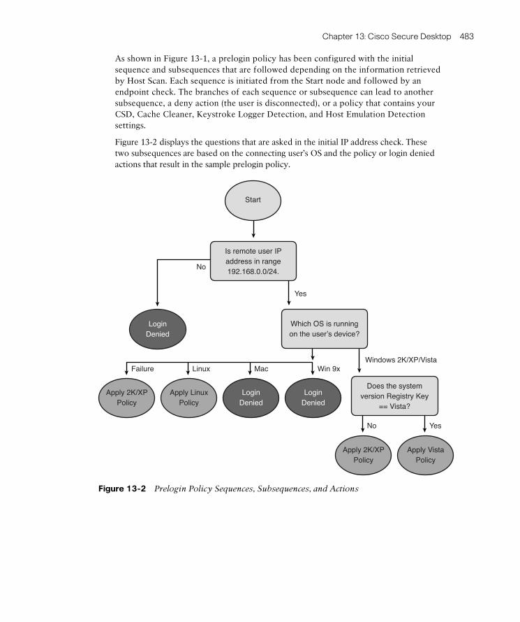
ptg8126969
Chapter 13: Cisco Secure Desktop 483
As shown in Figure 13-1 , a prelogin policy has been configured with the initial sequence and subsequences that are followed depending on the information retrieved by Host Scan. Each sequence is initiated from the Start node and followed by an endpoint check. The branches of each sequence or subsequence can lead to another subsequence, a deny action (the user is disconnected), or a policy that contains your CSD, Cache Cleaner, Keystroke Logger Detection, and Host Emulation Detection settings.
Figure 13-2 displays the questions that are asked in the initial IP address check. These two subsequences are based on the connecting user’s OS and the policy or login denied actions that result in the sample prelogin policy.
Is remote user IPaddress in range192.168.0.0/24.
Does the systemversion Registry Key
== Vista?
Which OS is runningon the user’s device?
LoginDenied
LoginDenied
No
No
Win 9xMacLinuxFailure
Yes
Windows 2K/XP/Vista
Yes
LoginDenied
Apply VistaPolicy
Apply 2K/XPPolicy
Apply LinuxPolicy
Apply 2K/XPPolicy
Start
Figure 13-2 Prelogin Policy Sequences, Subsequences, and Actions

ptg8126969
484 CCNP Security VPN 642-648 Official Cert Guide
Host Scan
Three types of host scans are available:
■ Basic host scans
■ Endpoint assessments
■ Advanced endpoint assessments
The ASA uses Host Scan to make policy decisions based on the remote user’s OS, patch level, Registry keys (Windows only), local files, IP address, and digital cer-tificates. In addition, Host Scan can detect keystroke loggers and host emulation. Beginning with AnyConnect Secure Mobility Client Version 3.0.0 and Adaptive
Security Appliance (ASA) Version 8.4, the Host Scan module is available separately, as part of the CSD software, or as part of the AnyConnect software bundle. In earlier AnyConnect and ASA versions, the Host Scan module was available only as part of the CSD software.
The introduction of Host Scan as an independent module allows for updates to be deployed and installed more frequently than in earlier releases; that is, it is faster to release a new version of Host Scan and its list of supported software (antivirus, antispy-ware, and so on) than the full CSD package each time. AnyConnect client versions pre-3.0.0 can work with the up-to-date and future versions of the Host Scan module that are deployed independently. However, it is not possible to run AnyConnect 3.0.0 and later with earlier versions of the Host Scan module. For example, if an AnyConnect client using Version 3.0.1 attempts to connect to an ASA using the Host Scan version bundled with the CSD 2.2, the prelogin assessment will fail, and the connection attempt will be denied.
Endpoint Assessment extensions can be enabled to check the user’s device for installed antivirus, antispyware, and firewall software, in addition to installed definition files or patches and standard Host Scan parameters mentioned earlier.
You can also purchase an additional license to enable advanced Endpoint Assessment extensions through which you can check for locally installed antivirus, antispyware, firewall software, definitions, and patches; these also enable remediation to occur. For example, if the antivirus software you are checking for is an earlier version than that specified in your policy, you can automatically perform the actions to update it or, for example, if a user were to disable his antivirus or personal firewall installed locally on his device, Host Scan will attempt for a period of 60 seconds to reenable them.
Secure Desktop (Vault)
The Vault is a secure partition on the remote user’s device that is created during CSD installation and before login, which then provides a Secure Desktop area that a user accesses when using CSD. CSD encrypts any files associated with the VPN session and located within the secure partition created. In addition, CSD also removes any cookies,

ptg8126969
Chapter 13: Cisco Secure Desktop 485
browser history, and temporary or permanent files that have been created or accessed during the VPN session after a remote user has logged out, the session terminates abnor-mally, or the users VPN session times out.
In addition to creating a secure partition, you can control the user experience by allow-ing or denying access to locally installed programs, file systems, and the local desktop. The following is a list of applications that have been known to work (tested) within a Vault session:
■ Microsoft Office 2007 (Word, Excel, PowerPoint, Notepad, and WordPad)
■ Instant messaging (Sametime 3.5, WebEx Connect 6.5)
■ Email (Outlook 3.5 and Eudora)
■ Browsers (Internet Explorer 7, 8, and 9; Firefox 3.5)
■ Adobe Reader 9
■ Antivirus, antispyware, and firewall products supported by Host Scan
■ Native Windows, Linux, and Mac OS X command-line FTP client
■ Commands frequently used in Windows command prompt, such as dir , cd , del , ftp , ipconfig, and net start/stop/status
■ Windows Explorer
■ AnyConnect Secure Mobility Client, Release 2.5 on supported Windows XP plat-forms only
■ Clientless VPN access (Smart tunnels, Outlook Web Access [OWA] , and Dominos
Web Access [DWA] ).
The CSD environment can be fully customized, allowing for the use of a corporate logo for a desktop background image, custom button images, and so on. You can also provide remote users with the option to save their files and settings accessed during a VPN ses-sion within the CSD. However, CSD reuse can occur only when a remote user attempts to establish a VPN connection from the same device.
Cache Cleaner
Cache Cleaner is an alternative to Secure Desktop, with limited functionality, that is commonly deployed to operating systems that are unsupported by the Secure Desktop (and in general is deployed for clientless SSL VPN sessions). The Cache Cleaner can run on Windows, Linux, or Mac devices and operates by clearing the user’s browser cache (including any stored passwords, downloaded files, and so on) on termination of the session either through the user logging out or the VPN session timing out. The Cache Cleaner can operate in one of two modes. The amount of cache information removed depends on the mode configured:

ptg8126969
486 CCNP Security VPN 642-648 Official Cert Guide
■ Clear the Whole Cache (IE Only)
■ Clear the Current Session Cache
When configured to clear only the current session cache after a minute of the user initially logging in to the VPN, Cache Cleaner takes a snapshot of the current browser cache. Later, when the VPN is disconnected, the Cache Cleaner removes all browser cache information and attempts to restore the snapshot taken at the beginning of the session.
One of the main downsides with the Cache Cleaner program is seen when a connected user opens a second browser window. Unfortunately, the Cache Cleaner monitors only the previously opened window. Therefore, users must be educated that for the security of their data, the original browser window used to log in should be the only one used during their SSL VPN session
Keystroke Logger
Keystroke Logger, when enabled, downloads to the user’s machine and scans it for any known or suspected keystroke logging software applications that might have been installed on the user’s machine. The Keystroke Logger can be configured with a list of known applications that might or might not have been approved by the administrator. If any software is located that is not approved, the user may be prompted with a list of the application names that have been located and asked to approve them, or the VPN can be configured to terminate.
The Keystroke Logger can detect both User and Kernel mode software keystroke log-gers. However, it cannot detect the presence of hardware keystroke loggers. The module can run on Windows 32-bit devices and requires the local user to have administrative privileges before it can operate.
Integration with DAP
As covered in Chapter 11 , CSD is heavily integrated into the DAP policy selection and assignment procedures. When you choose to perform posture assessment, the OS version and patch level are determined by the basic host scan. However, you can also retrieve advanced settings, such as the antivirus vendor and status, local firewall, and so on, performed by the endpoint assessment and advanced Endpoint Assessment extensions, and thus base your policy decisions and assignments on the results received.
Host Emulation Detection
CSD can detect whether your remote user’s SSL VPN session has originated from within a virtual machine environment, and it enables you to base your policy decision on the results received. For example, you might want to restrict access to remote users who

ptg8126969
Chapter 13: Cisco Secure Desktop 487
are connecting to your organization using an OS within a virtual machine (limited to Windows 32-bit systems only).
Windows Mobile Device Management
When you deploy the AnyConnect client to remote devices, additional posture checks can be performed by the Host Scan module that is specific to mobile devices. So, you can create specific DAPs for mobile devices. However, the feature requires AnyConnect to be installed on the remote system and an Advanced Endpoint Assessment license on the ASA.
Standalone Installation Packages
As well as being able to automatically deploy the CSD package to remote users during a login attempt, you can also download standalone versions of the various CSD packages (OS specific) for manual or company-wide automatic installation. However, any manu-ally installed CSD packages cannot be automatically uninstalled from the user’s machine if configured to do so on the ASA.
CSD Manual Launch
Once CSD is installed locally on the user’s device, it is possible for the user to open the CSD software and automatically start a clientless SSL VPN session without the need for Java or ActiveX controls.
CSD Order of Operations
As discussed earlier, three phases occur: before (prelogin), during (post-login), and after a remote user’s SSL VPN session (session termination). The following subsections identify the steps taken from the prelogin stage to the end of a user’s VPN session.
Prelogin Phase
1. The user enters the SSL VPN URL or starts the AnyConnect client to access the SSL VPN.
2. The OS Detection module is downloaded, runs, and reports back the device’s OS and patch level to the ASA.
3. The Host Scan module is downloaded and runs on the client device for additional policy-matching criteria (for example, Registry keys and local file systems).
4. Based on the OS Detection and Host Scan module information, the prelogin policy is matched and applied to the user or the connection is denied.
Key Topic

ptg8126969
488 CCNP Security VPN 642-648 Official Cert Guide
5. If the connection is allowed, the remote machine is checked for keyloggers and host emulation. Furthermore, if an Advanced Endpoint Assessment license has been installed and the option configured within the policy, the remote machine is checked for antivirus, antispyware, and personal firewalls installed. At this stage, any remediation required is also conducted.
6. Depending on the prelogin policy applied, the Vault or Cache Cleaner downloads and installs on the user’s device.
7. The user enters his VPN credentials and is authenticated using the configured authentication methods for the connection profile he is connecting to.
8. After successful authentication, any matching DAP records, group policies, and user attributes are applied in accordance with the ASA’s hierarchal policy assignment model.
9. The SSL VPN session is established.
Post-Login Phase
10. The remote user is now using her VPN session within the Vault area or with Cache Cleaner running. Depending on the settings applied during the prelogin phase, a web page may open to, for example, a company intranet or webmail session; the remote user may be restricted to using only her web browser; printing may be dis-abled, and so on.
Session-Termination Phase
11. The user has finished with the SSL VPN session and logs out, or either the inactivity or idle timer expires.
12. The VPN session-termination phase settings are applied. For example, cache data is removed, files are deleted, and Vault, AnyConnect, or Cache Cleaner is uninstalled.
As described in the preceding list, the first phase (prelogin) occurs after the user has navigated to the SSL VPN portal URL (unless connecting with AnyConnect). If CSD has been enabled for the particular connection profile users are connecting to (determined by the alias entered), they are presented with the Cisco Secure Desktop WebLaunch page, as shown in Figure 13-3 .

ptg8126969
Chapter 13: Cisco Secure Desktop 489
Figure 13-3 Cisco Secure Desktop WebLaunch
After the WebLaunch page is presented, the following two stages occur:
■ The OS Detection module is launched for detection of the remote device’s OS.
■ The Host Scan module is downloaded and installed.
The installation and running of these modules takes care of the prelogin assessment phase. These modules gather the information you require for your prelogin policy assignment (for example, which OS is installed on a remote user’s device, or whether their antivirus is running with the most up-to-date definitions installed). These set-tings are all determined by the Host Scan parameters you have defined, along with the prelogin policy you have configured (which is explained in further detail in the next section).
After the initial prelogin assessment, the ASA should have determined whether login is denied or allowed, matched the CSD policy applied to the user, and determined whether the user will be using the Vault (Secure Desktop) or Cache Cleaner.
Depending on the policy that has been applied to them at this stage, you can check whether the connecting user is doing so from a virtual machine and for any keylogging software that might have been intentionally or inadvertently installed on the remote device. You can specify a list of approved or “safe” keylogging software that can be ignored by the CSD or Cache Cleaner. However, if keylogging software is encountered and is not on the approved list (or you have not specified a list), the CSD will not install. After the host emulation and keylogging software checks have been performed and passed, the Vault (Secure Desktop) or Cache Cleaner applications download and install on the remote device.
Key Topic

ptg8126969
490 CCNP Security VPN 642-648 Official Cert Guide
After the Vault or Cache Cleaner has been installed and is running, the user is now presented with the familiar login page for the SSL VPN and can begin or continue an SSL VPN session. After authentication, any DAP records, group policies, and user set-tings become active. When users finish their session and log out, or the inactivity timer expires, the configured settings are applied (for example, to remove the CSD installation from the remote device or leave it installed for future use, run an application, provide the user access to their Vault again, and allow users to save settings). These settings are configured in the prelogin policy that had been applied to the user at the beginning of the connection (before login).
CSD Supported Browsers, Operating Systems, and Credentials
Before you can enable and deploy CSD and configure the prelogin policies that will apply to remote users, you must first assess the possible and common environments they might be connecting from. Based on the results you gather, you can determine groups of users with the same or similar settings and examine the environments that are available to them.
Table 13-2 lists the supported operating systems, required user privilege levels, and sup-ported browsers as of CSD Version 3.5. The table begins with the operating systems sup-ported by CSD.
Table 13-2 CSD Supported Operating Systems
Operating
System
Prelogin
Assessment
Host
Scan
Vault Cache
Cleaner
(32-Bit
Browsers
Only)
Keystroke
Logger
Detection
Host
Emulation
Detection
Windows XP SP2 x64 (64 bit)
X X
Windows XP SP2 and SP3 x86 (32 bit)
X X X X X X
Windows Vista x86 (32 bit) and x64 (64 bit)
X X X
Requires KB935855
X X
Requires KB935855
X
Requires KB935855
Windows 7 x86 (32 bit) and x64 (64 bit)
X X X
Key Topic

ptg8126969
Chapter 13: Cisco Secure Desktop 491
Operating
System
Prelogin
Assessment
Host
Scan
Vault Cache
Cleaner
(32-Bit
Browsers
Only)
Keystroke
Logger
Detection
Host
Emulation
Detection
Windows Mobile 6.0, 6.1, 6.1.4, and 6.5
X X X
Mac OS X 10.6, 10.6.1, 10.6.2x86 (32 bit), and x64 (64 bit)
X X X
Mac OS X 10.5.x x86 (32 bit) and x64 (64 bit)
X X X
Red Hat Enterprise Linux 3 x86 (32 bit) and x64 (64 bit) biarch
X X* X**
Red Hat Enterprise Linux 4 x86 (32 bit) and x64 (64 bit) biarch
X X* X**
Fedora Core 4 and later x86 (32 bit) and x64 (64 bit) biarch
X X* X**
Ubuntu X X X
* 32-bit and 64-bit biarch Linux operating systems (that is, 64-bit operating systems that can run 32-bit code) require the 32-bit versions of these libraries to run Host Scan: libx-ml2, libcurl (with openssl support), openssl, glibc 2.3.2 or later, and libz.
** 32-bit and 64-bit biarch Linux operating systems (that is, 64-bit operating systems that can run 32-bit code) require the 32-bit versions of these libraries to run Cache Cleaner: libxml2, libcurl (with openssl support), openssl, glibc 2.3.2 or later, and libz.

ptg8126969
492 CCNP Security VPN 642-648 Official Cert Guide
Based on the installation method chosen for the Secure Desktop, the local account privi-leges required by the remote users on their device can differ. Table 13-3 lists the installa-tion options available for remote users and their corresponding privilege levels required when using the AnyConnect Secure Mobility Client. Table 13-4 lists the installation options available when using a clientless SSL VPN connection.
Table 13-3 CSD Privilege Levels Required for Installation with AnyConnect Client
AnyConnect Client
Installed
AnyConnect Client
and CSD Install
Together
Executable File
Administrative privileges required?
No Yes Yes
Table 13-4 CSD Privilege Levels Required for Installation During Clientless SSL VPN
ActiveX Microsoft JVM Sun JVM Executable File
Administrative privileges required?
Yes No No Yes
As you can see from these tables, there are a few CSD installation options available to your remote users. When the AnyConnect client is already installed, the CSD instal-lation is similar to that of updating the existing AnyConnect installation, so there is no requirement for administrative privileges on the local machine. However, if the AnyConnect client is not installed and the two are installed together, the local admin-istrative rights are required. CSD alone cannot be used for full tunneling. Therefore, there is no need to use the executable file without the AnyConnect client if a full tunnel is required.
When you are initiating a clientless SSL VPN connection along with the CSD, admin-istrative privileges are required for both the ActiveX and Microsoft Java Virtual
Machine (JVM) installation options. However, because the Sun JVM is given the appropriate permissions, it handles its own security and therefore does not require local administrative privileges for CSD installations. The executable file method is intended for users who do not have ActiveX or Java installed or enabled on their con-necting device. The user can select the option to download the csd.exe file (the file extension changes depending on the OS), and once installed can type in the URL to the SSL VPN appliance when prompted. However, the initial installation requires adminis-trative privileges.
Table 13-5 lists the supported browsers when using CSD for Host Scan, Cache Cleaner, Secure Desktop, WebLaunch, and Prelogin Assessment modules to be able to run. The relevant browser security or advanced options must be selected to enable ActiveX
Key Topic

ptg8126969
Chapter 13: Cisco Secure Desktop 493
controls or Java, and browsers must support Extensible Markup Language (XML) pars-ing options. Also note that Host Scan and Cache Cleaner do not support 64-bit versions of Internet Explorer.
Table 13-5 CSD Prelogin Assessment and Host Scan Module Supported Browsers
Prelogin Assessment Host Scan
Internet Explorer 6 Yes Yes
Internet Explorer 7 Yes Yes
Mozilla Firefox 3.0.x Yes Yes
Safari 3.2.1 Yes Yes
Enabling Cisco Secure Desktop on the ASA
The process of enabling CSD on an ASA is pretty straightforward and begins by obtain-ing the latest CSD PKG file from Cisco.com. After you have obtained a copy of the CSD package, upload it to the ASA’s flash so that you can enable it. You can do so by navigating within the ASDM to either Configuration > Remote Access VPN > Secure Desktop Manager > Setup and clicking the Upload File button (illustrated in Figure 13-4 ) or navigating to Tools > File Management and using the file transfer menus to upload the PKG file from your local PC to the ASA.
Figure 13-4 ASDM Uploading the CSD Image
After you have uploaded the necessary PKG file, you can then enable the CSD by choosing Enable Secure Desktop or by entering the csd image location and csd enable CLI commands within webvpn configuration mode. After you do so and save your local configuration to flash, the CSD menu options become available on the left side of the screen below the original setup menu, as shown in Figure 13-5 .
Key Topic

ptg8126969
494 CCNP Security VPN 642-648 Official Cert Guide
Figure 13-5 ASDM Enable CSD
You can now carry out the configuration of your CSD customization, prelogin and post-login options, and policies. Note that all CSD-related configurations are stored also in XML format, on flash in the disk0:/sdesktop/data.xml path. When enabled, CSD reads the configuration from this file if it exists; otherwise, it creates it.
To customize the environment for your remote users, use the Secure Desktop Customization panel, found by navigating to Configuration > Remote Access VPN > Secure Desktop Manager > Secure Desktop Customization .
You are immediately greeted with the Customization window, shown in Figure 13-6 , where you can change the CSD text color, banners, and Secure Desktop background by uploading your own images.
Figure 13-6 ASDM CSD Customization

ptg8126969
Chapter 13: Cisco Secure Desktop 495
CSD can be enabled per connection profile, allowing you to apply CSD prelogin poli-cies to only those users who are, for example, home workers or remote engineers. To make use of this setting, the remote user must navigate to the specific group URL of the SSL VPN connection. You can find the option to disable the CSD within the connection profile settings at Configuration > Remote Access VPN > Clientless SSL VPN Access > Connection Profiles . Select the connection profile for which you want to disable CSD shown in the list of available profiles and choose Edit . In the Edit Clientless SSL VPN Connection Profile window, navigate to Advanced > Clientless SSL VPN , and toward the bottom of the window, choose Do Not Run CSD , as shown in Figure 13-7 . Note that the connection profile is required to have a group URL applied if one does not exist already.
Figure 13-7 Disable the CSD for a Particular Connection Profile/Tunnel Group
Configure Prelogin Criteria
Now that you have enabled the CSD package and taken a look at the customization and connection/tunnel options available, you can examine the prelogin configuration options and policies. The prelogin criteria you select can dictate the experience that your users receive through their SSL VPN connection. You can map the selection and match cri-teria using the intuitive flow-based GUI of the prelogin policy window, available at Configuration > Remote Access VPN > Secure Desktop Manager > Prelogin Policy .
Key Topic

ptg8126969
496 CCNP Security VPN 642-648 Official Cert Guide
By default, only one policy is configured (named default) for use with the CSD prelogin criteria. However, you can add more as you go or as your circumstances require. Figure 13-8 displays the initial Prelogin Policy window.
Figure 13-8 CSD Prelogin Policy Window
Based on the current actions defined within the default Prelogin Policy window, CSD installs on all remote users who connect to the SSL VPN, but you can change this behav-ior to deny all users instead. However, depending on your environment, you might want to change this behavior. For example, it is recommended practice to deploy CSD or Vault access to home users or users with corporate devices. However, for guests and remote users connecting from public machines, Cache Cleaner should be used instead.
You are given a few options within the prelogin policy that can enable you to determine whether a remote user is connecting from a corporate-owned device, a public device, or other device:
■ Registry Check: You can check for a specific key within the Windows Registry.
■ File Check: You can check for the existence of a particular local file on the user’s device.
■ Certificate Check: If your organization takes advantage of an internal or external Public Key Infrastructure (PKI) infrastructure, you can check for certain fields and values within certificates that have been deployed to users or devices. However, note that this is not a cryptographic check. It cannot guarantee that the certificate is issued by a certain certificate authority, but only verifies existence of a certificate and certain attributes within it.

ptg8126969
Chapter 13: Cisco Secure Desktop 497
■ OS Check: You can check for a particular OS running on a user’s device.
■ IP Address Check: You can check for a specific IP address or subnet that a remote user is connecting from.
For this example, start by dividing users based on the OS they are using on the device they are connecting from. You can do so by clicking the plus (+) symbol shown between the Start and Default Policy in the flow diagram, shown in Figure 13-9 . You are then pre-sented with the available policy criteria against which you can match a user’s settings and environment; for this example, we choose OS Check from the list and then click Add .
Figure 13-9 Insert a New Match Criteria into the CSD Prelogin Policy
As you can see in Figure 13-10 , as soon as we have added the OS Check, we are pre-sented with a new set of branches in our flow diagram, which list the available operating systems we can match against and the result (either allow or deny the user to connect).

ptg8126969
498 CCNP Security VPN 642-648 Official Cert Guide
Figure 13-10 Additional OS Check Branches Added to the Prelogin Policy
Using the preceding example, you can start to modify the environment your remote users receive based on the prelogin criteria they match (that is, the OS their device is running).
You can see in Figure 13-9 the example policy denies all operating systems apart from Windows 2000/XP/Vista/Win7. However, you can change this to also allow Linux users to connect. Double-click the current Login Denied policy decision next to Linux, and you are presented with a new window giving you the following options:
■ Login Denied
■ Policy
■ Subsequence
By selecting Policy , you can create a new prelogin policy or assign matching users to an existing one. (Only the Default prelogin policy exists at the moment.) If a policy by the name you have entered does not already exist, you can type in the name and click Update . A new branch is added to the CSD ASDM menu on the left under Prelogin Policy, containing the Keystroke Logger, Cache Cleaner, and Vault options you can cus-tomize for matching users of this policy.

ptg8126969
Chapter 13: Cisco Secure Desktop 499
If you select Subsequence , you can extend the flow diagram and, subsequently, the policy for this group of users who have matched the preceding criteria, basically adding more endpoint checks. You can once again add a label for the policy subsequence. This can be either a new or existing policy.
For this example, we change the login denied action for Linux users to instead apply the Linux policy we will create. We also change the name of the Default policy currently applied to our Windows OS users by double-clicking the Default flow action applied to them and changing the displayed label to Windows . As shown in Figure 13-11 , two poli-cies now appear in the menu on the left: Windows and Linux.
Figure 13-11 Addition and Modification of CSD Prelogin Policy Elements
Now that a basic prelogin policy has been set to match for Windows or Linux, all other users or OS types will be denied and will receive an “Access Denied” message on the CSD WebLaunch page, informing the users to contact their administrator. To continue the example, now extend the policy by clicking the plus (+) and the Windows policy action that is applied to users and adding the action File Check . For now, we use the default actions of the user having to have a local file of example.dat in the root of his C: drive. You can, however, change this particular option to match only if a file does not exist, is a particular version, or has a checksum that matches a specific value you enter. As shown in Figure 13-12 , after you click the Update button, the tree extends for Windows OS users, and additional Success or Failure branches are added, with the suc-cess applying the original Windows policy.

ptg8126969
500 CCNP Security VPN 642-648 Official Cert Guide
Figure 13-12 Create an Additional Match Criteria for Prelogin Policy Assignment
With the prelogin policy complete, you can now take a look at and configure the result-ing policies that will be applied to Windows and Linux users. As shown in Figure 13-12 , you are given the following menu items per policy for the user environment and end-of-session customization:
■ Keystroke Logger and Safety Checks
■ Cache Cleaner
■ Secure Desktop (Vault) General
■ Secure Desktop (Vault) Settings
■ Secure Desktop (Vault) Browser
Before you proceed to configure these menu settings, however, you must choose whether your users will receive the Vault or Cache Cleaner on policy application. This is achieved by choosing the root of the policy object within the menu displayed (that is, Windows or Linux). You have the option of choosing Secure Desktop (Vault) or Cache Cleaner. You can, however, leave both deselected and only subject your users to Host Scan checks if this is required by your environment. Note that you can choose only one option, not both together. If you choose Secure Desktop, and it cannot be installed on remote system but Cache Cleaner can be, Cache Cleaner is installed instead, although unchecked.
Keystroke Logger and Safety Checks
Within the Keystroke Logger and Safety Checks window, we are given the option to check the user devices for keystroke logging software they might have installed. The resulting action if any are found is to deny the connection and prevent the further installation of any CSD or Cache Cleaner modules. However, if your corporation has

ptg8126969
Chapter 13: Cisco Secure Desktop 501
sanctioned the use of particular keystroke logging software (for example, used for internal auditing), it is possible to add the name of the logging application for this to be bypassed and thus allowed. Note that this detects/protects against software keyloggers, not hardware ones. You are also given the option to turn on host emulation checking. (That is, is the host connecting from within a virtual machine?) By default, the action Allow is applied to any user connecting from a virtual machine. However, this can be changed by selecting Always Deny Access If Running Within Emulation .
Cache Cleaner
Within the Cache Cleaner window, you have the following options:
■ Launch Hidden URL After Installation: Along with an accompanying text field for you to be able to enter the URL, this option is sometimes used if your corpora-tion uses session logging utilities.
■ Show Success Message at the End of Successful Installation (Windows
Only): This option, if selected, displays a message to the user after the Cache Cleaner module has installed.
■ Launch Cleanup upon Timeout Based on Inactivity: By default, this option is selected and set to 5 minutes. Therefore, after 5 minutes of mouse inactivity, the user is disconnected, logged out, and the browser window closed (where available). Network inactivity is related to the idle timeout (also called traffic timer), which is configurable in the Group Policy section. It is important to note that if either timer expires, it will terminate the session.
■ Launch Cleanup upon Closing of All Browser Instances or SSL VPN
Connections: Starts cache cleanup process when all browser windows are closed or the session is closed.
■ Disable Cancel Button (Windows Only): Select this option if you want to remove the option to cancel Cache Cleaner actions from the user.
■ Clean the Whole Cache in Addition to the Current Session Cache (IE Only): As mentioned earlier, the Cache Cleaner by default watches only for session data on the current browser window opened during connection establishment (for example, Internet Explorer users). However, this option can be selected to remove the whole cache after they have finished their connection, including files, browsing history, and passwords retained before the session began.
■ Secure Delete: Select the number of times the Cache Cleaner will attempt to remove items from the cache on the user exiting or their session timing out, using a U.S. Department of Defense (DoD) sanitation algorithm. By default, this is set to 3. However, you can set it to a value between 1 and 27.

ptg8126969
502 CCNP Security VPN 642-648 Official Cert Guide
Secure Desktop (Vault) General
In this window, you can specify the general settings that apply to your Secure Desktop (Vault) users before during and after their connection. You have the following options:
■ Enable Switching Between Secure Desktop (Vault) and Local Desktop: This option is selected by default to allow access to both desktops. You can, however, restrict users to only allow them access to the Secure Desktop during their session, thus further securing their session. However, in situations where a user might need to respond to a prompt or gain access to a local application, access to both the secure desktop (Vault) and unsecured (local) desktop might be required.
■ Enable Vault Reuse: If you select this option, your users can save the settings from the current Secure Desktop session and access them again when reconnecting the SSL VPN in the future. If the option is selected, the user is prompted to create a password for the first time. On subsequent connection attempts from the same PC, the user is asked to reenter this password.
■ Suggest Application Uninstall on Secure Desktop Closing: If you select this option, the user is prompted to either remove or keep the installed Secure Desktop software used during this session. This might save time and be useful for home users who do not want to have to install and remove the software each time they connect.
■ Force Application Uninstall on Secure Desktop Closing: If selected, this option disallows users to choose if they will keep the software installed, and instead removes it without intervention.
■ Enable Secure Desktop (Vault) Inactivity Timeout: Selected by default, after 5 minutes of mouse inactivity, Secure Desktop is automatically closed.
■ Enable Secure Desktop (Vault) Inactivity Timeout Audio Alert: This option works together with the previous inactivity timer setting.
■ Open the Following URL After the Secure Desktop (Vault) Closes: As it says, this option can allow you to open a URL after the CSD session has closed (for example, a survey, questionnaire, or specific corporate script).
■ Secure Delete: Select the number of times the Secure Desktop will attempt to remove items on users exiting or their session timing out. By default, this is set to 3. However, you can set it to a value between 1 and 27.
■ Launch the Following Application After Installation: Select this option if your users have access to a locally installed corporate program or a diagnostic/logging program.

ptg8126969
Chapter 13: Cisco Secure Desktop 503
Secure Desktop (Vault) Settings
In this window, you can select the options that dictate what your connected users can or cannot access during their connection:
■ Restrict Application Usage: By default, the user is given access to the installed web browser only. However, by selecting this option, you can select the applica-tions that are available to your users within their web browser on Secure Desktop (that is, browser helpers). Figure 13-13 displays the current list of available browser helpers at this time. You can also optionally insert a hash of the program file that can be checked on its use. This hash is used to check the authenticity of an installed application.
Figure 13-13 Available Browser Helper Applications
■ Disable Access to Network Drives and Network Folders: By default, this option is selected. However, if your users require access to network shares and so on while connected to the SSL VPN, deselect this option.
■ Disable Access to Removable Drives and Removable Folders: Select this option if you want to prevent users from being able to access USB or removable media. This will, for example, prevent users from copying internal resources onto them or reduce the risk of malware and viruses from entering the user’s session and the network if present on his or her removable hardware. A subitem exists for this option for enabling or disabling encryption of files on removable drives. If the user is legitimately copying files from your corporate environment onto removable media, make sure this option is disabled. However, to increase security and to pre-vent the loss of internal data, select this option.

ptg8126969
504 CCNP Security VPN 642-648 Official Cert Guide
■ Disable Registry Modification: Registry modification is usually conducted by the installation of a program or running of a script. Select this option to prevent any virus or malware from saving or modifying settings within the Registry if users have inadvertently downloaded or accessed something they shouldn’t have.
■ Disable Command Prompt Access: Select this option if you do not want your remote users to be able to have command prompt access during their SSL VPN session.
■ Disable Printing: Select this option if you want to prevent your remote users from being able to print your corporation’s internal data.
■ Allow Email Applications to Work Transparently: If selected, this option allows the user to use email applications when using Secure Desktop and prevent the deletion of downloaded email attachments by the Secure Desktop on session ter-mination. Currently, supported email applications are Outlook Express, Outlook, Eudora, and Lotus Notes. Note that email attachments during a CSD session are saved both to the Vault and nonsecure (normal) My Documents folders. Therefore, if a remote user wants to delete a downloaded attachment, this must occur in both locations.
Secure Desktop (Vault) Browser
In this window, you can customize user browser settings for the duration of their SSL VPN session. You can achieve this by modifying the home page or adding bookmarks/favorites. This can be a great tool to use when providing users with a familiar environ-ment for them to access. For example, if your organization internally uses group policies to add internal or company resources to the bookmarks list, you can mirror these set-tings for remote users.
Host Endpoint Assessment
As mentioned earlier, three different types of host scan are available:
■ Basic host scans
■ Endpoint assessments
■ Advanced endpoint assessments
A basic host scan checks for and provides information to the ASA for further policy deci-sion making and assignment. This is typically OS and patch-level information. However, it is possible to add custom criteria to scan for by navigating to Configuration > Remote Access VPN > Secure Desktop Manager > Host Scan , as shown in Figure 13-14 .
Key Topic

ptg8126969
Chapter 13: Cisco Secure Desktop 505
Figure 13-14 CSD Host Scan Custom Criteria
In the Host Scan window, you can add your custom scan criteria. By clicking Add on the right side of the window, you can add one or more of the following criteria:
■ Registry Scan: Checks for a particular Registry key and value on the local machine
■ File Scan: Checks for a local file by name
■ Process Scan: Checks for a running process name on the local machine (for exam-ple, winword.exe)
The example in Figure 13-3 has configured Host Scan to look specifically for the file test.txt within the root of the users C:\ drive. Toward the bottom of the window, notice the highlighted Endpoint Assessment extension. Select this option to allow the Host Scan module to scan for well-known antivirus, personal firewall, and antispyware pro-grams. The information about any applications located on the remote user’s system is reported back to the ASA for further policy assignment through DAPs.
The Advanced Endpoint Assessment extension is available through the purchase of an additional license from Cisco, and as soon as you have installed the license through Configuration > Device Management > Licenses , the extension becomes available to select within the Host Scan Extensions panel.
As well as remediation, the Advanced Endpoint Assessment extension enables you to enforce rules or exceptions within personal firewall and antispyware programs. Based on the success or failure of the remediation attempts, you can allow or deny the user connection. This feature can be compared to a lightweight implementation of Network
Access Control (NAC) , which is used to perform posture assessment against a user’s device and optionally to perform remediation before granting network access.

ptg8126969
506 CCNP Security VPN 642-648 Official Cert Guide
Authorization Using DAPs
As you saw in the earlier chapter covering DAP deployment, a number of policy ele-ments require the installation of CSD before the profile settings can be configured (for example, antivirus, local files, and personal firewall). The Host Scan and Endpoint Assessment extensions, when enabled, can be used alongside DAP by first scanning for endpoint criteria and sending the results of their scan back to the ASA for policy retriev-al and assignment based on configured DAP endpoint attributes.
As you can see in Figure 13-15 , a DAP policy has been created within the ASDM loca-tion Configuration > Remote Access VPN > Clientless SSL VPN Access > Dynamic Access Policies . Within the DAP policy, a policy has been created to check for the user connection type (clientless) (to make sure they do not have 360Safe.com’s Ant-Spyware program installed), the existence of the Microsoft Windows Firewall and whether it is running, and also that McAfee Managed VirusScan is installed and running. These end-point attributes are unavailable to us if the CSD has been disabled.
Figure 13-15 ASDM DAP Endpoint Attribute Configuration
The endpoint attributes listed in Table 13-6 are available for configuration and subse-quent matching based on the CSD being previously enabled.
Table 13-6 Available DAP Endpoint Attribute Criteria with CSD Enabled
Endpoint
Attribute
Purpose
Antispyware Requires CSD and checks for an installed, enabled, or disabled antispyware program from an extensive list of well-known programs.
Choose the vendor, product ID, version, and last update time and date.
Antivirus Requires CSD and checks for an installed, enabled, or disabled antivirus program from an extensive list of well-known programs.
Choose the vendor, product ID, version, and last update time and date.

ptg8126969
Chapter 13: Cisco Secure Desktop 507
Endpoint
Attribute
Purpose
Device Requires CSD and checks for a match on the following:
Hostname
MAC address
Port number
Privacy protection
Version of CSD installed
Version of Endpoint Assessment extension
Personal firewall Requires CSD and checks for an installed, enabled, or disabled personal firewall program from an extensive list of well-known programs.
Choose the vendor, product ID, and version.
Policy Requires CSD and checks for name of the applied CSD policy.
Process Requires CSD and checks for a process that does or does not exist based on your criteria.
Registry Requires CSD and checks for a Registry entry that does or does not exist based on your criteria.
Specify the type, value, and case of the Registry entry.
Troubleshooting Cisco Secure Desktop
In the previous sections, you learned the basic elements and configuration required for a successful CSD installation. You looked at the prelogin assessment tree-based GUI and various policy options that are available to you for policy assignment, Host Scan ele-ments, and configuration with DAP. Now armed with this information, you are ready to take a look at some common troubleshooting tasks you might face when deploying CSD for secure access into an environment.
One of the most common reasons for policy assignments or prelogin assessments to fail is local authentication or browser settings. It is imperative that the user has the correct ActiveX or Java settings enabled for the modules to be able to run and install. It is also important to note that a user must have local administrative privileges, unless installing through a clientless VPN and using the Sun Java virtual machine. However, it is more likely that users will connect from many different locations and device types via SSL VPN. For this reason alone, you can determine how important it is to prepare a full assessment of your current environment before deploying CSD access. This assessment minimizes the disruption and downtime your users might otherwise experience.

ptg8126969
508 CCNP Security VPN 642-648 Official Cert Guide
Secure Sockets Layer/Transport Layer Security (SSL/TLS) is commonly enabled on a connecting user’s browser by default. However, it is worth checking with your users to see whether they can browse to HTTPS-enabled sites. Connectivity errors or problems might also be the cause of a user being unable to access your SSL VPN. The familiar tools to use when troubleshooting client connectivity include the following:
■ Ping by fully qualified domain name (FQDN) or IP address if name resolution is not functional.
■ Traceroute to verify where possibly connectivity is blocked in the path.
■ NSLookup to check on FQDN to IP address resolution.
After troubleshooting client connectivity and confirming the user can access your SSL VPN appliance, you can determine further possible causes with CSD by inspecting the Windows Event Viewer application logs, shown in Figure 13-16 .
Figure 13-16 CSD Endpoint Information: Windows Event Viewer
Key Topic

ptg8126969
Chapter 13: Cisco Secure Desktop 509
The remote device’s Event Viewer information shown here displays the results gathered by the Host Scan and Endpoint Assessment modules after downloading and running. You can view a comprehensive list of all settings searched for and found using the modules, such as OS version and patch level, the KB files installed, service pack, any local files or Registry keys it has been configured to search for, personal firewall, and antivirus. The Event Viewer logs in Figure 13-15 report the endpoint assessment scan located a personal firewall, the name of the firewall is Microsoft Windows Firewall, and the version is XPSP2+. However, it is disabled. If the policy had called for the remote user’s personal firewall to be enabled, the prelogin assessment would have failed, causing the connecting user to receive an “Access Denied” message within the CSD WebLaunch window.
ADSM logging and Event Viewer can also help you troubleshoot and debug. You can specify the amount of information that is logged by CSD during its operation by navi-gating to Configuration > Remote Access VPN > Secure Desktop Manager > Global Settings within the ASDM, where you can choose from the following logging-level options:
■ Errors: Logs events that prevent CSD operation
■ Warnings: Logs events that prevent optimal CSD operation
■ Information: Logs events that describe the state, configuration, and operation of the CSD
■ Debugging: Full logging of all CSD events

ptg8126969
510 CCNP Security VPN 642-648 Official Cert Guide
Exam Preparation Tasks
As mentioned in the section “How to Use This Book” in the Introduction, you have a few choices for exam preparation: Chapter 22 , “Final Exam Preparation,” Appendix C , “Memory Tables” (CD only), and the exam simulation questions on the CD.
Review All Key Topics
Review the most important topics in the chapter, noted with the Key Topic icon in the outer margin of the page. Table 13-7 lists a reference of these key topics and the page numbers on which each is found.
Table 13-7 Key Topics
Key Topic Element Description Page
Bulleted list CSD phases 481
Topic Prelogin assessment criteria and options 482
Topic CSD order of operations 487
Bulleted list WebLaunch background actions 489
Table 13-2 CSD supported OS 490
Table 13-3 CSD required credentials 492
Topic Enabling Secure Desktop on the ASA 493
Topic Configuring prelogin criteria 495
Topic Host endpoint assessment 504
Topic Troubleshooting client CSD installation with Event Viewer
508
Complete Tables and Lists from Memory
Print a copy of Appendix C , “Memory Tables” (found on the CD), or at least the section for this chapter, and complete the tables and lists from memory. Appendix D , “Memory Tables Answer Key,” also on the CD, includes completed tables and lists to check your work.
Define Key Terms
Define the following key terms from this chapter, and check your answers in the glossary:
CSD, DAP, Host Scan, prelogin assessment, Vault
Key Topic

ptg8126969
This page intentionally left blank

ptg8126969
This chapter covers the following subjects:
■ Cisco VPN Client Features: This section discusses the features of the client software and the support-ed device operating systems.
■ Client Software Installation and Basic
Configuration: This section covers the installation of the client software on a Microsoft Windows 7 device and walks through the steps required to implement a basic VPN connection.
■ Advanced Profile Settings: This section examines PCF configuration files and the advanced options available when customizing the client for our remote users and OEM use.
■ VPN Client Software GUI Customization: This section discusses further customizing the client GUI for the remote user experience.
■ Troubleshooting VPN Client Connectivity: This section covers how to troubleshoot connectivity errors.

ptg8126969
Despite the introduction of Secure Sockets Layer virtual private networks (SSL VPN) , the Cisco IPsec VPN client remains one of the most common applications used by corporate remote workers to connect into their office environment. The client enables remote workers to seamlessly continue working from their location over any IP-enabled network, just as if they were in the office.
By the end of this chapter, you will understand and be able to explain how to install and configure the Cisco VPN Client and how to troubleshoot common connectivity issues.
As discussed in Chapter 1 , “Examining the Role of VPNs and the Technologies Supported by the ASA,” and Chapter 8 , “Deploying an AnyConnect Remote Access VPN Solution,” two versions of Internet Key Exchange (IKE) are now supported by the Adaptive Security Appliance (ASA) starting from Version 8.4: IKEv1 and IKEv2. The discussions about Internet Key Exchange (IKE) within this chapter refer only to IKEv1 because the Cisco IPsec VPN currently offers support only for IKEv1. There are no current plans to add support for IKEv2 to the IPsec client, because it has been officially declared end-of-sale/life (EOS/EOL) with no successor for IPsec IKEv1 client in the pipeline.
“Do I Know This Already?” Quiz
The “Do I Know This Already?” quiz helps you determine your level of knowledge on this chapter’s topics before you begin. Table 14-1 details the major topics discussed in this chapter and their corresponding quiz sections.
Table 14-1 “Do I Know This Already?” Section-to-Question Mapping
Foundation Topics Section Questions
Advanced Profile Settings 1
IPsec Review 2 , 3 , 4 , 5
Client Software Installation and Basic Configuration 6
CHAPTER 14
Deploying and Managing the Cisco VPN Client

ptg8126969
514 CCNP Security VPN 642-648 Official Cert Guide
1. Which files are used for holding connection entry information?
a. TXT
b. PCF
c. CSV
d. MDB
2. Which of the following are not platforms capable of running the Cisco IPsec VPN Client? (Choose all that apply.)
a. Android
b. Windows XP
c. Linux
d. Mac OS X 10.4
3. Which of the following are capable of fulfilling the role of the VPN head-end device?
a. Cisco ASA 5500
b. Cisco PIX
c. Cisco ACE
d. Cisco Catalyst 6500
4. Which of the following are not valid DH groups for use with the Cisco IPsec VPN Client? (Choose all that apply.)
a. 1
b. 2
c. 5
d. 7
5. What is the recommended value when setting the MTU for a connection?
a. 576
b. 1500
c. 1300
d. 1518

ptg8126969
Chapter 14: Deploying and Managing the Cisco VPN Client 515
Foundation Topics
Cisco IPsec VPN Client Features
Now that you have reviewed the basics of the operations and protocols required for the creation of an IPsec VPN tunnel, it is time to move on to the IPsec VPN client. The IPsec VPN client performs the peer operations required for the correct establishment of an IPsec tunnel with a VPN head end. The head-end functions are commonly carried out by one of the following devices: ASA, PIX, VPN concentrator, or Cisco IOS router, providing access to corporate resources for authenticated users through the established tunnel.
The Cisco IPsec VPN client has been made available as a separate download for the fol-lowing operating systems:
■ Microsoft Windows 2000, XP, Vista, and 7 (both 32-bit and 64-bit versions)
■ Linux (Intel)
■ Solaris UltraSPARC 32 bit and 64 bit
■ Mac OS X 10.4 and 10.5
It is also compatible for use with the following Cisco products that have been config-ured to assume the role of the VPN peer or head end:
■ Cisco IOS Software-based platforms 12.2(8)T and later
■ Cisco ASA 5500 series appliances Version 7.0 and later
■ Cisco PIX security appliance software Version 6.2.2(122) or 6.3(1)
■ Cisco 7600/6500 IPsec VPN Services module and Cisco IPsec VPN SPA (Shared Port Adapter) using 12.2SX and later
■ Cisco VPN 3000 Concentrator Version 3.0 and later
Tables 14-2 , 14-3 , and 14-4 list the available features and any protocol support the Cisco VPN client offers. Although this might not be a key element of the information required for the CCNP Security VPN exam, it is worthwhile knowing what the VPN client is capable of when you are preparing to deploy a remote-access VPN solution in a real environment.

ptg8126969
516 CCNP Security VPN 642-648 Official Cert Guide
Table 14-2 General Functions Available in the Cisco VPN Client
Functions Details
Connection types supported
Internet-attached Ethernet, async serial PPP
Protocol support IP/IPsec
User authentication methods available
RADIUS, TACACS+, RSA SecurID, VPN Server local authentication, PKI, smart cards, Microsoft Active Directory
General features Online help, event logging, Network Address Translation (NAT) Transparency, optional MTU size setting, support for dynamic Domain Name System (DNS) , virtual adapter, VPN client application programming interface (API) , and so on
Firewall Support for firewalls, centralized protection policy, stateful firewall, Internet Control Message Protocol (ICMP) permission
IPsec Internet Security Association and Key Management Protocol (ISAKMP) , Internet Key Exchange (IKE) keepalives, split tunneling, split DNS support, LZS data compression, single security association (SA)
Troubleshooting Multiple logging levels available for local event and connection logging
Table 14-3 Windows Features Supported by the Cisco VPN Client
Features Details
Password Expiration Support for internal password policies. That is, users may be required to change their Windows domain password every 30 days. If this occurs during the time they are attempting to log in to the VPN, the client prompts them to enter a new password and confirm it.
Start Before Logon This is an important feature for users with roaming profiles that may require network access during their login to their local machine. The VPN client can be configured to start before the user logs in to Windows, allowing the client to initiate a connection to the network before logging in locally.
Automatic VPN Disconnect on Logoff
The software enables you to disable or enable the automatic disconnection of the VPN connection if the user chooses to log off from his local machine.

ptg8126969
Chapter 14: Deploying and Managing the Cisco VPN Client 517
Table 14-4 Cisco VPN Client Supported IPsec Attributes
IPsec Attribute Details
Main and Aggressive mode
Available IKE Phase 1 methods
Authentication algorithms
Hash-based Message Authentication Code (HMAC) message digest 5 algorithm (MD5)
HMAC Secure Hash Algorithm 1 (SHA-1)
Peer authentication modes
Pre-shared keys
Mutual group authentication
X.509 digital certificates
Diffie-Hellman groups
Group 1 768-bit Prime Modulus
Group 2 1024-bit Prime Modulus
Group 5 1536-bit Prime Modulus
XAuth Support for IKE user authentication (optional IKE Phase 1.5)
Tunnel encapsulation modes
IPsec over UDP (port manually configured)
IPsec over TCP (port manually configured)
NAT Traversal (NAT-T) IPsec over User Datagram Protocol (UDP) /4500
Note For up-to-date product information and features supported by the Cisco IPsec VPN client, go to Cisco.com and see the Cisco VPN client data sheets located at Products & Services > Security > Cisco VPN Client > Product Literature > Data Sheets .
Cisco ASA Basic Remote IPsec Client Configuration
The process of configuring the ASA for remote IPsec client connections is similar to that which you have already seen within the sections that detail SSL and IKEv1 connectivity. For example, a connection profile (tunnel group) is created for the purposes of tunnel termination, then a group policy can be created containing the various attributes that may be required to control user access to resources, specify authentication server types, address pools, and so on. This in turn can be attached to your new connection profile or local user accounts for further granularity.
If you have already created a group policy object or are planning to use the default group policy object that exists on the ASA, the first step, as with any configuration of a VPN on the ASA, is the connection profile configuration. You use the tunnel-group name type remote-access command at the command-line interface (CLI) to create the new connection profile. After this, you can specify the various attributes and IPsec-
Key Topic

ptg8126969
518 CCNP Security VPN 642-648 Official Cert Guide
specific properties using the tunnel-group name general-attributes and tunnel-group name ipsec-attributes commands, respectively. However if you have not yet created a group policy and want to define one of your own, when configuring using the CLI it is important to carry out this action before attempting to assign one to the connection pro-file. Otherwise, you receive the message “ERROR: group-policy name does not exist.” Example 14-1 displays the commands required for a basic IPsec client configuration. The crypto map, transform sets, and policies created are covered in more detail in Chapter 15 , “Deploying Easy VPN Solutions.”
Example 14-1 IPsec Remote-Access Configuration
CCNPSec# conf t
CCNPSec(config)# group-policy ipsec-ra-policy internal
CCNPSec(config)# group-policy ipsec-ra-policy attributes
CCNPSec(config-group-policy)# vpn-tunnel-protocol ikev1
CCNPSec(config-group-policy)# exit
CCNPSec(config)# tunnel-group ipsec-ra type remote-access
CCNPSec(config)# tunnel-group ipsec-ra general-attributes
CCNPSec(config-tunnel-general)# default-group-policy ipsec-ra-policy
CCNPSec(config-tunnel-general)# address-pool 192
CCNPSec(config-tunnel-general)# dns name-server 1.1.1.1 2.2.2.2
CCNPSec(config-tunnel-general)# exit
CCNPSec(config)# tunnel-group ipsec-ra ipsec-attributes
CCNPSec(config-tunnel-ipsec)# ikev1 pre-shared-key Pr3Shar3dK3y
CCNPSec(config-tunnel-ipsec)# ikev1 user-authentication none
CCNPSec(config-tunnel-ipsec)# exit
CCNPSec(config)# crypto ikev1 enable outside
CCNPSec(config)# crypto ikev1 policy 5
CCNPSec(config-ikev1-policy)# authentication pre-share
CCNPSec(config-ikev1-policy)# encryption 3des
CCNPSec(config-ikev1-policy)# hash sha
CCNPSec(config-ikev1-policy)# group 2
CCNPSec(config-ikev1-policy)# lifetime 86400
CCNPSec(config-ikev1-policy)# exit
CCNPSec(config)# crypto ipsec ikev1 transform-set ESP-AES-256-MD5 esp-aes-256 esp-md5-hmac
CCNPSec(config)# crypto ipsec ikev1 transform-set ESP-DES-MD5 esp-des esp-md5-hmac
CCNPSec(config)# crypto ipsec ikev1 transform-set ESP-DES-SHA esp-des esp-sha-hmac
CCNPSec(config)# crypto ipsec ikev1 transform-set ESP-3DES-SHA esp-3des esp-sha-hmac
CCNPSec(config)# crypto ipsec ikev1 transform-set ESP-3DES-MD5 esp-3des esp-md5-hmac
CCNPSec(config)# crypto dynamic-map IKEV1CLIENT_DYN_CRYPTO_MAP 65535 set ikev1 transform- set ESP-AES-256-MD5 ESP-3DES-SHA ESP-3DES-MD5 ESP-DES-SHA ESP-DES-MD5
CCNPSec(config)# crypto map VPNCLIENTMAP 65535 ipsec-isakmp dynamic IKEV1CLIENT_DYN_CRYPTO_MAP
CCNPSec(config)# crypto map VPNCLIENTMAP interface outside

ptg8126969
Chapter 14: Deploying and Managing the Cisco VPN Client 519
Let’s take a look at the configuration shown in Example 14-1 . First, you enter global con-figuration mode ( conf t ). With the next three lines, you configure a new internal group policy object that will be used along with the connection profile. The second line in the example, group-policy ipsec-ra-policy internal , creates the group policy object. You saw this in earlier examples when working with SSL VPNs. The same should be true for lines three and four, whereby the group policy’s attributes are configured. Unlike earlier exam-ples, however, the only protocol allowed with this policy is IKEv1. Beginning with line six, the connection profile configuration is carried out by first issuing the tunnel-group ipsec-ra remote-access command. After this, in line seven, the tunnel-group ipsec-ra general-attributes command is used to enter the tunnel-group (connection profile) configuration mode, allowing for the specific tunnel attributes to be specified. For example, as shown, the default group policy object for the connection profile has been configured using the new group policy object created in line two. An address pool and DNS servers have been configured to allow for connecting clients to receive an IP address after successful authen-tication and to resolve internal names to addresses.
Following on from the general properties described in the preceding paragraph (and that you have seen already in the earlier examples in this book), the example now moves to the IKEv1-specific properties of the connection profile by first entering the tunnel-group ipsec-ra ipsec-attributes command to move you into the ipsec attributes configuration mode of your connection profile. In this mode, you can specify pre-shared keys, PFS usage, DH groups, and so on. However, for this example only the pre-shared key has been configured using the ikev1 pre-shared-key key command. In addition to the pre-shared key, XAuth has been disabled using the ikev1 user-authentication none command.
Using the ASDM to achieve the same result is quite straightforward, as you have seen in earlier examples in this book. Just navigate to Configuration > Remote Access VPN > Network (Client) Access > IPsec (IKEv1) Connection Profiles and click Add . A Connection Profile window open, where you can enter the name and specify the group policy, authentication server groups, and IP address pools, as shown in Figure 14-1 .
Figure 14-1 IPsec Client VPN Configuration

ptg8126969
520 CCNP Security VPN 642-648 Official Cert Guide
The last item to be configured in Example 14-1 was the disabling of XAuth. You can achieve this via the ASDM Connection Profile window by navigating to Advanced > IPsec > IKE Authentication . As shown in Figure 14-2 , to disable XAuth, choose Disable User Authentication During IKE from the drop-down menu.
Figure 14-2 Disabling XAuth for IPsec Client Connectivity
IPsec Client Software Installation and
Basic Configuration
Now that you have seen how to configure a basic connection profile allowing IPsec client connectivity to be established with your ASA, you can move on to examine the IPsec client itself in more detail.
You can install the Cisco VPN Client manually by using the Installation Wizard or auto-matically by deploying the available MSI file to Microsoft Windows devices using a group policy.
Installation begins by obtaining a copy of the VPN client. A copy of the client is shipped along with any purchased ASA or VPN Concentrator 3000 device (with the exception of the ASA 5505). Customers with a valid service contract and account may also download the latest copy of the VPN client from the Cisco.com website.
After you have obtained a copy of the software, continue the install by unzipping the packaged files and double-clicking the setup.exe file. After a few moments, the Welcome screen appears, as shown in Figure 14-3 .
Key Topic

ptg8126969
Chapter 14: Deploying and Managing the Cisco VPN Client 521
Figure 14-3 IPsec VPN Client Installation Wizard: Screen 1
Read through the information on the Welcome screen and click Next to continue to the client software license agreement, shown in Figure 14-4 .
Figure 14-4 IPsec VPN Client Installation Wizard: Screen 2
You are given a chance to review the license agreement. Upon agreement, click the I Accept the License Agreement radio button, shown in Figure 14-4 , and then click Next .
The third screen, shown in Figure 14-5 , enables you to choose the destination path the files will be installed to. Unless you have a specific destination to use, it is best to keep the default path and click Next .

ptg8126969
522 CCNP Security VPN 642-648 Official Cert Guide
Figure 14-5 IPsec VPN Client Installation Wizard: Screen 3
After you have accepted the license agreement and chosen the destination folder used to store the installed Cisco IPsec VPN client files, the wizard has enough information to proceed with the installation, as shown in Figure 14-6 . Select Next to proceed with the installation, or click Back to review the earlier options.
Figure 14-6 IPsec VPN Client Installation Wizard: Screen 4
As shown in Figure 14-7 , the wizard now moves on to copy the required files and install the necessary applications and services for the program to operate.

ptg8126969
Chapter 14: Deploying and Managing the Cisco VPN Client 523
Figure 14-7 IPsec VPN Client Installation Wizard: Screen 5
When the process has finished, the Successfully Installed window opens, as shown in Figure 14-8 . Click Finish to close the wizard, and when prompted, restart your device.
Figure 14-8 IPsec VPN Client Installation Wizard: Screen 6
Success! The VPN client is now installed. On a Windows machine, navigate to Start > All Programs > Cisco Systems VPN Client to see the following items have been installed:
■ Set MTU
■ VPN client
Clicking Help opens a browser-based help menu, which provides configuration and troubleshooting guidance.

ptg8126969
524 CCNP Security VPN 642-648 Official Cert Guide
Set MTU enables you to choose from the available interfaces on the device and set a specific maximum transmission unit (MTU) value. The recommended value is 1300 bytes, as shown in Figure 14-9 . You might need to modify the MTU value to minimize any fragmentation that might occur because of the increase in packet size with the additional headers IPsec use requires. Fragmented packets are commonly blocked on firewalls and routers, causing your user’s VPN connection to fail. Note that at the install moment, the VPN client automatically modifies the MTU to 1300 for all your interfaces.
Figure 14-9 Set MTU Application Window
Now you can explore the VPN client. You are first presented with the Connection Entries panel, shown in Figure 14-10 .
Figure 14-10 Cisco IPsec VPN Client Window
As shown in Figure 14-10 , six menu items are present, as follows:
■ Connection Entries: The Connection Entries tab is presented by default. This menu item contains buttons that enable you to connect, create a new connection, import an existing connection or connections from a PCF file, modify an existing connection, or remove connections from the list.

ptg8126969
Chapter 14: Deploying and Managing the Cisco VPN Client 525
■ Status: In the Status menu, you can see any notifications you might receive during the connection and statistics about protected routes (traffic sent over the VPN tun-nel), tunnel negotiation details, and data statistics.
■ Certificates: In the Certificates menu, you can manage your machine certificates for authentication purposes. You must use this area of the VPN client if you are using Public Key Infrastructure (PKI) for peer-authentication purposes. You can also use this tab to enroll with an existing certificate authority (CA) using the Certificate Enrollment Wizard. This can prove useful if your organization does not make use of the auto-enrollment or automatic certificate distribution services of an internal or external CA.
■ Log: We take another look at the Log menu later in this chapter. Briefly, in this menu, you can enable logging, specify the log levels per function (that is, IKE, IPsec, firewall, and so on), and view the Log Window.
■ Options: In the Options menu, you can launch an application upon successful establishment of a VPN session, access the preferences menu, and switch between simple and advanced views.
■ Help: Using the Help menu, you can inspect the VPN client version.
To create a new connection entry, click New on the Connection Entries tab. The follow-ing sections discuss the information required in the Create New VPN Connection Entry window, which opens on a tab-by-tab basis.
Create New VPN Connection Entry, Main Window
Enter the following information for the identification of your VPN connection and a successful connection attempt to occur:
■ Connection name: This is a local name for the connection that your remote users can use to easily identify the VPN connection if they have multiple connections.
■ Description: You can help your remote users further by entering a description for the connection here (for example, remote connection to the head office).
■ Host: Enter the IP address or hostname of the remote VPN endpoint device (the VPN gateway in the case of a VPN client).
Authentication Tab
You use one of three types of authentication: group authentication, certificate authen-tication, or mutual group authentication (both group and certificates). You need this information before you can proceed any further because, depending on your choice, certain options in the VPN client become unavailable. For example, if you select Certificate Authentication, the Group Authentication fields dim and become uneditable. After you have determined the type of authentication you want to use, you can collect
Key Topic

ptg8126969
526 CCNP Security VPN 642-648 Official Cert Guide
the remaining information required for your connection. For this example, we choose Group Authentication. So, we need the following information:
■ Group name: The connection profile name created on the ASA
■ Password: The pre-shared key configured in the connection profile of the ASA
If you choose Certificate Authentication, you need the identity certificate file and the certificate of the root CA (if it is not in the default trusted root CAs of the operating system). If you choose Mutual Authentication, you need only the CA certificate of the entity that issued a certificate to the VPN gateway.
Group and certificate authentication methods are symmetrical; both client and server authenticate each other using the same method. However, the authentication of a remote user with mutual group authentication (also called hybrid authentication) is different:
■ The VPN gateway authenticates the client by group password.
■ The VPN client then authenticates the VPN gateway by group password. Note that the exchange is digitally signed by the RSA private key of the VPN gateway.
For the purposes of this example, we selected Group Authentication and entered our details for group name ccnpvpnlab and the password security .
Transport Tab
As mentioned earlier, NAT-T is used to overcome the use of Network/Path Address
Translation (NAT/PAT) with a VPN. By default, the use of UDP/4500 for NAT-T is automatically selected. However, you can choose to use TCP and specify the port to be used. If you select TCP, the port number must match on both ends for successful communication. In the unlikely event that your remote user is not sitting behind a NAT device, you can uncheck Enable Transparent Tunneling . However, you should leave this option checked.
You can also check the Local LAN Access option, also known as split tunneling. This option must be configured on the ASA or other VPN device you are connecting to, as well; enabling it only on the VPN client has no effect. Enable the use of split tunneling if your users require access to resources on their LAN (for example, printers and remote drives). For security reasons, most organizations deny the use of split tunneling because of the security holes it can introduce into a network.
Backup Servers Tab
If you have more than one VPN device available for your remote users to connect to for failover reasons, you can enter them on a priority basis. (Devices at the top of the list are used before devices at the bottom.) If the Enable Backup Servers option is checked and the VPN client cannot connect to the preferred device, the VPN client tries to connect to the devices listed within this tab until a connection is established (or it runs out of devices to try).

ptg8126969
Chapter 14: Deploying and Managing the Cisco VPN Client 527
Dial-Up Tab
On this tab, you can specify whether the VPN client should try to establish a dial-up connection, using either the built-in Microsoft dial-up networking or a third-party appli-cation. If this option has been checked, the dial-up connection automatically begins con-necting when a user double-clicks the connection entry in the list or chooses to connect. Upon successful connection, the client proceeds to establish the VPN connection.
Figure 14-11 shows the parameters we entered for our VPN connection entry example. All other options were left at their default values.
Figure 14-11 IPsec VPN Client Connection Entry with Group Authentication
After saving the connection entry (by clicking the Save button), you can establish the VPN connection by highlighting the entry in the list and clicking Connect . When the VPN connection is successfully established, you should be able to see the VPN client closed padlock (locked) icon within the list of icons on the taskbar, as shown in Figure 14-12 . You can also view the statistics for the connection by right-clicking the padlock icon and choosing Statistics . The window displayed in the center of Figure 14-12 opens, enabling you to view the number of bytes and packets sent and received, along with the connection information (for example, head-end name and time connected). This can prove to be a useful tool when troubleshooting, as discussed later in this chapter.

ptg8126969
528 CCNP Security VPN 642-648 Official Cert Guide
Figure 14-12 IPsec VPN Client Successful Connection
You can disconnect from the VPN connection by one of two methods: You can right-click the padlock icon and choose Disconnect or you can select the connection entry within the VPN client and choose Disconnect . The padlock icon then changes to that of an unlocked/open padlock.
Advanced Profile Settings
When you create a connection entry, the information entered is stored in a PCF file used by the VPN client. By default, all PCF filenames match the connection entry and are located in C:\Program Files\Cisco Systems\VPN Client\Profiles. (For a non-Windows OS, the location is /etc/CiscoSystemsVPNClient/Profiles.)
The configuration parameters within the PCF file are kept in clear text, allowing for the information to be modified offline (outside of the VPN client software), except for the group and user passwords. This can come in handy when you have a large number of remote users who use the same connection entry. You can create a new PCF file and modify the contents based on the connection information required, and you can then distribute the PCF file to users or make it available for download from a publicly avail-able but secure area of a website or intranet.
Example 14-2 shows the contents of a PCF file.
Example 14-2 Cisco VPN Client PCF File Contents
[main]
Description=
Host=ccnp.vpn.lab
AuthType=1
GroupName=ccnpvpnlab
GroupPwd=
enc_GroupPwd=DC68293E270386B05559370C08DD50877E7324C336023546F49

ptg8126969
Chapter 14: Deploying and Managing the Cisco VPN Client 529
4EAB7D0DC589858C6F9F1B671AE15266387D313D916E3D790AC3ADB528895
EnableISPConnect=0
ISPConnectType=0
ISPConnect=
ISPPhonebook=
ISPCommand=
Username=
SaveUserPassword=0
UserPassword=
enc_UserPassword=
NTDomain=
EnableBackup=0
BackupServer=
EnableMSLogon=1
MSLogonType=0
EnableNat=1
TunnelingMode=0
TcpTunnelingPort=10000
CertStore=0
CertName=
CertPath=
CertSubjectName=
CertSerialHash=00000000000000000000000000000000
SendCertChain=0
PeerTimeout=90
EnableLocalLAN=0
The field names in the PCF file are fairly intuitive and have been grouped together in their own sections, as follows:
■ Group Authentication
■ GroupName
■ GroupPWD
■ Dial-Up
■ EnableISPConnect
■ ISPConnectType
■ ISPConnect
■ ISPPhonebook
■ ISPCommand
The majority of the parameters available in the PCF file are also available for configura-tion within the VPN client. However, Table 14-5 lists those that are available only within the PCF file and that must be manually entered.

ptg8126969
530 CCNP Security VPN 642-648 Official Cert Guide
Table 14-5 Configuration Items Available Only Within the PCF File
Parameter Value
encGroupPwd Binary data represented as alphanumeric text
encUserPassword Binary data represented as alphanumeric text
SaveUserPassword 0 - Default, users unable to save their password locally
1 - Save the user password locally
VerifyCertDN* Include any certificate DN values of both subject and issuer.
DH Group* 1, 2, or 5
SDIUserHardwareToken*
0 - Default value Yes use RSA SoftID
1 - No Ignore “RSA SoftID Software” installed on the PC
EnableSplitDNS* 0 - No
1 - Yes (Default)
UseLegacyIKEPort* 0 - Turn off legacy setting and use cTCP dynamic ports
1 - Keep the legacy IKE ports 500/4500 (default)
ForceNetLogin* Windows only
0, 1, 2, 3 used to control netlogin
ForceNatT* 0 - Default (Off)
1 - ForceNatT - Negotiate NatT when available
* By default, these items are not present within a PCF file and must be explicitly created.
In addition to creating and deploying custom PCF files for remote users, you can customize the VPN client experience itself. As discussed in the next section, you can upload your own images to the VPN client directory, thereby customizing the user GUI experience. You can also set items and configuration parameters to Read-Only mode, thus disabling any user modifications within the GUI.
The customization of the VPN client GUI environment depends on the parameters with-in the vpnclient.ini file. This file is located, by default, in the following locations:
■ Windows: C:\Program Files\Cisco Systems\VPN Client\
■ Non-Windows OS: .../etc/CiscoSystemsVPNClient/
Example 14-3 shows the contents of the vpnclient.ini file.

ptg8126969
Chapter 14: Deploying and Managing the Cisco VPN Client 531
Example 14-3 Default Vpnclient.ini file with DefaultConnectionEntry Parameter
[main]
ClientLanguage=
[GUI]
ShowCACerts=1
WindowWidth=600
WindowHeight=330
WindowX=227
WindowY=115
VisibleTab=0
ConnectionAttribute=0
AdvancedView=1
LogWindowWidth=0
LogWindowHeight=0
LogWindowX=0
LogWindowY=0
DefaultConnectionEntry=CCNP Security VPN 1
This example gives you a basic idea about the format and parameters you can modify within the vpnclient.ini file. Each section is preceded by its own title within square brackets, [ ], with the parameters following. Also in the example, you can see a new entry has been created for the default connection entry CCNP Security VPN 1. If you have multiple connection entries, you can change this value to the name of a preferred one.
Example 14-4 includes more parameters that may be entered to further customize your user’s experience. In this example, Autoinitiation has been entered, which means the VPN client will start before the user has logged in to her device. Logging for IPsec and IKE have both been enabled with levels 3 and 1, respectively. After the user logs in, the application launcher opens the program located in C:\apps\appname.exe.
The file further customizes the GUI environment by minimizing the client upon con-nection, making the overall VPN client smaller when maximized and presenting the user with the Advanced view (allowing the user to view all items within the VPN client win-dow). Example 14-4 shows this expanded vpnclient.ini file.
Example 14-4 Expanded vpnclient.ini file with Additional Parameters
[main]
RunAtLogon=0
EnableLog=1
DialerDisconnect=1
AutoInitiationEnable=1
AutoInitiationRetryInterval=1
AutoInitiationRetryLimit=50
AutoInitiationList=techsupport,admin
[LOG.IKE]

ptg8126969
532 CCNP Security VPN 642-648 Official Cert Guide
LogLevel=1
[LOG.IPSEC]
LogLevel=3
[Application Launcher]
Enable=1
Command=c:\apps\apname.exe
[NetLogin]
Force=1
Wait=10
DefaultMsg=For authorized users only
Separator=**************************************
[GUI]
WindowWidth=578
WindowHeight=367
WindowX=324
WindowY=112
VisibleTab=0
ConnectionAttribute=0
AdvancedView=1
DefaultConnectionEntry=ACME
MinimizeOnConnect=1
UseWindowSettings=1
ShowToolTips=1
ShowConnectHistory=1
AccessibilityOption=1
Table 14-6 lists a few of the available vpnclient.ini parameters and their values. To view a list of every parameter that you can enter or modify within the vpnclient.ini file, see the Cisco VPN Client Administrator Guide available from Cisco.com for your specific release of the Cisco VPN Client software. Any one of these may be entered into your vpnclient.ini file regardless of your particular OS. However, if you enable Windows-specific parameters and copy the file onto a Linux or Mac device, the Windows param-eters are ignored. The same behavior occurs when working with PCF files.
Table 14-6 vpnclient.ini File Parameters and Values
INI Parameter (Keyword) VPN Client Parameter
Description
Values VPN Client GUI
Configuration
Locations
[main] Required keyword to identify main section.
[main]
Enter exactly as shown, as first entry in the file.
Does not appear in GUI

ptg8126969
Chapter 14: Deploying and Managing the Cisco VPN Client 533
INI Parameter (Keyword) VPN Client Parameter
Description
Values VPN Client GUI
Configuration
Locations
DialupWait Specifies the number of seconds to wait between receiving an IP address from a third-party dialer, such as General Packet Radio Services (GPRS) , before initiating an IKE tunnel.
This grants enough time for the connection to go through on the first attempt.
After the keyword and equal sign, enter the number of seconds to wait.
For example:
DialupWait = 1
Default number = 0
Does not appear in GUI
MissingGroupDialog Controls the pop-up window warning that occurs when a user tries to connect without setting the group name in a pre-shared connection.
0 = (default) Do not show the warning message.
1 = Show the warning message.
Does not appear in GUI
RunAtLogon (Windows only)
Specifies whether to start the VPN client connection before users log in to their Microsoft network. Available only for the Windows NT platform (Windows NT 4.0, Windows 2000, and Windows XP). This feature is sometimes known as the NT Logon feature.
0 = Disable (default)
1 = Enable
Options > Windows Logon Properties > Enable Start Before Logon
DialerDisconnect= (Windows only)
Determines whether to automatically disconnect upon logging out of a Windows NT platform (Windows NT 4.0, Windows 2000, and Windows XP). Disabling this parameter lets the VPN connection remain when the user logs out, allowing that user to log back in without having to establish another connection.
0 = Disable
1 = Enable (default disconnect on logoff)
Options > Windows Logon Properties, Disconnect VPN connection when logging off

ptg8126969
534 CCNP Security VPN 642-648 Official Cert Guide
INI Parameter (Keyword) VPN Client Parameter
Description
Values VPN Client GUI
Configuration
Locations
EnableLog= Determines whether to override log settings for the classes that use the logging services. By default, logging is turned on. This parameter lets a user disable logging without having to set the log levels to 0 for each of the classes. By disabling logging, you can improve the performance of the client system.
0 = Disable
1 = Enable (default)
Log, Enable/Disable
StatefulFirewall= (Windows only)
Determines whether the stateful firewall is always on. When enabled, the stateful firewall always-on feature allows no inbound sessions from any network, whether a VPN connection is in effect or not. Also, the firewall is active for both tunneled and nontunneled traffic.
0 = Disable (default)
1 = Enable
Options > Stateful Firewall (Always On)
StatefulFirewallAllowICMP (Windows only)
Controls whether StatefulFirewall (Always On) allows ICMP traffic.
Some Dynamic Host Control Protocol (DHCP) servers use ICMP pings to detect whether the DHCP client PCs are up so that the lease can be revoked or retained.
0 = Disable (default)
1 = Enable
Does not appear in the GUI
AutoInitiationEnable Enables auto-initiation, which is an automated method for establishing a wireless VPN connection in a LAN environment. Can actually be used for both wired and wireless environments, although it was designed with wireless in mind.
0 = Disable (default)
1 = Enable
Options > Automatic VPN Initiation

ptg8126969
Chapter 14: Deploying and Managing the Cisco VPN Client 535
INI Parameter (Keyword) VPN Client Parameter
Description
Values VPN Client GUI
Configuration
Locations
AutoInitiationRetry-Interval Specifies the time to wait before retrying auto initiation after a connection attempt failure. The AutoInitiationRetryInterval-Type parameter specifies whether this time is in minutes or seconds.
The default is 1 minute.
The range is 1 to 10 minutes or 5 to 600 seconds.
Options > Automatic VPN Initiation
AutoInitiationRetry-IntervalType
Specifies whether the retry interval is displayed in minutes (the default) or seconds. The default is 0 (minutes).
0 = minutes (default)
1 = seconds
Options > Automatic VPN Initiation
AutoInitiationRetry-Limit Identifies the number of consecutive connection failures before auto-initiation gives up and quits trying to connect.
1 to 1000
Default = 0 (no limit)
N/A
AutoInitiationList Identifies auto-initiation-related section names within the vpnclient.ini file. The vpnclient.ini file can contain a maximum of 64 auto-initiation list entries.
A list of section names separated by commas (for example, SJWLAN, RTPWLAN, CHWLAN).
Does not appear in GUI
SetMTU (non-Windows only, 4.8.x and later)
Specifies the value to be used for the MTU while the VPN client is connected. For comparison, Windows uses a default value of 1300.
After the keyword and equal sign, enter the MTU value to be used:
■ SetMTU=1356 (non-Windows default)
■ SetMTU=1200 (suggested troubleshoot-ing point)
Does not appear in GUI

ptg8126969
536 CCNP Security VPN 642-648 Official Cert Guide
Example 14-5 shows a sample configuration of the vpnclient.ini file.
Example 14-5 Cisco VPN Client Log Window Output Example
[main]
AutoInitiationEnable = 1
AutoInitiationRetryInterval = 60
AutoInitiationRetryIntervalType = 1
AutoInitiationRetryLimit = 25
StatefulFirewall = 1
StatefulFirewallAllowICMP = 1
RunAtLogon = 1
DialerDisconnect = 1
VPN Client Software GUI Customization
Now that you know the available options for customizing the user’s connection experi-ence, it is time to look at the additional customization options to provide users with a program that has been modified to their corporate environment.
You can customize the GUI by swapping the default PNG files with your own. The name of any PNG files you want to include in the VPN client must match those of the default files exactly; otherwise, the client will not recognize them. By default, all image files used by the VPN client are included in the following directories:
■ Windows: C:\Program Files\Cisco Systems\VPN Client\Resources
■ Non-Windows OS: .../etc/CiscoSystemsVPNClient/Resources
Table 14-7 describes some of the images that you can replace.
Table 14-7 VPN Client GUI Replaceable Image PNG Files
PNG File Description
Splash_screen.png The splash screen that appears for 2 to 5 seconds before the VPN client loads
Title_bar.png The title image to the left of the title bar
Logo.png The organizational logo that is visible when in Advanced mode
New_profile.png The New visible when in Advanced mode

ptg8126969
Chapter 14: Deploying and Managing the Cisco VPN Client 537
You can also replace the following padlock icon files, as long as the ICO files use exact-
ly the same name:
■ connected.ico
■ unconnected.ico
■ disconnecting.ico
Note Table 14-5 is not an exhaustive list. To view the names and descriptions of all image files that you may replace, see the Cisco VPN Client Administrator Guide at Cisco.com for your version of the client.
Troubleshooting VPN Client Connectivity
To troubleshoot a remote user’s connection to your VPN head-end device, you have two main areas to examine:
■ VPN head-end connectivity and configuration (ASA, PIX, router, concentrator)
■ VPN client connectivity and configuration
This discussion assumes that all configuration items on your VPN head-end device are correct, the devices have connectivity to the public Internet, and remote users can con-nect.
As with any troubleshooting task with remote user connectivity, you must first deter-mine whether they can gain outside connectivity to the public Internet or at least contact your VPN head device. You can do so by using the troubleshooting tools built in to many popular operating systems:
■ Ping
■ Traceroute
■ NSLookup
It is also worth checking for any locally installed firewall or antivirus products that might not have been automatically configured during or after the VPN client installation. For example, an exception is automatically created within the Windows Personal Firewall for traffic originating from and traveling to the vpnclient.exe. However, other third-party products might not have carried out this action.
After you have established that your remote user can contact your VPN head-end device, you can troubleshoot the VPN connection specifically.
The VPN client, as discussed earlier, can log a vast amount of information locally about a user’s connection state and protocol operation, as shown in Figure 14-13 .
Key Topic

ptg8126969
538 CCNP Security VPN 642-648 Official Cert Guide
Figure 14-13 Cisco VPN Client Logging Window and Available Log Levels
As you can see, the logging feature is, by default, in a disabled state (as evident by the Enable icon being visible. When logging is enabled, a Disable icon is present on the Log tab). You can view all logging information within the detachable logging window by clicking the Log Window button, and you can specify logging levels 1 (lowest amount of information) to 3 (greatest depth of information) for the following protocols and software modules:
■ IKEv1
■ Connection Manager
■ Daemon (cvpnd)
■ User authentication
■ Certificates
■ IPsec
■ Command line
■ GUI
■ PPP
■ Firewall
You can save the Log Window contents to a local file for further examination by a sup-port representative. (For example, a remote user might be asked to enable logging, save the file locally, and email it to his support department for further troubleshooting.) Note that by default, the VPN client stores logging information locally within the C:\Program Files\Cisco Systems\VPN Client\Logs\ directory, using the following naming convention for the files created:
LOG-YYYY-MM-DD-HH-MM-SS.txt

ptg8126969
Chapter 14: Deploying and Managing the Cisco VPN Client 539
Example 14-6 is an excerpt from the Log Window during the IKE phase of a VPN con-nection.
Example 14-6 Cisco VPN Client Log Window Output Example
Cisco Systems VPN Client Version 5.0.02.0090
Copyright (C) 1998-2007 Cisco Systems, Inc. All Rights Reserved.
Client Type(s): Windows, WinNT
Running on: 6.1.7600
Config file directory: C:\Program Files\Cisco Systems\VPN Client\
1 17:11:19.537 01/16/11 Sev=Info/6 IKE/0x6300003B
Attempting to establish a connection with 172.30.255.2.
2 17:11:20.067 01/16/11 Sev=Info/4 IKE/0x63000013
SENDING >>> ISAKMP OAK AG (SA, KE, NON, ID, VID(Xauth), VID(dpd), VID(Frag), VID(Nat- T), VID(Unity)) to 172.30.255.2
3 17:11:20.083 01/16/11 Sev=Info/4 IPSEC/0x63700008
IPsec driver successfully started
4 17:11:20.083 01/16/11 Sev=Info/4 IPSEC/0x63700014
Deleted all keys
5 17:11:20.083 01/16/11 Sev=Info/6 IPSEC/0x6370002C
Sent 297 packets, 0 were fragmented.
6 17:11:20.083 01/16/11 Sev=Info/5 IKE/0x6300002F
Received ISAKMP packet: peer = 172.30.255.2
7 17:11:20.083 01/16/11 Sev=Info/4 IKE/0x63000014
RECEIVING <<< ISAKMP OAK AG (SA, KE, NON, ID, HASH, VID(Unity), VID(Xauth), VID(dpd),VID(Nat-T), NAT-D, NAT-D, VID(Frag), VID(?)) from 172.30.255.2
8 17:11:20.129 01/16/11 Sev=Info/5 IKE/0x63000001
Peer is a Cisco-Unity compliant peer
9 17:11:20.129 01/16/11 Sev=Info/5 IKE/0x63000001
Peer supports XAUTH
10 17:11:20.129 01/16/11 Sev=Info/5 IKE/0x63000001
Peer supports DPD
11 17:11:20.129 01/16/11 Sev=Info/5 IKE/0x63000001
Peer supports NAT-T

ptg8126969
540 CCNP Security VPN 642-648 Official Cert Guide
12 17:11:20.129 01/16/11 Sev=Info/5 IKE/0x63000001
Peer supports IKE fragmentation payloads
13 17:11:20.176 01/16/11 Sev=Info/6 IKE/0x63000001
IOS Vendor ID Contruction successful
14 17:11:20.192 01/16/11 Sev=Info/4 IKE/0x63000013
SENDING >>> ISAKMP OAK AG *(HASH, NOTIFY:STATUS_INITIAL_CONTACT, NAT-D, NAT-D, VID(?), VID(Unity)) to 172.30.255.2
15 17:11:20.254 01/16/11 Sev=Info/4 IKE/0x63000083
IKE Port in use - Local Port = 0xDBF0, Remote Port = 0x01F4
16 17:11:20.254 01/16/11 Sev=Info/5 IKE/0x63000072
Automatic NAT Detection Status:
Remote end is NOT behind a NAT device
This end is NOT behind a NAT device
At a glance, you can see the version and client type are presented at the top of the out-put. For informational purposes, the config file directory has also been included.
The IKE phase has started with a remote client attempting to initiate a connection with the peer 172.30.255.2 (Step 1). The key and session information are successfully sent (Step 2), the IPsec driver is then started (Step 3), and all existing keys are removed for security reasons (Step 4). Step 5 indicates the amount of information sent so far in the process by our client, and in Step 6, the software receives the first ISAKMP packet for Phase 1 negotiation of the parameters sent in Step 2.
In addition to the Log Window, you can use the Statistics window to aid in your trou-bleshooting, as shown in Figure 14-14 .

ptg8126969
Chapter 14: Deploying and Managing the Cisco VPN Client 541
Figure 14-14 Cisco VPN Client Log Window, Statistics Window, and Route Print Output
With the information displayed in this window, you can determine the number of pack-ets and bytes sent and received the amount of information that has been successfully encrypted and decrypted and any compression algorithms that might be in use during a connection.
If the packet and byte counters you view are not as expected (for example, you do not see any packets appearing to be sent using the VPN), you can further troubleshoot any possible routing issues that might occur because of the existence of split tunneling or local routes that might be taking precedence. You can do so on a Windows machine using the route print command and on Linux/Mac machines using the route -n com-mand.

ptg8126969
542 CCNP Security VPN 642-648 Official Cert Guide
Exam Preparation Tasks
As mentioned in the section “How to Use This Book” in the Introduction, you have a few choices for exam preparation: Chapter 22 , “Final Exam Preparation,” Appendix C , “Memory Tables” (CD only), and the exam simulation questions on the CD.
Review All Key Topics
Review the most important topics in the chapter, noted with the Key Topic icon in the outer margin of the page. Table 14-8 lists a reference of these key topics and the page numbers on which each is found.
Table 14-8 Key Topics
Key Topic Element Description Page
Topic Cisco ASA basic remote IPsec client configuration 517
Topic IPsec client software installation and basic configuration
520
Topic Cisco IPsec client authentication tab 525
Topic Troubleshooting VPN client connectivity 537
Complete Tables and Lists from Memory
Print a copy of Appendix C , “Memory Tables” (found on the CD), or at least the section for this chapter, and complete the tables and lists from memory. Appendix D , “Memory Tables Answer Key,” also on the CD, includes completed tables and lists to check your work.
Define Key Terms
Define the following key terms from this chapter, and check your answers in the glossary:
NAT-T, MTU
Key Topic

ptg8126969
This page intentionally left blank

ptg8126969
This chapter covers the following subjects:
■ Configuration Procedures, Deployment
Procedures, and Information Gathering: This section discusses what to do before deploying an Easy VPN solution, including gathering the infor-mation required for successful configuration and operation.
■ Easy VPN Basic Configuration: The section reviews the basic Easy VPN configuration.
■ VPN Client Authentication Using Pre-Shared
Keys: This section covers the successful establish-ment of a VPN connection between an Easy VPN server and a client using pre-shared keys.
■ Using XAUTH for Client Access: This section reviews the use of XAUTH for client authentication using the local database.
■ IP Address Allocation Using the VPN Client: This section covers the use of user-specific addressing and local IP pools and the configura-tion required for successful communication with a remote DHCP server.
■ Controlling Your Environment with Advanced
Features: This section explains how to further con-trol your remote clients through policy, ACL, and split-tunnel assignment.
■ Troubleshooting a Basic Easy VPN: This section covers how to troubleshoot a failed VPN client con-nection.

ptg8126969
The deployment of an Easy VPN solution can allow your remote clients to connect into your environment using a secure virtual private network (VPN) tunnel, and requires only basic configuration parameters being entered onto your Adaptive Security
Appliance (ASA) device. With a basic Easy VPN connection, and depending on the policies configured, you can provide users with a secure tunnel, Internet Key Exchange
(IKEv1) , and IPsec policy assignment, IP address, and other attribute assignments, along with access to internal resources. This chapter guides you through the steps required to complete a basic Easy VPN configuration and then further customize the configuration to match the settings required for your environment.
“Do I Know This Already?” Quiz
The “Do I Know This Already?” quiz helps you determine your level of knowledge on this chapter’s topics before you begin. Table 15-1 details the major topics discussed in this chapter and their corresponding quiz sections.
Table 15-1 “Do I Know This Already?” Section-to-Question Mapping
Foundation Topics Section Questions
Controlling Your Environment with Advanced Features 1 , 4 , 6
Easy VPN Basic Configuration 2 , 5
IP Address Allocation Using the VPN Client 3
1. Which ACL type is used with split-tunneling configuration?
a. Extended
b. Standard
CHAPTER 15
Deploying Easy VPN Solutions

ptg8126969
546 CCNP Security VPN 642-648 Official Cert Guide
2. Which Diffie-Hellman group must be used for a tunnel establishment between an ASA device and the Cisco IPsec VPN client to be successful?
a. 1
b. 2
c. 3
d. 5
3. Which methods are available for client IP address assignment?
a. Authentication servers
b. DHCP
c. Local IP pools
d. Direct user assignment
e. All of the above
4. Which is the preferred method of controlling VPN client access to internal resources?
a. Interface ACLs
b. ACL bypass
c. Per-user or per-group ACL
5. Which of the following is not required for a basic Easy VPN configuration?
a. ASA outside IP address
b. Configure required routing
c. Interface ACL configuration
d. Preferred IPsec policies
6. Which of the following is not classed as an advanced method for controlling VPN client access to resources?
a. ACL bypass
b. Interface ACLs
c. Per-group or per-user ACLs
d. DAP records

ptg8126969
Chapter 15: Deploying Easy VPN Solutions 547
Foundation Topics
Configuration Procedures, Deployment Procedures,
and Information Gathering
The Cisco Easy VPN solution can enable a hardware device or software client to connect to an environment using a minimal IPsec configuration. A central site can push policy information and updates to the connecting device or client, providing a scalable and manageable solution when working with multiple remote sites.
An Easy VPN solution contains the following three components:
■ Easy VPN remote: The connecting device, which can be a hardware router (800, 1700, 1800, 1900, 2800, 2900, or 3800 series and UBR900) or a firewall appliance (ASA 5505, PIX 501, and 506E). Easy VPN can enable these devices to connect to the Easy VPN server and receive policy information with as little as an IP address and password configured.
■ Easy VPN client: The Cisco IPsec VPN client software that can be used by remote and mobile workers to connect to the Easy VPN server.
■ Easy VPN server: The terminating device, situated at a central site, can run on either a router (800, 1700, 1800, 1900, 2800, 2900, 3800, 3900, ASR 1000, 6500 or 7600 with VPN SPA, 7200, and 7301 series) or a firewall (Cisco ASA 5500 and PIX appliances). The Easy VPN Server uses the IKEv1 Mode-Config mechanism to push policy attributes—for example, DNS addresses, split-tunneling configuration, ban-ners, firewall policies, and IP addressing information for VPN client software—to Easy VPN Remote clients each time they connect.
Before approaching the configuration tasks required to deploy an Easy VPN solution, you must first gather the information needed by looking at your current environment and security policies you might already have in place.
Specifically, you need to carry out the following steps for a basic configuration:
■ Configure ASA IP addresses.
■ Configure required routing.
■ Configure preferred IKEv1 policies (Easy VPN does not provide support for IKEv2).
■ Configure preferred IPsec policies.
■ Configure hybrid authentication (optional).
■ Configure client settings.
■ Configure basic access control.
■ Install and configure the Cisco VPN client software.

ptg8126969
548 CCNP Security VPN 642-648 Official Cert Guide
Table 15-2 describes each of these parameters.
Table 15-2 Basic Configuration Parameters and Required Information for Easy VPN
Parameter Description/Value
Configure ASA IP addresses
These are the IP addresses that will be applied on an interface facing the internal network (typically the inside or demilitarized zone [DMZ] ) to your ASA’s external-facing interface (typically the outside interface) for use by remote clients to communicate with the Adaptive Security Appliance (ASA) for VPN tunnel establishment. The external-facing IP address can either be a public routable address or an address assigned from your internal IP addressing plan (typically RFC1918) that might have been subject to a Network Address Translation (NAT) further toward your organization’s gateway to the Internet. Regardless of the type of external address used, both must be unused and routable within your environment.
Configure required routing
With the outside IP address configured, you can now proceed to configure your routing behavior for the ASA to be able to connect to your remote clients. Depending on your organization’s routing behavior and protocols, this might be achieved with a dynamic routing protocol. However, it is common practice to use a static route to your Internet edge router, as it is in the example in this chapter.
Configure preferred IKEv1 policies
This step is optional. However, based on your existing security policies and the default ASA policies (these are added after enabling ISAKMP on an interface using the Adaptive Security Device Manager [ASDM] ), you might need to further customize the various combinations of encryption or authentication parameters and protocols in use. If configuration is done from the command line, when ISAKMP is enabled on an interface, no default IKEv1 policies are automatically created. This section also includes the use of peer authentication and whether an extended authentication scheme will be used (for example, XAUTH).
Configure preferred IPsec policies
This step is optional. However, based on your requirement to further customize the default ASA policies (10 of these are added after enabling ISAKMP on an interface using the ASDM), you might need to further customize the various combinations of encryption or authentication parameters and protocols in use. If configuration is done from the command line, when ISAKMP is enabled on an interface no default IPsec policies get created.
Configure hybrid authentication (optional)
You may choose to implement hybrid authentication to prevent the use of man-in-the-middle attacks. By choosing to introduce this step, we provide the client with a way to authenticate the ASA device through the use of certificates.
Key Topic

ptg8126969
Chapter 15: Deploying Easy VPN Solutions 549
Parameter Description/Value
Configure client settings
As part of your configuration, you must determine and enter the required information that will be applied to connecting clients (for example: IP address pools, the use of internal, external or static assignment, Domain Name System [DNS] servers, and domain suffixes).
Configure basic access control
You do this through the use of policy assignment and access control lists (ACLs) . Depending on the resource access you are providing to users, you might or might not want to restrict their movement within your network environment.
Install and configure the Cisco IPsec VPN client software
For further information about the installation of the client software and basic parameters required to add a connection, see Chapter 14 , “Deploying and Managing the Cisco VPN Client.”
Easy VPN Basic Configuration
Although the ASDM has many wizards that you can use for VPN and policy configura-tion, for the exam you must be able to configure a basic VPN configuration without them. Therefore, this section guides you through the various manual configuration pro-cedures using both the command-line interface (CLI) and ASDM without the use of the ASDM wizards.
ASA IP Addresses
To begin your configuration, you must obtain the IP addresses allowing for successful communication to your ASA device, both from the internal/DMZ network and external/public-facing networks. These addresses must also be unique and routable within and outside of your organization for communication to occur with the ASA and any associ-ated VPN connections.
Example 15-1 and Figure 15-1 show the configuration of the outside IP address using both the CLI and ASDM for this example. As mentioned earlier, an internal IP address must also be configured. However, it is assumed when connecting to the device using the ASDM for configuration purposes you already have one applied.
Example 15-1 Interface IP Address Configuration
CCNPSec# conf t
CCNPSec(config)# interface gigabitethernet0/0
CCNPSec(config-if)# nameif outside
CCNPSec(config-if)# ip address 172,30.255.2 255.255.255.240
CCNPSec(config-if)# no shutdown
CCNPSec(config-if)# end
CCNPSec#
Key Topic

ptg8126969
550 CCNP Security VPN 642-648 Official Cert Guide
Figure 15-1 displays the configuration carried out using the ASDM Edit Interfaces pane located at Configuration > Device Setup > Interfaces . To open the window, select the physical interface or appropriate VLAN and click Edit .
Figure 15-1 Apply ASA Interface IPv4 Address
Configure Required Routing
As previously mentioned, this step might require you to configure a dynamic rout-ing protocol, such as RIP or Open Shortest Path First (OSPF) , for correct operation within your environment. However, for the purposes of this example, a static route to an Internet edge router has been configured, as shown in Figure 15-2 and Example 15-2 .
Example 15-2 IP Route Configuration
CCNPSec# conf t
CCNPSec(config)# route outside 0.0.0.0 0.0.0.0 172.30.255.1
CCNPSec(config)# end
CCNPSec#

ptg8126969
Chapter 15: Deploying Easy VPN Solutions 551
Figure 15-2 ASA Static Route Configuration
Enable IPsec Connectivity
With the IP addresses and routing configured, you next enable IPsec connectivity on the outside interface. By default, IPsec operation is disabled, so this step is required for correct operation. Note that although the ASDM GUI says Enable Interfaces for IPsec Access, you are actually enabling IKEv1 processing on the respective interface. IPsec/IKEv1 naming is used interchangeably when configuring IPsec VPNs within the ASDM. Although not technically correct, Cisco is probably trying to make configuration through the ASDM possible for people of various technical abilities, many of which will have heard of IPsec rather than IKEv1 because of the marketing hype. Therefore, the wording on the GUI makes it easier, most likely, for them to distinguish where a VPN is or is not configured.
Figure 15-3 shows the configuration procedure used to enable IPsec using the ASDM. To complete this operation, navigate to Configuration > Remote Access VPN > Network (Client) Access > IPsec(IKEv1) Connection Profiles.

ptg8126969
552 CCNP Security VPN 642-648 Official Cert Guide
Figure 15-3 Enable IPsec on the Outside ASA Interface
When you arrive at the correct location, it is just a matter of checking the box next to the outside interface for IPsec to be enabled.
After you have enabled IPsec, a number of actions occur on the ASA device.
For example, 10 new IPsec transform sets are created for the authentication and encryp-tion parameter negotiation with clients, and they are listed in order of priority with the top of the list being preferred, as follows. (These transform sets cannot be edited or deleted from the ASDM, but once applied to the ASA, they can be edited or deleted from the command-line.)
■ ESP-AES-128-SHA
■ ESP-AES-128-MD5
■ ESP-AES-192-SHA
■ ESP-AES-192-MD5
■ ESP-AES-256-SHA
■ ESP-AES-256-MD5
■ ESP-3DES-SHA
■ ESP-3DES-MD5
■ ESP-DES-SHA
■ ESP-DES-MD5

ptg8126969
Chapter 15: Deploying Easy VPN Solutions 553
Table 15-3 shows the new IKEv1 policies and their corresponding parameters.
Table 15-3 IKEv1 Policies and Parameters
IKEV1 Policy Parameters
Crypto ikev1 policy 10 Authentication crack
Encryption aes-256
Hash sha
Group 2
Lifetime 86400
Crypto ikev1 policy 20 Authentication rsa-sig
Encryption aes-256
Hash sha
Group 2
Lifetime 86400
Crypto ikev1 policy 30 Authentication pre-share
Encryption aes-256
Hash sha
Group 2
Lifetime 86400
Crypto ikev1 policy 40 Authentication crack
Encryption aes-192
Hash sha
Group 2
Lifetime 86400
Crypto ikev1 policy 50 Authentication rsa-sig
Encryption aes-192
Hash sha
Group 2
Lifetime 86400
Key Topic

ptg8126969
554 CCNP Security VPN 642-648 Official Cert Guide
IKEV1 Policy Parameters
Crypto ikev1 policy 60 Authentication pre-share
Encryption aes-192
Hash sha
Group 2
Lifetime 86400
Crypto ikev1 policy 70 Authentication crack
Encryption aes
Hash sha
Group 2
Lifetime 86400
Crypto ikev1 policy 80 Authentication rsa-sig
Encryption aes-256
Hash sha
Group 2
Lifetime 86400
Crypto ikev1 policy 90 Authentication pre-share
Encryption aes
Hash sha
Group 2
Lifetime 86400
Crypto ikev1 policy 100 Authentication crack
Encryption 3des
Hash sha
Group 2
Lifetime 86400
Crypto ikev1 policy 110 Authentication rsa-sig
Encryption 3des
Hash sha
Group 2
Lifetime 86400

ptg8126969
Chapter 15: Deploying Easy VPN Solutions 555
IKEV1 Policy Parameters
Crypto ikev1 policy 120 Authentication pres-share
Encryption 3des
Hash sha
Group 2
Lifetime 86400
Crypto ikev1 policy 130 Authentication crack
Encryption des
Hash sha
Group 2
Lifetime 86400
Crypto ikev1 policy 140 Authentication rsa-sig
Encryption des
Hash sha
Group 2
Lifetime 86400
Crypto ikev1 policy 150 Authentication pre-share
Encryption des
Hash sha
Group 2
Lifetime 86400
A new dynamic and static IPsec crypto map is configured with the priority of 65535 (appearing last in the list of any existing maps) and contains the newly created IPsec transform sets just listed. The static crypto map is also applied to the IPsec/IKEv1-enabled interface. (For a refresher on how to use static and dynamic crypto maps, see Chapter 14 , “Deploying and Managing the Cisco VPN Client.”)
When you are using the command line to enable IKEv1 on an interface, transform sets, IKEv1 policies, and crypto maps are not created automatically. Therefore, you must create them manually. You might consider this as either a good or a bad thing. It can be good in that you can create and customize the necessary transform sets, policies, and crypto maps yourself without having to edit or remove existing ones. However, it also increases your own workload. So, it’s up to you whether you use the ASDM or CLI for configuration purposes.

ptg8126969
556 CCNP Security VPN 642-648 Official Cert Guide
Example 15-3 shows the necessary commands required to enable IKEv1/IPsec connectiv-ity on the ASA’s outside interface and implement the transform sets, policies, and crypto maps that were created automatically in the earlier ASDM example. After you configure these items, you can check their configuration by using the show run crypto ikev1 , show run crypto ipsec , and show run crypto map commands, respectively, as shown toward the end of the example.
Example 15-3 IPsec Transform Sets, IKEv1 Policies, Crypto Map, and Enabling IKEv1
CCNPSec# conf t
CCNPSec(config)# !!Begin by enabling IKEv1 on the outside interface of the ASA!!
CCNPSec(config)# crypto ikev1 enable outside
CCNPSec(config)# !!Now create the two IKEv1 policies using the details shown in the earlier ASDM example!!
CCNPSec(config)# crypto ikev1 policy 5
CCNPSec(config-ikev1-policy)# authentication pre-share
CCNPSec(config-ikev1-policy)# encryption 3des
CCNPSec(config-ikev1-policy)# hash sha
CCNPSec(config-ikev1-policy)# group 2
CCNPSec(config-ikev1-policy)# lifetime 86400
CCNPSec(config-ikev1-policy)# crypto ikev1 policy 10
CCNPSec(config-ikev1-policy)# authentication pre-share
CCNPSec(config-ikev1-policy)# encryption des
CCNPSec(config-ikev1-policy)# hash sha
CCNPSec(config-ikev1-policy)# group 2
CCNPSec(config-ikev1-policy)# lifetime 86400
CCNPSec(config)# !!Exit back to global configuration mode and create the 10 new transform sets also shown in the earlier ASDM example!!
CCNPSec(config-ikev1-policy)# exit
CCNPSec(config)# crypto ipsec ikev1 transform-set ESP-AES-256-MD5 esp-aes-256 esp-md5-hmac
CCNPSec(config)# crypto ipsec ikev1 transform-set ESP-DES-SHA esp-des esp-sha-hmac
CCNPSec(config)# crypto ipsec ikev1 transform-set ESP-3DES-SHA esp-3des esp-sha-hmac
CCNPSec(config)# crypto ipsec ikev1 transform-set ESP-DES-MD5 esp-des esp-md5-hmac
CCNPSec(config)# crypto ipsec ikev1 transform-set ESP-AES-192-MD5 esp-aes-192 esp-md5-hmac
CCNPSec(config)# crypto ipsec ikev1 transform-set ESP-3DES-MD5 esp-3des esp-md5-hmac
CCNPSec(config)# crypto ipsec ikev1 transform-set ESP-AES-256-SHA esp-aes-256 esp-sha-hmac
CCNPSec(config)# crypto ipsec ikev1 transform-set ESP-AES-128-SHA esp-aes esp-sha-hmac
CCNPSec(config)# crypto ipsec ikev1 transform-set ESP-AES-192-SHA esp-aes-192 esp-sha-hmac

ptg8126969
Chapter 15: Deploying Easy VPN Solutions 557
CCNPSec(config)# crypto ipsec ikev1 transform-set ESP-AES-128-MD5 esp-aes esp-md5-hmac
CCNPSec(config)# !!Now create your dynamic crypto map for incoming easy VPN connections, referencing the new transform sets created earlier!!
CCNPSec(config)# crypto dynamic-map EASY_DYN_CRYPTO_MAP 65535 set ikev1 transform-set ESP-AES-128-SHA ESP-AES-128-MD5 ESP-AES-192-SHA ESP-AES-192-MD5 ESP-AES-256-SHA ESP- AES-256-MD5 ESP-3DES-SHA ESP-3DES-MD5 ESP-DES-SHA ESP-DES-MD5
CCNPSec(config)# !!Create your static crypto map and attach the dynamic crypto map created. Remember the high priority as this is a dynamic map, only more specific, i.e. site-to-site VPNs should have a lower priority!!
CCNPSec(config)# crypto map EASYMAP 65535 ipsec-isakmp dynamic EASY_DYN_CRYPTO_MAP
CCNPSec(config)# !!Finally attach the static crypto map to the interface your Easy VPN Remote connections will be incoming on!!
CCNPSec(config)# crypto map EASYMAP interface outside
CCNPSec(config)#
CCNPSec(config)# !!Confirm you configuration has been applied!!
CCNPSec(config)# show run crypto ikev1
crypto ikev1 enable outside
crypto ikev1 policy 5
authentication pre-share
encryption 3des
hash sha
group 2
lifetime 86400
crypto ikev1 policy 10
authentication pre-share
encryption des
hash sha
group 2
lifetime 86400
CCNPSec(config)#
CCNPSec(config)# show run crypto ipsec
crypto ipsec ikev1 transform-set ESP-AES-256-MD5 esp-aes-256 esp-md5-hmac
crypto ipsec ikev1 transform-set ESP-DES-SHA esp-des esp-sha-hmac
crypto ipsec ikev1 transform-set ESP-3DES-SHA esp-3des esp-sha-hmac
crypto ipsec ikev1 transform-set ESP-DES-MD5 esp-des esp-md5-hmac
crypto ipsec ikev1 transform-set ESP-AES-192-MD5 esp-aes-192 esp-md5-hmac
crypto ipsec ikev1 transform-set ESP-3DES-MD5 esp-3des esp-md5-hmac
crypto ipsec ikev1 transform-set ESP-AES-256-SHA esp-aes-256 esp-sha-hmac
crypto ipsec ikev1 transform-set ESP-AES-128-SHA esp-aes esp-sha-hmac
crypto ipsec ikev1 transform-set ESP-AES-192-SHA esp-aes-192 esp-sha-hmac
crypto ipsec ikev1 transform-set ESP-AES-128-MD5 esp-aes esp-md5-hmac

ptg8126969
558 CCNP Security VPN 642-648 Official Cert Guide
CCNPSec(config)#
CCNPSec(config)# show run crypto dynamic-map
crypto dynamic-map EASY_DYN_CRYPTO_MAP 65535 set ikev1 transform-set ESP-AES-128-SHA ESP-AES-128-MD5 ESP-AES-192-SHA ESP-AES-192-MD5 ESP-AES-256-SHA ESP-AES-256-MD5 ESP- 3DES-SHA ESP-3DES-MD5 ESP-DES-SHA ESP-DES-MD5
CCNPSec(config)#
Configure Preferred IKEv1 and IPsec Policies
As discussed earlier, after you enable IPsec on the outside interface using the ASDM, two new IKE policies and an IPsec policy (crypto map) are created. You can tune/modify the configured policies to offer the security parameters required by your environment. For example, many organizations might view the use of a Data Encryption Standard
(DES) policy as a security risk. Therefore, the recommended approach is to remove the policy from the list of those available and configure your own custom policies.
Begin by looking at the IKEv1 policies in place. At the moment, as shown in Figure 15-4 , there are two system-configured policies with priorities 5 and 10 (with the lower policy number preferred). To continue the example configuration using the ASDM, navigate to Configuration > Remote Access VPN > Network (Client) Access > Advanced > IPsec > IKE Policies , and then remove the policy with priority 10 and create a new custom policy with the following parameters:
■ Priority: 1. This policy will be preferred over all others in the list.
■ Encryption: AES-256. This is the highest level of encryption offered by the ASA.
■ Hash: SHA. It is advisable to use Secure Hash (SHA) . However, if your organiza-tion has a requirement for message digest 5 algorithm (MD5) until an upgrade takes place, this option is also available.
■ DH group: 2 (options 1, 2, 5). Warning: If you are planning to deploy your Easy VPN for the use with remote clients using the Cisco IPsec VPN client, only group 2 is supported for pre-shared key authentication. For hybrid or certificate authentica-tion, both group 2 and group 5 are supported.
■ Authentication: Pre-share. Each end of the VPN connection will use the same pre-shared key for peer authentication.
■ Lifetime (seconds): Default value of 86400.
Key Topic

ptg8126969
Chapter 15: Deploying Easy VPN Solutions 559
Figure 15-4 Configuration of a New IKEv1 Policy Item
When using the CLI for configuration purposes, you can prepend the no to a previously typed command or configuration item to remove it. For example, to remove the policy configured earlier with priority 10, enter no crypto ikev1 policy 10 in global configura-tion mode. After removing the policy, you can configure the new policy with priority 1 using the details shown in Figure 15-4 .
Example 15-4 displays the configuration steps taken to first remove the configure policy.
Example 15-4 IPsec Transform Sets, IKEv1 Policies, Crypto Map, and Enabling IKEv1
CCNPSec# conf t
CCNPSec(config)# !!Begin by removing the policy with priority 10!!
CCNPSec(config)# no crypto ikev1 policy 10
CCNPSec(config)# !!Now add the new policy with priority 1!!
CCNPSec(config)# crypto ikev1 policy 1
CCNPSec(config-ikev1-policy)# authentication pre-share
CCNPSec(config-ikev1-policy)# encryption aes-256
CCNPSec(config-ikev1-policy)# hash sha
CCNPSec(config-ikev1-policy)# group 1
CCNPSec(config-ikev1-policy)# lifetime 86400
CCNPSec(config-ikev1-policy)# exit
CCNPSec(config)# !!Now verify your configuration!!
CCNPSec(config)# show run crypto ikev1

ptg8126969
560 CCNP Security VPN 642-648 Official Cert Guide
crypto ikev1 enable outside
!!Output Omitted for Brevity!!
authentication pre-share
encryption aes-256
hash sha
group 1
lifetime 86400
crypto ikev1 policy 5
authentication pre-share
encryption 3des
hash sha
group 2
lifetime 86400
CCNPSec(config)# !!Simple!!
IKEv1 or ISAKMP policy priority is important because the ASA, on initiating or responding to an IKEv1 session, behaves as follows: When initiating, it sends all of its IKEv1 policies to the remote VPN gateway for negotiation in the order of their prior-ity values, from lowest to highest. The remote endpoint compares all of these (in the order it receives them) with its own policies and stops on the first match. For a match, everything except lifetime needs to be the same value, because lifetime is negotiated and the lowest value configured between the two peers is used in the end. Remember when working with IKEv1 policies that a lower priority value actually means a higher priority in terms of preference.
With the example IKEv1 policy now configured, you can move on to tuning the IPsec policy (crypto map) for use with IPsec clients. Again using the ASDM, begin by navigat-ing to Configuration > Remote Access VPN > Network (Client) Access > Advanced > IPsec > Crypto Maps , shown in Figure 15-5 .

ptg8126969
Chapter 15: Deploying Easy VPN Solutions 561
Figure 15-5 IPsec Crypto Map Configuration
The system created a dynamic IPsec crypto map, with priority 65535 currently con-figured to send all traffic through the VPN tunnel and offering the ten transform sets created earlier for parameter negotiation with connecting clients. However, note what is not visible here is the fact that this dynamic crypto map is bound to a static crypto map, which is in turn applied on the outside interface. Recall that you cannot apply dynamic crypto maps directly to interfaces.
By default, this crypto map will allow Easy VPN clients to establish a VPN connection with your device.
To create a new IPsec crypto map, click Add in the top of the pane beneath the title bar and you are presented with the window shown in Figure 15-6 .

ptg8126969
562 CCNP Security VPN 642-648 Official Cert Guide
Figure 15-6 IPsec Crypto Map Configuration Window
In this window, you can specify the configuration parameters outlined in Tables 15-4 , 15-5 , and 15-6 . The corresponding CLI commands are also included in each table.
Table 15-4 Tunnel Policy (Crypto Map) Basic Tab
Field CLI Commands Value
Interface crypto map name interface interface
Select from the list of available interfaces this crypto map will apply to. When you use the ASDM for configuration purposes, the outside interface is the default. When you are working with the command line, there is no default interface and so you must specify this (as shown in the middle column here).

ptg8126969
Chapter 15: Deploying Easy VPN Solutions 563
Field CLI Commands Value
Policy Type Dynamic map configuration: crypto dynamic-map sequence/priority
Static map configuration: crypto map name sequence/priority
Static: Commonly used with LAN-to-LAN (L2L) tunnels whereby both peers will be configured with the same and complete information because all parameters are known.
Dynamic: Allow the ASA to select the preferred settings from those available or configured for parameter negotiation with the client. This policy type is commonly used in remote-access VPN scenarios (where the IP address of the connecting remote client is unknown, unlike static policies—that is, LAN-to-LAN tunnels—where the IP addresses of both endpoints, local and remote, have been preconfigured).
Priority N/A. This parameter is added as part of the overall crypto dynamic-map or static crypto map commands during parameter configuration.
Enter the priority/sequence number of this crypto map. Values range from 1 to 65535, with 1 being the preferred (first) policy map to be checked for parameter matches. It is common for a dynamic catchall policy to be given the value of 65535, allowing for more specific policies to be entered below.
IKEv1 IPSec Proposal
Dynamic map configuration: crypto dynamic-map name sequence/priority set ikev1 transform-set transform sets
Static map configuration: crypto map name sequence/priority set ikev1 transform-set transform sets
Choose from the list of available transform sets and move up or down in your collected list to sort into a priority order. Those at the top of the list are sent to the client first.

ptg8126969
564 CCNP Security VPN 642-648 Official Cert Guide
Field CLI Commands Value
Connection Type
Static map configuration only: crypto map name sequence/priority set connection-type [ answer-only | bidirectional | originate-only ]
Choose from Bidirectional, Originate Only, or Answer Only.
This option specifies how the ASA will behave when configured with a VPN connection entry. However, these settings only really apply when L2L connections have been configured (static crypto maps). If you have selected Dynamic for the crypto map type earlier, this option disappears and the action of Answer Only is applied. This makes perfect sense because you cannot initiate a VPN session with someone whose IP address is unknown to you, such as a VPN client who can connect from anywhere on the Internet. This is also the case when configuring using the CLI. The crypto dynamic-map command does not enable you to set the connection type; only the static map does ( crypto map name seq ).
IP Address of Peer to Be Added
Dynamic configuration: crypto dynamic-map name sequence/priority set peer ip address | ipv6 address
Static configuration: crypto map name sequence/priority set peer ip address | ipv6 address
IP address of the remote VPN endpoint, applicable for both static and dynamic crypto maps. (It is less often used with dynamic crypto maps.) Policies with the Originate Only policy type might have up to 10 backup peers configured for failover reasons. Although you can specify peer addresses when using dynamic crypto maps for the purposes of restricting which remote devices can dynamically connect to your VPN, the use of this feature is optional. By default, a dynamic crypto map accepts dynamic connections from any remote device that starts a connection to the local ASA device.

ptg8126969
Chapter 15: Deploying Easy VPN Solutions 565
Field CLI Commands Value
Enable PFS Dynamic map configuration: crypto dynamic-map name sequence/priority set pfs group
Static map configuration: crypto map name sequence/priority set pfs group
Note that both dynamic and static commands provide the following groups for selection:
Group1 — DH Group 1
Group2 — DH Group 2
Group5 — DH Group 5
Disabled by default, this option enables you to specify a DH group type used to derive Phase 2 keying material (instead of the default behavior in which the Phase 2 keys are derived from the Phase 1 master key). Whenever Phase 2 key material needs to be renegotiated, Phase1 key material is also renegotiated. You can select between DH1, DH2, and DH5, with DH2 being default.
Table 15-5 Tunnel Policy (Crypto Map) Advanced Tab
Field CLI Command(s) Value
Security Association Lifetime Settings
Time
Dynamic map configuration: crypto dynamic-map name sequence/priority set security-association lifetime seconds 120–2147483647
Static map configuration: crypto map name sequence/priority set security-association lifetime seconds 120–2147483647
Specify the length of time that will pass before a new security association (SA) is negotiated (default 8 hours).
Security Association Lifetime Settings
Traffic Volume
Dynamic map configuration: crypto dynamic-map name sequence/priority set security-association lifetime kilobytes 10–2147483647
Static map configuration: crypto map name sequence/priority set security-association lifetime kilobytes 10–2147483647
Specify the amount of traffic that will pass before a new SA is negotiated (default 4608000 KB).
Enable Reverse Route Injection
Dynamic map configuration: crypto dynamic-map name sequence/priority set reverse-route
Static map configuration: crypto map name sequence/priority set reverse-route
Enable the use of reverse route injection for routes to the connecting host to automatically be created and installed into the routing table of the ASA. This is disabled by default.

ptg8126969
566 CCNP Security VPN 642-648 Official Cert Guide
Field CLI Command(s) Value
Device Certificate (Static Map Only) (Optionally, check the send CA Certificate Chain check box.)
crypto map name sequence/priority set trustpoint name [ chain ]
Select the certificate authority (CA) certificate from a list of those configured. When configuring using the CLI, you can append the optional chain keyword to the overall command to enable sending of the complete certificate chain (if available).
IKE Negotiation Mode (Static Map Only)
crypto map name sequence/priority set ikev1 phase1-mode [ main | aggressive group1 | group2 | group5 ]
Choose the IKE negotiation mode used when initiating a session (the responder always negotiates this), either Main mode, which is the default, or Aggressive mode.
For Aggressive mode, you can also specify the DH group to be used (default DH group 2).
Table 15-6 Traffic Selection Tab
Field CLI Commands Value
Network Type
N/A* Choose from either IPv4 or IPv6 depending on the protocol and addressing scheme in use at either end of your tunnel.
Protect/Do Not Protect
N/A* Choose from Protect or Do Not Protect, to indicate whether the traffic specified will be sent across the VPN tunnel.
Source N/A* Choose the source of traffic from configured networks/hosts within the ASA. Source , in this case, refers to traffic coming from the local subnets attached to the ASA destined for the remote VPN endpoints.
Destination N/A* Choose the destination of traffic from configured networks/hosts within the ASA. Destination , in this case, refers to subnets/networks located at the remote endpoints LAN.
Service N/A* Choose the specific service, if required, for matching traffic. (The default is IP.) If you select a specific service, such as UDP or TCP, this will act as a destination service/port in correlation with the previously defined source/destination traffic.

ptg8126969
Chapter 15: Deploying Easy VPN Solutions 567
Field CLI Commands Value
Enable Rule N/A* Selected by default.
Source Service (TCP or UDP Only)
N/A* Choose from a list of predefined TCP or UDP protocols. With this option, if you selected TCP or UDP previously in Service, you can also match on source UDP/TCP ports. However, you must match the protocol TCP/UDP with one from the Service selection.
Time Range N/A* Choose from a list of predefined time ranges for which this rule will become active.
* The ASDM options in Table 15-5 are collected and used to create an access list for traffic-matching purposes. When you are configuring using the CLI, you must create an access list by using the access-list... global configuration command. You can use it along with either a static or dynamic crypto map to match incoming traffic using either the crypto dynamic-map name sequence/priority match address access-list name or crypto map name sequence/priority match address access-list name commands, respectively.
Client IP Address Assignment
IP address assignment is a mandatory configuration. If this is not configured, the VPN session for remote VPN clients will fail in IKE Phase 1.5, where Push Config takes place and the client is given an IP address and optionally DNS server, domain names, WINS servers, and so on. Although the VPN session may be correctly configured, if the cli-ent cannot receive an IP address, the ASA sees the VPN session as not functional and restricts the connection from being successful.
There is no restriction to IP addresses assigned to remote VPN clients. However, these addresses need to be unique within your enterprise and routable, so that when clients access internal resources, traffic can be routed back toward the ASA. The ASA, by default, proxies IP addresses assigned to VPN clients because there is no logical/physical interface on the ASA with IP address assigned from the same subnet.
For this example, a new internal local pool holding a small number of addresses has been created named 192 . (Had this been a production network, we would have assigned a more meaningful name for quick identification.) In addition, the 192 address pool has been assigned to the DefaultRAGroup connection profile.
Figure 15-7 outlines this configuration.

ptg8126969
568 CCNP Security VPN 642-648 Official Cert Guide
Figure 15-7 Local IP Address Pool Configuration and Assignment to a Connection Profile
You can add the local IPv4 or IPv6 address pool to the configuration of your connection profile by using the address-pool name or ipv6-address-pool name commands when in connection-profile general-attributes configuration mode, as shown in Example 15-5 .
Example 15-5 Assigning an IP Address Pool to a Connection Profile (Tunnel Group)
CCNPSec# conf t
CCNPSec(config)# tunnel-group DefaultRAGroup general-attributes
CCNPSec(config-tunnel-general)# address-pool 192
CCNPSec(config-tunnel-general)# ipv6-address-pool ipv6-192
CCNPSec(config-tunnel-general)#
At this point in the configuration, believe it or not, you have enabled enough to allow an Easy VPN client to establish an IPsec VPN connection with your ASA. However, at the moment, connected clients can access all resources within your internal network, and you are using only group names and pre-shared keys for authentication. The follow-ing sections cover the use of pre-shared key configuration, XAUTH implementation, IP address allocation using internal or external servers, and the use of policies to control remote users access to resources.

ptg8126969
Chapter 15: Deploying Easy VPN Solutions 569
VPN Client Authentication Using Pre-Shared Keys
As shown, creating a basic configuration for a client to be able to establish a remote connection to your Easy VPN server (ASA) is pretty straightforward. However, now that you have seen how to create a basic configuration, you can start to explore the details that must further customize and secure your deployment.
A pre-shared key, also known as a group password, is by no means a foolproof authen-tication method. Static password schemes always inherently suffer from the issue that they are in fact static. That is, they are usually configured at the time of the VPN creation by the security administrator and then forgotten. Let’s be honest here: How many of you work in an environment that makes use of IPsec VPNs and can say you change the pre-shared keys on all of your VPN connections once a week, month, or even a year? Unfortunately, this is the case in many environments, mainly because of the administrative burden that is involved with changing the key. It is not too much of a problem if you own the equipment at either end of the connection and only have a small handful of device configurations to modify. However, when you encounter a site with more than 100 VPNs and various third parties that need to be contacted to make sure they too make the configuration changes, you then start to get into the realm of our third parties’ own security level agreements (SLAs) and scheduled configuration win-dows. As you can imagine, people do not usually line up to be the one responsible for this task. However, by not changing the keys regularly, you open yourselves up to the forever-looming possibility of an attacker compromising those keys.
If an attacker were to gain access to the group name and pre-shared keys in use on your network, the attacker could initiate a connection into your environment through your ASA device. Many people also assume that by deploying XAUTH they are protected from this very possibility occurring, because they have now introduced an additional level of authentication. It is true that the use of one-time passwords (OTP) or one-way authentication mechanisms used by XAUTH can increase the security of your VPN deployment by prompting the user to enter additional information upon connection. However, if an attacker again had gained access to your group name and pre-shared key, the attacker could then, at least theoretically, spoof the identity of your legitimate ASA device, causing your remote clients to connect to the attacker rather than your genuine VPN head end. Once connected, the attacker could prompt for and retrieve the user’s XAUTH credentials to store them for later use when accessing your internal resources through its now established VPN to your legitimate ASA device. This kind of attack can occur when your remote clients cannot validate the identity of the ASA device they are connecting to. However, you can thwart such an attack by implementing a hybrid-style authentication scheme, making use of Public Key Infrastructure (PKI) and certificate assignment to devices. ( Chapter 17 , “Advanced Easy VPN Authorization,” covers the use of certificates and PKI for authentication purposes.)
For now, we return the discussion to the subject of configuring pre-shared key authen-tication for use between your remote clients and ASA device. You can achieve this task by creating a custom group policy object that will allow access only to IPsec VPN con-nections.

ptg8126969
570 CCNP Security VPN 642-648 Official Cert Guide
All other settings remain at their defaults for now. Create a new connection entry for use by remote clients and review the pre-shared key entry. This connection entry and group policy is then referred to in later configuration tasks.
The group policy configuration has been carried out in this example using the ASDM by first navigating to Configuration > Remote Access VPN > Network (Client) Access > Group Policies . As shown in Figure 15-8 , the policy has been named CCNP-VPN-POLICY . The default Inherit option for the tunnel protocol configuration has been unchecked, and only IPsec IKEv1 has been selected. All other policy attributes have been left at their default values for now.
Figure 15-8 IPsec Group Policy Configuration
After the group policy object is created, a custom connection profile (tunnel group) can be created and configured to reference the newly created group policy. As shown in Figure 15-9 , the new connection profile has been configured using the ASDM by navigating to Configuration > Remote Access VPN > Network (Client) Access > IPsec (IKEv1) Connection Profiles and entering the following parameters:
■ Name: CCNP-VPN-CONN
■ Pre-Shared Key: security
■ Server Group: LOCAL
■ Client Address Pools: 192 address pool created earlier
■ Group Policy: CCNP-VPN-POLICY
■ Enable IPsec Protocol: Checked (inherited from the group policy object)
Key Topic

ptg8126969
Chapter 15: Deploying Easy VPN Solutions 571
Figure 15-9 Adding an IPsec Connection Profile
Example 15-6 shows how to configure the group policy and connection profile via the CLI. After creating the connection profile, you then need to enter into tunnel-group ipsec-attributes configuration mode, from where you can enter the pre-shared key to be used between remote clients and your ASA. After entering the pre-shared key, enter into tunnel-group general-attributes configuration mode and enter the remaining parameters that will be applied to your connection profile. Recall that by default LOCAL authenti-cation is used for every connection profile (tunnel group). Therefore, you do not have to configure this option when working from the command line.
Example 15-6 Creating a New Group Policy Object and Connection Profile for Easy VPN Connectivity
CCNPSec# !!Begin by creating the group policy and allowing only IKEv1 as the tunnel protocol using the vpn-tunnel-protocol value command!!
CCNPSec(config)# group-policy CCNP-VPN-POLICY internal
CCNPSec(config)# group-policy CCNP-VPN-POLICY attributes
CCNPSec(config-group-policy)# vpn-tunnel-protocol ikev1
CCNPSec(config-group-policy)# exit
CCNPSec(config)# !!Now create the connection profile using the attributes specified earlier and assign the new group policy to it!!

ptg8126969
572 CCNP Security VPN 642-648 Official Cert Guide
CCNPSec(config)# tunnel-group CCNP-VPN-CONN type remote-access
CCNPSec(config)# tunnel-group CCNP-VPN-CONN ipsec-attributes
CCNPSec(config-tunnel-ipsec)# ikev1 pre-shared-key security
CCNPSec(config-tunnel-ipsec)# tunnel-group CCNP-VPN-CONN general-attributes
CCNPSec(config-tunnel-general)# address-pool 192
CCNPSec(config-tunnel-general)# default-group-policy CCNP-VPN-POLICY
CCNPSec(config-tunnel-general)# exit
Now the policy and connection profile have been configured with the necessary proto-cols in use for your connection (IPsec) along with the pre-shared key used for authenti-cation purposes between remote clients and the ASA device, the ASA is ready to accept connections from remote clients.
Notice, however, that you cannot view the pre-shared key added. This holds true when viewing the configuration through the CLI, too. Instead, you are presented with a series of asterisks (****). Therefore, if you ever need to validate the saved key, you cannot, and you run the risk of having to reenter the key (or enter a new one), which could lead to a large amount of administrative overhead if the saved key has in fact been changed by another colleague. In addition, remote clients must now change their saved configuration for a successful connection to establish. However, all hope is not lost, because you can view the saved key, as shown in Example 15-7 .
Example 15-7 Pre-Shared Key Retrieval
Show run
!
Output Abbreviated
!
tunnel-group CCNP-VPN-CONN ipsec-attributes
pre-shared-key *****
!
Notice above the key is replaced with asterisks; however, using the fol-lowing command we can view the key in clear text, this is due to the keys being hidden by the cli parser only during their output to the terminal
!
more system:running-config
!
Output Abbreviated
!
tunnel-group CCNP-VPN-CONN ipsec-attributes
pre-shared-key security
!

ptg8126969
Chapter 15: Deploying Easy VPN Solutions 573
You can produce the same results by viewing the ASA running configuration through the HTTP console or by downloading the configuration file to a TFTP or FTP server and viewing the file offline. However, if the thought of your pre-shared keys and passwords being stored in the native configuration file in clear text sends a shiver down your spine, you can overcome this using the following new commands available in OS 8.3.1:
■ key config-key password-encryption
■ password encryption aes
Using XAUTH for VPN Client Access
As discussed earlier, you can enable the use of XAUTH for additional authentication purposes, resulting in your users being prompted for a username and password during their connection attempt.
In this example, the group policy and connection profiles created earlier are used. To configure XAUTH under the IPsec-specific parameters of your connection profile using the ASDM, navigate to Configuration > Remote Access VPN > Network (Client) Access > IPsec(IKEv1) Connection Profiles , as shown in Figure 15-10 . Then choose your connection profile from the list (CCNP-VPN-CONN, created earlier) and click Edit .
Figure 15-10 Connection Profile XAUTH Configuration

ptg8126969
574 CCNP Security VPN 642-648 Official Cert Guide
In the Connection Profile window, navigate to Advanced > IPsec > IKE Authentication and choose XAUTH (Extended User Authentication) from the drop-down list. For this example, the option for the ASA to display an Enter Your Username and Password dia-log box to the user during authentication has also been selected. Note that XAUTH is enabled by default in any new connection profile you create because it is inherited from the default DefaultRAGroup connection profile.
To achieve the same results using the CLI, enter the ikev1 user-authentication xauth command to enable XAUTH and the ikev1 radius-sdi-xauth command so that users are prompted for a username and password. Both commands are entered when in tunnel-group ipsec-attributes configuration mode.
Next, create a local user account for testing purposes. To do so, enter the username name password password global configuration mode command on the command line, or navigate to Configuration > Device Management > Users/AAA > User Accounts and click Add within the ASDM.
As shown in Figure 15-11 , the username EzUser1 and the password security have been used. The check box option of No ASDM, SSH, Telnet or Console Access has also been checked because this user will be used only for the purposes of VPN authentica-tion, and there is no need for the user to log in to the ASA device for any management capacity.
Figure 15-11 ASDM Local User Account Creation

ptg8126969
Chapter 15: Deploying Easy VPN Solutions 575
Recall that when configuring a vpn only user account using the CLI, you first need to enter into the user account attributes configuration mode by entering username user attributes when in global configuration mode. From here, you can enter the command service-type remote-access command to remove any management access.
Now, when a user attempts to connect to the ASA device, the user receives a prompt for additional authentication parameters, as shown in Figure 15-12 . You can now enter the credentials for the new user account (created earlier) for the connection to succeed.
Figure 15-12 Cisco VPN Client XAUTH Prompt for Additional Authentication Parameters
IP Address Allocation Using the VPN Client
You have a few options available when deciding on an IP address assignment method.
However, before you begin the configuration, you must first tell the ASA which meth-ods should be used. You can use the ASDM to do this by navigating to Configuration > Remote Access VPN > Network (Client) Access > Address Assignment > Assignment Policy , as shown in Figure 15-13 .
Figure 15-13 IP Assignment Policy Methods

ptg8126969
576 CCNP Security VPN 642-648 Official Cert Guide
You have three options to choose from, listed in order of preference for assigning IP addresses to VPN clients:
■ Use Authentication Server: Internal and remote authentication, authorization,
and accounting (AAA) servers.
■ Use DHCP: An external or internally available Dynamic Host Control Protocol
(DHCP) server.
■ Use Internal Address Pools: An internal address pool configured locally on the ASA device.
Optionally, enter vpn-addr-assign [ aaa | dhcp | local reuse-delay num ] using the CLI when in global configuration mode to achieve the desired results (instead of using the ASDM).
For this example, the Use Authentication Server and Use Internal Address Pools options have been selected. After checking the option to use internal address pools, you are presented with the option to enable client reuse of IP addresses. This is similar in operation to DHCP lease times, in that the default timeout for leases is 5 minutes. However, it is worth considering an increase to the default if a few or many of your remote clients suffer from poor-quality connections that require them to reconnect often.
Direct user assignment of IP addresses allows you to further control the specific addresses your users receive. For example, company directors might have specific inter-nal access (administered with access lists) that might be easier to control if they connect using the same address each time. This also removes the need to create a DHCP reserva-tion on a remote DHCP server, somewhat lessening the administrative burden. However, there are drawbacks to using this scheme: If you have many users into your environment, this will not scale very easily.
To configure the allocation of a specific IP address directly to a user, enter user attri-butes configuration mode using the username user attributes command when in global configuration mode. When in this mode, enter vpn-framed-ip-address address mask , as shown in Example 15-8 .
Example 15-8 Assigning an IP Address Directly to a User Account
CCNPSec# conf t
CCNPSec(config)# username EzUser1 attributes
CCNPSec(config-username)# vpn-framed-ip-address 192.168.1.100 255.255.255.0
Alternatively, if you are using the ASDM for configuration purposes, open the user account configuration window by navigating to Configuration > Device Management > Users/AAA > User Accounts . In this window, choose the VPN Policy option from the menu. At the bottom, enter a dedicated IP address in the last two fields, as shown in Figure 15-14 .
Key Topic

ptg8126969
Chapter 15: Deploying Easy VPN Solutions 577
Figure 15-14 User-Dedicated IP Address Assignment
As mentioned earlier, if your VPN deployment is in use by a large number of remote cli-ents, a dedicated IP address assignment policy will not scale well because of the admin-istrative overhead and general manageability. In such a case, consider the use of a DHCP server with a scope configured containing the available IP addresses that are dynamically assigned to your users.
The ASA enables you to create local address pools, which, depending on your environ-ment, may be allocated to a group of clients either by using a group policy or connec-tion profile. For this example, the CCNP-VPN-CONN connection profile is used again, as this should be the only connection profile that is configured for IPsec access.
The first step in assigning an IPv4 address pool to remote clients is to create one. You can do so via the command line by entering the ip local pool name start ip-end ip mask subnet mask command (or you can use the ASDM). Example 15-9 shows the configura-tion of a new IPv4 address pool. Following this, an IPv4 address pool is created using the ASDM. (At the time of this writing, there is no support for IPv6 using Easy VPN, and because VPN Client is now End of Life (EOL) , it probably will not be added.)
Example 15-9 Creating a New IPv4 Address Pool
CCNPSec# conf t
CCNPSec(config)# ip local pool IPSEC-POOL 192.168.1.111-192.168.1.222 mask
255.255.255.

ptg8126969
578 CCNP Security VPN 642-648 Official Cert Guide
Figure 15-15 shows the configuration parameters entered for the address pool in the Add IP Pool window accessed by navigating within the ASDM to Configuration > Remote Access VPN > Network (Client) Access > Address Assignment > Address Pools and clicking Add . The details used for both Example 15-8 and the ASDM example in Figure 15-15 are as follows:
■ Name: IPSEC-POOL
■ Starting IP Address: 192.168.1.111
■ Ending IP Address: 192.168.1.222
■ Subnet Mask: 255.255.255.0
Figure 15-15 IP Address Pool Creation
After creating an address pool, you can assign it to a connection profile or group policy. Begin by opening your chosen connection profile by navigating in the ASDM to Configuration > Remote Access VPN > Network (Client) Access > IPsec (IKEv1) Connection Profiles . Then select the connection profile from the list and click Edit . Alternatively, you can enter tunnel-group general-attributes configuration mode using the CLI, as shown in Example 15-9 .
Figure 15-16 shows the Connection Profile window and the selection of the address pool. The address pool is selected from the list and the Add button clicked. As always after making a change, remember to save your configuration changes.

ptg8126969
Chapter 15: Deploying Easy VPN Solutions 579
Figure 15-16 Local Address Pool Connection Profile Assignment
Example 15-10 shows how to achieve the same results as shown in Figure 15-16 (where the ASDM is used) when using the CLI for configuration purposes.
Example 15-10 Assigning Your New IP Address Pool to a Connection Profile
CCNPSec# conf t
CCNPSec(config)# tunnel-group CCNP-VPN-CONN general-attributes
CCNPSec(config-tunnel-general)# address-pool IPSEC-POOL
CCNPSec(config-tunnel-general)#
In addition to allocating an IP address to connected clients, it is useful, and in many instances required, to have their DNS server addresses (and optionally a DNS suffix) sent to them. You can fulfill this requirement through the use of group policy objects. Within the ASDM, begin by navigating to Configuration > Remote Access VPN > Network (Client) Access > Group Policies . Select the group policy object from the list, and click Edit . When the group policy object edit window opens, choose the Servers menu option on the left, and in the pane on the right, uncheck the option to inherit DNS server settings.

ptg8126969
580 CCNP Security VPN 642-648 Official Cert Guide
Inside the DNS Servers field, you can enter up to two DNS servers, separated by a comma, space, or semicolon, as shown in the configuration in Figure 15-17 .
Figure 15-17 User DNS Servers and DNS Suffix Configuration
After you enter your DNS servers, expand the available options by clicking More Options . You can now view the Domain field used to enter the DNS suffix that will be applied to your clients. Uncheck the Inherit option to edit the field contents and enter the domain suffix in use. Upon connection, your clients will now be assigned an IP address with the default lease time of 5 minutes (300 seconds) and their primary and backup DNS servers and the DNS suffix.
Example 15-11 shows how to configure the same using the CLI. Just enter dns-server value ip1 ip2 and default-domain value domain name within group-policy attributes configuration mode.
Example 15-11 Configuring DNS Servers and a Domain Name for Use by Clients
CCNPSec# conf t
CCNPSec(config)# group-policy CCNP-VPN-POLICY attributes
CCNPSec(config-group-policy)# dns-server value 192.168.1.1 192.168.1.2
CCNPSec(config-group-policy)# default-domain value vpn.lab
CCNPSec(config-group-policy)#
DHCP Configuration
As discussed earlier, when enabling the various address assignment features you are also given the option of using a remote (available externally or internally to your network) DHCP server for address and network information assignment purposes. You can con-figure this by first enabling the use of DHCP within the available assignment methods.

ptg8126969
Chapter 15: Deploying Easy VPN Solutions 581
(Refer back to Figure 15-13 for the specific configuration steps required.) When you have completed this step, you can then configure the addresses of available DHCP serv-ers for use with your remote clients.
Open the properties window of your specific connection profile using the ASDM by navigating to Configuration > Remote Access VPN > Network (Client) Access > IPsec (IKEv1) Connection Profiles . Select the connection profile from the available list and click Edit .
In the Client Address Assignment section, about midway down in the profile properties pane as shown in the earlier Figure 15-16 , enter the addresses of the available DHCP servers. The ASA allows up to 10 DHCP server addresses for use by remote clients to be added.
As with most configuration tasks you have seen so far in this book, you can use the CLI to complete the same configuration. Just enter the dhcp-server servers command (each server should be separated by a space if you are entering more than one) when in tunnel-group general-attributes configuration mode.
Each address is tried in the order entered until a response is received. As per RFC 2131 for DHCP, the ASA sets the giaddr field in DHCP packets it receives from remote users with the IP address of the interface used to communicate with the DHCP server (for example, the inside interface), and then forwards the modified DHCP packets to your DHCP server.
However, this causes your remote users to receive an IP addresses from the directly con-nected subnet of the ASA. If the DHCP server has the appropriate scope of addresses for that subnet/network configured, this behavior may be undesirable if, for example, you want to have your remote users allocated an IP address from a specific scope that is not already in use on your network. For this to occur, you must configure the ASA to include an IP address from the subnet/network that you require the IP addresses to be allocated from (within the giaddr field of received DHCP packets). Upon receipt of this information, the DHCP server can then provide a remote user with an IP address from the correct scope you have specified.
You can achieve this behavior described (whereby the ASA modifies the giaddr field accordingly) by configuring the DHCP Scope attribute in your group policy objects available by clicking the More Options link in the Servers pane of the ASDM window, as shown in Figure 15-17 . In the DHCP Scope field, you can enter an IP address from the subnet/network from which you want your remote users to receive addresses. Alternatively, you can enter the dhcp-network-scope network command in group-policy attributes configuration mode when working from the CLI. However, it is also important to note that if you create a new DHCP scope for a subnet/network that is not currently in use on your network, you also must add the appropriate routing information onto your network devices to send all packets destined for IP addresses allocated within these networks to the ASA.

ptg8126969
582 CCNP Security VPN 642-648 Official Cert Guide
Controlling Your Environment with Advanced Features
So, you have enabled IPsec; configured your connection profiles, group policies, and authentication; and you have even given the connecting clients an IP address and DNS information. Great! They can connect and access everything on your internal network... ah, that does not sound so good anymore, does it?
Controlling the access your remote clients have when connected into your environment is an important piece of the puzzle when deploying a VPN solution. If you do not, you run the risk of your Sales users potentially being able to access your Accounts depart-ment information, your support engineers being able to access important HR records and find out exactly how much the Sales users are earning... and this could make for a very bad day at the office (or out of the office, depending on how you look at it). Luckily, you have a few options available that permit or deny access to certain resources based on who the user is through his or her applied policies:
■ ACL bypass: You can configure your ASA device to allow all VPN traffic to bypass any configured interface ACLs, thereby allowing all remote client/site traf-fic into your environment and providing full internal resource access. However, implementing this option is recommended only if you are using another method of access control along the internal path to your ASA or within your network. By allowing this option, you are effectively saying, “I trust all VPN traffic entering my network.” It is important to note, however, you can still apply per-group, per-user, and dynamic access policy (DAP) -assigned ACLs, service policies, and service mod-ule redirection even with ACL bypass enabled.
■ Interface ACLs: If you disable ACL bypass, you can control client VPN access through the use of interface ACLs. However, this method is recommended only when a comprehensive IP addressing plan has been implemented, resulting in VPN users and groups receiving contiguous ranges of addresses. Otherwise, if the ranges are noncontiguous, you run the risk of a large number of configurations having to be entered if you are applying similar rules or regularly updating the access lists applied to all users and groups.
■ Per-group or per-user ACLs: This is the recommended approach to control-ling remote client access. ACLs can be created and applied dynamically to users or groups through policy assignment methods (that is, group policies/DAPs). With this method, all VPN traffic from a particular group or user that reaches the ASA com-ing through the tunnel is controlled by this ACL.
■ Split tunneling: By default, the ASA tunnels all client traffic through the VPN to itself. However, split-tunneling rules can be configured to restrict or further control the type of traffic sent through the VPN (for example, to increase the performance of user applications that do not require the use of the VPN tunnel). Some organiza-tions choose to allow all remote client Internet traffic to bypass the VPN tunnel and leave the client’s device directly through their local Internet connection. However, by enabling such access, we open ourselves up to the potential of any compro-mised client devices acting as a relay between the trusted and untrusted networks (that is, forwarding unwanted traffic from the local LAN through the VPN tunnel).
Key Topic

ptg8126969
Chapter 15: Deploying Easy VPN Solutions 583
Organizations also risk losing the ability to filter their remote users’ web traffic (which has been the source of many discussions and court battles in the past few years), unless their web filtering is carried out by a publicly available service (for example, an IronPort appliance or filtering organization).
ACL Bypass Configuration
This task can be achieved by either entering the sysopt connection permit-vpn CLI com-mand when in global configuration mode or by using the ASDM. There are two loca-tions within the ASDM to configure ACL bypass (although this might differ depending on the version of ASDM you are using):
■ Configure > Remote Access VPN > Network (Client) Access > AnyConnect Connection Profiles
■ Configure > Remote Access VPN > Network (Client) Access > IPsec(IKEv1) Connection Profiles
Both locations allow the same configuration to be applied. Just select the option present-ed for this configuration to take effect, as shown in Figure 15-18 . Note that ACL bypass is enabled by default.
Figure 15-18 ACL Bypass Configuration
Basic Interface ACL Configuration
With the Bypass ACL option turned off, you can configure ACLs to allow only spe-cific VPN client traffic access into your environment within the ASDM by navigating to Configure > Firewall > Access Rules . In the Access Rules window, click Add , and

ptg8126969
584 CCNP Security VPN 642-648 Official Cert Guide
the Add Access Rule window opens. In this window, you can configure the following parameters:
■ Interface: Choose the appropriate interface from the drop-down list. You typically select the outside interface for this task unless your VPNs are terminating on a dif-ferent interface.
■ Action: Permit or Deny. If you are creating a new ACL to allow access, you need to select the Permit action.
■ Source: The source address is that of an IP address pool, specific IP address within a pool, or one has been assigned directly to a user.
■ Destination: Enter the IP address or range of addresses for the internal resources to which you are granting access.
■ Service: Select the specific service (that is, TCP, UDP, HTTP) to which you are allowing access.
■ Description: Optionally, add a description to this ACL for informational purposes. Many organizations require the addition of a description or note for internal change management purposes.
■ Enable Logging: By default, this box is checked to enable logging for this particu-lar ACL entry. However, if you do not want to log any information using this ACL, uncheck the box.
■ Logging Level: Select the level of logging (that is, how much information and what depth you require to be logged).
If you click More Options , you can select to disable the rule, basically making it inactive by unchecking the Enable Rule box. You can also specify the source port if above filter-ing was done for TCP/UDP services, the time range for when this rule is active, and the direction the ACL is applied on the interface (In is the default).
The same configuration options are available when configuring your ASA using the com-mand line, as shown in the following example:
access-list id [ line line-number] [ extended] { deny | permit}
{protocol | object-group { service_obj_grp_id | protocol_obj_grp_id}}{host sip | sip smask | interface ifc | any | object-group network_obj_grp_id | object network_object_id} [ operator port [ port] | object-group service_obj_grp_id] {host dip | dip dmask | interface ifc | any | object-groupnetwork_obj_grp_id | object net work_object_id} [operator port [port] | object-groupservice_obj_grp_id] [log [dis able] | [level] | [default] [[interval secs]]

ptg8126969
Chapter 15: Deploying Easy VPN Solutions 585
As you can see from the preceding command, you have many options when configuring your ACL. These are the same options you have when working from the ASDM. In addi-tion to the options/parameters shown in the ACL command, the source and destination addresses can also be referred to using configured object groups, a specific host, or any source or destination using the any keyword.
Unlike when configuring an ACL using the ASDM, when using the CLI to create, add, or remove multiple entries to an ACL, you must make sure the name given when carrying out your configuration is the same for every line you enter. Only then will the configura-tion of a line apply to an existing ACL.
After creating your ACL, you can then apply it to an interface by using the access-group acl name [ in | out | global ] interface interface command shown in Example 15-12 . Remember that when configuring ACLs, you can have only one ACL per interface per direction (that is, one in the direction of in on your inside interface and one in the direc-tion of out on the same interface); no more can be applied to that interface. You can optionally omit a specific interface and enter the global keyword instead of a direction (in or out). Doing so causes the ASA to apply the ACL to traffic on all interfaces.
For this example, a new ACL entry is created that allows HTTP access from remote VPN clients on the 10.10.1.0/28 subnet to the internal web server 192.168.1.10, as shown in Example 15-12 using the CLI and in Figure 15-19 with the ASDM.
Example 15-12 Configuring an Extended ACL and Applying It to the Outside Interface
CCNPSec# conf t
CCNPSec(config)# access-list outside extended permit tcp 10.10.1.0 255.255.255.240 host
192.168.1.10 eq 80
CCNPSec(config)# access-group outside in interface outside
When you are configuring rules using the ASDM, the ASDM’s diagram can serve as a useful tool if you have many ACLs configured and need a way to quickly determine the actions, protocols, and addresses that have been configured. The ACL diagram has been enabled in the ASDM shown in the figure and provides a clear graphical representation of the ACL configu-ration.
When allowing access from VPN clients using ACLs, it is important to be wary of the possibil-ity of non-VPN devices taking advantage of the same ACLs by spoofing the VPN addresses, because both VPN and non-VPN devices will match the configured ACL rules if the same source addresses are being used. A common way to mitigate this kind of attack is to imple-ment ACLs or Unicast Reverse Path Forwarding (uRPF) on the upstream router (next out-side hop) directly attached to your ASA.

ptg8126969
586 CCNP Security VPN 642-648 Official Cert Guide
Figure 15-19 Creation and Verification of a New ACL Entry
Per-Group ACL Configuration
As mentioned earlier, per-group or per-user ACLs are preferred over those applied directly to the interface, mainly because of management and support overhead reasons.
The difference this time between applying an ACL to an interface and applying an ACL to a group policy is you are allowing you further granularity when it comes to control-ling your VPN clients’ access to your internal resources when applying to a group policy. Also when you use the ACL on the interface to control VPN traffic, you cannot enforce those rules to be applicable only to traffic from VPN clients, so it could be possible for an attacked or other malicious user to spoof the address of a VPN client and initiate harmful traffic into the network.
Begin the configuration task by opening the group policy object you want to apply the ACL to by navigating to Configuration > Remote Access VPN > Network (Client) Access > Group Policies , highlighting your chosen group policy object, and clicking Edit .
After creating an ACL using the steps shown in the earlier “Basic Interface ACL Configuration” section, you can apply it to a group policy. To do so, just choose the entry from the group policy IPv4 Filter drop-down list, as shown in Figure 15-20 .

ptg8126969
Chapter 15: Deploying Easy VPN Solutions 587
Figure 15-20 Per-Group ACL Configuration, Applying Your ACL to the Group
The configuration process is just as simple when configuring your group policy using the CLI. First enter into group-policy attributes configuration mode. Then use the vpn-filter value acl name command to apply your chosen ACL, as shown in Example 15-13 .
Example 15-13 Applying Your ACL to a Group Policy
CCNPSec# conf t
CCNPSec(config)# group-policy CCNP-VPN-POLICY attributes
CCNPSec(config-group-policy)# vpn-filter value VPN_ACCESS_IN
CCNPSec(config-group-policy)#
Per-User ACL Configuration
The configuration required for the successful implementation of per-user ACLs is similar to that of the per-group ACL configuration. The only difference, of course, is the ACL is now applied directly to a user account.
To configure the local user accounts using the CLI, navigate to user attributes configura-tion mode by entering the username name attributes global configuration mode com-mand. Then enter the vpn-filter value acl name command. Alternatively, you can use the ASDM. In that case, navigate to Configuration > Device Management > Users/AAA > User Accounts , select the desired user account from the list of those available, and click Edit . In the user account properties window, choose VPN Policy from the menu on the left, uncheck the Inherit option next to the IPv4 Filter field, and select the configured ACL. If no ACLs exist, you can click Manage to go to the ACL Manager window and create a new one. Figure 15-21 shows the assignment of an IPv4 per-user ACL.

ptg8126969
588 CCNP Security VPN 642-648 Official Cert Guide
Figure 15-21 Per-User ACL Assignment
Split-Tunneling Configuration
Recall that split tunneling enables you to control the traffic that is tunneled through the VPN connection to the ASA and the traffic that will be sent directly by the client device to the LAN or Internet.
Begin the process of configuring split tunneling by first creating a standard access list entry. (Because you will only be matching one network/subnet/address, there is no need for the advanced source and destination capabilities an extended ACL can give you. Split tunneling actually supports only standard ACLs, and within it, you specify protected resources VPN clients are given access to.)
You can configure a standard ACL using the access-list name standard [ line line-num ] [ permit | deny ] [ network/hostname mask | host host ip/name | any ] command, as shown in Example 15-14 . In this example, the ASA’s internal network 192.168.1.0/24 has been used.
Again, you can also use the ASDM to do the same thing. Navigate to the Standard ACL window ( Configure > Firewall > Advanced > Standard ACL ). Click Add at the top of the pane and choose ACL . When prompted, enter a name for the new ACL and click OK . Back in the Standard ACL window, select the newly created ACL and again click Add . This time, choose ACE from the menu, and in the Add ACE dialog, leave the default action of Permit and add the network range, subnet, or specific IP address fol-lowed by the prefix, and then click OK .

ptg8126969
Chapter 15: Deploying Easy VPN Solutions 589
Example 15-14 Configuring a Standard Access List
CCNPSec# conf t
CCNPSec(config)# access-list VPN-SPLIT standard permit 192.168.1.0 255.255.255.0
CCNPSec(config)#
The process of assigning a split-tunneling ACL occurs through the use of group policies. Using the ASDM, open the group policy object on which to enable split tunneling by first navigating to Configuration > Remote Access VPN > Network (Client) Access > Group Policies . Highlight the group policy object in the list and click Edit .
In the Edit Internal Group Policy dialog, expand the Advanced list in the menu on the left and choose Split Tunneling from the list.
In the Split Tunneling pane, uncheck Inherit next to the Policy field, and choose the desired behavior from the policy drop-down list:
■ Tunnel All Networks: Default
■ Tunnel Network List Below: Only tunnel the specified networks
■ Exclude Network List Below: Tunnel everything but the specified networks
For this example, Tunnel Network List Below has been selected. To add the network list, the Inherit option next to the Network List field has been unchecked and the stan-dard ACL created earlier chosen from the drop-down list. As discussed in Chapter 8 , “Deploying an AnyConnect Remote-Access VPN Solution,” when you are configuring your ASA using the CLI, you can achieve the same split-tunneling behavior by using the split-tunnel-policy option command within group-policy attributes configuration mode. This command has the following options:
■ split-tunnel-policy tunnelall
■ split-tunnel-policy excludespecified
■ split-tunnel-policy tunnelspecified
As with the ASDM example, when using the excludespecified or tunnelspecified options, you need to specify which networks/subnets are excluded or included by using the standard ACL created earlier. You can then add this to your group policy attributes by using the split-tunnel-network-list value acl name command, as shown in Example 15-15 .
Example 15-15 Configuring Split Tunneling Within a Group Policy Object
CCNPSec# conf t
CCNPSec(config)# group-policy CCNP-VPN-CONN attributes
CCNPSec(config-group-policy)# split-tunnel-policy tunnelspecified
CCNPSec(config-group-policy)# split-tunnel-network-list value VPN-SPLIT

ptg8126969
590 CCNP Security VPN 642-648 Official Cert Guide
That’s it. You have configured the desired behavior of only tunneling traffic destined to your internal network range through the VPN, and all remaining traffic (that is, Internet) will be sent directly to the destination without going through the VPN. Figure 15-22 shows this configuration achieved using the ASDM.
Figure 15-22 Group Policy Split-Tunneling Configuration
Troubleshooting a Basic Easy VPN
When troubleshooting VPN connectivity between the Easy VPN server (ASA) and an IPsec client, you can use both devices to obtain further information and progress through the fault-finding process. As discussed in Chapter 14 , you can configure the IPsec VPN client to log and display a large amount of protocol and process information that is extremely useful when troubleshooting VPN connectivity. The ASA can also pro-vide a vast amount of information through both its internal logging and debugging abili-ties (for example, via the debug crypto ikev1 and debug crypto ipsec commands).
It is recommended practice to explore the information gathered by both devices when troubleshooting a problem with VPN connectivity. Note that for simple configuration mismatches, the ASA is specific enough in its logging (viewed either through the ASDM Log Window or by issuing the CLI command show logging ) and so you might find that enabling debugging for the problem is unnecessary. However, for advanced problems, debugging can provide you with a great deal of detailed information and so you may want to enable it.

ptg8126969
Chapter 15: Deploying Easy VPN Solutions 591
You can use the flowchart in Figure 15-23 as a troubleshooting guide when you encoun-ter VPN connectivity errors.
CheckIKE and IPsec
Policies
VPN SessionDoesn’t Establish
Verify Policy Agreement- debug crypto isakmp- debug crypto ipsec- show run crypto ipsec all, show run crypto ikev1- ASDM Log Viewer- ASDM -Configuration > Remote Access VPN >
Network (Client) Access > Advanced > IPsec
VPN Session Established/Contact Cisco TAC
Verify UserAuthentication
Verify Full TunnelPermissions
Verify Connection Profile and Group Policy Permissions- show run tunnel-group- show run group-policy- ASDM -Configuration > Remote Access VPN >
Network (Client) Access > IPsec (IKEv1) Connection Profiles
Verify AddressAssignment
Verify User Credentials- show logging- show run user- ASDM Log Viewer- ASDM -Configuration > Remote Access VPN >
AAA/Local Users > User Accounts
Verify Presence of Address Pools or Per-User Settings- show run- ASDM -Configuration > Remote Access VPN >
Network (Client) Access > Address Assignment > Address Pools
- ASDM -Configuration > Remote Access VPN >AAA/Local Users > Local Users
Figure 15-23 Basic Easy VPN Troubleshooting Flowchart

ptg8126969
592 CCNP Security VPN 642-648 Official Cert Guide
Exam Preparation Tasks
As mentioned in the section “How to Use This Book” in the Introduction, you have a few choices for exam preparation: Chapter 22 , “Final Exam Preparation,” Appendix C , “Memory Tables” (CD only), and the exam simulation questions on the CD.
Review All Key Topics
Review the most important topics in the chapter, noted with the Key Topic icon in the outer margin of the page. Table 15-7 lists a reference of these key topics and the page numbers on which each is found.
Table 15-7 Key Topics
Key Topic Element Description Page
Table 15-2 Basic information required for Easy VPN configuration 548
Topic Easy VPN basic configuration 549
Table 15-3 Default IKEv1 Policies 553
Bulleted List IKEv1 Connection profile configuration 558
Topic Pre-shared authentication configuration 570
Bulleted list Available client IP address-allocation methods 576
Bulleted list Available methods for controlling VPN client resource access
582
Complete Tables and Lists from Memory
Print a copy of Appendix C , “Memory Tables” (found on the CD), or at least the section for this chapter, and complete the tables and lists from memory. Appendix D , “Memory Tables Answer Key,” also on the CD, includes completed tables and lists to check your work.
Define Key Terms
Define the following key terms from this chapter and check your answers in the glossary:
ACE (access control entry), ACL (access control list), split tunneling
Key Topic

ptg8126969
This page intentionally left blank

ptg8126969
This chapter covers the following subjects:
■ Authentication Options and Strategies: This section reviews the information discussed in earlier chapters about the use of PKI, digital certificates, and certificate mappings. In addition, you learn the use of NTP for correct local clock synchronization for the purposes of certificate validation.
■ Configuring PKI for Use with Easy VPN: This section covers how to configure PKI for Easy VPN authentication purposes.
■ Configuring Certificate Mappings: This section discusses the certificate mappings feature for cor-rect certificate choice and presentation to remote clients.
■ Provisioning Certificates from a Third-Party
CA: This section covers the use of a third-party root CA for the purposes of certificate enrollment and generation.
■ Advanced PKI Deployment Strategies: This sec-tion reviews the available methods for advanced deployment of digital certificates within your envi-ronment with the use of OCSP and CRL.
■ Troubleshooting Advanced Authentication for
Easy VPN: This section provides a brief overview of some of the common troubleshooting tools avail-able when working with an Easy VPN failure scenario.

ptg8126969
As discussed in earlier chapters, the use of digital certificates and Public Key
Infrastructure (PKI) is widespread for authentication purposes and heavily implemented within Secure Sockets Layer virtual private network (SSL VPN) deployments. This chapter examines the PKI concept and digital certificate method of authentication, and then covers the information and configuration tasks required for their deployment with-in an Easy VPN solution.
“Do I Know This Already?” Quiz
The “Do I Know This Already?” quiz helps you determine your level of knowledge on this chapter’s topics before you begin. Table 16-1 details the major topics discussed in this chapter and their corresponding quiz sections.
Table 16-1 “Do I Know This Already?” Section-to-Question Mapping
Foundation Topics Section Questions
Advanced PKI Deployment Strategies 1 , 2 , 6
Authentication Options and Strategies 3 , 4
Configuring PKI with IPsec Easy VPNs 5
1. Within which field of a digital certificate used for identity reasons would you com-monly find a username?
a. S
b. CN
c. SP
d. AIA
CHAPTER 16
Advanced Authentication and Authorization Using Easy VPN

ptg8126969
596 CCNP Security VPN 642-648 Official Cert Guide
2. Which of the following are valid certificate revocation list methods? (Choose all that apply.)
a. OCSP
b. HTTP
c. CRL
d. AAA
3. When choosing to implement a one-way certificate-based authentication scheme, which one would you choose?
a. Mutual/hybrid
b. Certificate
c. Pre-shared key
d. XAUTH
4. When configuring your ASA to use more than one NTP server, what parameter decides whether one server is used or the other?
a. Priority
b. Preferred
c. Accuracy
d. Trusted key
5. After receiving a digital certificate from a CA, you import it into the Windows cer-tificate store using the wizard; before you can view the certificate in the Cisco IPsec VPN client, you must also manually import the certificate using the VPN client.
a. True
b. False
6. When examining a digital certificate for the available OCSP and CRL revocation list locations, in which fields would you find the information?
a. AIA
b. SER
c. CDP
d. CN

ptg8126969
Chapter 16: Advanced Authentication and Authorization Using Easy VPN 597
Foundation Topics
Authentication Options and Strategies
In earlier discussions about a basic Easy VPN deployment, you learned that several authentication options are available. The use of pre-shared key and XAUTH-based deployments has already been discussed, so in this chapter the discussion continues with the two remaining authentication options:
■ Mutual/hybrid authentication
■ Authentication using digital certificates
Both options require the use of digital certificates. If you recall, digital certificates are used to provide a method of validating the identity of a server, client, or other device. The device’s corresponding public key is sent with the certificate.
A certificate is issued by a certificate authority (CA) , which may be public (commercial provider) or private (internal), depending on your organization’s chosen PKI deploy-ment. Regardless of the type of CA, when a digital certificate is used for the purposes of authentication, the issuing CA must also be trusted by the authenticating device or browser that received the certificate. Otherwise, the certificate is assumed invalid and the peer unauthenticated. Figure 16-1 shows this process.
Remote User RunningCisco IPsec VPN Client
Client Private Key Authenticated!
Authenticated!
Optional X-AuthRequest
12
3
46
7
CERTIFICATE
CN
OU
D
SN
Internal RootCA Store
Root CA Certificateand Public Key
Cisco ASA “VPN Head End”
ASA Private Key
5
CERTIFICATE
CN
OU
D
SN
Internal RootCA Store
Root CA Certificateand Public Key
CERTIFICATE
CN
OU
D
SN
CERTIFICATE
CN
OU
D
SN
Username:Password:
Figure 16-1 Basic Digital Certificate Authentication Process
Key Topic

ptg8126969
598 CCNP Security VPN 642-648 Official Cert Guide
Following is an explanation of the steps shown in Figure 16-1 . For more informa-tion about the overall process, see Chapter 1 , “Examining the Role of VPNs and the Technologies Supported by the ASA.”
1. The Adaptive Security Appliance (ASA) has sent a copy of its digital certificate to the IPsec client for authentication purposes. The certificate has been encrypted/digitally signed using the root CA’s private key on being issued to the ASA.
2. The IPsec client receives the ASA’s certificate, verifies that the root CA’s certificate (that issued the ASA’s certificate) is in its local trusted root CA store, and decrypts (verifies the signature) the ASA certificate using the stored root CA’s public key.
3. The ASA’s certificate has been validated using the stored CA information, and the authenticity of the ASA is confirmed.
4. The IPsec client sends a copy of its digital certificate to the ASA for authentication purposes. The certificate has been encrypted/digitally signed using the issuing root CA’s private key.
5. The ASA receives the IPsec client’s certificate, verifies the issuing root CA’s certifi-cate is in its local trusted root CA store, and decrypts (verifies the signature) the client’s certificate using the stored root CA’s public key.
6. The IPsec client’s certificate has been validated using the stored CA information, and the authenticity of the IPsec is confirmed.
7. (Optional) In the case of mutual/hybrid or certificate authentication, the connecting user of the IPsec client can now be prompted for additional authentication informa-tion using XAUTH. If XAUTH was disabled on the ASA at the connection profile level, this step does not occur.
You might recall that when a host wants to receive a certificate for the purpose of send-ing to devices for validation checking, a request is sent to a CA, along with the device’s public key from a generated private/public key pair. The process of requesting a certifi-cate from a CA is known as enrollment.
A host can use two methods when enrolling with a CA, depending on the services made available by the CA:
■ Automatic enrollment (online): The device may send its information gathered to the CA for the purposes of enrollment to a URL or online script for automatic enrollment purposes.
■ Manual enrollment (offline): The device compiles all requested information along with its public key and stores the information in a file offline. This file can be later emailed or uploaded to the CA for processing and validation procedures to take place.

ptg8126969
Chapter 16: Advanced Authentication and Authorization Using Easy VPN 599
Both the IPsec VPN client and the ASA support automatic and manual enrollment methods.
For the purposes of verifying the validity of digital certificates (among other param-eters), the fields Valid From and Valid To are included in the certificate and checked against the receiving device’s date and time. Therefore, it is important that the local devices have the correct and accurate time and date information. You can do so by manually setting the clock on each device. However, the accuracy of such a task can be questioned (that is, the source you are using, your ability to set the specific time, and so on). Therefore, the use Network Time Protocol (NTP) is preferred and encouraged for accurate time synchronization of the devices on your network. As discussed in earlier chapters with regard to using PKI as an advanced authentication scheme, you can con-figure NTP from either the command-line interface (CLI) and Adaptive Security Device
Manager (ASDM) .
Configuring PKI for Use with Easy VPN
Before your remote users can successfully establish a working VPN connection using certificate-based authentication, you must first enable the use of certificates in two places:
■ ASA connection profile (tunnel group)
■ IPsec VPN client
The process of enabling certificate-based authentication for IPsec VPNs is largely the same as that for clientless SSL and AnyConnect full-tunnel VPNs. Each IPsec IKEv1 con-nection profile that will be using certificate-based authentication requires an identity certificate to be installed and selected by entering the correct trustpoint name into the tunnel-groups ipsec-attributes configuration mode (when configuring using the CLI). In addition to the connection profile (tunnel-group) configuration, a new IKEv1 policy needs to be created with its authentication set to RSA-SIG before certificate authentica-tion can be negotiated.
After submitting a certificate signing request (CSR) (see Chapter 3 , “Deploying a Clientless VPN Solution,” for more information about the CSR generation process), receiving your identity certificate back, and importing the certificate onto your device, you can select the certificate for use with your connection profile.
To select an identity certificate, navigate in the ASDM to Configuration > Remote Access VPN > Network (Client) Access > IPsec Connection Profiles , select the connec-tion profile you want to edit from the list, and click Edit to open the properties window, as shown in Figure 16-2 . In the Edit IPsec Remote Access Connect Profile that opens, choose Identity Certificate and click the Manage button to choose one.
Key Topic

ptg8126969
600 CCNP Security VPN 642-648 Official Cert Guide
Figure 16-2 Connection Profile Identity Certificate Selection
After selecting the correct identity certificate and entering this into your connection profile configuration, you can create a new IKEv1 policy. Setting the authentication mode to RSA-SIG causes the ASA to send this policy to the connecting client/device with certificate authentication set as the available authentication mode to use during pol-icy negotiation. Furthermore, if you give your new IKEv1 policy a lower number (higher priority) than existing policies, this causes the ASA device to send this policy first during negotiation.
To create the new IKEv1 policy, navigate within the ASDM to Configuration > Remote Access VPN > Network (Client) Access > Advanced > IPsec > IKE Policies and click the Add button within the IKEv1 Policies section of the window. The Add IKE Policy window appears. From here, you can set the priority, authentication type, encryption, hash, Diffie-Hellman group, and lifetime, as you have seen in earlier IKE policy configu-ration examples. Figure 16-3 shows the configuration using the ASDM.

ptg8126969
Chapter 16: Advanced Authentication and Authorization Using Easy VPN 601
Figure 16-3 IKEv1 Policy Configuration
Example 16-1 displays the commands required when using the CLI to configure certifi-cate-based authentication.
Example 16-1 Adding Certificate Authentication to Your Connection Profile
CCNPSec(config)# !!First create your IKEv1 policy!!
CCNPSec(config)# crypto ikev1 policy 1
CCNPSec(config-ikev1-policy)# group 5
CCNPSec(config-ikev1-policy)# encryption aes-256
CCNPSec(config-ikev1-policy)# authentication rsa-sig
CCNPSec(config-ikev1-policy)# exit
CCNPSec(config)# !!Now add your trustpoint/identity certificate to the connection profile!!
CCNPSec(config)# tunnel-group CCNP-VPN-CONN ipsec-attributes
CCNPSec(config-tunnel-ipsec)# ikev1 trust-point IdentityCert1
CCNPSec(config-tunnel-ipsec)#
The process of configuring an IPsec VPN client to use certificate-based authentication is also straightforward. If an identity certificate and associated root CA certificates are already installed in the local machine’s certificate store, the VPN client software loads them automatically upon startup (Windows). These are shown within the certificate’s pane and their associated store listed as Microsoft, as shown in Figure 16-4 . By default, you cannot view the CA root and intermediate certificates within the VPN client. However, you can change this behavior to make all certificates viewable by choosing the Show CA/RA Certificates option from the client’s Certificates menu.

ptg8126969
602 CCNP Security VPN 642-648 Official Cert Guide
Figure 16-4 Cisco IPsec VPN Client Certificate Store
If an identity certificate is not yet installed, however, you can create a new CSR for one by clicking Enroll. The Certificate Enrollment dialog opens, and you can choose wheth-er this is to be a manual or automatic enrollment, as shown in Figure 16-5 .
Figure 16-5 Cisco IPsec VPN Client Certificate Enrollment Method
Remember that automatic enrollment involves the process of contacting the server via a specified URL using Simple Certificate Enrollment Protocol (SCEP) , whereas manual enrollment involves the creation of a local CSR file for later uploading or emailing to the issuing CA.
When the preferred method for enrollment is chosen, click Next and enter any informa-tion you have available (or require, in the case of certificate mappings) to populate the various certificate fields. As shown in Figure 16-6 , the list is not exhaustive. The only field that is marked as required when enrolling using the IPsec client is the certificate’s CN. It is typical with identity certificates used for the purposes of authentication to

ptg8126969
Chapter 16: Advanced Authentication and Authorization Using Easy VPN 603
enter the remote user’s username or device name into this field for accounting purposes. However, this may vary depending on your deployment.
Figure 16-6 Cisco IPsec VPN Client Certificate Enrollment Field Population
After entering the necessary information into the Enrollment window, click Enroll . A dialog box alerts you to the creation of the CSR (if offline is chosen) or the status of the automatic enrollment (denied or successful).
Back on the Certificates tab, you can now see your new identity certificate in the list, and the store is currently identified as Request, as shown in Figure 16-7 . Because for this example we have chosen to generate the CSR offline, once we have received the approved certificate file back from the CA, we can import it by clicking Import . If there are no errors with the file after the import has completed, the certificate moves from the request store to the Cisco certificate store.
Figure 16-7 Cisco IPsec VPN Client CSR Pending Certificate Import

ptg8126969
604 CCNP Security VPN 642-648 Official Cert Guide
After you have installed your identity certificates and those of your root CA, you must configure the connection entry to use certificate-based authentication.
Select the connection from the available list on the Connection Entries tab and choose Modify from the menu bar. In the connection entry properties window that opens, choose Certificate Authentication . From the drop-down list of available certificates, choose your desired identity certificate for this connection and click Save . You should now be able to establish the connection successfully using certificate authentication.
Note You can use XAUTH in addition to certificate-based authentication. Although it is your decision whether to use it, by default it is enabled on every newly created con-nection-profile, and its use is recommended to strengthen the authentication process.
Configuring Mutual/Hybrid Authentication
Mutual/hybrid authentication, so named because of the difference in terminology between the IPsec VPN client and the ASA, is carried out using a combination of pre-shared keys and certificates. However, unlike the use of native certificate-based authenti-cation discussed in the preceding section, only the ASA requires an identity certificate to be installed and configured within the connection profile authentication methods.
Although the client does not require its own identity certificate, it does require the cer-tificate of any CA or intermediate CAs that are responsible for issuing the ASA’s identity certificate. After retrieving the issuing CA certificates and installing them into its local “trusted root certificate store,” the client can validate the authenticity of the received ASA’s identity certificate.
As with other authentication methods, the use of XAUTH for user-based authentication is optional, and if required, may also be configured for additional security purposes.
To configure mutual authentication on the IPsec VPN client, the CA root certificate responsible for the ASA’s identity certificate must be installed in the device’s local certif-icate store. You can do so by obtaining a local copy of the certificate on the device and clicking Import in the IPsec client (and carry out the same action for any additional root certificates that may also have been issued by this CA). In the Connection Entries win-dow, select the connection entry from the list, and in the Properties dialog, as shown in Figure 16-8 , click the Mutual Group Authentication radio button, enter the valid group name and pre-shared key, and click Save .

ptg8126969
Chapter 16: Advanced Authentication and Authorization Using Easy VPN 605
Figure 16-8 Cisco IPsec VPN Client Enabling Mutual Group Authentication
Configuration for the client is now complete. However, you must also configure your ASA for use with mutual authentication, as follows:
Step 1. Enter the connection profile name (group name).
Step 2. Enter the pre-shared key.
Step 3. Select the identity certificate to use with the connection profile.
Step 4. Enable the use of hybrid XAUTH authentication.
You have already seen the configuration required to carry out the first three steps, so the next section moves directly on to enabling hybrid XAUTH. To configure hybrid XAUTH authentication, enter the ikev1-user-authentication hybrid command within tunnel-group ipsec-attributes configuration mode using the CLI; alternatively, when using the ASDM, navigate within the connection profile properties window to IPsec > IKE Authentication , as shown in Figure 16-9 , change the current default mode from XAUTH (Extended Authentication) to Hybrid XAUTH , and click OK .

ptg8126969
606 CCNP Security VPN 642-648 Official Cert Guide
Figure 16-9 Connection Profile Hybrid XAUTH Configuration
At this point, the configuration now allows your remote client and ASA to form a suc-cessful VPN tunnel between them (depending on the correct pre-shared key and group name being used).
Configuring Digital Certificate Mappings
As you have seen in the earlier chapters covering clientless SSL VPNs, you can select the connection profile a user receives based on specific information that has been stored within the available attributes of their identity certificates.
The various fields can be matched by a certificate-to-connection profile map that may be configured with one or more rules that define the fields that match. Therefore, you can use a granular approach when faced with multiple users who might have matching infor-mation within the various fields of their identity certificates. In this example, two users initiate a new connection to the ASA device (userA and userB). For the purposes of this example, two new certificate profile maps have been configured with the following rules:
■ CertificateMAP1
■ Rule1 - Organizational Unit (OU) = Engineering
■ Connection Profile - EngGeneric
Key Topic

ptg8126969
Chapter 16: Advanced Authentication and Authorization Using Easy VPN 607
■ CertificateMAP2
■ Rule1 - Organizational Unit (OU) = Engineering
■ Rule2 - State/Province (SP) = NY
■ Connection Profile EngNY
Note that if multiple certificate maps are configured, these are processed in the order of entry. Only within a certificate map are the entries ordered and evaluated based on their configured sequence values. Based on this certificate-to-connection profile map-ping information in the preceding example, if userA and userB both have the OU field Engineering in their certificate, they will connect using the EngGeneric connection pro-file. However, if userB’s SP field value is NY and userA’s SP field value is NJ, the connec-tion profile EngGeneric is still applied to both users.
In addition to creating your own custom certificate mapping profiles, you can specify criteria used for mapping a connection profile in the way of policies. In the ASDM, the criteria available for selection is presented as a series of option boxes and can be configured in the Certificate to Connection Profile Maps Policy pane in the following location: by navigating to Configure > Remote Access VPN > Network (Client) Access > Advanced > IPsec > Certificate to Connection Profile Maps > Policy . In the Policy pane, you have the following options. (You can enter their corresponding command-line commands within global configuration mode; these are also shown.)
■ Use the configured rules to match a certificate to a connection profile. (This option must be selected before any incoming identity certificates are evaluated against your configured mapping rules.) CLI command: tunnel-group-map enable rules
■ Use the certificate OU field to determine the connection profile. CLI command: tunnel-group-map enable ou
■ Use the IKE identity to determine the connection profile. CLI command: tunnel-group-map enable ike-id
■ Use the peer IP address to determine the connection profile. CLI command: tunnel-group-map enable peer-ip
■ Default connection profile. Select the default connection profile name from the drop-down list of those configured. If none of the points listed match along with any custom certificate maps you have created, the user is applied this connection profile. CLI command: tunnel-group-map default-group connection profile
Note that if several or all the options are enabled, the ASA tries to map an incoming VPN session to a connection profile in the order of operation as listed here.
You can also configure the mapping profiles and rules as described here by navigating within the ASDM to Configure > Remote Access VPN > Network (Client) Access > Advanced > IPsec > Certificate to Connection Profile Maps > Rules .

ptg8126969
608 CCNP Security VPN 642-648 Official Cert Guide
Creating a new certificate to connection profile map is a two-step process:
Step 1. Create a new map.
Create a new map by clicking Add underneath the Certificate to Connection Profile Maps section of the pane. In the window that opens, enter a name for the new map, enter the priority value (anything from 0 to 65535, with the lower number being the higher priority), and choose the connection profile this map will apply to (that is, which connection profile will be applied to the users who match the parameters matched in the rules configured for this policy).
Step 2. Create rules and apply them to the new map.
To create a new rule, select the map created in the previous step (or an exist-ing one) and click Add in the Mapping Criteria section of the Rules pane. In the Add Certificate Matching Rule Criterion window, you can select from the fields listed in Table 16-2 , and enter the values required for a match to occur.
Table 16-2 Create a New Certificate-to-Profile Map Rule
Field Component
Subject —Whole Field—
Subject Country (C)
Subject Common Name (CN)
Subject DN Qualifier (DNQ)
Subject E-mail Address (EA)
Subject Generational Qualifier (GENQ)
Subject Given Name (GN)
Subject Initials (I)
Subject Locality (L)
Subject Name (N)
Subject Organization (O)
Subject Organizational Unit (OU)
Subject Serial Number (SER)
Subject Surname (SN)
Subject State/Province (SP)
Subject Title (T)
Subject User ID (UID)
Subject Unstructured Name (UNAME)
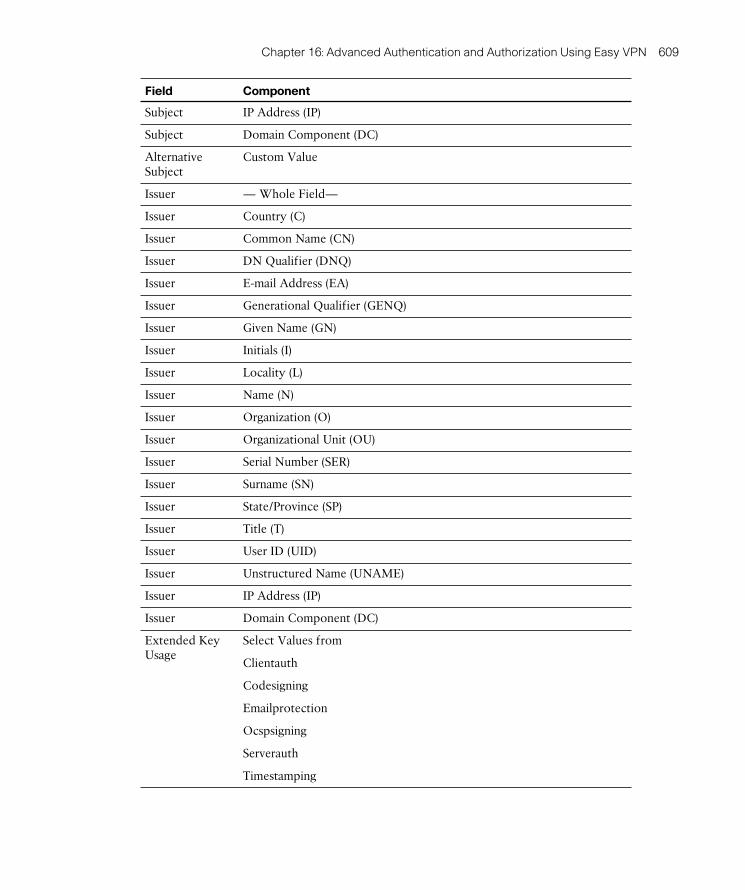
ptg8126969
Chapter 16: Advanced Authentication and Authorization Using Easy VPN 609
Field Component
Subject IP Address (IP)
Subject Domain Component (DC)
Alternative Subject
Custom Value
Issuer — Whole Field—
Issuer Country (C)
Issuer Common Name (CN)
Issuer DN Qualifier (DNQ)
Issuer E-mail Address (EA)
Issuer Generational Qualifier (GENQ)
Issuer Given Name (GN)
Issuer Initials (I)
Issuer Locality (L)
Issuer Name (N)
Issuer Organization (O)
Issuer Organizational Unit (OU)
Issuer Serial Number (SER)
Issuer Surname (SN)
Issuer State/Province (SP)
Issuer Title (T)
Issuer User ID (UID)
Issuer Unstructured Name (UNAME)
Issuer IP Address (IP)
Issuer Domain Component (DC)
Extended Key Usage
Select Values from
Clientauth
Codesigning
Emailprotection
Ocspsigning
Serverauth
Timestamping

ptg8126969
610 CCNP Security VPN 642-648 Official Cert Guide
Rules are given automatic priority levels when configured, with the ordering of the rules from highest priority (lowest number) to lowest priority.
Example 16-2 shows the commands required to configure certificate mapping rules via the command line. For further command information and options, see Chapter 9 , “Advanced Authentication and Authorization of AnyConnect VPNs.”
Example 16-2 Certificate-to-Connection Profile Mapping Rules
CCNPSec(config)# !!Begin by creating your new certificate mapping and giv-ing it a priority!!
CCNPSec(config)# crypto ca certificate map Country-Map 10
CCNPSec(config-ca-cert-map)# !!Now within the correct certificate mapping configuration mode, create your rules as required!!
CCNPSec(config-ca-cert-map)# subject-name attr c eq US
CCNPSec(config-ca-cert-map)# !!Now apply your new certificate mapping and the rules it contains to the connection profile you want it applied to!!
CCNPSec(config-cert-mapping)# tunnel-group-map Country-Map CCNP-VPN-CONN
Note Although not shown in Example 16-2 , with the tunnel-group-map command, you can enter an index value between 1 and 65535 before entering the certificate map name. This can provide you with the means to attach multiple certificate maps to a single tunnel group/connection profile. The index value provides a priority value for the ASA to use when inspecting the maps applied to a connection profile, with the lowest number being the highest priority.
Provisioning Certificates from a Third-Party CA
This section provides a working example of an IPsec VPN client configured to connect to an ASA device. Both are using the unique identity certificates that have been assigned to them using the local CA configured on the ASA. Note that in the CCNP Security VPN exam course, this particular section of the course uses the Microsoft CA server, which is available only on the Windows Server platforms. However, for certificate enrollment purposes, the majority of CAs follow a process similar to the one described earlier, whether they require a CSR file emailed to them, the contents of the file pasted into an online form, or enrollment via an automatic process.
Note The following information in this section assumes you have already config-ured the local CA server on the ASA device. If you are unfamiliar with the configura-tion required for enabling the local CA server, you are encouraged to read Chapter 5 , “Customizing the Clientless Portal.”

ptg8126969
Chapter 16: Advanced Authentication and Authorization Using Easy VPN 611
For this example, begin by creating two users in the local CA server database with the following attributes:
■ Username: ezuser
■ Email ID: [email protected]
■ Subject (DN String): OU=Sales
■ Device/Role: Cisco IPsec VPN Client
■ Username: ezserver
■ Email ID: [email protected]
■ Subject (DN String): OU=Engineering
■ Device/Role: ASA Device
After the addition of the users, select each in turn and click Email OTP . This causes the ASA to send each remote user an email (to the email address configured in their user account) via the mail server entered into the local CA server configuration. The email contains information similar to that shown in Example 16-3 .
Example 16-3 Received Enrollment Email from ASA CA Admin
You have been granted access to enroll for a certificate.
The credentials below can be used to obtain your certificate.
Username: ezuser
One-time Password: B3DC9569C6572F1A
Enrollment is allowed until: 07:50:36 UTC Mon Nov 22 2010
NOTE: The one-time password is also used as the passphrase to unlock the
certificate file.
Please visit the following site to obtain your certificate:
https://CCNP.VPN.LAB/+CSCOCA+/enroll.html
You may be asked to verify the fingerprint/thumbprint of the CA certificate
during installation of the certificates. The fingerprint/thumbprint
should be:
MD5: F39470FE 493EC3C1 210416D2 42F4B0CB
SHA1: A8BC57F3 CBE92751 961DEFF6 2A09AA5F 58E72A80
When the remote user opens the URL as directed, the ASA user enrollment screen appears, as illustrated in Figure 16-10 . For purposes of this example, we created a test remote user account in our CA database. Our test user receives an email from the ASA’s CA, and we log in to the CA web portal using the link, username, and OTP contained in the email. After clicking Submit , we are prompted to save or open our certificate infor-mation. For this example, we have saved the certificate to our desktop. The process we have just carried out for our test remote user (ezuser) is the same for any remote users you have set up for certificate enrollment.

ptg8126969
612 CCNP Security VPN 642-648 Official Cert Guide
Figure 16-10 ASA Local CA User Enrollment
Carry out the same actions as earlier for the ezserver user, and now you have the identity certificates required for authentication. (The certificate information is downloaded from the ASA CA in PKCS#12 format, automatically containing the CA chain [CA root] cer-tificates you require.)
Now that your users have their identity certificates, you can carry on with the configu-ration process and import them onto any remote user devices they may be using. To import the certificate for the ezuser user account, open the Cisco IPsec VPN client, navigate to Certificates > Import , and in the Import Certificate window shown in Figure 16-11 , select the certificate file on the desktop saved earlier. Now enter the one-time
password (OTP) received in the email from the ASA local CA as the passphrase, and then click Import . A pop-up window announces the successful import of the certificate information.

ptg8126969
Chapter 16: Advanced Authentication and Authorization Using Easy VPN 613
Figure 16-11 Cisco IPsec VPN Client: Import Certificate Window
After the certificate has been imported successfully into the VPN client’s certificate store, the remote user can now use it for authentication with your Easy VPN connection. In the IPsec client, select the Connection Entries tab and then select the desired con-nection entry from the list; now click Modify to open the connection entry’s Properties window, shown in Figure 16-12 .
Figure 16-12 Cisco IPsec VPN Client: Configure Certificate Authentication
In this window, select Certificate Based as the authentication type, and from the drop-down menu, choose the newly imported identity certificate for the ezuser user account, then click Save .

ptg8126969
614 CCNP Security VPN 642-648 Official Cert Guide
To import the new identity certificate for the ezserver user account into your ASA’s cer-tificate store, open the Identity Certificates window, found by navigating to Configure > Remote Access VPN > Certificate Management > Identity Certificates . Click Add and enter a name for the trustpoint. (This is optional; you can choose to keep the default of TrustPoint<next available number>.) Then (similar to the VPN client process earlier), select the certificate you saved to your desktop earlier, but this time choose the one for user ezserver. Now enter the OTP included in the original enrollment email for the pass-phrase, as shown in Figure 16-13 .
Note The local CA certificate, which is actually a self-signed certificate at the moment the local CA was enabled, cannot be used as an identity certificate. The CA certificate is used only to digitally sign certificates to endpoints. This is why you actually need an identity certificate on the ASA itself.
Figure 16-13 ASA ASDM Import Identity Certificate Window
When you finish entering your information, click Add Certificate . You can now use this identity certificate in your connection profile for the purposes of peer authentication.
The process to import an identity certificate when working from the command line is also a simple two-step process. First, create the trustpoint that will be used to hold your certificate information. When creating the trustpoint, you must also configure the enrollment type and so on. After creating the trustpoint, you can then import the cer-tificate that will be used by copying and pasting the certificate file contents into the CLI window, as shown in Example 16-4 .

ptg8126969
Chapter 16: Advanced Authentication and Authorization Using Easy VPN 615
Example 16-4 Creating a New Trustpoint and Importing the Identity Certificate
CCNPSec(config)# crypto ca trustpoint 3rdPartyIdentityCert
CCNPSec(config-ca-trustpoint)# enrollment terminal
CCNPSec(config-ca-trustpoint)# subject-name CN=CCNP.VPN.LAB
CCNPSec(config-ca-trustpoint)# id-usage ssl-ipsec
CCNPSec(config-ca-trustpoint)# exit
CCNPSec(config)# crypto ca enroll 3rdPartyIdentityCert
!!Enter enrollment details here
IPS Category CLI is not configured
Using the ASDM, start by navigating to Configure > Remote Access VPN > Network (Client) Access > IPsec(IKEv1) Connection Profiles , select your chosen connection profile from the list, and then click Edit to open the Edit Connection Profile dialog.
From the drop-down list of available identity certificates, select the newly imported cer-tificate from the list and then click OK , as shown in Figure 16-14 . That’s it. You can now establish a VPN tunnel between your client software and ASA using the certificate-based peer authentication scheme.
Figure 16-14 ASA ASDM Connection Profile Identity Certificate Selection

ptg8126969
616 CCNP Security VPN 642-648 Official Cert Guide
Example 16-5 displays the commands required to carry out the same process using the CLI. Notice that the process is the same as that shown in the earlier Example 16-1 . However, for this example, the configuration of a new IKEv1 policy to include RSA-SIG is already assumed to be configured. Remember that this step is required before the two peers can negotiate the user of digital certificates as an authentication scheme. If your configuration requires a new IKEv1 policy to be created, refer back to Example 16-1 for further information.
Example 16-5 Adding Certificate Authentication to Your Connection Profile
CCNPSec(config)# tunnel-group CCNP-VPN-CONN ipsec-attributes
CCNPSec(config-tunnel-ipsec)# ikev1 trust-point 3rdPartyIdentityCert
Note Whereas identity certificates generated by the local CA will work for peer authentication reasons, on the ASA a self-signed certificate will not. Therefore, if you are testing certificate-based authentication on your ASA device, you should use the local CA server or a third-party internal or public service. Many public CAs now offer free trial certificates that you can use for such purposes.
Advanced PKI Deployment Strategies
So far, the basic configuration deployments and tasks that must be followed to imple-ment them have been discussed. This section now builds on that information and intro-duces you to some of the advanced authorization and certificate revocation list (CRL) methods that are available (namely, CRLs, Online Certificate Status Protocol [OCSP] , and authentication, authorization, and accounting [AAA] ).
CRLs
Certificate revocation lists, defined in RFCs 3280 and 5280, are the older method for the online checking of a certificate’s status. The CRL contains a list of CNs, serial num-bers, the date revoked, and the issuing CA name of certificates that have been revoked and should not be used. The CRL is made available to authenticating devices by a URL contained in the certificate of the device being authenticated.
CRLs are often published immediately after a certificate has been revoked and added to the list. However, they are also published periodically. The validity of the CA issuing the CRL is checked in the same way as the validity of a certificate: using a combination of a digital fingerprint and the server’s public key.
Key Topic

ptg8126969
Chapter 16: Advanced Authentication and Authorization Using Easy VPN 617
OCSP
Online Certificate Status Protocol (RFC 2560) is the alternative and preferred method, because of the bandwidth savings and faster transaction time. OCSP allows an authen-ticating device to send a request for the status of a certificate by its serial number to an OCSP responder, whose role can be carried out by either the CA responsible for issu-ing the certificate being authenticated or a subordinate CA/RA. The responder sends back to the requestor (authentication device) a status of Good, Revoked, or Unknown. If a Revoked or Unknown status is received by the requestor, the authentication pro-cess fails. With OCSP, there is no need to download a possibly large file containing all revoked certificates, as is the case with CRL.
OCSP messages are sent in clear text and are therefore susceptible to man-in-the-middle attacks. To overcome this problem, OCSP can be configured on the requestor to send a nonce (a randomly generated number) that must be included in sent and received mes-sages for the purposes of message integrity checking.
Figure 16-15 shows a typical OCSP conversation that has been carried out between a web browser and a CA. In the fourth line, after the TCP connection has been built (using the three-way handshake), the user’s web browser sends a request to the responder that includes the serial number of the certificate it is in the process of authenticating. In the sixth line (highlighted), the web browser receives a response of Good from the respond-er (as you can see in the highlighted field in the lower section of the figure), and the TCP connection is then gracefully closed.
Figure 16-15 OCSP Request/Response Example
The OCSP information can be found in the Authority Information Access (AIA) field within a certificate, an example of which is shown in Example 16-6 .

ptg8126969
618 CCNP Security VPN 642-648 Official Cert Guide
Example 16-6 Digital Certificate AIA Field
[1]Authority Info Access
Access Method=On-line Certificate Status Protocol (1.3.6.1.5.5.7.48.1)
Alternative Name:
URL=http://ocsp.thawte.com
[2]Authority Info Access
Access Method=Certification Authority Issuer (1.3.6.1.5.5.7.48.2)
Alternative Name:
URL=http://www.thawte.com/repository/Thawte_SGC_CA.crt
AAA
AAA certificate authorization can be carried out by an external RADIUS server (for example, Cisco Access Control Server [ACS] ). With AAA, you can control user certifi-cate authorization by disabling, enabling, or removing a user account. When the ASA device receives a user certificate, it forwards the username in a predefined field and a generic password (used for all users) to the RADIUS server for authorization.
These methods should be used in the following priority:
■ AAA: Preferred. Use if you have access to an external RADIUS server and are also using downloadable access lists and so on.
■ OCSP: Recommended for use if you do not have access to an AAA server but have an available OCSP server.
■ CRL: Use only as a last resort if the preceding two methods are unavailable for use.
Regardless of the connection type you have chosen to configure (for example, clientless SSL, AnyConnect full tunnel, or IPsec site to site), the same values are available when you are configuring the certificate revocation methods and options, and there are no specific settings per connection type. With this fresh in mind, there is no need to cover old ground again. However if you need to “brush up” or revisit the configuration tasks required to enable CRL or OCSP, see the “Advanced PKI Deployment Strategies” sec-tion in Chapter 9 .
Troubleshooting Advanced Authentication for
Easy VPN
When approaching the task of troubleshooting any deployment, it is first important to make sure you understand the underlying technology and protocol operations that combine to provide the successful (or not, as the case may be) parameter negotiation and tunnel establishment. Therefore, if you are unsure which phase of a connection you are looking at, revisit the IPsec and IKE information discussed earlier in this book.

ptg8126969
Chapter 16: Advanced Authentication and Authorization Using Easy VPN 619
The devices used (for example, the VPN client and ASA) can provide you with a large amount of information that can prove to prove useful when troubleshooting a problem. The following is a brief list of the tools available to you:
■ Cisco IPsec VPN client logging facility and window
■ ASA internal logging buffer
■ ASA real-time logging console
■ ASA debug commands
In addition to this list, you can send Simple Network Messaging Protocol (SNMP) and syslog information to a remote server that can be later used for troubleshooting pur-poses.
For example, an engineer has configured certificate authentication on his ASA device and his remote IPsec VPN client. However, after several minutes of trying to establish, it is clear the connection is not working, and the error message he receives on the VPN client is “Remote peer is no longer responding.” The information in the ASA Real-Time Log Viewer, as shown in Figure 16-16 , provides an indication of where the fault lies.
Figure 16-16 Cisco IPsec VPN Client Error Message and ASA Real-Time Log Viewer

ptg8126969
620 CCNP Security VPN 642-648 Official Cert Guide
By examining the Real-Time Log Viewer output, you can decipher that your ASA does not have the necessary IKE policies available. As you can see farther down in the list, all others have been tried but no match has been found. This is common when certificate-based authentication has been enabled within the connection profile on the ASA but the default IKEv1 policies used to negotiate the necessary Phase 1 information are config-ured only for pre-shared key information. In this instance, we have used the information to add a new IKEv1 policy using AES-256, SHA, and RSA-SIG authentication with the default lifetimes. Afterward, the IPsec client can now connect successfully.
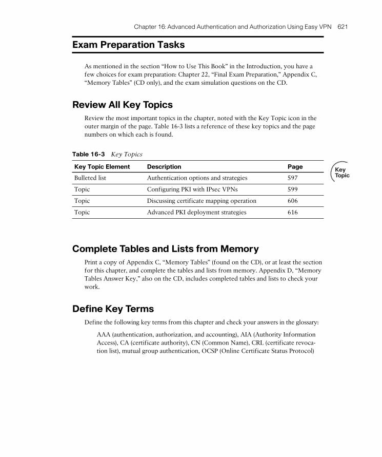
ptg8126969
Chapter 16: Advanced Authentication and Authorization Using Easy VPN 621
Exam Preparation Tasks
As mentioned in the section “How to Use This Book” in the Introduction, you have a few choices for exam preparation: Chapter 22 , “Final Exam Preparation,” Appendix C , “Memory Tables” (CD only), and the exam simulation questions on the CD.
Review All Key Topics
Review the most important topics in the chapter, noted with the Key Topic icon in the outer margin of the page. Table 16-3 lists a reference of these key topics and the page numbers on which each is found.
Table 16-3 Key Topics
Key Topic Element Description Page
Bulleted list Authentication options and strategies 597
Topic Configuring PKI with IPsec VPNs 599
Topic Discussing certificate mapping operation 606
Topic Advanced PKI deployment strategies 616
Complete Tables and Lists from Memory
Print a copy of Appendix C , “Memory Tables” (found on the CD), or at least the section for this chapter, and complete the tables and lists from memory. Appendix D , “Memory Tables Answer Key,” also on the CD, includes completed tables and lists to check your work.
Define Key Terms
Define the following key terms from this chapter and check your answers in the glossary:
AAA (authentication, authorization, and accounting), AIA (Authority Information Access), CA (certificate authority), CN (Common Name), CRL (certificate revoca-tion list), mutual group authentication, OCSP (Online Certificate Status Protocol)
Key Topic
ptg8126969
This chapter covers the following subjects:
■ Configuration Procedures, Deployment
Strategies, and Information Gathering: This sec-tion covers what to consider when deciding whether to deploy an internal AAA server for authorization.
■ Configuring Local and Remote Group Policies: This section discusses the differences between ASA local and remote group policies and the configura-tion required on the ASA for the deployment of each.
■ Accounting Methods for Operational
Information: This section reviews the accounting methods available on the ASA for connection and user information gathering.

ptg8126969
In earlier chapters, you learned how to plan for and configure the various authentication mechanisms available on the Adaptive Security Appliance (ASA) to allow remote users access into your environment. Now that you have given them access, you need to con-trol and account for it.
The information in this chapter will enable you to prepare for the deployment of an advanced authorization scheme for your remote users, allowing you to control the level of access granted to them based on such information as their internal department, user-name, IP address, and so on, using the familiar local group policies that are configured on the ASA device. This chapter also introduces you to remote group policies, their con-figuration on the ASA, and their remote server requirements.
After the various ways to authorize remote users into your environment has been explored, the discussion moves on to review the accounting methods available on the ASA device that enable you to track the success or failure of specific authorization set-tings and connections.
“Do I Know This Already?” Quiz
The “Do I Know This Already?” quiz helps you determine your level of knowledge on this chapter’s topics before you begin. Table 17-1 details the major topics discussed in this chapter and their corresponding quiz sections.
Table 17-1 “Do I Know This Already?” Section-to-Question Mapping
Foundation Topics Section Questions
Configuring Local and Remote Group Policies 1 , 2 , 3 , 4
Accounting methods for Operational Information 5 , 6 , 7
CHAPTER 17
Advanced Easy VPN Authorization

ptg8126969
624 CCNP Security VPN 642-648 Official Cert Guide
1. Which of the following are available group policy types on the ASA? (Choose all that apply.)
a. Internal
b. External
c. Active
d. Standby
2. Which of the following are legitimate ways to assign a group policy? (Choose all that apply.)
a. DAP
b. Direct user assignment
c. Connection profile
d. AAA
3. In what format are the attributes stored in an external group policy?
a. Text files
b. A/V pairs
c. CSV files
d. XML files
4. Which of the following remote user types are external group policy objects avail-able on? (Choose all that apply.)
a. LDAP
b. TACACS+
c. SDI
d. RADIUS

ptg8126969
Chapter 17: Advanced Easy VPN Authorization 625
5. By default, where is ASA syslog information stored?
a. External syslog server
b. Internal syslog server
c. NetFlow collection service
d. ASA internal buffer
6. When configuring an AAA server on the ASA, which communication protocol when configured allows for secure (SSL/TLS) communication between the AAA server and the ASA?
a. UDP
b. SCEP
c. SMTP
d. TCP
7. Which of the following are available actions used for NetFlow flow information creation? (Choose all that apply.)
a. Created
b. Denied
c. Torn down
d. Dropped

ptg8126969
626 CCNP Security VPN 642-648 Official Cert Guide
Foundation Topics
Configuration Procedures, Deployment Strategies,
and Information Gathering
The role of authorization in any virtual private network (VPN) deployment is an impor-tant one. With it, you can control which of your remote users can or cannot access cor-porate servers, email, financial and personnel records, and even the Internet. However, not only can you control the level of access each remote user has in your corporate environment, you can also control the user’s connection experience through maximum connection times, timeout settings, simultaneous logins, portal customization, and so on.
You can restrict or allow access to specific internal resources from remote users using the available policy options on the ASA device, whether you allow full access from all remote users to all of your internal resources (really not recommended) or, as shown in Figure 17-1 , you provide remote users access to only the internal resources they require. (For example, Client A can access the corporate finance server and file server but not the corporate email server, but Client B can access the corporate email server and file server but not the corporate finance server.) Specifically, this chapter focuses on the role of group policies for user authorization purposes, and as you will see in the next sec-tion, you can assign IPv4 and IPv6 access lists in group policy objects that allow or deny access to internal servers for a particular group, access hours, maximum connection time, and so on.
WAN/Internet
Client B
Client A
ASA
CorporateFinanceServer
CorporateEmailServer
CorporateFile
Server
Figure 17-1 ASA Authorizing (or Not) Remote Users
In addition to the available authorization attributes that can be applied by local group policies to remote users, you can extend the role of authorization to a remote (internal) authentication, authorization, and accounting (AAA) server. After the remote user has been authenticated, the remote AAA server is queried for the authorization attributes that should be applied to their session.

ptg8126969
Chapter 17: Advanced Easy VPN Authorization 627
Configuring Local and Remote Group Policies
Via group policies, you can assign attributes to users and groups based on their indi-vidual user account, group membership, or the connection profile used to connect to the ASA device.
Using group policy objects, you can define the following user authorization settings (and many more, as discussed momentarily):
■ Set the maximum connection time applied to remote users before they are required to carry out the connection process and reauthenticate.
■ Control the number of simultaneous logins that can be made using the particular user account.
■ Restrict access only to the internal resources and subnets using IPv4 filters ( access
control lists [ACL] ).
■ Define the networks used for split tunneling.
■ Control remote user access hours (the time they can and cannot log in).
Recall from the information shown in Chapter 2 , “Configuring Policies, Inheritance, and Attributes,” covering group policies, you can configure two types of group policy objects. The location of the policy attributes contained in them dictates the type of policy it is:
■ Local group policies (also known as internal group policies) are policy objects that have been configured locally on the ASA along with the attributes they contain. They are assigned either to local users directly (local user accounts configured on the ASA) or in connection profiles.
■ Remote group policies (also known as external group policies) are applied either to remote users or groups. The attributes contained in a remote group policy are configured on a remote (typically internal) AAA server (for example, RADIUS or Lightweight Directory Access Protocol [LDAP] ) in the form of attribute/value
(A/V) pairs. However, the remote group policy container (name) must also be con-figured on the ASA device, even though authorization attributes are imported from the AAA server.
Local group policy and the remote group policy containers are both configured on the ASA using the group-policy name [ internal | external ] global configuration command via the command-line interface (CLI) or within Configuration > Remote Access VPN > Network (Client) Access > Group Policies if you have chosen to use the Adaptive
Security Device Manager (ASDM) for configuration purposes. Within the ASDM, begin by clicking Add . Then, from the Add menu, choose either Internal Group Policy or External Group Policy . For this example, as shown in Figure 17-2 , the Add External Group Policy option was selected.
Key Topic

ptg8126969
628 CCNP Security VPN 642-648 Official Cert Guide
Figure 17-2 External Group Policy Configuration
In the Add External Group Policy window, enter the following details:
■ Name: Enter a name for the group policy object. This is the actual username used by the ASA and configured within the RADIUS server’s database for authentication purposes between the ASA and the RADIUS server.
■ Server Group: Choose an existing AAA server group or create a new one.
■ Password: Enter a password to be used for authentication with the AAA servers. This is the password configured for the previously defined username also used for the group policy name.
The group policy object is then used as a container for the A/V attributes received from the internal AAA server. Example 17-1 displays the configuration of an external group policy object when working from the CLI.
Example 17-1 External Group Policy Object Configuration
CCNPSec# conf t
CCNPSec(config)# group-policy Remote_EzVPN_Policy external server-group RADIUS password security
If you want to create a new AAA server group instead of selecting an existing one, you can choose New > New RADIUS Server Group or New > New LDAP Server Group in the ASDM’s Add External Group Policy window. After choosing the appropriate server group type to create, enter the following information into the Add AAA Server Group window:
■ Server Group: Enter a name for the server group.
■ Protocol: Uneditable. This displays either RADIUS or LDAP depending on your chosen group.

ptg8126969
Chapter 17: Advanced Easy VPN Authorization 629
■ Accounting Mode: Choose either Simultaneous (the ASA sends accounting data to all servers in the group) or Single (the ASA sends accounting data to only one server); this option is not available for LDAP server groups.
■ Reactivation Mode: Choose either Depletion (servers that have failed in the group are only reactivated when all other servers in the group are inactive) or Timed (failed servers are reactivated after 30 seconds). If you choose Depletion, you can also modify the dead timer (default 10 minutes), which is time that elapses between dis-abling the last server in the group and the reenabling of all servers.
■ Max Failed Attempts: Enter the maximum number of attempts that will be used to connect to a server configured in the server group until declaring it dead; the default is 3.
■ Enable Interim Accounting Update: Choose this option to enable multisession accounting for both AnyConnect and clientless Secure Sockets Layer (SSL) VPNs.
■ Enable Active Directory Agent mode: Not relevant for VPN configuration, but it is related to the identify firewall feature.
■ VPN3K Compatibility: Choose Do Not Merge (to disable merging of RADIUS downloadable ACLs with received A/V pair ACLs), Place the Downloadable ACL After the Cisco AV Pair ACL, or Place the Downloadable ACL Before the Cisco AV Pair ACL.
After creating your new AAA server group, you then need to add AAA servers to it in the AAA Server Groups window ( Configuration > Remote Access VPN > AAA/Local Users > AAA Server Groups ), as shown in Figure 17-3 . Note that for this configuration to be fully usable and valid, configurations on the remote LDAP or RADIUS servers need to be per-formed. (LDAP and RADIUS configuration is beyond the scope of this book.)
Figure 17-3 AAA Server Configuration

ptg8126969
630 CCNP Security VPN 642-648 Official Cert Guide
Example 17-2 displays the commands required to create a new AAA server group and add a new external server to the group.
Example 17-2 Creating a New AAA Server Group and Adding an External Radius Server
CCNPSec# !! First create your new AAA server group ready to add your exter-nal AAA server!!
CCNPSec# conf t
CCNPSec(config)# aaa-server RADIUS protocol radius
CCNPSec(config-aaa-server-group)# !!Now enter the details of your AAA server and add it to the new group!!
CCNPSec(config-aaa-server-group)# exit
CCNPSec(config)# aaa-server RADIUS (outside) host 172.30.255.5
CCNPSec(config-aaa-server-host)# key security
CCNPSec(config-aaa-server-host)# radius-common-pw security
When creating a new internal group policy object using the CLI, use the global con-figuration command group-policy name internal from name . The from name options available with the command are optional enable you to specify an existing group policy object that can be used as a template and its settings copied from. After you create the group policy object, you can enter the group-policy name attributes to set any specific attributes required using the commands shown in Table 17-2 in group policy attributes configuration mode.
When using the ASDM, click Add > Add Internal Group Policy to open the Add Internal Group Policy window, shown in Figure 17-4 . As you can see, many more options are available for this configuration, because all attributes of the group policy are configured and stored on the ASA. Begin by giving the policy a name, which is the only mandatory attribute required when configuring a new policy. All other attributes are by default inherited from the default group policy object (DfltGrpPolicy).
Table 17-2 lists the General window fields and values that you can use to configure the remaining general attributes you want to set explicitly. In addition, the table includes the corresponding CLI commands in case you have chosen to configure your ASA using the CLI. Note that before configuration is possible, you must uncheck the respective field’s Inherit option. However, you do not have to do so when you are using the CLI to configure the attributes; as soon as you configure a setting, the default inheritance is overridden.

ptg8126969
Chapter 17: Advanced Easy VPN Authorization 631
Figure 17-4 Internal Group Policy Configuration
Table 17-2 Internal Group Policy Attributes
Field CLI Commands Value
Banner banner value enter up to 500 characters
Enter a banner that will be displayed to users as they attempt to connect to the VPN.
SCEP Forwarding URL
scep-forwarding-url value url
Enter the URL that users of this group policy will use to automatically request digital certificates (if using certificate-based authentication).
Address Pools address-pools value enter up to 6 address pools separated by a space
Choose an IP address pool from the list. An IP address will be assigned to users for use during their connection.
IPv6 Address Pools
ipv6-address-pools value enter up to 6 address pools separated by a space
Select an IPv6 address pool from the list. An IP address will be assigned to users for use during their connection.
Tunneling Protocols
vpn-tunnel-protocol [ ikev1 | ikev2 | l2tp-ipsec | ssl-client | ssl-clientless ]
Choose from the available tunneling protocols that this group policy object will apply to.

ptg8126969
632 CCNP Security VPN 642-648 Official Cert Guide
Field CLI Commands Value
IPv4 Filter vpn-filter value acl name
Select an IPv4 ACL from the list to restrict network access during the user’s connection to only the networks/hosts the user requires.
IPv6 Filter ipv6-vpn-filter value ipv6 acl name
Choose an IPv6 ACL from the list to restrict network access during the user’s connection to only the networks/hosts the user requires.
NAC Policy nac-policy policy name
Select a Network Access Control (NAC) policy from the list of those configured. The NAC policy is used to perform posture assessment and validation for the connecting user.
Access Hours vpn-access-hours value time-range name
Choose a time range from those previously configured if you only allow access to this connection during specific times (for example, regular business hours).
Simultaneous Logins
vpn-simultaneous-logins 0-2147483647
Enter the number of simultaneous logins that can appear for this user account. (The default is 3.) A value of 0 prevents any logins from occurring, and remote users are unable to gain VPN access.
Restrict Access to VLAN (5505 Only)
vlan vlan id Choose the only VLAN (Inside, Outside, DMZ) you will allow this connecting user access to. The default value is None.
Connection Profile (Tunnel Group) Lock
group-lock value connection profile
Choose the connection profile from the list. This group policy object will only be assigned to the selected connection profile. This setting basically makes the group policy usable only by a certain connection profile.
Maximum Connect Time
vpn-session-timeout { none | 1-4473924 }
Choose either Unlimited or enter the number of minutes the user is allowed to be connected before being automatically disconnected. (The default is Unlimited or None.)
Idle Timeout vpn-idle-timeout { none | 1-35791394 }
Choose either Unlimited (value of None) or enter the number of minutes the user’s connection can be idle before being automatically disconnected. (The default is 30 minutes.)
On Smart Card Removal
smartcard-removal-disconnect [ enable | disable ]
Choose the option to either keep the user’s connection connected or disconnect the connection upon the user removing her smart card.
After setting the specific general attributes required in your local group policy, you can assign the policy either directly to a local user account or globally to all users of a con-nection in the connection profile’s properties.

ptg8126969
Chapter 17: Advanced Easy VPN Authorization 633
Assigning a Group Policy to a Local User Account
Begin this task by entering the user attributes configuration mode using the username- name attributes global configuration command. Within this mode, you can apply the group policy using the vpn-group-policy policy name command, as shown in Example 17-3 .
Example 17-3 Assigning a Group Policy Directly to a User
CCNPSec# conf t
CCNPSec(config)# username EzUser1 attributes
CCNPSec(config-username)# vpn-group-policy EasyVPN
When using the ASDM, start by opening your user’s account properties in Configuration > Remote Access VPN > AAA/Local Users > User Accounts . In the User Accounts window, choose the local user account to apply the group policy object to and click Edit .
As shown in Figure 17-5 , in the Edit User Account window that opens, we choose VPN Policy from the menu on the left and uncheck the Inherit check box next to the Group Policy section. Using the drop-down list, we then choose the group policy object we want applied to the user account.
Figure 17-5 Assigning a Group Policy Directly to a User
Key Topic

ptg8126969
634 CCNP Security VPN 642-648 Official Cert Guide
Assigning a Group Policy to a Connection Profile
You can assign a group policy object to a connection profile using the CLI of ASDM. Via the CLI, issue the default-group-policy policy name command within tunnel-group general-attributes configuration mode. Alternatively, open the ASDM connection profile properties window by navigating to Configuration > Remote Access VPN > Network (Client) Access > IPsec (IKEv1) Connection Profiles . Select the connection profile to assign the group policy object to from the list and click Edit .
In the Edit IPsec Remote Access Connection Profile Name window, use the drop-down list in the Default Group Policy section of the window to select the group policy object to be applied, as shown in Figure 17-6 .
Figure 17-6 Assigning a Group Policy to a Connection Profile
In addition to the more general properties that you can assign using a group policy object, you can assign advanced properties (for example, split-tunneling exceptions and rules).
The configuration in Figure 17-7 shows the split-tunneling properties located in the Advanced > Split Tunneling section of the Edit Internal Group Policy - Name window.
Key Topic

ptg8126969
Chapter 17: Advanced Easy VPN Authorization 635
Figure 17-7 Group Policy Split-Tunneling Configuration
For this example, the domain name vpn.lab has been added as a Domain Name System
(DNS) name, indicating to the Easy VPN clients that any requests for DNS information for hosts in this domain should be tunneled (for example, secretfiles.vpn.lab). In addi-tion to the configuration of DNS names, the option to tunnel only the list specified in the preconfigured ACL Internal_Servers by using the Policy and Network List fields has been configured. Example 17-4 displays the same configuration achieved via the CLI.
Example 17-4 Configuring Split Tunneling
CCNPSec# conf t
CCNPSec(config)# group-policy Internal-EzVPN-POLICY attributes
CCNPSec(config-group-policy)# split-tunnel-policy tunnelspecified
CCNPSec(config-group-policy)# split-tunnel-network-list value Internal_Servers
CCNPSec(config-group-policy)# default-domain value VPN.LAB
The configuration shown in Figure 17-7 and Example 17-4 results in DNS requests for devices in the domain name vpn.lab, or traffic matching that of the ACL Internal_Servers, to be sent by Easy VPN clients through the VPN tunnel to the ASA and on to the corporate network. All other traffic (for example, the remote user device’s LAN or Internet data) travels directly to the destination rather than through the VPN tunnel.

ptg8126969
636 CCNP Security VPN 642-648 Official Cert Guide
Accounting Methods for Operational Information
You have at your disposal the following logging mechanisms on the ASA to monitor remote user activity and connection state:
■ Syslog
■ NetFlow 9
■ RADIUS accounting
■ Simple Network Management Protocol (SNMP)
Syslog can provide a large amount of information for statistics-based analysis or infor-mation regarding the current ASA’s health and the status of our remote connections. In addition to being able to send syslog (debugging, informational, and so on) information to remote servers for offline inspection, you can choose to store it in a local buffer on the ASA for later viewing when working on the device.
Figure 17-8 shows the ASDM’s Logging Setup window available via Configuration > Device Management > Logging > Logging Setup . To enable logging, just check the Enable Logging check box. You can also optionally include debugging informa-tion when troubleshooting a feature/error on the ASA by checking the Send Debug Messages as Syslogs check box.
Figure 17-8 Enable Logging in the ASDM and Specify Location
In the Logging Setup window, you can also enable logging on the failover device if you are running two ASAs in a hardware failover pair, and you can select to send your syslog
Key Topic

ptg8126969
Chapter 17: Advanced Easy VPN Authorization 637
information in EMBLEM format. (This is required if you are running CiscoWorks software as applications. For example, RME [Resource Manager Essentials] processes syslog infor-mation in EMBLEM format.) In addition to these options, in the Logging to Internal Buffer section of the window, you can increase or decrease the size of the internal buffer used to store the logging information (default is 4096 bytes) on the ASA. The internal buffer is a rolling log, meaning as soon as it becomes full, any new information starts to overwrite the older information in the buffer. For example, if your ASA device is logging a large amount of information while you are trying to troubleshoot an error, it is worthwhile to increase the size of the logging buffer to prevent the information you might require being overwritten before you have had a chance to look at it. In this section, you can also configure the ASA to store the buffer information in a file on the ASA’s flash device or upload it to an FTP server when it reaches a specific size. This can also prevent your valuable log information from being overwritten. In the final section of the window, you can select the amount of informa-tion that is written to the ASDM log viewer (visible on the home page). The default is 100 messages.
After you have enabled logging on the ASA device, you can navigate to Configuration > Device Management > Logging > Syslog Servers and configure the remote servers to which the ASA will send its generated syslogs.
Figure 17-9 shows the Syslog Servers window and the Add Syslog Server window that opens when you click Add . In the Add Syslog Server window, select the interface your server is available on, enter the IP address of the server, and select either TCP or UDP (default) and the port (514 by default). In addition, you can check to enable the option Log Messages in Cisco EMBLEM Format (UDP only) or the option to Enable Secure Syslog Using SSL/TLS (Secure Sockets Layer/Transport Layer Security) . (This lat-ter option is available only when using TCP for communications between the ASA and server.)
Figure 17-9 Creating a New Syslog Entry
After you have entered your syslog servers, you need to then specify the level of log-ging information that will be sent to our syslog server. In Configuration > Device Management > Logging > Logging Filters , you can choose from the following:

ptg8126969
638 CCNP Security VPN 642-648 Official Cert Guide
■ Emergencies
■ Alerts
■ Critical
■ Errors
■ Warnings
■ Notifications
■ Informational
■ Debugging
As shown in Figure 17-10 , you can choose the level of logging per function on the ASA. For example, you might want to send informational messages to the console but debug-ging information to the ASA’s internal buffer.
Figure 17-10 Choose the Logging Level per Function
And that’s it! Well... not quite. At the moment, enough options have been selected and enough information entered for the ASA to be able to log to the internal buffer, syslog, and servers. Now you can start to get really granular with the control you have over sys-log information. For example, if you are interested in only a particular log message or set of messages, you can create a filter in the Event Lists window. After creating a filter, you can select this in the Logging Filters window instead of selecting a predefined log-ging level.
Key Topic

ptg8126969
Chapter 17: Advanced Easy VPN Authorization 639
You can optionally rate limit the number of log messages sent per second per logging level, or even per log message, in the Rate Limit window. You can set up a dedicated facility per logging level, if you want to view or filter the different logging levels easily on our syslog server. And in the E-Mail Setup and SMTP windows, you can set up the parameters and options used to send syslog information to a recipient via email.
The process of configuring logging on your ASA when working from the CLI is, as you can imagine, a lot faster because you do not have to open and close all the different win-dows or check on uncheck any of the options. However, which method you choose to use to configure your ASA is up to you, although for the exam it is a good idea to have an understanding of the various CLI commands that are available and their correspond-ing ASDM locations and values.
For example, to enable informational logging to the local buffer of the ASA, you can enter the following commands in enable mode:
logging buffered informational
logging enable
For logging to become operational, the latter command must be issued.
Similarly, to set up logging to an external server, you can enter the following enable mode commands:
logging trap informational
logging host [ nameif] { hostname | ip address} port [ format emblem]
Again, you can use the format emblem keywords along with the command to enable the use of the EMBLEM format when working with a supported RADIUS server. When con-figuring logging to a destination or the local buffer, the same logging levels are available (for example, notifications, emergencies, debugging) as shown in Example 17-5 . You have the choice of either entering the name of the level (for example, informational ) or the corresponding severity level ( 6 ); both achieve the same result.
Example 17-5 Available CLI Logging Severities
CCNPSec(config)# logging buffered ?
configure mode commands/options:
<0-7> Enter syslog level (0 - 7)
WORD Specify the name of logging list
alerts Immediate action needed (severity=1)
critical Critical conditions (severity=2)
debugging Debugging messages (severity=7)
emergencies System is unusable (severity=0)
errors Error conditions (severity=3)
informational Informational messages (severity=6)
notifications Normal but significant conditions (severity=5)
warnings Warning conditions (severity=4)

ptg8126969
640 CCNP Security VPN 642-648 Official Cert Guide
You can view logging information held in the ASA’s internal buffer in Monitoring > Logging > Log Buffer . Alternatively, you can enter the show logging command when using the CLI. Choose the logging level you are interested in viewing and click View . Figure 17-11 shows an example of the log buffer contents in the internal logging buffer viewed using the ASDM.
Note To clear the local buffer of all logs, enter clear logging buffer in privileged EXEC (enable) mode.
Figure 17-11 ASA Internal Log Buffer
NetFlow 9
With NetFlow logging, you can view information on a flow-by-flow basis based on Layer 3 and Layer 4 information of a conversation. Unlike sending information to a col-lector in tuple format (which can lead to limitations in the amount of information sent in any one packet, like its predecessor NetFlow 5), NetFlow 9 uses a template-based method of transferring information to a server running the NetFlow collector service. The template is sent to the server at specific intervals (30 minutes) and is used to format the information it receives from the ASA.

ptg8126969
Chapter 17: Advanced Easy VPN Authorization 641
The ASA can send NetFlow 9 information to a server running the NetFlow 9 collector service (all other versions are incompatible) based on the following packet-flow actions occurring:
■ Created
■ Denied (excluding flows denied by Ethertype ACLs).
■ Torn down
Figure 17-12 shows the configuration of NetFlow on the ASA device using the ASDM.
Figure 17-12 ASA NetFlow Configuration
In the NetFlow window ( Configuration > Device Management > Logging > NetFlow ), you can enter a value in minutes for the interval used to send the Version 9 template to the collection service running on your remote server (default 30). Optionally, you can choose to delay the sending of flow-creation events by a specific time you enter in seconds (which can help minimize the amount of information sent at any one time if, for example, a lot of flows are created at once on the ASA device). You also enter your flow collector’s (server) IP address, the interface they are available on, and the UDP port that will be used for the communication of NetFlow information to them. After entering this information, you can then specify the type of event for which NetFlow information is sent to the servers. As shown in Figure 17-12 , three events can cause the information to be sent. You can specify the event using a service policy that, if you recall from earlier chapters, you have already seen when used to create quality of service (QoS) policies on the ASA.
Key Topic

ptg8126969
642 CCNP Security VPN 642-648 Official Cert Guide
However, unlike QoS policies, NetFlow policies can be applied only globally, not per interface. By default, the ASA has an existing default service policy that is applied glob-ally to the ASA. However, you cannot edit this in the ASDM, so you must create a new global service policy and either use an access list to define the IP addresses for which your NetFlow flow information will be generated or use the class-default class of your policy.
To configure NetFlow via the CLI, enter flow-export option global configuration com-mand (with the exception of service policy configuration, which is shown in a moment). Table 17-3 lists the options/values available for this command. Notice how these are also the same options that are available when using the ASDM.
Table 17-3 flow-export CLI Commands
CLI Commands Value
flow-export delay flow-create 1-180 Enter the delay in seconds between 1 and 180 after which flow creation information will be exported.
flow-export destination [ nameif ] { hostname | ip address } port
Enter the interface, hostname/IP address, and optionally a port that will be used to export information to a destination host.
flow-export template timeout-rate 1-3600 Enter the time in minutes (default 30) that template information will be re-sent.
In this example, a new global service policy is created using the class-default class to match all traffic for NetFlow flow information. Begin by opening the service policy in the ASDM Service Policy Rules window ( Configuration > Firewall > Service Policy Rules ) and clicking Add . Then choose Add Service Policy Rule. In the Add Service Policy Rule Wizard - Service Policy window, choose Global - Applies to All Interfaces and click Next .
On the next screen, Add Service Policy Rule Wizard - Traffic Classification Wizard, choose the Use Class-Default as the Traffic Class and click Next .
Then, in the Add Service Policy Rule Wizard - Rule Actions window, open the NetFlow tab. On this tab, click Add . In the new Add Flow Event window that opens, shown in Figure 17-13 , choose the event that will trigger the sending of NetFlow information from the Flow Event Type drop-down box and check the box next to the host for which you want to enable this rule. Finally, click OK and Finish to apply the new rule.

ptg8126969
Chapter 17: Advanced Easy VPN Authorization 643
Figure 17-13 ASA NetFlow Service Policy Configuration
Example 17-6 displays the same configuration as the earlier ASDM example, but this time configured using the CLI.
Example 17-6 NetFlow Export Configuration
CCNPSec(config)# flow-export destination inside 192.168.1.100 5010
CCNPSec(config)# policy-map global_policy
CCNPSec(config-pmap)# class class-default
CCNPSec(config-pmap-c)# flow-export event-type flow-create destination 192.168.1.100
RADIUS VPN Accounting
You can enable RADIUS accounting information so that your support representatives can interrogate the RADIUS logging information to see whether a VPN connection has succeeded or failed (and if failed, why).
To enable RADIUS accounting in a connection profile, as shown in Figure 17-14 , navi-gate to Configuration > Remote Access VPN > Network (Client) Access > IPsec (IKEv1) Connection Profiles . Choose your connection profile from the list and click Edit . In the Edit IPsec Remote Access Connection Profile: Name window, choose Advanced > Accounting from the menu on the left. In the Accounting window, from the drop-down list choose the RADIUS server group that contains the RADIUS servers

ptg8126969
644 CCNP Security VPN 642-648 Official Cert Guide
to which the ASA will be sending its accounting information. You can also create a new server group by clicking Manage if no groups are currently available.
Figure 17-14 IKEv1 Connection Profile RADIUS Accounting Configuration
The CLI configuration is just as simple. You configure the accounting servers within the now familiar tunnel-group general-attributes configuration mode with accounting-serv-er-group name , as shown in Example 17-7 .
Example 17-7 Connection Profile Accounting Server Configuration
CCNPSec(config)# tunnel-group DefaultRAGroup general-attributes
CCNPSec(config-tunnel-general)# accounting-server-group RADIUS
After configuring RADIUS accounting servers in a connection profile, you can inspect the received RADIUS accounting information on your RADIUS server implementation using the various logging options that are available.
SNMP
The ASA can support access for device and statistical interrogation using SNMP Version 1, Version 2c, and Version 3. Many texts and books already explain the differences between these versions, so to save you from reading it all again, this discussion assumes that you know enough about SNMP already to have made the decision that if Version 3 is available on a device, you use Version 3 to access it.

ptg8126969
Chapter 17: Advanced Easy VPN Authorization 645
You configure the various SNMP options (traps, location, global community string, and hosts) in Configuration > Device Management > Management Access > SNMP , as shown in Figure 17-15 .
Figure 17-15 ASA SNMP Configuration
In the SNMP window, you can configure all the familiar options for the protocol, such as the community string, contact, location, and listening port (UDP 161 by default). You can configure the criteria for trap information to be sent by clicking Configure Traps and choosing from the available options in the SNMP Trap Configuration window that opens.
In addition, in the SNMP window, in the SNMP Host Access List section, you can explicitly enter the addresses of your servers that will be accessing your ASA device. You can also create the users and groups that will be used for SNMPv3 access in the SNMPv3 Users section of the window.
To configure SNMP hosts, options, and attributes via the CLI, enter the snmp-server option global configuration mode command. Table 17-4 describes the configuration options you have for this command. Note that these are the same as those available within the ASDM SNMP window shown earlier in Figure 17-15 .
Table 17-4 snmp-server CLI Commands
CLI Commands Value
snmp-server community string Enter the community string used for authentication with SNMP versions earlier than Version 3.
snmp-server contact value Enter the contact information that will be held within the SNMP MIB object sysContact.

ptg8126969
646 CCNP Security VPN 642-648 Official Cert Guide
CLI Commands Value
snmp-server enable traps option Enter the trap option that will enable the appropriate amount and detail of information you require to be sent to the SNMP server. The available options are as follows:
all —Enable all traps.
connection-limit-reached —Enable connection limit traps.
cpu —Enable CPU utilization-related traps.
entity —Enable ENTITY MIB notifications.
ikev2 —Enable IKEv2 traps.
interface-threshold —Enable interface threshold reached traps.
ipsec —Enable IPSec traps.
memory-threshold —Enable memory threshold reached traps.
nat —Enable Network Address Translation (NAT) -related traps.
remote-access —Enable remote-access traps.
snmp —Enable SNMP traps.
syslog —Enable syslog traps.
snmp-server group name v3 [ auth | priv | noauth ]
Enter this command to configure a group for use with Version 3 servers and the purposes of authentication ( auth ) or encryption ( priv ) of SNMP information.
snmp-server host [ nameif ] hostname / ip address [ community value ] [ udp-port port ] [ poll ] [ trap ] [ version 1 | 2c | 3 ]
Use this command to enter the location, hostname/IP address and port number of an SNMP server used to send SNMP information to/from the ASA. You can also optionally enter a community value and SNMP version, and you can use the trap keyword to send traps to only the specified host or use the poll keyword to allow polling to occur only from this host.
snmp-server listen-port value Enter the port that will be used by the local SNMP engine on the ASA to listen for incoming SNMP requests (default 161).
snmp-server location value Use this command to enter the value for the MIB object sysLocation (for example, Floor1East).
snmp-server user username groupname v3 [ auth { md5 | sha } password ] [ priv des | 3des | aes { 256 | 192 | 128 } password ]
Use this command to create a local SNMP user account for use with Version 3. Note that you must first configure the group the user will belong to on the ASA by entering the snmp-server group name command.

ptg8126969
Chapter 17: Advanced Easy VPN Authorization 647
Exam Preparation Tasks
As mentioned in the section “How to Use This Book” in the Introduction, you have a few choices for exam preparation: Chapter 22 , “Final Exam Preparation,” Appendix C , “Memory Tables” (CD only), and the exam simulation questions on the CD.
Review All Key Topics
Review the most important topics in the chapter, noted with the Key Topic icon in the outer margin of the page. Table 17-5 lists a reference of these key topics and the page numbers on which each is found.
Table 17-5 Key Topics
Key Topic Element Description Page
Bulleted list Group policy types 627
Subtopic Assigning a group policy to a user account 633
Subtopic Assigning a group policy to a connection profile
634
Bulleted list Available accounting methods 636
Bulleted list Available logging levels 638
Bulleted list NetFlow flow-creation actions 641
Complete Tables and Lists from Memory
Print a copy of Appendix C , “Memory Tables” (found on the CD), or at least the section for this chapter, and complete the tables and lists from memory. Appendix D , “Memory Tables Answer Key,” also on the CD, includes completed tables and lists to check your work.
Define Key Terms
Define the following key terms from this chapter, and check your answers in the glossary:
external group policy, internal group policy, NetFlow, SNMP (Simple Network Management Protocol)
Key Topic

ptg8126969
This chapter covers the following subjects:
■ Configuration Procedures, Deployment
Strategies, and Information Gathering: This section reviews the HA methods available for Easy VPN connections and their operation.
■ Easy VPN Client HA and Failover: This section discusses the failover methods available for a VPN client connection to the Easy VPN server.
■ Hardware-Based Failover with VPNs: This sec-tion covers the configuration required to deploy a hardware-based active/standby failover solution.
■ Clustering Configuration for Easy VPN: This sec-tion reviews the implementation of VPN clustering on the ASA device.
■ Troubleshooting Device HA and Clustering: This section discusses troubleshooting procedures with various available tools.

ptg8126969
With the deployment of a virtual private network (VPN) service, you can offer familiar resources to users outside their office environment. These users expect the same level of uptime and service as they receive on the LAN. Therefore, when deploying VPN services, you must provide high availability (HA) . By the end of this chapter, you will understand and be able to configure the available HA methods to an IPsec client. You will also be able to configure Adaptive Security Appliance (ASA) built-in functions to provide stateful failover. In addition to the introduction of an external load balancer for service enhancement, this chapter expands on material covered earlier by exploring the differences between the options available for particular VPN deployments.
“Do I Know This Already?” Quiz
The “Do I Know This Already?” quiz helps you determine your level of knowledge on this chapter’s topics before you begin. Table 18-1 details the major topics discussed in this chapter and their corresponding quiz sections.
Table 18-1 “Do I Know This Already?” Section-to-Question Mapping
Foundation Topics Section Questions
Configuration Procedures, Deployment Strategies, and Information Gathering 1 , 2
Easy VPN Client HA and Failover 4 , 6 , 9
Hardware-Based Failover with VPNs 3 , 7 , 8 , 10
Clustering Configuration for Easy VPN 5
CHAPTER 18
High Availability and Performance for Easy VPN

ptg8126969
650 CCNP Security VPN 642-648 Official Cert Guide
1. When deploying an active/standby failover solution for HA requirements, which should you configure to prevent the use of an ASA answering an ARP request with the BIA for its physical interface?
a. DPD
b. VMAC
c. ARP
d. Interface Monitoring
2. Which of the following are available for use when deploying a stateful HA solution for Easy VPN? (Choose all that apply.)
a. Active/active failover
b. Redundant peering
c. VPN clustering
d. Active/standby failover
3. By default, how many interfaces must be in any state other than UP for a failover to occur?
a. 1
b. 2
c. 3
d. 250
4. When deploying an HA or VPN load-sharing configuration using the IPsec VPN client software, which method is available?
a. Redundant peering
b. Active/active failover
c. Active/standby failover
d. VPN clustering
5. What is the minimum number of cluster members before a cluster can become operational?
a. 1
b. 5
c. 10
d. 100

ptg8126969
Chapter 18: High Availability and Performance for Easy VPN 651
6. Which of the following protocols are used for the periodic keepalives sent between IKE peers during periods of inactivity?
a. IPsec
b. ICMP
c. DPD
d. UDP
7. What type of packet is sent by a peer across a failover link to detect the operational state of a peer device?
a. DPD
b. Hello
c. ACK
d. GoodBye
8. Which of the following are available interface types that can be used for a stateful failover link between peers?
a. Any unused physical interface
b. The existing failover interface
c. An existing -network interface
d. All of the above
9. By default, after how many DPD R_U_THERE packets sent without receiving a DPD_R_U_THERE_ACK response is a peer declared down and a session deleted?
a. 3
b. 4
c. 5
d. 6
10. What is the default number of seconds before a monitored interface availability status is changed causing a failover to occur?
a. 10
b. 30
c. 500
d. 25

ptg8126969
652 CCNP Security VPN 642-648 Official Cert Guide
Foundation Topics
Configuration Procedures, Deployment Strategies,
and Information Gathering
When preparing to introduce HA to improve service for your remote users, it is impor-tant to determine the overall level of service you want to achieve and the resources you have available. For example, do your users require their sessions to stay up and active during a device failure event? Does your internal budget allow for the procurement of additional devices, if required, to achieve HA?
The following is a brief list of the failover methods available using the ASA, VPN client software, or external hardware:
■ Failover: An internal mechanism provided by the ASA and can be configured in one of two modes, depending on the environment in which you want to deploy it:
■ Active/active: As the name suggests, both ASA devices are enabled and inspect-ing traffic simultaneously, allowing for a much greater percentage of available resources for deployment. However, active/active configuration does not provide support for any type of VPN deployment, so we do not spend any more time looking at this option.
■ Active/standby: In this configuration, one ASA device is active and passing/inspecting traffic while the other is on standby, monitoring the state of the other until it must take the active role (that is, until the current active device is restarted or becomes unavailable).
These failover methods require the use of identical hardware and software version (both major and minor versions), which might (unless you have a spare ASA device sitting around) require the purchase of additional hardware.
■ VPN clustering: Another method of failover offered by the ASA. However, this is more of a performance benefit than failover. If a failover occurs, connected users must reestablish their connection, at which point their session is directed to another member of the cluster by the active cluster master.
■ Redundant peering: The Cisco IPsec VPN client can store up to 10 different peer IP addresses for the use as backup servers. During a failover condition, the IPsec cli-ent software attempts to connect to the next available peer in the list of those con-figured.
■ External load balancing: This method requires an external load balancer (for example, an ACE 4710 appliance or module in a 6500/7600 switch/router). The Application Control Engine (ACE) will have a public-facing IP address configured, known as a virtual IP address (VIP) . You can have several ASAs behind the ACE and configured as real servers; on receiving a request for the VIP, the ACE forwards it to one of the real servers (ASAs) it has configured.

ptg8126969
Chapter 18: High Availability and Performance for Easy VPN 653
HA can be categorized into one of two types:
■ Stateful
■ Stateless
By stateful , the operation of keeping existing connections alive and up during a failover situation is meant. This method is by far the most popular choice and is provided native-ly by the ASA in active/standby failover mode. However, as mentioned earlier, if you are configuring the built-in failover method available on the ASA, you must use identi-cal software and hardware devices. At present, this is the only stateful failover solution available to the ASA for use with VPNs.
Stateless , as you have probably guessed already, is a type of HA that does not enable keeping a user’s existing connection open. However, depending on the HA method deployed, this type of failover can provide the designer with a greater level of scope. After all, methods are available that do not require identical hardware/software. Be aware, however, that the use of the ASA’s failover method still requires the ASA pair to have identical hardware and software versions installed.
Table 18-2 (also shown in earlier chapters covering HA) summarizes the available methods.
Table 18-2 Advantages and Limitations of Available HA Methods
Method Advantages Limitations
Active/standby failover
Can offer stateful or stateless methods. Stateful operation is required to prevent session reestablishment during or after a failover.
No load sharing or balancing occurs between devices. Only one device is active at a time. Lack of support for clientless Secure Sockets Layer (SSL) VPN applications.
Requires identical hardware and software versions.
VPN load balancing (clustering)
Allows for the load between devices to be shared among them based on the “least-used” device receiving the latest connection attempt.
Differing hardware and software revisions can be used.
Native, built-in ASA feature.
Cannot provide stateful failover.
Load balancing using an external load balancer
Allows for the load between devices to be shared among them. We have greater flexibility in choosing load-balancing algorithms than clustering.
Differing hardware and software revisions can be used.
Cannot provide stateful failover.
No active failover between devices. Clients must reconnect to the next available device after being disconnected.
Key Topic

ptg8126969
654 CCNP Security VPN 642-648 Official Cert Guide
Method Advantages Limitations
Redundant VPN servers
Allows for connections to be shared among available devices based on clients using different VPN server addresses.
Differing hardware and software revisions can be used.
No active failover detection. Clients must use dead-peer detection (DPD) for peer-availability detection.
Connections are not stateful.
Clientless SSL VPN cannot use this method.
Given a set of requirements, you should now have an idea of the appropriate method of HA. For example:
■ If you require the operation of stateful HA, the only solution currently available is ASA active/standby failover.
■ However, if you require VPN connections to be shared among the available equip-ment you have and do not require the implementation of a stateful solution, you can deploy VPN clustering directly on the ASA devices. This will manage the avail-able devices and automatically share the incoming connections between them.
■ If your ASA devices include the use of those with a lower software level that might not have the VPN clustering option available, you can use an external load balancer and achieve the load-balancing behavior using the available features (for example, sticky sessions, round robin, and so on).
■ If you want to share the incoming VPN connections between available devices but do so by configuration applied on your VPN clients, you can use redundant peering within the client software. You could also go as far as to install the available VPN head-end device addresses in a different order, based on the client’s group member-ship, and so on.
Easy VPN Client HA and Failover
The IPsec VPN client software allows for the configuration of up to 10 backup servers for use when the primary VPN head end is unavailable. The client can detect the avail-ability of the VPN head end during the initial connection phase, and also by using DPD.
DPD is simply a method of sending periodic keepalives during periods of inactivity. The default inactivity time for a group is 300 seconds. Therefore, if a connection is idle for 300 seconds, the client or ASA (depending on which end has DPD enabled and whose timer elapses first) sends a DPD R_U_THERE packet. Upon receipt of the DPD packet, the device or software should send back a DPD R_U_THERE_ACK. If the remote peer is unavailable, however, the sending device continues to send R_U_THERE packets every keepalive period (by default, 2 seconds) until it has sent four and received no reply. At this point, the connection is torn down. Example 18-1 shows the DPD operation during an established connection using the IPsec VPN client.

ptg8126969
Chapter 18: High Availability and Performance for Easy VPN 655
Example 18-1 DPD Operation During an IPsec Connection
1 20:20:48.701 01/24/11 Sev=Info/4 IKE/0x63000013
SENDING >>> ISAKMP OAK INFO *(HASH, NOTIFY:DPD_REQUEST) to 172.30.255.2
2 20:20:48.701 01/24/11 Sev=Info/6 IKE/0x6300003D
Sending DPD request to 172.30.255.2, our seq# = 3329592955
3 20:20:48.701 01/24/11 Sev=Info/5 IKE/0x6300002F
Received ISAKMP packet: peer = 172.30.255.2
4 20:20:48.701 01/24/11 Sev=Info/4 IKE/0x63000014
RECEIVING <<< ISAKMP OAK INFO *(HASH, NOTIFY:DPD_ACK) from 172.30.255.2
5 20:20:48.701 01/24/11 Sev=Info/5 IKE/0x63000040
Received DPD ACK from 172.30.255.2, seq# received = 3329592955, seq# expected = 3329592955
Figure 18-1 displays the Backup Servers tab in the IPsec VPN client. To access this, select the connection entry from the list shown in the Connection Entries tab. In the Properties window, display the Backup Servers tab.
Figure 18-1 Cisco IPsec VPN Client: Connection Entry Properties, Backup Servers
You first check the Enable Backup Servers check box, and then click Add to enter the IP address or hostname of the available peer device.
You can enter up to 10 peers in the Backup Server list. They are each used in order from the top of the list to the bottom. If you want a particular peer address preferred over the others, select the entry in the list and use the arrow buttons on the right side to reorder them. Although you can specify backup servers directly in the IPsec VPN client, you

ptg8126969
656 CCNP Security VPN 642-648 Official Cert Guide
have the option to push backup server information on first successful connection from the ASA. In the group policy attached to the connection profile, navigate to Advanced > IPsec Client > IPsec Backup Servers, where you have the following options:
■ Keep Client Configuration (default) specifies to keep whatever configuration was done on the client side in the Backup Servers section.
■ Use the Backup Servers Below specifies the backup server configuration from the client be overwritten with configured servers from the ASA.
■ Clear Client Configuration specifies to just clear any backup server configuration that exists on the client.
Hardware-Based Failover with VPNs
Active/standby failover consists of two ASAs connected using a dedicated failover link. The link can be any of the unused Ethernet interfaces on the ASA. However, note that no network traffic is passed across this link because it is used for the purposes of failover control messages only. It is recommended practice to use an Ethernet connec-tion between the two devices that both connect into a switch. You can, however, use a crossover connection if a switch is unavailable. Bear in mind that if the failover interface fails on one of the devices in the failover pair, and you have a direct connection between them, both interfaces are caused to fail, which can make it difficult to narrow down which device the problem has occurred on.
When configuring the failover mode for stateful operation, you should use a dedicated Ethernet connection for stateful information to be passed between devices. Although it is recommended, the use of a dedicated Ethernet connection is not required. For exam-ple, if you do not have the relevant interfaces available, you can use the failover link or a connection used for network traffic (not recommended). If you attempt to configure a regular data interface also as the stateful link, you may still proceed but will also receive a warning telling you this is not the recommended practice.
The following information is sent across the failover link by both devices:
■ State (active or standby)
■ Keepalives (hellos)
■ Network link status
■ MAC address exchange
■ Configuration synchronization and initial replication
Table 18-3 describes license requirements that govern whether the use of failover is available.

ptg8126969
Chapter 18: High Availability and Performance for Easy VPN 657
Table 18-3 ASA Hardware-Based Failover License Requirements
ASA Model License Required
ASA 5505* Security Plus
ASA 5510 Security Plus
All remaining models Base license
*Stateful failover is not supported on the ASA 5505 device.
As you saw earlier, the devices must have identical hardware and software before being able to use failover between them. They must also be running in the same mode (for example, router, transparent, or multiple-context modes).
There are three stages to configuring a failover pair for active/standby operation:
■ Configure the primary ASA device for failover.
■ Configure the secondary ASA device for failover.
■ Configure optional active/standby failover settings.
To configure failover, navigate in the ASDM to Configuration > Device Management > High Availability > Failover or use the failover option’ global configuration command.
In this pane, described in Table 18-4 , enter the specific configuration information required for failover operation. The table also contains the corresponding CLI commands that can be entered to enable failover when configuring from the CLI.
Table 18-4 ASDM Failover Configuration Items
Field CLI Commands Value
Enable Failover failover Check this box to enable failover.
Use 32-Hexadecimal Character Key and Shared Key
failover key { key | hex key }
Enter the shared key that will be used by each device to create the encryption key used on the failover link. The key can be 1 to 64 alphanumeric characters in length. However, if you have selected the option to enable the use of a 32-hexadecimal character key, enter the 32-character hex key into the Shared Key field.
LAN Failover
Interface N/A Select an available/unused interface from the drop-down list for the use as the failover link.
Logical Name failover lan interface name logical interface name
Enter a name for the interface.
Key Topic
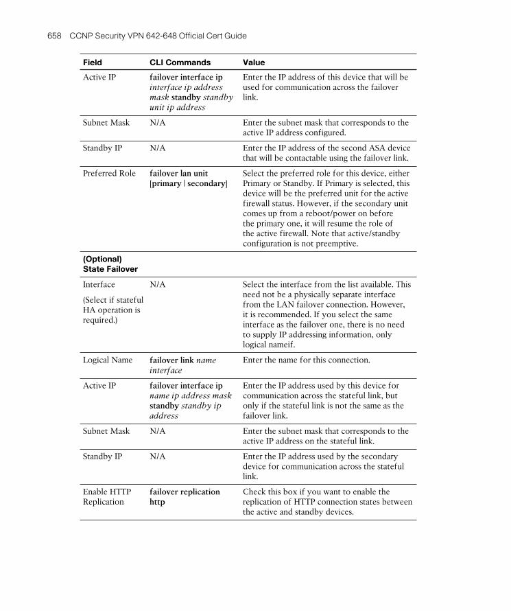
ptg8126969
658 CCNP Security VPN 642-648 Official Cert Guide
Field CLI Commands Value
Active IP failover interface ip interface ip address mask standby standby unit ip address
Enter the IP address of this device that will be used for communication across the failover link.
Subnet Mask N/A Enter the subnet mask that corresponds to the active IP address configured.
Standby IP N/A Enter the IP address of the second ASA device that will be contactable using the failover link.
Preferred Role failover lan unit [ primary | secondary ]
Select the preferred role for this device, either Primary or Standby. If Primary is selected, this device will be the preferred unit for the active firewall status. However, if the secondary unit comes up from a reboot/power on before the primary one, it will resume the role of the active firewall. Note that active/standby configuration is not preemptive.
(Optional)
State Failover
Interface
(Select if stateful HA operation is required.)
N/A Select the interface from the list available. This need not be a physically separate interface from the LAN failover connection. However, it is recommended. If you select the same interface as the failover one, there is no need to supply IP addressing information, only logical nameif.
Logical Name failover link name interface
Enter the name for this connection.
Active IP failover interface ip name ip address mask standby standby ip address
Enter the IP address used by this device for communication across the stateful link, but only if the stateful link is not the same as the failover link.
Subnet Mask N/A Enter the subnet mask that corresponds to the active IP address on the stateful link.
Standby IP N/A Enter the IP address used by the secondary device for communication across the stateful link.
Enable HTTP Replication
failover replication http
Check this box if you want to enable the replication of HTTP connection states between the active and standby devices.

ptg8126969
Chapter 18: High Availability and Performance for Easy VPN 659
Figure 18-2 shows an ASDM Failover pane configuration example.
Figure 18-2 ASDM Active/Standby Failover Configuration
After entering the configuration parameters required for failover, and (optionally) con-figuring the details required for stateful operation, click Apply . A dialog box, shown in Figure 18-3 , asks for the IP address of the secondary ASA device and whether the con-figuration replication should commence now between the two devices.
Figure 18-3 ASDM Active/Standby Failover Secondary Device Configuration

ptg8126969
660 CCNP Security VPN 642-648 Official Cert Guide
Before you proceed, you must configure the secondary device following the steps listed for the primary device. Configuration is identical on the secondary unit, both from CLI and ASDM. The only difference is that you designate the box as secondary: failover lan unit secondary . Except for failover-related configuration, the only additional configura-tion you need to do on the secondary device is to enable/unshut the failover link and stateful interfaces.
After you have configured the standby device to match that of the primary, select Yes to enable the configuration replication between devices. During this stage, the running configuration of the standby device is wiped of all content apart from the failover-specific commands. The configuration from the active device is then copied across the failover link and applied to the standby device. Note the following about a failover con-figuration:
■ After failover is configured and a relationship established between the two boxes, no configuration changes are done on the standby unit, only on the active one. Any configuration changes done on the standby will lead failover to fail because units no longer have configurations synchronized. Remember that the entire configuration is replicated from active to standby.
■ The active role is not tied to the primary role. The active device is the one forward-ing traffic, but the active device can be either the primary or secondary box.
■ If you do not configure a virtual MAC address (VMAC, which is covered later in this chapter), the primary device’s unit IP and MAC addresses are used. The excep-tion here is when both units are down and the secondary unit boots first. In this case, the primary’s unit IP addresses is used but the secondary’s MAC addresses is used.
■ The secondary IP, also known as the standby IP, is used only for the boxes to detect failures when a monitored interface goes down, or to gain management access to the secondary unit. These IPs are never used to forward data traffic.
Configure Optional Active/Standby Failover Settings
So far, the configuration reviewed in the previous sections has enabled a basic failover solution with stateful operation. You can enter information using the various optional settings to improve the service that has been deployed. For example, at the moment, the units in the example failover pair are using their own burned-in addresses (BIA) and are both up and running. Therefore, when a client or other device sends an Address
Resolution Protocol (ARP) for the corresponding Layer 2 address for the active unit IP address, they will receive the primary unit’s own MAC address (BIA). This can cause user traffic and sessions to be dropped if, for example, during a maintenance window you took both units down and the secondary unit had come up before the primary unit and taken over the role of the active unit. In this case, because the secondary unit does not see the primary, it takes over the role of active and use its own MAC addresses (BIA) because it does not know the MAC addresses of the primary unit (but does know the primary unit’s IP addresses). Clients and infrastructure devices continue to have an

ptg8126969
Chapter 18: High Availability and Performance for Easy VPN 661
ARP mapping between the primary’s unit IP address pointing to the primary’s unit MAC address, which at this moment does not replicate the reality. Even more, when the pri-mary unit boots, the secondary unit obtains the MAC addresses from the primary unit, which again can cause network traffic disruption.
You can solve this problem by entering VMACs that will be shared among the devices and sent to the users rather than the device-specific BIAs. VMACs are configured using the failover mac address interface active unit vmac standby unit vmac global con-figuration command. Alternatively, on the MAC Addresses tab in the ASDM’s Failover menu, click Add . In the Add Interface Mac Address window, shown in Figure 18-4 , select the interface for which the new VMAC will apply and enter the hexadecimal VMAC for both the active and standby units.
Figure 18-4 ASDM Failover VMAC Configuration Window
As you generally configure VMAC information to improve the service your users receive during a failover condition, you can also enable or disable the interfaces moni-tored for failover conditions to either occur or remain stable, thereby minimizing any potential disruption to users. For example, if a management interface moves to a down state, you might not necessarily want a failover condition to occur. However, if one criti-cal interface moves into a down state, you might want to fail the active unit over to the standby unit immediately.
Interface monitoring can be disabled for each interface. You accomplish this by navi-gating to the ASDM Interfaces pane and deselecting the relevant interface from the list shown. By default, all physical interfaces are monitored (with the exception of subinter-faces). A monitored interface can have one of the following statuses:
■ Unknown: Initial status. This status can also mean the status cannot be determined.
■ Normal: The interface is receiving traffic.
■ Testing: Hello messages are not heard on the interface for five poll times.
■ Link Down: The interface or VLAN is administratively down.
■ No Link: The physical link for the interface is down.
■ Failed: No traffic is received on the interface, yet traffic is heard on the peer interface.
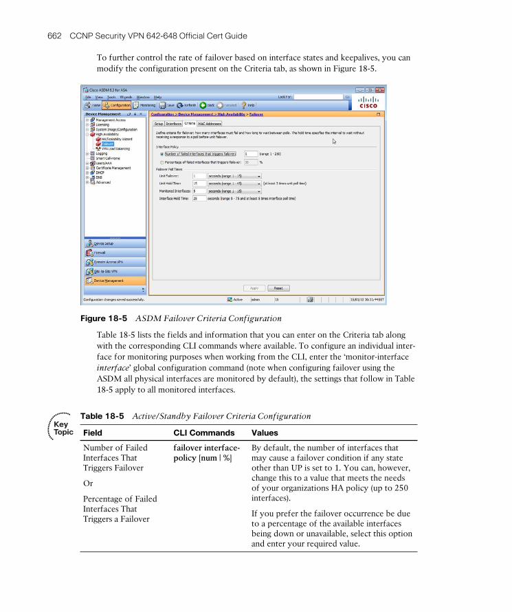
ptg8126969
662 CCNP Security VPN 642-648 Official Cert Guide
To further control the rate of failover based on interface states and keepalives, you can modify the configuration present on the Criteria tab, as shown in Figure 18-5 .
Figure 18-5 ASDM Failover Criteria Configuration
Table 18-5 lists the fields and information that you can enter on the Criteria tab along with the corresponding CLI commands where available. To configure an individual inter-face for monitoring purposes when working from the CLI, enter the ‘monitor-interface interface ’ global configuration command (note when configuring failover using the ASDM all physical interfaces are monitored by default), the settings that follow in Table 18-5 apply to all monitored interfaces.
Table 18-5 Active/Standby Failover Criteria Configuration
Field CLI Commands Values
Number of Failed Interfaces That Triggers Failover
Or
Percentage of Failed Interfaces That Triggers a Failover
failover interface-policy [ num | % ]
By default, the number of interfaces that may cause a failover condition if any state other than UP is set to 1. You can, however, change this to a value that meets the needs of your organizations HA policy (up to 250 interfaces).
If you prefer the failover occurrence be due to a percentage of the available interfaces being down or unavailable, select this option and enter your required value.
Key Topic

ptg8126969
Chapter 18: High Availability and Performance for Easy VPN 663
Field CLI Commands Values
Unit Failover failover polltime [ msec ] time [ holdtime [ msec ] time ]
Enter the number of seconds (1–15) or milliseconds (200–999) between failover hellos sent between peers. (The default is 1 second.)
Unit Hold Time N/A Enter the number of seconds (1–45) or milliseconds (800–999) between the absence of hellos before a failover occurs, at least 3 times the unit poll time. (The default is 15 seconds.)
Monitored Interfaces failover polltime interface [ msec ] time [ holdtime time ]
Enter the number of seconds (1–15) or milliseconds (500–999) between interface polls for the purpose of monitoring. (The default is 5 seconds.)
Interface Hold Time N/A Enter the number of seconds (5–75 and at least 5 times the configured interface poll time) before a monitored interfaces state is changed based on the absence of polling information. (The default is 25 seconds.)
Clustering Configuration for Easy VPN
An alternative way to implement a stateless HA scheme is to use the built-in clustering (VPN load-balancing) feature. This is supported for SSL VPN (client and clientless) and Easy VPN Remote (software and hardware clients), but not for L2TP, PPTP, L2TP/IPsec, or site-to-site IPsec VPN.
For performance and limited (stateless) HA, clustering (or VPN load balancing, as it is more commonly known) can be used to divide our remote clients’ Easy VPN sessions between ASA devices without having to duplicate hardware, software, or intermediate load balancers (ACE). After a failover has occurred, if DPD is enabled between the client and server, the client can automatically reconnect to the VIP for session reestablishment. However, if keepalives/DPD are not enabled, the remote client must create a new session to the VIP address.
Clustering can be configured on an ASA 5510 with an installed Security Plus license, or an ASA 5520 and higher device. The devices are also required to have an installed Triple
Data Encryption Standard/Advanced Encryption Standard (3DES/AES) license for operation. If the load-balancing module cannot detect the presence of a 3DES/AES license, it becomes unavailable.
Figure 18-6 illustrates the behavior of VPN clustering when configured on three devices. One ASA acts as the master, directing the incoming requests to the remaining ASA devices in the cluster.

ptg8126969
664 CCNP Security VPN 642-648 Official Cert Guide
Client A
Client B
External IP10.1.1.3/24
External IP10.1.1.1/24
External IP10.1.1.2/24
Master
Cluster Device CInternal IP192.168.1.3/24
Cluster Device AInternal IP192.168.1.1/24
Cluster Device BInternal IP192.168.1.2/24
WAN/Internet LAN
Figure 18-6 VPN Cluster Operation
The master device performs the task of load balancing. The master device is the first to start up and automatically assumes the role. However, if multiple devices are configured for the same cluster and restarted at the same time, the device with the higher priority wins the election. If at any point during operation the master device becomes unavailable or fails, the cluster member with the next highest priority becomes the active master in its place. There is no preempting once the active master has been elected. For example, if an active master already exists for a cluster and a new cluster member with a higher priority is introduced, it cannot take over the role from the active master while it is still available.
The configuration required to create a cluster and add members is straightforward: All members of the same cluster must have an identical virtual cluster IP address, User
Datagram Protocol (UDP) port, and IPsec encryption key (used to encrypt messages between active members), and each device’s public and private interfaces must be on the same network with each other.
Figure 18-7 displays the load balancing (VPN cluster) configuration window, which you can access in the ASDM by navigating to Configuration > Remote Access VPN > Load Balancing .
Figure 18-7 ASDM VPN Cluster Configuration

ptg8126969
Chapter 18: High Availability and Performance for Easy VPN 665
Table 18-6 lists the configuration fields and descriptions found on the Load Balancing pane. Alternatively, you can issue the vpn load-balancing global configuration command to enter you into load-balancing (clustering) configuration mode, where you can config-ure the various clustering settings/attributes that are available using the CLI. Table 18-6 also includes the corresponding CLI commands where available.
Table 18-6 ASDM VPN Cluster Configurable Fields and Values
Field CLI Commands Value
Participate in Load Balancing Cluster*
participate (Enter last after completing the cluster configuration.)
Disabled by default. Before this device can join an active cluster or become the master of a new one, you must select this option.
Cluster IP Address*
cluster ip address ip address Enter the virtual cluster IP address to be used by this cluster. All members of the cluster must have the same address configured, and this address must be within the same subnet as the device IP address configured on the interface.
UDP Port* cluster port port Enter the UDP port used for cluster member communication. This port must be unused on the network. (The default is 9023.)
Enable IPsec Encryption*
cluster encryption For messages between cluster members to be encrypted instead of sent in plain text, select this option.
IPsec Shared Secret*
cluster key value Enter the shared secret that will be used by each cluster member to encrypt the messages between them.
Verify Secret* N/A Enter the shared secret from the preceding step again to confirm your entry.
Public Interface
interface lbpublic interface Select from the drop-down list your public/external-facing interface. Cluster member interfaces must be on the same network.
Priority priority value Enter the priority value 1–10 for this device used for master negotiations. The higher value wins. (The default is 5.)
Private Interface
interface lbprivate interface Select from the drop-down list your private/internal-facing interface. Cluster member interfaces must be on the same network.
NAT Assigned IP Address
nat ip address Enter the IP address the device is being NAT-ed to. If you are not using Network Address Translation (NAT) on your network, leave this field blank.
Key Topic

ptg8126969
666 CCNP Security VPN 642-648 Official Cert Guide
Field CLI Commands Value
Send FQDN to Client Instead of an IP Address When Redirecting
redirect-fqdn [ enable | disable ]
By default, the cluster master sends the IP address of a cluster member to a connecting user/client when redirecting. However, if using certificates, the master can be configured to send the fully qualified domain name (FQDN) after performing a reverse Domain Name System (DNS) lookup of the cluster member it is redirecting to.
*These values must match on each cluster member before successful operation can com-mence.
Troubleshooting Device Failover and Clustering
When troubleshooting device failover, you can start by checking the status of the failover configuration in the ASDM by navigating to Monitoring > Properties > Failover > Status or by issuing the show failover command. As shown in Figure 18-8 , the ASDM Failover Status window displays the failover criteria, the failover interface, and the current active unit.
Figure 18-8 ASDM Failover Status Window

ptg8126969
Chapter 18: High Availability and Performance for Easy VPN 667
In this window, you can also reload the standby device, reset the current failover state, and force the device to take the active or standby role if you need to take the current active device out of operation for further troubleshooting.
If you suspect degradation of performance is due to the number of sessions, available bandwidth, or open connections to your device (for example, if you suspect a denial or distributed denial-of-service [DoS/DDoS] attack might be occurring), you can view the current connection and failover Xmit and Receive queues by viewing the appropriate graphs by navigating to Monitoring > Properties > Failover > Graphs . (This informa-tion is also available when using the show failover CLI command, but the information is shown as a series of numbers.) As with other troubleshooting sections, you should use both the real-time monitor and ASA’s internal logging buffer to inspect any alarms or alerts that may be occurring due to physical or (depending on your configuration) logical interfaces being down or inactive.
If an active/active situation has inadvertently occurred, check for any cabling or switch configuration errors along the path between the two ASA devices. For example, if a failover interface on one ASA has been placed into an incorrect VLAN during operation, the failover hold times will expire on both devices. However, the interfaces and their states will still remain up, resulting in the two devices both taking the role of the active device. Note that this scenario can happen only if the failover link fails at startup, result-ing in both units becoming active. If the failover link fails during operation, the failover link is marked as failed on the standby unit, which remains in the standby state. If you suspect such a situation, check the current failover status to determine whether this has occurred. Examine the failover role displayed, fix the connection or intermediate device error if required, and restart the standby device to resume normal operation.
To begin troubleshooting client connectivity to your ASA cluster, it is advisable to start with the familiar tools:
■ Ping
■ Traceroute
■ NSLookup
If the problem experienced is due to the cluster members being unable to communicate with each other, or possibly a configuration error on one or more of the cluster devices, check to make sure you have the required topology and all the correct information on each cluster member for successful operation.
Each cluster member’s internal and external interface must be connected to the same network. (That is, they should all have an IP address belonging to the same internal and external subnet.)

ptg8126969
668 CCNP Security VPN 642-648 Official Cert Guide
When you have verified the devices are on the same network, you can proceed to check the configuration on and between the devices. At a minimum, each device must have the following matching configuration:
■ Participate in Load Balancing Cluster: Enabled
■ Virtual cluster IP address
■ UDP port
If IPsec has been configured for the encryption of messages between devices, you must make sure on each cluster device that IPsec encryption has been enabled, and then enter and reenter the shared secret on the new device (or All, if none of them can communi-cate).
Ensure that the public and private interfaces have been selected as the correct physical interfaces on the device (that is, public - outside, private - inside).
Finally, check each device for the correct certificates. If certificates are being used by cluster members, each should have the following loaded on them:
■ Device-specific certificate
■ Unified Communications Certificate (UCC) or wildcard certificate imported from the master
Navigate to Monitoring > VPN > VPN Statistics > VPN Cluster Loads within the ASDM to view each of the configured devices within the pane or use the show vpn load-balancing command to view the status of the clustering configuration. In addition to the show command, you can issue the debug vpnlb level command to view detailed information about the status of your clustering configuration, the device operation, and communication.
You can use the flowchart in Figure 18-9 as a guide when troubleshooting a cluster con-figuration.

ptg8126969
Chapter 18: High Availability and Performance for Easy VPN 669
Cluster LoadBalancing
Doesn’t Work
Correct
Correct
Correct
VPN ClusteringWorks
Check ClusterSettings
Verify cluster VIP, UDP Port,and Encryption settings match on all members.
Verify ASACertificates
Check that UCC, Multiple, orWildcard certificates are installed on all members.
Verify RouteRedistribution
Check the routing table on the ASA for connected host routes.Verify the routing table oninternal routers for dynamicallylearned client host routes.
Figure 18-9 Troubleshooting ASA VPN Clustering

ptg8126969
670 CCNP Security VPN 642-648 Official Cert Guide
Exam Preparation Tasks
As mentioned in the section “How to Use This Book” in the Introduction, you have a few choices for exam preparation: Chapter 22 , “Final Exam Preparation,” Appendix C , “Memory Tables” (CD only), and the exam simulation questions on the CD.
Review All Key Topics
Review the most important topics in the chapter, noted with the Key Topic icon in the outer margin of the page. Table 18-7 lists a reference of these key topics and the page numbers on which each is found.
Table 18-7 Key Topics
Key Topic Element Description Page
Table 18-2 Available HA and load-balancing methods 653
Table 18-4 Failover configuration 657
Table 18-5 Active/standby failover criteria 662
Table 18-6 VPN cluster configuration 665
Complete Tables and Lists from Memory
Print a copy of Appendix C , “Memory Tables” (found on the CD), or at least the section for this chapter, and complete the tables and lists from memory. Appendix D , “Memory Tables Answer Key,” also on the CD, includes completed tables and lists to check your work.
Define Key Terms
Define the following key terms from this chapter and check your answers in the glossary:
ACE, BIA, hello packet, hold time, stateful, stateless, VMAC
Key Topic

ptg8126969
This page intentionally left blank

ptg8126969
This chapter covers the following subjects:
■ Easy VPN Remote Hardware Client Overview: This section discusses the available operation of the Easy VPN Remote hardware client available on the Cisco ASA 5505 device.
■ Configuring a Basic Easy VPN Remote Client
Using the ASA 5505: This section explains how to configure a basic Easy VPN Remote client on an ASA 5505 device.
■ Configuring Advanced Easy VPN Remote Client
Settings for the ASA 5505: This section reviews the advanced settings available on an ASA 5505 when configured as an Easy VPN Remote client, and discusses the configuration required on both the ASA 5505 device and the VPN head-end device.
■ Troubleshooting the ASA 5505 Easy VPN
Remote Hardware Client: This section identifies the tools available on the ASA 5505 device you can use to verify the operation of an Easy VPN client connection.

ptg8126969
It’s now time to move on from the discussion of the Easy VPN Server capabilities of the Adaptive Security Appliance (ASA) product family and concentrate now on the hardware client functionality offered only by the ASA 5505 device. This places the ASA 5505 as a perfect device for small office/home office (SOHO) deployment or environ-ments that require a large amount of remote-site connectivity. By completing the config-uration required to enable the ASA 5505 as an Easy VPN Remote client, the complexity and local support that may have been required at a remote site are removed, enabling the end users behind the device to use the negotiated IPsec virtual private network (VPN) for secure connectivity into their regional or central HQ office.
“Do I Know This Already?” Quiz
The “Do I Know This Already?” quiz helps you determine your level of knowledge on this chapter’s topics before you begin. Table 19-1 details the major topics discussed in this chapter and their corresponding quiz sections.
Table 19-1 “Do I Know This Already?” Section-to-Question Mapping
Foundation Topics Section Questions
Easy VPN Hardware Remote Client Overview 6
Configure a Basic Easy VPN Remote Client Using the ASA 5505 2 , 5
Configuring Advanced Easy VPN Remote Client Settings for the ASA 5505 1 , 3 , 4 , 6
1. When deploying an advanced authentication scheme that requires each user at the remote site to enter authentication parameters before tunnel access is granted, which option would you choose for your deployment?
a. SUA
b. Unit Authentication
c. IUA
d. X-Auth
CHAPTER 19
Easy VPN Operation Using the ASA 5505 as a Hardware Client

ptg8126969
674 CCNP Security VPN 642-648 Official Cert Guide
2. Which of the following are available authentication methods used between the Easy VPN Remote client and server for tunnel establishment? (Choose all that apply.)
a. Pre-shared keys
b. RSA SecurId
c. X.509 certificates
d. RSA certificates
3. Which advanced hardware client feature, if enabled, allows a Cisco Aironet access point at the remote site to contact a RADIUS server at the VPN head-end site when Easy VPN advanced authentication methods have been deployed?
a. Device Pass-Through
b. LEAP Bypass
c. Network Extension mode
d. Client mode
4. When preparing to allow a Cisco IP phone unauthenticated access to a VPN head-end site without having to authenticate first, which two items require configuration and details of the phone to be entered?
a. VPN head-end group policy object
b. VPN head-end connection profile
c. Cisco Easy VPN Remote client MAC exemption list
d. Cisco Easy VPN Remote client firewall rules
5. What is the minimum number of configuration steps required for a basic Easy VPN Remote client to set up a tunnel?
a. 3
b. 4
c. 5
d. None (because it is an automatic process)
6. Which of the following are valid modes of operation when configuring the Easy VPN Remote client device?
a. Client mode
b. Network Extension mode
c. Remote mode
d. Local mode

ptg8126969
Chapter 19: Easy VPN Operation Using the ASA 5505 as a Hardware Client 675
Foundation Topics
Easy VPN Remote Hardware Client Overview
The Easy VPN chapters up to this point have covered the configuration steps required to enable a basic and advanced Easy VPN Server deployment on the ASA using the Cisco IPsec VPN Client as an example of a remote client. This chapter concentrates solely on the role an ASA 5505 device can take as an Easy VPN hardware client (also known as an Easy VPN Remote endpoint). Note that Easy VPN relies solely on Internet Key
Exchange Version 1 (IKEv1) . IKEv2 does not support this functionality.
Throughout the Adaptive Security Appliance (ASA) product family, the role of an Easy VPN Remote hardware client is available on only an ASA 5505, largely because of its design, which is based on the use for SOHO and remote-branch deployments. The ASA 5505 can also operate as an Easy VPN server. There is no default mode of operation, however, because either Server or Client mode can be used on the device. Do note, how-ever, that the two cannot operate together.
In addition to the ASA 5505 device, the following devices can fulfill the role of an Easy VPN Remote client:
■ PIX 501/506E
■ 800, 1800, 1900, 2800, 2900, 3800, 3900 series Integrated Services Routers (ISR)
■ uBR 900 series routers
When choosing to deploy ASA 5505 as a hardware Easy VPN Remote client, you have two modes of operation to choose from, depending on the environment into which you are introducing your remote site:
■ Client mode
■ Network Extension mode
Client Mode
In Client mode, the end devices within the remote client’s network (ASA 5505 client’s inside hosts) are hidden from the head-end site by the implementation of automatic Network/Port Address Translation (NAT/PAT) rules. As clients of the remote site contact resources using the Easy VPN connection, the ASA 5505 automatically creates the necessary NAT and PAT translations using the IP address associated with the ASA’s outside interface. Therefore, the only IP address that is presented to the head-end site by the remote site is that of the remote client device.
Key Topic

ptg8126969
676 CCNP Security VPN 642-648 Official Cert Guide
In addition to the NAT/PAT entries, the ASA 5505 creates the necessary access control
lists (ACL) that are required for the appropriate traffic to be matched and sent across the VPN tunnel to the head-end device.
The ASA hardware client also supports the use of split tunneling when configured on the head-end device. This provides for the use of resources on the local LAN, and enables the use of direct Internet access from the remote client’s site without the need to send all traffic through the VPN tunnel.
Figure 19-1 displays the operation of an ASA 5505 Easy VPN hardware client when run-ning in Client mode.
NAT/PAT Performed on ASAClient AIP Address 192.168.1.2/24
Client BIP Address 192.168.1.3/24
ASA 5505EzVPN Client
VPNHead End
VPN Tunnel
Outside IP10.1.1.3/24
Inside IP192.168.1.1/24
Figure 19-1 ASA 5505 Easy VPN Remote Endpoint Client Mode
Network Extension Mode
Network Extension mode (NEM) does not perform any outgoing NAT or PAT. Therefore, it allows for the end devices within the remote site to be contacted directly. The client devices are assigned individual IP addresses for use across the virtual private
network (VPN) tunnel, as shown in Figure 19-2 .
The use of split tunneling is also supported when using NEM. It is deployed to the remote client by the head-end device’s configured group policies.
NEM is typically deployed for the use of direct end-user device access and site-to-site access between the remote client site and the VPN head-end site, or the remote client site and another remote site.

ptg8126969
Chapter 19: Easy VPN Operation Using the ASA 5505 as a Hardware Client 677
Client AssignedIP Address 172.30.255.2
Client AIP Address 192.168.1.2/24
Client BIP Address 192.168.1.3/24
ASA 5505EzVPN Client
(Spoke)
VPN Tunnel
VPN Tunnel
Outside IP10.1.1.3/24
Inside IP192.168.1.1/24
Client CIP Address 192.168.2.2/24
Client DIP Address 192.168.2.3/24
ASA 5505EzVPN Client
(Spoke)
VPN HeadEnd (Hub)
Figure 19-2 ASA 5505 Easy VPN Remote Endpoint Network Extension Mode
When a requirement exists for a remote client site to contact another remote site through their established VPN tunnels, the use of the same-security-traffic permit intra-interface command is required on the VPN head-end device. As packets in this design are sent and received to and from remote sites on the same interface of the VPN head-end device (effectively creating a “hairpin” situation), the same-security-traffic permit intra-interface command permits this behavior to occur. This design is common-ly referred to as a hub-and-spoke network, with the VPN head-end carrying out the role of the hub and the remote sites carrying out the role of the spokes. It is also important to remember when configuring the ACLs to define your VPN’s interesting traffic (traffic that will be matched and sent through the VPN tunnel to the remote network) to include the subnets of all remote sites where access is required from the Easy VPN Remote cli-ent site you are configuring.

ptg8126969
678 CCNP Security VPN 642-648 Official Cert Guide
Configuring a Basic Easy VPN Remote Client Using the
ASA 5505
This section covers the Easy VPN Remote client configuration required on an ASA 5505 device. However, it is assumed that the required configuration steps have been carried out on another ASA or other VPN termination device for the deployment of an Easy VPN server.
To begin, you can access the Easy VPN Remote pane within the Adaptive Security
Device Manager (ASDM) by navigating to Configuration > Remote Access VPN > Easy VPN Remote , shown in Figure 19-3 .
Figure 19-3 ASDM Easy VPN Remote Configuration
You must perform four steps to complete the configuration with the minimal required information:
Step 1. Enable Easy VPN Remote.
Step 2. Select the operational mode of either Client or Network Extension.
Step 3. Select the authentication scheme.
Step 4. Enter the addresses of the Easy VPN server.
For this example, begin by selecting Enable Easy VPN Remote to enable the hardware client function and select Pre-Shared Key authentication entering the following details:
■ Group Name: CCNP-REMOTE
■ Group Password: Security
Key Topic

ptg8126969
Chapter 19: Easy VPN Operation Using the ASA 5505 as a Hardware Client 679
If you select X.509 certificate authentication, you can select one of the existing identity certificates available on the ASA from the drop-down list that appears or import a new certificate by clicking the Identity Certificates link. If you leave the selected certificate as None, the ASA device attempts to use RSA certificates for authentication purposes.
Now enter the following Easy VPN server IP addresses: 1.1.1.1 and 2.2.2.2 . The server IP addresses are tried in order from the top of the list to the bottom. So, if the first serv-er (1.1.1.1) is unavailable, the client tries to initiate a connection to the second (2.2.2.2) instead. You can change server-use order by selecting the appropriate server from the list and clicking the Move Up or Move Down buttons.
Example 19-1 displays the same configuration carried out using the available command-
line interface (CLI) commands
Example 19-1 Easy VPN Hardware Client Basic Configuration
CCNPSec(config)# vpnclient vpngroup CCNP-REMOTE password security
CCNPSec(config)# vpnclient server 1.1.1.1 2.2.2.2
CCNPSec(config)# vpnclient enable
Configuring Advanced Easy VPN Remote Client
Settings for the ASA 5505
You can optionally configure four advanced settings on the ASA 5505 hardware client. This section describes these available settings and their respective configuration and any additional configuration that is required on the VPN head-end device for their operation to be successful.
The following are the advanced settings you can configure:
■ X-Auth and Device Authentication
■ Remote Management
■ NAT Transparency
■ Device Pass-Through
X-Auth and Device Authentication
All authentication options within this section are configured in the applied group policy object on the VPN head-end device. However, for the authentication to be successful and depending on the type of authentication that has been enabled, you need to enter user credentials onto the remote ASA device. Otherwise, the individual users on the remote site are prompted for authentication credentials.
Key Topic

ptg8126969
680 CCNP Security VPN 642-648 Official Cert Guide
The available authentication options that can be incorporated into your remote client Easy VPN deployment include the following:
■ No X-Auth
■ Unit Authentication (Automatic X-Auth)
■ Secure Unit Authentication
■ Individual User Authentication
By default, no X-Auth authentication is applied to a remote VPN connection. Therefore, after entering the initial group authentication (consisting of a group name, pre-shared key, or certificate), the ASA is not required to supply any additional authentication cre-dentials during VPN tunnel initiation. For the connection to be successful when the ASA is the head-end, X-Auth needs to be disabled in the connection profile at the head-end, as well, because on the ASA X-Auth is enabled by default within each configured con-nection profile.
Unit Authentication (Automatic X-Auth) occurs each time the VPN connection is initi-ated. The required username and password are preconfigured on the connecting ASA device, negating the requirement for a user or administrator to actively enter authentica-tion credentials each time a new VPN tunnel is established. The username and password can be entered using the vpnclient username user password password global configura-tion command or are saved in the User Settings section of the Easy VPN Remote pane, as shown in Figure 19-4 .
Figure 19-4 ASA Easy VPN Remote Automatic X-Auth Credentials

ptg8126969
Chapter 19: Easy VPN Operation Using the ASA 5505 as a Hardware Client 681
Secure Unit Authentication (SUA) , also known as Interactive Unit Authentication, is enabled by the policy pushed down to the client from the Easy VPN server. Each time a VPN connection is initiated, the user is required to authenticate the ASA before a suc-cessful connection is established. Because of the policy push by the Easy VPN server, any preconfigured authentication parameters on the ASA 5505 are ignored. When SUA is disabled and Hardware Remote works in Network Extension mode, the VPN session is automatically initiated. When SUA is disabled and Hardware Remote works in Client mode, the VPN session is automatically initiated only if interesting traffic (to be protect-ed) is detected. Of course, the VPN session can be manually initiated from the ASA CLI with the command vpnclient connect . For SUA to work, credentials need to be supplied via a web browser. The simplest way to accomplish this is to instruct a user to initiate a web browser session to a protected resource. At this moment, the hardware remote redirects the user to a local login page to supply a username and password, used by SUA to complete the authentication process and bring the tunnel up. Once authenticated, if the initiated URL is valid, the user is redirected to the accessed resource.
Individual User Authentication (IUA) requires each user at the remote site to authen-ticate before being granted access to the VPN tunnel. User authentication is carried out by HTTP redirection on the ASA 5505 client device if one of the following is true:
■ No pre-authentication parameters have been configured and SUA is not enabled.
■ IUA is enabled on the VPN server head-end.
For user authentication to be carried out, the remote clients must open a web browser session, at which point they are prompted to enter the credentials. The problem with SUA is that once the tunnel is up, anyone (authenticated or not) can send traffic through the tunnel. With IUA, you can force all users to authenticate. The Hardware Remote keeps track of authenticated clients based on the IP/MAC address pair.
SUA and IUA are both enabled based on the group policy settings configured on the VPN head-end and applied to the remote client device. To configure each of these settings, either enter into group policy attributes configuration mode using the CLI or navigate to Configure > Remote Access VPN > Network (Client) Access > Group Policies within the ASDM and open the appropriate group policy object on the Easy VPN server device. Example 19-2 dis-plays the configuration commands required to enable SUA or IUA using the CLI. Following the CLI example, the alternative configuration using the ASDM is also shown.
Example 19-2 Configure SUA and IUA Within a Group Policy
CCNPSec(config)# group-policy CCNP-VPN-POLICY attributes
CCNPSec(config-group-policy)# !!Begin by optionally configuring SUA!!
CCNPSec(config-group-policy)# secure-unit-authentication enable
CCNPSec(config-group-policy)# !!If IUA is required instead, begin by dis-abling SUA and enable IUA
CCNPSec(config-group-policy)# secure-unit-authentication disable
CCNPSec(config-group-policy)# user-authentication enable
CCNPSec(config-group-policy)# !!Enter an optional timeout value in minutes for user authentication
CCNPSec(config-group-policy)# user-authentication-idle-timeout 10

ptg8126969
682 CCNP Security VPN 642-648 Official Cert Guide
When using the ASDM for configuration purposes, within the group policy object, expand the menu on the left side to Advanced > IPsec Client > Hardware Client . To enable SUA, uncheck Inherit next to Require Interactive Client Authentication and check Enable, as shown in Figure 19-5 .
Figure 19-5 Easy VPN Server, Enable SUA
If you require the use of IUA instead, uncheck Inherit next to Require Individual User Authentication and optionally enter an idle timeout value for re-authentication purposes, as shown in Figure 19-6 .
Figure 19-6 Easy VPN Server, Enable IUA

ptg8126969
Chapter 19: Easy VPN Operation Using the ASA 5505 as a Hardware Client 683
Remote Management
Two options are available to enable remote management of the Easy VPN Remote cli-ent ASA’s outside interface from administrators located at the head-end site (behind the Easy VPN Server ASA). These two options are Enable Tunneled Management and Clear Tunneled Management. You can configure both using the CLI or within the ASDM Easy VPN Remote pane by clicking the Advanced button.
Tunneled Management
If you use tunneled management, each session from a management station to the ASA device is tunneled through its own automatically generated IPsec tunnel. For an ASA remote client device, you must enter the IP addresses of each individual manage-ment station or network/subnet into the ASA’s Advanced Easy VPN Properties dia-log and click Add (shown in Figure 19-7 ). You must also check the Enable Tunneled Management check box. Alternatively, you can enter the vpnclient management tunnel ip address mask CLI command for each network or host you want to add.
Figure 19-7 ASA Easy VPN Remote Client Enable Tunneled Management Access

ptg8126969
684 CCNP Security VPN 642-648 Official Cert Guide
Clear Tunneled Management
You can check the Clear Tunnel Management check box (within the ASDM’s Advanced Easy VPN Properties dialog) if you do not want the management connections from head-end office clients to the remote ASA to be automatically tunneled. If you check this box, the normal routing process is followed for clients to be able to access the remote ASA device. This option is recommended if a NAT device is within the path between the VPN head-end device and the ASA remote device, When working from the CLI, you can enter the vpnclient management clear command to achieve the same result.
NAT Traversal
IKEv1 NAT Traversal (NAT-T) is enabled by default by using User Datagram Protocol
(UDP) and assigning port number 4500. The purpose of NAT Traversal, as you can prob-ably guess from the name, is to allow for successful communication between two IPsec hosts for tunnel negotiation purposes when a NAT/PAT device is in the path of commu-nication.
The initial problem that arises with having a PAT device within the path is when IPsec uses the Encapsulating Security Payload (ESP) protocol for packet encapsulation. ESP is an IP protocol that does not by default use TCP or UDP for transport purposes. It is connectionless by nature, and therefore the ESP packets contain no port information that can be used by a PAT device to build a translation. Cisco can use both the NAT-T standard and a proprietary method to encapsulate IPsec packets within a UDP datagram to enable the successful transmission when traversing a PAT device. However, some organizations’ firewall policies do not allow UDP inbound access to their organization, so an option to use TCP instead of UDP had to be added to get around this problem.
You can either enable the use of TCP by entering the vpnclient ipsec-over-tcp port port global configuration command or, as shown in Figure 19-8 , you can enable TCP by navi-gating to the same Advanced dialog used earlier within the ASDM ( Configure > Remote Access VPN > Easy VPN Remote > Advanced ). Once there, just check the Enable check box in the IPsec over TCP section and enter a port number between 1 and 65535. Unlike UDP, when using TCP you must specify the port and match on both the VPN head-end and the Easy VPN Remote devices.

ptg8126969
Chapter 19: Easy VPN Operation Using the ASA 5505 as a Hardware Client 685
Figure 19-8 ASDM Easy VPN Remote, Advanced Easy VPN Properties, Enable TCP NAT Traversal
Device Pass-Through
To accompany the implementation of any IUA authentication that might have been configured, you can also configure the option to allow certain devices to pass traffic through the tunnel without having to authenticate. This is helpful because many devices do not support interactive authentication methods other than standard ones such as 802.1x (for example, IP phones, printers, and wireless access points).
The configuration to enable the authentication bypass of certain devices is carried out on both the group policy applied to the client using the VPN head-end device and the Easy VPN Remote device. As shown in Figure 19-9 , on the VPN head-end device, select the appropriate group policy from Configuration > Remote Access VPN > Network (Client) Access > Group Policies and click Edit . Within the Edit Internal Group Policy dialog, use the menu on the left side to navigate to Advanced > IPsec Client > Hardware Client , uncheck the Inherit check box next to Cisco IP Phone Bypass, and click the Enable button.
Key Topic

ptg8126969
686 CCNP Security VPN 642-648 Official Cert Guide
Figure 19-9 ASDM Edit Internal Group Policy, Allow Device Pass-Through
Doing this enables the Authentication Bypass feature, but it works only if the hardware client functions in Network Extension mode. Optionally, if you have autonomous Cisco Aironet wireless access points located in your remote office, you might also want to enable the LEAP Bypass option to allow the head-end for wireless clients using Lightweight Extensible Authentication Protocol (LEAP) authentication to bypass the authentication process. This works for both Client and Network Extension mode, and LEAP authentication packets travel through the tunnel only to a RADIUS server on ports 1645 or 1812. Note that this is only for the process of users authenticating to the wire-less infrastructure. Afterward, each user still needs to authenticate because of the IUA.
Example 19-3 displays the commands required when working through the CLI to enable both IP phone and LEAP bypass on the VPN head-end device. You can optionally turn off each of both of these features by using the disable keyword in place of enable shown in the example.
Example 19-3 Configure IP Phone and LEAP Bypass on the VPN Head-End Device
CCNPSec(config)# group-policy CCNP-VPN-POLICY attributes
CCNPSec(config-group-policy)# ip-phone-bypass enable
CCNPSec(config-group-policy)# leap-bypass enable
After enabling Device Pass-Through on the VPN head-end, you also need to com-plete the configuration on the Easy VPN Remote client. Within the ASDM, open the Advanced menu located via Configuration > Remote Access VPN > Easy VPN Remote > Advanced , and then, as shown in Figure 19-10 , enter the MAC addresses per device

ptg8126969
Chapter 19: Easy VPN Operation Using the ASA 5505 as a Hardware Client 687
(or range of MAC addresses that require the use of device pass-through). As shown in Figure 19-10 , we have entered the MAC address for a Cisco IP phone with the mask FFFF.FFFF.FFFF, to allow this specific address only within the MAC Exemption sec-tion of the Advanced dialog. Whereas a mask of FFFF.FFFF.FFFF matches only the specified MAC, a mask of 0000.0000.0000 matches one MAC address, and a mask of FFFF.FF00.0000 matches all devices made by the same manufacturer. You can use the corresponding CLI command vpnclient mac-exempt mac address 48-bit mask to enable the bypass option on the VPN client device for each device or a range of devices that require bypass to be enabled.
Figure 19-10 ASDM Easy VPN Remote Advanced Properties, Allow Device Pass-Through
Troubleshooting the ASA 5505 Easy VPN Remote
Hardware Client
When troubleshooting an Easy VPN connection, follow the same rules as discussed in earlier chapters. For example, make sure the required connectivity exists between the client and server and use the available tools such as ping, traceroute, and NSLookup. (The role of NSLookup is mentioned here based on a connection entry created using the hostname of a device.) For troubleshooting the Easy VPN Remote device specifically,

ptg8126969
688 CCNP Security VPN 642-648 Official Cert Guide
some additional tools and commands can be of great use before, during, and after a con-nection attempt.
You can begin by looking at the VPN Connection Status panel in the ASDM. This can indicate the current connection status and the various parameters configured (for exam-ple, split tunnel network lists, backup servers, authentication schemes in use). In addi-tion, you can view the current full Easy VPN Remote configuration within this window and, if required, copy and paste it into an email/web form for further troubleshooting by corporate site support personnel.
You can also control the connection status from this pane by either choosing to discon-nect an already established tunnel or forcing the connection of a disconnected tunnel, as shown in Figure 19-11 . You can access the Connection Status pane via Monitoring > VPN > Easy VPN Client > VPN Connection Status .
Figure 19-11 ASDM Easy VPN Client, Connection Status Pane
The ASDM also has graph functions that enable you to check the status of a connection. To access the graphs, navigate to Monitoring > VPN > VPN Connection Graphs > IPsec Tunnels . As shown in Figure 19-12 , we have selected both IPsec Active Tunnels and IKE Active Tunnels for graph purposes.

ptg8126969
Chapter 19: Easy VPN Operation Using the ASA 5505 as a Hardware Client 689
Figure 19-12 IDS and IPS Operational Differences
After clicking the Show Graphs button at the bottom of the pane, you are presented with the current connection status. What you are looking for in these graphs is a steady line next to the number of expected sessions you have open. (In the case of the Easy VPN Remote client, this is one.) As you can also see in Figure 19-12 , we have the expected number of active connections on our Easy VPN Remote client (one).
You can access further information using the following debug commands from the command-line interface (CLI):
■ debug crypto ikev1
■ debug crypto ipsec
These commands provide you with a great deal of information involved in the con-nection establishment, policy negotiation, and peer authentication process within their respective IKEv1 phases (IKEv1 Phase 1 and IKEv1 Phase 2).

ptg8126969
690 CCNP Security VPN 642-648 Official Cert Guide
Exam Preparation Tasks
As mentioned in the section “How to Use This Book” in the Introduction, you have a few choices for exam preparation: Chapter 22 , “Final Exam Preparation,” Appendix C , “Memory Tables” (CD only), and the exam simulation questions on the CD.
Review All Key Topics
Review the most important topics in the chapter, noted with the Key Topic icon in the outer margin of the page. Table 19-2 lists a reference of these key topics and the page numbers on which each is found.
Table 19-2 Key Topics
Key Topic Element Description Page
Bulleted list Easy VPN Remote-supported hardware platforms 675
Step list Basic Easy VPN Remote configuration 678
Topic X-Auth and device authentication 679
Topic Device Pass-Through 685
Complete Tables and Lists from Memory
Print a copy of Appendix C , “Memory Tables” (found on the CD), or at least the section for this chapter, and complete the tables and lists from memory. Appendix D , “Memory Tables Answer Key,” also on the CD, includes completed tables and lists to check your work.
Define Key Terms
Define the following key terms from this chapter and check your answers in the glossary:
Device Pass-Through, IUA, SUA
Key Topic

ptg8126969
This page intentionally left blank

ptg8126969
This chapter covers the following subjects:
■ Configuration Procedures, Deployment
Strategies, and Information Gathering: This sec-tion reviews the common deployment methods and designs that are used for IPsec site-to-site VPNs and the information necessary for a basic VPN deploy-ment.
■ Configuring a Basic IKEv1 IPsec Site-to-Site
VPN: This section discusses how to configure a successful deployment between two sites using the ASDM.
■ Configuring a Basic IKEv2 IPsec Site-to-Site
VPN: This section explains how to configure a new site-to-site tunnel with the ASDM and using IKEv2.
■ Configuring Advanced Authentication for IPsec
Site-to-Site VPNs: This section covers the role of PKI (instead of PSKs) when deployed for peer authentication reasons and looks at the configura-tion necessary for a successful connection attempt to occur.
■ Troubleshooting an IPsec Site-to-Site VPN: This section reviews the available tools in the ASDM that enable you to verify and troubleshoot site-to-site VPN connectivity.

ptg8126969
In the earlier chapters, we discussed and configured various virtual private network
(VPN) deployment methods that allow remote users access to your central office resources, either through a software or hardware IPsec VPN client and client or client-less Secure Sockets Layer (SSL) VPN. However, site-to-site VPNs have been around (and have become popular) since the days when organizations had to make use of private connections. These were commonly deployed between themselves and a remote site using either dedicated physical lines or virtual circuits provisioned by a service provider in their network.
With the introduction of the Internet and subsequent surge in businesses becoming IP enabled, the IPsec site-to-site VPN allowed organizations to quickly provision secure connectivity to remote and partner offices at a dramatically lower cost than dedicated physical connections, with the additional flexibility of having greater control and visibil-ity of the connection (unlike third-party provisioned virtual circuits).
In this chapter, a few of the available and common deployment scenarios that have been used by organizations to allow secure connectivity between sites are discussed. The information required to configure a basic site-to-site VPN connection is then reviewed. The first scenario uses pre-shared key (PSK) peer authentication. The second uses the advanced method of public key infrastructure (PKI) and digital certificates.
“Do I Know This Already?” Quiz
The “Do I Know This Already?” quiz helps you determine your level of knowledge on this chapter’s topics before you begin. Table 20-1 details the major topics discussed in this chapter and their corresponding quiz sections.
Table 20-1 “Do I Know This Already?” Section-to-Question Mapping
Foundation Topics Section Questions
Configuration Procedures, Deployment Strategies, and Information Gathering
1 , 2 , 3
Configuring a Basic IPsec Site-to-Site VPN 4 , 5 , 6
Configuring Advanced Authentication for IPsec Site-to-Site VPNs 8
Troubleshooting an IPsec Site-to-Site VPN 7
CHAPTER 20
Deploying IPsec Site-to-Site VPNs

ptg8126969
694 CCNP Security VPN 642-648 Official Cert Guide
1. When deploying an IPsec site-to-site VPN, what is the recommended method of peer authentication from a security perspective?
a. Pre-shared keys
b. Digital certificates
c. Biometrics
d. OTP
2. During which phase does peer authentication occur?
a. 1
b. 2
c. 1.5
d. 5
3. Which of the following are available Diffie-Hellman groups for use on the ASA? (Choose all that apply.)
a. 1
b. 2
c. 5
d. 7
4. How many methods exist for IPsec site-to-site VPN configuration using the ASDM?
a. 1
b. 2
c. 3
d. None
5. By default, which ASA interface in the ASDM is enabled for IPsec operation?
a. Inside
b. Outside
c. DMZ
d. Management
e. None

ptg8126969
Chapter 20: Deploying IPsec Site-to-Site VPNs 695
6. When configuring an IPsec site-to-site VPN, where are your available authentication options stored?
a. Connection profile
b. ISAKMP policy
c. Tunnel group
d. Group policy
7. You have configured your IKEv1 policies and have confirmed that your site-to-site VPN tunnel is established and operational. However, your hosts are unable to access resources on the remote network. What is the most likely cause of this problem?
a. Interface ACLs
b. NAT
c. Crypto ACLs
d. Routing
e. All of the above
8. When configuring peer authentication using digital certificates, what can you choose to send the root CA and intermediate CA certificates to the peer?
a. Briefcase
b. Certificate chain
c. Certificate link
d. Certificate rope

ptg8126969
696 CCNP Security VPN 642-648 Official Cert Guide
Foundation Topics
Configuration Procedures, Deployment Strategies,
and Information Gathering
As discussed in earlier chapters, you can deploy a number of VPN solutions using the Adaptive Security Appliance (ASA) . However, for longer duration of secure connectiv-ity between sites or for multiple remote users in the same location, the remote-access VPN deployments you have seen do not scale well. When facing this scenario, the pre-ferred choice is to use an IPsec site-to-site VPN. In this deployment, each site has an ASA device configured with the appropriate information for tunnel creation.
The process of secure tunnel creation is carried out by parameter negotiation and authentication using the same Internet Key Exchange Version 1 (IKEv1) , Internet Key Exchange Version 2 (IKEv2) , Internet Security Association and Key
Management Protocol (ISAKMP) , Oakley, Encapsulating Security Payload (ESP) , and Authentication Header (AH) protocols that have been discussed in previous chapters. Before a connection is initiated, you must first configure the ASA with the IPv4 or IPv6 addresses you trust at each end of the connection (or as is more popularly known, the interesting traffic). As shown in Figure 20-1 , the tunnel-initiation process begins if the ASA device receives traffic from a local device that is intended for a device at a config-ured remote site that matches the defined interesting traffic.
ASA
Client
Ah, I see you are 10.1.1.53and want to speak to192.168.1.111. That’s
interesting! You can gothrough the IPsec tunnel.
Site BSite A
192.168.1.111/24
Client
ISAKMP SA
IPsec SA
IPsec SA
ASAIP WAN/Internet
I want to speakto 192.168.1.111.
10.1.1.53/24
Figure 20-1 IKEv1and IKEv2 IPsec Site-to-Site VPN Connectivity

ptg8126969
Chapter 20: Deploying IPsec Site-to-Site VPNs 697
Recall that during IKEv1 Phase 1, a bidirectional security association (SA) is created between peers for the purpose of policy negotiation and key exchange for IKEv1 Phase 2 operation, and for the successful creation of unidirectional SAs by each peer. It is dur-ing Phase 1 that each peer is authenticated, either using PSKs or digital certificates.
In a basic or small VPN deployment, PSKs are commonly deployed because of the requirement for simplicity, ease of management, and cost (overruling the decision to implement an internal PKI solution or purchase digital certificates from an external provider). However, as the number of site-to-site VPNs grows, the use of PSKs for peer authentication does not scale well and can quickly become a large headache for manage-ment. Therefore, the use of digital certificates in this environment is preferred.
IPsec site-to-site VPNs are deployed for many reasons, such as enabling secure con-nectivity to remote offices, partner sites, and third-party support companies. However, many organizations also use them as a means of WAN backup connectivity (for example, customers that may have many interconnected sites using a private Multiprotocol Label
Switching [MPLS] or service provider WAN, which provides a backup connection to the Internet over which an IPsec tunnel has been configured). During a failure of the WAN circuit, the site-to-site traffic is rerouted across the IPsec tunnel. There is also a cost benefit with this scenario: Internet connections are fairly inexpensive, but the cus-tomer does not have to pay their WAN provider for two expensive dedicated circuits, one of which will be seldom used unless a failure of the primary occurs.
As with any solution, you must select the appropriate device that will scale well with your current and future deployment requirements. Table 20-2 lists the available ASA platforms and their respective VPN performance statistics.
Table 20-2 ASA IPsec Site-to-Site VPN Capacity and Performance Information
Model AES or 3DES Available
Throughput
Concurrent
IPsec Peers
VPN Cluster
ASA 5505 (Base license)
100 Mbps 10 No
ASA 5505 (Security Plus license)
100 Mbps 25 No
ASA 5510 170 Mbps 250 Yes (Security Plus license)
ASA 5520 225 Mbps 750 Yes
ASA 5540 325 Mbps 5000 Yes
ASA 5550 425 Mbps 5000 Yes
ASA 5580-20 1 Gbps 10,000 Yes
ASA 5580-40 1 Gbps 10,000 Yes
ASA 5585-X SSP-10 1 Gbps 5,000 Yes
ASA 5585-X SSP-20 2 Gbps 10,000 Yes
Key Topic

ptg8126969
698 CCNP Security VPN 642-648 Official Cert Guide
Model AES or 3DES Available
Throughput
Concurrent
IPsec Peers
VPN Cluster
ASA 5585-X SSP-40 3 Gbps 10,000 Yes
ASA 5585-X SSP-60 5 Gbps 10,000 Yes
IKEv1
The following lists the information required and that must be configured before a basic IKEv1 IPsec site-to-site connection and the relevant phases and respective operations can take place. The sections that follow provide further information for the two IKEv1 phases, respectively:
■ Interesting traffic: The local and remote devices/subnets that will require access to each other through the tunnel must be defined on each ASA device for a connec-tion to initialize. In addition to its definition, the relevant routing must be in place and any interesting traffic must also be excluded from any NAT rules that it may normally be subject to.
■ IKEv1 Phase 1: Peer authentication schemes, authentication, encryption, lifetimes, and Diffie-Hellman (DH) groups.
■ IKEv1 Phase 2: IPsec authentication, encryption, SA lifetimes, modes, encapsula-tion, and so on.
Phase 1
For this phase, you need to choose and configure the appropriate IKEv1 parameters that will be used for policy negotiation between sites. The information contained in these consists of the following:
■ Peer authentication scheme (preshared keys or digital certificates)
■ Authentication ( message digest 5 algorithm [MD5] or Secure Hash Version 1
[SHA-1] )
■ Encryption ( Digital Encryption Standard [DES] , Triple DES [3DES] , Advanced
Encryption Standard [AES] )
■ Tunnel lifetime in seconds, from 120 to 2,147,483,647
■ Diffie-Hellman groups (1, 2, or 5)
Recall that IKEv1 Phase 1 operates in either one of two modes: Main mode or Aggressive mode. Depending on the mode chosen, either six or three messages are exchanged during the parameter-negotiation and tunnel-build process. Except for remote-access IPsec VPNs with preshared key authentication, where the ASA uses
Key Topic

ptg8126969
Chapter 20: Deploying IPsec Site-to-Site VPNs 699
Aggressive mode, it negotiates and uses Main mode. Although Main mode offers iden-tity protection, when used with PSK authentication it needs to know the peer’s PSK prior to knowledge of its identity. For these reasons, Main mode does not fit in environ-ments where the IP address does not identify the peer, such as Easy VPN Remote. In Aggressive mode, identities are exchanged in the first two messages.
IKEv1 Main mode uses three pairs of messages (making six in total) between peers:
■ Pair 1 consists of the IKEv1 security policies configured: One peer (initiator) begins by sending one or more policies, including the Diffie-Hellman. The receiving peer responds (responder) with its choice from the proposals.
■ Diffie-Hellman key exchange: Diffie-Hellman creates shared secret keys using the agreed on Diffie-Hellman group/algorithm and encrypts nonces (a randomly generated number) that begin life by first being exchanged between peers, are then encrypted by the receiving peer, sent back to the sender, and decrypted using the generated keys.
■ Authentication: Each peer is authenticated by the other by using preshared keys, digital certificates, and so on. These packets (and all others exchanged dur-ing the negotiations) are encrypted using the methods agreed on in the proposals exchanged earlier.
IKEv1 Aggressive mode uses only three messages rather than the six used with Main mode. The same information is exchanged between peers. However, the process is abbreviated by carrying out the following actions:
■ The initiator sends Diffie-Hellman, signed nonces, identity information, IKEv1 poli-cies, and so forth.
■ The responder authenticates the packet and sends back IKEv1 policies, nonces, key material, and identification parameters that are required to complete the exchange.
■ The initiator authenticates the responder’s packet and replies, confirming the exchange.
Note Out of the two available modes, Main mode is the preferred because of the lack of encryption used between hosts in Aggressive mode, which makes it possible for an attacker to sniff the packets and discover peer identity information. Both modes are enabled by default on ASA, and Aggressive mode can even be disabled globally, which will prohibit Easy VPN with PSK to be successfully established.
After successful policy negotiation, key exchange, and peer authentication, a bidirec-tional SA is created between peers.

ptg8126969
700 CCNP Security VPN 642-648 Official Cert Guide
Phase 2 (Quick Mode)
For this phase, you need to configure the IPsec transform sets used for policy negotia-tion and unidirectional SA creation. Regardless of the parameters/attributes you have selected, the same five pieces of information are always sent:
■ IPsec encryption algorithm (DES, 3DES, AES)
■ IPsec authentication algorithm (MD5, SHA-1)
■ IPsec encapsulation protocol (AH or ESP) (Note, however, that AH is no longer sup-ported on ASA Version 7.0 and later.)
■ IPsec SA lifetime (seconds or kilobytes)
■ IPsec mode (Tunnel, Transport)
The Diffie-Hellman process is carried out again using new nonces exchanged between peers. If Perfect Forward Security (PFS) is disabled (default), the encryption session keys generated are based on the master key derived during Phase 1’s Diffie-Hellman process. However, if PFS is enabled, new shared keys should be generated for use with Diffie-Hellman, and the ones created during Phase 1 are not used.
With the process complete, a unidirectional SA is generated by each peer. Therefore, each peer will have at least two SAs, one for the inbound direction and one for the out-bound direction. SAs are an identifier used locally by each peer to reference the relevant information used for secure communications in internal databases. Note that Phase 2 SAs are unidirectional in nature. Each SA, inbound and outbound, has its own session encryption key, but Phase 1 SAs are bidirectional because they use only one session encryption key. Each SA has three parameters:
■ Destination IP address
■ SPI (security parameter index)
■ IPsec protocol in use (ESP or AH)
Two databases are used on the ASA for each interface to store SAs and policy informa-tion by each peer. These are the security association database (SAD) and the security
policy database (SPA) . The two databases each hold different information but are used together to determine whether a packet belongs to a VPN (is interesting) and the corre-sponding encryption and authentication information to use.
Each peer maintains a SAD for each direction of traffic on each interface. The SAD holds information such as the SPI, secret keys, IPsec profile for this SA, IPsec mode (Tunnel or Transport), Peer address, lifetime (seconds or kilobytes), and sequence counters.
The SPD holds policy information, interesting traffic information, and SPIs.
During the configuration of an IPsec site-to-site VPN tunnel, as soon as the crypto map has been applied to an interface, the two databases are created for that interface. If at any point the crypto map is modified or removed, the database information is updated, and any current connections are dropped.

ptg8126969
Chapter 20: Deploying IPsec Site-to-Site VPNs 701
Depending on the direction of a packet, either the SPD or SAD is checked for a packet’s SA details first. For example, an outbound packet traveling through an interface with an applied crypto map is first examined against the SPD for a match. If the packets source/destination IP addresses are that of an “interesting” flow, the packet is assigned to an SA and the details from SAD are checked for and applied next. However, if the packet is that of an incoming direction, the SPI in either the AH or ESP header is used to determine the corresponding entry in the SAD first. Afterward, the SPD is consulted for policy (decryption/authentication) information and so on.
If at any point in the process an SA has not been located for the incoming or outgoing packet, a new site-to-site tunnel is initiated, using IKEv1.
IKEv2
Recall from earlier chapters that IKEv2 has streamlined the original IKEv1 packet exchanges during Phase 1 and Phase 2 operation (Main mode, Aggressive mode, and Quick mode) used to create IKE and IPsec SAs for a secure communications tunnel. Unlike IKEv1, which uses either nine messages (Main mode = six + Quick mode = three) or six messages (Aggressive mode = three + Quick mode = three) for successful opera-tion, IKEv2 introduces a new packet-exchange process using only four messages. (Note that additional child SAs require further packet exchanges, so this number may increase.)
A successful IKEv2 message exchange involves a pair of messages for each of the phases listed here, which have been created to replace the older IKEv1 Phase 1 and Phase 2 negotiations. The corresponding IKEv1 “phases” are shown next to the relevant IKEv2 phase for your reference:
■ IKE_SA_INIT (Phase 1)
■ IKE_AUTH (Phase 1 and 2)
Phase 1
The first exchange, IKE_SA_INIT, is used to negotiate the security parameters by send-ing IKEv2 proposals, including the configured encryption and integrity protocols, Diffie-Hellman values, and nonces (random) numbers. At this point, the two peers generate SKEYSEED (a seed security key value), from which all future IKE keys are generated. The messages that follow in later exchanges are encrypted and authenticated using keys generated from the SKEYSEED value.
Phase 2
The second exchange, IKE_AUTH, operates over the IKE_SA created by the IKE_SA_INIT exchanges and is used to validate the identity of the peers and negotiate the vari-ous encryption, authentication, and integrity protocols to establish the first CHILD_SA for use by ESP or AH in which IPsec communication occurs. Peers are validated using PSKs, certificates, or Extensible Authentication Protocol (EAP) (allowing for legacy authentication methods between peers).

ptg8126969
702 CCNP Security VPN 642-648 Official Cert Guide
The first CHILD_SA created in the second exchange (Phase 2) is commonly the only SA created for IPsec communication. However, if an application or peer requires the use of additional SAs to secure traffic through an encrypted tunnel, IKEv2 uses the CREATE_CHILD_SA exchange. During the CREATE_CHILD_SA exchange, new Diffie-Hellman values may be generated and cryptographic protocols used. (That is, there is no require-ment for later SAs to use the same key material created during the initial IKE_SA_INIT exchange.) This behavior is similar in function to the use of PFS, whereby during an IKEv1 Quick mode exchange, new Diffie-Hellman values may be used to prevent the reuse of key material created in the previous Phase 1 exchanges. If you do not want to multiplex multiple source/destination traffic pairs over the same SA, you’ll usually have multiple CREATE_CHILD_SA exchanges to create multiple SAs for securing data traffic.
Configuring a Basic IKEv1 IPsec Site-to-Site VPN
Before a site-to-site VPN can be configured and successfully established between peers, you must first establish the following information to proceed with your configuration:
■ IKEv1 policies used (3DES, AES, MD5, SHA, lifetime, Diffie-Hellman group)
■ IPsec policies/transform sets used (3DES, AES, MD5, SHA, lifetime, Diffie-Hellman group)
■ Authentication type (preshared keys, digital certificates)
■ Peer addresses (the publicly accessible IP addresses of each ASA device)
■ Local and remote identity IPv4 or IPv6 subnets/networks (the interesting traffic at each site requiring access to each other)
As soon as you have this information, you can begin your configuration. We use PSKs for this example because we are covering only the configuration of a basic site-to-site VPN. However, you can also configure digital certificates for peer authentication pur-poses, as discussed later in this chapter.
You can deploy a basic site-to-site VPN in three steps:
Step 1. Configure basic peer authentication. Enable IKEv1 on the interface and con-figure PSKs and IKEv1 policies.
Step 2. Configure transmission protection. Configure IPsec transform sets, peer addresses, and local and remote identity (interesting traffic).
Step 3. Verify communication through the encrypted tunnel.
Key Topic

ptg8126969
Chapter 20: Deploying IPsec Site-to-Site VPNs 703
In addition to the various options and information required for configuration of your VPN, you have four choices when it comes to configuration methods:
■ ASDM IPsec VPN Wizard
■ ASDM site-to-site VPN connection profiles
■ ASDM site-to-site VPN Advanced menus
■ Command-line configuration
For this example, the configuration is completed using both the Adaptive Security
Device Manager (ASDM) Advanced menus (so that you can see the configuration items in a step-by-step manner) and the command-line interface (CLI) . Connection profile configuration is then revisited for the purposes of this topic, where you can enter all the details required for your VPN connection using the one ASDM window. (Note that this book does not cover the use of the VPN Wizard.)
Configure Basic Peer Authentication
As you learned in the preceding section, the first step required for a basic site-to-site VPN deployment is configuring basic peer authentication. The following sections show how to do so.
Enable IKEv1 on the Interface
Begin the configuration by enabling IKEv1 on the interface your VPN connections will be established to and from, as shown in Example 20-1 . This process is the same as that shown in earlier chapters covering Easy VPN. Note, however, that here you use ASDM Advanced menus (as shown in Figure 20-2 ) rather than the connection profile window used in earlier chapters.
Example 20-1 Enable IKEv1 on the Outside Interface
CCNPSec# conf t
CCNPSec(config)# crypto ikev1 enable outside
Within the ASDM, first navigate to Configuration > Site-to-Site VPN > Connection Profiles and enable IKEv1 processing on the outside interface. In our case, it is the inter-face VPN the tunnel is terminated on.

ptg8126969
704 CCNP Security VPN 642-648 Official Cert Guide
Figure 20-2 ASDM Site-to-Site VPN: Enable IKEv1 on the Outside ASA Interface
Within ASDM, by navigating to Configuration > Site-to-Site VPN > Advanced > IKE Parameters, in the Identity Sent to Peer section, you can specify the identity that will be sent by this device when it is an IKE initiator. For example, will the interface IP address be sent to the remote peer, the hostname, or key ID? By default, this is set to Automatic. The use of Automatic is recommended when you have a mixture of PSK and digital cer-tificate authentication. The ASA automatically uses its IP address as its identity for PSK authentication and its fully qualified domain name (FQDN) as its identity for digital certificate authentication. Within this window, you have session control options, includ-ing the option to disable inbound Aggressive mode connections (enabled by just check-ing the relevant box). You can also alert peers before disconnecting, in which case the ASA sends a disconnect message to the remote peers to which it is connected, to enable connections to be gracefully closed during a reload operation of the ASA and to allow the connections to be torn down voluntarily if a reload has been scheduled to occur. In addition to having the ability to configure NAT Transparency within this window, you can configure the use of IPsec over TCP and can specify up to 10 port numbers for this purpose (used in the order they are entered). You learned about IPsec over TCP in ear-lier chapters of this book.
Example 20-2 also shows the configuration of these items when using the CLI to carry out your configuration,

ptg8126969
Chapter 20: Deploying IPsec Site-to-Site VPNs 705
Example 20-2 Enable ISAKMP Session Control Options
CCNPSec# conf t
CCNPSec(config)# !!Configure the identity explicitly, options are address, auto (default), hostname, key-id
CCNPSec(config)# crypto isakmp identity address
CCNPSec(config)# !!Configure optional session control options, beginning with disabling aggressive mode inbound connections!!
CCNPSec(config)# crypto ikev1 am-disable
CCNPSec(config)# !!Enable open sessions to be closed voluntarily upon a reload!!
CCNPSec(config)# crypto isakmp reload-wait
CCNPSec(config)# !!Enable remote peers to gracefully close connections with the use of a disconnect notification!!
CCNPSec(config)# crypto isakmp disconnect-notify
Configure IKEv1 Policies
Next, configure your IKEv1 policies for successful Phase 1 policy negotiation between peers. You saw this configuration task earlier when reading the Cisco IPsec VPN client and Easy VPN chapters. No difference exists between the configuration of IKEv1 poli-cies regardless of the connectivity requirement (for example, IPsec VPN client or site-to-site VPN). Example 20-3 shows the relevant commands required to configure a new IKEv1 policy using the CLI.
Example 20-3 Create IKEv1 Policies
CCNPSec(config)# crypto ikev1 policy 2
CCNPSec(config-ikev1-policy)# authentication pre-share
CCNPSec(config-ikev1-policy)# encryption aes-256
CCNPSec(config-ikev1-policy)# hash sha
CCNPSec(config-ikev1-policy)# group 2
CCNPSec(config-ikev1-policy)# lifetime 86400
CCNPSec(config-ikev1-policy)# exit

ptg8126969
706 CCNP Security VPN 642-648 Official Cert Guide
Alternatively, when carrying out the configuration using the ASDM, you navigate to Configuration > Site-to-Site VPN > Advanced > IKE Policies , as shown in Figure 20-3 . You can create a custom policy by clicking Add in the IKEv1 Policies section. In the Add IKE Policy dialog, enter a priority for the new policy. Remember that policies are sent in order of priority from lowest number to highest. Therefore, if the policy needs to be sent to the connecting peer before all others, it should have a lower number than any others configured. Then choose peer authentication method, encryption algorithm, authentication hash, DH group, and lifetime settings, and then click OK .
Figure 20-3 ASDM Site-to-Site VPN: Create Our IKE Policy
Configure Pre-Shared Keys
In the next step, you must create a tunnel group (connection profile) for you to be able to successfully enter the PSK that will be used for authentication purposes between the two connecting peers. Example 20-4 shows the configuration of the new tunnel group along with the PSK that has been entered within tunnel-group ipsec attributes configura-tion mode using the ikev1 pre-shared-key key value command. Unlike earlier examples you have seen in this book, the tunnel-group type must be set to ipsec-l2l for success-ful site-to-site VPN operation to occur. When using the ASDM, you configure this at Configuration > Site-to-Site VPN > Advanced > Tunnel Groups , as shown in Figure 20-4 .
Example 20-4 Create Tunnel Group and Configure the PSK
CCNPSec(config)# tunnel-group 192.168.1.1 type ipsec-l2l
CCNPSec(config)# tunnel-group 192.168.1.1 ipsec-attributes
CCNPSec(config-tunnel-ipsec)# ikev1 pre-shared-key security

ptg8126969
Chapter 20: Deploying IPsec Site-to-Site VPNs 707
Figure 20-4 ASDM Site-to-Site VPN: Create Tunnel Group
For this configuration example, the tunnel name as the peer IP address and the PSK has been entered. At this stage in the configuration, you can leave all other details in this at their default values.
Configure Transmission Protection
This section explains how to configure the general IPsec settings and transform sets and how to define interesting traffic required for a site-to-site VPN to successfully establish.
Select Transform Set and VPN Peer
With the interface selected and IKEv1 parameters set up, you can now move on to configuring IKEv1 IPsec (Phase 2) transform sets and peer address information. Beginning with a configuration using the ASDM. Navigate to Configuration > Site-to-Site VPN > Advanced > Crypto Maps . In the Crypto Maps window, click Add , and in the Edit IPsec Rule dialog, shown in Figure 20-5 , you must select or enter the fol-lowing information:
■ The interface to which the crypto map will be applied.
■ The IPsec IKEv1 proposals (transform sets) that will be used. (For this example, a few of the defaults have been selected for this basic VPN.)

ptg8126969
708 CCNP Security VPN 642-648 Official Cert Guide
■ The connection type:
■ Bidirectional: The connection can be initiated by this peer or the remote peer.
■ Originate-Only: Only this peer can initiate a connection and will ignore any initiation requests from remote peers.
■ Answer-Only: This peer listens for initiation requests from a remote peer but does not initiate the connection itself.
■ The IP address of the remote peer.
■ Optionally, select the use of PFS and the corresponding DH group to use.
Figure 20-5 ASDM Site-to-Site VPN: Configure the Crypto Map
As mentioned earlier, for this example we selected a predefined transform set. However, if you require a custom transform set for your connection, you can enter a new one or modify one of the default sets in Configuration > Site-to-Site VPN > Advanced > IPsec Proposals (Transform Sets) .
As shown in Figure 20-6 , you can create a new set by clicking Add under the IKEv1 IPsec Proposals (Transform Sets) section. In the Add Transform Set dialog, enter a name and select the IPsec mode (Tunnel or Transport), the ESP encryption algorithm (DES, 3DES, AES-128, AES-192, AES-256, or None), and the ESP authentication hash algo-rithm (MD5, SHA, or None).

ptg8126969
Chapter 20: Deploying IPsec Site-to-Site VPNs 709
Note Although our previous discussions focused on the IPsec protocols (ESP or AH), the AH protocol has been removed from the PIX and ASA for many reasons, including its inability to work with a Network Address Translation (NAT) device in the path of communications.
Figure 20-6 Create Custom IPsec Transform Sets
Define Interesting Traffic
In this next step, enter the interesting traffic that will be matched and sent through the VPN tunnel to the remote site for communication. You can enter this information using the same Edit IPsec Rule in the Traffic Selection tab.
On this tab, you can select preconfigured IPv4 or IPv6 source and destination network object groups containing the subnets or specific hosts that require access through the tunnel or you can enter them manually into the Source and Destination fields, respec-tively. This information must match at the remote peer end but be reversed for a suc-cessful connection to establish. You can also select a specific service or protocol that these subnets/hosts may be using to access resources through the tunnel.
In the More Options section, you can disable or enable the traffic selection criteria you have entered, specify a TCP or User Datagram Protocol (UDP) service, and select a pre-defined time range access control list (ACL) if, for example, you want to allow access to or from these specific subnets/hosts only during work hours or in the evening.
As shown in Figure 20-7 , the source and destination subnets have been entered and TCP has also been selected as the service/protocol used through the tunnel. Although it is possible to have restricted this further to a specific service (for example, Simple
Network Messaging Protocol [SMTP] or HTTP), for the purposes of this example, the entire protocol allowing all TCP services has been selected. (Again, this is for the pur-poses of this example and is not recommended when carrying out your configuration on a device performing security and VPN functions in a live network.)

ptg8126969
710 CCNP Security VPN 642-648 Official Cert Guide
Figure 20-7 ASDM Site-to-Site VPN: Configure the Crypto Map (Interesting Traffic Definition)
Example 20-5 shows the full configuration done via the CLI. In addition to the crypto map configuration, a new IPv6 access list has been created for use when matching inter-esting traffic between the two sites. An IPv6 address and new route has also been added to illustrate the addition of an IPv6 route that will be required to allow the ASA to route interesting traffic to the appropriate interface that the sample crypto map has been applied on and the destination subnet is reachable through. For the configuration to suc-ceed, the remote peer must have the same interesting_ipv6_traffic ACL configured, but with the source and destination prefixes reversed. Apart from the use of IPv6, no differ-ences exist between the crypto map configuration required for either IPv4 or IPv6.
Example 20-5 Crypto Map, Access List, Interface, and Route Configuration
CCNPSec(config)# ipv6 access-list interesting_ipv6_traffic line 1 permit tcp 2001:48::/64 2001:50::/64
CCNPSec(config)# crypto ipsec ikev1 transform-set ESP-AES-256-SHA esp-aes-256 esp-sha-hmac
CCNPSec(config)# crypto ipsec ikev1 transform-set ESP-AES-192-SHA esp-aes-192 esp-sha-hmac
CCNPSec(config)# crypto ipsec ikev1 transform-set ESP-AES-128-SHA esp-aes-128 esp-sha-hmac
CCNPSec(config)# crypto ipsec ikev1 transform-set ESP-3DES-SHA esp-3des esp-sha-hmac
CCNPSec(config)# crypto map ipv6_map 1 match address interesting_ipv6_traffic
CCNPSec(config)# crypto map ipv6_map 1 set peer 2001:49::2

ptg8126969
Chapter 20: Deploying IPsec Site-to-Site VPNs 711
CCNPSec(config)# crypto map ipv6_map 1 set ikev1 transform-set ESP-AES-256-SHA ESP-AES-192-SHA ESP-AES-128-SHA ESP-3DES-SHA
CCNPSec(config)# interface gigabitethernet0/0
CCNPSec(config-if)# ipv6 address 2001:49::1/96
CCNPSec(config-if)# exit
CCNPSec(config)# ipv6 route outside 2001:50::/64 2001:49::2
And that is it. At this stage, you have entered enough information for a basic IPsec site-to-site VPN connection. If the IKEv1 policies, IPsec transform sets, and PSKs match, and the remote peer enters your ASA’s public IP address into the crypto map (IPsec Rule window), the two will be able to successfully connect. It is also important to remember that your interesting traffic definitions must include the same hosts/subnets for both destination and source. As mentioned earlier, the interesting traffic configured on peer should be reversed when configured on the corresponding remote peer.
So far, the configuration has been carried out using just two of the four available con-figuration methods: the Advanced menu in the ASDM and the CLI. However, there is a simpler way to define all of our VPN connection information: using the ASDM Tunnel Group/Connection Profile window.
As shown in Figure 20-8 , the configuration procedure is started by first creating a new connection profile. To do so, you open the Add Site-to-Site Connection Profile dialog in the ASDM Connection Profiles window by navigating to Configuration > Site-to-Site VPN > Connection Profiles and clicking Add .
Figure 20-8 Add IPsec Site-to-Site VPN: Connection Profile Window

ptg8126969
712 CCNP Security VPN 642-648 Official Cert Guide
Table 20-3 lists the configuration options and corresponding values you can enter in this window. Note that these are the same values you have already seen/entered in the previ-ous ASDM and CLI examples.
Table 20-3 Add IPsec Site-to-Site Connection Profile Fields and Values
Field Value
Peer IP Address Enter the peer IP address in this field. You also have the option to define whether the peer uses a static IP address (default). If unchecked, the field becomes unavailable and we are able to add a connection entry name only.
Connection Name (Optional) Enter a name for this connection. By default, the peer IP address entered in the previous step is used.
Interface Choose one from a list of available interfaces that our connection will be using for inbound/outbound connectivity (tunnel termination).
Protected Networks (IP Address Type)
Here you define your interesting traffic that will be able to traverse the VPN tunnel. Select whether your hosts will be using IPv4 or IPv6 addresses.
Protected Networks IPv4/IPv6 (Local Network)
Enter here or select from a list the internal networks that are able to access the remote networks through the VPN tunnel.
Protected Networks (Remote Networks)
Enter here or select from the list the remote hosts/subnets our inside hosts/subnets will be accessing through the VPN tunnel.
Group Policy Name Select the group policy object that will apply to this connection profile. Optionally, select the use IKEv1 and or IKEv2 for this connection profile by checking either Enable IKEv1 or Enable IKEv2, respectively. (By default, the protocols enabled are copied from the group policy settings.)
IKEv1 Settings - Pre-Shared Key
If you are using PSK authentication for this connection, enter the PSK into this field.
IKEv1 Settings - Device Certificate
If you are using certificate-based authentication for this connection, choose the identity certificate from the drop-down list that will be used for this device. Alternatively, click the Manage button to be able to add, edit, or remove the installed identity certificates.
IKEv1 Settings - IKE Policy
Select your proposals from the list of those configured or add new ones for the use of Phase 1 (IKEv1) parameters.
IKEv1 Settings IPsec Proposal
Select your proposals from the list of those configured or add new ones for the use of Phase 2 (IPsec) parameters.
Key Topic

ptg8126969
Chapter 20: Deploying IPsec Site-to-Site VPNs 713
You can further customize your site-to-site VPN connection by opening the crypto map properties that are available in the Advanced menu of the Connection Profile window, shown in Figure 20-9 . In this pane, you can modify the priority assigned to your profile. If you require this connection entry to be used above a dynamic one that has also been created, for example, you can also enable PFS, NAT Traversal (NAT-T) , and reverse
route injection (RRI) . RRI, for example, allows for the subnets used by your remote sites to be entered into your ASA’s routing table on successful connection. These routes can be advertised to other internal network equipment by configuring dynamic routing pro-tocols on your ASA devices.
Figure 20-9 Add IPsec Site-to-Site VPN Connection Profile: Advanced (Crypto Map Entry)
Also in this window, you can specify the SA lifetime based on time or traffic volume (if both are specified, the one that expires first takes precedence), select the connection type (bidirectional and so on), select the certificate authority (CA) certificate if using digital certificates for peer authentication purposes, and select the IKEv1 negotiation mode (either Main [default] or Aggressive). If you choose Aggressive, you cannot select a new DH group for shared key negotiations.
In the next Advanced menu (Tunnel Group), shown in Figure 20-10 , you can modify the certificate settings, such as requiring the peer ID to be validated against the details entered in the provided digital certificate, enabling or disabling keepalives ( dead peer
detection [DPD] ) between our peers, and selecting a group policy that can be applied to this connection.

ptg8126969
714 CCNP Security VPN 642-648 Official Cert Guide
Figure 20-10 Add IPsec Site-to-Site VPN Connection Profile: Advanced (Tunnel Group)
Configuring a Basic IKEv2 IPsec Site-to-Site VPN
The configuration required for a basic IKEv2 site-to-site VPN is similar to that shown in the previous section for IKEv1. However, when you configure IKEv2 VPN access, whether for remote access or site-to-site purposes, the ASA requires specific IKEv2 pro-posals (transform sets), crypto maps, and interesting traffic (access list) definitions to be used. Note, however, that tunnel groups can be shared between both IKEv1 and IKEv2.
Recall from the earlier section that in addition to IKEv1 connectivity, the following parameters are required for the successful establishment of an IKEv2 tunnel (configured at both ends):
■ IKEv2 policies used (priority, encryption and hash algorithms, lifetime, DH group)
■ IPsec policies/transform sets (3DES, AES, MD5, SHA, lifetime, DH group)
■ Authentication type (PSKs [local and or remote], digital certificates)
■ Peer addresses (the publicly accessible IP addresses of each ASA device)
■ Local and remote identity IPv4 or IPv6 subnets/networks (the interesting traffic at each site requiring access to each other)
Key Topic

ptg8126969
Chapter 20: Deploying IPsec Site-to-Site VPNs 715
Again, the same as already shown for an IKEv1 deployment, you can deploy a basic site-to-site VPN using IKEv2 in three steps:
Step 1. Configure basic peer authentication. Enable IKEv2 on the interface and con-figure PSKs and IKEv2 policies.
Step 2. Configure transmission protection. Configure IPsec transform sets, peer addresses, and local and remote identity (interesting traffic).
Step 3. Verify communication through the encrypted tunnel.
The process of enabling IKEv2 processing on an ASA interface is as straightforward as enabling IKEv1 or any of the other protocols you have seen throughout this book. Begin by navigating within the ASDM to Configuration > Site to Site VPN > Connection Profiles and checking the Allow IKEv2 Access check box next to the appropriate inter-face (usually the outside interface), as shown in Figure 20-11 .
Figure 20-11 Enabling IKEv2 on the ASA’s Outside Interface
After configuring IKEv2 on the relevant interface of your ASA device, you are ready to create your tunnel group. You enter the remote peer IP address, PSKs, or choose the appropriate authentication type (pre-shared or certificate based), define interesting traf-fic, and so on. When you click the Add button within the Connection Profiles window shown in Figure 20-11 , the familiar Add IPsec Site-to-Site Connection Profile window appears, within which for this example the IP address of the remote peer has been entered. (Note the name was also autocompleted based on the IP address value.) The interface has also been selected. In addition to these settings, the IPv6 subnets have been defined for use as interesting traffic that will be matched and encrypted by this VPN

ptg8126969
716 CCNP Security VPN 642-648 Official Cert Guide
tunnel when established. Note that the ASA allows for the following combinations of IPv4 and IPv6 when you configure an IPsec site-to-site VPN tunnel:
■ IPv6 used for outside addresses on both local and remote peers, IPv4 used on inter-nal networks by both local and remote peers
■ IPv6 used for internal networks, and IPv4 used for external interface addresses on both local and remote peers
■ IPv6 used for both internal networks and external interfaces on both local and remote peers
Based on the configuration shown so far, this example is using IPv6 as the addressing scheme for internal networking purposes and IPv4 addresses on the outside ASA inter-face at both the local and remote peer locations.
Figure 20-12 Tunnel Group Configuration (IKEv2)
In addition to the settings entered previously, you can specify the IKEv2 and IPsec pro-posals and PSKs (both local and remote) that are to be used by the connection profile, as shown in Figure 20-13 .

ptg8126969
Chapter 20: Deploying IPsec Site-to-Site VPNs 717
Figure 20-13 IKEv2 PSK, Authentication, Policy, and IPsec Proposal Configuration
You enter this information in the Add IPsec Site-to-Site Connection Profile window, as well. After you check the Enable IKEv2 check box, the IKEv2 Settings tab appears, on which you can enter the appropriate information. Similar to the creation of IKEv1 proposals shown in the earlier section, you can also add a new IKEv2 or IPsec proposal by clicking the Manage button next to IKE Policy and then selecting Add within the Configure IKEv2 Policies window, as shown in Figure 20-14 . Alternatively, just click the Select button next to the IPsec Proposal section, and then click Add within the Select IPsec Proposals window that opens.
After you enter the information required for the authentication methods and have selected your certificates or entered your PSKs, interesting traffic definitions, and IKEv2 and IPsec proposals, as shown in the earlier sections, you are ready to go. Note that although the example worked through here displayed the configuration of a new tunnel group, it is also possible to use an existing tunnel group for IKEv1 purposes.

ptg8126969
718 CCNP Security VPN 642-648 Official Cert Guide
Figure 20-14 Creating a New IKEv2 Policy (Proposal)
Configure Advanced Authentication for IKEv1 IPsec
Site-to-Site VPNs
As you saw in the preceding section, the configuration required for a basic IPsec site-to-site VPN is pretty straightforward. As mentioned previously, however, although the use of PSKs for peer authentication purposes can work well for small deployments, as the number of tunnels configured between devices grow, the management of such a deploy-ment can become, well, unmanageable. Therefore, the preferred method of peer authen-tication is now reviewed: digital certificates.
You have already seen the implementation of PKI in the earlier AnyConnect, client-less SSL VPN, and Easy VPN chapters, so there is no need to cover old ground again. However, if you are interested in reviewing the steps required for the successful enroll-ment and import of a CA certificate, revisit these chapters.
Recall that you can manage the internal CA certificates and root CA certificates that have been successfully imported in the Identity Certificates and CA Certificates areas of the ASDM. You can access these by navigating to Configuration > Site-to-Site VPN > Certificate Management . Alternatively, issue the show run crypto ca trustpoint and show run crypto ca certificates trustpoint name commands using the CLI. Use the
Key Topic

ptg8126969
Chapter 20: Deploying IPsec Site-to-Site VPNs 719
crypto ca trustpoint name command to enter into trustpoint configuration mode, from where you can edit or add new parameters that may apply to an installed CA or identity certificate. Example 20-6 shows the output of the show run crypto ca trustpoint com-mand (to first identify a trustpoint) and the show run crypto ca certificate trustpoint
name command (with a specific trustpoint name, to view the certificates, if any, that have been installed and are contained within this trustpoint).
Example 20-6 Viewing and Verifying Trustpoint Configuration and Associated Certificates
CCNPSec# show run crypto ca trustpoint
crypto ca trustpoint TrustPoint0
revocation-check ocsp crl
enrollment terminal
keypair KeyPair1
crl configure
cache-time 1440
crypto ca trustpoint TrustPoint1
keypair KeyPair1
crl configure
enrollment terminal
subject-name CN=CCNP.LAB.COM,OU=LAB,O=CCNP LAB CORP,C=GB
CCNPSec#
CCNPSec# show crypto ca certificates TrustPoint0
CA Certificate
Status: Available
Certificate Serial Number: 168164a428ca12dfab12f19fb1b93554
Certificate Usage: General Purpose
Public Key Type: RSA (2048 bits)
Signature Algorithm: SHA1 with RSA Encryption
Issuer Name:
cn=VeriSign Trial Secure Server Root CA - G2
ou=For Test Purposes Only. No assurances.
o=VeriSign\, Inc.
c=US
Subject Name:
cn=VeriSign Trial Secure Server Root CA - G2
ou=For Test Purposes Only. No assurances.
o=VeriSign\, Inc.
c=US
Validity Date:
start date: 01:00:00 GMT/BDT Apr 1 2009
end date: 00:59:59 GMT/BDT Apr 1 2029
Associated Trustpoints: TrustPoint0
CCNPSec#

ptg8126969
720 CCNP Security VPN 642-648 Official Cert Guide
As shown in Figure 20-15 , the ASDM lists the available CA certificates in the Identity Certificates pane, along with their expiration date, the configured trustpoint, their usage options, and the CA name that issued them. You can view the specific certificate details that are also shown within Example 20-6 by selecting one of the imported certificates from the list shown and clicking Show Details on the right side of the window.
Figure 20-15 ASDM Certificate Management, Identity Certificates Window
If no certificates are listed, you can enroll for a new one by clicking the Enroll ASA SSL VPN with Entrust button or importing an already saved certificate file by clicking Add on the right side of the window.
By choosing the option to Enroll/Create a New CSR , you are also able to create a new key pair, which is required for the subsequent transmission of our ASA’s public key in the certificate.
It is also important to make sure that you have the corresponding root CA and any inter-mediate root CAs that may be used for the authentication of digital certificates. If the relevant remote peers’ root CA certificates have not been imported into your ASA’s cer-tificate store, peer authentication will fail, and your IPsec VPN tunnel will not establish.

ptg8126969
Chapter 20: Deploying IPsec Site-to-Site VPNs 721
Note Although selecting the option to enroll with Entrust might be a little confusing if you want to create a certificate signing request (CSR) and use a different third-party CA, fear not, because you are still able to do this in the window that opens after you choose this option.
The process of configuring a site-to-site VPN when using PKI/digital certificates for the purposes of peer authentication follows the same steps as the basic configuration exam-ple covered previously. However, in this particular case, instead of entering a PSK in the connection profile or tunnel group configuration, select the relevant certificate from the list of those available. Figure 20-16 shows the selection of the certificate file being used for peer authentication purposes in this example. If you do not have any certificate files available, you could click Manage . Doing so opens the Manage Identity Certificates dialog box and allows you to perform all the tasks available in the Identity Certificates window mentioned earlier to create a new CSR and install a new Identity certificate.
Figure 20-16 IPsec Site-to-Site Connection Profile: Peer PKI Authentication
After selecting the certificate for use, you can then select the root CA certificate you have installed, along with the option to send the full certificate chain ( Root CA Certificate > Intermediate Root CA Certificate > Peer Identity Certificate ), allowing for the receiving peer to successfully authenticate the ASA. The selection of the root CA certificate and certificate chain options are carried out in the Advanced > Crypto Map area of the Connection Profile window. As you can see in Figure 20-17 , the root CA cer-tificate has been selected, and the option to send the certificate chain has been chosen.

ptg8126969
722 CCNP Security VPN 642-648 Official Cert Guide
Figure 20-17 IPsec Site-to-Site Connection Profile: Advanced (Crypto Map Entry)
Example 20-7 shows the configuration commands required to enable the sending of an identity certificate within a connection profile (tunnel group) configuration. Note that this configuration is similar to the examples shown within the Easy VPN advanced authentication chapter to enable PKI for authentication purposes.
Example 20-7 Adding an Identity Certificate to Your Tunnel Group Configuration for Authentication Purposes
CCNPSec# conf t
CCNPSec(config)# tunnel-group 192.168.1.1 ipsec-attributes
CCNPSec(config-tunnel-ipsec)# ikev1 trustpoint TrustPoint0
CCNPSec(config-tunnel-ipsec)# end
CCNPSec#
With the configuration applied, you have now successfully carried out the steps required to enable peer authentication using digital certificates/PKI.
You can further customize the behavior defined by the use of digital certificates using certificate-to-connection profile mappings. Again, as covered in detail in earlier chapters, via the maps and containing rules that you configure, you can automatically select the appropriate connection profile that your connecting peers will use, based on the criteria

ptg8126969
Chapter 20: Deploying IPsec Site-to-Site VPNs 723
in their digital certificate. Note that the order listed earlier is the order in which the ASA tries to match the incoming VPN session to a connection profile name. You can use the following naming conventions when creating the connection profile:
■ Any string. For example, if you use certificate-to-connection profile maps, it is possible to match the configured attributes in the peer’s presented certificate and associate the VPN session to a connection profile based on configured rules. This option is disabled by default and is used only for digital certificate authentication.
■ The OU attribute from remote’s peer identity certificate (only used for digital cer-tificate authentication).
■ The IKEv1 identity used by the remote peer. ASA, by default, uses its FQDN as identity for digital certificate authentication and its IP address of the VPN terminat-ing interface for PSK authentication.
■ The peer’s IP address, from the VPN terminating interface. This works for both PSK and digital certificate authentication and acts as a gateway of last resort.
To enable the use of your configured certificate to connection maps, you can add them to the policy criteria that is automatically checked against a connecting peers certificate, by entering the tunnel-group-map enable rules global configuration command. Alternatively, navigate within the ASDM to C onfiguration > Site-to-Site VPN > Advanced > Certificate to Connection Profile Maps > Policy , as shown in Figure 20-18 . Then check the Use the Configured Rules to Match a Certificate to a Connection Profile check box. If you do not check this option, the ASA will not use the mapping rules that you create.
Figure 20-18 Certificate-to-Connection Profile Maps Policy

ptg8126969
724 CCNP Security VPN 642-648 Official Cert Guide
To create the necessary maps and their associated rules for the selection of your con-nection profile for connecting peers using the ASDM, navigate to Configuration > Site-to-Site VPN > Advanced > Certificate to Connection Profile Maps > Rules and click Add in the Certificate to Connection Profile Maps section of the window. In the Add Certificate Matching Rule dialog, give the map a name, a priority (lowest preferred), and select the connection profile you want it to map to from the list of those available.
As shown in Figure 20-19 , we have configured our new map with the following details:
■ Name: IPsecCCNPVPN
■ Priority: 10
■ Mapped to Connection Profile: 192.168.1.1 (the name given to our connection profile earlier)
Figure 20-19 Certificate-to-Connection Profile Maps Matching Rule Configuration
After creating the certificate map, you can configure the rules with attributes that will be checked against the incoming peer certificates and will result in the connection profile being selected when a match occurs.
You configure this by first selecting a certificate map from the list available and then clicking Add in the Mapping Criteria section of the window.
In the Add Certificate Matching Rule Criterion window, you can select the various fields that are carried in a digital certificate and enter the corresponding value that you want your rule to match on. For example, as shown in Figure 20-20 , a rule has been config-ured as follows:
■ Field: Subject
■ Component: Common Name (CN)
■ Operator: Equals
■ Value: remote vpn peer

ptg8126969
Chapter 20: Deploying IPsec Site-to-Site VPNs 725
Figure 20-20 Certificate-to-Connection Profile Maps Rule Criterion Configuration
Example 20-8 shows the commands required to carry out the same configuration as that shown with the ASDM. This time, however, the CLI is used to gain further information about the available configuration modes.
Example 20-8 Configuring Certificate Mapping Rules
CCNPSec# conf t
CCNPSec(config)# crypto ca certificate map IPSecCCNPVPN 10
CCNPSec(config-ca-cert-map)# crypto ca certificate map IPSecCCNPVPN 10
CCNPSec(config-ca-cert-map)# subject-name attr cn eq remote.vpn.peer
CCNPSec(config-ca-cert-map)# tunnel-group-map IPSecCCNPVPN 10 192.168.1.1
Now if the connecting peer presents the ASA with its digital certificate that contains the CN value that matches the configured mapping rule (remote vpn peer), the result will be that connection profile 192.168.1.1 will be used to establish the VPN session. Otherwise, if no match occurs, the ASA proceeds further and tries to determine the con-nection profile based on the other options available.
Troubleshooting an IPsec Site-to-Site VPN Connection
Having two IKEv1 and IKEv2 tunnel-creation phases allows you to apply a phased approach to troubleshooting an IPsec site-to-site VPN connection. To troubleshoot a connection error between your ASA and a remote peer, follow these steps.
Tunnel Not Establishing: Phase 1
■ Is IKEv1 or IKEv2 enabled on the correct interface? Use show run crypto ikev1 to check your configuration to make sure you have enabled the relevant IKE version on the outside interface. Alternatively, check Configuration > Site-to-Site VPN > Connection Profiles in the ASDM. Also check for any ACLs applied to the incom-ing interface of your device, and make sure the necessary ports/protocols have been

ptg8126969
726 CCNP Security VPN 642-648 Official Cert Guide
allowed through (for example, AH IP protocol 50, ESP IP protocol 51, IKEv1 UDP 500, and NAT-T UDP 4500).
■ Are the appropriate IKEv1 or IKEv2 policies available? Check your ISAKMP poli-cies to make sure that you have the appropriate encryption, authentication meth-ods, hash, and DH groups available. Lifetimes do not need to match at each end for Phase 1 to complete successfully because this is negotiated and the lowest value from ones configured in both ends are used. You can check ISAKMP poli-cies using the same command shown earlier in this list (b) or within the ASDM at Configuration > Site-to-Site VPN > Advanced > IKE Policies .
■ Do you have the correct authentication parameters? If you are using PSK authen-tication, make sure that both your ASA and the remote end have the correct PSK configured. If using digital certificates, check for the validity of your certificates and that of your peers. Make sure they are in the correct date/time to be used, their serial numbers are not on any of the CAs’ published certificate revocation lists
(CRL) , the hostnames configured in the certificates match those configured on the peer devices, and that each end has the appropriate CA root and intermediate cer-tificates in their local certificate stores.
■ Make sure traffic you want to go through the tunnel is routed over the interface where crypto map is applied, so the crypto process gets triggered.
■ Make sure the connection profile name can be matched by the ASA used algorithm discussed earlier. If you created certificate to connection profile maps, make sure attributes used in rules have indeed the required values in the remote’s peer certifi-cate.
Tunnel Not Establishing: Phase 2
■ Are your IPsec policies configured to match those of the remote peer? Check your available IPsec proposals against those of the peer device to make sure that both are offering acceptable policies that can be agreed on using the show run ipsec com-mand or within Configuration > Site-to-Site VPN > Advanced > IPsec Proposals (Transform Sets) of the ASDM. Also confirm that the available transform sets have been configured in your crypto map at Configuration > Site-to-Site VPN > Advanced > Crypto Maps or by issuing the show run crypto map command at the CLI.
■ Make sure the crypto ACL (one which defines interesting traffic) is configured in mirror on the two VPN endpoints (for example, ASA1 Network 1 allowed to Network 2, ASA2 Network 2 allowed to Network 1).

ptg8126969
Chapter 20: Deploying IPsec Site-to-Site VPNs 727
Traffic Not Passing Through Your Tunnel
Reasons why your devices might not be able to reach those at the remote end through the tunnel might include the following:
■ Interesting traffic/ACLs: Check the local and remote network information that has been entered for your interesting traffic. Have the appropriate subnets/hosts been allowed? Do the ACLs match in reverse order at each end of the connection (for example, ASA1 Network 1 allowed to Network 2, ASA2 Network 2 allowed to Network 1)?
■ Local NAT: Make sure that any traffic that has been marked as interesting is config-ured to bypass any NAT rules for packets traveling out of the destination interface toward the remote network.
If you want traffic that travels over the tunnel to be NAT’ed, make sure you config-ured the crypto ACL to match on the NAT’ed subnets, because from the order-of-operation point of view, NAT takes place before the crypto process.
■ NAT-T: Is there a NAT device in the path of your tunnel? NAT-T works during the connection phase to report whether there is or is not a NAT device in the path between the tunnel endpoints. If NAT-T has been disabled, your networks at each end will not be able to communicate with each other, because ESP is not NAT aware and will be dropped along the path.
■ Routing: Are the appropriate routes in place on each of the devices at either end of the tunnel? If not, your ASA or the remote device may not be able to direct packets to the remote subnets through the tunnel, and they might be subject to a default route.
■ RRI: Do you have any internal routes advertised in the interior gateway protocol
(IGP) of your network? If any devices in your network do not have a specific route for the remote network via your ASA device, they may be sending the traffic to their default route or another destination.
■ ACLs: Is your IPsec traffic subject to the same interface ACLs as incoming packets? If so, you might want to bypass the ACLs for IPsec traffic or allow through the appropriate packets.
As with any troubleshooting scenario, the statistics, debugging, and syslog information provided by the ASDM can be a great resource when troubleshooting a connection:
■ You can view the IKE/IPsec tunnel statistics by issuing the show vpn-sessiondb l2l command or by navigating to Monitoring > VPN > VPN Statistics > Global IKE/IPsec Statistics . These statistics enable you to monitor any failures that may be occurring (for example, dropped packets, authentication, and hash failures). From here, if you notice a large number of a particular type of failure, you can use the debugging tools to further investigate the cause.

ptg8126969
728 CCNP Security VPN 642-648 Official Cert Guide
■ The Real-Time Log Viewer and syslog enable you to view debugging information for in-depth and detailed analysis of a problem. As you have seen in earlier trouble-shooting discussions, you can open the Real-Time Log Viewer by navigating to Monitoring > Logging > Real Time Log Viewer . Alternatively, issue the show log-ging command to view the logging information currently stored in the ASA’s local buffer for further troubleshooting purposes. Select the appropriate level of logging information you want to receive and click View . Be prepared, however, for a large amount of information to appear if you have selected debugging and have a particu-larly busy/large network. It is generally not recommended to enable debugging on a production environment (or at least during business hours) without supervision from a Cisco Technical Assistance Center (TAC) engineer.

ptg8126969
Chapter 20: Deploying IPsec Site-to-Site VPNs 729
Exam Preparation Tasks
As mentioned in the section “How to Use This Book” in the Introduction, you have a few choices for exam preparation: Chapter 22 , “Final Exam Preparation,” Appendix C , “Memory Tables” (CD only), and the exam simulation questions on the CD.
Review All Key Topics
Review the most important topics in the chapter, noted with the Key Topic icon in the outer margin of the page. Table 20-4 lists a reference of these key topics and the page numbers on which each is found.
Table 20-4 Key Topics
Key Topic Element Description Page
Table 20-2 ASA capacity and performance information 697
Topic IKEv1 phases 698
Topic Configuring a basic IKEv1 IPsec site-to-site VPN connection
702
Table 20-3 IPsec connection profile information 712
Topic Configuring a basic IKEv2 IPsec site-to-site VPN connection
714
Topic Configuring advanced authentication for IPsec site-to-site VPNs
718
Complete Tables and Lists from Memory
Print a copy of Appendix C , “Memory Tables” (found on the CD), or at least the section for this chapter, and complete the tables and lists from memory. Appendix D , “Memory Tables Answer Key,” also on the CD, includes completed tables and lists to check your work.
Define Key Terms
Define the following key terms from this chapter, and check your answers in the glossary:
ESP (Encapsulating Security Payload), IKEv1, RRI (reverse route injection)
Key Topic

ptg8126969
This chapter covers the following subjects:
■ Configuration Procedures, Deployment
Strategies, and Information Gathering: This sec-tion covers how to tune performance across your site-to-site VPN tunnel and how to deploy high availability.
■ High Assurance with QoS: This section discusses QoS methods and reviews a basic QoS deployment for voice traffic prioritization using the ASDM.
■ Deploying Redundant Peering for Site-to-Site
VPNs: This section examines the operation of redundant peering and works through a basic con-figuration required for redundant peering deploy-ment using the ASDM.
■ Site-to-Site VPN Redundancy Using Routing: This section covers the configuration of redundancy between two IPsec VPN tunnels using OSPF as the dynamic routing protocol.
■ Hardware-Based Failover with VPNs: This sec-tion discusses the active/standby failover method available for HA and how to configure it.
■ Troubleshooting HA Deployment: This section covers tools in the ASDM that enable you to verify and troubleshoot an HA configuration.

ptg8126969
This chapter builds on the preceding chapter (which covered IPsec site-to-site VPN deployment) and explains how you can deploy high availability (HA) between multiple peers and connections. This chapter also covers various quality of service (QoS) meth-ods and their basic deployment for the prioritization of voice traffic traveling through your IPsec site-to-site virtual private network (VPN) tunnel.
“Do I Know This Already?” Quiz
The “Do I Know This Already?” quiz helps you determine your level of knowledge on this chapter’s topics before you begin. Table 21-1 details the major topics discussed in this chapter and their corresponding quiz sections.
Table 21-1 “Do I Know This Already?” Section-to-Question Mapping
Foundation Topics Section Questions
Configuration Procedures, Deployment Strategies, and Information Gathering
1
High Assurance with QoS 2 , 3 , 4
Site-to-Site VPN Redundancy Using Routing 5 , 6
Hardware-Based Failover with VPNs 7 , 8
1. When deploying an HA solution for VPN, which method can provide you with stateful failover?
a. Active/active failover
b. Active/standby failover
c. Redundant peering
d. Redundancy with routing
CHAPTER 21
High Availability and Performance Strategies for IPsec Site-to-Site VPNs

ptg8126969
732 CCNP Security VPN 642-648 Official Cert Guide
2. How many configuration elements are required for a successful QoS deployment using the MQC?
a. 1
b. 2
c. 3
d. 4
3. When configuring QoS policies, at which stage do you configure your classification criteria?
a. Policy maps
b. Class maps
c. Service policy
d. Rate limiting
4. When deciding to rate limit the amount of traffic passing through your ASA 10/100 interface to 3 Mb, but any out-of-profile traffic must be buffered and not dropped, which type of bandwidth management would you deploy?
a. Shaping
b. Policing
5. True or false: When you are configuring OSPF to form a neighborship between your ASA devices, your ASA-facing interfaces must be in the same area.
a. True
b. False
6. True or false: When you are configuring OSPF between neighboring ASA devices, the OSPF process ID must match.
a. True
b. False
7. True or false: When you are configuring an active/standby failover pair, the stateful interface must use a separate physical interface.
a. True
b. False
8. When you are configuring active/standby failover, which of the following is not a required step for successful operation?
a. Configure failover interfaces
b. Configure standby peer interface addresses
c. Select failover criteria
d. Configure interface virtual MAC addresses

ptg8126969
Chapter 21: High Availability and Performance Strategies for IPsec Site-to-Site VPNs 733
Foundation Topics
Configuration Procedures, Deployment Strategies,
and Information Gathering
As mentioned in earlier chapters when discussing the deployment of failover and HA, a number of methods are available. This is also true for IPsec site-to-site VPN tunnels. However, in addition to HA, you can apply QoS policies to traffic traveling through your VPN tunnel for the purposes of prioritization, policing, and queuing.
As with any HA and performance-improvement deployment, it is important to first gauge the level of HA you require. For example, do you require your users’ VPN tunnels to stay up and connected during a failover? Or do you only require the availability of multiple VPN endpoints that during a failover can be used to terminate a new VPN con-nection from your device?
Depending on your answers to these questions, you will have a good indication of the HA method you require, based on the available methods and the level of redundancy they offer. Table 21-2 reviews the available HA methods and their respective benefits and limitations.
Table 21-2 ASA HA Methods
Method Benefits/Limitations
Active/standby failover VPN tunnels remain up during a failover event, and session state is maintained (stateful).
Cannot provide load balancing/load sharing of VPN connections between devices.
Identical hardware and software is required on devices in the failover pair.
Easiest HA method to deploy.
Redundant peering Can provide multiple ASA device addresses for VPN termination during a failover.
Cannot provide stateful failover.
Can provide manual load sharing by placing available devices in a different order of priority.
Routing redundancy Can provide for the failover to another device/tunnel using the existence of multiple routes and different costs/metrics.
Cannot provide stateful failover.
Hardware and software can be of different types/levels.
Key Topic

ptg8126969
734 CCNP Security VPN 642-648 Official Cert Guide
After reviewing the information in Table 21-2 , you can make a better decision about which failover/load-sharing method might meet your expectations for an HA deploy-ment based on the requirements you have been given. For example, if you require state-ful failover and your VPN tunnels to remain active during a failover event, you must use active/standby failover.
Or, if you only require that during a failover, your VPN tunnel is reestablished using the next-available device or a secondary tunnel, you can choose redundant peering or to deploy a dynamic routing protocol between your VPN peers and manipulate the proto-col metrics to achieve the desired routing behavior.
The deployment of each method is discussed in greater detail in the following sections.
High Assurance with QoS
So far, the various methods to enable load sharing and HA when deploying a VPN solu-tion, have been discussed within earlier chapters of this book. However, this section describes what happens when packets are sent through a VPN tunnel that requires ser-vice differentiation and a higher priority than others.
QoS can be configured for just that: It enables you to differentiate between multiple traf-fic flows traveling through your VPN tunnel and provide them with a different level of service based on their endpoint information, packet markings, application type, and so on.
When approaching the task of configuring QoS using the command-line interface (CLI) on the Adaptive Security Appliance (ASA) , you use the Modular Policy Framework
(MPF) terminology, which is similar in functionality to Modular QoS CLI (MQC) from Cisco routers. Through a combination of class maps, policy maps, and service policies, you can match the traffic you want to apply a service to (class maps), apply the service you want to the traffic matched in the previous step (policy maps), and apply your new rules to an interface or globally (service policy).
The following methods are QoS actions that can be applied to traffic traveling through a VPN on the ASA:
■ Policing: You can apply policing to incoming or outgoing traffic, globally or per interface. Policing can allow you to rate limit the amount of traffic sent and received through an interface (for example, if you are connected using a 10-Mb interface but all traffic must not exceed 2 Mb). Traffic that exceeds the limit imposed via policing may either be dropped or transmitted, depending on your overall QoS strategy. In the VPN context, policing is available only for IKEv1/IKEv2 IPsec site-to-site and IKEv1 remote-access tunnels, and not for a Secure
Sockets Layer (SSL) VPN, be it client or clientless.
■ Shaping: You can apply shaping to outgoing traffic using the class-default class only, because the ASA requires all traffic to be matched for traffic shaping and cannot be applied per interface. This makes traffic shaping unavailable for VPN tunnels because (as discussed later) to apply QoS to VPN tunnels, you need a specific command inside a class map, which is match tunnel-group , and this is not supported in class-default.

ptg8126969
Chapter 21: High Availability and Performance Strategies for IPsec Site-to-Site VPNs 735
Shaping, similar to policing, lets you rate limit the amount of traffic sent through an interface. However, unlike policing, instead of packets dropping out of profile traffic (exceeding the bandwidth limit you have set), the shaper places the packets into a buffer to achieve smoothing of a traffic flow to match the limit imposed. Note that traffic shaping is not supported on the ASA 5580.
■ Low-latency queuing (LLQ): LLQ enables you to prioritize some packets/flows over others. For example, if you have voice and email traffic using the same connec-tion, you can tell the ASA to always send the voice traffic ahead of the email traffic (give it priority). LLQ is available for both IKEv1/IKEv2 IPsec and SSL VPN tunnels.
By default, all traffic sent and received through the ASA, regardless of the application type, is classed as best effort. However, this can cause problems when delay-sensitive applications (for example, voice and video applications, which typically send small pack-ets at a constant rate) have to wait for other application data (for example, email or FTP, which typically send larger packet sizes or periodically burst large amounts of data at a time) to be sent during periods of congestion.
You can overcome this problem by implementing LLQ in your environment and assign-ing delay-sensitive (voice) packets to a priority queue. Any voice packets traveling through the interface to which your QoS policy is applied will then be prioritized and sent before other applications, resulting in a smooth flow of packets.
LLQ is a combination of the older priority queuing (PQ) method and class-based
weighted fair queuing (CBWFQ) , which you usually see configured on a router used in a QoS deployment. However, unlike the older PQ, where each matching packet is given priority and sent before any others (which might result in queue starvation), LLQ resolves this problem by giving priority to selected traffic but at a policed rate. However, note that CBWFQ is not available on the ASA with MPF. This term is used here just to better explain the behavior.
When configuring QoS using the MPF on the CLI, you generally implement things in the following order:
■ Class map configuration: Select the traffic to which you want to apply your QoS actions.
■ Policy map configuration: Apply your chosen QoS actions to the traffic selected in the class map defined earlier.
■ Service policy configuration: Apply your QoS matching and associated actions to an interface or globally.
However, when configuring QoS using the ASDM, although you still achieve the same results, the order of configuration is changed, as follows:
■ Service policy configuration
■ Class map configuration
■ Policy map configuration
Key Topic

ptg8126969
736 CCNP Security VPN 642-648 Official Cert Guide
Figure 21-1 illustrates the ordered steps taken to configure QoS using the ASDM and CLI and their relationship.
Class MapConfiguration
Policy MapConfiguration
Service PolicyConfiguration
MQC CLI QOSConfiguration
Service PolicyConfiguration
Class-MapConfiguration
Policy-MapConfiguration
ASDM QOSConfiguration
Figure 21-1 ASDM and IOS MQC QoS Configuration Comparison
Basic QoS Configuration
For this configuration example that follows, the following requirements have been set:
■ Voice packets must be prioritized over all others.
■ All traffic must be policed to 2 Mb.
The configuration begins by navigating in the Adaptive Security Device Manager
(ASDM) to Configuration > Firewall > Service Policy Rules .
By default, no QoS policies are applied. Therefore, you must create a new one by click-ing Add at the top of the pane. The Add Service Policy Rule Wizard - Service Policy window opens, as shown in Figure 21-2 .
Next, select the interface the service policy will be applied to and give it a name. (Make sure the selected interface is the one terminating VPN tunnels if you want QoS policies to apply to VPN traffic.) In this example, the name CCNP-VPN-QoS-Policy is used. After entering the name, click Next and, as shown in Figure 21-3 , you are asked to select the criteria that your packets will be matched against.

ptg8126969
Chapter 21: High Availability and Performance Strategies for IPsec Site-to-Site VPNs 737
Figure 21-2 ASDM QoS Service Policy Configuration
Figure 21-3 ASDM QoS Service Policy Configuration: Class Map

ptg8126969
738 CCNP Security VPN 642-648 Official Cert Guide
To meet the requirements for this example, the Tunnel Group option has been selected because the traffic being matched will travel through the VPN tunnel; in addition, IP differentiated services codepoint (DSCP) has been selected to match traffic that has already been marked using a QoS policy by the sending device or another device closer to the source within the network. On the next screen, the VPN tunnel group is selected from the drop-down list. However, if a tunnel group is not available, you can select Manage to create a new one. In that case, if you were to match only the tunnel group in the preceding screen, without the DSCP, you could also select the second match criteria to be Match Flow Destination IP Address. (Criteria used to define a flow is the destina-tion IP address, and all traffic going to a unique destination IP address is considered a flow.) With this selection, the end result is that the policy action is applied to each flow instead of the entire class of traffic.
With policing in mind, for site-to-site IPsec VPNs, this does not make any difference because there is only one destination IP address: the remote end of the tunnel. For remote-access VPN tunnels, though, because theoretically remote clients initiate sessions from different places around the globe and are identified by unique public IP addresses, the policed rate is applicable per user/peer address in the matched tunnel group. Note that in a user-configured class map, not the class-default, if you match on a tunnel group, you cannot even configure policing unless you specify in the class map the second match option to be match flow ip destination-address .
After you select the tunnel group, traffic that is traveling through the VPN tunnel will be matched. In the Add Service Policy Rule Wizard - Traffic Match, IP Diffserv CodePoint (DSCP) window, select the appropriate IP DSCP value that will be used to match voice packets. By default, voice is applied the Expedited Forwarding (EF) (46) DSCP value, so this value has been selected from the list of available values on the left and the option to move it into the right pane for matching purposes selected, as shown in Figure 21-4 .
In the Add Service Policy Rule Wizard - Rule Actions window, select the QoS actions that will be applied to the traffic that matches the class map created. This step effective-ly creates the policy map in the background. To apply the desired QoS actions for the prioritization of the matched voice traffic, open the QoS tab, and in the window shown in Figure 21-5 , check Enable Priority for This Flow , and then click Finish .
Note So far, the QoS configuration has depended on matching packets that have already been tagged within the network. For example, any voice packets matched on the ASA with IP DSCP 46 would have previously been matched and marked earlier within the network path for them to have the DSCP 46 applied. It is generally recommended that QoS markings be applied as close to the traffic source as possible (that is, either marked by the phone itself or on the receiving access switch port).

ptg8126969
Chapter 21: High Availability and Performance Strategies for IPsec Site-to-Site VPNs 739
Figure 21-4 ASDM QoS Service Policy Configuration: Class Map Continued
Figure 21-5 ASDM QoS Service Policy Configuration: Policy Map Configuration

ptg8126969
740 CCNP Security VPN 642-648 Official Cert Guide
To achieve the remaining actions of the desired QoS policy, the same steps must be fol-lowed again to enable the selection of all traffic and policing it to 2 Mb.
Begin the remaining configuration by clicking Add in the Service Policy Rules pane. Then, in the Add Service Policy Rule Wizard shown in Figure 21-6 , from the Interface drop-down list, choose the outside interface, which will automatically select the service policy created earlier. (You can have only one service policy applied per ASA interface.)
Figure 21-6 ASDM QoS Service Policy Configuration: Service Policy Selection
In the Add Service Policy Rule Wizard - Traffic Classification Criteria window, select the default class map (class-default) for traffic selection. The default class map is configured automatically at the end of every policy map and acts as a catchall policy. Therefore, any remaining traffic that does not match the custom class maps will be matched using the default class map class-default, as shown in Figure 21-7 .
Key Topic

ptg8126969
Chapter 21: High Availability and Performance Strategies for IPsec Site-to-Site VPNs 741
Figure 21-7 ASDM QoS Service Policy Configuration: Default Traffic Class Selection
After you select the class map that will match all remaining traffic, you can now con-figure the policing that will apply to it. In the Add Service Policy Rule Wizard - Rule Actions window, open the QoS tab and from the list of available options, check Enable Policing and then Outbound Policing , because for this example, all remaining traffic will be policed to 2-Mb Outbound.
The following details are entered for the configuration, as shown in Figure 21-8 :
■ Committed Rate (bps): 2000000
■ Conform Action: Transmit
■ Exceed Action: Drop
■ Burst Size: Left at default, 1500

ptg8126969
742 CCNP Security VPN 642-648 Official Cert Guide
Figure 21-8 ASDM QoS Service Policy Configuration: Policy Map Policing
And that is it for this example QoS configuration. The prioritization for voice traffic traveling through the VPN tunnel and policing all remaining traffic to 2 Mb has been configured. Any traffic in the 2-Mb limit will be sent. However, any out-of-profile traf-fic that exceeds the 2 Mb will be dropped.
As you have seen in the earlier chapters of this book, the majority of the tasks that can be carried out using the ASDM are also achievable via the CLI. This applies to the con-figuration of QoS, too. Example 21-1 shows the necessary commands used to configure the same QoS policy created earlier using the ASDM, but this time with the CLI. Note how the actions (service policy, policy map, class map configuration) are reversed as mentioned at the beginning of this section.
Example 21-1 QoS Prioritization and Policing Configuration
CCNPSec# conf t
CCNPSec(config)# !!Begin by creating the class-map that will be used to match traffic travelling through the connection profile and with a DSCP value of 46!!
CCNPSec(config)# class-map outside-class
CCNPSec(config-cmap)# match dscp 46
CCNPSec(config-cmap)# match tunnel-group 192.168.1.1
CCNPSec(config-cmap)# !!Now create the Policy map referencing the new class map, in addition configure policing within the class-default class whilst in policy map con figuration mode!!

ptg8126969
Chapter 21: High Availability and Performance Strategies for IPsec Site-to-Site VPNs 743
CCNPSec(config-cmap)# policy-map CCNP-VPN-QOS-Policy
CCNPSec(config-pmap)# class outside-class
CCNPSec(config-pmap-c)# priority
CCNPSec(config-pmap-c)# class class-default
CCNPSec(config-pmap-c)# police output 2000000 1500 conform-action transmit exceed-action drop
CCNPSec(config-pmap-c)# !!Finally, attach the policy map to the outside interface using a service policy!!
CCNPSec(config-pmap-c)# service-policy CCNP-VPN-QOS-Policy interface outside
You can view the resulting actions and configuration of QoS policies in the Service Policy Rules window. To further guide your understanding, click Diagram in this win-dow to see a visual representation of the configuration. In addition to using the ASDM, you can enter the show run policy-map , show run class-map , and show run service-policy commands at the CLI to view the configuration, as shown in Example 21-2 .
Example 21-2 Verify QoS Configuration
CCNPSec# show run policy-map
! Output Omitted for Brevity !
policy-map CCNP-VPN-QOS-Policy
class outside-class
priority
class class-default
police output 2000000 1500
!
CCNPSec# show run class-map
!
class-map outside-class
match dscp ef
match tunnel-group 10.1.1.1
!
CCNPSec# show run service-policy
service-policy CCNP-VPN-QOS-Policy interface outside
CCNPSec#
Deploying Redundant Peering for Site-to-Site VPNs
Just as a basic failover deployment can be achieved using redundant peering with the Cisco IPsec VPN client and the Easy VPN client, basic failover deployment can also be achieved for IPsec site-to-site VPNs.

ptg8126969
744 CCNP Security VPN 642-648 Official Cert Guide
Although this method of failover does not provide for stateful session maintenance, it is an easy way to enable failover for users if the primary ASA becomes unavailable. If dead
peer detection (DPD) is used, the remote ASA device can detect when a failover of the primary device occurs and attempt a connection to a backup server that has been configured.
You can enter your backup ASA devices on a peer in the crypto map configuration using the crypto map name priority set peer peer1 peer2 peer3 CLI command. You cannot do so, however, if you already have a peer(s) configured within this crypto map; in that case, you must first remove them by entering the preceding command prepending the no keyword and then re-add them. (You can enter up to 10 peers separated by a space.)
Alternatively, using the ASDM, you can configure additional peers by first opening the Edit IPsec Rule dialog by navigating to Configuration > Site-to-Site VPN > Advanced > Crypto Maps , where you select the correct crypto map from the list of those available and click Edit .
In the Edit IPsec Rule window that opens in the Peer Settings section, you can enter the IP addresses of any additional peers/backup servers, as shown in Figure 21-9 .
Figure 21-9 IPsec Site-to-Site VPN Redundant Peer Configuration

ptg8126969
Chapter 21: High Availability and Performance Strategies for IPsec Site-to-Site VPNs 745
During a failover, a new VPN session is established with the backup peer IP once the pri-mary peer is no longer available/reachable based on configured DPD settings. However, once the primary peer is again reachable, there is no preemption. (That is, a new session will not automatically be established with the primary IP address of the VPN peer.)
Note Note that multiple peers are supported only for IKEv1 IPsec site-to-site VPNs
Now that you have entered your redundant peers, you can optionally tune DPD time-outs to either speed up or slow down the detection of a communication problem between peers.
You configure DPD timeouts in the tunnel group configuration located in Configuration > Site-to-Site VPN > Advanced > Tunnel Groups , shown in Figure 21-10 . Check the option to Monitor Keepalives , and in the Confidence Interval field, enter the amount of time in seconds for this peer to wait until it starts to send DPD packets because of tun-nel inactivity (sort of an idle timer). The retry interval can be used to specify the amount of time in seconds between DPD packets being sent to a peer device. Alternatively, using the CLI, enter the isakmp keepalive threshold [ confidence seconds | infinite ] retry sec-
onds [ disable ] command within tunnel-group ipsec-attributes configuration mode.
Figure 21-10 IPsec Site-to-Site VPN Redundant Peer: Optional DPD Settings

ptg8126969
746 CCNP Security VPN 642-648 Official Cert Guide
Site-to-Site VPN Redundancy Using Routing
If you have multiple devices with VPN tunnels configured for failover purposes, you can route between them by using either a dynamic routing protocol or static routes. For a small deployment, it might be common for a floating static route toward the client des-tinations to be used or even associated with a track, using the IOS IP service level agree-
ment (SLA) feature.
However, for a large organization with multiple internal routers and equipment, the stat-ic routing method does not scale well. Therefore, you must use a dynamic routing proto-col to manage the distribution of routes to remote subnets and manipulate the metrics of this protocol to allow you to manage the direction that traffic takes.
For this scenario to work, you must configure a dynamic routing protocol on the ASA and between peers for routes to be advertised to remote sites and vice versa. Unlike the configuration on a router that hosts an IPsec tunnel, you do not require our Open
Shortest Path First (OSPF) packets to be sent through the tunnel using an additional generic routing encapsulation (GRE) tunnel. As an example, you have two ASA devices in your local site, each of which has a VPN tunnel established to the remote site. OSPF will be configured on both ASA devices, and each device will peer with the remote site ASA and internal routes for propagation of remote subnets throughout your routers. In the following configuration example, the steps required to enable OSPF and peering between the local and remote ASA are described. Only one ASA device configuration is shown because the steps required on both devices are the same, apart from the manual cost increase on the secondary ASA interface, which is discussed in the example.
Begin the configuration by adding OSPF to the list of interesting traffic that will be allowed to travel through the VPN. This task is required for OSPF to function between peers, neighborships to be established, and routing tables to be populated.
An additional Access Control Entry (ACE) can be added to the existing crypto access
control list (ACL) . However, this must also be carried out on the peer ASA/device. Navigate to Configuration> Site-to-Site VPN > Advanced >ACL Manager , select the existing ACL from the list, and click Add > ACE . In the Add ACE dialog, enter the outside/public-facing IP address of the ASA in the Source field and the outside/public-facing IP address of the remote ASA in the Destination field. Then choose OSPF as the service and click OK . Figure 21-11 shows this configuration.
Key Topic

ptg8126969
Chapter 21: High Availability and Performance Strategies for IPsec Site-to-Site VPNs 747
Figure 21-11 IPsec ACE Entry: Add OSPF as Interesting Traffic
Next, the OSPF process is enabled on the ASA device by navigating to Configuration > Device Setup > Routing > OSPF > Setup , shown in Figure 21-12 . In this window, OSPF Process 1 is enabled, and a number entered for the process ID. This number is used only locally and is not required to match on both ends of the connection, although you might find it easier for troubleshooting to give both ASAs the same process ID.
Figure 21-12 Enable OSPF Process on Your ASA Device

ptg8126969
748 CCNP Security VPN 642-648 Official Cert Guide
After you enable the OSPF process, the ASA needs to be informed of which net-works it will be advertising. For this example, both the internal and remote subnets are entered, as shown in Figure 21-13 . The configuration of OSPF networks is carried out in Configuration > Device Setup > Routing > OSPF > Setup > Area/Networks . Once there, click Add to open the Add OSPF Area dialog.
Figure 21-13 Create OSPF Area and Advertised Networks
In this dialog, as you can also see in Figure 21-13 , the following information has been entered:
■ Area ID: 1 (This must be the same on either end of your VPN.)
■ Area Type: Normal
■ Area Networks: 172.30.255.0/28 and 10.0.0.0/24
■ Authentication: None
Now you can configure the interface properties within Configuration > Device Setup > Routing > OSPF > Interface > Properties . Select the outside interface from the list and click Edit . In the Interface Properties window, the OSPF network type of point-to-point nonbroadcast is used, so begin by unchecking Broadcast , because this device is the secondary path to the remote network. The OSPF cost of the interface needs to be manipulated by entering a larger value into the Cost field. This task is carried out on this

ptg8126969
Chapter 21: High Availability and Performance Strategies for IPsec Site-to-Site VPNs 749
device only, and the second ASA device uses the default value of 10. Therefore, the path toward the remote network through our second device will have a lower metric and be preferred by internal routers.
Figure 21-14 shows the configuration for this task.
Figure 21-14 Modify OSPF Interface Network Type and OSPF Interface Cost (Secondary)
After changing the default OSPF interface behavior of broadcast to nonbroadcast, the address of the ASA’s OSPF neighbor (remote peer) needs to be manually configured because they will no longer be able to automatically build a neighbor relationship. (The disabling of broadcast also disables multicast and breaks the default behavior of dynami-cally discovering neighbors using the OSPF multicast address 224.0.0.5.)
The neighbor IP address is entered by navigating to Configuration > Device Setup > Routing > OSPF > Static Neighbor and clicking Add to create a new one. In the Add OSPF Neighbor Entry dialog, shown in Figure 21-15 , choose the new OSPF process ID from the drop-down list, enter the neighbor’s outside IP address, and select the inter-face over which this ASA will be contacting the neighbor (outside). After entering these details, click OK .
Figure 21-15 Static OSPF Neighbor Entry
That is it, as far as the example goes. However, if you were configuring this deploy-ment for a production network, you would also need to enable the OSPF process on

ptg8126969
750 CCNP Security VPN 642-648 Official Cert Guide
the internal interfaces of your ASA and configure the relevant areas and networks to be advertised. After carrying out these actions, you are then ready to set up a neighbor relationship with your internal routing equipment and begin advertising routes to them. Note that the functionality of using OSPF directly over IPsec without any sort of tun-neling mechanism like GRE is available only on the ASA. Another exception from the normal behavior of OSPF is the fact that peers do not share the same subnet, which usu-ally prohibits OSPF neighborship forming. Example 21-3 shows the corresponding OSPF CLI configuration for this example.
Example 21-3 OSPF Process and Interface Configuration
CCNPSec1(config)#
CCNPSec1(config)# !!Begin by configuring ASA1 !!
CCNPSec1(config)# router ospf 1
CCNPSec1(config-router)# area 1
CCNPSec1(config-router)# network 172.30.255.0 255.255.255.240 area 1
CCNPSec1(config-router)# network 10.0.0.0 255.255.255.0 area 1
CCNPSec1(config-router)# neighbor 172.30.255.1 interface outside
INFO: Neighbor command will take effect after network-type is enabled
on the interface
CCNPSec1(config-router)# interface GigabitEthernet0/0
CCNPSec1(config-if)# ospf cost 20
CCNPSec1(config-if)# ospf network point-to-point non-broadcast
CCNPSec1(config-if)# end
CCNPSec1# !! Now carry out the same configuration on ASA2 but changing the interface cost to a lower value!!
CCNPSec2(config)#
CCNPSec2(config)# router ospf 1
CCNPSec2(config-router)# area 1
CCNPSec2(config-router)# network 172.30.255.0 255.255.255.240 area 1
CCNPSec2(config-router)# network 10.0.0.0 255.255.255.0 area 1
CCNPSec2(config-router)# neighbor 172.30.255.2 interface outside
INFO: Neighbor command will take effect after network-type is enabled
on the interface
CCNPSec2(config-router)# interface GigabitEthernet0/0
CCNPSec2(config-if)# ospf cost 10
CCNPSec2(config-if)# ospf network point-to-point non-broadcast
CCNPSec2(config-if)# end
CCNPSec2#
Hardware-Based Failover with VPNs
As discussed in the opening section of this chapter, many HA options are available for both IPsec and SSL VPNs. Your overall requirements will dictate the failover/HA meth-od you deploy.

ptg8126969
Chapter 21: High Availability and Performance Strategies for IPsec Site-to-Site VPNs 751
For example, the active/standby failover method is the only one that supports stateful session failover. Therefore, if a failover occurs, the VPN tunnels to your remote sites remain active and your users do not have to reopen applications and such.
For this deployment, the devices must be of the same model and running the same soft-ware release. There must also be a dedicated failover interface/connection and option-ally a dedicated connection used for stateful session information, as shown in Figure 21-16 .
ASA Failover
Active Device
VPN Tunnel
VPN Tunnel
Dedicated FailoverConnection
Dedicated Interface forState Information
ASA Failover
Standby Device
Remote ASADevice
Outside VIP172.30.255.1/30
Figure 21-16 ASA Hardware Failover Pair Configuration
There are three mandatory and one optional step for configuring active/standby failover:
Step 1. Configure LAN failover interfaces.
Step 2. Configure standby addresses on interfaces used for traffic forwarding.
Step 3. Define failover criteria.
Optional Configure nondefault MAC addresses.
Configure LAN Failover Interfaces
In this step, select the interfaces that will be used for your failover deployment and, optionally, the stateful connection. You can select the same interface for both roles. However, it is recommended to use separate physical interfaces because of the large amount of information that might be sent across the stateful link, if on your ASA device

ptg8126969
752 CCNP Security VPN 642-648 Official Cert Guide
you have interfaces with different physical speeds. For example, if you are using 100-Mb interfaces for forwarding, your stateful link should also be a 100-Mb interface. However, if you are using 1-Gb interfaces for forwarding, your stateful link should also be a 1-Gb link.
During this step, you also define the active and standby IP addresses that will be used between the two devices on both the failover and optional stateful link, and configure the role of the device—for example, primary or secondary (active or standby, respec-tively, in normal circumstances, although any box can be the active unit).
Figure 21-17 shows the configuration and details entered to enable failover and a state-ful connection and Example 21-4 displays the same configuration carried out using the CLI. The configuration details have been entered using the ASDM within Configuration > Device Management > High Availability > Failover .
Figure 21-17 ASA ASDM Failover Pair Configuration

ptg8126969
Chapter 21: High Availability and Performance Strategies for IPsec Site-to-Site VPNs 753
Example 21-4 Primary ASA Failover Configuration
CCNPSec(config)# failover lan interface Failover GigabitEthernet0/2
CCNPSec(config)# failover interface ip Failover 172.30.255.1 255.255.255.252 standby 172.30.255.2
CCNPSec(config)# failover key security
CCNPSec(config)# failover link Stateful GigabitEthernet0/3
CCNPSec(config)# failover interface ip Stateful 172.30.255.5 255.255.255.252 standby 172.30.255.6
CCNPSec(config)# failover lan unit primary
CCNPSec(config)# failover
Configure Standby Addresses on Interfaces Used for Traffic Forwarding
In this next step, configure the standby IP addresses that will be used by your peer ASA device using the Interfaces tab of the Failover window, as shown in Figure 21-18 . For the configuration commands to complete this step using the CLI, refer to Example 21-4 .
Figure 21-18 ASA ASDM Failover Standby IP Address Configuration

ptg8126969
754 CCNP Security VPN 642-648 Official Cert Guide
Define Failover Criteria
To finish the failover configuration, you can specify the criteria that will actually cause the devices to fail over between active and standby units. A failover can occur based on a number of interfaces being in a down or unknown state. By default, a failover occurs if only one interface is in any state other than up. However, this can be changed to either a number between 1 and 250 or a percentage of overall interfaces.
As shown in Figure 21-19 , this example uses the default values. For more information about interface monitoring and failover commands using the CLI, see Chapter 18 , “High Availability and Performance for Easy VPN.”
Figure 21-19 ASA ASDM Failover Criteria
Configure Nondefault Mac Addresses
After completing the three mandatory steps required for a basic failover configuration, you have the option to configure virtual MAC (VMAC) addresses that will be used to represent your interfaces responsible for forwarding. This step is optional. However, it is recommended because of the potential downtime that might result if a standby/second-ary device were ever to become available before the primary/active. This was explained in detail in Chapter 18 .
Key Topic

ptg8126969
Chapter 21: High Availability and Performance Strategies for IPsec Site-to-Site VPNs 755
You can configure VMACs using the failover mac address interface active unit vmac
standby unit vmac global configuration CLI command or on the MAC Addresses tab of the ASDM Failover window. For VMAC configuration using the ASDM, start by click-ing the Add button (by default, none are configured). Then, in the Edit Interface Mac Addresses window, select each of the interfaces responsible for forwarding. You enter both the active interface MAC address and the interface MAC address of the standby device, and you continue this operation for each interface available, as shown in Figure 21-20 .
Figure 21-20 ASA ASDM Failover VMAC Configuration
Troubleshooting HA Deployment
As with the majority of features available for configuration using the ASDM and CLI, you have a large number of tools and commands that can provide statistics and connec-tivity information to help you troubleshoot your HA deployment.
For example, when troubleshooting a failover deployment, you can quickly view your failover status by issuing the show failover command or by navigating to Monitoring > Properties > Failover > Status within the ASDM. Figure 21-21 shows the information available within the ASDM Failover Status window.

ptg8126969
756 CCNP Security VPN 642-648 Official Cert Guide
Figure 21-21 ASDM Active/Standby Failover Status
In this window, you can also reload the standby device, reset the current failover state, and force the device to take the active or standby role if you need to take the current active device out of operation for further troubleshooting. The corresponding CLI com-mands to carry out these actions are failover reload-standby and failover active, respec-tively. In addition, when working from the CLI, you can issue remote commands from the active unit to the standby unit by using the failover exec command command on the active ASA device.
If degradation of performance might be due to the number of sessions or open con-nections to the device (for example, if it is possible that a denial-of-service/distributed
DoS [DoS/DDoS] attack might be occurring), you can view the current connection and failover Xmit and Receive queues by selecting the appropriate graphs available and opening them in the Monitoring > Properties > Failover > Graphs section of the ASDM.

ptg8126969
Chapter 21: High Availability and Performance Strategies for IPsec Site-to-Site VPNs 757
As with other troubleshooting sections, the use of the real-time monitor and the ASA internal logging buffer (available using the show logging command) are recommended for inspection of any alarms or alerts that might be occurring because physical or (depending on configuration) logical interfaces are down or inactive.
If an active/active situation has inadvertently occurred, check for any cabling or switch configuration errors along the path between the two ASA devices. For example, if a failover interface on one ASA is placed into an incorrect VLAN during operation, the failover holdtimes will expire on both devices. However, the interfaces and their states will still remain up, resulting in the two devices both taking the role of the active device. Note that this scenario can happen only if the failover link fails at machine startup, resulting in both units becoming active. If the failover link fails during operation, the failover link is marked as failed on the standby unit, which remains in the standby state.
If such a situation might be occurring, you can check the current failover status to see whether this has occurred by examining the failover role displayed. In this instance, you can fix the connection or intermediate device error and restart the standby device to resume normal operation. Note that in this scenario, if VMACs were not configured, it is possible that devices on the directly connected subnets of the ASA use the secondary’s ASA MAC address as a Layer 3 to Layer 2 mapping for the ASA’s primary IP address. Because this is not functional, you might need to manually clear the Address Resolution
Protocol (ARP) cache on directly connected devices to resume normal network opera-tion, even though you have restarted the secondary box.

ptg8126969
758 CCNP Security VPN 642-648 Official Cert Guide
Exam Preparation Tasks
As mentioned in the section “How to Use This Book” in the Introduction, you have a few choices for exam preparation: Chapter 22 , “Final Exam Preparation,” Appendix C , “Memory Tables” (CD only), and the exam simulation questions on the CD.
Review All Key Topics
Review the most important topics in the chapter, noted with the Key Topic icon in the outer margin of the page. Table 21-3 lists a reference of these key topics and the page numbers on which each is found.
Table 21-3 Key Topics
Key Topic Element Description Page
Table 21-2 Available HA methods and their benefits/limitations 733
Topic QoS configuration building blocks 735
Topic QoS class-default operation 740
Topic Failover with dynamic routing 746
Topic Failover VMAC configuration 754
Complete Tables and Lists from Memory
Print a copy of Appendix C , “Memory Tables” (found on the CD), or at least the section for this chapter, and complete the tables and lists from memory. Appendix D , “Memory Tables Answer Key,” also on the CD, includes completed tables and lists to check your work.
Define Key Terms
Define the following key terms from this chapter, and check your answers in the glossary:
class map, MPF (Modular Policy Framework), policing, policy map, service policy, shaping, VMAC (virtual MAC address)
Key Topic

ptg8126969
This page intentionally left blank

ptg8126969

ptg8126969
The first 21 chapters of this book cover the technologies, protocols, design concepts, and considerations necessary to prepare for the 642-648 CCNP Security VPN exam. Although these chapters supply the detailed information, most people need more prepa-ration than just reading the first 21 chapters of this book. This chapter details a set of tools and a study plan to help you complete your preparation for the exams.
This short chapter has two main sections. The first section lists the exam preparation tools useful at this point in the study process. The second section lists a suggested study plan now that you have completed all the earlier chapters in this book.
Note Note that Appendix C , “Memory Tables,” and Appendix D , “Memory Tables Answer Key,” exist as soft-copy appendixes on the CD included at the back of this book.
Tools for Final Preparation
This section lists some information about the available tools and how to access the tools.
Pearson Cert Practice Test Engine and Questions on the CD
The CD at the back of this book includes the Pearson Cert Practice Test engine—soft-ware that displays and grades a set of exam-realistic multiple-choice questions. Using the Pearson Cert Practice Test engine, you can either study by going through the questions in Study mode or take a simulated (timed) CCNP Security VPN exam.
The installation process requires two major steps. The CD at the back of this book has a recent copy of the Pearson Cert Practice Test engine. The practice exam—the database of CCNP Security VPN exam questions—is not on the CD.
CHAPTER 22
Final Exam Preparation

ptg8126969
762 CCNP Security VPN 642-648 Official Cert Guide
Note The cardboard CD case at the back of this book includes the CD and a piece of paper. The paper lists the activation key for the practice exam associated with this book. Do not lose the activation key . On the opposite side of the paper from the activation code is a unique, one-time-use coupon code for the purchase of the CCNP Security
VPN Official Cert Guide, Premium Edition .
Install the Software from the CD
The software installation process is pretty straightforward as compared to other software installation processes. To be complete, the following steps outline the installation process:
Step 1. Insert the CD into your PC.
Step 2. The software that automatically runs is the Cisco Press software to access and use all CD-based features, including the exam engine and the CD-only appen-dixes. From the main menu, click the Install the Exam Engine option.
Step 3. Respond to window prompts as with any typical software installation process.
The installation process gives you the option to activate your exam with the activation code supplied on the paper in the CD sleeve. This process requires that you establish a Pearson website login. You need this login to activate the exam, so please do register when prompted. If you already have a Pearson website login, there is no need to register again. Just use your existing login.
Activate and Download the Practice Exam
Once the exam engine is installed, you should then activate the exam associated with this book (if you did not do so during the installation process), as follows:
Step 1. Start the Pearson Cert Practice Test (PCPT) software from the Windows Start menu or from your desktop shortcut icon.
Step 2. To activate and download the exam associated with this book, from the My Products or Tools tab, click the Activate button.
Step 3. On the next screen, enter the activation key from paper inside the cardboard CD holder at the back of the book. After doing so, click the Activate button.
Step 4. The activation process downloads the practice exam. Click Next , and then click Finish .
When the activation process completes, the My Products tab should list your new exam. If you do not see the exam, make sure you have selected the My Products tab on the menu. At this point, the software and practice exam are ready to use. Just select the exam and click the Use button.

ptg8126969
Chapter 22: Final Exam Preparation 763
To update a particular exam you have already activated and downloaded, open the Tools tab and click the Update Products button. Updating your exams ensures you have the latest changes and updates to the exam data.
If you want to check for updates to the Pearson Cert Practice Test engine software, open the Tools tab and click the Update Application button. Doing so ensures you are running the latest version of the software engine.
Activating Other Exams
The exam software installation process, and the registration process, has to happen only once. Then, for each new exam, only a few steps are required. For instance, if you buy another new Cisco Press Official Cert Guide or Pearson IT Certification Cert Guide, extract the activation code from the CD sleeve at the back of that book—you do not even need the CD at this point. From there, all you have to do is start the exam engine (if not still up and running) and perform steps 2 through 4 from the previous list.
Premium Edition
In addition to the free practice exam provided on the CD-ROM, you can purchase addi-tional exams with expanded functionality directly from Pearson IT Certification. The Premium Edition of this title contains an additional two full practice exams and an eBook (in both PDF and ePub format). In addition, the Premium Edition title also has remediation for each question to the specific part of the eBook that relates to that question.
Because you have purchased the print version of this title, you can purchase the Premium Edition at a deep discount. There is a coupon code in the CD sleeve that con-tains a one-time-use code and instructions for where you can purchase the Premium Edition.
To view the Premium Edition product page, go to http://pearsonitcertification.com/title/9780132966405 .
The Cisco Learning Network
Cisco provides a wide variety of CCNP preparation tools at a Cisco Systems website called the Cisco Learning Network. This site includes a large variety of exam preparation tools, including sample questions, forums on each Cisco exam, learning video games, and information about each exam.
To reach the Cisco Learning Network, go to www.cisco.com/go/learnnetspace , or just search for “Cisco Learning Network.” You must use the login you created at Cisco.com. If you do not have such a login, you can register for free. To register, simply go to Cisco.com, click Register at the top of the page, and supply some information.

ptg8126969
764 CCNP Security VPN 642-648 Official Cert Guide
Memory Tables
Like most Official Cert Guides from Cisco Press, this book purposefully organizes infor-mation into tables and lists for easier study and review. Rereading these tables can prove to be very useful before the exam. However, it is easy to skim over the tables without paying attention to every detail, especially when you remember having seen the table’s contents when reading the chapter.
Instead of just reading the tables in the various chapters, you can use another review tool that this book’s Appendixes C and D provide. Appendix C , “Memory Tables,” lists par-tially completed versions of many of the tables from the book. You can open Appendix C (a PDF on the CD that comes with this book) and print the appendix. For review, you can attempt to complete the tables. This exercise can help you focus on the review. It also exercises the memory connectors in your brain, plus it makes you think about the information without as much information, which forces a little more contemplation about the facts.
Appendix D , “Memory Tables Answer Key,” also a PDF located on the CD, lists the completed tables to check yourself. You can also just refer to the tables as printed in the book.
Suggested Plan for Final Review/Study
This section lists a suggested study plan from the point at which you finish reading through Chapter 21 , “High Availability and Performance Strategies for IPsec Site-to-Site VPNs,” until you take the 642-648 CCNP Security VPN exam. Certainly, you can ignore this plan, use it as is, or just take suggestions from it.
The plan consists of four steps:
Step 1. Review key topics and DIKTA questions: You can use the table that lists the key topics in each chapter or just flip the pages looking for key topics. Also, reviewing the “Do I Know This Already?” questions from the beginning of the chapter can be helpful for review.
Step 2. Complete memory tables: Open Appendix C on the CD and print the entire appendix, or print the tables by major part. Then complete the tables.
Step 3. Subnetting practice: If you can no longer do subnetting well and quickly without a subnetting calculator, take some time to get better and faster before going to take the 642-648 CCNP Security VPN exam.
Step 4. Use the Pearson Cert Practice Test engine to practice: You can use the Pearson Cert Practice Test engine on the CD to study using a bank of unique exam-realistic questions available only with this book.

ptg8126969
Chapter 22: Final Exam Preparation 765
Using the Exam Engine
The Pearson Cert Practice Test engine on the CD includes a database of questions cre-ated specifically for this book. The Pearson Cert Practice Test engine can be used either in Study mode or Practice Exam mode, as follows:
■ Study mode: Study mode is most useful when you want to use the questions for learning and practicing. In Study mode, you can select options like randomizing the order of the questions and answers, automatically viewing answers to the questions as you go, testing on specific topics, and many other options.
■ Practice Exam mode: This mode presents questions in a timed environment, pro-viding you with a more realistic experience. It also restricts your ability to see your score as you progress through the exam and view answers to questions as you are taking the exam. These timed exams not only allow you to study for the actual 642-648 CCNP Security VPN exam, they also help you simulate the time pressure that can occur when taking the actual exam.
When doing your final preparation, you can use Study mode, Practice Exam mode, or both. However, after you have seen each question a couple of times, you will likely start to remember the questions, and the usefulness of the exam database might diminish. So, consider the following options when using the exam engine:
■ Use this question database for review. Use Study mode to study the questions by chapter, just as with the other final review steps listed in this chapter. Plan on get-ting another exam (possibly from the Premium Edition) if you want to take addi-tional simulated exams.
■ Save the question database, not using it for review during your review of each book part. Save it until the end so that you will not have seen the questions before. Then, use Practice Exam mode to simulate the exam.
Picking the correct mode from the exam engine’s user interface is pretty obvious. The following steps show how to move to the screen from which to select Study or Practice Exam mode:
Step 1. Open the My Products tab if you are not already at that screen.
Step 2. Select the exam you want to use from the list of available exams.
Step 3. Click the Use button.
The engine then displays a window from which you can choose Study mode or Practice Exam mode. When in Study mode, you can further choose the book chapters, limiting the questions to those explained in the specified chapters of the book.

ptg8126969
766 CCNP Security VPN 642-648 Official Cert Guide
Summary
The tools and suggestions listed in this chapter are designed with one goal in mind: to help you develop the skills required to pass the 642-648 CCNP Security VPN exam. This book has been developed from the beginning to not just tell you the facts, but also to help you learn how to apply the facts. No matter what your experience level is leading up to when you take the exams, it is our hope that the broad range of preparation tools, and even the structure of the book, helps you pass the exam with ease.

ptg8126969
This page intentionally left blank

ptg8126969

ptg8126969
Chapter 1
1. A, B, and D
2. A, B, and D
3. A, B, and D
4. A and C
5. A, B, and D
6. C
7. A and C
8. D
9. C
Chapter 2
1. D
2. A
3. A, B, and C
4. B, C, and D
5. A and B
6. A and D
Chapter 3
1. B and D
2. C
3. E
4. D
5. A and C
APPENDIX A
Answers to the “Do I Know This Already?” Quizzes
6. D
7. A, C, D, and E
8. C
9. C, E, and F
10. D
Chapter 4
1. A and D
2. A, B, D, E, and G
3. C, E, and F
4. A
5. A, C, and D
6. B
7. D
8. A and C
9. C
10. A and D
Chapter 5
1. A, B, and D
2. A and C
3. B and C
4. A, C, D, and E
5. A
6. D

ptg8126969
770 CCNP Security VPN 642-648 Official Cert Guide
Chapter 6
1. A
2. A and D
3. B
4. C
5. C
6. D
7. B
Chapter 7
1. B
2. A and C
3. C
4. B
5. C
6. A
Chapter 8
1. B and C
2. C
3. A
4. B
5. A, B, and C
6. C
7. A, B, and C
8. B
9. B
10. C
11. B
Chapter 9
1. B and C
2. B
3. A, C, and D
4. C
5. A
6. B
7. A
Chapter 10
1. A and B
2. A, C, and D
3. C and D
4. A, B, D, and E
5. A and D
6. B
Chapter 11
1. A, B, and D
2. A and C
3. B and D
4. F
5. A
6. A and B
Chapter 12
1. B
2. B
3. D
4. C
5. C
6. D

ptg8126969
Appendix A: Answers to the “Do I Know This Already?” Quizzes 771
Chapter 13
1. C
2. A, B, and D
3. D
4. C
5. B
6. D
Chapter 14
1. B
2. A
3. A and B
4. D
5. C
Chapter 15
1. B
2. B
3. E
4. C
5. C
6. D
Chapter 16
1. B
2. A and C
3. A
4. C
5. B
6. A and C
Chapter 17
1. A and B
2. B and C
3. B
4. A and D
5. D
6. D
7. A, B, and C
Chapter 18
1. B
2. D
3. A
4. A
5. A
6. C
7. B
8. D
9. B
10. D
Chapter 19
1. C
2. A, C, and D
3. B
4. A and C
5. B
6. A and B

ptg8126969
772 CCNP Security VPN 642-648 Official Cert Guide
Chapter 20
1. B
2. A
3. A, B, and C
4. C
5. B
6. C
7. E
8. B
Chapter 21
1. B
2. C
3. B
4. A
5. A
6. B
7. B
8. D

ptg8126969
This page intentionally left blank

ptg8126969

ptg8126969
Over time, reader feedback allows Cisco Press to gauge which topics give our readers the most problems when taking the exams. To assist readers, authors may create new materials clarifying and expanding on those troublesome exam topics. Such additional content about this exam will be posted as a PDF document on this book’s companion website, at http://www.ciscopress.com/title/9780132966405 .
This appendix is intended to provide you with updated information if Cisco makes minor modifications to the exam on which this book is based. When Cisco releases an entirely new exam, the changes are usually too extensive to provide in a simple update appendix. In those cases, you need to consult the new edition of the book for the updated content.
This appendix attempts to fill the void that occurs with any print book. In particular, this appendix does the following:
■ Mentions technical items that might not have been mentioned elsewhere in the book
■ Covers new topics if Cisco adds new content to the exam over time
■ Provides a way to get up-to-the-minute current information about content for the exam
Always Get the Latest at the Companion Website
You are reading the version of this appendix that was available when your book was printed. However, given that the main purpose of this appendix is to be a living, chang-ing document, it is important that you look for the latest version online at the book’s companion website. To do so, follow these steps:
Step 1. Browse to http://www.ciscopress.com/title/9781587204470 .
Step 2. Under the More Information box, choose Updates .
Step 3. Download the latest Appendix B document.
APPENDIX B
642-648 CCNP Security VPN Exam Updates, Version 1.0

ptg8126969
776 CCNP Security VPN 642-648 Official Cert Guide
Note The downloaded document has a version number. Comparing the version of this print Appendix B (Version 1.0) with the latest online version of this appendix, you should do the following:
■ Same version: Ignore the PDF that you downloaded from the companion website.
■ Website has a later version: Ignore this Appendix B in your book and read only the latest version that you downloaded from the companion website.
If there is no appendix posted on the book’s website, that simply means there have been no updates to post and that Version 1.0 is still the latest version.
Technical Content
The current version of this appendix does not contain any additional technical coverage.

ptg8126969
This page intentionally left blank

ptg8126969

ptg8126969
Glossary
3DES Triple Data Encryption Standard. A 168-bit key symmetric encryption algorithm used for data confidentiality (encryption).
AAA Authentication, authorization, and accounting. Provides a framework for granting or denying user access rights within the network and associated information held for their activities.
AAA (LOCAL) The local user database of the ASA device used to store user accounts and associated attributes.
ACE Access control entry. Contains access control parameters and actions.
ACE The Cisco Application Control Engine can be either a standalone 4710 appliance or a 7600/6500 module. Regardless of the physical configuration, the device provides high-level load-balancing services.
ACL Access control list. Used to permit or deny packets into or out of the ASA device. Contains one or more ACEs.
Active/Standby Failover method providing HA.
AES Advanced Encryption Standard. A symmetric encryption algorithm used for data con-fidentiality (encryption).
AH Authentication Header. A protocol used within IPsec operation for the successful authentication, antireplay, and integrity parameter management.
AIA Authority Information Access. A field within a digital certificate used to store the online OCSP URL and parameters.
APCF XML file used by an application helper to determine the when, how, and what resources of an application need to be modified for correct display or operation.
asymmetric key protocol Protocols within this category use different keys at each end of the conversation. This is generally used for the secure transport of symmetric keys.
BIA Burned-in address. The MAC address applied to a physical interface by the manufac-turer.
bookmark list An ordered list of URLs for user access to defined resources.
CA Certificate Authority. The entity or server responsible for the generation, revocation, and deployment of digital certificates.

ptg8126969
780 CCNP Security VPN 642-648 Official Cert Guide
CIFS Common Internet File System. A protocol used for file and folder access within a network.
class map Used in a QoS deployment to hold parameters and criteria for matching packets.
cluster A method providing load balancing between VPN devices based on the least-load-ed device.
clustering A stateless HA method provided by two or more ASA devices. One ASA is del-egated the role of master responsible for directing user connections to cluster ASA members based on load.
CN Common Name. A field within a digital certificate commonly populated with the user-name if used for identity authentication or the FQDN of a peer.
code signing A method used by program developers to secure the integrity of a program by attaching a computed signature for the checks to be carried out by the receiving client.
connection profile A VPN protocol-specific connection object and container for connec-tion-specific parameters and attributes.
content rewrite engine The internal component of the ASA used for the rewrite of the URL and objects returned to the client browser after a request.
CRL Certificate revocation list. Issued by a CA containing an up-to-date list of certificate serial numbers for certificates that have been issued but revoked.
CSD Cisco Secure Desktop. Provides a secure remote environment for user connectivity.
CSR Certificate signing request. A file generated by a host to request a digital certificate from a CA.
DAP Dynamic access policy. Used for the assignment of policy parameters and actions based on user AAA and machine posture validation attributes.
DART Diagnosis and Reporting Tool. An optional module used to collect a large amount of information from the AnyConnect logs, installed software, modules, and the overall environ-ment.
DES Data Encryption Standard. An older 56-bit key symmetric encryption algorithm used for data confidentiality (encryption).
device pass-through Allows for devices on the remote site that are unable to participate in authentication to access network resources without having to authenticate.
Diffie-Hellman An asymmetric key algorithm used to create a secure channel through which keys used by symmetric encryption algorithms can be shared/transferred.
digital signature Hash value generated by a protocol such as SHA or MD5 and assigned to a file or application for integrity-check purposes.
DNS Domain Name System. Used to provide a mapping of IP addresses to names on a network.

ptg8126969
Glossary 781
DPD Dead peer detection. Used as a keepalive function between a VPN client and server for failover and DTLS fallback.
DTLS Datagram Transport Layer Security. An implementation of the TLS protocol using the UDP transport protocol to transmit delay-sensitive data.
email proxy A function provided by the ASA to facilitate the secure connection of com-mon mail protocols POP3S, IMAP4S, and SMTPS.
ESP Encapsulating Security Payload. A protocol used within IPsec operation for successful authentication, antireplay, integrity, and encryption parameter management.
external group policy A group policy object configured on the ASA whose attributes are held on an external AAA server in the form of RADIUS or LDAP attribute/value (A/V) pairs.
group policy Policy object container used to store VPN portal objects and settings.
hello packet Periodic packets sent between hosts to check the status of a device/connec-tion.
hold time The length of time from when a host sends a hello packet until it is received.
Host Scan Posture assessment module for attribute gathering and remediation.
IKEv1 A protocol that operates using UDP port 500 and is used as a framework for under-lying protocols and their negotiations for successful tunnel establishment.
internal group policy A locally configured group policy whose attributes are stored on the ASA device and which is used for connection profile- or user-specific policy attribute assignments.
IPsec Internet Protocol Security. A common VPN methodology for the secure transfer of data across an IP networks. Protocols used by IPsec for key exchange, encryption, authenti-cation, and integrity can be Diffie-Hellman, 3DES, AES, pre-shared keys, MD5, and so on.
ISAKMP Internet Security Association and Key Management Protocol. Used by IKE for key and SA parameter negotiation.
IUA Interactive user authentication. When configured in the applied VPN head-end group policy, it requires the users on the remote device network to individually authenticate before network access is granted through the tunnel.
LDAP Lightweight Directory Access Protocol. A common protocol used to query for parameters and objects from a directory containing user and other similar objects.
LLQ Low-latency queuing. Allows for the prioritization of defined application data but policed to a predefined rate.
macro substitution Allows the use of predefined or POST data for authentication and customization purposes.
master The VPN device responsible for redirecting requests among cluster members. The master is elected based on priority or the first active device in the cluster.
MPF Modular Policy Framework. A command-line framework used to configure and hold all QoS elements among other functionalities.

ptg8126969
782 CCNP Security VPN 642-648 Official Cert Guide
mutual group authentication A method of authentication used to provide an additional level of security when deploying a VPN connection using pre-shared key peer authentication. The head end can be configured to present an identity certificate to the remote user.
NAM Network Access Manager. An optional AnyConnect module allowing for the man-agement of remote user wired and wireless connectivity.
NetFlow A Cisco technology that creates accounting data in the form of flow information based on Layer 3 and Layer 4 packet information.
OCSP Online Certificate Status Protocol. A recommended revocation list retrieval proto-col, commonly operating over HTTP.
PAC Proxy auto-configuration file. An administratively defined or automatically generated file used to automate the configuration of proxy server parameters.
PKI Public key infrastructure. The overall framework governing the standards and opera-tions of a digital certificate deployment.
plug-in A thin client Java-based version of an application typically used for remote-access purposes.
policing A method of rate-limiting traffic sent through or coming into an interface, with out-of-profile traffic usually dropped.
policy map Used in a QoS deployment to apply chosen QoS settings to those packets matched using a class map.
port forwarding applet Java applet used to configure the local client settings in prepara-tion for application access.
prelogin assessment The phase before a user login, allowing for policy assignment based on device and connecting environment attributes.
proxy server An internal or external server for the use of forwarding requests and responses between source and destination.
resource mask A user-defined parameter used by the ASA to determine valid content for rewrite operations.
RRI Reverse route injection. Can enable the installation of routes into the ASA local routing table for a remote site subnet, and these in turn can be advertised in a network using an IGP.
SBL Start Before Login. An AnyConnect module responsible for allowing the user to con-nect to a VPN before logging in to the machine.
service policy Used in a QoS deployment to apply the policy map at the interface or global level, basically activating the chosen QoS settings.
shaping A method of limiting the rate of traffic sent through an interface and buffering any out-of-profile traffic for later sending to achieve a result close to the configured CIR.
smart tunnel list A software list containing all smart tunnel entries configured for a par-ticular group or user.

ptg8126969
Glossary 783
SNMP Simple Network Management Protocol. Standards-based protocol used to provide device and statistical information to servers.
split tunneling A method of controlling which traffic is tunneled through the VPN or sent directly to the destination.
SSL Secure Sockets Layer. The predecessor to the now-current TLS standard and which was created to provide secure HTTP transfer.
SSO Single Sign On. The use of a single authentication cookie or credential type for suc-cessive authentication requests.
stateful A method of sharing session information between devices to provide for continu-ing communication following a failover.
stateless A method of failover or load-balancing HA configuration that does not provide for the synchronization of session information between devices.
SUA Secure unit authentication. When configured, requires the ASA to authenticate using nonpreconfigured parameters before the tunnel setup can continue.
symmetric key protocol Protocols within this category use the same keys at each end of the conversation for encryption/authentication reasons.
TLS Transport Layer Security, the IETF standard of the SSL protocol for the secure com-munication of HTTP information.
Vault Secure Desktop partition applied to a remote user for higher local and endpoint security.
VIP Virtual IP address shared between all members within a VPN cluster. Clients direct their requests to this IP address; the master receives them, and then redirects to the least-loaded device.
VMAC A shared virtual MAC address between ASA devices in a hardware failover configu-ration.
XML Extensible Markup Language. A lightweight markup format typically used to store objects and settings for fast access rather than using a database.

ptg8126969
Index
A
AAA, external servers, 65 - 67
access control
DAPs, 432 - 435
attributes, 217 - 218
authorization parameters, con-figuring, 224 - 225
creating, 219
record aggregation, 227 - 232
troubleshooting, 233 - 236
for SSL VPNs, 105 - 115
bookmarks, 106
CIFS, 107
FTP, 107 - 111
group policies, 111 - 115
HTTPS, 106 - 107
ACL bypass, configuring Easy VPN, 583
ACLs (access control lists)
AnyConnect Secure Mobility client, configuring, 296 - 299
Easy VPN
configuring, 583 - 585
per-group ACLs, configuring, 586 - 587
per-user ACLs, configuring, 587
activating practice exam, 762 - 763
active ASA licenses, viewing, 34
active/active failover, 241
active/standby failover, 241 - 242
advanced authorization settings, troubleshooting, 435 - 437
advanced PKI deployment strategies, 355 - 359
advanced profile settings, IPsec VPN client, 528 - 536
advanced settings, configuring Easy VPN Remote hardware client on ASA 5505, 679 - 687
Advanced tab (Configuration Options for CA Certificate window), 86 - 95
advantages
of available ASA VPN methods, 8 - 9
of HA methods, 243-244
Aggressive mode (IKEv1 Phase 1), 16
AH (Authentication Header), 17 - 19
antireplay, 7
AnyConnect Secure Mobility client
ACLs, configuring, 296 - 299
client IP address allocation, 285 - 295
client profiles, managing, 387 - 390
customizing, 396 - 405
DART, 367
full-tunnel SSL VPN, deploying, 261 - 278
CA enrollment, 265
connection profile, creating, 273 - 278
identity certificates, adding, 265 - 269
interfaces, enabling, 272 - 273
IP addressing, 262
IPv6 access, 263 - 264
signing root CA, adding, 269 - 271

ptg8126969
IKEv2 VPN, deploying, 278 - 285
installing, 261
automatic web deployment, 378 - 387
manual predeployment, 375 - 378
panes, 259 - 260
redundant VPN peering, configuring, 462 - 465
SBL, 392 - 394
split tunneling, configuring, 299 - 303
troubleshooting, 305 - 310
Trusted Network Detection, 394 - 397
application access methods, SSL VPNs, 132 - 157
client-server plug-ins, 142 - 149
port forwarding, 134 - 141
smart tunnels, 150 - 157
troubleshooting, 160 - 164
Application Helper profiles, 118 - 119
ASA (Adaptive Security Appliance)
Application Helper profiles, 118 - 119
certificates, importing, 351 - 353
Configuration Options for CA Certificate window, 81 - 102
Advanced tab, 86 - 95
CRL Retrieval Method tab, 82 - 83
CRL Retrieval Policy tab, 82
OSCP Rules tab, 83 - 86
Revocation Check tab, 82
CSD, enabling, 493 - 495
IPsec VPN client, configuring remote IPsec client, 517 - 520
licensing, 33 - 43
ASA 5505, 35
ASA 5510, 36
ASA 5520, 37-38
ASA 5540, 39
ASA 5550, 40
ASA 5580, 41
failover licensing, 43
time-based licensing (ASA), 42 - 43
VPN-specific licensing, 37 - 42
logging, 636 - 646
NetFlow logging, 640 - 643
RADIUS, 643 - 644
SNMP, 644 - 646
syslog, 637 - 639
packets, order of processing, 31 - 33
simultaneous VPN connections, 10
VPN methods, advantages of, 8 - 9
ASA 5505
Easy VPN hardware client, 675 - 677
client mode, 675
NEM, 676 - 677
Easy VPN Remote client
advanced settings, configuring, 679 - 687
configuring, 678 - 679
troubleshooting, 687 - 689
licensing, 35
ASA 5510, licensing, 36
ASA 5520, licensing, 37-38

ptg8126969
786 ASA 5540, licensing
ASA 5540, licensing, 39
ASA 5550, licensing, 40
ASA 5580, licensing, 41
ASDM
AnyConnect Secure Mobility client, customizing, 396 - 405
logging, configuring, 424 - 432
NTP, configuring, 320 - 321
QoS, configuring, 452 - 459
assigning
group policies
to connection profile, 634 - 635
to local user account (Easy VPN), 633 - 634
group policy objects to users, 420 - 422
IP addresses
AnyConnect Secure Mobility client deployment, 285 - 295
Easy VPN configuration, 562 - 568
policies, 50 - 52
asymmetric key algorithms, 12 - 14
attributes of DAPs, 217 - 218
authentication, 6
certificate mapping, 318 - 320
criteria, 337 - 339
certificate-based, creating connection profiles, 353 - 355
digital certificates, 316 - 318
double authentication, 358 - 365
for SSL VPNs, 197 - 202
Easy VPN, 597 - 599
troubleshooting, 618 - 619
hybrid authentication, configuring Easy VPN, 604 - 606
IPsec site-to-site VPN, 718 - 725
mutual authentication, configuring Easy VPN, 604 - 606
SSL VPNs, 185 - 187
SSO, 202 - 206
authorization
advanced settings, troubleshooting, 435 - 437
DAPs, 432 - 435
on CSD, 506 - 507
local group policies, configuring Easy VPN, 627 - 631
automatic web deployment, AnyConnect Secure Mobility client, 378 - 387
B
basic Easy VPN configuration, 548 - 581
ASA IP addresses, configuring, 549
client authentication with preshared keys, configuring, 569 - 573
DHCP, configuring, 580 - 581
IKEv1 policies, configuring, 558 - 562
IP addresses
allocating, 575 - 580
assigning, 562 - 568
IPsec connectivity, configuring, 551 - 558
routing, configuring, 550
XAUTH, configuring, 573 - 575
basic layout, configuring SSL VPN portal, 170 - 175
bookmark lists, creating, 107 - 109
bookmarks
creating, 109 - 111
SSL VPNs, 106
C
Cache Cleaner (CSD), 485 - 486 , 501
CAs
digital certificates, provisioning as local CA, 321 - 333
enrollment, 265
for SSL VPNs, configuring, 187 - 197
CBWFQ (class-based weighted fair queuing), 451
CCS (ChangeCypherSpec) packets, 27 - 28

ptg8126969
CLI 787
certificate mapping, 318 - 320
certificate-to-connection profile map-ping, configuring, 334 - 337
configuring, 326 - 339
mapping criteria, 337 - 339
certificates
client certificate authentication
troubleshooting, 206 - 209
provisioning as local CA, 321 - 333
provisioning from third-party CA, 339 - 355
SSL VPNs
troubleshooting, 123
certificates, configuring CAs for SSL VPNs, 187 - 197
certificate-to-connection profile mapping, 56
configuring, 334 - 337
CIFS (Common Internet File System), 107
Cisco AnyConnect, SSL VPN portal integration, 183 - 184
Cisco Easy VPN
ACL bypass, configuring, 583
ACLs, configuring, 583 - 585
ASA IP addresses, configuring, 549
authentication, 597 - 599
troubleshooting, 618 - 619
certificates, provisioning from third-party CA, 610 - 616
client authentication with preshared keys, configuring, 569 - 573
DHCP, configuring, 580 - 581
digital certificate mapping, configuring, 606 - 610
failover
clustering, 662 - 665
hardware-based, 656 - 663
troubleshooting, 665 - 668
group policies, assigning
to connection profile, 634 - 635
to local user account, 633 - 634
HA, 653 - 656
hybrid authentication, configuring, 604 - 606
IKEv1 policies, configuring, 558 - 562
IP addresses
allocating, 575 - 580
assigning, 562 - 568
IPsec connectivity, configuring, 551 - 558
local group policies, configuring, 627 - 631
mutual authentication, configuring, 604 - 606
per-group ACLs, configuring, 586 - 587
per-user ACLs, configuring, 587
PKI
advanced deployment strategies, 616 - 618
configuring, 599 - 604
remote group policies, configuring, 627 - 631
routing, configuring, 550
split tunneling, configuring, 588 - 590
troubleshooting, 590 - 591
XAUTH, configuring, 573 - 575
Cisco IPsec VPN client
advanced profile settings, 528 - 536
connectivity, troubleshooting, 537 - 541
features, 515 - 517
general functions, 515
GUI, customizing, 536 - 537
installing, 520 - 524
menu items, 524 - 528
remote IPsec client
configuring, 517 - 520
supported IPsec attributes, 515
supported Windows features, 515
vpnclient.ini file, 530 - 536
Cisco Learning Network, 763
CLI
logging, enabling, 424 - 432
QoS, configuring, 459 - 461

ptg8126969
788 client certificate authentication, troubleshooting
client certificate authentication, troubleshooting, 206 - 209
client IP address allocation, AnyConnect Secure Mobility client, 285 - 295
client profiles, managing on AnyConnect client, 387 - 390
client-server plug-ins for SSL VPNs, configuring, 142 - 149
clustering, 242 , 446
configuring, 472 - 475
on Easy VPN, 662 - 665
troubleshooting, 249 - 252
commands, show vpn-sessiondb command, 427
confidentiality, 6
Configuration Options for CA Certificate window (ASA), 81 - 102
Advanced tab, 86 - 95
CRL Retrieval Policy tab, 82
OSCP Rules tab, 83 - 86
Revocation Check tab, 82
configuring
AnyConnect Secure Mobility client
ACLs, 296 - 299
redundant VPN peering, 462 - 465
ASA 5505, Easy VPN Remote client, 678 - 679
certificate mapping
certificate-to-connection profile mapping, 334 - 337
criteria, 337 - 339
content caching, 244 - 246
DAPs, authorization parameters, 224 - 225
Easy VPN, 547 - 581
ACL bypass, 583
ACLs, 583 - 585
ASA IP addresses, 549
client authentication with preshared keys, 569 - 573
DHCP, 580 - 581
digital certificate mapping, 606 - 610
IKEv1 policies, 558 - 562
IPsec connectivity, 551 - 558
local group policies, 627 - 631
mutual authentication, 604 - 606
per-group ACLs, 586 - 587
per-user ACLs, 587
PKI, 599 - 604
remote group policies, 627 - 631
routing, 550
split tunneling, 588 - 590
XAUTH, 573 - 575
external load balancing, 475 - 476
failover, hardware-based, 466 - 471
group policies
internal group policies, 414 - 420
split tunneling, 422 - 424
IPsec site-to-site VPN
advanced authentication, 718 - 725
IKEv1, 697 - 713
IKEv2, 701 - 702 , 714 - 717
IPsec VPN client, remote IPsec client, 517 - 520
logging, 424 - 432
NetFlow logging, 640 - 643
RADIUS, 643 - 644
SNMP, 644 - 646
syslog, 637 - 639
NTP (Network Time Protocol), 320 - 321
QoS
with ASDM, 452 - 459
with CLI, 459 - 461
on IPsec site-to-site VPN, 734 - 743
SSL VPN portal, basic layout, 170 - 175
SSL VPNs
CAs, 187 - 197
client-server plug-ins, 142 - 149
CRL, 81 - 102
DNS, 78 - 79
email proxy, 158 - 159
hostname, 78 - 79

ptg8126969
DART (Diagnostic AnyConnect Reporting Tool) 789
internal HTTP/HTTPS proxy, 159 - 160
port forwarding, 134 - 141
smart tunnels, 150 - 157
SSO, 202 - 206
user attributes, 63 - 65
VMAC addresses, 471
VPN load balancing, 472 - 475
connection profiles, 52 - 60
certificate-to-connection profile mapping, 56
creating for AnyConnect full-tunnel SSL VPN, 273 - 278
default connection profiles, 57 - 60
group aliases, 54 - 56
group policies, assigning, 634 - 635
Group URLs, 53
per-user connection profile lock, 56 - 57
SSL VPNs, 99 - 105
creating, 99 - 105
connectivity, troubleshooting IPsec VPN client, 537 - 541
content caching, 243 - 246
content transformation, SSL VPNs, 116 - 120
Application Helper profiles, 118 - 119
gateway content rewriting, 116 - 118
Java code signing, 120
controlling remote user access hours for AnyConnect client, 303 - 304
creating
bookmark lists, 107 - 109
DAPs, 219 , 434
group policies, 62 - 63
external group policies, 66 - 67
local user accounts for SSL VPNs, 97 - 99
criteria
for certificate mapping, 337 - 339
for prelogin phase (CSD), 495 - 500
CRL Retrieval Method tab (Configuration Options for CA Certificate window), 82 - 83
CRL Retrieval Policy tab (Configuration Options for CA Certificate window), 82
CSD (Cisco Secure Desktop)
authorization with DAPs, 506 - 507
Cache Cleaner, 485 - 486 , 501
enabling on ASA, 493 - 495
Host Emulation Detection, 486 - 487
host endpoint assessment, 504 - 505
Host Scan, 484
Keystroke Logger, 486
post-login phase, 488
Prelogin Assessment, 482 - 483
prelogin criteria, 495 - 500
prelogin phase, 487 - 488
session-termination phase, 488 - 490
supported operating systems, 490 - 492
troubleshooting, 506 - 509
Vault, 484 - 485 , 502 - 504
customizing
AnyConnect Secure Mobility client, 396 - 405
IPsec VPN client GUI, 536 - 537
D
DAPs (dynamic access policies), 47 , 432 - 435
AAA attributes, specifying, 220 - 221
attributes, 217 - 218
authorization parameters, configuring, 224 - 225
creating, 219
CSD, authorization, 506 - 507
record aggregation, 227 - 232
troubleshooting, 233 - 236
DART (Diagnostic AnyConnect Reporting Tool), 367

ptg8126969
790 dedicated connection profile, configuring for enrollment
dedicated connection profile, configuring for enrollment, 343 - 347
default connection profiles, 57 - 60
deploying
AnyConnect full-tunnel SSL VPN, 261 - 278
identity certificate, adding to ASA, 265 - 269
interfaces, enabling, 272 - 273
IP addressing, 262
IPv6 access, 263 - 264
signing root CA, adding to ASA, 269 - 271
DAPs, 219 - 225
DTLS, 447 - 450
PKI, 355 - 359
on Easy VPN, 616 - 618
SSL VPNs
access control, 105 - 115
connection profiles, 99 - 105
hostname, 78 - 79
interfaces, enabling, 95 - 97
IP addressing, 78
local user accounts, creating, 97 - 99
DHCP, configuring Easy VPN, 580 - 581
digital certificates, 14
authentication, 316 - 318
provisioning as local CA, 321 - 333
disabling DTLS, 449
DNS, configuring SSL VPNs, 78 - 79
domain name, configuring SSL VPNs, 78 - 79
double authentication, 358 - 365
SSL VPNs, configuring, 197 - 202
downloadable ACLs, configuring AnyConnect Secure Mobility client, 296 - 299
downloading practice exam, 762 - 763
DPD (dead peer detection), configuring, 462 - 465
DTLS (Datagram Transport Layer Security), 29 - 31
deploying, 447 - 450
E
Easy VPN
ACL bypass, configuring, 583
ACLs, configuring, 583 - 585
ASA IP addresses, configuring, 549
authentication, 597 - 599
troubleshooting, 618 - 619
certificates, provisioning from third-party CA, 610 - 616
client authentication with preshared keys, configuring, 569 - 573
configuring, 547 - 581
DHCP, configuring, 580 - 581
digital certificate mapping, configuring, 606 - 610
failover
clustering, 662 - 665
hardware-based, 656 - 663
troubleshooting, 665 - 668
group policies, assigning
to connection profile, 634 - 635
to local user account, 633 - 634
HA, 653 - 656
hybrid authentication, configuring, 604 - 606
IKEv1 policies, configuring, 558 - 562
IP addresses
allocating, 575 - 580
assigning, 562 - 568
IPsec connectivity, configuring, 551 - 558
local group policies, configuring, 627 - 631
mutual authentication, configuring, 604 - 606
per-group ACLs, configuring, 586 - 587
per-user ACLs, configuring, 587
PKI
advanced deployment strategies, 616 - 618
configuring, 599 - 604

ptg8126969
group policies 791
remote group policies, configuring, 627 - 631
Remote hardware client, 675 - 677
ASA 5505, configuring, 678 - 679
troubleshooting, 687 - 689
routing, configuring, 550
split tunneling, configuring, 588 - 590
troubleshooting, 590 - 591
XAUTH, configuring, 573 - 575
email proxy for SSL VPNs, configuring, 158 - 159
enabling
CSD on ASA, 493 - 495
DTLS, 449
interface health monitoring, 470
RADIUS, 430 - 432
SSL VPN interfaces, 95 - 97
encryption
asymmetric key algorithms, 12 - 14
symmetric key algorithms, 12 - 14
endpoint attributes for DAPs, specifying, 221 - 224
enforcing policies, hierarchical policy model, 52
enrollment
dedicated connection profile, configuring, 343 - 347
SCEP, 340
Epoch field (DTLS packets), 30
ESP (Encapsulating Security Payload), 17 - 19
external AAA servers, 65 - 67
external CAs for SSL VPNs, configuring, 187 - 197
external group policies, 61
creating, 66 - 67
for SSL VPNs, 245 - 247
external load balancing, 242 , 446 - 447
configuring, 475 - 476
troubleshooting, 249 - 252
F
failover, 241
active/active, 241
active/standby, 241 - 242
AnyConnect Secure Mobility client, configuring, 462 - 465
clustering, 662 - 665
on Easy VPN, troubleshooting, 665 - 668
hardware-based, 444 - 445 , 656 - 663
configuring, 466 - 471
IPsec site-to-site VPN, 750 - 755
flexibility in policy assignment, 50
FTP, creating bookmark lists, 107 - 109
full-tunnel SSL VPN, deploying, 261 - 278
CA enrollment, 265
connection profile, creating, 273 - 278
identity certificates, adding, 265 - 269
IP addressing, 262
IPv6 access, 263 - 264
signing root CA, adding, 269 - 271
G
gateway content rewriting, SSL VPNs, 116 - 118
GRE (generic routing encryption), 6
group aliases, 54 - 56
group policies, 61 - 63
assigning
to connection profile (Easy VPN), 634 - 635
to local user account (Easy VPN), 633 - 634
configuring, 412 - 420
creating, 62 - 63
external group policies, 61
creating, 66 - 67

ptg8126969
792 group policies
internal group policies, configuring, 414 - 420
local group policies, 412
Easy VPN, configuring, 627 - 631
objects, 61 - 62
assigning to users, 420 - 422
remote group policies, 412
Easy VPN, configuring, 627 - 631
split tunneling, configuring, 422 - 424
Group URLs, 53
GUI (IPsec VPN client), customizing, 536 - 537
H
HA (high availability)
clustering, 242 , 446
on Easy VPN, 653 - 656
external load balancing, 242 , 446 - 447
failover, 241
active/active, 241
active/standby, 241 - 242
hardware-based, 444 - 445
hardware-based failover on IPsec site-to-site VPN, 750 - 755
on IPsec site-to-site VPN
troubleshooting, 755 - 757
IPsec site-to-site VPN, QoS, 734 - 743
redundant VPN peering, 243 , 446
on IPsec site-to-site VPN, 743 - 745
stateful, 653
stateless, 653
handshake process (SSL/TLS), 24 - 28
hardware-based failover, 444 - 445
configuring, 466 - 471
on Easy VPN, 656 - 663
on IPsec site-to-site VPN, 750 - 755
help files, SSL VPN portal, 182 - 183
hierarchical policy model, 52
Host Emulation Detection (CSD), 486 - 487
host endpoint assessment (CSD), 504 - 505
Host Scan (CSD), 484
hostname, configuring SSL VPNs, 78 - 79
HTTPS (Hypertext Transfer Protocol Secure), 74
internal HTTP/HTTPS proxy, configuring, 159 - 160
for SSL VPNs, 106 - 107
hybrid authentication, configuring Easy VPN, 604 - 606
I
identity certificates, adding to ASA, 265 - 269
IKEv1, 15 - 17
IPsec site-to-site VPN
advanced authentication, configuring, 718 - 725
configuring, 697 - 713
Phase 1, 15
Aggressive mode, 16
Main mode, 16
Phase 2, 16
IKEv2, 20 - 21
AnyConnect VPN solution, deploying, 278 - 285
IPsec site-to-site VPN
configuring, 701-702, 714 - 717
packet-exchange process, 20 - 21
importing certificates into ASA, 351 - 353
inheritance, 217
installing
AnyConnect Secure Mobility client, 261
automatic web deployment, 378 - 387
manual predeployment, 375 - 378
IPsec VPN client, 520 - 524
Pearson Cert Test Engine, 762

ptg8126969
LLQ (low-latency queuing) 793
integrity, 7
interface health monitoring, enabling, 470
interfaces, enabling on SSL VPNs, 95 - 97
internal CAs for SSL VPNs, configuring, 187 - 197
internal group policies, configuring, 414 - 420
internal HTTP/HTTPS proxy for SSL VPNs, configuring, 159 - 160
IP addressing
AnyConnect Secure Mobility client, client IP address allocation, 285 - 295
for full-tunnel SSL VPN, 262
SSL VPNs, deploying, 78
VIPs, 446
IPsec, 14 - 21
AH, 17 - 19
ESP, 17 - 19
IKEv1, 15 - 17
ISAKMP, 15
Phase 1, 15
Phase 2, 16
IKEv2, 20 - 21
AnyConnect VPN solution, deploying, 278 - 285
packet-exchange process, 20 - 21
IPsec site-to-site VPN
HA
QoS, 734 - 743
redundant VPN peering, 743 - 745
troubleshooting, 755 - 757
hardware-based failover, 750 - 755
IKEv1
advanced authentication, configuring, 718 - 725
configuring, 697 - 713
IKEV2
configuring, 701-702, 714 - 717
performance, 697
QoS, configuring, 734 - 743
routing, 746 - 750
troubleshooting, 725 - 728
IPsec VPN client
advanced profile settings, 528 - 536
connectivity, troubleshooting, 537 - 541
features, 515 - 517
general functions, 515
GUI, customizing, 536 - 537
installing, 520 - 524
menu items, 524 - 528
remote IPsec client, configuring, 517 - 520
supported IPsec attributes, 515
supported Windows features, 515
vpnclient.ini file, 530 - 536
IPv6 access, AnyConnect full-tunnel SSL VPN, 263 - 264
J-K
Java code signing, 120
key exchange
public keys, 14
symmetric key algorithms, 13
Keystroke Logger (CSD), 486
L
language localization, configuring SSL VPN portal, 177 - 181
licensing
active ASA licenses, viewing, 34
failover licensing, 43
model-specific licensing, 35 - 37
shared SSL VPN licenses, 43
time-based licensing, 42 - 43
VPN-specific licensing, 37 - 42
LLQ (low-latency queuing), 451

ptg8126969
794 load balancing
load balancing
clustering for SSL VPNs, 247 - 249
external load balancing, 242 , 245 - 247 , 446 - 447
configuring, 475 - 476
troubleshooting, 249 - 252
VPN load balancing, 242
configuring, 472 - 475
local CA, provisioning digital certificates, 321 - 333
local group policies, 412
Easy VPN, configuring, 627 - 631
local user accounts
group policies, assigning, 633 - 634
for SSL VPNs, creating, 97 - 99
logging, 636 - 646
configuring, 424 - 432
NetFlow logging, 640 - 643
enabling, 429 - 431
RADIUS, configuring, 643 - 644
SNMP, configuring, 644 - 646
syslog, configuring, 637 - 639
login phases, 49
login URLs, 77
logon page, configuring SSL VPN portal, 172 - 174
logout page, configuring SSL VPN portal, 175
M
Main mode (IKEv1 Phase 1), 16
managing AnyConnect Secure Mobility client, client profiles, 387 - 390
manual predeployment option, AnyConnect Secure Mobility client, 375 - 378
memory tables, 764
menu items, Cisco IPsec VPN client, 524 - 528
model-specific licensing (ASA), 35 - 37
MPLS VPNs, 6
mutual authentication, configuring Easy VPN, 604 - 606
N
NAT-T (NAT Traversal), 19
NEM (Network Extension mode), 676 - 677
NetFlow logging, 640 - 643
enabling, 429 - 431
NTP (Network Time Protocol), configuring, 320 - 321
O
Oakley, 15
objects
AnyConnect Secure Mobility client, customizing, 396 - 405
assigning to users, 420 - 422
group policies, 61 - 62
operating systems, CSD support, 490 - 492
order of packet processing on ASA, 31 - 33
OSCP (Online Certificate Status Protocol), 355 - 359
OSCP Rules tab (Configuration Options for CA Certificate window), 83 - 86
OTPs (one-time passwords), 17
out-of-the-box configuration, SSL VPN portal, 176 - 177
P
Packet Tracer tool, 33
packet-exchange process (IKEv2), 20 - 21
packets
ASA processing order, 31 - 33
DTLS, Epoch field, 30

ptg8126969
Premium Edition product page 795
SSL
ClientHello, 25 - 26
Record protocol, 23 - 24
TLS, CCS packets, 27 - 28
panes, AnyConnect Secure Mobility client, 259 - 260
passwords, OTPs, 17
PAT (Port Address Translation), 19
PCF files, 528 - 530
Pearson Cert Test Engine
installing, 762
preparing for exam, 765
performance
content caching, 243 - 246
IPsec site-to-site VPN, 697
per-group ACLs, configuring Easy VPN, 586 - 587
per-user connection profile lock, 56 - 57
per-user DTLS, enabling, 450
PFS (Perfect Forwarding Secrecy), 21
Phase 1 (IKEv1), 15
Aggressive mode, 16
Main mode, 16
PKI
deploying, 355 - 359
OSCP, 355 - 359
Easy VPN
advanced deployment strategies, 616 - 618
configuring, 599 - 604
troubleshooting, 206 - 209
placement of VPN termination device, 10 - 12
plug-ins, 76 , 131 - 132
application access methods for SSL VPNs, configuring, 142 - 149
policies
assigning, 50 - 52
connection profiles, 52 - 60
certificate-to-connection profile mapping, 56
creating for AnyConnect full-tunnel SSL VPN, 273 - 278
default connection profiles, 57 - 60
group aliases, 54 - 56
group policies, assigning, 634 - 635
Group URLs, 53
per-user connection profile lock, 56 - 57
for SSL VPNs, creating, 99 - 105
external AAA servers, 65 - 67
group policies, 61 - 63
creating, 62 - 63
external group policies, 61
internal group policies, configuring, 414 - 420
objects, 61 - 62
objects, assigning to users, 420 - 422
hierarchical policy model, 52
inheritance, 217
profiles, certificate-to-connection profile mapping, 334 - 337
user attributes, configuring, 63 - 65
policing, 451
port forwarding, 75 - 76 , 131
for SSL VPNs, configuring, 134 - 141
portal (SSL VPN)
AnyConnect integration, 183 - 184
basic layout, configuring, 170 - 175
help files, 182 - 183
language localization, 177 - 181
out-of-the-box configuration, 176 - 177
post-login phase, 49
post-login phase (CSD), 488
practice exam, downloading, 762 - 763
Prelogin Assessment (CSD), 482 - 483
prelogin phase, 49
prelogin phase (CSD), 487 - 488
criteria, 495 - 500
Premium Edition product page, 763

ptg8126969
796 preparing for exam
preparing for exam
Pearson Cert Test Engine, 765
tools, 761 - 764
priority queuing, 451
provisioning
certificates as local CA, 321 - 333
certificates from third-party CA, 339 - 355 , 610 - 616
certificate, importing into ASA, 351 - 353
client certificate selection, configuring, 348 - 351
connection profile, creating with certificate-based authentication, 353 - 355
dedicated connection profile, configuring for enrollment, 343 - 347
XML profiles, configuring for use by AnyConnect client, 342 - 344
public keys, 14
Q
QoS (quality of service), 450 - 461
configuring
with ASDM, 452 - 459
with CLI, 459 - 461
on IPsec site-to-site VPN, configuring, 734 - 743
LLQ, 451
policing, 451
traffic shaping, 451
queuing, 451 - 452
Quick mode (IKEv1 Phase 2), 17
R
RADIUS
enabling, 430 - 432
logging, 643 - 644
supported attributes on ASA, 67
record aggregation, DAPs, 227 - 232
Record protocol (SSL), 23 - 24
redundant VPN peering, 243 , 446
AnyConnect Secure Mobility client, configuring, 462 - 465
on IPsec site-to-site VPN, 743 - 745
remote group policies, 412
Easy VPN, configuring, 627 - 631
remote IPsec client, configuring, 517 - 520
remote user access hours, controlling for AnyConnect Secure Mobility client, 303 - 304
reverse proxy, 75
Revocation Check tab (Configuration Options for CA Certificate window), 82
routing on IPsec site-to-site VPN, 746 - 750
S
SBL (Start Before Login), 392 - 394
scalability in policy assignment, 50
SCEP (Simple Certificate Enrollment Protocol), 340
Secure Desktop
authorization with DAPs, 506 - 507
Cache Cleaner, 485 - 486 , 501
enabling on ASA, 493 - 495
Host Emulation Detection, 486 - 487
host endpoint assessment, 504 - 505
Host Scan, 484
Keystroke Logger, 486
post-login phase, 488
Prelogin Assessment, 482 - 483
prelogin criteria, 495 - 500
prelogin phase, 487 - 488
session-termination phase, 488 - 490
supported operating systems, 490 - 492
troubleshooting, 506 - 509
Vault, 484 - 485 , 502 - 504

ptg8126969
SSL VPNs 797
security . See also antireplay
authentication, 6
certificate mapping, 318 - 320
with digital certificates, 316 - 318
double authentication, 197 - 202 , 358 - 365
Easy VPN, 597 - 599
SSL VPNs, 185 - 187
confidentiality, 6
integrity, 7
session-termination phase (CSD), 488 - 490
shaping, 451
shared SSL VPN licenses, 43
show vpn-sessiondb command, 427
S-HTTP (Secure Hypertext Transfer Protocol), 22
signing root CA, adding to ASA, 269 - 271
simultaneous VPN connections (ASA), 10
smart tunnels, 76 , 132
application access methods for SSL VPNs, configuring, 150 - 157
SNMP (Simple Network Management Protocol), configuring, 644 - 646
specifying
AAA attributes for DAPs, 220 - 221
endpoint attributes for DAPs, 221 - 224
split tunneling
AnyConnect Secure Mobility client, configuring, 299 - 303
configuring, 422 - 424
Easy VPN, configuring, 588 - 590
SSL (Secure Sockets Layer), 21 - 28
CCS packets, 27 - 28
ClientHello packet, 25 - 26
handshake process, 24 - 28
Record protocol, 23 - 24
SSL VPNs
access control, 105 - 115
bookmarks, 106
CIFS, 107
FTP, 107 - 111
group policies, 111 - 115
HTTPS, 106 - 107
application access methods, 132 - 157
client-server plug-ins, 142 - 149
port forwarding, 134 - 141
smart tunnels, 150 - 157
troubleshooting, 160 - 164
authentication, 185 - 187
CAs, configuring, 187 - 197
clustering, 247 - 249
troubleshooting, 249 - 252
connection profiles, creating, 99 - 105
content transformation, 116 - 120
Application Helper profiles, 118 - 119
gateway content rewriting, 116 - 118
Java code signing, 120
CRL, configuring, 81 - 102
domain name, configuring, 78 - 79
double authentication, 197 - 202
email proxy, configuring, 158 - 159
external load balancing, 245 - 247
troubleshooting, 249 - 252
hostname, configuring, 78 - 79
interfaces, enabling, 95 - 97
internal HTTP/HTTPS proxy, configuring, 159 - 160
IP addressing, deploying, 78
local user accounts, creating, 97 - 99
login URLs, 77
plug-ins, 76 , 131 - 132
port forwarding, 75 - 76 , 131
portal, configuring
AnyConnect integration, 183 - 184
basic layout, 170 - 175
help files, 182 - 183
language localization, 177 - 181
out-of-the-box configuration, 176 - 177

ptg8126969
798 SSL VPNs
reverse proxy, 75
shared licenses, 43
smart tunnels, 76 , 132
SSO, 75
troubleshooting, 120 - 123
SSO (single sign-on), 75
SSL VPNs, configuring, 202 - 206
troubleshooting, 206 - 209
stateful HA, 653
stateless HA, 653
static passwords, 186
symmetric key algorithms, 12 - 14
key exchange, 13
syslog, configuring, 637 - 639
T
termination devices (VPNs), placement, 10 - 12
third-party CAs, provisioning certificates, 339 - 355
certificate, importing into ASA, 351 - 353
client certificate selection, configuring, 348 - 351
connection profile, creating with certificate-based authentication, 353 - 355
dedicated connection profile, configuring for enrollment, 343 - 347
XML profiles, configuring for use by AnyConnect client, 342 - 344
time-based licensing (ASA), 42 - 43
TLS, 21 - 28
CCS packets, 27 - 28
ClientHello packet, 25 - 26
handshake process, 24 - 28
traffic shaping, 451
triple authentication, 358 - 365
troubleshooting
AnyConnect Secure Mobility client, 305 - 310
DART, 367
authorization, advanced settings, 435 - 437
Cisco Easy VPN, 590 - 591
clustering, 249 - 252
CSD, 506 - 509
DAPs, 233 - 236
Easy VPN, authentication, 618 - 619
Easy VPN Remote client, 687 - 689
failover, Easy VPN, 665 - 668
IPsec site-to-site VPN, 725 - 728
HA, 755 - 757
IPsec VPN client connectivity, 537 - 541
load balancing, 249 - 252
PKI integration, 206 - 209
SSL VPNs, 120 - 123
application access methods, 160 - 164
SSO, 206 - 209
Trusted Network Detection, 394 - 397
tunnel groups, 52 - 60
tunneling
smart tunnels, 76 , 132
application access for SSL VPNs, configuring, 150 - 157
split tunneling
configuring, 422 - 424
Easy VPN, configuring, 588 - 590
split tunneling, configuring on AnyConnect Secure Mobility client, 299 - 303
U-V
user attributes, configuring, 63 - 65
Vault (CSD), 484 - 485 , 502 - 504
viewing active ASA licenses, 34
VIP (virtual IP address), 446
VLANs, 6
VMAC (Virtual MAC) addresses, configuring, 471

ptg8126969
XML profiles, configuring for AnyConnect client 799
vpnclient.ini file, 530 - 536
VPNs
AnyConnect Secure Mobility client
automatic web deployment, 378 - 387
client IP address allocation, 285 - 295
client profiles, managing, 387 - 390
customizing, 396 - 405
manual predeployment option, 375 - 378
SBL, 392 - 394
troubleshooting, 305 - 310
Trusted Network Detection, 394 - 397
ASA available methods, advantages of, 8 - 9
IPsec VPN client
advanced profile settings, 528 - 536
connectivity, troubleshooting, 537 - 541
general functions, 515
GUI, customizing, 536 - 537
installing, 520 - 524
menu items, 524 - 528
remote IPsec client, configuring, 517 - 520
supported IPsec attributes, 515
supported Windows features, 515
vpnclient.ini file, 530 - 536
MPLS, 6
SSL VPNs
access control, 105 - 115
application access methods, 132 - 157
authentication, 185 - 187
CAs, configuring, 187 - 197
Cisco AnyConnect portal integration, 183 - 184
clustering, 247 - 249
connection profiles, creating, 99 - 105
content transformation, 116 - 120
CRL, configuring, 81 - 102
email proxy, configuring, 158 - 159
local user accounts, creating, 97 - 99
login URLs, 77
plug-ins, 76
port forwarding, 75 - 76
reverse proxy, 75
smart tunnels, 76 , 132
SSO, 75
troubleshooting, 120 - 123
termination device placement, 10 - 12
VLANs, 6
W-X-Y-Z
Windows operating system, supported IPsec VPN client features, 515
XAUTH (Extended Authentication)
Easy VPN, configuring, 573 - 575
XML profiles, configuring for AnyConnect client, 342 - 344

ptg8126969
This page intentionally left blank

ptg8126969

ptg8126969
Chapter 2
Table 2-2 ASA tunnel-group CLI Command Configuration Options
Command Information
Use this command for initial connection profile creation. Use remote-access if the connection profile will be used for SSL, IKEv1, or IKEv2 VPNs using either web-based, AnyConnect, or IPsec VPN client connectivity. Alternatively, use ipsec-l2lif the connection profile will be used for IPsec site-to-site VPN purposes.
Use this command to enter the connection profile general configuration mode, in which you can associate address pools, DHCP servers, authentication servers, and so on to the connection profile.
Use this command to enter the connection profile ipsec configuration mode, in which you can enter IKE- and ISAKMP-specific values (for example, nat-traversal).
Use this command to enter the connection profile PPP configuration mode, in which you can enter PPP-specific authentication methods.
Use this command to enter the connection profile webvpn configuration mode, in which you can enter clientless SSL VPN-specific values and attributes such as portal customization, group URLs CSD (Cisco Secure Desktop), and so on.
APPENDIX C
Memory Tables

ptg8126969
4 CCNP Security VPN 642-648 Official Cert Guide
Table 2-3 Optional Parameters for the username Command
Command Parameters Information
Enter this command after entering the user’s password if the password has been previously encrypted on another device and you are copying and pasting in the value.
Enter this option if the user’s password should be encrypted using MSCHAP.
Enter this command if you want to assign the user a privilege command, either restricting or allowing the user to carry out configuration actions on the device. Select a value from 0 to 15, 15 (default) granting the highest level of access to the ASA, and 0 indicating this user cannot make any configuration changes. Enter 0 if this user will be used for VPN purposes only.
Chapter 3
Table 3-2 DNS Server Group Configuration Options
Command Value
Enter the domain name that will be appended to DNS queries for this server group.
Enter up to 6 DNS servers each separated by a space.
Enter the number of times from 0 to 10 that a name server configured in this group will be retried.
Enter the time from 0–30 seconds the ASA should wait for a response to a query from a name server.

ptg8126969
Appendix C: Memory Tables 5
Table 3-4 Automatic Certificate Enrollment Commands
Command Command Options/Explanation
Enter the email address of the technical/administrative contact for your organization. This is included in the Subject Alternative Name field of the certificate.
Enter the fully qualified domain name to be used within the certificate. This will be sent to the CA and included in the Subject Alternative Name field.
Use this command to tell the CA to include the IP address of the ASA within the certificate.
Used to tell the ASA to check all certificates with the server entered instead of that found within the AIA extension of the certificate.
Disables nonce extensions that are used to avoid replay attacks by cryptographically binding requests with responses.
Enter a password for revocation requests to be authenticated by the server with.
Enter the name you want entered into the certificate DN field in X.509 format. To prevent errors within the command, enclose your name within quotes (that is, “ciscocomcert”).
Tells the issuing CA to include this ASA’s serial number in the certificate.
Table 3-6 Cisco ASA Connection Profile General Attributes CLI Configuration
Command Description
Enter the name of an AAA server group that can be used for accounting purposes.
Enter the name of a predefined IPv4 IP address pool (used in client-based SSL or IPsec VPNs).
Used by ASDM only.
Enter a username that will be used for AAA authorization and accounting purposes to represent users of this connection profile.
Enter the AAA server that supplies authorization attributes for sessions established using this connection profile.

ptg8126969
6 CCNP Security VPN 642-648 Official Cert Guide
Command Description
Enter the name of an AAA server group used for authentication purposes with this connection profile.
Require successful user authorization by an external AAA server before the remote user’s connection is successfully established.
Enter the name of an AAA server group used for authorization purposes with this connection profile.
Enter the name of a group policy that will be applied to this connection profile.
Enter the IP address or name of a Dynamic Host Configuration Protocol (DHCP) server that will be used to issue IP addresses to VPN client-based remote users.
Enter the name of a pre-defined IPv6 IP address pool (used in client-based SSL or IPsec VPNs).
Enter this option if you want to override the AAA server’s attribute signaling the user account has been disabled.
Enter this command along with the subcommand password-expire-in-days 0-180 to enable password management.
Use this command to enable Simple Certificate Enrollment Protocol (SCEP) for use with this connection profile and the assigned CA certificate.
Enter the name of a secondary AAA server group for authentication purposes.
Enter this command along with the certificate attribute (for example, C, CN, EA, O), to use the contained value as the secondary username for authentication purposes.
Enter this command to strip the group name for AAA authentication purposes.
Enter this command to strip the realm name for AAA authentication purposes.
Enter this command along with the certificate attribute (for example, C, CN, EA, O), to use the contained value as the username for authentication purposes.
Enter a name for this connection profile to be accessed by a remote user through the selection from a drop-down box.

ptg8126969
Appendix C: Memory Tables 7
Chapter 4
Table 4-2 Application Access Methods
Method Advantages/Disadvantages
Allows limited application access for remote users through the SSL VPN tunnel.
Requires local administrator rights on client machine.
Requires client applications to be locally installed and their settings modified.
Limited to TCP applications using well-known static ports.
Windows, Mac OS X, and limited Linux OS support.
Allows application access for remote users through the SSL VPN tunnel.
Does not require client application to be locally installed.
Does not require local administrator access.
Limited to plug-in range available from Cisco.com (RDP, RDP2, VNC, ICA, and SSH/Telnet).
Windows, Mac OS X, and limited Linux OS support.
Allows application access for remote users through the SSL VPN tunnel.
Requires client applications to be locally installed.
Does not require local administrator access.
Local application settings do not need to be modified.
Higher number of TCP applications natively supported than port forwarding. Applications requiring dynamic port support may require a VPN client or AnyConnect session if smart tunnel split tunneling based on destination networks is not configured.
Supports Windows and Mac OS X, but only for TCP applications.

ptg8126969
8 CCNP Security VPN 642-648 Official Cert Guide
Chapter 5
Table 5-4 Advantages and Disadvantages of Internal or External CAs
Application/Task External CA Internal CA
Certificate generation and deployment
Certificate trust
Cost
Scalability/future growth
Available resources
Manageability/flexibility
Integration

ptg8126969
Appendix C: Memory Tables 9
Chapter 7
Table 7-2 Advantages and Limitations of Available HA Methods
Method Advantages Limitations
Can offer stateful or stateless methods. Stateful operation is required to prevent session reestablishment during or after a failover.
No load sharing or balancing occurs between devices. Only one device is active at a time. Lack of support for stateful failover of clientless SSL VPN applications.
Allows for the load between devices to be shared among them based on the “least-used” device receiving the latest connection attempt.
Differing hardware and software revisions can be used.
Native, built-in ASA feature.
Cannot provide stateful failover.
Allows for the load between devices to be shared among them. You have greater flexibility in choosing load-balancing algorithms than you do with clustering.
Differing hardware and software revisions can be used.
Cannot provide stateful failover.
No active failover between devices. Clients must reconnect to the next available device after being disconnected.
Allows for connections to be shared among available devices based on clients using different VPN server addresses.
You can use differing hardware and software versions.
No active failover detection. Clients must use DPD for peer detection.
Connections are not stateful.
Clientless SSL VPN cannot use this method.

ptg8126969
10 CCNP Security VPN 642-648 Official Cert Guide
Chapter 9
Table 9-2 Add NTP Server Configuration Window Fields and Values
Field CLI Commands Value
IP Address hostname(config)# ntp server ip address/hostname [prefer]
Interface hostname(config)# ntp serverip address/hostname source inside | outside
Authentication Key hostname(config)# ntp serverip address/hostname key key num
Trusted hostname(config)# ntp trusted-key key num
Key Value hostname(config)# ntp authentication-key num md5key value
Re-Enter Key Value N/A

ptg8126969
Appendix C: Memory Tables 11
Chapter 11
Table 11-6 show vpn-sessiondb Optional Commands
Command Value
You can append this command to the vpn-sessiondb or vpn-sessiondbkeyword command. Use this to display a large amount of in-depth information about the current VPN connectivity status being queried. The information is displayed in machine-readable format.
This command causes the ASA to display information in an untruncated form, using the | and || symbols to separate strings.
Use this command to view the current ratio of connections active on the ASA by either protocol or encryption when you specify the protocol or encryption keywords, respectively.
Use this command to view the current ratio of encryption types used by active sessions on the ASA.
Use this command to view the current ratio of protocol types (for example, SSL, IKEV2) used by active sessions on the ASA.
Use this command to view a summary of the current VPN licensing used on the ASA platform.
Use this command to view only AnyConnect-specific session information.
Use this command to view current email-proxy statistics and connections.
Enter the index command followed by the specific index given to a user session to view only that session information.

ptg8126969
12 CCNP Security VPN 642-648 Official Cert Guide
Command Value
Use this command to view only LAN-to-LAN/site-to-site IPsec VPN statistics.
Use this command to view IKEv1 remote-access VPN session information.
Use this command to view current VPN load-balancing management session information.
Use this command to view clientless SSL VPN statistics and information only.
Use this command followed by the filter criteria specified to view only the session/statistical information required.
Use this command followed by any criteria specified to sort the command outputs to a format you require.
Chapter 12
Table 12-2 Advantages and Limitations of Various HA Methods
Method Advantages Disadvantages
Can provide stateful or stateless methods. Stateful operation is required to prevent session reestablishment during or after a failover.
No load sharing or balancing occurs between devices. Only one device is active at a time. Lack of stateful failover support for clientless SSL VPN applications.
Allows for the load between devices to be shared among them based on the “least-used” device receiving the latest connection attempt.
Differing hardware and software revisions can be used.
Native, built-in ASA feature.
Cannot provide stateful failover, nondeterministic.

ptg8126969
Appendix C: Memory Tables 13
Method Advantages Disadvantages
Allows for connections to be shared among available devices based on clients using different VPN server addresses.
Differing hardware and software revisions can be used.
No active failover detection; clients must use DPD for peer detection.
Connections are not stateful.
Clientless SSL VPN cannot use this method for automatic reconnection.
Allows for the load between devices to be shared among them. We have greater flexibility in choosing load-balancing algorithms than clustering.
Differing hardware and software revisions can be used.
Cannot provide stateful failover.
No active failover between devices. Clients must reconnect to the next available device after being disconnected.
Chapter 13
Table 13-2 CSD Supported Operating Systems
Operating System
Prelogin Assessment
Host Scan
Vault Cache Cleaner (32-Bit Browsers Only)
Keystroke Logger Detection
Host Emulation Detection
X X
X X X X X X
X X X
Requires KB935855
X X
Requires KB935855
X
Requires KB935855
X X X
X X X

ptg8126969
14 CCNP Security VPN 642-648 Official Cert Guide
Operating System
Prelogin Assessment
Host Scan
Vault Cache Cleaner (32-Bit Browsers Only)
Keystroke Logger Detection
Host Emulation Detection
X X X
X X X
X X* X**
X X* X**
X X* X**
X X X
Chapter 18
Table 18-2 Advantages and Limitations of Available HA Methods
Method Advantages Limitations
Can offer stateful or stateless methods. Stateful operation is required to prevent session reestablishment during or after a failover.
No load sharing or balancing occurs between devices. Only one device is active at a time. Lack of support for clientless Secure Sockets Layer (SSL)VPN applications.
Requires identical hardware and software versions.

ptg8126969
Appendix C: Memory Tables 15
Method Advantages Limitations
Allows for the load between devices to be shared among them based on the “least-used” device receiving the latest connection attempt.
Differing hardware and software revisions can be used.
Native, built-in ASA feature.
Cannot provide stateful failover.
Allows for the load between devices to be shared among them. We have greater flexibility in choosing load-balancing algorithms than clustering.
Differing hardware and software revisions can be used.
Cannot provide stateful failover.
No active failover between devices. Clients must reconnect to the next available device after being disconnected.
Allows for connections to be shared among available devices based on clients using different VPN server addresses.
Differing hardware and software revisions can be used.
No active failover detection. Clients must use dead-peer detection (DPD) for peer-availability detection.
Connections are not stateful.
Clientless SSL VPN cannot use this method.
Chapter 20
Table 20-2 ASA IPsec Site-to-Site VPN Capacity and Performance Information
Model AES or 3DES Available Throughput
Concurrent IPsec Peers
VPN Cluster
ASA 5505 (Base license) 100 Mbps No
ASA 5505 (Security Plus license)
100 Mbps No
ASA 5510 170 Mbps Yes (Security Plus license)
ASA 5520 225 Mbps Yes

ptg8126969
16 CCNP Security VPN 642-648 Official Cert Guide
Model AES or 3DES Available Throughput
Concurrent IPsec Peers
VPN Cluster
ASA 5540 325 Mbps Yes
ASA 5550 425 Mbps Yes
ASA 5580-20 1 Gbps Yes
ASA 5580-40 1 Gbps Yes
ASA 5585-X SSP-10 1 Gbps Yes
ASA 5585-X SSP-20 2 Gbps Yes
ASA 5585-X SSP-40 3 Gbps Yes
ASA 5585-X SSP-60 5 Gbps Yes
Table 20-3 Add IPsec Site-to-Site Connection Profile Fields and Values
Field Value
Peer IP Address
Connection Name
Interface
Protected Networks (IP Address Type)
Protected Networks IPv4/IPv6 (Local Network)
Protected Networks (Remote Networks)
Group Policy Name
IKEv1 Settings - Pre-Shared Key

ptg8126969
Appendix C: Memory Tables 17
Field Value
IKEv1 Settings - Device Certificate
IKEv1 Settings - IKE Policy
IKEv1 Settings IPsec Proposal
Chapter 21
Table 21-2 ASA HA Methods
Method Benefits/Limitations
VPN tunnels remain up during a failover event, and session state is maintained (stateful).
Cannot provide load balancing/load sharing of VPN connections between devices.
Identical hardware and software is required on devices in the failover pair.
Easiest HA method to deploy.
Can provide multiple ASA device addresses for VPN termination during a failover.
Cannot provide stateful failover.
Can provide manual load sharing by placing available devices in a different order of priority.
Can provide for the failover to another device/tunnel using the existence of multiple routes and different costs/metrics.
Cannot provide stateful failover.
Hardware and software can be of different types/levels.

ptg8126969

ptg8126969
Chapter 2
Table 2-2 ASA tunnel-group CLI Command Configuration Options
Command Information
tunnel-group name type remote-access | ipsec-l2l
Use this command for initial connection profile creation. Use remote-access if the connection profile will be used for SSL, IKEv1, or IKEv2 VPNs using either web-based, AnyConnect, or IPsec VPN client connectivity. Alternatively, use ipsec-l2l if the connection profile will be used for IPsec site-to-site VPN purposes.
tunnel-group name general-attributes Use this command to enter the connection profile general configuration mode, in which you can associate address pools, DHCP servers, authentication servers, and so on to the connection profile.
tunnel-group name ipsec-attributes Use this command to enter the connection profile ipsec configuration mode, in which you can enter IKE- and ISAKMP-specific values (for example, nat-traversal).
tunnel-group name ppp-attributes Use this command to enter the connection profile PPP configuration mode, in which you can enter PPP-specific authentication methods.
tunnel-group name webvpn-attributes Use this command to enter the connection profile webvpn configuration mode, in which you can enter clientless SSL VPN-specific values and attributes such as portal customization, group URLs CSD (Cisco Secure Desktop), and so on.
APPENDIX D
Memory Tables Answer Key

ptg8126969
20 CCNP Security VPN 642-648 Official Cert Guide
Table 2-3 Optional Parameters for the username Command
Command Parameters
Information
encrypted Enter this command after entering the user’s password if the password has been previously encrypted on another device and you are copying and pasting in the value.
mschap | nt-encrypted
Enter this option if the user’s password should be encrypted using MSCHAP.
privilege Enter this command if you want to assign the user a privilege command, either restricting or allowing the user to carry out configuration actions on the device. Select a value from 0 to 15, 15 (default) granting the highest level of access to the ASA, and 0 indicating this user cannot make any configuration changes. Enter 0 if this user will be used for VPN purposes only.
Chapter 3
Table 3-2 DNS Server Group Configuration Options
Command Value
domain-name Enter the domain name that will be appended to DNS queries for this server group.
name-server Enter up to 6 DNS servers each separated by a space.
retries Enter the number of times from 0 to 10 that a name server configured in this group will be retried.
timeout Enter the time from 0–30 seconds the ASA should wait for a response to a query from a name server.
Table 3-4 Automatic Certificate Enrollment Commands
Command Command Options/Explanation
email email address Enter the email address of the technical/administrative contact for your organization. This is included in the Subject Alternative Name field of the certificate.
fqdn cisco.com Enter the fully qualified domain name to be used within the certificate. This will be sent to the CA and included in the Subject Alternative Name field.

ptg8126969
Appendix D: Memory Tables Answer Key 21
Command Command Options/Explanation
ip-address ASA IP address
Use this command to tell the CA to include the IP address of the ASA within the certificate.
ocsp url url Used to tell the ASA to check all certificates with the server entered instead of that found within the AIA extension of the certificate.
ocsp disable-nonce Disables nonce extensions that are used to avoid replay attacks by cryptographically binding requests with responses.
password password Enter a password for revocation requests to be authenticated by the server with.
subject-name name Enter the name you want entered into the certificate DN field in X.509 format. To prevent errors within the command, enclose your name within quotes (that is, “ciscocomcert”).
serial-number Tells the issuing CA to include this ASA’s serial number in the certificate.
Table 3-6 Cisco ASA Connection Profile General Attributes CLI Configuration
Command Description
accounting-server-group Enter the name of an AAA server group that can be used for accounting purposes.
address-pool Enter the name of a predefined IPv4 IP address pool (used in client-based SSL or IPsec VPNs).
annotation Used by ASDM only.
authenticated-session-username
Enter a username that will be used for AAA authorization and accounting purposes to represent users of this connection profile.
authentication-attr- from-server
Enter the AAA server that supplies authorization attributes for sessions established using this connection profile.
authentication-server-group
Enter the name of an AAA server group used for authentication purposes with this connection profile.
authorization-required Require successful user authorization by an external AAA server before the remote user’s connection is successfully established.
authorization-server-group
Enter the name of an AAA server group used for authorization purposes with this connection profile.
default-group-policy Enter the name of a group policy that will be applied to this connection profile.

ptg8126969
22 CCNP Security VPN 642-648 Official Cert Guide
Command Description
dhcp-server Enter the IP address or name of a Dynamic Host Configuration Protocol (DHCP) server that will be used to issue IP addresses to VPN client-based remote users.
ipv6-address-pool Enter the name of a pre-defined IPv6 IP address pool (used in client-based SSL or IPsec VPNs).
override-account-disable Enter this option if you want to override the AAA server’s attribute signaling the user account has been disabled.
password-management Enter this command along with the subcommand password-expire-in-days 0-180 to enable password management.
scep-enrollment enable Use this command to enable Simple Certificate Enrollment Protocol (SCEP) for use with this connection profile and the assigned CA certificate.
secondary-authentication-server-group
Enter the name of a secondary AAA server group for authentication purposes.
secondary-username-from-certificate
Enter this command along with the certificate attribute (for example, C, CN, EA, O), to use the contained value as the secondary username for authentication purposes.
strip-group Enter this command to strip the group name for AAA authentication purposes.
strip-realm Enter this command to strip the realm name for AAA authentication purposes.
username-from-certificate
Enter this command along with the certificate attribute (for example, C, CN, EA, O), to use the contained value as the username for authentication purposes.
group-alias (webvpn configuration mode)
Enter a name for this connection profile to be accessed by a remote user through the selection from a drop-down box.

ptg8126969
Appendix D: Memory Tables Answer Key 23
Chapter 4
Table 4-2 Application Access Methods
Method Advantages/Disadvantages
Port forwarding Allows limited application access for remote users through the SSL VPN tunnel.
Requires local administrator rights on client machine.
Requires client applications to be locally installed and their settings modified.
Limited to TCP applications using well-known static ports.
Windows, Mac OS X, and limited Linux OS support.
Client-server plug-in Allows application access for remote users through the SSL VPN tunnel.
Does not require client application to be locally installed.
Does not require local administrator access.
Limited to plug-in range available from Cisco.com (RDP, RDP2, VNC, ICA, and SSH/Telnet).
Windows, Mac OS X, and limited Linux OS support.
Smart tunnel Allows application access for remote users through the SSL VPN tunnel.
Requires client applications to be locally installed.
Does not require local administrator access.
Local application settings do not need to be modified.
Higher number of TCP applications natively supported than port forwarding. Applications requiring dynamic port support may require a VPN client or AnyConnect session if smart tunnel split tunneling based on destination networks is not configured.
Supports Windows and Mac OS X, but only for TCP applications.

ptg8126969
24 CCNP Security VPN 642-648 Official Cert Guide
Chapter 5
Table 5-4 Advantages and Disadvantages of Internal or External CAs
Application/Task External CA Internal CA
Certificate generation and deployment
The responsibility of certificate generation and deployment is down to the external CA.
The responsibility of certificate generation and deployment is down to the internal CA.
Certificate trust External certificates are automatically trusted by common Internet browsers and generally trusted by partners/guests.
Internal certificates are generally not accepted by partners or guests to a company. Browser trust depends on internal root CA certificates being imported.
Cost A cost is usually involved per certificate file generated unless bulk deployment packages are available.
There is no cost involved with certificate generation when using an internal CA.
Scalability/future growth
External CAs are usually worldwide trusted authorities with all necessary resources in place to manage multiple or a larger number of certificate requests.
Cost might be an issue when expanding an internal CA deployment because any future servers might have to be purchased. New root CA certificates must be imported in all client browsers.
Available resources External CAs are experts in their field and employ key staff for the purpose of certificate generation/management.
In-house staff might need to undergo training, or new staff might need to be employed because of a rise in workload (depending on the size of your deployment).
Manageability/flexibility
We are limited to what we can or cannot achieve or the speed of deployment with external CAs because they are a separate company in their own right.
We have the flexibility with internal CA deployment to be able to scale up or down to meet our needs at our own pace in our own timeframe.
Integration External CAs are usually only used for certificate generation and authentication and cannot be integrated into other internal applications or deployments.
Internal CAs, depending on your deployment, may be used for other purposes or integration with third-party databases or products (for example, Microsoft Active Directory).

ptg8126969
Appendix D: Memory Tables Answer Key 25
Chapter 7
Table 7-2 Advantages and Limitations of Available HA Methods
Method Advantages Limitations
Active/standby failover
Can offer stateful or stateless methods. Stateful operation is required to prevent session reestablishment during or after a failover.
No load sharing or balancing occurs between devices. Only one device is active at a time. Lack of support for stateful failover of clientless SSL VPN applications.
VPN load balancing (clustering)
Allows for the load between devices to be shared among them based on the “least-used” device receiving the latest connection attempt.
Differing hardware and software revisions can be used.
Native, built-in ASA feature.
Cannot provide stateful failover.
Load balancing using an external load balancer
Allows for the load between devices to be shared among them. You have greater flexibility in choosing load-balancing algorithms than you do with clustering.
Differing hardware and software revisions can be used.
Cannot provide stateful failover.
No active failover between devices. Clients must reconnect to the next available device after being disconnected.
Redundant VPN servers
Allows for connections to be shared among available devices based on clients using different VPN server addresses.
You can use differing hardware and software versions.
No active failover detection. Clients must use DPD for peer detection.
Connections are not stateful.
Clientless SSL VPN cannot use this method.

ptg8126969
26 CCNP Security VPN 642-648 Official Cert Guide
Chapter 9
Table 9-2 Add NTP Server Configuration Window Fields and Values
Field CLI Commands Value
IP Address hostname(config)# ntp server ip address/hostname [prefer]
Enter the IP address of the NTP server you want to add. (Optionally, check the Preferred check box, or enter the preferkeyword when using the CLI, if you have multiple NTP servers configured and want to prefer this one over the remaining servers of similar accuracy.)
Interface hostname(config)# ntp server ip address/hostname source inside |outside
Choose the interface that is used to reach the configured server from the drop-down list of available interfaces; this needs to be the interface that is closest to the NTP server.
Authentication Key
hostname(config)# ntp server ip address/hostname key key num
Enter a number for the authentication key used between the ASA device and the NTP server.
Trusted hostname(config)# ntp trusted-keykey num
Select this option to confirm that this authentication key is trusted. For authentication to function correctly, this box must be checked.
Key Value hostname(config)# ntp authentication-key num md5 key value
Enter the authentication key string.
Re-Enter Key Value
N/A Reenter the authentication key string to confirm the entry is correct.

ptg8126969
Appendix D: Memory Tables Answer Key 27
Chapter 11
Table 11-6 show vpn-sessiondb Optional Commands
Command Value
detail You can append this command to the vpn-sessiondb or vpn-sessiondb keyword command. Use this to display a large amount of in-depth information about the current VPN connectivity status being queried. The information is displayed in machine-readable format.
full This command causes the ASA to display information in an untruncated form, using the | and || symbols to separate strings.
ratio Use this command to view the current ratio of connections active on the ASA by either protocol or encryption when you specify the protocol or encryption keywords, respectively.
encryption Use this command to view the current ratio of encryption types used by active sessions on the ASA.
protocol Use this command to view the current ratio of protocol types (for example, SSL, IKEV2) used by active sessions on the ASA.
license-summary Use this command to view a summary of the current VPN licensing used on the ASA platform.
anyconnect Use this command to view only AnyConnect-specific session information.
email-proxy Use this command to view current email-proxy statistics and connections.
index number Enter the index command followed by the specific index given to a user session to view only that session information.
l2l Use this command to view only LAN-to-LAN/site-to-site IPsec VPN statistics.
ra-ikev1-ipsec Use this command to view IKEv1 remote-access VPN session information.
vpn-lb Use this command to view current VPN load-balancing management session information.
webvpn Use this command to view clientless SSL VPN statistics and information only.
filter criteria Use this command followed by the filter criteria specified to view only the session/statistical information required.
sort criteria Use this command followed by any criteria specified to sort the command outputs to a format you require.

ptg8126969
28 CCNP Security VPN 642-648 Official Cert Guide
Chapter 12
Table 12-2 Advantages and Limitations of Various HA Methods
Method Advantages Disadvantages
Active/standby failover
Can provide stateful or stateless methods. Stateful operation is required to prevent session reestablishment during or after a failover.
No load sharing or balancing occurs between devices. Only one device is active at a time. Lack of stateful failover support for clientless SSL VPN applications.
VPN load balancing (clustering)
Allows for the load between devices to be shared among them based on the “least-used” device receiving the latest connection attempt.
Differing hardware and software revisions can be used.
Native, built-in ASA feature.
Cannot provide stateful failover, nondeterministic.
Redundant VPN servers
Allows for connections to be shared among available devices based on clients using different VPN server addresses.
Differing hardware and software revisions can be used.
No active failover detection; clients must use DPD for peer detection.
Connections are not stateful.
Clientless SSL VPN cannot use this method for automatic reconnection.
Load balancing using an external load balancer
Allows for the load between devices to be shared among them. We have greater flexibility in choosing load-balancing algorithms than clustering.
Differing hardware and software revisions can be used.
Cannot provide stateful failover.
No active failover between devices. Clients must reconnect to the next available device after being disconnected.

ptg8126969
Appendix D: Memory Tables Answer Key 29
Chapter 13
Table 13-2 CSD Supported Operating Systems
Operating System
Prelogin Assessment
Host Scan
Vault Cache Cleaner (32-Bit Browsers Only)
Keystroke Logger Detection
Host Emulation Detection
Windows XP SP2 x64 (64 bit)
X X
Windows XP SP2 and SP3 x86 (32 bit)
X X X X X X
Windows Vista x86 (32 bit) and x64 (64 bit)
X X X
Requires KB935855
X X
Requires KB935855
X
Requires KB935855
Windows 7 x86 (32 bit) and x64 (64 bit)
X X X
Windows Mobile 6.0, 6.1, 6.1.4, and 6.5
X X X
Mac OS X 10.6, 10.6.1, 10.6.2x86 (32 bit), and x64 (64 bit)
X X X
Mac OS X 10.5.x x86 (32 bit) and x64 (64 bit)
X X X
Red Hat Enterprise Linux 3 x86 (32 bit) and x64 (64 bit) biarch
X X* X**
Red Hat Enterprise Linux 4 x86 (32 bit) and x64 (64 bit) biarch
X X* X**
Fedora Core 4 and later x86 (32 bit) and x64 (64 bit) biarch
X X* X**

ptg8126969
30 CCNP Security VPN 642-648 Official Cert Guide
Operating System
Prelogin Assessment
Host Scan
Vault Cache Cleaner (32-Bit Browsers Only)
Keystroke Logger Detection
Host Emulation Detection
Ubuntu X X X
* 32-bit and 64-bit biarch Linux operating systems (that is, 64-bit operating systems that
can run 32-bit code) require the 32-bit versions of these libraries to run Host Scan: libx-
ml2, libcurl (with openssl support), openssl, glibc 2.3.2 or later, and libz.
** 32-bit and 64-bit biarch Linux operating systems (that is, 64-bit operating systems that
can run 32-bit code) require the 32-bit versions of these libraries to run Cache Cleaner:
libxml2, libcurl (with openssl support), openssl, glibc 2.3.2 or later, and libz.
Chapter 18
Table 18-2 Advantages and Limitations of Available HA Methods
Method Advantages Limitations
Active/standby failover
Can offer stateful or stateless methods. Stateful operation is required to prevent session reestablishment during or after a failover.
No load sharing or balancing occurs between devices. Only one device is active at a time. Lack of support for clientless Secure Sockets Layer (SSL) VPN applications.
Requires identical hardware and software versions.
VPN load balancing (clustering)
Allows for the load between devices to be shared among them based on the “least-used” device receiving the latest connection attempt.
Differing hardware and software revisions can be used.
Native, built-in ASA feature.
Cannot provide stateful failover.
Load balancing using an external load balancer
Allows for the load between devices to be shared among them. We have greater flexibility in choosing load-balancing algorithms than clustering.
Differing hardware and software revisions can be used.
Cannot provide stateful failover.
No active failover between devices. Clients must reconnect to the next available device after being disconnected.

ptg8126969
Appendix D: Memory Tables Answer Key 31
Method Advantages Limitations
Redundant VPN servers
Allows for connections to be shared among available devices based on clients using different VPN server addresses.
Differing hardware and software revisions can be used.
No active failover detection. Clients must use dead-peer detection (DPD)for peer-availability detection.
Connections are not stateful.
Clientless SSL VPN cannot use this method.
Chapter 20
Table 20-2 ASA IPsec Site-to-Site VPN Capacity and Performance Information
Model AES or 3DES Available Throughput
Concurrent IPsec Peers
VPN Cluster
ASA 5505 (Base license)
100 Mbps 10 No
ASA 5505 (Security Plus license)
100 Mbps 25 No
ASA 5510 170 Mbps 250 Yes (Security Plus license)
ASA 5520 225 Mbps 750 Yes
ASA 5540 325 Mbps 5,000 Yes
ASA 5550 425 Mbps 5,000 Yes
ASA 5580-20 1 Gbps 10,000 Yes
ASA 5580-40 1 Gbps 10,000 Yes
ASA 5585-X SSP-10 1 Gbps 5,000 Yes
ASA 5585-X SSP-20 2 Gbps 10,000 Yes
ASA 5585-X SSP-40 3 Gbps 10,000 Yes
ASA 5585-X SSP-60 5 Gbps 10,000 Yes

ptg8126969
32 CCNP Security VPN 642-648 Official Cert Guide
Table 20-3 Add IPsec Site-to-Site Connection Profile Fields and Values
Field Value
Peer IP Address Enter the peer IP address in this field. You also have the option to define whether the peer uses a static IP address (default). If unchecked, the field becomes unavailable and we are able to add a connection entry name only.
Connection Name
(Optional) Enter a name for this connection. By default, the peer IP address entered in the previous step is used.
Interface Choose one from a list of available interfaces that our connection will be using for inbound/outbound connectivity (tunnel termination).
Protected Networks (IP Address Type)
Here you define your interesting traffic that will be able to traverse the VPN tunnel. Select whether your hosts will be using IPv4 or IPv6 addresses.
Protected Networks IPv4/IPv6 (Local Network)
Enter here or select from a list the internal networks that are able to access the remote networks through the VPN tunnel.
Protected Networks (Remote Networks)
Enter here or select from the list the remote hosts/subnets our inside hosts/subnets will be accessing through the VPN tunnel.
Group Policy Name
Select the group policy object that will apply to this connection profile. Optionally, select the use IKEv1 and or IKEv2 for this connection profile by checking either Enable IKEv1 or Enable IKEv2, respectively. (By default, the protocols enabled are copied from the group policy settings.)
IKEv1 Settings - Pre-Shared Key
If you are using PSK authentication for this connection, enter the PSK into this field.
IKEv1 Settings - Device Certificate
If you are using certificate-based authentication for this connection, choose the identity certificate from the drop-down list that will be used for this device. Alternatively, click the Manage button to be able to add, edit, or remove the installed identity certificates.
IKEv1 Settings - IKE Policy
Select your proposals from the list of those configured or add new ones for the use of Phase 1 (IKEv1) parameters.
IKEv1 Settings IPsec Proposal
Select your proposals from the list of those configured or add new ones for the use of Phase 2 (IPsec) parameters.

ptg8126969
Appendix D: Memory Tables Answer Key 33
Chapter 21
Table 21-2 ASA HA Methods
Method Benefits/Limitations
Active/standby failover VPN tunnels remain up during a failover event, and session state is maintained (stateful).
Cannot provide load balancing/load sharing of VPN connections between devices.
Identical hardware and software is required on devices in the failover pair.
Easiest HA method to deploy.
Redundant peering Can provide multiple ASA device addresses for VPN termination during a failover.
Cannot provide stateful failover.
Can provide manual load sharing by placing available devices in a different order of priority.
Routing redundancy Can provide for the failover to another device/tunnel using the existence of multiple routes and different costs/metrics.
Cannot provide stateful failover.
Hardware and software can be of different types/levels.