CCNP and CCIE Enterprise Core: ENCOR 350-401 Official ...
33
-
Upload
khangminh22 -
Category
Documents
-
view
0 -
download
0
Transcript of CCNP and CCIE Enterprise Core: ENCOR 350-401 Official ...
ptg999
ptg999
Cisco Press
CCNP and CCIE
Enterprise Core
ENCOR 350-401
Official Cert Guide
BRAD EDGEWORTH, CCIE No. 31574
RAMIRO GARZA RIOS, CCIE No. 15469
DAVID HUCABY, CCIE No. 4594
JASON GOOLEY, CCIE No. 38759
ptg999
ii CCNP and CCIE Enterprise Core ENCOR 350-401 Official Cert Guide
CCNP and CCIE Enterprise Core ENCOR 350-401 Official Cert GuideBrad Edgeworth, Ramiro Garza Rios, David Hucaby, Jason Gooley
Copyright © 2020 Cisco Systems, Inc.
Published by:
Cisco Press
All rights reserved. No part of this book may be reproduced or transmitted in any form or by any means, electronic or mechanical, including photocopying, recording, or by any information storage and retrieval system, without written permission from the publisher, except for the inclusion of brief quotations in a review.
ScoutAutomatedPrintCode
Library of Congress Control Number: 2019951592
ISBN-13: 978-1-58714-523-0
ISBN-10: 1-58714-523-5
Warning and DisclaimerThis book is designed to provide information about the CCNP and CCIE Enterprise Core Exam. Every effort has been made to make this book as complete and as accurate as possible, but no warranty or fitness is implied.
The information is provided on an “as is” basis. The authors, Cisco Press, and Cisco Systems, Inc. shall have neither liability nor responsibility to any person or entity with respect to any loss or damages arising from the information contained in this book or from the use of the discs or programs that may accom-pany it.
The opinions expressed in this book belong to the author and are not necessarily those of Cisco Systems, Inc.
Trademark AcknowledgmentsAll terms mentioned in this book that are known to be trademarks or service marks have been appropriately capitalized. Cisco Press or Cisco Systems, Inc., cannot attest to the accuracy of this information. Use of a term in this book should not be regarded as affecting the validity of any trademark or service mark.
Special SalesFor information about buying this title in bulk quantities, or for special sales opportunities (which may include electronic versions; custom cover designs; and content particular to your business, training goals, marketing focus, or branding interests), please contact our corporate sales department at [email protected] or (800) 382-3419.
For government sales inquiries, please contact [email protected].
For questions about sales outside the U.S., please contact [email protected].
ptg999
iii
Feedback InformationAt Cisco Press, our goal is to create in-depth technical books of the highest quality and value. Each book is crafted with care and precision, undergoing rigorous development that involves the unique expertise of members from the professional technical community.
Readers’ feedback is a natural continuation of this process. If you have any comments regarding how we could improve the quality of this book, or otherwise alter it to better suit your needs, you can contact us through email at [email protected]. Please make sure to include the book title and ISBN in your message.
We greatly appreciate your assistance.
Editor-in-Chief: Mark Taub
Alliances Manager, Cisco Press: Arezou Gol
Director, ITP Product Management: Brett Bartow
Managing Editor: Sandra Schroeder
Development Editor: Ellie Bru
Senior Project Editor: Tonya Simpson
Copy Editor: Kitty Wilson
Technical Editor(s): Richard Furr, Denise Fishburne, Dmitry Figol, Patrick Croak
Editorial Assistant: Cindy Teeters
Cover Designer: Chuti Prasertsith
Composition: codeMantra
Indexer: Tim Wright
Proofreader: Abigail Manheim
Cisco and the Cisco logo are trademarks or registered trademarks of Cisco and/or its affiliates in the U.S. and other countries. To view a list of Cisco trademarks, go to this URL: www.cisco.com/go/trademarks. Third party trademarks mentioned are the property of their respective owners. The use of the word partner does
not imply a partnership relationship between Cisco and any other company. (1110R)
Americas HeadquartersCisco Systems, Inc.San Jose, CA
Asia Pacific HeadquartersCisco Systems (USA) Pte. Ltd.Singapore
Europe HeadquartersCisco Systems International BV Amsterdam, The Netherlands
Cisco has more than 200 offices worldwide. Addresses, phone numbers, and fax numbers are listed on the Cisco Website at www.cisco.com/go/offices.
ptg999
iv CCNP and CCIE Enterprise Core ENCOR 350-401 Official Cert Guide
About the AuthorsBrad Edgeworth, CCIE No. 31574 (R&S and SP), is a systems architect at Cisco Systems. Brad is a distinguished speaker at Cisco Live, where he has presented on various topics. Before joining Cisco, Brad worked as a network architect and consultant for various Fortune 500 companies. Brad’s expertise is based on enterprise and service provider environments, with an emphasis on architectural and operational simplicity. Brad holds a bachelor of arts degree in computer systems management from St. Edward’s University in Austin, Texas. Brad can be found on Twitter as @BradEdgeworth.
Ramiro Garza Rios, CCIE No. 15469 (R&S, SP, and Security), is a solutions architect in the Cisco Customer Experience (CX) organization. His expertise is on enterprise and service provider network environments, with a focus on evolving architectures and next-generation technologies. He is also a Cisco Live distinguished speaker. Ramiro recently concluded a multi-year Cisco ACI project for one of the top three Tier 1 ISPs in the United States.
Before joining Cisco Systems in 2005, he was a network consulting and presales engineer for a Cisco Gold Partner in Mexico, where he planned, designed, and implemented both enterprise and service provider networks.
David Hucaby, CCIE No. 4594 (R&S), CWNE No. 292, is a lead network engineer for the University of Kentucky Healthcare, where he focuses on wireless networks in a large medical environment. David holds bachelor’s and master’s degrees in electrical engineering from the University of Kentucky. He has been authoring Cisco Press titles for 20 years.
Jason Gooley, CCIE No. 38759 (R&S and SP), is a very enthusiastic and spontaneous person who has more than 20 years of experience in the industry. Currently, Jason works as a technical solutions architect for the Worldwide Enterprise Networking Sales team at Cisco Systems. Jason is very passionate about helping others in the industry succeed. In addition to being a Cisco Press author, Jason is a distinguished speaker at Cisco Live, contributes to the development of the Cisco CCIE and DevNet exams, provides training for Learning@Cisco, is an active CCIE mentor, is a committee member for the Cisco Continuing Education Program (CE), and is a program committee member of the Chicago Network Operators Group (CHI-NOG), www.chinog.org. Jason also hosts a show called MetalDevOps. Jason can be found at www.MetalDevOps.com, @MetalDevOps, and @Jason_Gooley on all social media platforms.
ptg999
viii CCNP and CCIE Enterprise Core ENCOR 350-401 Official Cert Guide
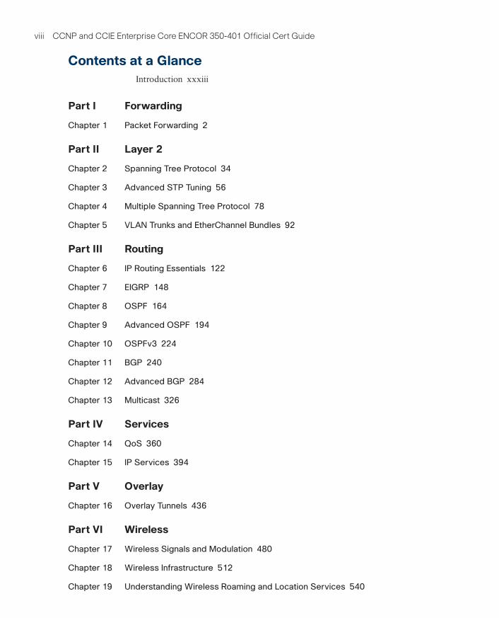
Contents at a GlanceIntroduction xxxiii
Part I Forwarding
Chapter 1 Packet Forwarding 2
Part II Layer 2
Chapter 2 Spanning Tree Protocol 34
Chapter 3 Advanced STP Tuning 56
Chapter 4 Multiple Spanning Tree Protocol 78
Chapter 5 VLAN Trunks and EtherChannel Bundles 92
Part III Routing
Chapter 6 IP Routing Essentials 122
Chapter 7 EIGRP 148
Chapter 8 OSPF 164
Chapter 9 Advanced OSPF 194
Chapter 10 OSPFv3 224
Chapter 11 BGP 240
Chapter 12 Advanced BGP 284
Chapter 13 Multicast 326
Part IV Services
Chapter 14 QoS 360
Chapter 15 IP Services 394
Part V Overlay
Chapter 16 Overlay Tunnels 436
Part VI Wireless
Chapter 17 Wireless Signals and Modulation 480
Chapter 18 Wireless Infrastructure 512
Chapter 19 Understanding Wireless Roaming and Location Services 540
ptg999
ix
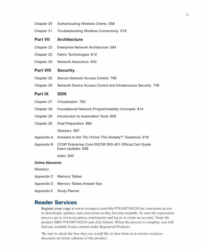
Chapter 20 Authenticating Wireless Clients 558
Chapter 21 Troubleshooting Wireless Connectivity 576
Part VII Architecture
Chapter 22 Enterprise Network Architecture 594
Chapter 23 Fabric Technologies 612
Chapter 24 Network Assurance 642
Part VIII Security
Chapter 25 Secure Network Access Control 706
Chapter 26 Network Device Access Control and Infrastructure Security 746
Part IX SDN
Chapter 27 Virtualization 792
Chapter 28 Foundational Network Programmability Concepts 814
Chapter 29 Introduction to Automation Tools 856
Chapter 30 Final Preparation 890
Glossary 897
Appendix A Answers to the “Do I Know This Already?” Questions 918
Appendix B CCNP Enterprise Core ENCOR 350-401 Official Cert Guide
Exam Updates 938
Index 940
Online Elements
Glossary
Appendix C Memory Tables
Appendix D Memory Tables Answer Key
Appendix E Study Planner
Reader ServicesRegister your copy at www.ciscopress.com/title/9781587145230 for convenient access to downloads, updates, and corrections as they become available. To start the registration process, go to www.ciscopress.com/register and log in or create an account.* Enter the product ISBN 9781587145230 and click Submit. When the process is complete, you will find any available bonus content under Registered Products.
*Be sure to check the box that you would like to hear from us to receive exclusivediscounts on future editions of this product.
ptg999
xxxi
Icons Used in This Book
www
Hub VSS
IDS
DWDM/Optical Services Router
Wireless Router
Line: Serial
Wireless Connectivity
Multicast
Cloud
Switch Router Server
Telepresence500
ASA 5500
Printer
Access Point
Cisco CA
Building
WSA
Virtual Server
DNA Center
ESACUCM
Wireless Transport
Clock
Server Farm
Web Server
ISE
Route/SwitchProcessor
Firewall
Cisco Nexus 9300 Series
Phone
Multilayer Switch
TelepresenceManager
API Controller
Terminal
Wireless LAN Controller
Router w/Firewall
ptg999
CHAPTER 6
IP Routing Essentials
This chapter covers the following subjects:
Routing Protocol Overview: This section explains how different routing protocols advertise and identify routes.
Path Selection: This section explains the logic a router uses to identify the best route and install it in the routing table.
Static Routing: This section provides a brief overview of fundamental static route concepts.
Virtual Routing and Forwarding: This section explains the creation of logical routers on a physical router.
This chapter revisits the fundamentals from Chapter 1, “Packet Forwarding,” as well as some of the components of the operations of a router. It reinforces the logic of the programming of the Routing Information Base (RIB), reviews differences between common routing proto-cols, and explains common concepts related to static routes.
“Do I Know This Already?” QuizThe “Do I Know This Already?” quiz allows you to assess whether you should read the entire chapter. If you miss no more than one of these self-assessment questions, you might want to move ahead to the “Exam Preparation Tasks” section. Table 6-1 lists the major headings in this chapter and the “Do I Know This Already?” quiz questions covering the material in those headings so you can assess your knowledge of these specific areas. The answers to the “Do I Know This Already?” quiz appear in Appendix A, “Answers to the ‘Do I Know This Already?’ Quiz Questions.”
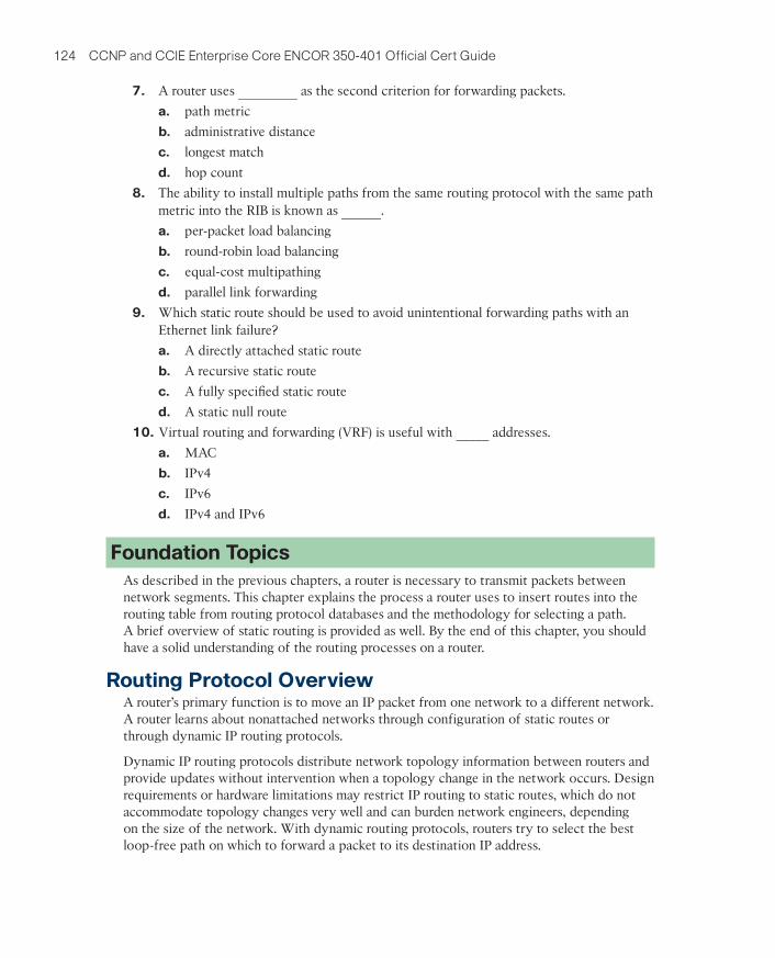
Table 6-1 “Do I Know This Already?” Foundation Topics Section-to-Question Mapping
Foundation Topics Section Questions
Routing Protocol Overview 1–5
Path Selection 6–8
Static Routing 9
Virtual Routing and Forwarding 10
ptg999
124 CCNP and CCIE Enterprise Core ENCOR 350-401 Official Cert Guide
7. A router uses _________ as the second criterion for forwarding packets.
a. path metric
b. administrative distance
c. longest match
d. hop count
8. The ability to install multiple paths from the same routing protocol with the same pathmetric into the RIB is known as ______.
a. per-packet load balancing
b. round-robin load balancing
c. equal-cost multipathing
d. parallel link forwarding
9. Which static route should be used to avoid unintentional forwarding paths with anEthernet link failure?
a. A directly attached static route
b. A recursive static route
c. A fully specifi ed static route
d. A static null route
10. Virtual routing and forwarding (VRF) is useful with _____ addresses.
a. MAC
b. IPv4
c. IPv6
d. IPv4 and IPv6
Foundation TopicsAs described in the previous chapters, a router is necessary to transmit packets between network segments. This chapter explains the process a router uses to insert routes into the routing table from routing protocol databases and the methodology for selecting a path. A brief overview of static routing is provided as well. By the end of this chapter, you should have a solid understanding of the routing processes on a router.
Routing Protocol OverviewA router’s primary function is to move an IP packet from one network to a different network. A router learns about nonattached networks through configuration of static routes or through dynamic IP routing protocols.
Dynamic IP routing protocols distribute network topology information between routers and provide updates without intervention when a topology change in the network occurs. Design requirements or hardware limitations may restrict IP routing to static routes, which do not accommodate topology changes very well and can burden network engineers, depending on the size of the network. With dynamic routing protocols, routers try to select the best loop-free path on which to forward a packet to its destination IP address.
ptg999
Chapter 6: IP Routing Essentials 125
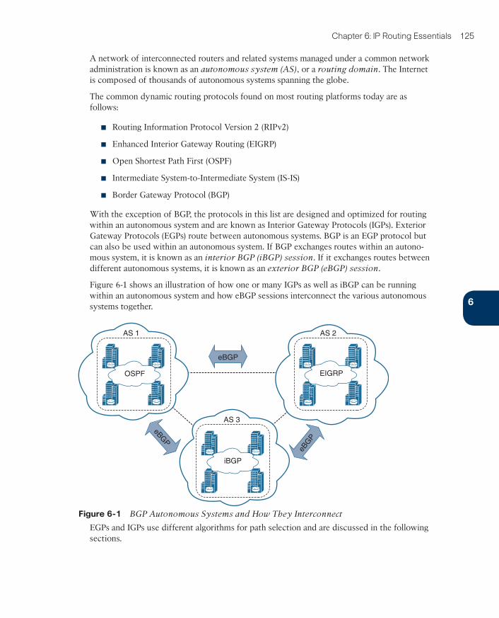
A network of interconnected routers and related systems managed under a common network administration is known as an autonomous system (AS), or a routing domain. The Internet is composed of thousands of autonomous systems spanning the globe.
The common dynamic routing protocols found on most routing platforms today are as follows:
■ Routing Information Protocol Version 2 (RIPv2)
■ Enhanced Interior Gateway Routing (EIGRP)
■ Open Shortest Path First (OSPF)
■ Intermediate System-to-Intermediate System (IS-IS)
■ Border Gateway Protocol (BGP)
With the exception of BGP, the protocols in this list are designed and optimized for routing within an autonomous system and are known as Interior Gateway Protocols (IGPs). Exterior Gateway Protocols (EGPs) route between autonomous systems. BGP is an EGP protocol but can also be used within an autonomous system. If BGP exchanges routes within an autono-mous system, it is known as an interior BGP (iBGP) session. If it exchanges routes between different autonomous systems, it is known as an exterior BGP (eBGP) session.
Figure 6-1 shows an illustration of how one or many IGPs as well as iBGP can be running within an autonomous system and how eBGP sessions interconnect the various autonomous systems together.
AS 3
AS 2
EIGRP
eBGP
eBG
P
eBG
P
iBGP
OSPF
AS 1
Figure 6-1 BGP Autonomous Systems and How They Interconnect
EGPs and IGPs use different algorithms for path selection and are discussed in the following sections.
6
ptg999
126 CCNP and CCIE Enterprise Core ENCOR 350-401 Official Cert Guide
Distance Vector AlgorithmsDistance vector routing protocols, such as RIP, advertise routes as vectors, where distance is a metric (or cost) such as hop count, and vector is the next-hop router’s IP used to reach the destination:
■ Distance: The distance is the route metric to reach the network.
■ Vector: The vector is the interface or direction to reach the network.
When a router receives routing information from a neighbor, it stores it in a local routing database as it is received, and the distance vector algorithm (such as the Bellman-Ford and Ford-Fulkerson algorithms) is used to determine which paths are the best loop-free paths to each reachable destination. When the best paths are determined, they are installed into the routing table and are advertised to each neighbor router.
Routers running distance vector protocols advertise the routing information to their neighbors from their own perspective, modified from the original route received. Therefore, a distance vector protocol does not have a complete map of the whole network; instead, its database reflects that a neighbor router knows how to reach the destination network and how far the neighbor router is from the destination network. The advantage of distance vector protocols is that they require less CPU and memory and can run on low-end routers.
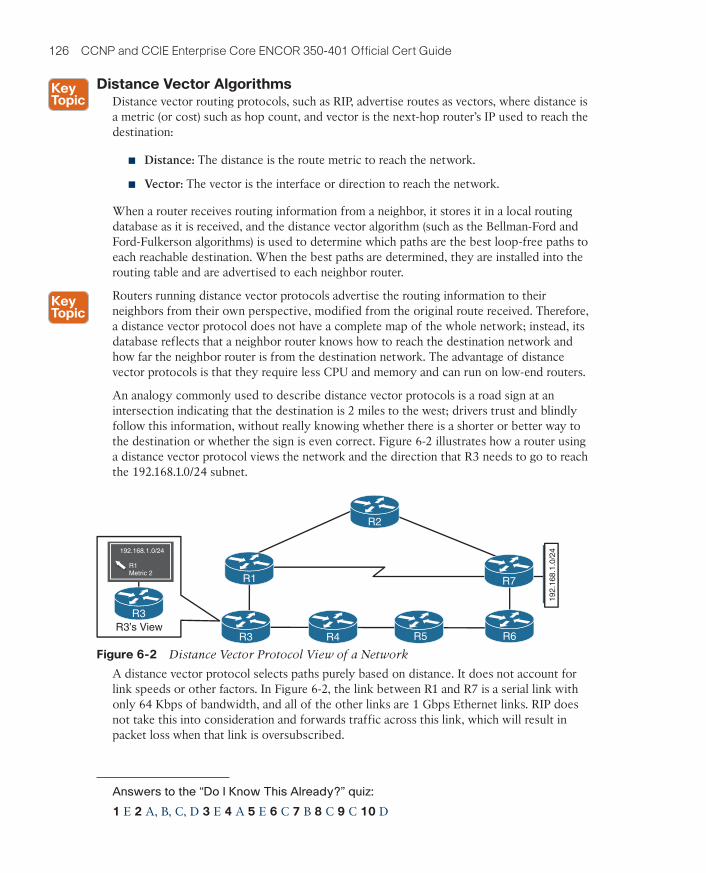
An analogy commonly used to describe distance vector protocols is a road sign at an intersection indicating that the destination is 2 miles to the west; drivers trust and blindly follow this information, without really knowing whether there is a shorter or better way to the destination or whether the sign is even correct. Figure 6-2 illustrates how a router using a distance vector protocol views the network and the direction that R3 needs to go to reach the 192.168.1.0/24 subnet.
192.1
68.1
.0/2
4
R3’s View
192.168.1.0/24
R1 Metric 2
R3
R2
R7
R3
R1
R6R4 R5
R3
Figure 6-2 Distance Vector Protocol View of a Network
A distance vector protocol selects paths purely based on distance. It does not account for link speeds or other factors. In Figure 6-2, the link between R1 and R7 is a serial link with only 64 Kbps of bandwidth, and all of the other links are 1 Gbps Ethernet links. RIP does not take this into consideration and forwards traffic across this link, which will result in packet loss when that link is oversubscribed.
Answers to the “Do I Know This Already?” quiz:
1 E 2 A, B, C, D 3 E 4 A 5 E 6 C 7 B 8 C 9 C 10 D
ptg999
Chapter 6: IP Routing Essentials 127
Enhanced Distance Vector AlgorithmsThe diffusing update algorithm (DUAL) is an enhanced distance vector algorithm that EIGRP uses to calculate the shortest path to a destination within a network. EIGRP advertises network information to its neighbors as other distance vector protocols do, but it has some enhancements, as its name suggests. The following are some of the enhancements introduced into this algorithm compared to other distance vector algorithms:
■ It offers rapid convergence time for changes in the network topology.
■ It sends updates only when there is a change in the network. It does not send full routing table updates in a periodic fashion, as distance vector protocols do.
■ It uses hellos and forms neighbor relationships just as link-state protocols do.
■ It uses bandwidth, delay, reliability, load, and maximum transmission unit (MTU) sizeinstead of hop count for path calculations.
■ It has the option to load balance traffic across equal- or unequal-cost paths.
EIGRP is sometimes referred to as a hybrid routing protocol because it has characteristics of both distance vector and link-state protocols, as shown in the preceding list. EIGRP relies on more advanced metrics other than hop count (for example, bandwidth) for its best-path calculations. By default, EIGRP advertises the total path delay and minimum bandwidth for a route. This information is advertised out every direction, as happens with a distance vector routing protocol; however, each router can calculate the best path based on the information provided by its direct neighbors.
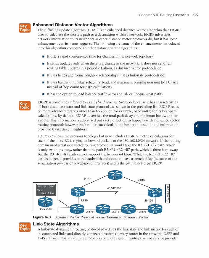
Figure 6-3 shows the previous topology but now includes EIGRP’s metric calculations for each of the links. R3 is trying to forward packets to the 192.168.1.0/24 network. If the routing domain used a distance vector routing protocol, it would take the R3→R1→R7 path, which is only two hops away, rather than the path R3→R1→R2→R7 path, which is three hops away. But the R3→R1→R7 path cannot support traffic over 64 kbps. While the R3→R1→R2→R7 path is longer, it provides more bandwidth and does not have as much delay (because of the serialization process on lower-speed interfaces) and is the path selected by EIGRP.
192.1
68.1
.0/2
4
R3’s View
192.168.1.0/24
2,816
2,816
2,816 2,816 2,816
28,160
40,512,000
2,816
R1 Metric 8,448
R3
R2
R7
R3
R1
R6R4 R5
R3
Figure 6-3 Distance Vector Protocol Versus Enhanced Distance Vector
Link-State AlgorithmsA link-state dynamic IP routing protocol advertises the link state and link metric for each of its connected links and directly connected routers to every router in the network. OSPF and IS-IS are two link-state routing protocols commonly used in enterprise and service provider
6
ptg999
128 CCNP and CCIE Enterprise Core ENCOR 350-401 Official Cert Guide
networks. OSPF advertisements are called link-state advertisements (LSAs), and IS-IS uses link-state packets (LSPs) for its advertisements.
As a router receives an advertisement from a neighbor, it stores the information in a local database called the link-state database (LSDB) and advertises the link-state information on to each of its neighbor routers exactly as it was received. The link-state information is essen-tially flooded throughout the network, unchanged, from router to router, just as the originat-ing router advertised it. This allows all the routers in the network to have a synchronized and identical map of the network.
Using the complete map of the network, every router in the network then runs the Dijkstra shortest path first (SPF) algorithm to calculate the best shortest loop-free paths. The link-state algorithm then populates the routing table with this information.
Due to having the complete map of the network, link-state protocols usually require more CPU and memory than distance vector protocols, but they are less prone to routing loops and make better path decisions. In addition, link-state protocols are equipped with extended capabilities such as opaque LSAs for OSPF and TLVs (type/length/value) for IS-IS that allow them to support features commonly used by service providers, such as MPLS traffic engineering.
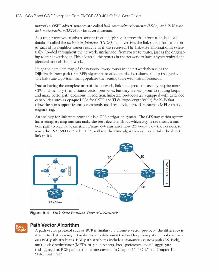
An analogy for link-state protocols is a GPS navigation system. The GPS navigation system has a complete map and can make the best decision about which way is the shortest and best path to reach a destination. Figure 6-4 illustrates how R3 would view the network to reach the 192.168.1.0/24 subnet. R1 will use the same algorithm as R3 and take the direct link to R4.
R3’s View
192.1
68.1
.0/2
4
20
10
20
50
10
R1
R2
R4
R3
192.1
68.1
.0/2
4
20
10
20
50
10
R2
R1
R3
R4
R3
Figure 6-4 Link-State Protocol View of a Network
Path Vector AlgorithmA path vector protocol such as BGP is similar to a distance vector protocol; the difference is that instead of looking at the distance to determine the best loop-free path, it looks at vari-ous BGP path attributes. BGP path attributes include autonomous system path (AS_Path), multi-exit discriminator (MED), origin, next hop, local preference, atomic aggregate, and aggregator. BGP path attributes are covered in Chapter 11, “BGP,” and Chapter 12, “Advanced BGP.”
ptg999
Chapter 6: IP Routing Essentials 129
A path vector protocol guarantees loop-free paths by keeping a record of each autonomous system that the routing advertisement traverses. Any time a router receives an advertisement in which it is already part of the AS_Path, the advertisement is rejected because accepting the AS_Path would effectively result in a routing loop.
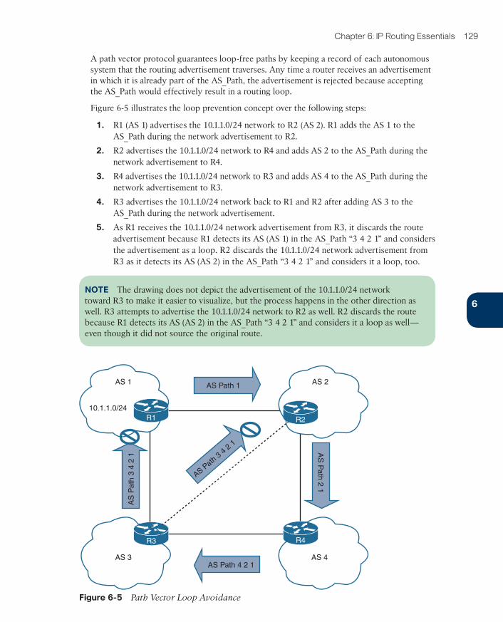
Figure 6-5 illustrates the loop prevention concept over the following steps:
1. R1 (AS 1) advertises the 10.1.1.0/24 network to R2 (AS 2). R1 adds the AS 1 to theAS_Path during the network advertisement to R2.
2. R2 advertises the 10.1.1.0/24 network to R4 and adds AS 2 to the AS_Path during thenetwork advertisement to R4.
3. R4 advertises the 10.1.1.0/24 network to R3 and adds AS 4 to the AS_Path during thenetwork advertisement to R3.
4. R3 advertises the 10.1.1.0/24 network back to R1 and R2 after adding AS 3 to theAS_Path during the network advertisement.
5. As R1 receives the 10.1.1.0/24 network advertisement from R3, it discards the routeadvertisement because R1 detects its AS (AS 1) in the AS_Path “3 4 2 1” and considersthe advertisement as a loop. R2 discards the 10.1.1.0/24 network advertisement fromR3 as it detects its AS (AS 2) in the AS_Path “3 4 2 1” and considers it a loop, too.
NOTE The drawing does not depict the advertisement of the 10.1.1.0/24 network toward R3 to make it easier to visualize, but the process happens in the other direction as well. R3 attempts to advertise the 10.1.1.0/24 network to R2 as well. R2 discards the route because R1 detects its AS (AS 2) in the AS_Path “3 4 2 1” and considers it a loop as well—even though it did not source the original route.
R1 R2
R4R3
AS 1
10.1.1.0/24
AS Path 1
AS Path 4 2 1
AS
Path
2 1
AS Path
3 4
2 1
AS
Path
3 4
2 1
AS 3 AS 4
AS 2
Figure 6-5 Path Vector Loop Avoidance
6
ptg999
130 CCNP and CCIE Enterprise Core ENCOR 350-401 Official Cert Guide
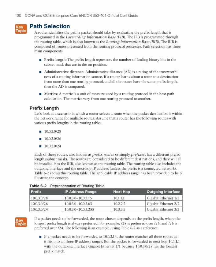
Path SelectionA router identifies the path a packet should take by evaluating the prefix length that is programmed in the Forwarding Information Base (FIB). The FIB is programmed through the routing table, which is also known as the Routing Information Base (RIB). The RIB is composed of routes presented from the routing protocol processes. Path selection has three main components:
■ Prefix length: The prefix length represents the number of leading binary bits in thesubnet mask that are in the on position.
■ Administrative distance: Administrative distance (AD) is a rating of the trustworthi-ness of a routing information source. If a router learns about a route to a destinationfrom more than one routing protocol, and all the routes have the same prefix length,then the AD is compared.
■ Metrics: A metric is a unit of measure used by a routing protocol in the best-path calculation. The metrics vary from one routing protocol to another.
Prefix LengthLet’s look at a scenario in which a router selects a route when the packet destination is within the network range for multiple routes. Assume that a router has the following routes with various prefix lengths in the routing table:
■ 10.0.3.0/28
■ 10.0.3.0/26
■ 10.0.3.0/24
Each of these routes, also known as prefix routes or simply prefixes, has a different prefix length (subnet mask). The routes are considered to be different destinations, and they will all be installed into the RIB, also known as the routing table. The routing table also includes the outgoing interface and the next-hop IP address (unless the prefix is a connected network). Table 6-2 shows this routing table. The applicable IP address range has been provided to help illustrate the concept.
Table 6-2 Representation of Routing Table
Prefix IP Address Range Next Hop Outgoing Interface
10.0.3.0/28 10.0.3.0–10.0.3.15 10.1.1.1 Gigabit Ethernet 1/1
10.0.3.0/26 10.0.3.0–10.0.3.63 10.2.2.2 Gigabit Ethernet 2/2
10.0.3.0/24 10.0.3.0–10.0.3.255 10.3.3.3 Gigabit Ethernet 3/3
If a packet needs to be forwarded, the route chosen depends on the prefix length, where the longest prefix length is always preferred. For example, /28 is preferred over /26, and /26 is preferred over /24. The following is an example, using Table 6-2 as a reference:
■ If a packet needs to be forwarded to 10.0.3.14, the router matches all three routes asit fits into all three IP address ranges. But the packet is forwarded to next hop 10.1.1.1with the outgoing interface Gigabit Ethernet 1/1 because 10.0.3.0/28 has the longestprefix match.
ptg999
Chapter 6: IP Routing Essentials 131
■ If a packet needs to be forwarded to 10.0.3.42, the router matches the 10.0.3.0/24 and10.0.3.0/26 prefixes. But the packet is forwarded to 10.2.2.2 with the outgoing interfaceGigabit Ethernet 2/2 because 10.0.3.0/26 has the longest prefix match.
■ If a packet needs to be forwarded to 10.0.3.100, the router matches only the 10.0.3.0/24prefix. The packet is forwarded to 10.3.3.3 with the outgoing interface GigabitEthernet 3/3.
The forwarding decision is a function of the FIB and results from the calculations performed in the RIB. The RIB is calculated through the combination of routing protocol metrics and administrative distance.
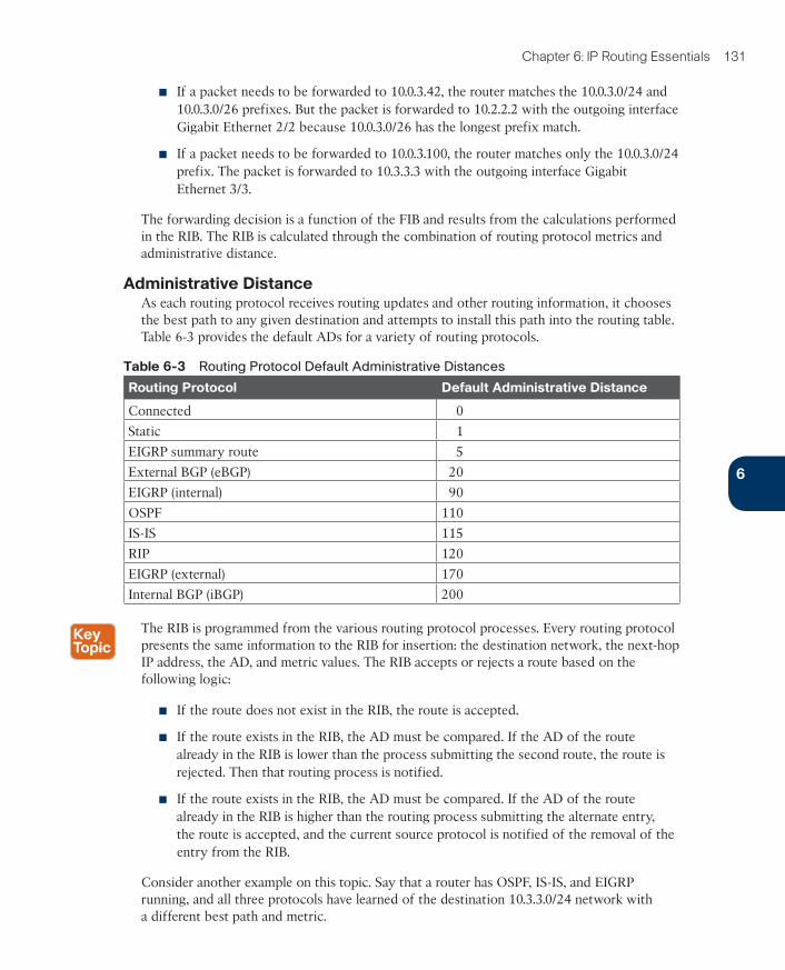
Administrative DistanceAs each routing protocol receives routing updates and other routing information, it chooses the best path to any given destination and attempts to install this path into the routing table. Table 6-3 provides the default ADs for a variety of routing protocols.
Table 6-3 Routing Protocol Default Administrative Distances
Routing Protocol Default Administrative Distance
Connected 0
Static 1
EIGRP summary route 5
External BGP (eBGP) 20
EIGRP (internal) 90
OSPF 110
IS-IS 115
RIP 120
EIGRP (external) 170
Internal BGP (iBGP) 200
The RIB is programmed from the various routing protocol processes. Every routing protocol presents the same information to the RIB for insertion: the destination network, the next-hop IP address, the AD, and metric values. The RIB accepts or rejects a route based on the following logic:
■ If the route does not exist in the RIB, the route is accepted.
■ If the route exists in the RIB, the AD must be compared. If the AD of the routealready in the RIB is lower than the process submitting the second route, the route isrejected. Then that routing process is notified.
■ If the route exists in the RIB, the AD must be compared. If the AD of the routealready in the RIB is higher than the routing process submitting the alternate entry,the route is accepted, and the current source protocol is notified of the removal of theentry from the RIB.
Consider another example on this topic. Say that a router has OSPF, IS-IS, and EIGRP running, and all three protocols have learned of the destination 10.3.3.0/24 network with a different best path and metric.
6
ptg999
132 CCNP and CCIE Enterprise Core ENCOR 350-401 Official Cert Guide
Each of these three protocols attempts to install the route to 10.3.3.0/24 into the routing table. Because the prefix length is the same, the next decision point is the AD, where the routing protocol with the lowest AD installs the route into the routing table.
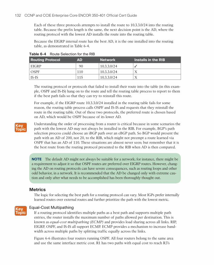
Because the EIGRP internal route has the best AD, it is the one installed into the routing table, as demonstrated in Table 6-4.
Table 6-4 Route Selection for the RIB
Routing Protocol AD Network Installs in the RIB
EIGRP 90 10.3.3.0/24 ✓
OSPF 110 10.3.3.0/24 X
IS-IS 115 10.3.3.0/24 X
The routing protocol or protocols that failed to install their route into the table (in this exam-ple, OSPF and IS-IS) hang on to the route and tell the routing table process to report to them if the best path fails so that they can try to reinstall this route.
For example, if the EIGRP route 10.3.3.0/24 installed in the routing table fails for some reason, the routing table process calls OSPF and IS-IS and requests that they reinstall the route in the routing table. Out of these two protocols, the preferred route is chosen based on AD, which would be OSPF because of its lower AD.
Understanding the order of processing from a router is critical because in some scenarios the path with the lowest AD may not always be installed in the RIB. For example, BGP’s path selection process could choose an iBGP path over an eBGP path. So BGP would present the path with an AD of 200, not 20, to the RIB, which might not preempt a route learned via OSPF that has an AD of 110. These situations are almost never seen; but remember that it is the best route from the routing protocol presented to the RIB when AD is then compared.
NOTE The default AD might not always be suitable for a network; for instance, there might be a requirement to adjust it so that OSPF routes are preferred over EIGRP routes. However, chang-ing the AD on routing protocols can have severe consequences, such as routing loops and other odd behavior, in a network. It is recommended that the AD be changed only with extreme cau-tion and only after what needs to be accomplished has been thoroughly thought out.
MetricsThe logic for selecting the best path for a routing protocol can vary. Most IGPs prefer internally learned routes over external routes and further prioritize the path with the lowest metric.
Equal-Cost Multipathing
If a routing protocol identifies multiple paths as a best path and supports multiple path entries, the router installs the maximum number of paths allowed per destination. This is known as equal-cost multipathing (ECMP) and provides load sharing across all links. RIP, EIGRP, OSPF, and IS-IS all support ECMP. ECMP provides a mechanism to increase band-width across multiple paths by splitting traffic equally across the links.
Figure 6-6 illustrates four routers running OSPF. All four routers belong to the same area and use the same interface metric cost. R1 has two paths with equal cost to reach R3’s
ptg999
Chapter 6: IP Routing Essentials 133
10.3.3.0/24 network. R1 installs both routes in the routing table and forwards traffic across the R1–R2–R3 and R1–R4–R3 path to reach the 10.3.3.0/24 network.
10.3
.3.0
/24
10
10
10
10
Metric 20
Metric 20
R2
R3
R4
R1
Figure 6-6 OSPF ECMP Technology
The output in Example 6-1 confirms that both paths have been installed into the RIB and, because the metrics are identical, that the router is using ECMP.
Example 6-1 R1’s Routing Table, Showing the ECMP Paths to 10.3.3.0/24
R1# show ip route
! Output omitted for brevity
O 10.3.3.0/24 [110/30] via 10.12.1.2, 00:49:12, GigabitEthernet0/2
[110/30] via 10.14.1.4, 00:49:51, GigabitEthernet0/4
Unequal-Cost Load Balancing
By default, routing protocols install only routes with the lowest path metric. However, EIGRP can be configured (not enabled by default) to install multiple routes with different path metrics. This allows for unequal-cost load balancing across multiple paths. Traffic is transmitted out the router’s interfaces based on that path’s metrics in ratio to other the interface’s metrics.
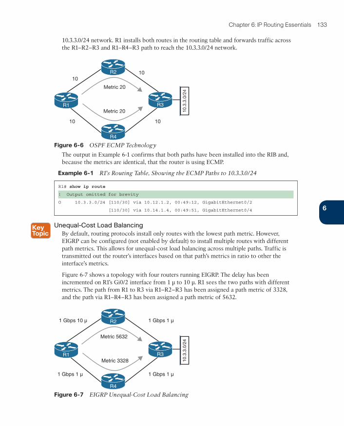
Figure 6-7 shows a topology with four routers running EIGRP. The delay has been incremented on R1’s Gi0/2 interface from 1 μ to 10 μ. R1 sees the two paths with different metrics. The path from R1 to R3 via R1–R2–R3 has been assigned a path metric of 3328, and the path via R1–R4–R3 has been assigned a path metric of 5632.
10.3
.3.0
/24
1 Gbps 10 µ
1 Gbps 1 µ
1 Gbps 1 µ
1 Gbps 1 µ
Metric 5632
Metric 3328
R2
R3
R4
R1
Figure 6-7 EIGRP Unequal-Cost Load Balancing
6
ptg999
134 CCNP and CCIE Enterprise Core ENCOR 350-401 Official Cert Guide
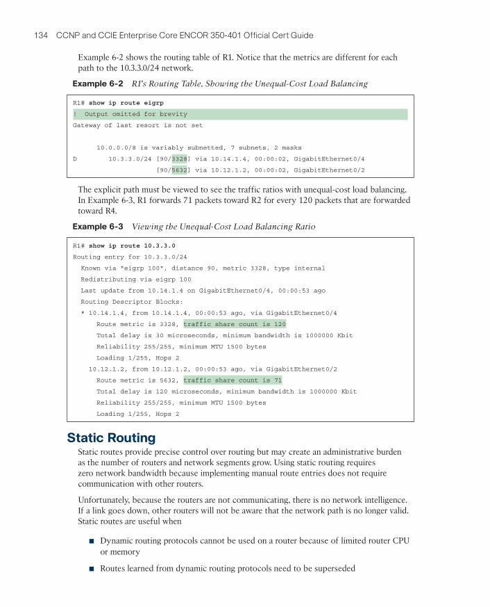
Example 6-2 shows the routing table of R1. Notice that the metrics are different for each path to the 10.3.3.0/24 network.
Example 6-2 R1’s Routing Table, Showing the Unequal-Cost Load Balancing
R1# show ip route eigrp
! Output omitted for brevity
Gateway of last resort is not set
10.0.0.0/8 is variably subnetted, 7 subnets, 2 masks
D 10.3.3.0/24 [90/3328] via 10.14.1.4, 00:00:02, GigabitEthernet0/4
[90/5632] via 10.12.1.2, 00:00:02, GigabitEthernet0/2
The explicit path must be viewed to see the traffic ratios with unequal-cost load balancing. In Example 6-3, R1 forwards 71 packets toward R2 for every 120 packets that are forwarded toward R4.
Example 6-3 Viewing the Unequal-Cost Load Balancing Ratio
R1# show ip route 10.3.3.0
Routing entry for 10.3.3.0/24
Known via "eigrp 100", distance 90, metric 3328, type internal
Redistributing via eigrp 100
Last update from 10.14.1.4 on GigabitEthernet0/4, 00:00:53 ago
Routing Descriptor Blocks:
* 10.14.1.4, from 10.14.1.4, 00:00:53 ago, via GigabitEthernet0/4
Route metric is 3328, traffic share count is 120
Total delay is 30 microseconds, minimum bandwidth is 1000000 Kbit
Reliability 255/255, minimum MTU 1500 bytes
Loading 1/255, Hops 2
10.12.1.2, from 10.12.1.2, 00:00:53 ago, via GigabitEthernet0/2
Route metric is 5632, traffic share count is 71
Total delay is 120 microseconds, minimum bandwidth is 1000000 Kbit
Reliability 255/255, minimum MTU 1500 bytes
Loading 1/255, Hops 2
Static RoutingStatic routes provide precise control over routing but may create an administrative burden as the number of routers and network segments grow. Using static routing requires zero network bandwidth because implementing manual route entries does not require communication with other routers.
Unfortunately, because the routers are not communicating, there is no network intelligence. If a link goes down, other routers will not be aware that the network path is no longer valid. Static routes are useful when
■ Dynamic routing protocols cannot be used on a router because of limited router CPUor memory
■ Routes learned from dynamic routing protocols need to be superseded
ptg999
Chapter 6: IP Routing Essentials 135
Static Route TypesStatic routes can be classified as one of the following:
■ Directly attached static routes
■ Recursive static route
■ Fully specified static route
Directly Attached Static Routes
Point-to-point (P2P) serial interfaces do not have to worry about maintaining an adjacency table and do not use Address Resolution Protocol (ARP), so static routes can directly refer-ence the outbound interface of a router. A static route that uses only the outbound next-hop interface is known as a directly attached static route, and it requires that the outbound interface be in an up state for the route to be installed into the RIB.
Directly attached static routes are configured with the command ip route network subnet-mask next-hop-interface-id.
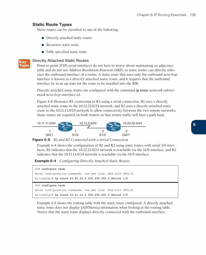
Figure 6-8 illustrates R1 connecting to R2 using a serial connection. R1 uses a directly attached static route to the 10.22.22.0/24 network, and R2 uses a directly attached static route to the 10.11.11.0/24 network to allow connectivity between the two remote networks. Static routes are required on both routers so that return traffic will have a path back.
10.12.2.0/24 10.22.22.0/24
.1S1/0
.2S1/0
10.11.11.0/24
.1Gi0/1
.2Gi0/1
R1 R2
Figure 6-8 R1 and R2 Connected with a Serial Connection
Example 6-4 shows the configuration of R1 and R2 using static routes with serial 1/0 inter-faces. R1 indicates that the 10.22.22.0/24 network is reachable via the S1/0 interface, and R2 indicates that the 10.11.11.0/24 network is reachable via the S1/0 interface.
Example 6-4 Configuring Directly Attached Static Routes
R1# configure term
Enter configuration commands, one per line. End with CNTL/Z.
R1(config)# ip route 10.22.22.0 255.255.255.0 Serial 1/0
R2# configure term
Enter configuration commands, one per line. End with CNTL/Z.
R2(config)# ip route 10.11.11.0 255.255.255.0 Serial 1/0
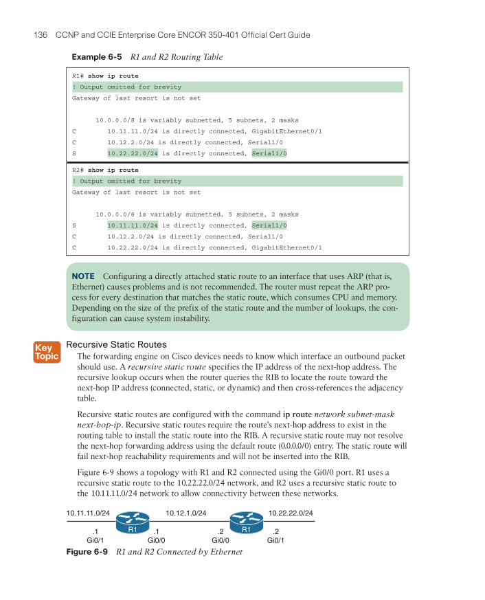
Example 6-5 shows the routing table with the static route configured. A directly attached static route does not display [AD/Metric] information when looking at the routing table. Notice that the static route displays directly connected with the outbound interface.
6
ptg999
136 CCNP and CCIE Enterprise Core ENCOR 350-401 Official Cert Guide
Example 6-5 R1 and R2 Routing Table
R1# show ip route
! Output omitted for brevity
Gateway of last resort is not set
10.0.0.0/8 is variably subnetted, 5 subnets, 2 masks
C 10.11.11.0/24 is directly connected, GigabitEthernet0/1
C 10.12.2.0/24 is directly connected, Serial1/0
S 10.22.22.0/24 is directly connected, Serial1/0
R2# show ip route
! Output omitted for brevity
Gateway of last resort is not set
10.0.0.0/8 is variably subnetted, 5 subnets, 2 masks
S 10.11.11.0/24 is directly connected, Serial1/0
C 10.12.2.0/24 is directly connected, Serial1/0
C 10.22.22.0/24 is directly connected, GigabitEthernet0/1
NOTE Configuring a directly attached static route to an interface that uses ARP (that is, Ethernet) causes problems and is not recommended. The router must repeat the ARP pro-cess for every destination that matches the static route, which consumes CPU and memory. Depending on the size of the prefix of the static route and the number of lookups, the con-figuration can cause system instability.
Recursive Static Routes
The forwarding engine on Cisco devices needs to know which interface an outbound packet should use. A recursive static route specifies the IP address of the next-hop address. The recursive lookup occurs when the router queries the RIB to locate the route toward the next-hop IP address (connected, static, or dynamic) and then cross-references the adjacency table.
Recursive static routes are configured with the command ip route network subnet-mask next-hop-ip. Recursive static routes require the route’s next-hop address to exist in the routing table to install the static route into the RIB. A recursive static route may not resolve the next-hop forwarding address using the default route (0.0.0.0/0) entry. The static route will fail next-hop reachability requirements and will not be inserted into the RIB.
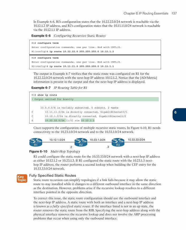
Figure 6-9 shows a topology with R1 and R2 connected using the Gi0/0 port. R1 uses a recursive static route to the 10.22.22.0/24 network, and R2 uses a recursive static route to the 10.11.11.0/24 network to allow connectivity between these networks.
10.12.1.0/24 10.22.22.0/24
.1Gi0/0
.2Gi0/0
10.11.11.0/24
.1Gi0/1
.2Gi0/1
R2R1R1 R1
Figure 6-9 R1 and R2 Connected by Ethernet
ptg999
Chapter 6: IP Routing Essentials 137
In Example 6-6, R1’s configuration states that the 10.22.22.0/24 network is reachable via the 10.12.1.2 IP address, and R2’s configuration states that the 10.11.11.0/24 network is reachable via the 10.12.1.1 IP address.
Example 6-6 Configuring Recursive Static Routes
R1# configure term
Enter configuration commands, one per line. End with CNTL/Z.
R1(config)# ip route 10.22.22.0 255.255.255.0 10.12.1.2
R2# configure term
Enter configuration commands, one per line. End with CNTL/Z.
R2(config)# ip route 10.11.11.0 255.255.255.0 10.12.1.1
The output in Example 6-7 verifies that the static route was configured on R1 for the 10.22.22.0/24 network with the next-hop IP address 10.12.1.2. Notice that the [AD/Metric] information is present in the output and that the next-hop IP address is displayed.
Example 6-7 IP Routing Table for R1
R1# show ip route
! Output omitted for brevity
10.0.0.0/8 is variably subnetted, 5 subnets, 2 masks
C 10.11.11.0/24 is directly connected, GigabitEthernet0/1
C 10.12.1.0/24 is directly connected, GigabitEthernet0/0
S 10.22.22.0/24 [1/0] via 10.12.1.2
Cisco supports the configuration of multiple recursive static routes. In Figure 6-10, R1 needs connectivity to the 10.23.1.0/24 network and to the 10.33.1.0/24 network.
10.12.1.0/24 10.23.1.0/24
.2
10.33.33.0/24
.3R1 R2 R3
Figure 6-10 Multi-Hop Topology
R1 could configure the static route for the 10.33.33.0/24 network with a next-hop IP address as either 10.12.1.2 or 10.23.1.3. If R1 configured the static route with the 10.23.1.3 next-hop IP address, the router performs a second lookup when building the CEF entry for the 10.33.33.0/24 network.
Fully Specified Static Routes
Static route recursion can simplify topologies if a link fails because it may allow the static route to stay installed while it changes to a different outbound interface in the same direction as the destination. However, problems arise if the recursive lookup resolves to a different interface pointed in the opposite direction.
To correct this issue, the static route configuration should use the outbound interface and the next-hop IP address. A static route with both an interface and a next-hop IP address is known as a fully specified static route. If the interface listed is not in an up state, the router removes the static route from the RIB. Specifying the next-hop address along with the physical interface removes the recursive lookup and does not involve the ARP processing problems that occur when using only the outbound interface.
6
ptg999
138 CCNP and CCIE Enterprise Core ENCOR 350-401 Official Cert Guide
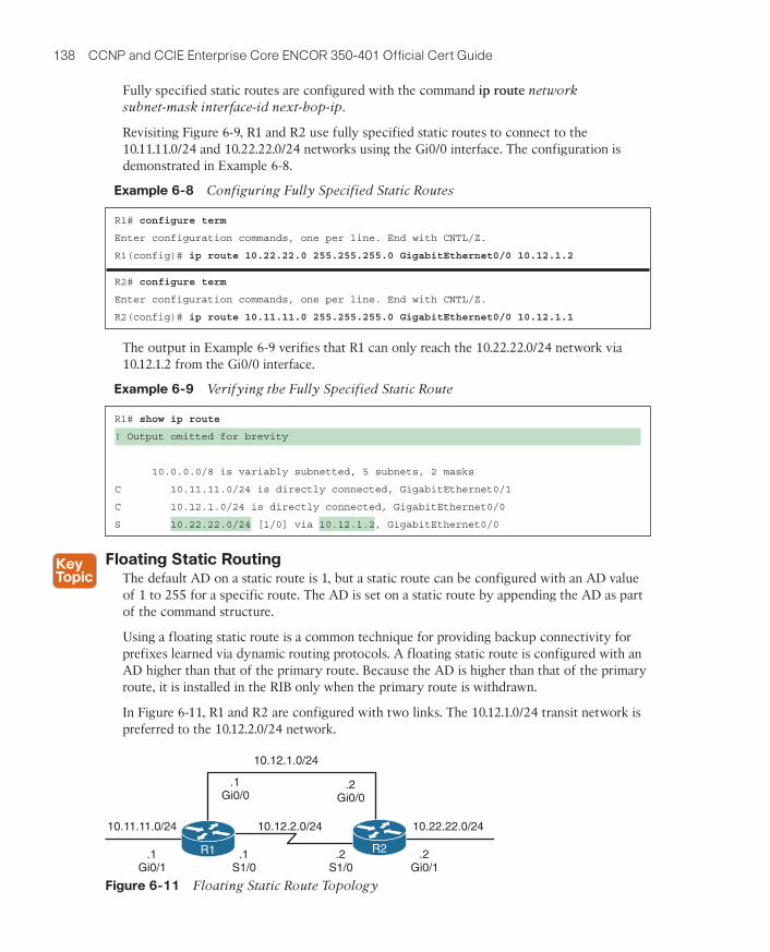
Fully specified static routes are configured with the command ip route network subnet-mask interface-id next-hop-ip.
Revisiting Figure 6-9, R1 and R2 use fully specified static routes to connect to the 10.11.11.0/24 and 10.22.22.0/24 networks using the Gi0/0 interface. The configuration is demonstrated in Example 6-8.
Example 6-8 Configuring Fully Specified Static Routes
R1# configure term
Enter configuration commands, one per line. End with CNTL/Z.
R1(config)# ip route 10.22.22.0 255.255.255.0 GigabitEthernet0/0 10.12.1.2
R2# configure term
Enter configuration commands, one per line. End with CNTL/Z.
R2(config)# ip route 10.11.11.0 255.255.255.0 GigabitEthernet0/0 10.12.1.1
The output in Example 6-9 verifies that R1 can only reach the 10.22.22.0/24 network via 10.12.1.2 from the Gi0/0 interface.
Example 6-9 Verifying the Fully Specified Static Route
R1# show ip route
! Output omitted for brevity
10.0.0.0/8 is variably subnetted, 5 subnets, 2 masks
C 10.11.11.0/24 is directly connected, GigabitEthernet0/1
C 10.12.1.0/24 is directly connected, GigabitEthernet0/0
S 10.22.22.0/24 [1/0] via 10.12.1.2, GigabitEthernet0/0
Floating Static RoutingThe default AD on a static route is 1, but a static route can be configured with an AD value of 1 to 255 for a specific route. The AD is set on a static route by appending the AD as part of the command structure.
Using a floating static route is a common technique for providing backup connectivity for prefixes learned via dynamic routing protocols. A floating static route is configured with an AD higher than that of the primary route. Because the AD is higher than that of the primary route, it is installed in the RIB only when the primary route is withdrawn.
In Figure 6-11, R1 and R2 are configured with two links. The 10.12.1.0/24 transit network is preferred to the 10.12.2.0/24 network.
10.12.2.0/24 10.22.22.0/24
.1S1/0
.2S1/0
10.11.11.0/24
.1Gi0/1
.2Gi0/1
10.12.1.0/24
.1Gi0/0
R2R1
.2Gi0/0
R1 R2
Figure 6-11 Floating Static Route Topology
ptg999
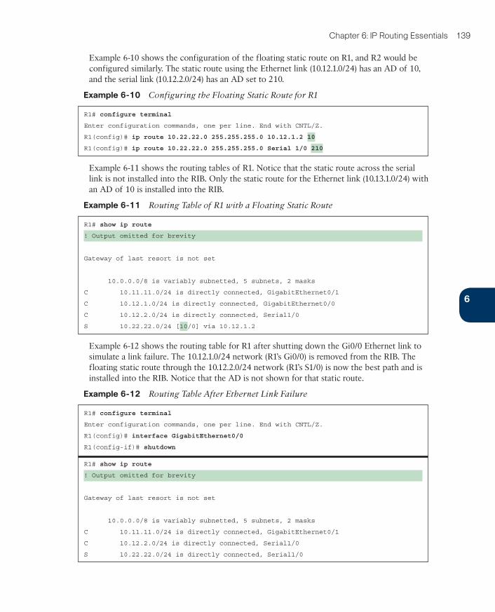
Chapter 6: IP Routing Essentials 139
Example 6-10 shows the configuration of the floating static route on R1, and R2 would be configured similarly. The static route using the Ethernet link (10.12.1.0/24) has an AD of 10, and the serial link (10.12.2.0/24) has an AD set to 210.
Example 6-10 Configuring the Floating Static Route for R1
R1# configure terminal
Enter configuration commands, one per line. End with CNTL/Z.
R1(config)# ip route 10.22.22.0 255.255.255.0 10.12.1.2 10
R1(config)# ip route 10.22.22.0 255.255.255.0 Serial 1/0 210
Example 6-11 shows the routing tables of R1. Notice that the static route across the serial link is not installed into the RIB. Only the static route for the Ethernet link (10.13.1.0/24) with an AD of 10 is installed into the RIB.
Example 6-11 Routing Table of R1 with a Floating Static Route
R1# show ip route
! Output omitted for brevity
Gateway of last resort is not set
10.0.0.0/8 is variably subnetted, 5 subnets, 2 masks
C 10.11.11.0/24 is directly connected, GigabitEthernet0/1
C 10.12.1.0/24 is directly connected, GigabitEthernet0/0
C 10.12.2.0/24 is directly connected, Serial1/0
S 10.22.22.0/24 [10/0] via 10.12.1.2
Example 6-12 shows the routing table for R1 after shutting down the Gi0/0 Ethernet link to simulate a link failure. The 10.12.1.0/24 network (R1’s Gi0/0) is removed from the RIB. The floating static route through the 10.12.2.0/24 network (R1’s S1/0) is now the best path and is installed into the RIB. Notice that the AD is not shown for that static route.
Example 6-12 Routing Table After Ethernet Link Failure
R1# configure terminal
Enter configuration commands, one per line. End with CNTL/Z.
R1(config)# interface GigabitEthernet0/0
R1(config-if)# shutdown
R1# show ip route
! Output omitted for brevity
Gateway of last resort is not set
10.0.0.0/8 is variably subnetted, 5 subnets, 2 masks
C 10.11.11.0/24 is directly connected, GigabitEthernet0/1
C 10.12.2.0/24 is directly connected, Serial1/0
S 10.22.22.0/24 is directly connected, Serial1/0
6

ptg999
140 CCNP and CCIE Enterprise Core ENCOR 350-401 Official Cert Guide
Even though the static route’s AD is not shown, it is still programmed in the RIB. Example 6-13 shows the explicit network entry. The output confirms that the floating static route with AD 210 is currently active in the routing table.
Example 6-13 Verifying the AD for the Floating Static Route
R1# show ip route 10.22.22.0
Routing entry for 10.22.22.0/24
Known via "static", distance 210, metric 0 (connected)
Routing Descriptor Blocks:
* directly connected, via Serial1/0
Route metric is 0, traffic share count is 1
Static Null RoutesThe null interface is a virtual interface that is always in an up state. Null interfaces do not forward or receive network traffic and drop all traffic destined toward them without adding overhead to a router’s CPU.
Configuring a static route to a null interface provides a method of dropping network traffic without requiring the configuration of an access list. Creating a static route to the Null0 interface is a common technique to prevent routing loops. The static route to the Null0 interface uses a summarized network range, and routes that are more specific point toward the actual destination.
Figure 6-12 shows a common topology in which company ABC has acquired the 172.16.0.0/20 network range from its service provider. ABC uses only a portion of the given addresses but keeps the large network block in anticipation of future growth.
ISP R1 R2Internet
192.168.1.0/30
172.1
6.2
.0/2
4
172.1
6.3
.0/2
4
172.16.1.0/30
172.16.0.0/20
.1 .1 .2.2
Company ABC
Figure 6-12 Routing Loop Topology
The service provider places a static route for the 172.16.0.0/20 network to R1’s interface (192.168.1.1). R1 uses a static default route pointed toward the service provider (192.168.1.2) and a static route to the 172.16.3.0/24 network via R2 (172.16.1.2). Because R2 accesses all other networks through R1, a static default route points toward R1’s interface (172.16.1.1).
If packets are sent to any address in the 172.16.0.0/20 range that is not used by company ABC, the packet gets stuck in a loop between R1 and the ISP, consuming additional band-width until the packet’s TTL expires.
ptg999
Chapter 6: IP Routing Essentials 141
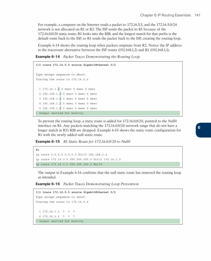
For example, a computer on the Internet sends a packet to 172.16.5.5, and the 172.16.5.0/24 network is not allocated on R1 or R2. The ISP sends the packet to R1 because of the 172.16.0.0/20 static route; R1 looks into the RIB, and the longest match for that prefix is the default route back to the ISP, so R1 sends the packet back to the ISP, creating the routing loop.
Example 6-14 shows the routing loop when packets originate from R2. Notice the IP address in the traceroute alternative between the ISP router (192.168.1.2) and R1 (192.168.1.1).
Example 6-14 Packet Traces Demonstrating the Routing Loop
R2# trace 172.16.5.5 source GigabitEthernet 0/2
Type escape sequence to abort.
Tracing the route to 172.16.5.5
1 172.16.1.1 0 msec 0 msec 0 msec
2 192.168.1.1 0 msec 0 msec 0 msec
3 192.168.1.2 0 msec 4 msec 0 msec
4 192.168.1.1 0 msec 0 msec 0 msec
5 192.168.1.2 0 msec 0 msec 0 msec
! Output omitted for brevity
To prevent the routing loop, a static route is added for 172.16.0.0/20, pointed to the Null0 interface on R1. Any packets matching the 172.16.0.0/20 network range that do not have a longer match in R1’s RIB are dropped. Example 6-15 shows the static route configuration for R1 with the newly added null static route.
Example 6-15 R1 Static Route for 172.16.0.0/20 to Null0
R1
ip route 0.0.0.0 0.0.0.0 Gi0/0 192.168.1.2
ip route 172.16.3.0 255.255.255.0 Gi0/2 172.16.1.2
ip route 172.16.0.0 255.255.240.0 Null0
The output in Example 6-16 confirms that the null static route has removed the routing loop as intended.
Example 6-16 Packet Traces Demonstrating Loop Prevention
R2# trace 172.16.5.5 source GigabitEthernet 0/2
Type escape sequence to abort.
Tracing the route to 172.16.5.5
1 172.16.1.1 * * *
2 172.16.1.1 * * *
! Output omitted for brevity
6
ptg999
142 CCNP and CCIE Enterprise Core ENCOR 350-401 Official Cert Guide
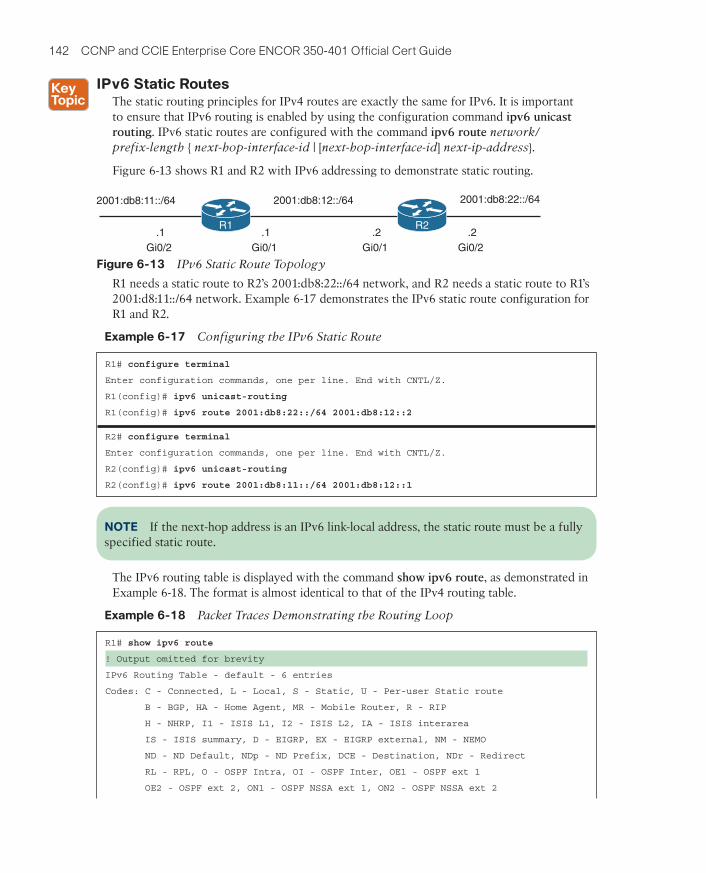
IPv6 Static RoutesThe static routing principles for IPv4 routes are exactly the same for IPv6. It is important to ensure that IPv6 routing is enabled by using the configuration command ipv6 unicast routing. IPv6 static routes are configured with the command ipv6 route network/prefix-length { next-hop-interface-id | [next-hop-interface-id] next-ip-address}.
Figure 6-13 shows R1 and R2 with IPv6 addressing to demonstrate static routing.
2001:db8:12::/64
.1
Gi0/1
.2
Gi0/1
2001:db8:11::/64
.1
Gi0/2
.2
Gi0/2
2001:db8:22::/64
R1 R2
Figure 6-13 IPv6 Static Route Topology
R1 needs a static route to R2’s 2001:db8:22::/64 network, and R2 needs a static route to R1’s 2001:d8:11::/64 network. Example 6-17 demonstrates the IPv6 static route configuration for R1 and R2.
Example 6-17 Configuring the IPv6 Static Route
R1# configure terminal
Enter configuration commands, one per line. End with CNTL/Z.
R1(config)# ipv6 unicast-routing
R1(config)# ipv6 route 2001:db8:22::/64 2001:db8:12::2
R2# configure terminal
Enter configuration commands, one per line. End with CNTL/Z.
R2(config)# ipv6 unicast-routing
R2(config)# ipv6 route 2001:db8:11::/64 2001:db8:12::1
NOTE If the next-hop address is an IPv6 link-local address, the static route must be a fully specified static route.
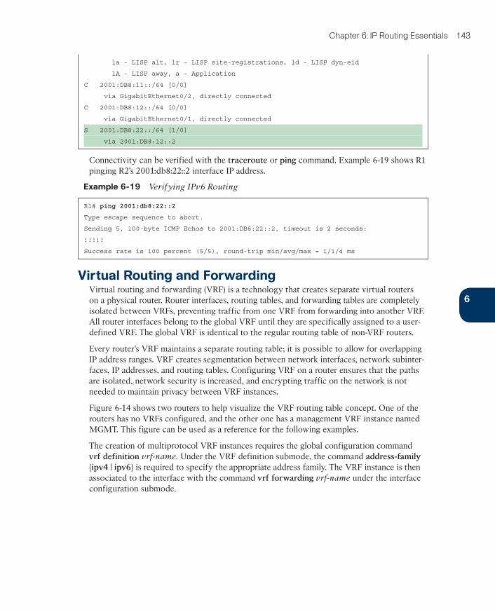
The IPv6 routing table is displayed with the command show ipv6 route, as demonstrated in Example 6-18. The format is almost identical to that of the IPv4 routing table.
Example 6-18 Packet Traces Demonstrating the Routing Loop
R1# show ipv6 route
! Output omitted for brevity
IPv6 Routing Table - default - 6 entries
Codes: C - Connected, L - Local, S - Static, U - Per-user Static route
B - BGP, HA - Home Agent, MR - Mobile Router, R - RIP
H - NHRP, I1 - ISIS L1, I2 - ISIS L2, IA - ISIS interarea
IS - ISIS summary, D - EIGRP, EX - EIGRP external, NM - NEMO
ND - ND Default, NDp - ND Prefix, DCE - Destination, NDr - Redirect
RL - RPL, O - OSPF Intra, OI - OSPF Inter, OE1 - OSPF ext 1
OE2 - OSPF ext 2, ON1 - OSPF NSSA ext 1, ON2 - OSPF NSSA ext 2
ptg999
Chapter 6: IP Routing Essentials 143
la - LISP alt, lr - LISP site-registrations, ld - LISP dyn-eid
lA - LISP away, a - Application
C 2001:DB8:11::/64 [0/0]
via GigabitEthernet0/2, directly connected
C 2001:DB8:12::/64 [0/0]
via GigabitEthernet0/1, directly connected
S 2001:DB8:22::/64 [1/0]
via 2001:DB8:12::2
Connectivity can be verified with the traceroute or ping command. Example 6-19 shows R1 pinging R2’s 2001:db8:22::2 interface IP address.
Example 6-19 Verifying IPv6 Routing
R1# ping 2001:db8:22::2
Type escape sequence to abort.
Sending 5, 100-byte ICMP Echos to 2001:DB8:22::2, timeout is 2 seconds:
!!!!!
Success rate is 100 percent (5/5), round-trip min/avg/max = 1/1/4 ms
Virtual Routing and ForwardingVirtual routing and forwarding (VRF) is a technology that creates separate virtual routers on a physical router. Router interfaces, routing tables, and forwarding tables are completely isolated between VRFs, preventing traffic from one VRF from forwarding into another VRF. All router interfaces belong to the global VRF until they are specifically assigned to a user-defined VRF. The global VRF is identical to the regular routing table of non-VRF routers.
Every router’s VRF maintains a separate routing table; it is possible to allow for overlapping IP address ranges. VRF creates segmentation between network interfaces, network subinter-faces, IP addresses, and routing tables. Configuring VRF on a router ensures that the paths are isolated, network security is increased, and encrypting traffic on the network is not needed to maintain privacy between VRF instances.
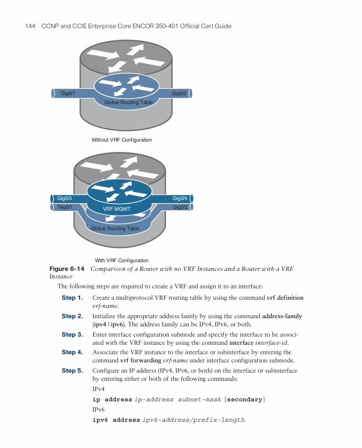
Figure 6-14 shows two routers to help visualize the VRF routing table concept. One of the routers has no VRFs configured, and the other one has a management VRF instance named MGMT. This figure can be used as a reference for the following examples.
The creation of multiprotocol VRF instances requires the global configuration command vrf definition vrf-name. Under the VRF definition submode, the command address-family {ipv4 | ipv6} is required to specify the appropriate address family. The VRF instance is then associated to the interface with the command vrf forwarding vrf-name under the interface configuration submode.
6
ptg999
144 CCNP and CCIE Enterprise Core ENCOR 350-401 Official Cert Guide
Without VRF Configuration
With VRF Configuration
Gig0/1 Gig0/2
Global Routing Table
Gig0/2
Global Routing Table
Gig0/1
Gig0/4
VRF MGMT
Gig0/3
Figure 6-14 Comparison of a Router with no VRF Instances and a Router with a VRF Instance
The following steps are required to create a VRF and assign it to an interface:
Step 1. Create a multiprotocol VRF routing table by using the command vrf definition vrf-name.
Step 2. Initialize the appropriate address family by using the command address-family {ipv4 | ipv6}. The address family can be IPv4, IPv6, or both.
Step 3. Enter interface configuration submode and specify the interface to be associ-ated with the VRF instance by using the command interface interface-id.
Step 4. Associate the VRF instance to the interface or subinterface by entering the command vrf forwarding vrf-name under interface configuration submode.
Step 5. Configure an IP address (IPv4, IPv6, or both) on the interface or subinterface by entering either or both of the following commands:
IPv4
ip address ip-address subnet-mask [secondary]
IPv6
ipv6 address ipv6-address/prefix-length
ptg999
Chapter 6: IP Routing Essentials 145
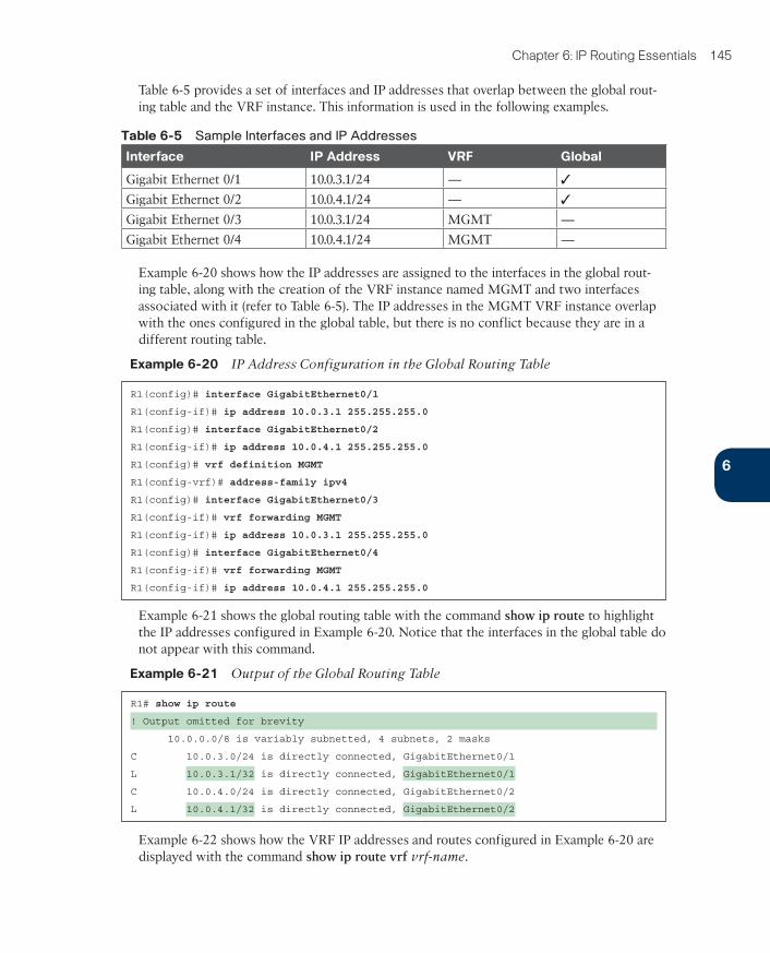
Table 6-5 provides a set of interfaces and IP addresses that overlap between the global rout-ing table and the VRF instance. This information is used in the following examples.
Table 6-5 Sample Interfaces and IP Addresses
Interface IP Address VRF Global
Gigabit Ethernet 0/1 10.0.3.1/24 — ✓
Gigabit Ethernet 0/2 10.0.4.1/24 — ✓
Gigabit Ethernet 0/3 10.0.3.1/24 MGMT —
Gigabit Ethernet 0/4 10.0.4.1/24 MGMT —
Example 6-20 shows how the IP addresses are assigned to the interfaces in the global rout-ing table, along with the creation of the VRF instance named MGMT and two interfaces associated with it (refer to Table 6-5). The IP addresses in the MGMT VRF instance overlap with the ones configured in the global table, but there is no conflict because they are in a different routing table.
Example 6-20 IP Address Configuration in the Global Routing Table
R1(config)# interface GigabitEthernet0/1
R1(config-if)# ip address 10.0.3.1 255.255.255.0
R1(config)# interface GigabitEthernet0/2
R1(config-if)# ip address 10.0.4.1 255.255.255.0
R1(config)# vrf definition MGMT
R1(config-vrf)# address-family ipv4
R1(config)# interface GigabitEthernet0/3
R1(config-if)# vrf forwarding MGMT
R1(config-if)# ip address 10.0.3.1 255.255.255.0
R1(config)# interface GigabitEthernet0/4
R1(config-if)# vrf forwarding MGMT
R1(config-if)# ip address 10.0.4.1 255.255.255.0
Example 6-21 shows the global routing table with the command show ip route to highlight the IP addresses configured in Example 6-20. Notice that the interfaces in the global table do not appear with this command.
Example 6-21 Output of the Global Routing Table
R1# show ip route
! Output omitted for brevity
10.0.0.0/8 is variably subnetted, 4 subnets, 2 masks
C 10.0.3.0/24 is directly connected, GigabitEthernet0/1
L 10.0.3.1/32 is directly connected, GigabitEthernet0/1
C 10.0.4.0/24 is directly connected, GigabitEthernet0/2
L 10.0.4.1/32 is directly connected, GigabitEthernet0/2
Example 6-22 shows how the VRF IP addresses and routes configured in Example 6-20 are displayed with the command show ip route vrf vrf-name.
6
ptg999
146 CCNP and CCIE Enterprise Core ENCOR 350-401 Official Cert Guide
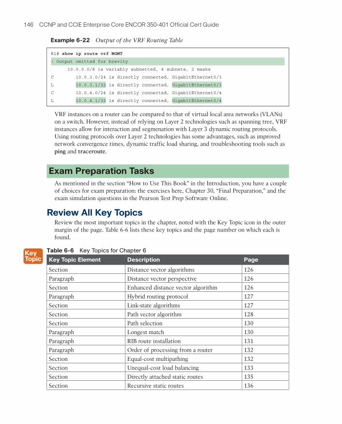
Example 6-22 Output of the VRF Routing Table
R1# show ip route vrf MGMT
! Output omitted for brevity
10.0.0.0/8 is variably subnetted, 4 subnets, 2 masks
C 10.0.3.0/24 is directly connected, GigabitEthernet0/3
L 10.0.3.1/32 is directly connected, GigabitEthernet0/3
C 10.0.4.0/24 is directly connected, GigabitEthernet0/4
L 10.0.4.1/32 is directly connected, GigabitEthernet0/4
VRF instances on a router can be compared to that of virtual local area networks (VLANs) on a switch. However, instead of relying on Layer 2 technologies such as spanning tree, VRF instances allow for interaction and segmenation with Layer 3 dynamic routing protocols. Using routing protocols over Layer 2 technologies has some advantages, such as improved network convergence times, dynamic traffic load sharing, and troubleshooting tools such as ping and traceroute.
Exam Preparation TasksAs mentioned in the section “How to Use This Book” in the Introduction, you have a couple of choices for exam preparation: the exercises here, Chapter 30, “Final Preparation,” and the exam simulation questions in the Pearson Test Prep Software Online.
Review All Key TopicsReview the most important topics in the chapter, noted with the Key Topic icon in the outer margin of the page. Table 6-6 lists these key topics and the page number on which each is found.
Table 6-6 Key Topics for Chapter 6
Key Topic Element Description Page
Section Distance vector algorithms 126
Paragraph Distance vector perspective 126
Section Enhanced distance vector algorithm 126
Paragraph Hybrid routing protocol 127
Section Link-state algorithms 127
Section Path vector algorithm 128
Section Path selection 130
Paragraph Longest match 130
Paragraph RIB route installation 131
Paragraph Order of processing from a router 132
Section Equal-cost multipathing 132
Section Unequal-cost load balancing 133
Section Directly attached static routes 135
Section Recursive static routes 136
ptg999
Chapter 6: IP Routing Essentials 147
Key Topic Element Description Page
Section Fully specified static routes 137
Section Floating static routing 138
Section Static null routes 140
Section IPv6 static routes 142
Complete Tables and Lists from MemoryThere are no memory tables in this chapter.
Define Key TermsDefine the following key terms from this chapter and check your answers in the Glossary:
administrative distance, directly attached static route, distance vector routing protocol, enhanced distance vector routing protocol, equal-cost multipathing, floating static route, fully specified static route, link-state routing protocol, path vector routing protocol, prefix length, recursive static route, static null route, unequal-cost load balancing
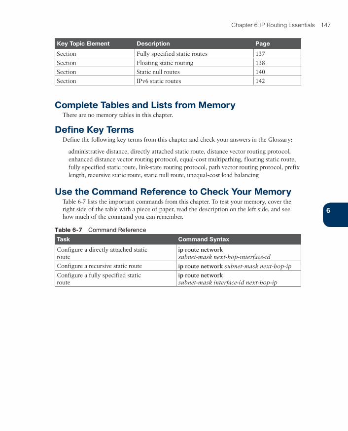
Use the Command Reference to Check Your MemoryTable 6-7 lists the important commands from this chapter. To test your memory, cover the right side of the table with a piece of paper, read the description on the left side, and see how much of the command you can remember.
Table 6-7 Command Reference
Task Command Syntax
Configure a directly attached static route
ip route network subnet-mask next-hop-interface-id
Configure a recursive static route ip route network subnet-mask next-hop-ip
Configure a fully specified static route
ip route network subnet-mask interface-id next-hop-ip
6