Catenary Vaults: A solution to low-cost housing in South Africa
234
Catenary Vaults: A solution to low-cost housing in South Africa Ivanka Bulovic A research report submitted to the Faculty of Engineering and the Built Environment, University of the Witwatersrand, Johannesburg, in partial fulfilment of the requirements for the degree of Master of Science in Engineering. Johannesburg 2014 The financial assistance of the National Research Foundation (N R F) towards this research is hereby acknowledged. Opinions expressed and conclusions arrived at, are those of the author and are not necessarily to be attributed to the NRF.
-
Upload
khangminh22 -
Category
Documents
-
view
3 -
download
0
Transcript of Catenary Vaults: A solution to low-cost housing in South Africa
Catenary Vaults: A solution to low-cost
housing in South Africa
Ivanka Bulovic
A research report submitted to the Faculty of Engineering and the Built Environment,
University of the Witwatersrand, Johannesburg, in partial fulfilment of the
requirements for the degree of Master of Science in Engineering.
Johannesburg 2014
The financial assistance of the National Research Foundation (N R F) towards this
research is hereby acknowledged. Opinions expressed and conclusions arrived at,
are those of the author and are not necessarily to be attributed to the NRF.

1
Table of Contents
Table of Contents ................................................................................................................................. 1
Declaration ............................................................................................................................................ 5
Abstract .................................................................................................................................................. 6
Acknowledgements .............................................................................................................................. 7
List of Figures ....................................................................................................................................... 8
List of Tables ....................................................................................................................................... 13
List of Symbols ................................................................................................................................... 14
1. Introduction .................................................................................................................................. 16
1.1. Problem Statement ............................................................................................................ 16
1.2. Objectives ............................................................................................................................ 17
1.3. Scope ................................................................................................................................... 18
2. Literature Review ....................................................................................................................... 20
2.1. Introduction .......................................................................................................................... 20
2.2. Materials .............................................................................................................................. 23
2.2.1. Tiles .............................................................................................................................. 23
2.2.2. Bricks and Blocks ....................................................................................................... 26
2.2.3. Surface Protection ...................................................................................................... 29
2.3. Forms, Modelling and Spacing ......................................................................................... 31
2.4. Construction Methods ........................................................................................................ 38
2.4.1. With Formwork ............................................................................................................ 39
2.4.2. Without Formwork ...................................................................................................... 42
2.5. Conclusion ........................................................................................................................... 44
3. Layout and shape establishment ............................................................................................. 46
3.1. Design Considerations ...................................................................................................... 46
3.2. Design Selection ................................................................................................................. 49
4. Materials Investigation ............................................................................................................... 54
4.1. Introduction .......................................................................................................................... 54
4.2. Production process ............................................................................................................ 55
4.2.1. Soil Selection .............................................................................................................. 55
4.2.2. Mix ratios ..................................................................................................................... 56

2
4.2.3. Production ................................................................................................................... 57
4.2.4. Problems in production .............................................................................................. 59
4.3. Material properties ............................................................................................................. 59
4.3.1. Dry-stack interlocking Blocks .................................................................................... 60
4.3.2. Splitter-Brick Block ..................................................................................................... 62
5. Method of Analysis for a Catenary Curve ............................................................................... 64
5.1. Introduction .......................................................................................................................... 64
5.2. Mathematical definition ...................................................................................................... 64
5.3. The Graphical method ....................................................................................................... 64
5.4. Segmental Equilibrium Method ........................................................................................ 67
5.4.1. Introduction .................................................................................................................. 67
5.4.2. Theoretical basis ........................................................................................................ 67
5.4.3. The Middle-Third concept ......................................................................................... 69
5.4.4. Method of Design ....................................................................................................... 71
5.5. Finite Element Method ....................................................................................................... 77
6. Structural Analysis and Design of Catenary Vaults .............................................................. 79
6.1. Introduction .......................................................................................................................... 79
6.2. Case study: Bapong ........................................................................................................... 79
6.2.1. Introduction .................................................................................................................. 79
6.2.2. Finite Element Results ............................................................................................... 83
6.3. Loading ................................................................................................................................ 85
6.4. Loading Combinations and Patterns ............................................................................... 91
6.5. Design Process using the Segmental Equilibrium Method .......................................... 94
6.5.1. Dead Load Design...................................................................................................... 94
6.5.2. Dead Load, Live Load and Wind Load Analysis .................................................. 100
6.6. Finite Element Analysis ................................................................................................... 109
6.6.1. Verification Phase .................................................................................................... 109
6.6.2. Analysis of Temperature Loading .......................................................................... 113
6.7. Discussion of Results ...................................................................................................... 115
6.7.1. Thrust Line Analysis ................................................................................................. 115
6.7.2. Finite Element Analysis ........................................................................................... 120
6.8. Conclusion ......................................................................................................................... 120

3
7. Structural Member Design ...................................................................................................... 121
7.1. Slab..................................................................................................................................... 121
7.1.1. Introduction ................................................................................................................ 121
7.1.2. Design ........................................................................................................................ 121
7.2. Masonry wall design ........................................................................................................ 123
7.2.1. Introduction ................................................................................................................ 123
7.2.2. Loading ...................................................................................................................... 123
7.2.3. Design ........................................................................................................................ 124
7.3. Thrust Force Structural Components Design .............................................................. 126
7.3.1. Introduction ................................................................................................................ 126
7.3.2. Lintel Design ............................................................................................................. 127
7.3.3. Steel Ties and Welds ............................................................................................... 130
7.4. Foundation design ............................................................................................................ 133
7.4.1. Introduction ................................................................................................................ 133
7.4.2. Design ........................................................................................................................ 134
7.4.3. Loading ...................................................................................................................... 134
7.4.4. Flexural steel ............................................................................................................. 135
8. Construction .............................................................................................................................. 137
8.1. Introduction ........................................................................................................................ 137
8.2. Site preparation ................................................................................................................ 137
8.3. Foundations....................................................................................................................... 137
8.4. Exterior Walls .................................................................................................................... 140
8.5. Rib and Block Slab ........................................................................................................... 148
8.6. Lintels and Steel Ties ...................................................................................................... 151
8.7. Vaulted roof ....................................................................................................................... 152
8.8. Top Floor Walls ................................................................................................................. 163
8.9. Interior Construction and Final Finishes ....................................................................... 164
9. Cost Analysis ............................................................................................................................ 170
9.1. Introduction ........................................................................................................................ 170
9.2. Breakdown......................................................................................................................... 170
10. Conclusions and Recommendations ................................................................................. 174
10.1. The superior structural form and layout .................................................................... 174
4
10.2. Essential design considerations for catenary vaults ............................................... 174
10.3. Material selection.......................................................................................................... 175
10.4. Methods of construction .............................................................................................. 176
10.5. Costing analysis ........................................................................................................... 176
References ........................................................................................................................................ 178
Appendix A ........................................................................................................................................ 182
Appendix B ........................................................................................................................................ 223

5
Declaration
I declare that this research report is my own unaided work. It is being submitted to
the Degree of Master of Science to the University of the Witwatersrand,
Johannesburg. It has not been submitted before for any degree or examination to
any other University.
Signature …………………………………………
Ivanka Bulovic
……… day of ……… year 2014.
6
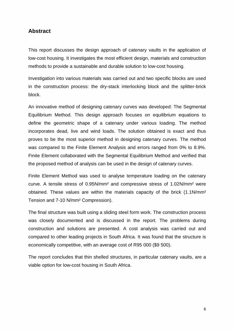
Abstract
This report discusses the design approach of catenary vaults in the application of
low-cost housing. It investigates the most efficient design, materials and construction
methods to provide a sustainable and durable solution to low-cost housing.
Investigation into various materials was carried out and two specific blocks are used
in the construction process: the dry-stack interlocking block and the splitter-brick
block.
An innovative method of designing catenary curves was developed: The Segmental
Equilibrium Method. This design approach focuses on equilibrium equations to
define the geometric shape of a catenary under various loading. The method
incorporates dead, live and wind loads. The solution obtained is exact and thus
proves to be the most superior method in designing catenary curves. The method
was compared to the Finite Element Analysis and errors ranged from 0% to 8.9%.
Finite Element collaborated with the Segmental Equilibrium Method and verified that
the proposed method of analysis can be used in the design of catenary curves.
Finite Element Method was used to analyse temperature loading on the catenary
curve. A tensile stress of 0.95N/mm² and compressive stress of 1.02N/mm² were
obtained. These values are within the materials capacity of the brick (1.1N/mm²
Tension and 7-10 N/mm² Compression).
The final structure was built using a sliding steel form work. The construction process
was closely documented and is discussed in the report. The problems during
construction and solutions are presented. A cost analysis was carried out and
compared to other leading projects in South Africa. It was found that the structure is
economically competitive, with an average cost of R95 000 ($9 500).
The report concludes that thin shelled structures, in particular catenary vaults, are a
viable option for low-cost housing in South Africa.

7
Acknowledgements
First and foremost, I would like to thank my supervisor Prof Gohnert for his invaluable
support and guidance throughout my masters career. Thank you for offering me this
amazing opportunity and opening so many doors for me. Your support has been incredible
and I am eternally grateful for your commitment in showing me the dream that is civil
engineering.
I would also like to thank Ryan Bradley and the entire Lab Staff at Wits for all their support
and help. To Eric, Wayne, Henrique, Dumisani, Sam and Sish: this project would not have
been possible without your huge contribution during the construction process. Thank you.
To all our sponsors: Hydraform, Spancon, Macsteel, Robor, Wispeco, Afrisam and Lintel
Suppliers. Thank you for all your invaluable contribution. Each donation made a huge
difference in ensuring the success of this project. We look forward to continuing working with
you in the future as this project grows. Hydraform, thank you for dedicating your time, money
and irreplaceable labour to this project; you made this project possible.
To National Research Foundation for investing in my research and supporting me financially:
thank you.
I would like to thank my sister, Nena; boyfriend, James and my friend, Robyn, who helped
motivate me over the past two years.
Lastly and most importantly, my parents: thank you for supporting me financially and
emotionally over my entire schooling career and for giving me the opportunity to follow my
dreams. I would not be where I am today were it not for you and I am eternally grateful for
everything you have done for me.

8
List of Figures
Chapter 2
Figure 2-1: Four stages of mature Guastavino tile construction procedure - Ochsendorf (2010, p 127)
.............................................................................................................................................................. 25
Figure 2-2: Mapungubwe Interpretation Centre .................................................................................. 26
Figure 2-3: Left: A cracked dome at the Sparrow Aids Village; Right: A membrane layer is applied to
the cracked dome ................................................................................................................................. 31
Figure 2-4: The catenary Curve and the Gothic Pointed Arch - Fitchen (1961, pp. 81) ......................... 34
Figure 2-5: Maximising on space and usability in various forms and designs - Joffroy (1994, p 16) .... 36
Figure 2-6: Casa Mila, Barcelona (left - (Sennott, 2004)) and the Sheffield Winter Gardens, England
(right - (Hymers, 2005)) ......................................................................................................................... 38
Figure 2-7: Gateway Arch, US (left (Grigonis, 2011) -) and the Pantheon, Rome (right) ...................... 38
Figure 2-8: A sliding formwork used to construct a vault (Joffroy, 1994, p 20) ................................... 40
Figure 2-9: The vaulted roof in Bapong Township was constructed with a sliding formwork ............. 41
Chapter 3
Figure 3-1: Type Plan Built in MacNamee Village, Port Elizabeth (Calderwood, 1953, p19-21) .......... 47
Figure 3-2: Type Plan Built in Orlando, Johannesburg (Calderwood, 1953, p19-21) ............................ 47
Figure 3-3: Type Plan Built in Sharpe Township, Vereeniging (Calderwood, 1953 p19-21) ................. 48
Figure 3-4: Layout of housing prototype .............................................................................................. 52
Figure 3-5: Interior Layout of housing prototype ................................................................................. 53
Chapter 4
Figure 4-1: The Drop Test (Hydraform, 2012, p 32) .............................................................................. 58
Figure 4-2: Curing curve for a 1:12 block (Hydraform, 2012, p 37) ...................................................... 58
Figure 4-3: Dimensions of the dry-stack interlocking block .................................................................. 61
Figure 4-4: The Dry-stack Interlocking Blocks used in the construction of the prototype ................... 62
Figure 4-5: Image of the split-brick block that separates into 3 individual bricks (Hydraform, 2012, p
53) ......................................................................................................................................................... 62
Figure 4-6: Dimensions of the “half” split-brick block used in the prototype ...................................... 63
Figure 4-7: Image of the split-brick block used in the construction of the vault roof in the prototype
as supplied by Hydraform ..................................................................................................................... 63
Chapter 5
Figure 5-1: The graphical method (Allen & Zalewski, 2010, p 76) ........................................................ 66
Figure 5-2: Hanging chain with its inverted form and corresponding thrust line through the thickness
of the curve ( Allen & Zalewski, 2010, p 220) ....................................................................................... 68

9
Figure 5-3: All internal and external forces applied to each segment, in equilibrium (Allen & Zilewski,
2010, p 220) .......................................................................................................................................... 68
Figure 5-4: (a) Maximum and minimum thrusts lines within the vault, (b) Minimum thrust lines and
(c) maximum thrust lines can cause cracking in the vault (Allen & Zalewski, 2010, p 221) ................. 69
Figure 5-5: The Initial angle at which the reaction force is orientated................................................. 72
Figure 5-6: A diagram illustrating the meaning of each heading in table 5-1 ...................................... 73
Figure 5-7: Trig is used to obtain the remaining components of the Left Thrust y Force .................... 74
Figure 5-8: Equilibrium at the centre of the segment, combining internal & external forces (Allen &
Zilewski, 2010, p 220) ........................................................................................................................... 75
Figure 5-9: Each co-ordinate represents the centroid of the segment. The first and last are inputted
manually to account for the geometry (length) of the segment .......................................................... 76
Chapter 6
Figure 6-1: Bapong case study location: image obtained off Google Earth.......................................... 80
Figure 6-2: Bapong township, a set of abandoned structures .............................................................. 80
Figure 6-3: The abandoned structures are in impeccable condition even with no maintenance ........ 81
Figure 6-4: A crack occurs at the centre, or high point, of all the roof structures ............................... 82
Figure 6-5: Steel ties are present in the structure to restrain the thrust force .................................... 82
Figure 6-6: All the edges of the vault must be restrained in all directions (i.e. pinned connection) due
to its direct connection to the surrounding wall .................................................................................. 83
Figure 6-7: Results of the load case whereby the structure has a temperature loading along the left
side of the vault .................................................................................................................................... 84
Figure 6-8: Results of a load case whereby the structure has a full wind load, temperature loading
along the right side of the vault and a live loading along the left side of the vault ............................. 84
Figure 6-9: A graphical explanation of cracking in a restrained vault after thermal loads are applied 85
Figure 6-10: Wind distribution over a vaulted roof with a rectangular base (SABS 0160-3, 2009, p37)
.............................................................................................................................................................. 88
Figure 6-11: External pressure coefficients for a multi-span vaulted roof ........................................... 89
Figure 6-12: Left - Wind pressure distribution as seen in SABS 0160-3 (2009, p 31); Right-The final
external pressure values applied in the prototype as per code ........................................................... 89
Figure 6-13: External pressure coefficient distribution over a curved roof (Blackmore & Tsokri, 2006,
p 837) .................................................................................................................................................... 90
Figure 6-14: Loading patterns for the applied live loads: (a) Full horizontal projection, (b) half load
over the left half, (c) half load over the right half, (d) point load at the centre, (e) point load at a
quarter length, (f) point load at three quarters. ................................................................................... 93
Figure 6-15: Investigated loading patterns for temperature loads: (a) temperature loading over the
entire structure, (b) temperature loading over the right half of the structure, (c) temperature loading
over the left half of the structure ......................................................................................................... 93
Figure 6-16: An Excel spread sheet showing the design process of a catenary curve subject to dead
loading................................................................................................................................................... 99
Figure 6-17: A graph representing the final geometry of the vaulted roof ........................................ 100
Figure 6-18: A horizontal projection of the live load over a segment ................................................ 102
10
Figure 6-19: A summary of all of the collapsed loads and their distances to edge - Left: Dead and Live
Loads; Right: Wind Loads .................................................................................................................... 105
Figure 6-20: An Excel spread sheet showing the design process of a catenary curve subject to vertical
and lateral loading .............................................................................................................................. 108
Figure 6-21: The final thrust line obtained for the load case of: DL+LL(R)+WL(Cpi=-0.2) .................. 109
Figure 6-22: A comparison of the Segmental Equilibrium Method and Finite element method when
subject to dead loads .......................................................................................................................... 111
Figure 6-23: A comparison of the Segmental Equilibrium Method and Finite element method when
subject to dead and live loads ............................................................................................................ 111
Figure 6-24: A comparison of the Segmental Equilibrium Method and Finite element method when
subject to dead, full live and wind loads (Cpi=-0.2) ............................................................................ 112
Figure 6-25: A comparison of the Segmental Equilibrium Method and Finite element method when
subject to dead and wind loads (Cpi=-0.2) ......................................................................................... 112
Figure 6-26: A model of the worst load case inputted to LISA 7.7.1: DL+WL+TL ............................... 113
Figure 6-27: The dominant principal stress distribution on the upper surface of the vault under the
most severe loading case .................................................................................................................... 114
Figure 6-28: The minor principal stress distributions on the upper surface of the vault under the most
severe loading case ............................................................................................................................. 114
Figure 6-29: The dominant principal stress distribution on the bottom surface of the vault under the
most severe loading case .................................................................................................................... 115
Figure 6-30: A graph representing the thrust lines obtained from only wind and dead load
combinations ...................................................................................................................................... 116
Figure 6-31: A graph representing the thrust lines obtained from only live (udl) and dead load
combinations ...................................................................................................................................... 116
Figure 6-32: A graph representing the thrust lines obtained from wind (cpi=0), live (udl) and dead
load combinations............................................................................................................................... 117
Figure 6-33: A graph representing the thrust lines obtained from wind (cpi=-0.2), live (udl) and dead
load combinations............................................................................................................................... 117
Figure 6-34: A graph representing the thrust lines obtained from only live (point) and dead load
combinations ...................................................................................................................................... 118
Figure 6-35: A graph representing the thrust lines obtained from wind (cpi=0), live (point) and dead
load combinations............................................................................................................................... 118
Figure 6-36: A graph representing the thrust lines obtained from wind (cpi=-0.2), live (point) and
dead load combinations ...................................................................................................................... 119
Chapter 7
Figure 7-1: Detail of rib-and-block slab as supplied by Spancon ........................................................ 122
Figure 7-2: Layout of the wall system highlighting the function of each wall as well as the wall with
the greatest applied load .................................................................................................................... 123
Figure 7-3: The loading and eccentricity as applied to the wall ......................................................... 125
Figure 7-4: A layout describing the manner in which the system is set out to contain the thrust force
............................................................................................................................................................ 126
11
Figure 7-5: The manner in which the lintels are loaded by the horizontal thrust exerted by the vault
............................................................................................................................................................ 127
Figure 7-6: Two lintels are placed on top of one another to ensure the ties fall within the concrete
section and are therefore covered ..................................................................................................... 128
Figure 7-7: The tube-weld-tie connection with an applied force in the tie ........................................ 131
Figure 7-8: Calculation of the weld size .............................................................................................. 131
Figure 7-9: A layout showing where the foundations are positioned ................................................ 133
Figure 7-10: Dimensions and detailing of the foundation .................................................................. 134
Figure 7-11: An analysis of the foundation of a 1m section of soil collapses ..................................... 136
Chapter 8
Figure 8-1: The foundation is measured and set up using builder’s line before it is dug to the required
depth ................................................................................................................................................... 138
Figure 8-2: The steel sections are assembled into the inverted T shape and dropped into the
foundations ......................................................................................................................................... 138
Figure 8-3: Holes are drilled into the raft foundation so that the edges of the steel cages can be
connected into the raft ....................................................................................................................... 139
Figure 8-4: Readymix Concrete is poured into the foundation .......................................................... 139
Figure 8-5: A 10mm layer is positioned over the entire foundation to bind the old and new concrete
properly ............................................................................................................................................... 140
Figure 8-6: Cement bricks are used to construct the base of the wall to 300mm above ground level
............................................................................................................................................................ 141
Figure 8-7: The cement bricks are built to 300mm before the dry-stack layers begin ....................... 141
Figure 8-8: A layer of DPC is placed between the cement bricks and earth blocks............................ 142
Figure 8-9: The method of constructing two courses of dry stack interlocking blocks (Hydraform,
2012, p 55) .......................................................................................................................................... 143
Figure 8-10: Construction of the walls is done from the corners-inwards ......................................... 144
Figure 8-11: A completed dry-stack wall ............................................................................................ 144
Figure 8-12: The construction of the wall when openings for windows and doors are required ...... 145
Figure 8-13: Lintels are positioned above the windows and doors to support the bricks above them
............................................................................................................................................................ 145
Figure 8-14: Lintels are positioned above all openings to support the bricks above it; the last layer of
bricks is mortared in to lock the walls ................................................................................................ 146
Figure 8-15: Ties are placed in the wall to connect the exterior and interior walls at a later stage .. 146
Figure 8-16: The completed walls with the last layer of dry-stack mortared in to lock the walls ...... 147
Figure 8-17: The completed first level, where the last two layers of bricks are cement bricks ......... 147
Figure 8-18: Cement Blocks used in the rib-and-block slab ................................................................ 148
Figure 8-19: Placing the blocks between the ribs ............................................................................... 148
Figure 8-20: Props are set up under the slab to support it until concrete is poured ......................... 149
Figure 8-21: Steel mesh and reinforcing is positioned on top of the slab .......................................... 149
Figure 8-22: Wood shuttering is used around the openings .............................................................. 150
Figure 8-23: The final concrete pour; the slab is no complete and left to cure ................................. 150
12
Figure 8-24: The steel ties are welded to the tubes at the ends of the structure .............................. 151
Figure 8-25: The tubes are placed over the lintels and then filled with grout ................................... 152
Figure 8-26: A stencil is used to determine the shape and guide the bending of the flat bars .......... 153
Figure 8-27: The steel formworks used to construct the vaults ......................................................... 153
Figure 8-28: The two formworks at site, ready to be lifted and for construction to commence ....... 154
Figure 8-29: The formwork is propped up onto bricks which can easily be pulled out ...................... 154
Figure 8-30: The first layer of bricks as at the same level as the slab ................................................ 155
Figure 8-31: The start of the construction of the vaults ..................................................................... 156
Figure 8-32: Inaccuracies in following the form during construction ................................................. 157
Figure 8-33: Accurate and efficient construction ............................................................................... 157
Figure 8-34: Constructing on each side to prevent swaying of the formwork under the weight of the
vault .................................................................................................................................................... 158
Figure 8-35: Cracking occurred along the apex as the vault is restrained from contracting naturally
............................................................................................................................................................ 159
Figure 8-36: Completing the last few layers in the construction of the first section ......................... 159
Figure 8-37: The first length is complete: the most difficult section .................................................. 160
Figure 8-38: The formwork is shifted and repositioned to continue construction of the vault ......... 160
Figure 8-39: Construction of the second section is completed, the formwork is dropped and shifted
and construction continues ................................................................................................................ 161
Figure 8-40: The construction of the vaults continues ....................................................................... 161
Figure 8-41: Construction of the first vault is almost complete ......................................................... 162
Figure 8-42: The second vault nearing completion ............................................................................ 162
Figure 8-43: The completed vaulted roof ........................................................................................... 163
Figure 8-44: The completed catenary roof ......................................................................................... 163
Figure 8-45: The construction of the top floor walls .......................................................................... 164
Figure 8-46: Completion of the top floor walls and thus the superstructure..................................... 164
Figure 8-47: The pouring of the floor slabs ......................................................................................... 165
Figure 8-48: The construction of the internal walls ............................................................................ 166
Figure 8-49: Construction of the staircase using lintels, blocks and mortar ...................................... 166
Figure 8-50: Plastering of the structure .............................................................................................. 167
Figure 8-51: The installation of the windows ..................................................................................... 167
Figure 8-52: The door is installed and painting of the plaster commences ....................................... 168
Figure 8-53: The completion of the painting concludes the construction of the structure ............... 168
Figure 8-54: The front view of the completed prototype ................................................................... 169
Figure 8-55: The back view of the completed prototype ................................................................... 169
13
List of Tables
Chapter 4
Table 4-1: Material properties of CSEB ................................................................................................. 60
Chapter 5
Table 5-1: The spread sheet layout for the equilibrium method (Figure 5-6) ...................................... 73
Chapter 6
Table 6-1: Wind pressure distribution (N/m2) values on the catenary roof ......................................... 91
Table 6-2: Dead Loads applied to the vault .......................................................................................... 95
Table 6-3: Loading combinations applied in analysis of vault .............................................................. 95
Table 6-4: Dead loads applied to vaulted roof.................................................................................... 101
Table 6-5: The value of the live load applied on the vault, obtained from SABS 0160 (2009) ........... 102
Table 6-6: Wind Pressures values distributed over the vaulted roof (Refer to Figure 6-10) .............. 103
Table 6-7: Loading combinations for the analysis of a catenary vault ............................................... 104
Table 6-8: Load reactions comparison of the results obtained from Finite element Analysis and the
Segmental Equilibrium Method .......................................................................................................... 110
Chapter 7
Table 7-1: Properties of materials used in the slab ............................................................................ 121
Table 7-2: A table summarising the material and section properties of the lintels ........................... 129
Table 7-3: A table detailing the steel required in the foundation ...................................................... 136
Chapter 9
Table 9-1: A cost breakdown of the materials required for the construction of the low-cost housing
prototype ............................................................................................................................................ 170

14
List of Symbols
Description Symbol
Cartesian x – coordinate x
Cartesian y – coordinate y
Section Modulus Z
Applied Load P
Thickness t
Eccentricity e
Stress σ
Initial angle, theta θ
Sum of Moments ∑M
Sum of forces in the y direction ∑Fy
Sum of forces in the x direction ∑Fx
Dead Load DL
Wind Speed
Altitude Constant
Wind Speed Multipliers
Wind pressure
External Pressure Coefficient Cpe
Internal Pressure Coefficient Cpi
Point Load PL
Ultimate Limit State ULS
Service Limit State SLS
Live Load LL
Wind Load WL
Horizontal H

15
Vertical V
Capacity Reduction Factor β
Characteristic Compressive Strength fk
Material Safety Factor γm
Length L
Height h
Characteristic Stength Pu
Yield Strength fy
Radius of bar r
Pie π
Throat thickness a
Total Service Load Ps
Compression C
Tension T

16
1. Introduction
1.1. Problem Statement
Many South Africans live a life of extreme poverty with limited access to basic
infrastructure, including housing. It is difficult to provide housing for everyone, and
this is further exacerbated by the common use of large quantities of concrete as a
construction material. Because of the expense, current concrete construction is not a
sustainable solution to South Africa’s housing problem. Either a new material or a
new design must be established in order to achieve a more economical solution. A
clear example of this is RDP housing and its ineffectiveness in alleviating poverty.
The cost is high and the quality of construction is poor. In addition, on a daily basis,
we are faced with extensive environmental issues caused by the use of concrete,
e.g. pollution, flooding, exploitation of resources, heat islands, etc. (Birkinshaw,
2008). A new solution needs to be investigated where the form of housing is cheap,
materials are locally obtained. The design and construction is robust and most
importantly, the structure is environmentally friendly.
In 2007, it was found that 11 percent of the South African population live in shacks
(FinScope, 2007). This number has increased considerably since 2007 and is still on
the rise (Birkinshaw, 2008). Birkinshaw (2008) found that the number of South
African households residing in shacks is increasing at more than double the rate at
which the population is growing, with more than 2 million people currently residing in
shacks. The living conditions of these people are extremely low and thousands of
related deaths occur every year (Birkinshaw, 2008). Thus, it is important that the
basic needs of people are met and their living conditions improved.
To improve living conditions, several factors must be investigated. Firstly, it is
important that low energy and locally sourced materials are utilised in the
construction process. This will reduce costs to a minimum and provide a more
sustainable solution. Secondly, the structures need to be thermally efficient as a
major cause of death in informal settlements is as a result of heating during winter.
Uncontrolled shack fires are created whilst trying to warm households during the

17
winter months. Lastly and most important, a more structurally robust design needs to
be determined to ensure that the inhabitants have a long term home, regardless of
the prevailing weather conditions.
We need to respond, and therefore it is important to investigate creative solutions to
the housing problems, experienced both in South Africa and around the world. In
addition, we are faced with climate change and therefore we cannot construct in the
usual manner. Other issues include excessive energy consumption in the production
phase, pollution, temperature changes and lack of good thermal properties. The
current solution is not sustainable.
Thin shells have been found to be a very effective solution (Joffroy, 1994). They are
versatile and easy to construct, requiring minimal amounts of materials. Shell forms
can eliminate expensive forces, such as shears and moments, and increase their
durability considerably. Thin shells have the ability to resist extreme loading
conditions; this is highlighted by a Youtube clip in The Weather Channel (2009),
documenting a shell home which survived Hurricane Ivan. Thin shells, in conjunction
with environmentally agreeable materials, are a superior solution in terms of
strength, economy of materials and cost to the consumer.
1.2. Objectives
The objectives of this research report:
Investigate properties of materials which have low energy consumption, are
cheap and locally obtainable
Investigate various housing forms and determine the most suitable form for
low-cost housing, incorporating thin shells
Establish an effective method of designing and analysing catenary vaults
Design an effective low-cost housing prototype and identify the important
design criteria that needs to be considered
Construct a durable and structurally efficient low cost housing prototype
18
1.3. Scope
This research report comprises of ten chapters. The contents of each of the chapters
are outlined below:
Chapter 2 highlights previous literature and research done on low-cost housing
projects. It highlights the benefits of thin shells as a solution to low-cost housing as
well as shortfalls in knowledge on designing catenary vaults. It also discusses
various building materials and construction methods required in the use of thin
shelled structures.
Chapter 3 investigates various forms and layouts suitable for low-cost housing. This
chapter highlights the need for housing; which minimises on thermal energy and
natural flow of the energy within the structure. A final prototype design is also
presented.
Chapter 4 presents information regarding the various building materials which are
used in the construction of the prototype. The advantages and shortfalls are
highlighted and guidance as to how the user can produce his own building materials
on site.
In Chapter 5, various methods of designing catenary curves are discussed and a
new method of design is presented, based on equilibrium principles.
Chapter 6 utilises the method described in Chapter 5, and covers an in-depth step-
by-step analysis and design of the catenary roof of the housing prototype. A case
study of an existing site is also explored and analysed to highlight various design
principles. Finite Element is used to compare the results of the proposed Equilibrium
Method, as well as assess temperature loading on the structure.
Chapter 7 covers the design of the remainder of the structure including the slab, the
walls, the thrust components and the foundations.
Chapter 8 discusses and illustrates the construction process of the low-cost housing
prototype.
A short summary of the costing of the structure is provided in Chapter 9.

19
Conclusions and recommendations are made in Chapter 10.

20
2. Literature Review
2.1. Introduction
Throughout the ages, structures and their forms have revolutionised and changed
civilization dramatically. This change has been due to technological advances as
well as social demands. Thin shelled structures have been in existance from as early
as the late 1800’s. Architects and engineers, such as Eduardo Torroja, Heinz Isler,
Dante Bini, and the like, were very active in the design and construction of these
forms (Wilson, 2005). Architects are interested in and passionate for these structural
types because of their diversity and ability to adapt to various climatic conditions
(Joffroy, 1994). Their ability to cover larger spaces made them popular in the
construction of religious buildings, schools, hospitals and simple low-cost housing
(Joffroy, 1994).
Arches, vaults and the like have been around for thousands of years and many can
still be found in the Middle East, North Africa and many European countries, where
they were widely used (Joffroy, 1994). Even with a decrease in popularity, many of
these countries still build these structures to continue the rich heritage and living
traditions associated with these building forms.
Timbrel vaults form part of the thin-shell family of structures; however, their specific
characteristics warrant a specific definition. It has been found that the most apt
description is that “timbrel vaults are masonry vaults made with brick and mortar,
with a good strength in compression, and can be constructed with remarkable
thinness and without the use of formwork. Their uniqueness derives from their
construction: the bricks are placed flatly, forming one or more layers and they are
constructed without centring or other support. The bricks are placed in arches or
successive rings to complete the vault.” (Huerta, The Mechanics of Timbrel vaults: A
Historical Outline, 2003, p. 89). Timbrel vaults are an ancient form of construction
initially introduced in the fourteenth century, but not until the sixteenth century did it
become common practice (Huerta, The Mechanics of Timbrel vaults: A Historical

21
Outline, 2003). Currently, shells are not commonly used, even though its popularity
has increased.
However, it was Rafael Guastavino who put his foot in the door regarding vaulting
and he was particularly active in tile vaulting. It was Guastavino’s theory of ‘cohesive
construction’ that allowed the methods of construction of timbrel vaults to make the
transition into the 20th century and therefore make a monumental imprint in the
history of thin shells (Huerta, The Mechanics of Timbrel vaults: A Historical Outline,
2003). He refined the thousand year old building system of ‘Catalan Vaulting’, which
involves a technique involving the erection of thin terra-cotta tiles. Catalan vaulting is
the same practice as Timbrel vaulting, varying only by the name given in the various
regions in which it is being constructed. Guastavino’s tile vaulting technique
contributed considerably to many prestigious buildings of his time, but little of his
legacy. However, the structural behaviour of the Catalan vault has received
considerable attention in literature (Atamturktur, 2006).
Guastavino made a number of material and construction technique breakthroughs.
His main construction technique -- “Cohesive Construction Technique”-- is defined
as the bond between the terracotta tiles and the Portland cement, due to cohesive
forces. His greatest contribution to the technique was altering the traditional gypsum
mortar (Plaster of Paris) with rapidly hardening Portland cement, thus enabling him
to build vaults that spanned three to five times the typical span of traditional Catalan
vaulting (Tarragó, 2002). The technical advancements made by Guastavino, in terms
of material breakthroughs, allowed him to enhance his career to world renowned
standings, starting with the design and construction of the Boston Public Library. The
Guastavino era marks the highest point of the tile vaulting industry and thin shelled
structures (Atamturktur, 2006).
Thin shells have become less popular over the years. This has been due to a
number of factors, including high labour costs and the high cost of formwork (Wilson,
2005). Many of these factors are also relevant to the decrease in the use of domes,
arches and vaulted structures. A major factor in the modern world of construction is
the social aspect of acceptance. Thin shells are rejected by people for a number of
22
reasons, ranging from cultural expectations to lack of modernism. Shell structures
have been considered an expensive and difficult form of construction, but if designed
for local conditions, they can eliminate many of the considered and current problems
(Wilson, 2005).
These structures have many advantages. Domes and vaults have been found to be
economical, safe and aesthetically pleasing. They require the minimum use of
materials, which may be produced locally and at a low cost (Wilson, 2005). Joffroy
(1994) outlines a number of advantages and opportunities in using vaults, which
include job creation, foreign currency savings, great aesthetic potential, wide variety
of uses and economic benefits. Huerta (2003) found that thin shells are an excellent
alternative to floor and roof systems, as they provide exceptional fire resistance.
In most parts of the world, there is a significant need for earthquake-safe housing,
and these forms have proved to be extremely effective in resisting these natural
disasters (Joffroy, 1994). Through the use of innovative techniques, many of the
above stated problems can be eliminated. The use of vaults and shells in
construction are relatively foreign in this age; however, there is constant research
and development programmes being carried out to improve the design and
construction of shells. Recent interest and improved technology have allowed for the
design and construction of these unique structures to be mastered once again and a
considerable amount of increased knowledge to be added to this research field.
(Joffroy, 1994).
A significant cost in the construction of low-cost housing is the roof structure, and the
deficiency of good quality and readily available materials. An alternative structural
form is necessary to minimise these costs, preserve tradition and make use of local
and easily accessible materials. This form needs to satisfy local conditions which
include cultural, economic and climatic aspects. In the form of vaults, Joffroy (1994)
provides a valuable alternative.
“Dome structures not only provide great strength, but do it by using less material
than other structures.” (Wilson, 2005, p. 9)

23
2.2. Materials
Shell structures have been built for centuries using various building materials,
ranging from straw and grass to reinforced concrete. The construction of thin shells
in modern-day sees the use of reinforced concrete to be most effective due to its
strength and durable characteristics. For this reason, most of the available literature
refers to ‘thin shell concrete structures’ and ‘advancements in reinforced concrete
shells’ (Cowan, 1977).
There are a number of material options that require investigation when designing
and constructing a thin shelled structure. Wilson (2005) constructs his structures out
of reinforced concrete as this allows for versatility in design and thus allows for the
construction of any desired shape. It also allows for thicker, larger structures to be
built, without the need for complex thin shell theory to be applied. Concrete is readily
available in many locations and requires minimal maintenance if used correctly.
However, it is an expensive method of construction due to the need for cement and
steel reinforcing. Guastavino rejected the use of reinforced concrete due to the
excessive cost incurred in their construction and “problems with irregular setting of
the concrete” (Huerta, The Mechanics of Timbrel vaults: A Historical Outline, 2003,
p. 104). Cement requires a large amount of energy in the production phase, and is
responsible for emitting greenhouse gases into the atmosphere. Thin shells require a
much smaller volume of material when compared to standard methods of
construction, and this makes them more economical and therefore results in a large
reduction in energy consumption and pollution (Wilson, 2005). A new building
material needs to be established to further reduce the cost of construction. It is
important to note that due to the thin nature of shells, bricks and tiles may be used in
their construction.
2.2.1. Tiles
There is a considerable amount of information covering the structural mechanics of
reinforced concrete thin shells. However, there is far less literature on the structural
behaviour of tile vaulting. Although this type of construction has been around for over

24
seven hundred years, interest in building these types of structures declined during
the twentieth century (Ochsendorf, 2010). It is only recently that a renewed interest
in tile vaulting has been established, as the properties of this material allows for
more advantageous construction projects to be carried out with respect to available
skills, flexibility within the structure and construction costs (Ochsendorf, 2010). Not to
mention the much lower environmental impact in comparison with reinforced
concrete shells.
Guastavino established that due to the lighter weight of the tiles, they create a lower
horizontal thrust than conventional masonry structures. Tiles are brittle, and
therefore they are strong in compression, but very weak in tension. This is important
for the modelling and designing process as no unwanted forces are to be created in
the construction phase otherwise the material may fail (Ochsendorf, 2010). The lack
of space between and around the tile does not allow for safety reinforcing to be
positioned in a structurally viable way.
Huerta (2003) identified that the main reason behind the use of “fast-setting mortar”
and “thin-brick” (Ramage, 2004) or tiles is that not only do these materials allow for
large areas to be covered “gracefully and economically”, but have also found that low
levels of tensile forces, shear forces and moments have been detected in these
structures during various load tests.
Figure 2-1, by Guastavino, is a good example that demonstrates the construction
process and hence the method of using tiles and fast setting mortar for construction
purposes (Ochsendorf, 2010). Figure 2-1 explains how the first layer utilises fast
setting mortar to obtain the correct geometry. Each succeeding layer is laid by
applying a layer of mortar, the first layer which now acts as formwork.

25
Figure 2-1: Four stages of mature Guastavino tile construction procedure - Ochsendorf (2010, p
127)
Investigations into the viability of the use of masonry methods for present times are
currently underway, with the initiation of various projects around the construction of
tile vaults. One such project is the construction of vaults from stabilized earth tiles in
Mapungubwe in Limpopo, South Africa (Figure 2-2). A paper presented on this
project states that “Currently, research is being undertaken both to increase the
strength of the tiles in compression, tension and shear, and to simplify the method of
construction to facilitate less-skilled workers with relatively low levels of supervision”
(Fitchett, 2009b).This is an indication of attempts to re-employ the use of tiles in vault
construction as it is proven to be a successful method. The Mapungubwe project
was highly successful and won various architectural awards due to its aesthetic
appeal.
26
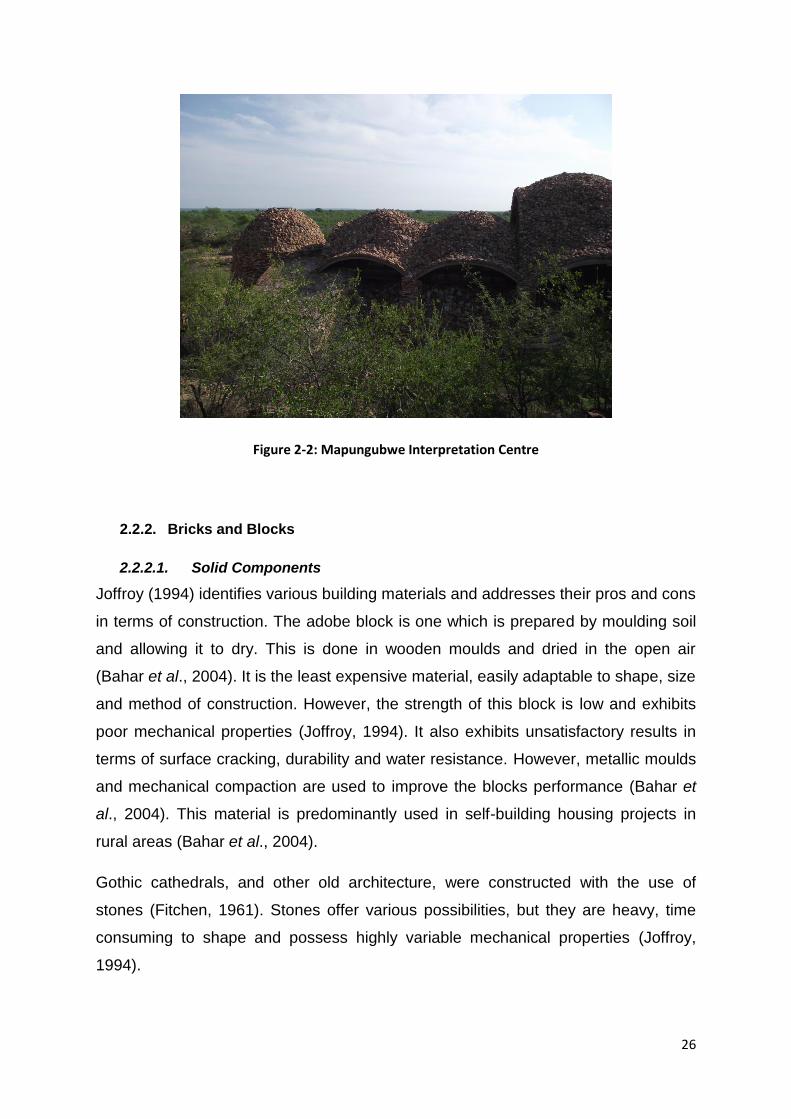
Figure 2-2: Mapungubwe Interpretation Centre
2.2.2. Bricks and Blocks
2.2.2.1. Solid Components
Joffroy (1994) identifies various building materials and addresses their pros and cons
in terms of construction. The adobe block is one which is prepared by moulding soil
and allowing it to dry. This is done in wooden moulds and dried in the open air
(Bahar et al., 2004). It is the least expensive material, easily adaptable to shape, size
and method of construction. However, the strength of this block is low and exhibits
poor mechanical properties (Joffroy, 1994). It also exhibits unsatisfactory results in
terms of surface cracking, durability and water resistance. However, metallic moulds
and mechanical compaction are used to improve the blocks performance (Bahar et
al., 2004). This material is predominantly used in self-building housing projects in
rural areas (Bahar et al., 2004).
Gothic cathedrals, and other old architecture, were constructed with the use of
stones (Fitchen, 1961). Stones offer various possibilities, but they are heavy, time
consuming to shape and possess highly variable mechanical properties (Joffroy,
1994).

27
The oldest form of earth construction is that of rammed earth. It involves pouring the
material into pre-prepared formwork. The material consists of earth stabilised by
natural fibres or binders, and is poured in sections and compacted manually to
construct an entire wall. The properties of the soils used should include large grain
sizes. There are a number of projects that can be found in Algiers, Algeria where
prototypes and housing projects have made use of rammed earth methods
(CNERIB, 1991). This method has also been used to construct low cost grain silos
where earth material was stabilised with wheat straw (Bartali, 1991).
The fired solid brick is an expensive form of construction but generally performs well
for all dimensioned buildings and is versatile in its shape and size. The fired hollow
brick is lighter than the standard solid brick but requires special application
techniques (Joffroy, 1994).
The compressed cement bonded earth block (CCBEB) is a viable alternative to more
costly forms of construction, i.e. the fired brick. This block has good mechanical
strength, but may deteriorate when exposed to water (Joffroy, 1994). Cement
Stabilised Earth Blocks (CSEB) are blocks made from raw or mixed soils, stabilised
with cement or fly ash, poured into a press and compressed with either a manual or
mechanical press, forming the required building block (Auroville Earth Institute,
2012).
There has been considerable research done in CSEB, particularly in Algeria, as a
solution to low-cost housing (Bahar et al., 2004). Earth construction is relatively
abundant and makes use of cheap labour. Soil-based construction methods have
been used throughout North Africa for centuries, particularly in the form of blocks,
and in Algeria, the earth block is the most commonly used building material.
However, it was found that the problems associated with earth blocks are that of
shrinkage cracking, low strength and lack of durability. Therefore, continuous
maintenance is required and technological improvements are needed to resist the
effects of water. Furthermore, soils vary from one region to another and this needs to
be incorporated in the experimentation and specification process. These historic
structures are an inspiration to modern architecture, but there is a need to improve

28
the properties of these materials. Through considerable experimentation, it was
found that the best option is that of cement stabilisation in conjunction with
mechanical compaction (Bahar et al., 2004).
A major obstacle in masonry development is that of social status. Earth construction
is considered a material for the poor, due to its low quality and durability, as well as
affordability and abundance. However, materials such as cement, aggregate, steel
and fired bricks are lacking. Sometimes these materials need to be imported, and
are expensive. Concrete, besides the high cost, is found to have a low thermal
performance. Therefore, it is important for future construction to lean more towards
environmentally friendly and cheaper materials. Earth construction is a strong and
viable solution, which has considerable traditional meaning within the local
communities, as well as excellent thermal properties (Bahar et al., 2004).
2.2.2.2. Binder Components
Mortar is a component that is overlooked when discussing optimisation of material
costs. The four major alternatives in the use of low-cost housing are: earth mortar,
stabilized earth mortar, lime-sand mortar, gypsum mortar and cement-sand mortar
(Joffroy, 1994). All of the above alternatives vary depending on whether bricks or
tiles are used in conjunction with the binder for construction and their components.
Cement-sand mortar is the most readily used binder, but also has a high cost. It is
important to limit the amount of cement used in the mortar so as to minimise the
costs without jeopardising the overall strength. The mortar is very effective in
bonding good quality fired earth bricks as well as sand-cement blocks. They have
been effective in the construction of medium-span vaults (Joffroy, 1994).
Earth mortar is historically used to bond adobe blocks, fired bricks and stone. The
mortar has excellent sticking abilities and allows for easy construction of vaults,
without the need for shuttering. However, it is extremely susceptible to shrinkage so
it is important that straw or sand is added to a mix which contains an excessive
amount of clay content (Joffroy, 1994).

29
Stabilised earth mortar is earth mortar with the addition of a stabiliser in the form of
cement, lime, plaster or bitumen. This mix is also effective in conjunction with fired
bricks or compressed earth blocks (Joffroy, 1994).
Lime-sand mortar is useful in that it is very malleable and sets extremely slowly, thus
increasing the workability of the mortar. However, this mortar does portray average
characteristics and relatively low strength. There are methods to improve it through
the addition of crushed brick or pozzolanas. It is generally used in conjunction with
fired blocks or stone (Joffroy, 1994).
Lastly, gypsum mortar sets extremely quickly allowing the application of adhesive
techniques to be used. This mortar can be stabilised through the addition of lime.
Therefore, smaller scale vaults or models can be made quickly and efficiently using
this mortar (Joffroy, 1994). It has been found that a fast setting mortar, such as
gypsum mortar, has needs that must be met to ensure that the construction is done
correctly and the bricks adhere effectively. Ramage (2004) found that by soaking the
bricks in water, before applying the plaster, allowed the mortar to adhere better to
the brick. The mortar also needs to be mixed in small batches and applied to one
brick at a time.
2.2.3. Surface Protection
Depending on the type of materials the engineer decides to use, various
maintenance problems can occur, i.e. durability problems, infiltration, cracking, etc.
In particular, it is important to protect vaults and domes from infiltration of rainwater
and preserve its durability. This can be done in a number of ways with the main aim
consisting of channelling the water away from the building using downpipes or
waterspouts. Depending on the budget at hand, various methods of surface
protection can be applied (Joffroy, 1994).
Various forms of materials, as discussed previously, differ in terms of maintenance
and effects caused by weathering. Almost all shells made of earth bricks, concrete or
clay bricks are extremely susceptible to cracking when constructed with tension-
weak materials. This leads to infiltration and water damage. While adobe blocks and

30
other earth based blocks and bricks require more maintenance as water damage will
cause durability issues (Joffroy, 1994).
An earth plaster is the cheapest solution but requires regular maintenance
depending on the quantity and nature of rainfall, the area in which it is situated and
the various forms of weathering it is exposed to. A sand-cement mortar would crack
as it is too rigid; therefore, a corresponding membrane should be used in
conjunction. The better render solution is one of lime-sand and gypsum-lime-sand,
as they have greater malleability but some maintenance would still be required
(Joffroy, 1994).
A further option for surface protection is a form of roof covering. Adding another layer
of material on top of the vault will protect the primary layer. Previous and current
solutions include thatch, tiles, stones, etc. These can also provide another means of
directing the water away from the roof without much notable infiltration. If done
correctly, these solutions can still be cheap and extremely effective, requiring
minimal maintenance (Joffroy, 1994).
A common method which has been applied to a number of projects is the use of
membranes as a layer on the outer surface of the vault or dome. This can be done in
a single or multiple layers of bitumen-based membrane, metal leaves or acrylic-fabric
membranes. Another popular membrane is that of waterproof paint. This solution,
although effective, is relatively expensive (Joffroy, 1994). An example of this form of
waterproofing can be found at The Sparrow Aids Village in Johannesburg (Figure 2-
3). This village has experienced considerable cracking and a membrane has been
applied on the outer surface of the domes to minimise water damage. The
membrane used is a fabric over which an acrylic waterproof paint is applied. This
material is extremely effective, as it is flexible and capable of withstanding thermal
movements. It has improved the domes quality considerably, and now there is
minimal, if any, water infiltration within the domes.

31
Figure 2-3: Left: A cracked dome at the Sparrow Aids Village; Right: A membrane layer is applied to
the cracked dome
The choice of the shape is crucial in terms of construction and economic efficiency.
The ideal option in minimising infiltration problems is to construct a sloping roof. This
allows for the water to drain naturally off the structure and not gather in a section of
the roof, resulting in infiltration. Infiltration is generally not an issue for rounded
structures, as these forms are quite steep and only a small gradient is required to
allow for natural drainage.
2.3. Forms, Modelling and Spacing
Form finding is an extremely complex process which entails finding a shape which is
structurally sound. This step is generally done well through the observation and
identification of problems in other structures of similar form. Mimicking natural
shapes is extremely important in order to achieve a strong solution; with one of the
best examples being that of an egg. Although an egg is made of somewhat weak
and soft materials, its oblong shape is extremely strong. There are many forms of
vaults ranging from the barrel vault, being the simplest, to more complex vaults like
the domical vault and so forth (Joffroy, 1994).
Safety is essential when designing structures, and many countries worldwide need to
design for seismic action. Thin shells have been found to be extremely effective in
terms of withstanding earthquakes, hurricanes and the like (Wilson, 2005). Building a
domed house is a safer, more economic, longer lasting and easier option than
building a standard similar sized house (Wilson, 2005). A good example of this is the

32
construction of a home on Pensacola Beach, Florida, designed by Arnold Wilson.
The house withstood Hurricane Ivan with minimal damage, while surrounding
properties, following standard designs, collapsed (The Weather Channel, 2009).
Furthermore, the structure withstood a further two hurricanes, Denis and Katrina.
Wilson (2005, p. 13) states that “The storm surge forced water through the ground
floor garage and tore away the breakaway staircase. The living quarters were
undamaged.”
Fire is another safety feature that needs to be incorporated in all designs. The South
African Standards Code of Practice stipulates that there must be a specified amount
of time that the structure needs to be standing so that all personnel in the building
can evacuate safely (SABS 0100-1: South African Standard Code of Practice; The
structural use of concrete, 2000). In 1988, a large domed grain storage facility in
Alabama caught alight and burned for 20 days without collapse (Wilson, 2005).
Eventually, a dust explosion occurred within the structure and the top of the dome
burst off, allowing for a relief valve to be created, and in turn saved many lives as
well as the surrounding property (Wilson, 2005).
The process of form finding, with regards to thin shells and vaults, is not well
covered. One exception is the engineer Heinz Isler – who is considered the pioneer
of the fabric form-finding method. “A method of form-finding used by Heinz Isler is to
suspend a membrane between supports disposed in the same relative positions as
in the real structure and leave it to deform under its own uniform weight. Under this
load the membrane takes up a shape such that, within it, only tensile forces are
present, as a cloth affords no resistance to bending or compression” (Chilton, 2000,
p. 35). Once the cloth is suspended from all four points, it can be soaked in water
and frozen or covered in self-setting polyester resin, until a solid form is achieved.
The form is inverted so that the cloth will be in pure compression as opposed to its
natural, hanging tensile state, thus achieving the desired shape (Chilton, 2000).
Atamturktur (2006) investigates the effects of vibration and dynamic testing of
spherical structures in order to test the structural form. He also utilises his research
to investigate various design methods.

33
Atamturktur bases his design procedure of domes on the Finite Element Method of
modelling. He describes finite element analysis (FEA) as an “approximate numerical
method that solves for the distribution of forces, displacements, or strains in a
system” (Atamturktur, 2006, p. 90). His approach in completing an FEA is to “build
an analytical model, which idealizes the variables of the structure under study:
geometry, material properties, and boundary conditions, as well as existing or
possible loadings…fine tuning the FE model by comparisons of analytical and
experimental frequencies and mode shapes” and finalizing the procedure “with the
determination of the static state of stress, strain and displacements” (Atamturktur,
2006, pp. 90-91). As with any project, it is important to make valid assumptions in
order to design the structure efficiently. The most important assumptions that are
noted by Atamturktur include: a uniform thickness of the shell, all materials can be
assumed to be isotropic and homogeneous, the structure is subject to linear elastic
behaviour of materials and minimal deflections occur.
Various research has been completed in the construction of medieval vault erection,
in particular gothic cathedrals. Gothic cathedrals date back to as far as the 12th
century and many of them are still around today. Their structural knowledge was far
advanced in comparison to their technology and various observations have been
made that are of significant importance (Fitchen, 1961).
Fitchen (1961) identifies that the simplest and truest type of vault is that of a semi-
cylindrical barrel vault. They are structurally sound and extremely simple to
construct. The semi-cylindrical barrel vault was extremely common and extensively
used within the gothic cathedrals, but a problem with this form was that it did not
span very effectively, prohibiting the maximum height that was to be achieved, as
well as minimising the amount of light made available within the structure. The semi-
cylindrical vault was found to be a poor form structurally for cathedrals. A new shape
and solution needed to be found.
As the Gothic era progressed, it was found that many of these vaults tended to be
strongly pointed at the tip and this caused many structural troubles in the form of
cracking and even collapse. Thus, after considerable experimentation, it was found
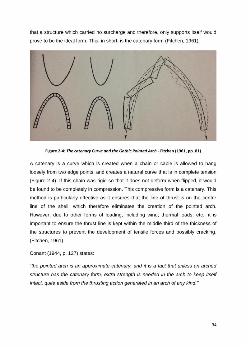
34
that a structure which carried no surcharge and therefore, only supports itself would
prove to be the ideal form. This, in short, is the catenary form (Fitchen, 1961).
Figure 2-4: The catenary Curve and the Gothic Pointed Arch - Fitchen (1961, pp. 81)
A catenary is a curve which is created when a chain or cable is allowed to hang
loosely from two edge points, and creates a natural curve that is in complete tension
(Figure 2-4). If this chain was rigid so that it does not deform when flipped, it would
be found to be completely in compression. This compressive form is a catenary. This
method is particularly effective as it ensures that the line of thrust is on the centre
line of the shell, which therefore eliminates the creation of the pointed arch.
However, due to other forms of loading, including wind, thermal loads, etc., it is
important to ensure the thrust line is kept within the middle third of the thickness of
the structures to prevent the development of tensile forces and possibly cracking.
(Fitchen, 1961).
Conant (1944, p. 127) states:
“the pointed arch is an approximate catenary, and it is a fact that unless an arched
structure has the catenary form, extra strength is needed in the arch to keep itself
intact, quite aside from the thrusting action generated in an arch of any kind.”
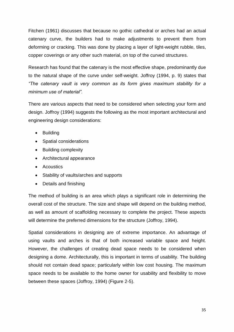
35
Fitchen (1961) discusses that because no gothic cathedral or arches had an actual
catenary curve, the builders had to make adjustments to prevent them from
deforming or cracking. This was done by placing a layer of light-weight rubble, tiles,
copper coverings or any other such material, on top of the curved structures.
Research has found that the catenary is the most effective shape, predominantly due
to the natural shape of the curve under self-weight. Joffroy (1994, p. 9) states that
“The catenary vault is very common as its form gives maximum stability for a
minimum use of material”.
There are various aspects that need to be considered when selecting your form and
design. Joffroy (1994) suggests the following as the most important architectural and
engineering design considerations:
Building
Spatial considerations
Building complexity
Architectural appearance
Acoustics
Stability of vaults/arches and supports
Details and finishing
The method of building is an area which plays a significant role in determining the
overall cost of the structure. The size and shape will depend on the building method,
as well as amount of scaffolding necessary to complete the project. These aspects
will determine the preferred dimensions for the structure (Joffroy, 1994).
Spatial considerations in designing are of extreme importance. An advantage of
using vaults and arches is that of both increased variable space and height.
However, the challenges of creating dead space needs to be considered when
designing a dome. Architecturally, this is important in terms of usability. The building
should not contain dead space; particularly within low cost housing. The maximum
space needs to be available to the home owner for usability and flexibility to move
between these spaces (Joffroy, 1994) (Figure 2-5).

36
Figure 2-5: Maximising on space and usability in various forms and designs - Joffroy (1994, p 16)
The method of constructing these structures can range from basic construction
methods to extremely complex. A sophisticated system is the most efficient and
optimal route and makes use of its materials effectively and keeps costs at a low.
However, a sophisticated system can be challenging as construction is more
complex, increasing the chances of mistakes during construction. A simple
construction process is generally preferred to eliminate the possibility of any
mistakes, and to ensure that the structure is as optimal as possible (Joffroy, 1994).
The architect plays an important role in the design phase of the project. They can
offer many design variations of the structure whilst adding considerable aesthetic
appeal. The architect can effectively optimise the space availability of the structure.
They are essential in ensuring social acceptability and cultural preservation (Joffroy,
1994).
Acoustics is an aspect generally over looked but very common in curved shapes.
Depending on the intended use of the space, a high degree of reverberation can be
created, and this can serve as a disadvantage or an asset. There are various simple
methods that can be implemented to minimise the acoustical effects; such as
suspending cloths (Joffroy, 1994).
Vaults and arches, due to their high thrust forces, need to be designed and
supported effectively in order to prevent the structure from collapse. A thrust force is
that force which pushes out the supporting bases. The size of it will vary depending
on its degree of flatness, the span and weight of the structure. Therefore, the
structure needs to be as close as possible to the line of thrust to ensure that the form

37
is stable. There are a number of ways to contain the thrust force; these include
cancelling it out by juxtaposition, widening the walls, adding buttresses and ties or
ring-beams (Joffroy, 1994). The use of buttresses is very common in the design of
shells. The function of the buttress is to channel the outward thrust from the vault to
the vertical walls and in turn, to the ground, safely (Ochsendorf, 2010).
The catenary form allows for more flexibility and leeway to the desires and needs of
the designer, such as high levels of light. One of the distinctive features of gothic
cathedrals is the numerous glass windows and the amount of light. This was
identified and applied to many of the cathedrals that can still be seen today.
Joffroy (1994, p. 17) emphasises the importance of using catenaries: “In the case of
vaults, for evenly distributed loads, the best form resembles that of an inverted
suspended chain (catenary). This applies both to flatter and slender forms.”
Some examples of projects that have successfully made use of catenaries include:
Keleti Railway Station, Budapest, Hungary
Casa Mila, Barcelona, Spain (Figure 2-6)
Sheffield Winter Gardens, Sheffield, England (Figure 2-6)
Gateway Arch, St Louis, United States (Figure 2-7)
The Pantheon, Rome, Italy (Figure 2-7)

38
Figure 2-6: Casa Mila, Barcelona (left - (Sennott, 2004)) and the Sheffield Winter Gardens, England
(right - (Hymers, 2005))
Figure 2-7: Gateway Arch, US (left (Grigonis, 2011) -) and the Pantheon, Rome (right)
2.4. Construction Methods
“In all cases, the professional training which is given during project implementation is
an asset which can benefit the whole community. Involving local tradesmen,
39
entrepreneurs, architects, engineers and draftsmen, ensures the possibility of
spontaneous and correct replication of the building models proposed and their
dissemination.” (Joffroy, 1994, p. 12)
Shell structures have a unique shape which requires skilled labour for successful
construction. Professional training needs to be provided to construction workers to
ensure that the desired form, which is of critical importance, is achieved to prevent
structural damage or failure. This technique can be mastered relatively quickly with
the use of correct tools and effective training. In addition, the engineer also requires
specialised knowledge and understanding in the theory of thin shells before
attempting to design such a structure (Joffroy, 1994). The architect needs to have a
broad knowledge of the form to enable the efficient use of technology in terms of
creativity and evolution (Joffroy, 1994).
There are various forms of construction that have been identified and used in the
medieval times. The foremost construction methods used include earth mounded
form (both in full and in section), continuous wooden boarding formwork, and a
sectioned boarded formwork using much less wood. As can be noted, wood was the
predominant material used in formwork, due to its inexpensiveness and availability
(Fitchen, 1961).
We have advanced considerably in both technology and knowledge on construction
since medieval times. Various more modern construction methods have been
explored all over the world using an assortment of materials. The majority of the
information that is available is on reinforced concrete shells are found in publications
such as Wilson (2005), Allen and Zalewski (2010) and Cowan (1977). There is very
little information on tile or brick construction, but there are a few recurring methods
which appear in majority of the reviewed journals e.g. inflatable formworks, visual
guides, Cupola Tracer, etc. (Gohnert, 2011).
2.4.1. With Formwork
Arches, vaults, domes and cupolas require different methods of construction. The
focus will be predominantly on arches and vaults, which are built in a very similar
manner.

40
The first suggestion is one of constructing a formwork of the same shape as the arch
or vault. The formwork material is usually, but not exclusively, wood or metal. The
formwork needs to be collapsible and therefore easily removable once the structure
is complete. This not only eases the construction process, but also allows for the
reuse of materials. Therefore, the formwork should be robust and precise to ensure
maximum quality. This method is effective in low-cost housing schemes where
structures have the same shape; therefore, the formwork can be reused, minimising
construction costs. Other types of formwork include that of earth formwork and
balloons. Earth formwork is used as a base when building with blocks and bricks,
which are covered by a layer of mortar forming the desired shape. However, this is
not a reusable type of formwork and is also more time consuming (Joffroy, 1994).
A sliding formwork is limited to only barrel vaults, but proves to be a very effective
option. The sliding formwork method is extremely economical as the formwork is
simply repositioned through sliding, as stages of the vault are completed (Joffroy,
1994). The method of sliding was used in the construction of several abandoned
buildings in the township of Bapong, South Africa (Figure 2-8 and 2-9). These
structures have been standing for decades, but are in excellent condition due to their
high quality construction. It is important to note that even if the design is excellent,
the method of construction is just as important and sliding formwork allows these
precise shapes to be constructed effectively.
Figure 2-8: A sliding formwork used to construct a vault (Joffroy, 1994, p 20)

41
Figure 2-9: The vaulted roof in Bapong Township was constructed with a sliding formwork
Another method of construction, which has not been used as much as standard
formwork, is one of an inflatable balloon. It is an effective way of building as it is
extremely economic since it can be easily reused (Wilson, 2005). This method was
suggested by Wilson (2005) and the use is demonstrated in Talocchino’s (2005)
masters’ dissertation. Wilson (2005) used the balloon method to create a shell out of
reinforced concrete. Talocchino’s (2005) shell was constructed in Johannesburg
(Central Johannesburg College). The shell was constructed by inflating a large
balloon, with a shape identical to the shape of the shell. Contrary to Wilson,
Talocchino was able to reuse his formwork, since it was deflated and removed after
construction.
Other projects done in Southern Africa have used other innovative methods of
construction. In Buane, Mozambique, a Cupola tracer was used to form a shell which
rotated around a centre pole as formwork. This formwork was built using the exact
dimensioning of the domed shape, thus guiding the workers during construction.
They only had to turn the rotating arm to place the bricks in the correct positions. The
major drawback with this method was the difficulty in constructing the apex, as the
bricks were slipping with the use of conventional mortar. Thus, an earth mound
formwork was used for the final stages of construction. This caused major
inconsistencies in the construction as the precise shape could not be achieved at the
apex (Gohnert, 2011).

42
Using formwork eases and speeds up the process of construction, however, certain
structures have curves and forms that are too complicated or expensive to replicate
and manufacture; therefore, construction without formwork needs to be explored.
2.4.2. Without Formwork
Arches can be built in a simple manner without the use of formwork. This is done by
constructing each succeeding course slightly higher than the preceding one and so
the previous layer is used as formwork.
The ‘Splice’ method is the most economic and efficient method. By using small and
fairly thin members, each successive layer makes use of the previous layers mortar,
improving its cohesion. It is therefore laid in layers, face on, at a steep angle to the
vertical so that it doesn’t collapse. This principle can be used with varying shapes
and sizes to build barrel, groined, dominical, etc. vaults (Joffroy, 1994).
Joffroy (1994) also determines that one can build a structure ‘by eye’ with the
assistance of light tools and guides, such as masonry to ensure the accurate shape
is obtained.
The final method of construction is that of increasingly inclined rings. This is a
method which consists of constructing rings of tiles or bricks in layers, from the
bottom up to the apex. Each successive layer decreases in diameter as construction
moves up towards the centre. The technique is similar to that of the ‘slice’ method,
where a simple rotating guide is implemented to delineate the general shape in the
air before the correct form is built (Joffroy, 1994).
An example of the ‘no formwork’ construction method is that of Ramage (2004).
Ramage constructed his own Catalan vault in hope of investigating various
construction methods and highlighting their various strengths and weaknesses.
Ramage (2004) refers to Catalan vaulting as a “monumental construction method”,
which relies on fast-setting mortar for construction and the structural form for
strength. This method, also referred to as the Cohesive Construction technique,
requires no formwork, even when spanning large open spaces. This is important as

43
the most valuable aspect of the vault is the final form once completed. This
technique allows for effective spanning of large areas, gracefully and economically.
The groin sections (of parabolic shape) in Ramage’s vault were not constructed
using this technique and thus formwork had to be built for these sections, allowing
for easy construction. The central vault is therefore defined by the curves of the
groin. Wooden battens were cut to length and used as a guide to direct the builder
during construction. After the formwork had been designed and finalised,
construction began and the first layer was laid using Plaster-of-Paris, setting in
approximately 10 seconds. “This is the key to the system: a fast setting mortar on
two edges of a tile allows it to hold itself after being tapped into place. No formwork
is needed” (Ramage, 2004).
This structure was made using thin bricks (not tiles) and proved to be extremely
effective. He started construction at the corners, working his way to the centre of the
vault. The second layer is applied directly on the first layer, which now serves as
formwork. The second layer was laid in conjunction with weatherproof Portland
Cement Mortar instead of quick-drying plaster, as instant setting is no longer a
concern. Ramage built his structure by standing on the outside to allow for easier
access, but it is important to note that typically such a structure is built whereby the
builder stands at the centre of the form and builds in a circular fashion around him
and eventually from below. The application of these techniques, and essentially the
shape and form of the vault, ensure that the structure is of the highest strength and
within a day, the tiles have set and are able to hold their entire weight.
The Mapungubwe project utilized a very simple but effective method of construction:
‘Without formwork or centring, the masons construct much of the vault by sighting
between completed portions and curved plywood guides’ (Fitchett, 2009b, pg. 4).
The construction process does need to be monitored by an experienced contractor
to ensure that every tile gets placed in the correct position. It is also important to
construct large reinforced concrete buttresses as the span of the vault needed
several layers of tiles to achieve the required strength, hence creating a greater
horizontal thrust (Fitchett, 2009b).

44
Atamturktur (2006) makes a very important note on horizontal thrust. He discusses
how Guastavino and other scholars believed that a unified dome exerts minimal
horizontal thrust, but since these structures are clearly not perfectly rigid, a larger
horizontal thrust needs to be considered in the designing process. Despite
Guastavino’s arguments, his calculations have always taken horizontal thrust into
account. Thus, it is important that a base is set during construction to resist
horizontal thrust, i.e. steel ties or buttresses.
The construction market is a relatively conservative market and a new idea is
generally relatively difficult to implement. Thus, prototypes and pilot projects are
necessary to promote such activities and convince the market of the success of this
form. This can also be done through the construction of buildings of interest, which
the general public is more likely to appreciate and support. The public has a social
responsibility in determining what an acceptable structure is. By providing them with
an understanding of the possibilities that these structures can offer, we will more
likely be successful in convincing the public that these forms are the future. This can
be utilised to implement a more economic housing project. However, in developing
countries, where funds are not as readily available for construction, rash and
successful pilot projects of housing can be sufficient, but are more risky in not being
socially accepted (Joffroy, 1994).
High quality design and construction are important factors in gaining public
confidence around new types of structures. For example, excessive cracking and
sloppy construction can create uneasiness within the public about the structural
robustness of such a form. Efficiency is a good indication; a structure which takes
months to build with constant delays does not offer a sustainable and effective
solution to the public. Thus, good organization and effective planning on site will
provide the public with the confidence they require to accept the newer structural
forms, such as thin-shelled structures (Joffroy, 1994).
2.5. Conclusion
Thin-shelled structures are a possible solution to the low-income housing problems
experiences in South Africa and other developing countries across the world. The

45
aim of this thesis is to establish a proficient low-cost housing solution through the
process of form-finding, design and construction of a prototype home that will be
monitored in the future. This research attempts to design the cheapest, most
efficient, and strongest shape for the specific purpose that these structures become
an answer the South Africa’s housing problem.

46
3. Layout and shape establishment
3.1. Design Considerations
”House design can be defined as the organization of space in such a manner as to
provide for the domestic needs of present day society in the most economical and
efficient way” (Calderwood, 1953, p. 33)
There are a number of aspects that need to be considered when selecting the
internal layout of a house. The circulation of the house is defined by the overall flow
and practicality of each room in relation to the remaining rooms to create a normal
living environment. A good circulation throughout the house indicates a good layout
where each room needs to be strategically positioned (Calderwood, 1953). Low-cost
housing has less flexibility in changes in design due to the lack of space. Because of
this it is even more essential to establish a good layout to maximise on the space
that is available.
There are a number of key elements that have been highlighted by Calderwood
(1953). Window arrangements, kitchen to bathroom distances and bedroom
placement are essential. It is essential that bedrooms have some sense of seclusion,
even in a low-cost house. Various examples of bad circulation were examined. The
main areas of bad practice include: minimal seclusion of bedrooms, all rooms
opening off the kitchen, common bathrooms placed between bedrooms, etc. Highly
complex arrangements are also ineffective and expensive. They generally tend to
create a lack in comfort and ease of living i.e. external bathrooms, major storage
areas, etc. Figures 3.1 and 3.2 are examples of poorly designed houses. A simple
design is usually the most effective solution, as demonstrated in Figure 3.3.
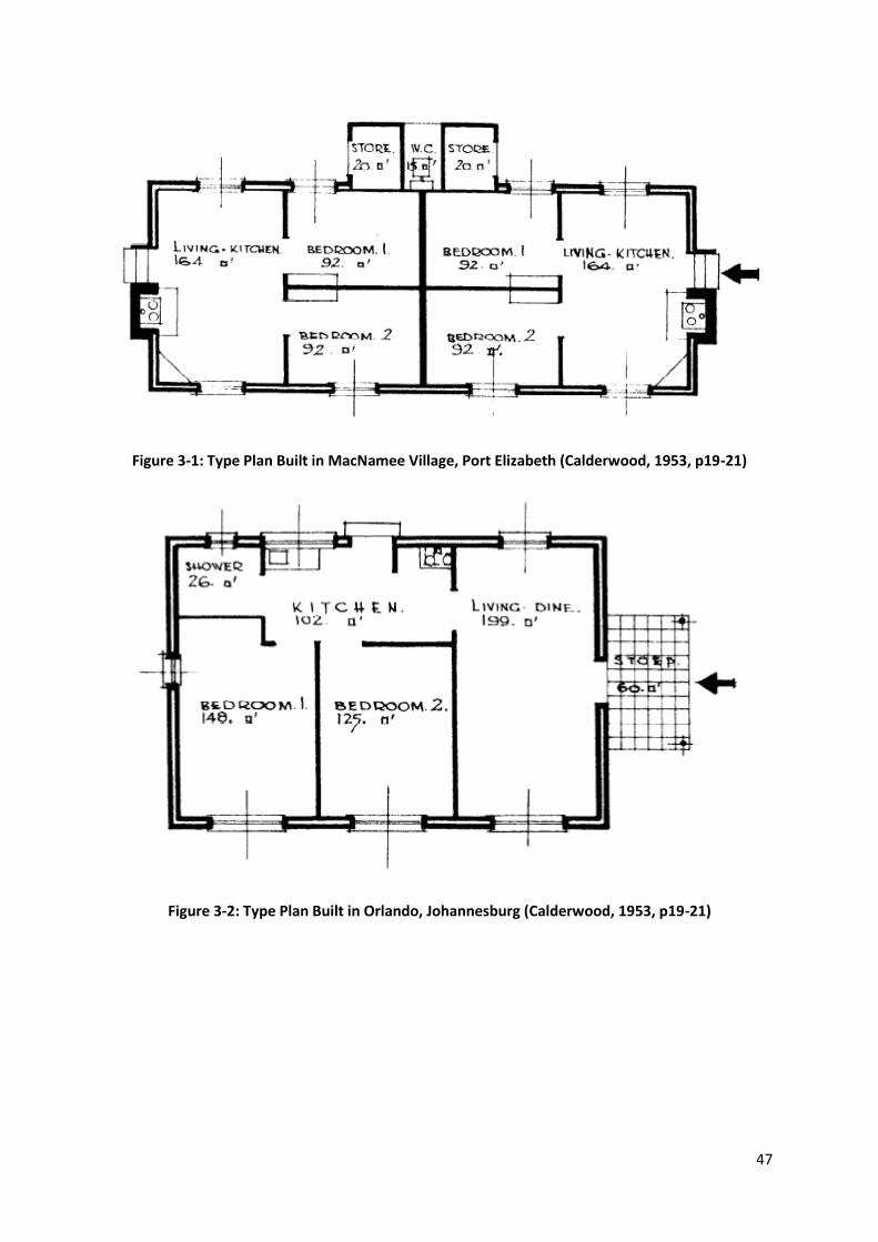
47
Figure 3-1: Type Plan Built in MacNamee Village, Port Elizabeth (Calderwood, 1953, p19-21)
Figure 3-2: Type Plan Built in Orlando, Johannesburg (Calderwood, 1953, p19-21)

48
Figure 3-3: Type Plan Built in Sharpe Township, Vereeniging (Calderwood, 1953 p19-21)
When selecting a layout for low-cost housing, it is essential to ensure that all basic
needs of people are met in such a small space. This incorporates protection to
people against weather conditions, crime and other such elements. However, the
main challenge is providing a flexible plan which can satisfy people’s needs at
present as well as for future generations (Calderwood, 1953). Social design is
important as demands of people are constantly changing and acceptance by society
is important to ensure that the project/prototype is effectively implemented. The
design needs to be simple to ensure that all costs are minimised, but also to allow for
adaptiveness. This may be in the form of design, construction materials or methods.
Another field that is extremely important in the housing construction industry is that
of site selection. Site selection has direct bearing on the success of a project. The
type of environment established and developmental costs vary considerably, with
different sites. When selecting a site, the following aspects need to be taken into
consideration: zoning, health, transport, job opportunities, services, topography, soil
conditions, social survey, area and shape of the site and the cost of the land

49
(Calderwood, 1953). For many low-cost housing programmes, choice in site is
limited, but these areas can still be explored in improving the existing site.
3.2. Design Selection
The currently implemented low-cost housing scheme in South Africa is RDP
(Reconstruction and Development Programme) housing. This housing project has
proven to be unsuccessful and has created considerable outcry amongst
communities. The sizes of the houses range from approximately 36-45 square
metres (City of Johannesburg, 2008) and cost between R50000 and R70000 to
construct (SAPA, 2011). The aim of this research is to provide a house for people
which is more spacious and environmentally friendly, while still being competitive in
the cost market.
When selecting a layout and shape, the major aim is to optimise costs and space.
The most efficient shape for housing is a square one. Even though this shape
appears to be smaller than a rectangular one, it is in fact the optimal solution to
provide maximum space.
It is difficult to cut down on construction costs, particularly in the low-cost sector, so it
is important to perform a general cost breakdown to establish which area uses up
majority of the funds. Two sources, Taylor (2011) and Braxton (2013), discuss the
cost breakdown when constructing a typical house. They found that approximately
25 percent of the funds are spent on the roofing system. In some instances, as much
as a third of the costs were used for roof construction (Minke, 2000). Thus, this
indicates that the roof is the most economically sensitive area in a house. Walls are
found to be the least sensitive, as they can be constructed using almost any
material. Services and finishes are the areas which utilise the most funds and are
variable depending on the extent of finishing required.
The typical roofing system is trusses and tiles, or in the case of low-cost housing,
sheet metal. Both of these solutions are impractical as the cost is either too high or
the quality too low. However, even though there are many options in the roofing
sector, none of these provide a cheap and structurally effective solution. Within the
low-cost housing sector, it is extremely common that people make use of corrugated
50
steel as a roofing material. This solution is not sustainable, however cheap. Some of
the major problems highlighted with this form of roofing include poor thermal
properties, high maintenance costs due to poor resilience to weather and noise
created during rain or hail. Rhyner et al. (1998) found that there are major energy
savings when constructing with curved forms. There is an approximate energy
saving of 22% when using curved instead of flat roofs.
Thus, a new option needs to be considered in the low-cost housing sector, which will
keep costs at a minimum, improve structural performance, resilience and thermal
efficiency. Thin shells have proven to be an extremely economical and structurally
exceptional solution. Therefore, the concept of designing a square household with a
vaulted roof was created. These structures have the ability to span very large areas
and have been found to be the most economical means of construction. A vaulted
roof would create more space, while simultaneously keeping the costs at a minimum,
as only a single layer of bricks are required. However, the shape of the vault is an
essential aspect in the structural success of the solution.
Talocchino (2005) did considerable research in form finding and identifying the ideal
shape. During his investigation, he stated that the catenary was in fact the best
structural shape as it eliminated all forces except for compressive forces, but it had a
high level of wasted space (Talocchino, 2005). This is essential when considering
low-cost housing solutions, as space is minimal and needs to be optimised to its best
ability. However, the difference between the two investigations is that Talocchino’s
made use of thin shells for the entire structure while the proposed design uses them
as the roof structure.
Both housing ideas are extremely innovative. However, a vaulted roof and standard
lower floor is a combination of both current and novel design methods, and thus
more likely to be socially accepted. The lower level is designed as an ordinary
house, while a vaulted roof allows for more space within the structure. Therefore, a
catenary vault is selected to act as the roof structure. If the roof is constructed at a
very steep angle, there is minimal space wastage as the upper floor can be utilised
and minimal dead space is created. It is also important to consider furniture within a

51
house, i.e. fridge, cupboards, beds, etc. By creating a square lower level, this allows
for no loss of space whilst still minimising construction costs with the construction of
a vaulted roof.
A number of other areas were also considered in the selection of the design, but
most importantly, the ability for this prototype to act as a home. Even though this is a
low-cost housing solution, it is still important that it exhibits homely characteristics to
ensure social acceptability and an overall approval from society.
Low-cost houses are extremely cramped. Unfortunately this is inevitable and thus it
is important to create a sense of space, even if there isn’t much. The idea of
maximising on space with a high roof was also justified when it was decided to
create a double volume area. The high roof would allow for more air and light to
penetrate the house and in turn create this desired sense of space. A general design
was selected (Figure 3-4) and an analysis was performed to ensure that the design
is a structurally viable solution.

52
Figure 3-4: Layout of housing prototype
The general layout of the housing prototype is illustrated in Figure 3-4, while the
selected internal layout is shown in Figure 3-5 below. The internal layout is
orientated so that the lounge and bedroom face eastwards, thus maximising on
morning sun. The upper floor space is utilised as a bedroom that is not generally
found in typical housing designs. This space was selected to maximise on the
number of residents per house without creating a sense of overcrowding.
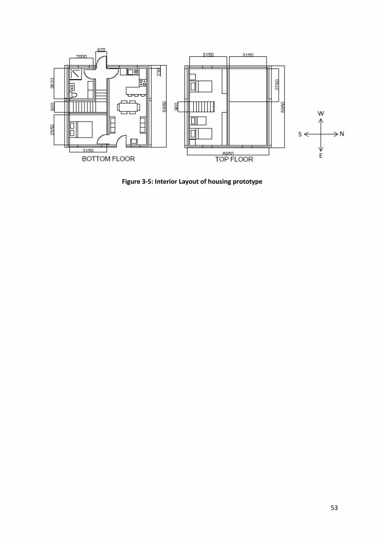
53
Figure 3-5: Interior Layout of housing prototype

54
4. Materials Investigation
Majority of houses in South Africa are built using ordinary clay or cement bricks.
Even though these materials are very cheap, they are not a sustainable solution as
they are environmentally harmful, particularly in the production phase. Transport is
also a major concern when it comes to rural construction. Transporting the materials
to site is expensive and difficult, creating major unnecessary cost increases. Thus, it
is necessary to consider other more sustainable options. In this section, we will
discuss the material properties that are required when constructing a low-cost house.
In particular, Hydraform produced cement stabilised earth bricks will be analysed. A
thorough investigation into Hydraforms material selection, testing and brick
production will be discussed.
4.1. Introduction
Cement Stabilised Earth Bricks (CSEB) are a relatively new material in the
construction industry, showing its face for the first time in the 19th century in Europe
(Auroville Earth Institute, 2012). Since then, the concept has rapidly grown in
popularity and its various uses can be seen throughout the world. The use of soil as
a building material has been investigated extensively before it was able to compete
with the current cement bricks. A major problem with soil is that it lacks strength and
durability. However, after continuous research and testing in stabilisers, compression
machines and material studies, CSEB has improved drastically. Today, the CSEB is
able to compete with conventional bricks in terms of performance and cost, where
savings are approximately 18% (Uzoegbo & Hobona, 1999). Rhyner et al. (1998),
found that the insulation properties of these bricks are excellent and a 33% saving in
electrical energy is possible.
Although CSEB have many favourable properties, there have been many debates
regarding their appropriateness. They are generally perceived as inferior, due to the
lack of standards in the construction industry, as well as social unacceptability,
primarily with people with low income. CSEB also has a poor reputation, and
assumed to be weak in compressive strength.

55
However, Houben & Boubekeur (1998) found that these bricks have sufficient
strength to construct a two to three storey buildings. Since 1998, there has been
considerable ground breaking work in the production and use of CSEB. Hydraform, a
leading brick and block making Machine Company, are achieving compressive
strengths of as high as 10MPa. These strengths are considerably higher than what is
needed for the construction of a simple house.
Hydraform have put a foot in the door with their innovative and affordable brick
machines worldwide. They have proved that the CSEB, if made properly, is just as
effective and durable as the current cement bricks. The dry-stack interlocking block
has also reduced construction speeds by approximately half, with its quick and
efficient stacking system. The other block that is used in the construction of this
prototype house is the Hydraform splitter-brick block.
4.2. Production process
The materials, mix ratios and other specifications in the production of these bricks
can be found in the Hydraform training manual (2012). A two week research
programme at the Algerian research facilities, CNERIB, was completed during the
duration of the project. Research, tests and investigation into various materials were
performed. Bricks were produced and various tests were carried out to investigate
their strength and durability. This section covers the general method of producing
CSEB. The information provided is a combination of Hydraform methods, as well as
the research and work experience obtained in Algeria.
4.2.1. Soil Selection
In order to achieve the best blocks, it is important to ensure that the correct soil is
used in the production process. The type of soil is particularly important in ensuring
that the correct strength is achieved. Hydraform use a sandy-loam soil, found at least
1m below the ground, which contains more sand than clay and fines, and no organic
material (Hydraform, 2012). Auroville Earth Institute (2012) stipulates that no top soil
may be used due to having a high content of organic matter. Correct amounts of
both clays and sands are important, as the clay improves the bricks workability while
the sand is the binder which essentially provides the strength. This is not always

56
possible as soils vary considerably at different sites. When one considers that the
aim of this project is to establish a housing solution, which can be implemented
anywhere, a soil selecting guide is of utmost importance in ensuring that the most
suited soil in the area is found and used. Hydraform (2012) provides a guide that
helps the user to locate the most suitable soil at a perspective site. The three most
important considerations when selecting a soil include: finding a well-graded soil
(clay content ranging between 15% and 35%) and a soil that is free of roots, leaves
or any other organic material (Hydraform, 2012).
There are a number of field tests which can be done to check the adequacy of the
soil, i.e. the visual test, the wash test, the jar test and the shrinkage test. Each of
these tests have different indicators which determine the quantity of clay and sand
present in the mix. (Hydraform, 2012)
4.2.2. Mix ratios
Mix ratios for block production vary depending on the required strength. The blocks
used in this project are 10MPa in strength. For this strength a general mix ratio for
cement to soil is 1:8. This strength is sufficient to support a double storey building.
The colour of the blocks will vary according to the type of soil that is used and can be
modified with the use of cement dyes (Hydraform, 2012) or oxides.
Hydraform (2012) provides a valuable site guide in measuring the correct mix ratios.
By using a wheelbarrow, an accurate material mix is established with minimal effort,
e.g. one bag of cement (50kg) mixed with four wheelbarrows (65L each) produces a
10MPa block. This is extremely effective, since simplicity is crucial in low cost
projects.
There are many advantages associated with CSEB. However, there is one area in
which these materials suffer from durability issues. Durability is an aspect in which
CSEB are lacking. Since the blocks are predominantly made up of soil, they are
affected by water. There has been considerable research in water proofing the
blocks with various additives. In the blocks made by Hydraform, a chemical called
Pareflo is used. Pareflo is added into the mix, prior to production. This chemical acts
as a water repellent without affecting the mechanical strength of the block (Chryso,

57
2008). Pareflo has improved the material durability, but it has also been found to be
environmentally sustainable (Chryso SA, 2012).
4.2.3. Production
The production process of the bricks and blocks is very simple. First, the material is
sieved to ensure any unwanted particles are removed. A 8-10mm sieve can easily
be made on site by using local materials to create a frame and some mesh.
Secondly, the desired mix ratio is determined and the materials are mixed together
while slowly adding water. It is important that the correct clay content is achieved
otherwise the soil will be difficult to handle. The soil should have a clay content
between 15 and 35 percent. The clay content can be determined using a number of
tests; i.e. visual test, jar test, wash test, etc., but the most accurate is the shrinkage
test. By measuring the shrinkage of the soil in a mould, the clay content can be
determined. The soil-cement mix is mixed either by hand or by using a pan mixer.
The mix is determined by the material volume (Hydraform, 2012).
The mix is then checked to ensure it has the correct moisture content. A drop test is
used to establish whether more water or soil/cement mix needs to be added (Figure
4-1). The water content can also be checked by producing a block and observing
any cracking or changes in block length that may occur. A short, wet block with
cracks indicates too much moisture. While a very dry mix will produce a long, brittle,
unworkable block. The water content required depends on the moisture content of
the soil but is usually approximately one litre per block. However, sometimes the
water content is correct but the blocks still vary in length. This can be due to
insufficient material being poured into the chamber, or the operator is not allowing
the machines to complete the full compressive action before removing the bricks
from the chamber. Thus, it is necessary that the machine operators have sufficient
training so that the blocks produced are of good quality.
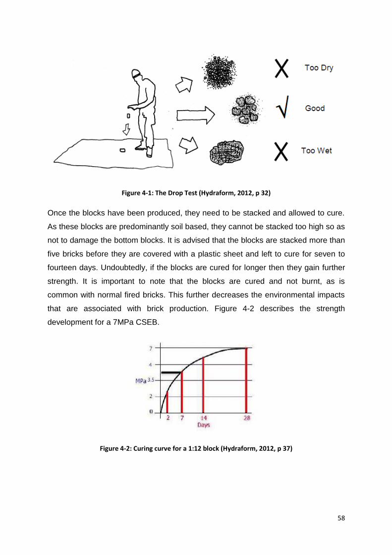
58
Figure 4-1: The Drop Test (Hydraform, 2012, p 32)
Once the blocks have been produced, they need to be stacked and allowed to cure.
As these blocks are predominantly soil based, they cannot be stacked too high so as
not to damage the bottom blocks. It is advised that the blocks are stacked more than
five bricks before they are covered with a plastic sheet and left to cure for seven to
fourteen days. Undoubtedly, if the blocks are cured for longer then they gain further
strength. It is important to note that the blocks are cured and not burnt, as is
common with normal fired bricks. This further decreases the environmental impacts
that are associated with brick production. Figure 4-2 describes the strength
development for a 7MPa CSEB.
Figure 4-2: Curing curve for a 1:12 block (Hydraform, 2012, p 37)

59
When building, in a barren rural area, it is important to consider the water
requirements of the blocks. There needs to be access to water, or sufficient water on
site, to ensure that the blocks can be constructed and that enough water is available
for curing. Generally the latter of the two is overlooked. And, if the blocks are not
cured properly, then they may not gain their required strength.
4.2.4. Problems in production
There are many challenges in the production phase of the building materials. A
major one is a lack of training in the use of the machines, resulting in the production
of poor quality blocks. This also includes the lack of expertise in maintaining the
machinery, which is demonstrated when blocks with rounded edges or reduced
interlocking are produced.
Inadequate mix ratios are an even more common challenge in block production and
are likely to occur. This includes having too much or too little water, and having
cement or soil in the mixing step. Inadequate mix ratios result in problems such as
rough surfaces, cracks in the block and varying block dimensions.
4.3. Material properties
Hydraform are the current leaders in the production and testing of CSEB blocks in
South Africa. Hydraform (2012) performs a number of tests to ensure that the
necessary compressive strength is achieved. Thus, a simple compression test is
performed throughout the production phase to provide a rough estimate of the
strength of the bricks and blocks. This test is not as accurate as laboratory tests, but
it is designed to give a rough estimate to ensure that the mix is sufficient. The block
tester consists of a simple device that utilises a jack and gauge to obtain the failure
compressive strength of the produced bricks. Such a test is vital when working and
producing blocks on site, if there is no access to sophisticated laboratory tests.
Material properties of CSEB blocks obtained from various literature and for different
experiments are summarised in Table 4-1.

60
Table 4-1: Material properties of CSEB
Property Hydraform Auroville Wits University
Density (kg/m³) 1950 1900-2200 1900-1950
Poisson’s ratio - 0.15-0.35 0.2
28 Day Compressive
Strength (MPa) 7-10 5-7 5-5.4
28 Day Tensile
Strength (MPa) ~1.1 1-2 1.18-1.4
Youngs modulus
(MPa) - 700-1000 3500
Thermal
conductivity/coefficient
of thermal expansion
(mm/m°C)
- 0.01-0.015 -
The reported values were obtained from Auroville Earth Institute (2012), Magaia
(2003) and Fernandez (2003) from Wits University, and publications and testing from
Hydraform.
The two blocks that are utilised in this project are the Hydraform dry-stack
interlocking block and the Hydraform Splitter-brick Block. The dry stack block is used
to speed up the construction process and minimise costs. The splitter brick block is
used in the vault due to its relevant size and to ensure that a strong joint is created
between the bricks. This is attributed to the grove in the brick, allowing it to act as a
key between each layer.
4.3.1. Dry-stack interlocking Blocks
Dry-stack interlocking blocks have proven to be one of the most ingenious inventions
since the introduction of CSEB. Hydraform makes these blocks so they are almost
identical to standard clay bricks in terms of strength, while also possessing many
more added benefits. They can be produced from either soils or recycled material
and still achieve a very high compressive strength.

61
Many benefits have been noted when changing from standard brick-mortar
construction to dry-stack interlocking construction. It is common for a house to be
constructed with double brick, connected with mortar. However, Hydraform have
managed to eliminate the need for any mortar by merely interlocking the blocks. This
results in considerable cost and time savings, as construction is quick and efficient.
These bricks also provide a lovely face brick finish, eliminating the need for plaster.
These blocks are particularly effective in walls and other vertically loaded structural
members. Since they are dry-stack, they can only support nominal horizontal forces.
The blocks, however, can be used like conventional mortared bricks if they are
required to carry horizontal forces. In this case, the user would still have cost savings
as the mortar required would be approximately three quarters of that required for
double brick, because there are a smaller number of joints and no centre joint.
All the interlocking bricks used in this project are 10MPa in compressive strength,
after 14 days of curing. A 1:8 mix ratio is used to achieve this strength. Hydraform
provide a number of machines and moulds to satisfy the various sizes of required
blocks. The block dimensions used in the production of the low-cost house are
presented in Figure 4-3 and an image of the final product in Figure 4-4.
Figure 4-3: Dimensions of the dry-stack interlocking block

62
Figure 4-4: The Dry-stack Interlocking Blocks used in the construction of the prototype
4.3.2. Splitter-Brick Block
The current splitter-brick block is a single block which splits up into three separate
normal sized bricks as shown in Figure 4-5.
Figure 4-5: Image of the split-brick block that separates into 3 individual bricks (Hydraform, 2012,
p 53)
A problem with this type of block is that the central piece has two rough sides as
opposed to the outer ones which have one each. This is generally undesirable as
most users are looking for a smooth finish rather than a rough one. The middle brick
is usual disposed of due to its undesired look. This results in considerable wastage
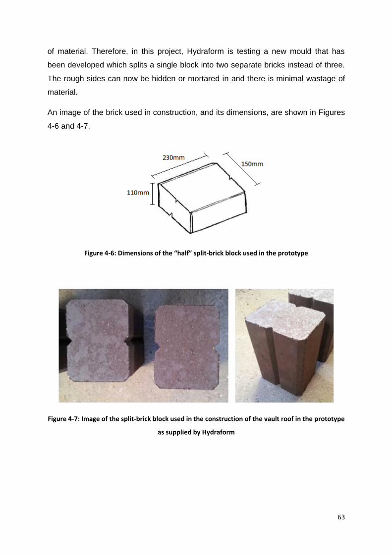
63
of material. Therefore, in this project, Hydraform is testing a new mould that has
been developed which splits a single block into two separate bricks instead of three.
The rough sides can now be hidden or mortared in and there is minimal wastage of
material.
An image of the brick used in construction, and its dimensions, are shown in Figures
4-6 and 4-7.
Figure 4-6: Dimensions of the “half” split-brick block used in the prototype
Figure 4-7: Image of the split-brick block used in the construction of the vault roof in the prototype
as supplied by Hydraform

64
5. Method of Analysis for a Catenary Curve
5.1. Introduction
“The ideal shape for resisting loads distributed uniformly along a surface is a
catenary, the curve taken under its own weight by a hanging chain or cable” (Allen &
Zalewski, 2010, p. 65)
The process of designing and analysing a catenary curve is a field which has not
been extensively explored or discussed. Allen & Zalewski (2010) briefly discuss the
method of design using Hooke’s Law and then elaborate on the Graphical Method of
design. Catenary curves are the most natural and efficient form, yet they are not
utilised or explored as much as they should be. If a simple and effective method of
designing a catenary curve can be established, the curve can be utilised at a greater
scale, encouraging more efficient and structurally sound design.
5.2. Mathematical definition
The catenary curve equation was established in the 17th century by Huygens,
Bernoulli and Leibniz (Carlson, 2013).
Mathematically, it is defined by the following equation:
(
) (5-1)
Where ‘x’ represents the vertex when x=0, and ‘a’ is a parameter that can be any
number except zero, and controls how rapidly the curve “opens up”. The parameter
‘a’ can also be described as the scaling factor for the curve. (Weisstein, n.d.)
This mathematical representation of the curve is ineffective in design as it fails to
take variable loading into account. The equation merely describes the shape of the
curve and the relationship between its ‘x’ and ’y’ variables.
5.3. The Graphical method
The Graphical method is a method of approximation which is carried out by
assuming a curve and then working backward to establish the actual, true curve. The
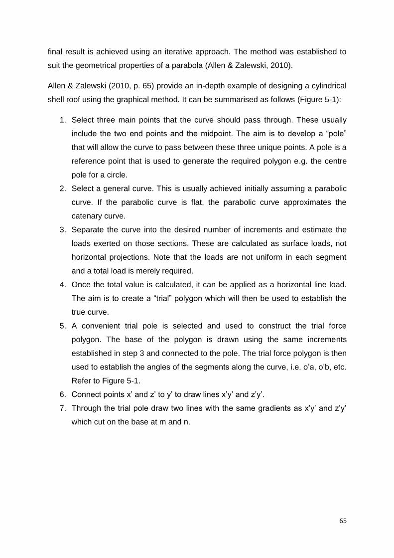
65
final result is achieved using an iterative approach. The method was established to
suit the geometrical properties of a parabola (Allen & Zalewski, 2010).
Allen & Zalewski (2010, p. 65) provide an in-depth example of designing a cylindrical
shell roof using the graphical method. It can be summarised as follows (Figure 5-1):
1. Select three main points that the curve should pass through. These usually
include the two end points and the midpoint. The aim is to develop a “pole”
that will allow the curve to pass between these three unique points. A pole is a
reference point that is used to generate the required polygon e.g. the centre
pole for a circle.
2. Select a general curve. This is usually achieved initially assuming a parabolic
curve. If the parabolic curve is flat, the parabolic curve approximates the
catenary curve.
3. Separate the curve into the desired number of increments and estimate the
loads exerted on those sections. These are calculated as surface loads, not
horizontal projections. Note that the loads are not uniform in each segment
and a total load is merely required.
4. Once the total value is calculated, it can be applied as a horizontal line load.
The aim is to create a “trial” polygon which will then be used to establish the
true curve.
5. A convenient trial pole is selected and used to construct the trial force
polygon. The base of the polygon is drawn using the same increments
established in step 3 and connected to the pole. The trial force polygon is then
used to establish the angles of the segments along the curve, i.e. o’a, o’b, etc.
Refer to Figure 5-1.
6. Connect points x’ and z’ to y’ to draw lines x’y’ and z’y’.
7. Through the trial pole draw two lines with the same gradients as x’y’ and z’y’
which cut on the base at m and n.

66
Figure 5-1: The graphical method (Allen & Zalewski, 2010, p 76)
8. At the true curve, connect the end points to the midpoint creating lines xy and
yz. These are the true closing strings. Through point’s m and n, draw lines of
the same gradients as xy and yz. Their intersection creates the real, final pole.
9. New rays are drawn from final point o to the respective base points a to k. The
rays are used to determine the angle of each segment oa to ok and the true
curve is determined.
This method has been found to be accurate in determining the internal forces of any
structure and it works well for vertical loads. The method is, however, labour
intensive and complex when dealing with a form other than the parabolic form (Allen
& Zalewski, 2010). There is considerable difficulty in modelling and analysing
horizontal forces when using the graphical method. There is little guidance in
designing and modelling complex lateral forces such as wind or snow. Allen &
Zalewski (2010) suggest that this method not be used when modelling such complex
shapes, particularly under lateral loading, but to rather design an approximate shape

67
and then stiffen the curve to provide resistance to these forces. Otherwise, a new
method needs to be explored.
5.4. Segmental Equilibrium Method
5.4.1. Introduction
In the 1670’s, a Scientist by the name of Robert Hooke expressed considerable
interest in catenary curves and how they work. His aim was to determine the ideal
shape of an arch. With this in mind, Hooke established that the inverted catenary
was the ideal shape for an arch. He also stated that if an arch of another shape is
effective, it is merely because somewhere in the thickness of the membrane, a
catenary can be found (Huerta, 2006).
Hooke performed most of his experiments using hanging chain models. When
analysing the models more closely, Hooke found that in order for the hanging chain
to be in pure tension, and therefore the inverted arch to be in pure compression, both
have to be in equilibrium. Thus, Hooke’s principle was born (Allen & Zalewski, 2010).
The graphical method struggles to incorporate any lateral forces, due to the
complexity of the method. It is important to establish a mathematical method which
incorporates both horizontal and vertical forces i.e. the segmental equilibrium
method.
5.4.2. Theoretical basis
The equilibrium method is a mathematical method which utilises the loading on the
structure to establish the thrust line of the curve. The line of thrust is a representation
of equilibrium within the structure. It can be described as “a theoretical line that
represents the path of the resultants of the compressive forces through the structure”
(Allen & Zalewski, 2010, p. 219).

68
Figure 5-2: Hanging chain with its inverted form and corresponding thrust line through the
thickness of the curve ( Allen & Zalewski, 2010, p 220)
Figure 5-3: All internal and external forces applied to each segment, in equilibrium (Allen &
Zilewski, 2010, p 220)
Figures 5-2 and 5-3 demonstrate how equilibrium is used in each section to
determine the overall thrust line of the structure. Each individual segment is
analysed, incorporating all the forces and loads exerted on it. The arch is held in
place by the compressive forces, applied from one block to the other. Since we know
that each block carries the compression force exerted by blocks on either side of it,

69
they can be combined with the external loads, as well as its’ self-weight to determine
the line of thrust of the structure (Allen & Zalewski, 2010).
If the equilibrium line, i.e. the thrust line, extends to the edge or outside of the
thickness of the material, tensile forces are created which result in cracking, and
possibly failure. If the thrust line reaches the edge cracking will occur, or in some
instances hinges will form, as high stresses are created at those particular points
(Figure 5-4).
Figure 5-4: (a) Maximum and minimum thrusts lines within the vault, (b) Minimum thrust lines and
(c) maximum thrust lines can cause cracking in the vault (Allen & Zalewski, 2010, p 221)
5.4.3. The Middle-Third concept
There are a number of ways to analyse the design results of a catenary. The more
effective method is that of the middle third. This consists of choosing a constant
thickness for the vault and checking that all the thrust lines, for the various load
cases fall within the middle third of the section. This method was chosen as the

70
thickness of the CSEB remains constant throughout. Majority of the vaults that have
been built are made from either concrete or bricks. Both of these materials have
minimal tensile strength. If the thrust line falls within the middle third of the section,
the material will be in compression. However, if the thrust lines move out of the
middle third, those areas will be subjected to tensile forces and cracking may occur
(Allen & Zalewski, 2010). The aim is to avoid any tensile forces, since most masonry
materials are not designed to carry these forces effectively. The middle-third theory
is substantiated as follows:
(5-2)
and the section width=1
Solve for σ=0
e is only half of the middle third
(5-3)

71
5.4.4. Method of Design
The segmental equilibrium method of design is a new method of determining the
shape of a catenary shell. Not only is the method computerized but incorporates
complex loading arrangements, such as wind and non-symmetrical gravity loads. It
must also be noted that the finite element methods are used to analyse a pre-
determined shape. The segmental equilibrium method determines the shape, as well
as the membrane forces (i.e. thrust line). This method is easily set up in Excel and
allows for analysis and design of catenary curves. A step-by-step explanation of the
method is provided.
1. Begin by inputting all the necessary material properties. These include density
and Youngs modulus.
2. Pick a set of general dimensions for the structure, including the height and
width of the curve. It is important to have some idea of the size of the curve
that is desired. The solution is iterative and therefore these dimensions will
change slightly throughout the analysis. If the desired curve is flat, the user
may estimate the shape of the curve using a parabolic equation.
3. Input the length of barrel vault you wish to design. It is simplest to pick a 1m
length, a segment which represents the length of the shell.
4. Select an initial segment size. The segment height is not necessarily a true
reflection of the actual segment height, but rather a segment height so that
the coordinates of the curve can be calculated. The shorter the segment
height, the more segments, but the more accurate the curve will be. The
height can be an arbitrary value or it can represent the size of the brick and
mortar joint.
5. Select an initial angle at the reaction. This angle is the starting angle at the left
hand base of the shell. This angle is depicted in Figure 5-5. The angle of the
reaction is also the angle at the base of the shell.
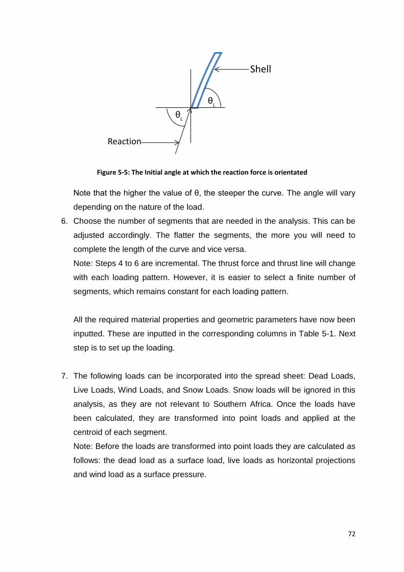
72
Figure 5-5: The Initial angle at which the reaction force is orientated
Note that the higher the value of θ, the steeper the curve. The angle will vary
depending on the nature of the load.
6. Choose the number of segments that are needed in the analysis. This can be
adjusted accordingly. The flatter the segments, the more you will need to
complete the length of the curve and vice versa.
Note: Steps 4 to 6 are incremental. The thrust force and thrust line will change
with each loading pattern. However, it is easier to select a finite number of
segments, which remains constant for each loading pattern.
All the required material properties and geometric parameters have now been
inputted. These are inputted in the corresponding columns in Table 5-1. Next
step is to set up the loading.
7. The following loads can be incorporated into the spread sheet: Dead Loads,
Live Loads, Wind Loads, and Snow Loads. Snow loads will be ignored in this
analysis, as they are not relevant to Southern Africa. Once the loads have
been calculated, they are transformed into point loads and applied at the
centroid of each segment.
Note: Before the loads are transformed into point loads they are calculated as
follows: the dead load as a surface load, live loads as horizontal projections
and wind load as a surface pressure.
θL
θL
Shell
Reaction

73
8. The following ultimate load cases are investigated, according to the loading
code SABS 0160-2 (2009):
1.5*Dead Load
1.2*Dead Load + 1.6*Live Load
1.2*Dead Load + 0.5*Live Load + 1.3*Wind Load
0.9*Dead Load + 1.3*Wind Load
9. Now set up your spread sheet (Table 5-1). The following headings are
recommended, but can differ depending on the user and what is required in
the calculations.
Table 5-1: The spread sheet layout for the equilibrium method (Figure 5-6)
Segment
No.
Height
of
Segment
Weight Left
Angle
Left
Thrust
x
Left
Thrust
y
Left
Thrust
Resultant
Right
Thrust
x
Right
Thrust
y
Right
Thrust
Resultant
Right
angle
Co-
ordinates
X Y
10. The first step is to calculate the actual shape of the curve. Therefore, only
gravitational forces are taken into account.
Assumption: The thrust line established from the self-weight is the centre line
of the curve.
When applying live and wind loads at a later stage, the same analysis process
applies.
Figure 5-6: A diagram illustrating the meaning of each heading in table 5-1
Segment height
Weight
Left Thrust
Right Thrust Right Angle
Left Angle
Centroid
Segment

74
11. The gravitational loading is applied as a point load at the centroid of each
segment. At this moment, all the loading is constant and vertical, inputted in
the column labelled weight. This value will vary with the various loading
combinations and patterns. Each segment is loaded individually.
12. Columns marked Segment no., Height of Segment and Left Angle consist of
the values chosen in steps 4 to 6.
13. The first force, Left Thrust y, is now calculated. The first and last vertical
reactions are merely the total weight divided by two as the curve is
symmetrically loaded. This can also be calculated through equilibrium
equations such as ∑M=0.
14. Now Left Thrust x and Left Thrust Resultant can be calculated. This is done
through the use of trigonometry as depicted in Figure 5-7.
Figure 5-7: Trig is used to obtain the remaining components of the Left Thrust y Force
15. From here the Right Thrust x, Right Thrust y and Right Thrust Resultant are
calculated. These forces are calculated at the centroid of the segment and
therefore the loading on the segment is incorporated into these calculations.
The following equilibrium equations are used in this step: ∑Fy=0 and ∑Fx=0.
This is applied as follows:
∑ (5-4)
Left Thrust y
Left Thrust x
Left Thrust
θL

75
And
∑ (5-5)
When other loads are analysed, they are also applied at the centroid of the
segment and the different loading components need to be added correctly into
the above equations (Figure 5-8).
Figure 5-8: Equilibrium at the centre of the segment, combining internal & external forces (Allen &
Zilewski, 2010, p 220)
16. The Right Thrust is now calculated using Pythagoras theorem.
17. The new angle for the next section of the thrust line is calculated using
trigonometry as demonstrated in Figure 5-7.
18. Lastly, the co-ordinates are calculated. Each co-ordinate represents the
centroid of each segment EXCEPT for the first and last co-ordinates. Co-
ordinate (0,0) is NOT the first co-ordinate established. This point is a selected
point of axes from where the curve is chosen to begin and is manually
inputted by the user. The first calculated co-ordinate is at the centroid as seen
in Figure 5-9. Since the calculated co-ordinates are representing the centroids
of the segments, the very first and last co-ordinates are inputted to ensure
that the extra length of structural segment is also depicted in the curve.
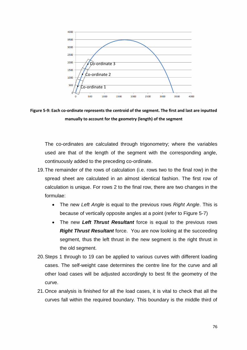
76
Figure 5-9: Each co-ordinate represents the centroid of the segment. The first and last are inputted
manually to account for the geometry (length) of the segment
The co-ordinates are calculated through trigonometry; where the variables
used are that of the length of the segment with the corresponding angle,
continuously added to the preceding co-ordinate.
19. The remainder of the rows of calculation (i.e. rows two to the final row) in the
spread sheet are calculated in an almost identical fashion. The first row of
calculation is unique. For rows 2 to the final row, there are two changes in the
formulae:
The new Left Angle is equal to the previous rows Right Angle. This is
because of vertically opposite angles at a point (refer to Figure 5-7)
The new Left Thrust Resultant force is equal to the previous rows
Right Thrust Resultant force. You are now looking at the succeeding
segment, thus the left thrust in the new segment is the right thrust in
the old segment.
20. Steps 1 through to 19 can be applied to various curves with different loading
cases. The self-weight case determines the centre line for the curve and all
other load cases will be adjusted accordingly to best fit the geometry of the
curve.
21. Once analysis is finished for all the load cases, it is vital to check that all the
curves fall within the required boundary. This boundary is the middle third of
Co-ordinate 1
Co-ordinate 2
Co-ordinate 3
77
the thickness of the material (refer to section 5.5.3). The check is best done
by plotting the curves on the same set of axis as the middle third boundaries.
The middle third is drawn in the same way as the centreline however the
geometry is set and properties are adjusted to suit.
22. The final step in the design is to ensure that the material is capable of
supporting the curve. The maximum stresses from all analysed load cases are
obtained and compared to the materials strength capacity. If all the curves fall
within the middle third, then only the compressive strength need be
compared. If the curves fall outside of the middle third, then the tensile
strengths also need to be checked or the thickness of the shell increased. The
maximum deflections are also obtained for further design requirements.
5.5. Finite Element Method
Finite element method (FEM) is the most commonly used method in structural
design and is extremely effective, when used correctly. However, if the user is not
aware of its limitations, the results could be detrimental. In addition, designs which
require an in-depth mathematical understanding should generally avoid using FEM,
and the designer should rather consider a different approach in solving the problem.
Bathe & Chapelle (2011) provide an in-depth guide on how to analyse thin shelled
structures using finite element analysis. The thin nature and complexity of the curve
makes these structures difficult to model. Even though FEM is widely used, it was
initially designed to solve thin shells, as first principle methods were too complex
(Argyris, 1954).
When modelling complex structures, such as thin shells, there are a number of
‘rules’ that need to be followed. Subjects such as element size, element type, type of
analysis, constraints, etc. need to be carefully selected. The curves and geometry of
thin shells are the main aspects that make them very difficult to model.
There are a few points to take into consideration when modelling thin shells to
ensure that the results achieved are accurate. These include:

78
Sharp changes in geometry cause major discrepancies in the results. The
elements need to be smooth and continuous (Talocchino, 2005).
The shape should never be modelled using linear elements, but rather
quadrilateral or triangular. If quadrilateral elements are to be used, they need
to be either eight or nine node to improve accuracy.
All elements need to be orientated in the correct direction i.e. all elements are
created in a clockwise direction so that all the same faces face outwards.
Use as many elements as possible when meshing the model. This improves
the accuracy, as the elements are smaller. It also minimises the number of
linear, rigid sections as there are more points allowing for smoother changes
in geometry.
When modelling symmetrical objects, only small segments need be modelled
and not the entire object as long as the correct constraints are applied.
The assumptions made and process followed in designing this vault will be
discussed at a later stage.

79
6. Structural Analysis and Design of Catenary Vaults
6.1. Introduction
In this chapter, the segmental equilibrium method will be applied to design the
catenary vaults of the prototype structure. All analysis will be performed as well as
an investigation into a case study situated in South Africa. This section will focus on
the roof structure and the adequacy of this method in structural design. The shape of
the structure, as discussed in Chapter 3, is a square structure with two vaulted
sections acting simultaneously as the roof and upper storey.
The loading is designed in accordance with SABS 0160 (2009). All finite element
analysis done for both the case study and actual design are carried out in LISA
version 7.7.1, a finite element programme. The results of the FEA analysis and
equilibrium method are compared to check the accuracy of the results.
6.2. Case study: Bapong
6.2.1. Introduction
Bapong is a township situated just off the R556 en route to Sun City in North-West
province, South Africa. The case study consists of a series of vaulted structures that
have been abandoned, located on the end of a school property. They are unique in
shape and have made use of the catenary vault in its design (Figures 6-1 to 6-3).

80
Figure 6-1: Bapong case study location: image obtained off Google Earth
Figure 6-2: Bapong township, a set of abandoned structures

81
Figure 6-3: The abandoned structures are in impeccable condition even with no maintenance
A site visit was arranged to inspect these structures and assess their condition as
well as to highlight any major problems with their design and construction. These
structures have proved to be extremely durable and structurally efficient. They are
estimated to be approximately 20 years old with no apparent maintenance over the
years.
The structures showed minimal deterioration and minor cracking. However, along the
apex, or high point of the vaults, a crack had occurred, as seen in Figure 6-4. This
was recurring in all the roof structures and no certain cause for the cracking was
identified. Thus, a detailed finite element analysis was carried out to establish what
has caused the recurring cracking.

82
Figure 6-4: A crack occurs at the centre, or high point, of all the roof structures
In the structures, both buttresses and steel ties were present. It is not clear whether
the buttresses had a structural or aesthetic purpose. However, the steel ties are
structural elements used to restrain the horizontal thrust force exerted by the vault
(Figure 6-5).
Figure 6-5: Steel ties are present in the structure to restrain the thrust force
The shape of the roof is a catenary, and because of its shape the shell is in excellent
condition. This is a valuable case study which highlights the high level of
sustainability and durability of vault structures.

83
6.2.2. Finite Element Results
A finite element analysis was carried out to investigate the cause of the cracking in
the vaults. Various loading conditions were investigated. The shape was modelled in
LISA, a finite element programme. The elements used are nine noded shell
quadrilaterals. The end conditions are applied at the relevant nodes. It is essential
that these end conditions are accurate, as they will create major discrepancies in the
results if modelled incorrectly. The edges of the roof are connected to the end walls
and therefore pinned along the edges. It was also noted, at the site visit, that the
edges of the vault were tied in to the wall. This meant that all edges of the vault were
restrained, and thus all edges must be modelled as pinned connections (Figure 6-6).
Figure 6-6: All the edges of the vault must be restrained in all directions (i.e. pinned connection) due to its direct connection to the surrounding wall
The vault is subjected to live loads, wind loads and temperature loads.
The analysis was performed and it was found that temperature loading caused
considerable changes in stresses along the apex of the structure. This is due to the
vault being unable to expand or contract, as no expansion joint is present between
the vault and wall. This causes the structure to crack when it expands or shrinks as it
is unable to move freely, thus resulting in extremely high stresses at the edges.
Figures 6-7 and 6-8 are results of the analysis of two different loading combinations,

84
both including temperature changes, which show the distribution of stresses along
the vault. At the centre it is clear that there is a sudden change in stresses from
compressive to tensile, causing cracking in the vaults.
Figure 6-7: Results of the load case whereby the structure has a temperature loading along the left side of the vault
Figure 6-8: Results of a load case whereby the structure has a full wind load, temperature loading along the right side of the vault and a live loading along the left side of the vault
Note that positive values are tensile and negative values are compressive. Due to
the restraining of the edges of the vault, considerable tensile forces formed at the
apex, which caused cracking. Figure 6-7 shows that a tensile patch forms at the top
of the structure when it is under dead and temperature loads. Figure 6-8 shows a
clear change from compressive to tensile stresses along the apex of the vault. The
cracking of the vault can also be explained in conjunction with Figure 6-9. Figure 6-9
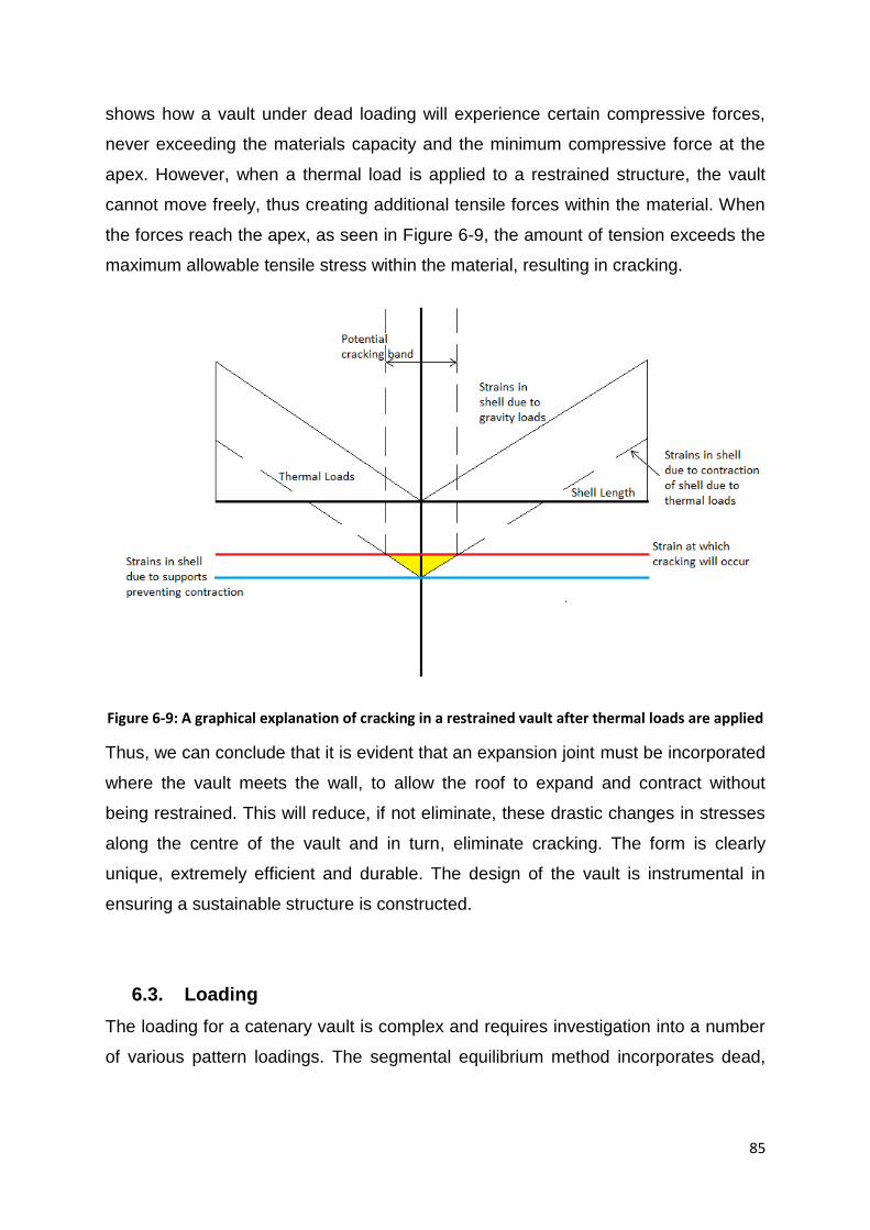
85
shows how a vault under dead loading will experience certain compressive forces,
never exceeding the materials capacity and the minimum compressive force at the
apex. However, when a thermal load is applied to a restrained structure, the vault
cannot move freely, thus creating additional tensile forces within the material. When
the forces reach the apex, as seen in Figure 6-9, the amount of tension exceeds the
maximum allowable tensile stress within the material, resulting in cracking.
Figure 6-9: A graphical explanation of cracking in a restrained vault after thermal loads are applied
Thus, we can conclude that it is evident that an expansion joint must be incorporated
where the vault meets the wall, to allow the roof to expand and contract without
being restrained. This will reduce, if not eliminate, these drastic changes in stresses
along the centre of the vault and in turn, eliminate cracking. The form is clearly
unique, extremely efficient and durable. The design of the vault is instrumental in
ensuring a sustainable structure is constructed.
6.3. Loading
The loading for a catenary vault is complex and requires investigation into a number
of various pattern loadings. The segmental equilibrium method incorporates dead,

86
live and wind loading. Temperature loading is usually analysed in finite elements, as
it is too complex to incorporate into the computerised equilibrium method.
Dead Load/Self-weight
The self-weight of the structure is the force exerted by the weight of the vault
materials, i.e. the loading that the structure is permanently supporting.
The dead load in this design consists of the materials within the structure.
Therefore, the material properties of the blocks, mortar, plaster, etc. are
included as dead loads. The load is calculated as a uniformly distributed load
(UDL) over the surface of the structure. The calculation of the dead load for
the vaulted roof is as follows:
The self-weight of both the block and plaster is calculated as follows:
Thus the dead load exerted on the structure is:
( ) ( )
Live loading
The live load is obtained from the loading code SABS 0160-2 (2009), and
applied in a number of pattern loading combinations on the structure.
The live loading selected in the design of the roof structure is for maintenance
and repair, i.e. an inaccessible roof load. The loading provided is a horizontal
UDL of 0.25kN/m², or a concentrated point load of 0.9kN applied over an area
of 1m².
Wind loading
The wind loading was done in accordance with SABS 0160-3 (2009). It is
calculated as a surface pressure over the different sections of the structure
and applied accordingly.
Considerable research has demonstrated that curved structures resist wind
loads extremely well. There is no official wind loading guide for catenary
87
curves; however, SABS 0160-3 (2009) addresses vaulted roofs and domes
and this method was applied to this project. In some instances, when the
vaults are extremely high, it is recommended to apply the same theory as you
would for a pitch roof (Blackmore & Tsokri, 2006). Thus, by combining both
theories, wind loading values are calculated and applied to the vaulted roof.
The construction of this structure is to occur in Johannesburg. The aim is to
apply this project as a low-cost housing solution, thus the structure will be
located in townships or other densely inhabited areas. The following wind
loading values are selected:
⁄ ( )
( )
Note: Class B is to determine forces on structural members as well as
resultant forces and overturning moments for structures which do not exceed
50m in any dimension. Category 3 is selected for closely spaced obstructions,
generally the size of domestic housing (i.e. fully or substantially developed
suburbs, industrial areas and towns).
Once these initial values are set, the steps as outlined in SABS 0160-3 (2009)
are followed so that all wind pressures applied over the structure are
calculated. In order to calculate an accurate wind pressure over the structure,
the wind speed multiplier, kz, will need to be adjusted to suit a 6m height. This
is done simply by interpolating the existing values in the 5-10m range.
A kz value of 0.654 is obtained and the wind pressure is calculated as follows:
[ ( )] (6-1)

88
[ ( )]
⁄
The external pressure coefficients, Cpe, are obtained from Figure 14 in SABS
0160-3 (2009, p37). The pressure distribution over a vaulted roof is
summarised as follows:
Figure 6-10: Wind distribution over a vaulted roof with a rectangular base (SABS 0160-3, 2009, p37)
The pressure over the surface of the vault is separated into quarters where
the first quarter has a pressure A, the second and third a pressure B and the
fourth a pressure C. It is important to note that Figure 6-10 represents positive
pressure values acting downward. Thus, all negative values are applied in the
opposite direction, i.e. acting upwards. The first vault’s Cpe values are
calculated as explained above. However, for the second vault, the values and
distribution changes slightly as stated by the multi-span roof wind theory in
Figure 13c, SABS 0160-3 (2009, p36).
The external pressure coefficients for the structure, for wind angles of 0° and
180°, are summarised in Figure 6-11.

89
Figure 6-11: External pressure coefficients for a multi-span vaulted roof
If the direction of the wind changes to 90°, two different pressure space
configurations are assessed.
If the vaults are assumed to behave in a similar manner as a duo-pitched roof,
a pressure distribution as described in SABS 0160-3 (2009) is applied as
follows (Figure 6-12):
Figure 6-12: Left - Wind pressure distribution as seen in SABS 0160-3 (2009, p 31); Right-The final external pressure values applied in the prototype as per code
The external pressure coefficients distribution for a curved roof, according to
Blackmore & Tsokri (2006), is presented in Figure 6-13. These curves do not
consider catenary vaults, but can be applied as a possible loading pattern.

90
There are no published codes or literature describing the exact wind
distribution on the surface of a catenary vault and therefore these various
scenarios are analysed to ensure the worst loading pattern is accounted for.
Figure 6-13: External pressure coefficient distribution over a curved roof (Blackmore & Tsokri, 2006, p 837)
When values of A to F are calculated, they are found to have the same values
found in Figure 6-12, following an almost identical distribution.
In order to calculate the final wind pressure values applied onto the vaulted
roof, a simple calculation must be applied to each of the sections for both
wind directions of θ=0°/180° and 90°.
( ) (6-2)
Cpi values of 0 and -0.2 are investigated and all wind pressures are calculated
and applied to the vaults. Table 6-1 summarises the wind pressure
configurations applied to the vaults during analysis.

91
Table 6-1: Wind pressure distribution (N/m2) values on the catenary roof
Wind
Angle Section
Wind Pressure (N/m²) Wind Pressure (N/m²)
Cpi=0 Cpi=-0.2
1st Vault 2nd Vault 1st Vault 2nd Vault
Θ=0° and
180°
A 273.6 273.6 342 342
B (1st half) -410.4 -410.4 -342 -342
B (2nd half) -410.4 -246.2 -342 -177.8
C -136.8 -82.1 -68.4 -13.7
Θ=90°
F -376.2 -307.8
G -410.4 -342
H -273.6 -205.2
I -171 -102.6
Temperature loading
Temperature loads have been found to cause significant cracking, and yet
they are very often overlooked. This load varies according to the environment
in which the structure is situated (i.e. some places experience temperature
changes of 5°C throughout the day while others can range by as much as
30°C). In Johannesburg, a temperature difference of 20°C is normally
assumed.
6.4. Loading Combinations and Patterns
A number of loading combinations and patterns were investigated in both the Excel
and the finite element analysis of design, as per SABS 0160 (2009). The following
loading ultimate limit state combinations were assessed:
1.5 x Dead Load
1.2 x Dead Load + 1.6 x Live Load
1.2 x Dead Load + 0.5 x Live Load + 1.3 x Wind Load
0.9 x Dead Load + 1.3 x Wind Load
The following service limit state combinations were investigated as well:
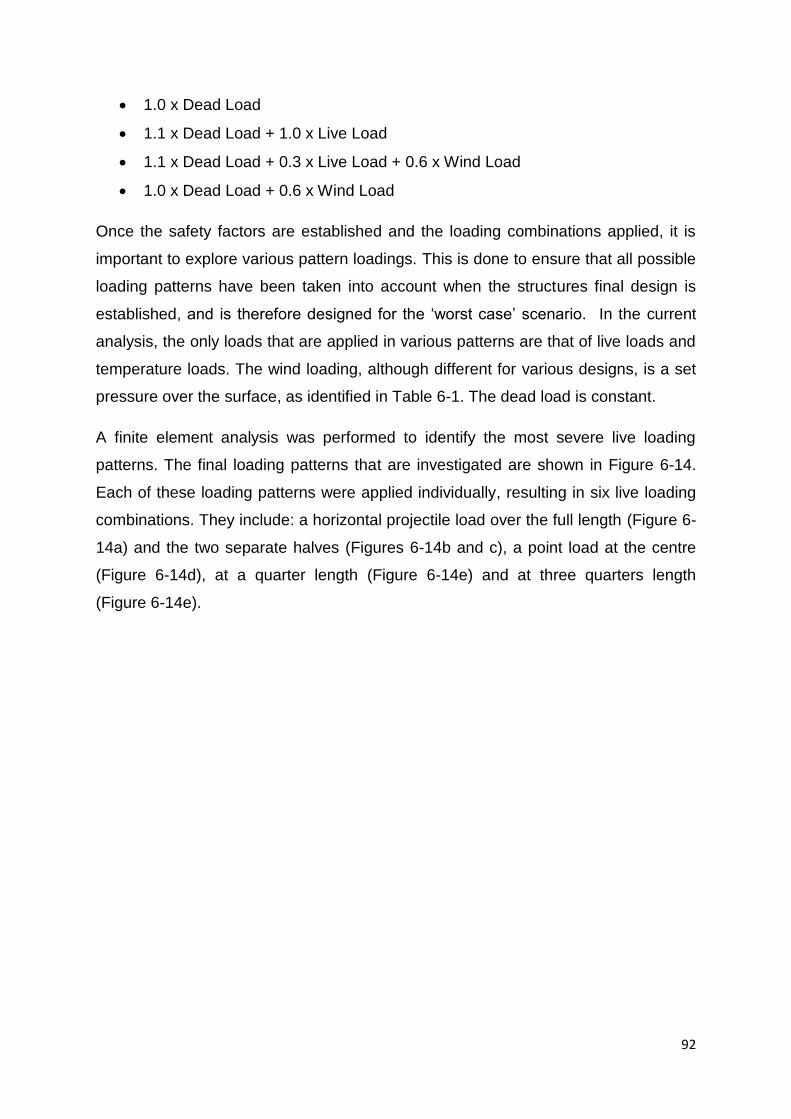
92
1.0 x Dead Load
1.1 x Dead Load + 1.0 x Live Load
1.1 x Dead Load + 0.3 x Live Load + 0.6 x Wind Load
1.0 x Dead Load + 0.6 x Wind Load
Once the safety factors are established and the loading combinations applied, it is
important to explore various pattern loadings. This is done to ensure that all possible
loading patterns have been taken into account when the structures final design is
established, and is therefore designed for the ‘worst case’ scenario. In the current
analysis, the only loads that are applied in various patterns are that of live loads and
temperature loads. The wind loading, although different for various designs, is a set
pressure over the surface, as identified in Table 6-1. The dead load is constant.
A finite element analysis was performed to identify the most severe live loading
patterns. The final loading patterns that are investigated are shown in Figure 6-14.
Each of these loading patterns were applied individually, resulting in six live loading
combinations. They include: a horizontal projectile load over the full length (Figure 6-
14a) and the two separate halves (Figures 6-14b and c), a point load at the centre
(Figure 6-14d), at a quarter length (Figure 6-14e) and at three quarters length
(Figure 6-14e).

93
Figure 6-14: Loading patterns for the applied live loads: (a) Full horizontal projection, (b) half load over the left half, (c) half load over the right half, (d) point load at the centre, (e) point load at a
quarter length, (f) point load at three quarters.
The temperature loading was assessed and selected in a similar manner to the live
loading. The key loading patterns are summarised in Figure 6-15. Positive and
negative temperature changes, resulting in shrinkage and expansion, were
investigated.
Figure 6-15: Investigated loading patterns for temperature loads: (a) temperature loading over the entire structure, (b) temperature loading over the right half of the structure, (c) temperature
loading over the left half of the structure

94
6.5. Design Process using the Segmental Equilibrium Method
Chapter 5 discussed the process by which a catenary curve is designed using the
segmental equilibrium method. In this section, the process of designing the roof
structure of the prototype will be discussed in detail.
6.5.1. Dead Load Design
The first step is to establish the geometry of the curve. The user has a general idea
of the dimensions of the curve, i.e. its length and height. All the designs are done to
a metre length vault section. Gravity loading determines the dimensions of the vault;
however, the lateral forces determine the required thickness of the shell. All final
calculations were done in Excel spread sheets (Appendix A). The steps presented
below can be followed in the spread sheet on page 99. The process is as follows:
1. Input all the material properties:
Density = 1950kg/m3
Young’s Modulus = 3500MPa
2. Add the initial vault dimensions. These are important when you are iterating to
ensure that the curve spans the required vault size. These values are the
initially assumed dimensions as discussed in Chapter 3.
Height = 3.5m
Length = 3.4m
3. Select an initial segment size. The segment height chosen was 130mm. This
height was selected to allow for higher accuracy in shorter heights but with
more number of segments spanning the length of the curve. The length of the
segment will vary with each load case. It was roughly estimated that 63
segments were to be used. This number is a random estimate; however, the
more segments you have the higher the accuracy.
4. An initial angle of 80° is selected as the vault is predominantly vertical. This
value will also change with each load case in the iterative approach.
5. The various loads are now incorporated into the spread sheet and all factors
are applied. In this example, only the gravity loads will be discussed. These
loads are transformed into point loads that are applied at the centre of each
segment (Table 6-2 and 6-3). These point loads are calculated according to

95
the length of the segment, thus with a differing segment height, the value of
the point load will also vary.
Table 6-2: Dead Loads applied to the vault
Loads
Dead Load
Units
Bricks/Masonry weight per block 2.88 kN/m2
Weight of each segment as a point load 0.37 kN
Table 6-3: Loading combinations applied in analysis of vault
Load combinations
ULS DL (kN)
LC1 1.5DL 0.56
SLS DL (kN)
LC1 1.0DL 0.37
6. The spread sheet is now set up as demonstrated in point 9 of section 5.5.4.
The thrust line under gravitational forces can now be calculated. In this
section, we are only discussing the dead load applied to the structure which
will be constant at each segment; thus, the value in the weight column is
identical for each segment. All the previously chosen values are inputted into
the spread sheet. These include initial segment height, angle and number of
segments. The first row of calculation is the most unique and complex as
values may need to be manually inputted or calculated in a separate
spreadsheet. The remaining rows of calculation follow a continuous pattern
generated from the previous rows of results. All steps can be followed in the
spread sheet presented on page 99 (Figure 6-16).
7. The first calculation includes establishing the exact value of the left thrust
force, which is also the reaction force at the left end of the curve. Since the
loading is symmetrical over the structure, a simple equilibrium calculation can
be done to establish the vertical component of this force, i.e. ∑Fy=0. The left

96
and right reaction forces are identical and thus the total dead load is
calculated and halved.
( )
8. Left Thrust x and Left Thrust Resultant are calculated using trigonometry as
follows:
( )
( )
( ) ( )
Note: The chosen sign notation indicates that any forces to the right and up
are positive.
9. The remaining steps will follow a continuous pattern throughout the spread
sheet. Right thrust x and right thrust y are calculated through equilibrium
equations, i.e. ∑Fy=0 and ∑Fx=0. This is done at the centre of the segment,
where equilibrium is calculated around that point incorporating all the various
loading. In this case, there are no horizontal loads applied to the structure,
only a vertical dead load. Thus, the right thrust x is identical in magnitude but
opposite in direction to left thrust x.
The right thrust y has to account for the reaction force from the left as well as
any external vertical forces.
( )
The Right Thrust Resultant force can now be calculated using Pythagoras
theorems:
√

97
10. The new angle is calculated. This is done using the newly calculated right side
forces and trigonometry.
(
) (
)
11. Finally, the co-ordinates of the centre of the first segment are calculated. This
is the start of the thrust line. The co-ordinates are calculated using
trigonometry as follows.
( ) ( )
( ) ( )
Note that the angle used is the old angle and not the new one calculated in
point 10. These points represent the centre of the segment and therefore do
not start at (0,0). Thus, each succeeding co-ordinate will be calculated as
before, using trig, but simultaneously added to the preceding co-ordinate. This
is covered in point 14.
12. The first row of calculation is now complete. The second row needs to be set
up accordingly and all the succeeding rows of calculation follow the same
formulae as row 2. The Excel spread (see page 99) sheet highlights in green
the values that are carried over from the previous row, i.e. the Right Thrust
Resultant Force becomes the Left Thrust Resultant Force in the
succeeding row and the newly calculated right angle becomes the left angle
on the succeeding row. Now that the left thrust force is calculated, the left
thrust x and left thrust y are calculated using trig in conjunction with the new
angle.
( )
13. The right thrust values and new angle are calculated in the same manner as
in step 9 and 10.
14. The new co-ordinate is calculated in the same way as point 11; however, it is
added to the preceding co-ordinate.
( ) ( )

98
( ) ( )
15. Steps 12 to 14 are repeated for all of the remaining segments, resulting in a
final thrust line.
16. As mentioned previously, each co-ordinate represents the centre of the
segment. Thus, the first half and last half of the segment (i.e. height) are not
incorporated into the calculation. In order to complete the curve, (0,0) is
inputted as the first co-ordinate to ease calculations, and the final co-ordinate
is calculated very simply. The values to be added in the x and y co-ordinates
are given as the difference between the first and second co-ordinate. Since
the first co-ordinate is (0,0) the value of the second is the difference, and need
only be added to the final point.
The final dimensions of the curve, with the assumed initial inputs, were too
high and exceeded the intended height of the shell. Thus, the above process
was repeated, in an iterative approach, by varying the initial angle and the
segment height until a more satisfactory set of dimensions was achieved.
The final initial angle is 80.5° and a segment height of 128.2mm. This
provided us with a final curve with a vault height of 3482.85mm and a width of
3383.37mm. The final spread sheet for the calculation of the thrust line under
dead load, and essential the final geometry, can be found in Appendix A.

99
Figure 6-16: An Excel spread sheet showing the design process of a catenary curve subject to dead loading
XY
1130
0.5680.00
3.1117.63
17.90-3.11
-17.0717.35
79.680.00
0.00
2130
0.5679.68
3.1117.07
17.35-3.11
-16.5116.80
79.3422.57
128.03
3130
0.5679.34
3.1116.51
16.80-3.11
-15.9516.25
78.9745.87
255.92
4130
0.5678.97
3.1115.95
16.25-3.11
-15.3915.70
78.5869.92
383.68
5130
0.5678.58
3.1115.39
15.70-3.11
-14.8315.15
78.1694.79
511.28
6130
0.5678.16
3.1114.83
15.15-3.11
-14.2714.60
77.71120.52
638.70
7130
0.5677.71
3.1114.27
14.60-3.11
-13.7114.06
77.23147.19
765.94
8130
0.5677.23
3.1113.71
14.06-3.11
-13.1513.51
76.70174.86
892.96
9130
0.5676.70
3.1113.15
13.51-3.11
-12.5912.97
76.13203.60
1019.74
10130
0.5676.13
3.1112.59
12.97-3.11
-12.0312.43
75.51233.50
1146.26
11130
0.5675.51
3.1112.03
12.43-3.11
-11.4711.88
74.84264.66
1272.47
12130
0.5674.84
3.1111.47
11.88-3.11
-10.9111.34
74.10297.18
1398.34
13130
0.5674.10
3.1110.91
11.34-3.11
-10.3510.81
73.29331.17
1523.81
14130
0.5673.29
3.1110.35
10.81-3.11
-9.7910.27
72.39366.79
1648.84
15130
0.5672.39
3.119.79
10.27-3.11
-9.239.74
71.40404.17
1773.35
16130
0.5671.40
3.119.23
9.74-3.11
-8.679.21
70.29443.49
1897.26
17130
0.5670.29
3.118.67
9.21-3.11
-8.118.69
69.04484.97
2020.46
57130
0.56-77.23
3.11-13.71
14.06-3.11
14.2714.60
-77.713337.08
1019.74
58130
0.56-77.71
3.11-14.27
14.60-3.11
14.8315.15
-78.163365.83
892.96
59130
0.56-78.16
3.11-14.83
15.15-3.11
15.3915.70
-78.583393.49
765.94
60130
0.56-78.58
3.11-15.39
15.70-3.11
15.9516.25
-78.973420.16
638.70
61130
0.56-78.97
3.11-15.95
16.25-3.11
16.5116.80
-79.343445.90
511.28
62130
0.56-79.34
3.11-16.51
16.80-3.11
17.0717.35
-79.683470.77
383.68
63130
0.56-79.68
3.11-17.07
17.35-3.11
17.6317.90
-80.003494.82
255.92
3518.11128.03
3540.690.00
Left Th
rust
Re
sultan
t
Righ
t
Thru
st x
Righ
t
Thru
st y
Righ
t Thru
st
Re
sultan
t
Righ
t
angle
Co
-ord
inate
sSe
gme
nt
no
.
He
ight o
f
Segm
en
tW
eigh
tLe
ft
An
gle
Left
Thru
st x
Left
Thru
st y
63 b
ricks a
re u
sed, a
s
chose
n in
step 3
An in
itial a
ssum
ed b
rick
length
of 1
30m
m is
applie
d
A c
onsta
nt d
ead lo
ad is
applie
d to
all th
e b
ricks
The in
itially
assu
med
angle
is inputte
d
Left R
eactio
n F
orc
e o
f
the c
urv
e
Inse
rt co-o
rdin
ate
(0,0
)
as a
startin
g p
oin
t
Calc
ula
te th
e fin
al c
o-
ord
inate
, thus ta
kin
g
into
account th
e
rem
ain
der o
f the b
rick
segm
ent
Each c
o-o
rdin
ate
repre
sent th
e c
entre
poin
t for th
e b
rick
Left T
hru
st (line 2
) =
Rig
ht T
hru
st (Lin
e 1
)
Left a
ngle
(line 2
) =
Rig
ht a
ngle
(Lin
e 1
)
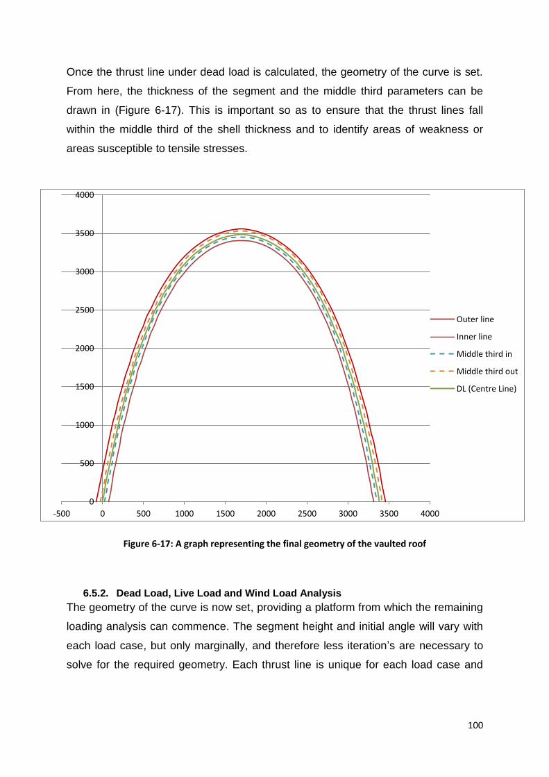
100
Once the thrust line under dead load is calculated, the geometry of the curve is set.
From here, the thickness of the segment and the middle third parameters can be
drawn in (Figure 6-17). This is important so as to ensure that the thrust lines fall
within the middle third of the shell thickness and to identify areas of weakness or
areas susceptible to tensile stresses.
Figure 6-17: A graph representing the final geometry of the vaulted roof
6.5.2. Dead Load, Live Load and Wind Load Analysis
The geometry of the curve is now set, providing a platform from which the remaining
loading analysis can commence. The segment height and initial angle will vary with
each load case, but only marginally, and therefore less iteration’s are necessary to
solve for the required geometry. Each thrust line is unique for each load case and
0
500
1000
1500
2000
2500
3000
3500
4000
-500 0 500 1000 1500 2000 2500 3000 3500 4000
Outer line
Inner line
Middle third in
Middle third out
DL (Centre Line)

101
the aim is to get it as close as possible to the original (dead load) thrust line,
therefore keeping it in the middle third of the segment thickness.
Thrust Line Analysis with only dead loads is relatively simple. The process becomes
considerably more complex when a lateral force is applied; such as wind loading. In
this section, a detailed step by step design process will be discussed which will cover
a number of varying loads. The curve will be subject to a wind load, live load and
dead load. The live load is a horizontal projection over all or a portion of the curve,
as described in figure 6-5, and the wind load has a Cpi value of -0.2. No different to
the dead load calculation, the analysis phase begins with an assumed initial angle
and segment height. These values are varied to achieve the required geometry for
the specific thrust line. In this step, the final values achieved in the dead load
calculation are used as the initial guess and then follow an iterative process to
calculate the actual angle and segment height. Unlike section 6.6.1, the final
calculations steps will be covered with the correct angle and segment height value
for that specific thrust line.
1. The material properties are as before (refer to step 1 in section 6.6.1) and the
thrust line should fit within the middle third, as seen in figure 6-15.
2. The segment height and angle, for the final thrust line, are 133mm and 83.3°
respectively. This has been obtained through an iterative process.
3. The load cases are now incorporated into the spread sheet (Table 6-4, 6-5
and 6-6). These loads include live loads, wind loads and dead loads. As
before, these loads are transformed from loads and surface loads into point
loads, and applied at the centre of each segment.
The dead load is calculated as a vertical force:
Table 6-4: Dead loads applied to vaulted roof
Loads
Dead Load
Units
Bricks/Masonry weight per block 2.88 kN/m2
Weight of each segment as a point load 0.37 kN

102
The live load is not a UDL over the surface of the structure, as is the dead
load, but rather a horizontal projection over the structure and therefore the
value of the live load applied is different for each segment. This value
depends on the angle at which the segment is situated, i.e. for a steeper
section the live load will be less as it covers less of a horizontal distance and
vice versa for more horizontal sections (Figure 6-18).
Table 6-5: The value of the live load applied on the vault, obtained from SABS 0160 (2009)
Live Load 0.25 kN/m2
Figure 6-18: A horizontal projection of the live load over a segment
⁄ (6-3)
Where x is the length of the live load exerted on that segment and is
calculated as follows:
( ) (6-4)
The live load at the apex of the curve is calculated as follows:
( ( ))
This point load is then added to the dead load value at the segment centroid.
This value will vary at each segment, depending on the angle of the segment.

103
The calculation of the wind load is slightly more complex as it has a horizontal
and vertical component. The wind load is a pressure over the surface of the
vault. As with the other loads, the wind pressure is transformed into a point
load and then separated into its relevant components and applied to the
segments. It is assumed that the wind load is perpendicular to the segment
and thus the components will vary according to the angle of the segment. In
this load case, a wind pressure with a Cpi value of -0.2 is used.
Table 6-6: Wind Pressures values distributed over the vaulted roof (Refer to Figure 6-10)
Wind Load
(kN/m2) Cpi=-0.2
Point Load
(kN)
1st section (A) 0.342 0.044
2nd and 3rd
section (B) -0.342 -0.044
4th section (C) -0.068 -0.0089
To calculate the horizontal and vertical components at any given segment, the
following steps are followed:
( ) (6-5)
( ) (6-6)
If a random segment is selected for analysis, in this case segment no 12, the
wind load is calculated as follows:
This segment falls within the 1st section, therefore Wind Load is
0.044kN.
The load factor of the current load combination is 1.6
The angle of the segment is obtained from the DL spread sheet so that
the true angle of the segment is used. The angle is 75.58°
( )

104
( )
These values are reasonable as the segment is at a steep angle, therefore
the load will predominantly have a horizontal component.
The loads are inputted into the relevant cells by the user. As noted in the
spread sheet, the live loads are only applied from segment 32 onwards as the
loading pattern comprises of a live load over the second half of the vault
(Figure 6-14c). The wind load is adjusted at every quarter point, as indicated
by SABS0160-3 (2009).
A summary of the loading combinations is presented in Table 6-7.
Table 6-7: Loading combinations for the analysis of a catenary vault
Load combinations
ULS DL (kN) LL (kN/m²) WL1 (kN) WL2+3 (kN) WL4 (kN)
LC1 1.5DL 0.552 0 0 0 0
LC2 1.2DL+1.6LL 0.441 0.400 0 0 0
LC3 1.2DL +0.5LL +1.3WL 0.441 0.125 0.057 -0.057 -0.011
LC4 0.9DL+1.3WL 0.331 0 0.057 -0.057 -0.011
SLS DL (kN) LL (kN/m²) WL1 (kN) WL2+3 (kN) WL4 (kN)
LC1 1.0DL 0.368 0 0 0 0
LC2 1.1DL+1.0LL 0.405 0.250 0 0 0
LC3 1.1DL+0.3LL+0.6WL 0.405 0.075 0.026 -0.026 -0.005
LC4 1.0DL+0.6WL 0.368 0 0.026 -0.026 -0.005
4. Now that the loading columns are complete, the first row of calculations can
be set up. The first step is to calculate the left thrust y. As discussed
previously, this force is the reaction force of the vault on the left hand side.
Unlike the previous example, the loading is not symmetrical and the reaction
cannot be calculated by simply adding and halving the external loads. The

105
force can still be calculated through the use of equilibrium, but by utilising a
slightly more complex method, i.e. ∑M=0. Each of the external loads are
totalled and transformed into a single point load with a corresponding distance
to the edge. The dead and live loads are simply multiplied by the length of the
load and applied as point loads. The wind loads are transformed in their
corresponding sections and applied as point loads in the centroid of each
section. It is important to obtain the correct distance to the edge of the vault,
as well as angle at which the load is orientated. The loads are separated as
presented in figure 6-19.
Figure 6-19: A summary of all of the collapsed loads and their distances to edge - Left: Dead and Live Loads; Right: Wind Loads
The left thrust force is calculated as follows:
(( ) ( ) ) ⁄
(6-7)
Thus, the value of the Left Thrust Y for this load case has a value of 13.24kN.
5. The Left thrust x and Left Thrust are calculated as before:
( )
( )

106
( ) ( )
6. The remainder of the steps follow a similar procedure as in section 6.6.1.
Previously, when calculating the Right Thrust x, it was merely equal to the Left
Thrust x. However, in this load case, there is an external horizontal force
exerted by the wind load that needs to be considered in the calculation. Thus,
the Right Thrust x, is calculated as follows:
( ) (6-8)
( )
The Right Thrust Y is calculated, as before, by taking into account all the
vertical forces exerted on that particular segment.
( )
(6-9)
( )
( ) ( )
In this load case, the live load is equal to zero for the first calculation and the
following 30 as the load only falls over the second half of the vault.
The Right Thrust is calculated as follows:
√
7. The new angle is calculated:
(
) (
)
8. Lastly, the co-ordinates of the centre of the first segment are calculated as in
section 6.6.1.
( ) ( )
( ) ( )
107
9. The remaining rows of calculation follow a constant formula. The right thrust
and its components, as well as the new angle are calculated as discussed
previously. It is important to note that:
Right Thrust (Row 1) = Left Thrust (Row 2)
New Angle (Row 1) = Old Angle (Row 2)
10. The left thrust components are calculated using trigonometry. Steps 6 to 9 are
repeated for each succeeding row.
11. The co-ordinates are calculated in the same manner as step 8; however, they
are also added to the preceding co-ordinate.
( ) ( )
( ) ( )
All calculations can be followed on page 108.

108
Figure 6-20: An Excel spread sheet showing the design process of a catenary curve subject to vertical and lateral loading
XY
1133
0.44140.0570
0.05620.0094
83.301.556
13.24213.333
-1.612-12.791
12.89282.82
00
2133
0.44140.0570
0.05620.0097
82.821.612
12.79112.892
-1.668-12.340
12.45282.30
15.52132.09
3133
0.44140.0570
0.05610.0100
82.301.668
12.34012.452
-1.724-11.889
12.01381.75
32.14264.05
4133
0.44140.0570
0.05600.0104
81.751.724
11.88912.013
-1.780-11.437
11.57581.15
49.96395.85
5133
0.44140.0570
0.05600.0107
81.151.780
11.43711.575
-1.836-10.985
11.13780.51
69.05527.47
6133
0.44140.0570
0.05590.0111
80.511.836
10.98511.137
-1.892-10.532
10.70179.82
89.50658.89
7133
0.44140.0570
0.05580.0115
79.821.892
10.53210.701
-1.948-10.079
10.26679.06
111.43790.07
15133
0.44140.0570
0.05460.0164
71.292.335
6.8947.278
-2.390-6.436
6.86569.63
357.421824.36
16133
0.44140.0570
0.05430.0173
69.632.390
6.4366.865
-2.444-5.977
6.45767.76
400.091950.33
17133
0.4414-0.0570
-0.0540-0.0184
67.762.444
5.9776.457
-2.390-5.554
6.04666.72
446.382075.01
18133
0.4414-0.0570
-0.0536-0.0195
66.722.390
5.5546.046
-2.336-5.132
5.63965.52
496.722198.12
19133
0.4414-0.0570
-0.0531-0.0207
65.522.336
5.1325.639
-2.283-4.711
5.23564.14
549.292320.29
30133
0.4414-0.0570
-0.0244-0.0515
18.871.829
0.6251.933
-1.805-0.235
1.8207.42
1423.543457.15
31133
0.4414-0.0570
-0.0156-0.0548
7.421.805
0.2351.820
-1.7890.151
1.796-4.84
1549.393500.16
32133
0.4574-0.0570
-0.0054-0.0567
-4.841.789
-0.1511.796
-1.7840.552
1.867-17.20
1681.283517.34
33133
0.4574-0.0570
0.0054-0.0567
-17.201.784
-0.5521.867
-1.7890.953
2.027-28.04
1813.803506.12
34133
0.4568-0.0570
0.0156-0.0548
-28.041.789
-0.9532.027
-1.8051.355
2.257-36.89
1940.863466.79
46133
0.4473-0.0570
0.0531-0.0207
-68.972.283
-5.9386.361
-2.3366.364
6.779-69.84
2843.612194.26
47133
0.4469-0.0570
0.0536-0.0195
-69.842.336
-6.3646.779
-2.3906.791
7.200-70.61
2891.352070.12
48133
0.4466-0.0114
0.0108-0.0037
-70.612.390
-6.7917.200
-2.4017.234
7.622-71.64
2937.191945.27
49133
0.4463-0.0114
0.0109-0.0035
-71.642.401
-7.2347.622
-2.4127.677
8.047-72.56
2981.341819.81
50133
0.4460-0.0114
0.0109-0.0033
-72.562.412
-7.6778.047
-2.4238.120
8.474-73.39
3023.231693.58
61133
0.4443-0.0114
0.0112-0.0021
-78.582.533
-12.54512.798
-2.54512.987
13.234-78.91
3327.82536.45
62133
0.4442-0.0114
0.0112-0.0020
-78.912.545
-12.98713.234
-2.55613.429
13.670-79.22
3355.82406.43
63133
0.4442-0.0114
0.0112-0.0019
-79.222.556
-13.42913.670
-2.56713.871
14.107-79.52
3382.96276.23
3409.29145.86
3434.860.00
DL + LL
pe
r blo
ck
Left
An
gle
Left
Thru
st x
Left
Thru
st yW
L VW
L HW
ind
Load
… …… …
Left Th
rust
Re
sultan
t
Righ
t
Thru
st x
Righ
t
Thru
st y
Righ
t Thru
st
Re
sultan
t
Righ
t
angle
Co
-ord
inate
sSe
gme
nt
no
.
He
ight o
f
Segm
en
t
Dead L
oad o
nly
DL+
LL: L
ive L
oad is
over 2
nd h
alf o
f
curv
e
Change in
win
d
pre
ssure
at th
is bric
k
WL H
= W
L*sin
(orig
angle
)
WL V
= W
L*cos(o
rig a
ngle
)Calc
ula
ted b
y u
sing sta
tic
equilib
irum
: ∑M
=0
Rig
ht a
ngle
(Lin
e 1
) =
Left A
ngle
(Lin
e 2
)
Inse
rt co-o
rd a
s
startin
g p
oin
t
Rig
ht T
hru
st (Lin
e 1
) =
Left T
hru
st (Lin
e 2
)
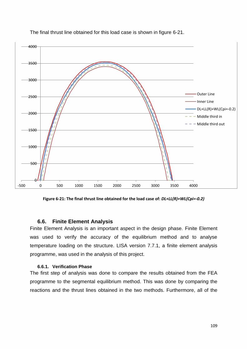
109
The final thrust line obtained for this load case is shown in figure 6-21.
Figure 6-21: The final thrust line obtained for the load case of: DL+LL(R)+WL(Cpi=-0.2)
6.6. Finite Element Analysis
Finite Element Analysis is an important aspect in the design phase. Finite Element
was used to verify the accuracy of the equilibrium method and to analyse
temperature loading on the structure. LISA version 7.7.1, a finite element analysis
programme, was used in the analysis of this project.
6.6.1. Verification Phase
The first step of analysis was done to compare the results obtained from the FEA
programme to the segmental equilibrium method. This was done by comparing the
reactions and the thrust lines obtained in the two methods. Furthermore, all of the
0
500
1000
1500
2000
2500
3000
3500
4000
-500 0 500 1000 1500 2000 2500 3000 3500 4000
Outer Line
Inner Line
DL+LL(R)+WL(Cpi=-0.2)
Middle third in
Middle third out

110
load cases were modelled in the programme and a selected set of critical cases
evaluated.
A summary of the reactions obtained are compared and presented in Table 6-8
below. The errors obtained in Table 6-8 are minor and verify that the equilibrium
method is correct and is a viable method for the design of catenary curves. The
errors obtained for the vertical reactions range between 2.8 and 6.1 percent. The
vertical reactions are significantly larger than the horizontal reactions. The horizontal
reactions are smaller in magnitude with greater percentage errors, as they are more
sensitive to smaller variations in value. The horizontal reaction errors are in the
range of 0 and 8.9 percent.
Table 6-8: Load reactions comparison of the results obtained from Finite element Analysis and the Segmental Equilibrium Method
Load Case Excel ∑H (kN) LISA ∑H (kN) Error Excel ∑V (kN) LISA ∑V (kN) Error
Dead Load, Live Load (Full)
0 0 0% 29.588 30.413 2.8%
Dead Load, Live Load (Left half)
0 0 0% 28.529 29.684 4.7%
Dead Load, Wind Load Cpi=-0.2
-1.012 -1.093 8% 19.936 20.924 5%
Dead Load, Live Load (full), Wind Load Cpi=-0.2
-1.016 -1.093 7.6% 27.322 28.462 4.2%
Dead Load, Live Load (Left half),
Wind Load Cpi=0 -1.000 -0.911 8.9% 26.814 28.463 6.1%
Dead Load, Live Load (Right half),
Wind Load Cpi=-0.2
-1.012
-1.093 8% 27.113 28.238 4.2%
The second phase of verification consists of comparing the thrust lines obtained from
the two methods. Figures 6-22 to 6-25 compares the thrust lines obtained from finite
element and the segmental equilibrium method. The thrust lines are similar and

111
verify the viability of the segmental equilibrium method. Lateral loads create a
greater discrepancy in the thrust lines, than vertical loading. Discrepancies in the
thrust lines are due to the approximate nature of the finite element method as a
means of designing catenary curves. The discrepancies can also be attributed to the
fact that the number of segments and sizes differ, and therefore the plots will vary
with accuracy.
Figure 6-22: A comparison of the Segmental Equilibrium Method and Finite element method when subject to dead loads
Figure 6-23: A comparison of the Segmental Equilibrium Method and Finite element method when subject to dead and live loads
0
500
1000
1500
2000
2500
3000
3500
4000
0 500 1000 1500 2000 2500 3000 3500 4000
EquilibriumMethod
0
500
1000
1500
2000
2500
3000
3500
4000
0 500 1000 1500 2000 2500 3000 3500 4000
EquilibriumMethod
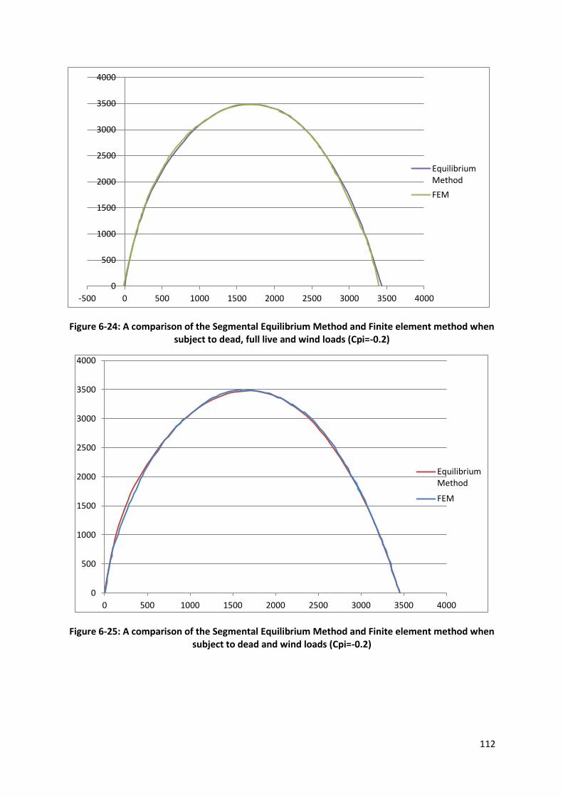
112
Figure 6-24: A comparison of the Segmental Equilibrium Method and Finite element method when subject to dead, full live and wind loads (Cpi=-0.2)
Figure 6-25: A comparison of the Segmental Equilibrium Method and Finite element method when subject to dead and wind loads (Cpi=-0.2)
0
500
1000
1500
2000
2500
3000
3500
4000
-500 0 500 1000 1500 2000 2500 3000 3500 4000
EquilibriumMethod
FEM
0
500
1000
1500
2000
2500
3000
3500
4000
0 500 1000 1500 2000 2500 3000 3500 4000
EquilibriumMethod
FEM

113
6.6.2. Analysis of Temperature Loading
Finite Element was used to analyse temperature loading on the structure. A
temperature difference of 20°, in expansion and contraction, was analysed when
applied to the full and half surface of the structure.
All loading combinations and patterns were investigated in combination with
temperature loading. All the finite element results from the loading cases can be
found in Appendix B. Here, we will discuss the worst loading case which created the
highest stresses within the vault.
The analysis showed that the structure was subject to the highest tensile stresses
during temperature changes (±20°) combined with wind action, i.e. Dead Load +
Wind Load (Cpi = 0) + Temperature Load (±20°). These tensile stresses are
predominantly found at the base of the structure and sometimes in small clusters
close to the apex. Figures 6-26 to 6-29 demonstrate the distribution of tensile and
compressive forces throughout the structure under the worst loading case. Note that
the edges of the vault in this project are not restrained in any way, and are therefore
allowed to expand and contract naturally.
Figure 6-26: A model of the worst load case inputted to LISA 7.7.1: DL+WL+TL
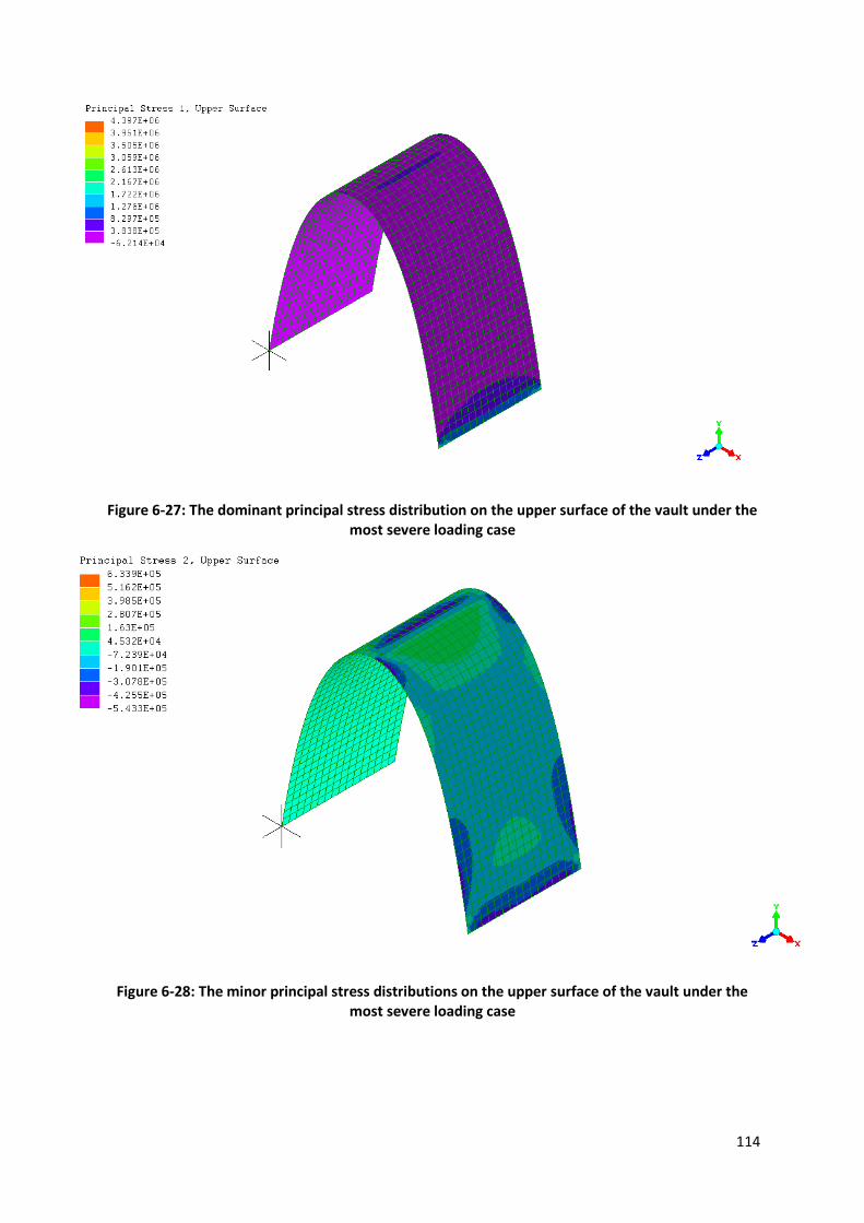
114
Figure 6-27: The dominant principal stress distribution on the upper surface of the vault under the most severe loading case
Figure 6-28: The minor principal stress distributions on the upper surface of the vault under the most severe loading case

115
Figure 6-29: The dominant principal stress distribution on the bottom surface of the vault under the most severe loading case
Note: All negative values represent compressive stresses and positive values
represent tensile stresses. The analysis displays what occurs on the upper and
bottom surfaces of the material with major and minor stresses. From the above
figures, it is clear the tensile stress are very concentrated to specific areas, i.e.
Figure 6-27 – dark blue, Figure 6-28 – bright green, Figure 6-29 – light green.
6.7. Discussion of Results
6.7.1. Thrust Line Analysis
All loading combinations and patterns were investigated and plotted to identify areas
of weakness and further investigation. Figures 6-30 to 6-36 display the thrust lines
obtained from all the investigated loading combinations. Figure 6-30 shows the
loading patterns which are only loaded with wind loads, Figures 6-31 to 6-33
represent only UDL live loads and Figures 6-34 to 6-36 are loaded with a point live
load. Areas which require further investigation are ones where the thrust line falls
outside of the middle third.

116
Figure 6-30: A graph representing the thrust lines obtained from only wind and dead load combinations
Figure 6-31: A graph representing the thrust lines obtained from only live (udl) and dead load combinations
0
500
1000
1500
2000
2500
3000
3500
4000
-100 400 900 1400 1900 2400 2900 3400 3900
Outer line
Inner line
DL+WL(Cpi=0)
DL+WL(Cpi=-0.2)
Middle third in
Middle third out
0
500
1000
1500
2000
2500
3000
3500
4000
-500 0 500 1000 1500 2000 2500 3000 3500 4000
Outer Line
Inner Line
DL+LL(Full)
DL+LL(Left)
DL+LL(Right)
middle third out
middle third in

117
Figure 6-32: A graph representing the thrust lines obtained from wind (cpi=0), live (udl) and dead load combinations
Figure 6-33: A graph representing the thrust lines obtained from wind (cpi=-0.2), live (udl) and dead load combinations
0
500
1000
1500
2000
2500
3000
3500
4000
-500 0 500 1000 1500 2000 2500 3000 3500 4000
Outer Line
Inner Line
DL+LL(F)+WL(Cpi=0)
DL+LL(L)+WL(Cpi=0)
DL+LL(R)+WL(Cpi=0)
Middle third in
Middle third out
0
500
1000
1500
2000
2500
3000
3500
4000
-500 0 500 1000 1500 2000 2500 3000 3500 4000
Outer Line
Inner Line
DL+LL(F)+WL(Cpi=-0.2)
DL+LL(L)+WL(Cpi=-0.2)
DL+LL(R)+WL(Cpi=-0.2)
Middle third in
Middle third out
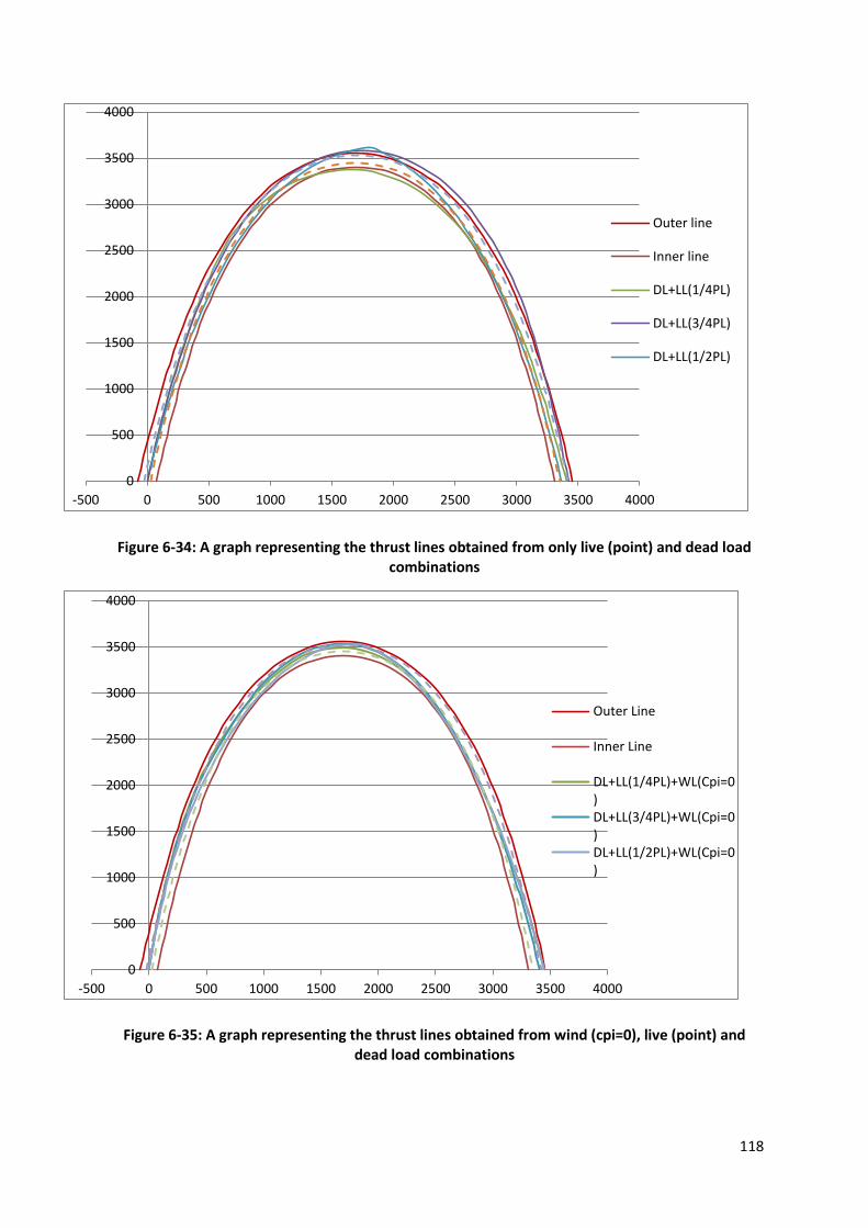
118
Figure 6-34: A graph representing the thrust lines obtained from only live (point) and dead load combinations
Figure 6-35: A graph representing the thrust lines obtained from wind (cpi=0), live (point) and dead load combinations
0
500
1000
1500
2000
2500
3000
3500
4000
-500 0 500 1000 1500 2000 2500 3000 3500 4000
Outer line
Inner line
DL+LL(1/4PL)
DL+LL(3/4PL)
DL+LL(1/2PL)
0
500
1000
1500
2000
2500
3000
3500
4000
-500 0 500 1000 1500 2000 2500 3000 3500 4000
Outer Line
Inner Line
DL+LL(1/4PL)+WL(Cpi=0)DL+LL(3/4PL)+WL(Cpi=0)DL+LL(1/2PL)+WL(Cpi=0)
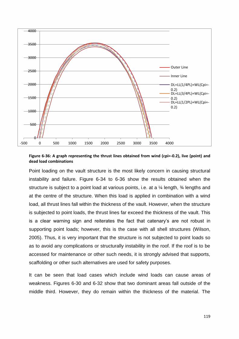
119
Figure 6-36: A graph representing the thrust lines obtained from wind (cpi=-0.2), live (point) and dead load combinations
Point loading on the vault structure is the most likely concern in causing structural
instability and failure. Figure 6-34 to 6-36 show the results obtained when the
structure is subject to a point load at various points, i.e. at a ¼ length, ¾ lengths and
at the centre of the structure. When this load is applied in combination with a wind
load, all thrust lines fall within the thickness of the vault. However, when the structure
is subjected to point loads, the thrust lines far exceed the thickness of the vault. This
is a clear warning sign and reiterates the fact that catenary’s are not robust in
supporting point loads; however, this is the case with all shell structures (Wilson,
2005). Thus, it is very important that the structure is not subjected to point loads so
as to avoid any complications or structurally instability in the roof. If the roof is to be
accessed for maintenance or other such needs, it is strongly advised that supports,
scaffolding or other such alternatives are used for safety purposes.
It can be seen that load cases which include wind loads can cause areas of
weakness. Figures 6-30 and 6-32 show that two dominant areas fall outside of the
middle third. However, they do remain within the thickness of the material. The
0
500
1000
1500
2000
2500
3000
3500
4000
-500 0 500 1000 1500 2000 2500 3000 3500 4000
Outer Line
Inner Line
DL+LL(1/4PL)+WL(Cpi=-0.2)DL+LL(3/4PL)+WL(Cpi=-0.2)DL+LL(1/2PL)+WL(Cpi=-0.2)

120
tensile forces in these areas are obtained from the finite element analysis and
compared to the tensile strength of the material. The maximum tensile forces are
minor and fall within the tensile limit of 1.1N/mm² (refer to Chapter 4). All tensile
stresses obtained are within a range of 0.11-0.95N/mm².
6.7.2. Finite Element Analysis
Finite Element was carried out to assess the effects of temperature loading on the
structure. Temperature loading was found to be the most severe loading case,
creating the largest tensile and compressive stresses. As discussed previously, there
is a change in stresses on the centre line of the curve. However, in this case the
change is gradual and not abrupt as is the case for Bapong. Therefore this does not
create concern in terms of cracking. All compressive stresses are below the
compressive strength of the material. It is advised that the stresses do not exceed a
third of the strength (rule of thumb). The maximum compressive stress obtained is
1.02N/mm², where the strength of the masonry is 3.75N/mm². The maximum tensile
stresses are of magnitude 0.99N/mm². This value is quite close to the tensile
strength of the material and it is advised that additional precautionary measures
should be taken once construction is complete.
6.8. Conclusion
It is concluded that all load cases are within the required limits. Thus, the above
curve is the finalised design of the roof structure. However, it was decided that a
layer of a very lightly coloured form of waterproofing, paint or fabric would be placed
over the roof to minimise the temperature loading on the structure. This in turn would
minimise the chance of cracking within the roof structure.

121
7. Structural Member Design
The design of all the members in this chapter were carried out in accordance with
the reinforced and pre-stressed concrete codes SABS 0100-1 (2000) and BS8100-1
(1997), as well as the masonry codes BS 5628-1(1992) and ENV1996-1-1 (1996). A
number of elements were selected prior to design and the capacity was checked to
ensure that the elements were sufficient to support the exerted loading. In this
chapter, the design process and detail of all members are discussed. All the
members are designed to capacity, finalising the design of the prototype structure
before construction can commence.
7.1. Slab
7.1.1. Introduction
The design of the slab was conducted by Spancon, a local distributor of slab
systems. A rib and block slab was decided on to minimise the quantity of concrete
used, which is approximately 30% less than normal slabs. It is also the most cost
effective solution for slab flooring. This is highlighted particularly in the installation
process. The slab is very easy to install, and thus less labour is needed in shorter
periods. The slab merely utilises lintels as the ribs and hollow precast blocks (void
formers) which are placed between the lintels, thus eliminating the need for formwork
or scaffolding. A ready mix of concrete is used and minimal steel reinforcing is
required. A rib and block slab has also proved to have excellent insulation properties
(Spancon, 2013). This is particularly important when designing for a low-cost house.
7.1.2. Design
All slab specifications and designs are supplied by Spancon (Table 7-1, Figure 7-1).
Table 7-1: Properties of materials used in the slab
Loading 1.5kN/m²
Reinforcing steel Y10
Ready mix concrete quantity 3m³
Ready mix concrete strength 25MPa
Floor area 28m²
Thickness of slab 170mm
Thickness of concrete above rib and block system 50mm
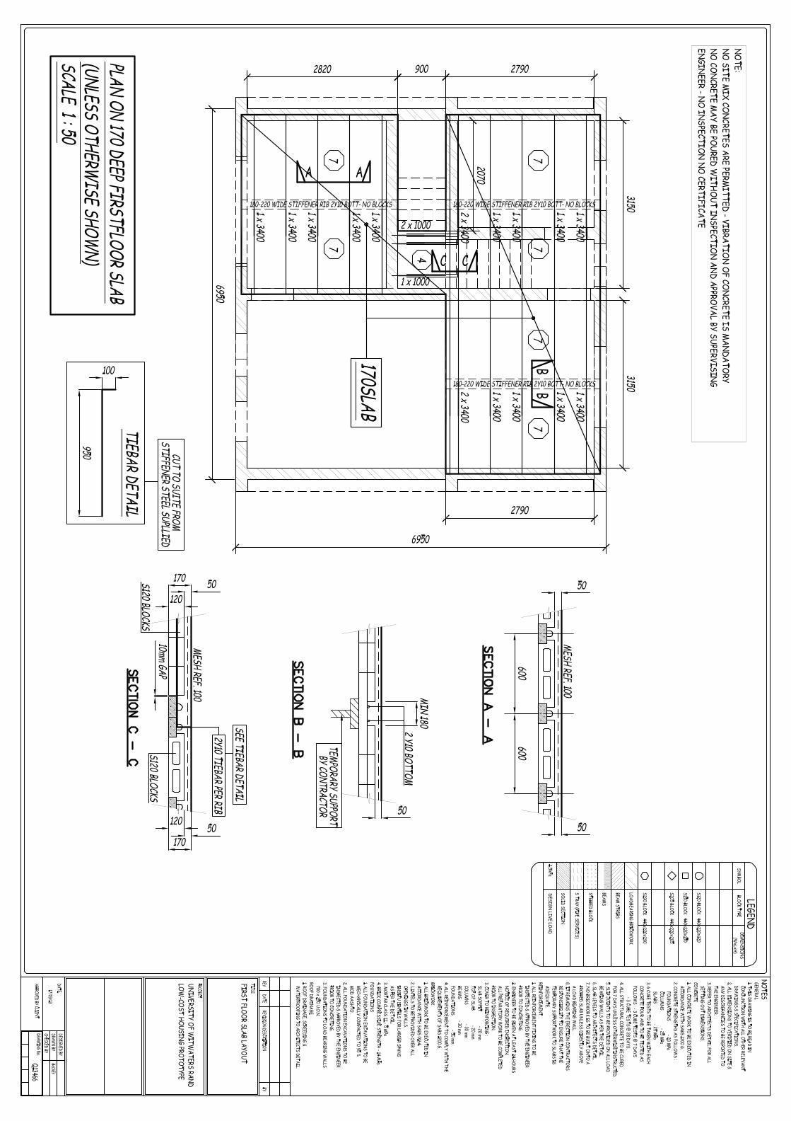

123
7.2. Masonry wall design
7.2.1. Introduction
The design of the wall is done in accordance with BS 5628-1 (1992) and ENV 1996-
1-1 (1996). The method adopted is that of a simple masonry design where the total
loads is compared to the resistance of the material and its capacity to support it. The
buckling of the wall is also checked during design. The walls that require analysis are
the load carrying walls. All of the walls in the prototype are of the same height, and
thus only the wall with the highest applied load need be checked.
7.2.2. Loading
The load carried by the walls is simply vertical. This is due to the fact that the lintels
and ties (as explained in more detail in section 7.3) resist the horizontal loading.
Therefore the walls only need to be checked for buckling and its compressive
strength capacity.
Figure 7-2 illustrates which of the walls are load bearing as well as the wall with the
highest load. The central wall is the highest load carrier and is therefore selected for
design. A metre length section of the wall is designed.
Figure 7-2: Layout of the wall system highlighting the function of each wall as well as the wall with the greatest applied load

124
The loading exerted on the central wall is summarised as follows:
Dead Load
o Self-weight of wall = 11.15kN/m
o Vaults = 12.08kN/m per vault. However, there are two vaults being
exerted on the central wall, thus a total load of 24.16kN/m is used
o Slab = 13.75kN/m
Live Load
o For dwellings =1.5kN/m2 x 1.5 = 2.25kN/m
The total load exerted on the wall is 51.31kN/m.
7.2.3. Design
There are two methods that can be employed in the design of a masonry wall. The
first method is to calculate the characteristic compressive strength needed to resist
the applied load and compare it to the compressive strength of the materials. The
second method calculates the stresses exerted by the loading and compares it to the
ultimate stress allowed. Both methods were applied and found the design to be
satisfactory.
However, the first method also checks for buckling. Thus, method one will be applied
and the results are presented below.
When designing a wall, the β value is critical. This value is the capacity reduction
factors and is dependent on the slenderness of the wall. It also highlights and
combats the likelihood of the wall buckling. In order to obtain the β value, the
eccentricity of the loading needs to be calculated. The layout of the loading is
described in Figure 7-3 and the eccentricity can calculated as described below.

125
Figure 7-3: The loading and eccentricity as applied to the wall
Where w1 = Vault loads and self-weight of wall
w2 = Load from the full slab
w3 = Load from sectioned slab
t = thickness of the wall (220mm)
In this case, a β value of 1 was obtained. This indicates that the wall is not
susceptible to buckling. The design compressive strength is now calculated.
The design strength is calculated using the following equation:
(7-1)
Where β is the capacity reduction factor
t is the thickness of the section
fk is the characteristic compressive strength
γm is the material safety factor (3.5)
The compressive strength required, under the stipulated loading, was found to be
1.24MPa. The compressive strength of the material is 10MPa. This value has not
been reduced, as it usually would be in combination with mortar, as the wall is dry
stack. The wall is clearly suitable in supporting the above loads.

126
7.3. Thrust Force Structural Components Design
7.3.1. Introduction
The design of the lintels in this project varies slightly to the standard use of lintels.
Lintels are generally used to support sections of walls above windows and doors.
They act as composite beams, which comprise of concrete lintels and masonry.
However, in this project, there is a need for a structural member to counteract the
outward thrust of the vaults. Since the masonry walls cannot support these horizontal
thrusts, particularly when dry stacked, a new innovative approach is required. A
simple, but effective method was established. The solution is a simple combination
of lintels, steel tubes and reinforcing bars. As demonstrated in Figure 7-4, the lintels
are simply placed within the steel tubes which are then welded to the ties (reinforcing
bars). The ties contain the outward thrust force exerted by the vaults.
Figure 7-4: A layout describing the manner in which the system is set out to contain the thrust force

127
7.3.2. Lintel Design
7.3.2.1. Introduction
This design is done in accordance with SABS 0100-1 (2000) and BS 8110-1 (1997).
It is designed as a pre-stressed concrete section, satisfying all the relevant checks.
The lintel is designed as a 1 metre length section. All material properties are
obtained from Lintel Supplier, a local supplier of lintels in South Africa. The lintels
were precast and pre-tensioned in a plant and shipped to site. It is important to note
that lintels are able to resist horizontal forces. The same method of design is used
with the sections rotated 90°, as described in Figure 7-5.
Figure 7-5: The manner in which the lintels are loaded by the horizontal thrust exerted by the vault
It is important to note that the ties attached to the lintels need to be cast within the
concrete slab to limit corrosion. To reach the necessary height whereby the ties are
covered, two lintels are placed on top of one another and mortared together to act as
a single beam. The configuration is illustrated in Figure 7-6.

128
Figure 7-6: Two lintels are placed on top of one another to ensure the ties fall within the concrete section and are therefore covered
7.3.2.2. Loading
The loading exerted on the lintels is the horizontal thrust force exerted by the vaulted
roof. This value is obtained from either the segmental equilibrium method or the finite
element analysis. All load cases are analysed and the greatest reaction forces are
used in the design of the lintels.
The greatest horizontal reaction, exerted by the vaults, is 2kN per metre length. This
value is obtained when only a dead load and temperature load (20°C change) are
exerted on the vault. This value is applied to the lintels, as demonstrated in Figure 7-
5.
7.3.2.3. Design
In the design phase, a pre-stressed concrete analysis was carried out to ensure that
the lintels can resist the loading. The properties and dimensions of the lintels are
fixed and summarised in Table 7-2. It was decided that the lintels would be

129
orientated in such a way to ensure that the load is carried in the stiff, rigid direction,
as can be seen in Figure 7-5.
Table 7-2: A table summarising the material and section properties of the lintels
Concrete Properties Value Unit Notes
Strength at 28days 35 MPa
Strength at release 12 MPa
Young’s Modulus at 28
days
30000 MPa
Young’s Modulus at
release
18171 MPa
Section Properties
Height per lintel 70 mm Two lintels are used, thus a height of
140mm
Width 135 mm
Strand Properties
No of wires 4
Wire Diameter 2.64 mm
Characteristic strength, Pu 9.31 kN Per lintel
Initial Jacking Force 70 %
(Lintel Suppliers, 2009)
The design process is followed in accordance with SABS 0100-1 (2000), pre-
stressed concrete. The lintels were analysed and the results are given below:
Service stresses at Transfer
o Stress at Top = 5.22 MPa < 6MPa ok
o Stress at Bottom = 1.79MPa < 6MPa ok
Long term service Stresses
o Stresses at Top = 8.19MPa < 11.55MPa ok
o Stresses at Bottom = 1.35MPa < 11.55MPa ok
Ultimate Moment of resistance = 11.05kNm > Moment under ultimate load =
2.08kNm ok
130
Shear under ultimate load = 4.16 kNmm < 4.75 ok
Shear under ultimate load = 4.16 kNmm < Shear capacity (uncracked section)
= 17.25 kNmm ok
Shear under ultimate load = 4.16 kNmm < Shear capacity (cracked section) =
9.22 kNmm ok
Deflection at Camber transfer satisfied
Long term deflection satisfied (l/300)
The analysis process ensured that all code checks are satisfied and thus the lintels
are sufficient to carry the required load.
7.3.3. Steel Ties and Welds
7.3.3.1. Introduction
As previously discussed, one of the most important design aspects of this project is
that of the ties required to support the horizontal forces exerted by the vaulted roof.
Figure 7-4 and 7-6 illustrates the layout of the steel ties required in the prototype.
These ties work in a way such that when the roof kicks outward, the ties (that are
attached to the lintels) go into tension and restrain the structure from collapsing.
Thus, it is necessary that the welds and ties are strong enough to resist the outward
thrust force of 2kN per metre length of the vault.
The ties are to be welded to the steel tubes and therefore a R10 reinforcing bar is
chosen to ensure a good quality weld is created and sufficient strength is provided in
the section.
7.3.3.2. Design
A weld design is required to ensure that sufficient support is provided to the structure
(Figure 7-7).
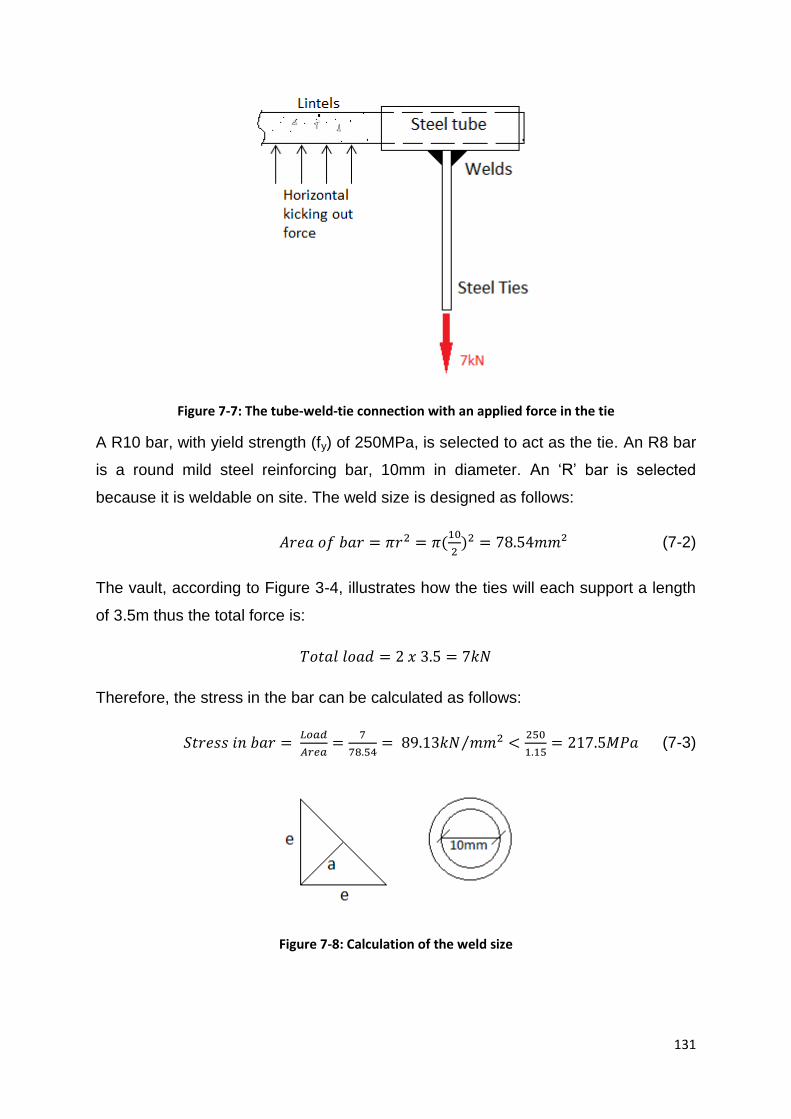
131
Figure 7-7: The tube-weld-tie connection with an applied force in the tie
A R10 bar, with yield strength (fy) of 250MPa, is selected to act as the tie. An R8 bar
is a round mild steel reinforcing bar, 10mm in diameter. An ‘R’ bar is selected
because it is weldable on site. The weld size is designed as follows:
(
) (7-2)
The vault, according to Figure 3-4, illustrates how the ties will each support a length
of 3.5m thus the total force is:
Therefore, the stress in the bar can be calculated as follows:
⁄
(7-3)
Figure 7-8: Calculation of the weld size

132
Where ‘e’ is the leg length of the weld and ‘a’ the throat thickness (Figure 7-8).
If we assume a minimum weld size of 4mm, we can thus calculate ‘a’, and effectively
determine whether the weld is suitable to carry the load.
( )
Thus, the unity throat welded area
( )
The shear resistance of the steel and weld are compared. The shear resistance of
the steel is calculated as follows:
(7-4)
The shear resistance of the weld is calculated as follows:
( ) (7-5)
( ) ok
The minimum weld size of 5mm is used for the prototype. An electrode of 480MPa is
used; thus, the weld yield strength exceeds the yield strength of the steel, of
250MPa.
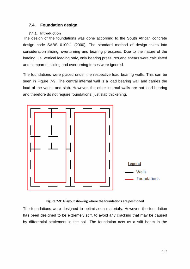
133
7.4. Foundation design
7.4.1. Introduction
The design of the foundations was done according to the South African concrete
design code SABS 0100-1 (2000). The standard method of design takes into
consideration sliding, overturning and bearing pressures. Due to the nature of the
loading, i.e. vertical loading only, only bearing pressures and shears were calculated
and compared, sliding and overturning forces were ignored.
The foundations were placed under the respective load bearing walls. This can be
seen in Figure 7-9. The central internal wall is a load bearing wall and carries the
load of the vaults and slab. However, the other internal walls are not load bearing
and therefore do not require foundations, just slab thickening.
Figure 7-9: A layout showing where the foundations are positioned
The foundations were designed to optimise on materials. However, the foundation
has been designed to be extremely stiff, to avoid any cracking that may be caused
by differential settlement in the soil. The foundation acts as a stiff beam in the

134
vertical direction with a horizontal footing at the base to ensure that the bearing
pressure is never exceeded.
7.4.2. Design
The dimensions of the foundation were selected and optimised in the design
process. The final design dimensions and details are shown in Figure 7-10.
Figure 7-10: Dimensions and detailing of the foundation
7.4.3. Loading
A bearing pressure of 100kPa was selected to design a standard shape, since soil
bearing capacities are rarely lower that this value within South Africa. The bearing
pressure was compared to the loading to ensure that the foundation is sufficient in
135
supporting the building. The stress from the loading is calculated using the following
equation:
(7-4)
Where Ps is the total service load on the structure, and ab is the cross sectional area
of the foundation. The equation is for vertical loads only.
The loading exerted on the foundation is a combination of dead loads and live loads.
The bearing pressure was checked for dead load only, as well as a combination of
dead and live loads. The dead load consists of the vault, slab, wall, brick shuttering,
soil, surface bed, and self-weight of the foundation, totalling 68.86kN. The live load,
as per SABS0100-1 (2000) is taken as 1.5kN/m2. Once all these values have been
calculated and added using the service safety factors, of 1.0DL+1.1LL, a total load of
71.11kN is exerted on the foundation. The bearing pressure was calculated and the
results are as follows:
( )
( ) ⁄
( )
( ) ⁄
Note: The soil bearing capacity at the site of the prototype is much greater then
100kPa, but the foundation was designed to be used at almost any location in South
Africa.
7.4.4. Flexural steel
As discussed, it is important that the foundations do not move when differential
settlement occurs. This, being the worst case scenario, was the basis of design. As a
precaution, one metre section of soil was assumed to have settled, which is depicted
in Figure 7-11.
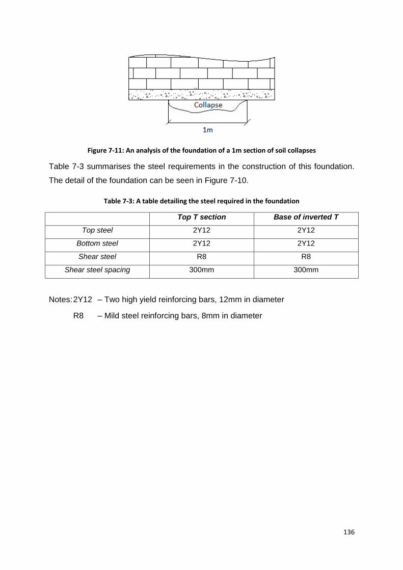
136
Figure 7-11: An analysis of the foundation of a 1m section of soil collapses
Table 7-3 summarises the steel requirements in the construction of this foundation.
The detail of the foundation can be seen in Figure 7-10.
Table 7-3: A table detailing the steel required in the foundation
Top T section Base of inverted T
Top steel 2Y12 2Y12
Bottom steel 2Y12 2Y12
Shear steel R8 R8
Shear steel spacing 300mm 300mm
Notes: 2Y12 – Two high yield reinforcing bars, 12mm in diameter
R8 – Mild steel reinforcing bars, 8mm in diameter

137
8. Construction
8.1. Introduction
The construction process is vital in ensuring that thin shells are favoured over the
standard form of rectangular housing. Thin shells are very difficult and complex to
construct and a variety of methods have been explored over the years. Some of
these methods include using visual guides, balloon formworks ( Gohnert, 2011,
Wilson, 2005), compacted soil forms (Wilson, 2005) and the like. The aim of this
project is to explore innovative methods to simplify and speed up the process of
construction. It is just as important that the method of construction is cheap, while
maintaining a high level of accuracy. The vault will adopt an original method, which
utilises a shifting formwork.
8.2. Site preparation
The site that we were provided with is situated on West Campus at the University of
the Witwatersrand, South Africa. The site was previously used as a housing site and
building material was strewn over the surface; thus, there is no vegetation that
needed to be removed. Builders line was used to measure and layout the foundation
before digging began.
8.3. Foundations
Construction commenced by digging the foundations to the required depth. Digging
proved to be relatively quick and easy. However, since this is a previously built up
site, there were sections that contained concrete members that needed to be
demolished. This proved quite difficult and time consuming. Furthermore,
approximately 400mm below ground level, a raft foundation was found. This raft
foundation served as the foundation for the previous properties. The raft foundation
takes up approximately two-thirds of the foundation area. The raft foundation is in
excellent condition and it would be very expensive and time consuming to
breakdown. It was decided that the raft would be utilised and incorporated into the
structure. The section not containing the raft was dug to the required depth and the
new foundation was built with ties into the existing raft foundations (Figure 8-1).

138
Figure 8-1: The foundation is measured and set up using builder’s line before it is dug to the required depth
The foundation steel cages were assembled in the inverted “T” shape and dropped
into the excavations (Figure 8-2). Holes were drilled into the existing raft foundation
and rebar was used to connect the cage to the existing section (Figure 8-3).
Figure 8-2: The steel sections are assembled into the inverted T shape and dropped into the foundations

139
Figure 8-3: Holes are drilled into the raft foundation so that the edges of the steel cages can be connected into the raft
The concrete was then poured (Figure 8-4). Afrisam, a local concrete supplier in
South Africa, sponsored the Readymix concrete, at a strength of 25MPa.
Figure 8-4: Readymix Concrete is poured into the foundation
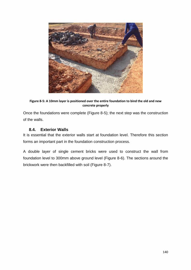
140
Figure 8-5: A 10mm layer is positioned over the entire foundation to bind the old and new concrete properly
Once the foundations were complete (Figure 8-5); the next step was the construction
of the walls.
8.4. Exterior Walls
It is essential that the exterior walls start at foundation level. Therefore this section
forms an important part in the foundation construction process.
A double layer of single cement bricks were used to construct the wall from
foundation level to 300mm above ground level (Figure 8-6). The sections around the
brickwork were then backfilled with soil (Figure 8-7).
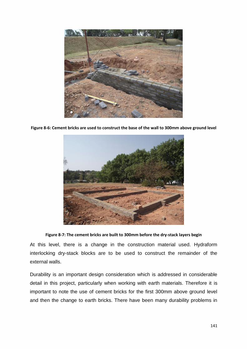
141
Figure 8-6: Cement bricks are used to construct the base of the wall to 300mm above ground level
Figure 8-7: The cement bricks are built to 300mm before the dry-stack layers begin
At this level, there is a change in the construction material used. Hydraform
interlocking dry-stack blocks are to be used to construct the remainder of the
external walls.
Durability is an important design consideration which is addressed in considerable
detail in this project, particularly when working with earth materials. Therefore it is
important to note the use of cement bricks for the first 300mm above ground level
and then the change to earth bricks. There have been many durability problems in

142
many projects, in both South Africa and Algeria, where earth blocks are used at
ground level. This is due to the collection of rainwater at the base and in turn, the
rapid deterioration of these bricks. Soil blocks have been known to loose as much as
70% strength if submerged for long periods of time (Ipinge, 2012).
To ensure that no durability problems arise, to minimise maintenance needs, cement
bricks are used to the required height, followed by a damp proof course (DPC)
(Figure 8-8). The DPC layer (plastic sheeting) is placed before the first layer of dry
stack blocks are placed. This ensures that no water passes through the DPC layer
and absorbed by the CSEB. The first layer of blocks has to be mortared to the DPC
layer. All succeeding layers are simply dry-stacked and interlocked, with no mortar
required in the joints. Builder’s line is used to ensure that the first layer of blocks is
perfectly level. This is extremely important to ensure that the remainder of the blocks
interlock properly. Uneven surfaces will cause openings in joints and interlocking will
be difficult.
Figure 8-8: A layer of DPC is placed between the cement bricks and earth blocks
Dry stack interlocking blocks have many benefits, particularly ease and speed of
construction. The blocks are designed in such a way to slide into one another without

143
requiring mortar. As demonstrated in Figure 8-9, the succeeding courses lock
perfectly, with one another to create a strong and durable wall. The figure also
demonstrates how each course is laid and locked in the opposite direction to the
previous, i.e. one layer will be laid with the ‘front’ of the block facing the right and the
following layer will face the opposite way, to the left (Hydraform, 2012).
Figure 8-9: The method of constructing two courses of dry stack interlocking blocks (Hydraform, 2012, p 55)
When constructing with interlocking blocks, it is important to understand the exact
method of construction to ensure that the blocks interlock properly. The corners are
first built up and then constructed inwards towards the wall centre (Figure 8-10). The
last block is cut to size to ensure it fits snuggly. The last block acts as a key, locking
that specific layer of bricks. This is repeated until the wall is completed (Figure 8-11).
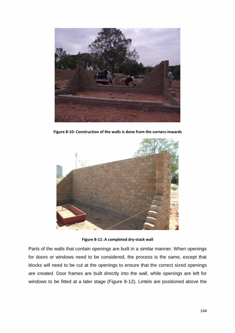
144
Figure 8-10: Construction of the walls is done from the corners-inwards
Figure 8-11: A completed dry-stack wall
Parts of the walls that contain openings are built in a similar manner. When openings
for doors or windows need to be considered, the process is the same, except that
blocks will need to be cut at the openings to ensure that the correct sized openings
are created. Door frames are built directly into the wall, while openings are left for
windows to be fitted at a later stage (Figure 8-12). Lintels are positioned above the
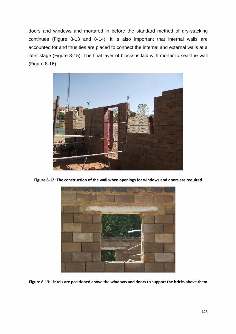
145
doors and windows and mortared in before the standard method of dry-stacking
continues (Figure 8-13 and 8-14). It is also important that internal walls are
accounted for and thus ties are placed to connect the internal and external walls at a
later stage (Figure 8-15). The final layer of blocks is laid with mortar to seal the wall
(Figure 8-16).
Figure 8-12: The construction of the wall when openings for windows and doors are required
Figure 8-13: Lintels are positioned above the windows and doors to support the bricks above them

146
Figure 8-14: Lintels are positioned above all openings to support the bricks above it; the last layer of bricks is mortared in to lock the walls
Figure 8-15: Ties are placed in the wall to connect the exterior and interior walls at a later stage

147
Figure 8-16: The completed walls with the last layer of dry-stack mortared in to lock the walls
The final two layers of the first floor walls are completed using cement bricks (Figure
8-17). This is done to ‘lock’ the wall before the slab is set up, as well as to minimise
cracking caused during expansion. Cracking between the slab and the wall can
occur if there is a large discrepancy in the material properties. Once the slab is set
up, it will expand and shrink with varying temperature variations. By adding two
layers of cement bricks, the expansion difference in the expansion of the wall and
slab will be considerably less than if the slab is connected to the CSEB directly.
Figure 8-17: The completed first level, where the last two layers of bricks are cement bricks
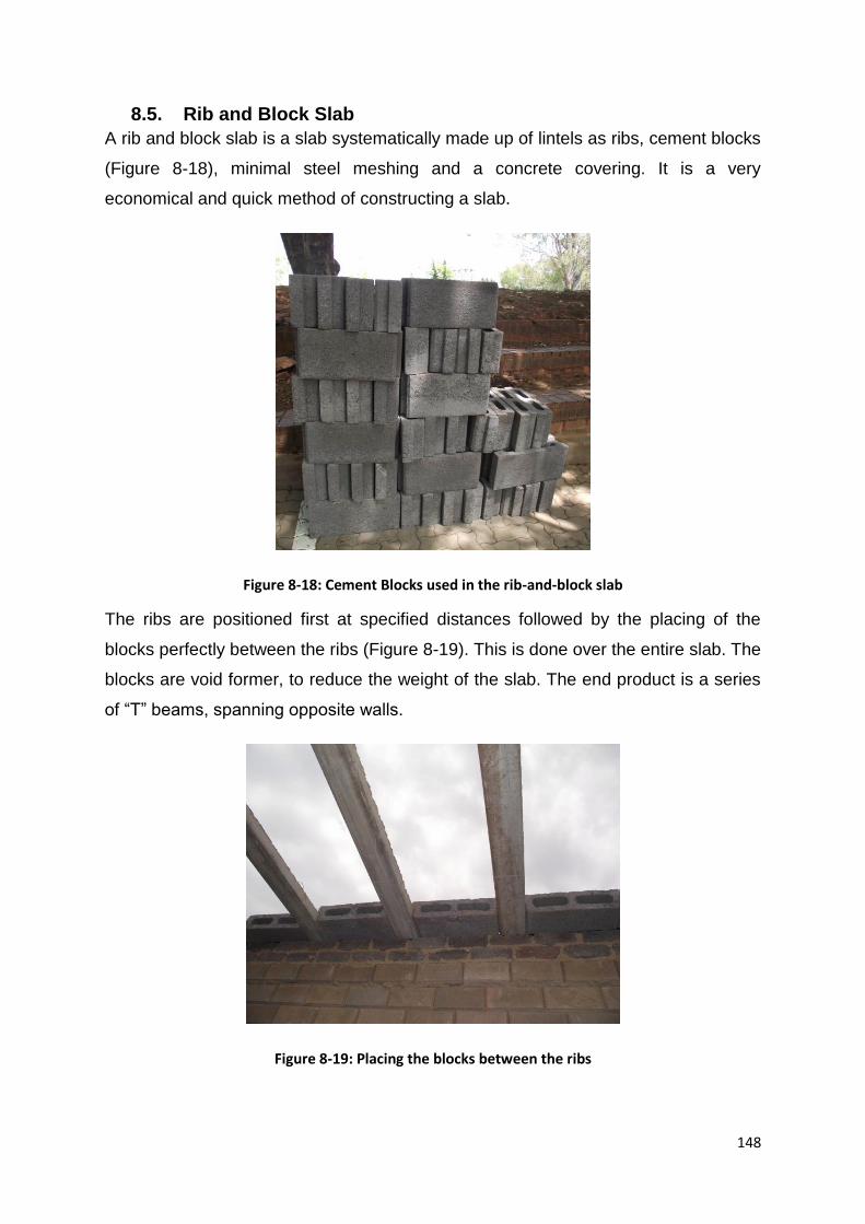
148
8.5. Rib and Block Slab
A rib and block slab is a slab systematically made up of lintels as ribs, cement blocks
(Figure 8-18), minimal steel meshing and a concrete covering. It is a very
economical and quick method of constructing a slab.
Figure 8-18: Cement Blocks used in the rib-and-block slab
The ribs are positioned first at specified distances followed by the placing of the
blocks perfectly between the ribs (Figure 8-19). This is done over the entire slab. The
blocks are void former, to reduce the weight of the slab. The end product is a series
of “T” beams, spanning opposite walls.
Figure 8-19: Placing the blocks between the ribs

149
Props are positioned underneath the slab for support until the concrete is poured and
the slab is sealed (Figure 8-20). Reinforcing and meshing is placed on top of the rib
and block system (Figure 8-21).
Figure 8-20: Props are set up under the slab to support it until concrete is poured
Figure 8-21: Steel mesh and reinforcing is positioned on top of the slab
Before the concrete pour can be done, the slab must be shuttered, but just around
edges. Wood shuttering is placed around all openings, which is removed once the

150
slab has cured (Figure 8-22). Brick shuttering is used around the edges of the slab
so as to allow for an easy continuation of the wall construction.
Figure 8-22: Wood shuttering is used around the openings
Prior to the concrete pour, the lintels and steel ties need to be positioned. This is
discussed in detail in section 8.6. Once the ties are set in place, the concrete is
poured and the slab is left to cure for 7-14 days (Figure 8-23) before the props are
removed.
Figure 8-23: The final concrete pour; the slab is no complete and left to cure
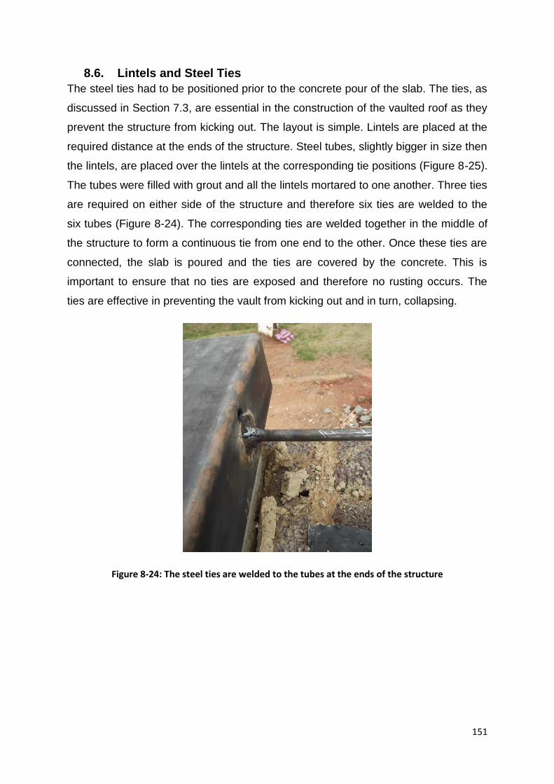
151
8.6. Lintels and Steel Ties
The steel ties had to be positioned prior to the concrete pour of the slab. The ties, as
discussed in Section 7.3, are essential in the construction of the vaulted roof as they
prevent the structure from kicking out. The layout is simple. Lintels are placed at the
required distance at the ends of the structure. Steel tubes, slightly bigger in size then
the lintels, are placed over the lintels at the corresponding tie positions (Figure 8-25).
The tubes were filled with grout and all the lintels mortared to one another. Three ties
are required on either side of the structure and therefore six ties are welded to the
six tubes (Figure 8-24). The corresponding ties are welded together in the middle of
the structure to form a continuous tie from one end to the other. Once these ties are
connected, the slab is poured and the ties are covered by the concrete. This is
important to ensure that no ties are exposed and therefore no rusting occurs. The
ties are effective in preventing the vault from kicking out and in turn, collapsing.
Figure 8-24: The steel ties are welded to the tubes at the ends of the structure

152
Figure 8-25: The tubes are placed over the lintels and then filled with grout
8.7. Vaulted roof
The vaulted roof proved to be the most difficult and time consuming section of the
structure. The construction of the vault is a new experience and thus required a
considerable amount of brain storming and decision making along the way. The
vaults were constructed using the Hydraform Splitter-brick block.
It was decided that a formwork would need to be provided to ensure that the
accuracy of the shape is achieved. A number of materials were considered and
finally, a steel formwork was chosen. The main motivation for choosing this formwork
was accuracy and price. A stencil of the formwork was created and flat bars were
bent to the correct shape (Figure 8-26). Steel allowed us to achieve the best possible
shape with minimal work involved in creating it.

153
Figure 8-26: A stencil is used to determine the shape and guide the bending of the flat bars
The frames were then assembled and braced into a solid one metre length formwork
section (Figure 8-27). Steel sheeting was then riveted onto the outside of the frame,
completing the formwork. The formwork was designed and built to be one metre
shorter in height than the actual vault to allow for easy dropping and shifting of the
formwork. Two identical forms were created so that both vaults could be constructed
simultaneously (Figure 8-28).
Figure 8-27: The steel formworks used to construct the vaults

154
Figure 8-28: The two formworks at site, ready to be lifted and for construction to commence
The form work was lifted onto the slab and propped up on bricks to reach the desired
height, before construction commenced (Figure 8-29).
Figure 8-29: The formwork is propped up onto bricks which can easily be pulled out
The first layer of bricks was constructed prior to the pouring of the slab. This was
essential for two key reasons:

155
1. The ties had to be attached to the first few layers of blocks to ensure that they
worked effectively in case of any outward thrusts created by the structure at
the base
2. The ties had to be covered within the slab to avoid any rusting
Thus, the start of the roof occurs at the slab surface and the remainder is built with
the use of the constructed formwork (Figure 8-30).
Figure 8-30: The first layer of bricks as at the same level as the slab
The process of building the vaults is relatively difficult as the scaffolding needs to be
set up adequately to allow for safe and accurate construction (Figure 8-31). Once the
scaffolding is up, the construction went relatively quickly and accurately due to the
effective formwork. A vault was constructed in metre length sections. Once each
section is completed and allowed to dry, the formwork dropped and repositioned for
the construction of subsequent sections.

156
Figure 8-31: The start of the construction of the vaults
The construction proved to be relatively difficult and slow. The manner in which the
scaffolding was to be positioned, to ensure that the bricks could be laid efficiently,
took considerable brain storming. A flexible and easily adjustable system needed to
be set up as too much time was spent readjusting the formwork as the construction
progressed. The first layer of construction was slow as the scaffolding proved to be a
problem. A system was set up that incorporates scaffolding and steel lip channels.
The lip channels span the entire length of the structure allowing the builders access
between the two vaults.
The first layer of construction was a testing period for the formwork. At the base of
the vault, where the forces are predominantly vertical, the formwork was found to
work very effectively. Further up, where the angle changes to predominantly
horizontal, the formwork began to warp. Certain areas contained insufficient bracing
and the bricks sagged slightly. This was easily solved by propping either the bricks
or the formwork at the warped point until the mortar had hardened. Additional
bracing was added to the formwork once the first layer was completed to avoid
continued warping within the vault. Throughout the construction process, a number
of mistakes occurred (Figure 8-32). At times, layers of blocks had to be removed and
rebuilt to rectify the mistakes.

157
Figure 8-32: Inaccuracies in following the form during construction
The construction, although slow, was extremely accurate (Figure 8-33). The first
layer of construction was the learning curve and the next few layers were completed
quickly.
Figure 8-33: Accurate and efficient construction
The two vaults are built simultaneously so that the thrust force is controlled by both
structures. The vaults are built from either side to prevent distortions in the formwork
and cause inaccuracies in the form (Figure 8-34).

158
Figure 8-34: Constructing on each side to prevent swaying of the formwork under the weight of the vault
Initially, the first length of the vault was constructed and the formwork was left in
position allowing the mortar to set. However, after a day, a crack had formed at the
apex of the vault (Figure 8-35). This crack is caused by the shrinking of the vault as
the mortar dries. The formwork prevents the vault from contracting naturally, creating
a crack along the apex of the vault. Therefore, the manner of drying had to be
adjusted. The final layer of blocks was laid, as before, but the mortar was allowed an
initial set before the formwork was dropped and the vault was allowed to dry
unrestrained. This eliminated cracking at the apex and the remainder of the vaults
were completed with precision and efficiency.

159
Figure 8-35: Cracking occurred along the apex as the vault is restrained from contracting naturally
Once the first layer was complete, the formwork was shifted, repositioned and
construction could continue (Figure 8-36 to 8-37). This was repeated until the entire
structure was completed (Figure).
Figure 8-36: Completing the last few layers in the construction of the first section
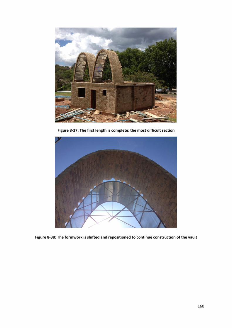
160
Figure 8-37: The first length is complete: the most difficult section
Figure 8-38: The formwork is shifted and repositioned to continue construction of the vault
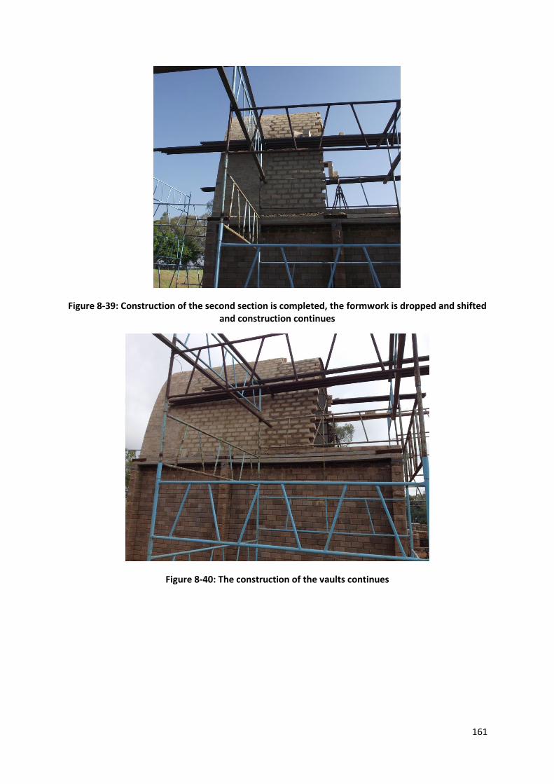
161
Figure 8-39: Construction of the second section is completed, the formwork is dropped and shifted and construction continues
Figure 8-40: The construction of the vaults continues

162
Figure 8-41: Construction of the first vault is almost complete
Figure 8-42: The second vault nearing completion

163
Figure 8-43: The completed vaulted roof
Figure 8-44: The completed catenary roof
8.8. Top Floor Walls
The final step of the construction of the superstructure is the top floor walls (Figure 8-
45 and 8-46). These walls close up the vaults, making it a habitable living space. The
blocks used in the construction of these walls are the Hydraform dry-stack
interlocking blocks. The method of construction followed a similar process as
described in Section 8.4, where window openings had to be accounted for.
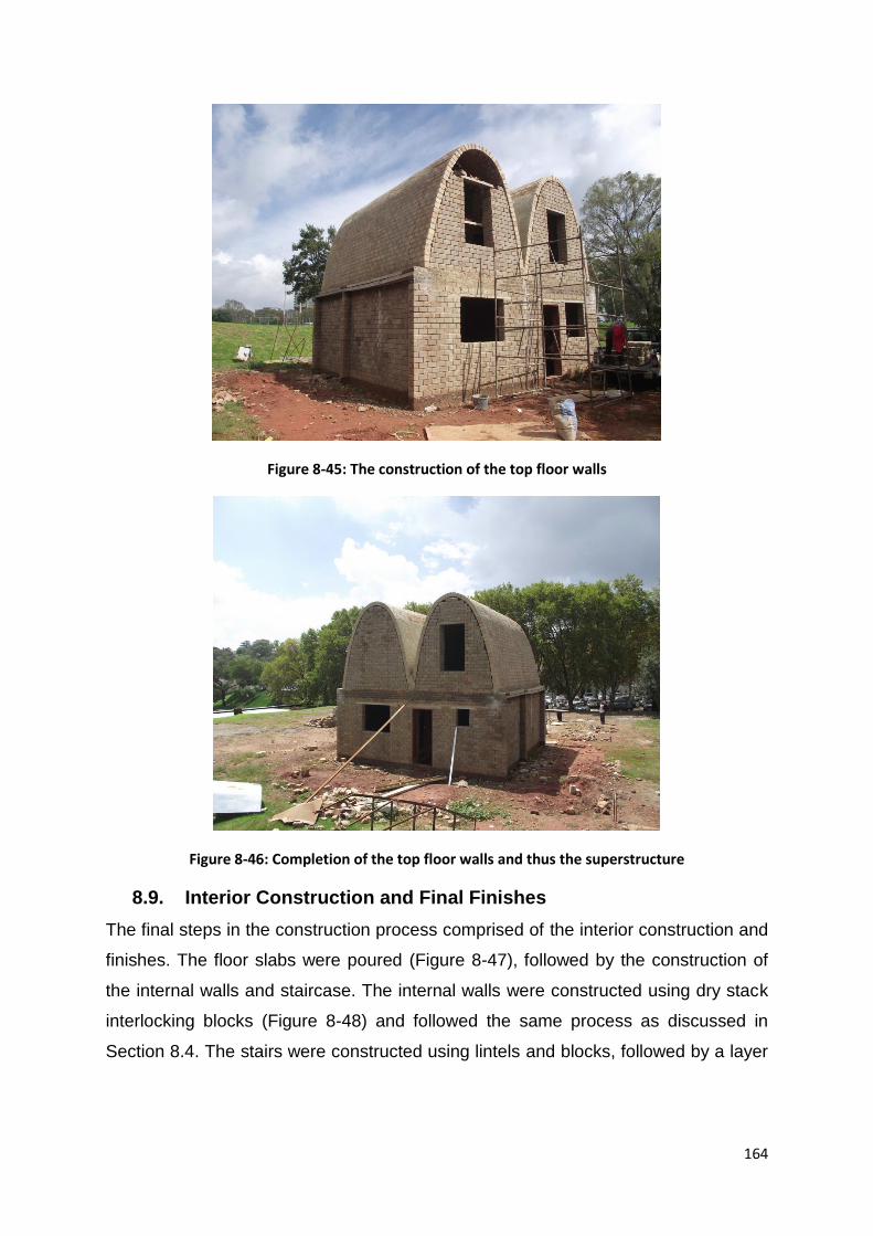
164
Figure 8-45: The construction of the top floor walls
Figure 8-46: Completion of the top floor walls and thus the superstructure
8.9. Interior Construction and Final Finishes
The final steps in the construction process comprised of the interior construction and
finishes. The floor slabs were poured (Figure 8-47), followed by the construction of
the internal walls and staircase. The internal walls were constructed using dry stack
interlocking blocks (Figure 8-48) and followed the same process as discussed in
Section 8.4. The stairs were constructed using lintels and blocks, followed by a layer
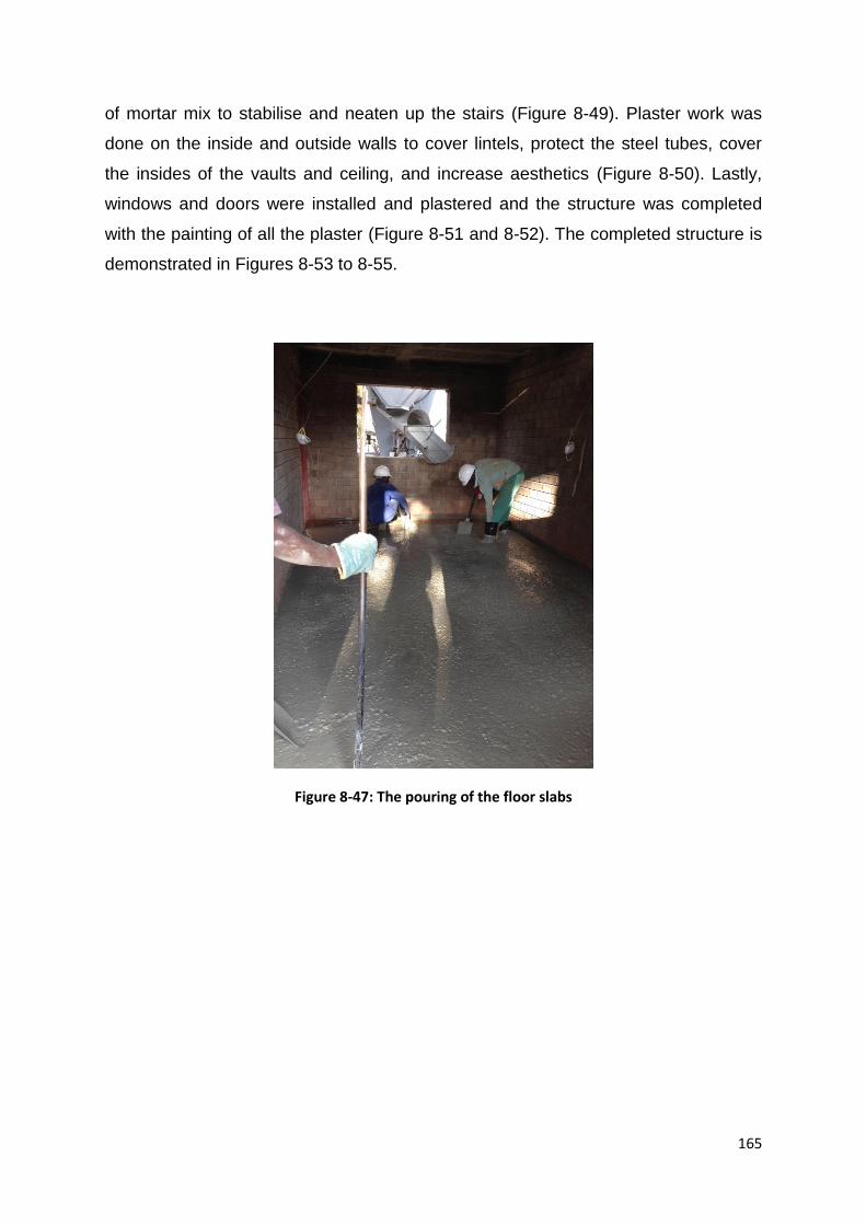
165
of mortar mix to stabilise and neaten up the stairs (Figure 8-49). Plaster work was
done on the inside and outside walls to cover lintels, protect the steel tubes, cover
the insides of the vaults and ceiling, and increase aesthetics (Figure 8-50). Lastly,
windows and doors were installed and plastered and the structure was completed
with the painting of all the plaster (Figure 8-51 and 8-52). The completed structure is
demonstrated in Figures 8-53 to 8-55.
Figure 8-47: The pouring of the floor slabs

166
Figure 8-48: The construction of the internal walls
Figure 8-49: Construction of the staircase using lintels, blocks and mortar
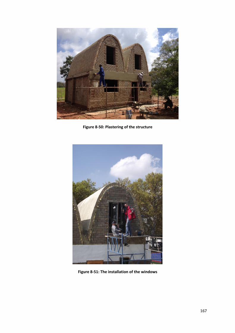
167
Figure 8-50: Plastering of the structure
Figure 8-51: The installation of the windows
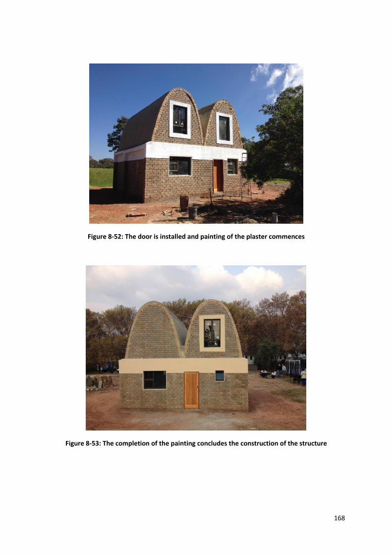
168
Figure 8-52: The door is installed and painting of the plaster commences
Figure 8-53: The completion of the painting concludes the construction of the structure
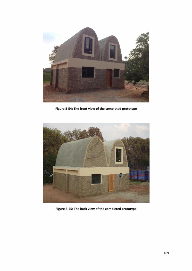
169
Figure 8-54: The front view of the completed prototype
Figure 8-55: The back view of the completed prototype

170
9. Cost Analysis
9.1. Introduction
The cost of constructing this project is vital in establishing whether it is a viable
option for low-cost housing in South Africa. Considerable research has been done in
comparing the costs of various housing solutions, e.g. Talocchino (2005).
When comparing the costs of different housing solutions, various aspects need to be
considered. Some of these aspects include ease of construction, floor size, formwork
required, labour availability, etc. It is essential that people are satisfied with the final
product to ensure it is a success.
In this chapter, a cost breakdown is carried out. This cost is compared to various
other projects, in the Section 10.5, to assess its viability.
This project was funded by a number of generous and interested parties. These
include Hydraform, Spancon, Afrisam, Lintel Suppliers, WISPECO Aluminium,
Macsteel and Robor. Majority of the materials were donated by these companies and
the costing below is that of the actual costing has the materials not been donated
(Table 9-1).
9.2. Breakdown
Table 9-1: A cost breakdown of the materials required for the construction of the low-cost housing prototype
Cost Breakdown of Prototype
Component Quantity Approximate
(Rands)
Approximate
(US Dollars)
Share of
cost (%)
Foundations R20889.32 $2089
21.48%
Reinforcing Steel 420kg (Y and
R) R3902.22 $390
Ready-mix
Concrete 10.7m³ R9497 $950
Brickforce 5 rolls R213.75 $21

171
Bricks 4000 R5000 $500
Cement 10 bags R774.50 $78
Builders sand 3m³ R1466.25 $147
DPC 2 rolls R35.60 $4
Walls R15121.10 $1512
16.55%
Hydraform Blocks 2760 R12420 $1242
Lintels 16 R480 $48
Cement 3 bags R232.35 $23
Builders sand 1m³ R488.75 $49
Bricks 1200 R1500 $150
Slab R11062.71 $1106
11.38%
Ribs 28m² of
slab area R8400 $840 Blocks
Reinforcing steel
Ready-mix
Concrete 3m³ R2662.71 $266
Structural Ties R1600 $160
1.65%
Lintels 12 R990 $99
Steel tubes 33.164kg R200 $20
Steel Ties 6 R288 $29
Cement 1 bag R77.45 $8
Builders sand 0.5m³ R244.38 $24
Vaulted Roof R20167.55 $2017
20.74%
Formwork R6362.05 $636
Steel frames 4 R1181.04 $118
Bracing Varies R2000 $200
Steel sheeting 6 R1844.81 $185
Masonite boards 8 R720 $72
Builders wood 2 R376.20 $38
Gum poles 4 R240 $24
Materials R13805.50 $1381
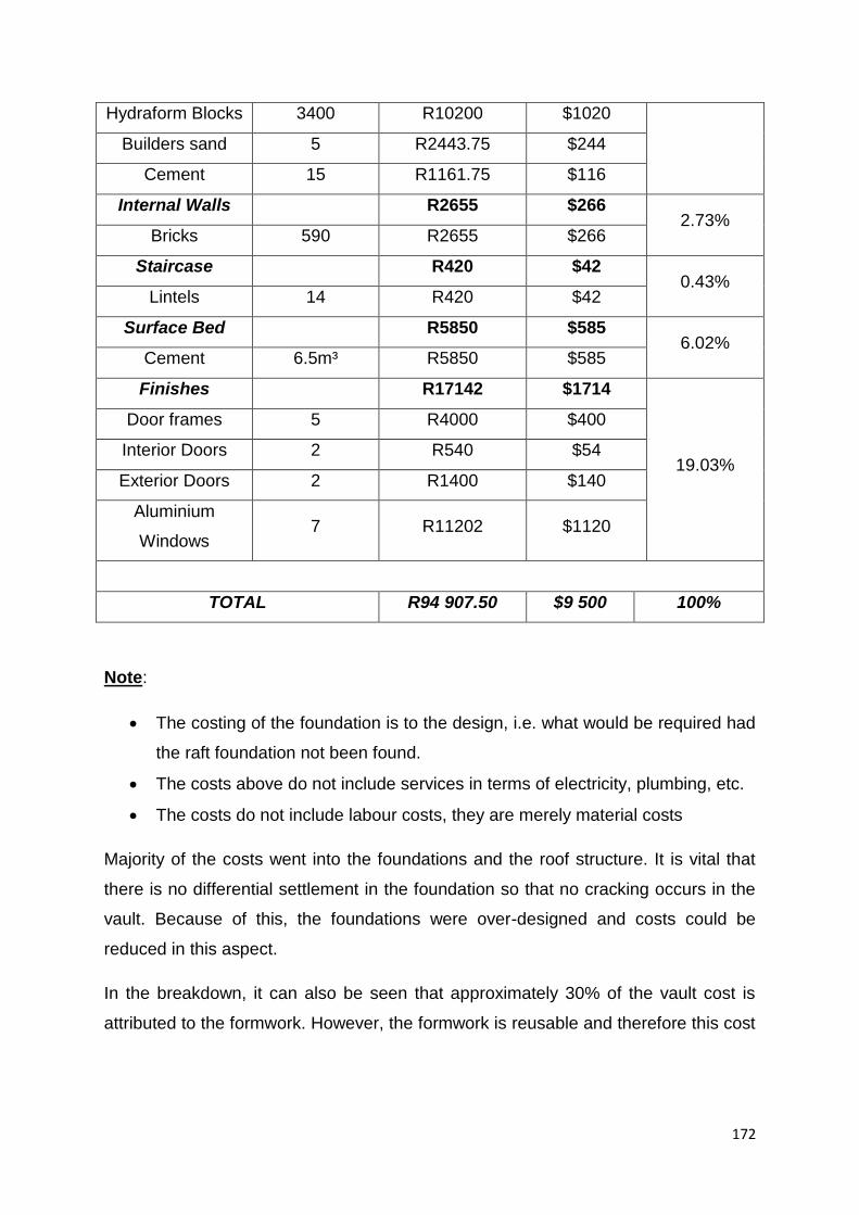
172
Hydraform Blocks 3400 R10200 $1020
Builders sand 5 R2443.75 $244
Cement 15 R1161.75 $116
Internal Walls R2655 $266 2.73%
Bricks 590 R2655 $266
Staircase R420 $42 0.43%
Lintels 14 R420 $42
Surface Bed R5850 $585 6.02%
Cement 6.5m³ R5850 $585
Finishes R17142 $1714
19.03%
Door frames 5 R4000 $400
Interior Doors 2 R540 $54
Exterior Doors 2 R1400 $140
Aluminium
Windows 7 R11202 $1120
TOTAL R94 907.50 $9 500 100%
Note:
The costing of the foundation is to the design, i.e. what would be required had
the raft foundation not been found.
The costs above do not include services in terms of electricity, plumbing, etc.
The costs do not include labour costs, they are merely material costs
Majority of the costs went into the foundations and the roof structure. It is vital that
there is no differential settlement in the foundation so that no cracking occurs in the
vault. Because of this, the foundations were over-designed and costs could be
reduced in this aspect.
In the breakdown, it can also be seen that approximately 30% of the vault cost is
attributed to the formwork. However, the formwork is reusable and therefore this cost

173
will diminish significantly. To reduce these costs, other methods of construction need
to be investigated. The prices stipulated are for a single building. These prices will
change if a larger scale project is implemented. Specific areas where these costs will
change include: formwork costs, brick making machines, foundations, finishes, etc. A
more expensive, but economical formwork can be applied at a larger scale, i.e. an
inflatable formwork (Gohnert, 2011, Wilson, 2005). This method may not be an
affordable solution on a small scale, but other construction methods should be
explored for larger scale developments.
In terms of brick costs, it is more affordable to purchase a block machine when
constructing at a larger scale. This will minimise the costs and time of construction
considerably, when materials are mass produced locally.
There are a number of ways in which the costs can be reduced more or kept at a
minimum. One aspect, which is not covered in this report, is that of labour. The aim
of this project is to involve the community and people who will be living in low-cost
houses. Thus, it is expected that labour costs will be at a minimum due to the
involvement of the residents in all aspects of the project.
174
10. Conclusions and Recommendations
10.1. The superior structural form and layout
A superior structure is not simply defined by its image or cost, but by a number of
different criteria, such as energy efficiency, durability, social acceptance, etc. The
prototype in this project considers a number of various criteria to ensure that the
most efficient and comfortable home is produced, utilising a small budget. The
orientation of the structure, in relation to the sun, to maximise solar power is vital in
ensuring the residents have minimal electricity expenses. In addition, the internal
layout of the home is essential. The internal layout of the house is selected to
maximise on privacy and space, whilst simultaneously creating comfort and natural
light.
A square form is selected for the bottom floor as the most optimal shape for
maximising on space. Since most informal settlements are extremely dense and
each resident has minimal floor area, the house is designed to be a double story
house to maximise on space. Two catenary vaults are designed as the roof structure
as well as the upper floor section. The very high vaults are designed to: 1.) utilise the
upstairs area as a second bedroom and 2.) create a double volume area to provide
natural light and reduce the feeling of confinement. The vaults are also incorporated
to minimise on costs, while simultaneously maximising on thermal efficiency. The
roof is designed as a natural, sustainable form which will require marginal
maintenance due to its superior structural strength.
The most architecturally and structurally efficient structure, the catenary vault, is
designed to maximise on space whilst minimising on costs in all areas (i.e.
maintenance, costs, electricity, etc.) and providing a safe, durable and
environmentally friendly solution for all.
10.2. Essential design considerations for catenary vaults
A method of design, The Segmental Equilibrium Method, was developed in this
report to design catenary vaults. This method permits the accurate design of
catenary vaults under both vertical and lateral loading. However, at present the

175
Segmental Equilibrium Method cannot analyse temperature loading, which is carried
by using finite elements. The Segmental Equilibrium Method is particularly effective
in allowing the user to design the most natural form under the stipulated loading, with
an efficient and accurate method.
It would be substantially more time consuming and labour intensive to define the
same curve in finite element, or using another form of design. The Segmental
Equilibrium Method utilises simple equilibrium equations to define a natural and
efficient curve to support the various loading criteria. The thrust lines under each
loading combination or pattern can be plotted, and the various areas of weakness
identified.
It was found that the loading case which generates the greatest tensile and
compressive forces is that of dead load, wind load (Cpi=0) and a temperature drop of
20° over the right half of the structure. The form of loading is exaggerated as the
temperature will vary along the structure. To simplify analysis and ensure that the
structure is sufficiently designed a worst case temperature loading was investigated
where the entire side was subject to the temperature change. However, this load
does not exceed the strength capacity of the material and the design is therefore
adequate.
The structure exhibits a considerable weakness, and possibly failure, under point
loads. It is clear that two dimensional shells, such as vaults and arches, are not
effective in supporting point loads. Thus, it is recommended that all maintenance is
done from an adjacent support system which provides access to the roof. The design
of the form also takes into consideration this weakness; therefore, a very steep form
is selected where access without additional support is extremely difficult. However,
point loads and shell systems do not mix and is a problem with all shell structures.
10.3. Material selection
The materials used in the construction of the prototype proved to be very effective in
a number of ways. These blocks have excellent thermal properties, are easy to
produce, require minimal energy input in the production phase and are cost effective.
The dry stack interlocking blocks eased the construction process considerably and
176
saved costs in the form of mortar and speed of construction. The splitter-brick blocks
were very effective in the construction of the vaults, as they provided the required
thickness that ordinary bricks would not have. They also ensured that a strong joint
was created in the grove, creating a key between each block.
The blocks exhibit excellent compressive and tensile strengths and are able to
compete with ordinary cement bricks. During the analysis process, the forces
exerted by the wall and vault do not exceed the capacity of the building materials.
The blocks are satisfactory in the construction of double storey buildings as well as
curved forms. However, due to the tensile forces created from the temperature
loading, it is recommended that a waterproof layer or paint is applied onto the
surface of the vaults to minimise the temperature differences in the material.
10.4. Methods of construction
A number of methods of construction were discussed in this report; however, the
method of a sliding formwork was selected and utilised. This method proved to be
very effective in ensuring the form was precise. However, it slowed the construction
process down considerably. Due to the size of the vaults, it was difficult to determine
the amount of bracing required to adequately support the bricks without overloading
the formwork. These forms are heavy and therefore difficult to move, but if they are
not sufficiently braced, warping occurs causing inaccuracies and thus delays in
construction. The formwork must also be dropped after an initial set in the mortar to
allow the vault to contract naturally as the mortar dries. This prevents the structure
from being restrained so no cracks will form.
Even though the construction was accurate, different methods of formwork should be
investigated. More costly methods of construction can also be considered if this
project is applied at mass scale, as recycling the formwork could make it more
efficient and cost effective
10.5. Costing analysis
The prototype form is an innovative and effective solution to low-cost housing. The
cost of current RDP infrastructure programme in South Africa has been found to be
ineffective (Blumenfeld, 1996). For smaller floor areas, the cost is only marginally
177
less i.e. costs approximately R1500/m² ($150/m²) (Mica, 2013). However, some
literature suggests that costs can reach R2400/m² ($240/m²) for a RDP house
(Mabeba, n.d.). This thesis presents a new solution to lost-cost housing which is
approximately double in floor size to an RDP house and costs only in the range of
11% to 30% more. However, labour costs still need to be incorporated in the
calculations and this could cause the costs to vary considerably depending on the
community involvement. The costs provided above will also vary considerably if the
project is applied at a larger scale as production and costs of bricks will be
considerably less. Catenary vaults as a solution to low-cost housing is a viable and
cost effective solution in South Africa.

178
References
Allen, E., & Zalewski, W. (2010). From and Forces: Designing efficient, expressive structures. New
Jersey: John Wiley & Sons, Inc.
Argyris, J. (1954). Energy Theorems and Structural Analysis: A Generalized Discourse with
Applications on Energy Principles of Structural Analysis Including the Effects of Temperature
and Non-Linear Stress-Strain Relations. Aircraft Engineering and Aerospace Technology, Vol
26, p 347 - 356.
Atamturktur, H. (2006). Structural Assesment of Guastavino Domes. Pennsylvania: The Pennsylvania
State University.
Auroville Earth Institute. (2012). Auroville Earth Institute: UNESCO Chair Earthern Architecture.
Retrieved January 14, 2013, from Auroville Earth Institute Web Site: http://www.earth-
auroville.com/index.php
Bahar, R., Benazzoug, M., & Kenai, S. (2004). Performance of compacted cement-stabilised soil.
Elsevier, Vol 26, p 811-820.
Bartali, H. (1991). La terre arme de paille pour les constructions. Proceedings of the French-Maghreb
Symposium on Construction with Local Materials, p 551.
Bathe, K., & Chapelle, D. (2011). The Finite Element Analysis of Shells – Fundamentals (Second
Edition). Berlin: Springer.
Birkinshaw, M. (2008). A Devil in the Shacks. Retrieved January 24, 2014, from Pambazuka News:
http://www.pambazuka.org/en/category/features/50572
Blackmore, P., & Tsokri, E. (2006). Wind Loads on Curved Roofs. Journal of Wind Engineering and
Industrial Aerodynamics, Vol 94, p 833–844.
Blumenfeld, J. (1996). RDP RIP? Reflections on economic growth and development policy in South
Africa. Retrieved January 31, 2013, from Africa Portal Library:
http://www.africaportal.org/dspace/articles/rdp-rip-reflections-economic-growth-and-
development-policy-south-africa
Braxton, K. (2013). The Cost Breakdown of a Typical House. Retrieved September 30, 2013, from
RMB Building & Design Llc:
http://www.rmbbuildinganddesign.com/blog.php?filter=post&blog_id=85
British Standards Institute. (1996). EN 1996-1-1: Eurocode 6: Design of Masonry Structures. London:
British Standards Institute.
British Standards Institution. (1992). BS 5628:Part1- 1992: Structural Use of Unreinforced Masonry.
London: British Standards Institute Group.
179
British Standards Institution. (1997). BS 8110-1: Structural use of concrete. Code of practice for
design and construction. London: British Standards Institute Group.
Calderwood, D. (1953). Native Housing in South Africa. Johannesburg: University of the
Witwatersrand.
Carlson, S. (2013). Catenary: Encyclopædia Britannica Online Academic Edition. Retrieved October
14, 2013, from Encyclopædia Britannica:
http://www.britannica.com/EBchecked/topic/99414/catenary
Chilton, J. (2000). The Engineer's Contribution to Contemporary Architecture: Heinz Isler. London:
Thomas Telford Publishing.
Chryso. (2008). Concrete Admixtures: Chryso Pareflo 10. Retrieved October 10, 2013, from Chryso:
Chemical Solutions for the Construction Material Industry:
http://www.chryso.com/upload/t_documents/Fichier_L2/48811/FP_Pareflo10_GB_Issy_L10
022-HD.pdf
Chryso SA. (2012). Foxing Efflorescence. Retrieved October 10, 2013, from CHRYSO Southern Africa
(Pty) Ltd.: http://za.chryso.com/upload/t_documents/Fichier_L1/48885/monier_article.pdf
City of Johannesburg. (2008). Housing Week starts in a frenzy. Retrieved September 30, 2013, from
Official Website Of The City Of Johannesburg:
http://www.joburg.org.za/index.php?option=com_content&task=view&id=2544&Itemid=20
4
CNERIB. (1991). MATLOC 91; Ministry of Housing. Proceedings of Maghrebin Symposium on
Development of Construction with Local Materials, p 209.
Conant, K. (1944). Observations on the Vaulting Problems of the Period 1088-1211. Gazette des
Beaux-Arts, 127-34, ser.6, vol xxvi.
Cowan, H. (1977). A History of Masonry and Concrete Domes in Building Construction. Building and
Construction, vol. 12, pp.1-24.
Fernandez, R. (2003). Fibre Reinforced Soil Crete Blocks for the Construction of Low-Cost Housing.
Johannesburg: MSc Dissertation, University of the Witwatersrand.
FinScope. (2007). My home is my castle/cluster/townhouse/shack – housing in South Africa. South
Africa: FinScope.
Fitchen, J. (1961). The Construction of Gothic cathedrals. Oxford: The Clarendon Press.
Fitchett, A. (2009b). Timbrel Vaults From Stabilized Earth Tile. Bath: NOCMAT Conference.
Gohnert, M. (2011). Thin Shell Earth Structures: A Low Cost Housing Solution. Inaugural speech:
University of the Witwatersrand.

180
Grigonis, R. (2011). The Gateway Arch — Its History and Architecture. Retrieved January 15, 2014,
from Interesting America: http://www.interestingamerica.com/2011-04-
09_Gateway_Arch_Architecture_by_R_Grigonis_41.html
Houben, H., & Boubekeur, S. (1998). Compressed Earth Blocks: standards. Brussels: CRATerre-EAG.
Huerta, S. (2003). The Mechanics of Timbrel vaults: A Historical Outline. Becchi, A, F. Foce and O
Pedemonte eds. Essays on the History of Mechanics. Birkhauser.
Huerta, S. (2006). Structural Design in the Work of Gaudi. Architectural Science Review, Vol 49.2, p
324-339.
Hydraform. (2012). Hydraform Training Manual. Johnnesburg: Hydraform.
Hymers, P. (2005). Planning and Building a Conservatory. New Holland, p 36.
Ipinge, I. (2012). Durability of compressed stabilised earth blocks. Johannesburg: MSc Dissertation,
University of the Witwatersrand.
Joffroy, T. (1994). The Basics of Building with Arches, Vaults and Cupolas. St. Gallen: SKAT.
Lintel Suppliers. (2009). Services: Lintel Suppliers. Retrieved November 11, 2013, from Lintel
Suppliers: http://www.lintelsuppliers.co.za/services.html
Mabeba, P. (n.d.). Lynedoch Pilot RDP House. Cape Town: Sustainability Institute.
Magaia, S. (2003). Domes in Low-Cost Housing. Johannesburg: MSc Dissertation, University of the
Witwatersrand.
Mica. (2013). Mica FAQ's. Retrieved January 23, 2014, from Mica Web site:
http://www.mica.co.za/index.php/faqs/item/46-how-much-does-it-cost-to-build-per-
square-metre
Minke, G. (2000). Earth Construction Handbook: The building material earth in a modern
architecture. Boston: WIT Press.
Ochsendorf, J. (2010). Guastavino Vaulting The Art Of Structural Tiling. New York: Princeton
Architectural Press.
Ramage, M. (2004). Building A Catalan Vault. Retrieved from Massachusetts Institute of Technology:
http://www.guastavino.net/
Rhyner, K., Melendez, M., Ruiz, P., & Castro, M. (1998). Un techno como un arcoiris: bovedas de
ladrillos en la construccion popular. ECOSUR, group sofonias/CIDEM.
SABS. (2000). SABS 0100-1: South African Standard Code of Practice; The structural use of concrete.
Pretoria: The South African Bureau of Standards.
181
SAPA. (2011). RDP houses to 'bona fide' citizens. Retrieved September 30, 2013, from News24:
http://www.news24.com/SouthAfrica/News/RDP-houses-to-bona-fide-citizens-20111019
Sennott, S. (2004). Encyclopedia of Twentieth Century Architecture. Taylor & Francis, p 224.
South African Bureau of Standards. (1980). SABS 0164-1: 1980: Unreinforced Masonry. Pretoria:
SABS.
South African Bureau of Standards. (2000). SABS 0100-1: South African Standard Code of Practice;
The structural use of concrete. Pretoria: The South African Bureau of Standards.
South African Bureau of Standards. (2009). SABS 0160-2: South African Standard Code of Practice;
Self-weight and Imposed Load. Pretoria: The South African Bureau of Standards.
South African Bureau of Standards. (2009). SABS 0160-3: South African Standard Code of Practice;
Wind Actions. Pretoria: The South African Bureau of Standards.
Spancon. (2013). Rib and Block Slabs. Retrieved November 10, 2013, from SPANCON:
http://www.spancon.co.za/rib-and-block-slabs/
Talocchino, G. (2005). Design & Construction Criteria for Domes in Low-Cost housing. Johannesburg:
MSc Dissertation, University of the Witwatersrand.
Tarragó, S. (2002). Guastavino Company (1885-1962), Catalogue of Works in Catalonia and.
Barcelona: Collegi d'Arquitectes de Catalunya.
Taylor, H. (2011). New Construction Cost Breakdown. Retrieved September 30, 2013, from National
Assocation of Home Builders: http://www.nahb.org/generic.aspx?genericContentID=169974
The Weather Channel. (2009). Youtube. Retrieved February 17, 2012, from Man Survives Hurricane
Ivan inHUrricane-Proof House:
http://www.youtube.com/watch?v=St4umWJttYk&feature=related
Uzoegbo, H., & Hobona, D. (1999). The Structural Behaviour of dry-stacked walls. Johannesburg:
Research project. University of the Witwatersrand.
Weisstein, E. (n.d.). Catenary. From MathWorld--A Wolfram Web Resource:
http://mathworld.wolfram.com/Catenary.html.
Wilson, A. (2005). Practical Design of Concrete Shells. Monolithic Dome Institute.

182
Appendix A

X Y
1 128.20 0.55 80.50 2.91 17.38 17.62 -2.91 -16.83 17.08 80.19 0 0
2 128.20 0.55 80.19 2.91 16.83 17.08 -2.91 -16.28 16.54 79.87 21.16 126.44
3 128.20 0.55 79.87 2.91 16.28 16.54 -2.91 -15.73 15.99 79.52 42.99 252.76
4 128.20 0.55 79.52 2.91 15.73 15.99 -2.91 -15.17 15.45 79.15 65.54 378.96
5 128.20 0.55 79.15 2.91 15.17 15.45 -2.91 -14.62 14.91 78.75 88.86 505.02
6 128.20 0.55 78.75 2.91 14.62 14.91 -2.91 -14.07 14.37 78.32 112.99 630.93
7 128.20 0.55 78.32 2.91 14.07 14.37 -2.91 -13.52 13.83 77.86 138.00 756.66
8 128.20 0.55 77.86 2.91 13.52 13.83 -2.91 -12.97 13.29 77.36 163.95 882.20
9 128.20 0.55 77.36 2.91 12.97 13.29 -2.91 -12.42 12.75 76.81 190.92 1007.53
10 128.20 0.55 76.81 2.91 12.42 12.75 -2.91 -11.86 12.21 76.22 218.98 1132.62
11 128.20 0.55 76.22 2.91 11.86 12.21 -2.91 -11.31 11.68 75.58 248.22 1257.44
12 128.20 0.55 75.58 2.91 11.31 11.68 -2.91 -10.76 11.15 74.87 278.75 1381.95
13 128.20 0.55 74.87 2.91 10.76 11.15 -2.91 -10.21 10.61 74.10 310.67 1506.11
14 128.20 0.55 74.10 2.91 10.21 10.61 -2.91 -9.66 10.08 73.24 344.13 1629.86
15 128.20 0.55 73.24 2.91 9.66 10.08 -2.91 -9.10 9.56 72.28 379.26 1753.15
16 128.20 0.55 72.28 2.91 9.10 9.56 -2.91 -8.55 9.03 71.22 416.23 1875.90
17 128.20 0.55 71.22 2.91 8.55 9.03 -2.91 -8.00 8.51 70.02 455.24 1998.02
18 128.20 0.55 70.02 2.91 8.00 8.51 -2.91 -7.45 8.00 68.67 496.52 2119.39
19 128.20 0.55 68.67 2.91 7.45 8.00 -2.91 -6.90 7.49 67.13 540.32 2239.87
20 128.20 0.55 67.13 2.91 6.90 7.49 -2.91 -6.35 6.98 65.37 586.95 2359.29
21 128.20 0.55 65.37 2.91 6.35 6.98 -2.91 -5.79 6.48 63.34 636.76 2477.41
22 128.20 0.55 63.34 2.91 5.79 6.48 -2.91 -5.24 5.99 60.98 690.18 2593.95
23 128.20 0.55 60.98 2.91 5.24 5.99 -2.91 -4.69 5.52 58.19 747.70 2708.52
24 128.20 0.55 58.19 2.91 4.69 5.52 -2.91 -4.14 5.06 54.90 809.90 2820.62
25 128.20 0.55 54.90 2.91 4.14 5.06 -2.91 -3.59 4.62 50.96 877.46 2929.57
26 128.20 0.55 50.96 2.91 3.59 4.62 -2.91 -3.03 4.20 46.22 951.18 3034.45
27 128.20 0.55 46.22 2.91 3.03 4.20 -2.91 -2.48 3.82 40.49 1031.92 3134.02
28 128.20 0.55 40.49 2.91 2.48 3.82 -2.91 -1.93 3.49 33.58 1120.63 3226.57
29 128.20 0.55 33.58 2.91 1.93 3.49 -2.91 -1.38 3.22 25.37 1218.13 3309.81
30 128.20 0.55 25.37 2.91 1.38 3.22 -2.91 -0.83 3.02 15.88 1324.93 3380.72
31 128.20 0.55 15.88 2.91 0.83 3.02 -2.91 -0.28 2.92 5.42 1440.76 3435.65
32 128.20 0.55 5.42 2.91 0.28 2.92 -2.91 0.28 2.92 -5.42 1564.06 3470.74
Left Thrust
y
Segment
no.
Height of
SegmentWeight Left Angle
Left Thrust
xCo-ordinates
Left ThrustRight
Thrust x
Right
Thrust y
Right
ThrustRight angle
183

33 128.20 0.55 -5.42 2.91 -0.28 2.92 -2.91 0.83 3.02 -15.88 1691.69 3482.85
34 128.20 0.55 -15.88 2.91 -0.83 3.02 -2.91 1.38 3.22 -25.37 1819.31 3470.74
35 128.20 0.55 -25.37 2.91 -1.38 3.22 -2.91 1.93 3.49 -33.58 1942.61 3435.65
36 128.20 0.55 -33.58 2.91 -1.93 3.49 -2.91 2.48 3.82 -40.49 2058.44 3380.72
37 128.20 0.55 -40.49 2.91 -2.48 3.82 -2.91 3.03 4.20 -46.22 2165.24 3309.81
38 128.20 0.55 -46.22 2.91 -3.03 4.20 -2.91 3.59 4.62 -50.96 2262.74 3226.57
39 128.20 0.55 -50.96 2.91 -3.59 4.62 -2.91 4.14 5.06 -54.90 2351.45 3134.02
40 128.20 0.55 -54.90 2.91 -4.14 5.06 -2.91 4.69 5.52 -58.19 2432.20 3034.45
41 128.20 0.55 -58.19 2.91 -4.69 5.52 -2.91 5.24 5.99 -60.98 2505.91 2929.57
42 128.20 0.55 -60.98 2.91 -5.24 5.99 -2.91 5.79 6.48 -63.34 2573.48 2820.62
43 128.20 0.55 -63.34 2.91 -5.79 6.48 -2.91 6.35 6.98 -65.37 2635.68 2708.52
44 128.20 0.55 -65.37 2.91 -6.35 6.98 -2.91 6.90 7.49 -67.13 2693.19 2593.95
45 128.20 0.55 -67.13 2.91 -6.90 7.49 -2.91 7.45 8.00 -68.67 2746.61 2477.41
46 128.20 0.55 -68.67 2.91 -7.45 8.00 -2.91 8.00 8.51 -70.02 2796.42 2359.29
47 128.20 0.55 -70.02 2.91 -8.00 8.51 -2.91 8.55 9.03 -71.22 2843.05 2239.87
48 128.20 0.55 -71.22 2.91 -8.55 9.03 -2.91 9.10 9.56 -72.28 2886.85 2119.39
49 128.20 0.55 -72.28 2.91 -9.10 9.56 -2.91 9.66 10.08 -73.24 2928.13 1998.02
50 128.20 0.55 -73.24 2.91 -9.66 10.08 -2.91 10.21 10.61 -74.10 2967.14 1875.90
51 128.20 0.55 -74.10 2.91 -10.21 10.61 -2.91 10.76 11.15 -74.87 3004.12 1753.15
52 128.20 0.55 -74.87 2.91 -10.76 11.15 -2.91 11.31 11.68 -75.58 3039.25 1629.86
53 128.20 0.55 -75.58 2.91 -11.31 11.68 -2.91 11.86 12.21 -76.22 3072.70 1506.11
54 128.20 0.55 -76.22 2.91 -11.86 12.21 -2.91 12.42 12.75 -76.81 3104.63 1381.95
55 128.20 0.55 -76.81 2.91 -12.42 12.75 -2.91 12.97 13.29 -77.36 3135.15 1257.44
56 128.20 0.55 -77.36 2.91 -12.97 13.29 -2.91 13.52 13.83 -77.86 3164.39 1132.62
57 128.20 0.55 -77.86 2.91 -13.52 13.83 -2.91 14.07 14.37 -78.32 3192.45 1007.53
58 128.20 0.55 -78.32 2.91 -14.07 14.37 -2.91 14.62 14.91 -78.75 3219.42 882.20
59 128.20 0.55 -78.75 2.91 -14.62 14.91 -2.91 15.17 15.45 -79.15 3245.37 756.66
60 128.20 0.55 -79.15 2.91 -15.17 15.45 -2.91 15.73 15.99 -79.52 3270.38 630.93
61 128.20 0.55 -79.52 2.91 -15.73 15.99 -2.91 16.28 16.54 -79.87 3294.51 505.02
62 128.20 0.55 -79.87 2.91 -16.28 16.54 -2.91 16.83 17.08 -80.19 3317.83 378.96
63 128.20 0.55 -80.19 2.91 -16.83 17.08 -2.91 17.38 17.62 -80.50 3340.38 252.76
3362.21 126.44
3383.37 0
184

X Y
1 130 0.456 80.200 2.519 14.582 14.797 -2.519 -14.125 14.348 79.890 0 0
2 130 0.457 79.890 2.519 14.125 14.348 -2.519 -13.668 13.899 79.559 22.127 128.103
3 130 0.457 79.559 2.519 13.668 13.899 -2.519 -13.212 13.449 79.207 44.948 256.084
4 130 0.457 79.207 2.519 13.212 13.449 -2.519 -12.754 13.001 78.829 68.506 383.932
5 130 0.458 78.829 2.519 12.754 13.001 -2.519 -12.297 12.552 78.424 92.851 511.632
6 130 0.458 78.424 2.519 12.297 12.552 -2.519 -11.839 12.104 77.989 118.036 639.169
7 130 0.458 77.989 2.519 11.839 12.104 -2.519 -11.380 11.656 77.520 144.122 766.525
8 130 0.459 77.520 2.519 11.380 11.656 -2.519 -10.921 11.208 77.014 171.174 893.679
9 130 0.459 77.014 2.519 10.921 11.208 -2.519 -10.462 10.761 76.464 199.266 1020.608
10 130 0.460 76.464 2.519 10.462 10.761 -2.519 -10.002 10.314 75.866 228.480 1147.283
11 130 0.460 75.866 2.519 10.002 10.314 -2.519 -9.542 9.869 75.213 258.907 1273.672
12 130 0.461 75.213 2.519 9.542 9.869 -2.519 -9.081 9.424 74.498 290.652 1399.736
13 130 0.462 74.498 2.519 9.081 9.424 -2.519 -8.619 8.980 73.711 323.830 1525.431
14 130 0.462 73.711 2.519 8.619 8.980 -2.519 -8.157 8.537 72.840 358.576 1650.702
15 130 0.463 72.840 2.519 8.157 8.537 -2.519 -7.693 8.095 71.873 395.039 1775.483
16 130 0.464 71.873 2.519 7.693 8.095 -2.519 -7.229 7.655 70.792 433.395 1899.696
17 130 0.465 70.792 2.519 7.229 7.655 -2.519 -6.764 7.218 69.577 473.841 2023.244
18 130 0.466 69.577 2.519 6.764 7.218 -2.519 -6.298 6.783 68.202 516.612 2146.007
19 130 0.468 68.202 2.519 6.298 6.783 -2.519 -5.830 6.351 66.636 561.975 2267.835
20 130 0.469 66.636 2.519 5.830 6.351 -2.519 -5.361 5.923 64.836 610.248 2388.540
21 130 0.471 64.836 2.519 5.361 5.923 -2.519 -4.891 5.501 62.752 661.803 2507.881
22 130 0.473 62.752 2.519 4.891 5.501 -2.519 -4.418 5.086 60.314 717.079 2625.543
23 130 0.475 60.314 2.519 4.418 5.086 -2.519 -3.943 4.679 57.434 776.599 2741.117
24 130 0.477 57.434 2.519 3.943 4.679 -2.519 -3.466 4.285 53.998 840.982 2854.055
25 130 0.480 53.998 2.519 3.466 4.285 -2.519 -2.986 3.907 49.857 910.957 2963.615
26 130 0.483 49.857 2.519 2.986 3.907 -2.519 -2.503 3.551 44.825 987.373 3068.785
27 130 0.487 44.825 2.519 2.503 3.551 -2.519 -2.017 3.227 38.684 1071.184 3168.161
28 130 0.490 38.684 2.519 2.017 3.227 -2.519 -1.526 2.945 31.216 1163.388 3259.804
29 130 0.494 31.216 2.519 1.526 2.945 -2.519 -1.032 2.722 22.288 1264.866 3341.058
30 130 0.497 22.288 2.519 1.032 2.722 -2.519 -0.535 2.575 12.002 1376.044 3408.433
31 130 0.499 12.002 2.519 0.535 2.575 -2.519 -0.037 2.519 0.836 1496.332 3457.738
32 130 0.499 0.836 2.519 0.037 2.519 -2.519 0.462 2.561 -10.398 1623.490 3484.770
Co-ordinatesSegment
no.
Height of
SegmentDL+LL(F) Left Angle
Left Thrust
x
Left
Thrust yLeft Thrust
Right
Thrust x
Right Thrust
y
Right
Thrust
Right
angle
185
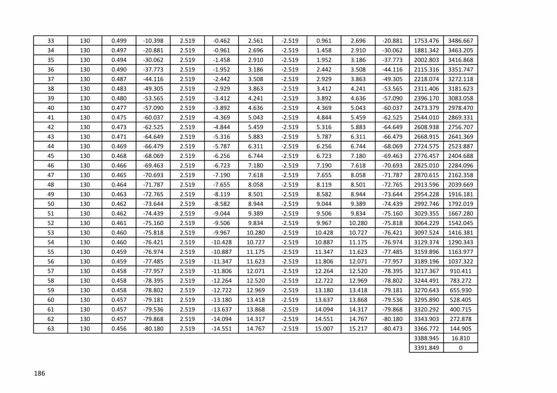
33 130 0.499 -10.398 2.519 -0.462 2.561 -2.519 0.961 2.696 -20.881 1753.476 3486.667
34 130 0.497 -20.881 2.519 -0.961 2.696 -2.519 1.458 2.910 -30.062 1881.342 3463.205
35 130 0.494 -30.062 2.519 -1.458 2.910 -2.519 1.952 3.186 -37.773 2002.803 3416.868
36 130 0.490 -37.773 2.519 -1.952 3.186 -2.519 2.442 3.508 -44.116 2115.316 3351.747
37 130 0.487 -44.116 2.519 -2.442 3.508 -2.519 2.929 3.863 -49.305 2218.074 3272.118
38 130 0.483 -49.305 2.519 -2.929 3.863 -2.519 3.412 4.241 -53.565 2311.406 3181.623
39 130 0.480 -53.565 2.519 -3.412 4.241 -2.519 3.892 4.636 -57.090 2396.170 3083.058
40 130 0.477 -57.090 2.519 -3.892 4.636 -2.519 4.369 5.043 -60.037 2473.379 2978.470
41 130 0.475 -60.037 2.519 -4.369 5.043 -2.519 4.844 5.459 -62.525 2544.010 2869.331
42 130 0.473 -62.525 2.519 -4.844 5.459 -2.519 5.316 5.883 -64.649 2608.938 2756.707
43 130 0.471 -64.649 2.519 -5.316 5.883 -2.519 5.787 6.311 -66.479 2668.915 2641.369
44 130 0.469 -66.479 2.519 -5.787 6.311 -2.519 6.256 6.744 -68.069 2724.575 2523.887
45 130 0.468 -68.069 2.519 -6.256 6.744 -2.519 6.723 7.180 -69.463 2776.457 2404.688
46 130 0.466 -69.463 2.519 -6.723 7.180 -2.519 7.190 7.618 -70.693 2825.010 2284.096
47 130 0.465 -70.693 2.519 -7.190 7.618 -2.519 7.655 8.058 -71.787 2870.615 2162.358
48 130 0.464 -71.787 2.519 -7.655 8.058 -2.519 8.119 8.501 -72.765 2913.596 2039.669
49 130 0.463 -72.765 2.519 -8.119 8.501 -2.519 8.582 8.944 -73.644 2954.228 1916.181
50 130 0.462 -73.644 2.519 -8.582 8.944 -2.519 9.044 9.389 -74.439 2992.746 1792.019
51 130 0.462 -74.439 2.519 -9.044 9.389 -2.519 9.506 9.834 -75.160 3029.355 1667.280
52 130 0.461 -75.160 2.519 -9.506 9.834 -2.519 9.967 10.280 -75.818 3064.229 1542.045
53 130 0.460 -75.818 2.519 -9.967 10.280 -2.519 10.428 10.727 -76.421 3097.524 1416.381
54 130 0.460 -76.421 2.519 -10.428 10.727 -2.519 10.887 11.175 -76.974 3129.374 1290.343
55 130 0.459 -76.974 2.519 -10.887 11.175 -2.519 11.347 11.623 -77.485 3159.896 1163.977
56 130 0.459 -77.485 2.519 -11.347 11.623 -2.519 11.806 12.071 -77.957 3189.196 1037.322
57 130 0.458 -77.957 2.519 -11.806 12.071 -2.519 12.264 12.520 -78.395 3217.367 910.411
58 130 0.458 -78.395 2.519 -12.264 12.520 -2.519 12.722 12.969 -78.802 3244.491 783.272
59 130 0.458 -78.802 2.519 -12.722 12.969 -2.519 13.180 13.418 -79.181 3270.643 655.930
60 130 0.457 -79.181 2.519 -13.180 13.418 -2.519 13.637 13.868 -79.536 3295.890 528.405
61 130 0.457 -79.536 2.519 -13.637 13.868 -2.519 14.094 14.317 -79.868 3320.292 400.715
62 130 0.457 -79.868 2.519 -14.094 14.317 -2.519 14.551 14.767 -80.180 3343.903 272.878
63 130 0.456 -80.180 2.519 -14.551 14.767 -2.519 15.007 15.217 -80.473 3366.772 144.905
3388.945 16.810
3391.849 0
186

X Y1 129 0.450 80.500 2.412 14.412 14.613 -2.412 -13.962 14.169 80.200 0 0
2 129 0.450 80.200 2.412 13.962 14.169 -2.412 -13.512 13.725 79.879 21.291 127.231
3 129 0.451 79.879 2.412 13.512 13.725 -2.412 -13.061 13.282 79.538 43.249 254.348
4 129 0.451 79.538 2.412 13.061 13.282 -2.412 -12.610 12.838 79.172 65.917 381.341
5 129 0.451 79.172 2.412 12.610 12.838 -2.412 -12.158 12.395 78.780 89.342 508.196
6 129 0.452 78.780 2.412 12.158 12.395 -2.412 -11.707 11.953 78.359 113.575 634.900
7 129 0.452 78.359 2.412 11.707 11.953 -2.412 -11.254 11.510 77.905 138.675 761.434
8 129 0.453 77.905 2.412 11.254 11.510 -2.412 -10.802 11.068 77.414 164.705 887.781
9 129 0.453 77.414 2.412 10.802 11.068 -2.412 -10.349 10.626 76.881 191.735 1013.917
10 129 0.454 76.881 2.412 10.349 10.626 -2.412 -9.895 10.185 76.302 219.846 1139.817
11 129 0.454 76.302 2.412 9.895 10.185 -2.412 -9.441 9.744 75.670 249.125 1265.450
12 129 0.455 75.670 2.412 9.441 9.744 -2.412 -8.986 9.304 74.976 279.673 1390.781
13 129 0.455 74.976 2.412 8.986 9.304 -2.412 -8.531 8.865 74.213 311.602 1515.767
14 129 0.456 74.213 2.412 8.531 8.865 -2.412 -8.074 8.427 73.369 345.042 1640.358
15 129 0.457 73.369 2.412 8.074 8.427 -2.412 -7.617 7.990 72.431 380.137 1764.492
16 129 0.458 72.431 2.412 7.617 7.990 -2.412 -7.159 7.555 71.383 417.057 1888.096
17 129 0.459 71.383 2.412 7.159 7.555 -2.412 -6.700 7.121 70.204 455.996 2011.079
18 129 0.460 70.204 2.412 6.700 7.121 -2.412 -6.240 6.690 68.869 497.178 2133.329
19 129 0.461 68.869 2.412 6.240 6.690 -2.412 -5.779 6.262 67.348 540.867 2254.705
20 129 0.463 67.348 2.412 5.779 6.262 -2.412 -5.316 5.838 65.598 587.371 2375.031
21 129 0.464 65.598 2.412 5.316 5.838 -2.412 -4.852 5.418 63.568 637.054 2494.080
22 129 0.466 63.568 2.412 4.852 5.418 -2.412 -4.386 5.005 61.192 690.349 2611.556
23 129 0.468 61.192 2.412 4.386 5.005 -2.412 -3.917 4.600 58.379 747.770 2727.072
24 129 0.471 58.379 2.412 3.917 4.600 -2.412 -3.446 4.206 55.014 809.933 2840.106
25 129 0.474 55.014 2.412 3.446 4.206 -2.412 -2.972 3.828 50.945 877.568 2949.954
26 129 0.477 50.945 2.412 2.972 3.828 -2.412 -2.496 3.471 45.978 951.534 3055.642
27 129 0.480 45.978 2.412 2.496 3.471 -2.412 -2.015 3.143 39.880 1032.813 3155.816
28 129 0.484 39.880 2.412 2.015 3.143 -2.412 -1.531 2.857 32.407 1122.460 3248.576
29 129 0.488 32.407 2.412 1.531 2.857 -2.412 -1.043 2.628 23.391 1221.453 3331.288
30 129 0.491 23.391 2.412 1.043 2.628 -2.412 -0.552 2.474 12.902 1330.363 3400.422
31 129 0.492 12.902 2.412 0.552 2.474 -2.412 -0.060 2.413 1.425 1448.762 3451.636
32 129 0.492 1.425 2.412 0.060 2.413 -2.412 0.432 2.450 -10.166 1574.505 3480.440
Co-ordinatesSegment
no.
Height of
SegmentDL+LL(L) Left Angle
Left Thrust
x
Left Thrust
yLeft Thrust
Right
Thrust x
Right
Thrust y
Right
ThrustRight angle
187
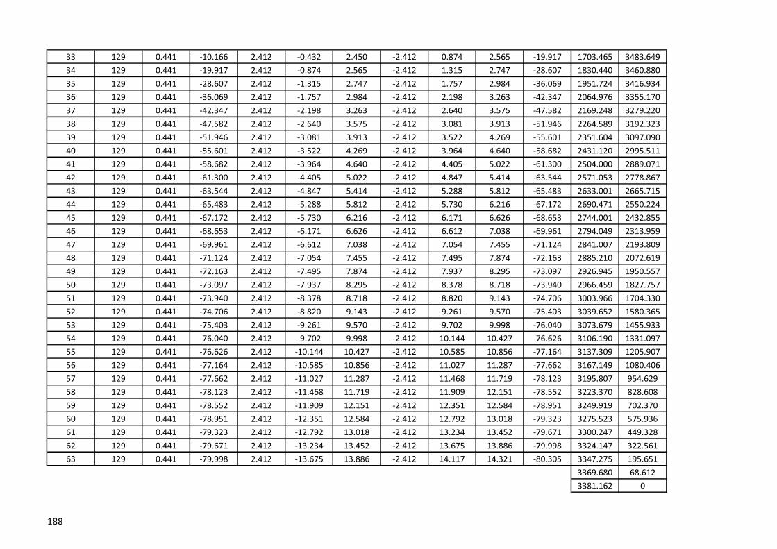
33 129 0.441 -10.166 2.412 -0.432 2.450 -2.412 0.874 2.565 -19.917 1703.465 3483.649
34 129 0.441 -19.917 2.412 -0.874 2.565 -2.412 1.315 2.747 -28.607 1830.440 3460.880
35 129 0.441 -28.607 2.412 -1.315 2.747 -2.412 1.757 2.984 -36.069 1951.724 3416.934
36 129 0.441 -36.069 2.412 -1.757 2.984 -2.412 2.198 3.263 -42.347 2064.976 3355.170
37 129 0.441 -42.347 2.412 -2.198 3.263 -2.412 2.640 3.575 -47.582 2169.248 3279.220
38 129 0.441 -47.582 2.412 -2.640 3.575 -2.412 3.081 3.913 -51.946 2264.589 3192.323
39 129 0.441 -51.946 2.412 -3.081 3.913 -2.412 3.522 4.269 -55.601 2351.604 3097.090
40 129 0.441 -55.601 2.412 -3.522 4.269 -2.412 3.964 4.640 -58.682 2431.120 2995.511
41 129 0.441 -58.682 2.412 -3.964 4.640 -2.412 4.405 5.022 -61.300 2504.000 2889.071
42 129 0.441 -61.300 2.412 -4.405 5.022 -2.412 4.847 5.414 -63.544 2571.053 2778.867
43 129 0.441 -63.544 2.412 -4.847 5.414 -2.412 5.288 5.812 -65.483 2633.001 2665.715
44 129 0.441 -65.483 2.412 -5.288 5.812 -2.412 5.730 6.216 -67.172 2690.471 2550.224
45 129 0.441 -67.172 2.412 -5.730 6.216 -2.412 6.171 6.626 -68.653 2744.001 2432.855
46 129 0.441 -68.653 2.412 -6.171 6.626 -2.412 6.612 7.038 -69.961 2794.049 2313.959
47 129 0.441 -69.961 2.412 -6.612 7.038 -2.412 7.054 7.455 -71.124 2841.007 2193.809
48 129 0.441 -71.124 2.412 -7.054 7.455 -2.412 7.495 7.874 -72.163 2885.210 2072.619
49 129 0.441 -72.163 2.412 -7.495 7.874 -2.412 7.937 8.295 -73.097 2926.945 1950.557
50 129 0.441 -73.097 2.412 -7.937 8.295 -2.412 8.378 8.718 -73.940 2966.459 1827.757
51 129 0.441 -73.940 2.412 -8.378 8.718 -2.412 8.820 9.143 -74.706 3003.966 1704.330
52 129 0.441 -74.706 2.412 -8.820 9.143 -2.412 9.261 9.570 -75.403 3039.652 1580.365
53 129 0.441 -75.403 2.412 -9.261 9.570 -2.412 9.702 9.998 -76.040 3073.679 1455.933
54 129 0.441 -76.040 2.412 -9.702 9.998 -2.412 10.144 10.427 -76.626 3106.190 1331.097
55 129 0.441 -76.626 2.412 -10.144 10.427 -2.412 10.585 10.856 -77.164 3137.309 1205.907
56 129 0.441 -77.164 2.412 -10.585 10.856 -2.412 11.027 11.287 -77.662 3167.149 1080.406
57 129 0.441 -77.662 2.412 -11.027 11.287 -2.412 11.468 11.719 -78.123 3195.807 954.629
58 129 0.441 -78.123 2.412 -11.468 11.719 -2.412 11.909 12.151 -78.552 3223.370 828.608
59 129 0.441 -78.552 2.412 -11.909 12.151 -2.412 12.351 12.584 -78.951 3249.919 702.370
60 129 0.441 -78.951 2.412 -12.351 12.584 -2.412 12.792 13.018 -79.323 3275.523 575.936
61 129 0.441 -79.323 2.412 -12.792 13.018 -2.412 13.234 13.452 -79.671 3300.247 449.328
62 129 0.441 -79.671 2.412 -13.234 13.452 -2.412 13.675 13.886 -79.998 3324.147 322.561
63 129 0.441 -79.998 2.412 -13.675 13.886 -2.412 14.117 14.321 -80.305 3347.275 195.651
3369.680 68.612
3381.162 0
188

X Y1 127 0.441 80.200 2.431 14.074 14.282 -2.431 -13.633 13.848 79.889 0 0
2 127 0.441 79.889 2.431 13.633 13.848 -2.431 -13.191 13.413 79.558 21.617 125.147
3 127 0.441 79.558 2.431 13.191 13.413 -2.431 -12.750 12.979 79.205 43.912 250.174
4 127 0.441 79.205 2.431 12.750 12.979 -2.431 -12.308 12.546 78.827 66.929 375.071
5 127 0.441 78.827 2.431 12.308 12.546 -2.431 -11.867 12.113 78.423 90.716 499.824
6 127 0.441 78.423 2.431 11.867 12.113 -2.431 -11.425 11.681 77.988 115.324 624.417
7 127 0.441 77.988 2.431 11.425 11.681 -2.431 -10.984 11.250 77.520 140.812 748.833
8 127 0.441 77.520 2.431 10.984 11.250 -2.431 -10.543 10.819 77.015 167.242 873.052
9 127 0.441 77.015 2.431 10.543 10.819 -2.431 -10.101 10.390 76.468 194.685 997.052
10 127 0.441 76.468 2.431 10.101 10.390 -2.431 -9.660 9.961 75.874 223.221 1120.804
11 127 0.441 75.874 2.431 9.660 9.961 -2.431 -9.218 9.533 75.227 252.937 1244.279
12 127 0.441 75.227 2.431 9.218 9.533 -2.431 -8.777 9.107 74.519 283.932 1367.439
13 127 0.441 74.519 2.431 8.777 9.107 -2.431 -8.335 8.683 73.741 316.316 1490.240
14 127 0.441 73.741 2.431 8.335 8.683 -2.431 -7.894 8.260 72.884 350.216 1612.632
15 127 0.441 72.884 2.431 7.894 8.260 -2.431 -7.453 7.839 71.934 385.774 1734.553
16 127 0.441 71.934 2.431 7.453 7.839 -2.431 -7.011 7.421 70.877 423.151 1855.928
17 127 0.441 70.877 2.431 7.011 7.421 -2.431 -6.570 7.005 69.694 462.536 1976.667
18 127 0.441 69.694 2.431 6.570 7.005 -2.431 -6.128 6.593 68.363 504.140 2096.659
19 127 0.441 68.363 2.431 6.128 6.593 -2.431 -5.687 6.185 66.855 548.213 2215.766
20 127 0.441 66.855 2.431 5.687 6.185 -2.431 -5.246 5.781 65.135 595.042 2333.818
21 127 0.441 65.135 2.431 5.246 5.781 -2.431 -4.804 5.384 63.159 644.961 2450.596
22 127 0.441 63.159 2.431 4.804 5.384 -2.431 -4.363 4.994 60.872 698.362 2565.823
23 127 0.441 60.872 2.431 4.363 4.994 -2.431 -3.921 4.614 58.203 755.704 2679.141
24 127 0.441 58.203 2.431 3.921 4.614 -2.431 -3.480 4.245 55.062 817.522 2790.080
25 127 0.441 55.062 2.431 3.480 4.245 -2.431 -3.038 3.891 51.337 884.440 2898.020
26 127 0.441 51.337 2.431 3.038 3.891 -2.431 -2.597 3.557 46.891 957.171 3002.131
27 127 0.441 46.891 2.431 2.597 3.557 -2.431 -2.156 3.249 41.563 1036.513 3101.297
28 127 0.441 41.563 2.431 2.156 3.249 -2.431 -1.714 2.975 35.188 1123.303 3194.014
29 127 0.441 35.188 2.431 1.714 2.975 -2.431 -1.273 2.744 27.634 1218.327 3278.272
30 127 0.441 27.634 2.431 1.273 2.744 -2.431 -0.831 2.569 18.879 1322.119 3351.458
31 127 0.441 18.879 2.431 0.831 2.569 -2.431 -0.390 2.462 9.111 1434.632 3410.363
32 127 0.492 9.111 2.431 0.390 2.462 -2.431 0.103 2.433 -2.417 1554.801 3451.455
Co-ordinatesSegment
no.
Height of
SegmentDL+LL(R) Left Angle
Left Thrust
x
Left Thrust
yLeft Thrust
Right
Thrust x
Right
Thrust y
Right
ThrustRight angle
189
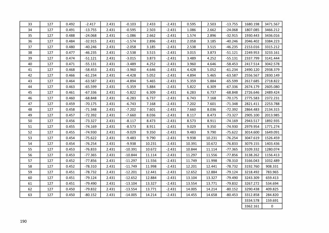
33 127 0.492 -2.417 2.431 -0.103 2.433 -2.431 0.595 2.503 -13.755 1680.198 3471.567
34 127 0.491 -13.755 2.431 -0.595 2.503 -2.431 1.086 2.662 -24.068 1807.085 3466.212
35 127 0.488 -24.068 2.431 -1.086 2.662 -2.431 1.574 2.896 -32.915 1930.443 3436.016
36 127 0.484 -32.915 2.431 -1.574 2.896 -2.431 2.058 3.185 -40.246 2046.402 3384.223
37 127 0.480 -40.246 2.431 -2.058 3.185 -2.431 2.538 3.515 -46.235 2153.016 3315.212
38 127 0.477 -46.235 2.431 -2.538 3.515 -2.431 3.015 3.873 -51.121 2249.953 3233.161
39 127 0.474 -51.121 2.431 -3.015 3.873 -2.431 3.489 4.252 -55.131 2337.799 3141.444
40 127 0.471 -55.131 2.431 -3.489 4.252 -2.431 3.960 4.646 -58.453 2417.514 3042.578
41 127 0.468 -58.453 2.431 -3.960 4.646 -2.431 4.428 5.052 -61.234 2490.120 2938.379
42 127 0.466 -61.234 2.431 -4.428 5.052 -2.431 4.894 5.465 -63.587 2556.567 2830.149
43 127 0.464 -63.587 2.431 -4.894 5.465 -2.431 5.359 5.884 -65.599 2617.685 2718.822
44 127 0.463 -65.599 2.431 -5.359 5.884 -2.431 5.822 6.309 -67.336 2674.179 2605.080
45 127 0.461 -67.336 2.431 -5.822 6.309 -2.431 6.283 6.737 -68.848 2726.646 2489.424
46 127 0.460 -68.848 2.431 -6.283 6.737 -2.431 6.743 7.168 -70.175 2775.583 2372.231
47 127 0.459 -70.175 2.431 -6.743 7.168 -2.431 7.202 7.601 -71.348 2821.411 2253.788
48 127 0.458 -71.348 2.431 -7.202 7.601 -2.431 7.660 8.036 -72.392 2864.483 2134.315
49 127 0.457 -72.392 2.431 -7.660 8.036 -2.431 8.117 8.473 -73.327 2905.100 2013.985
50 127 0.456 -73.327 2.431 -8.117 8.473 -2.431 8.573 8.911 -74.169 2943.517 1892.935
51 127 0.455 -74.169 2.431 -8.573 8.911 -2.431 9.029 9.350 -74.930 2979.954 1771.274
52 127 0.455 -74.930 2.431 -9.029 9.350 -2.431 9.483 9.790 -75.622 3014.600 1649.091
53 127 0.454 -75.622 2.431 -9.483 9.790 -2.431 9.938 10.231 -76.254 3047.619 1526.459
54 127 0.454 -76.254 2.431 -9.938 10.231 -2.431 10.391 10.672 -76.833 3079.155 1403.436
55 127 0.453 -76.833 2.431 -10.391 10.672 -2.431 10.844 11.114 -77.365 3109.332 1280.074
56 127 0.453 -77.365 2.431 -10.844 11.114 -2.431 11.297 11.556 -77.856 3138.262 1156.413
57 127 0.452 -77.856 2.431 -11.297 11.556 -2.431 11.749 11.998 -78.310 3166.043 1032.489
58 127 0.452 -78.310 2.431 -11.749 11.998 -2.431 12.201 12.441 -78.732 3192.760 908.331
59 127 0.451 -78.732 2.431 -12.201 12.441 -2.431 12.652 12.884 -79.124 3218.492 783.965
60 127 0.451 -79.124 2.431 -12.652 12.884 -2.431 13.104 13.327 -79.490 3243.309 659.413
61 127 0.451 -79.490 2.431 -13.104 13.327 -2.431 13.554 13.771 -79.832 3267.272 534.694
62 127 0.450 -79.832 2.431 -13.554 13.771 -2.431 14.005 14.214 -80.152 3290.438 409.825
63 127 0.450 -80.152 2.431 -14.005 14.214 -2.431 14.455 14.658 -80.453 3312.858 284.820
3334.578 159.691
3362.161 0
190

X Y1 134 0.444 0.046 0.045 0.008 82.500 1.736 13.183 13.296 -1.780 -12.731 12.855 82.038 0 0
2 134 0.444 0.046 0.045 0.008 82.038 1.780 12.731 12.855 -1.825 -12.279 12.414 81.544 17.491 132.854
3 134 0.444 0.046 0.045 0.008 81.544 1.825 12.279 12.414 -1.870 -11.827 11.974 81.013 36.051 265.562
4 134 0.444 0.046 0.045 0.008 81.013 1.870 11.827 11.974 -1.915 -11.374 11.534 80.442 55.755 398.105
5 134 0.445 0.046 0.045 0.009 80.442 1.915 11.374 11.534 -1.960 -10.921 11.095 79.825 76.686 530.461
6 134 0.445 0.046 0.045 0.009 79.825 1.960 10.921 11.095 -2.005 -10.467 10.657 79.158 98.936 662.600
7 134 0.445 0.046 0.045 0.009 79.158 2.005 10.467 10.657 -2.049 -10.013 10.221 78.433 122.607 794.493
8 134 0.445 0.046 0.045 0.010 78.433 2.049 10.013 10.221 -2.094 -9.559 9.785 77.644 147.812 926.101
9 134 0.445 0.046 0.044 0.010 77.644 2.094 9.559 9.785 -2.138 -9.103 9.351 76.781 174.680 1057.380
10 134 0.445 0.046 0.044 0.010 76.781 2.138 9.103 9.351 -2.183 -8.648 8.919 75.834 203.354 1188.276
11 134 0.445 0.046 0.044 0.011 75.834 2.183 8.648 8.919 -2.227 -8.192 8.489 74.791 233.996 1318.726
12 134 0.446 0.046 0.044 0.011 74.791 2.227 8.192 8.489 -2.271 -7.735 8.061 73.636 266.790 1448.651
13 134 0.446 0.046 0.044 0.012 73.636 2.271 7.735 8.061 -2.315 -7.277 7.636 72.351 301.945 1577.957
14 134 0.446 0.046 0.044 0.012 72.351 2.315 7.277 7.636 -2.359 -6.818 7.215 70.915 339.699 1706.529
15 134 0.446 0.046 0.044 0.013 70.915 2.359 6.818 7.215 -2.403 -6.359 6.798 69.301 380.325 1834.222
16 134 0.447 0.046 0.043 0.014 69.301 2.403 6.359 6.798 -2.446 -5.898 6.386 67.476 424.140 1960.856
17 134 0.447 -0.068 -0.065 -0.022 67.476 2.446 5.898 6.386 -2.381 -5.474 5.969 66.487 471.504 2086.206
18 134 0.447 -0.068 -0.064 -0.023 66.487 2.381 5.474 5.969 -2.317 -5.050 5.556 65.351 522.836 2209.984
19 134 0.448 -0.068 -0.064 -0.025 65.351 2.317 5.050 5.556 -2.253 -4.627 5.146 64.033 576.296 2332.859
20 134 0.448 -0.068 -0.063 -0.027 64.033 2.253 4.627 5.146 -2.190 -4.205 4.742 62.487 632.181 2454.649
21 134 0.449 -0.068 -0.062 -0.028 62.487 2.190 4.205 4.742 -2.128 -3.785 4.343 60.654 690.854 2575.121
22 134 0.449 -0.068 -0.061 -0.031 60.654 2.128 3.785 4.343 -2.067 -3.367 3.951 58.451 752.755 2693.966
23 134 0.450 -0.068 -0.060 -0.033 58.451 2.067 3.367 3.951 -2.007 -2.950 3.568 55.768 818.427 2810.770
24 134 0.451 -0.068 -0.058 -0.036 55.768 2.007 2.950 3.568 -1.949 -2.536 3.198 52.449 888.539 2924.964
25 134 0.452 -0.068 -0.056 -0.039 52.449 1.949 2.536 3.198 -1.893 -2.123 2.845 48.279 963.920 3035.751
26 134 0.453 -0.068 -0.053 -0.043 48.279 1.893 2.123 2.845 -1.840 -1.714 2.515 42.966 1045.590 3141.987
27 134 0.454 -0.068 -0.049 -0.047 42.966 1.840 1.714 2.515 -1.791 -1.308 2.217 36.137 1134.768 3242.003
28 134 0.455 -0.068 -0.044 -0.052 36.137 1.791 1.308 2.217 -1.746 -0.905 1.967 27.391 1232.823 3333.333
29 134 0.456 -0.068 -0.038 -0.057 27.391 1.746 0.905 1.967 -1.708 -0.506 1.782 16.495 1341.042 3412.356
30 134 0.457 -0.068 -0.029 -0.062 16.495 1.708 0.506 1.782 -1.679 -0.111 1.683 3.778 1460.019 3474.004
31 134 0.457 -0.068 -0.019 -0.066 3.778 1.679 0.111 1.683 -1.660 0.281 1.684 -9.595 1588.504 3512.051
32 134 0.457 -0.068 -0.006 -0.068 -9.595 1.660 -0.281 1.684 -1.654 0.670 1.785 -22.054 1722.213 3520.881
WL VSegment
no.
Height of
Segment
DL +
LL(F)
Wind Load
(Cpi=0)WL H
Right
angleCo-ordinatesLeft
Angle
Left
Thrust x
Left Thrust
y
Left
Thrust
Right
Thrust x
Right
Thrust
Right
Thrust y
191

33 134 0.457 -0.068 0.006 -0.068 -22.054 1.654 -0.670 1.785 -1.660 1.059 1.970 -32.538 1854.338 3498.544
34 134 0.457 -0.068 0.019 -0.066 -32.538 1.660 -1.059 1.970 -1.679 1.450 2.219 -40.819 1978.534 3448.230
35 134 0.456 -0.068 0.029 -0.062 -40.819 1.679 -1.450 2.219 -1.708 1.845 2.514 -47.193 2091.501 3376.158
36 134 0.455 -0.068 0.038 -0.057 -47.193 1.708 -1.845 2.514 -1.746 2.242 2.842 -52.088 2192.909 3288.566
37 134 0.454 -0.068 0.044 -0.052 -52.088 1.746 -2.242 2.842 -1.791 2.644 3.193 -55.890 2283.967 3190.258
38 134 0.453 -0.068 0.049 -0.047 -55.890 1.791 -2.644 3.193 -1.840 3.049 3.561 -58.889 2366.302 3084.537
39 134 0.452 -0.068 0.053 -0.043 -58.889 1.840 -3.049 3.561 -1.893 3.458 3.942 -61.296 2441.447 2973.590
40 134 0.451 -0.068 0.056 -0.039 -61.296 1.893 -3.458 3.942 -1.949 3.869 4.332 -63.260 2510.684 2858.863
41 134 0.450 -0.068 0.058 -0.036 -63.260 1.949 -3.869 4.332 -2.007 4.283 4.730 -64.887 2575.041 2741.329
42 134 0.449 -0.068 0.060 -0.033 -64.887 2.007 -4.283 4.730 -2.067 4.699 5.133 -66.254 2635.333 2621.659
43 134 0.449 -0.068 0.061 -0.031 -66.254 2.067 -4.699 5.133 -2.128 5.117 5.542 -67.415 2692.203 2500.326
44 134 0.448 -0.068 0.062 -0.028 -67.415 2.128 -5.117 5.542 -2.190 5.536 5.954 -68.414 2746.163 2377.671
45 134 0.448 -0.068 0.063 -0.027 -68.414 2.190 -5.536 5.954 -2.253 5.957 6.369 -69.280 2797.626 2253.947
46 134 0.447 -0.068 0.064 -0.025 -69.280 2.253 -5.957 6.369 -2.317 6.380 6.787 -70.039 2846.925 2129.345
47 134 0.447 -0.068 0.064 -0.023 -70.039 2.317 -6.380 6.787 -2.381 6.803 7.208 -70.708 2894.334 2004.012
48 134 0.447 -0.023 0.022 -0.007 -70.708 2.381 -6.803 7.208 -2.403 7.242 7.631 -71.644 2940.080 1878.062
49 134 0.446 -0.023 0.022 -0.007 -71.644 2.403 -7.242 7.631 -2.425 7.682 8.055 -72.482 2984.352 1751.587
50 134 0.446 -0.023 0.022 -0.007 -72.482 2.425 -7.682 8.055 -2.447 8.121 8.482 -73.235 3026.551 1624.405
51 134 0.446 -0.023 0.022 -0.006 -73.235 2.447 -8.121 8.482 -2.468 8.561 8.910 -73.915 3066.886 1496.620
52 134 0.446 -0.023 0.022 -0.006 -73.915 2.468 -8.561 8.910 -2.490 9.000 9.339 -74.533 3105.538 1368.315
53 134 0.445 -0.023 0.022 -0.006 -74.533 2.490 -9.000 9.339 -2.513 9.440 9.769 -75.096 3142.664 1239.561
54 134 0.445 -0.023 0.022 -0.005 -75.096 2.513 -9.440 9.769 -2.535 9.880 10.200 -75.611 3178.400 1110.414
55 134 0.445 -0.023 0.022 -0.005 -75.611 2.535 -9.880 10.200 -2.557 10.320 10.632 -76.084 3212.865 980.922
56 134 0.445 -0.023 0.022 -0.005 -76.084 2.557 -10.320 10.632 -2.579 10.760 11.065 -76.520 3246.164 851.126
57 134 0.445 -0.023 0.022 -0.005 -76.520 2.579 -10.760 11.065 -2.601 11.200 11.498 -76.923 3278.390 721.058
58 134 0.445 -0.023 0.022 -0.005 -76.923 2.601 -11.200 11.498 -2.624 11.640 11.932 -77.297 3309.625 590.750
59 134 0.445 -0.023 0.022 -0.004 -77.297 2.624 -11.640 11.932 -2.646 12.080 12.366 -77.644 3339.943 460.224
60 134 0.444 -0.023 0.022 -0.004 -77.644 2.646 -12.080 12.366 -2.669 12.520 12.801 -77.968 3369.409 329.504
61 134 0.444 -0.023 0.022 -0.004 -77.968 2.669 -12.520 12.801 -2.691 12.960 13.237 -78.270 3398.082 198.608
62 134 0.444 -0.023 0.022 -0.004 -78.270 2.691 -12.960 13.237 -2.713 13.401 13.672 -78.553 3426.015 67.552
63 134 0.444 -0.023 0.022 -0.004 -78.553 2.713 -13.401 13.672 -2.736 13.841 14.109 -78.819 3453.256 -63.650
3479.849 -194.985
192

X Y1 132.3 0.444 0.057 0.056 0.009 83.200 1.598 13.401 13.496 -1.654 -12.947 13.052 82.719 0 0
2 132.3 0.444 0.057 0.056 0.010 82.719 1.654 12.947 13.052 -1.710 -12.493 12.610 82.205 15.665 131.369
3 132.3 0.444 0.057 0.056 0.010 82.205 1.710 12.493 12.610 -1.766 -12.039 12.168 81.653 32.431 262.603
4 132.3 0.444 0.057 0.056 0.010 81.653 1.766 12.039 12.168 -1.822 -11.584 11.726 81.059 50.376 393.680
5 132.3 0.445 0.057 0.056 0.011 81.059 1.822 11.584 11.726 -1.878 -11.129 11.286 80.419 69.582 524.578
6 132.3 0.445 0.057 0.056 0.011 80.419 1.878 11.129 11.286 -1.934 -10.673 10.847 79.727 90.144 655.271
7 132.3 0.445 0.057 0.056 0.012 79.727 1.934 10.673 10.847 -1.990 -10.217 10.409 78.977 112.163 785.726
8 132.3 0.445 0.057 0.056 0.012 78.977 1.990 10.217 10.409 -2.046 -9.760 9.972 78.161 135.757 915.905
9 132.3 0.445 0.057 0.056 0.012 78.161 2.046 9.760 9.972 -2.101 -9.302 9.537 77.270 161.053 1045.764
10 132.3 0.445 0.057 0.055 0.013 77.270 2.101 9.302 9.537 -2.157 -8.844 9.103 76.293 188.197 1175.250
11 132.3 0.445 0.057 0.055 0.014 76.293 2.157 8.844 9.103 -2.212 -8.385 8.672 75.219 217.351 1304.297
12 132.3 0.446 0.057 0.055 0.014 75.219 2.212 8.385 8.672 -2.268 -7.925 8.243 74.033 248.699 1432.830
13 132.3 0.446 0.057 0.055 0.015 74.033 2.268 7.925 8.243 -2.323 -7.464 7.817 72.716 282.452 1560.752
14 132.3 0.446 0.057 0.055 0.016 72.716 2.323 7.464 7.817 -2.377 -7.003 7.395 71.248 318.845 1687.948
15 132.3 0.446 0.057 0.055 0.016 71.248 2.377 7.003 7.395 -2.432 -6.540 6.978 69.602 358.152 1814.274
16 132.3 0.447 0.057 0.054 0.017 69.602 2.432 6.540 6.978 -2.486 -6.076 6.565 67.746 400.683 1939.551
17 132.3 0.447 -0.057 -0.054 -0.018 67.746 2.486 6.076 6.565 -2.432 -5.648 6.149 66.699 446.795 2063.555
18 132.3 0.447 -0.057 -0.054 -0.019 66.699 2.432 5.648 6.149 -2.379 -5.220 5.736 65.500 496.898 2186.001
19 132.3 0.448 -0.057 -0.053 -0.021 65.500 2.379 5.220 5.736 -2.326 -4.793 5.327 64.116 549.231 2307.510
20 132.3 0.448 -0.057 -0.053 -0.022 64.116 2.326 4.793 5.327 -2.273 -4.367 4.923 62.501 604.094 2427.899
21 132.3 0.449 -0.057 -0.052 -0.024 62.501 2.273 4.367 4.923 -2.221 -3.942 4.525 60.599 661.850 2546.926
22 132.3 0.449 -0.057 -0.051 -0.026 60.599 2.221 3.942 4.525 -2.170 -3.518 4.134 58.331 722.937 2664.279
23 132.3 0.450 -0.057 -0.050 -0.028 58.331 2.170 3.518 4.134 -2.121 -3.096 3.753 55.593 787.885 2779.539
24 132.3 0.451 -0.057 -0.048 -0.030 55.593 2.121 3.096 3.753 -2.072 -2.676 3.384 52.244 857.344 2892.139
25 132.3 0.452 -0.057 -0.047 -0.033 52.244 2.072 2.676 3.384 -2.025 -2.257 3.032 48.092 932.103 3001.293
26 132.3 0.453 -0.057 -0.044 -0.036 48.092 2.025 2.257 3.032 -1.981 -1.840 2.704 42.887 1013.110 3105.892
27 132.3 0.454 -0.057 -0.041 -0.039 42.887 1.981 1.840 2.704 -1.940 -1.426 2.408 36.318 1101.477 3204.353
28 132.3 0.455 -0.057 -0.037 -0.043 36.318 1.940 1.426 2.408 -1.903 -1.015 2.157 28.064 1198.413 3294.391
29 132.3 0.456 -0.057 -0.032 -0.047 28.064 1.903 1.015 2.157 -1.872 -0.606 1.967 17.947 1305.013 3372.747
30 132.3 0.457 -0.057 -0.024 -0.051 17.947 1.872 0.606 1.967 -1.847 -0.201 1.858 6.206 1421.757 3434.989
31 132.3 0.457 -0.057 -0.016 -0.055 6.206 1.847 0.201 1.858 -1.831 0.202 1.843 -6.285 1547.620 3475.756
32 132.3 0.457 -0.057 -0.005 -0.057 -6.285 1.831 -0.202 1.843 -1.826 0.602 1.923 -18.257 1679.144 3490.057
WL VSegment
no.
Height of
SegmentDL + LL(F)
Wind Load
(Cpi=-0.2)WL H
Right
Thrust
Right
angleCo-ordinatesLeft
Angle
Left
Thrust x
Left
Thrust y
Left
Thrust
Right
Thrust x
Right
Thrust y
193
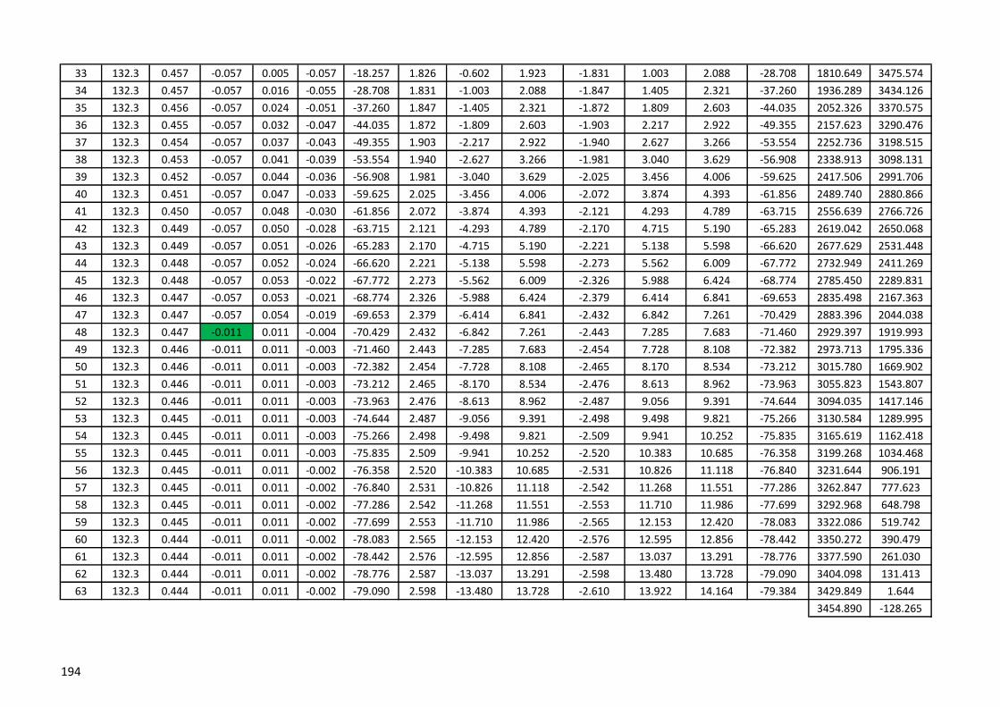
33 132.3 0.457 -0.057 0.005 -0.057 -18.257 1.826 -0.602 1.923 -1.831 1.003 2.088 -28.708 1810.649 3475.574
34 132.3 0.457 -0.057 0.016 -0.055 -28.708 1.831 -1.003 2.088 -1.847 1.405 2.321 -37.260 1936.289 3434.126
35 132.3 0.456 -0.057 0.024 -0.051 -37.260 1.847 -1.405 2.321 -1.872 1.809 2.603 -44.035 2052.326 3370.575
36 132.3 0.455 -0.057 0.032 -0.047 -44.035 1.872 -1.809 2.603 -1.903 2.217 2.922 -49.355 2157.623 3290.476
37 132.3 0.454 -0.057 0.037 -0.043 -49.355 1.903 -2.217 2.922 -1.940 2.627 3.266 -53.554 2252.736 3198.515
38 132.3 0.453 -0.057 0.041 -0.039 -53.554 1.940 -2.627 3.266 -1.981 3.040 3.629 -56.908 2338.913 3098.131
39 132.3 0.452 -0.057 0.044 -0.036 -56.908 1.981 -3.040 3.629 -2.025 3.456 4.006 -59.625 2417.506 2991.706
40 132.3 0.451 -0.057 0.047 -0.033 -59.625 2.025 -3.456 4.006 -2.072 3.874 4.393 -61.856 2489.740 2880.866
41 132.3 0.450 -0.057 0.048 -0.030 -61.856 2.072 -3.874 4.393 -2.121 4.293 4.789 -63.715 2556.639 2766.726
42 132.3 0.449 -0.057 0.050 -0.028 -63.715 2.121 -4.293 4.789 -2.170 4.715 5.190 -65.283 2619.042 2650.068
43 132.3 0.449 -0.057 0.051 -0.026 -65.283 2.170 -4.715 5.190 -2.221 5.138 5.598 -66.620 2677.629 2531.448
44 132.3 0.448 -0.057 0.052 -0.024 -66.620 2.221 -5.138 5.598 -2.273 5.562 6.009 -67.772 2732.949 2411.269
45 132.3 0.448 -0.057 0.053 -0.022 -67.772 2.273 -5.562 6.009 -2.326 5.988 6.424 -68.774 2785.450 2289.831
46 132.3 0.447 -0.057 0.053 -0.021 -68.774 2.326 -5.988 6.424 -2.379 6.414 6.841 -69.653 2835.498 2167.363
47 132.3 0.447 -0.057 0.054 -0.019 -69.653 2.379 -6.414 6.841 -2.432 6.842 7.261 -70.429 2883.396 2044.038
48 132.3 0.447 -0.011 0.011 -0.004 -70.429 2.432 -6.842 7.261 -2.443 7.285 7.683 -71.460 2929.397 1919.993
49 132.3 0.446 -0.011 0.011 -0.003 -71.460 2.443 -7.285 7.683 -2.454 7.728 8.108 -72.382 2973.713 1795.336
50 132.3 0.446 -0.011 0.011 -0.003 -72.382 2.454 -7.728 8.108 -2.465 8.170 8.534 -73.212 3015.780 1669.902
51 132.3 0.446 -0.011 0.011 -0.003 -73.212 2.465 -8.170 8.534 -2.476 8.613 8.962 -73.963 3055.823 1543.807
52 132.3 0.446 -0.011 0.011 -0.003 -73.963 2.476 -8.613 8.962 -2.487 9.056 9.391 -74.644 3094.035 1417.146
53 132.3 0.445 -0.011 0.011 -0.003 -74.644 2.487 -9.056 9.391 -2.498 9.498 9.821 -75.266 3130.584 1289.995
54 132.3 0.445 -0.011 0.011 -0.003 -75.266 2.498 -9.498 9.821 -2.509 9.941 10.252 -75.835 3165.619 1162.418
55 132.3 0.445 -0.011 0.011 -0.003 -75.835 2.509 -9.941 10.252 -2.520 10.383 10.685 -76.358 3199.268 1034.468
56 132.3 0.445 -0.011 0.011 -0.002 -76.358 2.520 -10.383 10.685 -2.531 10.826 11.118 -76.840 3231.644 906.191
57 132.3 0.445 -0.011 0.011 -0.002 -76.840 2.531 -10.826 11.118 -2.542 11.268 11.551 -77.286 3262.847 777.623
58 132.3 0.445 -0.011 0.011 -0.002 -77.286 2.542 -11.268 11.551 -2.553 11.710 11.986 -77.699 3292.968 648.798
59 132.3 0.445 -0.011 0.011 -0.002 -77.699 2.553 -11.710 11.986 -2.565 12.153 12.420 -78.083 3322.086 519.742
60 132.3 0.444 -0.011 0.011 -0.002 -78.083 2.565 -12.153 12.420 -2.576 12.595 12.856 -78.442 3350.272 390.479
61 132.3 0.444 -0.011 0.011 -0.002 -78.442 2.576 -12.595 12.856 -2.587 13.037 13.291 -78.776 3377.590 261.030
62 132.3 0.444 -0.011 0.011 -0.002 -78.776 2.587 -13.037 13.291 -2.598 13.480 13.728 -79.090 3404.098 131.413
63 132.3 0.444 -0.011 0.011 -0.002 -79.090 2.598 -13.480 13.728 -2.610 13.922 14.164 -79.384 3429.849 1.644
3454.890 -128.265
194

X Y
1 134.5 0.444 0.046 0.045 0.008 82.600 1.705 13.130 13.240 -1.750 -12.678 12.798 82.140 0 0
2 134.5 0.444 0.046 0.045 0.008 82.140 1.750 12.678 12.798 -1.795 -12.226 12.357 81.647 17.323 133.380
3 134.5 0.444 0.046 0.045 0.008 81.647 1.795 12.226 12.357 -1.840 -11.774 11.917 81.117 35.717 266.616
4 134.5 0.444 0.046 0.045 0.008 81.117 1.840 11.774 11.917 -1.885 -11.321 11.477 80.547 55.256 399.689
5 134.5 0.445 0.046 0.045 0.009 80.547 1.885 11.321 11.477 -1.930 -10.868 11.038 79.932 76.024 532.576
6 134.5 0.445 0.046 0.045 0.009 79.932 1.930 10.868 11.038 -1.974 -10.414 10.600 79.265 98.113 665.250
7 134.5 0.445 0.046 0.045 0.009 79.265 1.974 10.414 10.600 -2.019 -9.960 10.163 78.541 121.627 797.679
8 134.5 0.445 0.046 0.045 0.010 78.541 2.019 9.960 10.163 -2.064 -9.506 9.727 77.752 146.680 929.825
9 134.5 0.445 0.046 0.044 0.010 77.752 2.064 9.506 9.727 -2.108 -9.051 9.293 76.888 173.401 1061.644
10 134.5 0.445 0.046 0.044 0.010 76.888 2.108 9.051 9.293 -2.152 -8.595 8.860 75.940 201.935 1193.082
11 134.5 0.445 0.046 0.044 0.011 75.940 2.152 8.595 8.860 -2.197 -8.139 8.430 74.895 232.447 1324.076
12 134.5 0.446 0.046 0.044 0.011 74.895 2.197 8.139 8.430 -2.241 -7.682 8.002 73.737 265.121 1454.546
13 134.5 0.446 0.046 0.044 0.012 73.737 2.241 7.682 8.002 -2.285 -7.224 7.577 72.448 300.171 1584.399
14 134.5 0.446 0.046 0.044 0.012 72.448 2.285 7.224 7.577 -2.329 -6.766 7.155 71.006 337.838 1713.517
15 134.5 0.446 0.046 0.044 0.013 71.006 2.329 6.766 7.155 -2.372 -6.306 6.738 69.383 378.399 1841.755
16 134.5 0.447 0.046 0.043 0.014 69.383 2.372 6.306 6.738 -2.416 -5.846 6.325 67.545 422.176 1968.932
17 134.5 0.447 -0.068 -0.065 -0.022 67.545 2.416 5.846 6.325 -2.351 -5.421 5.909 66.552 469.537 2094.818
18 134.5 0.447 -0.068 -0.064 -0.023 66.552 2.351 5.421 5.909 -2.287 -4.997 5.495 65.408 520.909 2219.120
19 134.5 0.448 -0.068 -0.064 -0.025 65.408 2.287 4.997 5.495 -2.223 -4.574 5.086 64.079 574.429 2342.513
20 134.5 0.448 -0.068 -0.063 -0.027 64.079 2.223 4.574 5.086 -2.160 -4.153 4.681 62.517 630.402 2464.813
21 134.5 0.449 -0.068 -0.062 -0.028 62.517 2.160 4.153 4.681 -2.098 -3.732 4.282 60.660 689.197 2585.782
22 134.5 0.449 -0.068 -0.061 -0.031 60.660 2.098 3.732 4.282 -2.037 -3.314 3.890 58.424 751.267 2705.103
23 134.5 0.450 -0.068 -0.060 -0.033 58.424 2.037 3.314 3.890 -1.977 -2.897 3.508 55.691 817.171 2822.350
24 134.5 0.451 -0.068 -0.058 -0.036 55.691 1.977 2.897 3.508 -1.919 -2.483 3.138 52.298 887.600 2936.937
25 134.5 0.452 -0.068 -0.056 -0.039 52.298 1.919 2.483 3.138 -1.863 -2.070 2.785 48.020 963.412 3048.035
26 134.5 0.453 -0.068 -0.053 -0.043 48.020 1.863 2.070 2.785 -1.810 -1.661 2.457 42.545 1045.665 3154.452
27 134.5 0.454 -0.068 -0.049 -0.047 42.545 1.810 1.661 2.457 -1.760 -1.255 2.162 35.479 1135.629 3254.436
28 134.5 0.455 -0.068 -0.044 -0.052 35.479 1.760 1.255 2.162 -1.716 -0.852 1.916 26.403 1234.721 3345.381
29 134.5 0.456 -0.068 -0.038 -0.057 26.403 1.716 0.852 1.916 -1.678 -0.453 1.738 15.108 1344.248 3423.445
30 134.5 0.457 -0.068 -0.029 -0.062 15.108 1.678 0.453 1.738 -1.649 -0.058 1.650 2.015 1464.718 3483.256
31 134.5 0.457 -0.068 -0.019 -0.066 2.015 1.649 0.058 1.650 -1.630 0.334 1.664 -11.564 1594.569 3518.311
32 134.5 0.457 -0.068 -0.006 -0.068 -11.564 1.630 -0.334 1.664 -1.624 0.723 1.777 -23.998 1728.986 3523.041
WL VSegment
no.
Height of
SegmentDL + LL(L)
Wind Load
(Cpi=0)WL H
Right
Thrust
Right
angleCo-ordinatesLeft
Angle
Left Thrust
x
Left
Thrust y
Left
Thrust
Right
Thrust x
Right
Thrust y
195

33 134.5 0.441 -0.068 0.006 -0.068 -23.998 1.624 -0.723 1.777 -1.630 1.096 1.964 -33.918 1860.756 3496.077
34 134.5 0.441 -0.068 0.019 -0.066 -33.918 1.630 -1.096 1.964 -1.649 1.472 2.210 -41.753 1983.630 3441.376
35 134.5 0.441 -0.068 0.029 -0.062 -41.753 1.649 -1.472 2.210 -1.678 1.851 2.499 -47.810 2095.242 3366.323
36 134.5 0.441 -0.068 0.038 -0.057 -47.810 1.678 -1.851 2.499 -1.716 2.236 2.819 -52.494 2195.583 3276.758
37 134.5 0.441 -0.068 0.044 -0.052 -52.494 1.716 -2.236 2.819 -1.760 2.625 3.161 -56.155 2285.912 3177.104
38 134.5 0.441 -0.068 0.049 -0.047 -56.155 1.760 -2.625 3.161 -1.810 3.019 3.520 -59.062 2367.802 3070.406
39 134.5 0.441 -0.068 0.053 -0.043 -59.062 1.810 -3.019 3.520 -1.863 3.418 3.892 -61.406 2442.710 2958.697
40 134.5 0.441 -0.068 0.056 -0.039 -61.406 1.863 -3.418 3.892 -1.919 3.820 4.275 -63.327 2511.859 2843.334
41 134.5 0.441 -0.068 0.058 -0.036 -63.327 1.919 -3.820 4.275 -1.977 4.225 4.665 -64.924 2576.231 2725.238
42 134.5 0.441 -0.068 0.060 -0.033 -64.924 1.977 -4.225 4.665 -2.037 4.633 5.061 -66.270 2636.607 2605.051
43 134.5 0.441 -0.068 0.061 -0.031 -66.270 2.037 -4.633 5.061 -2.098 5.044 5.463 -67.417 2693.610 2483.228
44 134.5 0.441 -0.068 0.062 -0.028 -67.417 2.098 -5.044 5.463 -2.160 5.457 5.869 -68.404 2747.736 2360.100
45 134.5 0.441 -0.068 0.063 -0.027 -68.404 2.160 -5.457 5.869 -2.223 5.872 6.279 -69.263 2799.388 2235.913
46 134.5 0.441 -0.068 0.064 -0.025 -69.263 2.223 -5.872 6.279 -2.287 6.289 6.691 -70.016 2848.891 2110.854
47 134.5 0.441 -0.068 0.064 -0.023 -70.016 2.287 -6.289 6.691 -2.351 6.707 7.107 -70.681 2896.515 1985.068
48 134.5 0.441 -0.023 0.022 -0.007 -70.681 2.351 -6.707 7.107 -2.373 7.141 7.525 -71.619 2942.482 1858.666
49 134.5 0.441 -0.023 0.022 -0.007 -71.619 2.373 -7.141 7.525 -2.394 7.575 7.945 -72.459 2986.979 1731.740
50 134.5 0.441 -0.023 0.022 -0.007 -72.459 2.394 -7.575 7.945 -2.416 8.010 8.366 -73.214 3029.391 1604.102
51 134.5 0.441 -0.023 0.022 -0.006 -73.214 2.416 -8.010 8.366 -2.438 8.445 8.790 -73.896 3069.929 1475.857
52 134.5 0.441 -0.023 0.022 -0.006 -73.896 2.438 -8.445 8.790 -2.460 8.881 9.215 -74.516 3108.773 1347.088
53 134.5 0.441 -0.023 0.022 -0.006 -74.516 2.460 -8.881 9.215 -2.482 9.316 9.641 -75.080 3146.081 1217.866
54 134.5 0.441 -0.023 0.022 -0.005 -75.080 2.482 -9.316 9.641 -2.504 9.752 10.069 -75.597 3181.989 1088.248
55 134.5 0.441 -0.023 0.022 -0.005 -75.597 2.504 -9.752 10.069 -2.527 10.189 10.497 -76.072 3216.618 958.282
56 134.5 0.441 -0.023 0.022 -0.005 -76.072 2.527 -10.189 10.497 -2.549 10.625 10.926 -76.510 3250.073 828.009
57 134.5 0.441 -0.023 0.022 -0.005 -76.510 2.549 -10.625 10.926 -2.571 11.062 11.357 -76.915 3282.446 697.463
58 134.5 0.441 -0.023 0.022 -0.005 -76.915 2.571 -11.062 11.357 -2.594 11.498 11.787 -77.290 3313.822 566.674
59 134.5 0.441 -0.023 0.022 -0.004 -77.290 2.594 -11.498 11.787 -2.616 11.935 12.219 -77.638 3344.273 435.667
60 134.5 0.441 -0.023 0.022 -0.004 -77.638 2.616 -11.935 12.219 -2.638 12.373 12.651 -77.963 3373.867 304.463
61 134.5 0.441 -0.023 0.022 -0.004 -77.963 2.638 -12.373 12.651 -2.661 12.810 13.083 -78.266 3402.661 173.081
62 134.5 0.441 -0.023 0.022 -0.004 -78.266 2.661 -12.810 13.083 -2.683 13.247 13.516 -78.550 3430.711 41.538
63 134.5 0.441 -0.023 0.022 -0.004 -78.550 2.683 -13.247 13.516 -2.706 13.685 13.950 -78.816 3458.063 -90.151
3484.763 -221.974
196
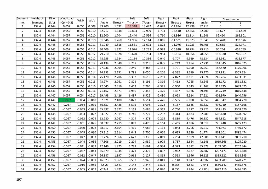
X Y1 132.4 0.444 0.057 0.056 0.009 83.200 1.592 13.348 13.442 -1.648 -12.894 12.999 82.717 0 0
2 132.4 0.444 0.057 0.056 0.010 82.717 1.648 12.894 12.999 -1.704 -12.440 12.556 82.200 15.677 131.469
3 132.4 0.444 0.057 0.056 0.010 82.200 1.704 12.440 12.556 -1.760 -11.986 12.114 81.646 32.460 262.801
4 132.4 0.444 0.057 0.056 0.010 81.646 1.760 11.986 12.114 -1.816 -11.531 11.673 81.049 50.428 393.976
5 132.4 0.445 0.057 0.056 0.011 81.049 1.816 11.531 11.673 -1.872 -11.076 11.233 80.406 69.665 524.971
6 132.4 0.445 0.057 0.056 0.011 80.406 1.872 11.076 11.233 -1.928 -10.620 10.794 79.710 90.264 655.759
7 132.4 0.445 0.057 0.056 0.012 79.710 1.928 10.620 10.794 -1.984 -10.164 10.356 78.955 112.330 786.307
8 132.4 0.445 0.057 0.056 0.012 78.955 1.984 10.164 10.356 -2.040 -9.707 9.919 78.134 135.981 916.577
9 132.4 0.445 0.057 0.056 0.012 78.134 2.040 9.707 9.919 -2.095 -9.249 9.484 77.236 161.345 1046.525
10 132.4 0.445 0.057 0.055 0.013 77.236 2.095 9.249 9.484 -2.151 -8.791 9.050 76.253 188.570 1176.096
11 132.4 0.445 0.057 0.055 0.014 76.253 2.151 8.791 9.050 -2.206 -8.332 8.619 75.170 217.821 1305.224
12 132.4 0.446 0.057 0.055 0.014 75.170 2.206 8.332 8.619 -2.261 -7.872 8.191 73.974 249.284 1433.831
13 132.4 0.446 0.057 0.055 0.015 73.974 2.261 7.872 8.191 -2.316 -7.412 7.765 72.645 283.172 1561.821
14 132.4 0.446 0.057 0.055 0.016 72.645 2.316 7.412 7.765 -2.371 -6.950 7.343 71.162 319.725 1689.075
15 132.4 0.446 0.057 0.055 0.016 71.162 2.371 6.950 7.343 -2.426 -6.487 6.926 69.498 359.219 1815.448
16 132.4 0.447 0.057 0.054 0.017 69.498 2.426 6.487 6.926 -2.480 -6.023 6.514 67.621 401.970 1940.756
17 132.4 0.447 -0.057 -0.054 -0.018 67.621 2.480 6.023 6.514 -2.426 -5.595 6.098 66.557 448.342 2064.770
18 132.4 0.447 -0.057 -0.054 -0.019 66.557 2.426 5.595 6.098 -2.372 -5.167 5.685 65.337 498.750 2187.198
19 132.4 0.448 -0.057 -0.053 -0.021 65.337 2.372 5.167 5.685 -2.319 -4.740 5.277 63.927 551.423 2308.670
20 132.4 0.448 -0.057 -0.053 -0.022 63.927 2.319 4.740 5.277 -2.267 -4.314 4.873 62.280 606.670 2428.992
21 132.4 0.449 -0.057 -0.052 -0.024 62.280 2.267 4.314 4.873 -2.215 -3.889 4.476 60.337 664.862 2547.918
22 132.4 0.449 -0.057 -0.051 -0.026 60.337 2.215 3.889 4.476 -2.164 -3.465 4.086 58.017 726.448 2665.123
23 132.4 0.450 -0.057 -0.050 -0.028 58.017 2.164 3.465 4.086 -2.114 -3.043 3.706 55.212 791.973 2780.172
24 132.4 0.451 -0.057 -0.048 -0.030 55.212 2.114 3.043 3.706 -2.066 -2.623 3.339 51.774 862.101 2892.474
25 132.4 0.452 -0.057 -0.047 -0.033 51.774 2.066 2.623 3.339 -2.019 -2.204 2.989 47.506 937.641 3001.210
26 132.4 0.453 -0.057 -0.044 -0.036 47.506 2.019 2.204 2.989 -1.975 -1.787 2.664 42.146 1019.566 3105.220
27 132.4 0.454 -0.057 -0.041 -0.039 42.146 1.975 1.787 2.664 -1.934 -1.373 2.372 35.379 1109.005 3202.844
28 132.4 0.455 -0.057 -0.037 -0.043 35.379 1.934 1.373 2.372 -1.897 -0.962 2.127 26.887 1207.171 3291.688
29 132.4 0.456 -0.057 -0.032 -0.047 26.887 1.897 0.962 2.127 -1.865 -0.553 1.946 16.523 1315.122 3368.345
30 132.4 0.457 -0.057 -0.024 -0.051 16.523 1.865 0.553 1.946 -1.841 -0.148 1.847 4.596 1433.209 3428.221
31 132.4 0.457 -0.057 -0.016 -0.055 4.596 1.841 0.148 1.847 -1.825 0.255 1.843 -7.941 1560.142 3465.876
32 132.4 0.457 -0.057 -0.005 -0.057 -7.941 1.825 -0.255 1.843 -1.820 0.655 1.934 -19.801 1692.116 3476.485
WL VSegment
no.
Height of
Segment
DL +
LL(L)
Wind Load
(Cpi=-0.2)WL H
Right
Thrust
Right
angleCo-ordinatesLeft
Angle
Left
Thrust x
Left
Thrust y
Left
Thrust
Right
Thrust x
Right
Thrust y
197

33 132.4 0.441 -0.057 0.005 -0.057 -19.801 1.820 -0.655 1.934 -1.825 1.040 2.101 -29.672 1823.247 3458.195
34 132.4 0.441 -0.057 0.016 -0.055 -29.672 1.825 -1.040 2.101 -1.841 1.426 2.329 -37.774 1947.818 3413.343
35 132.4 0.441 -0.057 0.024 -0.051 -37.774 1.841 -1.426 2.329 -1.865 1.816 2.604 -44.241 2062.857 3347.799
36 132.4 0.441 -0.057 0.032 -0.047 -44.241 1.865 -1.816 2.604 -1.897 2.210 2.913 -49.367 2167.510 3266.698
37 132.4 0.441 -0.057 0.037 -0.043 -49.367 1.897 -2.210 2.913 -1.934 2.608 3.247 -53.449 2262.363 3174.326
38 132.4 0.441 -0.057 0.041 -0.039 -53.449 1.934 -2.608 3.247 -1.975 3.010 3.600 -56.735 2348.584 3073.848
39 132.4 0.441 -0.057 0.044 -0.036 -56.735 1.975 -3.010 3.600 -2.019 3.416 3.968 -59.413 2427.433 2967.487
40 132.4 0.441 -0.057 0.047 -0.033 -59.413 2.019 -3.416 3.968 -2.066 3.825 4.347 -61.625 2500.057 2856.783
41 132.4 0.441 -0.057 0.048 -0.030 -61.625 2.066 -3.825 4.347 -2.114 4.236 4.734 -63.476 2567.428 2742.805
42 132.4 0.441 -0.057 0.050 -0.028 -63.476 2.114 -4.236 4.734 -2.164 4.650 5.129 -65.042 2630.350 2626.312
43 132.4 0.441 -0.057 0.051 -0.026 -65.042 2.164 -4.650 5.129 -2.215 5.066 5.529 -66.382 2689.476 2507.848
44 132.4 0.441 -0.057 0.052 -0.024 -66.382 2.215 -5.066 5.529 -2.267 5.483 5.933 -67.540 2745.343 2387.812
45 132.4 0.441 -0.057 0.053 -0.022 -67.540 2.267 -5.483 5.933 -2.319 5.903 6.342 -68.548 2798.387 2266.502
46 132.4 0.441 -0.057 0.053 -0.021 -68.548 2.319 -5.903 6.342 -2.372 6.323 6.754 -69.434 2848.970 2144.145
47 132.4 0.441 -0.057 0.054 -0.019 -69.434 2.372 -6.323 6.754 -2.426 6.745 7.168 -70.218 2897.390 2020.917
48 132.4 0.441 -0.011 0.011 -0.004 -70.218 2.426 -6.745 7.168 -2.437 7.183 7.585 -71.261 2943.900 1896.955
49 132.4 0.441 -0.011 0.011 -0.003 -71.261 2.437 -7.183 7.585 -2.448 7.621 8.004 -72.194 2988.709 1772.368
50 132.4 0.441 -0.011 0.011 -0.003 -72.194 2.448 -7.621 8.004 -2.459 8.059 8.426 -73.035 3031.244 1646.986
51 132.4 0.441 -0.011 0.011 -0.003 -73.035 2.459 -8.059 8.426 -2.470 8.497 8.849 -73.795 3071.731 1520.928
52 132.4 0.441 -0.011 0.011 -0.003 -73.795 2.470 -8.497 8.849 -2.481 8.936 9.274 -74.486 3110.364 1394.290
53 132.4 0.441 -0.011 0.011 -0.003 -74.486 2.481 -8.936 9.274 -2.492 9.374 9.700 -75.116 3147.313 1267.151
54 132.4 0.441 -0.011 0.011 -0.003 -75.116 2.492 -9.374 9.700 -2.503 9.813 10.127 -75.693 3182.728 1139.575
55 132.4 0.441 -0.011 0.011 -0.003 -75.693 2.503 -9.813 10.127 -2.514 10.252 10.556 -76.223 3216.737 1011.617
56 132.4 0.441 -0.011 0.011 -0.002 -76.223 2.514 -10.252 10.556 -2.525 10.691 10.985 -76.712 3249.455 883.324
57 132.4 0.441 -0.011 0.011 -0.002 -76.712 2.525 -10.691 10.985 -2.536 11.130 11.415 -77.164 3280.985 754.733
58 132.4 0.441 -0.011 0.011 -0.002 -77.164 2.536 -11.130 11.415 -2.547 11.569 11.846 -77.583 3311.417 625.878
59 132.4 0.441 -0.011 0.011 -0.002 -77.583 2.547 -11.569 11.846 -2.558 12.008 12.278 -77.973 3340.831 496.786
60 132.4 0.441 -0.011 0.011 -0.002 -77.973 2.558 -12.008 12.278 -2.570 12.447 12.710 -78.336 3369.300 367.483
61 132.4 0.441 -0.011 0.011 -0.002 -78.336 2.570 -12.447 12.710 -2.581 12.887 13.143 -78.676 3396.889 237.989
62 132.4 0.441 -0.011 0.011 -0.002 -78.676 2.581 -12.887 13.143 -2.592 13.326 13.576 -78.993 3423.656 108.323
63 132.4 0.441 -0.011 0.011 -0.002 -78.993 2.592 -13.326 13.576 -2.603 13.766 14.010 -79.291 3449.654 -21.499
3474.933 -151.463
198
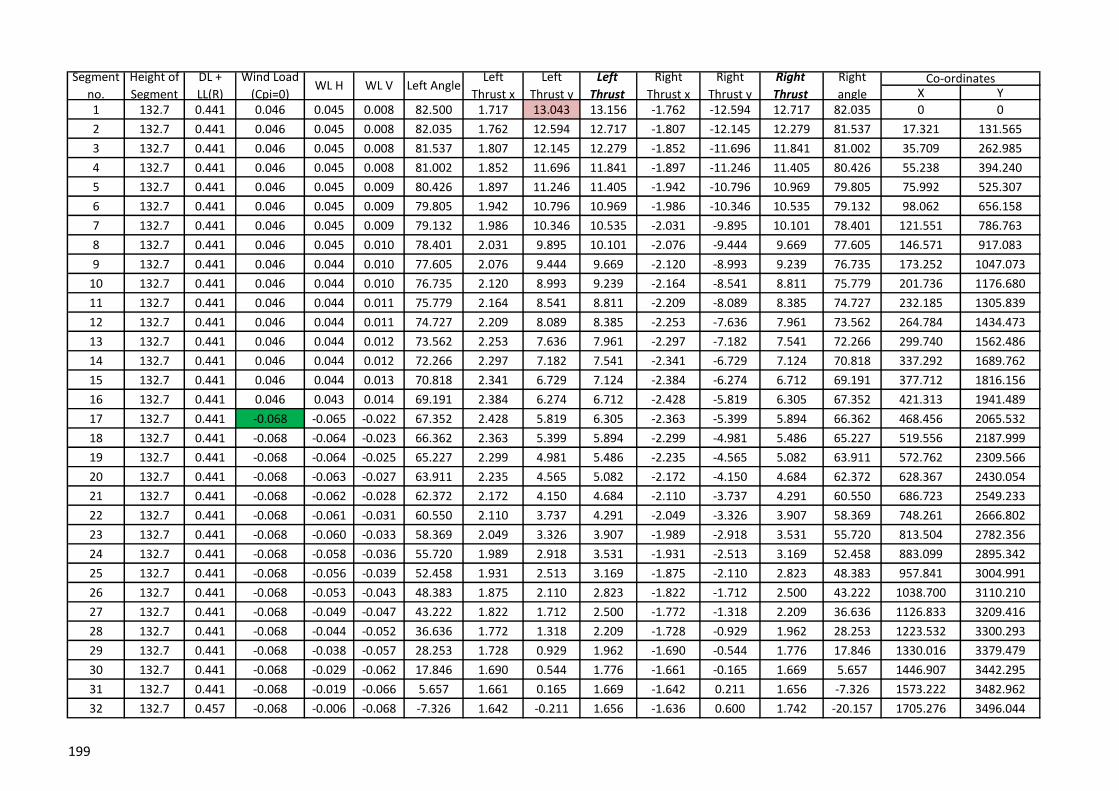
X Y
1 132.7 0.441 0.046 0.045 0.008 82.500 1.717 13.043 13.156 -1.762 -12.594 12.717 82.035 0 0
2 132.7 0.441 0.046 0.045 0.008 82.035 1.762 12.594 12.717 -1.807 -12.145 12.279 81.537 17.321 131.565
3 132.7 0.441 0.046 0.045 0.008 81.537 1.807 12.145 12.279 -1.852 -11.696 11.841 81.002 35.709 262.985
4 132.7 0.441 0.046 0.045 0.008 81.002 1.852 11.696 11.841 -1.897 -11.246 11.405 80.426 55.238 394.240
5 132.7 0.441 0.046 0.045 0.009 80.426 1.897 11.246 11.405 -1.942 -10.796 10.969 79.805 75.992 525.307
6 132.7 0.441 0.046 0.045 0.009 79.805 1.942 10.796 10.969 -1.986 -10.346 10.535 79.132 98.062 656.158
7 132.7 0.441 0.046 0.045 0.009 79.132 1.986 10.346 10.535 -2.031 -9.895 10.101 78.401 121.551 786.763
8 132.7 0.441 0.046 0.045 0.010 78.401 2.031 9.895 10.101 -2.076 -9.444 9.669 77.605 146.571 917.083
9 132.7 0.441 0.046 0.044 0.010 77.605 2.076 9.444 9.669 -2.120 -8.993 9.239 76.735 173.252 1047.073
10 132.7 0.441 0.046 0.044 0.010 76.735 2.120 8.993 9.239 -2.164 -8.541 8.811 75.779 201.736 1176.680
11 132.7 0.441 0.046 0.044 0.011 75.779 2.164 8.541 8.811 -2.209 -8.089 8.385 74.727 232.185 1305.839
12 132.7 0.441 0.046 0.044 0.011 74.727 2.209 8.089 8.385 -2.253 -7.636 7.961 73.562 264.784 1434.473
13 132.7 0.441 0.046 0.044 0.012 73.562 2.253 7.636 7.961 -2.297 -7.182 7.541 72.266 299.740 1562.486
14 132.7 0.441 0.046 0.044 0.012 72.266 2.297 7.182 7.541 -2.341 -6.729 7.124 70.818 337.292 1689.762
15 132.7 0.441 0.046 0.044 0.013 70.818 2.341 6.729 7.124 -2.384 -6.274 6.712 69.191 377.712 1816.156
16 132.7 0.441 0.046 0.043 0.014 69.191 2.384 6.274 6.712 -2.428 -5.819 6.305 67.352 421.313 1941.489
17 132.7 0.441 -0.068 -0.065 -0.022 67.352 2.428 5.819 6.305 -2.363 -5.399 5.894 66.362 468.456 2065.532
18 132.7 0.441 -0.068 -0.064 -0.023 66.362 2.363 5.399 5.894 -2.299 -4.981 5.486 65.227 519.556 2187.999
19 132.7 0.441 -0.068 -0.064 -0.025 65.227 2.299 4.981 5.486 -2.235 -4.565 5.082 63.911 572.762 2309.566
20 132.7 0.441 -0.068 -0.063 -0.027 63.911 2.235 4.565 5.082 -2.172 -4.150 4.684 62.372 628.367 2430.054
21 132.7 0.441 -0.068 -0.062 -0.028 62.372 2.172 4.150 4.684 -2.110 -3.737 4.291 60.550 686.723 2549.233
22 132.7 0.441 -0.068 -0.061 -0.031 60.550 2.110 3.737 4.291 -2.049 -3.326 3.907 58.369 748.261 2666.802
23 132.7 0.441 -0.068 -0.060 -0.033 58.369 2.049 3.326 3.907 -1.989 -2.918 3.531 55.720 813.504 2782.356
24 132.7 0.441 -0.068 -0.058 -0.036 55.720 1.989 2.918 3.531 -1.931 -2.513 3.169 52.458 883.099 2895.342
25 132.7 0.441 -0.068 -0.056 -0.039 52.458 1.931 2.513 3.169 -1.875 -2.110 2.823 48.383 957.841 3004.991
26 132.7 0.441 -0.068 -0.053 -0.043 48.383 1.875 2.110 2.823 -1.822 -1.712 2.500 43.222 1038.700 3110.210
27 132.7 0.441 -0.068 -0.049 -0.047 43.222 1.822 1.712 2.500 -1.772 -1.318 2.209 36.636 1126.833 3209.416
28 132.7 0.441 -0.068 -0.044 -0.052 36.636 1.772 1.318 2.209 -1.728 -0.929 1.962 28.253 1223.532 3300.293
29 132.7 0.441 -0.068 -0.038 -0.057 28.253 1.728 0.929 1.962 -1.690 -0.544 1.776 17.846 1330.016 3379.479
30 132.7 0.441 -0.068 -0.029 -0.062 17.846 1.690 0.544 1.776 -1.661 -0.165 1.669 5.657 1446.907 3442.295
31 132.7 0.441 -0.068 -0.019 -0.066 5.657 1.661 0.165 1.669 -1.642 0.211 1.656 -7.326 1573.222 3482.962
32 132.7 0.457 -0.068 -0.006 -0.068 -7.326 1.642 -0.211 1.656 -1.636 0.600 1.742 -20.157 1705.276 3496.044
WL VSegment
no.
Height of
Segment
DL +
LL(R)
Wind Load
(Cpi=0)WL H
Right
Thrust
Right
angleCo-ordinates
Left Angle Left
Thrust x
Left
Thrust y
Left
Thrust
Right
Thrust x
Right
Thrust y
199
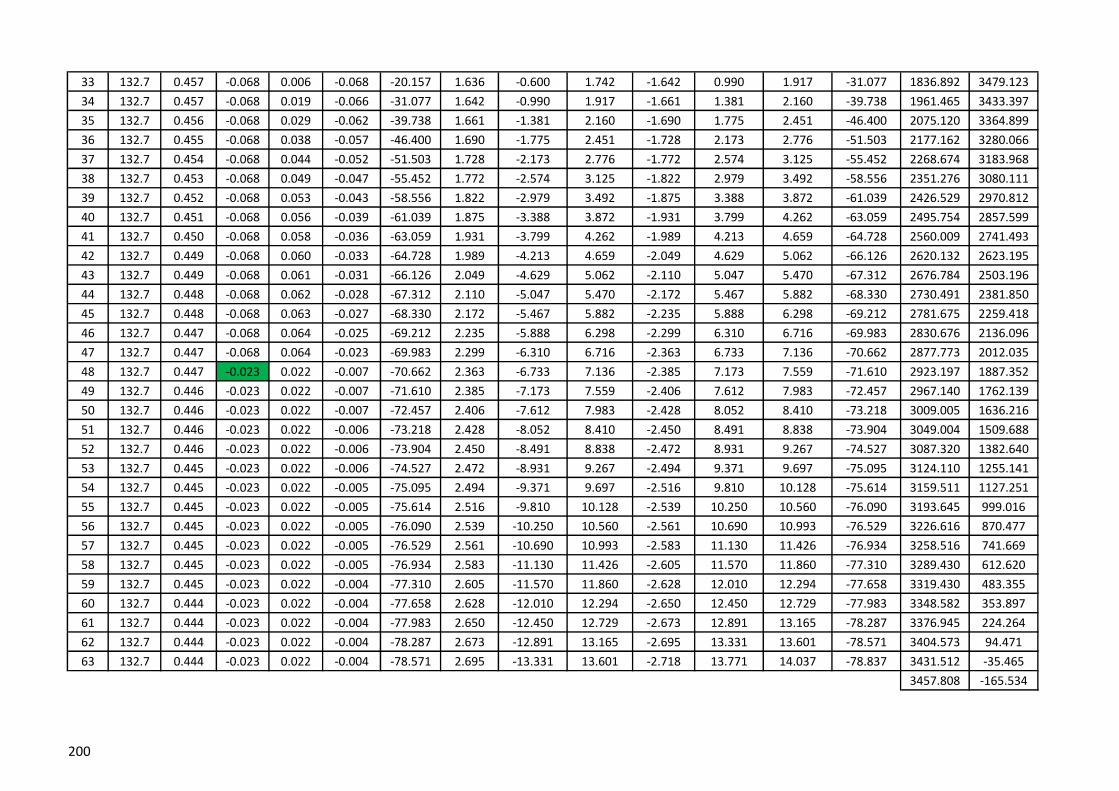
33 132.7 0.457 -0.068 0.006 -0.068 -20.157 1.636 -0.600 1.742 -1.642 0.990 1.917 -31.077 1836.892 3479.123
34 132.7 0.457 -0.068 0.019 -0.066 -31.077 1.642 -0.990 1.917 -1.661 1.381 2.160 -39.738 1961.465 3433.397
35 132.7 0.456 -0.068 0.029 -0.062 -39.738 1.661 -1.381 2.160 -1.690 1.775 2.451 -46.400 2075.120 3364.899
36 132.7 0.455 -0.068 0.038 -0.057 -46.400 1.690 -1.775 2.451 -1.728 2.173 2.776 -51.503 2177.162 3280.066
37 132.7 0.454 -0.068 0.044 -0.052 -51.503 1.728 -2.173 2.776 -1.772 2.574 3.125 -55.452 2268.674 3183.968
38 132.7 0.453 -0.068 0.049 -0.047 -55.452 1.772 -2.574 3.125 -1.822 2.979 3.492 -58.556 2351.276 3080.111
39 132.7 0.452 -0.068 0.053 -0.043 -58.556 1.822 -2.979 3.492 -1.875 3.388 3.872 -61.039 2426.529 2970.812
40 132.7 0.451 -0.068 0.056 -0.039 -61.039 1.875 -3.388 3.872 -1.931 3.799 4.262 -63.059 2495.754 2857.599
41 132.7 0.450 -0.068 0.058 -0.036 -63.059 1.931 -3.799 4.262 -1.989 4.213 4.659 -64.728 2560.009 2741.493
42 132.7 0.449 -0.068 0.060 -0.033 -64.728 1.989 -4.213 4.659 -2.049 4.629 5.062 -66.126 2620.132 2623.195
43 132.7 0.449 -0.068 0.061 -0.031 -66.126 2.049 -4.629 5.062 -2.110 5.047 5.470 -67.312 2676.784 2503.196
44 132.7 0.448 -0.068 0.062 -0.028 -67.312 2.110 -5.047 5.470 -2.172 5.467 5.882 -68.330 2730.491 2381.850
45 132.7 0.448 -0.068 0.063 -0.027 -68.330 2.172 -5.467 5.882 -2.235 5.888 6.298 -69.212 2781.675 2259.418
46 132.7 0.447 -0.068 0.064 -0.025 -69.212 2.235 -5.888 6.298 -2.299 6.310 6.716 -69.983 2830.676 2136.096
47 132.7 0.447 -0.068 0.064 -0.023 -69.983 2.299 -6.310 6.716 -2.363 6.733 7.136 -70.662 2877.773 2012.035
48 132.7 0.447 -0.023 0.022 -0.007 -70.662 2.363 -6.733 7.136 -2.385 7.173 7.559 -71.610 2923.197 1887.352
49 132.7 0.446 -0.023 0.022 -0.007 -71.610 2.385 -7.173 7.559 -2.406 7.612 7.983 -72.457 2967.140 1762.139
50 132.7 0.446 -0.023 0.022 -0.007 -72.457 2.406 -7.612 7.983 -2.428 8.052 8.410 -73.218 3009.005 1636.216
51 132.7 0.446 -0.023 0.022 -0.006 -73.218 2.428 -8.052 8.410 -2.450 8.491 8.838 -73.904 3049.004 1509.688
52 132.7 0.446 -0.023 0.022 -0.006 -73.904 2.450 -8.491 8.838 -2.472 8.931 9.267 -74.527 3087.320 1382.640
53 132.7 0.445 -0.023 0.022 -0.006 -74.527 2.472 -8.931 9.267 -2.494 9.371 9.697 -75.095 3124.110 1255.141
54 132.7 0.445 -0.023 0.022 -0.005 -75.095 2.494 -9.371 9.697 -2.516 9.810 10.128 -75.614 3159.511 1127.251
55 132.7 0.445 -0.023 0.022 -0.005 -75.614 2.516 -9.810 10.128 -2.539 10.250 10.560 -76.090 3193.645 999.016
56 132.7 0.445 -0.023 0.022 -0.005 -76.090 2.539 -10.250 10.560 -2.561 10.690 10.993 -76.529 3226.616 870.477
57 132.7 0.445 -0.023 0.022 -0.005 -76.529 2.561 -10.690 10.993 -2.583 11.130 11.426 -76.934 3258.516 741.669
58 132.7 0.445 -0.023 0.022 -0.005 -76.934 2.583 -11.130 11.426 -2.605 11.570 11.860 -77.310 3289.430 612.620
59 132.7 0.445 -0.023 0.022 -0.004 -77.310 2.605 -11.570 11.860 -2.628 12.010 12.294 -77.658 3319.430 483.355
60 132.7 0.444 -0.023 0.022 -0.004 -77.658 2.628 -12.010 12.294 -2.650 12.450 12.729 -77.983 3348.582 353.897
61 132.7 0.444 -0.023 0.022 -0.004 -77.983 2.650 -12.450 12.729 -2.673 12.891 13.165 -78.287 3376.945 224.264
62 132.7 0.444 -0.023 0.022 -0.004 -78.287 2.673 -12.891 13.165 -2.695 13.331 13.601 -78.571 3404.573 94.471
63 132.7 0.444 -0.023 0.022 -0.004 -78.571 2.695 -13.331 13.601 -2.718 13.771 14.037 -78.837 3431.512 -35.465
3457.808 -165.534
200

X Y
1 133 0.441 0.057 0.056 0.009 83.300 1.556 13.242 13.333 -1.612 -12.791 12.892 82.818 0 0
2 133 0.441 0.057 0.056 0.010 82.818 1.612 12.791 12.892 -1.668 -12.340 12.452 82.302 15.517 132.092
3 133 0.441 0.057 0.056 0.010 82.302 1.668 12.340 12.452 -1.724 -11.889 12.013 81.749 32.145 264.048
4 133 0.441 0.057 0.056 0.010 81.749 1.724 11.889 12.013 -1.780 -11.437 11.575 81.153 49.960 395.850
5 133 0.441 0.057 0.056 0.011 81.153 1.780 11.437 11.575 -1.836 -10.985 11.137 80.511 69.048 527.473
6 133 0.441 0.057 0.056 0.011 80.511 1.836 10.985 11.137 -1.892 -10.532 10.701 79.816 89.502 658.890
7 133 0.441 0.057 0.056 0.012 79.816 1.892 10.532 10.701 -1.948 -10.079 10.266 79.062 111.429 790.071
8 133 0.441 0.057 0.056 0.012 79.062 1.948 10.079 10.266 -2.004 -9.626 9.832 78.242 134.945 920.975
9 133 0.441 0.057 0.056 0.012 78.242 2.004 9.626 9.832 -2.059 -9.172 9.400 77.347 160.180 1051.559
10 133 0.441 0.057 0.055 0.013 77.347 2.059 9.172 9.400 -2.115 -8.717 8.970 76.365 187.282 1181.768
11 133 0.441 0.057 0.055 0.014 76.365 2.115 8.717 8.970 -2.170 -8.262 8.543 75.285 216.417 1311.538
12 133 0.441 0.057 0.055 0.014 75.285 2.170 8.262 8.543 -2.225 -7.807 8.118 74.091 247.770 1440.790
13 133 0.441 0.057 0.055 0.015 74.091 2.225 7.807 8.118 -2.280 -7.351 7.696 72.766 281.554 1569.427
14 133 0.441 0.057 0.055 0.016 72.766 2.280 7.351 7.696 -2.335 -6.894 7.278 71.287 318.012 1697.333
15 133 0.441 0.057 0.055 0.016 71.287 2.335 6.894 7.278 -2.390 -6.436 6.865 69.630 357.417 1824.361
16 133 0.441 0.057 0.054 0.017 69.630 2.390 6.436 6.865 -2.444 -5.977 6.457 67.761 400.087 1950.331
17 133 0.441 -0.057 -0.054 -0.018 67.761 2.444 5.977 6.457 -2.390 -5.554 6.046 66.717 446.382 2075.013
18 133 0.441 -0.057 -0.054 -0.019 66.717 2.390 5.554 6.046 -2.336 -5.132 5.639 65.522 496.720 2198.120
19 133 0.441 -0.057 -0.053 -0.021 65.522 2.336 5.132 5.639 -2.283 -4.711 5.235 64.143 549.292 2320.288
20 133 0.441 -0.057 -0.053 -0.022 64.143 2.283 4.711 5.235 -2.231 -4.292 4.837 62.536 604.400 2441.334
21 133 0.441 -0.057 -0.052 -0.024 62.536 2.231 4.292 4.837 -2.179 -3.874 4.445 60.646 662.406 2561.018
22 133 0.441 -0.057 -0.051 -0.026 60.646 2.179 3.874 4.445 -2.128 -3.458 4.061 58.395 723.744 2679.030
23 133 0.441 -0.057 -0.050 -0.028 58.395 2.128 3.458 4.061 -2.078 -3.045 3.686 55.683 788.942 2794.953
24 133 0.441 -0.057 -0.048 -0.030 55.683 2.078 3.045 3.686 -2.030 -2.633 3.325 52.374 858.642 2908.226
25 133 0.441 -0.057 -0.047 -0.033 52.374 2.030 2.633 3.325 -1.983 -2.225 2.980 48.284 933.623 3018.076
26 133 0.441 -0.057 -0.044 -0.036 48.284 1.983 2.225 2.980 -1.939 -1.819 2.659 43.174 1014.820 3123.414
27 133 0.441 -0.057 -0.041 -0.039 43.174 1.939 1.819 2.659 -1.898 -1.417 2.368 36.750 1103.323 3222.692
28 133 0.441 -0.057 -0.037 -0.043 36.750 1.898 1.417 2.368 -1.861 -1.019 2.121 28.707 1200.317 3313.693
29 133 0.441 -0.057 -0.032 -0.047 28.707 1.861 1.019 2.121 -1.829 -0.625 1.933 18.866 1306.884 3393.269
30 133 0.441 -0.057 -0.024 -0.051 18.866 1.829 0.625 1.933 -1.805 -0.235 1.820 7.422 1423.537 3457.153
31 133 0.441 -0.057 -0.016 -0.055 7.422 1.805 0.235 1.820 -1.789 0.151 1.796 -4.840 1549.392 3500.158
32 133 0.457 -0.057 -0.005 -0.057 -4.840 1.789 -0.151 1.796 -1.784 0.552 1.867 -17.199 1681.278 3517.339
WL VSegment
no.
Height of
Segment
DL +
LL(R)
Wind Load
(Cpi=-0.2)WL H
Right
Thrust
Right
angleCo-ordinatesLeft
Angle
Left
Thrust x
Left
Thrust y
Left
Thrust
Right
Thrust x
Right
Thrust y
201

33 133 0.457 -0.057 0.005 -0.057 -17.199 1.784 -0.552 1.867 -1.789 0.953 2.027 -28.037 1813.804 3506.118
34 133 0.457 -0.057 0.016 -0.055 -28.037 1.789 -0.953 2.027 -1.805 1.355 2.257 -36.895 1940.856 3466.791
35 133 0.456 -0.057 0.024 -0.051 -36.895 1.805 -1.355 2.257 -1.829 1.759 2.538 -43.883 2058.249 3404.276
36 133 0.455 -0.057 0.032 -0.047 -43.883 1.829 -1.759 2.538 -1.861 2.166 2.856 -49.342 2164.614 3324.430
37 133 0.454 -0.057 0.037 -0.043 -49.342 1.861 -2.166 2.856 -1.898 2.577 3.200 -53.629 2260.475 3232.236
38 133 0.453 -0.057 0.041 -0.039 -53.629 1.898 -2.577 3.200 -1.939 2.990 3.563 -57.037 2347.129 3131.340
39 133 0.452 -0.057 0.044 -0.036 -57.037 1.939 -2.990 3.563 -1.983 3.405 3.941 -59.786 2425.999 3024.249
40 133 0.451 -0.057 0.047 -0.033 -59.786 1.983 -3.405 3.941 -2.030 3.823 4.329 -62.037 2498.363 2912.658
41 133 0.450 -0.057 0.048 -0.030 -62.037 2.030 -3.823 4.329 -2.078 4.243 4.725 -63.906 2565.293 2797.726
42 133 0.449 -0.057 0.050 -0.028 -63.906 2.078 -4.243 4.725 -2.128 4.665 5.127 -65.478 2627.657 2680.254
43 133 0.449 -0.057 0.051 -0.026 -65.478 2.128 -4.665 5.127 -2.179 5.088 5.535 -66.816 2686.158 2560.811
44 133 0.448 -0.057 0.052 -0.024 -66.816 2.179 -5.088 5.535 -2.231 5.512 5.946 -67.966 2741.359 2439.807
45 133 0.448 -0.057 0.053 -0.022 -67.966 2.231 -5.512 5.946 -2.283 5.938 6.361 -68.966 2793.720 2317.548
46 133 0.447 -0.057 0.053 -0.021 -68.966 2.283 -5.938 6.361 -2.336 6.364 6.779 -69.841 2843.615 2194.262
47 133 0.447 -0.057 0.054 -0.019 -69.841 2.336 -6.364 6.779 -2.390 6.791 7.200 -70.613 2891.352 2070.124
48 133 0.447 -0.011 0.011 -0.004 -70.613 2.390 -6.791 7.200 -2.401 7.234 7.622 -71.642 2937.188 1945.272
49 133 0.446 -0.011 0.011 -0.003 -71.642 2.401 -7.234 7.622 -2.412 7.677 8.047 -72.561 2981.337 1819.813
50 133 0.446 -0.011 0.011 -0.003 -72.561 2.412 -7.677 8.047 -2.423 8.120 8.474 -73.388 3023.226 1693.582
51 133 0.446 -0.011 0.011 -0.003 -73.388 2.423 -8.120 8.474 -2.433 8.563 8.902 -74.135 3063.084 1566.695
52 133 0.446 -0.011 0.011 -0.003 -74.135 2.433 -8.563 8.902 -2.444 9.005 9.331 -74.813 3101.107 1439.246
53 133 0.445 -0.011 0.011 -0.003 -74.813 2.444 -9.005 9.331 -2.456 9.448 9.762 -75.431 3137.465 1311.312
54 133 0.445 -0.011 0.011 -0.003 -75.431 2.456 -9.448 9.762 -2.467 9.890 10.193 -75.997 3172.307 1182.957
55 133 0.445 -0.011 0.011 -0.003 -75.997 2.467 -9.890 10.193 -2.478 10.333 10.626 -76.516 3205.762 1054.233
56 133 0.445 -0.011 0.011 -0.002 -76.516 2.478 -10.333 10.626 -2.489 10.775 11.059 -76.994 3237.946 925.186
57 133 0.445 -0.011 0.011 -0.002 -76.994 2.489 -10.775 11.059 -2.500 11.218 11.493 -77.437 3268.958 795.852
58 133 0.445 -0.011 0.011 -0.002 -77.437 2.500 -11.218 11.493 -2.511 11.660 11.927 -77.846 3298.890 666.264
59 133 0.445 -0.011 0.011 -0.002 -77.846 2.511 -11.660 11.927 -2.522 12.102 12.362 -78.227 3327.820 536.449
60 133 0.444 -0.011 0.011 -0.002 -78.227 2.522 -12.102 12.362 -2.533 12.545 12.798 -78.582 3355.821 406.430
61 133 0.444 -0.011 0.011 -0.002 -78.582 2.533 -12.545 12.798 -2.545 12.987 13.234 -78.914 3382.956 276.227
62 133 0.444 -0.011 0.011 -0.002 -78.914 2.545 -12.987 13.234 -2.556 13.429 13.670 -79.224 3409.285 145.859
63 133 0.444 -0.011 0.011 -0.002 -79.224 2.556 -13.429 13.670 -2.567 13.871 14.107 -79.515 3434.859 15.341
3459.726 -115.313
202
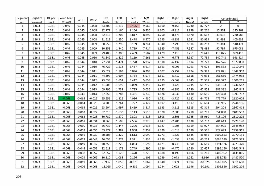
X Y1 136.3 0.331 0.046 0.045 0.008 83.300 1.115 9.495 9.560 -1.160 -9.156 9.230 82.777 0 0
2 136.3 0.331 0.046 0.045 0.008 82.777 1.160 9.156 9.230 -1.205 -8.817 8.899 82.216 15.902 135.369
3 136.3 0.331 0.046 0.045 0.008 82.216 1.205 8.817 8.899 -1.250 -8.478 8.570 81.612 33.038 270.588
4 136.3 0.331 0.046 0.045 0.008 81.612 1.250 8.478 8.570 -1.295 -8.139 8.241 80.959 51.498 405.632
5 136.3 0.331 0.046 0.045 0.009 80.959 1.295 8.139 8.241 -1.340 -7.799 7.914 80.253 71.381 540.474
6 136.3 0.331 0.046 0.045 0.009 80.253 1.340 7.799 7.914 -1.385 -7.459 7.587 79.485 92.799 675.081
7 136.3 0.331 0.046 0.045 0.009 79.485 1.385 7.459 7.587 -1.429 -7.119 7.261 78.649 115.875 809.413
8 136.3 0.331 0.046 0.045 0.010 78.649 1.429 7.119 7.261 -1.474 -6.778 6.937 77.734 140.748 943.424
9 136.3 0.331 0.046 0.044 0.010 77.734 1.474 6.778 6.937 -1.518 -6.437 6.614 76.729 167.576 1077.058
10 136.3 0.331 0.046 0.044 0.010 76.729 1.518 6.437 6.614 -1.563 -6.096 6.293 75.622 196.533 1210.246
11 136.3 0.331 0.046 0.044 0.011 75.622 1.563 6.096 6.293 -1.607 -5.754 5.974 74.397 227.821 1342.907
12 136.3 0.331 0.046 0.044 0.011 74.397 1.607 5.754 5.974 -1.651 -5.412 5.658 73.033 261.666 1474.938
13 136.3 0.331 0.046 0.044 0.012 73.033 1.651 5.412 5.658 -1.695 -5.069 5.345 71.508 298.327 1606.215
14 136.3 0.331 0.046 0.044 0.012 71.508 1.695 5.069 5.345 -1.739 -4.725 5.035 69.795 338.103 1736.582
15 136.3 0.331 0.046 0.044 0.013 69.795 1.739 4.725 5.035 -1.783 -4.381 4.730 67.858 381.332 1865.845
16 136.3 0.331 0.046 0.043 0.014 67.858 1.783 4.381 4.730 -1.826 -4.036 4.430 65.656 428.408 1993.757
17 136.3 0.331 -0.068 -0.065 -0.022 65.656 1.826 4.036 4.430 -1.761 -3.727 4.122 64.705 479.779 2120.005
18 136.3 0.331 -0.068 -0.064 -0.023 64.705 1.761 3.727 4.122 -1.697 -3.419 3.817 63.604 535.965 2244.186
19 136.3 0.331 -0.068 -0.064 -0.025 63.604 1.697 3.419 3.817 -1.633 -3.113 3.515 62.315 594.204 2367.418
20 136.3 0.331 -0.068 -0.063 -0.027 62.315 1.633 3.113 3.515 -1.570 -2.808 3.218 60.789 654.800 2489.507
21 136.3 0.331 -0.068 -0.062 -0.028 60.789 1.570 2.808 3.218 -1.508 -2.506 2.925 58.960 718.126 2610.203
22 136.3 0.331 -0.068 -0.061 -0.031 58.960 1.508 2.506 2.925 -1.447 -2.206 2.638 56.732 784.643 2729.170
23 136.3 0.331 -0.068 -0.060 -0.033 56.732 1.447 2.206 2.638 -1.387 -1.908 2.359 53.977 854.925 2845.952
24 136.3 0.331 -0.068 -0.058 -0.036 53.977 1.387 1.908 2.359 -1.329 -1.613 2.090 50.506 929.693 2959.915
25 136.3 0.331 -0.068 -0.056 -0.039 50.506 1.329 1.613 2.090 -1.273 -1.321 1.835 46.056 1009.853 3070.151
26 136.3 0.331 -0.068 -0.053 -0.043 46.056 1.273 1.321 1.835 -1.220 -1.033 1.599 40.253 1096.539 3175.333
27 136.3 0.331 -0.068 -0.049 -0.047 40.253 1.220 1.033 1.599 -1.171 -0.749 1.390 32.619 1191.126 3273.470
28 136.3 0.331 -0.068 -0.044 -0.052 32.619 1.171 0.749 1.390 -1.126 -0.470 1.220 22.657 1295.150 3361.543
29 136.3 0.331 -0.068 -0.038 -0.057 22.657 1.126 0.470 1.220 -1.088 -0.196 1.106 10.210 1409.952 3435.015
30 136.3 0.331 -0.068 -0.029 -0.062 10.210 1.088 0.196 1.106 -1.059 0.073 1.062 -3.956 1535.733 3487.520
31 136.3 0.331 -0.068 -0.019 -0.066 -3.956 1.059 -0.073 1.062 -1.040 0.339 1.094 -18.025 1669.875 3511.680
32 136.3 0.331 -0.068 -0.006 -0.068 -18.025 1.040 -0.339 1.094 -1.034 0.602 1.196 -30.191 1805.850 3502.276
WL VSegment
no.
Height of
Segment
DL per
block
Wind Load
(Cpi=0)WL H
Right
Thrust
Right
angleCo-ordinatesLeft
Angle
Left
Thrust x
Left
Thrust y
Left
Thrust
Right
Thrust x
Right
Thrust y
203
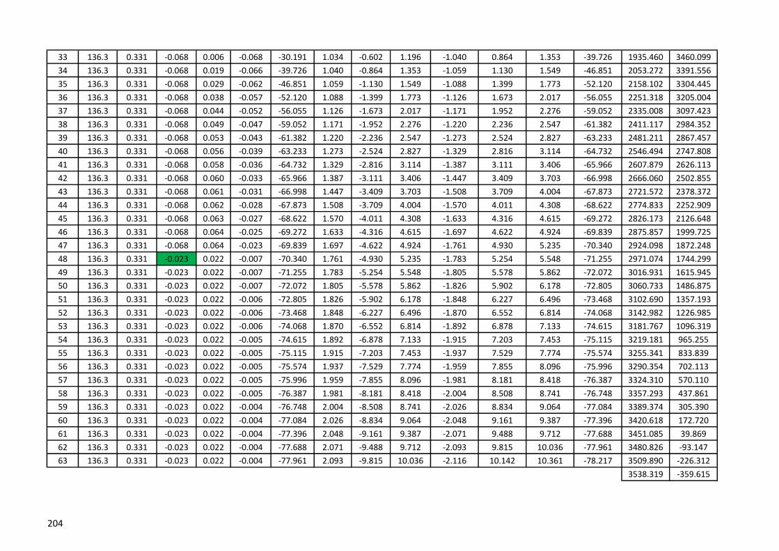
33 136.3 0.331 -0.068 0.006 -0.068 -30.191 1.034 -0.602 1.196 -1.040 0.864 1.353 -39.726 1935.460 3460.099
34 136.3 0.331 -0.068 0.019 -0.066 -39.726 1.040 -0.864 1.353 -1.059 1.130 1.549 -46.851 2053.272 3391.556
35 136.3 0.331 -0.068 0.029 -0.062 -46.851 1.059 -1.130 1.549 -1.088 1.399 1.773 -52.120 2158.102 3304.445
36 136.3 0.331 -0.068 0.038 -0.057 -52.120 1.088 -1.399 1.773 -1.126 1.673 2.017 -56.055 2251.318 3205.004
37 136.3 0.331 -0.068 0.044 -0.052 -56.055 1.126 -1.673 2.017 -1.171 1.952 2.276 -59.052 2335.008 3097.423
38 136.3 0.331 -0.068 0.049 -0.047 -59.052 1.171 -1.952 2.276 -1.220 2.236 2.547 -61.382 2411.117 2984.352
39 136.3 0.331 -0.068 0.053 -0.043 -61.382 1.220 -2.236 2.547 -1.273 2.524 2.827 -63.233 2481.211 2867.457
40 136.3 0.331 -0.068 0.056 -0.039 -63.233 1.273 -2.524 2.827 -1.329 2.816 3.114 -64.732 2546.494 2747.808
41 136.3 0.331 -0.068 0.058 -0.036 -64.732 1.329 -2.816 3.114 -1.387 3.111 3.406 -65.966 2607.879 2626.113
42 136.3 0.331 -0.068 0.060 -0.033 -65.966 1.387 -3.111 3.406 -1.447 3.409 3.703 -66.998 2666.060 2502.855
43 136.3 0.331 -0.068 0.061 -0.031 -66.998 1.447 -3.409 3.703 -1.508 3.709 4.004 -67.873 2721.572 2378.372
44 136.3 0.331 -0.068 0.062 -0.028 -67.873 1.508 -3.709 4.004 -1.570 4.011 4.308 -68.622 2774.833 2252.909
45 136.3 0.331 -0.068 0.063 -0.027 -68.622 1.570 -4.011 4.308 -1.633 4.316 4.615 -69.272 2826.173 2126.648
46 136.3 0.331 -0.068 0.064 -0.025 -69.272 1.633 -4.316 4.615 -1.697 4.622 4.924 -69.839 2875.857 1999.725
47 136.3 0.331 -0.068 0.064 -0.023 -69.839 1.697 -4.622 4.924 -1.761 4.930 5.235 -70.340 2924.098 1872.248
48 136.3 0.331 -0.023 0.022 -0.007 -70.340 1.761 -4.930 5.235 -1.783 5.254 5.548 -71.255 2971.074 1744.299
49 136.3 0.331 -0.023 0.022 -0.007 -71.255 1.783 -5.254 5.548 -1.805 5.578 5.862 -72.072 3016.931 1615.945
50 136.3 0.331 -0.023 0.022 -0.007 -72.072 1.805 -5.578 5.862 -1.826 5.902 6.178 -72.805 3060.733 1486.875
51 136.3 0.331 -0.023 0.022 -0.006 -72.805 1.826 -5.902 6.178 -1.848 6.227 6.496 -73.468 3102.690 1357.193
52 136.3 0.331 -0.023 0.022 -0.006 -73.468 1.848 -6.227 6.496 -1.870 6.552 6.814 -74.068 3142.982 1226.985
53 136.3 0.331 -0.023 0.022 -0.006 -74.068 1.870 -6.552 6.814 -1.892 6.878 7.133 -74.615 3181.767 1096.319
54 136.3 0.331 -0.023 0.022 -0.005 -74.615 1.892 -6.878 7.133 -1.915 7.203 7.453 -75.115 3219.181 965.255
55 136.3 0.331 -0.023 0.022 -0.005 -75.115 1.915 -7.203 7.453 -1.937 7.529 7.774 -75.574 3255.341 833.839
56 136.3 0.331 -0.023 0.022 -0.005 -75.574 1.937 -7.529 7.774 -1.959 7.855 8.096 -75.996 3290.354 702.113
57 136.3 0.331 -0.023 0.022 -0.005 -75.996 1.959 -7.855 8.096 -1.981 8.181 8.418 -76.387 3324.310 570.110
58 136.3 0.331 -0.023 0.022 -0.005 -76.387 1.981 -8.181 8.418 -2.004 8.508 8.741 -76.748 3357.293 437.861
59 136.3 0.331 -0.023 0.022 -0.004 -76.748 2.004 -8.508 8.741 -2.026 8.834 9.064 -77.084 3389.374 305.390
60 136.3 0.331 -0.023 0.022 -0.004 -77.084 2.026 -8.834 9.064 -2.048 9.161 9.387 -77.396 3420.618 172.720
61 136.3 0.331 -0.023 0.022 -0.004 -77.396 2.048 -9.161 9.387 -2.071 9.488 9.712 -77.688 3451.085 39.869
62 136.3 0.331 -0.023 0.022 -0.004 -77.688 2.071 -9.488 9.712 -2.093 9.815 10.036 -77.961 3480.826 -93.147
63 136.3 0.331 -0.023 0.022 -0.004 -77.961 2.093 -9.815 10.036 -2.116 10.142 10.361 -78.217 3509.890 -226.312
3538.319 -359.615
204
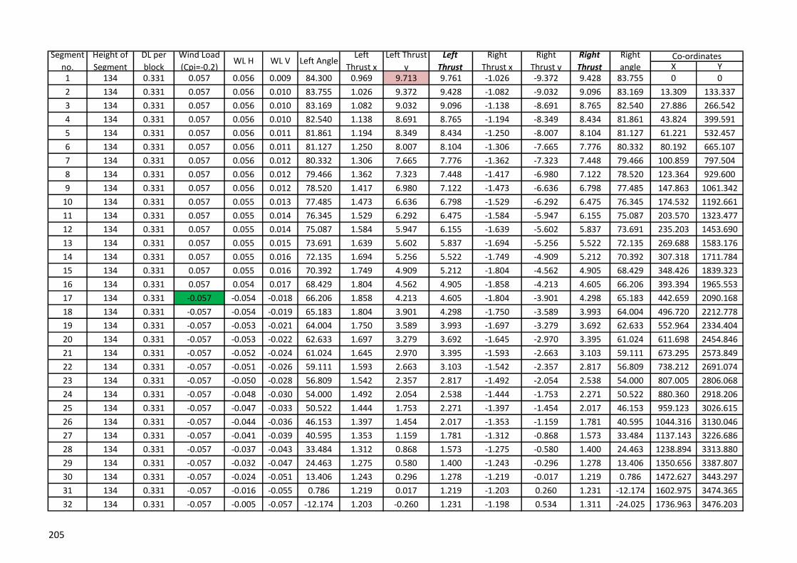
X Y1 134 0.331 0.057 0.056 0.009 84.300 0.969 9.713 9.761 -1.026 -9.372 9.428 83.755 0 0
2 134 0.331 0.057 0.056 0.010 83.755 1.026 9.372 9.428 -1.082 -9.032 9.096 83.169 13.309 133.337
3 134 0.331 0.057 0.056 0.010 83.169 1.082 9.032 9.096 -1.138 -8.691 8.765 82.540 27.886 266.542
4 134 0.331 0.057 0.056 0.010 82.540 1.138 8.691 8.765 -1.194 -8.349 8.434 81.861 43.824 399.591
5 134 0.331 0.057 0.056 0.011 81.861 1.194 8.349 8.434 -1.250 -8.007 8.104 81.127 61.221 532.457
6 134 0.331 0.057 0.056 0.011 81.127 1.250 8.007 8.104 -1.306 -7.665 7.776 80.332 80.192 665.107
7 134 0.331 0.057 0.056 0.012 80.332 1.306 7.665 7.776 -1.362 -7.323 7.448 79.466 100.859 797.504
8 134 0.331 0.057 0.056 0.012 79.466 1.362 7.323 7.448 -1.417 -6.980 7.122 78.520 123.364 929.600
9 134 0.331 0.057 0.056 0.012 78.520 1.417 6.980 7.122 -1.473 -6.636 6.798 77.485 147.863 1061.342
10 134 0.331 0.057 0.055 0.013 77.485 1.473 6.636 6.798 -1.529 -6.292 6.475 76.345 174.532 1192.661
11 134 0.331 0.057 0.055 0.014 76.345 1.529 6.292 6.475 -1.584 -5.947 6.155 75.087 203.570 1323.477
12 134 0.331 0.057 0.055 0.014 75.087 1.584 5.947 6.155 -1.639 -5.602 5.837 73.691 235.203 1453.690
13 134 0.331 0.057 0.055 0.015 73.691 1.639 5.602 5.837 -1.694 -5.256 5.522 72.135 269.688 1583.176
14 134 0.331 0.057 0.055 0.016 72.135 1.694 5.256 5.522 -1.749 -4.909 5.212 70.392 307.318 1711.784
15 134 0.331 0.057 0.055 0.016 70.392 1.749 4.909 5.212 -1.804 -4.562 4.905 68.429 348.426 1839.323
16 134 0.331 0.057 0.054 0.017 68.429 1.804 4.562 4.905 -1.858 -4.213 4.605 66.206 393.394 1965.553
17 134 0.331 -0.057 -0.054 -0.018 66.206 1.858 4.213 4.605 -1.804 -3.901 4.298 65.183 442.659 2090.168
18 134 0.331 -0.057 -0.054 -0.019 65.183 1.804 3.901 4.298 -1.750 -3.589 3.993 64.004 496.720 2212.778
19 134 0.331 -0.057 -0.053 -0.021 64.004 1.750 3.589 3.993 -1.697 -3.279 3.692 62.633 552.964 2334.404
20 134 0.331 -0.057 -0.053 -0.022 62.633 1.697 3.279 3.692 -1.645 -2.970 3.395 61.024 611.698 2454.846
21 134 0.331 -0.057 -0.052 -0.024 61.024 1.645 2.970 3.395 -1.593 -2.663 3.103 59.111 673.295 2573.849
22 134 0.331 -0.057 -0.051 -0.026 59.111 1.593 2.663 3.103 -1.542 -2.357 2.817 56.809 738.212 2691.074
23 134 0.331 -0.057 -0.050 -0.028 56.809 1.542 2.357 2.817 -1.492 -2.054 2.538 54.000 807.005 2806.068
24 134 0.331 -0.057 -0.048 -0.030 54.000 1.492 2.054 2.538 -1.444 -1.753 2.271 50.522 880.360 2918.206
25 134 0.331 -0.057 -0.047 -0.033 50.522 1.444 1.753 2.271 -1.397 -1.454 2.017 46.153 959.123 3026.615
26 134 0.331 -0.057 -0.044 -0.036 46.153 1.397 1.454 2.017 -1.353 -1.159 1.781 40.595 1044.316 3130.046
27 134 0.331 -0.057 -0.041 -0.039 40.595 1.353 1.159 1.781 -1.312 -0.868 1.573 33.484 1137.143 3226.686
28 134 0.331 -0.057 -0.037 -0.043 33.484 1.312 0.868 1.573 -1.275 -0.580 1.400 24.463 1238.894 3313.880
29 134 0.331 -0.057 -0.032 -0.047 24.463 1.275 0.580 1.400 -1.243 -0.296 1.278 13.406 1350.656 3387.807
30 134 0.331 -0.057 -0.024 -0.051 13.406 1.243 0.296 1.278 -1.219 -0.017 1.219 0.786 1472.627 3443.297
31 134 0.331 -0.057 -0.016 -0.055 0.786 1.219 0.017 1.219 -1.203 0.260 1.231 -12.174 1602.975 3474.365
32 134 0.331 -0.057 -0.005 -0.057 -12.174 1.203 -0.260 1.231 -1.198 0.534 1.311 -24.025 1736.963 3476.203
WL VSegment
no.
Height of
Segment
DL per
block
Wind Load
(Cpi=-0.2)WL H
Right
Thrust
Right
angleCo-ordinatesLeft Angle
Left
Thrust x
Left Thrust
y
Left
Thrust
Right
Thrust x
Right
Thrust y
205

33 134 0.331 -0.057 0.005 -0.057 -24.025 1.198 -0.534 1.311 -1.203 0.808 1.449 -33.893 1867.949 3447.944
34 134 0.331 -0.057 0.016 -0.055 -33.893 1.203 -0.808 1.449 -1.219 1.084 1.631 -41.665 1990.340 3393.387
35 134 0.331 -0.057 0.024 -0.051 -41.665 1.219 -1.084 1.631 -1.243 1.364 1.845 -47.656 2101.571 3318.663
36 134 0.331 -0.057 0.032 -0.047 -47.656 1.243 -1.364 1.845 -1.275 1.648 2.083 -52.274 2201.675 3229.583
37 134 0.331 -0.057 0.037 -0.043 -52.274 1.275 -1.648 2.083 -1.312 1.935 2.338 -55.874 2291.934 3130.541
38 134 0.331 -0.057 0.041 -0.039 -55.874 1.312 -1.935 2.338 -1.353 2.227 2.606 -58.724 2373.926 3024.554
39 134 0.331 -0.057 0.044 -0.036 -58.724 1.353 -2.227 2.606 -1.397 2.522 2.883 -61.018 2449.102 2913.628
40 134 0.331 -0.057 0.047 -0.033 -61.018 1.397 -2.522 2.883 -1.444 2.820 3.168 -62.894 2518.671 2799.102
41 134 0.331 -0.057 0.048 -0.030 -62.894 1.444 -2.820 3.168 -1.492 3.121 3.460 -64.452 2583.599 2681.883
42 134 0.331 -0.057 0.050 -0.028 -64.452 1.492 -3.121 3.460 -1.542 3.425 3.756 -65.762 2644.654 2562.601
43 134 0.331 -0.057 0.051 -0.026 -65.762 1.542 -3.425 3.756 -1.593 3.730 4.056 -66.878 2702.445 2441.703
44 134 0.331 -0.057 0.052 -0.024 -66.878 1.593 -3.730 4.056 -1.645 4.038 4.360 -67.837 2757.455 2319.515
45 134 0.331 -0.057 0.053 -0.022 -67.837 1.645 -4.038 4.360 -1.697 4.347 4.666 -68.671 2810.077 2196.280
46 134 0.331 -0.057 0.053 -0.021 -68.671 1.697 -4.347 4.666 -1.750 4.657 4.975 -69.402 2860.627 2072.180
47 134 0.331 -0.057 0.054 -0.019 -69.402 1.750 -4.657 4.975 -1.804 4.969 5.286 -70.046 2909.365 1947.358
48 134 0.331 -0.011 0.011 -0.004 -70.046 1.804 -4.969 5.286 -1.815 5.296 5.598 -71.086 2956.509 1821.925
49 134 0.331 -0.011 0.011 -0.003 -71.086 1.815 -5.296 5.598 -1.825 5.623 5.912 -72.016 3002.238 1695.969
50 134 0.331 -0.011 0.011 -0.003 -72.016 1.825 -5.623 5.912 -1.836 5.951 6.228 -72.851 3045.673 1569.204
51 134 0.331 -0.011 0.011 -0.003 -72.851 1.836 -5.951 6.228 -1.847 6.279 6.545 -73.606 3087.047 1441.751
52 134 0.331 -0.011 0.011 -0.003 -73.606 1.847 -6.279 6.545 -1.858 6.607 6.864 -74.291 3126.558 1313.709
53 134 0.331 -0.011 0.011 -0.003 -74.291 1.858 -6.607 6.864 -1.869 6.936 7.183 -74.915 3164.378 1185.157
54 134 0.331 -0.011 0.011 -0.003 -74.915 1.869 -6.936 7.183 -1.880 7.264 7.503 -75.486 3200.659 1056.162
55 134 0.331 -0.011 0.011 -0.003 -75.486 1.880 -7.264 7.503 -1.892 7.592 7.824 -76.010 3235.533 926.780
56 134 0.331 -0.011 0.011 -0.002 -76.010 1.892 -7.592 7.824 -1.903 7.921 8.146 -76.493 3269.116 797.056
57 134 0.331 -0.011 0.011 -0.002 -76.493 1.903 -7.921 8.146 -1.914 8.250 8.469 -76.939 3301.511 667.031
58 134 0.331 -0.011 0.011 -0.002 -76.939 1.914 -8.250 8.469 -1.925 8.578 8.792 -77.352 3332.809 536.737
59 134 0.331 -0.011 0.011 -0.002 -77.352 1.925 -8.578 8.792 -1.936 8.907 9.115 -77.736 3363.092 406.204
60 134 0.331 -0.011 0.011 -0.002 -77.736 1.936 -8.907 9.115 -1.947 9.236 9.439 -78.094 3392.432 275.455
61 134 0.331 -0.011 0.011 -0.002 -78.094 1.947 -9.236 9.439 -1.959 9.565 9.764 -78.428 3420.896 144.513
62 134 0.331 -0.011 0.011 -0.002 -78.428 1.959 -9.565 9.764 -1.970 9.894 10.088 -78.740 3448.541 13.396
63 134 0.331 -0.011 0.011 -0.002 -78.740 1.970 -9.894 10.088 -1.981 10.223 10.413 -79.033 3475.422 -117.880
3501.586 -249.301
206

X Y
1 134 0.461 80.500 2.394 14.305 14.504 -2.394 -13.843 14.049 80.189 0 0
2 134 0.461 80.189 2.394 13.843 14.049 -2.394 -13.382 13.594 79.858 22.116 132.162
3 134 0.461 79.858 2.394 13.382 13.594 -2.394 -12.921 13.140 79.504 44.949 264.203
4 134 0.461 79.504 2.394 12.921 13.140 -2.394 -12.459 12.687 79.124 68.545 396.109
5 134 0.461 79.124 2.394 12.459 12.687 -2.394 -11.998 12.234 78.716 92.955 527.867
6 134 0.461 78.716 2.394 11.998 12.234 -2.394 -11.536 11.782 78.277 118.239 659.460
7 134 0.461 78.277 2.394 11.536 11.782 -2.394 -11.075 11.331 77.803 144.457 790.870
8 134 0.461 77.803 2.394 11.075 11.331 -2.394 -10.614 10.880 77.290 171.683 922.075
9 134 0.461 77.290 2.394 10.614 10.880 -2.394 -10.152 10.431 76.732 199.992 1053.050
10 134 0.461 76.732 2.394 10.152 10.431 -2.394 -9.691 9.982 76.125 229.474 1183.767
11 134 0.461 76.125 2.394 9.691 9.982 -2.394 -9.229 9.535 75.460 260.227 1314.190
12 134 0.461 75.460 2.394 9.229 9.535 -2.394 -8.768 9.089 74.729 292.362 1444.280
13 134 0.461 74.729 2.394 8.768 9.089 -2.394 -8.307 8.645 73.924 326.004 1573.988
14 134 0.461 73.924 2.394 8.307 8.645 -2.394 -7.845 8.202 73.031 361.296 1703.257
15 134 0.461 73.031 2.394 7.845 8.202 -2.394 -7.384 7.762 72.037 398.403 1832.017
16 134 0.461 72.037 2.394 7.384 7.762 -2.394 -6.922 7.325 70.924 437.510 1960.183
17 134 0.461 70.924 2.394 6.922 7.325 -2.394 -6.461 6.890 69.670 478.835 2087.652
18 134 0.461 69.670 2.394 6.461 6.890 -2.394 -6.000 6.459 68.248 522.629 2214.294
19 134 0.461 68.248 2.394 6.000 6.459 -2.394 -5.538 6.033 66.624 569.184 2339.947
20 134 0.461 66.624 2.394 5.538 6.033 -2.394 -5.077 5.613 64.755 618.842 2464.405
21 134 0.461 64.755 2.394 5.077 5.613 -2.394 -4.615 5.199 62.586 672.008 2587.407
22 134 0.461 62.586 2.394 4.615 5.199 -2.394 -4.154 4.794 60.046 729.158 2708.609
23 134 0.461 60.046 2.394 4.154 4.794 -2.394 -3.693 4.401 57.045 790.854 2827.561
24 134 0.461 57.045 2.394 3.693 4.401 -2.394 -3.231 4.021 53.467 857.760 2943.663
25 134 0.461 53.467 2.394 3.231 4.021 -2.394 -2.770 3.661 49.164 930.653 3056.102
26 134 0.461 49.164 2.394 2.770 3.661 -2.394 -2.308 3.325 43.959 1010.421 3163.773
27 134 0.461 43.959 2.394 2.308 3.325 -2.394 -1.847 3.023 37.652 1098.043 3265.156
28 134 0.461 37.652 2.394 1.847 3.023 -2.394 -1.386 2.766 30.062 1194.502 3358.170
29 134 0.461 30.062 2.394 1.386 2.766 -2.394 -0.924 2.566 21.109 1300.594 3440.026
30 134 0.461 21.109 2.394 0.924 2.566 -2.394 -0.463 2.438 10.940 1416.569 3507.151
31 134 0.461 10.940 2.394 0.463 2.438 -2.394 -0.001 2.394 0.032 1541.577 3555.411
32 134 0.461 0.032 2.394 0.001 2.394 -2.394 0.460 2.438 -10.879 1673.142 3580.842
Co-ordinatesSegment
no.
Height of
Segment
DL+LL(PL-
3/4)Left Angle
Left Thrust
x
Left
Thrust yLeft Thrust
Right
Thrust x
Right
Thrust y
Right
ThrustRight angle
207

33 134 0.461 -10.879 2.394 -0.460 2.438 -2.394 0.921 2.565 -21.054 1807.142 3580.916
34 134 0.461 -21.054 2.394 -0.921 2.565 -2.394 1.383 2.765 -30.015 1938.733 3555.624
35 134 0.461 -30.015 2.394 -1.383 2.765 -2.394 1.844 3.022 -37.612 2063.788 3507.485
36 134 0.461 -37.612 2.394 -1.844 3.022 -2.394 2.306 3.324 -43.926 2179.818 3440.455
37 134 0.461 -43.926 2.394 -2.306 3.324 -2.394 2.767 3.659 -49.137 2285.967 3358.672
38 134 0.461 -49.137 2.394 -2.767 3.659 -2.394 3.229 4.019 -53.445 2382.479 3265.713
39 134 0.461 -53.445 2.394 -3.229 4.019 -2.394 3.690 4.398 -57.027 2470.149 3164.372
40 134 0.461 -57.027 2.394 -3.690 4.398 -2.394 4.151 4.792 -60.031 2549.959 3056.732
41 134 0.461 -60.031 2.394 -4.151 4.792 -2.394 4.613 5.197 -62.573 2622.888 2944.316
42 134 0.461 -62.573 2.394 -4.613 5.197 -2.394 5.074 5.610 -64.744 2689.826 2828.233
43 134 0.461 -64.744 2.394 -5.074 5.610 -2.394 5.536 6.031 -66.614 2751.550 2709.295
44 134 0.461 -66.614 2.394 -5.536 6.031 -2.394 5.997 6.457 -68.239 2808.724 2588.105
45 134 0.461 -68.239 2.394 -5.997 6.457 -2.394 6.458 6.888 -69.663 2861.911 2465.112
46 134 0.461 -69.663 2.394 -6.458 6.888 -2.394 6.920 7.322 -70.917 2911.589 2340.661
47 134 0.461 -70.917 2.394 -6.920 7.322 -2.394 7.381 7.760 -72.031 2958.160 2215.014
48 134 2.061 -72.031 2.394 -7.381 7.760 -2.394 9.443 9.741 -75.774 3001.969 2088.378
49 134 0.461 -75.774 2.394 -9.443 9.741 -2.394 9.904 10.189 -76.412 3043.307 1960.914
50 134 0.461 -76.412 2.394 -9.904 10.189 -2.394 10.365 10.638 -76.996 3076.236 1831.023
51 134 0.461 -76.996 2.394 -10.365 10.638 -2.394 10.827 11.088 -77.532 3107.718 1700.773
52 134 0.461 -77.532 2.394 -10.827 11.088 -2.394 11.288 11.539 -78.027 3137.870 1570.210
53 134 0.461 -78.027 2.394 -11.288 11.539 -2.394 11.750 11.991 -78.484 3166.799 1439.370
54 134 0.461 -78.484 2.394 -11.750 11.991 -2.394 12.211 12.443 -78.909 3194.598 1308.285
55 134 0.461 -78.909 2.394 -12.211 12.443 -2.394 12.672 12.896 -79.303 3221.349 1176.982
56 134 0.461 -79.303 2.394 -12.672 12.896 -2.394 13.134 13.350 -79.670 3247.127 1045.485
57 134 0.461 -79.670 2.394 -13.134 13.350 -2.394 13.595 13.804 -80.014 3272.000 913.814
58 134 0.461 -80.014 2.394 -13.595 13.804 -2.394 14.057 14.259 -80.335 3296.027 781.985
59 134 0.461 -80.335 2.394 -14.057 14.259 -2.394 14.518 14.714 -80.637 3319.264 650.016
60 134 0.461 -80.637 2.394 -14.518 14.714 -2.394 14.979 15.169 -80.921 3341.760 517.917
61 134 0.461 -80.921 2.394 -14.979 15.169 -2.394 15.441 15.625 -81.188 3363.561 385.703
62 134 0.461 -81.188 2.394 -15.441 15.625 -2.394 15.902 16.081 -81.439 3384.706 253.382
63 134 0.461 -81.439 2.394 -15.902 16.081 -2.394 16.364 16.538 -81.677 3405.235 120.963
3425.182 -11.544
208

X Y1 133 0.458 79.500 2.725 14.705 14.955 -2.725 -14.247 14.505 79.170 0 0
2 133 0.458 79.170 2.725 14.247 14.505 -2.725 -13.789 14.056 78.820 24.237 130.773
3 133 0.458 78.820 2.725 13.789 14.056 -2.725 -13.331 13.607 78.446 49.227 261.404
4 133 0.458 78.446 2.725 13.331 13.607 -2.725 -12.873 13.158 78.046 75.015 391.880
5 133 0.458 78.046 2.725 12.873 13.158 -2.725 -12.415 12.711 77.619 101.655 522.185
6 133 0.458 77.619 2.725 12.415 12.711 -2.725 -11.957 12.264 77.160 129.202 652.301
7 133 0.458 77.160 2.725 11.957 12.264 -2.725 -11.499 11.818 76.666 157.719 782.207
8 133 0.458 76.666 2.725 11.499 11.818 -2.725 -11.041 11.373 76.134 187.276 911.882
9 133 0.458 76.134 2.725 11.041 11.373 -2.725 -10.583 10.928 75.559 217.948 1041.297
10 133 0.458 75.559 2.725 10.583 10.928 -2.725 -10.125 10.486 74.935 249.821 1170.421
11 133 0.458 74.935 2.725 10.125 10.486 -2.725 -9.667 10.044 74.256 282.989 1299.219
12 133 0.458 74.256 2.725 9.667 10.044 -2.725 -9.209 9.604 73.515 317.558 1427.648
13 133 0.458 73.515 2.725 9.209 9.604 -2.725 -8.751 9.166 72.702 353.647 1555.658
14 133 0.458 72.702 2.725 8.751 9.166 -2.725 -8.293 8.730 71.808 391.388 1683.191
15 133 0.458 71.808 2.725 8.293 8.730 -2.725 -7.835 8.296 70.821 430.934 1810.175
16 133 0.458 70.821 2.725 7.835 8.296 -2.725 -7.377 7.865 69.725 472.456 1936.528
17 133 0.458 69.725 2.725 7.377 7.865 -2.725 -6.920 7.437 68.502 516.150 2062.146
18 133 0.458 68.502 2.725 6.920 7.437 -2.725 -6.462 7.013 67.131 562.238 2186.905
19 133 0.458 67.131 2.725 6.462 7.013 -2.725 -6.004 6.593 65.584 610.979 2310.652
20 133 0.458 65.584 2.725 6.004 6.593 -2.725 -5.546 6.179 63.828 662.666 2433.198
21 133 0.458 63.828 2.725 5.546 6.179 -2.725 -5.088 5.772 61.823 717.643 2554.303
22 133 0.458 61.823 2.725 5.088 5.772 -2.725 -4.630 5.372 59.516 776.304 2673.667
23 133 0.458 59.516 2.725 4.630 5.372 -2.725 -4.172 4.983 56.844 839.107 2790.906
24 133 0.458 56.844 2.725 4.172 4.983 -2.725 -3.714 4.607 53.727 906.578 2905.521
25 133 0.458 53.727 2.725 3.714 4.607 -2.725 -3.256 4.246 50.068 979.319 3016.866
26 133 0.458 50.068 2.725 3.256 4.246 -2.725 -2.798 3.906 45.752 1058.007 3124.091
27 133 0.458 45.752 2.725 2.798 3.906 -2.725 -2.340 3.592 40.648 1143.377 3226.077
28 133 0.458 40.648 2.725 2.340 3.592 -2.725 -1.882 3.312 34.626 1236.180 3321.348
29 133 0.458 34.626 2.725 1.882 3.312 -2.725 -1.424 3.075 27.587 1337.090 3407.985
30 133 0.458 27.587 2.725 1.424 3.075 -2.725 -0.966 2.892 19.517 1446.533 3483.558
31 133 0.458 19.517 2.725 0.966 2.892 -2.725 -0.508 2.772 10.560 1564.412 3545.149
32 133 2.058 10.560 2.725 0.508 2.772 -2.725 1.550 3.135 -29.627 1689.771 3589.583
Co-ordinatesSegment
no.
Height of
Segment
DL+LL(1/2
PL)Left Angle
Left Thrust
x
Left Thrust
yLeft Thrust
Right
Thrust x
Right
Thrust y
Right
ThrustRight angle
209

33 133 0.458 -29.627 2.725 -1.550 3.135 -2.725 2.008 3.385 -36.380 1820.518 3613.957
34 133 0.458 -36.380 2.725 -2.008 3.385 -2.725 2.466 3.675 -42.138 1936.130 3548.209
35 133 0.458 -42.138 2.725 -2.466 3.675 -2.725 2.924 3.997 -47.011 2043.209 3469.321
36 133 0.458 -47.011 2.725 -2.924 3.997 -2.725 3.382 4.343 -51.134 2141.833 3380.090
37 133 0.458 -51.134 2.725 -3.382 4.343 -2.725 3.840 4.709 -54.633 2232.519 3282.802
38 133 0.458 -54.633 2.725 -3.840 4.709 -2.725 4.298 5.089 -57.619 2315.976 3179.245
39 133 0.458 -57.619 2.725 -4.298 5.089 -2.725 4.756 5.481 -60.184 2392.958 3070.789
40 133 0.458 -60.184 2.725 -4.756 5.481 -2.725 5.214 5.883 -62.402 2464.186 2958.469
41 133 0.458 -62.402 2.725 -5.214 5.883 -2.725 5.672 6.292 -64.334 2530.316 2843.075
42 133 0.458 -64.334 2.725 -5.672 6.292 -2.725 6.130 6.708 -66.028 2591.931 2725.208
43 133 0.458 -66.028 2.725 -6.130 6.708 -2.725 6.587 7.129 -67.524 2649.536 2605.331
44 133 0.458 -67.524 2.725 -6.587 7.129 -2.725 7.045 7.554 -68.852 2703.572 2483.802
45 133 0.458 -68.852 2.725 -7.045 7.554 -2.725 7.503 7.983 -70.038 2754.417 2360.905
46 133 0.458 -70.038 2.725 -7.503 7.983 -2.725 7.961 8.415 -71.103 2802.400 2236.862
47 133 0.458 -71.103 2.725 -7.961 8.415 -2.725 8.419 8.849 -72.063 2847.806 2111.853
48 133 0.458 -72.063 2.725 -8.419 8.849 -2.725 8.877 9.286 -72.933 2890.882 1986.022
49 133 0.458 -72.933 2.725 -8.877 9.286 -2.725 9.335 9.725 -73.725 2931.842 1859.486
50 133 0.458 -73.725 2.725 -9.335 9.725 -2.725 9.793 10.165 -74.448 2970.876 1732.343
51 133 0.458 -74.448 2.725 -9.793 10.165 -2.725 10.251 10.607 -75.112 3008.149 1604.673
52 133 0.458 -75.112 2.725 -10.251 10.607 -2.725 10.709 11.050 -75.722 3043.807 1476.542
53 133 0.458 -75.722 2.725 -10.709 11.050 -2.725 11.167 11.495 -76.285 3077.979 1348.007
54 133 0.458 -76.285 2.725 -11.167 11.495 -2.725 11.625 11.940 -76.806 3110.781 1219.115
55 133 0.458 -76.806 2.725 -11.625 11.940 -2.725 12.083 12.387 -77.289 3142.315 1089.908
56 133 0.458 -77.289 2.725 -12.083 12.387 -2.725 12.541 12.834 -77.739 3172.672 960.419
57 133 0.458 -77.739 2.725 -12.541 12.834 -2.725 12.999 13.282 -78.159 3201.936 830.678
58 133 0.458 -78.159 2.725 -12.999 13.282 -2.725 13.457 13.730 -78.551 3230.180 700.712
59 133 0.458 -78.551 2.725 -13.457 13.730 -2.725 13.915 14.179 -78.918 3257.472 570.542
60 133 0.458 -78.918 2.725 -13.915 14.179 -2.725 14.373 14.629 -79.263 3283.872 440.188
61 133 0.458 -79.263 2.725 -14.373 14.629 -2.725 14.831 15.079 -79.587 3309.436 309.668
62 133 0.458 -79.587 2.725 -14.831 15.079 -2.725 15.289 15.530 -79.893 3334.214 178.997
63 133 0.458 -79.893 2.725 -15.289 15.530 -2.725 15.747 15.981 -80.181 3358.252 48.187
3381.593 -82.749
210
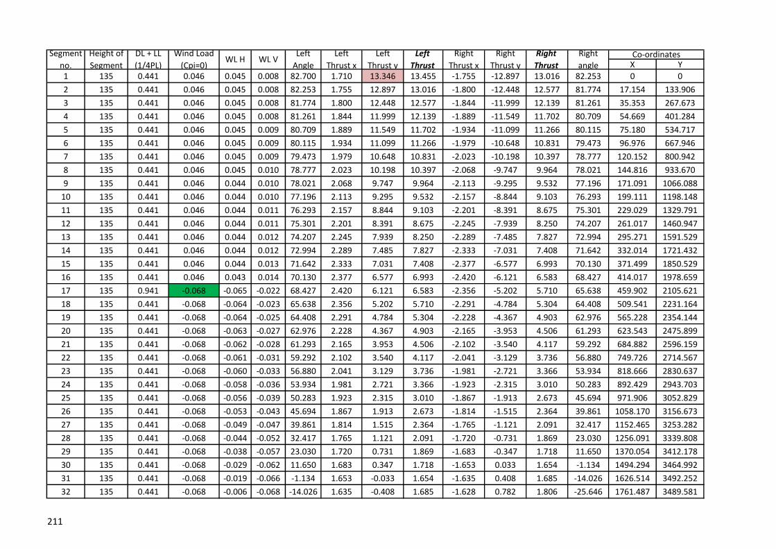
X Y
1 135 0.441 0.046 0.045 0.008 82.700 1.710 13.346 13.455 -1.755 -12.897 13.016 82.253 0 0
2 135 0.441 0.046 0.045 0.008 82.253 1.755 12.897 13.016 -1.800 -12.448 12.577 81.774 17.154 133.906
3 135 0.441 0.046 0.045 0.008 81.774 1.800 12.448 12.577 -1.844 -11.999 12.139 81.261 35.353 267.673
4 135 0.441 0.046 0.045 0.008 81.261 1.844 11.999 12.139 -1.889 -11.549 11.702 80.709 54.669 401.284
5 135 0.441 0.046 0.045 0.009 80.709 1.889 11.549 11.702 -1.934 -11.099 11.266 80.115 75.180 534.717
6 135 0.441 0.046 0.045 0.009 80.115 1.934 11.099 11.266 -1.979 -10.648 10.831 79.473 96.976 667.946
7 135 0.441 0.046 0.045 0.009 79.473 1.979 10.648 10.831 -2.023 -10.198 10.397 78.777 120.152 800.942
8 135 0.441 0.046 0.045 0.010 78.777 2.023 10.198 10.397 -2.068 -9.747 9.964 78.021 144.816 933.670
9 135 0.441 0.046 0.044 0.010 78.021 2.068 9.747 9.964 -2.113 -9.295 9.532 77.196 171.091 1066.088
10 135 0.441 0.046 0.044 0.010 77.196 2.113 9.295 9.532 -2.157 -8.844 9.103 76.293 199.111 1198.148
11 135 0.441 0.046 0.044 0.011 76.293 2.157 8.844 9.103 -2.201 -8.391 8.675 75.301 229.029 1329.791
12 135 0.441 0.046 0.044 0.011 75.301 2.201 8.391 8.675 -2.245 -7.939 8.250 74.207 261.017 1460.947
13 135 0.441 0.046 0.044 0.012 74.207 2.245 7.939 8.250 -2.289 -7.485 7.827 72.994 295.271 1591.529
14 135 0.441 0.046 0.044 0.012 72.994 2.289 7.485 7.827 -2.333 -7.031 7.408 71.642 332.014 1721.432
15 135 0.441 0.046 0.044 0.013 71.642 2.333 7.031 7.408 -2.377 -6.577 6.993 70.130 371.499 1850.529
16 135 0.441 0.046 0.043 0.014 70.130 2.377 6.577 6.993 -2.420 -6.121 6.583 68.427 414.017 1978.659
17 135 0.941 -0.068 -0.065 -0.022 68.427 2.420 6.121 6.583 -2.356 -5.202 5.710 65.638 459.902 2105.621
18 135 0.441 -0.068 -0.064 -0.023 65.638 2.356 5.202 5.710 -2.291 -4.784 5.304 64.408 509.541 2231.164
19 135 0.441 -0.068 -0.064 -0.025 64.408 2.291 4.784 5.304 -2.228 -4.367 4.903 62.976 565.228 2354.144
20 135 0.441 -0.068 -0.063 -0.027 62.976 2.228 4.367 4.903 -2.165 -3.953 4.506 61.293 623.543 2475.899
21 135 0.441 -0.068 -0.062 -0.028 61.293 2.165 3.953 4.506 -2.102 -3.540 4.117 59.292 684.882 2596.159
22 135 0.441 -0.068 -0.061 -0.031 59.292 2.102 3.540 4.117 -2.041 -3.129 3.736 56.880 749.726 2714.567
23 135 0.441 -0.068 -0.060 -0.033 56.880 2.041 3.129 3.736 -1.981 -2.721 3.366 53.934 818.666 2830.637
24 135 0.441 -0.068 -0.058 -0.036 53.934 1.981 2.721 3.366 -1.923 -2.315 3.010 50.283 892.429 2943.703
25 135 0.441 -0.068 -0.056 -0.039 50.283 1.923 2.315 3.010 -1.867 -1.913 2.673 45.694 971.906 3052.829
26 135 0.441 -0.068 -0.053 -0.043 45.694 1.867 1.913 2.673 -1.814 -1.515 2.364 39.861 1058.170 3156.673
27 135 0.441 -0.068 -0.049 -0.047 39.861 1.814 1.515 2.364 -1.765 -1.121 2.091 32.417 1152.465 3253.282
28 135 0.441 -0.068 -0.044 -0.052 32.417 1.765 1.121 2.091 -1.720 -0.731 1.869 23.030 1256.091 3339.808
29 135 0.441 -0.068 -0.038 -0.057 23.030 1.720 0.731 1.869 -1.683 -0.347 1.718 11.650 1370.054 3412.178
30 135 0.441 -0.068 -0.029 -0.062 11.650 1.683 0.347 1.718 -1.653 0.033 1.654 -1.134 1494.294 3464.992
31 135 0.441 -0.068 -0.019 -0.066 -1.134 1.653 -0.033 1.654 -1.635 0.408 1.685 -14.026 1626.514 3492.252
32 135 0.441 -0.068 -0.006 -0.068 -14.026 1.635 -0.408 1.685 -1.628 0.782 1.806 -25.646 1761.487 3489.581
WL VSegment
no.
Height of
Segment
DL + LL
(1/4PL)
Wind Load
(Cpi=0)WL H
Right
Thrust
Right
angleCo-ordinatesLeft
Angle
Left
Thrust x
Left
Thrust y
Left
Thrust
Right
Thrust x
Right
Thrust y
211

33 135 0.441 -0.068 0.006 -0.068 -25.646 1.628 -0.782 1.806 -1.635 1.155 2.001 -35.245 1892.462 3456.861
34 135 0.441 -0.068 0.019 -0.066 -35.245 1.635 -1.155 2.001 -1.653 1.531 2.253 -42.794 2014.162 3398.432
35 135 0.441 -0.068 0.029 -0.062 -42.794 1.653 -1.531 2.253 -1.683 1.910 2.546 -48.625 2124.416 3320.526
36 135 0.441 -0.068 0.038 -0.057 -48.625 1.683 -1.910 2.546 -1.720 2.295 2.868 -53.139 2223.479 3228.813
37 135 0.441 -0.068 0.044 -0.052 -53.139 1.720 -2.295 2.868 -1.765 2.684 3.212 -56.674 2312.711 3127.508
38 135 0.441 -0.068 0.049 -0.047 -56.674 1.765 -2.684 3.212 -1.814 3.078 3.573 -59.486 2393.694 3019.495
39 135 0.441 -0.068 0.053 -0.043 -59.486 1.814 -3.078 3.573 -1.867 3.477 3.946 -61.758 2467.863 2906.694
40 135 0.441 -0.068 0.056 -0.039 -61.758 1.867 -3.477 3.946 -1.923 3.879 4.329 -63.624 2536.410 2790.392
41 135 0.441 -0.068 0.058 -0.036 -63.624 1.923 -3.879 4.329 -1.981 4.284 4.720 -65.178 2600.290 2671.462
42 135 0.441 -0.068 0.060 -0.033 -65.178 1.981 -4.284 4.720 -2.041 4.692 5.117 -66.490 2660.265 2550.516
43 135 0.441 -0.068 0.061 -0.031 -66.490 2.041 -4.692 5.117 -2.102 5.103 5.519 -67.609 2716.937 2427.987
44 135 0.441 -0.068 0.062 -0.028 -67.609 2.102 -5.103 5.519 -2.165 5.516 5.925 -68.574 2770.790 2304.193
45 135 0.441 -0.068 0.063 -0.027 -68.574 2.165 -5.516 5.925 -2.228 5.931 6.335 -69.414 2822.216 2179.372
46 135 0.441 -0.068 0.064 -0.025 -69.414 2.228 -5.931 6.335 -2.291 6.347 6.748 -70.151 2871.531 2053.702
47 135 0.441 -0.068 0.064 -0.023 -70.151 2.291 -6.347 6.748 -2.356 6.765 7.164 -70.803 2918.999 1927.322
48 135 0.441 -0.023 0.022 -0.007 -70.803 2.356 -6.765 7.164 -2.377 7.199 7.582 -71.728 2964.837 1800.342
49 135 0.441 -0.023 0.022 -0.007 -71.728 2.377 -7.199 7.582 -2.399 7.634 8.002 -72.555 3009.227 1672.849
50 135 0.441 -0.023 0.022 -0.007 -72.555 2.399 -7.634 8.002 -2.421 8.069 8.424 -73.300 3051.555 1544.656
51 135 0.441 -0.023 0.022 -0.006 -73.300 2.421 -8.069 8.424 -2.443 8.504 8.848 -73.974 3092.026 1415.866
52 135 0.441 -0.023 0.022 -0.006 -73.974 2.443 -8.504 8.848 -2.465 8.939 9.273 -74.586 3130.819 1286.559
53 135 0.441 -0.023 0.022 -0.006 -74.586 2.465 -8.939 9.273 -2.487 9.375 9.699 -75.145 3168.089 1156.806
54 135 0.441 -0.023 0.022 -0.005 -75.145 2.487 -9.375 9.699 -2.509 9.811 10.127 -75.656 3203.970 1026.661
55 135 0.441 -0.023 0.022 -0.005 -75.656 2.509 -9.811 10.127 -2.531 10.247 10.555 -76.126 3238.581 896.174
56 135 0.441 -0.023 0.022 -0.005 -76.126 2.531 -10.247 10.555 -2.553 10.684 10.985 -76.559 3272.026 765.382
57 135 0.441 -0.023 0.022 -0.005 -76.559 2.553 -10.684 10.985 -2.576 11.120 11.415 -76.960 3304.398 634.321
58 135 0.441 -0.023 0.022 -0.005 -76.960 2.576 -11.120 11.415 -2.598 11.557 11.846 -77.331 3335.778 503.018
59 135 0.441 -0.023 0.022 -0.004 -77.331 2.598 -11.557 11.846 -2.620 11.994 12.277 -77.677 3366.239 371.500
60 135 0.441 -0.023 0.022 -0.004 -77.677 2.620 -11.994 12.277 -2.643 12.431 12.709 -77.999 3395.846 239.787
61 135 0.441 -0.023 0.022 -0.004 -77.999 2.643 -12.431 12.709 -2.665 12.869 13.142 -78.299 3424.659 107.897
62 135 0.441 -0.023 0.022 -0.004 -78.299 2.665 -12.869 13.142 -2.688 13.306 13.575 -78.581 3452.730 -24.152
63 135 0.441 -0.023 0.022 -0.004 -78.581 2.688 -13.306 13.575 -2.710 13.744 14.008 -78.845 3480.107 -156.347
3506.835 -288.675
212

X Y1 133 0.441 0.057 0.056 0.009 83.300 1.593 13.564 13.657 -1.650 -13.113 13.217 82.830 0 0
2 133 0.441 0.057 0.056 0.010 82.830 1.650 13.113 13.217 -1.706 -12.662 12.777 82.328 15.517 132.092
3 133 0.441 0.057 0.056 0.010 82.328 1.706 12.662 12.777 -1.762 -12.211 12.337 81.789 32.118 264.052
4 133 0.441 0.057 0.056 0.010 81.789 1.762 12.211 12.337 -1.818 -11.759 11.899 81.212 49.874 395.861
5 133 0.441 0.057 0.056 0.011 81.212 1.818 11.759 11.899 -1.874 -11.307 11.461 80.590 68.868 527.498
6 133 0.441 0.057 0.056 0.011 80.590 1.874 11.307 11.461 -1.930 -10.854 11.025 79.918 89.189 658.936
7 133 0.441 0.057 0.056 0.012 79.918 1.930 10.854 11.025 -1.986 -10.401 10.589 79.192 110.935 790.146
8 133 0.441 0.057 0.056 0.012 79.192 1.986 10.401 10.589 -2.041 -9.948 10.155 78.404 134.217 921.093
9 133 0.441 0.057 0.056 0.012 78.404 2.041 9.948 10.155 -2.097 -9.494 9.723 77.545 159.157 1051.733
10 133 0.441 0.057 0.055 0.013 77.545 2.097 9.494 9.723 -2.152 -9.040 9.292 76.606 185.892 1182.019
11 133 0.441 0.057 0.055 0.014 76.606 2.152 9.040 9.292 -2.208 -8.585 8.864 75.577 214.577 1311.888
12 133 0.441 0.057 0.055 0.014 75.577 2.208 8.585 8.864 -2.263 -8.129 8.438 74.443 245.385 1441.271
13 133 0.441 0.057 0.055 0.015 74.443 2.263 8.129 8.438 -2.318 -7.673 8.015 73.189 278.513 1570.079
14 133 0.441 0.057 0.055 0.016 73.189 2.318 7.673 8.015 -2.373 -7.216 7.596 71.796 314.182 1698.207
15 133 0.441 0.057 0.055 0.016 71.796 2.373 7.216 7.596 -2.427 -6.758 7.181 70.241 352.647 1825.523
16 133 0.441 0.057 0.054 0.017 70.241 2.427 6.758 7.181 -2.482 -6.299 6.770 68.496 394.196 1951.867
17 133 0.941 -0.057 -0.054 -0.018 68.496 2.482 6.299 6.770 -2.428 -5.376 5.899 65.696 439.158 2077.037
18 133 0.441 -0.057 -0.054 -0.019 65.696 2.428 5.376 5.899 -2.374 -4.954 5.494 64.394 487.911 2200.779
19 133 0.441 -0.057 -0.053 -0.021 64.394 2.374 4.954 5.494 -2.321 -4.533 5.093 62.887 542.651 2321.992
20 133 0.441 -0.057 -0.053 -0.022 62.887 2.321 4.533 5.093 -2.269 -4.114 4.698 61.126 600.131 2441.929
21 133 0.441 -0.057 -0.052 -0.024 61.126 2.269 4.114 4.698 -2.217 -3.696 4.310 59.048 660.746 2560.313
22 133 0.441 -0.057 -0.051 -0.026 59.048 2.217 3.696 4.310 -2.166 -3.280 3.931 56.566 724.969 2676.779
23 133 0.441 -0.057 -0.050 -0.028 56.566 2.166 3.280 3.931 -2.116 -2.867 3.563 53.568 793.374 2790.840
24 133 0.441 -0.057 -0.048 -0.030 53.568 2.116 2.867 3.563 -2.068 -2.455 3.210 49.900 866.653 2901.831
25 133 0.441 -0.057 -0.047 -0.033 49.900 2.068 2.455 3.210 -2.021 -2.047 2.876 45.363 945.638 3008.838
26 133 0.441 -0.057 -0.044 -0.036 45.363 2.021 2.047 2.876 -1.977 -1.641 2.569 39.702 1031.306 3110.573
27 133 0.441 -0.057 -0.041 -0.039 39.702 1.977 1.641 2.569 -1.936 -1.239 2.298 32.629 1124.755 3205.211
28 133 0.441 -0.057 -0.037 -0.043 32.629 1.936 1.239 2.298 -1.899 -0.841 2.077 23.895 1227.082 3290.170
29 133 0.441 -0.057 -0.032 -0.047 23.895 1.899 0.841 2.077 -1.867 -0.447 1.920 13.469 1339.093 3361.883
30 133 0.441 -0.057 -0.024 -0.051 13.469 1.867 0.447 1.920 -1.843 -0.057 1.843 1.779 1460.693 3415.756
31 133 0.441 -0.057 -0.016 -0.055 1.779 1.843 0.057 1.843 -1.827 0.329 1.856 -10.219 1590.035 3446.735
32 133 0.441 -0.057 -0.005 -0.057 -10.219 1.827 -0.329 1.856 -1.822 0.714 1.957 -21.405 1722.971 3450.865
WL VSegment
no.
Height of
Segment
DL + LL
(1/4PL)
Wind Load
(Cpi=-0.2)WL H
Right
Thrust
Right
angleCo-ordinatesLeft
Angle
Left
Thrust x
Left
Thrust y
Left
Thrust
Right
Thrust x
Right
Thrust y
213
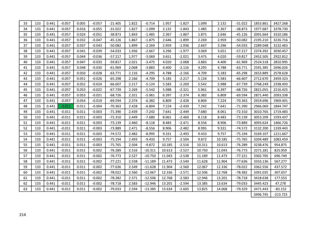
33 133 0.441 -0.057 0.005 -0.057 -21.405 1.822 -0.714 1.957 -1.827 1.099 2.132 -31.022 1853.861 3427.268
34 133 0.441 -0.057 0.016 -0.055 -31.022 1.827 -1.099 2.132 -1.843 1.485 2.367 -38.873 1977.687 3378.730
35 133 0.441 -0.057 0.024 -0.051 -38.873 1.843 -1.485 2.367 -1.867 1.875 2.646 -45.126 2091.664 3310.186
36 133 0.441 -0.057 0.032 -0.047 -45.126 1.867 -1.875 2.646 -1.899 2.269 2.959 -50.082 2195.210 3226.716
37 133 0.441 -0.057 0.037 -0.043 -50.082 1.899 -2.269 2.959 -1.936 2.667 3.296 -54.033 2289.048 3132.463
38 133 0.441 -0.057 0.041 -0.039 -54.033 1.936 -2.667 3.296 -1.977 3.069 3.651 -57.217 2374.392 3030.457
39 133 0.441 -0.057 0.044 -0.036 -57.217 1.977 -3.069 3.651 -2.021 3.475 4.020 -59.817 2452.505 2922.812
40 133 0.441 -0.057 0.047 -0.033 -59.817 2.021 -3.475 4.020 -2.068 3.883 4.400 -61.969 2524.518 2810.995
41 133 0.441 -0.057 0.048 -0.030 -61.969 2.068 -3.883 4.400 -2.116 4.295 4.788 -63.771 2591.385 2696.026
42 133 0.441 -0.057 0.050 -0.028 -63.771 2.116 -4.295 4.788 -2.166 4.709 5.183 -65.298 2653.889 2578.628
43 133 0.441 -0.057 0.051 -0.026 -65.298 2.166 -4.709 5.183 -2.217 5.124 5.583 -66.607 2712.670 2459.323
44 133 0.441 -0.057 0.052 -0.024 -66.607 2.217 -5.124 5.583 -2.269 5.542 5.988 -67.739 2768.249 2338.493
45 133 0.441 -0.057 0.053 -0.022 -67.739 2.269 -5.542 5.988 -2.321 5.961 6.397 -68.726 2821.055 2216.425
46 133 0.441 -0.057 0.053 -0.021 -68.726 2.321 -5.961 6.397 -2.374 6.382 6.809 -69.594 2871.440 2093.338
47 133 0.441 -0.057 0.054 -0.019 -69.594 2.374 -6.382 6.809 -2.428 6.804 7.224 -70.363 2919.696 1969.401
48 133 0.441 -0.011 0.011 -0.004 -70.363 2.428 -6.804 7.224 -2.439 7.242 7.641 -71.390 2966.069 1844.747
49 133 0.441 -0.011 0.011 -0.003 -71.390 2.439 -7.242 7.641 -2.449 7.680 8.061 -72.310 3010.765 1719.483
50 133 0.441 -0.011 0.011 -0.003 -72.310 2.449 -7.680 8.061 -2.460 8.118 8.483 -73.139 3053.209 1593.437
51 133 0.441 -0.011 0.011 -0.003 -73.139 2.460 -8.118 8.483 -2.471 8.556 8.906 -73.889 3093.624 1466.726
52 133 0.441 -0.011 0.011 -0.003 -73.889 2.471 -8.556 8.906 -2.482 8.995 9.331 -74.572 3132.200 1339.443
53 133 0.441 -0.011 0.011 -0.003 -74.572 2.482 -8.995 9.331 -2.493 9.433 9.757 -75.194 3169.107 1211.667
54 133 0.441 -0.011 0.011 -0.003 -75.194 2.493 -9.433 9.757 -2.504 9.872 10.185 -75.765 3204.489 1083.459
55 133 0.441 -0.011 0.011 -0.003 -75.765 2.504 -9.872 10.185 -2.516 10.311 10.613 -76.289 3238.476 954.875
56 133 0.441 -0.011 0.011 -0.002 -76.289 2.516 -10.311 10.613 -2.527 10.750 11.043 -76.773 3271.181 825.959
57 133 0.441 -0.011 0.011 -0.002 -76.773 2.527 -10.750 11.043 -2.538 11.189 11.473 -77.221 3302.705 696.749
58 133 0.441 -0.011 0.011 -0.002 -77.221 2.538 -11.189 11.473 -2.549 11.628 11.904 -77.636 3333.136 567.277
59 133 0.441 -0.011 0.011 -0.002 -77.636 2.549 -11.628 11.904 -2.560 12.067 12.336 -78.022 3362.556 437.572
60 133 0.441 -0.011 0.011 -0.002 -78.022 2.560 -12.067 12.336 -2.571 12.506 12.768 -78.382 3391.035 307.657
61 133 0.441 -0.011 0.011 -0.002 -78.382 2.571 -12.506 12.768 -2.583 12.946 13.201 -78.718 3418.638 177.553
62 133 0.441 -0.011 0.011 -0.002 -78.718 2.583 -12.946 13.201 -2.594 13.385 13.634 -79.033 3445.423 47.278
63 133 0.441 -0.011 0.011 -0.002 -79.033 2.594 -13.385 13.634 -2.605 13.825 14.068 -79.329 3471.443 -83.152
3496.745 -213.723
214

X Y
1 133 0.441 0.046 0.045 0.008 82.700 1.678 13.096 13.203 -1.723 -12.647 12.764 82.244 0 0
2 133 0.441 0.046 0.045 0.008 82.244 1.723 12.647 12.764 -1.768 -12.198 12.325 81.755 16.900 131.922
3 133 0.441 0.046 0.045 0.008 81.755 1.768 12.198 12.325 -1.812 -11.749 11.888 81.230 34.849 263.705
4 133 0.441 0.046 0.045 0.008 81.230 1.812 11.749 11.888 -1.857 -11.299 11.450 80.665 53.923 395.330
5 133 0.441 0.046 0.045 0.009 80.665 1.857 11.299 11.450 -1.902 -10.849 11.014 80.056 74.200 526.775
6 133 0.441 0.046 0.045 0.009 80.056 1.902 10.849 11.014 -1.947 -10.398 10.579 79.396 95.773 658.014
7 133 0.441 0.046 0.045 0.009 79.396 1.947 10.398 10.579 -1.991 -9.948 10.145 78.680 118.741 789.016
8 133 0.441 0.046 0.045 0.010 78.680 1.991 9.948 10.145 -2.036 -9.497 9.713 77.900 143.216 919.745
9 133 0.441 0.046 0.044 0.010 77.900 2.036 9.497 9.713 -2.081 -9.045 9.282 77.047 169.323 1050.157
10 133 0.441 0.046 0.044 0.010 77.047 2.081 9.045 9.282 -2.125 -8.594 8.852 76.111 197.203 1180.202
11 133 0.441 0.046 0.044 0.011 76.111 2.125 8.594 8.852 -2.169 -8.141 8.425 75.081 227.015 1309.818
12 133 0.441 0.046 0.044 0.011 75.081 2.169 8.141 8.425 -2.213 -7.689 8.001 73.940 258.940 1438.930
13 133 0.441 0.046 0.044 0.012 73.940 2.213 7.689 8.001 -2.257 -7.235 7.579 72.672 293.182 1567.446
14 133 0.441 0.046 0.044 0.012 72.672 2.257 7.235 7.579 -2.301 -6.781 7.161 71.256 329.975 1695.255
15 133 0.441 0.046 0.044 0.013 71.256 2.301 6.781 7.161 -2.345 -6.327 6.747 69.664 369.588 1822.219
16 133 0.441 0.046 0.043 0.014 69.664 2.345 6.327 6.747 -2.388 -5.871 6.339 67.865 412.327 1948.165
17 133 0.441 -0.068 -0.065 -0.022 67.865 2.388 5.871 6.339 -2.324 -5.452 5.926 66.917 458.548 2072.875
18 133 0.441 -0.068 -0.064 -0.023 66.917 2.324 5.452 5.926 -2.259 -5.034 5.518 65.829 508.661 2196.073
19 133 0.441 -0.068 -0.064 -0.025 65.829 2.259 5.034 5.518 -2.196 -4.617 5.113 64.569 560.806 2318.425
20 133 0.441 -0.068 -0.063 -0.027 64.569 2.196 4.617 5.113 -2.133 -4.203 4.713 63.095 615.264 2439.765
21 133 0.441 -0.068 -0.062 -0.028 63.095 2.133 4.203 4.713 -2.070 -3.790 4.318 61.351 672.377 2559.878
22 133 0.441 -0.068 -0.061 -0.031 61.351 2.070 3.790 4.318 -2.009 -3.379 3.931 59.263 732.561 2678.481
23 133 0.441 -0.068 -0.060 -0.033 59.263 2.009 3.379 3.931 -1.949 -2.971 3.553 56.726 796.326 2795.199
24 133 0.441 -0.068 -0.058 -0.036 56.726 1.949 2.971 3.553 -1.891 -2.565 3.187 53.600 864.303 2909.515
25 133 0.441 -0.068 -0.056 -0.039 53.600 1.891 2.565 3.187 -1.835 -2.163 2.837 49.687 937.272 3020.710
26 133 0.441 -0.068 -0.053 -0.043 49.687 1.835 2.163 2.837 -1.782 -1.765 2.508 44.719 1016.197 3127.761
27 133 0.441 -0.068 -0.049 -0.047 44.719 1.782 1.765 2.508 -1.733 -1.371 2.209 38.346 1102.243 3229.177
28 133 0.441 -0.068 -0.044 -0.052 38.346 1.733 1.371 2.209 -1.688 -0.981 1.953 30.166 1196.748 3322.761
29 133 0.441 -0.068 -0.038 -0.057 30.166 1.688 0.981 1.953 -1.651 -0.597 1.755 19.882 1301.057 3405.274
30 133 0.441 -0.068 -0.029 -0.062 19.882 1.651 0.597 1.755 -1.621 -0.217 1.636 7.633 1416.045 3472.108
31 133 0.441 -0.068 -0.019 -0.066 7.633 1.621 0.217 1.636 -1.603 0.158 1.610 -5.643 1541.118 3517.338
32 133 0.441 -0.068 -0.006 -0.068 -5.643 1.603 -0.158 1.610 -1.596 0.532 1.682 -18.423 1672.940 3535.005
WL VSegment
no.
Height of
Segment
DL +
LL(3/4PL)
Wind Load
(Cpi=0)WL H
Right
Thrust
Right
angleCo-ordinatesLeft
Angle
Left
Thrust x
Left
Thrust y
Left
Thrust
Right
Thrust x
Right
Thrust y
215

33 133 0.441 -0.068 0.006 -0.068 -18.423 1.596 -0.532 1.682 -1.603 0.905 1.840 -29.455 1805.295 3521.926
34 133 0.441 -0.068 0.019 -0.066 -29.455 1.603 -0.905 1.840 -1.621 1.281 2.066 -38.305 1931.478 3479.893
35 133 0.441 -0.068 0.029 -0.062 -38.305 1.621 -1.281 2.066 -1.651 1.660 2.341 -45.167 2047.288 3414.493
36 133 0.441 -0.068 0.038 -0.057 -45.167 1.651 -1.660 2.341 -1.688 2.045 2.652 -50.452 2151.656 3332.053
37 133 0.441 -0.068 0.044 -0.052 -50.452 1.688 -2.045 2.652 -1.733 2.434 2.988 -54.553 2245.426 3237.733
38 133 0.441 -0.068 0.049 -0.047 -54.553 1.733 -2.434 2.988 -1.782 2.828 3.343 -57.783 2330.111 3135.179
39 133 0.441 -0.068 0.053 -0.043 -57.783 1.782 -2.828 3.343 -1.835 3.227 3.712 -60.368 2407.244 3026.830
40 133 0.441 -0.068 0.056 -0.039 -60.368 1.835 -3.227 3.712 -1.891 3.629 4.092 -62.471 2478.150 2914.308
41 133 0.441 -0.068 0.058 -0.036 -62.471 1.891 -3.629 4.092 -1.949 4.034 4.480 -64.208 2543.910 2798.702
42 133 0.441 -0.068 0.060 -0.033 -64.208 1.949 -4.034 4.480 -2.009 4.442 4.876 -65.663 2605.382 2680.761
43 133 0.441 -0.068 0.061 -0.031 -65.663 2.009 -4.442 4.876 -2.070 4.853 5.276 -66.896 2663.251 2561.010
44 133 0.441 -0.068 0.062 -0.028 -66.896 2.070 -4.853 5.276 -2.133 5.266 5.681 -67.954 2718.061 2439.829
45 133 0.441 -0.068 0.063 -0.027 -67.954 2.133 -5.266 5.681 -2.196 5.681 6.090 -68.869 2770.250 2317.496
46 133 0.441 -0.068 0.064 -0.025 -68.869 2.196 -5.681 6.090 -2.259 6.097 6.502 -69.669 2820.173 2194.221
47 133 0.441 -0.068 0.064 -0.023 -69.669 2.259 -6.097 6.502 -2.324 6.515 6.917 -70.372 2868.119 2070.164
48 133 0.941 -0.023 0.022 -0.007 -70.372 2.324 -6.515 6.917 -2.345 7.449 7.810 -72.526 2914.330 1945.450
49 133 0.441 -0.023 0.022 -0.007 -72.526 2.345 -7.449 7.810 -2.367 7.884 8.232 -73.290 2959.005 1820.178
50 133 0.441 -0.023 0.022 -0.007 -73.290 2.367 -7.884 8.232 -2.389 8.319 8.655 -73.979 2998.942 1693.316
51 133 0.441 -0.023 0.022 -0.006 -73.979 2.389 -8.319 8.655 -2.411 8.754 9.080 -74.604 3037.184 1565.932
52 133 0.441 -0.023 0.022 -0.006 -74.604 2.411 -8.754 9.080 -2.433 9.189 9.506 -75.173 3073.891 1438.098
53 133 0.441 -0.023 0.022 -0.006 -75.173 2.433 -9.189 9.506 -2.455 9.625 9.933 -75.693 3109.201 1309.871
54 133 0.441 -0.023 0.022 -0.005 -75.693 2.455 -9.625 9.933 -2.477 10.061 10.362 -76.170 3143.237 1181.300
55 133 0.441 -0.023 0.022 -0.005 -76.170 2.477 -10.061 10.362 -2.499 10.497 10.791 -76.609 3176.103 1052.425
56 133 0.441 -0.023 0.022 -0.005 -76.609 2.499 -10.497 10.791 -2.521 10.934 11.221 -77.015 3207.896 923.280
57 133 0.441 -0.023 0.022 -0.005 -77.015 2.521 -10.934 11.221 -2.544 11.370 11.651 -77.391 3238.697 793.896
58 133 0.441 -0.023 0.022 -0.005 -77.391 2.544 -11.370 11.651 -2.566 11.807 12.083 -77.739 3268.582 664.297
59 133 0.441 -0.023 0.022 -0.004 -77.739 2.566 -11.807 12.083 -2.588 12.244 12.515 -78.064 3297.617 534.505
60 133 0.441 -0.023 0.022 -0.004 -78.064 2.588 -12.244 12.515 -2.611 12.681 12.947 -78.367 3325.860 404.538
61 133 0.441 -0.023 0.022 -0.004 -78.367 2.611 -12.681 12.947 -2.633 13.119 13.380 -78.651 3353.367 274.414
62 133 0.441 -0.023 0.022 -0.004 -78.651 2.633 -13.119 13.380 -2.656 13.556 13.814 -78.917 3380.184 144.146
63 133 0.441 -0.023 0.022 -0.004 -78.917 2.656 -13.556 13.814 -2.678 13.994 14.248 -79.166 3406.357 13.746
3431.925 -116.773
216

X Y1 132 0.441 0.057 0.056 0.009 83.500 1.517 13.314 13.400 -1.573 -12.863 12.959 83.027 0 0
2 132 0.441 0.057 0.056 0.010 83.027 1.573 12.863 12.959 -1.629 -12.412 12.519 82.522 14.943 131.151
3 132 0.441 0.057 0.056 0.010 82.522 1.629 12.412 12.519 -1.685 -11.961 12.079 81.979 30.967 262.175
4 132 0.441 0.057 0.056 0.010 81.979 1.685 11.961 12.079 -1.741 -11.509 11.640 81.396 48.147 393.052
5 132 0.441 0.057 0.056 0.011 81.396 1.741 11.509 11.640 -1.797 -11.057 11.202 80.766 66.566 523.761
6 132 0.441 0.057 0.056 0.011 80.766 1.797 11.057 11.202 -1.853 -10.604 10.765 80.086 86.315 654.275
7 132 0.441 0.057 0.056 0.012 80.086 1.853 10.604 10.765 -1.909 -10.151 10.329 79.349 107.495 784.565
8 132 0.441 0.057 0.056 0.012 79.349 1.909 10.151 10.329 -1.965 -9.698 9.895 78.546 130.221 914.594
9 132 0.441 0.057 0.056 0.012 78.546 1.965 9.698 9.895 -2.021 -9.244 9.462 77.670 154.619 1044.320
10 132 0.441 0.057 0.055 0.013 77.670 2.021 9.244 9.462 -2.076 -8.790 9.031 76.711 180.831 1173.691
11 132 0.441 0.057 0.055 0.014 76.711 2.076 8.790 9.031 -2.131 -8.335 8.603 75.655 209.018 1302.646
12 132 0.441 0.057 0.055 0.014 75.655 2.131 8.335 8.603 -2.187 -7.879 8.177 74.490 239.360 1431.112
13 132 0.441 0.057 0.055 0.015 74.490 2.187 7.879 8.177 -2.242 -7.423 7.754 73.196 272.064 1558.996
14 132 0.441 0.057 0.055 0.016 73.196 2.242 7.423 7.754 -2.296 -6.966 7.334 71.754 307.362 1686.189
15 132 0.441 0.057 0.055 0.016 71.754 2.296 6.966 7.334 -2.351 -6.508 6.919 70.137 345.523 1812.553
16 132 0.441 0.057 0.054 0.017 70.137 2.351 6.508 6.919 -2.405 -6.049 6.510 68.316 386.852 1937.916
17 132 0.441 -0.057 -0.054 -0.018 68.316 2.405 6.049 6.510 -2.351 -5.626 6.098 67.318 431.702 2062.063
18 132 0.441 -0.057 -0.054 -0.019 67.318 2.351 5.626 6.098 -2.298 -5.204 5.689 66.177 480.475 2184.722
19 132 0.441 -0.057 -0.053 -0.021 66.177 2.298 5.204 5.689 -2.245 -4.783 5.284 64.861 531.376 2306.513
20 132 0.441 -0.057 -0.053 -0.022 64.861 2.245 4.783 5.284 -2.192 -4.364 4.884 63.329 584.693 2427.266
21 132 0.441 -0.057 -0.052 -0.024 63.329 2.192 4.364 4.884 -2.140 -3.946 4.489 61.526 640.769 2546.763
22 132 0.441 -0.057 -0.051 -0.026 61.526 2.140 3.946 4.489 -2.089 -3.530 4.102 59.382 700.020 2664.717
23 132 0.441 -0.057 -0.050 -0.028 59.382 2.089 3.530 4.102 -2.040 -3.117 3.725 56.800 762.952 2780.750
24 132 0.441 -0.057 -0.048 -0.030 56.800 2.040 3.117 3.725 -1.991 -2.705 3.359 53.647 830.180 2894.348
25 132 0.441 -0.057 -0.047 -0.033 53.647 1.991 2.705 3.359 -1.944 -2.297 3.009 49.747 902.459 3004.800
26 132 0.441 -0.057 -0.044 -0.036 49.747 1.944 2.297 3.009 -1.900 -1.891 2.681 44.863 980.703 3111.110
27 132 0.441 -0.057 -0.041 -0.039 44.863 1.900 1.891 2.681 -1.859 -1.489 2.382 38.696 1065.996 3211.853
28 132 0.441 -0.057 -0.037 -0.043 38.696 1.859 1.489 2.382 -1.822 -1.091 2.124 30.915 1159.557 3304.968
29 132 0.441 -0.057 -0.032 -0.047 30.915 1.822 1.091 2.124 -1.791 -0.697 1.921 21.274 1262.579 3387.493
30 132 0.441 -0.057 -0.024 -0.051 21.274 1.791 0.697 1.921 -1.766 -0.307 1.793 9.869 1375.826 3455.309
31 132 0.441 -0.057 -0.016 -0.055 9.869 1.766 0.307 1.793 -1.751 0.079 1.752 -2.596 1498.831 3503.203
32 132 0.441 -0.057 -0.005 -0.057 -2.596 1.751 -0.079 1.752 -1.745 0.464 1.806 -14.891 1628.878 3525.827
WL VSegme
nt no.
Height
of
DL +
LL(3/4PL)
Wind
Load WL H
Right
Thrust
Right
angleCo-ordinatesLeft
Angle
Left
Thrust x
Left
Thrust y
Left
Thrust
Right
Thrust x
Right
Thrust y
217

33 132 0.441 -0.057 0.005 -0.057 -14.891 1.745 -0.464 1.806 -1.751 0.849 1.945 -25.866 1760.742 3519.849
34 132 0.441 -0.057 0.016 -0.055 -25.866 1.751 -0.849 1.945 -1.766 1.235 2.155 -34.971 1888.310 3485.928
35 132 0.441 -0.057 0.024 -0.051 -34.971 1.766 -1.235 2.155 -1.791 1.625 2.418 -42.230 2007.085 3428.340
36 132 0.441 -0.057 0.032 -0.047 -42.230 1.791 -1.625 2.418 -1.822 2.019 2.720 -47.938 2115.251 3352.682
37 132 0.441 -0.057 0.037 -0.043 -47.938 1.822 -2.019 2.720 -1.859 2.417 3.049 -52.437 2212.991 3263.964
38 132 0.441 -0.057 0.041 -0.039 -52.437 1.859 -2.417 3.049 -1.900 2.819 3.400 -56.019 2301.423 3165.965
39 132 0.441 -0.057 0.044 -0.036 -56.019 1.900 -2.819 3.400 -1.944 3.225 3.766 -58.911 2381.895 3061.331
40 132 0.441 -0.057 0.047 -0.033 -58.911 1.944 -3.225 3.766 -1.991 3.633 4.143 -61.277 2455.671 2951.873
41 132 0.441 -0.057 0.048 -0.030 -61.277 1.991 -3.633 4.143 -2.040 4.045 4.530 -63.241 2523.832 2838.833
42 132 0.441 -0.057 0.050 -0.028 -63.241 2.040 -4.045 4.530 -2.089 4.459 4.924 -64.891 2587.268 2723.075
43 132 0.441 -0.057 0.051 -0.026 -64.891 2.089 -4.459 4.924 -2.140 4.874 5.324 -66.294 2646.699 2605.211
44 132 0.441 -0.057 0.052 -0.024 -66.294 2.140 -4.874 5.324 -2.192 5.292 5.728 -67.499 2702.712 2485.685
45 132 0.441 -0.057 0.053 -0.022 -67.499 2.192 -5.292 5.728 -2.245 5.711 6.137 -68.544 2755.782 2364.823
46 132 0.441 -0.057 0.053 -0.021 -68.544 2.245 -5.711 6.137 -2.298 6.132 6.548 -69.458 2806.298 2242.871
47 132 0.441 -0.057 0.054 -0.019 -69.458 2.298 -6.132 6.548 -2.351 6.554 6.963 -70.264 2854.580 2120.019
48 132 0.941 -0.011 0.011 -0.004 -70.264 2.351 -6.554 6.963 -2.362 7.492 7.855 -72.500 2900.897 1996.411
49 132 0.441 -0.011 0.011 -0.003 -72.500 2.362 -7.492 7.855 -2.373 7.930 8.277 -73.340 2945.472 1872.165
50 132 0.441 -0.011 0.011 -0.003 -73.340 2.373 -7.930 8.277 -2.384 8.368 8.701 -74.099 2985.165 1746.274
51 132 0.441 -0.011 0.011 -0.003 -74.099 2.384 -8.368 8.701 -2.395 8.806 9.126 -74.786 3023.007 1619.815
52 132 0.441 -0.011 0.011 -0.003 -74.786 2.395 -8.806 9.126 -2.406 9.245 9.553 -75.413 3059.173 1492.866
53 132 0.441 -0.011 0.011 -0.003 -75.413 2.406 -9.245 9.553 -2.417 9.683 9.980 -75.986 3093.813 1365.493
54 132 0.441 -0.011 0.011 -0.003 -75.986 2.417 -9.683 9.980 -2.428 10.122 10.409 -76.511 3127.058 1237.748
55 132 0.441 -0.011 0.011 -0.003 -76.511 2.428 -10.122 10.409 -2.439 10.561 10.839 -76.995 3159.024 1109.677
56 132 0.441 -0.011 0.011 -0.002 -76.995 2.439 -10.561 10.839 -2.450 11.000 11.269 -77.442 3189.813 981.318
57 132 0.441 -0.011 0.011 -0.002 -77.442 2.450 -11.000 11.269 -2.461 11.439 11.700 -77.856 3219.518 852.703
58 132 0.441 -0.011 0.011 -0.002 -77.856 2.461 -11.439 11.700 -2.472 11.878 12.132 -78.241 3248.217 723.861
59 132 0.441 -0.011 0.011 -0.002 -78.241 2.472 -11.878 12.132 -2.484 12.317 12.565 -78.599 3275.985 594.815
60 132 0.441 -0.011 0.011 -0.002 -78.599 2.484 -12.317 12.565 -2.495 12.756 12.998 -78.934 3302.886 465.585
61 132 0.441 -0.011 0.011 -0.002 -78.934 2.495 -12.756 12.998 -2.506 13.196 13.431 -79.247 3328.978 336.189
62 132 0.441 -0.011 0.011 -0.002 -79.247 2.506 -13.196 13.431 -2.517 13.635 13.865 -79.540 3354.314 206.644
63 132 0.441 -0.011 0.011 -0.002 -79.540 2.517 -13.635 13.865 -2.529 14.075 14.300 -79.815 3378.943 76.962
3402.908 -52.845
218

X Y
1 133 0.441 0.046 0.045 0.008 82.050 1.846 13.221 13.349 -1.891 -12.772 12.911 81.577 0.000 0.000
2 133 0.441 0.046 0.045 0.008 81.577 1.891 12.772 12.911 -1.936 -12.323 12.474 81.070 18.395 131.722
3 133 0.441 0.046 0.045 0.008 81.070 1.936 12.323 12.474 -1.981 -11.874 12.038 80.527 37.877 263.287
4 133 0.441 0.046 0.045 0.008 80.527 1.981 11.874 12.038 -2.026 -11.424 11.602 79.943 58.522 394.675
5 133 0.441 0.046 0.045 0.009 79.943 2.026 11.424 11.602 -2.071 -10.974 11.167 79.314 80.411 525.862
6 133 0.441 0.046 0.045 0.009 79.314 2.071 10.974 11.167 -2.115 -10.523 10.734 78.634 103.635 656.818
7 133 0.441 0.046 0.045 0.009 78.634 2.115 10.523 10.734 -2.160 -10.073 10.302 77.896 128.297 787.512
8 133 0.441 0.046 0.045 0.010 77.896 2.160 10.073 10.302 -2.205 -9.622 9.871 77.094 154.509 917.903
9 133 0.441 0.046 0.044 0.010 77.094 2.205 9.622 9.871 -2.249 -9.170 9.442 76.219 182.397 1047.946
10 133 0.441 0.046 0.044 0.010 76.219 2.249 9.170 9.442 -2.294 -8.719 9.015 75.261 212.102 1177.587
11 133 0.441 0.046 0.044 0.011 75.261 2.294 8.719 9.015 -2.338 -8.266 8.591 74.208 243.783 1306.758
12 133 0.441 0.046 0.044 0.011 74.208 2.338 8.266 8.591 -2.382 -7.814 8.169 73.046 277.620 1435.382
13 133 0.441 0.046 0.044 0.012 73.046 2.382 7.814 8.169 -2.426 -7.360 7.750 71.757 313.815 1563.362
14 133 0.441 0.046 0.044 0.012 71.757 2.426 7.360 7.750 -2.470 -6.906 7.335 70.321 352.599 1690.582
15 133 0.441 0.046 0.044 0.013 70.321 2.470 6.906 7.335 -2.514 -6.452 6.924 68.714 394.235 1816.897
16 133 0.441 0.046 0.043 0.014 68.714 2.514 6.452 6.924 -2.557 -5.996 6.519 66.906 439.022 1942.129
17 133 0.441 -0.068 -0.065 -0.022 66.906 2.557 5.996 6.519 -2.492 -5.577 6.109 65.921 487.303 2066.056
18 133 0.441 -0.068 -0.064 -0.023 65.921 2.492 5.577 6.109 -2.428 -5.159 5.702 64.797 539.472 2188.397
19 133 0.441 -0.068 -0.064 -0.025 64.797 2.428 5.159 5.702 -2.364 -4.742 5.299 63.502 593.735 2309.824
20 133 0.441 -0.068 -0.063 -0.027 63.502 2.364 4.742 5.299 -2.301 -4.328 4.901 61.998 650.371 2430.163
21 133 0.441 -0.068 -0.062 -0.028 61.998 2.301 4.328 4.901 -2.239 -3.915 4.510 60.232 709.710 2549.192
22 133 0.441 -0.068 -0.061 -0.031 60.232 2.239 3.915 4.510 -2.178 -3.504 4.126 58.136 772.155 2666.621
23 133 0.441 -0.068 -0.060 -0.033 58.136 2.178 3.504 4.126 -2.118 -3.096 3.751 55.619 838.188 2782.071
24 133 0.441 -0.068 -0.058 -0.036 55.619 2.118 3.096 3.751 -2.060 -2.690 3.388 52.558 908.399 2895.028
25 133 0.441 -0.068 -0.056 -0.039 52.558 2.060 2.690 3.388 -2.004 -2.288 3.042 48.788 983.503 3004.793
26 133 0.441 -0.068 -0.053 -0.043 48.788 2.004 2.288 3.042 -1.951 -1.890 2.716 44.089 1064.361 3110.392
27 133 0.441 -0.068 -0.049 -0.047 44.089 1.951 1.890 2.716 -1.902 -1.496 2.419 38.189 1151.989 3210.444
28 133 0.441 -0.068 -0.044 -0.052 38.189 1.902 1.496 2.419 -1.857 -1.106 2.162 30.784 1247.517 3302.982
29 133 0.441 -0.068 -0.038 -0.057 30.784 1.857 1.106 2.162 -1.819 -0.722 1.957 21.644 1352.052 3385.210
30 133 0.441 -0.068 -0.029 -0.062 21.644 1.819 0.722 1.957 -1.790 -0.342 1.822 10.826 1466.313 3453.279
31 133 0.441 -0.068 -0.019 -0.066 10.826 1.790 0.342 1.822 -1.771 0.033 1.772 -1.079 1589.936 3502.334
32 133 0.941 -0.068 -0.006 -0.068 -1.079 1.771 -0.033 1.772 -1.765 0.907 1.984 -27.192 1720.569 3527.314
WL VSegment
no.
Height of
Segment
DL + LL
(1/2PL)
Wind Load
(Cpi=0)WL H
Right
Thrust
Right
angleCo-ordinatesLeft
Angle
Left
Thrust x
Left Thrust
y
Left
Thrust
Right
Thrust x
Right
Thrust y
219

33 133 0.441 -0.068 0.006 -0.068 -27.192 1.765 -0.907 1.984 -1.771 1.280 2.185 -35.854 1853.546 3524.810
34 133 0.441 -0.068 0.019 -0.066 -35.854 1.771 -1.280 2.185 -1.790 1.656 2.438 -42.767 1971.846 3464.032
35 133 0.441 -0.068 0.029 -0.062 -42.767 1.790 -1.656 2.438 -1.819 2.035 2.730 -48.207 2079.644 3386.131
36 133 0.441 -0.068 0.038 -0.057 -48.207 1.819 -2.035 2.730 -1.857 2.420 3.050 -52.494 2177.282 3295.821
37 133 0.441 -0.068 0.044 -0.052 -52.494 1.857 -2.420 3.050 -1.902 2.809 3.392 -55.905 2265.918 3196.662
38 133 0.441 -0.068 0.049 -0.047 -55.905 1.902 -2.809 3.392 -1.951 3.203 3.751 -58.657 2346.895 3091.154
39 133 0.441 -0.068 0.053 -0.043 -58.657 1.951 -3.203 3.751 -2.004 3.602 4.122 -60.907 2421.450 2981.015
40 133 0.441 -0.068 0.056 -0.039 -60.907 2.004 -3.602 4.122 -2.060 4.004 4.503 -62.773 2490.632 2867.425
41 133 0.441 -0.068 0.058 -0.036 -62.773 2.060 -4.004 4.503 -2.118 4.409 4.891 -64.340 2555.300 2751.205
42 133 0.441 -0.068 0.060 -0.033 -64.340 2.118 -4.409 4.891 -2.178 4.817 5.287 -65.672 2616.150 2632.942
43 133 0.441 -0.068 0.061 -0.031 -65.672 2.178 -4.817 5.287 -2.239 5.228 5.687 -66.816 2673.743 2513.058
44 133 0.441 -0.068 0.062 -0.028 -66.816 2.239 -5.228 5.687 -2.301 5.641 6.092 -67.807 2728.534 2391.868
45 133 0.441 -0.068 0.063 -0.027 -67.807 2.301 -5.641 6.092 -2.364 6.056 6.501 -68.674 2780.895 2269.609
46 133 0.441 -0.068 0.064 -0.025 -68.674 2.364 -6.056 6.501 -2.428 6.472 6.913 -69.437 2831.133 2146.462
47 133 0.441 -0.068 0.064 -0.023 -69.437 2.428 -6.472 6.913 -2.492 6.890 7.327 -70.115 2879.502 2022.569
48 133 0.441 -0.023 0.022 -0.007 -70.115 2.492 -6.890 7.327 -2.514 7.324 7.744 -71.057 2926.216 1898.043
49 133 0.441 -0.023 0.022 -0.007 -71.057 2.514 -7.324 7.744 -2.536 7.759 8.163 -71.903 2971.454 1772.973
50 133 0.441 -0.023 0.022 -0.007 -71.903 2.536 -7.759 8.163 -2.557 8.194 8.584 -72.666 3014.628 1647.175
51 133 0.441 -0.023 0.022 -0.006 -72.666 2.557 -8.194 8.584 -2.579 8.629 9.006 -73.358 3055.941 1520.755
52 133 0.441 -0.023 0.022 -0.006 -73.358 2.579 -8.629 9.006 -2.601 9.064 9.430 -73.988 3095.567 1393.795
53 133 0.441 -0.023 0.022 -0.006 -73.988 2.601 -9.064 9.430 -2.623 9.500 9.856 -74.563 3133.657 1266.366
54 133 0.441 -0.023 0.022 -0.005 -74.563 2.623 -9.500 9.856 -2.646 9.936 10.282 -75.091 3170.344 1138.526
55 133 0.441 -0.023 0.022 -0.005 -75.091 2.646 -9.936 10.282 -2.668 10.372 10.710 -75.576 3205.746 1010.324
56 133 0.441 -0.023 0.022 -0.005 -75.576 2.668 -10.372 10.710 -2.690 10.809 11.139 -76.025 3239.965 881.801
57 133 0.441 -0.023 0.022 -0.005 -76.025 2.690 -10.809 11.139 -2.712 11.245 11.568 -76.440 3273.094 752.994
58 133 0.441 -0.023 0.022 -0.005 -76.440 2.712 -11.245 11.568 -2.735 11.682 11.998 -76.825 3305.214 623.930
59 133 0.441 -0.023 0.022 -0.004 -76.825 2.735 -11.682 11.998 -2.757 12.119 12.429 -77.184 3336.398 494.638
60 133 0.441 -0.023 0.022 -0.004 -77.184 2.757 -12.119 12.429 -2.779 12.556 12.860 -77.519 3366.711 365.138
61 133 0.441 -0.023 0.022 -0.004 -77.519 2.779 -12.556 12.860 -2.802 12.994 13.292 -77.832 3396.213 235.452
62 133 0.441 -0.023 0.022 -0.004 -77.832 2.802 -12.994 13.292 -2.824 13.431 13.725 -78.125 3424.956 105.595
63 133 0.441 -0.023 0.022 -0.004 -78.125 2.824 -13.431 13.725 -2.847 13.869 14.158 -78.401 3452.990 -24.417
3480.358 -154.571
220
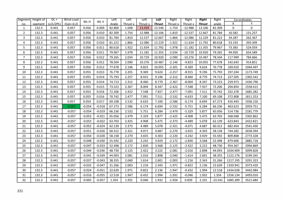
X Y
1 132.3 0.441 0.057 0.056 0.009 82.800 1.698 13.439 13.546 -1.754 -12.988 13.106 82.309 0 0
2 132.3 0.441 0.057 0.056 0.010 82.309 1.754 12.988 13.106 -1.810 -12.537 12.667 81.784 16.582 131.257
3 132.3 0.441 0.057 0.056 0.010 81.784 1.810 12.537 12.667 -1.866 -12.086 12.229 81.222 34.287 262.367
4 132.3 0.441 0.057 0.056 0.010 81.222 1.866 12.086 12.229 -1.922 -11.634 11.792 80.618 53.193 393.309
5 132.3 0.441 0.057 0.056 0.011 80.618 1.922 11.634 11.792 -1.978 -11.182 11.355 79.967 73.383 524.059
6 132.3 0.441 0.057 0.056 0.011 79.967 1.978 11.182 11.355 -2.034 -10.729 10.920 79.265 94.950 654.589
7 132.3 0.441 0.057 0.056 0.012 79.265 2.034 10.729 10.920 -2.090 -10.276 10.487 78.504 117.999 784.866
8 132.3 0.441 0.057 0.056 0.012 78.504 2.090 10.276 10.487 -2.146 -9.823 10.055 77.678 142.643 914.851
9 132.3 0.441 0.057 0.056 0.012 77.678 2.146 9.823 10.055 -2.201 -9.369 9.624 76.778 169.010 1044.497
10 132.3 0.441 0.057 0.055 0.013 76.778 2.201 9.369 9.624 -2.257 -8.915 9.196 75.793 197.244 1173.749
11 132.3 0.441 0.057 0.055 0.014 75.793 2.257 8.915 9.196 -2.312 -8.460 8.770 74.713 227.505 1302.542
12 132.3 0.441 0.057 0.055 0.014 74.713 2.312 8.460 8.770 -2.367 -8.004 8.347 73.523 259.973 1430.796
13 132.3 0.441 0.057 0.055 0.015 73.523 2.367 8.004 8.347 -2.422 -7.548 7.927 72.206 294.854 1558.415
14 132.3 0.441 0.057 0.055 0.016 72.206 2.422 7.548 7.927 -2.477 -7.091 7.511 70.742 332.378 1685.282
15 132.3 0.441 0.057 0.055 0.016 70.742 2.477 7.091 7.511 -2.532 -6.633 7.100 69.108 372.808 1811.253
16 132.3 0.441 0.057 0.054 0.017 69.108 2.532 6.633 7.100 -2.586 -6.174 6.694 67.273 416.443 1936.150
17 132.3 0.441 -0.057 -0.054 -0.018 67.273 2.586 6.174 6.694 -2.532 -5.751 6.284 66.236 463.623 2059.751
18 132.3 0.441 -0.057 -0.054 -0.019 66.236 2.532 5.751 6.284 -2.479 -5.329 5.877 65.056 514.736 2181.779
19 132.3 0.441 -0.057 -0.053 -0.021 65.056 2.479 5.329 5.877 -2.425 -4.908 5.475 63.703 568.048 2302.862
20 132.3 0.441 -0.057 -0.053 -0.022 63.703 2.425 4.908 5.475 -2.373 -4.489 5.078 62.139 623.843 2422.821
21 132.3 0.441 -0.057 -0.052 -0.024 62.139 2.373 4.489 5.078 -2.321 -4.071 4.687 60.312 682.454 2541.430
22 132.3 0.441 -0.057 -0.051 -0.026 60.312 2.321 4.071 4.687 -2.270 -3.655 4.303 58.158 744.282 2658.394
23 132.3 0.441 -0.057 -0.050 -0.028 58.158 2.270 3.655 4.303 -2.220 -3.242 3.929 55.592 809.808 2773.328
24 132.3 0.441 -0.057 -0.048 -0.030 55.592 2.220 3.242 3.929 -2.172 -2.830 3.568 52.498 879.606 2885.718
25 132.3 0.441 -0.057 -0.047 -0.033 52.498 2.172 2.830 3.568 -2.125 -2.422 3.222 48.730 954.367 2994.869
26 132.3 0.441 -0.057 -0.044 -0.036 48.730 2.125 2.422 3.222 -2.081 -2.016 2.898 44.093 1034.909 3099.828
27 132.3 0.441 -0.057 -0.041 -0.039 44.093 2.081 2.016 2.898 -2.040 -1.614 2.601 38.355 1122.176 3199.265
28 132.3 0.441 -0.057 -0.037 -0.043 38.355 2.040 1.614 2.601 -2.003 -1.216 2.343 31.266 1217.195 3291.323
29 132.3 0.441 -0.057 -0.032 -0.047 31.266 2.003 1.216 2.343 -1.971 -0.822 2.136 22.639 1320.941 3373.420
30 132.3 0.441 -0.057 -0.024 -0.051 22.639 1.971 0.822 2.136 -1.947 -0.432 1.994 12.518 1434.028 3442.084
31 132.3 0.441 -0.057 -0.016 -0.055 12.518 1.947 0.432 1.994 -1.931 -0.046 1.932 1.354 1556.134 3493.010
32 132.3 0.941 -0.057 -0.005 -0.057 1.354 1.931 0.046 1.932 -1.926 0.839 2.101 -23.541 1685.289 3521.684
WL VSegment
no.
Height of
segment
DL +
LL(1/2PL)
Wind Load
(Cpi=-0.2)WL H
Right
Thrust
Right
angleCo-ordinatesLeft
Angle
Left
Thrust x
Left
Thrust y
Left
Thrust
Right
Thrust x
Right
Thrust y
221
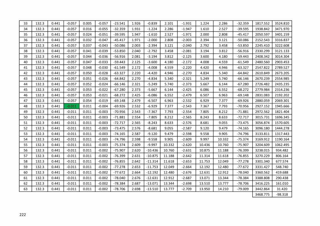
33 132.3 0.441 -0.057 0.005 -0.057 -23.541 1.926 -0.839 2.101 -1.931 1.224 2.286 -32.359 1817.552 3524.810
34 132.3 0.441 -0.057 0.016 -0.055 -32.359 1.931 -1.224 2.286 -1.947 1.610 2.527 -39.595 1938.842 3471.970
35 132.3 0.441 -0.057 0.024 -0.051 -39.595 1.947 -1.610 2.527 -1.971 2.000 2.808 -45.417 2050.597 3401.159
36 132.3 0.441 -0.057 0.032 -0.047 -45.417 1.971 -2.000 2.808 -2.003 2.394 3.121 -50.086 2152.543 3316.837
37 132.3 0.441 -0.057 0.037 -0.043 -50.086 2.003 -2.394 3.121 -2.040 2.792 3.458 -53.850 2245.410 3222.608
38 132.3 0.441 -0.057 0.041 -0.039 -53.850 2.040 -2.792 3.458 -2.081 3.194 3.812 -56.916 2330.299 3121.133
39 132.3 0.441 -0.057 0.044 -0.036 -56.916 2.081 -3.194 3.812 -2.125 3.600 4.180 -59.443 2408.342 3014.304
40 132.3 0.441 -0.057 0.047 -0.033 -59.443 2.125 -3.600 4.180 -2.172 4.008 4.559 -61.549 2480.560 2903.453
41 132.3 0.441 -0.057 0.048 -0.030 -61.549 2.172 -4.008 4.559 -2.220 4.420 4.946 -63.327 2547.822 2789.527
42 132.3 0.441 -0.057 0.050 -0.028 -63.327 2.220 -4.420 4.946 -2.270 4.834 5.340 -64.842 2610.849 2673.205
43 132.3 0.441 -0.057 0.051 -0.026 -64.842 2.270 -4.834 5.340 -2.321 5.249 5.740 -66.146 2670.239 2554.985
44 132.3 0.441 -0.057 0.052 -0.024 -66.146 2.321 -5.249 5.740 -2.373 5.667 6.144 -67.280 2726.482 2435.235
45 132.3 0.441 -0.057 0.053 -0.022 -67.280 2.373 -5.667 6.144 -2.425 6.086 6.552 -68.272 2779.984 2314.236
46 132.3 0.441 -0.057 0.053 -0.021 -68.272 2.425 -6.086 6.552 -2.479 6.507 6.963 -69.148 2831.083 2192.202
47 132.3 0.441 -0.057 0.054 -0.019 -69.148 2.479 -6.507 6.963 -2.532 6.929 7.377 -69.926 2880.059 2069.301
48 132.3 0.441 -0.011 0.011 -0.004 -69.926 2.532 -6.929 7.377 -2.543 7.367 7.793 -70.956 2927.152 1945.666
49 132.3 0.441 -0.011 0.011 -0.003 -70.956 2.543 -7.367 7.793 -2.554 7.805 8.212 -71.881 2972.562 1821.404
50 132.3 0.441 -0.011 0.011 -0.003 -71.881 2.554 -7.805 8.212 -2.565 8.243 8.633 -72.717 3015.731 1696.345
51 132.3 0.441 -0.011 0.011 -0.003 -72.717 2.565 -8.243 8.633 -2.576 8.681 9.055 -73.475 3056.874 1570.605
52 132.3 0.441 -0.011 0.011 -0.003 -73.475 2.576 -8.681 9.055 -2.587 9.120 9.479 -74.165 3096.180 1444.278
53 132.3 0.441 -0.011 0.011 -0.003 -74.165 2.587 -9.120 9.479 -2.598 9.558 9.905 -74.796 3133.811 1317.443
54 132.3 0.441 -0.011 0.011 -0.003 -74.796 2.598 -9.558 9.905 -2.609 9.997 10.332 -75.374 3169.912 1190.164
55 132.3 0.441 -0.011 0.011 -0.003 -75.374 2.609 -9.997 10.332 -2.620 10.436 10.760 -75.907 3204.609 1062.495
56 132.3 0.441 -0.011 0.011 -0.002 -75.907 2.620 -10.436 10.760 -2.631 10.875 11.188 -76.399 3238.015 934.482
57 132.3 0.441 -0.011 0.011 -0.002 -76.399 2.631 -10.875 11.188 -2.642 11.314 11.618 -76.855 3270.229 806.164
58 132.3 0.441 -0.011 0.011 -0.002 -76.855 2.642 -11.314 11.618 -2.653 11.753 12.049 -77.278 3301.340 677.574
59 132.3 0.441 -0.011 0.011 -0.002 -77.278 2.653 -11.753 12.049 -2.664 12.192 12.480 -77.672 3331.427 548.740
60 132.3 0.441 -0.011 0.011 -0.002 -77.672 2.664 -12.192 12.480 -2.676 12.631 12.912 -78.040 3360.562 419.688
61 132.3 0.441 -0.011 0.011 -0.002 -78.040 2.676 -12.631 12.912 -2.687 13.071 13.344 -78.384 3388.808 290.438
62 132.3 0.441 -0.011 0.011 -0.002 -78.384 2.687 -13.071 13.344 -2.698 13.510 13.777 -78.706 3416.225 161.010
63 132.3 0.441 -0.011 0.011 -0.002 -78.706 2.698 -13.510 13.777 -2.709 13.950 14.210 -79.009 3442.864 31.420
3468.775 -98.318
222

223
Appendix B
I. Dead Load, T=20° full
II. Dead Load, T=20° left half
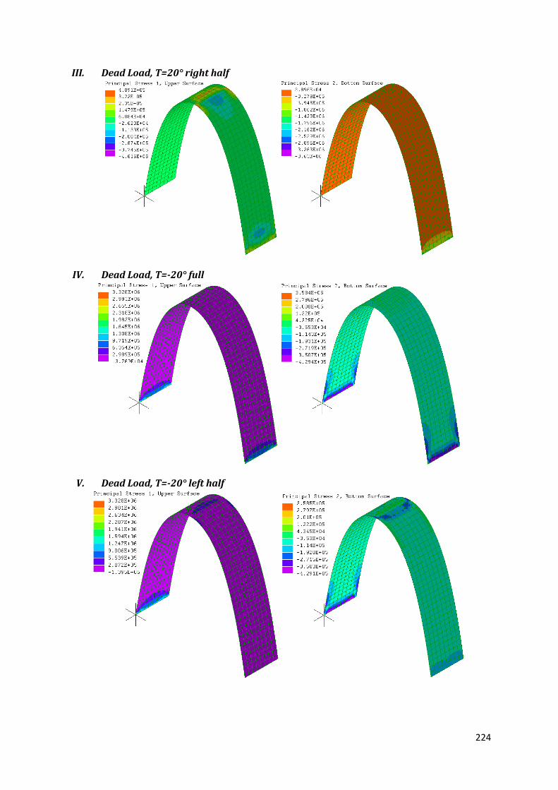
224
III. Dead Load, T=20° right half
IV. Dead Load, T=-20° full
V. Dead Load, T=-20° left half

225
VI. Dead Load, T=-20° right half
VII. Dead Load, Live Load full, T=20° left half
VIII. Dead Load, Live Load full, T=-20° left half

226
IX. Dead Load, Live Load full, Wind Load (Cpi=0), T=20° left half
X. Dead Load, Live Load full, Wind Load (Cpi=0), T=-20° right half
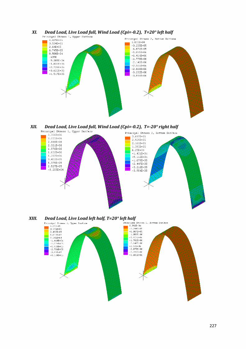
227
XI. Dead Load, Live Load full, Wind Load (Cpi=-0.2), T=20° left half
XII. Dead Load, Live Load full, Wind Load (Cpi=-0.2), T=-20° right half
XIII. Dead Load, Live Load left half, T=20° left half

228
XIV. Dead Load, Live Load left half, T=-20° right half
XV. Dead Load, Live Load left half, Wind Load (Cpi=0), T=20° left half
XVI. Dead Load, Live Load left half, Wind Load (Cpi=0), T=-20° right half
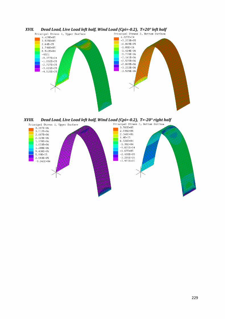
229
XVII. Dead Load, Live Load left half, Wind Load (Cpi=-0.2), T=20° left half
XVIII. Dead Load, Live Load left half, Wind Load (Cpi=-0.2), T=-20° right half
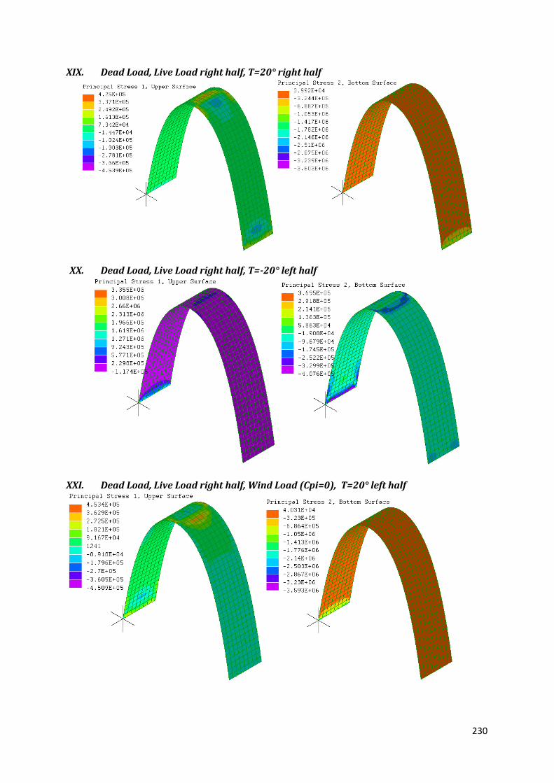
230
XIX. Dead Load, Live Load right half, T=20° right half
XX. Dead Load, Live Load right half, T=-20° left half
XXI. Dead Load, Live Load right half, Wind Load (Cpi=0), T=20° left half

231
XXII. Dead Load, Live Load right half, Wind Load (Cpi=0), T=-20° right half
XXIII. Dead Load, Live Load right half, Wind Load (Cpi=-0.2), T=20° left half
XXIV. Dead Load, Live Load right half, Wind Load (Cpi=-0.2), T=-20° right half

232
XXV. Dead Load, Wind Load (Cpi=0), T=20° left half
XXVI. Dead Load, Wind Load (Cpi=-0.2), T=20° left half
XXVII. Dead Load, Wind Load (Cpi=0), T=-20° right half

233
XXVIII. Dead Load, Wind Load (Cpi=0), T=-20° right half